Harbor engineering - CORE
135
i.:i.i:ii!i:u..'.v.a>r
-
Upload
khangminh22 -
Category
Documents
-
view
4 -
download
0
Transcript of Harbor engineering - CORE

i.:i.i:ii!i:u..'.v.a>r


0^ ,,r^^

wU
HARBOR ENaiNEERINO
BY
KoiCHi Hattori
THESISFOR THE
DKGREE OF
i
Bachelor of Science
IN
Civile ENaiNEERING
IN THE
COLLEGE OF ENGINEERING
UNIVERSITY OF ILLINOIS
1911
tit

\<\\\
mi
UNIVERSITY OF ILLINOIS
May 25, 1911
I reconunenci that the thesis prepared under my supervis-
ion KOI CHI IIATTORI entitled Harbor Engineering be approved as
fulfilling this part of the requirements for tne degree of Bach-
elor of Science in Civil Engineering.
Recomiricndat ion approved:
Head of the Department of Civil Engineering.

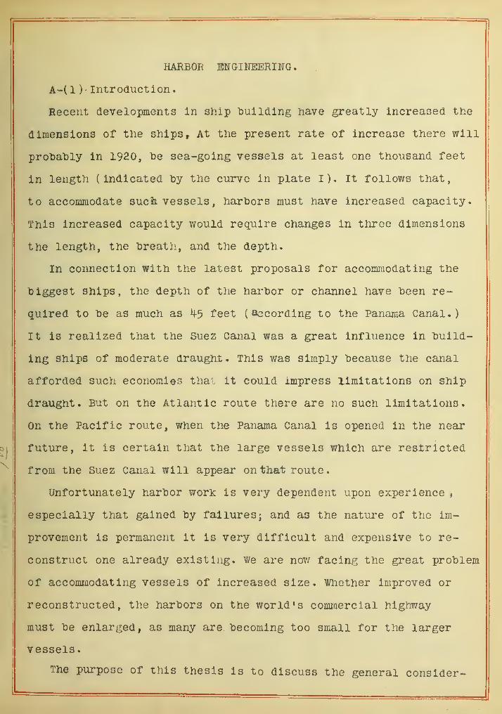
HARBOR EKGINEERIITG.
A-( 1 ) • Introduction.
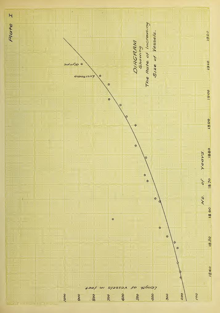
Recent developments in ship building have greatly increased the
dimensions of the ships ^ At the present rate of increase there will
probably in 1920, be sea-going vessels at least one thousand feet
in length (indicated "by the curve in plate I). It follov/s that,
to accommodate such vessels, harhors must have increased capacity.
This increased capacity would require changes in throe dimensions
the length, the "breath, and the depth.
In connection with the latest proposals for accommodating the
"biggest Ships, the depth of the harhor or channel have "been re-
quired to "be as much as ^5 feet (according to the Panama Canal.)
It is realized that the Suez Canal was a great influence in "build-
ing Ships of moderate draught. This was simply because the canal
afforded such economies thai it could impress limitations on ship
draught. But on the Atlantic route there are no such limitations.
On the Pacific route, when the Paiiama Canal is opened in the near
future, it is certain that the large vessels v/hich are restricted
from the Suez Canal will appear on that route.
Unfortunately har"bor work is very dependent upon experience ,
especially that gained by failures ^ and as the nature of the im-
provement is permanent it is very difficult and expensive to re-
construct one already existing. We are now facing the great problem
of accommodating vessels of increased size. Whether improved or
reconstructed, the harbors on the world's commercial highway
must be enlarged, as many are, becoming too small for the larger
vessels.
The purpose of this thesis is to discuss the general consider-

Digitized by the Internet Archive
in 2013
http://archive.org/details/harborengineerinOOhatt
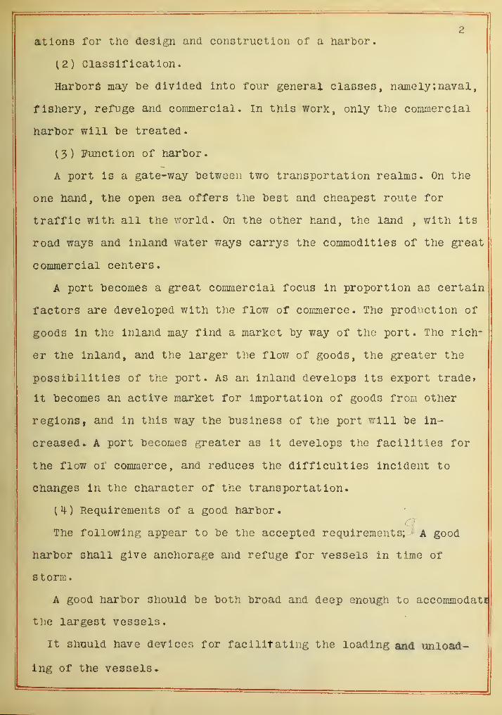
2
ations for tlio design and construction of a hartoor.
(2) Classification.
HarlDors may tie divided into four general classes, namely; naval,
fishery, refuge and commercial, in this work, only the commercial
harljor will be treated.
13) function of harbor.
A port is a gate-way between two transportation realms. On the
one hand, the open sea offers the best and cheapest route for
traffic with all the world. On the other hand, the land , with its
road ways and inland water ways carrys the commodities of the great
commercial centers.
A port becomes a great commercial focus in proportion as certain
factors are developed with the flow of commerce. The production of
goods in the inland may find a market by v/ay of the port. The rich-
er the inland, and the larger the flow of goods, the greater the
possibilities of the port. As an inland develops its export trade?
it becomes an active market for importation of goods from other
regions, and in this way the business of the port will be in-
creased* A port becomes greater as it develops the facilities for
the flov/ or commerce, and reduces the difficulties incident to
Changes in the character of the transportation.
^M-) Requirements of a good harbor.
The following appear to be the accepted requirements; ' A good
harbor shall give anchorage and refuge for vessels in time of
s torm.
A good harbor should be both broad and deep enough to accommodati
the largest vessels.
It shuuld have devices for facilitating the loading and unload-
ing of the vessels*

It should nave a iDelt-line rail-way connection between general
water traffic and adjacent railroads, if possible local industries.
It snould De provided witn a ship repairing and building system.
It should have good organization and good regulation and
control.
^5) Preparation for designing a harbor.
Each different locality has its own peculiarities and therefore
each particular case must be considered carefully in designing a
harbor. From this study it appears that the following are the
most important it ens included in such a study;
(a) General Census
(b) Topographic survey
( c ) Sounding
( d ) Boring
(e) Wind
( f ) ¥/aves
(g) Tide and tidal current
(h) Silting and littoral current
(i ) Ice
(J) Materials for construction,
(a) General census.
Under" this item, the nature of the port at the present as well
as the probable future character should be carefully investigated.
This is of great importance for the determination of water area
of the outer and inner harbors, and the preperation for the future
extension. The following are the principle parts of the census;
Population.
Financial condition.
General traffic and the amount.

Special traffic and the amount
»
Relation to other ports.
Value of the port, prominent peculiarities.
Vessels; Kind of vessels, number of vessels, tonnage,
mciximum numlDer and tonnage of vessel In
harDor a same time .numlDer in particular sea-
son, rate of Increasing size of vessels .
Future development of shipping, and opportunities of
commerce and Industry.
(Id) Topographic survey.
A comprehensive and detailed survey should te made to ascer-
-tain the degree of the exposure of the harbor. The waves which oc-
cur in the harhor depend upon the exposure of the side from which
shelter 1 s most needed • In this respect, the determination of the
position of shoals. Island and coast, and distance to the opposite
nearest land are desirable.
The trlangulation should be made Including all the harbor and
vicinity^ and should establish permanent marks which will be used as
a basis for the sounding, boring, the observation of tidal currents
and the determination of the character of the sea structures.
( c ) Soundiing.
Sounding should be taken at sufficiently short intervals
to admit contours being accurately laid down. Special care should
be taken over rocky ground to show actual elevation of bed as it
Is usually very Irregular. The nature of the sea bed should be
also ascertained by procuring a sample of the bottom at each sound-
ing. The depth of water should be refered to lowest spring tide.
A set of soundings of a harbor though complete cannot
furnish all the necessary information regarding the nature of the

5surface of "bottom of the harfeor and Its changes. There should iDe
a series of such soundings at the time of faroatest and least
disturbance, and extending over a number of years to exfbH com-
parative changes and show the relative movement both in amount
and direction.
(d) Boring.
The borings should be made to ascertain the nature of the
strata below the bottom for a considerable depth and in sufficient-
ly close Intervals over the entire harbor. It is very important
to determine the bearing power of the bottom vrtiere a heavy breai:-
water is to be built, or to ascertain the liind of machinery which
is used to dredge the channel and to what extent it is used.
The careful exarainatlon of the material excavated should
be made especially for the doclc v/all and the breakwater, as in the
former case the design of the v/all must bo made to depend upon the
nature of the foundation which affects the cost of such ?;orks
very largely.. In a docli: surrounded by quay walls^ the cost
constitutes a very important part of the total expenditure, andi©
the case of the breaicwater insufficient bearing pov/er of the soil
causes considerable settlement which leads the destruction of whole
structures.
(e) Wind.
Wind is the generator of the sea waves which Interfere with
the construction of sea wor]cs. The harbor construction work should
' be arranged so as to taice advantage of the worlcing season.
I
It is important to observe the direction, strength,
duration, relative frequency, and sequence of winds extending
over as long a period as possible. Most authorities suggest
that the result should be plotted using the ieaufort Scale.

6
( f ) Waves
.
In planning a sea structure, it Is very Important to secure
in advance data relating to tiie waves. The following sulDjects
are suggested by Captain D.D. Gaillard;
Frequency and violence of storms.
Tne direction and maximum velocity of storm wind.
S'etcn or distance to opposite snore.
The direction of wave travel.
The maximum height and length of storm wave.
Whether or not waves "break in advance of, or in the
viclillty of^ the site during storms.
The governing depth in the vicinity.
The character of the bottom.
Special waves which are not storm waves.
It should "be remembered that the greatest wave which can
reach the port occurs only once in several years. The observation^
should therefore be kept continuously as long as possible. The
results of the observations may be checked by careful study
either of the effect the wave action upon the sea works which
are already built in the harbor or vicinity, or "by a study of marks
upon the rocky coast or cliff which has been subject to the con-
tinuous action of waves.
(g) Tide and tidal current.
Before and during a harbor construction, the tidal obser--±ide
vat ion should be made by means of self-recording gauges* There
are four important facts in the tide determination.
(1) The tidal establishment at full tide and change,
or "Correct Establishment". This is of great
value to vessels leaving or entering a tidal
harbor.

4
7
(2) The highest and lowest spring tides.
The effective depth in a tidal harbor depends upon
the lowest water. It is there-fore necessary to
Know the lowest spring tide.
(3) The average tidal ranges.
The wave action upon the sea worKs is raost severe
at the average lov/ and high tide. The wider the
range of tide the stronger and heavier the sea-
structure should he.
The datum- average spring water level.
Prom the point of sanitation in a harbor, navigation of vessels,
and maintainance of the depth of water in a channel, it appears
from this study that the following items should he carefully in-
vestigated;
M£LXimum and minimum velocity of tidal current.
The direction of tidal current.
The effect of an ocean current.
Currents caused hy storm,
(h) Silting and littoral currents.
In a closed harbor , it has been often experienced that a con-
siderable amount of silting caused the harbor to become shallower
and ultimately become choked and rendered useless* The careful .
study of the silting therefore should be made before attempting
sea construction as break-waters and jetties.
Where littoral currents exist, they cause the sand and shingle
to travel with the counter action of waves. If the nature of the
current varies as the weather changes, careful study in respect
to this is required. The investigation should include the coast
for a long distance on either side of the site of the proposed work.

8
Small coal, pieces of burnt clay or other easily recogniza'ble
material may "be deposited at points alomg the coast In various
depths of water, to determine the relation of strength and duratio]
of the flood, et)"b and littoral currents,
(i ) Ice.
In some localities, there are many records of serious
damage to the sea structure caused lay the floating ice. The
following items appear to he of value for reference in designing
break- v/aters on sea works^ where ice is encountered,;
The extent of the ice field.
The magnitude of a floating ice.
The relative motion with wind and current.
(J) Material for construction.
Sand and stone are the materials most extensively usedin
in harbor works, if such a material is found aboundantely^the
vicinity of the site, the cost of construction will be reduced
greatly. Many specimens should be collected and a comDaratlve
study according to the follov/ing items should be made;
Quality of materials,- physical and chemical.
Durability*
Specific Gravity.
(Quantity.
Cost of transportation.
(B) The Broalcwater
.
(1) Purpose.
Tne t)reakv/ater Is a structure built for the purpose of
toreaicing or reducing the force exerted "by the waves, thus pro-
ducing the still water in the harbor* The main purposes of a "break-
water are as follows;
To provide safe anchorage for vessels*
To facilitate loading and unloading vessels.
To protect the structures in the harbors.
( 2 ) The Type Forms
.
Brea}£waters may be classified in two general types, namely,
the vertical type and the mound type.
I. Vertical types.
The vertical type of the brea]ayater includes the folloT/ing
seven different forms of construction;
(a) Timber framing filled with rubble stone.
(b) Masonry or concrete bloclcs with a hearting of dry
rubble stone.
(c) Concrete blocks laid in horizontal courses.
(d) Mass work of concrete.
(e) Mass worK of concrete with concrete bags.
(f ) Concrete blocks laid in sloping courses.
(g) Reinforced concrete caissons.
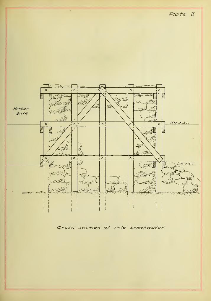
(a) Timber framing breaicwater filled with rubble stone.
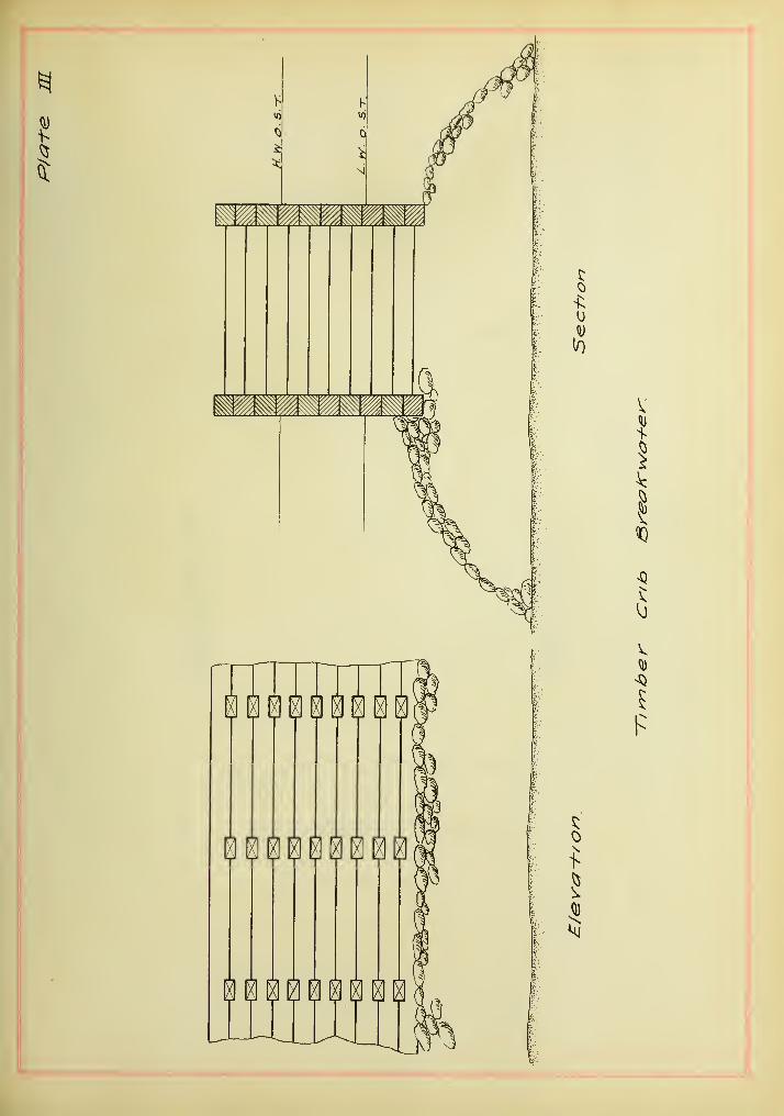
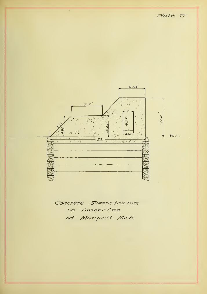
This type of breakwater has been extensively used in the
Great Lakes of the United states. There are two destinct forms of
breakwater in this class. One employes pile work (Plate II) and
the other crib work (Plate III and IV).
The function of this type of breakwater is to encase the

10rut>l3le and prevent its dispersion, the rubtole gives support to
the framing by its weight.
In the hreat-water of pile work, the larger stone should
"be used for the faces of the hreaKwater and the piles should he
well "braced together as shown in the figure, (Plate II). The heart-
ing is usually dumped from wagons.
In the second form of hreaKwater of timber crib work,
the cross section should he square this being the most economical
form. The crib is usually built in sections on the land, and sunk
into place with or without a superstructure.
rt is very important, in constructing either pile or
crib breakwaters, to back up the same with rubble as quickly as
possible, because upon this, the stability of the structure in a
great measure depends, and frames, while impacked, are very liable
to be displaced and damaged even by moderate sea.
Advantages and disadvantages.
This Class of breakwater is best suited for shallow water
where they are not to be exposed to very heavy sea, and especially
as a dike for training the channel at the mouth of a river.
Where sutlble materials can be obtained at reasonable cost
the breakwater will be constructed qulckiy^ and at considerably
less cost than those built of solid masonry or concrete. But in
general, the timber works are of temporary nature, and liable to
decay between high and low water levels. Moreover it receives the
attack of the teredo and other sea worms, unless the timber has been
well treated and protected.
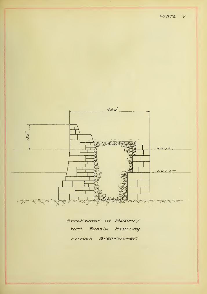
(b) Break\vaters of masonry or concrete blocks with a heart-
ing of dry rubble stone.
A typical form of this class of breakwater is shown in
Plate V. The dimensions ar» those of the Filrush breakwater.

11It consists of tnree parts; tne masonry or concrete walls on sea
and h£Lrt)or sides and the rutolDle hearting.
The vertical walls are "built with or without cement raort«r
and filled with loose ru"bi3le stone from wagons.
Advantages and disadvantages*
This class of "breaKwater is only suitable for the site wher i
exposure is not severe. In constructing the l)reaicwater expensive
machinery is not required, and accordingly the first cost may toe
low as compared with other types of toreaicwaters
.
The outer walls act as retaining walls separately as there
is no connection between them and during a storm, the hearting
acts as a wedge "between the walls, its action being increased by
the falling of the mass of water upon the road-way. This type re-
quires exceptionally strong and heavy construction and proportional
increase in the cost.
The failures of this class of breakwater are started by the
ploughing out of the rubble hearting, and followed by the overturn-
ing of the v/alls which have lost their support. The breaicwater
therefore is most suitable as a landing pier where no heavy wave
action exists.
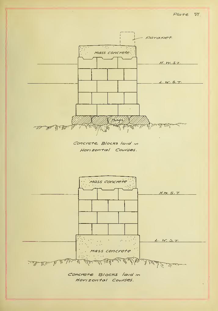
(c) Concrete blocks laid in horizontal courses.
This class of vertical breaicwater is illustrated in plate
"VI. It consists of concrete bloclcs laid in horizontal courses
with broken Joints, and mass concrete is deposited over whole width
of the breaijurater to make it form a monolithic mass.
The leveling of the foundation is most essential part of the
construction. Any irregularity of the surface of bed should be re-
moved^or filled with mass concrete, or concrete bags by the aid of
divers
.

12On the prepared foundation telow the low water level, the
concrete iDlocKs are laid "dry", those ahove the level set in cem-
ent and grout
.
Advantages and disadvantages.
This form of brealcwater Is recommended for shallow or for
moderate depth of water where the foundation Is rock, as progression
of the work is rapid.
It is very difficult cOid expensive to secure perfect con-
tact of successive layers, especially laelow the low water.
Trouhle is often experienced "by the settlement of the dry
set "blocKs. The blocks come to "bear upon each other at a point or
edge which is apt to cause breakage of the "blocks, or they are
liable to fall away from the monolithic work and be easily drawn
out by the waves.
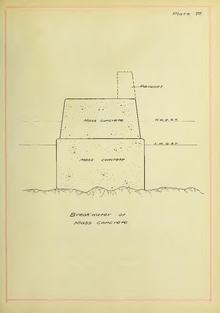
^d) Breakwater of mass concrete.
The typical section of this bresikwater is shown in plate VII.
The breakwater is of the monolithic concrete deposited within temp-
orary timber forms.
This method of construction is very suitable to rocky ground
and Is not applicable to exposed situations.
Advsmtages and disadvantages.
This system of breakwaters possesses the follovring merits;
It is applicable either belov/ or above water level,
and to large and small works alike.
It may be carried out with a very small expenditure for
constructing plant.
The tedious and expensive operation of leveling foundat-
ions is reduced greatly.
A large monolithic block may be constructed at a time.

13
The disadvantages are as follows;
It Is a "good weather method", so there is no worlc for
the employee engaged on the construction when it Is
interrupted toy a rough sea.
The great difficulties in iDulldlng the forms in water
and to conform with irregularities of the surface of
roclc, thus increases the cost.
The interruption of the worK: and the lossof cement arise
from the injury to the forms,
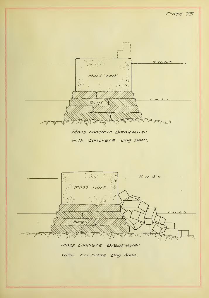
(e) Mass work of concrete with concrete "bags.
In this class of vertical toreaicwater , the large canvas or
jute "bags containing from 4- to 20 tons of fresh mixed concrete
form a "base for a monolithic mass concrete above them as shown in
plate VIII.
The purpose of using concrete "bags is to prevent the cement
from washing out when deposited under water.
The "bag wori: is usually hrouglit up to or ahove the lowfrc3rr\es
water and the temporary timber^ are huilt on the top of the bags
to receive the concrete.
It is not desirable to expose a bag work face to the stroke
of very heavy waves as there are usually some spaces between the
bags. To protect the face of bag work, rip-rap wave breakers are
used on the weather side as shown in jjlate VIII.
This class of breakwater is most suitable in shallow water
and slight exposure, as it is not entirely a monolithic mass.
Advantages and disadvantages.
The merits of this method of constructing breakwaters are
as follows;
It saves the cost of timber for the frames and labor.

There is less danger of cement being washed out
When deposited
•
The disadvantages are as follows
;
The iDag is liable to be torn while being deposited
in the water.
The concrete in a bag is liable to be brolcen into
pieces when lowered toy the bottom.
It is also a"good weather method", and so it has
the same disadvantages as the preceding class of
breaicwaters, to which reference is made.
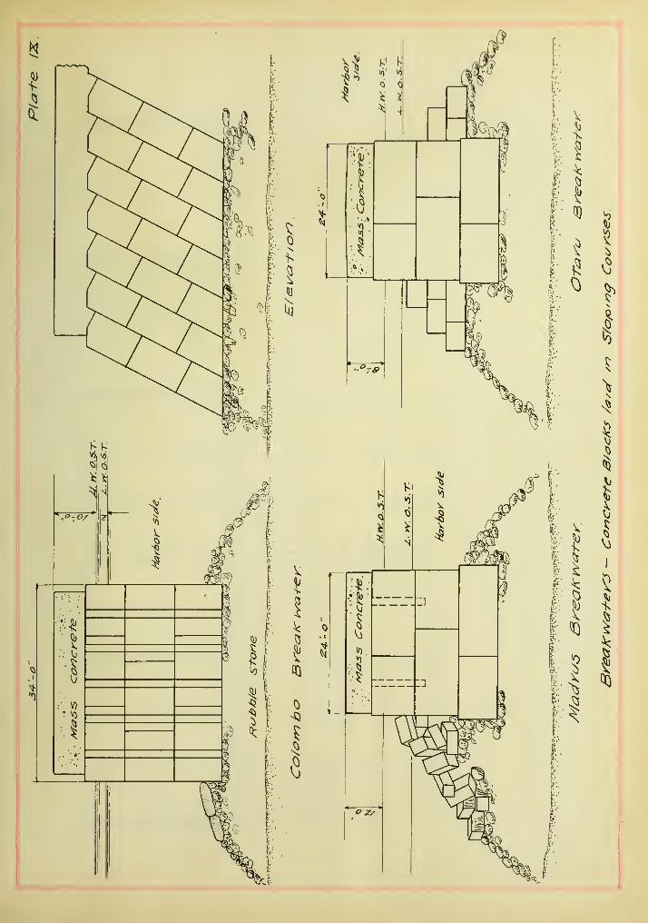
[t) Concrete blocks laid in sloping courses.
Tills form of breai:water is used most successfully
in almost all localities. The concrete bloc]cs are laid in inclined
position malting an angle of 65 to SO degrees with the horizontal
axis, Which rests on the base of rubble stone, bags or mass con-
crete.
The inequalities at the quay level are adjusted by a
capping of mass worK vmich binds together the blocics which form
the monolithic breai[water. Also the blocks are bound togeth3r not
only by breaking Joints with each other but by means of joggles of
large size,, formed by filling grooves with concrete in bags.
The typical form of breakwater of this class is shown
in plate IX.
Advantages and disadvantages.
The advantages of this breakwater are as follows;
It is suitable for either the purely vertical type
or for a combination with a rubble base.
It is the most suitable form for the site which
is subjected to heavy wave action.

15ine injury resulting irom seLuienienx is less Liian
m x/ie case or ouner DreajcwaLers or une verx.ica,i type*
ine DreajCT/aLer 3 may oe duiii. on any Kino, or sea oecL
or bottoin#
ine progress ox consurucLion or x.ne oreajiLwaLer is
VQry rapid ao lu is xaiu iiom tne i.op oi une DrecLitwater
oitQii Dy means oi a sex.Ling macnme.
Un6 uXoclU.VcUl liclgri JLtj LIlclL bn6I 6 Id O. ocnClrlliCy 1 OI l>116
Slope Lo Decome iiatuer auring cons urucu ion*
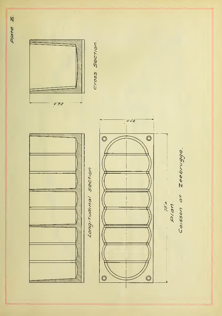
^g) Reinforced concrete caisson brea}£water.
This is the latest type of the vertical hreakwater as
adopted in several places.
The reinforced concrete caisson as shown in plate IX,
is "built on the land and floated hetween the guides over a "base
previously prepared. Then toy knocking out the pins, the caisson
is sunk in place and filled with concrete rapidly.
The figureC Plate X) shows the caisson used in the "break
water at Zeehrugge, Belgium, which was 75 feet long, 27 feet wide,
and of 7 thousand tons in weight.
The dj sadvantaget; of this system are as follov/s
;
Extra cost of making a large steel skeleton.
Great skill is required to form the caisson properly
The advantages of this system are as follows;
Rapid progress of the work.
Increased strength of hreakv/ater
.
It is most suitahle for an open sea.
It is suitable for deep Tfater work.
16II. Moimd types.
The mound type of the torealcwater includes two different
typos of construction, viz;
(a) Mounds formed toy rulDtole stone,
("b) Mounds of concrete blocks thrown together,
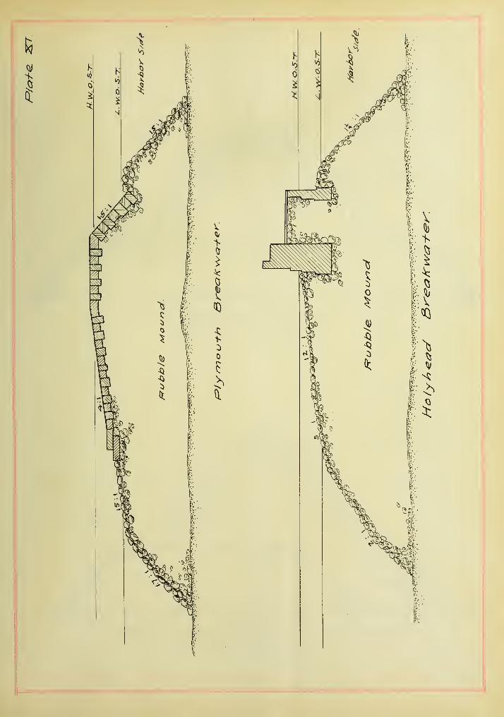
(a) Mound hrealcwatar of ruhhle stone.
There are two distinct forms of hreaicwaters of rubble
stone, those with and those without a superstructure. The two forms
are shown in plate XI.
The former consists entirely of rubble stone tJirown
into the sea and allows the waves to form a natural slope. The lat-
ter has a vertical or sloped masonry structure on the mound.
It is evident that the mound type of brealcwater is only
applicable where there is an abundant and. good supply of suitable
stone in the vicinity.
The advantages of these breaicwaters are as follows;
Cheapness of material.
Simple methods of construction.
Rapidity of construction.
The disadvantage Is the high cost of maintenance,
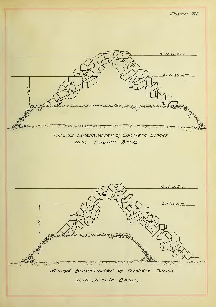
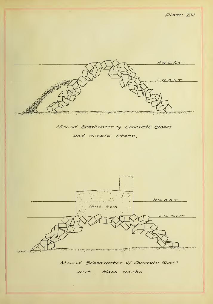
(b) Mounds of concrete blocks.
There are a few breakwaters which are constructed
entirely of pell-mell block construction on account of the cost
of concrete blocks. So the combination of rubble stone and pell-
mell blocks is used quiet v/idely. Such combinations" are very
neuinerous and a few of them are shown in plates Xti an6XIll.
The following are the most common types found in the
Mediterranean Sea;
(1) Pell-mell mound of blocks placed upon the base

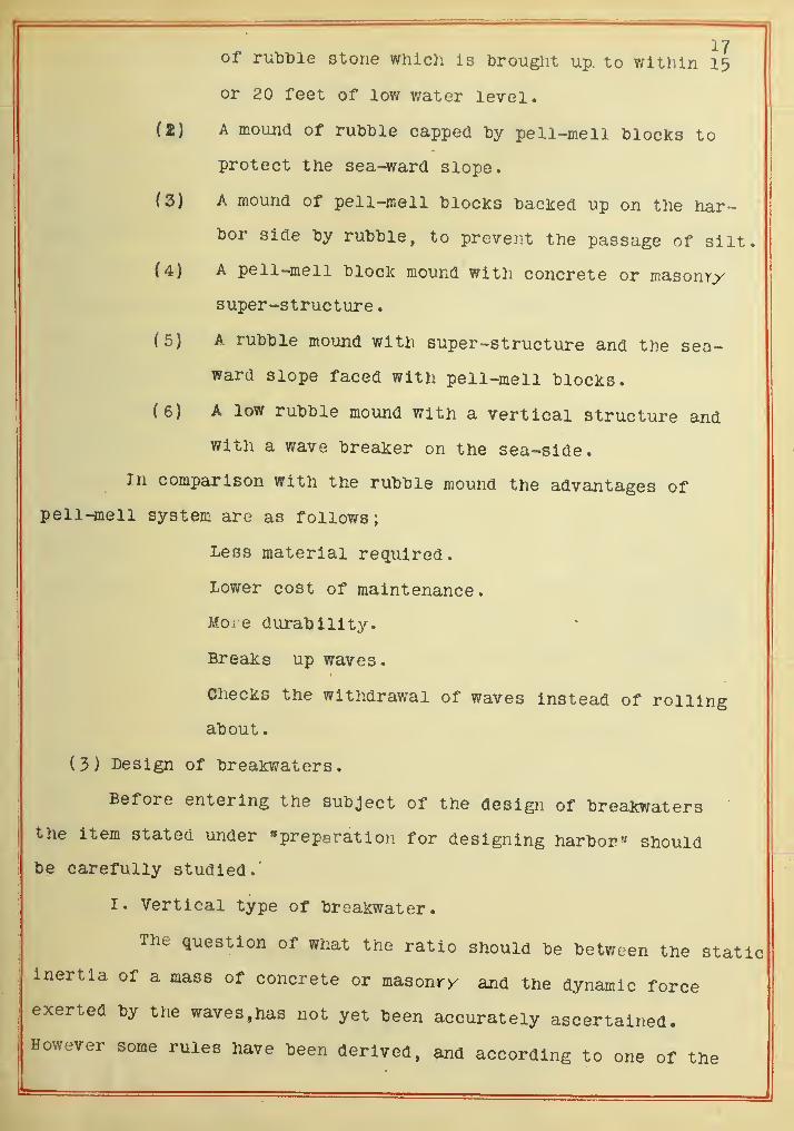
17of rut)t)le stone which is Drought up. to within 15
or 20 feet of low water level.
(I) A mound of ruDble capped Dy pell-mell blocKs to
protect the sea-ward slope.
(3) A mound of pell-mell tlocks toacked up on the har-
bor side Dy ruDDle, to prevent the passage of silt.
(4) A pell-mell hloclc mound with concrete or masonry
super-structure.
(5) A rubtole mound with super-structure and the sea-
ward slope faced with pell-mell hloclis.
f6) A low rut)hle mound with a vertical structure and
with a wave breaker on the sea-side.
In comparison with the rubble mound the advantages of
pell-mell system are as follov/s
;
Less material required.
Lower cost of maintenance.
More durability.
Breaks up waves.
Checks the withdrawal of waves instead of rolling
about
.
(3) Design of breaKwaters.
Before entering the subject of the design of breakwaters'
the item stated under "preparation for designing harbor" should
be carefully studied.'
I. Vertical type of breakwater.
The question of what the ratio should be between the staticinertia of a mass of concrete or masonry and the dynamic force
exerted by the waves. has not yet been accurately ascertained.
However some rules have been derived, and according to one of the

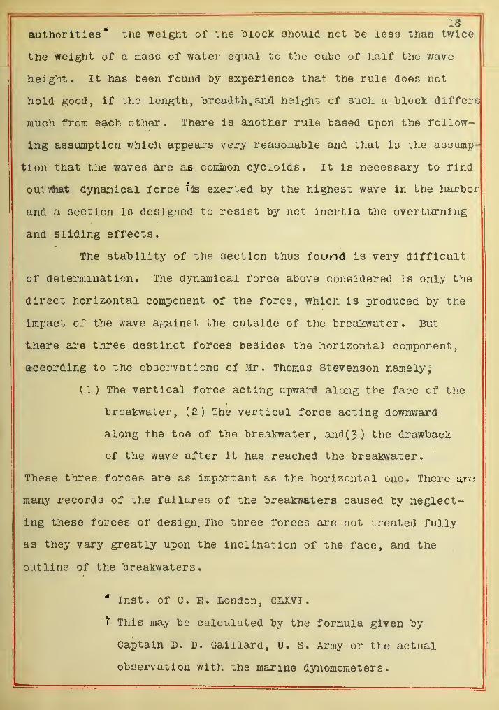
authorities* the weight of the hloclc should not "be less than twice
the weight of a mass of water equal to the culoe of half the v/ave
height. It has toeen found hy experience that the rule does not
hold good, if the length, toreadth, and height of such a "bloclc differs
much from each otJier. There is another rule "based upon the follow-
ing assumption which appears very reasonable and that is the assump-
tion that the waves are as comhion cycloids. It is necessary to find
oulTAhat dynamical force tjs exerted by the highest wave in the harbor
and a section is designed to resist by net inertia the overturning
and sliding effects.
The stability of the section thus found is very difficult
of determination. The dynamical force above considered is only the
direct horizontal component of the force, which is produced by the
impact of the wave against the outside of the brealcwater. But
there are three destinct forces besides the horizontal component,
according to the observations of Mr. Thomas Stevenson namely,
(1) The vertical force acting upward along the face of the
breakwater, (2) The vertical force acting downv/ard
along the toe of the brealcwater, and(3) the drawback
of the wave after it has reached the breakwater.
These three forces are as important as the horizontal one. There are
many records of the failures of the breakwaters caused by neglect-
ing these forces of design. The three forces are not treated fully
as they vary greatly upon the inclination of the face, and the
outline of the breakwaters.
* Inst, of C. E. London, CLXVI
.
t This may be calculated by the formula given by
Captain D. D. Gaillard, U. S. Army or the actual
observation with the marine dynomometers
.

The19
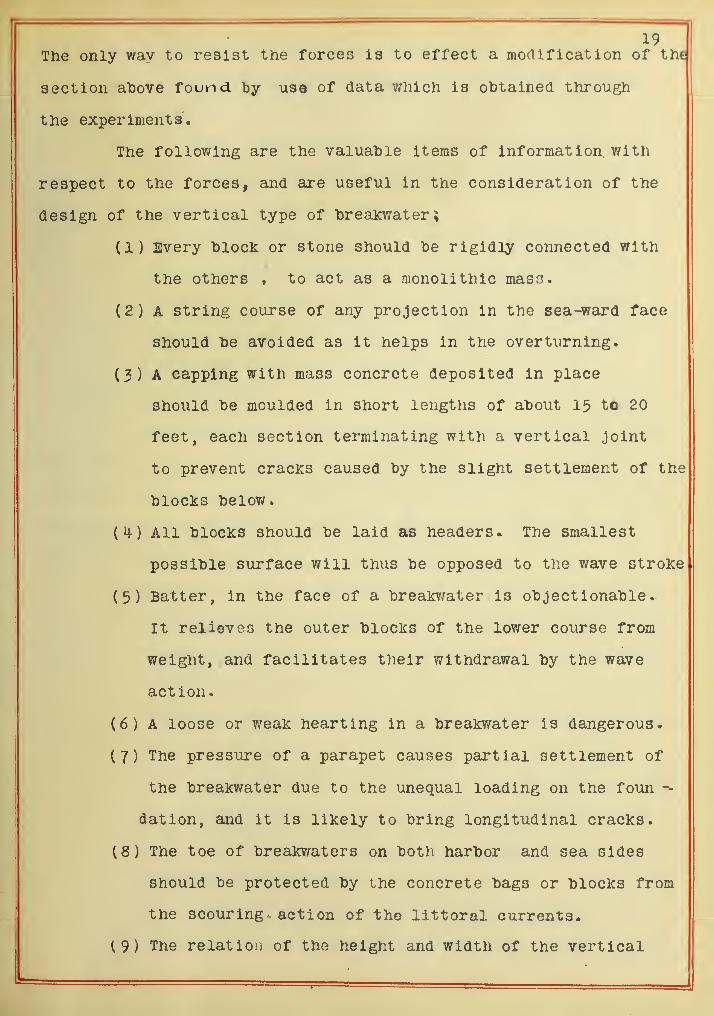
only way to resist trie rorces is to eriect a. monincation oi me
section above found by use of data which is olJtained through
the experiments.
The following are the vaiua"ble items of information, with
respect to the forces, and are useful in the consideration of the
design of the vertical type of hreaicwater
;
(1) Every bloclc or stone should he rigidly connected with
the others , to act as a monolithic mass.
(2) A string course of any projection in the sea-ward face
should he avoided as it helps in the overturning.
(3) A capping with mass concrete deposited in place
Should "be moulded in short lengths of ahout 15 to 20
feet, each section terminating with a vertical Joint
to prevent cracKs caused "by the slight settlement of the
hloclts "below.
All hlocks Should he laid as headers. The smallest
possihle surface will thus he opposed to the wave stroke
(5) Batter, in the face of a hrealcv/ater is ohjectionahle
.
It relieves the outer hloclcs of the lov/er course from
weight, and facilitates their withdrawal hy the wave
action.
(6) A loose or weak hearting in a hreaioirater is dangerous.
(7) The pressure of a parapet causes partial settlement of
the hreaKwater due to the unequal loading on the foun
dation, and it is likely to bring longitudinal cracks.
( S ^ The toe of hreakwaters on both harbor and sea sides
Should be protected by the concrete bags or blocks from
the scouring action of the littoral currents.
(9) The relatioii of the height and width of the vertical

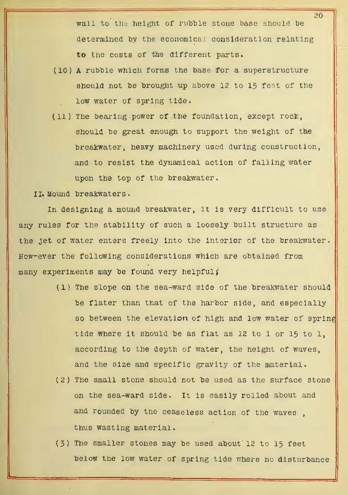
wall to th-i height of rulDlDle stone base should be
determined "by the economical consideration relating
to the costs of the different parts.
(10) A ruhhle which forms the hase for a superstructure
should not he brought up above 12 to 15 feet of the
low water of spring tide.
(11) The bearing -power of the foundation, except rocK,
should be great enough to support the weight of tlie
breakwater, heavy machinery used during construction,
and to resist the dynamical action of falling v;ater
upon the top of the brealcwater.
II. Mound brealcwaters
.
In designing a mound breakwater, it Is very difficult to use
any rules for the stability of such a loosely built structure as
the jet of water enters freely into the interior of the brea]o?ater.
How-ever the following considerations which are obtained from
many experiments may be found very helpful
(1) The slope on the sea-ward side of the breakwater should
be flater than that of the harbor side, and especially
so between the elevation of high and low water of spring
tide Where it should be as flat as 12 to 1 or 15 to 1,
according to the depth of v/ater, the height of waves,
and the size and specific gravity of the material.
(2) The small stone should not be used as the surface stone
on the sea-ward side. It is easily rolled about and
and rounded by the ceaseless action of the waves,
thus wasting material.
(3) The smaller stones may be used about 12 to 15 feet
below the low water of spring tide where no disturbance

occurs.
(M-) A moderate mixture of small material in the mound
assists the stability of tne "breaicwater , "but the use
of an excessive amount of small stones reduces the
strength of the "brealcwater and causes unequal settle-
ment •
(5) The placing of a vertical structure upon a ruhhle stone
mound is very olDjectional. It increases scouring
action upon the sea-ward slope which ploughs out stones
from ahout 20 to 30 feet below the low water of spririg
tide.
(6) The pitching of the surface of a ruhhle mound as
shown in plate XI is very object ionable . It faciliates
drawing haclc of waves and disturbs the rubble at the
toe of the pitching.
(7) The width of the mound breakwater at tlie foundation
should be increased according to che bearing pov/er
of the sea-bed.
(8) In a pell-mell mound placed upon a rubble stone base
the latter should be wide enough to allow of a level
bench extending beyond the toe of the blocK slope.
(9) The size of blocks for pell-mell work should be determ-
ined by a careful study of the work already built in
the vicinity and of the conditions at the site.
Ill, Effects of ice.
In the northern localities, the effects of ice should not
be forgotten in designing either vertical or mound types of break-
waters or any other sea structures.
One effect of the ice is the formation of the mass upon

V
\
22the structure, resulting from the freezing of the water thrown
upon the hrealcwater waves. This is a large additional load on
the hrealcwater, and at the same time, it increases the area of sur-
face exposed to wave action, and reduces the stability of the hreaK
water.
The floating ice on the sea- ward side of the hreakwater
is another serious matter, but if pack ice covers a broad area
of the surface of water, it acts as a floating breakwater, and
reduces considerably the wave action before the wave reaches the
breakv/ater.
Still another effect of ice which is most dangerous to
a sea structure is that which occurs when the surface of the water
is covered with floating ice of firm pieces, and they do not act as
a floating breakwater, but they are thrown by the waves against the
sea structure and causes serious damage.
(4) Location of breakwater.
The location of breakwaters depends greatly upon the con-
figuration of the coast line, the extent of sheltered area required
and the location of the requisite depth.
At the same time,, the location depends partly upon the type
of breakwater adopted to suit the exposure of the harbor. In
general, the vertical type of breakwater should be so located that
the longitudinal axis of the breakwater should be placed at an
oblique angle to the direction of the prevailing heavy storms to
reduce the force of wave action against the structures. The mound
type of breakwater should be laid out far enough to make the waves
break squarely on it since if waves break obliquely upon a rubble
mound they cause the stone to travel.
Still another fact to keep in view is the easy approach
23during heavy gales for tne vessels entering the har'bor.
If the brealcwaters are built too nearly parallel to each
otlier near the entrance, it is very dangerous to vessels navigating
between them as the vessels could not develop very muoh speed in
this position.
Finally, the hrealcwater should he so located, as to accomo-
date the growth of the port and so as to admit of its easy exten-
s ion when additional area is required.
(5) Construction.
In constructing the hrealcwaters , the following precautions
should always he Kept in mind
;
tl) The materials to he used in the hreakwater should he
kept on hand in ahundant quantities and sent out with-
out any delay whenever weather or sea permits.
(2) All machinery should "be kept in good condition.
(3) All tools and equipment should he placed in a safe
place at the end of each days work.
(^) The end of the breakwater is the weakest point while
the work is in progress, so the proper protection
should he made for wave action when the days work is
over.
(3) Work should not he left half done at any time.
The general methods of handling materials for constructing
a breakwater are as follov/s;
I Pile driving.
For driving the piles of a timber framed breakwater, any
methods may be applied to the extension of the work according to
the conditions of the site. But a steam-hammer pile driver on a
barge is most extensively used for this purpose,owing to the rapidity
and efficiency of its work and effectiveness of its blow.
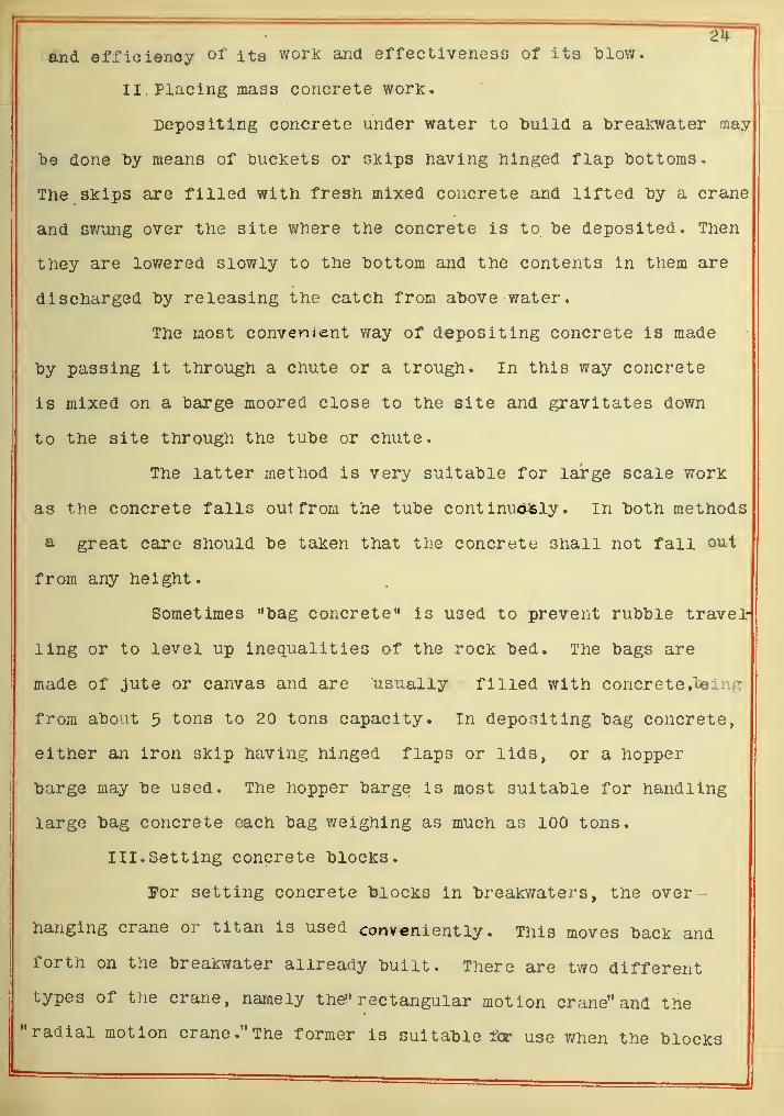
II. Placing mass concrete worK.
Depositing concrete under water to "build a "brealcwater may
"be done by means of buckets or skips having hinged flap bottoms.
The skips are filled with fresh mixed concrete and lifted by a crane
and svmng over the site where the concrete is to be deposited. Then
they are lov/ered slowly to the bottom and the contents in them are
discharged by releasing the catch from above water.
The most convenient way of depositing concrete is made
by passing it through a chute or a trough. In this way concrete
is mixed on a bairge moored close to the site and gravitates down
to the site through the tube or chute.
The latter method is very suitable for large scale work
as the concrete falls ou1 from the tube cont Inucwsly In both methods
a great care should be taken that the concrete shall not fall out
from any height.
Sometimes "bag concrete" is used to prevent rubble travel-
ling or to level up inequalities of the rock bed. The bags are
made of jute or canvas and are usually filled with concrete»"bBing
from about 5 tons to 20 tons capacity. In depositing bag concrete,
either an iron skip having hinged flaps or lids, or a hopper
barge may be used. The hopper barge is most suitable for handling
large bag concrete each bag weighing as much as 100 tons.
III. Setting concrete blocks.
For setting concrete blocks in breakv/aters, the over-
hanging crane or titan is used conveniently. This moves back and
forth on the breakwater allready built. There are two different
types of the crane, namely the!' rectangular motion cr?ine" and the
"radial motion crane."The former is suitable for use when the blocks

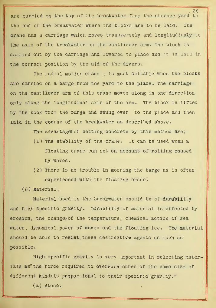
are carried on the top of the "breakwater from the storage yard to
the end of the breakwater where the 'blocks are to "be laid. The
crane has a carriage which moves transversely and longitudlnaly to
the axis of the "breakwater on the cantilever arm. The hlock is
carried out by the carriage and lowered to place and it is laid in
the correct position "by the aid of the divers.
The radial motion crane , Is most suitable when the blocks
are carried on a barge from the yard to the place. The carriage
on the cantilever arm of this crane moves along in one direction
only along the longitudinal axis of the arm. The block is lifted
by the hook from the barge and swung over to the place and then
laid in the course of the breakwater as described above.
The advantages of setting concrete by this method are;
(1) The stability of the crane. It can be used when a
floating crane can not on account of rolling caused
by waves.
(2) There is no trouble In mooring the barge as is often
experienced with the floating crane.
( 6 ) Material.
Material used in the breakwater should be of durability
and high specific gravity. Durability of material is effected by
erosion, the changcjs of the temperature, chemical action of sea
water, dynamical, power of waves and the floating ice. The material
should be able to resist these destructive agents as much as
possible.
High specific gravity is very important in selecting mater-
ials as" the force required to overturn cubes of the same size of
different kinds is proportional to their specific gravity."
(a) Stone.

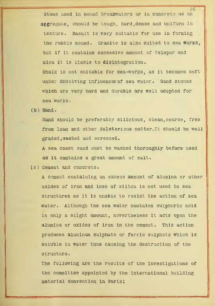
26stone used In mound breatovaters or In concreto as an
aggregate, should be tough, hard, dense and uniform In
texture. Basalt is very suitable for use in forming
the rubble mound. Granite Is also suited to sea woriis,
"but if it contains excessive amount of felspar and
mica It is liable to disintegration.
Cnalk is not suitable for sea-worKs, as it becomes soft
under dissolving influences of sea water. Sand stones
which are very hard and durable are well adopted for
sea works
.
(b) Sand.
Sand should be preferably silicious, clean, course, free
from loam and other deleterious matter. It should be well
graded , washed €md screened.
A sea coast sand must be washed thoroughly before used
as it contains a great amount of salt.
(,c ) Cement and concrete.
A CGmeut containing an excess amount of alumina or other
oxides of iron and less of silica is not used in sea
structures as it is unable to resist the action of sea
water. Although the sea water contains sulphuric acid
in only a slight amount, nevertheless it acts upon the
alumina or oxides of iron in the cement. This action
produces aluminum sulphate or ferric sulphate which Is
. soluble in water thus causing the destruction of the
structure.
The following are the results of the investigations of
the committee appointed by the International building
material convention in Paris;

27" (l»)The erosion of a sea structure of cement la
caused cneifly by the production of calcium
aluminum sulphate.
(2.) cement should not contain more than four per
cent of alumina.
(3.)rt is "better to replace the alumina lay iron
oxide as it is less harmful.
(%.)The dangerous effect of alumina in cement will
be reduced by adding proper amounts of pozzolan
which contains considerable amount of silica."
Many investigations have been made acting upon the above
suggestions and the conclusions are as follows;
" The strength of concrete or mortar made by the mixture of
Portland cement and pozzolan ^ains with age, while those made by
Portland cement alone loses with age, in sea water".*
The other requisites for a good cement and concrete, are
almost the same as that of any other engineering wori:.
(d) Timber,
Any Kind of wood is liable to be attacked by sea worms to
a greater or less degree. It is unwise to use any timber where sea
worms are active. However, the use of timber under water , as a
foundation work will be safe from the attack of the marine insects
Which is most serious between high and low water level.
Although creosoted piles last 28 to 30 years, it Is still
economically better to use the concrete piles.
* Report of Otaru harbor works
.

• 28( e ) Metals
.
Metals most extensively used In tne sea works are cast
iron, wrought iron, and steel. The durability of these metals
depends upon the amount of salt or any acid in the water and the
degree of exposure to the waves. There are many records about
erosion of metals used in sea works showing quite wide variations.
It is very difficult to fix a limit for their life in sea works.
The painting of the metals is done to prevent "both
the erosion and corrosion, but it is not applicable under water.
It might be better that the metals be galvanized as such have been
known to last for several years.
The use of various kinds of metals in the same place
should be avoided because this causes galvanic action through the
sea water and increases the erosion oonsiderably.

29'
f^VtaiTJTPl TnTnTOVPinPTi t. »wiicuiiicx x.iixyji. wv c;uiv><ii v •
\ JL 1 OLLL V V*J^ O •
is a most Important and at tne same time difficult item in
liartor engineering.
Before deciding the work to "be undertaken in the improve-
. -ment of a channel, the following surveys should "be made;
(1) Maximum and minimum discharge of channel.
. (2) Maximum and minimum velocities*
(3) Kind and quality of sediment.
(4) Tidal effect upon wat^r level and velocity.
(5) Silting.
(6) Wind.
(7) Difference between eTD"b and flood tide.
(S) Tidal currents and littoral currents.
( 9 ) Materials of bed of channel and their extent
.
(10) General topographic survey and hydrography.
In constructing or designing a channel or an estuary.
the following physical laws as presented iDy Prof. L. M. Haupt,
1
"before the Engineer's cluh of Philadelphia, should "be considered;
1 The resultant effect is that produced by the effort
of nature to establish and maintain an equilibrium.
Any improvement should therefore aim to aid and not
to oppose it.
2 A force will carry a lesser load up a slope than
it will roll down. Hence it will be foutad that the
gentler slopes will face or oppose the current and
the steeper ones the over-fall. Thus it can be de-

30
Viopii mnvlncr snfl fTHm WkiPriPP PfirnP tTlP Pfl 1 TMPnt >Ui^C^Xl lUUV XXi^ CLXl^ 1.1. \Jlll itlidiV'O ^CUiiO OXXO O^VAXXUCXiw •
( TVip f11 RP'haTP'p nf* t >ip plili t1<ip^'hp1n<T an oTnpn t. —\ ^ ) X.XXC7 LLXOV^XXO^X VJ<X 0XXC7 W U bXlU.v7^ UwXXX^ C1»IA^XXX^1X u
Pfl "hv t.yip land di*ainae'p\ Is <7TPat pr fhan fhat.^V«L "^Jf vXXVv XCIrXXvl VJ.X J.i.XU4i^V^J ^ X w O-X ^ Cfc U C5 X wXXCAXX (rfXXa#w
nf tViP fl ooti vfftipn not affpotpfl "hv 1 npal fnndit—u XX\? -X X^Jv./vX viXXwXX XXw U dX X vl^o OOlX UJf XvJVyCbX ^vJXXVXX u
X UliO »
TViP Infatinrt w>ipt"p tViP mrnnfilno' cjpa and land\'r } ISLKZ X.\J\^fX\j X v^XX VYXXv^X \7 UXXC7 wU^UDXXX^ OC7CX UrXXVX XCI#XXU
fr»T*ppci nTP mr%ct+ npPT'Tv in prm1l1"hT*inTn will ViPX UX O CLl C iUVJO u XXUCIX XJr XXX CL^IXXXX UX X IXllX j kl X X X L/O
indipatpd Irv tVip T"p1 at 1 VP "nPTTfiananpp nt* tVif* "hottoni iXXXLX X v^C* u\7\X X^J' UXXW XS^XCbuXVw UwX XXLCXX Xd»XX v>O wX UXX^ k/V^vV/ WilX 1
/ Pi \ TVi p i >i t p'T*iYiprl i a t p fT" riTi t wVi pt*p tViP aptinn andXxic; Xxi cX iucU X ct L> c XXvJiXU, WlXcX i^xXt; ckOUXUXi dxxu
OTmoQ itir>n npniiT" will l^p WPll r\f^'fAx\p^c\ liv t }1PUJL/UUOX ox <JXX U V.' ^ LXX , rVXXX UC VVCXX U.vZX XXX UJr u IXC
riPDnsites forrnine* a chain of suhmerired breast
W vJX JS.O •
^/^^ Tt ic{ pactipT* to ripflppt ot* d i vpTt a fnTPP t Vian
1 1 i <^ t. n nnnnsp it. .XO XkJ Ow VyJJL/VyLJV-* XV*
f 7^ T?lnwincr wat pt will follow tViP linP<^ of Ipa^^t.V f / X' XVJiI XXX^ VtOiOCX VI X X X XUXXWW OXXC XXXXv^O \JX XCiCbO w
"rpcji cstmipp and crT* PfitPT dpplivitv.X <C« D X O dlX^ V? dXXVX g^X CcXOCX OICV^XXVXOJ^*
1 J? ^ TViP TPcsnltnnt nf n c!v<it pm nf fnT*r»pc5 wliipli nfPI Oi XXXC XCOU.X0 CkXX <JX d Ojr o CXU <JX X UX v7 o VVXXX OXX cLX C
in pnn 1 1 1 l^T* 1 iiTT mav Tip PVianP'Pd 1n difpption andXXX v;VJLLXXXV/X X (XUX XXXCtJr yJ^ wXXdXX^^ VU. XXX VXXX \w/^tiX\yXX dXXVX
intpnfsit.v l^v mndifvinp" thp ponrnonpnt foropfs
.
XXXOv^XXkJX ujf '^%/ XLLVy vX X X XXX^ U XX^ V^iXi L/v^XXv7XX w XV^XV^^O*
» q) Anv cjiiT^mPf p*pd oli<=?t Tiir»t 1 on to a tidp ot* piTPVPnt' / f AllJ O LXk/XXXsI^X ^V7VX UUOOXLXV^OXUXX OvJ CI* OX^w VJX WLXXXwXXO
wVi ioYi PTPatP^ Pn nvpyfa 11 ot* t^T" ndnpp<5 latPfalWXXXUXX V^X CdOCSO dXX VJVOXXdXX UX J[JX ULUX^CO XdOCiXdX
pnT*T*pnt CI pnTitQi^icj ol prn pti t a nf i t cs nwTi d p c; _V^UXXcxxoD, v.>uxx dX iio oixc cxi^nxcxxoo kjx. XOo UVfxi u.c;o~
tTiiPtion hv und PT*rn i n i n c .ox IjIV>OXV/1X| IAXX^x^ X XU XXX X XX^ •
a l^n'rr P 1 awci will q pt'Vp n<5 a crnidp tn dp + PT'm imp t>ip "frsfneicidUU V U XdW a VVXXX DCXVC dS d ^U.XlXv7 OU IXCOCXxUXIXc; OxiC XUXV^Co
and agencies which have com'bineQ to produce existing effects and
help to ascertain whether they are permanent or constant in their
action, and whether constructive or destructive in character. Then
it follows, that it may he determined what remedy should he applied

31to maintain or improve t)ie channels.
(2) Construction of channel
.
In constructing a channel the aim must "be to direct and aid
the natural forces tending to remove the bar and keep the channel
open, and to protect them from having a counter effect. This will
toe accomplished hy the following;
( l). Concentrating and directing the currents, more espec-
ially on the ehh, that their whole scouring power shall he utilized
in forcing and maintaining the channel, so that the matter carried
hy outgoing tide shall he held in suspension until it is hrought
under the influence of cross littoral current or into deep water.
(2) Increasing the volume of water which passes over the
har at each tide. This will he done hy enlarging tidal compartments
within the estuary or harhor hy means of dredging,
(3l I'rotecting the outgoing current hy means of the hreak-f
waters, dikes or jetties from the deflecting effect of prevalent
heavy sea for such a distance as will enable it to carry the matter
in suspension out to the sea.
These are the general methods with v/hich channels must he
treated. The application of the methods depend upon the local
condition which should he carefully considered.
Dredging.
Dredging is a matter of considerable importance in connect-
ion with the construction and maintenanoe of a channel as the
scouring forces upon the obstruction to be removed generally are
limited by the reason that the strong currents are very dangerous
to the navigation of the vessels, and the forces are no longer
applicable upon the single boulders or rod:.
The class of machines to be used depends upon the magnitude

32
of the operation, the facilities for disposal, and the conditions
generally under whlcli the worK has to be carried on*
Dredging appliances may be classified as follows^
(a)—- suction dredges,
(b) Ladder dredges,
(c) -^— flDlpper dredges,
(jrab dredges,
(a) Suction dredges.
The suction dredges or sand pump dredges consist essent-
ially of a continous pipe or tube through sand or other light mat-
erial is sucked up from the bottom.
The sand usually contains large volumes of water, about
90 to 96;^cf which has to be delivered into the hopper barge or throijg.
.
outlet pipes leading to the place where it is to be discharged.
This class of dredge is very suitable for removing
sand or mud. If a suitable device, like cutting blades, is attached
ed to the end of the suction pipe it is still applicable in clay
or mud.
^b) Ladder dredges.
A ladder or bucket dredge conslslB of an endless chain
connecting a series of buckets which traverse in succession on
an Inclined plane about two pivots or tumblers, excavating materials
at the lower tumbler and discharging it into a chute while passing
I
over the upper tumbler.
I This dredge is a very efficient appliance when large
quantities of material extending over considerable area have to be
removed, owing to its continuous working when a practioally uniform
bottom is required. It cannot be worked in a swell or a shallow
body of water and is not an economical machine in the matter of

33power, as tlie dredged material Is lifted by the machine about
25 to 30 feet ahove tlie water line, representing a corresponding
waste of energy.
There are two forms of "bucket dredges ; one is attend-
ed hy hopper harges and the other is the comhination of the hopper
and dredger which conveys dredged material to the place of deposit,
(c) Dipper dredges.
The apparatus, consisting of a simple bucKet at the
end of along lever or arm and is mounted upon a harge. The action
of the "bucKet is that of an upward curved sweep against the "bottom.
The contents of the buclcet are discharged into a hopper through
the bottom of the "bucicet which is hinged.
It is capable of working in the stiff clay, the hard
marl and boulders, and also will take hard rock with the assist-
ance of a little blasting.
( d ) Grab dredge
.
These dredges are essentially segmental scoops, generally
tv/o or more quadrants, which rotate about a central pivot, meeting
in the closed position, forming a semi -cylindrical or conical
bucket. The apparatus is manipulated by means of chairs in connect-
ion with the crane, which llftes the bucicet.
The grab ^Iredge is a comparatively cheap machine and
is very usefull in removing silt, loose soil, boulders, and large
pieces of blasted rock. It is suitable to be used in confined sit-
uations and for a considerable depth in exposed places.
( 3 ) Maintenance.
In order to keep an open channel in continuous service,
dredges should be used co-operatively with the natural forces.
Many devices, as sluice or floating deflectors have

34.
toeen used for scouring away aiid preventing accumulation of sana,
and It was found that tney are applicalJle in a certain depth of
water. Beyond the limit or to maintain the depth of water required
for navigating of some vessels, it is always neccessary to use a
dredge more or less.
To what extent the dredging should be undertaken in the
channel is a large pro'blem and it should be carefully considered
in connection with the revenue , and the value of the channel.
(D) Docks.
I. Classes.
Docks may he classified as follows;
1. Wet docks or basins.
2. Dry or graving docks.
3. Lifting and floating docks.
If. Slips. ,
1. Wet docks or basins,
(a) Purposes.
I
The wet docks or basins are areas of Impounded water,
I
usually several acres in extent, within which vessels can remain
afloat at a constant level. Independent of external tidal action
and free from waves thus facilitating the loading and unloading
I of the vessels.
!There are two different forms of this kind of dock
namely, the tidal dock and the closed dock. The closed dock has
gates or caissons in order that the water may be retained at a
nearly uniform level, while the tidal or open dock , as the n:me
Implies, has an open entrance.

35The following are the comparative advantages and disadvantages
of the tidal smd closed doclc;
(1) The ships can leave or enter at any time from the
tidal doclcs.
(E) There is no troulDle to open or close the gates or
caissons in the tidal doclcs.
(3) The required depth should "be kept telow the low water
level. An extra height of quay wall is needed or
dredging of the bottom according to the range of the
tide.
(4) The elevation of water changes frequently with the ti-
dal dock, which is very inconvenient in unloading and
loading vessels.
(5$There is prohabllity of silting in the tidal dock
where the tidal current carries with it a large quant-
ity of suspended matter.
(6) The closed dock has the uniform or constant level of
water. It is very convenient for mooring vessels and
facilitates the unloading and the loading prooess.
(7)There is no danger from silting in the closed dock.
The time for entering and leaving the closed dock is
restricted by the closed gates.
(8)The extra cost of gates and gate machinery is required
for the closed dock.
(Id) Location.
The follovfing considerations should "be kept in viev; In
the location of either tidal or closed dock;
Wliere the range of the tide is considerable, closed
docks are required.

36For the ships of great length, a docK is more necessary
than for the ships of small size,
wiiere the hartoor or anchorage is lia'ble to surface
waves of considerable height or of any ground swells,
a dock is more necessary than where there is "better
protection
.
In a tideless harbor, the tidal dock is most suitable.
It should be located in the most convenien.t position
for connection with the railroads and warehouses.
( c ) Construction.
The general plan of the basin which affords the maximum
accommodation combined with the greatest facilities for maneuver-
ing ships, will depend upon the class of ships and the nature of the
trade. In view of the increasing length of ocean going steamers,
the docks should leave more than 800 feet width and 1000 feet length
in turning basins. On the other hand, in determining the width of
the basin , the care must be taken to reserve an ample area for
Wharfage purposes, railroads and warehouses.
The shape of the basin may be any geometrical figure,
or of several figures in combination. The most suitable forms are
the rectangular, the square, and the diamond. The square form
offers an advantage of plenty of space for the turning of vessels,
but would give a shorter available length of wharfage than a basin
of recta).gular form of the same area. The rectangular form, is
therefore commonly used. The diamond is a slight deformation of the
square and when an entrance is located at one of the acute angles,
it gives quiet a convenient form.
The proper proportion between the surface of the dock
and its periphery should be considered from the economical point

37of view. Any undue surface area on the required wharfage increases
the cost of excavation, or dredging, and land area.
The introduction of jetties projecting out into the
iDasin offers a convenient and economical means of increasing the
wharfage. This should he kept in view in constructing a "basin.
An important point in docK location is the supply of fresh water
to the hasin, to prevent the stagnant water around the dock from
hecoming foul and unsanitary,
(d) Handling machinery.
The predominant factor which limits the rapidity and
despatch in the operation of handling the cargoes between ship
and shore is the economic method employed. The extra oost due to
delays in connection with the berthing and departing of ships
^
imperfect or inadequate handling machinery, ^and the depreciation of
the apparatus will reach an extravagant total. It has been author-
itatively stated that in the case of one Atlantic liner alone ,the
loss of a single day per voyage is equivalent to |13,000 per annum.
There are many Icinds of apparatus used in connection
with the terminal facilities, such as light houses, gate machinery,
Cargo handling machinery is one demanding most
attention, since it effects so great economy.
For the handling machinery .^cranes ( from half a' ton
to 150 tons or more ) are most extensively used. They are divided
into two classes^ namely,moving cranes and fixed cranes.
Usually, the smaller classes of the moving cranes are
used most conveniently in the loading and unloading of vessels.
(A) Moving cranes may he classified as follows,
(1) Locomotive crane.,
This is the most useful of the many types of cranes

38which can be used on a wharf or Jetty. The cranes are constructed
to fit any gage of tracK, and are operatefl accordingly hy steam.
(2) Traveling bridge crane.
This type of crane is used very succesfully on the
great lalces in the loading and unloading of iron ore. The crane is
usually of cantilever type ,and operated by electric power. The
gantry frame straddles the railroads, and travels back and forth
along the coping level. A grab shovel which is operated by means
of cables runs over the bottom chords of the bridge and io dropped
into the hold through an opening in the declc of the vessel. The
bucket or shovel moves traiisversely to the railroad and dumps the
ore in the storage yard on the opposite side of the vessel.
(3) Floating cranes.
The floating crane is, of ordinary Jib type mounted on
a barge, and Is a valuable adjunct to the equipment of a dock
system. The cranes are constructed up to 100 tons in lifting poweK
(4) Trarisporters
.
This is a form of a vertical framework in the shape of
the letter "A", at right angles to which the transporting beam is
set. The frame is free to travel along the quay on a line of rails,
and Is steadied by a second line of rails placed at some distance
above the quay level, so as to prevent overturning.
(B) The fixed cranes may be similiarly classified as follow
I. Revolving cranes.
This crane is the cantilever type and revolves around
the vertical axis, it is built to handle very heavy loads up to
150 tons or more.
II. Derrick cranes.
It is very difficult to employ large cranes among the

3.9
masts, yards, stays etc. of the vessels. In this case the derrlcls:
cranes are used conveniently.
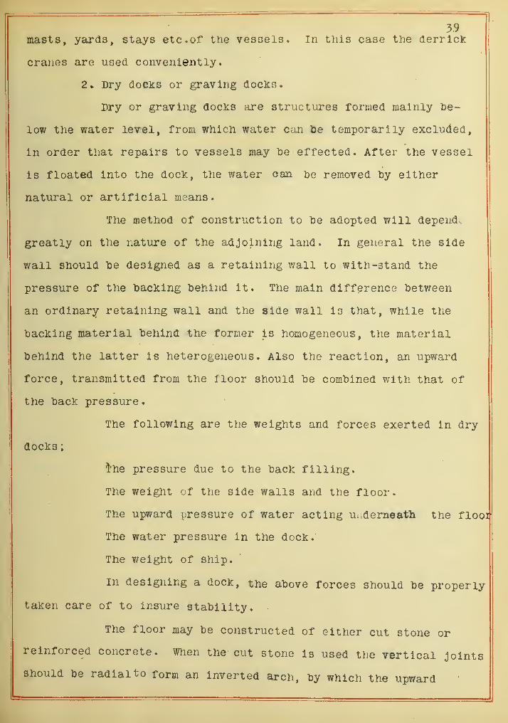
2- Dry docks or graving docks.
Dry or graving docks are structures formed mainly "be-
low the water level, from which water can be temporarily excluded,
in order that repairs to vessels may be effected. After the vessel
is floated into the dock, the v/ater can he removed by either
natural or artificial means.
The method of construction to be adopted will depend
greatly on the nature of the adjoining land. In general the side
wall should be designed as a retaining v/all to with -stand the
pressure of the backing behind it. The main difference betv/een
an ordinary retaining wall and the side wall is that, while the
backing material behind the former is homogeneous, the material
behind the latter is heterogeneous. Also the reaction, an upward
force, transmitted from the floor should be combined with that of
the back pressure.
The following are the weights and forces exerted in dry
docks
;
i'he pressure due to the back filling.
The weight of the side walls and the floor.
The upward pressure of water acting Ui:derneath the flooi'
The water pressure in the dock.
The weight of ship.
In designing a dock, the above forces should be properly
taken care of to insure stability.
The floor may be constructed of either cut stone or
reinforced concrete. When the cut stone is used the vertical joints
Should be radialto form an Inverted arch, by which the upward

1+0
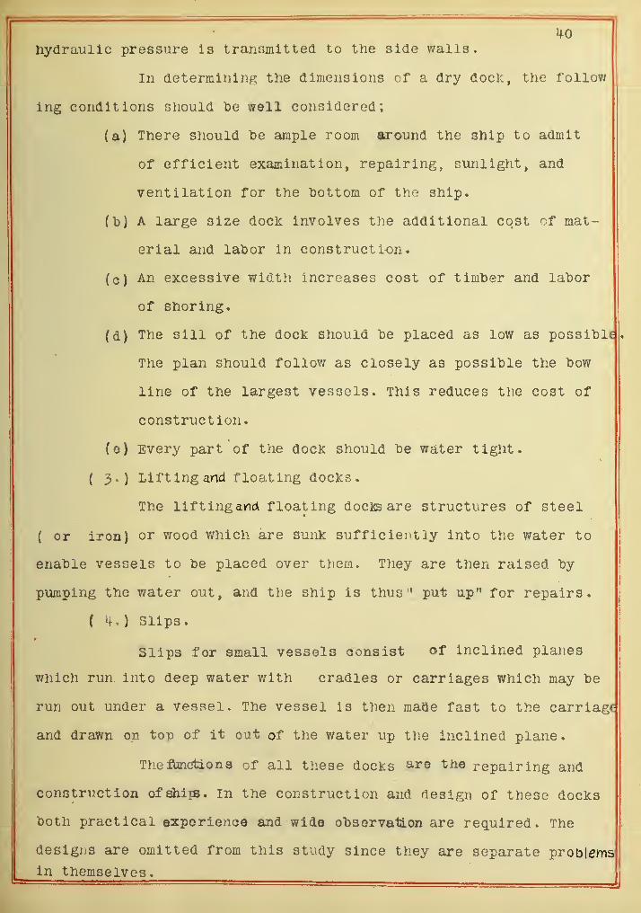
Hydraulic pressure is transmitted to the side walls.
In determining the dimensions of a dry docl:, the follow
irig conditions should he well considered;
(a) There should he ample room around the ship to admit
of efficient examination, repairing, sunlight, and
ventilation for the hottom of the ship.
(b) A large size docl: involves the additional cost of mat-
erial and lahor in construction.
(c) An excessive width increases cost of timher and lahor
of shoring.
(d) The sill of the dock should he placed as low as possihle
The plan should follow as closely as possihle the how
line of the largest vessels. This reduces the cost of
construction.
(e) Every part of the dock should he water tight.
( 3) Lifting and floating doclcs .
The liftingancA floating doc]s are structures of steel
( or iron) or wood which are sunk sufficiently into the water to
enahle vessels to he placed over them. They are then raised hy
pumping the water out, and tne ship is thus" put up" for repairs.
Slips.•
Slips for small vessels consist of inclined planes
which run into deep water with cradles or carriages which may he
run out under a vessel. The vessel is then maQe fast to the carriage
and drawn on top of it out of the water up the inclined plane.
Theflmcitions of all these docks Q-^re the repairing and
construction of ships. In the construction and design of these doclcs
hoth practical experienoo and wide ohservation are required. The
designs are omitted from this study since they are separate problems
in themselves.

I
;
" '
in
Conclusion.
In conclusion It may t>e said that Harbor Engineering
is sucli a large subject that it involves all kinds of engineering
work. Most of the large harbor improvements have "been made by the
governments , and in most cases the government engineers have de-
signed and constructed the Improvements. There are many good
books published on various phases of the work and a list of those
found useful In this study are given in the bibliography. The
most extensive work of Investigation appears to have been made
by the engineers of the United States government, but there Is
still much to be developed In the art of Harbor Engineering.

M-2
^E) Bibliography.
(a) General.
"cnicago HarlDor and water front park"- Improvement
question. Eng. News Jan. 23,1908.
Chicago harbor. "Investigation of future develop-
ment of harbor". The Harbor comriiission Report
1909.
"Coast Erosion", Erosion of coast and its dynamical
action, tidal phenomena, and tide gage etc.
Cyclopedia Britanica pp. 375-407.
"Lover Harbor,- Difficulties of Extension". Eng.
London Aug. 10, 1906.
"Few French dry docks", information in regards to
the new docks at St. Nazaire and Bordeaur.
Eng. London. Jan. 6, 1911
•
"Brazilian floating dock". 22000 ton capacity , det-
ailed description of the dock built in England
and towed to Brazil. Inst. Marine Eng. Jan. 1911-
"Review of the development of Dry Docks". Marine
Review March 11, 1909.
"Design and construction of harbor",principles and
practice. Thomas Stevenson.
"Harbor and Docks"- principles and practice of
construction. L.E.V. Harcourt.
"Harbor and Dock Extens ion"-physical difficulties of
Eng. London Jan. 10, 19OS.
"Harbor Improvements", description of recent work
at port of Nev/ York. Scl. American, Dec. 5, 19OS.

^3
"Harbor ana Waterway In 19O6". Bemarks on th strug-
gle between ship builders and harbor authorities.
Eng. London Jan. i4-,1907.
"Harbor Construction"- Principles and Practice,
by w. Shield.
"Harbor Englneering"-Treatise on the principles
and practise of; by B. Cunningham.
Hakodate harbor, construction and description of
basins and Jetties. "Annual Reports".
"Harbor works and Dock construction" ; by V/.W. squir|
"Havre port works", details of construction.
Eng. London May 29, 19OS.
London Harbor. "Proposed improvements of the port".
Eng. London Feb. 3, 1911.
London Harbor. "Discussion of the present con-
ditions". Eng. London Jan. 19, 1906.
Manila, P.I. "Remarks upon the harbor construct-
ion now in progressat Manila". By Curtis and
Townsend. 1906.
Manzanillo, Mexico. "Description of harbor imp-
rovement on the Pacific Coast". Cossier's Mag.
Jan. 1911.
"A treatise on Masonry Construction", foundations
under water etc. by Prof. I. 0. Baker.
Hew South v/ales, "Improvement at the entrance to
the Riclimond River", description of the work.
Inst, of Civil Eng. #731S0N. .
Brew York Harbor "Barriers to International Trade".
By H. M. Haupt. Casslers Mag. May 1909.

"Protection of Small Harbors on Lake Michigan" , the
effect of wave action and suggestion to resist the
action, ^ng. Record. Jan. 20, 1906*
Rhode Island Harhors. "Commission Annual Report".
Providence Harbor - -Dredging work.
Newport Harbor- - - -Dredging work.
Point Judith - - - - Breakwater work.
Ssikonnet Harbor Improvement of Sakonnet
Improvements of Rivers,
Improvement of Powtucket River.
Block Island — — Construction of refuge.
San Francisco Harbor works , "Biennial Report of
California State Harbor Commission".
Seaham Harbor "New Works of Seaham Harbor". Engr.
London Nov. 10,1905.
"Theory and practise of Surveying"* Hydrographlc
Surveying. By J. B. Johnson.
"Tide", Theory and observation of tide. By G.H. Dar-
win.
"Time and tide". By Sir R. Ball.
"Wave action". A theory Of the wave water, conclusion
based on the vertical circulation of water.
By Morton F. Sanborn. Pro.AJl. Sos. of C. E. Dec.'lC
"V/ave action in Relation to Engineering Structures".
Professional papers no. 31 of the corps of Eng-
ineers, U. 3. Army. By D. D. Gaillard, Captain.
"Wood destroyers". Marine Insects in water of the
South Atlantic ports. Eng. News Jan. 5, 1911.

^5(13 ) Breakwater
.
Algoma Hart)or,wls. "'Construction of iDreaicwater" . Eng.
Rec, March 21, 1908.
"Baltimore breakwater". Detailed description of tlie
work of reconstruction. Engr. London, Jan. 29 1909
•
"Bomtay breakv/ater " . Description of "breakwater. Eng.
London, Aug. li^, 1909*
"Harbor beach, Mien" . Description of improvement. Eng.
News, March 28, 1907
.
"General consideration for designing breakwaters".
Inst, of C. E. of London. CXXXVIII.
Cleveland Ohio, "Design of breakwater*; Eng. News, Marc
15, 1906. May 1^, 1907.
•Colombo Harbor" Description of construction Eng.
London, Dec. 7, 1906.
Breakwater, "Historical sketcli and description of
harbor In u. s. A." cyclopedia America, III.
"Fishery harbors of Scotland" .Description of the works,
location of breakwater, and methods of construction.
Eng. Nev/s, Feb. 10,1906.
Genoa, "Extension of the port". Plan of improvements.
Eng. London, May, 11 1906.
Glasgow "Extention of Glasgow Harbor". Eng. London,
sept. 4, 190s.
"Otaru Harbor, construction of Breaicwater" . Annual
reports of Otaru Harbor works.
sandy Bay, Mass. "Breakwater for national harbor of
refuge". Description of v/orks. Eng. News, March 8,
1906.

u"Yokohama Harbor works". Design of brealcwater , har-
bor pollution. Report of Harhor Commission of
Yokohama
.
Agate Bay, Two Harhois , K inn. Design of wooden crlh
hrealcwater. By S. u. Wliite. "Year Book" of Univ-
ersity of Minnesota, 1902.
(c ) channel.
"Buoying and liglitlng of navigable channels and reg
iations". Eng. London, April 6, 1906.
*Buoys, light houses, fog alarms etc. near Belle
Isle". The Quebec district. Can. Engr. Sept. 3, 1909.
"Calumet Harbor south Chicago". Improvement of the
mouth of the calumet river. Eng. Rec. April, 22, 1911
"Dikes". A concrete pile for river revetment, des-
cription of test work constructed near Ellwood Kans.
Eng. Rec. Jan. 23, 1909
•
"Estuary channels and their treatment" . Eig. London.
Oct. 30, 190s.
Gary, ind. "Construction of channel from Lake Mich-
igan". Marine Rev. June 21, 1906.
Bar improvement of llew York harbors , "Harbor Studies".
By Prof. L. M. Haupt.
"Light House". A new automatic flash light, description
of apparatus for producing a flash light, and requir-

I
^7
ing attention at protracted Intervals. Engr. Lon-
don. Dec 23, 1910.
"Light House". Ancient and modern , type form of,
construction of , kinds of lights, light house adm-
inistration. By D. P. Houses.
Panama Canal. "Report of isthmian Canal". U. S.
Chief Engr.
Panama Cu.nal. " Retrieval at Panama". By L. V. Bates,
saint Kazaire. "Nev/ entrance at Saint Nazaire". Eng.
London Aug. 9, 1907«
"Silt and Scour". Discussion of the theories of, Eng.
London, Oct. 19, 1906.
Thames, "Deepening the navigable Channel". Eng.London
Oct. 19, 1906*
Wliithy Harbor Improvement , "Improvements of me mouth
of river Esk". Eng. London, Sept. M*, 190S»
(d ) Docks
.
Aimer ia, "Construction of storage and the shipment
of iron ore ". Inst, of C. E. Ho. 356M-.
"Atlantic City steel pier". Reconstruction with re-
inforced concrete. Eng. News. July 26, 19O6.
"Calumet Harbor in south Chicago" .Description of dock
construction. Eng. Rec. April 22,1911.
Clyde and Tyne."Ship yard extended and constructed
of tidal basinf. Engr. London Feb. 17, 1911.

"Chalmette docks of Few Orleans". Description of con-
structions. Eng. Rec. July 28, 1906*
Dulutn, "A large coal dock". Description of dock
equipment for unloading from vessels and delivering
to storage. Eng. Rec. Oct. 23, 1909
"'Colman dock, Seattle" . Description of new dock yoOft.
long. Marine Rev. Dec. 3, 190S.
"Dock Engineering". The treatise on the principles
and practise. By Bryson Cunningham, 190^-.
"Dock on the Cuyahoga river Cleaveland, Ohio?. Des-
cription of a heavy concrete dock. Eng. Rec. April
3, 1909.
"Dock and dock constructions". General description
and remarks. By C. Colson.
"'Docks and Ferries in Hew York harlDor'i. Annual report,
City of Hew York.
"Comparison of European and American harTjors and docks
Pro. Am. Soc. of Civ. Engrs. May 19OS.
"Key harbor ore dock of Canadian Northern Railway".
Description of the doc^, a conveyor trestle, and
unloading trestle. Eng. Rec. March 20, 1909.
"Docks of Immingham" . Description of new extension
dock works of the great Central R.R. Co. on the
number river. Engrig. May IM-, 1909.
"Dock Walls". Design and construction of, by John H.
Allen.
"Floating Dock". Theory of the stability of a dock.
Cassler's Mag. sept. 1909.

^9
"Graving Docks of Hong Kong". Description of construct-
ion, Eng. London, Nov. 10 1905.
"Graving Docks of the World". Discussion of size.
Engr. London, April 30, 1909.
Grimsby, "The Great Central R.R. Union Docks".
Description of construction, En^-;. London, July, 20,
19O6.
"Keyham Dock Yard Exten ion". Description of work
constructed in 1896, Inst . of Civ. Eng. #3701-3728.
"Pedestal Pile". Supporting power and driving of, xhe
Concrete pile and Foundation Co. N.Y.
"Quay Wall in Open water". Construction "by diver. Eng.
Rec. Vol. 59 pp. 696.
"Quay side Cargo Appliances". Modern practice. CasslerS
Mag. May, 1904-
.
"Stability of Sea Walls". Principles of hetrogentous
Dack filling. Eng. Nev/s, Aug. 23, 19 06.
"Stuyvesant Docks of I.C. R.P.. at Few Orleans". A mod-
ern tide water freight terminal. Eng. Rec. June 23,
1906.
"Wharf Conveyor and Grain Elevator System at East
Boston, Mass". Electrically operated. Eng. News,
April 6, 1911.
Wharves. "A large Coal Storage at Superior, Wis".
Eng. Rec. Nov. 30, 1907.


PJote E


CZbricr^s/-(S Scf/o<s>r\strue:Tuyie
on T"/ Kk-) t> & Cr/ jb


'~\—^ /—r~
\
CTorjcrei-^ B/ocMs /arc/ /r^
J- hr. :b.-7-

\

/^/^T^e VJTT


I,
I
A/]ouno/ S,yeaHW£3i-er of (Zoncre+e B/cDcfcs

H.w.o. S.-r.
Z. w; a. s.-r.
-i-^1
Moss Wor/K-
/-/.W.0.3>.
/\/J a<y^<^ 8t^e'<3/'rYyct-f-^y a/ Cancrete' 3/ocfrS