Public Works Standards - City of Gig Harbor
386
C I T Y O F G I G H A R B O R Public Works Standards E F F E C T I V E D A T E J A N U A R Y 1 , 2 0 1 7 PUBLIC WORKS DEPARTMENT 3510 Grandview Street Gig Harbor, Washington 98335 (253) 851-6170 www.cityofgigharbor.net
-
Upload
khangminh22 -
Category
Documents
-
view
2 -
download
0
Transcript of Public Works Standards - City of Gig Harbor

C I T Y O F G I G H A R B O R
Public Works Standards
E F F E C T I V E D A T E J A N U A R Y 1 , 2 0 1 7
PUBLIC WORKS DEPARTMENT 3510 Grandview Street Gig Harbor, Washington 98335 (253) 851-6170 www.cityofgigharbor.net

CITY OF GIG HARBOR PUBLIC WORKS STANDARDS - 2017
Mayor
Jill Guernsey
City Council
Timothy Payne
Steven Ekberg
Rahna Lovrovich
Casey Arbenz
Ken Malich
Michael Perrow
Paul Kadzik
City Administrator: Ron Williams
Public Works Director: Jeff Langhelm, P.E.
City Engineer: Stephen Misiurak, P.E.
Planning Director: Jennifer Kester
Building Official – Fire Marshal: Paul Rice
Prepared by:
CITY OF GIG HARBOR PUBLIC WORKS DEPARTMENT

CITY OF GIG HARBOR PUBLIC WORKS STANDARDS - 2017
TABLE OF CONTENTS 1-1
TABLE OF CONTENTS
Chapter 1: General Chapter 2: Transportation Chapter 3: Storm Chapter 4: Water Chapter 5: Wastewater

CITY OF GIG HARBOR PUBLIC WORKS STANDARDS - 2017
GENERAL PUBLIC WORKS CONSIDERATIONS 1 - 1
1.0 GENERAL PUBLIC WORKS CONSIDERATIONS ................................................ 2 1.005 Applicability ....................................................................................................... 2 1.010 Standard Specifications ..................................................................................... 2 1.015 Shortened Designation ...................................................................................... 4 1.020 Applicability ....................................................................................................... 4 1.025 Definitions and Terms ....................................................................................... 4 1.030 Changes to Standards ....................................................................................... 7 1.035 Variances .......................................................................................................... 7 1.040 Design Standards .............................................................................................. 8 1.050 Plan Review .................................................................................................... 10 1.055 Construction Control ........................................................................................ 11 1.060 Inspection ........................................................................................................ 11 1.065 Record Drawings ............................................................................................. 12 1.070 Fees ................................................................................................................ 22 1.080 Permits ............................................................................................................ 22 1.090 Financial Guarantees ...................................................................................... 23 1.100 Utility Locations ............................................................................................... 24 1.110 Easements ...................................................................................................... 25 1.120 Latecomers Agreements ................................................................................. 25 1.130 Utility Extension ............................................................................................... 26 1.140 Traffic Control .................................................................................................. 26 1.150 Call Before You Dig ......................................................................................... 26

CITY OF GIG HARBOR PUBLIC WORKS STANDARDS - 2017
GENERAL PUBLIC WORKS CONSIDERATIONS 1 - 2
CHAPTER 1
1.0 GENERAL PUBLIC WORKS CONSIDERATIONS 1.005 Applicability
These City of Gig Harbor Public Works Standards are applicable in varying locations, depending on the service area of the City facility or service. In general, the following Chapters are applicable in the specific locations of each facility or service provided by the City as noted below.
Chapter 2 – Transportation: Incorporated limits of the City of Gig Harbor Chapter 3 – Stormwater: Incorporated limits of the City of Gig Harbor Chapter 4 – Water: Water Service area of the City of Gig Harbor Water
Department Chapter 5 – Wastewater: Urban growth area of the City of Gig Harbor and
special service areas as determined by Pierce County and the City of Gig Harbor
1.010 Standard Specifications
Design detail, workmanship, and materials shall be in accordance with the most current edition of the WSDOT Standard Specifications for Road, Bridge and Municipal Construction and the Standard Plans for Road, Bridge and Municipal Construction all written and promulgated by the Washington State Chapter of the American Public Works Association and the Washington State Department of Transportation, except where these standards provide otherwise. (Section 13.12.010 GHMC)
All applicable rules of Washington State shall be adhered to with respect to safety, construction methods, and other state requirements. This includes, but is not limited to the Revised Code of Washington (RCW) and the Washington Administrative Code (WAC). The following specifications shall be applicable when pertinent, when specifically cited in the standards or when required by a higher funding authority: A. Conditions and standards as set forth in the most current edition of the
City of Gig Harbor Water System Plan. B. Conditions and standards as set forth in the most current edition of the
City of Gig Harbor Wastewater Comprehensive Plan. C. Conditions and standards as set forth in the most current edition of the
City of Gig Harbor Stormwater Management and Site Development Manual and Stormwater Comprehensive Plan.
D. Conditions and standards as set forth in the most current edition of the
City of Gig Harbor Parks, Recreation and Open Space Plan.

CITY OF GIG HARBOR PUBLIC WORKS STANDARDS - 2017
GENERAL PUBLIC WORKS CONSIDERATIONS 1 - 3
E. Conditions and standards as set forth in the most current edition of the
Gig Harbor Peninsula Community Plan. F. Rules and regulations as adopted in the City of Gig Harbor Municipal
Code (GHMC). G. Conditions and standards as set forth in the most current edition of the
City of Gig Harbor Transportation Plan. H. Criteria set forth in the Local Agency Guidelines as amended and
approved by Washington State Department of Transportation Standard Specifications for Roads, Bridges and Municipal Construction, most current edition.
I. City and County Design Standards for the Construction of Urban and
Rural Arterial and Collector Roads Promulgated by the City Engineers Association of Washington, most current edition.
J. U.S. Department of Transportation Manual on Uniform Traffic Control
Devices (MUTCD), as amended and approved by Washington State Department of Transportation.
K. Washington State Department of Transportation Design Manual as
amended and approved by Washington State Department of Transportation (WSDOT).
L. Washington State Department of Transportation Construction Manual as
amended and approved by WSDOT. M. Washington State Department of Transportation Standard Plans for
Road, Bridge, and Municipal Construction (Standard Plans) as amended and approved by WSDOT.
N. Conditions and standards as set forth in the State of Washington
Department of Ecology Criteria for Sewage Works Design, most current edition.
O. Conditions and standards as set forth by the State of Washington,
Department of Labor and Industries. P. Conditions and standards as set forth in the most current adopted edition
of the International Fire Code. Q. Conditions and standards as set forth in the International Building Code,
most current adopted edition. R. Criteria set forth in the Access Management Manual by the
Transportation Research Board and the National Research Council, 2003.

CITY OF GIG HARBOR PUBLIC WORKS STANDARDS - 2017
GENERAL PUBLIC WORKS CONSIDERATIONS 1 - 4
S. Criteria set forth in Transportation and Land Development by V.G. Stover and F. Koepke and the Institute of Transportation Engineers.
T. Criteria and guidelines set forth in A Policy On Geometric Design of
Highways and Streets by American Association of State Highway and Transportation Officials (AASHTO), most current addition.
U. Design criteria of federal agencies including the Department of Housing,
Urban Development and the Federal Housing Administration. V. Rules and regulations of the State Board of Health regarding public water
supplies, as published by the State Department of Health and the American Water Works Association.
W. Spellings shall be defined by the Oxford Advanced American Dictionary. W. Other specifications not listed above may apply when required by the City
of Gig Harbor.
1.015 Shortened Designation
These Public Works Standards shall be cited routinely in the text as the "Standards." This is not to infer that the guideline portion of this book constitutes Standards, this is simply a shortened designation for the name of this document.
1.020 Applicability
These standards shall govern all new construction and upgrading of facilities both in the right-of-way and on-site for transportation and transportation related facilities, storm drainage facilities, sewer and water improvements, landscape and irrigation, park, recreation, and open-space facilities within the City of Gig Harbor and the City of Gig Harbor Urban Growth Area.
1.025 Definitions and Terms
“Access Way” - Travel way with private ownership and maintenance where general public use is allowed. “Building Sewer” – That section of the sewer line extending from the lateral sewer (located at the edge of right-of-way or edge of the public sewer easement) to two feet outside the outer foundation wall of a building or structure. "City Engineer" -- The City Engineer or his/her duly authorized representative.
“City Inspector” -- The City of Gig Harbor inspector or his/her duly
authorized representative.

CITY OF GIG HARBOR PUBLIC WORKS STANDARDS - 2017
GENERAL PUBLIC WORKS CONSIDERATIONS 1 - 5
"Curb Cut" – An access without a curb radius, generally used where lower traffic volumes are anticipated.
"Curb Return" – An access with a turning or curb radius. A curb return is generally used for higher traffic volumes to enable vehicles to turn safely off the roadway.
"Developer" -- Any person, firm, partnership, association, joint venture, corporation or any other entity responsible for a given project.
"Easement" -- The right to use a defined area of property for specific purpose/purposes as set forth in the easement document, on a plat or short plat, or as required for purposes as set forth herein.
"Engineer" -- Any Washington State licensed professional Engineer who represents the developer.
"ERU" -- The unit used to calculate sewer consumption. One Equivalent Residential Unit (ERU) equals 150 gallons of water consumed per day.
"Force Main" -- Any sewer main that transports wastewater under pressure.
"GHMC" -- City of Gig Harbor Municipal Code.
“Gravity Sewer Main” or “Main” – That section of sewer line in which lateral sewers connect to, is located in the right of way or public sewer easement, and is operated and maintained by the City. See also public sanitary sewer.
“Grease Interceptor” -- An interceptor of at least 750 gallon capacity to serve one or more fixtures and which shall be remotely located.
“Grease Trap” -- A device designed to retain grease from one to a maximum of four fixtures.
“Grinder Pump” -- A pump that grinds sewage waste into a fine slurry and then pressurizes it to permit transport through small diameter sewer force main pipes.
"Half-Street" -- Street improvements constructed along the entire property frontage utilizing half the regular width of the right-of-way and permitted as an interim facility pending construction of the other half of the street by the adjacent owner. In some instances, it may be necessary to construct more than half the street depending on the classification of the street.
"Interceptor" -- A sewer that receives flow from a number of main or trunk sewers, force mains, etc.

CITY OF GIG HARBOR PUBLIC WORKS STANDARDS - 2017
GENERAL PUBLIC WORKS CONSIDERATIONS 1 - 6
“Land Surveyor” -- Professional Surveyor registered in the State of Washington to practice Land Surveying per RCW 18.43.
“Latecomers Agreement” -- A written contract between the City and the developer(s) providing the partial reimbursement of the cost of constructing the water and/or sewer facilities. (GHMC 13.35)
"Lateral Sewer" -- That section of the sewer line extending from the public sanitary sewer to the edge of right-of-way or edge of the public sewer easement.
"Lot or Street Frontage" -- The distance between the two points where the lot lines intersect the boundary of public street right-of-way.
“Peak Hour” -- The 60 minute period with the greatest sum of traffic volumes on a roadway segment or passing through the area of a project.
“Planning Director” -- the City of Gig Harbor Planning Director or his/her duly authorized representative.
"Plans" -- The plans, profiles, cross sections, elevations, details, and supplementary specifications, signed by a licensed professional engineer and approved by the Planning Director and the City Engineer, which show the location, character, dimensions, and details of the work to be performed. “Private Driveway” - Travel way with private ownership and maintenance that has limited or restricted access by the ownership for no more than two tax parcels or no more than two residential units. "Private Roadway" -- Travel way with private ownership and maintenance where general public use is limited or restricted at the discretion of the private ownership.
"Private Sewer" -- That portion of the system located on private property where no easements are granted to the City. Maintenance of a private sewer shall be the responsibility of the property owner(s).
"Project" -- General term encompassing all phases of the work to be performed and is synonymous to the term "improvement” or "work".
"Public Sanitary Sewer" – That section of sewer line in which lateral sewers connect to, is located in the right of way or public sewer easement, and is operated and maintained by the City. See also Gravity Sewer Main.
"Public Street" -- Publicly owned and maintained street.

CITY OF GIG HARBOR PUBLIC WORKS STANDARDS - 2017
GENERAL PUBLIC WORKS CONSIDERATIONS 1 - 7
"Right-of-Way" -- A general term denoting public land, property, or interest therein (e.g., an easement) acquired for or devoted to a public street, public access or public use.
"Road" -- Used interchangeably with street.
"Road or Driveway" – A traveled surface used to represent an access point onto the roadway.
"Sewer Main" or "Trunk" -- A sewer that receives flow from one or more mains.
“Side Sewer” – The term used to describe both the building sewer and the lateral sewer.
"S.T.E.P. Main" -- Septic Tank Effluent Pumping main. A low pressure, sewer force main that transports only effluent from S.T.E.P. tanks.
"Street" -- Used interchangeably with road.
“Trip Generation Manual” -- The latest edition of the Trip Generation Manual as published by the Institute of Transportation Engineers.
"Use of Pronoun" -- As used herein, the singular shall include the plural, and the plural the singular; any masculine pronoun shall include the feminine or neuter gender and vice versa; and the term "person" includes natural person or persons, firm, co-partnership, corporation or association, or combination thereof.
"Utility" -- A company providing public service including, but are not limited to, gas, oil, electric power, street lighting, telephone, telegraph, water, sewer, or cable television, whether or not such company is privately owned or owned by a governmental entity.
1.030 Changes to Standards
These Standards are adopted by ordinance and may only be amended upon approval by the City Council.
1.035 Variances
A. Submittal Requirements. A request for a variance from the Public Works Standards must be submitted in writing to the City Engineer for review. A separate and stand along application is required for each and every variance request along with the required filing fee. Multiple variance requests cannot be combined under a single variance application. A complete application for a variance shall consist of:
1. Completed variance application; 2. Two (2) 11”x17” sets of the site plan;

CITY OF GIG HARBOR PUBLIC WORKS STANDARDS - 2017
GENERAL PUBLIC WORKS CONSIDERATIONS 1 - 8
3. A letter describing the variance requested, explaining the reasons for the requested variance, and addressing each of the criteria for approval as found in Ordinance 832. The letter must be sealed by a registered engineer licensed in the state of Washington;
4. Supporting exhibits; and 5. Payment of the filing fee as established by the City.
B. Processing. A variance from the Public Works Standards is a Type II
application (see GHMC § 19.01.003). Because the technical nature of a variance request may require review by an outside consultant, variance requests shall not be subject to the deadline for issuance of a final decision in GHMC § 19.05.008 and RCW 36.70B.C90. However, the variance is subject to the determination of application completeness in GHMC § 19.02.003, optional consolidated permit processing procedures in GHMC § 19.01.002, the notice of application procedures in GHMC § 19.02.003 and the issuance of a notice of written notice of decision in GHMC § 19.05.008. The remaining sections of Title 19 GHMC are optional for the processing of a variance under this section.
C. Criteria for Approval. Variances from the Public Works Standards may be
granted by the City Engineer if the applicant presents substantial evidence to demonstrate that all of the following criteria for approval are satisfied:
1. Strict compliance with the public works standards is undesirable or
impractical because of impracticality or undesirable conditions; 2. The proposed variation(s) are functionally equivalent to and are
consistent with the intent of the Public Works Standards, and/or provide compensating benefits to the City and the public;
3. The proposed variation(s) are based on sound engineering judgment;
4. The proposed variations have not been made necessary by actions of the applicant or property owner; and
5. Safety, function, appearance and. economical maintenance requirements are met with the proposed variation(s).
D. Final Decision. The City Engineer shall issue his/her findings and
conclusions on the variance in writing, and shall provide a copy to the applicant as well as all persons requesting notification. If the application does not satisfy any one of the above criteria, the City Engineer shall deny the application. A variance may be conditioned to the extent necessary to address any engineering, public health, safety, or welfare concerns, and as allowed by applicable law.
E. Appeals. Appeals of a variance shall be filed and processed as described
in Title 19 GHMC for a Type II application. 1.040 Design Standards
A. Detailed plans, prepared by a Washington state licensed engineer, must be submitted to the City for plan review and

CITY OF GIG HARBOR PUBLIC WORKS STANDARDS - 2017
GENERAL PUBLIC WORKS CONSIDERATIONS 1 - 9
approval prior to the commencement of any construction. The applicant's engineer shall be a Professional engineer, registered as such in the State of Washington. All plans must be checked, signed and stamped by the applicant's engineer prior to submittal for plan review. Final plans shall be approved by the Planning Director and the City Engineer prior to the start of construction.
B. The number and size of plans shall be published in a checklist
by the City Engineer and available on the City webpage and at the Public Works Department.
C. Separate plan and profile drawings are required for all
proposed transportation-related improvements, street illumination, traffic signalization, storm drainage facilities (whether public or private), and sewer and water improvements. For specific minimum requirements, contact the City of Gig Harbor Engineering Department for the latest version of the Plan Check List. Some items of the checklist, though called for, may be unnecessary for a given project. This will be decided during the Site Plan Review or the Engineering Plan Review stage.
D. Specifications shall be required and submitted with the plans if
General Notes do not adequately cover the project requirements.
E. Signed originals of all necessary easements and/or right-of-
way dedication documents meeting all the current recording Standards must be reviewed, approved and recorded prior to receiving signed issued for construction plans.
F. A copy of the Maintenance Schedule for Drainage Systems can
be found in Chapter 8 of the City of Gig Harbor Stormwater Management and Site Development Manual.
G. An Engineer’s Estimate prepared by an engineer licensed in
the State of Washington shall be required prior to Engineering plan approval, and shall follow the WSDOT Standard Bid Item Description and Format.
H. All entrances onto public right-of-way must have a sight
distance certification and be stamped and signed by a licensed professional engineer. The design criteria must adhere to the guidelines set forth by A Policy on Geometric Design of Highways and Streets by AASHTO.
I. Please contact the City of Gig Harbor Engineering Department
for a copy of the most current Plan Review Application and Plan Review Checklist.

CITY OF GIG HARBOR PUBLIC WORKS STANDARDS - 2017
GENERAL PUBLIC WORKS CONSIDERATIONS 1 - 10
1.050 Plan Review
A. Preliminary Civil Plan Review All plans and related documents are to be submitted to the
Planning Department along with payment of the plan review fee, as required in Section 1.070. The Public Works Department will review the plans in accordance with the City’s Municipal Code.
B. Civil Construction Plan Review
All plans and related documents are to be submitted to the Public Works Department along with payment of the plan review fee, as required in Section 1.070. The Public Works Department and other appropriate City Departments will review the plans in accordance with the City’s Municipal code.
Any necessary easements or dedications shall be signed and notarized and submitted in a recordable format along with the plans. An engineer’s estimate shall be submitted prior to plan approval. City staff will make a cursory check of the plans against the plan’s checklist on the preceding pages. Plans that meet the minimum checklist requirements as to context will be routed to the appropriate City staff and the Plan Review Process will begin. The initial turn-around time for the first review of plans submittal is normally three weeks. The Engineer is then requested to submit the original drawings for approval or is notified of additional required revisions. For subsequent reviews, the Engineer will submit three sets of drawings for re-review or will be notified of additional required revisions. Additional review time will be required if revisions are necessary. If the City’s comments are not adequately addressed at a second review, a third submittal is required and additional fees for review of a third submittal will be levied, as established by resolution of the city council. “Third Submittal” shall mean the third and any subsequent submittal of construction drawings, specifications, drainage calculations, and/or other information that requires additional plan checking even when plans have otherwise been approved. Approved plans will be returned to the Engineer only after the plan check, construction inspection fees have been paid and any required agreements, easements or dedications have been signed and notarized by the developer. Utility connection fees shall be paid prior to the Building Permit issuance. Plans that have been approved more than 180 days before construction begins (i.e., a preconstruction meeting scheduled and inspection fees paid) shall be subject to re-review.

CITY OF GIG HARBOR PUBLIC WORKS STANDARDS - 2017
GENERAL PUBLIC WORKS CONSIDERATIONS 1 - 11
1.055 Construction Control
Work performed for the construction or improvement of City roads and utilities whether by or for a private developer, by City employees, or by a City contractor, shall be done to the satisfaction of the City and in accordance with approved plans. It is emphasized that no work shall be started until such plans are approved. Any revision to such plans shall be approved by the City before being implemented. Failure to receive the City's approval can result in removal or modification of construction at the contractor’s or developer’s expense to bring it into conformance with approved plans.
The developer, contractor or their agents shall have on site or have web access to the digital version of the most current copy of the City of Gig Harbor Public Works Standards during the entire construction along with an approved, signed set of construction drawings and any necessary permits required for the project. A pre-construction meeting shall be required in advance of any construction and at which time the approved sets of construction drawings will be provided. The pre-construction meeting shall be held a minimum of 72 hours prior to the start of construction. Call the City of Gig Harbor Engineering Department to schedule a pre-construction meeting at (253) 851-6170.
1.060 Inspection
All work performed within the public right-of-way or easements, or as described in these Standards or Title 12 of the GHMC, whether by or for a private developer, by City employees, or by a City contractor, shall be completed to the satisfaction of the City and in accordance with the WSDOT Standard Specifications, any approved plans and these Standards. Unless otherwise approved, any revision to construction plans must be approved by the City before being implemented. Revisions shall be prepared by the developer’s engineer and submitted to the City for review and approval. City plan approval is required prior to construction.
It is the responsibility of the developer, contractor, or their agents to notify the City in advance of the commencement of any authorized work. A preconstruction meeting and/or field review shall be required before the commencement of work. All fees shall be paid prior to the preconstruction meeting. Any necessary easements or dedications are required before plan approval.
The City shall have authority to enforce these Standards as well as other referenced or pertinent specifications. The City will appoint project engineers, assistants and inspectors as necessary to inspect the work and they will exercise such authority as the City Engineer may delegate.
All specific inspections, test measurements or actions required of all work and materials are set forth in their respective sections herein. Tests shall be performed at the developer or contractor's expense. The City will not accept any unauthorized or defective work. Unauthorized or defective work includes work or materials that do not conform to City

CITY OF GIG HARBOR PUBLIC WORKS STANDARDS - 2017
GENERAL PUBLIC WORKS CONSIDERATIONS 1 - 12
requirements; work done beyond the lines and grades set by the approved plans or the engineer; and materials furnished without the City’s knowledge. At the City’s order, the contractor shall immediately remedy, remove, replace, or dispose of unauthorized or defective work or materials and bear all costs of doing so.
Failure to comply with the provisions of these Standards may result in stop work orders, removal of work accomplished, or other penalties as established by ordinance. A project is considered final when the City Council has accepted the project as complete and a maintenance bond for the project has been accepted by the City.
1.065 Record Drawings
Record drawings shall be required whenever field changes are made to approved plans. The record drawing shall be completed and certified and sealed by a professional engineer currently licensed in the State of Washington. The record drawing shall be submitted on paper and on a read/write CD in AutoCAD compatible format unless otherwise approved by the City. The digital format of the drawings shall be in AutoCAD compatible file and include all improvements in the right of way an all storm water, water, and sewer utilities. The horizontal datum shall be NAD1983/91 HARN State Plane South FIPS 4602, or as otherwise approved by the City Engineer. The vertical datum shall be NAVD 88, or as otherwise approved by the City Engineer. Final City project approval will not be granted until the record drawing has been submitted and accepted by the City. The AutoCAD Record Drawings shall depict and incorporate all the field revisions and shall be stamped and signed by the Engineer of Record. The Record Drawings must be a “bound” CAD file, which makes all the XREFS files part of the one file.
Construction Features
1. Record drawings will show accurate locations of storm, sewer, water mains and other water appurtenances, structures, conduits, power poles, light standards, power service cabinets, vaults, width of streets, sidewalks, landscaping areas, building footprints, channelization and pavement markings, property lined, easements, storm ponds etc.
2. The following is a list of the tolerance limits and construction features to
be incorporated into the record drawings:
Tolerance Limits: • Surveyed sewer and storm water elevations……….......+/-0.01’ Includes pipe invert elevations, top of casting (manhole, Inlets, etc.) • Surveyed water elevations……………………………….+/-0.25’

CITY OF GIG HARBOR PUBLIC WORKS STANDARDS - 2017
GENERAL PUBLIC WORKS CONSIDERATIONS 1 - 13
• Horizontal and vertical alignment……………………......+/-0.10’
Storm Drainage
Storm drainage features are intended to move rainwater and/or groundwater. Record drawings shall indicate all necessary information about the storm drainage system to evaluate whether the constructed features will be able to function as intended by the design. Information shall be field verified and/or surveyed as outlined in the following table. Generally the following information is required who should provide the information is shown in parentheses:
[the remainder of this page left intentionally blank]

CITY OF GIG HARBOR PUBLIC WORKS STANDARDS - 2017
GENERAL PUBLIC WORKS CONSIDERATIONS 1 - 14
Figure 1.1 Storm Drainage
Storm Drainage Features
Field Verify Mark on field drawing plan set all changes
from design drawings (Contractor and
Inspector)
Survey (Licensed Surveyor)
Indicate on Record Drawings
(Record Drawing Preparer/Engineer
Pipes Material, Diameter Inverts-(All pipe ends in structures of out) Location of Ends- (Not in Structures)
Redraw pipe on drawings if it moved two ft. or more. Recalculate slope based in record length and surveyed inverts. Indicate new information on plans (ex. Slope, length, diameter, etc.)
CB’s/manholes/inlets Size, type Rim Elevation Location of Structure
Redraw Structure on drawings if it moved two ft. or more. Indicate new information on plans
Culverts Material/ size Location of ends Inverts-(Of structure ends and of stream if flow line natural or filled with earth)
Redraw culvert on drawings if it moved two ft. or move two ft. or more. Recalculate slope based on record length and surveyed inverts. Indicate new information on plans (ex. Slope, length, diameter, etc.)
Under drains Pipe location, material, cleanout locations
Redraw under drains on drawings if it moved two ft. or more.
Other drainage
features
Redraw feature on drawings if it moved two ft. or more.

CITY OF GIG HARBOR PUBLIC WORKS STANDARDS - 2017
GENERAL PUBLIC WORKS CONSIDERATIONS 1 - 15
Stormwater Management
Stormwater Management features are intended to control the rate and/or quality of the rainwater runoff. Record drawings shall indicate all necessary information about the stormwater management system to evaluate whether the constructed features will be able to function as intended by the design. Information shall be field verified and/or surveyed as outlined in the following table. The record drawings must include a Storm Pond Certification Letter stamped and signed by the engineer of record. This letter must state that the pond was constructed per the engineer’s design and that the as-built size meets or exceeds the designed storage capacity. Generally the following information is required who should provide the information is shown in parentheses:
Figure 1.2 Stormwater Management
Storm drainage features
Field verify Mark on field drawing plan set all changes
from design drawings (Contractor and
Inspector)
Survey (Licensed Surveyor)
Indicate on record drawings (Record Drawing
Preparer/Engineer)
Vaults Material, type, size, control systems (orifice size, weir dimensions)
Control structure location Control elevations (orifice inverts, weir elevations) Bottom elevation Access locations
Redraw structures on drawings if it moved two ft. or more. Indicate new information on plans (ex.. size type, etc.)
Ponds Size, shape, letter from engineer of record certifying the construction and size of the storm pond.
Control structure location Control elevations (orifice inverts, Weir elevations) Overflow elevation Bottom elevation Water surface shape (spot locations around edge of water surface – enough to indicate shape/ location six shots minimum)
Redraw pond on drawings if moved ten ft. or more. Recalculate size based on water surface shape. Indicate new information on plans (ex. size, shape, etc.)
Bio filters/ swales Length, width Inlet invert Outlet invert
Redraw biofilter/swale on drawings if it moved two ft. or more.
Infiltration systems/ French drains
Material, size, pipe (size, type, diameter)
Inlet invert Bottom elevation
Redraw feature on drawings it moved two ft. or more.

CITY OF GIG HARBOR PUBLIC WORKS STANDARDS - 2017
GENERAL PUBLIC WORKS CONSIDERATIONS 1 - 16
Natural Resources
Natural resources features are non-structural features that convey and/or hold water. Record drawings shall indicate all necessary information about the natural resource to evaluate whether the constructed features will be able to function as intended by the design. Information shall be field verified and/or surveyed as outlined in the following table. Generally the following information is required who should provide the information is shown in parentheses:
Figure 1.3 Natural Resources
[the remainder of this page left intentionally blank]
Natural Resources feature
Field verify Mark on field drawing plan set all changes
from design drawings (Contractor and
Inspector)
Survey (Licensed Surveyor)
Indicate on record drawings (Record
Drawing Prepare/Engineer)
Streams Centerline of stream Redraw stream on drawings if it moved two ft. of more
Wetlands Boundary of created of modified wetlands, and boundary of current wetlands
Redraw wetland in drawings if it moved ten ft. or more. Recalculate size based on wetlands shape. Indicate new information on plans (ex. size, shape, etc.)

CITY OF GIG HARBOR PUBLIC WORKS STANDARDS - 2017
GENERAL PUBLIC WORKS CONSIDERATIONS 1 - 17
Water System
Water system features are intended to move or hold potable water. Record drawings shall indicate all necessary information about the water system to evaluate whether the constructed features will be able to function as intended by the design. Information shall be field verified and/or surveyed as outlined in the following table. Generally the following information is required who should provide the information is shown in parentheses:
Figure 1.4 Water System
Water system feature Field verify Mark on field drawing plan set all changed
from design drawings (Contractor and
Inspector)
Survey (Licensed Surveyor)
Indicate on record drawings (Record
Drawing Preparer/Engineer)
Pipes and fittings 1) Material, size, joint type, and fitting 2) Crossing invert location and invert of any utility crossings 3) Depth of pipes at every fitting
Horizontal location of main: 1) Outside of ROW- every 100 ft. 2) Within ROW- distance off centerline of road. (Use pipe locator for location.)
Redraw pipe on drawings if it moved two or more ft. horizontally. Indicate new information on plans (ex. diameter, horizontal and vertical location of pipe, length between fittings, joint type, etc.)
Valves (Gate valves GV,
Butterfly Valves BFV, Air Vac AV, fire line
detector check valves, and Blow Offs BO
Size, type, length of valve extension used
Horizontal locations as follows: 1) GV –center of valve (same as center of box) 2) BFV –center of valve box 3) AV –center of meter box assembly and center of stand pope at post 4) BO –center of meter box assembly
Redraw valve on drawings if it moved two ft. or more. Indicate new information on plans (ex. size, type, etc.)
Hydrants Hydrant bury depth Horizontal location of hydrant (center of valve stem)
Redraw hydrant on drawings if it moved two ft. of more. Indicate new information on plans
Service lines Material, size, location
Redraw service line on setter on drawings if it moved two ft. or more. Indicate new information on plans (ex. size, type, etc.)

CITY OF GIG HARBOR PUBLIC WORKS STANDARDS - 2017
GENERAL PUBLIC WORKS CONSIDERATIONS 1 - 18
Meters Type, size, vault or box and size
Horizontal location of center of box or vault
Redraw box or vault on drawings if it moved two ft. or more. Indicate new information on plans (ex. size, type, etc.)
PRV (Pressure Reducer Valve)
Size, vault size, vault drain data
1) Horizontal location of the center of vault 2) Horizontal location of relief pipe, catch basin, and air vac stand pipe.
Redraw vault on drawings if it moved two ft. or more. Indicate new information on plans (ex. size, type, etc.)
Fire system (PIV post indicator valve, FDC fire dept. connection) Private fire line
Material, size, locations of pipe and appurtenances
1) Horizontal location of PIV, FDC (center) 2) Horizontal location of vault center 3) All valve connections to City mains
Redraw pipe, vault, PIV, FDC, on drawings if it moved two ft. or more. Indicate new information on plans (ex. size, type, etc.)
Back flow devices Device type, size, service line size, location of drain
Horizontal location of center of vault of box.
Redraw vault or box on drawings if moved two ft. or more. Indicate new information on plans (ex. size, type, etc.)

CITY OF GIG HARBOR PUBLIC WORKS STANDARDS - 2017
GENERAL PUBLIC WORKS CONSIDERATIONS 1 - 19
Sanitary Sewer
Sanitary sewer features are intended to transport sanitary waste into a collection system. Record drawings shall indicate all necessary information about the sanitary sewer system to evaluate whether the constructed features will be able to function as intended by the design. Information shall be field verified and/or surveyed as outlined in the following table. Generally the following information is required who should provide the information is shown in parentheses:
Figure 1.5 Sanitary Sewer
Sanitary Sewer Feature
Field Verify Mark on field drawing plan set all changed
from design drawings (Contractor and
Inspector)
Survey (Licensed Surveyor)
Indicate on record drawings (Record
Drawing Preparer/Engineer)
Manholes Manhole diameter, type
1) Horizontal location of center of manhole. 2) Rim elevation and all pipe invert elevations.
Note all changes and correct elevations
Pipe (Gravity Sewer Main)
Material, size, Distance to each side sewer tee location from the downstream manhole.
Length (horizontal length if pipe from center of manhole to center of manhole.)
Redraw pipe on drawings if it moved two ft. or more. Recalculate slope based on record length and surveyed inverts. Indicate new information on plans (ex. slope, length, diameter, etc.)
Pipe and fittings (Force Main)
1)Material, size, joint type, fittings 2) Measure distance between fittings from center of fittings. 3) Crossing information –location of any utility crossings 4) Depth of force main
Horizontal location of main: 1) Outside of ROW- every 100 ft. 2) Within ROW- distance off centerline of road. (Use pipe locator for location.)
Redraw pipe on drawings if moved two ft. or more. Indicate new information on plans (ex. size, length, etc.)

CITY OF GIG HARBOR PUBLIC WORKS STANDARDS - 2017
GENERAL PUBLIC WORKS CONSIDERATIONS 1 - 20
Side Sewer Plats Pipe material, size, length of side sewer stub. Commercial 1) Pipe material and size. 2) Length of side sewer stub. 3) Distance between each cleanout.
Plats 1) Location of end of side sewer (marked by 4x4.) Commercial Horizontal location and ground elevation of all side sewer surface cleanouts.
Plats 1) Note all changes. 2) Show side sewer tee station. Commercial 1) Note all changes. 2) Show location and ground elevation of side sewer cleanouts. 3) Side sewer as-built
Valves Size, type, length of valve nut extension used
1) Horizontal location of GV –center of valve box 2) AV –center of meter box assembly and center of stand pipe at post 3) BO –center of meter box assembly
Redraw valve on drawings if moved two ft. or more. Indicate new information on plans (ex. size, type, etc.)
Air Vacs Size, type 1) Horizontal location of center of meter box assembly and center of stand pipe of post.
Redraw air vac on drawings if moved two ft. or more. Indicate new information on plans (ex. size, type, etc.)
Cleanouts Size 1) Rim elevation of center of cleanout. 2) Horizontal location of center of cleanout.
Redraw cleanout on drawings if moved two ft. or more. Indicate new information on plans.
Grease Interceptor/ Oil Water Separators
1) Pipe material, size 2) Vault dimensions and size
Horizontal location of center of vault
Redraw structures on drawings if moved two ft. or more. Indicate new information on plans (ex. size, type, etc.)

CITY OF GIG HARBOR PUBLIC WORKS STANDARDS - 2017
GENERAL PUBLIC WORKS CONSIDERATIONS 1 - 21
Transportation
Transportation features are surface structures that are intended to help facilitate the movement of the general public. Record drawings shall indicate all necessary information about the transportation features to evaluate whether the constructed features will be able to function as intended by the design. Information shall be field verified and/or surveyed as outlined in the following table. Generally the following information is required and who should provide the information is shown in parentheses:
Figure 1.6 Transportation
Transportation Features
Field verify Mark on field drawing plan set all changed from design drawings (Contractor and Inspector)
Survey (Licensed Surveyor)
Indicate on record drawings (Record Drawing Preparer/ Engineer)
Pavement Material, depth, width Curb and Gutter Location of face of
curb, type, and top of curb elevations
Redraw structure on drawings if moved two ft. or more
Driveways Location, width, type, curve and line information
Redraw structure on drawings if moved two ft. or more
Channelization Materials and layout Signage Location, size, type Street Lighting Height, wattage Pole location, service
cabinet location, j-boxes Redraw structure on drawings if moved two ft. or more
Sidewalk Location, width Traffic Signals Pole locations, signal
cabinets, j-boxes, traffic loops
Redraw structure on drawings if moved two ft. or more
Monument Cases Location Horizontal coordinates, and vertical elevation
Conduit Location, size, type Junction Boxes Location, type ADA Facilities Location, type Revise all spot elevation
points and slope percentages from original design construction drawings
Redraw entire ADA ramp showing as-constructed elevations and slopes for all points originally shown on construction drawings

CITY OF GIG HARBOR PUBLIC WORKS STANDARDS - 2017
GENERAL PUBLIC WORKS CONSIDERATIONS 1 - 22
1.070 Fees
Fees, charges or financial guarantee requirements shall be as established by the city council by the passage of a resolution adopting a fee, charge, and financial guarantee requirement schedule except where specifically set forth in the City of Gig Harbor Municipal Code (GHMC). It is the applicant's responsibility to verify the current fee schedule.
All plan review fees are due upon submittal of plans for review. All remaining plan check fees are due prior to the release of the “Issued for Construction” plans. All inspection fees are due before final, “Issued for Construction” plans are released. In addition, there are various service and General Facility charges. We strongly urge all applicants to request an estimate of these fees and charges from the City's Public Works and Planning and Building Departments as soon as practical.
1.080 Permits
Before any person, firm or corporation shall commence or permit any other person, firm or corporation to commence any work to grade, pave, level, alter, construct, repair, remove, excavate or place any pavement, sidewalk, crosswalk, curb, driveway, gutter, drain, sewer, water, conduit, tank, vault, street banner or any other structure, utility or improvement located over, under or upon any public right-of-way or easement in the City of Gig Harbor, or place any structure, building, barricade, material, earth, gravel, rock, debris or any other material or thing tending to obstruct, damage, disturb, occupy, or interfere with the free use thereof or any improvement situate therein, or cause a dangerous condition, a permit shall be obtained in accordance with Title 12 of the Gig Harbor Municipal Code. A separate permit shall be obtained for each separate project. In the case of work contracted with the City, the signing of the contract shall constitute an Encroachment Permit. Much of the work covered under these Standards will require multiple permit authority reviews and approvals. Several types of permits and approvals require prior approval from the authority before a building or other permit can be issued. Any questions regarding information about permits, approvals and agreements should be directed to the appropriate departments. The following general categories describe some of the permits, approvals and agreements, along with issuing permit/code authority identified in parentheses: A. Environmental Review
For most projects, a SEPA Environmental Checklist must be completed by the applicant and submitted along with plans, specifications and other

CITY OF GIG HARBOR PUBLIC WORKS STANDARDS - 2017
GENERAL PUBLIC WORKS CONSIDERATIONS 1 - 23
information when approval or permits are being requested for a project. Environmental reviews are conducted by the SEPA responsible official.
B. Construction Permits
1. Clearing and Grading Permit (Engineering Division of the Public
Works Department). A Clearing and Grading Permit is required in accordance with Section 14.40 of the Gig Harbor Municipal Code.
2. Building Permit (Building Division). A Building Permit is required
for most construction work including alteration, repairs and demolition.
3. Encroachment Permit (Engineering Division of the Public Works
Department). An Encroachment Permit is required for any work within the right-of-way as set forth in Section 12.02 of the GHMC. Such work may include: utilities work, lane closures, driveways, curbs, sidewalks, and haul routes. Permission to temporarily close a street or portion thereof for construction activities or special events is obtained through the Encroachment Permit.
4. Civil Permit. A Civil Permit is required for any site development
activity, including construction activity. Site development activities requiring a Civil Permit are listed in GHMC 12.06.
C. Approvals and other Permits
There are several other permits or approvals that may be required and referred to in these Standards which include but are not limited to: Site Plan Review, Design Review Board, plat and short plat approvals, and Certificate of Occupancy.
In addition, there are several other City approvals (land use) which may have to be obtained prior to the above listed permits and which may affect the Standards as contained in this document and which include, but are not limited to, Variance; Conditional Use; Planned Residential Development; Planned Unit Development; Shoreline Substantial Development Permit or any other State or Federal permits.
1.090 Financial Guarantees
Bonds or other allowable financial securities may be required by the City to guarantee the performance of or maintenance of required work. A guarantee shall be required for maintenance as outlined in Section 12.06.100 of the City of Gig Harbor Municipal Code and Stormwater Management and Site Development Manual. The type and amount of security shall be per code, or, if not specified, be at the discretion of the City. Types of securities include but are not limited to a bond with a surety qualified to do a bonding business in this state, a cash deposit, an assigned savings account, or cash set aside. For bond forms, see City of Gig Harbor Website or contact City of Gig Harbor Engineering Department.

CITY OF GIG HARBOR PUBLIC WORKS STANDARDS - 2017
GENERAL PUBLIC WORKS CONSIDERATIONS 1 - 24
Final City acceptance shall not be given until all the required work is complete and accepted by the City and the maintenance financial guarantee(s) are in place.
1.100 Utility Locations
A. Applicants shall call 811 for utility locates for design purposes and show existing utilities on application materials using the best information available. Additional verification may be required during design, including excavation (potholing), if utilities are shown to be in conflict with the proposed design or may not meet minimum cover depths during construction.
B. Proposed and existing utilities within a proposed or existing public right-
of-way or public easement shall be located (or relocated) as shown in the Details. Deviations from the Details will be allowed as follows:
1. Where frontage improvements are not required in accordance with
Section 2B.080 existing utilities may remain in their original location; or
2. Where the public right of way frontage along the developing
property is less than 200 ft. long the existing overhead utilities may remain overhead; or
3. Where existing utilities are converted from overhead to
underground beyond the frontage of the developing property the relocated utility may be located within the right-of-way under the sidewalk; or
4. Where the existing overhead utility contains electrical voltage at or
above medium voltage distribution as defined by IEEE, the City Engineer shall consult with the franchise utility regarding relocation of the overhead utility lines. The City Engineer shall approve a deviation where:
i. The franchise utility plans to relocate the existing
overhead utility to underground within seven (7) years of the date of the underlying project permit decision as depicted in the utility’s Reliability Plan. If the franchise utility determines the project falls within said Plan, the developer will only be responsible for the installation of the required underground utility civil infrastructure and the franchise utility will be required to complete the work according to the established Plan; or
ii. The franchise utility identifies substantial
operational impacts to the franchise utility infrastructure caused by relocating existing overhead utility to underground.

CITY OF GIG HARBOR PUBLIC WORKS STANDARDS - 2017
GENERAL PUBLIC WORKS CONSIDERATIONS 1 - 25
5. Any deviation approved through subsection B shall become a
condition of the underlying project permit application and may be appealed with any appeal of the underlying project permit application as prescribed in Title 19 of the Gig Harbor Municipal Code.
C. All costs associated with installing new utilities, undergrounding existing
overhead utilities, and relocating existing overhead utilities shall be paid fully by the developer in accordance with Section 12.18.260 GHMC. Where, for operational purposes, the utility requires extending undergrounding or relocating their utility line beyond the frontage of the developing property, those additional expenses shall also be paid fully by the developer.
D. An Encroachment Permit is required of any existing utility work in accordance with Title 12 GHMC and Section 1.080.
1.110 Easements
A. Where public utilities and/or their conveyance systems cross private lands, an easement must be granted to the City. The Public Works Department will generally process, record and file all easements. If the property is to be platted, the easement must be conveyed when the short plat or final plat is filed. All easements not shown on a plat must be prepared by a licensed land surveyor.
B. Easement widths shall be 15 ft. for a single utility and 20 ft. for dual
utilities. Temporary construction easements shall be 30 ft. minimum in total width, including the permanent easement. When trench depths dictate or where pipe diameter or vault widths exceed four ft., a wider easement may be required by the City Engineer.
C. Easements are required to be submitted in draft, unsigned, for review and
approval by the City Attorney prior to plan approval. Signed, notarized easements are required prior to plan approval. Any change in design which places an amenity i.e., water, sewer, sidewalk, etc. outside of the easement may necessitate stopping of construction until plans and easements can be resubmitted and approved. A plan review fee shall be based on the rate as established for resubmittals. Easements will be filed by the City upon plan approval.
1.120 Latecomers Agreements
Any person who constructs a water or sewer main extension may, with the approval of the City Engineer and the City Council, execute a Latecomer Agreement for water and/or sewer facilities. (GHMC 13.35) The water and/or sewer facility to be constructed must be consistent with the City’s latest adopted version of the Comprehensive Plan and shall be within the City or within ten miles of the City corporate limits and connecting with the City

CITY OF GIG HARBOR PUBLIC WORKS STANDARDS - 2017
GENERAL PUBLIC WORKS CONSIDERATIONS 1 - 26
public water or City sewage system to serve the area in which the real estate owned by the latecomers is located. The applicant must comply with all the terms and conditions of Section 13.35 GHMC.
1.130 Utility Extension
A. Utility mains shall be extended to and through the extremes of the property being developed when the following situations occur:
1. Roadway frontage improvements are required in accordance with
Section 2B.080; or 2. The extension will allow for a future loop connection, benefit public
health or safety, or due to impacts from the development.
In all other cases utility mains shall, at a minimum, be extended to the location of the perpendicular utility connection to the building(s). B. Owners of properties lying outside of the current city limits, but within the
City’s Utility Service Area, may connect to City utilities contingent on approval of a City-provided utility extension agreement in accordance with Chapter 13.34 GHMC.
1.140 Traffic Control
See Section 2B.130. 1.150 Call Before You Dig
All developers/contractors are responsible for timely notification of all utilities in advance of any construction in right-of-way or utility easements. The utilities one-call Underground Location Center phone number is 811 or www.wucc.org.
End of Section

CITY OF GIG HARBOR PUBLIC WORKS STANDARDS - 2017
TRANSPORTATION 2-1
2.0 TRANSPORTATION ........................................................................................................... 5 2A GENERAL CONSIDERATIONS ................................................................................... 5
2A.010 General .............................................................................................................. 5 2B ROADWAYS ................................................................................................................ 5
2B.010 General .............................................................................................................. 5 2B.020 Design Standards .............................................................................................. 5 2B.025 Access Management ....................................................................................... 10 2B.030 Functional Classification and Connectivity ....................................................... 12 2B.035 Traffic Impact Analysis / Trip Generation and Distribution Study ..................... 13 2B.040 Naming ............................................................................................................ 21 2B.050 Signing ............................................................................................................ 22 2B.060 Right-of-Way ................................................................................................... 22 2B.070 Private Roadways ............................................................................................ 23 2B.072 Private Driveways ............................................................................................ 24 2B.075 Access Ways ................................................................................................... 27 2B.076 Gated Access .................................................................................................. 28 2B.080 Roadway Frontage Improvements ................................................................... 29 2B.090 Cul-de-sac ....................................................................................................... 30 2B.100 Dead End Roadways ....................................................................................... 31 2B.110 Half Roadway .................................................................................................. 31 2B.115 Fire Access Roads ........................................................................................... 32 2B.125 Landscape/Planter Areas................................................................................. 32 2B.130 Traffic Control .................................................................................................. 33 2B.140 Intersections .................................................................................................... 34 2B.150 Intersection Sight Distance .............................................................................. 35 2B.160 Surfacing Requirements .................................................................................. 35 2B.165 Channelization and Pavement Markings .......................................................... 37 2B.166 Removal of Channelization Pavement Markings .............................................. 37 2B.167 Application of Channelization Pavement Markings .......................................... 38 2B.168 Pavement Marking Material ............................................................................. 39 2B.170 Temporary Roadway Patching ......................................................................... 40 2B.180 Trench Backfill and Restoration ....................................................................... 40 2B.190 Staking ............................................................................................................ 41 2B.200 Testing ............................................................................................................. 42
2C SIDEWALKS, CURBS AND GUTTERS ..................................................................... 42 2C.010 General ............................................................................................................ 42 2C.020 Design Standards ............................................................................................ 43 2C.030 Sidewalks ........................................................................................................ 43 2C.040 Curb and Gutter ............................................................................................... 45 2C.050 Crosswalks ...................................................................................................... 45 2C.060 Staking ............................................................................................................ 45 2C.070 Testing ............................................................................................................. 45
2D PEDESTRIAN FACILITIES ........................................................................................ 46 2D.010 General ............................................................................................................ 46

CITY OF GIG HARBOR PUBLIC WORKS STANDARDS - 2017
TRANSPORTATION 2-2
2D.020 Design Standards ............................................................................................ 46 2E BICYCLE FACILITIES ................................................................................................ 49
2E.010 General ............................................................................................................ 49 2E.020 Design Standards ............................................................................................ 49 2E.030 Signing and Marking ........................................................................................ 49 2E.040 Staking and Testing ......................................................................................... 49
2F ILLUMINATION ......................................................................................................... 49 2F.010 General ............................................................................................................ 49 2F.020 Design Standards ............................................................................................ 49 2F.040 Staking ............................................................................................................ 54 2F.050 Testing ............................................................................................................. 54
2G TRAFFIC CONTROL DEVICES and TRAFFIC SIGNAL CONSTRUCTION INSPECTION ........................................................................................................................ 54
2G.010 General ............................................................................................................ 54 2G.020 Construction .................................................................................................... 54 2G.030 Design Standards ............................................................................................ 55 2G.040 Induction Loops ............................................................................................... 56 2G.050 Staking ............................................................................................................ 56 2G.060 Testing ............................................................................................................. 56 2G.070 Functional Testing ........................................................................................... 57 2G.080 Illumination During Construction ...................................................................... 57 2G.090 Traffic Signal Standards – Approval ................................................................ 58 2G.100 Temporary Video Detection System ................................................................ 58 2G.110 Existing Traffic Detection Loops ...................................................................... 58 2G.120 Traffic Signal Heads ........................................................................................ 58 2G.130 Signal Head Covering ...................................................................................... 58 2G.140 New Signal Turn-On or Switch-Over Operations.............................................. 59 2G.150 Permitted Hours for New Signal Turn-On or Switch-Over Operations .............. 59 2G.160 New Signal Ahead/Signal Revision Warning Signing ....................................... 59
2H ROADSIDE FEATURES ............................................................................................. 59 2H.010 General ............................................................................................................ 59 2H.020 Design Standards ............................................................................................ 60 2H.030 Staking ............................................................................................................ 60 2H.040 Testing ............................................................................................................. 60 2H.050 Survey Monuments and Benchmark(s) ............................................................ 60 2H.060 Bus Pads, Shelters and Amenities ................................................................... 61 2H.070 Mailboxes ........................................................................................................ 61 2H.080 Retaining Walls................................................................................................ 62 2H.090 Street Trees ..................................................................................................... 62 2H.110 Parking Lots .................................................................................................... 63
2I ROADWAY SIGNAGE ............................................................................................... 64 2I.010 General ............................................................................................................ 64 2I.020 Stop Signs ....................................................................................................... 64 2I.030 Roadway Name Signs ..................................................................................... 64

CITY OF GIG HARBOR PUBLIC WORKS STANDARDS - 2017
TRANSPORTATION 2-3
2I.040 Traffic Control Plans (TCP’s) ........................................................................... 65 2I.050 Hazard Protection ............................................................................................ 65 2I.060 Working Visibility ............................................................................................. 65 2I.070 Traffic Revision Warning Signing ..................................................................... 65

CITY OF GIG HARBOR PUBLIC WORKS STANDARDS - 2017
TRANSPORTATION 2-4
LIST OF FIGURES
CHAPTER 2 - TRANSPORTATION
Figure 2.1 Minimum Roadway Design Standards
Figure 2.2 Access Spacing
Figure 2.3 Drive Approach on a Downgrade
Figure 2.4 Gated Access
Figure 2.5 Landscape/Planter Areas
Figure 2.6 U.S. Access Board Accessibility Requirements for Pedestrian Facility
Design
(For WSDOT guidance, see referenced chapter sections in table)
Figure 2.7 Average Maintained Horizontal Illumination (Foot Candles)

CITY OF GIG HARBOR PUBLIC WORKS STANDARDS - 2017
TRANSPORTATION 2-5
CHAPTER 2 2.000 TRANSPORTATION 2A GENERAL CONSIDERATIONS 2A.010 General
The overall goal of this section is to encourage the uniform development of an integrated, fully accessible public transportation system that will facilitate present and future travel demand with minimal environmental impact to the community as a whole. All design standards shall follow accepted engineering practices with an emphasis on safety. Safety shall override the supplemental Standards as outlined in this document.
This section provides minimum development standards supplementing the
applicable standards as set forth in Section 1.010. All new and re-development projects shall comply with the Low Impact
Development Standards set forth in the most current edition of the City of Gig Harbor Stormwater Management and Site Development Manual and construction details outlined in this chapter.
2B ROADWAYS 2B.010 General Roadway design must provide for the maximum vehicular loading conditions
anticipated. The width and grade of the pavement must conform to specific standards set forth herein for safety and uniformity.
2B.020 Design Standards
The design of roadways shall depend upon their functional classification and usage. The design elements of City roadways shall conform to City Standards as set forth herein and current design practice as set forth in Section 1.010. Standard design cross-sections and structures are shown in the details at the end of this section. Alternate structural sections may be used based on the criteria as outlined in Section 2B.160. Safety shall be paramount in any roadway design.
Federally classified roadways on the National Highway System shall meet the
design standards required for those roadways. Any modification to those standards shall comply with the deviation process as established by the WSDOT Local Agency Guidelines Manual. Deviations require justification with safety being a prime consideration.

CITY OF GIG HARBOR PUBLIC WORKS STANDARDS - 2017
TRANSPORTATION 2-6
The layout of roadways shall be based on their functional requirements, i.e., the grouping of roadways based on the service they provide. See Section 2B.025 for Access Management criteria and 2B.030 for Functional Classification applications. See the Minimum Roadway Design Standards table, Figure 2.1, for design criteria.
The layout of roadways shall provide for the continuation of existing principal
roadways in adjoining subdivisions or for their proper projection when adjoining property is not subdivided. Minor roadways, which serve primarily to provide access to abutting property, shall be designed to discourage through traffic.
GENERAL ROADWAY LAYOUT REQUIREMENTS ARE AS FOLLOWS:
A. Alignment. Alignment of boulevards, principal arterials and
collectors shall conform to the Transportation Comprehensive Plan. The City of Gig Harbor City Engineer shall approve deviations to the Transportation Element of the Comprehensive Plan.
B. Grade. Roadway grade should conform closely to the natural
contour of the land. In some cases a different grade may be required by the City Engineer. See the Minimum Roadway Design Standards table for specifics.
C. Width. The pavement and right-of-way width depend on the
roadway classification and functional requirements. See roadway details for specifics. Roadway widths shall be measured from face-of-curb to face-of-curb on roadways with a cement concrete curb and gutter. The table of Minimum Roadway Design Standards show the minimum widths allowed.
D. The general notes listed below on the following pages shall be
included on any plans dealing with roadway design in addition to all applicable requirements in Section 1.040.
GENERAL NOTES (ROADWAY CONSTRUCTION)
1. All workmanship and materials shall be in accordance with City of Gig
Harbor Public Works Standards and the most current copy of the WSDOT Standard Specifications for Road, Bridge and Municipal Construction. In cases of conflict, the most stringent standard shall apply.
2. The contractor shall be in compliance with all safety standards and
requirements as set forth by OSHA, WISHA and the Washington State Department of Labor and Industries.
3. The contractor shall be responsible for all traffic control in accordance
with the WSDOT Standard Plans for Road, Bridge and Municipal Construction and/or the Manual on Uniform Traffic Control Devices

CITY OF GIG HARBOR PUBLIC WORKS STANDARDS - 2017
TRANSPORTATION 2-7
(MUTCD). Prior to disruption of any traffic, a traffic control plan shall be prepared and submitted to the City for approval by the Engineer of Record. No work shall commence until all approved traffic control is in place.
4. All curb and gutter, roadway grades, sidewalk grades and any other
vertical and/or horizontal alignments shall be staked by a registered surveyor licensed in the State of Washington.
5. All approvals and permits required by the City of Gig Harbor shall be
obtained by the contractor prior to the start of construction. 6. If construction is to take place in other jurisdiction’s right-of-way (i.e.,
Pierce County, the State, or other adjacent municipalities), the contractor shall notify the City. All the required approvals and permits shall be obtained prior to starting work. The contractor shall reimburse the City for associated permit fees.
7. A pre-construction meeting shall be held with the City of Gig Harbor
Construction Inspector a minimum of 72 hours prior to the start of construction.
8. The contractor shall be fully responsible for the location and protection of
all existing utilities. The contractor shall verify all utility locations prior to construction by calling the Underground Locate line at 811 a minimum of 48 hours prior to any excavation.
9. It shall be the responsibility of the contractor to have a copy of an
approved set of plans on the construction site at all times.
10. All surveying and staking shall be performed per the corresponding section of the City of Gig Harbor Public Works Standards.
11. Temporary erosion control/water pollution prevention measures shall be
required in accordance with Section 1-07.15 of the WSDOT Standard Specifications for Road, Bridge and Municipal Construction and the City of Gig Harbor Stormwater Management and Site Development Manual. At no time will silts and debris be allowed to drain into an existing or newly installed facility unless special provisions have been designed. Projects that exceed one acre or more in size are required to obtain a General Construction Storm Water permit through the Department of Ecology. A copy of this permit must be submitted to the City prior to the start of any construction.
12. Where new asphalt joins existing, the existing asphalt shall be cut to a
neat vertical edge and tacked with Asphalt Emulsion type CSS-1 in accordance with the standard specifications. The new asphalt shall be feathered back over the existing to provide for a seal at the saw cut location and the joint is to be sealed with grade AR-4000W paving asphalt.

CITY OF GIG HARBOR PUBLIC WORKS STANDARDS - 2017
TRANSPORTATION 2-8
13. Compaction of sub-grade, rock, and asphalt shall be in accordance with
the most current adopted version of the WSDOT Standard Specifications for Road, Bridge and Municipal Construction.
14. Form and sub-grade inspection by the City is required before pouring
concrete. 24 hours’ notice to the City is required for form inspection. 15. See the City of Gig Harbor Public Works Standards, Section 2B.200, for
testing and sampling frequencies. 16. All sign sheeting shall be high intensity prismatic retroreflective and in
conformance with the Manual on Uniform Traffic Control Devices (MUTCD).
[the remainder of this page left intentionally blank]

CITY OF GIG HARBOR PUBLIC WORKS STANDARDS - 2017
TRANSPORTATION 2-9
Figure 2.1 Minimum Roadway Design Standards
DESIGN STANDARD
Arterials Major Collectors Minor Collectors Major Local Residential
Minor Local Residential
Private
DESIGN LIMITATIONS
Access and intersections are limited.
Access limited to one driveway per SF residential lot.
MINIMUM STRUCTURAL
DESIGN
See Details 2-01 through 2-08
MINIMUM RIGHT-OF-WAY
See Details 2-01 through 2-08
MINIMUM PAVEMENT
WIDTH
See Details 2-01 through 2-08
PARKING LANE
None allowed Allowed on Type I where bulb-out
parking is provided.
Prohibited on Type II
Allowed on Type I where bulb-out
parking is provided.
Prohibited on Type II
Bulb-out parking required except in
intersection transition section
Prohibited
Bulb-out parking allowed
except in intersection transition section
MINIMUM GRADE
With curb and gutter or concrete roadway, minimum grade 0.5% On ACP roadway with no curb and gutter or curb and gutter on one side only, minimum grade
1.0% MAXIMUM
GRADE
8.0%
10.0%
12.0%
15.0%
15.0%
15.0% 7 % regardless of roadway classification in Commercial and Industrial Zones
CURB Longitudinal slope minimum 0.5% on tangents Minimum curb return grade to catch basin 1.0%
SIDEWALKS
See Details 2-01 through 2-10 for width variances INTERSECTION CURB RADIUS
The minor intersecting roadway shall control the curb radii
W/O MEDIAN
35'
30'
30'
25'
20'
10'
WITH MEDIAN
35'
35'
35'
30'
25'
15' DESIGN SPEED
NEW ROAD
35 mph
30 mph
30 mph
25 mph
20 mph
20 mph DESIGN SPEED EXISTING RDS
5 mph above posted speed limit
MINIMUM CENTERLINE
RADIUS WITHOUT
455' @ 30 mph 1,120' @ 45 mph 630' @ 35 mph 1,430' @ 50 mph
860' @ 40 mph
195' @ 20 mph
305' @ 25 mph
100'
Res. = 100' Com. = 195' Industrial =
195' INTERSECTION Use AASHTO for centerline radius restrictions at intersections.
SUPER-ELEVATION
Requires approval of the City Engineer. If allowed, design shall be per AASHTO with the
maximum super elevation not to exceed 4% Not allowed

CITY OF GIG HARBOR PUBLIC WORKS STANDARDS - 2017
TRANSPORTATION 2-10
2B.025 Access Management The City has adopted these Access Management guidelines. City facilities shall
meet these Standards in addition to the access requirements as set forth in RCW 47.50, WAC 468-51, WAC 468-52 and all other applicable RCW’s and WAC’s.
Access Management is a tool to address traffic congestion, crashes, and loss
of roadway capacity. The intent of Access Management is to provide access for land development while preserving the flow of traffic in terms of safety, capacity and speed of travel.
The benefits of access management include:
• Safety – by reducing the number and severity of crashes; • Operation – by reducing delays while maximizing the roadway
potential capacity; • Environmental – by lowering the amount of air pollution caused by
stop-and-go operation thereby increasing fuel economy; • Economics – by preserving public investment in the roadway
infrastructure, avoiding the need for roadway widening or other roadway improvements.
The objective of access management include:
• Establish guidelines for location and design of driveways • Provide access from public roadways • Define an access control hierarchy for all roadways • Regulate access location and design; intersections, signal and
access spacing standards; corner clearances; joint and cross access; functional areas of an intersection and medians
• Provide connectivity between neighborhoods and adjoining land uses
A. Determination of Access Classification
Determination of access shall be the responsibility of the City. The developer shall provide the following information at the time of Civil Plan Permit Application along with recommendations to assist the City in determining access locations:
1. City of Gig Harbor land use plans, zoning, and land development
regulations as set forth in adopted comprehensive plans.
2. The current and potential functional classification of the roadway. See Section 2B.030.

CITY OF GIG HARBOR PUBLIC WORKS STANDARDS - 2017
TRANSPORTATION 2-11
3. Existing and projected traffic volumes, accident history, and other operational considerations.
4. Existing and projected state, local, and regional planning
organization transportation plans and needs, including considerations of new or improved facilities.
5. Drainage requirements. 6. The physical features of lands adjoining the roadway. 7. The type and volume of traffic requiring access. 8. The availability of alternative connections to the existing roadway
network. 9. The cumulative effect of existing and projected connections on the
roadway’s ability to provide safe and efficient movement of people and goods.
B. Access Spacing
Access points shall be located to reduce the possibility of weaving, lane shifts, or other conflicts in the traffic stream. Existing access on both sides of the roadway shall be analyzed to determine proper location for a new access. The following guidelines shall be used for spacing between access points.
Figure 2.2 Access Spacing
*Desirable spacing will be required except in older developments where insufficient frontage exists Source: Adapted from Iowa Access Management Handbook
The spacing standards are for full access. Restricted access (i.e. right-in, right-out) shall be half the amount shown in the table above provided that the requirements in 2B.025D can be achieved. If the spacing requirements and the connectivity requirements as outlined in this section cannot be achieved, the access shall be designed by a traffic engineer using the objectives herein. All distances given in this section are measured centerline to centerline.
Functional Classification
Minimum Spacing* (feet)
Desirable Spacing* (feet)
Boulevard/Arterial 275 350 Major Collector 230 300 Minor Collector 185 235
Major/Minor Local Residential 150 190

CITY OF GIG HARBOR PUBLIC WORKS STANDARDS - 2017
TRANSPORTATION 2-12
C. Functional Area
The functional area of an intersection is defined as the area beyond the physical intersection that comprises decision and maneuver distance plus any required vehicle storage length. The “clear area” between functional areas can be defined as the “window” in which direct access can be provided. See Section 2B.140 for corner clearance restrictions within the functional area of an intersection. See Section 2B.025D for median opening restrictions within an intersection functional area.
D. Medians
Raised or landscaped medians in the center of a road separate opposing lanes of traffic, and shall be used to restrict turning and crossing movements. Median openings shall not occur within the functional area of an intersection. See Section 2B.025C for more information on functional areas. See Section 2B.140 for driveway restrictions in the functional area of an intersection. A single yellow center stripe is required 6 inches off the face of the median curb unless otherwise approved by the City Engineer. Medians are required as specified on the applicable roadway detail at the end of this section. Medians shall be designed so as not to limit turning radius or sight distance at intersections. A non-restrictive median or two way left turn lane may be used when special conditions exist. Medians shall be formed in accordance with WSDOT Standard Plans as approved by the City Engineer. Placement of the curbs shall be based on the WSDOT Design Manual requirements. Landscaping and irrigation shall be required. Irrigation shall be installed per Section 4.185. When retrofitting existing sites where medians cannot be installed because of limited right-of-way, barrier curbs between opposing lanes of traffic shall be installed. The use of a concrete barrier island used to divert traffic (i.e. a “pork chop” shaped barrier) restricting turns to right-in, right-out only, generally need to be combined with a barrier curb or other appropriate treatment as determined by the City Engineer.
2B.030 Functional Classification and Connectivity
Roadway hierarchy based on functional classification provides a network of roadways based on distinct travel movements and the service they provide. Roadway layout shall be based primarily on the safety, efficiency of traffic flow, and functional use of the roadway. Roadways are divided into boulevards, arterials, major and minor collectors, major and minor local residential, private roadways, and alleys.

CITY OF GIG HARBOR PUBLIC WORKS STANDARDS - 2017
TRANSPORTATION 2-13
Roadways of all classifications shall be planned to provide for
connectivity of existing and proposed roadways in relation to adjoining parcels and possible future connections as approved by the City. New development roadway systems should be designed so as to minimize pedestrian travel to bus stops.
Roadway classifications have been identified in the most current adopted
version of the City of Gig Harbor Transportation Plan. The City Engineer will classify all new roadways according to the factors set below:
Boulevards and arterials are intended for the efficient movement of
people and goods and have the highest level of access control. They have limited access and accommodate controlled intersections Collectors generally connect commercial, industrial, and residential projects to other collectors, arterials and boulevards and have a moderate level of access control. Minor collectors may be used if turn lanes are not required. If the collector connects to another collector or to an arterial, the roadway shall be a major collector. The City will determine if a collector is a major or a minor, type I or type II, based on a review of the development potential of all contributing properties, the existing right-of-way, if it is an existing roadway, and the necessity of turn lanes. Auxiliary left turn and right turn lanes are desired when connecting to boulevards, arterials, and major collectors. The design of left and right turn auxiliary lanes shall conform to the geometric requirements outlined in “Transportation and Land Development”.
Major and minor local residential roadways shall interconnect with each
other and with minor collectors and have a minimum level of access control. Alleys in residential neighborhoods are encouraged. If the local residential roadway connects to a major collector or to an arterial, the roadway shall be a major local residential. High density, multi-family projects shall be served by a major local residential. In such developments, connectivity shall be a key design factor, although the internal flow shall be discontinuous to discourage cut-through traffic movement and excessive speed. Traffic calming techniques shall be designed into all residential subdivisions. The pedestrian network shall be paramount in the residential roadway network. Minor local residential roadways serve as land access from residences and generally connect with major local residential and minor collectors. Safety is always the major consideration when determining intersection locations and connectivity.
2B.035 Traffic Impact Analysis / Trip Generation and Distribution Study
A. Introduction
A Traffic Impact Analysis (TIA) or Trip Generation and Distribution Report is a specialized study of the impacts a certain type and size of development will have on the surrounding transportation system. The

CITY OF GIG HARBOR PUBLIC WORKS STANDARDS - 2017
TRANSPORTATION 2-14
purpose of these reports are to determine what impact development traffic will have on the existing and proposed roadway network and what impact the existing and projected traffic on the roadway system will have on the “new development”. These guidelines have been prepared to establish the requirements for a Traffic Impact Analysis or Trip Generation and Distribution Study. The City Engineer will be the person responsible under SEPA as well as City ordinances for determining the need for a Traffic Impact Analysis.
B. Level of Analysis
To adequately assess a new development’s traffic impact on the transportation system and level of traffic service, the City Engineer may require a TIA. The developer of a proposed development or redevelopment has the responsibility of preparing, for City review, a Traffic Impact Analysis as required below:
• Level I TIA. Trip Generation and Distribution Study. (Exhibit A
shows a Level I TIA Sample Outline- actual report contents may vary.)
• Level II TIA. Traffic Impact Analysis. (Refer to Exhibit B for
Sample Outline- actual report contents may vary.) C. Conditions for Level I Traffic Impact Analysis
A complete Level I TIA shall be required if any one of the following conditions are met: • The project generates 11 or more PM peak hour trips; or • The project requires a SEPA review. • Other conditions that require this level of analysis as determined
by the City Engineer. A Level I TIA may be required by the City to determine the need and scope of a Level II TIA. A Level I TIA may be expanded to a Level II TIA if any of the conditions in Section D are met. D. Conditions for Level II Traffic Impact Analysis
The following is a list of specific conditions that may dictate the requirement for preparing a Level II TIA. The City Engineer may require the preparation of a TIA if one or more of the following conditions are satisfied: • The project generates more than 15 PM peak hour trips.

CITY OF GIG HARBOR PUBLIC WORKS STANDARDS - 2017
TRANSPORTATION 2-15
• The City has required that an Environmental Assessment or Environmental Impact Statement be prepared;
• A re-zone of the subject property is being proposed; • Current traffic problems exist in the local area as identified by the
City or a previous traffic study, such as a high-accident location, poor roadway alignment, or capacity deficiency;
• Adjacent neighborhoods or other areas are perceived to be impacted;
• The current or projected level of service of the roadway system in the vicinity of the development is perceived to be significantly affected, or is expected to exceed City adopted level of service standards;
• The new development may potentially affect the implementation of the roadway system outlined in the Transportation Element of the comprehensive plan, the Transportation Improvement Program, or any other documented transportation project;
• The original TIA is more than 2 years old or the proposed land use intensity increased by more than 10 percent.
• The “new development” is within an existing or proposed transportation benefit area. This may include Latecomer Agreements, Local Improvement Districts (LID), or local/state transportation improvement areas programmed for development reimbursements.
• The “new development” generates more than 25 percent of site-generated peak hour traffic through a signalized intersection or the “critical” movement at an un-signalized intersection.
• Other conditions that require additional study as determined by the City Engineer
E. Estimating Trip Generation The Institute of Transportation Engineers (ITE) Trip Generation
Manual provides trip generation rates for a variety of land uses, consisting of average rates or fitted curve equations. Unless otherwise proposed by the applicant and approved in writing by the City Engineer; the latest edition of the ITE Manual shall be used to estimate the number of trips for a proposed development.

CITY OF GIG HARBOR PUBLIC WORKS STANDARDS - 2017
TRANSPORTATION 2-16
F. Report Certification
Traffic Impact Analyses (TIA) and Trip Generation and Distribution Studies shall be conducted under the direction of a responsible individual or firm acceptable to the City Engineer. The TIA shall be prepared by a registered engineer licensed in the State of Washington with special training and experience in traffic engineering and who is a member of the Institute of Transportation Engineers (ITE). The developer shall provide the City Engineer with the credentials of the individual(s) selected to perform the TIA.
G. Extent of Study Area
The study area shall include all site access drives, adjacent driveways, adjacent roadways, and major roadways and intersections in all directions from the site that are impacted by 15 or more inbound and outbound PM peak hour trips, or less as required by the City. Once the trip distribution for the new development has been approved by the City Engineer, a formal “scoping” meeting shall be conducted to clearly identify study area and contents expected in the TIA.
H. Scope of Work
The level of detail and scope of work of a TIA (Level I or II) may vary with the size, complexity, and location of the “new development”. A TIA shall be a thorough review of the immediate and long-range effects of the “new development” on the transportation system.
• Mitigation
The TIA shall include a proposed mitigation plan. The mitigation
may be either the construction of necessary transportation system improvements and/or contributions to the City for the new development’s fair share cost of identified future transportation improvements. Mitigation measures shall be required to the extent that the transportation facilities operate at or above the City’s adopted Level of Service (LOS) standards.
I. Access Management
Requests for site access shall be addressed in the Traffic Impact Analysis. Recommendations shall include site access and transportation improvements needed to maintain traffic flow to, from, within, and past the site at an acceptable and safe level of service.

CITY OF GIG HARBOR PUBLIC WORKS STANDARDS - 2017
TRANSPORTATION 2-17
J. Peak Traffic Hours
For traffic analysis, the PM peak hour conditions shall be used. The PM peak hour is defined as the 60-minute period between 4:00 p.m. and 6:00 p.m. with the greatest sum of traffic volumes on a roadway segment or passing through the area of the project. Reversed flow at intersections from morning to afternoon, and other unusual conditions, shall require analysis for both AM and PM peak hour conditions, as required by the City.
K. Estimation of Pass-by Trips
Adjustments to trip generation made for “pass-by” or “mixed-use” traffic volumes shall follow the methodology outlined in the latest edition of the ITE Trip Generation Manual.
L. Traffic Distribution
The directional distribution of traffic to and from the project shall be estimated using local traffic volume data provided by the City of Gig Harbor, Pierce County, and the Washington State Department of Transportation Traffic Data Office.
The City Engineer shall approve the trip distribution for a “development” after the project has been included in the City Traffic Model and the proposed distribution compared to the distribution shown in the Concurring Evaluation Report.
A graphical distribution map shall be submitted showing site-generated PM peak hour traffic. Generally, traffic shall be distributed to one PM peak trip within the Transportation Plan Area if a generic distribution is not used (15 trips if a generic distribution is used). This map shall clearly identify all traffic movements and the percentage of site traffic.
M. Minimum Levels of Service
The minimum level of service (LOS) for roads within the city limits shall be as shown in the transportation element of the city’s comprehensive plan.
[the remainder of this page left intentionally blank]

CITY OF GIG HARBOR PUBLIC WORKS STANDARDS - 2017
TRANSPORTATION 2-18
EXHIBIT A – TRANSPORTATION IMPACT ANALYSIS
LEVEL I STUDY REPORT FORMAT
I. Introduction and Summary
1. Report Certification 2. Purpose of Report and Study Objectives
II. Proposed Development
1. Description 2. Location and Vicinity Map 3. Site Plan 4. Proposed Zoning 5. Proposed Land Use and Intensity 6. Phasing and Timing of the Project
III. Existing Conditions
1. Study Area a. Limits of traffic study b. Existing zoning c. Existing land uses d. Accident History e. Existing Access
2. Site Accessibility
a. Area roadway system b. Transit service c. Pedestrian and Bicycle Facilities
IV. Trip Generation and Distribution
1. Trip Generation 2. Trip Distribution 3. Estimate of non-motorized trip generation / distribution
V. Access Classification Information
VI. Appendices
1. Trip Generation Calculations 2. Pass-by and Origin-Destination Studies 3. References

CITY OF GIG HARBOR PUBLIC WORKS STANDARDS - 2017
TRANSPORTATION 2-19
EXHIBIT B - TRANSPORTATION IMPACT ANALYSIS
LEVEL II STUDY REPORT FORMAT
I. Introduction
1. Report Certification 2. Project Overview
a. Site vicinity map 3. Study Context
II. Project Description
1. Development proposal a. Site plan b. Proposed zoning c. Proposed land use and intensity d. Phasing and timing of project
III. Background Information
1. Area Land Uses 2. Roadway and Existing Access Inventory 3. Traffic Volume Data
a. Figure illustrating existing PM peak hour traffic volumes 4. Public Transportation 5. Accident History
IV. Traffic Generation and Distribution
1. Traffic Generation 2. Traffic Distribution 3. Figure illustrating project traffic on roadway network 4. Estimate of non-motorized trip generation / distribution
V. Future Traffic Conditions
1. Roadway Improvements 2. Pipeline Development Projects
a. Figure showing pipeline projects traffic volumes at study intersections
3. Future Traffic Volumes a. Figure illustrating projected traffic without project b. Figure illustrating projected traffic with full project c. Figure illustrating projected non-motorized use

CITY OF GIG HARBOR PUBLIC WORKS STANDARDS - 2017
TRANSPORTATION 2-20
VI. Traffic Operations Analysis (Existing & Future)
1. Capacity Analysis 2. Signalized Intersections 3. Un-signalized Intersections 4. Project Driveways
VII. Access Classification Information / Access Management VIII. Safety Analysis IX. Mitigation X. Appendices
1. Trip generation calculations 2. Turning Movement Count worksheets 3. Passer-by and origin-destination studies 4. Pipeline traffic volumes worksheets 5. Capacity analysis worksheets
[the remainder of this page left intentionally blank]

CITY OF GIG HARBOR PUBLIC WORKS STANDARDS - 2017
TRANSPORTATION 2-21
2B.040 Naming
Roadways (ways-of-travel) shall be named according to the following specific criteria: (GHMC 12.12)
A. Streets are major ways-of-travel which run in an east/west direction;
B. Avenues are major ways-of-travel which run in a north/south direction;
C. Drives are winding major ways-of-travel or other major ways-of-travel, as
designated by the Gig Harbor City Council;
D. The designation “road,” as determined by the City Council, shall be used only where the name has long-standing meaning or public sentiment;
E. “Places” shall be permanently closed avenues which run in a north/south
direction;
F. “Courts” shall be permanently closed roadways which run east-west, such as a cul-de-sac;
G. Boulevards and Parkways may run north, south, east and west, or
diagonally and shall be named. Boulevards and Parkways shall be functionally classed as a major collector or an arterial and shall contain a landscaped median.
H. Loops shall be small loop-type roadways to carry the name of the
roadway from which they originate;
I. Lanes shall be private roads;
All proposed names for new or existing ways-of-travel and private roads must be reviewed and approved by the Gig Harbor City Council (private driveways are exempt). City ways-of-travel shall not have a number or “N.W.” as a designator.
An address number will be assigned to all new buildings at the time of final plat, Site Plan Review, or at the time the building permit is issued. It is then the owner's responsibility to see that the house numbers are placed clearly and visibly at the main entrance to the property or at the principal place of ingress (GHMC 12.12).
The developer must check with the Building Official regarding the naming
of roadways. This should be done at the time the preliminary plat is submitted and again upon approval of the final plat. The Building Official will insure that the name assigned to a new roadway is consistent with policies of the City (GHMC 12.12).

CITY OF GIG HARBOR PUBLIC WORKS STANDARDS - 2017
TRANSPORTATION 2-22
2B.050 Signing
The developer/contractor is responsible for providing, installing, and maintaining all construction signs and temporary traffic control devices. These shall comply with the provisions as established by the US Department of Transportation Manual on Uniform Traffic Control Devices (MUTCD) and the WSDOT Standard Plans for Road, Bridge and Municipal Construction. All signs shall be High Intensity Prismatic Retroreflective Sheeting of one of the following grades, Type III, IV or VIII and also conform to the MUTCD requirements.
2B.060 Right-of-Way
Right-of-way shall be dedicated for a plat, short plat, a binding site plan for a project that triggers Site Plan Review or for a conditional use permit. The requirement to dedicate right-of-way shall be determined by the City or Regional Transportation Plans, by a Traffic Impact Analysis, or as determined by the Public Works Department. Although a right-of-way dedication may be required, frontage improvements may be deferred per Section 2B.080 of the Public Works Standards.
Right-of-way is determined by the functional classification of a roadway. See
details at the end of this section for specific right-of-way widths. See 2B.090 for radius requirements at a cul-de-sac "bulb." Right-of-way at a "bulb" shall be increased accordingly.
Right-of-way requirements may be increased if additional lanes, pockets,
intersection treatments, transit lanes, bus loading zones, bus shelters, loading zones, operational speed, bike lanes, utilities, schools or other factors and/or future planned improvements are required as determined by the City Engineer. The right-of-way boundaries at intersections shall be sufficient to contain all portions of the sidewalk, curb ramps, all signal and lighting appurtenances and any other appurtenance associated with a public utility.
Right-of-way shall be conveyed to the City on a recorded plat right-of-way
dedication deed. If the dedication is by deed, the deed shall be submitted to the City and approved before construction begins; before a building permit is issued; before a tenant improvement is issued; or prior to certificate of occupancy, whichever comes first.
When right-of-way is conveyed to the City by plat or by dedication deed, the
right-of-way centerline or other appropriate control line shall be monumented by a registered Professional Land Surveyor licensed in the state of Washington. A monumentation plan shall be submitted to the Public Works Department for approval prior to placement of the monument positions. Contact the City of Gig Harbor Public Works Department for an example of a Right-of-Way Dedication Deed.

CITY OF GIG HARBOR PUBLIC WORKS STANDARDS - 2017
TRANSPORTATION 2-23
2B.070 Private Roadways Private roadways are defined in Section 1.025.
A. Criteria for allowing private roadways.
1. Private roadways will be allowed only if the City Engineer makes a determination that the private roadway is not needed for traffic circulation under the criteria set forth in this Section, the City’s Public Works Standards and the Transportation Element of the City’s Comprehensive Plan.
2. Private roadways will not be allowed (a) when the roadway connects two
public roadways; and (b) when in conflict with the adopted arterial plan or roadway circulation plan, adopted in the City’s Transportation Element of the Comprehensive Plan.
3. Private roadways shall be located within separate tracts or parcels.
4. Private roadways shall be no longer than 500 ft. (measured from edge of public right of way to the pivot point of the cul-de-sac or turn around area).
5. Private roadways shall use curb cuts at public roadways.
6. Private roadways shall be named. See Chapter 12.12 GHMC.
7. When three or more lots or dwelling units are served on a dead-end greater than one hundred and fifty feet (150) feet in length, a turnaround having an improved radius of forty-five (45) feet, or an equivalent, workable maneuvering area approved by the City Building Official, shall be provided at the end of the private roadway
8. Any connecting streets connecting to a private street, if not already
brought up to City Standards shall be improved to City street and utility standards as part of City approval of the private roadway.
B. Maintenance - The City will not maintain private roadways, signs or
drainage improvements on private roadways. As a condition of constructing a private roadway, the City requires owners of the private roadway enter into a private maintenance agreement between themselves describing their responsibilities and providing notice to subsequent purchasers that the City does not own or maintain the private roadway. The agreement must be on a form approved by the City Attorney and recorded with the Pierce County Auditor. The agreement shall contain the following specific terms: (1) the responsibilities of the individual owners for maintenance, repair and reconstruction of the private roadway; (2) maintenance methods; (3) standards of maintenance; (4) distribution of expenses; (5) remedies for noncompliance with the agreement; (6) exchange of right of use

CITY OF GIG HARBOR PUBLIC WORKS STANDARDS - 2017
TRANSPORTATION 2-24
easements; and (7) the creation of a private roadway maintenance fund and the annual assessment.
C. Notice on the final plat regarding Private Roadways - Each development,
plat or short plat with a private roadway shall contain a notice to the public/purchasers, which shall contain the following language, “The City of Gig Harbor has no responsibility to build, improve, maintain or otherwise serve any private roadways providing access to the property described in this plat. Any private access roadway shall remain a private roadway unless it is upgraded to public roadway standards at the expense of the developer or adjoining lot owners and the City chooses to accept such private roadway for public ownership and maintenance.”
D. Gates - Private roadways may use gates to restrict access. Gates shall
be equipped with emergency access in accordance with the requirements of the City Building Official.
E. Utilities – City water and sewer utilities located within public roadways
within a plat, short plat or development shall be owned and maintained by the City. If the City owns utilities within the development and the development is served by a private road, then an easement shall be granted to the City over the road to access, operate and maintain its utilities.
F. Signs - Private roadway signs with roadway designations shall be
provided by the developer at the intersection of private roadways with other private roadways and public roadways. Such signs shall meet the specifications in the City’s Public Works Standards and in the case of intersections with public roadways; signs shall either be located within the public right-of-way or within a separate maintenance easement. Maintenance and repair of such roadway signs shall be included in the maintenance agreement between the private property owners.
G. Bonds - All private roadways shall be constructed prior to the time that
the developer makes application for final plat approval. Bonds or other methods of assuring construction of improvements shall not be allowed for the future construction of private roadways after final plat approval.
H. Construction - Private roadways are the responsibility of the developer to
construct to the requirements in the City’s Public Works Standards. Upon completion of the required improvements, the developer will be required to submit a statement to the City warranting that the improvements have been completed in accordance with Section 12.06.100 of the Gig Harbor Municipal Code.
2B.072 Private Driveways Private driveways, also known as “driveways”, are defined in Section 1.025. See Section 2B.025, Access Management, for additional access information and spacing requirements.

CITY OF GIG HARBOR PUBLIC WORKS STANDARDS - 2017
TRANSPORTATION 2-25
All abandoned driveway areas along the frontage of redeveloped property shall be removed and the curbing, planter strip and sidewalk or shoulder and ditch section shall be properly restored. All driveway entrances that are within an existing or proposed sidewalk section shall be constructed of Portland Concrete Cement and shall be subject to the same testing and inspection requirements as curb, gutter, and sidewalk construction. Joint-use driveways serving two adjacent parcels are encouraged whenever feasible. A joint-use driveway serving two adjacent parcels is required if contiguous property is under the same ownership. Where joint-use driveways are installed an easement and a maintenance agreement shall be recorded for both parcels specifying maintenance and joint usage in perpetuity. The following criteria shall apply to all residential driveways:
A. All Private Driveways
1. Private driveways shall use driveway entrances at public
roadways. Construction details of driveway entrances shall meet the requirements of WSDOT Standard Plans.
2. Private driveway accesses shall meet the sight distance
requirements of Section 2B.150 and Figure 2.3 below.
3. Private driveways may be gated.
4. Private driveways shall not be named.
B. Residential Driveways
If these criteria cannot be met for residential driveways the developer will have to hire a traffic engineer to design the most appropriate access with safety being the primary design criteria and obtain a City approved variance.
1. In new construction, residential driveways shall not be permitted
to access arterials, major collectors, or minor collectors unless the property has no other reasonable access to the general roadway system. Where this is necessary, the driveway shall access the roadway with the lower functional classification.
2. The maximum residential driveway width onto an arterial or collector shall be 24-feet. The maximum residential driveway width onto any other roadway classification shall be 20-feet.
3. The minimum driveway length shall be 20-feet from the residential structure to the back of walk.

CITY OF GIG HARBOR PUBLIC WORKS STANDARDS - 2017
TRANSPORTATION 2-26
FIGURE 2.3 Drive Approach, On a Downgrade
Source: Adapted from Oregon DOT

CITY OF GIG HARBOR PUBLIC WORKS STANDARDS - 2017
TRANSPORTATION 2-27
C. Commercial Driveways
Commercial driveways shall be those driveways constructed for access to private property to serve commercial, industrial, and multi-family projects. The following criteria shall apply to all commercial driveways.
1. Access to a public roadway shall be limited to one commercial
driveway connected to the lowest classified roadway for each tract of property separately owned. Property fronting more than one public roadway may be permitted an access to each public roadway if the City’s Traffic Report supports multiple accesses and with the approval of the City Engineer. Properties contiguous to each other and owned by the same person are considered to be one tract.
2. Commercial properties shall provide internal connections between
neighboring properties where feasible. Developments must give priority to internal access before access to the public roadway system is permitted. Cross access allows vehicles to circulate between commercial properties without having to re-enter the public roadway system.
3. No commercial driveway shall be approved where backing onto
the sidewalk or roadway will occur. 4. Parking lot circulation and signing shall be provided within the site.
The public right-of-way shall not be utilized as part of the parking lot flow.
5. Commercial driveway widths and throat length shall be designed
in accordance with Chapter 7 of the Institute of Transportation Engineers Transportation and Land Development Manual. Widths beyond those identified may be approved by the City Engineer.
2B.075 Access Ways
Access ways are defined in Section 1.025.
A. Criteria for allowing access ways.
1. Access ways shall use driveway entrances at public
2. Access ways shall not be named.
3. Access ways may include parking lots.
4. Access ways are not limited by dimension.

CITY OF GIG HARBOR PUBLIC WORKS STANDARDS - 2017
TRANSPORTATION 2-28
5. Access ways shall have area for emergency vehicles to maneuver and turn around in accordance with requirements of the City Building Official.
B. Maintenance - The City will not maintain access ways or their related improvements.
C. Gates – Gates shall not be used along access ways.
2B.076 Gated Access
Gates to neighborhoods or gated communities are be allowed only on private roadways or private driveways, both residential and commercial. Access ways are not considered private driveways. The following conditions shall apply for gated access:
A. Private Roadways and Private Commercial Driveways. A turn around
area and minimum stacking distance shall be required as depicted in Figure 2.4 below.
Figure 2.4 Gated Access
GateFOC38' R
R/W45' R
"X"
Public Street R/W

CITY OF GIG HARBOR PUBLIC WORKS STANDARDS - 2017
TRANSPORTATION 2-29
Intersecting
Public Roadway Classification
“X” Distance
Arterial
If only one access use 5-feet per PM peak hour trip. Minimum “x” distance shall be 100.
Major and Minor
Collector
1-foot per PM peak hour trip. Minimum “x” distance shall be 20-feet.
Major and Minor Local Residential
and private
0.5-foot per PM peak hour trip. Minimum “x” distance shall be 10-feet.
B. Private Residential Driveways. A minimum stacking distance “x” only per Figure 2.4 shall be required for private residential driveways.
C. Mailboxes meeting U.S. Postal Service standards shall be located on the
public side of the gate. See Section 2G.070. D. Gates shall be equipped with emergency access in accordance with
requirements of the City Building Official. 2B.080 Roadway Frontage Improvements
Roadway frontage improvements in accordance to this section and the Details at the end of this Chapter shall be installed along the entire public right of way frontage of the property at the time of construction when any one of the following situations occurs:
A. The property received approval of a site plan, planned residential district,
planned unit development, plat; or short plat; or
B. The property contains an existing commercial or multi-family building and alterations or improvements to existing structures on such properties where the estimated cost of the alterations or improvements constitute 25 percent or more of the value of the existing structures on the property.
See also Section 2C.010. Utility relocations shall follow the requirements as outlined in Section 1.100. Utility extensions shall follow the requirements of Section 1.130.
Typical frontage improvements will include but are not limited to: curb and gutter; sidewalk; roadway storm drainage; roadway lighting system; traffic signal relocation, modification or installation, traffic control devices, signal interconnect, public transit amenities; roadway signing; utility undergrounding; planter strips; landscaping and irrigation; and roadway

CITY OF GIG HARBOR PUBLIC WORKS STANDARDS - 2017
TRANSPORTATION 2-30
widening. Plans shall be prepared and signed by a licensed civil engineer registered in the State of Washington.
All frontage improvements shall be made across full frontage of property from centerline to right-of-way line. Widening and/or overlays shall have a minimum new pavement width of one lane to the centerline of the roadway. Off project site frontage improvements may be required if determined by the City for public safety or due to impacts from the development. Frontage improvements may be deferred by signing a Development Agreement or by paying a fee in lieu of constructing the improvements. If a fee in lieu of is paid, it shall be based on the engineer’s estimate and the City will be responsible for constructing said improvements at a later date. If the frontage improvements are deferred, all necessary right-of-way must be dedicated prior to development approval. If additional right-of-way is required and the side slopes exceed 7:1 slope, then an additional slope easement shall also be required to facilitate construction of future improvements. The dimensions of the slope easement will be determined by the City Engineer. All methods of deferral, and components thereof, must be in place, signed, collected, and processed prior to the project scheduling a preconstruction meeting.
2B.090 Cul-de-sac
Cul-de-sacs may be allowed by variance with the approval of the City Engineer where geographical, topographic or environmental conditions preclude connection. When these conditions preclude roadway connections, continuous non-vehicular connections should still be attempted. Cul-de-sacs may also be allowed for short plats bordered on three sides by properties developed to their maximum use. Temporary dead-ends or a shared access may be required for plats where the potential for future connectivity exists due to the proximity of underdeveloped properties. Roadways designed to have one-end permanently closed shall be no longer than 500-feet as measured from the intersecting right-of-way line extended, to the center of the cul-de-sac. At the closed end, there shall be a widened bulb having a minimum paved traveled radius as shown in the Minimum Roadway Design Standards Table. See Section 2B.100 for dead end requirements. A depressed curb around the cul-de-sac radius shall be required where multiple driveways exist within fifteen-feet of each other as measured from edge of driveway to edge of driveway. This is required to eliminate

CITY OF GIG HARBOR PUBLIC WORKS STANDARDS - 2017
TRANSPORTATION 2-31
the “roller coaster” effect of driveway cuts. Cul-de-sacs shall be sloped at a minimum 2 percent from center-to-edge or edge-to-edge to facilitate drainage.
2B.100 Dead End Roadways
Where a roadway is dead-ended, turn around provisions and a type III red-and-white barricade installed for the full width of the roadway must be provided where the road serves more than one lot. See 2-11 and 2-12 Hammerheads will not be allowed on a dead end in a residential area. Hammerheads may be allowed in commercial or industrial areas. Permanent dead ends shall be properly signed per Section 3C-04 of the MUTCD.
At the end of a sidewalk to be extended in the future, a red-and- white
type II barricade, the full width of a sidewalk, is required. See Section 2C.030 (9) for interim requirements at a dead-end sidewalk.
2B.110 Half Roadway
A half roadway is an otherwise acceptable roadway section modified to
conform to limited right-of-way on the boundary of property subject to development. See definition in Section 1.025.
A. A half roadway may be permitted subject to approval by the City
Engineer and the following conditions:
1. There is reasonable assurance of obtaining the prescribed additional right-of-way from the adjoining property suitable for future completion of a full section roadway, and;
2. Such alignment is consistent with or will establish a
circulation pattern, and; 3. The right-of-way width of the half roadway is not less than
one-half of the proposed total width of the right-of-way and may be required to be greater than one-half the total proposed width to accommodate adequate driving lanes until the other half of the roadway is constructed, and;
4. The traveled way shall be surfaced the same as the
designated roadway classification, and; 5. The half roadway shall be graded consistent with the
centerline of the ultimate roadway section on the property line, and;
6. The roadway section meets the ultimate roadway section
and all applicable stormwater requirements, and

CITY OF GIG HARBOR PUBLIC WORKS STANDARDS - 2017
TRANSPORTATION 2-32
7. Property line edge of the roadway shall be finished with permanent concrete curb and gutter to insure proper drainage, bank stability and traffic safety.
2B.115 Fire Access Roads
Fire Department access roads shall be designed and installed per the most current adopted edition of the Fire Code as adopted and amended by the Gig Harbor Municipal Code and as accepted by the Building Official.
2B.125 Landscape/Planter Areas Landscape and planter area widths shall be as shown on details at the end of
this section. Landscaping methods shall be in compliance with the current City of Gig Harbor Public Works Standards and City of Gig Harbor Storm Water Management Manual.
The City of Gig Harbor supports a reduction or elimination of lawn in landscape
and planter areas. Provide plantings alternative to lawn where appropriate, preferably plantings that are drought resistant.
See Section 4.185 for irrigation system requirements. The following are planting directions for establishing shrubbery or laws:
Excavate the area to be landscaped to the depth of 12” below finished grade. Scarify or aerate the sub-grade by tilling, disking, harrowing, or other method as approved by the City. Remove debris and stones from the surface and subgrade that are larger than 1 inch in any dimension. Backfill the excavated area with Topsoil Type A to a 10” depth. Remove all rocks, sticks, and other debris 1-inch and larger. Cover area with 2” of approved mulch and feather away from trunks of vegetation so not to bury the plant crown. The finished grade of the combined topsoil and mulch shall be flush with adjacent pavement or curbs.
See Appendix A at the end of this chapter for specific information on tree
species, size, location, required topsoil volume, and spacing. Trees located in planter strips shall be installed per Detail 2-26. Trees located in tree wells shall be installed per Detail 2-27.
If the volume of Topsoil Type A within the available landscape area does not
meet the cubic foot requirement for the selected tree, per the approved street tree list, then CU Structural Soil® must be used under hardscape areas to meet the required volume. Structural Soil® or approved equal shall be installed per manufacturer’s recommendations.
Topsoil Type A Topsoil Type A shall be composed of a three-way mix consisting by volume of:
3 parts soil 3 parts 5/8-inch compost 1 part sand

CITY OF GIG HARBOR PUBLIC WORKS STANDARDS - 2017
TRANSPORTATION 2-33
Soil is classified as gravelly sand, well-graded sand, poorly graded sand, or silt
sand. Compost shall be a weed free, well decomposed, humus-like material derived
from the decomposition of grass clippings, leaves, branches, wood and other organic materials. Composts containing shavings, cedar sawdust, or straw will not be permitted. Compost shall be produced at a permitted solid waste composting facility.
Sand shall consist of 100 percent passing the 3/8-inch sieve, minimum 95
percent passing the #4 sieve, and maximum of 5 percent passing the #100 sieve.
2B.130 Traffic Control
The contractor shall be responsible for all traffic control in accordance with the
most current WSDOT Standard Plans for Road, Bridge and Municipal Construction, and the Manual on Uniform Traffic Control Devices (MUTCD). Prior to the disruption of any traffic, a traffic control plan shall be prepared and submitted to the City for approval. At no time shall a roadway be blocked without the approval of the City Engineer. No work shall commence until the City has approved the plan and the traffic control is in place.
There shall be no restrictions or interruptions to traffic on Saturdays, Sundays
or holidays. In addition, there shall be no restrictions or interruptions to traffic after 12:00 noon on the day prior to a holiday or holiday weekend unless approved by the City Engineer.
There shall be no restrictions or interruptions to traffic on arterial roadways
during the peak traffic hours of 7:00 A.M to 9:00 A.M. and from 3:30 P.M. to 6:00 P.M. Monday through Friday, except when deemed necessary by the City. If the City determines the peak hours differ from those specified, the contractor will be required to adjust his working hours accordingly.
No work shall be allowed in or adjacent to a residential zone between the hours
of 8:00 P.M. and 7:00 A.M. on weekdays, and between 8:00 P.M. and 8:00 A.M. on weekends and Federal, State or City-observed holidays. A waiver to this ordinance will not be allowed except in the case of an emergency or where operations are necessary during such hours in order to promote the safety of the traveling public.
The City may require roadway work to commence at night when it is in the best
interest of the public. Two-way traffic shall be maintained at all times unless specifically approved in
the traffic control plan. Flaggers shall be shown on the traffic control plan except for emergency situations. The developer is responsible for traffic control signing per Section 2B.050, Signing.

CITY OF GIG HARBOR PUBLIC WORKS STANDARDS - 2017
TRANSPORTATION 2-34
All lane restrictions shall be held to a minimum time and length. Lane closures shall comply with the traffic control plans, these specifications, the MUTCD, and the WSDOT Standard Plans. If the City determines that lane restrictions are causing congestion, the contractor will be required to open any lanes, as determined by the City, until the congestion is eliminated. There shall be no delay to medical, fire, police, or other emergency vehicles with flashing lights or sirens. The contractor shall maintain pedestrian access through or around the project site at all times without having pedestrians enter the travel lane. Flaggers shall possess a current flagging card issued by the State of Washington prior to performing any traffic control work on a project. Workers engaged in flagging shall wear reflective clothing and hard hats in accordance with the WSDOT Standard Specifications for Road, Bridge and Municipal Construction and the requirements of the Dept. of Labor and Industry. Flagger’s paddles shall meet MUTCD standards. Anyone performing the role of a flagger or spotter shall not operate a personal electronic device at any time. The Engineer may remove from the job site immediately and without warning anyone performing the role of a flagger or spotter AND operating a personal electronic device. A two-way radio used for traffic control purposes shall not be considered a personal electronic device. Temporary traffic control refers to the control of all types of traffic, including vehicles, bicyclists, and pedestrians (including pedestrians with disabilities). Any sidewalk closures shall be accomplished by a continuous cane-detectable barrier, and the walkway shall be free from any hazards and clear of obstructions such as signs and traffic barriers. Access shall be maintained to temporary transit stops.
2B.140 Intersections
An intersection may be any access point, whether a public roadway or a public or private driveway, onto a public roadway. See Section 2B.025 for Access Management criteria and 2B.030 for intersections as they relate to Functional Classification. See Section 2B.140 for driveway access issues. See Section 2B.150 for sight obstruction criteria.
A. Roadway intersections shall be laid out so as to intersect as nearly as
possible at right angles. All intersections shall be designed so as not to create a safety problem. Sharp angled intersections shall be avoided. If through traffic is not desired on the minor legs, for reasons of traffic safety, a "T" intersection (three-legged) is preferable to the crossroad (four-legged) intersection for local access roadways. For safe design, the following types of intersection features shall be avoided unless approved by the City Engineer:

CITY OF GIG HARBOR PUBLIC WORKS STANDARDS - 2017
TRANSPORTATION 2-35
1. Intersections with more than four intersecting roadways; 2. "Y" type intersections where roadways meet at acute angles; 3. Intersections adjacent to bridges and other sight obstructions.
B. On sloping approaches at an intersection, landings shall be provided with grade not to exceed 3 percent slope for a distance of 30-feet approaching any arterial or 20-feet approaching a collector or local access roadway, measured from nearest right-of-way line (extended) of the intersecting roadway.
2B.150 Intersection Sight Distance
The sight distance at all intersections shall meet the requirements of Section 9.5 of AASHTOs Policy on Geometric Design of Highways and Roadways (6th Edition). The criteria in this section shall be applied to all intersections with public roadways, including private roads and private driveway entrances. The criteria shall also apply to potential sight obstructions due to roadwayscape amenities such as signs, trees, fences, bus shelters, etc.
The area within the sight triangle shall be subject to said restrictions to maintain
a clear view on the intersection approach. The ultimate roadway width (number of lanes) per the most current version of the City’s Transportation Plan shall be used to calculate the dimensions of the sight distance triangle.
Exclusions. Sight obstructions that may be excluded from these requirements
include: utility poles, regulatory signs, trees trimmed from the base to a height of 10 feet above the roadway centerline, places where the contour of the ground is such that there can be no cross visibility at the intersection, saplings or plant species of open growth habits and not in the form of a hedge which are so planted and trimmed as to leave at all seasons a clear and unobstructed cross view, buildings constructed in conformance with the provisions of appropriate zoning regulations, and preexisting buildings.
The engineer of record shall provide a clear site distance on the plans for each
and every driveway intersection and intersection.
2B.160 Surfacing Requirements
The details at the end of this section provide design information on the design methods and pavement requirements for all public roadways. Porous pavements will be evaluated on a case by case basis.
Fire access road structures shall meet the Standards provided in Section 2B.115. Alternate materials may be approved by the City of Gig Harbor Building Official. All other surfacing located in the public right of way shall meet the following
requirements:

CITY OF GIG HARBOR PUBLIC WORKS STANDARDS - 2017
TRANSPORTATION 2-36
A. Sidewalks
Surfacing: 4" Commercial Concrete Base: 2" Crushed Surfacing Top Course or well
graded sand Alt. Surfacing*: 2-1/2” Hot Mix Asphalt *Asphalt sidewalks will not be permitted unless approved in writing by the City Engineer.
B. Driveway Entrances
Surfacing: 6" Portland Cement Concrete with 3-day cure at 4,000 psi
Base: 1" Crushed Surfacing Top Course or well graded sand
C. Class 1 Bike Path
Surfacing: 2-1/2" Hot Mix Asphalt Base: 2" Crushed Surfacing Top Course
Where a variance to the requirements above is desired, the following information shall be submitted with the variance request:
A. Designs shall be based on soil tests to determine the actual
Washington stabilometer R-value. B. One soil sample per every 500 lineal feet of centerline with three
(3) minimum per project representative of the roadway subgrade shall be taken to determine a statistical representation of the existing soil conditions.
C. Soil tests shall be performed by an engineering firm specializing
in soils analysis.
D. The soils report, signed and stamped by a soils engineer licensed by the State of Washington, shall be based on actual soils tests and submitted with the plans. All depths indicated are a minimum compacted depth.
E. Ballast shall consist of crushed, partially crushed, or naturally
occurring granular material from approved sources and shall meet the WSDOT Standard Specifications for Road, Bridge and Municipal Construction ballast specification 9-03.9(1) for grading and quality. The City Engineer or his/her representative will determine the exact point of acceptance.

CITY OF GIG HARBOR PUBLIC WORKS STANDARDS - 2017
TRANSPORTATION 2-37
2B.165 Channelization and Pavement Markings
Channelization and pavement markings shall be meet the requirements of this section and shall comply with the WSDOT Standard Plans and all applicable MUTCD, AASHTO, and WAC standards and regulations. Channelization and pavement markings shall be placed on all roadways in accordance with the Standard Plans unless otherwise noted in Exceptions below. Additional striping and pavement marking requirements shall include the following:
• A blue raised pavement marker is required in the centerline of the
traveled roadway at 90 degrees to the location of a fire hydrant. • A stop bar consisting of 24-inch wide thermoplastic stripe shall be
required where a stop sign is required. • Striping shall be required in conjunction with roundabouts or other
traffic calming devices. • Striping may be required in conjunction with a neighborhood
entrance or entrance turn lane. • Striping shall be required to delineate bulb-out parking except
when concrete valley gutters are present. • The thermoplastic material used to form pavement markings shall
be as listed on the most current version of the WSDOT Qualified Products List.
Exceptions:
Minor Local Roadways. Edge line and centerline striping along minor local roadways may be omitted upon written approval from the City Engineer. Crosswalks. Stamped and pigmented cement concrete crosswalks as specified in the Details at the end of this chapter shall be installed at all legs of an intersection with a classified roadway. Unless otherwise determined as a condition of permit approval, thermoplastic crosswalk markings may be used in accordance with the Standard Plans for all other locations.
2B.166 Removal of Channelization Pavement Markings
For painted pavement markings: the Contractor shall be required to remove all conflicting painted longitudinal line and transverse pavement markings by means of water blasting, no grinding of painted longitudinal line pavement markings shall be allowed, except as noted below. Vacuum shrouded equipment, or other equally effective means, shall be used to contain and collect all pavement marking debris, water, or spent abrasive. Collected debris shall be disposed of off the project site and in accordance with Department of Ecology and other Federal, State, and local regulations.
For chip seal roadways, grinding or other means of painted pavement marking removal may be allowed, if approved by the Engineer. If the chip seal

CITY OF GIG HARBOR PUBLIC WORKS STANDARDS - 2017
TRANSPORTATION 2-38
surfacing is removed during the removal of the pavement markings, then the contractor will be required to re-apply chip seal in the affected areas, in accordance with WSDOT specifications. Collected debris shall be disposed of off the project site and in accordance with Department of Ecology and other Federal, State, and local regulations.
For plastic pavement markings: the Contractor shall be required to remove all conflicting plastic longitudinal line and transverse pavement markings such as: stop lines, crosswalks, words, letters, and symbol markings by means of grinding is allowed to a depth just above the roadway surface, then water blasting to remove the remaining markings. Shot blasting is not allowed. Collected debris shall be disposed of off the project site and in accordance with Department of Ecology and other Federal, State, and local regulations. The Contractor shall be required to remove vehicle tracking of plastic pavement markings, as identified by the Engineer. If, in the opinion of the Engineer, the pavement is materially damaged by pavement marking removal or raised pavement marking removal, such damage shall be repaired by the Contractor in to the satisfaction of the City Engineer.
2B.167 Application of Channelization Pavement Markings
Dryness of the pavement shall be defined as having no rain for 24 hours prior to installation. In the event that this is not satisfied and the Contractor wishes to apply paint or Type D plastic pavement markings, a moisture test shall be performed by the Contractor, in the presence of the Engineer. The moisture test shall consist of the following: the Contractor shall supply and affix a 24-inch by 24-inch square piece of translucent plastic to the pavement surface using duct tape to completely seal all of the edges of the plastic. Let stand approximately 20 minutes and check for moisture bubbles on the inside surface of the plastic. If moisture bubbles on the plastic are larger than a pencil eraser, the pavement contains too much water. Under these conditions, the Contractor will not be allowed to apply paint or Type D plastic pavement markings until the pavement is dry enough to prevent the moisture bubbles from forming on the plastic. All longitudinal pavement markings shall be applied, in cycle, in the direction of traffic, unless specifically approved by the Engineer. For Type B plastic markings, the material shall not overlap and there shall not be gaps between individual segments of the material. For Type D, liquid cold applied methyl methacrylate, longitudinal line markings, Type D-3 or Type D-4 shall be used. Type D-3 or Type D-4 application method shall be defined as machine extrusion. Application by walk-behind carts is not allowed.

CITY OF GIG HARBOR PUBLIC WORKS STANDARDS - 2017
TRANSPORTATION 2-39
Two applications of paint shall be required for all paint stripe markings as per the Plans or WSDOT Standard Specifications. Plastic Pavement Markings shall be applied per the Plans or the WSDOT Standard Specifications.
2B.168 Pavement Marking Material
Paint
White and yellow paint shall comply with the Standard Specifications for low VOC (volatile organic compound) waterborne paint. The use of solvent based paint will not be permitted unless approved by the city engineer. The use of black paint will not be permitted, unless specifically approved by the Engineer.
Low VOC Waterborne Paint All pavement markings for longitudinal line markings shall be low VOC waterborne paint unless otherwise shown in the Plans.
Plastic
Plastic pavement marking material shall be used, when called for in the Plans. Plastic pavement marking material shall comply with the Standard Specifications, as amended by the Special Provisions for:
Type B – Pre-formed fused thermoplastic with heat indicators Type D – Liquid cold applied methyl methacrylate Type B marking material shall be used for symbols, arrows, crosswalk lines, and stop lines, unless otherwise noted in the Plans. Type D marking material shall be used for longitudinal lines, as shown in the Plans.
Type B – Pre-Formed Fused Thermoplastic
In addition to the requirements for Type B material, pavement markings for each transverse marking shall include heat indicators. Heat indicators shall be included on the top surface of the material (bead side) and shall have regularly spaced indents. These indents will act as indicators for determining the correct amount of heat application and will close upon application when heated to the proper molten state. Type B plastic material shall have a minimum thickness of 125-mil. For crosswalk lines only, an enhanced slip/skid resistant material shall be used. Upon application, the material shall provide a minimum skid resistance value of 60 BPN when tested according to ASTM E 303.
Type D - Liquid Cold Applied Methyl Methacrylate Type D-3 and Type D-4 material shall be applied by machine extrusion.

CITY OF GIG HARBOR PUBLIC WORKS STANDARDS - 2017
TRANSPORTATION 2-40
All pavement markings for longitudinal line markings specified in the Plans as plastic shall be Type D-3 or Type D-4 liquid cold applied methyl methacrylate.
2B.170 Temporary Roadway Patching
All excavations within or across roadways, driveways or failure of the existing pavement which will be exposed to traffic shall be temporarily patched by the end of the working day, or as directed by the City. The patch shall be accomplished by using 2-inch Class B Asphalt Concrete Pavement when available or 2-inch medium-curing (MC-250) Liquid Asphalt (cold mix), 2-inch Asphalt Treated Base (ATB), or steel plates.
Asphalt Treated Base (ATB) used for temporary restoration may be dumped
directly into the trench, bladed and rolled. After rolling, the trench must be filled flush with asphalt concrete pavement to provide a smooth riding surface.
The contractor shall maintain all temporary patches until such time as the
permanent pavement is in place. If, after reasonable notification, the contractor is unable to maintain a patch for whatever reason, the City will patch it at the contractor’s expense for actual cost plus overhead and materials.
Steel plates may be used in lieu of temporary asphalt with the permission of
the City engineer or duly appointed representative. Steel plates must be secured to the ground to ensure that no movement occurs. Cold mix will be placed as a transition ramp on all edges of steel plates where traffic or pedestrians will enter onto and exit off of the steel plates. Appropriate warning signs conforming to the latest version of the MUTCD will be used and maintained as long as steel plates are in use.
2B.180 Trench Backfill and Restoration Trench restoration shall be either by a patch or patch-plus-overlay as
required by the City. All trench and pavement cuts shall be made by saw cuts. The cuts shall be a
minimum of 1 foot outside the trench width.
A. All trenching shall be backfilled as shown in the appropriate trench restoration detail at the end of this section. The trench shall be compacted in accordance with Section 2-03.14 of the WSDOT Standard Specifications for Road, Bridge and Municipal Construction.
B. If, when trenching, cement concrete is encountered, cement concrete
shall be used to restore the patch. When cement concrete is anticipated or encountered, a trench restoration detail shall be designed by a geotechnical engineer and submitted to the City for review and approval. The geotechnical engineer shall address existing and proposed joint location, load transfer, and joint pinning, if applicable.

CITY OF GIG HARBOR PUBLIC WORKS STANDARDS - 2017
TRANSPORTATION 2-41
Tack shall be applied to the existing pavement and edge of cut and shall be emulsified asphalt grade CSS-1 as specified in Section 9.02.1(6) of the WSDOT Standard Specifications. Tack coat shall be applied as specified in Section 5-04 of the WSDOT Standard Specifications.
C. Asphalt concrete pavement shall be placed on the prepared surface by
an approved paving machine and shall be in accordance with the requirements of Section 5-04 of the WSDOT Standard Specifications for Road, Bridge and Municipal Construction.
Longitudinal trenching within the traveled roadway shall be subject to a
full lane HMA overlay for trench restoration.
D. All joints shall be sealed using paving asphalt AR4000W.
E. When trenching within the roadway shoulder(s), the shoulder shall be restored to its original or better condition.
F. The final trench patch shall be completed as soon as possible and shall
be completed within two weeks after first opening the trench. This time frame may be adjusted if delays are due to inclement paving weather or other adverse conditions that may exist. See 2B.160 for inclement weather constraints. Delaying of final patch of overlay work is allowable only subject to the City Engineer approval. The City Engineer may deem it necessary to complete the work within the 3-day time frame and not allow any time extensions. If this occurs, the contractor shall perform the necessary work as directed by the City Engineer.
2B.190 Staking All surveying and staking shall be performed by a licensed engineering or
surveying firm capable of performing such work. The engineer or surveyor directing such work shall be licensed as a professional land surveyor by the State of Washington.
A pre-construction meeting shall be held with the City prior to commencing
staking. All construction staking shall be inspected by the City prior to construction and all cut sheets will be provided to the City inspector.
The minimum staking of roadways shall be as directed by the City Engineer or
as follows:
1. Stake centerline every 50 feet in tangent sections and 25 feet in curved sections plus grade breaks, PVC’s, PVT’s, high points and low points, with cuts and/or fills to sub-grade.
2. Stake top of ballast and top of crushed surfacing at centerline and
edge of pavement at the above-described intervals.

CITY OF GIG HARBOR PUBLIC WORKS STANDARDS - 2017
TRANSPORTATION 2-42
3. Stake top back of curb at a minimum of 3 foot consistent offset at the above-described intervals with cut or fill to finished grade.
4. Stake water mains to center of pipe every 100 feet and at every
fitting along with cut and fill information. Stake location of hydrants, blow offs, air vacs, back flow preventers, water services, and any other appurtenance along with cut and fill information.
5. Stake all storm and sewer structures with rim and invert cut/ fill
information.
6. Stake all roadway lights locations, sign locations, channelization markings and monuments.
2B.200 Testing Testing shall be required at the developers or contractors expense. The testing
shall be ordered by the City construction inspector from an approved independent certified testing lab approved by the City. Testing shall be done on all materials and construction as specified in the WSDOT Standard Specifications for Road, Bridge and Municipal Construction and with frequency as specified in “Sampling and Testing Frequency Guide” located in Section 9-5.7 of the WSDOT Construction Manual and the project specifications and/or as requested by the City Engineer.
In addition, the City shall be notified before each phase that roadway
construction commences (i.e. staking, grading, sub-grade, ballast, base, top course, and surfacing).
2C SIDEWALKS, CURBS AND GUTTERS
2C.010 General
Portland cement concrete curbs, gutters, and sidewalks in accordance with this section, the WSDOT Standard Plans, City of Gig Harbor Stormwater Management and Site Development Manual and the Details at the end of this Chapter shall be installed along the entire public right of way frontage of a property to establish public access along public rights of way at the time of construction when any of the following situations occur:
A. The property received approval of a site plan, planned residential district,
planned unit development, subdivision; or short subdivision; or
B. The property contains an existing commercial or multi-family building and alterations or improvements to existing structures on such properties where the estimated cost of the alterations or improvements constitute 25 percent or more of the value of the existing structures on the property; or

CITY OF GIG HARBOR PUBLIC WORKS STANDARDS - 2017
TRANSPORTATION 2-43
C. The property received any land use or building approval and has frontage along a non-motorized facility as shown in the City’s Non-Motorized Facility Plan.
In cases where an existing sidewalk is located adjacent to the curb and a planter strip is required in accordance with Section 2B.080 and the Details at the end of this Chapter, the existing sidewalk shall be removed and a new sidewalk shall be placed to accommodate a new planter strip.
Sidewalk construction may be deferred with the following conditions:
A. Upon written approval by the City Engineer; and
B. The necessary right-of-way is deeded to the City prior to approval.
Sidewalks shall be located within the right of way at the back of right of way. Sidewalks may be located within an easement with the approval of the City Engineer.
Building footings shall not be located under a public sidewalk.
2C.020 Design Standards Plans for the construction of sidewalks, curb and gutters are to be submitted as
part of the civil permit application when applicable. The City has set forth minimum standards as outlined in this section which
must be met in the design and construction of sidewalks, curbs and gutters.
2C.030 Sidewalks
A. All public roadways shall have sidewalks on both sides of the roadway as shown on the roadway details at the end of this section. See Section 2B.070 for sidewalk requirements on private roadways. For specific driveway requirements, see Section 2B.140. For applicable bike path information, see Section 2D.
B. The design and construction of all sidewalks, curbs, gutters and
walkways shall meet the following minimum standards: 1. Sidewalks shall be constructed of commercial concrete a
minimum of 4 inches thick. When a portion of the sidewalk functions as a driveway, the sidewalk shall be a minimum 6 inches thick through the driveway section.
2. The design and construction of all sidewalks, curbs, gutters and
walkways shall meet the following minimum standards: The width of sidewalks shall be 5.5 feet minimum unless
otherwise approved by the City Engineer. When the sidewalk, curb and gutter are contiguous, the width of the sidewalk shall be

CITY OF GIG HARBOR PUBLIC WORKS STANDARDS - 2017
TRANSPORTATION 2-44
measured from back of curb and gutter to back of sidewalk. Those sidewalks designated in the City’s Non-motorized Facilities Plan as bike paths shall, in addition, meet the minimum width requirements established for said bike paths. The City Engineer shall require that the design of all sidewalks provides for a gradual rather than an abrupt transition between sidewalks of different widths or alignments.
3. If sidewalk widening is required, it shall be accomplished with a
monolithic width pour. This may require removal of an existing sidewalk.
4. The City Engineer may reduce the sidewalk width for sidewalks over 6 feet wide if the City does not anticipate probable pedestrian traffic through the horizon year indicated by the traffic analysis. If the width of the sidewalk is reduced, the right-of-way width shall not be reduced. Instead, the planter width shall be increased accordingly.
5. To accommodate bicycles on sidewalks, a minimum design speed of 20 mph shall be used; however, when the grade exceeds 4 percent, a design speed of not less than 30 mph shall be used unless otherwise approved by the City Engineer.
6. All sidewalks must be constructed to provide for curb ramps in accordance with the ADA accessibility criteria access. See Section 2B.070 for curb ramp requirements on private roadways. The Engineer of Record shall detail out each and every curb ramp with accompanying finish grade elevations in accordance with the above standards. All ADA ramps shall be designed in accordance with Chapter 1510 (Pedestrian Facilities) of the WSDOT Design Manual showing plan and profile views. All ADA ramps shall be constructed in accordance with the latest WSDOT Standard Plans for Road, Bridge and Municipal Construction. Any utility structure lids/hatches and walking surfaces that lay within the pedestrian access path shall have non-skid properties that meet the requirements of the Americans with Disabilities Act (ADA) section A4.5. Special coatings or treatments may need to be applied to these structure lids in order for them to meet the requirements of ADA section A4.5.
7. Form and sub-grade inspection by the City are required before sidewalk and curb access ramps are poured. Forms shall be the same height as the thickness of the sidewalk, curb and gutter, or driveway. Concrete sampling for compressive strength way be required at the discretion of the City Engineer.
8. Monolithic pour of curb, gutter and sidewalk will not be allowed, unless approved by the City Engineer.

CITY OF GIG HARBOR PUBLIC WORKS STANDARDS - 2017
TRANSPORTATION 2-45
9. Sidewalks that dead-end at the project property line shall have a minimum 5-foot wide asphalt concrete pavement ramp constructed, at a maximum 12:1 slope, which abuts the sidewalk and joins to the edge of the roadway. A barricade may be required per Section 2B.100. A 3-foot wide advance-warning strip shall be constructed 5 feet from the end of the sidewalk and prior to the asphalt concrete pavement ramp. When the sidewalk is extended in the future, these interim measures shall be removed.
10. For driveway requirements, see section 2B.072.
2C.040 Curb and Gutter Portland cement concrete curb and gutter per the details referenced in this
chapter shall be used for all roadway edges unless otherwise approved by the City Engineer. See Section 2B.090 and Detail 2-20 for curb requirements around cul-de-sacs.
Form and sub-grade inspection by the City are required before curb and gutter
are poured. The face or top of all new curbs shall be embossed to denote the location of
water and sewer services crossings. Water services shall be marked ¼ inch into concrete with a "W" and side sewers shall be marked with an "S".
2C.050 Crosswalks All crosswalks shall be designed in accordance with Chapter 1510 (Pedestrian
Facilities) of the WSDOT Design Manual and the MUTCD. See Figure 2.6 2C.060 Staking All surveying and staking shall be performed by engineering or surveying firm
capable of performing such work. The engineer or surveyor directing such work shall be licensed as a professional land surveyor by the State of Washington.
A preconstruction meeting shall be held with the City prior to commencing
staking. All construction staking shall be inspected by the City prior to construction.
The minimum staking of curb, gutter and sidewalk shall be as directed by the
City Engineer or as described in section 2B-190. 2C.070 Testing Testing shall be required per Section 2B.200. In addition, the City shall be notified before each phase of sidewalk, curb and
gutter construction commences.

CITY OF GIG HARBOR PUBLIC WORKS STANDARDS - 2017
TRANSPORTATION 2-46
2D PEDESTRIAN FACILITIES 2D.010 General Pedestrian facilities are to be designed and constructed so they are readily
accessible to and usable by persons with disabilities. Pedestrian crossings that occur at an uncontrolled intersection or mid-block
crossing shall be equipped with a Rectangular Rapid Flashing Beacon (RRFB) system. The RRFB system shall be AC powered but solar powered systems will be allowed at the discretion of the City Engineer. RRFB systems shall be the SC315 Gen III (or most current version), manufactured by Carmanah©, or approved equal. Layout of the RRFB system shall comply with WSDOT and MUTCD standards and shall be designed by a licensed engineer. RRFB systems may also be required at other pedestrian crossings such as round-abouts and other intersection designated by the City Engineer.
2D.020 Design Standards The design of pedestrian facilities shall be in accordance with Chapter 1510
(Pedestrian Facilities) of the WSDOT Design Manual and the 2005 Edition of the Proposed Accessibility Guidelines for Pedestrian Facilities in the Public Right of Way. See Figure 2.6 on the following pages.
[The remainder of this page left intentionally blank]

CITY OF GIG HARBOR PUBLIC WORKS STANDARDS - 2017
TRANSPORTATION 2-47
Figure 2.6 U.S. Access Board Accessibility Requirements for Pedestrian Facility Design (For WSDOT guidance, see referenced chapter sections in table)

CITY OF GIG HARBOR PUBLIC WORKS STANDARDS - 2017
TRANSPORTATION 2-48
Figure 2.6 U.S. Access Board Accessibility Requirements for Pedestrian Facility Design (For WSDOT guidance, see referenced chapter sections in table)

CITY OF GIG HARBOR PUBLIC WORKS STANDARDS - 2017
TRANSPORTATION 2-49
2E BICYCLE FACILITIES 2E.010 General Bikeway construction may be required in conjunction with any new plat or short
plat as indicated in the Gig Harbor Transportation Plan. See details at the end of this chapter for bikeway classifications.
Bikeways located outside of the public right-of-way may be located within an
easement or dedicated as a separate tract of land to the City of Gig Harbor for public use. The easement or tract shall be 20 feet wide.
2E.020 Design Standards The design of bicycle paths shall depend upon their type and usage. Bike path
surfacing shall be as outlined in Section 2B.160. Bike lanes and shared roadways shall be surfaced the same as the adjacent motor vehicle roadway.
All minimum design standards as set forth in Section 1.040 shall apply. 2E.030 Signing and Marking
In general, all bikeway facilities shall be signed per the MUTCD or as specified herein. The bike lane stripes and pavement markings shall be as shown on the details at the end of this section.
2E.040 Staking and Testing Staking and testing shall be done in accordance with roadway staking and
testing as outlined in Section 2B.190 and 2B.200. 2F ILLUMINATION 2F.010 General All new commercial or residential subdivisions, short subdivisions or property
development requiring Site Plan Review shall provide roadway lights in accordance with the standards for such improvements of the City and they shall be owned and operated by the City. Illumination within private roadways shall be privately owned and maintained.
2F.020 Design Standards A roadway lighting plan submitted by the applicant and approved by the City
Engineer shall be required for all roadway light installations. Type of installation shall be as set forth in WSDOT Standard Specifications for Road, Bridge and Municipal Construction and as directed by the City except where noted herein.

CITY OF GIG HARBOR PUBLIC WORKS STANDARDS - 2017
TRANSPORTATION 2-50
All public roadway light designs shall be prepared by an engineering firm capable of performing such work. The engineer shall be licensed by the State of Washington. All developments shall submit the lighting plan on a separate sheet. See the Plan Checklist in Section 1.040 for lighting plan and report components. After system is completed and approved, a set of "as-built" drawings, per Section 1.065, shall be submitted to the City as a permanent record.
Lights shall be located in accordance with the illumination standards and the roadway details at the end of this section. In addition, intersections shall be illuminated to 1.5 times the highest foot candle requirement of the roadways surrounding the intersection. Poles shall be opposite across the roadway or on one side of the roadway. Staggered spacing will be allowed. Roadway lighting must be connected to a metered service disconnect.
For the purposes of this section, area classes are determined by zoning as
follows: Commercial C1 Commercial/Light Industrial B1 Retail, Limited B2 Retail, General Intermediate RB1 Residential Business RB2 Residential/Business DB Downtown Business WC Waterfront Commercial WM Waterfront Millville Residential R1 Single Family R2 Single Family/Duplex R3 Multifamily As new zones are created, they will be classified for the design of illumination
by the City Engineer. If road widths differ from those in the Illuminations Standards table, other spacing will be determined by the project engineer and reviewed and approved by the City Engineer using the following criteria:
FIGURE 2.7 Average Maintained Horizontal Illumination (Foot Candles)
Road Class AREA CLASS
Residential Intermediate Industrial Commercial Residential/Private 0.4 0.6 N/A 0.89 Collectors 0.6 0.8 1.0 1.2 Arterials 0.8 1.2 1.4 1.6 Boulevards 0.8 1.2 1.4 1.6

CITY OF GIG HARBOR PUBLIC WORKS STANDARDS - 2017
TRANSPORTATION 2-51
Uniformity ratio: 6:1 average: minimum for residential and 4:1 average: minimum for collector 3:1 average: minimum for arterial and boulevard Dirt Factor = 0.85, lamp lumen depreciation factor = 0.73 Min. Weak Point Light = 0.2fc except residential roadway Average illumination at intersections 1.5 times the illumination required on the
more highly illuminated roadway. Line loss calculations shall show that no more than five percent voltage drop
occurs in any circuit. Lamp Load factor shall equal 1.2. Pole foundations shall be per Detail 2-28. Poles located within the clear zone
or poles on roadways with no curb shall have break-away foundations per the WSDOT Standard Specifications for Road, Bridge and Municipal Construction.
The General Notes for Street Light Construction need to be included on any
plans dealing with street design in addition to all applicable requirements as set forth in Section 1.040.
GENERAL NOTES (Roadway Illumination Construction)
1. All workmanship, materials and testing shall be in accordance with the
most current WSDOT Standard Specifications for Road, Bridge and Municipal Construction, National Electrical Code or City of Gig Harbor Public Works Standards unless otherwise specified below. In cases of conflict, the most stringent standard shall apply. When the most stringent standard is not clear, the City Engineer will make the determination. The electrical contractor shall be familiar with all above stated publications and guidelines as they will be strictly enforced by the State of Washington Department of Labor and Industries.
2. The contractor shall be in compliance with all safety standards and
requirements as set forth by OSHA, WISHA and the State of Washington, Department of Labor and Industries.
3. The contractor shall be responsible for all traffic control in accordance
with the WSDOT Standard Plans for Road, Bridge and Municipal Construction and/or the Manual on Uniform Traffic Control Devices (MUTCD). Prior to disruption of any traffic, a traffic control plan shall be prepared and submitted to the City for review and approval. No work shall commence until all approved traffic control is in place.
4. All approvals and permits required by the City of Gig Harbor shall be
obtained by the contractor prior to the start of construction.
5. If construction is to take place in the County and/or Washington State Department of Transportation right-of-way, the contractor shall notify the

CITY OF GIG HARBOR PUBLIC WORKS STANDARDS - 2017
TRANSPORTATION 2-52
City. The City shall obtain all the required approvals and permits. The contractor shall reimburse the City for associated permit fees.
6. Electrical permits and inspections are required for all roadway lighting
installations within the City of Gig Harbor. The contractor is responsible for obtaining said permits prior to any type of actual construction. These permits are available from the Washington State Department of Labor and Industries. The developer/ contractor is responsible for all connection fees associated with the electrical systems and should contact Peninsula Light Co. at (253) 857-1541 for connection requirements and fee amounts.
7. A pre-construction meeting shall be held with the City of Gig Harbor
Construction Inspector prior to the start of construction.
8. Prior to installation of any materials, the electrical contractor shall submit for approval by the City three copies of material catalog cuts, specifications, shop drawings and/or wiring diagrams. Any materials purchased or labor performed prior to such approval shall be at the Contractor's risk. Mounting heights, arm length, power source, luminaire type and bolt patterns shall follow City of Gig Harbor Public Works Standards, Section 2F.020. Modifications of any portion of the lighting system will not be allowed without prior approval by the City.
9. It shall be the responsibility of the contractor to have a copy of an
approved set of plans on the construction site at all times.
10. All surveying and staking shall be performed per the corresponding section of the City of Gig Harbor Public Works Standards.
11. Temporary erosion control/water pollution measures shall be required in
accordance with Section 1-07.15 of the WSDOT Standard Specifications for Road, Bridge and Municipal Construction and the Gig Harbor Stormwater Management and Site Development Manual. At no time will silts and debris be allowed to drain into an existing or newly installed facility unless special provisions have been designed.
12. The contractor shall be fully responsible for the location and protection of
all existing utilities. The contractor shall verify all utility locations prior to construction by calling the Underground Locate Line at 811 a minimum of 48 hours prior to any excavation. The contractor will also be responsible for maintaining all locate marks once the utilities have been located.
13. A 500 volt Megger Test will be performed by the contractor on each
circuit between conductor and ground prior to acceptance of the lighting system. The insulation resistance shall not be less than 6 mega ohms to ground for runs over 2,500 ft. nor less than 8 mega ohms for runs under 2,500 ft. A functional test will be performed by the City in which it is demonstrated that each and every part of the system functions as specified or intended herein. WSDOT Standard Specifications for Road,

CITY OF GIG HARBOR PUBLIC WORKS STANDARDS - 2017
TRANSPORTATION 2-53
Bridge and Municipal Construction 8-20.3(11). Lamp, photocell and fixture shall be under warranty for a period of two years.
14. All lighting poles shall be as specified in Section 2E.020 of the Gig Harbor
Public Works Standards. The Sonotube form shall be removed to below ground level. Pole bases shall be grouted and all luminaire heads shall be plumb and level.
15. Cement concrete bases shall follow City of Gig Harbor Public Works
Standards Detail 2-28, Decorative Luminaire Base. The depth and size of all concrete street light foundations shall be designed by a licensed professional engineer based on soil conditions, pole height, wind load, etc. Design criteria and calculations shall be submitted to the City with illumination plan submittal.
16. The photo cell window shall face north unless otherwise directed by the
City. The service disconnect shall not be mounted on the luminaire pole. The service disconnect shall be manufactured by Skyline Electric and MFG. Company, see Detail 2-23.
17. All lighting wire shall be copper with a minimum size of #8. All wire shall
be suitable for wet locations. All wire shall be installed in schedule 40 PVC conduit with a minimum diameter of 2 inches. A bushing or bell-end shall be used at the end of a conduit that terminates at a junction box or luminaire pole. Conductor identification shall be an integral part of the insulation of the conductors throughout the system i.e., color coded wire. Equipment grounding conductor shall be #8 copper. All splices or taps shall be made by approved methods utilizing epoxy kits rated at 600 volts (i.e., 3-M 82-A2). All splices shall be made with pressure type connectors (wire nuts will not be allowed). Direct burial wire will not be allowed. All other installation shall conform to NEC, WSDOT and MUTCD standards.
18. Each luminaire pole shall have an in-line, fused, water-tight electrical
disconnect located at the base of the pole. Access to these fused disconnects shall be through the hand-hole on the pole. The hand-hole shall be facing away from on-coming traffic. Additional conductor length shall be left inside the pole and pull or junction box equal to a loop having a diameter of one foot. Load side of in-line fuse to luminaire head shall be cable and pole bracket wire, 2 conductor, 19 strand copper #10 and shall be supported at the end of the luminaire arm by an approved means. Fuse size, disconnect installation and grounding in pole shall conform to NEC standards.
19. Approved pull boxes or junction boxes shall be installed when conduit
runs are more than 200 feet. In addition, a pull box or junction box shall be located within 10 feet of each luminaire pole and at every road crossing. Boxes shall be clearly and indelibly marked as lighting boxes by the legend, “L.T.” or “LIGHTING”. See WSDOT standard plan J-11a. At the end of the project following final acceptance from City Inspector, all junction boxes shall be “tack” welded closed. Tack welds are to prevent

CITY OF GIG HARBOR PUBLIC WORKS STANDARDS - 2017
TRANSPORTATION 2-54
wire theft and shall be two 1” long welds on opposite sides of lid. Welds will then be treated with cold galvanizing spray.
20. Any modification to approved lighting plans shall be reviewed and
approved by the City prior to installation. Any approved modifications shall be shown on the Record Drawings supplied to the City after the lighting installation is completed and before final acceptance. It shall be the responsibility of the electrical contractor to ensure these record drawings are provided to the City.
2F.040 Staking
All surveying and staking shall be performed by an engineering or surveying firm capable of performing such work. The engineer or surveyor directing such work shall be licensed as a professional land surveyor by the State of Washington. A preconstruction meeting shall be held with the City prior to commencing staking. All construction staking shall be inspected by the City prior to construction.
The minimum staking of luminaries shall be as follows:
1. Location and elevation to the center of every pole base. 2. Location and elevation of each service disconnect.
2F.050 Testing
All illumination systems shall be subject to a Dept. of Labor and Industries electrical inspection which shall include Megger testing and a functional test. Lamp, photocell and fixture shall be under warranty for a period of two years.
2G TRAFFIC CONTROL DEVICES and TRAFFIC SIGNAL
CONSTRUCTION INSPECTION 2G.010 General Traffic control devices shall be installed per the requirements set forth herein.
This work shall consist of furnishing and installing a complete and functional traffic control system, of controllers, signals and appurtenances as required by the City.
Traffic control devices may include, but are not limited to; signals, traffic
islands, modern roundabouts, stop or yield control devices, or traffic calming features.
2G.020 Construction

CITY OF GIG HARBOR PUBLIC WORKS STANDARDS - 2017
TRANSPORTATION 2-55
Traffic signals and illumination on signal poles installed within City right of way shall meet all requirements of the City and WSDOT.
2G.030 Design Standards If a traffic control device is required, then the developer shall be required to
pay the cost for the City’s on-call, contracted traffic services, or, if the City’s schedule allows, shall pay for the City to design the traffic control device. The City shall retain the right to determine the appropriate traffic control device based on an approved Traffic Impact Analysis. Design of appropriate traffic control devices shall be performed by a City approved traffic design consultant.
Signal systems shall be designed in accordance with the specifications as set forth by the City of Gig Harbor, ITE, AASHTO, Pierce County and or WSDOT. The WSDOT Standard Specifications for Road, Bridge and Municipal Construction shall be used unless otherwise authorized by the City. Electrical permits are required for all traffic control devices. The contractor is responsible for obtaining all permits prior to construction. All new traffic control devices or any alteration or modification to any existing device shall conform to the 2005 Accessible Public Rights of Way Accessibility Guidelines (PROWAG) and shall be equipped with the following APS features; pushbutton locator tone, tactile arrow, audible and vibrotactile walk indications, automatic volume adjustment and countdown signal heads. All applicable design requirements set forth in Section 1.040 and listed on the plan checklist shall be included. When analyzing intersections for traffic control devices, impacts to the entire roadway corridor shall be considered. All signal poles and signal bases shall be of the decorative type as described in the City of Gig Harbor Municipal Code and per the construction details at the end of this section. All control cabinets and service cabinets shall be green in color outside to match decorative poles and bases and white on inside. All specifications and material samples shall be submitted to the City for review and approval prior to installation. Installation of traffic control signal are not the solution for all intersection traffic concerns. Indiscriminate installation of signals can adversely affect the safety and efficiency of vehicle, bicycle, and pedestrian traffic.
As a result, installation of a traffic control signal is to satisfy specific “warrants,” which are found in the MUTCD. A signal warrant is a minimum condition in which a signal may be installed. Satisfying a signal warrant does not mandate the installation of a traffic signal; it only indicates that an engineering study, is needed to determine whether the signal is an appropriate traffic control solution.

CITY OF GIG HARBOR PUBLIC WORKS STANDARDS - 2017
TRANSPORTATION 2-56
Properly designed, located, operated, and maintained traffic control signals should offer the following:
• Allow for the orderly movement of traffic. • Increase the traffic handling capacity of the intersection. • Reduce the frequency of severe crashes. • Can be coordinated to provide for continuous or nearly continuous
movement of traffic at a definite speed along a corridor. • Can be used to interrupt heavy traffic at intervals to permit other
traffic, vehicular or pedestrian, to cross. • Can be preempted to allow emergency vehicle passage.
2G.040 Induction Loops
Induction loops shall be constructed per WSDOT Standard Specification 8-20.3(14)C and the following:
A. Loops shall not be cut into final lift of new asphalt.
B. Loops shall be pre-formed in crushed surfacing top course (CSTC)
before paving or shall be cut in existing asphalt or leveling course to sub-base before intersection is overlaid.
2G.050 Staking All surveying and staking shall be performed by an engineering or surveying
firm capable of performing such work. The engineer or surveyor directing such work shall be licensed as a professional land surveyor by the State of Washington.
A preconstruction meeting shall be held with the City prior to commencing
staking. All construction staking shall be inspected by the City prior to construction.
The minimum staking of signals shall be as follows:
A. Location, with cut or fill to center of all pole bases. B. Location of junction box. C. Location of all corners of controller base. D. Location of the service disconnect.
2G.060 Testing
All traffic control devices shall be subject to any necessary electrical
inspections as well as requirements as set forth in Section 2B.200.

CITY OF GIG HARBOR PUBLIC WORKS STANDARDS - 2017
TRANSPORTATION 2-57
A signal system shall not be approved or accepted by the City until the signal has performed correctly to the City's satisfaction for a 30-day "check-out" period as outlined below.
All traffic signal control equipment shall be tested per section 9-29.13 of the
WSDOT Standard Specifications for Road, Bridge, and Municipal Construction prior to being installed.
2G.070 Functional Testing Field testing of illumination, traffic signal systems, and electrical for traffic
control systems shall be per Section 8-20 of the WSDOT Standard Specifications for Road, Bridge and Municipal Construction with the following exceptions:
The insulation resistance shall not be less than 50 mega ohms between the
conductor and ground on all circuits of any length. A functional test shall be made to demonstrate that each and every part of the
system functions as specified. The contractor shall perform in the presence of the City, frequency response
and noise tests between each controller cabinet. The same test shall also be performed on all unused (spare) pairs between the master controller and the most distant cable termination cabinet served by the pair.
The contractor shall perform continuity checks from all wires to ground, to the
satisfaction of the City. The functional test for the traffic signal system shall consist of not less than
five days of continuous, satisfactory operation. If unsatisfactory performance of the system develops, the condition shall be corrected and the test shall be repeated until the five days of continuous, satisfactory operation is obtained.
A shutdown of the electrical system resulting from damage caused by public
traffic, from a power interruption, or from unsatisfactory performance of City furnished materials may not constitute discontinuity of the functional test.
Turn-on of the new traffic control shall be accomplished by qualified factory
signal technicians with three days advance notice to the City. The contractor shall not turn on any signal system or part thereof visible to any traveled roadway without the accompaniment of the City. The temporary and permanent signing and pavement marking shall be installed in accordance with the plans and specifications or as approved by the City before the new traffic controls are turned on.
2G.080 Illumination During Construction
Pre-existing illumination shall be maintained and functional at all times during construction until the new illumination is operational.

CITY OF GIG HARBOR PUBLIC WORKS STANDARDS - 2017
TRANSPORTATION 2-58
2G.090 Traffic Signal Standards – Approval
If the proposed signal standards are not on WSDOT’s Pre-approved List (http://www.wsdot.wa.gov/eesc/bridge/lightsignalstandards/index.cfm). Signal Pole shop drawings (Six (6) sets of copies) shall be submitted to WSDOT’s construction representative for transmittal to WSDOT Headquarters for approval.
2G.100 Temporary Video Detection System
If any induction loop is scheduled to be disabled, a temporary video detection system shall be completely installed and made operational prior to any associated induction loop being disabled.
2G.110 Existing Traffic Detection Loops
The Contractor shall notify the City’s construction representative a minimum of five (5) working days in advance of pavement removal or grinding in areas with existing loops. If the City’s construction representative suspects that damage to any loop not identified in the Plans as being replaced may have resulted from the Contractor’s operations or is not operating adequately, the City’s construction representative may order the Contractor to perform the field tests specified in Section 8-20.3(14)D of the WSDOT Standard Specifications for Road, Bridge, and Municipal Construction. The test results shall be recorded and submitted to the City’s construction representative. Loops that fail any of these tests shall be replaced. Loops that fail the tests, as described above, and are replaced shall be installed in accordance with current WSDOT Design Standards and Standard Plans, as determined by the City’s construction representative. If traffic signal loops fail the tests, as described above, are not replaced and operational within 48 hours, the Contractor shall install and maintain interim video detection until the replacement loops are operational. The type of interim video detection furnished shall be approved by WSDOT’s construction representative prior to installation.
2G.120 Traffic Signal Heads
Unless ordered by the City’s construction representative, signal heads shall not be installed at any intersection until all other signal equipment is installed and the controller is in place, inspected, and ready for operation at that intersection, except that the signal heads may be mounted if the faces are covered with a black opaque material.
2G.130 Signal Head Covering

CITY OF GIG HARBOR PUBLIC WORKS STANDARDS - 2017
TRANSPORTATION 2-59
The signal head covering material shall be manufactured from a durable fabric material, black in color with a mesh front, and designed to fit the signal head configuration properly. The covers shall have an attachment method that will hold the cover securely to the signal in heavy wind. The covers shall be provided with a drain to expel any accumulated water.
2G.140 New Signal Turn-On or Switch-Over Operations
The Contractor shall contact the City’s construction representative at least five (5) working days prior to scheduling a signal turn-on in order to assure that all appropriate items of WSDOT’s “Traffic Signal Turn-On Checklist” are satisfactorily addressed. The Pre-Turn-On and Turn-On shall not occur until applicable Checklist items are installed and/or connected. The Checklist can be located on the WSDOT’s website at: http://www.wsdot.wa.gov/Northwest/DevelopmentServices/Location/Agency. htm (Go to: “What is needed to turn on a traffic signal?”).
2G.150 Permitted Hours for New Signal Turn-On or Switch-Over Operations
Unless approved by the City’s construction representative, no change to signal stop and go will be allowed between 6:00 a.m. to 10:00 a.m. or between 2:00 p.m. to 7:00 p.m. on Monday through Thursday – nor will signal operation changes be allowed on Friday, weekends, holidays, or the day preceding a holiday.
2G.160 New Signal Ahead/Signal Revision Warning Signing
“NEW SIGNAL AHEAD” (W20-902) or “SIGNAL REVISION AHEAD” (W20-903) signs shall be installed in advance of all affected directions of travel on the Project when a new traffic signal system is installed or when modifications to an existing signal are made. The location of the signs shall be per Section 2C.05 of the MUTCD, or as directed by the City’s construction representative. These signs are 48” X 48” black letters on orange background, and shall be post mounted. The bottom of the sign shall be mounted seven (7) feet above the pavement elevation. Each sign shall have three 12” x 12” Fluorescent Orange flags or Flag Signs mounted on both sides and on top of the sign. The Flag Signs shall be made of aluminum. Flags shall be made of durable cloth or plastic. The signs and flags shall stay erect for six to eight weeks or as directed by the City’s construction representative.
2H ROADSIDE FEATURES 2H.010 General
Miscellaneous features included herein shall be developed and constructed to
encourage the uniform development and use of roadside features wherever possible.

CITY OF GIG HARBOR PUBLIC WORKS STANDARDS - 2017
TRANSPORTATION 2-60
2H.020 Design Standards
The design and placement of roadside features included herein shall adhere to the specific requirements as listed for each feature, and, when applicable, to the appropriate Standards as set forth in Section 1.010 and 1.040.
2H.030 Staking All surveying and staking shall be performed by an engineering or surveying
firm capable of performing such work. The engineer or surveyor directing such work shall be licensed as a professional land surveyor by the State of Washington.
A preconstruction meeting shall be held with the City prior to commencing
staking. All construction shall be inspected by the City prior to construction. 2H.040 Testing Testing shall be required per Section 2B.200. 2H.050 Survey Monuments and Benchmark(s)
A. All existing survey control monuments which will be disturbed or destroyed during construction shall be referenced by the developer’s professional land surveyor prior to construction and replaced after construction by the developer or a professional land surveyor licensed by the State of Washington. All applicable statutes regulations and ordinances will be complied with, including but not limited to, WAC 332-120, WAC 332-130, and RCW 58.09. The monuments shall be replaced with the proper type as outlined in B or C below at the expense of the responsible builder or developer. As described in Section 332-120 of the WAC, a Remove or Destroy Survey Monument permit is required. This permit application can be obtained at the Public Works Department and is issued through the Washington State Department of Natural Resources. See Detail 2-24 and 2-25.
B. Roadway type: Boulevards, arterials, major collectors, and at the option
of the City, bus routes and truck routes.
A poured-in place concrete surface monument per City of Gig Harbor Standards is required.
The monument case shall be installed after the final course of surfacing has been placed.
C. . Roadway type: Minor collectors; major, minor, local, residential and
private roadways and those roadways not specifically outlined in 2G.050B above.

CITY OF GIG HARBOR PUBLIC WORKS STANDARDS - 2017
TRANSPORTATION 2-61
A poured-in-place per City of Gig Harbor Standards is required.
D. Monument Locations
Appropriate monuments shall be placed:
1. At all roadway intersections. At intersections when roadways listed in 2G.050C intersect with boulevards, arterials or major collectors, the monuments shall be placed at the intersection of the centerline of the minor roadways (listed in 2G.050C) with the right-of-way line of a boulevard, arterial or major collector;
2. At the PC and PT’s of all horizontal curves or at the PI if it lies in
the traveled roadway; 3. At all DLC corners, section corners, quarter corners and sixteenth
corners that fall within the subdivision. Where these points fall outside of the pavement or sidewalks, a poured-in-place monument per City of Gig Harbor Standards shall be set so that the top of the monument is one foot below the surface of the ground.
E. Record of Survey for New Monuments
1. Prior to final acceptance for all new plats, a record of survey shall be included with all record drawings for any monuments that were disturbed during construction and/or for any new monuments that were constructed as part of the project.
2H.060 Bus Pads, Shelters and Amenities Different population densities dictate the number and placement of bus stops.
The location of Pierce Transit and/or public school district bus pads, shelters, or amenities will be evaluated on a case-by-case basis for each project. Pierce Transit and the school district shall make every effort to coordinate the location of bus stops and shall work with the City to determine the best location for the required amenity.
2H.070 Mailboxes
All access ramps servicing transit stops, park & ride lots, rest areas, buildings, and other facilities shall be designed in accordance with Chapter 1510 of the WSDOT Design Manual.
A. During construction, existing mailboxes shall be accessible for the
delivery of mail or, if necessary, moved to a temporary location. Temporary relocation shall be coordinated with the US Postal Service. The mailboxes shall be reinstalled at the original location or, if construction has made it impossible, to a location as outlined below and approved by the U.S. Postal Service.

CITY OF GIG HARBOR PUBLIC WORKS STANDARDS - 2017
TRANSPORTATION 2-62
B. Mailboxes in new developments shall be clustered. Contact the U.S.
Postal Service for location details. C. Mailboxes shall be set on posts strong enough to give firm support but
not to exceed 4 x 4-inch wood or one 1-1/2-inch diameter pipe, or material and design with comparable breakaway characteristics.
2H.080 Retaining Walls
Rock walls, brick, concrete building block, or other approved material may be used for erosion protection of cut or fill embankments, for structurally retaining embankments, or as desired for aesthetic purposes. The height of a retaining wall is that distance as measured from the bottom of the footing, regardless of whether the footing is buried or exposed, to the top of the wall. Retaining walls on private property shall meet the requirements of the adopted Building Code. Retaining walls located on private property shall be set back from any public right-of-way line a distance at least equal to the height of the wall unless otherwise approved by the City Engineer. Retaining walls located on private property where the public right-of-way line is closer than the height of the wall shall not exceed 4 feet in height unless the wall is designed by a Washington State licensed professional engineer and the wall meets all the requirements of the adopted building code. Walls meeting this criteria must be approved by the City Engineer and the Building Official. Retaining walls over 4 feet in height located on a public right-of-way shall meet or exceed WSDOT Design Standards and be designed by a Washington State licensed professional engineer.
2H.090 Street Trees All public roadways within the City will be planted with trees to create a distinct
and pleasant character for those roadways and shall not be a sight distance impediment. The street trees identified in the appendices at the end of this chapter shall be required in or along the public right-of-way. See Appendix A for complete list of approved street trees. See Section 2B.125 “Landscape/Planter Areas” for specific site preparation requirements.
A. Planting size: Trees, 1.5” caliper, measured 6 inches above the base.
Ground cover, 4” pot or 1-gallon container spaced no greater than 24 inches on center in a triangular pattern to provide 100% coverage in 3-years. Low growth shrubs, 1-gallon container at 3 feet on center in a

CITY OF GIG HARBOR PUBLIC WORKS STANDARDS - 2017
TRANSPORTATION 2-63
triangular pattern. Medium shrubs, 18 to 24 inches in height or 2 to 3-gallon container evenly space in a triangular pattern at 5 feet on center.
B. Location: Trees shall be centered in the median or as shown on the
applicable roadway detail. Trees shall be spaced no greater than the mature spread, as indicated in the approved street tree list, with a maximum spacing of 35-feet on center. Exceptions may be made when there are existing sidewalks. Street trees may then be planted 3 to 5 feet behind the sidewalk. Tree spacing may be adjusted slightly to allow a minimum of 10 foot spacing on either side of a driveway. Tree spacing may also be adjusted as directed by the City Engineer to accommodate for special circumstances and as indicated below:
• Street Lights, Utility Poles, Driveways, Alleys – 15’ • Hydrants – 10’ • Intersections – 30’ • Street Signs (Excluding Parking Signs) – 20’ • Mail Boxes, Utility Boxes – 8’
C. Maintenance: All projects, regardless of type or zoning, required to plant
street trees will also be required to maintain the trees in perpetuity regardless of ownership. Trees shall be maintained per ANSI A300, Standard Practices for Trees, Shrubs and other Woody Plant Maintenance. All property owners shall be responsible for mowing and weeding planter strips in abutting right of way except owners of single family residential properties that are not part of a home owner’s association. The City will be responsible for pruning all street trees located in the right-of-way. The owner/homeowner’s association is responsible for mowing and weeding. Medians shall be maintained by the City. See Section 4.185 for installation and maintenance of irrigation systems.
D. Irrigation or supplemental water must be provided to right of way
plantings per Section 4.185 of the City of Gig Harbor Public Works Standards.
E. Root barriers shall be required to be installed adjacent to back of curb and front of sidewalk. Root barrier shall be DeepRoot 24-2, DeepRoot (800) 458-7668 Tree Root Guide RS-40 by Root Solutions, or approved equal. Root barrier length will be 15-feet centered on tree trunk.
F. Trees must be in good health and form and conform to current ANSI Z60 American Standard for Nursery Stock or tree will be rejected on site.
2H.110 Parking Lots The construction of parking lots within the City shall be reviewed and approved
by the Public Works Department. Access and drainage issues are governed by the Public Works Standards. Contact the Public Works Engineering Department to determine if the parking lot requires a Site Plan Review process.

CITY OF GIG HARBOR PUBLIC WORKS STANDARDS - 2017
TRANSPORTATION 2-64
Minimum requirements for parking lot capacity shall be determined at Site Plan Review.
The Public Works Department may require plans for the access. Access points
to parking lots shall meet all the criteria as outlined in Sections 2B.025, Access Management, and 2B.140, Driveways.
Plans and specifications as required in Section 3, Storm Drainage, shall be
required to be submitted for review and approval by the City with respect to storm drainage discharge and on site retention or detention, matching roadway and/or sidewalk grades, access locations, parking layout, and to check for future roadway improvement conformity and City zoning regulations.
Parking lot surfacing materials shall satisfy the requirement for a permanent
all-weather surface. Asphalt concrete pavement and cement concrete pavement satisfy this requirement and are approved materials. Gravel surfaces are not acceptable as approved surface material types. Combination grass/paving systems are approved surface material types; however, their use is limited to surplus parking only.
2I ROADWAY SIGNAGE 2I.010 General
All traffic signs must conform to the MUTCD, as adopted by the City of Gig
Harbor pursuant to WAC 468-95-010. All traffic signs within the City right of way shall be installed in accordance with the requirements of the City Engineer. All sign sheeting shall be High Intensity Prismatic Retroreflective sheeting of one of the following grades, Type III, VI, or VIII, and also conform to the MUTCD requirements.
2I.020 Stop Signs
Stop signs shall be installed by the developer on all unsignalized local public
road approaches to City arterials or State highways, all private road approaches to City arterial roads, and at other locations determined by the City Engineer as soon as the road approach is opened to vehicular use. The stop sign for a private road approach must be maintained by the property owner(s) that have legal access to the private road. Stop sign construction and location must be in accordance with the City of Gig Harbor Standard Drawings.
2I.030 Roadway Name Signs
Roadway name signs for private roads or driveway approaches shall be
installed by the developer. Street name signs for private roads and driveway approaches shall be maintained by the property owner(s) that have legal access to the road or approach. Street name signs for public roads will be installed by the developer and maintained by the City. Street name sign construction and location must be in accordance with the City’s Standard

CITY OF GIG HARBOR PUBLIC WORKS STANDARDS - 2017
TRANSPORTATION 2-65
Drawings. Street names and/or numbers shall be in accordance with Chapter 12.12 Gig Harbor Municipal Code. Street name signs for private roads and driveway approaches shall be installed prior to the final inspection. All signs shall include a serial number, whose number will be provided by the City.
2I.040 Traffic Control Plans (TCP’s)
During the construction and/or maintenance of the roadway facility, the Contractor shall submit traffic control plans (TCP’s) to the City for review and approval at least ten (10) working days in advance of the time that signing and other traffic control devices will be required. These TCP’s shall be in compliance with the project specific traffic control plans in accordance with WSDOT Work Zone Traffic Control Guidelines M54-44 or the Manual on Uniform Traffic Control Devices (MUTCD) for Streets and Highways, Part 6, Chapter 6H and Washington Modifications thereto.
2I.050 Hazard Protection
All hazards to vehicular, pedestrian, and bicycle traffic shall be marked by warning signs, barricades, and lights.
2I.060 Working Visibility
All workers within the City-owned right of way who are exposed to either traffic or construction equipment within the work zone shall wear high-visibility safety apparel meeting Performance Class 2 or 3 requirements of the ANSI/ISEF 107-2010 publication titled “American National Standard for High Visibility Safety Apparel and Headwear”.
2I.070 Traffic Revision Warning Signing
When the permanent channelization of the roadway is changed, “TRAFFIC REVISION AHEAD” (W20-901) signs shall be installed in advance of the affected directions of travel of the Project. The location of the signs shall be per Section 2C.05 of the MUTCD, or as directed by the City. These signs are 48” X 48” black letters on orange background, and shall be post mounted. The bottom of the sign shall be mounted seven (7) feet above the pavement elevation. Each sign shall have three (3) 12” X 12” fluorescent orange flags or Flag Signs mounted on both sides and on top of the sign. The Flag Signs shall be made of aluminum. Flags shall be made of durable cloth or plastic. The signs and flags shall stay erect for six to eight weeks or as directed by the City.

CITY OF GIG HARBOR PUBLIC WORKS STANDARDS - 2017
TRANSPORTATION 2-66
LIST OF DETAILS CHAPTER 2 - TRANSPORTATION
Title Detail Roadway Sections:
Boulevard/Arterial ........................................................................... 2-01
Major Collector Type I ..................................................................... 2-02
Major Collector Type II .................................................................... 2-03
Minor Collector Type I...................................................................... 2.04
Minor Collector Type II..................................................................... 2-05
Major Local Residential ................................................................... 2-06
Minor Local Residential ................................................................... 2-07
Roadway Design Private ................................................................. 2-08
Bulb-out Parking ........................................................................................................ 2-09
Cement Concrete Valley Gutter .................................................................................... 2-10
Dead End and Fire Access ........................................................................................... 2-11
Temporary Barricade and Notice Sign .......................................................................... 2-12
Pavement Design Standards ........................................................................................ 2-13
Perpendicular Trench Restoration - Arterials, Blvds & Collectors ................................. 2-14
Parallel Trench Restoration - Arterials, Blvds & Collectors ........................................... 2-15
Trench Restoration for Unpaved Areas ........................................................................ 2-16
Pavement Edge Grinding ............................................................................................ 2-17
Sidewalk ……………………………………………………………………………… ........ 2-18
Sidewalk Spacing ....................................................................................................... 2-19
Cement Concrete Curb and Gutter Pan ...................................................................... 2-20
Mailbox - Cluster Style ................................................................................................. 2-21
Mailbox Stand ........................................................................................................ 2-22
Metered Service Disconnect for Roadway Lighting and Traffic Signals ....................... 2-23
Cast in Place Monument ............................................................................................. 2-24
Monument Case and Cover with Riser ........................................................................ 2-25
Tree Planter and Barrier in Planter Strip ....................................................................... 2-26
Tree Well and Grate ..................................................................................................... 2-27
Decorative Luminaire Base........................................................................................... 2-28
Standard 15 Foot Light Pole ......................................................................................... 2-29
Standard 20 Foot Light Pole ......................................................................................... 2-30

CITY OF GIG HARBOR PUBLIC WORKS STANDARDS - 2017
TRANSPORTATION 2-67
Standard 30 Foot Light Pole ......................................................................................... 2-31
Patterned Cement Concrete Crosswalk ........................................................................ 2-32
Pedestrian Guard ........................................................................................................ 2-33
LUMEC 5566 (Min.) Lumen LED Luminaire ................................................................ 2-34
LUMEC 7833 (Min.) Lumen LED Luminaire .................................................................. 2-35
LUMEC 13544 (Min.) Lumen LED Luminaire ................................................................ 2-36
Sign:
Public Road Street Name ................................................................ 2-37
16” Overhead Street Name .............................................................. 2-38
24” Overhead Street Name .............................................................. 2-39
Private Road Street Name ............................................................... 2-40
Temporary Road Closure ............................................................................................. 2-41
Sign Post - Slip Base for Classified Roadways ............................................................. 2-42
Sign Post - Non slip Base for Non Classified Roadways .............................................. 2-43
Stop Sign Installation .................................................................................................... 2-44
Sign Notes and Details .......................................................................................... .......2-45
Permeable Driveway.....................................................................................................2-46
Ballasted Cement Concrete Sidewalk...........................................................................2-47
Pervious Concrete Sidewalk.........................................................................................2-48a
Pervious Concrete Sidewalk.........................................................................................2-48b
Typical Pavement Restoration for Pervious Concrete................................................... 2-49
Typical Pavement Restoration for Porous Asphalt Pavement....................................... 2-50
Permeable Roadway with Impervious Sidewalk............................................................2-51a
Permeable Roadway with Pervious Sidewalk................................................................2-51b
Permeable Roadway with Planting Strip........................................................................2-51c
Pervious Parking Lane Terraced Subgrade.................................................................. 2-52
Trench Dam..................................................................................................................2-53
Observation/Monitoring Ports for Stormwater Facilities.................................................2-54
Bioretention...................................................................................................................2-55a
Bioretention with Underdrain.........................................................................................2-55b
Bioretention with Liner and Underdrain.........................................................................2-55c
Transition Zone Sections.............................................................................................. 2-56
Bioretention with Sloped Sides, Constant Bottom Width...............................................2-57a
Bioretention with Sloped Sides, Varying Bottom Width.................................................2-57b

CITY OF GIG HARBOR PUBLIC WORKS STANDARDS - 2017
TRANSPORTATION 2-68
Curb Bulbout with Sloped Sides Bioretention...............................................................2-58
Bulbout (inline) Curb Cut..............................................................................................2-59
Curb Cut for Facility with Graded Side Slopes..............................................................2-60
Inlet Trench Drain into Sloped Facility...........................................................................2-61
Stormwater Sediment Forebay with Concrete Through.................................................2-62
Presettling Cell with Pipe or Curb Cut........................................................................... 2-63
Permeable Pavement Overflow Infiltration Gallery........................................................2-64
Green Stormwater Infrastructure Edge Treatments...................................................... 2-65
Planting Zone Diagram Bioretention with Side Slopes.................................................. 2-66
Pavement Markings...................................................................................................... 2-67
Rectangular Rapid Flashing Beacon with Signage (RRFB)...........................................2-68
End of Section

BOULEVARD/ARTERIAL
ROADWAY SECTION
2-01

TYPE I
ROADWAY SECTION
MAJOR COLLECTOR
2-02

TYPE II
ROADWAY SECTION
MAJOR COLLECTOR
2-03

TYPE I
ROADWAY SECTION
MINOR COLLECTOR
2-04

TYPE II
ROADWAY SECTION
MINOR COLLECTOR
2-05

RESIDENTIAL
MAJOR LOCAL
ROADWAY SECTION
2-06

RESIDENTIAL
MINOR LOCAL
ROADWAY SECTION
2-07

PRIVATE
ROADWAY SECTION
2-08

BULB-OUT PARKING
2-09

2-10
CEMENT CONCRETE
VALLEY GUTTER
VALLEY GUTTER
VALLEY GUTTER WITH CATCH BASIN

FIRE ACCESS
DEAD END AND
2-11

TEMPORARY BARRICADE
2-12AND NOTICE SIGN

STANDARDS
PAVEMENT DESIGN
2-13

2-14
PERPENDICULAR TRENCH
RESTORATION
ARTERIALS, BLVDS.,
AND COLLECTORS

2-15
PARALLEL TRENCH
RESTORATION
ARTERIALS, BLVDS.,
AND COLLECTORS

2-16
TRENCH RESTORATION
FOR UNPAVED AREAS

EDGE GRINDING
PAVEMENT
2-17

SIDEWALK
2-18

SIDEWALK SPACING
2-19

CURB & GUTTER PAN
CEMENT CONCRETE
2-20

CLUSTER STYLE
MAIL BOX
2-21

MAILBOX STAND
2-22

FOR STREET LIGHTING
METERED
SERVICE DISCONNECT
AND TRAFFIC SIGNALS
2-23

MONUMENT
CAST IN PLACE
2-24

COVER WITH RISER
MONUMENT CASE AND
2-25
BOTTOM VIEW
COVER SECTION
FRAME SECTION

5' M
IN
.
12
"
MIN
.
BA
LL
DE
PT
H
SIDES OF PLANTING PIT
ROOT BARRIER (SEE NOTE)
PLANTING MOUND
1"
NOTES:
1. TREES MUST BE IN GOOD HEALTH, NOT SHOW ANY FORM OF DISEASE, AND CONFORM TO CURRENT ANSI Z60 AMERICAN
STANDARDS FOR NURSERY STOCK, OR TREE WILL BE REJECTED ON SITE.
2. TOPSOIL VOLUME PER APPENDIX A OF CHAPTER 2 SHALL BE DIMENSIONED AS FOLLOWS:
DEPTH (MIN.) = 4 FT.
WIDTH (MIN.) = PLANTER STRIP WIDTH (MEASURED FROM BACK OF CURB TO FACE OF SIDEWALK)
LENGTH (MAX.) = 2 x WIDTH
TOPSOIL VOLUME SHALL INCLUDE TOTAL VOLUME OF TOPSOIL TYPE A AND CU SOILS.
3. ROOT BARRIER SHALL BE DEEP ROOT 24-2 BY DEEP ROOT, TREE ROOT GUIDE RS-40 BY ROOT SOLUTIONS, ROOT BARRIER
PANEL EP-1250 BY NDS, OR APPROVED EQUAL. ROOT BARRIER SHALL BE 15 FT. LONG CENTER ON THE TREE, 2' DEEP, AND ON
BOTH SIDES OF THE TREE (TYP).
4. TREES SHALL BE LOCATED OUTSIDE ANY INTERSECTION SIGHT DISTANCE TRIANGLE. SEE SECTION 2B.150.
2" MULCH LAYER FEATHERED AWAY FROM TRUNK
TO BE FLUSH WITH PAVED SURFACE/FINISHED GRADE
TO ALLOW FOR SETTLING.
IN PLANTER STRIP
TREE PLANTER
AND BARRIER
2-26
TREE WRAP AS SPECIFIED TO FIRST BRANCHING.
TOPSOIL TYPE A PER SECTION
2B.125
FINISH GRADE
SIDEWALK
CURB
LOCATE IRRIGATION MAINLINE AND
VALVES BEHIND BACK OF WALK
IRRIGATION LATERAL
(SUPPLY) LINE TO PLANTINGS
CU SOILS SHALL BE USED TO MEET
TOPSOIL VOLUME FOR REQUIRED TREES
PER SECTION 2B.125 (SEE NOTE)
CU SOIL (TYP)
1" 'PROLOCK' CHAIN LOCK TREE TIE OR EQUAL AND
2" DIA. TREE STAKES (TYP) - AS REQUIRED BY CITY
PER CIVIL PLAN REVIEW
PLANTING DIRECTIONS:
1. THOROUGHLY SCARIFY SIDES AND BOTTOM OF PLANTING PIT. REMOVE ANY DEBRIS AND STONES LARGER THAN 1" IN ANY
DIRECTION AND AMEND NATIVE SOIL AT BOTTOM WITH 10% COMPOST TO CREATE PLANTING MOUND. LIGHTLY COMPACT SOIL
AND WATER BACKFILL TO PREVENT SETTLING.
2. AFTER THE PROPER DEPTH OF THE PLANT MATERIAL HAS BEEN ESTABLISHED, PLACE THE ROOT BALL IN THE CENTER OF
THE HOLE WITH ROOT BALL 1 INCH HIGHER THAN DEPTH GROWN IN NURSERY.
3. RELEASE AND COMPLETELY REMOVE TREE FROM CONTAINER (BURLAP, WIRE, GROW BAG ETC.) AND DISCARD OFF-SITE.
4. SPREAD ROOTS TO A NATURAL SPREAD AND DISTRIBUTION. BACKFILL, WORKING THE SOIL AROUND THE ROOTS WITH
TOPSOIL TYPE A.
5. PLACE FERTILIZER TABLETS AS SPECIFIED.
6. TAMP TO COMPACT THE BACKFILL AND PROVIDE A SLIGHT
DEPRESSION AND WATERING SAUCER, TAKING CARE TO NOT
INJURE THE ROOT SYSTEM WHILE BACKFILLING.
7. STREET TREES SHALL NOT BE LOCATED IN THE SIGHT
DISTANCE TRIANGLE EXCEPT AS PROVIDED IN SECTION 2B.150.

GRATE WITH FRAME TO BE
INSTALLED FLUSH WITH
SIDEWALK
NOTE: REFER TO DETAIL 2-26 FOR TREE PLANTING
AND SOIL REQUIREMENTS.
2. GRATES SHALL BE CAST IN TWO PIECES.
1. OPENING FOR TREE SHALL BE BETWEEN 16"
AND 18" DIAM.
4. GRATE SHALL BE CAST IRON PER ASTM A48
CLASS 35B OR BETTER.
3. NO OPENING IN GRATE DESIGN SHALL BE
GREATER THAN
1
2
".
5. GRATE SHALL BE 5' SQUARE 'FAN' BY URBAN
ACCESSORIES OR APPROVED EQUAL. GRATES
SHALL BE INSTALLED WITH BRACKETS AND/OR
FRAMES PER THE MANUFACTURER'S
RECOMMENDATION. ALL GRATES SHALL SATISFY
ADA STANDARDS.
AND GRATE
TREE WELL
2-27
2" VOID BETWEEN GRATE
AND TOP SOIL
CURB
SIDEWALK
GRATE NOTES:

LUMINAIRE BASE2-28
DECORATIVE

STANDARD
15 FOOT LIGHT POLE
2-29

STANDARD
20 FOOT LIGHT POLE
2-30

STANDARD
30 FOOT LIGHT POLE
2-31

PATTERNED CEMENT
2-32CONCRETE CROSSWALK

GUARD
PEDESTRIAN
2-33

LED LUMINAIRE
LUMEC 5566 (MIN.)
LUMEN
2-34

2-35LED LUMINAIRE
LUMEC 7833 (MIN.)
LUMEN

2-36LED LUMINAIRE
LUMEC 13544 (MIN.)
LUMEN

Main St E
STREET NAME
SIGN - PUBLIC ROAD
2-37
Main St E

STREET NAME
SIGN - 16" OVERHEAD
2-38
38th Av
Olympic Dr

STREET NAME
SIGN - 24" OVERHEAD
2-39
000 St
Xxxxxx Rd

STREET NAME
SIGN - PRIVATE ROAD
2-40
Main StPRIVATE ROAD
PRIVATE ROAD342 Av

ROAD CLOSURE
SIGN - TEMPORARY
2-41

SLIP BASE FOR
SIGN POST -
2-42
CLASSIFIED ROADWAYS

NON SLIP BASE FOR NON
SIGN POST -
2-43
CLASSIFIED ROADWAYS

INSTALLATION
STOP SIGN
2-44

NOTES AND DETAILS
SIGN
2-45

DA
TE
CIT
Y E
NG
INE
ER
AP
PR
OV
ED
FO
R P
UB
LIC
AT
ION
CIT
Y O
F G
IG H
AR
BO
R E
NG
INE
ER
ING
DIV
ISIO
N
DE
TA
IL N
O.
DE
TA
IL N
AM
E
PE
RM
EA
BL
E D
RIV
EW
AY
2-4
6
08
/16
1.
Perm
eable
p
ave
rs m
ay b
e a
llo
we
d. C
ro
ss se
ctio
n sh
all m
ee
t
manufactu
re
r's re
co
mm
en
da
tio
ns a
nd
in
clud
e a
n a
pp
ro
pria
te
rese
rvo
ir
layer and
sca
rifica
tio
n o
f su
bg
ra
de
p
er S
WS
DM
.
2.
Lim
it run-o
n to
p
erm
ea
ble p
ave
me
nt su
rfa
ce
s to
th
e m
axim
um
e
xte
nt
practicable
. R
un
-o
n sh
all o
nly b
e a
llo
we
d fro
m fu
lly sta
bilize
d are
as.
3.
6-inch m
in
im
um
tre
atm
en
t la
ye
r o
f sa
nd o
r m
ed
ia
if re
qu
ire
d p
er S
WS
DM
.
4.
Thicker se
ction
o
f b
alla
st m
ay b
e re
qu
ire
d to
e
sta
blish
su
fficie
nt re
se
rvo
ir
capacity. E
ng
in
ee
r to
p
ro
vid
e ca
lcu
la
tio
ns p
er S
WS
DM
.
5.
Geotextile
m
ay b
e re
qu
ire
d b
etw
ee
n n
ative
so
ils a
nd p
erm
ea
ble
p
ave
me
nt
section, pe
r so
ils p
ro
fe
ssio
na
l re
co
mm
en
da
tio
n. G
eo
te
xtile
w
ill b
e req
uire
d
betw
een
p
erm
ea
ble
b
allast a
nd
sa
nd
la
ye
r. N
on-w
ove
n g
eo
te
xtile
to
conform
to
W
SD
OT
S
pe
c. 9
-3
3.2
(1
), T
ab
le
s 1
a
nd
2
.
6.
Refer to
V
olu
me
III S
ectio
n 3
.5
o
f th
e S
WS
DM
(E
co
lo
gy B
MP
T
5.1
5 fo
r
design crite
ria a
nd
so
ils su
ita
bility.
7.
Work w
ith
in
rig
ht-o
f-w
ay sh
all b
e in
co
mp
lia
nce
w
ith
th
e S
WS
DM
fo
r
subgrad
e a
nd
p
erm
ea
ble b
alla
st. It is re
co
mm
en
de
d to
fo
llo
w th
e
Storm
wate
r M
an
ag
em
en
t a
nd S
ite
D
eve
lo
pm
en
t M
an
ual fo
r w
ork o
n
private pro
pe
rty.
8.
Geom
em
bran
e b
arrie
r sh
all p
ro
vid
e a
n im
pe
rm
ea
ble
b
arrie
r b
etw
een
standard a
nd
p
erm
ea
ble
se
ctio
n. It sh
all b
e in
sta
lle
d b
elo
w fin
ish
ed
g
ra
de
and per S
td
. P
la
n 2
-6
5. G
eo
me
mb
ra
ne
b
arrie
r se
am
s sh
all ove
rla
p a
t
least 18" o
r p
er m
an
ufa
ctu
re
r's re
co
mm
end
atio
ns. G
eo
me
mb
ra
ne
b
arrie
r
shall exte
nd
th
e le
ng
th
o
f th
e p
erm
ea
ble
se
ction
w
he
n a
dja
ce
nt to
standard p
ave
me
nt.
9.
This figure
a
pp
lica
ble
to
d
rive
wa
ys tha
t a
re
fla
t o
r slo
pe
a
wa
y fro
m th
e
structure
. A
dd
itio
na
l d
esig
n con
sid
era
tio
ns a
re
re
qu
ire
d w
he
n th
e
drivew
ay slo
pe
s to
wa
rd
th
e stru
cture
.
PE
RV
IO
US
C
ON
CR
ET
E S
EC
TIO
N
NT
S
PO
RO
US
H
MA
S
EC
TIO
N
NT
S
6" M
IN
.
PE
RV
IO
US
CO
NC
RE
TE
6" M
IN
.
PE
RM
EA
BL
E
BA
LL
AS
T,
SE
E N
OT
E 4
2" M
IN
.
SC
AR
IF
Y
SU
BG
RA
DE
PLA
N
NT
S
DR
IV
EW
AY
EN
TR
AN
CE
P
ER
WS
DO
T S
TA
ND
AR
D
PL
AN
S
PE
RM
EA
BL
E
DR
IV
EW
AY
5' M
IN
.
P
L
SID
EW
AL
K
GE
OM
EM
BR
AN
E
BA
RR
IE
R IN
ST
AL
LE
D
AN
D A
NC
HO
RE
D P
ER
MA
NU
FA
CT
UR
ER
(IF
R
EQ
UIR
ED
P
ER
SO
IL
S P
RO
FE
SS
IO
NA
L,
TY
PIC
AL
V
ER
TIC
AL
LY
AN
D T
O T
WO
F
EE
T
HO
RIZ
ON
TA
L F
RO
M
ST
RU
CT
UR
E), S
EE
NO
TE
8
6" M
IN
.
6" M
IN
.,
0%
S
LO
PE
ST
RU
CT
UR
E
DR
IV
EW
AY
EN
TR
AN
CE
P
ER
WS
DO
T
ST
AN
DA
RD
PL
AN
S
SID
EW
AL
K
SE
E S
TD
P
LA
NS
2
-1
8,
2-4
7 A
ND
2
-4
8
10
% M
AX
. S
LO
PE
PR
OF
ILE
NT
S
6" M
IN
.
PE
RM
EA
BL
E
BA
LL
AS
T,
SE
E N
OT
E 4
4" M
IN
.
PO
RO
US
H
MA
CU
RB
ST
RE
ET
R/W
R/W
NO
TE
S:
GE
OM
EM
BR
AN
E B
AR
RIE
R,
SE
E N
OT
E 8
2" M
IN
.
SC
AR
IF
Y
SU
BG
RA
DE
GE
OT
EX
TIL
E,
SE
E N
OT
E 5
3%
M
AX
.
6" M
IN
. O
PT
IO
NA
L
TR
EA
TM
EN
T
LA
YE
R,
SE
E N
OT
E 3
6" M
IN
. O
PT
IO
NA
L
TR
EA
TM
EN
T
LA
YE
R,
SE
E N
OT
E 3
GE
OT
EX
TIL
E R
EQ
UIR
ED
B
ET
WE
EN
PE
RM
EA
BL
E B
AL
LA
ST
A
ND
S
AN
D L
AY
ER
IF
S
AN
D L
AY
ER
U
TIL
IZ
ED
. G
EO
TE
XT
IL
E
MA
Y B
E R
EQ
UIR
ED
B
ET
WE
EN
P
ER
ME
AB
LE
BA
LL
AS
T A
ND
N
AT
IV
E S
OIL
S, S
EE
N
OT
E 5
GE
OT
EX
TIL
E R
EQ
UIR
ED
B
ET
WE
EN
PE
RM
EA
BL
E B
AL
LA
ST
A
ND
S
AN
D L
AY
ER
IF
S
AN
D L
AY
ER
U
TIL
IZ
ED
. G
EO
TE
XT
IL
E M
AY
BE
R
EQ
UIR
ED
B
ET
WE
EN
P
ER
ME
AB
LE
BA
LL
AS
T A
ND
N
AT
IV
E S
OIL
S, S
EE
N
OT
E 5
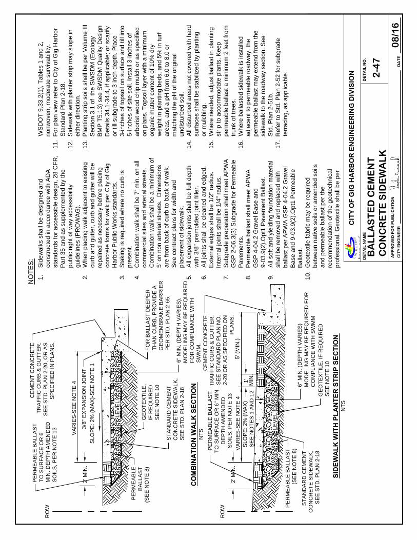
DA
TE
CIT
Y E
NG
INE
ER
AP
PR
OV
ED
FO
R P
UB
LIC
AT
ION
CIT
Y O
F G
IG H
AR
BO
R E
NG
INE
ER
ING
DIV
ISIO
N
DE
TA
IL N
O.
DE
TA
IL N
AM
E
BA
LL
AS
TE
D C
EM
EN
TC
ON
CR
ET
E S
IDE
WA
LK
2-4
7
08
/16
VA
RIE
S-S
EE
N
OT
E 4
SL
OP
E: 2
% (M
AX
)-S
EE
N
OT
E 1
NO
TE
S:
5' (M
IN
.)
VA
RIE
S-S
EE
N
OT
E 4
1.
Sidew
alks shall be design
ed a
nd
constructed in accordance
w
ith
A
DA
standards for accessible d
esig
n, 28
C
FR
,
Part 35 and as supplem
en
te
d b
y th
e
public right of w
ay accessib
ility
guidelines (P
RO
WA
G).
2.
When placing w
alk adjace
nt to
e
xistin
g
curb and gutter, curb and
g
utte
r w
ill b
e
repaired as necessary befo
re
pla
cin
g
concrete form
s for w
alk pe
r C
ity o
f G
ig
Harbor P
ublic W
orks stan
da
rd
s.
3.
Staking is required w
here
n
o cu
rb
is
present.
4.
Com
bination w
alk shall be
7
' m
in
. o
n a
ll
com
mercial sites and arte
ria
l stre
ets.
Com
bination w
alk shall be
a
m
in
im
um
o
f
5' on non arterial streets. D
im
en
sio
ns
are from
back of curb to b
ack o
f w
alk.
See contract plans for w
idth
an
d
placem
ent of sidew
alk.
5.
All expansion joints shall be
fu
ll d
ep
th
with 3/8" prem
olded join
t fille
r.
6.
All joints shall be cleaned a
nd
e
dg
ed.
External edges shall be 1/2
" ra
diu
s.
Internal joints shall be 1/4
" ra
diu
s.
7.
Subgrade preparation sha
ll m
eet A
PW
A
GS
P 2-06.3(3) S
ubgrade fo
r P
erm
ea
ble
Pavem
ents.
8.
Perm
eable ballast shall m
eet A
PW
A
GS
P 4-04.2 G
ravel B
ase a
nd
9-03.9(2).O
pt1 P
avem
en
t B
alla
st.
9.
All soft and yielding foun
da
tio
n m
aterial
shall be rem
oved and rep
la
ce
d w
ith
ballast per A
PW
A G
SP
4
-04
.2
G
ra
ve
l
Base and 9-03.9(2).O
pt1 P
erm
ea
ble
Ballast.
10.
Geotextile fabric m
ay be
re
qu
ire
d
betw
een native soils or am
en
de
d so
ils
and perm
eable ballast p
er th
e
recom
mendation of the ge
otech
nica
l
professional. G
eotextile sh
all b
e p
er
WS
DO
T 9
.3
3.2
(1
), T
ab
le
s 1
a
nd
2
,
no
nw
ove
n, m
od
era
te
su
rviva
bility.
11
.F
or pla
n vie
w re
fe
r to
C
ity o
f G
ig
H
arb
or
Sta
nda
rd
P
la
n 2
-1
8.
12
.S
id
ew
alk w
ith
p
la
nte
r strip
m
ay slo
pe
in
eith
er d
ire
ction
.
13
.P
la
ntin
g strip
so
ils sh
all b
e p
er V
olum
e III
Se
ctio
n 3
.1
o
f th
e S
WS
DM
(E
co
lo
gy
BM
P T
5.1
3) se
e S
WS
DM
Q
ua
lity D
esig
n
De
tails 3
4.1
-3
4.4
, if a
pp
lica
ble; o
r sca
rify
or till su
bg
ra
de
to
3
in
ch
d
ep
th
. P
la
ce
3-in
ch
es of to
pso
il o
n su
rfa
ce
a
nd
till in
to
5-in
ch
es of site
so
il. In
sta
ll 3
-in
ch
es o
f
arb
orist w
oo
d ch
ip
m
ulch
o
r a
s sp
ecifie
d
on
p
la
ns. T
op
so
il la
ye
r w
ith
a
m
in
im
um
org
an
ic m
atte
r co
nte
nt o
f 1
0%
dry
we
ig
ht in
p
la
nting
b
ed
s, a
nd
5
% in
tu
rf
are
as, an
d a
p
H fro
m 6
.0
to
8
.0
o
r
ma
tch
ing
th
e p
H o
f th
e o
rig
in
al
un
distu
rb
ed
so
il.
14
.A
ll d
istu
rb
ed
a
re
as n
ot co
ve
re
d w
ith
h
ard
su
rfa
ce
s sha
ll b
e sta
bilize
d b
y p
la
ntin
g
or m
ulch
in
g.
15
.W
he
re
n
ee
ded
, a
dju
st b
alla
st in
p
la
ntin
g
strip
to
a
ccom
mod
ate
p
la
nts. K
ee
p
pe
rm
eab
le
b
alla
st a
m
in
im
um
2
fe
et fro
m
tru
nk o
f tree
s.
16
.W
he
re
b
alla
ste
d sid
ew
alk is in
sta
lle
d
ad
ja
ce
nt to
p
erm
ea
ble
ro
ad
wa
y, th
e
pe
rm
eab
le
b
alla
st m
ay e
xte
nd
from
th
e
sid
ew
alk to
th
e ro
ad
wa
y se
ctio
n. S
ee
Std
. P
lan
2
-5
1b
.
17
.R
efer to
S
td
. P
la
n 2
-5
2 for su
bg
ra
de
te
rra
cin
g, a
s a
pp
lica
ble
.
3/8
" E
XP
AN
SIO
N JO
IN
T
PE
RM
EA
BL
E
BA
LL
AS
T
(S
EE
N
OT
E 8
)
PE
RM
EA
BL
E B
AL
LA
ST
(S
EE
N
OT
E 8
)
NT
S
NT
S
GE
OT
EX
TIL
E,
IF
R
EQ
UIR
ED
SE
E N
OT
E 1
0
GE
OT
EX
TIL
E, IF
R
EQ
UIR
ED
SE
E N
OT
E 1
0
PE
RM
EA
BL
E B
AL
LA
ST
TO
S
UR
FA
CE
O
R 6
" M
IN
.
DE
PT
H A
ME
ND
ED
SO
IL
S, P
ER
N
OT
E 1
3
RO
W
RO
W
CO
MB
IN
AT
IO
N W
AL
K S
EC
TIO
N
SID
EW
AL
K W
IT
H P
LA
NT
ER
S
TR
IP
S
EC
TIO
N
PE
RM
EA
BL
E B
AL
LA
ST
TO
S
UR
FA
CE
O
R 6
"
MIN
. D
EP
TH
A
ME
ND
ED
SO
IL
S, P
ER
N
OT
E 1
3
CE
ME
NT
C
ON
CR
ET
E
TR
AF
FIC
C
UR
B &
G
UT
TE
R.
SE
E S
TA
ND
AR
D P
LA
N N
O.
2-2
0 O
R A
S S
PE
CIF
IE
D O
N
PL
AN
S.
CE
ME
NT
C
ON
CR
ET
E
TR
AF
FIC
C
UR
B &
G
UT
TE
R.
SE
E S
TD
. P
LA
N 2
-2
0, O
R A
S
SP
EC
IF
IE
D IN
P
LA
NS
.
2' M
IN
.
2' M
IN
.
6" M
IN
. (D
EP
TH
V
AR
IE
S).
MO
DE
LIN
G M
AY
B
E R
EQ
UIR
ED
FO
R C
OM
PL
IA
NC
E W
IT
H
SW
MM
.
6" M
IN
. (D
EP
TH
V
AR
IE
S)
MO
DE
LIN
G M
AY
B
E R
EQ
UIR
ED
F
OR
CO
MP
LIA
NC
E W
IT
H S
WM
M
1'
MIN
.
FO
R B
AL
LA
ST
D
EE
PE
R
TH
AN
C
UR
B, P
RO
VID
E A
GE
OM
EM
BR
AN
E B
AR
RIE
R
PE
R S
TD
. P
LA
N 2
-6
5.
SL
OP
E: 2
% (M
AX
)
SE
E N
OT
ES
1
A
ND
1
2
ST
AN
DA
RD
C
EM
EN
T
CO
NC
RE
TE
S
ID
EW
AL
K,
SE
E S
TD
. P
LA
N 2
-1
8
ST
AN
DA
RD
C
EM
EN
T
CO
NC
RE
TE
S
ID
EW
AL
K,
SE
E S
TD
. P
LA
N 2
-1
8
LE
VE
L
LE
VE
L

DA
TE
CIT
Y E
NG
INE
ER
AP
PR
OV
ED
FO
R P
UB
LIC
AT
ION
CIT
Y O
F G
IG H
AR
BO
R E
NG
INE
ER
ING
DIV
ISIO
N
DE
TA
IL N
O.
DE
TA
IL N
AM
E
PE
RV
IOU
S C
ON
CR
ET
E S
IDE
WA
LK
2-4
8a
08
/16
VA
RIE
S-S
EE
N
OT
E 4
4"
15
' M
AX
.1
5' M
AX
.
CU
RB
4"
CU
RB
A
A
PL
AN
TIN
G S
TR
IP
B B
5' (M
IN
.)
SE
CT
IO
N A
-A
CE
ME
NT
C
ON
CR
ET
E T
RA
FF
IC
CU
RB
&
G
UT
TE
R. S
EE
S
TD
.
PL
AN
2
-2
0 O
R A
S S
PE
CIF
IE
D
ON
P
LA
NS
IS
OL
AT
IO
N JO
IN
T
CE
ME
NT
C
ON
CR
ET
E
TR
AF
FIC
C
UR
B &
GU
TT
ER
. S
EE
S
TD
.
PL
AN
2
-2
0 O
R A
S
SP
EC
IF
IE
D IN
P
LA
NS
CO
NT
RA
CT
IO
N JO
IN
T
CO
NT
RA
CT
IO
N
JO
IN
T (T
YP
.)
UT
IL
IT
Y L
ID
S (S
UC
H A
S
CL
EA
NO
UT
S)
SH
AL
L B
E C
EN
TE
RE
D W
IT
HIN
CO
NT
RA
CT
IO
N JO
IN
T W
IT
H
IS
OL
AT
IO
N JO
IN
T A
LL
A
RO
UN
D L
ID
UT
IL
IT
Y
SE
RV
IC
E B
OX
(IS
OL
AT
IO
N
JO
IN
T A
LL
AR
OU
ND
)
PE
RM
EA
BL
E B
AL
LA
ST
(S
EE
N
OT
ES
9
, 1
3 A
ND
1
4)
PE
RM
EA
BL
E B
AL
LA
ST
(S
EE
N
OT
ES
9
, 1
3 A
ND
1
4)
NT
S
SE
CT
IO
N B
-B
NT
S
PL
AN
NT
S
GE
OT
EX
TIL
E IF
RE
QU
IR
ED
, S
EE
N
OT
E 1
1
GE
OT
EX
TIL
E IF
RE
QU
IR
ED
, S
EE
NO
TE
1
1
6" M
IN
. D
EP
TH
A
ME
ND
ED
S
OIL
S
SE
E N
OT
E 1
2
PA
RK
IN
G
1
1
1
1
1
1
6" M
IN
. D
EP
TH
AM
EN
DE
D
SO
IL
S S
EE
NO
TE
1
2
4" M
IN
. (D
EP
TH
V
AR
IE
S)
MO
DE
LIN
G M
AY
B
E R
EQ
UIR
ED
FO
R C
OM
PL
IA
NC
E W
IT
H S
WM
M
4" M
IN
. (D
EP
TH
V
AR
IE
S)
MO
DE
LIN
G M
AY
B
E R
EQ
UIR
ED
FO
R C
OM
PL
IA
NC
E W
IT
H S
WS
DM
IS
OL
AT
IO
N JO
IN
T
AD
JA
CE
NT
T
O
ST
AN
DA
RD
CO
NC
RE
TE
SID
EW
AL
K (T
YP
.)
CO
NT
RA
CT
IO
N JO
IN
T T
O M
AT
CH
CU
RB
, JO
IN
T S
PA
CIN
G N
OT
T
O
EX
CE
ED
1
5'. C
LO
SE
R JO
IN
T
SP
AC
IN
G IS
R
EC
OM
ME
ND
ED
O
N
CU
RV
ES
.
LE
VE
L
LE
VE
L
SLO
PE
: 2%
(M
AX
)
SE
E N
OT
E 1
2'
SLO
PE
: 2%
(M
AX
)
SE
E N
OT
E 1
1'
VA
RIE
S-S
EE
N
OT
E 4
NO
TE
S:
1.
See
2-4
8b
fo
r N
otes.
2'

DA
TE
CIT
Y E
NG
INE
ER
AP
PR
OV
ED
FO
R P
UB
LIC
AT
ION
CIT
Y O
F G
IG H
AR
BO
R E
NG
INE
ER
ING
DIV
ISIO
N
DE
TA
IL N
O.
DE
TA
IL N
AM
E
PE
RV
IOU
S C
ON
CR
ET
E S
IDE
WA
LK
2-4
8b
08
/16
NO
TE
S:
1.
Sidew
alks shall be designed and constructed in
accordance w
ith A
DA
standards for accessible design,
28 C
FR
, P
art 35 and a
s supplem
ented by the public
right of w
ay accessibility guidelines (P
RO
WA
G).
2.
When placing w
alk adjacent to existing curb and gutter,
curb and gutter w
ill be repaired as necessary before
placing concrete form
s for w
alk per C
ity of G
ig H
arbor
Public W
orks standards.
3.
Staking is required w
here no curb is present.
4.
Com
bination w
alk sha
ll be 7' m
in. on all com
mercial
sites and arterial streets. C
om
bination w
alk shall be a
minim
um
of 5' on non arterial streets. D
im
ensions are
from
back of curb to b
ack of w
alk. S
ee contract plans
for w
idth and placem
ent of sidew
alk.
5.
All isolation joints sha
ll be full depth w
ith 3/8" prem
olded
joint filler.
6.
All joints shall be clea
n and edged. Joint edges shall be
1/2" radius.
7.
Subgrade preparation
shall m
eet A
PW
A G
SP
2-06.3(3)
Subgrade for P
erm
eab
le P
avem
ents.
8.
All soft and yielding fo
undation m
aterial shall be
rem
oved and replaced w
ith ballast per A
PW
A G
SP
4-04.2 G
ravel B
ase an
d 9-03.9(2).O
pt1 P
erm
eable
Ballast.
9.
Perm
eable ballast sha
ll m
eet A
PW
A G
SP
4-04.2 G
ravel
Base and 9-03.9(2).O
pt1 P
erm
eable B
allast.
10.
All pervious surfaces sh
all be vacuum
ed im
mediately
after com
pletion of saw
cutting to prevent clogging per
Std. P
lan 2-49.
11.
Geotextile fabric m
ay be required betw
een native soils
and perm
eable ballast p
er th
e re
co
mm
en
da
tio
n o
f th
e
geotechnical professio
na
l. G
eo
te
xtile
sh
all b
e p
er
WS
DO
T 9.33.2(1) T
ables 1
an
d 2
, n
on
wo
ve
n, m
od
era
te
survivability.
12.
Planting strip soils sh
all be
p
er V
olu
me
III S
ectio
n 3
.1
o
f
the S
WS
DM
(E
cology B
MP
T
5.1
3) se
e S
WS
DM
Quantity D
esign D
eta
ils 34
.1
-3
4.4
, if a
pp
lica
ble
; o
r
scarify or till subgrad
e to
3 in
ch
d
ep
th
. P
la
ce
3 in
ch
es
of topsoil on surface
a
nd
till in
to
5
-in
ch
es o
f site
so
il.
Install 3-inches of arb
orist w
oo
d ch
ip
m
ulch
or a
s
specified on plans. T
op
soil la
ye
r w
ith
a
m
in
im
um
organic m
atter conte
nt of 1
0%
d
ry w
eig
ht in
pla
ntin
g
beds, and 5%
in turf a
re
as, a
nd
a p
H fro
m 6
.0
to
8
.0
or
matching the pH
of th
e o
rig
in
al u
nd
isturbe
d so
il.
13.
Where needed, adju
st b
alla
st in
p
la
ntin
g strip
to
accom
modate plants. K
ee
p p
erm
ea
ble
b
alla
st a
minim
um
2 feet from
tru
nk o
f tre
es.
14.
For ballast deeper tha
n cu
rb
, p
ro
vid
e a
g
eo
me
mb
ra
ne
barrier per S
td. P
lan 2
-65
b
etw
ee
n p
erm
ea
ble
b
alla
st
and road section unle
ss a
dja
ce
nt ro
ad
is pe
rm
ea
ble
.
15.
All disturbed areas no
t cove
re
d w
ith
h
ard
su
rfa
ce
s sh
all
be stabilized by planting
o
r m
ulch
in
g.
16.
Refer to S
td. P
lan 2-5
2 fo
r su
bg
ra
de
te
rra
cin
g, a
s
applicable.

DA
TE
CIT
Y E
NG
INE
ER
AP
PR
OV
ED
FO
R P
UB
LIC
AT
ION
CIT
Y O
F G
IG H
AR
BO
R E
NG
INE
ER
ING
DIV
ISIO
N
DE
TA
IL N
O.
DE
TA
IL N
AM
E
TY
PIC
AL
PA
VE
ME
NT
RE
ST
OR
AT
ION
FO
R P
ER
VIO
US
CO
NC
RE
TE
2-4
9
08
/16
NO
TE
S:
CO
NS
TR
UC
TIO
N JO
IN
T
EX
IS
TIN
G P
ER
VIO
US
CO
NC
RE
TE
P
AV
EM
EN
T
PE
RV
IO
US
CO
NC
RE
TE
PA
VE
ME
NT
MA
TC
H E
XIS
TIN
G
TH
IC
KN
ES
S
1. T
o b
e u
sed
o
nly w
here abutting surfaces are p
ervious concrete or as
dire
cte
d in
w
ritin
g by C
ity of G
ig H
arbor. P
erm
eable roads m
ay be
re
qu
ire
d to be
patched in an alternate m
aterial a
s directed in w
riting by
City o
f G
ig
H
arbor.
2. A
ll pave
me
nt re
storation w
ork shall also m
eet the requirem
ents of the
City o
f G
ig
H
arbor P
ublic W
orks standards.
3. T
em
pora
ry S
urface R
estoration:
Arterials, in
du
strial areas and/or roads w
ith bus traffic
: T
em
porary patches
sha
ll be
com
pacted and leveled to a m
inim
um
of 3-inches of hot-m
ix asphalt
(H
MA
).
Re
sid
en
tials and alleys: T
em
porary patches shall be com
pacted and
le
vele
d to a m
inim
um
of 2-inches of either H
MA
or cold-m
ix asphalt.
Tem
po
ra
ry pa
tches betw
een O
ctober 1st and M
arch 31st shall be m
ade
with
H
MA
u
nless otherw
ise approved.
4. A
ll p
erm
an
en
t final patches shall be rectangula
r in shape and constructed
pa
ra
lle
l an
d pe
rpendicular to the road centerline.
5. W
he
re e
xisting
pavem
ent defects are in close proxim
ity to the new
cut, the
in
spe
cto
r m
ay require additional pavem
ent rem
oval to elim
inate the
pa
vem
en
t d
efect.
6. T
he fina
l cut edge of paved surfaces shall be sm
ooth and straight,
co
nsiste
nt w
ith grinding or saw
cutting devices. N
o jagged, broken or
un
de
rm
ine
d ed
ges are allow
ed. C
utting w
heel run-out beyond the lim
its of
th
e op
en
ing
shall be filled in accordance w
ith W
SD
OT
S
tandard
Sp
ecifica
tion
5
-05.3(8)B
for cem
ent concrete surfaces. Joint sealant shall
no
t m
igrate b
eyond run-out areas.
7. A
ll p
erviou
s surfaces shall be vacuum
ed im
mediately after com
pletion of
saw
cu
tting
to
p
revent clogging.
8. P
erm
an
en
t P
an
el R
eplacem
ent:
Arterials, in
du
strial areas and/or roads w
ith bus traffic:
10
0%
pa
ne
l re
placem
ent is required for all affected panels. M
onolithic
cu
rbs w
ill be
po
ured at tim
e of panel replacem
ent.
Re
sid
en
tial an
d A
lleys: Panels cut greater than ½ the panel length, width,
or total a
re
a, including the 2-foot cut back, w
ill require 100%
panel
replacement. Panels cut less than ½ the panel length, width, or total area,
in
clud
ing
th
e 2
-foot cut back w
ill require 50%
p
an
el replacem
ent.
Three
-p
iece
p
anels are not acceptable and w
ill require 100%
panel
re
pla
cem
en
t.
9. P
ervious concrete pavem
en
t m
ix sha
ll b
e a
pp
ro
ve
d in
w
ritin
g by th
e C
ity o
f
Gig H
arbor.
10. W
here geotextile fabric o
r ge
om
em
bra
ne
lin
er e
xist u
nd
er th
e p
erm
ea
ble
ballast, replace w
ith sa
me
m
ate
ria
l. A
dd
itio
na
l w
id
th
o
f e
xca
va
tio
n m
ay b
e
necessary to overlay fa
bric o
r lin
er. W
he
re
a
lin
er is u
se
d to
cre
ate
a
watertight barrier, repair p
er m
an
ufa
ctu
re
r's sp
ecificatio
ns to
m
ain
ta
in
a
watertight barrier.
EX
IS
TIN
G P
ER
ME
AB
LE
BA
LL
AS
T
PR
OP
OS
ED
PE
RM
EA
BL
E B
AL
LA
ST
TO
M
AT
CH
E
XIS
TIN
G
PE
RM
EA
BL
E B
AL
LA
ST
(T
HIC
KN
ES
S A
ND
GR
AD
AT
IO
N)
2' M
IN
. C
UT
B
AC
K O
VE
R
UN
DIS
TU
RB
ED
P
ER
ME
AB
LE
BA
LL
AS
T
FO
R E
XT
EN
TS
O
F
PA
NE
L R
EP
LA
CE
ME
NT
SE
E N
OT
E 8

DA
TE
CIT
Y E
NG
INE
ER
AP
PR
OV
ED
FO
R P
UB
LIC
AT
ION
CIT
Y O
F G
IG H
AR
BO
R E
NG
INE
ER
ING
DIV
ISIO
N
DE
TA
IL N
O.
DE
TA
IL N
AM
E
TY
PIC
AL
PA
VE
ME
NT
RE
ST
OR
AT
ION
FO
R P
OR
OU
S A
SP
HA
LT
PA
VE
ME
NT
2-5
0
08
/16
NO
TE
S:
1. T
o be used only w
here abutting surfaces are
porous asphalt or as directed in w
riting by C
ity
of G
ig H
arbor. P
erm
eable roads m
ay be required
to be patched in an alternate m
aterial as
directed in w
riting by C
ity of G
ig H
arbor.
2. A
ll pavem
ent restoration w
ork shall also m
eet
the requirem
ents of the C
ity of G
ig H
arbor
Public W
orks standards. F
or any streets exem
pt
from
this policy, com
pliance w
ith notes 8 and 9
is not required, com
pliance w
ith note 12 is
required.
3. T
em
porary S
urface R
estoration:
Arterials, industrial areas and/or roads w
ith bus
traffic: T
em
porary patches shall be com
pacted and
leveled to a m
inim
um
of 3-inches of hot-m
ix asphalt
(H
MA
).
Residentials and alleys
: T
em
porary patches shall
be com
pacted and leveled to a m
inim
um
of 2-inches
of either H
MA
or cold-m
ix asphalt. T
em
porary
patches betw
een O
ctober 1st and M
arch 31st shall
be m
ade w
ith H
MA
unless otherw
ise approved.
4. A
ll perm
anent final patches shall be rectangular in
shape and constructed parallel and perpendicular to
the road centerline.
5. W
here existing pavem
ent defects are in close
proxim
ity to the new
cut, the C
ity Inspector m
ay
require additional pavem
ent rem
oval to elim
inate
the pavem
ent defect.
6. T
he final cut edge of paved surfaces shall be
sm
ooth and straight, consistent w
ith grinding or saw
cutting devices. N
o jagged, broken or underm
ined
edges are allow
ed. C
utting w
heel run-out beyond
the lim
its of the opening shall be filled in accordance
with W
SD
OT
S
tandard S
pecification 5-04.3(5)C
for
asphalt concrete surfaces. Joint sealant shall not
migrate beyond run-out areas.
7. F
inal com
paction of porous H
MA
shall m
eet A
PW
A
GS
P 5-04.3(10)A
G
eneral.
Isolated patches
: M
inim
um
1 test per patch up to
150 square feet, and 1 test required every
additional 300 square feet, thereafter.
Trench patches
: 1 test every 150 linear feet of
trench w
ith a m
inim
um
of 2 tests per trench.
T
esting shall be perform
ed by a certified
independent testing laboratory or certified tester, as
approved by the C
ity's Inspector. T
ests shall be
com
pleted and reports identifying the project
num
ber subm
itted to the C
ity's Inspector w
ithin 48
hours of test.
8. Longitudinal construction joints shall only be located
at the center or edge of affected lanes.
Roadw
ays 20 feet or less in w
idth and all alleys are
considered one-lane streets. N
on-arterial roadw
ays
greater than 20 feet in w
idth w
ith no traffic
channelization are considered tw
o-lane streets w
ith
one-lane either side of the centerline of the street.
N
on-arterial streets greater than 32 feet in w
idth
with no traffic channelization m
ay be considered
three lane streets upon prior approval from
the C
ity
Engineer.
9. T
ransverse construction joints term
inate at the edge
of the 2' cut back.
10. P
orous H
MA
and A
sphalt T
reated P
erm
eable B
ase
(A
TP
B) pavem
ent shall not be placed over C
DF
until
approved by the C
ity.
11. W
here geotextile fabric or geom
em
brane liner exist
under the perm
eable ballast, replace w
ith sam
e
material. A
dditional w
idth of excavation m
ay be
necessary to overlay fabric or liner. W
here a liner is
used to create a w
atertigtht barrier, repair per
manufacturer's specifications and to m
aintain a
watertight barrier.
12. If rem
aining pavem
ent adjacent to the patch is less
than 3' w
ide, rem
ove and replace asphalt concrete
pavem
ent to m
atch existing (m
inim
um
2").
13. A
ll pervious surfaces shall be vacuum
ed
im
mediately after com
pletion of saw
cutting to
prevent clogging.
CO
NS
TR
UC
TIO
N JO
IN
T,
SE
E N
OT
E 8
EX
IS
TIN
G P
OR
OU
S
AS
PH
AL
T
PR
OP
OS
ED
P
ER
ME
AB
LE
BA
LL
AS
T (M
AT
CH
E
XIS
TIN
G
PE
RM
EA
BL
E B
AL
LA
ST
TH
IC
KN
ES
S A
ND
G
RA
DA
TIO
N)
PO
RO
US
H
MA
PA
VE
ME
NT
P
G 7
0-2
2E
R,
SE
E T
AB
LE
1
AS
PH
AL
T T
RE
AT
ED
PE
RM
EA
BL
E B
AS
E (A
TP
B)
EX
IS
TIN
G A
TP
B
EX
IS
TIN
G
PE
RM
EA
BL
E B
AL
LA
ST
AR
TE
RIA
LS
&
IN
DU
ST
RIA
L A
RE
AS
RE
SID
EN
TIA
LS
A
ND
AL
LE
YS
PA
VE
ME
NT
R
EP
LA
CE
ME
NT
D
EP
TH
IN
C
UT
B
AC
K Z
ON
E
TA
BL
E 1
PE
R W
RIT
TE
N A
UT
HO
RIZ
AT
IO
N
ON
LY
MA
TC
H E
XIS
TIN
G, O
R 2
" P
OR
OU
S
HM
A O
VE
R 3
" A
TP
B,
WH
IC
HE
VE
R IS
G
RE
AT
ER
CU
T B
AC
K Z
ON
E
2' M
IN
. C
UT
B
AC
K O
VE
R
UN
DIS
TU
RB
ED
P
ER
ME
AB
LE
B
AL
LA
ST

DA
TE
CIT
Y E
NG
INE
ER
AP
PR
OV
ED
FO
R P
UB
LIC
AT
ION
CIT
Y O
F G
IG H
AR
BO
R E
NG
INE
ER
ING
DIV
ISIO
N
DE
TA
IL N
O.
DE
TA
IL N
AM
E
PE
RM
EA
BL
E R
OA
DW
AY
WIT
H IM
PE
RV
IOU
S S
IDE
WA
LK
2-5
1a
08
/16
1.
Pe
rm
ea
ble
ballast shall m
eet A
PW
A G
SP
4-04.2
Gravel B
ase
a
nd
9-03.9(2) P
erm
eable B
allast O
pt1
an
d sha
ll b
e insta
lled per A
PW
A G
SP
4-04.3(5)
Sh
ap
ing
an
d C
om
paction.
2.
Min
im
um
su
rface
longitudinal slope shall be 0.5%
.
3.
Ge
om
em
bran
e b
arrier shall provide an im
perm
eable
ba
rrie
r be
tw
ee
n standard and perm
eable section.
Ge
om
em
bran
e m
ay also be required at the should
er
sid
e o
f th
e ro
ad
. It shall be installed 1" below
finished
grad
e o
f su
rfacing
, as show
n. A
lternatively, the liner
sh
all fo
ld o
ver th
e perm
eable ballast a m
inim
um
o
f 6".
Ge
om
em
bran
e b
arrier seam
s shall overlap at least 18"
or per m
anufacturer's recom
mendations.
Geom
em
brane barrier shall extend the length of th
e
perm
eable section w
hen adjacent to standard
pavem
ent. S
ee S
td. P
lan 2-65.
4.
Geotextile to be provided w
hen recom
mended by
geotechnical professional and shall be required w
he
n
fines in native subgrade exceed 7%
on the #200
sieve.
5.
Geotextile for separation per W
SD
OT
9.33.2(1),
woven, T
able 3 and installed per W
SD
OT
2-12.3(1
).
6.
See S
td. P
lan 2-13 for m
inim
um
pavem
ent section
.
7.
Pe
rm
ea
ble
p
ave
me
nt su
rfacing
sh
all m
ee
t A
PW
A
GS
P 5
-0
4.3
C
on
stru
ctio
n R
eq
uirem
en
ts P
oro
us
Asp
ha
lt (P
HM
A/P
WM
A) A
cce
pta
nce
In
filtra
tio
n T
est
fo
r p
oro
us a
sp
ha
lt o
r 5
-0
6.3
(6
)A
Infiltra
tio
n R
ate
o
f th
e
Pla
ce
d P
ave
me
nt fo
r p
erviou
s co
ncre
te
.
8.
Pe
rm
ea
ble
b
alla
st m
ay b
e exte
nd
ed
u
nd
er cu
rb
a
nd
sid
ew
alk w
he
n a
pp
ro
ve
d, se
e S
td. P
la
n 2
-5
1b
.
0-2%
T
YP
.
SLO
PE
: 2%
(M
AX
)
CE
ME
NT
C
ON
CR
ET
E T
RA
FF
IC
C
UR
B,
SE
E S
TA
ND
AR
D P
LA
N 2
-2
0
(N
O G
UT
TE
R)
GE
OT
EX
TIL
E,
SE
E N
OT
E 4
PO
RO
US
H
MA
AS
PH
AL
T T
RE
AT
ED
P
ER
ME
AB
LE
B
AS
E
CO
NC
RE
TE
S
ID
EW
AL
K,
SE
E S
TD
. P
LA
N 2
-1
8
0-2%
T
YP
.
SLO
PE
: 2%
(M
AX
)
CE
ME
NT
C
ON
CR
ET
E T
RA
FF
IC
C
UR
B,
SE
E S
TA
ND
AR
D P
LA
N 2
-2
0 (N
O G
UT
TE
R)
GE
OT
EX
TIL
E,
SE
E N
OT
E 4
PR
EP
AR
E A
ND
P
RO
TE
CT
S
UB
GR
AD
E P
ER
A
PW
A G
SP
4-0
4.3
(5
) S
HA
PIN
G A
ND
C
OM
PA
CT
IO
N
GE
OM
EM
BR
AN
E B
AR
RIE
R (S
EE
NO
TE
3
) O
R C
ON
CR
ET
E B
AN
D
PE
R S
TD
. P
LA
N 2
-6
5
PE
RV
IO
US
C
ON
CR
ET
E
LE
VE
L
LE
VE
L
4" D
EP
TH
C
LE
AN
C
RU
SH
ED
B
AS
E
CO
UR
SE
P
ER
W
SD
OT
9
-0
3.9
(3
)
1'
1'
NO
TE
S:
PE
RM
EA
BL
E B
AL
LA
ST
GE
OM
EM
BR
AN
E B
AR
RIE
R (S
EE
NO
TE
3
) O
R C
ON
CR
ET
E B
AN
D
PE
R S
TD
. P
LA
N 2
-6
5
PE
RM
EA
BL
E B
AL
LA
ST
CO
NC
RE
TE
S
ID
EW
AL
K,
SE
E S
TD
. P
LA
N 2
-1
8
GE
OT
EX
TIL
E O
R G
EO
ME
MB
RA
NE
BA
RR
IE
R W
HE
N N
EE
DE
D, S
EE
N
OT
E 3
PR
EP
AR
E A
ND
P
RO
TE
CT
S
UB
GR
AD
E P
ER
A
PW
A G
SP
4-0
4.3
(5
) S
HA
PIN
G A
ND
C
OM
PA
CT
IO
N
NT
S
PE
RV
IO
US
CO
NC
RE
TE
NT
S
PO
RO
US
AS
PH
AL
T
1'
1'
ST
AN
DA
RD
P
AV
EM
EN
T L
AN
E
(IF
A
PP
LIC
AB
LE
)
BA
SE
C
OU
RS
E O
R
OT
HE
R S
UIT
AB
LE
F
IL
L
BA
SE
C
OU
RS
E O
R
OT
HE
R S
UIT
AB
LE
F
IL
L
ST
AN
DA
RD
P
AV
EM
EN
T L
AN
E
(IF
A
PP
LIC
AB
LE
)
EN
D G
EO
ME
MB
RA
NE
EN
D G
EO
ME
MB
RA
NE
EN
D G
EO
ME
MB
RA
NE
1'
4" D
EP
TH
C
LE
AN
C
RU
SH
ED
B
AS
E
CO
UR
SE
P
ER
W
SD
OT
9
-0
3.9
(3
)
GE
OT
EX
TIL
E O
R G
EO
ME
MB
RA
NE
BA
RR
IE
R W
HE
N N
EE
DE
D, S
EE
N
OT
E 3
EN
D G
EO
ME
MB
RA
NE
1'

DA
TE
CIT
Y E
NG
INE
ER
AP
PR
OV
ED
FO
R P
UB
LIC
AT
ION
CIT
Y O
F G
IG H
AR
BO
R E
NG
INE
ER
ING
DIV
ISIO
N
DE
TA
IL N
O.
DE
TA
IL N
AM
E
PE
RM
EA
BL
E R
OA
DW
AY
WIT
H P
ER
VIO
US
SID
EW
AL
K2
-51
b
08
/16
0-2%
T
YP
.
2%
(M
AX
)
CE
ME
NT
C
ON
CR
ET
E T
RA
FF
IC
C
UR
B,
SE
E S
TA
ND
AR
D P
LA
N 2
-2
0
(N
O G
UT
TE
R)
3/8
" E
XP
AN
SIO
N JO
IN
T
PE
RV
IO
US
C
ON
CR
ET
E
SID
EW
AL
K - S
EE
S
TD
. P
LA
N 2
-1
8
PE
RM
EA
BL
E P
AV
EM
EN
T
GE
OT
EX
TIL
E, S
EE
N
OT
E 4
LE
VE
L
2'
8" D
EP
TH
A
ME
ND
ED
S
OIL
(S
EE
N
OT
E 7
)
CE
ME
NT
C
ON
CR
ET
E T
RA
FF
IC
C
UR
B,
SE
E S
TA
ND
AR
D P
LA
N 2
-2
0
(N
O G
UT
TE
R)
GE
OT
EX
TIL
E,
SE
E N
OT
E 4
PR
EP
AR
E A
ND
P
RO
TE
CT
S
UB
GR
AD
E P
ER
A
PW
A
GS
P 4
-0
4.3
(5
) S
HA
PIN
G A
ND
C
OM
PA
CT
IO
N
GE
OM
EM
BR
AN
E B
AR
RIE
R (S
EE
N
OT
E 3
) O
R
CO
NC
RE
TE
B
AN
D P
ER
S
TD
. P
LA
N 2
-6
5
GE
OT
EX
TIL
E,
SE
E N
OT
E 4
PE
RV
IO
US
C
ON
CR
ET
E
SID
EW
AL
K - S
EE
S
TD
. P
LA
N 2
-1
8
PE
RM
EA
BL
E B
AL
LA
ST
- L
AY
ER
S M
AY
B
E
CO
NN
EC
TE
D
MIN
.6
" D
EP
TH
AM
EN
DE
D S
OIL
(S
EE
N
OT
E 7
)
2%
(M
AX
)
PE
RM
EA
BL
E P
AV
EM
EN
T
(S
EE
N
OT
E 6
)
LE
VE
L
2'
MIN
. 6
" D
EP
TH
AM
EN
DE
D S
OIL
(S
EE
N
OT
E 7
)
4" x 2
0" C
LE
AN
C
RU
SH
ED
BA
SE
C
OU
RS
E P
ER
W
SD
OT
9-0
3.9
(3
)
NO
TE
S:
1.
Pe
rm
ea
ble
b
alla
st sh
all m
ee
t A
PW
A G
SP
4
-0
4.2
G
ra
ve
l
Ba
se
a
nd
9
-0
3.9
(2
) P
erm
ea
ble
B
alla
st O
pt1
a
nd
sh
all b
e
in
sta
lle
d p
er A
PW
A G
SP
4
-0
4.3
(5
) S
ha
pin
g a
nd
Co
mp
actio
n.
2.M
in
im
um
su
rfa
ce
lo
ng
itu
din
al slo
pe
sh
all b
e 0
.5
%.
3.G
eo
me
mb
ra
ne
b
arrie
r sh
all p
ro
vid
e a
n im
pe
rm
ea
ble
ba
rrie
r b
etw
ee
n sta
nd
ard
a
nd
p
erm
ea
ble
se
ctio
n.
Ge
om
em
bra
ne
m
ay a
lso
b
e re
qu
ire
d a
t th
e sh
ou
ld
er sid
e
of th
e ro
ad
. It sh
all b
e in
sta
lle
d 1
" b
elo
w fin
ish
ed
g
ra
de
o
f
su
rfa
cin
g, a
s sh
ow
n. A
lte
rn
ative
ly, th
e lin
er sh
all fo
ld
ove
r th
e p
erm
ea
ble
b
alla
st a
m
in
im
um
o
f 6
".
Ge
om
em
bra
ne
b
arrie
r se
am
s sh
all o
ve
rla
p a
t le
ast 1
8" o
r
pe
r m
an
ufa
ctu
re
r's re
co
mm
en
da
tio
ns. G
eo
me
mb
ra
ne
ba
rrie
r sh
all e
xte
nd
th
e le
ng
th
o
f th
e p
erm
ea
ble
se
ctio
n
wh
en
a
dja
ce
nt to
sta
nd
ard
p
ave
me
nt. S
ee
S
td
. P
la
n
2-6
5.
4.G
eo
te
xtile
to
b
e p
ro
vid
ed
w
he
n re
co
mm
en
de
d b
y
ge
ote
ch
nica
l p
ro
fe
ssio
na
l a
nd
sh
all b
e re
qu
ire
d w
he
n
fin
es in
n
ative
su
bg
ra
de
e
xce
ed
7
% o
n th
e #
20
0 sie
ve
.
5.G
eo
te
xtile
fo
r se
pa
ra
tio
n p
er W
SD
OT
9
.3
3.2
(1
), w
ove
n,
Ta
ble
3
a
nd
in
sta
lle
d p
er W
SD
OT
2
-1
2.3
(1
). G
eo
te
xtile
un
de
r sid
ew
alk m
ay b
e sa
me
a
s u
nd
er ro
ad
o
r W
SD
OT
9.3
3.2
(1
), T
ab
le
s 1
a
nd
2
, n
on
wo
ve
n, m
od
era
te
su
rviva
bility.
6.S
ee
S
td
. P
la
n 2
-1
3 fo
r m
in
im
um
p
ave
me
nt se
ctio
n.
7.P
la
ntin
g strip
so
ils sh
all b
e p
er B
MP
L
61
3 (se
e S
WS
DM
Qu
an
tity D
esig
n D
eta
ils 7
.1
-7
.4
), if a
pp
lica
ble
; o
r sca
rify
or till su
bg
ra
de
to
3
-in
ch
d
ep
th
; p
la
ce
3
-in
ch
es o
f to
pso
il
on
su
rfa
ce
a
nd
till in
to
5
-in
ch
es o
f site
so
il. In
sta
ll
3-in
ch
es o
f a
rb
orist w
oo
d ch
ip
m
ulch
o
r a
s sp
ecifie
d o
n
pla
ns. T
op
so
il la
ye
r w
ith
a
m
in
im
um
o
rg
an
ic m
atte
r
co
nte
nt o
f 1
0%
d
ry w
eig
ht in
p
la
ntin
g b
ed
s, a
nd
5
% in
tu
rf a
re
as, a
nd
a
p
H fro
m 6
.0
to
8
.0
o
r m
atch
in
g th
e p
H
of th
e o
rig
in
al u
nd
istu
rb
ed
so
il.
8.P
erm
ea
ble
p
ave
me
nt su
rfa
cin
g sh
all m
ee
t A
PW
A G
SP
5-0
4.3
C
on
stru
ctio
n R
eq
uire
me
nts P
oro
us A
sp
ha
lt
(P
HM
A/P
WM
A) A
cce
pta
nce
In
filtra
tio
n T
est fo
r p
oro
us
asp
ha
lt o
r 5
-0
6.3
(6
)A
In
filtra
tio
n R
ate
o
f th
e P
la
ce
d
Pa
ve
me
nt fo
r p
ervio
us co
ncre
te
.
9.P
erm
ea
ble
b
alla
st m
ay b
e e
xte
nd
ed
u
nd
er cu
rb
a
nd
sid
ew
alk w
he
n a
pp
ro
ve
d.
NT
S
PR
EP
AR
E A
ND
P
RO
TE
CT
S
UB
GR
AD
E P
ER
A
PW
A
GS
P 4
-0
4.3
(5
) S
HA
PIN
G A
ND
C
OM
PA
CT
IO
N
4" x 2
0" C
LE
AN
C
RU
SH
ED
B
AS
E
CO
UR
SE
P
ER
W
SD
OT
9
-0
3.9
(3
)
PE
RM
EA
BL
E B
AL
LA
ST
PE
RM
EA
BL
E B
AL
LA
ST
1'
1'
ST
AN
DA
RD
P
AV
EM
EN
T L
AN
E
(IF
A
PP
LIC
AB
LE
)
ST
AN
DA
RD
P
AV
EM
EN
T L
AN
E
(IF
A
PP
LIC
AB
LE
)
GE
OM
EM
BR
AN
E B
AR
RIE
R (S
EE
N
OT
E 3
) O
R
CO
NC
RE
TE
B
AN
D P
ER
S
TD
. P
LA
N 2
-6
5
PE
RM
EA
BL
E
RO
AD
WA
Y W
IT
H
PL
AN
TIN
G S
TR
IP
AN
D P
ER
VIO
US
SID
EW
AL
K
NT
S
PE
RM
EA
BL
E
RO
AD
WA
Y W
IT
H
CO
MB
IN
AT
IO
N
PE
RV
IO
US
SID
EW
AL
K
LE
VE
L
LE
VE
L
1'
1'
EN
D G
EO
ME
MB
RA
NE
EN
D G
EO
ME
MB
RA
NE
0-2%
T
YP
.
2%
(M
AX
)

DA
TE
CIT
Y E
NG
INE
ER
AP
PR
OV
ED
FO
R P
UB
LIC
AT
ION
CIT
Y O
F G
IG H
AR
BO
R E
NG
INE
ER
ING
DIV
ISIO
N
DE
TA
IL N
O.
DE
TA
IL N
AM
E
PE
RM
EA
BL
E R
OA
DW
AY
WIT
H P
LA
NT
ING
ST
RIP
2-5
1c
08
/16
CO
NC
RE
TE
S
ID
EW
AL
K
SE
E S
TD
. P
LA
N 2
-4
7
0-2%
T
YP
.
2%
(M
AX
)
CE
ME
NT
C
ON
CR
ET
E T
RA
FF
IC
C
UR
B,
SE
E S
TA
ND
AR
D P
LA
N 2
-2
0 (N
O G
UT
TE
R)
GE
OM
EM
BR
AN
E B
AR
RIE
R
WH
EN
N
EE
DE
D S
EE
N
OT
E 3
GE
OT
EX
TIL
E, S
EE
N
OT
E 4
PR
EP
AR
E A
ND
P
RO
TE
CT
S
UB
GR
AD
E P
ER
A
PW
A G
SP
2-0
6.3
(3
) S
UB
GR
AD
E F
OR
P
ER
ME
AB
LE
P
AV
EM
EN
TS
GE
OM
EM
BR
AN
E B
AR
RIE
R (S
EE
NO
TE
3
) O
R C
ON
CR
ET
E B
AN
D
PE
R S
TD
. P
LA
N 2
-6
5
PO
RO
US
H
MA
AS
PH
AL
T T
RE
AT
ED
P
ER
ME
AB
LE
B
AS
E
CO
NC
RE
TE
S
ID
EW
AL
K
SE
E S
TD
. P
LA
N 2
-4
7
CE
ME
NT
C
ON
CR
ET
E T
RA
FF
IC
C
UR
B, S
EE
ST
AN
DA
RD
P
LA
N 2
-2
0 (N
O G
UT
TE
R)
GE
OT
EX
TIL
E, S
EE
N
OT
E 4
PR
EP
AR
E A
ND
P
RO
TE
CT
S
UB
GR
AD
E P
ER
A
PW
A G
SP
2-0
6.3
(3
) S
UB
GR
AD
E F
OR
P
ER
ME
AB
LE
P
AV
EM
EN
TS
GE
OM
EM
BR
AN
E B
AR
RIE
R (S
EE
N
OT
E 3
) O
R
CO
NC
RE
TE
B
AN
D P
ER
S
TD
. P
LA
N 2
-6
5
PE
RV
IO
US
C
ON
CR
ET
E
LE
VE
L
LE
VE
L
4" x 2
0" C
LE
AN
C
RU
SH
ED
B
AS
E
CO
UR
SE
P
ER
W
SD
OT
9
-0
3.9
(3
)
4" x 2
0" C
LE
AN
C
RU
SH
ED
B
AS
E
CO
UR
SE
P
ER
W
SD
OT
9
-0
3.9
(3
)
1'
1'
8" M
IN
. D
EP
TH
AM
EN
DE
D S
OIL
(S
EE
N
OT
E 7
)
8" M
IN
. D
EP
TH
A
ME
ND
ED
S
OIL
(S
EE
N
OT
E 7
)
NO
TE
S:
GE
OM
EM
BR
AN
E B
AR
RIE
R
WH
EN
N
EE
DE
D S
EE
N
OT
E 3
1'
1'
ST
AN
DA
RD
P
AV
EM
EN
T L
AN
E
(IF
A
PP
LIC
AB
LE
)
ST
AN
DA
RD
P
AV
EM
EN
T L
AN
E
(IF
A
PP
LIC
AB
LE
)
NT
S
PE
RV
IO
US
CO
NC
RE
TE
NT
S
PO
RO
US
AS
PH
AL
T
EN
D G
EO
ME
MB
RA
NE
EN
D G
EO
ME
MB
RA
NE
EN
D G
EO
ME
MB
RA
NE
EN
D G
EO
ME
MB
RA
NE
1.P
erm
ea
ble
b
alla
st sh
all m
ee
t A
PW
A G
SP
4
-0
4.2
Gra
ve
l B
ase
a
nd
9
-0
3.9
(2
) P
erm
ea
ble
B
alla
st
Op
t1
a
nd
sh
all b
e in
sta
lle
d p
er A
PW
A G
SP
4-0
4.3
(5
) S
ha
pin
g a
nd
C
om
pa
ctio
n.
2.M
in
im
um
su
rfa
ce
lo
ng
itu
din
al slo
pe
sh
all b
e 0
.5
%.
3.G
eo
me
mb
ra
ne
b
arrie
r sh
all p
ro
vid
e a
n
im
pe
rm
ea
ble
b
arrie
r b
etw
ee
n sta
nd
ard
a
nd
pe
rm
ea
ble
se
ctio
n. G
eo
me
mb
ra
ne
m
ay a
lso
b
e
re
qu
ire
d a
t th
e sh
ou
ld
er sid
e o
f th
e ro
ad
. It sh
all
be
in
sta
lle
d 1
" b
elo
w fin
ish
ed
g
ra
de
o
f su
rfa
cin
g,
as sh
ow
n. A
lte
rn
ative
ly, th
e lin
er sh
all fo
ld
o
ve
r
th
e p
erm
ea
ble
b
alla
st a
m
in
im
um
o
f 6
".
Ge
om
em
bra
ne
b
arrie
r se
am
s sh
all o
ve
rla
p a
t
le
ast 1
8" o
r p
er m
an
ufa
ctu
re
r's re
co
mm
en
da
tio
ns.
Ge
om
em
bra
ne
b
arrie
r sh
all e
xte
nd
th
e le
ng
th
o
f
th
e p
erm
ea
ble
se
ctio
n w
he
n a
dja
ce
nt to
sta
nd
ard
pa
ve
me
nt. S
ee
S
td
. P
la
n 2
-6
5.
4.G
eo
te
xtile
to
b
e p
ro
vid
ed
w
he
n re
co
mm
en
de
d b
y
ge
ote
ch
nica
l p
ro
fe
ssio
na
l a
nd
sh
all b
e re
qu
ire
d
wh
en
fin
es in
n
ative
su
bg
ra
de
e
xce
ed
7
% o
n th
e
#2
00
sie
ve
.
5.G
eo
te
xtile
fo
r se
pa
ra
tio
n p
er W
SD
OT
9
.3
3.2
(1
),
wo
ve
n, T
ab
le
3
a
nd
in
sta
lle
d p
er W
SD
OT
2-1
2.3
(1
). G
eo
te
xtile
u
nd
er sid
ew
alk m
ay b
e sa
me
as u
nd
er ro
ad
o
r W
SD
OT
9
.3
3.2
(1
), T
ab
le
s 1
a
nd
2, n
on
wo
ve
n, m
od
era
te
su
rviva
bility.
6.S
ee
S
td
. P
la
n 2
-1
3 fo
r m
in
im
um
p
ave
me
nt
se
ctio
n.
7.P
la
ntin
g strip
so
ils sh
all b
e p
er B
MP
L
61
3 (se
e
SW
SD
M Q
ua
ntity D
esig
n D
eta
ils 7
.1
-7
.4
), if
ap
plica
ble
; o
r sca
rify o
r till su
bg
ra
de
to
3
-in
ch
de
pth
; p
la
ce
3
-in
ch
es o
f to
pso
il o
n su
rfa
ce
a
nd
till
in
to
5
-in
ch
es o
f site
so
il. In
sta
ll 3
-in
ch
es o
f a
rb
orist
wo
od
ch
ip
m
ulch
o
r a
s sp
ecifie
d o
n p
la
ns. T
op
so
il
la
ye
r w
ith
a
m
in
im
um
o
rg
an
ic m
atte
r co
nte
nt o
f
10
% d
ry w
eig
ht in
p
la
ntin
g b
ed
s, a
nd
5
% in
tu
rf
are
as, a
nd
a
p
H fro
m 6
.0
to
8
.0
o
r m
atch
in
g th
e
pH
o
f th
e o
rig
in
al u
nd
istu
rb
ed
so
il.
8.P
erm
ea
ble
p
ave
me
nt su
rfa
cin
g sh
all m
ee
t A
PW
A
GS
P 5
-0
4.3
C
on
stru
ctio
n R
eq
uire
me
nts P
oro
us
Asp
ha
lt (P
HM
A/P
WM
A) A
cce
pta
nce
In
filtra
tio
n
Te
st fo
r p
oro
us a
sp
ha
lt o
r 5
-0
6.3
(6
)A
In
filtra
tio
n
Ra
te
o
f th
e P
la
ce
d P
ave
me
nt fo
r p
ervio
us
co
ncre
te
.
9.P
erm
ea
ble
b
alla
st m
ay b
e e
xte
nd
ed
u
nd
er cu
rb
an
d sid
ew
alk w
he
n a
pp
ro
ve
d, se
e S
td
. P
la
n
2-5
1b
.
0-2%
T
YP
.
2%
(M
AX
)
4" M
IN
. D
EP
TH
P
ER
ME
AB
LE
BA
LL
AS
T B
EL
OW
B
AS
E C
OU
RS
E
4" M
IN
. D
EP
TH
P
ER
ME
AB
LE
BA
LL
AS
T B
EL
OW
B
AS
E C
OU
RS
E

DA
TE
CIT
Y E
NG
INE
ER
AP
PR
OV
ED
FO
R P
UB
LIC
AT
ION
CIT
Y O
F G
IG H
AR
BO
R E
NG
INE
ER
ING
DIV
ISIO
N
DE
TA
IL N
O.
DE
TA
IL N
AM
E
PE
RV
IOU
S P
AR
KIN
G L
AN
ET
ER
RA
CE
D S
UB
GR
AD
E2
-52
08
/16
3%
(M
AX
.)
3%
(M
AX
.)
3%
<
F
IN
IS
H G
RA
DE
<
10%
VA
RIE
S
(1
2" M
AX
.)
NO
TE
S:
1.
For finish grade no steeper than 10%
.
2.
Geotextile to be provided betw
een native soil and perm
eable ballast w
hen recom
mended by geo
te
chn
ica
l p
ro
fe
ssio
na
l
and shall be required w
hen fines in native subgrade exceed 7%
on the #200 sieve.
3.
Geotextile for separation under roadw
ays shall be per W
SD
OT
9.33.2(1), w
oven, T
able 3 and in
sta
lle
d p
er W
SD
OT
2-12.3(1). G
eotextile under sidew
alk m
ay be sam
e as under road or W
SD
OT
9.33.2(1), T
ables 1
an
d 2
, n
on
wo
ven
,
mo
derate survivability.
4.
See S
td. P
lans 2-51a, b and c for perm
eable roadw
ay sections.
6.
See S
td. P
lans 2-48a and b for perm
eable sidew
alk sections.
VA
RIE
S
GE
OT
EX
TIL
E F
AB
RIC
(IF
R
EQ
UIR
ED
- S
EE
N
OT
E 2
)
1:1
M
AX
.
SL
OP
E
PE
RM
EA
BL
E P
AV
EM
EN
T
MIN
IM
UM
P
ER
ME
AB
LE
B
AL
LA
ST
DE
PT
H P
ER
P
LA
NS
PE
RM
EA
BL
E B
AL
LA
ST

DA
TE
CIT
Y E
NG
INE
ER
AP
PR
OV
ED
FO
R P
UB
LIC
AT
ION
CIT
Y O
F G
IG H
AR
BO
R E
NG
INE
ER
ING
DIV
ISIO
N
DE
TA
IL N
O.
DE
TA
IL N
AM
E
TR
EN
CH
DA
M2
-53
08
/16
NO
TE
S:
1.
Lo
catio
n o
n m
ains per plan sheet.
2.
Re
vie
w d
esign w
ith the C
ity for
utilities greater than 36 inches in
diam
eter.
3.
Fo
r service lines, install trench dam
s
at a
pproxim
ate back of w
alk w
here
utility se
rvices are installed beyond
th
e pe
rm
eable ballast section.
4.
Du
ctile
iron pipe shall be encased in
a p
olye
thylene sleeve, m
eeting the
re
qu
ire
ments of A
merican
Wate
rw
orks A
ssociation (A
WW
A).
12
" T
HIC
K B
EN
TO
NIT
E, C
DF
,
OR
O
TH
ER
M
AT
ER
IA
L A
S
AP
PR
OV
ED
B
Y E
NG
IN
EE
R
PIP
E B
ED
DIN
G Z
ON
E
UT
IL
IT
Y P
IP
E
12
" M
IN
. B
EY
ON
D P
IP
E
BE
DD
IN
G M
AT
ER
IA
L
(A
LL
E
DG
ES
)
TR
EN
CH
W
AL
L (T
YP
.)
TR
EN
CH
D
AM
UT
IL
IT
Y P
IP
E
12
"
12
"
A
A
PL
AN
NT
S
SE
CT
IO
N
NT
S
PE
RM
EA
BL
E P
AV
EM
EN
T

DA
TE
CIT
Y E
NG
INE
ER
AP
PR
OV
ED
FO
R P
UB
LIC
AT
ION
CIT
Y O
F G
IG H
AR
BO
R E
NG
INE
ER
ING
DIV
ISIO
N
DE
TA
IL N
O.
DE
TA
IL N
AM
E
OB
SE
RV
AT
ION
/MO
NIT
OR
ING
PO
RT
SF
OR
ST
OR
MW
AT
ER
FA
CIL
ITIE
S2
-54
08
/16
PV
C F
OO
T P
LA
TE
6" D
IA
P
ER
FO
RA
TE
D P
VC
P
IP
E
PE
R W
SD
OT
9
-0
5.2
(6
)
GR
AV
EL
B
AC
KF
IL
L F
OR
D
RY
WE
LL
S
PE
R W
SD
OT
9
-0
3.1
2(5
) O
R
AG
GR
EG
AT
E P
ER
W
SD
OT
9
-0
3.1
2(4
)
GR
AV
EL
B
AC
KF
IL
L F
OR
D
RA
IN
S
BE
NT
ON
IT
E O
R C
DF
12
" D
IA
P
VC
PIP
E, S
DR
3
5
6" D
IA
P
VC
P
IP
E, S
DR
3
5
12"
DEPTH AS SPECIFIED TO BOTTOM OF
PERVIOUS PAVEMENT SUBBASE
SECTION OR BIORETENTION SOIL MEDIA
OR AS SPECIFIED
CA
ST
IR
ON
F
RA
ME
, C
OV
ER
A
ND
C
ON
CR
ET
E
CO
LL
AR
P
ER
W
SD
OT
S
TA
ND
AR
D P
LA
N
B-8
5.4
0-0
0 W
IT
H L
ET
TE
RS
"M
P" O
N T
HE
CO
VE
R W
IT
H L
OC
KIN
G C
OV
ER
12
"
CO
NS
TR
UC
TIO
N G
EO
TE
XT
IL
E
BO
TT
OM
, S
ID
ES
A
ND
T
OP
PE
R W
SD
OT
9
-3
3.2
(1
) T
AB
LE
S
1 A
ND
2
6" W
AT
ER
Q
UA
LIT
Y
TR
EA
TM
EN
T L
AY
ER
O
R 1
8" O
F
SU
IT
AB
LE
N
AT
IV
E S
OIL
FO
R P
ER
VIO
US
P
AV
EM
EN
T
FIN
IS
HE
D G
RA
DE
CE
ME
NT
C
ON
CR
ET
E
CO
LL
AR
(N
OT
R
EQ
UIR
ED
IN
N
ON
-T
RA
FF
IC
A
RE
AS
)
IN
VE
RT
E
LE
V P
ER
P
LA
N
PR
EP
AR
ED
S
UB
GR
AD
E
TH
RE
AD
ED
P
LU
G
PA
VE
ME
NT
S
EC
TIO
N /
SU
RF
AC
IN
G P
ER
P
LA
N
℄

DA
TE
CIT
Y E
NG
INE
ER
AP
PR
OV
ED
FO
R P
UB
LIC
AT
ION
CIT
Y O
F G
IG H
AR
BO
R E
NG
INE
ER
ING
DIV
ISIO
N
DE
TA
IL N
O.
DE
TA
IL N
AM
E
BIO
RE
TE
NT
ION
2-5
5a
8/1
6
18
" M
IN
. B
IO
RE
TE
NT
IO
N S
OIL
ME
DIA
(B
SM
) T
HIC
KN
ES
S T
O
EX
TE
ND
T
O T
OP
O
F P
ON
DIN
G
DE
PT
H
OV
ER
FL
OW
S
TR
UC
TU
RE
, P
ER
SW
SD
M Q
UA
NT
IT
Y D
ES
IG
N
DE
TA
IL
S 2
6.2
U
NL
ES
S
SP
EC
IF
IE
D O
TH
ER
WIS
E. R
IM
SE
T A
T T
OP
O
F P
ON
DIN
G.
SE
E N
OT
E 9
.
CE
ME
NT
T
RA
FF
IC
CU
RB
A
ND
GU
TT
ER
NO
TE
S:
1.
Se
e S
td
. P
lan
s 2
-57a and b for plan view
. S
ee S
td. P
lan 2-56 for transition zone requirem
ents.
2.
24-inch
m
in
im
um
required w
here adjacent to parking.
3.
Avoid
com
pactio
n of existing subgrade below
facility.
4.
Sca
rify sub
grade
3-inches m
inim
um
before bioretention soil m
edia installation.
5.
Pla
ntin
gs pe
r S
td
. P
lan 2-66 and plans.
6.
Pla
ntin
gs ad
jace
nt to parking shall be selected and spaced to allow
pedestrian access to vehicles.
7.
Sizing
a
nd
d
esign of facility per V
olum
e III S
ection 3.4 of the S
WS
DM
.
8.
Fre
eb
oa
rd d
ep
th varies (2-inches or 6-inches) d
epending upon size of drainage area. F
or freeboard, ponding a
nd
ove
rflo
w d
ep
th
, se
e V
olu
me III se
ctio
n 3
.4
of the
S
WS
DM
.
9.
Ove
rflo
w typ
e d
epends on project design. S
ee S
WS
DM
Q
uantity D
esign D
etails 26.2. A
lternate overflow
type
m
ay b
e a
llo
we
d.
10.
Sid
e slo
pe
s ste
eper than 3:1 m
ay be approved if overall facility depth is less than 3 feet from
top of m
ulch to to
p o
f fa
cility.
11.
In
le
t e
leva
tion
to
be above freeboard elevation.
SE
E N
OT
ES
3
A
ND
4
TR
AN
SIT
IO
N Z
ON
E,
SE
E N
OT
E 1
TR
AN
SIT
IO
N Z
ON
E,
SE
E N
OT
E 1
2" T
O 4
" D
EP
TH
A
RB
OR
IS
T
WO
OD
C
HIP
M
UL
CH
O
N S
ID
E
SL
OP
ES
A
ND
B
OT
TO
M
MA
X S
ID
E S
LO
PE
3
:1
18
" O
R 2
4" M
IN
SE
E N
OT
ES
1
A
ND
2
TO
P O
F B
AN
K
EL
EV
AT
IO
N
6"
SID
EW
ALK
AD
JA
CE
NT
S
LO
PE
WIT
H P
LA
NT
IN
GS
1"
BS
M B
OT
TO
M
WID
TH
VA
RIE
S, 1
' M
IN
3
1
18
" M
IN
SE
E N
OT
E 1
2%
MA
X.
PO
ND
IN
G D
EP
TH
12
" M
AX
.
2%
MA
X.
FR
EE
BO
AR
D,
SE
E N
OT
E 8
ST
RE
ET

DA
TE
CIT
Y E
NG
INE
ER
AP
PR
OV
ED
FO
R P
UB
LIC
AT
ION
CIT
Y O
F G
IG H
AR
BO
R E
NG
INE
ER
ING
DIV
ISIO
N
DE
TA
IL N
O.
DE
TA
IL N
AM
E
BIO
RE
TE
NT
ION
WIT
HU
ND
ER
DR
AIN
2-5
5b
08
/16
U
ND
ER
DR
AIN
BE
DD
IN
G, 1
8" M
IN
. O
R
WH
EN
M
EE
TIN
G S
WM
M
MIN
. R
EQ
. #
5, F
UL
L
BO
TT
OM
W
ID
TH
A
ND
LE
NG
TH
6" M
IN
.
UN
DE
RD
RA
IN
B
ED
DIN
G,
SE
E N
OT
E 1
2
UNDERDRAIN PIPE, 6" MIN. Ø
SL
OT
TE
D P
VC
P
ER
A
ST
M
D1
78
5 S
CH
4
0. S
LO
TS
P
ER
SW
SD
M. S
LO
PE
P
IP
E A
T 0
.5
%
MIN
. U
NL
ES
S O
TH
ER
WIS
E
SP
EC
IF
IE
D
18
" M
IN
.
NO
TE
S:
1.
Se
e S
td
. P
lan
s 2-5
7a and b for plan view
. S
ee S
td. P
lan 2-56 for
tra
nsition
zon
e re
quirem
ents.
2.
24
-inch
m
inim
um
required w
here adjacent to parkin
g.
3.
Avoid com
pa
ction
of existing subgrade below
facility.
4.
Sca
rify sub
gra
de
3-inches m
inim
um
before bioretention soil m
edia installation.
5.
Pla
ntin
gs pe
r S
td
. P
lan 2-66 and plans.
6.
Pla
ntin
gs ad
ja
cen
t to parking shall be selected and spaced to allow
pedestrian access to vehicles.
7.
Sizing a
nd
d
esign of facility per V
olum
e III S
ection 3.4 of the S
WS
DM
.
8.
Fre
ebo
ard de
pth
varies (2-inches or 6-inches) dep
ending upon size of drainage area. F
or freeboard, ponding and
o
ve
rflo
w d
ep
th
, see
V
olu
me
III S
ectio
n 3
.4
of the
S
WS
DM
.
9.
Overflo
w type d
ep
ends on project design. S
ee S
WS
DM
Q
uantity D
esign D
etails 26.2. A
lternate overflow
type m
ay b
e a
llo
we
d.
10
.S
id
e slo
pe
s ste
epe
r than 3:1 m
ay be approved if overall facility depth is less than 3 feet from
top of m
ulch to top
o
f fa
cility.
11
.In
le
t e
leva
tion
to
be
above freeboard elevation.
12
.U
nd
erdra
in
b
ed
din
g per W
SD
OT
9-03.12(4) G
ravel B
ackfill for D
rains.
18
" M
IN
. B
IO
RE
TE
NT
IO
N S
OIL
ME
DIA
(B
SM
) T
HIC
KN
ES
S T
O
EX
TE
ND
T
O T
OP
O
F P
ON
DIN
G
DE
PT
H
OV
ER
FL
OW
S
TR
UC
TU
RE
, P
ER
ST
D. P
LA
N S
WS
DM
Q
UA
NT
IT
Y
DE
SIG
N D
ET
AIL
S 2
6.2
U
NL
ES
S
SP
EC
IF
IE
D O
TH
ER
WIS
E. R
IM
SE
T A
T T
OP
O
F P
ON
DIN
G.
SE
E N
OT
E 9
.
CE
ME
NT
T
RA
FF
IC
CU
RB
A
ND
GU
TT
ER
SE
E N
OT
ES
3
A
ND
4
TR
AN
SIT
IO
N Z
ON
E,
SE
E N
OT
E 1
TR
AN
SIT
IO
N Z
ON
E,
SE
E N
OT
E 1
2" T
O 4
" D
EP
TH
A
RB
OR
IS
T
WO
OD
C
HIP
M
UL
CH
O
N S
ID
E
SL
OP
ES
A
ND
B
OT
TO
M
MA
X S
ID
E S
LO
PE
3
:1
18
" O
R 2
4" M
IN
SE
E N
OT
ES
1
A
ND
2
TO
P O
F B
AN
K
EL
EV
AT
IO
N
6"
SID
EW
ALK
AD
JA
CE
NT
S
LO
PE
WIT
H P
LA
NT
IN
GS
1"
BS
M B
OT
TO
M
WID
TH
VA
RIE
S, 1
' M
IN
3
1
18
" M
IN
SE
E N
OT
E 1
2%
MA
X.
PO
ND
IN
G D
EP
TH
12
" M
AX
.
2%
MA
X.
FR
EE
BO
AR
D,
SE
E N
OT
E 8
6" M
IN
.
ST
RE
ET

DA
TE
CIT
Y E
NG
INE
ER
AP
PR
OV
ED
FO
R P
UB
LIC
AT
ION
CIT
Y O
F G
IG H
AR
BO
R E
NG
INE
ER
ING
DIV
ISIO
N
DE
TA
IL N
O.
DE
TA
IL N
AM
E
BIO
RE
TE
NT
ION
WIT
H L
INE
RA
ND
UN
DE
RD
RA
IN2
-55
c
08
/16
18
" M
IN
. B
IO
RE
TE
NT
IO
N S
OIL
M
ED
IA
(B
SM
) T
HIC
KN
ES
S T
O E
XT
EN
D T
O
TO
P O
F P
ON
DIN
G D
EP
TH
OV
ER
FL
OW
S
TR
UC
TU
RE
, P
ER
S
TD
. P
LA
N
SW
SD
M Q
UA
NT
IT
Y D
ES
IG
N D
ET
AIL
S 2
6.2
UN
LE
SS
S
PE
CIF
IE
D O
TH
ER
WIS
E.
RIM
S
ET
A
T T
OP
O
F P
ON
DIN
G. S
EE
N
OT
E 1
2.
TO
P O
F B
AN
K
EL
EV
AT
IO
N
CE
ME
NT
T
RA
FF
IC
C
UR
B
AN
D G
UT
TE
R
6"
AD
JA
CE
NT
S
LO
PE
WIT
H P
LA
NT
IN
GS
BS
M B
OT
TO
M W
ID
TH
VA
RIE
S, 1
' M
IN
PO
ND
IN
G D
EP
TH
12
" M
AX
.
FR
EE
BO
AR
D
NO
TE
S:
1.
Se
e S
td
. P
la
ns 2-57 and b for plan view
. S
ee S
td. P
lan
2-5
6 for transition
zone requirem
ents.
2.
24
-inch
m
in
im
um
required w
here adjacent to parking.
3.
Ge
om
em
bran
e liner per S
WS
DM
and shall be P
VC
with a
m
in
im
um
th
ickness of 30 m
ils and in accordance
with A
ST
M D
71
76
. S
eam
s shall be w
aterproof. Liner to
cre
ate a w
ate
rtig
ht installation to top of freeboard.
Pre
pa
re
subg
ra
de
for liner per E
ngineer. Liner
sp
ecification
m
ay vary based on site conditions.
4.
Pe
ne
tratio
ns thro
ugh facility liner shall be w
atertight
an
d sha
ll preve
nt p
referential flow
into utility trenches
(e
.g. w
ate
r stop, tre
nch block, or trench collar), as
ap
pro
priate.
5.
Provide geotextile under P
VC
liner to protect liner fro
m
sharp rocks if recom
mended by liner m
anufacturer.
Geotextile per liner m
anufacturer.
6.
Liner secured at top and/or keyed per m
anufacture
r. A
ll
seam
s to be sealed and w
aterproof per m
anufacturer
and all penetrations to be booted. Liner shall be
installed and seam
ed to create a w
atertight installa
tio
n
to top of freeboard.
7.
Plantings per S
td. P
lan 2-66 and plans.
8.
Plantings adjacent to parking shall be selected and
spaced to allow
pedestrian access to vehicles.
9.
Sizing and design of facility per V
olum
e III S
ection
3.4
of the S
WS
DM
.
10.
Fre
eb
oa
rd
d
ep
th va
rie
s (2
-in
ch
es o
r 6
-in
ch
es)
dep
en
din
g u
po
n size
o
f d
ra
in
ag
e a
re
a. F
or fre
eb
oa
rd
,
po
nd
in
g a
nd
o
verflow
d
ep
th
, se
e S
WS
DM
B
MP
L
630
.
11.
Un
de
rd
ra
in
b
ed
din
g p
er W
SD
OT
9
-0
3.1
2(4
) G
ra
ve
l
Ba
ckfill fo
r D
ra
in
s.
12.
Ove
rflo
w typ
e d
ep
en
ds on
p
ro
je
ct d
esig
n. S
ee
S
WS
DM
Qu
atity D
esig
n D
eta
ils 2
6.2
. A
lte
rn
ate
o
ve
rflo
w typ
e
ma
y b
e a
llo
we
d.
13.
Side
slo
pe
s ste
ep
er th
an
3
:1
m
ay b
e a
pp
ro
ved
if o
ve
ra
ll
fa
cility d
epth
is le
ss th
an
3
fe
et fro
m to
p o
f m
ulch
to
to
p
of fa
cility.
14.
In
le
t e
le
va
tio
n to b
e a
bo
ve
fre
eb
oard e
le
va
tio
n.
WID
TH
VA
RIE
S
18
" M
IN
.
6" M
IN
.
UN
DE
RD
RA
IN
B
ED
DIN
G,
SE
E N
OT
E 1
1
UNDERDRAIN PIPE, 6" MIN. Ø SLOTTED
PV
C P
ER
A
ST
M D
17
85
S
CH
4
0. S
LO
TS
PE
R S
WS
DM
. S
LO
PE
P
IP
E A
T 0
.5
% M
IN
UN
LE
SS
O
TH
ER
WIS
E S
PE
CIF
IE
D
18
" O
R 2
4" M
IN
SE
E N
OT
ES
1
A
ND
2
SID
EW
ALK
1"
ST
RE
ET
TR
AN
SIT
IO
N Z
ON
E, S
EE
N
OT
E 1
IN
ST
AL
L L
IN
ER
T
O C
RE
AT
E A
WA
TE
RT
IG
HT
IN
ST
AL
LA
TIO
N P
ER
MA
NU
FA
CT
UR
ER
'S
R
EQ
UIR
EM
EN
TS
.
SE
E N
OT
E 3
.
TR
AN
SIT
IO
N Z
ON
E, S
EE
N
OT
E 1
2 T
O 4
" D
EP
TH
A
RB
OR
IS
T W
OO
D C
HIP
MU
LC
H O
N S
ID
E S
LO
PE
S A
ND
B
OT
TO
M
6"
18
" O
R 2
4" M
IN
SE
E N
OT
E 1
LIN
ER
K
EY
P
ER
M
AN
UF
AC
TU
RE
R'S
RE
CO
MM
EN
DA
TIO
NS
(T
YP
), K
EY
SH
AL
L N
OT
U
ND
ER
MIN
E E
XIS
TIN
G
IN
FR
AS
TR
UC
TU
RE
A
S A
PP
LIC
AB
LE
OP
TIO
NA
L G
EO
TE
XT
IL
E B
EL
OW
L
IN
ER
SE
E N
OT
E 5
.
6" M
IN
. (E
AC
H S
ID
E)
UN
DIS
TU
RB
ED
N
AT
IV
E S
UB
GR
AD
E
2%
MA
X.
2%
MA
X.
1
3
SE
E N
OT
E 1
0

DA
TE
CIT
Y E
NG
INE
ER
AP
PR
OV
ED
FO
R P
UB
LIC
AT
ION
CIT
Y O
F G
IG H
AR
BO
R E
NG
INE
ER
ING
DIV
ISIO
N
DE
TA
IL N
O.
DE
TA
IL N
AM
E
TR
AN
SIT
ION
ZO
NE
SE
CT
ION
S2
-56
08
/16
18
" O
R 2
4" M
IN
.
SE
E N
OT
E 3
ST
RE
ET
TO
P O
F B
AN
K
EL
EV
AT
IO
N
CO
NC
RE
TE
C
UR
B
2%
6"
NT
S
TO
P O
F
FR
EE
BO
AR
D
TO
P O
F P
ON
DIN
G
NO
TE
S:
1.
1-inch
g
ra
de
ch
an
ge from
edge of sidew
alk, curb and/or other
ha
rd surfa
ce.
2.
2%
m
ax. slo
pe
fo
r shoulder / level area.
3.
Shou
ld
er / leve
l area w
idth to be 24-inches m
inim
um
w
hen
adjace
nt to
drivew
ay, on street parking or driving
surface w
ith
flu
sh
o
r n
o curb. P
lantings adjacent to parking sh
all be
se
le
cte
d a
nd sp
aced to allow
access to vehicles.
4.
Com
pa
ct transition
zone soil to 90%
m
ax. m
odifie
d proctor
den
sity (A
ST
M D
1557).
5.
Tran
sition
zo
ne
soil shall be per V
olum
e III S
ection
3.1 of the
SW
SD
M (E
cology B
MP
T
5.13) option 2 or 4 (S
WS
DM
Qua
ntity D
esig
n D
etails 34.2 and 34.4) as applicable or per
No
te
6
.
6.
Soil a
me
ndm
en
t: scarify or till subgrade to 3-inch
depth. P
lace
3-inch
es o
f top
so
il on surface and till into 5-inche
s of site soil.
In
stall 3-inch
es w
oodchip m
ulch or as specified o
n plans.
Sca
rification
do
es not apply to lined facilities. T
opsoil shall
ha
ve
a
m
in
im
um
organic m
atter content of 10%
d
ry w
eight in
plan
ting
be
ds, a
nd
5%
in turf areas and a pH
from
6.0 to 8.0 or
matching the
pH
o
f the original undisturbed soil.
7.
18
" m
inim
um
bio
retention soil m
edia (B
SM
) to top of ponding
dep
th.
8.
See S
td. P
la
n 2-55
a, b, and c for bioretention cross sections
and
S
td. P
lan
s 2
-5
7a and b for plan view
s.
9.
See S
td. P
la
n 2-60
for curb cuts or S
td. P
lan 2-61
for trench
drain
inle
ts.
10
.F
or fa
cilities w
ith liners, provide liner anchor per
man
ufacturer's recom
mendations, see S
td. P
lan 2-55c.
TR
AN
SIT
IO
N Z
ON
E S
OIL
,
SE
E N
OT
E 5
BIO
RE
TE
NT
IO
N
SO
IL
M
ED
IA
(B
SM
) S
EE
NO
TE
7
NT
S
BIO
RE
TE
NT
IO
N S
OIL
M
ED
IA
(B
SM
) S
EE
N
OT
E 7
1"
TR
AN
SIT
IO
N Z
ON
E S
OIL
, S
EE
NO
TE
5
2" T
O 4
" D
EP
TH
A
RB
OR
IS
T W
OO
D
CH
IP
M
UL
CH
18
" O
R 2
4" M
IN
SE
E N
OT
E 3
2 T
O 4
" D
EP
TH
A
RB
OR
IS
T W
OO
D
CH
IP
M
UL
CH
TO
P O
F
FR
EE
BO
AR
D
SID
EW
AL
K, D
RIV
EW
AY
OR
D
RIV
IN
G S
UR
FA
CE
TO
P O
F
PO
ND
IN
G
2%
1"
SL
OP
ED
B
IO
RE
TE
NT
IO
N A
DJA
CE
NT
T
O S
ID
EW
AL
K, D
RIV
EW
AY
OR
D
RIV
IN
G S
UR
FA
CE
W
IT
H N
O O
R F
LU
SH
C
UR
B
SL
OP
ED
B
IO
RE
TE
NT
IO
N
SE
CT
IO
N A
DJA
CE
NT
T
O C
UR
B

DA
TE
CIT
Y E
NG
INE
ER
AP
PR
OV
ED
FO
R P
UB
LIC
AT
ION
CIT
Y O
F G
IG H
AR
BO
R E
NG
INE
ER
ING
DIV
ISIO
N
DE
TA
IL N
O.
DE
TA
IL N
AM
E
BIO
RE
TE
NT
ION
WIT
H S
LO
PE
DS
IDE
S, C
ON
ST
AN
T B
OT
TO
M W
IDT
H2
-57
a
08
/16
WIDTH VARIES
SEE PLANS
FA
CIL
IT
Y (L
EN
GT
H V
AR
IE
S)
A
A
NO
TE
S:
1.
Plan
tin
gs pe
r S
td
. P
lan 2-66 and plans.
2.
Lo
catio
n, dista
nce
betw
een curb cuts, and num
ber of
cu
rb
cu
ts va
ry w
ith facility length and road slope.
Se
e pla
n for loca
tion.
3.
In
let a
nd
o
verflow
elevation per plans.
4.
Free
bo
ard de
pth va
ries (2-inches to 6-inches)
de
pe
nd
ing
up
on
size of drainage area. S
ee V
olum
e III
Se
ctio
n 3
.4
of th
e S
WS
DM
. F
reeboard depth per plans.
5.
We
irs or te
rracin
g m
ay also be used, see plans.
6.
Se
e S
td. P
lan
2
-5
6 for transition zone beyond top of
fa
cility.
7.
Se
e S
td. P
lan
s 2
-5
5a, b and c for section view
.
TO
P O
F P
ON
DIN
G W
AT
ER
S
UR
FA
CE
= O
VE
RL
OW
E
LE
VA
TIO
N.
VA
RIE
S
SE
E N
OT
E 2
NT
S
SE
CT
IO
N A
-A
NT
S
PL
AN
CU
RB
C
UT
P
ER
ST
D. P
LA
N 2
-6
0
FA
CE
O
F C
UR
B
CE
NT
ER
LIN
E O
F
FA
CIL
IT
Y
CU
RB
C
UT
P
ER
S
TD
. P
LA
N 2
-6
0 (IF
RE
QU
IR
ED
)
SID
EW
AL
K
ST
RE
ET
TO
P O
F F
AC
IL
IT
Y
(T
YP
)
BO
TT
OM
O
F F
AC
IL
IT
Y
(T
YP
)
BO
TT
OM
W
ID
TH
IS
C
ON
ST
AN
T
SE
E P
LA
NS
F
OR
S
LO
PE
. S
LO
PE
IS
S
IM
IL
AR
TO
/ M
AT
CH
ES
L
ON
GIT
UD
IN
AL
S
LO
PE
O
F
TH
E R
OA
D. M
AX
B
OT
TO
M S
LO
PE
3
%
MA
X 1
(T
YP
)
3
2" O
R 6
" M
IN
F
RE
EB
OA
RD
,
SE
E N
OT
E 4
(T
YP
)
1 M
AX
(T
YP
)
3
BO
TT
OM
O
F F
AC
IL
IT
Y
TO
P O
F F
AC
IL
IT
Y
ST
RE
ET
G
RA
DE
PL
AN
TE
R V
EG
ET
AT
IO
N P
ER
PL
AN
S A
ND
P
LA
NT
IN
G
GU
ID
AN
CE
P
ER
S
TD
. P
LA
N 2
-6
6
OV
ER
FL
OW
S
TR
UC
TU
RE
PE
R S
WS
DM
Q
UA
NT
IT
Y
DE
SIG
N D
ET
AIL
2
6.2
IF
SH
OW
N O
N P
LA
N

DA
TE
CIT
Y E
NG
INE
ER
AP
PR
OV
ED
FO
R P
UB
LIC
AT
ION
CIT
Y O
F G
IG H
AR
BO
R E
NG
INE
ER
ING
DIV
ISIO
N
DE
TA
IL N
O.
DE
TA
IL N
AM
E
BIO
RE
TE
NT
ION
WIT
H S
LO
PE
DS
IDE
S, V
AR
YIN
G B
OT
TO
M W
IDT
H2
-57
b
08
/16
NO
TE
S:
1.
Pla
ntin
gs p
er S
td. P
lan 2-66 and plans.
2.
Lo
catio
n, distan
ce betw
een curb cuts, and num
ber
of curb
cuts vary w
ith facility length and road slope.
Pro
vid
e a
m
inim
um
one curb cut per facility. S
ee
pla
n for lo
catio
n.
3.
In
le
t and
ove
rflow
elevation per plans.
4.
Fre
eb
oa
rd d
ep
th
varies (2-inches to 6-inches)
de
pe
nding
u
po
n size of drainage area. S
ee
Vo
lum
e III S
ection 3.4 of the S
WS
DM
. F
reeboard
de
pth pe
r p
lan
s.
5.
See
S
td. P
la
n 2
-56 for transition zone beyond top
of fa
cility.
6.
Weirs o
r terracing m
ay also be used, see plans.
7.
See
S
td. P
la
ns 2
-55a, b and c for section view
.
WIDTH VARIES,
SEE PLANS
FA
CIL
IT
Y (L
EN
GT
H V
AR
IE
S)
SID
EW
AL
K
NT
S
PL
AN
ST
RE
ET
ST
RE
ET
G
RA
DE
A
CU
RB
C
UT
P
ER
ST
D. P
LA
N 2
-6
0
FA
CE
O
F C
UR
B
CE
NT
ER
LIN
E O
F
FA
CIL
IT
Y
CU
RB
C
UT
P
ER
ST
D. P
LA
N 2
-6
0 (IF
RE
QU
IR
ED
)
TO
P O
F F
AC
IL
IT
Y
(T
YP
)
BO
TT
OM
O
F
FA
CIL
IT
Y (T
YP
)
BO
TT
OM
W
ID
TH
VA
RIE
S
A
TO
P O
F P
ON
DIN
G W
AT
ER
S
UR
FA
CE
=
OV
ER
FL
OW
E
LE
VA
TIO
N. S
EE
N
OT
E 3
.
MA
X 1
(T
YP
)
3
2" O
R 6
" M
IN
F
RE
EB
OA
RD
,
SE
E N
OT
E 4
(T
YP
)
1 M
AX
(T
YP
)
3
BO
TT
OM
O
F F
AC
IL
IT
Y, L
EV
EL
TO
P O
F F
AC
IL
IT
Y
SE
E N
OT
E 2
VA
RIE
S
NT
S
SE
CT
IO
N A
-A
OV
ER
FL
OW
S
TR
UC
TU
RE
PE
R S
WS
DM
Q
UA
NT
IT
Y
DE
SIG
N D
ET
AIL
2
6.2
IF
SH
OW
N O
N P
LA
N
PL
AN
TE
R V
EG
ET
AT
IO
N P
ER
PL
AN
S A
ND
P
LA
NT
IN
G
GU
ID
AN
CE
P
ER
S
TD
. P
LA
N
2-6
6

DA
TE
CIT
Y E
NG
INE
ER
AP
PR
OV
ED
FO
R P
UB
LIC
AT
ION
CIT
Y O
F G
IG H
AR
BO
R E
NG
INE
ER
ING
DIV
ISIO
N
DE
TA
IL N
O.
DE
TA
IL N
AM
E
CU
RB
BU
LB
OU
T W
ITH
SL
OP
ED
SID
ES
BIO
RE
TE
NT
ION
2-5
8
08
/16
NO
TE
S:
1.
Existing and proposed utility lines shall be located out of facility unless otherw
ise
approved by E
ngineer.
2.
Abandoned utilities w
ithin footprint of facility shall be rem
oved as needed. C
oordinate w
ith
utility provider and E
ngineer.
3.
Curb bulbout w
idth and street w
idth varies w
ith street type (e.g. arterial vs. residential).
Maxim
um
w
idths and lengths to be determ
ined by C
ity based on street.
4.
See S
tandard P
lans 2-55a, 2-55
b, 2-55c for section.
5.
Overflow
structure per S
WS
DM
Q
uantity D
esign D
etails 26.2, if show
n on plans. B
oth
curb cuts m
ay be inlets if show
n on plans and alternate overflow
is provided.
TO
P O
F F
AC
IL
IT
Y
BO
TT
OM
O
F F
AC
IL
IT
Y
(S
HA
PE
V
AR
IE
S - S
EE
PL
AN
S)
NT
S
PL
AN
R=
15
' (T
YP
)
IN
LE
T - B
UL
BO
UT
CU
RB
C
UT
P
ER
S
TD
.
PL
AN
2
-5
9
CE
ME
NT
C
ON
C T
RA
FF
IC
CU
RB
&
G
UT
TE
R P
ER
ST
D. P
LA
N 2
-2
0
OP
TIO
NA
L IN
LE
T C
UR
B C
UT
&
CO
BB
LE
S P
ER
S
TD
. P
LA
N 2
-6
0,
2-6
2
SID
EW
AL
K
ST
RE
ET
IN
FL
OW
OU
TF
LO
W
OU
TL
ET
- B
UL
BO
UT
CU
RB
C
UT
P
ER
S
TD
.
PL
AN
2
-5
9
R=
15
' (T
YP
)
PL
AN
TE
R V
EG
ET
AT
IO
N P
ER
LA
ND
SC
AP
E P
LA
NS
&
P
LA
NT
IN
G
GU
ID
AN
CE
P
ER
S
TD
. P
LA
N 2
-6
6
LE
NG
TH
V
AR
IE
S, S
EE
N
OT
E 3
CO
BB
LE
S P
ER
ST
D. P
LA
N 2
-5
9
BU
LB
OU
T W
ID
TH
VA
RIE
S,
SE
E N
OT
E 3
ST
RE
ET
W
ID
TH
VA
RIE
S,
SE
E N
OT
E 3
18
"
18
"

DA
TE
CIT
Y E
NG
INE
ER
AP
PR
OV
ED
FO
R P
UB
LIC
AT
ION
CIT
Y O
F G
IG H
AR
BO
R E
NG
INE
ER
ING
DIV
ISIO
N
DE
TA
IL N
O.
DE
TA
IL N
AM
E
Bu
lbo
ut
(in
line
) C
urb
Cu
t2
-59
08
/16
4" (M
IN
)
CO
NC
RE
TE
GU
TT
ER
E
XT
EN
SIO
N
12
"
12
"
SE
E N
OT
E 1
12
"
12
" S
EE
NO
TE
1
2%
12
"
6"
6"
GU
TT
ER
CU
RB
R
ET
UR
N
CO
NC
RE
TE
CU
RB
&
G
UT
TE
R
PE
R S
TD
. P
LA
N
2-2
0
SU
BG
RA
DE
TO
P O
F C
UR
B,
SE
E N
OT
E 1
PT
P
ER
P
LA
N
4" T
HIC
K
CO
NC
RE
TE
GU
TT
ER
EX
TE
NS
IO
N
CO
NC
RE
TE
C
UR
B &
G
UT
TE
R
PE
R S
TD
. P
LA
N 2
-2
0
RA
DIU
S O
F C
UR
B
BU
LB
P
ER
P
LA
N
OU
TL
ET
- D
EP
RE
SS
C
UR
B 1
" A
T
IN
TE
RF
AC
E B
ET
WE
EN
G
UT
TE
R
AN
D G
UT
TE
R E
XT
EN
SIO
N
EX
TE
ND
C
OB
BL
ES
A
T
18
" W
ID
TH
T
O B
OT
TO
M
OF
F
AC
IL
IT
Y
RA
DIU
S O
F C
UR
B
BU
LB
P
ER
P
LA
N
GU
TT
ER
E
LE
VP
C P
ER
P
LA
N
IN
LE
T D
EP
RE
SS
C
UR
B 1
"
AT
IN
TE
RF
AC
E B
ET
WE
EN
GU
TT
ER
A
ND
C
ON
CR
ET
E
PA
D
CO
NC
RE
TE
C
UR
B &
G
UT
TE
R
PE
R S
TD
. P
LA
N 2
-2
0
4" T
HIC
K C
ON
CR
ET
E
GU
TT
ER
E
XT
EN
SIO
N
8" M
IN
. D
EP
TH
C
OB
BL
ES
(T
YP
)
SE
E N
OT
E 3
A A
NT
S
NT
S
NT
S
NO
TE
S:
1.
Ta
pe
r cu
rb
h
eigh
t fro
m to
p o
f cu
rb
to to
p
of co
ncre
te
gu
tte
r e
xte
nsio
n.
2.
Se
e C
ity o
f G
ig H
arb
or P
ub
lic W
orks
sta
nd
ard
s for lim
its of re
sto
ra
tio
n o
n
existin
g ro
ad
ways.
3.
Co
bb
le
s sh
all b
e 6
" co
bb
le
s p
er W
SD
OT
9-0
3.1
1(2
).
4.
Se
e S
td
. P
la
n 2
-5
8fo
r cu
rb
b
ulb
w
ith
bio
re
te
ntio
n.
5.
Typ
e 1
fo
r tra
ffic flo
w fro
m b
ulb
ou
t
to
wa
rd
sta
nd
ard ro
ad
se
ctio
n. T
yp
e 2
fo
r
tra
ffic flo
w fro
m sta
nd
ard
ro
ad
se
ctio
n
to
wa
rd
b
ulb
ou
t.
6.
Pa
ve
men
t m
arkin
g m
ay b
e re
qu
ire
d pe
r
City o
f G
ig
H
arb
or P
ub
lic W
orks.
2%
CU
RB
O
PE
NIN
G T
YP
E 2
PL
AN
V
IE
W
SE
CT
IO
N A
-A
CU
RB
O
PE
NIN
G T
YP
E 1
PL
AN
V
IE
W
TO
P O
F
MU
LC
H
BIO
RE
TE
NT
IO
N
FA
CIL
IT
Y
ST
RE
ET
ST
RE
ET
(3
) R
AIS
ED
P
AV
EM
EN
T M
AR
KE
RS
(R
EF
LE
CT
IV
E
WH
IT
E) E
Q. S
PA
CE
D IN
D
IR
EC
TIO
N O
F T
RA
VE
L
AN
D C
EN
TE
RE
D IN
G
UT
TE
R P
AN
6"
MIN
.
ST
RE
ET
G
UT
TE
R
SL
OP
E 1
.0
% M
IN
.

DA
TE
CIT
Y E
NG
INE
ER
AP
PR
OV
ED
FO
R P
UB
LIC
AT
ION
CIT
Y O
F G
IG H
AR
BO
R E
NG
INE
ER
ING
DIV
ISIO
N
DE
TA
IL N
O.
DE
TA
IL N
AM
E
CU
RB
CU
T F
OR
FA
CIL
ITY
WIT
HG
RA
DE
D S
IDE
SL
OP
ES
2-6
0
08
/16
12
"
12
" M
IN
.
TO
1
8" M
AX
.
SE
E N
OT
E 1
12
"
6" (T
YP
)
6"
(T
YP
)
NT
S
IN
LE
T C
UR
B C
UT
O
PE
NIN
G
MA
TC
H
EX
IS
TIN
G
6
"
1
2
"
A
A
1
2
"
1
2
"
3
'
M
I
N
.
B
B
1
2
"
M
I
N
.
T
O
1
8
"
M
A
X
.
MA
TC
H E
X.
CR
OS
S
SL
OP
E
NT
S
NT
S
SE
CT
IO
N A
-A
SE
CT
IO
N B
-B
CO
BB
LE
S P
ER
NO
TE
2
6
"
6
"
ST
RE
ET
MO
DIF
IE
D C
ON
C C
UR
B &
GU
TT
ER
P
ER
S
TD
. P
LA
N 2
-2
0
CO
NC
RE
TE
C
UR
B &
GU
TT
ER
P
ER
S
TD
.
PL
AN
2
-2
0
TO
P O
F C
UR
B
GU
TT
ER
L
IN
E
GU
TT
ER
S
LO
PE
GU
TT
ER
S
LO
PE
TO
P O
F C
UR
B
GU
TT
ER
L
IN
E
NO
TE
S:
1.
For curb cu
ts in
to
b
io
re
ten
tio
n se
e S
WS
DM
B
MP
L
63
0.
2.
Cobb
le
s sh
all b
e 6
" co
bb
les p
er W
SD
OT
9
-0
3.1
1(2
). C
ob
ble p
ad
to
be 8
" th
ick b
y th
e w
id
th o
f th
e co
ncre
te
p
ad
p
lu
s 6
in
ch
es o
n e
ithe
r
side (w
id
th 2
4" m
in
. to
3
0" m
ax.) fo
r 1
2" fro
m o
pe
nin
g th
en
ta
pe
r to
12" w
id
e.
TO
P O
F B
AN
K
EL
EV
AT
IO
N
CO
BB
LE
S, S
EE
N
OT
E 2
DE
PR
ES
S G
UT
TE
R 1
"
2'
MO
DIF
IE
D C
ON
C C
UR
B
& G
UT
TE
R
BO
TT
OM
4" C
ST
C
SE
E S
TD
.
PL
AN
2
-1
8
TY
PIC
AL
G
UT
TE
R E
LE
VA
TIO
N
FL
OW
L
IN
E R
EF
ER
EN
CE
LO
CA
TIO
N
ST
RE
ET
6"
6"
6"
6"
6"
DE
PR
ES
S G
UT
TE
R 1
"
AT
O
PE
NIN
G
6" (T
YP
)
PR
OV
ID
E 2
" M
IN
. T
OT
AL
E
LE
VA
TIO
N
DIF
FE
RE
NC
E F
RO
M T
YP
IC
AL
GU
TT
ER
E
LE
VA
TIO
N T
O T
OP
O
F
RO
CK
A
T E
ND
O
F C
ON
CR
ET
E P
AD
6
"
GR
AD
E B
RE
AK
F
OR
D
EP
RE
SS
IO
N (T
YP
.)
CO
MP
AC
T B
IO
RE
TE
NT
IO
N S
OIL
M
IX
UN
DE
R C
OB
BL
ES
T
O 9
0%
M
AX
.
MO
DIF
IE
D P
RO
CT
OR
D
EN
SIT
Y (A
ST
M
D1
55
7)

DA
TE
CIT
Y E
NG
INE
ER
AP
PR
OV
ED
FO
R P
UB
LIC
AT
ION
CIT
Y O
F G
IG H
AR
BO
R E
NG
INE
ER
ING
DIV
ISIO
N
DE
TA
IL N
O.
DE
TA
IL N
AM
E
INL
ET
TR
EN
CH
DR
AIN
INT
OS
LO
PE
D F
AC
ILIT
Y2
-61
08
/16
FLO
W
1"
SH
EL
F
A*
B*
C*
22
" M
IN
30
" M
IN
12
"
6"
6"
12
"
12
"
6"
1%
MA
TC
H E
X C
UR
B
& G
UT
TE
R
2%
18
"S
ID
EW
AL
K
A*
TR
EN
CH
W
ID
TH
B*
GR
AT
E W
ID
TH
C*
FR
AM
E W
ID
TH
10
"
*T
RE
NC
H G
RA
TIN
G D
IM
EN
SIO
NS
1.
Ma
xim
um
g
ra
te
h
ole
w
id
th
(o
pen
)
1
4
". G
ra
te
sh
all b
e U
rb
an
Acce
sso
rie
s 1
2"x1
8" title
w
ave
tre
nch g
ra
te
a
nd
1
2" w
id
e
typ
e "S
" p
ed
estria
n d
uty tre
nch
g
ra
te
fra
me
, o
r a
pp
ro
ve
d
equ
al.
2.
Grate
fin
ish
sh
all b
e ra
w o
r p
ow
de
r co
ate
d to
a
ch
ie
ve
a
minim
um
co
efficie
nt o
f frictio
n o
f 0.6
0. U
se
o
f p
ow
de
r
co
atin
g a
nd
co
lo
r in
p
ub
lic rig
ht o
f w
ay sh
all b
e a
pp
ro
ved
in
writin
g b
y th
e C
ity o
f G
ig
H
arb
or.
11
7
8
"1
2
1
8
"
B B
A
A
PLA
N
SE
CT
IO
N A
-A
GR
AT
IN
G &
F
RA
ME
SE
CT
IO
N B
-B
NT
S
NT
S
NT
S
NT
S
1
-
1
-
SID
EW
AL
K
12
" M
IN
., S
LO
PE
C
ON
CR
ET
E
TR
OU
GH
E
DG
E T
O M
AT
CH
FIN
IS
HE
D G
RA
DE
CO
BB
LE
S S
HA
LL
B
E
6" C
OB
BL
ES
P
ER
WS
DO
T 9
-0
3.1
1(2
)
SID
EW
AL
K
TO
P O
F
IN
LE
T
CH
AN
NE
L
WA
LL
SL
OP
E G
UT
TE
R
LIN
E T
OW
AR
D
TR
EN
CH
OP
EN
IN
G, 1
2"
EIT
HE
R S
ID
E
ST
RE
ET
P
AV
EM
EN
T
CE
ME
NT
C
ON
CR
ET
E
TR
AF
FIC
C
UR
B A
ND
GU
TT
ER
M
AT
CH
E
X.
GR
AT
E
MA
TC
H S
ID
EW
AL
K S
LO
PE
FA
CIL
IT
Y S
ID
E S
LO
PE
CO
BB
LE
S (1
2" D
EP
TH
)
FA
CIL
IT
Y B
OT
TO
M
CO
MP
AC
TE
D
SU
BG
RA
DE
MO
NO
LIT
HIC
P
OU
R
EX
PA
NS
IO
N JO
IN
T
EA
CH
S
ID
E (T
YP
)
TO
P O
F C
UR
B
IN
LE
T C
HA
NN
EL
WA
LL
S
CO
NC
RE
TE
P
AD
(D
EP
TH
PE
R S
EC
TIO
N A
-A
)
12
"X
18
" G
RA
TE
(B
OL
T IN
PL
AC
E), S
EE
T
AB
LE
B
EL
OW
TO
P O
F G
RA
TE
=T
OP
O
F C
UR
B
FR
AM
E
5/1
6" A
LL
EN
WR
EN
CH
B
OL
TS
,
FL
US
H
GR
AT
E
#3
X2
" R
EB
AR
1
8"
O.C
., W
EL
D A
LL
AR
OU
ND
ST
RE
ET
18
" T
RA
NS
IT
IO
N Z
ON
E, S
EE
ST
D. P
LA
N 2
-5
6
CU
RB
O
PE
NIN
G,
SE
E S
EC
TIO
N B
-B
AN
D S
TD
. P
LA
N 2
-6
0
FO
R G
RA
DIN
G A
T
CU
RB
L
IN
E
12
"
12
"
CO
NC
RE
TE
P
AD
1
2" B
EY
ON
D
GR
AT
E A
T S
AM
E S
LO
PE
A
S
SID
E W
AL
LS
1" M
IN
.
DR
OP
24
"
1/8" ± GAP
NO
TE
S:
CE
ME
NT
C
ON
CR
ET
E
TR
AF
FIC
C
UR
B A
ND
GU
TT
ER
. S
EE
S
TD
.
PL
AN
2
-2
0

DA
TE
CIT
Y E
NG
INE
ER
AP
PR
OV
ED
FO
R P
UB
LIC
AT
ION
CIT
Y O
F G
IG H
AR
BO
R E
NG
INE
ER
ING
DIV
ISIO
N
DE
TA
IL N
O.
DE
TA
IL N
AM
E
ST
OR
MW
AT
ER
SE
DIM
EN
T F
OR
EB
AY
WIT
H C
ON
CR
ET
E T
HR
OU
GH
2-6
2
08
/16
FL
OW
12
" M
IN
.
AA
PL
AN
NT
S
BO
TT
OM
O
F F
AC
IL
IT
Y
CU
RB
&
G
UT
TE
R P
ER
S
TD
.
PL
AN
2
-2
0 (T
YP
)
SL
OP
E C
ON
CR
ET
E C
UR
B
AN
D T
RO
UG
H
ST
RE
ET
NO
TE
S:
1.
If sed
im
ent fore
ba
y depth is greater than 12", use
WS
DO
T C
on
crete
Inlet S
td. P
lan B
-25.60-00 w
ith
fra
me
an
d van
ed
grate.
6"
2%
ST
RE
ET
TR
OU
GH
C
ON
CR
ET
E C
UR
B
HE
IG
HT
V
AR
IE
S (7
" A
T
GU
TT
ER
, 4
" A
T B
OT
TO
M O
F
FA
CIL
IT
Y)
FA
CIL
IT
Y S
ID
E S
LO
PE
6" M
IN
.
LE
VE
L A
RE
A
4"
6" T
HIC
K C
ON
CR
ET
E
SE
DIM
EN
T F
OR
EB
AY
, S
EE
NO
TE
1
.
12
"
MIN
.
CO
NC
RE
TE
S
ED
IM
EN
T
FO
RE
BA
Y, S
EE
N
OT
E 1
.
6" M
IN
. L
EV
EL
A
RE
A
2%
2%
WID
TH
PE
R
PL
AN
FA
CIL
IT
Y
BO
TT
OM
A
RE
A
12
"
MIN
.
SL
OP
E
WID
TH
V
AR
IE
S
6" (T
YP
)
SE
CT
IO
N A
-A
NT
S
6" M
IN
S
UM
P,
S
EE
N
OT
E 1
CU
RB
C
UT
P
ER
ST
D. P
LA
N 2
-6
0
DE
PR
ES
S G
UT
TE
R
1" A
T O
PE
NIN
G
6" (T
YP
)
FA
CIL
IT
Y
BO
TT
OM
(S
AM
E
EL
EV
AT
IO
N)
PR
OV
ID
E C
ON
ST
AN
T S
LO
PE
IN
T
RO
UG
H F
RO
M G
UT
TE
R
TO
B
OT
TO
M O
F S
LO
PE
DE
SIG
N W
AT
ER
SU
RF
AC
E (M
US
T B
E
LO
WE
R T
HA
N C
UR
B
CU
T E
LE
VA
TIO
N)
R=
3/4
" (T
YP
)
CO
MP
AC
T S
UB
GR
AD
E U
ND
ER
TR
OU
GH
A
ND
F
OR
EB
AY
T
O 9
0 -
95
% M
AX
. M
OD
IF
IE
D P
RO
CT
OR
DE
NS
IT
Y (A
ST
M D
15
57
)

DA
TE
CIT
Y E
NG
INE
ER
AP
PR
OV
ED
FO
R P
UB
LIC
AT
ION
CIT
Y O
F G
IG H
AR
BO
R E
NG
INE
ER
ING
DIV
ISIO
N
DE
TA
IL N
O.
DE
TA
IL N
AM
E
PR
ES
ET
TL
ING
CE
LL
WIT
H P
IPE
OR
CU
RB
CU
T2
-63
08
/16
SE
CT
IO
N A
-A
(E
NL
AR
GE
ME
NT
)
MA
TC
H B
OT
TO
M
WID
TH
O
F F
AC
IL
IT
Y
SE
CT
IO
N 1
2" M
IN
SE
CT
IO
N B
-B
(E
NL
AR
GE
ME
NT
)
12" MIN
COBBLES
12"± EACH SIDE
MA
TC
H B
OT
TO
M
WID
TH
O
F F
AC
IL
IT
Y
SE
CT
IO
N 1
2" M
IN
6"±
24"±
SE
CT
IO
N C
-C
(E
NL
AR
GE
ME
NT
)
2.5
" M
IN
12"
PR
EC
AS
T C
ON
CR
ET
E P
AD
S
EC
TIO
N
PR
EC
AS
T C
ON
CR
ET
E P
AD
P
LA
N
30
"
12"±
PL
AN
PIP
E F
RO
M C
B (IF
SH
OW
N O
N P
LA
NS
)
24"±
PR
EC
AS
T C
ON
CR
ET
E
PA
D, S
EE
N
OT
E 3
ST
AR
T O
F B
OT
TO
M
OF
F
AC
IL
IT
Y
CU
RB
C
UT
P
ER
ST
D P
LA
N 2
-6
0
12"±
CO
BB
LE
S (T
YP
),
SE
E N
OT
E 2
FL
OW
BIO
RE
TE
NT
IO
N
CE
LL
S
EC
TIO
N P
ER
PL
AN
PIP
E D
IS
CH
AR
GE
(5
) 1
-M
AN
B
OU
LD
ER
S
PE
R W
SD
OT
9
-0
3.1
1(3
)
IN
LE
T P
IP
E
(IF
S
HO
WN
ON
P
LA
NS
)
PR
EC
AS
T C
ON
CR
ET
E P
AD
8" M
IN
. D
EP
TH
C
OB
BL
ES
BE
LO
W P
RE
CA
ST
C
ON
CR
ET
E
PA
D
BO
UL
DE
R (T
YP
)
GE
OT
EX
TIL
E, S
EE
N
OT
E 1
BE
VE
L E
ND
OF
P
IP
E
PIP
E IE
P
ER
PL
AN
S
CO
MP
AC
T B
IO
RE
TE
NT
IO
N
SO
IL
T
O 9
0%
-9
5%
M
AX
MO
DIF
IE
D P
RO
CT
OR
DE
NS
IT
Y (A
ST
M D
15
57
)
UN
DE
R C
ON
CR
ET
E P
AD
AN
D B
OU
LD
ER
S
GE
OT
EX
TIL
E,
SE
E N
OT
E 1
DE
PR
ES
SE
D IN
DE
NT
AT
IO
NS
DE
PR
ES
SE
D IN
DE
NT
AT
IO
NS
FO
RM
ED
F
RO
M 4
"-6
" C
OB
BL
ES
(T
YP
)
IN
LE
T P
IP
E (IF
S
HO
WN
ON
P
LA
NS
)
PR
EC
AS
T C
ON
CR
ET
E P
AD
,
DE
PR
ES
S S
LIG
HT
LY
B
EL
OW
AD
JA
CE
NT
C
OB
BL
ES
PL
AN
TIN
GS
P
ER
LA
ND
SC
AP
E P
LA
NS
GE
OT
EX
TIL
E,
SE
E N
OT
E 1
CO
MP
AC
T B
IO
RE
TE
NT
IO
N
SO
IL
T
O 9
0%
-9
5%
M
AX
.
MO
DIF
IE
D P
RO
CT
OR
DE
NS
IT
Y (A
ST
M D
15
57
)
UN
DE
R C
ON
CR
ET
E P
AD
AB
CC
AB
TO
P O
F F
AC
IL
IT
Y
NT
S
ST
RE
ET
NT
S
NT
S
NT
S
NT
S
NT
S
CU
RB
&
GU
TT
ER
PR
ES
ET
TL
IN
G
ZO
NE
NO
TE
S:
1.
Geo
textile
sh
all be
non-w
oven, m
oderate survivability per W
SD
OT
9-33.2(1), T
ables 1 and 2.
2.
Cobb
les sh
all b
e 6
" cobbles per W
SD
OT
9-03.11(2).
3.
Purch
ase
d con
crete pad w
ith dim
ensions of sim
ilar size m
ay be used.
PR
ES
ET
TL
IN
G
ZO
NE
O
F C
EL
L
ST
AR
T O
F
BO
TT
OM
O
F
CE
LL
12"±
3" P
IP
E E
XT
EN
SIO
N O
N C
ON
CR
ET
E P
AD
CO
BB
LE
S S
HA
LL
B
E 6
"
CO
BB
LE
S P
ER
W
SD
OT
9-0
3.1
1(2
). C
OB
BL
E
PA
D T
O B
E 8
" T
HIC
K
BY
T
HE
W
ID
TH
O
F T
HE
CU
RB
O
PE
NIN
G P
LU
S
6 IN
CH
ES
O
N E
IT
HE
R
SID
E (W
ID
TH
2
4" M
IN
.
TO
3
0" M
AX
.) F
OR
1
2"
FR
OM
O
PE
NIN
G T
HE
N
TA
PE
R T
O 1
2" W
ID
E.

DA
TE
CIT
Y E
NG
INE
ER
AP
PR
OV
ED
FO
R P
UB
LIC
AT
ION
CIT
Y O
F G
IG H
AR
BO
R E
NG
INE
ER
ING
DIV
ISIO
N
DE
TA
IL N
O.
DE
TA
IL N
AM
E
PE
RM
EA
BL
E P
AV
EM
EN
T O
VE
RF
LO
WIN
FIL
TR
AT
ION
GA
LL
ER
Y2
-64
08
/16
3
1
3
1
3
1
2'
MIN
.
4.0
'
MIN
.
AD
JA
CE
NT
LA
ND
SC
AP
E
AR
EA
S O
R
SID
EW
AL
K
CU
RB
-C
UT
OP
EN
IN
G
A
A
PL
AN
NT
S
SE
CT
IO
N A
-A
NT
S
3
1
2'-0
" M
IN
.
SE
E N
OT
E 6
CU
RB
C
UT
P
ER
ST
D. P
LA
N 2
-6
0
4" S
TR
EA
MB
ED
C
OB
BL
ES
P
ER
W
SD
OT
9-0
3.1
1(2
), 6
" M
IN
. T
HIC
KN
ES
S
4" S
TR
EA
MB
ED
CO
BB
LE
S P
ER
W
SD
OT
9-0
3.1
1(2
)
PE
RM
EA
BL
E
PA
VE
ME
NT
PE
RM
EA
BL
E
BA
LL
AS
T
NO
TE
S:
1.
Ove
rflo
w in
filtra
tio
n ga
lle
ry m
ay b
e u
se
d a
dja
ce
nt to
lo
w
points in
p
erm
ea
ble
p
ave
me
nts.
2.
Dim
ensio
ns sho
wn
a
re
m
in
im
um
s. D
esig
n co
nd
itio
ns m
ay
warra
nt la
rg
er d
im
en
sio
ns.
3.
Loca
tio
n a
nd
sp
acin
g o
f o
ve
rflow
in
filtra
tio
n g
alle
ry p
er
plans.
4.
See S
td
. P
lan
2
-6
0 fo
r cu
rb
cu
t.
5.
See V
olu
me
III S
ectio
n 3
.5
o
f th
e S
WS
DM
(E
co
lo
gy B
MP
T5.1
5) a
nd
S
td
. P
la
ns 2
-5
1a
, b
, c fo
r p
erm
ea
ble
p
ave
me
nts.
6.
For u
se
in p
la
nte
r strip
s, m
in
im
um
b
otto
m w
id
th
m
ay b
e
adju
sted
to 1
.5
fe
et if n
ee
ded
.
MA
TC
H
EX
IS
TIN
G
PE
RM
EA
BL
E
PA
VE
ME
NT
6" M
IN
.
DE
PT
H
PR
OV
ID
E 3
" M
IN
IM
UM
PE
RM
EA
BL
E B
AL
LA
ST
UN
DE
R C
UR
B
3
1

DA
TE
CIT
Y E
NG
INE
ER
AP
PR
OV
ED
FO
R P
UB
LIC
AT
ION
CIT
Y O
F G
IG H
AR
BO
R E
NG
INE
ER
ING
DIV
ISIO
N
DE
TA
IL N
O.
DE
TA
IL N
AM
E
GR
EE
N S
TO
RM
WA
TE
RIN
FR
AS
TR
UC
TU
RE
ED
GE
TR
EA
TM
EN
TS
2-6
5
08
/16
PE
RM
EA
BL
E
PA
VE
ME
NT
SE
CT
IO
N
IM
PE
RM
EA
BL
E
PA
VE
ME
NT
SE
CT
IO
N
1'
2" (M
IN
) E
MB
ED
ME
NT
B
EL
OW
AD
JA
CE
NT
IM
PE
RM
EA
BL
E
PA
VE
ME
NT
B
AS
E
FL
US
H
SU
RF
AC
ES
EX
TE
ND
T
O B
OT
TO
M O
F P
ER
ME
AB
LE
BA
LL
AS
T, S
EE
N
OT
E 1
CO
NC
RE
TE
B
AN
D B
ET
WE
EN
P
AV
EM
EN
T T
YP
ES
NT
S
CO
NC
RE
TE
B
AN
D A
T L
AN
DS
CA
PE
NT
S
PE
RM
EA
BL
E O
R
IM
PE
RM
EA
BL
E
SE
CT
IO
N EX
TE
ND
T
O
BO
TT
OM
O
F
PE
RM
EA
BL
E
BA
LL
AS
T, S
EE
NO
TE
1
CO
NC
RE
TE
B
AN
D S
LO
PE
T
O M
AT
CH
R
OA
D S
LO
PE
RA
IS
ED
P
AV
EM
EN
T M
AR
KE
R M
AY
B
E R
EQ
UIR
ED
DE
PR
ES
S L
AN
DS
CA
PE
1
" N
EX
T
TO
C
ON
CR
ET
E B
AN
D
1'
8"
1
1
1. W
he
n u
se
d a
s a
visu
al se
pa
ra
tio
n o
r to
sta
bilize
su
rfa
cin
g m
ate
ria
l, e
dg
e tre
atm
en
t is n
ot re
qu
ire
d to
exte
nd
m
ore
th
an
1
2 in
ch
es b
elo
w to
p o
f w
ea
rin
g co
urse
un
le
ss th
e p
erm
ea
ble
p
ave
me
nt se
ctio
n is a
dja
ce
nt to
a
sta
nd
ard
p
ave
me
nt se
ctio
n. W
he
n p
erm
ea
ble
p
ave
me
nt
is a
dja
ce
nt to
a
sta
nd
ard
p
ave
me
nt se
ctio
n, e
dg
e
tre
atm
en
t sh
all e
xte
nd
to
th
e b
otto
m o
f th
e p
erm
ea
ble
pa
ve
me
nt se
ctio
n o
r 2
in
ch
es b
elo
w th
e im
pe
rm
ea
ble
pa
ve
me
nt se
ctio
n, w
hich
eve
r is d
ee
pe
r a
nd
a
s a
pp
ro
ve
d
by th
e g
eo
te
ch
nica
l e
ng
in
ee
r.
W
he
n u
se
d a
s a
b
arrie
r to
la
te
ra
l w
ate
r flo
w, e
dg
e
tre
atm
en
t d
ep
th
sh
all b
e 1
2 in
ch
es m
in
im
um
o
r to
th
e
bo
tto
m o
f th
e p
erm
ea
ble
p
ave
me
nt se
ctio
n, w
hich
eve
r is
de
ep
er o
r d
ee
pe
r a
s re
co
mm
en
de
d b
y th
e g
eo
te
ch
nica
l
en
gin
ee
r.
2. E
xp
an
sio
n jo
in
t in
b
an
d sp
ace
d @
1
5' m
ax.
3. G
eo
me
mb
ra
ne
b
arrie
r sh
all p
ro
vid
e a
n im
pe
rm
ea
ble
ba
rrie
r b
etw
ee
n sta
nd
ard
a
nd
p
erm
ea
ble
se
ctio
n. It sh
all
be
in
sta
lle
d 1
" b
elo
w fin
ish
ed
g
ra
de
o
f su
rfa
cin
g, a
s
sh
ow
n. A
lte
rn
ative
ly, th
e lin
er sh
all fo
ld
o
ve
r th
e
pe
rm
ea
ble
b
alla
st a
m
in
im
um
o
f 6
" o
r fu
rth
er if
re
co
mm
en
de
d b
y th
e g
eo
te
ch
nica
l e
ng
in
ee
r.
Ge
om
em
bra
ne
b
arrie
r se
am
s sh
all o
ve
rla
p a
t le
ast 1
8"
or p
er m
an
ufa
ctu
re
r's re
co
mm
en
da
tio
ns. G
eo
me
mb
ra
ne
ba
rrie
r sh
all e
xte
nd
th
e lin
ea
r le
ng
th
o
f th
e p
erm
ea
ble
se
ctio
n w
he
n a
dja
ce
nt to
sta
nd
ard
p
ave
me
nt.
4.
Ge
ote
xtile
fo
r se
pa
ra
tio
n p
er W
SD
OT
9
.3
3.2
(1
), w
ove
n,
Ta
ble
3
.
5.
All jo
in
ts sh
all b
e cle
an
ed
a
nd
e
dg
ed
. E
xte
rn
al e
dg
es
sh
all b
e 1
/2
" ra
diu
s. In
te
rn
al jo
in
ts sh
all b
e 1
/2
" ra
diu
s.
6.
All e
xp
an
sio
n jo
in
ts sh
all b
e fu
ll d
ep
th
w
ith
3
/8
"
pre
mo
ld
ed
jo
in
t fille
r.
7.
All so
ft a
nd
yie
ld
in
g fo
un
da
tio
n m
ate
ria
l b
en
ea
th
b
an
d
sh
all b
e re
mo
ve
d a
nd
re
pla
ce
d w
ith
cru
sh
ed
su
rfa
cin
g
to
p co
urse
(C
ST
C) p
er W
SD
OT
S
ectio
n 9
-0
3.9
(3
).
8.
Ma
xim
um
d
ep
th
o
f co
ncre
te
b
an
d sh
all b
e 3
0 in
ch
es.
9.
A co
mb
in
atio
n o
f g
eo
me
mb
ra
ne
lin
er a
nd
co
ncre
te
b
an
d
ma
y b
e u
se
d, if re
qu
ire
d. L
in
er to
b
e p
la
ce
d b
etw
ee
n
pe
rm
ea
ble
se
ctio
n a
nd
co
ncre
te
b
an
d.
10
.C
on
cre
te
b
an
d sh
all n
ot b
e u
se
d p
erp
en
dicu
la
r to
th
e
flo
w o
f tra
ffic.
NO
TE
S:
1'
AM
EN
DE
D T
OP
SO
IL
O
R
CR
US
HE
D S
UR
FA
CIN
G T
OP
CO
UR
SE
, P
ER
P
LA
NS
CO
NC
RE
TE
B
AN
D S
LO
PE
T
O
MA
TC
H R
OA
D, R
AIS
ED
PA
VE
ME
NT
M
AR
KE
R
MA
Y B
E R
EQ
UIR
ED
CO
NC
RE
TE
B
AN
D
BA
CK
FIL
L W
IT
H
SU
IT
AB
LE
N
AT
IV
E
SO
IL
S
LA
ND
SC
AP
E
GE
OT
EX
TIL
E
IF
R
EQ
UIR
ED
GE
OT
EX
TIL
E
IF
R
EQ
UIR
ED
,
SE
E N
OT
E 4
PE
RM
EA
BL
E
PA
VE
ME
NT
SE
CT
IO
N
1
1
IM
PE
RM
EA
BL
E
PA
VE
ME
NT
SE
CT
IO
N
FL
US
H
SU
RF
AC
ES
GE
OM
EM
BR
AN
E
BA
RR
IE
R
SE
E N
OT
E 3
12
"
MIN
.
GE
OT
EX
TIL
E IF
RE
QU
IR
ED
NT
S
GE
OM
EM
BR
AN
E B
AR
RIE
R
BE
TW
EE
N P
AV
EM
EN
T T
YP
ES
GE
OM
EM
BR
AN
E T
O
TE
RM
IN
AT
E 1
IN
CH
B
EL
OW
TO
P O
F S
UR
FA
CIN
G O
R
FO
LD
O
VE
R P
ER
ME
AB
LE
BA
LL
AS
T, S
EE
N
OT
E 3

DA
TE
CIT
Y E
NG
INE
ER
AP
PR
OV
ED
FO
R P
UB
LIC
AT
ION
CIT
Y O
F G
IG H
AR
BO
R E
NG
INE
ER
ING
DIV
ISIO
N
DE
TA
IL N
O.
DE
TA
IL N
AM
E
PL
AN
TIN
G Z
ON
E D
IAG
RA
MB
IOR
ET
EN
TIO
N W
ITH
SID
E S
LO
PE
S2
-66
08
/16
CO
BB
LE
F
LO
W
PA
TH
(T
YP
.)
SY
MB
OL
Em
ergents, P
ere
nn
ia
ls &
L
ow
Shrubs (P
lants tha
t ca
n to
le
ra
te
standing w
ater)
ZO
NE
PLA
NT
T
YP
ELO
CA
TIO
N
1
Fa
cility B
otto
m
Groundcovers / S
hru
bs
3
Up
pe
r S
lo
pe
/ S
id
ew
alk
Gra
de
Accent S
hrub
(S
elect appropriate
sh
ru
b
based on zone)
1,2,3
Sid
ew
alk G
ra
de
/ L
ow
er S
lo
pe
/ F
acility B
otto
m
Tree
Up
pe
r S
lo
pe
Lo
ca
te
tre
es to
a
llo
w fo
r p
ed
estria
n
an
d ve
hicu
la
r cle
ara
nce
s. T
re
es to
b
e
lo
ca
te
d o
utside
o
f lin
er fo
r lin
ed
fa
cilitie
s.
13 3
ST
RE
ET
Em
ergents, P
ere
nn
ia
ls &
L
ow
Shrubs (P
lants th
at ca
n to
le
ra
te
occasional stan
ding
w
ate
r)
TO
P O
F F
AC
IL
IT
Y
SE
E N
OT
E 8
2L
ow
er S
lo
pe
to to
p o
f p
on
din
g
2
NO
TE
S:
1.
All pla
ntin
gs sha
ll be selected w
ith a m
axim
um
m
ature height not
grea
ter th
an
3
0 in
ches above the top of facility, w
ith
the exception
of tre
es a
nd
a
ccen
t shrubs.
2.
Se
e S
td
. P
la
ns 2-55a, 2-55b, or 2-55c for plan and section view
s
of b
iorete
ntion
w
ith sloped sides.
3.
Se
e R
ain G
arde
n H
andbook for W
estern W
ashington: A
G
uide for
De
sign
, M
ain
te
na
nce, and Installation for plant se
lection, spacing
an
d de
nsitie
s.
4.
Ch
oo
se a m
inim
um
50%
evergreen plants.
5.
Pro
vid
e m
ulch
p
er V
olum
e III S
ection 3.4 of the S
WS
DM
and S
td.
Pla
ns 2
-5
5a
, 2
-55
b or 2-55c.
6.
Pla
nting
s a
dja
cen
t to street, drivew
ay or sidew
alk shall be selected
an
d spa
ced
to
a
llo
w access to vehicles and not im
pede
pe
destrian
s.
7.
Pla
nts sh
all b
e spaced to ensure clear access and unim
peded flow
fro
m inlets, o
utle
ts and overflow
s.
8.
Co
ntin
ue
m
ulch
fo
r a m
inim
um
of 2-feet past the top of bank
elevatio
n o
r insta
ll landscape edging if facility is adjacent to turf.
SID
EW
AL
K
2
1,2,3

MARKINGS
PAVEMENT
2-67

FLASHING BEACON WITH
RECTANGULAR RAPID
2-68
SIGNAGE (RRFB)
©

Smal
l Tre
es:
Bota
nica
Nam
eCo
mm
on N
ame
Mat
ure
Heig
htM
atur
e Sp
read
Min
imum
Pl
ante
r Wid
thM
in. S
oil V
olum
e in
Cu
bic
Feet
Spec
ial U
seAc
er B
uerg
eria
num
Trid
ent M
aple
20'
20'
5'50
0U
nder
Pow
er L
ines
Acer
Gin
nala
'Fla
me'
Flam
e M
aple
20'
20'
5'50
0U
nder
Pow
er L
ines
Acer
Pen
sylv
anic
umSt
riped
Map
le25
'20
'5'
500
Und
er P
ower
Lin
esAc
er T
atar
icum
'Pat
dell'
Patt
ern
Perf
ect T
arta
rian
Map
le25
'20
'5'
500
Und
er P
ower
Lin
esAc
er T
runc
atum
'Rub
y Su
nset
'Ru
by S
unse
t Map
le25
'20
'5'
500
Und
er P
ower
Lin
esAm
elan
chie
r Gra
ndifl
ora
'Aut
umn
Brill
ianc
e'Au
tum
n Br
illia
nce
Serv
iceb
erry
20'
15'
5'30
0 U
nder
Pow
er L
ines
Carp
inus
Car
olin
iana
Amer
ican
Hor
nbea
m35
'20
'5'
500
Und
er P
ower
Lin
esCh
iona
nthu
s ret
usus
Chin
ese
Frin
ge T
ree
20'
20'
5'50
0U
nder
Pow
er L
ines
Chio
nant
hus r
etus
us 'T
okyo
Tow
er'
Toky
o To
wer
Frin
ge T
ree
20'
10'
5'15
0U
nder
Pow
er L
ines
Corn
us F
lorid
a 'C
omco
'Ch
erok
ee B
rave
Dog
woo
d25
'22
'5'
600
Und
er P
ower
Lin
esCo
rnus
Flo
rida
'Che
roke
e Pr
ince
ss'
Cher
okee
Prin
cess
Dog
woo
d24
'20
'5'
500
Und
er P
ower
Lin
esCo
rnus
Flo
rdia
'Pra
irie
Pink
'Pr
airie
Pin
k Do
gwoo
d20
'20
'5'
500
Und
er P
ower
Lin
esCo
rnus
Kou
sa 'C
hine
nsis'
Chin
ese
Kous
a Do
gwoo
d20
'20
'5'
500
Und
er P
ower
Lin
esCo
rnus
Kou
sa 'S
atom
i'Sa
tom
i Dog
woo
d20
'20
'5'
500
Und
er P
ower
Lin
esCo
rnus
Kou
sa 'S
umm
er F
un'
Sum
mer
Fun
Dog
woo
d18
'15
'5'
300
Und
er P
ower
Lin
esCo
rnus
x R
utda
nCe
lest
ial D
ogw
ood
20'
20'
5'50
0U
nder
Pow
er L
ines
Corn
us x
Rut
gan
Stel
lar P
ink
Dogw
ood
20'
20'
5'50
0U
nder
Pow
er L
ines
Corn
us 'E
ddie
's W
hite
Won
der'
Eddi
e's W
hite
Won
der D
ogw
ood
25'
20'
5'50
0U
nder
Pow
er L
ines
Hale
sia C
arol
ina
'Wed
ding
Bel
ls'W
eddi
ng B
ells
Silv
erbe
ll25
'20
'5'
500
Und
er P
ower
Lin
esKo
elre
uter
ia P
anic
ulat
a 'C
oral
Sun
'Co
ral S
un G
olde
nrai
n Tr
ee20
'20
'5'
500
Und
er P
ower
Lin
esM
aack
ia A
mur
ensis
Amur
Map
le25
'20
'5'
500
Und
er P
ower
Lin
esM
alus
'Adi
rond
ack'
Adiro
ndac
k Cr
abap
ple
18'
10'
5'15
0U
nder
Pow
er L
ines
Mal
us 'C
entu
rion'
Cent
urio
n Cr
abap
ple
20'
15'
5'30
0U
nder
Pow
er L
ines
Mal
us 'H
arve
st G
old'
Harv
est G
old
Crab
appl
e20
'15
'5'
300
Und
er P
ower
Lin
esM
alus
'Jar
min
'M
arile
e Cr
abap
ple
24'
10'
5'15
0U
nder
Pow
er L
ines
Mal
us 'P
rairi
efire
'Pr
airie
fire
Crab
appl
e20
'20
'5'
500
Und
er P
ower
Lin
esM
alus
'Rob
inso
n'Ro
bins
on C
raba
pple
25'
25'
5'75
0U
nder
Pow
er L
ines
Mal
us 'T
scho
nosk
ii'Ts
chon
oski
i Cra
bapp
le28
'14
'5'
250
Und
er P
ower
Lin
esO
xyde
ndru
m A
rbor
eum
Sour
woo
d20
'15
'5'
300
Und
er P
ower
Lin
esPa
rrot
ia P
ersic
a 'JL
Col
umna
r'Pe
rsia
n Sp
ire P
arro
tia25
'10
'5'
150
Und
er P
ower
Lin
es
Appr
oved
Str
eet T
ree
List
- Ap
pend
ix A
CIT
Y O
F G
IG H
AR
BO
RPU
BLI
C W
OR
KS
STA
ND
AR
DS
- 201
7
APP
END
IX A
- TR
AN
SPO
RTA
TIO
NPa
ge 1
of 5

Bota
nica
Nam
eCo
mm
on N
ame
Mat
ure
Heig
htM
atur
e Sp
read
Min
imum
Pl
ante
r Wid
thM
in. S
oil V
olum
e in
Cu
bic
Feet
Spec
ial U
sePa
rrot
ia P
ersic
a 'R
uby
Vase
'Ru
by V
ase
Parr
otia
25'
10'
5'15
0U
nder
Pow
er L
ines
Parr
otia
Per
sica
'Van
essa
'Va
ness
a Pa
rrot
ia28
'14
'5'
250
Und
er P
ower
Lin
esPr
unus
Cer
assif
era
'Crip
oiza
m'
Crim
son
Poin
te P
lum
25'
10'
5'15
0U
nder
Pow
er L
ines
Prun
us C
eras
sifer
a 'K
raut
er V
esuv
ius'
Krau
ter V
esuv
ius P
lum
20'
15'
5'30
0U
nder
Pow
er L
ines
Prun
us C
eras
sifer
a 'T
hund
ercl
oud'
Thun
derc
loud
Plu
m20
'20
'5'
500
Und
er P
ower
Lin
esPr
unus
Sar
gent
ii 'P
ink
Flai
r'Pi
nk F
lair
Cher
ry25
'15
'5'
300
Und
er P
ower
Lin
esPr
unus
Ser
rula
ta 'A
man
ogaw
a'Am
anog
awa
Che
rry
20'
6'5'
50U
nder
Pow
er L
ines
Prun
us S
erru
lata
'Roy
al B
urgu
ndy'
Roya
l Bur
gund
y Ch
erry
20'
15'
8'30
0U
nder
Pow
er L
ines
Prun
us S
ubhi
rtel
la 'A
utum
nalis
Ros
ea'
Autu
mn
Flow
erin
g Ch
erry
25'
22'
5'60
0U
nder
Pow
er L
ines
Prun
us 'F
irst B
lush
'Fi
rst B
lush
Che
rry
25'
12'
5'20
0U
nder
Pow
er L
ines
Prun
us 'O
kam
e'O
kam
e Ch
erry
25'
20'
5'50
0 U
nder
Pow
er L
ines
Prun
us x
Yed
oens
is 'A
kebo
no'
Akeb
ono
Cher
ry25
'25
'5'
750
Und
er P
ower
Lin
esPr
unus
Virg
inia
na 'C
anad
a Re
d'Ca
nada
Red
Impr
oved
Cho
kech
erry
25'
20'
5'50
0U
nder
Pow
er L
ines
Styr
ax Ja
poni
cus '
Snow
cone
'Sn
owco
ne S
now
bell
25'
20'
5'50
0U
nder
Pow
er L
ines
Styr
ax O
bass
iaFr
agra
nt S
now
bell
25'
20'
5'50
0U
nder
Pow
er L
ines
Syrin
ga R
etic
ulat
a 'Iv
ory
Silk
'Iv
ory
Silk
Japa
nese
Lila
c Tr
ee20
'15
'5'
300
Und
er P
ower
Lin
esZe
lkov
a Se
rrat
a 'C
ity S
prite
'Ci
ty S
prite
Zel
kova
24'
8'5'
80U
nder
Pow
er L
ines
Med
ium
Tre
es:
Bota
nica
Nam
eCo
mm
on N
ame
Mat
ure
Heig
htM
atur
e Sp
read
Min
imum
Pl
ante
r Wid
thM
in. S
oil V
olum
e in
Cu
bic
Feet
Spec
ial U
seAc
er R
ubru
m 'A
utum
n Fl
ame'
Autu
mn
Flam
e Re
d M
aple
35'
35'
12'
1500
Acer
Pla
tano
ides
'Dru
mm
ondi
iSi
lver
Var
iega
ted
Map
le35
'25
'12
'75
0Ac
er P
lata
noid
es 'P
rince
ton
Gol
d'Pr
ince
ton
Gol
d M
aple
35'
30'
12'
1200
Acer
Tru
ncat
um 'C
rimso
n Su
nset
'Cr
imso
n Su
nset
Map
le35
'35
'8'
1200
Acer
Tru
ncat
um 'W
arre
nred
'Pa
cific
Sun
set M
aple
30'
25'
8'75
0Ac
er T
. x P
lata
noid
es 'U
rban
Sun
set'
Urb
an S
unse
t Map
le35
'20
'12
'50
0Ae
scul
us x
Car
nea
'Brio
tii'
Brio
tti R
ed H
orse
ches
tnut
30'
35'
8'15
00Ca
rpin
us B
etul
us 'F
astig
iata
'Fa
stig
iata
Hor
nbea
m35
'25
'8'
750
Fagu
s Syl
vatic
a 'R
oseo
mar
gina
ta'
Tric
olor
Bee
ch30
'20
'8'
500
Gle
dits
ia T
riaca
noth
us 'I
mco
le'
Impe
rial H
oney
locu
st35
'35
'8'
1500
Hale
sia C
arol
ina
'Ros
y Ri
dge'
Rosy
Rid
ge S
ilver
bell
30'
20'
8'50
0
CIT
Y O
F G
IG H
AR
BO
RPU
BLI
C W
OR
KS
STA
ND
AR
DS
- 201
7
APP
END
IX A
- TR
AN
SPO
RTA
TIO
NPa
ge 2
of 5

Bota
nica
Nam
eCo
mm
on N
ame
Mat
ure
Heig
htM
atur
e Sp
read
Min
imum
Pl
ante
r Wid
thM
in. S
oil V
olum
e in
Cu
bic
Feet
Spec
ial U
seKo
elre
uter
ia P
anic
ulat
aG
olde
n Ra
in T
ree
30'
30'
8'12
00M
alus
'Dol
go'
Dolg
o Cr
abap
ple
30'
25'
8'75
0N
yssa
Syl
vatic
aBl
ack
Tupe
lo35
'20
'8'
500
Nys
sa S
ylva
tica
'Gum
Dro
p'G
um D
rop
Blac
k Tu
pelo
30'
20'
8'50
0Pa
rrot
ia P
ersic
aPe
rsia
n Pa
rrot
ia30
'20
'8'
500
Pist
acia
Chi
nens
isCh
ines
e Pi
stac
he30
'30
'8'
1200
Prun
us S
erru
lata
'Kw
anza
n'Kw
anza
n Ch
erry
30'
20'
8'50
0Pr
unus
x Y
edoe
nsis
Yosh
ino
Cher
ry30
'30
'8'
1200
Pyru
s Cal
lery
ana
'Red
spire
'Re
dspi
re P
ear
35'
25'
8'75
0Li
mite
dPy
rus C
alle
ryan
a 'T
rinity
'Tr
inity
Pea
r30
'25
'8'
750
Lim
ited
Stea
rtia
Pse
udoc
amel
liaJa
pane
se S
tew
artia
30'
20'
8'50
0Ti
lia A
mer
ican
a x
Euch
lora
'Red
mon
d'Re
dmon
d Li
nden
35'
25'
8'75
0Ti
lia C
orda
ta 'D
e G
root
'De
Gro
ot L
inde
n30
'20
'8'
500
Ulm
us P
ropi
nqua
'Em
eral
d Su
nshi
ne'
Emer
ald
Suns
hine
Elm
35'
25'
8'75
0
Larg
e Tr
ees:
Bota
nica
Nam
eCo
mm
on N
ame
Mat
ure
Heig
htM
atur
e Sp
read
Min
imum
Pl
ante
r Wid
thM
in. S
oil V
olum
e in
Cu
bic
Feet
Spec
ial U
seAc
er x
Fre
eman
ii 'Je
ffers
red'
Autu
mn
Blaz
e M
aple
50'
40'
12'
2000
Acer
x F
reem
anii
Celza
m'
Cele
brat
ion
Map
le50
'35
'12
'15
00Ac
er x
Fre
eman
ii 'M
arm
o'M
arm
o M
aple
55'
45'
12'
2500
Acer
Pla
tano
ides
'Col
umna
rbro
ad'
Park
way
Nor
way
Map
le40
'25
'12
'75
0Ac
er P
lata
noid
es 'C
rimso
n Ki
ng'
Crim
son
King
Nor
way
Map
le40
'35
'12
'15
00Ac
er P
lata
noid
es 'D
ebor
ah'
Debo
rah
Nor
way
Map
le45
'40
'12
'20
00Ac
er P
lata
noid
es 'E
mer
ald
Que
en'
Emer
ald
Que
en N
orw
ay M
aple
50'
40'
12'
2000
Acer
Rub
rum
'Bra
ndyw
ine'
Bran
dyw
ine
Red
Map
le40
'30
'12
'12
00Li
mite
dAc
er R
ubru
m 'O
ctob
er G
lory
'O
ctob
er G
lory
Red
Map
le40
'35
'12
'15
00Li
mite
dAc
er R
ubru
m 'F
rank
sred
'Re
d Su
nset
Red
Map
le45
'35
'12
'15
00Li
mite
dAc
er S
acch
arum
'Aut
umn
Sple
ndor
'Au
tum
n Sp
lend
or S
ugar
Map
le45
'40
'12
'20
00Ac
er S
acch
arum
'Com
mem
orat
ion'
Com
mem
orat
ion
Suga
r Map
le50
'35
'12
'15
00
CIT
Y O
F G
IG H
AR
BO
RPU
BLI
C W
OR
KS
STA
ND
AR
DS
- 201
7
APP
END
IX A
- TR
AN
SPO
RTA
TIO
NPa
ge 3
of 5

Bota
nica
Nam
eCo
mm
on N
ame
Mat
ure
Heig
htM
atur
e Sp
read
Min
imum
Pl
ante
r Wid
thM
in. S
oil V
olum
e in
Cu
bic
Feet
Spec
ial U
seCa
rpin
us B
etul
us 'E
mer
ald
Aven
ue'
Emer
ald
Aven
ue H
ornb
eam
40'
28'
10'
950
Cerc
idip
hyllu
m Ja
poni
cum
Kats
ura
40'
28'
10'
950
Fagu
s Syl
vatic
a 'A
sple
ndifo
lia'
Fern
Lea
f Bee
ch50
'40
'12
'20
00Fa
gus S
ylva
tica
'Riv
ersii
'Ri
vers
Bee
ch50
'40
'12
'20
00G
inkg
o Bi
loba
'Aut
umn
Gol
d'Au
tum
n G
old
Gin
kgo
45'
35'
12'
1500
Gle
dits
ia T
riaca
ntho
s 'Sh
adm
aste
r'Sh
adm
aste
r Hon
eylo
cust
45'
35'
12'
1500
Gle
dits
ia T
riaca
ntho
s 'Su
ncol
e'Su
ncol
e Ho
neyl
ocus
t40
'35
'10
'15
00N
yssa
Syl
vatic
a 'W
ildfir
e'W
ildfir
e Bl
ack
Tupe
lo40
'25
'10
'75
0Ro
bini
a Ps
eudo
acac
ia 'F
risia
'Fr
isia
Blac
k Lo
cust
40'
25'
10'
750
Robi
nia
Pseu
doac
acia
'Pur
ple
Robe
'Pu
rple
Rob
e Bl
ack
Locu
st50
'35
'12
'15
00Ti
lia C
orda
ta 'G
reen
spire
'G
reen
spire
Lin
den
40'
30'
10'
1200
Tilia
Cor
data
'Har
vest
Gol
d'Ha
rves
t Gol
d Li
nden
40'
30'
10'
1200
Tilia
Cor
data
'Bai
leyi
'Sh
amro
ck L
inde
n40
'30
'10
'12
00U
lmus
'Fro
ntie
r'Fr
ontie
r Elm
40'
30'
10'
1200
Ulm
us 'H
omes
tead
'Ho
mes
tead
Elm
55'
35'
12'
1500
Ulm
us 'P
ione
er'
Pion
eer E
lm50
'50
'12
'30
00U
lmus
Wils
onia
na 'P
rosp
ecto
r'Pr
ospe
ctor
Elm
40'
30'
10'
1200
Zelk
ova
Serr
ata
'Gre
en V
ase'
Gre
en V
ase
Zelk
ova
45'
30'
10'
1200
Zelk
ova
Serr
ata
'Vill
age
Gre
en'
Villa
ge G
reen
Zel
kova
40'
40'
12'
2000
Colu
mna
r Tre
es:
Bota
nica
Nam
eCo
mm
on N
ame
Mat
ure
Heig
htM
atur
e Sp
read
Min
imum
Pl
ante
r Wid
thM
in. S
oil V
olum
e in
Cu
bic
Feet
Spec
ial U
seAc
er T
arta
ricum
'JFS
-KW
2'Ru
gged
Cha
rm T
arta
rian
Map
le28
'15
'5'
300
Und
er P
ower
Lin
esAc
er S
acch
arum
'Bar
rett
Col
e'Ap
ollo
Sug
ar M
aple
30'
10'
5'15
0Ac
er S
acch
arum
'Reb
a'Be
lle T
ower
Sug
ar M
aple
45'
18'
8'40
0Ac
er R
ubru
m 'S
cars
en'
Scar
let S
entin
el R
ed M
aple
38'
15'
8'30
0Li
mite
dAc
er R
ubru
m 'R
ed R
ocke
t'Re
d Ro
cket
Red
Map
le38
'15
'8'
300
Lim
ited
Acer
Rub
rum
'Bow
hall'
Bow
hall
Red
Map
le40
'15
'8'
300
Lim
ited
Acer
Rub
rum
'Arm
stro
ng'
Arm
stro
ng R
ed M
aple
45'
15'
8'30
0Li
mite
dAc
er P
lata
noid
es 'C
rimso
n Se
ntry
'Cr
imso
n Se
ntry
Nor
way
Map
le25
'15
'5'
300
Und
er P
ower
Lin
esAc
er P
lata
noid
es 'C
olum
nar'
Colu
mna
r Nor
way
Map
le35
'15
'8'
300
CIT
Y O
F G
IG H
AR
BO
RPU
BLI
C W
OR
KS
STA
ND
AR
DS
- 201
7
APP
END
IX A
- TR
AN
SPO
RTA
TIO
NPa
ge 4
of 5

Bota
nica
Nam
eCo
mm
on N
ame
Mat
ure
Heig
htM
atur
e Sp
read
Min
imum
Pl
ante
r Wid
thM
in. S
oil V
olum
e in
Cu
bic
Feet
Spec
ial U
seCa
rpin
us B
etul
us 'F
rans
Fon
tain
e'Fr
ans F
onta
ine
Horn
beam
35'
15'
5'30
0Ce
rcid
iphy
llum
Japo
nicu
m 'R
otfu
chs'
Red
Fox
Kats
ura
30'
16'
5'35
0Fa
gus S
ylva
tica
'Daw
yck
Purp
le'
Daw
yck
Purp
le B
eech
40'
12'
8'20
0Fa
gus S
ylva
tica
'Fas
tigia
ta'
Colu
mna
r Bee
ch45
'15
'8'
300
Fagu
s Syl
vatic
a 'R
ed O
belis
k'Re
d O
belis
k Be
ech
35'
12'
8'20
0G
inkg
o Bi
loba
'Gol
den
Colo
nade
'G
olde
n Co
lona
de G
inkg
o45
'25
'8'
750
Gin
kgo
Bilo
ba 'P
rince
ton
Sent
ry'
Prin
ceto
n Se
ntry
Gin
kgo
40'
15'
8'30
0G
ledi
tsia
Tria
cant
hos '
Drav
es'
Stre
et K
eepe
r Hon
eylo
cust
45'
20'
8'50
0Ko
elre
uter
ia P
anic
ulat
a 'F
astig
iata
'Co
lum
nar G
olde
nrai
n Tr
ee25
'10
'5'
150
Und
er P
ower
Lin
esM
agno
lia G
rand
iflor
a 'E
dith
Bog
ue'
Edith
Bog
ue S
outh
ern
Mag
nolia
30'
15'
8'30
0M
agno
lia G
rand
iflor
a 'D
.D. B
lanc
hard
'D.
D. B
lanc
hard
Sou
ther
n M
agno
lia35
'20
'8'
500
Mag
nolia
'Gal
axy'
Gal
axy
Mag
nolia
30'
15'
5'30
0Py
rus C
alle
ryan
a 'G
lens
For
m'
Chan
ticle
er P
ear
40'
15'
8'30
0Li
mite
dPy
rus C
alle
ryan
a 'C
apita
l'Ca
pita
l Pea
r35
'12
'5'
200
Lim
ited
Que
rcus
Pal
ustr
is 'P
ringr
een'
Gre
en P
illar
Pin
Oak
50'
15'
8'30
0Q
uerc
us R
obur
'Crim
schm
idt'
Crim
son
Spire
Eng
lish
Oak
45'
15'
8'30
0Q
uerc
us R
obur
'Ski
nny
Gen
es'
Skin
ny G
enes
Eng
lish
Oak
45'
10'
8'15
0Q
uerc
us R
obur
'Kin
dred
Spi
rit'
Kind
red
Spiri
t Eng
lish
Oak
30'
6'5'
50Q
uerc
us R
obur
'Fas
tigia
ta'
Colu
mna
r Eng
lis O
ak45
'15
'8'
300
Tilli
a Co
rdat
a 'C
orza
m'
Corin
thia
n Li
nden
45'
15'
8'30
0Ze
lkov
a Se
rrat
a 'M
usas
hino
'M
usas
hino
Col
umna
r Zel
kova
45'
15'
12'
300
Proh
ibite
d in
Rig
ht-o
f-Way
:
Alde
rM
ount
ain
Ash
Ash
Mul
berr
yAs
pen
Popl
arBi
g Le
af M
aple
Silv
er M
aple
Birc
hSu
mac
Boxe
lder
Syca
mor
eCo
tton
woo
dW
illow
Lond
on P
lane
CIT
Y O
F G
IG H
AR
BO
RPU
BLI
C W
OR
KS
STA
ND
AR
DS
- 201
7
APP
END
IX A
- TR
AN
SPO
RTA
TIO
NPa
ge 5
of 5

CITY OF GIG HARBOR PUBLIC WORKS STANDARDS - 2017
STORM DRAINAGE 3-1
3.000 STORM DRAINAGE ........................................................................................... 2
3.010 General ......................................................................................................... 2
3.020 Design Standards ......................................................................................... 2
3.022 Landscape Considerations............................................................................ 5
3.025 Conveyance .................................................................................................. 6
3.030 Staking.......................................................................................................... 6
3.035 Erosion Control ............................................................................................. 7
3.040 Trench Excavation ........................................................................................ 7
3.030 Backfilling ..................................................................................................... 7
3.060 Street Patching and Restoration ................................................................... 7
3.070 Clearing of Permanent Retention/Detention Areas ........................................ 7
3.080 Maintenance ................................................................................................. 7

CITY OF GIG HARBOR PUBLIC WORKS STANDARDS - 2017
STORM DRAINAGE 3-2
CHAPTER 3 3.000 STORM DRAINAGE 3.010 General
The standards established by this section are intended to represent the minimum standards for the design and construction of storm drainage facilities. Sizing of storm water conveyance and retention/detention systems are the responsibility of the professional engineer retained by the developer and is subject to approval by the City. Specific projects may warrant storm drainage facilities be constructed in excess of the requirements of this section, e.g., slopes of 15 degrees or greater will be subject to the criteria of the City’s Critical Areas Ordinance (GHMC 18.08); developments which occurs within 200 feet of tidally-influenced waters will require review under the City’s Shoreline Master Program. Generally when this situation occurs, the environmental review (SEPA) will address the requirements of additional storm drainage runoff concerns. The City does, however, reserve the right to impose more stringent storm drainage runoff discharge, retention/detention and infiltration criteria when and so the public interest is best served. The City of Gig Harbor Stormwater Management and Site Development Manual (most current edition), is considered a part of this section and the Public Works Standards. This Manual sets forth the minimum drainage, erosion control and Low Impact Development requirements as supplemented herein. Where conflicting information occurs within this section, known as Section 3 Storm Drainage, the Manual shall supersede. All new and re-development projects shall comply with the Low Impact Development standards set forth in the most current edition of the City of Gig Harbor Stormwater Management and Site Development Manual and construction details outlined in Chapter 2 Transportation section of these standards.
3.020 Design Standards The design of storm drainage and/or retention/detention system shall depend on
the type and local site conditions. The design elements of storm drainage systems shall conform to the City of Gig Harbor Stormwater Management and Site Development Manual and Section 14.20 of the GHMC.
A. Use of designated open space areas for stormwater detention/retention
and for infiltration shall satisfy all conditions of the City of Gig Harbor for usability and landscape conformity. See Section 3.022 for landscape considerations.

CITY OF GIG HARBOR PUBLIC WORKS STANDARDS - 2017
STORM DRAINAGE 3-3
In determining usability of open space where drainage concepts are involved, staff will apply two main tests: Orientation of Design and Overall Aesthetic Impression.
Because the primary purpose of consolidated open space is to provide usable area for recreation activities, buffer zones, and green belt areas, the open space must be designed for this intent. Any use of this area for stormwater detention/retention must clearly be subordinate to and not detract from open space uses. Because active recreation requires primarily flat topography, the usable open space will be predominantly flat. In no event shall slopes exceed 4:1 (horizontal: vertical) where drainage facilities are present and a minimum of 50 percent of the linear slope length shall not exceed 7:1. Design of the combined facility, as well as ease of access into and out of the facility, will be considered by the City in review of the design of such facilities.
Open space also serves an aesthetic function by providing areas of green
space that are attractive and an amenity to the project site. The second test applied to open space will be that of the general impression the open space provides. The open space must be designed to give the impression of an attractive open space area available for park uses.
B. Infiltration trenches shall not be located under a public roadway prism.
Infiltration trenches and swales may be located within the public right-of-way within a planter strip or green belt as long as the trench or swale does not interfere with the original intent of the planter strip or green belt.
C. Maximum catch basin spacing shall be 300 feet on boulevards, arterials
and collectors; and 300 feet on all other street classifications. The General Notes on the following pages shall be included on any plans
dealing with storm systems in the City.
GENERAL NOTES (STORM DRAIN CONSTRUCTION)
1. All workmanship and materials shall be in accordance with City of Gig Harbor standards and the most current copy of the State of Washington WSDOT Standard Specifications for Road, Bridge and Municipal Construction. (WSDOT). In cases of conflict, the most stringent standard shall apply.
2. The contractor shall be in compliance with all safety standards and requirements
as set forth by OSHA, WISHA and the State of Washington, Department of Labor and Industries.
3. The contractor shall be responsible for all traffic control in accordance with
Section 2B.126 of the Gig Harbor Public Works Standards, the WSDOT Standard Plans for Road, Bridge and Municipal Construction (all applicable “K” plans) and/or the Manual on Uniform Traffic Control Devices (MUTCD). Prior to disruption of any traffic, a traffic control plan shall be prepared and submitted to

CITY OF GIG HARBOR PUBLIC WORKS STANDARDS - 2017
STORM DRAINAGE 3-4
the City for approval. No work shall commence until all approved traffic control is in place.
4. All approvals and permits required by the City of Gig Harbor shall be obtained by
the contractor prior to the start of construction. A grading permit for storm pond construction may be required.
5. If construction is to take place in the County and/or Washington State
Department of Transportation right-of-way, the contractor shall notify the City and the City shall obtain all the required approvals and permits. The contractor shall reimburse the City for associated permit fees.
6. A preconstruction meeting shall be held with the City of Gig Harbor prior to the
start of construction. 7. The contractor shall be fully responsible for the location and protection of all
existing utilities. The contractor shall verify all utility locations prior to construction by calling the Underground Locate line at 811 a minimum of 48 hours prior to any excavation.
8. It shall be the responsibility of the contractor to have a copy of an approved set of
plans on the construction site at all times. 9. All surveying and staking shall be performed per the corresponding section of the
City of Gig Harbor Public Works Standards. 10. Temporary erosion control/water pollution measures shall be required in
accordance with the WSDOT Standard Specifications, the Department of Ecology NPDES requirements and the City of Gig Harbor Stormwater Management and Site Development Manual and as follows:
A. Soil erosion and water pollution/flood control plans shall be submitted to
the City, approved by the City, and implemented by the contractor prior to disturbing any soil on the site. Submittal and approval of these plans shall preclude any construction activity on the site.
B. All permanent storage and retention/detention areas used as part of the
temporary erosion control and water pollution/flood activities and conveyance systems shall be cleaned of all silts, sand, and other materials following completion of construction and the permanent facilities shall then be completed including permanent infiltration areas.
11. Storm drain pipe shall: be on the WSDOT Qualified Products list for the specification listed below:
A. Plain concrete storm sewer pipe or reinforced concrete storm sewer pipe
per WSDOT Standard Specification 9-05.7. B. Ductile iron sewer pipe per WSDOT Standard Specification 9-05.13.

CITY OF GIG HARBOR PUBLIC WORKS STANDARDS - 2017
STORM DRAINAGE 3-5
C. Corrugated storm sewer polyethylene pipe per WSDOT Standard Specifications 9-05.20.
D. PVC storm pipe conforming to ASTM D 3034 SDR or ASTM F 789 with
joints and gaskets conforming to ASTM D 3212 and ASTM F 477.
12. All storm drainage systems are required to be air testable at 4 psi per WSDOT testing procedures. At the discretion of the City Inspector all flexible pipes shall be mandrel tested per WSDOT standards. Testing shall be done by the contractor, and witnessed by City Inspector.
13. At the discretion of the City Engineer, testing of the storm sewer may also include
videotaping of the main by the contractor. Immediately prior to videotaping, enough water shall be run down the line so it comes out the lower catch basin. A copy of the video shall be submitted to the City of Gig Harbor. Acceptance of the line will not be made until after the video has been reviewed and approved by the City. Testing shall take place after all underground utilities are installed and compaction of the roadway subgrade is complete. Testing shall occur before placement of any pavement.
14. Special structures, such as oil/water separators and outlet controls, shall be
installed per plans and manufacturers' recommendations. 15. All disturbed areas shall be seeded and mulched. For sites where vegetation
has been planted through hydro seeding, the financial guarantee will not be released until the vegetation has been thoroughly established.
16. Where connections require "field verifications", connection points will be exposed
by contractor and fittings verified 48 hours prior to distributing shut-down notices. 17. All catch basins/manholes shall have concrete collars per Gig Harbor detail 3-5. 18. Any changes to the design shall first be reviewed and approved by the project
engineer and the City Engineer. 19. A stamped and signed letter from the engineer of record attesting to the
construction of any storm water facility, and a Pond Volume Certification Letter will be required prior to final acceptance of project.
3.022 Landscape Considerations
The final landscape design shall be prepared by a licensed landscape architect or certified nurseryperson. Wherever possible, existing trees and other native vegetation around the facility shall be saved. This allows for a smooth transition to other undeveloped areas and helps retain the character of the site.
New vegetation will need to be planted regardless of how much is cleared.
Plantings should be designed with specific functions in mind: soil preservation, erosion control, evapotranspiration, screening, space definition, sun and shade, and others. Use a combination of trees, shrubs and groundcovers to provide variety and interest. Plant at least three different species of trees and shrubs.

CITY OF GIG HARBOR PUBLIC WORKS STANDARDS - 2017
STORM DRAINAGE 3-6
Native plants that will tolerate flooding and wet conditions are preferred. To ensure survival of newly planted native vegetation, it is recommended that the plants be irrigated for the first season. In wet ponds with standing water, wetland herbaceous species (cattails, sedges, rushes, etc.) must be included.
Regional wet ponds located in commercial developments should be designed
with consideration for pedestrian and passive recreation facilities. Amenities around regional wet ponds such as picnic tables, benches, gazebos, etc. are encouraged. Aeration and/or recirculation of the water, such as waterfalls, cascades and fountains, should be considered to reduce the potential for odors to develop during the warmer months, to add visual interest, and to mask unwanted traffic noise.
3.025 Conveyance
Pipe: Storm drain pipe within a public right-of-way or easement shall be sized to carry the maximum anticipated runoff from the possible contributing area using a 25-year, 24-hour storm event model or a continuous time series model with 25-year conditions, whichever is more stringent. The minimum cover for storm drain pipe shall be 2 feet. Where the minimum depth includes the roadway section, structural calculations for the appropriate H-loading shall be submitted along with the plans. All pipe specified where the cover is 2 feet or less shall be ductile iron of a class determined by the structural calculations. All pipe for storm mains shall comply with the requirements specified in the Storm General Notes on the previous pages Channels: The City encourages the use of open vegetated channels to convey stormwater runoff when possible. Open channels shall meet the sizing requirements of piped systems. Any open channels proposed to be located within public right-of-way shall require special approval from City Engineer. Generally open channels shall not exceed 2.5 feet in depth and shall have maximum 3:1 side slopes. All open channels shall be vegetated with grass or other vegetation as approved by the City. Channel velocities shall be controlled so as to prevent scouring of the channel bottom and sides.
3.030 Staking
All surveying and staking shall be performed by an engineering or surveying firm capable of performing such work. The engineer or surveyor directing such work shall be licensed as a professional land surveyor by the State of Washington. A preconstruction meeting shall be held with the City prior to commencing staking. All construction staking shall be inspected by the City prior to construction. The minimum staking of storm sewer systems shall be as directed by the City Engineer or as follows:

CITY OF GIG HARBOR PUBLIC WORKS STANDARDS - 2017
STORM DRAINAGE 3-7
A. Stake centerline alignment every 50 feet with station and cut or fill to
invert of pipe. B. Stake location of all catch basins, manholes and other fixtures for grade
and alignment with cut or fill to rim and invert of all pipes. C. Grade stake or slope stake (as appropriate) at intervals, sufficient to
control location, size and depth of retention/detention facilities.
3.035 Erosion Control
See Section 14.20 and 14.40 of the GHMC for specific erosion control requirements.
3.040 Trench Excavation See Section 4.160 for requirements regarding trench excavation. 3.030 Backfilling See Section 4.170 for requirements regarding backfilling. Pea gravel shall NOT be used as bedding or backfill of storm piping or structures. 3.060 Street Patching and Restoration
See Section 2B.170 and 2B.180 for requirements regarding street patching and trench restoration.
3.070 Clearing of Permanent Retention/Detention Areas
Systems shall be cleared of all silt, sand and other material when the infiltration rate becomes 60 percent of the initial. No vegetation shall be planted in the infiltration area of the retention/detention area.
3.080 Maintenance
The City shall maintain all stormwater system elements such as catch basins, oil water separators, and conveyance systems located within the public rights-of-way. The development’s owner association shall be responsible for maintaining the on-site storm water facilities including, but not limited to, the on-site ponds, catch basins and conveyance system. Prior to the final acceptance of any private development project, the owner/ developer must provide a maintenance schedule and agreement for all the storm water facilities per requirements outlined in the City of Gig Harbor Stormwater Management Site Development Manual.

CITY OF GIG HARBOR PUBLIC WORKS STANDARDS - 2017
STORM DRAINAGE 3-8
LIST OF DETAILS CHAPTER 3 - STORM DRAINAGE
Title Detail
Catch Basin Marker…………………………………………………………………......... 3-01
Curb Inlet…………………………………………………………………………………... 3-02
Infiltration Trench………………………………………………………………………...... 3-03
Silt Trap Tee and Depression Detail for Catch Basin………………………………..... 3-04
Storm Manhole Collar…………………………………………………………………….. 3-05
Stormwater Chamber Detail.......................................................................................3-06
Chamber Inspection and Maintenance.......................................................................3-07

MARKER
CATCH BASIN
3-01

CURB INLET
3-02

INFILTRATION TRENCH
3-03

SILT TRAP TEE AND
3-04
DEPRESSION DETAIL
FOR CATCH BASINS

STORM
3-05
MANHOLE COLLAR

3-06CHAMBER DETAIL
STORMWATER
D
E
PAVEMENT LAYER (DESIGNED
BY SITE DESIGN ENGINEER)
C
A
*TO BOTTOM OF FLEXIBLE PAVEMENT. FOR UNPAVED
INSTALLATIONS WHERE RUTTING FROM VEHICLES MAY OCCUR,
INCREASE COVER TO 30" (750 mm).
SE
E
TA
BLE
1
B
ENBEDMENT STONE SHALL BE A CLEAN, CRUSHED
AND ANGULAR STONE THAT MEETS THE CHAMBER
MANUFACTURES SPECIFICATIONS.

3-07AND MAINTENANCE
CHAMBER INSPECTION
SUMP DEPTH TBD BY
SITE DESIGN ENGINEER
(24" [600 mm] MIN.
24" (600 mm) HDPE ACCESS PIPE REQUIRED
USE FACTORY PRE-CORED END CAP
TWO LAYERS OF GEOSYNTHETICS 315WTM WOVEN
GEOTEXTILE BETWEEN FOUNDATION STONE AND
CHAMBERS 8.25' (2.51 m) MIN WIDE CONTINUOUS
CATCH BASIN
OR
MANHOLE
COVER PIPE CONNECTION TO END
CAP WITH NON-WOVEN GEOTEXTILE
STORM WATER CHAMBER
END CAP
MAINTENANCE ROW DETAIL
NTS
OPTIONAL OBSERVATION PORT
INSPECTION & MAINTENANCE
STEP 1) INSPECT MAINTENANCE ROW FOR SEDIMENT
A. OBSERVATION PORT (IF PRESENT)
A.1. REMOVE/OPEN LID ON INLINE DRAIN
A.2. REMOVE AND CLEAN
FILTER IF INSTALLED
A.3. USING A FLASHLIGHT AND STADIA ROD, MEASURE DEPTH OF SEDIMENT AND RECORD ON
MAINTENANCE LOG
A.4. LOWER A CAMERA INTO MAINTENANCE ROW FOR VISUAL INSPECTION OF SEDIMENT LEVELS
(OPTIONAL)
A.5. IF SEDIMENT IS AT, OR ABOVE, 3" (80 mm) PROCEED TO STEP 2. IF NOT, PROCEED TO STEP 3.
B. ALL MAINTENANCE ROWS
B.1. REMOVE COVER FROM STRUCTURE AT UPSTREAM END OF MAINTENANCE ROW
B.2. USING A FLASHLIGHT, INSPECT DOWN THE MAINTENANCE ROW THROUGH OUTLET PIPE
i) MIRRORS ON POLES OR CAMERAS MAY BE USED TO AVOID A CONFINED SPACE ENTRY
ii) FOLLOW OSHA REGULATIONS FOR CONFINED SPACE ENTRY IF ENTERING MANHOLE
B.3. IF SEDIMENT IS AT, OR ABOVE, 3" (80 mm) PROCEED TO STEP 2. IF NOT, PROCEED TO STEP 3.
STEP 2) CLEAN OUT MAINTENANCE
ROW
USING THE JETVAC PROCESS
A. A FIXED CULVERT CLEANING NOZZLE WITH REAR FACING SPREAD OF 45" (1.1 m) OR MORE IS
PREFERRED
B. APPLY MULTIPLE PASSES OF JETVAC UNTIL BACKFLUSH WATER IS CLEAN
C. VACUUM STRUCTURE SUMP AS REQUIRED
STEP 3) REPLACE ALL COVERS, GRATES, FILTERS, AND LIDS; RECORD OBSERVATIONS AND ACTIONS.
STEP 4) INSPECT AND CLEAN BASINS AND MANHOLES UPSTREAM OF THE SYSTEM.
RECOMMENDED)
FABRIC WITHOUT SEAMS

CITY OF GIG HARBOR PUBLIC WORKS STANDARDS - 2017
WATER 4 - 1
4.000 WATER ............................................................................................................ 2 4.010 General ......................................................................................................... 2 4.020 Design Standards ......................................................................................... 2 4.025 Wellhead Protection Areas............................................................................ 7 4.030 Main Line ...................................................................................................... 7 4.040 Connection to Existing Water Main ............................................................... 8 4.050 Service Interruption ....................................................................................... 9 4.060 Hydrants ....................................................................................................... 9 4.062 Hydrant Meters ............................................................................................10 4.065 Sprinkler Underground Line .........................................................................11 4.070 Valves ..........................................................................................................11 4.080 Air and Vacuum Release Valve ...................................................................12 4.090 Blowoff Assembly ........................................................................................12 4.100 Backflow Prevention ....................................................................................12 4.110 Service Connection ......................................................................................13 4.120 Construction Water Policy ............................................................................15 4.125 Marking Service Lines ..................................................................................16 4.130 Potable Water/ Non- Potable Crossings .......................................................17 4.145 Thrust Blocking ............................................................................................18 4.150 Staking.........................................................................................................18 4.160 Trench Excavation .......................................................................................19 4.170 Backfilling ....................................................................................................20 4.175 Street Patching and Restoration ..................................................................20 4.180 Testing and Disinfection ...............................................................................20 4.181 Hydrostatic Pressure ....................................................................................20 PIPE SIZE..................................................................................................................21 4.185 Irrigation .......................................................................................................22 4.190 Inspection of Work .......................................................................................29
LIST OF FIGURES CHAPTER 4 – WATER
Figure 4-1 Process to Obtain Water Service Figure 4-2 Potable Water/ Non- Potable Crossings Figure 4-3 Hydrostatic Pressure Figure 4-4 Irrigation Figure 4-4 Material Specifications

CITY OF GIG HARBOR PUBLIC WORKS STANDARDS - 2017
WATER 4 - 2
CHAPTER 4
4.000 WATER 4.010 General These standards apply only to the City of Gig Harbor Water Department’s
Water System. Any extension of the Gig Harbor Water System must be approved by the City Engineer. All extensions must conform to these standards, the Department of Health (DOH) requirements and the most current Gig Harbor Water System Plan. In the event of any conflict between the Public Works Standards and the Water System Plan, the Water System Plan will govern.
In designing and planning for any development, it is the developer’s
responsibility to see that adequate water for both domestic use and fire protection is attainable. The developer must show in the proposed plans how water will be supplied and whether adequate water flow and pressure will be attained in case of fire. A water hydraulic analysis of the system will be required.
Prior to the release of any water meters, all public works improvements must
be completed and approved including granting of right-of-way or easements, and all applicable fees must be paid.
4.020 Design Standards The design of any water extension/connection shall conform to City Standards
and any applicable standards as set forth herein and in Section 1.010 and 1.040.
The layout of extensions shall provide for the future continuation and/or
"looping" of the existing system as determined by the City. In addition, main extensions shall be extended as required in Section 1.130.
The General Notes on the following page shall be included on any plans
dealing with water system design.
GENERAL NOTES (WATER MAIN INSTALLATION) 1. All workmanship and material shall be in accordance with City of Gig Harbor
standards and the most current copy of the WSDOT/APWA Standard Specifications for Road, Bridge and Municipal Construction. In cases of conflict, the most stringent standard shall apply.
2. The Contractor shall be in compliance with all safety standards and requirements
as set forth by OSHA, WISHA and the Washington State Department of Labor and Industries.

CITY OF GIG HARBOR PUBLIC WORKS STANDARDS - 2017
WATER 4 - 3
3. The Contractor shall be responsible for all traffic control in accordance with Section 2B.130 of the Gig Harbor Public Works Standards, the WSDOT Standard Plans for Road, Bridge and Municipal Construction and/or the Manual on Uniform Traffic Control Devices (MUTCD). Prior to disruption of any traffic, a traffic control plan shall be prepared and submitted to the City for approval. No work shall commence until all approved traffic control is in place.
4. All approvals and permits required by the City of Gig Harbor shall be obtained by
the Contractor prior to the start of construction. 5. If construction is to take place in the County and/or Washington State
Department of Transportation right-of-way, the Contractor shall notify the City. The City shall obtain all the required County and WSDOT permits. The Contractor shall adhere to all the permit requirements. The Contractor shall reimburse the City for associated permit fees.
6. A pre-construction meeting shall be held with the City of Gig Harbor Construction
Inspector prior to the start of construction. 7. The Contractor shall be fully responsible for the location and protection of all
existing utilities. The Contractor shall verify all utility locations prior to construction by calling the Underground Locate line at 811 a minimum of 48 hours prior to any excavation.
8. It shall be the responsibility of the Contractor to have a copy of an approved set
of plans on the construction site at all times. 9. All surveying and staking shall be performed per the corresponding chapter of
the City of Gig Harbor Public Works Standards. 10. Temporary erosion control/water pollution measures shall be required in
accordance with Section 1-07.15 of the WSDOT/APWA Standard Specifications for Road, Bridge and Municipal Construction and the Gig Harbor 2010 Stormwater Management and Site Development Manual. At no time will silts and debris be allowed to drain into an existing or newly installed facility unless special previsions have been designed.
11. All pipe for water mains shall comply with one of the following types: Ductile Iron Pipe: Ductile iron pipe may be used on mains up to ten in. diameter.
Ductile iron pipe shall be used on mains over ten in. in diameter. Ductile iron pipe shall conform to AWWA C 151 Class 52 and have a cement mortar lining conforming to AWWA C 104. All pipes shall be joined using non restrained joints which shall be rubber gaskets, push on type or mechanical joint, conforming to AWWA C 111.
PVC Pipe: PVC pipe may be used on mains eight in. through 10 in. in diameter.
All PVC pipe shall conform to the latest revision of AWWA C900 Class 200 standards, and shall be blue in color. See Section 4.030B for more detailed specifications.

CITY OF GIG HARBOR PUBLIC WORKS STANDARDS - 2017
WATER 4 - 4
12. Gate valves shall be epoxy coated resilient wedge, NRS (Non Rising Stem) with O-ring seals. Valve ends shall be mechanical joint or ANSI flanges. Gate valves shall conform to AWWA C515 Standard. Valves shall be Mueller, M & H, Kennedy, Clow R/W or Waterous Series 500. Gate Valves shall be used for all valves: 2 in. to 12 in.: the design, materials and workmanship of all gate valves shall be ductile iron body resilient wedge valves conforming to AWWA C515 latest revision. Gate valves shall be resilient wedge non-rising stem (NRS) with two internal O-ring stem seals. Butterfly Valves shall be used for all valves larger than 12 in. Butterfly valves shall conform to AWWA C504, Class 150B, with cast iron short body, O-ring stem seals, geared operator designed for underground installation, and a 2 in. square operating nut. Butterfly valves shall be Mueller, Linseal III, Kennedy, M & H, Pratt Groundhog, or Allis Chalmers.
13. Existing valves shall be operated by City employees only. 14. Hydrants shall be Mueller Super Centurion 250, or Clow Medallion 929 or MH
EJIW 5CD250. Hydrants shall be bagged until system is approved.
15. All lines shall be disinfected and tested in conformance with the above referenced specification (Note 1) and Section 4.190 of the Public Works Standards. Microbiological testing of disinfected water mains shall be conducted only by laboratories that have been certified by the state Department of Health (DOH) for drinking water analysis. The City will only accept results from samples analyzed using method number 9221D or 9222B from Standard Methods for the Examination of Water and Wastewater, 19th Ed. (APHA et al. 1995), or corresponding methods from later editions. The City of Gig Harbor Construction Inspector will obtain water samples for microbiological testing and no main will be put into service until a passing test is achieved. It is the contractors/developers responsibility to achieve a passing test. If the initial microbiological test fails, contractor/developer shall flush and disinfect lines again, and a second test will be taken by the City. If this second test should fail, additional disinfection and flushing will be required along with any other means of cleaning the lines that is required by the City Engineer. All expenses incurred following the second failing bacterial test will be paid for by the contractor/developer.
16. All pipe and services shall be installed with continuous tracer tape installed 12 in. to 18 in. under the final ground surface. The marker shall be plastic non-biodegradable, metal core or backing marked water which can be detected by a standard metal detector. Tape shall be Terra Tape "D" or approved equal. In addition to tracer tape, install direct bury, U.S.E.14 gauge blue coated copper wire, wrapped around or taped to the pipe, as shown on Detail 4-08. Low voltage grease-type splice kits shall be used on tracer wire. Continuity testing of the wire will be done by the Contractor.
17. All service line locations shall be marked on the face of the curb with an
embossed "W" 3 in. high and 1/4 in. into concrete. 18. The Contractor will provide the City 72-hours’ notice prior to scheduling a main
shutdown. Where connections require "field verification", connection points shall be exposed by the Contractor and fittings verified 72 hours prior to distributing shut down notices.

CITY OF GIG HARBOR PUBLIC WORKS STANDARDS - 2017
WATER 4 - 5
19. All water mains shall be staked for grades and alignment by a professional land
surveyor capable of performing such work. 20. Separation between water and sewer shall be maintained per Department of
Ecology (DOE) standards. 21. A concrete pad per detail 4-08 shall be installed around all valve boxes and blow-
offs that are not in a pavement area. 22. No physical connection to the existing water system will be allowed until the new
water main has passed a hydrostatic pressure test and microbiological test. 23. The minimum cover depth over all water lines shall be 36 in. unless otherwise
noted on the plans.
[the remainder of this page left intentionally blank]

CITY OF GIG HARBOR PUBLIC WORKS STANDARDS - 2017
WATER 4 - 6
NO
YES
Applicant Requests Water Service through
Water Service CRC Application
Inside City
Water Service
Provide Applicant with Responsible
Purveyor Inside City
Limits?
NO
YES
Apply for Utility Extension Agreement and
Pay Fees
City Council Approves
Utility Extension
Agreement?
Submit Construction Plans and Pay Fees
NO
YES
Applicant Must Find Alternative Water
Source Plans
Approved?
Revise and Resubmit
NO
YES
Record Drawings
Construct and Inspect Facilities
Testing (Pressure and Bacteriological)
Pay Inspection Fees and Hold Pre-Construction
Meeting
Meter Installed and Operational
Figure 4-1 Process to Obtain Water Service

CITY OF GIG HARBOR PUBLIC WORKS STANDARDS - 2017
WATER 4 - 7
4.025 Wellhead Protection Areas
Private wells within the City of Gig Harbor shall comply with Department of Health and Department of Ecology standards. The wellhead protection area designated for each of the City’s wells is an irregular boundary determined by topography, water flow patterns (both above and below ground) soil types, flow rates and other criteria. Please contact the Public Works Plan review staff or the Tacoma-Pierce County Health Department to determine if your project is situated within a wellhead protection area. In order to protect the public water supply, the following criteria shall apply to any project or portion of a project which is partially or completely located within a wellhead protection area.
• All storm water shall be directed away from the well’s 100-foot sanitary
setback.
• A storm and erosion control plan requiring treatment of storm water is required. Depending on the individual characteristics of the project, and the susceptibility of the particular wellhead to contamination, more stringent treatment requirements than those required in the City of Gig Harbor Stormwater Management and Site Development Manual (most current addition) may be imposed by the City.
• If the project is to be platted, it must be noted within the covenants of the
plat and in the General Notes of any engineering plans that the project is located within the one, five, or ten year time-of-travel zone wellhead protection area.
• All garbage bins and dumpsters, except in single family subdivisions,
shall be covered in a manner that prevents rainwater from entering the containers. A sanitary drain shall be provided for compaction-style dumpsters that may generate leachate.
• In commercial projects, where hazardous products are stored or used, a
spill and containment plan shall be implemented. Depending on the nature of a project, more stringent spill and containment requirements than those required in the Gig Harbor Management and Site Development Manual may be imposed by the City.
4.030 Main Line
A. Water mains shall be sized in accordance with Chapter 2 of the Water System Plan. Water mains sizes shall be verified by hydraulic analysis to provide adequate domestic flow plus fire flow at the required residual pressure. Fire flow requirements will be determined by the Gig Harbor Fire Marshal and the City of Gig Harbor Water System Plan. Check with Gig Harbor Fire Marshal for Class U requirements. Fire hydrants shall be located on water mains 8 in. diameter or larger.

CITY OF GIG HARBOR PUBLIC WORKS STANDARDS - 2017
WATER 4 - 8
B. All pipe for water mains shall comply with the City’s General Notes for water main installation.
C. All fittings shall be ductile iron compact fittings conforming to AWWA C
153 or Class 250 gray iron conforming to AWWA C 110 and C 111. All shall be cement mortar lined conforming to AWWA C 104. Plain end fittings shall be ductile iron if mechanical joint retainer glands are installed on the plain ends. All fittings shall be connected by flanges or mechanical joints.
D. All pipe and services shall be installed with continuous tracer tape
installed 12 to 18 in. under the final ground surface. The marker shall be plastic non-biodegradable, metal core or backing which can be detected by a standard metal detector. Tape shall be Terra Tape "D" or approved equal. In addition to tracer tape, install 14 gauge, direct bury, U.S.E. blue coated copper wire, wrapped around or taped to the top of pipe, brought up and tied off at valve body as shown on detail 4-08.
E. The minimum cover for all water mains from top of pipe to finish grade
shall be 42 in. unless otherwise approved. If the pipe is offset to the edge of the road, the actual roadway cross grade shall be projected out and used to measure cover to top of pipe.
4.040 Connection to Existing Water Main
The developer's engineer shall be responsible for determining the scope of work for connection to existing water mains. Cut-in tees may be allowed only with the approval of the City Engineer. See detail number 4-07.
It shall be the Contractor's responsibility to field verify the location and depth of
the existing main and the fittings required to make the connections to the existing mains.
No tap shall be made to an existing main on a Friday without City approval. A City representative shall be present throughout the entire connection or
tapping procedure. No physical connection to the existing City water system will be allowed until
the new main has passed a hydrostatic pressure test, and a microbiological test. Temporary blocking and blow offs will need to be incorporated into the new main construction until these tests have been passed. At that point connecting fittings and pipe will need to be thoroughly cleaned and disinfected prior to the connection to the existing system. The City Construction Inspector must be present to witness all tie-ins.

CITY OF GIG HARBOR PUBLIC WORKS STANDARDS - 2017
WATER 4 - 9
4.050 Service Interruption The Contractor shall give the City a minimum of 72-hours’ notice of any
planned connection to an existing pipeline. This includes all cut-ins and live taps. Notice is required so any disruptions to existing services can be scheduled. The City will notify customers involved or affected by the water service interruption. The Contractor shall make every effort to schedule water main construction with a minimum interruption of water service. In certain situations, the City may dictate scheduling of water main shutdowns so as not to impose unnecessary shutdowns during specific periods to existing customers.
4.060 Hydrants
A. The lead from the service main to the fire hydrant shall be as specified on detail 4-01.
B. Fire Hydrants shall have two, 2-1/2 in. outlets and one, 4-1/2 in. pumper
port outlet fitted with a 5 in. Stortz adapter. All outport threads shall be national standard thread. The hydrant operating nut shall always open counter-clockwise. The valve opening shall be 5-1/4 in. diameter. The hydrant shall have a positive and automatic barrel drain. Hydrant shall be of the "safety" or break-away style. All exposed portions of the hydrants shall be field painted with one coat of paint approved by the City Engineer prior to final acceptance.
C. The Public Works Department and the Gig Harbor Fire Marshal shall work
together to insure that adequate hydrant spacing and installation are achieved.
Unless otherwise required by the governing authority, the following
guidelines shall apply for hydrant number and location. Spacing shall be measured to the pathway required for the Pierce County Fire District 5 to lay the fire hose. This spacing shall be determined by the Gig Harbor Fire Marshal.
1. At least one hydrant shall be installed at all intersections.
2. Fire hydrant spacing shall conform to the City of Gig Harbor Fire Marshal requirements and Appendix C of the International Fire Code.
3. Where a cul-de-sac or dead end exceeds 200 feet from the center
of the intersection to the end of the cul-de-sac, a hydrant shall be located at the intersection and additional hydrants shall be required in accordance with Appendix C of the International Fire Code.
4. Where hydrants are located on private property, easements shall
be provided. Easements shall be to the benefit of the City of Gig Harbor and Pierce Co. Fire District #5.

CITY OF GIG HARBOR PUBLIC WORKS STANDARDS - 2017
WATER 4 - 10
5. A two-way, blue reflective hydrant marker shall be required
perpendicular to each hydrant. Hydrant markers shall be placed six in. from the centerline on the same side of the road as the hydrant.
6. In addition to any approvals by the City Engineering Department,
installation of all private fire service mains serving fire sprinkler and/or standpipe systems shall require a permit and inspections from the building and fire safety department.
A scaled down plan view of the proposed water system shall be included on the plans. The scale shall be appropriate to show the entire proposed system. This plan view shall show the location of all the proposed hydrants plus the location of the appropriate existing hydrants adjoining the project. If the project only includes the addition of one or two new hydrants, the location of at least two existing hydrants in the project vicinity need to be shown on the plan view.
E. Fire hydrants shall be set as shown in standard detail number 4-01.
F. For requirements regarding use, size and location of a fire department
connection (FDC) and/or post indicator valve contact the Gig Harbor Fire Marshal. Location of FDC shall be shown on water plans.
G. Where needed, the Engineering Department or the Gig Harbor Fire
Marshal may require hydrants to be protected by two or more bollards. See detail 4-12.
H. Fire hydrants meeting required fire flow must be installed, tested, and
accepted prior to the issuance of a building permit in new subdivisions and short plats. Fire hydrants must be installed, tested, and accepted prior to bringing combustible materials on to the site for other construction.
4.062 Hydrant Meters
The City of Gig Harbor requires that Contractors and Developers use a hydrant meters to monitor the usage of construction water. The Contractor/developer is required to provide their own hydrant meter and backflow preventer that is to be approved for use by the City of Gig Harbor Construction Inspector. The Contractor/developer shall set up an account with the Public Works Department Utility Billing Clerk for the water that is to be use on the construction site. Charges for the amount of water used will be assessed on a bi-monthly time period or when the project is requesting final inspection. All water usage fees shall be paid prior to project final approval. The Contractor shall insure that measures to prevent backflow, cross connections and contamination of the City system comply with the Cross Connection Control Procedures and Practices. The Contractor will be required

CITY OF GIG HARBOR PUBLIC WORKS STANDARDS - 2017
WATER 4 - 11
to install, at a minimum, a double check valve on the hydrant meter being used. The Contractor will also be required to have the check valve tested by an independent certified back flow assembly tester and shall provide a passing test report on the back flow device to the City Construction Inspector prior to using the hydrant meter for construction water. When using the hydrant meter to fill a vehicle, the vehicle must be equipped with an approved anti-siphon air gap. The air gap shall be at least twice the diameter of the inlet pipe.
4.065 Sprinkler Underground Line
This section refers to building fire sprinkler lines and not irrigation or landscape sprinkler lines.
A. A permit is required from the building and fire safety department prior to
installation of any fire sprinkler or standpipe mains, valves, or other system appurtenances.
B. The City Fire Marshal will witness all testing and flushing of underground
sprinkler and standpipe piping. Underground piping shall be installed in accordance with the Gig Harbor Municipal Code and NFPA Standards13 and 24.
C. The sprinkler underground line shall not be tested until the City has tested
and approved the distribution main up to the City valve. See drawing 4-28 for a map clarifying the location of the City valve and the sprinkler or standpipe underground piping.
D. If a double check valve assembly (DCVA) is not located in a public right –
of-way, easements for the DCVA to the benefit of the City and Pierce Co. Fire District #5 shall be required. The sprinkler/standpipe underground line shall be that portion of the line located behind the City valve.
E. In no instance shall domestic or irrigation service connections be made to
the sprinkler underground line.
F. See Section 4.110 “Backflow Prevention” for additional information.
4.070 Valves All valves and fittings shall be ductile iron with ANSI flanges or mechanical joint
ends. All existing valves shall be operated by City employees only. Valves shall be installed in the distribution system at sufficient intervals to
facilitate system repair and maintenance, but in no case shall there be less than one valve every 1000 feet. Generally, there shall be three valves on each tee and four valves on each cross. Valves installed with tees and crosses shall be flanged together. All valves shall open in a counter-clockwise direction when standing on the ground surface. Specific requirements for valve spacing will be made at the plan review stage.

CITY OF GIG HARBOR PUBLIC WORKS STANDARDS - 2017
WATER 4 - 12
A. Valve Box: All valves shall have a valve box set to grade with a slip type cast iron base from valve to within 5 in. of valve box top. If valves are not set in paved area, a concrete pad shall be set around each valve box at finished grade. In areas where valve box falls in road shoulder, the ditch and shoulder shall be graded before placing asphalt or concrete pad. See detail 4-08.
B. Valve Marker Post: Valve marker posts shall be 4 in. x 4 in. reinforced
concrete or schedule 40 steel posts 5 feet long stamped with "W" and distance to valve. Post shall be painted with 1 base coat and 2 coats white oil base enamel. The need for valve marker posts will be determined during plan review. See detail 4-12.
4.080 Air and Vacuum Release Valve Air and vacuum release valves (ARV) shall be as shown on detail 4-15 and 4-
16 for mains up to 12 in. in diameter. The engineer shall size the ARV for mains 14 in. in diameter and larger.
ARV’s must be installed so as not to create a cross connection situation.
The installation shall be set at the high point of the line when required. ARV’s shall not be installed in areas subject to high ground water or flooding. Drains may be required to insure that no standing water will accumulate in the air release manhole. Where possible, pipes are to be graded to prevent the need for an air release valve.
4.090 Blowoff Assembly Blowoff assemblies will not be allowed at the end of dead-end mains unless
approved by the City Engineer. Hydrants will be set at the end of all dead-end mains and will act as the blowoff. See Section 4.060 for hydrant requirements.
4.100 Backflow Prevention
Backflow prevention shall be installed in accordance with Title 13.06 GHMC, Ordinance No. 1331. The installation of required backflow devices is necessary to protect the existing water system and users from possible contamination. All water system connections to serve newly constructed and existing buildings; properties with domestic potable water; sprinkler underground lines or irrigation systems shall comply with the minimum backflow prevention requirements as established by the Department of Health (DOH), the American Water Works Association (AWWA) Standards, and the City of Gig Harbor. When a backflow prevention assembly is required, plans must be submitted to the City of Gig Harbor for review prior to installation. All backflow devices must be inspected and approved by a certified backflow device tester prior to use. Cross connections with the City of Gig Harbor water system shall be prohibited under all circumstances.

CITY OF GIG HARBOR PUBLIC WORKS STANDARDS - 2017
WATER 4 - 13
The City shall be provided with a successfully completed test report of any backflow prevention device before releasing the certificate of occupancy on any building. See Section 4.065 for additional information regarding sprinkler underground lines. Refer to Section 4.062 for requirements when filling vehicles with a hydrant meter.
4.110 Service Connection
A. All service connections relating to new development shall be installed by the developer at the time of mainline construction. Services shall not be connected to a hydrant lead or the sprinkler underground line. After all the public works improvements are approved, the owner may apply for a water meter. Bonding may be allowed for commercial projects only. The City will install a water meter after the application has been made and all applicable fees have been paid. Water meters will be set only after the system is inspected and approved.
B. When water is desired to a parcel fronting an existing main but not served
by an existing service line, an application must be made to the City. Upon approval of the application and payment of all applicable fees, the City will tap the main, and install the meter, saddle, service line, box, and setter.
Service taps larger than 2 in., connecting to an existing main, shall be
made by the Contractor per Section 4.040. Service taps that require crossing an arterial street in excess of two-lane widths shall be made by the Contractor. These types of services shall be denoted on the plans.
C. Service lines shall be as specified herein. No glued joints will be
accepted. Service lines shall be installed perpendicular to and 22 ½° above horizontal of the main. Tracer tape and wire wrapped around the pipe shall be installed on all service lines. Service line locate wire will be spliced into main line locate wire using low voltage grease type direct bury splice kits.
One inch diameter service lines shall be pressure class 200, polyethylene
plastic pipe manufactured from all virgin material, category 5, grade P34, class C high density polyethylene ID ASTM D2239-SDR7 PE3408; cell classification 335434C to 355434C from Philips Driscopipe, Eagle Pacific (3408), Superlon Plastics, or approved equal and shall be BLUE in color.
1½ in. to 2 in. diameter service lines shall be pressure class 200, polyethylene plastic tubing manufactured from all virgin material category 5, grade P34, class C high density weight polyethylene OD ASTM D2737-SDR7 PE3408 or ASTM D2239-SDR7 PE3408; cell classification 335434C to 355434C, from Philips Driscopipe, Eagle Pacific (3408), Superlon Plastics, or approved equal and shall be BLUE in color. 2 in.

CITY OF GIG HARBOR PUBLIC WORKS STANDARDS - 2017
WATER 4 - 14
service lines shall have a 2 in. gate valve set on main at point of connection. Pressure Reducing Valves may be required per the National Plumbing Code and the Building Officials requirements. Pressure reducing valves (PRV’s) shall be installed on the customer’s side of the water meter. Operation and maintenance of the PRV will be the responsibility of the property owner.
D. Master meters will not be allowed for service to more than one per
building. Deviations to this may be granted by the City Engineer. An approved backflow prevention assembly must be installed in conjunction with any master meter.
E. When connection to the public water system is desired by a residential
customer connected to an existing well, a physical disconnect from the well must be made. This is necessary to assure that an unapproved auxiliary water supply (the customer’s well) will not contaminate the City’s water supply. The customer’s well may be kept serviceable for irrigation purposes provided it is in compliance with DOE setback standards. If the well is not decommissioned per DOE standards upon connection to the City water supply, the customer is required to install an approved reduced pressure (RP) backflow device on the customer side of the meter. No water meter will be installed until a cross connection inspection has been completed to the satisfaction of the City.
When connection to the public water system is desired by a commercial
customer connected to an existing well, or with a well on site, a physical disconnect from the well must be maintained. The customer’s well may be kept serviceable for irrigation purposes only, provided it is in compliance with DOE setback standards. If a well is going to be used for irrigation, an RP device as approved by DOH shall be required. If an existing well is not going to be used for irrigation purposes, it must be decommissioned per DOE standards. No water meter will be installed until the RP device is installed and a cross connection inspection has been completed to the satisfaction of the City.
F. Lots or pads created by plats, re-plats, short plats, or binding site plans
shall have a water service installed as required below. In single family subdivisions (including mobile home and manufactured
home subdivisions), a service shall be provided to each lot or pad, including open tracts and landscaping in the right-of-way. If a domestic and an irrigation meter are desired at a particular lot or tract, additional services shall be installed.
Duplexes shall have a separate service installed for each living unit
regardless of how many duplexes are on a single lot. Example: One duplex on one lot shall have two services, two duplexes on one lot shall have four services and so on. A subdivision of duplexes shall have at least one service installed at all open tracts.

CITY OF GIG HARBOR PUBLIC WORKS STANDARDS - 2017
WATER 4 - 15
Multi-family and commercial complexes shall have at least one meter installed per separate building and a separate irrigation meter(s) for open spaces and landscaping. Additional meters to a multi-family or commercial building may be installed if desired. At least one service shall be installed at all open tracts. Master meters shall meet the criteria as outlined in 4.120D above.
G. Sample stations per detail 4-19 may be required. The requirement for the
location of the sample station will be determined by the City during the plan review. Sample stations shall be located behind the walk, in an open space, or in a utility easement whenever possible and shall generally be centrally located in the project at a low point if possible.
H. Service configuration shall be as shown on details at the end of this
chapter. Water meters 4 in. and larger shall not be placed in a traffic bearing location. For services larger than 4 in., the engineer shall submit a detail for approval that addresses the following:
• Meter type (turbine, compound, magnetic etc.) and size. • A valve shall be located on both sides of the meter. • A lockable bypass is required. • Check valves shall be required on the bypass and the meter. • Supports (jack stands) are required under the meter and bypass. • The vault specified shall provide an 18” clear space from the vault
wall to the closest edge of the meter, valves, or pipe. • The vault shall have a double lid with a reader lid insert or have a
remote readout display. • The distance from the top of the meter to the bottom of the lid
shall be 24 in. minimum and 30 in. maximum. • A ladder shall be provided in the vault. • Drainage must be provided for the meter pit.
4.120 Construction Water Policy
The goal of this section is to assure a consistent, fair and equitable approach for allowing potable City water to be used for construction purposes. It is the further intent of this policy to ensure the City’s water distribution system is not compromised due to construction practices. Construction water is not to be used for irrigation purposes. The use of construction water shall not create a backflow, cross connection or contamination potential with the City water supply. If the site to be served by construction water is on a STEP sewer system, the STEP sewer system must be installed, tested, and approved prior to the City installing the water meter. Construction water may be used to fill and test the STEP tank provided that it does not create a cross connection potential.

CITY OF GIG HARBOR PUBLIC WORKS STANDARDS - 2017
WATER 4 - 16
A. Single Family Residential Construction Requirements:
1. The subject parcel is within the City’s water service area. 2. All required Public Works improvements have been completed. 3. Construction water for each individual lot or parcel is required. The
City will charge a flat fee for this service for a period not to exceed 90 days.
4. Each individual lot or parcel will pay utility connection charges for
water services in addition to the construction water charge. These charges must be paid before a water meter will be dropped. Connection charges include but are not limited to: sewer, stormwater, tap, drop, general facility charges, and latecomer’s fees. The City will require at least 48 hours’ notice prior to dropping meters. All charges must be paid at City Hall.
5. The contractor/developer will supply their own construction bib to
obtain water from the setter. A vacuum breaker is required on all construction bibs and must be in place at all times.
B. Commercial Construction Requirements:
1. The subject parcel is within the City’s water service area. 2. All public works improvements have been completed. 3. Construction water may only be obtained through a hydrant meter
and backflow preventer supplied by the contractor/developer and inspected by the City prior to use. The contractor/developer is required to supply a backflow device on all construction meters and must provide a current inspection certification for all backflow devices. All water used for construction must be metered.
4. The City will charge the Contractor/Developer for construction
water based on “before and after” meter readings. (See Section 4.062 Hydrant Meters.)
4.125 Marking Service Lines The location of all service lines shall be marked on the face or top of the
cement concrete curb with a "W" 3 in. in height and 1/4 in. into the concrete. When an asphalt rolled curb is allowed, the water shall be marked with a tag secured with a "PK" nail one-foot toward centerline from the gutter. The tag shall be a minimum 1 1/4 in. diameter, 0.050 in. thick aluminum disk stamped "W" or an unstamped blue plastic equivalent.

CITY OF GIG HARBOR PUBLIC WORKS STANDARDS - 2017
WATER 4 - 17
4.130 Potable Water/ Non- Potable Crossings
Potable water mains are recommended to maintain 10 feet horizontal and 18 in. vertical separation (Note: separation distance should be measured as the distance from the closest sides of the outside of the two pipes) above non-potable pipelines (i.e., sanitary sewers, reclaimed water piping, irrigation lines, etc.) If site conditions do not allow such minimum separations, pipelines may be located closer to each other provided additional precautions are identified and instituted to assure protection of the potable line. At a minimum, potable water mains should maintain a minimum 5 feet horizontal and 12 in. vertical separation clearance from non-potable conveyance systems.
Potable and non-potable pipelines may be located in a common trench if the horizontal spacing between outer pipe walls is at least 5 feet and the vertical spacing is at least 18 in. from the invert wall of the potable line to the crown wall of the non-potable line. The non-potable line should be below the potable line on a ‘bench’ of undisturbed soil. If the minimum separation distances cannot be maintained, one or both of the pipelines should be encased with a structurally sound material such as concrete, CDF, or a larger pressure rated pipe (sleeve). Pressure rated pipe (sleeve) shall be at a minimum C900 PVC when protecting PVC or HDPE pipe, and Ductile Iron when protecting steel or ductile iron pipe. For pipe crossings where the potable line is closer than 18 vertical in. from the non-potable line or the potable line must cross under the non-potable line, the potable line should be cased with pressure- rated pipe extending a minimum of 10 feet to either side of the crossing. To accommodate crossings, the minimum cover for a water main of 36 in. may be reduced to 24 in. upon approval by the City to provide for as much vertical separation as possible. When a reduced depth is allowed, ductile piping and/or casings may be required. The longest standard length of water pipe shall be installed so that the joints will fall equidistant from any sewer crossing. In some cases where minimum separation cannot be maintained, it may be necessary to encase the water pipe and/or the sewer service per DOE Criteria for Sewage Works Design. No concrete shall be installed unless specifically directed by the City.
Situations not addressed below shall follow the criteria as outlined in the above mentioned document, most current edition.
[the remainder of this page left intentionally blank]

CITY OF GIG HARBOR PUBLIC WORKS STANDARDS - 2017
WATER 4 - 18
Figure 4-2 Potable Water/ Non- Potable Crossings
4.145 Thrust Blocking
Location of thrust blocking shall be shown on plans. Thrust blocks shall comply with detail number 4-17 and 4-18. Thrust blocks shall consist of Class B concrete poured against undisturbed earth. A plastic barrier shall be placed between all thrust blocks and fittings. The addition of restrained joint fittings may not eliminate the need for thrust blocking.
4.150 Staking
All surveying and staking shall be performed by an engineering or surveying firm capable of performing such work. The engineer or surveyor directing such work shall be licensed as a professional land surveyor by the State of Washington.
Water
Non
Symmetrical about center line of water
Undisturbed Earth
Symmetrical about center line of water
Water
Non
Required Separation between Water Lines Non Potable Pipe, Unusual Conditions Parallel Construction
Required Separation between Water Lines and Non Potable Pipe, Parallel Construction
10'
18"
5'
18"

CITY OF GIG HARBOR PUBLIC WORKS STANDARDS - 2017
WATER 4 - 19
A preconstruction meeting shall be held with the City prior to commencing staking. All construction staking shall be inspected by the City prior to construction. The minimum staking of waterlines shall be as directed by the City Engineer or as follows:
A. Stake centerline alignment every 50 feet with cut or fill to invert of pipe maintaining 36 in. of cover over pipe.
B. Stake location of all fire hydrants, hydrant flange elevations, tees, water
meters, setters and other fixtures and mark with cut or fill to finished grade.
4.160 Trench Excavation
A. Clearing and grubbing where required shall be performed within the
easement or public right-of-way as permitted by the City and/or governing agencies. Debris resulting from the clearing and grubbing shall be disposed of by the owner or Contractor in accordance with the terms of all applicable permits.
B. Trenches shall be excavated to the line and depth designated by the City
to provide a minimum of 42 in. of cover over the pipe, as shown in detail 4-05. Except for unusual circumstances where approved by the City, the trench sides shall be excavated vertically and the trench width shall be excavated only to such widths as are necessary for adequate working space as allowed by the governing agency. The trench shall be kept free from water until joining is complete. Surface water shall be diverted so as not to enter the trench. The owner shall maintain sufficient pumping equipment on the job to insure that these provisions are carried out.
C. The Contractor shall perform all excavation of every description and
whatever substance encountered and boulders, rocks, roots and other obstructions shall be entirely removed or cut out to the width of the trench and to a depth 4 in. below water main grade. Where materials are removed from below water main grade, the trench shall be backfilled to grade with material satisfactory to the City and thoroughly compacted.
D. Trenching and shoring operations shall not proceed more than 100 feet in
advance of pipe laying without approval of the City and shall be in conformance with Washington Industrial Safety and Health Administration (WISHA), Washington Department of Labor and Industries (L & I) and the Office of Safety and Health Administration (OSHA) Safety Standards.
E. The bottom of the trench shall be finished to grade with hand tools in such
a manner that the pipe will have bearing along the entire length of the barrel. The bell holes shall be excavated with hand tools to sufficient size to make up the joint.

CITY OF GIG HARBOR PUBLIC WORKS STANDARDS - 2017
WATER 4 - 20
4.170 Backfilling
Backfilling and surface restoration shall closely follow installation of pipe so that not more than 100 feet is left exposed during construction hours without approval of the City. Pea gravel shall NOT be used as bedding or backfill of water piping or structures.
4.175 Street Patching and Restoration
See Section 2 for requirements regarding street patching and trench restoration.
4.180 Testing and Disinfection
Microbiological testing of disinfected water mains shall be conducted only by laboratories that have been certified by the state DOH for drinking water analysis. The City will only accept results from samples analyzed using method number 9221D or 9222B from Standard Methods for the Examination of Water and Wastewater, 19th Ed. (APHA et al 1995), or corresponding methods from later editions. The water main pipes shall be disinfected and tested before being placed in service. Water for testing and disinfecting shall be obtained by the developer by arrangement with the City. All pumps, gauges, plugs, saddles, corporation stops, miscellaneous hose and piping, and measuring equipment necessary for performing the test shall be furnished, installed and operated by the developer. Feed for the pump shall be from a barrel or other container, wherein the actual amount of “makeup” water can be measured periodically during the test period. The section to be disinfected shall be thoroughly flushed at maximum flow prior to chlorination. The pipeline shall be backfilled sufficiently to prevent movement of the pipe under pressure. All thrust blocks shall be in place and time allowed for the concrete to cure before testing. Where permanent blocking is not required, the developer shall furnish and install temporary blocking. No physical connection to the City’s existing water system will be allowed until a passing microbiological test is acquired. The contractor/developer will be responsible for all cost associated with bacterial testing per the City’s Construction Fee Schedule. Two tests will be conducted on any hydrant, double check valve assembly, pressure reducing valve installed on main lines or section of water main up to 500’ in length. An additional sample will be taken for every 500’ of main installed if mainline installation that exceeds 500’. Additional samples may be required at the discretion of the City’s Construction Inspector. In the event that a sample fails microbiological testing, all retesting costs and reimbursement for City Construction Inspectors wages shall be paid for by the contractor/developer.
4.181 Hydrostatic Pressure
Prior to the acceptance of the work, the installed pipeline shall be subjected to a hydrostatic pressure test per Section 7-09.3 of the WSDOT Standard, latest

CITY OF GIG HARBOR PUBLIC WORKS STANDARDS - 2017
WATER 4 - 21
edition. The main shall be pumped up to 150 psi over static line pressure but in no case shall the test pressure be less than 225 pounds per square in. for a period of not less than 15 minutes for all lines. All tests shall be made with the hydrant auxiliary gate valves open and pressure against the hydrant valve. Hydrostatic tests shall be performed on every complete section of water main between two valves and each valve shall withstand the same test pressure as the pipe with no pressure active in the section of pipe beyond the closed valve. No physical connection to the City’s existing water system will be allowed until the new line passes hydrostatic test. Defective materials or workmanship, discovered as a result of the tests, shall be replaced. Whenever it is necessary to replace defective material or correct the workmanship, the tests shall be rerun at the developer’s own expense, until a satisfactory test is obtained. The pipe shall also be disinfected when being tested. As each length of pipe is laid, calcium hypochlorite or other disinfecting agent, having an available chlorine content of about 45 percent shall be placed in the pipe in sufficient quantities to give a dosage of about 50 ppm available chlorine, calculated on the volume of water which the pipe will contain. The disinfectant may be placed in the upstream or high pressure end of the pipe. The following table shows the amount of high test calcium hypochlorite which should be used in each 20 foot length of pipe of various sizes:
Figure 4-3 Hydrostatic Pressure
PIPE SIZE (Inside Diameter in In.)
HIGH TEST HYPOCHLORITE REQUIRED
(Ounces per 20-foot length to give 50 ppm available chlorine)
2, 3, 4 & 4 0.4 8 0.7 10 & 12 1.0 14 2.0
The calcium hypochlorite or other disinfecting agent used for this purpose shall be furnished by the developer. When the line is complete and ready to disinfect, water shall be allowed to flow in slowly so not to displace the chlorine agent, until it appears at the far end of the line. The system shall then be flushed through the fire hydrants or into the next section, until a test shows no more than 0.2 ppm available chlorine. If any of the materials need to be replaced, the line shall again be disinfected and tested. The line may be pressure tested. The line may be pressure tested at the same time it is disinfected. The water system will not be acceptable to the City until a receipt of a satisfactory report from the County or State Department of Health on water samples submitted to that office for bacteriological analysis. Should the initial

CITY OF GIG HARBOR PUBLIC WORKS STANDARDS - 2017
WATER 4 - 22
treatment result in an unsatisfactory bacteriological test, the original chlorination procedure shall be repeated by the Contractor until satisfactory results are obtained. The sample can only be taken on Mondays, Tuesdays, and Wednesdays until noon. Testing and sampling shall take place after all underground utilities are installed and compaction of the roadway section is complete.
The Contractor shall provide all necessary equipment and shall perform all work connected with the tests. The test pump shall be clean and disinfected and shall only be used on potable water supplies. Tests shall be made after all water main and service connections have been made and the roadway section is constructed to subgrade. The Contractor shall perform the test to assure that the equipment to be used for the test is adequate and in good operating condition and the air in the line has been released before requesting the City to witness the test. See Section 4.110 for testing responsibilities for backflow prevention devices.
4.185 Irrigation All irrigation systems located within the public right-of-way shall be designed by
a State of Washington registered landscape architect or City approved design firm. Parts lists shall be submitted with each project.
The general notes on the following pages are required on all plans for City
operated or maintained irrigation systems or on any owner association operated or maintained irrigation systems located within the public right-of-way.
Irrigation systems shall be installed with an approved backflow prevention
assembly in accordance with Section 4.110 of this manual and approved by AWWA and the Department of Health. Backflow devices will be required to be tested by a certified tester prior to the setting of irrigation meter and before final acceptance is granted.
The irrigation system shall be installed after the area has been properly
prepared. See Section 2B.125 for soil preparation requirements. The pipe trenches shall be no wider than is necessary to lay the pipe or install equipment. The top 4 in. of topsoil shall be kept separate from the subsoil and shall be replaced as the top layer when backfill is made.
Irrigation sprinklers shall be situated so as to not wet any public street or
sidewalk. Turf heads shall be 1/2 in. above finished grade as measured from the top of the sprinkler. Shrub heads shall be placed on risers approximately 12-in. above finished grade unless otherwise specified. Drip irrigation emitters shall be installed in accordance with the manufacturer’s recommendations.
Installation and maintenance of irrigation systems in roadway planter strips
shall be as shown in the table below. The system maintainer shall be responsible for the on-going water and power expenses incurred.

CITY OF GIG HARBOR PUBLIC WORKS STANDARDS - 2017
WATER 4 - 23
Figure 4-4 Irrigation
Single Family Residential Zones
Multi-Family & All Other Zones
Arterial Boulevard
Developer installs, Homeowners Association maintains.
Developer installs. Owner or Owners Association maintains.
Arterials Developer installs, Homeowners Assn. maintains.
Developer installs. Owner or Owners Association maintains.
Collectors Developer installs, Homeowners Assn. maintains
Developer installs, Owners Association maintains
Residential Builder installs & homeowner maintains
Owner installs, owner maintains
GENERAL NOTES (IRRIGATION SYSTEMS)
1. All workmanship, material and testing shall be in accordance with the City of
Gig Harbor Public Works Standards, the National Electrical Code and the most current copy of the WSDOT Standard Specifications for Road, Bridge and Municipal Construction unless otherwise specified below. In cases of conflict, the most stringent standard shall apply.
2. The Contractor shall be in compliance with all safety standards and
requirements as set forth by OSHA, WISHA and the Washington State Department of Labor and Industries.
3. The Contractor shall be responsible for all traffic control in accordance with
Section 2B.126 of the Gig Harbor Public Works Standards, the WSDOT/APWA Standard Plans for Road, Bridge and Municipal Construction and the Manual on Uniform Traffic Control Devices (MUTCD). Prior to disruption of any traffic, a traffic control plan shall be prepared and submitted to the City for approval. No work shall commence until all approved traffic control is in place.
4. All approvals and permits required by the City of Gig Harbor shall be obtained
by the Contractor prior to the start of construction. 5. If construction is to take place in the County and/or Washington State
Department of Transportation right-of-way, the Contractor shall notify the City 10 working days in advance of construction. The City shall obtain all the required County and WSDOT permits. The Contractor shall adhere to all the permit requirements. The Contractor shall reimburse the City for associated permit fees.
6. A pre-construction meeting shall be held with the City of Gig Harbor
Construction Inspector prior to the start of construction. 7. The Contractor shall be fully responsible for the location and protection of all
existing utilities. The Contractor shall verify all utility locations prior to

CITY OF GIG HARBOR PUBLIC WORKS STANDARDS - 2017
WATER 4 - 24
construction by calling the Underground Locate line at 811 a minimum of 48 hours prior to any excavation.
8. It shall be the responsibility of the Contractor to have a copy of an approved set of plans on the construction site at all times.
9. Temporary erosion control/water pollution measures shall be required in
accordance with Section 1-07.15 of the WSDOT Standard Specifications for Road, Bridge and Municipal Construction and the Stormwater Management and Site Development Manual for Gig Harbor. At no time will silts and debris be allowed to drain into an existing or newly installed facility unless special provisions have been designed.
10. Electrical permits and inspections are required for all irrigation services within
the City of Gig Harbor. The Contractor is responsible for obtaining all the required permits prior to any type of actual construction. Any materials purchased or labor performed prior to such approval shall be at the Contractor’s own risk.
11. A clearly marked service disconnect shall be provided for every automatic
irrigation installation unless otherwise stated on a City approved set of plans. The location and installation of the disconnect shall conform to the National Electrical Code (NEC) and City of Gig Harbor Public Works Standards. The service disconnect shall be Labor and Industries approved.
12. All low voltage wire shall be a minimum size of #14 UF from each control valve
to the terminal interface. 13. All low voltage splices shall be of a type equal to a 3-M-BY-054007-09053 or a
Labor and Industries approved equal. All splices shall be done in valve control boxes. Direct burial splicing will not be allowed.
14. The automatic controller components shall be approved by the City. 15. The City will be given 72 hours’ notice prior to scheduling a shutdown. Where
connections require "field verification", connection points will be exposed by the Contractor and the fittings verified 48 hours prior to distributing shut-down notices.
16. All irrigation main line and lateral lines shall be sch. 40 PVC piping or better. A. Layout of Irrigation System
The Contractor shall stake all irrigation heads and mark all proposed trenches within the irrigation system per the approved plans prior to installing the system. Alterations in layout may be expected, i.e., to conform to ground conditions and to obtain full and adequate coverage to the landscaping. However, no alterations shall be made without prior authorization by the City.
B. Excavation

CITY OF GIG HARBOR PUBLIC WORKS STANDARDS - 2017
WATER 4 - 25
All soil shall be prepared as specified in 2B.125 prior to trenching. Trenches shall be no wider at any point than is necessary to lay pipe or install equipment. Trench bottoms shall be relatively smooth and of sand or other suitable material free from rocks, stones, or other material which could damage the pipe. Trenches in rock or similar characteristic ground shall be excavated to 4 in. below the required depth and shall be backfilled to the required depth with sand or other City approved material. Detectable marking tape shall be placed in the trench 4 in. directly above, parallel to, and along the entire length of all non-metallic water line and non-metallic conduit. The width and depth of the tape shall be as recommended by the manufacturer or the City. Locate wire shall be placed with all nonmetallic water lines. Locate wire will terminate in all control valve boxes and shall be placed in ditch before water lines are backfilled.
C. Piping
The irrigation main line is the line containing the supply usually situated between the irrigation meter and the irrigation control valves. The irrigation lateral lines are the lines between the irrigation control valves and the connections to the irrigation heads. Swing joints, thick walled poly pipe, flexible risers, rigid pipe risers, and associated fittings are not considered part of the lateral line but incidental components of the irrigation heads. All PVC pipe used for irrigation main line or irrigation lateral lines shall be schedule 40 or better. All water lines shall be a minimum of 18 in. below finished grade as measured from the top of the pipe. Where possible, mains and laterals or section piping shall be placed in the same trench. If water lines are to be installed under existing pavement, the main shall be installed within a minimum 4-in. diameter conduit. All non-metallic water lines to be installed under areas to be paved shall be placed within a minimum 4-in. diameter conduit. The irrigation conduit shall extend a minimum of 1 foot beyond the structure under which conduit is being jacked or bored.
D. Pipe Connections
During construction, pipe ends shall be plugged or capped to prevent entry of dirt, rocks, or other debris. PVC pipe, couplings and fittings shall be handled and installed with care and in accordance with the manufacturer’s recommendation. The outside of the PVC pipe shall be chamfered to a minimum of 1/14 in. at approximately 22 degrees. Pipe and fittings shall be joined by solvent welding. Solvents used must penetrate the surface of both pipe and fittings which will result in complete fusion at the joint. The solvent and cement shall be of a type recommended by the pipe manufacturer.

CITY OF GIG HARBOR PUBLIC WORKS STANDARDS - 2017
WATER 4 - 26
Threaded PVC joints shall be assembled using Teflon tape as recommended by the pipe manufacturer. On plastic-to-metal connections, work the metal connection first. Use a non-hardening compound on threaded connections. Connections between metal and plastic are to be threaded utilizing female threaded PVC adapters with a threaded schedule 80 PVC nipple only.
E. Electrical Wire Installation
The electrical controller shall be located in an open space or in a utility easement whenever possible.
Wiring between the automatic controller and the automatic valves shall be
placed inside a 3/4 in. irrigation conduit, #14 wire and may share a common neutral. A spare #14 UF yellow wire shall be installed from the controller to the furthest valve in each direction, looping through each control valve box. There shall be a 2-foot loop left in each control valve box. Separate control conductors shall be run from the automatic controller to each valve. When more than one automatic controller is required, a separate common neutral shall be provided for each controller and the automatic valve which it controls. Wire shall be installed adjacent to the irrigation pipe. Plastic tape or nylon ty-wraps shall be used to bundle wires together at 10-foot intervals. Detectable marking tape shall be placed over the top of the irrigation conduit.
Wiring placed under pavement and walls or through walls, shall be placed
in irrigation conduit. This conduit shall be PVC class 200 and shall not be less than 4 in. in diameter.
Splices will be permitted only at junction boxes, valve boxes, or at control
equipment. A minimum of 2-feet of excess conductor wire shall be left at all splices and terminal and control valves to facilitate inspection and future splicing.
F. Material Specifications
As a means of keeping our parts inventory to a minimum and our maintenance personnel familiarized and knowledgeable about product operation, the following is a list of approved products to be used on all jobs in which the City will be responsible for maintenance and operations. Requests for approved equals need to be submitted to the City for review.

CITY OF GIG HARBOR PUBLIC WORKS STANDARDS - 2017
WATER 4 - 27
Figure 4-5 Material Specifications
Description Approved Device
Pop Up Spray Heads Rainbird or Hunter products • minimum of 4” pop up • check valves on all heads • pressure regulated spray on
pressure over 40 psi • installed on Toro or Rain Bird
Funny Pipe
Gear Driven Rotary Heads
Rain Bird or Hunter • installed on Funny Pipe or
swing joints • check valves on all heads
Remote Control Valve
Rain Bird or Hunter products
Quick Coupling Valves
West Ag 4V100-R-Y • Rainbird 44RC
Double Check Backflow
Preventer
• Wilkins 950XLT installed with schedule 80 PVC, or brass union
• Back flow preventors must be tested and passed prior to setting of irrigation meter
Flow Sensing Device
Data Industrial IR series • installed with master control
valve
Automatic Controller • Rain Bird or Hunter with VRA
low profile antenna, install with Data Retrieval Board
• installed in vandal resistant pedestal
Valve Boxes
• Carson 910-12B for Quick Coupler
• Carson 1419B for remote control valve
Shut-Off Valves
Wilkins 215 ball valve
Pressure Reducing Valve Wilkins 600l or approved equal • Required if water static
pressure exceeds 75 psi

CITY OF GIG HARBOR PUBLIC WORKS STANDARDS - 2017
WATER 4 - 28
G. Flushing
All main supply lines shall receive two fully open flushings to remove debris that may have entered the line during construction. The first flushing shall be completed prior to installing valves or testing.
All lateral lines shall receive one full-open flushing prior to placement of sprinkler heads, emitters, and drain valves. Note, drain valves on main lines are not recommended. It is the City of Gig Harbor’s preference to have quick couplers installed on the downstream side at the cross connection device and at each terminus of the main line from the cross connection device. The flushing shall be of sufficient duration to remove any dirt and debris that have entered the lateral lines during construction.
H. Testing
All gauges used for testing water pressure shall be certified correct by an independent testing laboratory immediately prior to use on the project. Gauges shall be retested when ordered by the Inspector.
Automatic controllers shall be tested by actual operation for a period of two weeks under normal operating conditions. Should adjustments be required, the Contractor shall do so according to the manufacturer’s recommendation or under the City’s direction until the operation is satisfactory to the City.
All main lines shall be purged of air and tested with a minimum static water pressure of 150 psi for 40 minutes without introduction of additional service or pumping pressure. Testing shall be done with one pressure gauge installed on the line in a location determined by the City Inspector. Lines which show loss of pressure exceeding 5 psi after 40 minutes will be rejected.
All lateral lines shall be purged of air and tested in place at operating line pressure with a pressure gauge and with all fittings capped or plugged. The operating line pressure shall be maintained for 30 minutes with valves closed and without introduction of additional pressure. Lines which show leaks of loss of pressure exceeding 5 psi at the end of specified test period will be rejected.
The Contractor shall correct rejected installations and retest for leaks as specified herein.
I. Backfill
Backfill shall not be started until all piping has been inspected, tested and approved by the City Inspector, after which, backfilling shall be completed as soon as possible. All backfill material placed within 4 in. of the pipe shall be free of rocks, roots, or other objectionable material which might cut or otherwise damage the pipe.

CITY OF GIG HARBOR PUBLIC WORKS STANDARDS - 2017
WATER 4 - 29
Backfill from the bottom of the trench to approximately 4 in. above the pipe shall be by continuous compacting in a manner that will not damage pipe or wiring and shall proceed evenly on both sides of the pipe. The remainder of the backfill shall be thoroughly compacted, except that heavy equipment shall not be used within 18 in. of any pipe. The top 4 in. of the backfill shall be of topsoil material.
J. Adjusting System
Before final inspection, the Contractor shall adjust and balance all sprinklers to provide adequate and uniform coverage. Spray patterns shall be balanced by adjusting individual sprinkler heads with the adjustment screws or replacing nozzles to produce a uniform pattern.
K. System Operation
The irrigation system shall be completely installed, tested and operable
prior to planting unless otherwise specified in the plans or as approved by the City. The Contractor shall be responsible for all maintenance, repair, testing, inspecting and automatic operation of the system until all work is considered complete as determined by the final inspection. Developer is responsible for all water service connection and meter installation charges associated with irrigation water meter.
L. Record Drawings
Upon final acceptance of the work, the Contractor shall submit two record drawings per Section 1.065.
4.190 Inspection of Work
In no event shall the work or any portion thereof, be covered up until the Construction Inspector has completed inspection and approved the same. If any work should be covered up without prior inspection and approval by the Construction Inspector, it must, if required by the City Engineer, be uncovered for examination at the developer/contractor’s expense. The Construction Inspector shall at all times have access to the work wherever it is in preparation of progress and the developer/contractor shall provide facilities for such access and for such inspection. If the specifications, laws, ordinances, or any public authority shall require any work to be specially tested or approved, the Construction Inspector shall be given timely notice of its readiness for inspection and, if the inspection is by other authority than the City, the date fixed for such inspection. All inspections by the Construction Inspector will be made with all reasonable promptness, but in no event shall the lack of prompt inspections be construed to allow the cover up of the work or any portion of it without inspection. Re-examination of questioned work may be ordered by the City Engineer and, if so ordered, the work must be uncovered by the developer/contractor.

CITY OF GIG HARBOR PUBLIC WORKS STANDARDS - 2017
WATER 4 - 30
LIST OF DETAILS CHAPTER 4 WATER
Title Detail Hydrant Assembly ...................................................................................................... 4-01
3/4" or 1” Service Connection .................................................................................... 4-02
1-1/2" and 2” Service Connection ............................................................................... 4-03
Standard Plumbing Configuration for 3” and 4” Meters ............................................... 4-04
Water Main Depth Requirements ................................................................................ 4-05
Ductile Iron Water Main Trench Section ..................................................................... 4-06
Connection to Existing Main ....................................................................................... 4-07
Standard Valve Box and Assembly ............................................................................. 4-08
2” Blow-Off Assembly ................................................................................................. 4-09
In-Line Blow-Off Assembly ......................................................................................... 4-10
2” Blow-Off Assembly for Dead End Line ................................................................... 4-11
Valve Marker Post and Hydrant Bollard ...................................................................... 4-12
Fire Sprinkler Underground Easement Limits ............................................................. 4-13
Single Service Double Check Valve Assembly with FDC ............................................ 4-14
1” Air and Vacuum Release Assembly...................................................................... 4-15
2” Air and Vacuum Release Assembly ..................................................................... 4-16
Thrust Loads ............................................................................................................ 4-17
Standard Blocking Details......................................................................................... 4-18
Sampling Station ........................................................................................................ 4-19
Backflow Prevention for Vehicle Filling ....................................................................... 4-20
Fire Sprinkler Underground Testing Limits .................................................................. 4-21

HYDRANT ASSEMBLY
4-01
HYDRANT ASSEMBLY

SERVICE CONNECTION
1 INCH
4-02
SERVICE CONNECTION
1 INCH

SERVICE CONNECTION
2" WATER
4-03
SERVICE CONNECTION
2" WATER

3" AND 4" METERS
STANDARD PLUMBING
CONFIGURATION FOR
4-04

DEPTH REQUIREMENTS
WATER MAIN
4-05

MAIN TRENCH SECTION
WATER
4-06
MAIN TRENCH SECTION
WATER

EXISTING MAIN
CONNECTION TO
4-07

BOX & ASSEMBLY
STANDARD VALVE
4-08

2" BLOWOFF ASSEMBLY
4-09

ASSEMBLY
IN-LINE BLOWOFF
4-10

FOR DEAD END LINE
2" BLOWOFF ASSEMBLY
4-11

AND HYDRANT BOLLARD
VALVE MARKER POST
4-12

EASEMENT LIMITS
FIRE SPRINKLER
UNDERGROUND
4-13

ASSEMBLE WITH FDC
SINGLE SERVICE
DOUBLE CHECK VALVE
4-14
PLAN

RELEASE ASSEMBLY
1" AIR AND VACUUM
4-15

RELEASE ASSEMBLY
2" AIR AND VACUUM
4-16

THRUST LOADS
4-17
THRUST LOADS
SAFE SOIL BEARING LOADS

BLOCKING DETAILS
STANDARD
4-18

SAMPLING STATION
4-19

FOR VEHICLE FILLING
BACKFLOW PREVENTION
4-20

TESTING LIMITS
FIRE SPRINKLER
UNDERGROUND
4-21

CITY OF GIG HARBOR PUBLIC WORKS STANDARDS - 2017
WASTEWATER 5-1
CHAPTER 5 ............................................................................................................................... 3
5.000 SANITARY SEWER .................................................................................................... 3
5A GENERAL CONSIDERATIONS ...................................................................................... 3
5A.010 General ................................................................................................................. 3
5A.011 Grease Interceptors .............................................................................................. 3
5A.012 Grinder Pump Specifications ................................................................................. 4
5A.013 Duplex and Multi-Family Sewers ........................................................................... 4
5A.020 Sanitary Sewer/Water Main Crossings .................................................................. 4
5A.030 Staking.................................................................................................................. 4
5A.040 Trench Excavation ................................................................................................ 4
5A.050 Backfilling ............................................................................................................. 5
5A.060 Street Patching and Restoration ........................................................................... 5
5A.070 Testing .................................................................................................................. 5
5A.080 Effluent Spills ........................................................................................................ 7
5A.090 Pollutant Discharge Limitations ............................................................................. 7
5B GRAVITY SEWER .........................................................................................................11
5B.010 General ................................................................................................................11
5B.020 Design Standards ................................................................................................11
5B.030 Gravity Sewer Mains ............................................................................................16
5B.040 Connection to Existing System ............................................................................16
5B.050 Side Sewers ........................................................................................................17
5B.060 Manholes .............................................................................................................18
5B.070 Slope ...................................................................................................................19
5B.080 Increasing Size ....................................................................................................20
5B.090 High Velocity Protection .......................................................................................20
5B.100 Drops ...................................................................................................................20
5B.110 Clean outs ...........................................................................................................21
5C LIFT STATIONS .............................................................................................................21
5C.010 General ................................................................................................................21
5C.020 Design Report Standards .....................................................................................21
5C.030 Design Drawings ..................................................................................................23
5C.040 Submittals ............................................................................................................23
5C.050 Lift Station ............................................................................................................28
5C.060 Electrical ..............................................................................................................28
5C.070 Auxiliary Power System/ Auxiliary Pumping System ............................................33
5C.080 Odor Control ........................................................................................................38

CITY OF GIG HARBOR PUBLIC WORKS STANDARDS - 2017
WASTEWATER 5-2
5C.090 Lift Station Inspection Checklist ...........................................................................38
5D PRESSURE SEWER (PRESSURE MAIN) .....................................................................45
5D.010 General ................................................................................................................45
5D.020 Design Standards ................................................................................................45
5D.030 STEP/Grinder/Lift Station Pressure Main ...........................................................47
5D.035 Connections to Pressure Mains ...........................................................................48
5D.045 Valves ..................................................................................................................48
5D.055 Fittings .................................................................................................................49
5D.060 Pressure Main Low Point Drain ............................................................................49
5D.065 STEP/Grinder Pressure Main Pigging Ports .........................................................49
5D.070 Thrust Blocking ....................................................................................................49
5D.080 Pressure Main Termination ..................................................................................50
5E STEP ONSITE SYSTEM: ...............................................................................................50
5E.010 General ................................................................................................................50
5E.020 Design Standards ................................................................................................51
5E.030 Concrete STEP / Septic Tanks ............................................................................51
5E.040 Service Lateral Pipe and Building Sewer .............................................................53
5E.050 Fittings .................................................................................................................54
5E.060 Service Lateral Valves .........................................................................................54
5E.070 Tank Risers and Lids ...........................................................................................55
5E.080 Pumping Tank Equipment ....................................................................................56
5E.090 Control Panel Power ............................................................................................56
5E.095 Control Panels .....................................................................................................56
Appendix A Wastewater Pump Specs…..………………………………………….......................60
LIST OF FIGURES CHAPTER 5 SEWER
Figure 5.1 Process to Obtain Sewer Service
Figure 5.2 Slope

CITY OF GIG HARBOR PUBLIC WORKS STANDARDS - 2017
WASTEWATER 5-3
CHAPTER 5 5.000 SANITARY SEWER 5A GENERAL CONSIDERATIONS 5A.010 General
Sanitary sewerage refers to waste water derived from domestic, commercial and industrial pretreated waste to which storm, surface, and ground water are not intentionally admitted. Any extension of Gig Harbor’s sanitary sewer system shall be approved by the City Engineer and shall conform to the City of Gig Harbor’s Comprehensive Wastewater Plan, Tacoma - Pierce County Health Department, Department of Ecology (DOE), and Department of Health (DOH) requirements. Specific site conditions may require variance from the comprehensive plan and require approval from the Public Works Director and DOE. The owners of all new houses, buildings, structures, or other uses of property used for human occupancy shall be required to connect the improvements on their properties to a public sanitary sewer, except as provided in sub-section E of GHMC 13.28.100. Anyone who wishes to connect to the City's sewer system should contact the Public Works Department for an estimate of the fee(s) for such a connection. See Section 1.025 for definitions of specific sewers.
5A.011 Grease Interceptors See Chapter 13.30 of the Gig Harbor Municipal Code for grease interceptor
requirements, rules and regulations.
A grease interceptor shall be installed in the waste line leading from sinks, drains, and other fixtures or equipment for all food service establishments such as restaurants, cafes, lunch counters, cafeterias, bars, and clubs, hotel, hospital, sanitarium, factory or school kitchens, or other establishments where grease may be introduced into the publicly owned treatment works (POTW) in quantities that can affect line stoppage or hinder sewage treatment or disposal.
The grease interceptor installation shall comply with the provisions of Chapter 10 of the Uniform Plumbing Code, and shall result in the discharge of no more than 100 mg/l fats, oils or grease
A grease interceptor is not required for individual dwelling units. Each food service establishment must be connected to an individual interceptor.
Car washing facilities and/or other businesses which handle liquid wastes containing grease, flammable wastes, sand, solids, acid or alkaline substances or other

CITY OF GIG HARBOR PUBLIC WORKS STANDARDS - 2017
WASTEWATER 5-4
ingredients harmful to POTW, shall install industrial interceptors (clarifiers) and separators.
5A.012 Grinder Pump Specifications Side sewer connections to the sewer main which originate from elevations lower than
the sewer stub elevation shall require installation of a grinder pump, each one specific for single family units. Reference Appendix A- Wastewater for grinder pump specifications.
5A.013 Duplex and Multi-Family Sewers
Duplexes on a gravity sewer, regardless of the number of units on a lot, may have a single or dual service provided to each building. In the case where a STEP system services a duplex in accordance with Section 5E, the duplex shall be served by one-3,000 gallon tank assembly. The tank servicing a duplex shall have a duplex electrical control box designed to operate if either side were to disconnect from the power source. Services for multi-family and commercial complexes shall be as required in the Uniform Plumbing Code.
5A.020 Sanitary Sewer/Water Main Crossings
See Section 4.130 for requirements regarding sewer and water separation.
5A.030 Staking All surveying and staking shall be performed by an engineering or surveying firm capable of performing such work. The engineer or surveyor directing such work shall be licensed as a professional engineer or a professional land surveyor by the State of Washington. A pre-construction meeting shall be held with the City inspector prior to commencing staking. All construction staking shall be inspected by the City prior to construction. The minimum staking of sewer lines shall be as directed by the City Engineer or as follows: A. Stake location of mainline pipe and laterals every 50 ft. with cut or fill to
invert of pipe. B. Stake location of all manholes for alignment and grade with cut or fill to
rim and invert of pipes. C. Location of valves, fixtures and septic tank shall be staked for force mains
and STEP systems. 5A.040 Trench Excavation
See Section 4.160 for requirements regarding trench excavation.

CITY OF GIG HARBOR PUBLIC WORKS STANDARDS - 2017
WASTEWATER 5-5
5A.050 Backfilling
See Section 4.170 for requirements regarding back filling. Pea gravel shall NOT be used as bedding or backfill of sewer piping or structures.
5A.060 Street Patching and Restoration
See Section 2B.170 and 2B.180 for requirements regarding street patching and trench restoration.
5A.070 Testing
Prior to acceptance and approval of construction, the following tests shall apply to each type of construction. A. Gravity Sewer
1. Prior to acceptance of the project, the gravity sewer pipe shall be subject
to a low pressure air test per WSDOT/APWA Standards. The contractor shall furnish all equipment and personnel for conducting the test under the observation of the City inspector. The testing equipment shall be subject to the approval of the City.
The contractor shall make an air test for his own purposes prior to notifying the City to witness the test. The acceptance air test shall be made after the trench is back filled and compacted and the roadway Section is completed to sub grade.
All wyes, tees and end of side sewer stubs shall be plugged with flexible joint caps or acceptable alternates, securely fastened to withstand the internal test pressures. Such plugs or caps shall be readily removable and their removal shall provide a socket suitable for making a flexible jointed lateral connection or extension.
2. Testing of the sewer main shall include a television inspection by the
contractor. The camera must be equipped with a rotating head to allow televising of the side sewers as mainline inspection is occurring. The camera unit shall be equipped with a measuring device that is in plain view ahead of the camera. The device shall be 1” in diameter and on a flexible shaft. Television inspection shall be done after the WSDOT Low Pressure Air Test has passed, main cleaned with eductor truck equipped with pressure jetter, and before the roadway is paved. Immediately prior to a television inspection enough water shall be run down the line so it comes out the lower manhole. A copy of the video and written report shall be submitted to the City. The written report shall include the manhole number that the inspection originates at and show the ft., age and size of the line and the ft., age of all side sewers and any defects including debris that is encountered during the inspection. Any bellies encountered that exceed 3/8 in. or greater will need to be excavated and repaired. After repair has been made, the line will need to be videoed again to confirm repair. Acceptance of the line will be made after the video has been

CITY OF GIG HARBOR PUBLIC WORKS STANDARDS - 2017
WASTEWATER 5-6
reviewed and approved by the Inspector. Any tap to an existing system needs to be televised as well.
3. A water or a negative air pressure “vacuum” test of all manholes is also
required. 4. The water test shall be made by the contractor first by filling the manhole
up with water and letting it sit for 24 hours to allow the water to saturate the concrete. After 24 hours the manhole shall be filled to the top of the cone. The water cannot drop more than 0.05 gallons in 15 minutes per ft. of head above invert to pass. Upon completion of the water test, the water shall be pumped out of the manhole and not allowed to be released to the system.
5. The negative air pressure “vacuum” test may be used for testing concrete
manholes. The test shall be in accordance with ASTM C 1244-93 except that the duration shall be 5 seconds per ft. as measured from the bottom of the manhole channel to the ring regardless of manhole diameter. A vacuum of 10 in. of mercury shall be drawn on the manhole, the valve on the vacuum line of the test head shall be closed, and the vacuum pump shall be shut off. The time shall be measured for the vacuum to drop to 9 in. of mercury. The manhole shall pass if the time for the vacuum reading to drop from 10 in. to 9 in. of mercury meets or exceeds the time calculated
6. A mandrel test in accordance with WSDOT Standard Specifications shall
be required at the direction of the City construction inspector on all sewers except laterals as defined in Section 1.025 of these Standards.
B. Lift Station Pressure Main
1. Prior to acceptance of the project, the pressure line and service lines shall
be subjected to a hydrostatic pressure test of 200 pounds for two hours and any leaks or imperfections developing under said pressure shall be remedied by the contractor. No air will be allowed in the line. The main shall be tested between valves. Insofar as possible, no hydrostatic pressure shall be placed against the opposite side of the valve being tested. The 200 psi pressure test shall be maintained while the entire installation is inspected. The contractor shall provide all necessary equipment and shall perform all work connected with the tests. Tests shall be made after all connections have been made. This is to include any and all connections as shown on the plan. The contractor shall perform all tests to assure that the equipment to be used for the test is adequate and in good operating condition and the air in the line has been released before requesting the City to witness the test.
2. A water or vacuum test for all wet wells in accordance with the manhole
water test for gravity sewer shall be required. 3. A mandrel test in accordance with the Standard Specifications is required.

CITY OF GIG HARBOR PUBLIC WORKS STANDARDS - 2017
WASTEWATER 5-7
4. Pump operation, alarms, and electrical inspection of all lift stations is required.
C. STEP/Grinder Pressure Main System
1. Prior to acceptance of the project, the pressure mainline and service lines
shall be subject to a hydrostatic pressure test of 75 pounds for 15 minutes and any leaks or imperfections developing under said pressure shall be remedied by the contractor. No air will be allowed in the line. The main shall be tested between valves. Insofar as possible, no hydrostatic pressure shall be placed against the opposite side of the valve being tested. The pressure test shall be maintained while the entire installation is inspected.
The contractor shall provide all necessary equipment and shall perform all
work connected with the tests. Tests shall be made after all connections have been made. The contractor shall perform all tests to assure that the equipment to be used for the test is adequate and in good operating condition and the air in the line has been released before requesting the City to witness the test.
2. A water test of the septic, STEP or grinder tank at the factory and on site
after installation is required in accordance with the criteria outlined in Section 5E.030.
3. Electrical inspection and testing of all electrical components of the system
is required. All tested parts must pass before the City accepts the system. Additionally all electrical structures shall have a concrete base or floor.
5A.080 Effluent Spills
All discharges from the sewerage collection system and spills of any type that may affect human health or the environment must be immediately reported to the Tacoma - Pierce County Health Department and the Department of Ecology. As soon as the spill information is known, the persons responsible for the spill must notify the Department of Ecology of the spill, provide as much information as possible and be sure to give a detailed spill location description, including the estimated volume of discharge and the name of a person to contact for information. The Washington State Emergency Management Division 24-hour Spill telephone number is 1-800-258-5990. A complete report on the nature, cause and extent of the spill and steps taken to clean up the spill and prevent future spills must be made to the Department of Ecology within 24 hours following the initial spill report call.
5A.090 Pollutant Discharge Limitations The City of Gig Harbor in its National Pollutant Discharge Elimination System (NPDES) contains many requirements for testing. In that list are numerous analytes, to include but not limited to metals, organic and microbiological. The City must test for, and has limitations on, quantities that can be discharged in the City’s effluent to the Puget Sound and the bio-solids that are currently land applied. In today’s industry and high

CITY OF GIG HARBOR PUBLIC WORKS STANDARDS - 2017
WASTEWATER 5-8
tech manufacturing processes many chemicals are used. Many of those chemicals that are used pose a threat to the environment if discharged to water or land applied. These interferences can come from a commercial kitchen, carwash, boat wash, fabrication, electronic and other forms of industry or home based businesses. Regardless of the origin of any of the pollutants, Best Management Practices (BMP’s) must be used to mitigate the disposal of such pollutants to the publicly owned treatment works (POTW). If BMP’s are not sufficient to mitigate the discharge, then a method of onsite treatment shall be used to maintain the City’s compliance with any discharge to the environment. Each site is generally unique in its discharge and it shall become the generators responsibility to engineer and provide an approvable method of treatment to not allow discharge beyond any limits set by EPA, the Washington State Department of Ecology, Pierce County and the City of Gig Harbor. This engineered method of treatment shall be reviewed and approved by the Wastewater Treatment Plant Supervisor prior to any construction and shall be submitted to the City through the land use process. The following is a list of all pollutants that the City must test for and monitor. All generators of waste discharged to the City of Gig Harbor POTW shall be subject to testing, monitoring and treatment of listed pollutants:
CONVENTIONALS Biochemical Oxygen Demand/Carbonaceous Biochemical Oxygen Demand Fecal Coliform
pH Total Suspended Solids Chlorine (Total Residual)
EFFLUENT CHARACTERIZATION Total Ammonia Nitrate + Nitrite Nitrogen Total Kjeldahl Nitrogen (TKN) Total Phosphorus Soluble Reactive Phosphorus NON-CONVENTIONALS Dissolved Oxygen Oil & Grease (HEM) (Hexane Extractable Material) Solids (Residue) PRIORITY POLLUTANTS METALS, CYANIDE & TOTAL PHENOLS Cyanide Phenolics (Total Phenols) Antimony Arsenic Beryllium Cadmium Chromium, Hexavalent Chromium Copper

CITY OF GIG HARBOR PUBLIC WORKS STANDARDS - 2017
WASTEWATER 5-9
Lead Mercury Nickel Selenium Silver Thallium Zinc 2-Chlorophenol 2,4-Dichlorophenol 2,4-Dimethylphenol 4,6-Dinitro-2- Methyl phenol (4,6 dinitro- o-cresol) 2,4-Dinitrophenol 2-Nitrophenol 4-NitrophenolPentachlorophenol Phenol 2,4,6-Trichlorophenol VOLATILE COMPOUNDS Acrolein Acrylonitrile Benzene Bromoform Carbon Tetrachloride Chlorobenzene Chloroethane 2-Chloroethylvinylether Chloroform Dibromochloromethane (chlorodibromomethane) 1,2-Dichlorobenzene 1,3-Dichlorobenzene 1,4-Dichlorobenzene Dichlorobromomethane 1,1-Dichloroethane 1,2-Dichloroethane 1,1-Dichloroethene (1,1- dichloroethylene) 1,2-Dichloropropane 1,3-Dichloropropene (1,3 Dichloropropylene) Ethylbenzene Bromomethane (methyl bromide) Chloromethane (methyl chloride) Methylene Chloride 1,1,2,2-Tetrachloroethane Tetrachloroethene (tetrachloroethylene) Toluene 1,2 Trans- Dichloroethylene OR Trans 1,2 Dichloroet 1,1,1-Trichloroethane 1,1,2-Trichloroethane 4-Chloro-3-Methylphenol (Parachlorometa cresol) Trichloroethene (Trichloroethylene) Vinyl Chloride

CITY OF GIG HARBOR PUBLIC WORKS STANDARDS - 2017
WASTEWATER 5-10
BASE/NEUTRAL COMPOUNDS Acenaphthene Acenaphthylene Anthracene Benzidine Butyl benzyl phthalate (Benzyl butyl phthalate) Benzo[a]anthracene Benzo(b)fluoranthene (3,4 -Benzofluoranthene) Benzo(j)fluoranthene Benzo(k)fluoranthene (11,12- benzofluoranthene) Benzo(r,s,t)pentaphene (dibenzo(a,i) pyrene) Benzo(a)pyrene Benzo(ghi)perylene Bis(2-Chloroethoxy) Methane Bis(2-Chloroethyl)Ether Bis(2-Chloroisopropyl) ether Bis(2-Ethylhexyl) Phthalate 4-Bromophenyl phenyl ether 2-Chloronaphthalene 4-Chlorophenyl- Phenylether Chrysene Dibenzo (a,h)acridine Dibenzo (a,j)acridine Dibenzo(a,h)anthracene Dibenzo(a,e)pyrene Dibenzo(a,h)pyrene 3,3'-Dichlorobenzidine Diethyl phthalate Dimethyl phthalate Dibutyl phthalate (Di-n- butyl phthalate) 2,4-Dinitrotoluene 2,6-Dinitrotoluene Di-N-Octyl Phthalate 1,2-Diphenylhydrazine Fluoranthene Fluorene Hexachlorobenzene Hexachlorobutadiene Hexachlorocyclopentadie ne (hexachloropentadiene) Hexachloroethane Indeno(1,2,3-cd)pyrene Isophorone 3-Methyl cholanthrene (1,2-dihydro-3-methyl- Benz[j]aceanthrylene) Naphthalene Nitrobenzene N-Nitrosodimethylamine N-Nitrosodi-n-propylamine N-Nitrosodiphenylamine Perylene

CITY OF GIG HARBOR PUBLIC WORKS STANDARDS - 2017
WASTEWATER 5-11
Phenanthrene Pyrene 1,2,4-Trichlorobenzene PESTICIDES/PCB’s PCB-aroclor 1242 PCB-aroclor 1254 PCB-aroclor 1221 PCB-aroclor 1232 PCB-aroclor 1248 PCB-aroclor 1260 PCB-aroclor 1016 WHOLE EFFLUENT TOXICITY TESTING ACUTE TOXICITY TESTING
5B GRAVITY SEWER 5B.010 General
All sewers shall be designed as a gravity sewer whenever physically feasible or as outlined in the Comprehensive Sanitary Sewer Plan.
5B.020 Design Standards
The design of any sewer extension/connection shall conform to City Standards, Department of Ecology's Criteria of Sewage Works Design and any applicable standards as set forth herein and in Section 1.010 and 1.040. The layout of extensions shall provide for the future continuation of the existing system as determined by the City. See Section 1.130 for utility extension information. New gravity sewer systems shall be designed on the basis of an average daily per capita flow of sewage in accordance with Chapter 3 of the Wastewater Comprehensive Plan. This figure is assumed to cover normal infiltration, but an additional allowance shall be made where conditions are unfavorable. Generally, laterals and sub main sewers should be designed to carry, when running full, not less than 400 gallons daily per capita contributions of sewage. When deviations from the foregoing per capita rates are used, a description of the procedure used for sewer design shall be submitted to the City Engineer for review and approval. The General Notes on the following page shall be included on any plans dealing with sanitary sewer design.
GENERAL NOTES (SANITARY SEWER MAIN INSTALLATION)
1. All workmanship and materials shall be in accordance with City of Gig Harbor Public Works Standards and the most current copy of the State of Washington Standard Specifications for Road, Bridge and Municipal Construction. In cases of conflict, the most stringent standard shall apply.

CITY OF GIG HARBOR PUBLIC WORKS STANDARDS - 2017
WASTEWATER 5-12
2. All safety standards and requirements shall be complied with as set forth by OSHA, WISHA and Washington State Department of Labor and Industries. 3. City of Gig Harbor datum shall be used for all vertical control. A list of benchmarks is available at the Engineering Department. 4. All approvals and permits required by the City of Gig Harbor shall be obtained by the contractor prior to the start of construction. 5. If construction is to take place in the County and/or Washington State Department of Transportation right-of-way, the contractor shall notify the City. The City will obtain the County and/or WSDOT permit(s) and provide a copy to the contractor. The contractor shall reimburse the City for associated permit fees. 6. A pre-construction meeting shall be held with the City of Gig Harbor Construction Inspector prior to the start of construction. 7. The City of Gig Harbor Construction Inspector shall be notified a minimum
of 48 hours in advance of a tap connection to an existing main or lateral. The inspector shall be present at the time of the tap. Any material removed in the tap process must be given to the City Inspector at the time of the tap.
8. The contractor shall be fully responsible for the location and protection of
all existing utilities. The contractor shall verify all utility locations prior to construction by calling the Underground Locate line at 811 a minimum of 48 hours prior to any excavation.
9. Gravity sewer main shall be green PVC, ASTM D 3034 SDR 35 or ASTM
F 589 with joints and rubber gaskets conforming to ASTM D 3212 and ASTM F 455, and shall be green in color.
10. Pre-cast manholes shall meet the requirements of ASTM C 458.
Manholes shall be Type 1-48" manhole unless otherwise specified on the plans. Joints shall be rubber gasket conforming to ASTM C 443 and shall be grouted from the inside and outside. Lift holes shall be grouted from the outside and inside of the manhole. (See Note 1.) All manholes used in a STEP system, manholes where a force main terminates into, and gravity manholes as determined by the City, must be properly coated inside with a coating system manufactured by either Spectra Shield©, SprayWall© by Sprayroq or approved equal to prevent hydrogen sulfide corrosion.
11. Manhole frames and covers shall have a ductile iron casting marked
"sewer” and shall be capable of withstanding a test load of 120,000 lbs. and meet AASHTO M 306 standards. Covers shall be one-man operable using standard tools. Covers shall be hinged and incorporate a 90 degree blocking system to prevent accidental closure and come complete with hinge infiltration plug. Frames shall be circular and shall incorporate a

CITY OF GIG HARBOR PUBLIC WORKS STANDARDS - 2017
WASTEWATER 5-13
sealing ring and provide a 24 in. clear opening. The frame depth shall not exceed 4 in. and the flange shall incorporate bedding slots and bolt holes. All components shall be black coated with a total weight not to exceed 200lbs. The manufacturer shall be East Jordan Iron Works, Olympic Foundry or an approved equal. Lock-type covers shall be required in all multi-family complexes, on school grounds, on manholes containing odor control devices or as determined by the City.
12. Side sewer services shall be PVC, ASTM D 3034 SDR 35 and green in
color with flexible gasket joints. Side sewer connections shall be made by a tap to an existing main or a wye branch from a new main connected above the spring line of the pipe.
13. All sewer mains shall be field staked for grades and alignment by a
licensed engineering or surveying firm qualified to perform such work.
14. All plastic pipe and services shall be installed with continuous tracer tape installed 12" to 18" under the proposed finished sub grade. The marker shall be plastic non-biodegradable, metal core or backing, marked “sewer” which can be detected by a standard metal detector. In addition, STEP systems and force mains shall be installed with 14 gauge coated copper wire wrapped around all plastic pipe, brought up and tied off at valve body. Tape shall be Terra Tape "D" or approved equal. The tape and wire shall be furnished by the contractor. All sewer pipe shall be green in color. If pipe used is not green in color a PVC sheathing or ‘polywrap’ shall be installed on pipe during construction.
15. All side sewers locations shall be marked on the face of the curb with an
embossed "S" 3 in. high and ¼ in. into concrete and have the stub marked with treated 4 in. x 4 in. posts with wire.
16. Compaction of the backfill material shall be required in accordance with
the above mentioned specification (See Note #1). Refer to the applicable Details 2-14 through 2-16. No pea gravel will be allowed as pipe bedding.
17. A 3-ft. square by 8 in. thick concrete pad with welded wire or #4 rebar
shall be installed around all clean outs that are not in a pavement area. 18. Temporary street patching shall be allowed as approved by the City
Engineer. Temporary street patching shall be provided by placement and compaction of 1 in. maximum asphalt concrete cold mix. Contractor shall be responsible for maintenance as required.
19. Erosion control measures shall be taken by the contractor during
construction to prevent infiltration of existing and proposed storm drainage facilities and roadways.
20. The contractor shall be responsible for all traffic control in accordance
with Section 2B.126 of the Gig Harbor Public Works Standards, the WSDOT Standard Plans for Road, Bridge and Municipal Construction (all applicable “K” plans) and/or the Manual on Uniform Traffic Control

CITY OF GIG HARBOR PUBLIC WORKS STANDARDS - 2017
WASTEWATER 5-14
Devices (MUTCD). Prior to disruption of any traffic, a traffic control plan shall be prepared and submitted to the City for approval. No work shall commence until all approved traffic control is in place.
21. It shall be the responsibility of the contractor to have a copy of the
approved plans on construction site whenever construction is in progress. 22. Any changes to the design shall first be reviewed and approved by the
project engineer and the City of Gig Harbor. 23. All lines shall be high velocity cleaned, pressure tested, and video
inspected prior to paving in conformance with the above referenced specifications. Hydrant flushing of lines is not an acceptable cleaning method. Testing of the sanitary sewer main shall include videotaping of the main by the contractor. Immediately prior to videotaping, enough water shall be run down the line so it comes out the lower manhole. The contractor shall install a screen at the lower manhole to catch all debris. A copy of the video shall be submitted to the City of Gig Harbor. Acceptance of the line will be made after the video has been reviewed and approved by the inspector. Any bellies in main greater than 3/8” shall be dug up and repaired prior to acceptance. A re-inspection video will be required after repair has been made. A water or vacuum test of all manholes in accordance with Gig Harbor standards is also required. Testing shall take place after all underground utilities are installed and compaction of the roadway sub grade is completed. After the paving and raising of manholes is complete, the developer shall clean the sewer conveyance system again at the developer’s expense. The method of cleaning shall be a high velocity water pressure cleaning. All rocks and debris shall be removed and be disposed of at the developer’s expense.
24. Contractors shall be responsible for cleanup of any debris in new or
existing manholes and mains associated with the project after the new lines are cleaned as outlined above.
25. All STEP mains shall be hydrostatically tested in conformance with the
above-referenced specification for testing water mains. In addition, all STEP mains shall be pigged in the presence of the City Inspector prior to placing STEP main in service.
26. Prior to backfill, all mains and appurtenances shall be inspected and
approved by the City of Gig Harbor Construction Inspector. Approval shall not relieve the contractor for correction of any deficiencies and/or failures as determined by subsequent testing and inspections. It shall be the contractor's responsibility to notify the City of Gig Harbor for the required inspections.
27. When using steel plates over the trench, “Steel Plates Ahead” and
“Motorcycles Users Extreme Caution” signs shall be required.

CITY OF GIG HARBOR PUBLIC WORKS STANDARDS - 2017
WASTEWATER 5-15
Figure 5.1 Process to Obtain Sewer Service
NO
YES
Applicant Requests Sewer Service through
Sewer Service CRC Application
Inside City
Limits?
Existing Lift Station
Available Per
Wastewater Plan?
NO
City Council Approves
Utility Extension
Agreement?
Apply For Utility
Extension Agreement and Pay Fees
YES
Applicant Must Find Alternative Sewer
Source
Plans
Approved?
Submit Construction
Plans To Connect To Lift Station and Pay Fees
NO
YES
Record Drawings
Construct and Inspect Facilities
Pressure Testing
Pay Inspection Fees and Hold Pre-Construction
Meeting
Operational
Design and Construct Lift Station and Force Main,
Dedicate to City
Revise and Resubmit
NO
YES

CITY OF GIG HARBOR PUBLIC WORKS STANDARDS - 2017
WASTEWATER 5-16
5B.030 Gravity Sewer Mains
A. Size: Gravity sewer mains shall be sized for the ultimate development of the tributary area as described in the most current City of Gig Harbor Wastewater Comprehensive Plan. Nothing shall preclude the City from requiring the installation of a larger sized main if the City determines a larger size is needed to meet the requirements for future service.
The minimum size for mains shall be 8 in. inside in diameter. The design is subject to all other design requirements in this chapter. B. Material: Gravity sewer mains shall be green PVC, ASTM D 3034, SDR 35 or
ASTM F 589 with joints and rubber gaskets conforming to ASTM D 3212 and ASTM F 455 and shall be green in color.
C. Depth: Gravity sewer mains will typically have a minimum depth of 5 ft. to
provide gravity service to adjoining parcels, adequate head room within manholes for maintenance personnel and vertical clearance between water and sewer lines. Actual depth will be determined by slope, flow, velocity and elevation of existing system.
D. Connections: All side sewer connections to the main shall be made with a wye
connection. All new mains connecting to existing mains shall require the installation of a new manhole if not made at an existing manhole.
E. At no time shall a gravity sewer main be installed with a reverse direction of flow.
The maximum deflection angle through a manhole shall not exceed 90 degrees. F. Pipe material requirements may change due to the depth of the sewer mainline.
Sewers over 20’ in depth to invert shall be C900, C905 or ductile iron, green in color, or wrapped in green ‘polywrap’.
5B.040 Connection to Existing System
A. Where connecting to the existing system, all new sewer connections shall be physically plugged until all tests have been completed and the City approves the removal of the plug.
B. Connection of new pipe lines to existing manholes shall be accomplished by
using provided penetrations. Where penetrations are not available, the manhole shall be core-drilled for connection, and a link-seal connection will be used. The transition of connecting channels shall be constructed so as not to interrupt existing flow patterns.
C. Connection of a pipe line to a system where a manhole is not available shall be
accomplished by pouring a concrete base and setting manhole Sections. The existing pipe shall not be cut into until approval is received from the City.
D. Connections to manholes requiring a drop shall follow the criteria as outlined in
Section 5B.100.

CITY OF GIG HARBOR PUBLIC WORKS STANDARDS - 2017
WASTEWATER 5-17
E. All multi family, commercial and industrial sewer lateral connections shall be
made at the manhole. A manhole shall be installed for lateral connections if one is not available. All new connections to existing manholes shall be channeled to meet existing flow line. If incoming slope of pipe is such that unusual turbulence is created, manhole shall be armored and coated to protect.
F. Taps shall not be allowed to protrude more than 1 in. into the existing main. A
City inspector shall be notified 48 hours prior to any tap of a City sewer. A City Inspector shall be present to witness the tap and collect all material from the tap process. The mainline, at the tap location, shall be televised from the nearest manhole, a minimum of 10 ft. beyond the tap, after tapping and prior to approval to insure compliance. Taps shall be Romac’s style CB sewer saddle with Ductile plus saddle, stainless steel strap and rubber gasket meeting ASTM D-2000 3 BA515 or City approved equal. The manufactured bevel on the pipe to be inserted into the saddle shall be cut off to avoid pushing the pipe into the main.
5B.050 Side Sewers A. Installation, operation and maintenance of the side sewer shall be the sole
responsibility of the property owner. The City does not insure the owner from any loss or damage associated with connection to the City’s public sanitary sewer.
B. Building sewers shall be a minimum 4 in. diameter. Prior to connection of a
building sewer to the lateral or public sanitary sewer an encroachment or civil permit must be obtained from the City. Materials and design criteria for a building sewer are covered by the Uniform Plumbing Code (UPC) as adopted by GHMC Title 15. Inspection of the building sewer is the responsibility of the Public Works Department.
C. Each separate building shall have its own separate side sewer connection to the
City’s sewer system unless otherwise approved in writing by the Superintendent. D. Side sewers for single family residential properties shall not be connected to the
system at the manhole. Manhole sizing, where side sewers are connected, shall be the same as designated in Section 5B.060 of this manual, unless approved by the City Engineer.
E. Location of clean out for building sewer is governed by the UPC. F. A 6-in. clean out shall be installed in the lateral sewer at the edge of the right of
way or public easement.
G. Where the City is requested to locate a side sewer per Section 1.150, the City will only locate the lateral sewer. The building owner shall locate the building sewer.
H. The location of all side sewers shall be marked on the face or top of the cement
concrete curb with an "S" 1/4 in. into the concrete.

CITY OF GIG HARBOR PUBLIC WORKS STANDARDS - 2017
WASTEWATER 5-18
5B.060 Manholes
Precast manholes shall meet the requirements of ASTM C 478 with either a precast base or a cast-in-place base made from 3000 psi structural concrete. Manholes shall be Type 1, 48 in. diameter minimum. The minimum clear opening in the manhole frame shall be 24-in. Joints shall be of a rubber gasket conforming to ASTM C 443 and shall be grouted from the inside and out. Lift holes shall be grouted from the outside and inside of the manhole. Manholes constructed of other materials may be approved by the City Engineer, provided they meet the requirements of 2.318 of Department of Ecology's Criteria for Sewage Works Design. Material specifications need to be submitted for review before an alternate material will be considered. See drawing numbers 5-1 and 5-2 for details. All STEP system manholes, force main termination manholes and manholes where the incoming pipe exceeds 5% slope or greater shall be coated for hydrogen sulfide protection with a high build modified polymer, as manufactured by Spectra Shield or approved equal. An eccentric manhole cone shall be offset so as not to be located in the tire track of a traveled lane. Manhole frames and covers shall be capable of withstanding test load of 120,000 lbs. Covers shall be one-man operable using standard tools. Covers shall be hinged and incorporate a 90 degree blocking system to prevent accidental closure and come complete with hinge infiltration plug. Frames shall be circular and shall incorporate a sealing ring and provide a 24-in., clear opening. The frame depth shall not exceed 4 in. and the flange shall incorporate bedding slots and bolt holes. Manufacturer shall be East Jordon Iron Works, Olympic Foundry or approved equal. Repairs of defects by welding or by the use of smooth-on or similar material will not be permitted. Manhole rings and covers shall be machine-finished or ground-on seating surfaces so as to assure a non-rocking, self-seating (easily removed and replaced without the use of a sledge hammer). Manholes located in areas subject to inflow shall be equipped with a Preco sewer guard watertight manhole insert or approved equal. Where lock-type castings are called for, the casting device shall be such that the cover may be readily released from the ring and all movable parts shall be made of stainless steel materials and otherwise arranged to avoid possible binding. Lock-type covers shall be required in all multi-family complexes, on school grounds, on manholes containing odor control devices and as determined by the City. All manhole steps must conform to State L&I requirements and shall be fabricated of polypropylene conforming to an ASTM D-4101 specification, injection molded around a 1/2 in. ASTM A-615 grade 60 steel reinforcing bar with non-slip drop-type steps, precast into the walls of the manhole. All steps shall project uniformity from the inside wall of the manhole. Steps shall be installed to form a continuous vertical ladder with rungs equally spaced on 12-in. centers. The top two safety steps (hand holds) shall not be installed in the manhole. If an eccentric cone is used on the manhole, all steps in both the cone and manhole must align in a straight vertical line. Generally, gravity sewers shall be designed with straight alignment between manholes. Curved alignment of the sewer shall not be permitted. When possible on straight thru

CITY OF GIG HARBOR PUBLIC WORKS STANDARDS - 2017
WASTEWATER 5-19
alignment on new manholes, run pipe thru manhole, pour channel, then remove top of pipe to provide smooth abrasion resistant channel. Manholes shall be provided at a maximum of 400-ft. intervals for 8- in. to 15-in. sewers, 500-ft. intervals for 18-in. to 30-in. sewers, at intersections, and at changes in direction, grade or pipe size. (See also Section 5B.080.) Minimum slope through the manhole shall be 1/10th of one ft. from invert in to invert out. Manhole sizing shall be determined by the following criteria:
A. 48 in. Manhole
1. 2 connecting pipes, 8 in. to 12 in. diameter 2. 3 connecting pipes, 8 in. to 10 in. diameter, perpendicular 3. 4 connecting pipes, 8 in. diameter, perpendicular
B. 54 in. Manhole
1. 2 connecting pipes, 8 in. to 12 in. with less than 45 degree deflection 2. 3 connecting pipes, 10 in. to 12 in. diameter, perpendicular 3. 4 connecting pipes, 10 in. to 12 in. diameter, perpendicular
C. 72 in. Manhole
1. 2 connecting pipes, 15 in. to 18 in. diameter with less than 45 degree
deflection 2. 3 connecting pipes, 15 in. diameter, perpendicular 3. 4 connecting pipes, 15 in. diameter, perpendicular In the above criteria "deflection" refers to the angle between any 2 pipe channels in the manhole. For other pipe configurations, the size of the manhole shall be approved by the City. The above configurations will provide adequate shelves and room for maintenance and televising mains.
5B.070 Slope
All sewers shall be designed and constructed to give mean velocities, when flowing full, of not less than 2.0 ft. per second based on Manning’s formula using an "n" value of 0.013. Use of other practical "n" values may be permitted by the City if deemed

CITY OF GIG HARBOR PUBLIC WORKS STANDARDS - 2017
WASTEWATER 5-20
justifiable on the basis of research or field data submitted. The following minimum slopes, in Figure 5.2, should be provided; however, slopes greater than these are desirable.
Figure 5.2 Slope
Sewer Size Minimum % Slope (In.) % (Ft. per 100')
8 0.40 (0.0040 Ft/Ft) 10 0.28 (0.0028 Ft/Ft) 12 0.22 (0.0022 Ft/Ft) 14 0.15 (0.0015 Ft/Ft) 15 0.15 (0.0015 Ft/Ft) 16 0.14 (0.0014 Ft/Ft) 18 0.12 (0.0012 Ft/Ft) 21 0.10 (0.0010 Ft/Ft) 24 0.08 (0.0008 Ft/Ft) 25 0.05 (0.0005 Ft/Ft) 30 0.06 (0.0006 Ft/Ft) 36 0.05 (0.0005 Ft/Ft)
Under special conditions, slopes slightly less than those required for the 2.0 ft. per second velocity may be permitted by the City Engineer. Such decreased slopes will only be considered where the depth of flow will be 30 percent of the diameter or greater for design average flow. Whenever such decreased slopes are proposed, the design engineer shall furnish the plans with his/her computations of the depths of flow in such pipes at minimum, average, and daily or hourly rates of flow. Larger pipe size shall not be allowed to achieve lesser slopes. Sewers shall be laid with uniform slope between manholes.
5B.080 Increasing Size
Manholes shall be provided where pipe size changes occur. Where a smaller sewer joins a larger one, the invert of the larger sewer should be lowered sufficiently to maintain the same energy gradient. An approximate method for securing these results is to place the 0.8 depth point of both sewers at the same elevation.
5B.090 High Velocity Protection Where velocities greater than 15 ft. per second are expected, special provisions such as thrust-blocking and lining of manholes and piping materials shall be made to protect against decomposition of materials and displacement by erosion and shock.
5B.100 Drops
Straight grades between inverts are preferred over drops whenever possible when connecting to an existing manhole. Care must be taken when designing steep grades or sweeps so as not to create a situation of excessive velocity or excavation. Grade

CITY OF GIG HARBOR PUBLIC WORKS STANDARDS - 2017
WASTEWATER 5-21
changes associated with "sweeps" shall not be allowed unless otherwise approved by the City Engineer. An inside drop connection shall be provided for a sewer entering a manhole at an elevation of 24-in. or more above the manhole invert. Where the difference in elevation between the incoming sewer and the manhole invert is less than 24-in., the invert shall be filleted and armored/coated to prevent solids deposition and corrosion of fillet.
If an inside drop is permitted, the corresponding manhole will need to be upgraded to at least a 60 in. manhole. See Detail 5-10 for inside drop pipe connections. An outside drop connection will not be allowed by the City unless otherwise approved by the City Engineer or Waste Water Treatment Plant Supervisor.
5B.110 Clean outs
Clean outs are not an acceptable substitute for manholes, however, they may be used in lieu of manholes at the end of 8-in. diameter lines of not more than 150 ft. in length. This does not include a 6-in. building sewer to serve one or two single-family dwellings. Location of cleanout for building sewer is governed by the Uniform Plumbing Code as adopted by GHMC Title 15. All clean outs in the City right-of-way or easements shall be extended to grade and a 3-ft. square by 8-in. thick concrete pad with welded wire or #4 rebar shall be installed around all clean outs that are not in a pavement area. See Detail 5-4.
5C LIFT STATIONS 5C.010 General
The need for a sewage lift station, as identified in the Wastewater Comprehensive Plan or necessary for a development as determined by the City, shall be presented by the developer in a design report. If the City determines the area cannot be served by gravity services, the developer shall provide information and design the lift station to comply with the following minimum standards in this chapter.
5C.020 Design Report Standards If a lift station is determined to be necessary, the developer shall perform a study prepared and stamped by a professional engineer licensed in the State of Washington to determine that the lift station installation is sized to serve the overall sewage flows generated within the designated waste water basin. The waste water basin study shall include the developer’s plat boundary area and may include adjacent and future service areas as determined by the City. The final service area shall be the entire designated sewer basin as identified in the current Wastewater Comprehensive Plan which will be served by the installation of the lift station(s). The design of any lift station shall conform to City of Gig Harbor standards, Department of Ecology’s Criteria for Sewage Works Design and applicable standards as set forth in herein and in Sections 3.020 and 3.040.

CITY OF GIG HARBOR PUBLIC WORKS STANDARDS - 2017
WASTEWATER 5-22
The station’s design flow capacity shall be based on an average daily per capita flow with related peaking factors and inflow/infiltration allowances. Documentation of present and future service area flow rates for lift station size and capacity determination shall be included in the report. The effects of the minimum flow conditions shall be estimated to be sure that retention of the sewage in the wet well will not create a nuisance and that pumping equipment operation will be optimized. The wet well shall be sized to provide full submergence on the pumps as recommended by the pump manufacturer and a minimum of six minutes between pump cycles at pump design capacity. The wet well shall be sized to provide reserve capacity as large as reasonable possible to allow adequate time for emergency responses during a failure. The lift station shall be sized to meet the maximum rate of flow expected. The size of the receiving sewer shall also match the flow expected. At least two pumping units shall be provided at each lift station installation. The pumps shall have sufficient capacity and capability to efficiently handle the peak design flow with one pump out of service and to ensure a minimum velocity of 2-1/2 ft. per second velocity in the pressure main. The pressure main shall be sized for a minimum velocity of 3-1/2 ft. per second and a maximum velocity of 8 ft. per second. The minimum inside diameter of the pressure main shall be 4 in. Four copies of the design report shall be submitted to the City for review. As a minimum, the report shall include:
1. Project description 2. Projected flows 3. Connection point with downstream capacity 4. Wet well sizing 5. Run time calculation and cycle time 6. Pump station head calculation and system curve 7. Pump selection and wet well details 8. Pressure main size, length and material (see Section 5D Pressure Sewer) 9. Electrical requirements and Generator sizing if auxiliary pump is not used.
10. Odor and corrosion calculations 11. Geotechnical analysis for wet well and lift station site 12. Backfill and compaction specifications 13. Preliminary site plan layout
Information prepared by an engineering firm with experience in hydrogen sulfide formation and remediation shall be provided for the following:
A. Collection system to the lift station B. Lift station wet well C. Pressure main D. Downstream gravity system E. A statement that odors will not be detected at the lift station site or
at the point of release, or the Developer will provide odor control

CITY OF GIG HARBOR PUBLIC WORKS STANDARDS - 2017
WASTEWATER 5-23
and corrosion reduction at the appropriate locations in accordance with current City of Gig Harbor odor and corrosion control method. See also Section 5D.080 Pressure Main Termination.
5C.030 Design Drawings
The drawings shall be prepared by a professional engineer licensed in the State of Washington to an appropriate scale to show details of the site. See Section 1.040. The developer’s engineer shall revise the drawings and review all dimensions to ensure accuracy for the applicable site and pump selection. The detailed engineering drawings shall accurately depict the equipment selected by the engineer. The drawings shall include an equipment list showing manufacturer, model number and size or capacity for all structures, mechanical and electrical components, and structural/building plans to house vital mechanical equipment. The developer shall furnish a site layout for the lift station installation. The lift station shall be located as far as practicable from present and/or proposed residential areas. Sites shall be of sufficient size for access, maintenance and future expansion or addition, if applicable. Lift station sites together with access to the site shall be deeded to the City. As a minimum, the following shall be provided on the plans for construction:
1. Complete lift station, to include but not limited to, wet well structure to house all vital components and vaults
2. Auxiliary power or auxiliary pump as determined by the City 3. All electrical 4. Telemetry compatible with existing system, including complete start up
and revising existing screens at the Gig Harbor Wastewater Treatment Plant.
5. 2-in. water service with RPBA assembly and wash down hydrant. 6. Odor control, as applicable for location and capacity. 7. Site soil conditions. Excavation, select backfill and compaction
requirements. 8. Cuts and fills to provide level site for maintenance. 9. Asphalt, concrete pavement for access.
10. Concrete within the maintenance area. 11. Landscaping per City of Gig Harbor criteria. 12. 6 or 7-ft. high fence enclosing the site and a 12-ft. wide lockable access
gate 13. Address sign 14. Site lighting
5C.040 Submittals
At the time construction plans are submitted for approval, the following information shall be provided:

CITY OF GIG HARBOR PUBLIC WORKS STANDARDS - 2017
WASTEWATER 5-24
1. Pump Data Size and type Pump curves Head capacity Velocity Manufacturer/distributor
2. Motor Data Size and type Horsepower Service factor Motor insulation Cycle length Full load amps Voltage Frame and type of mount Manufacturer/distributor
3. Controls Type Timers and relay mounting Motor starter size Phase monitor NEMA type enclosure Thermal magnetic circuit breaker GFI outlet Indicating lights Level controller Telemetry failure points Elapse time meters Component manufacturer/distributor Hand/Off/Auto (HOA) switch
4. Telemetry
Alarm system (must be compatible with City system by mission).
5. Auxiliary Power/Auxiliary Pumping
All lift stations must be furnished with auxiliary-powered generators by Onan. Diesel generator Fuel storage tank (24-hour reserve capacity) Automatic transfer switch, dry contacts for Mission telemetry Or as determined by the city auxiliary diesel powered dri-prime centrifugal screw pump Self-contained level control Exercise timer Dry contacts for Mission telemetry Fuel storage tank (24 hour reserve capacity minimum)
6. Maintenance Warranty for two years Staff training upon completion Tools and equipment required

CITY OF GIG HARBOR PUBLIC WORKS STANDARDS - 2017
WASTEWATER 5-25
7. Electrical Service Specifications (service size, and voltage, motor size, enclosure type, etc.) Source of power Calculations Single line diagram Primary distribution equipment Service entrance Branch circuiting Mechanical equipment power requirements Control diagrams & schematics Schedules of fixtures, panel boards & switch gear Shop drawings
8. Lighting Exterior/Interior lighting AC and DC lighting circuits
9. Wet Well Size Storage capacity Wet well slope bottom/ fillet design (per pump manufactures recommendations). Access hatch Locking mechanism Penetration seals Safety entry equipment Safety net Manufacturer Corrosion protection, material, application, warranty.
10. Valve Vault Size Access ladder Access hatch Penetration seals Manufacturer
11. Piping and Valves Size and material type Valves Flow meter Bypass pumping fittings camlock Pipe supports Corrosion protection, material, application, warranty
12. Testing Plan Factory test Operational test & start up Pressure test Startup & training
13. Corrosion Protection
type of materials coatings linings maintenance
14. Site layout
location of lift station on property Building renditions suitable for review by the City

CITY OF GIG HARBOR PUBLIC WORKS STANDARDS - 2017
WASTEWATER 5-26
and Design Review Board, if applicable, including building materials (type and color)
See Section 5D “Pressure Sewer” for additional information regarding force mains. The design drawings may be used to provide the information required in items 1 through 14 above. Design drawings shall be reviewed and verified for completeness and compliance by the design engineer prior to submittal to the City. The City’s review does not relieve the engineer and/or developer of the responsibility for constructing a lift station that is trouble free and suitable for its purpose. The general notes for gravity sewer and pressure sewer construction found in Section 5B and 5D of this chapter shall accompany the following lift station general notes on the plans.
GENERAL NOTES (LIFT STATION INSTALLATION)
1. All workmanship, materials and testing shall be in accordance with the most
current WSDOT Standard Specifications for Road, Bridge and Municipal Construction, National Electrical Code and City of Gig Harbor Standards unless otherwise specified below. In cases of conflict, the most stringent standard shall apply. When the most stringent standard is not clear, the City Engineer will make the determination. The electrical contractor shall be familiar with all above stated publications and guidelines as they will be strictly enforced by the City.
2. Any changes to the station design shall first be reviewed and approved by the
project engineer and the City of Gig Harbor. 3. Contractors shall be responsible for cleanup of any debris in the wet well, tanks,
vaults and site associated with the project prior to start up. 4. Prior to backfill, all mains, tanks, wet wells and vaults shall be inspected and
approved by the City of Gig Harbor Construction Inspector and/or special inspections by approved inspection firm. Approval shall not relieve the contractor for correction of any deficiencies and/or failures as determined by subsequent testing and inspections. It shall be the contractor’s responsibility to notify the City of Gig Harbor for the required inspections.
5. All work shall be done per the National Electrical Code (N.E.C.) and The City of
Gig Harbor Standards. The City of Gig Harbor Standards may exceed the N.E.C. The developer shall obtain all permits and arrange inspections.
6. The developer shall coordinate power service with serving utilities and make
arrangements for power service connection. It shall be the developer’s responsibility to maintain power service for private lift stations serving commercial properties or developments.
7. Prior to testing and start-up of the lift station, three hard copies and two electronic
copies of the Operation and Maintenance Manual, together with the number of approved copies required by the developer, shall be submitted to the City for

CITY OF GIG HARBOR PUBLIC WORKS STANDARDS - 2017
WASTEWATER 5-27
review and approval. Equipment specific manuals shall be delivered with equipment or prior to delivery, but no later than delivery.
8. The Developer, at its own expense with the design engineer and all other parties
involved in the lift station construction, shall arrange for an authorized factory-trained representative of the company or companies supplying the various items of equipment to check the installation, adjust and test the equipment furnished before the acceptance of the work by the City. The factory representative shall be responsible to check and resolve any unacceptable vibration of the pump assemblies. Furthermore, the developer shall assist and instruct the City’s operating staff in adjusting and operating the equipment during the initial start-up period. They shall also provide a follow up training session after 6 months of operations. Said representative shall be experienced and knowledgeable of the equipment being tested.
9. The developer, at its own expense, shall conduct an instruction program for up to
five personnel designated by the City. The developer shall furnish the services of qualified instructors from the various equipment manufacturers. Program shall include instruction covering basic system operation theory, routine maintenance and repair, and hands-on operation of equipment. Training shall not proceed until all operation maintenance manuals are complete and accepted by the City.
10. All equipment shall be tested and developer shall demonstrate to City personnel
that proper operation and capacity have been fully obtained. The City will not accept any facility until successful full operation of all components has been demonstrated by the developer.
11. It is the developer’s responsibility to construct and start-up a complete and trouble-free system. The developer shall be responsible for correcting all design errors and/or construction defects that are discovered in the start-up or during the warranty period of the agreement with the City.
12. The developer shall give initial lubrication to all equipment as required by the part or component manufacturer.
13. Lift station and generator, site, driveway, access, concrete areas, lighting and
water service shall all be completed prior to start-up request and inspection. 14. Generator/auxiliary pump and a 24-hour fuel storage tank shall be mounted on a
concrete pad. The generator/auxiliary pump shall have weather proof sound dampening enclosure, block heater, battery charger, auto exerciser, radiator louvers or protection and shall comply with all requirements in Section 5C.070 of the City of Gig Harbor Standards.
15. Telemetry shall be set up completely and coordinated with the Mission including
revising telemetry computer screens at Gig Harbor Wastewater Treatment Plant prior to start up request and acceptance.
16. Specific spare parts shall be provided for the station at time of startup
acceptance:

CITY OF GIG HARBOR PUBLIC WORKS STANDARDS - 2017
WASTEWATER 5-28
• One set mechanical seals. • One set of O-rings. • One set of pump wear rings.
Additionally, any special tools specific to the pump manufacturer shall be provided to the City of Gig Harbor at start up.
5C.050 Lift Station
The Lift Station shall be of submersible style non-clog pumps mounted in the wet well, and shall meet all of the conditions outlined in Section 5C. Two styles of pumps are referenced in this section: They are a standard non-clog centrifugal pump with either an open channel or a vortex impeller and clog free screw centrifugal pump. The City shall designate which style of pump to be used, depending on the waste being received at the lift station.
Requirements: Non-clog open channel or vortex pumps Furnish and install submersible non-clog wastewater pumps. Each pump shall be equipped with submersible electric motor, connected for operation on 480 volts, 3 phase, 60 hertz, with submersible cable (SUBCAB) suitable for submersible pump application of adequate length to remove pump from wet well without disconnecting. The power cable shall be sized according to NEC and ICEA standards and also meet with U.L. and C.S.A. P MSHA approval. The pump shall be supplied with discharge connection capable of delivering flow as set forth in the Engineering/Hydraulic Report, Public Works Standards, and Wastewater Comprehensive Plan. Pump Design: The pumps shall be automatically and firmly connected to the discharge connection, guided by no less than two stainless guide bars extending from the top of the station to the discharge connection. There shall be no need for personnel to enter the wet well. Sealing of the pumping unit to the discharge connection shall be accomplished by a machined metal-to-metal watertight contact with O-ring. Pump Construction: See Appendix for pump specifications
5C.060 Electrical
General
Definition of all terms shall be according to AIA and IEEE standard definitions. Shop drawings shall be submitted during design review on all special equipment and approval obtained before manufacture. Drawings are diagrammatic; locations of all outlets to be checked and verified on project site. Where conflict occurs with other equipment, the developer shall consult City for final decision. The developer is responsible for obtaining rough-in dimensions from supplier for equipment.

CITY OF GIG HARBOR PUBLIC WORKS STANDARDS - 2017
WASTEWATER 5-29
All work shall be done per National Electrical Code as amended by WAC 296-46, and City of Gig Harbor Standards. The most stringent standard shall apply. The developer shall obtain all permits and arrange inspections. The developer shall coordinate power service with serving utilities and make arrangements for power service connection. The pump control and electrical equipment shall be factory manufactured and field installed. It shall be fabricated and assembled by an approved U.L. 508 listed manufacturer. Pump Station Telemetry & Controls: Duplex Pump Control Function: The two submersible pumps shall operate in a duplex mode. Each pump shall be provided with a “Hand off Auto” (HOA) selector switch which shall control the pump as follows:
1. Hand Position: When the HOA switch is placed in the hand position, the
pump shall immediately start and run until HOA switch is placed in the off position. Pumps shall not be controlled by level sensors when the HOA switch is in the hand position.
2. Off position: When the HOA switch is placed in the off position, the
pumps shall immediately stop, regardless of the water level. 3. Auto position: When the HOA switch is placed in the auto position, the
pumps shall start and stop automatically in response to the water level and in the sequence determined by the controller. One pump shall start as the lead pump when the water level rises above the lead pump-on level. The pump shall run continuously until the water level decreases to the pump-off level. When both pumps are called to run, the lag pump will be set to shut off at a point 10 percent or another set point as determined by the City before the lead pump shut off.
Pump running indication: Provide indicating lights (green) that shall indicate the pump running condition. The light shall glow steadily when pump is running and shall be turned off whenever the pump is not running. In addition, provide contacts for remote monitoring of pump operation. Provide red indicating lights when pump is not running. Alarms: Alarms shall be reported locally at the control panel and dry contacts provided for remote alarms. In the event of an alarm, individual indicating alarm lights on the pump control panel shall be lit to pinpoint the specific trouble. The alarm contact wiring shall be complete to the telemetry box as per Mission Control instructions for landing. The schematic and line diagrams shall show the following telemetry points if applicable and a common termination point shall be provided in the lift station to interface between the lift station and the remote telemetry unit (RTU). The telemetry points shall consist of the following:

CITY OF GIG HARBOR PUBLIC WORKS STANDARDS - 2017
WASTEWATER 5-30
Standard Lift Station • High wet well • Low wet well • Phase loss • Pump 1 run • Pump 2 run • Pump 1 fail • Pump 1 seal fail • Pump 1 high temperature • Pump 2 fail • Pump 2 seal fail • Pump 2 high temperature • Intrusion • Wet well level • Station overflow • Operator in trouble • Generator/Dri-prime run • Generator/Dri-prime off • Power failure
Control Panels: Circuit breakers, motor starters, control power transformers, control relays, interlocks, selector switches, elapsed time meters, contacts for remote mounted equipment and other type devices required to meet the functional equipment specified herein. The control panel, designed by the pump manufacturer, shall be UL listed and shall have the following minimum features:
1. Enclosure (cabinet) shall be stainless steel NEMA 4x construction.
2. Intrinsic-safe barrier relays for liquid-level sensor circuits. 3. Indicating light units shall be all-tight type. Units shall include a 120-6 volt
transformer and 6-8 volt lamp and shall be of the illuminated push-button type with the push-button wired for push-to-test function. Lens caps for lights indicating alarms shall be red and for lights indicating motor running status, green. Six spare lamps shall be furnished.
4. Elapsed time meters shall have a 5-digit, non-reset register with the last
digit indicating tenths of an hour. 5. Control relays shall be hermetically sealed, industrial grade rated for 600
Volts AC. Contacts shall be silver alloy. Parts shall be corrosion-resistant or treated in an approved manner to resist corrosion.
6. Selector switches shall be 3-position maintained type meeting NEMA type
13 requirements. Legend plate shall be marked “hand-off-auto”. Selector switches shall be provided with a padlock attachment (so that switch can be locked in the off position),

CITY OF GIG HARBOR PUBLIC WORKS STANDARDS - 2017
WASTEWATER 5-31
7. Provide for each starter a fused control circuit transformer with two fuses
in the primary and one fuse in the secondary. 8. Panel wiring shall be stranded type XHIHW or SIS rated 90 degrees
Celsius with a minimum size of no. 14 AWG. Compression or ring tongue type lugs shall be used for transformers. Wires crossing hinges shall be installed in a manner to prevent chaffing. Plastic wire gutters and nylon cable wrap and wires shall be used to guide and train the wire as necessary.
9. Space shall be provided for Mission telemetry. This space shall be a
minimum of 16 in. x 14 in. x 8 in. The telemetry unit shall be provided and installed per specification as required by the City. Telemetry shall be operational prior to station acceptance.
10. Main disconnect and transfer switches shall be mounted in the enclosure.
11. Cellular antenna and mounting installation shall be per Mission recommendation.
High Level Sensors: Level sensors shall be a float switch type utilizing a mercury switch mounted in a chemical resistant casing suspended on its own cable. If the sensor comes in contact with the rising-liquid level, the sensor shall tilt and cause the internal mercury switch to close its contact. The sensor shall stay tilted until the liquid level decreases below the sensor. The level sensor shall be designed for intrinsically-safe low power applications. Sensor shall be provided for high-level alarm. The following list of approved materials shall be shown on the plans and include brand name, model and part numbers. APPROVED ELECTRICAL MATERIALS LIST:
Wiring / Instrumentation / Controls:
A. Conduit and fittings - Underground or entering wet well, vaults and cabinets shall
be PVC coated rigid steel RMC with polyethylene inner coat.
B. Supports and mounting brackets - Shall be stainless steel uni-strut, brackets and clamps with stainless steel mounting hardware.
C. Wire - #14 copper THWN minimum. D. Enclosure – Hoffman, or approved equal, stainless steel NEMA 4X. Standard
Burgess lock #Al36. Double entry doors. Minimum cabinet size 60 in. x 60 in. Rain gutter and weather proof seal. Hoffman Lighting and D-AH8001b heater. Cabinet shall display a permanent mounted identification tag with model, serial number, make and manufacturer info.

CITY OF GIG HARBOR PUBLIC WORKS STANDARDS - 2017
WASTEWATER 5-32
E. Control panel box – Hoffman or approved equal stainless steel enclosure. Orenco duplex community systems shall use standard Orenco fiberglass control panel box.
F. Intrusion switch – Cuttler Hammer or Square D. G. Timers – Crouzet chronos or approved equal H. Relays – Idec or approved equal I. Phase Monitor – Diversified Electronics Model #SLA-440-ALE J. Thermal magnetic circuit breakers – Square D or Cuttler Hammer K. Indicator Lights – Cuttler Hammer or Square D L. Fuses & Holder– Bussman M. Starters – Sprecher Schuh, Cuttler Hammer or Square D N. Overloads - Sprecher Schuh, Cuttler Hammer or Square D O. Selector Switches – Square-D or Cuttler Hammer, Class 9001, Type TL3, or
equal. P. Float switch – Rotofloat Q. Limit switches – GO Switch Model #11-11120-00 or approved equal R. Control Breakers – Square D class 9080 GCB S. Automatic Transfer switch – Onan T. Manual Transfer switch – Cutler Hammer or Square D, knife style U. Elapsed Time Meter – Yokogawa 240211AAAB V. Amp Meters – Yokogawa W. Receptacle – Leviton 20A – 120v GFCI with weatherproof cover. X. Level Controller – Siemens pressure transducer, key pad 69900005. (No splice
allowed in cable). Y. UPS Back Up – Sola /Heavy Duty Z. Transformers – Sola/Heavy Duty AA. Power Supply – Power 1 International Power BB. Terminal Blocks – Entrelec M 4/6 5116

CITY OF GIG HARBOR PUBLIC WORKS STANDARDS - 2017
WASTEWATER 5-33
CC. Radio Telemetry – Mission Cellular
All penetrations made to panels, breaker boxes, soft starts, etc. shall be made with water tight fittings such as a Myers hub.
5C.070 Auxiliary Power System/ Auxiliary Pumping System
General
Onan diesel emergency power generation equipment shall be provided at the lift station site which will operate the lift station in the event of a commercial power outage. It is essential that the emergency system be designed with capacity and rating to carry safely the entire connected lift station load. The auxiliary power unit shall be complete in every respect and shall include, but not be limited to, the following:
1. Generator, control panel and circuit breaker. 2. Engine, radiator and exhaust system. 3. Fuel tank (capacity for 24 hours full load, plus 25 percent). 4. Generator set enclosure, lockable to City standards. 5. Automatic transfer switch. 6. Radiator protection or automatic louvers. 7. Block heater. 8. Battery and rack. 9. Battery charger.
10. Conduit, wire and piping.
The generator set and transfer switch shall be Cummins/Onan, complying with the latest edition of Onan Corporation Standard Specifications and with the City standards. The generator shall be 60 Hertz, 3-phase, 480 volt standby power. The generator set/auxiliary pump shall include the following:
Engine:
• Single phase, 1500 watt coolant heater manufactured by KIM – hot shot 115 volt or 240 volt sized accordingly for the engine and climate conditions.

CITY OF GIG HARBOR PUBLIC WORKS STANDARDS - 2017
WASTEWATER 5-34
Generator set:
• Mainline circuit breaker • Weather-protective/sound dampening enclosure with mounted silencer
(maximum noise level of 68 dBA at 23 ft.).
Accessories:
• Batteries • Battery Charger, 2 AMP, 12 VDC, 120 VAC Input • Vibration Isolators, pad type
Control Panel:
• Annunciator relays (12) • Run relay package (3) • Low coolant level shutdown • Anti-condensation space heater, 120 VAC • Oil temperature gauge • Wattmeter • Emergency stop switch • Low oil pressure shutdown
Fuel System:
• Diesel
Alternator:
• Anti-condensation heater, 120 VAC
Exhaust System:
• Exhaust silencer (68dBA AT 23 ft.)
Control Features:
• Run-stop-remote switch • Remote starting, 12-volt, 2-wire • Coolant temperature gauge • Field circuit breaker • DC voltmeter • Running time meter • Lamp test switch • Oil pressure gauge • Fault reset switch • Cycle cranking

CITY OF GIG HARBOR PUBLIC WORKS STANDARDS - 2017
WASTEWATER 5-35
• 12-light engine monitor with individual 1/2 amp relay signals and a common alarm contact for each of the following conditions:
• Run (green Light) • Pre-warning for low oil pressure (yellow Light) • Pre-warning for high coolant temp (yellow Light) • Low oil pressure shutdown (red Light) • High coolant temperature shutdown (red Light) • Over crank shutdown (red Light) • Over speed shutdown (red Light) • Switch off (flashing red Light - indicates generator set not in automatic start
mode) • Low coolant temperature (yellow Light) • Low fuel (yellow Light) • Two customer selected faults (red Light)
AC Meter Package:
Order with NFPA 110 monitor to meet code requirements.
• AC voltmeter (dual range) • AC ammeter (dual range) • Voltmeter/ammeter phase selector switch with an off position • Dual scale frequency meter/tachometer • AC rheostat (panel mounted) for +5 percent voltage adjust
The transfer switch shall include the following:
• Sized for full station and auxiliary equipment load, plus 25 percent
Pole Configuration:
• Poles - 3 (neutral)
Frequency:
• 60 hertz
Application:
• Application - Utility to Genset System Operation:
• Three-phase, 3-wire or 4-wire Enclosure:
• B002 type 3R; Intended for outdoor use also for interior application (dust
proof and rainproof) shall have radiator grill protection or automatic louver system.

CITY OF GIG HARBOR PUBLIC WORKS STANDARDS - 2017
WASTEWATER 5-36
Listing:
• Listing - UL 1008
Programmed Transition:
• Program transition - 1-60 sec.
Exerciser Clock:
• 7-day Solid-State exerciser clock Application Modules:
• Monitor - Phase sequence/balance
Suitable guards shall be provided on all electrical parts to minimize the personal shock hazard. Generator shall be broken-in sufficiently to permit application of full load immediately upon installation. Generator supplier shall provide all tools for the generator set as recommended and required by the manufacturer. Generator installation shall be checked by the supplier after installation to determine that the installation is correct. Written confirmation shall be provided to the City. Generator supplier shall perform a full load test for 2 hours after installation is complete. Provide resistive load bank for this test. Generator supplier shall provide a minimum of 4 hours of training for City personnel at the station site during start-up. Generator manufacturer shall provide three hard and two electronic copies of the maintenance and operation manual. These manuals shall be complete and shall include all information necessary to all City personnel to maintain the generator. Manuals shall be delivered with or prior to delivery of equipment. Generator and fuel tank mounting pad shall be reinforced concrete to carry the weight of the unit and shall extend a minimum of 6 in. beyond generator housing. Chamfer all edges 3/4 in.
Auxiliary Pump:
• Weather-protective/sound dampening enclosure with mounted silencer (maximum noise level of 68 dBA at 23 ft.). For interior application also.

CITY OF GIG HARBOR PUBLIC WORKS STANDARDS - 2017
WASTEWATER 5-37
Fuel System:
• Diesel
Accessories:
• Batteries • Battery Charger, 2 AMP, 12 VDC, 120 VAC Input • Vibration Isolators, pad type
Control Panel:
• Annunciator relays • Run relay package (3) • Low coolant level shutdown • Oil pressure gauge • Emergency stop switch • Low oil pressure shutdown
Exhaust System:
• Exhaust silencer (68dBA AT 23 ft.)
Control Features:
• Run-stop-remote switch • Remote starting, 12-volt, 2-wire • Coolant temperature gauge • DC voltmeter • Running time meter • Oil pressure gauge • 8-light engine monitor with individual 1/2 amp relay signals and a common
alarm contact for each of the following conditions: • Run (green light) • Low oil pressure shutdown (red light) • High coolant temperature shutdown (red light) • Over crank shutdown (red light) • Over speed shutdown (red light) • Low coolant temperature (yellow light) • Low fuel (yellow light) • Two customer selected faults (red light)
Exerciser Clock:
• 7-day Solid-State exerciser clock
Suitable guards shall be provided on all parts to minimize the personal shock and mechanical hazard.

CITY OF GIG HARBOR PUBLIC WORKS STANDARDS - 2017
WASTEWATER 5-38
Engine shall be broken-in sufficiently to permit application of full load immediately upon installation. Supplier shall provide all tools for the generator set as recommended and required by the manufacturer. Installation shall be checked by the supplier after installation to determine that the installation is correct. Written confirmation shall be provided to the City. Supplier shall perform a full load test after installation is complete. Supplier shall provide a minimum of 4 hours of training for City personnel at the station site during start-up. Manufacturer shall provide 5 copies of the maintenance and operation manual. These manuals shall be complete and shall include all information necessary to all City personnel to maintain the unit. Mounting pad shall be reinforced concrete to carry the weight of the unit and shall extend a minimum of 6 in. beyond housing. Chamfer all edges 3/4 in.
5C.080 Odor Control Odor control shall be provided at the lift station and/or at the pressure main discharge manhole as determined and required by the City. Refer to Section 5D.080 for pressure main termination and odor control requirements.
5C.090 Lift Station Inspection Checklist
The checklist on the following pages will be used by the City when doing a final inspection of a lift station. Additional items may be added depending on the type and style of station constructed. The list on the following page is provided to help the developer prepare for the final inspection.
[the remainder of this page left intentionally blank]

CITY OF GIG HARBOR PUBLIC WORKS STANDARDS - 2017
WASTEWATER 5-39
LIFT STATION INSPECTION CHECKLIST Inspectors: ___________________________________ Date: ______________________ ___________________________________ Date: _______________________ Name of Lift Station: ____________________________________________________________________________________ Location: ____________________________________________________________________________________ Address: ____________________________________________________________________________________ Assigned Lift Station Number: _________ OPERATION OKAY Yes No Control Panel components: Ultrasonic level instrument _____ _____ Pump Run Lights: _____ _____ Hour Meters: _____ _____ H.O.A.: _____ _____ Limit Switches: _____ _____ Panel wiring _____ _____ Grounding _____ _____ UPS _____ _____ Power supplies _____ _____ Legend Plates _____ _____ Markings and Identifications _____ _____ Comments: ____________________________________________________________________________________ ________________________________________________________________________________________________________________________________________________________________________ Alarm Functions: Power Fail: _____ _____ High Wet Well: _____ _____ Low Wet Well: _____ _____ Control Override _____ _____ Intrusion _____ _____ Pump run _____ _____ Pump fail _____ _____ Seal fail _____ _____ Overflow _____ _____ High temperature _____ _____ Generator failure _____ _____ Operator in trouble _____ _____ Intrusion _____ _____

CITY OF GIG HARBOR PUBLIC WORKS STANDARDS - 2017
WASTEWATER 5-40
Pump Functions: Pump #1 Fail: _____ _____ Pump #2 Fail: _____ _____ Pump #1 Run: _____ _____ Pump #2 Run: _____ _____ Pump control override: _____ _____
Comments:______________________________________________________________ Telemetry Function at Maintenance Shop:
High Wet Well: _____ _____ Pump #1 Fail: _____ _____ Pump #2 Fail: _____ _____ Intrusion: _____ _____ Pump #1 Run: _____ _____ Pump #2 Run: _____ _____ Phase loss: _____ _____ Pump control override: _____ _____ Wet Well Level: _____ _____
Comments: _______________________________________________________________________ _______________________________________________________________________
Control Panel Enclosures Appropriate UL Labels: ______ ______ Comments: ____________________________________
Wiring Schematics for Correlation: ______ ______ Comments: ____________________________________
Wire Gauge (usually 18): ______ ______ Comments: ____________________________________
Raceways & Electrical Conduit for Defects: ______ ______ Comments: ____________________________________ Terminal Block: ______ ______ Comments: ____________________________________
Proper Sized Circuit Breakers & Fuses: ______ ______ Comments: __________________________________ Electrical Control Devices Sized for Motors: ______ ______ Comments: ____________________________________
Overload Devices, Trip Test & Manual Reset: ______ ______ Comments: ____________________________________
All Wires Connected & Grounding: ______ ______ Comments: ____________________________________ Transformers: ______ ______

CITY OF GIG HARBOR PUBLIC WORKS STANDARDS - 2017
WASTEWATER 5-41
Comments: ____________________________________ Load Centers: _____ _____ Comments: _________________________________________
Electrical cabinet Heater Operation: _____ _____ Comments: _________________________________________ Disconnect Operation: _____ _____ Comments: _________________________________________ Auxiliary Generator Operation: _____ _____ Comments: ________________________________________
Transfer Switch Operation: _____ _____ Comments: ________________________________________ Isolation Valves Operation: _____ _____ Comments: ________________________________________
Check Valve Operation: _____ _____ Limit Switches: Comments: ________________________________________
Emergency Bypass Operation & Fittings: _____ _____ Comments: ________________________________________ All Nuts, Bolts and Anchors to spec., grade and in place: _____ _____ Comments: ________________________________________
All Mechanical Components Installed in Wet Well: _____ _____ Comments: ________________________________________
Wet Well Piping for Proper Size: _____ _____ Comments: _______________________________________
Corrosion Resistant (epoxy coating wet well pipes): _____ _____ Comments: ________________________________________ Calcium Aluminate Coating in Wet Well: _____ _____ Comments: ________________________________________
Flow Meter: _____ _____ Comments: ________________________________________ Note: Check that motors are not exceeding their nameplate amperage multiplied by the motor service
factor, (i.e., with FLA = 10 and SF = 1.15, the amperage recorded should not exceed 11.5 amps). The motor will operate satisfactorily under the following conditions of voltage and frequency variation, but not necessarily in accordance with the standards established for operation under rated conditions.

CITY OF GIG HARBOR PUBLIC WORKS STANDARDS - 2017
WASTEWATER 5-42
• The voltage variation may not exceed 10% above or below rating specified on the motor nameplate.
• The frequency variation may not exceed 5% above or below motor nameplate. • The sum of the voltage and frequency variations may not exceed 10% above or
below motor nameplate rating, provided the frequency variation does not exceed 5%.
Motor Nameplate Amps: #1 __________ #2 ____________ #3 _____________
Motor Nameplate SF Amps: #1 __________ #2 ___________ #3 ______________
Voltage Taken @ Terminal Block: L1 _________ L2 ___________ L3 ______________
OPERATION OKAY Yes No Unusual Noise #1 Pump or Motor: _____ _____ Comments: _______________________________________ Unusual Noise #2 Pump or Motor: _____ _____ Comments: _______________________________________ Unusual Noise #3 Pump or Motor: _____ _____ Comments: ________________________________________ Proper Pump Rotation: _____ _____ Comments: __________________________________________ Sealed Bearings: _____ _____ Comments: ________________________________________ Pump Alternator Operation: _____ _____ Comments: __________________________________________ AMP reading recorded at startup: #1 ___________ #2 __________ #3 _______________ Comments:______________________________________________________________________________________________________________________________________________________________ __________________________________________________________________________________ Motor Data: HP _________ RPM __________Phase _________ Cycle ___________Volt __________ Comments:___________________________________________________________________________________________________________________________________________________________________________________________________________________________________________________ Pump Design in gallons per minute: #1 _________ #2 __________ #3 ___________ # 1___________ #2____________ #3 _____________TDH ______________________ Comments:__________________________________________________________________________________________________________________________________________________________________________________________________________________________________________________

CITY OF GIG HARBOR PUBLIC WORKS STANDARDS - 2017
WASTEWATER 5-43
Pump performance during startup in gallons per minute: #1 _________ #2 _________ #3 _________ #1, #2 and 3 __________ TDH __________ Comments:___________________________________________________________________________________________________________________________________________________________________________________________________________________________________________________ Hour Meter Readings: #1________________ #2 ________________ #3________________ Comments:___________________________________________________________________________________________________________________________________________________________________________________________________________________________________________________ Pump #1 Running Amps: L1 ____________ L2 ____________ L3 _______________ Pump #2 Running Amps: L1 ____________ L2 ____________ L3 _______________ Pump #3 Running Amps: L1 ____________ L2 ____________ L3 _______________ Actual Wet Well Pump down and fill levels: High Water: ________________ Fill Level: ________________ Pump Down: ________________ OPERATION OKAY Yes No Debris in Wet Well: _____ _____ Comments: __________________________________________ Wet Well Ladder: _____ _____ Comments: _________________________________________ Infiltration Points: _____ _____ Comments: __________________________________________ Operation of Wet Well Hatch & Latch: _____ _____ Comments: __________________________________________ Wet Well Safety Net: _____ _____ Comments: __________________________________________ Wet Well & Site Cleanliness: _____ _____ Comments: ________________________________________ Operation of Valve Vault Hatch & Latch: _____ _____ Comments: __________________________________________ Valve Vault Drain Sump / Cleanliness: _____ _____ Comments: __________________________________________ 2” Wash Down Hydrant and DCVA: _____ _____

CITY OF GIG HARBOR PUBLIC WORKS STANDARDS - 2017
WASTEWATER 5-44
Comments: __________________________________________ Locks: _____ _____ Comments: __________________________________________ Site Lighting: _____ _____ Comments: __________________________________________ Fence and Gate Area: _____ _____ Comments: ___________________________________________ Driveway / Access: _____ _____ Comment: __________________________________________ O & M Manuals (3 hard, 2 electronic copies): _____ _____ Comments: _________________________________________ Warranty: _____ _____ Comments: _________________________________________ Other Comments: ____________________________________________________________________________________ ____________________________________________________________________________________________________________________________________________________________________________________________________________________________________________________________________________________________________________________________________________________________________________________________________________________________________ Inspectors Signature of Acceptance: Project Inspector: ____________________________________ Date: _______________ Shop Operations: ____________________________________ Date: _______________

CITY OF GIG HARBOR PUBLIC WORKS STANDARDS - 2017
WASTEWATER 5-45
5D PRESSURE SEWER (PRESSURE MAIN) 5D.010 General
Low pressure systems, such as STEP or grinder i.e., force mains, may be considered for situations where high ground water table or topography conditions make gravity sewer impractical. Lift station pressure mains will also fall under this design criteria. STEP systems are addressed separately in Section 5E, and are only allowed with approval of the City in extreme cases.
5D.020 Design Standards
The design of any sewer extension/connection shall conform to City standards, Department of Ecology's Criteria of Sewage Works Design, and any applicable standards as set forth herein and in Sections 1.010 and 1.040. The layout of extensions shall provide for the future continuation of the existing system as determined by the City. In addition, main extensions shall be extended to and through the site of the affected property fronting the main. The system shall be designed at full depth of flow on the basis of an average daily per capita flow as shown on the table in Section 5B.020. A friction factor of 0.013 shall be used for Manning’s "n" value. New sewer systems shall be designed by methods in conjunction with the basis of per capita flow rates. Methods shall include the use of peaking factors for the contributing area, allowances for future commercial and industrial areas, and modification of per capita flow rates based on specific data. Documentation of the alternative method used shall be provided along with plans. Privately owned pressure mains shall have a control valve installed on the main at the right of way. Grinder and/or STEP sewers may be allowed to connect to gravity sewer mains. STEP sewers shall not be allowed to connect to lift station pressure mains. Pressure sewer pipe shall be even sizes only (i.e. 2 in., 4 in., 6 in., etc.) Minimum pressure sewer pipe size for STEP shall be 2 in. grinder shall be 1 ¼ in diameter. Sdr 11 polyethelene. Minimum pressure sewer (pressure main) pipe size for lift stations shall be 4 in. diameter. The applicable General Notes in Section 5B.020 shall be included on any plans dealing with pressure sanitary sewer design.

CITY OF GIG HARBOR PUBLIC WORKS STANDARDS - 2017
WASTEWATER 5-46
GENERAL NOTES (PRESSURE SEWER MAIN INSTALLATION)
1. All workmanship and materials shall be in accordance with City of Gig Harbor standards and
the most current copy of the State of Washington Standard Specifications for Road, Bridge and Municipal Construction (WSDOT). In cases of conflict, the most stringent standard shall apply.
2. All safety standards and requirements shall be complied with as set forth by OSHA, WISHA
and Washington State Department of Labor and Industries. 3. All approvals and permits required by the City of Gig Harbor shall be obtained by the
contractor prior to the start of construction. 4. If construction is to take place in the County right-of-way, the contractor shall notify the City.
The City will obtain all the required approvals and permits and provide a copy to the contractor. The contractor shall reimburse the City for associated permit fees.
5. A pre-construction meeting shall be held with the City of Gig Harbor Construction Inspector
prior to the start of construction. 6. The City of Gig Harbor Construction Inspector shall be notified a minimum of 48 hours in
advance of a tap connection to an existing main. The inspector shall be present at the time of the tap.
7. Any changes to the design shall first be reviewed and approved by the project engineer and
the City of Gig Harbor. 8. The contractor shall be responsible for all traffic control in accordance with the Manual on
Uniform Traffic Control Devices (MUTCD). Prior to disruption of any traffic, traffic control plans shall be prepared and submitted to the City for approval. No work shall commence until all approved traffic control is in place.
9. The contractor shall be fully responsible for the location and protection of all existing utilities.
The contractor shall verify all utility locations prior to construction by calling the Underground Locate Line at 811 a minimum of 48 hours prior to any excavation.
10. All sewer mains shall be field staked for grades and alignment in accordance with Section
5A.030 of the Development Guidelines. 11. All side sewer locations shall be marked on the face of the curb with an embossed "S" 3 in.
high and ¼ in. into concrete. 12. Pipe bedding material for sewer mains shall conform to Section 9-03.9(3) of the WSDOT
Standard Specifications for Road, Bridge, and Municipal Construction. No “pea” gravel will be allowed.
13. A 3 ft. square x 8 in. thick concrete pad with #4 rebar shall be installed around all valves that
are not in a pavement area.

CITY OF GIG HARBOR PUBLIC WORKS STANDARDS - 2017
WASTEWATER 5-47
14. Temporary street patching shall be allowed for as approved by the City Engineer. Temporary street patching shall be provided by placement and compaction of 1 in. maximum asphalt concrete cold mix. Contractor shall be responsible for maintenance as required.
15. Erosion control measures shall be taken by the contractor during construction to prevent
infiltration of existing and proposed storm drainage facilities and roadways. 16. All buried power for STEP/Grinder systems shall be installed with continuous tracer tape
installed 12 in. above the buried power. The marker shall be plastic non-biodegradable, metal core backing marked "power". Tape shall be furnished by contractor.
17. Pressure mains 2 in. diameter shall be Schedule 80 PVC, ASTM D2241, SDR 21 with
rubber gasket joints. Gaskets shall comply with ASTM D 1869 (5E.030). Pressure mains over 2 in. diameter shall be PVC C-900. Welded poly (HDPE) pipe shall be high-density ASTM D 3350, SDR 11 3408 socket welded or butt fusion welded. Fittings and valves shall comply with Section 5E.040 of the Development Guidelines.
18. STEP/Grinder service line from main connection to service ball valve shall be 1 ¼ in. or 2 in.
diameter schedule 80 PVC. HDPE pipe shall be high-density ASTM D 3350, SDR 11 3408 socket or butt fusion welded.
19. All plastic pipe and services shall be installed with continuous tracer tape installed 12 in. to
18 in. under the proposed finished sub grade. The marker shall be plastic non-biodegradable, metal core or backing marked sewer which can be detected by a standard metal detector. In addition, STEP systems and pressure mains shall be installed with 14-gauge direct bury, USE green coated copper wire wrapped around all plastic pipe, brought up and tied off at valve body. Continuity testing of the wire will be done by the City. Tape shall be Terra Tape "D" or approved equal. The tape and wire shall be furnished by the contractor.
20. All pressure mains shall be hydrostatic tested in conformance with the above-referenced
specification for testing water mains. (See note 1) In addition, all pressure mains shall be pigged in the presence of the City Inspector prior to placing the main in service.
21. Prior to backfill, all mains and appurtenances shall be inspected and approved by the City of
Gig Harbor Construction Inspector. Approval shall not relieve the contractor for correction of any deficiencies and/or failures as determined by subsequent testing and inspections. It shall be the contractor's responsibility to notify the City of Gig Harbor for the required inspections.
5D.030 STEP/Grinder/Lift Station Pressure Main
A. Material: 2 in. diameter pressure mains shall be schedule 80 pipe with gasket couplings. Glued or solvent weld pipe and fittings will not be allowed. 1 ¼ in. SDR 11 PE pipe may be used for the grinder pump pressure main. Pressure main 4 in. to 12 in. shall be ductile iron AWWA C151 class 52 with ductile iron fittings, PVC C-900 or PVC C-905 with gasket joints. For 14 in. to 24 in. mains, pipe shall be ductile iron AWWA C151 Class 52 with ductile iron fittings and

CITY OF GIG HARBOR PUBLIC WORKS STANDARDS - 2017
WASTEWATER 5-48
gasket joints. All ductile iron pipe and fittings shall be epoxy coated on the inside of the pipe. The coating material shall be designed for use with corrosive materials. Pipe material & fittings for pressure mains larger than 24 in. shall be reviewed by the City of Gig Harbor. All pressure mains are to be green in color or wrapped with green sewer ‘polywrap’.
B. Depth: Pressure mains shall have a minimum 36 in. of cover to top of pipe. See
Section 5A.020 for sanitary sewer/water main crossing requirements.
C. Lift Station Pressure Main Velocity: The minimum velocity allowed is 2 ft. per second (fps) at average dry weather flow. 2 fps is required to maintain solids in suspension, although 3 fps is desired to scour settled solids. Maximum velocity allowed shall be 8 fps.
5D.035 Connections to Pressure Mains
Connection to existing pressure main shall be done with stainless steel tapping saddle and epoxy coated resilient wedge gate valve. When connecting a STEP or grinder main or service lateral to a lift station pressure main, a check valve shall be installed up stream of the tapping valve at back of ROW. The check valve shall be made accessible for maintenance or replacement. Installation of a manhole/vault with bottom shall be required to facilitate access to the check valve.
5D.045 Valves
All valves up to 2 in. shall be red handle Philmac FIPT x FIPT ball valves with appropriate couplings. All valves 4 in. to 24 in. shall be M&H resilient seat gate valves or approved equal. Gate valves shall be ductile iron and epoxy coated on the inside and outside as specified in 5D.030. All plug valves shall have a 2 in. operating nut. Gate valves 10 in. and larger shall have gear reduction operation. Tapping valves shall be resilient wedge gate valves and be epoxy coated on the inside and outside. All pressure mains are to be green in color or wrapped with green sewer ‘polywrap’. All valve types 3” and larger used in wastewater application shall be internally coated with a Fusion Bonded Epoxy Coating. The coating shall be a one part heat curable, thermosetting epoxy coating designed for the corrosion protection of metal in a wastewater application. The epoxy is applied to preheated steel as a dry powder which melts and cures to a uniform thickness. Manufacturers: Product shall be: 3M Scotchkote 134 Fusion Bonded Epoxy Coating or approved equal.
A. Pressure main valve spacing: Valves shall be installed at all locations where the size of the pipe changes. (See
also 5D.065 pig port requirements for pipe line size changes and spacing). Three valves shall be installed at each cross and two valves shall be installed at every tee. In no case shall valve spacing exceed 1000 ft. for mains up to 10 ft. Valve spacing shall not exceed 500 ft. for mains over 10 in. At every lift station, a pressure main isolation valve is required within ten ft. of the station.
B. Air/vacuum release valves:

CITY OF GIG HARBOR PUBLIC WORKS STANDARDS - 2017
WASTEWATER 5-49
Air release valves shall be Crispin Model PVC US10S with ¼ in. operating orifice and operating range of 10 to 100 psi. Air release valves and air/vacuum valves shall be located at the high points of the line. This needs to stay. Air release valves shall be fitted with an activated carbon canister to absorb compounds with disagreeable odors prior to releasing the air to the surrounding area. Grades shall be designed to minimize the need for air/vacuum valves when practical. Vehicular access to valve is required for maintenance. See detail 5-5.
C. Pressure sustaining valve assembly:
Pressure sustaining valves are sometimes required in the design of STEP systems to keep the pipeline full during periods of low or no flow or when siphoning conditions exist. Pressure sustaining valve and assembly shall be reviewed by the City of Gig Harbor prior to approval.
5D.055 Fittings
All pipe fittings shall have a minimum working pressure rating equal to the pipe with which they are connected.
5D.060 Pressure Main Low Point Drain
Provisions to drain a pressure main to facilitate repairs or to temporarily remove pressure main from service shall be provided. This may be accomplished through the use of a valved tee connected to a drain line at the low point of the line. See detail 5-27.
5D.065 STEP/Grinder Pressure Main Pigging Ports
A pipeline pig is a projectile that is forced through the inside of a pipe to clean pressure pipelines. A pigging port is used as a point to send or retrieve the pig. Pigging ports shall be required:
1. At every change in pipeline size. 2. At the end of every dead end line. 3. At the connection point to the main when the main being constructed will
be a secondary main. 4. Location and number of pigging ports required are subject to review and
approval by the City of Gig Harbor. See details 5-18, 5-19. 5D.070 Thrust Blocking
Location of thrust blocking shall be shown on plans. Thrust block concrete shall be Class B poured against undisturbed earth. A plastic barrier shall be placed between all thrust blocks and fittings. See standard detail number 4-17 and 4-18 in water Section. Designed and approved restraining joint systems may be allowed in lieu of thrust blocking. Restraining joint brand, type and size shall be specified on the plans.

CITY OF GIG HARBOR PUBLIC WORKS STANDARDS - 2017
WASTEWATER 5-50
5D.080 Pressure Main Termination
Sewer odors and gases, hydrogen sulfide odors (H2S), and the buildup of sulfuric acid (H2SO4) occur in the operation of a pressure main and/or STEP/grinder system. To mitigate these conditions, some type of control method(s) shall be used. This may include chemical addition at the pump station and/or the reaeration of the waste water at or near the terminus. Reaeration may include the following:
1. Construction of a vault housing and aspiration assembly. 2. The use of hydraulic fall (vertical siphon) within the terminal manhole. 3. High velocity discharge with smooth transition so as to not cause
splashing of force main into the downstream gravity sewer.
These methods would all require an adequate source of fresh air at the vault or manhole. Odor and corrosion control measures shall be addressed on pressure sewer systems connecting to a gravity sewer system. All continued odor and corrosion costs shall be paid by the developer. A determination of need for odor and corrosion prevention shall be prepared and stamped by a professional engineer licensed in the State of Washington. The report, along with said engineer’s history of odor control experience and references, shall be submitted during design phase for review by the City of Gig Harbor. As a minimum, the odor control system shall be designed and installed according to current method of City of Gig Harbor odor control treatment. If required, an odor control facility shall be installed in order to inject a treatment product into the system so that both odor and corrosion issues generated by the system are addressed. The pressure main shall be sized to provide adequate contact time for treatment to be effective. All manholes within 400 ft. downstream of the outfall manhole and including the outfall manhole shall be entirely coated from the top grade ring to the channel flow line with Spectra Shield. The coating shall be applied under direction of the product representative, by a factory trained/certified applicator of the product. If new gravity manholes are to be installed at the terminus, all of the new manholes shall be coated as well. The pressure main discharge shall be made with a smooth transition of flow into the existing flow so as to not cause splashing of the effluent at the discharge. The developer shall provide the City with a signed maintenance contract showing continued odor control treatment will be provided.
5E STEP ONSITE SYSTEM: 5E.010 General
A Septic Tank Effluent Pump (STEP) system may only be installed in accordance with the existing sewer agreements outlined in Chapter 1 of the City of Gig Harbor Wastewater Comprehensive Plan.

CITY OF GIG HARBOR PUBLIC WORKS STANDARDS - 2017
WASTEWATER 5-51
A STEP system is a facility consisting of a tank or tanks for settling and digesting wastewater solids, and a pressure piping system for conveying the supernatant liquid into the sewer system. STEP pump systems shall be designed and installed as a single family system. Only sanitary wastewater shall be discharged into the tank. Roof drains and other storm water sources shall be strictly excluded. Power for the single family system shall be provided by the customer. All Grinder systems shall be owned and maintained by the customer.
5E.020 Design Standards
The design of any STEP sewer system shall conform to City standards and any applicable standards as set forth herein and in Sections 1.010 and 1.040. The layout of extensions shall provide for the future continuation of the existing system as determined by the City. In addition, main extension shall be extended to and through the side of the affected property fronting the main. Individual STEP service boxes shall be located at the corner of the lot opposite the water meter. STEP service boxes shall not be installed in driveways. The location of these boxes should be coordinated with Peninsula Light Company so the STEP services can be located on the same corner of the lot as the power drops. Odor control measures shall be addressed on STEP/Grinder sewer systems connecting to a gravity sewer. An odor control facility shall be installed in order to inject a treatment product into the system so that both odor and corrosion issues generated by the system are addressed. Odor control system shall be designed according to current method of City of Gig Harbor odor control treatment. The STEP/Grinder system main shall be sized to provide adequate contact time for treatment to be effective. An adequately sized space shall be provided and an easement granted to the City of Gig Harbor for the installation of the odor control facility. The standards outlined in Section 5D “Pressure Sewer” of this manual shall be used for the design and construction of STEP/Grinder pressure mains. Pump, pipeline, and appurtenant component sizing shall conform to the criteria as set forth in the Gig Harbor "Comprehensive Sanitary Sewer Plan”. The applicable General Notes in Section 5B.020 shall be included on any plans dealing with pressure sanitary sewer design. The standards outlined in Section 5D.080 “Pressure Main Termination” shall be used for STEP main termination.
5E.030 Concrete STEP / Septic Tanks
Tanks shall be rectangular, pre-cast concrete, dual chamber, and shall have been designed by a registered structural engineer. The chambers shall be divided in such a

CITY OF GIG HARBOR PUBLIC WORKS STANDARDS - 2017
WASTEWATER 5-52
way that 1/3 of the tank capacity is designed as the pumping chamber and 2/3 of the tank capacity is designed as the settling chamber. All tanks shall be manufactured for acceptance of pump assemblies and effluent filters. Tanks shall use Orenco flanged tank adapters cast into the concrete for the 24 in. and 30 in. openings to allow positive attachment of the risers. The interior shall be coated after installation with an approved coating. The exterior shall be coated with a coal tar epoxy. The manufacturer shall provide the structural design and certification to the City for review. The design or analysis shall be in accordance with accepted engineering practice. Tanks 1.5 ft. to 4 ft. in depth shall be designed for the following loading conditions:
Loading Criteria
A. Top of tank 400 pounds per square ft. B. Lateral load of 62.4 pounds per square ft. (62.4 pcf equivalent fluid). C. The tank shall be designed to support a 2,500 pound wheel load with minimum
allowable earth cover. D. The tank shall be designed to withstand hydrostatic loading equal to the
maximum depth of bury, in addition to the soil loading. Maximum depth of bury shall be measured from the ground elevation to the invert of the sewer line entering the tank.
Deeper installations, if required by local conditions, will require special consideration, as will tanks located where a vehicle might be driven over them. Tanks approved as traffic bearing tanks shall be designed to withstand an H-20 live load with a minimum soil cover of 18 in. Load rating of tank shall be clearly stamped in lid and side of tank. A specific design done by a structural engineer needs to be submitted to verify that the tank specified is designed for the depth and loading to be incurred. All tanks shall be guaranteed in writing by the tank manufacturer for a period of five years from the date of delivery to the project. Manufacturer's signed guarantee shall accompany delivery. Systems installed on a site where an existing septic tank exists may not use the existing tank. The existing tank must be removed or abandoned per DOH and/or county requirements. Concrete material and construction shall meet the requirements of Section 6-02 of the WSDOT Standard Specifications for Road, Bridge, and Municipal Construction, most current edition. The concrete mix shall not be modified unless the mix design is reviewed and approved by the City. Walls, bottom and top of reinforced-concrete tanks shall be designed across the shortest dimension using one-way slab analysis. Stresses in each face of monolithically-constructed tanks may be determined by analyzing the tank cross-section as a continuous fixed frame.

CITY OF GIG HARBOR PUBLIC WORKS STANDARDS - 2017
WASTEWATER 5-53
The walls and bottom slab shall be poured monolithically. Concrete shall achieve a minimum compressive strength of 4000 psi in 28 days. Date of manufacture shall be clearly stamped in lid and side of tank. Reinforcing steel shall be ASTM A-615, Grade 60, fy = 60,000 psi. Details and placement shall be in accordance with ACI 315 and ACI 318. Modification of completed or existing tanks will not be permitted for structural, warranty, and liability reasons. In order to demonstrate water tightness, tanks shall be tested prior to acceptance. Each tank shall be tested at the factory, by filling with water to the base of the riser and letting stand. After 24 hours, the tank shall be refilled to the soffit and the ex-filtration rate shall be determined by measuring the water loss during the next two hours. The two-hour water loss shall not exceed one gallon. Tanks shall not be moved from the manufacturer’s site to the job site until the tank has cured for at least seven days and has reached two- thirds of the design strength. Tanks shall be bedded on 6 5/8 in. crushed rock (CSTC). Backfill material shall be sand to within 12 in. of the finished grade. Sides shall be compacted in 2 ft. lifts to the same or greater density than the surrounding area. After the tanks have been set in place and the riser installed, but prior to back filling, and after coatings have been applied, each tank shall be tested by filling the tank riser with water to the top or to a level that equals 3 psi against the tank to riser seal for a two-hour period. Water loss during the test shall not exceed 1 gallon. Electrical “J” box shall not be submerged during the test. Tanks, installed where groundwater levels are above tank bottom, require precautions to prevent flotation. In general, tanks shall immediately be filled with water, after coating, and shall not be pumped down more than 3 ft. below top of tank. Finish grading, cleanup, and restoration shall be completed prior to final acceptance by the City. Fiberglass tanks will not be allowed.
5E.040 Service Lateral Pipe and Building Sewer
A. Service line: See City of Gig Harbor STEP System Requirement Chart for pipe
size. Pipe shall be schedule 80 PVC water pipe, solvent weld joint located at 90 degrees to the mainline when possible. Solvent cements and primer for joining PVC pipe and fittings shall comply with ASTM D 2564 and shall be used as recommended by the pipe and fitting manufacturers. Poly pipe shall be high-density ASTM D 3350, SDR 11 3408 socket or butt fusion welded. Services shall have a minimum 24 in. cover to top of pipe. Pressure services must cross under any water line. See Section 4.130 for water and sewer separation requirements.

CITY OF GIG HARBOR PUBLIC WORKS STANDARDS - 2017
WASTEWATER 5-54
B. Building Sewer: The gravity building sewer pipe between the building and the
tank for a single family system shall be designed and installed in accordance with the Uniform Plumbing Code as adopted in GHMC Title 15. A clean out shall be installed on the gravity building sewer, located between the structure and the tank, raised to grade and installed per plumbing code.
C. All pipe shall be installed with continuous tracer tape installed 12 in. to 18 in.
under the proposed finished grade. The marker tape shall be plastic, non-biodegradable, with a metal core or backing which can be detected by a standard metal detector. Tape shall be Terra Tape "D" or approved equal. In addition to tracer tape, install 14 gauge, green coated copper wire, wrapped around the pipe, brought up and tied off at the valve boxes.
D. Bedding:
1. Bedding shall be crushed material meeting the requirements of Section 9-03 of the WSDOT Standard Specifications latest edition.
2. Bedding shall be installed as shown on the construction details. No pea
gravel shall be used.
5E.050 Fittings
Solvent weld fittings for one inch through two inches of pipe shall be socket type Schedule 80 and shall comply with ASTM D 1584 and ASTM D 2466. Poly fittings shall be electro fusion welded high density ASTM D 3350 socket or butt fusion welded and of the same pressure rating and classification as the pipe.
5E.060 Service Lateral Valves
A. All service valves shall be 1 ¼ in. or 2 in. Philmac FIPT x FIPT ball valves. Valves shall be left “off” and have a threaded plug installed in the end until the lot is connected.
B. Check Valves: Check valves used on service lines shall be a tee or wye pattern
swing check PVC. Valves shall have a working pressure of 150 psi. Valves shall be designed for use with corrosive fluids. A check valve shall be installed at the end of the service stub out at the property line to be installed in a valve box. Check valves shall be King Brothers, KSC or approved equal. The check valve shall be mounted horizontally and be visible in the valve box along with the ball valve. Check valve shall not be buried.
C. Service valve box lids. Valve box lids shall be specified to be marked "SEWER"
so they can quickly be distinguished from valves in the water system. D. Service Valve Boxes: Earth Bury:
• Carson 1419E. For single service.

CITY OF GIG HARBOR PUBLIC WORKS STANDARDS - 2017
WASTEWATER 5-55
• Carson 1324E. For large or community type service.
Traffic Areas: • Midstates Plastics BCF 1419SL. For single family service. • Midstates Plastics BCF 1324SL for large or community type service.
5E.070 Tank Risers and Lids
A. Tank chamber risers shall be 8, 24, 30 or 48 in. diameter, fiberglass ribbed or
PVC as manufactured by Orenco Systems, INC., 2826 Colonial Road, Roseburg, Oregon 95450 or approved equal. Solids compartment risers shall be 24 in. diameter. Clean out risers between compartments on 1,500 and 3,000 tanks shall be 8 in. diameter. Pump chamber risers shall be 30 in. diameter. 3,000 and 1,500 gallon tank riser height shall not exceed 48 in. from top of tank to finished grade. All tank riser lids shall be set to grade for maintenance access.
1. Primary tanks shall have 24 in. risers evenly spaced along tank length to
facilitate pumping. Spacing of risers shall not exceed 10 ft. to center of risers. No shrubs, bushes, ground cover or trees shall be planted within a 3 ft. radius of the tank lids. All tank riser lids shall be set to grade for maintenance access.
Pump chamber risers shall be factory equipped with the following:
B. Appropriately sized (IPS) neoprene grommets shall be installed no less than 8 in.
from the top of the riser and no more than 12 in. from the top of the riser around the pump discharge pipe(s) and electrical splice box conduits where they exit the riser and create a seal to prevent the infiltration of ground water into the tank.
C. Single family tank splice box shall be Orenco Model SB4. D. Motor leads shall exit riser and be housed in a standard concrete electrical
junction box. There shall be a slack loop in the junction box along with Erickson union and seal off. Motor leads shall be continuous from motors to electrical cabinet without splices.
A lid shall be furnished with each riser. It shall be latching and constructed of
fiberglass with an aggregate finish. Riser and lid combination shall be able to support a 2500 pound wheel load. This does not imply that PVC risers are intended for traffic areas.
Each riser shall be bonded to the top of the concrete tank with a two-part epoxy
that shall be supplied with the riser by the manufacturer. The epoxy shall be applied in accordance with the manufacturer's recommendations. A generous bead of epoxy shall be laid completely around the bottom of the riser prior to mounting the riser on the top of the tank. After the riser is in place, a generous fillet shall be run completely around the inside base. The epoxy shall be allowed 4-hours curing time at 64 degrees Fahrenheit; otherwise a greater time shall be allowed based on the manufacturer's recommendations before backfill is placed

CITY OF GIG HARBOR PUBLIC WORKS STANDARDS - 2017
WASTEWATER 5-56
over tank. Care shall be exercised during the curing period to avoid dislodging the riser or disrupting the water-tight seal between the riser and tank.
5E.080 Pumping Tank Equipment
Pumps shall be UL listed for use in effluent. All pumping systems shall be Orenco Systems Model OSI S 4000 Series High Head Pumping Assemblies or approved equal. See City of Gig Harbor STEP System Requirement Chart and details. All pumping systems shall be installed in accordance with the manufacturer's recommendations.
5E.090 Control Panel Power
See Detail 5-17 for single family control panel and Section 5E.095. All buried power shall be installed with continuous tracer tape installed 6 in. above the buried power. The marker tape(s) shall be plastic non-biodegradable and be labeled with the appropriate marking. Wiring from the pump control panel to the splice box in the wet well riser shall be a minimum #14 stranded wire and colored insulation matching the manufacturer’s diagram. Connections in the riser junction box shall be installed as per the manufacturer’s specification. A good quality heat shrink shall be used on all leads. Splices shall be capable of lifting out of the junction box a minimum of 6 in. The motor and control circuits will be merged as part of the inspection procedure and shall be no less than 50 mega ohms before acceptance by the City.
5E.095 Control Panels
A. Control panels for single family dwellings shall be Orenco Systems Model #ORS1DS, City of Gig Harbor Control Panel or City approved equal. Control panel boxes shall not be painted. The control panel and riser junction box shall be dry and clean before acceptance. The control panel shall be furnished with the following features:
1. Rating: 1 HP/115 VAC, 2 HP/230 VAC, single phase, 60 Hz. Motor start
contact shall be rated for 25 FLA (full load amps), single phase, 60 Hz
2. Audible alarm, panel mount with a minimum of 80 dB sound pressure at 24 in. continuous sound
3. Oil-tight visual alarm, red lens, with push-to-silence feature
4. Automatic audio-alarm reset
5. 15 amp motor rated toggle switch, single-pole, double-throw with three
positions: manual (MAN), automatic (AUTO) and center (OFF)

CITY OF GIG HARBOR PUBLIC WORKS STANDARDS - 2017
WASTEWATER 5-57
6. NEMA 4X-rated fiberglass enclosure with gasketed, hinged cover, and locking latch. Padlock will be installed by City at time of City's acceptance of the completed installation and shall signify final acceptance.
7. Alarm circuit shall be wired separately from the pump, so that if the
internal pump overload switch is tripped, the alarm will still function.
8. 20-amp power disconnect assembly toggle switch to de-energize entire control panel, to permit servicing panel without access to the customer's breaker switches.
9. All wiring systems shall be installed in accordance with the National
Electrical Code (NEC) and City of Gig Harbor specifications and the manufacturer’s specifications. In cases of conflict the most stringent standard shall apply.
[the remainder of this page left intentionally blank]

CITY OF GIG HARBOR PUBLIC WORKS STANDARDS - 2017
WASTEWATER 5-58
LIST OF DETAILS
CHAPTER 5 SEWER Title Detail
Type 1 Manhole ...................................................................................................... 5-1
Shallow Manhole ..................................................................................................... 5-2
Manhole Collar ........................................................................................................ 5-3
End of Line Cleanout............................................................................................... 5-4
Air Release Assembly ............................................................................................. 5-5
Side Sewer Connection ........................................................................................... 5-6
Inside Drop Connection ........................................................................................... 5-7
1,500 Gallon S.T.E.P. Septic Tank .......................................................................... 5-8
3,000 Gallon S.T.E.P. Septic Tank .......................................................................... 5-9
1,500 Gallon S.T.E.P. Tank..................................................................................... 5-10
3,000 Gallon S.T.E.P. Tank..................................................................................... 5-11
Standard Valve Box ................................................................................................ 5-12
Valve Marker Post ................................................................................................... 5-13
STEP. Control Panel Detail ..................................................................................... 5-14
Single Family Service Connection ........................................................................... 5-15
Pig Catcher Port 4” and Larger ............................................................................... 5-16
Inline Pig Catcher Port 4” and Larger ...................................................................... 5-17
2” Pig Catcher Port ................................................................................................. 5-18
2” Line Pig Catcher Port .......................................................................................... 5-19
Launch Port 4” and Larger ...................................................................................... 5-20
2” Launch Port ........................................................................................................ 5-21
Outfall Manhole Pig Catcher ................................................................................... 5-22
Future Extension Pressure Mains ........................................................................... 5-23
Ultrasonic Level Sensor Mounting ........................................................................... 5-24
Gravity Sanitary Sewer Service ............................................................................... 5-25
Gravity Sewer Tap Connection ............................................................................... 5-26
Low Point Drain ....................................................................................................... 5-27
Connection to Existing Pressure Main ..................................................................... 5-28
Grease Interceptor – 600 to 7000 gallons – with oil and water separator ................ 5-29
Transducer Float Tree ............................................................................................. 5-30

CITY OF GIG HARBOR PUBLIC WORKS STANDARDS - 2017
WASTEWATER 5-59
Grinder Pump Line Inside Drop Connection..............................................................5-31

TYPE 1 MANHOLE
5-01

SHALLOW MANHOLE
5-02

MANHOLE COLLAR
5-03

CLEANOUT5-04
END OF LINE

RELEASE ASSEMBLY
AIR VALVE
5-05

CONNECTION
SIDE SEWER
5-06

DROP CONNECTION
INSIDE
5-07

S.T.E.P SEPTIC TANK
1500 GALLON
5-08

S.T.E.P SEPTIC TANK
3000 GALLON
5-09

S.T.E.P. TANK
1500 GALLON
5-10

S.T.E.P. TANK
3000 GALLON
5-11

STANDARD VALVE BOX
5-12

VALVE MARKER POST
5-13

CONTROL PANEL
S.T.E.P.
5-14

SERVICE CONNECTION
SINGLE FAMILY
S.T.E.P.
5-15

4" AND LARGER
PIG CATCHER PORT
5-16

PORT 4" AND LARGER
INLINE PIG CATCHER
5-17

CATCHER PORT
2" PIG
5-18

CATCHER PORT
2" LINE PIG
5-19

4" AND LARGER
LAUNCH PORT
5-20

2" LAUNCH PORT
5-21

PIG CATCHER
OUTFALL MANHOLE
5-22

PRESSURE MAINS
FUTURE EXTENSION
5-23

SENSOR MOUNTING
ULTRASONIC LEVEL
5-24

SEWER SERVICE
GRAVITY SANITARY
5-25

TAP CONNECTION
GRAVITY SEWER
5-26

LOW POINT DRAIN
5-27

PRESSURE MAIN
CONNECTION TO
EXISTING
5-28

5-29
GREASE INTERCEPTOR
600 - 7000 GALLONS
WITH OIL AND WATER
SEPARATOR
SECTION VIEW AA
Design Criteria:
INLET
A
PLAN VIEW
Notes:
OUTLET
A
DETAIL 1

FLOAT TREE
TRANSDUCER/
5-30

INSIDE DROP CONN.
GRINDER PUMP LINE
5-31
INSIDE DROP CONNECTION
GRINDER PUMP LINE

CITY OF GIG HARBOR PUBLIC WORKS STANDARDS - 2017
APPENDIX A – WASTEWATER 1 - 1
Appendix A Wastewater Pump Specifications
SUBMERSIBLE SEWAGE PUMP SPECIFICATIONS
1. Pump Case: Cast iron, ASTM A48, class 35B 2. Motor Housing: Cast iron, ASTM A48, class 35B 3. Impeller: Cast Iron, ASTM A48, class 35B 4. Intermediate Housing (backplate): cast iron, ASTM A48, class 35B 5. Discharge Base Elbow: Cast iron, ASTM A48, class 35B 6. Pump/Motor Shaft: Entire shaft is to be ASTM A276 type 420 stainless steel) 7. Wear Ring, case: Cast iron, ASTM A48, minimum 200 Brinell 8. Wear Ring, impeller (enclosed impellers only): Stainless steel, AISI329, 350 Brinnel 9. O-Rings: Nitrile rubber (NBR) 10. Fasteners (including impeller fastener): Stainless steel, ASTM A276 type 316Ti. 11. Lower Seal Faces: Silicon Carbide/Silicon Carbide 12. Upper Seal Faces: Silicon carbide stationary/carbon rotating 13. Guide Rails and Mounting Brackets: Stainless steel, ASTM A276 type 316 14. Lifting Chain or Cable: Stainless steel, ASTM A276 type 316 15. Oil-all uses ecologically safe, paraffin or mineral base 16. Power/Control Cable Jacket: Chloroprene with non-wicking fillers
Major pump components shall be of gray cast iron, ASTM A-48, class 35B with smooth surfaces devoid of blow holes or other irregularities. All exposed nuts or bolts shall be ANSI Type 316 stainless steel construction. All metal surfaces coming into contact with sewage, other than stainless steel, shall be protected by a factory applied spray coating of high solids two component thick coat paint with an epoxy resin base, free of any chips, cracks, voids or imperfections. This coating shall be non-toxic and be approved for water and wastewater applications. Sealing design shall incorporate metal-to-metal contact between machined surfaces. Critical mating surfaces where watertight sealing is required shall be machined and fitted with nitrite or Viton rubber O-rings. Fittings will be the result of controlled compression of rubber O-rings in two planes and O-ring contact of four sides without the requirement of a specific torque limit. Rectangular cross-sectioned gaskets requiring specific torque limits to achieve compression shall not be considered as adequate or equal. No secondary sealing compounds, elliptical O-rings, grease or other devices shall be used. MOTOR Provide a motor which is squirrel cage, induction in design, housed in a completely watertight and air filled chamber - with a min 1.15 service factor. Insulate the motor stator with, at minimum, Class F insulation rated for 311 degrees F. Provide temperature protection and seal leak detection as described in Section 2.3. Provide adequately rated motor with sufficient surface area for ambient only cooling without the need for oil circulation systems or submergence (cooling) jackets which circulate pumped media for motor cooling. If cooling jackets are provided, they must be designed to pass 3 in. wastewater solids (or to filter out all solids) while maintaining a minimum 2 ft. per second non-settling velocity of coolant at all anticipated pump operating speeds. Provide motors which are capable of operating for unlimited periods of time in a dry mode without damage to motor or seals (motors rated for “short duty in air” or “15 minutes in air” will not be acceptable). Provide motors which are designed, rated and warranted for continuous operation. Do not provide motors which contain in excess of two gallons of oil (combined total for cooling and seals) or which contain other than ecologically safe paraffin base or mineral base oil. Provide motors

CITY OF GIG HARBOR PUBLIC WORKS STANDARDS - 2017
APPENDIX A – WASTEWATER 1 - 2
which are FM listed for use in Class I Division 1 Groups C&D hazardous locations as defined by the National Electric Code A performance chart shall be provided showing curves for torque, current, power factor, input/output kW and efficiency. This chart shall also include data on starting and no-load characteristics. POWER CABLE Provide ample power/control cable with each pump to remove without disconnecting, suitable for submersible wastewater application, sized in accordance with NEC requirements. Provide cable terminal box on side of motor housing, with cable entry sealed to insure that no entry of moisture is possible into the high-voltage motor/terminal area even if the cable is damaged or severed below water level. The cable seal shall include a compressed rubber grommet to seal the cable exterior and epoxy fill to seal the interior passages. A strain relief device, in direct contact with both the cable and the cast iron entry housing, shall be provided. The cable entry shall be rated by Factory Mutual (or UL) for submerged operating depths to 85 ft. The motor horsepower shall be adequate so that the pump is non-overloading throughout the entire pump performance curve from shut-off through run-out. BEARINGS Furnish upper and lower bearings, single row (preferred) or double row as needed to provide a B10 life of, at minimum, 100,000 hours at all anticipated axial and radial loadings. Provide sealed/shielded (permanently lubricated) bearings. MECHANICAL Shaft Seal Provide two totally independent mechanical shaft seals, installed in tandem, each with its own independent single spring system acting in a common direction. Install the upper seal in an oil-filled chamber with drain and an inspection plug (with positive anti-leak seal) for easy external access to the pump. Provide seals requiring neither routine maintenance nor adjustment, but capable of being easily inspected and replaced. Provide seals which are non-proprietary in design, with replacements available from a source other than the pump Manufacturer or its distributors. Do not provide seals with the following characteristics: conventional double mechanical seals with single or multiple springs acting in opposed direction; seals incorporating coolant circulating impellers, seals with face materials other than those specified. Cartridge type systems shall be acceptable. No system requiring a pressure differential to offset pressure and to effect sealing shall be used. Proprietary seals shall not be allowed. Pump Shaft Pump and motor shaft shall be the same unit. The pump shaft is an extension of the motor shaft. Couplings shall not be acceptable. Impeller The impeller(s) shall be of gray cast iron, class 35B, dynamically balanced, semi-open, non-clogging design capable of handling soils, fibrous materials, heavy sludge and other matter found in wastewater. The impeller(s) shall have a back shroud only with back pump-out vanes to equalize axial thrust, and curved blades which protrude into the pump casing for maximum efficiency. The impeller will create a vortex which carries solids through the pump casing without passing through the blades. Impeller(s) shall be capable of passing a minimum 3 in. diameter solid. Specific impeller configuration may be required by the City depending on specific material within the pumped wastewater. Mass moment of inertia calculations shall be provided by the pump Manufacturer upon request. The impellers shall be keyed to the shaft, retained with an Allen head bolt.

CITY OF GIG HARBOR PUBLIC WORKS STANDARDS - 2017
APPENDIX A – WASTEWATER 1 - 3
Wear Rings A wear ring system shall be used to provide efficient sealing between the volute and suction inlet of the impeller. Each pump shall be equipped with a replaceable wear ring insert fitted to the volute inlet see “Materials” Section above for proper material and hardness. MAJOR COMPONENTS Furnish major components (pump case, impeller, intermediate housing, motor housing) of cast material as specified with smooth surfaces devoid of blow holes and other irregularities. Pump case design shall incorporate a centerline discharge for stability when mounted on the base elbow. TEMPERATURE PROTECTION Furnish temperature monitoring devices in motor windings for use in conjunction with and supplemental to external motor overload protection. Arrange controls to shut down pump should any of the monitors detect high temperature and automatically reset once motor temperature returns to normal. Set temperature monitors at levels recommended by pump Manufacturer SEAL LEAK DETECTION Provide a detector in the motor's stator cavity which allows a control panel mounted relay to indicate leakage into the motor. In addition, on motors 80HP and larger provide a stainless steel float switch in a separate leakage collection chamber to indicate leakage past the inner mechanical seal prior to its entrance into either the motor stator cavity or the lower bearing. Electronic probes which depend on sensing resistance value changes in seal oil will not be acceptable as seal leak indicators. MOTOR SENSOR MONITORING RELAY The pump supplier shall furnish all relays required for monitoring all motor sensors. The relays shall be installed by others in the motor control panel and properly wired in accordance with pump Manufacturer’s instructions. Relays shall mount in standard 12-pin socket bases (provided) and shall operate on available control voltage of 24-240 VAC. If relays require an input voltage that is not available in the motor control panel an adequate transformer (with fused input) shall be provided by the pump supplier. Relays shall have a power consumption of no more than 2.8 watt and shall be UL approved. Relays shall be modular in design, with each relay monitoring no more than two motor sensor functions. Each relay module shall include a dual color (red/green) LED to indicate the status of each monitored sensor. Green will indicate “status OK”; red will indicate a failure or an alarm condition. A self-corrected fault will allow the relay output contacts to reset, and cause the LED to change from a steady alarm indication to a flashing signal. The LED shall continue to flash until locally cleared, providing the operator an indication of a potential intermittent fault. Each relay shall also include a power-on LED and both “test” and “reset” push buttons. An independent fail-safe (switch on power loss) form-C output contact shall be included for each monitored sensor to provide a normally-open and normally-closed dry contact to initiate a remote alarm device or shut down the motor. Contacts shall be rated for 5 amps at 120 volt. MISCELLANEOUS The pump guide rails shall be 2-in. diameter minimum, 316 stainless steel pipe. All brackets and mounting hardware shall be 316 stainless steel construction. Each pump shall be fitted with a 316 stainless lifting bracket large enough to be easily attached to with a crane lifting hook without manned entry into the wet well. Attach stainless steel lifting chains. The following spare parts shall be provided: One set mechanical seals One set O-rings One set wear rings

CITY OF GIG HARBOR PUBLIC WORKS STANDARDS - 2017
APPENDIX A – WASTEWATER 1 - 4
SCREW CENTRIFUGAL PUMP SPECIFICATIONS PART 1 GENERAL There shall be supplied, as shown by the plans, dry or wet pit screw centrifugal pumps - specifically designed to pump raw, unscreened sewage, bio solids, or other media containing solids and/or rags and other fibrous materials without clogging. QUALITY ASSURANCE All pumping systems furnished under this Section shall be of a design and manufacture that has been used in similar applications, and it shall be demonstrated to the satisfaction of the Owner that the quality is equal to systems made by that Manufacturer specifically named herein. Manufacturers shall provide evidence of at least five installations in which similarly sized systems have provided satisfactory performance for a minimum of five years in a similar application. To insure a consistent high standard of quality, the Manufacturer of this pumping system shall comply with the requirements of the ISO 9001 Quality System and such compliance shall be verified by an independent certification agency approved by the International Organization for Standardization. Documentation shall be submitted for approval showing compliance with this requirement, and the pumping system will not be released for shipment until approved. Unit responsibility. Screw centrifugal pump, complete with immersible motor, fast-out and lifting cable or pump base and all other specified accessories and appurtenances shall be furnished by the pump Manufacturer to insure compatibility and integrity of the individual components, and provide the specified warranty for all components. The screw centrifugal pumps specified in this Section shall be furnished by and be the product of one Manufacturer. SUBMITTALS Submit shop drawings and product data. Submit Manufacturer’s installation instructions. Submittal data shall be prepared, in its entirety, by the equipment Manufacturer. Shop drawings prepared by the Manufacturer’s sales representative, fabrication shop, or other than the listed Manufacturer shall not be acceptable. No additions or modifications to the Manufacturer’s submittal shall be accepted, with the sole exception of a cover letter provided by the Manufacturer’s local representative. OPERATION AND MAINTENANCE DATA Submit operation and maintenance data Include maintenance instructions, assembly views, lubrication instructions and replacement parts lists. DELIVERY, STORAGE AND HANDLING Deliver, store, handle and protect under provisions of section SERVICES OF MANUFACTURER Furnish the services of a representative of the Manufacturer to assist in adjusting and testing the equipment furnished, to supervise in the initial operation, and to make any final adjustments as may be necessary to assure the Owner that the pump(s) are in satisfactory operating condition. Furnish sufficient supervision, data, and information from the Manufacturer to train operators in the proper operation and maintenance of the pump(s) furnished.

CITY OF GIG HARBOR PUBLIC WORKS STANDARDS - 2017
APPENDIX A – WASTEWATER 1 - 5
PART 2 PRODUCTS PERFORMANCE The pumps shall be designed for continuous operation and will be operated continuously under normal service. To minimize operational power costs, the hydraulic efficiencies listed for each pump are the minimum acceptable and must be guaranteed by the Manufacturer. A. OPERATION CRITERIA Flow
GPM TDH FT
Brake HP Required
Min. Shut-Off TDH
Motor Size
Motor RPM
Maximum Condition
Minimum Condition
B. PUMP CRITERIA 1. Minimum suction diameter ________ 2. Minimum discharge diameter ________ 3. Minimum non-compressible solids passage ________ 4. Minimum B-10 bearing life ________ C. PRODUCT DESIGN The basic design shall be a single-passage, clog-free pump, utilizing a screw-centrifugal impeller. The overall pump design shall combine high efficiency, low required NPSH, a large solid passage and the ability to handle rags or other fibrous material without plugging. 1. The hydraulic design of the impeller shall combine the action of a positive displacement screw with the action of a single-vane centrifugal impeller to provide a single, non-bifurcated flow stream with only gradual changes in flow direction. The leading edge of the impeller vane shall blend into the impeller body in such a way that any rag or other fibrous material caught on the leading edge and folded over both sides of the vane will be unfolded and released as the textile follows the flow stream through the pump. The impeller flange or impeller shall contain a spiral groove on the rear face so that any solids in the pumped media are discharged from the space between the backplate and the rear of the impeller. 2. In order to maintain optimum running clearances along the entire length of the impeller, to maintain design hydraulic efficiencies, the geometry of the impeller and suction piece shall be conical, so any axial adjustment of the impeller will cause the clearance between the impeller and suction piece to change uniformly along the entire length of the impeller. Designs incorporating curved, or combination curved/conical impeller and suction piece are not acceptable as in such designs, clearances cannot be adjusted uniformly over the full length of the impeller. 3. Suction and discharge flanges shall be drilled to meet ANSI 125 lb. bolting. MATERIALS OF CONSTRUCTION Abrasion-Resistant Construction The pump volute, backplate and suction piece housing shall be of close-grained cast iron, ASTM A 48-CL30.

CITY OF GIG HARBOR PUBLIC WORKS STANDARDS - 2017
APPENDIX A – WASTEWATER 1 - 6
The impeller shall be of 450 Brinell hardness hi-chrome Iron, ASTM A 532-CL.III Type A1. Liner - The suction shall have an independently replaceable suction liner of minimum 450 Brinell hi-chrome Iron, ASTM A 532-CL.III type A1 and shall be externally adjustable by means of three stainless steel regulating screws (except D3K and D4K, which shall be adjustable by shims). Each adjusting screw shall incorporate a mechanism for positively advancing, positively retracting, and positively locking the position of the suction liner, so that the necessary running clearances between the liner and impeller can be maintained without disassembly of the pump and/or piping. IMMERSIBLE MOTOR DESIGN Motors shall be of the explosion-proof design, approved by Factory Mutual for uses in class I, groups C&D and hazardous locations. The motors shall be of the immersible type, suitable for full-load, continuous operation either completely dry or fully submerged in the pumped liquid of up to 65 ft. depths. Motors shall be of the "air-filled" type, to optimize efficiency, with stator and rotor housed in a watertight chamber containing only air. Motors of the "oil-filled" type with stator and rotor immersed in oil or motors which circulate the pumped media through internal cooling media channels, ports, or jackets are not acceptable. Motors shall incorporate a separate heat-exchanger circuit, with a shaft-mounted cooling pump circulating oil from a jacket surrounding the stator housing to a heat-exchanger surface cast into the pump backplate. The circulating oil shall transfer excess motor heat directly to the pumped media inside the pump volute, without the need of submergence for adequate motor cooling at any continuous power output up to and including rated powers in ambient of 40 degrees Celsius. Alternately, motors shall dissipate heat directly (by convection) from the exposed stator housing to surrounding ambient air, without the need of submergence for adequate motor cooling at any continuous power output up to and including rated power in ambient of 40 degrees Celsius. Motor stator windings and leads shall be Class H wire, insulated with moisture-resistant Class F insulation for operation at temperatures up to 155 degrees Celsius. Motors shall have the stator varnish applied by the "vacuum-pressure impregnation" method to ensure thorough and complete varnish penetration. The stator shall be heat-shrink fitted into the stator housing. Motor cable-entry sealing assembly shall consist of the following five components to ensure a positive, redundantly watertight seal: The sealing components shall be mechanically isolated from cable strains by a two-piece restraining clamp, which will securely grip the cable above the moisture-sealing components and bear any mechanical forces applied to the cable. The cable moisture seal shall consist of an elastomer grommet, prevented from extruding past the cable by stainless-steel retaining washers on either side. The grommet shall be compressed tightly against the cable outside diameter (and the entry assembly inner diameter) by a screwed follower gland. Each individual conductor shall be interrupted by a solid-copper isolation dam to prevent wicking of moisture through the conductor strands. The cable insulation shall be sealed by an epoxy poured into the cable entry and totally encapsulating the stripped-back insulation and the individual copper dams. This poured epoxy seal shall also function as a redundant seal for the cable outside diameter.

CITY OF GIG HARBOR PUBLIC WORKS STANDARDS - 2017
APPENDIX A – WASTEWATER 1 - 7
The cable-free end shall be sealed from moisture-entry during shipping, storage and prior to connection to the control panel by a plastic sleeve securely clamped over the cable end. Motors which use only a compress-grommet gland or only a poured epoxy seal, without benefit of redundancy of both types together, are not equal or acceptable. Shaft sealing shall be by independently-mounted, tandem mechanical seals contained in an oil chamber that is formed as an intrinsic part of the motor frame and allows the seals to be completely submerged in and lubricated by the oil bath. The mechanical seal nearest the bearing shall utilize carbon/ceramic faces, and shall isolate the seal cooling oil from the motor frame. The mechanical seal nearest the impeller shall be a stainless steel or rubber bellows-type construction firmly attached to the rotating face and clamped to the shaft, to prevent contaminants from contacting the stainless-steel spring which loads the seal face. The seal faces shall be a solid tungsten-carbide rotating face running against a solid silicon-carbide stationary face. Seals with both faces of similar materials or seals with bonded, soldered, or converted face surfaces are not equal or acceptable. The mechanical seal nearest the impeller shall be contained in a seal chamber formed by the impeller flange and a recess cast into the motor frame. To prevent debris from entering the chamber and to prolong the mechanical seal life, a flush port shall be provided so that an optional external water flush can be supplied directly into the seal channel The mechanical seal nearest the impeller shall be isolated from contaminants in the pumped media by a labyrinth-fit between the backside of the impeller and the backplate, as well as by pump-out grooves cast into the impeller back shroud and into the backplate, to minimize debris reaching the shaft seal. Both inner and outer seals shall be dimensionally interchangeable with standard off-the-shelf, in.-size, john crane mechanical seals, or equal, to allow second-source availability of seals from local distributors for emergency repairs. The thrust bearings shall be designed to take the full axial load of the impeller. Motors shall be submersible, 3 phase, 60 cycle, with HP, RPM and volts to meet design criteria. Protection devices. The motor shall be provided with the following protection devices: Two normally closed thermal sensors embedded in the stator windings, wired in series, will open a protective circuit if winding temperature exceeds rated operating temperature. These sensors automatically reset when winding temperature has cooled to a safe operating temperature. A conductivity probe to monitor the moisture content of the oil in the chamber between the outer and the inner mechanical seals. The probe shall be wired to a separate protective circuit, which, when connected to a conductivity-sensitive relay in the control panel, will trip an alarm if moisture content of the oil indicates a failure of the outer mechanical seal. MOUNTING Fast Out System. The Manufacturer shall provide a cast fast-out fixture which shall be permanently mounted in the wet well as shown by the plans. The fixture shall cantilever the entire pump and motor from the volute discharge flange, providing an unobstructed sump floor under the pump.

CITY OF GIG HARBOR PUBLIC WORKS STANDARDS - 2017
APPENDIX A – WASTEWATER 1 - 8
The fixtures shall include a 90 degree elbow to connect to vertical piping, and shall provide mounts for two-316 stainless steel rails of standard schedule pipe, which will guide the pump into position. The pump shall be supported by a positive metal-to-metal interlocking flange, which is additionally sealed by a leak-proof nitrile rubber ring pressed against the fixture flange by the weight of the pump. Wet Well, Valve Vault, Piping, Fittings and Valves: The wet well shall be a pre-cast manhole meeting the requirements of ASTM C 458 with a flat top cover and aluminum access hatch designed for H-20 loading. Wet well shall be a minimum of six ft. in diameter. A larger diameter wet well may be required upon review by the City. If wet well is too large to be of pre-cast type, a cast in place or sunken casson may be required. The wet well shall be designed for the soil conditions on the site including soil bearing conditions and ground water levels. Ladder rungs shall not extend below the high-water level line. The valve vault shall be a pre-cast utility vault as manufactured by Utility Vault, Inc. Provide solid walls without knockouts, but with pre-cut holes for pipe penetrations. All pipes shall be grouted in place with non-shrink grout. Vault shall have a floor with drain sump and drain line back to wet well with an inline check valve and inline trap to prevent odors from entering the vault. The access hatches shall be hinged, spring-assisted hatches designed for H-20 loading. The hatch for the pump station shall be the size recommended by the pump Manufacturer but shall be no less than 2-36 in. x 36 in. minimum clear inside opening. The hatches for both the wet well and valve vault shall be by the same Manufacturer and shall be Halliday products or approved equal. The access hatch shall include a written Manufacturer’s guarantee to seal out all offensive odors completely. The inside of the wet well shall be coated completely to prevent corrosion. Wet Well Coating: The wet well coating material shall be Spectra Shield or approved equal. The product shall be installed in accordance with the Manufacturer’s instructions by a factory certified applicator. The wet well shall be thoroughly pressure washed using a minimum of 5,000 psi in preparation for the application to remove any dirt, debris or loose material. The sprayed-on material shall be applied completely and uniformly to cover the wet well concrete floor, walls and underside of lid, a minimum of 0.40 in. in thickness. Finished surface shall be free of imperfections. All manhole joints and pipe penetrations shall be watertight to prevent infiltration or ex-filtration of the wet well prior to application of the product. Any drilling, cutting or fabricating done in the wet well that breaks or disturbs the newly applied coating shall be repaired with the same Spectra Shield coating in accordance with the Manufacturer’s instructions. All piping and fittings in the wet well and valve pit and between the two units shall be ductile iron, class 52 and shall be 401 ceramic lined to a minimum of 40 mils. or be constructed of 316 stainless steel.

CITY OF GIG HARBOR PUBLIC WORKS STANDARDS - 2017
APPENDIX A – WASTEWATER 1 - 9
The isolation valves in the vault shall be epoxy coated M&H Series valves or approved equal, meeting the requirements of AWWA C 509. Valves larger than 6 in. shall have gear reduction operation with hand wheels. 4 in. and 6 in. valves shall have hand wheel operator. The check valves shall be epoxy or P.E. lined and coated clow F 5381 equipped with outside spring and levers or approved equal. The by-pass emergency pumping connections shall be equipped with 6-in. PT coupling aluminum, female, Cam lock fittings or approved equal. A 6 in/ Cam lock plug shall be installed in each fitting. AUXILLARY SCREW PUMPING UNIT SPECIFICATIONS EQUIPMENT AND COMPONENT NAME(S) AND NUMBER(S) PART 1 GENERAL 1.1 WORK OF THIS SECTION
A. Work: The work necessary to furnish a complete portable pumping unit including screw centrifugal pump, diesel engine, vacuum assisted dry priming system, controls, noise enclosure and associated accessories and appurtenances.
B. Unit Responsibility: The work requires that the centrifugal screw portable pumping complete with all accessories and appurtenances (including, but not necessarily limited to, diesel engine, starter, control panel, hoses, priming system, trailer, and noise enclosure be the end product of the supplier. The supplier shall furnish all components and accessories of the system to enhance compatibility, ease of operation and maintenance and, as necessary, to place the equipment in operation conforming to the specified performance, features, and functions. The foregoing shall in no way alter or modify the Contractor’s responsibilities under the contract documents. The Contractor is responsible to the Owner for providing the equipment systems as specified herein.
C. Like items of equipment provided hereunder shall be the end products of one Manufacturer in order to achieve standardization for appearance, operation, maintenance, spare parts and Manufacturer’s service.
D. See Conditions of the Contract and Division 1, General Requirements, which contain information and requirements that apply to the work specified herein and are mandatory for this project.
1.2 REFERENCES A. The following is a list of standards which may be referenced in this section:
1. American Bearing Manufacturers’ Association (ABMA) 2. American National Standards Institute (ANSI): B16.1 3. Cast Iron Pipe and Flanges and Flanged Fittings 4. ASTM International (ASTM): A48, Standard Specification for Gray Iron Castings 5. Hydraulic Institute Standards (HIS) 6. Occupational Safety and Health Administration (OSHA).
1.3 DEFINITIONS Terminology pertaining to the pumping unit performance and construction shall conform to the ratings and nomenclature of the Hydraulic Institute Standards. 1.4 SUBMITTALS A. Action submittals:
1. Shop drawings: a. Make, model, weight, and horsepower of pump assembly.

CITY OF GIG HARBOR PUBLIC WORKS STANDARDS - 2017
APPENDIX A – WASTEWATER 1 - 10
b. Complete pump, diesel engine, and vacuum pump catalog information, descriptive literature, specifications and identification of materials of construction.
c. Performance data curves at nominal pump speed showing head, capacity, horsepower demand, NPSH required and pump efficiency over entire operation range of pump, from shutoff to maximum capacity. Indicate separately: head, capacity, and horsepower demand, NPSHR and overall efficiency require at rated conditions and at secondary conditions.
d. Performance data curves for rated pump RPM. e. Certified detailed mechanical and electrical drawings showing equipment dimensions,
arrangement, assembly, including locations and type of connections and weights of major equipment and components.
f. Complete diesel engine nameplate data, engine Manufacturer, including any motor modifications.
g. Factory Finish System
B. Information Submittals: 1. Special shipping, storage and protections, and handling instructions. 2. Manufacturer’s printed installation instructions. 3. Suggested spare parts list to maintain equipment in service for period of 1 year and 5
years. Include a list of special tools required for checking, testing, parts replacement and maintenance with current price information.
4. List special tools, materials, and supplies furnished with equipment for use prior to and during startup and for future maintenance.
5. Operation and maintenance Data: As specified in Section 01430 “Operation and Maintenance Data”.
1.6 OPERATIONS AND MAINTENANCE DATA A. O&M Manuals: Content, format and schedule for providing as specified in Section 01430 “Operation and Maintenance Data”. B. Maintenance Summary Forms: As specified in Section 01430, “Operation and Maintenance Data”. 1.7 EXTRA MATERIALS A. Furnish for each set of pumps: One complete set of any special tools required to dismantle pump. PART 2 PRODUCTS GENERAL
A. Provide a complete, coordinated, and fully functional operating system. B. Coordinate pump, diesel engine, and priming system as a system. C. Pumps supplied under this section to be a standard product of manufacture and to have proven
reliability. D. Portable pump system to be capable of running dry or in snoring conditions.
MANUFACTURERS A. “Screwsucker™” Pumping System, by APSCO, Inc. of Kirkland, WA. (Ph. 425-822-3335).
EQUIPMENT DESCRIPTION AND CONSTRUCTION DETAILS A. Pump:

CITY OF GIG HARBOR PUBLIC WORKS STANDARDS - 2017
APPENDIX A – WASTEWATER 1 - 11
1. Pump shall be a Hidrostal Pump. The basic design shall be a single passage, clog free pump utilizing a screw centrifugal impeller.
2. Continuously rising head-capacity curve from run out to shutoff. 3. Designed to operate continuously at any point in specified operating range of performance
curve without cavitation, overheating, or excessive vibration. 4. Engine nameplate horsepower rating not to be exceeded by pump brake horsepower
required at any point on nominal pump performance curve. 5. Pump shall be capable of continuous operation in dry condition.
B. Casing:
1. Back pullout design allowing for removal of rotating element without disturbing piping connections.
2. Heavy wall, one-piece volute construction with integral flanged discharge flange and smooth fluid passages.
3. Provide drilled and tapped volute vent and drain connections. 4. The pump volute, backplate and suction piece housing shall be of close-grained cast iron,
ASTM A48-CL30. 5. The impeller shall be ASTM A-536 72 iron, HB 270. 6. The suction shall have an independently replaceable suction liner minimum 270 Brinell Iron,
ASTM A 536-72 and shall be externally adjustable by means of three stainless steel regulating screws. Each adjusting screw shall incorporate a mechanism for positively advancing, positively retracting and positively locking the position of the suction liner in so that the necessary running clearances between the liner and impeller can be maintained.
C. Bearing Housing: 1. The bearing housing shall be of cast iron, ASTM A48Cl-30 and shall be of the back pull out
design. 2. The shaft shall be steel and provided with suitable bearings capable of taking all mechanical
and hydraulic loads. Unless otherwise specified, bearings shall provide a minimum B10 bearing life of 50,000 hours without credit for hydraulic balancing by pump out vanes, grooves, or wear rings.
3. The shaft seals shall be isolated from contaminants in the pumped media by a labyrinth fit between the impeller backside and the volute back plate, as well as by pump-out grooves machined into the impeller back shroud and into the volute back plate, to prevent debris reach the shaft seal.
D. Mechanical Seal: 1. Tandem mechanical seal arrangement requiring no external flush. Shaft sealing shall be by independently-mounted, tandem mechanical seals contained in an oil chamber that is formed as an intrinsic part of the bearing frame and allows the seals to be completely submerged in and lubricated by the oil bath. Externally-mounted oil reservoirs are not acceptable. 2. The mechanical seal nearest the bearing shall utilize carbon/ceramic faces and shall isolate the seal cooling oil from the bearing frame. 3. The mechanical seal nearest the impeller shall be a stainless steel or rubber bellows type construction firmly attached to the rotating face and clamped to the shaft, to prevent contaminants from contacting the stainless-steel spring which loads the seal face. The seal faces shall be a solid tungsten-carbide rotating face running against a solid silicon-carbide stationary face. Seals with both faces of similar materials or seals with bonded, soldered or converted face surfaces are not equal or acceptable.

CITY OF GIG HARBOR PUBLIC WORKS STANDARDS - 2017
APPENDIX A – WASTEWATER 1 - 12
E. Diesel Engine 1. The diesel engine shall be a Deutz, John Deere or Caterpillar, four-stroke, water-cooled, high efficiency diesel engine. 2. The engine starting system shall be a 12 volt. Operation may be manual or with automatic level switching. 3. A 12-volt electric starter shall be an integral part of the engine.
F. Priming System and Control Panel 1. The priming system shall be a “dry prime” vacuum system which shall incorporate a priming chamber, priming probes, and controlled via an electronic control module. 2. A Busch Vacuum pump shall be supplied. The vacuum pump shall be oil lubricated and driven by a magnetic clutch from the diesel engine via a V-belt from the pump shaft. A solenoid valve will operate simultaneously with the vacuum pump clutch. The normally closed solenoid valve will only open when the magnetic clutch on the vacuum pump is engaged. 3. The priming chamber shall have a clear Plexiglas viewing window with electronic level probes mounted in the priming chamber. 4. An electronic control panel shall be furnished to control the dry prime vacuum system.
G. Control Panel
1. A control panel will be furnished in a NEMA 4X enclosure. The outside of the panel shall be furnished with an hour meter, run light, automatic start/stop and level control switch, low fuel light, and tachometer.
2. The control panel will be furnished with a connection for automatic start-stop of the unit with level control probes.
3. The control module must be supplied with functionality to automatically exercise the system weekly for a minimum of ten minutes.
4. A cell phone connection will be supplied in the electronic control module so that the unit can be monitored from a remote location.
5. The control panel shall operate and incorporate all the electrical features for the engine, pump, priming system, and automatic level control.
6. A magnetic clutch is to be provided that couples the primary pump, vacuum pump and diesel engine together. The magnetic clutch control is to be incorporated into the electronic control module.
7. Engine temperature and oil pressure shutdown protection shall be included.
H. Sound Attenuated Enclosure 1. The pump, diesel engine, control panel, and priming system shall be mounted in a sound
enclosure. With the unit operating at full speed, Contractor must guarantee a noise level not to exceed 65 dBA at 23 ft.
2. A 125 gallon integrated fuel tank shall be part of the enclosure. Under the fuel tank shall be a containment vessel to prevent fuel, water or oil from spilling on the ground around the unit. A fuel gauge is to be supplied that will have a connection to the integrated cell phone in the electronic control module.
3. A lifting eye is to be integrated into the sound enclosure for lifting of unit. 4. The pumping unit is to be supplied with four sound proof doors that are all lockable. 5. Heavy duty 12-volt marine battery is to be furnished. 6. Flanged suction and discharge connections to be furnished.
I. Fuel Consumption - The pump system shall be capable of running continuously without re-fueling for
48 hours at 1,500 rpm on 125 gallons of diesel fuel.

CITY OF GIG HARBOR PUBLIC WORKS STANDARDS - 2017
APPENDIX A – WASTEWATER 1 - 13
3.5 MANUFACTURER’S SERVICES A. Installation, Startup, and Testing Services:
1. Provide complete Manufacturer’s installation, startup, and testing services in accordance with
Section 01640 “Manufacturers’ Services” and Section 01810 “Equipment Testing and Facility Startup”.
2. Provide qualifications of Manufacturer’s representative. 3. Provide 3 hard copies and 2 electronic O&M manuals on or prior to delivery of equipment.
B. Training Services 1. Provide training of Owner’s personnel in accordance with Section 01640 “Manufacturers’
Services”. 2. Provide 1 person per day of pre-startup training, which shall be provided in one session.
SUBMERSIBLE CHOPPER PUMP SPECIFICATIONS GENERAL 1.1 DESCRIPTION The pump shall be specifically designed to pump waste solids at heavy consistencies without plugging or dewatering of the solids. Materials shall be chopped/macerated and conditioned by the pump as an integral part of the pumping action. The pump must have demonstrated the ability to chop through and pump high concentrations of solids such as plastics, heavy rags, grease and hair balls, wood, paper products and stringy materials without plugging, both in tests and field applications. 1.2 QUALITY ASSURANCE AND PERFORMANCE AFFIDAVIT The pump shall meet City’s standard 2 (two) year warranty and a performance affidavit for equipment to be furnished in accordance with this section. The warranty for workmanship and materials shall be Manufacturer's standard for 2 years from startup, not to exceed 30 months from factory shipment. In the performance affidavit, the Manufacturer must certify to the Contractor and the Owner, that the Contract Documents have been examined, and that the equipment will meet in every way the performance requirements set forth in the Contract Documents for the application specified. Shop drawings will not be reviewed prior to the receipt by the Engineer of an acceptable performance affidavit. The performance affidavit must be signed by an officer of the company manufacturing the equipment, and witnessed by a notary public. The performance affidavit must include a statement that the equipment will not clog or bind on solids typically found in the application set forth. PART 2 PRODUCTS 2.1 APPROVED MANUFACTURER Pump shall be manufactured by Vaughan Co., Inc. or approved equal. It is the express intent of these specifications to accurately describe equipment that is a regular production item of the specified Manufacturer, and that has a proven record of performance in identical (not just similar) applications in other treatment facilities. The chopper pump Manufacturer shall have a minimum of twenty (20) years of documented experience in the design and production of chopper pumps of all types, and not less than five (5) years of experience in the production of the exact equipment as specified herein. Alternates shall be pre-approved no less than 15 days prior to the bid date, accompanied by a list of no less than twenty five (25) reference installations of chopper pumps in identical service applications. At least five (5) of the reference installations provided shall be of the exact model pump specified herein.

CITY OF GIG HARBOR PUBLIC WORKS STANDARDS - 2017
APPENDIX A – WASTEWATER 1 - 14
References shall be pumps that have been used in continuous service for a period of no less than three (3) years. Only equipment that is in service at the time of referral shall be considered valid. Pumps that have been removed from service for any reason will not be considered as references. Telephone numbers and contact names shall be provided for any/all references upon request from the Engineer. Provision of performance bonds or other means of circumventing the above requirements for historical references and verification of past performance in identical applications are not considered an acceptable means of verifying the Manufacturer’s experience. 2.2 SERVICE CONDITIONS The pumps specified in this section will pump ____________ using the following design flow criteria: GPM: _____ TDH: _____ HP: _____ RPM: _____ 2.3 PUMP CONSTRUCTION Casing and Back Pull-Out Plate: The pump casing shall be of volute design, spiraling outward to the 125 lb. flanged centerline discharge. Back pull-out design shall incorporate jacking bolts for accurate adjustment of impeller-to-cutter bar clearance. Casing and backplate shall be ductile cast iron with all water passages to be smooth, and free of blowholes and imperfections for good flow characteristics. A pressure tap shall be included on or near the discharge flange. Backplate shall include a replaceable Rockwell C 60 steel cutter adjustable for 0.005-0.015" clearance to cut against the rotating impeller pumpout vanes for removing fiber and debris. Impeller: Shall be semi-open type with pump out vanes to reduce seal area pressure. Chopping/maceration of materials shall be accomplished by the action of the cupped and sharpened leading edges of the impeller blades moving across the cutter bar at the intake openings, with a maximum set clearance between the impeller and cutter bar of 0.015-0.025” cold. Impeller shall be cast alloy steel heat treated to minimum Rockwell C 60 and dynamically balanced. The impeller shall be keyed to the shaft and shall have no axial adjustments and no set screws. Cutter Bar Plate: Shall be recessed into the pump bowl and shall contain at least 2 shear bars extending diametrically across the intake opening to within 0.010-0.020” of the rotating cutter nut tooth, for the purpose of preventing intake opening blockage and wrapping of debris at the shaft area. Chopper pumps utilizing individually mounted shear bars shall not be acceptable. Cutter bar shall be alloy steel heat-treated to minimum Rockwell C 60. Cutter Nut: The impeller shall be secured to the shaft using a cutter nut, designed to cut stringy materials and prevent binding using a raised, rotating cutter tooth. The cutter nut shall be cast steel heat treated to minimum Rockwell C 60. Upper Cutter: Shall be threaded into the back pull-out adapter plate behind the impeller, designed to cut against the pump-out vanes and the impeller hub, reducing and removing stringy materials from the mechanical seal area. Upper cutter shall be cast steel heat treated to minimum Rockwell C 60. The upper cutter teeth are positioned as closely as possible to the center of shaft rotation to minimize cutting torque and nuisance motor tripping. The ratio of upper cutter cutting diameter to shaft diameter in the upper cutter area of the pump shall be 3.0 or less. Shafting: Pump shafting shall be heat-treated alloy steel. The pump shaft shall directly couple to the motor shaft, with a bolt and keyway. Stainless Steel Nameplates: Shall be attached to the pump and drive motor giving the Manufacturer’s model and serial number, rated capacity, head, speed and all pertinent data.

CITY OF GIG HARBOR PUBLIC WORKS STANDARDS - 2017
APPENDIX A – WASTEWATER 1 - 15
2.4.SUBMERSIBLE ELECTRIC MOTOR Submersible Electric Motor: The submersible motor shall be U/L LISTED EXPLOSION PROOF for Class 1, Group D, Division 1 hazardous locations, rated at ___ HP,____ RPM, 480 Volts, 60 Hertz and 3 phase, with a 1.15 service factor (1.0 for Continuous In-Air) and Class F insulation. Motor shall be equipped with tandem independently mounted mechanical seals in oil bath and with dual moisture sensing probes. The inner and outer seals shall be separated by an oil-filled chamber. Double-seal (back to back) configurations are not acceptable due to the potential for failure of both seals as a result of lodged solids. The oil chamber shall act as a barrier to trap moisture and provide sufficient time for a planned shutdown. The oil shall also provide lubrication to the internal seal. The inner seal shall be a standard UL listed John Crane Type 21 or equal, with carbon rotating face and ceramic stationary face. The outer seal construction shall be designed for easy replacement. Outer mechanical seal shall be 316 stainless steel pusher type with silicon or tungsten carbide faces. Seal shall be positively driven by set screws. Elastomers shall be of Viton®. Motor shall include two normally closed automatic resetting thermostats connected in series and imbedded in adjoining phases. Motor frame shall be cast iron, and all hardware and shaft shall be stainless steel. 2.5 GUIDE RAIL SYSTEM Provide a guide rail system consisting of two stainless steel guide rails, cast ductile iron pump guide bracket and discharge elbow with mounting feet and 125 lb. flanges, an upper stainless steel guide rail mounting bracket and intermediate guide brackets every 10 feet. 2.6 SURFACE PREPARATION Solvent wash, coat with minimum 3 MDFT epoxy.
SERVICE LATERAL KIT WITH STAINLESS STEEL VALVES AND ENGINEERED THERMOPLASTIC COMPRESSION FITTINGS SPECIFICATION
General Description: The Manufacturer shall furnish service lateral kits (exclusive of piping); each consisting of three (3) compression fittings, one (1) combination curb stop/check valve assembly and one (1) curb box. The curb stop/check valve assembly shall be 304 stainless steel and have a two-piece cast 304 stainless steel housing. All plastic compression fittings are to be molded from polypropylene and shall be tested for resistance to aging, pressure rating, tensile strength, and flexural strength. All components shall incorporate compression fitting connections for easy, reliable installation of piping. The lateral kit shall be rated for 150 psi service. Lateral kits with pressure-tested combination curb stop/ check valve assembly shall be provided by Environment One Corporation, Niskayuna, New York, or approved equal. Shop Drawings: After receipt of notice to proceed, the Manufacturer shall furnish a minimum of six (6) sets of shop drawings detailing the equipment to be furnished, including dimensional data and materials of construction. The specifying engineer shall promptly review this data and return two (2) copies as accepted, or with requested modifications. Upon receipt of accepted shop drawings, the Manufacturer shall proceed immediately with fabrication of the equipment. Warranty: All merchandise is warranted to be free from defects in materials and factory workmanship. Environment One shall provide, free of charge, new products in equal quantities for any that prove defective within two (2) years from date of shipment from our factory. The Manufacturer shall not be liable for any loss, damage, or injury, direct or consequential, arising out of the use of or the inability to use the product. Before using, the user shall determine the suitability of the product for his intended use and user assumes all risk and liability whatever in connection therewith. No claims for labor or consequential damage will be allowed. The foregoing may not be changed except by agreement signed by an officer of the Manufacturer.

CITY OF GIG HARBOR PUBLIC WORKS STANDARDS - 2017
APPENDIX A – WASTEWATER 1 - 16
Product Engineered Thermoplastic Fittings: All plastic fitting components are to be in compliance with applicable ASTM standards. All pipe connections shall be made using compression fitting connections including a Buna-N o-ring for sealing to the outside diameter of the pipe. A split-collet locking device shall be integrated into all pipe connection fittings to securely restrain the pipe from hydraulic pressure and external loading caused by shifting and settling. Stainless Steel Curb Stop/Check Valve Assembly: The curb stop shall be pressure-tight in both directions. The ball valve actuator shall include position stop features at the fully opened and closed positions. The curb stop/check valve assembly shall be designed to withstand a working pressure of 235 psi. The stainless steel check valve shall be integral with the curb stop valve. The check valve will provide a full-ported 1-1/4” passageway and shall introduce minimal friction loss at maximum rated flow. The flapper hinge design shall provide a maximum degree of freedom and ensure seating at low back pressure. Curb Boxes: Shall be manufactured by Carson or approved equal of adequate size and depth to maintain valves. Valves shall be at edge of ROW on Owner’s side and shall remain Owner’s responsibility to maintain. High Density Polyethylene Pipe (Supplied by others) Pipe shall be have a working pressure of 200 psi minimum and shall be classified SDR per ASTM D 3035. Deviations: If a supplier chooses to submit a bid that does not meet all the requirements of this specification, the bid shall include a written description of the deviation with data that shows the magnitude of the deviation and the justification for the deviation from this specification. The decision to accept material deviating from this specification shall be the responsibility of the specifying engineer. Certification: The Owner or the specifying engineer may request certified lab data to verify the physical properties of the pipe materials supplied under this specification or may take random samples and have them tested by an independent laboratory. Rejection: Polyethylene pipe may be rejected for failure to meet any of the requirements of this specification. Pipe Dimensions: The SDR (Standard Dimension Ratio) of the pipe supplied shall be as specified by the specifying engineer. SDR 7, 9 and 11 fittings are available from the Manufacturer. SIDR 7 fittings will not work with SDR pipe. Execution Factory Test: The stainless steel, combination curb stop/check valve component shall be 100 percent hydrostatically tested to 150 psi in the factory. Construction Practices Pipe shall be stored on clean, level ground to prevent undue scratching or gouging of the pipe. If the pipe must be stacked for storage, such stacking should be in accordance with the pipe Manufacturer’s recommendations. The pipe should be handled in such a manner that it is not damaged by being dragged over sharp objects or cut by chokers or lifting equipment.

CITY OF GIG HARBOR PUBLIC WORKS STANDARDS - 2017
APPENDIX A – WASTEWATER 1 - 17
Segments of pipe having cuts or gouges in excess of 10 percent of the wall thickness of the pipe shall be cut out and removed. The undamaged portions of the pipe shall be rejoined using the butt fusion joining method. Sections of polyethylene pipe should be joined into continuous lengths on the job site above ground. The joining method shall be the butt-fusion method and shall be performed in strict accordance with the pipe Manufacturer’s recommendations. The butt-fusion equipment used in the joining procedure shall be capable of meeting all conditions recommended by the pipe Manufacturer, including, but not limited to, fusion temperature, alignment, and fusion pressure. Fused segments of pipe shall be handled so as to avoid damage to the pipe. When lifting fused sections of pipe, chains or cable-type chokers should be avoided. Nylon slings are preferred. Spreader bars should be used when lifting long, fused sections. Care should be exercised to avoid cutting or gouging the pipe. Installation Assemble the compression fittings according to the fitting Manufacturer’s recommendations. The trench and trench bottom should be constructed in accordance with City of Gig Harbor Public Works Standards trench/backfill requirements.
END OF SECTION

CITY OF GIG HARBOR PUBLIC WORKS STANDARDS - 2017
APPENDIX A – WASTEWATER 1 - 18
SECTION: GRINDER PUMP STATIONS 1.0 General 1.01 GENERAL DESCRIPTION: The Manufacturer shall furnish complete factory-built and tested
grinder pump unit(s), each consisting of a grinder pump core suitably mounted on an integral stand of stainless steel, special polyethylene tank, electrical quick disconnect (NEMA 6P), pump removal harness, discharge assembly/shut-off valve, anti-siphon valve/check valve assembly, electrical alarm assembly and all necessary internal wiring and controls. For ease of serviceability, all pump motor/grinder units shall be of like type and horsepower throughout the system.
1.02 SUBMITTALS: After receipt of notice to proceed, the Manufacturer shall furnish a minimum of six
(6) sets of shop drawings detailing the equipment to be furnished including dimensional data and materials of construction. The Engineer shall promptly review this data, and return two copies as accepted, or with requested modifications. Upon receipt of accepted shop drawings, the Manufacturer shall proceed immediately with fabrication of the equipment.
1.03 MANUFACTURER: Grinder pump stations, complete with all appurtenances, form an integral
system, and as such, shall be supplied by one grinder pump station Manufacturer. The Contractor shall be responsible for the satisfactory operation of the entire system. The equipment specified shall be a product of a company experienced in the design and manufacture of grinder pumps for specific use in low pressure sewage systems. The company shall submit detailed installation and user instructions for its product, submit evidence of an established service program including complete parts and service manuals, and be responsible for maintaining a continuing inventory of grinder pump replacement parts. The Manufacturer shall provide, upon request, a reference and contact list from ten of its largest contiguous grinder pump installations of the type of grinder pumps described within this specification.
The Manufacturer of the grinder pump station shall be Environment One Corporation (or Proposed
Alternate). Attention is directed to the fact that the drawings and overall system design are based on a
particular piece of equipment from a particular Manufacturer. These specifications are intended to provide guidelines for standard equipment of a recognized Manufacturer who already meets all the requirements of this specification.
1.03a ALTERNATE EQUIPMENT: In the event that the Contractor or another supplier proposes an
Alternate to the specified Manufacturer, the Engineer recognizes that it will be difficult to conform to certain details of this Specification due to different manufacturing techniques or grinder pump station designs. If proposing an Alternate, the Contractor (supplier) must submit, no less than 15 business days in advance of the bid date, a complete description of any changes that will be necessary to the system design, a complete submittal package as outlined in Section 1.02 SUBMITTALS, a system hydraulic analysis based on the proposed pump (including pipe sizes, flows, velocities, retention times and number and location of recommended valves and cleanouts, if any), a list of exceptions to this specification, and demonstration of compliance to Section 1.04 EXPERIENCE CLAUSE of this specification. The Contractor (supplier) must also complete the Manufacturer Disclosure Statement found at the end of this specification. This information must be submitted to the Engineer for pre-approval of the alternate equipment being proposed and determination of compliance with these Contract Documents. If the equipment differs materially or differs from the dimensions given on the Drawings, the Contractor (supplier) shall submit complete drawings showing elevations, dimensions, or any necessary changes to the Contract Documents for the proposed equipment and its installation. Pre-approval, if granted, will be provided in writing by the Engineer to the Contractor (supplier) at least five business days in advance of the bid date. If the Engineer’s approval is obtained for Alternate Equipment, the Contractor (supplier) must make any needed changes in the structures, system design, piping or electrical systems necessary to accommodate the proposed equipment at the expense of the Contractor (supplier).

CITY OF GIG HARBOR PUBLIC WORKS STANDARDS - 2017
APPENDIX A – WASTEWATER 1 - 19
1.04 EXPERIENCE CLAUSE: The equipment furnished hereunder shall be the product of a company experienced in the design and manufacture of grinder pumps specifically designed for use in low pressure systems. All Manufacturers proposing equipment for this project shall have at least 10 years of experience in the design and manufacture of units of identical size(s) and performance to the specified units. All Manufacturers proposing equipment for this project must also have not less than 500 successful installations of low pressure sewer systems utilizing grinder pumps of like type to the grinder pumps specified herein. An installation is defined as a minimum of 25 pumps discharging into a common force main which forms a low pressure sewer system. The Contractor (supplier) proposing alternate equipment shall also submit, as part of the bid schedule, an installation list with contact person(s), phone number(s) and date(s) of at least 10 installations of the type of pump specified herein that have been in operation for at least 10 years.
In lieu of this experience clause, the Contractor (supplier) of alternate equipment will be required to
submit a 5-year performance bond for 100 percent of the stipulated cost of the equipment as bid and as shown in the Bid Schedule. This performance bond will be used to guarantee the replacement of the equipment in the event that it fails within the bond period.
1.05 OPERATING CONDITIONS: The pumps shall be capable of delivering 15 GPM against a rated
total dynamic head of 0 feet (0 PSIG), 11 GPM against a rated total dynamic head of 92 feet (40 PSIG), and 7.8 GPM against a rated total dynamic head of 185 feet (80 PSIG). The pump(s) must also be capable of operating at negative total dynamic head without overloading the motor(s). Under no conditions shall in-line piping or valving be allowed to create a false apparent head.
1.06 WARRANTY: The grinder pump Manufacturer shall provide a part(s) and labor warranty on the
complete station and accessories, including, but not limited to, the panel for a period of 24 months after notice of Owner’s acceptance, but no greater than 27 months after receipt of shipment. Any manufacturing defects found during the warranty period will be reported to the Manufacturer by the Owner and will be corrected by the Manufacturer at no cost to the Owner.
1.07 WARRANTY PERFORMANCE CERTIFICATION: As a bid certification requirement, each bidder
shall provide with their bid schedule a Warranty Performance Certification statement executed by the most senior executive officer of the grinder pump Manufacturer, which certifies a minimum of a 24-month warranty. They must further detail any exclusions from the warranty or additional cost items required to maintain the equipment in warrantable condition, including all associated labor and shipping fees, and certify that the Manufacturer will bear all costs to correct any original equipment deficiency for the effective period of the warranty. All preventive maintenance type requirements shall be included in this form as exclusions. These requirements include, but are not limited to, unjamming of grinder mechanism, periodic motor maintenance, and periodic cleaning of liquid level controls. Should the Contractor (supplier) elect to submit a performance bond in lieu of the experience clause outlined above, this Warranty Performance Certification shall also be used as a criterion to evaluate the Contractor’s (supplier’s) performance over the warranty period. A Warranty Performance Certification form is included with the bid schedule and must be completed and submitted as part of the bid package. Bids with incomplete forms or missing forms will be considered nonresponsive.
2.0 PRODUCT 2.01 PUMP: The pump shall be a custom designed, integral, vertical rotor, motor driven, solids handling
pump of the progressing cavity type with a single mechanical seal. Double radial O-ring seals are required at all casting joints to minimize corrosion and create a protective barrier. All pump castings shall be cast iron, fully epoxy coated to 8-10 mil Nominal dry thickness, wet applied. The rotor shall be through-hardened, highly polished, precipitation hardened stainless steel. The stator shall be of a specifically compounded ethylene propylene synthetic elastomer. This material shall be suitable for domestic wastewater service. Its physical properties shall include high tear and abrasion resistance, grease resistance, water and detergent resistance, temperature stability, excellent aging

CITY OF GIG HARBOR PUBLIC WORKS STANDARDS - 2017
APPENDIX A – WASTEWATER 1 - 20
properties, and outstanding wear resistance. Buna-N is not acceptable as a stator material because it does not exhibit the properties as outlined above and required for wastewater service.
2.02 GRINDER: The grinder shall be placed immediately below the pumping elements and shall be
direct-driven by a single, one-piece motor shaft. The grinder impeller (cutter wheel) assembly shall be securely fastened to the pump motor shaft by means of a threaded connection attaching the grinder impeller to the motor shaft. Attachment by means of pins or keys will not be acceptable. The grinder impeller shall be a one-piece, 4140 cutter wheel of the rotating type with inductively hardened cutter teeth. The cutter teeth shall be inductively hardened to Rockwell 50 – 60c for abrasion resistance. The shredder ring shall be of the stationary type and the material shall be white cast iron. The teeth shall be ground into the material to achieve effective grinding. The shredder ring shall have a staggered tooth pattern with only one edge engaged at a time, maximizing the cutting torque. These materials have been chosen for their capacity to perform in the intended environment as they are materials with wear and corrosive resistant properties.
This assembly shall be dynamically balanced and operate without objectionable noise or vibration
over the entire range of recommended operating pressures. The grinder shall be constructed so as to minimize clogging and jamming under all normal operating conditions including starting. Sufficient vortex action shall be created to scour the tank free of deposits or sludge banks which would impair the operation of the pump. These requirements shall be accomplished by the following, in conjunction with the pump:
1. The grinder shall be positioned in such a way that solids are fed in an upward flow direction. 2. The maximum flow rate through the cutting mechanism must not exceed 4 feet per second.
This is a critical design element to minimize jamming and as such must be adhered to. 3. The inlet shroud shall have a diameter of no less than 5 inches. Inlet shrouds that are less than
5 inches in diameter will not be accepted due to their inability to maintain the specified 4 feet per second maximum inlet velocity which by design prevents unnecessary jamming of the cutter mechanism and minimizes blinding of the pump by large objects that block the inlet shroud.
4. The impeller mechanism must rotate at a nominal speed of no greater than 1800 rpm.
The grinder shall be capable of reducing all components in normal domestic sewage, including a
reasonable amount of “foreign objects,” such as paper, wood, plastic, glass, wipes, rubber and the like, to finely-divided particles which will pass freely through the passages of the pump and the 1-1/4" diameter stainless steel discharge piping.
2.03 ELECTRIC MOTOR: As a maximum, the motor shall be a 1 HP, 1725 RPM, 240 Volt 60 Hertz, 1
Phase, capacitor start, ball bearing, air-cooled induction type with Class F installation, low starting current not to exceed 30 amperes and high starting torque of 8.4 foot pounds. The motor shall be press-fit into the casting for better heat transfer and longer winding life. Inherent protection against running overloads or locked rotor conditions for the pump motor shall be provided by the use of an automatic-reset, integral thermal overload protector incorporated into the motor. This motor protector combination shall have been specifically investigated and listed by Underwriters Laboratories, Inc., for the application. Non-capacitor start motors or permanent split capacitor motors will not be accepted because of their reduced starting torque and consequent diminished grinding capability. The wet portion of the motor armature must be 300 Series stainless. To reduce the potential of environmental concerns, the expense of handling and disposing of oil, and the associated maintenance costs, oil-filled motors will not be accepted.
2.04 MECHANICAL SEAL: The pump/core shall be provided with a mechanical shaft seal to prevent
leakage between the motor and pump. The seal shall have a stationary ceramic seat and carbon rotating surface with faces precision lapped and held in position by a stainless steel spring.

CITY OF GIG HARBOR PUBLIC WORKS STANDARDS - 2017
APPENDIX A – WASTEWATER 1 - 21
2.05 TANK:
Polyethylene Construction. The tank shall be made of rotational molded polyethylene with high environmental stress cracking resistance. All seams created during tank construction are to be thermally welded and factory tested for leak tightness. The tank wall and bottom must withstand the pressure exerted by saturated soil loading at maximum burial depth. All station components must function normally when exposed to 150 percent of the maximum external soil and hydrostatic pressure.
The overall basin capacity shall be 476 gallons. The basin shall incorporate a tapered bottom with an inside diameter of no greater than 46 inches, reducing to a diameter no greater than 42 inches, to minimize the retained volume. The largest diameter must be no less than 50 inches and no greater than 52 inches.
A station that is 77 inches tall shall have no greater than a 36 inch outside diameter flat fiberglass cover. The 77 inch tall station can be extended in 6 inch increments with normal cylindrical fiberglass extensions.
Taller stations shall have an accessway with a shroud and domed cover. The accessway shall be an integral extension of the wetwell assembly and shall include a lockable cover assembly with integral vent providing low profile mounting and watertight capability. The cover shall be high density polyethylene, green in color, with a load rating of 150 lbs per square foot. To minimize the station’s on-site footprint, the domed cover shall have an outside diameter of no greater than 30 inches. Accessway design and construction shall enable field adjustment of station height in 3-inch increments without the use of any adhesives or sealants requiring cure time before installation can be completed. Corrugated sections are to be made of a double-wall HDPE construction with the internal wall being generally smooth. Corrugations of the outside wall are to be of a minimum amplitude of 1-1/2 inch to provide necessary transverse stiffness. Any incidental sections of a single-wall construction are to be a minimum .250 inch thick. All seams created during tank construction are to be thermally welded and factory tested for leak tightness. The accessway wall must withstand the pressure exerted by saturated soil loading at maximum burial depth and must function normally when exposed to 150 percent of the maximum external soil and hydrostatic pressure. The tank and factory penetrations shall be factory tested and guaranteed to be watertight.
The tank shall be furnished with one EPDM grommet fitting to accept a 4.50" OD DWV or Schedule 40 pipe. Tank dimensions shall be as shown on the contract drawings.
2.06 DISCHARGE HOSE AND DISCONNECT/VALVE: All discharge fittings and piping shall be constructed of polypropylene, EPDM or PVC. The discharge hose assembly shall include a shut-off valve rated for 200 psi WOG and a quick disconnect feature to simplify installation and pump removal. The bulkhead penetration shall be factory installed and warranted by the Manufacturer to be watertight.
2.07 ELECTRICAL QUICK DISCONNECT: The grinder pump core shall include a factory-installed
NEMA 6P electrical quick disconnect (EQD) for all power and control functions. The EQD will be supplied with 32’ total, 25’ of useable, electrical supply cable (ESC) to connect to the alarm panel. The EQD shall require no tools for assembly, seal against water before the electrical connection is made, and include radial seals to assure a watertight seal regardless of tightening torque. Plug-type connections of the power cable onto the pump housing will not be acceptable due to the potential for leaks and electrical shorts. Junction boxes are not acceptable due to the large number of potential leak points. The EQD shall be so designed to be conducive to field wiring as required.
2.08 CHECK VALVE: The pump discharge shall be equipped with a factory installed, gravity operated,
flapper-type integral check valve built into the discharge piping. The check valve will provide a full-ported passageway when open, and shall introduce a friction loss of less than 6 inches of water at

CITY OF GIG HARBOR PUBLIC WORKS STANDARDS - 2017
APPENDIX A – WASTEWATER 1 - 22
maximum rated flow. Moving parts will be made of a 300 Series stainless steel and fabric reinforced synthetic elastomer to ensure corrosion resistance, dimensional stability, and fatigue strength. A nonmetallic hinge shall be an integral part of the flapper assembly providing a maximum degree of freedom to assure seating even at a very low back-pressure. The valve body shall be an injection molded part made of an engineered thermoplastic resin. The valve shall be rated for continuous operating pressure of 235 psi. Ball-type check valves are unacceptable due to their limited sealing capacity in slurry applications.
2.09 ANTI-SIPHON VALVE: The pump discharge shall be equipped with a factory-installed, gravity-
operated, flapper-type integral anti-siphon valve built into the discharge piping. Moving parts will be made of 300 Series stainless steel and fabric-reinforced synthetic elastomer to ensure corrosion resistance, dimensional stability, and fatigue strength. A nonmetallic hinge shall be an integral part of the flapper assembly, providing a maximum degree of freedom to ensure proper operation even at a very low pressure. The valve body shall be injection-molded from an engineered thermoplastic resin. Holes or ports in the discharge piping are not acceptable anti-siphon devices due to their tendency to clog from the solids in the slurry being pumped. The anti-siphon port diameter shall be no less than 60% of the inside diameter of the pump discharge piping.
2.10 CORE UNIT: The grinder pump station shall have an easily removable core assembly containing
pump, motor, grinder, all motor controls, check valve, anti-siphon valve, electrical quick disconnect and wiring. The watertight integrity of the core unit shall be established by a 100% factory test at a minimum of 5 PSIG.
2.11 CONTROLS: All necessary motor starting controls shall be located in the cast iron enclosure of the
core unit secured by stainless steel fasteners. Locating motor starting controls in a plastic enclosure is not acceptable. Wastewater level sensing controls shall be housed in a separate enclosure from motor starting controls. Level sensor housing must be sealed via a radial type seal; solvents or glues are not acceptable. Level sensing control housing must be integrally attached to pump assembly so that it may be removed from the station with the pump and in such a way as to minimize the potential for the accumulation of grease and debris accumulation, etc. Level sensing housing must be a high-impact thermoplastic copolymer over-molded with a thermo plastic elastomer. The use of PVC for the level sensing housing is not acceptable. Non-fouling wastewater level controls for controlling pump operation shall be accomplished by monitoring the pressure changes in an integral air column connected to a pressure switch. The air column shall be integrally molded from a thermoplastic elastomer suitable for use in wastewater and with excellent impact resistance. The air column shall have only a single connection between the water level being monitored and the pressure switch. Any connections are to be sealed radially with redundant O-rings. The level detection device shall have no moving parts in direct contact with the wastewater and shall be integral to the pump core assembly in a single, readily-exchanged unit. Depressing the push to run button must operate the pump even with the level sensor housing removed from the pump. All fasteners throughout the assembly shall be 300 Series stainless steel. High-level sensing will be accomplished in the manner detailed above by a separate air column sensor and pressure switch of the same type. Closure of the high-level sensing device will energize an alarm circuit as well as a redundant pump-on circuit. For increased reliability, pump ON/OFF and high-level alarm functions shall not be controlled by the same switch. Float switches of any kind, including float trees, will not be accepted due to the periodic need to maintain (rinsing, cleaning) such devices and their tendency to malfunction because of incorrect wiring, tangling, grease buildup, and mechanical cord fatigue. To assure reliable operation of the pressure switches, each core shall be equipped with a factory installed equalizer diaphragm that compensates for any atmospheric pressure or temperature changes. Tube or piping runs outside of the station tank or into tank-mounted junction boxes providing pressure switch equalization will not be permitted due to their susceptibility to condensation, kinking, pinching, and insect infestation. The grinder pump will be furnished with a 6

CITY OF GIG HARBOR PUBLIC WORKS STANDARDS - 2017
APPENDIX A – WASTEWATER 1 - 23
conductor 14 gauge, type SJOW cable, pre-wired and watertight to meet UL requirements with a FACTORY INSTALLED NEMA 6P EQD half attached to it.
2.12 ALARM PANEL(S): SIMPLEX STATION: Each grinder pump station shall include a NEMA 4X, UL-listed alarm panel suitable for wall or pole
mounting. The NEMA 4X enclosure shall be manufactured of thermoplastic polyester to ensure corrosion resistance. The enclosure shall include a hinged, lockable cover with padlock, preventing access to electrical components, and creating a secured safety front to allow access only to authorized personnel. The enclosure shall not exceed 10.5" W x 14" H x 7" D, or 12.5" W x 16" H x 7.5" D if certain options are included.
The alarm panel shall contain one 15-amp, double-pole circuit breaker for the pump core’s power
circuit and one 15-amp single-pole circuit breaker for the alarm circuit. The panel shall contain a push-to-run feature, an internal run indicator, and a complete alarm circuit. All circuit boards in the alarm panel are to be protected with a conformal coating on both sides and the AC power circuit shall include an auto resetting fuse.
The alarm panel shall include the following features: external audible and visual alarm; push-to-run
switch; push-to-silence switch; redundant pump start; and high level alarm capability. The alarm sequence is to be as follows when the pump and alarm breakers are on:
1. When liquid level in the sewage wet-well rises above the alarm level, the contacts on the alarm
pressure switch activate, audible and visual alarms are activated, and the redundant pump starting system is energized.
2. The audible alarm may be silenced by means of the externally mounted, push-to-silence
button. 3. Visual alarm remains illuminated until the sewage level in the wet-well drops below the “off”
setting of the alarm pressure switch. The visual alarm lamp shall be inside a red, oblong lens at least 3.75" L x 2.38" W x 1.5" H. Visual
alarm shall be mounted to the top of the enclosure in such a manner as to maintain NEMA 4X rating. The audible alarm shall be externally mounted on the bottom of the enclosure, capable of 93 dB @ 2 feet. The audible alarm shall be capable of being deactivated by depressing a push-type switch that is encapsulated in a weatherproof silicone boot and mounted on the bottom of the enclosure (push-to-silence button).
The entire alarm panel, as manufactured and including any of the following options shall be listed
by Underwriters Laboratories, Inc. (OPTIONAL) Alarm Contacts Package – Note: The Alarm Contacts Package is included with
Sentry Simplex PreSTAT Panels
• Alarm Activated Dry Contacts – Normally open relay contact closes upon alarm activation.
• Alarm Activated Contacts for Remote Indoor Alarm Module – Will work with or without
power to the alarm panel and is designed to work with E/One’s Remote Sentry. • Alarm Activated Remote (Powered) Contacts – Normally open contacts that close on
alarm, providing 120V on high level alarm.
(OPTIONAL) Generator Receptacle and Auto Transfer – The alarm panel shall include a 20 amp, 250 VAC generator receptacle with a spring-loaded, gasketed cover suitably mounted to

CITY OF GIG HARBOR PUBLIC WORKS STANDARDS - 2017
APPENDIX A – WASTEWATER 1 - 24
provide access for connection of an external generator while maintaining a NEMA 4X rating. An automatic transfer switch shall be provided, which automatically switches from AC power to generator power. Power shall be provided to that alarm panel through the generator receptacle whenever power is present at the receptacle, allowing the audible and visual alarms to function normally in generator mode. When power is no longer applied to the generator receptacle, the panel is automatically switched back to the AC Mains power. (No manual switching within the panel enclosure is necessary to switch from generator power back to AC Mains, so the mode cannot be inadvertently left in the generator position after pumping down the station in generator mode as is the case with a manual transfer switch).
(OPTIONAL) Service Equipment/Main Service Disconnect Breaker – A separate, internal breaker rated and approved for use as “service equipment” and acts as a main service disconnect of the grinder pump station shall be provided.
(OPTIONAL) Remote Sentry Indoor Alarm Module – A separate, remote indoor alarm module shall be provided to indicate a high level alarm with or without AC power to the grinder pump station. The Remote Sentry indoor alarm module shall have an internal power source enabling its continued operation without AC power. The Remote Sentry shall have an audible alarm and a visual alarm, both of which shall automatically reset if the high level alarm condition is eliminated. The Remote Sentry indoor alarm module shall include a Silence button for the audible alarm and a Test button. (OPTIONAL) Run-time/Hour Meter – A run-time or hour meter to display the total run-time or operation time for the pump core shall be provided. (OPTIONAL) Event/Cycle Counter – An event or cycle counter to display the number of operations of the pump core shall be provided. (OPTIONAL) SENTRY SIMPLEX PROTECT Provides protection from the following operating conditions:
• Low Voltage (Brownout) Protection – A lockout cycle will prevent the motor from operating and will illuminate an LED if: o the incoming AC Mains voltage drops below a predetermined minimum, typically 12%
of nameplate (211 volts for a 240 volt system) for 2 to 3 seconds, regardless of whether the motor is running
o the lockout cycle will end if the incoming AC Mains voltage returns to a predetermined value, typically 10% of nameplate (216 volts for a 240 volt system)
The system continues to retest the voltage every second indefinitely. If the lockout cycle has been initiated and the voltage comes back above the predetermined starting voltage, the system will function normally. The LED remains illuminated during a Brownout condition and remains latched until the pump breaker is turned off and then on again (reset). The audible and visual alarm will not be activated unless there is a high wastewater level in the tank.
• Run Dry Protection – A 20-minute lockout cycle will prevent the motor from operating and will illuminate an LED when the wastewater level in the tank is below the pump inlet level. The condition is rechecked every 20 minutes. If the lockout cycle has been initiated and the condition is satisfied, the pump is not allowed to cycle normally but the LED remains latched. The LED will remain latched until the pump breaker is turned off and then on again (reset). If the condition is not satisfied after 3 consecutive attempts, the visual alarm will be activated until the pump breaker is turned off and on (reset) or until there is one cycle of normal operation. If a high level condition is presented at any time, a pump run cycle will be activated.
• High System Pressure Protection – A 20-minute lockout cycle will prevent the motor from operating and will illuminate an LED when the pressure in the discharge line is atypically

CITY OF GIG HARBOR PUBLIC WORKS STANDARDS - 2017
APPENDIX A – WASTEWATER 1 - 25
high (closed valve or abnormal line plug). The condition is rechecked every 20 minutes. If the condition is satisfied, the pump is allowed to cycle normally but the LED remains latched. If the condition is not satisfied after 3 consecutive attempts, the pump is locked out indefinitely until the condition is removed and power is reset. The LED will remain latched until the pump breaker is turned off and then on again (reset). The audible and visual alarm will be activated.
In all of the above cases, if more than one error condition is presented, the LED depicting the most recent error condition will be displayed. Other included features:
• Alarm Activated Dry Contacts – Normally open relay contact closes upon alarm activation. • Alarm Activated Contacts for Remote Indoor Alarm Module – Will work with or without
power to the alarm panel and is designed to work with E/One’s Remote Sentry. • Includes Inner Door Dead Front • Separate LED’s for each condition
(OPTIONAL) SENTRY SIMPLEX PROTECT PLUS:
• All Sentry Protect features (as detailed above) • High/Low Voltage monitoring with Trouble indication • High/Low Wattage (wattage is used instead of current because it is a better indicator of
pump performance) monitoring with Trouble indication • Extended Run Time monitoring with Trouble indication • Cycle/Event Counter • Run Time Counter (Hour Meter) • Run Time Limit (time adjustable, user selected options: 10 minutes (default) to 120 minutes
in 1-minute intervals • Power-up Delay (time adjustable, user selected options: None (default), to 300 minutes in
1-minute intervals • Alarm Delay (time adjustable, user selected options: None (default) or adjustable in 1-
minute intervals • System self-test diagnostic • User selectable Alarm latch • User Selectable Protect Mode disable • User selectable buzzer timer
Specific Protect PLUS indicators and programming features shall include:
• Ready LED to indicate AC power to the station is satisfactory • Pump Run LED to indicate pump is operating • Trouble LED indicator and predictive Visual Alarm notification (“blinking” alarm lamp; clears
on Normal cycle) • High Level Alarm LED indicator • Manual Run switch to manually activate pump • Menu-driven programmable controller with navigation overlay-type buttons (Enter, Scroll,
Up, Down) • Normal Operation LED and Mode button for Mode status • Pump Performance menu LED with LCD Display of the following pump performance
statistics: o Real-time Voltage o Real-time Amperage o Real-time Wattage o Minimum/Maximum/Average Voltage o Minimum/Maximum/Average Amperage o Minimum/Maximum/Average Wattage

CITY OF GIG HARBOR PUBLIC WORKS STANDARDS - 2017
APPENDIX A – WASTEWATER 1 - 26
o Minimum/Maximum Run-time o Average Run-time o Last Run-time o Cycle/Event Counter o Run Time Counter (Hour Meter)
• Diagnostics Menu LED • Initialize System Menu LED • Run Limit Menu LED • Alarm Delay Menu LED • Power Delay Menu LED
DUPLEX STATIONS MOD T260 DUPLEX:
Each grinder pump station shall include a NEMA 4X, UL-listed alarm panel suitable for wall or pole
mounting. The NEMA 4X enclosure shall be manufactured of thermoplastic to ensure corrosion resistance. The enclosure shall include a hinged, lockable cover with padlock, preventing access to electrical components, and creating a secured safety front to allow access only to authorized personnel. The standard enclosure shall not exceed 12.5" W x 16" H x 7.5" D.
The panel shall contain one 15-amp single pole circuit breaker for the alarm circuit and one 15-amp double pole circuit breaker per core for the power circuit. The panel shall contain a push-to-run feature, an internal run indicator, and a complete alarm circuit. All circuit boards in the alarm panel are to be protected with a conformal coating on both sides and the AC power circuit shall include an auto resetting fuse.
The visual alarm lamp shall be inside a red, oblong lens at least 3.75" L x 2.38" W x 1.5" H. Visual alarm shall be mounted to the top of the enclosure in such a manner as to maintain NEMA 4X rating. The audible alarm shall be externally mounted on the bottom of the enclosure, capable of 93 dB @ 2 feet. The audible alarm shall be capable of being deactivated by depressing a push-type switch that is encapsulated in a weatherproof silicone boot and mounted on the bottom of the enclosure (push-to-silence button). The high-level alarm system shall operate as follows:
1. The panel will go into alarm mode if either pump’s alarm switch closes. During the initial alarm mode both pumps will run and the alarm light and buzzer will be delayed for a period of time based on user settings (default is 3-1/2 minutes). If the station is still in high-level alarm after the delay, the light and buzzer will be activated.
2. The audible alarm may be silenced by means of the externally mounted push-to-silence button.
3. The visual alarm remains illuminated until the sewage level in the wet well drops below the “off” setting of the alarm switch for both pumps.
The entire alarm panel, as manufactured and including any of the following options shall be listed by Underwriters Laboratories, Inc. (OPTIONAL) Generator Receptacle and Auto Transfer – The alarm panel shall include a 20 amp, 250 VAC generator receptacle with a spring-loaded, gasketed cover suitably mounted to provide access for connection of an external generator while maintaining a NEMA 4X rating. An automatic transfer switch shall be provided, which automatically switches from AC power to generator power. Power shall be provided to the alarm panel through the generator receptacle whenever power is present at the receptacle, allowing the audible and visual alarms to function normally in generator mode. When power is no longer applied to the generator receptacle, the

CITY OF GIG HARBOR PUBLIC WORKS STANDARDS - 2017
APPENDIX A – WASTEWATER 1 - 27
panel is automatically switched back to the AC Mains power. (No manual switching within the panel enclosure is necessary to switch from generator power back to AC Mains, so the mode cannot be inadvertently left in the generator position after pumping down the station in generator mode as is the case with a manual transfer switch).
(OPTIONAL) Service Equipment/Main Service Disconnect Breaker – A separate, internal breaker rated and approved for use as “service equipment” and acts as a main service disconnect of the grinder pump station shall be provided.
(OPTIONAL) Remote Sentry Indoor Alarm Module – A separate, remote indoor alarm module shall be provided to indicate a high level alarm with or without AC power to the grinder pump station. The Remote Sentry indoor alarm module shall have an internal power source enabling its continued operation without AC power. The Remote Sentry shall have an audible alarm and a visual alarm, both of which shall automatically reset if the high level alarm condition is eliminated. The Remote Sentry indoor alarm module shall include a Silence button for the audible alarm and a Test button. (OPTIONAL) Run-time/Hour Meter – A run-time or hour meter to display the total run-time or operation time for the pump core shall be provided. (OPTIONAL) Event/Cycle Counter – An event or cycle counter to display the number of operations of the pump core shall be provided.
(OPTIONAL) External Autodialer –
• Four separate voice message alarm zones • Calls up to 8 telephones, cell phones or pagers • Built-in line seizure • Remote Turn Off feature allows termination of activated channel • EEPROM Memory retains program despite power loss • Listen-in verification and communication • Universal dial tone • Built-in auxiliary output to drive external siren, strobe or relay • Five optional settings for notifications of a power loss occurrence — instantaneous, 15
minutes, 2 hours, 12 hours or 24 hours • One channel for power-loss sensing, three hardwired channels for additional input • Dialer senses loss of power and based on setting; will notify parties of loss condition only
when specified time has elapsed • If power restores before set time has elapsed, no call will be made • Package includes battery backup and transformer
DUPLEX PROTECT PLUS:
Each grinder pump station shall include a NEMA 4X, UL-listed alarm panel suitable for wall or pole
mounting. The NEMA 4X enclosure shall be manufactured of thermoplastic to ensure corrosion resistance. The enclosure shall include a hinged, lockable cover with padlock, preventing access to electrical components, and creating a secured safety front to allow access only to authorized personnel. The standard enclosure shall not exceed 12.5" W x 16" H x 7.5" D.
The panel shall contain one 15-amp single pole circuit breaker for the alarm circuit and one 15-amp double pole circuit breaker per core for the power circuit. The panel shall contain a push-to-run feature, an internal run indicator, and a complete alarm circuit. All circuit boards in the alarm panel are to be protected with a conformal coating on both sides and the AC power circuit shall include an auto resetting fuse.

CITY OF GIG HARBOR PUBLIC WORKS STANDARDS - 2017
APPENDIX A – WASTEWATER 1 - 28
The visual alarm lamp shall be inside a red, oblong lens at least 3.75" L x 2.38" W x 1.5" H. Visual alarm shall be mounted to the top of the enclosure in such a manner as to maintain NEMA 4X rating. The audible alarm shall be externally mounted on the bottom of the enclosure, capable of 93 dB @ 2 feet. The audible alarm shall be capable of being deactivated by depressing a push-type switch that is encapsulated in a weatherproof silicone boot and mounted on the bottom of the enclosure (push-to-silence button). The high-level alarm system shall operate as follows:
1. The panel will go into alarm mode if either pump’s alarm switch closes. During the initial alarm mode both pumps will run and the alarm light and buzzer will be delayed for a period of time based on user settings (default is 3-1/2 minutes). If the station is still in high-level alarm after the delay, the light and buzzer will be activated.
2. The audible alarm may be silenced by means of the externally mounted push-to-silence button.
3. The visual alarm remains illuminated until the sewage level in the wet well drops below the “off” setting of the alarm switch for both pumps.
The entire alarm panel, as manufactured and including any of the following options shall be listed by Underwriters Laboratories, Inc. Contains the following features:
• Alarm Activated Dry Contacts – Normally open relay contact closes upon alarm activation.
• Alarm Activated Contacts for Remote Indoor Alarm Module – Will work with or without
power to the alarm panel and is designed to work with E/One’s Remote Sentry. • Includes Inner Door Dead Front
• Separate LED’s for each condition
Provides protection from the following operating conditions:
• Low Voltage (Brownout) Protection – A lockout cycle will prevent the motor from operating and will illuminate the Trouble LED if: o the incoming AC Mains voltage drops below a predetermined minimum, typically 12%
of nameplate (211 volts for a 240 volt system) for 2 to 3 seconds, regardless of whether the motor is running
o the lockout cycle will end if the incoming AC Mains voltage returns to a predetermined value, typically 10% of nameplate (216 volts for a 240 volt system).
The system continues to retest the voltage every second indefinitely. If the lockout cycle has been initiated and the voltage comes back above the predetermined starting voltage, the system will function normally. The Trouble LED remains illuminated during a Brownout condition and a corresponding Brownout message will be displayed on the LCD screen. The LED will turn off when the Brownout condition ends and the LCD message remains latched until the panel is reset. The audible and visual alarm will not be activated unless there is a high wastewater level in the tank.
• Run Dry Protection – A 20-minute lockout cycle will prevent the motor from operating and will illuminate the Trouble LED when the wastewater level in the tank is below the pump inlet shroud. A corresponding Run Dry message will be displayed on the LCD screen. The condition is rechecked every 20 minutes and the LCD message remains latched. If the condition is satisfied, the pump is allowed to cycle normally and the Trouble LED will go out, but the LCD message remains latched. The LCD message will remain latched until the

CITY OF GIG HARBOR PUBLIC WORKS STANDARDS - 2017
APPENDIX A – WASTEWATER 1 - 29
panel is reset. If the condition is not satisfied after 3 consecutive attempts, the visual alarm will be activated until the panel is reset or until there is one cycle of normal operation. If a high level condition is presented at any time, a pump run cycle will be activated.
• High System Pressure Protection – A 20-minute lockout cycle will prevent the motor from operating and will illuminate the Trouble LED when the pressure in the discharge line is atypically high (closed valve or abnormal line plug). A corresponding Overpressure message will be displayed on the LCD screen. The condition is rechecked every 20 minutes. If the condition is satisfied, the pump is allowed to cycle normally and the Trouble LED will turn off, but the LCD message remains latched. The LCD message will remain latched until the panel is reset. If the condition is not satisfied after 3 consecutive attempts, the pump is locked out indefinitely and the audible and visual alarm will be activated. The LCD message and alarms will remain latched until the condition is removed and the panel is reset.
In all of the above cases, if more than one error condition is presented, the LCD message depicting the most recent error condition will be displayed. PROTECT PLUS FEATURES:
• High/Low Voltage monitoring with Trouble indication • High/Low Wattage (wattage is used instead of current because it is a better indicator of
pump performance) monitoring with Trouble indication • Extended Run Time monitoring with Trouble indication • Cycle/Event Counter • Run Time Counter (Hour Meter) • Run Time Limit — time adjustable, user-selected options: 10 minutes (default) to 120
minutes in 1-minute intervals • Power-up Delay — time adjustable, user-selected options: None (default), to 300 minutes
in 1-minute intervals • Alarm Delay — time adjustable, user-selected options: zero to 10 minutes in 30-second
increments; 4 minutes is default • System self-test diagnostic • User-selectable Alarm latch • User-selectable Protect Mode disable • User-selectable buzzer timer
Specific Duplex Protect PLUS indicators and programming features shall include:
• Ready LED to indicate AC power to the station is satisfactory • Pump Run LED to indicate pump is operating (LCD indicates which pump is running) • Trouble LED indicator and predictive Visual Alarm notification (“blinking” alarm lamp; clears
on Normal cycle) • High Level Alarm LED indicator (LCD indicates which pump is in alarm) • Manual Run switch to manually activate pumps • Lead/Lag indication (LCD indicates which pump is lead) • Menu-driven programmable controller with navigation overlay-type buttons (Enter, Scroll,
Up, Down) • Normal Operation LED and Mode button for Mode status • Pump Performance menu LED with LCD display of the following pump performance
statistics: o Real-time Voltage o Real-time Amperage o Real-time Wattage o Minimum/Maximum/Average Voltage o Minimum/Maximum/Average Amperage

CITY OF GIG HARBOR PUBLIC WORKS STANDARDS - 2017
APPENDIX A – WASTEWATER 1 - 30
o Minimum/Maximum/Average Wattage o Minimum/Maximum Run-time o Average Run-time o Last Run-time o Cycle/Event Counter o Run Time Counter (Hour Meter)
• Diagnostics Menu LED • Initialize System Menu LED • Run Limit Menu LED • Alarm Delay Menu LED • Power Delay Menu LED • Pump alternating options (no alternation, adjustable time based and test) • Pump alternating time options — 24 hours to 72 hours in 12-hour increments
(OPTIONAL) Generator Receptacle and Auto Transfer – The alarm panel shall include a 20 amp, 250 VAC generator receptacle with a spring-loaded, gasketed cover suitably mounted to provide access for connection of an external generator while maintaining a NEMA 4X rating. An automatic transfer switch shall be provided, which automatically switches from AC power to generator power. Power shall be provided to the alarm panel through the generator receptacle whenever power is present at the receptacle, allowing the audible and visual alarms to function normally in generator mode. When power is no longer applied to the generator receptacle, the panel is automatically switched back to the AC Mains power. (No manual switching within the panel enclosure is necessary to switch from generator power back to AC Mains, so the mode cannot be inadvertently left in the generator position after pumping down the station in generator mode as is the case with a manual transfer switch).
(OPTIONAL) Service Equipment/Main Service Disconnect Breaker – A separate, internal breaker that is rated and approved for use as “service equipment” and acts as a main service disconnect of the grinder pump station shall be provided.
(OPTIONAL) Remote Sentry Indoor Alarm Module – A separate, remote indoor alarm module shall be provided to indicate a high level alarm with or without AC power to the grinder pump station. The Remote Sentry indoor alarm module shall have an internal power source enabling its continued operation without AC power. The Remote Sentry shall have an audible alarm and a visual alarm, both of which shall automatically reset if the high level alarm condition is eliminated. The Remote Sentry indoor alarm module shall include a Silence button for the audible alarm and a Test button. (OPTIONAL) External Autodialer –
• Four separate voice message alarm zones • Calls up to 8 telephones, cell phones or pagers • Built-in line seizure • Remote Turn Off feature allows termination of activated channel • EEPROM Memory retains program despite power loss • Listen-in verification and communication • Universal dial tone • Built-in auxiliary output to drive external siren, strobe or relay • Five optional settings for notifications of a power loss occurrence — instantaneous, 15
minutes, 2 hours, 12 hours or 24 hours • One channel for power-loss sensing, three hardwired channels for additional input • Dialer senses loss of power and based on setting; will notify parties of loss condition only
when specified time has elapsed • If power restores before set time has elapsed, no call will be made • Package includes battery backup and transformer

CITY OF GIG HARBOR PUBLIC WORKS STANDARDS - 2017
APPENDIX A – WASTEWATER 1 - 31
2.13 SERVICEABILITY: The grinder pump core, including level sensor assembly, shall have two lifting hooks complete with lift-out harness connected to its top housing to facilitate easy core removal when necessary. The level sensor assembly must be easily removed from the pump assembly for service or replacement. All mechanical and electrical connections must provide easy disconnect capability for core unit removal and installation. Each EQD half must include a water-tight cover to protect the internal electrical pins while the EQD is unplugged. A pump push-to-run feature will be provided for field trouble shooting. The push-to-run feature must operate the pump even if the level sensor assembly has been removed from the pump assembly. All motor control components shall be mounted on a readily replaceable bracket for ease of field service.
2.14 OSHA CONFINED SPACE: All maintenance tasks for the grinder pump station must be possible
without entry into the grinder pump station (as per OSHA 1910.146 Permit-required confined spaces). “Entry means the action by which a person passes through an opening into a permit-required confined space. Entry includes ensuing work activities in that space and is considered to have occurred as soon as any part of the entrant’s body breaks the plane of an opening into the space.”
2.15 SAFETY: The grinder pump shall be free from electrical and fire hazards as required in a residential
environment. As evidence of compliance with this requirement, the completely assembled and wired grinder pump station shall be listed by Underwriters Laboratories, Inc., to be safe and appropriate for the intended use. UL listing of components of the station, or third-party testing to UL standard are not acceptable.
The grinder pump shall meet accepted standards for plumbing equipment for use in or near
residences, shall be free from noise, odor, or health hazards, and shall have been tested by an independent laboratory to certify its capability to perform as specified in either individual or low pressure sewer system applications. As evidence of compliance with this requirement, the grinder pump shall bear the seal of NSF International. Third-party testing to NSF standard is not acceptable.
3.0 EXECUTION 3.01 FACTORY TEST: Each grinder pump shall be submerged and operated for 1.5 minutes (minimum).
Included in this procedure will be the testing of all ancillary components such as, the anti-siphon valve, check valve, discharge assembly and each unit’s dedicated level controls and motor controls. All factory tests shall incorporate each of the above listed items. Actual appurtenances and controls which will be installed in the field shall be particular to the tested pump only. A common set of appurtenances and controls for all pumps is not acceptable. Certified test results shall be available upon request showing the operation of each grinder pump at two different points on its curve. Additional validation tests include: integral level control performance, continuity to ground and acoustic tests of the rotating components.
The Engineer reserves the right to inspect such testing procedures with representatives of the
Owner, at the Grinder Pump Manufacturer’s facility. All HDPE basins shall be factory leak tested to assure the integrity of all joints, seams and
penetrations. All necessary penetrations such as inlets, discharge fittings and cable connectors shall be included in this test along with their respective sealing means (grommets, gaskets etc.).
3.02 CERTIFIED SERVICE PROGRAM: The grinder pump Manufacturer shall provide a program implemented by the Manufacturer’s personnel as described in this specification to certify the service company as an authorized serviced center. As evidence of this, the Manufacturer shall provide, when requested, sufficient evidence that they have maintained their own service department for a minimum of 30 years and currently employ a minimum of five employees specifically in the service department.

CITY OF GIG HARBOR PUBLIC WORKS STANDARDS - 2017
APPENDIX A – WASTEWATER 1 - 32
As part of this program, the Manufacturer shall evaluate the service technicians as well as the service organization annually. The service company will be authorized by the Manufacturer to make independent warranty judgments. The areas covered by the program shall include, as a minimum:
1. Pump Population Information — The service company will maintain a detailed database for the grinder pumps in the territory that tracks serial numbers by address.
2. Inventory Management — The service company must maintain an appropriate level of inventory (pumps, tanks, panels, service parts, etc.) including regular inventory review and proper inventory labeling. Service technicians will also maintain appropriate parts inventory and spare core(s) on service vehicles.
3. Service Personnel Certification — Service technicians will maintain their level-specific certification annually. The certifications are given in field troubleshooting, repair, and training.
4. Service Documentation and Records — Start up sheets, service call records, and customer feedback will be recorded by the service company.
5. Shop Organization — The service company will keep its service shop organized and pumps will be tagged with site information at all times. The shop will have all required equipment, a test tank, and cleaning tools necessary to service pumps properly.
3.03 DELIVERY: All grinder pump core units, including level controls, will be delivered to the job site 100
percent completely assembled, including testing, ready for installation. Grinder pump cores will be shipped separately from the tanks. Installing the cores and discharge piping/hose into the tanks is the only assembly step required and allowed due to the workmanship issues associated with other on-site assembly. Grinder pump cores must be boxed for ease of handling.
3.04 INSTALLATION: Earth excavation and backfill are specified under SITE WORK, but are also to be
done as a part of the work under this section, including any necessary sheeting and bracing. The Contractor shall be responsible for handling ground water to provide a firm, dry subgrade for
the structure, and shall guard against flotation or other damage resulting from general water or flooding.
The grinder pump stations shall not be set into the excavation until the installation procedures and
excavation have been approved by the Engineer. Remove packing material. User instructions MUST be given to the Owner. Hardware supplied with
the unit, if required, will be used at installation. The basin will be supplied with a standard 4" inlet grommet (4.50" OD) for connecting the incoming sewer line. Appropriate inlet piping must be used. The basin may not be dropped, rolled or laid on its side for any reason.
Installation shall be accomplished so that 1" to 4" of accessway, below the bottom of the lid,
extends above the finished grade line. The finished grade shall slope away from the unit. The diameter of the excavated hole must be large enough to allow for the concrete anchor.
A 6" inch (minimum) layer of naturally rounded aggregate, clean and free flowing, with particle size
of not less than 1/8" or more than 3/4" shall be used as bedding material under each unit. A concrete anti-flotation collar, as detailed on the drawings, and sized according to the
Manufacturer’s instructions, shall be required and shall be pre-cast to the grinder pump or poured in place. Each grinder pump station with its pre-cast anti-flotation collar shall have a minimum of three lifting eyes for loading and unloading purposes.
If the concrete is poured in place, the unit shall be leveled, and filled with water, to the bottom of the
inlet, to help prevent the unit from shifting while the concrete is being poured. The concrete must be

CITY OF GIG HARBOR PUBLIC WORKS STANDARDS - 2017
APPENDIX A – WASTEWATER 1 - 33
manually vibrated to ensure there are no voids. If it is necessary to pour the concrete to a level higher than the inlet piping, an 8" sleeve is required over the inlet prior to the concrete being poured.
The Contractor will provide and install a 4-foot piece of 4-inch SCH 40 PVC pipe with water tight
cap, to stub-out the inlet for the property owners’ Installation Contractor, as depicted on the contract drawings.
The electrical enclosure shall be furnished, installed and wired to the grinder pump station by the
Contractor. An alarm device is required on every installation, there shall be NO EXCEPTIONS. It will be the responsibility of the Contractor and the Engineer to coordinate with the individual property owner(s) to determine the optimum location for the alarm panel.
The Contractor shall mount the alarm device in a conspicuous location, as per national and local
codes. The alarm panel will be connected to the grinder pump station by a length of 6-conductor type TC cable as shown on the contract drawings. The power and alarm circuits must be on separate power circuits. The grinder pump stations will be provided with 32’ total, 25’ of useable, electrical supply cable to connect the station to the alarm panel. This cable shall be supplied with a FACTORY INSTALLED EQD half to connect to the mating EQD half on the core.
3.05 BACKFILL REQUIREMENTS: Proper backfill is essential to the long-term reliability of any
underground structure. Several methods of backfill are available to produce favorable results with different native soil conditions. The most highly recommended method of backfilling is to surround the unit to grade using Class I or Class II backfill material as defined in ASTM 2321. Class 1A and Class 1B are recommended where frost heave is a concern; Class 1B is a better choice when the native soil is sand or if a high, fluctuating water table is expected. Class 1, angular crushed stone, offers an added benefit in that it doesn’t need to be compacted.
Class II, naturally rounded stone, may require more compactive effort, or tamping, to achieve the
proper density. If the native soil condition consists of clean compactable soil, with less than 12% fines, free of ice, rocks, roots and organic material, it may be an acceptable backfill. Soil must be compacted in lifts not to exceed one foot to reach a final Proctor Density of between 85% and 90%. Heavy, non-compactable clays and silts are not suitable backfill for this or any underground structure such as inlet or discharge lines.
If you are unsure of the consistency of the native soil, it is recommended that a geotechnical
evaluation of the material is obtained before specifying backfill. Another option is the use of a flowable fill (i.e., low slump concrete). This is particularly attractive
when installing grinder pump stations in augured holes where tight clearances make it difficult to assure proper backfilling and compaction with dry materials. Flowable fills should not be dropped more than four feet from the discharge to the bottom of the hole to avoid separation of the constituent materials.
Backfill of clean, native earth, free of rocks, roots, and foreign objects, shall be thoroughly
compacted in lifts not exceeding 12" to a final Proctor Density of not less than 85%. Improper backfilling may result in damaged accessways. The grinder pump station shall be installed at a minimum depth from grade to the top of the 1 1/4" discharge line, to assure maximum frost protection. The finish grade line shall be 1" to 4" below the bottom of the lid, and final grade shall slope away from the grinder pump station.
All restoration will be the responsibility of the Contractor. Per unit costs for this item shall be
included in the Contractor’s bid price for the individual grinder pump station. The properties shall be restored to their original condition in all respects, including, but not limited to, curb and sidewalk replacement, landscaping, loaming and seeding, and restoration of the traveled ways, as directed by the Engineer.

CITY OF GIG HARBOR PUBLIC WORKS STANDARDS - 2017
APPENDIX A – WASTEWATER 1 - 34
3.06 START-UP AND FIELD TESTING: The Manufacturer shall provide the services of qualified factory
trained technician(s) who shall inspect the placement and wiring of each station, perform field tests as specified herein, and instruct the Owner’s personnel in the operation and maintenance of the equipment before the stations are accepted by the Owner.
All equipment and materials necessary to perform testing shall be the responsibility of the Installing
Contractor. This includes, as a minimum, a portable generator and power cable (if temporary power is required), water in each basin (filled to a depth sufficient to verify the high level alarm is operating), and opening of all valves in the system. These steps shall be completed prior to the qualified factory trained technician(s) arrival on site.
The services of a trained, factory-authorized technician shall be provided at a rate of 40 hours for
every 100 grinder pump stations supplied. Upon completion of the installation, the authorized factory technician(s) will perform the following
test on each station:
1. Make certain the discharge shut-off valve in the station is fully open. 2. Turn ON the alarm power circuit and verify the alarm is functioning properly. 3. Turn ON the pump power circuit. Initiate the pump operation to verify automatic “on/off” controls
are operative. The pump should immediately turn ON. 4. Consult the Manufacturer’s Service Manual for detailed start-up procedures.
Upon completion of the start-up and testing, the Manufacturer shall submit to the Engineer the start-
up authorization form describing the results of the tests performed for each grinder pump station. Final acceptance of the system will not occur until authorization forms have been received for each pump station installed and any installation deficiencies corrected.
4.0 OPERATION AND MAINTENANCE 4.01 SPARE CORE: The Manufacturer will supply one spare grinder pump core for every 50 grinder
pump stations installed or portion thereof, complete with all operational controls, level sensors, check valve, anti-siphon valve, pump/motor unit, and grinder.
4.02 MANUALS: The Manufacturer shall supply four copies of Operation and Maintenance Manuals to
the Owner, and one copy of the same to the Engineer.
END OF SECTION

CITY OF GIG HARBOR PUBLIC WORKS STANDARDS - 2017
APPENDIX A – WASTEWATER 1 - 35
WARRANTY PERFORMANCE CERTIFICATION As a pre-bid certification requirement, each bidder shall provide a Warranty Performance Certification executed by the most senior executive officer, which certifies a minimum of a two (2) year warranty. They must further detail any exclusions from the warranty or additional cost items required to maintain the equipment in warrantable condition, including all associated labor and shipping fees, and certify that the Manufacturer will bear all costs to correct original equipment deficiency for the effective period of the warranty. I,__________________________________________________, by and through my duly authorized signature below as its most senior operating executive, certify that ______________ ___________________________________________________ will provide a two (2) year warranty on grinder pump equipment manufactured and supplied by _______________________ ____________________________________________________ for the ___________________ ____________________________________________________ project. I further certify that, other than failure to install equipment in accordance with Manufacturer’s instructions, no exclusions and/or cost items to maintain said equipment in warrantable condition, including labor, travel and shipping fees, exist except as detailed immediately below:
EXCLUSIONS: 1. _________________________________________________ 2. _________________________________________________ 3. _________________________________________________ COST ITEMS TO MAINTAIN EQUIPMENT Required Avg. monthly cost ($)
IN WARRANTABLE CONDITION: Frequency (mos) times warranty period 1. _______________________ ______________ $ _____________ 2. _______________________ ______________ $ _____________ 3. _______________________ ______________ $ _____________ 4. _______________________ ______________ $ _____________ 5. _______________________ ______________ $ _____________ Total labor/material cost to maintain equipment in warrantable condition for warranty period ($):
For any items not identified as exclusions or additional cost items above, OR for additional labor & material costs required to maintain equipment in warrantable condition that exceed the Avg. monthly cost ($) detailed above, ____________________________________ will bear all costs to correct such original equipment deficiency for the effective period of the warranty including all applicable labor, travel and shipping fees. ___________________________________ _________________ Signature Date ___________________________________ Title

CITY OF GIG HARBOR PUBLIC WORKS STANDARDS - 2017
APPENDIX A – WASTEWATER 1 - 36
MANUFACTURER’S DISCLOSURE STATEMENT Note: To be completed if proposing an alternate 1.0 GENERAL: 1.01 General Description Describe all non-conforming aspects to the specification: __________________________________________________________________________________________________________________________________________________________________________________________________________________________________________________________________________________________________________________________________________________________________________________________________________________________________________________________________________________________________________________________________________ 1.04 Experience
List 10 low pressure sewer system installations of the type of pump/station specified (progressive cavity type) that have been in operation for a period of no less than ten years with a minimum of 100 pumps pumping into a “common” low pressure sewer system. Provide Name and Location, Contact Name, Phone Number, Number of Pumps, and Install Date for each. _______________________________________________________________________________________________________________________________________________________________________________________________________________________________________________________________________________________________________________________________________________________________________________________________________________________________________________________________________________________________________________________________________________________________________________________________________________________________________________________________________________________________________________________________________________________________________________________________________________ 1.05 Operating Conditions Describe all non-conforming aspects to the specification: ________________________________________________________________________________________________________________________________________________________________________ 1.06 Warranty Fully state the Manufacturer’s warranty: ____________________________________________________________________________________________________________________________________________________________________________________________________________________________________________________________________________________________________________________________________________________________________________________________________________________________________ 2.0 PRODUCT: 2.01 Pump Describe all non-conforming aspects to the specification: ________________________________________________________________________________________________________________________________________________________________________ 2.02 Grinder Describe all non-conforming aspects to the specification: ____________________________________________________________________________________________________________________________________________________________________________________________________________________________________________________________

CITY OF GIG HARBOR PUBLIC WORKS STANDARDS - 2017
APPENDIX A – WASTEWATER 1 - 37
2.03 Motor Describe all non-conforming aspects to the specification: ____________________________________________________________________________________________________________________________________________________________________________________________________________________________________________________________ 2.05 Tank Describe all non-conforming aspects to the specification: ____________________________________________________________________________________________________________________________________________________________________________________________________________________________________________________________ 2.07 Electrical Quick Disconnect Describe all non-conforming aspects to the specification: ____________________________________________________________________________________________________________________________________________________________________________________________________________________________________________________________ 2.08 Check Valve Describe all non-conforming aspects to the specification: ____________________________________________________________________________________________________________________________________________________________________________________________________________________________________________________________ 2.09 Anti-Siphon Valve Describe all non-conforming aspects to the specification: ____________________________________________________________________________________________________________________________________________________________________________________________________________________________________________________________ 2.11 Controls Describe all non-conforming aspects to the specification: _____________________________________________________________________________________________________________________________________________________________________________________________________________________________________________________________________ 2.15 Safety Describe all non-conforming aspects to the specification: ________________________________________________________________________________________________________________________________________________________________________ 3.0 EXECUTION: 3.01 Factory Test Describe all non-conforming aspects to the specification: ____________________________________________________________________________________________________________________________________________________________________________________________________________________________________________________________ I attest that all questions are answered truthfully and all non-conforming aspects to the specifications have been described where requested. Manufacturer: ____________________________________________________

CITY OF GIG HARBOR PUBLIC WORKS STANDARDS - 2017
APPENDIX A – WASTEWATER 1 - 38
By: ______________________ ______________________ Date: ________ Name of Corporate Officer Signature ______________________ Title of Corporate Officer Witness: __________________ ______________________ Date: ________ Name Signature

CITY OF GIG HARBOR PUBLIC WORKS STANDARDS - 2017
APPENDIX A – WASTEWATER 1 - 39
SECTION: GRINDER PUMP STATIONS
1.0 General 1.01 GENERAL DESCRIPTION: The Manufacturer shall furnish complete factory-built and tested
grinder pump unit(s), each consisting of a grinder pump core suitably mounted on an integral stand of stainless steel, special polyethylene tank, electrical quick disconnect (NEMA 6P), pump removal harness, discharge assembly/shut-off valve, anti-siphon valve/check valve assembly, electrical alarm assembly and all necessary internal wiring and controls. For ease of serviceability, all pump motor/grinder units shall be of like type and horsepower throughout the system.
1.02 SUBMITTALS: After receipt of notice to proceed, the Manufacturer shall furnish a minimum of six
sets of shop drawings detailing the equipment to be furnished including dimensional data and materials of construction. The Engineer shall promptly review this data, and return two copies as accepted, or with requested modifications. Upon receipt of accepted shop drawings, the Manufacturer shall proceed immediately with fabrication of the equipment.
1.03 MANUFACTURER: Grinder pump stations, complete with all appurtenances, form an integral
system, and as such, shall be supplied by one grinder pump station Manufacturer. The Contractor shall be responsible for the satisfactory operation of the entire system. The equipment specified shall be a product of a company experienced in the design and manufacture of grinder pumps for specific use in low pressure sewage systems. The company shall submit detailed installation and user instructions for its product, submit evidence of an established service program including complete parts and service manuals, and be responsible for maintaining a continuing inventory of grinder pump replacement parts. The Manufacturer shall provide, upon request, a reference and contact list from ten of its largest contiguous grinder pump installations of the type of grinder pumps described within this specification.
The Manufacturer of the grinder pump station shall be Environment One Corporation (or Proposed
Alternate). Attention is directed to the fact that the drawings and overall system design are based on a
particular piece of equipment from a particular Manufacturer. These specifications are intended to provide guidelines for standard equipment of a recognized Manufacturer who already meets all the requirements of this specification.
1.03a ALTERNATE EQUIPMENT: In the event that the Contractor or another supplier proposes an
Alternate to the specified Manufacturer, the Engineer recognizes that it will be difficult to conform to certain details of this Specification due to different manufacturing techniques or grinder pump station designs. If proposing an Alternate, the Contractor (supplier) must submit, no less than 15 business days in advance of the bid date, a complete description of any changes that will be necessary to the system design, a complete submittal package as outlined in Section 1.02 SUBMITTALS, a system hydraulic analysis based on the proposed pump (including pipe sizes, flows, velocities, retention times and number and location of recommended valves and cleanouts, if any), a list of exceptions to this specification, and demonstration of compliance to Section 1.04 EXPERIENCE CLAUSE of this specification. The Contractor (supplier) must also complete the Manufacturer Disclosure Statement found at the end of this specification. This information must be submitted to the Engineer for pre-approval of the alternate equipment being proposed and determination of compliance with these Contract Documents. If the equipment differs materially or differs from the dimensions given on the Drawings, the Contractor (supplier) shall submit complete drawings showing elevations, dimensions, or any necessary changes to the Contract Documents for the proposed equipment and its installation. Pre-approval, if granted, will be provided in writing by the Engineer to the Contractor (supplier) at least five business days in advance of the bid date. If the Engineer’s approval is obtained for Alternate Equipment, the Contractor (supplier) must make

CITY OF GIG HARBOR PUBLIC WORKS STANDARDS - 2017
APPENDIX A – WASTEWATER 1 - 40
any needed changes in the structures, system design, piping or electrical systems necessary to accommodate the proposed equipment at the expense of the Contractor (supplier).
1.04 EXPERIENCE CLAUSE: The equipment furnished hereunder shall be the product of a company
experienced in the design and manufacture of grinder pumps specifically designed for use in low pressure systems. All Manufacturers proposing equipment for this project shall have at least 10 years of experience in the design and manufacture of units of identical size(s) and performance to the specified units. All Manufacturers proposing equipment for this project must also have not less than 500 successful installations of low pressure sewer systems utilizing grinder pumps of like type to the grinder pumps specified herein. An installation is defined as a minimum of 25 pumps discharging into a common force main which forms a low pressure sewer system. The Contractor (supplier) proposing alternate equipment shall also submit, as part of the bid schedule, an installation list with contact person(s), phone number(s) and date(s) of at least 10 installations of the type of pump specified herein that have been in operation for at least 10 years.
In lieu of this experience clause, the Contractor (supplier) of alternate equipment will be required to
submit a 5-year performance bond for 100 percent of the stipulated cost of the equipment as bid and as shown in the Bid Schedule. This performance bond will be used to guarantee the replacement of the equipment in the event that it fails within the bond period.
1.05 OPERATING CONDITIONS: The pumps shall be capable of delivering 15 GPM against a rated
total dynamic head of 0 feet (0 PSIG), 11 GPM against a rated total dynamic head of 92 feet (40 PSIG), and 7.8 GPM against a rated total dynamic head of 185 feet (80 PSIG). The pump(s) must also be capable of operating at negative total dynamic head without overloading the motor(s). Under no conditions shall in-line piping or valving be allowed to create a false apparent head.
1.06 WARRANTY: The grinder pump Manufacturer shall provide a part(s) and labor warranty on the
complete station and accessories, including, but not limited to, the panel for a period of 24 months after notice of Owner’s acceptance, but no greater than 27 months after receipt of shipment. Any manufacturing defects found during the warranty period will be reported to the Manufacturer by the Owner and will be corrected by the Manufacturer at no cost to the Owner.
1.07 WARRANTY PERFORMANCE CERTIFICATION: As a bid certification requirement, each bidder
shall provide with their bid schedule a Warranty Performance Certification statement executed by the most senior executive officer of the grinder pump Manufacturer, which certifies a minimum of a 24-month warranty. They must further detail any exclusions from the warranty or additional cost items required to maintain the equipment in warrantable condition, including all associated labor and shipping fees, and certify that the Manufacturer will bear all costs to correct any original equipment deficiency for the effective period of the warranty. All preventive maintenance type requirements shall be included in this form as exclusions. These requirements include, but are not limited to, unjamming of grinder mechanism, periodic motor maintenance, and periodic cleaning of liquid level controls. Should the Contractor (supplier) elect to submit a performance bond in lieu of the experience clause outlined above, this Warranty Performance Certification shall also be used as a criterion to evaluate the Contractor’s (supplier’s) performance over the warranty period. A Warranty Performance Certification form is included with the bid schedule and must be completed and submitted as part of the bid package. Bids with incomplete forms or missing forms will be considered nonresponsive.
2.0 PRODUCT 2.01 PUMP: The pump shall be a custom designed, integral, vertical rotor, motor driven, solids handling
pump of the progressing cavity type with a single mechanical seal. Double radial O-ring seals are required at all casting joints to minimize corrosion and create a protective barrier. All pump castings shall be cast iron, fully epoxy coated to 8-10 mil Nominal dry thickness, wet applied. The rotor shall be through-hardened, highly polished, precipitation hardened stainless steel. The stator shall be of a specifically compounded ethylene propylene synthetic elastomer. This material shall be suitable

CITY OF GIG HARBOR PUBLIC WORKS STANDARDS - 2017
APPENDIX A – WASTEWATER 1 - 41
for domestic wastewater service. Its physical properties shall include high tear and abrasion resistance, grease resistance, water and detergent resistance, temperature stability, excellent aging properties, and outstanding wear resistance. Buna-N is not acceptable as a stator material because it does not exhibit the properties as outlined above and required for wastewater service.
2.02 GRINDER: The grinder shall be placed immediately below the pumping elements and shall be
direct-driven by a single, one-piece motor shaft. The grinder impeller (cutter wheel) assembly shall be securely fastened to the pump motor shaft by means of a threaded connection attaching the grinder impeller to the motor shaft. Attachment by means of pins or keys will not be acceptable. The grinder impeller shall be a one-piece, 4140 cutter wheel of the rotating type with inductively hardened cutter teeth. The cutter teeth shall be inductively hardened to Rockwell 50 – 60c for abrasion resistance. The shredder ring shall be of the stationary type and the material shall be white cast iron. The teeth shall be ground into the material to achieve effective grinding. The shredder ring shall have a staggered tooth pattern with only one edge engaged at a time, maximizing the cutting torque. These materials have been chosen for their capacity to perform in the intended environment as they are materials with wear and corrosive resistant properties.
This assembly shall be dynamically balanced and operate without objectionable noise or vibration
over the entire range of recommended operating pressures. The grinder shall be constructed so as to minimize clogging and jamming under all normal operating conditions including starting. Sufficient vortex action shall be created to scour the tank free of deposits or sludge banks which would impair the operation of the pump. These requirements shall be accomplished by the following, in conjunction with the pump:
1. The grinder shall be positioned in such a way that solids are fed in an upward flow direction. 2. The maximum flow rate through the cutting mechanism must not exceed 4 feet per second.
This is a critical design element to minimize jamming and as such must be adhered to. 3. The inlet shroud shall have a diameter of no less than 5 inches. Inlet shrouds that are less than
5 inches in diameter will not be accepted due to their inability to maintain the specified 4 feet per second maximum inlet velocity which by design prevents unnecessary jamming of the cutter mechanism and minimizes blinding of the pump by large objects that block the inlet shroud.
4. The impeller mechanism must rotate at a nominal speed of no greater than 1800 rpm.
The grinder shall be capable of reducing all components in normal domestic sewage, including a
reasonable amount of “foreign objects,” such as paper, wood, plastic, glass, wipes, rubber and the like, to finely-divided particles which will pass freely through the passages of the pump and the 1-1/4" diameter stainless steel discharge piping.
2.03 ELECTRIC MOTOR: As a maximum, the motor shall be a 1 HP, 1725 RPM, 240 Volt 60 Hertz, 1
Phase, capacitor start, ball bearing, air-cooled induction type with Class F installation, low starting current not to exceed 30 amperes and high starting torque of 8.4 foot pounds. The motor shall be press-fit into the casting for better heat transfer and longer winding life. Inherent protection against running overloads or locked rotor conditions for the pump motor shall be provided by the use of an automatic-reset, integral thermal overload protector incorporated into the motor. This motor protector combination shall have been specifically investigated and listed by Underwriters Laboratories, Inc., for the application. Non-capacitor start motors or permanent split capacitor motors will not be accepted because of their reduced starting torque and consequent diminished grinding capability. The wet portion of the motor armature must be 300 Series stainless. To reduce the potential of environmental concerns, the expense of handling and disposing of oil, and the associated maintenance costs, oil-filled motors will not be accepted.

CITY OF GIG HARBOR PUBLIC WORKS STANDARDS - 2017
APPENDIX A – WASTEWATER 1 - 42
2.04 MECHANICAL SEAL: The pump/core shall be provided with a mechanical shaft seal to prevent leakage between the motor and pump. The seal shall have a stationary ceramic seat and carbon rotating surface with faces precision lapped and held in position by a stainless steel spring.
2.05 TANK: Polyethylene Construction. The tank shall be made of rotational molded polyethylene with high environmental stress cracking resistance. All seams created during tank construction are to be thermally welded and factory tested for leak tightness. The tank wall and bottom must withstand the pressure exerted by saturated soil loading at maximum burial depth. All station components must function normally when exposed to 150 percent of the maximum external soil and hydrostatic pressure.
The overall basin capacity shall be 237 gallons. The basin shall incorporate a tapered bottom with an inside diameter of no greater than 28 inches to minimize the retained volume and shall be designed to fit into most septic tanks after removal of the septic tank cover. The largest diameter must be no less than 50 inches and no greater than 52 inches.
A station that is 55 inches tall shall have no greater than a 36 inch outside diameter flat fiberglass cover. The 55 inch tall station can be extended in 6 inch increments with normal cylindrical fiberglass extensions.
Taller stations shall have an accessway with a shroud and domed cover. The accessway shall be an integral extension of the wetwell assembly and shall include a lockable cover assembly with integral vent providing low profile mounting and watertight capability. The cover shall be high density polyethylene, green in color, with a load rating of 150 lbs per square foot. The domed cover shall have an outside diameter of no greater than 30 inches. Accessway design and construction shall enable field adjustment of station height in 3” increments without the use of any adhesives or sealants requiring cure time before installation can be completed. Corrugated sections are to be made of a double-wall HDPE construction with the internal wall being generally smooth. Corrugations of the outside wall are to be of a minimum amplitude of 1-1/2 inch to provide necessary transverse stiffness. Any incidental sections of a single-wall construction are to be a minimum .250 inch thick. All seams created during tank construction are to be thermally welded and factory tested for leak tightness. The accessway wall must withstand the pressure exerted by saturated soil loading at maximum burial depth and must function normally when exposed to 150 percent of the maximum external soil and hydrostatic pressure. The tank and factory penetrations shall be factory tested and guaranteed to be watertight.
The tank shall be furnished with one EPDM grommet fitting to accept a 4.50" OD DWV or Schedule 40 pipe. Tank dimensions shall be as shown on the contract drawings.
2.06 DISCHARGE HOSE AND DISCONNECT/VALVE: All discharge fittings and piping shall be constructed of polypropylene, EPDM or PVC. The discharge hose assembly shall include a shut-off valve rated for 200 psi WOG and a quick disconnect feature to simplify installation and pump removal. The bulkhead penetration shall be factory installed and warranted by the Manufacturer to be watertight.
2.07 ELECTRICAL QUICK DISCONNECT: The grinder pump core shall include a factory-installed
NEMA 6P electrical quick disconnect (EQD) for all power and control functions. The EQD will be supplied with 32’ total, 25’ of useable, electrical supply cable (ESC) to connect to the alarm panel. The EQD shall require no tools for assembly, seal against water before the electrical connection is made, and include radial seals to assure a watertight seal regardless of tightening torque. Plug-type connections of the power cable onto the pump housing will not be acceptable due to the potential for leaks and electrical shorts. Junction boxes are not acceptable due to the large number of potential leak points. The EQD shall be so designed to be conducive to field wiring as required.
2.08 CHECK VALVE: The pump discharge shall be equipped with a factory installed, gravity operated,
flapper-type integral check valve built into the discharge piping. The check valve will provide a full-

CITY OF GIG HARBOR PUBLIC WORKS STANDARDS - 2017
APPENDIX A – WASTEWATER 1 - 43
ported passageway when open, and shall introduce a friction loss of less than 6 inches of water at maximum rated flow. Moving parts will be made of a 300 Series stainless steel and fabric reinforced synthetic elastomer to ensure corrosion resistance, dimensional stability, and fatigue strength. A nonmetallic hinge shall be an integral part of the flapper assembly providing a maximum degree of freedom to assure seating even at a very low back-pressure. The valve body shall be an injection molded part made of an engineered thermoplastic resin. The valve shall be rated for continuous operating pressure of 235 psi. Ball-type check valves are unacceptable due to their limited sealing capacity in slurry applications.
2.09 ANTI-SIPHON VALVE: The pump discharge shall be equipped with a factory-installed, gravity-
operated, flapper-type integral anti-siphon valve built into the discharge piping. Moving parts will be made of 300 Series stainless steel and fabric-reinforced synthetic elastomer to ensure corrosion resistance, dimensional stability, and fatigue strength. A nonmetallic hinge shall be an integral part of the flapper assembly, providing a maximum degree of freedom to ensure proper operation even at a very low pressure. The valve body shall be injection-molded from an engineered thermoplastic resin. Holes or ports in the discharge piping are not acceptable anti-siphon devices due to their tendency to clog from the solids in the slurry being pumped. The anti-siphon port diameter shall be no less than 60% of the inside diameter of the pump discharge piping.
2.10 CORE UNIT: The grinder pump station shall have an easily removable core assembly containing
pump, motor, grinder, all motor controls, check valve, anti-siphon valve, electrical quick disconnect and wiring. The watertight integrity of the core unit shall be established by a 100% factory test at a minimum of 5 PSIG.
2.11 CONTROLS: All necessary motor starting controls shall be located in the cast iron enclosure of the
core unit secured by stainless steel fasteners. Locating motor starting controls in a plastic enclosure is not acceptable. Wastewater level sensing controls shall be housed in a separate enclosure from motor starting controls. Level sensor housing must be sealed via a radial type seal; solvents or glues are not acceptable. Level sensing control housing must be integrally attached to pump assembly so that it may be removed from the station with the pump and in such a way as to minimize the potential for the accumulation of grease and debris accumulation, etc. Level sensing housing must be a high-impact thermoplastic copolymer over-molded with a thermo plastic elastomer. The use of PVC for the level sensing housing is not acceptable. Non-fouling wastewater level controls for controlling pump operation shall be accomplished by monitoring the pressure changes in an integral air column connected to a pressure switch. The air column shall be integrally molded from a thermoplastic elastomer suitable for use in wastewater and with excellent impact resistance. The air column shall have only a single connection between the water level being monitored and the pressure switch. Any connections are to be sealed radially with redundant O-rings. The level detection device shall have no moving parts in direct contact with the wastewater and shall be integral to the pump core assembly in a single, readily-exchanged unit. Depressing the push to run button must operate the pump even with the level sensor housing removed from the pump. All fasteners throughout the assembly shall be 300 Series stainless steel. High-level sensing will be accomplished in the manner detailed above by a separate air column sensor and pressure switch of the same type. Closure of the high-level sensing device will energize an alarm circuit as well as a redundant pump-on circuit. For increased reliability, pump ON/OFF and high-level alarm functions shall not be controlled by the same switch. Float switches of any kind, including float trees, will not be accepted due to the periodic need to maintain (rinsing, cleaning) such devices and their tendency to malfunction because of incorrect wiring, tangling, grease buildup, and mechanical cord fatigue. To assure reliable operation of the pressure switches, each core shall be equipped with a factory installed equalizer diaphragm that compensates for any atmospheric pressure or temperature changes. Tube or piping runs outside of the station tank or into tank-mounted junction boxes providing pressure switch equalization will not be permitted due to their susceptibility to

CITY OF GIG HARBOR PUBLIC WORKS STANDARDS - 2017
APPENDIX A – WASTEWATER 1 - 44
condensation, kinking, pinching, and insect infestation. The grinder pump will be furnished with a 6 conductor 14 gauge, type SJOW cable, pre-wired and watertight to meet UL requirements with a FACTORY INSTALLED NEMA 6P EQD half attached to it.
2.12 ALARM PANEL: Each grinder pump station shall include a NEMA 4X, UL-listed alarm panel
suitable for wall or pole mounting. The NEMA 4X enclosure shall be manufactured of thermoplastic polyester to ensure corrosion resistance. The enclosure shall include a hinged, lockable cover with padlock, preventing access to electrical components, and creating a secured safety front to allow access only to authorized personnel. The enclosure shall not exceed 10.5" W x 14" H x 7" D, or 12.5" W x 16" H x 7.5" D if certain options are included.
The alarm panel shall contain one 15-amp, double-pole circuit breaker for the pump core’s power
circuit and one 15-amp single-pole circuit breaker for the alarm circuit. The panel shall contain a push-to-run feature, an internal run indicator, and a complete alarm circuit. All circuit boards in the alarm panel are to be protected with a conformal coating on both sides and the AC power circuit shall include an auto resetting fuse.
The alarm panel shall include the following features: external audible and visual alarm; push-to-run
switch; push-to-silence switch; redundant pump start; and high level alarm capability. The alarm sequence is to be as follows when the pump and alarm breakers are on:
1. When liquid level in the sewage wet-well rises above the alarm level, the contacts on the alarm
pressure switch activate, audible and visual alarms are activated, and the redundant pump starting system is energized.
2. The audible alarm may be silenced by means of the externally mounted, push-to-silence
button. 3. Visual alarm remains illuminated until the sewage level in the wet-well drops below the “off”
setting of the alarm pressure switch. The visual alarm lamp shall be inside a red, oblong lens at least 3.75" L x 2.38" W x 1.5" H. Visual
alarm shall be mounted to the top of the enclosure in such a manner as to maintain NEMA 4X rating. The audible alarm shall be externally mounted on the bottom of the enclosure, capable of 93 dB @ 2 feet. The audible alarm shall be capable of being deactivated by depressing a push-type switch that is encapsulated in a weatherproof silicone boot and mounted on the bottom of the enclosure (push-to-silence button).
The entire alarm panel, as manufactured and including any of the following options shall be listed
by Underwriters Laboratories, Inc. (OPTIONAL) Alarm Contacts Package – Note: The Alarm Contacts Package is included with
Sentry Simplex PreSTAT Panels • Alarm Activated Dry Contacts – Normally open relay contact closes upon alarm
activation. • Alarm Activated Contacts for Remote Indoor Alarm Module – Will work with or without
power to the alarm panel and is designed to work with E/One’s Remote Sentry. • Alarm Activated Remote (Powered) Contacts – Normally open contacts that close on
alarm, providing 120V on high level alarm.
(OPTIONAL) Generator Receptacle and Auto Transfer – The alarm panel shall include a 20 amp, 250 VAC generator receptacle with a spring-loaded, gasketed cover suitably mounted to provide access for connection of an external generator while maintaining a NEMA 4X rating. An automatic transfer switch shall be provided, which automatically switches from AC power to

CITY OF GIG HARBOR PUBLIC WORKS STANDARDS - 2017
APPENDIX A – WASTEWATER 1 - 45
generator power. Power shall be provided to that alarm panel through the generator receptacle whenever power is present at the receptacle, allowing the audible and visual alarms to function normally in generator mode. When power is no longer applied to the generator receptacle, the panel is automatically switched back to the AC Mains power. (No manual switching within the panel enclosure is necessary to switch from generator power back to AC Mains, so the mode cannot be inadvertently left in the generator position after pumping down the station in generator mode as is the case with a manual transfer switch).
(OPTIONAL) Service Equipment/Main Service Disconnect Breaker – A separate, internal breaker rated and approved for use as “service equipment” and acts as a main service disconnect of the grinder pump station shall be provided.
(OPTIONAL) Remote Sentry Indoor Alarm Module – A separate, remote indoor alarm module shall be provided to indicate a high level alarm with or without AC power to the grinder pump station. The Remote Sentry indoor alarm module shall have an internal power source enabling its continued operation without AC power. The Remote Sentry shall have an audible alarm and a visual alarm, both of which shall automatically reset if the high level alarm condition is eliminated. The Remote Sentry indoor alarm module shall include a Silence button for the audible alarm and a Test button. (OPTIONAL) Run-time/Hour Meter – A run-time or hour meter to display the total run-time or operation time for the pump core shall be provided. (OPTIONAL) Event/Cycle Counter – An event or cycle counter to display the number of operations of the pump core shall be provided. (OPTIONAL) SENTRY SIMPLEX PROTECT: Provides protection from the following operating conditions:
• Low Voltage (Brownout) Protection – A lockout cycle will prevent the motor from operating and will illuminate an LED if: o the incoming AC Mains voltage drops below a predetermined minimum, typically 12%
of nameplate (211 volts for a 240 volt system) for 2 to 3 seconds, regardless of whether the motor is running or not
o the lockout cycle will end if the incoming AC Mains voltage returns to a predetermined value, typically 10% of nameplate (216 volts for a 240 volt system)
The system continues to retest the voltage every second indefinitely. If the lockout cycle has been initiated and the voltage comes back above the predetermined starting voltage, the system will function normally. The LED remains illuminated during a Brownout condition and remains latched until the pump breaker is turned off and then on again (reset). The audible and visual alarm will not be activated unless there is a high wastewater level in the tank.
• Run Dry Protection – A 20-minute lockout cycle will prevent the motor from operating and will illuminate an LED when the wastewater level in the tank is below the pump inlet level. The condition is rechecked every 20 minutes. If the lockout cycle has been initiated and the condition is satisfied, the pump is not allowed to cycle normally but the LED remains latched. The LED will remain latched until the pump breaker is turned off and then on again (reset). If the condition is not satisfied after 3 consecutive attempts, the visual alarm will be activated until the pump breaker is turned off and on (reset) or until there is one cycle of normal operation. If a high level condition is presented at any time, a pump run cycle will be activated.
• High System Pressure Protection – A 20-minute lockout cycle will prevent the motor from operating and will illuminate an LED when the pressure in the discharge line is atypically

CITY OF GIG HARBOR PUBLIC WORKS STANDARDS - 2017
APPENDIX A – WASTEWATER 1 - 46
high (closed valve or abnormal line plug). The condition is rechecked every 20 minutes. If the condition is satisfied, the pump is allowed to cycle normally but the LED remains latched. If the condition is not satisfied after 3 consecutive attempts, the pump is locked out indefinitely until the condition is removed and power is reset. The LED will remain latched until the pump breaker is turned off and then on again (reset). The audible and visual alarm will be activated.
In all of the above cases, if more than one error condition is presented, the LED depicting the most recent error condition will be displayed. Other included features:
• Alarm Activated Dry Contacts – Normally open relay contact closes upon alarm activation. • Alarm Activated Contacts for Remote Indoor Alarm Module – Will work with or without
power to the alarm panel and is designed to work with E/One’s Remote Sentry. • Includes Inner Door Dead Front • Separate LED’s for each condition
(OPTIONAL) SENTRY SIMPLEX PROTECT PLUS:
• All Sentry Protect features (as detailed above) • High/Low Voltage monitoring with Trouble indication • High/Low Wattage (wattage is used instead of current because it is a better indicator of
pump performance) monitoring with Trouble indication • Extended Run Time monitoring with Trouble indication • Cycle/Event Counter • Run Time Counter (Hour Meter) • Run Time Limit (time adjustable, user selected options: 10 minutes (default) to 120 minutes
in 1-minute intervals • Power-up Delay (time adjustable, user selected options: None (default), to 300 minutes in
1-minute intervals • Alarm Delay (time adjustable, user selected options: None (default) or adjustable in 1-
minute intervals • System self-test diagnostic • User selectable Alarm latch • User Selectable Protect Mode disable • User selectable buzzer timer
Specific Protect PLUS indicators and programming features shall include:
• Ready LED to indicate AC power to the station is satisfactory • Pump Run LED to indicate pump is operating • Trouble LED indicator and predictive Visual Alarm notification (“blinking” alarm lamp; clears
on Normal cycle) • High Level Alarm LED indicator • Manual Run switch to manually activate pump • Menu-driven programmable controller with navigation overlay-type buttons (Enter, Scroll,
Up, Down) • Normal Operation LED and Mode button for Mode status • Pump Performance menu LED with LCD Display of the following pump performance
statistics: o Real-time Voltage o Real-time Amperage o Real-time Wattage o Minimum/Maximum/Average Voltage o Minimum/Maximum/Average Amperage o Minimum/Maximum/Average Wattage

CITY OF GIG HARBOR PUBLIC WORKS STANDARDS - 2017
APPENDIX A – WASTEWATER 1 - 47
o Minimum/Maximum Run-time o Average Run-time o Last Run-time o Cycle/Event Counter o Run Time Counter (Hour Meter)
• Diagnostics Menu LED • Initialize System Menu LED • Run Limit Menu LED • Alarm Delay Menu LED • Power Delay Menu LED
2.13 SERVICEABILITY: The grinder pump core, including level sensor assembly, shall have two lifting hooks complete with lift-out harness connected to its top housing to facilitate easy core removal when necessary. The level sensor assembly must be easily removed from the pump assembly for service or replacement. All mechanical and electrical connections must provide easy disconnect capability for core unit removal and installation. Each EQD half must include a water-tight cover to protect the internal electrical pins while the EQD is unplugged. A pump push-to-run feature will be provided for field trouble shooting. The push-to-run feature must operate the pump even if the level sensor assembly has been removed from the pump assembly. All motor control components shall be mounted on a readily replaceable bracket for ease of field service.
2.14 OSHA CONFINED SPACE: All maintenance tasks for the grinder pump station must be possible
without entry into the grinder pump station (as per OSHA 1910.146 Permit-required confined spaces). “Entry means the action by which a person passes through an opening into a permit-required confined space. Entry includes ensuing work activities in that space and is considered to have occurred as soon as any part of the entrant’s body breaks the plane of an opening into the space.”
2.15 SAFETY: The grinder pump shall be free from electrical and fire hazards as required in a residential
environment. As evidence of compliance with this requirement, the completely assembled and wired grinder pump station shall be listed by Underwriters Laboratories, Inc., to be safe and appropriate for the intended use. UL listing of components of the station, or third-party testing to UL standard are not acceptable.
The grinder pump shall meet accepted standards for plumbing equipment for use in or near
residences, shall be free from noise, odor, or health hazards, and shall have been tested by an independent laboratory to certify its capability to perform as specified in either individual or low pressure sewer system applications. As evidence of compliance with this requirement, the grinder pump shall bear the seal of NSF International. Third-party testing to NSF standard is not acceptable.
3.0 EXECUTION 3.01 FACTORY TEST: Each grinder pump shall be submerged and operated for 1.5 minutes (minimum).
Included in this procedure will be the testing of all ancillary components such as, the anti-siphon valve, check valve, discharge assembly and each unit’s dedicated level controls and motor controls. All factory tests shall incorporate each of the above listed items. Actual appurtenances and controls which will be installed in the field shall be particular to the tested pump only. A common set of appurtenances and controls for all pumps is not acceptable. Certified test results shall be available upon request showing the operation of each grinder pump at two different points on its curve. Additional validation tests include: integral level control performance, continuity to ground and acoustic tests of the rotating components.
The ENGINEER reserves the right to inspect such testing procedures with representatives of the
OWNER, at the GRINDER PUMP MANUFACTURER’S facility.

CITY OF GIG HARBOR PUBLIC WORKS STANDARDS - 2017
APPENDIX A – WASTEWATER 1 - 48
All HDPE basins shall be factory leak tested to assure the integrity of all joints, seams and penetrations. All necessary penetrations such as inlets, discharge fittings and cable connectors shall be included in this test along with their respective sealing means (grommets, gaskets etc.).
3.02 CERTIFIED SERVICE PROGRAM: The grinder pump Manufacturer shall provide a program implemented by the Manufacturer’s personnel as described in this specification to certify the service company as an authorized serviced center. As evidence of this, the Manufacturer shall provide, when requested, sufficient evidence that they have maintained their own service department for a minimum of 30 years and currently employ a minimum of five employees specifically in the service department.
As part of this program, the Manufacturer shall evaluate the service technicians as well as the service organization annually. The service company will be authorized by the Manufacturer to make independent warranty judgments. The areas covered by the program shall include, as a minimum:
1. Pump Population Information — The service company will maintain a detailed database for the grinder pumps in the territory that tracks serial numbers by address.
2. Inventory Management — The service company must maintain an appropriate level of inventory (pumps, tanks, panels, service parts, etc.) including regular inventory review and proper inventory labeling. Service technicians will also maintain appropriate parts inventory and spare core(s) on service vehicles.
3. Service Personnel Certification — Service technicians will maintain their level-specific certification annually. The certifications are given in field troubleshooting, repair, and training.
4. Service Documentation and Records — Start up sheets, service call records, and customer feedback will be recorded by the service company.
5. Shop Organization — The service company will keep its service shop organized and pumps will be tagged with site information at all times. The shop will have all required equipment, a test tank, and cleaning tools necessary to service pumps properly.
3.03 DELIVERY: All grinder pump core units, including level controls, will be delivered to the job site 100
percent completely assembled, including testing, ready for installation. Grinder pump cores will be shipped separately from the tanks. Installing the cores and discharge piping/hose into the tanks is the only assembly step required and allowed due to the workmanship issues associated with other on-site assembly. Grinder pump cores must be boxed for ease of handling.
3.04 INSTALLATION: Earth excavation and backfill are specified under SITE WORK, but are also to be
done as a part of the work under this section, including any necessary sheeting and bracing. The Contractor shall be responsible for handling ground water to provide a firm, dry subgrade for
the structure, and shall guard against flotation or other damage resulting from general water or flooding.
The grinder pump stations shall not be set into the excavation until the installation procedures and
excavation have been approved by the Engineer. Remove packing material. User instructions MUST be given to the Owner. Hardware supplied with
the unit, if required, will be used at installation. The basin will be supplied with a standard 4" inlet grommet (4.50" OD) for connecting the incoming sewer line. Appropriate inlet piping must be used. The basin may not be dropped, rolled or laid on its side for any reason.
Installation shall be accomplished so that 1" to 4" of accessway, below the bottom of the lid,
extends above the finished grade line. The finished grade shall slope away from the unit. The diameter of the excavated hole must be large enough to allow for the concrete anchor.

CITY OF GIG HARBOR PUBLIC WORKS STANDARDS - 2017
APPENDIX A – WASTEWATER 1 - 49
A 6" inch (minimum) layer of naturally rounded aggregate, clean and free flowing, with particle size of not less than 1/8" or more than 3/4" shall be used as bedding material under each unit.
A concrete anti-flotation collar, as detailed on the drawings, and sized according to the
Manufacturer’s instructions, shall be required and shall be pre-cast to the grinder pump or poured in place. Each grinder pump station with its pre-cast anti-flotation collar shall have a minimum of three lifting eyes for loading and unloading purposes.
If the concrete is poured in place, the unit shall be leveled, and filled with water, to the bottom of the
inlet, to help prevent the unit from shifting while the concrete is being poured. The concrete must be manually vibrated to ensure there are no voids. If it is necessary to pour the concrete to a level higher than the inlet piping, an 8" sleeve is required over the inlet prior to the concrete being poured.
The Contractor will provide and install a 4-foot piece of 4-inch SCH 40 PVC pipe with water tight
cap, to stub-out the inlet for the property owner’s Installation Contractor, as depicted on the contract drawings.
The electrical enclosure shall be furnished, installed and wired to the grinder pump station by the
Contractor. An alarm device is required on every installation, there shall be NO EXCEPTIONS. It will be the responsibility of the Contractor and the Engineer to coordinate with the individual property owner(s) to determine the optimum location for the alarm panel.
The Contractor shall mount the alarm device in a conspicuous location, as per national and local
codes. The alarm panel will be connected to the grinder pump station by a length of 6-conductor type TC cable as shown on the contract drawings. The power and alarm circuits must be on separate power circuits. The grinder pump stations will be provided with 32’ total, 25’ of useable, electrical supply cable to connect the station to the alarm panel. This cable shall be supplied with a FACTORY INSTALLED EQD half to connect to the mating EQD half on the core.
3.05 BACKFILL REQUIREMENTS: Proper backfill is essential to the long-term reliability of any
underground structure. Several methods of backfill are available to produce favorable results with different native soil conditions. The most highly recommended method of backfilling is to surround the unit to grade using Class I or Class II backfill material as defined in ASTM 2321. Class 1A and Class 1B are recommended where frost heave is a concern; Class 1B is a better choice when the native soil is sand or if a high, fluctuating water table is expected. Class 1, angular crushed stone, offers an added benefit in that it doesn’t need to be compacted.
Class II, naturally rounded stone, may require more compactive effort, or tamping, to achieve the
proper density. If the native soil condition consists of clean compactable soil, with less than 12% fines, free of ice, rocks, roots and organic material, it may be an acceptable backfill. Soil must be compacted in lifts not to exceed one foot to reach a final Proctor Density of between 85% and 90%. Heavy, non-compactable clays and silts are not suitable backfill for this or any underground structure such as inlet or discharge lines.
If you are unsure of the consistency of the native soil, it is recommended that a geotechnical
evaluation of the material is obtained before specifying backfill. Another option is the use of a flowable fill (i.e., low slump concrete). This is particularly attractive
when installing grinder pump stations in augured holes where tight clearances make it difficult to assure proper backfilling and compaction with dry materials. Flowable fills should not be dropped more than four feet from the discharge to the bottom of the hole to avoid separation of the constituent materials.
Backfill of clean, native earth, free of rocks, roots, and foreign objects, shall be thoroughly
compacted in lifts not exceeding 12" to a final Proctor Density of not less than 85%. Improper

CITY OF GIG HARBOR PUBLIC WORKS STANDARDS - 2017
APPENDIX A – WASTEWATER 1 - 50
backfilling may result in damaged accessways. The grinder pump station shall be installed at a minimum depth from grade to the top of the 1 1/4" discharge line, to assure maximum frost protection. The finish grade line shall be 1" to 4" below the bottom of the lid, and final grade shall slope away from the grinder pump station.
All restoration will be the responsibility of the Contractor. Per unit costs for this item shall be
included in the Contractor’s bid price for the individual grinder pump station. The properties shall be restored to their original condition in all respects, including, but not limited to, curb and sidewalk replacement, landscaping, loaming and seeding, and restoration of the traveled ways, as directed by the Engineer.
3.06 START-UP AND FIELD TESTING: The Manufacturer shall provide the services of qualified factory
trained technician(s) who shall inspect the placement and wiring of each station, perform field tests as specified herein, and instruct the Owner’s personnel in the operation and maintenance of the equipment before the stations are accepted by the Owner.
All equipment and materials necessary to perform testing shall be the responsibility of the Installing
Contractor. This includes, as a minimum, a portable generator and power cable (if temporary power is required), water in each basin (filled to a depth sufficient to verify the high level alarm is operating), and opening of all valves in the system. These steps shall be completed prior to the qualified factory trained technician(s) arrival on site.
The services of a trained, factory-authorized technician shall be provided at a rate of 40 hours for
every 100 grinder pump stations supplied. Upon completion of the installation, the authorized factory technician(s) will perform the following
test on each station:
1. Make certain the discharge shut-off valve in the station is fully open. 2. Turn ON the alarm power circuit and verify the alarm is functioning properly. 4. Turn ON the pump power circuit. Initiate the pump operation to verify automatic “on/off” controls
are operative. The pump should immediately turn ON. 4. Consult the Manufacturer’s Service Manual for detailed start-up procedures.
Upon completion of the start-up and testing, the Manufacturer shall submit to the Engineer the start-
up authorization form describing the results of the tests performed for each grinder pump station. Final acceptance of the system will not occur until authorization forms have been received for each pump station installed and any installation deficiencies corrected.
4.0 OPERATION AND MAINTENANCE 4.01 SPARE CORE: The Manufacturer will supply one spare grinder pump core for every 50 grinder
pump stations installed or portion thereof, complete with all operational controls, level sensors, check valve, anti-siphon valve, pump/motor unit, and grinder.
4.02 MANUALS: The Manufacturer shall supply four copies of Operation and Maintenance Manuals to
the Owner, and one copy of the same to the Engineer.
END OF SECTION

CITY OF GIG HARBOR PUBLIC WORKS STANDARDS - 2017
APPENDIX A – WASTEWATER 1 - 51
WARRANTY PERFORMANCE CERTIFICATION As a pre-bid certification requirement, each bidder shall provide a Warranty Performance Certification executed by the most senior executive officer, which certifies a minimum of a two (2) year warranty. They must further detail any exclusions from the warranty or additional cost items required to maintain the equipment in warrantable condition, including all associated labor and shipping fees, and certify that the Manufacturer will bear all costs to correct original equipment deficiency for the effective period of the warranty. I,__________________________________________________, by and through my duly authorized signature below as its most senior operating executive, certify that ______________ ___________________________________________________ will provide a two (2) year warranty on grinder pump equipment manufactured and supplied by _______________________ ____________________________________________________ for the ___________________ ____________________________________________________ project. I further certify that, other than failure to install equipment in accordance with Manufacturer’s instructions, no exclusions and/or cost items to maintain said equipment in warrantable condition, including labor, travel and shipping fees, exist except as detailed immediately below:
EXCLUSIONS: 1. _________________________________________________ 2. _________________________________________________ 3. _________________________________________________ COST ITEMS TO MAINTAIN EQUIPMENT Required Avg. monthly cost ($)
IN WARRANTABLE CONDITION: Frequency (mos) times warranty period 1. _______________________ ______________ $ _____________ 2. _______________________ ______________ $ _____________ 3. _______________________ ______________ $ _____________ 4. _______________________ ______________ $ _____________ 5. _______________________ ______________ $ _____________ Total labor/material cost to maintain equipment in warrantable condition for warranty period ($):
For any items not identified as exclusions or additional cost items above, OR for additional labor & material costs required to maintain equipment in warrantable condition that exceed the Avg. monthly cost ($) detailed above, ____________________________________ will bear all costs to correct such original equipment deficiency for the effective period of the warranty including all applicable labor, travel and shipping fees. ___________________________________ _________________ Signature Date ___________________________________ Title

CITY OF GIG HARBOR PUBLIC WORKS STANDARDS - 2017
APPENDIX A – WASTEWATER 1 - 52
MANUFACTURER’S DISCLOSURE STATEMENT Note: To be completed if proposing an alternate 1.0 GENERAL: 1.01 General Description Describe all non-conforming aspects to the specification: ________________________________________________________________________________________________________________________________________________________________________________________________________________________________________________________________________________________________________________________________________________________________________________________________________________________________________________________________________________________________________________________ 1.04 Experience
List 10 low pressure sewer system installations of the type of pump/station specified (progressive cavity type) that have been in operation for a period of no less than ten years with a minimum of 100 pumps pumping into a “common” low pressure sewer system. Provide Name and Location, Contact Name, Phone Number, Number of Pumps, and Install Date for each. ____________________________________________________________________________________________________________________________________________________________________________________________________________________________________________________________________________________________________________________________________________________________________________________________________________________________________________________________________________________________________________________________________________________________________________________________________________________________________________________________________________________________________________________________________________________________________________________ 1.05 Operating Conditions Describe all non-conforming aspects to the specification: ________________________________________________________________________________________________________________________________________________________________________ 1.06 Warranty Fully state the Manufacturer’s warranty: ____________________________________________________________________________________________________________________________________________________________________________________________________________________________________________________________________________________________________________________________________________________________________________________________________________________________________ 2.0 PRODUCT: 2.01 Pump Describe all non-conforming aspects to the specification: ________________________________________________________________________________________________________________________________________________________________________ 2.02 Grinder Describe all non-conforming aspects to the specification: ____________________________________________________________________________________________________________________________________________________________________________________________________________________________________________________________

CITY OF GIG HARBOR PUBLIC WORKS STANDARDS - 2017
APPENDIX A – WASTEWATER 1 - 53
2.03 Motor Describe all non-conforming aspects to the specification: ____________________________________________________________________________________________________________________________________________________________________________________________________________________________________________________________ 2.05 Tank Describe all non-conforming aspects to the specification: ____________________________________________________________________________________________________________________________________________________________________________________________________________________________________________________________ 2.07 Electrical Quick Disconnect Describe all non-conforming aspects to the specification: ____________________________________________________________________________________________________________________________________________________________________________________________________________________________________________________________ 2.08 Check Valve Describe all non-conforming aspects to the specification: ____________________________________________________________________________________________________________________________________________________________________________________________________________________________________________________________ 2.09 Anti-Siphon Valve Describe all non-conforming aspects to the specification: ____________________________________________________________________________________________________________________________________________________________________________________________________________________________________________________________ 2.11 Controls Describe all non-conforming aspects to the specification: ____________________________________________________________________________________________________________________________________________________________________________________________________________________________________________________________ 2.15 Safety Describe all non-conforming aspects to the specification: ________________________________________________________________________________________________________________________________________________________________________ 3.0 EXECUTION: 3.01 Factory Test Describe all non-conforming aspects to the specification: ____________________________________________________________________________________________________________________________________________________________________________________________________________________________________________________________

CITY OF GIG HARBOR PUBLIC WORKS STANDARDS - 2017
APPENDIX A – WASTEWATER 1 - 54
I attest that all questions are answered truthfully and all non-conforming aspects to the specifications have been described where requested. Manufacturer: ____________________________________________________ By: ______________________ ______________________ Date: ________ Name of Corporate Officer Signature ______________________ Title of Corporate Officer Witness: __________________ ______________________ Date: ________ Name Signature


![1986-12-25 - Newport Harbor Ensign[Icon]](https://static.fdokumen.com/doc/165x107/631b1d25f6a8ee1ff700a4c5/1986-12-25-newport-harbor-ensignicon.jpg)