
WRAP-historical-review-prescriptive-design-rules-robustness ...

HAPTIC INTERFACE CONTROL DESIGN FOR PERFORMANCE
AND STABILITY ROBUSTNESS
By
Taweedej Sirithanapipat
Dissertation
Submitted to the Faculty of the
Graduate School of Vanderbilt University
in partial fulfillment of the requirements
for the degree of
DOCTOR OF PHILOSOPHY
in
Mechanical Engineering
May, 2002
Nashville, Tennessee
Approved by:
Prof. Michael Goldfarb (Chair)
Prof. Nilanjan Sarkar
Prof. Kenneth D. Frampton
Prof. Alvin M. Strauss
Prof. George E. Cook

ACKNOWLEDEMENTS
I am indebted to my parents, who have always encouraged me to follow my own interests
in my own way. I am very grateful of their supports. My brothers and sisters who make me think
of them since I left home for a long time.
I would like to express my gratitude and appreciation to my advisor Professor Michael
Goldfarb for all his thoughtful guidance and invaluable assistance throughout my graduate
research at Vanderbilt University. I also thank Professors N. Sarkar, Ken Frampton, A.M. Strauss
and G.E. Cook for joining my dissertation committee.
Past and present fellow students in Microrobotics lab gave me a pleasant time around the
lab. The valuable inputs and helpful discussions from Kevin Fite were very appreciated. I also
thanked him for reading and grammatical correcting my dissertation.
I also thank to the fellow Thai students at Vanderbilt University who made our life here
more enjoyable than it should be. Thanks to Narun and Watchara for their help settles up my
living at Vandy.
Partial funding from Faculty of Engineering, Kasetsart University, Thai Government, Dr.
Goldfarb’s supplement and Mechanical Engineering Department, Vanderbilt University were
very appreciated. Special thanks go to the Dean of Engineering Faculty, Kasetsart University,
Assc. Prof. Vudthechai Kapilakarn and Mechanical Engineering Department Head, Asst. Prof.
Mayuree Tespol for their understanding and fast decision on all my request.
I thank my wife, Noi, for her love, patience and understanding for the hard work of my
graduate study.
ii
TABLE OF CONTENTS
Page
ACKNOWLEDEMENTS............................................................................................................... ii
LIST OF TABLES ......................................................................................................................... vi
LIST OF FIGURES....................................................................................................................... vii
Chapter
I. INTRODUCTION......................................................................................................................1
Type of haptic display..........................................................................................................2 Stability and performance of a haptic system ......................................................................3 Previous research .................................................................................................................4
Energy-based..................................................................................................................4 Numerically-based .........................................................................................................5 Frequency-based ............................................................................................................5 Miscellaneous ................................................................................................................6
Objective ..............................................................................................................................7
II. HAPTIC SYSTEM SIMULATIONS AND RESULTS.............................................................8
Approach..............................................................................................................................8 Modeling ..............................................................................................................................9 Stability and transparency..................................................................................................12 Haptic system control architectures ...................................................................................13 Discrete-time consideration ...............................................................................................16 Simulations ........................................................................................................................18 Simulation results ..............................................................................................................19
Continuous-time simulation results .............................................................................19 Case A. Open loop force control............................................................................19 Case B. Open loop force control with haptic compensator....................................20 Case C. Closed loop force control .........................................................................22 Case D. Closed loop force control with haptic compensator.................................23
Discrete-time simulation results ..................................................................................25 Case A. Open loop force control............................................................................25 Case B. Open loop force control with haptic compensator....................................27 Case C. Closed loop force control .........................................................................28 Case D. Closed loop force control with haptic compensator.................................29
Summarized simulation transparency and stability margins..............................................30 Discussion ..........................................................................................................................32
III. EXPERIMENT SETUP ...........................................................................................................34
Transparency measurement................................................................................................34 Stability measurement........................................................................................................35 Virtual environment impedance.........................................................................................36
iii

Experimental closed-loop force control gains ...................................................................36
IV. EXPERIMENTAL RESULTS.................................................................................................40
Experimental results in X-Axis..........................................................................................40 Case A. Open loop force control..................................................................................40 Case B. Open loop force control with haptic compensator..........................................41
Designed haptic compensator on X-Axis...............................................................41 Case C. Closed loop force control ...............................................................................43 Case D. Closed loop force control with haptic compensator.......................................45
Designed haptic compensator with force feedback on X-Axis..............................45 Experimental results in Y-Axis..........................................................................................47
Case A. Open loop force control..................................................................................47 Case B. Open loop force control with haptic compensator..........................................48
Designed compensator on Y-Axis .........................................................................48 Case C. Closed loop force control ...............................................................................50 Case D. Closed loop force control with haptic compensator.......................................52
Designed haptic compensator with force feedback. on Y-Axis.............................52 Experimental results in Z-Axis ..........................................................................................54
Case A. Open loop force control..................................................................................54 Case B. Open loop force control with haptic compensator..........................................55
Designed compensator on Z-Axis..........................................................................55 Case C. Closed loop force control ...............................................................................57 Case D. Closed loop force control with haptic compensator.......................................59
Designed haptic compensator with force feedback. on Z-Axis .............................59 Summarized experiment transparency and stability margins.............................................61
V. CONCLUSIONS......................................................................................................................64
Appendices
A. 4 TRIAL TRANSPARENCY RESULTS OF X-AXIS
Case A Open loop force control.........................................................................................65 Case B Open loop force control with haptic compensator.................................................67 Case C Closed loop force control ......................................................................................69 Case D Closed loop force control with haptic compensator..............................................71
B. 4 TRIAL TRANSPARENCY RESULTS OF Y-AXIS
Case A Open loop force control.........................................................................................73 Case B Open loop force control with haptic compensator.................................................75 Case C Closed loop force control ......................................................................................77 Case D Closed loop force control with haptic compensator..............................................79
C. 4 TRIAL TRANSPARENCY RESULTS OF Z-AXIS
iv

Case A Open loop force control.........................................................................................81 Case B Open loop force control with haptic compensator.................................................83 Case C Closed loop force control ......................................................................................85 Case D Closed loop force control with haptic compensator..............................................87
REFERENCES ..............................................................................................................................89
v
LIST OF TABLES
Table Page 2-1. Numerical values for parameters used in simulation.............................................................18 2-2. Transparency bandwidth of various haptic system architectures...........................................30 2-3. Stability margins of various haptic system architectures.......................................................30 3-1. Force control closed-loop gains.............................................................................................37 3-2. Force control stability margins. .............................................................................................37 4-1. Experimental transparency bandwidths for each axis (Hz.) ..................................................61 4-2. Experimental stability margins for X-Axis............................................................................61 4-3. Experimental stability margins for Y-Axis............................................................................62 4-4. Experimental stability margins for Z-Axis. ...........................................................................62
vi

LIST OF FIGURES
Figure Page 2-1. Haptic system as a feedback control loop. ...........................................................................8 2-2. Human haptic interface interaction model. ..........................................................................9 2-3. Human manipulator interaction with simulated environment. ..........................................10 2-4. Compensated haptic system. ..............................................................................................12 2-5. Haptic system block diagrams. ..........................................................................................14 2-6. Discrete-time haptic system block diagrams......................................................................17 2-7. Continuous-time transparency for uncompensated loop without force
feedback. ............................................................................................................................19 2-8. Continuous-time stability margin for uncompensated loop without
force feedback. ...................................................................................................................20
2-9. ���
����
�
�
����
����
�
�
��
3246.3
95.04.19.51 s
sssCh Case B compensator. ...........................................................21
2-10. Continuous-time transparency for haptic compensated loop without
force feedback. ...................................................................................................................21 2-12. Continuous-time transparency for uncompensated loop with force
feedback. ............................................................................................................................22 2-13. Continuous-time stability margin for uncompensated loop with force
feedback. 23
2-14. ���
����
�
�
����
����
�
�
��
12294
841475.62 s
sssCh Case D compensator..............................................................24
2-15. Continuous-time transparency for haptic compensated loop with force
feedback. 24 2-16. Continuous-time stability margin for haptic compensated loop with
force feedback. ...................................................................................................................25
vii

2-17. Discrete-time transparency for uncompensated loop without force feedback. ............................................................................................................................26
2-18. Discrete-time stability margin for uncompensated loop without force
feedback. ............................................................................................................................26 2-19. Discrete-time transparency for haptic compensated loop without force
feedback. 27 2-21. Discrete-time transparency for uncompensated loop with force
feedback. ............................................................................................................................28 2-22. Discrete-time stability margin for uncompensated loop with force
feedback. ............................................................................................................................28 2-23. Discrete-time transparency for haptic compensated loop with force
feedback. ............................................................................................................................29 2-24. Discrete-time stability margin for haptic compensated loop with force
feedback. ............................................................................................................................29 2-25. Transparency bandwidth of continuous-time simulation...................................................31 2-26. Transparency bandwidth of discrete-time simulation. .......................................................32 3-1. Human operator with the haptic interface (inset shows the human
stylus grip)..........................................................................................................................34 3-2. Loop to experimentally measure the loop transfer function and
stability robustness.............................................................................................................36 3-3. Symmetry stiffness implemented as the tested virtual environment..................................36 3-4. Open-loop force responses.................................................................................................38 3-5. Closed-loop force responses. .............................................................................................39 4-1. X-Axis transparency for uncompensated loop without force feedback. ............................40 4-2. X-Axis stability margins for uncompensated loop without force
feedback. ............................................................................................................................41 4-3. X-Axis haptic compensator without force feedback..........................................................42 4-4. X-Axis transparency for haptic compensated without force feedback. .............................42
viii
4-5. X-Axis stability margins for haptic compensated without force
feedback. ............................................................................................................................43 4-6. X-Axis transparency for uncompensated loop with force feedback. .................................44 4-7. X-Axis stability margins for uncompensated with force feedback. ...................................44 4-8. X-Axis haptic compensator with force feedback. ..............................................................45 4-9. X-Axis transparency for haptic compensated with force feedback....................................46 4-10. X-Axis stability margins for haptic compensated with force feedback. ............................46 4-11. Y-Axis transparency for uncompensated loop without force feedback. ............................47 4-12. Y-Axis stability margins for uncompensated loop without force
feedback. ............................................................................................................................48 4-13. Y-Axis haptic compensator for no force feedback. ...........................................................49 4-14. Y-Axis transparency for haptic compensated without force feedback. .............................49 4-15. Y-Axis stability margins for haptic compensated without force
feedback. ............................................................................................................................50 4-16. Y-Axis transparency for uncompensated loop with force feedback. .................................51 4-17. Y-Axis stability margins for uncompensated with force feedback. ...................................51 4-18. Y-Axis haptic compensator for force feedback.. ...............................................................52 4-19. Y-Axis transparency for haptic compensated with force feedback....................................53 4-20. Y-Axis stability margins for haptic compensated with force feedback. ............................53 4-21. Z-Axis transparency for uncompensated loop without force feedback..............................54 4-22. Z-Axis stability margins for uncompensated loop without force
feedback. ............................................................................................................................55 4-23. Z-Axis haptic compensator for no force feedback.............................................................56 4-24. Z-Axis Transparency for haptic compensated loop without force
feedback. ............................................................................................................................56
ix

4-25. Z-Axis stability margins for haptic compensated loop without force
feedback. ............................................................................................................................57 4-26. Z-Axis transparency for uncompensated loop with force feedback...................................58 4-27. Z-Axis stability margins for uncompensated loop with force feedback. .............................58 4-28. Z-Axis haptic compensator for force feedback..................................................................59 4-29. Z-Axis transparency for haptic compensated with force feedback. ...................................60 4-30. Z-Axis stability margins for haptic compensated with force feedback..............................60 A-1. X-Axis transparency for uncompensated loop without force feedback
(Trial 1). .............................................................................................................................65 A-2. X-Axis transparency for uncompensated loop without force feedback
(Trial 2). .............................................................................................................................65 A-3. X-Axis transparency for uncompensated loop without force feedback
(Trial 3). .............................................................................................................................66 A-4. X-Axis transparency for uncompensated loop without force feedback
(Trial 4). .............................................................................................................................66 A-5. X-Axis transparency for compensated without force feedback (Trial
1). .......................................................................................................................................67 A-6. X-Axis transparency for compensated without force feedback (Trial
2). .......................................................................................................................................67 A-7. X-Axis transparency for compensated without force feedback (Trial
3). .......................................................................................................................................68 A-8. X-Axis transparency for compensated without force feedback (Trial
4). .......................................................................................................................................68 A-9. X-Axis transparency for uncompensated loop with force feedback
(Trial 1). .............................................................................................................................69 A-10. X-Axis transparency for uncompensated loop with force feedback
(Trial 2). .............................................................................................................................69
x

A-11. X-Axis transparency for uncompensated loop with force feedback (Trial 3). .............................................................................................................................70
A-12. X-Axis transparency for uncompensated loop with force feedback
(Trial 4). .............................................................................................................................70 A-13. X-Axis transparency for compensated with force feedback (Trial 1). ...............................71 A-14. X-Axis transparency for compensated with force feedback (Trial 2). ...............................71 A-15. X-Axis transparency for compensated with force feedback (Trial 3). ...............................72 A-16. X-Axis transparency for compensated with force feedback (Trial 4). ...............................72 A-17. Y-Axis transparency for uncompensated loop without force feedback
(Trial 1). .............................................................................................................................73 A-18. Y-Axis transparency for uncompensated loop without force feedback
(Trial 2). .............................................................................................................................73 A-19. Y-Axis transparency for uncompensated loop without force feedback
(Trial 3). .............................................................................................................................74 A-20. Y-Axis transparency for uncompensated loop without force feedback
(Trial 4). .............................................................................................................................74 A-21. Y-Axis transparency for compensated without force feedback (Trial
1). .......................................................................................................................................75 A-22. Y-Axis transparency for compensated without force feedback (Trial
2). .......................................................................................................................................75 A-23. Y-Axis transparency for compensated without force feedback (Trial
3). .......................................................................................................................................76 A-24. Y-Axis transparency for compensated without force feedback (Trial
4). .......................................................................................................................................76 A-25. Y-Axis transparency for uncompensated loop with force feedback
(Trial 1). .............................................................................................................................77 A-26. Y-Axis transparency for uncompensated loop with force feedback
(Trial 2). .............................................................................................................................77
xi
A-27. Y-Axis transparency for uncompensated loop with force feedback (Trial 3). .............................................................................................................................78
A-28. Y-Axis transparency for uncompensated loop with force feedback
(Trial 4). .............................................................................................................................78 A-29. Y-Axis transparency for compensated with force feedback (Trial 1). ...............................79 A-30. Y-Axis transparency for compensated with force feedback (Trial 2). ...............................79 A-31. Y-Axis transparency for compensated with force feedback (Trial 3). ...............................80 A-32. Y-Axis transparency for compensated with force feedback (Trial 4). ...............................80 A-33. Z-Axis transparency for uncompensated loop without force feedback
(Trial 1). .............................................................................................................................81 A-34. Z-Axis transparency for uncompensated loop without force feedback
(Trial 2). .............................................................................................................................81 A-35. Z-Axis transparency for uncompensated loop without force feedback
(Trial 3). .............................................................................................................................82 A-36. Z-Axis transparency for uncompensated loop without force feedback
(Trial 4). .............................................................................................................................82 A-37. Z-Axis transparency for compensated without force feedback (Trial
1). .......................................................................................................................................83 A-38. Z-Axis transparency for compensated without force feedback (Trial
2). .......................................................................................................................................83 A-39. Z-Axis transparency for compensated without force feedback (Trial
3). .......................................................................................................................................84 A-40. Z-Axis transparency for compensated without force feedback (Trial
4). .......................................................................................................................................84 A-41. Z-Axis transparency for uncompensated loop with force feedback
(Trial 1). .............................................................................................................................85 A-42. Z-Axis transparency for uncompensated loop with force feedback
(Trial 2). .............................................................................................................................85
xii

A-43. Z-Axis transparency for uncompensated loop with force feedback (Trial 3). .............................................................................................................................86
A-44. Z-Axis transparency for uncompensated loop with force feedback
(Trial 4). .............................................................................................................................86 A-45. Z-Axis transparency for compensated with force feedback (Trial 1). ...............................87 A-46. Z-Axis transparency for compensated with force feedback (Trial 2). ...............................87 A-47. Z-Axis transparency for compensated with force feedback (Trial 3). ...............................88 A-48. Z-Axis transparency for compensated with force feedback (Trial 4). ...............................88
xiii

CHAPTER I
INTRODUCTION
Haptic means sense of touch and also sense of body position and motion (kinesthesia). A
haptic interface is a device that accepts as input the motion or force of a human operator, and
outputs force or motion to the operator as prescribed by a computer-simulated (virtual)
environment. This haptic interface can be viewed as a generator of mechanical impedances or
admittances. An historical overview of the haptic interfaces is listed in [Durlach and Mavor 95].
There has been increased attention in the field of haptic research in recent years. A typical
haptic interface involves a manipulator capable of force reflection (often called a
manipulandum). The PHANToM, developed by SensAble Technologies, Inc. is one example of a
commercial haptic interface used in many research labs. Other examples include a force-feedback
joystick and mouse (e.g., Logitech iFeel mouse, Logitech WingMan Force Feedback Mouse,
Nostromo n30 Game mouse, and Gravis Destroyer Joystick), which are capable of providing a
more interactive interface between a computer and its human operator. A compilation of the
haptic interface devices academically developed can be found in http://www.cs.utah.edu/classes/
cs6360-jmh/Nahvi/haptic.html.
A haptic interface provides for realistic interaction between a human operator and a
virtual environment created with computer-simulated mathematical models. There are numerous
applications of a haptic system [Durlach and Mavor 95]. Some of them are listed as follow:
�� Entertaining:
Computer games with a force feedback device can offer the player more realistic
feeling. The haptic sense will enhance the excitement to the player beyond vision and
hearing perception.
�� Education/training:
o Skilled operators can be trained before actual system installation.
o An untrained doctor can gain more experience by the use of a haptic simulation of
medical application.
o Computer drawing can give the feeling of the surface and texture.
1

o A haptic interface can provide a sense of molecular-scale interaction and other
physical phenomena which lay beyond the realm of direct human interaction.
�� Industrial applications:
o virtual product prototyping allows significant product development prior to any
actual fabrication.
o telemanipulation performance can be improved with the haptic feedback.
Type of haptic display
There are two main types for a haptic system: impedance type and admittance type. The
impedance display type will sense the position from the manipulator and a computer simulation
will calculate the force output to the manipulator. Most haptic interfaces use impedance displays.
This is the simplest and least expensive choice because it requires only an actuator and position
or velocity sensor. The admittance display type will sense the force from the manipulator and a
computer simulation will calculate the position output to the manipulator. This type of display
usually used in a heavy industrial robot, since these are non-backdrivable. Because of the force
input, an expensive force sensor is needed for the admittance type of haptic system.
The impedance type haptic system can be represented as
XsZF )(� (1-1)
and the admittance type haptic system as
FsZ
X)(
1� (1-2)
The spring and damper model are widely used for force-displacement model to construct a virtual
environment.
The admittance type of haptic device can be found in [Yokokohji et al. 96] and [Clover
99 , Clover et al. 97]. They used a well known PUMA robot in their research. [Adams et al. 98]
used a high-bandwidth force-display, a planar cartesian type robot, in their group research. The
rest of the haptic interface research is of an impedance type.
For the impedance display type, displacement or velocity is the input for calculating the
force output. The impedance will act like a differentiator to the displacement input or
velocity input. Noise amplification is an adverse effect from the differentiator causing system
)(sZ
2

vibration. For the admittance display type, displacement is the output from the force input. The
admittance )(
1sZ
will act like an integrator to the force input. It is known that the integrator is a
cleaner operation than the differentiator, but it can have integrator wind-up problems.
When introducing a time delay by an discrete-time implementation of a virtual
environment, a impedance type haptic system can generate energy induced the instability.
[Colgate et al. 93] showed an example of squeezing and releasing a virtual spring that results in
generation of energy. [Gillespie and Cutkosky 96] discussed the energy leak caused by the zero
order hold and the asynchronous switching times. But the admittance type haptic system outputs
motion from force input, and the energy in the system always dissipates. This indicates that the
impedance type haptic system has less passivity than the admittance type haptic system. Thus
most of the haptic research is focused on the problem of passivity within the impedance type
haptic display.
Stability and performance of a haptic system
Important issues for a haptic system are the performance evaluation and controller design
for providing a high-precision stable system. Since there is no unique way to quantify the quality
of the haptic interface, many researchers have investigated this topic. [Hayward and Astley 96]
discussed the existing performance measurement in haptic literature. A measure for performance
of a teleoperation system, called transparency introduced in bilateral teleoperation by [Lawrence
93], is a suitable measurement for both teleoperation and haptic system. This transparency
measures the degree of distortion of the feeling between the operator and the remote
environment, and is used in teleoperation work by [Fite et al. 00], [Hahstrudi-Zaad and
Salcudean 99].
Stability is of primary concern in feedback control systems. In haptic simulation,
instability can cause an undesirable feeling to the user, distorting the transparent interaction with
the virtual environment, or can be dangerous if the manipulator can output an instantaneous high
force.
3

Previous research
A number of researchers have considered the analysis of stability in haptic systems. There
are several approaches to design and analyze stability of haptic systems. They can be divided into
a few general categories:
�� Energy-based
�� Numerically-based
�� Frequency domain based
�� Others
Energy-based
A significant volume of haptics research utilizes energy-based approaches to address
stability. The energy that releases from the virtual environment makes the virtual environment
active, which feels unrealistic and causes the destabilizing effect. The Passivity criterion, for
example, was used by [Colgate et al. 93], [Colgate and Brown 94], [Brown and Colgate 98].
Colgate’s works discussed haptic display of a virtual wall and derived conditions for passivity of
the haptic display. An artificial coupling impedance, called a virtual coupling, was used to
stabilize the haptic system. Increasing sampling rate and inherent damping were shown to
improve passivity. Z-width, a stable dynamic range of impedances which a certain device can
display, was defined as a performance index in Colgate’s work. It was shown from passivity
analysis that instability limits the maximum achievable impedance. [Miller et al. 99] extended
the same passivity concept for nonlinear environment analysis and found the damping parameters
for stable operation. The energy-based approach always assumes that human operator and virtual
environment are passive. [Adams & Hannaford 99], [Adams et al. 00], [Adam et al. 98], [Adams
and Hannaford 98] used a two-port network formulation from circuit theory to explicitly derive
the virtual coupling network. This virtual coupling network was designed to satisfy the
conditions for Lewellyn’s absolute stability. It was shown in their works that this design
approach can be used for both impedance and admittance types of haptic interfaces. Similar work
of [Zills and Salisbury] used the same idea of simplified virtual coupling network to prevent
constraint penetration. [Hannaford and Ryu 01] introduced a time-based passivity observer and
4

passivity controller to stabilize the haptic system. The passivity controller will dissipate the
amount of generated energy returned by the passivity observer.
Numerically-based
In [Gillespie and Cutkosky 96], a control algorithm to avoid instability in a virtual wall
was developed. Half-sample prediction technique and digital domain design were suggested to
cope with the zero order hold effect. This work incorporated a human finger model, given by a
static second order impedance, in controller designs for particular rendering of a virtual wall.
[Brown and Colgate 98] recommended an explicit Euler integration for velocity updates coupled
with trapezoidal integration for position to allow the widest range of virtual masses to be
simulated. A numerical method for improving the performance of a haptic system was also
studied by [Ellis et al. 96]. This numerical method seeks to reduce the error in force values
presented to the operator. [Cavusoglu and Tendick 00] proposed a multirate simulation for high
fidelity haptic interaction. The local linear approximation showed reducing a minimal amount of
oscillatory behavior in the virtual environment interaction.
Frequency-based
In [Lawrence et al. 96], the quantitative measurement of the loop gain of haptic system
was studied. Different types of control laws, or essentially different representations of the virtual
environment, were tested to see the hardness of the virtual wall. Proportional control,
proportional plus phase-lead, and proportional plus phase-lag were used for the control law. The
stability margin was improved with the phase-lead case, and the virtual wall also felt harder. [Lee
et al. 00] used a similar approach for experimentally obtaining the open-loop frequency response
of a force-controlled haptic system. A compensator was then designed to enhance the stability
margin and close loop force bandwidth. This was technically closed loop force control. Though
not applied to haptic system, [Fite et al. 00] utilized frequency-domain concepts to address the
performance and stability robustness of a teleoperation architecture.
5

Miscellaneous
[Prisco et al. 99] studied the haptic interface called Thumb Exos System. This approach is
basically a two-port network analysis with closed loop force control and passivity analysis. [Love
and Book 95] studied the contact stability of virtual wall using Jury stability criterion to obtain
the parameter limit of the system characteristic equation. The simulation results showed that the
stability increased when increasing the sampling rate and increasing the viscous friction. [Luecke
and Chai 97] utilized the Lyapunov stability and Routh-Hurwitz to show the stable performance
limit of the haptic system. The results were very similar to Colgate’s passivity requirement
[Colgate and Brown 94]. [Springer and Ferrier 99] studied the decoupled actuator/pre-contact
distance sensing control algorithm. The decoupled actuator operated on the distance information
to properly control the location of the contact sensed by the operator before the actual contact has
occurred. They compared the numerical results between the simulated wall model and the real
wall model. An optimal solution minimizing the transparency performance index was solved via
H2 optimal problem by [Eom et al. 00]. They suggested a controller design method for multi-axis
haptic display. The disturbance observer was created to decouple the multi-axis haptic display
into several single DOF haptic models. The controller derived from small gain theorem proposed
in this work is essentially the controller around the haptic interface. [DiMaio et al. 00] applied a
four-channel architecture from teleoperation work to the planar pantograph interface. Force
tracking and position tracking of two-channel and four-channel architectures were compared
6
Objective
This thesis will focus on utilizing classical control analysis and design tools to improve
stability and performance of a haptic system. A performance metric adopted from
telemanipulation research called transparency is used. Improvements in stability can be
demonstrated by classical stability margin. Four haptic control system architectures are simulated
and then implemented on a research haptic interface in the Microrobotics Lab.
7

CHAPTER II
HAPTIC SYSTEM SIMULATIONS AND RESULTS
Classical loop shaping methods offer several clear advantages over conventional network
theory and energy-based (passivity) approaches for design and analysis of the transparency and
stability of the haptic system. The proposed work treats the haptic system as a single feedback
loop (including human operator, haptic interface, and virtual environment) which can then be
analyzed and compensated using classical control techniques. In this framework, a single
compensator will affect both the stability and performance of the loop. The stability can be
addressed by the gain cross-over frequency, and the rest of the frequency domain can be used to
improve the performance of the haptic system.
Approach
A haptic system is basically composed of a human operator, haptic interface, and
computer simulation. The treatment of the haptic system as a feedback control loop is shown in
Figure 2-1. In this figure the compensator is shown to compensate for the stability of the haptic
system as well as the transparency which will be discussed later on.
Compensator
A Feedback Control Loop Treatmentfor Haptic System
Haptic InterfaceComputer Simulation
Human Operator
Figure 2-1. Haptic system as a feedback control loop.
The classical frequency domain linear analysis and design tools will be used in the haptic
simulation. Linear design tools are well developed and easily implementable. This design method
8

requires no assumption on the passivity of the human operator. For this linear classical frequency
domain method, each subsystem is assumed to be linear and time-invariant. This assumption is
not overly restrictive, though, since the control approach can be shown to be robust to model
variation.
Modeling
A model of a human operator and haptic interface interaction with force constraint from
the virtual environment simulation can be modeled as in Figure 2-2. In this simplified model, the
human operator is modeled as a spring-mass-damper system for the arm in series with a spring-
damper system for the finger. The subscripts a and f denote arm and finger parameters,
respectively. The human voluntary motion included in the model captures the motion imposed by
the musculature. As such, the human commands motion of the master/human interface using
voluntary motion at the base of the arm reflected through the arm dynamics.
The values of the parameters were approximated from several test subjects and the haptic
interface interaction. The haptic interface is modeled as a mass-damper system. Mass and damper
values are the approximate values obtained from the Microrobotics Lab haptic interface in � axis.
Xhv
Ma Mm
Xh Xm
ba
kakf
bmbf
Fd
Ground
Figure 2-2. Human haptic interface interaction model.
Parameters used in the model are listed as:
Fd: force desired at the manipulator
Fh: force imposed on the human operator
Xm: manipulator displacement
9

Mm: manipulator inertia
bm: manipulator damping
Xh: human operator movement
Xhv: human operator voluntary movement
Ma: human operator arm inertia
ba: human operator arm damping
ka: human operator arm stiffness
bf: human operator finger damping
kf: human operator finger stiffness
Fd is the desired force in the haptic system calculated from the virtual environment model.
However the desired force Fd will be filtered through the manipulator dynamic. The human
operator will feel the force Fh, given by:
)()( hmfhmfh xxkxxbF ���� �� (2-1)
The equations of motion for the human manipulator interaction model are:
hfhfdmfmmfmm xkxbFxkxbbxM ������� ���� )( (2-2)
)()()()( hmfhmfhvhahvhaha xxkxxbxxkxxbxM �������� ������ (2-3)
Figure 2-3 shows the diagram of the human haptic interface interaction with the virtual
environment, Ze. The virtual environment is modeled as a high stiffness spring, since high
stiffness provides a means for assessing the limits of both performance and stability ( see, for
example, [Lawrence 96], [Colgate et al. 93].
Xhv
Ma Mm
Xh Xm
ba
kakf
bmbf
Fd
Ground
ZeXm Fd Figure 2-3. Human manipulator interaction with simulated environment.
10

Using the Laplace transform and algebraic arrangement of equations (2-2) and (2-3), the
relationship between the total force felt by human operator Fh in response to the force output
from the manipulator Fm and the human voluntary motion Xhv can be written as:
hvhvmmh XGFGF �� (2-4)
mG is the transfer function relating the output force from the manipulator to the force felt by
human operator, defined as:
m
hm F
F�G
Den
kkskbkbsMkbbsMb fafaafaffaaf �����
�
)()( 23
(2-5)
hvG is the transfer function relating the human voluntary motion to the force felt by human
operator, defined as:
hv
hhv X
F�G
Den
skkbsBsAsbbM afmfam ���
�
234
(2-6)
where
fama kksEsDsCsMMDen �����234
famafmmfa kbMkbMbbbA ���
afmfmaamf kkMkbbkbbB ���
)()( fammfa bbMbbMC ����
aamfmafmfa MkbbMMkbbbD ������ )()(
)()( mafmfa bbkbbkE ����
The human admittance can be found as:
FxYh �
fafaaffafafa
fafaa
kkskbkbskMbbsbMkksbbsM
�����
����
�
)()()()(
23
2
(2-7)
11

A haptic compensator (C ) cascaded in the haptic system loop is shown in Figure 2-4.
This compensator will be designed independent of the virtual environment, . The purpose for
this haptic compensator is to improve the stability and transparency of the closed-loop haptic
system.
h
eZ
Xhv
Ma Mm
Xh Xm
ba
kakf
bmbf
Fd
Ground
Ze
Xm
Fd
Ch
Computer
Figure 2-4. Compensated haptic system.
Stability and transparency
To achieve good performance, given the system stability margins, the transparency
transfer function is required to be unity over a bandwidth at least as large as the sensory and
motor bandwidth of the human operator. This makes the user feel no dynamics between the user
and the haptic interface other than the simulated environment. The �3dB band will be used to
characterize the transparency bandwidth as proposed in [Fite, et.al. 00].
12
Haptic system control architectures
The block diagrams of the combination of open and closed loop force control, with and
without haptic compensator are shown in Figure 2-5.
Configuration in Figure 2-5(a) is the open-loop force control and uncompensated loop
haptic system.
The total human movement results from components due to the human voluntary motion
and that arising through interaction with the haptic loop. This total motion is the input to the
simulated environment, which is modeled as an impedance . eZ
The transmitted impedance that the human operator feels is:
meh
mt GZ
XF
Z �� (2-8)
The transparency transfer function G is the ratio of the transmitted impedance to the
simulated impedance.
transp
e
ttransp Z
Z�G (2-9)
The transparency transfer function of open-loop force control and non-compensated
haptic system becomes:
me
metransp G
ZGZ
G �� (2-10)
13

Ghv Yh Ze Gm Yh
Xhv Fh
Xm
Xh Fd FmXhvi
(a) Open-loop Force ControlImpedance Type Haptic System
(b) Open-loop Force ControlImpedance Type Haptic-Compensated System
Ghv Yh Ze Gm Yh
Xhv Fh Xhvi
Xm
Xh Fd FmCh1
(d) Closed-loop Force ControlImpedance Type Haptic-Compensated System
(c) Closed-loop Force ControlImpedance Type Haptic System
Ghv Yh Ze Gm Yh
Xhv Fh
Xm
Xh Fd FmCm
Xhvi
Ghv Yh Ze Gm Yh
Xhv Fh
Xm
XhFd Fm
CmCh2
Xhvi
Figure 2-5. Haptic system block diagrams.
14

The stability of the system can be checked by the total forward loop frequency response.
From Figure 2-5(a), the stability transfer function is:
hmestab YGZG )1(�� (2-11)
The minus sign is added to make the total forward loop gain in the form of Nyquist like
or negative feedback loop.
From Figure 2-5(b), the haptic compensator ( ) is included in the forward path to
improve the stability and transparency of the haptic system. This haptic compensator is a
combination of phase lead and phase lag type:
1hC
��
���
����
�
�
��
n
i hi
hihh Ps
ZsKC
11 (2-12)
The case in Figure 2-5(b) is for open-loop force control with haptic compensator. The
transparency transfer function and the stability transfer function are:
mhtransp GCG 1� (2-13)
hmehstab YGZCG 1)1(�� (2-14)
Closed-loop force control will reduce the effect of the friction and inertia felt in the
system as well as improving the loop disturbance rejection. A force feedback loop is used in the
manipulator as shown in Figure 2-5(c). A proportional plus integral controller is used. mC
��
���
� ��
sKsK
C IPm (2-15)
The transparency transfer function and stability transfer function of the closed-loop force
control with no haptic compensator in Figure 2-5(c) are: 'mtransp GG � (2-16)
hmestab YGZG ')1(�� (2-17)
where mm
mmm GC
GC�
�
1'G (2-18)
15

Then the transparency transfer function and stability transfer function of the closed-loop
force control with haptic compensator in Figure 2-5(d) are: '
2 mhtransp GCG � (2-19)
hmehstab YGZCG '2)1(�� (2-20)
where ��
��
�
�
��
�
�
�
��
n
i fi
fifh Ps
ZsK
12C (2-21)
Discrete-time consideration
To consider the discrete time domain results, a zero-order hold is included into the loop
as shown in Figure 2-6. Zero-order hold dynamic is used to check the simulation results.
Typically the effect of sample and hold will destabilize the control system as the phase drops
faster than the continuous-time domain. The zero-order hold dynamic is given by:
sTeZOH
sT��
1 (2-22)
A 4th order Pade approximation is utilized to provide a linear approximation of the pure
time-delay , allowing the zero-order hold dynamic to be included in the classical analysis. sTe�
...48
)(8
)(2
1
...48
)(8
)(2
132
32
����
����
��
TsTsTs
TsTsTs
e sT (2-23)
16

(a) Open-loop Force ControlImpedance Type Haptic System
(d) Closed-loop Force ControlImpedance Type Haptic-Compensated System
(c) Closed-loop Force ControlImpedance Type Haptic System
(b) Open-loop Force ControlImpedance Type Haptic-Compensated System
Ghv Yh Ze Gm Yh
Xhv Fh
Xm
Xh Fd FmZOH
Xhvi
Ghv Yh Ze Gm Yh
Xhv Fh
Xm
XhFd Fm
CmZOHXhvi
Ghv Yh Ze Gm Yh
Xhv Fh
Xm
XhFd
Fm
CmCh2ZOHXhvi
Ghv Yh Ze Gm Yh
Xhv Fh
Xm
Xh Fd FmCh1ZOHXhvi
Figure 2-6. Discrete-time haptic system block diagrams.
17

Simulations
A simulation of each architecture pictured in Figure 2-5 and Figure 2-6 was performed
using Matlab software. Model parameters are shown in Table 2-1.
Table 2-1. Numerical values for parameters used in simulation.
Mm: manipulator inertia 1.85 Kg
bm: manipulator damping 1 N/m/s
Ma: human operator arm inertia 3.25 Kg
ba: human operator arm damping 93 N/m/s
ka: human operator arm stiffness 4.3 N/m
bf: human operator finger damping 9.8 N/m/s
kf: human operator finger stiffness 46 N/m
T: sampling period 1/1000 s
Ze: environment impedance (pure stiffness) 100 N/m
The compensators used in the simulation are listed as:
���
����
�
�
����
����
�
�
��
3246.3
95.04.19.51 s
sssCh and
���
����
�
�
����
����
�
�
��
12294
841475.62 s
sssCh .
The KP and KI in force feedback loop are 5 N/N and 25 N/(N.sec) respectively.
Simulation result data are shown in the following section.
18

Simulation results
Continuous time simulation results (Figure 2.5) and discrete time simulation results
(Figure 2.6) are shown. There are 4 cases under each simulation. Summarized tables are shown
after the graph results.
Continuous-time simulation results
Case A. Open loop force control
Figure 2-7 shows the simulation transparency for uncompensated loop without force
feedback. The transparency bandwidth is about 1.4 Hz.
Figure 2-7. Continuous-time transparency for uncompensated loop without force feedback.
Figure 2-8 shows the simulation result of the stability margins for Case A. The gain
margin is infinite and the phase margin is . �50
19

Figure 2-8. Continuous-time stability margin for uncompensated loop without force feedback.
Case B. Open loop force control with haptic compensator
The designed compensator used in the simulation is a lag-lead type:
���
����
�
�
����
����
�
�
��
3246.3
95.04.19.51 s
sssCh
and the frequency loop shape is shown in Figure 2-9.
Note that this compensator is used in both continuous-time simulation and discrete-time
simulation for haptic compensated loop without force feedback.
20

Figure 2-9. ���
����
�
�
����
����
�
�
��
3246.3
95.04.19.51 s
sssCh Case B compensator.
Figure 2-10 shows the simulation transparency for haptic compensated loop without force
feedback. The transparency bandwidth is about 4.5 Hz, which is about 3 times the transparency
bandwidth of Case A (1.4 Hz).
Figure 2-10. Continuous-time transparency for haptic compensated loop without force
feedback.
21

Figure 2-11 shows the simulation result of the stability margins for Case B. The gain
margin is infinite and the phase margin is 84 (compared to 50 in Case A). � �
Figure 2-11. Continuous-time stability margin for haptic compensated loop without force
feedback.
Case C. Closed loop force control
Figure 2-12 shows the simulation transparency for uncompensated loop with force
feedback. The transparency bandwidth is about 4.5 Hz.
Figure 2-12. Continuous-time transparency for uncompensated loop with force feedback.
22

Figure 2-13 shows the simulation result of the stability margins for Case C. The gain
margin is infinite and the phase margin is . �91
Figure 2-13. Continuous-time stability margin for uncompensated loop with force feedback.
Case D. Closed loop force control with haptic compensator
The designed compensator used in the simulation is a lead-lead type:
���
����
�
�
����
����
�
�
��
12294
841475.62 s
sssCh
and the frequency loop shape is shown in Figure 2-14.
Note that this compensator is used in both continuous-time simulation and discrete-time
simulation for haptic compensated loop with force feedback.
23

Figure 2-14. ���
����
�
�
����
����
�
�
��
12294
841475.62 s
sssCh Case D compensator.
Figure 2-15 shows the simulation transparency for haptic compensated loop with force
feedback. The transparency bandwidth is about 35 Hz, significantly improved over Case C (4.5
Hz).
Figure 2-15. Continuous-time transparency for haptic compensated loop with force feedback.
24
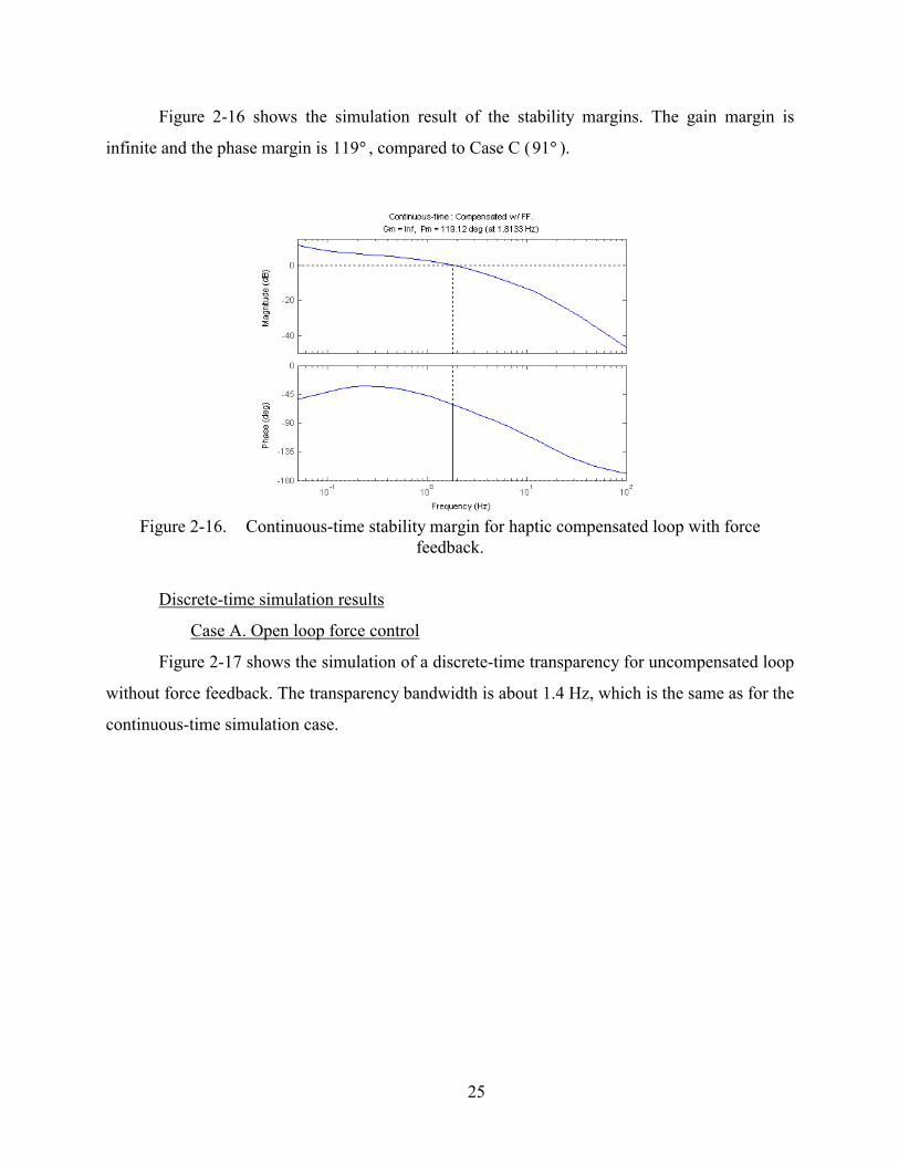
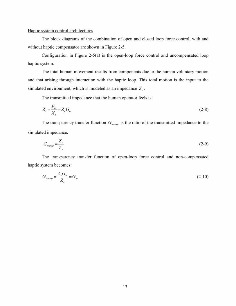
Figure 2-16 shows the simulation result of the stability margins. The gain margin is
infinite and the phase margin is 119 , compared to Case C (91 ). � �
Figure 2-16. Continuous-time stability margin for haptic compensated loop with force
feedback.
Discrete-time simulation results
Case A. Open loop force control
Figure 2-17 shows the simulation of a discrete-time transparency for uncompensated loop
without force feedback. The transparency bandwidth is about 1.4 Hz, which is the same as for the
continuous-time simulation case.
25

Figure 2-17. Discrete-time transparency for uncompensated loop without force feedback.
Figure 2-18 shows the simulation result of the stability margins for Case A. The gain
margin is not infinite due to the sampling period in ZOH. The resulting gain margin is 46 dB.
Similar to the continuous-time case, the phase margin for the discrete-time case is 50 . �
Figure 2-18. Discrete-time stability margin for uncompensated loop without force feedback.
26

Case B. Open loop force control with haptic compensator
Figure 2-19 shows the simulation of a discrete-time transparency for uncompensated loop
without force feedback. The transparency bandwidth is about 4.5 Hz with the use of the same
haptic compensator as for the continuous-time simulation case.
Figure 2-19. Discrete-time transparency for haptic compensated loop without force feedback.
Figure 2-20 shows the simulation result of the stability margins for Case B. The gain
margin is 46 dB and the phase margin is . �84
Figure 2-20. Discrete-time stability margin for haptic compensated loop without force
feedback.
27

Case C. Closed loop force control
Figure 2-21 shows the simulation of a discrete-time transparency for uncompensated loop
with force feedback. The transparency bandwidth is about 4.5 Hz.
Figure 2-21. Discrete-time transparency for uncompensated loop with force feedback.
Figure 2-22 shows the simulation result of the stability margins for Case C. The gain
margin is 46 dB and the phase margin is . �91
Figure 2-22. Discrete-time stability margin for uncompensated loop with force feedback.
28

Case D. Closed loop force control with haptic compensator
Figure 2-23 shows the simulation of a discrete-time transparency for compensated loop
with force feedback. The transparency bandwidth is about 35 Hz.
Figure 2-23. Discrete-time transparency for haptic compensated loop with force feedback.
Figure 2-24 shows the simulation result of the stability margins for Case D. The gain
margin is 43 dB and the phase margin is 119 . �
Figure 2-24. Discrete-time stability margin for haptic compensated loop with force feedback.
29

Summarized simulation transparency and stability margins
The transparency bandwidth and stability margins for the continuous-time simulation
architectures shown in Figure 2-5 and for the discrete-time simulation architectures shown in
Figure 2-6 are summarized in Table 2-2 and Table 2-3 respectively.
Table 2-2. Transparency bandwidth of various haptic system architectures.
Transparency (Hz)
Continuous Discrete
(Ts = 1/1000 sec.)
(a) Open loop force control 1.4 1.4
(b) Open loop force control with haptic compensator 4.5 4.5
(c) Closed loop force control 4.5 4.5
(d) Closed loop force control with haptic compensator 35 35
Table 2-3. Stability margins of various haptic system architectures.
Stability
Continuous Discrete (Ts = 1/1000 sec.)
GM. PM. GM. PM.
(a) Open loop force control � �50 (1.17) 46dB(17.2) �50 (1.17)
(b) Open loop force control with haptic compensator � �84 (1.63) 46dB(1088) �84 (1.63)
(c) Closed loop force control � �91 (1.63) 46dB(341) �91 (1.63)
(d) Closed loop force control with haptic compensator � �119 (1.8) 43dB(1141) �119 (1.8)
*The numbers in the parentheses shows the respective cross over frequency in Hz.
30

The summarized frequency plots of the transparency bandwidths are shown in Figure 2-
25 and Figure 2-26 for continuous-time simulation and discrete-time simulation respectively. In
the discrete-time simulation, the sampling period (ZOH) results in faster drop in phase but little
change in magnitude.
Figure 2-25. Transparency bandwidth of continuous-time simulation.
31

Figure 2-26. Transparency bandwidth of discrete-time simulation.
Discussion
The simulation showed that the outer loop compensator (the haptic compensator)
improved the system stability and transparency both in continuous-time simulations (Figure 2-7
to Figure 2-16) and discrete-time simulations (Figure 2-17 to Figure 2-24). In the continuous-
time case, gain margins for all architectures are infinite. In discrete-time simulations, the gain
margins for all cases are finite, but still quite large (> 40dB.). Since the stability and transparency
for continuous-time case and discrete-time case are about the same, this implies that the sampling
time of 1 msec. should be fast enough for the haptic system.
The force feedback loop helps reduce the disturbances and improve the accurate display
of the desired forces arising from virtual environment interaction. The transparency bandwidth of
the haptic system with force feedback is about 3 times that of the system without force feedback,
though the stability of a closed-loop system is inferior to the open-loop system.
The haptic compensator can improve both the transparency and stability at the same time.
The transparency bandwidth was improved from 1.4 Hz to 4.5 Hz for the open loop force control
case, and from 4.5 Hz to 35 Hz for the closed loop force control case (see Figure 2-25 and Figure
32

2-26). Additionally, the phase margin was increased from 50 to 84 (see Figure 2-8 and Figure
2-11 for continuous-time case and Figure 2-18 and Figure 2-20 for discrete-time case) and from
to 119 (see Figure 2-13 and Figure 2-16 for continuous-time case and Figure 2-22 and
Figure 2-24 for discrete-time case) for the open and closed loop force control cases, respectively,
with no substantive decrease in the gain margins.
� �
�91 �
The haptic compensator alone provides marked improvements to both transparency and
stability. These improvements are obtained without the benefit of a force sensor and closed loop
force control. Given that cost is a significant issue, this frequency-based compensation provides a
means for significant enhancements without the often costly addition of a force sensor.
In conclusion, the design of a compensator in the frequency domain and its application to
the haptic system provide a practical means for obtaining the desired performance and stability
robustness.
33
CHAPTER III
EXPERIMENT SETUP
To verify the simulation results, experiments are carried out in the Microrobotics Lab.
The 3 degree-of-freedom manipulator to be used in the experiments is a direct-drive design with
low inertia and zero backlash, designed to be used as a high-performance haptic interface [Perry
96]. This manipulator is equipped with potentiometers for position measurement and a 6-axis
force sensor for end point force measurements. A stylus type of interface is used for human
operator interaction with the manipulator and the computer-generated environment, see Figure 3-
1. A Pentium III 550 MHz computer with A/D converter interface is used with Matlab Real Time
Workshop under a Windows NT operating system to provide real-time computation of the virtual
environment and control of the manipulator.
Figure 3-1. Human operator with the haptic interface (inset shows the human stylus grip).
Transparency measurement
The transparency of the haptic system can be described by the transparency transfer
function as derived in equation (2-9), or similarly the transmitted impedance derived in equation
(2-8). The position of the human is obtained by transforming the joint angle position
measurements using the forward kinematics of the manipulator. The force sensor, mounted at the
end effector, provides a direct measure of the forces applied to the human operator. Along any
34

degree of freedom, the ratio of the force to the motion yields the stiffness or the transmitted
impedance. The transparency transfer function can be obtained by the ratio of this transmitted
impedance to the desired virtual impedance. Spectral analysis of the temporal force and position
data provides a means for estimating the frequency response of the haptic system’s transparency.
The transmitted impedance is computed by dividing the cross-power spectral density between the
motion input and the force output by the power spectral density of the motion input. The
transparency frequency response is then obtained by dividing the experimental measure of the
transmitted impedance by the desired virtual impedance.
When conducting the experiments to measure the system’s transparency, the human
operator will excite the system in a random manner in order to approximate a pseudo-random
band-limited white noise input. The frequency responses for four trials will be averaged. For
these experiments, the dynamics of the haptic interface are assumed to be decoupled along each
degree of freedom. Each of the experiments will be conducted along all three degrees of freedom.
Stability measurement
The stability of a control system is determined by the gain and phase margins of the total
forward loop transfer function. By breaking the loop at point B in Figure 3-2, an experimental
measure of the loop transfer function and its closed loop stability robustness are obtained. In
order to obtain the loop’s frequency response, band-limited white noise (Xd) is input to the
system while measuring the output motion response of the operator (Xh). Techniques similar to
that used to compute the transparency frequency response can be applied to obtain the
experimental loop transfer function. Due to noise in the computed phase information, however,
no useful information regarding the stability robustness could be ascertained. Instead, the gain
and phase margins are measured directly from sinusoidal excitation at the phase and gain
crossover frequencies, respectively. The stability measurements assume no voluntary motion
input from the human (ie., Xhv = 0).
35

Ze Gm Yh
Xhv
Xm
Xh Fd Fm
Method to obtain transfer function(assume Xhv = 0)
XdB
Figure 3-2. Loop to experimentally measure the loop transfer function and stability robustness.
Virtual environment impedance
The existing test metric widely used in testing the performance of haptic system is a hard
wall, which is a unilateral constraint ([Colgate et al. 93], [Clover 99], [Salcudean and Vlaar 94],
[Hannaford and Ryu 01]). Since proposed analysis requires all of the loop’s components to be
linear, the virtual environment has to be modified to accommodate this requirement. Instead of a
hard nonlinear environment, (i.e., a wall or hard stop) a relatively soft stiffness environment is
used in the experiments. The symmetric environment stiffness shown in Figure 3-3 is the virtual
environment implemented for the experiments. A stiffness of 100 N/m is used to simulate the
virtual environment.
kk
Figure 3-3. Symmetry stiffness implemented as the tested virtual environment.
Experimental closed-loop force control gains
To perform the closed-loop force control inside the haptic simulation, the gains of the
proportional and integral (PI) force controller are tuned for each axis independently. The human
is coupled to the manipulator during the open/closed loop force tests. The input tracking signal is
a square wave with an amplitude of 2 Newtons and a frequency of 0.5 Hz. The improvement in
closed loop force control is shown in tracking result plots. Gains for each axis are shown in Table
3-1. Time history data of the open loop force control response and close loop force control
36

response are shown in Figure 3-4 and Figure 3-5 respectively. The data show the overall
performance improvements of closed loop force control. Closed loop control eliminates the
steady-state error in each axis, while enhancing the rise time and settling time of the response.
Stability margins of the force control loop are experimentally obtained. The gain margin and
phase margin of each controller in X, Y, and Z axis are shown in Table 3-2.
The proportional gains on X and Y Axes are set to zero. The responses even with only a
small proportional gain exhibited too much overshoot on those axes. However, the proportional
gain in the Z-Axis resulted in improved rise time and settling time. The presence of relatively
large inertia in Z-Axis necessitates the use of proportional gain to achieve performaCnce
comparable to that of the X and Y Axes.
Table 3-1. Force control closed-loop gains.
Kp Ki
X-Axis 0 15 Y-Axis 0 30 Z-Axis 3 50
Table 3-2. Force control stability margins.
Gain Margin (dB) Phase Margin (degree)
X-Axis 22 70
Y-Axis 25 72
Z-Axis 3.7 29
37

Figure 3-4. Open-loop force responses.
38

Figure 3-5. Closed-loop force responses.
39

CHAPTER IV
EXPERIMENTAL RESULTS
Transparency bandwidth and stability margins plots are shown for X, Y, and Z Axes for
each case. The transparency figures represent the average of four experimental trials. These 4
cases are: open loop force control, open loop force control with haptic compensator, closed loop
force control, and closed loop force control with haptic compensator. These are the architectures
shown in Figure 2-6. Following the presentation of the four cases for each degree of freedom, the
complete results are summarized in tables at the end of this chapter.
Experimental results in X-Axis
Case A. Open loop force control
Figure 4-1 shows the experimental transparency for uncompensated loop without force
feedback along the X-Axis. The transparency bandwidth is about 0.3 Hz. The poor transparency
bandwidth is primarily due to the constant gain offset at the low frequency (0.1 Hz.-1 Hz.).
Ignoring the DC offset, the transparency bandwidth is about 1 Hz.
Figure 4-1. X-Axis transparency for uncompensated loop without force feedback.
40
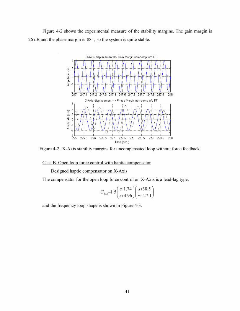
Figure 4-2 shows the experimental measure of the stability margins. The gain margin is
26 dB and the phase margin is , so the system is quite stable. �88
Figure 4-2. X-Axis stability margins for uncompensated loop without force feedback.
Case B. Open loop force control with haptic compensator
Designed haptic compensator on X-Axis
The compensator for the open loop force control on X-Axis is a lead-lag type:
���
����
�
�
����
����
�
�
��
1.275.38
96.474.1
5.11 ss
ss
C xh
and the frequency loop shape is shown in Figure 4-3.
41

Figure 4-3. X-Axis haptic compensator without force feedback.
Figure 4-4 shows the experimental measure of the X-Axis transparency for the haptic
compensated loop without force feedback. The transparency bandwidth is 3 Hz. The haptic
compensator used in Case B (3 Hz) showed a significant improvement over Case A (1 Hz).
Ignoring the DC offset of Case A, the haptic compensator increased the the transparency
bandwidth of the loop by a factor of 3.
Figure 4-4. X-Axis transparency for haptic compensated without force feedback.
42

Figure 4-5 shows the experimental measure of the stability margins. The gain margin is
13 dB and the phase margin is 42 . The stability margins with the haptic compensator are lower
than the system without the compensator, but the system still maintains a more than adequate
margin of stability.
�
Figure 4-5. X-Axis stability margins for haptic compensated without force feedback.
Case C. Closed loop force control
Figure 4-6 shows the experimental transparency for the uncompensated loop with force
feedback along the X-Axis. The transparency bandwidth is 3 Hz. Compared with Cases A (open
loop force control), the uncompensated loop with force feedback provides significant
improvements to the transparency bandwidth.
43

Figure 4-6. X-Axis transparency for uncompensated loop with force feedback.
Figure 4-7 shows the experimental measure of the stability margins. The gain margin is 7
dB and the phase margin is 14 . As evidenced by the stability margins, the benefits of force
feedback to the loop transparency are attained at the expense of stability robustness.
�
Figure 4-7. X-Axis stability margins for uncompensated with force feedback.
44

Case D. Closed loop force control with haptic compensator
Designed haptic compensator with force feedback on X-Axis
The compensator for the closed loop force control on X-Axis is a lead-lag type:
���
����
�
�
����
����
�
�
��
2.1944
237.7501.12 s
ss
sC xh
and the frequency loop shape is shown in Figure 4-8.
Figure 4-8. X-Axis haptic compensator with force feedback.
Figure 4-9 shows the experimental transparency for haptic compensated with force
feedback along the X-Axis. The transparency bandwidth is 3.5 Hz.
45

Figure 4-9. X-Axis transparency for haptic compensated with force feedback.
Figure 4-10 shows the experimental measure of the stability margins. The gain margin is
12 dB and the phase margin is 12 . The stability margins for this case showed a marginal
improvement over Case C.
�
Figure 4-10. X-Axis stability margins for haptic compensated with force feedback.
46

The transparency bandwidth is improved through the use of haptic compensation in the
loop. This is true for both system with open loop force control and closed loop force control,
comparing Figure 4-1 to Figure 4-4 and Figure 4-6 to Figure 4-9 respectively.
From the results shown in Figure 4-10, the stability margins using haptic compensation
with force feedback are also improved. The compensators used in Cases B and D provide
significant low frequency phase-lead, coupled with small amount of high frequency phase-lag.
Experimental results in Y-Axis
Case A. Open loop force control
Figure 4-11 shows the experimental transparency for uncompensated loop without force
feedback of Y-Axis. There is no transparency at all for this axis. The large DC offset is primarily
due to the effects of gravity acting on the system in the direction of Y-Axis. Ignoring the offset,
the transparency bandwidth is 1-2 Hz.
Figure 4-11. Y-Axis transparency for uncompensated loop without force feedback.
Figure 4-12 shows the experimental measure of the stability margins. The gain margin is
20 dB and the phase margin is 95 . Analogous to the X-Axis, case A for the Y-Axis exhibits a
large margin of stability.
�
47

Figure 4-12. Y-Axis stability margins for uncompensated loop without force feedback.
Case B. Open loop force control with haptic compensator
Designed compensator on Y-Axis
The compensator for the open loop force control on Y-Axis is a lead-lag type:
���
����
�
�
����
����
�
�
��
08.2619.78
53.1926.11
9.01 ss
ss
C yh
and the frequency loop shape is shown in Figure 4-13.
48

Figure 4-13. Y-Axis haptic compensator for no force feedback.
Because the haptic compensator is designed to counteract the gravity effect, the
transparency bandwidth exhibits significant improvement compared to Case A. The transparency
bandwidth shown in Figure 4-14 is about 3.6 Hz.
Figure 4-14. Y-Axis transparency for haptic compensated without force feedback.
49

Figure 4-15 shows the experimental measure of the stability margins. The gain margin is
12 dB and the phase margin is . Though the stability margins with the haptic compensator are
lower than those without the compensator, the haptic compensated loop maintains a significant
margin of stability.
�44
Figure 4-15. Y-Axis stability margins for haptic compensated without force feedback.
Case C. Closed loop force control
Figure 4-16 shows the experimental transparency for uncompensated loop with force
feedback of Y-Axis. The gravity effect is compensated by the force feedback loop. The
transparency bandwidth for this case is about 3.6 Hz.
50

Figure 4-16. Y-Axis transparency for uncompensated loop with force feedback.
Figure 4-17 shows the experimental measure of the stability margins. The gain margin is
5 dB and the phase margin is . The stability margins with the force feedback loop are lower
than the system without force feedback in Case A. Similar to X-Axis, the performance benefits
are attained at the cost of some of the stability robustness.
�50
Figure 4-17. Y-Axis stability margins for uncompensated with force feedback.
51

Case D. Closed loop force control with haptic compensator
Designed haptic compensator with force feedback. on Y-Axis
The compensator for the Y-Axis loop with force feedback is a lead-lead compensator
given by:
���
����
�
�
����
����
�
�
��
7.2430
6.251523.12 s
ss
sC yh
and the frequency loop shape is shown in Figure 4-18.
Figure 4-18. Y-Axis haptic compensator for force feedback..
Figure 4-19 shows the experimental transparency for haptic compensated with force
feedback of Y-Axis. The transparency bandwidth is 4.1 Hz., compared to 3.6 Hz in Case C.
52

Figure 4-19. Y-Axis transparency for haptic compensated with force feedback.
Figure 4-20 shows the experimental measure of the stability margins. The gain margin is
15 dB and the phase margin is . The stability margins with the force feedback loop are
improved with the addition of the haptic compensator in the loop. Although the phase margin
shows only small improvement, the gain margin is significantly increased..
�53
Figure 4-20. Y-Axis stability margins for haptic compensated with force feedback.
53

Experimental results in Z-Axis
Case A. Open loop force control
Figure 4-21 shows the experimental transparency for the uncompensated Z-Axis loop
without force feedback. The transparency bandwidth is about 0.85 Hz.
Figure 4-21. Z-Axis transparency for uncompensated loop without force feedback.
Figure 4-22 shows the experimental measure of the stability margins. The gain margin is
20 dB and the phase margin is . �28
54

Figure 4-22. Z-Axis stability margins for uncompensated loop without force feedback.
Case B. Open loop force control with haptic compensator
Designed compensator on Z-Axis
The compensator for the open loop force control on Z-Axis is a lead-lag type:
���
����
�
�
����
����
�
�
��
5.84.12
2.44.1
5.11 ss
ss
C zh
and the frequency loop shape is shown in Figure 4-23.
55

Figure 4-23. Z-Axis haptic compensator for no force feedback.
Figure 4-24 shows the experimental transparency for haptic compensated without force
feedback of Z-Axis. The transparency bandwidth is 1.6 Hz. The compensator used in Case B
showed a significant improvement over the transparency in Case A(0.85 Hz.).
Figure 4-24. Z-Axis Transparency for haptic compensated loop without force feedback.
56

Figure 4-25 shows the experimental measure of the stability margins. The gain margin is
8 dB and the phase margin is 35 . The phase margin is improved over Case A by about 7
degrees, but the gain margin is decreased.
�
Figure 4-25. Z-Axis stability margins for haptic compensated loop without force feedback.
Case C. Closed loop force control
Figure 4-26 shows the experimental transparency for the uncompensated Z-Axis with
force feedback. The transparency bandwidth is about 1.6 Hz. A noticeable improvement in
transparency over Case A is seen with the addition of the force feedback loop.
57

Figure 4-26. Z-Axis transparency for uncompensated loop with force feedback.
Figure 4-27 shows the experimental measure of the stability margins. The gain margin is
2 dB and the phase margin is 13 . The system is stable, but only marginally. �
Figure 4-27. Z-Axis stability margins for uncompensated loop with force feedback.
58

Case D. Closed loop force control with haptic compensator
Designed haptic compensator with force feedback. on Z-Axis
The compensator for the closed loop force control on Z-Axis is a lead-lag type:
���
����
�
�
����
����
�
�
��
6.2240
265.954.12 s
sssC zh
and the frequency loop shape is shown in Figure 4-28.
Figure 4-28. Z-Axis haptic compensator for force feedback.
Figure 4-29 shows the experimental transparency for compensated Z-Axis with force
feedback. The transparency bandwidth is about 2.5 Hz. A significant improve in transparency is
exhibit in this Z-Axis when adding both the force feedback loop and the haptic compensator.
Both terms help to compensate the large inertia primarily evident in the Z-Axis.
59

Figure 4-29. Z-Axis transparency for haptic compensated with force feedback.
Figure 4-30 shows the experimental measure of the stability margins. The gain margin is
8 dB and the phase margin is , a significant improvement over the margins of Case C. �23
Figure 4-30. Z-Axis stability margins for haptic compensated with force feedback.
60

Summarized experiment transparency and stability margins
Average frequency responses of the transparency transfer function Gtranp are summarized
in Table 4-1 for all axes. The 4 trial frequency responses of transparency transfer function Gtransp
for each axis are included in Appendix section.
Summarized tables of the experimental stability margin results are shown in Table 4-2, 4-
3, and 4-4 for X, Y, and Z Axes respectively.
Table 4-1. Experimental transparency bandwidths for each axis (Hz.)
Experiment Transparency BW.
X-Axis Y-Axis Z-Axis
(a) Open loop force control 0.32(1)* 0(2.7)* 0.85
(b) Open loop force control
with haptic compensator. 3 3.6 1.6
(c) Closed loop force control 3 3.6 1.6
(d) Closed loop force control
with haptic compensator 3.5 4.1 2.5
* This is the bandwidth when ignoring the DC offset.
Table 4-2. Experimental stability margins for X-Axis.
Experiment X-Axis Stability Margin
PM. GM.
(a) Open loop force control �88 (1.5 Hz) 26 dB(12 Hz)
(b) Open loop force control
with haptic compensator. �42 (3.2 Hz) 13 dB(5.5 Hz)
(c) Closed loop force control �14 (2.3 Hz) 7 dB(3.5 Hz)
(d) Closed loop force control
with haptic compensator �45 (2.5 Hz) 12 dB(4 Hz)
61

Table 4-3. Experimental stability margins for Y-Axis.
Experiment Y-Axis Stability Margin
PM. GM.
(a) Open loop force control �95 (1.5 Hz) 20 dB(10 Hz)
(b) Open loop force control
with haptic compensator. �44 (3.4 Hz) 12 dB(6.2 Hz)
(c) Closed loop force control �50 (3 Hz) 5 dB(4.3 Hz)
(d) Closed loop force control
with haptic compensator �53 (2.2 Hz) 15 dB(4.5 Hz)
Table 4-4. Experimental stability margins for Z-Axis.
Experiment Z-Axis Stability Margin
PM. GM.
(a) Open loop force control �28 (1.4 Hz) 20 dB(4.5 Hz)
(b) Open loop force control
with haptic compensator. �35 (1.83 Hz) 8 dB(2.8 Hz)
(c) Closed loop force control �13 (2.8 Hz) 2 dB(3.5 Hz)
(d) Closed loop force control
with haptic compensator �23 (2.9 Hz) 8 dB(3.9 Hz)
The inclusion of closed loop force control into a haptic system improves the transparency
bandwidth of the system compared to the transparency of open loop force control. However the
stability margins of the haptic loop with closed loop force control are less than those of the haptic
loop with open loop force control.
The most effective compensator for this haptic system used is a phase-lead type with a
small phase-lag added to the high frequency above 5 Hz. The design of the compensator is first
approached using the knowledge of the experimental gain and phase crossover frequency and the
frequency response of the transparency. The compensator is designed to enhance the transparency
62
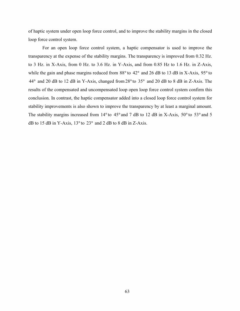
of haptic system under open loop force control, and to improve the stability margins in the closed
loop force control system.
For an open loop force control system, a haptic compensator is used to improve the
transparency at the expense of the stability margins. The transparency is improved from 0.32 Hz.
to 3 Hz. in X-Axis, from 0 Hz. to 3.6 Hz. in Y-Axis, and from 0.85 Hz to 1.6 Hz. in Z-Axis,
while the gain and phase margins reduced from 88 to and 26 dB to 13 dB in X-Axis, to
and 20 dB to 12 dB in Y-Axis, changed from to and 20 dB to 8 dB in Z-Axis. The
results of the compensated and uncompensated loop open loop force control system confirm this
conclusion. In contrast, the haptic compensator added into a closed loop force control system for
stability improvements is also shown to improve the transparency by at least a marginal amount.
The stability margins increased from 14 to and 7 dB to 12 dB in X-Axis, to and 5
dB to 15 dB in Y-Axis, 13 to and 2 dB to 8 dB in Z-Axis.
�
�
�42 �95
�
�44 �28 �35
� 45 �50 53
� �23
63

CHAPTER V
CONCLUSIONS
In the preceding chapters, the development of a haptic system controller was presented.
Simulation of four different control architectures for improving a haptic system performance and
stability were shown. Linear classical frequency design and analysis tools were applied in this
research, assuming linear time invariant model for both haptic interface and human operator. A
linear stiffness was used as the virtual environment. The approach was experimentally verified
with a 3-DOF high-performance impedance-type haptic interface.
According to the simulation, a compensator showed a significant improvement to both
performance and stability margins. The compensator was able to improve the stability margins on
both open loop force control and closed loop force control cases. However, in the experiment, the
compensator designed to improve transparency in open loop force control case lowered the
stability margins. On the other hand, the compensator designed to enhance stability margins for
closed loop force control cases also improved the transparency bandwidth by a small amount.
A number of factors limit the ability of the experiment to fully exhibit the benefits
predicted in simulation. Actuator saturation causes the experiment stability margins to be well
below the simulation stability margins. Noise also limits the attainable performance and stability
margins. The further discrepancies arise from unmodeled nonlinear dynamics in the haptic loop.
The proposed approach to haptic system control provides performance and stability
benefits for all configurations consider in this thesis. Most notably, the proposed approach can
provide the performance benefits of closed loop force control without requiring an expensive
load cell. Additionally, for the case of a haptic interface with closed loop force control, the
proposed method provides added stability robustness thereby increasing safety margin and
improving the range of attainable impedances.
64

APPENDIX A
4 TRIAL TRANSPARENCY RESULTS OF X-AXIS
Case A Open loop force control
Figure A-1. X-Axis transparency for uncompensated loop without force
feedback (Trial 1).
Figure A-2. X-Axis transparency for uncompensated loop without force
feedback (Trial 2).
65

Figure A-3. X-Axis transparency for uncompensated loop without force
feedback (Trial 3).
Figure A-4. X-Axis transparency for uncompensated loop without force
feedback (Trial 4).
66

Case B Open loop force control with haptic compensator
Figure A-5. X-Axis transparency for compensated without force feedback
(Trial 1).
Figure A-6. X-Axis transparency for compensated without force feedback
(Trial 2).
67

Figure A-7. X-Axis transparency for compensated without force feedback
(Trial 3).
Figure A-8. X-Axis transparency for compensated without force feedback
(Trial 4).
68

Case C Closed loop force control
Figure A-9. X-Axis transparency for uncompensated loop with force
feedback (Trial 1).
Figure A-10. X-Axis transparency for uncompensated loop with force
feedback (Trial 2).
69
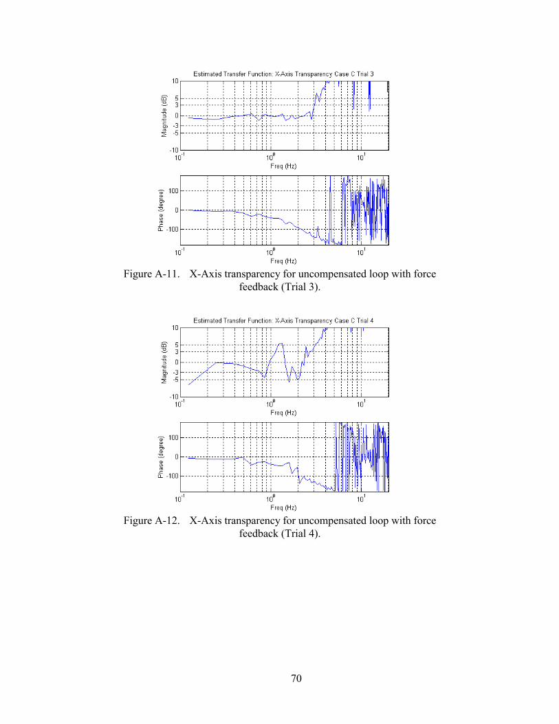
Figure A-11. X-Axis transparency for uncompensated loop with force
feedback (Trial 3).
Figure A-12. X-Axis transparency for uncompensated loop with force
feedback (Trial 4).
70

Case D Closed loop force control with haptic compensator
Figure A-13. X-Axis transparency for compensated with force feedback
(Trial 1).
Figure A-14. X-Axis transparency for compensated with force feedback
(Trial 2).
71

Figure A-15. X-Axis transparency for compensated with force feedback
(Trial 3).
Figure A-16. X-Axis transparency for compensated with force feedback
(Trial 4).
72

APPENDIX B
4 TRIAL TRANSPARENCY RESULTS OF Y-AXIS
Case A Open loop force control
Figure A-17. Y-Axis transparency for uncompensated loop without force
feedback (Trial 1).
Figure A-18. Y-Axis transparency for uncompensated loop without force
feedback (Trial 2).
73

Figure A-19. Y-Axis transparency for uncompensated loop without force
feedback (Trial 3).
Figure A-20. Y-Axis transparency for uncompensated loop without force
feedback (Trial 4).
74

Case B Open loop force control with haptic compensator
Figure A-21. Y-Axis transparency for compensated without force feedback
(Trial 1).
Figure A-22. Y-Axis transparency for compensated without force feedback
(Trial 2).
75

Figure A-23. Y-Axis transparency for compensated without force feedback
(Trial 3).
Figure A-24. Y-Axis transparency for compensated without force feedback
(Trial 4).
76

Case C Closed loop force control
Figure A-25. Y-Axis transparency for uncompensated loop with force
feedback (Trial 1).
Figure A-26. Y-Axis transparency for uncompensated loop with force
feedback (Trial 2).
77

Figure A-27. Y-Axis transparency for uncompensated loop with force
feedback (Trial 3).
Figure A-28. Y-Axis transparency for uncompensated loop with force
feedback (Trial 4).
78

Case D Closed loop force control with haptic compensator
Figure A-29. Y-Axis transparency for compensated with force feedback
(Trial 1).
Figure A-30. Y-Axis transparency for compensated with force feedback
(Trial 2).
79
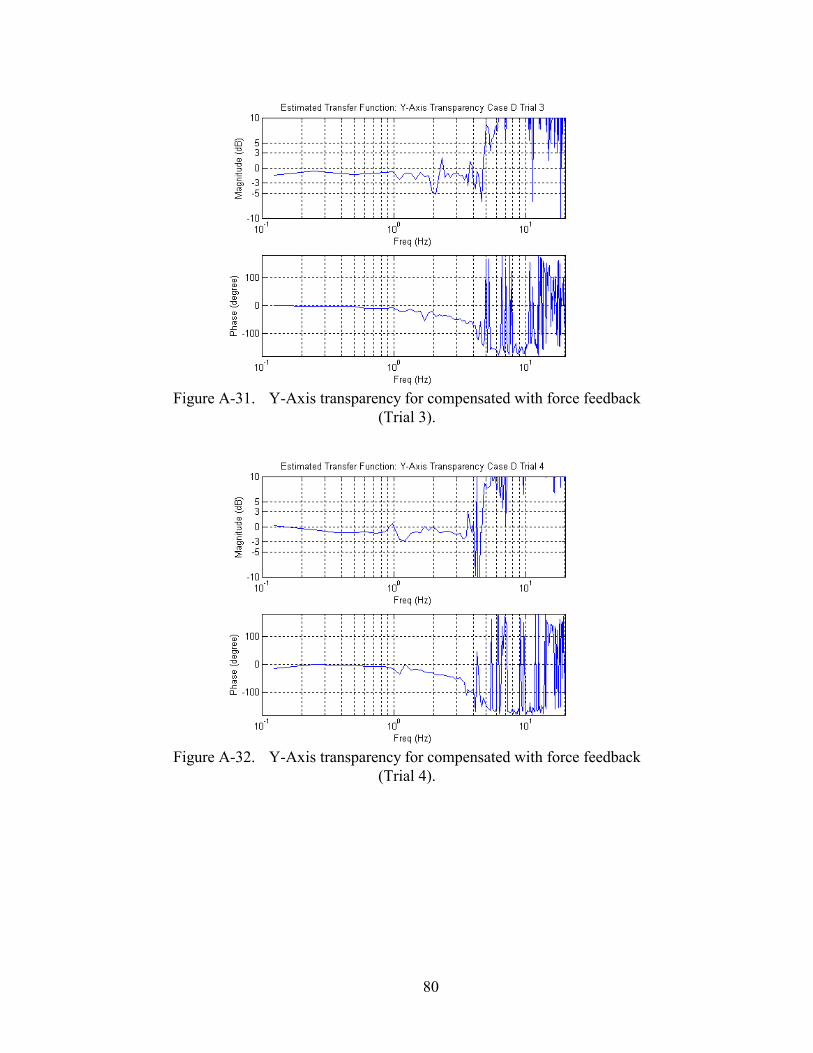
Figure A-31. Y-Axis transparency for compensated with force feedback
(Trial 3).
Figure A-32. Y-Axis transparency for compensated with force feedback
(Trial 4).
80

APPENDIX C
4 TRIAL TRANSPARENCY RESULTS OF Z-AXIS
Case A Open loop force control
Figure A-33. Z-Axis transparency for uncompensated loop without force
feedback (Trial 1).
Figure A-34. Z-Axis transparency for uncompensated loop without force
feedback (Trial 2).
81
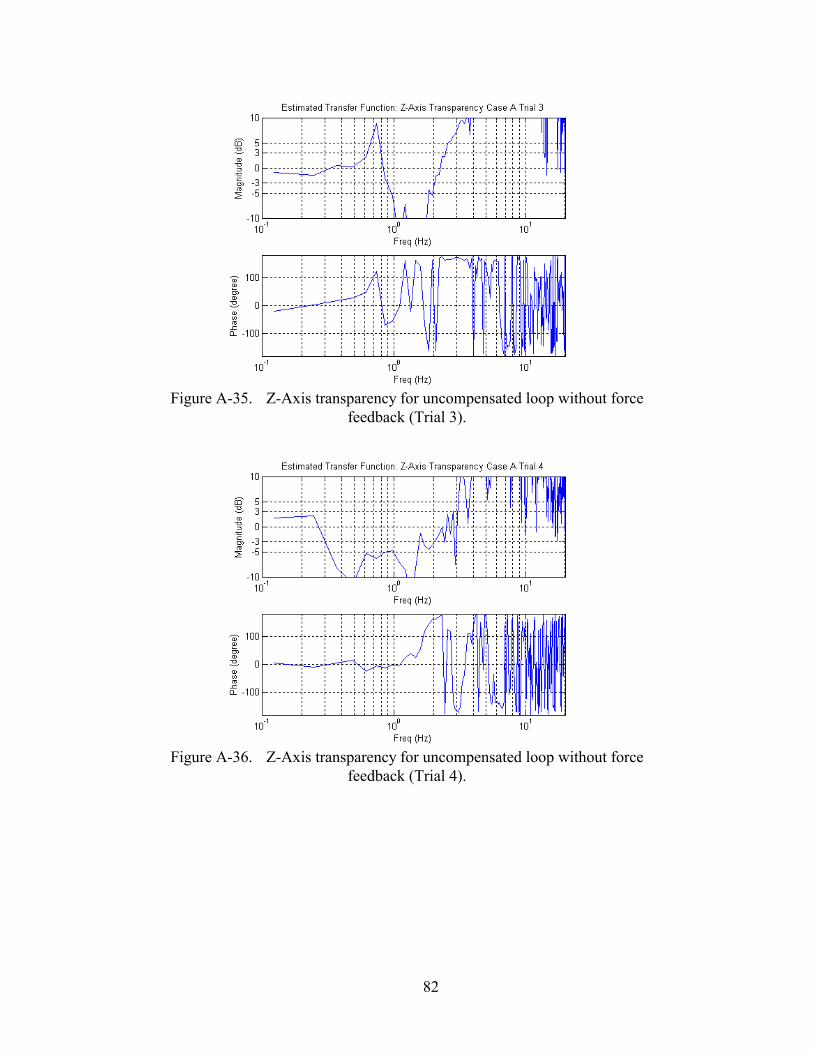
Figure A-35. Z-Axis transparency for uncompensated loop without force
feedback (Trial 3).
Figure A-36. Z-Axis transparency for uncompensated loop without force
feedback (Trial 4).
82

Case B Open loop force control with haptic compensator
Figure A-37. Z-Axis transparency for compensated without force feedback
(Trial 1).
Figure A-38. Z-Axis transparency for compensated without force feedback
(Trial 2).
83

Figure A-39. Z-Axis transparency for compensated without force feedback
(Trial 3).
Figure A-40. Z-Axis transparency for compensated without force feedback
(Trial 4).
84

Case C Closed loop force control
Figure A-41. Z-Axis transparency for uncompensated loop with force
feedback (Trial 1).
Figure A-42. Z-Axis transparency for uncompensated loop with force
feedback (Trial 2).
85

Figure A-43. Z-Axis transparency for uncompensated loop with force
feedback (Trial 3).
Figure A-44. Z-Axis transparency for uncompensated loop with force
feedback (Trial 4).
86
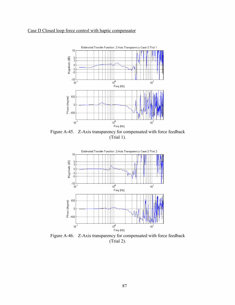
Case D Closed loop force control with haptic compensator
Figure A-45. Z-Axis transparency for compensated with force feedback
(Trial 1).
Figure A-46. Z-Axis transparency for compensated with force feedback
(Trial 2).
87

Figure A-47. Z-Axis transparency for compensated with force feedback
(Trial 3).
Figure A-48. Z-Axis transparency for compensated with force feedback
(Trial 4).
88

REFERENCES
[Adams et al. 00] R.J. Adams, Daniel Klowden and B. Hannaford,”Stable Haptic Interaction Using the Excalibur Force Display”, Proceedings of the 2000 IEEE, International Conference on Robotics & Automation. April 2000.
[Adams and Hanaford 99] R.J. Adams and B. Hannaford, “Stable Haptic Interaction with Virtual Environments”, IEEE Transactions on Robotics and Automation, Vol. 15, No. 3, June 1999.
[Adams et al. 98] R.J. Adams, M.R. Moreyra and B. Hannaford. "Stability and Performance of Haptic Displays: Theory and Experiments", Proceedings of the ASME International Mechanical Engineering Conference and Exposition, DSC-Vol. 64, 1998. pp. 227-234.
[Adams and Hannaford 98] R.J. Adams and B. Hannaford, “A Two-Port Framework for the Design of Unconditionally Stable Haptic Interfaces”, Proceedings of the IEEE International Conference on Intelligent Robots and Systems, Victoria, B.C. Canada. October 1998.
[Brown and Colgate 98] J. M. Brown, J.E.Colgate, “Minimum Mass for Haptic Display Simulations”, DSC-Vol. 64, Proceedings of the ASME, Dynamic Systems and Control Division, ASME 1998
[Carl 96] Carl M. Perry, “Design of a High Performance Robot for use in Haptic Interface and Force Feedback Research: Master Thesis”, Vanderbilt University, 1996., Nashville, TN.
[Cavusoglu and Tendick 00] Murat Cenk Cavusoglu and Frank Tendick, “Multirate Simulation of High Fidelity Haptic Interaction with Deformable Objects in Virtual Environments”, Proceeding of the IEEE Int’l Conf. Robotics and Automation 2000., Pp. 2458 –2465
[Clover 99] C.L. Clover, “A Control-System Architecture for Robots Used to Simulate Dynamic Force and Moment Interaction Between Humans and Virtual Objects”, IEEE Transactions on Systems, Man, and Cybernatics—Part C: Applications and Reviews, Vol. 29, No. 4. Nov 1999., Pp. 481 –493
[Clover et al. 97] C.L. Clover, G.R. Luecke, J.J. Troy and W.A. McNeely, “Dynamic Simulation of Virtual Mechanisms with Haptic Feedback Using Industrial Robotics Equipment”, Proceeding of the IEEE Int’l Conf. Robotics and Automation 1997., Pp. 724 –730
[Colgate et al. 93] J.E. Colgate, et al., “Implementation of Stiff Virtual Walls in Force-Reflecting Interfaces”, Virtual Reality Annual International Symposium, 1993., IEEE. Pp. 202 –208
[Colgate and Brown 94] J.E. Colgate, J.M. Brown, “Factors Affecting the Z-width of a Haptic Display”, Proceeding of the IEEE Int’l Conf. Robotics and Automation 1994., Pp. 3205 –3210
89

[DiMaio et al. 00] S. P. DiMaio, S. E. Salcudean and M. R. Sirouspour,"Haptic Interaction within a planar environment," In Proceedings of the 2000 ASME International Mechanical Engineering Congress & Exposition, Dynamic Systems and Control Division, November 2000.
[Durlach and Mavor 95] N.I.Durlach and A.S.Mavor,”Virtual Reality:Scientific and Technological Challenges”, National Academy Press, Washington, D.C. 1995
[Ellis et al. 96] R.E. Ellis, N. Sarkar, and M.A. Jenkins, ”Numerical Methods for The Haptic Presentation of Contact: Theory, Simulations, and Experiments”, Proceedings of the ASME International Mechanical Engineering Conference and Exposition, DSC-Vol. 58, Atlanta, GA, Nov 17-22, 1996. pp. 413-420.
[Eom et al. 00] K.S. Eom, I.H. Suh, and B.J. Yi, “A Design Method of Haptic Interface Controller Considering Transparency and Robust Stability”, Proceedings of the 2000 IEEE/RSJ International Conference on Intelligent Robots and Systems.
[Fite et al. 00] K.B. Fite, J.E. Speich and M. Goldfarb, “Transparency and Stability Robustness in Two-Channel Bilateral Telemanipulation”, ASME Journal of Dynamic Systems, Mesurement, and Control, 2000
[Gillespie and Cutkosky 96] B. Gillespie and M. Cutkosky. "Stable User-Specific Rendering of the Virtual Wall," Proceedings of the ASME International Mechanical Engineering Conference and Exposition, DSC-Vol. 58, Atlanta, GA, Nov 17-22, 1996. pp. 397-406.
[Hannaford and Ryu 01] B. Hannaford and Jee-Hwan Ryu. “Time Domain Passivity Control of Haptic Interfaces”, Proceedings of the 2001 IEEE, International Conference on Robotics & Automation. May 21-26, 2001
[Hayward and Astley 96] Vincent Hayward and Oliver R. Astley, “Performance Measures for Haptic Interfaces”, Robotics research: the seventh international symposium/Georges Giralt and Gerhard Hirzinger, eds. 1996, pp. 195-207.
[Kuo 91] Benjamin C. Kuo, “Automatic Control Systems” 6th Edition, Prentice-Hall, Inc. ISBN 0-13-051046-7
[Lawrence et al. 96] D.A. Lawrence, et.al.. "Quantitative Experimental Analysis of Transparency and Stability in Haptic Interfaces" Proceedings of the ASME International Mechanical Engineering Conference and Exposition, DSC-Vol. 58, Atlanta, GA, Nov 17-22, 1996. pp. 441-449.
[Lawrence 93] D. Lawrence, “Stability and Transparency in Bilateral Teleoperation”, IEEE Transactions on Robotics and Automation, Vol. 9, No. 5, October 1993.
[Lee et al. 00] C.D. Lee, D.A. Lawrence and L.Y. Pao, “A High-Bandwidth Force-Controlled Haptic Interface”, Proceedings of the ASME International Mechanical Engineering
90

Conference and Exposition, DSC-Vol. 69-2, Orlando, FL, Nov 5-10, 2000. pp. 1299-1308.
[Love and Book 95] Lonnie Love and Wayne Book, “Contact Stability Analysis of Virtual Walls”, Proceedings of the 1995 ASME International Mechanical Engineering Conference and Exposition, DSC-Vol. 57-2. pp. 689-694.
[Luecke and Chai 97] G.R.Luecke, Young-Ho Chai, “Stability and Performance Comparison of the Force Reflecting Haptic Manipulator”, Advanced Robotics, 1997. ICAR '97. Proceedings., 8th International Conference.
[Miller et al 99] B.E. Miller, J.E. Colgate, R.A. Freeman, “Guaranteed Stability of Haptic Systems with Nonlinear Virtual Environments”, IEEE Transactions on Robotics and Automation, September 1999.
[Ogata 97] Katsuhiko Ogata, “Modern Control Engineering” 3rd Edition, Prentice-Hall, Inc. ISBN 0-13-227307-1
[Prisco et al. 99] G.M. Prisco, et.al, “Haptic Control of the Hand Force Feedback System”, Proceedings of SPIE, Telemanipulator and Telepresence Technologies VI, 1999.
[Salcudean and Vlaar 94] S. Salcudean and T. Vlaar, “On the Emulation of Stiff Walls and Static Friction with a Magnetically Levitated Input/Output Device”, Proceedings of the 1994 ASME Winter Annual Meeting, DSC-Vol.55-1. pp.303-309
[Springer and Ferrier 99] Scott L. Springer and Nicola J. Ferrier, “New Method for Design and Control of Haptic Interfaces for Display of Rigid Surfaces”, Proceedings of the ASME International Mechanical Engineering Conference and Exposition, DSC-Vol. 67. pp. 237-244.
[Yokokohji et al. 96] Yasuyoshi Yokokohji, Ralph L. Hollis and Takeo Kanade, “What You Can See is What You Can Feel – Development of a Visual/Haptic Interface to Virtual Environment”, Proc. IEEE Virtual Reality Annual Int. Symposium, 1996, pp. 46-53.
[Zilles and Salisbury 95] C.B. Zilles and J.K. Salisbury, “A Constraint-based God-object Method For Haptic Display”, Intelligent Robots and Systems 95. 'Human Robot Interaction and Cooperative Robots', Proceedings. 1995 IEEE/RSJ International Conference on , Volume: 3 , 1995 Page(s): 146 -151 vol.3
91
Copyright © 2022 FDOKUMEN