Guidelines on the Calibration of Thermocouples - EURAMET
21
Guidelines on the Calibration of Thermocouples EURAMET Calibration Guide No. 8 Version 3.0 (02/2019)
-
Upload
khangminh22 -
Category
Documents
-
view
5 -
download
0
Transcript of Guidelines on the Calibration of Thermocouples - EURAMET

Guidelines on the Calibration of ThermocouplesEURAMET Calibration Guide No. 8Version 3.0 (02/2019)

EURAMET Calibration Guide No. 8 Version 3.0 (02/2019)
I-CAL-GUI-008/v3.0/2019-02-13
Authorship and Imprint
This document was developed by the EURAMET e.V., Technical Committee for Thermometry. Authors: Jonathan Pearce (NPL, United Kingdom), Narcisa Arifovic (UME, Turkey), Jovan Bojkovski (MIRS, Slovenia), Frank Edler (PTB, Germany), Martin de Groot (Consultancy, The Netherlands), Carmen Garcia Izquierdo (CEM, Spain), Murat Kalemci (UME, Turkey), Radek Strnad (CMI, Czech Republic). The authors of the current updated version acknowledge the authors of the original version 2.1. These are Georges Bonnier (LNE-INM, France), Eliane Renaot (LNE-INM, France), Erich Tegeler (PTB, Germany), and Mary White (NSAI, Ireland). EURAMET e.V. Bundesallee 100 38116 Braunschweig Germany E-Mail: [email protected] Phone: +49 531 592 1960 Versions
Version 3.0 (02/2019) Version 2.1 (10/2011) Version 2.0 (3/2011) Version 1.0 (7/2007) The current version contains numerous minor updates to reflect current best practice. The most significant update concerns the advice on thermoelectric homogeneity considerations in Section 9. In particular, the advice is customized for the major thermocouple groups (Type K and N, R and S, B, Au/Pt and Pt/Pd, and all other types). Guidance is given on the value to be taken in order to account for the effect of inhomogeneity on the uncertainty, in the absence of any useful measurements. Importantly, these values are derived from a comprehensive survey which is documented in the public scientific literature. Official language
The English language version of this document is the definitive version. The EURAMET Secretariat can give permission to translate this text into other languages, subject to certain conditions available on application. In case of any inconsistency between the terms of the translation and the terms of this document, this document shall prevail. Copyright
The copyright of this publication (EURAMET Calibration Guide No. 8, version 3.0 – English version) is held by © EURAMET e.V. 2019. The English language version of this publication is the definitive version. The text may not be copied for resale and may not be reproduced other than in full. Extracts may be taken only with the permission of the EURAMET Secretariat.
ISBN 978-3-942992-55-8 Image on cover page by NPL. Guidance for Users
This document gives guidance on measurement practices in the specified fields of measurements. By applying the recommendations presented in this document laboratories can produce calibration results that can be recognized and accepted throughout Europe. The approaches taken are not mandatory and are for the guidance of calibration laboratories. The document has been produced as a means of promoting a consistent approach to good measurement practice leading to and supporting laboratory accreditation.
The guide may be used by third parties e.g. National Accreditation Bodies and peer reviewers, as a reference only. Should the guide be adopted as part of a requirement of any such party, this shall be for that application only and the EURAMET Secretariat shall be informed of any such adoption.

EURAMET Calibration Guide No. 8 Version 3.0 (02/2019)
I-CAL-GUI-008/v3.0/2019-02-13
On request EURAMET may involve third parties in a stakeholder consultation when a review of the guide is planned. If you are interested, please contact the EURAMET Secretariat.
No representation is made, nor warranty given that this document or the information contained in it will be suitable for any particular purpose. In no event shall EURAMET, the authors or anyone else involved in the creation of the document be liable for any damages whatsoever arising out of the use of the information contained herein. The parties using the guide shall indemnify EURAMET accordingly.
Further information
For further information about this document, please contact your national contact person of the EURAMET Technical Committee for Thermometry (see www.euramet.org).
EURAMET Calibration Guide No. 8 Version 3.0 (02/2019)
Conditions for the Use and Translation of EURAMET Publications
To stimulate international harmonisation of technical procedures in metrology, EURAMET e.V. welcomes the use of its Calibration Guides and Technical Guides by other organisations, e.g. National Metrology Institutes, Regional Metrology Organisations, National Accreditation Bodies, or Regional Accreditation Organisations beyond Europe.
General Information
EURAMET e.V. holds the copyright on all documents developed within its committees. EURAMET documents may be translated and / or published by other organisations with the permission of EURAMET under the following conditions:
1) the use of the documents is for non-commercial purposes only,
2) resulting documents, in electronic or printed form, shall be distributed free of charge,
3) addenda, e.g. foreword or annexes, may be added, but must be clearly recognisable as such,
4) if a printed version is prepared, four copies shall be sent to the EURAMET Secretariat.
For national dissemination, EURAMET Members or Associates may add the name and/or logo of the National Metrology Institute (NMI) or Designated Institute (DI) to the document. The EURAMET Secretariat must be informed in advance.
Permission to translate or distribute reformatted EURAMET documents, including Calibration Guides and Technical Guides must be obtained from the EURAMET Secretariat in written form by e-mail to: [email protected].
Publication of Calibration Guides and Technical Guides by other Organisations
If an organisation intends to publish a Guide in its own version,
1) the document shall not be modified, except for references to specific European standards, organisations or situations. In this case, modifications must be recognisable as such, e.g. in a footnote,
2) the document may have the organisation’s own cover page and registration number. A reference to the original document must be made directly under the registration number as follows: ‘This document is identical to [title of the document, version number, publication year]. The copyright of the original version is held by © EURAMET e.V.’
Additionally, the following rules apply if a document is translated into another language.
Translation of EURAMET Publications
If an organisation intends to translate a EURAMET publication,
1) the document shall not be modified and shall be clearly recognisable as a translation of the corresponding EURAMET document,
2) reference must be made to the original document as follows: ‘This document is a translation of [title of the document, version number, publication year]. The copyright of the original version is held by © EURAMET e.V.’.
In case of any inconsistency between the terms of the translation and the terms of the original document the original document shall prevail.

EURAMET Calibration Guide No. 8
Version 3.0 (02/2019)
EURAMET Calibration Guide No. 8 Version 3.0 (02/2019)
Guidelines on the Calibration of
Thermocouples
Purpose
This document has been produced to enhance the equivalence and mutual recognition of
calibration results obtained by laboratories performing calibrations of thermocouples.

EURAMET Calibration Guide No. 8 Version 3.0 (02/2019)
- 2 -
Content
SCOPE .................................................................................................................................. 3
1 INTRODUCTION ............................................................................................................. 3
2 INFLUENCES TO BE TAKEN INTO ACCOUNT ............................................................. 3
3 EXTENSION AND COMPENSATING CABLES ............................................................... 4
4 REFERENCE (COLD) JUNCTION .................................................................................. 4
5 INITIAL INSPECTION ..................................................................................................... 5
6 HEAT TREATMENT ........................................................................................................ 5
7 THERMAL SOURCES ..................................................................................................... 6
8 IMMERSION DEPTH ....................................................................................................... 6
9 INHOMOGENEITY OF THE CONDUCTORS .................................................................. 7
10 MEASUREMENT PROCEDURE ..................................................................................... 7
11 ELECTRICAL MEASUREMENTS ................................................................................... 8
12 CHARACTERISTICS ....................................................................................................... 8
13 RECALIBRATION............................................................................................................ 9
14 REPORTING RESULTS ................................................................................................ 10
15 UNCERTAINTY OF CALIBRATION .............................................................................. 10
16 BIBLIOGRAPHY ............................................................................................................ 11
APPENDIX A ........................................................................................................................ 12
Example of an evaluation of calibration results and an uncertainty budget ........................... 12

EURAMET Calibration Guide No. 8 Version 3.0 (02/2019)
- 3 -
SCOPE
This guidance document has been written to meet the need for a basic advisory
document for laboratories undertaking the calibration of thermocouples. It is valid
primarily for thermocouple types standardised in accordance with temperature-emf
reference tables adopted by the IEC as IEC 60584-1: 2013 [1] and IEC 62460: 2008
[2]. The Guide covers the temperature range -200 C to +1600 °C, the calibrations
being carried out in terms of the International Temperature Scale of 1990 (ITS-90) [3].
Although most of the topics covered may apply equally to 'non-standard'
thermocouples, there may in these cases be other important considerations, outside
the scope of these guidelines, that may have to be taken into account [4-6].
1 INTRODUCTION
1.1 A thermocouple consists of two dissimilar conductors connected together at the
measuring junction (hot junction), the other ends (the reference junctions – cold
junction) being connected, either directly or by some suitable means, to a device for
measuring the thermo-electromotive force (emf, or voltage) generated in the circuit.
1.2 The electromotive force (emf) generated by a thermocouple is a function of the
temperatures of the measuring (hot) and reference (cold) junctions but, more
specifically, it is generated as a result of the temperature gradients which exist along
the lengths of the conductors. Effective measurements and calibrations are possible
only if the junctions are maintained in isothermal regions and at a depth sufficient to
overcome heat losses (or gains), thereby ensuring that each junction effectively
reaches the temperature of its environment.
1.3 The magnitude of the emfs depends on the materials of the conductors used for the
thermocouple and their metallurgical condition. Subsequent changes in the material
composition and condition caused by factors including oxidation, contamination,
mechanical strain, or thermal shock, also influence and modify the emf and an
associated calibration. Such change is influential only if it is located within the region of
a temperature gradient. The change is not detectable by recalibration if, for example, a
degraded length of conductor is located within the isothermal region of a calibration
bath. Consequently, if during use of the thermocouple the part exposed to the gradient
differs from the part exposed to the gradient during calibration, the calibration is not
representative of the thermocouple behaviour during use.
1.4 The annealing of noble metal conductors, and their anneal state, have an important
influence on their thermoelectric performance. This topic is covered in detail in [7].
1.5 With time and use, degradation of the thermocouple and its calibration is inevitable and
in the longer term, therefore, a scheme of regular checks and eventual replacement
should be established and maintained. For base-metal thermocouples used at high
temperatures, replacement rather than recalibration is recommended.
2 INFLUENCES TO BE TAKEN INTO ACCOUNT
2.1 When the calibration is carried out, it should be ensured that effects due to the
influences listed below are minimised. These influences should be taken into account
for calculating the uncertainty of measurement stated in the calibration certificate.

EURAMET Calibration Guide No. 8 Version 3.0 (02/2019)
- 4 -
2.2 Potential influences are:
• lack of immersion: poor contact and heat conduction along the thermocouple
• variation of temperature with time and spatial temperature distribution in the thermal source
• temperature variation in the cold (reference) junction
• parasitic thermovoltages, e.g. arising in connectors or from the use of a scanner or selector switch
• effects due to the use of extension or compensating cables
• electromagnetic interference
• mechanical stresses or deformations
• inhomogeneities along the lengths of the conductors due to
o oxidation or other chemical contamination
o changes in alloy composition, physical condition or crystal structure
o mechanical stresses or deformation
• breakdown of insulation resistance.
These influences are discussed in the following sections.
3 EXTENSION AND COMPENSATING CABLES
3.1 If, for practical reasons, the length of a thermocouple has to be increased this should be done using the correct extension or compensating cable. Extension cable consists of conductors made of nominally the same materials as the thermocouple conductors while compensating cable is made from a different pair of alloys. The cables are manufactured to match the emf/temperature characteristic of the thermocouple itself but over a restricted temperature range, no wider than -40 °C to +200 °C. Manufacturing tolerances are specified in EN IEC 60584-3 [8].
3.2 These cables should preferably be connected permanently to the thermocouple. Alternatively, connections to thermocouple wires are often made using special plugs and sockets (also made of compensating alloys). It is important to ensure that these secondary junctions are not located in temperature-gradient regions, since they can then generate additional thermovoltage, and they should be shielded or insulated against draughts, radiation, and rapid changes in ambient temperature.
3.3 The uncertainties of measurement associated with the use of extension and compensating leads are usually larger than those of continuous-wire thermocouples. This is attributable to the minor mismatch of materials and, in practice, difficulties in the measurement of the temperatures of the connections between conductors. The uncertainty of measurement may become similar to that of a continuous-wire thermocouple if the extension or compensating cable is included in the calibration. In this case, the extension or compensating cable is part of the thermocouple and should never be replaced by other wires even of the same type or batch. In order to estimate these uncertainty contributions, it is necessary to test the effect of changes in the temperature of the connections.
4 REFERENCE (COLD) JUNCTION
4.1 Thermocouple temperature-emf tables have the ice-point, 0 °C, as the reference temperature and this traditional fixed point temperature is preferred for accurate and

EURAMET Calibration Guide No. 8 Version 3.0 (02/2019)
- 5 -
reliable measurements. It is easily prepared using shaved or flaked ice mixed with water. De-ionised water is best, but in many countries tap-water may be good enough (with an ice point between -0,025 °C and 0 °C).
4.2 At the reference junction, commonly called the ‘cold’ junction, each thermocouple conductor is usually soft or hard soldered to a copper wire. Intermittent or permanent electrical failure at this connection can be caused by an oxide film forming on the thermocouple (base-metal) conductor or the copper wire. In preparation of the connection, the wire should be lightly cleaned with a fine abrasive paper. Each junction of wires should be insulated and the wires mounted in a light close-fitting sheath before insertion in ice/water baths. The copper wires should be taken from the same manufacturing batch.
4.3 Automatic cold-junction devices are used especially when large numbers and/or long-term thermocouple measurements are required. Their use should be accompanied by careful checks that the depth of immersion is adequate and that the total thermal loading does not exceed the capacity of the device. This may be achieved by monitoring the performance of one or two thermocouples used in the device, both with and without the full load of thermocouples, and comparisons can be made with their performance in an ice-bath. The cold-junction temperature should also be checked periodically.
4.4 The same remarks apply to reference junction boxes which may take the form of an insulated box containing reference junctions whose temperature is monitored by a thermometer either at ambient or a temperature provided by a thermostatically controlled heater. The effectiveness of the box's thermometer, thermal gradients along the reference junction boxes and controller should be checked periodically.
4.5 Cold-junction compensation is widely used in electronic temperature controllers and indicators. Electronic compensation modules are available, either mains or battery powered. It is important that the instruments are calibrated and used in environments where the temperature is not rapidly changing, and the effect of different environment temperatures should be checked [9].
4.6 If a reference (cold junction) temperature other than 0 °C is used with a thermocouple having a calibration referenced to 0 °C, the emf corresponding to the reference (cold junction) temperature chosen should be added to the measured emf output of the thermocouple. It is not correct to add the temperature of the reference (cold) junction as the correction.
5 INITIAL INSPECTION
Thermocouples are available in various forms of insulation and protective sheathing as well as in 'bare-wire' form. Initial inspection will therefore depend upon their construction and use. Obvious signs of mechanical defects, contamination, etc. should be recorded and the client informed if the laboratory feels that the validity or uncertainty of measurement in the calibration could be impaired. Any presence of moisture, particularly around compensating/extension lead connections, should be investigated as this may reduce the insulation resistance and/or lead to the generation of emfs by electrolytic action. Measurement of the insulation resistance is a convenient method to identify any moisture within the thermocouple.
6 HEAT TREATMENT
6.1 Every thermocouple which is to be calibrated should be homogeneous. Inhomoge-
neous thermocouples used under conditions different from which they were calibrated,
especially different temperature gradients, will give erroneous results which could

EURAMET Calibration Guide No. 8 Version 3.0 (02/2019)
- 6 -
amount to systematic deviations of several degrees Celsius, and in extreme cases
considerably more (see Section 1.3).
6.2 Heat treatment or annealing of a thermocouple is intended to produce a uniform
physical and chemical condition along the heated lengths of the thermocouple. It should
be seen as a kind of adjustment and, in the case of recalibrations, such heat treatment
should only be carried out with the formal agreement of the client.
6.3 For the best results, a thermocouple to be calibrated should first be annealed at maximum immersion at the highest temperature of intended use for several hours.
7 THERMAL SOURCES
7.1 Thermocouples are calibrated by measurement either at a series of fixed point temperatures, e.g. melting/freezing points, or by comparison with reference or standard thermometers, in thermally stabilised baths or furnaces suitable for the calibration, or by a combination of techniques, e.g. comparisons with a reference thermometer and/or fixed-point temperatures. Fixed-point(s) and standard thermometer(s) should be traceable to national standards. Generally, fixed point calibrations are only required for the calibration of noble metal thermocouples at the highest accuracy.
7.2 A thermally stabilised bath or furnace suitable for calibration is one in which spatial temperature profiling using two or more standard thermometers, at usually the mid-point and both ends of the working temperature range and within the working volume, has been shown to be within required limits. The inclusion of this profile in the calibration certificate may help resolve immersion problems, although the profile in furnaces can depend greatly on the dimension and sheath thermal characteristics of the thermocouple.
7.3 Temperature gradients within thermally stabilised baths or furnaces can be reduced or minimised by the insertion of an equalising block of high thermal conductivity and low specific heat, and drilled with thermowells of dimensions close to the thermocouple diameters to receive the standard and test instruments. Such a block is not always necessary, for example in multi-zone controlled furnaces and at high temperatures, where radiative heat transfer in a closed space is very efficient. Without a block, stabilisation may be achieved more quickly.
7.4 In liquid-filled baths, thermocouples should be loaded with a separation of about 1 cm and should not contact the enclosure bottom or sides which might be at a slightly different temperature from the liquid.
7.5 Standard and test thermocouples can be protected from contamination in a furnace or liquid-filled bath by inserting them in close-fitting thin-walled recrystallised alumina or quartz (up to 1000 °C) tubes with closed ends. However, longer immersion may be needed to compensate for the poorer thermal coupling and stem conduction effects.
8 IMMERSION DEPTH
8.1 When possible, thermocouples should be calibrated at the same immersion as required
in normal use. However, thermocouples should be immersed to a depth sufficient to
overcome heat losses or gains at high and low temperatures, respectively. Such effects
are larger for large diameter wires and thick-walled insulators and sheaths. Where
possible a thermocouple should be progressively immersed into a controlled calibration
enclosure until further immersion shows no change in the measured emfs, indicating
that an appropriate immersion depth has been reached. In some circumstances,
sheaths and linings may need to be removed and a more suitable insulator substituted.

EURAMET Calibration Guide No. 8 Version 3.0 (02/2019)
- 7 -
8.2 The considerations of Section 8.1 apply to both calibrations by comparison with a reference thermometer and fixed-point calibrations. A steady emf may be obtained, but this does not necessarily mean that the correct temperature has been reached. Adequate immersion is only demonstrated if the change in emf on withdrawing the thermocouple up to five centimetres is small compared with the required uncertainty of measurement in the calibration.
9 INHOMOGENEITY OF THE CONDUCTORS
9.1 The emf of a thermocouple is produced in a temperature gradient and not at the
thermocouple tip. In many cases the thermoelectric inhomogeneity of the conductors
limits the measurement uncertainty.
9.2 Inhomogeneity can be quantified by moving the measuring junction in an environment
with homogenous temperature distribution (e.g. a stirred liquid bath or a fixed point cell,
or specialised single gradient scanner [12]). During the inhomogeneity test different
parts of the wire are exposed to the region with the largest temperature gradient,
resulting in changes of the emf if the thermocouple is not homogeneous. For calibration
of reels of thermocouple wire, the inhomogeneity can be determined from the maximum
variation of the calibration of two or more thermocouples taken from the reel.
9.3 It is recommended to estimate the uncertainty contribution from the inhomogeneity as
rectangular contribution, with a full width equivalent to the largest difference found for
any two measurements during the test. If the test was only performed over a small
length of the thermocouple, the largest difference in emf found in the measurement
should be taken as half width of the rectangular distribution. In cases where individual
measurement of the inhomogeneity is not possible, it is recommended (for new
thermocouples only) to take the following values as contribution (k = 1) to the
uncertainty [10]:
• Type K and N: 0,1 % of temperature in °C
• Type R and S: 0,02 % of temperature in °C
• Type B: 0,05 % of temperature in °C
• Au/Pt and Pt/Pd: 0,01 % of temperature in °C
• All other types: 0,25 % of temperature in °C
See Section 13 for guidance on the recalibration of used thermocouples.
9.4 For an estimation of the inhomogeneity at other temperatures than those tested, it may be assumed that for noble and pure metal thermocouples inhomogeneity can be expressed as a percentage of the total temperature, which is a sufficient approximation
to the finding of [11]; although the published findings are expressed in terms of emf, here all advice is expressed in temperature terms to retain simplicity. The situation is very different for base metal thermocouples, which exhibit a wide range of temperature-dependent reversible and irreversible effects that make such an extrapolation impossible [13].
10 MEASUREMENT PROCEDURE
10.1 Generally, thermocouples should be calibrated at decreasing temperatures, starting
with the highest calibration temperature. Type K thermocouples, which are subject to
calibration changes on temperature cycling to 500 °C or above, should be calibrated at

EURAMET Calibration Guide No. 8 Version 3.0 (02/2019)
- 8 -
increasing temperatures, and the first calibration point repeated at the end as a check.
The same considerations apply to a lesser extent to other base-metal thermocouples.
10.2 In fixed point measurements, it is prudent to measure the melting or freezing point of
each realisation of temperature with a reference standard thermometer which should
be dedicated for this purpose. An erroneous or false plateau can arise with the use of
three-term temperature controllers or heat pipe furnaces which may hold the furnace
very precisely near, but not at the fixed-point temperature. It is important, therefore, to
witness the melting/freezing curve, and the undercool that precedes the temperature
rise to the freezing point arrest.
10.3 In calibrations by comparison with a reference thermometer, it is advisable to use two
standard thermometers which provide a cross check of one another and the calibration
system. To reduce the effects of drift (instability) in the thermal source, one of the
following measurement sequence should be followed:
S1, X1, X2 .... Xn, S2, S2, Xn .... X2, X1, S1
S1, X1, S1,X2, S1, .... S1, Xn, S1, S2, S1
where S1 and S2 are the two reference standards and X1, X2 .... Xn are the
thermocouples to be calibrated. Alternatively, if simultaneous measurement is possible
the sequence can be:
S1 & X1, S1 & X2, .... S1 & Xn, S1 & S2
This sequence may be repeated to give four or more measurements on each instrument. The mean values are calculated and any corrections (for example, due to voltmeter calibration) are applied. The temperature is taken to be the mean value
calculated from the results of S1 and S2.
11 ELECTRICAL MEASUREMENTS
11.1 Electrical measurements are normally made using digital voltmeters or direct reading temperature indicators. All electrical measurement systems should be traceably
calibrated over the whole of the required emf/temperature range.
11.2 Manual switchgear and dials on selector switches, reversing switches and manual potentiometers should be gently exercised on a daily basis through about twenty movements to clear oxide films and possible contact resistance.
11.3 When the closest accuracies are required measurements should be made of both forward and reverse polarities by means of a reversing switch. The average value of the measurements (ignoring the change in sign) eliminates or minimises the effect of the stray thermal emfs in the measuring system. Stray emfs can arise at any point in the measuring circuit where there is a change of temperature and at the juncture of dissimilar metals, e.g. copper wires and brass terminals. Suitable shielding and/or lagging and control of the ambient temperature should be provided. Digital voltmeters can behave differently in the positive and negative modes so both polarities should be calibrated if reversals are made. Alternatively the measuring circuit can be checked (and corrected) for any residual emfs by measurement of the circuit when the thermocouple is replaced by a short-circuit at the input connection terminals.
12 CHARACTERISTICS
12.1 Thermocouples are used to measure temperature in a certain range, not only at one temperature. The calibration laboratory therefore in many cases will provide the
EURAMET Calibration Guide No. 8 Version 3.0 (02/2019)
- 9 -
customer with the characteristic of the thermocouple, i.e. an interpolation formula with
a relation V = f(t).
12.2 Thermocouples are standardised, and the reference function for the most common thermocouple types is defined in EN IEC 62460 and EN IEC 60584-1 [1,2]. The characteristic of individual thermocouples is usually close to the reference function.
Therefore it is recommended to determine the deviation function g(t) from the reference
function for the thermocouple under test, expressed as g(t) = (V - Vref).
12.3 The deviation function g(t) usually is described as a low order polynomial. In many
cases a second order (quadratic) deviation function is a good choice, but depending on temperature range, type of thermocouple and measurement uncertainty a linear deviation may be adequate, or a third order (cubic) deviation function may be preferable.
12.4 The coefficients of the deviation function should be determined using a least square fit procedure. The measurement temperatures should be approximately evenly spaced, and the number of points used for the fit should be at least two more than the number of coefficients to be determined.
12.5 The characteristic for the thermocouple under calibration is given by adding the
deviation function to the reference function.
12.6 If it is within the calibration range, measurements at 0 °C should be made and included
as a calibration point, in the same way as for all other temperatures.
13 RECALIBRATION
13.1 There are no formally specified frequencies for the recalibration of thermocouples
because their types, temperature ranges, construction, application, intensity of use are
so numerous and varied. It should be expected that an in-house quality management
scheme evolves a checking and recalibration programme to meet its requirements and
experience.
13.2 Where there are long-term installations of thermocouples, calibration checks are best
made in situ by providing for the insertion of a standard alongside the working
thermocouple(s) as and when required. Alternatively, a thermocouple can be
temporarily substituted for a standard thermocouple and their emfs compared. In
practice, a programme of periodic replacement may be preferred.
13.3 A change in the emfs and calibration of a thermocouple as the result of use, or even as
the immediate result of calibration, can be quantified by immersing the thermocouple
in a thermally stabilised bath or furnace held at an appropriate temperature and
measuring the output at a series of immersion depths spanning the normal working
depth. If, finally, the thermocouple is substantially over-immersed, i.e. beyond any
previous working depth, the measured emfs should closely approximate the value
shown on the (first) calibration certificate at the corresponding temperature and
corroborate the validity of the two (possibly different) calibration systems. Nevertheless,
this effect of inhomogeneity (see Section 9) of the thermowires has to be taken into
account when estimating the measurement uncertainty.
13.4 For base-metal thermocouples, a replacement with a calibrated thermocouple rather
than a recalibration is often the best solution. Otherwise 'in-situ' calibration or checks
are advised. Careful heat treatment can sometimes reduce inhomogeneity.

EURAMET Calibration Guide No. 8 Version 3.0 (02/2019)
- 10 -
14 REPORTING RESULTS
14.1 The calibration certificate in which the results of the calibrations are reported should be
set out with due regard to the ease of assimilation by the user to avoid the possibility
of misuse or misunderstanding.
14.2 The technical content of the certificate should comprise the following:
• a clear identification of the items subjected to measurement including the thermocouple(s), any compensating or extension cables especially when these are separate items and any other instruments (e.g. digital indicators) that form part of the whole measured system;
• the temperature range covered by the calibration;
• a statement of any heat treatment carried out before the calibration;
• the depth of immersion of the sensor, relative to the position of the main temperature gradient of the bath or furnace, together with a statement on the inhomogeneity of thermocouple;
• the measurement procedure used (e.g. 'fixed' points, comparison with reference thermometer(s)), increasing or decreasing calibration temperatures;
• any relevant environmental conditions;
• any standard or other specification relevant to the procedure used (e.g. IEC reference tables [1,2]);
• an evaluation of the uncertainty of measurement associated with the results.
15 UNCERTAINTY OF CALIBRATION
15.1 Uncertainties of measurement should be calculated in accordance with EA publication EA-4/02 ‘Expression of the Uncertainty of Measurement in Calibration’ [13]. An example calibration showing likely sources of uncertainty is given in the appendix.

EURAMET Calibration Guide No. 8 Version 3.0 (02/2019)
- 11 -
16 BIBLIOGRAPHY
[1] IEC 60584-1: 2013. Thermocouples – Part 1: EMF Specifications and Tolerances
[2] IEC 62460: 2008. Temperature – Electromotive force (EMF) tables for pure-element thermocouple combinations
[3] Preston-Thomas, H.: The International Temperature Scale of 1990 (ITS-90), Metrologia Vol. 27 (1990) pp. 3-10 and 107; see also www.bipm.org
[4] American Society For Testing And Materials: Manual on the use of thermocouples
in temperature measurement. ASTM Special Technical Publication 470A
[5] Nicholas, J. V. and White, D. R.: Traceable Temperatures. John Wiley & Sons Ltd: Chichester, England, 2001
[6] BIPM: Techniques for Approximating the International Temperature Scale of 1990, Second Edition, 1997
[7] Jahan, F. and Ballico, M., Annealing state dependence of Type R and S thermocouples, International Journal of Thermophysics Vol. 31 (2010) 1544 – 1553
[8] IEC 60584-3: 2008. Thermocouples, Part 3, Extension and Compensating Cables — Tolerances and Identification System
[9] EURAMET Calibration Guide No. 11: 2011. Guidelines on the Calibration of Temperature Indicators and Simulators by Electrical Stimulation and Measurement
[10] Machin, J., Tucker, D. and Pearce, J., A comprehensive survey of thermoelectric homogeneity of commonly used thermocouple types, Measurement Science and Technology, Vol. 29 (2018) 067002
[11] Jahan, F. and Ballico, M.: A Study of the Temperature Dependence of Inhomogeneity in Platinum-Based Thermocouples, in: Temperature: Its Measurement and Control in Science and Industry, Vol. 7 (2003) 469 – 473
[12] Webster, E. and White, D.R., Thermocouple homogeneity scanning, Metrologia,
Vol. 52 (2015) 130 – 144
[13] EA-4/02 M: 2013. Expression of the Uncertainty of Measurement in Calibration

EURAMET Calibration Guide No. 8 Version 3.0 (02/2019)
- 12 -
APPENDIX A
Example of an evaluation of calibration results and an uncertainty budget
A1 Calibration of a type N thermocouple at 1000 °C
A1.1 In this example, a Type N thermocouple is calibrated by comparison with two reference
thermocouples of Type R in a horizontal furnace at a temperature of 1000 °C. The emfs
generated by the thermocouples are measured with a digital microvoltmeter through a
selector/reversing switch. All thermocouples have their reference junctions at 0 °C. The
test thermocouple is connected to the reference point using compensating cables.
A1.2 The temperature of the hot junction of the test thermocouple is given by:
FDS0
0S
S
RSiS2SiS1SiSS
FD
0S
S0
RiS2iS1iSS
FDSX
)(
)(
δδ(V)
tttC
CVCVCVCVt
ttC
tVVVVt
tttt
++−+++
++−+++=
++=
(A1.1)
The test thermocouple emf, with the cold junction at 0 °C, is given by:
0X
X0
X
LXRHXiX2iX1iX
0X
X0
X
XXX)()(
C
t
C
tVVVVVV
C
t
C
ttVtV
−
++++++=
−
+ (A1.2)
where
tS(V) temperature of the reference thermocouple as a function of emf with the cold
junction at 0 °C. The function is given in the calibration certificate.
ViS, ViX indications of the voltmeter (average of forward and reverse readings);
ViS1, ViX1 corrections due to the calibration of the voltmeter (average of forward and
reverse readings);
ViS2, ViX2 corrections due to the limited resolution of the voltmeter (average of forward and
reverse readings) – i.e. the addition or subtraction of an amount corresponding to half of the last digit of the voltmeter;
VR correction due to parasitic emfs in the selector switch, and any other part of the
measuring circuit not cancelled by the reversal of polarity;
t0S, t0X temperature corrections due to the reference temperatures;
CS, CX sensitivity coefficient of the thermocouples, in °C/µV, at the measuring
temperature of 1000 °C;
CS0, CX0 sensitivity coefficient of the thermocouples, in °C/µV, at the reference
temperature of 0 °C;
δtD drift of the reference thermocouples since the last calibration;
δtF temperature correction due to non-uniformity of the furnace;
t temperature at which the test thermocouple is to be calibrated (calibration
point);

EURAMET Calibration Guide No. 8 Version 3.0 (02/2019)
- 13 -
δt = t – tX deviation of the temperature of the calibration point from the temperature of the
furnace;
δVLX correction due to the compensation leads;
δVHX correction due to inhomogeneity of the thermowires (if measured, or taken from
this guide).
A1.3 The reported result is the output emf of the test thermocouple at the required
temperature t. Because the analysis consists of two steps — determination of the
temperature of the furnace and determination of emf of the test thermocouple — the
evaluation of the uncertainty of measurement is split in two parts. The standard
uncertainty (coverage factor k = 1) of each component is given in A1.14 and A1.15,
evaluated as outlined below. The probability distributions for Type B components are assumed to be rectangular, and the estimated upper and lower limits of the
uncertainties are therefore divided by 2√3.
A1.4 Reference standards: The Type R reference thermocouples are supplied with calibration certificates that relate the temperature at their hot junctions to the emf
produced, with their reference junctions at 0 °C. The expanded uncertainty of
calibration in Table A1.14 at 1000 °C is U = 0,6 °C (coverage factor k = 2).
From previous calibrations, the drift of the values of the reference standards is estimated to be zero within the limits of ± 0,3 °C.
A1.5 Sensitivity coefficients: The sensitivity coefficients of the reference and test thermocouples have been taken from reference tables.
1000 °C 0 °C
Reference thermocouple CS = 0,077 °C/µV CS0 = 0,189 °C/µV
Test thermocouple CX = 0,026 °C/µV CS0 = 0,039 °C/µV
In A1.14, the sensitivity coefficient for the uncertainty in the reference temperature of
the standard thermocouples is CS/CS0 = 0,077 / 0,189 = 0,407, see Equation A1.1
A1.6 Resolution and calibration of the voltmeter: A 4½ digit microvoltmeter has been
used in its 10 mV range, resulting in resolution limits of 0,5 µV at each indication. The
voltmeter has been calibrated and respective corrections to the measured emfs are made to all results. The calibration certificate gives a constant expanded uncertainty of
measurement of U = 2,0 µV for voltages below 50 mV (coverage factor k = 2).
A1.7 Parasitic voltages: Residual parasitic offset emfs due to the switch contacts have been
estimated to be zero within ± 2 µV.
A1.8 Reference temperatures: The temperature of the reference point of each thermocouple is known to be 0 °C within ± 0,1 °C.
A1.9 Non-uniformity of the furnace: The temperature gradients inside the furnace have been measured by moving a thermocouple to different positions. At 1000 °C, deviations from non-uniformity of temperature in the region of measurement are estimated to be zero within ± 1 °C.
A1.10 Compensation leads: The compensation leads have been tested in the range 0 °C to 40 °C. Emf differences between the leads and the thermocouple wires are estimated to
be less than 5 µV.
A.1.11 Inhomogeneity: The thermocouples have been tested using a movable heating source. Emf differences due to inhomogeneities of the thermowires are estimated to be
within ± 15 µV, in Table A1.15.

EURAMET Calibration Guide No. 8 Version 3.0 (02/2019)
- 14 -
A1.12 Observations: The voltmeter indications have been read in the following operational procedure, which gives 10 readings for every thermocouple and reduces the effects of
temperature drift in the thermal source and of parasitic emfs in the measuring circuit:
1st
cycle:
1st
reference, test thermocouple, 2nd
reference, 2nd
reference, test thermocouple,
1st
reference, and so on.
Reversed polarity.
2nd
cycle:
1st
reference, test thermocouple, 2nd
reference, 2nd
reference, test thermocouple,
1st
reference, and so on.
The procedure requires the difference between the two reference standards not to exceed 0,3 °C. If the difference is not within these limits the observations have to be repeated and/or the reasons for such a large difference have to be investigated.
Thermocouple 1st
reference Test 2nd
reference
Indicated voltage, after correction, see Equation A1.1
+10500 µV +36245 µV +10503 µV
+10503 µV +36248 µV +10503 µV
+10505 µV +36244 µV +10506 µV
+10505 µV +36249 µV +10507 µV
+10502 µV +36253 µV +10502 µV
-10503 µV -36248 µV -10505 µV
-10504 µV -36251 µV -10505 µV
-10501 µV -36254 µV -10504 µV
-10503 µV -36244 µV -10503 µV
-10499 µV -36244 µV -10502 µV
Mean voltage 10502,5 µV 36248 µV 10504 µV
Standard deviation of the mean
voltage s(V) 0,67 µV 1,26 µV 0,57 µV
Temperature of the hot junction 1000,473 °C ±
0,052 °C 1000,529 °C ± 0,044
°C
Temperature of the furnace (1000,505 ± 0,034) °C
A1.13 The ten readings on each thermocouple are corrected, and one observation of the
mean emf is deduced together with its standard deviation. The mean emfs of the
reference thermocouples are converted to temperature observations using the
temperature-emf relations given in their calibration certificates. By taking the weighted
mean, they are combined into one observation of the temperature of the furnace at the
location of the test thermocouple, assuming that tF = 0. The weighting factors for the
calculation of the weighted mean are proportional to 1/[s(V)]2, with s(V) being the
standard deviation of the mean emf of the thermocouples. The standard uncertainty of
the furnace temperature has been calculated as the standard uncertainty of the weighted mean of the temperatures measured by the two thermocouples.

EURAMET Calibration Guide No. 8 Version 3.0 (02/2019)
- 15 -
Note that this is only one (small) contribution to the uncertainty of the furnace temperature.
In a similar way, one observation of the emf of the test thermocouple is extracted.
A1.14 Uncertainty budget (temperature of the furnace):
A1.15 Uncertainty budget (emf of the thermocouple to be calibrated):
Quantity
Symbol
Xi
Estimate
xi
Standard
Uncertainty
u(xi)
Probability
Distribution
Sensitivity
Coefficient
ci
Uncertainty
Contribution
ui(y)
test thermocouple emf ViX 36 248 µV 1,26 µV Normal 1,0 1,26 µV
voltmeter calibration δViX1 0 µV 1,00 µV Normal 1,0 1,00 µV
voltmeter resolution δViX2 0 µV 0,29 µV Rectangular 1,0 0,29 µV
parasitic emfs δVR 0 µV 1,15 µV Rectangular 1,0 1,15 µV
compensation leads δVLX 0 µV 2,9 µV Rectangular 1,0 2,9 µV
temperature deviation of
calibration point (see
A1.14)
δtX 0,5 °C 0,685 °C Normal 38,5 µV/°C 26,37 µV
reference temperature δt0X 0 °C 0,058 °C Rectangular -25,6 µV/°C -1,48 µV
inhomogeneity test TC δVHX 0 µV 8,67 µV Rectangular 1,0 8,67 µV
Emf at 1000 °C VX 36 229 µV 28,02 µV
Quantity Symbol
Xi Estimate
xi
Standard Uncertainty
u(xi)
Probability Distribution
Sensitivity Coefficient
ci
Uncertainty Contribution
ui(y)
temperature of the furnace tS 1000,5 °C 0,01 °C Normal 1,0 0,034 °C
voltmeter calibration δViS1 0 µV 1,00 µV Normal 0,077 °C/µV 0,077 °C
voltmeter resolution δViS2 0 µV 0,29 µV Rectangular 0,077 °C/µV 0,022 °C
parasitic emfs δVR 0 µV 1,15 µV Rectangular 0,077 °C/µV 0,089 °C
reference temperature δt0S 0 °C 0,058 °C Rectangular -0,407 -0,024 °C
reference TC calibration δtS 0 °C 0,3 °C Normal 1,0 0,3 °C
drift in reference
thermocouples δtD 0 °C 0,173 °C Rectangular 1,0 0,173 °C
furnace non-uniformity δtF 0 °C 0,577 °C Rectangular 1,0 0,577 °C
tX 1000,5 °C 0,685 °C
EURAMET Calibration Guide No. 8 Version 3.0 (02/2019)
- 16 -
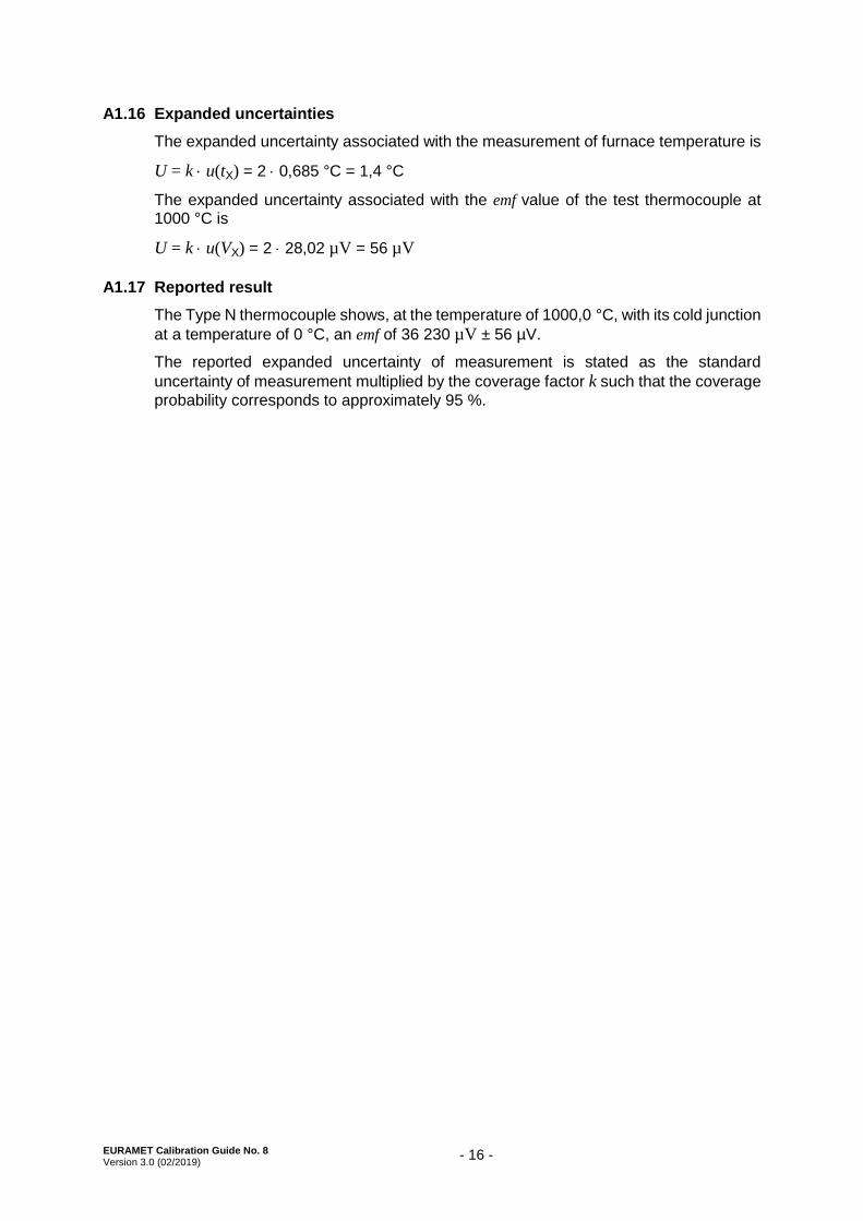
A1.16 Expanded uncertainties
The expanded uncertainty associated with the measurement of furnace temperature is
U = k u(tX) = 2 0,685 °C = 1,4 °C
The expanded uncertainty associated with the emf value of the test thermocouple at 1000 °C is
U = k u(VX) = 2 28,02 µV = 56 µV
A1.17 Reported result
The Type N thermocouple shows, at the temperature of 1000,0 °C, with its cold junction
at a temperature of 0 °C, an emf of 36 230 µV ± 56 µV.
The reported expanded uncertainty of measurement is stated as the standard
uncertainty of measurement multiplied by the coverage factor k such that the coverage
probability corresponds to approximately 95 %.

EURAMET e.V.Bundesallee 10038116 BraunschweigGermany
EURAMET e.V. is a non-profit association under German law.
Phone: +49 531 592 1960Fax: +49 531 592 1969E-mail: [email protected]