Thermocouples and sample probes for combustion studies
20
Prog. Energy Combust. Sei. 1993. Vol. 19. pp. 259-278 Printed in Great 8ritain. Ali rights reserved. 0360-- 1285/93 S24.oo· © 1993 Pergamon Press Ltd THERMOCOUPLES AND SAMPLE PROBES FOR COMBUSTION STUDIES M. V. HEITOR and A. L. N. MOREIRA* Instituto Superior Técnico, Department of Mechanical Engineering, Av. Rovisco Pais, 1096 Lisboa Codex, Portugal Received 14 Apri/ 1993 Abstract-The importance and limitations of probe methods for making measurements in combusting systems are reviewed and discussed in terms of the contributions that they can make to improve the knowledge and the modelling of practical systems. Emphasis is on measurements of temperature, major species and ion concentrations, which are discussed in terms of lhe need to determine and minimize probe-induced disturbances in practical combusting flows. In addition, errors arising from the difficulty in interpreting lhe results in turbulent flames are discussed and the review also provides some insight into measurements of time-resolved scalar quantities. CONTENTS Nomenclature I. Introduction 2. The Requirements for the Measuring Systems 3. Thermocouple Probes for Temperature Measurements 3.1. The measurement of time-resolved values 3.1. J. Probe induced perturbations 3.1.2. Errors arising from catalytic effects 3.1.3. Errors arising from heat transfer effects 3.1.4. Errors arising from the use of suction pyrometers 3. J .5. Errors arising from the averaging process 3.2. The measurement of time-resolved temperatures 3.2.1. The thermocouple time-constant 3.2.2. Measuring uncertainties 4. Sampling Probes for Major Species Concentrations Measurements 4.1. Probe induced perturbations and spatial resolution 4.2. Quenching efficiency 4.3. Errors arising from catalytic effects 4.4. Errors arising from the averaging process 5. Ionization Probes for Flame Detection 6. Conclusions Acknowledgements References 259 ~60 260 261 261 261 262 263 265 266 266 267 268 268 269 272 27'2 273 274 275 275 275 NOMENCLATURE e emissivity p specific weight a Stefan-Boltzrnann constant r time constant of the thermocouple !I. macro-scale ofturbulence A area c T- To progress variable, C =---- Tad - To calorific value at constant pressure probe tip diameter diameter of the stream tube at the probe entrance diameter convective heat transfer coefficient thermal conductivity Nusselt number mean temperature temperature fluctuation volume integrallength scale Superscripts (-) unweighted (or conventional Reynolds) average C) Favre (or density weighted) average (') fluctuation from unweighted average (") fluctuation from Favre average Subscripts o referred to the reactants g gas w thermocouple surface a furnace, or ambient condition Cp Dp DT d h k Nu T t V t • Author to whom correspondence should be addressed. 259
-
Upload
independent -
Category
Documents
-
view
0 -
download
0
Transcript of Thermocouples and sample probes for combustion studies
Prog. Energy Combust. Sei. 1993. Vol. 19. pp. 259-278Printed in Great 8ritain. Ali rights reserved.
0360-- 1285/93 S24.oo·© 1993 Pergamon Press Ltd
THERMOCOUPLES AND SAMPLE PROBES FOR COMBUSTIONSTUDIES
M. V. HEITOR and A. L. N. MOREIRA*
Instituto Superior Técnico, Department of Mechanical Engineering, Av. Rovisco Pais, 1096 Lisboa Codex, Portugal
Received 14 Apri/ 1993
Abstract-The importance and limitations of probe methods for making measurements in combustingsystems are reviewed and discussed in terms of the contributions that they can make to improve theknowledge and the modelling of practical systems. Emphasis is on measurements of temperature, majorspecies and ion concentrations, which are discussed in terms of lhe need to determine and minimizeprobe-induced disturbances in practical combusting flows. In addition, errors arising from the difficultyin interpreting lhe results in turbulent flames are discussed and the review also provides some insight intomeasurements of time-resolved scalar quantities.
CONTENTS
NomenclatureI. Introduction2. The Requirements for the Measuring Systems3. Thermocouple Probes for Temperature Measurements
3.1. The measurement of time-resolved values3.1. J. Probe induced perturbations3.1.2. Errors arising from catalytic effects3.1.3. Errors arising from heat transfer effects3.1.4. Errors arising from the use of suction pyrometers3. J .5. Errors arising from the averaging process
3.2. The measurement of time-resolved temperatures3.2.1. The thermocouple time-constant3.2.2. Measuring uncertainties
4. Sampling Probes for Major Species Concentrations Measurements4.1. Probe induced perturbations and spatial resolution4.2. Quenching efficiency4.3. Errors arising from catalytic effects4.4. Errors arising from the averaging process
5. Ionization Probes for Flame Detection6. ConclusionsAcknowledgementsReferences
259~6026026126126126226326526626626726826826927227'2273274275275275
NOMENCLATURE e emissivityp specific weighta Stefan-Boltzrnann constantr time constant of the thermocouple!I. macro-scale ofturbulence
A area
c T- Toprogress variable, C =----
Tad - Tocalorific value at constant pressureprobe tip diameterdiameter of the stream tube at the probe entrancediameterconvective heat transfer coefficientthermal conductivityNusselt numbermean temperaturetemperature fluctuationvolumeintegrallength scale
Superscripts(-) unweighted (or conventional Reynolds) averageC) Favre (or density weighted) average(') fluctuation from unweighted average(") fluctuation from Favre average
Subscriptso referred to the reactantsg gasw thermocouple surfacea furnace, or ambient condition
Cp
DpDTdhkNuTtVt
• Author to whom correspondence should be addressed.
259

I. INTRODUCTION
M. V. HEITOR and A. L. N. MOREIRA260
During the last twenty years combustion researchhas gained significant advances as a result of thedevelopment of new advanced diagnostic tools formeasuring the properties of combusting fíows inconfigurations of engineering interest. Their develop-ment has received continuing attention over the pastfew years and various books 1-6 and review papers 7-22 have attempted to provide up-to-date and com-plete information. Although numerous diagnostictechniques are available, the measurements of fíowproperties in combusting flows have traditionallybeen based on the introduction of probes into thef1ow.13-16 This raises the question of probe interfer-ence and accuracy, which can easily be made negligi-ble in streaming f1ows, but require careful attentionin recirculating turbulent f1ames, such as those typi-cal of many practical combustion devices, includingthe combustors of gas turbines and the burners ofindustrial furnaces.' 7-20 In these practical systemsproblems arise not only from probe interference ef-fects, but also from the lack of temporal resolutionand the difficulty in interpreting the results, namelyas far as the form of averaging of the measurementsis concerned.ê!
Optical techniques, including laser velocimetry andrelated forms for velocity and size measurements andspectroscopically-based laser diagnostic approachesfor species concentration and temperature measure-ments, have the potential to overcome these prob-lems, although other limitations may arise. Theserelate, above ali, to the requirements for opticalaccess and the difficulty in obtaining high qualitydata in strongly luminous and particle laden environ-rnents.ê While applications of laser velocimetry tocombusting systems have been extensively reportedand their accuracy well established,4.22-25 the meas-urements of scalar properties with laser-based meth-ods are dependent on a number of factors, such asthe presence of particles in the f1ow, and the accuracyof the results is still questionable, at least for f1ameswith practical relevance. It is c1ear then that probeswill continue to find application, at least for meanscalar measurements, and there is an incentive torefine these techniques in order to improve theiraccuracy and expand their applicability. To achievethese objectives it is convenient to review the presentknowledge on the use of probe techniques, and thisis presented here with emphasis on the use of thermo-couples, suction probes and ionization probes toobtain information on temperature, major speciescharacteristics and f1ame detection, respectively.
This article is organized as follows. The next sec-tion discusses the properties to be measured in practi-cal combustion systems and analyzes the require-ments for the measuring equipment taking intoaccount the relative advantages and disadvantages ofprobe diagnostics. Section 3 reviews the use of ther-mocouples for either time-averaged or time-resolved
temperature measurements in f1ames and Sections 4and 5 analyze the use of physical probes for themeasurement ofmajor species and ion concentrationsrespectively. The last section presents the most im-portant conclusions and recommendations of thisreview.
2. THE REQUIREMENTS FOR THE MEASURINGSYSTEMS
Measurements in combustion systems are requiredfor purposes of analysis and control. For example,information about the inlet flow rates and the tem-perature and species concentrations of the combus-tion products can be fed into the control system inorder to meet both the requirements of increasedefficiency and c1eanliness of the process.26-28 Also,calculation procedures have been developed, not onlyto provide design and testing aids, but also to give anew insight into the basic behaviour of chemicallyreacting flows.ê? These procedures have to devisetheoretical models in order to obtain closure andsolution of the fundamental equations of conserva-tion of mass, momentum, energy and individualspecies.30-32 Again, the availability of detailed experi-mental data are crucial for the formulation andvalidation of the analytical models.33-39
In general, the information obtained in practicalcombustion systems includes the spatial and tempo-ral distributions of the characteristics of the combus-tion mixture before and at ignition, which requiresknowledge of mean f1ow, turbulence levels, fuelvaporization, atomization and dispersion, Also,characteristic temperatures and concentrations ofcombustion products, including particulate matter,are to be obtained in practical combustion devices,such as development engines and combustion cham-bers as discussed, for example, in Ref. 6. In addition,it should be noted that most of the f1ames withpractical interest are turbulent, and a complete under-standing of the phenomena occurring in a combus-tion process requires more than the measurement ofindividual properties, and means have to be devisedto measure some of them simultaneously. Neverthe-less, this aspect is discussed elsewhere," and is notdiscussed in detail here.
Although it is c1ear that probe methods are cheap,inherently simple, easy to use and are often still themost accurate, severa Iquestions must be raised abouttheir use besides those of probe interference:• How far can probes resolve the smallest typical
scales in turbulent f1ames?• How far are the measured spatial and temporal
averages exclusively related with the properties ofinterest, say velocity, temperature or species con-centrations?Typical values for those scales may range from
0.2 mm in laboratory f1ames at atmospheric pressureto about lO,um in jet engine combustors at designpressures of 10 atm.,"? which are associated with

Thermocouples and sarnple probes 261 .
Topic
TABLEI. Overview of errors incurred in thermocouple measurements
References
Probe induced perturbationsContamination of noble metaisCatalytic effectsPerformance of non-catalytic coatingsConduction errorsRadiation errorsPerformance of suction pyrometersType of averaging
25,53, 10156,57,59,6425,41,58,60,61,64,67,68,7048,59,61,6249,58,70,71,72,73,75,8050,58,63,64,68,70,74,78,79,81,82,85,87,8815,58,60,88,91,12515,58,60,88,91,125
characteristic times varying from about 10 to0.2 usec. For comparison, a fine thermocoupleapproximately 40 f1.m in diameter, which represents agood compromise between durability in a wide rangeof practical fiames and good temporal re-sponse,41.42 has a cut-off frequency around 12 Hzand is, therefore, considerably smaller than the fre-quency of the smallest eddies. As a consequence, it isusually assumed that probes of large dimension, forexample sampling and pressure probes, measuredensity-weighted values of concentration and velocityand small-diameter thermocouples may give rise tounweighted temperatures. Clearly, careful considera-tion should be given to each measurement methodand to the details of its implementation before anassessement of accuracy is made. For example, radia-tion and conduction heat transfer along the wires ofa thermocouple can render temperature measure-ments erroneous, depending on the measured environ-ment. AIso care must be exercised in the design anduse of sampling probes to avoid chemical transforma-tion at the sampling orifice and in lines to the detec-tion equipment.
It may be tentatively concluded that the choice ofa measuring technique, either intrusive or optically-based, is not obvious, and depends upon a numberof factors including the complexity of the fiow analy-sis, as well as the skills and experience of the user.However, in what concerns the measurement ofscalar properties, the hardware capital costs andcomplexity of the laser-based diagnostics mitigateagainst their widespread adoption and still continueto Iimit the number of deployable systems available.As a consequence, probe methods are still largelyused for the measurement of scalar properties inmany industries and laboratories in the world. How-ever, while much attention has been paid to laser tech-niques, improvements in combustion measurementsusing mechanical probes have been largely ignored.
3. THERMOCOUPLE PROBES FOR TEMPERATUREMEASUREMENTS
3.1. The Measurement of Time-resolved Values
This section analyzes the capabilities of fine-wirethermocouples for temperature measurements in
fiames, as well as their Iimitations. The analysis isbased on the experience of the authors and on rel-evant works published in the Iiterature such as thosementioned in Table I. The table lists relevant workscontributing to the improvement of knowledge of thevarious sources of error associated with the use ofthermocouples for time-averaged temperature meas-urements. Attention is focused on the followingaspects which are discussed in the paragraphs below:probe-induced perturbations; contamination ofthermocouple wires; catalytic effects; conductionerrors; radiation errors and the consequent use ofsuction pyrometers; and the type of average given bythermocouple probes.
Although a number of noble metais and theiralloys may be recognized as reliable sensing elementsfor high temperature rneasurements.r+r" the out-standing properties of rhodium-platinum alloys arethe most suitable for combustion applications, eitherat laboratory or at industrial scale46-47 This type ofthermoelement has been widely used for more thanthirty years48-52 and is, therefore, considered moreoften throughout this analysis.
3.1.1. Probe induced perturbations
A thermocouple probe such as that of Fig, I,where typical dimensions are presented, is inexpensiveand relatively easy to fabricate and use, but cancause local and global field disturbances of either anaerodynamic, thermal or chemical nature.15.21 Theaerodynamic disturbances are Iikely to be the mostserious, and may be minimized in streaming fíowswithout zones of fiow reversal (i.e. in parabolic fiows)by adequate probe geometry. However, in recirculat-ing and swirling fiames, or other mathematicallyelliptic fiows, probe disturbances can be severe andalter the mixing characteristics of fuel and air and/orpromote a fiame holder. The problem has not beenextensively addressed in the Iiterature and requiresquantitative determination of the resulting measure-ment uncertainty, for example making use of a laservelocimeter to quantify the effects of introducing aprobe into the fiame. References 25 and 53 made useof this technique. In the latter work local probeperturbations precluded the use of 40 f1.m thermocou-pIes in the recirculation zone of a confined swirlingfiame; in the former, the perturbation induced by a

262 M. V. HEITOR and A. L. N. MOREIRA
SupportingWires (500 um)Pt : 13% Rh/Pt
ThermocoupleJunction (dw = 40: 80 um)
q> 2.5 TwinBoreAluminaTube
10 35
q> 4 StainlessSteel Tube
240
(dimensionin rnrn)Pt: 13% Rd
FIG. I. Schematic diagram of a thermocouple probe."! Typical thermocouple wire dimensions are in therange 15-8011m. The thermocouple is usually supported on wires of the same material with diameters of
350 or 500 11m.
80 Jlm thennocouple in the mean velocity field of anunconfined swirling flame was found to be negligible.
Local aerodynamic perturbations can also resultfrom the conversion of kinetic to thennal energy inthe boundary layer around the thennocouples. Theresulting error can, however, be negligible in cornbust-ing flows with Mach number lower than 0.1,54.55which covers most of the applications considered inthe present analysis. Other probe-induced interfer-ences incJude thennal disturbances, if the probe actsas a significant heat sink, and chemical perturbations,which are comparatively more important and resultfrom the promotion of chemical reactions on thesurface of the wires, as discussed below.
3.1.2. Errors arisingfrom cata/ytic effects
ln reducing atmospheres, i.e. those containing hy-drogen, water vapour, carbon monoxide, methane ororganic gases, pia tinum and its alloys tend to reactwith chemically active species and accelerate the de-composition of the nonnally stable refractory ceram-ics which are used to insulate the thermoelements.ê?Platinum silicides may be fonned above 1200°C andcan cause embrittlement of the wires, as discussed inRef. 57. It should be noted that contamination occurseven if the wires are not in intimate contact withsilica materiais, because silica is generally present infurnace insulations and carbon and sulphur can bepresent in the atmosphere where the formation ofthe volatile compound SiS2 is responsible for the con-tamination.
A different fonn of chemical disturbance can beinduced by catalysis on the thennocouple surface.Although noble metais are highly resistant to oxida-tion, when exposed to reducing atmospheres the plati-num surface may act as a catalyst for exoergic chemi-cal reactions, particularly in the fonn of radicalrecombination, and gives rise to systematic errors inthe values of temperature. Premixed flames are par-ticularly prone to this type of error 58 due to therecombination of OH radicais in the thennal bound-ary layer around the wire."?
Catalytic heating can be minimized by coating thewires with a suitable non-catalytic material. Silica-based coatings, like those used in Refs 59-61, havebeen shown to be prone to reduction by hydrogen inthe flame when exposed to temperatures higher than1l00°C and contaminate the wires.56.57A combina-tion of beryllia and yttrium oxide ceramic has beenfound to overcome these problems,62.63 but berylliais toxic and extremely poisonous, as discussed inRefs 60, 64 and 65. On the other hand, an alumina-based ceramic coating (90% AIz03-10%MgO)58 hasbeen widely used in laboratory environments duringthe past few years,25.27,41,52,66,67and is expected toavoid catalytic heating of the thennocouple surfacesin other flames with practical relevance. However,coating the wires increases their diameter, whichdeteriorates probe frequency response, and increasestheir emissivity, as discussed below.
The importance of catalysis can be confirmed byobserving the presence (or absence) of histeritic ef-fects, dependent on whether a temperature profile is

Thennocouples and sample probes
600 1000 1400
I!lr_~~~._t-- 600 1000 1400 T (K)z = 70 mm
30Ê 20.s 10
O
a)263.
b) ro
'" o '" oo o o oo o o o o
Quarl·3.0-.
air ·1.5--air + -----propane
1.5
3.0
r/Di
• 80 um uncoated
o 80 um coated
.• 40 um uncoated
TEMPERATURE ( K)
x/D: = 2.5 x/O, = 3.4
• • 300 urn uncoated
O O 300 um coated
FIG. 2. Radial profiles of mean temperature obtained with coated and uncoated thennocouples (a) in thecan-type gas-turbine model combusto r of Ref. 68 and (b) in the swirl-stabilized f1ame with axial fuel
injection of Ref. 25.
measured by transversing from cold reactants to hotproducts or vice versa, since catalysis gives rise tohigher temperatures for the profiles initiated at hotregions. An estimate of the catalytic error is oftennecessary and can be inferred from measurementsobtained with coated and uncoated thermocouples,as shown in the results of Fig. 2a, obtained in a can-type gas-turbine combustor.r" The figure shows thatcatalytic activity is more pronounced in the zones ofthe fiow where the larger concentrations of unburntfuel are encountered, although maximum absoluteerrors were found to be significantly larger in theswirling fiame of Ref. 25 (see Fig. 2b). The differentmagnitudes account for the strong dependence of thecatalytic activity on local mixture (thus, on localmean temperature, concentration of unburnt fueland Reynolds number) and on the hydrogen contentof the fuel and, therefore, on the fiow configurationunder analysis. For example, in the work of Ref. 67,catalysis precluded the use of 40 Ilm bare-wire ther-mocouples in a premixed disk stabilized propanej
air fiame with a Reynolds number equal to2 x 104, while Ref 52 reports errors smaller than30 K in a similar fiame of methanejair with a Rey-nolds number equal to 4.6 x 10⁴. AIso, Refs 59and 69 did not observe significant errors due tocatalysis, respectively in a fiat laminar premixedfiame of propanejair, and in a non-premixed swirlrecirculating propane fiame with a hot recirculatingregion.
3.1.3. Errors arisingfrom heat transfer effects
The source of errors referred to so far are a resultof probe perturbations, either of an aerodynamic,thermal or chemical nature. A steady-state differencebetween measured, Te, and true gas temperature,Tg, also occurs as a result of heat transfer betweenthe thermocouple bead, the wires and the surround-ings, as quantified in Eq. I and considered in thefollowing paragraphs.
264 M. V. HEITOR and A. L. N. MOREIRA
T4 [?; ?2 1:J h'tg' h't:"- - ae ('T'4 4) ae w 6 4Tw = Ta - -= 1 w - Ta --_- -=z + -=; + '"i'4 + -=- - - - conduction effects,h h T'; Tw 1 w h h
IIIII
3 II
C IQ) IÜ I
Q; IIa. IIIIg 2 II
W II
Ol IC I
O I
O I
Ü II
C IO I Main leade I
::l ,~ ~~:::7"",,"OC \ 300KOÜ \,
"''-, ........--- ---
O - - - -O 0.02 0.04 0.06 0.08 0.10 0.12
Wire Length- in
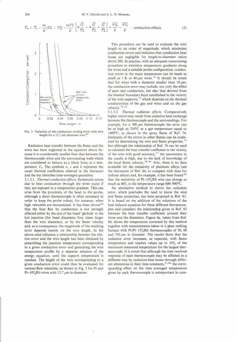
FIGo 3. Variation of the conduction cooling error with wirelength for a 12.7 Jlm platinum wire."?
Radiation heat transfer between the fiame and thewires has been neglected in the equation above be-cause it is considerably smaller than that between thethermocouple wires and the surrounding walls whichare considered to behave as a black body at a tem-perature Ta. The symbols a, e and h represent theusual thermal coefficients referred in the literatureand the bar identifies time-averaged quantities.3.1.3.1. Thermal conduction effects. Systematic errorsdue to heat conduction thraugh the wires occur ifthey are exposed to a temperature gradient. This canarise from the proximity of the bead to the probe,although a short thennocouple is often necessary inorder to keep the probe robust, for instance, whenhigh velocities are encountered. It has been showrr'"that the heat fiux by conduction is not stronglyaffected either by the size of the fused 'globule' at thehot junction (for bead diameters four times largerthan the wire diameter), or by the fiame velocityand, as a consequence, the magnitude of the resultingerrar depends mainly on the wire length. In theabove cited reference a relationship between the rela-tive error and the wire length has been obtained byprescribing the junction temperature correspondingto a given conduction erro r and generating the wiretemperature profile by a stepwise solution of theenergy equation, until the support temperature isreached. The length of the wire corresponding to agiven conduction erro r could then be evaluated forvarious fiow velocities, as shown in Fig. 3 for Pt andPt-IO%Rh wires with 12.7 ,um in diameter.
(I)
This procedure can be used to evaluate the wirelength to an order of magnitude, which minimizesconduction errors and indicates that conduction heatlosses are negligible for length-to-diameter ratiosabove 200. In practice, with an adequate transversingprocedure to minimize temperature gradients alongthe wires and a suitable probe configuration, conduc-tion errors in the mean temperature can be made assmall as I K in 40,um wires.?? It should be notedthat for wires with a diameter smaller than 10 ,um,the conduction error may include, not only the effectof pure end conduction, but also that derived fromthe thermal boundary layer established in the vicinityof the wire supports."! which depends on the thermalconductivities of the gas and wires and on the gasvelocity.72.733.1.3.2. Thermal radiation effects. Comparativelyhigher errors may result from radiative heat exchangebetween the thermocouple and the surroundings. Forexample, for a 300,um thermocouple the erro r canbe as high as 250°C at a gas temperature equal to1400°C, as shown in the spray fiame of Ref. 74.Estimates of the errors in other fiames can be evalu-ated by determining the wire and fiame properties,""but although the relationship of Ref. 76 can be usedto calculate the heat transfer coefficient in the vicinityof the wire with good accuracy.?? the uncertainty inthe results is high, due to the lack of knowledge ofthe local fiame velocity.78-82 AIso, there is no dataavailable for the emissivity of platinum alloys (seethe discussion of Ref. 64, to compare with data foriridium alloys) and, for example, it has been found 82that the emissivity of Pt-IO%Rh wire can change asmuch as 40% in the temperature range 600-900°C.
An alternative method to derive the radiationerro r, which precludes the need to know the wireand fiame properties, has been proposed in Ref. 82.It is based on the addition of the solutions of theheat balance equation for three different thermocou-pies and considers the relationship given in Ref. 83between the heat transfer coefficient around theirwires and the diameters. Figure 4a, taken from Ref.84, shows the temperature corrected by this methodtogether with measurements taken in a glass meltingfurnace with PtfPt-I3%Rh thermocouples of 50, 80and 350,um in diameter. The results show that theradiation error increases, as expected, with fiametemperature and reaches values up to 10% of themaximum measured temperature for the largest ther-mocouple. It is noted that although the time resolvedresponse of each thermocouple may be affected in adifferent way by radiation heat losses through differ-ent alterations in their time constants,51.80 the corre-sponding effect on the time averaged temperaturegiven by each thermocouple is unimportant in com-

Thermocouples and sample probes
a)1800
1700
1600
1500Ü 1400o
f-lJ. o 50 um
o o 80~m
o o 350 urn
• o 350 um, coated- corrected for radiation tosses
1300 o•1200
1100
1000o 150 450300 600
Dislance lo furnace watt (mm)
265.
b)
150
 40 pm wlla ai e.11 plane
• 80 um Wl/8 ai ex i! plane
200 • aõ um wue at z < 90 mm
6. tlO}.lm wlte ai exu plane
o 80).lm wrre ai 91111plane
D 80 jJmw1re at z <: 90 mm
(f)(f).2C
ºeui5C1la:
100
50
750 600 1400 18001000Measured Temperature T (K)
FIG. 4. Analysis of the radiation losses from Pt/Pt-l3%Rh thermocouples in (a) the glass meIting furnaceof Ref. 84 and (b) the can-type gas-turbine model combusto r ofRefs 42 and 68.
parison with the other sources of error, and themethod provides a good estimate of the radiationlosses of the thermocouples.
The calibration ofthermocouples in vacuum cham-bers has also been used to evaluate the magnitude ofheat losses by radiation following the method of Ref.85. This technique involves comparing temperaturereadings with electrically-heated thermocoupleseither in a vacuum chamber, where convection heattransfer is avoided, or in the fiame. An example ofthe use of the method is shown in Fig. 4b, whichquantifies the radiation losses of coated and uncoatedPtfPt-13%Rh thermocouples in the can-type gas-turbine combustor of Refs 42 and 68. The resultsconfirm the analysis of the previous paragraph andshow a monotonic increase of the radiation losseswith temperature, with values up to 10% of themeasured temperature at 1800 K for 80 Jim uncoatedwires. It should be noted that the method is based onthe assumption that the conductive heat losses fromthe beads and the radiation heat transfer betweenthe probe and the fiame are negligibly small and,again, that the average radiation temperature(T + 1')4 is equal to f4. The first assumption is notlikely to lead to significant errors and the effect of thesecond depends on the magnitude of the temperaturefiuctuations and cannot be exactly quantified. Forthe present case, the authors suggest that the resultsare overestimated by up to \0%. The results of Fig. 4also show that the use of an alumina-based ceramiccoating increases the radiation heat losses of the wireby a factor of around 2. The increased radiationerror typical of coated wires, together with theirincreased diameter, may therefore overcome thecatalytic error. 70
3.1.4. Errors arising from lhe use 01suctionpyrometers
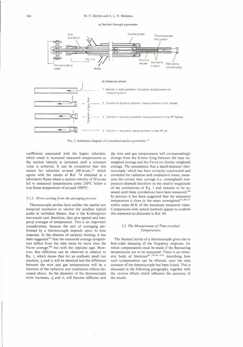
The analysis of the previous paragraph has focusedon the determination of the true fiame temperaturesfrom values measured by bare-wire thermocouples.An alternative approach of reducing measurementerrors associated with the radiation heat transferfrom the wires, is the use of suction pyrometers toprotect the thermocouples from the environment.The technique has been widely used in large fíames.'?since the use of pyrometers introduces problems re-lated to fiame disturbance, including the possibilityof density segregation due to non-isokinetic sam-pling.74.86 Figure 5 shows a schematic diagram of asuction pyrometer, which consists of a thermocoupleprotected by a sheath of fused pure alumina placedin two concentric shields of sillimanite that isolatethe thermocouple from the surrounding radiation.The head is fitted to the end of a water-cooledprobe, through which the combustion gases aresucked at a high velocity. A different kind of probemust be constructed when measurements are takenin particle-laden fiames, where high particle concen-trations can cause blockage of the probe, or in im-pinging high temperature fiames, such as those infurnaces with oxygen enrichrnent.ê" where probe-induced perturbation and probe resistance can giverise to important errors. In general, the geometry ofthe probe, the position of the thermocouple beadwithin the pyrometer and the geometry of the sheathinfiuence the accuracy of the measurements,74.87.88but the magnitude of the suction velocity is the mostimportant parameter to be considered in the analysisofthe results. This stems from the larger heat-transfer
266 M. V. HEITOR and A. L. N. MOREIRA
a) Section through pyrometer
Compensatingcable Water
F=====---y--.. lo -~-===~ Ol
~
õ
c::::::~..:::::.'-i---o
---ttmJ
Cooled probe
Refractorycement plug
(b) External shield
t . Section in static position: horizontal displacement ofmeasuring point
2. Suction in dynamic position: measurements in oil flames
3 . Suction in dymamic position: measurements in the PF flames
4 Suction in the wake: measurements m the PF jet
FIG. S. Schematic diagram of a standard suction pyrometer. 12
coefficients associated with the higher velocities,which result in increased measured temperatures asthe suction velocity is increased until a constantvalue is achieved. It can be considered that thisoccurs for velocities around 200 mjsec,12 whichagrees with the results of Ref. 74 obtained in alaboratory f1ame where a suction velocity of 50 mjsecled to measured temperatures some 230°C below atrue f1ame temperature of around 1000°C.
3.1.5. Errors arisingfrom the averagingprocess
Therrnocouple probes have neither the spatial nortemporal resolution to resolve the smallest typicalscales in turbulent f1ames, that is the Kolmogorovmicroscale and, therefore, they give spatial and tem-poral averages of temperature. This is an importantconsideration, because the sort of averaging per-forrned by a therrnocouple depends upon its timeresponse. In the absence of catalytic heating, it hasbeen suggested 14 that the measured average tempera-ture differs from the time mean by more than theFavre average.ê" but with the opposite signo How-ever, this difference can be observed in relation toEq. I, which shows that for an endlessly small hotjunction, t~ and t; will be identical and the differencebetween the wire and gas temperatures will be afunction of the radiation and conduction effects dis-cussed above. As the diameter of the thermocouplewires increases, t~ and t'w will become different and
the wire and gas temperatures will correspondinglydiverge from the forrner Iying between the time un-weighted average and the Favre (or density weighted)average. The assumption that a small-diameter ther-mocouple, which has been correctIy constructed andcorrected for radiation and conduction losses, meas-ures the correct time average (i.e. unweighted) tem-perature depends therefore on the relative magnitudeof the correlations of Eq. I and remains to be as-sessed until these correlations have been measured.P"In practice it has been suggested that the measuredtemperature is elose to the mean unweighted41.88.91within some 40 K of the maximum measured value.Comparisons with optical methods appear to confirrnthis statement as discussed in Ref. 60.
3.2 The Measurement ofTime-resolvedTemperatures
The therrnal inertia of a therrnocouple gives ris e tofirst-order damping of the frequency response, forwhich compensation must be made if the f1uctuatingtemperatures are to be measured. There is an exten-sive body of literature41.78.92-102 describing howsuch compensation can be effected, once the timeconstant of the therrnocouple has been found. This isdiscussed in the following paragraphs, together withthe various effects which influence the accuracy ofthe results.
Thermocouples and sample probes
Firsl point for lhecalculation of Tg
~11.6%
~'"
f-f
I I I Ioo 2 4 6 8
mst---
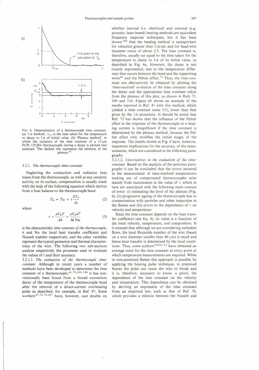
FIG. 6. Determination of a thermocouple time constant.(a) 'l/e method', 7:1/.is the time taken for the temperatureto decay to l/e of initial value. (b) 'Plateau method', inwhich the variation of the time constant of a 1511mPt/Pt-13%Rh thermocouple during a decay is plotted andanalysed. The dashed line represents the estimate of the
plateau.41
3.2.1. The thermocouple time-constant
Neglecting the conduction and radiation heatlosses from the thermocouple, as well as any catalyticactivity on íts surface, compensation is usually madewith the help of the following equation which derivesfrom a heat balance to the thermocouple bead:
ar,TG = Tw + r- (2)
dt
where
pCpV pCpd2
r=--=---Ah 4kNu
is the characteristic time constant 01the thermocouple,h and Nu the local heat transfer coefficient andNusselt number respectively, and the other varíablesrepresent the typical geometric and thermal character-istics of the wire. The following two sub-sectionsanalyze respectively the processes used to evaluatethe values of r and their accuracy.3.2.1.1. The evaluation 01 the thermocouple time-constant. Although in recent years a number ofmethods have been developed to determine the timeconstant of a thermocouple,41.73.102-106 it has con-ventionally been found from a forced convectiondecay of the temperature of the thermocouple beadafter the removal of a direct-current overheatingpulse as described, for example, in Ref. 97. Someworkers 67.72.73.107 have, however, cast doubts on
267
(3)
whether internal (i.e. electrical) and externa I (e.g.acoustic; laser-based) heating methods are equivalentfrequency response techniques, but it has beenshown 108 that the heating method is unimportantfor velocities greater than 2 m/sec and for bead/wirediameter ratios of about 2.5. The time constant is,therefore, usually set equal to the time taken for thetemperature to decay to l/e of its initial value, asdescribed in Fig. 6a. However, the decay is notexactly exponential, due to the temperature differ-ence that occurs between the bead and the supportingwires?" and the Peltier effect. 72 Thus, the time con-stant can alternatively be obtained by plotting the'time-resolved' evolution of the time constant alongthe decay and the appropriate time constant takenfrom the plateau of this plot, as shown in Refs 73,109 and 110. Figure 6b shows an example of theresults reported in Ref. 41 with this method, whichyielded a time constant some Ii% lower than thatgiven by the l/e procedure. It should be noted thatRef. 72 has shown that the infiuence of the Peltiereffect in the response of the thermocouple to a heat-ing current is insignificant if the time constant isdetermined by the plateau method, because the Pel-tier effect only modifies the initial stages of theresponse. The results shown in Fig. 6 have, however,important implications for the accuracy of the meas-urements, which are considered in the following para-graphs.3.2.1.2. Uncertainties in the evaluation 01 the time-constant. Based on the analysis of the previous para-graphs it can be concluded that the errors incurredin the measurement of time-resolved temperaturesmaking use of compensated thermocouples arisemainly from inaccuracies in the value of r, which inturn are associated with the following main sourcesof error: (i) estimating the levei of the plateau (Fig.6), (ii) progressive ageing of the thermocouple due tocontamination with particles and other impurities inthe fiames and (iii) errors in the dependence of r onvelocity and temperature.
Since the time constant depends on the heat trans-fer coefficient (see Eq. 4), its value is a function ofthe local velocity, temperature, and composition. Itis stressed that although we are considering turbulentfiows, the local Reynolds number of the wire (basedon a wire diameter smaller than 40 zmi) is small andhence heat transfer is determined by the local condi-tions. Thus, some authors 78.92.111 have obtained anaverage value for the time constant at every point atwhich temperature measurements are required. Whilein non-premixed fiames this approach is possible byapplying the heating pulse technique, in premixedfiames the pulse can cause the wire to break andit is, therefore, necessary to know, a priori, thedependence of the time constant on the velocityand temperature. This dependence can be obtainedby deriving an expression of the time constantfrom an empirical law, such as that of Ref. 76,which provides a relation between the Nusselt and

268 M. V. HEITOR and A. L. N. MOREIRA
Reynolds numbers.V This procedure has suggestedthat large temporal changes of temperature and velo-city imply that the response of the thermocouple isnon-linear, and the use of an average time constantleads to some error, as mentioned above. The effectis analogous to that which occurs in the context ofhot-wire anemometry+l" and the resulting error canbe quantified by compensating the temperaturedecay after the remova I of the heating pulse, whichshould give a step change decay (see Ref. 41 fordetails).
3.2.2. Measuring uncertainties
The evaluation of the time constant of the thermo-couple and subsequent compensation for thermalinertia can be done numerically and on-line. Numeri-cal compensation is usually preferred to the use ofanalogue circuits since it allows any dependence ofthe time constant on temperature and velocity to beincorporated." ' This is convenient because it removesthe needs of estimating the 'average' time constant atevery measurement point in the manner of, for exarn-pIe, Ref. 66. A more important advantage is that thenon-linear response of the thermocouple, due to thetemporal variation of the time constant, is to someextent taken into account. Thus the errors whichwould arise in the phase and variance of the cornpen-sated temperature through the use of a fixed, ratherthan ftuctuating, time constant 78.92 are expected tobe reduced by this procedure, as also confirmed inRef. 111.
There is no easy way of assessing the accuracy ofthe compensation, unless by comparison with meas-urements taken from a different instrument, such asmolecular Rayleigh scattering. An estimate of theshortcomings ofthe technique can, however, be madefrom the shape of the probability density functionsof compensated temperatures as extensiveIy reportedin the Iiterature.41.112 Measurements reported in theshear layer of a disk stabilized premixed ftame41.42
have shown that, although the temperature probabil-ity density functions show the bimodal shape ex-pected from the 'Bray-Moss-Libby' theory, themodes representing 'products' and 'reactants' do notcorrespond to values of the progress reaction vari-able,l13·114 C = (T - To)f(Tad - To), equal to oneand zero respectively. While the deviation of themode representing the 'products' from C = lhasbeen suggested to be due to factors other than com-pensation (such as mixing with entrained external airand radiation losses), the displacement of the moderepresenting 'reactants' from C = O is evidence ofpoor compensation.
It should be noted that the output compensationaccuracy of a thermocouple determines the extent towhich the highest frequency components in the ftowcan be measured. This is because the spectral densityof temperature ftuctuations in the ftow is attenuatedby a factor proportional to the time constant and to
the frequency. Ultimately, at higher frequencies, theattenuation is so large that the signal is indistinguish-able from the background noise of the electroniccomponents. Thus, the uncompensated signalstrength at the maximum measured frequency mustbe larger than the noise if the signal is to be accu-rately compensated. The practical difficulty is thatthis frequency is not known a priori, although it canbe estimated from the measurements by comparingthe uncompensated and compensated spectra withthat of the electronic noise."!
Another reason for the importance of the magni-tude of the maximum frequency response is that itsets the minimum sampling rate, which is necessaryto recover the sampled signal. In principIe, the mini-mum (or Nyquist) sampling rate is equal to twice themaximum frequency of the signal measured, but inaccordance with the practice of Refs 41 and 110 acorrect compensation procedure implies a cut-offfrequency about one quarter of the sampling fre-quency. It should also be noted that although thetechnique of compensation for thermal inertia is wellestablished for use in middle heated non-reacting airftows,73.115 it is not in reacting ftows. Reference 116has obtained a close agreement between the timeresolved temperature measurement from a compen-sated thermocouple td; = 25 11m) and that obtainedsimultaneously by laser Rayleigh scattering in anopen premixed methane-air ftame. Although similaragreement with other optical techniques has alsobeen reported for mean temperature values,117-120further research of this kind is required to establishthe accuracy of time-resolved thermocouple rneasure-ments.
4. SAMPLING PROBES FOR MAJOR SPECIESCONCENTRATIONS MEASUREMENTS
Gas sampling and subsequent analysis is a con-venient and an inexpensive method for measuringthe composition of combustion gases. To a largeextent the accuracy of these measurements is deter-mined by probe design and operating practice and itis clear that a careful analysis of the erro r sourcesresulting from the sampling process is a pre-requisiteto accurate composition measurements.
Prior to the analysis of these different aspects, itshould be noted that the chemical analysis can readilybe performed with commercially available instrumen-tation, which includes chromatography, infrared de-tectors (for CO, CO2, NOx, SOx, etc.), ftame ioniza-tion detectors (for unburned hydrocarbons), para-magnetic analyzers (for O2) and chemiluminescenceanalyzers (for NOx). These instruments are in generalaccurate and seldom Iimit the accuracy of the meas-urements.121.122
Although many different types of probes havebeen reported in the literature,13-15.121.122 theirdesign has been, in general, based on convectivecooling or on the aerodynamic quenching techniques.

Thermocouples and sample probes 269
Topic
TABLE 2. Overview of errors incurred in gas sampling
Reference
Probe-induced perturbations and compositionbiasing due to non-isokinetic sampling
Quenching efficiencyCatalytic effectsType of averaging
15,40,42,50,63,74,91,126,127,128,130, I31,13660, 124, 125, 134, 137, 138, 139, [40, 143133, [36,142, [44, 146, [4714,36,39,40,88, [48, 149
A first group of probes includes the widely usedstainless-steel probes of the pitot type, such as thatof Fig. 7a, which can additionally incorporate inter-nal static pressure taps to allow the matching of thesampling velocity to the stream velocity (i.e. isoki-netic sampling), as discussed in Ref. 64 and shown inFig.7b.
Also of the convective cooling type are the directwater-quench (shower) probes shown in Fig. 7c,which were used in Ref. 123 in semi-industrial typeof fiames. In these probes, the cooling water is mixedwith the sample gas at the probe tip to ensure a fastquench rate and then separated far downstream inthe sampling line making use of cyclone disengagersand ice baths.
In a third group of probes the sample is aerody-namically quenched through a rapid expansion nearthe probe tip, which is usually achieved in quartzmicroprobes such as those described in Refs 124 and125. These probes bring the advantage of reducedprobe interferences, but can give rise to low quench-ing rates and, as a consequence, the aerodynamicexpansion may have to be combined with convectivecooling, as in the probe of Ref. 124 shown in Fig.7d.
Although a large rate of cooling is needed in orderto conserve ali the initial gaseous constituents withtheir original concentrations, attention must also bepaid to the final temperature reached by the sampledue to the presence of condensable vapours. Forexample, when continuous analyzers (oxygen para-magnetic analyzer, infra-red analyzer, spectrometer)are used, it is necessary to eliminate completely anyparticles and water vapour from the gas sample.This is usually accomplished in the lines and auxilia-ries which ensure the transport of the sampled gasthrough the use of water condensers, drying tubesand filters. In this case, the sampled gas must becooled below the dew point and the measured compo-sition is obtained in a dry basis. However, the term'dry basis' can be misunderstood due to the presenceof other vapours with temperatures of saturationhigher than that of the water vapour. For example,the dew point corresponding to the condensation ofwater vapour depends on the type of fuel and on theoperating conditions of the burner, and is usuallyaround 40-50°C, but can increase up to 150°C in thepresence of traces of sulphur (mainly S03), whileheavy hydrocarbon vapours condense below 200-250°C. In practice, and for a well dimensioned probe,
either of the aerodynamic or the convective type ofquenching, the sample is cooled down to about300°CI3·14 at the tip of the probe, which is enoughto stop any chemical reaction of the gaseous constitu-ents. Therefore, the problem of condensation of va-pours only occurs along the suction line and if we tryto analyze any ofthose vapours (S02, unburnt hydro-carbons) additional heating must be supplied whichis usually accomplished by electrical resistances alongthe suction line. In this case the measured composi-tion is obtained in a wet basis.
Table 2 lists the main aspects Iikely to infiuencethe accuracy of the measurements, as follows: (i)probe-induced fiuid dynamic disturbances and com-position biasing due to non-isokinetic sampling; (ii)the efficiency of quenching; (iii) the catalytic effectson the probe surface; and (iv) the type of averaginggiven by the probes.
4.1. Probe lnduced Perturbations andSpatial Resolution
Sampling probes inherently interfere with the fiow,but their careful design and use can often keepinterferences down to an acceptable levei, particu-larly in fiows which do not include recirculation orswirl. The choice of the probe design and materialdepends on a number of factors, but are in generalconditioned by the relation between characteristiclength scales of the probe and the characteristicspatial-scales of the fiame under analysis. The criticallength scales associated with the probe are the probetip diameter, Dp, and the upstream diameter of thestream tube entering the probe, DT, which is definedas:
(4)
where ms is the mass gas sampling rate, p the specificweight of the gas at the measuring point and U thevelocity component of the undisturbed streamaligned with the probe at the nominal measuringpoint. As a rule of thumb, it has been suggestedê 'that when both Dp and DT are smaller than 10% ofany characteristic length scale of the fiow and theaxis of the probe is aligned with the mean fiow for atleast 10 diameters, interference effects can be kept aslow as 3%. However, besides the fact that the reduc-tion of a sampling probe at the levei of the small

270 M. V. HEITOR and A. L. N. MOREIRA
385
50Shealh Sore
1.0.6 ~
~Ell50::;rJa)
Cooper0.0.8
~
012.5
:~Ier ~ • t ~aler
Sampleoul
WalerOul WalerOuI
<1>23
Sample OUI r==!J.i'i1f- WalerStatic InPressure <I>3.2
b) r:==t-::ti1- WalerIn
101.2 102.4
016 <1>23
I'i 90 .1~
<D " 51 2 C") <D-o
~
-oII I~o~!c) ~
3062.08 ~]J ~
012.7
\
I. 800 IProbe StaticPressure Tap
Waler - Queneh Probe
d)19
1----- 246 -----
(Dimensions in mm)
FIG. 7. Current designs of gas sampling probes: (a) common water-cooled stainless-steel probe, as used inRef. 42; (b) isokinetic water-cooled stainless-stee1 probes used in Ref. 36; (c) direct quench probe used in
Ref. 123; (d) quartz probe with aerodynamic and convective cooling used in Ref. 124.
eddies (the spatial seale for the dissipation of turbu-lent fluetuations) is impossible, the small eddies eon-tain negligible fluetuation energy and thus do notaffeet the measurement of the mean eoneentration.
Therefore, the signifieant spatial-seales of the floware the integral length seale (t) whieh eharaeterizesthe gradients of the mean field and the macro-scaleof the turbulenee (A) whieh charaeterizes the
Thermocouples and sample probes 271
---- - Small Sampling70
z Probe CompositionsO 0.3 60 ::;;:i= o,o o,« 50 zct:u, Ow 0.2 40 i=..-J ÜO «::;;: a:
30 u,O (f)N (f)I
20 «N 0.1 ::;;:
O ON 10 zI
0.0 OC 2 4 6 8 10 12 14 16 18
rIa
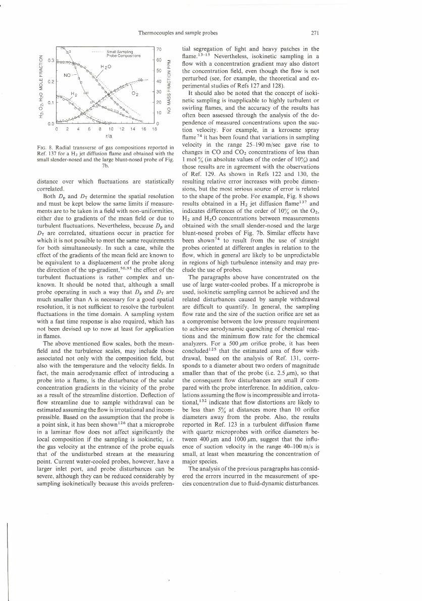
FIG. 8. Radial transverse of gas compositions reported inRef. 137 for a H2 jet diffusion flame and obtained with thesmall slender-nosed and the large blunt-nosed probe of Fig.
7b.
distance over which ftuctuations are statisticallycorrelated.
Both Dp and DT determine the spatial resolutionand must be kept below the same limits if measure-ments are to be taken in a field with non-uniformities,either due to gradients of the mean field or due toturbulent ftuctuations. Nevertheless, because Dp andDT are correlated, situations occur in practice forwhich it is not possible to meet the same requirementsfor both simultaneously. In such a case, while theeffect of the gradients of the mean field are known tobe equivalent to a displacement of the probe alongthe direction of the up-gradient.V'-?" the effect of theturbulent ftuctuations is rather complex and un-known. It should be noted that, although a smallprobe operating in such a way that Dp and DT aremuch smaller than A is necessary for a good spatialresolution, it is not sufficient to resolve the turbulentfluctuations in the time domain. A sampling systemwith a fast time response is also required, which hasnot been devised up to now at least for applicationin flames.
The above mentioned flow scales, both the mean-field and the turbulence scales, may include thoseassociated not only with the composition field, butalso with the temperature and the velocity fields. Infact, the main aerodynamic effect of introducing aprobe into a flame, is the disturbance of the scalarconcentration gradients in the vicinity of the probeas a result of the streamline distortion. Deftection offlow streamline due to sample withdrawal can beestimated assuming the flow is irrotational and incom-pressible. Based on the assumption that the probe isa point sink, it has been shown 126 that a microprobein a laminar flow does not affect significantly thelocal composition if the sampling is isokinetic, i.e.the gas velocity at the entrance of the probe equalsthat of the undisturbed stream at the measuringpoint. Current water-cooled probes, however, have alarger inlet port, and probe disturbances can besevere, aIthough they can be reduced considerably bysampling isokinetically because this avoids preferen-
tial segregation of light and heavy patches in theftame.13-15 Nevertheless, isokinetic sampling in aftow with a concentration gradient may also distortthe concentration field, even though the ftow is notperturbed (see, for example, the theoretical and ex-perimental studies of Refs 127 and 128).
It should also be noted that the concept of isoki-netic sampling is inapplicable to highly turbulent orswirling flames, and the accuracy of the results hasoften been assessed through the analysis of the de-pendence of measured concentrations upon the sue-tion velocity. For example, in a kerosene sprayftame 74 it has been found that variations in samplingvelocity in the range 25-190 mjsec gave rise tochanges in CO and CO2 concentrations of less thanI moi % (in absolute values of the order of 10%) andthose results are in agreement with the observationsof Ref. 129. As shown in Refs 122 and 130, theresulting relative error increases with probe dimen-sions, but the most serious source of error is relatedto the shape of the probe. For example, Fig. 8 showsresults obtained in a H2 jet diffusion flame '?? andindicates differences of the order of 10% on the 02,H2 and H20 concentrations between measurementsobtained with the small slender-nosed and the largeblunt-nosed probes of Fig. 7b. Similar effects havebeen shown 74 to result from the use of straightprobes oriented at different angles in relation to theftow, which in general are likely to be unpredictablein regions of high turbulence intensity and may pre-clude the use of probes.
The paragraphs above have concentrated on theuse of large water-cooled probes. If a microprobe isused, isokinetic sampling cannot be achieved and therelated disturbances caused by sample withdrawalare difficult to quantify. In general, the samplingftow rate and the size of the suction orifice are set asa compromise between the low pressure requirementto achieve aerodynamic quenching of chemical reac-tions and the minimum flow rate for the chemicalanalyzers. For a 500 Jlm orifice probe, it has beenconcluded+é? that the estimated area of ftow with-drawal, based on the analysis of Ref. 131, corre-sponds to a diameter about two orders of magnitudesmaller than that of the probe (i.e. 2.5 Jlm), so thatthe consequent ftow disturbances are small if com-pared with the probe interference. In addition, calcu-lations assuming the fíow is incompressible and irrota-tional.P? indicate that ftow distortions are likely tobe less than 5% at distances more than 10 orificediameters away from the probe. AIso, the resultsreported in Ref. 123 in a turbulent diffusion ftamewith quartz microprobes with orifice diameters be-tween 400 Jlm and 1000 Jlm, suggest that the influ-ence of suction velocity in the range 40-100 mjs issmall, at least when measuring the concentration ofmajor species.
The analysis ofthe previous paragraphs has consid-ered the errors incurred in the measurement of spe-cies concentration due to ftuid-dynamic disturbances.

272 M. V. HEITOR and A. L. N. MOREIRA
Thermal disturbances induced by the introduction ofcooled probes into a flame may also have to beconsidered.P:' but are, in general, comparativelysmall and are not discussed here in detail.
4.2. Quenching Efficiency
We now turn to the analysis of the extent to whichchemical reactions are effectively quenched in thesampling probes described above. Quenching is usu-ally attempted by a rapid reduction in gas tempera-ture, and following the analysis of Refs 121, 122and 134 va1ues of the order of 2 x 10⁶Kfsec areeasily obtained in water-cooled probes,74.135.136while values larger can be achieved in microprobeswith a sonic suction orifice.P"
In most of the turbulent combusting systems ofpractical interest the rate of reaction is controlled bydiffusion rather than by chemical kinetics and, there-fore, a 'slow' quench will give rise to an error equiva-lent to a corresponding position error in the stream-wise direction. Recombination of high temperaturedissociation products, such as H2 and O2 may occur,but the resulting errors incurred in the measurementsare in general overshadowed by those induced byprobe interference. Care should, however, be taken ifaerodynamic quenching is used, for example, on thebasis of simpIe compressible flow ca\culations usinga known coefficient of discharge for the divergentnozzle.P" The results depend on the stagnation tem-perature of the sample, but in general indicate thatthe backpressure in the probe must be considerablylower than 100 mmHg in order that the chemicalreactions are adequately and rapidly frozen on pass-ing through the nozzle, in which case sonic conditionsmust be assumed."? A decrease in the sampling pres-sure increases the rate of recombination of activespecies, such as OH, O and H, and reduces theresidence time of the sampling in the hot region ofthe probe, resulting in a decrease of the rate ofoxidation of the CO and NO.'39 Increased levelsof CO and NO with low sampling pressures arereported in Refs 60, 134, 138-140, and suggest thedependence of the quenching efficiency on samplingpressure.
It should also be noted that Ref. 124 has demon-strated that internal friction downstream of the diver-gent nozzle in a microprobe can prematurely returnthe flow to subsonic conditions. Determiningwhether this occurs is not trivial because quantitativeaccount must be taken of, among other variables,the external cooling and the initial temperature ofthe sample: the solution of the appropriate equationstherefore requires the use of a computer. Unfortu-nately, the published parametric studies do notpermit even a qualitative assessment of the perform-ance of most of the probes used, because the orificediameters are in general much smaller than those ofthe 'macroprobes' examined in the previous para-
graphs. However, it should be noted that when theinitial stagnation temperature of the sample is low itis easier to achieve adequate quenching.
In the absence of a ca\culation for the internalaerodynamics of the probes, an alternative strategyis to compare the results obtained with those fromother techniques. For example, Ref. 141 has foundthat the results obtained by an aerodynamic quench-ing probe agree with those obtained by a conven-tional water-cooled probe in a flow with combustion,where the relative large size of the water-cooledprobe does not disturb the flow. Also, Ref. 60 hasperformed meticulous comparisons between concen-trations of CO obtained by laser absorption spectro-scopy and probe techniques in laminar premixedflames at atmospheric pressure. The authors foundsuper-equilibrium levels of CO in lean flames withthe two methods, although probe resuIts were lowerby up to about 0.05 moI % (wet basis) which theyattributed to imperfect quenching which leads tosome CO-C02 conversion. For rich compositions,they found that the optical technique measured COconcentrations in good agreement with equilibriumca\culations but the probe measurements were belowequilibrium predictions by about 0.5 moI % (wetbasis). Reference 125 reports an analogous experi-ment by taking measurements at the centre of arecirculation zone as a function of equivalence ratio,as described in Fig. 9. At this location in the flame,the probe was always immersed in post-flame prod-uct gases and there was no 'intermittence' due to theoccurrence of unburnt reactant gases, at least forequivalence ratios well-removed from those assoei-ated with unstable combustion. For lean equivalenceratios, their results also show super-equilibrium levelsof CO in agreement with the probe measurements ofRef. 60, and this is an indication that at least someaerodynamic quenching might be taking place intheir probe. It should be pointed out that theconcentration of carbon monoxide is particularlysensitive to poor quenching as a consequence ofextended CO-to-C02 conversion, probably becauseof the presence of active species in the probe, suchas OH, which leads to the reaction CO +OH -+ CO2 + H.138
4.3. Errors Arising from Catalytic Effects
While a fast quench of the gas-phase reactions insamples withdrawn from flames by probes is desir-able, it should be noted that it increases the rate ofradical recombination and promotes the oxidationofNO.39,'42,'43 This fact, together with the catalyticactivity on the probe and sampling line materiaIs,make suction probes particularly prone to errors inthe measurement of NOx concentrations, 144,145Ref-erence 15 discusses the Iikely phenomena involved,which include reduction ofN02 by the probe surface,oxidation of NO to N02 by non-equilibrium species,

10
~N 5
O
O
10
~N 5O
O
O
0.4
~O 0.2O
O0.4
~O 0.2I=:>
O
Thermocouples and sample probes
Pó -
ac- C, ,,,,
~\.I
r- , ,,i;' ,
~r-" '",
I I I
~~,
r- -,
r- , -:ç 'I. ", , t-o : ~
11" I I-
CC -
GI~ I I
0.5 1.0 1.5
273
Blow Blow
Out Unstable Out
2000,,,
o
.-, ,,,t,,
t
,,
1500
0.5 1.0 1.5
oOisc; Br = 25 %
Re = 43 40010
~
--
- -----
Measurements
5
O
o Measuremenlsx/o = 0.63; r = O(Coated Thermocouple)
6. Calculated TemperatureF rom species
-- equilibrium(Adiabatic Conditions)
FIG. 9. Measurement of major species concentrations obtained in the centre of the recirculation zone inthe baffie-stabilized methane-air flame of Ref. 125.
and several eatalytie reaetions also at the probesurface. Although metallie probes are reeognized tobe partieularly prone to eatalysis,134.137the eatalytieaetivity has also been observed in quartz probes byRefs 144 and 146 and in siliea probes by Refs 142and 147. In addition, Ref. 60 refers to the oxidationof CO by atomie oxygen at the wall of eopper andquartz probes.
4.4. Errors Arisingfrom lhe Averaging Process
The sort of average given by eurrent probes is farfrom well understood. Density and eoneentrationtluetuations in turbulent tlames eomplicate the inter-pretation of the results due to the inability of thesampling system to follow these tluctuations. It hasbeen suggested 15 that the composition measured bya microprobe falls between the unweighted and thedensity weighted, or Favre, average, which has beenconfirmed by the results of Refs 88 and 148. Further,comparative studies of measurements with water-cooled probes and quartz microprobes 66 and ofprobe and optical methods36.39.149 indicate that themeasured concentrations are Iikely to be close to
JPECS 19:3-6
density weighted averages and within 10% of thetrue value.
Given the complexity of the phenomena outlinedin previous paragraphs it is not possible to estimatea priori the error incurred in probe measurements ofmajor species concentrations. Repeatability of datais important and must be considered, but ato miebalance should be verified and is the most importantcheck of data. In non-premixed tlames, for example,the C/H and N/O ratios should be preserved beeausediffusion efTects are expected to be small. Errorsbetween 6 and 20% are reported in Refs 50, 84 and150 in either hydrogen or hydrocarbon tlames withdifferent heat release rates. In addition, in turbulentpremixed tlames the overall stoichiometry shouldalso be preserved and, for example, Ref. 125 onlyreports uncertainties larger than 10% in regions of abaftle-stabilized tlame where concentration gradi-ents are large. These checks provide an estimation ofthe measurement precision, but they do not indicatewhether the sampling data are representa tive of theeomposition in the tlow. An aeeurate error analysisrequires, therefore, careful eonsideration of probe in-duced perturbations and of the sampling conditions,according to the analysis previously outlined.
274 M. V. HEITOR and A. L. N. MOREIRA
500
oo
Dimensions in mm
SiliconeRubber
t tcoolingwater
StainlessSteel
<t> 10
PlatlRh Wire
S. IONIZATlON PROBES FOR FLAME DETECfION
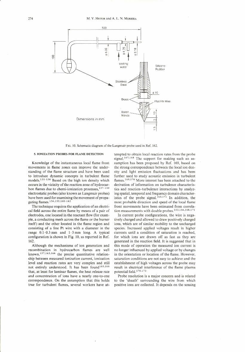
fIG. 10. Schematic diagram ofthe Langmuir probe used in Ref. 162.
Knowledge of the instantaneous local f1ame frontmovements in flame zones can improve the under-standing of the f1ame structure and have been usedto introduce dynamic concepts in turbulent fíamemodels.151-156 Based on the high ion density whichoccurs in the vicinity of the reaction zone of hydrocar-bon f1amesdue to chemi-ionization processes,157-159electrostatic probes (also known as Langmuir probes)have been used for examining the movement of propa-gating f1ames.154,155,160-162
The technique requires the application of an electri-cal field across the entire flame by means of a pair ofelectrodes, one located in the reactant flow (for exam-pie, a conducting mesh across the flame or the burneritself) and the other located in the f1ame region andconsisting of a fine Pt wire with a diameter in therange 0,1-0.3 mm and 1-3 mm long. A typicalconfiguration is shown in Fig. 10, as reported in Ref.162.
Although the mechanisms of ion generation andrecombination in hydrocarbon f1ames are wellknown,157,163.164 the precise quantitative relation-ship between measured ionization current, ionizationlevei and reaction rates are very complex and stillnot entirely understood. It has been found165,166that, at least for laminar f1ames, the heat release rateand concentration of ions have a near1y one-to-onecorrespondence. On the assumption that this holdstrue for turbulent flames, several workers have at-
tempted to obtain local reaction rates from the probesigna1.167.168The support for making such an as-sumption has been proposed by Ref. 169, based onthe strong correspondence between the local ion den-sity and Iight emission f1uctuations and has beenfurther used to study acoustic emission in turbulentflames.169,170More interest has been attached to thederivation of information on turbulence characteris-tics and reaction-turbulence interactions by analyz-ing spatial, temporal and frequency domain character-istics of the probe signa1.163,171In addition, themost probable direction and speed of the local flamefront movements have been estimated from correla-tion measurements with double probes. 153,154,168,171
In current probe configurations, the wire is nega-tively charged and allowed to draw positively chargedions, which are of similar mobility to the unchargedspecies. Increased applied voltages result in highercurrents until a condition of saturation is reached,for which ions are drawn off as fast as they aregenerated in the reaction field. It is suggested that inthis mode of operation the measured ion current isno longer influenced by applied voltage or by changesin the orientation or location of the flame. However,saturation conditions are not easy to achieve and theestablishment of high voltages across the probe mayresult in electrical interference of the f1ame plasmapotential field.170,173
Probe resolution is a major concern and is relatedto the 'sheath' surrounding the wire from whichpositive ions are collected. It depends on the sensing
Thermocouples and sample probes
wire diameter, applied voltage and flow velocity.l"?Values of the order of 0.4-2 mm are usuallyobtained with fine wire sensors (0.1-0.3 mm) operat-ing in the saturation mode (applied voltages from5 to 20V).153.157.162.170.176 The resulting frequencyresponse is defined by the drift velocity for ions inthe 'sheath' surrounding the wire and values up to5 kHz are referred to in Ref. 163 and up to 10kHzin Ref. 172.
Quantitative interpretation of the probe signal isnot straightforward and has been the subject ofdifferent analyses. Based on the fact that ions in ahydrocarbon flame originate in chemical reac-tions, 158.174.175it is generally assumed that in satura-tion conditions the ion density distribution acrossthe flame front is independent of its movement orshape. Hence, the time mean value of the ion currentto the electrostatic probe is proportional to the prob-ability density distribution of the flame front.154.176However, the dependence of the ionization currenton flow velocity'P? and on finite ion density in theburned gas,158.160 causes difficulty in interpretingthe mean ion current measured by the probes.P?and requires previous calibration if accurate quantita-tive measurements are to be obtained. 168.177 In addi-tion, it should be noted that non-premixed flamescause additional problems in the use of ion probesdue to the influence of local mixing on the fluctuatingion current. Also, the high electric loads of the sootformed in typical non-premixed flames of low-hydro-gen content fuels may disturb the ionization field ofthe homogeneous reaction 176 and preclude the useof the probes.
The works referred to so far show that the relationbetween ionization reactions (i.e. ion formation,charge exchange and ion recombination) and combus-tion reactions are not entirely understood, althoughit is known that ionization reaches a maximum leveIin the center of the reaction zone. It follows thatmeasurements concerning ionization should considerthe frequency content of the f1uctuating probe signalsin order to improve knowledge of reaction dynamics.In addition, simultaneous measurements of gas ve\oc-ity and ion current are important to extend theinformation derived from the probes to the analysisof combustion performance. Measurements of thiskind may be possible combining the probes describedabove with a laser velocimeter, although the requiredseeding particles can cause thermal ionization 157.177and particle deposition on the probe surface.162.171There are many engineering situations where knowl-edge of the time evolution of burned zones providesa valuable insight, among which the combustionchamber of internal combustion engines is an impor-tant example. In such hostile environments, whichlack optical access, single and multiple ionizationprobes have been used and combined with laservelocimetry'{ê+?? in such a way that the time inter-vaI from ignition until flame arrival at the sensorscould be detected. The measurements could be made
275
cycle-resolved and simultaneous with the cylinderpressure, permitting an analysis of the correlationbetween cyclic variability and combustion uniformity.
6. CONCLUSIONS
Probe measurements of scalar characteristics incombusting fíows have found increased applicationsin recent years and are reviewed with emphasis onthe use of thermocouples, suction probes and ioniza-tion probes for the analysis of temperature, majorspecies concentrations and flame detection, respec-tively.
The requirements for the measuring systems arebriefly summarized and the advantages/disadvan-tages of probe methods are outlined. The need todetermine and minimize probe-induced disturbancesin recirculating zones and swirling f1ames is pointedout, and errors arising from the difficulty in interpret-ing the results in turbulent flames are discussed.Since the response of the probes is not usually alinear function of the variable of interest, the 'aver-age' obtained may be biased in relation to densityweighted and unweighted values, and the extent ofthe bias is discussed in the paper regarding the typeand the size of the probe.
Acknowledgements- The assistance and support over anumber of years of Professor Diamantino F. G. Durão isgratefully acknowledged. We are also pleased to recordmany useful discussions with colleagues in the Departmentof Mechanical Engineering of I.S.T. and, in particular, withIsabel de Simões Carvalho, Edgar Caetano Fernandes andPaulo Cadete Ferrão. The assistance of Mr Carlos Carvalhoand lorge Coelho in preparing the manuscript is gratefullyacknowledged.
REFERENCES
I. LlNUMA, K., ASANUMA, T., OSHAWA, T. and DOI, l.,Laser diagnostics and modelling of combustion, Springer,Berlin (1987).
2. ECKBRETH, A. c., Laser Diagnostics for CombustionTemperature and Species, Energy and EngineeringScience Series, A. K. Gupta and D. G. Lilley (Eds),Abacus Press, U.K. (1988).
3. DURÃO, D. F. G., WHITELAW, J. H. and WITZE, P.,Instrumentation for Combustion and Flow in Engines,Kluwer (1989).
4. DURÃO, D. F. G. and HEITOR, M. V., Combusting FlowDiagnostics, D. F. G. Durão et al. (Eds), Kluwer I,(1991).
5. TAYLOR, A. M. K. P., Experimental Methodsfor Flowswith Combustion, Academic Press, New York (1991).
6. CHlGIER, N., Combustion Measurements, Hemisphere(1991).
7. OHASWA, T. and ASANUMA, T., High Temp. Technol.2(4),203 (1984).
8. JONES, W. P. and WHITELAW, J. H., Twentieth Sympo-sium (International) on Combustion, p. 233, The Com-bustion Institute, Pittsburgh (1985).
9. PENNER, S. P., WANG, C. P. and BAHADORI, M. Y.,Twentieth Symposium (International) on Combustion, p.1149, The Combustion Institute, Pittsburgh (1985).

276 M. V. HEITOR and A. L. N. MOREIRA
10. BILGER, R. W., Proc. 9th Australasian Fluid Mech.Conf, p. 545, Auckland (1986).
11. HANsoN, R. K., Twenty-first Symposium (Internationa/)on Combustion, p. 1677, The Combustion Institute,Pittsburgh (1986).
12. TAYALlS, N. E. and BATES,C. L, Flow Meas. Instrum. 1,77 (1990).
13. CHEDAILLE,J. and BRAUD, Y., Measurements in Flames,Edward Arnold, ? (1972).
14. BOWMAN,C. T., Prog. Astronaut. Aeronaut., B. T. Zinn(Ed.) 53, I (1977).
15. BILGER, R. W., Prog. Astronaut. Aeronaut., 8. T. Zinn(Ed.) 53, 44 (1977).
16. BECKER, H. A., Studies in Convection, B. E. Launder(Ed.), Vol. 2, p. 45 (1977).
17. GUPTA, A. K., LILLEY, O. G. and SYRED, N. SwirlFlows, Abacus Press, (1987).
18. LAWN, C. L, Prineiples of Combustion Engineering forBoilers, Academic Press, London (1987).
19. BAHR, D. W., Combusting Flow Diagnostics, D. F. G.Durão et aI. (Eds), Kluwer (1991).
20. RHINE, J. M. and TUCKER, M. r., Modelling of Gas-Fixed Furnaces and Boilers, British Gas (1991).
21. GOULDIN, F. C.; Testing and measurement techniquesin heat transfer and combustion. AGARD CP-281(1980).
22. DURST, F., MELLlNG, A. and WmTELAw, J. H., Princi-ples and Practice of Laser-Doppler Anemometry, 2ndEdn, Academic Press, New Y ork (1981).
23. CHIGIER, N. A., Combust. Flame 78, 129 (1989).24. HEIToR, M. V., TAYLOR, A. M. K. P. and WmTELAW,
J. H., Experimental Methodsfor Flows with Combustion,A. M. K. P. Taylor (Eds), Academic Press (1991).
25. DURÃO, D. F. G., HEITOR, M. V. and MOREIRA, A. L.N., Proc. 4th Int. Symp. on Appl. of L.A. to FluidMechanics, Pap. 1.9 (1988).
26. CARYLON, L. O., Melting Furnace Operation in theGlass Industry, A. G. Pincus Publ. Books for Industryand the Glass Industry Magazine, p. 197 (1976).
27. STANLEY, G. M. and ENSOR, T. F., Glass Technol., 22(N 2), 81 (1981).
28. CAIMBERLAIN,M., Glass Teehnol. 25 (N 5), 225 (1984).29. lONES, W. P., Prediction Methods for Turbulent Flows,
w. Kollman (Ed.) Hemisphere, p. 379 (1980).30. POPE, S. B., Annu. Rev. Fluid Mech. 19,237 (1987).31. PETERS, N., Twenty-first Symposium (Internationa/) on
Combustion, p. 1231, The Combustion Institute, Pitts-burgh (1988).
32. BORGHI, R., Prog. Energy Combust. Sei. 14,245 (1989).33. LAAP, M. and So, R. M., Testing and measurement
techniques in heat transfer and combustion. AGARDCP-281, 19 (1980).
34. JONES, W. P. and WHITELAW, J. H., Twentieth Sympo-sium (International) on Combustion, p. 233, The Com-bustion Institute, Pittsburgh (1985).
35. GEORGE, W. K. and TAULBEE,D. 8., Engineering Turbu-lenee Modelling and Experiments, W. Rodi and E. N.Ganic (Eds), 383, Elsevier, Amsterdam (1990).
36. KENNEDY, 1. M. and KENT, J. H., Seventeenth Sympo-sium (International) on Combustion, p. 279, The Com-bustion Institute, Pittsburgh (1979).
37. STARNER,S. H. and BILGER, R. W., Comb. Sei. Technol.21,259 (1980).
38. STARNER,S. H., Comb. Sei. Technol. 30, 145 (1983).39. DRAKE, M. c, BILGER, R. W. and STARNER, S. H.,
Nineteenth Symposium (International) on Combustion,p. 459, The Combustion Institute, Pittsburgh (1982).
40. GOULARD, R., MELLOR, A. M. and BILGER, R. W.,Combust. Sei. Technol. 14, 195 (1976).
41. HEITOR, M. V., TAYLOR, A. M. K. P. and WHlTELAW,r. H., Exp. Fluids 3, 323 (1985).
42. HEITOR, M. V. and WHITELAW, J. H. Combust. Flame64, I (1986).
43. BILLlNG, B. F., The Institution of Engineering Inspec-tion. Monograph 64/1 (1964).
44. WASAN, V. P. and GUPTA, C. L., Engelhard Tech. Bul/.(1968).
45. ECKERT, E. R. G. and GOLDSTEIN, R. L, Measurementin Heat Transfer, Hemisphere (1976).
46. DARLlNG, A. S., Platinum Met. Rev. 5,58 (1961).47. RHYS, D. W. and TAIMSALU, P., Engelhard Tech. Bul!.
X(2), 41-47 (1969).48. FRIEDMAN, R., Fourth Symposium (Internationa/) on
Combustion, Williams and Wilkins, p. 259 (1953).49. BRADLEY,D. and MATTHEWS, K. 1., J. Mech. Eng. Sei.
10,299 (1968).50. KENT, J. H. and BILGER, R. W., Fourteenth Symposium
(International) on Combustion, p. 615, The CombustionInstitute, Pittsburgh (1973).
51. LocKWOOD, F. C. and ODIDI, A. D. O., FifteenthSymposium (Internationa/) on Combustion, p. 561, TheCombustion Institute, Pittsburgh (1974).
52. HEITOR, M. V., TAYLOR, A. M. K. P. and WHITELAW, 1.H., J. Fluid Mech. 181,387 (1987).
53. SAMUELSEN,G. S., LARUE, J. C. and SEILER, E. T., Proc.2nd Int. Symp. Appl. of Laser Anemometry to FluidMechanics, Pap. 11.3, Lisbon (1984).
54. MOFFAT, R. r., Reinhold Publ. 3(2) (1962).55. FRISTROM, R. M., Combustion Measurements, R. Gou-
lard (Ed.), Academic Press (1976).56. BENNETT,H. E., Platinum Met. Rev. 5, 132 (1961).57. POLLOCK, D. O., Combust. Sei. Technol. 42, 111
(1984).58. ODlDl, A. D. O., Imperial College of Science and Tech-
nology, Mech. Eng. Dept, University of London(1974).
59. COOKSON, R. A., DUNHAM, P. G. and KILHAM, J. K.,Combust. Flame 8, 168 (1964).
60. SCHONUNG, S. M. and HANsoN, R. K., Combust. Sei.Technol. 24,227 (1981).
61. MADSON, J. M. and THEBY, F. A., Combust. Sei. Tech-nol. 36, 205 (1984).
62. KENT, r. H., Combust. Flame 24,279 (1970).63. KENT, J. H. and BILGER, R. W., Charles Kolling Re-
search Laboratory, Teehnical Note F-34 (1972).64. HAYHURST, A. N. and KITTELSON, D. 8., Combust.
Flame 28,301 (1977).65. MAGLlC, K. O., Measurement techniques in heat and
mass transfer, R. 1. Soloukhin and N. H. Afgan (Eds)(1985).
66. LOCKWOOD,F. C. and MONEIB, H., Combust. Sei. Tech-nol. 22,63 (1980).
67. NINA, M. N. R. and PITA, G. P., AGARD: 65th PEPSymposium, pp. 32.1-32.10, Bergen, Norway, May(1985).
68. BICEN, A. F., HEITOR, M. V. and WHITELAW, J. H.,Advanced instrumentation for aero gas turbine, AGAR-Dograph 399, pap. 14 (1986).
69. HEITOR, M. V. and MOREIRA, A. L. N., 8th TurbulentShear Flows, 31.5 (1991).
70. MONEIB, H. A., Experimental study of the fluctuatingtemperature in inert and reacting turbulent jets, Ph.D.Thesis, University of London (1980).
71. PARENTHOEN, P., PETlT, C. and LECORDlER, J. C., J.Fluid Mech. 124,457 (1982).
72. PETlT, c., GAJAN, P., LECORDIER, J. C. and PAR-ENTHOEN,P., J. Phys. E. Sci. Instrum. 15,760 (1982).
73. PARENTHOEN,P. LECORDlER,J. C., PETIT, C. and GAJAN,P., 8th Australasian Fluid Mechanics Conf., pp. 6B.I-6B.4, University ofNewcastle (1983).
74. ATTYA, A. M. and WHlTELAW, r. H., ASME Papo 81-WA1Ht-6 (1981).
75. SATO, A., HAsHIBA, K., HAsATANI, M., SUGAIYAMA,S.and KIMURA, L, Combust. Flame 24,35 (1975).
76. COLLlS, D. C. and WILLlAMS, M. L, J. Fluid Meeh. 6,357 (1959).

Thermocouples and sample probes
77. BRAOBURY,L. J. and CASTRO, I. P., J. Fluid Meeh. 51,487 (1972).
78. BALLANTYNE, A., BOON, D. J. and Moss, 1. B.,A.A.S. U. Memorandum No. 76/3 (1976).
79. SBAIBI, A., PARATHOEN, P. and LECORDIER, J. c., J.Phys. E: Sei. /nstrum. 22, 24 (1989).
80. SCADRON, M. D. and WARSHAWSKY, 1., NACA TN-2599 (1968).
81. BRAOLEY,D. and ENTWISTLE,A. G., Br. J. App/. Phys.12,708 (1961).
82. DE, D. S., J. Inst Energy, 113 (1981).83. HILPERT, R., Warmaggale von Glhlizter Drahten und
Rohrenin Lufstrosm. Forseh. Ingenieurwes. 4, 215(1933).
84. CARVALHO, M. G., DURÃO, D. F. G., HEITOR, M.V. and MOREIRA, A. L. N., Combust. Sei. Teehnol.(1991).
85. HOLDERNESS,F. H., TILSTON, J. R. and MACFARLENE,J. J., Electrical compensation for radiation loss inthermocouples, National Gas Turbine Establishment,Note No. NT 758 (1969).
86. BEER, J. M. and CHIGIER, N. A., Combustion Aerody-namies, Wiley, New York (1972).
87. KHALlL, M. B. and WHITELAW,J. H., Sixteenth Sympo-sium (International) on Combustion, p. 569, The Com-bustion Institute, Pittsburgh (1977).
88. JONES, W. P. and TORAL, H. Combust. Sei. Teehnol.31,249 (1983).
89. JONES, W. P., Predietion Methods for Turbulent Flows,W. Kollman (Ed.), Hemisphere, pp. 379-421 (1980).
90. BILGER, R. W., Experimental Methods for Flow withCombustion, A. M. K. P. Taylor (Ed)., AcademicPress, London (1991).
91. TORAL, H. and WHITELAW, J. H., Combust. Flame 45,251 (1982).
92. BALLANTYNE,A. and Moss, J. B., Combust. Sei. Teeh-no/. 17,63 (1977).
93. YULE, A. J. TAYWR, D. S. and CHIGIER, N. A., AIAAPapo 78-30 (1978).
94. YOSHIOA,A. and TSUJI, Seventeenth Symposium Unter-national) on Combustion, p. 945, The CombustionInstitute, Pittsburgh (1979).
95. LENZ, W. and GUENTHER, R., Combust. Flame 37,63-70 (1980).
96. YOSHIDA, A. and GÜNTHER, R., A/AA 18th AerospaeeSei. Meet., Pasadena, CA, Papo AIAA-80-0207 (1980).
97. LoCKWOOO, F. C. and MONEIB, H., Combust. Sei.Teehnol. 26, 177 (1981).
98. YANAGI, T. and MIMURA, Y., Eighteenth Symposium(International) on Combustion, p. 1031, The Cornbus-tion Institute, Pittsburgh (198 I).
99. TANAKA, H. and YANAGI, T., Combust. Flame 51,183(1983).
100. SIVASEGARAM,S. and WHITELAW, J. H., Exp. F/uids I,161 (1983).
101. LARUE, J. C., SAMUELSEN,G. S. and SEILER, E. T.,Twentieth Symposium (lnternational) on Combustion,p. 277, The Combustion Institute, Pittsburgh (1984).
102. KATSUKI, M., MIZUTANI, Y. and MATSUMOTO, Y.,Combust. Flame 67,27 (1987).
103. STRAHLE, W. C. and MUTHUKRISHNAN, M., A/AA J.24,1642 (1976).
104. TAKAGI, T., SHIN, H. D. and ISHIO, A., Combust.Flame41, 261 (1981).
105. BRADLEY,D., LAU, A. K. C. and MISSAGHI, M., Com-busto Sei. Teehnol. 6, 119 (1989).
106. SON, S. F., QUEIROZ, M. and Woon, C. G., Combust.Flame 106, 515 (1989).
107. BROWNE, L. W. B. and ANTONIA, R. A., 7th BiennialSymp. Turbulence, p. 173, Missouri (1981).
108. LUECK, R. G. and OSBORN, T. R. DISA Information24, 36 (1979).
109. LECORDIER, J. c., PARENTHOEN, P. and PETIT, c.,
277
Proe. 7th Biennial Symp. Turbulenee, p. 181, Rolla-Missouri (1981).
110. VERRIOPOULOS,C. A., Effects of convex surface curva-ture on heat transfer in turbulent flow, Ph.D. Thesis,University of London (1983).
I I 1. HOPKINS, K. c., LARUE, 1. C. and SAMUELSEN,G. S.,/nstrumentation for Combustion and Flow in Engines,D. F. G. Durão et aI. (Eds), Kluwer (1989).
112. BRUM, R. D., SAILER, E. T., LARUE, 1. C. and SAMU-ELSEN,G. S., A.l.A.A. 21st Aerospaee Meet., Nevada(1983).
113. BRAY, K. N. c., Turbulent Reaeting FloIVS, P. A.Libby and F. A. Williams (Eds), Springer (1980).
114. LIBBY, P. and BRAY, K. N. C., AIAA J. 19, 205(1981).
115. COMTE-BELWT, G., Annu. Rev. Fluids, p. 209, Ann.Rev. Inc., Paolo Alto (1976).
116. CHANDRAN, S. B. S., KOMERAH, N. M. and STRAHLE,W. C., Twentietn Symposium (International) on Com-bustion, p. 429, The Combustion Institute, Pittsburgh(1984).
117. ROQUEMORE,W. M. and Y ANEY, P. P., Proc. TenthMateriais Res. Symp. Characterization of High Tem-perature Vapours and Gases, 973, NBS, Maryland(1979).
118. CHAUVENAU,Y., CAMBRAY,P., GENGEMBRE,E., CHAM-PION, M. and BELLET, J. c., lnt. Colloq. Gas Dynam.Explosions and Reaetive Syst., Minsk, Aug. (198 I).
119. FARROW, R. L., MATTERN, P. L. and RAHN, L. A.,Appl. Opties 21, 3119 (1982).
120. REUSS, D. L., Combust. F/ame 49,207 (1983).121. TINÉ, G., Gas Sampling and Chemical Analysis in Com-
bustion Proeess, Pergamon, Oxford (1961).122. LENGELLE, G. and VERDlER, c., Gas sampling and
analysis in combustion phenomena, AGARDograph168 (1973).
123. HASSAN, M. M., LoCKWOOD, F. C. and MONEIB, H.A., Combust. Flame, 5, 249 (1983).
124. COLKET, M. B., CHIAPPETA, L., GUILLE, R. N., ZABIEL-SKI, M. F. and SEERY, D. J., Combust. Flame 44, 3(1982).
125. HEITOR, M. V., TAYWR, A. M. K. P. and WHlTELAW,J. H., Combust. Sei. Teehnol. 6,297 (1988)
126. WESTENBERG, A. A., RAEZER, S. D. and FRISTROM,R. M., Combust. F/ame 1,467 (1957).
127. YANAGI, T. and MIMURA, Y., Combust. Flame 18, 347(1972).
128. YANAGI, T., Combust. Flame 19, I (1972).129. VRANOS,A. FAUCHER,J. E. and CURTIS, W. E., Twelfth
Symposium (International) on Combustion, p. 1051,The Combustion Institute, Pittsburgh (1969).
130. YANAGI, T., Combust. Flame 28,33 (1977).131. FRIEDMAN, R. and CYPHERS, J. A., Chem. Phys. 23,
1875 (1955).132. ROSEN, P., The potentia1 ftow of a ftuid into a sampling
probe, Rep. A.P.L./JHU-CF-2248, The John HopkinsUniversity (1954).
133. ENGLAND, c., HOUSEMAN, J. and TEIXEIRA, D. P.,Combust. Flame 20, 439 (1973).
134. RAMSHAW,c., Notes on the measurement of gas com-position and mixture ratio in a rocket combustionchamber, lnstitute of Fuel, Decernber, 455 (1968).
135. KENT, J. H. and BILGER, R. W., Measurements inturbu1ent jet diffusion ftames, Charles Kolling Re-search Laboratory, Teehnieal Note F-4/ (1972).
136. AMIN, H., Combust. Sei. Teehno/. 15,31 (1977).137. BILGER, R. W. and BECK, R. E., Fifteenth Symposium
(lnternational) on Combustion, p. 541, The Cornbus-tion Institute, Pittsburgh (1975).
138. KRAMLlCH, J. C. and MALTE, P. c., Combust. Sei.Teehnol. 18,91 (1918)
139. MALTE, P. C. and KRAMLlCH, J. c., Combust. Sei.Teehnol. 22,263 (1980).

278 M. V. HEITOR and A. L. N. MOREIRA
140. ZABIELSKI,M. F., DODGEN, L. G., COLKET, M. B. andSEERY, D. J., Eighteenth Symposium iInternational s onCombustion, p. 1591, The Combustion Institute, Pitts-burgh (1981).
141. TSE, D., Thesis, University ofLondon (1988).142. ALLEN,J. D., Combust Flame24, 133 (1975).143. JOHNSON, G. M., SMITH, M. Y. and MULCHAY, M. F.
R., Seoenteenth Symposium (International) on Combus-tion, p. 647, The Combustion Institute, Pittsburgh(1979).
144. SCHEFER, R. W., MATTHEWS, R. D., CERNANSKY, N.P. and SAWYER, R. F., Measurements of NO and N02
in Combustion Systems, Eastern States Section/TheCombustion Institute, Fall Meeting, EI Segundo, Calí-fornia (1973).
145. CHERNANSKY,N. P., Prog. Astronaut. Aeronaut. 53,83(1977).
146. COLLlNS, L. W. and DOWNS, W. R., Combust. Flame25,277 (1975).
147. SAMUELSEN,G. S. and BENSON,R. c., Ann. Arbor. Sei.Pub. 65 (1979).
148. KENT, J. H. BILGER, R. W., Sixteentb Symposium(/nternational) on Combustion, p. 1643, The Combus-tion Institute, Pittsburgh (1977).
149. EBRAfiMI, I. and KLElNE, R. Sixteenth SymposiumUnternational) on Combustion, p. 1711, The Combus-tion Institute, Pittsburgh (1977).
150. VRANOS, A., FAUCHER, J. E. and CURTIS, W. E.,Twelfth Symposium (/nternational) on Combustion,p. 1051, The Combustion Institute, Pittsburgh (1969).
151. ELGOBASHI, S. E., Studies in Convection, AcademicPress, London (1977).
152. BERTRAND, c., POLLET, P. and DELBOURGO, R., 6thlnt. Symp. Combust. Proc., Poland (1979).
153. SUZUKI, T., HIRANO, T. and TSUJI, H., SeuenteenthSymposium (Internationa/) on Combustion, p. 289, TheCombustion Institute, Pittsburgh (1979).
154. SUZUKI, T. and HIRANO, T., Twentieth Symposium(lnternational) on Combustion, p. 437, The Cornbus-tion Institute, Pittsburgh (1984).
155. LEWIS, K. J. and Moss, J. B., Seoenteenth Symposium(/nternational) on Combustion, p. 267, The Cornbus-tion Institute, Pittsburgh (1979).
156. YOSHIDA, A. and GUENTHER, R., Combust. F/ame 38,249 (1980).
157. CALCOTE, H. F., Eighth Symposium (/nternationa/) onCombustion, p. 184, Williams and Wilkins (1962).
158. LAWTON, J. and WEINBERG, F. J., Electrical Aspects ofCombustion, Clarendon Press (1969).
159. TSUJI, H. and HIRANO, T., Combust. F/ame 15, 47(1970).
160. KARLOVITZ, B., DENNISTON, D. W., KNAPSCHAEFER,
D. H. and WELLS, F. E., Fourth Symposium iInter-national ; on Combustion, p. 613, Williams and Wi1kins(1953).
161. CHOMIAK,J. Combust. F/ame 18, 429 (1972).162. VENTURA, J. M. P., SUZUKI, T., YULE, A. J., RALPH,
S. and CHIGlER, N. A., Eighteenth Symposium tInter-nationa/) on Combustion, p. 1543, The CombustionInstitute, Pittsburgh (1981).
163. GREEN, J. A. and SUDGEN, T. M., Ninth Symposium(/nternational) on Combustion, p. 607, The Combus-tion Institute, Pittsburgh (1963).
164. MACLATCHY, C. S., Combust. Flame 36,171 (1979).165. WORTERBERG,G., Tenth Symposium (/nternational) on
Combustion, p. 651, The Combustion Institute, Pitts-burgh (1965).
166. Fox, M. D. and WEINBERG, F. J., Thirteenth Sympo-sium Unternationah on Combustion, p. 641, The Com-bustion Institute, Pittsburgh (1970).
167. CLEMENTS,R. H. and SMY, P. R., J. App/. Phys. 41, 9(1970).
168. AHLHEIM, M. and GÜNTHER, R., AIAA J. 20 (5), 638(1980).
169. MEHTA, G. K., RAMACHANDRA,M. K. and STRAHLE,W. c., Eighieenth Symposium (/nternational) on Com-bustion, p. 1051, The Combustion Institute, Pittsburgh(1981).
170. Fox, J. S. and BERTRAND,c., Eighteenth Symposium(/nternalional) on Combustion, p. 1553, The Combus-tion Institute, Pittsburgh (1981).
171. YULE, A. J., VENTURA, J. M. P. and CHIGIER, N. A.,On large eddy structure and turbu1ent mixing inflames, Proc. 7lh Symp. Turbulence, University ofMissouri-Rolla (1983).
172. ABDALLA, A. Y., ALI, B. 8., BRADLEY, D. and CHIN,S. B., Combust. F/ame43, 131 (1981).
173. BRADLEY,D. and IBRAHIM,S. M. A., 1. Phy. D., App/.Phys. 6,465 (1973).
174. ANDREWS, G. E., O'LEARY, S. and YAVUZ, H., Proc.Mech. Eng., 129 (1983).
175. PEETERS,J. and VAN TIGGELEN, A., Twelfth Symposium(International v on Combustion, p. 437, The Cornbus-tion Institute, Pittsburgh (1969).
176. LOCKWOOD, F. C. and ODIDI, A. D. D., FifteenthSymposium (International) on Combustion, p. 561, TheCombustion Institute, Pittsburgh (1975).
177. AHLHEIM, M. and GÜNTHER, R. Combust. Flame 36,117 (1979).
178. FOSTER, D. E. and WITZE, P. O., Exp. Fluids 6, 283(1988).
179. WITZE, P. O., Instrumentation for Combustion andFlow in Engines, D. F. G. Durào et ai. (Eds), K1uwer(1989).