Cordex 48-1kW 19" Shelf, Flush Mounting Up To 3000W With ...
Upload
khangminh22Category
view
3download
0
AIR FORCE REPORT NO. AEROSPACE REPORT NO.
SAMSO-TR-67-14 TR-O158(3240-20)-4
Experimental Evaluation of Flush ElectrostaticProbes for Reentry Measurements
JULY 1967
Prepared by W. P. THOMPSON
Acrodynamics and Propulsion Research Laboratory
Laboratory Operations
AEROSPACE CORPORATION
Prcpared for SPACE AND MISSILE SYSTEMS ORGANIZATIONAIR FORCE SYSTEMJ, COMMAND
LOS ANGELES AIR FORCE STATION
Los Ange1cs, Califorr,"a
Best Available Copy j - /
THIS ,'OFIJMENT, WAS BEFN APPPROVED j-OF PIJ7t '
.AND

Air Force Report No. Aerospace Report No.SAMSO-TR-67-14 TR-0158(3240-Z0)-4
EXPERIMENTAL EVALUATION OF FLUSH ELECTROSTATIC
PROBES FOR REENTRY MEASUREMENTS
Prepared by
W. P. ThompsonAerodynamics and Propulsion Research Laboratory
Laboratory OperationsAEROSPACE CORPORATION
July 1967
Best Available Copy
Prepared for
SPACE AND MISSILIE SYSTEMS ORGANIZATIONAIR FORCE SYSTEMS COMMAND
LOS ANGELES AIR FORCE STATIONLos Angeles, California
This document has been approved for public rele;seand sale; its distribution is unlimited.

S_ - .- -~ 7_-- - . ..- .. . . .. . . . . ...... - - - --- 1
FOREWORD I
This report is published by the Aerospace Corporation, El Segundo, 4
California, under Air Force Contract No. F04695-67-C-0158. 1]
This report, which documents research carried out from July 1966
through March 1967, was submitted on 29 August to Captain John T. Allton, ISMTRE, fcr review and approval.
The author is indebted to F. M. Chung and K. E. Starner for many . .
helpful discussions, and to K. E. Starner and D. J. Spencer for their devel-
opment of the arc-channel facility. C. Gaulin and R. Rossi of the Materials 4
Sciences Laboratory provided samples of CP and BeO for testing. The able
assistance of C. E. Gardner, H. Bixler, and T. Felker in the performance -
of the experiments is appreciated.
Approved
A. A HIartunian, Director i _
Aerodynamics and PropulsionResearch Labo:atory
Publication of this report does not constitute Air Force approval of the
report's findings or conclusions. It is published only for the exchange and
stimulation of ideas,
Ca in, United States Air ForceChiM, Applied Mechanics Branch
-i - - - -i-

ABSTRACT
The current collection characteristics of flush-mounted electrostatic
probes were determined in a simulated reentry boundary layer flow. The
thermochemistry and fluid dynamic profiles on sharp cones at 180 to 100 kft Ialtitude are simulated by a subsonic flow of arc-heated air in a 1/2 X 2 in,
cooled channel. The experimentally determined probe currents arc corre-
lated with the known channel electron densities using two theoretical models -
developed by Chung and Bredfeldt et al. It is found that for electron densities|
of order 1010 - 1013 Chung's theory correlates the data well. High tempera- ! --ture materials were tested, and stainless steel electrodes in pyrolytic boron
nitride insulators are recommended for operation up to surface temperatures _'
of 1400 0 K. Comparison of the two theoretical models in predicting flight per-
formance shows them in excellent agreement for sodiumn-contaminated ablat-
ing cones below 175 kft. For the low electron densities on sharp cones in Iclean air, neither theory is valid above 115 kft altitude. Detailed graphs and -
tables of flight environment, materials properties, and probe electrical
characteristics arc presented. I
EEi
Ir
I
II
IiI
-111-!
a

SiI
CONTENTS
FOREWORD ........................................ ii
A BSTRACT . ....................................... iii
NOMENCLATURE ................................... ix
I. INTRODUCTION ............................... I
II. REENTRY ENVIRONMENT ........................ 3
III. ARC-CHANNEL FLOW FACILITY ................... 9
-IV. PROBE CONSTRUCTION ..... ..... ............... 15
V. HIGH TEMPERATURE MATERIALS .................. 19
VI. PROBE ELECTRICAl CIRCUITRY ................... 25
VII. FLUSH PROBE THEORY OF OPERATION ............... 27
VIII. EXPERIMENTAL RESULTS ........................ 37
A. General Operation .......................... 37 -
B. High Temperature Effects ..................... 43 IIx. PREDICTED FLIGHT PERFORMANCE ................... 51
X. CONCLUSIONS............................................59
REFERENCES ...................................... 61

TABLES
1. Comparison of Microwave Measurements of n, with Flush 3Probe Results using Chung and SRI Theories ..... ............. 40
2. Boundary Layer Parameters used for Flight Performance
Estimates ............. .................................... 52
3. Flight Performance of I X 3 cm Double Flush Probe on
Carbon Phenolic Cone ......... ............................. 53
4. Flight Performance of I X 3 cm Double Probe onBeryllium Cone .......... ................................. 54i
FIGURES
1. Peak Electron Density in the Boundary Layer of
Reentering Cones ......... ............................... 2
2. Surface Tenmperature of Reentering Cones ...... ............... 4
3. Beat Flux to Surface of Reentering Cones ...................... 5
4. Boundary Layer Profiles on 8-deg Cone at 150 kft .............. 6
5. Boundary Layer Profiles on 8-deg Cone at 115 kft .............. 7 7
6. Arc-channel and Instrumentation Schematic. .................... 8
7. Arc-channel Test Section, Showing "Plug" and Wall-mountUd"Disc" Probes and X-band Microwave Window ................. 10
8. Arc-channel Profiles in 1/2-in. Dimension at NominalTest Point .. .................................... 2 . ....
9. Schematic of Flush Electrostatic Probe in BoundaryLayer, Showing Sheaths and Boundary Layer Profileson Typical Hypersonic Cone ........ ......................... 14
10, Flush Electrostatic Probes Used in Arc-channel ............... 16
11, Electrical Resistivity vs Temperature for High-temperature Insulators ......... ............................ 18
-vii-

12. Thermal Conductivity and Density for Heat Shields and
Insulators . . . . . . . . . . . . . . . . . . . . . . . . . . . . . . . . . . .. . 20
13. Specific Heat for Heat Shields and Insulators ...... ............. 21
14. 'Thermal Parameter (TrKpCp) 1 / 2 for Heat Shields andInsulators, Scales Temperature in Serni-infinite Slabunder Constant Heat Flux ........... .......................... 22
15. IHigh-temperature Disc Probe with Boron Nitride Insulatorin Lava Wall, Stainless Stecl Electrodes .................... ... 24
16. Electrical Circuits for Flush Probe Tests in Arc-channel ..... .. 2617. Ion Sheath Thickness as a Function of Bias Voltage and
Electron Density at Sheath Edge ......... ...................... 28
18. Comparison of Theoretical Electron Density Profile in aShock Tube Flat Plate Boundary Layer with Cylindricaland Flush Electrostatic Probe Measurements .................. 31
19. Comparison of Predicted and Measured Ion Currents ina Shock Tube Flat Plate Boundary Layer usingFlush Probes ............... .................................. 32
S 20. Current - Voltage Characteristics ci Three ProbeConfigurations .......... ... .................................. 36
21. Ion Density Profiles in Arc-channel from Flush ProbeMeasurements ............. .................................. 38
* 22. Arc-channel Electron Density Using Chung TheoryCornmared to Microwave Measurerment. ...... ................. 41
23. Probe Current as a Function of Insulator Temperature,Showing High-temperature Ohmic Leakage, Disc Probe ...... ... 42 I
* 24. Probe Error Current as a Function of Wall Temperature,Disc Probe ............... .................................... 44
25.. Determination of Effective Work Function for TherrnionicEmission as Possible Error Current Source, Disc Probe ..... .. 46
26. Effective Insulator Resistivity Derived from LeakageResistance vs Temperature, Disc Probe . ..................... 48
27. Flight Performance of I X 3 cm Double Flush Probe onCP and Be Vehicles ............ .............................. 56
-viii -
-v, - ;

NOMENGLATURE
a radius of disc probe element
A area of probe; thermionic emission constant, 60 amp/cm e K(Fig. 25)
A• Chung's parameter for sheath/B. L. thickness, Eq. (6)
c distance between centers of probe elemyents
Cp specific heat Id sheath thickness, Eq. 5 "
S
D diffusion coefficient -19 =
e electronic charge, 1. 6 X 10-19 coulomb
E electric field strength, volt/cmr
h altittde; specific enthalpy
I electric current collected by probe
J current density I/A, amperes/cm2
k Boltzmann constant, 1. 38 X 10 erg/°K
K thermal conductivity; mobility
1 Chapman-Rubesin parameter (p wIw/PoIo )0".2
L length of probe parallel to flow; mean free path
m particle mass
rm- mass flow rate
n particle numnber density
p pressure
Pr Prandtl number j±/p K
heat flux
-iX -
__________________________Art_

0 collision cross section
R resistance, ohms
Sc Schmidt number, e'/pI)
T temperature (°K or 0 C as noted)
t thickness of insulator
U Reentry velocity
S u flow velocity
SV bias voltage
V nlean thermal speed, Eq. (4)-I W width of probe element transverse to flow
distance from nose of vehicle
y distance nornmal to wall
A Chung's B. L. thickness, Eq. 7
:i 6 geometric B. L. thickness, u/u z 0.9900
Spermittivity of free space, 8.85 X 10 farad/rn
similarity parameter, Eq. (8)
X free space wavelength of microwave beam
A Debye length, Eq. (6)|!t viscosity
collision frequency
P Mass density; electric resistivity
(a electric conductivity
0 ther nionic work functior, electron volts (note K/e = 11, 6 00 0 K)
i -X-
|p
i4

Subdcripts
b bias (voltage)
C electron
g neutral gas
i ion
mn momentum transfer0 evaluated at B. L. temperature peak (or at electron peak, -1
assumed equivalent)
s evaluated at sheath edge -
sat s atu rated
th thermal
w evaluated at. wall
6 evaluated at B. L. edge
o0 free stream
cony convected contribution to current fttot COil absulf'lnfg all ions removed from B. L.
tot total current collected, drift + convection
x--xi- I
S.. . ... • • m ! !I !I ! I

1. INTRODUCTION
"The flush-mounted electrostatic probe is of great interest for themeasurcnmert of boundary layer electron density on reentry vehicles (Rein.
I and 2). It causes no flowfield disturbance, hai high sensitivity and widedynamaic range, and is mechanically and electrically simple. The theory ofcurrcnt collection by surface electrodes through boundary layers if not wellunderstood, however, and it is the purpoai oi this work to compare probeperformance in a simulated reentry boundary layer flow with two existingtheoretical models. In addition, the close nirriulatioi ofl boundary layer pro-tiles and burface temperature achievcd in the arc-fed han•ni] flow facLility
*---1Tiployed provides a realistic tpreflight evalualion of prubc S r1ogICt I -
m-aterial., and electrical cliaracleribtiCb.
N•
-|I
I _=
I-1. 1

RANGE OF ARC CHANNEL
loll (FIS
T- 2000-KU 23k I I/cc
SHARP dieg CONECARBON PHENOLIC100 ppN NaU:?- kII/ec/ABLATING
SHIARP 8 dig CONE81 RflLIUM
UAP :2Itf/ ^
oCLEAN AIR -
-PAL LONI et ai.SHAARPO 8 dig CONE
n6 C LAN AIR
20 20 180 160 140 120 cht kft
r ,kIt, /L j D nity ill the JuuJldy a uIlAeLzAtuINzg ne -
- I-i

II. REENTRY ENVIRONMENT
The reentry environment experienced at the surface of typical conical
bodies is shown in Figures 1-3. The boundary layer peak electron density,
surface temperature, and heat transfer rate are indicated as functions of
altitude. I Boundary layer profiles of temperature, density, and electron
concentration at two altitudes (Ref. 3) are shown in Figures 4 and 5. In
subsequent analysis, it will be assumed that at altitudes above nominal
transition (100 kft), the profiles in contaminated air are similar to the clean
air curves, differing only in the magnitude of electron concentration.
Although the conditions of flight for Figures 1, 4, and 5 are not identical,
the boundary layer profiles arc fairly insensitive to small velocity differences.
Thus we require the electrostatic probe to measure electron densities from
106 to I1 and to withstand surface temperatures up to 2000'K.
In order to establish the feasibility of the flush probe, we have per-
formed a laboratory calibration designed to simulate the essential features
of the rv•etry environment. We shall discuss the flow facility, its simula-
tion and diagnosis; flush probe geometry, circuitry, and high temperature
,_aterials; Ihi.orit.s of ,robe operation; experimental results: and finally, pre-
diction of flight perfornmance and recommendations for further development.
A
It. B, Sclberg, Aerospace Corp., San Bernardino, Calif., private
C1o1!ilunication,
-3-

'BORON NITRIDE
NOMINAL TRANSITIONI
220 200 180 160 140 120 100 80h, ki t
Figure 2. Surface Temperature of Reentering Cones

14,(.103E
2E
- 1
CARBON PPHENOULIRC
10
IN
Figure 3. Heat Flux to Surface of Reentering Cones
--5-

I 1
T
4000- 0.9
/ -0.8
h= 150kft
- 0.7
3000- 0.6
4- - 0.5 2
E 3- 2000 - 0.44.T
• 2- - 0.3
IL -0.2
1000-- 0.1
0 0.5 1.0 1.5y,cm
Figure 4. Boundary Layer Profiles on 8-deg Cone at 150 kft
-6,-
-I

2.01 II 0.04o 30
/ T
4000-
1 -oo0-03
3000-, E
2000
0.5 - 0.010 0
0 0.1 0,2 0.3 0.4 0.5 0.6y, cm
Figure 5. Boundary Layer Profiles on 8-deg Cone at 115 kft
-7-

STATIC PRESSURECONTROL VALVE
VACUUMT T IMANI FOLD
ALIGNMENT* ZOO kw BELLOWS-.
RECIFERTRANSITION -EXIT GAS TEMPERATURESECTION T(4 in. LONG) 14
AR ED._HEAT EXCHANGER
rh 4 n. H20 PROBE COOLING
02FLOW 'SECTION 2 nTAESNN2 T, PROFILE (PROBE IRAKEMON
OF TEST H20 COOLED PROBE
HEAT BLNERCO
SECTION ENTRANCE)
Figure, 6. Arc.-channel and Instrurnentation Schc~i-atic

IIi. ARC-CHANNEL FLOW FACILITY
We wish to simulate the boundary layer thickness, temperature,
density and electron concentration profiles, and chemical composition. The
facility developed (Ref. 4) is shown in Figures 6 and 7. A fully developed
pipe flow is established between cold walls in a rectangular channel, fed by a
subsonic 200 kw arc-jet flow. Nitrogen fed through the swirling arc is mixed
with cold oxygen tangentially injected in the plenum chamber, The mixing has
been checked by time-averaged mass spectrometer sampling downstream of the
plenum. Our nominal plenum condition is 40 torr at 60000 K. From the
plenum exit nozzle, a constant area transition to the 1/2 X 2 in. rectangular I
channel is made. Traverses of total pressure and ion current to a stagna-
tion Langmuir probe (Ref. 5) were mnade in the 2-in. direction with a water-
cooled probe. Three-point profiles were obtained in the 1/2-in. direction
with uncooled pressure a:.- Langmuir probe rakes rapidly injected and
removed from the flow after initial stabilization by means of a sliding channel
section. Average enthalpy at the test section (nominally 3000 Btu/lb) was s
obtained from heat balance on the individual channel sections and at the exit.
Using the known mass flow, static pressure, average enthalpy, and total
pressure profile, we use the Crocco integral technique to iterate upon assumedvelocity and static temperature profiles until a consistent set is obtalned.
Profiles of u, p, T, and n at a typical test point are shown in Figure 8. A
range of static pressure from 15 to 150 torr, peak n from 1010 to 1012Z-3 Ve
cm n , and centerline gas temperature from 3500 to 5500"H can be obtained. 4The thickness of 1/2 in. was chosen to simulate the boundary layer at about
150 kft. The density, temiperature, and velocity profiles in flight are, of
course, not symmetric, but the inmportant interaction is that between the
wall-mounted electrostatic probe (Ref. 2) and the profile out to peak n; the
relliainder of the profile need not be simulated in detail. The arc-channel -
flow thus simulates quite accurately the thermochemical properties, thick-
ness, and profiles of the reentry boundary layer, The velocity is not
I-9- 1•
____ _ __ ____ ____ ____ I

Fir '- t -C1111. cs e ilan
_____________jjtv ''Dst" ___ ____ __ a lid_ _ __

p =39 Torr"i = 1.2 g/sec AIRh = 2750 Btu/Ib T, 1 KT 2750 OK
1520 1 t/sec
v, 104 cmISec
7-6
/ /• n, tOll cn- 3 6
/I
C-.
2 4
< -n PROFILE EXTRAPOLATED 2FROM THREE POINT
, / _ RAKE MEASUREMENT
n PROFILE MEASURED BYVOLTAGE SWEEPINGFLUSH PROBE
A I ________ n
-0 0.2 0.4 0.6 0.8
Figure 8. Arc-channel Profiles in 1/2-in. Dimension atNominal Test Point
OWN1-

S* - :-;i• -2 r• i!; p•7 -:-vr I iq-- ri rr-- ---... r:. .. ---- - ! ,
sL,-nulat,-,d, s&rics, it J t; 0 -0.1. i-v',e.r of 1500 fps irn the channel (Mach number
s0. 3 based (" nia,. veti ,,.'y and ',eian temperature). IHowever, it will sub-
sequetls hn shown thwt over a s v,-ificant range of probe op. ration, the
bacundaiy layer velofzity ptofile ,oes not affect the probe operation so long an
.z ana f.? p-rofles av. crrre..
Electr'ct density was measured on the channel centerline with the
.taCnati.:'.Ž Langrnuir p.tobe (Refs. 5 and 6), and an integrated value was
-,,t:•d by x-band microwave interferometry (Ref. 7). Numerical calcula---"tions o1 phase shift, transmission, and reflection coefficientS for severaltion
" a.,uu•ied profiles were compared with measured values to estaulish average
electron nuriber density in the channel. Within the errors of rnieasurement
(*30 percent), no difference in the ir [erred centerline no among asaumrd
flat, triangular, or parabolic n profiles could be detected. The riicrowave
and Langmui- probe results were in good agreement, and P icrowavC was
used routinely. It was assumed for data reduction that the peak elct• -on
density was twice the average (integrated) value LA,( terninud frurn tht miiuro-
wave, as is borne out by the measured tangmuir probe 3- point profiles. it
should be noted that the mnicrowave propagation geanet ry is not plane 'ave
as assumned mn the numerical calculations. llowever, fo; thin slabs (6 < )0-exptIrinients performed by tho author have shown no tyslumatic differenc::s
between the results obtained with the slot aperture shown in Figure 7 andr
those found with large-aperture horns Lhrough qua rtz channtel walls. for
which the plane wave assumplion is fairly good. Also, calibration on filug-; -
of known dielectric constant inserted in the channel gave results within Zopercent of the known values. All windows and dielectric chanmne wallo in the
path of the microwave beam are chdie n to be haifwave platea, and arc 1ecec.-
practically invisible to tihe wave.
A numnerical program has bce. developed by 1). lvittel of thc Aerospac Corp.Computation and Data Processing Center.
-12- !
' I. "

The flow isi presumed to be in chemnical eonilibriurn. No theoretical
solution piresently e.,istH h-r :-eaeting compresaible lamninar pipe flow v ith
large heat transfer and diffusion; such a solution iv required for exact
ainalysis. Consideration of the plenum conditions (Ref. 8) and calculation
orecoinbiniation rates of 0 atoms and ionized species liithcanl id-I
cate that we should be at least necar equilibriumn. The flowv is -_out,.:xxliinated
by copper cxn~d sjodiumo, aso confirmend by spectral study, and it. wniy retain
0011IC 1tioneqUilibi 11u111 jonixat' on livel during its rapid cooling during passage
down the channel. liowe-ver, theL measured electron density le-vel is tuiuJh
lower at the dnntncl, center thaj, Qloal equilibriJum calculationls (J(ef.9)
asdon the T profile of Fi1gure 8, would suggest. S5ince n Cmust be decay-
ing froin the 6000" I le-inu, weu presouaile thait electron chemistry its In
equilibriu:;i, L~tronbgly nc dihivd by diffusbion to the walls. Hece)C tile electron
deu~tits it /lveul , al- te srncwlit tigle'. tha±n noprc-iuilibriuml .;lcan bharpu cole Cal -
eulatioint C)ýef. -31 siypge at, ;linu ate aC~olit to th1Ose achieved in! fligh)t onblun-tedl L1CU 11e 1 )in leal t~j, 0or onl coElutauulnlted ablatingt veh~icles
'J hJis ar I-CLhauiw) f low cuoW. lJ lvias beeni used by tlhe author fox -I stud)'
of antv~tniia brea ltov ii duringie reentry (lAIe. 10) andi has beenl proposed for _
eva lctiiiofl Of iLucIcOWu.VL 1-io, 1 )'d rice roe (ItUl. 1 1) an11d It! cn~dut tiity
ga;uges1 (l11-1. 12), arid !')7 tlhevita' loading inl anitenna wvindow matermait b tudies. f-
'flit itra t flux 2: xabuored a. tic tes-t weCton ojf our 1 -il.iiti.b. AUILUJI
aimniulatLed d':nsjity -allitudt, )ila±. been~ sup' j-iituip'scd on Figure 21 uiglit) hy a.
be altividat sitationls closer to the( pI ejunuiul .It WfNrt found that the, 1:uv r u'-
face of a I /4-hil ']Uar-tv, Wiall cualdsi' V brought1 to Nme liug te ll ta Lure(t O I)
after IU00 ecL of zuuux.'I hJue, aitluoubi; thav fli-Ajhu ivaut flux cannot bets!Iuju-

440
.-.. J F4J-
cc:
p 0o
-4-
LA-J
Cii
IV. PROBE CONSTRUCTION
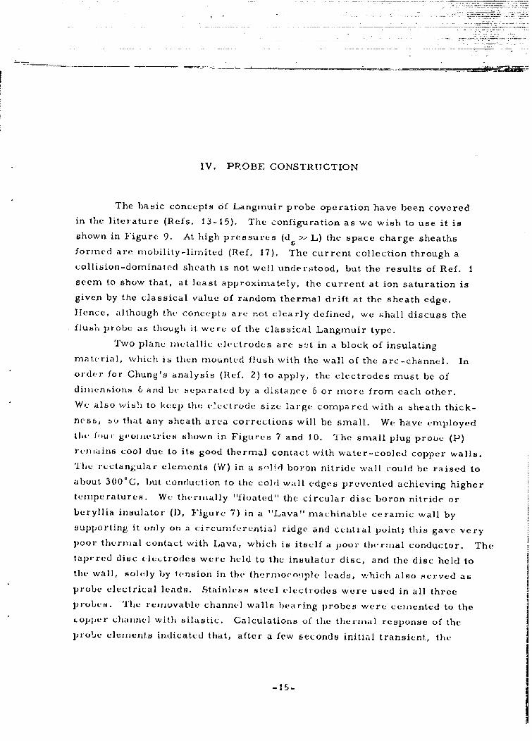
The basic concepts Of Langrnuir probe operation have been covered
in the literature (Refs, 13-15). The configuration as we wish to use it is
shown in Figure 9. At high pressures (ds x> L) the space charge sheaths
formed are rfobility-lilrited (Ref. 17). The current collection through a
collision-dominated sheath is not well understood, but the results of Ref. i
seem to show that, at least approximately, the current at ion saturation is
given by the classical value of random thermal drift at the sheath edge.
llence, although the concepts• are not clearly defined, we shall discuss the
flush probe as though it werte of the classical Langrmuir type.
Two plane metallic electrodes are s!t in a block of insulating
material, which is then mounted flush with the wall of the arc-channel. In
order for Chung's analysis (Ref. 2) to apply, the electrodes must be of
dinmensions 6 and be separated by a distance 6 or more from each other.
Wc also wish to keep the electrode size large compared with a sheath thick-feCss, so that any sheath area corrections will be small. We have employed
thl, four gtosJetries shown in Figures 7 and 10. The small plug probe (P)r•mains cool due to its good thermal contact with water-cooled copper walls.
Thlh rectangular elements (W) in a jolid boron nitride wall could be raised to
about 300 0 C, but conduction to the cold wall edges prevented achieving highertemperatures, We thermally ''floated'' the circular disc boron nitride or
beryllia insulator (1), Figure 7) in a "Lava" machinable ceramic wall by
supporting it only on a circumfecrential rd and central poit; this gave ve.ry
poor therntal contact with Lava, which is itself a poor thermal conductor. The
taperecd disc eletttrodes were held to the insulator disc, and the disc held to
the wall, solely by tension in the thermocorple leads, which also served as
probe electrical leads. Stainless steel electrodes were used in all three
probes. The removable channel walls bearing probes were cemented to thecopper channel with silasti.. Calculations of the thermal response of the
probe elcen.it indicated that, after a few seconds initial transient, the
-15-

U]
0'-4
U]
0
'-4
bO
-16.
I

back face of the solid boron nitride wall achieves a temperature within
10 percent or less of the front face; the stainless discs will track the insu-
lator disc to the same accuracy. The ultimate temperature achieved by the
floating disc probe is limited at about 1400 0 K by radiative equilibrium with
the aerodynamic heat transfer, with a heat flux of order 4 cal/cm 2 -sec at a
flow enthalpy of 3000 Btu/lb.
I
S. ...................... ... .. ... .................. ... ..I
-17-
'" : : ! .. ... ... .. ... ..... . . . i .. . ...i .. . ... .. .. .-- • ... . ... .... . .. ... .. .. .. -- --I •

1012AL NA 2 3 l
(3 M)
1011- BERYLLIA(BeO)(3 M)
1010
LAVA 1136 PYROLYTIC BORONMACHINABLE NITRIDE (PBN)E
08 CERAMIC (UNION CARBIDE)
io7 HOT-PRESSED10, BORON NITRIDE(NOR) (UNION CARBIDE)-
FUSED QUARTZ(ENGLEHARDT)
0 200 400 600 800 1000 1200
T, 6C
Figure I11. Electrical Resistivity vs Temperature forHigh-temperature Insulators
_f8I

V. HIGH TEMPERATURE MATERIALS
The performance of electrostatic probe materials at high temperature
is an important consideration in probe design. Typical probe currents will
be of order 106 amp at 10 v, requiring an insulator resistivity of order 108
ohm-cmr or better if leakage currents are not to contribute large errors.
Resistivity-temperature characteristics of typical candidate insulators are
shown in Figure 11, Thermal conductivity and density, specific heat, and
thermnal diffusion parameter (n Kp CGp)0/2 are shown in Figures 12-14.
Depending upon vehicle and mission requirements, the probe insulator may
be required to match heat shild surface temperature and ablation charac-
teristics, or may be permnitted to remain cool, so that the materials speci-
.fications can be relaxed. For reentry times of 10 sec or less, calculations
(Ref. 16) have shown that the insulation slab may be considered semni-infinite,
and hence the surface temperature of the various materials will scale as
(ITKp C Although beryllia (BeO) is thermally best, its brittleness,p
poor machinability, extreme toxicity, and poor thermal shock resistance
make it unsuitable in general. Loron nitride is the next best choice and is
widely available and easily fabricated. In particular, pyrolytic boron
nitride has been found to closely match the ablation characteristics of carbon
phenolics3 and will thus maintain structural integrity of the heat shield down
to low altitudes. Alumina, the various ceramics, and quartz are thermally
poor and are not easily machinable.
Electrode materials inust retain structural integrity at high tempera-
ture and must not form oxide layers whose electrical resistance can impede
ion collection. Copper and tantalum are thus eliminated; molybdenum is
almost unmachinable. The 300 series stainless steels have performed well
in the present arc tests, and noble metals may also serve.
H. DeBolt, AVCO/MSD, private communication.
-19-

BERYLLIUM METAL
ALSIMAG 754, p 2 .88 9/CC
BORON NITRIDE
P'2.I0 g/cc
ALSIMAG 719, p: 3.56 g/CC
0p p2.2 g/cc
CARBON PHENOL ICCHAR p =1.1 g/cc
___________________VIRGIN p 1.3 7 9/cci
0 200 400 600 800 1000 1200 1400T, C
Figure 12. Thermal Conductivity and Density forHteat Shields and Insulators
-20-
A.

0.9
0,8
0.7
0.6
P 0.5 -CPCA
BORON NITRIDEVIRGIN CP
L A VAT ALUM INA- - - -BRYLLUA
OUART?1
0I
"0 00 400 600 800 1000 1200 1400
T, -C
Figure 1.3. Specific Heat for Heat Shields and Insulators
-21- 1

V 0 BERYLLIUM METAL-
_E
UCbRON NITRIDE
jci.ALUMINAjo-I 0 LAVA
10 FUSED OUARTiCP CHAR
VIRGIN CP
0 200 400 600 800 1000 1200 1400
Figure 14. Therm-al Parameter (TTKPC 1/ for HeatShields and Insulators, Scales Tem pperature inSemi-infinite Slab under Constant Heat Flujx

IiU
Chemical contamination of the probe, changing its leakage resistance
or current collection characteristics, may occur on ablating vehicles. In
order to obtain an estimate of this effect, we have fabricated the probe shown
in Figure 15. A strip of carbon phenolic upstream of the probe is permitted
to ablate ov-r the probe during a run. Thermal calculations ensure that over
a period of 30 sec the sample will have fully charred and begun to recede, so
that the full pyrolysis and ablation history is simulated, as confirmed by
post-test inspection.
-23-
MUM

-LI__ __ - - -1
II4
I
I*1 I
II
0
__ I___
I-.
�ic00I'i �-.
0
I
II..
4-. -�ri.
0)
4.
cJ�
It.
Ii
II
�-3.1� iii
i�1

Since' the are -channel faril' ty iu f i'-itdy ntate, an(] wall tcinpurature
,a )ihtiUZIiL during tUemi ljAuVC a per .d ii-iny~ brit-or-.db, dc. iutt iirientation
waif uried for the fiunt pa~rt, The upurftlinf C)IILUit it4 u n in ig u.rec 16.
Either caiibratud microamrncturs or a i&tiipchiart recoxlcr were uaed for
muncureniczit of prubu current and 0li-M-10CLouple voltage. The V-I charac-
tenibticri of the probc were plottr,) ;;iqwi~i: by stwitchling~ voltage ati recorder
polarity. Qilerpi recording introduced beriuuB noijac and ground iools
probluinu fuumin the- &rL, and inevitable hl~h1 frcqu'nurey & rt tltvctuatio-pift Made
accurate data interpretation difficult. Rapid riwueeiny, of the prubc anddvtteri'in~ation of ulectrun temperature were not asuccussfuhl. '1111u, cofifli rlcd
carlruer work in arc -jct flown (ltdf. 6) tha~t I,,)aWted thatI time- -dvupendert Lon-
tt~iiinatIO11 Uffe'CtV pre'UVC1t 111UalAsingful uQ I CIO UdUc~ible VIC( tromn culleetlor. at
Iligh CU rreniltO Unle'UiH Vpecial WO!"irritlea o(irot 111-011C LIA ik d hIt alit Voltiou'
uweejsinkg arv reeipo ,Which LOUId nutI bet dvnze in the pi-Lunit wurk. burfuace
rvoistarice andl volt- ge- dru-p nre nt-ghligi),1 in thc ion Fiatu ration, reginiu oifLcC
(;u rrunt dunuity iri low, but it b)C-cOni 11 a he ri"UN prublc -u tit hillil eeC~tron
cur runtis In addition, rdnecv the pjrobe in upo-rating iii m highl y nurlu'mifo rill
boundary layer, tilt- isheathi PoUFutiolr, Idlocial thu ti , ~ibath edrpr. and collectedu
currunt dciiriity will 4ll Chanrmge Witi Wiait voltage anmd will rvilect the flow pro-
file ani well amn thec' leýt run tvinmpe-rature . l'WVl lowev r ,thlpobU Ilo6ttng 1101Cza-
tial (V1 whun I .-- 0) Canl be dutce r01mnilnd by hwuellmng," and wC mount decte rinileit to emiriurc that negative bliat voitiag0 ~'u -are uf11fie et to reach thU 1:1r, batUra-
tion, regizlir dchire4d,
ModV hWitcLaInlg pe rlaujtn up 1 40n ktulo time p uobf ilk threc UcLe t ric.1d
conrigur ai oiu ), i uittilke dloublel 0(Pm beit " R j, blnIt e]';1' xzt pm obu (othur
elerrrzilt groundcd to c-opper. Cl1~,11rm1..lwt of- 's, ou~ Oeticirodub nI,ortVd
tL 1; vtile ,~ if)rfu I. I j I sg a prI ,1obe 0 f I Wi, v 0 1- a r 1, (t u t, 1,;k oil pgr CP I vtry YAnd
mhuath aUC4 ,vr rvc1tJluit with voltage agninir rftertencd to 0-ixmmunl w Ih~)

iA M'T
RIDp
Fiuc1.EYtia cir .uitu o~ iu !ill11uj
TAPPED ELCROE
S ...- D • •, AT TERY 11
i ii
Sl'iIlut-c 16. Ela].-tricji] CirIcuit.M lo, 1"luuli )'rubv i
'1 tutu Ii_ ArL -Lthgu,Jl -
I

V11. FLUSH PROBE THEORY OF OPERATION
Twu different theoretical models of flush probe operation in a boundary
layer art: considered. In ion saturation, :Bredfeldt et al. at Stanford Research
Institute (SRI) (Ref. 1) suggest a model of the collison-dominated sheath on a
planar probe and assume that all the random thermal drift current of ions at
this sheath edge is collected by the probe. The B. L. fluid dynamics is a
separate input, and serves only to establish the n profile so that n at the
sheath edge can he calculated. Chung and Biankenship (Ref. 2) have simplified
Chung's earlier analyses (ReIn. 17 and 18) fox the case of ion saturation
operation under condit;one where the sheath is very thin compared to the
fluid boundary layer. When hypersonic approximations are used, the current
collected by the probe is dependent only on the fluid dynamics; the probe
serves only to establish boundary conditions for n . Both theories have fail-
ings. In the came of the SRI theory, the fluid dynamic velocity and electron
density profiles must be known in detail, which is unhandy for flight test
analysis. Chung's case depends only on the peak ne and on good engineering
aprifiximat~ons for the boundary layer structure and electrical behavior.
HIowever, no dependence of current on probe bias is predicted. Both theories
r'quire a!s-'ixptiun of thk: ion Schmidt numnber or mobility, which in hut at
all clearly established for a highly nonuniform boundary layer.
The details of the 1RI theory for both cylindrical and planar probes
arc gummarized in Rcfs. 1, 19, and 20, We restrict our discussion to bias
VOult1'g.i sufficiently negative that the probe draws ion saturation current J.
Thbe mobility-cont rolled sheat, thickneus d on a planar electrode is given
by,
n h I ion drift saturation current per
unit she-ath area at shieath edge
9% WV 2
-0 3 mobility-limited sheath (Ref. 15) (2)86
-27-

141
00 .1/ II
/141
ILI I -iC I CD
I- ~is 1-
w 0 0
/28

where nsis electron (= ion) density at the sheath edge, Vth is ion thermalIvelocity, e the electron charge (singly charged ions assumed), •othe per-
mittivity of free space, K. the ion mobility, and V the probe potential with
respect to the plasma. The ion mobility is given by (Ref. 21)
K. e e (31i = m Qm n v3)h
S1~i m gVt
where n is neutral gas number density. m. is ion mass, and Qmand Vm
the momentum transfer cross section and collision frequency. In reality,
• the mobility will vary through the sheath as a function of field strength,
I density, and tempeiature. However, the 1/3 power dependence of ds on K.i
permits the approximation of constant K.. We assume (Ref. 1) that all ions
in air are NO and m= i."3 X 10" cm2 , "n = 5.01X xI0-23 g. We also
note that
1/2[8kTl 4
Vth =[F-TWJ(4
where we assume T = T. =T at the boundary layer peak temperature andg i e 1
kis Boltzmann's consta~nt, 1.38 X 10⁻⁶ erg/°K. Then the sheath thickness
is given by
s .nv r+ 5kT/e] J
where the term 5kT/e represents the Langmuir (floating) potential. We shall
always operate in ion saturation where Vb»> 5kT/ec. Sheath thickness as a B
function of ne and Vb is plotted in Figure 17. (Note that since n p/T, dg8
is independent of T at constant p and is also independent of ion mass if Eqs.
(1) and (4) are used for J.) When the sheath thickness is an appreciable
-29-

,A-4
fraction of the probe dimension, corrections for sheath edge area must be
made to A; simply multiplying the perimeter by d is equivalent to the SRI5
use of a 60-deg segment of the cylindrical edge. Convection of ions into the ]upstream edge of the probe sheath is non-negligible at hypersonic velocities,
but can be ignored in the subsonic channel flow. The correctness of Eq. (1) ]for a collision-dominated sheath and the true effects of combined convection
and diffusion as a function of sheath thickness and probe size are not satis-
factorily established at present. On the basis of results taken from Re,. -
and presented in Figures 18 and 19, the correlation between cylindrical wire -A
probes and flush probes in probing the boundary layer n profile is excellent.
And, on the basis of comparisons with microwave measurement, the flush
probe theory with semiempirical corrections (Ref. 1) seems good to a
factor of 2 to 4 in determining absolute electron density. Since the boundary
layer profile in the SRI shock tube experiments duplicates qualitative,/ the
temperature at peak ne, the thickness 6, and hence the ion transport prop-
erties appropriate to conical vehicle reentry, the theory appears to be
i adeqtately tested and proven within the limits inherent in the assumptions
and the experiment. The assumptions of chemical freezing and thin sheath
limit the applications to 1012> ne > 109. In practical use, the measured
probe current I and the geometric area A are used to find J. If T and vthS t
are known from the assumed B. L. structure, Eq. (1) yields n., whence,
using -b, Eq. (5) yields d . Small corrections for sheath edge area ands
convection (assuming the u profile is known) are then made to yield final
values of n. at d
Chung's analysis (Ref. 2) requires several basic assumptions. The
sheath must be much thinner than the shear layer; this requires
10 kT -A A= 6. 9 )(6)
-30-
-- _ _ _ _ _ -- 1

' !I
,45V THEORY
/ 15V CYLINDRICAL
C
-1"'-- FLUSH PROBES
0.1 10 1 2 3S~Y, mm
Figure 18. Comparison of TheoreticalElectron Density Profile in a Shock
Tube Flat Plate Boundary Layerwith Cylindrical and Flush
Electrostatic ProbeMeasurements
-31- I

4m)
cIle
CD0
cc C)
0 LJ o
LiJ
0>
Figure 19. Comparison of Predicted and Measured Ion Currents in
a Shock Tube Flat Plate Boundary Layer using Flush Probes
-32-

where neo is the peak electron density in the boundary layer, T 6 is the
freestream temperature at y 6, the boundary layer edge, Ais the Debye
length, andYO
f f P/Pp0 dy (7)0
is essentially a boundary layer displacemrent thickness. Subscript o refers
to the temperature (or ne) peak, and 6 to the outer edge, of the boundary
layer. It is assumed that phenomena are essentially contr,'lled by the highly
conductive layer about yo0 TO, neo. The similarity parameter 11 is given by
[ = i p63 6 xI f p dy (8)
where u is fl(cw velocity, p and [L are density and viscosity, and I is the
Chapman-Rubesin parameter (pw11 /Poýo02.
The ion Schmidt number Sc. k= j/pD. is not specified. From simple
kinetic theory, ýt = 1/2 pLvth, D = 1/3 L vth, and Sc = 3/Z if ions diffise like
molecules. Chung (Ref. 22) has recently correlated his results of Refs. 17
and 18 to show explicitly the effect of varying Sc.. Comparison with Hoppman's
results (Ref. 23) for the parallel plate probe geometry of Ref. 18 shows a bet
fit to theory with Sci = 1.3. For the present experiments Sc.1 = i has been
assumed and provides adequate fit to the data. Experimental values of ion
diffusion or mobility coefficients in air vary widely. Cobine (Ref. 15) suggestsvalues of D. of order 0.028 c 2/sec at NTP. Frohn and DeBoer (Ref. 24)
-4 2 +suggest mobility of Kp = 2X io cm- torr/v sec for freshly formed NO ions
in air at 3000OK with ambipolar diffusion. If we assume the Einstein relation
Dp/Kp = kT/e, then D. 5 X 10³ at 10-3 standard density. Since gi 1 10-3 at
peak boundary layer temperature, this yields Sc. ~ 0. 1 if T = 3000°K, but
values perhaps an order of magnitude larger at 300 0 K. The ion temperature
is assumed to be in equilibrium with the neutrals throughout the boundary
-33- 1
I•

layer. The clear definition of Sc. deserves further study for nonuniform
flows.
The ion saturation current collected is then given by
JisScipopneo = 2. 68 1jO (9)
0
where jis is particle flux of ions/cm sec. Chung (Ref. 2) further extends
this result to the highly cooled boundary layer on cones, where
Jro(Re/I) PO t' 6 Sc. (1. 9 X 10⁸neo=p6oU(I0
where nCo is e/crno, J is in a 1 2p/eri, and Re p' 6 u 6 x/ý 6 . For highly cooled
cones, Eq. (19) and Figure 3 of Ref. 2 show that o 0z I . 1.
Several further assumptions are made when these formulae are used in
data reduction. For the arc-channel, Eq. (9) is used with, = 0. 845, as cal-
culated from Figure 10. Values of ja were taken from Baulknight (Ref. 25).
We measure T and p for each arc run and assume that T =1. 5 T and that
p = pRT for simplicity. The parameter I is of order 1. 12, and, as discussed
earlier, we arbitrarily set Sc. 1 ., Then1 5
n (cm - 1.. 0 t t2#J J(amp/cm2 ) (12)eo 0o(poise) T 0
For flight estimates, Eq. (10) is used directly, and the boundary layer
structure is as specified in Figures 4, 5, and 6, with 1o n 1. 1.
Chung (Refs. 1, 17, and 18) has considered the limitations of this
theory and finds that for the requirem-ents of frozen recombination and
A > to3 we must have 10 < ne < 10 1 for reasonable temperatures and
-34-

- - -. - -=
pressures achieved in laboratory or flight. In the shock tube, Bredfeldt12et al. (Ref. 1) found reconmbination to be serious for n > 101. Calculations
3 10of A show tihat A< 10 for n 10 , so it appears that in flight the most
serious limitation is in the thickening of the sheath at low n. For the ar.--- 4 1 1 13channrl tests, A -• 10 and 10 < n . 10 , so that the theory should apply.
Wc .'-so assume implicitly throughout that ion and electron temperatures are
equal to neutral tempperature at the channel centerline, but that T remainsC
frozen at the centerline value throughout the flow.
-35-

160 T T F FT
* -- MODE140- KEY No cm-3 (GEOMETRY, A, cm2
CIRCUIT)
-~ ~ ~ 2.2 X10" R 19120 PR 0.58
~ 38 XO" PD 0.58~ooWD 1.9"
A~ 4X10" DD 0.90x PD 0.50
s0o
*60 SINGLE PROBES -
~40
20
-20-
-40
-801,I I L 1 1 r-40 -30 -20 -10 0 10 20 30 40
Figure 20. Current -Voltage Characterifitics of ThreeProbe Configuration
-36-

A. GENE1'RAL OPERATION
The program of runs was designed to establisih the effects of varying
the following paramneters; probe geomnetry (plug, wall, or disc); probe m-ode
(single probes with refere2nce electrode grounded, or both electrodes shorte-d
together, or floating double probe);, insulator mnaterial; surface temperature;
carbon phenolic ablation; and ambient n Vand to establish, the correlation
lbetween the microwave measurement of n and the probe collected J. ,-t 1 sat
through the Chung arid SRI models. Over 50 runs were, taken, covering a
range of n Cf rom- Zx 1 01 to 3 X 10 with various probes singly and in
combination. Only a portion of the data is presecnted to illustrate thle major
conclusions drawn,
Figure 20 presents severa] V--1 characteristicsj at the lower electron
densities, It was found that for a single- probe the floating potential (i. e.
Vbwhn I r.0) is -15 ± 2 a t ni 4 X 10 and -5 ± at ne 3 X 10 No
attempt was made to interpret electron currents for reasons discussed
earlier, Thle floating doublAe probe shows an tLppropriately symmeittric
characteristic. By comparing ion saturation current for the three probe
conf igu rations. we re;ached the. follow irg conclusions:
1. J at V1 -45 is independent of the choice of probe geometryor circuitry, varying less than ±15 percent for the three configura-tions tested.
2. There is no interaction of two probes, e. g. , the plug and walltypes, when they are placed directly opposite each other,Although the electron sheaths on the negative electrodes are asthick as the channel, their interaction does not affect probe-performance.
3. Corrections for convection and -;heath area made according tothe SRI theory require a reduction in JTbsdo eoercaeof the probe) of no miore titan 30 percent.
S --
s _2__I
77--...._

j - - __---------- _
3 X 10120.03
A~ 4 X 10
2 X 10101 0.012
0.01-
0
00
00.05 0.10 0.0ds, cm
Figure 21. Ion Dý,ns~zv Profilcpn in Arrame frornreji~ualPro'be Mcasurenient5

Recent experimental and theoretical studies 5 of the effects of samp-
ling the boundary layer profile by varying probe voltage have shown that the
current denuity is a function of probe length in the flow direction. Since all
of our configurations have comparable streamwise size and since the
electrodea are electrically independent, being separated by several sheath
thicknesses, thebe effects were not observed.
For data reduction with the SRI model, it was initially assumed that
T = 3000°K and vth = 1.45 X 10S cm/sec. Then Eq. (1) yields ns at the sheath
edge and Eq. (5) and Figure 19 provide the sheath thickness d (which variesS
with Vb as we sweep through the probe characteristic). Tho.se values are
plotted in Figure 21, normalized to the peak ne, for several runs. Several
-conclusions are immediately apparent;
1. The measured n profiles fall far below the assumed profileobtained by extrapoiating the 3-point rake measurement to thewall (cf. Figure 8).
2. The curvature reversal between high n , high pressure and lowlow pressure cases is very clear and reproducible. Although
no detailed theoretical model is available, these observationsare consistent with a strong depletion of nae near the wall bydiffusion Pnd surface recombination. The discrepancy is faroutside any possible error in the approximate data reductionmethod used; detailed iteration on na , d , '.Z and v 5 profilescoes not appreciably change the resultant measured ne profile.Thus it appears that we cannot employ this experiment to verifythe SRI theory, since we apparently do not know the profile nearthe wall a priori. The SRI calibrations of Figures 18 and 19serve to establish the validity of their approach.
Table I summarizes all runs for which microwave data are available.
Results of data reduction based on the Chung theory [Eq. (If)] and SRI model,
with approximate sheath area and convection corrections, are shown. Thesedata are plotted on the basis of Chung's theory in Figure 22. where neC pre=
dicted from Eq. (11) is compa red to the microwave measurement. The
microwave measurement is accurate to about ±30 percent. Although Chung's E
theory does not explicitly consider any detailed mechanism of current
4It. Keil, Bell Telephone Laboratories, private communication.
W. Schaifrnan, Sta'tford Research Inst.tute, private communication.
_ - • = _ _ . . . .
I .|--.

Table 1. Comparison of Microwave Measurements of ne with FlushProbe Results Using Chung and SRI Theories
(V b =-45, ion saturation)
Data ResultsMode!
Vb45 non(Cliung) n(SRI)Run (ae Microwave, A, J, T Eq. (9). Eq. (1), ds.-3 2 2 3 -Fig. 1811 cm cmn A/cm* torr 1( cm -3 cm 3 cmn
X1011t 10-5 It1 xo7-22-z WR 4.02 1.93 5.09 30 4150 3.58 8.8 0.09PR 0.58 5.18s 3.64 8. 95 0,09
-3 WR 3.90 1.93 3.74 30 4150 2.63 6.47 0.097,4 WD 4.02 1.93 6.21 30 4150 4. 36 10.7 0. 082PD 0.58 6.41 4.51 11. 1 0. 081-5 WD 4.02 1.93 6.21 30 4150 4.36 10. 7 0.082-6 WS 3.78 3. 86 3.63 30 4150 2.55 6.29 0. 098PS 1.16 3.70 2.60 64 0.099
7-25_1 WR 4.3 1. 93 5.7 30 4150 4.0 I9.86 0. 085PR 6.7 0.58 6.7 4. 71 t I1. 6 0.081WD 1.93 7.0 4.92 12. 1 0,079PD 0. 58 5. 2 3.66 8.95 0.088-2 WR 3. 06 1.93 4. 5 30 4150 3. 16 7. 35 0. 093
-3 W .6 19 .1 3 10 43PR 0.58 4.5 3. 16 7.76 0.092
PD 0.58 6.55 4.61-8-9-1 WD 8. 3 1. 93 8.0o 28 4150 5. 63 13.8 0.076PD 0.58 6.9 4. 85 11.9 0.079
-2 WD 1.1.3 60 30 j4800 33. 2 1 0.2 0. 037?.Z9 WR 2.2 0.58 5.19g 16 3500 3. 0 8.96 0. 114
0t Ws 1.68 3.86 3.3 16 3500 2. 1 6.2z8 0. 104PS 1.1t6 372. 19 6. 56 0. 1038-9-3 WD 3. 1 1.93 72. 5 40 5600 41.6 125 0.6367-25-5 WR 2.0Z 1.93 2.48 41 3000 4.01-
-6 I) 2.42 1. 93 2.70 41 3000 4.40 4. 67 0.10o
81-4 30 5. 0.80 52 3 0 5600 30. 91. 0. 042
8-26-1. 13eWR 30 1. 93 53 40 5600 30 91 0. 04
-40.-

7 12I-O >$ .~+.U ERROR IN
040 MICROWAVE0 MEASUREMENT
-MAXIMUM CONVECTIONCORRECTION USING f
R.[%.I. MODELL
ION! 1012 1013
n0 MICROWAVE, cm30IFigure 22. Arc-channel Electron Density Usingo ChungI Theory _
Compared to Microwave Measurement 00
_ _ _ -- 41-j

C5
CDj
-T'-4
q~x L.Li Cou- L
ojL- L
cr -A

collection, the magnitude of correction to J, and hence to neo, for convection
sheath area effects in the SRI model is shown. All of the data fall within a
factor 2 of the microwave measurement, with a mean deviation of *25 per-
cent. It is concluded that, within the accuracy of the experiment, Chung's
theory will accurately predict peak neo, with Sci = 1, and that this theory can
be reliably used for the evaluation of flight measurements within the range of
validity as discussed earlier.
B. HIGH TEMPERATURE EFFECTS
The foregoing measurements and conclusions are valid up to surface
temperatures of about 800'C with stainless steel electrodes in a boron nitrideinsulation. With the solid boron nitride channel wall, we were never able to 3exceed 320'C. With the thermally floating disc probe, however, we achieved
temperatures up to 1020'C, and it is in the region above 800'G that anomalous
probe behavior is observed.
A typical run made with the disc probe is plotted in Figure 23. The
surface temperature of the stainless steel electrode was indicated by the
embedded Cr-Al thermocouple. Since the test duration was about 80 sec,
with a steady T rise of 10'/sec up to 1000°C, good thermal equilibration of
the probe elements was predicted from heat transfer calculations. The max-imum temperature achieved in runs of 2-rain duration at n-taxjuinmnL channel •
enthalpy was 1l00'C.
The collected probe current was observed to rise steeply above 800'C
and to decay over a period of several seconds after the arc shut off. Four
repeated runs were made, and the curve was found to be quite reproducible
within the errors of temperature - current synchronization. (Tempperature
and current could not be recorded simultaneously in floating double probe
mode since the thermocouple leads served both purposes; hence, the dati
scatter and synchronization problem were due to switching transients in the
recorder and the rapid time rate of current change toward the high tempera-
ture end of a run.) One thermocouple was fed to a calibrated microarnmrreter
-43-
|b=

1800 I IIIII
1600 0
1400o ERROR CURRENT A I =z I (T)-1 (300" K) :
!200 ~IN HOT FLOW ••
1200 MEASURED LEAKAGE CURRENT AFTERR
< 1000-
<3800
600 0
0 0
400 00"
2000001
Oooi
500 600 700 800 900 1000 1100 1200 1300 1400
T, 6C
Figure 24. Probe Error Current as a Function of WallTemperature, Disc Probe
-44-

S.. ....7" * . . . ... -.. ... ... - -7.. . --• ' r.= = ; r =2 t- - f l S "- " -a .. f W ' •-•: ••i - ..
reading directly in temperature; the other, used for data reduction, was fed
to the stripchart recorder. The two thermnocouples always agreed within
50'C.
The plug probe was monitored continuously throughout these runs and
maintained a constant current. Hence the high-temperature probe current
changes do not reflect any variation in the channel flow. The "error current"
AI = I(T) - 1(300°) for four runs is plotted as a function of temperature in
Figure 24. Note particularly that the solid points, representing error
current decay after arc shutoff, fail among those obtained during hot flow.
All were obtained with double probe at -65 volts bias.
Three possible causes of the error current at high temperature are
postulated:
1. ohmic leakage in the high temperature insulator
2. thermionic emnission from hot cathode, giving apparent ioncurrent increase
3. modification of the boundary layer profile toward higher ndue to high wall. temperature, i. e. , temperature jumpeffect at the wall
We dispose of 3 imiriediately, since the error current is present with
or without flow. (Temperature jump is discussed further in the final section.)
Thermionic emission is not so easily discarded. Error current data oi 6
Figure 24 are plotted in Figure 25 to yield the effective work function.
Assuming the current to be emission-limited (Ref. 15), (i. e., a high-vacuum
diode), r
J 60 T 2 -ikT (12)
whlence
dn (13)T(l 7f)
-45-

104
J: AT me - /kt T
n]-2
d(T) - -) T
OK - 1.77 X 10⁴ OK
#:1.52 eV
i03 - IFAm60, T-I000" K
JTHEORY = 1.23 A/cm2
JEXPT z3 X 1O-3 A/cm2
'-4 0
<1
7 89 10 I 12 13(1/T}: I0o4 oKiu
Figure 25. Determination of Effective Work Functionfor Thermionic Emission as Possible Error
Current Source, Disc Probe
-- ---- ---

_~_4a
A value of 0 1 j. 52 e- is obtained, an impossibly low work function, Even
thoriated and oxide cathodes niave work functions of 2 to 3 ev, and oxidized
steels are expected to lie ini the 3 to 4 cv range. However, this determina-
tion and the use of Eq. (1Z) are in question, since the actual current at
several lorr pressure will be diminished by space chaige and mobility effects,
but such modification can only result in rcqquiring an even lower work function
to explain the observed slope. If the error current is due to thermionic
Setni!ision, then it will incr('ase the apparent ion curxrut: thel conduction a
process must again be that of a mobility-limited diode between the two
electrodes. In this case only the electron mobility is of concern. if we
assune K = 1000 at I atn, V -45, x I cm, and v 30 torr, thbn Ie Sec volt(Ref. 15)
j9.95X i0 4 -1 -6 2
=5 1• = 5SN 10 C.ijcIn (14)
X9
The actual leakage currents are of order 0. 5 to 2 X i) amp /cnW' at a sur-
face temperature of 1000"G, Hence, altihoug, tht waork junction and pre-
dicted currents are both unrca.sca.nbly sinall, wet cannot e'ntirely clitllina.t;
ther~nionic enmission as a partial exp.lanation of the probt, error cur rent,
Chung'o analysi Z j.s v.iodified 1y ciissio., in. ý .hat he boundary conditi.on-
u 0 al the wa'l m•st be changed. lieweve , unme s the cintision rate is
so large that n in > 0. i, no sigmuic- nt -hange in -robe performances ' edc ed t-wall p. ak renroracVisprý:dicied,6
Ohmic lvakage through the Insulator is the rerai ning, and1 most likely,
possibility. If ve consider the,- electrostatic analogy between capacitance
a,vl t resistivity of t.o ,ircular condr ctors in semi i -irfirlit 171fhductn (Ref. 26),
then, for 0. 4-in. -diam discs on 0. 700-in. centers in a 0. 1 -in, -thick slab
-1-. M. Chung. privatet: •.oa.unicatioi-.,I S
-4-1 -

MANUFACTURER'S SPECIFICATIONSFOR HBR GRADE HOT-PRESSED
BORON NITRIDE
E10 5
104 N0t-
S104 0 0l}•
500 600 700 800 900 1000 1100
To"C
I ' I~ o r v L ' i ct v ift u t t r I u l ti i y I (- - v
1h0o I vdJ'd-4. !t" ni jill' vv 1 ]tDitc i'rubu
-'28-.

of boron nitride, we can evaluate the conductivity G from (see Figure 26)
t n (c / a)')I
where R - AI/V,
The resistivity p = l/o, derived from the experimental error cur-ents and
Eq. (15), is plotted in Figure 26 and compared with the manufacturer's
specifications for IEBR grade boron nitride. There seems little doubt that
tha leakage is almost entirely ohmic in origin. In order to check this hypo-
thesis, we took further runs in which V was rapidly switched between 45 and
15 v as T increased. One would expect the error currents to bear the ratio
3:1 at a given a(T). The results, however, showed a ratio aI(45)/AI(15) of
about 1.5 at 800-900'C, rising to Z.0 at 1000-11 00'G. Other effects may
thus be contributing to the leakage current, but certainly, in an order of
imagnit,,de_ sense, the resistivity of the insulator limits probe operation to
"I < 800'C tor hot-pt essed boron nitride. iFor the ge'ometry chosen, with
electrode dimensions and separation of the order of 1 cmr, a resistivity of
p ý 106 olhni-cri scums the lower limit for error-free operation of the disc
probe geometry. Recent data on pyrolytic boron nitride (PBN) in the direction F.parasIll to the h iubs trat,-' rho;-,s rcsiLtivity about ,.qual i n iht cf blerylhia.
Then a PBN insulator at n > 10 should be operable up to 1100%2 without
appreciable Jeakage.
One run was taken in which a 13cO insulator was used. This Be0 run
is the last entry in) 'Table I and is shown on Figure 23, It had 0. 3 X 1-in.
ejictrodus with the long dimiension parallel to the flow and agreeUd perfectly
with disc re.sults below 600'U, Serious leakage current developed at 600°G
and mechanical failurc occurred at 1000"W, presumiably due to thermal
stresfses. It is likely that the tiariple of 13co was not of optimuni purity,
sinlce noticeable change.sH in color and grain structurc were villible in the
litcce used, 'Ilie poor theritial shock resistlance and difficult machining
qualitics of lieU elitriirate it ivoili further consideration, since Pl1N is
-...... = =- :--:- 1•- *
electrically superior. In addition, the excellent match of PBN to the thcrznal,
Smecharnical, and ablative properties of carbon phenolics makes it very
attractive for composite high-temperature structures.The effects of ablation contamnination on probe performance were
istudied in two runs in whicl OP was permitted to ablate over a disc probe
. ! (Figure 15). The chacacteristics obtained duplicated those of the "clean"
run of Figure 25, indic,;ting that carbon phenolic pyrolysis and recession
will not affect probes in flight. The CP sample shown in Figure 15 was
thoroughiy charred and showed a recession of 1/32 in. after the run up to
1000°C wall temperature.
* I5-
S--.-.~ *--

1Aprob ?ZZIX. PREDICTED F;7Yd:1;;2R:1;4RMANLCY
Com plete performance curves for the flight performlance of a flush
probe will now be derived with the Chung and SRI models and the boundary
layer structure of Figures 1-5. We assume a double probe biased at 45 v, 3with electrode dimensions 1 X 3 cm, separated by t cm, wirTn long dimension
paral'le to the flow to mininmuý,c convection corrections. The insulator is
PBN of 1 cm thickness. We assume that the insulator behaves like a serili-
infinite solid and achieves a surface temperature given by the dotted curve (A
on Figure 2, scaled down from CP by the ratio of ("Kp C )/ We consider•E.
two vehicles at 23 kft/sec, sharp 8-deg cones, one of Be and one of CP.
The boundary layer paramneters are listed in Table 2. From these,
using Eqs. (9) and (10), we calculated the Chung prediction of ion saturation
current, which is shown in Tables 3 and 4. For Eq. (I1C), we note that1 -4
P6 •0 5.8 and p. 06 / -3, where 4 6 = 3.6X 10-t poise at 800°K, u 6 =
6.6 x 105 cm/sec, x = 300 cm, and Sci = I = 1Io = !. The parameter Ais noted, and the theory may be considered valid only for A > 103 [see Eq.(6)]. The results from Eqs. (9) and (10) differ by a factor 2, perhaps reflect-
ing error in the assumptions used in deriving Eq. (10) fromn (9).
The SRI model results are also shown in Tables 3 and 4. We find the
conivection correction by assuming that the velocity and electron density pro-
files are given by
\ / from peak n
2 Y_ )(YO 0to wall
n n from sheath
d s edge to wall
-51- --

Iable 2. Boundary Layer P'araneters used fur FlightPerformance Estimatesa
f u S i~cCI%h, 6 T o p,• oOqIp eC ',•
a P. pi 3kft c"K tOk r n x I -3 C111 ~ tiV"F •1•,3,:,
00 3. 25 5000 3.1 0. 16 . 35 6. 25 t0o 2. 8 x to 0.4
175 2. I 4800 7, I 0. 12 0. 80 6.0 7 X tO5 o X 108 0. 3
7 to150 1.35 4680 15.5 0.085 1.6 5.85 2Zx 10 zX 10 0,Z7,
IZ5 0.8 4550 43.5 0,055 4.5 5. 7 1.2x 109 x 10 101 0,2
115 0.635 4450 68 0.045 7.9 5.55 7.SX 10 3.SX 1012 0.175
00 0300 133 0,034 16 5.4 8x 10¹⁰ 1x It) U. I1
8 deg half-angle, sharp croc
U = 2 1, 6 kit/s
"1 6 800'K
S300 , i -
-4!
3.6X to- p4.i-e at 800B -IU " 1. 1 x 10t 3 poise at 4450'K
Profiles from Figures 4 and 5. Ref. 4; peak electron density from-Ij Figure 1.
Ai A

IQ01oq II: uZ.
0 N0
r -~ -
u ) a
0 N E
2C> -n
o *-r E ~C
II IN-5
-

Ir C r
x
0r 1
0~ o In
U
CN

I
and that the convected electron current from wall to sheath edge is
r2I W= Wf flu dy = Wen y (16)
For cases where the sheath approaches the boundary layer thickness
(given equivalently by A - 100, no- 10 dq - y ), an approximate model of
current collection is devised, assumning total collection of the convective
flux over the probe. For the probe geometry assurned and Vb = 45, the mean
local field is -15 v/crn and fills the boundary layer to a distance W on either
side of the ion collector, The ion drift velocity is given by
KVb 5V d i ft YE -w - 3 X 105 cm/sec
if D-Boer's value is used for K (Ref. 29). Diffusion velocity will be of
order
D dn D
where we assume the collector removes all ions over a dimension of order
W. Then
Vdiff D0. 02
vdrift b
(If we assume D/K = kT/e and T = 3500°K, then D/K 0. 3, whence the
result above.) Then, if the electrodes are at least twice as long as they are
-55-

0 TOTAL COLLECTION, EQ. I7U CHUNG, EQ- 5V EQ. 9 + EQ. 16 CONVECTION
10-2 6 S.R.I. MODEL, EQS. I, 16/A > 300, CHUNG /ESrIMATED PERFORMANCE
PROBE GEOMETRY /
10-3 Em_ / /
CARBON PHENOLIC /10-4 /v -
./ /v-
/0-5 0
/ /
0-6 ( / "-BERYLLIUM/ / L
13 A10-8 1 1 1 1 L-
220 200 180 160 140 120 100h, kft I
Figure 27. Flighl Pcrformance of I X 3 cm DoubleFlush Probe oil CP and Be Vehicles
. 1!
'4i

wide, all ions in a widthi 3 W ,kill be SXX epi out, and no 1o10ru U1 ii tenCr Ij
difiusion. 'Then
1 6 3 W637-e (1?)tot coil 2
using average n and u over the boundary layer. 'ibis very crude estimate
serves to extend the current collection prediction of Tables Ill and IV up to
200 kft, at least in an order-of-magnitude sensc,
These calculations are sunimarized in Figure 27, where the Chung
I Eq. (9)] and SRI results and the total collection results (assumed correct
when A > 300) are plotted vs altitude. Insulator leakage currents in PEN
at presumed surface temperatures (Figure 2) are negligible compared to the
ion currents. The expected overall flight performance is sho\kn by the
dotted lines. Ohung's theory in the form of Eq. (9) is usted, since it e'mploys
the boundary layer structure more directly. The almost exact agreement of
the SRI and Chung models for CP cones is surprising but very encouraging,
since they have been independently verified over the range of ne expected in
flight by Ref. I and this work, respectively. From 180 kft doxvn to transi-
tion on blunt or "dii--ty vehicles, wc may thus expect to make good sense out
of nOo deterniinations from flight measurement of ion saturation current,
using either theory. The convection corrections are negligible for the thin
sheaths of contaminated CP vehicles. Clean air (Bc heat shield) rtsults are
discouraging, however; only below 125 to 115 kft is tither theory valid, and
even then they disagree by a factor 2 or iuore. Since the SRI theory c:an
explicitly handle a moderatclv thick sheath, it i5 presumed more correct
than the Chung model for the beryllium vehicle case although both are on-
very shaky ground. Considerable hand-waving in the spirit of Eq. (17) seemlS
the only data interpretation schemre currently available for clean air flights.10
Good laboratory simulation and calibration for n < O0 appear urgently
required. The SRI shock tube resultb shown in Figure 19 do extend to 10",
'-57-A

but the empirical convection correction swamps tht. drift current at these
levels, and an effective 'total. collection" maxodel results,
Even with the apparently excellent prediction for success on C1) ,eli' , _ :
azcuracy no better than a factor 2 should be expected, Possible ynt-Armat,
crrors in the laboratory calibrations that have been dnn. and, nhore imnri art,
the unknown factors that appear in the theory (such an Sci) do not pe:rit any
rehlistic confidence levwd clojer than this.
The effects of temperature jumip, where insulator and heat bhild ,imert,
have caused some concern in probe interpretation. If we cunsider thal, OIe
diffusion of vorticity (i. c. , boundary layer growth), heat, and molecular orionic (ambipolar) species proceed at about the name rate when Sc 5 Pr bc I,
then the characteristic length for readjustment of the boundary layer profilc
or thickness to a temperature jmrip at x is itself x. Then, if we place the
probe at position x >,, and litmit its dimnensions to a few ht, L. 0i11%lu Lb , /eany temperature jump nhould Lave no elcct or, the profiles in 'h( viinity of "
the probe. In ai analytical btudy of the alla1J.ogugunj prlt) •n) oV (Jiu inu1uS
surface catalycity in a reacting boundary l,,ytr, Chung' found tIt ti.e bouuid'lu " yI=layer remains unaffected for many 6 dvwnuntri am of the surface diseoUtimiuity,
A.I.I
"TP. M. Churig p~ivate couri nmrica tioi.
-58-
____ '

X. CONCLLiJ1ONS
njiti 'de i'itiuilturin have becui Shjowit *u upt-rate iiuccctti~uliy inl Ti ,Atiuiated
ialg~i tenipi i',turQ r'iecittry -1sVl IIz teIt I(ll. YU. J.guiy cunldueting b"Uziddxy
laytr n approp rat t; to Via -Cozits' lul)[tud ill tor Or g Ihianttd 'ie1,i- Ic l Ilttheory of Chtung (Ref. Z') )1;11 beeni found to c or reel1y peic- r(Ij c1~ vIte trozn
den uit y. T1he renultiu arc riot rounfiltive to pruhr, filiap- or orientastion fulr tle
diszieniiion uf ordtie r 6t employcil ansd xugE-atvd for fliglit tutott ~. Several
ilopo'~r talttqrs yl-i ioiIJ rest :ain tu be a1ii;%C ied, e, I'~ U Icu ~l ar thito ic U VUIVI
tiilii.&xlitty ini St rut' Olv pr optj- IClsoik (,I o thi 01 y ;1,( pdap.j ia iroble
ge.(uiljtlu y Hot hligh altitudeL, low ?I Plilu;tivni), whvi t Ows -I'citlil all'] boVuzsrl'r I
latyrf 4's t if LOIAIp.I-laeL thitjtkulvH~t. It Ill klcaj th.lt tilhae i t phI u P be g-iolieti y
allI01%ait the qati ter y L;- ajitout be u 11 d 14or both1 "'di Iy' I IY d "L''Jcait'- veht'leIiv ,
Stil t-'4CC 101 delisit iii' dld' blit': Ai tide it' nit itiih by I1)01 0i 11 in 0 twu
ci-_-V. Stpuiu eUitelsbiUl1 of tliv ''tUtii Lo)JLL' LtiiJ1 161It-titt urt-il by dce Iwo r
(Poei. V7), With Very I11AC jUe letrol_~ti tu dirfiuie the gi-oiilttty _lcitlilý . otitlett I1, t'uI 11i itV , iiurshtItilt , u jAit A)-% WV] I VUt tlsvleiI'. , ill' U Wlaly 1 i CI- t lfIi 'jattili
pi ube, (if Olt' aqvitlilabi It L 1ttiq.IlpP1 )1.110 tOw tativitivit I tn'1)I 'Jyuia~msdit jQ11d to
C full thug 1f1 1-41w U1 dutoltidel Ut 1 111ty e St totu 011 1 cUt! y playffit-In ,
Thei p ICto ebnt aitaIly mi~ bim 1. becvit IllIaitf i to Lunidn'J rd lion of lailiiiri I
I ig
khIL 11hi-a Al U eULLjtilln dvimuty ill 'ib. 'I Ii' nltAj() iijuus1-vilutcst iiN that. t1V
Ch ',kruo deUItnIty heU highs celloUght to herj the l -#It I 011tl 1C 018111i Ohn it fluid liltisej
!'£( Ytr, whit L ilueu 11 WIUM-ly be OI iAHe Mau 01C the Y hiu lgh deutueit y, ight L-ttU ' I'LC
htIIijitI ilttUi Fc0111hitJutait Ob~thts1411,j b.elow 11aitionjjtj 4altjlu'I. It Ill mi-eltui luth
fu 10 Ihe iaboraultoY Ict" llt lltuhi tiUrhtilt I egLaP1it' t-ailit tIi si le o -ut, amt well
hil the U IEvilt!y a cqurlu fi '4al1ibi .Al~l of JAUj,5 hi fo hIIgha tltUdL, L-14JIalltil LV!l_
di hoist whcruI the t-Urt n! fljy'rjeiv a eisai V hAljiLt ubie,I

.11. A. )sredft-jut, W. L6. S-cb-Arfriliar, 11. Gullarit, and 1'. Mo rita,bouradai y La yerI loll Durimity ProfiltcF asi Mcas red b Electros tati AlPIrobt m, TeiLLica( l Repiort 33, Stanford R(Hv rtla lIntilutc, Mt-nloPaurk (1cbruiz'y I9)66); also AIAA j. 5, 91 (P)67).
2. 17). M. C..hunug lind V, 1). J3aljnkcri-mbiIJ, IJI't ti-oiE~tj tit; 1PI'(i for Ei C-Ct i'c1
De n i y M a u r men ta uReIr'I ntruy Vel1ti'- Ic Ii, -1 it -6(9(S6 21-0- 10) - Z,Acrovpaýe Cori). , &mn berticard no aMici6 ); 'o 3. spacecraft
_______f 171 (1966),
~, A. J.1 Pakit-z, .1. A. Mourv, and j1. 1. ELrduo, ''1'umcquilibriurnNunmirudliu r Suluti',ins (., the Laruninal 11,ouridg ry L ay,*r -;iU Eqatonj,AIAA 3. 2, 1706 (1964),
* ~~4. X, )--. Stariner an,] D). J, spell'.. r, Ali Art, 'J NPlari (Ahamu,-pt- fur 'I uutinljOf Rvitry I ,ou r =ii Layl'r JIII ]t rurm-T11t-iition, 'I .~ 11-061 (U4-10-5
Acu zu p'i L-corp., IA] Segundo (Nuvcniibe r P 66).
5. 1' IA C~hung,~ Wt.JPy lJjijyimtI 1Jojitjý1 iiij1,iiiiis~oUI-i slim It La~ury ial)1I16leut ro01taiu' Proivo~ Ch~t att 1.1 4t i~tio, 'I iJilt-77J(TJ
Ac IotpAILc Cor p. . Smui )l z iii dinti (July 1 96 1).
£~ 1. 6.starfiur, slaIit 'u 3 Puli 'Iigiiui r Prvobe Mcaia.li-ciwiintm III I
3-Tbeb--1ITL)T), , d". 1' ~77t, A IAA J. '2 1185 (0066).
7, it.U, JIahn, "'Nli ,-riivu 1'rubing of 101ulzcd Uaff IHuW1, ' 1'yti 1'IUids467 67 (1962).
LS. W. Iliu alld 6.- L6. btalz'-1IJ, 140iucjrilihii-uji i .Muttn hin Are Jct llow,'J - 1001 (,140= 10)-2, Awcroumpla I, Corp. 1, i-mvztW (8výpk -ji T, 1u r
9 J G1 , Logan arid C. J6." IJ iit-all, 'I ahflem of 'J1i )I'viihodIylill~il Propci-tic"of Air ficzin 3000o~ 1c) to t) U[UU;; ;t bderlval(if HFO ~ i-7 ~t pit),
LE 6- 1 u7 -A-3, Cur-ioivl Ac ruillatdpi ;-l Lab, , Ji7Tllld (janzual. vy i7
I1U, W. 1'. 'Ihoiiapnuio, M. Lpi'tcin, and G. 3. Lviiinrhi- , MVit rowavc 15rt-apk-d........i -j! ..... I......... 1... . - . A ,.-..ac
9Yj.Ju .2'ILJ .j AT rift I y y (-1 'd1, Uuilve ruity Wl
b7 TuFjo MAi
MiLLIC-i (Arl1£ )

11,. M.i X. 1at'in, A. 1). 1 l' r eons, andI D. 1-. Hinigwalt, RA- F Irnpcda rcelProbe for JReent ry ll'ai sia Sherath Mcaisuiremenits BSD -11')R -6-22,,
I'.1(ct romiagnetic 1kcaeai'cJi Corp. ,ColIlege Park, Mcl. (])icceniber
I L A. F. uhs, 0. L. (ihbl, aind W. RA. G; 'ibovisky, Use of TA-F Bridgefor Re''nt i PlaIsma Digi'ostic s, 'JYR- 669(6Z220-0)-l, Acrobsp' ct'
u r -) T'I Seguindo 7April 1966)- also J. Spacecraft Rockets 4, 327W) 67),
13. F. Y". Clicnx, ''Elecctric. Probes, ''in Di~'n )agnostic 'flchniqutcs,vd , R. 11, IuddlnI stlant ;JnrI~ S. 1'. Luon-ad 7AiT7d cnic Pruss, NuwYuri- (1965), Cha~pter 4.
14 3.1. Lallgiuir anjd 11, Motl-'SInIith, ''Studics ol Eh-ctric rDiscli~irg(cs inGatics at Low VPi, bburus , '' (Gt'. I-iAr. Rev. 27, 441) (19214).
I 5. 3 1)1. Coi',; 'u (ond~ucto rs, IDover Publicaiions, New Yurk(1 5 ti).
16. RA. 'V. Churchill, Modi-r'n Opuirational Malitbz,,iwits in )!Lnie ieMury'1 1 Book, Go, , 1n . Nkew York- (19ý41), p.10-6 ff.
1 7, P. M. Chung-, "Eilvccric';tI (h;tr'ac~tvrislics of Coutette and Staignation).uwi'l, ry La;ycr Flow;, of We-aky ]onj,'.d Gascb, '' l'yfi. Vluidb 7,
1.1'. M. c(.;llp"~, "''i h'OIy oi F'lee-t rojsaticý )oululi' 1'robr. Coul-1risud of'Iw-u Plairalli Plates, '' AIAA J, 4, 442 (1966).
I') 1I. RA. 11,r(-clwilelt, W. E. '-,ih'irlruin I, U.Outbart, anld T1. Mori'..,Vw h Uscý of, mli Priolbi'i in Rcuell Iry Ph vs ic s, TJd'cliuac; I T.'p'-rt 26,
5tnforj ie i rc m-.lituteMenlo Pa rk (May 1 965).
W0 '. V. 5'lihirfmuan, 'In he v oh f the 1,;mgimuir IProb)( to) Jieterminh'
Ei-Ltul ] )nitliihs urryounding KI(.enV VehTi(leCI 1.'inlal Rvpuorf-Coidt'.nI NA 1-267, hanfi'd lesc cis litit utu, Me-nlo Park
(Jiiiua my 196q4).
S1 5 .G, wn Basiti 1);it~i of ]);14laioua PhlytiC , M, I,'] Pr'V86,
2, 1). lIA. cI Ulj, ,D1)1 a gnullt ii 1'iU Iif f1,1 -Ccl rOutt;itiC DOIAul 1' rObe'SI01 CU,oitiuuii~iiui Pll~suii'u , 'I R-?', )pai i'liCeit of El'mi'gy luiguuit' I'iig.UnliVersity of Illilloib, ilsiC~ilO CirCle(lCcvn 1966).

23. R. Hoppman, An Experimental Investigation of the Conduction ofElectric Current between Cold Electrodes in Shock-ionized AirPlasmas, TR AE 6605, Rensselaer Polytechnic Institute, Troy(July 1965).
24. A. Frohn and P. C. T. DeBoer, "Ion Density Profiles behind ShockWaves in Air," AIAA J. 5, 261 (1967).
25. C. W. Baulknight, "The Calculation of Transport Properties atElevated Temperatures, " Transport Properties Gases, Proc. GasDyn. Symp., 2nd, Evanston (1958).
26. G. P. Harnwell, Principles of Electricity and Electromagnetism,McGraw-Hll Book 'o., Inc., New York (1949), p. 101, 42.
27. P. C. T. DeBoer, "Probe for Measuring Ion Density in a SlightlyIonized, High Speed Flow, " Rev. Sci. Inst. 37, 775 (1966).
SCO
-63-

UNCLASSIFIEDSecurity Classification
EXPERIME A E DOCUMENT CONTROL DATA - R&D(Security cleass ficati on of title. body of ah -tract and indexing alno ration must be ontoered when the over*1 I report of c less died)
Ioqir',INATINMG ACTIVITY (Corporate author) 2j, RCPOPRT SECURITY C LASSIFICATION
Aerospace CorporationI Unclassified
El Segundo, California 2b, GROUP
3 nEPORT TITLE
EXPERIMENTAL EVALUATION OF FLUSH ELECTROSTATIC PROBES
FOR REENTRY MEASUREMENTS
4 OESCRIPTIVE NOTES (Type of report and inclusive dates)
S AUTHOR(S) (Lost name, first name, initil)
Thompson, W. Paul
6 REPORT DATE 1 7a TOTAL NO OF PAGES 7b *jO OF REPS
July 1967 73 Z78. CONTRACT OR GRANT NO. g. ORIGINA#TORws REPORT NUMeER(S)
-RC. ( FO- ; q '- TR-0158(3240-20)-4
c b9 OTHER REPORT NO(S) (Any other numbe. that may be assfidedthis report)
d SAMSO-TR-67-1410 AVA ILABILITY/LIMITATION NOTICES
This document has been approved for public release and sale; its distributionis unlimited.
II SUPPLEMENTARY NOTES 12. SPONSORING MILITARY ACTIVITY
Space and Missile Systems OrganizationAir Force Systems CommandUnited States Air Force
13 ABSTRACT
The current collection characteristics of flush-mounted electrostatic probeswere determined in a simulated reentry boundary layer flow. The thermo-chemistry and fluid dynamic profiles on sharp cones at 180 to 100 kft altitudeare simulated by a subsonic flow of arc-heated air in a 1/2 X 2 in. cooledchannel. The experimentally determined probe currents are correlated withthe known channel electron densities using two theoretical models developedby Chung and Bredfeldt et at. It is found that for electron densities of order.U - 101 Chung's theory correlates the data well. High temperature mate-rials were tested, and stainless steel electrodes in pyrolytic boron nitrideinsulators ar.Ž recommended for operation up to surface temperatures of 1400.0
K. Comparison of thc two theoretical models in predicting flight performanceshnvws them in excellent agreement for sodium-contaminated ablating conesbelow 175 kft. For the low electron densities on sharp cones in clean air,neither theory is valid above 115 kft altitude. Detailed graphs and tables offlight environment, materials properties, and probe electrical characteristicsare presented.
Best Available Copy
DO FOR 1473 UNCLASSIFIEDSecuritv Classification

UNCLASSIFIEDSecurity Classification
14. KEY WORDS
Boundary layerElectrostatic probeIonizationPlasma diagnosticsReentry
Abstract (Continued)
Best Available Copy
UNCLASSIFIEDSecurity Classification
Copyright © 2022 FDOKUMEN