guideline district heating - Interreg North Sea Region
64
for local authorities guideline district heating
-
Upload
khangminh22 -
Category
Documents
-
view
0 -
download
0
Transcript of guideline district heating - Interreg North Sea Region

for local authorities
guideline district heating
Guid
eline district heating
for local authorities


for municipalities
heat networksguideline

Colophon
Why this guideline for municipalities?
By 2050, aside from our electricity supply we also want our heating supply to be green: making heating sustainable is one of the major challenges in the energy transition. Rolling out heat networks will make an important and indispensible contribution to this.Heat networks are developed at the scale of cities and municipalities in local projects. Local governments play an essential directing role in this.
With this guideline, we aim to give local governments a methodology for a concrete approach to heat network projects to enable cities and municipalities to start working on their own process of planning, decision-making and implementation.
On paper and online
As a supplement to this brochure, there is also an online platform on the website www.warmtenetwerk.be for municipalities with a variety of information: text templates, practical experiences, sample projects, policy instruments, urban planning ordnances, etc.We also invite local governments to make this document a living instrument: we will incorporate your experiences, remarks and additions in a subsequent version.Please contact Jo Neyens, policy specialist for heat networks, for this at [email protected]
Authors
Warmtenetwerk Vlaanderen [Flanders heat network] in collaboration with Interreg’s COBEN project and the strategic project Oost-Vlaanderen Energielandschap [East Flanders energy landscape].
Warmtenetwerk Vlaanderen is a technology platform of ODE, the umbrella organisation for sustainable energy, an industry association with 70 members (businesses, organisations and knowledge centres) that are active in heat networks in Flanders. Warmtenetwerk Vlaanderen aims to stimulate support for the development of heating and cooling networks in the Flemish Region by removing sticking points, adapting regulation and providing information to various actors.
COBEN is an Interreg project, North Sea Region, an abbreviation of “Delivering Community Benefits of Civic Energy”. The five countries par-ticipating in this project are studying how sustainable and locally-gener-ated energy can improve the quality of the environment. Our study area in East Flanders is Eeklo. There, COBEN is helping to facilitate the rollout of the largest heat network in Flanders with local benefits. The input from the different countries will be combined to form the recommendations and methodology for European regulations on sustainable energy.
For ten years, the Flemish government has been subsidising strategic pro-jects that contribute to the spatial quality of Flanders. Oost-Vlaanderen Energielandschap is one such strategic project with the objective of facili-tating the implementation of renewable energy in East Flanders by giving it a place in our landscape and mental space. Energy production is a new structuring function that demands full consideration against the conven-tional solutions. The project started with wind energy and is now working on a spatial policy and implementation looking at sustainable heat.

3
Con
tent
Content
1. Introduction 5
2. Making heat sustainable 7
2.1. New step-by-step strategy 72.2. From building to city 82.3. From high to low temperature 92.4. Local heat policy 9
3. Technology of heat networks 10
3.1. What is a heat network? 103.2. Potential 103.3. Heat sources 113.4. Heat pipes 123.5. Heat exchangers 133.6. Measuring and offsetting heat 133.7. Fourth-generation heat network 14
4. Technology of heat networks 16
4.1. Energy-efficiency 164.2. Making heat more sustainable: future-proofing 164.3. Ecological advantages 164.4. Less to worry about 164.5. System advantages, smart grids, storage 174.6. Economic advantages 17
5. Heat networks in spatial planning 18
5.1. Energy systems and spatial planning 185.2. Local heat planning 195.3. Local spatial instruments 225.4. Spatial planning and heat sources 225.5. Installing heat networks in the public domain 23
6. Levers and opportunities for rolling 25 out heat networks
6.1. Available heat source 256.2. High heat demand 256.3. New development and renovation 256.4. Coordination with public works 256.5. Pre-financing opportunity groups 266.6. Growth process 26
7. Role of local governments 29
7.1. Authority of local government 297.2. Roles and tasks in heat networks 297.3. Role of the local government 297.4. Roles for authorities above the local level 30
8. Collaboration & decision making 32
8.1. External partners: stakeholders and market operators 328.2. Stakeholder analysis 328.3. Internal cooperation: municipal services 328.4. Consultation structure 338.5. Political decision making 33

4
Hea
t ne
twor
ks g
uide
line
for m
unic
ipal
ities
9. Local policy instruments 35
9.1. Urban planning ordnance on central boiler rooms 359.2. Conditions in Spatial Implementation Plan 359.3. Conditions for development of own land: 36
connection obligation9.4. Concessions 369.5. Management transfer 369.6. Memorandum of understanding with project 37 developer
10. Heat network step by step plan 38
10.1. Project idea 3810.2. Feasibility study 3810.3. Detailed investigation and organisation project 3910.4. Project definition with business plan 3910.5. Tendering and permits 3910.6. Phasing and timing 39
11. Regulations 46
11.1. European regulations 4611.2. Flemish regulation on heat networks 46
12. Support measures 48
12.1. Green heat call 4812.2. Business park subsidies 4812.3. Investment deduction 4812.4. Ecology premium for SMEs 48
13. Sample projects 49
13.1. Metropolitan heat network 4913.2. Heat network in new urban development 5013.3. Heat network in social housing district 5113.4. Micro heat network on biomass 5213.5. Cooperative heat network with concession 5313.6. Increasing sustainability and expansion of 54 urban heat network13.7. LLow temperature energy network 55 with ground source heat pump
14. FAQ 57
References 59

5
Intr
oduc
tion
Green heat in the energy transition?
To counteract the consequences of climate change, we will need to make our energy system CO2-neutral. This demands a strategic approach in the long term, with ambitious objectives: a far-reaching energy transition.
This is in full swing, but in the past recent years this has primarily focused on green electricity; sustainable heating was somewhat overshadowed in the debate. Nevertheless, our heat consumption in Flanders was much greater, at 60%, than our electricity consumption, at 17%.
“Global warming is one of the greatest challenges in human history. Worldwide action is necessary to reverse this trend. And Flanders cannot lag behind in this effort. — Flemish climate resolution
wheat and cold, hot water electricity transport industrial process heat
30% 30%
17%23%
Energy consumption per sector in Flanders, 2014. (Brouwers 2017)
In buildings, energy consumption for space heating and domestic hot water accounts for as much as four fifths of the total. The majority of households use gas or fuel oil for this. That makes it a very big challenge to heat our buildings with climate-neutral technologies instead of oil or natural gas in the future: to achieve zero CO2 emissions by 2050, about 100,000 households will need to switch to green heat sources every year.
The average household in Flanders uses 20.9 MWh of heat and 3.5 MWh electricity per year; heat consumption in apartments is lower by half on average.
AVERAGE FAMILY ENERGY CONSUMPTION
HEATING
HOT WATER
LIGHTING
COOLING & FREEZING
WASHING & DRYINGCOOKING
OTHER
Average distribution of the energy consumption of a family (source: www.annemieturtelboom.be)
1 Introduction

6
Hea
t ne
twor
ks g
uide
line
for m
unic
ipal
ities
Why a guideline for municipalities?
Fortunately, the approach to making heating sustainable is not new: vision docu-ments, action models and regulations are available, and sustainable energy technologies themselves are also well-developed. The greatest challenges lie in interweaving the heat supply with spatial planning, energy renovation of existing buildings, financing, public support, switching to collective heat sources, etc.
Due to this complexity and the diversity of the local situation, the role of local governments is essential to direct local heating strategies.
Heat networks & local sustainable energy policy
The guideline is exclusively about heat networks as one of the important pillars of our future sustainable heat supply. We will go into how important this is below. Because developing heat networks is something that demands a local approach, this guideline is intended for local governments: municipalities, cities, as well as intermunicipal partnerships and provinces.
Because of the high local diversity, we do not try to create an organisation model. Rather, we give an overview of principles and steps that can be useful in all situations. The purpose of this guideline is to provide concrete building blocks with which local governments, in cooperation with other partners, can design their own process to develop heat networks.
Not an end in itself
Rolling out heat networks is not an end in itself: a heat network is not an energy source, but “only” a means of transporting shared heat. The major advantage of this is that a central, renewable heat source can make a large number of users sustainable at one stroke. According to research by Vito, heat networks are a viable solution to provide over 60% of heating demand in Flanders.
More than only residences
Aside from using energy to heat our homes and make domestic hot water, we also use it to heat other buildings including schools, public buildings, shops, offices, businesses, swimming pools, rest and care homes, etc. Industry also needs process heat to make products. A broader view of heat demand and the heat production can produce unexpected combinations, such as cooling from which the heat in the summer goes to a swimming pool, or even cooling with residual heat, or heat from sewers for collective residential heating.

7
Mak
ing
heat
sus
tain
able
Heat networks are not the only option to make heating more sustainable. A cohesive vision and strategy is essential for this, such as the Dutch “Nieuwe Stappenstrategie” [New Step-by-Step Strategy], an improved version of the “Trias Energetica”.
2.1. New step-by-step strategy
Since the end of the 1980s, the Trias Energetica was the guiding principle for a sustainable approach to the built environment, with these three steps:
1. Reduced demand 2. Use sustainable sources3. Meet the remaining demand cleanly and efficiently
However, this strategy did not produce the desired acceleration in sustainability.That is why the “Nieuwe Stappenstrategie” was developed in the Netherlands with more attention for the use of residual streams (materials and energy) inspired by the Cradle-to-Cradle philosophy:
1. Reduce demand (with intelligent and bioclimatic design) and save energy in the existing building stock. This is about using the local situation intel-ligently – climate, ground, surroundings. Saving energy in existing build-ings requires a sustained strategy to renovate all existing buildings for energy efficiency by 2050.
2. Reusing residual streams. Buildings and urban areas produce waste streams that we can use in the energy supply chain. Using more residual heat can make it easier to use sustainable sources by reducing the heat demand in advance.
This second step is new: it is about using residual streams optimally, not only at the building level but also at the urban scale. And not only energy, but also materials. Examples can include waste water treatment from which the sludge is fermented to produce biogas that can be used to produce heat and electricity.
energie centraalschoon en efficient
opwekken metfossiele bronnen
energie opgebouwniveau
schoon en efficient
opwekken metfossiele bronnen
reducing demand using residual streams sustainable generation clean delivery
city
reducing energydemand
through urbanmeasures
connecting tocentral energynetworks withresidual energy
centralsustainable
energygeneration
district
neighbourhood/cluster
building
reducing energydemand
through urbanplanning
measures
exchanging andbalancing or
cascadingenergy at thedistrict level
sustainableenergy
generation atthe district level
reducing energydemandthrough
neighbourhoodmeasures
exchanging andbalancing or
cascadingenergy at the
neighbourhoodlevel
sustainableenergy
generation atthe
neighbourhoodlevel
reducing energydemandthrough
architecturalmeasures
reusing residualstreams at thebuilding level
sustainableenergy
generation atthe building
level
New stappenstrategie per scale level (van den Dobbelsteen 2009)
3. Use sustainable sources. In the not-too-distant future, we simply will no longer have any other sources. That means we need to make use of the val-uable local renewable sources, and only look at importing energy after that.
4. (Meet the remaining demand cleanly and efficiently)
2 Making heat sustainable

8
Hea
t ne
twor
ks g
uide
line
for m
unic
ipal
ities
This fourth step is given in parentheses here because it is actually not desired: the challenge in the long term is to completely meet (heating) demand without additional fossil-fuel energy – this will then simply no longer be possible or desired. We already have to take this into account in the development of new areas or redevelopment of existing areas.
The new strategy also expands the view to the different scale levels in the built environment: building, cluster, district, city. This becomes clear in the chart. For example, at the building level heat recovery from ventilation air is already well-established. But there can also be potential to exchange, store or cascade energy at the scale of a (building) cluster or neighbourhood.
2.2. From building to city
From building to neighbourhood
What residual streams from the building, the surrounding neighbourhood or cluster can be useful to meet the remaining heating or cooling demand? Be sure to look at buildings that have different demand patterns, that have surpluses or that produce residual heat (or cold) themselves.
From cluster/neighbourhood to district
At the larger scale of a district, other (large) functions may be present with strongly variable supply and demand patterns such as shopping centres, swim-ming pools or concert halls. Because of this, it is also worth investigating energy exchange, storage and cascading to improve the collective energy balance. This can also be done by actively planning a new function with suitable heat demand to take up the remaining “gaps” in the heat balance (“energetic implanting”), such as a public swimming pool that uses residual heat continuously, even in the summer.
Collective heating supply in an existing neighbourhood
Step 00 Map out the energy demand > What is the energy consumption?Step 01 Reduce demand > Energy-ef�cient lighting and equipment.
Use district heating, consideration with regard to laying a pipenetwork.
Step 02 Reusing residual streams > Supplying waste heat from sustainablegeneration at the city level to the district heating system.
Step 03 Sustainable generation > At the urban scale, organic waste can generateheat and electricity via a bio-energy CHP.
W E W E W EEEE03
0405
0102
W warmteE energie
01 gas02 stroom03 CV ketel04 stadsverwarming05 groene stroom
ENERGY FLOW DIAGRAM
W heatE electricity
01 gas02 electricity03 CH boiler04 district heating05 green energy
The scale advantage of a district also applies to sustainable energy: capital-in-tensive sustainable sources work more effectively at the neighbourhood level. An example of this is a CHP powered by biomass in the form of woodchips from the local management of hedgerows. Deep geothermal is only feasible at an (even) larger scale.
From district to city and beyond
At the larger scale level of the municipality, city or region, heat networks become relevant. After all, sources of residual heat often lie outside the residential areas of a city, which makes a larger-scale approach logical.
Greater distances for transporting heat do not have to be a problem for the well-insulated pipes of a heat network: the average heat loss is one degree per kilometre of pipe length. There is also nothing to prevent smaller heat networks working at the district level, such as in the De Venning social housing project in Kortrijk, for example.

9
Mak
ing
heat
sus
tain
able
2.3. From high to low temperature
Energy-efficient residences can be heated with a low temperature of 25 to 40 degrees, which can come from “low-value” residual heat sources such as greenhouses or the heat from cooling systems for offices and shops. Other build-ing types demand higher temperatures, but these can again come from high-value processes. When we use residual heat streams at different temperatures effectively, we can do more with the same primary energy.
Applied to heat networks, this means stepped use of the heat in function of the temperature. A conventional heat network begins with supply at a temperature of 120°C (water under pressure) that can then supply existing heating systems at a temperature regime of 90-70°C, which is excellent for historical buildings with conventional central heating that are difficult to renovate. With the lower return temperature, the heat network can in turn supply more energy-efficient building types, for example at 70-40°C. And this return temperature can again provide low-temperature heating of new-built residences with floor or wall heating. We call this principle heat “cascading”.
Low temperature heating also provides more opportunities for new sustainable technologies to draw heat out of environmental sources at low temperature. This is usually done in combination with individual or shared heat pumps, which in turn can run on green electricity. The use of thermal solar energy in heat net-works in combination with heat storage works better for lower-temperature heating.
2.4. Local heat policy
Making heating more sustainable is part of the transition process to a climate-neutral energy supply. In this process, the desired long-term picture of the future forms the point on the horizon for a cohesive vision and long-term step-by-step plan.
The development of heat networks is one of the important options aside from individual solutions. Substantiating the choice of individual or collective technol-ogies begins with collecting data about heat consumption, heat sources and spatial developments.
The local government can use these building blocks to build up a vision for improving heating sustainability in phases, according to the specific characteris-tics of various districts and zones.
For more about this, see chapter 5 about heat in spatial planning.
Diagram of cascading in a heat network (Ecofys)

10
Hea
t ne
twor
ks g
uide
line
for m
unic
ipal
ities
3.1. What is a heat network?
A heat network (sometimes also called “district heating”) brings heat from one or more central heat sources to multiple heat users via underground insulated pipes. In essence, it is a very large central heating system at the scale of a dis-trict, city or even region. Cold networks are a similar solution to deliver collec-tive cooling to large users via a pipe network.
The heat clients can be very diverse: businesses, tertiary sector, residences, public buildings, etc. The heat is transported via water under pressure (or via steam for industrial heat exchange) in a closed network with separate pipes for heat supply and return.
A heat exchanger at the user delivers the heat to their interior system for space heating and domestic hot water.
Waste Heat
Community Heating and Cooling Plant
Solar
Natural Gas
Bioenery (Biogas)
Bioenergy (BioMass)
Geothermal
Future Energy Sources
Industrial
Retail
Residential
Commercial and Institutional
Electricity and Thermal Storage
Thermal Energy Grid
Electricity Distribution
Heat Sources
3.2. Potential
Rolling out heat networks is not an end in itself: a heat network is not an energy source, but “only” a means of transport to use large-scale sustainable heat sources efficiently to provide heating. A heat network is often the only way to use such sources efficiently.
The European STRATEGO study calculated for various European countries that heat networks can provide 40 to 70% of heating demand. VITO conducted a cost-benefit analysis for the Flemish Region in 2015. It found that 62% of total Flemish heat demand can be met cost-effectively by a heat network supplied with residual heat.
Brief history of heat networks Heat network technology is not new: as early as the 14th century, the French village Chaudes-Aigues had a heat network fed by a geothermal hot spring with wooden distribution pipes. The American city of Lockport started the first commercial heat network in 1877: a local entrepreneur built a central steam boiler to distribute heat to 14 companies via a steam network. By 1938, Aalst had its first steam pipe from the electrical power plant to the Zeeberg brewery. The steam network was later expanded to 50 km pipeline length, but this steam-powered heat network was shut down in 2004. In Ghent, the expansion of the district heating network from the De Ham power plant started in 1958, and now has a total of 23 km trench length. The first rollout of the heat network from the MIROM waste processing facil-ity in Roeselare started in 1986. The length of this network was recently dou-bled from 9 to 19 km. Follow this link for a current inventory
3 Technology of heat networks

11
Tech
nolo
gy o
f hea
t ne
twor
ks
3.3. Heat sources
In principle, building a heat network is independent of the source of heat pro-duction. For instance, it is possible to use residual heat or a gas boiler in an ini-tial phase and then switch to 100% renewable energy later. It is also possible to combine various heat sources.
A whole range of heat sources can supply heat to a heat network. We distinguish three types:
1. conventional fossil sources such as natural gas (for example via combined heat and power);
2. residual heat from various sources at high and low temperatures3. renewable energy sources
3.3.1. What is residual heat?Today, a lot of heat from all kinds of installations is discharged into the environ-ment (water or air) without a useful application. This includes heat that is released from electricity power plants, waste incinerators, industrial processes and cooling systems. We call this “residual heat”, which does not usually come from sustainable sources, but using it efficiently does save energy and CO2 emis-sions in comparison to the unused discharge. Residual heat from waste incinera-tion is actually partially renewable due to the share of organic biological materi-als that are regarded as renewable. In Flanders, OVAM uses a legally established percentage of 47.78% for this.
Residual heat is not only released from central sources, but also from local heat sources such as the cooling systems for large warehouses or datacentres. If they run on green energy, this will be green residual heat.
3.3.2. What are the sustainable heat sources for Flanders?Individual applications of green heat such as solar boilers and wood pellet fur-naces are well-known. They can be used just as effectively at the larger
collective scale of a heat network, often with economies of scale of more effi-cient use and the distribution of the fixed investment cost among a large number of users. This involves the following sustainable heat sources.
• thermal solar collectors (on roof or ground)• biomass (wood pellets, woodchips) or biogas (from fermentation systems)
for CHP installations (combined heat and power)
Industrial residual heat Residual heat from electrical power plants Geothermal (deep/shallow)
Biomass Waste water Thermal solar energy
Nonrecyclable Natural gas as transition Surface water
Heat sources for a heat network

12
Hea
t ne
twor
ks g
uide
line
for m
unic
ipal
ities
There are also less familiar heat sources from the “environment” (water and soil):
• shallow geothermal (ground source heat pump, borehole thermal energy storage);
• deep geothermal (geothermal boreholes at least 500 m deep);• drinking water extraction and surface water (rivers, lakes, sea) as sources
for further heating using heat pumps;• sewer water: energy from treatment facilities or residual heat from large
sewers. Large heat networks in other countries already have multiple heat sources on a network. Experiments are also being done with open networks with multiple, often smaller, heat and/or cold sources from different owners, who can therefore supply their own (residual) heat to the network. The placement and the design of the transport network does strongly affect the connection of new heat sources. Future-proof design is the challenge here.
3.4. Heat pipes
From the heat source, the heat is supplied to the users via transport pipes. Depending on the temperature of the transport fluid, the pipes can be made of steel or plastic. In any case, they are well-insulated and provided with leak detection. The pipes are usually laid under the ground at frost-free depth (80 cm). Because the heat network needs two pipes for supply and return, it is nec-essary to have enough “underground space” and coordination with other pipes for water, gas, etc. When crossing roads, railways and waterways, horizontal directional drilling is often necessary. Regular expansion bends are necessary to take up the thermal expansion and shrinkage, which take up more (under-ground) space and need to be taken into account in the spatial planning.
When laying heat pipes, it is particularly interesting to look for synergies with other works such as roadwork or the renewal of other pipelines. This can lead to considerable savings in the excavation work.
heat pipe in steel
polyurethane-foam with cable for leak detetction
polyethylene pipe sleeve
Flexible pipe in plastic (Terrendis)
Expansion bend in the Roeselare heat network

13
Tech
nolo
gy o
f hea
t ne
twor
ks
Apartment building substation, power 300 kW, dimensions 1 x 0.5 x 1 m (Danfoss)
3.5. Heat exchangers
The branches for the individual heating clients depart from the large transport pipe. The hot water circulates in a closed circuit through a heat exchanger that transfers the heat to the heating client’s installation for both domestic hot water and for space heating (via radiators or underfloor heating).
Heat exchangers come in a variety of power capacities and dimensions. In an apartment building, the heat first goes via a central substation in the central boiler room and then to the individual supply stations of the different apartments.
The individual supply stations have approximately the same dimensions as an individual gas wall boiler; central substations take up less space in the boiler room than conventional boilers.
The heat uptake and comfort temperature can be adjusted just like conventional modern heating with thermostat valves or a thermostat on a timer.
3.6. Measuring and offsetting heat
In contrast to using individual boilers, heat consumption is not measured and settled in kilowatt-hours (kWh) or cubic metres (m3) of gas, but per unit of heat. Digital meters based on flow and temperature difference can measure the heat consumption accurately and also make it possible to manage the network efficiently with remote readouts.
Residential heat exchanger Same size as a gas wall boiler

14
Hea
t ne
twor
ks g
uide
line
for m
unic
ipal
ities
3.7. Fourth-generation heat network
Since the first heat networks powered by coal and steam, the technology has not stood still. Today’s efficient heat networks belong to the “third generation” and can no longer be compared to the hissing steam pipes in Moscow or New York. In comparison with second-generation heat networks, we now use more renewa-ble energy sources, large-scale thermal storage for exchange with the electricity supply, prefabricated components (pipes, branch stations) and digital heat meters.
Fourth-generation heat networks are currently being developed full of innovative technologies:
• lower temperatures and higher yields• also suitable for low-energy homes• open heat networks with two-direction traffic• more emphasis on renewable sources, e.g. deep geothermal• combination of “low-temperature energy networks” and heat pumps
(central or individual)• intelligent thermal storage coupled to the electricity network and network
management• thermal solar energy with central seasonal storage

15
Tech
nolo
gy o
f hea
t ne
twor
ks
Heatstorage
CHP coalCHP oil
Heatstorage
CHP wasteCHP coal
CHP oil
CoalWaste
Local District Heating District Heating District Heating District Heating
Dist
rict h
eatin
g gr
id
Dist
rict c
oolin
g gr
id
CHPbiomass
2-wayDistrictHeating
Centralisedheat pump
Futureenergysource
CoalWaste
BiomassCHP Biomass
Industry surplus
Gas, WasteOil, Coal
PV, WaveWind surplus
Electricity
Geothermal
Large scale solar
Coldstorage
Large scale solar
Industry surplus
CHP wasteincineration
Alsolow energybuildings
Energy
< 200 oC
> 100 oC
< 100 oC
50-60oC (70oC)
Temperature level
1G / 1880-1930 2G / 1930-1980 3G / 1980-2020 4G / 2020-2050
1G: STEAM 2G: IN SITU 3G: PREFABRICATED 4G: 4th GENERATIONSteam system, steam pipes in concrete ducts
Low energy demandsSmart energy (optimum interaction of energy sources, distribution and consumption) 2-way DH
Pre-insulated pipesIndustrialised compact substations (also with insulation)Metering and monitoring
Pressurised hot-water systemHeavy equipmentLarge ”build on site” stations
Development (District Heating generation) /Period of best available technology
Centraliseddistrict cooling plant
Seasonalheat storage
Steamstorage
Heatstorage
www.4dh.dk
Biomassconversion
4DH
Four generations of heat networks (4DH Research Centre)
Heatstorage
CHP coalCHP oil
Heatstorage
CHP wasteCHP coal
CHP oil
CoalWaste
Local District Heating District Heating District Heating District Heating
Dist
rict h
eatin
g gr
id
Dist
rict c
oolin
g gr
id
CHPbiomass
2-wayDistrictHeating
Centralisedheat pump
Futureenergysource
CoalWaste
BiomassCHP Biomass
Industry surplus
Gas, WasteOil, Coal
PV, WaveWind surplus
Electricity
Geothermal
Large scale solar
Coldstorage
Large scale solar
Industry surplus
CHP wasteincineration
Alsolow energybuildings
Energy
< 200 oC
> 100 oC
< 100 oC
50-60oC (70oC)
Temperature level
1G / 1880-1930 2G / 1930-1980 3G / 1980-2020 4G / 2020-2050
1G: STEAM 2G: IN SITU 3G: PREFABRICATED 4G: 4th GENERATIONSteam system, steam pipes in concrete ducts
Low energy demandsSmart energy (optimum interaction of energy sources, distribution and consumption) 2-way DH
Pre-insulated pipesIndustrialised compact substations (also with insulation)Metering and monitoring
Pressurised hot-water systemHeavy equipmentLarge ”build on site” stations
Development (District Heating generation) /Period of best available technology
Centraliseddistrict cooling plant
Seasonalheat storage
Steamstorage
Heatstorage
www.4dh.dk
Biomassconversion
4DH

16
Hea
t ne
twor
ks g
uide
line
for m
unic
ipal
ities
4 Technology of heat networks
4.1. Energy-efficiency
In comparison with separate individual heating boilers, a heat network can use less energy to produce the same quantity of heat. Different effects play a role in this:
• Higher energy-efficiency in the central heat source through optimal combustion technology
• and fewer downtime losses than with separate individual heat production via CH boilers;
• The efficient use of residual heat that would otherwise be discharged: at a large scale this is only possible via a heat network;
• With CHP: better primary energy yield through the combined production of heat and electricity in comparison with separate generation;
• the effect of the mismatch in timing: most of the time, only limited thermal power is active for heating and hot water. The larger scale of a collective system needs a lower total heating capacity than the sum of all the individual boilers.
4.2. Making heat more sustainable: future-proofing
Because the heat is generated centrally it is also possible to improve sustaina-bility collectively, which gives all connected users sustainable heat at one stroke. This ecological advantage in combination with attractive and stable heat prices can be a lever for the local economy.
In a well-designed, sophisticated heat network, the pipe diameter is large enough for future expansions in zones where new heat users want to connect.
4.3. Ecological advantages
CO2 saving with heat networks
The heat supplied by a heat network has lower CO2 emissions per unit as a direct result of the higher energy efficiency and possible use of renewable heat sources.
In the Netherlands, every heat network has its own CO2 calculation based on the “Energiemaatregelen gebied” [district energy provisions] methodol-ogy. The heat network for Arnhem, Duiven and Westervoort was the clean-est in the Netherlands in 2016. There, CO2 emissions were 85 per cent lower than heating with CH boilers. http://CO2-reductierapporten.nuon.com/media/NUON_PRH_LNS_publieke_samenvatting.pdf
Reduction of pollution emissions
A central biomass boiler or incinerator also has an efficient flue gas scrubbing system that minimises the emissions of other pollutants such as particulate or nitrogen oxides relative to small individual biomass boilers.
4.4. Less to worry about
An external heat supply give the heat user less to worry about: connected build-ings need little infrastructure, it is fire-safe (no fuels needed) and there is no smoke emission or other nuisances. Periodic maintenance of individual CH boil-ers or chimneys is also no longer necessary. The heat supply is reliable and the comfort temperature can be controlled using a conventional room thermostat and/or thermostatic valves.

17
Tech
nolo
gy o
f hea
t ne
twor
ks
4.5. System advantages, smart grids, storage
Specific characteristics of heat networks are that they involve a major up-front investment (in time, labour and capital) and that the repayment effects only manifest in the long term. Once the initial investment has been made for the col-lective infrastructure, and on the condition that the heat density is high enough, the (social) cost of an extra individual connection is minimal.
Heat networks are the ideal means of transport to use residual heat from indus-trial processes or waste incineration. Collective infrastructure also keeps the costs of making heat production more sustainable within reasonable limits. Only a relatively small number of heat sources need to be modified. In this way, municipalities can make relatively large jumps toward the CO2 reduction targets determined in the Covenant of Mayors for 2030/2040 and climate-neutrality by 2050.
If it is ensured that there are different (types) of heat sources on the supply side as well as different types of users on the demand side, during operation it is possible to work toward well-balanced coordination of supply with demand, and vice versa. This has a positive effect on yield and also on the need for supply and demand security (with backup). An individual or ‘one-point-source solution’ cannot offer this certainty. The interconnection of electricity, heat and transport in an intelligent energy system is crucial for a 100% renewable energy system. These energy sectors are usually taken separately, but the exchange effect between electricity and heat can deliver great efficiency benefits. Various forms of thermal storage, that convert variable green power from wind turbines and PV panels into heat in various ways, play a special role in this:
• via heat pumps: storage in the thermal mass of buildings;• large power plant water tanks for heat storage (“heat buffers”) can provide
additional flexibility to the equilibrium balance of the electricity grid by taking up overproduction of green power and converting it into usable heat for a heat network.
• Conversely, heat buffers also make it possible to shift the time of heat production flexibly such that the profiles of production and uptake do not have to run in parallel. This can be a solution for residual heat and solar heat, for example. Storage also means that a CHP can produce electricity in function of the network management and can store the heat for later.
4.6. Economic advantages
“Not more than otherwise”
The “not more than otherwise” principle applies to the price of heat from a heat network: heat network customers never pay more on their annual bill than they would in comparison with conventional individual heat production, and often less. This principle is not laid down by law but is good practice.
Furthermore, the heat network operator takes care of maintaining the network, which is one less concern and one less cost for the customer.
By using residual heat and renewable sources the cost no longer depends on uncertain fossil fuel prices, which will continue to rise in the future.

18
Leid
raad
war
mte
nett
en v
oor g
emee
nten
5 Heat networks in spatial planning
5.1. Energy systems and spatial planning
The interplay between the energy system and spatial planning is gaining impor-tance in the framework of the energy transition with renewable energy installa-tions with much wider spatial distribution. This is currently clearest for energy transport (electricity, gas, heat) and for large, decentralised sources such as wind energy.
Locally generated (residual) heat and heat networks will also play a growing role in the heat supply, and therefore have an impact on spatial organisation. But there is also a reverse connection: a spatial policy that facilitates heat distribu-tion will have a positive impact on rolling out heat networks. That is why it is important for spatial planning to include the heat demand and the potential heat supply in new subdivisions, district renovations as well as the replacement of existing energy networks and other network infrastructure. These are the ideal moments to consider the various options to improve the sustainability of the heat supply between individual or collective systems and choice of heat sources.
According to European research, heat zoning plans at the local detail level are the top measure to facilitate the conversion to sustainable heat (i.e. not only heat networks).
Heat networks in the Flemish spatial policy plan The new Flemish spatial policy plan launches energy and more specifically heat as well as a guide for spatial planning because Flanders can gain a major energy benefit from this. Concretely, the policy plan states the fol-lowing points for these principles: – Energy-efficient spatial development: energy-efficiency as a basic prin-
ciple for energy-efficient building forms, higher residential densities and core reinforcement. In this way, spatial development considers the availa-bility and optimal use of energy and heat as much as possible
– Stimulating spatial energy exchange: energy exchange: combining func-tions in buildings, housing blocks, districts and (agro-)industrial complexes with a view to heat exchange makes it possible to use heat more effi-ciently. Higher (residential) densities contribute to the efficiency of heat networks. Spatial development localises the production, storage, transport and use of (renewable) energy close to other spatial functions to facilitate exchange and to reduce spatial fragmentation.
“Policy line 2: Maximising energy efficiency” is explicitly about heat net-works. This is coordinated best by the local authorities, supported by regional partnerships and the provinces. The spatial policy facilitates the installation of heat networks on one side by spreading knowledge about the use of the current instruments and by proactively simplifying the set of instruments. As a lead up to an action programme, the Flanders spatial policy plan (BRV) proposes supporting local governments with the roll-out of an extensive heat network. This could involve adapting the “strategic project” instrument or developing new spatial instruments.

19
Hea
t ne
twor
ks in
sp
atia
l pla
nnin
g
5.2. Local heat planning
Local heat planning is a vision of the local government that shows in detail what energy technologies are preferred in a certain district/part of your municipality. A local heat plan therefore states what energy network and/or source is preferred for a certain street or district. This is visually and spatially translated into heat zoning plans.
A municipality must be able to indicate where heat networks (or equivalent alter-natives) are to be placed in the future – ‘mandatory zones’, where heat networks are desirable if feasible (e.g. connection in later phase) – ‘potential zones’, and also where heat networks may not be installed – ‘restriction zones’. In such restriction zones, individual heat solutions will need to be installed or electrifi-cation must be used.
5.2.1. Inventory of heat demand and heat mapsA local vision is based on mapping the heat demand and the heat supply in the territory of the municipality. It does take some work to collect the figures for heat in a municipality: individual consumption figures are not accessible due to pri-vacy legislation, and in any case not all the data is collected centrally.
Only the consumption figures for natural gas and electrical heating are known per connection point from the meter readings by the network operator. There are no databases on other heat sources such as fuel oil, wood furnaces or heat pumps.
Because a large majority of residences are connected to the natural gas net-work, especially in residential areas, the consumption figures for natural gas do give a good approximation to take stock of the heat demand.
For the network operator Eandis, these figures are publically available at street level for every Flemish municipality in the operating area of the various intermu-nicipal partnerships under the Eandis umbrella.
https://www.eandis.be/nl/open-data-over-de-energiemarkt
5.2.2. Heat zoning plansTo draw up heat zoning plans, it is necessary to analyse the most suitable sus-tainable heat technologies in function of:
• The density of the heat demand, calculated in the parameter “linear heat density”: this is the annual heat consumption per linear metre of street length. As of 2.5 MWh/m.year, it is worth studying the feasibility of a heat network.
• The technical-spatial feasibility of sustainable heat sources (renewable sources, residual heat), the location of existing sources and the feasibility of connection to a heat network.
• The typology of the buildings based on insulation level, potential for energy renovation, the presence of a central boiler room, protection as a monument, etc.
The European research projects TABULA and EPISCOPE categorised residential typologies of residences (both individual and collective), depending on the build year, the type and the insulation level (see http://webtool.building-typology.eu/#bm).
The combination of the data collected via GIS processing produces map layers for a local heat zoning map. This makes it possible to work out the most optimal mix of technologies for sustainable heating per selected area with both individ-ual and collective installation (see example from Scotland). It is also possible to make the impact of different energy scenarios visible to each other.

20
Hea
t ne
twor
ks g
uide
line
for m
unic
ipal
ities
Number of addresses/ha
linear heat density [MWh/m street
length]
Thermal solar energy
Air-Water heat pump
Geothermal heat pump
Biomass boiler (building)
Biogas/syngas boiler or CHP
Connection to heat network
1. City centre:
Metropolitan centres › 100 › 10 (Y) (N) N N Y Y
Urban centres 50-100 7.5-10 (Y) (N) N N Y Y
Suburban centres and village centres
25-50 3-4 Y (Y) N N Y (Y)
Hamlets 5-10 1-1.5 Y (Y) (Y) (Y) Y (N)
2. Residential neighbourhood:
Urban residential area 50 4-7,5 (Y) (N) N N Y Y
Pre-war district with middleclass homes
50 5-8 Y (Y) N N Y (Y)
Pre-war district with working-class homes
50 3-5 Y (Y) N N Y (Y)
Post-war subdivision, low density
20-35 2-3 Y (J) (Y) N Y (Y)
Post-war subdivision, medium density
50 3.5-7 Y (Y) (Y) N Y Y
Post-war large-scale collective housing 50-100 4-7.5 Y N (N) (Y) Y Y
Single-family home district 1-Oct 1-2.5 Y (Y) Y Y Y (N)
Residential area with industrial activity
50 3-5 Y (Y) N N Y (Y)
3. Late-20th-century and post-20th-century mixed large-scale urban development
25-50 2-5 (Y) (Y) (Y) N Y Y
4. Non-residential neighbourhood
‹ 1 Situatieafhankelijk (Y) (Y) (Y) Y Y (Y)
5. Neighbourhoods with large unbuilt share
0-2 ‹ 1 Y Y Y Y Y N Typology of buildings with options for sustainable heat technologies in function of the density (Kelvin Solutions)
Opportunities – color codes
0 not applicable
Y most likely
(Y) likely, but subject to certain conditions
(Y) rather unlikely, unless…
N unlikely
21
Hea
t ne
twor
ks in
sp
atia
l pla
nnin
g
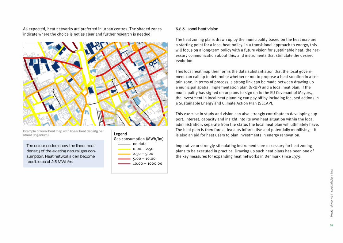
As expected, heat networks are preferred in urban centres. The shaded zones indicate where the choice is not as clear and further research is needed.
Example of local heat map with linear heat density per street (Ingenium). Legend
Gas consumption (MWh/lm) no data 0.00 – 2.50 2.50 – 5.00 5.00 – 10.00 10.00 – 1000.00
The colour codes show the linear heat density of the existing natural gas con-sumption. Heat networks can become feasible as of 2.5 MWh/m.
5.2.3. Local heat vision
The heat zoning plans drawn up by the municipality based on the heat map are a starting point for a local heat policy. In a transitional approach to energy, this will focus on a long-term policy with a future vision for sustainable heat, the nec-essary communication about this, and instruments that stimulate the desired evolution.
This local heat map then forms the data substantiation that the local govern-ment can call up to determine whether or not to propose a heat solution in a cer-tain zone. In terms of process, a strong link can be made between drawing up a municipal spatial implementation plan (GRUP) and a local heat plan. If the municipality has signed on or plans to sign on to the EU Covenant of Mayors, the investment in local heat planning can pay off by including focused actions in a Sustainable Energy and Climate Action Plan (SECAP).
This exercise in study and vision can also strongly contribute to developing sup-port, interest, capacity and insight into its own heat situation within the local administration, separate from the status the local heat plan will ultimately have. The heat plan is therefore at least as informative and potentially mobilising – it is also an aid for heat users to plan investments in energy renovation.
Imperative or strongly stimulating instruments are necessary for heat zoning plans to be executed in practice. Drawing up such heat plans has been one of the key measures for expanding heat networks in Denmark since 1979.

22
Hea
t ne
twor
ks g
uide
line
for m
unic
ipal
ities
Feasible and uncertain zones for heat network
Feasible and uncertain zones for green gas
Feasible and uncertain zones for heat pumps
Combination of the feasible and uncertain zones in a local heat zoning plan
Schematic example of a heat zoning plan (after Hawkey, 2017)
5.3. Local spatial instruments
5.3.1. Heat testOne of these municipal instruments can be a heat test. Like the water test, for example, it can form a weighting framework for heat networks versus other solu-tions at natural transition moments such as infrastructure works or new subdivi-sions and new construction projects. The principle of the heat test is included in the Flemish government’s Heat Plan: the concrete method and the (possible) regulations still need to be developed.
5.3.2. Increasing densityIncreasing the residential density in local residential areas also leads to greater linear heat density (MWh per meter street length). And that is good for the feasi-bility of a heat network, including in existing streets.
5.3.3. Reducing heat demandLower heat demand makes it possible to provide heat to more users with the same heat source via a heat network.
Reducing heat demand among residential consumers and the tertiary sector is also a spatial task:
• Linking residences (half-open, closed, stacked buildings) reduces the heat-loss surface;
• the orientation of the heated spaces on the south and attention for reducing shadows, optimising insolation in the heating season; this depends on the building geometry;
5.4. Spatial planning and heat sources
5.4.1. Coordination of heat demand and supplyThe spatial policy has little influence on the existing supply of heat or cold sources – in comparison with other sustainable energy sources such as wind and sun. After all, the heat source has often already been present for years, for example a company or incinerator with residual heat, a location for beneficial application of a ground source heat pump or the presence of favourable deep geothermal strata (depending on geological factors). For new installations and operations, spatial direction is of course desirable.
More realistically, it is about coordinating the heat supply and heat demand with each other in space and time. The vicinity of users and high densities are crucial spatial elements.

23
Hea
t ne
twor
ks in
sp
atia
l pla
nnin
g
By stimulating heat users to place themselves next to each other spatially, it is possible to use the residual heat from the one for other customers.
There are increasing symbioses between companies in which the one (waste pro-cessing) company transfers its residual heat to the other company and receives other streams or products in return.
The province of East Flanders has developed a provincial “heat policy line” about these principles (see website).
5.4.2. Cascading and spatial planningA heat network can use the principle of cascading to deliver heat at various (decreasing) temperatures in function of the heat demand of the users to be con-nected. That also presupposes spatial planning that takes this into account.
Not only the structure of a heat network, but also the rollout of one or more routes is largely determined by the type of demand. A heat network will prefera-bly first pass by higher-temperature users (e.g. industry, swimming pool or hos-pital), then e.g. 19th or 20th century buildings that cannot be insulated ade-quately and ultimately (possibly by return) modern residences that can be heated adequately with lower temperatures. This means that ‘heat cascading’ can also influence the planning of certain functions.
5.5. Installing heat networks in the public domain
As an operator of the public domain, the local government has an important facilitating role to play in installing heat networks. The local government must issue the necessary installation rights to the heat network operator. Since 2017, the use of the public domain by the heat network operator has been arranged better via the minimum regulation framework for heat networks.
5.5.1. Above-ground installationsThe most important above-ground installation is of course the heat source. For a new decentralised source such as a biomass-energy CHP fuelled by woodchips
or a geothermal heat source, it is necessary to have a suitable location, to pro-vide the spatial structure and to pay attention to the architectural design.
There are also smaller components such as pump stations and smaller control panels that can be installed relatively easily.
5.5.2. Underground organisationHeat pipes are usually installed underground. This does make the underground space busier, which is why there is a need for careful spatial planning under-ground and a correct inventory as in the KLIP [cables and pipes information portal].
Concretely, the local government can facilitate heat networks by providing reserved underground lanes when renewing the public domain. Via e.g. an urban planning ordnance, you can ensure that space is always reserved for heat pipes when installing new utility infrastructure in a high-opportunity zone for heat networks.
It is equally important to have good coordination with other earthworks or road works to reduce the installation costs and disruption by combining the works.
An interesting approach is to set up a desired underground transverse profile with the most ideal placement of the various types of pipes. This can vary by street type.
5.5.3. Planning of pipe routesThe feasibility of a heat network depends strongly on an optimal route choice, depending on heat sources, heat clients, and obstacles on the route such as roads, railways, sewers, etc. Horizontal directional drilling under this infrastruc-ture is technically possible, but increases the installation costs. Furthermore, theoretical routes often do not correspond with routes in practice. In reality, the most financially advantageous solution is not the shortest route from a to b. Because of this, it is important to look at reference prices that are used for the installation of heat networks. The cost price in a complex urban environment can easily become several times that of installing a micro network in a less urban environment.

24
Leid
raad
war
mte
nett
en v
oor g
emee
nten
Building line side Road side
VMW water pipe
Eandis heat pipes
Low voltage
OVBelgacom
Telenet
Soil profile with arrangement of underground pipes (source: Eandis requirements for Hooglede heat network)
Planning instruments for the substrate GIPOD GIPOD The Generic Information Platform for the Public Domain (GIPOD) brings together all the information about works or projects in the public as much as possible. It ensures that there is more coordination between utility and road works. https://overheid.vlaanderen.be/producten-diensten/generiek-informatieplatform-openbaar-domein-gipod KLIP The Cables and Pipes Information Portal (KLIP) is a web application intended to prevent damage to cables and pipes during earthworks. The KLIP does this by facilitating better access to and exchange of cable and pipe information between the parties involved in earthworks https://overheid.vlaanderen.be/producten-diensten/kabel-enleidinginformatieportaal-klip

25
Leve
rs a
nd o
pp
ortu
nitie
s fo
r rol
ling
out
heat
net
wor
ks
6 Levers and opportunities for rolling out heat networks
A heat network is not a primarily technical project, rather an organisational and spatial challenge: how heat users connect to a collective project with adequate guarantees in connection with the spatial situation. Heat networks don’t grow by themselves: it is best if local governments take on the role of director to actively steer the desired development of heat networks and to bring the appropriate partners to the table. It is important in this to seize levers and opportunities that can facilitate the installation of heat networks.
Connecting enough major heating demand to a heat source is essential for the development and planning of heat networks. Opportunities for heat networks can be found from two perspectives:
• by looking from an existing source (usually) of residual heat to the broader surroundings: where are the significant users, both now and in the future?
• Or from the perspective of the heat clients, at least if there is enough heat density (see below). The strategic question in this what sustainable source can provide heat to new developments?
6.1. Available heat source
The presence of a significant and sustainable heat source that can supply heat in the long term is an interesting point of departure: e.g. residual heat from indus-try, a CHP with reserve as a heat source, or favourable geological strata for deep geothermal. The supply of sustainable heat can be an attractive argument for the spatial development of industry and housing.
If there is already a heat transport network in the neighbourhood, this gives the possibility of branching and expansion with a new local heat network.
6.2. High heat demand
When mapping the heat demand, it is necessary to have a sufficiently broad view of all the categories of users. Large users can be a significant lever for the con-crete spatial planning of a heat network that other users can connect to. Municipal buildings with high heat demand and a central boiler room are the first things to consider.
6.3. New development and renovation
The demand for a collective heat supply solution often arises from a new project development, both of residential projects and other typologies (office zone, business parks). Project developers still hold on to the familiar formulas of indi-vidual gas boilers or central gas-powered boiler rooms too often. The first “solu-tion” is a serious hindrance to the possibility of connecting to a heat network in the future, the second option provides the necessary space in advance for replacement of a central boiler with a branch station for an apartment building. A municipal urban planning ordnance (see below) can require including a central boiler room for a minimum number of residential units as a condition for a permit to build a new collective residential project.
Large-scale renovation plans for collective buildings, for example, complete social residential districts or the approach to brownfields are the appropriate time to put heat networks on the table.
6.4. Coordination with public works
If working in the ground is scheduled, such as the renovation of underground pipes for sewerage, water, electricity, it is worthwhile to look at whether a heat network can also be put into the ground. This leads to strong savings on the

26
Hea
t ne
twor
ks g
uide
line
for m
unic
ipal
ities
costs and nuisance of excavation work and also leads to good underground spa-tial organisation.
Road works can also be a connection point for heat networks, for example the construction of an independent bicycle path or the renewal of pavements.
Information about the depreciation of the existing natural gas network long enough in advance is crucial to be able to draw up a strategic heat plan in good time: what sustainable heat sources will take its place and how can the munici-pality direct this replacement as well as possible. This not only applies to heat networks, but also to all individual or collective options for sustainability. And it is also necessary for scheduling private investments in alternatives. We can learn a lot from the Netherlands in this regard, which has been very active in phasing out gas by 2050.
6.5. Pre-financing opportunity groups
Citizens with low incomes run a high risk of energy poverty. The energy renova-tion of old residences can help with this, but does require high investments. The combination of insulation upgrades with connecting a heat network produces lower energy bills and takes care of this concern for residents. The municipality can consider offering pre-financing itself, or via an ESCO, to opportunity groups for the replacement costs of outdated, energy-wasting heating installations by connection to a heat network.
6.6. Growth process
Experiences abroad show that heat networks are evolving: the network expands in various phases, the heat sources are replaced or there are multiple sources on the network, separate smaller heat networks are linked to each other. We will therefore go further into the “growth” of heat networks.
Speelplein
Guldensporenlei
Diksmuidestraat
Bou
wsc
hen
Pad
Har
mon
iest
raat
Prin
sens
traa
t
Bar
eels
traa
t
Prinsessenstraat
De Merodelei
Dr N
and
Pee
ters
str
Speelplplpllleeeeinnnnnnnnnnn
GuldenspoGuldensporenlei
DDDDiiiiksmuidestksmuidestksmuidestksmuidestraat
Bou
wsc
hen
Pad
Har
mon
iest
Har
mon
iest
Har
mon
iest
rraat aat
Prin
sens
traa
t
Bar
eels
traa
t
PrinsessenstPrinsessenstPrinsessenstPrinsessenstPrinsessenstPrinsessenstraataat
De Merodelei
Dr N
and
Nan
d N
and
rrP
eete
rsst
r
Phase 1
Phase 1Fase 2
Phase 3
Phase 4
Phase 5
Boiler room
Heat network
Substation
Niefhout heat network in figures
Expansion in phases:
• phase 1: 138 residences
• phase 2: 123 residences
• phase 3: 100 residences
• phase 4: 147 residences
• phase 5: 90 residences
GuldenspoGuldenspoGuldensporenlei
Length of heat pipe: 1.8 km
Number of residential units: 600
First connection: expected early 2016
apartmentsrow houses
residential care centreassisted living homes
of�ces
Phasing in the Niefhout heat network in Turnhout (Eandis)

27
Leve
rs a
nd o
pp
ortu
nitie
s fo
r rol
ling
out
heat
net
wor
ks
Den Haag
RotterdamVierpolders
Pijnacker-Nootdorp
Zoetermeer
Capelle ad IJssel
Dordrecht
Leiden
Main structure for heat South Holland
Local heat networkLink to other
network
Geothermal source
Local heat network
Pipe trough the portPipe over WestPipe trough the middleLeiden region heat supplyExisting network
Residual heat source
Diagram for coupling local heat networks in the province of South Holland (Warmte Koude Zuid-Holland, 2016)
6.6.1. PhasingOne of the challenges in the development of a heat network is the phasing: not all heat clients start using heat, and therefore producing income, immediately after rolling out the network. On the other side, there is a major investment in the piping network, which is only paid back in the longer term. Clear communica-tion about the rollout over time can stimulate more heat clients to connect.
6.6.2. ExpansionA related point of attention is “planning for the future”. A heat network can begin with an initial route, but the strategic policy plan can look further ahead to future expansions on the basis of new developments or a gradual rollout in the existing buildings. It is then important to design the pipe diameter of the initial route for adequate capacity to supply future expansions.
Main structure of South Holland heat
An interesting option is also to connect new users who can use heat at a lower temperature to the return line of a heat network. For more about this, see the explanation of cascading.
6.6.3. Connecting the dotsWe are not yet this far along in Flanders, but abroad there is growing attention to connecting separate heat networks into larger networks. In the Netherlands they call this “connecting the dots”.
The advantage of the larger regional scale of connected heat networks is that large-scale sustainable heat sources such as deep geothermal or significant residual heat sources from major industrial zones can be distributed optimally over a large area.
In a regional heat network, various sources can also be used and upon the loss of a source, another new (sustainable) source can take over the heat supply.

28
Leid
raad
war
mte
nett
en v
oor g
emee
nten
6.6.4. Principle of “Heatnet Ready”The principle of connecting dots is also interesting on the small scale: in the Suikerpark project, a mixed live and work project on the site of the former sugar factory in Veurne, we use the strategy of “Heatnet Ready”: every new residential block gets a collective heating system which is set up such that the central boiler rooms can be replaced in the medium to long term by sub-stations for a larger heat network. This future evolution can occur without cost to the residences themselves: the heat exchanger has already been installed in the construction phase. In spatial terms, this does demand well-considered positioning of the branch points and boiler rooms for later optimal route planning of the heat network.
Top: First phase of Suikerpark project with the position of central boiler rooms depending on a later heat network (source: WVI / Suikerpark Veurne / project developer ION)
Bottom: Completed project with heat network with connections of central boiler rooms and individual residences

29
Rol
e of
loca
l gov
ernm
ents
7 Role of local governments
7.1. Authority of local government
According to the municipality decree, everything that is in the municipal interest falls under the authority of the municipal council. In other words: the municipali-ties can introduce and implement execute a heat policy taking into account the Flemish policy context. They have the best knowledge of the local situation and are often the greatest beneficiaries of their heat policy.
With this methodology, we also stimulate the municipality in a directing role or proactive role, not a passive role.
7.2. Roles and tasks in heat networks
An important theme for starting up and utilising heat networks is delineating the various roles that can include partners in a heat network.
In contrast to the gas and electricity market, with a strict separation between production, delivery and distribution, and with a free choice of supplier, heat networks are an essentially local element. With this, different organisational models can occur. Furthermore, there is a difference between the development and operation of the heat network: in the two phases there may be different partners that take on the tasks and responsibilities, but there may be overlap between installation and operation. In practice, there are various market models.
The market model is a description of all the roles that are relevant for the development and operation of a local heat network and of the parties that fulfil these roles, including a description of the way in which ownership, con-trol and management are organised.
7.3. Role of the local government
7.3.1. Director's roleThe feasibility of a heat network depends on connecting enough heat consumers (existing or to be built, both residential and other). That requires an active and coordinated approach through discussions with multiple parties (local govern-ment, construction principals, building owners, heat producers, etc.).
Heat producer
User(s)
heat price
• Production• Transport• Delivery
Heat producer(s)
Transport and distributio heatSupplier
User(s)
heat price
price
heat
Availability fee
Transport and
distribution network
Market models for heat networks: vertical integration versus a split structure (De Roo, 2013)

30
Hea
t ne
twor
ks g
uide
line
for m
unic
ipal
ities
Heat network type Heat production Transport/distribution Heat supply
Industrial residual heat to residences
Partner 1 Partner 2
Residual heat exchange between businesses
Partner 1
Deep geothermal to urban heat network
Partner 1 Partner 2 Partner 1
District heating network with gas/biomass boiler
Partner 1
Open large heat network, multiple sources
Partners a, b, c Partner 2, 3, 4 Partner x, y, z
Examples of various market models
For the optimal development of a heat network, the role of a “director” is indis-pensible, who oversees and coordinates the total project approach and monitors the performance of the various roles and tasks. The local government is best placed for this: it has a broad and complete view of current and future develop-ments of both private housing and other buildings. Furthermore, the local gov-ernment can also integrate its own buildings and land into a possible heat network.
7.3.2. Guaranteeing usersIt is only possible to guarantee enough heat consumers over a long period by establishing heat consumption by law and/or contractually prior to installing a heat network. The local government can play an essential role in this by:
• Imposing a connection obligation using a permit policy with local urban planning ordnances specifically for heat networks: an obligation to install a heat network in a new subdivision/urban development.
• establishing clear agreements using mutual engagements with real estate developers, etc.
• making central boiler rooms mandatory in new collective (residential) buildings;
• using its own public buildings as heat clients.
• clear communication about rolling out a heat network over time and the heat vision for various districts to enable residents to take this into account in renovation plans.
7.3.3. Spatial planning and heat networksAs described in chapter 5, the local government has an important responsibility in the spatial planning of a sustainable heat supply using heat zoning plans. The greatest challenge in this is connecting existing buildings to a future heat net-work. A solution that is already used in other countries, is marking off “heat net-work zones” (district heating zones) with a connection and (long term) consump-tion obligation in areas with adequate residential density.
Local authorities also have the important task of coordinating the planning process, and organising concessions in the public domain.
7.4. Roles for authorities above the local level
A possible additional role lies above the local level (intermunicipal partnerships, provinces, provincial development companies):
• coordinating and planning larger heat networks and their sources with a function above the local level and/or that exceed the municipal boundaries (primarily relevant when using residual heat from business parks);
• supporting local governments as a process leader and in drawing up heat zoning plans;
• drawing up a spatial policy line for heat to enable heat networks to be developed with proper spatial consideration: a framework for drawing up heat zoning plans.
• Three roles for a local government (Kelvin Solutions, 2017)• delivering data for the inventory of heat users and heat sources; drawing up
map materials.

31
Rol
e of
loca
l gov
ernm
ents
The province of East Flanders has made a local map for all its municipalities with the linear heat densities per street. In the province of Flemish Brabant, municipalities can call on provincial support for implementing a “Heat network screening for municipalities”.
Position Passive passenger Traffic director Active pilot
Role Tolerating/permitting heat network project
Facilitating heat network and drawing the outlines
Setting up municipal heat network to realise heat network
Impact Minimal impact on staffing and budget
Provide with staffing and financial resources
Major impact on extra staffing and extra resources
Risk Blootstelling aan verdoken risico’s Risks made visible and primarily assigned to external parties
Almost all risks borne by local government
Focus Granting access to public domain Facilitating a feasible and broadly-supported project; anchoring agreements in law
Making its own heat company operational with own accents
Policy impact Risk of fragmented and suboptimal local spatial and energy policy
Option to expand a coherent local spatial and energy policy
Need to expand a coherent local spatial and energy policy

32
Leid
raad
war
mte
nett
en v
oor g
emee
nten
8 Collaboration & decision making
Rolling out a heat network can only succeed in cooperation with various external partners, each with its interest and role.
8.1. External partners: stakeholders and market operators
• Energy sector: energy companies, network operators, ESCO• Industry: businesses with residual heat or with heat demand• Construction sector: consulting firms, project developers, social housing
associations• Large heat users: public buildings, educational institutions, rest and care
institutions, hospitals, apartment buildings• Authorities: local government, province, POM, intermunicipal partnerships,
Flemish government• Local civil society: citizens and associations
8.2. Stakeholder analysis
The first exploration phase of a possible heat network project starts with an analysis of the possible partners involved: a “stakeholder analysis”. See chapter 10 for more about this.
8.3 .Internal cooperation: municipal services
Taking on the management of a heat network as a local government presup-poses good cooperation between the different relevant municipal councillors and services:
• the environmental service/climate & energy department monitors the local climate & energy ambitions. The project leader for the heat network could also come out of this;
• the spatial planning service has all the information about spatial planning and also specifically directs projects for new developments. This service coordinates the spatial vision with the development of the heat network and can indicate opportunities. This also involves the discussion with project developers;
• the planning permits service tracks the permitting process for the heat network project;
• the public works service has the task of coordinating the future placement of the heat pipes in the ground with other utility lines and also signals the synergy of works planned in the public domain with the rollout of the heat network;
• the technical service/ heritage management has the data on boiler rooms and energy consumption needed for the investigation on connecting municipal buildings;
• Administrative affairs and legal service: over the course of the process to create a heat network with various partners, there are key moments to draw up cooperation agreements. This requires guidance by the general services that advise on administrative and legal aspects;
• Financial service: entering any subsidies, estimating the impact of dividends in intermunicipal partnerships, etc.;
• Communication service: setting up and performing (media) communication actions about the heat network project.

33
Col
lab
orat
ion
& d
ecis
ion
mak
ing
Discussion type Purpose Who Frequency
Political bureau-cratic consultation
political engagement
scheduling, activation
project leader of heat network and authorised councillors
biweekly
Steering group preparation of formal decisions, resolving conflicts
ll stakeholders:
politicians, department
heads, external partners
per quarter or per half year depend-ing on decision-making
Project team Directing/monitoring the project, detecting problems
Project leaders of the stakeholders
biweekly
Working groups Elaborating details of specific aspects
Project leaders and experts
whenever necessary
Informal contacts informing, conveying vision, increasing sup-port, setting course
Project leader for heat network to parties directly and indirectly
continuous
Consultation levels in rolling out a heat network
8.4. Consultation structure
Aside from a being technical project, a heat network is most of all an organisa-tional process that needs a number of years of lead time and a well-organised consultation structure. The table proposes an approach in different consultation levels and frequencies.
An active project team is crucial to keep the project “warm”. This includes the project leaders of the most important stakeholders. The local management has the important role of facilitator and initiative-taker in this. To progress effec-tively, the contribution and the interest and of the partner must be recognised. That builds trust and make the project more effective and efficient.
For cooperation in the project team, it is best for the partners involved to con-clude a “light” declaration of intent between them as a predecessor of the more formal collaboration agreement.
To keep the project on track, an active project leader is indispensible, preferably a neutral person such as a leading official within the municipal services. As a driver of the whole process, his or her role cannot be underestimated, with quite a few challenges along the way.
8.5. Political decision making
In a municipal direction about the development of heat networks also required local decision making. This is about the different aspects over the course of the rollout: principal conclusion, approval of the various agreements with other part-ners (letter of intent, partnership agreement), approval of planning permits, con-cessions, etc.
From start to finish, the installation of a heat network can easily take five years – usually longer than the local legislature. A change of coalition can disrupt the stability of the decision-making process. After all, municipal officials do not make the decisions, but prepare, analyse and execute – and also ensure admin-istrative continuity and stability.
There is also the possibility of a project developer that does not want a heat net-work sabotaging the process through political influence.

34
Leid
raad
war
mte
nett
en v
oor g
emee
nten
Rolling out heat networks across elections Proactive and strategic coordination between municipal services and politi-cians can keep the rollout of a heat network on track, with the following tips:
1. anchor the project in the municipal policy with adequate internal deci-sion making;
2. set up a structure with opposition parties across party lines
3. engage with external partners (e.g. the higher subsidising authority) that anchor the project
4. “no long-term plan without short-term successes”: schedule timely “cel-ebration moments”, also according to the electoral cycle.
Symbolic first pipe laying of the ECLUSE heat network (photo WNVL)

35
Loca
l pol
icy
inst
rum
ents
9 Local policy instruments
Municipalities and cities can use a number of urban planning instruments to facilitate and direct the development of heat networks.
9.1. Urban planning ordnance on central boiler rooms
Collective buildings with multiple residential units and mixed functions, due to their relatively high heat consumption, may be attractive users for a heat net-work. To avoid mortgaging the future connection of this (due to the choice of individual gas boilers per apartment), the municipality can impose the obligation to provide a central boiler room for new construction of these collective buildings.
As a legal instrument, the municipality can approve an urban planning ordnance for the whole territory. The obligation to provide collective boiler rooms usually applies as of a minimum number of apartments, e.g. from 10 or 20. Examples of the urban planning ordnances in Roeselare and Antwerp are available on the website.
In existing apartment buildings, the required approval by the association of joint owners can pose an obstacle to a switch from the central boiler room to a heat network connection. A possible legislative instrument is the obligation to con-nect to a thermal network if two thirds of the tenants agree to this, and this can be for a certain period (for example 5 to 10 years).
9.2. Conditions in Spatial Implementation Plan
When drawing up a Municipal Spatial Implementation Plan (GRUP), guidelines about a conditional connection obligation, a boiler room at ground level and/or reserved lanes for heat pipes can be useful.
• An obligation to connect to the heat network can be applied to work on buildings requiring a permit (this will be in both the urban planning conditions and the in explanatory note of the GRUP).
• This is of course only possible on the condition that the installation of a heat network is planned and the developer/operator of this heat network can submit a detailed quotation for connection in good time, taking into account the pricing principle of “not more than otherwise”.
• For individual residences, the spatial implementation plan can include the requirement that the boiler room is located on or close to ground level and is easily accessible from the public domain (e.g. on the street side).
• Reserved lanes in the public domain facilitate the later installation of a heat network. The spatial implementation plan can require these lanes to be provided, including lanes for them to be connected to the buildings.
• If space is still needed in the technical design of the heat network for heat production and/or transfer stations, the spatial implementation plan can also require the developer to provide space for this.
Example of regulations in spatial Implementation plan Conditional connection obligation “Every new building to be built with a certain heat demand (up to 70°C) must take the necessary measures to connect to the heat network. A connection to a local heat network is mandatory for all the building plots to be devel-oped, insofar as the heat network operator can submit that the heat supply will be operational on time when the respective buildings are put into use when it submits the formal engagement. The heat for the respective build-ings may be supplied via a temporary boiler room (for example via heat containers) in the startup phase.”

36
Hea
t ne
twor
ks g
uide
line
for m
unic
ipal
ities
Technical space at ground level “In all building designs, the project developer must provide for a technical room at or below ground level in all buildings, located at the street side where the heat connection of the building is housed. After drawing up the final design, the heat network operator will, in the detail study, stipulate further requirements regarding the minimal provisions and accessibility of the tech-nical rooms intended for the heat network. If the heat network operator cannot submit a formal engagement in good time that the heat network will be operational on time, the project developer must provide every building or provide multiple connected buildings with a collective heat production system at or close to ground level.” Reserved lanes in the public domain “Reserved lanes will be provided in the public domain for the installation of a heat network and its connection to the buildings. Further space must be provided for the pipes of the heat network insofar as applicable. The location of these areas must be worked out in detail with the heat network operator after the building plots are allocated.”
9.3. Conditions for development of own land: connection obligation
In the case that the municipality sells its own land to developers for new con-struction projects, it can also apply the condition there that a heat network must be installed in combination with a ban against the developer installing a gas network.
9.4. Concessions
A concession is necessary for the installation of heat network pipes in the public domain in the category of “concession procedure for public works in the utility sectors”. This can be assigned per project with a geographical delineation of the area or for the whole territory of the municipality. The concession can involve various partial projects: design, installation and/or operation of the heat net-work. Division into heat supply and heat distribution is also possible with differ-ent durations (e.g. 20 years for delivery and 40 years for distribution). A permit guideline describes the detailed conditions for assigning the concession and the procedure to be followed (see the example of Eeklo).
9.5. Management transfer
The distribution network operators have taken the initiative to make a proposal to all the municipalities to provide the management transfer for the development and operation of heat networks.
Instead of having to conduct its own public tender for a heat network, the munic-ipality does a management transfer for its full territory to the network operator and indirectly to the umbrella organisations of Eandis or Infrax and the common branch “warmte@vlaanderen” (under establishment). This structure can then stand in for the operational tasks for the activity of heat over all of Flanders.
In that case, the municipality entrusts the execution of decisions about heat net-works to the network operator, and the municipality itself no longer has the right to execute the same project independently or together with third parties. The municipality does reserve the right to “revoke the management transfer”. Such management transfer from the municipality/city must be done in accordance with the Decree on Intermunicipal Cooperation (DIS).

37
Loca
l pol
icy
inst
rum
ents
9.6. Memorandum of understanding with project developer
Memoranda of understanding with the developer are also possible. They lay down the agreement between the local government and the project developer, based on the principle of a gas-free district, to connect the new buildings to a heat network. Of course, such agreement can only be established in dialogue.
Memoranda of understanding: possible stipulations
• Engagement regarding the real estate development in relation to the heat distributor and supplier:
— Connection obligation — Access right (among others of buildings for the heat network
operator) — Coordination of technical building design and necessary heat
capacity — Possibly some agreements about costs and the share that is
financed by the developer: e.g. a one-time connection fee, installa-tion costs of pipes, etc.
• Engagement relating to the ground development on which the future real estate and public domain will be realised:
— Admission for installation of the heat distribution network in the ground;
— Location of the heat pipes and design details of the future public domain (in relation to above-ground parts of the heat network);
— Regulation for the transfer of the ground parcel on which the heat generation plant is placed and space intended for the realisation of a heat transfer station.

38
Leid
raad
war
mte
nett
en v
oor g
emee
nten
10 Heat network step by step plan
PHASE 1: EXPLORATION
Feasibility study
Project idea
PHASE 2: DEEPENING
Detailed investigation &
project organisation
Project definition &
Business plan
PHASE 3: EXECUTION
Procurement &
permits
Realisation heat network
Broadly, we can divide the process of rolling out a heat network into 6 steps. A general overview of this is given below; we will zoom in on the tasks within each phase later.
Phase 1: exploration
10.1. Project idea
The first idea to develop a heat network can come from various partners:
• local governments: the municipality itself, the intermunicipal partnership for waste processing, a regional intermunicipal partnership, or the province;
• the network operator• a private project developer or social housing association;• an energy company or a (local) energy cooperative.
Analysis of stakeholders
In this first exploratory step, an analysis of possible stakeholders must be done to clarify who can play what role in the new heat network.
Local heat vision
The local climate targets (covenant of mayors) or, better still, an explicit agree-ment in the administrative agreement, form an extra motivation for the munici-pality to actively guide and support the development of a heat network.
Working out a local heat vision is essential to obtain a clear view of the local opportunities for a heat network, looking at both energy data and spatial pre-conditions (residential densities, planned developments).
10.2. Feasibility study
On the basis of a first estimate, the municipality can then decide to take the next step: a correct feasibility study, which calculates using data from potential heat clients, available or desired heat sources, and various scenarios for pipe routes, possible supporting measures, attractive heat usage rates. The municipality will need to outsource such a study to an experienced study agency.

39
Hea
t ne
twor
k st
ep b
y st
ep p
lan
Phase 2: deepening
10.3. Detailed investigation and organisation project
A positive outcome of the feasibility study is the step to a decision in principle to develop the heat network further. This requires stronger engagement from the partners involved that came on board informally in the first exploratory phase.
In this step, it is necessary to conduct an in-depth round with possible new part-ners: large users that could be significant heat users, project developers with plans in the environment of the heat network, companies with residual heat, etc.
10.4. Project definition with business plan
In this phase, it is important to lay down the engagements of the various part-ners in writing, without extremely heavy legally detailed contracts but with a letter of intent that engages the undersigned parties to realise the project together.
It is just as important in this phase to establish specific urban planning costs that must be borne by real estate owner or project developer via a separate agreement.
Phase 3: execution
10.5. Tendering and permits
Before the formal tendering for the installation of the heat network can occur, first the necessary guarantees must be provided for the connection of heat clients to the future network: via urban planning anchoring of (mandatory) heat connec-tions in a GRUP or subdivision regulations.
A second important intermediate step to conclude the partnership agreement to realise the project. This confirms the concrete execution of the project.
The construction partners can then apply for the required environmental permits and installation rights to install the heat network in the public domain.
10.6. Phasing and timing
The following pages present a step by step plan for the three most important phases in rolling out a local heat network project, each with an overview table that lists all the tasks.
From the standpoint of a local government, we can look at the development of a heat network in three phases:
1. Exploratory phase: partners and general feasibility2. Deepening phase: substantiating feasibility3. Elaboration phase: technical choices, procurement, legal structure,
decision making and contracts.

40
Hea
t ne
twor
ks g
uide
line
for m
unic
ipal
ities
Project organization & guidanceYEAR 1 YEAR 2 YEAR 3 YEAR 4 YEAR 5
Legend
Timeline phase
Timeline aspect
Q1 Q2 Q3 Q4 Q1 Q2 Q3 Q4 Q1 Q2 Q3 Q4 Q1 Q2 Q3 Q4 Q1 Q2 Q3 Q4
PHASE 1: EXPLORATION
Feasibility
Chances of succes
PHASE 2: DEEPENING
Substantiating feasibility
Commitment of stakeholders
PHASE 3: EXECUTION
Design/Tender/Organization
Realization
Summary of phasing and timeline for a heat network project (source: Roadmap Warmtenet Oostende)
Phase 1: explorationIn the exploratory phase, the local government investigates whether the heat network will fit into its heat vision and whether the overall concept of the heat network will be feasible. In this phase, it is primarily about the possible partners and the general outlines
Purpose
The exploratory phase has two goals:
1. a first exploration of the desirability and the opportunities of a heat net-work and the possible partners that can or want to play a role in the project
2. general insight into the technical, legal and financial feasibility
For the realisation of a heat network, the engagement of multiple parties is desirable and often necessary. A project only has a chance of success if it is in the interest of all the parties involved. For that reason, is in this phase a well-organised dialogue with various possible partners is necessary, which will lead to the first agreements in principle.
Stakeholder analysis
A ‘stakeholder analysis’ creates an overview of the possible partners and their interests. Are these ‘stakeholders’ interested in a heat network project and are they prepared to study its feasibility collectively?
In an initial consultation, the municipality can argue the importance of a heat network in the framework of its vision on sustainable development, and also show the advantages for the stakeholder.
The level of engagement of a partner can vary, for example from personal inter-ests to the authority to make planning decisions. The focus of this in on who has an influence and/or interest in the project. The stakeholder analysis gives answers to the following questions:

41
Hea
t ne
twor
k st
ep b
y st
ep p
lan
1. Take stock of the parties involved;2. Define their interest and role;3. Estimate the positions & standpoints;4. Determine whether there is a basis for conflict/cooperation;5. The degree of power or influence determines the scope of the opportunity
or threat;6. Select the important and relevant actors.
Because every heat project is unique, the stakeholder analysis will also depend on the local situation.
These first discussions with stakeholders produce information about the feasi-bility and workability of the project: which aspects can be resolved or not? For example: a potential heat producer that has already indicated that an interven-tion in the primary process is not possible or unacceptable.
Attention points
Intelligent cooperation with a view to a good distribution of the risks can remove sticking points (see below). Important attention points for the approach and the process of successful cooperation:
• Cooperation begins with trust, and not with technology;• Listen to the wishes of the parties involved;• Speak at project level first;• Consult regularly and have understanding for the position, the background
and interest (culture) of the other party;
How to test initial feasibility
Together with the most relevant stakeholders, the project group makes a list of components of which the general feasibility is tested. Aspects that require a deeper analysis are discussed further in the deepening phase. This initial exploration is primarily about:
PHASE 1: EXPLORATION Who? When? Check
FEASIBILITY
Technical feasibility
Heat inventory: users/sources
Establishment of linear heat density
Public works opportunities
Listing project scenarios
Selection of pilot project(s)
Financial feasibility
Indication of order of magnitude of investment cost
Heat price
Support mechanisms
Legal feasibility
WORKABILITY
Identification of stakeholders
Identification of heat clients/producer
Market exploration of supplier(s)
Market exploration of transport/distribution
Analysis of stakeholders
Identification of sticking points & milestones
Stakeholder analysis
Social cost-benefit and government role
Identification of social costs-benefits
Government ambition level (Covenant of Mayors)
Government engagement
Process and decision making
Starting project group
Appointing project supervisor
Letter of intent

42
Hea
t ne
twor
ks g
uide
line
for m
unic
ipal
ities
• The broader spatial framework: what area is involved? What new developments are planned? Where are the large users located? What sources and users can a heat network link together?
• Heat usage: what users want to use heat? Do the heat supply and demand fit with each other? Does the temperature of the available heat correspond with the heat demand?
• Technologies: what technical solutions are available at a reasonable price?• legal test: can the project be realised within the existing regulations?• financial feasibility: do the future revenues cover the costs adequately, or is
additional support necessary, and is the project still feasible?• social support: aside from the direct benefits for the participating partners,
are there also benefits for the local community?• opportunities: are there moments when heat sources or infrastructure
works in the public domain will be replaced?
For the financial feasibility, it is necessary to draw up a business case that gives an overview of the all the costs and revenues and the expected return. A heat network project is only feasible if the business case is positive for all parties involved! This presupposes division into smaller projects: the business case for the provider (“can I earn back my costs and return for the risks?”), the distributor (the same) and the user (“is this the most economical heat supply?”).
Social cost-benefit analysis
A social cost-benefit analysis produces a full overview of the effects for society with a focus on ‘externalities’ of the possible investment decisions. These are effects on third parties that the investors do not (have to) take into account. An important and positive externality of a heat network project can for example be the lower emissions of particulate and CO2, or taking care of making the local heat supply sustainable for residents. The contribution of a heat network to local CO2 reduction fits within the municipal ambitions of the Covenant of Mayors and can also be an argument to support the project financially.
Result
The result of the exploratory phase is a collective decision: stop of continue. Projects that are not really feasible or do not have support are dropped. Projects with strong opportunities go further to the deepening phase.
Ideally, this phase is concluded with a letter of intent in which the parties involved express their shared ambition and make work agreements for the next part of the process.
A letter of intent broadly consists of:
• Objective of the letter of intent;• Partners involved;• Project description;• The substantive and financial frameworks for the next phase;• What (type) of decision should be made at the end of the next phase;• What results are produced at the end of the next phase;• The way in which these results are produced (use of people and resources,
planning, etc.).
Practical tips For the process of exploration, we recommend appointing a ‘process leader’ who organises the ‘pre-feasibility’ study. The emphasis of this role is placed on:
• the stakeholder analysis• monitoring the agenda for the process (planning) and the substantive
discussion• feedback from the feasibility analyses to the collective decision making
process

43
Hea
t ne
twor
k st
ep b
y st
ep p
lan
Phase 2: deepeningThe deepening phase focuses on the further substantiation of the feasibility, and the cooperation between the partners gains a formal character.
Purpose
The purpose of the deepening phase is to reach a decision in principle to realise the heat network project.
This requires:
1. robust substantiation of the ‘feasibility’ of the project;2. engagement of the partners involved to convert the opportunity into an
actual concrete project.
Contents
The deepening phase builds further on the work from the exploratory phase with:
• a complete technical design of the heat network;• a complete test of the legal feasibility;• a full-scale calculation of the financial feasibility, including the financing
plan;• consensus about the social benefits.
By complete and full-scale, we mean that designs and analyses are focused on the heat network itself (i.e. not just on key figures). These will also need to be detailed and complete, with all the critical components, costs, revenues and indirect effects. The analysis needs to be ‘robust’ to withstand the test of profes-sional evaluation.
The business case and – if relevant – the social cost-benefit analysis provide insight into the expected (financial and social) costs and benefits of a project. No matter how good the forecasts are, the predicted values will still be more or
PHASE 2: DEEPENING Who? When? Check
SUBSTANTIATING FEASIBILITY
Feasibility study
delineating study project
outsourcing study
Technical preliminary design of pilot projects
Selection of operation temperatures
Selection of material
Input and output
Network route and phasing design
Allocation of backup provisions
Selection of material
Permits
Financial/legal
Structuring heat operation
Drawing up business case
Market surveys
Pricing
Financing options
Risk analysis
Preparation of outsourcing/organisation
ENGAGEMENT PARTNERS
Local government decision in principle
Partnership agreement

44
Hea
t ne
twor
ks g
uide
line
for m
unic
ipal
ities
less uncertain. To make the right decision, a risk analysis is essential to obtain an overview of these uncertainties:
• what is the possible impact on the project outcome• what preventive measures are possible• who can bear certain risks the best.
The various analyses prepare for actual cooperation between the partners, with agreements about allocation of tasks, risks, control and return.
Proces
The deepening phase begins with the project group of partners who have signed the letter of intent. In the deepening process, they can agree on a concrete roadmap to distribute tasks, risks, control and return. To do this, excessive rigid-ity is not desirable: the investigations can produce new insights and the external context can change. The project must be able to respond to this.
Practical tips In this phase, active management and the use of more resources are essential:
• Central, tight project guidance/management• Releasing enough people and resources for the investigations• Incorporating second opinions to test the robustness of the
investigations
An action plan establishes:• which studies need to be conducted, by whom and at what time;• what input the different stakeholders give to the performance of these
studies;• how and when the (interim) results of these studies will be discussed;• how the decision making will look.
Depending on the scale and complexity of the project, it may be desirable to split the deepening phase into general elaboration and only then robust elabora-tion. This second step includes a full test of legal feasibility or further calcula-tion of the financial feasibility. It is not always necessary to have such expensive studies conducted separately: for example if the heat network project is out-sourced separately, this can also include the detailed elaboration.
Result
The result of this phase is a decision in principle to realise the heat network pro-ject. A positive decision can be made if the project is technically and legally fea-sible, has a risk-return balance that is acceptable for all the partners and all the partners can engage in it.
The decision in principle translates into a partnership agreement that contains the following elements:
• context of the heat network project;• description of the partners, intentions and ambitions;• purpose of the agreement;• description of the project;• assigning tasks and responsibilities;• starting point for cooperation and risk distribution between and among the
partners;• description of the project organisation;• starting points for project financing;• duration and conditions of this agreement.

45
Hea
t ne
twor
k st
ep b
y st
ep p
lan
Phase 3: elaborationThe elaboration phase is intended to tie up the loose ends. This phase can be useful in three different situations:
1. if there was still a lack of clarity among the cooperating partners when the partnership agreement was concluded. If this does not substantially influ-ence the major points of the partnership agreement, it can be practical to ‘park’ this point instead of immediately delaying the whole partnership agreement.
2. if the partners want to put a part of the heat network project to public pro-curement, this is also done in the elaboration phase. This usually involves procurement of the construction, the management and maintenance of the heat network.
3. finally, a heat network project usually requires project financing and sup-port measures. This demands a separate legal structure in which the pro-ject can be accommodated, and the details of the financing.
Result
The result of the elaboration phase is a final investment decision in the form of a realisation agreement between all the parties involved. The realisation of the heat-exchange project can now begin.
PHASE 3: ELABORATION: Who? When? Check
DESIGN/PROCUREMENT/ORGANISATION
Detailed technical design
Heat operation Procurement/Organisation
Financial legal
DECISION MAKING
Council decision
Realisation agreement

46
Leid
raad
war
mte
nett
en v
oor g
emee
nten
11 Regulations
11.1. European regulations
In February 2016, the European Commission proposed its new EU energy security plan which contains the first specific plan for heating and cooling in Europe. Heat networks were an important part of the strategic future vision in this plan.
The European Parliament adopted a resolution in September 2016 about this EU strategy on heating and cooling. It directs attention to the “vast unused poten-tial to use waste heat and district heating systems” and points to the fact that “50% of the demand for heating can be met with district heating”. The resolution also says that “the quantity of excess heat that is available in Europe is greater than the total demand for heating in all European buildings”
The document further emphasises the importance of efficient heat networks to replace more polluting individual heat sources in densely built urban areas. The European Parliament also calls on member states to work out fiscal and financial mechanisms to support the development of heat and cold networks.
The resolution also emphasises the role of local governments in designing a local sustainable energy strategy based on the inventory of heat and cold.
11.2. Flemish regulation on heat networks
11.2.1. Energy performance and interior climateCollective heat supply via heat networks can have a favourable influence on energy consumption, especially with the application of residual heat and sus-tainable heat sources. In the energy performance calculation methodology, external heat supply has a specific calculation framework. In addition, collective heat from sustainable sources can also be valorised in the minimum share of renewable energy.
To convince project developers, including a heat network in the interior climate energy performance calculation is an important argument, which needs to be given more attention at an early stage of the heat project.
11.2.2. Flemish regulatory framework for heat networksOn 14 October 2016, the Flemish government approved a new regulatory frame-work for heat or cold networks with an amendment to the Energy Decree. The regulatory framework primarily lays a legal basis for later implementation decrees. It also still needs to be put into effect by an implementation decree of the Flemish government.
Heat distribution within buildings does not fall within the application area of the legal framework. It is also not the intention to impose regulations for heat net-works within operations at industrial sites.
The accent lies on the procedures for non-payment, principles of public service obligations, consumer protection, defining market roles and appointing the VREG as regulator; furthermore there are also provisions for installation rights and expropriation rights of the local heat network operator.

47
Reg
ulat
ions
11.2.3. Mandatory feasibility studyAs of 31 January 2008, it is mandatory to determine whether an alternative energy system is cost-effective for new buildings with an area greater than 1000 m2. This also applies for the connection to a heat network (conversion of the European directive on energy performance of buildings). This mandatory feasibility study applies within a zone of less than 500 m away from the loca-tions indicated on the Flemish heat map. The technologies to be investigated in function of the building use and the floor area stand in the table in Appendix I of the Ministerial decree.
http://www.energiesparen.be/epb/haalbaarheidsonderzoek
Energy-intensive companies that take part in the (voluntary) energy policy agree-ment engage in this to implement potential studies for high-quality CHP and heat and cold networks.
http://www.ebo-vlaanderen.be/Pages/de-ebos.aspx
11.2.4. Cost-benefit analysis of heat networks in VLAREMThe VLAREM regulations determine that for certain permit applications, the fea-sibility of a CHP application or the use of residual heat (via a heat network) must be investigated. This concerns permit applications for large new combustion plants or electrical power plants and for heat networks. If the benefits are higher than the costs, the energy-efficient options must also be used.

48
Leid
raad
war
mte
nett
en v
oor g
emee
nten
12 Support measures
12.1. Green heat call
Since 2013, a support regulation for residual heat has been implemented for installations that use residual heat that meets economically demonstrated demand located in the Flemish Region for which green power certificates or combined heat and power certificates cannot be given. Support is provided in the form of an investment subsidy (maximum 1 million euros per investment project) and is assigned via a call-system with an annual call.
http://www.energiesparen.be/call-groene-warmte
12.2. Business park subsidies
The resolution of the Flemish Government of 24 May 2013 on subsidising busi-ness parks (see above) provides subsidies for the installation or expansion of a heat network at difficult or outdated business parks.
12.3. Investment deduction
For investments in energy-saving measures, SMEs can contribute a higher investment deduction from the taxable profit. In 2018 and 2019, this deduction was increased to 20%. Specifically for heat networks, waste heat (group 2, cate-gory 5) is recovered from existing processes.
https://www.vlaio.be/nl/download/pdf?file=generated-pdf/ maatregelfiche-investeringsaftrek-286-met-bijlagen_17.pdf
12.4. Ecology premium for SMEs
With the ecology premium (EP-PLUS), the Flemish Government aims to stimulate enterprises to organise their production processes to be environmentally friendly and energy efficient. The Ecologiepremie Plus, which is only for small and medi-um-sized enterprises, provides a support percentage for connection to an exist-ing heat network, i.e. 21.5% net subsidy. Only connection to an external heat network, including the installation costs, is eligible. The conditions are stated in the Limitatieve Technologieenlijst [exhaustive technology list] under numbers T 201039 and T 201044 (the only difference is the option “with or without heat exchanger”).
http://www.vlaio.be/sites/default/files/2017-11/EP-ltl-epplus-2017- 10-type_0_0.pdf

49
Sam
ple
pro
ject
s
13 Sample projects
13.1. Metropolitan heat network
Example: MIROM Roeselare
MIROM, the Roeselare-Menen intermunicipal partnership for environmental man-agement, has a waste incineration facility in Roeselare and by 1986 had con-nected part of the residual heat to the heat network in the city of Roeselare. MIROM supplies heat to 40 large uses via an underground pipe network with 19 km trench length.
Recently, the heat network was expanded with two new branches:
1. To Gitsestraat/Honzebroekstraat residential areaA new branch of the heat network is built and managed by the distribution net-work manager Eandis. The future heat clients include almost 1,000 residences and the complete Schiervelde site, as well as the new swimming pool.
2. Right through the centre toward Het Laere and further to De Ronde Kom. This new branch was realised under internal management and is managed by MIROM, with heat delivery to large users in the city centre. The end point is the site “De Ronde Kom”.
Market model
The MIROM heat network is mostly vertically integrated, which means that MIROM includes all the roles in the full supply chain:
• feasibility studies• installation of the heat network (via third parties)• production of heat• distribution of heat• suppliers’ role• financing, subsidies• complaints, measurements, communication
Diagram of the heat network of Roeselare with all expansions
Some tasks are subcontracted but remain 100% under supervision and manage-ment of MIROM. Only the role of ESCO in buildings is no longer performed by MIROM.
For a new branch, the network operator Eandis takes on a number of tasks:
• the heat production remains with MIROM• the heat from MIROM is transported to the new branch
Existing MIROM heat pipe
New MIROM heat pipe
New warmte@vlaanderen pipe

50
Hea
t ne
twor
ks g
uide
line
for m
unic
ipal
ities
50
Leid
raad
war
mte
nett
en v
oor g
emee
nten
• as of this branch-off, all other tasks are to be done by Eandis: installation and maintenance, distribution and delivery, invoicing, customer service
More info
http://www.mirom.be/warmtenet/ons-warm-verhaal/wie-verwarmt-er-met-duurzame-energie
13.2. Heat network in new urban development
Example: Nieuw Zuid Antwerp
Nieuw Zuid is a new residential district in the south of Antwerp, behind the new court of justice, along the Scheldekaaien in the extension of the Gedempte Zuiderdokken. This involves a functionally mixed district with residences, offices, shops and services.
Market model
For the heat network of the new urban development “Nieuw Zuid”, the city used the model of “concession of public works within the utility sectors” via govern-ment contracts.
Partners
A new consortium was awarded this concession: the intermunicipal energy part-nership IVEG, water link (Antwerp water authority), Veolia (energy services com-pany) and Indaver (waste processing facility) united in the new consortium “warmte@zuid”, which is building and managing the heat network in coopera-tion with the general project developer Triple Living. IVEG is the project leader and coordinates the installation of the heat network.
Legal: concession agreement
The concession was assigned in a Concession Procedure for public works within the utility sectors (a ‘Sui generis agreement’). The principles of this also give inspiration for other heat projects and partnership agreements.
The agreement includes two smaller projects: heat delivery for a period of 20 years and management of the heat distribution network for 40 years.
The periods are based on the technical lifespan of the infrastructure and make it possible to unbundle production, delivery and distribution in the longer term, if this becomes relevant.
The City of Antwerp monitors the contract and market oversight and continues to provide support.
Rendering of the new urban expansion Nieuw Zuid (Studio Associato Secchi-Vigano)

51
Sup
por
t m
easu
res
51
Sup
por
t m
easu
res
Roles of the partners
• warmte@zuid — financing of heat network + heat production — building & operating heat plant + heat generators — installation of heat network including all distribution pipes and heat deliv-
ery stations in buildings, — operating network. — delivery of the heat — metering the heat streams
• project developer
The heat project is created in close cooperation with the project developer Triple Living, owner of a large part of the grounds. It is engaged in the connection of the buildings to the heat network, pays a financial connection fee, and also makes the land for the infrastructure available. The connection obligation is also anchored in urban planning. The technical requirements for the interior installation were established in a separate technical standard customised for warmte@zuid.
Client service
For the future residents, warmte@zuid is putting a ‘heat agent’ in place who is responsible for client management and will answer all information requests.
Furthermore, a front-office and back-office are available that can process both administrative questions and technical issues accurately.
More info
http://www.warmteatzuid.be/
13.3. Heat network in social housing district
Example: Social housing project “De Venning”, Kortrijk
With European project support (ECO-Life project), the social housing association De Goedkope Woning in Kortrijk realised a low-energy residential district at the De Venning site with 82 new apartments, 64 new residences and 50 renovated residences.
The project also included building a local heat network of a total of 4 km, with a new heat generation plant consisting of a biomass CHP boiler in combination with a backup natural gas boiler.
Aerial photo of De Venning residential area in Kortrijk (photo Bob Defraeye)

52
Hea
t ne
twor
ks g
uide
line
for m
unic
ipal
ities
Market model
This is currently about full vertical integration: the social housing association built the network and does the distribution, management, billing and mainte-nance of the heat network, plus the operation of the heat generation plant. Heat is sold directly to the residential end users.
The plan over time is to evolve to attracting a private partner (an ESCO) that will take on the management of the heat generation plant and will sell the heat to the social housing company as an intermediate client, which in turn distributes the heat, meters and bills it to the residential end users.
Legal
Because the heat network is located almost completely on the private domain owned by the social housing company, no separate legal arrangements are needed.
Client service
Because the social housing association operates the heat network on its own domain, it is also the contact point for the tenants/heat clients.
More info
http://www.b2ai.com/nl/projecten/detail/sociale-woonwijk-venning-kortrijk
13.4. Micro heat network on biomass
Example: Bocholt
In the northern Limburg municipality of Bocholt, a woodchip boiler has been supplying heat to the school campus and the parish house since 2015. It is a small heat network powered by local biomass with woodchips coming from local hedgerows in Bocholt.
In this way, the Landschapsenergie [Landscape Energy] cooperative creates a win-win system for farmers, users and biodiversity and immediately offers an answer to the issues with fossil fuels.
Market model
The investment and management of the micro heat network of the ‘Landscape Energy’ cooperative established by the municipality of Bocholt, De Driehoek pri-mary school, PVL, Biotechnicum, Agro|Aanneming and Regionaal Landschap Lage Kempen. It received European, Flemish and provincial project support for this.
The different partners within the cooperation each have their own role: the municipality contributes its hedgerows, making their maintenance cheaper and

53
Sup
por
t m
easu
res
better than before. The farmers, united in an agricultural management group, provide the cyclical shrubbery management. They purchased special machinery for this that is also used elsewhere in the province of Limburg for the manage-ment of hedgerows.”
Local biomass
Local hedgerows use a sustainable alternative to fossil fuels to heat public buildings: this is a renewable local energy source that provides employment in the local area and benefits biodiversity. After about 10 years, the harvested hedgerows grow back to be harvested again. This is renewable, local energy. To heat the school buildings and the parish house with this micro heat network, about 190 tons of local woodchips are necessary. About 4 km of hedgerows is enough for this. The municipality of Bocholt alone has 100 km of hedgerows.
More info
http://www.agrobeheercentrum.be/Portals/4i/Publicaties/ 0i2329_ECO2_Brochure_Houtkanten_NL_LOW.pdf
13.5. Cooperative heat network with concession
Example: Eeklo
In December 2015, the city of Eeklo signed the Covenant of Mayors with the com-mitment to emit 30% less CO2 by 2040. The planned installation of a heat net-work supplied by renewable energy is a further step in this commitment.
Role of citizen cooperative
When two wind turbines on public land were allocated to the citizen cooperative Ecopower in 2009, an engagement list was set as a condition with actions in the area of renewable energy and rational energy use. The investigation on the fea-sibility of a heat network is one of the projects in this list.
In 2012, CORE cvba-so conducted a feasibility study for a heat network with residual heat of the waste-to-energy plant I.V.M. The study concluded that this could be technically and economically feasible, and furthermore reduce annual CO2emissions by 14-16 tons.
First phase: Oostveld micro-heat network
The construction of a sustainable sports complex with swimming pool in the B.L. Pussemierstraat provided an interesting opportunity for the realisation of an ini-tial micro-heat network: the new combustion plant was placed outside the sports complex to facilitate any modular expansions to the new swimming pool, De Wegel primary school, De Wegel residential project, the Sint-Jan psychiatric centre, the provincial technical institute and the Cavalier chocolate factory. This first small-scale heat network can perfectly be integrated later in a large heat network based on residual heat from IVM.
Concession for the use of the public domain
The city administration does not wish to install a heat network itself, but wants to open up its public domain via a concession for a project developer/associa-tion/etc. that wishes to realise the construction and operation of the heat net-work and the associated technical installations. The starting points for this project are in line with the earlier successful approach to wind energy: high attention for local creation of added value and direct financial participation for citizens in the project. That is why the city of Eeklo formulated the following conditions:
• The tenderer guarantees the supply reliability to the users on the principle “not more than otherwise” in comparison with individual gas installations;
• The tenderer bears the full operational risk. Partial compensation of the special risks is possible;
• The concession duration is 30 years, but is negotiable and can be extended by a maximum of two 10-year periods after which the concession can be publically opened again;
• The desire is to obtain 100% of the heat energy for the network from renewable sources in the shortest possible time;

54
Hea
t ne
twor
ks g
uide
line
for m
unic
ipal
ities
• The city of Eeklo makes the land of its public domain available to the candidate. This can translate to a valuation of this in the form of participation in the capital of the consortium that will install and operate the heat network. The city is however not required to take on this participation;
• Maximum direct financial participation and involvement of the residents in the heat network;
• The tenderer includes additional engagement for (joint) realisation and/or financing of REG and renewable energy projects.
In this heat network project, the city prefers a consortium model in which all the actors participate that are responsible for the management and/or operation of the network.
Geplande warmtenet van Eeklo (CORE, 2012)
Concession agreement
At the end of December 2017, the Eeklo municipal council approved the conces-sion agreement with the consortium between Ecopower cvba and Veolia NV-SA for the installation and operation of the heat network based on residual heat from the IVM incinerator in Eeklo.
It is specific to the heat network in Eeklo that citizens can also be joint owners of the heat network. That was one of the requirements of the city of Eeklo and fits perfectly within the local and provincial energy vision. In total, 35% of the pro-ject is open to direct financial participation.
Upon completion, the planned heat network could reach a total length of 29 km, which will make it the longest heat network in Flanders.
13.6. Increasing sustainability and expansion of urban heat network
13.7.Example: Ghent district heating
The EDF Luminus district heating network in Ghent distributes in two separate loops from the thermal electrical power plant De Ham at the Dampoort. Two large CHP units supply the heat to a network with a trench length of 23 km. With regard to heat delivery, the Ghent heat network is the largest in Belgium. It pro-vides various clients with heat: businesses, the university, the AZ Sint-Lucas hospital, social housing, a shopping centre, a library and even a swimming pool. Per year, the heat network supplies 70,000 MWh of heat, the equivalent of about 5500 families.
Market model
The full supply chain of the heat network is vertically integrated and is managed in full by EDF Luminus: from heat production to billing and customer service.

55
Sup
por
t m
easu
res
Rendering of Tondelier project (EDF Luminus)
Expansion to the Tondelier site
EDF Luminus and Tondelier Development nv will connect all 530 new-build resi-dences of the Tondelier district on the Gasmeterlaan in Ghent to the district heating network in 5 phases. A major expansion of the heat network is needed to connect the whole district, departing from the existing heat pipes at the Blaisantvest directly through the new urban development. The district itself will have a 4.4-kilometre local distribution network for space heating and domestic hot water.
Increasing sustainability of the heat source
By the end of 2018, EDF Luminus also invested in four new installations in the De Ham power plant, which will make the heat source sustainable:
• additional new combined heat and power of 5 MWth (aside from the two existing CHP units of 2.5 MWth each);
• hot water boiler to reduce the steam losses;• large heat storage for interaction with the electricity grid (smoothening
production peaks).• Innovative central heat pump at high temperature
13.8. Low temperature energy network with ground source heat pump
Example: Janseniushof energy network in Leuven
Fourth and fifth generation heat networks supply low-temperature heating, with a starting temperature of 40°C or lower, via underfloor heating. If necessary, a local heat pump can increase the primary temperature of this energy network to make domestic hot water. This approach has the advantage that many more different types of low-temperature heat sources can be harnessed for use such as solar collectors, cooling of CHP installations, or industrial residual heat.
Janseniushof project in Leuven
In the Janseniushof in Leuven, a pilot project is already working with this tech-nology. The residential project involves the redevelopment of the former car park for the hospital campus and contains 206 residential units in 4 construction phases. The last two phases in this serve as a pilot project for the ground source heat pump system and low-temperature energy network. The energy concept was concretely elaborated by the engineering firm Ingenium.
In the adjoining larger urban renewal project at the Hertogen site, the project developer Resiterra will also use a similar energy network for the new buildings. For the existing buildings, there will be a conventional heat network at higher temperature.

56
Leid
raad
war
mte
nett
en v
oor g
emee
nten
Ground source heat pump
The heat network here is direct connected to the borings for the ground source heat pump: three “doublettes”, each consisting of two boreholes (as heat and cold source).
In the heating season, the ground source heat pump circuit has a supply temper-ature of 14°C and a return temperature of 8°C. At such temperatures, the trans-port network loses very little heat to the ground, such that insulation of the buried pipes can be omitted. That saves a lot of time and money.
The energy network supplies the central boiler room with three separate apart-ment buildings, each with 2 collective heat pumps and individual small booster heat pumps for domestic hot water. By contrast, the ground-level row houses each have their own combination heat pump for heating and domestic hot water.
Free cooling for heat source regeneration
In the summer, the circulation is reversed and the water from the primary circuit cools the building mass via the underfloor heating system. This option provides added value and a commercial advantage. For the balanced functioning of the system, it is after all technically useful to cool as much as possible to regenerate the heat source optimally. Keeping the cooling free encourages the residents to use this function.
The nearby river Dyle also offers the extra possibility of charging up a heat source when the source temperature falls too low at the end of the heating season. Summer river water at 20°C is ideal for this.
Market model
Innovative technologies such as this low-temperature energy network requires its own energy manager. This role is taken on by the geothermal company IFTech, which provides the detailed design, the execution, the management, delivery and billing. Further, IFTech also takes on the role of investor and finan-cier of the low-temperature energy system. It therefore functions as an ESCO.
Fase 2
Fase 1
Fase 3 & 4
Rendering of the Janseniushof project (Ingenium)

57
FAQ
14 FAQ
Don’t heat networks have high heat losses?
Modern heat networks work much more efficiently than outdated “Eastern Bloc-style” district heating with steam pipes. In well-insulated heat pipes, the aver-age losses amount to 10-15% over the year. At full capacity in the winter, the losses can fall to as low as 3%. A current rule of thumb for the heat loss of well-insulated transport pipes is 1 degree per km pipe length.
Can’t heat networks only reach limited distances?
With the very well-insulated pipes (for example with vacuum between inner and outer pipe), long distances are very possible with little energy loss. The Amernet supplies heat over a distance of 17 km in the Dutch municipalities of Breda and Tilburg.
Do heat networks have a limited lifespan?
A heat network is written down over 30 years and has an even longer lifespan. The pipes are double-walled with very good insulation in between.
The inner pipe is made of steel, for high temperatures, or also in plastic for lower temperatures. There is a plastic protection pipe around the insulation. Couplings between pipes are laid carefully. Regular inspection and leak detection systems can detect any problems quickly.
Don’t energy-efficient homes need almost no heat anyway?
In very energy efficient homes, the heat consumption primarily consists of domestic hot water and extra heating during a shortened heating season. Domestic hot water for this can also come from a heat network.
These residences also typically have low temperature heating via underfloor heating, larger radiators or fan-coil units. This makes them particularly well-suited to low-temperature heat networks with sustainable sources such as
thermal solar energy or heat pumps. Due to the low heat demand, the same heat source can serve multiple residences.
Existing residences must be difficult to connect to a heat network…
For the energy renovation of existing residences, a heat network is a great option: instead of providing energy-efficient heating for each residence, this can be addressed centrally.
As an alternative to underground heat pipes, in Utrecht a series of existing row homes were connected with pipes in the attic. This saves on the installation costs of the pipe network. In another project, the heat pipes run under the roof gutters.
We no longer have a free choice of energy supplier
You can only choose your own energy supplier in the deregulated electricity and gas markets where various suppliers compete by price, and the physical pur-chase and sale of energy occur separately from each other. In a heat network, production and delivery are locally connected, and there will only be choices in the future if different heat suppliers are active on the same network.
Residual heat is not sustainable energy
Industrial residual heat often comes from processes with fossil fuels. But instead of discharging it unused, putting it to use increases energy efficiency. Furthermore, there is also green residual heat, usually from decentralised sources such as bio-fermentation or from installations that run on green energy, such as cooling systems for large warehouses or datacentres.

58
Leid
raad
war
mte
nett
en v
oor g
emee
nten
Heat networks are only practical for large cities.
An important parameter for the feasibility of a heat network is the linear heat density: the annual heat consumption per linear meter of pipe length (MWh/m). The value of this depends on the density of buildings and any large heat users in the neighbourhood. Adequate density can occurs or be built new just as well in smaller residential areas as in large cities.
Flanders has an extensive gas network, and therefore little opportunity for heat networks
The transition to a fully sustainable heating supply will ultimately make it neces-sary to phase out fossil natural gas in the long term. This is only possible with a clear vision and clear policy choices to achieve this. A “free of gas” strategy is necessary for this, even if there are already gas networks. In densely built up areas, heat networks can be the alternative. For new project developments, it is now no longer mandatory to install a gas network (cancellation of the legal degree of penetration for connectivity of natural gas). A more limited potential of “green gas” (renewable and synthetic methane) will become available for high-temperature applications in industry via existing gas lines).
Installation of heat network pipe in Tallinn, Estonia (Dmitry G, Wikimedia Commons)

59
Ref
eren
ces
References
Corens S. (2017), Nota stimuleren en verduurzamen van thermische energie, MINARAAD, 12 July 2017, https://www.minaraad.be/themas/klimaat/stimuleren-en-verduurzamen-van-thermi- sche-energie-in-vlaanderen/17-018%20nota%20thermische%20energie%20in%20 Vlaanderen.pdf/download
Cyx W., Leen H. (2017), Studieopdracht: naar een vergroening van de warmtevoorziening voor huishoudens in Vlaanderen, Kelvin Solutions commissioned by Bond Beter Leefmilieu, Oct. 2017 https://www.bondbeterleefmilieu.be/sites/default/files/files/studie-_naar_een_ver- groening_van_de_warmtevoorziening_voor_huishoudens_in_vlaanderen_def.pdf Cyx W., Leen H. (2017), Warmtenetten voor en door lokale besturen, Workshop voor lokale besturen, Ghent, presentation by Kelvin Solutions commissioned by Warmtenetwerk Vlaanderen, 27 Nov. 2017.
De Roo S. (2012), Haalbaarheidsstudie warmtenet Genk Zuid, study commissioned by POM Limburg, 3E, Stibbe, Greenvis
Eandis (2015), Warmtenet in Turnhout, wijk Niefhout, folder https://www.eandis.be/sites/eandis/files/documents/9000360-foldertje_warmte- netten_niefhout.pdf
European Commission (2016), An EU Strategy on Heating and Cooling, COM(2016) 51 final, Brussels, 16.2.2016
Commission Communication on an EU strategy for heating and cooling European Parliament (2016), European Parliament resolution of 13 September 2016 on an EU Strategy on Heating and Cooling (2016/2058(INI)), Brussels http://www.europarl.europa.eu/sides/getDoc.do?pubRef=-//EP//TEXT+TA+P8-TA-2016-0334+0+DOC+XML+V0//EN
Hawkey D. (red.) (2017), Heat & Energy Efficiency Strategies, and Regulation of District Heating; Response to Consultation from the Heat and the City Research Team, University of Edinburgh; School of Social and Political Science, University of Edinburgh, 18 April 2017 http://www.sociology.ed.ac.uk/__data/assets/pdf_file/0005/229928/HatCLHEESandDHRegsConsultationResponse_online.pdf
Pattijn P., Baumans A. (2018), Fifth-generation thermal grids and heat pumps; A pilot project i n Leuven, Belgium, paper for the REHVA Annual Meeting Conference “Low Carbon Technologies in HVAC”, 23 April 2018, Brussels https://www.rehvam2018atic.eu/
Polinder H. (2017), Validatie CO2-reductiemodel Nuon warmtenetten 2016, TNO-rapport TNO 2017 R10448 Public summary, 4 April 2017 http://CO2-reductierapporten.nuon.com/media/NUON_PRH_LNS_publieke_samenvatting.pdf
Programmabureau Warmte Koude Zuid-Holland (2016), 2035: op weg naar een CO2- neutrale gebouwde omgeving, Samenwerkingsverband Duurzame Warmte en Koude Zuid-Holland, www.warmopweg.nl, 2016
Soenens J., De Roo S. (2013), Roadmap warmtenet Oostende, commissioned by POM West-Vlaanderen, 2013
van den Dobbelsteen A. (ed.) (2009), REAP Rotterdamse EnergieAanpak en -Planning;
Op naar CO2 – neutrale stedenbouw, Projectgroep Hart van Zuid en Rotterdam Climate Initiative, Rotterdam, April 2009
van Vliet E., van Tilburg J. et al. (2016), Collectieve warmte naar lage temperatuur; Een verkenning van mogelijkheden en routes, Ecofys & Greenvis commissioned by RVO.nl voor de Topsector Energie TKI Urban Energy, Sept. 2016
https://www.ecofys.com/files/files/collectieve-warmte-naar-lage-temperatuur.pdf Zutterman P. (2018), WVI – een staalkaart van wqrme mogelijkheden, presentation at the VVSG inspiration day for green heat, 8 Feb. 2018, Brugge RVO (2014), Een handreiking voorgebiedsgerichte warmte-uitwisseling, Rijksdienst voor Ondernemend Nederland, Publication number: 2MJAP1307, January 2014 https://www.rvo.nl/sites/default/files/2014/05/Handreiking%20voor%20gebiedsge- richte%20warmte-uitwisseling.pdf


Warmtenetwerk Vlaanderen in partnership with the COBEN Interreg Project and the strategic project “Oost-Vlaanderen Energielandschap”.
Warmtenetwerk Vlaanderen is a technology platform of ODE, a sector association for sustainable energy. Warmtenetwerk Vlaanderen represents 70 members active in the sector of district heating in Flanders (businesses, organizations and knowledge institutions). The organization wants to encourage the broad-based development of heating and cooling networks in the Flemish Region by eliminating bottlenecks, con-tributing to optimized regulation and providing infor-mation to diverse stakeholders.
COBEN focuses on civic society as the key driver of the transition to renewables-based energy. The pro-ject aims to support a shift of energy value chains from centralized utilities to community-owned renew-able energy enterprises that provide tangible eco-nomic, environmental and social benefits to enrolled citizens. Such benefits include profit sharing, rebates, investment in social services, community infrastruc-ture and climate protection. A systematic process management approach involving local energy opera-tions, innovation centres, municipalities, SME clusters and cooperatives not only mobilizes local energy potentials in representative NSR communities but also demonstrates to later adopters how to make civic energy work.rgie.
Since ten years the Flemish Government supports strategic projects which improve the spatial quality of Flanders. Oost-Vlaanderen Energielandschap is one of them. The project wants to facilitate the installation of renewable energy in East Flanders by providing energy places in our landscape. Energy production is a new structuring function that requires a full consid-eration with classic space demanding actors. The pro-ject started with wind energy and now focuses on policy and implementation of sustainable heating.
http://www.warmtenetwerk.be https://civic-energy.eu/ https://www.energielandschap.be/