Das Magazin für Wasserstoff und Brennstoffzellen. - Interreg ...
Upload
khangminh22Category
view
1download
0
REUSE TOOLKIT
Structural work and envelope → Miscellaneous
Concrete shear wall Interreg FCRBE
2.91 v.01_2021_EN / 1 11
Iconography
Figures 1 to 8 : Methodological and technical guide for the reuse of concrete in walls, Editor Etienne Prat, CSTB. Dans REPAR#2 Le réemploi passerelle entre architec-ture et industrie, mars 2018, BENOIT J, SAUREL G, BILLET M, BOUGRAIN F, LAURENCEAU S, ADEME, BELLASTOCK, CSTB.
Disclaimer
This sheet is intended for designers, specifiers and other members of construction project teams wishing to reuse this building material or product. It is part of a collection of sheets aimed at bringing together the available information to date that is likely to facilitate the reuse of building materials and products.
This sheet has been produced by Bellastock within the framework of the Interreg FCRBE project - Facilitating the Circulation of Reclaimed Building Elements, supported by the entire project partnership. Sources of information include the experience of reclamation dealers and involved project partners, lessons learned from exemplary projects, available technical documentation, etc.
The sheets have been produced between 2019 and 2021. As the reclamation sector is evolving, some information, notably regarding pricing and availability, may change over the time. When the text refers to European standards, it is up to the project team to refer, if necessary, to their national implementations and local specificities.
It is important to note that the information presented here is not exhaustive or intended to replace the expertise of professionals. Specific questions are always project related and should be treated as such.
The complete collection of sheets (including the introductory sheet) is freely available from different reference websites (a.o. opalis.eu, nweurope.eu/fcrbe, futureuse.co.uk).
Non-exhaustive directories of dealers in reclaimed building materials are available on www.opalis.eu and www.salvoweb.com.
---
Interreg FCRBE partnership: Bellastock (FR), the Belgian Building Research Institute / BBRI (BE) , Brussels Environment (BE), the Scientific and Technical Center of Building / CSTB (FR), Confederation of Construction (BE), Rotor (BE), Salvo (UK) and University of Brighton (UK).
The information contained in this document does not necessarily reflect the position of all the FCRBE project partners nor that of the funding authorities.
Unless explicitly stated otherwise, the content of these sheets is credited in the Creative Commons Attribution NonCommercial – Share Alike format (CCBY-NC-SA).
Unless explicitly stated, the images used in this document belong to Ⓒ Bellastock. Any other image has been the subject of a systematic re-quest for authorisation from their authors or rightful owners. When this request has not been answered, we assumed that there were no ob-jections to the use of the image. If you feel that this interpretation is unreasonable, please let us know.
REUSE TOOLKIT
Structural work and envelope → Miscellaneous
Concrete shear wall Interreg FCRBE
Material description
Concrete walls or shear walls refer to parts of solid and vertical structures, in reinforced concrete, prefabricated or poured directly on site (shuttered con-crete).
Depending on their use, they can be qual-ified as:
→ load-bearing (or self-supporting) walls. They contribute to the stability of the building by supporting mainly vertical loads (e.g. ex-terior walls, crosswalls, etc.).
→ non-load bearing walls. They do not take up other loads than their own weight (e.g. in-terior partitions, etc.).
We talk of “shear” when the length of the element is equal to at least 4 times its thick-ness. The thickness varies according to the load to be taken up, with a minimum of 15 cm for walls exposed to bad weather. A thickness of between 10 and 15 cm may nev-ertheless be permitted on limited surfaces as long as it remains compatible with the con-structive provisions for reinforcement.
Interior walls, such as crosswalls and walls located on either side of an expansion joint, are not exposed to rain. They differ from exterior walls, being impervious to the rain which is generally ensured by a waterproof coating.
In general, the walls recovered for reuse are in the form of rectangular panels up to 3 × 2m.
Shear walls are not very common products in the reclamation market. It is however possible to undertake a specific reclamation process, in the context of a given project and upon the initiative of the spon-sors and designers.
Several architectural elements are likely to be reclaimed as concrete shear walls:
→ the interior crosswalls cast in situ. These are structural walls positioned inside buildings, perpendicular to the façade. The crosswalls work in compression and are generally lightly reinforced. The reinforcements are located to the right of the openings and at the ends of the walls. The fact that they have not been exposed to the elements facilitates their re-claim.
These walls have a variable thickness between 15 and 20 cm, their height most often corresponds to that of a storey, or about 250 cm in a housing building. The wall surfaces make it possible to produce ele-ments of variable size according to the de-sired layout and the class of use. The surface thickness ratio must be taken into account.
→ precast concrete panels. The regular use of precast concrete elements appeared after the Second World War, in a context of large-scale reconstruction. Since there has been a wide variety of prefabrication processes, there is a wide variety of elements, including within the same building: variety of shapes, different thicknesses depending on the ap-plications, variability of composition (density of the irons and reinforcements, with or without facing, multilayer or not, presence of an insulating layer inserted in the wall etc.).
In general, the greater presence of rein-forcement (in particular in panels more than 10 cm thick) makes cutting of prefabricated panels more complicated. Wherever possible, the reclamation of the entire element is preferable. Thinner elements (for example, from interior partitions) are generally less reinforced and are more suitable for cutting.
Regarding the finishing of the concrete ele-ments resulting from the reclamation, it is necessary to distinguish the condition of the surfaces after collecting the elements and the desired finishes during the material prepara-tion phase for their reclaim.
The concrete elements are generally collec-ted after cleaning, that is to say after removal of the finishing materials. To simplify, in a context of reusing concrete through recyc-ling, the cleaning has as a particular object-ive, to remove all the non-inert materials which could degrade the quality of the con-crete with a view to an optimal reclaim.
This stage site can therefore have an impact on the condition of the finished surfaces of the concrete.
In addition, the presence of dangerous sub-stances (e.g. asbestos, lead), in most cases leads to the removal of these substances. Depending on their location, this work con-sists of removing coatings and sanding sur-faces. Therefore, asbestos removal work also has an impact on the surface condition of the finished elements.
Thus, depending on the nature of the coat-ings, the demolition company's strategy, site conditions, the type of concrete finishes may vary. Taking into account the effects of the site makes it possible to refine the strategy for the surface treatment of the materials to be reclaimed.
Regarding the treatment of surfaces after collection and for reuse, the range of finishes is the same as that applicable to dry con-crete: bush hammering, polishing, shot blast-ing, etc.
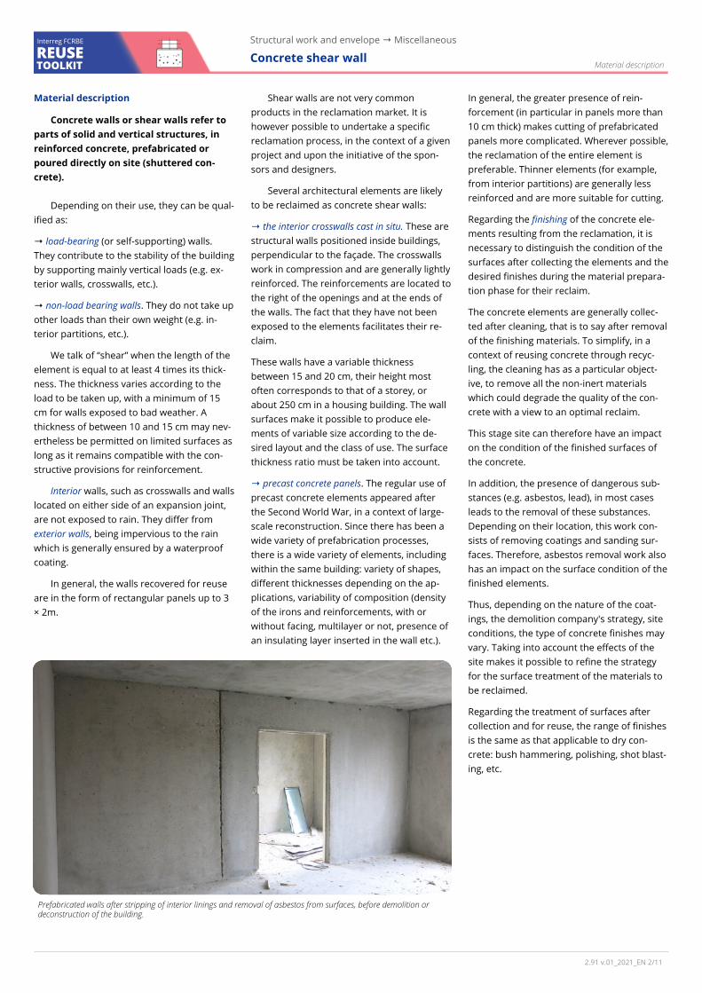
Prefabricated walls after stripping of interior linings and removal of asbestos from surfaces, before demolition or deconstruction of the building.
Material description
2.91 v.01_2021_EN / 2 11
REUSE TOOLKIT
Structural work and envelope → Miscellaneous
Concrete shear wall Interreg FCRBE
Material reclamation
The recovery of concrete shear walls requires heavy mechanical means which can be those of the demolition site. Re-covery depends on several factors: site constraints, location of elements in the building and desired result. It requires careful removal studies complementary to conventional demolition studies; the objective being to preserve the integrity of the elements in order to be able to re-use them. Certain steps must be anticip-ated, in particular if cutting is planned before demolishing the building, or if an-choring points must be installed to allow lifting of the elements to be collected, or even to expose so-called steel "keying" in order to separate prefabricated elements and allow their lifting.
In all cases, it is a question of putting in place all the necessary precautions in con-junction with the site safety coordinator.
→ Disassembly test (or expert opinion). It makes it possible to ensure in practice the technical and economic tenability of the planned removal. Given the experimental nature of the approach, it is wise to rely on the advice of experts and concrete demoli-tion and/or cutting companies, as well as on feedback from similar construction typolo-gies.
→ Diagnosis. The diagnostic mission is gener-ally organised in two phases:
1. Research and analysis of existing docu-ments providing information on the struc-ture to be demolished. This phase is completed by an on-site reconnaissance campaign.
2. Carrying out a survey on the elements. In the case of load-bearing walls, it is re-commended to increase the number of tests and material identification to in-crease the reliability of the results.
The objective of the diagnosis within the framework of reclaim of reinforced concrete is to have a representative image of the structure and its condition. For this, it is ne-cessary to investigate the following:
• Visual inspection of the thickness of the reinforced concrete wall;
• Visual inspection of the condition of the reinforced concrete reinforcements and measurements of the diameters of the bars;
• Measurement of the carbonation depth. (i.e. carbonation is a chemical reaction causing natural ageing of concrete);
• Measurement of the reinforcement cover-ing of the reinforced concrete and of their spacings. (i.e. the covering corresponds to the concrete thickness between a rein-forcement and the skin of the wall. It en-sures protection against corrosion of the reinforcement);
• Concrete compressive strength test;
• Tests of surface cohesion inclination and/or tearing (i.e. The surface cohesion of con-crete is the pressure that allows the mo-lecules to hold themselves together. It in-dicates the resistance to tearing of the sur-face layer of concrete. It measures the ad-hesion of repair products on concrete ).
Several criteria guide the choice and make it possible to check the potential of a batch of concrete shear walls for reclaim:
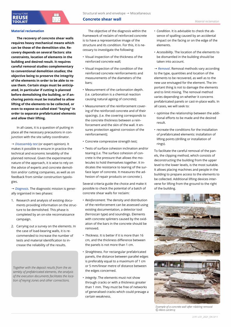
• Reinforcement. The density and distribution of the reinforcement can be assessed using existing documentation, a detector tool (ferroscan type) and soundings. Elements with concrete splinters caused by the oxid-ation of the bars in the concrete should be removed.
• Thickness. It is better if it is more than 16 cm, and the thickness difference between the panels is not more than 1 cm.
• Straightness. For rectangular prefabricated panels, the distance between parallel edges is preferably equal to a maximum of 1 cm or 5 mm/linear metre of distance between the edges concerned.
• Integrity. The elements must not show through cracks or with a thickness greater than 1 mm. They must be free of networks of generalised cracks which could presage a certain weakness.
• Condition. It is advisable to check the ab-sence of spalling caused by an accidental impact on the facing or on the edge of the elements.
• Accessibility. The location of the elements to be dismantled in the building should be taken into account.
→ Removal. Removal methods vary according to the type, quantities and location of the elements to be recovered, as well as to the new use envisaged for the element. The im-portant thing is not to damage the elements and to limit mixing. The removal method varies depending on whether it concerns prefabricated panels or cast-in-place walls. In all cases, we will seek to:
• optimise the relationship between the addi-tional efforts to be made and the desired result.
• recreate the conditions for the installation of prefabricated elements: installation of lifting points (drilling or installation of rings).
To facilitate the careful removal of the pan-els, the clipping method, which consists of deconstructing the building from the upper level to the lower levels, is the most suitable. It allows placing machines and people in the building to prepare access to the elements to be collected. Additional lifting devices inter-vene for lifting from the ground to the right of the building.
Material reclamation
Together with the deposit results from the as-sembly of prefabricated elements, the analysis of the execution documents facilitates the loca-tion of keying zones and other connections.
Example of a concrete wall after nibbling removal Ⓒ Alexis Leclercq
2.91 v.01_2021_EN / 3 11
REUSE TOOLKIT
Structural work and envelope → Miscellaneous
Concrete shear wall Interreg FCRBE
This way, the following method can be con-sidered:
1. Removal of the upper floor holding the wall from the top, in order to free a hold for the wall.
2. Removal of the element by nibbling at the foot of the wall or by tearing off the wall at the top by tilting. The latter method is however to be avoided for load-bearing walls made of reinforced concrete. This practice leads to the plasticisation (i.e. exceeding the yield strength) of the ver-tical reinforcements at the foot of the wall, making them unsuitable for a new structural use.
3. Cutting. Before removal, it is possible to cut the panels, using a technique suited to the desired end product and handling. The time required for cutting must be included in the work schedule. For the removal of prefabricated walls, a simple stripping of the assemblies is sometimes sufficient without having to resort to cut-ting.
4. Lay the panels on the level, using a mini-excavator.
5. Resize items to desired final dimensions (Optional. This operation can be carried out later in the workshop).
6. Final collection upon bringing down, by lifting with a mechanical shovel equipped with a sorting basket (i.e. a sorting basket is a gripper consisting of two metal jaws whose contact surface is a straight line, which makes it possible to distribute the pressure exerted on the material and limit shocks).
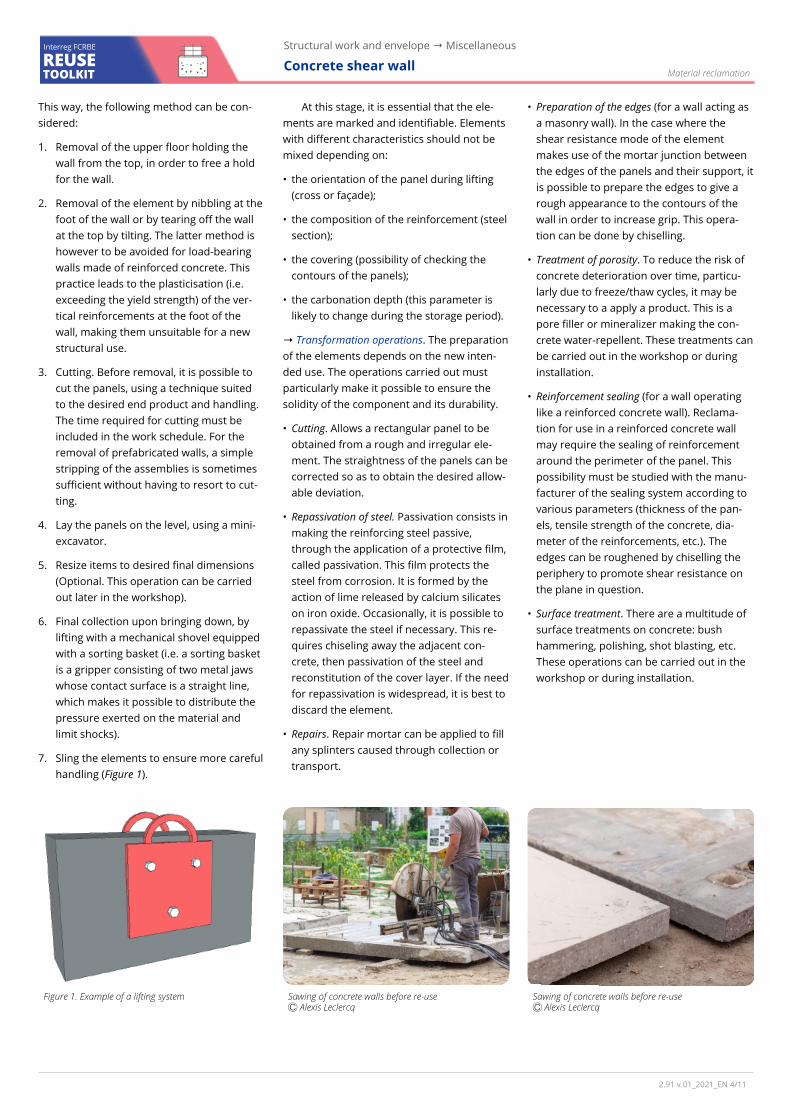
7. Sling the elements to ensure more careful handling (Figure 1).
At this stage, it is essential that the ele-ments are marked and identifiable. Elements with different characteristics should not be mixed depending on:
• the orientation of the panel during lifting (cross or façade);
• the composition of the reinforcement (steel section);
• the covering (possibility of checking the contours of the panels);
• the carbonation depth (this parameter is likely to change during the storage period).
→ Transformation operations. The preparation of the elements depends on the new inten-ded use. The operations carried out must particularly make it possible to ensure the solidity of the component and its durability.
• Cutting. Allows a rectangular panel to be obtained from a rough and irregular ele-ment. The straightness of the panels can be corrected so as to obtain the desired allow-able deviation.
• Repassivation of steel. Passivation consists in making the reinforcing steel passive, through the application of a protective film, called passivation. This film protects the steel from corrosion. It is formed by the action of lime released by calcium silicates on iron oxide. Occasionally, it is possible to repassivate the steel if necessary. This re-quires chiseling away the adjacent con-crete, then passivation of the steel and reconstitution of the cover layer. If the need for repassivation is widespread, it is best to discard the element.
• Repairs. Repair mortar can be applied to fill any splinters caused through collection or transport.
• Preparation of the edges (for a wall acting as a masonry wall). In the case where the shear resistance mode of the element makes use of the mortar junction between the edges of the panels and their support, it is possible to prepare the edges to give a rough appearance to the contours of the wall in order to increase grip. This opera-tion can be done by chiselling.
• Treatment of porosity. To reduce the risk of concrete deterioration over time, particu-larly due to freeze/thaw cycles, it may be necessary to a apply a product. This is a pore filler or mineralizer making the con-crete water-repellent. These treatments can be carried out in the workshop or during installation.
• Reinforcement sealing (for a wall operating like a reinforced concrete wall). Reclama-tion for use in a reinforced concrete wall may require the sealing of reinforcement around the perimeter of the panel. This possibility must be studied with the manu-facturer of the sealing system according to various parameters (thickness of the pan-els, tensile strength of the concrete, dia-meter of the reinforcements, etc.). The edges can be roughened by chiselling the periphery to promote shear resistance on the plane in question.
• Surface treatment. There are a multitude of surface treatments on concrete: bush hammering, polishing, shot blasting, etc. These operations can be carried out in the workshop or during installation.
Material reclamation
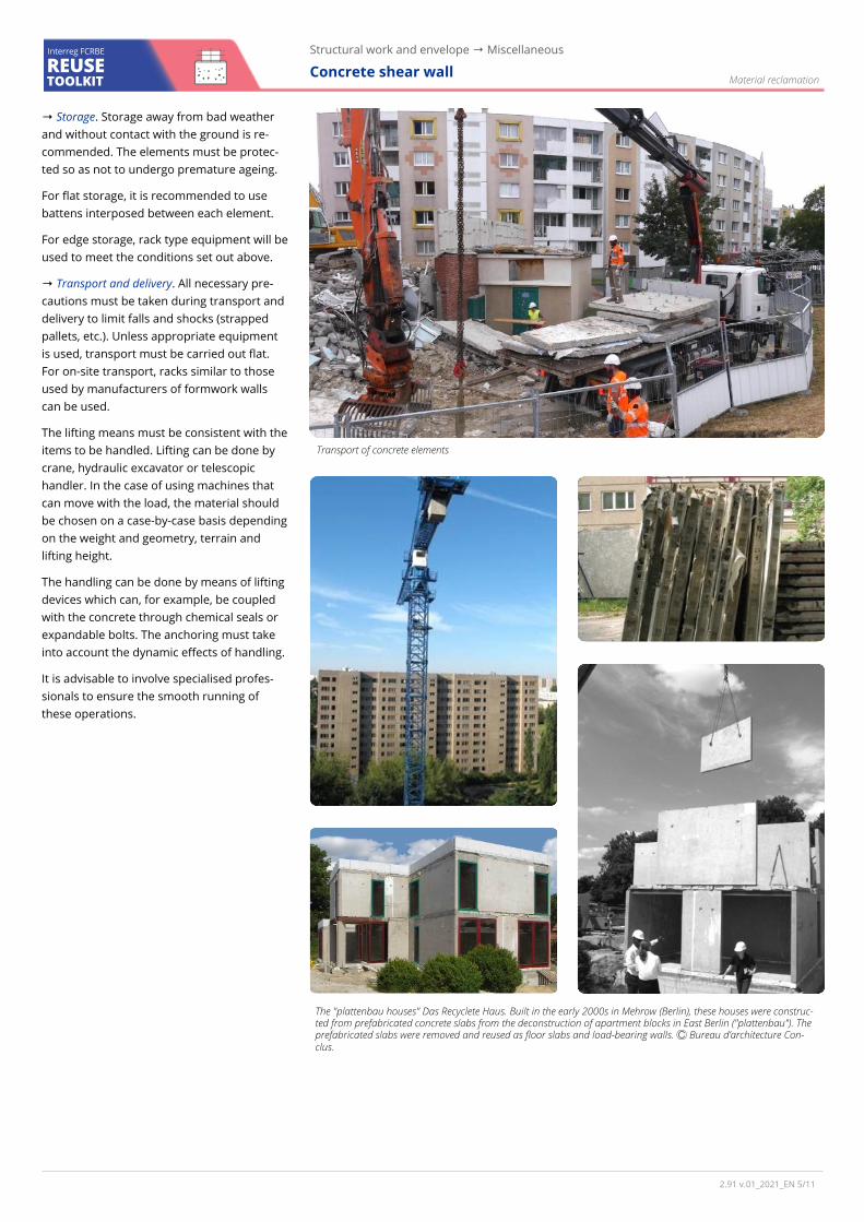
Sawing of concrete walls before re-use Ⓒ Alexis Leclercq
Sawing of concrete walls before re-use Ⓒ Alexis Leclercq
Figure 1. Example of a lifting system
2.91 v.01_2021_EN / 4 11
REUSE TOOLKIT
Structural work and envelope → Miscellaneous
Concrete shear wall Interreg FCRBE
Material reclamation
→ Storage. Storage away from bad weather and without contact with the ground is re-commended. The elements must be protec-ted so as not to undergo premature ageing.
For flat storage, it is recommended to use battens interposed between each element.
For edge storage, rack type equipment will be used to meet the conditions set out above.
→ Transport and delivery. All necessary pre-cautions must be taken during transport and delivery to limit falls and shocks (strapped pallets, etc.). Unless appropriate equipment is used, transport must be carried out flat. For on-site transport, racks similar to those used by manufacturers of formwork walls can be used.
The lifting means must be consistent with the items to be handled. Lifting can be done by crane, hydraulic excavator or telescopic handler. In the case of using machines that can move with the load, the material should be chosen on a case-by-case basis depending on the weight and geometry, terrain and lifting height.
The handling can be done by means of lifting devices which can, for example, be coupled with the concrete through chemical seals or expandable bolts. The anchoring must take into account the dynamic effects of handling.
It is advisable to involve specialised profes-sionals to ensure the smooth running of these operations.
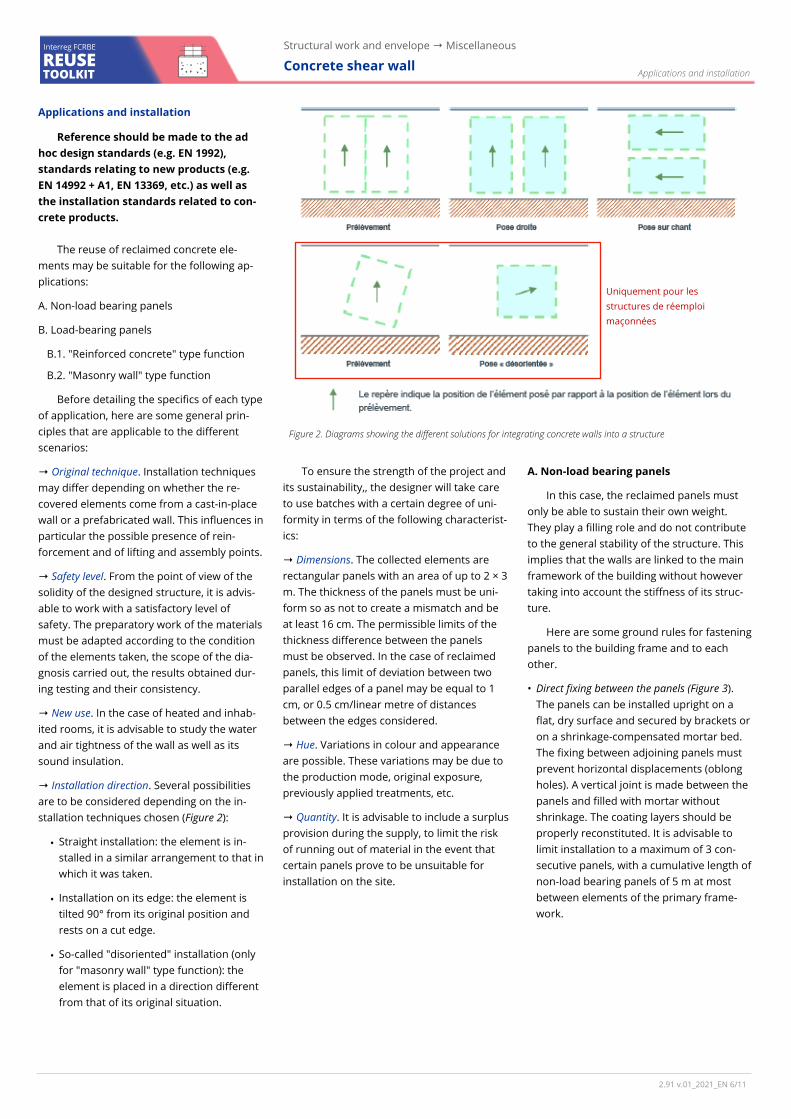
The "plattenbau houses" Das Recyclete Haus. Built in the early 2000s in Mehrow (Berlin), these houses were construc-ted from prefabricated concrete slabs from the deconstruction of apartment blocks in East Berlin ("plattenbau"). The prefabricated slabs were removed and reused as floor slabs and load-bearing walls. Ⓒ Bureau d’architecture Con-clus.
Transport of concrete elements
2.91 v.01_2021_EN / 5 11
REUSE TOOLKIT
Structural work and envelope → Miscellaneous
Concrete shear wall Interreg FCRBE
Applications and installation
Reference should be made to the ad hoc design standards (e.g. EN 1992), standards relating to new products (e.g. EN 14992 + A1, EN 13369, etc.) as well as the installation standards related to con-crete products.
The reuse of reclaimed concrete ele-ments may be suitable for the following ap-plications:
A. Non-load bearing panels
B. Load-bearing panels
B.1. "Reinforced concrete" type function
B.2. "Masonry wall" type function
Before detailing the specifics of each type of application, here are some general prin-ciples that are applicable to the different scenarios:
→ Original technique. Installation techniques may differ depending on whether the re-covered elements come from a cast-in-place wall or a prefabricated wall. This influences in particular the possible presence of rein-forcement and of lifting and assembly points.
→ Safety level. From the point of view of the solidity of the designed structure, it is advis-able to work with a satisfactory level of safety. The preparatory work of the materials must be adapted according to the condition of the elements taken, the scope of the dia-gnosis carried out, the results obtained dur-ing testing and their consistency.
→ New use. In the case of heated and inhab-ited rooms, it is advisable to study the water and air tightness of the wall as well as its sound insulation.
→ Installation direction. Several possibilities are to be considered depending on the in-stallation techniques chosen (Figure 2):
• Straight installation: the element is in-stalled in a similar arrangement to that in which it was taken.
• Installation on its edge: the element is tilted 90° from its original position and rests on a cut edge.
• So-called "disoriented" installation (only for "masonry wall" type function): the element is placed in a direction different from that of its original situation.
To ensure the strength of the project and its sustainability,, the designer will take care to use batches with a certain degree of uni-formity in terms of the following characterist-ics:
→ Dimensions. The collected elements are rectangular panels with an area of up to 2 × 3 m. The thickness of the panels must be uni-form so as not to create a mismatch and be at least 16 cm. The permissible limits of the thickness difference between the panels must be observed. In the case of reclaimed panels, this limit of deviation between two parallel edges of a panel may be equal to 1 cm, or 0.5 cm/linear metre of distances between the edges considered.
→ Hue. Variations in colour and appearance are possible. These variations may be due to the production mode, original exposure, previously applied treatments, etc.
→ Quantity. It is advisable to include a surplus provision during the supply, to limit the risk of running out of material in the event that certain panels prove to be unsuitable for installation on the site.
A. Non-load bearing panels
In this case, the reclaimed panels must only be able to sustain their own weight. They play a filling role and do not contribute to the general stability of the structure. This implies that the walls are linked to the main framework of the building without however taking into account the stiffness of its struc-ture.
Here are some ground rules for fastening panels to the building frame and to each other.
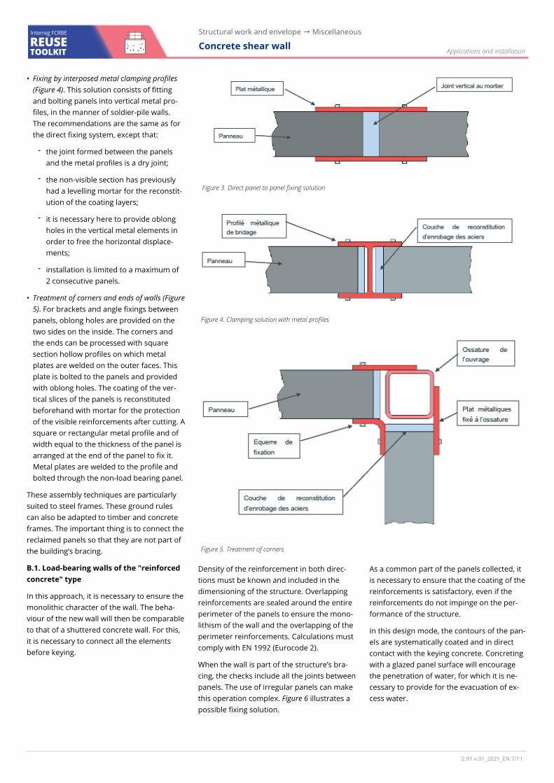
• Direct fixing between the panels (Figure 3). The panels can be installed upright on a flat, dry surface and secured by brackets or on a shrinkage-compensated mortar bed. The fixing between adjoining panels must prevent horizontal displacements (oblong holes). A vertical joint is made between the panels and filled with mortar without shrinkage. The coating layers should be properly reconstituted. It is advisable to limit installation to a maximum of 3 con-secutive panels, with a cumulative length of non-load bearing panels of 5 m at most between elements of the primary frame-work.
Applications and installation
2.91 v.01_2021_EN / 6 11
Figure 2. Diagrams showing the different solutions for integrating concrete walls into a structure
Uniquement pour les structures de réemploi maçonnées
REUSE TOOLKIT
Structural work and envelope → Miscellaneous
Concrete shear wall Interreg FCRBE
• Fixing by interposed metal clamping profiles (Figure 4). This solution consists of fitting and bolting panels into vertical metal pro-files, in the manner of soldier-pile walls. The recommendations are the same as for the direct fixing system, except that:
- the joint formed between the panels and the metal profiles is a dry joint;
- the non-visible section has previously had a levelling mortar for the reconstit-ution of the coating layers;
- it is necessary here to provide oblong holes in the vertical metal elements in order to free the horizontal displace-ments;
- installation is limited to a maximum of 2 consecutive panels.
• Treatment of corners and ends of walls (Figure 5). For brackets and angle fixings between panels, oblong holes are provided on the two sides on the inside. The corners and the ends can be processed with square section hollow profiles on which metal plates are welded on the outer faces. This plate is bolted to the panels and provided with oblong holes. The coating of the ver-tical slices of the panels is reconstituted beforehand with mortar for the protection of the visible reinforcements after cutting. A square or rectangular metal profile and of width equal to the thickness of the panel is arranged at the end of the panel to fix it. Metal plates are welded to the profile and bolted through the non-load bearing panel.
These assembly techniques are particularly suited to steel frames. These ground rules can also be adapted to timber and concrete frames. The important thing is to connect the reclaimed panels so that they are not part of the building’s bracing.
B.1. Load-bearing walls of the "reinforced concrete" type
In this approach, it is necessary to ensure the monolithic character of the wall. The beha-viour of the new wall will then be comparable to that of a shuttered concrete wall. For this, it is necessary to connect all the elements before keying.
Density of the reinforcement in both direc-tions must be known and included in the dimensioning of the structure. Overlapping reinforcements are sealed around the entire perimeter of the panels to ensure the mono-lithism of the wall and the overlapping of the perimeter reinforcements. Calculations must comply with EN 1992 (Eurocode 2).
When the wall is part of the structure’s bra-cing, the checks include all the joints between panels. The use of irregular panels can make this operation complex. Figure 6 illustrates a possible fixing solution.
As a common part of the panels collected, it is necessary to ensure that the coating of the reinforcements is satisfactory, even if the reinforcements do not impinge on the per-formance of the structure.
In this design mode, the contours of the pan-els are systematically coated and in direct contact with the keying concrete. Concreting with a glazed panel surface will encourage the penetration of water, for which it is ne-cessary to provide for the evacuation of ex-cess water.
Applications and installation
2.91 v.01_2021_EN / 7 11
Figure 5. Treatment of corners
Figure 4. Clamping solution with metal profiles
Figure 3. Direct panel to panel fixing solution
REUSE TOOLKIT
Structural work and envelope → Miscellaneous
Concrete shear wall Interreg FCRBE
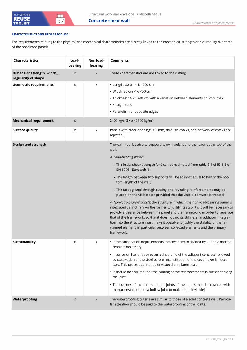
B.2. Load-bearing walls of the "masonry wall" type
In this approach, the reclaimed panels con-stituting the wall are confined and sur-rounded by vertical and horizontal wall ties. The wall consists of one or more panels installed so as to allow the creation of a compression link in order to ensure the resistance of the wall to horizontal forces. In the behavioural modelling of reinforced concrete, the compression link is the zone of compressed concrete, generally ob-liquely to the principal directions of the element.
Non reinforced elements can be used for this type of installation.
The panels are placed on a bed of mortar and propped up before installing all the wall ties. The straightness of the panels must be checked so that they can work with a consistently thick bed of mortar.
It is crucial that the panels adhere correctly to the mortar layer of the wall ties in order to guarantee good resistance to shear stresses (which can be estimated using §6.2.5 of standard EN 1992 - Eurocode 2). However, once cut the panels have edges with a glazed appearance, which are not very conducive to adhesion. From there, two main approaches are possible:
- Rough edge joint reinforcement (Figure 7). Once cut, the edges are subject to spe-cific preparatory work, for example by chiselling, in order to ensure a certain roughness (see § Material recovery). In this case, it is possible to estimate the initial shear strength, noted fvk0 from table 3.4 of §3.6.2 of EN 1996 - Euro-code 6.
- Joint reinforcement with assembly by metal plates (Figure 8). If the adhesion between the blocks is not proven or without prior qualification tests, con-nections by means of metal plates can then be considered. This approach is particularly interesting when it is neces-sary to guarantee a high resistance to shear (e.g. if the wall is part of the bra-cing or the resistance to seismic action).
Applications and installation
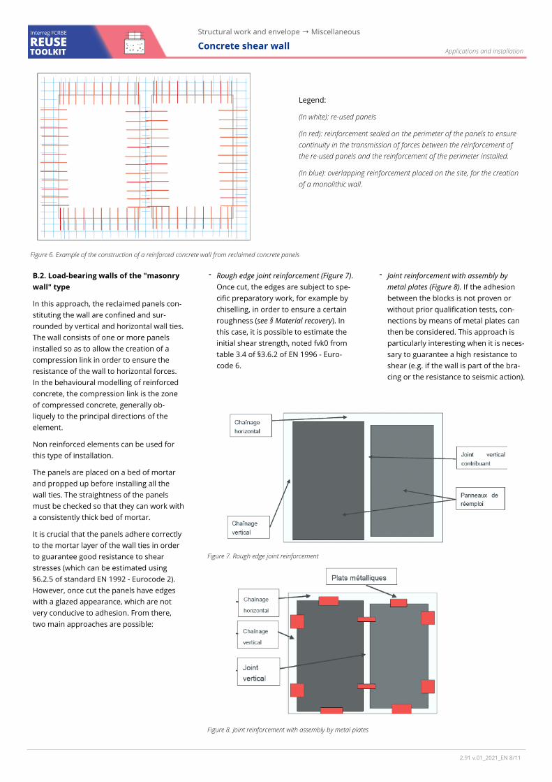
Legend:
(In white): re-used panels
(In red): reinforcement sealed on the perimeter of the panels to ensure continuity in the transmission of forces between the reinforcement of the re-used panels and the reinforcement of the perimeter installed.
(In blue): overlapping reinforcement placed on the site, for the creation of a monolithic wall.
Figure 6. Example of the construction of a reinforced concrete wall from reclaimed concrete panels
Figure 8. Joint reinforcement with assembly by metal plates
Figure 7. Rough edge joint reinforcement
2.91 v.01_2021_EN / 8 11
REUSE TOOLKIT
Structural work and envelope → Miscellaneous
Concrete shear wall Interreg FCRBE
Characteristics and fitness for use
Characteristics and fitness for use
The requirements relating to the physical and mechanical characteristics are directly linked to the mechanical strength and durability over time of the reclaimed panels.
Characteristics Load-bearing
Non load-bearing
Comments
Dimensions (length, width), regularity of shape
x x These characteristics are are linked to the cutting.
Geometric requirements x x • Length: 30 cm < L <200 cm
• Width: 30 cm < w <50 cm
• Thicknes: 16 < t <40 cm with a variation between elements of 6mm max
• Straightness
• Parallelism of opposite edges
Mechanical requirement x 2400 kg/m3 <ρ <2500 kg/m3
Surface quality x x Panels with crack openings > 1 mm, through cracks, or a network of cracks are rejected.
Design and strength The wall must be able to support its own weight and the loads at the top of the wall.
-> Load-bearing panels:
• The initial shear strength fvk0 can be estimated from table 3.4 of §3.6.2 of EN 1996 - Eurocode 6;
• The length between two supports will be at most equal to half of the bot-tom length of the wall;
• The faces glazed through cutting and revealing reinforcements may be placed on the visible side provided that the visible ironwork is treated
-> Non-load-bearing panels: the structure in which the non-load-bearing panel is integrated cannot rely on the former to justify its stability. It will be necessary to provide a clearance between the panel and the framework, in order to separate that of the framework, so that it does not aid its stiffness. In addition, integra-tion into the structure must make it possible to justify the stability of the re-claimed element, in particular between collected elements and the primary framework.
Sustainability x x • If the carbonation depth exceeds the cover depth divided by 2 then a mortar repair is necessary.
• If corrosion has already occurred, purging of the adjacent concrete followed by passivation of the steel before reconstitution of the cover layer is neces-sary. This process cannot be envisaged on a large scale.
• It should be ensured that the coating of the reinforcements is sufficient along the joint.
• The outlines of the panels and the joints of the panels must be covered with mortar (installation of a hollow joint to make them invisible)
Waterproofing x x The waterproofing criteria are similar to those of a solid concrete wall. Particu-lar attention should be paid to the waterproofing of the joints.
2.91 v.01_2021_EN / 9 11
REUSE TOOLKIT
Structural work and envelope → Miscellaneous
Concrete shear wall Interreg FCRBE
Characteristics and fitness for use
Characteristics Load-bearing
Non load-bearing
Comments
Performance in case of fire x x • Incombustible
• The resistance (R), waterproofing (E) and insulation (I) criteria are those of a reinforced concrete wall. These checks come under standard EN 1992-1-2 - Eurocode 2.
• The resistance can be increased or justified by the application of a plaster-board type top coat.
Sound reduction x x • Similar to that of a regular concrete wall with full joint.
• Same regulatory submission and justification by acoustic assessment of the system.
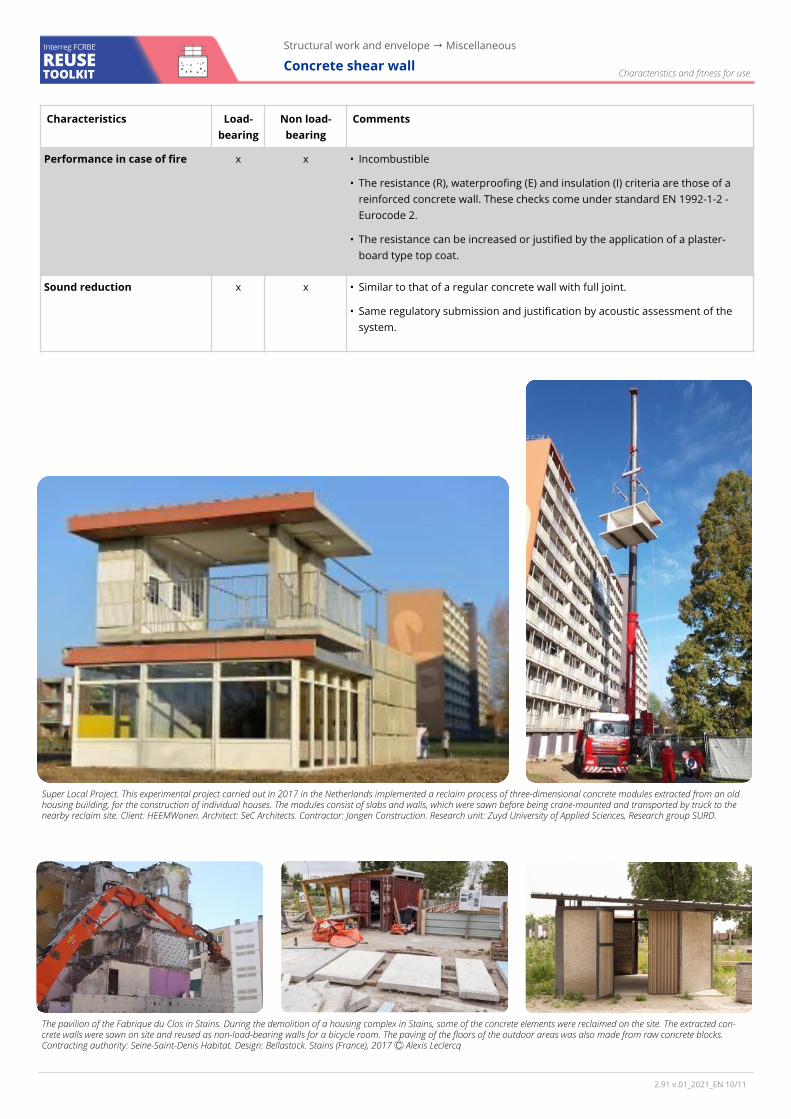
Super Local Project. This experimental project carried out in 2017 in the Netherlands implemented a reclaim process of three-dimensional concrete modules extracted from an old housing building, for the construction of individual houses. The modules consist of slabs and walls, which were sawn before being crane-mounted and transported by truck to the nearby reclaim site. Client: HEEMWonen. Architect: SeC Architects. Contractor: Jongen Construction. Research unit: Zuyd University of Applied Sciences, Research group SURD.
The pavilion of the Fabrique du Clos in Stains. During the demolition of a housing complex in Stains, some of the concrete elements were reclaimed on the site. The extracted con-crete walls were sawn on site and reused as non-load-bearing walls for a bicycle room. The paving of the floors of the outdoor areas was also made from raw concrete blocks. Contracting authority: Seine-Saint-Denis Habitat. Design: Bellastock. Stains (France), 2017 Ⓒ Alexis Leclercq
2.91 v.01_2021_EN / 10 11
Availability
Shear walls are not very common products in the reclamation market. It is however pos-sible to undertake a specific reclamation process, in the context of a given project and upon the initiative of the sponsors and de-signers. For this reason, the supply of con-crete walls is done directly from a demolition operation.
Indicative prices (Excl. tax)
The lack of an established channel does not allow precise pricing of reclaimed panels to be defined. In general, the price of a panel will depend on factors inherent to the source site (number of elements to be collected, complexity of the dismantling, planned ap-plication, etc.) and to the installation context.
Hazardous substances and precautions
During documentary investigation, certain usage restrictions may be issued, in particu-lar in the following cases:
→ Concrete that has been subjected to chemical attack by soils and natural ground-water (corresponding to the three exposure classes XA1, XA2 and XA3 of standard EN 206).
→ Possible presence of asbestos on the sur-face of the concrete wall (fireproof insulation on the façade, joint, interior coating glue, etc.). Prior asbestos removal from the build-ing can make it possible to clean the concrete elements of asbestos residues, a concrete element having been in contact with asbes-tos should not automatically be disqualified for reclaim at the diagnostic stage.
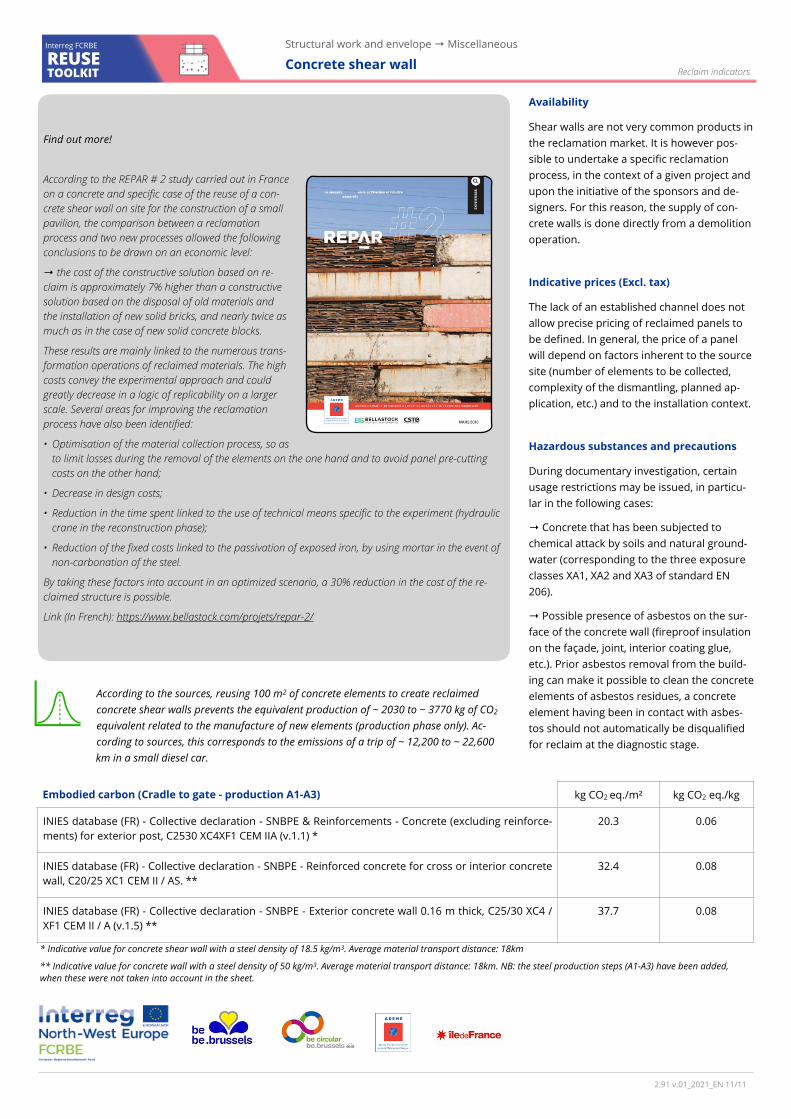
Find out more!
According to the REPAR # 2 study carried out in France on a concrete and specific case of the reuse of a con-crete shear wall on site for the construction of a small pavilion, the comparison between a reclamation process and two new processes allowed the following conclusions to be drawn on an economic level:
→ the cost of the constructive solution based on re-claim is approximately 7% higher than a constructive solution based on the disposal of old materials and the installation of new solid bricks, and nearly twice as much as in the case of new solid concrete blocks.
These results are mainly linked to the numerous trans-formation operations of reclaimed materials. The high costs convey the experimental approach and could greatly decrease in a logic of replicability on a larger scale. Several areas for improving the reclamation process have also been identified:
• Optimisation of the material collection process, so as to limit losses during the removal of the elements on the one hand and to avoid panel pre-cutting costs on the other hand;
• Decrease in design costs;
• Reduction in the time spent linked to the use of technical means specific to the experiment (hydraulic crane in the reconstruction phase);
• Reduction of the fixed costs linked to the passivation of exposed iron, by using mortar in the event of non-carbonation of the steel.
By taking these factors into account in an optimized scenario, a 30% reduction in the cost of the re-claimed structure is possible.
Link (In French): https://www.bellastock.com/projets/repar-2/
Reclaim indicators
Embodied carbon (Cradle to gate - production A1-A3) kg CO2 eq./m² kg CO2 eq./kg
INIES database (FR) - Collective declaration - SNBPE & Reinforcements - Concrete (excluding reinforce-ments) for exterior post, C2530 XC4XF1 CEM IIA (v.1.1) *
20.3 0.06
INIES database (FR) - Collective declaration - SNBPE - Reinforced concrete for cross or interior concrete wall, C20/25 XC1 CEM II / AS. **
32.4 0.08
INIES database (FR) - Collective declaration - SNBPE - Exterior concrete wall 0.16 m thick, C25/30 XC4 / XF1 CEM II / A (v.1.5) **
37.7 0.08
* Indicative value for concrete shear wall with a steel density of 18.5 kg/m3. Average material transport distance: 18km
** Indicative value for concrete wall with a steel density of 50 kg/m3. Average material transport distance: 18km. NB: the steel production steps (A1-A3) have been added, when these were not taken into account in the sheet.
According to the sources, reusing 100 m2 of concrete elements to create reclaimed concrete shear walls prevents the equivalent production of ~ 2030 to ~ 3770 kg of CO2 equivalent related to the manufacture of new elements (production phase only). Ac-cording to sources, this corresponds to the emissions of a trip of ~ 12,200 to ~ 22,600 km in a small diesel car.
Structural work and envelope → Miscellaneous
Concrete shear wall Interreg FCRBE
REUSE TOOLKIT
2.91 v.01_2021_EN / 11 11
Copyright © 2022 FDOKUMEN