Ecology Guideline
66
2009/12/25 Ecology Guideline (Draft) For the ICT Industry (Version 1) December 18, 2009 ICT Ecology Guideline Council
-
Upload
khangminh22 -
Category
Documents
-
view
0 -
download
0
Transcript of Ecology Guideline

2009/12/25
Ecology Guideline (Draft)
For the
ICT Industry
(Version 1)
December 18, 2009
ICT Ecology Guideline Council

1
Ecology Guideline Contents
1. Background and Purpose ········································································ 3
1.1 Background ····················································································· 3
1.2 Purpose ·························································································· 3
2. Definitions ··························································································· 5
3. Relative Positioning and Expected Impact ·················································· 6
3.1 Scope ····························································································· 6
3.2 Policy ····························································································· 6
3.3 Expectations for Respective Parties ······················································ 6
3.4 Expected Impact ··············································································· 7
3.5 Revisions ························································································ 8
3.6 Notice of Disclaimer·········································································· 8
4. Outline of the Guideline ·········································································· 9
4.1 Assessment Standards for Equipment Covered ······································ 9
4.2 Effort and Assessment Criteria for the “Eco ICT Logo” ························· 15
4.3 Image of Guideline Implementation ··················································· 16
5. Assessment Standards ·········································································· 17
5.1 Assessment Standards ····································································· 17
5.1.1 Scope ··················································································· 17
5.1.2 Stance on Other Assessment Standards ······································· 18
5.1.3 Consideration for Error ···························································· 18
5.2 Equipment Definitions, Figure of Merit, Normative References, Measurement
Procedures ···················································································· 19
5.2.1 Routers ················································································· 19
5.2.2 Switching Equipment ······························································ 23
5.2.3 Transport Equipment ······························································ 27
5.2.4 PON Equipment ····································································· 33
5.2.5 Broadband Base Station Equipment ··········································· 37
5.2.6 External Power Source ····························································· 42
5.2.7 Server Equipment ··································································· 45
5.3 Implementation ············································································· 47
6. Normative Reference for Data Centers ····················································· 49
6.1 Basic Approach to Normative Reference ············································· 49
6.2 Definition ····················································································· 49
6.3 Figure of Merit on Energy-Saving as a Normative Reference ··················· 49
6.4 Outline of Figure of Merit on Energy-Saving ········································ 51
6.5 Implementation ············································································· 52
7. Assessment Standard for Eco ICT Logo ···················································· 54
7.1 Purpose ························································································ 54
7.2 Checklist ······················································································· 54
7.3 Eco ICT Logo ················································································· 57
7.4 Implementation ············································································· 58
Attachment 1 Self Assessment Checklist for CO2 Emission Reduction Efforts by

2
Telecommunications Services Providers ······························ 61
Attachment 2 Application for Requesting Public Disclosure of CO2 Emission
Reduction Efforts by Telecommunications Services Providers · 62
Diagram of Logo for Reference ······························································· 63
8. Reference Material ··············································································· 64
9. Contacts ····························································································· 65

3
1. Background and Purpose
1.1 Background
In the face of global warming, Japan must take responsible action to reduce CO2
emissions and the info-communications technology (ICT) industry needs to further
strengthen its own voluntary efforts currently in effect.
As mentioned in the April 2008 Report Released by the “Study Group on ICT
Policy for Addressing Global Warming (Ministry of Internal Affairs and
Communications: MIC),” the use of ICT can dramatically increase efficiency in
production, consumption and industrial activities and greatly contribute to the
reduction of carbon emissions by replacing physical travel and easing traffic
congestion. However, the growth in the scale of ICT services which are realized
through configuring network equipment, servers, and other devices, and the
resulting traffic volume have led to increased consumption of energy (electricity),
translating into escalating CO2 emissions.
To address this increase in CO2 emissions, the MIC report released in June 2009 by
its “Study Group on Ecological Measures in the Info-communications Industry”
listed (i) the procurement of energy-efficient equipment by telecommunications
services providers and (ii) making reductions in CO2 emissions by
telecommunications services providers more visible as two of the numerous effective
measures in decreasing CO2 emissions. It also sought the creation of a guideline by
ICT associations with the cooperation of equipment vendors and other relevant
entities, covering such topics as “assessment of CO2 emissions by equipment,”
“labeling” and “Eco ICT Logo.”
With the release of this MIC report, the five industry organizations:
Telecommunications Carriers Association (TCA), Telecom Services Association
(TELESA), Japan Internet Providers Association (JAIPA), Communications and
Information network Association of Japan (CIAJ) and ASP ・ SaaS Industry
Consortium (ASPIC) created the “ICT Ecology Guideline Council,” (hereafter
referred to as “Council”) on June 26, 2009. The mission of the Council is to (1)
determine an “assessment standard” for use in energy-efficient “procurement
standards” of equipment and data center services by telecommunications services
providers and (2) create a guideline for “establishing procurement standards” and a
“self-assessment of actions” to indicate appropriate CO2 reduction references for
measures taken by individual telecommunications services providers.
1.2 Purpose
Curbing power consumption by the equipment used to provide services is an
effective way for telecommunications services providers to reduce CO2 emissions. To
that end, it is appropriate for individual telecommunications services providers to
establish “procurement standards” for buying telecommunications equipment and

4
services that emit lower amounts of CO2.
Furthermore, telecommunications services providers need to endeavor to increase
energy efficiency across the entire business spectrum. To further promote
ecology-conscious actions by telecommunications services providers, individual
companies need clear normative actions, and there needs to be a framework that
simplifies assessment by a third-party.
In consideration of these factors, this Guideline sets forth points 1) and 2) below
and by doing so, seeks to enhance ecology-conscious actions, such as efforts to
reduce CO2 emissions by telecommunications services providers.
(1) Guideline to establish procurement standards of energy-saving equipment
Indicate an “assessment standard” to assist the formulation of “procurement
standards” by telecommunications services providers for equipment and services
with a focus on the reduction of CO2 emissions.
(2) Guideline for disclosing self-assessment of ecology-conscious actions
Prepare a framework for public disclosure that facilitates an understanding of the
status of efforts to reduce CO2 emissions, in order to show that telecommunications
services providers are appropriately making such efforts. To that end, the Council
will provide a Self-Assessment Checklist and “Logo for acting for ecology.”
Furthermore, this guideline is a reference for telecommunications services
providers in establishing voluntary procurement standards. It is possible that
equipment deemed necessary by telecommunications services providers due to
performance and functional requirements do not meet the energy-saving standards
of this guideline.

5
2. Definitions
(1) Telecommunications services providers
Under this Guideline, an entity providing telecommunication services based on the
Telecommunications Business Act is referred to as a telecommunications services
provider. Moreover, the term is not limited to entities belonging to an industry
organization.
(2) Vendor
Under this Guideline, “vendors” refer to all equipment manufacturers (including
OEM businesses) but does not include businesses dealing solely in sales and
distribution.
(3) Eco ICT Logo
A symbol for broadly disseminating to the public that self-assessment of CO2
emission reducing and other ecologically conscious activities are being performed.
(4) Figure of merit
An index used to calculate the energy-saving effects of a device.
(5) Assessment result
A result of assessment.
(6) Normative reference
An assessment value that is the normative reference for determining the
energy-saving effect. In this Guideline, it is a value determined by a rank of ★★
(two stars) on an assessment scale of five.
(7) Assessment scale
An assessment scale of five ranks used to facilitate the understanding of
assessment regarding energy efficiency of equipment. Indicates rank by the number
of stars (★). The greater the number of stars, the greater the energy efficiency.
(8) Self assessment checklist
A table of assessment items established by the Council to be used for
self-assessment and public disclosure of ecology-conscious actions.
(9) Assessment standard based on the top runner method
Target reference values for energy conservation set forth under the Act on the
Rational Use of Energy (hereinafter referred as the Energy Conservation Law).
6
3 Relative Positioning and Expected Impact
3.1 Scope
This guideline basically applies to telecommunications services providers but also
considers serving as a reference for companies outside the scope of
telecommunications services providers that are planning “procurement standards”
or are engaged in broader efforts to reduce CO2 emissions.
3.2 Policy
As stated in 1.2 Purpose, the policy of this Guideline is to (1) lay down guidelines
for establishing a procurement standard of energy-saving equipment among
telecommunications services providers and (2) lay down guidelines for
self-assessment and disclosing ecology-conscious actions.
As for (1), laying down guidelines for establishing procurement standards of
energy-saving equipment among telecommunication carriers, this Guideline sets
forth:
categories, relevant equipment and assessment standards that can be shared
amongst the vendors and companies making the procurement; and
directions for easy-to-understand notations to be used by those involved in
procurement.
As for (2), laying guidelines for self-assessment and disclosing ecology-conscious
actions, this Guideline proposes a:
method of public disclosure using self-assessment checklists and “Eco ICT
Logo.”
3.3 Expectations for Respective Parties
By creating this Guideline, we expect the respective parties to take the following
actions:
(1) Telecommunications services providers
[1] Establishment of Procurement Standards
Referring to the figure of merit and assessment standards provided in this
Guideline for equipment and data centers, telecommunications services
providers shall formulate their own procurement standards incorporating
market trends and their respective business circumstances while allowing for
safety and reliability considerations.

7
[2] Indication of the “Eco ICT Logo”
Check the status of efforts and achievements in reducing CO2 emissions and
disclose those results using a “Eco ICT Logo,” to show that telecommunications
services providers are appropriately engaged in efforts to reduce CO2 emissions.
(2) Vendors
[1] Indication of equipment assessment results
Vendors wishing to register energy-saving equipment covered by the scope of
this Guideline with the Council must measure and evaluate the device in
accordance to section 5.2 of this Guideline and notify the Council of the
assessment results (assessment results and assessment scale ranking) so that the
information can be publicly disclosed on the Council homepage.
(3) Data center operators
[1] Public disclosure of data
In relation to data center services, data center operators shall publicly disclose
data relevant to energy-saving (such as PUE values, with measurement
conditions) which would serve as a reference for procurement by
telecommunications services providers.
3.4 Expected Impact
The relevant equipment and assessment standards indicated in this Guideline
allow for the establishment of categories and assessment standards that can be
shared by both vendors and the companies making the procurement, which benefits
both sides to the extent it can eliminate inconsistencies in manufacturing and
procurement. Furthermore, it is expected that as telecommunications services
providers add energy-saving items to their procurement standards and actively
install energy efficient equipment, which in turn will promote the development of
energy efficient ICT equipment.
<Image for use as reference>
Company ABC’s Procurement Standard (executed in FYxx)
In procuring materials, we at our company have clearly defined our stance to
contribute to the creation of a sound material-cycle society and have established a
procurement standard to further promote this effort.
1. Scope of equipment covered: ICT equipment and services
2. Procurement standard
For equipment listed in the “Ecology Guideline for ICT Industry,” procurement
decisions shall basically be made from among equipment with energy-saving
ranking of [ ]stars or above.
For equipment not listed in the Guideline, the equipment with the lowest
possible electric power consumption shall be procured.

8
By formulating an assessment standard with the objective of saving energy, it is
hoped that standardization bodies will conduct deliberations of low
power-consuming technologies (such as technologies to control stand-by power of
access equipment) at a faster pace.
3.5 Revisions
This guideline will require appropriate response to: changes in policy relating to
global warming measures; the status of ICT service provision; penetration of
equipment and the like; and technological advances. To that end, even after its
establishment, this Guideline shall continue to be studied by the Council and:
・ the scope of equipment covered shall be broadened, and
・ review of the criteria, such as figure of merit and normative reference shall be
made.
3.6 Notice of Disclaimer
(1) The Council shall not be liable for any damages resulting from the use of this
Guideline incurred by any user of this Guideline.
(2) The Council shall not be held liable for any conflicts resulting from the use of this
Guideline between the user of this Guideline and a third party (or third parties), in
which case, it shall be the responsibility of the user of this Guideline and the third
party (or third parties) to appropriately deal with the conflict.
9
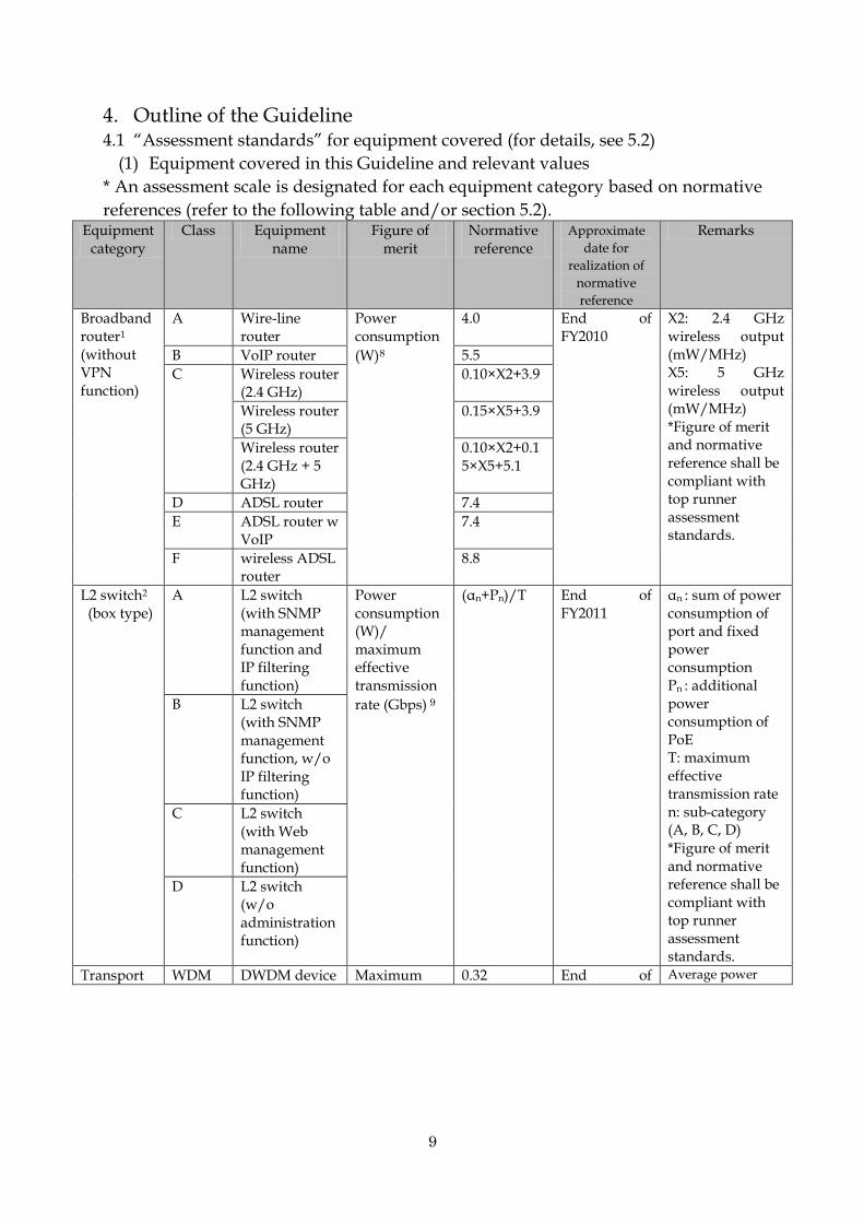
4. Outline of the Guideline 4.1 “Assessment standards” for equipment covered (for details, see 5.2)
(1) Equipment covered in this Guideline and relevant values
* An assessment scale is designated for each equipment category based on normative
references (refer to the following table and/or section 5.2). Equipment
category Class Equipment
name Figure of
merit Normative reference
Approximate
date for
realization of
normative
reference
Remarks
Broadband router1 (without VPN function)
A Wire-line router
Power consumption
(W)8
4.0 End of FY2010
X2: 2.4 GHz wireless output (mW/MHz) X5: 5 GHz wireless output (mW/MHz) *Figure of merit and normative reference shall be compliant with top runner assessment standards.
B VoIP router 5.5
C Wireless router (2.4 GHz)
0.10×X2+3.9
Wireless router (5 GHz)
0.15×X5+3.9
Wireless router (2.4 GHz + 5 GHz)
0.10×X2+0.15×X5+5.1
D ADSL router 7.4
E ADSL router w VoIP
7.4
F wireless ADSL router
8.8
L2 switch2 (box type)
A L2 switch (with SNMP management function and IP filtering function)
Power consumption (W)/ maximum effective transmission
rate (Gbps) 9
(αn+Pn)/T End of FY2011
αn : sum of power consumption of port and fixed power consumption Pn : additional power consumption of PoE T: maximum effective transmission rate n: sub-category (A, B, C, D) *Figure of merit and normative reference shall be compliant with top runner assessment standards.
B L2 switch (with SNMP management function, w/o IP filtering function)
C L2 switch (with Web management function)
D L2 switch (w/o administration function)
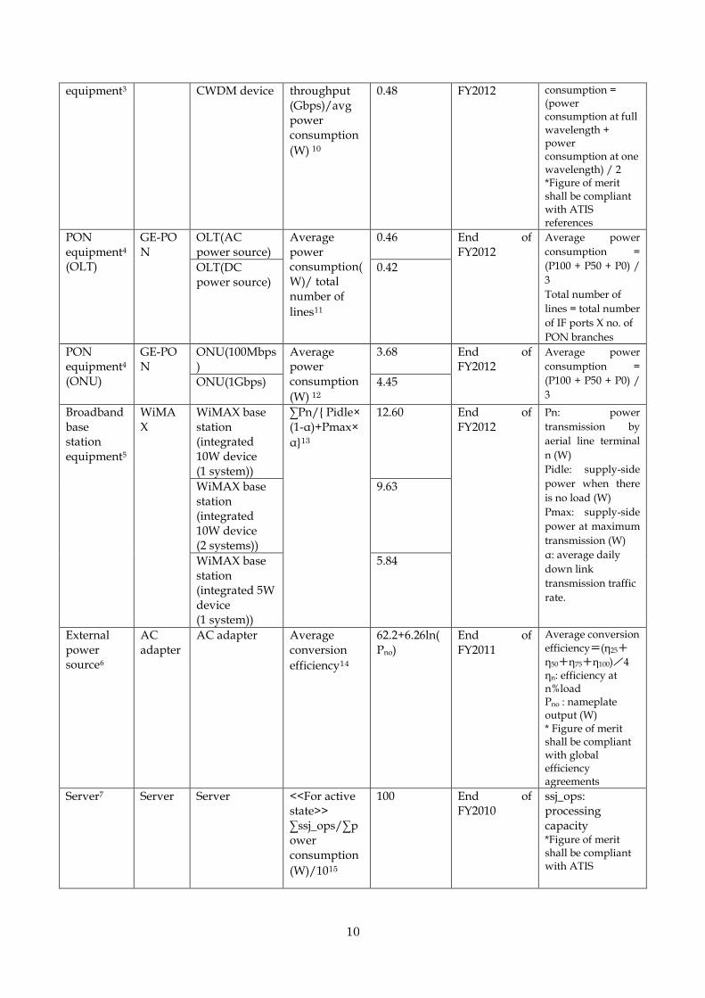
Transport WDM DWDM device Maximum 0.32 End of Average power
10
equipment3 CWDM device throughput (Gbps)/avg power consumption
(W) 10
0.48 FY2012 consumption = (power consumption at full wavelength + power consumption at one wavelength) / 2 *Figure of merit shall be compliant with ATIS references
PON equipment4 (OLT)
GE-PON
OLT(AC power source)
Average power consumption(W)/ total number of
lines11
0.46 End of FY2012
Average power
consumption =
(P100 + P50 + P0) /
3
Total number of
lines = total number
of IF ports X no. of
PON branches
OLT(DC power source)
0.42
PON equipment4 (ONU)
GE-PON
ONU(100Mbps)
Average power consumption
(W) 12
3.68 End of FY2012
Average power
consumption =
(P100 + P50 + P0) /
3 ONU(1Gbps) 4.45
Broadband base station equipment5
WiMAX
WiMAX base station (integrated 10W device (1 system))
∑Pn/{ Pidle× (1-α)+Pmax×
α}13
12.60 End of FY2012
Pn: power
transmission by
aerial line terminal
n (W)
Pidle: supply-side
power when there
is no load (W)
Pmax: supply-side
power at maximum
transmission (W)
α: average daily
down link
transmission traffic
rate.
WiMAX base station (integrated 10W device (2 systems))
9.63
WiMAX base station (integrated 5W device (1 system))
5.84
External power source6
AC adapter
AC adapter Average conversion
efficiency14
62.2+6.26ln(Pno)
End of FY2011
Average conversion
efficiency=(η25+
η50+η75+η100)/4 ηn: efficiency at n%load Pno : nameplate output (W) * Figure of merit shall be compliant with global efficiency agreements
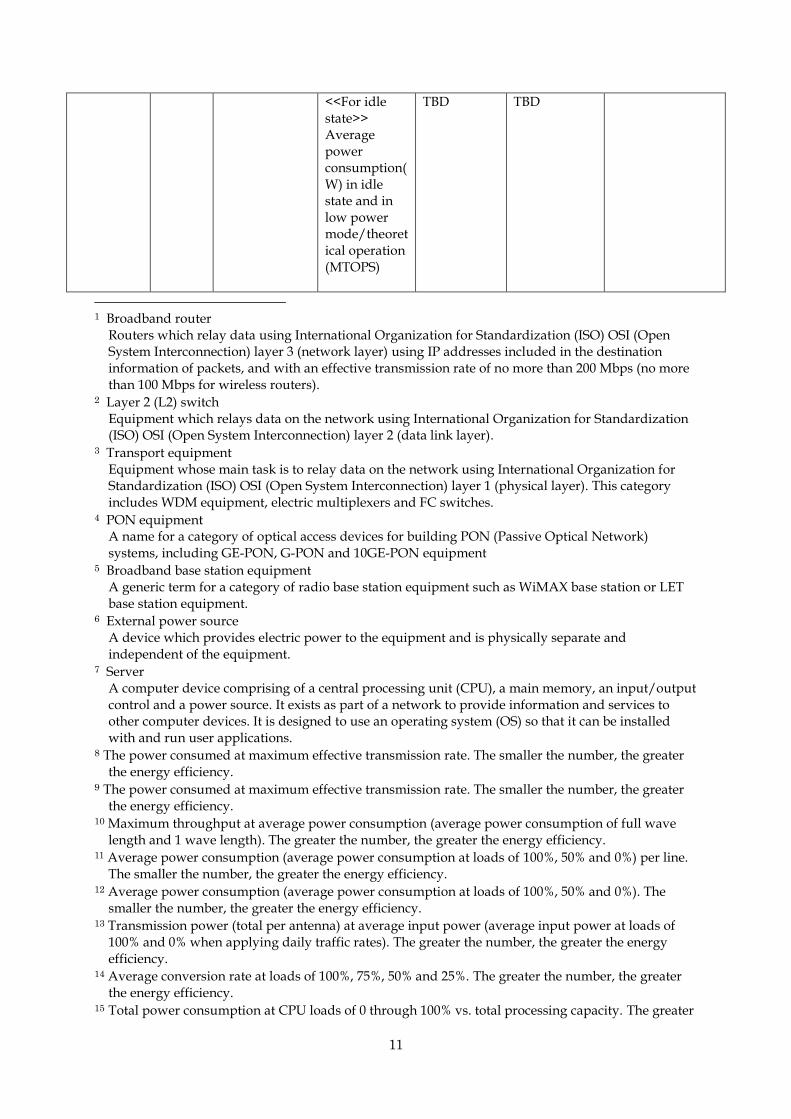
Server7 Server Server <<For active state>> ∑ssj_ops/∑power consumption
(W)/1015
100 End of FY2010
ssj_ops: processing capacity
*Figure of merit shall be compliant with ATIS
11
<<For idle state>> Average power consumption(W) in idle state and in low power mode/theoretical operation (MTOPS)
TBD TBD
1 Broadband router
Routers which relay data using International Organization for Standardization (ISO) OSI (Open System Interconnection) layer 3 (network layer) using IP addresses included in the destination information of packets, and with an effective transmission rate of no more than 200 Mbps (no more than 100 Mbps for wireless routers).
2 Layer 2 (L2) switch Equipment which relays data on the network using International Organization for Standardization (ISO) OSI (Open System Interconnection) layer 2 (data link layer).
3 Transport equipment Equipment whose main task is to relay data on the network using International Organization for Standardization (ISO) OSI (Open System Interconnection) layer 1 (physical layer). This category includes WDM equipment, electric multiplexers and FC switches.
4 PON equipment A name for a category of optical access devices for building PON (Passive Optical Network) systems, including GE-PON, G-PON and 10GE-PON equipment
5 Broadband base station equipment A generic term for a category of radio base station equipment such as WiMAX base station or LET base station equipment.
6 External power source A device which provides electric power to the equipment and is physically separate and independent of the equipment.
7 Server A computer device comprising of a central processing unit (CPU), a main memory, an input/output control and a power source. It exists as part of a network to provide information and services to other computer devices. It is designed to use an operating system (OS) so that it can be installed with and run user applications.
8 The power consumed at maximum effective transmission rate. The smaller the number, the greater the energy efficiency.
9 The power consumed at maximum effective transmission rate. The smaller the number, the greater the energy efficiency.
10 Maximum throughput at average power consumption (average power consumption of full wave length and 1 wave length). The greater the number, the greater the energy efficiency.
11 Average power consumption (average power consumption at loads of 100%, 50% and 0%) per line. The smaller the number, the greater the energy efficiency.
12 Average power consumption (average power consumption at loads of 100%, 50% and 0%). The smaller the number, the greater the energy efficiency.
13 Transmission power (total per antenna) at average input power (average input power at loads of 100% and 0% when applying daily traffic rates). The greater the number, the greater the energy efficiency.
14 Average conversion rate at loads of 100%, 75%, 50% and 25%. The greater the number, the greater the energy efficiency.
15 Total power consumption at CPU loads of 0 through 100% vs. total processing capacity. The greater

12
the number, the greater the energy efficiency.
(2) Assessment scale for relevant equipment [1] Broadband router (without VPN function) Figure of merit: En=power consumption (W) NR=normative reference
Assessment scale
Rate of reduction vs. power consumption
at NR
Energy efficiency ratio by sub-category
En (W)
Notes
A B C D E F Normative reference E (W) per table under 5.2.1-1 (3) Normative References
★★★★★ n≧30% E×0.7≧En
★★★★ 20%≦n<30% E×0.8≧En>E×0.7
★★★ 10%≦n<20% E×0.9≧En>E×0.8
★★(NR) 0%≦n<10% E=En>E×0.9
★ (NR not achieved) E<En
[2] L2 switch (box type) Figure of merit: En=energy consumption (W)/ maximum effective
transmission rate (Gbps) NR=normative reference
Assessment scale
Rate of reduction vs. power
consumption at NR
Energy efficiency ratio per
sub-category En (W) Remarks
A B C D Normative Reference E (W/Gbps) per table under 5.2.2-1 (3) Normative References
★★★★★ n≧30% En≦E×0.7
★★★★ 20%≦n<30% Ex0.7<En≦E×0.8
★★★ 10%≦n<20% Ex0.8<En≦E×0.9
★★(NR) 0%≦n<10% E×0.9<En≦E
★ (NR not achieved) En>E
Note: Rate of reduction of power consumption vs. NR shall be comparable for equipment with similar maximum effective transmission rates.
[3] WDM
Figure of merit: TEER= maximum throughput (Gbps)/ average power consumption (W)
NR=normative reference
Assessment scale
Rate of reduction vs. power consumption at
NR
Average power consumption for 800GbpsDWDM
Average power consumption for 40GbpsCWDM
★★★★★ n≧30% P≦1,750 P≦58.4
★★★★ 20%≦n<30% 1,750<P≦2,000 58.4<P≦66.7
★★★ 10%≦n<20% 2,000<P≦2,250 66.7<P≦75.0
★★(NR) 0%≦n<10% 2,250<P≦2,500 75.0<P≦83.3
★ (NR not achieved) P>2500 P>83.3

13
[4] GE-PON
OLT figure of merit: E= average energy consumption (W)/ total no. of lines ONU figure of merit: P= average energy consumption (W) NR=normative reference
Assessment
scale
Rate of reduction vs. power consumption
at NR
Average power
consumption for OLT
(AC power source) (W)
Average power
consumption for OLT
(DC power source) (W)
★★★★★ n≧30% E≦0.322 E≦0.294
★★★★ 20%≦n<30% 0.322<E≦0.368 0.294<E≦0.336
★★★ 10%≦n<20% 0.368<E≦0.414 0.336<E≦0.378
★★(NR) 0%≦n<10% 0.414<E≦0.46 0.378<E≦0.42
★ (NR not achieved) E>0.46 E>0.42
Assessment
scale
Rate of reduction vs. power consumption
at NR
Average power
consumption for ONU
(100 Mbps)
Average power
consumption for ONU (1
Gbps)
★★★★★ n≧30% P≦2.576 P≦3.115
★★★★ 20%≦n<30% 2.576<P≦2.944 3.115<P≦3.56
★★★ 10%≦n<20% 2.944<P≦3.312 3.56<P≦4.005
★★(NR) 0%≦n<10% 3.312<P≦3.68 4.005<P≦4.45
★ (NR not achieved) P>3.68 P>4.45
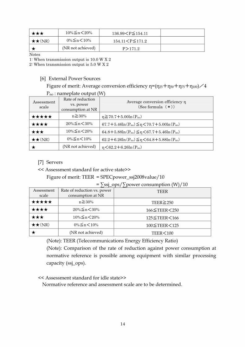
[5] WiMax base station equipment
Figure of merit: E= total transmission power (W)/average primary input
power (W)
Assessment
scale
Rate of reduction vs. power
consumption at NR
Reference average power consumption (W) for
integrated 10W equipment (single)
(Note 1)
Reference average power consumption (W) for
integrated 10W equipment (dual)
(Note 1)
★★★★★ n≧30% P≦111.09 P≦145.39
★★★★ 20%≦n<30% 111.09<P≦126.96 145.39<P≦166.16
★★★ 10%≦n<20% 126.96<P≦142.83 166.16<P≦186.93
★★(NR) 0%≦n<10% 142.83<P≦158.7 186.93<P≦207.7
★ (NR not achieved) P>157.8 P>207.7
Assessment
scale
Rate of reduction vs. power
consumption at NR
Reference average power consumption (W) for
integrated 5W equipment
(single) (W) (Note 2)
★★★★★ n≧30% P≦119.86
★★★★ 20%≦n<30% 119.86<P≦136.99
14
★★★ 10%≦n<20% 136.99<P≦154.11
★★(NR) 0%≦n<10% 154.11<P≦171.2
★ (NR not achieved) P>171.2
Notes
1: When transmission output is 10.0 W X 2
2: When transmission output is 5.0 W X 2
[6] External Power Sources
Figure of merit: Average conversion efficiency η=(η25+η50+η75+η100)/4
Pno : nameplate output (W)
Assessment
scale
Rate of reduction vs. power
consumption at NR
Average conversion efficiency η
(See formula (*))
★★★★★ n≧30% η≧70.7+5.00ln(Pno)
★★★★ 20%≦n<30% 67.7+5.46ln(Pno)≦η<70.7+5.00ln(Pno)
★★★ 10%≦n<20% 64.8+5.88ln(Pno)≦η<67.7+5.46ln(Pno)
★★(NR) 0%≦n<10% 62.2+6.26ln(Pno)≦η<64.8+5.88ln(Pno)
★ (NR not achieved) η<62.2+6.26ln(Pno)
[7] Servers
<< Assessment standard for active state>>
Figure of merit: TEER = SPECpower_ssj2008value/10
= ∑ssj_ops/∑power consumption (W)/10 Assessment
scale Rate of reduction vs. power
consumption at NR TEER
★★★★★ n≧30% TEER≧250
★★★★ 20%≦n<30% 166≦TEER<250
★★★ 10%≦n<20% 125≦TEER<166
★★(NR) 0%≦n<10% 100≦TEER<125
★ (NR not achieved) TEER<100
(Note): TEER (Telecommunications Energy Efficiency Ratio)
(Note): Comparison of the rate of reduction against power consumption at
normative reference is possible among equipment with similar processing
capacity (ssj_ops).
<< Assessment standard for idle state>>
Normative reference and assessment scale are to be determined.
15
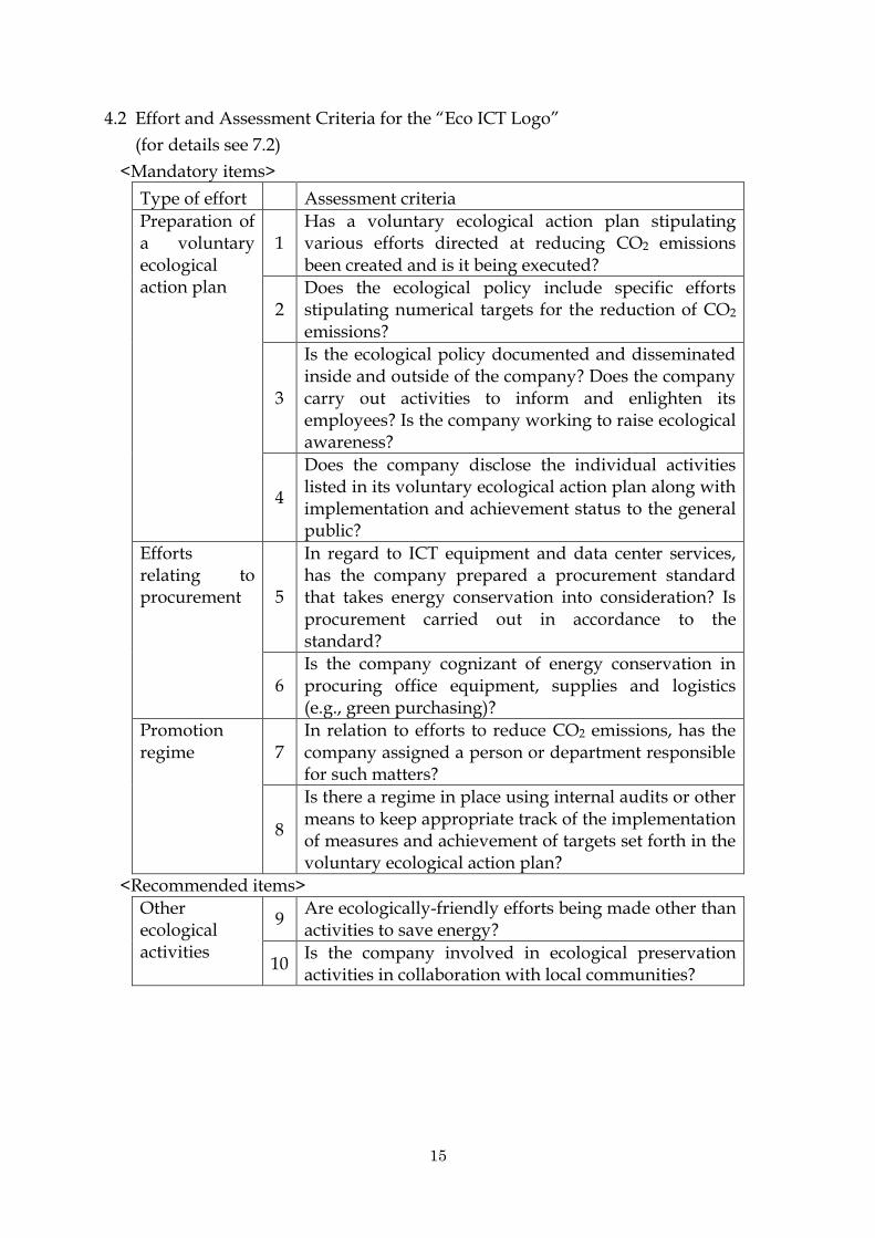
4.2 Effort and Assessment Criteria for the “Eco ICT Logo”
(for details see 7.2)
<Mandatory items>
Type of effort Assessment criteria
Preparation of a voluntary ecological action plan
1 Has a voluntary ecological action plan stipulating various efforts directed at reducing CO2 emissions been created and is it being executed?
2 Does the ecological policy include specific efforts stipulating numerical targets for the reduction of CO2 emissions?
3
Is the ecological policy documented and disseminated inside and outside of the company? Does the company carry out activities to inform and enlighten its employees? Is the company working to raise ecological awareness?
4
Does the company disclose the individual activities listed in its voluntary ecological action plan along with implementation and achievement status to the general public?
Efforts relating to procurement 5
In regard to ICT equipment and data center services, has the company prepared a procurement standard that takes energy conservation into consideration? Is procurement carried out in accordance to the standard?
6 Is the company cognizant of energy conservation in procuring office equipment, supplies and logistics (e.g., green purchasing)?
Promotion regime 7
In relation to efforts to reduce CO2 emissions, has the company assigned a person or department responsible for such matters?
8
Is there a regime in place using internal audits or other means to keep appropriate track of the implementation of measures and achievement of targets set forth in the voluntary ecological action plan?
<Recommended items>
Other ecological activities
9 Are ecologically-friendly efforts being made other than activities to save energy?
10 Is the company involved in ecological preservation activities in collaboration with local communities?

16
4.3 Image of Guideline Implementation
(1) Flow leading to public disclosure of assessment results by vendors and data
centers as well as how procurement by telecommunications services providers
would proceed.
(2) Flow of public disclosure of checklist and use of the “Eco ICT Logo” by
telecommunications services providers.
17
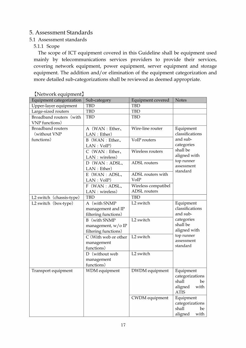
5. Assessment Standards 5.1 Assessment standards
5.1.1 Scope
The scope of ICT equipment covered in this Guideline shall be equipment used
mainly by telecommunications services providers to provide their services,
covering network equipment, power equipment, server equipment and storage
equipment. The addition and/or elimination of the equipment categorization and
more detailed sub-categorizations shall be reviewed as deemed appropriate.
【Network equipment】 Equipment categorization Sub-category Equipment covered Notes
Upper-layer equipment TBD TBD
Large-sized routers TBD TBD
Broadband routers(with
VNP functions)
TBD TBD
Broadband routers
(without VNP
functions)
A(WAN:Ether、
LAN:Ether)
Wire-line router Equipment classifications and sub- categories shall be aligned with top runner assessment standard
B(WAN:Ether、
LAN:VoIP)
VoIP routers
C(WAN:Ether、
LAN:wireless)
Wireless routers
D(WAN:ADSL、
LAN:Ether)
ADSL routers
E(WAN:ADSL、
LAN:VoIP)
ADSL routers with VoIP
F(WAN:ADSL、
LAN:wireless)
Wireless compatibel ADSL routers
L2 switch(chassis-type) TBD TBD
L2 switch(box-type) A(with SNMP management and IP
filtering functions)
L2 switch Equipment classifications and sub- categories shall be aligned with top runner assessment standard
B(with SNMP management, w/o IP
filtering functions)
L2 switch
C(With web or other management
functions)
L2 switch
D(without web management
functions)
L2 switch
Transport equipment WDM equipment DWDM equipment Equipment categorizations shall be aligned with ATIS
CWDM equipment Equipment categorizations shall be aligned with

18
ATIS
PON equipment GE-PON OLT
ONU
Broadband base station equipment
WiMAX WiMAX base stations
External power source AC adaptors AC adaptors Excludes re-chargers
【Power equipment】
Equipment categorization Sub-category Equipment covered Notes
UPS TBD TBD
Rectifier equipment TBD TBD
【Server equipment】 Equipment categorization Sub-category Equipment covered Notes
Server equipment Server equipment
Server equipment Equipment categorizations
of assessment standard for
active state and idle state shall be aligned with ATIS and top runner method respectively
【Storage equipment】
Equipment categorization Sub-category Equipment covered Notes
Storage equipment TBD TBD
TBD:To be determined
5.1.2 Stance on other assessment standards
In regard to specific assessment standards for the equipment subject to this
Guideline, in cases where appropriate standards covering practices by
telecommunications services providers already existed, those existing standards
were adopted. For equipment with no existing assessment standards, assessment
standards for similar equipment were used as reference.
5.1.3 Considerations for error
Acceptable margins due to diversity among equipment covered will be
addressed in the future.
19
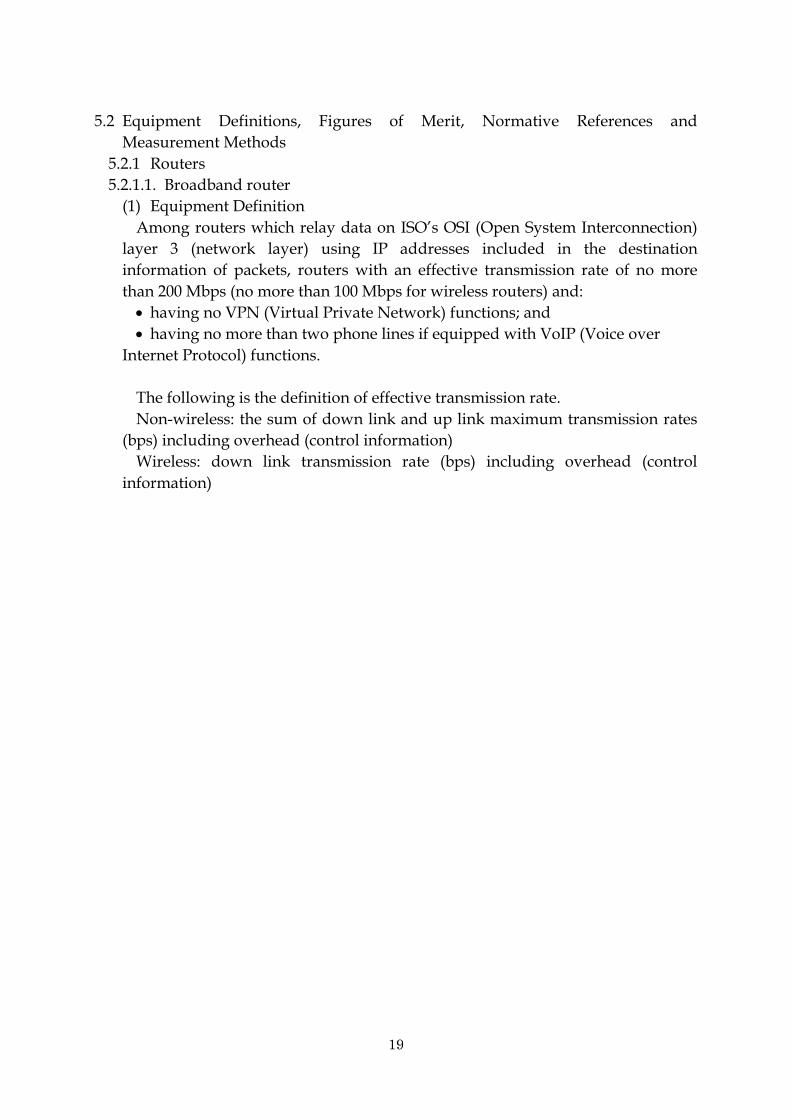
5.2 Equipment Definitions, Figures of Merit, Normative References and
Measurement Methods
5.2.1 Routers
5.2.1.1. Broadband router
(1) Equipment Definition
Among routers which relay data on ISO’s OSI (Open System Interconnection)
layer 3 (network layer) using IP addresses included in the destination
information of packets, routers with an effective transmission rate of no more
than 200 Mbps (no more than 100 Mbps for wireless routers) and:
having no VPN (Virtual Private Network) functions; and
having no more than two phone lines if equipped with VoIP (Voice over
Internet Protocol) functions.
The following is the definition of effective transmission rate.
Non-wireless: the sum of down link and up link maximum transmission rates
(bps) including overhead (control information)
Wireless: down link transmission rate (bps) including overhead (control
information)
20
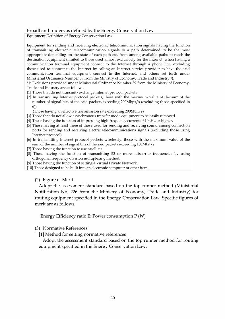
Broadband routers as defined by the Energy Conservation Law Equipment Definition of Energy Conservation Law Equipment for sending and receiving electronic telecommunication signals having the function of transmitting electronic telecommunication signals to a path determined to be the most appropriate depending on the state of each path etc. from among available paths to reach the destination equipment (limited to those used almost exclusively for the Internet; when having a communication terminal equipment connect to the Internet through a phone line, excluding those used to connect to the Internet by calling an Internet service provider to have the said communication terminal equipment connect to the Internet, and others set forth under Ministerial Ordinance Number 39 from the Ministry of Economy, Trade and Industry*1). *1: Exclusions provided under Ministerial Ordinance Number 39 from the Ministry of Economy, Trade and Industry are as follows. [1] Those that do not transmit/exchange Internet protocol packets [2] In transmitting Internet protocol packets, those with the maximum value of the sum of the
number of signal bits of the said packets exceeding 200Mbps/s (excluding those specified in 6)) (Those having an effective transmission rate exceeding 200Mbit/s)
[3] Those that do not allow asynchronous transfer mode equipment to be easily removed. [4] Those having the function of impressing high-frequency current of 10kHz or higher. [5] Those having at least three of those used for sending and receiving sound among connection
ports for sending and receiving electric telecommunications signals (excluding those using Internet protocol)
[6] In transmitting Internet protocol packets wirelessly, those with the maximum value of the sum of the number of signal bits of the said packets exceeding 100Mbit/s
[7] Those having the function to use satellites [8] Those having the function of transmitting 53 or more subcarrier frequencies by using
orthogonal frequency division multiplexing method. [9] Those having the function of setting a Virtual Private Network. [10] Those designed to be built into an electronic computer or other item.
(2) Figure of Merit
Adopt the assessment standard based on the top runner method (Ministerial
Notification No. 226 from the Ministry of Economy, Trade and Industry) for
routing equipment specified in the Energy Conservation Law. Specific figures of
merit are as follows.
Energy Efficiency ratio E: Power consumption P (W)
(3) Normative References
[1] Method for setting normative references
Adopt the assessment standard based on the top runner method for routing
equipment specified in the Energy Conservation Law.

21
[Normative References]
Specific normative references are as follows. Category
Energy efficiency ratio E(W) Type of
interface on WAN side
Type of interface on LAN side
Category name
Ethernet only
Ethernet only A 4.0
Ethernet with VoIP
B 5.5
Ethernet with wireless function
C When transmitting wirelessly on 2.4GHz band only:
E = 0.10×X2+3.9 When transmitting wirelessly on 5 GHz band only:
E=0.15×X5+3.9 When transmitting the two frequencies mentioned above simultaneously:
E=0.10×X2+0.15×X5+5.1
ADSL only Ethernet only D 7.4
Ethernet with VoIP
E 7.4
Ethernet with wireless function
F 8.8
Remarks 1: “WAN side” refers to the side of the port connected to a network such as the
Internet. “LAN side” refers to the side of the port connected to other equipment. 2: E, X2 and X5 represent the following values: E: Reference energy efficiency ratio (unit: W) X2: 2.4 GHz wireless output (unit: mW/MHz) X5: 5 GHz wireless output (unit: mW/MHz) 3: In subcategory C, for equipment capable of transmission after selecting wireless
2.4 GHz band or 5 GHz band, use the calculation formula for the frequency band with a higher effective transmission rate in (4) Measurement Methodology to calculate the value for the reference energy efficiency ratio.
[Approximate Timeline for Realizing the Normative References]
The end of Fiscal Year 2010 (adopted the target fiscal year per the standard on
routing equipment (Ministerial Notification No. 226 from the Ministry of
Economy, Trade and Industry), specified in the Energy Conservation Law),
[2] Assessment scale references
The rate of reduction versus the normative reference shall determine the
threshold. In the assessment scale, the rank covering the normative reference
shall be ★★. Assessment
scale
Rate of reduction vs. power
Energy efficiency ratio by
category En (W) Remarks

22
consumption at NR
A B C D E F NR E (W) per table under (3) 1) Normative References ★★★★★ n≧30% En≦E×0.7
★★★★ 20%≦n<30% E×0.7<En≦E×0.8
★★★ 10%≦n<20% E×0.8<En≦E×0.9
★★ (NR) 0%≦n<10% E×0.9<En≦E
★ (NR not achieved) En>E
(Note) In calculating energy efficiency ratio, calculate values to the first decimal place.
(4) Measurement Methodology
Measurement methods are as follows and coincide with those set forth under
Ministerial Notification Number 226 from the Ministry of Economy, Trade and
Industry, which sets forth, among other things, assessment standards for vendors
in relation to the stipulations of the Energy Conservation Law for routing
equipment.
[1] To measure energy efficiency, measure power consumption at maximum
effective transmission rate. Conditions for measuring power consumption
and maximum effective transmission rate are as follows.
(a) The maximum value of the sum of the number of packets per second
output to the WAN side and the number of packets per second output to
the LAN side.
(b) A 1,500 byte packet shall be transmitted for measurement. However, if
the transmission of a 1,500 byte packet is not possible, use the maximum
packet length.
(c) Use IP packets for unicast transmission.
(d) The data pattern of the header section is arbitrary. Use 0 for all data
patterns of the packet to be measured.
(e) When measuring power consumption, it shall be acceptable to transmit
the minimum packet suited to the maximum effective transmission rate
of the router.
(f) Enable routing of packets received by the router. Routing is the relay of
data to a destination determined by the IP address on a network using
the third layer (network layer) of a model indicated in the Basic
Reference Model 6 of Open Systems Interconnection stipulated in Japan
Industrial Standard X5003. Upon performing the relay, the TTL value,
which is the header information associated with an IP address, shall be
decremented and relayed to a different data link.
(g) Removable components and functions that can be disabled without
sacrificing the basic performance and functioning of the router shall be
removed or disabled, respectively, for the measurement.
(h) Ports not involved in the measurement can be linked down.
(i) The peripheral temperature shall fall within the range of 16 to 32°C.
However, for wireless routers the range shall be 0 to 40°C.

23
(j) Power voltage shall be within the range of +/-10% of rated input voltage
(100V or 200V).
(k) Use rated frequency for AC power source frequency.
(l) Conduct measurements with the router in a stationary state.
(m) For products using an AC power source, measure power consumption at
the power plug.
(n) In the case of AC power, use effective power as power consumption.
[2] Use the following conditions for routers with wireless functions
(a) Wireless transmission direction shall be from the WAN side to the LAN
side.
(b) If there are multiple wireless LAN interfaces capable of operating
simultaneously, operate them simultaneously.
(c) Use a configuration that disables functions such as data compression and
output power adjustment.
(d) Use maximum link speed of the router.
(e) Use packet generators as measurement equipment to measure wireless
LAN routers.
5.2.2 Switching Equipment
5.2.2.1. Layer 2 (L2) Switches (box type)
(1) Equipment Definition
Among equipment which relays data on the network using ISO’s OSI (Open
System Interconnection) layer 2 (data link layer) using the MAC address
included in the destination information of the packet and is a box type having
three or more communication ports. Equipment Definition in Energy Conservation Law Equipment for sending and receiving electronic telecommunication signals having the function of transmitting electronic telecommunication signals to a path determined separately for each destination from among two or more paths capable of transmission (limited to those used almost exclusively for the Internet; however excluding those capable of wireless telecommunication and others set forth under Ministerial Ordinance Number 39 from the Ministry of Economy, Trade and Industry*1).
*1: Exclusions provided under Article 48(21) of Ministerial Ordinance Number 39 from the Ministry of Economy, Trade and Industry (exclusions from specified equipment) are as follows.
[1] Those that do not transmit and switch Ethernet frames [2] Those that transmit and switch Internet protocol packets [3] Those with connection ports for sending and receiving electric telecommunications signals
having at least half of the connection ports utilize a two line connection [4] Those designed to be built into a housing, electronic computer or other item. [5] Those for controlling equipment that relay electrical telecommunications signal wirelessly [6] Those set forth by the Minister of Economy Trade and Industry that are primarily for
supplying power.

24
(2) Figure of merit
Adopt the assessment standard based on the top runner method for switching
equipment (Ministerial Notification No. 227 from the Ministry of Economy,
Trade and Industry), which are identified as specified equipment in the Energy
Conservation Law.
Energy efficiency E = power consumption/maximum effective transmission
rate (W /Gbps)
(3) Normative References
[1] Method for deciding Normative References
Adopt the assessment standard based on the top runner method for
switching equipment, which are identified as specified equipment in the
Energy Conservation Law.
[Normative References] Specific normative references are as follows.
However, the normative references do not apply to models with Pd/PSA, Pd/
PSB, Pd/PSC or Pd/PSD in excess of 16, per the following. Category Normative Reference:
Standard energy efficiency ratio
(W/Gbps)
Management functions
Type of management functions
IP filtering functions
Category name
With management functions
With SNMP functions With IP filtering functions
A
E=(αA+PA)/T
No IP filtering functions
B
E=(αB+PB)/T
With Web management and other management functions
C
E=(αC+PC)/T
No management functions
D E=(αD+PD)/T
Remarks 1: “Management functions” refers to functions for a network manager to acquire such
information as network components and telecommunications status for the purpose of operating the network efficiently.
2: Values for αA, αB, αC and αD shall be calculated using the following formula.
αA=0.578 × X1 + 1.88 × X2 + 15.9 × X3+βA
αB=0.375 × X1 + 1.88 × X2 + βB
αC=0.375 × X1 + 1.133 × X2 + βC
αD=0.272 × X1 + 1.133 × X2 + βD The value for αA, αB, αC or αD shall be 3 in cases where the equipment has only a 100 Mbps port, or where the equipment has a 100 Mbps port and a 1 Gbps port and the value for αA, αB, αC and αD is less than 3. Furthermore, the value for αA, αB, αC or αD shall be 4.5 in the event the equipment has only a 1Gbps port and the value for αA, αB, αC or αD is less than 4.5.
3: The value for X1 is the number of ports (unit: number of ports) with a line speed of

25
100 Mbps. The value for X2 is the number of ports (unit: number of ports) with a line speed of 1 Gbps. The value for X3 is the number of ports (unit: number of ports) with a line speed of 10 Gbps.
4: Use the values provided in the following table for βA, βB, βC and βD based on the appropriate categorization.
区分 βA βB βC βD
Has only a 100Mbps port 3.976 3.4 3.4 0.824
Has only a 1Gbps port 9.94 -5.07 -2.074 -2.074
Has only a 10Gbps port 0 0 0 0
Has a 100Mbps port and one 1 Gbps port 2.276 1.7 2.447 1.494
Has a 100Mbps port and two 1 Gbps ports 0.576 0 1.494 1.494
Has a 1Gbps port and a 10Gbps port -10.24 0 0 0
5: The values for PA, PB, PC and PD shall be calculated using the following formula.
PA=(0.0347×Pd/PSA)/(1-0.0347×Pd/PSA)×αA
PB=(0.0347×Pd/PSB)/(1-0.0347×Pd/PSB)×αB
PC=(0.0347×Pd/PSC)/(1-0.0347×Pd/PSC)×αC
PD=(0.0347×Pd/PSD)/(1-0.0347×Pd/PSD)×αD 6: The values for PSA, PSB, PSC and PSD shall be calculated using the following formula.
PSA=αA×0.85+1
PSB=αB×0.85+1
PSC=αC×0.85+1
PSD=αD×0.85+1 7: Pd represents the value for maximum power supply (unit: W) for power over
Ethernet. If the equipment has no power over Ethernet function, use 0. 8: T represents the value for maximum effective transmission rate (unit: Gbps) when
the frame length is 1,518 bytes.
[Approximate Timeline for Realizing the Normative References]
End of Fiscal Year 2011 (adopted the target fiscal year per the standard on
switching equipment (Ministerial Notification No. 227 from the Ministry of
Economy, Trade and Industry), specified in the Energy Conservation Law)
[2] Assessment scale references
Set a threshold for the improvement rate versus the energy efficiency of
normative reference. In assessment scale, the rank including normative
reference shall be ★★.
Assessment scale
Rate of reduction vs. power consumption
at NR
Energy efficiency ratio by category En
(W/Gbps) Remarks
A B C D Normative Reference E (W/Gbps) per table under (3) Normative References
★★★★★ n≧30% En≦E×0.7
★★★★ 20%≦n<30% Ex0.7<En≦E×0.8
★★★ 10%≦n<20% Ex0.8<En≦E×0.9
★★(NR) 0%≦n<10% E×0.9<En≦E
★ (NR not achieved) En>E
(Note) In calculating energy efficiency, drop digits beyond the first decimal point. (Note) Rate of reduction of power consumption vs. NR shall be comparable for equipment with
similar maximum effective transmission rates.

26
(4) Measurement Methodology
Measurement conditions are as follows in consideration of the contents of
Ministerial Notification Number 227 from the Ministry of Economy, Trade and
Industry, which sets forth judgment standards, among other things, for
manufacturers of switching equipment based on the stipulations of the Energy
Conservation Law.
[1] For energy efficiency, use the value resulting from dividing the value
expressed in W, representing power consumption during maximum
effective transmission rate when the frame length to be measured is 1,518
bytes, by a value expressed in Gbps, representing the aforementioned
effective transmission rate.
[2] Conditions for measuring power consumption and maximum effective
transmission rate are as follows.
(a) The value for maximum effective transmission rate is calculated using
the following formula.
T = R x (L+20) x 8
In this formula, T, R and L represent the following values.
T: Maximum effective transmission rate when the frame length is 1,518
bytes
R: The total number of frames output per second from all ports
L: Frame length (unit: bytes)
(b) Set switch so as to perform switching of received frames. Switching is the
relay of data on a network using the second layer (data link layer) of a
reference model indicated in Basic Reference Model 6 of Open Systems
Interconnection stipulated in Japan Industrial Standard X5003.
Specifically relay is performed referring to the MAC address.
(c) Use a frame for unicast transmission.
(d) The data pattern of the header section is arbitrary. Use 0 for all data
patterns of the frame to be measured.
(e) Measurement dependent on type of cascade connection at the ports are
permissible. In such cases, calculate maximum effective transmission rate
considering the number of cascade-connected ports.
(f) When measuring energy efficiency ratio, it is acceptable to transmit the
minimum frames required according to the maximum effective
transmission rate of the switch.
(g) Components that can be removed and functions that can be disabled
without sacrificing the basic performance and functioning of the switch
shall be removed or disabled, respectively, for the measurement.
(h) Ports not used in the measurement can be linked down.
27
(i) The peripheral temperature shall fall within the range of 16 to 32°C.
(j) Power voltage shall be within the range of +/-10% of rated input voltage
(100V or 200V) if the power source is AC and within the range of DC-57V
to DC-40.5V if the power source is DC.
(k) Use rated frequency for AC power source frequency.
(l) Conduct measurements with the switch in a stationary state.
(m) For products using an AC power source, measure power consumption at
the power plug terminal.
(n) In the case of AC power, use effective power as power consumption.
5.2.3 Transport Equipment
5.2.3.1. WDM Equipment
(1) Equipment Definition
WDM equipment is a product that performs info-communication functions
over a single fiber-optic cable by multiplexing multiple optic signals of
different wavelengths.
WDM equipment from recent years may include devices that integrate OSI
reference models from the second (data link) layer to the third (network)
layer. Due to the difficulty of defining a standard device configuration,
here WDM equipment refers to devices having only the OSI first (physical)
layer mounted.
This guideline applies to WDM equipment used in terrestrial systems.
Submarine systems are exempt. Furthermore, relay equipment is exempt
because relay equipment consumes less power compared to terminal
equipment.
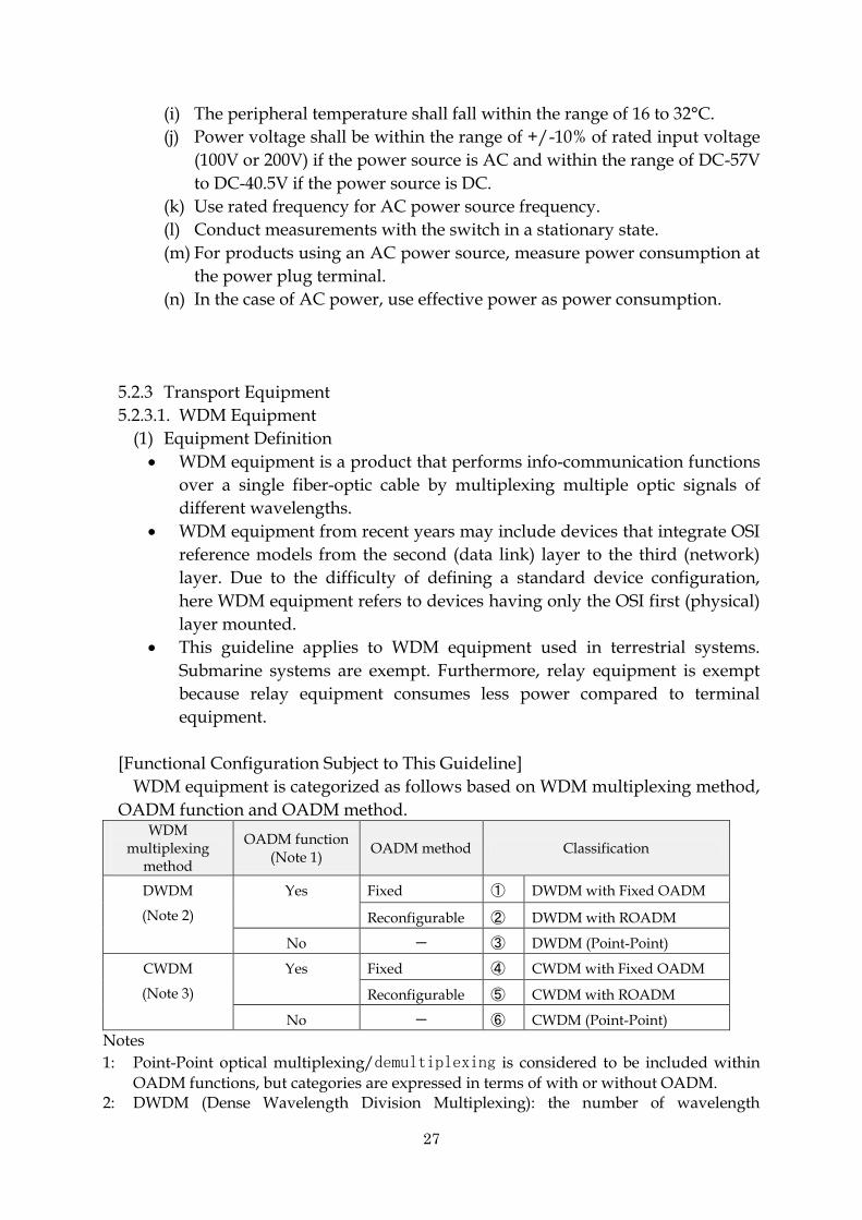
[Functional Configuration Subject to This Guideline]
WDM equipment is categorized as follows based on WDM multiplexing method,
OADM function and OADM method. WDM
multiplexing method
OADM function (Note 1)
OADM method Classification
DWDM
(Note 2)
Yes Fixed ① DWDM with Fixed OADM
Reconfigurable ② DWDM with ROADM
No - ③ DWDM (Point-Point)
CWDM
(Note 3)
Yes Fixed ④ CWDM with Fixed OADM
Reconfigurable ⑤ CWDM with ROADM
No - ⑥ CWDM (Point-Point)
Notes
1: Point-Point optical multiplexing/demultiplexing is considered to be included within
OADM functions, but categories are expressed in terms of with or without OADM. 2: DWDM (Dense Wavelength Division Multiplexing): the number of wavelength

28
multiplexing is mainly no less than 32ch. Primarily used in backbone and metro core networks.
3: CWDM (Coarse Wavelength Division Multiplexing): the number of wavelength multiplexing is mainly no more than 16ch. Primarily used in metro access and parts of metro core.
Among the above categories, 2) DWDM with ROADM and 6) CWDM (Point-Point)
are subject to this Guideline, both of which are expected to exhibit energy-saving
impact and for which future demand is forecast.
DeMux
OSC
OSC
OSC
OSC
Trans-ponder
CPU
①DWDM with Fixed OADM
⑥CWDM(Point to Point)
WSSOSC
OSC
OSC
OSC
②DWDM with ROADM
WSS
④CWDM with Fixed OADM
OSC
OSC OSC
OSC OSC
OSC OSC
OSC OSC
OSC
分波
OSC
OSC
③DWDM(Point to Point)
MuxMuxDeMux DeMux
Trans-ponder
CPU
DeMux DeMuxMux Mux
Trans-ponder
Trans-ponder
Trans-ponder
Trans-ponder
Trans-ponder
Trans-ponder
Mux
DeM
ux
DeM
uxM
ux
Mux
DeM
ux
Trans-ponder
Trans-ponder
CPU
Mux
DeM
ux
Mux
DeM
ux
Trans-ponder
Trans-ponder
CPU
(2) Figures of merit
Use the figure of merit TEER (Telecommunications Energy Efficiency Ratio)
(Note 1) for transport equipment stipulated by ATIS (Alliance for
Telecommunications Industry Solutions), as follows.
TEERCERT = DTEER/PTEER-CERT
= ΣDi/(PCERT-0+PCERT-50+PCERT-100)/3
TEERCERT: Certified TEER measured at a specific configuration (Note 2)
DTEER: Total data rate (bps)
PTEER-CERT: Measured power consumption (W)
Di: Data rate (bps) at a given interface i
PCERT-0: Measured power consumption (W) at a 0% data usage rate
PCERT-50: Measured power consumption (W) at a 50% data usage rate
PCERT-100: Measured power consumption (W) at a 100% data usage rate
(Note 1): ATIS-0600015.2009: General TEER base standard

29
(Note 2): ATIS-0600015.02.2009: Transport product category TEER
This figure of merit applies not only to WDM equipment but also to “transport
equipment” including SONET/SDH equipment and the like.
<For WDM Equipment>
DWDM figure of merit: TEER = maximum throughput (Gbps) / average power
consumption (W)
CWDM figure of merit: TEER = maximum throughput (Gbps) / average power
consumption (W)
Note: Calculate average power consumption = (power consumption at full
wavelength + power consumption at one wavelength) / 2.
Peak throughput is total throughput at full wavelength.
In WDM equipment, unlike packet interface cards, it is common for operations
to guarantee 100% transport constantly; therefore,
PCERT-0 = PCERT-50 = PCERT-100.
Thus, TEERCERT in WDM equipment under ATIS is substantially as follows.
TEERCERT = DTEER/PTEER-CERT
= maximum transmission capacity / power consumption when
configured for maximum transmission capacity
(This is provided as a ROADM system example for ATIS-0600015.02.2009.)
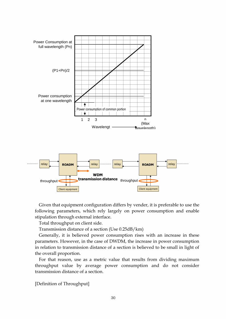
In evaluating the power consumption of equipment, measure power
consumption at one wavelength and at full wavelength, so as to provide
visibility into low power consumption in common portions such as the optical
amplifier and the optical multiplexer/demultiplexer, and use the following for
average power consumption.
Average power consumption = (power consumption at full wavelength + power
consumption at one wavelength) / 2
30
1 2 3 n(Max
wavelength)
Power consumption
at one wavelength
Power Consumption at
full wavelength (Pn)
(P1+Pn)/2
Wavelengt
h
Power consumption of common portion
relay relayROADM ROADM
WDMtransmission distance
throughput
Client equipment
relay
Client equipment
throughput
relay
Given that equipment configuration differs by vender, it is preferable to use the
following parameters, which rely largely on power consumption and enable
stipulation through external interface.
Total throughput on client side.
Transmission distance of a section (Use 0.25dB/km)
Generally, it is believed power consumption rises with an increase in these
parameters. However, in the case of DWDM, the increase in power consumption
in relation to transmission distance of a section is believed to be small in light of
the overall proportion.
For that reason, use as a metric value that results from dividing maximum
throughput value by average power consumption and do not consider
transmission distance of a section.
[Definition of Throughput]

31
Throughput is defined as the total effective client signal rate (converted to a
single direction) passing through the device (does not include FEC closed and
added within WDM).
throughput=0G
Client side (transponder) WDM side
throughput=0G (2.5G×4)
1 port transponder
MUX transponder
Example of throughput by transponder type
10G 10G+FEC
2.5G×4 10G+FEC
(3)
(3) Normative References
[1] Method for determining normative references
Normative references for DWDM and CWDM equipment shall be values
derived by adding enhancements accounting for technological trends to
average metric values based on products shipped in Fiscal Year 2008 (CIAJ
survey).
[Normative References]
DWDM equipment: 0.32 Gbps/W
CWDM equipment: 0.48 Gbps/W
[Approximate Timeline for Realizing the Normative References]
End of Fiscal Year 2012
[2] Assessment scale references
The reduction rate versus the normative reference shall determine the
threshold. In the assessment scale, the rank covering the normative reference
shall be ★★.
Reference example 1) Average power consumption for normative reference for
800 Gbps DWDM equipment is 2,500 W.
Reference example 2) Average power consumption for normative reference for
40 Gbps CWDM equipment is 83.3 W. Assessment
scale
Rate of reduction vs. power consumption
at NR
Average power
consumption for
800GbpsDWDM
Average power
consumption for
40GbpsCWDM
★★★★★ n≧30% P≦1,750 P≦58.4
★★★★ 20%≦n<30% 1,750W<P≦2,000 58.4W<P≦66.7

32
★★★ 10%≦n<20% 2,000W<P≦2,250 66.7W<P≦75.0W
★★(NR) 0%≦n<10% 2,250W<P≦2,500 75.0W<P≦83.3
★ Did not achieve NR P>2500 P>83.3
(Note) In calculating power consumption, drop digits beyond the first decimal point.
(4) Measurement Methodology
[1] Measurement configuration
(a) Subject: 1 piece of equipment (not in units of frames or shelves)
(b) Mounting: Configure and equip with function blocks to maximize
throughput
(c) Power source: Redundant configuration (DC)
(d) Optic cable connection:
> All mounted within device
> Corresponds to measuring equipment on client side
> Corresponds to return path of transmission
(e) Basic configuration
> Use Ring for DWDM with ROADM
>Use point to point for CWDM
Example of measurement configuration
Optical W
avelength
Division M
ultiplexing
Unit
(MUX/D
MU
X/O
SW
)
(transponder)
Op
tical A
mp
lifier
(AMP
)
Measurement Device
Op
tical A
mp
lifier
(AMP
)
AMP with maximum gain
Client interface: with maximum power consumption / throughput
To be connected
when loaded
[2] Measurement conditions
(a) Ecological conditions: Temperature of 25°C +/-5°C (no stipulations for
humidity or air pressure)
(b) Measurement precision: +/- 1%
(c) Test voltage: -48V +/- 1V in DC
(d) Slot mounting: Full mounting (use maximum mounting regardless of
redundancy)
Maximum mounting refers to the state that maximizes equipment
throughput.
Where different types of optical amps exist, equip with that which
provides maximum distance of a span.
Mount all cables

33
(e) Load conditions:
> 1 wave (minimum wavelength count but maximum bandwidth)
> Full wavelength (maximum bandwidth)
(f) Points to note in testing: Run for 15 continuous minutes under stipulated
conditions to stabilize before beginning measurement.
5.2.4 PON Equipment
5.2.4.1. GE-PON Equipment
(1) Equipment Definition
[Common Items]
Ethernet PON equipment in compliance with or an extension of IEEE802.3ah,
providing a maximum transmission rate of 1 Gbps.
OLT (Note 1)
Power source specifications (AC or DC)
No line concentrator functions (Note 2)
ONU (Note 3)
Power source specifications (AC) (Note 4)
Standalone functions only. Compound functions not included. (Note 5)
UNI type (100 Mbps or 1 Gbps)
Notes 1: NNI I/F and the number of ports not stipulated. QoS and functions such as priority
control not stipulated. Number of branches also not stipulated. 2: OLT applies for the domestic carrier market. If the OLT has functions other than PON
(such as line concentrator functions), disable those functions before taking measurements.
3: UNI I/F and the number of ports not stipulated. QoS and functions such as priority control not stipulated.
4: ONU applies to the domestic consumer market. AC adapter power supply is standard for ONU domestic consumer market.
5: If the ONU has multiple functions, disable those functions before taking measurements.
OLT
CPU
PON-IF n
MAC Opt.MDPHYPON-IF 2
PON-IF 1
MAC Opt.MDPHY ONU
MAC PHYOpt.MD
AC AdapterOpticalCoupler
・・・
・・・・・・
CoreNetwork
Routeror PC
AC or DC

34
(2) Figures of merit
For OLT, use a value that divides average power consumption for the OLT
(at full mounting), measured using DC input if the product power source is
DC and AC input if the power source is AC, by the total number of lines
(Total number of IF ports x number of PON branches).
OLT figure of merit: E = average power consumption (W)/total number of
lines
For ONU, use ONU average power consumption measured on the supply
side of the AC adapter.
ONU figure of merit: P = average power consumption (W)
Note:
Average power consumption = (power consumption at 100% load +
power consumption at 50% load + power consumption at 0% load) / 3
Total number of lines = total number of IF ports x 32
The above metrics shall be used as figure of merit not only for GE-PON, but
also for “PON Equipment” including G-PON and 10G-PON.
(3) Normative References
[1] Method for deciding Normative References
Normative references for OLT and ONU shall be values derived by adding
enhancements based on technological trends to average metric values
based on products shipped in Fiscal Year 2008 (CIAJ survey).
[Normative References]
OLT: 0.46 W (AC) or 0.42 W (DC)
ONU: 3.68 W (100Mbps) or 4.45 W (1Gbps)
[Approximate Timeline for Realizing the Normative References]
End of Fiscal Year 2012
[2] Assessment scale references
The reduction rate versus the normative reference shall determine the
threshold. In the assessment scale, the rank covering the normative reference
shall be ★★.
Average power consumption for OLT normative references: 0.46 W (AC
power supply) or 0.42 W (DC power supply)
Average power consumption for ONU normative references: 3.68 W (100
Mbps) or 4.45 W (1 Gbps).

35
OLT Power Consumption Values Assessment
scale Rate of reduction
vs. power consumption at NR
Average power consumption for OLT
(AC power source) (W)
Average power consumption for OLT
(DC power source) (W)
★★★★★ n≧30% E≦0.322 E≦0.294
★★★★ 20%≦n<30% 0.322W<E≦0.368 0.294W<E≦0.336
★★★ 10%≦n<20% 0.368W<E≦0.414 0.336W<E≦0.378
★★(NR) 0%≦n<10% 0.414W<E≦0.46 0.378W<E≦0.42
★ Did not achieve NR E>0.46 E>0.42
(Note) In calculating power consumption, drop digits beyond the third decimal point.
ONU Power Consumption Values Assessment
scale Rate of reduction
vs. power consumption at NR
Average power consumption for ONU
(100 Mbps)
Average power consumption for ONU (1
Gbps)
★★★★★ n≧30% P≦2.576 P≦3.115
★★★★ 20%≦n<30% 2.576<P≦2.944 3.115<P≦3.56
★★★ 10%≦n<20% 2.944<P≦3.312 3.56<P≦4.005
★★(NR) 0%≦n<10% 3.312<P≦3.68 4.005<P≦4.45
★ Did not achieve NR P>3.68 P>4.45
(Note) In calculating power consumption, drop digits beyond the third decimal point.
(4) Measurement Methodology
[1] Measurement configuration
[OLT]
For OLT, use 1 Gbps for both the NNI side and the PON side and use the
following three settings for load factor. Furthermore, in stipulating load
factor, the load factor specified by data entry side shall be used (NNI or
UNI).

36
100% load factor: a state where 64 byte frames flow continuously (without interruption). 50% load factor: the state where 512 byte frames flow 50%. 0% load factor: the state where frames are not flowing.
[ONU]
For ONU, carry out measurements using configurations (a) and (b). As in the
case of OLT, apply three load factor settings.
(a) 1 Gbps on PON side, 1 Gbps on UNI side
(b) 100 Mbps on PON side, 100 Mbps on UNI side
Furthermore, in stipulating load factor, as in the case of OLT, it shall be
acceptable to use the load factor specified by data entry sites (NNI or UNI).
[2] Measurement conditions (a) Temperature: room temperature (around 25°C +/- 5°C) (b) Humidity: no stipulation (c) Air pressure: no stipulation (d) Power supply conditions:
Using AC voltage: AC 100 V +/- 10% Using DC voltage: DC -48 +/- 1 V
OLT
PONIF 1
PONIF 2
PONIF n
CPU
NNI
ONU
ONU
ONU
PONIF UNI
Connect to any Control Equipment.(The condition is not defined.)
・・・・
・・・・
1G
1G
1G
1G
1G
1G
PowerMeter
System-1
AC Power Supply(DC Power Supply)
System-0
ONU
PONIF UNI
1G 1G
ONU
PONIF UNI
100M 100M
37
5.2.5 Broadband Base Station Equipment
5.2.5.1. WiMAXTM Base Station Equipment
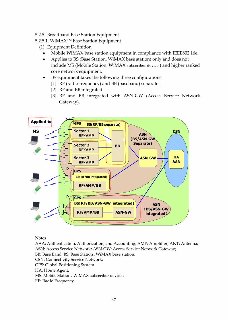
(1) Equipment Definition
Mobile WiMAX base station equipment in compliance with IEEE802.16e.
Applies to BS (Base Station, WiMAX base station) only and does not
include MS (Mobile Station, WiMAX subscriber device ) and higher ranked
core network equipment.
BS equipment takes the following three configurations.
[1] RF (radio frequency) and BB (baseband) separate.
[2] RF and BB integrated.
[3] RF and BB integrated with ASN-GW (Access Service Network
Gateway).
CSNASN
(BS/ASN-GWSeparate)
MS
HA
AAAASN-GW
Applied to
ASN
(BS/ASN-GW
integrated)
RF/AMP/BB
BS(RF/BB integrated)
GPS
△
RF/AMP/BB ASN-GW
BS(RF/BB/ASN-GW integrated)
△
GPS
Sector 3
RF/AMP
Sector 1
RF/AMP
Sector 2
RF/AMP
△
GPS BS(RF/BB separate)
BB
Notes
AAA: Authentication, Authorization, and Accounting; AMP: Amplifier; ANT: Antenna;
ASN: Access Service Network; ASN-GW: Access Service Network Gateway;
BB: Base Band; BS: Base Station、WiMAX base station; CSN: Connectivity Service Network;
GPS: Global Positioning System
HA: Home Agent; MS: Mobile Station、WiMAX subscriber device ;
RF: Radio Frequency

38
[Common Equipment Specifications and Equipment Configurations] Equipment
specifications/ configuration
Item name Specifications
Equipment specifications
Frequency band 2,595MHz - 2,625MHz or 2,582MHz - 2,592MHz
Signal bandwidth 10MHz
Duplex operation TDD
Wireless access system / modulation system
SOFDMA/QPSK, 16QAM, 64QAM (※)
※64QAM is down link only
FFT size 1024
UL/DL frame ratio DL/UL : (29:18)
Segmentation N/A
Inter-base station synchronization system
GPS
Equipment configuration
Antenna configuration MIMO Matrix-A or Matrix-B(2TX+2RX)
Notes:
SOFDMA: Scalable Orthogonal Frequency Division Multiple Access;
DL: Down Link; UL: Up Link;
QAM: Quadrature Amplitude Modulation;
QPSK: Quadrature Phase Shift Keying;
FFT: Fast Fourier Transform;
MIMO: Multiple Input Multiple Output;
FFT: Fast Fourier Transform
[Categorized Equipment Specifications and Equipment Configurations] Equipment
specifications / configuration
Item name Classification specification
Equipment specifications
RF output power ① 10W+10W
② 5W+5W
Primary power supply ① AC
② DC
Network interface ① Number of optical ports: N
② Number of electrical ports: M
Transmission carrier count ① 1
② 2
③ 3
Baseband processor ① single (1)
② dual (2)
Equipment configuration
RF/BB configuration ① Integrated
② Separate
The above items may be combined independent of each other. Of those combinations, the following three types, which are currently commercialized and thus able to be measured, are subject to this guideline.
Name Integrated 10W
equipment (1 BB system)
Integrated 10W equipment (2 BB
systems)
Integrated 5W equipment (1 BB
system)
Output power 10W+10W 10W+10W 5W+5W

39
Baseband processor 1 system 2 systems 1 system
RF/BB configuration
Integrated Integrated Integrated
Supply side power source input
AC AC AC
(2) Figures of merit
Figure of merit for broadband base station equipment shall be defined
following formula..
Figure of merit E= ΣPn/「Pidle×(1-α)+Pmax×α」
Pn: RF output power at antenna connecter n (W)
Pidle: primary power supply-side power when transmitting only the
Preamble and MAP.
Pmax: primary power supply-side power at maximum transmission
(W). The state where all down link symbols are being transmitted
based on an MS connection or the test settings.
α: average of daily down link transmission traffic rate. Average daily
traffic rate using down link Data Symbol, excluding Preambles and
MAP.
The above metrics shall be used as figures of merit not only for WiMAX
base station, but for "broadband base station equipment" including 3.5 G.,
3.9 G., and XGP.
<For WiMAX Two Antenna Base Station Equipment>
Till when the daily average down link traffic is available, calculate using
average primary power supply-side input power with α = 0.5.
Figure of merit = (Pout1 + Pout2) / {(Pidle + Pmax)/2}
Pout1: RF output power at antenna connecter # 1 (W)
Pout2: RF output power at antenna connecter # 2 (W)
Pidle: primary power supply-side input power under idle mode (W)
Pmax: primary power supply-side input power during maximum
transmission (W)
(3) Normative References
[1] Method for deciding Normative References
Normative references for the three types of WiMAX base station
equipment stipulated above, namely, an integrated 10 W equipment (one
system), integrated 10 W equipment (two systems), and integrated 5W
equipment (one system) shall be the enhanced figure based on technological

40
trends incorporated with average metric values from current products (CIAJ
survey).
[Normative References]
Integrated 10 W equipment (one system): 12.60
Integrated 10 W equipment (two systems): 9.63
Integrated 5W equipment (one system): 5.84
[Approximate Timeline for Realizing the Normative References]
End of Fiscal Year 2012
[2] Assessment scale references
The reduction rate versus the normative reference shall determine the
threshold. In the assessment scale, the rank covering the normative reference
shall be ★★.
Average power consumption for normative reference for integrated 10 W
equipment (one system): 158.7 W
Average power consumption for normative reference for integrated 10 W
equipment (two systems): 207.7 W
Average power consumption for normative reference for integrated 5 W
equipment (one system): 171.2 W Assessment
scale Rate of reduction
vs. power consumption at NR
Average power consumption normative reference for integrated
10W equipment (1BB ) (W) (Note 1)
Average power consumption normative reference for integrated
10W equipment (2BB ) (W) (Note 1)
★★★★★ n≧30% P≦111.09 P≦145.39
★★★★ 20%≦n<30% 111.09<P≦126.96 145.39<P≦166.16
★★★ 10%≦n<20% 126.96<P≦142.83 166.16<P≦186.93
★★(NR) 0%≦n<10% 142.83<P≦158.7 186.93<P≦207.7
★ Did not achieve NR P>157.8 P>207.7
(Note) In calculating power consumption, drop digits beyond the first decimal point.
Assessment
scale Rate of reduction
vs. power consumption at NR
Average power consumption normative reference for
integrated 5W equipment (1BB ) (W) (Note 2)
★★★★★ n≧30% P≦119.86
★★★★ 20%≦n<30% 119.86<P≦136.99
★★★ 10%≦n<20% 136.99<P≦154.11
★★(NR) 0%≦n<10% 154.11<P≦171.2
★ Did not achieve NR P>171.2
(Note) In calculating power consumption, discard digits beyond the first decimal point.
Notes 1: When RF output power at antenna connecters are 10.0 W X 2

41
2: When RF output power at antenna connecters are 5.0 W X 2
(4) Measurement Methodology
[1] Measurement configuration
[2] Measurement conditions
[Environment and Electrical Conditions]
Item Conditions Remarks
Environment conditions
Room temperature
+25℃±5℃
Primary power supply voltage
AC Designated voltage ± 1% 50Hz or 60Hz
DC Designated voltage ± 0.5%
Operating conditions 10W×2ANT ・ Designated power + 12.2%
No more than (+0.5dB)
・Measure up to one decimal point
Measure RF output power at antenna connecter by measurement method TELEC-T137.
5W ×2ANT
[Conditions Other than Environment and Electrical]
(a) The number of units of BS equipment or AMP to be measured shall be
more than one and stipulated separately.
Report the average from measuring multiple units to the Council
Secretariat.
(b) This guideline does not stipulate the number of times measurements
shall be taken for each measurement item in relation to a BS or AMP.
However, use an average value when measuring multiple times.
(c) Measure the following functions after having provided continuous
power supply to the equipment.
Applicable
BS
transmitter
tester Control PC
Power supply Power meter
※ 1
※ 1 Under DC input, acceptable to use ammeter/voltmeter instead of wattmeter .
Antenna connecter #2
attenuator
attenuator
Antenna connecter #1
Supply side power source input terminal
HF Power meter
Directional coupler
Directional coupler
Control terminal
HF Power meter
42
Upstream receiving circuit, line interface, GPS circuit
(d) Begin measurements after the equipment has been exposed to room
temperature for one or more hours with power plugged in.
[Measurement methodology]
Item Measurement method
Primary power supply side
power at maximum RF
output
Pmax Use an MS connection or test settings to set so that all down link symbols are transmitted.
Measure using a power meter.
Use effective power consumption of the equipment when input is AC.
Acceptable to use Ampere meter/voltmeter when input is DC.
Primary power supply-side input power
under idle mode
Pidle Put in a state where only down link preamble and MAP are being transmitted. (Data is PUSC)
5.2.6. External Power Sources
5.2.6.1. AC Adapters
(1) Equipment Definition
Among external power sources, refers to an AC-DC converter that takes AC
commercial power supply and provides DC power to the equipment.
This assessment applies to external power sources for customer-premises
equipment having a name plate output (rated output) Pno (Pno: Nameplate
Output Power) of 1W<Pno≦49W.
This assessment applies to AC adapters procured separately or those that are
included within the procurement of a piece of equipment which is not set forth
in 5.1.1 Scope of this Guideline. Those included with equipment for which
scope has been set forth in 5.1.1 Scope shall be assessed as part of the
equipment itself and shall be excluded from the assessment of this section.
Chargers for cellular phones and the like that are used for the purpose of
recharging batteries are exempt from this assessment.
(2) Figure of merit
The figures of merit are established in reference to the figures of merit set
forth under the International Efficiency Marking Protocol. Evaluate average
conversion efficiency η at nameplate output Pno (W) based on conversion
efficiency at 25% load η25, conversion efficiency at 50% load η50, conversion
efficiency at 75% load η75 and conversion efficiency at 100% load η100.
η=(η25+η50+η75+η100)/4
(3) Normative References
[1] Method for deciding normative references

43
Normative references are established in reference to International
Efficiency Marking Protocol.
Decide individual normative references for each nameplate output.
[Normative References]
As a normative reference for external power sources, average conversion
efficiency value at nameplate output Pno (W) shall be equivalent to Mark V of
the International Efficiency Marking Protocol
[Approximate Timeline for Realizing the Normative References]
April 2011 (as required by the EuP Directive (Directive on Eco-Design of
Energy Using Products).
[2] Assessment scale
The reduction rate versus the normative reference shall determine the
threshold. In the assessment scale, the rank covering the normative reference
shall be ★★.
Assessment scale
Rate of reduction vs. power
consumption at NR
Average conversion efficiency η
(See formula (*))
★★★★★ n≧30% η≧70.7+5.00ln(Pno)
★★★★ 20%≦n<30% 67.7+5.46ln(Pno)≦η<70.7+5.00ln(Pno)
★★★ 10%≦n<20% 64.8+5.88ln(Pno)≦η<67.7+5.46ln(Pno)
★★(NR) 0%≦n<10% 62.2+6.26ln(Pno)≦η<64.8+5.88ln(Pno)
★ Did not achieve NR η<62.2+6.26ln(Pno)
(Note) Pno: Nameplate Output Power (W)
(4) Measurement Methodology
[1] Measurement system

44
Aac
Vac 試験対象
Adc
Vdc
直流電力計交流電力計
Aac
Vac 試験対象
Adc
Vdc
直流電力計交流電力計
Example of a measurement system using variable resistance
Using variable resistance, measure conversion efficiencies η100, η75, η50 and η25 at
nameplate currents of 100%, 75%, 50%, and 25%, respectively, and seek the average
value η.
[2] Measurement conditions
Room temperature: 23°C +/- 5°C
Error tolerance of measurement equipment: use a calibrated
voltmeter/ammeter or power meter.
Error tolerance: No more than 2% error for the ammeter/voltmeter.
Precision of no less than 0.01 W for the power meter.
Voltage applied: Measure upon applying voltage of 100 V (+/- 1 V) at
frequencies of 50 Hz (+/- Hz) and 60 Hz (+/- 0.6 Hz).
Preparations prior to measurement: Begin measurements after running
100% nameplate current through the external power source to be tested
for no less than 30 minutes.
DC Power Meter AC Power Meter
Equipment to be
measured
45
5.2.7 Servers
<<Assessment standard for Active state>>
5.2.7.1. Servers
(1) Definition
In this Guideline, a server is a computer device comprising of a central
processing unit (CPU), a main memory, an input/output control and a power
source. It is designed to exist as part of a network to provide information and
services to other computer devices 24/7. It must be able to use an operating
system (OS) so that it can be installed with and run user applications. Examples
of servers include but are not limited to the following:
> file servers
> mail servers
> database server
> authentication server
> web server
> media server
> game server
* Devices sold as a single unit which are actually a combination of hardware
and software (such as appliances) shall be included under servers in this
section if all that is needed to change the device to a particular use is the
installation of (a) user application(s).
(2) Figure of merit
The TEER*1 determined by ATIS shall serve as an index, and will be
calculated as follows:
TEER=SPECpower_ssj2008value/10
Furthermore, SPECpower_ssj2008 figure is defined by SPEC (Standard
Performance Evaluation Corporation: http://www.spec.org/power_ssj2008)
and is calculated with the following equation.
Overall ssj_ops/watt=∑ssj_ops/∑power consumption (W)
ssj_ops is a metric for server processing capacity and is attained by
implementing SPECpower_ssj2008 v. 1.10 server power consumption
performance benchmark test program to the servers included in the scope of
the assessment. The performance (ssj_ops) at CPU load rates (0 – 100%) and
average power consumption are measured, then the capacity (ssj_ops) at the
respective target loads are totaled and divided by the total average power
consumption (W) (∑ssj_ops/∑power), and that figure is considered to be the
capacity metric (overall ssj_ops/watt) per electric power. *1 ATIS-0600015.01.2009: Energy Efficiency for Telecommunication

46
Equipment: Methodology for Measurement and Reporting – Server
Requirements.
(3) Normative reference
[1] Methodology for establishing normative reference
Publicly disclosed SPEC data is converted to TEER and a trend analysis of
the product shall be conducted.
[Normative reference]
TEER=100
[Approximate timeline for realizing normative reference]
The end of Fiscal Year 2010
[2] Assessment scale
The reduction rate versus the normative reference shall determine the
threshold. In the assessment scale, the rank covering the normative reference
shall be ★★.
Assessment
scale Reduction rate vs. power consumption
of NR Figure of merit (TEER)
★★★★★ n≧30% TEER≧250
★★★★ 20%≦n<30% 166≦TEER<250
★★★ 10%≦n<20% 125≦TEER<166
★★(NR) 0%≦n<10% 100≦TEER<125
★ Did not achieve NR TEER<100
(Note) It shall be possible to compare the rate of reduction of power
consumption against normative reference among equipment which
have similar ssj_ops at CPU load rates (0 – 100%). However, in case
of equipment with different ssj_ops at CPU load rates (0 – 100%), the
rate of reduction shall be analyzed in conjunction with the
performance of the equipment (i.e. power consumption shall increase
x% if performance increases x%).
[Formula for calibrating the threshold]
20% reduction: TEER/0.8=125
40% reduction: TEER/0.6=166
60% reduction: TEER/0.4=250
(4) Measurement methodology
[1] Measurement methodology
A testing program for power measurements of servers at benchmark points
is provided by SPEC. Equipment shall be measured using

47
SPECpower_ssj2008 v1.10. For details please refer to the following sites (*2,
*3).
*2: ATIS-0600015.2009: Energy Efficiency for Telecommunication Equipment:
Methodology for Measurement and Reporting – General Requirements
*3: SPEC User Guide
http://www.spec.org/power_ssj2008/docs/SPECpower_ssj2008-User_G
uide.pdf
[2] Measurement conditions
Measurements shall be taken in compliance to the ATIS measurement
conditions (*1, *2). For areas not covered by ATIS, measurements shall be in
compliance to the SPEC User Guide (*3). Furthermore, among the ATIS
measurement conditions, the following criteria shall be applied, taking into
consideration the equipment’s use in Japan.
Temperature: 25℃±3℃
Humidity: 30% - 75%
Voltage: -53VDC±1V, 100V±1% (50/60Hz±1%)
<< Assessment standard for idle state>>
Adopt the assessment standard based on the top runner method for computers
(Ministerial Notification No. 50 from the Ministry of Economy, Trade and
Industry), which are identified as specified equipment in the Energy
Conservation Law. Normative reference and assessment scale are to be
determined.
Figure of merit E = {(W1+W2)/2}/Q (W /MTOPS)
E: energy efficiency
W1: energy consumption in idle state
W2: energy consumption in low-power mode
Q: theoretical operation (MTOPS)
5.3 Implementation
5.3.1 Public disclosure of assessment results of energy-saving equipment and
target timeline for disclosure
Vendors wishing to register their energy-saving equipment with the Council
shall measure and assess the equipment in compliance to criteria outlined in 5.2
of this Guideline, submit the assessment results and other pertinent information
(normative reference and assessment scale ranking) to the Council, and publicly
disclose information via such medium as the Council website. Indication of the
assessment results in the vendor’s website or other medium, such as the vendor
catalog is left to the discretion of the vendor.
Furthermore, the target timeline for public disclosure of the assessment results
shall be July 1, 2010 or later.

48
5.3.2 Procurement of energy-saving equipment by telecommunications services
providers
Telecommunications services providers planning to procure energy-saving
equipment shall establish a procurement standard based on this Guideline and
the assessment results of energy-saving equipment publicly disclosed on the
Council’s website and other medium.
5.3.3 Addition of new equipment and review of the existing Guideline
Telecommunications services providers and vendors shall propose the addition
of new equipment to be covered in the scope of the Guideline or a review of
existing standards based on product trends, such as the emergence of new
functions. Upon receipt of a proposal, the Council shall decide on the addition of
the indicated equipment, the measurement methodology, normative reference,
and the timing of the new criteria implementation. In addition, the Council shall
review the Guideline as deemed appropriate.
For example, a review of the figure of merit will be necessary with the addition
of a new function (optical XC or packet switching for WDM equipment), or when
a new format is announced (10G-PON for GE-PON equipment), or a new
equipment which is not covered by existing definitions is announced.
・機器の測定、評価 ・自主的な評価結果公表
・公表(HP)
・調達基準作成 ・調達
・対象機器の追加、
基準値見直し提案
・対象機器追加、測定 方法、基準値の決定
・ガイドラインの見直し
・対象機器の追加、
基準値見直し提案 提案
Procurement of energy-saving ICT equipment by TSPs
評価結果通知
情報提供(応札)
参照
Image of implementation of assessment standard for equipment
・ ・Public disclosure
(HP)
>Establish procurement standard >Conduct procurement
>Review of equipment scope and Guideline
>Review of equipment scope, measurement methodology, normative reference. >Review of Guideline
>Review of equipment scope and Guideline
Council TSPs Vendor
Proposal
Submit assessment result
Provide information (bid)
Consult
Review of equipment scope and Guideline
Disclosure of assessment results of ecology- conscious actions
Proposal
Disclose
Consult
TSP= telecommunications services provider
>Measure and assess equipment >Disclose assessment results (voluntary)

49
6. Normative Reference for Data Centers
6.1 Basic Approach to Normative Reference
A data center is a complex facility combining ICT equipment such as servers,
storage equipment, and network equipment with other hardware including air
conditioning systems and power converters. Additionally, the various modes of use
and contractual agreements that exist contribute to a multifaceted situation.
Furthermore, in terms of software, data centers perform a variety of work and
individual data centers differ greatly in how and for what processes software is used.
For this reason, establishing a figure of merit on energy-saving as a normative
reference for data centers is no easy task. Currently studies on this issue are
underway inside and outside of Japan. Therefore this guideline uses PUE as one
figure of merit (details to follow) currently adopted broadly in relative terms, which
serves as a useful reference for data centers to perform CO2 emission reduction
activities and for Telecommunications services providers to procure data center
services. Even in the case of PUE, which has been adopted broadly in relative terms,
there is insufficient data from actual measurements and little data has been publicly
disclosed. Therefore, to promote telecommunications service providers’ CO2
emission reduction activities, it is hoped that data center operators measure energy
conservation related data (e.g. PUE with clear measurement conditions) and make
further efforts in public disclosure.
Unresolved challenges have been identified, such as the need for further
consideration of data center processing performance; for this reason, this Guideline
will continue to revisit figures of merit in consideration of future trends in studies on
the issues inside and outside of Japan.
6.2 Definition
A data center is a space or facility (including air conditioning, power converters,
etc.) used exclusively to store the ICT equipment (network equipment, servers,
storage equipment, etc.) it operates.
A data center may be a stand-alone building but also could occupy only a portion
of space in a shared facility (office, etc.) within a building used for other purposes.
However, this guideline assumes data centers primarily providing services to
external clients. Thus, this guideline does not assume application of a reference to a
small-scale server room equipped with only a few pieces of ICT equipment.
6.3 Figure of Merit on Energy-Saving As a Normative Reference
(1) The Current Situation of Figure of Merit on Energy-saving
As described above, figures of merit on energy-saving as normative reference for
data centers are currently under study inside and outside of Japan. Defining
energy efficiency of data centers is quite difficult and nothing that may be used as a
figure of merit having been adopted on a global scale exists at the present time.

50
Figure of merit on energy-saving may be categorized into the following two
types: using one figure of merit to represent the data center as a whole or using
multiple metrics as a set to represent the multifaceted aspects of data centers. For
example, in the case of the former, an energy productivity figure of merit (a ratio of
the amount of energy introduced to the data center versus the work processed by
the data center) is currently under study. No clear definition has been established,
however, as details are still under study inside and outside of Japan.
(2) Figure of Merit on Energy-saving That May Be Used so far
One figure of merit on energy-saving for data centers that may be used so far is
the Power Usage Effectiveness (PUE) figure of merit, which compares the power
consumption of the ICT equipment that should be in operation to the power
consumption of the facility portion (air-conditioning, power source, lighting, etc.)
used to operate the ICT equipment. PUE is a figure of merit proposed by The
Green Grid (US) and its definition is as follows.
PUE = power consumption of entire facility (ICT equipment + facilities) / power
consumption of ICT equipment
Based on this definition, one could say that a small PUE value could mean that
the facilities portion of a data center has good energy efficiency.
The inverse of PUE is the Data Center Infrastructure Efficiency (DCiE).
Presumably, these two metrics could be used in parallel depending on their
application, such as the method of managing the figures.
PUE and DCiE are the figures of merit on energy-saving for data centers most
widely adopted so far.
At the same time, there are those who point to issues with PUE and DCiE. One is
that the measurement methods are not always clearly defined. Another is that the
metrics do not consider differences in energy efficiency derived from efficiency of
the ICT equipment and operational proficiency.
(3) The Status of Studies at Related Organizations
In light of the current issues with PUE, The Green Grid and many other
organizations are studying the development of better figures of merit on
energy-saving.
The Green Grid is studying measurement guidelines, numerical reporting and a
certification system for PUE. Additionally, The Green Grid is involved in
developing the Data Center energy Productivity (DCeP) metric for representing the
energy productivity of the entire data center, including not only facilities but also
ICT equipment, and an applicable alternative figure of merit (proxy).
Also, Japan's Green IT Promotion Council has entered into an MOU with The
Green Grid to pursue the development of an independent figure of merit on
energy-saving covering the entire data center including ICT equipment.
51
Moreover, under the EU's Code of Conduct on Data Centers, a guideline
compiled for data centers, PUE is adopted as a figure of merit on energy-saving for
facilities, while a productivity figure of merit is to be decided in consideration of
future trends. Furthermore, the US Environmental Protection Agency (USEPA)
uses Energy Usage Effectiveness (EUE: a ratio similar to PUE, but calculated using
a supply-side energy conversion) and, has also begun activities so as to rate the
energy efficiency of facilities.
(4) Data Center Figure of Merit on Energy-Saving under this Guideline
In light of current studies on figures of merit on energy-saving and the situation
of global adoption, this Guideline preliminarily uses PUE, already gained adoption
as a figure of merit on energy-saving for the facilities portion, which serves as a
useful reference for data centers to perform CO2 emission reduction activities and
for telecommunications service providers to procure data center services. It is
preferred that data center operators measure energy conservation related data (e.g.
PUE with clear measurement conditions) and advance public disclosure. This
guideline will continue to revisit figures of merit in consideration of future trends
in studies on the issues inside and outside of Japan.
6.4 Outline of Figure of Merit on Energy-Saving
(1) PUE and DCiE
PUE, currently an important figure of merit on energy-saving for data centers, is
as described in 6.3(2), and its inverse is DCiE (DCiE = 1/PUE).
Here, ICT equipment includes computers, network equipment, ICT support
systems (printers, etc.), storage, and telecommunications equipment. Facilities are
equipment not included under ICT equipment, namely, electrical power
(converters, UPS, lighting, etc.), air conditioning (including cooling tower, cooling
water pump, humidifier, etc.), security equipment, building management systems
and the like. DCiE is simply the inverse of PUE; thus, articles subject to
measurement are the same in both cases.
In the case that a data center uses other energy sources in parallel to electrical
power, use an energy conversion value to calculate PUE or DCiE. Specifically, use a
crude oil equivalent value for the amount of energy consumed as defined by the
Energy Conservation Law.
(2) Measurement Methods for PUE and DCiE
A guideline set forth by The Green Grid exists for PUE and DCiE measurement
methods (measurement frequency, selecting measurement points, etc.). The
guideline indicates three levels (1 to 3). (For details see The Green Grid White
Paper Number 14 The Green Grid metrics: A detailed analysis of DCiE (Data
Center Infrastructure Efficiency).)
http://members.thegreengrid.org/japanese/gg_content/White_Paper_14_-_DCi
E_Detailed_Analysis_11.06.08_JP.pdf)
52
(3) Disclosure of PUE and DCiE Measurement Results
The energy efficiency of data centers is believed to differ depending on the
characteristics of the data center. Thus, in disclosing figures of merit on
energy-saving such as PUE or DCiE, the basic characteristics of a data center that
would significantly impact energy efficiency need also be disclosed. As an attempt
at tentative uniformity in consideration of user convenience, specific disclosure
items should include, in addition to the actual PUE measurement values,
measurement methodology, data center location, room temperature and humidity
settings, duration of measurement, and redundancy configurations.
This guideline will not stipulate uniform measurement methods, but the
measurement methods (measurement frequency, measurement sites, etc.) used by
the data center should be disclosed.
Disclosure items are currently under study at related organizations. This
guideline will consider additions or amendments as appropriate in light of the
results of those studies.
Disclosure item Example of Disclosure
Actual PUE measurement values (average/highest/lowest)
1.86/2.08/1.69
Measurement methodology
Measurement frequency
once weekly
Measurement points
ICT equipment power consumption: UPS Power consumption of entire facility: data center power supply input
Duration of measurement
October 2007 to September 2008
Basic Characteristics
Data center location Country, area (Kanto, etc.))
Room temperature and humidity settings
22℃/50-60%
Redundancy configuration
N+1
PUE disclosure items
6.5 Implementation (See 4.3 (1) diagram)
6.5.1 Disclosure Method of Energy Conservation Related Data of Data Center
Data center operators shall report energy conservation related data (e.g. PUE
with clear measurement conditions etc.) to the Council and disclose that
information via such medium as the Council’s website.(PUE measurement results
to be disclosed in accordance with the disclosure items set forth in 6.4(3))
6.5.2 Procurement by Telecommunications Service Providers of Data Center
Services
Telecommunications services providers seeking to procure data center services
shall refer to energy conservation related data of the data center disclosed in this

53
guideline, on the Council’s website and the like to formulate their procurement
standards, and procure the services by selecting a data center based on a
comprehensive assessment together with required functions and processing
performance.

54
7. Assessment Standard Eco ICT Logo
7.1 Purpose
7.1.1 Purpose of Self-Assessment of Efforts
The status of efforts and achievements in reducing CO2 emissions made by
telecommunications service providers needs to be publicly disclosed (made visible)
appropriately and in a timely fashion so that external parties including users and
other related parties may appropriately assess such efforts.
In light of such needs, the purpose is for telecommunications services providers
to checking the status of those efforts under their own initiative in and to enhance
their efforts to be ecologically conscious and to reduce their ecological burden.
7.1.2 Indication of Eco ICT Logo
Telecommunications services providers shall display the “Eco ICT Logo” as a
medium for broad public disclosure depending on the result of appropriate
self-assessment of their actions to reduce CO2 emissions etc. and to indicate the
status of such implemented actions.
Because efforts to reduce CO2 emissions need to become broader in scope,
telecommunications services providers not belonging to an industry group can
refer to this guideline to confirm efforts on their own initiative and display the
“Eco ICT Logo.”
7.2 Checklist
7.2.1 Purpose of the Checklist
The Council has prepared the Self Assessment Checklist for CO2 Emission
Reduction Efforts by Telecommunications Services Providers (hereinafter, the
Checklist) (see separate sheet) for telecommunications services providers to set
targets for reducing CO2 emissions and to use the checklist for self-confirmation
and make visible to others the efforts being taken.
The purpose is for telecommunications services providers to use this checklist to
perform self-assessments of the results of actions taken under autonomous action
plans prepared by individual companies and as a medium for public disclosure.
7.2.2 Checklist Assessment Items and Assessment Standards
<Preparation of a Voluntary Ecological Action Plan>
[1] Has a voluntary ecological action plan stipulating various efforts directed at
reducing CO2 emissions been created and is it being executed?
Is there a voluntary ecological action plan in place, which is aimed at
promoting ecological preservation activities such as the prevention of
global warming, reduction of waste and the promotion of reduce, reuse
and recycling activities?

55
[2] Does the ecological policy include specific efforts stipulating numerical
targets for the reduction of CO2 emissions?
Does the voluntary ecological action plan include specific activities and
numerical targets?
Examples
Reduce by the end of 2020 the amount of electricity used by ICT equipment
by 25%, compared to 1990 levels.
Switch to power generation of green power, purchase green power
certificates and the like, so that green power accounts for 10% of electricity
used.
10% reduction on a year-to-year base employees’ use of private vehicles for
commuting by promoting the use of public transportation, bicycles and
car-sharing.
[3] Is the ecological policy documented and disseminated inside and outside of
the company? Does the company carry out activities to inform and enlighten
its employees? Is the company working to raise ecological awareness?
Are employees informed of such plans through internal training events
and the like?
Is information disclosed outside the company or is information disclosed to
interested parties and other members of the general public when needed?
[4] Does the company disclose to the general public its activities and data such
as CO2 emission reduction?
Is such information as the status, accomplishments and track record of
specific activities under the voluntary ecological action plan disclosed to
the public?
Does that information continue to be publicly disclosed based on annual
reviews?
*May be substituted with the creation and disclosure of an ecological report,
CSR report, sustainability report, and the like.
Examples
URL of the company's website where the status of specific actions taken in
accordance with the voluntary ecological action plan is disclosed
URL of the company's blog where information on ecological activities is
disseminated on a continual basis
<Efforts Related to Procurement>
[5] In regard to ICT equipment and data center services, has the company
prepared a procurement standard that takes energy conservation into
consideration? Is procurement carried out in accordance with the standard?
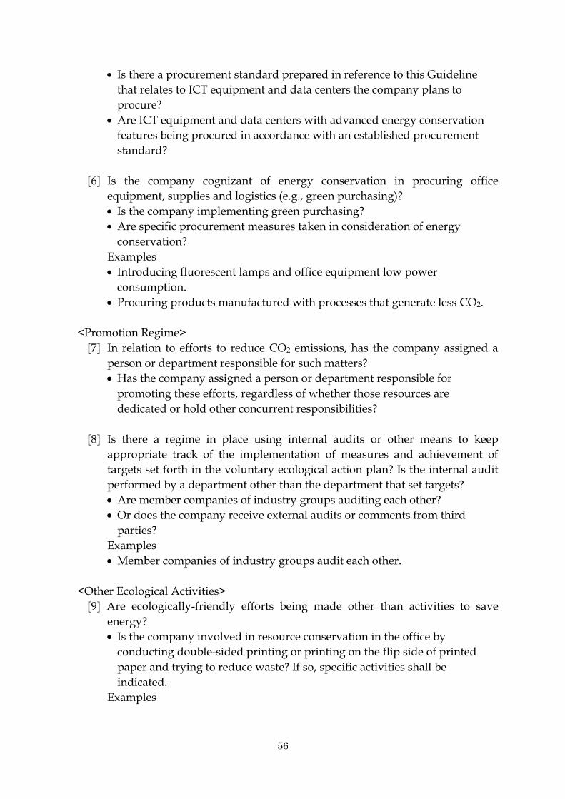
56
Is there a procurement standard prepared in reference to this Guideline
that relates to ICT equipment and data centers the company plans to
procure?
Are ICT equipment and data centers with advanced energy conservation
features being procured in accordance with an established procurement
standard?
[6] Is the company cognizant of energy conservation in procuring office
equipment, supplies and logistics (e.g., green purchasing)?
Is the company implementing green purchasing?
Are specific procurement measures taken in consideration of energy
conservation?
Examples
Introducing fluorescent lamps and office equipment low power
consumption.
Procuring products manufactured with processes that generate less CO2.
<Promotion Regime>
[7] In relation to efforts to reduce CO2 emissions, has the company assigned a
person or department responsible for such matters?
Has the company assigned a person or department responsible for
promoting these efforts, regardless of whether those resources are
dedicated or hold other concurrent responsibilities?
[8] Is there a regime in place using internal audits or other means to keep
appropriate track of the implementation of measures and achievement of
targets set forth in the voluntary ecological action plan? Is the internal audit
performed by a department other than the department that set targets?
Are member companies of industry groups auditing each other?
Or does the company receive external audits or comments from third
parties?
Examples
Member companies of industry groups audit each other.
<Other Ecological Activities>
[9] Are ecologically-friendly efforts being made other than activities to save
energy?
Is the company involved in resource conservation in the office by
conducting double-sided printing or printing on the flip side of printed
paper and trying to reduce waste? If so, specific activities shall be
indicated.
Examples

57
Working to use double-sided printing and copying, reduce the amount of
paper and ink used, and reduce the amount of power used for printing.
[10] Is the company involved in ecological preservation activities in collaboration
with local communities?
Does the company work on a continual basis with society on activities
related to ecological preservation?
Examples
Work jointly with regional organizations every month to pick up garbage
and increase plant coverage in local areas.
Participate in community recycling activities to actively recycle.
Participate in eco-cap activities and make contributions to society beyond
recycling efforts.
7.2.3 Review of the Checklist
The Council shall review this checklist and its items as appropriate in response
to: reviews of this Guideline; changes in policy relating to global warming
measures; revisions to laws and ordinances; the status of ICT service provision;
penetration of equipment and the like; and technological advances.
7.3. Eco ICT Logo
7.3.1 Method of Indication
In accordance with 7.3.2, telecommunications services providers may use on their
website and printed matter the name of the logo and the “Eco ICT Logo” set forth
in the reference section of the Guideline.
7.3.2 Usage Stipulations
(1) Usage Standard
In using the name and “Eco ICT Logo,” disclosure by the means set forth in 7.4.2
must be followed.
(2) How to Obtain
The “Eco ICT Logo” may be downloaded in electronic format from the Council's
website.
[1] The URL (Internet address) for downloading is indicated on the Council's
homepage.
[2] The URL for downloading may change. Therefore, when setting a link from
an external website, link to the Council’s homepage.
(3) The permissible scope of use of the name and “Eco ICT Logo” by a
telecommunications services provider
The company's website
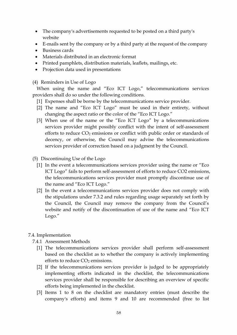
58
The company's advertisements requested to be posted on a third party's
website
E-mails sent by the company or by a third party at the request of the company
Business cards
Materials distributed in an electronic format
Printed pamphlets, distribution materials, leaflets, mailings, etc.
Projection data used in presentations
(4) Reminders in Use of Logo
When using the name and “Eco ICT Logo,” telecommunications services
providers shall do so under the following conditions.
[1] Expenses shall be borne by the telecommunications service provider.
[2] The name and “Eco ICT Logo” must be used in their entirety, without
changing the aspect ratio or the color of the “Eco ICT Logo.”
[3] When use of the name or the “Eco ICT Logo” by a telecommunications
services provider might possibly conflict with the intent of self-assessment
efforts to reduce CO2 emissions or conflict with public order or standards of
decency, or otherwise, the Council may advise the telecommunications
services provider of correction based on a judgment by the Council.
(5) Discontinuing Use of the Logo
[1] In the event a telecommunications services provider using the name or “Eco
ICT Logo” fails to perform self-assessment of efforts to reduce CO2 emissions,
the telecommunications services provider must promptly discontinue use of
the name and “Eco ICT Logo.”
[2] In the event a telecommunications services provider does not comply with
the stipulations under 7.3.2 and rules regarding usage separately set forth by
the Council, the Council may remove the company from the Council’s
website and notify of the discontinuation of use of the name and “Eco ICT
Logo.”
7.4. Implementation
7.4.1 Assessment Methods
[1] The telecommunications services provider shall perform self-assessment
based on the checklist as to whether the company is actively implementing
efforts to reduce CO2 emissions.
[2] If the telecommunications services provider is judged to be appropriately
implementing efforts indicated in the checklist, the telecommunications
services provider shall be responsible for describing an overview of specific
efforts being implemented in the checklist.
[3] Items 1 to 8 on the checklist are mandatory entries (must describe the
company's efforts) and items 9 and 10 are recommended (free to list

59
information in checklist or not).
[4] In the event certification of an international standard (ISO 14001) relating to
environmental management systems has been acquired, companies may
substitute check list entries as appropriate with an indication that
certification has been acquired under the applicable assessment items and a
description of where that information is made be publicly available.
7.4.2 Public Disclosure Methods by Telecommunications Services Providers
Conducting the Efforts
The following information of telecommunications services providers involved in
efforts complying with the checklist shall be publicly available through the
Council’s website.
Company name (personal name or trade name if an individual)
URL and link to where the checklist is posted
Telecommunications services providers need to disclose the completed checklist
and provide sufficient information for a user or viewer to understand what sort of
efforts was made that apply to or comply with the checklist per the self-assessment.
(1) Submitting Necessary Forms & Information
[1] Telecommunications services providers shall post the checklist prepared per
7.4.1(2) on their website and report by submitting the “Application for
Requesting Public Disclosure of CO2 Emission Reduction Efforts by
Telecommunication Services Providers” in attachment 2 (hereinafter
Application) to the Council.
[2] The Council shall confirm the contents of the Application and the items
disclosed on the checklist on the company’s website, and the information will
be disclosed to the public on the Council’s website.
[3] If a telecommunications services provider having information disclosed on
the Council’s website needs to revise targets aimed at reducing CO2
emissions or change specific effort within the effective period of disclosure,
the telecommunications services provider shall follow the procedures similar
to those for the original Application as deemed appropriate.
(2) Effective Period of Disclosure by the Council
[1] Regarding results of telecommunications services providers’ specific efforts
toward targets aimed at appropriately reducing CO2 emissions, such
targets need to be reviewed at least once a year since continuity and
improvement contributes greatly to reducing CO2 emissions. Thus, the
effective period of disclosure by the Council shall be no longer than one
year and continue to the last day of December of each year.
[2] When self-assessment of efforts to reduce CO2emissions is performed, a
checklist is completed and submitted at some point between January 1 and
the last day of December, the effective period of disclosure by the Council

60
shall continue until the last day of December of the year disclosure began
and shall not be calculated as one full year from the date of disclosure.
(3) Method of Renewing Public Disclosure by the Council
[1] Telecommunications services providers shall submit necessary information
to the Council between October 1 and the last day of November of each
year, receive confirmation for renewal and have disclosure by the Council
renewed.
[2] For renewal, a telecommunications services provider submits procedures
similar to those for the original report to the Council.
[3] If a telecommunications services provider does not report for renewal by
the last day of November each year, the Council may remove that company
from the list and cancel the company's usage of the name and “Eco ICT
Logo.”
[4] Telecommunications services providers removed from the list disclosed by
the Council must promptly discontinue use of the name and “Eco ICT
Logo” on their own websites and printed mattes.
(4) Others
[1] If a third party inquires about the disclosed contents regarding a
telecommunications services provider on the Council’s website, the inquiry
may be routed to the relevant telecommunications services provider.
[2] The telecommunications services provider subject to the inquiry must
answer and respond in good faith.
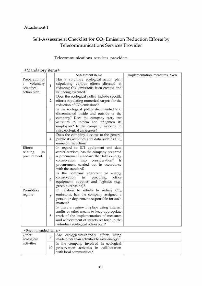
61
Attachment 1
Self-Assessment Checklist for CO2 Emission Reduction Efforts by
Telecommunications Services Provider
Telecommunications services provider:
<Mandatory items> Assessment items Implementation, measures taken
Preparation of a voluntary ecological action plan
1
Has a voluntary ecological action plan stipulating various efforts directed at reducing CO2 emissions been created and is it being executed?
2 Does the ecological policy include specific efforts stipulating numerical targets for the reduction of CO2 emissions?
3
Is the ecological policy documented and disseminated inside and outside of the company? Does the company carry out activities to inform and enlighten its employees? Is the company working to raise ecological awareness?
4 Does the company disclose to the general public its activities and data such as CO2 emission reduction?
Efforts relating to procurement
5
In regard to ICT equipment and data center services, has the company prepared a procurement standard that takes energy conservation into consideration? Is procurement carried out in accordance with the standard?
6
Is the company cognizant of energy conservation in procuring office equipment, supplies and logistics (e.g., green purchasing)?
Promotion regime
7
In relation to efforts to reduce CO2 emissions, has the company assigned a person or department responsible for such matters?
8
Is there a regime in place using internal audits or other means to keep appropriate track of the implementation of measures and achievement of targets set forth in the voluntary ecological action plan?
<Recommended items>
Other ecological activities
9 Are ecologically-friendly efforts being made other than activities to save energy?
10 Is the company involved in ecological preservation activities in collaboration with local communities?
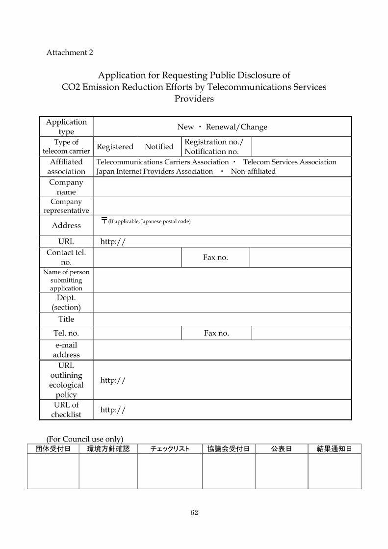
62
Attachment 2
Application for Requesting Public Disclosure of
CO2 Emission Reduction Efforts by Telecommunications Services
Providers
Application type
New ・ Renewal/Change
Type of telecom carrier
Registered Notified Registration no./ Notification no.
Affiliated association
Telecommunications Carriers Association ・ Telecom Services Association
Japan Internet Providers Association ・ Non-affiliated
Company name
Company representative
Address 〒(If applicable, Japanese postal code)
URL http://
Contact tel. no.
Fax no.
Name of person submitting application
Dept. (section)
Title
Tel. no. Fax no.
e-mail address
URL outlining ecological
policy
http://
URL of checklist
http://
(For Council use only) 団体受付日 環境方針確認 チェックリスト 協議会受付日 公表日 結果通知日

63
Diagram of Logo for Reference
[1] Eco ITC Logo design (tentative)
Logo
[2] Assessment scale symbol design
Logo

64
8. Reference Material
Omitted.

65
9. Contacts
Telecommunications Carriers Association
e-mail: [email protected]
Telecom Services Association
e-mail: [email protected]
Japan Internet Providers Association
e-mail: [email protected]
Communications and Information network Association e-mail: [email protected]
ASP・SaaS Industry Consortium
e-mail: [email protected]