Introduction to Seismic methods - Interreg North-West Europe
Upload
khangminh22Category
view
0download
0
Front cover
Working group QM Biomass DH Plants
Switzerland: Holzenergie Schweiz
Austria: AEE - Institute for Sustainable Technologies
Baden-Württemberg: University of Applied
Forest Sciences Rottenburg
Bayern: C.A.R.M.E.N. e.V.
Italy: APE FVG - Agenzia per l’Energia del Friuli Venezia Giulia
Standard hydraulic schemes Part I
Hans Rudolf Gabathuler Hans Mayer
translated with support from
CE-INTERREG-Project ENTRAIN

QM Holzheizwerke® (Quality Management (QM) for
Biomass District Heating (DH) Plants) refers to the qual-
ity standards for biomass heating plants jointly developed by
partners from Switzerland, Baden-Württemberg, Bavaria, Rhine-
land-Palatinate and Austria. The main aspects of the quality
standards include professional design, planning and implemen-
tation of the heating plant and the heating grid. Important quality
criteria encompass high operational reliability, precise control,
low emissions and economical fuel logistics. The aim is to
achieve an energy-efficient, environmentally friendly and eco-
nomical operation of the entire plant.
QM for Biomass DH Plants is designed for hot water systems
which are used to generate heat. Systems for generating elec-
tricity are not taken into account.
These Standard hydraulic schemes - Part I are tried and
tested solutions for monovalent or bivalent heat production sys-
tems for one or two biomass boilers, without or with storage tank.
Numerous solutions for space heating and domestic hot water
supply are also described for the heat consumer side. If a stand-
ard hydraulic scheme is chosen, the design and functional de-
scription of the system is particularly simple: calculations are
made in prepared tables and questions about the system concept
can be answered by simply ticking a box. This enables efficient
quality assurance and reduces planning errors to a minimum.
Further tried and tested solutions have been published as
"Standard hydraulic schemes - Part II".
The collected knowledge is published in German as series of
publications “QM Holzheizwerke”. English versions
of selected volumes are available.
Band 1: Q-Leitfaden (mit Q-Plan)
ISBN 978-3-937441-91-7
Band 2: Standard-Schaltungen – Teil I
ISBN 978-3-937441-92-4
Band 3: Muster-Ausschreibung Holzkessel
ISBN 978-3-937441-93-1
Band 4: Planungshandbuch
ISBN 978-3-937441-94-8 (is going to be updated)
Band 5: Standard-Schaltungen – Teil II
ISBN 978-3-937441-95-5
Band 6: Ratgeber zur Biomassekesselausschreibung
(Version Österreich)
ISBN 978-3-937441-89-4
English versions:
Volume 1: Q-Guidelines
Volume 2 and Volume 5: Standard hydraulic schemes
Volume 4: Planning Handbook
The publications of Quality Management for Biomass District Heating Plants can be downloaded or requested www.qm-biomass-dh-plants.com

Publication series QM for Biomass DH Plants Volume 2
developed by the Working Group Quality Management for Biomass District Heating Plants
Standard hydraulic schemes Part I
Hans Rudolf Gabathuler Hans Mayer Based on the second, expanded edition C.A.R.M.E.N. e.V. Straubing 2010
translated with support from
CE-INTERREG-Project ENTRAIN

Working group Quality Management for Bio-
mass District Heating Plants in different coun-
tries
Switzerland:
Holzenergie Schweiz with the financial support of
the Swiss Federal Office of Energy
www.qmholzheizwerke.ch
www.holzenergie.ch
Austria:
AEE INTEC – AEE - Institute for Sustainable Tech-
nologies
www.klimaaktiv.at/qmheizwerke
Germany:
Baden-Württemberg: University of Applied Forest
Sciences Rottenburg
Bayern: C.A.R.M.E.N. e.V.
www.qmholzheizwerke.de
Italy:
APE FVG - Agenzia per l’Energia del Friuli Vene-
zia Giulia
www.ape.fvg.it
These websites contain information and publica-
tions on the subject of biomass energy. From there
you can also download further documents and
software tools.
© Working Group Quality Management for Biomass
District Heating Plants
QM Holzheizwerke is a registered trademark.
Team of the working group
Quality Management for Biomass District
Heating Plants
Jürgen Good (Management), Verenum, CH
Stefan Thalmann, Verenum, CH
Daniel Binggeli, Federal Office of Energy, CH
Andreas Keel, Holzenergie Schweiz, CH
Andres Jenni, ardens GmbH, CH
Patrick Küttel, DM Energieberatung AG, CH
Harald Schrammel, AEE INTEC, AT
Sabrina Metz, AEE INTEC, AT
Gilbert Krapf, C.A.R.M.E.N. e.V., DE
Niels Alter, C.A.R.M.E.N. e.V., DE
Christian Leuchtweis, C.A.R.M.E.N. e.V., DE
Harald Thorwart, University of Applied Forest
Sciences Rottenburg, DE
Johanna Eichermüller, University of Applied Forest
Sciences Rottenburg, DE
Former team members:
Ruedi Bühler, Umwelt und Energie, CH
Hans Rudolf Gabathuler, Gabathuler Beratung
GmbH, CH
Franz Promitzer, LandesEnergieVerein Steier-
mark, AT
Helmut Böhnisch, Climate Protection and Energy
Agency Baden-Württemberg GmbH, DE
Helmut Bunk, Holzenergie-Beratung Bunk Ltd., DE
Bernhard Pex, C.A.R.M.E.N. e.V., DE
Bernd Textor, Forstliche Versuchs- und For-
schungsanstalt Baden-Württemberg, DE
Joachim Walter, Transferstelle für Rationelle und
Regenerative Energienutzung Bingen, DE
Authors
Hans Rudolf Gabathuler, Gabathuler Beratung GmbH
Hans Mayer, Mayer Ingenieur GmbH
Collaboration
Ruedi Bühler, Environment and Energy
Andres Jenni, ardens GmbH
Translation team
Carles Ribas Tugores, AEE INTEC
Christian Ramerstorfer, AEE INTEC

Foreword to the second, expanded edition
3
Standard hydraulic schemes - Part I
Foreword to the second, expanded edition
In the last four years, many wood heating plants have been built according to the present standard hydraulic
schemes. Thanks to the quality management system QM for Biomass DH Plants, it has fortunately been
possible to confirm that the proposed solutions are indeed operationally reliable, energy-efficient, environmen-
tally friendly and economical.
In addition, a lot of experience has been gained, which has been incorporated into the present second edition
as various minor additions and improvements. Errors have also been corrected, of course. Here are the most
important changes:
◼ Shortly after the first edition was published, it became apparent that the recording of the storage charge
status was causing difficulties. Therefore, a leaflet with various solutions was published on the Internet. In the
new edition, the recording of the storage tank state of charge is now described in detail, making the leaflet
superfluous for users of the present edition.
◼ Bivalent three-boiler systems with 2 biomass boilers and 1 oil/gas boiler have been built relatively often
recently. The advantage compared to a monovalent system with two biomass boilers is that the biomass boilers
can be designed smaller, and compared to a bivalent system with only one biomass boiler, there is the ad-
vantage that a satisfactory summer operation can be realised with the small biomass boiler. Therefore, two
new standard hydraulic schemes have been included: Bivalent three-boiler system (2 biomass boilers, 1 oil-
gas boiler) without storage tank (short designation WE7) and with storage tank (short designation WE8).
◼ Specifications for the time programme control were omitted for all circuits because the entry of the time
programmes is very time-consuming, the time programmes often change later and are also of secondary im-
portance for the correct functioning of the system.
◼ The operating mode "manual" is still provided, but no longer mandatory.
◼ The measuring point list for the automatic data recording system previously provided a return of the actual
value of the firing rate by the subordinate I&C system of the biomass boiler (no standard available signal). This
actual value was deleted from the measuring point list. Instead, a "boiler-internal setpoint value of the firing
rate (feedback)" (also standard available signal) was newly included in the measuring point list for all boilers.
◼ Since volume 5 "Standard hydraulic schemes - Part II" has been published in the meantime, which deals
with the control of the boiler circuit three-way valves for all common circuits in detail, the previous appendix 2
could be omitted.
The authors would like to thank the team of the QM Holzheizwerke working group, which made the revision
and printing of this second edition possible. They hope that the second edition will also fulfil its task of being a
reliable aid in the construction of operationally safe, energy-efficient, environmentally friendly and economical
wood heating plants.
November 2010

Content
4
Standard hydraulic schemes - Part I
Content
Introduction ........................................................................................................................................................ 9
Principles ........................................................................................................................................................... 9
Overview .......................................................................................................................................................... 10
I&C system levels ............................................................................................................................................ 16
Operating data recording for operational optimisation .................................................................................... 17
How is a standard hydraulic scheme described? ............................................................................................ 18
How is a non-standard hydraulic scheme described? ..................................................................................... 18
1. Monovalent biomass heating system without storage tank.............................................................. 19
1.1 Short description and responsibilities ............................................................................................... 19 1.1.1 User level ......................................................................................................................................... 19 1.1.2 Master I&C system ........................................................................................................................... 19 1.1.3 Subordinate I&C system 1: biomass boiler ...................................................................................... 19 1.1.4 Permissible minimum solution .......................................................................................................... 20 1.1.5 Selected structure of the I&C system levels .................................................................................... 20
1.2 Principle scheme and design ........................................................................................................... 21 1.2.1 Hydraulic circuit ................................................................................................................................ 21 1.2.2 Hydraulic and control design ............................................................................................................ 21
1.3 Functional description ...................................................................................................................... 24 1.3.1 Control scheme ................................................................................................................................ 24 1.3.2 Operating modes .............................................................................................................................. 24 1.3.3 Control .............................................................................................................................................. 24 1.3.4 Boiler circuit control .......................................................................................................................... 27 1.3.5 Boiler outlet temperature control ...................................................................................................... 27 1.3.6 Firing rate control ............................................................................................................................. 27 1.3.7 Chosen control concept ................................................................................................................... 28
1.4 Data recording for operational optimisation ..................................................................................... 29
1.5 Annex to the approval protocol ........................................................................................................ 31
2. Monovalent biomass heating system with storage tank................................................................... 32
2.1 Short description and responsibilities ............................................................................................... 32 2.1.1 User level ......................................................................................................................................... 32 2.1.2 Master I&C system ........................................................................................................................... 32 2.1.3 Subordinate I&C system 1: biomass boiler ...................................................................................... 32 2.1.4 Selected structure of the I&C system levels .................................................................................... 33
2.2 Principle scheme and design ........................................................................................................... 34 2.2.1 Hydraulic circuit ................................................................................................................................ 34 2.2.2 Hydraulic and control design ............................................................................................................ 34
2.3 Functional description ...................................................................................................................... 37 2.3.1 Control scheme ................................................................................................................................ 37 2.3.2 Operating modes .............................................................................................................................. 37 2.3.3 Control .............................................................................................................................................. 37 2.3.4 Boiler circuit control .......................................................................................................................... 37 2.3.5 Storage tank charging state control ................................................................................................. 39

Content
5
Standard hydraulic schemes - Part I
2.3.6 Firing rate control ............................................................................................................................. 40 2.3.7 Chosen control concept ................................................................................................................... 41
2.4 Data recording for operational optimisation ..................................................................................... 42
2.5 Annex to the approval protocol ........................................................................................................ 44
3. Bivalent biomass heating system without storage tank ................................................................... 45
3.1 Short description and responsibilities ............................................................................................... 45 3.1.1 User level ......................................................................................................................................... 45 3.1.2 Master I&C system ........................................................................................................................... 45 3.1.3 Subordinate I&C system 1: biomass boiler ...................................................................................... 45 3.1.4 Subordinate I&C system 2: oil/gas boiler ......................................................................................... 46 3.1.5 Selected structure of the I&C system levels .................................................................................... 46
3.2 Principle scheme and design ........................................................................................................... 48 3.2.1 Hydraulic circuit ................................................................................................................................ 48 3.2.2 Hydraulic and control design ............................................................................................................ 48
3.3 Functional description ...................................................................................................................... 51 3.3.1 Control scheme ................................................................................................................................ 51 3.3.2 Operating modes .............................................................................................................................. 51 3.3.3 Control .............................................................................................................................................. 51 3.3.4 Boiler circuit control biomass boiler .................................................................................................. 51 3.3.5 Boiler circuit control oil/gas boiler ..................................................................................................... 53 3.3.6 Main supply temperature control ...................................................................................................... 53 3.3.7 Firing rate control biomass boiler ..................................................................................................... 53 3.3.8 Firing rate control oil/gas boiler ........................................................................................................ 54 3.3.9 Sequence control biomass boiler - oil/gas boiler ............................................................................. 54 3.3.10 Chosen control concept ................................................................................................................... 55
3.4 Data recording for operational optimisation ..................................................................................... 56
3.5 Annex to the approval protocol ........................................................................................................ 58
4. Bivalent biomass heating system with storage tank ........................................................................ 60
4.1 Short description and responsibilities ............................................................................................... 60 4.1.1 User level ......................................................................................................................................... 60 4.1.2 Master I&C system ........................................................................................................................... 60 4.1.3 Subordinate I&C system 1: biomass boiler ...................................................................................... 60 4.1.4 Subordinate I&C system 2: oil/gas boiler ......................................................................................... 61 4.1.5 Selected structure of the I&C system levels .................................................................................... 61
4.2 Principle scheme and design ........................................................................................................... 63 4.2.1 Hydraulic circuit ................................................................................................................................ 63 4.2.2 Hydraulic and control design ............................................................................................................ 63
4.3 Functional description ...................................................................................................................... 66 4.3.1 Control scheme ................................................................................................................................ 66 4.3.2 Operating modes .............................................................................................................................. 66 4.3.3 Control .............................................................................................................................................. 66 4.3.4 Boiler circuit control biomass boiler .................................................................................................. 66 4.3.5 Boiler circuit control oil/gas boiler ..................................................................................................... 68 4.3.6 Storage tank charging status control ................................................................................................ 68 4.3.7 Firing rate control biomass boiler ..................................................................................................... 69 4.3.8 Firing rate control oil/gas boiler ........................................................................................................ 70 4.3.9 Sequence control biomass boiler - oil/gas boiler ............................................................................. 70 4.3.10 Chosen control concept ................................................................................................................... 70

Content
6
Standard hydraulic schemes - Part I
4.4 Data recording for operational optimisation ..................................................................................... 72
4.5 Annex to the approval protocol ........................................................................................................ 74
5. Monovalent two-boiler biomass heating system without storage tank ............................................. 76
5.1 Short description and responsibilities ............................................................................................... 76 5.1.1 User level ......................................................................................................................................... 76 5.1.2 Master I&C system ........................................................................................................................... 76 5.1.3 Subordinate I&C systems biomass boilers ...................................................................................... 76 5.1.4 Selected structure of the I&C system levels .................................................................................... 77
5.2 Principle scheme and design ........................................................................................................... 78 5.2.1 Hydraulic circuit ................................................................................................................................ 78 5.2.2 Hydraulic and control design ............................................................................................................ 78
5.3 Functional description ...................................................................................................................... 81 5.3.1 Control scheme ................................................................................................................................ 81 5.3.2 Operating modes .............................................................................................................................. 81 5.3.3 Control .............................................................................................................................................. 81 5.3.4 Boiler circuit control biomass boilers ................................................................................................ 81 5.3.5 Main supply temperature control ...................................................................................................... 83 5.3.6 Firing rate control biomass boilers ................................................................................................... 83 5.3.7 Sequence control biomass boilers ................................................................................................... 83 5.3.8 Chosen control concept ................................................................................................................... 85
5.4 Data recording for operational optimisation ..................................................................................... 85
5.5 Annex to the approval protocol ........................................................................................................ 88
6. Monovalent two-boiler biomass heating system with storage tank .................................................. 90
6.1 Short description and responsibilities ............................................................................................... 90 6.1.1 User level ......................................................................................................................................... 90 6.1.2 Master I&C system ........................................................................................................................... 90 6.1.3 Subordinate I&C systems biomass boilers ...................................................................................... 90 6.1.4 Selected structure of the I&C system levels .................................................................................... 91
6.2 Principle scheme and design ........................................................................................................... 92 6.2.1 Hydraulic circuit ................................................................................................................................ 92 6.2.2 Hydraulic and control design ............................................................................................................ 92
6.3 Functional description ...................................................................................................................... 95 6.3.1 Control scheme ................................................................................................................................ 95 6.3.2 Operating modes .............................................................................................................................. 95 6.3.3 Control .............................................................................................................................................. 95 6.3.4 Boiler circuit control biomass boilers ................................................................................................ 95 6.3.5 Storage tank charging status control ................................................................................................ 97 6.3.6 Firing rate control biomass boilers ................................................................................................... 98 6.3.7 Sequence control biomass boilers ................................................................................................... 99 6.3.8 Chosen control concept ................................................................................................................. 100
6.4 Data recording for operational optimisation ................................................................................... 100
6.5 Annex to the approval protocol ...................................................................................................... 103
7. Bivalent three-boiler system without storage tank (2 biomass boilers, 1 oil/gas boiler) ................ 105
7.1 Short description and responsibilities ............................................................................................. 105 7.1.1 User level ....................................................................................................................................... 105

Content
7
Standard hydraulic schemes - Part I
7.1.2 Master I&C system ......................................................................................................................... 105 7.1.3 Subordinate I&C systems biomass boilers .................................................................................... 105 7.1.4 Subordinate I&C system oil/gas boiler ........................................................................................... 106 7.1.5 Selected structure of the I&C system levels .................................................................................. 106
7.2 Principle scheme and design ......................................................................................................... 107 7.2.1 Hydraulic circuit .............................................................................................................................. 107 7.2.2 Hydraulic and control design .......................................................................................................... 108
7.3 Functional description .................................................................................................................... 111 7.3.1 Control scheme .............................................................................................................................. 111 7.3.2 Operating modes ............................................................................................................................ 111 7.3.3 Control ............................................................................................................................................ 112 7.3.4 Boiler circuit control biomass boilers .............................................................................................. 112 7.3.5 Boiler circuit control oil/gas boiler ................................................................................................... 112 7.3.6 Main supply temperature control .................................................................................................... 112 7.3.7 Firing rate control biomass boilers ................................................................................................. 113 7.3.8 Firing rate control oil/gas boiler ...................................................................................................... 113 7.3.9 Sequence control biomass boilers ................................................................................................. 115 7.3.10 Sequence control biomass boiler 1+2 - oil/gas boiler .................................................................... 116 7.3.11 Chosen control concept ................................................................................................................. 118
7.4 Data recording for operation optimisation ...................................................................................... 119
7.5 Annex to the approval protocol ...................................................................................................... 122
8. Bivalent three-boiler system with storage (2 biomass boilers, 1 oil/gas boiler) ............................. 124
8.1 Short description and responsibilities ............................................................................................. 124 8.1.1 User level ....................................................................................................................................... 124 8.1.2 Master I&C system ......................................................................................................................... 124 8.1.3 Subordinate I&C systems of the biomass boilers .......................................................................... 124 8.1.4 Subordinate I&C system of the oil/gas boiler ................................................................................. 125 8.1.5 Selected structure of the I&C system levels .................................................................................. 125
8.2 Principle scheme and design ......................................................................................................... 127 8.2.1 Hydraulic circuit .............................................................................................................................. 127 8.2.2 Hydraulic and control design .......................................................................................................... 127
8.3 Functional description .................................................................................................................... 130 8.3.1 Control scheme .............................................................................................................................. 130 8.3.2 Operating modes ............................................................................................................................ 130 8.3.3 Control ............................................................................................................................................ 131 8.3.4 Boiler circuit control biomass boilers .............................................................................................. 131 8.3.5 Boiler circuit control oil/gas boiler ................................................................................................... 131 8.3.6 Storage tank charging status control .............................................................................................. 131 8.3.7 Firing rate control biomass boilers ................................................................................................. 133 8.3.8 Firing rate control oil/gas boiler ...................................................................................................... 133 8.3.9 Sequence control biomass boilers ................................................................................................. 136 8.3.10 Sequence control biomass boiler 1+2 - oil/gas boiler .................................................................... 136 8.3.11 Chosen control concept ................................................................................................................. 138
8.4 Data recording for operation optimisation ...................................................................................... 139
8.5 Annex to the approval protocol ...................................................................................................... 142
9. District heating network (if available) ............................................................................................. 144
9.1 Heat consumers ............................................................................................................................. 144

Content
8
Standard hydraulic schemes - Part I
9.2 District heating network .................................................................................................................. 145
9.3 Pre-control, network pump, differential pressure control ............................................................... 146
10. System-specific amendments ........................................................................................................ 148
11. Heat consumers in the central heating plant (low pressure differential connections) .................... 149
11.1 Possibilities of realisation ............................................................................................................... 149
11.2 Hydraulic circuit .............................................................................................................................. 149
11.3 Hydraulic and control design .......................................................................................................... 149
11.4 Functional description .................................................................................................................... 150
12. Heat consumers on the district heating network (connections with pressure difference) .............. 152
12.1 Possibilities of realisation ............................................................................................................... 152
12.2 Hydraulic circuit .............................................................................................................................. 152
12.3 Further variants .............................................................................................................................. 156
12.4 Hydraulic and control design .......................................................................................................... 158
12.5 Functional description .................................................................................................................... 158
Literature ........................................................................................................................................................ 160
Appendix 1: Symbols ..................................................................................................................................... 161
Appendix 2: Title page ................................................................................................................................... 161

Introduction
9
Standard hydraulic schemes - Part I
Introduction
Principles The selection and description of the present Standard hydraulic schemes - Part I follows previously
established principles:
1. One proven hydraulic circuit per application in heat production.
2. Heat production can be expanded hydraulically and in terms of control technology as desired. An exception
was only made for the monovalent biomass heating plant without storage tank, where a minimum solution
is permitted in addition to the regular solution, but which cannot be expanded.
3. Primary boiler and secondary boiler are not hydraulically defined. This means that only parallel hydraulic
circuits are used for heat production (no series hydraulic circuits).
4. Control variable of the main controller is
- for systems without a storage tank, the main supply temperature,
- for systems with storage tanks, the storage tank charging status.
5. The correcting variable of the main controller is basically the setpoint of the firing rate of the biomass boiler
internal controller, e.g. in the sequence
Boiler 1 two-point - Boiler 1 continuous - Boiler 2 two-point - Boiler 2 continuous.
6. Strict coupling of hydraulic circuits with low pressure difference. This means that there is always a gener-
ously dimensioned bypass (“hydraulic separator") between two hydraulic circuits (each with its own pump).
7. All heat consumers connections for the lowest possible return temperature
- in the central heating plant with low-pressure difference connection,
- on the district heating network with differential pressure-affected connection.
8. compliance with minimum valve authorities (for definition see Planning Handbook [4]):
- three-way valves 0,5
- straight-way valves 0,3
Principle 5 has the consequence that only biomass boilers that can process an external setpoint signal for
the firing rate (from the master control system) are suitable for use in the present "Standard hydraulic
schemes - Part I". An exception here is the "minimum solution" for the monovalent single boiler system
without storage tank WE1, here the boiler water temperature is controlled solely via the PLC (programmable
logic controller) of the biomass boiler. Field-proven solutions that work without an external setpoint signal
for the firing rate have been published as Standard hydraulic schemes - Part II [5].
The functional descriptions define the basic principles of the respective control concept. The detailed real-
isation of the control concept is left to the I&C supplier and the planner. Examples:
- Setting initial conditions
- Attenuation/delay of external signals
- Pre- and post-run times of circulating pumps
- Defined valve positions
- Detailed description of the unblocking and blocking criteria
- Detailed description of the operating modes
- Information on the time programme control
- Alarming information
- Specifications for control cabinets, plug connections, etc.
- Requirements for expansion system, filling devices, heating water quality, etc.
- Site-specific requirements for the safety functions

Introduction
10
Standard hydraulic schemes - Part I
Overview Standard hydraulic schemes are described which can be combined within certain limits:
◼ Heat production (Table 1 and Table 2) with a low-pressure difference connection in the central heating
plant:
- Monovalent biomass heating system without storage tank (standard hydraulic scheme WE1)
- Monovalent biomass heating system with storage tank (standard hydraulic scheme WE2)
- Bivalent biomass heating system without storage tank (standard hydraulic scheme WE3)
- Bivalent biomass heating system with storage tank (standard hydraulic scheme WE4)
- Monovalent two-boiler biomass heating system without storage tank (standard hydraulic scheme WE5)
- Monovalent two-boiler biomass heating system with storage tank (standard hydraulic scheme WE6)
- Bivalent three-boiler system without storage tank, 2 biomass boilers, 1 oil/gas boiler (standard hydraulic
scheme WE7)
- Bivalent three-boiler system with storage tank, 2 biomass boilers, 1 oil/gas boiler (standard hydraulic
scheme WE8)
◼ If a district heating network is present: District heating network with pre-control, network pump
and differential pressure control.
◼ Heat consumers in the central heating plant with low-pressure difference connection
(Table 3):
- Heating group without heat exchanger (standard hydraulic scheme WA1)
- Heating group with heat exchanger (standard hydraulic scheme WA2)
- Three variants of water heaters (for domestic hot water supply – see standard hydraulic schemes WA3a,
WA3b, WA3c)
◼ Heat consumers on the district heating with differential pressure-affected connection
(Table 4):
- Heating group without heat exchanger (standard hydraulic scheme WA4)
- Heating group with heat exchanger (standard hydraulic scheme WA5)
- Combination of heating group without heat exchanger and water heater in three variants (standard hy-
draulic schemes WA6a, WA6b, WA6c).
- Combination of heating group with heat exchanger and water heater in three variants (standard hydraulic
schemes WA7a, WA7b, WA7c).
- Connection with heat exchanger and several heating groups and water heater on the secondary side -
(standard hydraulic scheme WA8)
- Heat transfer station with storage tank for several heating groups and water heaters (standard hydraulic
scheme WA9)
Figure 5 shows an example of a complete standard hydraulic scheme consisting of a heat production system
with low-pressure difference connections in the central heating plant and a district heating network with differ-
ential pressure-affected connections.
The choice of the standard hydraulic scheme for heat production (WE1 to WE8) is decisive for the design of
the system. The design of monovalent systems must be very precise; with bivalent systems, uncertainties can
be "covered" by the oil/gas boiler(s):
◼ For monovalent systems without storage (WE1, WE5), the biomass boiler(s) must be designed for
100% of the heat output demand including load peaks (situation recording [7]: see load characteristic curve -
solid line).
◼ In monovalent systems with storage (WE2, WE6), the biomass boiler(s) can be designed for 100%
of the heat output demand without load peaks (situation recording [7]: see load characteristic curve – dashed
line) (only applies to systems with predominantly space heating).
◼ In order to be able to cover 80...90% of the annual heat demand with biomass energy, the biomass boiler(s)
of bivalent systems without storage (WE3, WE7) can be designed for 60...70% of the heat output
demand (guiding value for systems with predominantly space heating).

Introduction
11
Standard hydraulic schemes - Part I
◼ In order to be able to cover 80...90% of the annual heat demand with biomass energy, the biomass boiler(s)
of bivalent systems with storage (WE4, WE8) can be designed even lower to 50... 60% of the heat
output demand (guiding value for systems with predominantly space heating).
◼ The oil/gas boiler in the case of bivalent systems can then be designed for the total output or as
a supplement to the total output in accordance with the safety considerations. Examples:
- In the case of a biomass boiler: Oil/gas boiler on total output (failure of biomass boiler is secured)
- In the case of two biomass boilers: addition of the smaller biomass boiler to the total output (failure of one
of the two biomass boilers is secured).
Label Description Requirements
WE1 Monovalent biomass heating system without storage
tank
◼ 100% of the annual heat demand (heating, hot water
and process heat demand) with biomass energy
◼ Design of the biomass boiler for 100% heat output re-
quirement including load peaks
◼ Low-load operation (summer) only possible if the sum-
mer load is sufficiently high.
◼ Heat capacity reserve for expansion only possible in ex-
ceptional cases due to low load problems
◼ Boiler return temperature protection and pre-control:
Valve authority 0,5
◼ Design temperature difference over the biomass boiler
15 K **
◼ Number of full load operating hours biomass boiler > 1500
h/a
WE2 Monovalent biomass heating system with storage tank
◼ 100% of the annual heat demand (heating, hot water
and process heat demand) with biomass energy
◼ Peak loads covered by storage tank, i.e. design of the
biomass boiler for 100% heat output demand without peak
loads.
◼ Low-load operation (summer) only possible if the sum-
mer load is sufficiently high.
◼ Heat capacity reserve for expansion only possible in ex-
ceptional cases due to low load problems
◼ Storage volume 1 h storage capacity (related to nominal
biomass boiler output) *
◼ Load control/boiler return temperature protection and pre-
control: Valve authority 0,5
◼ Design temperature difference over the biomass boiler
15 K **
◼ Number of full load operating hours biomass boiler > 2000
h/a
WE3 Bivalent biomass heating system without storage tank
◼ 80...90% of the annual heat demand (heating, hot water
and process heat demand) with biomass energy
◼ Design of the biomass boiler for 60... 70% * of the heat
output requirement
◼ Low-load operation (transition period/summer) with suf-
ficient load by biomass boiler, otherwise by oil/gas boiler
◼ High security of supply due to oil/gas boiler
◼ Expansion reserve possible through oil/gas boiler (with
corresponding reduction of the biomass coverage ratio)
◼ Boiler return temperature protection for both boilers and
pre-control: Valve authority 0,5
◼ Lay-out temperature difference above the biomass boiler
15 K **
◼ Number of full load operating hours biomass boiler > 2500
h/a;
target 4000 h/a
WE4 Bivalent biomass heating system with storage tank
◼ 80...90% of the annual heat demand (heating, hot water
and process heat demand) with biomass energy
◼ Peak loads covered by storage tank, i.e. design of the
biomass boiler for 50...60% * of the heat output require-
ment
◼ Low-load operation (transition period/summer) with suf-
ficient load by biomass boiler, otherwise by oil/gas boiler
◼ High security of supply due to oil/gas boiler
◼ Heat capacity reserve for expansion possible through
oil/gas boiler (with corresponding reduction of the biomass
coverage ratio)
◼ Storage volume 1 h storage capacity (related to nominal
biomass boiler output) *
◼ Load control/boiler return temperature protection for both
boilers and pre-control: Valve authority 0,5
◼ Design temperature difference over the biomass boiler
15 K **
◼ Number of full load operating hours biomass boiler > 3500
h/a;
target 4000 h/a
* Guiding value for systems with predominantly space heating
** Can be increased to reduce pump power consumption if it is ensured that this does not cause any control problems (e.g. oscilla-
tion of the boiler output due to temperature stratification).
Table 1: Standard hydraulic schemes heat production WE1 to WE4

Introduction
12
Standard hydraulic schemes - Part I
Label Description Requirements
WE5 Monovalent two-boiler biomass heating system with-
out storage tank
◼ 100% of the annual heat demand (heating, hot water
and process heat demand) with biomass energy
◼ Design of the biomass boilers for 100% heat output re-
quirement including load peaks
◼ Low-load operation (transition period/summer) generally
possible due to the small biomass boiler
◼ Heat capacity reserve for expansion possible with corre-
spondingly high investment costs (expensive biomass boil-
ers)
◼ Boiler return temperature protection for both boilers and
pre-control: Valve authority 0,5
◼ Design temperature difference above the boilers 15 K**
◼ Number of full load operating hours biomass boiler 1+2 >
1500 h/a
WE6 Monovalent two-boiler biomass heating system with
storage tank
◼ 100% of the annual heat demand (heating, hot water
and process heat demand) with biomass energy
◼ Load peaks covered by storage, i.e. design of the bio-
mass boiler for 100% heat output demand without load
peaks
◼ Low-load operation (transition period/summer) generally
possible due to the small biomass boiler
◼ Heat capacity reserve for expansion possible with corre-
spondingly high investment costs (expensive biomass boil-
ers)
◼ Storage volume 1 h storage capacity (related to nominal
output of larger biomass boiler) *
◼ Load control/boiler return temperature protection for both
boilers and pre-control: Valve authority 0,5
◼ Design temperature difference above the boilers 15 K **
◼ Number of full load operating hours biomass boiler 1+2 >
2000 h/a
WE7 Bivalent three-boiler system without storage tank
(2 biomass boilers, 1 oil/gas boiler)
◼ 80...90% of the annual heat demand (heating, hot water
and process heat demand) with biomass energy
◼ Design of the biomass boilers for 60... 70% * of the heat
output requirement
◼ Low-load operation (transition period/summer) usually
possible through the small biomass boiler, otherwise
through oil/gas boiler
◼ High security of supply due to oil/gas boiler
◼ Heat capacity reserve for expansion possible through
oil/gas boiler (with corresponding reduction of the biomass
coverage ratio)
◼ boiler return temperature protection for all boilers and pre-
control: Valve authority 0,5
◼ Design temperature difference above the biomass boilers
15 K **
◼ Number of full load operating hours biomass boiler 1+2 >
2500 h/a; target 4000 h/a
WE8 Bivalent three-boiler system with storage tank
(2 biomass boilers, 1 oil/gas boiler)
◼ 80...90% of the annual heat demand (heating, hot water
and process heat demand) with biomass energy
◼ Load peaks covered by storage, i.e. design of the bio-
mass boiler for 50...60% * of the heat output requirement
◼ Low-load operation (transition period/summer) usually
possible through the small biomass boiler, otherwise
through oil/gas boiler
◼ High security of supply due to oil/gas boiler
◼ Heat capacity reserve for expansion possible through
oil/gas boiler (with corresponding reduction of the biomass
coverage ratio)
◼ Storage volume 1 h storage capacity (related to nominal
output of the larger biomass boiler) *
◼ Load control/boiler return temperature protection for both
biomass boilers and pre-control: Valve authority 0,5
◼ Design temperature difference above the biomass boilers
15 K **
◼ Number of full load operating hours biomass boiler 1+2 >
3000 h/a; target 4000 h/a
* Guiding value for systems with predominantly space heating
** Can be increased to reduce pump power consumption if it is ensured that this does not cause any control problems (e.g. oscilla-
tion of the boiler output due to temperature stratification).
Table 2: Standard hydraulic schemes heat production WE5 to WE8

Introduction
13
Standard hydraulic schemes - Part I
Label Description Requirements
WA1 Heating group without heat exchanger
◼ Direct connection with three-way valve (admixing hydraulic configura-
tion)
◼ In case of multiple groups: Maximum pres-
sure drop across the variable flow sections
20% of the head of the smallest group pump
◼ Valve authority 0,5
WA2 Heating group with heat exchanger
◼ Indirect connection in case of large geodetic height difference of the
system and/or high pump pressure in case of widespread systems
(smaller operating pressure of the heating group possible)
◼ Valve authority 0,5
WA3 Water heater
◼ WA3a: External heat exchanger and charge control for stratified
charging of the water heater (relatively constant high heating output with
the lowest possible return temperature).
◼ WA3b: External heat exchanger without charge control
◼ WA3c: Internal heat exchanger
◼ Valve authority 0,5
Table 3: Low-pressure-difference heating group connections in the central heating plant

Introduction
14
Standard hydraulic schemes - Part I
Label Description Demands
WA4 Heating group without heat exchanger
◼ Direct connection (injection system with straight-way valve)
◼ Valve authority for straight-way 0,3
WA5 Heating group with heat exchanger
◼ Indirect connection in case of large geodetic height difference of the
system and/or high pump pressure in case of extensive systems
(smaller operating pressure of the heating group possible)
◼ Valve authority for straight-way valves 0,3
WA6 Combination heating group without heat exchanger and water
heater
◼ Direct connection of the heating group
◼ WA6a: External heat exchanger for hot water preparation with charge
control for stratified charging (relatively constant high heating output with
the lowest possible return temperature).
◼ WA6b: External heat exchanger for hot water preparation without
charge control
◼ WA6c: Water heater with internal heat exchanger
◼ Valve authority for three-way valves 0,5
◼ Valve authority for straight-way valves 0,3
WA7 Combination heating group with heat exchanger and water heater
◼ Indirect connection in case of large geodetic height difference of the
system and/or high pump pressure in case of extensive systems
(smaller operating pressure of the heating group possible)
◼ WA7a: External heat exchanger for hot water preparation with charge
control for stratified charging (relatively constant high heating output with
the lowest possible return temperature).
◼ WA7b: External heat exchanger for hot water preparation without
charge control
◼ WA7c: Water heater with internal heat exchanger
◼ Valve authority for three-way valves 0,5
◼ Valve authority for straight-way valves 0,3
WA8 Connection with heat exchanger and several heating groups and
water heater on the secondary side
◼ Indirect connection of several heating groups in case of large geo-
detic height difference of the system and/or high pump pressure in case
of extensive systems (smaller operating pressure of the heating groups
possible)
◼ Low-pressure difference connections on the secondary side analo-
gous to the standard hydraulic schemes WA1 (heating groups) and
WA3a...WA3c (water heaters)
◼ In case of several groups on the secondary
side: Maximum pressure drop across the varia-
ble flow sections 20% the head of the small-
est group pump
◼ Valve authority for three-way valves 0,5
◼ Valve authority for straight-way valves 0,3
WA9 Heat transfer station with storage tank for several heating groups
and water heaters
◼ For heat consumers with large peak loads
◼ Low-pressure difference connections on the secondary side analo-
gous to the standard hydraulic schemes WA1 (heating groups) and
WA3a...WA3c (water heaters)
◼ In case of several groups on the secondary
side: Maximum pressure drop across the varia-
ble flow sections 20% the head of the small-
est group pump
◼ Valve authority for three-way valves 0,5
◼ Valve authority for straight-way valves 0,3
Table 4: differential pressure-affected heating group connections on the district heating network

Introduction
15
Standard hydraulic schemes - Part I
Figure 5: Example of a complete standard hydraulic scheme consisting of WE4 (bivalent biomass heating system with storage tank)
with low-pressure difference connections in the central heating plant WA1 (heating groups) and WA3 (water heater) as well as differ-
ential pressure-affected connections on the district heating network WA 4 (heating groups) and WA6 (heating group with water heater).
Note that, WW: Hot water (domestic hot water supply), SP: Storage tank.
SPWA 4
WA 6
WW
WA 3
WW
WE 4
WA 1 WA 1
1
2
druckdifferenzarme Schnittstelle
druckdifferenzbehaftete Schnittstelle
2
2
WA 4
2
WA 4
2 2
1
1 11
Zentrale Fernleitung
Differential pressure-affected connection
Low-pressure difference connection
Central heating plant District heating network

Introduction
16
Standard hydraulic schemes - Part I
I&C system levels Within the standard hydraulic schemes for heat production, the following Instrumentation and Control (I&C)
system levels are distinguished (example in Figure 6):
◼ User level with interfaces to the master and subordinate I&C systems. A further distinction must be made
here:
- Service and emergency operation (operating elements in the control cabinet)
- Operation selection (operation selection switch in the control cabinet as the simplest solution, input via
PLC or input via master computer also possible)
- Change setpoints, time programmes, etc.
◼ Master I&C system with interfaces to the user level and to the subordinate I&C systems. A further
distinction must be made here:
- Control and regulation functions
- Data recording for operation optimisation (is mandatory as standard hydraulic scheme!)
◼ Subordinate I&C systems with interfaces to the user level and to the master I&C system. A further
distinction must be made here:
- I&C systems in the central heating plant (biomass boiler, oil/gas boiler, groups in the central heating plant).
- I&C systems at the trunk line (usually autonomous groups at the trunk line without interfaces to the central
heating plant).
Table 7 shows how the I&C system levels can actually be realised using three typical examples.
SPSHolz-kessel
SPSÖl/Gas-kessel
ReglerWA
ReglerWA
auton.Regler
WA
auton.Regler
WA
auton.Regler
WA
SPS oder Gebäudeleitsystem
SchaltschrankEvtl. Leitrechner
Be
die
nu
ng
se
ben
eU
nte
rge
ord
nete
MS
R-S
yste
me
Üb
erg
eo
rdn
ete
sM
SR
-Syste
m
Zentrale Fernleitung
Figure 6: User level, master I&C system and subordinate I&C systems (example).
Control cabinet
PLC or building management system
Possibly, master computer
Heating plant District heating network plant
Control-ler WA
Control-ler WA
Autono-mous Control-ler WA
Autono-mous Control-ler WA
Autono-mous Control-ler WA
Maste
r I&
C s
yste
m
Subo
rdin
ate
I&
C s
yste
m
User
level
PLC biomass boiler
PLC oil/gas boiler

Introduction
17
Standard hydraulic schemes - Part I
I&C system levels How are the I&C system levels realised?
Example 1: Realisa-
tion of the part with
grey background with -
individual control and
regulation units; oper-
ating data recording
with separate data log-
ger
Example 2: Realisation
of the part with grey
background with a PLC
or a small guidance
system (e.g. slimmed-
down version of a
building management
system with only one
controller and minimum
necessary control level)
Example 3: Realisation
of the part with grey
background with the
extended PLC of the
biomass boiler
Example 4: Realisation
of the part with grey
background with a
building management
system (the PLC of the
biomass boiler cannot
be replaced by the
building management
system here!)
User level
Service and
emergency
operation
Switch "Off-On-Auto" in
the control cabinet
Switch "Off-On-Auto" in
the control cabinet
Switch "Off-On-Auto" in
the control cabinet
Switch "Off-On-Auto" in
the control cabinet
Operational
choice,
sum-
mer/winter
Operation selection
and summer/winter
switch in the control
cabinet
Operation selection
and summer/winter
switch in the control
cabinet
Change
setpoints,
time
programme
s, etc.
Master I&C
system
Control &
regulate
Data re-
cording Data logger
Subordinate I&C systems in
the central heating plant
PLC of the biomass
boiler
PLC of the biomass
boiler
PLC of the
biomass boiler
Oil/gas boiler regulator Oil/gas boiler regulator
Group controller Group controller
Subordinate I&C systems in
the district heating network
Autonomous
group controllers
Autonomous
group controllers
Autonomous
group controllers
Table 7: Three typical implementation examples (Attention: automatic data recording must always be possible!)
Operating data recording for operational optimisation For each standard hydraulic scheme, it is mandatory to record operating data (at least temporarily for the
duration of the operating optimisation). This is assigned to the master I&C system. The following options are
available:
◼ Use of a data logger (at least temporarily during the period of operation optimisation) with interface in the
form of outgoing standard signals for analogue signals (e.g. 0...10 V, 4...20 mA) and potential-free contacts
for digital signals.
◼ Realisation of data recording within a PLC. Whether this is possible depends on the hardware and software
of the chosen system. A PC for data storage (at least temporarily for the duration of the operation optimisation)
is usually required.
◼ In the case of small guidance systems (e.g. slimmed-down version of a building management system
with only one controller and a minimally necessary control level), data recording is usually provided for by the
manufacturer today, but this usually requires a master computer (at least temporarily for the duration of the
operational optimisation).
◼ If a larger building management system is planned, the realisation of data recording should be
possible without any problems.
PL
C
or
smal
l gu
idan
ce
syst
em
Ind
ivid
ual
co
ntr
ol a
nd
re
gu
lati
on
u
nit
s
Bu
il
di
ng
m
an
ag
e-
me
nt
s
ys
te
m
Ext
end
ed P
LC
of
the
bio
mas
s b
oile
r

Introduction
18
Standard hydraulic schemes - Part I
How is a standard hydraulic scheme described? The standard hydraulic scheme for the specific project at hand consists of the following parts:
- Title page (taken from Annex 2)
- Description of the heat production (chapters 1, 2, 3, 4, 5, 6, 7 or 8; filled in, ticked* and adapted to the
actual planned hydraulic solution)
- If a district heating network exists: Description of the heat network (Chapter 9; completed, ticked and
adapted to the actual planned hydraulic solution).
- System-specific amendments (Chapter 10)
For the system to be considered a standard hydraulic scheme, the following requirements must be met:
- Principle scheme, control scheme and the running text in chapters 1 to 9 may not be changed (exception:
additions for a better understanding of the system). The current text contains "must" or "shall" formulations
which are to be understood as indispensable requirements for the system to be considered a standard
hydraulic scheme. "Can" formulations in the current text are to be understood as recommendations.
- All questions about the plant to be realised are to be answered by checking in the corresponding tables.
- All system-specific information is to be entered into the prepared tables.
The prescribed outline is to be adopted in order to avoid confusion and to facilitate the audit. Within
chapter 10 "System-specific amendments ", the division into chapters is left to the user.
Standard hydraulic scheme with minor deviations: If the intended solution largely corresponds to
a standard hydraulic scheme, but the listed requirements cannot be completely fulfilled, the corresponding
standard hydraulic scheme can be corrected and supplemented. The deviations must be specifically high-
lighted and justified.
How is a non-standard hydraulic scheme described? If there is no standard hydraulic scheme for the intended solution, the non-standard hydraulic scheme shall be
described analogously to a standard hydraulic scheme.
The hydraulics and the control concept of one standard hydraulic scheme result logically from the other. Larger
hydraulic schemes that are not defined as standard hydraulic schemes can therefore - thanks to the systematic
structure of the already existing standard hydraulic schemes - be derived from them without any problems.
* The easiest way to change the “” symbol to “” is to double-click on it. Then you can select the tick symbol
from the symbol list the first time, and when you click on it again, the tick symbol appears first in the list (of
previous used symbols).

1. Monovalent biomass heating system without storage tank
19
Standard hydraulic schemes - Part I
1. Monovalent biomass heating system without stor-age tank
1.1 Short description and responsibilities
1.1.1 User level
The simplest possible operation and a clear display of the main functions are required so that non-professional
personnel can also operate the system:
◼ The following requirements must be met for service and emergency operation:
- It must be possible to disable the automatic control system partially or completely for service work and in
case of emergency operation (e.g. via switch "off/on/automatic").
- Manual operation of the control valves must be guaranteed (e.g. manual adjustment at the control valve,
but this must not be disturbed by an incorrect control signal).
- All safety functions must be maintained
◼ The operating mode shall be selected in one of the following ways:
- Via switches in a conventional control panel (usually in the control cabinet).
- Via a PLC; however, this is only an option if the hardware and software requirements for convenient
operation are right.
- Via the master computer of a control system
◼ Further operation, such as adjusting setpoints, changing time programmes, etc., can be carried
out directly on the master and subordinate I&C systems (if necessary, also via the Internet).
1.1.2 Master I&C system
The master I&C system takes care of all master control and regulation functions and links the subordinate I&C
systems with each other. In addition, automatic data recording is also assigned to the master I&C system,
which is mandatory as a standard hydraulic scheme (at least temporarily for the duration of the operation
optimisation).
1.1.3 Subordinate I&C system 1: biomass boiler
The subordinate I&C system of the biomass boiler has to fulfil the following functions:
- Fire bed support operation or automatic ignition
- Control of the firing rate in manual and automatic operation based on the setpoint specification of the
master I&C system
- Control of the boiler water temperature during local operation
- Limitation of the firing rate due to the boiler water temperature in all operating modes
If a particle separator is necessary, it must be controlled by the subordinate I&C system of the biomass
boiler.
The safety of the biomass boiler, i.e. preventing the maximum permissible boiler water temperature from
being exceeded, must be ensured by the subordinate I&C system of the biomass boiler.
If the PLC of the biomass boiler can also fulfil the demands on the master I&C system (in particular also the
automatic data recording), the simultaneous use as a master and subordinate I&C system can
be tested.

1. Monovalent biomass heating system without storage tank
20
Standard hydraulic schemes - Part I
1.1.4 Permissible minimum solution
If the functions of the master I&C system can be solved via individual controllers and/or the PLC in the biomass
boiler, the boiler water temperature alone (same temperature but different measuring locations) can be con-
trolled via the PLC of the biomass boiler instead of the boiler outlet temperature. Automatic data recording
must then be realised via the PLC of the biomass boiler or via a data logger.
1.1.5 Selected structure of the I&C system levels
A person with main responsibility must be designated for the I&C planning (in particular also for the interface
definition).
The structure of the I&C system levels with responsibilities chosen for the project to be described can be
answered with Table 8.
I&C system level Questions and answers
Permitted
Minimum solution
Section 1.1.4
Is the permissible minimum solution selected?
Yes
No
User level
Section 1.1.1
Are the requirements for service and emergency operation met?
Yes (mandatory for standard hydraulic scheme) No
How does the operation mode selection take place?
Switch in a conventional control panel
Input via a PLC, sufficiently convenient operation is guaranteed
Input via the master computer of the control system
From where can the system be controlled and operated?
Only in the central heating plant
In the central heating plant and via modem
In the central heating plant and via the internet
Master I&C system
Section 1.1.2
How is the master I&C system implemented?
Minimum solution: Control of the firing rate via the PLC of the biomass boiler; boiler return temperature
protection with individual controller or via the PLC of the biomass boiler.
Use of the PLC of the biomass boiler as a master I&C system
Own master I&C system
Connection of master/subordinate I&C system via standard interface [9]?
Yes No
How is the automatic data recording done? (Must also be answered for the minimum solution!)
Data logger during operation optimisation, an interface is provided
Internal data recording in the master I&C system
Subordinate I&C sys-
tem 1:
Biomass boiler
Section 1.1.3
What is the position/tasks of the PLC of the biomass boiler?
Minimum solution: Control of the boiler water temperature solely via the PLC of the biomass boiler
It is used simultaneously as a master and subordinate I&C system
It is subordinated to the master I&C system
Responsibilities How are responsibilities regulated at the tender planning stage?
Specification of all I&C system levels by the main planner
Specification of all I&C system levels by the main planner with the involvement of I&C specialists
How are the responsibilities (especially interface definitions) regulated at the execution and approval stage?
Overall planning of all I&C system levels by the main planner
Overall planning of all I&C system levels by biomass boiler supplier
Overall planning of all I&C system levels by the supplier of the master I&C system
Planning of each I&C system level by the respective supplier (not permitted for standard hydraulic
schemes, as a main person responsible for I&C planning is explicitly required).
Table 8: Questions and answers on the chosen structure of the I&C system levels and responsibilities

1. Monovalent biomass heating system without storage tank
21
Standard hydraulic schemes - Part I
1.2 Principle scheme and design
1.2.1 Hydraulic circuit
The hydraulic circuit must comply with Figure 9 The following requirements must be met:
- The hydraulic circuit must actually be made low in pressure difference by the bypass, i.e. the shortest
possible bypass and pipe diameter bypass = pipe diameter main flow
- The interconnection of biomass boiler, bypass, low pressure distributor and pre-control must actually be
low pressure differential (short pipes, large pipe diameters).
The installation is also considered a standard hydraulic scheme if
- one pump is realised by two or more pumps connected in parallel or in series,
- the pre-control of the district heating network is realised by two control valves connected in parallel or with
a separate summer group,
- exhaust gas heat exchangers are integrated.
1.2.2 Hydraulic and control design
The hydraulic and control design must be carried out according to the generally accepted engineering stand-
ards. The requirements according to the Q-Guidelines [1] and the Planning Handbook [4] must be fulfilled, in
particular:
- Boiler return temperature protection and pre-control: valve authority 0,5
- Design temperature difference of the biomass boiler 15 K; smaller temperature difference necessary if
minimum permissible return temperature is high (e.g. with bark, landscape conservation wood); can be
increased to reduce pump power consumption if it is ensured that this does not cause any control-related
problems (e.g. oscillation of boiler output due to temperature stratification).
- The boiler inlet temperature should be at least 5 K higher than the minimum permissible return temperature
(boiler return temperature protection).
The hydraulic and control design shall be presented and documented in accordance with Table 10.
A maximum permissible main return temperature T143 must be specified.
If the temperature difference between the boiler outlet temperature and the boiler inlet temperature is more
than 10 K less than the temperature difference between the boiler outlet temperature and the maximum per-
missible main return temperature T143, it is recommended to provide a bypass in the boiler circuit
D111.
Important: To ensure that the boiler can always deliver the output, it must be ensured that the main return
temperature T143 cannot rise above the design value in any operating case (prescribe return temperature
limiter for all consumers!).

1. Monovalent biomass heating system without storage tank
22
Standard hydraulic schemes - Part I
Figure 9: Principle scheme of standard hydraulic scheme for monovalent biomass heating system without storage tank. Safety devices
and expansion system must be designed in accordance with the country-specific regulations.
Dru
ckd
iffe
ren
zarm
eS
ch
nitts
telle
(z.B
. V
ert
eile
r Z
en
tra
le)
Dru
ckd
iffe
ren
z-
beh
aft
ete
Schn
itts
telle
(Fe
rnle
itun
g)
T1
13
T1
42
T1
61
P1
61
V1
61
T1
51
T1
44
T1
43
T1
62
V1
11
P1
11
T1
11
W1
11
T1
12
T1
01
D111*
K1
11
* D
11
1 k
an
n e
ntf
alle
n (
sie
he A
bsch
nitt
1.2
.2)
Diffe
rential p
ressu
re-a
f-fe
cte
d c
on
nection
(D
istr
ict h
eating n
etw
ork
)
Low
-pre
ssure
diffe
rence
con
nection (
e.g
. hyd
raulic
sep
ara
tor
heating p
lant)
* D
111
ca
n b
e o
mitte
d (
see c
ha
pte
r 1
.2.2
)

1. Monovalent biomass heating system without storage tank
23
Standard hydraulic schemes - Part I
Hydraulic and control system design
Unit Example Label
Heat capacity demand of the overall system
Low-pressure difference connection kW 50
Differential pressure-affected connection (district heating network incl.
losses)
kW 250
Overall system kW 300
Guaranteed temperature limits
Main supply temperature °C 85 T142
Maximum permissible main return temperature °C 55 T143
Minimum permissible boiler inlet temperature (boiler return temperature
protection)
°C 60 T111
Maximum boiler water temperature (limit controller) °C 90 T113
Maximum permissible boiler water temperature (safety monitor) °C 110 T113
Boiler circuit
Max. boiler output kW 300 K111
Min. boiler output kW 90 K111
Boiler outlet temperature °C 85 T112/T113
Boiler pump flow rate m3/h 17,2 P111
Boiler pump delivery head m 3 P111
Resulting boiler inlet temperature °C 70 T111
Resulting flow rate control valve boiler circuit m3/h 8,6 V111
Resulting flow rate bypass m3/h 8,6 D111
Pressure drop control valve kPa 10 V111
Pressure drop section with variable volume flow kPa 8
Resulting valve authority – 0,56 V111
Design of pre-control and network pump in chapter 9!
Table 10: Hydraulic and control system design. The design data of the system to be executed are to be entered according to the
example (the exemplary values are to be deleted).

1. Monovalent biomass heating system without storage tank
24
Standard hydraulic schemes - Part I
1.3 Functional description
1.3.1 Control scheme
The system can be controlled and regulated in two ways:
◼ Standard hydraulic scheme with control of the boiler outlet temperature via the master
I&C system (Figure 11): The advantage of this solution is its compatibility with the other standard hydrau-
lic schemes; a later extension is possible with the same control concept.
◼ Permissible minimum solution according to section 1.1.4 (Figure 12): Instead of the boiler
outlet temperature, only the boiler water temperature (same temperature, but different measuring locations) is
controlled via the PLC of the biomass boiler. This solution is cheaper, but in the case of a later extension, the
control concept must be changed and the data recording for operation optimisation must be solved separately.
1.3.2 Operating modes
The following operating modes shall be provided:
◼ Off: The entire heat production system is out of operation, with the exception of the continuous operations
(automatic expansion unit, etc.)
◼ Manual: Setpoint firing rate "manual" can be set as a fixed value 30...100% on the master I&C system; this
operating mode is not mandatory.
◼ Local: The internal output control of the subordinate I&C system of the biomass boiler is activated (the
master I&C system may be out of operation or defective).
◼ Automatic: The setpoint for the firing rate is specified by the master I&C system as a function of the boiler
outlet temperature (= main control variable).
◼ Other operating modes: Especially for low-load operation (transition period, summer), other operating
modes may be necessary (e.g. conventional "summer/winter" changeover).
Permissible minimum solution according to section 1.1.4 (Figure 12): The operating modes
"manual" and "local" are omitted, and the main control variable in the operating mode "automatic" is not the
boiler outlet temperature but the boiler water temperature.
1.3.3 Control
The control of the specification, limitation, weather compensation and time programme control of the setpoints
as well as for the unblocking and blocking of boilers, pumps, etc. must be implemented by the master I&C
system.
With weather compensation, the outdoor air temperature can be recorded via a weather sensor on the
north side of the building, and the outdoor air temperature can then be used on the one hand as an instanta-
neous value and on the other hand as a 24-h average value to guide the setpoints and unblocking criteria.
Calculation of the 24-h mean value, for example, continuously over a window of the last 24 hours and recal-
culation every 15 minutes.
With a time programme control, time programme levels can be programmed for different functions.
Permissible minimum solution according to section 1.1.4 (Figure 12): The control is omitted.

1. Monovalent biomass heating system without storage tank
25
Standard hydraulic schemes - Part I
Kesse
lwasse
rte
mp
.
Ers
atz
grö
sse
fü
rF
eu
eru
ng
sle
istu
ng
90
°
Sollw
ert
Fe
ue
run
gs-
leis
tun
g0
/30..
.10
0%
Kesse
lein
tritts
tem
pe
ratu
r
Min.-Vorrang
MANUELL
AU
TO
LOKAL
Min.-Vorrang
Ke
ss
el
1
Aussentemperatur
Obere BegrenzungFeuerungsleistung
60
°
Ste
ue
run
g
Übe
rge
ord
ne
tes M
SR
-Syste
mU
nte
rgeo
rdn
ete
s M
SR
-Syste
m 1
: H
olz
ke
ssel
85
°
T1
13
K11
1 T1
11
V11
1
D111
T1
01
P11
1
Kesse
laustr
itts
tem
pe
ratu
r
Sollwert Kesselaustrittstemp.
T1
12
Figure 11: Control scheme standard hydraulic scheme monovalent biomass heating system without storage tank. The minimum priority
switches route the lowest input signal to the output. Numerical values are to be understood as examples. Safety functions are not
shown; these are to be implemented via the subordinate I&C system of the biomass boiler.
Subo
rdin
ate
I&
C s
yste
m 1
: B
iom
ass b
oile
r M
aste
r I&
C s
yste
m
B
oile
r In
let
tem
pera
ture
B
oile
r outlet
tem
pera
ture
B
oile
r 1
1
LOCAL
F
irin
g r
ate
set
poin
t 0/3
0 …
100 %
A
ctu
al valu
e
firing r
ate
B
oile
r w
ate
r te
mpera
ture
Min. - Priority
Min. - Priority
MANUAL
C
ontr
ol
Outdoor air temperature
Set point boiler outlet temperature
Upper limit of the firing rate

1. Monovalent biomass heating system without storage tank
26
Standard hydraulic schemes - Part I
Figure 12: Control scheme of the permissible minimum solution for a monovalent biomass heating system without storage tank. The
minimum priority switches route the lowest input signal to the output. Numerical values are to be understood as examples. Safety
functions are not drawn in; these are to be realised via the subordinate I&C system of the biomass boiler.
Kesse
lwasse
rte
mp
.
Ers
atz
grö
sse
fü
rF
eu
eru
ng
sle
istu
ng
90
°
Sollw
ert
Fe
ue
run
gs-
leis
tun
g0
/30..
.10
0%
Kesse
lein
tritts
tem
pe
ratu
r
Min.-Vorrang
Kes
se
l 1
60
°
Übe
rge
ord
ne
tes M
SR
-Syste
mU
nte
rgeo
rdn
ete
s M
SR
-Syste
m 1
: H
olz
ke
ssel
85
°
T1
13
K11
1 T1
11
V11
1
D111
P11
1
B
oile
r w
ate
r te
mpera
ture
B
oile
r 1
B
oile
r in
let
tem
pera
ture
Firin
g r
ate
set poin
t 0/3
0 …
100 %
Actu
al valu
e
firing r
ate
Min. - Priority
Subo
rdin
ate
I&
C s
yste
m 1
: B
iom
ass b
oile
r M
aste
r I&
C s
yste
m

1. Monovalent biomass heating system without storage tank
27
Standard hydraulic schemes - Part I
1.3.4 Boiler circuit control
The boiler circuit is to be controlled by the master I&C system.
In the "automatic" operating mode, if the boiler inlet temperature falls below the limit value, control must take
place at this limit value (= boiler return temperature protection).
In the "manual" operating mode, a boiler return temperature protection should also take place.
In the "local" operating mode, the boiler return temperature protection should continue to be in operation if the
master I&C system is still functioning (which may no longer be the case in emergency operation).
Permissible minimum solution according to section 1.1.4 (Figure 12): The boiler return tem-
perature protection is raised via individual controllers or via the PLC of the biomass boiler.
1.3.5 Boiler outlet temperature control
The control of the boiler outlet temperature is to be realised by the master I&C system.
The boiler exit temperature is to be controlled by adjusting the setpoint of the firing rate (= correcting variable)
to a fixed value.
Permissible minimum solution according to section 1.1.4 (Figure 12): Instead of the boiler
outlet temperature, only the boiler water temperature (same temperature, but different measuring locations) is
controlled via the PLC of the biomass boiler.
1.3.6 Firing rate control
The firing rate is controlled via the subordinate I&C system of the biomass boiler.
The biomass-fired furnace shall be equipped with automatic ignition. If this is not possible or not reasonable
according to the state of the art, it can be operated with fired bed support mode. In principle, the biomass-fired
furnace should always be operated at the lowest possible output so that it has to be switched on and off as
little as possible.
Permissible minimum solution according to section 1.1.4 (Figure 12): The following 4 para-
graphs are not relevant!
The controller for the boiler outlet temperature T113 of the master I&C system specifies the setpoint value for
the firing rate to the biomass firing system. With the help of the controller, the setpoint for the firing rate can
then be additionally guided and limited.
The internal controller for the boiler water temperature T113 of the subordinate I&C system has the following
functions:
- “Manual" operating mode (not mandatory): Control of the firing rate to a fixed value set on the master I&C
system, i.e. no control of the boiler outlet temperature T112, but limitation of the boiler water temperature
T113 (e.g. to 90°C).
- “Local" operating mode: Control of the boiler water temperature T113 to a fixed value set on the subordi-
nate I&C system (e.g. 85°C), limitation of the boiler water temperature T113 to a higher fixed value (e.g.
to 90°C).
- Operating mode "automatic": Limiting the boiler water temperature T113 (e.g. to 90°C)
In the output control range of the biomass-fired furnace of 30...100%, the control should be continuous. Below
this, the control must be in two-point mode. Switching between OFF (or fire bed support) and continuous
control is done via the respective active I&C system. If the biomass boiler manufacturer so wishes, the switch-
over can also always be made via the biomass boiler.
A recommendation for standard interfaces between the master I&C system and the biomass boiler, as well as
a list of control unit and biomass boiler manufacturers offering these interfaces, can be downloaded from the
Internet [9].

1. Monovalent biomass heating system without storage tank
28
Standard hydraulic schemes - Part I
Important: The safety of the biomass boiler, i.e. preventing the maximum permissible boiler water temper-
ature from being exceeded, must be additionally ensured by the subordinate I&C system of the biomass boiler.
1.3.7 Chosen control concept
The concept applicable to the project to be described, how to control the boiler circuit, the boiler outlet temper-
ature and the firing rate, shall be defined in Table 13
Operating mode
Boiler circuit control Boiler outlet temperature control (= main control variable)
Firing rate regulation
Off Inoperative
Manual Not pro-vided Minimum solution: "-manual" is omitted
T111 boiler return tempera-ture protection through master I&C system Limitation of boiler water temperature T113 by subordi-nate I&C system
Boiler outlet temperature control
T112 out of operation
Setpoint adjustable as a fixed value
on the master I&C system
Local Minimum solution: "lo-cal" is omit-ted
Control of boiler water tem-perature T113 by subordinate I&C system
Boiler outlet temperature control
T112 out of operation
Internal power controller of the subor-
dinate I&C system activated
Automatic Summer op-eration? Yes No
Minimum solution: T111 boiler return temperature pro-tection by individual controller Minimum solution: boiler re-turn temperature protection T111 by PLC of the biomass boiler T111 boiler return tempera-ture protection through master I&C system Limitation of boiler water temperature T113 by subordi-nate I&C system
Minimum solution: Control boiler
water temperature T113 by internal
controller of the biomass boiler
Control of the boiler outlet tempera-
ture T 112 by a master I&C system; the
correcting variable is the setpoint value
of the firing rate.
Minimum solution: Control of firing
rate by internal controller of the biomass
boiler
Control of firing rate by subordinate
I&C system; setpoint from master I&C
system
Summary Which operating modes are provided?
Off
Manual
Local
Automatic winter operation
Automatic summer operation
Other:
Table 13: Questions and answers on the chosen control concept

1. Monovalent biomass heating system without storage tank
29
Standard hydraulic schemes - Part I
1.4 Data recording for operational optimisation All precautions are to be taken so that a proper operational optimisation can be carried out and the subsequent
regular operation can be efficiently monitored. The measured variables to be recorded are to be marked with
a cross in Table 14measured variables marked "Standard" must be able to be recorded in any case; the con-
nection of the remaining measured variables is recommended. The measuring accuracy must meet the in-
creased requirements of a measuring system.
The questions and answers on automatic data recording for operation optimisation in Table 15must be an-
swered.
Standard Measuring points Label
Standard Outdoor air temperature T101
Standard Biomass boiler inlet temperature T111
Standard Biomass boiler outlet temperature T112
Boiler water temperature (other measuring point) T113
Standard * Main supply temperature after bypass T142
Standard Main return temperature before bypass T143
Standard * Main return temperature after bypass T144
Standard * Return temperature of the low-pressure difference connection T151
Standard Supply temperature of the pressure-difference connection T161
Standard * Return temperature of the differential pressure-affected connection T162
Standard Heat quantity/output heat meter biomass boiler ** W111
Water quantity/flow rate heat meter biomass boiler ** W111
Standard Setpoint of the firing rate biomass boiler ***
Boiler-internal setpoint of the firing rate (feedback biomass boiler)
Standard Exhaust gas temperature biomass boiler
Combustion chamber temperature biomass boiler
Standard * Residual oxygen biomass boiler
Measuring points particle separator; type:
* In order to reduce the effort for data recording, a reduction by these measuring points is accepted as permissible deviation for
operation optimisation.
** The heat meter must be equipped with an interface for recording the heat quantity [kWh] or water quantity [m³]. The graphical
representation, on the other hand, must be in terms of power [kW] or volume flow [m³/h].
*** Not applicable for the minimum solution.
Table 14: Measuring point list for automatic data recording. If the installation is to be considered a standard hydraulic scheme, it must
be possible to record all measured variables marked "Standard".

1. Monovalent biomass heating system without storage tank
30
Standard hydraulic schemes - Part I
Area Questions and answers
Hardware How is the automatic data recording for operation optimisation carried out?
With a separate data logger
With the PLC of the biomass boiler
With the master I&C system
How is the periodic reading of the data done?
Reading out the data on site Readout via landline phone (POTS) connection
Readout via ISDN telephone connection Readout via the Internet
Data recording What is the measurement interval?
10 seconds (recommendation) ..... seconds
What is the recording interval?
5 minutes (recommendation) ..... minutes
How are the analogue values recorded?
As an average value over the last recording interval (recommendation)
As instantaneous value
How is the recording done for meters?
As a sum value over the last recording interval (recommendation)
As current counter reading (Attention: is often set to zero by mistake)
How is the recording of running times done?
As runtime during the last recording interval (recommendation)
As the current number of operating hours (Attention: is often accidentally set to zero)
How large is the measured value memory?
30 days recording capacity (recommendation) ..... days recording capacity
Data evaluation What is the output format for evaluation in EXCEL?
CSV file with columns = time and measuring points, rows = values (recommendation)
Other:
How is the graphical representation done?
Related data as a weekly overview (recommendation)
Related data as a daily overview (recommendation)
Representation of heat, oil, gas, operating hours meters as output or volume flow (demand)
Other:
Responsibilities How are responsibilities regulated at the tender planning stage?
Specification of the autom. data recording by the main planner
Specification of the automatic data recording by the main planner with the involvement of the I&C spe-
cialist
How are the responsibilities regulated at the execution and approval stage?
Planning of the autom. data recording by the main planner
Planning of autom. data recording by biomass boiler suppliers
Planning of the autom. data recording by the supplier of the master I&C system
How are responsibilities regulated during operational optimisation?
Readout and data evaluation by main planner
Readout by biomass boiler supplier, data evaluation by main planner
Readout by supplier of master I&C system, data evaluation by main planner
Readout by operator, data evaluation by main planner
Readout and data evaluation by operator
Table 15: Questions and answers on automatic data recording for operation optimisation

1. Monovalent biomass heating system without storage tank
31
Standard hydraulic schemes - Part I
1.5 Annex to the approval protocol The execution phase is concluded by the approval test. At this time, an addendum to the approval protocol
shall be drawn up in accordance with Table 17.
The questions in Table 16 must be answered at the beginning of the tendering phase. The annex to the ap-
proval protocol according to Table 17 does not have to be filled in until the end of the execution phase. How-
ever, it is recommended to use these tables already during the tendering and execution phase for the prelimi-
nary determination of the planning values; so that the functionality of the system is clearly recognisable.
Who prepares the annex to the approval protocol?
Main planner
Biomass boiler supplier
Supplier of the I&C system
Table 16: Questions and answers on the annex to the approval protocol
Description Unit Example
Master I&C system
Connection of master/subordinate I&C system via standard interface [9]?
Yes No
◼ Boiler return temperature protection
Boiler inlet temperature limit °C 60
◼ Boiler outlet temperature control
Minimum solution: not applicable
Who specifies OFF (or fired bed support) and steady regulation?
The active control system Always the biomass boiler
Boiler outlet temperature setpoint °C 85
Continu-ous regu-lation
P-Band % 200
Integration time Min. 20
Two-point controller
Continuous control at setpoint firing control % 35
OFF (or fire bed support) at setpoint firing rate. % 25
Biomass boiler
◼ Heat output settings
Set minimum heat output with the reference fuel kW 90
Set maximum heat output with the reference fuel kW 300
◼ Subordinate I&C system 1
Minimum solution: Boiler water temperature is the main control variable
Boiler water temperature setpoint (for minimum solution) °C –
Boiler water temperature limitation °C 90
Safety shutdown at boiler water temperature °C 110
Table 17: Annex to the approval protocol - setting values; exemplary values are to be deleted

2. Monovalent biomass heating system with storage tank
32
Standard hydraulic schemes - Part I
2. Monovalent biomass heating system with storage tank
2.1 Short description and responsibilities
2.1.1 User level
The simplest possible operation and a clear display of the main functions are required so that non-professional
personnel can also operate the system:
◼ The following requirements must be met for service and emergency operation:
- It must be possible to disable the automatic control system partially or completely for service work and in
case of emergency operation (e.g. via switch "off/on/automatic").
- Subordinate I&C systems must be able to be operated independently of the master I&C system (e.g. in
the event of failure of the master I&C system).
- Manual operation of the control valves must be guaranteed (e.g. manual adjustment at the control valve,
but this must not be disturbed by an incorrect control signal).
- All safety functions must be maintained
◼ The operation mode selection shall be made in one of the following ways:
- Via switches in a conventional control panel (usually in the control cabinet).
- Via a PLC; however, this is only an option if the hardware and software requirements for convenient
operation are right.
- Via the master computer of a control system
◼ Further operation, such as adjusting setpoints, changing time programmes, etc., can be carried
out directly on the master and subordinate I&C systems (if necessary, also via the Internet).
2.1.2 Master I&C system
The master I&C system takes care of all master control and regulation functions and links the subordinate I&C
systems with each other. In addition, automatic data recording is also assigned to the master I&C system,
which is mandatory as a standard hydraulic scheme (at least temporarily for the duration of the operation
optimisation).
2.1.3 Subordinate I&C system 1: biomass boiler
The subordinate I&C system of the biomass boiler has to fulfil the following functions:
- Fire bed support operation or automatic ignition
- Control of the firing rate in manual and automatic operation based on the setpoint specification of the
master I&C system
- Control of the boiler water temperature during local operation
- Limitation of the firing rate due to the boiler water temperature in all operating modes
If a particle separator is necessary, it must be controlled by the subordinate I&C system of the biomass
boiler.
The safety of the biomass boiler, i.e. preventing the maximum permissible boiler water temperature from
being exceeded, must be ensured by the subordinate I&C system of the biomass boiler.

2. Monovalent biomass heating system with storage tank
33
Standard hydraulic schemes - Part I
If the PLC of the biomass boiler can also fulfil the demands on the master I&C system (in particular also the
automatic data recording), the simultaneous use as a master and subordinate I&C system can
be tested.
2.1.4 Selected structure of the I&C system levels
A person with main responsibility must be designated for the I&C planning (in particular also for the interface
definition).
The structure of the I&C system levels with responsibilities chosen for the project to be described can be
answered with Table 18.
I&C system level Questions and answers
User level
Section 2.1.1
Are the requirements for service and emergency operation met?
Yes (mandatory for standard hydraulic scheme) No
How does the operation mode selection take place?
Switch in a conventional control panel
Input via a PLC, sufficiently convenient operation is guaranteed
Input via the master computer of the control system
From where can the system be controlled and operated?
Only in the central heating
In the central heating plant and via modem
In the central heating plant and via the internet
Master I&C system
Section 2.1.2
How is the master I&C system implemented?
Individual controller as master I&C system
Use of the PLC of the biomass boiler as a master I&C system
Own master I&C system
Connection of master/subordinate I&C system via standard interface [9]?
Yes No
How is the automatic data recording done?
Data logger during operation optimisation, an interface is provided
Internal data recording in the master I&C system
Subordinate I&C sys-
tem 1:
Biomass boiler
Section 2.1.3
What is the position/tasks of the PLC of the biomass boiler?
It is used simultaneously as a master and subordinate I&C system
It is subordinated to the master I&C system
Responsibilities How are responsibilities regulated at the tender planning stage?
Specification of all I&C levels by the main planner
Specification of all I&C levels by the main planner with the involvement of I&C specialists
How are the responsibilities (especially interface definitions) regulated at the execution and approval stage?
Overall planning of all I&C system levels by the main planner
Overall planning of all I&C system levels by biomass boiler supplier
Overall planning of all I&C system levels by the supplier of the master I&C system
Planning of each I&C system level by the respective supplier (not permitted for standard hydraulic
scheme, as a main person responsible for I&C planning is explicitly required).
Table 18: Questions and answers on the chosen structure of the I&C system levels and responsibilities

2. Monovalent biomass heating system with storage tank
34
Standard hydraulic schemes - Part I
2.2 Principle scheme and design
2.2.1 Hydraulic circuit
The hydraulic circuit must comply with Figure 19 The following requirements must be met:
- The interconnection of biomass boiler, storage tank, low-pressure difference connection and pre-control
must actually be low pressure differential (short pipes, large pipe diameters).
- The storage facility must be consistently designed as a stratified storage facility.
- Storage connections with cross-section enlargement (speed reduction), baffle plate (refraction of the water
jet) and, if necessary, siphoned (prevention of one-pipe circulation).
- Storage connections only top and bottom (no connections in between)
- No pipes may be routed inside the storage tank (danger of "thermal agitation").
- Whenever possible, the storage tank should not be divided among several containers. If this requirement
cannot be met, the following must be observed:
• No connections between the storages
• When controlling the storage tank charging state, each storage tank is to be considered as a control
unit (problem: due to the individual stratification in each storage tank, the warmer storage tank can
be colder at the bottom than the colder storage tank at the top).
The installation is also considered a standard hydraulic scheme if
- one pump is realised by two or more pumps connected in parallel or in series,
- the pre-control of the district heating network is realised by two control valves connected in parallel or with
a separate summer group,
- exhaust gas heat exchanger can be integrated.
2.2.2 Hydraulic and control design
The hydraulic and control design must be carried out according to the generally accepted engineering stand-
ards. The requirements according to the Q-Guideline [1] and the Planning Handbook [4] must be fulfilled, in
particular:
- Storage volume 1 h storage capacity related to nominal biomass boiler output
- Load control/boiler return temperature protection and pre-control: Valve authority 0,5
- Design temperature difference above the biomass boiler 15 K; smaller temperature difference necessary
if minimum permissible return temperature is high (e.g. with bark, landscape conservation wood); it can be
increased to reduce pump power consumption if it is ensured that this does not cause any control-related
problems (e.g. oscillation of boiler output due to temperature stratification).
- The boiler inlet temperature should be at least 5 K higher than the minimum permissible return temperature
(boiler return temperature protection).
The hydraulic and control design shall be presented and documented in accordance with Table 20
A maximum permissible main return temperature T243 shall be specified.
If the temperature difference between the boiler outlet temperature and the boiler inlet temperature is more
than 10 K less than the temperature difference between the boiler outlet temperature and the maximum per-
missible main return temperature T243, it is recommended to provide a bypass in the boiler circuit
D211.
Important: To ensure that the boiler can always deliver the output, it must be ensured that the main return
temperature T243 cannot rise above the design value in any operating case (prescribe return temperature
limiter for all consumers!).

2. Monovalent biomass heating system with storage tank
35
Standard hydraulic schemes - Part I
Figure 19: Principle scheme of a monovalent biomass heating system with storage tank. Safety devices and expansion system must
be designed in accordance with the country-specific regulations.
Dru
ckd
iffe
ren
zarm
eS
ch
nitts
telle
(z.B
. V
ert
eile
r Z
en
tra
le)
Dru
ckd
iffe
ren
z-
beh
aft
ete
Schn
itts
telle
(Fe
rnle
itun
g)
T2
13
T2
32
T2
42
T2
61
P2
61
V2
61
T2
31
T2
33
T2
35
T2
34
T2
51
T2
44
T2
43
T2
62
V2
11
P2
11
T2
11
W2
11
T2
12
T2
01
D211*
K2
11
* D
21
1 k
an
n e
ntf
alle
n (
sie
he A
bsch
nitt
2.2
.2)
Diffe
rential p
ressu
re-a
f-fe
cte
d c
on
nection
(d
istr
ict
he
atin
g n
etw
ork
)
Low
-pre
ssure
diffe
rence
con
nection (
e.g
. hyd
raulic
sep
ara
tor
heating p
lant)
* D
211
ca
n b
e o
mitte
d (
see c
ha
pte
r 2
.2.2
)

2. Monovalent biomass heating system with storage tank
36
Standard hydraulic schemes - Part I
Hydraulic and control system design
Unit Example Label
Storage
Content m3 9
Heat capacity demand of the overall system
Low-pressure difference connection kW 50
Differential pressure-affected connection (district heating network incl.
losses)
kW 250
Overall system kW 300
Guaranteed temperature limits
Main supply temperature °C 85 T242
Maximum permissible main return temperature °C 55 T243
Minimum permissible boiler inlet temperature (boiler return temperature
protection)
°C 60 T211
Maximum boiler water temperature (limit controller) °C 90 T213
Maximum permissible boiler water temperature (safety monitor) °C 110 T213
Boiler circuit
Max. boiler output kW 300 K211
Min. boiler output kW 90 K211
Boiler outlet temperature °C 85 T212/T213
Boiler pump flow rate m3/h 17,2 P211
Boiler pump delivery head m 3 P211
Resulting boiler inlet temperature °C 70 T211
Resulting flow rate control valve boiler circuit m3/h 8,6 V211
Resulting flow rate bypass m3/h 8,6 D211
Pressure drop control valve kPa 10 V211
Pressure drop section with variable volume flow kPa 8
Resulting valve authority – 0,56 V211
Design of pre-control and network pump in chapter 9!
Table 20: Hydraulic and control system design. The design data of the system to be executed are to be entered according to the
example (the exemplary values are to be deleted).

2. Monovalent biomass heating system with storage tank
37
Standard hydraulic schemes - Part I
2.3 Functional description
2.3.1 Control scheme
The control and regulation of the system is to be carried out according to Figure 21.
2.3.2 Operating modes
The following operating modes shall be provided:
◼ Off: The entire heat production system is out of operation, with the exception of the continuous operations
(automatic expansion unit, etc.)
◼ Manual: Setpoint firing rate "manual" can be set as a fixed value 30...100% on the master I&C system; this
operating mode is not mandatory.
◼ Local: The internal output control of the subordinate I&C system of the biomass boiler is activated (the
master I&C system may be out of operation or defective).
◼ Automatic: The setpoint value of the firing rate is specified by the master I&C system depending on the
storage tank state of charge (= main control variable).
◼ Other operating modes: Especially for low-load operation (transition period, summer), other operating
modes may be necessary (e.g. conventional "summer/winter" changeover, low-load operation with
"charge/discharge storage tank", etc.).
2.3.3 Control
The control for the specification, limitation, weather compensation and time programme control of the setpoints
as well as for the unblocking and blocking of boilers, pumps, etc. must be implemented by the master I&C
system.
With weather compensation, the outdoor air temperature can be recorded via a weather sensor on the
north side of the building, and the outdoor air temperature can then be used on the one hand as an instanta-
neous value and on the other hand as a 24-h average value to guide the setpoints and unblocking criteria.
Calculation of the 24-h mean value, for example, continuously over a window of the last 24 hours and recal-
culation every 15 minutes.
With a time programme control, time programme levels can be programmed for different functions.
2.3.4 Boiler circuit control
The boiler circuit is to be controlled by the master I&C system.
In the "automatic" operating mode, the boiler outlet temperature should be controlled continuously via
the control valve in the boiler circuit to a fixed value. If the boiler inlet temperature falls below the limit value,
the control should be set to this limit value (= boiler return temperature protection).

2. Monovalent biomass heating system with storage tank
38
Standard hydraulic schemes - Part I
Min.-Vorrang
Kesse
lwasse
rte
mp
.
Kesse
laustr
itts
tem
pe
ratu
r
Ers
atz
grö
sse
fü
rF
eu
eru
ng
sle
istu
ng
90
°
Sollw
ert
Fe
ue
run
gs-
leis
tun
g0
/30..
.10
0%
Kesse
lein
tritts
tem
pe
ratu
r
Min.-Vorrang
MANUELL
AU
TO
LOKAL
Min.-Vorrang
10
0%
0%
Sp
eic
her
Ke
ss
el
1
Sollwert Speicherladezustand
Spe
ich
erl
ade
zu
sta
nd 0
...1
00
%
Aussentemperatur
Obere BegrenzungFeuerungsleistung
60
°
85
°
Ste
ue
run
g
Übe
rge
ord
ne
tes M
SR
-Syste
mU
nte
rgeo
rdn
ete
s M
SR
-Syste
m 1
: H
olz
ke
ssel
85
°
T2
12
T2
13
K21
1 T2
11
V21
1
D211
T2
01
T2
31
T2
32
T2
33
T2
34
T2
35
P21
1
Figure 21: Control scheme standard hydraulic scheme monovalent biomass heating system with storage tank. The minimum priority
switches route the lowest input signal to the output. Numerical values are to be understood as examples. Safety functions are not
shown; these are to be implemented via the subordinate I&C system of the biomass boiler.
Subo
rdin
ate
I&
C s
yste
m 1
: B
iom
ass b
oile
r M
aste
r I&
C s
yste
m
Contr
ol
MANUAL
Min. - Priority
Min. - Priority
LOCAL
Outdoor air temperature
Set point storage tank state of charge
Upper limit of the
firing rate
Min. - Priority
Boile
r In
let
tem
pera
ture
Firin
g r
ate
set
poin
t 0/3
0 …
100 %
Bo
iler
1
1
Actu
al valu
e
firing r
ate
Boile
r w
ate
r te
mpera
ture
B
oile
r outlet
tem
pera
ture
Sto
rage t
ank s
tate
of charg
e 0
… 1
00 %
Sto
rage t
ank

2. Monovalent biomass heating system with storage tank
39
Standard hydraulic schemes - Part I
2.3.5 Storage tank charging state control
The control of the storage tank charging state is to be realised by the master I&C system.
The state of charge of the storage tank should be recorded via at least 5 temperature sensors that are evenly
distributed over the height of the storage tank. This gives the state of charge of the storage tank from 0% to
100%.
Different variants are possible for recording the storage tank charging status. The following applies to variants
1 and 2:
w = Sensor signals "warm" when e.g. T 75°C
k = Sensor signals "cold" when e.g. T 65°C
Variant 1 (Table 22): With sensor values 20 - 40 - 60 - 80 - 100. For "all
sensors cold" the value is 0. This variant results in a stepped actual value
signal. Therefore, the (fast) P-component of the controller must not be too
large, and disturbances must mainly be compensated via the (slow) I-
component.
Variant 2: The stepped signal according to variant 1 can be smoothed
by a first-order control delay element (PT1 element). However, the time
constant of the PT1 element must not be too large, otherwise there is a
risk that the inevitable time delay of the actual value signal will lead to
disturbances. The "more continuous" actual value signal, however, allows
a somewhat larger P component in the controller compared to variant 1.
Variant 3 (Table 23): A smoothing of the characteristic curve can also be achieved if the temperature of the
active sensor is interpolated.
Sensor (from top to bottom) Value
1 2 3 4 5
< 60°C < 60°C < 60°C < 60°C < 60°C 0
60... 80°C < 60°C < 60°C < 60°C < 60°C 0...20
> 80°C 60... 80°C < 60°C < 60°C < 60°C 20...40
> 80°C > 80°C 60... 80°C < 60°C < 60°C 40...60
> 80°C > 80°C > 80°C 60... 80°C < 60°C 60...80
> 80°C > 80°C > 80°C > 80°C 60... 80°C 80...100
Table 23: Variant 3 (stepless)
With a good system, it can be assumed that for the sensor temperatures T1...T5 applies:
T1 T2 T3 T4 T5 (T1...T5 from top to bottom)
The active sensor is highlighted in grey in Table 23 following rule applies:
- Sensor 1 active when all other sensor temperatures < 80°C
- Sensor 2 active when sensor temperature T1 > 80°C
- Sensor 3 active when sensor temperature T2 > 80°C
- Sensor 4 active when sensor temperature T3 > 80°C
- Sensor 5 active when sensor temperature T4 > 80°C
The quality of the interpolation (smoothing of the signal) depends on the thickness of the mixing zone in the
storage tank, and this thickness is not a fixed quantity. For the same storage tank, it can be very different -
depending on the flow rate, cooling, etc. Basically:
- Thickness of the mixing zone zero (ideal stratified storage) results in no smoothing at all, the signal is just
as stepped as in variant 1
- Thickness of the mixing zone between zero and one probe distance results in an increasingly better
smoothing of the signal
- Thickness of the mixing zone very slightly greater than one sensor spacing gives the best smoothing
- Thickness of the mixing zone significantly greater than a probe spacing results in poorer smoothing again
Sensor (from top to bottom)
Value
1 2 3 4 5
k k k k k 0
w k k k k 20
w w k k k 40
w w w k k 60
w w w w k 80
w w w w w 100
Table 22: Variant 1 (in stages)

2. Monovalent biomass heating system with storage tank
40
Standard hydraulic schemes - Part I
Variant 4: Average storage tank temperature as a measure of the storage tank state of charge. The disad-
vantage here is that the actual storage tank state of charge is reproduced differently depending on the thick-
ness of the mixing zone, return temperature, cooling, etc: Thickness of the mixing zone zero (ideal stratified
storage tank) results in no smoothing at all, the signal is just as stepped as in variant 1; when designed for
85/55°C, the control range is 30 K, when the return comes back in the morning with 25°C, it is suddenly 60 K.
More than 5 storage sensors: Only with this (in combination with variants 1 to 4) can the signal really
be improved.
The storage tank is to be charged by a continuous control. This controller should have PI characteristics. As a
result of the I-component, the storage tank can thus be charged to a setpoint of 60...80% without a permanent
control deviation (as would be the case with the P controller) (in the case of a stepped signal, select a stepped
value, e.g. 60%). If the heat consumers suddenly demand more power, the storage charging state drops and
the firing rate is increased, and if less power is suddenly needed, the storage charging state rises and the firing
rate is regulated back. In the first case, the upper half of the storage tank is available as a power reserve until
the biomass boiler has reacted, and in the second case, the biomass boiler can deliver the temporary power
surplus to the lower half of the storage tank.
In systems with automatic ignition, the storage tank should be completely charged and discharged with re-
duced output during low-load operation (required biomass boiler output below the minimum output). A suitable
switching criterion must be defined for switching from "charge/discharge" to continuous control and back (e.g.
manual switching or switching according to time programme and outdoor air temperature).
2.3.6 Firing rate control
The firing rate is controlled via the subordinate I&C system of the biomass boiler.
The biomass-fired furnace shall be equipped with automatic ignition. If this is not possible or not reasonable
according to the state of the art, it can be operated with fire bed support mode. In principle, the biomass-fired
furnace should always be operated at the lowest possible output so that it has to be switched on and off as
little as possible.
The controller for the storage charging state of the master I&C system specifies the setpoint value for the firing
rate to the biomass firing system. With the help of the control system, it should then be possible to additionally
guide and limit the setpoint for the firing rate.
The internal controller for the boiler water temperature T213 of the subordinate I&C system has the following
functions:
- “Manual" operating mode (not mandatory): Control of the firing rate to a fixed value set on the master I&C
system, i.e. no control of the storage tank charging state, but limitation of the boiler water temperature
T213 (e.g. to 90°C).
- “Local" operating mode: Control of the boiler water temperature T213 to a fixed value set on the subordi-
nate I&C system (e.g. 85°C), limitation of the boiler water temperature T213 to a higher fixed value (e.g.
to 90°C).
- Operating mode "automatic": Limiting the boiler water temperature T213 (e.g. to 90°C)
In the output control range of the biomass-fired furnace of 30...100%, the control should be continuous. Below
this, the control must be in two-point mode. Switching between OFF (or fire bed support) and continuous
control is done via the respective active I&C system. If the biomass boiler manufacturer so wishes, the switch-
over can also always be made via the biomass boiler.
A recommendation for standard interfaces between the master I&C system and the biomass boiler, as well as
a list of control unit and biomass boiler manufacturers offering these interfaces, can be downloaded from the
Internet [9].
Important: The safety of the biomass boiler, i.e. preventing the maximum permissible boiler water temper-
ature from being exceeded, must be additionally ensured by the subordinate I&C system of the biomass boiler.

2. Monovalent biomass heating system with storage tank
41
Standard hydraulic schemes - Part I
2.3.7 Chosen control concept
The concept applicable to the project to be described, how to control the boiler circuit, the storage tank charging
state and the firing rate, shall be defined in Table 24
Operating mode
Boiler circuit control Storage tank state of charge control (= main control variable)
Firing rate regulation
Off Inoperative
Manual Not pro-vided
T211 boiler return tempera-ture protection through master I&C system Control of boiler outlet tem-perature T212 by master I&C system Limitation of boiler water temperature T213 by subordi-nate I&C system
Storage tank charging status control
out of operation
Setpoint adjustable as a fixed value
on the master I&C system
Local Control of boiler water tem-perature T213 by subordinate I&C system
Storage tank charging status control
out of operation
Internal power controller of the subor-
dinate I&C system activated
Automatic Summer op-eration? Yes No
T211 boiler return tempera-ture protection through master I&C system Control of boiler outlet tem-perature T212 by master I&C system Limitation of boiler water temperature T213 by subordi-nate I&C system
Control of the storage tank charging
status by the master I&C system; the
correcting variable is the setpoint value
of the firing rate.
Charge/discharge storage tank (low
load operation)
Control of firing rate by subordinate
I&C system; setpoint from master I&C
system
Acquisition of storage tank state of charge
Number of storage tank sensors: ...... (at least 5)
Stepped signal (variant 1)
Smoothing with PT1 element (variant 2)
Smoothing by interpolation via the temperature of the respective active sensor (variant 3)
Average storage tank temperature as a measure of the storage tank charging status (variant 4) Summary Which operating modes are provided?
Off
Manual
Local
Automatic winter operation by means of continuous storage control
Automatic low-load operation (transition period, summer) by charging/discharging the storage tank
Other:
Table 24: Questions and answers on the chosen control concept

2. Monovalent biomass heating system with storage tank
42
Standard hydraulic schemes - Part I
2.4 Data recording for operational optimisation All precautions are to be taken so that a proper operational optimisation can be carried out and the subsequent
regular operation can be efficiently monitored. The measured variables to be recorded are to be marked with
a cross in Table 25measured variables marked "Standard" must be able to be recorded in any case; the con-
nection of the remaining measured variables is recommended. The measuring accuracy must meet the in-
creased requirements of a measuring system.
The questions and answers on automatic data recording for operation optimisation in Table 26must be an-
swered.
Standard Measuring points Label
Standard Outdoor air temperature T201
Standard Biomass boiler inlet temperature T211
Standard Biomass boiler outlet temperature T212
Boiler water temperature (other measuring point) T213
Standard * Main supply temperature after storage tank T242
Standard Main return temperature before storage tank T243
Standard * Main return temperature after storage tank T244
Standard Storage tank temperature (top) T231
Standard Storage tank temperature T232
Standard Storage tank temperature (middle) T233
Standard Storage tank temperature T234
Standard Storage tank temperature (bottom) T235
Standard * Return temperature of the low-pressure difference connection T251
Standard Supply temperature of the differential pressure-affected connection T261
Standard * Return temperature of the differential pressure-affected connection T262
Standard Heat quantity/output heat meter biomass boiler ** W211
Water quantity/flow rate heat meter biomass boiler ** W211
Standard Setpoint value of the firing rate biomass boiler
Boiler-internal setpoint of the firing rate (feedback biomass boiler)
Standard Actual value of the storage tank charging state
Standard Exhaust gas temperature biomass boiler
Combustion chamber temperature biomass boiler
Standard * Residual oxygen biomass boiler
Measuring points particle separator; type:
* In order to reduce the effort for data recording, a reduction by these measuring points is accepted as permissible deviation for
operation optimisation.
** The heat meter must be equipped with an interface for recording the heat quantity [kWh] or water quantity [m³]. The graphical
representation, on the other hand, must be in terms of power [kW] or volume flow [m³/h].
Table 25: Measuring point list for automatic data recording. If the installation is to be considered a standard hydraulic scheme, it must
be possible to record all measured variables marked "Standard".

2. Monovalent biomass heating system with storage tank
43
Standard hydraulic schemes - Part I
Area Questions and answers
Hardware How is the automatic data recording for operation optimisation carried out?
With a separate data logger
With the PLC of the biomass boiler
With the master I&C system
How is the periodic reading of the data done?
Reading out the data on site Readout via landline phone (POTS) connection
Readout via ISDN telephone connection Readout via the Internet
Data recording What is the measurement interval?
10 seconds (recommendation) ..... seconds
What is the recording interval?
5 minutes (recommendation) ..... minutes
How are the analogue values recorded?
As an average value over the last recording interval (recommendation)
As instantaneous value
How is the recording done for meters?
As a sum value over the last recording interval (recommendation)
As current counter reading (Attention: is often set to zero by mistake)
How is the recording of running times done?
As runtime during the last recording interval (recommendation)
As the current number of operating hours (Attention: is often accidentally set to zero)
How large is the measured value memory?
30 days recording capacity (recommendation) ..... days recording capacity
Data evaluation What is the output format for evaluation in Excel?
CSV file with columns = time and measuring points, rows = values (recommendation)
Other:
How is the graphical representation done?
Related data as a weekly overview (recommendation)
Related data as a daily overview (recommendation)
Representation of heat, oil, gas, operating hours meters as output or volume flow (demand)
Other:
Responsibilities How are responsibilities regulated at the tender planning stage?
Specification of the autom. data recording by the main planner
Specification of the automatic data recording by the main planner with the involvement of the I&C spe-
cialist
How are the responsibilities regulated at the execution and approval stage?
Planning of the autom. data recording by the main planner
Planning of autom. data recording by biomass boiler suppliers
Planning of the autom. data recording by the supplier of the master I&C system
How are responsibilities regulated during operational optimisation?
Readout and data evaluation by main planner
Readout by biomass boiler supplier, data evaluation by main planner
Readout by supplier of master I&C system, data evaluation by main planner
Readout by operator, data evaluation by main planner
Readout and data evaluation by operator
Table 26: Questions and answers on automatic data recording for operation optimisation

2. Monovalent biomass heating system with storage tank
44
Standard hydraulic schemes - Part I
2.5 Annex to the approval protocol The execution phase is concluded by the approval test. At this time, an addendum to the approval protocol
shall be drawn up in accordance with Table 28.
The questions in Table 27 must be answered at the beginning of the tendering phase. The annex to the ap-
proval protocol according to Table 28 does not have to be filled in until the end of the execution phase. How-
ever, it is recommended to use these tables already during the tendering and execution phase for the prelimi-
nary determination of the planning values; so that the functionality of the system is clearly recognisable.
Who prepares the annex to the approval protocol?
Main planner
Biomass boiler supplier
Supplier of the master I&C system
Table 27: Questions and answers on the annex to the approval protocol
Description Unit Example
Master I&C system
Connection of master/subordinate I&C system via standard interface [9]?
Yes No
◼ Load control
Boiler outlet temperature setpoint °C 85
◼ Boiler return temperature protection
Boiler inlet temperature limit °C 60
◼ Storage charge control
Who specifies OFF (or fire bed support) and steady regulation?
The active control system Always the biomass boiler
How is the "continuous control" switched to "charge/discharge storage
tank"? Switchover by hand Other:
Setpoint storage tank state of charge % 60
Setpoint storage tank sensor "warm” °C 75
Setpoint storage tank sensor "cold” °C 65
Continu-ous regu-lation
P-Band % 200
Integration time Min. 20
Two-point controller
Continuous control at setpoint firing control % 35
OFF (or fire bed support) at setpoint firing rate. % 25
Filling and
emptying
the stor-
age
Biomass boiler ON at actual value of storage tank charging
status
% 0
Biomass boiler OFF at actual value of storage tank charging
status
% 100
Setpoint firing rate (fixed value) % 40
Biomass boiler
◼ Heat output settings
Set minimum heat output with the reference fuel kW 90
Set maximum heat output with the reference fuel kW 300
◼ Subordinate I&C system 1
Boiler water temperature setpoint for "local" operating mode °C 85
Boiler water temperature limitation °C 90
Safety shutdown at boiler water temperature °C 110
Table 28: Annex to the approval protocol - setting values; exemplary values are to be deleted

3. Bivalent biomass heating system without storage tank
45
Standard hydraulic schemes - Part I
3. Bivalent biomass heating system without storage tank
3.1 Short description and responsibilities
3.1.1 User level
The simplest possible operation and a clear display of the main functions are required so that non-professional
personnel can also operate the system:
◼ The following requirements must be met for service and emergency operation:
- It must be possible to disable the automatic control system partially or completely for service work and in
case of emergency operation (e.g. via switch "off/on/automatic").
- Subordinate I&C systems must be able to be operated independently of the master I&C system (e.g. in
the event of failure of the master I&C system).
- Manual operation of the control valves must be guaranteed (e.g. manual adjustment at the control valve,
but this must not be disturbed by an incorrect control signal).
- All safety functions must be maintained
◼ The operation mode selection shall be made in one of the following ways:
- Via switches in a conventional control panel (usually in the control cabinet).
- Via a PLC; however, this is only an option if the hardware and software requirements for convenient
operation are right.
- Via the master computer of a control system
◼ Further operation, such as adjusting setpoints, changing time programmes, etc., can be carried
out directly on the master and subordinate I&C systems (if necessary, also via the Internet).
3.1.2 Master I&C system
The master I&C system takes care of all master control and regulation functions and links the subordinate I&C
systems with each other. In addition, automatic data recording is also assigned to the master I&C system,
which is mandatory as a standard hydraulic scheme (at least temporarily for the duration of the operation
optimisation).
3.1.3 Subordinate I&C system 1: biomass boiler
The subordinate I&C system of the biomass boiler has to fulfil the following functions:
- Fire bed support operation or automatic ignition
- Control of the firing rate in manual and automatic operation based on the setpoint specification of the
master I&C system
- Control of the boiler water temperature during local operation
- Limitation of the firing rate due to the boiler water temperature in all operating modes
If a particle separator is necessary, it must be controlled by the subordinate I&C system of the biomass
boiler.
The safety of the biomass boiler, i.e. preventing the maximum permissible boiler water temperature from
being exceeded, must be ensured by the subordinate I&C system of the biomass boiler.

3. Bivalent biomass heating system without storage tank
46
Standard hydraulic schemes - Part I
If the PLC of the biomass boiler can also fulfil the demands on the master I&C system (in particular also the
automatic data recording), the simultaneous use as a master and subordinate I&C system can
be tested.
3.1.4 Subordinate I&C system 2: oil/gas boiler
The subordinate I&C system of the oil/gas boiler has to fulfil the following functions:
- pre-purge, ignition and flame monitoring
- Control of the firing rate in manual and automatic operation based on the setpoint specification of the
master I&C system (continuous in modulating operation, in stages in multi-stage operation)
- Control of the boiler water temperature during local operation
- Limitation of the firing rate due to the boiler water temperature in all operating modes
The safety of the oil/gas boiler, i.e. preventing the maximum permissible boiler water temperature from being
exceeded, must be ensured by the subordinate I&C system of the oil/gas boiler.
3.1.5 Selected structure of the I&C system levels
A person with main responsibility must be designated for the I&C planning (in particular also for the interface
definition).
The structure of the I&C system levels with responsibilities chosen for the project to be described can be
answered with Table 29.

3. Bivalent biomass heating system without storage tank
47
Standard hydraulic schemes - Part I
I&C system level Questions and answers
User level
Section 3.1.1
Are the requirements for service and emergency operation met?
Yes (mandatory for standard hydraulic scheme) No
How does the operation mode selection take place?
Switch in a conventional control panel
Input via a PLC, sufficiently convenient operation is guaranteed
Input via the master computer of the control system
From where can the system be controlled and operated?
Only in the central heating plant
In the central heating plant and via modem
In the central heating plant and via the internet
Master I&C system
Section 3.1.2
How is the master I&C system implemented?
Individual controller as master I&C system
Use of the PLC of the biomass boiler as a master I&C system
Own master I&C system
Connection of master/subordinate I&C systems via standard interface [9]?
Yes No
How is the automatic data recording done?
Data logger during operation optimisation, an interface is provided
Internal data recording in the master I&C system
Subordinate I&C sys-
tem 1:
Biomass boiler
Section 3.1.3
What is the position/tasks of the PLC of the biomass boiler?
It is used simultaneously as a master and subordinate I&C system
It is subordinated to the master I&C system
Subordinate I&C sys-
tem 2:
Oil/gas boiler
Section 3.1.4
What is the position/tasks of the I&C system of the oil/gas boiler?
It is subordinated to the master I&C system
Responsibilities How are responsibilities regulated at the tender planning stage?
Specification of all I&C levels by the main planner
Specification of all I&C levels by the main planner with the involvement of I&C specialists
How are the responsibilities (especially interface definitions) regulated at the execution and approval stage?
Overall planning of all I&C levels by the main planner
Overall planning of all I&C levels by biomass boiler supplier
Overall planning of all I&C levels by the supplier of the master I&C system
Planning of each I&C level by the respective supplier (not permitted for standard hydraulic scheme, as a
main person responsible for I&C planning is explicitly required).
Table 29: Questions and answers on the chosen structure of the I&C levels and responsibilities

3. Bivalent biomass heating system without storage tank
48
Standard hydraulic schemes - Part I
3.2 Principle scheme and design
3.2.1 Hydraulic circuit
The hydraulic circuit must comply with Figure 30 The following requirements must be met:
- The circuit must actually be made low in pressure difference by the bypass, i.e. the shortest possible
bypass and pipe diameter bypass = pipe diameter main flow
- The interconnection of biomass boiler, oil/gas boiler, bypass, low-pressure difference connection and pre-
control must actually be low pressure differential (short pipes, large pipe diameters).
- Make sure that the sensor for the main supply temperature is properly mixed (install a static mixer if nec-
essary).
The installation is also considered a standard hydraulic scheme if
- one pump is realised by two or more pumps connected in parallel or in series,
- the pre-control of the district heating network is realised by two control valves connected in parallel or with
a separate summer group,
- exhaust gas heat exchanger can be integrated.
3.2.2 Hydraulic and control design
The hydraulic and control design must be carried out according to the generally accepted engineering stand-
ards. The requirements according to the Q-Guideline [1] and the Planning Handbook [4] must be fulfilled, in
particular:
- Boiler return temperature protection for both boilers and pre-control: Valve authority 0,5
- Design temperature difference above the biomass boiler 15 K; smaller temperature difference necessary
if minimum permissible return temperature is high (e.g. with bark, landscape conservation wood); can be
increased to reduce pump power consumption if it is ensured that this does not cause any control-related
problems (e.g. oscillation of boiler output due to temperature stratification).
- The boiler inlet temperature should be at least 5 K higher than the minimum permissible return temperature
(boiler return temperature protection).
If the oil/gas boiler does not require a boiler return temperature protection, the three-way valve can be replaced
by a tightly closing motorised damper.
The hydraulic and control design shall be presented and documented in accordance with Table 31
A maximum permissible main return temperature T343 shall be specified.
If the temperature difference between the boiler outlet temperature and the boiler inlet temperature is more
than 10 K less than the temperature difference between the boiler outlet temperature and the maximum per-
missible main return temperature T343, a bypass can be provided in the boiler circuit D311/D321 (may
not be desirable for keeping the boiler water temperatures low).
Important: To ensure that the boilers can always deliver the output, it must be ensured that the main return
temperature T343 cannot rise above the design value in any operating case (prescribe return temperature
limiter for all consumers!).
Hydraulically and in terms of control technology, this circuit is demanding. Ultimately, the main planner must
decide whether the present WE3 circuit without storage tank is feasible or whether the next WE4 circuit with
storage tank is necessary. The following requirements should be met for the WE3 circuit:
- No too large load peaks and no oversized boilers
- Relatively stable main control variable (main supply temperature), i.e. no disturbance variables occurring
abruptly with high power and a stably set pre-control.
- A sufficiently large distance must be possible between the setpoint of the main supply temperature and
the limitation of the boiler water temperature of the biomass boiler, so that a "floating" of the boilers without
limitation of the biomass boiler output is possible (see section 3.3.9)
- Useful unblocking and blocking criteria for the sequence control of biomass boiler - oil/gas boiler, in order
to be able to successfully prevent frequent switching on and off.

3. Bivalent biomass heating system without storage tank
49
Standard hydraulic schemes - Part I
Figure 30: Principle scheme of a dual-fuel biomass heating system without storage tank. Safety devices and expansion system must
be designed in accordance with the country-specific regulations.
Dru
ckd
iffe
ren
zarm
eS
ch
nitts
telle
(z.B
. V
ert
eile
r Z
en
tra
le)
Dru
ckd
iffe
ren
z-
beh
aft
ete
Schn
itts
telle
(Fe
rnle
itun
g)
T3
13
T3
23T
34
1T
34
2T
36
1P
361
V3
61
T3
22
T3
21
T3
51
P3
21
V3
21
T3
44
T3
43
T3
62
V3
11
P3
11
T3
11
W3
11
T3
12
T3
01
D311*
D321*
W321
W322
K3
21
K3
11
* D
31
1/D
32
1 k
an
n e
ntfa
llen (
sie
he
Ab
schn
itt
3.2
.2)
Diffe
ren
tia
l pre
ssu
re-a
ffe
cte
d
co
nn
ectio
n
(dis
tric
t h
ea
tin
g n
etw
ork
)
Lo
w-p
ressu
re d
iffe
ren
ce
co
nn
ec-
tio
n (
e.g
. h
yd
rau
lic s
ep
ara
tor
he
atin
g p
lan
t)
* D
31
1/D
32
1 c
an
be
om
itte
d (
see
ch
ap
ter
3.2
.2)
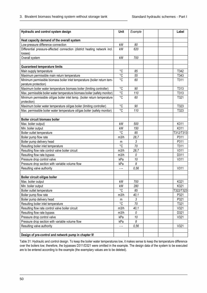
3. Bivalent biomass heating system without storage tank
50
Standard hydraulic schemes - Part I
Hydraulic and control system design
Unit Example Label
Heat capacity demand of the overall system
Low-pressure difference connection kW 80
Differential pressure-affected connection (district heating network incl.
losses)
kW 620
Overall system kW 700
Guaranteed temperature limits
Main supply temperature °C 85 T342
Maximum permissible main return temperature °C 55 T343
Minimum permissible biomass boiler inlet temperature (boiler return tem-
perature protection)
°C 60 T311
Maximum boiler water temperature biomass boiler (limiting controller) °C 90 T313
Max. permissible boiler water temperature biomass boiler (safety monitor) °C 110 T313
Minimum permissible oil/gas boiler inlet temp. (boiler return temperature
protection)
°C 60 T321
Maximum boiler water temperature oil/gas boiler (limiting controller) °C 90 T323
Max. permissible boiler water temperature oil/gas boiler (safety monitor) °C 110 T323
Boiler circuit biomass boiler
Max. boiler output) kW 500 K311
Min. boiler output kW 150 K311
Boiler outlet temperature °C 85 T312/T313
Boiler pump flow rate m3/h 28,7 P311
Boiler pump delivery head m 3 P311
Resulting boiler inlet temperature °C 70 T311
Resulting flow rate control valve boiler circuit m3/h 28,7 V311
Resulting flow rate bypass m3/h 0 D311
Pressure drop control valve kPa 10 V311
Pressure drop section with variable volume flow kPa 8
Resulting valve authority - – 0,56 V311
Boiler circuit oil/gas boiler
Max. boiler output kW 700 K321
Min. boiler output kW 280 K321
Boiler outlet temperature °C 85 T322/T323
Boiler pump flow rate m3/h 40,1 P321
Boiler pump delivery head m 3 P321
Resulting boiler inlet temperature °C 70 T321
Resulting flow rate control valve boiler circuit m3/h 40,1 V321
Resulting flow rate bypass m3/h 0 D321
Pressure drop control valve kPa 10 V321
Pressure drop section with variable volume flow kPa 8
Resulting valve authority - – 0,56 V321
Design of pre-control and network pump in chapter 9!
Table 31: Hydraulic and control design. To keep the boiler water temperatures low, it makes sense to keep the temperature difference
over the boilers low; therefore, the bypasses D311/D321 were omitted in the example. The design data of the system to be executed
are to be entered according to the example (the exemplary values are to be deleted).

3. Bivalent biomass heating system without storage tank
51
Standard hydraulic schemes - Part I
3.3 Functional description
3.3.1 Control scheme
The control and regulation of the system is to be carried out according to Figure 32.
3.3.2 Operating modes
The following operating modes shall be provided:
◼ Off: The entire heat production system is out of operation, with the exception of the continuous operations
(automatic expansion unit, etc.)
◼ Manual: Setpoint firing rate for both the biomass boiler and the oil/gas boiler can be set "manually" as fixed
values on the master I&C system; this operating mode is not mandatory.
◼ Local: The internal output controllers of the subordinate I&C systems of the biomass boiler or the oil/gas
boiler are activated (the master I&C system may be out of operation or defective).
◼ Automatic: The setpoint for the firing rate is specified as a sequence for both the biomass boiler and the
oil/gas boiler by the master I&C system as a function of the main supply temperature (= main control variable).
◼ Other operating modes: Especially for low-load operation (transition period, summer), other operating
modes may be necessary (e.g. conventional "summer/winter" changeover, low-load operation with "oil/gas
boiler alone", etc.).
3.3.3 Control
The control for the specification, limitation, weather compensation and time programme control of the setpoints
as well as for the unblocking and blocking of boilers, pumps, etc. must be implemented by the master I&C
system.
With weather compensation, the outdoor air temperature can be recorded via a weather sensor on the
north side of the building, and the outdoor air temperature can then be used on the one hand as an instanta-
neous value and on the other hand as a 24-h average value to guide the setpoints and unblocking criteria.
Calculation of the 24-h mean value, for example, continuously over a window of the last 24 hours and recal-
culation every 15 minutes.
With a time programme control, time programme levels can be programmed for different functions.
3.3.4 Boiler circuit control biomass boiler
The control of the boiler circuit for the biomass boiler is to be realised by the master I&C system.
In the "automatic" operating mode, if the boiler inlet temperature falls below the limit value, control must take
place at this limit value (= boiler return temperature protection).
In the "manual" operating mode, a boiler return temperature protection should also take place.
In the "local" operating mode, the boiler return temperature protection should continue to be in operation if the
master I&C system is still functioning (which may no longer be the case in emergency operation).

3. Bivalent biomass heating system without storage tank
52
Standard hydraulic schemes - Part I
Figure 32: Control scheme standard hydraulic scheme bivalent biomass heating system without storage tank. The minimum priority
switches route the lowest input signal to the output. Numerical values are to be understood as examples. Safety functions are not
shown; these are to be realised via the subordinate I&C systems of the boilers.
Kesse
lwasse
rte
mp
.
Ers
atz
grö
sse
fü
rF
eu
eru
ng
sle
istu
ng
95
°
Sollw
ert
Fe
ue
run
gs-
leis
tun
g0
/30..
.10
0%
Kesse
lein
tritts
tem
pe
ratu
r
Min.-Vorrang
MANUELL
AU
TO
LOKAL
Min.-Vorrang
Kes
se
l 2
Min.-Vorrang
LOKAL
MANUELL
AU
TO
Kesse
lwasse
rte
mp
.
90
°
Fe
ue
run
gsle
istu
ng
0/4
0..
.10
0%
Kesse
lein
tritts
tem
pe
ratu
r
Min.-Vorrang
Kes
se
l 1
Sollwert Hauptvorlauftemperatur
Sequenz Kessel 1
Sequenz Kessel 2
Hau
ptv
orl
au
fte
mp
era
tur
Aussentemperatur
1 2
Obere BegrenzungFeuerungsleistung
Freigabe Kessel 2AT <= 0° undHolzkessel = 100%
60
°6
0°
Ste
ue
run
g
Übe
rge
ord
ne
tes M
SR
-Syste
mU
nte
rgeo
rdn
ete
s M
SR
-Syste
m 2
: Ö
l-/G
aske
ssel
Unte
rgeo
rdn
ete
s M
SR
-Syste
m 1
: H
olz
ke
ssel
85
°
T3
13
K31
1 T3
11
V31
1
D311
T3
41
T3
01
T3
23
K32
1
T3
21
D321
P32
1 V32
1
P31
1
Subo
rdin
ate
I&
C s
yste
m 1
: B
iom
ass b
oile
r M
aste
r I&
C s
yste
m
Contr
ol
B
oile
r 2
Boile
r w
ate
r te
mpera
ture
Firin
g r
ate
set poin
t 0/4
0 …
100 %
Min. - Priority
Subo
rdin
ate
I&
C s
yste
m 2
: O
il/g
as b
oile
r
MANUAL
LOCAL
MANUAL
Min. - Priority
LOCAL
Boile
r In
let
tem
pera
ture
Bo
iler
1
1
Actu
al valu
e
firing r
ate
Min. - Priority
Upper limit of the firing rate
Outdoor air temperature
Set point main supply temperature
Sequence boiler 2
Sequence boiler 1
Main
supply
tem
pera
ture
Boile
r w
ate
r te
mpera
ture
Firin
g r
ate
set poin
t 0/3
0 …
100 %
Min. - Priority
Unblocking boiler 2 Outdoor air T ≤ 0 °C and biomass boiler = 100 %
Boile
r In
let
tem
pera
ture

3. Bivalent biomass heating system without storage tank
53
Standard hydraulic schemes - Part I
3.3.5 Boiler circuit control oil/gas boiler
The control of the boiler circuit for the oil/gas boiler is to be realised by the master I&C system.
In the "automatic" operating mode, if the boiler inlet temperature falls below the limit value, control must take
place at this limit value (= boiler return temperature protection).
In the "manual" operating mode, a boiler return temperature protection should also take place.
In the "local" operating mode, the boiler return temperature protection should continue to be in operation if the
master I&C system is still functioning (which may no longer be the case in emergency operation).
If the oil/gas boiler does not require a return temperature protection, this function is omitted.
3.3.6 Main supply temperature control
The control of the main supply temperature is to be realised by the master I&C system.
The main supply temperature is to be controlled to a fixed value by adjusting the setpoint values of the firing
rate (= correcting variables) for the biomass boiler and the oil/gas boiler in sequence.
Important: The firing rates of the boilers are controlled via the main supply temperature, i.e. the mixed
temperature of the two boiler outlet temperatures. Careful hydraulic balancing is necessary and the controllers
for limiting the boiler water temperatures must be set 5...15 K above the setpoint of the main supply tempera-
ture.
3.3.7 Firing rate control biomass boiler
The firing rate is controlled via the subordinate I&C system of the biomass boiler.
The biomass-fired furnace shall be equipped with automatic ignition. If this is not possible or not reasonable
according to the state of the art, it can be operated with fired bed support mode. In principle, the biomass-fired
furnace should always be operated at the lowest possible output so that it has to be switched on and off as
little as possible.
The controller for the main supply temperature of the master I&C system specifies the setpoint for the firing
rate to the biomass-fired furnace. With the help of the control system, the setpoint for the firing rate can then
be additionally guided and limited.
The internal controller for the boiler water temperature T313 of the subordinate I&C system has the following
functions:
- “Manual" operating mode (not mandatory): Control of the firing rate to a fixed value set on the master I&C
system, i.e. no control of the main supply temperature T341, but limitation of the boiler water temperature
T313 (e.g. to 95°C).
- “Local" operating mode: Control of the boiler water temperature T313 to a fixed value set on the subordi-
nate I&C system (e.g. 85°C), limitation of the boiler water temperature T313 to a higher fixed value (e.g.
to 95°C).
- Operating mode "automatic": Limiting the boiler water temperature T313 (e.g. to 95°C)
In the output control range of the biomass-fired furnace of 30...100%, the control should be continuous. Below
this, the control must be in two-point mode. Switching between OFF (or fire bed support) and continuous
control is done via the respective active I&C system. If the biomass boiler manufacturer so wishes, the switch-
over can also always be made via the biomass boiler.
A recommendation for standard interfaces between the master I&C system and the biomass boiler, as well as
a list of control unit and biomass boiler manufacturers offering these interfaces, can be downloaded from the
Internet [9].
Important: The safety of the biomass boiler, i.e. preventing the maximum permissible boiler water temper-
ature from being exceeded, must be additionally ensured by the subordinate I&C system of the biomass boiler.

3. Bivalent biomass heating system without storage tank
54
Standard hydraulic schemes - Part I
3.3.8 Firing rate control oil/gas boiler
The firing rate is controlled via the subordinate I&C system of the oil/gas boiler.
The control of the firing rate should be continuous (for modulating operation) or in stages (for multi-stage
operation). In principle, the oil/gas boiler should always be operated at the lowest possible output, and it should
only be unblocked when the biomass boiler has not been able to provide the output at full load for a long time.
The controller for the main supply temperature of the master I&C system gives the setpoint value of the firing
rate to the oil/gas boiler in sequence to the biomass boiler.
The internal controller for the boiler water temperature T323 of the subordinate I&C system has the following
functions:
- “Manual" operating mode (not mandatory): Control of the firing rate to a fixed value set on the master I&C
system, i.e. no control of the main supply temperature T341, but limitation of the boiler water temperature
T323 (e.g. to 90°C).
- “Local" operating mode: Control of the boiler water temperature T323 to a fixed value set on the subordi-
nate I&C system (e.g. 90°C).
- Operating mode "automatic": Limiting the boiler water temperature T323 (e.g. to 90°C)
Important: The safety of the oil/gas boiler, i.e. the prevention of exceeding the maximum permissible boiler
water temperature, must be additionally ensured by the subordinate I&C system of the oil/gas boiler.
3.3.9 Sequence control biomass boiler - oil/gas boiler
The downstream connection of the biomass boiler - oil/gas boiler must be implemented by the master I&C
system.
The sequence controller for the firing rate of the two boilers must be designed and supplemented with suitable
unblocking and blocking criteria in such a way that it reliably prevents the oil/gas boiler from being switched
on too frequently.
Examples of unblocking and blocking criteria for the oil/gas boiler are:
- Unblocking when certain minimum outdoor air temperature AND setpoint of the firing rate of the biomass
boiler is set to 100% for a certain time.
- Blocking (switching back) when the setpoint value of the firing rate of the biomass boiler has returned to
90% for a certain time.
If the biomass boiler goes on fault, the oil/gas boiler must be unblocked automatically.
The boiler that is not in operation must be completely isolated hydraulically from the rest of the system (no
faulty circulation due to overrun times, incorrectly set three-way valves, short circuits via safety lines, etc.).
Note: When switched on, boiler 2 has the full volume flow at minimum output and thus a smaller temperature
difference between inlet and outlet than at full load. This deviation causes a "floating" of the boiler water tem-
peratures: The temperature of boiler 1 (full load) is higher and that of boiler 2 (partial load) lower than the main
supply temperature. This must be taken into account in the design so that the limitation of the boiler water
temperature of boiler 1 can be set sufficiently high.
It is permissible to control the oil/gas boiler using the three-way valve if this improves the control quality:
- Oil/gas boiler correcting variable = setpoint of the firing rate (as before), but additional outlet temperature
control for the oil/gas boiler.
- Correcting variable oil/gas boiler = Stroke of the three-way valve in the boiler circuit (instead of the setpoint
of the firing rate); boiler water temperature controlled by the subordinate I&C system of the oil/gas boiler.
- It shall be indicated where the measurement location of the main control variable is (T341 or T342? Max-
imum precedence at T344?).

3. Bivalent biomass heating system without storage tank
55
Standard hydraulic schemes - Part I
3.3.10 Chosen control concept
The concept applicable to the project to be described, how to control the boiler circuits, the main supply tem-
perature and the firing rates, shall be defined in Table 33
Operating mode
Boiler circuit control: - Biomass boiler - Oil/gas boiler
Main supply temperature control (= main control variable)
Regulation of firing rates - Biomass boiler - Oil/gas boiler
Off Inoperative
Manual Not pro-vided
T311/T321 boiler return temperature protection sys-tems by master I&C system Limitation of boiler water temperatures T313/T323 by subordinate I&C systems
Control main supply temperature
T341 out of operation
Setpoints of the two firing rates can
be set as fixed values on the master I&C
system
Local Control of boiler water tem-peratures T313/T323 by subor-dinate I&C systems
Control main supply temperature
T341 out of operation
Internal power controllers of the sub-
ordinate I&C systems activated
Automatic Summer op-eration? Yes, with biomass boiler Yes, with oil/gas boiler No
T311/T321 boiler return temperature protection sys-tems by master I&C system Limiting boiler water tem-peratures T313/T323 by subor-dinate I&C systems
Control of the main supply tempera-
ture T341 by the master I&C system in
the sequence biomass boiler - oil/gas
boiler; the correcting variables are the
setpoints of the two firing rates.
Other permissible solutions:
Additional outlet temperature control
for oil/gas boiler
Correcting variable oil/gas boiler =
Stroke three-way valve in boiler circuit
Measuring point main supply tempera-
ture
for T341 at T342
Maximum priority at T344
Control of the two firing rates by the
subordinate I&C systems; setpoints from
the master I&C system in sequence bio-
mass boiler - oil/gas boiler
Summary Which operating modes are provided?
Off
Manual (for each boiler)
Local (for each boiler)
Automatic winter operation with biomass boiler and oil/gas boiler
Automatic low-load operation (transition period, summer) with biomass boiler)
Automatic low-load operation (transition period, summer) with oil-gas boiler
Oil/gas boiler alone (e.g. revision biomass boiler, emergency operation)
Other:
Table 33: Questions and answers on the chosen control concept

3. Bivalent biomass heating system without storage tank
56
Standard hydraulic schemes - Part I
3.4 Data recording for operational optimisation All precautions must be taken so that a proper operational optimisation can be carried out and the subsequent
regular operation can be efficiently monitored. The measured variables to be recorded are to be marked with
a cross in Table 34 measured variables marked "Standard" must be able to be recorded in any case; the
connection of the remaining measured variables is recommended. The measuring accuracy must meet the
increased requirements of a measuring system.
The questions and answers on automatic data recording for operational optimisation in Table 35 must be
answered.
Standard Measuring points Label
Standard Outdoor air temperature T301
Standard Biomass boiler inlet temperature T311
Standard Biomass boiler outlet temperature T312
Boiler water temperature biomass boiler (other measuring point) T313
Standard Oil/gas boiler inlet temperature T321
Standard Oil/gas boiler outlet temperature T322
Boiler water temperature oil-gas boiler (other measuring point) T323
Standard Main supply temperature before bypass T341
Standard * Main supply temperature after bypass T342
Standard Main return temperature before bypass T343
Standard * Main return temperature after bypass T344
Standard * Return temperature of the low-pressure difference connection T351
Standard Supply temperature of the differential pressure-affected connection T361
Standard * Return temperature of the differential pressure-affected connection T362
Standard Heat quantity/output heat meter biomass boiler ** W311
Water quantity/flow rate heat meter biomass boiler ** W311
Standard Oil/gas meter, if modulating oil/gas boiler *** W321/W322
Standard Operating hours stage 1/2, if two-stage oil/gas boiler W321/W322
Standard Setpoint value of the firing rate biomass boiler
Boiler-internal setpoint of the firing rate (feedback biomass boiler)
Standard Setpoint of the firing rate oil/gas boiler
Boiler-internal setpoint of the firing rate (feedback signal oil/gas boiler)
Standard Exhaust gas temperature biomass boiler
Combustion chamber temperature biomass boiler
Standard * Residual oxygen biomass boiler
Measuring points particle separator; type:
* In order to reduce the effort for data recording, a reduction by these measuring points is accepted as permissible deviation for
operation optimisation.
** The heat meter must be equipped with an interface for recording the heat quantity [kWh] or water quantity [m³]. The graphical
representation, however, must be in terms of power [kW] or volume flow [m³/h].
*** The oil/gas meter must be equipped with an interface for recording the oil or gas quantity [dm³ or m³]. The graphical representa-
tion, however, must be made as a volume flow [dm³/h or m³/h].
Table 34: Measuring point list for automatic data recording. If the installation is to be considered a standard hydraulic scheme, it must
be possible to record all measured variables marked "Standard".

3. Bivalent biomass heating system without storage tank
57
Standard hydraulic schemes - Part I
Area Questions and answers
Hardware How is the automatic data recording for operation optimisation carried out?
With a separate data logger
With the PLC of the biomass boiler
With the master I&C system
How is the periodic reading of the data done?
Reading out the data on site Readout via landline phone (POTS) connection
Readout via ISDN telephone connection Readout via the Internet
Data recording What is the measurement interval?
10 seconds (recommendation)..... seconds
What is the recording interval?
5 minutes (recommendation)..... minutes
How are the analogue values recorded?
As an average value over the last recording interval (recommendation)
As instantaneous value
How is the recording done for meters?
As a sum value over the last recording interval (recommendation)
As current counter reading (Attention: is often set to zero by mistake)
How is the recording of running times done?
As runtime during the last recording interval (recommendation)
As the current number of operating hours (Attention: is often accidentally set to zero)
How large is the measured value memory?
30 days recording capacity (recommendation)..... days recording capacity
Data evaluation What is the output format for evaluation in EXCEL?
CSV file with columns = time and measuring points, rows = values (recommendation)
Other:
How is the graphical representation done?
Related data as a weekly overview (recommendation)
Related data as a daily overview (recommendation)
Representation of heat, oil, gas, operating hours meters as output or volume flow (demand)
Other:
Responsibilities How are responsibilities regulated at the tender planning stage?
Specification of the autom. data recording by the main planner
Specification of the automatic data recording by the main planner with the involvement of the I&C spe-
cialist
How are the responsibilities regulated at the execution and approval stage?
Planning of the autom. data recording by the main planner
Planning of autom. data recording by biomass boiler suppliers
Planning of the autom. data recording by the supplier of the master I&C system
How are responsibilities regulated during operational optimisation?
Readout and data evaluation by main planner
Readout by biomass boiler supplier, data evaluation by main planner
Readout by supplier of master I&C system, data evaluation by main planner
Readout by operator, data evaluation by main planner
Readout and data evaluation by operator
Table 35: Questions and answers on automatic data recording for operation optimisation

3. Bivalent biomass heating system without storage tank
58
Standard hydraulic schemes - Part I
3.5 Annex to the approval protocol The execution phase is concluded by the approval test. At this time, an addendum to the approval protocol is
to be drawn up in accordance with Table 37.
The questions in Table 36 be answered at the beginning of the tendering phase. The annex to the approval
protocol according to Table 37 to be filled in at the end of the execution phase. However, it is recommended
to use these tables already during the tendering and execution stage for the preliminary determination of the
planning values; so that the functionality of the system is clearly recognisable.
Who prepares the addendum to the approval protocol?
Main planner
Biomass boiler supplier
Supplier of the master I&C system
Table 36: Questions and answers on the annex to the approval protocol

3. Bivalent biomass heating system without storage tank
59
Standard hydraulic schemes - Part I
Description Unit Example
Master I&C system
Connection of master/subordinate I&C systems via standard interface [9]?
Yes No
◼ Boiler return temperature protection
Boiler inlet temperature limit biomass boiler °C 60
Boiler inlet temperature limit oil/gas boiler °C 60
◼ Main supply temperature control
Who specifies OFF (or fire bed support) and steady regulation?
The active control system Always the biomass boiler
Main supply temperature setpoint °C 85
Continu-ous regu-lation in se-quence
P-band for sequence 1 (biomass boiler) % 200
Integration time for sequence 1 (biomass boiler) Min. 20
P-band for sequence 2 (oil/gas boiler) % 200
Integration time for sequence 2 (oil/gas boiler) Min. 20
Two-point controller in the se-quence
Biomass boiler continuous control at setpoint firing rate. % 35
Biomass boiler OFF/fire bed at setpoint firing rate % 25
Oil/gas boiler stage 1 ON at setpoint firing rate % 45
Oil/gas boiler stage 1 OFF at setpoint firing rate % 35
Oil/gas boiler stage 2 ON at setpoint firing rate % 75
Oil/gas boiler stage 2 OFF at setpoint firing rate % 65
◼ Sequence control biomass boiler - oil/gas boiler (modify if neces-
sary)
Unblocking criterion: Outdoor air temperature °C 0
AND (setpoint firing rate biomass boiler % 100
AND delay time) Min. 30
Blocking criterion: Setpoint firing rate biomass boiler % 90
AND delay time Min. 10
Biomass boiler
◼ Heat output settings
Set minimum heat output with the reference fuel kW 150
Set maximum heat output with the reference fuel kW 500
◼ Subordinate I&C system 1
Boiler water temperature setpoint for "local" operating mode °C 85
Boiler water temperature limitation °C 95
Safety shutdown at boiler water temperature °C 110
Oil/gas boiler
◼ Heat output settings
Set minimum heat output kW 280
Set maximum heat output stage 1+2 modulating kW 700
◼ Subordinate I&C system 2
Boiler water temperature limitation °C 90
Safety shutdown at boiler water temperature °C 110
Table 37: Annex to the approval protocol - setting values; exemplary values are to be deleted

4. Bivalent biomass heating system with storage tank
60
Standard hydraulic schemes - Part I
4. Bivalent biomass heating system with storage tank
4.1 Short description and responsibilities
4.1.1 User level
The simplest possible operation and a clear display of the main functions are required so that non-professional
personnel can also operate the system:
◼ The following requirements must be met for service and emergency operation:
- It must be possible to disable the automatic control system partially or completely for service work and in
case of emergency operation (e.g. via switch "off/on/automatic")
- Subordinate I&C systems must be able to be operated independently of the master I&C system (e.g. in
the event of failure of the master I&C system).
- Manual operation of the control valves must be guaranteed (e.g. manual adjustment at the control valve,
but this must not be disturbed by an incorrect control signal).
- All safety functions must be maintained
◼ The operation mode selection shall be made in one of the following ways:
- Via switches in a conventional control panel (usually in the control cabinet), this solution has proven
itself in practice.
- Via a PLC; however, this is only an option if the hardware and software requirements for convenient
operation are right.
- Via the master computer of a control system
◼ Further operation, such as adjusting setpoints, changing time programmes, etc., can be carried
out directly on the master and subordinate I&C systems (if necessary, also via the Internet).
4.1.2 Master I&C system
The master I&C system takes care of all master control and regulation functions and links the subordinate I&C
systems with each other. In addition, automatic data recording is also assigned to the master I&C system,
which is mandatory as a standard hydraulic scheme (at least temporarily for the duration of the operation
optimisation).
4.1.3 Subordinate I&C system 1: biomass boiler
The subordinate I&C system of the biomass boiler has to fulfil the following functions:
- Fire bed support operation or automatic ignition
- Control of the firing rate in manual and automatic operation based on the setpoint specification of the
master I&C system
- Control of the boiler water temperature during local operation
- Limitation of the firing rate due to the boiler water temperature in all operating modes
If a particle separator is necessary, it must be controlled by the subordinate I&C system of the biomass
boiler.
The safety of the biomass boiler, i.e. preventing the maximum permissible boiler water temperature from
being exceeded, must be ensured by the subordinate I&C system of the biomass boiler.
If the PLC of the biomass boiler can also fulfil the demands on the master I&C system (in particular also the
automatic data recording), the simultaneous use as a master and subordinate I&C system can
be tested.

4. Bivalent biomass heating system with storage tank
61
Standard hydraulic schemes - Part I
4.1.4 Subordinate I&C system 2: oil/gas boiler
The subordinate I&C system of the oil/gas boiler has to fulfil the following functions:
- Pre-purge, ignition and flame monitoring
- Control of the firing rate in manual and automatic operation based on the setpoint specification of the
master I&C system (continuous in modulating operation, in stages in multi-stage operation)
- Control of the boiler water temperature during local operation
- Limitation of the firing rate due to the boiler water temperature in all operating modes
The safety of the oil/gas boiler, i.e. preventing the maximum permissible boiler water temperature from being
exceeded, must be ensured by the subordinate I&C system of the oil/gas boiler.
4.1.5 Selected structure of the I&C system levels
A person with main responsibility must be designated for the I&C planning (in particular also for the interface
definition).
The structure of the I&C system levels with responsibilities chosen for the project to be described can be
answered with Table 38.

4. Bivalent biomass heating system with storage tank
62
Standard hydraulic schemes - Part I
I&C system level Questions and answers
User level
Section 4.1.1
Are the requirements for service and emergency operation met?
Yes (mandatory for standard hydraulic scheme) No
How does the operation mode selection take place?
Switch in a conventional control panel
Input via a PLC, sufficiently convenient operation is guaranteed
Input via the master computer of the control system
From where can the system be controlled and operated?
Only in the central heating plant
In the central heating plant and via modem
In the central heating plant and via the internet
Master I&C system
Section 4.1.2
How is the master I&C system implemented?
Individual controller as master I&C system
Use of the PLC of the biomass boiler as a master I&C system
Own master I&C system
Connection of master/subordinate I&C systems via standard interface [9]?
Yes No
How is the automatic data recording done?
Data logger during operation optimisation, an interface is provided
Internal data recording in the master I&C system
Subordinate I&C sys-
tem 1:
Biomass boiler
Section 4.1.3
What is the position/tasks of the PLC of the biomass boiler?
It is used simultaneously as a master and subordinate I&C system
It is subordinated to the master I&C system
Subordinate I&C sys-
tem 2:
Oil/gas boiler
Section 4.1.4
What is the position/tasks of the I&C system of the oil/gas boiler?
It is subordinated to the master I&C system
Responsibilities How are responsibilities regulated at the tender planning stage?
Specification of all I&C levels by the main planner
Specification of all I&C levels by the main planner with the involvement of I&C specialists
How are the responsibilities (especially interface definitions) regulated at the execution and approval stage?
Overall planning of all I&C levels by the main planner
Overall planning of all I&C levels by biomass boiler supplier
Overall planning of all I&C levels by the supplier of the master I&C system
Planning of each I&C level by the respective supplier (not permitted for standard hydraulic scheme, as a
main person responsible for I&C planning is explicitly required).
Table 38: Questions and answers on the chosen structure of the I&C levels and responsibilities

4. Bivalent biomass heating system with storage tank
63
Standard hydraulic schemes - Part I
4.2 Principle scheme and design
4.2.1 Hydraulic circuit
The hydraulic circuit must comply with Figure 39 The following requirements must be met:
- The interconnection of biomass boiler, oil/gas boiler, storage tank, low-pressure difference connection and
pre-control must actually be low pressure differential (short pipes, large pipe diameters).
- The storage system must be consistently designed as a stratified storage system.
- Storage connections with cross-section enlargement (speed reduction), baffle plate (refraction of the water
jet) and, if necessary, siphoned (prevention of one-pipe circulation).
- Storage connections only top and bottom (no connections in between)
- No pipes may be routed inside the storage tank (danger of "thermal agitation").
- Whenever possible, the storage tank should not be divided among several containers. If this requirement
cannot be met, the following must be observed:
• No connections between the storages
• When controlling the storage tank charging state, each storage tank is to be considered as a control
unit (problem: due to the individual stratification in each storage tank, the warmer storage tank can
be colder at the bottom than the colder storage tank at the top).
The installation is also considered a standard hydraulic scheme if
- one pump is realised by two or more pumps connected in parallel or in series,
- the pre-control of the district heating network is realised by two control valves connected in parallel or with
a separate summer group,
- exhaust gas heat exchanger can be integrated.
4.2.2 Hydraulic and control design
The hydraulic and control design must be carried out according to the generally accepted engineering stand-
ards. The requirements according to the Q-Guideline [1] and the Planning Handbook [4] must be fulfilled, in
particular:
- Storage volume 1 h storage capacity related to nominal biomass boiler output
- Load control/boiler return temperature protection for both boilers and pre-control: Valve authority 0,5
- Design temperature difference above the biomass boiler 15 K; smaller temperature difference necessary
if minimum permissible return temperature is high (e.g. with bark, landscape conservation wood); can be
increased to reduce pump power consumption if it is ensured that this does not cause any control-related
problems (e.g. oscillation of boiler output due to temperature stratification).
- The boiler inlet temperature should be at least 5 K higher than the minimum permissible return temperature
(boiler return temperature protection).
The hydraulic and control design shall be presented and documented in accordance with Table 40.
A maximum permissible main return temperature T443 shall be specified.
If the temperature difference between the boiler outlet temperature and the boiler inlet temperature is more
than 10 K less than the temperature difference between the boiler outlet temperature and the maximum per-
missible main return temperature T443, it is recommended to provide a bypass in the boiler circuit
D411/D421.
Important: To ensure that the boilers can always deliver the output, it must be ensured that the main return
temperature T443 cannot rise above the design value in any operating case (prescribe return temperature
limiter for all consumers!).

4. Bivalent biomass heating system with storage tank
64
Standard hydraulic schemes - Part I
Figure 39: Principle scheme of a dual-fuel biomass heating system with storage tank. Safety devices and expansion system must be
designed in accordance with the country-specific regulations.
Dru
ckd
iffe
ren
zarm
eS
ch
nitts
telle
(z.B
. V
ert
eile
r Z
en
tra
le)
Dru
ckd
iffe
ren
z-
beh
aft
ete
Schn
itts
telle
(Fe
rnle
itun
g)
T4
13
T4
23
T4
32
T4
41
T4
42
T4
61
P4
61
V4
61
T4
31
T4
33
T4
35
T4
22
T4
21
T4
34
T4
51
P4
21
V4
21
T4
44
T4
43
T4
62
V4
11
P4
11
T4
11
W4
11
T4
12
T4
01
D411*
D421*
W421
W422
K4
21
K4
11
* D
41
1/D
42
1 k
an
n e
ntfa
llen (
sie
he
Ab
schn
itt
4.2
.2)
* D
41
1/D
42
1 c
an
be
om
itte
d (
see
ch
ap
ter
4.2
.2)
Diffe
ren
tia
l pre
ssu
re-a
ffe
cte
d
co
nn
ectio
n
(dis
tric
t h
ea
tin
g n
etw
ork
)
Lo
w-p
ressu
re d
iffe
ren
ce
co
nn
ectio
n (
e.g
. h
yd
rau
lic
se
pa
rato
r h
eatin
g p
lan
t)

4. Bivalent biomass heating system with storage tank
65
Standard hydraulic schemes - Part I
Hydraulic and control system design
Unit Example Label
Storage
Content m3 10
Heat capacity demand of the overall system
Low-pressure difference connection kW 80
Differential pressure-affected connection (district heating network incl.
losses)
kW 620
Overall system kW 700
Guaranteed temperature limits
Main supply temperature °C 85 T442
Maximum permissible main return temperature °C 55 T443
Minimum permissible biomass boiler inlet temperature (boiler return tem-
perature protection)
°C 60 T411
Maximum boiler water temperature biomass boiler (limiting controller) °C 90 T413
Max. permissible boiler water temperature biomass boiler (safety monitor) °C 110 T413
Minimum permissible oil/gas boiler inlet temp. (boiler return temperature
protection)
°C 60 T421
Maximum boiler water temperature oil/gas boiler (limiting controller) °C 90 T423
Max. permissible boiler water temperature oil/gas boiler (safety monitor) °C 110 T423
Boiler circuit biomass boiler
Max. boiler output kW 350 K411
Min. boiler output kW 105 K411
Boiler outlet temperature °C 85 T412/T413
Boiler pump flow rate m3/h 20,1 P411
Boiler pump delivery head m 3 P411
Resulting boiler inlet temperature °C 70 T411
Resulting flow rate control valve boiler circuit m3/h 10,0 V411
Resulting flow rate bypass m3/h 10,0 D411
Pressure drop control valve kPa 10 V411
Pressure drop section with variable volume flow kPa 8 - –
Resulting valve authority - – 0,56 V411
Boiler circuit oil/gas boiler
Max. boiler output kW 700 K421
Min. boiler output kW 280 K421
Boiler outlet temperature °C 85 T422/T423
Boiler pump flow rate m3/h 40,1 P421
Boiler pump delivery head m 3 P421
Resulting boiler inlet temperature °C 70 T421
Resulting flow rate control valve boiler circuit m3/h 20,1 V421
Resulting flow rate bypass m3/h 20,1 D421
Pressure drop control valve kPa 10 V421
Pressure drop section with variable volume flow kPa 8 - –
Resulting valve authority - – 0,56 V421
Design of pre-control and network pump in chapter 9!
Table 40: Hydraulic and control system design. The design data of the system to be executed are to be entered according to the
example (the exemplary values are to be deleted).

4. Bivalent biomass heating system with storage tank
66
Standard hydraulic schemes - Part I
4.3 Functional description
4.3.1 Control scheme
The control and regulation of the system is to be carried out according to Figure 41.
4.3.2 Operating modes
The following operating modes shall be provided:
◼ Off: The entire heat production system is out of operation, with the exception of the continuous operations
(automatic expansion unit, etc.)
◼ Manual: Setpoint firing rate for both the biomass boiler and the oil/gas boiler can be set "manually" as fixed
values on the master I&C system; this operating mode is not mandatory.
◼ Local: The internal output controllers of the subordinate I&C systems of the biomass boiler or the oil/gas
boiler are activated (the master I&C system may be out of operation or defective).
◼ Automatic: The setpoint value of the firing rate is specified as a sequence for both the biomass boiler and
the oil/gas boiler by the master I&C system depending on the storage tank state of charge (= controlled varia-
ble).
◼ Other operating modes: Especially for low-load operation (transition period, summer), other operating
modes may be necessary (e.g. conventional "summer/winter" changeover, low-load operation with
"charge/discharge storage tank", low-load operation with "oil/gas boiler alone", etc.).
4.3.3 Control
The control for the specification, limitation, weather compensation and time programme control of the setpoints
as well as for the unblocking and blocking of boilers, pumps, etc. must be implemented by the master I&C
system.
With weather compensation, the outdoor air temperature can be recorded via a weather sensor on the
north side of the building, and the outdoor air temperature can then be used on the one hand as an instanta-
neous value and on the other hand as a 24-h average value to guide the setpoints and unblocking criteria.
Calculation of the 24-h mean value, for example, continuously over a window of the last 24 hours and recal-
culation every 15 minutes.
With a time programme control, time programme levels can be programmed for different functions.
4.3.4 Boiler circuit control biomass boiler
The control of the boiler circuit for the biomass boiler is to be realised by the master I&C system.
In the "automatic" operating mode, the boiler outlet temperature should be controlled continuously via
the control valve in the boiler circuit to a fixed value. If the boiler inlet temperature falls below the limit value,
the control should be set to this limit value (= boiler return temperature protection).

4. Bivalent biomass heating system with storage tank
67
Standard hydraulic schemes - Part I
Min.-Vorrang
Kesse
lwasse
rte
mp
.
Kesse
laustr
itts
tem
pe
ratu
r
Ers
atz
grö
sse
fü
rF
eu
eru
ng
sle
istu
ng
90
°
Sollw
ert
Fe
ue
run
gs-
leis
tun
g0
/30..
.10
0%
Kesse
lein
tritts
tem
pe
ratu
r
Min.-Vorrang
MANUELL
AU
TO
LOKAL
Min.-Vorrang
10
0%
0%
Sp
eic
her
Ke
ss
el
2
Min.-Vorrang
LOKAL
MANUELL
AU
TO
Kesse
lwasse
rte
mp
.
Kesse
laustr
itts
tem
pe
ratu
r
90
°
Fe
ue
run
gsle
istu
ng
0/4
0..
.10
0%
Kesse
lein
tritts
tem
pe
ratu
r
Min.-Vorrang
Ke
ss
el
1
Sollwert Speicherladezustand
Sequenz Kessel 1
Sequenz Kessel 2
Spe
ich
erl
ade
zu
sta
nd 0
...1
00
%
Aussentemperatur
1 2
Obere BegrenzungFeuerungsleistung
Freigabe Kessel 2AT <= 0° undHolzkessel = 100%
60
°
85
°
60
°
85
°
Ste
ue
run
g
Übe
rge
ord
ne
tes M
SR
-Syste
mU
nte
rgeo
rdn
ete
s M
SR
-Syste
m 2
: Ö
l-/G
aske
ssel
Unte
rgeo
rdn
ete
s M
SR
-Syste
m 1
: H
olz
ke
ssel
Min.-Vorrang
85
°
T4
12
T4
13
K41
1 T4
11
V41
1
D411
T4
22
T4
01
T4
31
T4
23
K42
1T
43
2
T4
33
T4
34
T4
35
T4
21
D421
P42
1 V42
1
P41
1
Figure 41: Control scheme standard hydraulic scheme bivalent biomass heating system with storage tank. The minimum priority
switches route the lowest input signal to the output. Numerical values are to be understood as examples. Safety functions are not
shown; these are to be realised via the subordinate I&C systems of the boilers.
Subo
rdin
ate
I&
C s
yste
m 1
: B
iom
ass b
oile
r M
aste
r I&
C s
yste
m
Subo
rdin
ate
I&
C s
yste
m 2
: O
il/g
as b
oile
r
Boile
r w
ate
r te
mpera
ture
Bo
iler
1
1
Actu
al valu
e
firing r
ate
Boile
r in
let
tem
pera
ture
Boile
r w
ate
r te
mpera
ture
Boile
r outlet
tem
pera
ture
Firin
g r
ate
set poin
t 0/3
0 …
100 %
Min. - Priority
Min. - Priority
Min. - Priority
LOCAL
Unblocking boiler 2 Outdoor air T ≤ 0 °C and biomass boiler = 100 %
Upper limit of the firing rate
Min. - Priority
MANUAL
Min. - Priority
Firin
g r
ate
set poin
t 0/4
0 …
100 %
Boile
r outlet
tem
pera
ture
Boile
r in
let
tem
pera
ture
Bo
iler
2
LOCAL
MANUAL
Sto
rag
e
Sequence boiler 2
Outdoor air temperature
Set point storage state of charge
Sequence boiler 1
Sto
rage s
tate
of
charg
e 0
… 1
00%
Min. - Priority
Contr
ol

4. Bivalent biomass heating system with storage tank
68
Standard hydraulic schemes - Part I
4.3.5 Boiler circuit control oil/gas boiler
The control of the boiler circuit for the oil/gas boiler is to be realised by the master I&C system.
In the "automatic" operating mode, the boiler outlet temperature should be controlled continuously via
the control valve in the boiler circuit to a fixed value. If the boiler inlet temperature falls below the limit value,
the control should be set to this limit value (= boiler return temperature protection).
To prevent uncontrolled charging of the storage tank in "manual", "local" or "oil/gas boiler alone" mode, the
oil/gas boiler should be switched off when the storage tank is charged to an adjustable value (e.g. off at 20%
and on again at 0%).
4.3.6 Storage tank charging status control
The control of the storage tank charging state is to be realised by the master I&C system.
The state of charge of the storage tank should be recorded via at least 5 temperature sensors that are evenly
distributed over the height of the storage tank. This gives the state of charge of the storage tank from 0% to
100%.
Different variants are possible for recording the storage tank charging status. The following applies to variants
1 and 2:
w = Sensor signals "warm" when e.g. T 75°C
k = Sensor signals "cold" when e.g. T 65°C
Variant 1 (Table 42): With sensor values 20 - 40 - 60 - 80 - 100. For "all
sensors cold" the value is 0. This variant results in a stepped actual value
signal. Therefore, the (fast) P component of the controller must not be too
large, and disturbances must mainly be compensated via the (slow) I com-
ponent.
Variant 2: The stepped signal according to variant 1 can be smoothed
by a first-order control delay element (PT1 element). However, the time
constant of the PT1 element must not be too large, otherwise there is a
risk that the inevitable time delay of the actual value signal will lead to
disturbances. The "more continuous" actual value signal, however, allows
a somewhat larger P component in the controller compared to variant 1.
Variant 3 (Table 43): A smoothing of the characteristic curve can also be achieved if the temperature of the
active sensor is interpolated.
Sensor (from top to bottom) Value
1 2 3 4 5
< 60°C < 60°C < 60°C < 60°C < 60°C 0
60...80°C < 60°C < 60°C < 60°C < 60°C 0...20
> 80°C 60...80°C < 60°C < 60°C < 60°C 20...40
> 80°C > 80°C 60...80°C < 60°C < 60°C 40...60
> 80°C > 80°C > 80°C 60...80°C < 60°C 60...80
> 80°C > 80°C > 80°C > 80°C 60...80°C 80...100
Table 43: Variant 3 (stepless)
With a good system, it can be assumed that for the sensor temperatures T1...T5 applies:
T1 T2 T3 T4 T5 (T1...T5 from top to bottom)
The active sensor is highlighted in grey in Table 43 following rule applies:
- Sensor 1 active when all other sensor temperatures < 80°C
- Sensor 2 active when sensor temperature T1 > 80°C
- Sensor 3 active when sensor temperature T2 > 80°C
Sensor (from top to bottom)
Value
1 2 3 4 5
k k k k k 0
w k k k k 20
w w k k k 40
w w w k k 60
w w w w k 80
w w w w w 100
Table 42: Variant 1 (in stages)

4. Bivalent biomass heating system with storage tank
69
Standard hydraulic schemes - Part I
- Sensor 4 active when sensor temperature T3 > 80°C
- Sensor 5 active when sensor temperature T4 > 80°C
The quality of the interpolation (smoothing of the signal) depends on the thickness of the mixing zone in the
storage tank, and this thickness is not a fixed quantity. With the same storage tank, it can be very different -
depending on the flow rate, cooling, etc. Basically:
- thickness of the mixing zone zero (ideal stratified storage) results in no smoothing at all, the signal is just
as stepped as in variant 1
- thickness of the mixing zone between zero and one probe distance results in an increasingly better
smoothing of the signal
- Thickness of the mixing zone very slightly greater than one sensor spacing gives the best smoothing
- Thickness of the mixing zone significantly greater than a probe spacing results in poorer smoothing again
Variant 4: Average storage tank temperature as a measure of the storage tank state of charge. The disad-
vantage here is that the actual storage tank state of charge is reproduced differently depending on the thick-
ness of the mixing zone, return temperature, cooling, etc: Thickness of the mixing zone zero (ideal stratified
storage tank) results in no smoothing at all, the signal is just as stepped as in variant 1; when designed for
85/55°C, the control range is 30 K, when the return comes back in the morning with 25°C, it is suddenly 60 K.
More than 5 storage sensors: Only with this (in combination with variants 1 to 4) can the signal really
be improved.
The storage tank is to be charged by a continuous control. This controller should have PI characteristics. As a
result of the I component, the storage tank can thus be charged to a setpoint of 60...80% without a permanent
control deviation (as would be the case with the P controller) (in the case of a stepped signal, select a stepped
value, e.g. 60%). If the heat consumers suddenly demand more power, the storage charging state drops and
the firing rate is increased, and if less power is suddenly needed, the storage charging state rises and the firing
rate is regulated back. In the first case, the upper half of the storage tank is available as a power reserve until
the biomass boiler has reacted, and in the second case, the biomass boiler can deliver the temporary power
surplus to the lower half of the storage tank.
In systems with automatic ignition, the storage tank should be completely charged and discharged with re-
duced output during low-load operation (required biomass boiler output below the minimum output). A suitable
switching criterion must be defined for switching from "charge/discharge" to continuous control and back (e.g.
manual switching or switching according to time programme and outdoor air temperature).
4.3.7 Firing rate control biomass boiler
The firing rate is controlled via the subordinate I&C system of the biomass boiler.
The biomass-fired furnace shall be equipped with automatic ignition. If this is not possible or not reasonable
according to the state of the art, it can be operated with fired bed support mode. In principle, the biomass-fired
furnace should always be operated at the lowest possible output so that it has to be switched on and off as
little as possible.
The controller for the storage charging state of the master I&C system specifies the setpoint value for the firing
rate to the biomass firing system. With the help of the control system, the setpoint for the firing rate can then
be additionally guided and limited.
The internal controller for the boiler water temperature T413 of the subordinate I&C system has the following
functions:
- “Manual" operating mode (not mandatory): Control of the firing rate to a fixed value set on the master I&C
system, i.e. no control of the storage tank charging state, but limitation of the boiler water temperature
T413 (e.g. to 90°C).
- “Local" operating mode: Control of the boiler water temperature T413 to a fixed value set on the subordi-
nate I&C system (e.g. 85°C), limitation of the boiler water temperature T413 to a higher fixed value (e.g.
to 90°C);
- Operating mode "automatic": Limiting the boiler water temperature T413 (e.g. to 90°C)

4. Bivalent biomass heating system with storage tank
70
Standard hydraulic schemes - Part I
In the output control range of the biomass-fired furnace of 30...100%, the control should be continuous. Below
this, the control must be in two-point mode. Switching between OFF (or fire bed support) and continuous
control is done via the respective active I&C system. If the biomass boiler manufacturer so wishes, the switch-
over can also always be made via the biomass boiler.
A recommendation for standard interfaces between the master I&C system and the biomass boiler, as well as
a list of control unit and biomass boiler manufacturers offering these interfaces, can be downloaded from the
Internet [9].
Important: The safety of the biomass boiler, i.e. preventing the maximum permissible boiler water temper-
ature from being exceeded, must be additionally ensured by the subordinate I&C system of the biomass boiler.
4.3.8 Firing rate control oil/gas boiler
The firing rate is controlled via the subordinate I&C system of the oil/gas boiler.
The control of the firing rate should be continuous (for modulating operation) or in stages (for multi-stage
operation). In principle, the oil/gas boiler should always be operated at the lowest possible output, and it should
only be unblocked when the biomass boiler has not been able to provide the output at full load for a long time.
The controller for the storage charging state of the master I&C system gives the setpoint value of the firing rate
to the oil/gas boiler in sequence to the biomass boiler.
The internal controller for the boiler water temperature T423 of the subordinate I&C system has the following
functions:
- “Manual" operating mode (not mandatory): Control of the firing rate to a fixed value set on the master I&C
system, i.e. no control of the main supply temperature T441, but limitation of the boiler water temperature
T423 (e.g. to 90°C).
- “Local" operating mode: Control of the boiler water temperature T423 to a fixed value set on the subordi-
nate I&C system (e.g. 90°C).
- Operating mode "automatic": Limiting the boiler water temperature T423 (e.g. to 90°C)
Important: The safety of the oil/gas boiler, i.e. the prevention of exceeding the maximum permissible boiler
water temperature, must be additionally ensured by the subordinate I&C system of the oil/gas boiler.
4.3.9 Sequence control biomass boiler - oil/gas boiler
The downstream connection between the biomass boiler and the oil/gas boiler must be implemented by the
master I&C system.
The sequence controller for the firing rate of the two boilers must be designed and supplemented with suitable
unblocking and blocking criteria in such a way that it reliably prevents the oil/gas boiler from being switched
on too frequently.
Examples of unblocking and blocking criteria for the oil/gas boiler are:
- Unblocking when certain minimum outdoor air temperature AND setpoint of the firing rate of the biomass
boiler is set to 100% for a certain time
- Blocking (switching back) when the setpoint value of the firing rate of the biomass boiler has returned to
90% for a certain time.
If the biomass boiler goes on fault, the oil/gas boiler must be unblocked automatically.
The boiler that is not in operation must be completely isolated hydraulically from the rest of the system (no
faulty circulation due to overrun times, incorrectly set three-way valves, short circuits via safety lines, etc.).
4.3.10 Chosen control concept
The concept applicable to the project to be described, how the control of the boiler circuits, the storage tank
charging state and the firing rates is to be carried out, is to be defined in Table 44

4. Bivalent biomass heating system with storage tank
71
Standard hydraulic schemes - Part I
Operating mode
Boiler circuit control: - Biomass boiler - Oil/gas boiler
Storage tank state of charge control (= main control variable)
Regulation of firing rates - Biomass boiler - Oil/gas boiler
Off Inoperative
Manual Not pro-vided
T411/T421 boiler return temperature protection sys-tems by master I&C system Control of boiler outlet tem-peratures T412/T422 by mas-ter I&C system Limitation of boiler water temperatures T413/T423 by subordinate I&C systems
Storage tank charging status control
out of operation
Setpoints of the two firing rates can
be set as fixed values on the master I&C
system
Local Control of boiler water tem-peratures T413/T423 by subor-dinate I&C systems
Storage tank charging status control
out of operation
Internal power controllers of the sub-
ordinate I&C systems activated
Automatic Summer op-eration? Yes, with biomass boiler Yes, with oil/gas boiler No
T411/T421 boiler return temperature protection sys-tems by master I&C system Control of boiler outlet tem-peratures T412/T422 by mas-ter I&C system Limitation of boiler water temperatures T413/T423 by subordinate I&C systems
Control of the storage tank charging
state by the master I&C system in the
sequence biomass boiler - oil/gas
boiler; the correcting variable is the set-
point values of the two firing rates.
Charge/discharge storage tank (low
load operation)
Control of the two firing rates by the
subordinate I&C systems; setpoints from
the master I&C system in sequence bio-
mass boiler - oil/gas boiler
Acquisition of storage tank state of charge
Number of storage tank sensors: ...... (at least 5)
Stepped signal (variant 1)
Smoothing with PT1 element (variant 2)
Smoothing by interpolation via the temperature of the respective active sensor (variant 3)
Average storage tank temperature as a measure of the storage tank charging status (variant 4)
Summary Which operating modes are provided?
Off
Manual (for each boiler)
Local (for each boiler)
Automatic winter operation by means of continuous storage control
Automatic low-load operation (transition period, summer) by charging/discharging the storage tank
Automatic low-load operation (transition period, summer) with oil/gas boiler
Oil/gas boiler alone (e.g. revision biomass boiler, emergency operation)
Other:
Table 44: Questions and answers on the chosen control concept

4. Bivalent biomass heating system with storage tank
72
Standard hydraulic schemes - Part I
4.4 Data recording for operational optimisation All precautions are to be taken so that a proper operational optimisation can be carried out and the subsequent
regular operation can be efficiently monitored. The measured variables to be recorded are to be marked with
a cross in Table 45measured variables marked "Standard" must be able to be recorded in any case; it is
recommended to connect the remaining measured variables. The measuring accuracy must meet the in-
creased requirements of a measuring system.
The questions and answers on automatic data recording for operational optimisation in Table 46must be an-
swered.
Standard Measuring points Label
Standard Outdoor air temperature T401
Standard Biomass boiler inlet temperature T411
Standard Biomass boiler outlet temperature T412
Boiler water temperature Biomass boiler (other measuring point) T413
Standard Oil/gas boiler inlet temperature T421
Standard Oil/gas boiler outlet temperature T422
Boiler water temperature oil-gas boiler (other measuring point) T423
Standard * Main supply temperature before storage tank T441
Standard * Main supply temperature after storage tank T442
Standard Main return temperature before storage tank T443
Standard * Main return temperature after storage tank T444
Standard Storage tank temperature (top) T431
Standard Storage tank temperature T432
Standard Storage tank temperature (middle) T433
Standard Storage tank temperature T434
Standard Storage tank temperature (bottom) T435
Standard * Return temperature of the low-pressure difference connection T451
Standard Supply temperature of the differential pressure-affected connection T461
Standard * Return temperature of the differential pressure-affected connection T462
Standard Heat quantity/output heat meter biomass boiler ** W411
Water quantity/flow rate heat meter biomass boiler ** W411
Standard Oil/gas meter, if modulating oil/gas boiler *** W421/W422
Standard Operating hours stage 1/2, if two-stage oil/gas boiler W421/W422
Standard Setpoint value of the firing rate biomass boiler
Boiler-internal setpoint of the firing rate (feedback biomass boiler)
Standard Setpoint of the firing rate oil/gas boiler
Boiler-internal setpoint of the firing rate (feedback signal oil/gas boiler)
Standard Actual value of the storage tank charging state
Standard Exhaust gas temperature biomass boiler
Combustion chamber temperature biomass boiler
Standard * Residual oxygen biomass boiler
Measuring points particle separator; type:
* In order to reduce the effort for data recording, a reduction by these measuring points is accepted as permissible deviation for
operation optimisation.
** The heat meter must be equipped with an interface for recording the heat quantity [kWh] or water quantity [m³]. The graphical
representation, however, must be in terms of power [kW] or volume flow [m³/h].
*** The oil/gas meter must be equipped with an interface for recording the oil or gas quantity [dm³ or m³]. The graphical representa-
tion, however, must be made as a volume flow [dm³/h or m³/h].
Table 45: Measuring point list for automatic data recording. If the installation is to be considered a standard hydraulic scheme, it must
be possible to record all measured variables marked "Standard".

4. Bivalent biomass heating system with storage tank
73
Standard hydraulic schemes - Part I
Area Questions and answers
Hardware How is the automatic data recording for operation optimisation carried out?
With a separate data logger
With the PLC of the biomass boiler
With the master I&C system
How is the periodic reading of the data done?
Reading out the data on site Readout via landline phone (POTS) connection
Readout via ISDN telephone connection Readout via the Internet
Data recording What is the measurement interval?
10 seconds (recommendation)..... seconds
What is the recording interval?
5 minutes (recommendation)..... minutes
How are the analogue values recorded?
As an average value over the last recording interval (recommendation)
As instantaneous value
How is the recording done for meters?
As a sum value over the last recording interval (recommendation)
As current counter reading (Attention: is often set to zero by mistake)
How is the recording of running times done?
As runtime during the last recording interval (recommendation)
As the current number of operating hours (Attention: is often accidentally set to zero)
How large is the measured value memory?
30 days recording capacity (recommendation)..... days recording capacity
Data evaluation What is the output format for evaluation in EXCEL?
CSV file with columns = time and measuring points, rows = values (recommendation)
Other:
How is the graphical representation done?
Related data as a weekly overview (recommendation)
Related data as a daily overview (recommendation)
Representation of heat, oil, gas, operating hours meters as output or volume flow (demand)
Other:
Responsibilities How are responsibilities regulated at the tender planning stage?
Specification of the autom. data recording by the main planner
Specification of the automatic data recording by the main planner with the involvement of the I&C spe-
cialist
How are the responsibilities regulated at the execution and approval stage?
Planning of the autom. data recording by the main planner
Planning of autom. data recording by biomass boiler suppliers
Planning of the autom. data recording by the supplier of the master I&C system
How are responsibilities regulated during operational optimisation?
Readout and data evaluation by main planner
Readout by biomass boiler supplier, data evaluation by main planner
Readout by supplier of master I&C system, data evaluation by main planner
Readout by operator, data evaluation by main planner
Readout and data evaluation by operator
Table 46: Questions and answers on data recording for operational optimisation

4. Bivalent biomass heating system with storage tank
74
Standard hydraulic schemes - Part I
4.5 Annex to the approval protocol The execution phase is concluded by the approval test. At this time, an addendum to the approval protocol
shall be drawn up in accordance with Table 48.
The questions in Table 47 be answered at the beginning of the tendering phase. The annex to the approval
protocol according to Table 48 only has to be filled in at the end of the execution phase. However, it is recom-
mended to use these tables already during the tendering and execution phase for the preliminary determination
of the planning values; so that the functionality of the system is clearly recognisable.
Who prepares the addendum to the approval protocol?
Main planner
Biomass boiler supplier
Supplier of the master I&C system
Table 47: Questions and answers on the annex to the approval protocol

4. Bivalent biomass heating system with storage tank
75
Standard hydraulic schemes - Part I
Description Unit Example
Master I&C system
Connection of master/subordinate I&C systems via standard interface [9]?
Yes No
◼ Boiler return temperature protection
Boiler inlet temperature limit biomass boiler °C 60
Boiler inlet temperature limit oil/gas boiler °C 60
◼ Storage charge control
Who specifies OFF (or fire bed support) and steady regulation?
The active control system Always the biomass boiler
How is the "continuous control" switched to "charge/discharge storage
tank"? Switchover by hand Other:
Setpoint storage tank state of charge % 60
Setpoint storage tank sensor "warm” °C 75
Setpoint storage tank sensor "cold” °C 65
Continu-ous regu-lation in se-quence
P-band for sequence 1 (biomass boiler) % 200
Integration time for sequence 1 (biomass boiler) Min. 20
P-band for sequence 2 (oil/gas boiler) % 200
Integration time for sequence 2 (oil/gas boiler) Min. 20
Two-point controller in the se-quence
Biomass boiler continuous control at setpoint firing rate. % 35
Biomass boiler OFF/fire bed at setpoint firing rate % 25
Oil/gas boiler stage 1 ON at setpoint firing rate % 45
Oil/gas boiler stage 1 OFF at setpoint firing rate % 35
Oil/gas boiler stage 2 ON at setpoint firing rate % 75
Oil/gas boiler stage 2 OFF at setpoint firing rate % 65
Filling and
emptying
the reser-
voir
Biomass boiler ON at actual value of storage tank charging
status
% 0%
Biomass boiler OFF at actual value of storage tank charging
status
% 100%
Setpoint firing rate (fixed value) % 40%
◼ Sequence control biomass boiler - oil/gas boiler (modify if neces-
sary)
Unblocking criterion: Outdoor air temperature °C 0
AND (setpoint firing rate biomass boiler % 100
AND delay time) Min. 30
Blocking criterion: Setpoint firing rate biomass boiler % 90
AND delay time Min. 10
Biomass boiler
◼ Heat output settings
Set minimum heat output with the reference fuel kW 105
Set maximum heat output with the reference fuel kW 350
◼ Subordinate I&C system 1
Boiler water temperature setpoint for "local" operating mode °C 85
Boiler water temperature limitation °C 95
Safety shutdown at boiler water temperature °C 110
Oil/gas boiler
◼ Heat output settings
Set minimum heat output kW 280
Set maximum heat output stage 1+2 modulating kW 700
◼ Subordinate I&C system 2
Boiler water temperature limitation °C 90
Safety shutdown at boiler water temperature °C 110
Table 48: Annex to the approval protocol - setting values; exemplary values are to be deleted

5. Monovalent two-boiler biomass heating system without storage
tank
76
Standard hydraulic schemes - Part I
5. Monovalent two-boiler biomass heating system without storage tank
5.1 Short description and responsibilities
5.1.1 User level
The simplest possible operation and a clear display of the main functions are required so that non-professional
personnel can also operate the system:
◼ The following requirements must be met for service and emergency operation:
- It must be possible to disable the automatic control system partially or completely for service work and
in case of emergency operation (e.g. via switch "off/on/automatic").
- Subordinate I&C systems must be able to be operated independently of the master I&C system (e.g. in
case of failure of the master I&C system).
- Manual operation of the control valves must be guaranteed (e.g. manual adjustment at the control valve,
but this must not be disturbed by an incorrect control signal).
- All safety functions must be maintained
◼ The operation mode selection shall be made in one of the following ways:
- Via switches in a conventional control panel (usually in the control cabinet).
- Via a PLC; however, this is only an option if the hardware and software requirements for convenient
operation are right.
- Via the master computer of a control system
◼ Further operation, such as adjusting setpoints, changing time programmes, etc., can be carried
out directly on the master and subordinate I&C systems (if necessary, also via the Internet).
5.1.2 Master I&C system
The master I&C system takes care of all master control and regulation functions and links the subordinate I&C
systems with each other. In addition, automatic data recording is also assigned to the master I&C system,
which is mandatory as a standard hydraulic scheme (at least temporarily for the duration of the operation
optimisation).
5.1.3 Subordinate I&C systems biomass boilers
The subordinate I&C systems of the biomass boilers have to fulfil the following functions:
- Fire bed support operation or automatic ignition
- Control of the firing rate in manual and automatic operation based on the setpoint specification of the
master I&C system
- Control of the boiler water temperature during local operation
- Limitation of the firing rate due to the boiler water temperature in all operating modes
If particle separators are necessary, these are to be controlled by the subordinate I&C systems of the
biomass boilers.
The safety of the biomass boilers, i.e. the prevention of exceeding the maximum permissible boiler water
temperature, must be ensured by the subordinate I&C systems of the biomass boilers.

5. Monovalent two-boiler biomass heating system without storage
tank
77
Standard hydraulic schemes - Part I
If the PLCs of the biomass boilers can also fulfil the requirements for the master I&C system (in particular also
the automatic data recording), the simultaneous use as a master and subordinate I&C system
can be tested.
5.1.4 Selected structure of the I&C system levels
A person with main responsibility must be designated for the I&C planning (in particular also for the interface
definition).
The structure of the I&C system levels with responsibilities chosen for the project to be described can be
answered with Table 49.
I&C system level Questions and answers
User level
Section 5.1.1
Are the requirements for service and emergency operation met?
Yes (mandatory for standard hydraulic scheme) No
How does the operation mode selection take place?
Switch in a conventional control panel
Input via a PLC, sufficiently convenient operation is guaranteed
Input via the master computer of the control system
From where can the system be controlled and operated?
Only in the central heating plant
In the central heating plant and via modem
In the central heating plant and via the internet
Master I&C system
Section 5.1.2
How is the master I&C system implemented?
Individual controller as master I&C system
Use of the common PLC of the biomass boilers as a master I&C system
Own master I&C system
Connection of master/subordinate I&C systems via standard interface [9]?
Yes No
How is the automatic data recording done?
Data logger during operation optimisation, an interface is provided
Internal data recording in the master I&C system
Subordinate I&C sys-
tems of the biomass
boilers
Section 5.1.3
What is the position/tasks of the PLCs of the biomass boilers?
A single PLC for both biomass boilers, which is used simultaneously as the master and subordinate I&C
systems
A single PLC for both biomass boilers, subordinated to the master I&C system
Separate PLC for both biomass boilers, subordinated to the master I&C system
Responsibilities How are responsibilities regulated at the tender planning stage?
Specification of all I&C levels by the main planner
Specification of all I&C levels by the main planner with the involvement of I&C specialists
How are the responsibilities (especially interface definitions) regulated at the execution and approval stage?
Overall planning of all I&C levels by the main planner
Overall planning of all I&C levels by biomass boiler supplier
Overall planning of all I&C levels by the supplier of the master I&C system
Planning of each I&C level by the respective supplier (not permitted for standard hydraulic scheme, as a
main person responsible for I&C planning is explicitly required).
Table 49: Questions and answers on the chosen structure of the I&C levels and responsibilities

5. Monovalent two-boiler biomass heating system without storage
tank
78
Standard hydraulic schemes - Part I
5.2 Principle scheme and design
5.2.1 Hydraulic circuit
The hydraulic circuit must comply with Figure 50 The following requirements must be met:
- The circuit must actually be made low in pressure difference by the bypass, i.e. the shortest possible
bypass and pipe diameter bypass = pipe diameter main flow
- The interconnection of the biomass boilers, the bypass, the low-pressure difference connection and the
pre-control must actually be low pressure differential (short pipes, large pipe diameters).
- Make sure that the sensor for the main supply temperature is properly mixed (install a static mixer if nec-
essary).
The installation is also considered a standard hydraulic scheme if
- one pump is realised by two or more pumps connected in parallel or in series,
- the pre-control of the district heating network is realised by two control valves connected in parallel or with
a separate summer group,
- only one common heat meter is installed for both boilers in the main return (to check the boiler output, the
other boiler must be out of operation!),
- exhaust gas heat exchanger can be integrated.
5.2.2 Hydraulic and control design
The hydraulic and control design must be carried out according to the generally accepted engineering stand-
ards. The requirements according to the Q-Guideline [1] and the Planning Handbook [4] must be fulfilled, in
particular:
- Boiler return temperature protection for both boilers and pre-control: Valve authority 0,5
- Design temperature difference above the biomass boilers 15 K; smaller temperature difference neces-
sary if minimum permissible return temperature is high (e.g. with bark, landscape conservation wood); can
be increased to reduce pump power consumption if it is ensured that this does not cause any control-
related problems (e.g. oscillation of boiler output due to temperature stratification).
- The boiler inlet temperature should be at least 5 K higher than the minimum permissible return temperature
(boiler return temperature protection).
The hydraulic and control design shall be presented and documented in accordance with Table 51.
A maximum permissible main return temperature T543 shall be specified.
If the temperature difference between the boiler outlet temperature and the boiler inlet temperature is more
than 10 K less than the temperature difference between the boiler outlet temperature and the maximum per-
missible main return temperature T543, it is recommended to provide a bypass in the boiler circuit
D511/D521.
Important: To ensure that the boilers can always deliver the output, it must be ensured that the main return
temperature T543 cannot rise above the design value in any operating case (prescribe return temperature
limiter for all consumers!).

5. Monovalent two-boiler biomass heating system without storage
tank
79
Standard hydraulic schemes - Part I
Figure 50: Principle scheme of a monovalent two-boiler biomass heating system without storage tank. Safety devices and expansion
system must be designed in accordance with the country-specific regulations.
Dru
ckd
iffe
ren
zarm
eS
ch
nitts
telle
(z.B
. V
ert
eile
r Z
en
tra
le)
Dru
ckd
iffe
ren
z-
beh
aft
ete
Schn
itts
telle
(Fe
rnle
itun
g)
T5
13
T5
23T
54
1T
54
2T
56
1P
561
V5
61
T5
22
T5
21
T5
51
P5
21
V5
21
T5
44
T5
43
T5
62
V5
11
P5
11
T5
11
W5
11
T5
12
T5
01
D511*
D521*
K5
21
K5
11
D52
2D
51
2
W5
21
* D
51
1/D
52
1 k
an
n e
ntfa
llen (
sie
he
Ab
schn
itt
5.2
.2)
* D
51
1/D
52
1 c
an
be
om
itte
d (
see
ch
ap
ter
5.2
.2)
Diffe
ren
tia
l pre
ssu
re-a
ffe
cte
d
co
nn
ectio
n
(dis
tric
t h
ea
tin
g n
etw
ork
)
Lo
w-p
ressu
re d
iffe
ren
ce
co
nn
ectio
n (
e.g
. h
yd
rau
lic
se
pa
rato
r h
eatin
g p
lan
t)

5. Monovalent two-boiler biomass heating system without storage
tank
80
Standard hydraulic schemes - Part I
Hydraulic and control system design
Unit Example Label
Heat capacity demand of the overall system
Low-pressure difference connection kW 80
Differential pressure-affected connection (district heating network incl.
losses)
kW 620
Overall system kW 700
Guaranteed temperature limits
Main supply temperature °C 85 T542
Maximum permissible main return temperature °C 55 T543
Minimum permissible inlet temperature Biomass boiler 1 (boiler return
temperature protection)
°C 60 T511
Maximum boiler water temperature Biomass boiler 1 (limiting controller) °C 90 T513
Max. permissible boiler water temp. Biomass boiler 1 (safety monitor) °C 110 T513
Minimum permissible inlet temperature Biomass boiler 2 (boiler return
temperature protection)
°C 60 T521
Maximum boiler water temperature Biomass boiler 2 (limiting controller) °C 90 T523
Max. permissible boiler water temp. Biomass boiler 2 (safety monitor) °C 110 T523
Boiler circuit Biomass boiler 1
Max. boiler output kW 230 K511
Min. boiler output kW 70 K511
Boiler outlet temperature °C 85 T512/T513
Boiler pump flow rate m3/h 13,2 P511
Boiler pump delivery head m 3 P511
Resulting boiler inlet temperature °C 70 T511
Resulting flow rate control valve boiler circuit m3/h 6,6 V511
Resulting flow rate bypass m3/h 6,6 D511
Pressure drop control valve kPa 10 V511
Pressure drop section with variable volume flow kPa 8
Resulting valve authority - – 0,56 V511
Boiler circuit Biomass boiler 2
Max. boiler output kW 470 K521
Min. boiler output kW 140 K521
Boiler outlet temperature °C 85 T522/T523
Boiler pump flow rate m3/h 27,0 P521
Boiler pump delivery head m 3 P521
Resulting boiler inlet temperature °C 70 T521
Resulting flow rate control valve boiler circuit m3/h 13,5 V521
Resulting flow rate bypass m3/h 13,5 D521
Pressure drop control valve kPa 10 V521
Pressure drop section with variable volume flow kPa 8
Resulting valve authority - – 0,56 V521
Design of pre-control and network pump in chapter 9!
Table 51: Hydraulic and control system design. The design data of the system to be executed are to be entered according to the
example (the exemplary values are to be deleted).

5. Monovalent two-boiler biomass heating system without storage
tank
81
Standard hydraulic schemes - Part I
5.3 Functional description
5.3.1 Control scheme
The control and regulation of the system should be carried out according to Figure 52.
5.3.2 Operating modes
The following operating modes shall be provided:
◼ Off: The entire heat production system is out of operation, with the exception of the continuous operations
(automatic expansion unit, etc.)
◼ Manual: Setpoint firing rate for each of the two biomass boilers can be set "manually" as fixed values on
the master I&C system; this operating mode is not mandatory
◼ Local: The internal power controllers of the subordinate I&C systems of the biomass boilers are activated
(the master I&C system may be out of operation or defective)
◼ Automatic: The setpoint for the firing rate is specified for both biomass boilers by the master I&C system
as a function of the main supply temperature (= main control variable) as a sequence control.
◼ Boiler 1 alone - Boiler 2 alone - Sequence control: Manual changeover of low-load operation to
operation with automatic sequence control and back
◼ Other operating modes: Especially for low-load operation (transition period, summer), other operating
modes may be necessary (e.g. conventional "summer/winter" changeover, etc.).
5.3.3 Control
The control for the specification, limitation, weather compensation and time programme control of the setpoints
as well as for the unblocking and blocking of boilers, pumps, etc. must be implemented by the master I&C
system.
With weather compensation, the outdoor air temperature can be recorded via a weather sensor on the
north side of the building, and the outdoor air temperature can then be used on the one hand as an instanta-
neous value and on the other hand as a 24-h average value to guide the setpoints and unblocking criteria.
Calculation of the 24-h mean value, for example, continuously over a window of the last 24 hours and recal-
culation every 15 minutes.
With a time programme control, time programme levels can be programmed for different functions.
5.3.4 Boiler circuit control biomass boilers
The control of the boiler circuits of the biomass boilers is to be realised by the master I&C system.
In the "automatic" operating mode, if the boiler inlet temperature falls below the limit value, control must take
place at this limit value (= boiler return temperature protection).
In the "manual" operating mode, a boiler return temperature protection should also take place.
In the "local" operating mode, the boiler return temperature protection should continue to be in operation if the
master I&C system is still functioning (which may no longer be the case in emergency operation).

5. Monovalent two-boiler biomass heating system without storage
tank
82
Standard hydraulic schemes - Part I
Kesse
lwasse
rte
mp
.
Ers
atz
grö
sse
fü
rF
eu
eru
ng
sle
istu
ng
90
°
Sollw
ert
Fe
ue
run
gs-
leis
tun
g0
/30..
.10
0%
Kesse
lein
tritts
tem
pe
ratu
r
Min.-Vorrang
MANUELL
AU
TO
LOKAL
Kes
se
l 2
MANUELL
Kesse
lein
tritts
tem
pe
ratu
r
Kes
se
l 1
Hau
ptv
orl
au
fte
mp
era
tur
Aussentemperatur
60
°6
0°
Ste
ue
run
g
Übe
rge
ord
ne
tes M
SR
-Syste
mU
nte
rgeo
rdn
ete
s M
SR
-Syste
m 2
: H
olz
ke
ssel
Unte
rgeo
rdn
ete
s M
SR
-Syste
m 1
: H
olz
ke
ssel
85
°
T5
13
K51
1 T5
11
V51
1
D511
T5
41
T5
01
K52
1
T5
21
D521
P52
1 V52
1
P51
1
Min.-Vorrang
AU
TO
LOKAL
90
°
85
°
Kesse
lwasse
rte
mp
.
Ers
atz
grö
sse
fü
rF
eu
eru
ng
sle
istu
ng
Sollw
ert
Fe
ue
run
gs-
leis
tun
g0
/30..
.10
0%
T5
23
Sollwert Hauptvorlauftemperatur
Fo
lge
sc
ha
ltu
ng
D51
2D
52
2
A BC
D
Figure 52: Control scheme standard hydraulic scheme monovalent two-boiler biomass heating system without storage tank. For the
sequence control, see Figure 53. The minimum priority switches route the lowest input signal to the output. Numerical values are to
be understood as examples. Safety functions are not shown; these are to be realised via the subordinate I&C systems of the boilers.
Boile
r w
ate
r te
mpera
ture
MANUAL
Firin
g r
ate
set poin
t 0/3
0 …
100 %
Main
supply
tem
pera
ture
LOCAL
Min. - Priority
Actu
al valu
e
firing r
ate
Boile
r in
let
tem
pera
ture
Min. - Priority
Subo
rdin
ate
I&
C s
yste
m 1
: B
iom
ass b
oile
r M
aste
r I&
C s
yste
m
Subo
rdin
ate
I&
C s
yste
m 2
: bio
mass b
oile
r
Set point main supply temperature
Con
tro
l
Firin
g r
ate
set poin
t 0/3
0 …
100 %
Bo
iler
1
Boile
r in
let
tem
pera
ture
Boile
r w
ate
r te
mpera
ture
LOCAL
MANUAL
Actu
al valu
e
firing r
ate
Bo
iler
2
Outdoor air temperature

5. Monovalent two-boiler biomass heating system without storage
tank
83
Standard hydraulic schemes - Part I
5.3.5 Main supply temperature control
The control of the main supply temperature is to be realised by the master I&C system.
The main supply temperature must be controlled to a fixed value by adjusting the setpoint values of the firing
rate (= correcting variables) for the biomass boilers as a sequence control.
Important: The firing rates of the two biomass boilers are controlled in parallel via the main supply temper-
ature, i.e. the mixed temperature of the two boiler outlet temperatures. To ensure that both biomass boilers
operate as parallel as possible, careful hydraulic balancing is necessary, and the controllers for limiting the
boiler water temperatures T513 and T523 must be set 5...10 K above the setpoint of the main supply temper-
ature.
5.3.6 Firing rate control biomass boilers
The firing rate is controlled via the subordinate I&C systems of the biomass boilers.
At least Biomass boiler 1 shall be equipped with automatic ignition. If this is not possible or not reasonable
according to the state of the art, fired bed support operation can be used. In principle, the biomass-fired furnace
should always be operated at the lowest possible output so that they have to be switched on and off as little
as possible.
The controller for the main supply temperature of the master I&C system provides the setpoints for the firing
rate to the biomass firing units as a sequence control. With the help of the controller, the setpoints for the firing
rate can then be additionally guided and limited.
The internal controllers for the boiler water temperatures T513/T523 of the two subordinate I&C systems have
the following functions:
- “Manual" operating mode (not mandatory): Control of the firing rate to a fixed value set on the master I&C
system, i.e. no control of the main supply temperature T541, but limitation of the boiler water temperature
T513/T523 (e.g. to 90°C).
- “Local" operating mode: Control of the boiler water temperature T513/T523 to a fixed value set on the
subordinate I&C system (e.g. 85°C), limitation of the boiler water temperature T513/T523 to a fixed value
higher by approx. 5...10 K (e.g. to 90°C).
- Operating mode "automatic": Limiting the boiler water temperature T513/T523 (e.g. to 90°C)
In the output control range of the biomass-fired furnace of 30...100%, the control should be continuous. Below
this, the control must be in two-point mode. Switching between OFF (or fire bed support) and continuous
control is done via the respective active I&C system. If the biomass boiler manufacturer so wishes, the switch-
over can also always be made via the biomass boiler.
A recommendation for standard interfaces between the master I&C system and the biomass boiler, as well as
a list of control unit and biomass boiler manufacturers offering these interfaces, can be downloaded from the
Internet [9].
Important: The safety of the biomass boilers, i.e. the prevention of exceeding the maximum permissible
boiler water temperature, must be additionally ensured by the subordinate I&C system of the biomass boilers.
5.3.7 Sequence control biomass boilers
The sequence control of the biomass boilers is to be realised by the master I&C system.
The following example assumes a power split of the two biomass boilers of 33% for boiler 1 and 67% for boiler
2. Switching from low-load operation to operation with automatic sequence control and back is done manually
(percentages refer to the total output):
- Manual switchover to boiler 2 alone (20...67%) if boiler 1 alone (10...33%) can no longer cover the daily
demand
- Manual switchover to automatic sequence control if boiler 2 alone (20...67%) can no longer cover the daily
demand.

5. Monovalent two-boiler biomass heating system without storage
tank
84
Standard hydraulic schemes - Part I
- Manual switch back to boiler 2 alone (20...67%) when the daily demand can again be covered by boiler 2
alone for the foreseeable future.
- Manual switch back to boiler 1 alone (10...33%) when the daily demand can again be covered by boiler 1
alone for the foreseeable future.
The automatic sequence control must be carried out as follows (percentages refer to the total power):
- boiler 2 alone (20...67%)
- Automatic connection of boiler 1 (10...33%) by means of automatic ignition (or fired bed support operation
for large systems) if boiler 2 (20...67%) can no longer cover the hourly heat demand.
- Parallel operation boiler 1 and boiler 2 (together 30...100%)
- Automatic switch back to boiler 2 alone (20...67%) if the hourly heat demand falls below the sum of the
two minimum outputs of 30%.
Figure 53 shows an example of the implementation of the sequence control.
The boiler that is not in operation must be completely isolated hydraulically from the rest of the system (no
faulty circulation due to overrun times, incorrectly set three-way valves, short circuits via safety lines, etc.).
30%
67%
Anzug- undAbfallverzögerung
1 Stunde
Folge-regler 1
(x 3)
Folge-regler 3
(x 1)
Folge-regler 2(x 1,5)
Kessel 1 allein
C
D
A
B
Ist
Soll
Kessel 1
Kessel 2
Kessel 2 allein
Folge Kessel 2 - Kessel 1+2
Figure 53: Example for the realisation of the sequence control. Interfaces A-D refer to Figure 52. To ensure that the circuit gain is the
same for all three control circuits, the transmission coefficients of the three controllers are to be selected in a ratio of 3 : 1,5 : 1 (P-band
reciprocal values 0,33 : 0,67 : 1).
Set point
Only boiler 1
Actual value
Only boiler 2
Secondary boiler 2 - boiler 1+2
Start-up and Off delays 1 Hour
Boiler 1
Boiler 2
Slave controller 2
(x 1,5)
Slave controller 3
(x 1)
Slave controller 1
(x 3)

5. Monovalent two-boiler biomass heating system without storage
tank
85
Standard hydraulic schemes - Part I
5.3.8 Chosen control concept
The concept applicable to the project to be described, how to control the boiler circuits, the main supply tem-
perature and the firing rates, shall be defined in Table 54
Operating mode
Boiler circuit control: - Biomass boiler 1 - Biomass boiler 2
Main supply temperature control (= main control variable)
Regulation of firing rates - Biomass boiler 1 - Biomass boiler 2
Off Inoperative
Manual Not pro-vided
T511/T521 boiler return temperature protection sys-tems by master I&C system Limitation of boiler water temperatures T513/T523 by subordinate I&C systems
Control main supply temperature
T541 out of operation
Setpoints of the two firing rates can
be set as fixed values on the master I&C
system
Local Control of boiler water tem-peratures T513/T523 by subor-dinate I&C systems
Control main supply temperature
T541 out of operation
Internal power controllers of the sub-
ordinate I&C systems activated
Automatic Summer op-eration? Yes No
T511/T521 boiler return temperature protection sys-tems by master I&C system Limitation of boiler water temperatures T513/T523 by subordinate I&C systems
Control of main supply temperature
T541 by master I&C system according
to special sequence control; the cor-
recting variable is the setpoint values
of the two firing rates.
Control of the two firing rates by the
subordinate I&C systems; setpoints from
the master I&C system according to spe-
cial sequence control
Summary Which operating modes are provided?
Off
Manual (for each boiler)
Local (for each boiler)
Automatic winter operation Biomass boiler 1 alone (small boiler)
Automatic winter operation Biomass boiler 2 alone (large boiler)
Automatic winter operation Biomass boiler 1 + 2 in parallel (without automatic sequence control)
Automatic sequence control Biomass boiler 2 alone - Biomass boiler 1 + 2 in parallel
Automatic low-load operation (transition period, summer) with Biomass boiler 1
Other:
Table 54: Questions and answers on the chosen control concept.
5.4 Data recording for operational optimisation All precautions must be taken so that a proper operational optimisation can be carried out and the subsequent
regular operation can be efficiently monitored. The measured variables to be recorded are to be marked with
a cross in Table 55 measured variables marked "Standard" must be able to be recorded in any case; the
connection of the remaining measured variables is recommended. The measuring accuracy must meet the
increased requirements of a measuring system.
The questions and answers on automatic data recording for operation optimisation in Table 56 must be an-
swered.

5. Monovalent two-boiler biomass heating system without storage
tank
86
Standard hydraulic schemes - Part I
Standard Measuring points Label
Standard Outdoor air temperature T501
Standard Inlet temperature Biomass boiler 1 T511
Standard Outlet temperature Biomass boiler 1 T512
Boiler water temperature Biomass boiler 1 (other measuring point) T513
Standard Inlet temperature Biomass boiler 2 T521
Standard Outlet temperature Biomass boiler 2 T522
Boiler water temperature Biomass boiler 2 (other measuring point) T523
Standard Main supply temperature before bypass T541
Standard * Main supply temperature after bypass T542
Standard Main return temperature before bypass T543
Standard * Main return temperature after bypass T544
Standard * Return temperature of the low-pressure difference connection T551
Standard Supply temperature of the differential pressure-affected connection T561
Standard * Return temperature of the differential pressure-affected connection T562
Standard Heat quantity/output heat meter Biomass boiler 1 ** W511
Water quantity/flow rate heat meter Biomass boiler 1 ** W511
Standard Heat quantity/output heat meter Biomass boiler 2 ** W521
Water quantity/flow rate heat meter Biomass boiler 2 ** W521
Standard Setpoint of the firing rate Biomass boiler 1
Boiler-internal setpoint of the firing rate (feedback signal Biomass boiler 1)
Standard Setpoint of the firing rate Biomass boiler 2
Boiler-internal setpoint of the firing rate (feedback signal Biomass boiler 2)
Standard Flue gas temperature Biomass boiler 1
Combustion chamber temperature Biomass boiler 1
Standard * Residual oxygen Biomass boiler 1
Standard Flue gas temperature Biomass boiler 1
Combustion chamber temperature Biomass boiler 1
Standard * Residual oxygen Biomass boiler 1
Measuring points Particle separator 1; type:
Measuring points Particle separator 2; type:
* In order to reduce the effort for data recording, a reduction by these measuring points is accepted as permissible deviation for
operation optimisation.
** The heat meter must be equipped with an interface for recording the heat quantity [kWh] or water quantity [m³]. The graphical
representation, however, must be in terms of output [kW] or volume flow [m³/h]. A common heat meter for both boilers in the
main return is permissible (to check the boiler output, the other boiler must be out of operation).
Table 55: Measuring point list for automatic data recording. If the installation is to be considered a standard hydraulic scheme, it must
be possible to record all measured variables marked "Standard".

5. Monovalent two-boiler biomass heating system without storage
tank
87
Standard hydraulic schemes - Part I
Area Questions and answers
Hardware How is the automatic data recording for operation optimisation carried out?
With a separate data logger
With the PLC of the biomass boiler
With the master I&C system
How is the periodic reading of the data done?
Reading out the data on site Readout via landline phone (POTS) connection
Readout via ISDN telephone connection Readout via the Internet
Data recording What is the measurement interval?
10 seconds (recommendation)..... seconds
What is the recording interval?
5 minutes (recommendation)..... minutes
How are the analogue values recorded?
As an average value over the last recording interval (recommendation)
As instantaneous value
How is the recording done for meters?
As a sum value over the last recording interval (recommendation)
As current counter reading (Attention: is often set to zero by mistake)
How is the recording of running times done?
As runtime during the last recording interval (recommendation)
As the current number of operating hours (Attention: is often accidentally set to zero)
How large is the measured value memory?
30 days recording capacity (recommendation)..... days recording capacity
Data evaluation What is the output format for evaluation in EXCEL?
CSV file with columns = time and measuring points, rows = values (recommendation)
Other:
How is the graphical representation done?
Related data as a weekly overview (recommendation)
Related data as a daily overview (recommendation)
Representation of heat, oil, gas, operating hours meters as output or volume flow (demand)
Other:
Responsibilities How are responsibilities regulated at the tender planning stage?
Specification of the autom. data recording by the main planner
Specification of the automatic data recording by the main planner with the involvement of the I&C spe-
cialist
How are the responsibilities regulated at the execution and approval stage?
Planning of the autom. data recording by the main planner
Planning of autom. data recording by biomass boiler suppliers
Planning of the autom. data recording by the supplier of the master I&C system
How are responsibilities regulated during operational optimisation?
Readout and data evaluation by main planner
Readout by biomass boiler supplier, data evaluation by main planner
Readout by supplier of master I&C system, data evaluation by main planner
Readout by operator, data evaluation by main planner
Readout and data evaluation by operator
Table 56: Questions and answers on automatic data recording for operation optimisation

5. Monovalent two-boiler biomass heating system without storage
tank
88
Standard hydraulic schemes - Part I
5.5 Annex to the approval protocol The execution phase is concluded by the approval test. At this time, an addendum to the approval protocol is
to be drawn up in accordance with Table 58.
The questions in Table 57 must be answered at the beginning of the tendering phase. The annex to the ap-
proval protocol according to Table 58 only has to be filled in at the end of the execution phase. However, it is
recommended to use these tables already during the tendering and execution phase for the preliminary deter-
mination of the planning values; so that the functionality of the system is clearly recognisable.
Who prepares the addendum to the approval protocol?
Main planner
Biomass boiler supplier
Supplier of the master I&C system
Table 57: Questions and answers on the annex to the approval protocol

5. Monovalent two-boiler biomass heating system without storage
tank
89
Standard hydraulic schemes - Part I
Description Unit Example
Master I&C system
Connection of master/subordinate I&C systems via standard interface
[9]? Yes No
◼ Boiler return temperature protection
Boiler inlet temperature limit Biomass boiler 1 °C 60
Boiler inlet temperature limit Biomass boiler 2 °C 60
◼ Main supply temperature control
Who specifies OFF (or fire bed support) and steady regulation?
The active control system Always the biomass boiler
Main supply temperature setpoint °C 85
Continu-ous control Slave con-troller
P-band slave controller 1 (Biomass boiler 1 alone) % 75
Integration time slave controller 1 (Biomass boiler 1 alone) Min. 20
P-band slave controller 2 (Biomass boiler 2 alone) % 150
Integration time slave controller 2 (Biomass boiler 2 alone) Min. 20
P-band slave controller 3 (Biomass boiler 1+2) % 225
Integration time slave controller 3 (Biomass boiler 1+2) Min. 20
Two-point controller
Biomass boiler 1 continuous control at setpoint firing rate. % 35
Biomass boiler 1 OFF/fire bed at setpoint firing rate % 25
Biomass boiler 2 continuous control at setpoint firing rate. % 35
Biomass boiler 2 OFF/fire bed at setpoint firing rate % 25
◼ Sequence control Biomass boiler 2 - Biomass boiler 1+2 (modify
if necessary)
Unblocking criterion Biomass boiler 1:
Setpoint firing rate Biomass boiler 2 (in % of total output) % 100 (67)
AND delay time Min. 60
Blocking criterion Biomass boiler 1:
Setpoint firing rate Biomass boiler 1+2 % 30
AND delay time Min. 60
Biomass boiler 1
◼ Heat output settings
Set minimum heat output with the reference fuel kW 70
Set maximum heat output with the reference fuel kW 230
◼ Subordinate I&C system 1
Boiler water temperature setpoint for "local" operating mode °C 85
Boiler water temperature limitation °C 90
Safety shutdown at boiler water temperature °C 110
Biomass boiler 2
◼ Heat output settings
Set minimum heat output with the reference fuel kW 140
Set maximum heat output with the reference fuel kW 470
◼ Subordinate I&C system 2
Boiler water temperature setpoint for "local" operating mode °C 85
Boiler water temperature limitation °C 90
Safety shutdown at boiler water temperature °C 110
Table 58: Annex to the approval protocol - setting values; exemplary values are to be deleted

6. Monovalent two-boiler biomass heating system with storage tank
90
Standard hydraulic schemes - Part I
6. Monovalent two-boiler biomass heating system with storage tank
6.1 Short description and responsibilities
6.1.1 User level
The simplest possible operation and a clear display of the main functions are required so that non-professional
personnel can also operate the system:
◼ The following requirements must be met for service and emergency operation:
- It must be possible to disable the automatic control system partially or completely for service work and in
case of emergency operation (e.g. via switch "off/on/automatic").
- Subordinate I&C systems must be able to be operated independently of the master I&C system (e.g. in
case of failure of the master I&C system).
- Manual operation of the control valves must be guaranteed (e.g. manual adjustment at the control valve,
but this must not be disturbed by an incorrect control signal).
- All safety functions must be maintained
◼ The operation mode selection shall be made in one of the following ways:
- Via switches in a conventional control panel (usually in the control cabinet).
- Via a PLC; however, this is only an option if the hardware and software requirements for convenient
operation are right.
- Via the master computer of a control system
◼ Further operation, such as adjusting setpoints, changing time programmes, etc., can be carried
out directly on the master and subordinate I&C systems (if necessary, also via the Internet).
6.1.2 Master I&C system
The master I&C system takes care of all master control and regulation functions and links the subordinate I&C
systems with each other. In addition, automatic data recording is also assigned to the master I&C system,
which is mandatory as a standard hydraulic scheme (at least temporarily for the duration of the operation
optimisation).
6.1.3 Subordinate I&C systems biomass boilers
The subordinate I&C systems of the biomass boilers have to fulfil the following functions:
- Fire bed support operation or automatic ignition
- Control of the firing rate in manual and automatic operation based on the setpoint specification of the
master I&C system
- Control of the boiler water temperature during local operation
- Limitation of the firing rate due to the boiler water temperature in all operating modes
If particle separators are necessary, these are to be controlled by the subordinate I&C systems of the
biomass boilers.
The safety of the biomass boilers, i.e. the prevention of exceeding the maximum permissible boiler water
temperature, must be ensured by the subordinate I&C systems of the biomass boilers.

6. Monovalent two-boiler biomass heating system with storage tank
91
Standard hydraulic schemes - Part I
If the PLCs of the biomass boilers can also fulfil the requirements for the master I&C system (in particular also
the automatic data recording), the simultaneous use as a master and subordinate I&C system
can be tested.
6.1.4 Selected structure of the I&C system levels
A person with main responsibility must be designated for the I&C planning (in particular also for the interface
definition).
The structure of the I&C system levels with responsibilities chosen for the project to be described can be
answered with Table 59.
I&C system level Questions and answers
User level
Section 6.1.1
Are the requirements for service and emergency operation met?
Yes (mandatory for standard hydraulic scheme) No
How does the operation mode selection take place?
Switch in a conventional control panel
Input via a PLC, sufficiently convenient operation is guaranteed
Input via the master computer of the control system
From where can the system be controlled and operated?
Only in the central heating plant
In the central heating plant and via modem
In the central heating plant and via the internet
Master I&C system
Section 6.1.2
How is the master I&C system implemented?
Individual controller as master I&C system
Use of the common PLC of the biomass boilers as a master I&C system
Own master I&C system
Connection of master/subordinate I&C systems via standard interface [9]?
Yes No
How is the automatic data recording done?
Data logger during operation optimisation, an interface is provided
Internal data recording in the master I&C system
Subordinate I&C sys-
tems of the biomass
boilers
Section 6.1.3
What is the position/tasks of the PLCs of the biomass boilers?
A single PLC for both biomass boilers, which is used simultaneously as the master and subordinate I&C
systems
A single PLC for both biomass boilers, subordinated to the master I&C system
Separate PLC for both biomass boilers, subordinated to the master I&C system
Responsibilities How are responsibilities regulated at the tender planning stage?
Specification of all I&C levels by the main planner
Specification of all I&C levels by the main planner with the involvement of I&C specialists
How are the responsibilities (especially interface definitions) regulated at the execution and approval stage?
Overall planning of all I&C levels by the main planner
Overall planning of all I&C levels by biomass boiler supplier
Overall planning of all I&C levels by the supplier of the master I&C system
Planning of each I&C level by the respective supplier (not permitted for standard hydraulic scheme, as a
main person responsible for I&C planning is explicitly required).
Table 59: Questions on the chosen structure of the I&C levels and responsibilities

6. Monovalent two-boiler biomass heating system with storage tank
92
Standard hydraulic schemes - Part I
6.2 Principle scheme and design
6.2.1 Hydraulic circuit
The hydraulic circuit must comply with Figure 60 The following requirements must be met:
- The interconnection of the biomass boilers, the storage tank, the low-pressure difference connection and
the pre-control must actually be low pressure differential (short pipes, large pipe diameters).
- The storage system must be consistently designed as a stratified storage system.
- Storage connections with cross-section enlargement (speed reduction), baffle plate (refraction of the water
jet) and, if necessary, siphoned (prevention of one-pipe circulation).
- Storage connections only top and bottom (no connections in between)
- No pipes may be routed inside the storage tank (danger of "thermal agitation").
- Whenever possible, the storage tank should not be divided among several containers. If this requirement
cannot be met, the following must be observed:
• No connections between the storages
• When controlling the storage tank charging state, each storage tank is to be considered as a control
unit (problem: due to the individual stratification in each storage tank, the warmer storage tank can
be colder at the bottom than the colder storage tank at the top).
The installation is also considered a standard hydraulic scheme if
- one pump is realised by two or more pumps connected in parallel or in series,
- the pre-control of the district heating network is realised by two control valves connected in parallel or with
a separate summer group,
- only one common heat meter is installed for both boilers in the main return (to check the boiler output, the
other boiler must be out of operation!),
- exhaust gas heat exchanger can be integrated.
6.2.2 Hydraulic and control design
The hydraulic and control design must be carried out according to the generally accepted engineering stand-
ards. The requirements according to the Q-Guideline [1] and the Planning Handbook [4] must be fulfilled, in
particular:
- Storage volume 1 h storage capacity related to the nominal output of the larger biomass boiler
- Load control/boiler return temperature protection for both boilers and pre-control: Valve authority 0,5
- Design temperature difference above the biomass boilers 15 K; smaller temperature difference neces-
sary if minimum permissible return temperature is high (e.g. with bark, landscape conservation wood); can
be increased to reduce pump power consumption if it is ensured that this does not cause any control-
related problems (e.g. oscillation of boiler output due to temperature stratification).
- The boiler inlet temperature should be at least 5 K higher than the minimum permissible return temperature
(boiler return temperature protection).
The hydraulic and control design shall be presented and documented in accordance with Table 61.
A maximum permissible main return temperature T643 shall be specified.
If the temperature difference between the boiler outlet temperature and the boiler inlet temperature is more
than 10 K less than the temperature difference between the boiler outlet temperature and the maximum per-
missible main return temperature T643, it is recommended to provide a bypass in the boiler circuit
D611/D621.
Important: To ensure that the boilers can always deliver the output, it must be ensured that the main return
temperature T643 cannot rise above the design value in any operating case (prescribe return temperature
limiter for all consumers!).

6. Monovalent two-boiler biomass heating system with storage tank
93
Standard hydraulic schemes - Part I
Figure 60: Principle scheme of a monovalent two-boiler biomass heating system with storage tank. Safety devices and expansion
system must be designed in accordance with the country-specific regulations.
Dru
ckd
iffe
ren
zarm
eS
ch
nitts
telle
(z.B
. V
ert
eile
r Z
en
tra
le)
Dru
ckd
iffe
ren
z-
beh
aft
ete
Schn
itts
telle
(Fe
rnle
itun
g)
T6
13
T6
23
T6
32
T6
41
T6
42
T6
61
P6
61
V6
61
T6
31
T6
33
T6
35
T6
22
T6
21
T6
34
T6
51
P6
21
V6
21
T6
44
T6
43
T6
62
V6
11
P6
11
T6
11
W6
11
T6
12
T6
01
D611*
D621*
K6
21
K6
11
W6
21
D62
2D
61
2
* D
61
1/D
62
1 k
an
n e
ntfa
llen (
sie
he
Ab
schn
itt
6.2
.2)
* D
611
/D6
21 c
an
be
om
itte
d (
se
e c
hap
ter
6.2
.2)
Diffe
ren
tia
l pre
ssu
re-a
ffe
cte
d
co
nn
ectio
n
(dis
tric
t h
ea
tin
g n
etw
ork
)
Lo
w-p
ressu
re d
iffe
ren
ce
co
nn
ectio
n (
e.g
. h
yd
rau
lic
se
pa
rato
r h
eatin
g p
lan
t)

6. Monovalent two-boiler biomass heating system with storage tank
94
Standard hydraulic schemes - Part I
Hydraulic and control system design
Unit Example Label
Storage
Content m3 14
Heat capacity demand of the overall system
Low-pressure difference connection kW 80
Differential pressure-affected connection (district heating network incl. losses) kW 620
Overall system kW 700
Guaranteed temperature limits
Main supply temperature °C 85 T642
Maximum permissible main return temperature °C 55 T643
Minimum permissible inlet temperature Biomass boiler 1 (boiler return temper-
ature protection)
°C 60 T611
Maximum boiler water temperature Biomass boiler 1 (limiting controller) °C 90 T613
Max. permissible boiler water temperature Biomass boiler 1 (safety monitor) °C 110 T613
Minimum permissible inlet temp. Biomass boiler 2 (boiler return temperature
protection)
°C 60 T621
Maximum boiler water temperature Biomass boiler 2 (limiting controller) °C 90 T623
Max. permissible boiler water temperature Biomass boiler 2 (safety monitor) °C 110 T623
Boiler circuit Biomass boiler 1
Max. boiler output kW 230 K611
Min. boiler output kW 70 K611
Boiler outlet temperature °C 85 T612/T613
Boiler pump flow rate m3/h 13,2 P611
Boiler pump delivery head m 3 P611
Resulting boiler inlet temperature °C 70 T611
Resulting flow rate control valve boiler circuit m3/h 6,6 V611
Resulting flow rate bypass m3/h 6,6 D611
Pressure drop control valve kPa 10 V611
Pressure drop section with variable volume flow kPa 8
Resulting valve authority – 0,56 V611
Boiler circuit Biomass boiler 2
Max. boiler output kW 470 K621
Min. boiler output kW 140 K621
Boiler outlet temperature °C 85 T622/T623
Boiler pump flow rate m3/h 27,0 P621
Boiler pump delivery head m 3 P621
Resulting boiler inlet temperature °C 70 T621
Resulting flow rate control valve boiler circuit m3/h 13,5 V621
Resulting flow rate bypass m3/h 13,5 D621
Pressure drop control valve kPa 10 V621
Pressure drop section with variable volume flow kPa 8
Resulting valve authority – 0,56 V621
Design of pre-control and network pump in chapter 9!
Table 61: Hydraulic and control system design. The design data of the system to be executed are to be entered according to the
example (the exemplary values are to be deleted).

6. Monovalent two-boiler biomass heating system with storage tank
95
Standard hydraulic schemes - Part I
6.3 Functional description
6.3.1 Control scheme
The control and regulation of the system is to be carried out according to Figure 62.
6.3.2 Operating modes
The following operating modes shall be provided:
◼ Off: The entire heat production system is out of operation, with the exception of the continuous operations
(automatic expansion unit, etc.)
◼ Manual: Setpoint firing rate for each of the two biomass boilers can be set "manually" as fixed values on
the master I&C system; this operating mode is not mandatory
◼ Local: The internal power controllers of the subordinate I&C systems of the biomass boilers are activated
(the master I&C system may be out of operation or defective)
◼ Automatic: The setpoint for the firing rate is specified for both biomass boilers by the master I&C system
as a function of the storage tank charging status (= main control variable) as a sequence control.
◼ Boiler 1 alone - Boiler 2 alone - Sequence control: Manual changeover of low-load operation to
operation with automatic sequence control and back
◼ Other operating modes: Especially for low-load operation (transition period, summer), other operating
modes may be necessary (e.g. conventional "summer/winter" changeover, low-load operation with
"charge/discharge storage tank", etc.).
6.3.3 Control
The control for the specification, limitation, weather compensation and time programme control of the setpoints
as well as for the unblocking and blocking of boilers, pumps, etc. must be implemented by the master I&C
system.
With weather compensation, the outdoor air temperature can be recorded via a weather sensor on the
north side of the building, and the outdoor air temperature can then be used on the one hand as an instanta-
neous value and on the other hand as a 24-h average value to guide the setpoints and unblocking criteria.
Calculation of the 24-h mean value, for example, continuously over a window of the last 24 hours and recal-
culation every 15 minutes.
With a time programme control, time programme levels can be programmed for different functions.
6.3.4 Boiler circuit control biomass boilers
The control of the boiler circuits of the biomass boilers is to be realised by the master I&C system.
In the "automatic" operating mode, the boiler outlet temperature should be controlled continuously via
the control valve in the boiler circuit to a fixed value. If the boiler inlet temperature falls below the limit value,
the control should be set to this limit value (= boiler return temperature protection).

6. Monovalent two-boiler biomass heating system with storage tank
96
Standard hydraulic schemes - Part I
Min.-Vorrang
Kesse
lwasse
rte
mp
.
Kesse
laustr
itts
tem
pe
ratu
r
Ers
atz
grö
sse
fü
rF
eu
eru
ng
sle
istu
ng
90
°
Sollw
ert
Fe
ue
run
gs-
leis
tun
g0
/30..
.10
0%
Kesse
lein
tritts
tem
pe
ratu
r
Min.-Vorrang
MANUELL
AU
TO
LOKAL1
00
%
0%
Sp
eic
he
rK
es
se
l 2
MANUELL
AU
TO
Kesse
laustr
itts
tem
pe
ratu
r
Kesse
lein
tritts
tem
pe
ratu
r
Kes
se
l 1
Sollwert Speicherladezustand
Spe
ich
erl
ade
zu
sta
nd 0
...1
00
%
Aussentemperatur6
0°
85
°
60
°
85
°
Ste
ue
run
g
Übe
rge
ord
ne
tes M
SR
-Syste
mU
nte
rgeo
rdn
ete
s M
SR
-Syste
m 2
: H
olz
ke
ssel
Unte
rgeo
rdn
ete
s M
SR
-Syste
m 1
: H
olz
ke
ssel
Min.-Vorrang
85
°
T6
12
T6
13
K61
1 T6
11
V61
1
D611
T6
22
T6
01
T6
31
K62
1T
63
2
T6
33
T6
34
T6
35
T6
21
D621
P62
1 V62
1
P61
1
90
°
85
°
Kesse
lwasse
rte
mp
.
Ers
atz
grö
sse
fü
rF
eu
eru
ng
sle
istu
ng
Sollw
ert
Fe
ue
run
gs-
leis
tun
g0
/30..
.10
0%
T6
23
Min.-Vorrang
D61
2D
62
2
Fo
lge
sc
ha
ltu
ng
A BC
D
LOKAL
Figure 62: Control scheme standard hydraulic scheme monovalent two-boiler system with storage tank. Sequence control, see Figure
62. The minimum priority switches route the lowest input signal to the output. Numerical values are to be understood as examples.
Safety functions are not shown; these are to be implemented via the subordinate I&C systems of the boilers.
Boile
r w
ate
r te
mpera
ture
Actu
al valu
e
firing r
ate
Boile
r w
ate
r te
mpera
ture
MANUAL
Min. - Priority
Firin
g r
ate
set poin
t 0/3
0 …
100 %
Boile
r outlet
tem
pera
ture
Boile
r in
let
tem
pera
ture
Bo
iler
2
LOCAL
Sto
rag
e
Sto
rage s
tate
of
charg
e 0
… 1
00%
Min. - Priority
Actu
al valu
e
firing r
ate
Boile
r outlet
tem
pera
ture
Boile
r in
let
tem
pera
ture
MANUAL
Min. - Priority
LOCAL
Min. - Priority
Subo
rdin
ate
I&
C s
yste
m 1
: B
iom
ass b
oile
r M
aste
r I&
C s
yste
m
Subo
rdin
ate
I&
C s
yste
m 2
: B
iom
ass b
oile
r
Outdoor air temperature
Set point storage state of charge
Con
tro
l
Firin
g r
ate
set poin
t 0/3
0 …
100 %
Bo
iler
1
Se
qu
en
ce
co
ntr
ol

6. Monovalent two-boiler biomass heating system with storage tank
97
Standard hydraulic schemes - Part I
6.3.5 Storage tank charging status control
The control of the storage tank charging state is to be realised by the master I&C system.
The state of charge of the storage tank should be recorded via at least 5 temperature sensors that are evenly
distributed over the height of the storage tank. This gives the state of charge of the storage tank from 0% to
100%.
Different variants are possible for recording the storage tank charging status. The following applies to variants
1 and 2:
w = Sensor signals "warm" when e.g. T 75°C
k = Sensor signals "cold" when e.g. T 65°C
Variant 1 (Table 63): With sensor values 20 - 40 - 60 - 80 - 100. For "all
sensors cold" the value is 0. This variant results in a stepped actual value
signal. Therefore, the (fast) P component of the controller must not be too
large, and disturbances must mainly be compensated via the (slow) I com-
ponent.
Variant 2: The stepped signal according to variant 1 can be smoothed
by a first-order control delay element (PT1 element). However, the time
constant of the PT1 element must not be too large, otherwise there is a
risk that the inevitable time delay of the actual value signal will lead to
disturbances. The "more continuous" actual value signal, however, allows
a somewhat larger P component in the controller compared to variant 1.
Variant 3 (Table 64): A smoothing of the characteristic curve can also be achieved if the temperature of the
active sensor is interpolated.
Sensor (from top to bottom) Value
1 2 3 4 5
< 60°C < 60°C < 60°C < 60°C < 60°C 0
60...80°C < 60°C < 60°C < 60°C < 60°C 0...20
> 80°C 60...80°C < 60°C < 60°C < 60°C 20...40
> 80°C > 80°C 60...80°C < 60°C < 60°C 40...60
> 80°C > 80°C > 80°C 60...80°C < 60°C 60...80
> 80°C > 80°C > 80°C > 80°C 60...80°C 80...100
Table 64: Variant 3 (stepless)
With a good system, it can be assumed that for the sensor temperatures T1...T5 applies:
T1 T2 T3 T4 T5 (T1...T5 from top to bottom)
The active sensor is highlighted in grey in Table 64 following rule applies:
- Sensor 1 active when all other sensor temperatures < 80°C
- Sensor 2 active when sensor temperature T1 > 80°C
- Sensor 3 active when sensor temperature T2 > 80°C
- Sensor 4 active when sensor temperature T3 > 80°C
- Sensor 5 active when sensor temperature T4 > 80°C
The quality of the interpolation (smoothing of the signal) depends on the thickness of the mixing zone in the
storage tank, and this thickness is not a fixed quantity. With the same storage tank, it can be very different -
depending on the flow rate, cooling, etc. Basically:
- thickness of the mixing zone zero (ideal stratified storage) results in no smoothing at all, the signal is just
as stepped as in variant 1
- thickness of the mixing zone between zero and one probe distance results in an increasingly better
smoothing of the signal
- Thickness of the mixing zone very slightly greater than one sensor spacing gives the best smoothing
- Thickness of the mixing zone significantly greater than a probe spacing results in poorer smoothing again
Sensor (from top to bottom)
Value
1 2 3 4 5
k k k k k 0
w k k k k 20
w w k k k 40
w w w k k 60
w w w w k 80
w w w w w 100
Table 63: Variant 1 (in stages)

6. Monovalent two-boiler biomass heating system with storage tank
98
Standard hydraulic schemes - Part I
Variant 4: Average storage tank temperature as a measure of the storage tank state of charge. The disad-
vantage here is that the actual storage tank state of charge is reproduced differently depending on the thick-
ness of the mixing zone, return temperature, cooling, etc: Thickness of the mixing zone zero (ideal stratified
storage tank) results in no smoothing at all, the signal is just as stepped as in variant 1; when designed for
85/55°C, the control range is 30 K, when the return comes back in the morning at 25°C, this is suddenly 60 K.
More than 5 storage sensors: Only with this (in combination with variants 1 to 4) can the signal really
be improved.
The storage tank is to be charged by a continuous control. This controller should have PI characteristics. As a
result of the I component, the storage tank can thus be charged to a setpoint of 60...80% without a permanent
control deviation (as would be the case with the P controller) (in the case of a stepped signal, select a stepped
value, e.g. 60%). If the heat consumers suddenly demand more power, the storage charging state drops and
the firing rate is increased, and if less power is suddenly needed, the storage charging state rises and the firing
rate is regulated back. In the first case, the upper half of the storage tank is available as a power reserve until
the biomass boiler has reacted, and in the second case, the biomass boiler can deliver the temporary power
surplus to the lower half of the storage tank.
In systems with automatic ignition, the storage tank should be completely charged and discharged with re-
duced output during low-load operation (required biomass boiler output below the minimum output). A suitable
switching criterion must be defined for switching from "charge/discharge" to continuous control and back (e.g.
manual switching or switching according to time programme and outdoor air temperature).
6.3.6 Firing rate control biomass boilers
The firing rate is controlled via the subordinate I&C systems of the biomass boilers.
At least Biomass boiler 1 shall be equipped with automatic ignition. If this is not possible or not reasonable
according to the state of the art, fired bed support operation can be used. In principle, the biomass-fired furnace
should always be operated at the lowest possible output so that they have to be switched on and off as little
as possible.
The controller for the storage charging state of the master I&C system specifies the setpoints for the firing rate
to the biomass-fired furnace as a sequence control. With the help of the controller, the setpoints for the firing
rate can then be additionally guided and limited.
The internal controllers for the boiler water temperatures T613/T623 of the two subordinate I&C systems have
the following functions:
- “Manual" operating mode (not mandatory): Control of the firing rate to a fixed value set on the master I&C
system, i.e. no control of the main supply temperature T641, but limitation of the boiler water temperature
T613/T623 (e.g. to 90°C).
- “Local" operating mode: Control of the boiler water temperature T613/T623 to a fixed value set on the
subordinate I&C system (e.g. 85°C), limitation of the boiler water temperature T613/T623 to a higher fixed
value (e.g. to 90°C).
- Operating mode "automatic": Limiting the boiler water temperature T613/T623 (e.g. to 90°C)
In the output control range of the biomass-fired furnace of 30...100%, the control should be continuous. Below
this, the control must be in two-point mode. Switching between OFF (or fire bed support) and continuous
control is done via the respective active I&C system. If the biomass boiler manufacturer so wishes, the switch-
over can also always be made via the biomass boiler.
A recommendation for standard interfaces between the master I&C system and the biomass boiler, as well as
a list of control unit and biomass boiler manufacturers offering these interfaces, can be downloaded from the
Internet [9].
Important: The safety of the biomass boilers, i.e. the prevention of exceeding the maximum permissible
boiler water temperature, must be additionally ensured by the subordinate I&C system of the biomass boilers.

6. Monovalent two-boiler biomass heating system with storage tank
99
Standard hydraulic schemes - Part I
6.3.7 Sequence control biomass boilers
The sequence control of the biomass boilers is to be realised by the master I&C system.
The following example assumes a power split of the two biomass boilers of 33% for boiler 1 and 67% for boiler
2. Switching from low-load operation to operation with automatic sequence control and back is done manually
(percentages refer to the total output):
- Manual switchover to boiler 2 alone (20...67%) if boiler 1 alone (10...33%) can no longer cover the daily
demand
- Manual switchover to automatic sequence control if boiler 2 alone (20...67%) can no longer cover the daily
demand.
- Manual switch back to boiler 2 alone (20...67%) when the daily demand can again be covered by boiler 2
alone for the foreseeable future.
- Manual switch back to boiler 1 alone (10...33%) when the daily demand can again be covered by boiler 1
alone for the foreseeable future.
The automatic sequence control must be carried out as follows (percentages refer to the total power):
- boiler 2 alone (20...67%)
- Automatic connection of boiler 1 (10...33%) by means of automatic ignition (or fired bed support operation
for large systems) if boiler 2 (20...67%) can no longer cover the hourly heat demand.
- Parallel operation boiler 1 and boiler 2 (together 30...100%)
- Automatic switch back to boiler 2 alone (20...67%) if the hourly heat demand falls below the sum of the
two minimum outputs of 30%.
Figure 65 shows an example of the implementation of the sequence control.
The boiler that is not in operation must be completely isolated hydraulically from the rest of the system (no
faulty circulation due to overrun times, incorrectly set three-way valves, short circuits via safety lines, etc.).
30%
67%
Anzug- undAbfallverzögerung
1 Stunde
Folge-regler 1
(x 3)
Folge-regler 3
(x 1)
Folge-regler 2(x 1,5)
Kessel 1 allein
C
D
A
B
Ist
Soll
Kessel 1
Kessel 2
Kessel 2 allein
Folge Kessel 2 - Kessel 1+2
Figure 65: Example for the realisation of the sequence control. Interfaces A-D refer to Figure 62. To ensure that the circuit gain is the
same for all three control circuits, the transmission coefficients of the three controllers are to be selected in a ratio of 3 : 1,5 : 1 (P-band
reciprocal values 0,33 : 0,67 : 1).
Set point
Only boiler 1
Actual value
Only boiler 2
Secondary boiler 2 - boiler 1+2
Start-up and Off delays 1 Hour
Boiler 1
Boiler 2
Slave controller 2
(x 1,5)
Slave controller 3
(x 1)
Slave controller 1
(x 3)

6. Monovalent two-boiler biomass heating system with storage tank
100
Standard hydraulic schemes - Part I
6.3.8 Chosen control concept
The concept applicable to the project to be described, how the control of the boiler circuits, the storage tank
charging state and the firing rates is to be carried out, is to be defined in Table 66 (an example is entered).
Operating mode
Boiler circuit control: - Biomass boiler 1 - Biomass boiler 2
Storage tank state of charge control (= main control variable)
Regulation of firing rates - Biomass boiler 1 - Biomass boiler 2
Off Inoperative
Manual Not pro-vided
T611/T621 boiler return temperature protection sys-tems by master I&C system Control of boiler outlet tem-peratures T612/T622 by mas-ter I&C system Limitation of boiler water temperatures T613/T623 by subordinate I&C systems
Storage tank charging status control
out of operation
Setpoints of the two firing rates can
be set as fixed values on the master I&C
system
Local Control of boiler water tem-peratures T613/T623 by subor-dinate I&C systems
Storage tank charging status control
out of operation
Internal power controllers of the sub-
ordinate I&C systems activated
Automatic Summer op-eration? Yes No
T611/T621 boiler return temperature protection sys-tems by master I&C system Control of boiler outlet tem-peratures T612/T622 by mas-ter I&C system Limitation of boiler water temperatures T613/T623 by subordinate I&C systems
Control of the storage tank charging
status by the master I&C system ac-
cording to a special sequence control;
the correcting variable is the setpoint
values of the two firing rates.
Charge/discharge storage tank (low
load operation)
Control of the two firing rates by the
subordinate I&C systems; setpoints from
the master I&C system according to spe-
cial sequence control
Acquisition of storage tank state of charge
Number of storage tank sensors: ...... (at least 5)
Stepped signal (variant 1)
Smoothing with PT1 element (variant 2)
Smoothing by interpolation via the temperature of the respective active sensor (variant 3)
Average storage tank temperature as a measure of the storage tank charging status (variant 4)
Summary Which operating modes are provided?
Off
Manual (for each boiler)
Local (for each boiler)
Automatic winter operation Biomass boiler 1 alone (small boiler)
Automatic winter operation Biomass boiler 2 alone (large boiler)
Automatic winter operation Biomass boiler 1 + 2 in parallel (without automatic sequence control)
Automatic sequence control Biomass boiler 2 alone - Biomass boiler 1 + 2 in parallel
Automatic low-load operation (transition period, summer) by charging/discharging storage with Biomass boiler 1
Other:
Table 66: Questions and answers on the chosen control concept
6.4 Data recording for operational optimisation All precautions must be taken so that a proper operational optimisation can be carried out and the subsequent
regular operation can be efficiently monitored. The measured variables to be recorded are to be marked with
a cross in Table 67 measured variables marked "Standard" must be able to be recorded in any case; the
connection of the remaining measured variables is recommended. The measuring accuracy must meet the
increased requirements of a measuring system.
The questions and answers on automatic data recording for operation optimisation in Table 68 must be an-
swered.

6. Monovalent two-boiler biomass heating system with storage tank
101
Standard hydraulic schemes - Part I
Standard Measuring points Label
Standard Outdoor air temperature T601
Standard Inlet temperature Biomass boiler 1 T611
Standard Outlet temperature Biomass boiler 1 T612
Boiler water temperature Biomass boiler 1 (other measuring point) T613
Standard Inlet temperature Biomass boiler 2 T621
Standard Outlet temperature Biomass boiler 2 T622
Boiler water temperature Biomass boiler 2 (other measuring point) T623
Standard * Main supply temperature before storage tank T641
Standard * Main supply temperature after storage tank T642
Standard Main return temperature before storage tank T643
Standard * Main return temperature after storage tank T644
Standard Storage tank temperature (top) T631
Standard Storage tank temperature T632
Standard Storage tank temperature (middle) T633
Standard Storage tank temperature T634
Standard Storage tank temperature (bottom) T635
Standard * Return temperature of the low-pressure difference connection T651
Standard Supply temperature of the differential pressure-affected connection T661
Standard * Return temperature of the differential pressure-affected connection T662
Standard Heat quantity/output heat meter Biomass boiler 1 ** W611
Water quantity/flow rate heat meter Biomass boiler 1 ** W611
Standard Heat quantity/output heat meter Biomass boiler 2 ** W621
Water quantity/flow rate heat meter Biomass boiler 2 ** W621
Standard Setpoint of the firing rate Biomass boiler 1
Boiler-internal setpoint of the firing rate (feedback signal Biomass boiler 1)
Standard Setpoint of the firing rate Biomass boiler 2
Boiler-internal setpoint of the firing rate (feedback signal Biomass boiler 2)
Standard Actual value of the storage tank charging state
Standard Flue gas temperature Biomass boiler 1
Combustion chamber temperature Biomass boiler 1
Standard * Residual oxygen Biomass boiler 1
Standard Flue gas temperature Biomass boiler 1
Combustion chamber temperature Biomass boiler 1
Standard * Residual oxygen Biomass boiler 1
Measuring points Particle separator 1; type:
Measuring points Particle separator 2; type:
* In order to reduce the effort for data recording, a reduction by these measuring points is accepted as permissible deviation for
operation optimisation.
** The heat meter must be equipped with an interface for recording the heat quantity [kWh] or water quantity [m³]. The graphical
representation, however, must be in terms of output [kW] or volume flow [m³/h]. A common heat meter for both boilers in the
main return is permissible (to check the boiler output, the other boiler must be out of operation).
Table 67: Measuring point list for automatic data recording. If the installation is to be considered a standard hydraulic scheme, it must
be possible to record all measured variables marked "Standard".

6. Monovalent two-boiler biomass heating system with storage tank
102
Standard hydraulic schemes - Part I
Area Questions and answers
Hardware How is the automatic data recording for operation optimisation carried out?
With a separate data logger
With the PLC of the biomass boiler
With the master I&C system
How is the periodic reading of the data done?
Readout of data on site, i.e. no telephone connection/modem necessary
landline phone connection with analogue modem ISDN telephone connection with terminal adapter
Data recording What is the measurement interval?
10 seconds (recommendation)..... seconds
What is the recording interval?
5 minutes (recommendation)..... minutes
How are the analogue values recorded?
As an average value over the last recording interval (recommendation)
As instantaneous value
How is the recording done for meters?
As a sum value over the last recording interval (recommendation)
As current counter reading (Attention: is often set to zero by mistake)
How is the recording of running times done?
As runtime during the last recording interval (recommendation)
As the current number of operating hours (Attention: is often accidentally set to zero)
How large is the measured value memory?
30 days recording capacity (recommendation)..... days recording capacity
Data evaluation What is the output format for evaluation in EXCEL?
CSV file with columns = time and measuring points, rows = values (recommendation)
Other:
How is the graphical representation done?
Related data as a weekly overview (recommendation)
Related data as a daily overview (recommendation)
Representation of heat, oil, gas, operating hours meters as output or volume flow (demand)
Other:
Responsibilities How are responsibilities regulated at the tender planning stage?
Specification of the autom. data recording by the main planner
Specification of the automatic data recording by the main planner with the involvement of the I&C spe-
cialist
How are the responsibilities regulated at the execution and approval stage?
Planning of the autom. data recording by the main planner
Planning of autom. data recording by biomass boiler suppliers
Planning of the autom. data recording by the supplier of the master I&C system
How are responsibilities regulated during operational optimisation?
Readout and data evaluation by main planner
Readout by biomass boiler supplier, data evaluation by main planner
Readout by supplier of master I&C system, data evaluation by main planner
Readout by operator, data evaluation by main planner
Readout and data evaluation by operator
Table 68: Questions and answers on automatic data recording for operation optimisation

6. Monovalent two-boiler biomass heating system with storage tank
103
Standard hydraulic schemes - Part I
6.5 Annex to the approval protocol The execution phase is concluded by the approval test. At this time, an addendum to the approval protocol is
to be drawn up in accordance with Table 70.
The questions in Table 69 must be answered at the beginning of the tendering phase. The annex to the ap-
proval protocol according to Table 70 does not have to be filled in until the end of the execution phase. How-
ever, it is recommended to use these tables already during the tendering and execution phase for the provi-
sional determination of the planning values; only in this way will the functioning of the system be clearly rec-
ognisable.
Who prepares the addendum to the approval protocol?
Main planner
Biomass boiler supplier
Supplier of the master I&C system
Table 69: Questions and answers on the annex to the approval protocol

6. Monovalent two-boiler biomass heating system with storage tank
104
Standard hydraulic schemes - Part I
Description Unit Example
Master I&C system
Connection of master/subordinate I&C systems via standard interface [9]?
Yes No
◼ Load control
Boiler outlet temperature setpoint Biomass boiler 1 °C 85
Setpoint boiler outlet temperature Biomass boiler 2 °C 85
◼ Boiler return temperature protection
Boiler inlet temperature limit Biomass boiler 1 °C 60
Boiler inlet temperature limit Biomass boiler 2 °C 60
◼ Storage charge control
Who specifies OFF (or fire bed support) and steady regulation?
The active control system Always the biomass boiler
How is the "continuous control" switched to "charge/discharge storage
tank"? Switchover by hand Other:
Setpoint storage tank state of charge % 60
Setpoint storage tank sensor "warm” °C 75
Setpoint storage tank sensor "cold” °C 65
Continu-ous regu-lation in se-quence
P-band slave controller 1 (Biomass boiler 1 alone) % 75
Integration time slave controller 1 (Biomass boiler 1 alone) Min. 20
P-band slave controller 2 (Biomass boiler 2 alone) % 150
Integration time slave controller 2 (Biomass boiler 2 alone) Min. 20
P-band slave controller 3 (Biomass boiler 1+2) % 225
Integration time slave controller 3 (Biomass boiler 1+2) Min. 20
Two-point controller in the se-quence
Biomass boiler 1 continuous control at setpoint firing rate. % 35
Biomass boiler 1 OFF/fire bed at setpoint firing rate % 25
Biomass boiler 2 continuous control at setpoint firing rate. % 35
Biomass boiler 2 OFF/fire bed at setpoint firing rate % 25
◼ Sequence control Biomass boiler 2 - Biomass boiler 1+2 (modify if
necessary)
Unblocking criterion Biomass boiler 1:
Setpoint firing rate Biomass boiler 2 (in % of total output) % 100 (67)
AND delay time Min. 60
Blocking criterion Biomass boiler 1:
Setpoint firing rate Biomass boiler 1+2 % 30
AND delay time Min. 60
Biomass boiler 1
◼ Heat output settings
Set minimum heat output with the reference fuel kW 70
Set maximum heat output with the reference fuel kW 230
◼ Subordinate I&C system 1
Boiler water temperature setpoint for "local" operating mode °C 85
Boiler water temperature limitation °C 90
Safety shutdown at boiler water temperature °C 110
Biomass boiler 2
◼ Heat output settings
Set minimum heat output with the reference fuel kW 140
Set maximum heat output with the reference fuel kW 470
◼ Subordinate I&C system 2
Boiler water temperature setpoint for "local" operating mode °C 85
Boiler water temperature limitation °C 90
Safety shutdown at boiler water temperature °C 110
Table 70: Annex to the approval protocol - setting values; exemplary values are to be deleted

7. Bivalent three-boiler system without storage tank (2 biomass
boilers, 1 oil/gas boiler)
105
Standard hydraulic schemes - Part I
7. Bivalent three-boiler system without storage tank (2 biomass boilers, 1 oil/gas boiler)
7.1 Short description and responsibilities
7.1.1 User level
The simplest possible operation and a clear display of the main functions are required so that non-professional
personnel can also operate the system:
◼ The following requirements must be met for service and emergency operation:
- It must be possible to disable the automatic control system partially or completely for service work and in
case of emergency operation (e.g. via switch "off/on/automatic").
- Subordinate I&C systems must be able to be operated independently of the master I&C system (e.g. in
case of failure of the master I&C system).
- Manual operation of the control valves must be guaranteed (e.g. manual adjustment at the control valve,
but this must not be disturbed by an incorrect control signal).
- All safety functions must be maintained
◼ The operation mode selection shall be made in one of the following ways:
- Via switches in a conventional control panel (usually in the control cabinet).
- Via a PLC; however, this is only an option if the hardware and software requirements for convenient oper-
ation are right.
- Via the master computer of a control system
◼ Further operation, such as adjusting setpoints, changing time programmes, etc., can be carried
out directly on the master and subordinate I&C systems (if necessary, also via the Internet).
7.1.2 Master I&C system
The master I&C system takes care of all master control and regulation functions and links the subordinate I&C
systems with each other. In addition, automatic data recording is also assigned to the master I&C system,
which is mandatory as a standard hydraulic scheme (at least temporarily for the duration of the operation
optimisation).
7.1.3 Subordinate I&C systems biomass boilers
The subordinate I&C systems of the biomass boilers have to fulfil the following functions:
- Fire bed support operation or automatic ignition
- Control of the firing rate in manual and automatic operation based on the setpoint specification of the
master I&C system
- Control of the boiler water temperature during local operation
- Limitation of the firing rate due to the boiler water temperature in all operating modes
If particle separators are necessary, these are to be controlled by the subordinate I&C systems of the
biomass boilers.
The safety of the biomass boilers, i.e. the prevention of exceeding the maximum permissible boiler water
temperature, must be ensured by the subordinate I&C systems of the biomass boilers.

7. Bivalent three-boiler system without storage tank (2 biomass
boilers, 1 oil/gas boiler)
106
Standard hydraulic schemes - Part I
If the PLCs of the biomass boilers can also fulfil the requirements for the master I&C system (in particular also
the automatic data recording), the simultaneous use as a master and subordinate I&C system
can be tested.
7.1.4 Subordinate I&C system oil/gas boiler
The subordinate I&C system of the oil/gas boiler has to fulfil the following functions:
- pre-purge, ignition and flame monitoring
- Control of the firing rate in manual and automatic operation based on the setpoint specification of the
master I&C system (continuous in modulating operation, in stages in multi-stage operation)
- Control of the boiler water temperature during local operation
- Limitation of the firing rate due to the boiler water temperature in all operating modes
The safety of the oil/gas boiler, i.e. preventing the maximum permissible boiler water temperature from being
exceeded, must be ensured by the subordinate I&C system of the oil/gas boiler.
7.1.5 Selected structure of the I&C system levels
A person with main responsibility must be designated for the I&C planning (in particular also for the interface
definition).
The structure of the I&C system levels with responsibilities chosen for the project to be described can be
answered with Table 71.

7. Bivalent three-boiler system without storage tank (2 biomass
boilers, 1 oil/gas boiler)
107
Standard hydraulic schemes - Part I
I&C system level Questions and answers
User level
Section 7.1.1
Are the requirements for service and emergency operation met?
Yes (mandatory for standard hydraulic scheme) No
How does the operation mode selection take place?
Switch in a conventional control panel
Input via a PLC, sufficiently convenient operation is guaranteed
Input via the master computer of the control system
From where can the system be controlled and operated?
Only in the central heating plant
In the central heating plant and via modem
In the central heating plant and via the internet
Master I&C system
Section 7.1.2
How is the master I&C system implemented?
Individual controller as master I&C system
Use of the common PLC of the biomass boilers as a master I&C system
Own master I&C system
Connection of master/subordinate I&C systems via standard interface [9]?
Yes No
How is the automatic data recording done?
Data logger during operation optimisation, an interface is provided
Internal data recording in the master I&C system
Subordinate I&C sys-
tems of the biomass
boilers
Section 7.1.3
What is the position/tasks of the PLCs of the biomass boilers?
A single PLC for both biomass boilers, which is used simultaneously as the master and subordinate I&C
systems
A single PLC for both biomass boilers, subordinated to the master I&C system
Separate PLC for both biomass boilers, subordinated to the master I&C system
Subordinate I&C sys-
tem of the
Oil/gas boiler
Section 7.1.4
What is the position/tasks of the I&C system of the oil/gas boiler?
It is subordinated to the master I&C system
Responsibilities How are responsibilities regulated at the tender planning stage?
Specification of all I&C levels by the main planner
Specification of all I&C levels by the main planner with the involvement of I&C specialists
How are the responsibilities (especially interface definitions) regulated at the execution and approval stage?
Overall planning of all I&C levels by the main planner
Overall planning of all I&C levels by biomass boiler supplier
Overall planning of all I&C levels by the supplier of the master I&C system
Planning of each I&C level by the respective supplier (not permitted for standard hydraulic scheme, as a
main person responsible for I&C planning is explicitly required).
Table 71: Questions and answers on the chosen structure of the I&C levels and responsibilities
7.2 Principle scheme and design
7.2.1 Hydraulic circuit
The hydraulic circuit must comply with Figure 72 The following requirements must be met:
9. The circuit must actually be made low in pressure difference by the bypass, i.e. the shortest possible
bypass and pipe diameter bypass = pipe diameter main flow
10. The interconnection of the biomass boiler, the oil/gas boiler, the bypass, the low-pressure difference con-
nection and the pre-control must actually be low pressure differential (short pipes, large pipe diameters).
11. Make sure that the sensor for the main supply temperature is properly mixed (install a static mixer if nec-
essary).

7. Bivalent three-boiler system without storage tank (2 biomass
boilers, 1 oil/gas boiler)
108
Standard hydraulic schemes - Part I
The installation is also considered a standard hydraulic scheme if
- one pump is realised by two or more pumps connected in parallel or in series,
- the pre-control of the district heating network is realised by two control valves connected in parallel or with
a separate summer group,
- only one common heat meter is installed for both biomass boilers in the main return (to check the boiler
output, the other boiler must be out of operation!),
- exhaust gas heat exchanger can be integrated.
7.2.2 Hydraulic and control design
The hydraulic and control design must be carried out according to the generally accepted engineering stand-
ards. The requirements according to the Q-Guideline [1] and the Planning Handbook [4] must be fulfilled, in
particular:
- Boiler return temperature protection for the boilers and the pre-control: Valve authority 0,5
- Design temperature difference above the biomass boilers 15 K; smaller temperature difference neces-
sary if minimum permissible return temperature is high (e.g. with bark, landscape conservation wood); can
be increased to reduce pump power consumption if it is ensured that this does not cause any control-
related problems (e.g. oscillation of boiler output due to temperature stratification).
- The boiler inlet temperature should be at least 5 K higher than the minimum permissible return temperature
(boiler return temperature protection).
If the oil/gas boiler does not require a boiler return temperature protection, the three-way valve can be replaced
by a tightly closing motorised damper.
The hydraulic and control design shall be presented and documented in accordance with Table 73 and
Table 74.
A maximum permissible main return temperature T743 shall be specified.
If the temperature difference between the boiler outlet temperature and the boiler inlet temperature is more
than 10 K less than the temperature difference between the boiler outlet temperature and the maximum per-
missible main return temperature T743, a bypass can be provided in the boiler circuit
D711/D721/D731 (may not be desirable for keeping the boiler water temperatures low).
Important: To ensure that the boilers can always deliver the output, it must be ensured that the main return
temperature T743 cannot rise above the design value in any operating case (prescribe return temperature
limiter for all consumers!).
Hydraulically and in terms of control technology, this circuit is demanding. Ultimately, the main planner must
decide whether the present WE7 circuit without storage tank is feasible or whether the next WE8 circuit with
storage tank is necessary. The following requirements should be met for the WE7 circuit:
- No too large load peaks and no oversized boilers
- Relatively stable main control variable (main supply temperature), i.e. no disturbance variables occurring
abruptly with high power and a stably set pre-control.
- A sufficiently large distance must be possible between the setpoint of the main supply temperature and
the limitation of the boiler water temperatures of the biomass boilers, so that a "floating" of the boilers
without limitation of the biomass boiler outputs is possible.
- Useful unblocking and blocking criteria for the sequence control of biomass boiler 1+2 - oil/gas boiler, in
order to successfully prevent frequent switching on and off.

7. Bivalent three-boiler system without storage tank (2 biomass
boilers, 1 oil/gas boiler)
109
Standard hydraulic schemes - Part I
Figure 72: Principle scheme of a bivalent three-boiler system without storage tank. Safety devices and expansion system must be
designed in accordance with the country-specific regulations.
* D
71
1/D
72
1/D
73
1 c
an
be
om
itte
d (
se
e c
ha
pte
r 7
.2.2
)
Diffe
ren
tia
l pre
ssu
re-a
ffe
cte
d
co
nn
ectio
n
(dis
tric
t h
ea
tin
g n
etw
ork
)
Lo
w-p
ressu
re d
iffe
ren
ce
co
nn
ectio
n (
e.g
. h
yd
rau
lic
se
pa
rato
r h
eatin
g p
lan
t)
* D
711
/D7
21/D
73
1 c
an b
e o
mitte
d (
see
cha
pte
r 7
.2.2
)
Diffe
ren
tia
l pre
ssu
re-a
ffe
cte
d
co
nn
ectio
n
(dis
tric
t h
ea
tin
g n
etw
ork
)
Lo
w-p
ressu
re d
iffe
ren
ce
co
nn
ectio
n (
e.g
. h
yd
rau
lic
se
pa
rato
r h
eatin
g p
lan
t)

7. Bivalent three-boiler system without storage tank (2 biomass
boilers, 1 oil/gas boiler)
110
Standard hydraulic schemes - Part I
Hydraulic and control system design
Unit Example Label
Heat capacity demand of the overall system
Low-pressure difference connection kW 200
Differential pressure-affected connection (district heating network incl.
losses)
kW 1800
Overall system kW 2000
Guaranteed temperature limits
Main supply temperature °C 85 T742
Maximum permissible main return temperature °C 55 T743
Minimum permissible inlet temperature Biomass boiler 1 (boiler return tem-
perature protection)
°C 60 T711
Maximum boiler water temperature Biomass boiler 1 (limiting controller) °C 90 T713
Max. permissible boiler water temperature Biomass boiler 1 (safety monitor) °C 110 T713
Minimum permissible inlet temp. Biomass boiler 2 (boiler return temperature
protection)
°C 60 T721
Maximum boiler water temperature Biomass boiler 2 (limiting controller) °C 90 T723
Max. permissible boiler water temperature Biomass boiler 2 (safety monitor) °C 110 T723
Minimum permissible inlet temperature oil-gas boiler (boiler return tempera-
ture protection)
°C 60 T731
Maximum boiler water temperature oil-gas boiler (limiting controller) °C 90 T733
Max. perm. boiler water temperature oil-gas boiler (safety monitor) °C 110 T733
Boiler circuit Biomass boiler 1
Max. boiler output kW 450 K711
Min. boiler output kW 135 K711
Boiler outlet temperature °C 85 T712/T713
Boiler pump flow rate m3/h 25,8 P711
Boiler pump delivery head m 3 P711
Resulting boiler inlet temperature °C 70 T711
Resulting flow rate control valve boiler circuit m3/h 25,8 V711
Resulting flow rate bypass m3/h 0 D711
Pressure drop control valve kPa 10 V711
Pressure drop section with variable volume flow kPa 8
Resulting valve authority - – 0,56 V711
Boiler circuit Biomass boiler 2
Max. boiler output kW 900 K721
Min. boiler output kW 270 K721
Boiler outlet temperature °C 85 T722/T723
Boiler pump flow rate m3/h 51,6 P721
Boiler pump delivery head m 3 P721
Resulting boiler inlet temperature °C 70 T721
Resulting flow rate control valve boiler circuit m3/h 51,6 V721
Resulting flow rate bypass m3/h 0 D721
Pressure drop control valve kPa 10 V721
Pressure drop section with variable volume flow kPa 8
Resulting valve authority - – 0,56 V721
Table 73: Hydraulic and control design (Part 1). To keep the boiler water temperatures low, it makes sense to keep the temperature
difference over the boilers low; therefore, bypasses D711/7321/D731 were omitted in the example. The design data of the system to
be executed are to be entered according to the example (the exemplary values are to be deleted).

7. Bivalent three-boiler system without storage tank (2 biomass
boilers, 1 oil/gas boiler)
111
Standard hydraulic schemes - Part I
Hydraulic and control system design
Unit Example Label
Boiler circuit oil/gas boiler
Max. boiler output kW 1550 K731
Min. boiler output kW 620 K731
Boiler outlet temperature °C 85 T732/T733
Boiler pump flow rate m3/h 88,9 P731
Boiler pump delivery head m 3 P731
Resulting boiler inlet temperature °C 70 T731
Resulting flow rate control valve boiler circuit m3/h 88,9 V731
Resulting flow rate bypass m3/h 0 D731
Pressure drop control valve kPa 10 V731
Pressure drop section with variable volume flow kPa 8 - –
Resulting valve authority - – 0,56 V731
Design of pre-control and network pump in chapter 9!
Table 74: Hydraulic and control design (Part 2). To keep the boiler water temperatures low, it makes sense to keep the temperature
difference over the boilers low; therefore, bypasses D711/7321/D731 were omitted in the example. The design data of the system to
be executed are to be entered according to the example (the exemplary values are to be deleted).
7.3 Functional description
7.3.1 Control scheme
The control and regulation of the system should be carried out according to Figure 75and Figure 76.
7.3.2 Operating modes
The following operating modes shall be provided:
◼ Off: The entire heat production system is out of operation, with the exception of the continuous operations
(automatic expansion unit, etc.)
◼ Manual: Setpoint firing rate for each of the two biomass boilers can be set "manually" as fixed values on
the master I&C system; this operating mode is not mandatory
◼ Local: The internal power controllers of the subordinate I&C systems of the boilers are activated (the
master I&C system may be out of operation or defective)
◼ Automatic: The setpoint for the firing rate is specified for all boilers by the master I&C system as a function
of the main supply temperature (= main control variable) as a sequence control.
◼ Biomass boiler 1 alone - Biomass boiler 2 alone - Sequence control: Manual changeover
from low-load operation to operation with automatic sequence control and back
◼ Other operating modes: Especially for low-load operation (transition period, summer), other operating
modes may be necessary (e.g. conventional "summer/winter" changeover, low-load operation with "oil/gas
boiler alone", etc.).

7. Bivalent three-boiler system without storage tank (2 biomass
boilers, 1 oil/gas boiler)
112
Standard hydraulic schemes - Part I
7.3.3 Control
The control for the specification, limitation, weather compensation and time programme control of the setpoints
as well as for the unblocking and blocking of boilers, pumps, etc. must be implemented by the master I&C
system.
With weather compensation, the outdoor air temperature can be recorded via a weather sensor on the
north side of the building, and the outdoor air temperature can then be used on the one hand as an instanta-
neous value and on the other hand as a 24-h average value to guide the setpoints and unblocking criteria.
Calculation of the 24-h mean value, for example, continuously over a window of the last 24 hours and recal-
culation every 15 minutes.
With a time programme control, time programme levels can be programmed for different functions.
7.3.4 Boiler circuit control biomass boilers
The control of the boiler circuits of the biomass boilers is to be realised by the master I&C system.
In the "automatic" operating mode, if the boiler inlet temperature falls below the limit value, control must take
place at this limit value (= boiler return temperature protection).
In the "manual" operating mode, a boiler return temperature protection should also take place.
In the "local" operating mode, the boiler return temperature protection should continue to be in operation if the
master I&C system is still functioning (which may no longer be the case in emergency operation).
7.3.5 Boiler circuit control oil/gas boiler
The control of the boiler circuit for the oil/gas boiler is to be realised by the master I&C system.
In the "automatic" operating mode, if the boiler inlet temperature falls below the limit value, control must take
place at this limit value (= boiler return temperature protection).
In the "manual" operating mode, a boiler return temperature protection should also take place.
In the "local" operating mode, the boiler return temperature protection should continue to be in operation if the
master I&C system is still functioning (which may no longer be the case in emergency operation).
If the oil/gas boiler does not require a return temperature protection, this function is omitted.
7.3.6 Main supply temperature control
The control of the main supply temperature is to be realised by the master I&C system.
The main supply temperature is to be controlled to a fixed value by adjusting the setpoint values of the firing
rate (= correcting variables) for the three boilers.
Important: The firing rates of the three boilers are controlled via the main supply temperature, i.e. the mixed
temperature of the three boiler outlet temperatures. Careful hydraulic balancing is necessary and the control-
lers for limiting the boiler water temperatures must be set 5...10 K above the setpoint of the main supply tem-
perature.

7. Bivalent three-boiler system without storage tank (2 biomass
boilers, 1 oil/gas boiler)
113
Standard hydraulic schemes - Part I
7.3.7 Firing rate control biomass boilers
The firing rate is controlled via the subordinate I&C systems of the biomass boilers.
At least Biomass boiler 1 shall be equipped with automatic ignition. If this is not possible or not reasonable
according to the state of the art, fired bed support operation can be used. In principle, the biomass-fired furnace
should always be operated at the lowest possible output so that they have to be switched on and off as little
as possible.
The controller for the main supply temperature of the master I&C system specifies the setpoints for the firing
rate to the biomass firing units as a sequence control. With the help of the controller, the setpoints for the firing
rate can then be additionally guided and limited.
The internal controllers for the boiler water temperatures T713/T723 of the two subordinate I&C systems have
the following functions:
- “Manual" operating mode (not mandatory): Control of the firing rate to a fixed value set on the master I&C
system, i.e. no control of the main supply temperature T741, but limitation of the boiler water temperature
T713/T723 (e.g. to 90°C).
- “Local" operating mode: Control of the boiler water temperature T713/T723 to a fixed value set on the
subordinate I&C system (e.g. 85°C), limitation of the boiler water temperature T713/T723 to a fixed value
higher by approx. 5...10 K (e.g. to 90°C).
- Operating mode "automatic": Limiting the boiler water temperature T713/T723 (e.g. to 90°C)
In the output control range of the biomass-fired furnace of 30...100%, the control should be continuous. Below
this, the control must be in two-point mode. Switching between OFF (or fire bed support) and continuous
control is done via the respective active I&C system. If the biomass boiler manufacturer so wishes, the switch-
over can also always be made via the biomass boiler.
A recommendation for standard interfaces between the master I&C system and the biomass boiler, as well as
a list of control unit and biomass boiler manufacturers offering these interfaces, can be downloaded from the
Internet [9].
Important: The safety of the biomass boilers, i.e. the prevention of exceeding the maximum permissible
boiler water temperature, must be additionally ensured by the subordinate I&C system of the biomass boilers.
7.3.8 Firing rate control oil/gas boiler
The firing rate is controlled via the subordinate I&C system of the oil/gas boiler.
The control of the firing rate should be continuous (for modulating operation) or in stages (for multi-stage
operation). In principle, the oil/gas boiler should always be operated at the lowest possible output, and it should
only be unblocked when the biomass boilers have not been able to provide the output at full load for a long
time.
The controller for the main supply temperature of the master I&C system gives the setpoint value of the firing
rate to the oil/gas boiler in sequence to the biomass boilers.
The internal controller for the boiler water temperature of the subordinate I&C system has the following func-
tions:
- “Manual" operating mode (not mandatory): Control of the firing rate to a fixed value set on the master I&C
system, i.e. no control of the main supply temperature T741, but limitation of the boiler water temperature
(e.g. to 90°C).
- “Local" operating mode: Control of the boiler water temperature to a fixed value set on the subordinate
I&C system (e.g. 90°C).
- Operating mode "automatic": Limiting the boiler water temperature (e.g. to 90°C)
Important: The safety of the oil/gas boiler, i.e. the prevention of exceeding the maximum permissible boiler
water temperature, must be additionally ensured by the subordinate I&C system of the oil/gas boiler.

7. Bivalent three-boiler system without storage tank (2 biomass
boilers, 1 oil/gas boiler)
114
Standard hydraulic schemes - Part I
Figure 75: Control scheme for the two biomass boilers. Sequence control see Figure 77. The minimum priority switches route the
lowest input signal to the output. Numerical values are to be understood as examples. Safety functions are not shown; these are to be
realised via the subordinate I&C systems of the boilers.
B
oile
r w
ate
r te
mpera
ture
MANUAL
Firin
g r
ate
set poin
t 0/3
0 …
100 %
Main
supply
tem
pera
ture
LOCAL
Actu
al valu
e
firing r
ate
Min. - Priority
Subo
rdin
ate
I&
C s
yste
m 1
: B
iom
ass b
oile
r M
aste
r I&
C s
yste
m
Subo
rdin
ate
I&
C s
yste
m 2
: bio
mass b
oile
r
Set point main supply temperature
Con
tro
l
Firin
g r
ate
set poin
t 0/3
0 …
100 %
Boile
r in
let
tem
pera
ture
Outdoor air temperature
MANUAL
LOCAL
Min. - Priority
Boile
r w
ate
r te
mpera
ture
Actu
al valu
e
firing r
ate
Boile
r in
let
tem
pera
ture
Se
qu
en
ce
co
ntr
ol
Bo
iler
1
Bo
iler
2

7. Bivalent three-boiler system without storage tank (2 biomass
boilers, 1 oil/gas boiler)
115
Standard hydraulic schemes - Part I
Figure 76: Control scheme for the oil/gas boiler. Sequence boiler 3 (input E) see Figure 75. The minimum priority switches route the
lowest input signal to the output. Numerical values are to be understood as examples. Safety functions are not drawn in; these are to
be realised via the subordinate I&C systems of the boilers.
7.3.9 Sequence control biomass boilers
The sequence control of the biomass boilers is to be realised by the master I&C system.
The following example assumes a power split of the two biomass boilers of 33% for boiler 1 and 67% for boiler
2. Switching from low-load operation to operation with automatic sequence control and back is done manually
(percentages refer to the total output of the two biomass boilers):
- Manual switchover to boiler 2 alone (20...67%) if boiler 1 alone (10...33%) can no longer cover the daily
demand
- Manual switchover to automatic sequence control if boiler 2 alone (20...67%) can no longer cover the daily
demand.
- Manual switch back to boiler 2 alone (20...67%) when the daily demand can again be covered by boiler 2
alone for the foreseeable future.
Control
Boiler 3 LO
CA
L
Min
. -
Priority
Subordinate I&C system 3: Oil/gas boiler Master I&C system
Sequence b
oile
r 3
Firing rate set point 0/40 … 100 %
Outd
oor
air t
em
pera
ture
MA
NU
AL
Boiler water temperature
Actual value firing rate
Boiler inlet temperature
Unblo
ck b
oile
r 3
Min
. -
Priority

7. Bivalent three-boiler system without storage tank (2 biomass
boilers, 1 oil/gas boiler)
116
Standard hydraulic schemes - Part I
- Manual switch back to boiler 1 alone (10...33%) when the daily demand can again be covered by boiler 1
alone for the foreseeable future.
The automatic sequence control must be carried out as follows (percentages refer to the total output of the two
biomass boilers):
- boiler 2 alone (20...67%)
- Automatic connection of boiler 1 (10...33%) by means of automatic ignition (or fired bed support operation
for large systems) if boiler 2 (20...67%) can no longer cover the hourly heat demand.
- Parallel operation boiler 1 and boiler 2 (together 30...100%)
- Automatic switch back to boiler 2 alone (20...67%) if the hourly heat demand falls below the sum of the
two minimum outputs of 30%.
Figure 77 shows an example of the implementation of the sequence control.
The boiler that is not in operation must be completely isolated hydraulically from the rest of the system (no
faulty circulation due to overrun times, incorrectly set three-way valves, short circuits via safety lines, etc.).
7.3.10 Sequence control biomass boiler 1+2 - oil/gas boiler
The sequence control biomass boiler 1+2 - oil/gas boiler is to be implemented by the master I&C system.
The sequence controller of the oil/gas boiler must be designed and supplemented with suitable unblocking and
blocking criteria in such a way that the oil/gas boiler is reliably prevented from being switched on too frequently.
Examples of unblocking and blocking criteria for the oil/gas boiler are:
- Unblocking when certain minimum outdoor air temperature AND setpoint of the firing rate of the two bio-
mass boilers is set to 100% for a certain time.
- Blocking (switching back) when the setpoint value of the firing rate of the two biomass boilers has returned
to 90% for a certain time.
If a biomass boiler goes on fault, the oil/gas boiler must be unblocked automatically.
When the oil/gas boiler is not in operation, it must be completely isolated hydraulically from the rest of the
system (no faulty circulation due to overrun times, incorrectly set three-way valves, short circuits via safety
lines, etc.).
It is permissible to control the oil/gas boiler using the three-way valve if this improves the control quality:
- Oil/gas boiler correcting variable = setpoint of the firing rate (as before), but additional outlet temperature
control for the oil/gas boiler.
- Correcting variable oil/gas boiler = Stroke of the three-way valve in the boiler circuit (instead of the setpoint
of the firing rate); boiler water temperature controlled by the subordinate I&C system of the oil/gas boiler.
- Indicate where the measurement location of the main control variable is (T741 or T742? Maximum prece-
dence at T744?).

7. Bivalent three-boiler system without storage tank (2 biomass
boilers, 1 oil/gas boiler)
117
Standard hydraulic schemes - Part I
Figure 77: Example of the realisation of the sequence controller. Slave controller 3 is a sequence controller with two outputs. The
interfaces A-E refer to Figure 75 and Figure 76. To ensure that the circuit gain is the same for all three control circuits, the transfer
coefficients of the three controllers (depending on the design) are to be selected in a ratio of 4...6 : 2...3 : 1 (P-band reciprocal values
0,25...0,17 : 0,5...0,33 : 1).
Set point
Only boiler 1
Actual value
Only boiler 2
Secondary boiler 2 - boiler 1+2 - boiler 1+2+3
Start-up and Off delays 1 Hour
Boiler 1
Boiler 2
Slave controller 3
(x 1)
Slave controller 1
(x4…6)
Boiler 3
Start-up and Off delays 1 Hour
Slave controller 2
(x2…3)

7. Bivalent three-boiler system without storage tank (2 biomass
boilers, 1 oil/gas boiler)
118
Standard hydraulic schemes - Part I
7.3.11 Chosen control concept
The concept applicable to the project to be described, how to control the boiler circuits, the main supply tem-
perature and the firing rates, shall be defined in Table 78.
Operating mode
Boiler circuit control: - Biomass boiler 1 - Biomass boiler 2 - Oil/gas boiler
Main supply temperature control (= main control variable)
Regulation of firing rates - Biomass boiler 1 - Biomass boiler 2 - Oil/gas boiler
Off Inoperative
Manual Not pro-vided
Boiler return temperature protection through master I&C system Limiting boiler water tem-peratures through subordinate I&C systems
Control main supply temperature
T741 out of operation
Setpoints of the two firing rates can
be set as fixed values on the master I&C
system
Local Control of boiler water tem-peratures by subordinate I&C systems
Control main supply temperature
T741 out of operation
Internal power controllers of the sub-
ordinate I&C systems activated
Automatic Summer op-eration? Yes, with biomass boiler Yes, with oil/gas boiler No
Boiler return temperature protection through master I&C system Limiting boiler water tem-peratures through subordinate I&C systems
Control of main supply temperature
T741 by master I&C system according
to special sequence control; the control
variable is the setpoint values of the fir-
ing rates.
Other permissible solutions:
Additional outlet temperature control
for oil/gas boiler
Control variable oil/gas boiler =
Stroke three-way valve in boiler circuit
Measuring point Main supply tempera-
ture
for T741 at T742
Maximum priority at T744
Control of the firing rates by the sub-
ordinate I&C systems; setpoints from the
master I&C system according to the spe-
cial sequence control.
Summary Which operating modes are provided?
Off
Manual (for each boiler)
Local (for each boiler)
Automatic winter operation Biomass boiler 1 alone (small boiler)
Automatic winter operation Biomass boiler 2 alone (large boiler)
Automatic winter operation Biomass boiler 1 + 2 in parallel (without automatic sequence control)
Automatic sequence control Biomass boiler 2 alone - Biomass boiler 1 + 2 in parallel - oil/gas boiler
Automatic low-load operation (transition period, summer) with Biomass boiler 1
Automatic low-load operation (transition period, summer) with oil-gas boiler
Oil/gas boiler alone (e.g. revision biomass boiler, emergency operation)
Other:
Table 78: Questions and answers on the chosen control concept.

7. Bivalent three-boiler system without storage tank (2 biomass
boilers, 1 oil/gas boiler)
119
Standard hydraulic schemes - Part I
7.4 Data recording for operation optimisation All precautions are to be taken so that a proper operational optimisation can be carried out and the subsequent
regular operation can be efficiently monitored. The measured variables to be recorded are to be marked with
a cross in Table 79 and Table 80 measured variables marked "Standard" must be able to be recorded in any
case; the connection of the remaining measured variables is recommended. The measuring accuracy must
meet the increased requirements of a measuring system.
The questions and answers on automatic data recording for operation optimisation in Table 81 must be an-
swered.
Standard Measuring points Label
Standard Outdoor air temperature T701
Standard Inlet temperature Biomass boiler 1 T711
Standard Outlet temperature Biomass boiler 1 T712
Boiler water temperature Biomass boiler 1 (other measuring point) T713
Standard Inlet temperature Biomass boiler 2 T721
Standard Outlet temperature Biomass boiler 2 T722
Boiler water temperature Biomass boiler 2 (other measuring point) T723
Standard Inlet temperature oil/gas boiler T731
Standard Outlet temperature oil/gas boiler T732
Boiler water temperature oil/gas boiler (other measuring point) T733
Standard Main supply temperature before bypass T741
Standard * Main supply temperature after bypass T742
Standard Main return temperature before bypass T743
Standard * Main return temperature after bypass T744
Standard * Return temperature of the low-pressure difference connection T751
Standard Supply temperature of the differential pressure-affected connection T761
Standard * Return temperature of the differential pressure-affected connection T762
* In order to reduce the effort for data recording, a reduction by these measuring points is accepted as permissible deviation for
operation optimisation.
Table 79: Measuring point list for automatic data recording (part 1). If the installation is to be considered a standard hydraulic scheme,
it must be possible to record all measured variables marked "Standard".

7. Bivalent three-boiler system without storage tank (2 biomass
boilers, 1 oil/gas boiler)
120
Standard hydraulic schemes - Part I
Standard Measuring points Label
Standard Heat quantity/output heat meter Biomass boiler 1 ** W711
Water quantity/flow rate heat meter Biomass boiler 1 ** W711
Standard Heat quantity/output heat meter Biomass boiler 2 ** W721
Water quantity/flow rate heat meter Biomass boiler 2 ** W721
Standard Oil/gas meter, if modulating oil/gas boiler *** W731/W732
Standard Operating hours stage 1/2, if two-stage oil/gas boiler W731/W732
Standard Setpoint of the firing rate Biomass boiler 1
Boiler-internal setpoint of the firing rate (feedback signal Biomass boiler 1)
Standard Setpoint of the firing rate Biomass boiler 2
Boiler-internal setpoint of the firing rate (feedback signal Biomass boiler 2)
Standard Setpoint of the firing rate oil/gas boiler
Boiler-internal setpoint of the firing rate (feedback signal oil/gas boiler)
Standard Flue gas temperature Biomass boiler 1
Combustion chamber temperature Biomass boiler 1
Standard * Residual oxygen Biomass boiler 1
Standard Flue gas temperature Biomass boiler 1
Combustion chamber temperature Biomass boiler 1
Standard * Residual oxygen Biomass boiler 1
Measuring points Particle separator 1; type:
Measuring points Particle separator 2; type:
* In order to reduce the effort for data recording, a reduction by these measuring points is accepted as permissible deviation for
operation optimisation.
** The heat meter must be equipped with an interface for recording the heat quantity [kWh] or water quantity [m³]. The graphical
representation, however, must be in terms of output [kW] or volume flow [m³/h]. A common heat meter for both boilers in the
main return is permissible (to check the boiler output, the other boiler must be out of operation).
*** The oil/gas meter must be equipped with an interface for recording the oil or gas quantity [dm³ or m³]. The graphical representa-
tion, however, must be made as a volume flow [dm³/h or m³/h].
Table 80: Measuring point list for automatic data recording (part 2). If the installation is to be considered a standard hydraulic scheme,
it must be possible to record all measured variables marked "Standard".

7. Bivalent three-boiler system without storage tank (2 biomass
boilers, 1 oil/gas boiler)
121
Standard hydraulic schemes - Part I
Area Questions and answers
Hardware How is the automatic data recording for operation optimisation carried out?
With a separate data logger
With the PLC of the biomass boiler
With the master I&C system
How is the periodic reading of the data done?
Reading out the data on site Readout via landline phone (POTS) connection
Readout via ISDN telephone connection Readout via the Internet
Data recording What is the measurement interval?
10 seconds (recommendation)..... seconds
What is the recording interval?
5 minutes (recommendation)..... minutes
How are the analogue values recorded?
As an average value over the last recording interval (recommendation)
As instantaneous value
How is the recording done for meters?
As a sum value over the last recording interval (recommendation)
As current counter reading (Attention: is often set to zero by mistake)
How is the recording of running times done?
As runtime during the last recording interval (recommendation)
As the current number of operating hours (Attention: is often accidentally set to zero)
How large is the measured value memory?
30 days recording capacity (recommendation)..... days recording capacity
Data evaluation What is the output format for evaluation in EXCEL?
CSV file with columns = time and measuring points, rows = values (recommendation)
Other:
How is the graphical representation done?
Related data as a weekly overview (recommendation)
Related data as a daily overview (recommendation)
Representation of heat, oil, gas, operating hours meters as output or volume flow (demand)
Other:
Responsibilities How are responsibilities regulated at the tender planning stage?
Specification of the autom. data recording by the main planner
Specification of the automatic data recording by the main planner with the involvement of the I&C spe-
cialist
How are the responsibilities regulated at the execution and approval stage?
Planning of the autom. data recording by the main planner
Planning of autom. data recording by biomass boiler suppliers
Planning of the autom. data recording by the supplier of the master I&C system
How are responsibilities regulated during operational optimisation?
Readout and data evaluation by main planner
Readout by biomass boiler supplier, data evaluation by main planner
Readout by supplier of master I&C system, data evaluation by main planner
Readout by operator, data evaluation by main planner
Readout and data evaluation by operator
Table 81: Questions and answers on automatic data recording for operation optimisation

7. Bivalent three-boiler system without storage tank (2 biomass
boilers, 1 oil/gas boiler)
122
Standard hydraulic schemes - Part I
7.5 Annex to the approval protocol The execution phase is concluded by the approval test. At this time, an addendum to the approval protocol
shall be drawn up in accordance with Table 82 to Table 84.
The questions in Table 82must be answered at the beginning of the tendering phase. The annex to the ap-
proval protocol according to Table 83 and Table 84 must only be completed at the end of the execution phase.
However, it is recommended to use these tables already during the tendering and execution phase for the
preliminary determination of the planning values; so that the functionality of the system is clearly recognisable.
Who prepares the addendum to the approval protocol?
Main planner
Biomass boiler supplier
Supplier of the master I&C system
Table 82: Questions and answers on the annex to the approval protocol
Description Unit Example
Master I&C system
Connection of master/subordinate I&C systems via standard interface [9]?
Yes No
◼ Boiler return temperature protection
Boiler inlet temperature limit Biomass boiler 1 °C 60
Boiler inlet temperature limit Biomass boiler 2 °C 60
Boiler inlet temperature limit oil/gas boiler °C 60
◼ Main supply temperature control
Who specifies OFF (or fire bed support) and steady regulation?
The active control system Always the biomass boiler
Main supply temperature setpoint °C 85
Continu-ous control Slave con-troller
P-band slave controller 1 (Biomass boiler 1 alone) % 75
Integration time slave controller 1 (Biomass boiler 1 alone) Min. 20
P-band slave controller 2 (Biomass boiler 2 alone) % 150
Integration time slave controller 2 (Biomass boiler 2 alone) Min. 20
P-band slave controller 3 (Biomass boiler 1+2) % 225
Integration time slave controller 3 (Biomass boiler 1+2) Min. 20
Two-point controller (oil/gas boiler in sequence)
Biomass boiler 1 continuous control at setpoint firing rate. % 35
Biomass boiler 1 OFF/fire bed at setpoint firing rate % 25
Biomass boiler 2 continuous control at setpoint firing rate. % 35
Biomass boiler 2 OFF/fire bed at setpoint firing rate % 25
Oil/gas boiler stage 1 ON at setpoint firing rate % 45
Oil/gas boiler stage 1 OFF at setpoint firing rate % 35
Oil/gas boiler stage 2 ON at setpoint firing rate % 75
Oil/gas boiler stage 2 OFF at setpoint firing rate % 65
Table 83: Supplement to the approval protocol (part 1) - setting values; exemplary values are to be deleted

7. Bivalent three-boiler system without storage tank (2 biomass
boilers, 1 oil/gas boiler)
123
Standard hydraulic schemes - Part I
Description Unit Example
◼ Sequence control Biomass boiler 2 - Biomass boiler 1+2 (modify
if necessary)
Unblocking criterion Biomass boiler 1:
Setpoint firing rate Biomass boiler 2 (in % of total output) % 100 (67)
AND delay time Min. 60
Blocking criterion Biomass boiler 1:
Setpoint firing rate Biomass boiler 1+2 % 30
AND delay time Min. 60
◼ Sequence control Biomass boiler 1+2 - oil/gas boiler (modify if necessary)
Unblocking criterion: Outdoor air temperature °C 0
AND (setpoint firing rate Biomass boiler 1+2 % 100
AND delay time) Min. 30
Blocking criterion: Setpoint firing rate Biomass boiler 1+2 % 90
AND delay time Min. 10
Biomass boiler 1
◼ Heat output settings
Set minimum heat output with the reference fuel kW 135
Set maximum heat output with the reference fuel kW 450
◼ Subordinate I&C system 1
Boiler water temperature setpoint for "local" operating mode °C 85
Boiler water temperature limitation °C 95
Safety shutdown at boiler water temperature °C 110
Biomass boiler 2
◼ Heat output settings
Set minimum heat output with the reference fuel kW 270
Set maximum heat output with the reference fuel kW 900
◼ Subordinate I&C system 2
Boiler water temperature setpoint for "local" operating mode °C 85
Boiler water temperature limitation °C 95
Safety shutdown at boiler water temperature °C 110
Oil/gas boiler
◼ Heat output settings
Set minimum heat output kW 620
Set maximum heat output kW 1550
◼ Subordinate I&C system 3
Boiler water temperature limitation °C 90
Safety shutdown at boiler water temperature °C 110
Table 84: Annex to the approval protocol (part 2) - setting values; exemplary values to be deleted

8. Bivalent three-boiler system with storage (2 biomass boilers, 1
oil/gas boiler)
124
Standard hydraulic schemes - Part I
8. Bivalent three-boiler system with storage (2 bio-mass boilers, 1 oil/gas boiler)
8.1 Short description and responsibilities
8.1.1 User level
The simplest possible operation and a clear display of the main functions are required so that non-professional
personnel can also operate the system:
◼ The following requirements must be met for service and emergency operation:
- It must be possible to disable the automatic control system partially or completely for service work and
in case of emergency operation (e.g. via switch "off/on/automatic").
- Subordinate I&C systems must be able to be operated independently of the master I&C system (e.g. in
case of failure of the master I&C system).
- Manual operation of the control valves must be guaranteed (e.g. manual adjustment at the control valve,
but this must not be disturbed by an incorrect control signal).
- All safety functions must be maintained
◼ The operation mode selection shall be made in one of the following ways:
- Via switches in a conventional control panel (usually in the control cabinet).
- Via a PLC; however, this is only an option if the hardware and software requirements for convenient oper-
ation are right.
- Via the master computer of a control system
◼ Further operation, such as adjusting setpoints, changing time programmes, etc., can be carried
out directly on the master and subordinate I&C systems (if necessary, also via the Internet).
8.1.2 Master I&C system
The master I&C system takes care of all master control and regulation functions and links the subordinate I&C
systems with each other. In addition, automatic data recording is also assigned to the master I&C system,
which is mandatory as a standard hydraulic scheme (at least temporarily for the duration of the operation
optimisation).
8.1.3 Subordinate I&C systems of the biomass boilers
The subordinate I&C systems of the biomass boilers have to fulfil the following functions:
- Fire bed support operation or automatic ignition
- Control of the firing rate in manual and automatic operation based on the setpoint specification of the
master I&C system
- Control of the boiler water temperature during local operation
- Limitation of the firing rate due to the boiler water temperature in all operating modes
If particle separators are necessary, these are to be controlled by the subordinate I&C systems of the
biomass boilers.
The safety of the biomass boilers, i.e. the prevention of exceeding the maximum permissible boiler water
temperature, must be ensured by the subordinate I&C systems of the biomass boilers.

8. Bivalent three-boiler system with storage (2 biomass boilers, 1
oil/gas boiler)
125
Standard hydraulic schemes - Part I
If the PLCs of the biomass boilers can also fulfil the requirements for the master I&C system (in particular also
the automatic data recording), the simultaneous use as a master and subordinate I&C system
can be tested.
8.1.4 Subordinate I&C system of the oil/gas boiler
The subordinate I&C system of the oil/gas boiler has to fulfil the following functions:
- pre-purge, ignition and flame monitoring
- Control of the firing rate in manual and automatic operation based on the setpoint specification of the
master I&C system (continuous in modulating operation, in stages in multi-stage operation)
- Control of the boiler water temperature during local operation
- Limitation of the firing rate due to the boiler water temperature in all operating modes
The safety of the oil/gas boiler, i.e. preventing the maximum permissible boiler water temperature from being
exceeded, must be ensured by the subordinate I&C system of the oil/gas boiler.
8.1.5 Selected structure of the I&C system levels
A person with main responsibility must be designated for the I&C planning (in particular also for the interface
definition).
The structure of the I&C system levels with responsibilities chosen for the project to be described can be
answered with Table 85.

8. Bivalent three-boiler system with storage (2 biomass boilers, 1
oil/gas boiler)
126
Standard hydraulic schemes - Part I
I&C system level Questions and answers
User level
Section 8.1.1
Are the requirements for service and emergency operation met?
Yes (mandatory for standard hydraulic scheme) No
How does the operation mode selection take place?
Switch in a conventional control panel
Input via a PLC, sufficiently convenient operation is guaranteed
Input via the master computer of the control system
From where can the system be controlled and operated?
Only in the central heating plant
In the central heating plant and via modem
In the central heating plant and via the internet
Master I&C system
Section 8.1.2
How is the master I&C system implemented?
Individual controller as master I&C system
Use of the common PLC of the biomass boilers as a master I&C system
Own master I&C system
Connection of master/subordinate I&C systems via standard interface [9]?
Yes No
How is the automatic data recording done?
Data logger during operation optimisation, an interface is provided
Internal data recording in the master I&C system
Subordinate I&C sys-
tems of the biomass
boilers
Section 8.1.3
What is the position/tasks of the PLCs of the biomass boilers?
A single PLC for both biomass boilers, which is used simultaneously as the master and subordinate I&C
systems
A single PLC for both biomass boilers, subordinated to the master I&C system
Separate PLC for both biomass boilers, subordinated to the master I&C system
Subordinate I&C sys-
tem of the
Oil/gas boiler
Section 8.1.4
What is the position/tasks of the I&C system of the oil/gas boiler?
It is subordinated to the master I&C system
Responsibilities How are responsibilities regulated at the tender planning stage?
Specification of all I&C levels by the main planner
Specification of all I&C levels by the main planner with the involvement of I&C specialists
How are the responsibilities (especially interface definitions) regulated at the execution and approval stage?
Overall planning of all I&C levels by the main planner
Overall planning of all I&C levels by biomass boiler supplier
Overall planning of all I&C levels by the supplier of the master I&C system
Planning of each I&C level by the respective supplier (not permitted for standard hydraulic scheme, as a
main person responsible for I&C planning is explicitly required).
Table 85: Questions on the chosen structure of the I&C levels and responsibilities

8. Bivalent three-boiler system with storage (2 biomass boilers, 1
oil/gas boiler)
127
Standard hydraulic schemes - Part I
8.2 Principle scheme and design
8.2.1 Hydraulic circuit
The hydraulic circuit must comply with Figure 86 The following requirements must be met:
The interconnection of the biomass boiler, the oil/gas boiler, the storage tank, the low-pressure difference
connection and the pre-control must actually be low pressure differential (short pipes, large pipe diameters).
- The storage system must be consistently designed as a stratified storage system.
- Storage connections with cross-section enlargement (speed reduction), baffle plate (refraction of the water
jet) and, if necessary, siphoned (prevention of one-pipe circulation).
- Storage connections only top and bottom (no connections in between)
- No pipes may be routed inside the storage tank (danger of "thermal agitation").
- Whenever possible, the storage tank should not be divided among several containers. If this requirement
cannot be met, the following must be observed:
• No connections between the storages
• When controlling the storage tank charging state, each storage tank is to be considered as a control
unit (problem: due to the individual stratification in each storage tank, the warmer storage tank can
be colder at the bottom than the colder storage tank at the top).
The installation is also considered a standard hydraulic scheme if
- one pump is realised by two or more pumps connected in parallel or in series,
- the pre-control of the district heating network is realised by two control valves connected in parallel or with
a separate summer group,
- only one common heat meter is installed for both biomass boilers in the main return (to check the boiler
output, the other boiler must be out of operation!),
exhaust gas heat exchanger can be integrated.
8.2.2 Hydraulic and control design
The hydraulic and control design must be carried out according to the generally accepted engineering stand-
ards. The requirements according to the Q-Guideline [1] and the Planning Handbook [4] must be fulfilled, in
particular:
- Storage volume 1 h storage capacity related to the nominal output of the larger biomass boiler
- Load control/boiler return temperature protection for the boilers and the pre-control: Valve authority 0,5
- Design temperature difference above the biomass boilers 15 K; smaller temperature difference neces-
sary if minimum permissible return temperature is high (e.g. with bark, landscape conservation wood); can
be increased to reduce pump power consumption if it is ensured that this does not cause any control-
related problems (e.g. oscillation of boiler output due to temperature stratification).
- The boiler inlet temperature should be at least 5 K higher than the minimum permissible return temperature
(boiler return temperature protection).
The hydraulic and control design shall be presented and documented in accordance with Table 87 and
Table 88.
A maximum permissible main return temperature T843 shall be specified.
If the temperature difference between the boiler outlet temperature and the boiler inlet temperature is more
than 10 K less than the temperature difference between the boiler outlet temperature and the maximum per-
missible main return temperature T843, it is recommended to provide a bypass in the boiler circuit
D811/D821/D831.
Important: To ensure that the boilers can always deliver the output, it must be ensured that the main return
temperature T843 cannot rise above the design value in any operating case (prescribe return temperature
limiter for all consumers!).

8. Bivalent three-boiler system with storage (2 biomass boilers, 1
oil/gas boiler)
128
Standard hydraulic schemes - Part I
Figure 86: Principle scheme of a bivalent three-boiler system with storage tank. Safety devices and expansion system must be de-
signed in accordance with the country-specific regulations.
* D
81
1/D
82
1/D
83
1 c
an
be
om
itte
d (
se
e c
ha
pte
r 8
.2.2
)
D
iffe
ren
tia
l pre
ssu
re-a
ffe
cte
d
co
nn
ectio
n
(dis
tric
t h
ea
tin
g n
etw
ork
)
L
ow
-pre
ssu
re d
iffe
ren
ce
co
nn
ectio
n (
e.g
. h
yd
rau
lic
se
pa
rato
r h
eatin
g p
lan
t)

8. Bivalent three-boiler system with storage (2 biomass boilers, 1
oil/gas boiler)
129
Standard hydraulic schemes - Part I
Hydraulic and control system design
Unit Example Label
Storage
Content m3 14
Heat capacity demand of the overall system
Low-pressure difference connection kW 200
Differential pressure-affected connection (district heating network incl. losses) kW 1800
Overall system kW 2000
Guaranteed temperature limits
Main supply temperature °C 85 T542
Maximum permissible main return temperature °C 55 T543
Minimum permissible inlet temperature Biomass boiler 1 (boiler return temper-
ature protection)
°C 60 T511
Maximum boiler water temperature Biomass boiler 1 (limiting controller) °C 90 T513
Max. permissible boiler water temperature Biomass boiler 1 (safety monitor) °C 110 T513
Minimum permissible inlet temperature Biomass boiler 2 (boiler return temper-
ature protection)
°C 60 T521
Maximum boiler water temperature Biomass boiler 2 (limiting controller) °C 90 T523
Max. permissible boiler water temperature Biomass boiler 2 (safety monitor) °C 110 T523
Minimum permissible inlet temperature oil-gas boiler (boiler return temperature
protection)
°C 60 T521
Maximum boiler water temperature oil-gas boiler (limiting controller) °C 90 T523
Max. perm. boiler water temperature oil-gas boiler (safety monitor) °C 110 T523
Boiler circuit Biomass boiler 1
Max. boiler output kW 330 K811
Min. boiler output kW 100 K811
Boiler outlet temperature °C 85 T812/T813
Boiler pump flow rate m3/h 18,9 P811
Boiler pump delivery head m 3 P811
Resulting boiler inlet temperature °C 70 T811
Resulting flow rate control valve boiler circuit m3/h 9,5 V811
Resulting flow rate bypass m3/h 9,5 D811
Pressure drop control valve kPa 10 V811
Pressure drop section with variable volume flow kPa 8 - –
Resulting valve authority – 0,56 V811
Boiler circuit Biomass boiler 2
Max. boiler output kW 670 K821
Min. boiler output kW 200 K821
Boiler outlet temperature °C 85 T822/T823
Boiler pump flow rate m3/h 38,4 P821
Boiler pump delivery head m 3 P821
Resulting boiler inlet temperature °C 70 T821
Resulting flow rate control valve boiler circuit m3/h 19,2 V821
Resulting flow rate bypass m3/h 19,2 D821
Pressure drop control valve kPa 10 V821
Pressure drop section with variable volume flow kPa 8
Resulting valve authority 0,56 0,56 V821
Table 87: Hydraulic and control system design (Part 1). The design data of the system to be executed are to be entered according to
the example (the exemplary values are to be deleted).

8. Bivalent three-boiler system with storage (2 biomass boilers, 1
oil/gas boiler)
130
Standard hydraulic schemes - Part I
Hydraulic and control system design
Unit Example Label
Boiler circuit oil/gas boiler
Max. boiler output kW 1670 K831
Min. boiler output kW 670 K831
Boiler outlet temperature °C 85 T832/T833
Boiler pump flow rate m3/h 95,8 P831
Boiler pump delivery head m 3 P831
Resulting boiler inlet temperature °C 70 T831
Resulting flow rate control valve boiler circuit m3/h 47,9 V831
Resulting flow rate bypass m3/h 47,9 D831
Pressure drop control valve kPa 10 V831
Pressure drop section with variable volume flow kPa 8 - –
Resulting valve authority - – 0,56 V831
Design of pre-control and network pump in chapter 9!
Table 88: Hydraulic and control system design (Part 2). The design data of the system to be executed are to be entered according to
the example (the exemplary values are to be deleted).
8.3 Functional description
8.3.1 Control scheme
The control and regulation of the system should be carried out according to Figure 91 and Figure 92.
8.3.2 Operating modes
The following operating modes shall be provided:
◼ Off: The entire heat production system is out of operation, with the exception of the continuous operations
(automatic expansion unit, etc.)
◼ Manual: Setpoint firing rate for each of the two biomass boilers can be set "manually" as fixed values on
the master I&C system; this operating mode is not mandatory
◼ Local: The internal power controllers of the subordinate I&C systems of the boilers are activated (the
master I&C system may be out of operation or defective)
◼ Automatic: The setpoint for the firing rate is specified for all boilers by the master I&C system as a function
of the storage tank charging status (= main control variable) as a sequence control.
◼ Biomass boiler 1 alone - Biomass boiler 2 alone - Sequence control: Manual changeover
from low-load operation to operation with automatic sequence control and back
◼ Other operating modes: Especially for low-load operation (transition period, summer), other operating
modes may be necessary (e.g. conventional "summer/winter" changeover, low-load operation with
"charge/discharge storage tank", low-load operation with "oil/gas boiler alone", etc.).

8. Bivalent three-boiler system with storage (2 biomass boilers, 1
oil/gas boiler)
131
Standard hydraulic schemes - Part I
8.3.3 Control
The control for the specification, limitation, weather compensation and time programme control of the setpoints
as well as for the unblocking and blocking of boilers, pumps, etc. must be implemented by the master I&C
system.
With weather compensation, the outdoor air temperature can be recorded via a weather sensor on the
north side of the building, and the outdoor air temperature can then be used on the one hand as an instanta-
neous value and on the other hand as a 24-h average value to guide the setpoints and unblocking criteria.
Calculation of the 24-h mean value, for example, continuously over a window of the last 24 hours and recal-
culation every 15 minutes.
With a time programme control, time programme levels can be programmed for different functions.
8.3.4 Boiler circuit control biomass boilers
The control of the boiler circuits of the biomass boilers is to be realised by the master I&C system.
In the "automatic" operating mode, the boiler outlet temperature should be controlled continuously via
the control valve in the boiler circuit to a fixed value. If the boiler inlet temperature falls below the limit value,
the control should be set to this limit value (= boiler return temperature protection).
8.3.5 Boiler circuit control oil/gas boiler
The control of the boiler circuit for the oil/gas boiler is to be realised by the master I&C system.
In the "automatic" operating mode, the boiler outlet temperature should be controlled continuously via
the control valve in the boiler circuit to a fixed value. If the boiler inlet temperature falls below the limit value,
the control should be set to this limit value (= boiler return temperature protection).
To prevent uncontrolled charging of the storage tank in "manual", "local" or "oil/gas boiler alone" mode, the
oil/gas boiler should be switched off when the storage tank is charged to an adjustable value (e.g. off at 20%
and on again at 0%).
8.3.6 Storage tank charging status control
The control of the storage tank charging state is to be realised by the master I&C system.
The state of charge of the storage tank should be recorded via at least 5 temperature sensors that are evenly
distributed over the height of the storage tank. This gives the state of charge of the storage tank from 0% to
100%.
Different variants are possible for recording the storage tank charging status. The following applies to variants
1 and 2:
w = Sensor signals "warm" when e.g. T 75°C
k = Sensor signals "cold" when e.g. T 65°C
Variant 1 (Table 89): With sensor values 20 - 40 - 60 - 80 - 100. For "all
sensors cold" the value is 0. This variant results in a stepped actual value
signal. Therefore, the (fast) P component of the controller must not be too
large, and disturbances must mainly be compensated via the (slow) I com-
ponent.
Variant 2: The stepped signal according to variant 1 can be smoothed
by a first-order control delay element (PT1 element). However, the time
constant of the PT1 element must not be too large, otherwise there is a
risk that the inevitable time delay of the actual value signal will lead to
disturbances. However, the "more continuous" actual value signal allows
a somewhat larger P component in the controller compared to variant 1.
Sensor (from top to bottom)
Value
1 2 3 4 5
k k k k k 0
w k k k k 20
w w k k k 40
w w w k k 60
w w w w k 80
w w w w w 100
Table 89: Variant 1 (in stages)

8. Bivalent three-boiler system with storage (2 biomass boilers, 1
oil/gas boiler)
132
Standard hydraulic schemes - Part I
Variant 3 (Table 90): A smoothing of the characteristic curve can also be achieved if the temperature of the
active sensor is interpolated.
Sensor (from top to bottom) Value
1 2 3 4 5
< 60°C < 60°C < 60°C < 60°C < 60°C 0
60...80°C < 60°C < 60°C < 60°C < 60°C 0...20
> 80°C 60...80°C < 60°C < 60°C < 60°C 20...40
> 80°C > 80°C 60...80°C < 60°C < 60°C 40...60
> 80°C > 80°C > 80°C 60...80°C < 60°C 60...80
> 80°C > 80°C > 80°C > 80°C 60...80°C 80...100
Table 90: Variant 3 (stepless)
With a good system, it can be assumed that for the sensor temperatures T1...T5 applies:
T1 T2 T3 T4 T5 (T1...T5 from top to bottom)
The active sensor is highlighted in grey in Table 90 following rule applies:
- Sensor 1 active when all other sensor temperatures < 80°C
- Sensor 2 active when sensor temperature T1 > 80°C
- Sensor 3 active when sensor temperature T2 > 80°C
- Sensor 4 active when sensor temperature T3 > 80°C
- Sensor 5 active when sensor temperature T4 > 80°C
The quality of the interpolation (smoothing of the signal) depends on the thickness of the mixing zone in the
storage tank, and this thickness is not a fixed quantity. For the same storage tank, it can be very different -
depending on the flow rate, cooling, etc. Basically:
- thickness of the mixing zone zero (ideal stratified storage) results in no smoothing at all, the signal is just
as stepped as in variant 1
- thickness of the mixing zone between zero and one probe distance results in an increasingly better
smoothing of the signal
- Thickness of the mixing zone very slightly greater than one sensor spacing gives the best smoothing
- Thickness of the mixing zone significantly greater than a probe spacing results in poorer smoothing again
Variant 4: Average storage tank temperature as a measure of the storage tank state of charge. The disad-
vantage here is that the actual storage tank state of charge is reproduced differently depending on the thick-
ness of the mixing zone, return temperature, cooling, etc: Thickness of the mixing zone zero (ideal stratified
storage tank) results in no smoothing at all, the signal is just as stepped as in variant 1; when designed for
85/55°C, the control range is 30 K, when the return comes back in the morning at 25°C, this is suddenly 60 K.
More than 5 storage sensors: Only with this (in combination with variants 1 to 4) can the signal really
be improved.
The storage tank is to be charged by a continuous control. This controller should have PI characteristics. As a
result of the I component, the storage tank can thus be charged to a setpoint of 60...80% without a permanent
control deviation (as would be the case with the P controller) (in the case of a stepped signal, select a stepped
value, e.g. 60%). If the heat consumers suddenly demand more power, the storage charging state drops and
the firing rate is increased, and if less power is suddenly needed, the storage charging state rises and the firing
rate is regulated back. In the first case, the upper half of the storage tank is available as a power reserve until
the biomass boiler has reacted, and in the second case, the biomass boiler can deliver the temporary power
surplus to the lower half of the storage tank.
In systems with automatic ignition, the storage tank should be completely charged and discharged with re-
duced output during low-load operation (required biomass boiler output below the minimum output). A suitable
switching criterion must be defined for switching from "charge/discharge" to continuous control and back (e.g.
manual switching or switching according to time programme and outdoor air temperature).

8. Bivalent three-boiler system with storage (2 biomass boilers, 1
oil/gas boiler)
133
Standard hydraulic schemes - Part I
8.3.7 Firing rate control biomass boilers
The firing rate is controlled via the subordinate I&C systems of the biomass boilers.
At least Biomass boiler 1 shall be equipped with automatic ignition. If this is not possible or not reasonable
according to the state of the art, fired bed support operation can be used. In principle, the biomass-fired furnace
should always be operated at the lowest possible output so that they have to be switched on and off as little
as possible.
The controller for the storage charging state of the master I&C system specifies the setpoints for the firing rate
to the biomass-fired furnace as a sequence control. With the help of the controller, the setpoints for the firing
rate can then be additionally guided and limited.
The internal controllers for the boiler water temperatures T813/T823 of the two subordinate I&C systems have
the following functions:
- “Manual" operating mode (not mandatory): Control of the firing rate to a fixed value set on the master I&C
system, i.e. no control of the main supply temperature T841, but limitation of the boiler water temperature
T813/T823 (e.g. to 90°C).
- “Local" operating mode: Control of the boiler water temperature T813/T823 to a fixed value set on the
subordinate I&C system (e.g. 85°C), limitation of the boiler water temperature T813/T823 to a fixed value
about 5 K higher (e.g. to 90°C).
- Operating mode "automatic": Limiting the boiler water temperature T813/T823 (e.g. to 90°C)
In the output control range of the biomass-fired furnace of 30...100%, the control should be continuous. Below
this, the control must be in two-point mode. Switching between OFF (or fire bed support) and continuous
control is done via the respective active I&C system. If the biomass boiler manufacturer so wishes, the switch-
over can also always be made via the biomass boiler.
A recommendation for standard interfaces between the master I&C system and the biomass boiler, as well as
a list of control unit and biomass boiler manufacturers offering these interfaces, can be downloaded from the
Internet [9].
Important: The safety of the biomass boilers, i.e. the prevention of exceeding the maximum permissible
boiler water temperature, must be additionally ensured by the subordinate I&C system of the biomass boilers.
8.3.8 Firing rate control oil/gas boiler
The firing rate is controlled via the subordinate I&C system of the oil/gas boiler.
The control of the firing rate should be continuous (for modulating operation) or in stages (for multi-stage
operation). In principle, the oil/gas boiler should always be operated at the lowest possible output, and it should
only be unblocked when the biomass boilers have not been able to provide the output at full load for a long
time.
The controller for the storage charging state of the master I&C system gives the setpoint value of the firing rate
to the oil/gas boiler in sequence to the biomass boilers.
The internal controller for the boiler water temperature of the subordinate I&C system has the following func-
tions:
- “Manual" operating mode (not mandatory): Control of the firing rate to a fixed value set on the master I&C
system, i.e. no control of the main supply temperature T841, but limitation of the boiler water temperature
(e.g. to 90°C).
- “Local" operating mode: Control of the boiler water temperature to a fixed value set on the subordinate
I&C system (e.g. 90°C).
- Operating mode "automatic": Limiting the boiler water temperature (e.g. to 90°C)
Important: The safety of the oil/gas boiler, i.e. the prevention of exceeding the maximum permissible boiler
water temperature, must be additionally ensured by the subordinate I&C system of the oil/gas boiler.

8. Bivalent three-boiler system with storage (2 biomass boilers, 1
oil/gas boiler)
134
Standard hydraulic schemes - Part I
Figure 91: Control scheme for the two biomass boilers. Sequence control see Figure 93. The minimum priority switches route the
lowest input signal to the output. Numerical values are to be understood as examples. Safety functions are not shown; these are to be
realised via the subordinate I&C systems of the boilers.
Boile
r w
ate
r te
mpera
ture
MANUAL
Firin
g r
ate
set poin
t 0/3
0 …
100 %
Sto
rage s
tate
of
charg
e 0
… 1
00%
LOCAL A
ctu
al valu
e
firing r
ate
Min. - Priority
Subo
rdin
ate
I&
C s
yste
m 1
: B
iom
ass b
oile
r M
aste
r I&
C s
yste
m
Subo
rdin
ate
I&
C s
yste
m 2
: bio
mass b
oile
r
Set point storage state of charge
Con
tro
l
Boile
r in
let
tem
pera
ture
Outdoor air temperature
LOCAL
Min. - Priority
Bo
iler
1
Boile
r w
ate
r te
mpera
ture
Firin
g r
ate
set poin
t 0/3
0 …
100 %
Actu
al valu
e
firing r
ate
Boile
r in
let
tem
pera
ture
Boile
r outlet
tem
pera
ture
MANUAL
Min. - Priority
Min. - Priority
Bo
iler
2
Sto
rag
e
Boile
r outlet
tem
pera
ture
Se
qu
en
ce
co
ntr
ol

8. Bivalent three-boiler system with storage (2 biomass boilers, 1
oil/gas boiler)
135
Standard hydraulic schemes - Part I
Figure 92: Control scheme for the oil/gas boiler. Sequence boiler 3 (input E) see Figure 93. The minimum priority switches route the
lowest input signal to the output. Numerical values are to be understood as examples. Safety functions are not shown; these are to be
realised via the subordinate I&C systems of the boilers.
Min
. -
Priority
LO
CA
L
Subordinate I&C system 1: Oil/gas boiler Master I&C system
Boiler water temperature
Firing rate set point 0/40 … 100 %
Boiler inlet temperature
Outd
oor
air t
em
pera
ture
MA
NU
AL
Min
. -
Priority
Min
. -
Priority
Boiler outlet temperature
Unblo
ck b
oile
r 3
Control
Sequence b
oile
r 3
Boiler 3

8. Bivalent three-boiler system with storage (2 biomass boilers, 1
oil/gas boiler)
136
Standard hydraulic schemes - Part I
8.3.9 Sequence control biomass boilers
The sequence control of the biomass boilers is to be realised by the master I&C system.
The following example assumes a power split of the two biomass boilers of 33% for boiler 1 and 67% for boiler
2. Switching from low-load operation to operation with automatic sequence control and back is done manually
(percentages refer to the total output of the two biomass boilers):
- Manual switchover to boiler 2 alone (20...67%) if boiler 1 alone (10...33%) can no longer cover the daily
demand
- Manual switchover to automatic sequence control if boiler 2 alone (20...67%) can no longer cover the daily
demand.
- Manual switch back to boiler 2 alone (20...67%) when the daily demand can again be covered by boiler 2
alone for the foreseeable future.
- Manual switch back to boiler 1 alone (10...33%) when the daily demand can again be covered by boiler 1
alone for the foreseeable future.
The automatic sequence control must be carried out as follows (percentages refer to the total output of the two
biomass boilers):
- boiler 2 alone (20...67%)
- Automatic connection of boiler 1 (10...33%) by means of automatic ignition (or fired bed support operation
for large systems) if boiler 2 (20...67%) can no longer cover the hourly heat demand.
- Parallel operation boiler 1 and boiler 2 (together 30...100%)
- Automatic switch back to boiler 2 alone (20...67%) if the hourly heat demand falls below the sum of the
two minimum outputs of 30%.
An example of the implementation of the sequence control is shown in Figure 93.
The boiler that is not in operation must be completely isolated hydraulically from the rest of the system (no
faulty circulation due to overrun times, incorrectly set three-way valves, short circuits via safety lines, etc.).
8.3.10 Sequence control biomass boiler 1+2 - oil/gas boiler
The sequence control biomass boiler 1+2 - oil/gas boiler is to be implemented by the master I&C system.
The sequence controller of the oil/gas boiler must be designed and supplemented with suitable unblocking and
blocking criteria in such a way that the oil/gas boiler is reliably prevented from being switched on too frequently.
Examples of unblocking and blocking criteria for the oil/gas boiler are:
- Unblocking when certain minimum outdoor air temperature AND setpoint of the firing rate of the two bio-
mass boilers is set to 100% for a certain time.
- Blocking (switching back) when the setpoint value of the firing rate of the two biomass boilers has returned
to 90% for a certain time.
If a biomass boiler goes on fault, the oil/gas boiler must be unblocked automatically.
When the oil/gas boiler is not in operation, it must be completely isolated hydraulically from the rest of the
system (no faulty circulation due to overrun times, incorrectly set three-way valves, short circuits via safety
lines, etc.).

8. Bivalent three-boiler system with storage (2 biomass boilers, 1
oil/gas boiler)
137
Standard hydraulic schemes - Part I
Figure 93: Example of the realisation of the sequence controller. Slave controller 3 is a sequence controller with two outputs. The
interfaces A-E refer to Figure 91 and Figure 92. To ensure that the circuit gain is the same for all three control circuits, the transfer
coefficients of the three controllers (depending on the design) are to be selected in a ratio of 4...6 : 2...3 : 1 (P-band reciprocal values
0,25...0,17 : 0,5...0,33 : 1).
Set point
Only boiler 1
Actual value
Only boiler 2
Secondary boiler 2 - boiler 1+2 - boiler 1+2+3
Start-up and Off delays 1 Hour
Boiler 1
Boiler 2
Slave controller 2
(x2…3)
Slave controller 3
(x 1)
Slave controller 1
(x4…6)
Boiler 3
Start-up and Off delays 1 Hour

8. Bivalent three-boiler system with storage (2 biomass boilers, 1
oil/gas boiler)
138
Standard hydraulic schemes - Part I
8.3.11 Chosen control concept
The concept applicable to the project to be described as to how the control of the boiler circuits, the storage
tank charging state and the firing rates is to be carried out is to be defined in Table 94 (an example is entered).
Operating mode
Boiler circuit control: - Biomass boiler 1 - Biomass boiler 2 - Oil/gas boiler
Storage tank state of charge control (= main control variable)
Regulation of firing rates - Biomass boiler 1 - Biomass boiler 2 - Oil/gas boiler
Off Inoperative
Manual Not pro-vided
Boiler return temperature protection through master I&C system Control of boiler outlet tem-peratures by master I&C sys-tem Limiting boiler water tem-peratures through subordinate I&C systems
Storage tank charging status control
out of operation
Setpoint values of the firing rates can
be set as fixed values on the master I&C
system
Local Control of boiler water tem-peratures by subordinate I&C systems
Storage tank charging status control
out of operation
Internal power controllers of the sub-
ordinate I&C systems activated
Automatic Summer op-eration? Yes, with biomass boiler Yes, with oil/gas boiler No
Boiler return temperature protection through master I&C system Control of boiler outlet tem-peratures by master I&C sys-tem Limiting boiler water tem-peratures through subordinate I&C systems
Control of the storage tank charging
status by the master I&C system ac-
cording to a special sequence control;
the correcting variable is the setpoint
values of the firing rates.
Charge/discharge storage tank (low
load operation)
Control of the firing rates by the sub-
ordinate I&C systems; setpoints from the
master I&C system according to the spe-
cial sequence control.
Acquisition of storage tank state of charge
Number of storage tank sensors: ...... (at least 5)
Stepped signal (variant 1)
Smoothing with PT1 element (variant 2)
Smoothing by interpolation via the temperature of the respective active sensor (variant 3)
Average storage tank temperature as a measure of the storage tank charging status (variant 4) Summary Which operating modes are provided?
Off
Manual (for each boiler)
Local (for each boiler)
Automatic winter operation Biomass boiler 1 alone (small boiler)
Automatic winter operation Biomass boiler 2 alone (large boiler)
Automatic winter operation Biomass boiler 1 + 2 in parallel (without automatic sequence control)
Automatic sequence control Biomass boiler 2 alone - Biomass boiler 1 + 2 in parallel - oil/gas boiler
Automatic low-load operation (transition period, summer) by charging/discharging storage with Biomass boiler 1
Automatic low-load operation (transition period, summer) with oil-gas boiler
Oil/gas boiler alone (e.g. revision biomass boiler, emergency operation)
Other:
Table 94: Questions and answers on the chosen control concept

8. Bivalent three-boiler system with storage (2 biomass boilers, 1
oil/gas boiler)
139
Standard hydraulic schemes - Part I
8.4 Data recording for operation optimisation All precautions are to be taken so that a proper operational optimisation can be carried out and the subsequent
regular operation can be efficiently monitored. The measured variables to be recorded are to be marked with
a cross in Table 95 and Table 96 The measured variables marked "Standard" must be able to be recorded in
any case; the connection of the remaining measured variables is recommended. The measuring accuracy
must meet the increased requirements of a measuring system.
The questions and answers on automatic data recording for operational optimisation in Table 97must be an-
swered.
Standard Measuring points Label
Standard Outdoor air temperature T801
Standard Inlet temperature Biomass boiler 1 T811
Standard Outlet temperature Biomass boiler 1 T812
Boiler water temperature Biomass boiler 1 (other measuring point) T813
Standard Inlet temperature Biomass boiler 2 T821
Standard Outlet temperature Biomass boiler 2 T822
Boiler water temperature Biomass boiler 2 (other measuring point) T823
Standard Inlet temperature oil/gas boiler T831
Standard Outlet temperature oil/gas boiler T832
Boiler water temperature oil/gas boiler (other measuring point) T833
Standard * Main supply temperature before storage tank T841
Standard * Main supply temperature after storage tank T842
Standard Main return temperature before storage tank T843
Standard * Main return temperature after storage tank T844
Standard Storage tank temperature (top) T831
Standard Storage tank temperature T832
Standard Storage tank temperature (middle) T833
Standard Storage tank temperature T834
Standard Storage tank temperature (bottom) T835
Standard * Return temperature of the low-pressure difference connection T851
Standard Supply temperature of the differential pressure-affected connection T861
Standard * Return temperature of the differential pressure-affected connection T862
* In order to reduce the effort for data recording, a reduction by these measuring points is accepted as permissible deviation for
operation optimisation.
Table 95: Measuring point list for automatic data recording (part 1). If the installation is to be considered a standard hydraulic scheme,
it must be possible to record all measured variables marked "Standard".

8. Bivalent three-boiler system with storage (2 biomass boilers, 1
oil/gas boiler)
140
Standard hydraulic schemes - Part I
Standard Measuring points Label
Standard Heat quantity/output heat meter Biomass boiler 1 ** W811
Water quantity/flow rate heat meter Biomass boiler 1 ** W811
Standard Heat quantity/output heat meter Biomass boiler 2 ** W821
Water quantity/flow rate heat meter Biomass boiler 2 ** W821
Standard Oil/gas meter, if modulating oil/gas boiler *** W831/W832
Standard Operating hours stage 1/2, if two-stage oil/gas boiler W831/W832
Standard Setpoint of the firing rate Biomass boiler 1
Boiler-internal setpoint of the firing rate (feedback signal Biomass boiler 1)
Standard Setpoint of the firing rate Biomass boiler 2
Boiler-internal setpoint of the firing rate (feedback signal Biomass boiler 2)
Standard Setpoint of the firing rate oil/gas boiler
Boiler-internal setpoint of the firing rate (feedback signal oil/gas boiler)
Standard Actual value of the storage tank charging state
Standard Flue gas temperature Biomass boiler 1
Combustion chamber temperature Biomass boiler 1
Standard * Residual oxygen Biomass boiler 1
Standard Flue gas temperature Biomass boiler 1
Combustion chamber temperature Biomass boiler 1
Standard * Residual oxygen Biomass boiler 1
Measuring points Particle separator 1; type:
Measuring points Particle separator 2; type:
* In order to reduce the effort for data recording, a reduction by these measuring points is accepted as permissible deviation for
operation optimisation.
** The heat meter must be equipped with an interface for recording the heat quantity [kWh] or water quantity [m³]. The graphical
representation, however, must be in terms of output [kW] or volume flow [m³/h]. A common heat meter for both boilers in the
main return is permissible (to check the boiler output, the other boiler must be out of operation).
*** The oil/gas meter must be equipped with an interface for recording the oil or gas quantity [dm³ or m³]. The graphical representa-
tion, however, must be made as a volume flow [dm³/h or m³/h].
Table 96: Measuring point list for automatic data recording (part 2). If the installation is to be considered a standard hydraulic scheme,
it must be possible to record all measured variables marked "Standard".

8. Bivalent three-boiler system with storage (2 biomass boilers, 1
oil/gas boiler)
141
Standard hydraulic schemes - Part I
Area Questions and answers
Hardware How is the automatic data recording for operational optimisation carried out?
With a separate data logger
With the PLC of the biomass boiler
With the master I&C system
How is the periodic reading of the data done?
Reading out the data on site Readout via landline phone (POTS) connection
Readout via ISDN telephone connection Readout via the Internet
Data recording What is the measurement interval?
10 seconds (recommendation)..... seconds
What is the recording interval?
5 minutes (recommendation)..... minutes
How are the analogue values recorded?
As an average value over the last recording interval (recommendation)
As instantaneous value
How is the recording done for meters?
As a sum value over the last recording interval (recommendation)
As current counter reading (Attention: is often set to zero by mistake)
How is the recording of running times done?
As runtime during the last recording interval (recommendation)
As the current number of operating hours (Attention: is often accidentally set to zero)
How large is the measured value memory?
30 days recording capacity (recommendation)..... days recording capacity
Data evaluation What is the output format for evaluation in EXCEL?
CSV file with columns = time and measuring points, rows = values (recommendation)
Other:
How is the graphical representation done?
Related data as a weekly overview (recommendation)
Related data as a daily overview (recommendation)
Representation of heat, oil, gas, operating hours meters as output or volume flow (demand)
Other:
Responsibilities How are responsibilities regulated at the tender planning stage?
Specification of the autom. data recording by the main planner
Specification of the automatic data recording by the main planner with the involvement of the I&C spe-
cialist
How are the responsibilities regulated at the execution and approval stage?
Planning of the autom. data recording by the main planner
Planning of autom. data recording by biomass boiler suppliers
Planning of the autom. data recording by the supplier of the master I&C system
How are responsibilities regulated during operational optimisation?
Readout and data evaluation by main planner
Readout by biomass boiler supplier, data evaluation by main planner
Readout by supplier of master I&C system, data evaluation by main planner
Readout by operator, data evaluation by main planner
Readout and data evaluation by operator
Table 97: Questions and answers on automatic data recording for operational optimisation

8. Bivalent three-boiler system with storage (2 biomass boilers, 1
oil/gas boiler)
142
Standard hydraulic schemes - Part I
8.5 Annex to the approval protocol The execution phase is concluded by the approval test. At this point, an addendum to the approval protocol is
to be drawn up in accordance with Table 98 to Table 100.
The questions in Table 98 must be answered at the beginning of the tendering phase. The annex to the ap-
proval protocol according to Table 99 and Table 100 must only be completed at the end of the execution phase.
However, it is recommended to use these tables already during the tendering and execution phase for the
preliminary determination of the planning values; so that the functionality of the system is clearly recognisable.
Who prepares the addendum to the approval protocol?
Main planner
Biomass boiler supplier
Supplier of the master I&C system
Table 98: Questions and answers on the annex to the approval protocol
Description Unit Example
Master I&C system
Connection of master/subordinate I&C systems via standard interface [9]?
Yes No
◼ Load control
Boiler outlet temperature setpoint Biomass boiler 1 °C 85
Setpoint boiler outlet temperature Biomass boiler 2 °C 85
Boiler outlet temperature setpoint oil/gas boiler °C 85
◼ Boiler return temperature protection
Boiler inlet temperature limit Biomass boiler 1 °C 60
Boiler inlet temperature limit Biomass boiler 2 °C 60
Boiler inlet temperature limit oil/gas boiler °C 60
◼ Storage charge control
Who specifies OFF (or fire bed support) and steady regulation?
The active control system Always the biomass boiler
How is the "continuous control" switched to "charge/discharge storage
tank"? Switchover by hand Other:
Setpoint storage tank state of charge % 60
Setpoint storage tank sensor "warm” °C 75
Setpoint storage tank sensor "cold” °C 65
Continu-ous control Slave con-troller
P-band slave controller 1 (Biomass boiler 1 alone) % 75
Integration time slave controller 1 (Biomass boiler 1 alone) Min. 20
P-band slave controller 2 (Biomass boiler 2 alone) % 150
Integration time slave controller 2 (Biomass boiler 2 alone) Min. 20
P-band slave controller 3 (Biomass boiler 1+2) % 225
Integration time slave controller 3 (Biomass boiler 1+2) Min. 20
Two-point controller (oil/gas boiler in sequence)
Biomass boiler 1 continuous control at setpoint firing rate. % 35
Biomass boiler 1 OFF/fire bed at setpoint firing rate % 25
Biomass boiler 2 continuous control at setpoint firing rate. % 35
Biomass boiler 2 OFF/fire bed at setpoint firing rate % 25
Oil/gas boiler stage 1 ON at setpoint firing rate % 45
Oil/gas boiler stage 1 OFF at setpoint firing rate % 35
Oil/gas boiler stage 2 ON at setpoint firing rate % 75
Oil/gas boiler stage 2 OFF at setpoint firing rate % 65
Table 99: Supplement to the approval protocol (part 1) - setting values; exemplary values are to be deleted

8. Bivalent three-boiler system with storage (2 biomass boilers, 1
oil/gas boiler)
143
Standard hydraulic schemes - Part I
Description Unit Example
◼ Sequence control Biomass boiler 2 - Biomass boiler 1+2 (modify
if necessary)
Unblocking criterion Biomass boiler 1:
Setpoint firing rate Biomass boiler 2 (in % of total output) % 100 (67)
AND delay time Min. 60
Blocking criterion Biomass boiler 1:
Setpoint firing rate Biomass boiler 1+2 % 30
AND delay time Min. 60
◼ Sequence control Biomass boiler 1+2 - oil/gas boiler (modify if necessary)
Unblocking criterion: Outdoor air temperature °C 0
AND (setpoint firing rate Biomass boiler 1+2 % 100
AND delay time) Min. 30
Blocking criterion: Setpoint firing rate Biomass boiler 1+2 % 90
AND delay time Min. 10
Biomass boiler 1
◼ Heat output settings
Set minimum heat output with the reference fuel kW 100
Set maximum heat output with the reference fuel kW 330
◼ Subordinate I&C system 1
Boiler water temperature setpoint for "local" operating mode °C 85
Boiler water temperature limitation °C 95
Safety shutdown at boiler water temperature °C 110
Biomass boiler 2
◼ Heat output settings
Set minimum heat output with the reference fuel kW 200
Set maximum heat output with the reference fuel kW 670
◼ Subordinate I&C system 2
Boiler water temperature setpoint for "local" operating mode °C 85
Boiler water temperature limitation °C 95
Safety shutdown at boiler water temperature °C 110
Oil/gas boiler
◼ Heat output settings
Set minimum heat output kW 670
Set maximum heat output kW 1670
◼ Subordinate I&C system 3
Boiler water temperature limitation °C 90
Safety shutdown at boiler water temperature °C 110
Table 100: Supplement to the approval protocol (part 2) - setting values; exemplary values are to be deleted

9. District heating network (if available)
144
Standard hydraulic schemes - Part I
9. District heating network (if available)
9.1 Heat consumers For the heat consumers, the questions in Table 101 answered.
Description Questions and answers
Differential pressure-
affected connections
on the district heating
network
Chapter 12
How are the pressure-differential connections on the district heating network controlled?
Individual controller
PLC of the master I&C system for heat production
PLC of the biomass boiler(s), which is used as the master I&C system of the heat production.
Small guidance system
Building management system
Are differential pressure regulators installed?
No
Yes, pressure differential regulator between flow and return
Yes, combination valves
Responsibilities ac-
cording to phases
and customers
How are responsibilities regulated at the tender planning stage?
Specification of all customers by the main planner
How are the responsibilities regulated at the execution and approval stage?
Overall planning of all customers by the main planner
Overall planning of all customers by the main supplier of the I&C systems
Planning of each buyer by the respective supplier
Table 101: Questions and answers on heat consumers

9. District heating network (if available)
145
Standard hydraulic schemes - Part I
9.2 District heating network For the district heating network, the questions in Table 102 answered.
Description Questions and answers
District heating net-
work system
Which pipe system?
Rigid plastic casing pipes, steel inner pipe
Flexible plastic casing pipes, steel inner pipe
Flexible plastic casing pipes, plastic inner pipe
Flexible plastic casing pipes, double inner pipe steel
Flexible plastic casing pipes, double inner pipe plastic
Flexible steel casing pipes, steel inner pipe
Other:
Which monitoring and fault location system?
Resistance method
Pulse transit time method
Other:
How are the line connections made?
Fittings
Drilling
How are the pipes laid?
Thermally not pre-tensioned
Thermally pre-tensioned
Extent Total path length ...................... Trm
Length of the most unfavourable trunk line relevant for the district heating network calculation ................ Trm
Length of the most unfavourable branch line relevant for the district heating network calculation ............. Trm
Length of the most unfavourable house connection relevant for the district
heating network calculation ...................... Trm
Decisive pipe length = 2 x (trunk line + branch line + house connection) ..........................m
District heating net-
work calculation
How was the district heating network calculated?
Method (e.g. software) ..................................................................................................
- Heating water temperature used as a basis ........................ °C
- Pipe roughness used as a basis .......................mm
Maximum flow velocity at DN ........... ....................... m/s
Pressure drop relevant trunk line + branch line + house connection ...................... kPa
Specific pressure drop network pipe = pressure drop / relevant pipe length .................... Pa/m
Pressure drop of most unfavourable heat consumer (critical node) ...................... kPa
Pressure drop rest (pre-control etc.) ...................... kPa
Necessary delivery head of the network pump ..........................m
Nominal pressure of the district heating network ....................... bar
Responsibilities How are responsibilities regulated at the tender planning stage?
Specification of the trunk line by the main planner
Other:
How are the responsibilities regulated at the execution and approval stage?
Overall planning of the trunk line by the main planner
Other:
Table 102: Questions and answers on district heating network

9. District heating network (if available)
146
Standard hydraulic schemes - Part I
9.3 Pre-control, network pump, differential pressure control The pre-control of the district heating network is to be weather-compensated and time programme-con-
trolled by the master I&C system. The pre-control can be realised with one or two control valves (see Planning
Handbook [4]).
Pre-control is not necessary if the heat network must always be operated at the temperature level of the heat
production.
In the case of extensive district heating networks, several network pumps can also be used if the following
conditions are met:
- Parallel connection of two pumps, if only one pump is in operation at a time (i.e. second pump is used as
a standby pump)
- Parallel connection of several pumps, if several pumps are more favourable for achieving the required flow
rate (efficiency, costs).
- Series connection of several pumps, if several pumps are more favourable for achieving the required head
(efficiency, costs).
Sizing of the network pump according to Table 103
The network pump is to be equipped with a differential pressure control. The measuring point(s) of the
differential pressure control must be selected in such a way that the pressure difference fluctuation in the
network is only large enough to ensure faultless operation at every operating point (see Planning Handbook
[4]).
For the chosen concept of pre-control and differential pressure control of the district heating network, the
questions in Table 104 to be answered.
Hydraulic and control system design
Unit Example Label
Guaranteed temperature limits
Maximum supply temperature district heating network °C 85 T*61
Maximum permissible return temperature district heating network °C 55 T*62
Pre-control and network pump
Heat output district heating network kW 1000
Delivery flow network pump m3/h 28,7 P*61
Delivery head network pump m 25 P*61
Flow rate control valve Pre-control District heating network m3/h 28,7 V*61
Pressure drop control valve kPa 10 V*61
Pressure drop section with variable volume flow kPa 8
Resulting valve authority – 0,56 V*61
Number corresponding to the standard hydraulic scheme used
Table 103: Dimensioning of pre-control and network pump; exemplary values to be deleted

9. District heating network (if available)
147
Standard hydraulic schemes - Part I
Assembly Questions and answers
Weather-compen-
sated pre-control
district heating net-
work
How is the pre-control realised?
Through master I&C system By PLC of the biomass boiler Separate individual controller
Number of control valves?
1 control valve 2 control valves in parallel
Network pump(s) Number and mode of operation?
One pump Two pumps in series; reason: .....
Two pumps in alternative operation Two pumps in parallel operation (not recommended!)
Design?
Canned pump(s) In-line pump(s) base-mounted pump(s)
Differential pressure
control
How is the differential pressure control realised?
Constant pressure control built into pump(s)
Proportional pressure control built into pump(s) (so-called "negative" pump characteristic)
Through master I&C system
Through PLC of the biomass boiler
Separate individual controller(s)
What is the method for differential pressure control?
Constant pressure above the pump(s)
Proportional pressure over the pump(s)
Constant pressure between flow and return at the pump(s)
Constant pressure at a measuring point in the network; measuring point: .....
Bad point control at ..... Measuring locations in the network
Control to the control valve position of the most unfavourable heat consumer in each case
Type of speed adjustment?
Built in pump(s) Separate frequency converter(s)
Table 104: Answers to the questions on pre-control of the network pump and differential pressure control

10. System-specific amendments
148
Standard hydraulic schemes - Part I
10. System-specific amendments System-specific amendments should be integrated into this description if possible; these can be, for example:
- Special operating modes
- Information on the time programme control
- Alarming information
- Specifications for control cabinets, plug connections, etc.
- requirements for expansion subordinate, filling equipment, heating water quality, etc.
- Location-specific requirements for the safety functions
Chapter 10 is available for this purpose. The hierarchy of the chapter division is left to the user.

11. Heat consumers in the central heating plant (low pressure
differential connections)
149
Standard hydraulic schemes - Part I
11. Heat consumers in the central heating plant (low pressure differential connections)
11.1 Possibilities of realisation ◼ The control/regulation of the heating groups in the central heating plant by individual controllers is the
simplest solution for smaller systems.
◼ A solution via the PLC of the master I&C system of the heat production or the PLC of the
biomass boiler(s) (if this is already used as the master I&C system of the heat production) is also possible.
◼ For medium-sized and larger installations, it can also be a solution via a small guidance system or a
larger building management system.
11.2 Hydraulic circuit The standard hydraulic circuits are those shown in Figure 105:
◼ WA1: Direct connection of a heating group without heat exchanger with three-way valve (mixing
circuit)
◼ WA2: Indirect connection of a heating group with heat exchanger in case of large geodetic height
difference of the system and/or high pump pressure in case of extensive systems (smaller operating pressure
of the heating group possible).
◼ WA3a: Connection of a hot water heater with external heat exchanger and charge control:
Results in a constant high heating output at a constant high hot water temperature and defined low return
temperature
◼ WA3b: Connection of a water heater with external heat exchanger without charge control:
The charge control of the water heater according to WA3a can be dispensed with if the maximum permissible
return temperature can nevertheless be guaranteed by suitable hydraulic and control measures (this require-
ment does not have to be met for a system without a storage tank).
◼ WA3c: Connection of a water heater with internal heat exchanger: The maximum permissible
return temperature must be guaranteed by suitable hydraulic and control measures (for a system without a
storage tank, this requirement does not have to be met).
11.3 Hydraulic and control design The hydraulic and control design must be carried out according to the generally accepted engineering stand-
ards. The requirements according to the Q-Guideline [1] and the Planning Handbook [4] must be fulfilled, in
particular:
- Valve authority 0,5, i.e. Pressure drop across control valve Pressure drop across variable flow section
- In case of several heating groups with three-way valves: Prevention of mutual influence due to miscircu-
lation, i.e. maximum pressure drop over the sections with variable flow 20% delivery head of the smallest
group pump (first AND second requirement must be fulfilled!)
- If the maximum Supply temperature of the heating group is lower than the maximum supply temperature
on the primary side, a bypass must be installed upstream of the group pump
- The circuits must be designed in such a way that the maximum permissible return temperature can be
maintained in every operating case.

11. Heat consumers in the central heating plant (low pressure
differential connections)
150
Standard hydraulic schemes - Part I
The consumers on the secondary side of heat exchangers (here in particular WA2) must always
be connected as pressure-differential connections in accordance with section 12.2. Low-pressure-differential
connections are only possible in exceptional cases if the secondary-side pressure drop of the heat exchanger
at design flow meets the above-mentioned requirements.
11.4 Functional description ◼ WA1: Weather-compensated supply temperature control. For systems with storage tank, return tempera-
ture limitation if there is a risk of exceeding the maximum permissible return temperature.
◼ WA2: Weather-compensated control of the secondary-side supply temperature via the primary-side three-
way valve. For systems with storage tank, primary-side return temperature limitation if there is a risk of ex-
ceeding the maximum permissible return temperature.
◼ WA3a: Charge control of the hot water tank to a fixed value via the three-way valve on the secondary side.
Switch-on sensor at the top (e.g. at 2/3 height) and switch-off sensor at the bottom of the storage tank. Primary-
side control of the heat exchanger inlet temperature via the primary-side three-way valve (protection against
calcification). In the case of a system with a storage tank, return temperature limitation on the primary side if
there is a risk of the maximum permissible return temperature being exceeded.
◼ WA3b: Switch-on sensor at the top (e.g. at 2/3 height) and switch-off sensor at the bottom of the storage
tank. Primary-side control of the heat exchanger inlet temperature via the primary-side three-way valve (pro-
tection against calcification). In the case of a system with a storage tank, return temperature limitation on the
primary side if there is a risk of the maximum permissible return temperature being exceeded.
◼ WA3c: Switch-on sensor at the top (e.g. at 2/3 height) and switch-off sensor at the bottom of the storage
tank. Primary-side control of the heat exchanger inlet temperature via the primary-side three-way valve (pro-
tection against calcification). In the case of a system with a storage tank, return temperature limitation on the
primary side if there is a risk of the maximum permissible return temperature being exceeded.
The throttling elements with the footnote "not applicable if no temperature change" in Figure 105 required in
the following cases, for example:
- The heat consumer is an underfloor heating system with a much lower supply temperature than the district
heating network.
- Heat consumer is a hard water heating system (prevention of heat exchanger calcification).

11. Heat consumers in the central heating plant (low pressure
differential connections)
151
Standard hydraulic schemes - Part I
Figure 105: Principle scheme of low-pressure differential connections in the central heating plant. Safety devices and expansion system
are not shown; these must be designed according to the country-specific regulations.
p ~ 0~
WW
KW
WW
p ~ 0~p ~ 0~
*
WA1 WA2 WA3a
* *
p ~ 0~
WW
KW
WWWA3b
*
p ~ 0~
WW
KW
entfällt, falls kein
Temperaturwechsel*
WA3c
*
WW
*To be omitted, in case of no temperature change

12. Heat consumers on the district heating network (connections with
pressure difference)
152
Standard hydraulic schemes - Part I
12. Heat consumers on the district heating network (connections with pressure difference)
12.1 Possibilities of realisation ◼ Control/regulation of the district heating network connections by means of individual controllers is the
simplest solution for smaller systems
◼ For medium-sized and larger installations, it can also be a solution via a small guidance system or a
larger building management system
12.2 Hydraulic circuit The standard hydraulic circuits are those shown in Figure 106 and Figure 107:
◼ WA4a: Direct connection of a heating group without heat exchanger by means of a throttle circuit
(variable flow in the heating group, e.g. connection of an air heater).
◼ WA4b: Direct connection of a heating group without heat exchanger by means of injection circuit
with straight-way valve (constant flow in the heating group, e.g. connection of a radiator or underfloor heating).
◼ WA5: Indirect connection of a heating group with heat exchanger in case of large geodetic height
difference of the system and/or high pump pressure in case of extensive systems (smaller operating pressure
of the heating group possible).
◼ WA6: Combination heating group without heat exchanger and water heater:
- Direct connection of the heating group
- WA6a: Connection of a hot water heater with external heat exchanger and charge control: Results in a
constant high heating output at a constant high hot water temperature and defined low return temperature.
- WA6b: Connection of a water heater with external heat exchanger without charge control: The charge
control of the water heater according to WA3a can be dispensed with if the maximum permissible return
temperature can nevertheless be guaranteed by suitable hydraulic and control measures.
- WA6c: Connection of a hot water heater with internal heat exchanger: The maximum permissible return
temperature must be guaranteed by suitable hydraulic and control measures.
◼ WA7: Combination heating group with heat exchanger and water heater:
- Indirect connection of the heating group in the case of large geodetic height difference of the system and/or
high pump pressure in the case of extensive systems (smaller operating pressure of the heating group
possible)
- WA7a: Connection of a hot water heater with external heat exchanger and charge control: Results in a
constant high heating output at a constant high hot water temperature and defined low return temperature.
- WA7b: Connection of a water heater with external heat exchanger without charge control: The charge
control of the water heater according to WA3a can be dispensed with if the maximum permissible return
temperature can nevertheless be guaranteed by suitable hydraulic and control measures.
- WA7c: Connection of a hot water heater with internal heat exchanger: The maximum permissible return
temperature must be guaranteed by suitable hydraulic and control measures.
◼ WA8: Connection with heat exchanger and several heating groups and water heater on
the secondary side:
- Indirect connection in case of large geodetic height difference of the system and/or high pump pressure in
case of extensive systems (smaller operating pressure of the heating group possible).
- Low pressure differential connection on the secondary side analogous to the standard hydraulic schemes
WA1 (heating groups) and WA3a...WA3c (water heaters)

12. Heat consumers on the district heating network (connections
with pressure difference)
153
Standard hydraulic schemes - Part I
Attention: This circuit is only possible if the secondary side connection of the heat exchanger can be made
with such a low pressure difference that the following requirements are met:
- Valve authority 0,5, i.e. Pressure drop across control valve Pressure drop across section with variable
flow (= heat exchanger + connection pipes)
- Maximum pressure drop across the variable flow sections).
◼ WA9: Heat transfer station with storage tank for several heating groups and water heat-
ers:
- For heat consumers with large peak loads
- Low pressure differential connection on the secondary side analogous to the standard hydraulic schemes
WA1 (heating groups) and WA3a...WA3c (water heaters)
Attention: Observe the nominal pressure of the heating water tank.
The heat exchangers for hot water preparation in the standard hydraulic schemes WA6 and WA7 are always
connected in the same way as circuit WA4a, so that hot water preparation with hard water is also possible
(prevention of heat exchanger calcification). If this is not necessary (soft water or district heating network tem-
perature always below 70°C), it is also possible to connect analogue circuit WA4b or WA5 (i.e. pump and non-
return valve are omitted).
The check valves in the bypasses to prevent the return temperature rise due to miscirculation (flow primary >
flow secondary) can be omitted if the disadvantages outweigh the advantage mentioned. Disadvantages are:
- Single-sided hydraulic decoupling
- Pump pressures are added in case of miscirculation
- Group gets warm despite the pump being switched off if the valve is opened unintentionally
Bypasses or overflow valves to ensure a minimum flow at the end of the strings (e.g. prevention of "cold taps")
are only permissible if no other solution is possible and it can be guaranteed that the flow is so low that no
malfunctions occur (hardly possible for systems with storage tanks!).
The circuits are also considered standard hydraulic schemes if
- the straight-way valves are mounted in the return,
- the differential pressure regulators are mounted in the flow,
- the differential pressure control takes place directly above each straight-way valve (combination valves).

12. Heat consumers on the district heating network (connections with
pressure difference)
154
Standard hydraulic schemes - Part I
Figure 106: Principle scheme of pressure-differential connections on the district heating network WA4 to WA6. Safety devices and
expansion equipment are not shown; these must be designed in accordance with the country-specific regulations.
p
WA4a WA5
p
WW
KW
WW
p
WA6a
WW
KW
WW
WW
KW
WW
WA6b WA6c
WA4b
p

12. Heat consumers on the district heating network (connections
with pressure difference)
155
Standard hydraulic schemes - Part I
Figure 107: Principle scheme of pressure-differential connections on the district heating network WA7 to WA9. Safety devices and
expansion equipment are not shown; these must be designed in accordance with the country-specific regulations.
p
WW
KW
WW
p
WA7a
WW
KW
WW
WW
KW
WW
WA7b WA7c
*
WA8
*
p
*
WA9
*
entfällt, falls kein
Temperaturwechsel*
Achtung:Sekundärseite muss
druckdifferenzarm sein!
Heizwasser-Speicher
Nenndruck
beachten!
DruckdifferenzarmeAnschlüsse WA1...WA3
DruckdifferenzarmeAnschlüsse WA1...WA3
Low-pressure difference connections WA1…WA3
Low-pressure difference connections WA1…WA3
Hot water storage
Pay atten-tion to the nominal
pressure!
Attention: Secondary side should be low pressure!
*To be omitted, in case of no temperature change

12. Heat consumers on the district heating network (connections with
pressure difference)
156
Standard hydraulic schemes - Part I
12.3 Further variants For all circuits with hot water preparation, there are still the following options (Figure 108):
◼ Residual heat utilisation: Equipment with an additional heat exchanger in the cold-water line in order
to cool down the return flow as much as possible. This circuit can be combined with all standard hydraulic
schemes WA6 to WA9. Caution with high return temperatures and hard drinking water!
◼ Hot water preparation by means of instantaneous water heater: This circuit can be combined
with the standard hydraulic schemes WA6 to WA9 (connection analogous to variants a, b and c). The disad-
vantage of this circuit is:
- Oft insufficient hot water peak output
- The frequently occurring power peaks cannot be eliminated by a "boiler priority switch”
- Suitable for soft drinking water only
◼ Connections with jet pump: This circuit can be used analogously to the standard hydraulic schemes
WA4 to WA9. The jet pump results in temperature control with variable flow. For comparison: WA4a gives a
flow control with variable flow, WA4b a temperature control with constant flow. Caution is advised because of
the variable flow in poorly balanced heat consumer networks (danger of "dying" of poorly flowing system parts
at low load).

12. Heat consumers on the district heating network (connections
with pressure difference)
157
Standard hydraulic schemes - Part I
Figure 108: Residual heat utilisation for cooling the return flow as much as possible and hot water preparation by means of instanta-
neous water heater (for integration and possible problems see text!)
p
WW
KW
WW
KW
WW
Restwärmenutzung Warmwasserbereitungmittels Durchlauferhitzer
p
Anschlüsse mit Strahlpumpe
Indirekter Anschluss
Strahlpumpe
p
Direktanschluss
Strahlpumpe
Jet pump
Connections with jet pump
Jet pump
Indirect connection Direct connection
CW
Residual heat utilization Hot water preparation by instantaneous water heater

12. Heat consumers on the district heating network (connections with
pressure difference)
158
Standard hydraulic schemes - Part I
12.4 Hydraulic and control design The hydraulic and control design must be carried out according to the generally accepted engineering stand-
ards. The requirements according to the Q-Guideline [1] and the Planning Handbook [4] must be fulfilled, in
particular:
- Valve authority three-way valves 0,5
- Valve authority straight-way valves 0,3
- The circuits must be designed in such a way that the maximum permissible return temperature can be
maintained in every operating case.
Taps on the secondary side of heat exchangers (here in particular WA5 and WA7 to WA9) should
if possible - be connected as pressure-differential connections in accordance with the above-mentioned re-
quirements. Low pressure differential connections are only possible if the secondary side pressure drop of the
heat exchanger at design flow complies with the requirements of section 12.2.
12.5 Functional description ◼ WA4a and WA4b: Weather-compensated supply temperature control. Return temperature limitation if
there is a risk of exceeding the maximum permissible return temperature.
◼ WA5: Weather-compensated control of the secondary-side supply temperature via the primary-side straight
way valve. Primary-side return temperature limitation if there is a risk of exceeding the maximum permissible
return temperature.
◼ WA6 Heating circuit: Weather-compensated supply temperature control. Return temperature limitation
if there is a risk of exceeding the maximum permissible return temperature. Water heating:
- WA6a: Charge control of the hot water tank to a fixed value via the three-way valve on the secondary side.
Switch-on sensor at the top (e.g. at 2/3 height) and switch-off sensor at the bottom of the storage tank.
Primary-side control of the heat exchanger inlet temperature via the primary-side three-way valve (protec-
tion against calcification). Return temperature limitation if there is a risk of exceeding the maximum per-
missible return temperature.
- WA6b: Switch-on sensor at the top (e.g. at 2/3 height) and switch-off sensor at the bottom of the storage
tank. Primary-side control of the heat exchanger inlet temperature via the primary-side three-way valve
(protection against calcification). Return temperature limitation if there is a risk of exceeding the maximum
permissible return temperature.
- WA6c: Switch-on sensor at the top (e.g. at 2/3 height) and switch-off sensor at the bottom of the storage
tank. Primary-side control of the heat exchanger inlet temperature via the primary-side three-way valve
(protection against calcification). Return temperature limitation if there is a risk of exceeding the maximum
permissible return temperature.
◼ WA7 Heating circuit: Weather-compensated control of the secondary-side supply temperature via the
primary-side straight way valve. Primary-side return temperature limitation if there is a risk of exceeding the
maximum permissible return temperature. Water heating:
- WA7a: Charge control of the hot water tank to a fixed value via the three-way valve on the secondary side.
Switch-on sensor at the top (e.g. at 2/3 height) and switch-off sensor at the bottom of the storage tank.
Primary-side control of the heat exchanger inlet temperature via the primary-side three-way valve (protec-
tion against calcification). Return temperature limitation if there is a risk of exceeding the maximum per-
missible return temperature.
- WA7b: Switch-on sensor at the top (e.g. at 2/3 height) and switch-off sensor at the bottom of the storage
tank. Primary-side control of the heat exchanger inlet temperature via the primary-side three-way valve
(protection against calcification). Return temperature limitation if there is a risk of exceeding the maximum
permissible return temperature.
- WA7c: Switch-on sensor at the top (e.g. at 2/3 height) and switch-off sensor at the bottom of the storage
tank. Primary-side control of the heat exchanger inlet temperature via the primary-side three-way valve
(protection against calcification). Return temperature limitation if there is a risk of exceeding the maximum
permissible return temperature.

12. Heat consumers on the district heating network (connections
with pressure difference)
159
Standard hydraulic schemes - Part I
◼ WA8: Primary-side control of the heat exchanger inlet temperature via the straight-way valve. Return tem-
perature limitation if there is a risk of exceeding the maximum permissible return temperature. Secondary-side
control according to the functional descriptions WA1 (heating groups) and WA3a...WA3c (water heaters).
◼ WA9: Charging of the heating storage tank via the primary side through valve. Switch-on sensor at the top
and switch-off sensor at the bottom of the heating tank. Secondary side control according to function descrip-
tions WA1 (heating groups) and WA3a...WA3c (water heater).

Literature
160
Standard hydraulic schemes - Part I
Literature [1] Ruedi Bühler, Hans Rudolf Gabathuler, Andres Jenni: Q-Leitfaden. Straubing: C.A.R.M.E.N. e.V., the 3rd,
expanded edition will be published in 2011. ISBN 978-3-937441-91-3. (Publication series QM
Holzheizwerke, Volume 1).
[2] Hans Rudolf Gabathuler, Hans Mayer: Standard hydraulic schemes - Part I. Straubing: C.A.R.M.E.N. e.V.,
2nd, expanded edition 2010. ISBN 978-3-937441-92-1. (Series of publications QM Holzheizwerke, Vol-
ume 2).
[3] Arbeitsgemeinschaft QM Holzheizwerke: Muster-Ausschreibung Holzkessel. Straubing: C.A.R.M.E.N.
e.V., 2004. ISBN 978-3-937441-93-X. (Series of publications QM Holzheizwerke, Volume 3).
[4] Arbeitsgemeinschaft QM Holzheizwerke: Planungshandbuch. Straubing: C.A.R.M.E.N. e.V., 2nd, slightly
revised edition 2008. ISBN 978-3-937441-94-8 (publication series QM Holzheizwerke, Volume 4).
[5] Alfred Hammerschmid, Anton Stallinger: Standard-Schaltungen - Teil II. Straubing: C.A.R.M.E.N. e.V.,
2006. ISBN 978-3-937441-95-6. (Schriftenreihe QM Holzheizwerke, Band 5)
[6] Bernhard Enzesberger, Johann Reinalter: Ratgeber zur Biomassekesselausschreibung (Version Öster-
reich). Straubing: C.A.R.M.E.N. e.V., 2009. ISBN 978-3-937441-89-4. (Schriftenreihe QM Holzheizwerke,
Band 6).
[7] Situation recording with EXCEL table. Both the EXCEL table and the manual are available as free down-
loads (see note).
[8] Frequently Asked Questions (FAQ). Problems that occur frequently are recorded as FAQs as quickly as
possible and posted on the Internet. These can then be downloaded free of charge as individual FAQs or
as a complete FAQ collection (see note).
[9] Recommendation Standard Interfaces. Both the recommendation and a list of biomass boiler and control
unit manufacturers offering these standard interfaces are available as free downloads (see note).
Note: Titles [1] to [6] can be ordered from bookshops or directly from the QM Holzheizwerke website (see
internet addresses on page 2). [7] to [9] and numerous other documents and software aids on the subject of
biomass energy can also be found on this website.

Appendix 1: Symbols
161
Standard hydraulic schemes - Part I
Appendix 1: Symbols
Appendix 2: Title page ➔
Min
.-V
orr
an
g
Holzfeuerung
Ölfeuerung
Gasfeuerung
InnenliegenderWärmetauscher
Wärmetauscher
Expansionsgefäss
Absperrarmatur
Drosselarmatur(Druckmessstutzen empfohlen)
Rückschlagventil
Schmutzfänger
Sicherheitsventil
Istwert
Sollwert
StellgrösseRegler allgemein
Istwert
Sollwert
Stellgrössen Regler mit 2 Stellgrössenals Sequenz
12
Minimal-Vorrangschalter(tiefstes Eingangssignal wirdauf Ausgang geschaltet)
Zeitprogrammsteuerung
Umwälzpumpe
Verdichter
Durchgangsventilmit Stellgerät
Dreiwegventilmit Stellgerät
Druckdifferenzreglermit Stellgerätohne Hilfsenergie
Strahlpumpemit Stellgerät
Wärmezähler
Temperaturfühler
Druckfühler
Aussentemperaturfühler
Biomass-fired stove Oil-fired furnace Gas-fired furnace Internal heat exchanger Heat exchanger Expansion vessel Circulation pump Compressor Straight-way valve with controlling device Three-way valve with con-trolling device Difference pressure regu-lator with controlling de-vice and no auxiliary en-ergy Jet pump with controlling device Heat meter
Shutoff valve Throttling valve (pressure measurement connection suggested) Non-return valve Strainer Safety valve Controller “generic” Controller with 2 correcting variables as a sequence Minimal-Priority switch (lowest input sig-nal activates the output signal) Time-schedule controller Temperature sensor Pressure sensor Outdoor air temperature sensor
Actual value
Set point
Set point
Actual value
Correcting variable
Correcting variable
Min
.-P
riority

Hydraulic and Short designation .............................
control system solution Project number .............................
Project Plant designation:
Plant address:
Plant operator:
Address:
Contact person:
Phone: ................................. Fax: .................................... E-mail: ..................................
Responsible for QM for Biomass District Heating Plants
Delegate of the plant operator:
Phone: ................................. Fax: .................................... E-mail: ..................................
Q-manager:
Phone: ................................. Fax: .................................... E-mail: ..................................
Main planner Company:
Address:
Clerk:
Phone: ................................. Fax: .................................... E-mail: ..................................
Presentation of the main planner
This is a standard hydraulic scheme according to the documentation "Standard hydraulic schemes, 2nd edition". WE1 Monovalent without storage tank → chapter 1 WE2 Monovalent with storage tank → chapter 2 WE3 Bivalent without storage tank → chapter 3 WE4 Bivalent with storage tank → chapter 4 WE5 Monovalent two-boiler biomass heating system without storage tank → chapter 5 WE6 Monovalent two-boiler biomass heating system with storage tank → chapter 6 WE7 Bivalent three-boiler system without storage (2 biomass boilers, 1 oil/gas boiler) → chapter 7 WE8 Bivalent three-boiler system with storage (2 biomass boilers, 1 oil/gas boiler) → chapter 8 Non-standard hydraulic scheme → own description
The chosen standard hydraulic scheme corresponds exactly to the specification contains the following deviations:
Is a district heating network available? no yes → chapter 9
Heat consumers
n° Low-pressure difference connec-tions
n° Differential pressure-affected connections
Non-standard hydraulic schemes Non-standard hydraulic schemes
Total Total
System-specific amendments → chapter 10
10.1 10.2 10.3 10.4 10.5 10.6
Confirmation of the main planner
For the accuracy of the above statement and the attached documents: Date ....................................... Signature .................................................................................................


Back cover
Copyright © 2022 FDOKUMEN