Growth and sculpting of Co nano-strings on Si micro-cantilevers: magneto-mechanical properties
6
IOP PUBLISHING NANOTECHNOLOGY Nanotechnology 21 (2010) 095702 (6pp) doi:10.1088/0957-4484/21/9/095702 Growth and sculpting of Co nano-strings on Si micro-cantilevers: magneto-mechanical properties V Madurga, C Favieres and J Vergara Laboratory of Magnetism, Department of Physics, Public University of Navarre, Campus Arrosad´ ıa, s/n, Pamplona E-31006, Spain E-mail: [email protected] Received 2 March 2009, in final form 3 August 2009 Published 3 February 2010 Online at stacks.iop.org/Nano/21/095702 Abstract Si micro-cantilevers were coated with Co nano-strings, which were simultaneously grown and sculpted during off-normal pulsed laser deposition. The surface morphology of micro-cantilevers with longitudinal or transverse nano-strings was analysed by scanning tunnelling microscopy. Magnetic anisotropy was detected with a magnetization direction parallel to the nano-strings. The two micro-cantilever types exhibited different mechanical behaviours when placed in a non-uniform magnetic field. By varying the relative position of the micro-cantilever with respect to the gradient direction of this field, a split in the resonant frequency shift of the micro-cantilevers was generated, depending on the direction of magnetic anisotropy. Discrimination was achieved between the micro-cantilevers with transverse nano-strings and the micro-cantilevers with longitudinal nano-strings. The lowest limit of magnetic moment for distinction between these covered micro-cantilevers was 10 −8 emu. The possible benefits of these magneto-mechanical properties for the biological, chemical and physical applications of some nano-mechanical devices are pointed out. 1. Introduction Generation of nano-strings that are oriented perpendicular to the incidence plane of the plasma on Co films using off- normal pulsed laser deposition (PLD) has been reported [1]. In this report, images of such nano-strings, with controlled length and width, were presented for the first time. These nano-structures were similar to those obtained by ion erosion of Cu film surfaces [2] and to those derived by numerical integration of the kinetic surface morphology equation also under erosion [3]. The PLD Co films exhibited magnetic anisotropy, where the magnetization lies in the direction of the nano-strings [1]. Additionally, they exhibited optical and transport anisotropies [4]. Magnetic anisotropies in thin films are associated, amongst other things, with the structure, stresses, and morphology of the samples. It has long been established that the growth of thin films by off-normal deposition allows for the induction of uniaxial in-plane magnetic anisotropy [5–7]. Currently, different methods using the oblique-incidence geometry, such as molecular beam epitaxy [8], vacuum deposition [9], e-beam evaporation [10], sputtering [11], and pulsed laser deposition [1], are suitable for growing a large variety of thin films that exhibit such anisotropies. Micro-cantilevers are mechanical devices with interesting applications and associated phenomena. They were initially used to measure surface topographies in atomic force microscopes (AFM) [12] and, since then have been extensively used as high sensitivity sensors in different fields. Examples include highly sensitive magnetometry [13], measurements of changes in magnetic field of 10 nT [14], and measurements of M– H hysteresis curves of thin films [15]. A review of such topics can be found in the literature [16]. Micro- cantilevers are also used in sensors for chemical and biological applications [17]. An extensive description of such devices and their applications has been reported [18]. In this reference, a detailed critical revision of the fundamentals and applications of numerous functionalized micro- and nano-cantilevers has been provided. Specifically, the cases of various biological or chemical sensors that require anisotropic properties in order 0957-4484/10/095702+06$30.00 © 2010 IOP Publishing Ltd Printed in the UK 1
Transcript of Growth and sculpting of Co nano-strings on Si micro-cantilevers: magneto-mechanical properties

IOP PUBLISHING NANOTECHNOLOGY
Nanotechnology 21 (2010) 095702 (6pp) doi:10.1088/0957-4484/21/9/095702
Growth and sculpting of Co nano-stringson Si micro-cantilevers:magneto-mechanical propertiesV Madurga, C Favieres and J Vergara
Laboratory of Magnetism, Department of Physics, Public University of Navarre,Campus Arrosadıa, s/n, Pamplona E-31006, Spain
E-mail: [email protected]
Received 2 March 2009, in final form 3 August 2009Published 3 February 2010Online at stacks.iop.org/Nano/21/095702
AbstractSi micro-cantilevers were coated with Co nano-strings, which were simultaneously grown andsculpted during off-normal pulsed laser deposition. The surface morphology ofmicro-cantilevers with longitudinal or transverse nano-strings was analysed by scanningtunnelling microscopy. Magnetic anisotropy was detected with a magnetization directionparallel to the nano-strings. The two micro-cantilever types exhibited different mechanicalbehaviours when placed in a non-uniform magnetic field. By varying the relative position of themicro-cantilever with respect to the gradient direction of this field, a split in the resonantfrequency shift of the micro-cantilevers was generated, depending on the direction of magneticanisotropy. Discrimination was achieved between the micro-cantilevers with transversenano-strings and the micro-cantilevers with longitudinal nano-strings. The lowest limit ofmagnetic moment for distinction between these covered micro-cantilevers was 10−8 emu. Thepossible benefits of these magneto-mechanical properties for the biological, chemical andphysical applications of some nano-mechanical devices are pointed out.
1. Introduction
Generation of nano-strings that are oriented perpendicular tothe incidence plane of the plasma on Co films using off-normal pulsed laser deposition (PLD) has been reported [1].In this report, images of such nano-strings, with controlledlength and width, were presented for the first time. Thesenano-structures were similar to those obtained by ion erosionof Cu film surfaces [2] and to those derived by numericalintegration of the kinetic surface morphology equation alsounder erosion [3]. The PLD Co films exhibited magneticanisotropy, where the magnetization lies in the direction ofthe nano-strings [1]. Additionally, they exhibited optical andtransport anisotropies [4].
Magnetic anisotropies in thin films are associated,amongst other things, with the structure, stresses, andmorphology of the samples. It has long been established thatthe growth of thin films by off-normal deposition allows forthe induction of uniaxial in-plane magnetic anisotropy [5–7].Currently, different methods using the oblique-incidence
geometry, such as molecular beam epitaxy [8], vacuumdeposition [9], e-beam evaporation [10], sputtering [11], andpulsed laser deposition [1], are suitable for growing a largevariety of thin films that exhibit such anisotropies.
Micro-cantilevers are mechanical devices with interestingapplications and associated phenomena. They were initiallyused to measure surface topographies in atomic forcemicroscopes (AFM) [12] and, since then have been extensivelyused as high sensitivity sensors in different fields. Examplesinclude highly sensitive magnetometry [13], measurements ofchanges in magnetic field of 10 nT [14], and measurementsof M–H hysteresis curves of thin films [15]. A reviewof such topics can be found in the literature [16]. Micro-cantilevers are also used in sensors for chemical and biologicalapplications [17]. An extensive description of such devices andtheir applications has been reported [18]. In this reference, adetailed critical revision of the fundamentals and applicationsof numerous functionalized micro- and nano-cantilevers hasbeen provided. Specifically, the cases of various biological orchemical sensors that require anisotropic properties in order
0957-4484/10/095702+06$30.00 © 2010 IOP Publishing Ltd Printed in the UK1

Nanotechnology 21 (2010) 095702 V Madurga et al
to improve their function, as well as the cases of magneticactivation of nano-mechanical devices, including those thatwork in a fluidic environment, could be improved by the nano-strings of Co analysed in this work.
Previous works have demonstrated the deposition ofthin films on micro-cantilevers for different applications, forexample, to perform non-contact current measurements [19] orprecise magnetic determinations in films [20].
The aim of this work is to demonstrate the generationof nano-strings on micro-cantilevers, revealing potentialapplications for micro-mechanical devices and opening a newfield of study related to nanoscale phenomena. Two physicalproperties for the coated micro-cantilevers are achieved: first,a morphological anisotropy controlled at the nano-metrescale and, second, a controlled magnetic anisotropy; bothanisotropies can be tailored in their magnitude and direction.The first, for example, opens the possibility of avoiding orreducing phenomena associated with non-desirable activitythat is randomly oriented, as happens in some biologicalsensors. Additionally, it could be useful to directionally drivethe chemical activity in some sensors: for example, as thebuffer layer in gold-based sensors. Possible applications ofthe second, the magnetic anisotropy, could include facilitatingthe magnetic activation of micro-cantilevers, including thoseworking in a fluidic environment, the possible magnetic controlof changes in the characteristic parameters of micro-cantileverswhen sensing and facilitating the use of these nano-mechanicaldevices in magnetometry.
In this work the nano-strings were generated in the micro-cantilever plane, parallel or perpendicular to the longitudinalaxis of the micro-cantilever. The magnetic anisotropyassociated with the direction of the nano-strings was studiedby examining the response of the various micro-cantilevers toa pre-determined magnetic field.
2. Experimental procedures
Si micro-cantilevers (≈450 μm long, ≈50 μm wide, ≈2 μmthick) with mechanical resonance at frequency νo ≈ 104 s−1
and spring constants of ≈0.2 N m−1 were coated with Conano-strings. These nano-strings were grown by off-normalPLD. A pulsed Nd–YAG laser (λ = 1064 nm, 20 Hzrepetition rate, 5 ns pulse and an energy of 220 mJ/pulse inthe target’s spot, ≈12 mm2 in area) was used. The targetwas a pure Co disk. The chamber had a base pressureof 10−6 mbar. The micro-cantilevers were positioned at adistance of 70 mm from the target. The micro-cantileverswere placed on the lateral surface of a rotating cone, withangle π–2θ (see figure 1) to allow for deposition at an off-normal angle, θ . Micro-cantilever holders were designed sothat the micro-cantilevers’ longitudinal axes were positionedparallel or perpendicular to the cone generatrix, the micro-cantilever’s plane remaining in both cases parallel to the lateralsurface of the cone (see figure 1). This arrangement allowedfor simultaneous off-normal coating of two micro-cantilevers,parallel and perpendicular to the cone generatrix, respectively,in addition to one glass circle, 7 mm in diameter.
Figure 1. Schematic representation of the oblique PLD experimentalsetup used for generating nano-strings on both micro-cantilevers anda glass substrate. Transverse nano-strings are expected to form forthe micro-cantilever parallel to the cone generatrix, and longitudinalnano-strings are expected to form for the micro-cantileverperpendicular to the cone generatrix.
The magnetic hysteresis loops of the coated glass circleswere determined by a vibrating sample magnetometer (VSM).The magnetic field was applied parallel or perpendicular to thedirection that was coincident with the cone generatrix. Thevalue of the measured magnetic moment of each film wasused to deduce its thickness. Different films were grown, withthicknesses between 5 and 60 nm.
Scanning tunnelling microscopy (STM) was performedto examine the coated glass circles and the coated micro-cantilevers.
The mechanical resonant frequency, ν, of each coatedmicro-cantilever was determined through location as theworking micro-cantilever in the head of an AFM [21]. Thesystem performed a driving frequency scan for mechanicaloscillation of the micro-cantilever, measuring the amplitudeand the phase of the micro-cantilever’s deflection. So, thecantilever’s resonant frequency was found. The accuracy ofthe ν measurements was ±1/10 000.
The influence on ν of a non-uniform magnetic field B
was also studied. So, the micro-cantilever was placed 0.5 mmabove the surface of a magnet (cylindrically shaped SmCo,which was 25 mm in diameter and 6 mm high). The micro-cantilever formed an angle of 20◦ with this surface, based onthe AFM’s head geometry. Furthermore, the micro-cantilevercould be displaced parallel to the surface of the magnet alonga diameter parallel to the longitudinal direction of the micro-cantilever.
3. Results and discussion
Figure 2 shows the magnetic hysteresis loops correspondingto the films deposited at an off-normal angle of 50◦ onglass for different times (4, 14, 25 and 35 min). An easydirection for the magnetization was found perpendicular to theincidence plane of the plasma for all of the samples. Themagnetic anisotropy field had values between 4.6 × 10⁴ and5.8 × 104 A m−1; meanwhile, the magnetic anisotropy fieldfor the coated glasses at θ = 0◦ was two orders of magnitudelower [1]. We deduced the thickness of the films by consideringtheir area and the spontaneous magnetization value μ0 Ms =1.41 T [22], t(Co,glass) = m(Co,glass)/[S(Co,glass)Ms], where
2

Nanotechnology 21 (2010) 095702 V Madurga et al
Figure 2. Easy (perpendicular to the cone generatrix) and hard(parallel to the cone generatrix) hysteresis loops for the filmsobtained by deposition for 4, 14, 25 and 35 min on glass circles atoff-normal angle 50◦. A magnetic anisotropy perpendicular to theincidence plane of the plasma can be observed for all the films.
Figure 3. STM surface morphology of the film obtained by 50◦off-normal deposition for 14 min on a glass circle. The nano-stringsgenerated are perpendicular to the incidence plane of the plasmaduring deposition. The medium width of the nano-strings is12–13 nm.
m(Co,glass) is the measured magnetic moment of the film coatingof the glass. Each of these substrates and the two micro-cantilevers (positioned parallel and perpendicular, respectively,to the generatrix of the cone) were coated simultaneously. Bothalso were covered at an off-normal angle of 50◦.
The STM result from the film deposited at an off-normalangle of 50◦ for 14 min on the glass circle is shown in figure 3.A nano-string-like surface morphology is observed.
The surface region shown, 300 nm × 300 nm, displaysthese nano-strings in the direction perpendicular to theincidence plane of the plasma, with length 200–300 nmand medium width 〈w〉 = 12–13 nm. This result is inaccordance with the work of [1] and was used to explain themagnetic anisotropy exhibited by these oblique deposited films(unpublished).
STM studies performed directly on the coated Si micro-cantilevers showed that the nano-string morphology was
Figure 4. STM images, 75 nm × 75 nm, obtained directly fromcoated Si micro-cantilevers with longitudinal Co nano-strings (leftside) and transversal nano-strings (right side). This result is similarto that observed for the off-normal coated glass substrates. (See thenano-strings in figure 3.)
reproduced on these substrates (figure 4). The properties ofthese nano-strings were similar to those observed on the coatedglass substrates. The nano-strings were always positionedperpendicular to the incidence plane of the plasma. The micro-cantilevers that were coated with their longitudinal directionpositioned perpendicular to the cone generatrix exhibited nano-strings positioned parallel to their longitudinal direction, asshown in figure 4 (left side). Opposite to this result, the micro-cantilevers that were coated with their longitudinal directionpositioned parallel to the cone generatrix exhibited nano-strings positioned perpendicular to their longitudinal direction,as shown in figure 4 (right side). These results confirmthe possibility of generating nano-string morphologies on Co-coated Si micro-cantilevers.
The magnetic properties of these Si micro-cantileverscoated with Co nano-strings might be expected to be similarto those of the Co-coated glass substrates: exhibiting magneticanisotropy with the easy direction positioned parallel to thenano-strings. This is, an easy direction for magnetizationparallel to the longitudinal direction of the micro-cantileverswith longitudinal nano-strings and an easy direction formagnetization transverse to the longitudinal direction of themicro-cantilevers with transverse nano-strings. Thus, differentreactions are expected for the two types of micro-cantileverswhen they are under the action of an adequate magnetic field.
We designate ν as the resonant frequency of the coatedmicro-cantilever, so
ν2 = A(k/mass) (1)
where A is a constant and k and mass the spring constant and themass of the coated micro-cantilever, respectively. We designateνB as its resonant frequency under the action of the magneticfield B.
Figure 5 (top) shows the ratio ν2B/ν2 for different positions
of the micro-cantilever with respect to the magnet, that is, with
3
Nanotechnology 21 (2010) 095702 V Madurga et al
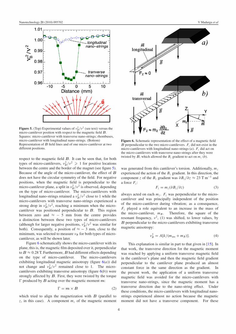
Figure 5. (Top) Experimental values of ν2B/ν2 (see text) versus the
micro-cantilever position with respect to the magnetic field B.Squares: micro-cantilever with transverse nano-strings; rhombuses,micro-cantilever with longitudinal nano-strings. (Bottom)Representation of B field lines and of one micro-cantilever at twodifferent positions.
respect to the magnetic field B. It can be seen that, for bothtypes of micro-cantilevers, ν2
B/ν2 � 1 for positive locationsbetween the centre and the border of the magnet (see figure 5).Because of the angle of the micro-cantilever, the effect of Bdoes not have the circular symmetry of the field. For negativepositions, when the magnetic field is perpendicular to themicro-cantilever plane, a split in ν2
B/ν2 is observed, dependingon the type of micro-cantilever. The micro-cantilevers withlongitudinal nano-strings retained a ν2
B/ν2 close to 1 while themicro-cantilevers with transverse nano-strings experienced astrong drop in ν2
B/ν2, reaching a minimum when the micro-cantilever was positioned perpendicular to B. This regionbetween zero and ≈ − 5 mm from the centre providesa distinction between these two types of micro-cantilevers(although for larger negative positions, ν2
B/ν2 was similar forboth). Consequently, a position of ≈ − 3 mm, close to theminimum, was selected to measure νB for both types of micro-cantilever, as will be shown later.
Figure 6 schematically shows the micro-cantilever with itsplane, this is, the magnetic film deposited over it, perpendicularto B ≈ 0.28 T. Furthermore, B had different effects dependingon the type of micro-cantilever. The micro-cantileversexhibiting longitudinal magnetic anisotropy (figure 6(a)) didnot change and ν2
B/ν2 remained close to 1. The micro-cantilevers exhibiting transverse anisotropy (figure 6(b)) werestrongly affected by B. First, they were twisted by the torque� produced by B acting over the magnetic moment m:
� = m × B (2)
which tried to align the magnetization with B (parallel toz, in this case). A component mz of the magnetic moment
Figure 6. Schematic representation of the effect of a magnetic fieldB perpendicular to the two micro-cantilevers. Fz did not exist in themicro-cantilevers with longitudinal nano-strings (a). Fz did act onthe micro-cantilevers with transverse nano-strings after they weretwisted by B, which allowed the Bz gradient to act on mz (b).
was generated from this cantilever’s torsion. Additionally, mz
experienced the action of the Bz gradient. In this direction, thecomponent z of the Bz gradient was ∂ Bz/∂z ≈ 23 T m−1 anda force Fz :
Fz = mz(∂ Bz/∂z) (3)
always acted on each mz . Fz was perpendicular to the micro-cantilever and was principally independent of the positionof the micro-cantilever during vibration; as a consequence,Fz played a role equivalent to an increase in the mass ofthe micro-cantilever, m B . Therefore, the square of theresonant frequency, ν2, (1) was shifted, to lower values, byB perpendicular to the micro-cantilevers exhibiting transversemagnetic anisotropy:
ν2B = A[k/(mass + m B)]. (4)
This explanation is similar in part to that given in [15]. Inthat work, the transverse direction for the magnetic momentwas reached by applying a uniform transverse magnetic fieldin the cantilever’s plane and then the magnetic field gradientperpendicular to the cantilever plane produced an almostconstant force in the same direction as the gradient. Inthe present work, the application of a uniform transversemagnetic field was avoided for the micro-cantilevers withtransverse nano-strings, since the magnetic moment has atransverse direction due to the nano-string effect. Underthese conditions, the micro-cantilevers with longitudinal nano-strings experienced almost no action because the magneticmoment did not have a transverse component. For these
4
Nanotechnology 21 (2010) 095702 V Madurga et al
micro-cantilevers with longitudinal nano-strings, transversemagnetic fields (of the order of the controlled anisotropy field)could be necessary for achieving a shift in their resonantfrequency similar to that measured for the micro-cantileverswith transverse nano-strings.
For positions far from those corresponding to thisfrequency split, both types of micro-cantilevers exhibited thesame behaviour, with ν2
B/ν2 > 1. This corresponded toan increase in k, which can be explained by consideringthat, for these positions, B longitudinally aligned the micro-cantilevers through the torque � (2). The torque tried tokeep the micro-cantilever in alignment during vibration, taking� different values depending of the angle between m andB. The dependence of � on the micro-cantilever positionduring vibration results in an increase in k. It is important toobserve that for these positions, when ν2
B/ν2 > 1, the relativeincrements in the resonant frequency have the same values forboth types of micro-cantilevers (figure 5 (top)), independent oftheir different magnetic and morphological anisotropies. Thiscan be explained by considering that for both types of micro-cantilevers, the effect of the magnetic field through the torque� (2) (which was produced by the same magnetic field B,the same magnetic moment m and the same angle betweenm and B), resulted in the same value of ν2
B/ν2. This alsoconfirms that the magnetic moments of the films for both typesof micro-cantilevers have the same value, because the films,which were deposited simultaneously for the same amount oftime, had the same mass. This also confirms that the magneticfield B was strong enough to rotate the magnetic moment fromthe transverse to the longitudinal micro-cantilever direction forthe micro-cantilever with transverse nano-strings. Once themagnetic moment was aligned longitudinally, as in the case ofthe micro-cantilever with longitudinal nano-strings, both typesof micro-cantilevers experienced the same relative change in k.
In summary, the gradient of the selected B perpendicularto the micro-cantilever produced a shift to lower values inthe resonant frequency of the micro-cantilever with transverseanisotropy, while the same gradient and the same field didnot produce modification in the mechanical properties of themicro-cantilever with longitudinal anisotropy.
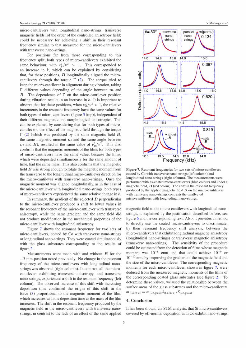
Figure 7 shows the resonant frequency for two sets ofmicro-cantilevers, coated by Co with transverse nano-stringsor longitudinal nano-strings. They were coated simultaneouslywith the glass substrates corresponding to the results offigure 2.
Measurements were made with and without B for the−3 mm position noted previously. No change in the resonantfrequency of the micro-cantilevers with longitudinal nano-strings was observed (right column). In contrast, all the micro-cantilevers exhibiting transverse anisotropy, and transversenano-strings, experienced a shift in the resonant frequency (leftcolumn). The observed increase of this shift with increasingdeposition time confirmed the origin of this shift in theforce (3) proportional to the magnetic moment of the film,which increases with the deposition time as the mass of the filmincreases. The shift in the resonant frequency produced by themagnetic field in the micro-cantilevers with transverse nano-strings, in contrast to the lack of an effect of the same applied
Figure 7. Resonant frequencies for two sets of micro-cantileverscoated by Co with transverse nano-strings (left column) andlongitudinal nano-strings (right column). The measurements wereperformed with as-coated micro-cantilevers (blue colour) and under amagnetic field, B (red colour). The shift in the resonant frequencyproduced by the applied magnetic field B on the micro-cantileverswith transverse nano-strings contrasts the unaffectedmicro-cantilevers with longitudinal nano-strings.
magnetic field to the micro-cantilevers with longitudinal nano-strings, is explained by the justification described before, seefigure 6 and the corresponding text. Also, it provides a methodto directly use the coated micro-cantilevers to discriminate,by their resonant frequency shift analysis, between themicro-cantilevers that exhibit longitudinal magnetic anisotropy(longitudinal nano-strings) or transverse magnetic anisotropy(transverse nano-strings). The sensitivity of the procedurecould be estimated from the detection of films whose magneticmoment was 10−8 emu and that could achieve 10−9 or10−10 emu by improving the gradient of the magnetic field andthe size of the micro-cantilever. The corresponding magneticmoments for each micro-cantilever, shown in figure 7, werededuced from the measured magnetic moments of the films ofthe corresponding coated glass substrates (see figure 2). Todetermine these values, we used the relationship between thesurface areas of the glass substrates and the micro-cantileversm(Co,m-c) = m(Co,glass)S(Co,m-c)/S(Co,glass).
4. Conclusion
It has been shown, via STM analysis, that Si micro-cantileverscovered by off-normal deposition with Co exhibit nano-strings
5
Nanotechnology 21 (2010) 095702 V Madurga et al
with pre-determined directions, either parallel or perpendicularto the longitudinal axis of the micro-cantilever. The magneticanisotropy associated with the orientation of the nano-stringswas distinguished by the different mechanical responses ofthe coated micro-cantilevers to a given magnetic field. Theselected magnetic field gradient only affected the resonantfrequency of the micro-cantilevers with transverse nano-strings, while the micro-cantilevers with longitudinal nano-strings were unaffected. A lowest limit in the detectedmagnetic moment of the film of 10−8 emu was achieved.
Acknowledgments
This work was partially supported by the Spanish Governmentunder project MAT2007–66252.
References
[1] Madurga V, Vergara J and Favieres C 2004 J. Magn. Magn.Mater. 272–276 1681
[2] Rusponi S, Constantini G, Boragno C and Valbusa U 1998Phys. Rev. Lett. 81 4184
[3] Munoz–Garcıa J, Castro M and Cuerno R 2006 Phys. Rev. Lett.96 086101
[4] Madurga V, Vergara J and Favieres C Int. Conf. TNT 2005Trends in Nanotechnology (Oviedo, Spain, Aug.–Sept.2005)
[5] Knorr T G and Hoffman R W 1959 Phys. Rev. 113 1039
[6] Smith D O 1959 J. Appl. Phys. 30 264S[7] Smith D O, Cohen M S and Weiss G P 1960 J. Appl. Phys.
60 1755[8] van Dijken S, Di Santo G and Poelsema B 2001 Phys. Rev. B
63 104431[9] Alameda J M, Carmona F, Salas F H, Alvarez–Prado L M,
Morales R and Perez G T 1996 J. Magn. Magn. Mater.154 249
[10] Nozawa T, Morimoto F, Harazono R and Nouchi N 2006J. Magn. Magn. Mater. 304 e672
[11] Labrune M, Hamzaoui S and Puchalska I B 1982 J. Magn.Magn. Mater. 27 323
[12] Binning G, Quate C F and Gerber Ch 1986 Phys. Rev. Lett.56 930
[13] Stipe B C, Mamin H J, Stowe T D, Kenny T W andRugar D 2001 Phys. Rev. Lett. 86 2874
[14] Cowburn R P, Moulin A M and Welland M E 1997 Appl. Phys.Lett. 71 2202
[15] Chabot M D and Moreland J 2003 J. Appl. Phys. 93 7897[16] Moreland J 2003 J. Phys. D: Appl. Phys. 36 R39[17] Larik N V, Sepaniak M L and Datskos P G 2004 Rev. Sci.
Instrum. 75 2229[18] Waggoner Philip S and Craighead Harold G 2007 Lab Chip.
7 1238[19] Goedeke S M, Allison S W and Datskos P G 2004 Sensors
Actuators A 112 32[20] Wallis T M, Moreland J and Kabos P 2006 Appl. Phys. Lett.
89 122502[21] Horcas I, Hernandez R, Gomez-Rodrıguez J M, Colchero J,
Gomez-Herrero J and Baro A M 2007 Rev. Sci. Instrum.78 013705
[22] Madurga V, Favieres C and Vergara J 2007 J. Non-Cryst. Solids353 941
6