
Ground-Based Transceiver (GBT) For Broadcast Services ...
137
Department of Transportation Federal Aviation Administration System Specification Ground-Based Transceiver (GBT) For Broadcast Services Using the Universal Access Transceiver (UAT) Data Link FAA-E-2973 01/15/04
-
Upload
khangminh22 -
Category
Documents
-
view
0 -
download
0
Transcript of Ground-Based Transceiver (GBT) For Broadcast Services ...
Department of Transportation
Federal Aviation Administration
System Specification
Ground-Based Transceiver (GBT) For
Broadcast Services Using the Universal Access Transceiver (UAT) Data Link
FAA-E-2973
01/15/04

(This page intentionally left blank.)

i
TABLE OF CONTENTS1.0 ................................................................. SCOPE AND BACKGROUND 1
1.1 Broadcast Data Link Services ........................................................................................................ 1 1.1.1 ADS-B........................................................................................................................... 1 1.1.2 TIS-B............................................................................................................................. 1 1.1.3 FIS-B............................................................................................................................. 2
1.2 Basic Data Link Functions of the GBT .......................................................................................... 2 1.3 GBT External Interfaces................................................................................................................. 3
1.3.1 Air Interface .................................................................................................................. 4 1.3.2 Ground Interface ........................................................................................................... 4 1.3.3 Local Maintenance Interface......................................................................................... 4 1.3.4 Remote Maintenance Interface ..................................................................................... 4 1.3.5 External Timing Input................................................................................................... 4
1.4 Data Link Medium for the Air Interface ........................................................................................ 4 1.5 Overview of UAT Data Link.......................................................................................................... 5
1.5.1 Medium Access Approach............................................................................................ 5 1.5.2 ADS-B Message Transmission ..................................................................................... 6 1.5.3 TIS-B Transmission ...................................................................................................... 7 1.5.4 Ground Uplink Message Transmission (FIS-B) ........................................................... 7
2.0 APPLICABLE DOCUMENTS.......................................................................................................... 7 2.1 Government Documents................................................................................................................. 7
2.1.1 Orders............................................................................................................................ 7 2.1.2 Specifications................................................................................................................ 7 2.1.3 Standards....................................................................................................................... 8 2.1.4 Other Government Documents ..................................................................................... 8
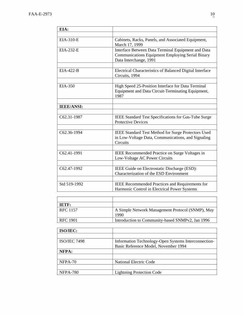
2.2 Non-Government Documents......................................................................................................... 9 2.3 Documentation Sources................................................................................................................ 11
2.3.1 FAA Documents ......................................................................................................... 11 2.3.2 Military and Federal Documents ................................................................................ 11 2.3.3 Federal Communications Commission Documents.................................................... 11 2.3.4 Electronic Industries Alliance Documents.................................................................. 11 2.3.5 National Telecommunications and Information Administration Documents............. 11 2.3.6 RTCA, Inc. Documents............................................................................................... 11 2.3.7 ISO/IEC Documents ................................................................................................... 11 2.3.8 IEEE/ANSI Documents .............................................................................................. 12 2.3.9 NIST Documents ........................................................................................................ 12 2.3.10 NFPA Documents ....................................................................................................... 12
3.0 REQUIREMENTS........................................................................................................................... 12 3.1 Definitions.................................................................................................................................... 12
3.1.1 “Shall”......................................................................................................................... 12 3.1.2 “Should”...................................................................................................................... 12 3.1.3 “Will”.......................................................................................................................... 12
3.2 GBT Requirements....................................................................................................................... 13 3.2.1 GBT Functions and Software Requirements .............................................................. 13
3.2.1.1 System Software ............................................................................................................ 13 3.2.1.1.1 Identification of Software ............................................................................................14
3.2.1.1.1.1 Classes of Software ............................................................................................. 14 3.2.1.1.1.2 Categories of Software ........................................................................................ 14
3.2.1.1.2 Software Partitioning ...................................................................................................15 3.2.1.1.3 Software Standards ......................................................................................................15 3.2.1.1.4 New Software Maintainability .....................................................................................15

ii
3.2.1.1.5 Documentation.............................................................................................................16 3.2.1.2 Processor Requirements................................................................................................. 16 3.2.1.3 GBT State and State Transition ..................................................................................... 17
3.2.1.3.1 State Transition ............................................................................................................17 3.2.1.3.2 Off State .......................................................................................................................17 3.2.1.3.3 Power Up State ............................................................................................................17 3.2.1.3.4 Off Line State...............................................................................................................17 3.2.1.3.5 On Line State ...............................................................................................................18 3.2.1.3.6 Recovery State .............................................................................................................18 3.2.1.3.7 Failed State ..................................................................................................................18 3.2.1.3.8 Power Down State .......................................................................................................19
3.2.1.4 Procedures for ADS-B Message Reception and Reporting ........................................... 19 3.2.1.4.1 ADS-B Report Construction ........................................................................................19 3.2.1.4.2 Time of Message Receipt.............................................................................................21 3.2.1.4.3 Time of Applicability...................................................................................................21 3.2.1.4.4 Time of Message Transmission ...................................................................................21 3.2.1.4.5 ADS-B Message Discarding ........................................................................................22 3.2.1.4.6 Status Indication ..........................................................................................................22
3.2.1.5 Procedures for TIS-B Message Transmission................................................................ 23 3.2.1.5.1 TIS-B Message Construction.......................................................................................23 3.2.1.5.2 TIS-B Uplink Media Access........................................................................................25 3.2.1.5.3 Report Discarding ........................................................................................................25 3.2.1.5.4 Status Indication ..........................................................................................................26
3.2.1.6 Procedures for Ground Uplink Message Transmission ................................................. 26 3.2.1.6.1 Ground Uplink Message Construction.........................................................................26 3.2.1.6.2 Ground Uplink Message Media Access.......................................................................26
3.2.1.6.2.1 Time Slots............................................................................................................ 27 3.2.1.6.2.2 Time Slot Rotation and “Channels” .................................................................... 27 3.2.1.6.2.3 Transmission of Ground Uplink Message ........................................................... 28
3.2.1.6.3 Discarding of Uplink Data Blocks ...............................................................................28 3.2.1.6.4 Status Indication ..........................................................................................................28
3.2.1.7 Procedures for GBT Status Reporting ........................................................................... 28 3.2.1.7.1 Status Report Construction ..........................................................................................28 3.2.1.7.2 Status Report Discarding .............................................................................................29
3.2.1.8 Characteristics of the Ground Interface ......................................................................... 30 3.2.1.8.1 Interface Decomposition and Options..........................................................................30 3.2.1.8.2 Application Layer: Application Elements....................................................................30
3.2.1.8.2.1 Target Reports ..................................................................................................... 30 3.2.1.8.2.2 Uplink Data Blocks ............................................................................................. 30 3.2.1.8.2.3 GBT Status Reports ............................................................................................. 31
3.2.1.8.3 Presentation Layer: BSDU...........................................................................................31 3.2.1.8.4 Session Layer: SDU.....................................................................................................33 3.2.1.8.5 Transport and Network Layers ....................................................................................34
3.2.1.8.5.1 TCP/IP ................................................................................................................. 34 3.2.1.8.5.2 UDP/IP ................................................................................................................ 34
3.2.1.8.6 Data Link and Physical Layers for Serial Interface .....................................................34 3.2.1.8.6.1 Synchronous ........................................................................................................ 34 3.2.1.8.6.2 Asynchronous ...................................................................................................... 35 3.2.1.8.6.3 Ethernet................................................................................................................ 35
3.2.1.9 GBT Timing................................................................................................................... 35 3.2.2 Performance Requirements......................................................................................... 35
3.2.2.1 Receiver Characteristics................................................................................................. 35 3.2.2.1.1 Sensitivity for Long ADS-B Messages (supersedes DO-282 Section 2.2.8.2.1.1) ......35

iii
3.2.2.1.2 Sensitivity for Ground Uplink Messages (supersedes DO-282 Section 2.2.8.2.1.2) ...36 3.2.2.1.3 Receiver Selectivity .....................................................................................................36 3.2.2.1.4 Receiver Tolerance to Pulsed Interference ..................................................................36 3.2.2.1.5 Receiver Tolerance to Overlapping ADS-B Messages................................................36 3.2.2.1.6 Receiver Desired Signal Dynamic Range....................................................................37 3.2.2.1.7 Receiver Recovery from Large Inband Signals. ..........................................................37
3.2.2.2 Transmitter Characteristics ............................................................................................ 37 3.2.2.2.1 Modulation Distortion..................................................................................................37 3.2.2.2.2 Transmitter Power Levels and Ranges.........................................................................37 3.2.2.2.3 Transmitter Power Output............................................................................................37 3.2.2.2.4 Transmitter Timeout ....................................................................................................38 3.2.2.2.5 Transmitter Duty Cycle................................................................................................38
3.2.2.3 Receiver Availability ..................................................................................................... 38 3.2.2.3.1 Transmit-Receive Turnaround Time............................................................................38
3.2.2.4 GBT Throughput Performance ...................................................................................... 38 3.2.2.5 GBT Timing Source....................................................................................................... 40
3.2.2.5.1 GPS Antenna................................................................................................................40 3.2.2.5.2 GPS Satellite Tracking and Masking...........................................................................40 3.2.2.5.3 GPS Receiver System Sensitivity ................................................................................40
3.2.3 Site Control and Monitoring ....................................................................................... 40 3.2.3.1 Technician Access ......................................................................................................... 40
3.2.3.1.1 Local Maintenance Interface........................................................................................41 3.2.3.1.2 Remote Maintenance Interface ....................................................................................41 3.2.3.1.3 Management Information Base....................................................................................41
3.2.3.2 GBT Internal RF Test Support....................................................................................... 41 3.2.3.2.1 ADS-B Test Message (Online State) ...........................................................................41 3.2.3.2.2 Loopback Test Mode (Offline State) ...........................................................................42 3.2.3.2.3 Sensitivity Test Mode (Offline State) ..........................................................................44
3.2.3.3 GBT Control .................................................................................................................. 44 3.2.3.3.1 Control Session ............................................................................................................44 3.2.3.3.2 Control Parameter Adjustments ...................................................................................45
3.2.3.3.2.1 GBT Configuration Items (ID = 1.1 through 1.15) ............................................. 47 3.2.3.3.2.2 Real Time Read Back (ID = 5)............................................................................ 50 3.2.3.3.2.3 Event Log Read Back (ID = 6)............................................................................ 50 3.2.3.3.2.4 GPS Satellite Observation Log Read back (ID = 7) ............................................ 50 3.2.3.3.2.5 Alarm/Alert Threshold Setting (ID = 10) ............................................................ 50 3.2.3.3.2.6 Suppress Alert/Alarm (ID = 11) .......................................................................... 50 3.2.3.3.2.7 Reset (ID = 15) .................................................................................................... 50 3.2.3.3.2.8 Power Down (ID = 16) ........................................................................................ 51 3.2.3.3.2.9 Software Upload Enable/Disable (ID = 20) ........................................................ 51 3.2.3.3.2.10 Software Upload (ID = 21)................................................................................ 51 3.2.3.3.2.11 Switch Software Version (ID = 22)................................................................... 51 3.2.3.3.2.12 Test Mode (ID = 25).......................................................................................... 51 3.2.3.3.2.13 ADS-B Test Message Level (ID = 26) .............................................................. 52
3.2.3.4 GBT Monitoring and Reporting..................................................................................... 52 3.2.3.4.1 Non-Congesting Monitoring........................................................................................52 3.2.3.4.2 Alarm/Alert Monitoring Suppression ..........................................................................52 3.2.3.4.3 Alarm/Alert Processing................................................................................................53 3.2.3.4.4 GBT Monitoring Parameters........................................................................................54
3.2.3.4.4.1 GBT Configuration Items (ID = 1.1 through 1.15) ............................................. 56 3.2.3.4.4.2 GBT State (ID = 4) .............................................................................................. 56 3.2.3.4.4.3 Suppress Alarm/Alert Setting (ID=11)................................................................ 56 3.2.3.4.4.4 Software Upload Setting (ID=20)........................................................................ 56

iv
3.2.3.4.4.5 Software Version (ID = 23) ................................................................................. 56 3.2.3.4.4.6 In-Service Time (ID = 53) ................................................................................... 57 3.2.3.4.4.7 Receiver Status .................................................................................................... 57 3.2.3.4.4.8 Transmitter Status................................................................................................ 57 3.2.3.4.4.9 Discard Event ...................................................................................................... 57 3.2.3.4.4.10 Transmit Antenna VSWR (ID = 55).................................................................. 58 3.2.3.4.4.11 Transmitter Timeout (ID = 56).......................................................................... 58 3.2.3.4.4.12 Measured Power Output (ID = 57) .................................................................... 58 3.2.3.4.4.13 GBT Timing Status (ID = 91)............................................................................ 58
3.2.3.5 Event Logging Requirements......................................................................................... 59 3.2.3.5.1 State Transition Log Entry...........................................................................................59 3.2.3.5.2 Log-In / Log-Out Log Entry ........................................................................................59 3.2.3.5.3 Control Event Log Entry..............................................................................................60 3.2.3.5.4 Failure Event Log Entry...............................................................................................60 3.2.3.5.5 Alarm/Alert/Return to Normal (RTN) Log Entry........................................................60 3.2.3.5.6 GBT Event Log Maintenance ......................................................................................61 3.2.3.5.7 Event Log Read back ...................................................................................................61
3.2.3.6 GPS Satellite Observation Log Requirements ............................................................... 61 3.2.3.7 INFOSEC Requirements................................................................................................ 62
3.2.3.7.1 Verification ..................................................................................................................62 3.2.3.7.2 Keys .............................................................................................................................62 3.2.3.7.3 Security Procedures .....................................................................................................62
3.2.3.7.3.1 Software Upload Security.................................................................................... 63 3.2.3.7.4 Boot Cycle ...................................................................................................................63 3.2.3.7.5 Physical Security..........................................................................................................63
3.2.3.8 Vendor Built In Test ...................................................................................................... 64 3.2.3.9 GBT Failure Detection and Reporting ........................................................................... 64
3.3 Interfaces ...................................................................................................................................... 64 3.3.1 Air Interface ................................................................................................................ 64 3.3.2 Ground Interface ......................................................................................................... 65
3.3.2.1 Serial .............................................................................................................................. 65 3.3.2.1.1 Asynchronous ..............................................................................................................65 3.3.2.1.2 Synchronous.................................................................................................................65
3.3.2.2 Ethernet .......................................................................................................................... 65 3.3.3 External Timing Input................................................................................................. 65 3.3.4 Electrical Input Power................................................................................................. 65 3.3.5 Remote Maintenance Interface ................................................................................... 65 3.3.6 Local Maintenance Interface....................................................................................... 65 3.3.7 Integral GPS RF Connector ........................................................................................ 66 3.3.8 ADS-B Test Message Out........................................................................................... 66
3.4 Construction Requirements .......................................................................................................... 66 3.4.1 Physical Requirements................................................................................................ 66
3.4.1.1 Reserved......................................................................................................................... 66 3.4.1.1.1 Workmanship...............................................................................................................66 3.4.1.1.2 Equipment Size ............................................................................................................66 3.4.1.1.3 Equipment Weight .......................................................................................................66 3.4.1.1.4 Equipment Slides .........................................................................................................66 3.4.1.1.5 Nameplates...................................................................................................................67 3.4.1.1.6 Pin Layout Identification .............................................................................................67 3.4.1.1.7 GBT Installation/Removal ...........................................................................................67 3.4.1.1.8 GBT Set-Up .................................................................................................................67 3.4.1.1.9 GBT Warm-up .............................................................................................................67 3.4.1.1.10 Thermal Protection.......................................................................................................67

v
3.4.1.1.11 Shock and Vibration Protection ...................................................................................68 3.4.1.1.12 Grounding, Bonding, and Shielding ............................................................................68 3.4.1.1.13 Lightning Protection ....................................................................................................68 3.4.1.1.14 Acoustical Noise Criteria Requirement .......................................................................68 3.4.1.1.15 Materials, Processes, and Parts ....................................................................................68
3.4.1.1.15.1 Ferrous Materials............................................................................................... 68 3.4.1.1.15.2 Arc-Resistant Materials ..................................................................................... 69 3.4.1.1.15.3 Dissimilar Metals............................................................................................... 69 3.4.1.1.15.4 Fibrous Material ................................................................................................ 69 3.4.1.1.15.5 Flammable Materials ......................................................................................... 69
3.4.1.1.16 Antenna Assembly Materials and Finish .....................................................................69 3.4.1.1.17 Safety ...........................................................................................................................69 3.4.1.1.18 Removable Parts and Mating Connectors....................................................................69
3.4.1.2 Controls.......................................................................................................................... 70 3.4.1.2.1 Detents .........................................................................................................................70 3.4.1.2.2 Adjustment Range........................................................................................................70 3.4.1.2.3 Power Switches/Power On Indicators..........................................................................70 3.4.1.2.4 Front Panel Display......................................................................................................70 3.4.1.2.5 Functions and Labeling................................................................................................71
3.4.1.3 GBT Identification (ID) Numbering .............................................................................. 71 3.4.2 Electrical Requirements .............................................................................................. 72
3.4.2.1 Input Power Requirements............................................................................................. 72 3.4.2.1.1 Power Cord ..................................................................................................................72
3.4.2.2 Reverse Polarity Protection............................................................................................ 72 3.4.2.3 Circuit Protection ........................................................................................................... 72
3.4.2.3.1 Current Overload Protection ........................................................................................73 3.4.2.3.2 Protective Caps ............................................................................................................73 3.4.2.3.3 Electrostatic Discharge Control ...................................................................................73 3.4.2.3.4 Surge Protection...........................................................................................................73 3.4.2.3.5 Transient Protection .....................................................................................................73
3.4.2.4 Test Points...................................................................................................................... 73 3.4.2.5 VSWR Protection........................................................................................................... 73 3.4.2.6 Loss of Input Voltage..................................................................................................... 74
3.4.3 Environmental Conditions .......................................................................................... 74 3.4.3.1 Operating Conditions ..................................................................................................... 74
3.4.3.1.1 Indoor Operating Conditions .......................................................................................74 3.4.3.1.2 Outdoor Operating Conditions.....................................................................................74
3.4.3.2 Non-Operating Conditions............................................................................................. 74 3.4.3.3 Equipment Ventilation and Cooling .............................................................................. 75
3.4.4 Electromagnetic Compatibility Requirements............................................................ 75 3.5 Quality Factors ............................................................................................................................. 75
3.5.1 Reliability.................................................................................................................... 75 3.5.1.1 Mean Time Between Failures ........................................................................................ 75
3.5.2 Maintainability............................................................................................................ 75 3.5.2.1 Mean Time To Repair .................................................................................................... 75 3.5.2.2 Periodic Maintenance..................................................................................................... 75
3.5.3 Service Life................................................................................................................. 76 3.5.4 Availability ................................................................................................................. 76
3.6 Flexibility and future services and capabilities ............................................................................ 76 3.6.1 Flexibility.................................................................................................................... 76 3.6.2 Future Services, capabilities, and changes.................................................................. 76
4.0 QUALITY ASSURANCE PROVISIONS....................................................................................... 76 4.1 Responsibility For Inspection....................................................................................................... 76
vi
4.2 Special Tests And Examinations.................................................................................................. 76 4.3 Requirement Cross Reference ...................................................................................................... 76 4.4 Qualification Test Requirements.................................................................................................. 77
4.4.1 Test Planning/Procedures............................................................................................ 77 4.4.2 Test Phases and Levels ............................................................................................... 77
4.5 Qualification/Verification Methods .............................................................................................77 4.5.1 Inspection.................................................................................................................... 77 4.5.2 Test.............................................................................................................................. 77 4.5.3 Demonstration............................................................................................................. 77 4.5.4 Analysis....................................................................................................................... 78
5.0 DEFINITIONS................................................................................................................................. 78 5.1 Notes on Information Items.......................................................................................................... 78 5.2 Applicable Definitions ................................................................................................................. 78
5.2.1 Mean Time Between Failures (MTBF)....................................................................... 78 5.2.2 Mean Time To Repair (MTTR) .................................................................................. 78 5.2.3 Mean Time To Repair Maximum ............................................................................... 78 5.2.4 Duty Cycle .................................................................................................................. 79 5.2.5 Line Replaceable Unit (LRU)..................................................................................... 79 5.2.6 Initialization ................................................................................................................ 79 5.2.7 Restoration .................................................................................................................. 79 5.2.8 GBT State Definitions................................................................................................. 79
5.2.8.1 Non-Volatile Memory.................................................................................................... 81 5.2.9 Equipment Failures ..................................................................................................... 81
5.2.9.1 Non-critical Equipment Failure ..................................................................................... 81 5.2.9.2 Critical Equipment Failure............................................................................................. 82
5.2.10 GBT RF Output........................................................................................................... 82 5.2.11 GBT RF Input ............................................................................................................. 82 5.2.12 Message....................................................................................................................... 82
6.0 ACRONYMS................................................................................................................................... 83 A.1 GENERAL............................................................................................................................................. 1 A.2 TARGET REPORT CONSTRUCTION EXAMPLE............................................................................ 2 A.3 USER APPLICATION PROFILE AND CONSTRUCTION FOR CAT 033 TARGET REPORTS.... 3 A.4 FORMAT AND ENCODING OF CAT 033 (V 1.0) DATA ITEMS................................................... 4 B.1 GENERAL ............................................................................................................................................. 1 B.2 TARGET REPORT CONSTRUCTION EXAMPLE ............................................................................ 2 B.3 USER APPLICATION PROFILE AND CONSTRUCTION FOR CAT 023 TARGET REPORTS ..3 B.4 FORMAT AND ENCODING OF CAT 023 (V 1.0) DATA ITEMS ................................................... 4

FAA-E-2973 1
1.0 SCOPE AND BACKGROUND
This document is the subsystem specification for the Ground Based Transceiver (GBT). The fundamental role of the GBT is to support broadcast data link services. These services are known as Automatic Dependent Surveillance-Broadcast (ADS-B), Traffic Information Services-Broadcast (TIS-B) and Flight Information Services-Broadcast (FIS-B).
1.1 Broadcast Data Link Services
1.1.1 ADS-B
ADS-B is a system by which aircraft, certain equipped surface vehicles, and fixed ground locations can share (i.e., broadcast) position, velocity, and other information with one another. With such information made available by ADS-B from other proximate aircraft1, it is possible to establish the relative position and movement of those aircraft with reference to one’s own aircraft. It is also possible for ground-based facilities to monitor ADS-B broadcasts to enable basic surveillance capabilities, or to supplement existing surveillance systems. Other data that are shared using ADS-B include information related to the aircraft’s intended flight path (“intent” data), aircraft type, and other information.
ADS-B is automatic in the sense that no pilot or controller action is required for the information to be broadcast. It is dependent surveillance in the sense that the aircraft surveillance-type information is derived from on-board navigation equipment.
ADS-B is considered to be a key enabling technology to enhance safety and efficiency in airspace operations. RTCA Special Committee SC-186 has documented a wide range of applications of ADS-B focused on those goals in RTCA/DO-242A. These include basic applications, such as the use of ADS-B to enhance the pilot’s visual acquisition of other nearby aircraft, as well as more advanced applications, such as enabling enhanced closely spaced parallel approach operations. Other applications involving airport surface operations, improved surveillance in non-radar airspace, and advanced conflict management are also described.
1.1.2 TIS-B
Traffic Information Service - Broadcast (TIS-B) is a ground-based service to ADS-B-equipped aircraft to provide surveillance data about non-ADS-B-equipped aircraft. TIS-B may also be used in ADS-B implementations involving multiple ADS-B data links to provide a cross-link—or “gateway”—between ADS-B equipped aircraft using different data links. The service is intended to provide ADS-B-equipped aircraft with a more-complete traffic picture in situations where not all aircraft are equipped with ADS-B (or with the same ADS-B data link).
1 ADS-B can also be used for surveillance of ground vehicles on the airport surface. Use of the term “aircraft” includes ground vehicles equipped with ADS-B.

FAA-E-2973 2
As commonly envisioned, TIS-B involves three major functions. First, another source of surveillance information on non-ADS-B aircraft (such as Secondary Surveillance Radar (SSR)) must be available. Second, this surveillance information must be converted and processed so as to be usable by ADS-B-equipped aircraft. And third, a broadcast facility and protocol is necessary to convey this information to ADS-B-equipped aircraft.
1.1.3 FIS-B
FIS-B is the ground-to-air broadcast of non-control, advisory information needed by pilots to operate more safely and efficiently in the National Airspace System and in international airspace. FIS provides to pilots the necessary weather graphics (e.g., NEXRAD reflectivity) and text (e.g., METAR and TAF), Special Use Airspace information, Notices to Airmen, and other information.
1.2 Basic Data Link Functions of the GBT
The GBT’s primary function is that of translating data link traffic between the GBT’s Air Interface (the RF medium) and the GBT’s Ground Interface (interface to other ground systems). The GBT is an event driven system that performs the following three fundamental tasks:
• Reception of ADS-B messages received over the GBT’s Air Interface is mapped into ADS-B reports for transmission over the GBT’s Ground Interface to an end system.
• Reception of TIS-B reports over the GBT’s Ground Interface are mapped into TIS-B messages for transmission over the GBT’s Air Interface to aircraft.
• Reception of Uplink Data Blocks containing FIS information over the GBT’s Ground Interface are mapped into Ground Uplink messages for transmission over the GBT’s Air Interface to aircraft.
FAA-E-2973 3
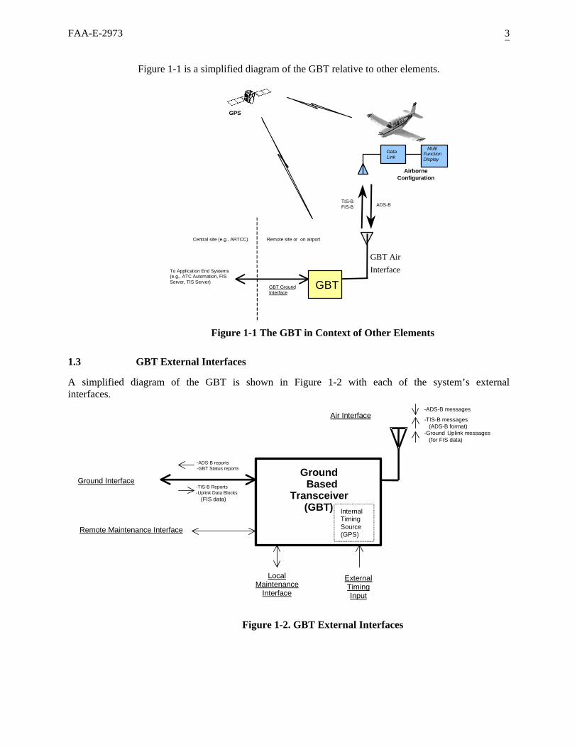
Figure 1-1 is a simplified diagram of the GBT relative to other elements.
Airborne Configuration
DataLink
Multi - Function
Display
GBT
GPS
TIS-BFIS-B ADS-B
GBT Air Interface
GBT GroundInterface
To Application End Systems (e.g., ATC Automation, FIS Server, TIS Server)
Remote site or on airportCentral site (e.g., ARTCC)
Figure 1-1 The GBT in Context of Other Elements
1.3 GBT External Interfaces
A simplified diagram of the GBT is shown in Figure 1-2 with each of the system’s external interfaces.
GroundBased
Transceiver(GBT)
-ADS-B reports -GBT Status reports
-TIS-B Reports - Uplink Data Blocks (FIS data)
-ADS-B messages
-TIS-B messages (ADS-B format)-Ground Uplink messages ( for FIS data)
Air Interface
Ground Interface
Remote Maintenance Interface
LocalMaintenance
Interface
ExternalTimingInput
InternalTimingSource(GPS)
Figure 1-2. GBT External Interfaces

FAA-E-2973 4
1.3.1 Air Interface
The GBT Air Interface carries message traffic over the data link RF medium. Message traffic includes ADS-B messages transmitted from aircraft, TIS-B messages transmitted from the GBT and Ground Uplink messages transmitted from the GBT.
1.3.2 Ground Interface
The GBT Ground Interface conveys ADS-B reports from the GBT, TIS-B reports to the GBT and Uplink Data Blocks (containing FIS data) to the GBT. The Ground Interface also conveys periodic Status reports from the GBT.
1.3.3 Local Maintenance Interface
The GBTs Local Maintenance Interface supports both monitoring and control of various GBT functions when the technician has physical access to the GBT equipment.
1.3.4 Remote Maintenance Interface
The GBTs Remote Maintenance Interface supports most of the monitoring and control functions offered by the local maintenance port. However this interface is intended to be accessed from a central site remote from the GBT equipment.
1.3.5 External Timing Input
The GBT requires timing information both to control media access for uplink transmissions and to support time stamping of ADS-B reports. The GBT is specified to have a GPS-based integral time reference. For cases where the GBT is in an environment where the integral GPS time reference cannot be used, an external time source can be applied to the External Timing Input. Selection of integral vs. external timing is configurable.
1.4 Data Link Medium for the Air Interface
The GBT governed by this specification employs the Universal Access Transceiver (UAT) data link as the RF medium. It could be more precisely called the “GBTUAT”. GBT functionality employing the 1090 MHz Extended Squitter data link (the “GBT1090”) will be specified separately. It is expected that a GBT system employing the 1090 MHz Extended Squitter data link will have external interfaces compatible with those defined by this specification as much as possible—with the exception of the Air Interface. Responses to this specification and the GBT SOW should include a description of the 1090 MHz Extended Squitter data link integration into the GBT subsystem. Hereafter in this document the term “GBT” will be used to mean “GBTUAT”.

FAA-E-2973 5
1.5 Overview of UAT Data Link
The UAT is a multi-purpose data link intended to operate globally on a single channel with a channel-signaling rate of just over 1Mbps. By design, UAT supports multiple broadcast services including FIS-B and TIS-B in addition to ADS-B. This is accomplished using a hybrid medium access approach that incorporates both time-slotted and random un-slotted access. By virtue of its waveform, signaling rate, precise time reference, and message-starting discipline, UAT can also support independent measurement of range to most other participants in the medium.
There are two basic types of broadcast transmissions - or messages - on the UAT channel: the ADS-B message, and the Ground Uplink message. An aircraft broadcasts the ADS-B message. TIS-B information will be broadcast by the GBT but using the ADS-B message format. The Ground Uplink message is used by ground stations to uplink FIS data such as text and graphical weather data, advisories, and other aeronautical information, to any aircraft that may be in the service volume of the ground station. Regardless of type, each message has two fundamental components: the message payload that contains user information, and message overhead, principally consisting of forward error correction code parity, that supports the transfer of the data.
1.5.1 Medium Access Approach
UAT Message transmissions are governed by a combination of time-slotted and random-access techniques. Figure 1-3 illustrates the basic UAT Message timing structure called a UAT frame. A frame is one second long and begins at the start of each Universal Coordinated Time (UTC) second. Each frame is divided into two segments: the Ground Segment in which Ground Uplink messages are broadcast2 in one or more Time Slots, and the ADS-B Segment in which ADS-B messages are broadcast by aircraft and, TIS-B messages from ground stations. Guard times are incorporated between the segments to allow for signal propagation and timing drift. The UAT frame is further divided into Message Start Opportunities (MSOs) that are spaced at 250µs intervals. This spacing represents the smallest time increment used by UAT for scheduling message transmissions, and all such transmissions must start only at a valid MSO.
2 Ground Uplink messages are used by the GBT for transmitting FIS data, but need not be restricted to only FIS data in the future. However, throughout this specification, the Ground Uplink message is associated with FIS data.

FAA-E-2973 6
timing drift (not to scale)
6ms 6ms12ms
UAT Frame = One UTC Second
(Start: on the UTC second) (End)
MSO 0 MSO 3951
Message Start Opportunities (MSOs)
Notes : 1. Shaded segments represent guard times for signal
2. ADS-B transmissions will partially occur within the final guard interval when the last MSO is selected.
ADS-B Segment 800 ms
Ground Segment 176 ms
MSO 752MSO 704
Figure 1-3. UAT Frame
As shown in Figure 1-3, 176 milliseconds in each 1-second UAT frame are devoted to Ground Uplink message transmissions and 800ms are devoted to ADS-B message transmissions. MSO’s start at the end of the initial 6ms guard time, are spaced at 250µs intervals, and are numbered sequentially from 0 through 3951.
1.5.2 ADS-B Message Transmission
As shown in Figure 1-3, the ADS-B Segment of each UAT frame is 800 milliseconds long, and spans 3200 MSOs (i.e., from MSO 752 to, and including, MSO 3951). All aircraft-transmitted ADS-B messages (as well as ground-transmitted TIS-B messages) are transmitted in this segment of the frame. Each UAT-equipped aircraft makes exactly one ADS-B message transmission per frame, and makes a pseudo-random selection from among any of the 3200 MSOs in the segment to start transmission of the message. Six milliseconds of guard time are appended after the ADS-B Segment to fill out the UAT frame to the end of the UTC second.
The pseudo-random selection of an MSO within each UAT frame for the start of an aircraft’s ADS-B message is intended to prevent two aircraft from systematically interfering with each other’s ADS-B message transmissions. Adherence to the MSO-based timing scheme enables the receiving UAT equipment to determine range to the UAT equipment that transmitted the message. This information could be used in validity checks of the position data conveyed in the ADS-B message itself.

FAA-E-2973 7
1.5.3 TIS-B Transmission
From the perspective of a receiving aircraft, TIS-B transmissions will appear to be nearly identical to ADS-B messages both in terms of message format and media access. For clarity, the term “TIS-B message” will be used throughout this document, even though the ADS-B message format is used for TIS-B. Per this specification, TIS-B messages will also be transmitted in the ADS-B segment of the UAT frame3. Detailed procedures for GBT transmission of TIS-B messages are provided in Section 3.2.1.5.
1.5.4 Ground Uplink Message Transmission (FIS-B)
Ground Uplink messages are used to support FIS-B. Ground Uplink messages will occur within one or more of the 32 Time Slots defined within the ground segment of the UAT frame. Detailed procedures for Ground Uplink message transmission are provided in Section 3.2.1.6.
2.0 Applicable Documents
2.1 Government Documents
The following documents form a part of this specification and are applicable to the extent specified here. In case of conflict between the documents referenced here and the contents of this specification, the contents of this specification shall take precedence.
2.1.1 Orders FAA Order 6950.19A Practices and Procedures for Lightning Protection,
Grounding, Bonding, and Shielding Implementation, July 1, 1996
2.1.2 Specifications FAA: FAA-STD-060 Data Standard for the National Airspace System (NAS),
October 4, 2002 FAA-C-1217F Electrical Work, Interior, February 12, 1996 FAA-G-2100G Electronic Equipment, General Requirements, Latest
Version
3Other approaches to uplinking TIS-B are possible using a special TIS-B format and the Ground Segment of the UAT frame. However, this is outside the scope of this specification. Also, there may be additional TIS-B information to be broadcast to describe the service available. The implementation requirements for this additional information are presently undefined. It is expected that this additional information could be conveyed in the Ground Uplink Message.

FAA-E-2973 8
2.1.3 Standards FAA: FAA-STD-019C Lightning Protection, Grounding, Bonding and
Shielding Requirements for Facilities, June 1, 1999 FAA-STD-020B Grounding, Bonding and Shielding, May 11, 1992 FAA-E-2911 NAS System Level Specification, March 26, 1998 FAA-STD-060, Rev. A Data Standard for the National Airspace System, (NAS)
October 4, 2002 FAA-STD-026A Software Development for the National Airspace System
(NAS), August 4, 1993 ICD-GPS-060 GPS User Equipment (Phase III) Interface
Military: MIL-HDBK-454 (A) General Guidelines for Electronic Equipment,
November 3, 2000 MIL-STD-461E Electromagnetic Emission and Susceptibility
Requirements for the Control of Electromagnetic Interference, August 20, 1999
MIL-STD-810F Environmental Test Methods and Engineering
Guidelines, January 1, 2000 MIL-STD-889B Dissimilar Metals, May 17, 1993
2.1.4 Other Government Documents FAA:
DOT/FAA/CT-96/1 Human Factors Design Guide for Acquisition of Commercial Off-the-Shelf Subsystems, Non-Developmental Items, and Developmental Systems, January 15, 1996
DOT/FAA/NAS-IC-51070000-2
NAS Infrastructure Management System Manager/Managed Subsystem Agent Using the Simple Network Management Protocol Version 3 (SNMPv3)
Overview of the FAA ADS-B Link Decision
Presents an overview of the FAA decision on the ADS-B link architecture for use in the National Airspace System and discusses associated operational implications. http://www.faa.gov/asd

FAA-E-2973 9
FCC: 47 CFR Part 2 Frequency Allocations and Radio Treaty Matters;
General Rules and Regulations, October 1998 47 CFR Part 87 Aviation Services, October 1998 NIST: FIPS PUB 140-1 Federal Information Processing Standards Publication,
Security Requirements for Cryptographic Modules, National Institute of Standards and Technology, January 11, 1994
FIPS PUB 186-2 Federal Information Processing Standards Publication,
Specifications for Digital Signature Standard (DSS), National Institute of Standards and Technology, January 27, 2000
NTIA: Manual of Regulations and Procedures for Federal
Radio Frequency Management, January 2000 Edition with January/May/September 2001 Revisions
2.2 Non-Government Documents IEEE: IEEE 100-1996 Standard Dictionary of Electrical and Electronic Terms IEEE 12207.0 Software Life Cycle Processes, 1996 IEEE 12207.1 Software Life Cycle Processes – Life Cycle Data, 1997 IEEE 12207.2 Software Life Cycle Processes – Implementation
Considerations, 1997 RTCA: DO-282 Minimum Operational Performance Standards for
Universal Access Transceiver (UAT), August, 2002 DO-260A Minimum Operational Performance Standards for 1090
MHz Automatic Dependent Surveillance – Broadcast (ADS-B)
DO-278 Guidelines for Communications, Navigation, and Air Traffic Management (CNS/ATM) systems software integrity assurance.
FAA-E-2973 10
EIA: EIA-310-E Cabinets, Racks, Panels, and Associated Equipment,
March 17, 1999 EIA-232-E Interface Between Data Terminal Equipment and Data
Communications Equipment Employing Serial Binary Data Interchange, 1991
EIA-422-B Electrical Characteristics of Balanced Digital Interface
Circuits, 1994 EIA-350 High Speed 25-Position Interface for Data Terminal
Equipment and Data Circuit-Terminating Equipment, 1987
IEEE/ANSI: C62.31-1987 IEEE Standard Test Specifications for Gas-Tube Surge
Protective Devices C62.36-1994 IEEE Standard Test Method for Surge Protectors Used
in Low-Voltage Data, Communications, and Signaling Circuits
C62.41-1991 IEEE Recommended Practice on Surge Voltages in
Low-Voltage AC Power Circuits C62.47-1992 IEEE Guide on Electrostatic Discharge (ESD):
Characterization of the ESD Environment Std 519-1992 IEEE Recommended Practices and Requirements for
Harmonic Control in Electrical Power Systems
IETF: RFC 1157 A Simple Network Management Protocol (SNMP), May
1990 RFC 1901 Introduction to Community-based SNMPv2, Jan 1996
ISO/IEC: ISO/IEC 7498 Information Technology-Open Systems Interconnection-
Basic Reference Model, November 1994 NFPA: NFPA-70 National Electric Code NFPA-780 Lightning Protection Code

FAA-E-2973 11
2.3 Documentation Sources
2.3.1 FAA Documents
Copies of FAA specifications, standards, and publications may be obtained from Leslie Boehler, Capstone Contracting Officer, FAA, 222 West 7th Avenue, Anchorage AK 99501, telephone (907) 271-5842. Requests should clearly identify the desired material by number and state the intended use of the material. Revision FAA=G-2100G may be downloaded from the FAA at web site http://www.faa.gov/asd/standards/index.htm.
2.3.2 Military and Federal Documents
Single copies of unclassified military and federal specifications, standards, and publications may be obtained by writing the Naval Publications and Forms Center, 5801 Tabor Avenue, Philadelphia, PA 19120 or by calling (215) 697 3321 Monday through Friday, 8:00 a.m. to 4:30 p.m. (EST).
2.3.3 Federal Communications Commission Documents
Copies of 47 CFR, Part 2 and Part 87 may be obtained from the FCC, 445 12th Street, SW, Washington D.C. or by downloading from the FCC web site at www.fcc.gov/oet/info/rules.
2.3.4 Electronic Industries Alliance Documents
Copies of Electronic Industries Alliance (EIA) standards may be obtained from the Electronic Industries Alliance, 2500 Wilson Boulevard, Arlington, VA 22201-3834, by calling (703) 907-7500, or through the web site http://www.eia.org.
2.3.5 National Telecommunications and Information Administration Documents
Copies of National Telecommunications and Information Administration (NTIA) materials may be obtained from NTIA, Department of Commerce, 14th Street and Constitution Avenue NW, Washington, DC 20230, by calling (202) 377-1832, or through the web site http://www.ntia.doc.gov.
2.3.6 RTCA, Inc. Documents
Copies of RTCA, Inc. documents may be obtained from RTCA, Incorporated, 1828 L Street NW, Suite 805, Washington, DC 20036, by calling (202) 833-9339, or through the web site http://www.rtca.org.
2.3.7 ISO/IEC Documents
Copies of International Standards Organization documents may be obtained from American National Standards Institute, 11 West 42nd Street, 13th floor, New York, NY 10036. Telephone: (212) 642-4900, Telefax: (212) 398-0023, E-mail: [email protected], Web: http://www.ansi.org/ or http://www.iso.ch/.

FAA-E-2973 12
2.3.8 IEEE/ANSI Documents
Copies of IEEE/ANSI documents may be obtained from IEEE Customer Service, 445 Hoes Lane, P.O. Box 1331, Piscataway, NJ 08855-1331, or by calling (800) 701-4333 (in U.S. and Canada), or (732) 981-0060 (outside of U.S. and Canada).
2.3.9 NIST Documents
Copies of National Institute of Standards and Technology may be obtained from NIST, 100 Bureau Drive, Gaithersburg, MD 20899-3460, or by calling (301) 975-6478.
2.3.10 NFPA Documents
Copies of National Fire Protection Association (NFPA) documents may be obtained from NFPA, 1 Batterymark Park, Quincy, MA 02269-9101 or by calling (617) 770-3000.
3.0 REQUIREMENTS
3.1 Definitions
3.1.1 “Shall”
When used in this specification, the word “shall” refers to an explicit requirement of a system component or the complete system
3.1.2 “Should”
When used in this specification, the word “should” refers to a desired characteristic of a system component or the complete system.
3.1.3 “Will”
When used in this specification, the word “will” provides information for a characteristic of a system component or a complete related system.
FAA-E-2973 13
3.2 GBT Requirements
3.2.1 GBT Functions and Software Requirements
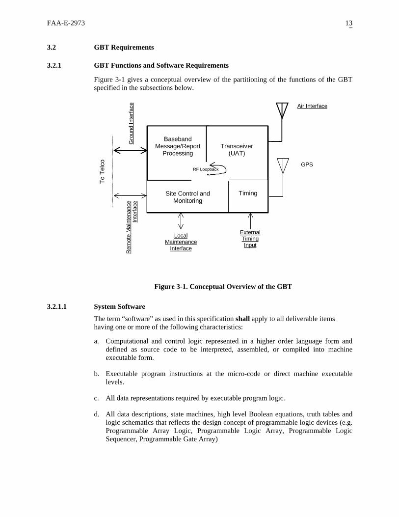
Figure 3-1 gives a conceptual overview of the partitioning of the functions of the GBT specified in the subsections below.
Air Interface
Gro
und
Inte
rface
ExternalTimingInput
BasebandMessage/Report
ProcessingTransceiver
(UAT)
TimingSite Control andMonitoring
GPS
LocalMaintenance
InterfaceRem
oin
te M
ate
nanc
eIn
terfa
ce
RF Loopback
To T
elco
Figure 3-1. Conceptual Overview of the GBT
3.2.1.1 System Software
The term “software” as used in this specification shall apply to all deliverable items having one or more of the following characteristics:
a. Computational and control logic represented in a higher order language form and defined as source code to be interpreted, assembled, or compiled into machine executable form.
b. Executable program instructions at the micro-code or direct machine executable levels.
c. All data representations required by executable program logic.
d. All data descriptions, state machines, high level Boolean equations, truth tables and logic schematics that reflects the design concept of programmable logic devices (e.g. Programmable Array Logic, Programmable Logic Array, Programmable Logic Sequencer, Programmable Gate Array)

FAA-E-2973 14
These deliverable items are further identified as being processed/executed on computational /control hardware. This hardware consists of CPU’s or programmable controllers/devices or both, whether used as general purpose (as in the computer subsystem) or dedicated hardware.
All items meeting the above criteria shall be subject to the software requirements of this specification. The Contracting Officer shall make exceptions only upon written authorization.
The term “firmware” as used in this specification shall apply to all computer programs or micro-programs that are loaded in class of memory (Read Only Memory (ROM), Programmable Read Only Memory (PROM), or write able control store) that cannot be dynamically modified by the computer during processing.
3.2.1.1.1 Identification of Software
The GBT software (including firmware) shall be divided and identified by two classifications and four categories.
3.2.1.1.1.1 Classes of Software
The two major classifications are NAS Operational Software (NAS OP/SW) and Support Software SW.
a. NAS/OP. All operational software used in the performance of the surveillance mission is classified as real-time, high-reliability, and mission-critical. It consists of the embedded software and firmware, including Built-in-Test and Fault Isolation Test software used by the GBT system. Modifications made to this class of software shall conform to the requirements defined in IEEE 12207.
b. Support SW. Support SW is all software used to support development and maintenance of the NAS OP/SW at the Program Support Facility. (PSF) Strong use of COTS software tools will be applied in the production of the NAS OP/SW.
3.2.1.1.1.2 Categories of Software
If applicable, the above two classifications shall be divided into each of the following four categories.
a. Reusable Software. This software is developed for the core GBT system and reusable with no modification.
b. Developmental. Computer software configuration items (CSCIs) developed to support the NAS interfaces or other GBT requirements after contract award, or software that requires the revision of more than 30 percent change measured in source lines of code per component.
c. Modified. Software requiring less than 30 percent change measures in source lines of code per component.
d. Commercial-Off-the-Shelf (COTS). This software is purchased from commercial vendors. They may be components of the NAS OP/SW or Support SW.

FAA-E-2973 15
3.2.1.1.2 Software Partitioning
The GBT operational software components shall be clearly identifiable by category. All operational software shall be functionally partitioned into, and documented as separate computer software items. Operational software consists of the prime mission equipment software, including the operating system and the software that provides surveillance data, resides in built-in-test equipment, collects and extracts data for analysis, and supports the NAS interfaces.
3.2.1.1.3 Software Standards
a. Software developed prior to contract award shall be shown to be developed in accordance with the contractor’s documented specifications and standards.
b. All new software and firmware shall be developed in accordance with IEEE 12207. When revisions of more than 30 percent of an existing CSCI are made, the entire CSCI shall be revised in accordance with IEEE 12207. Design emphasis shall be placed on reliability, error detection and reporting, fault tolerance, and recovery from abnormal conditions, as well as functional performance. Modifications to existing code shall be developed utilizing the contractor’s documented specifications and standards.
3.2.1.1.4 New Software Maintainability
New GBT software shall have the following maintainability characteristics:
a. Software performance monitoring and software maintenance operations shall not interrupt normal system operation.
b. GBT software shall be designed as a collection of software units.
c. Each software unit shall include error detection and exception handling capabilities.
d. Each unit shall be independently maintainable.
e. Identical software, adapted to the local resources, environment, and workload, shall be installed in each site. Local “patches” to executable code and data tables shall not be used.
f. New software and firmware developed shall support system and subsystem modification, enhancement, and expansion throughout the expected lifetime of the GBT. Provision shall be made in instruction code, data tables, and databases, to accommodate additional functions, new equipment, and new data.
g. The software design shall provide logical and physical data independence. Changes made to the logical structure of the data shall not impact the application programs. Changes made to the physical structure of the data shall not impact the logical structure of the data or the application programs. Each level shall be complete and independent, containing definitions of data and the operations on the data.
h. The software design shall provide data integrity. It shall protect data from accidental loss or damage.

FAA-E-2973 16
i. The software design shall provide a controlled approach to adding new data and to modifying and retrieving existing data. It shall provide logical data to the application programs as required. It shall provide status information to the application programs on the outcome of data requests, including error indications.
j. The software design shall assure that the system is initialized to a correct, well-defined state upon recovery from a fault, and that all processing interrupted by a fault is properly continued after recovery.
k. The software design shall incorporate a responsive real-time operating system with a standard compiler, loader, software development library (SDL), and other debug and utility tools.
l. Deviations from these requirements that are necessary to meet the overall specifications or are beneficial to the Government shall be requested in writing, with contractor justification, and submitted to the Contracting officer. Justifications will include, at a minimum, purpose of deviation, application to the system, delivered product description with documentation, supporting analysis showing that requirements are met, and benefits to the Government.
3.2.1.1.5 Documentation
Documentation of existing or modified software and firmware shall consist of requirements, specifications, design documents, and test documents in a format that adheres to the contractor standards. All documentation of new operational and support software shall be developed in accordance with IEEE 12207.
3.2.1.2 Processor Requirements
a. User access/synchronization schemes in the equipment should be configurable.
Note: The purpose of requesting the access/synchronization schemes to be configurable is to allow ease of changes as data link standards are further refined/defined, and to allow implementation of future capabilities as the GBT system evolves to meet NAS needs.
b. The GBT shall use no more than 50 percent of its non-volatile memory (as defined in Section 5.2.9.1) or storage, under worst-case conditions (e.g., when the GBT has both the software–in-use and a second software version loaded).
c. The GBT shall use no more than 50 percent of its Random Access Memory (RAM), under worst-case conditions (e.g., when the GBT has both the software-in-use and a second software version loaded).
d. The processor utilization of the GBT shall be 50 percent or less when measured over any 1-second interval when subjected to the maximum loading presented in Section 3.2.2.4 for the Ethernet option of the Ground Interface.
e. If the GBT does not successfully restart after receipt and execution of the Switch Software Version control parameter command, the GBT equipment shall revert to the previous version of software and restart.

FAA-E-2973 17
f. If the software upload is rejected, either by failed Cyclic Redundancy Check (CRC) or incorrect authentication, the GBT shall indicate the rejection and the reason for the rejection in the Control Event Log. (Section 3.2.3.5.3)
3.2.1.3 GBT State and State Transition
a. The GBT shall have the following states: Off, Power Up, Offline, Online, Recovery, Failed and Power Down (if exercised), as defined in Section 5, Figure 5-1, and Table 5-1, as applicable.
b. The GBT shall provide visual indication of the Online, Offline, Recovery, and Failed states in accordance with 3.4.1.2.4
Note: For the definition of critical and non-critical equipment failures see Section 5.2.9.
3.2.1.3.1 State Transition
The GBT shall transition from state to state in accordance with Section 5, Figure 5-1, and Table 5-1, as applicable.
3.2.1.3.2 Off State
a. When in the OFF state, the GBT shall not transmit on the Air Interface.
b. When in the OFF state, the GBT shall not generate any form of data output.
c. When DC power is present at the GBT power input, the GBT shall provide visual indication of power.
3.2.1.3.3 Power Up State
a. When in the Power Up state,
1) The GBT shall not transmit on the Air Interface. 2) The GBT shall not generate any form of data output.
b. The time between application/restoration of power to the GBT and the GBT’s transition out of the Power Up state shall not exceed 90 seconds.
c. The GBT shall conduct and complete Power On Self Test functions in the Power Up state.
3.2.1.3.4 Off Line State
The GBT shall be in the Offline state during the period that a Control Session is active as defined in Section 3.2.3.3.1. When in the Offline state the GBT shall:
1. Discontinue operational ADS-B message reception and reporting (Section 3.2.1.4).
2. Discontinue operational TIS-B message transmission, if applicable (Section 3.2.1.5).
3. Discontinue operational Ground Uplink message transmission, if applicable (Section 3.2.1.6).

FAA-E-2973 18
4. Continue Status reporting (Section 3.2.1.7) with an indication the GBT is in the Offline state.
5. Respond to control commands.
Note: Establishing a Control Session is the only condition that will place the GBT into the Offline state.
3.2.1.3.5 On Line State
When in Online state, the GBT shall enable all functions with the exception of those requiring a Control Session.
Note: Being in the online state does not automatically enable transmission over the Air Interface. The ability to transmit messages over the Air Interface must additionally be enabled through various GBT configuration items.
3.2.1.3.6 Recovery State
a. The GBT shall enter the Recovery state when the GBT detects a potentially recoverable failure.
b. Potentially recoverable failures shall include, but not be limited to, over temperature conditions.
c. When in Recovery state, the GBT shall not transmit.
d. When in Recovery state the GBT shall not generate any ADS-B target reports on the Ground Interface.
e. The GBT shall transition from the Recovery state to the previous state if the recovery process has been successful (e.g., the recoverable fault was eliminated).
f. The GBT shall transition from the Recovery state to the failed state if the recovery process was not successful (e.g., the potentially recoverable fault could not be eliminated).
3.2.1.3.7 Failed State
a. When in Failed state,
1. The GBT shall not transmit on the Air Interface.
2. The GBT shall not generate any ADS-B target reports on the Ground Interface.
3. The GBT shall enable only those control parameter commands that can be executed accurately.
b. The GBT shall transition to the Failed state if the GBT detects a failure that as a minimum requires the restoration (warm start) action as defined in Section 5.2.7.

FAA-E-2973 19
3.2.1.3.8 Power Down State
a. If the GBT employs a Power Down state, then when in Power Down state,
1. The GBT transmitter shall not transmit.
2. The GBT receiver shall not generate any form of data output.
3. All GBT functions shall be disabled, except logging/reporting and front panel indication.
b. If the Power Down state is implemented, the GBT shall accept the control parameter to transition to the Power Down state (“Power Down” (ID = 16)) only from the Local Maintenance Interface.
3.2.1.4 Procedures for ADS-B Message Reception and Reporting
a. The GBT shall decode received ADS-B messages per the message format described in Sections 2.2.3 through 2.2.3.1.3.2 of RTCA DO-282.
b. The GBT shall convert each such message into an ADS-B report on the GBT Ground Interface in the order received.
3.2.1.4.1 ADS-B Report Construction
a. The GBT shall generate ADS-B reports in response to each ADS-B message received.
b. ADS-B reports shall be in the format given in the ASTERIX Category 033 description of Appendix A.
c. Individual Data Items of Cat 033 shall be determined as given in Table 3-1.
d. The GBT shall encode only those data items required for each report and reflect the included data items in the FSPEC (see Appendix A, Section A.2).
Note: Systems receiving ADS-B reports from the GBT must parse the FSPEC for proper decoding of reports.

FAA-E-2973 20
Table 3-1 Contents of Data Items in the ADS-B Report
ASTERIX Cat 33 Data Item Source used in Composing Data Item
FRN4 Name Data flow
Criteria for Including Data Item
Bit 6 (Version Status): Established by the CAT033 VERSION_STATUS configuration item Bits 5-1 (Version Number): Fixed field value of ONE
1 Version Every ADS-B report
The value of SIC and SAC provided as configuration items
2 Data Source Id Every ADS-B report
Bit 3 set; All others ZERO 3 Link Indicator Every ADS-B report Value computed per Section 3.2.1.4.3 4 Time of Applicability Every ADS-B report Derived from “ADDRESS QUALIFIER” and “ADDRESS” fields of ADS-B message payload.
5 Target Address Every ADS-B report
Bit 16 (UTC Coupled): set to ONE if ADS-B message payload indicated “UTC-coupled”. Bits 15-4: Derived from “NIC”, “SIL” and “NACp” fields of ADS-B message payload. Bit 3 (Position Estimated): Always set to ZERO (for measured position). Bit 2 (Velocity Estimated): Always set to ZERO (for measured velocity)
6 Integrity and Accuracy Parameters
Every ADS-B report
Derived from “LATITUDE” and “LONGITUDE” fields of ADS-B message payload.
7 Latitude/Longitude Every ADS-B report
Derived from the “ALTITUDE TYPE” and “ALTITUDE” fields of the ADS-B message payload
8 Pressure Altitude Every ADS-B report
Derived from “A/G STATE”, “HORIZONTAL VELOCITY” and “VERTICAL VELOCITY” fields of the ADS-B message
9 Velocity (Airborne) Reported when the “A/G STATE” field of the ADS-B message indicates the AIRBORNE condition.
Derived from “A/G STATE”, and “HORIZONTAL VELOCITY” fields of the ADS-B message.
10 Velocity (Surface) Reported when the “A/G STATE” field of the ADS-B message indicates the ON GROUND condition.
Derived from the Flight Plan ID field of the ADS-B message when “CSID” flag = ZERO
11 Mode 3/A Code 5
Derived from the “CALL SIGN” field of the ADS-B message
12 Target Identification
Derived from the “EMITTER CATEGORY” field of the AD-B message
13 Emitter Category
Derived from the “EMERGENCY PRIORITY STATUS” and “OPERATIONAL MODES” field of the ADS-B message.
14 Target Status
Each of these Data Items reported only when present in the ADS-B message.
Derived from the “ALTITUDE TYPE” and “SECONDARY ALTITUDE” fields of the ADS-B message payload
15 Geometric Altitude Reported only when present in the ADS-B message AND reporting of this Item is enabled in the ADS-B_REPORT_FSPEC_FILTER configuration item.
N/A 16 Reserved Never Value computed per Section 3.2.1.4.4 17 Time of Message
Transmission Reported only when present in the ADS-B message AND reporting of this Item is enabled in the ADS-B_REPORT_FSPEC_FILTER configuration item.
4 Field Reference Number from the ASTERIX definition (Appendix A) 5 GBT shall set bit 13 of FRN 11 (Mode A code “invalid”) if any of the left-most 4 characters fall outside the range “0” – “7” in the Flight Plan ID field of the ADS-B message (see UAT WP 14-02A).

FAA-E-2973 21
Value computed per Section 3.2.1.4.2 truncated to the fractional seconds
18 Time of Message Receipt
Reported when reporting of this item is enabled in the in the ADS-B_REPORT_FSPEC_FILTER configuration item.
N/A 19 Reserved Never N/A 20 Reserved Never N/A 21 Reserved Never
3.2.1.4.2 Time of Message Receipt
a. The GBT shall declare a Time of Message Receipt (TOMR) for each ADS-B message received.
b. Time measurement shall be relative to the arrival of the optimum sample point of the first bit of the UAT synchronization sequence at the GBT antenna terminal.
Note: See Sections 2.2.2.3 and 2.2.6.2.2 of DO-282.
c. Time measurement shall be made to a resolution of 100 nanoseconds or less.
Note: The GBT provides its best estimate of time if in the non-UTC coupled condition with accuracy consistent with requirements of Section 3.2.2.5
3.2.1.4.3 Time of Applicability
The GBT shall derive a Time of Applicability for each received ADS-B message based on the TOMR of Section 3.2.1.4.2 above as follows:
a. If the ADS-B message payload indicates “UTC Coupled” and the Non-Precision Condition, the Time of Applicability is the start of the 1-second UTC epoch containing the TOMR.
b. If the ADS-B message payload indicates “UTC Coupled” and the Precision Condition, the Time of Applicability is the start of the 0.2-second UTC epoch containing the TOMR.
c. If the ADS-B message payload indicates “Non-UTC Coupled”, the Time of Applicability is the TOMR minus 1 second.
Note: See Section 2.2.4.5.2.8 and 2.2.7.2 of DO-282.
3.2.1.4.4 Time of Message Transmission
a. The GBT shall derive a Time of Message Transmission relative to the 1-second UTC epoch based on the ”TRANSMIT MSO” field of the ADS-B message payload encoded per Section 2.2.4.5.4.7 of DO-282.
b. The GBT shall derive the Time of Transmission unambiguously based on the TOMR from Section 3.2.1.4.2.

FAA-E-2973 22
Notes:
1. The GBT is required to derive the Time of Message Transmission only for ADS-B messages with the Mode Status element: those with Payload Type Code of “1” or “3” (see DO-282, Section 2.2.4). These are transmitted at a once per 4-second rate.
2. This unambiguous derivation is required because only the 6 LSBs are provided in the “TRANSMIT MSO” field of the ADS-B message payload.
3.2.1.4.5 ADS-B Message Discarding
a. The ADS-B Reporting Interval shall be one second and include the entire ADS-B segment of the current UAT frame and the entire Ground Segment of the subsequent UAT frame as depicted in Figure 3-2.
b. The GBT shall discard any ADS-B message that cannot be issued as an ADS-B report at the Ground Interface in the ADS-B Reporting Interval within which the corresponding ADS-B message was received.
time
UAT Frame N+1UAT Frame N
ADS-B ReportingInterval N(1 second)
GroundSegment(176 ms)
GroundSegment(176 ms)
ADS-B Segment(800 ms)
ADS-B Segment(800 ms)
Figure 3-2. ADS-B Reporting Interval
Note: The purpose of the ADS-B Reporting Interval is to establish a systematic method for discarding ADS-B messages when the ADS-B message arrival rate at the Air Interface exceeds the bandwidth available on the Ground Interface. Given the random nature of aircraft ADS-B message transmission within the UAT frame, this discard approach results in a graceful surveillance degradation should the number of ADS-B aircraft momentarily overload the Ground Interface.
c. When the TIS-B_FILTER configuration item is “On”, the GBT shall discard all received messages whose ADDRESS QUALIFIER field (Section 2.2.4.5.1.2 of DO-282) indicates the message was a TIS-B transmission (i.e., the values “2” and “3”).
Note: Since ADS-B and TIS-B use the same UAT message format; this filter is needed to prevent needless flooding of the Ground Interface due to TIS-B transmissions from co-sited or nearby GBT’s.
3.2.1.4.6 Status Indication
The Status report shall provide a count of all ADS-B messages that have been discarded during the current status-reporting interval.
FAA-E-2973 23
3.2.1.5 Procedures for TIS-B Message Transmission
The GBT shall receive TIS-B reports over the GBT Ground Side Interface and convert each such report into a TIS-B message on the GBT Air Interface.
3.2.1.5.1 TIS-B Message Construction
a. TIS-B messages shall use the ADS-B message format described in Sections 2.2.3 through 2.2.3.1.3.2 of RTCA DO-282.
b. The data items present in the corresponding TIS-B report shall determine the payload portion of a TIS-B message. Each data item present shall be mapped into its corresponding message payload element per Table 3-2.
c. The GBT shall discard all TIS-B reports received prior to the Time of Applicability indicated in the TIS-B report.
d. The GBT shall discard all TIS-B reports received at the GBT more than TIS-B TIMEOUT seconds beyond the Time of Applicability indicated in the TIS-B report.
e. The GBT shall perform no extrapolation of the position data in the TIS-B report.

FAA-E-2973 24
Table 3-2. Payload Composition of TIS-B Message
ADS-B Payload Field Name (RTCA DO-282)
Source used in Composing Data Item
Field Name DO-282 Ref Para
Data flow ZERO if all data items in the TIS-B report fit within the “Basic” ADS-B message, otherwise ONE
“PAYLOAD TYPE CODE” 2.2.4.5.1.1
The Address Qualifier sub item from the “Target Address” (FRN 5) data item of the TIS-B report
“ADDRESS QUALIFIER” 2.2.4.5.1.2
The “24 bit Address” sub item from the “Target Address” (FRN 5) data item of the TIS-B report
“ADDRESS” 2.2.4.5.1.3
Derived from the “Aircraft Latitude and Longitude” (FRN 7) data item
“LATITUDE” and “LONGITUDE”
2.2.4.5.2.1
Encode as ZERO if the “Pressure Altitude” (FRN 8) data item has information available; otherwise encode as ONE if the “Geometric Altitude” (FRN 15) data item has information available.
“ALTITUDE TYPE” 2.2.4.5.2.2
Derive from the “Pressure Altitude” (FRN 8) data item if information available, otherwise derive from the “Geometric Altitude” (FRN 15) data item if information is available
“ALTITUDE” 2.2.4.5.2.3
The “NIC” sub item from the “Integrity and Accuracy Parameters” (FRN 6) data item.
“NIC” 2.2.4.5.2.4
Encode as “2” when “Velocity (Surface)” (FRN10) data item is present; encode as “1” if either N/S or E/W Velocities exceed 1000 kts; encode as “0” otherwise.
“A/G STATE” 2.2.4.5.2.5
Derive from information contained in either the “Velocity (Airborne)” (FRN 9) data item or the “Velocity (Surface)” (FRN 10) data item
“HORIZONTAL VELOCITY” 2.2.4.5.2.6
Derive from velocity information contained in the “Velocity (Airborne)” (FRN 9) data item.
“VERTICAL VELOCITY” 2.2.4.5.2.7
Sta
te V
ecto
r Ele
men
ts p
rese
nt in
eve
ry T
IS-B
mes
sage
Configuration item TIS-B_SITE_ID “TIS-B SITE ID” 2.2.4.5.3.1
“EMITTER CATEGORY AND CALL SIGN CHARACTERS #1 AND #2”
2.2.4.5.4.1 and 2.2.4.5.4.2
“CALL SIGN CHARACTERS #3, #4 AND #5”
2.2.4.5.4.2
Based on combination of “Emitter Category” (FRN 13) and “Target Identification” (FRN 12) data items encoded in compressed format per Section 2.2.4.5.4.3 of DO-282
“CALL SIGN CHARACTERS #6, #7 AND #8”
2.2.4.5.4.2
Derive from the “Target Status” (FRN 14) data item if available; otherwise encode as “No emergency/Not reported”
“EMERGENCY/PRIORITY STATUS”
2.2.4.5.4.4
Encode as “1” “UAT MOPS VERSION” 2.2.4.5.4.5 The “SIL” sub item from the “Integrity and Accuracy Parameters” (FRN 6) data item.
“SIL” 2.2.4.5.4.6
The 6 LSBs of the MSO selected for this TIS-B message per the procedure in Section 3.2.1.5.2 of this specification
“TRANSMIT MSO” 2.2.4.5.4.7
The “NACp” sub item from the “Integrity and Accuracy Parameters” (FRN 6) data item.
“NACp” 2.2.4.5.4.9
The “NACv” sub item from the “Integrity is encoded as all zeros.
“NACv” 2.2.4.5.4.10
Always encode as ZERO “NICbaro” 2.2.4.5.4.11 Always encode as: -CDTI Traffic Display Capability: NO -TCAS/ACAS Installed and Operational: YES
“CAPABILITY CODES” 2.2.4.5.4.12
Derive from “Target Status” (FRN 14) data item. “OPERATIONAL MODES” 2.2.4.5.4.13 Always ZERO “TRUE/MAG” 2.2.4.5.4.14 Always ONE “CSID” 2.2.4.5.4.15 M
ode
Sta
tus
Ele
men
t pre
sent
in e
very
TIS
-B m
essa
ge g
ener
ated
from
a
TIS
-Bre
port
that
incl
udes
“Tar
getI
dent
ifica
tion”
(FR
N12
)
Always ALL Zeros Reserved 2.2.4.5.4.16

FAA-E-2973 25
3.2.1.5.2 TIS-B Uplink Media Access
a. Each TIS-B message shall always begin on an even numbered MSO.
b. TIS-B messages shall occur only within the designated TIS-B transmission window(s) described in d) below.
c. When the TIS-B_OPERATING_MODE = “Disabled”, no TIS-B message transmissions shall occur regardless of TIS-B reports received on the GBT Ground Side Interface.
d. When the TIS-B_OPERATING_MODE = “Enabled”, there shall be five TIS-B transmission windows each of 19 milliseconds (76 MSOs) duration. Messages can be either the UAT “Basic” or “Long” format in any combination. The TIS-B transmission windows shall occur within the ADS-B Segment of the UAT Frame beginning at each of the following times after the start of the UTC second:
194 milliseconds (MSO 752) + OFFSET 354 milliseconds (MSO 1392) + OFFSET 514 milliseconds (MSO 2032) + OFFSET 674 milliseconds (MSO 2672) + OFFSET 834 milliseconds (MSO 3312) + OFFSET
Where OFFSET is a configuration item that can take on one of the following mutually exclusive values:
“ZERO” “20” milliseconds (80 MSOs) “40” milliseconds (160 MSOs) “60” milliseconds (240 MSOs) “80” milliseconds (320 MSOs) “100” milliseconds (400 MSOs) “120” milliseconds (480 MSOs) “140” milliseconds (560 MSOs)
Note: A maximum of 38 TIS-B messages can be packed into each transmission window for a maximum capacity of 190 TIS-B messages transmitted per second.
Note: TIS-B message transmission times are distributed in this manner to allow TIS-B uplinks to be organized among multiple proximate stations
e. The GBT receiver shall be available per the requirement of Section 3.2.2.3 at any time during the TIS-B transmission window in which no TIS-B message information is being transmitted.
Note: During times of light TIS-B report load, there may be a significant portion of the TIS-B transmission window in which no TIS-B message information is transmitted. It is important for ADS-B receptions to be supported when this occurs.
3.2.1.5.3 Report Discarding
The GBT shall discard (i.e., not transmit) any TIS-B report that would incur more than a 600 millisecond TIS-B throughput delay.
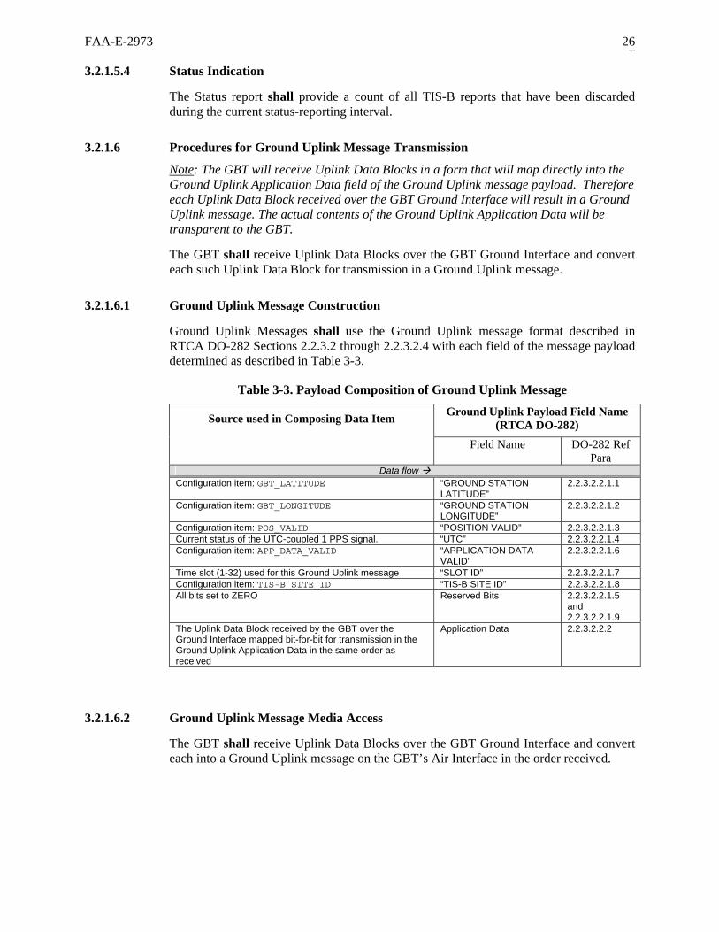
FAA-E-2973 26
3.2.1.5.4 Status Indication
The Status report shall provide a count of all TIS-B reports that have been discarded during the current status-reporting interval.
3.2.1.6 Procedures for Ground Uplink Message Transmission
Note: The GBT will receive Uplink Data Blocks in a form that will map directly into the Ground Uplink Application Data field of the Ground Uplink message payload. Therefore each Uplink Data Block received over the GBT Ground Interface will result in a Ground Uplink message. The actual contents of the Ground Uplink Application Data will be transparent to the GBT.
The GBT shall receive Uplink Data Blocks over the GBT Ground Interface and convert each such Uplink Data Block for transmission in a Ground Uplink message.
3.2.1.6.1 Ground Uplink Message Construction
Ground Uplink Messages shall use the Ground Uplink message format described in RTCA DO-282 Sections 2.2.3.2 through 2.2.3.2.4 with each field of the message payload determined as described in Table 3-3.
Table 3-3. Payload Composition of Ground Uplink Message
Ground Uplink Payload Field Name (RTCA DO-282) Source used in Composing Data Item
Field Name DO-282 Ref Para
Data flow Configuration item: GBT_LATITUDE “GROUND STATION
LATITUDE” 2.2.3.2.2.1.1
Configuration item: GBT_LONGITUDE “GROUND STATION LONGITUDE”
2.2.3.2.2.1.2
Configuration item: POS_VALID “POSITION VALID” 2.2.3.2.2.1.3 Current status of the UTC-coupled 1 PPS signal. “UTC” 2.2.3.2.2.1.4 Configuration item: APP_DATA_VALID “APPLICATION DATA
VALID” 2.2.3.2.2.1.6
Time slot (1-32) used for this Ground Uplink message “SLOT ID” 2.2.3.2.2.1.7 Configuration item: TIS-B_SITE_ID “TIS-B SITE ID” 2.2.3.2.2.1.8 All bits set to ZERO Reserved Bits 2.2.3.2.2.1.5
and 2.2.3.2.2.1.9
The Uplink Data Block received by the GBT over the Ground Interface mapped bit-for-bit for transmission in the Ground Uplink Application Data in the same order as received
Application Data 2.2.3.2.2.2
3.2.1.6.2 Ground Uplink Message Media Access
The GBT shall receive Uplink Data Blocks over the GBT Ground Interface and convert each into a Ground Uplink message on the GBT’s Air Interface in the order received.

FAA-E-2973 27
3.2.1.6.2.1 Time Slots
The GBT shall establish 32 Time Slots for transmission of Ground Uplink messages as defined in Table 3-4.
Table 3-4. Time Slot Definition for the UAT Ground Segment
Time Slot Span Time Slot Span
Slot ID # Starting MSO
Ending MSO
Slot ID # Starting MSO
Ending MSO
1 0 22 17 352 374 2 22 44 18 374 396 3 44 66 19 396 418 4 66 88 20 418 440 5 88 110 21 440 462 6 110 132 22 462 484 7 132 154 23 484 506 8 154 176 24 506 528 9 176 198 25 528 550 10 198 220 26 550 572 11 220 242 27 572 594 12 242 264 28 594 616 13 264 286 29 616 638 14 286 308 30 638 660 15 308 330 31 660 682 16 330 352 32 682 704
3.2.1.6.2.2 Time Slot Rotation and “Channels”
a. Time Slot resources assignable to the GBT shall be made on a continually shifting basis. This assignable resource will be subsequently referred to as a “Channel” to distinguish it from a Time Slot.
b. Channel #1-32 shall increment by 1 Time Slot per second (modulo 32).
c. The Channel # and Time Slot # shall align at midnight UTC time and every 32 seconds thereafter (see Figure 3-3).
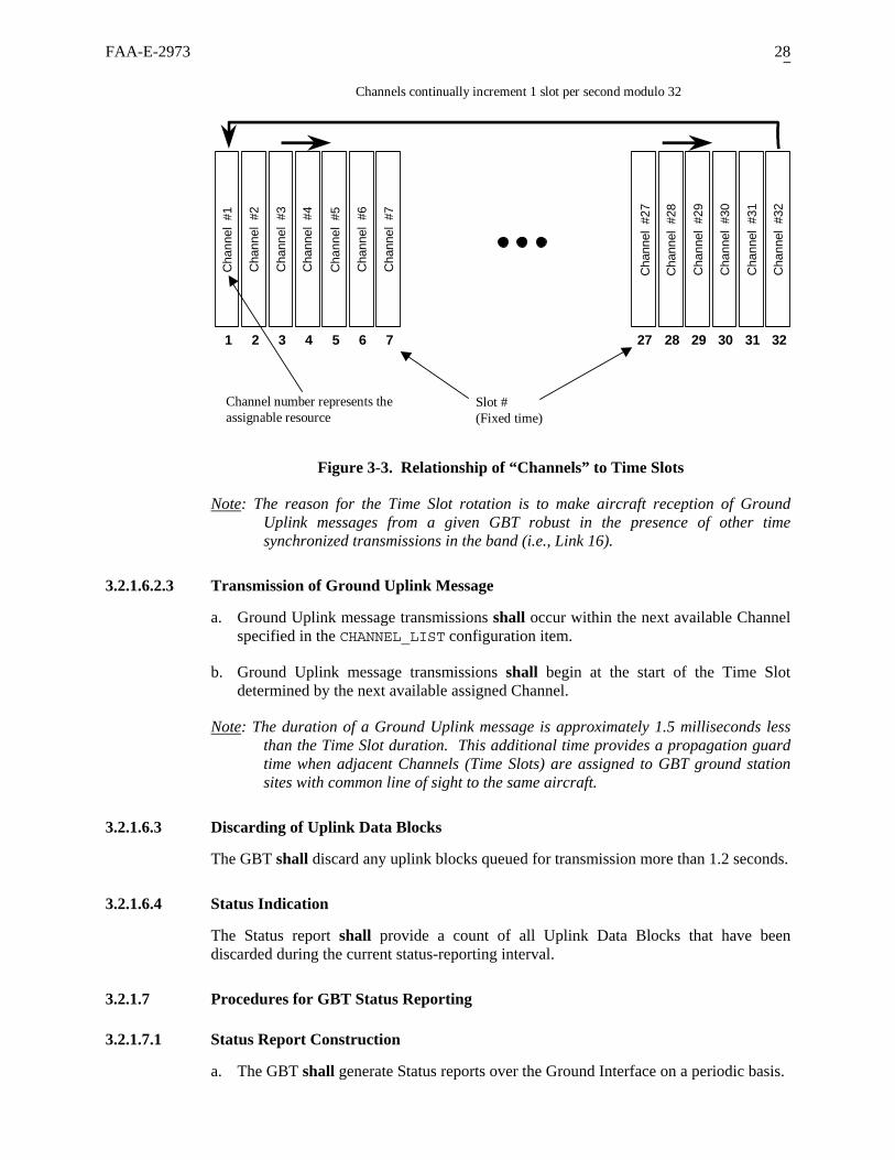
FAA-E-2973 28
1 2 3 4 5 6 7 27 28 29 30 31 32
Channel number represents theassignable resource
nnel
hann
el
hann
el
hann
el
nnel
hann
el
Cha
nnel
Cha
nnel
Cha
nnel
Cha
nnel
Cha
nnel
Cha
nnel
Cha
nnel
Cha
C C C Cha
C
#1 #2 #3 #4 #5 #6 #7
#29
#30
#31
#32#27
#28
Slot #(Fixed time)
Channels continually increment 1 slot per second modulo 32
Not
Figure 3-3. Relationship of “Channels” to Time Slots
e: The reason for the Time Slot rotation is to make aircraft reception of Ground Uplink messages from a given GBT robust in the presence of other time
3.2.1.6.2.3
a. essage transmissions shall occur within the next available Channel specified in the CHANNEL_LIST configuration item.
b. Ground Uplink message transmissions shall begin at the start of the Time Slot determined by the next available assigned Channel.
Note
synchronized transmissions in the band (i.e., Link 16).
Transmission of Ground Uplink Message
Ground Uplink m
: The duration of a Ground Uplink message is approximately 1.5 milliseconds less than the Time Slot duration. This additional time provides a propagation guard time when adjacent Channels (Time Slots) are assigned to GBT ground station sites with common line of sight to the same aircraft.
3.2.1.6.3 Discarding of Uplink Data Blocks
The GBT shall discard any uplink blocks queued for transmission more than 1.2 seconds.
3.2.1.6.4 Status Indication
The Status report shall provide a count of all Uplink Data Blocks that have been discarded during the current status-reporting interval.
3.2.1.7 Procedures for GBT Status Reporting
3.2.1.7.1 Status Report Construction
a. The GBT shall generate Status reports over the Ground Interface on a periodic basis.

FAA-E-2973 29
b. Status repor intervals using the STATUS_REPORT_INT m: 1, 2, 3, 4, 5, 6, 10, 15, and
c. Status reports shall be issued within 1 second after the end of the Status Reporting
shall be in the format given in the ASTERIX Category 023 description
sha ined as given in T
ent f D in the S
ASTERIX Cat 023 Data Item
t periodicity shall be configurable to one of the following ERVAL configuration ite
30 seconds.
Interval to which
d. Status reports
it applies.
of Appendix B.
e. Individual Data Items of Cat 023 ll be determ able 3-5
Table 3-5 Cont s o ata Items tatus Report
Source used in Composing Data Item
FRN6 Name Data flow
Criteria for Including Data Item
Bit 6 (Version Status): Established by theCAT023 VERSION_STATU
S configuration
1 Version Number Included in every Status report
item Bits 5-1 (Version Number): Fixed field valueof ONE The value of SIC and SAC provided as 2 Included in every Status report configuration items
Data Source Identifier
The UTC second that marks the end of theStatus Reporting Interval.
3 Time of Status Report
Included in every Status report
Bit 8: GBT Timing status as of the end oStatus reporting interval.
f the
he Status Reporting Interval. Bit 1: always ZERO
4 GBT Status Included in every Status report
Bit 7: Receiver Status as of the end of theStatus Reporting Interval. Bit 6: Transmitter status as of the end of the Status Reporting Interval. Bit 5: always ZERO Bits 4-2: GBT State as of the end of t
GPS system health parameters to include receiver status, antenna sense, and geom
5 Integral GPS system health status Parameters
Included in every Status report
etry. Position determined bGPS RepounavaADS-B_REPORTING is “disabled”.
6 Latitude/Longitude Included in every Status report y the GBT’s integral sensor at the end of the Status rting Interval. . Set to ALL ZEROs if ilable. Set to ALL ONES when
Count of all ADS-B messages discarded durin
7 ADS-B messages carded
Included in every Status report g the Status Reporting Interval dis
Count of all TIS-the Status Repo
reports discarded
Included in every Status report B reports discarded during 8 TIS-B rting Interval
Counduring the Status
Uplink Data Blocks Included in every Status report t of all Uplink Data Blocks discarded 9 Reporting Interval discarded
3.2.1.7.2 Status Report Discarding
Status reports shall not be discarded or delayed, i.e., they have higher priority than ADS-B reports when the report load exceeds the capacity of the Ground Interface line speed.
6 Field Reference Number from the ASTERIX definition (Appendix B)

FAA-E-2973 30
3.2.1.8 Characteristi
3.2.1.8.1 Interface Decomposition and Option
The GBT Ground I all sup ple mutually e e interface options with their correspon cols as Table 3-6. The protocol employed at each equivalent layer of the OSI mod ubparagraphs that follow.
Table 3-6. GB Protocols
ace Option
cs of the Ground Interface
s
nterface shding proto
port multi shown in
xclusiv
el is described in the s
T d Ground Interface Options an
InterfLayer of OSI Model
EtherneTCP/I
t-/IP
t- EtherneP UDP
Serial
Application Application Elements Presentation Broadcast Services Data Unit (BSDU)
Session Session Layer Data Unit (SDU) Transport TCP UDP Not used Network IP Not used
Data Link ANSI/IEEE 802.3 ASYNC SYNC HDLC
Physical EIA-232 EIA-422 EIA/TIA 568A
pplication Elements
3.2.1.8.2.1 Target Reports
encoding structure (Category 033) is
3.2.1.8.2.2 Uplink Data Blocks
plink Data Blocks are provided to the GBT in a form for direct mapping into the pplication Data Field of the UAT Ground Uplink message. The contents and format of e Uplink Data Block is transparent to the GBT.
Blocks will always be provided to the GBT including fill bits
3.2.1.8.2 Application Layer: A
The application layer represents the transfer of the following application elements:
• Target Reports (ADS-B or TIS-B) • Uplink Data Blocks • GBT Status Reports
The GBT Ground Interface employs a common Target Report format for either TIS-B information to be uplinked by the GBT or ADS-B information that has just been received by the GBT from an aircraft. A single common All Purpose Structured Eurocontrol Surveillance Information Exchange (ASTERIX)used for Target Reports (ADS-B and TIS-B) as given in Appendix A.
UAth
Note: Full size Uplink Dataif necessary

FAA-E-2973 31
3.2.1.8.2.3 GBT Status
o allow application end ategory 023) is used for
3.2.1.8.3 Presentation Layer: BSDU
• Identify application elements • Provide error detection of the application element that may occur in
transmission between the GBT and the ground application end system
a. Each BSDU shall encapsulate a single application element.
Note:
Reports
GBT Status Reports are issued periodically from the GBT tsystems to monitor GBT health. ASTERIX encoding structure (Cperiodic Status reports as given in Appendix B.
The BSDU serves the following functions:
• Delimit application elements
This requirement supports a minimum and constant time delay for each ADS-B message.
b. The format of the BSDU shall be as described in reduced font below:
Figure 3-4 below shows the format of the SDU.
Identifier(1 byte)
ApplicationElement
Length(2 bytes)
CRC-16(2 bytes)
Broadcast ServicesData Unit (BSDU)
(Presentation Layer)
Transmission Order
Figure 3-4. BSDU Construct
Identifier: This byte is used to distinguish between the different BSDU types indicated in Table 3-7 below. Since Target reports and periodic Status reports use the ASTERIX construction, their BSDU identifier is synonymous with the ASTERIX Category.
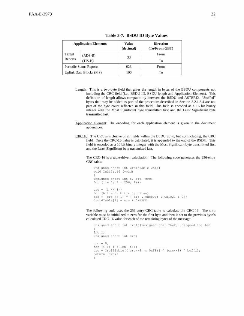
FAA-E-2973 32
Table 3-7. BSDU ID Byte Values
Application Elements Value (decimal)
Direction (To/From GBT)
(ADS-B) From Target Reports (TIS-B)
33 To
Periodic Status Reports 023 From Uplink Data Blocks (FIS) 100 To
Length: This is a two-byte field that gives the length in bytes of the BSDU components not including the CRC field (i.e., BSDU ID, BSDU length and Application Element). This definition of length allows compatibility between the BSDU and ASTERIX. “Stuffed” bytes that may be added as part of the procedure described in Section 3.2.1.8.4 are not part of the byte count reflected in this field. This field is encoded as a 16 bit binary integer with the Most Significant byte transmitted first and the Least Significant byte transmitted last.
Application Element: The encoding for each application element is given in the document appendices.
CRC 16: The CRC is inclusive of all fields within the BSDU up to, but not including, the CRC field. Once the CRC-16 value is calculated, it is appended to the end of the BSDU. This field is encoded as a 16 bit binary integer with the Most Significant byte transmitted first and the Least Significant byte transmitted last.
The CRC-16 is a table-driven calculation. The following code generates the 256-entry CRC table:
unsigned short int Crc16Table[256]; void InitCrc16 (void) { unsigned short int i, bit, crc; for (i = 0; i < 256; i++) { crc = (i << 8); for (bit = 0; bit < 8; bit++) crc = (crc << 1) ^ ((crc & 0x8000) ? 0x1021 : 0); Crc16Table[i] = crc & 0xFFFF; }
The following code uses the 256-entry CRC table to calculate the CRC-16. The crc variable must be initialized to zero for the first byte and then is set to the previous byte’s calculated CRC-16 value for each of the remaining bytes of the message:
unsigned short int crc16(unsigned char *buf, unsigned int len) { int i; unsigned short int crc; crc = 0; for (i=0; i < len; i++) crc = Crc16Table[((crc>>8) & 0xFF)] ^ (crc<<8) ^ buf[i]; return (crc); }

FAA-E-2973 33
3.2.1.8.4 Session Layer: SDU
The SDU supports the following functions:
• Distribution of BSDUs to various ground application end systems • Detection and delimiting of each individual BSDU
a. The GBT shall be configurable through the SDU_HEADER configuration item to either “implement” or “omit” the use of the Session header.
b. Each SDU shall encapsulate exactly one BSDU.
c. The format of the SDU shall be as described in reduced font below:
Figure 3-5 shows the format of the SDU.
SessionLayer ID(1 byte)
BSDU
Session Layer DataUnit (SDU)
(detection, delimiting anddistribution of BSDUs)
Transmission Order
SByte
Seq(4
SyncByte
Synchr
ync
uencebytes)
Sequence(4 bytes)
Figure 3-5. Session Layer Wrapper
onizing Byte Sequence: synchronizing bytes are used to indicate the start and end of a BSDU in the data stream. The synchronizing byte sequence consists of the following hexadecimal bytes in their transmission order: 01 FF FF FF.
the possibility of a synchronizing byte sequence occurring in an outgoing BSDU. When the first three bytes of the synchronizing byte
ce of stuffed bytes in the incoming data stream. When the first three bytes of the synchronizing frame sequence followed by a byte with a value
Note:
Byte stuffing is performed to eliminate
sequence is found within the outgoing BSDU, one byte with a value of ZERO is inserted (or “stuffed”) into the data stream following these three bytes. Byte de-stuffing is performed to remove the occurren
of ZERO is found within the incoming data stream the byte with a value of ZERO is discarded and not used in the construction of a BSDU. The sequence 01 FF FF will only be followed by a 00 or a FF. Any other condition indicates an error in the data.
When multiple SDUs are transmitted back-to-back, a single synchronizing byte sequence may d
Note:
elimit these messages.
Implementation of the synchronizing byte is limited to the asynchronous serial interface and the TCP/IP Ethernet in It is not available under the other Ground Interface configura
n La
sequence terface..
tions
Sessio yer ID: This byte provi n application y a distribution function as part of the ground system external to the GB s field is encoded as an 8 bit binary inte h the Most Significant bit trans first and the Least Significant bit
. Table 3-8 shows the encoding s byte.
des a code for use bT. Thimitted ger wit
transmitted last of thi
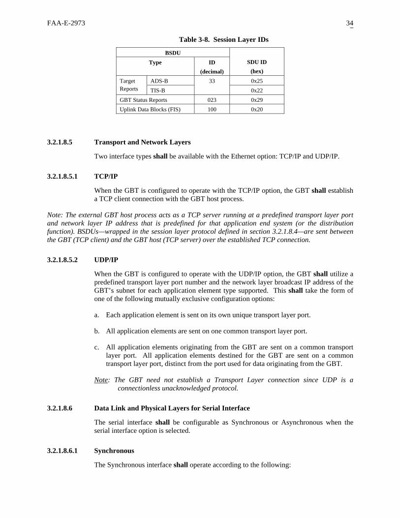
FAA-E-2973 34
Table 3-8. Session Layer IDs
BSDU Type ID
(decimal) SDU ID
(hex)
ADS-B 0x25 Target 33 Reports TIS-B 0x22 GBT Status Reports 023 0x29 Uplink Data Blocks (FIS) 100 0x20
3.2.1.8.5 Transport and Network Layers
Two interface types shall be available with the Ethernet option: TCP/IP and UDP/IP.
3.2.1.8.5.1
Note: The exter ort layer port and network layer IP address that is pfunction). BSDU e sent between the GBT (TCP c
3.2.1.8.5.2 UD
GBT’s upported. This shall take the form of one of the following mutually exclusive configuration options:
nt on one common transport layer port.
elements originating from the GBT are sent on a common transport layer port. All application elements destined for the GBT are sent on a common
g from the GBT.
Note
TCP/IP
When the GBT is configured to operate with the TCP/IP option, the GBT shall establish a TCP client connection with the GBT host process.
nal GBT host process acts as a TCP server running at a predefined transpredefined for that application end system (or the distribution
s—wrapped in the session layer protocol defined in section 3.2.1.8.4—arlient) and the GBT host (TCP server) over the established TCP connection.
P/IP
When the GBT is configured to operate with the UDP/IP option, the GBT shall utilize a predefined transport layer port number and the network layer broadcast IP address of the
subnet for each application element type s
a. Each application element is sent on its own unique transport layer port.
b. All application elements are se
c. All application
transport layer port, distinct from the port used for data originatin
: The T a connect
3.2.1.8.6 Data Link and
The serial interserial interface o
3.2.1.8.6.1 Synchronous
The Synchronous interface
GB need not establish a Transport Layer connection since UDP is ionless unacknowledged protocol.
Physical Layers for Serial Interface
face shall be configurable as Synchronous or Asynchronous when the ption is selected.
shall operate according to the following:
FAA-E-2973 35
• HDLC, (unbalanced mode), Asynchronous Receive Mode (ARM) full ons interface), mation frames.
wed onnectionless/acknowledgeless
ays assumed to be logically connected orm link-setup or link
speed selectable as a configuration item. Physical characteristics shall be in accordance with EIA-530 and Section
3.2.1.8.6.2 Asynchronous
The Asynchronous interface operate according to the following:
al characteristics per EIA-232 at 1.2 to 115 kbps with speed able as a configuration item,
3.2.1.8.6.3 Eth
stry standard Ethernet in accordance with
minimum of 10 Mbps.
3.2.1.9
URCE
3.2.2
3.2.2.1 Receive
The A DO-282 Sections 2.2.8.2 through 2.2.8.3.4 with exceptions or qualifications as detailed in the subparagraphs
Not
duplex enabled (assumes a point-to-point communicatiGBT acts as Primary, sending and receiving only inforSupervisory frames and unnumbered format command frames disalloin either direction. This creates a cprotocol, i.e. the secondary is alw
r the primary to perfwithout the need fodisconnection.
• Electrical characteristics per EIA-422 interface at 1.2 to 115 kbps with
• 3.3.2.1.2
shall
• Electricselect
• 8 data bits, 1 stop bit, No parity, • No Flow control. • Physical characteristics shall be in accordance with Section 3.3.2.1.1
ernet
The Ethernet interface shall be induANSI/IEEE 802.3 (ISO/IEC 8802-3).
The physical layer shall perform at a
GBT Timing
a. The GBT shall support two sources of timing: an integral GPS-based source and anexternal source through the External Timing Interface.
b. The source used by the GBT shall be determined by the TIMING_SOconfiguration item.
Performance Requirements
r Characteristics
GBT receiver shall meet all the requirements of RTC
below.
e: Detailed information exchange formats for transactions on the Local and Remote to be Vendor defined.
3.2.2.1.1
Long ADS-B messages applied to the Air Interface port at a level of –98 dBm shall better under the following
Maintenance interfaces are
Sensitivity for Long ADS-B Messages (supersedes DO-282 Section 2.2.8.2.1.1)
produce a rate of Successful Message Reception of 90% or simultaneous conditions:

FAA-E-2973 36
a. The desired signal is subject to the maximum permitted signal frequency offset plus air-to-ground Doppler at 600 knots closure/opening.
b. The desired signal is subject to the maximum modulation distortion allowed in DO-282 Section 2.2.2.4.
Notes:
1. This also ensures that the Basic ADS-B Message will be received at the same desired signal level.
2. This shall include the effects of the T/R switch.
3.2.2.1.2
Gro –96 dBm shall
a.
m modulation distortion allowed in
perly receive the longer Ground Uplink message (assuming that the baud rate accuracy of the transmitter is 2 PPM).
results in no output on the Ground
.g., test point that provides count of Successful Message Reception).
3.2.2.1.3
licable only to equipment classes A0, A1L,
3.2.2.1.4
only to equipment classes A0, A1L,
3.2.2.1.5
DO-282 Section 2.2.8.2.5 requirements applicable only to equipment classes A0, A1L,
Sensitivity for Ground Uplink Messages (supersedes DO-282 Section 2.2.8.2.1.2)
und Uplink messages applied to the Air Interface port at a level ofproduce a rate of Successful Message Reception of 90% or better under the following simultaneous conditions:
The desired signal is subject to the maximum permitted signal frequency offset.
b. The desired signal is subject to the maximuSection 2.2.2.4. of DO-282.
Notes:
1. This requirement ensures the baud rate accuracy supporting demodulation in the GBT equipment is adequate to pro
2. Since reception of the Ground Uplink message Interface, the manufacturer shall provide the indication of Successful Message Reception in some other way (e
3. This shall include the effects of the T/R switch.
Receiver Selectivity
DO-282 Section 2.2.8.2.3 requirements appA1H, and A2 shall apply to the GBT.
Receiver Tolerance to Pulsed Interference
DO-282 Section 2.2.8.2.4 requirements applicableA1H, and A2 shall apply to the GBT.
Receiver Tolerance to Overlapping ADS-B Messages
A1H, and A2 shall apply to the GBT.

FAA-E-2973 37
3.2.2.1.6 Receiver Desired Signal Dynamic Range
The GBT shall achieve a Successful Message Reception rate of 99% or better when thdesired signal level at the Air Interface is between -95 dBm and -10 dBm.
e
Inband Signals.
d at +10 dBm.
3.2.2.2 Transmitt
The GBT transmitter 2 Sections 2.2.2.1 through xcep ons as detailed in the subparagraphs below.
3.2.2.2.1 Modulation rtion
DO-282 4 requirements for modul ll afor Groun essage tra s from t
3.2.2.2.2
a. The GBT shall support four power level settings within the ranges as shown in Table 3-9. Power levels are measured in terms of power presented at the Air Interface port
of the T/R switch.
Minimum Power Maximum Power
3.2.2.1.7 Receiver Recovery from Large
The GBT shall return to the sensitivity specified in Sections 3.2.2.1.1 and 3.2.2.1.2 within 50 microseconds after application of a 4500 microsecond pulse inban
Note: This assures the GBT receiver recovers from a Ground Uplink message transmission from a cosited redundant GBT.
er Characteristics
shall meet all the requirements of RTCA DO-28 2.2.2.7 with e tions or qualificati
Disto
Section 2.2.2.d m
ation distortion sha lso be applicable Uplink nsmission he GBT.
Transmitter Power Levels and Ranges
of the GBT including the effects
Table 3-9: Transmitter Power Requirements
Power Level Nominal Power Setting
“Off” 0 Watts (-80 dBm) “Low” 10 Watts 7 watts (+38.5 dBm) 14 watts (+41.5 dBm)
“Medium” 25 Watts 16 watts (+42 dBm) 32 watts (+45 dBm) “High” 75 Watts 50 watts (+47 dBm) 100 watts (+50 dBm)
b. POWER_LEVEL shall be selectable as a configuration item.
3.2.2.2.3
tude profile of transmitted
b. Time/Amplitude profile requirements are applicable for all messages transmitted from the GBT.
Transmitter Power Output
DO-282 Section 2.2.2.5 requirements for the Time/Amplimessages shall be applicable with the following qualifications:
a. References to Table 2-1 and Table 2-2 in subparagraphs b), c), d) and e) of DO-282 Section 2.2.2.5 shall instead refer to Table 3-9 of this specification.

FAA-E-2973 38
3.2.2.2.4 Transmitter Timeout
Whenever the RF level at the Air Interface Port exceeds –60 dBm for more than 50% of any 40 millisecond period, the GBT shall:
a. Declare a transmitter timeout Alarm in the Status report.
b. Automatically assume the “Off” setting for the Transmitter Level control parameter.
Note: This requirement is structured for verification testing through intentional “over assignment” of Channels when configuring the GBT (see Section 3.2.2.2.5).
3.2.2.2.5
The e of operating with the simultaneous combination of TIS-B at a full target load of 190 per second and a maximum of 8 Ground Uplink
bination of OFFSET and CHANNEL_LIST assignments.
Transmitter Duty Cycle
GBT transmitter shall be capabl
messages per second in any com
Notes:
1. A configuration constraint that requires successive Channel assignments to be spaced at most 4 apart is acceptable (e.g., Channel assignments of 1, 5, 9, 13…29 or 2, 6, 10, 14…30 etc).
e configuration of any arbitrary list of channel
3.2.2.3 Receiver Availability
The GBintervalof the f sequence of a transmitted message and ends within the transmit-receive turnaround time.
3.2.2.3.1
ity
Note:
2. However, the GBT shall support thassignments in order to support verification testing of the “Transmitter Timeout” requirement (Section 3.2.2.2.4).
T receiver shall be enabled and available for message reception except for the s that begin a maximum of 50 microseconds prior to the optimum sampling point irst bit of the synchronization
Transmit-Receive Turnaround Time
The GBT shall switch from transmission to reception and return to the sensitivspecified in Sections 3.2.2.1.1 and 3.2.2.1.2 within 50 microseconds after transmitting amessage.
Transmit to Receive switching time is defined as the time between the optimum sampling point of the last information bit of one transmit message and the optimum sampling point of the first bit of the synchronization sequence of the subsequent receive message.
3.2.2.4 GBT Throughput Performance
GBT throughput performance requirements vary depending on the Ground Interface option selected. The GBT shall meet the throughput and delay requirements given in Table 3-10. Each row of the table represents a set of throughput requirements that shall be met simultaneously.
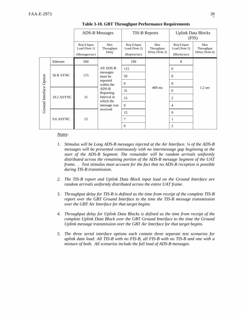
FAA-E-2973 39
Table 3-10. GBT Throughput Performance Requirements
ADS-B Messages TIS-B Reports Uplink Data Blocks (FIS)
Req’d Input Load (Note 1)
(Messages/sec)
Max Throughput
Delay
Req’d Input Load (Note 2)
(Reports/sec)
Max Throughput
Delay (Note 3)
Req’d Input Load (Note 2)
(Blocks/sec)
Max Throughput
Delay (Note 4)
Ethernet 500 190 8
115 0
50 8
56 K SYNC
115
0 8
31 0
15 2
19.2 ASYNC
31
0 4
15 0
7 1
Gro
und
Inte
rfac
e O
ptio
n
9.6 ASYNC
15
All ADS-B messages must be reported within the ADS-B Reporting Interval in which the message was received
0
400 ms
2
1.2 sec
Notes:
1. Stimulus will be Long ADS-B messages injected at the Air Interface. ¼ of the ADS-B messages will be presented continuously with no intermessage gap beginning at the start of the ADS-B Segment. The remainder will be random arrivals uniformly distributed across the remaining portion of the ADS-B message Segment of the UAT frame. . Test stimulus must account for the fact that no ADS-B reception is possible during TIS-B transmission.
2. The TIS-B report and Uplink Data Block input load on the Ground Interface are random arrivals uniformly distributed across the entire UAT frame.
3. Throughput delay for TIS-B is defined as the time from receipt of the complete TIS-B report over the GBT Ground Interface to the time the TIS-B message transmission over the GBT Air Interface for that target begins.
4. Throughput delay for Uplink Data Blocks is defined as the time from receipt of the complete Uplink Data Block over the GBT Ground Interface to the time the Ground Uplink message transmission over the GBT Air Interface for that target begins.
5. The three serial interface options each contain three separate test scenarios for uplink data load: All TIS-B with no FIS-B, all FIS-B with no TIS-B and one with a mixture of both. All scenarios include the full load of ADS-B messages.

FAA-E-2973 40
3.2.2.5 GBT Timing Source
a. The GBT shall employ a GPS-based timing source referenced to UTC that supports a timing accuracy of +/- 500 ns of UTC. When UTC timing is available from the GPS source, the GBT shall be in the UTC-coupled condition
b. When the GBT has entered the ALARM condition for the GBT Timing Status monitor parameter, the GBT shall estimate—or “coast”—time such that the GBT assigns the “Time of Applicability” data item for ADS-B reports with an error of no greater than +/- 1 second from the actual time of applicability for up to 1 hour.
3.2.2.5.1 GPS Antenna
a. A matching GPS antenna shall be provided for the GPS system.
b. The requirement of Section 3.2.2.5.a., shall be met with up to 100 meters of GPS antenna cable through the use of a programmable cable delay, if required.
c. The requirements of Section 3.4.3.1.2 shall be met.
3.2.2.5.2 GPS Satellite Tracking and Masking
a. The GPS subsystem shall be capable of tracking a minimum of eight satellites simultaneously.
b. Accurate timing as defined in Section 3.2.2.5.a shall be capable of being generated from only one satellite.
c. Normal satellite masking shall apply for any satellites below 10 degrees above the horizon. This angle shall be reduced to 0.5 degrees above the horizon if insufficient satellites above 10 degrees above the horizon are available to provide accurate timing.
3.2.2.5.3 GPS Receiver System Sensitivity
The GPS system is designed to provide a –130-dBm signal at the earth surface. To provide a level of immunity from environmental attenuation, the GPS receiver shall have the capability to acquire signals of at least –136 dBm level at the antenna and remain tracking to a level of at least –143 dBm signal strength.
3.2.3 Site Control and Monitoring
3.2.3.1 Technician Access
The GBT shall support access by maintenance technicians for control and monitoring of GBT parameters in one of two ways:
a. A Local Maintenance Interface on the front panel of the GBT for connection of a local PC for test and control functions.
b. A Remote Maintenance Interface on the rear of the GBT for connection to the control facility.

FAA-E-2973 41
3.2.3.1.1 Local Maintenance Interface
a. The GBT shall accept control input, provide control replies, and provide monitoring output and alarm/alert indications via the Local Maintenance Interface connector.
b. Upon connection of a local maintenance terminal, the GBT shall continue to operate in its current state. Upon establishment of a control session (login), the GBT shall change from its current state to the Offline state.
3.2.3.1.2 Remote Maintenance Interface
a. The GBT Remote Maintenance Interface should implement SNMPv2c in accordance with RFC 1901 for remote monitor and control in addition to the protocols required by NAS-IC-51070000-2.
b. The GBT shall accept control input, provide control replies, and provide monitoring output and alarm/alert indications via the Remote Maintenance Interface connector.
c. Upon connection of a remote maintenance terminal, the GBT shall continue to operate in its current state. Upon establishment of a control session (login), the GBT shall change from its current state to the Offline state.
Note: The FAA’s NIMS management platform is only SNMPv1 and SNMPv2c compatible at this time. An upgrade to SNMPv3 is planned for the future.
3.2.3.1.3 Management Information Base
The GBT Management Information Base (MIB) should be implemented IAW NAS-IC-51070000-2.
3.2.3.2 GBT Internal RF Test Support
Note: The requirements of this section are intended to support monitoring of the GBT’s RF performance on a remote basis. Differing support is needed for each of the two following GBT conditions; when in the online state (fully operational), and when placed in the Offline state by the maintenance technician (non-operational).
3.2.3.2.1 ADS-B Test Message (Online State)
a. The GBT shall generate an ADS-B Test message in the “Basic” ADS-B message format to verify operation of the ADS-B reception function.
b. The ADS-B Test message shall be composed according to Table 3-11.

FAA-E-2973 42
Table 3-11. Payload Composition of ADS-B Test Message
ADS-B Message Payload Field Field Name DO-282 Ref
Para
Contents
“PAYLOAD TYPE CODE” 2.2.4.5.1.1 ZERO (“Basic” ADS-B message) “ADDRESS QUALIFIER” 2.2.4.5.1.2 “5” (Code for “Fixed ADS-B
Beacon”) “ADDRESS” 2.2.4.5.1.3 Configuration item
ADS-B_TEST_MSG_ADDR “LATITUDE” and “LONGITUDE” 2.2.4.5.2.1 Provided each second by integral
GPS. Set to ALL ZEROs when not available
“ALTITUDE TYPE” 2.2.4.5.2.2 ZERO “ALTITUDE” 2.2.4.5.2.3 ALL ZEROS (Code for “Information
not available”) “NIC” 2.2.4.5.2.4 ALL ZEROs (Code for “Integrity
Unknown”) “A/G STATE” 2.2.4.5.2.5 ALL Zeros “HORIZONTAL VELOCITY” 2.2.4.5.2.6 Provided each second by integral
GPS “VERTICAL VELOCITY” 2.2.4.5.2.7 ALL Zeros “UTC” 2.2.4.5.2.8 ALL Zeros “Reserved” 2.2.4.5.2.9 ALL Zeros
c. The ADS-B Test message shall be generated and reported every twelve seconds, +/- 1 second.
d. The ADS-B Test message shall not conflict with any ADS-B message reception during the ADS-B segment of the UAT frame.
e. The ADS-B report resulting from the ADS-B Test message shall always be reported in the reporting interval in which it was generated regardless of the ADS-B message load.
f. The ADS-B Test message shall be inserted into the receiver front end, to include any receiver power or pre-amplifiers, so that a complete system check can be initiated.
g. The level of the ADS-B Test message present at the receiver front end shall be at least 5 dB above the level required to achieve a rate of Successful Message Reception of 90% or better.
h. The level of the ADS-B Test message present at the Air Interface port shall not exceed –60 dBm.
3.2.3.2.2 Loopback Test Mode (Offline State)
Note: The Loopback mode samples and receives the GBT uplink transmissions at the receiver front end so the reception can be reported on the GBT’s Ground Interface. Loopback mode also supports a power measurement of Ground Uplink messages. Loopback mode is intended only for maintenance use as a remote check on the transmitter functionality.
When placed in the Loopback test mode:
a. The GBT shall transmit a single TIS-B in response to a loopback message in accordance with the requirements of Section 3.2.1.5. through 3.2.1.5.2. within 2 seconds of receipt of a TIS-B report on the Ground Interface.

FAA-E-2973 43
Note: The loopback test for TIS-B messages will be supported though a special loopback application external to the GBT. This loopback application provides a stimulus consisting of a single TIS-B report applied to the GBT’s Ground Interface. The loopback application will expect an ADS-B report to be subsequently received from the GBT’s Ground Interface for bit-wise comparison with the original TIS-B report.
b. The GBT shall transmit a single Ground Uplink message in response to a loopback message in accordance with the requirements of Sections 3.2.1.6 through 3.2.1.6.2.3 in Channel #32 within 2 seconds of receipt of an Uplink Data Block on the Ground Interface.
Note: The loopback test for Ground Uplink messages will be supported though a special loopback application external to the GBT. This loopback application provides a stimulus consisting of a single Uplink Data Block applied to the GBT’s Ground Interface. The loopback application will expect a “read back” of the Uplink Data Block to be subsequently received from the GBT’s Ground Interface for bit-wise comparison. There is no requirement for the GBT to either compose or confirm the information in the loopback message.
c. The GBT shall transmit all messages in loopback mode according to the POWER_LEVEL configuration parameter.
Note: This is necessary to simultaneously support the remote power level measurement. Maintenance procedures and the loopback application will ensure resulting messages are infrequent and formatted such that they will be ignored by avionics equipment.
d. The GBT should provide a power level measurement for each Loopback Ground Uplink message transmitted and report the measured level in the Measured Power Output monitoring parameter (ID # 57).
e. Message receptions in Loopback test mode:
1. Shall be processed through the receiver’s RF section, to include the T/R switch when present.
2. Shall result in an ADS-B report on each Successful Message Reception of the TIS-B loopback message.
3. Shall result in an Uplink Data Block (sent from the GBT) on each Successful Message Reception of the Ground Uplink loopback message.
4. Shall result in reports for loopback receptions and not for receptions from the Air Interface
f. The GBT shall remain in Loopback test mode until explicitly taken out of Loopback test mode, or until the Control Session is terminated, which ever comes first.
g. The GBT shall treat all traffic received on the Ground Interface (TIS-B reports and Uplink Data Blocks) as requiring a loopback response from the GBT.

FAA-E-2973 44
3.2.3.2.3 Sensitivity Test Mode (Offline State)
Note: The Sensitivity test mode causes ADS-B Test messages to be internally generated and injected into the receiver. This mode allows the maintenance technician to control the level of the ADS-B Test message as applied to the receiver front end. By comparing the ADS-B report rate to the known rate of internal ADS-B Test messages transmitted, the technician is able to estimate the receiver sensitivity. Sensitivity test mode is intended only for maintenance use as a remote check on the receiver.
When placed in the Sensitivity test mode:
a. The GBT should generate ADS-B Test messages in accordance with the requirements of Section 3.2.3.2.1 with the exception that the ADS-B test message is generated at a rate of once per second.
b. The GBT should support adjustment of the level of the ADS-B Test message in a range of at least ± 10 dB relative to the sensitivity threshold for Basic ADS-B messages (see Section 3.2.2.1.1) in 1 dB increments.
c. The level of the ADS-B Test message provided to the receiver for each adjustment step should be stable and repeatable to within ± 1 dB.
d. A sample of the ADS-B Test message being injected into the receiver should be provided at an externally accessible test point.
3.2.3.3 GBT Control
3.2.3.3.1 Control Session
Note: A control session is used to convey control parameters, and receive both control replies and solicited monitoring messages. A control session is not required for unsolicited radio monitoring messages.
Note: A user will log in either via the Remote Maintenance Interface or the Local Maintenance Interface to initiate a control session. A session is initiated after receipt of a Login and authentication of a security key. A session ends with a log-out, physical disconnection of the Local Terminal, or when no control parameters are received within 30 minutes.
a. The GBT shall initiate a control session upon successful authentication of log on / security key.
b. As long as a valid session is active on one control interface, the GBT shall reject all control parameters from the other control interface.
c. The GBT shall terminate the control session upon log-out, disconnection of local maintenance terminal, or after no control parameter is received within 30 minutes.
d. The GBT shall be in the Offline State during a control session.
e. A control parameter command shall be processed within an average of 1 second over any 15-minute period with a maximum time of 2 seconds.

FAA-E-2973 45
3.2.3.3.2 Control Parameter Adjustments
a. The GBT shall allow modification of the control parameters of the GBT equipment summarized in Table 3-12.
b. The GBT equipment shall set parameters to within the tolerance of the associated monitoring parameter (i.e., same Parameter ID).
Note: In some cases the step size is finer than the resolution to allow for finer tuning of the parameters using external test equipment.
Note: The control parameter value ranges, maximum step sizes and default values are summarized in Table 3-12.
c. The GBT shall reply to request messages with a reply message containing the parameter setting actually enacted by the GBT.
d. Rejected request messages shall contain the original parameter setting with an error code indicating the reason for rejection.
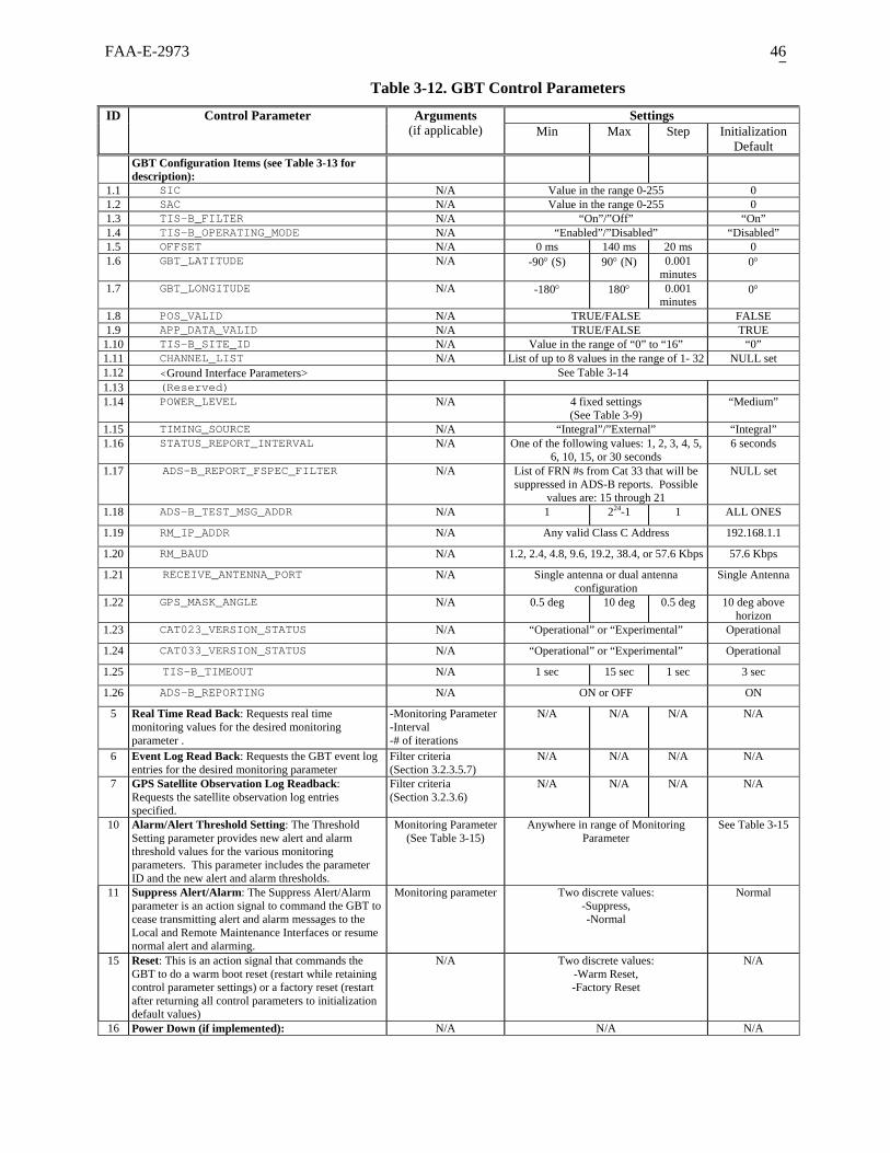
FAA-E-2973 46
Table 3-12. GBT Control Parameters
Settings ID Control Parameter Arguments (if applicable) Min Max Step Initialization
Default GBT Configuration Items (see Table 3-13 for
description):
1.1 SIC N/A Value in the range 0-255 0 1.2 SAC N/A Value in the range 0-255 0 1.3 TIS-B_FILTER N/A “On”/”Off” “On” 1.4 TIS-B_OPERATING_MODE N/A “Enabled”/”Disabled” “Disabled” 1.5 OFFSET N/A 0 ms 140 ms 20 ms 0 1.6 GBT_LATITUDE N/A -90° (S) 90° (N) 0.001
minutes 0°
1.7 GBT_LONGITUDE N/A -180° 180° 0.001 minutes
0°
1.8 POS_VALID N/A TRUE/FALSE FALSE 1.9 APP_DATA_VALID N/A TRUE/FALSE TRUE
1.10 TIS-B_SITE_ID N/A Value in the range of “0” to “16” “0” 1.11 CHANNEL_LIST N/A List of up to 8 values in the range of 1- 32 NULL set 1.12 <Ground Interface Parameters> See Table 3-14 1.13 (Reserved) 1.14 POWER_LEVEL N/A 4 fixed settings
(See Table 3-9) “Medium”
1.15 TIMING_SOURCE N/A “Integral”/”External” “Integral” 1.16 STATUS_REPORT_INTERVAL N/A One of the following values: 1, 2, 3, 4, 5,
6, 10, 15, or 30 seconds 6 seconds
1.17 ADS-B_REPORT_FSPEC_FILTER N/A List of FRN #s from Cat 33 that will be suppressed in ADS-B reports. Possible
values are: 15 through 21
NULL set
1.18 ADS-B_TEST_MSG_ADDR N/A 1 224-1 1 ALL ONES
1.19 RM_IP_ADDR N/A Any valid Class C Address 192.168.1.1
1.20 RM_BAUD N/A 1.2, 2.4, 4.8, 9.6, 19.2, 38.4, or 57.6 Kbps 57.6 Kbps
1.21 RECEIVE_ANTENNA_PORT N/A Single antenna or dual antenna configuration
Single Antenna
1.22 GPS_MASK_ANGLE N/A 0.5 deg 10 deg 0.5 deg 10 deg above horizon
1.23 CAT023_VERSION_STATUS N/A “Operational” or “Experimental” Operational
1.24 CAT033_VERSION_STATUS N/A “Operational” or “Experimental” Operational
1.25 TIS-B_TIMEOUT N/A 1 sec 15 sec 1 sec 3 sec
1.26 ADS-B_REPORTING N/A ON or OFF ON
5 Real Time Read Back: Requests real time monitoring values for the desired monitoring parameter .
-Monitoring Parameter -Interval -# of iterations
N/A N/A N/A N/A
6 Event Log Read Back: Requests the GBT event log entries for the desired monitoring parameter
Filter criteria (Section 3.2.3.5.7)
N/A N/A N/A N/A
7 GPS Satellite Observation Log Readback: Requests the satellite observation log entries specified.
Filter criteria (Section 3.2.3.6)
N/A N/A N/A N/A
10 Alarm/Alert Threshold Setting: The Threshold Setting parameter provides new alert and alarm threshold values for the various monitoring parameters. This parameter includes the parameter ID and the new alert and alarm thresholds.
Monitoring Parameter (See Table 3-15)
Anywhere in range of Monitoring Parameter
See Table 3-15
11 Suppress Alert/Alarm: The Suppress Alert/Alarm parameter is an action signal to command the GBT to cease transmitting alert and alarm messages to the Local and Remote Maintenance Interfaces or resume normal alert and alarming.
Monitoring parameter Two discrete values: -Suppress, -Normal
Normal
15 Reset: This is an action signal that commands the GBT to do a warm boot reset (restart while retaining control parameter settings) or a factory reset (restart after returning all control parameters to initialization default values)
N/A Two discrete values: -Warm Reset, -Factory Reset
N/A
16 Power Down (if implemented): N/A N/A N/A

FAA-E-2973 47
Settings ID Control Parameter Arguments (if applicable) Min Max Step Initialization
Default 20 Software Upload Enable/Disable: This is an action
signal that enables the equipment to upload operational software.
N/A Two discrete values: -Enable Upload, -Disable Upload
Disable Upload
21 Software Upload: This is the mechanism for actually uploading the operational software executable image. This parameter is used in conjunction with parameter 22.
-Block Number, -Total Blocks, -Binary Data Block (variable length)
N/A N/A N/A N/A
22 Switch Software Version: This is an action signal that indicates to the equipment to reboot with the stored software image indicated.
N/A N/A N/A N/A N/A
25 Test Mode: This places the GBT in the Loopback test mode, the Sensitivity test mode or Test mode OFF to allow remote checks of the transmitter (and receiver remotely.
N/A Three possible settings: -“Loopback test mode”, -“Sensitivity test mode”,
-“Test mode OFF”
Test mode OFF
26 ADS-B Test Message Level: Allows the maintenance technician to adjust the level in 1 dB steps to ascertain the receiver sensitivity. This control parameter is only available when the Test Mode parameter is set to “Sensitivity test mode”
N/A A range of at least +/- 10 dB around the sensitivity threshold (90% Successful
Message Reception) in 1 dB increments
N/A
Note
The Initialization Default values for each parameter represents the “hard-coded” factory settings required upon GBT initialization.
3.2.3.3.2.1 GBT Configuration Items (ID = 1.1 through 1.15)
The GBT configuration items shall perform the functions indicated in Table 3-13 and Table 3-14

FAA-E-2973 48
Table 3-13. Description of GBT Configuration Items
ID GBT Configuration Item Description
1.1 SIC System Identification Code: used to identify individual systems 1.2 SAC System Area Code: used to identify regions of the world 1.3 TIS-B_FILTER When set, this flag eliminates reporting of TIS-B messages 1.4 TIS-B_OPERATING_MODE When set, this flag enables TIS-B message transmissions when the GBT
is in the Online state 1.5 OFFSET Controls the offset timing for TIS-B message transmissions for a
particular GBT. This value will vary among proximate GBT sites to ensure TIS-B message transmissions will not be subject to “same slot” interference
1.6 GBT_LATITUDE Surveyed location provided to the GBT 1.7 GBT_LONGITUDE Surveyed location provided to the GBT 1.8 POS_VALID Set to indicate to avionics that the Ground Uplink message contains a
valid position 1.9 APP_DATA_VALID Set to indicate to avionics that the Ground Uplink message contains a
valid application data 1.10 TIS-B_SITE_ID Allows avionics to link TIS-B messages with physical location of the
GBT from which they are transmitted (via the position encoded in the Ground Uplink messages)
1.11 CHANNEL_LIST List of Channels available to this GBT as a resource for transmitting Ground Uplink messages
1.12 <Ground Interface Parameters> (see Table 3-14) 1.13 (Reserved) 1.14 POWER_LEVEL Sets the GBTs power level to one of four settings 1.15 TIMING_SOURCE Selects either the GBTs integral (GPS) timing source or the external
timing source for purposes of controlling media access and time stamping reports
1.16 STATUS_REPORT_INTERVAL Selects the periodic reporting interval for the Status report 1.17 ADS-B_REPORT_FSPEC_FILTER List of FRN #s from Cat 33 that will be suppressed in ADS-B reports.
Possible values are: 15 through 21 1.18 ADS-B_TEST_MSG_ADDR Establishes the “ADDRESS” fields of the ADS-B test message 1.19 RM_IP_ADDR Establishes the IP address of the GBTs Remote Maintenance interface 1.20 RM_BAUD Establishes the baud rate for the Remote Maintenance interface 1.21 RECEIVE_ANTENNA_PORT Selects a single or dual antenna configuration. If the dual antenna
configuration is selected, the receive only antenna port will be activated in hardware
1.22 GPS_MASK_ANGLE The GPS mask angle can be reduced to 0.5 degrees above the horizon if insufficient satellites are available to provide accurate position and time.
1.23 CAT023_VERSION_STATUS Used to announce the operational status of the GBT to recipients of Status reports
1.24 CAT033_VERSION_STATUS Used to announce the operational status of the GBT to recipients of ADS-B reports
1.25 TIS-B_TIMEOUT Maximum allowable age of TIS-B reports upon receipt by the GBT in order for them to be transmitted instead of “discarded”.
1.26 ADS-B_REPORTING Establishes whether or not ADS-B reports generated by the GBT due to message receptions off the Air Interface are to be issued over the Ground Interface. Disabling ADS-B Reporting does not affect Status reporting or reporting of ADS-B Test messages

FAA-E-2973 49
Table 3-14. GBT Ground Interface Configuration Items Default Description Configuration Item Possible values
PHYSICAL_INTERFACE_TYPE “Ethernet” or
“Serial” “Serial” The groundside interface will be limited to one physical
connection, either Ethernet or serial. Ethernet Parameters: Ethernet parameters: The Ethernet parameters are only
applicable when the physical interface is set to ‘Ethernet’. NETMASK Any valid
NETMASK 255.255.255.0 The network layer IP subnet mask value. This value,
combined with the SOURCE_IP_ADDR defines the address space and range on the subnet.
SOURCE_IP_ADDR Any valid IP Address
192.168.1.254 The IP address of the GBT.
DESTINATION_IP_ADDR Any valid IP Address
192.168.1.255 The IP address of the network node communicating with the GBT. All data received from the airside interface will be sent to this IP address. This will be the IP address of the TCP server if the TCP transport layer protocol is used.
GATEWAY_IP_ADDR Any valid IP Address
192.168.1.1 The IP address of the network node used for communicating with external subnets.
TRANSPORT_LAYER_PROTOCOL “UDP” or “TCP” “UDP” The groundside interface will be limited to one logical connection using either the TCP or UDP transport layer protocol.
UDP_SOURCE_PORT 0 to 99999 22222 Port number to receive uplink target data and uplink data blocks corresponding to section 3.2.1.8.5.2 option c.
UDP_DESTINATION_PORT 0 to 99999 33333 Port number to transmit downlink target data and status reports corresponding to section 3.2.1.8.5.2 option c.
UDP_STATUS_PORT 0 to 99999 22222 Port number to transmit Status data corresponding section 3.2.1.8.5.2 option a.
UDP_ADS-B_PORT 0 to 99999 33333 Port number to transmit ADS-B and TIS-B data corresponding to section 3.2.1.8.5.2 option a.
UDP_FIS-B_PORT 0 to 99999 11111 Port number to receive and transmit Uplink Data Blocks corresponding to section 3.2.1.8.5.2 option a.
UDP_TX_RX_Port 0 to 99999 22222 Port number for all transmit and receive data corresponding to section 3.2.1.8.5.2 option b.
TCP_Port 0 to 99999 22222 Port number to connect to the TCP server. Both uplink and downlink data is sent over this port.
Serial Parameters: The serial parameters are only applicable when the physical interface is set to ‘serial’. The GBT serial interface will be wired as data communications equipment (DCE).
BAUD_RATE 1.2, 2.4, 4.8, 9.6, 19.2, 38.4, or 57.6
Kbps
19.2 Kbps All standard serial communications baud rate values are acceptable. Values represent Kilobits per second.
DATALINK “Sync “ or “Async”
“Async” When the asynchronous protocol is selected, the serial interface will be set to 8 data bits, no parity, and one stop bit (8-none-1). When the synchronous protocol is selected, HDLC, NRM mode (unbalanced), ARM enabled (assumes a point-to-point full duplex communications interface), GBT acts as Primary sending only information frames. Supervisory frames and Unnumbered frames disallowed in either direction.
SYNC_FRAMES “On” or “Off” “On” Use or omit the message delimiting synchronizing sequence
Session Layer Parameters: SDU_HEADER “On” or “Off” “On” Use or omit the session layer header

FAA-E-2973 50
3.2.3.3.2.2 Real Time Read Back (ID = 5)
The real time read back parameter shall:
a. Cause the GBT equipment to reply with a monitoring message containing the real time monitored value of the monitoring parameter specified.
b. Accept three arguments: monitoring parameter, Interval, and number of iterations.
Note: This supports the requirement of Section 3.2.3.4.b.1.
3.2.3.3.2.3 Event Log Read Back (ID = 6)
The event log read back parameter shall cause the GBT equipment to reply with the event log entries for the filter criteria specified.
Note: This supports the requirement of Section 3.2.3.5.7.
3.2.3.3.2.4 GPS Satellite Observation Log Read back (ID = 7)
The GPS Satellite Observation log read back parameter shall cause the GBT equipment to reply with the log entries for the filter criteria specified.
Note: This supports the requirement of Section 3.2.3.6.
3.2.3.3.2.5 Alarm/Alert Threshold Setting (ID = 10)
The threshold setting parameter shall:
a. Establish new alert and alarm threshold values for the monitoring parameters as specified in Table 3-15, item 55.
b. Contain thresholds for low Alarm, high Alarm, low Alert, high Alert (as applicable) of variable type with values anywhere in the range of the associated parameter values specified in Table 3-15.
3.2.3.3.2.6 Suppress Alert/Alarm (ID = 11)
The suppress alert/alarm parameter shall cause the GBT equipment to cease or resume transmitting alert and alarm messages to the Local and Remote Maintenance Interfaces for the monitoring parameter specified.
3.2.3.3.2.7 Reset (ID = 15)
The reset parameter shall:
a. Have two values: Warm Reset and Factory Reset.
b. Cause the GBT to transition to the Power Up state (and initiate Power Up sequence) after two Reset (Warm Reset) control parameters are received within 1 second.

FAA-E-2973 51
c. Restore all control parameters to their default value and cause the GBT to clear the link and then to transition to the Power Up state (and initiate Power Up sequence) after two Reset (Factory Reset) control parameters are received within 1 second.
3.2.3.3.2.8 Power Down (ID = 16)
If implemented, the Power Down parameter shall force the GBT into the OFF state.
3.2.3.3.2.9 Software Upload Enable/Disable (ID = 20)
The software upload enable/disable parameter shall:
a. Enable the GBT equipment to upload operational software to support the programmability requirements of Sections 3.2.3.3.2.11.
b. Have two discrete values: Enable Upload and Disable Upload.
c. Have a default value of Disable Upload.
3.2.3.3.2.10 Software Upload (ID = 21)
The software upload parameter shall:
a. Communicate blocks of the new operational software executable image to reprogram the GBT to support the programmability requirements of Section 3.2.3.3.2.11
b. Be rejected unless the Software Upload Enable/Disable parameter indicates that an upload is enabled.
c. Not include the Binary Data in the Control reply message.
d. Have Three Fields: Block Number, Total Blocks, Program Binary Block (variable length).
3.2.3.3.2.11 Switch Software Version (ID = 22)
The switch software version parameter shall:
a. Indicate to the GBT equipment to reboot to the alternate stored software image provided in the procedure of Section 3.2.3.3.2.10.
b. Cause the GBT to transition to the Power Up state and begin operation using the alternate software image (and initiate Power Up sequence) after two Switch Software Version control parameters are received within 1 second.
c. Allow repeated switching between the primary and alternate software images.
3.2.3.3.2.12 Test Mode (ID = 25)
The Test Mode parameter shall:
a. Establish the GBT in special test modes that support testing of transmitter and receiver performance per Sections 3.2.3.2.2 and 3.2.3.2.3.

FAA-E-2973 52
b. Have three discrete values: Loopback test mode, Sensitivity test mode, and Test mode OFF.
c. Have a default value of Test mode OFF.
3.2.3.3.2.13 ADS-B Test Message Level (ID = 26)
When in the Sensitivity test mode, the GBT shall support control of the level of the ADS-B Test message.
3.2.3.4 GBT Monitoring and Reporting
a. The GBT monitoring function shall perform real-time system performance monitoring and provide real-time system performance reporting when the GBT is in the online state.
b. There shall be three instances where monitoring messages are sent to the Local and Remote Maintenance Interfaces:
1. Upon request via a Control message with parameter ID = 5.
2. When an alert or alarm threshold is crossed, and
3. When a monitored parameter returns to a value within the normal range.
c. The alert or alarm status messages shall be sent within an average of 2 seconds over any 15 minute period and a maximum time of 4 seconds of when the parameter being monitored crosses the threshold level.
3.2.3.4.1 Non-Congesting Monitoring
a. The GBT shall monitor automatically on a continuous basis without blocking or delaying operational communications and management and without the need for the insertion of an external command.
b. The GBT monitoring shall not cause the GBT function to degrade below requirements during operation of the system.
c. Regardless of the frequency of alarm and alert status messages, the GBT monitoring shall not prevent the reception and processing of commands.
3.2.3.4.2 Alarm/Alert Monitoring Suppression
a. The GBT equipment shall suppress alarm and alert status messages to the Local and Remote Maintenance Interfaces upon command.
b. The GBT equipment shall send an alert event acknowledging the command to suppress alarm and alert status messages before suppressing alarm and alert monitoring messages.

FAA-E-2973 53
3.2.3.4.3 Alarm/Alert Processing
a. The GBT parameters to be monitored shall be described by three monitor parameter states:
Normal Alert Alarm
b. The monitored parameter states shall be defined by a range of values that are adjoined such that the value range of the alert state is bordering on the normal state at one end of its range and the alarm state on the other side of its range. Figure 3-6 illustrates Normal, Alert and Alarm Range for a Parameter that has both an upper and lower alert and alarm range.
Parameter Normal Operating Range
Alert Range
Alert Range
Alarm Range
Alarm Range
Parameter Values
Figure 3-6 Normal, Alert and Alarm Range for a Parameter
c. A monitored parameter shall change state when the monitored parameter value transitions from a value within one range to a value within another range, if applicable for the parameter.
d. The GBT shall determine the change between normal state, alert state, and alarm state of GBT status parameter by comparing data to pre-established thresholds.
e. The GBT shall apply a discriminating function (hysteresis) at the boundaries of the ranges to minimize the declaration of alarms and alerts generated under monitored parameter transient conditions.
f. The GBT shall automatically declare an alert event when a monitored parameter and/or element status changes to a value that is outside the normal range but within the alert range.
g. The alert event shall be reported once per occurrence.
h. The GBT shall not generate spurious alert events in any state or transition.
i. The GBT shall automatically declare a return to normal event when a monitored parameter and/or element status that was previously outside the normal range changes to a value that is inside the normal range.
j. The return to normal event shall be reported once per occurrence.

FAA-E-2973 54
k. The GBT shall automatically declare an alarm event when a monitored parameter and/or element status changes to a value crossing from the normal or alert range to the alarm range.
l. The alarm event shall be reported once per occurrence.
m. The GBT shall not generate spurious alarm events in any state or transition.
n. The GBT shall automatically declare a state change event when the value changes for a monitored parameter and/or element status that indicates a configuration or mode change to the GBT.
o. The GBT State change event shall be reported once per occurrence.
3.2.3.4.4 GBT Monitoring Parameters
a. The GBT equipment shall monitor the parameters summarized in Table 3-15.
b. An event notification or request for data shall be processed within an average of 2 seconds over any 15-minute period and a maximum time of 4 seconds.

FAA-E-2973 55
Table 3-15 GBT Monitoring Parameters
Monitored Values ID Monitoring Parameter Arguments (if applicable) Min Max Step Tolerance
(Acceptable Error)
Alert Values Alarm Values
1 GBT Configuration Items: Current setting for GBT Configuration items
The specific Configuration Item requested
(ID=1.x)
Current setting in use by the GBT
N/A Alert on acceptance of
new value with Item and new
value
N/A
4 GBT State: The GBT State parameter indicates that the GBT is in one of four states: Online, Offline, Recovery or Fail.
N/A One of 4 discrete values -Off Line -On Line
-Recovery -Fail
N/A Alert on State change (other than to Fail)
Alarm on Fail
11 Suppress Alert/Alarm Setting: The Suppress Alarm/Alert Setting parameter indicates whether Alarms and Alerts are suppressed or enabled
Monitoring Parameter
Two discrete values: -Suppress, -Normal
N/A N/A N/A
20 Software Upload Setting: The Software Upload Setting parameter indicated whether software uploading is prohibited or enabled
N/A Two discrete values: -Enable Upload, -Disable Upload
N/A N/A N/A
23 Software Version: The Software Version parameter indicates the current version of the software active, as well as the standby software version.
N/A 1 255 1 0 N/A N/A
31 Receiver Status N/A “Normal” or “Alarm condition” (i.e., fault
detected)
N/A N/A On Alarm condition
32 Transmitter Status N/A “Normal” or “Alarm condition” (i.e., fault
detected)
N/A N/A On Alarm condition
33 Discard Event: Alert issued when either the ADS-B, TIS-B or Uplink Data Block discard Data Items in the Status Report are non-zero.
N/A N/A N/A N/A N/A Alert when any discard count in Status report is
non-zero
N/A
53 In-Service Time: The In-Service Time parameter indicates the number of hours the GBT component has been powered.
N/A 0 hrs 224 – 1 hrs
1 hr +/- 1 hr N/A N/A
55 Transmit Antenna VSWR: The Transmit Antenna VSWR parameter indicates whether the VSWR of the transmit antenna is within an acceptable operating range.
Three Discrete Values: Normal,
Alert, Alarm
N/A N/A N/A N/A Alert (reflected power
is >9.5 dB below Output Power, i.e.,
VSWR is > 2:1 but less than
4:1)
Alarm (reflected power is >4.5 dB
below Output Power, i.e.,
VSWR is >= 4:1)
56 Transmitter Timeout: Alarm to indicate
a condition where the GBT transmitter has exceeded duty cycle limits resulting in automatic transmitter shutdown.
N/A NORMAL or ALARM N/A N/A ALARM on transmitter
timeout
57 Measured Power Output: The Measured Power Output parameter indicates the current, actual RF transmission power at the GBT RF output. This measurement is only available during the Loopback test mode when the GBT is in the Offline state
Power in dBm 30 dBm 50 dBm 0.5 dB +/- 1 dB N/A N/A
91 GBT Timing Status (TFOM): The status of the integral or external timing source which ever is selected in the GBT configuration.
N/A 1 10 1 0 4 ≥5
Shaded rows indicate monitor parameters that are also reflected in the Status report.

FAA-E-2973 56
3.2.3.4.4.1 GBT Configuration Items (ID = 1.1 through 1.15)
The GBT shall provide the current setting for the Configuration Item specified.
3.2.3.4.4.2 GBT State (ID = 4)
The GBT state parameter shall:
a. Indicate the GBT equipment is in one of four states as per Section 3-15, Id. 4.
b. Be one of 4 discrete values: Offline, Online, Recovery or Fail.
c. Have an alarm value if transition to Fail state.
d. Have an alert value for other state transitions.
3.2.3.4.4.3 Suppress Alarm/Alert Setting (ID=11)
The suppress alarm/alert Setting parameter shall:
a. Indicate the setting of the Suppress Alarm/Alert parameter.
b. Be one of two discrete values, either “Suppress” or “Normal”.
3.2.3.4.4.4 Software Upload Setting (ID=20)
The software upload setting parameter shall:
a. Indicate the setting of the Software Upload parameter.
b. Be one of two discrete values, either “Enable Upload” or “Disable Upload”.
3.2.3.4.4.5 Software Version (ID = 23)
The software version parameter shall:
a. Indicate the current version of the software active in the GBT equipment, as well as the version number of the standby software version.
b. Be one of 255 discrete values for each field.
c. Have a minimum value of 1.
d. Have a maximum value of 255.
e. Use a value of 0 to indicate an invalid or non-existent version.
f. Have a resolution (step size) of 1.
FAA-E-2973 57
3.2.3.4.4.6 In-Service Time (ID = 53)
The in-service time parameter shall:
a. Indicate the number of hours the GBT equipment has been continuously powered.
b. Be provided in hours.
c. Have a minimum value of 0 hours.
d. Have a maximum value of 224-1 hours.
e. Have a resolution (step size) of 1 hour.
f. Have a tolerance (acceptable error) of +/- 1 hour.
g. Provide a reset (to ZERO) by a reset action accessible only locally.
Note: This reset need not be part of the Local Maintenance interface.
3.2.3.4.4.7 Receiver Status
The receiver status parameter shall indicate the GBT’s receiver as either in a “normal” condition (no fault detected by the GBT) or an “alarm” condition (fault detected by the GBT).
3.2.3.4.4.8 Transmitter Status
The transmitter status parameter shall indicate the GBT’s transmitter as either in a “normal” condition (no fault detected by the GBT) or an “alarm” condition (fault detected by the GBT).
3.2.3.4.4.9 Discard Event
The discard event parameter shall indicate:
a. the “normal” condition when all discard counts are zero in a Status reporting interval.
b. the “alert” condition when any discard counts are non-zero in a Status reporting interval.

FAA-E-2973 58
3.2.3.4.4.10 Transmit Antenna VSWR (ID = 55)
The transmit antenna VSWR parameter shall:
a. Be one of three discrete values as given below:
Condition Relative Power VSWR
NORMAL Reflected power is at most 9.5 dB below the forward power
2:1 or less
ALERT Reflected power is between 4.5 and 9.5 dB below the forward power
Between 2:1 and 4:1
ALARM Reflected power is 4.5 dB or less below the forward power
4:1 or greater
3.2.3.4.4.11 Transmitter Timeout (ID = 56)
The Transmitter Timeout parameter shall report a Transmitter Timeout Alarm when the transmitter duty cycle exceeds the limit established in Section 3.2.2.2.4.
3.2.3.4.4.12 Measured Power Output (ID = 57)
The measured power output parameter shall:
a. Measure the average RF power at the Air Interface during transmission of a Ground Uplink loopback message.
b. Be a power level in dBm.
c. Have a minimum value of 30 dBm.
d. Have a maximum value of 50 dBm.
e. Have a resolution (step size) of 0.5 dB for all GBT transmitter configurations.
f. Have a tolerance (acceptable error) of ±1 dB for all GBT transmitter configurations.
3.2.3.4.4.13 GBT Timing Status (ID = 91)
The GBT Timing Status parameter shall:
a. Be based on the Time Figure of Merit (TFOM) parameter derived by the integral or external time source (whichever is selected via the GBT configuration).
b. Be three discrete values:
NORMAL TFOM <= 3 ALERT TFOM = 4 ALARM TFOM >= 5

FAA-E-2973 59
Note: The range and meaning of TFOM values is as follows:
TFOM Value Timing Uncertainty1 <= +/- 1 nanosecond 2 <= +/- 10 nanoseconds 3 <= +/- 100 nanoseconds4 <= +/- 1microsecond 5 <= +/- 10 microseconds
3.2.3.5 Event Logging Requirements
The GBT shall log the following events:
a. State change events, defined as the transition from one state to any other state.
b. Log-in/Log-out events, defined as the initiation/termination of a Control Session.
c. Control events, defined as receipt of any control parameter command except ID#5, Real Time Read back, and ID#6, event Log Read back.
d. Failure events, defined as the detection of any failure.
e. Alarm/Alert/Return to Normal events, defined as a monitored parameter crossing of any active alarm or alert threshold.
3.2.3.5.1 State Transition Log Entry
a. For state transitions, the GBT shall log the:
Event Type as State Change. FROM state. TO state. Date/time of event to the nearest second UTC in the format
(MM/DD/YYYY/HH:MM:SS).
b. The Event Type field shall contain a coded indication of the event type.
3.2.3.5.2 Log-In / Log-Out Log Entry
a. For Log-in/Log-out events, the GBT shall log the:
Event Type as Log-in/Log-out. Date/time of event to the nearest second UTC in the format
(MM/DD/YYYY/HH:MM:SS). Session Action. User Identification. User Terminal Identification. Authentication Result.
b. The Session Action field shall indicate whether the Log-In/Log-Out Event was a Login, Commanded Log Out, or Automatic Log-Out.

FAA-E-2973 60
c. Authentication Result field shall indicate whether the Digital Signature associated with the Log- In was authenticated or rejected.
3.2.3.5.3 Control Event Log Entry
a. For Control events, the GBT shall log the:
Event Type as Control. Control Parameter ID. Control Parameter BEFORE value. Control Parameter value except software update payload. Date/time (of Control command receipt) to the nearest second UTC in
the format (MM/DD/YYYY/HH:MM:SS). User Identification. User Terminal identification. GBT Response.
b. The GBT Response field shall indicate whether the GBT accepted or rejected the control parameter command.
c. If the GBT rejects the control parameter command, the GBT Response field shall contain the error code.
3.2.3.5.4 Failure Event Log Entry
a. For Failure events, the GBT shall log the:
Event Type as Failure. FROM state. TO state (Recovery or Failed). Failure code. Date/time (of Failure) to the nearest second UTC in the format
(MM/DD/YYYY/HH:MM:SS).
b. The Failure code field shall contain text or numeric codes to indicate the specific failure type.
3.2.3.5.5 Alarm/Alert/Return to Normal (RTN) Log Entry
a. For Alarm/Alert/RTN events, the GBT shall log the:
Event Type as Alarm/Alert/RTN. Monitored Parameter ID. Monitored Parameter value. Date/time of event to the nearest second UTC in the format
(MM/DD/YYYY/HH:MM:SS).
b. The Event Type field shall be coded to indicate whether the event was an Alarm, an Alert or a Return to Normal.

FAA-E-2973 61
3.2.3.5.6 GBT Event Log Maintenance
a. The GBT shall log at least 1000 events, in any combination of events, and log events on a First In, First Out basis.
b. The GBT log and log entries shall be retained while the GBT is any state, including OFF state, and through any transition, including power loss and restoration, for the life of the GBT equipment.
3.2.3.5.7 Event Log Read back
The GBT shall reply to a Control Parameter #6, Event Log Read back with the Event Log entries that match the Filter and Qualifier criteria, as follows: FILTER QUALIFIER GBT reads back:All all event log entries All Date/Time all event log entries since Date/Time State Change all state change event log entries State Change Date/Time all state change event log entries since Date/Time Control all control event log entries Control-DT Date/Time all control event log entries since Date/Time Control-ID ID all control event log entries with Control parameter ID specified Failure all failure event log entries Alarm/Alert/RTN all alarm/alert/RTN event log entries Alarm/Alert/RTN-DT Date/Time all alarm/alert/RTN event log entries since Date/Time Alarm/Alert/RTN-ID ID all alarm/alert/RTN event log entries with alarm/alert/RTN set
against Monitored parameter ID specified Log-In/Log-Out all log-in/log-out event log entries Log-In/Log-Out Date/Time all log-in/log-out event log entries since Date/Time Security all security log entries (see Section 3.2.3.7.3.d)
3.2.3.6 GPS Satellite Observation Log Requirements
a. Once per minute, the GBT shall log the following GPS satellite observation data:
1. List of Tracked Satellites including the following data for each:
Satellite Anti-Spoof Flag. Satellite Unhealthy Flag. Satellite Inaccurate Flag. Satellite Parity Error Flag. Elevation angle of each satellite above the horizon. Azimuth angle of each satellite from north (0-359°). Satellite ID. Satellite Signal To Noise Ratio (SNR).
2. Date/time of satellite observation to the nearest second UTC in the format (MM/DD/YYYY/HH:MM:SS).
b. The GBT shall be capable of holding at least 1000 GPS satellite observations on a First In First Out basis.
c. The GPS Satellite Observation log and log entries shall be retained while the GBT is in any state, including the OFF state, and through any transition, including power loss and restoration, for the life of the GBT equipment.
FAA-E-2973 62
d. The GBT shall reply to a Control Parameter #7 GPS Satellite Observation Read back that matches the Filter and Qualifier criteria, as follows:
FILTER QUALIFIER GBT reads back:All all log entries All Date/Time all log entries since Date/Time
3.2.3.7 INFOSEC Requirements
The GBT equipment will meet the appropriate technical, administrative, physical, and personnel security requirements to ensure the integrity, availability, and confidentiality throughout the service period of performance.
3.2.3.7.1 Verification
a. The GBT shall verify the authenticity, integrity and time validity of the digital signed information received via the Local and Remote Maintenance Interfaces.
b. The digital signature algorithm that performs this verification shall correspond to at least one of the algorithms defined in FIPS 186-2.
c. The digital signature function shall meet or exceed security level 1 as defined in FIPS 140-1.
d. The digital signature function shall be validated according to FIPS 140-1 by an accredited FIPS 140-1 testing laboratory.
3.2.3.7.2 Keys
a. The GBT shall provide storage for 10 public keys, any of which may be used in verifying the digital signature defined in 3.2.3.7.1.
b. The storage for public keys shall be in non-volatile memory and be maintained through power loss and restoration.
c. The GBT shall provide a mechanism to add and delete public keys via the Local and Remote Maintenance Interfaces.
3.2.3.7.3 Security Procedures
a. All control parameter commands, except ID#5 Real Time Readback, ID #6 Event Log Readback, and ID #7 GPS Satellite Observation Readback shall be accepted only if the requesting device establishes a Control session, by providing a valid digitally signed authorization key (“security key”) as defined in FIPS PUB 140-1.
Note: Control parameterID 5, ID6, and ID 7are the only control parametesr that the GBT will accept when no Control session has been established.
Note: The “security key” will consist of a FAA-generated digital signature of an FAA-selected data field. The FAA-selected data field may be unique to each User Terminal. The security key will be supplied through the Local or Remote Maintenance Interface.

FAA-E-2973 63
b. All control parameter commands, except ID#5 Real Time Readback, ID #6 Event Log Readback, and ID #7 GPS Satellite Observation Readback received without establishment of, or outside of, a Control session, or are associated with a security key that fails digital signature verification, shall be rejected.
c. The GBT shall receive and authenticate the security key each time a login is attempted through the Local and Remote Maintenance Interfaces.
d. The GBT shall maintain a log of security keys and signatures so that an access history can be tracked. This log shall be permanent and unalterable and contain a minimum of the most recent 500 occurrences. The security log shall include the following:
1. Authorized access and by which security key
2. Unauthorized access attempts
3. Log or function accessed
4. Change date and time of software
5. Change date and time of security key codes
Note: Security procedures apply to Control sessions only. These security requirements apply only to the GBT processing of control parameters. These security requirements do not apply to the GBT’s Ground Interface or Air Interface.
3.2.3.7.3.1 Software Upload Security
a. Software uploads that are not digitally signed or contain an invalid digital signature shall be rejected.
Note: The Software Upload control parameter (ID#21) message will contain, in the last delivered program binary block, a digital signature appended to the software binary image as a signature specifically for the software image contained in the program binary blocks.
b. If the Software Upload capability is still enabled when a user’s control session is ended, the Software Upload parameter shall be set to disable
3.2.3.7.4 Boot Cycle
The GBT boot cycle or equivalent shall be secured so the possibility of an unintentional switch of the GBT operating software during the boot cycle does not occur.
3.2.3.7.5 Physical Security
a. The GBT equipment shall utilize tamper-proof seals, an example being of those used by quality inspectors, to indicate the physical security of any item (LRU) integral to the GBT equipment.
Note: FIPS PUB 140-1, paragraph 4-5, requires this.

FAA-E-2973 64
b. The physical security of the end item GBT will be encompassed by the FAA installation site security.
3.2.3.8 Vendor Built In Test
Any Vendor developed built-in test (BIT) capability for the GBT shall be provided to the FAA.
3.2.3.9 GBT Failure Detection and Reporting
The GBT shall detect and report critical equipment failures to the Local and Remote Maintenance Interfaces automatically when the GBT is in the Offline and Online states and during Recovery.
Note: See Section 5.2.9 for definitions of critical and non-critical equipment failures.
3.3 Interfaces
3.3.1 Air Interface
a. The GBT shall support two Air Interface configuration options:
1. Combined transmit and receive through a single GBT antenna port.
2. Separate GBT antenna ports for transmit and receive.
b. The Air Interface shall be configurable to either Air Interface option by an on site technician without opening the GBT.
c. Air Interface connectors shall be 50 ohm coaxial type N female.
d. The transmit/receive switch shall be integral to the GBT
Note: It may desirable in some installations to use a transmit antenna with minimal gain where many GBTs are sited. This controls co-channel interference better. See Figure 3-7 for one possible implementation for configuring the air interface option.
GBT Enclosure
T/RSwitch
To RxFrom Tx
Rx-only antenna
Example Implementation of the Air Interface Option
(when present)
Figure 3-7. An

FAA-E-2973 65
3.3.2 Ground Interface
There shall be three Ground Interface connector options: Two for Serial and one for Ethernet.
3.3.2.1.1 Asynchronous
be supported with a female DB9 RS-232.
3.3.2.1.2 Syn
/RS-
3.3.2.2
The Ethernet interface option shall be supported with a female RJ-45 for supporting Cat
3.3.3 Externa
nterface shall be provided and consist of a Precise Time and rdance with ICD-GPS-060, Revision B.
b. all include 1 PPS, BCD Time Code, and Timing Fault Discrete.
d. The BCD Time Code and Timing Fault Discrete signals shall share a common DB9
3.3.2.1 Serial
The GBT shall support synchronous and asynchronous Serial interface configurations.
This interface option shall
chronous
This interface option shall be supported with a female DB25 (EIA-530 pin-out) EIA422.
Ethernet
5 wire media.
l Timing Input
a. An external timing iTime Interval (PTTI) interface in acco
PTTI signals sh
c. The 1 PPS physical interface shall be 50 ohm, BNC.
female connector.
Note: This external timing interface is required to support installations where use external timing source may be preferable to the integral GPS source.
of an
rized
Section 3.3.1.3.3.
ce Interface
al interface.
3.3.6 Local Maintenance Interface
The Local Maintenance interface shall be a female DB9, RS 232 serial interface.
3.3.4 Electrical Input Power
a. Electrical input power connectors shall be of the male, two-conductor type polafor DC inputs.
b. The power connector shall conform to FAA-G-2100G, Commercial equivalent connectors are acceptable if available.
3.3.5 Remote Maintenan
The Remote Maintenance interface shall be a female DB9, RS 232 seri

FAA-E-2973 66
3.3.7 Integral GPS RF Connector
The GPS RF connector shall be a 50-ohm coaxial type TNC female.
Out connector shall be a female SMA type
3.4
3.4.1 Physical Requirements
3.4.1.1 Rese
3.4.1.1.1 Wo
HD d also be applied.
3.4.1.1.2 u
c. The GBT equipment shall not exceed 3 units in height and 19 inches in depth. (1 unit
e. The GBT equipment shall not protrude greater than 2 inches from the front mounting
3.4.1.1.3
The individual GBT rack mounted equipment chassis weight shall not exceed 37 pounds , Section 3.3.6.3, to be lifted by one
person.
3.4.1.1.4 Equ
a. o control, monitoring and maintenance A standard 19-inch equipment rack.
b.
1. extend the GBT equipment the full length of the GBT equipment.
2. have end-stops that prevent over-extension,
3.3.8 ADS-B Test Message Out
The ADS-B Test Message
Construction Requirements
rved
rkmanship
Workmanship shall be in accordance with the requirements of this specification.MIL-BK-454, Guideline 9 criteria shoul
Eq ipment Size
a. The GBT equipment shall be constructed to allow for installation into a standard 19-inch equipment rack (EIA 3U).
b. Mounting hole dimensions, spacing, and panel size shall be as specified in EIA-310E (old designation EIA-RS-310D).
is equal to 1.75 inches).
d. More than one chassis is permissible, however the 3-unit total height limitation still applies.
plane.
Equipment Weight
for each unit in accordance with FAA-G-2100G
ipment Slides
The GBT equipment shall allow access tactivities with the equipment bolted to the FA
The GBT equipment shall include slides that:

FAA-E-2973 67
3. meet FAA-G-2100G, Section 3.1.2.4.3,
Each GBT equipment or subsystem furnished shall have a nameplate mounted on the
Sub
3.4.1.1.6
a.
b.
signation. Non-COTS cable connectors shall be mechanically keyed to prevent incorrect installation and hookup. The mating
g) that is electrically energized shall contain female shall
moval
3.4.1.1.8 GBT Set-Up
The GBT equipment be initially set up and adjusted under normal operating
seco
3.4.1.1.10
a. equipment shall protect itself from damage during any over-temperature/over-heat condition. An over-heat/over-temperature condition is any
exceeds 50° C (122° F).
4. have the slide component attached to the GBT be separable, without tools, from the slide-component that will be attached to the equipment rack.
3.4.1.1.5 Nameplates
front of the chassis as specified in FAA-G-2100G, Section 3.3.3.1 and associated sections.
Pin Layout Identification
Numbering or lettering on, or immediately adjacent to, the connectors shall identify all connector pins.
All cable connectors furnished on the equipment for making external connections shall be clearly identified on the plug-in side by labels descriptive of their specific function and by the proper reference de
connector part (connector or plucontacts, unless approved by the FAA. All cable connectors be mechanically retained in place, excluding internal power cables. Connectors shall comply with paragraph 3.3.1.3.3 of FAA-G-2100G.
3.4.1.1.7 GBT Installation/Re
The GBT equipment shall be constructed to be installed, removed, and reinstalled with a minimum of common tools and without extensive disassembly.
shallconditions (see Section 3.4.3.1), following the procedures in the technical instruction book.
3.4.1.1.9 GBT Warm-up
The GBT equipment shall meet the requirements of full power operation within 90 nds of turn on.
Thermal Protection
The GBT
GBT operating temperature that
b. The GBT shall operate without degradation within the temperature range specified in Table 3-17.

FAA-E-2973 68
3.4.1.1.11
a. to MIL-STD-810, Method 516.5, and
r position.
erformance shall occur under the environmental service and
3.4.1.1.12
The GBT equipment grounding, bonding, and shielding protection shall be as specified in 0, and associated Subsections.
3.4.1.1.13
ment shall be protected from the effects of lightning as specified in FAA Order 6950.19, Chapter 2, Section 6. The subsystem antenna assemblies shall be in
ning Protection Code.
3.4.1.1.14
Sou rated by the GBT equipment in normal
3.4.1.1.15
a. Selection
c. shall be operated within their electrical ratings uirements of this specification.
d insects, non-hygroscopic s specified herein.
electromechanical parts used in the GBT equipment shall
Shock and Vibration Protection
Shock and vibration protection shall conformProcedure VI - Bench Handling.
b. In all cases specified in a. above, no fixed part shall become loose.
c. No movable part or permanently set adjustment shall shift its setting o
d. No degradation in GBT poperational conditions specified herein.
Grounding, Bonding, and Shielding
FAA-STD-020B, Sections 3.8, 3.9, and 3.1
Lightning Protection
All GBT equip
compliance with NFPA-780, Light
Acoustical Noise Criteria Requirement
nd pressure and acoustic noise levels geneoperation shall not exceed the limits as specified in FAA-G-2100G, Section 3.3.6.1, Subsection c.
Materials, Processes, and Parts
of materials shall be consistent with the requirement of economicallyproducing a system that performs its specified functions with ruggedness and durability for a 20-year operational period.
b. The components shall be equal to or better than those components meeting the applicable EIA standards and suitable for the purpose intended.
All parts used in the GBT equipment and the environmental req
d. The materials chosen shall be non-nutrient to fungus anand not adversely affected by the environmental condition
e. All electrical, electronic orbe new. Recycled metals or plastics may be used for mechanical or structural parts as appropriate.
3.4.1.1.15.1 Ferrous Materials
Ferrous materials, if used, shall be corrosion-resisting types.

FAA-E-2973 69
3.4.1.1.15.2 Arc-Resistant Materials
ed for insulation of electrical power circuits where arcing is likely to occur.
3.4.1.1.15.3 Dissim
ilar metal combinations shall be in accordance with FAA-G-2100G, Section 3.3.1.1.1 and MIL-STD-889.
3.4.1.1.15.4 Fibrous
3.4.1.1.15.5
3.4.1.1.16 Antenna Assembly Materials and Finish
All Antenna Assemblies, including all exterior RF wires and waveguides, shall utilize
The latter includes environments with high salt content (5 percent salt concentration by weight) and/o ial pollutants of particulates and sulfur and/or nitrogen oxides
port diating elements (reference paragraph 3.3.5.6 of FAA-G-2100G) may require written approval of the FAA. All electrical performance
3.4.1.1.17 Safety
way contribute to the destruction of the equipment or any part of its ent.
b.
c.
3.4.1.1.18 Rem
mporarily from modules or components during removal or insertion. The GBT system shall use mechanical means (interlocks or keys) to prevent insertion or connection of plug-in modules that are incorrectly oriented. When redundant modules are incorporated into the GBT equipment, it shall be possible to remove any one of the redundant modules without interruption of service. All GBT equipment shall meet accessibility requirements defined in section 3.1.2.4 of FAA-G-2100G.
Arc-resistant materials shall be us
ilar Metals
Selection and protection of dissim
Material
Fibrous material shall not be used.
Flammable Materials
Flammable materials shall not be used without prior FAA approval in accordance with FAA-G-2100G, Section 3.3.1.1.3.
materials, coatings and finishes that are inherently resistant to a corrosive environment.
r with industrat maximum allowable ambient concentrations. Certain materials for any exposed
ion(s) of the antenna ra
requirements of this specification shall be met with finish applied.
a. A GBT equipment malfunction shall in no environm
Safety shall conform to the requirements of FAA-G-2100G, Section 3.3.5 and associated Subsections.
Any exposed or accessible area of the GBT equipment that could pose a thermal contact hazard, as defined in the FAA Human Factors Guide, section 12.10.1, shall be clearly labeled as a Thermal Contact Hazard.
ovable Parts and Mating Connectors
a. The GBT equipment shall permit removal of all modules and printed circuit assemblies without causing damage to the modules, printed circuit assemblies or any other equipment. Mechanical interlocks or keyed elements may be used to disconnect power te

FAA-E-2973 70
b. When two or more pieces of equipment require interconnection, the necessary mating connectors (except coaxial) shall be supplied for both the GBT and associated
hat interfaces with the GBT in accordance with FAA-G-2100G, Section 3.1.2.1.
3.4.1.2
to p
3.4.1.2.2
a. tion and maintenance controls shall be constructed to preclude damage to the equipment or its subassemblies when
avel.
iticality of
3.4.1.2.3 Pow es/Power On Indicators
.
b. A DC Power On indicator shall be located adjacent to the DC Power switch, and be er is applied to the GBT and the DC Power Switch is in the On
c. e protected from inadvertent action (operation).
3.4.1.2.4 Front Panel Display
a.
b. ons on the front panel as
dicates the
2.
5. icator lights for RF Transmit, RF Receive, Data Transmit, and Data
equipment t
Controls
3.4.1.2.1 Detents
The controls with an “OFF” position shall have a detent or equivalent in the ON position revent inadvertent operation.
Adjustment Range
The adjustment range of the GBT equipment opera
adjusted to the limits of the control tr
b. The range of control shall be constructed to reduce the sensitivity and crthe adjustment task to the maximum extent possible.
er Switch
a. The GBT equipment shall have a front panel mounted DC power switch
lit when DC Powposition.
Power switches shall b
The GBT equipment front panel shall provide separate visual indicators (e.g., LEDs) for quick-look status.
The GBT visual indicators shall provide visual indicatifollows:
1. A flashy red indicator that is lit in the event of an alarm. Solid red inGBT is in Failed state.
An amber indicator that is lit in the event of an alert.,
3. A white indicator, which is lit when DC power is applied to the GBT.
4. A green indicator that is lit when the GBT is in the Online state, off when in the Offline state, and flashes when in the Recovery state.
Green indReceive.

FAA-E-2973 71
6. The visual indications for failure events, alarm events and alert events shall
e visual indicators shall be viewable for at least +/- 60 degrees off horizontal
3.4.1.2.5 Functions and Labeling
ed to disassemble the part or adjacent functional or structural
d. Delayed action fus W”.
e. All fuse m ll be on the insertion side, so as to be visible when replacing
functions and corresp labels shall be available on the Table 3-16:
Fun
remain until the failure, alarm or alert is cleared by the respective Return to Normal.
7. Thor vertical axis and be clearly visible from 10 feet away in a brightly lit room.
a. Labeling shall be permanent, legible, and mounted so that the data are visible to personnel without the neparts.
b. Connectors shall be identified on the plug-in side by labels that describe their specific functions.
c. All fuse positions shall be marked with the rated current capacity, voltage rating, and type of fuse to be used.
es shall have the additional designation “SLO
arkings shafuses.
f. The following onding equipment as specified in
Table 3-16 GBT ctions and Labeling
Functions Labeling DC Power ON/OFF Switch DC PWR ON/OFF DC Power ON Indication Light DC PWR - White Alert Indication Light Amber Alarm/Failure Indication Light Alarm (Flashing) Failure (on) Red Online/Offline/Recovery Indication Light / OFFLINE (off)
R (flashing) - Green ONLINE (on)/RECOVE
RF Transmit Indication Light RF TRANSMIT - Green RF Receive Indication Light RF RECEIVE - Green Data Transmit Indication Light DATA TRANSMIT - Green Data Receive Indication Light DATA RECEIVE - Green DC Fuse Holder/Circuit Breaker AMP (TBS) 4 VDC/ (TBS) Amps (Slow*) 2DC Input Power Connector 24 +/- 6 VDC GB GBT RF T Antenna RF Out Connector GBT Antenna GPS Connector GPS ANT Local Maintenance Interface Connector LOCAL MAINT INTERFACE Remote Maintenance Interface Connector REMOTE MAINT INTERFACE ADS-B Te ADS-B TEST MSG OUT st Message Output * If applicable
3.4.1.3 GBT Identification (ID) Numbering
geable and unique identification (ID)
mou
Each GBT shall have a permanent, non-channumber, which is marked on the exterior and visually accessible when the GBT is
nted in a standard 19-inch rack.

FAA-E-2973 72
3.4.2
3.4.2.1 Input Power Requirements
a.
ically resume normal operation once 24 VDC input power is restored. The GBT shall ride-through all DC power interruptions/outages of 20 ms or less.
d.
e. ment shall be 15 amperes for DC power.
f. pment, nor cause false operation or false output, when DC power is outside its normal limits of
s cannot be maintained due to power conditions, the GBT system shall cease operation. Automated means
uch stoppage shall be provided.
ent.
pliant with paragraph 3.3.1.3.3.3 of FAA-G-2100G.
3.4.2.2
The GBT eq
3.4.2.3 Circuit Protection
circuits shall include circuit protection, which
b. When the short or open is removed, circuit performance shall show no sign of
Electrical Requirements
The GBT equipment shall meet the requirements of this specification with input voltage of 24 VDC ( ± 6 volts), negative ground.
b. The GBT equipment shall operate under varying conditions, such as slow variations of DC line voltage as defined in Section 16.5.2.5 of RTCA DO 160D.
c. The GBT equipment shall operate without degradation of performance, and automat
DC voltage input shall be from the rear of the GBT equipment, and when practical, be located on the lower right side of the GBT equipment as viewed from the rear.
The maximum current limits for the GBT equip
The GBT equipment shall not sustain damage to or alteration of its equi
operation, including total loss of power. If proper operation
for startup after s
g. The GBT equipment A.C. electrical features shall meet the electrical power source requirements of FAA-G-2100G, section 3.1.1 and associated subsections.
Note: the vendor shall supply the actual average current values.
3.4.2.1.1 Power Cord
a. The equipment shall be provided with a removable six-foot, two-conductor DC power cord, matching with the respective connector on the GBT equipm
b. Power connectors shall be com
Reverse Polarity Protection
uipment shall incorporate reverse polarity protection to prevent damage to the GBT equipment if the polarity of the 24 VDC input voltage is reversed.
a. All GBT equipment input/output prevents opens or shorts at the input/output terminals from damaging the equipment.
performance degradation in accordance with FAA-G-2100G, Section 3.1.1.7.

FAA-E-2973 73
3.4.2.3.1 Current Overload Protection
b. Current overload protection for the GBT equipment shall be provided by fuses, tective devices for the primary input DC circuit as ction 3.3.1.3.2, 3.3.1.4.1 and associated Subsections.
3.4.2.3.2
Protective caps for mating with normally unmated or infrequently used connectors (i.e. t connectors) on the GBT receiver and transmitter shall be
th FAA-G-2100G, Section 3.3.1.3.3.4.
3.4.2.3.3
cified in FAA-G-2100G, Section 3.2.7 and FAA-STD-020B, Section 3.12.3.
3.4.2.3.4 Surge
Profrom r line or the signal/communications cables. The devices shall withstand repeated surges without damage or change in operating characteristics. The
thro
3.4.2.3.5 Tra
a. be protected to prevent damage from electrical transients as specified in FAA-G-2100G, section 3.1.1.7, and FAA-STD-020B, section 3.7 and
tions.
gnals resulting from intentional operation by operators or maintenance personnel. All GBT
with FAA Order 6950.19, Chapter 3, Section 6, and -G-2100G. All supporting equipment shall not provide any
Sections 3.4.2 and 3.4.3, inclusive.
3.4.2.4 Test Points
3.4.2.5 VSWR Protection
rmanent damage from infinite VSWR.
a. The GBT equipment shall be protected to prevent damage from current overload as specified in FAA-G-2100G paragraph 3.1.1.6 and FAA-STD-020B.
circuit breakers, or other prospecified in FAA-G-2100G, Se
Protective Caps
test/diagnostic input/outpuprovided in accordance wi
Electrostatic Discharge Control
All circuits and components used in the GBT equipment that are susceptible to damage by ESD shall be protected as spe
Protection
tective devices shall be provided as necessary to prevent damage to the equipment surges on the DC powe
protective devices shall be in accordance with the applicable parts of Paragraphs 3.1 ugh 3.7 of FAA-STD-020B.
nsient Protection
The GBT equipment shall
associated subsec
b. The GBT system shall not produce false operational or maintenance si
equipment shall complyparagraph 3.1.1.7 of FAAfalse data during operation under the environmental conditions specified in
External test points, if applicable, should be female BNC type connectors.
The GBT equipment shall not sustain pe

FAA-E-2973 74
3.4.2.6 Loss of Input Voltage
The loss or variance of input vocircuit protector devices, shall n
ltage, including loss of voltage caused by activation of ot cause or induce any damage to any component in the
3.4.3 Environmental Conditio
T hall be c ny combination of en rvice code ance belo
3.4.3.1 Operating Conditions
3.4.3.1.1 Indoor Operating Conditions
Thespec
T
GBT equipment or other interfacing equipment.
ns
he GBT equipment se
onstructed of materials to withstand anditions specified below without cvironmental and s
gradation of performausing damage or
w the requirements of this specification.
GBT equipment shall be able to operate in a facility under the operating conditions ified in Table 3-17:
Table 3-17 Indoor Operating Conditions
emperature Range -10° C to +50° C (+14°C to +122°F) Relative Humidity 5 to 90 percent (above 40°C (104°F), the relative
humidity is based on the dew point of 40° C) Altitude 0 to 15,000 Feet
3.4.3.1.2 Out
a. Any external components of the GBT equipment shall be weather resistant and human factors criteria in accordance with FAA
Human Factors Guide, Section 12.10.1.
nvironment is that the lower end of the temperature range shall be as defined in MIL-STD-810F, Table C-I, for the entire set of conditions defined a ). The equipment shall
ormation up to 0.5 inches in e environ ds nd are sub
3.4.3.2 Non-Operating Conditions
hose conditions affecting
at a requirements for non-operating conditions in Table 3-18:
Table 3-18 Non-Operating Conditions
(-40° F to +158°F)
door Operating Conditions
accessible for repair considering
b. Any vendor-provided GBT equipment located outdoors, such as GPS antenna, shall operate in environmental conditions as defined in FAA-G-2100G Standards, Section 3.2.1.1.2. An exception to the e
s SEVERE COLD (i.e. at -51° C (-60° F)survive without def ice to 75mm thickness and hailstonesdiameter during thwill be identified a
mental conditions defined. Exceptions to these standarject to FAA approval.
Non-operating conditions for the GBT equipment are tequipment in storage, in shipment, in the process of being installed at a site, and installed
site but non-operating. The GBT equipment shall meet the
Temperature Range -40° C to +70° CRelative Humidity Up to 100 percent including condensation due to
temperature changes Altitude 0 to 50,000 Feet
FAA-E-2973 75
3.4.3.3 Equ
a.
3.4.4 Electromagnetic Compatibility Requirements
and susceptibility of the GBT equipment shall not exceed ents CE-102, CE106, CS-101, CS-114, CS-115,
RE103, RS101 and RS-103 except that RS-103 shall test to a maximum radiated field strength of 10 volts for all frequencies. Where conflict exists
rocurement”, “Ground Air Force Procurement”, and
used for GBT equipment shielding shall be in compliance with the requirements of FAA-STD-020B, Section 3.10.
3.5 a
3.5.1
3.5.1.1 ailures
en Failures (MTBF) for the GBT equipment shall be not ars). The MTBF pertains to the Critical Equipment Failure as
defined in 5.2.9.2
3.5.2
ment shall provide parameter adjustments for routine maintenance.
onsist of the following minimum LRUs by approximate functional boundary as indicated below:
•
3.5.2.2
equipment shall be configured so that periodic maintenance can be without disrupting other GBTs that are on-line.
ipment Ventilation and Cooling
The GBT front panel shall not present a thermal contact hazard to personnel in accordance with FAA Human Factors Guide, Section 12.10.1.
b. The GBT shall not require a ventilating or cooling fan.
a. Electromagnetic emission the limits in MIL-STD-461 requiremCS-116, RE-102,
between “Ground Navy P“Ground Army Procurement”, the “Ground Navy Procurement” takes precedence (MIL-STD-461, Table V).
b. The materials
Qu lity Factors
Reliability
Mean Time Between F
The predicted Mean Time Betweless than 26,280 hours (3 ye
Maintainability
a. The GBT equip
b. The GBT equipment should c
• RF Transceiver GPS Sensor
• All other functionality
3.5.2.1 Mean Time To Repair
The Mean Time To Repair (MTTR) of the GBT equipment shall not be greater than 30 minutes at the site.
Periodic Maintenance
a. The GBT performed
b. Periodic maintenance intervals shall meet or exceed one year.

FAA-E-2973 76
3.5.3 Service Life
The GBT equipment shall have a useful service life of at least 10 years under mission operating conditions for 24 hours per day, seven days per week with downtime for corrective and preventative maintenance not to exceed that necessary to satisfy the reliability, maintainability, and availability requirements of this specification.
3.5.4 Availability
minimum inherent availability threshold equal to 0.99995.
3.6
ment does not represent the desired end-state GBT. Certain features and capabilities could not be specified at the time of writing of the
t at the time or the capability was not yet anded that the capabilities be
3.6.1 Fle
It is de ing into account the future services and capabilities listed in section 3.6.2 so the GBT does not require a later major redesign and rep mand sof allows these future services and capabilities to be incorporated into it with minimal effort and cost.
3.6.2 Future Services, capabilities, and changes
may include but are not limited to the following:
1. Changes to the ADS-B and TIS-B definition, standards, and formats. Because -B are still new evolving concepts, it is likely that ill occur.
2. RMM capabilities are likely to change and evolve as the FAA’s national RMM
4.0
4.1 Responsibility For Inspection
4.2 Special Tests And Examinations
4.3 s Reference
The Contractor Verification Requirement Traceability Matrix provides a mapping of requirement “shalls”.
The GBT shall have aInherent availability is defined as MTBF/(MTBF+MTTR).
Flexibility and future services and capabilities
The GBT specified within the docu
specification because standards did not exismature enough, and/or cost and schedule constraints demdelayed to later builds.
xibility
sired that the GBT be designed tak
lace ent after they are initially fielded. The GBT should employ a modular hardware tware design that
Future services and capabilities
ADS-B and especially TISchanges to these concepts w
system evolves.
QUALITY ASSURANCE PROVISIONS
Not applicable
Not Applicable
Requirement Cros

FAA-E-2973 77
4.4 Qualification Test Requirements
4.4.1
t the contractor has met and plem fication FAA # to be
tion in accordance with
4.4.2
The GBT test efforts will consist of four distinct test phases:
c. Contractor-conducted Production Acceptance Test (PAT).
Independent Operational Test & Evaluation (IOT&E).
4.5
requirement verification.
4.5.1
ces. Inspection will verify workmanship, physical condition, construction features, and document/drawing compliance. All tests are non-destructive,
the hardware, the technical data and documentation.
4.5.2
l “pass/fail” condition. The
of instfeat
Test Planning/Procedures
The test and evaluation process will be used to ensure thaim ented the requirements of the Traceability Matrix [this speciassigned]. The contractor will perform the requirement verificathe contract SOW.
Test Phases and Levels
a. Contractor-conducted Factory Acceptance Test (FAT).
b. Government/Contractor - conducted Operational Test (OT).
d. Government - conducted
Qualification/Verification Methods
The GBT will undergo test and evaluation to verify that the GBT meets specification requirements. The verification methods noted below will be mandatory for GBT
Inspection
Inspection of GBT will include verifying physical characteristics to determine compliance with requirements without the use of special laboratory equipment, procedures, items or servi
static-state examinations of
Test
The GBT testing will measure hardware performance during or after the controlled application of functional stimuli. Measurements require the use of laboratory equipment, procedures, items, and/or services. Quantitative measurements are analyzed to determine the degree of compliance.
4.5.3 Demonstration
Demonstration verification method is used to indicate a generaitems being verified are observed but not quantitatively measured in a dynamic state. This method may use technical data and documentation to determine the qualitative properties
the item being tested. This method does not require special test equipment or ruction to vary characteristics such as operational performance, human engineering ures, and service, access features, or transportability.

FAA-E-2973 78
4.5.4
The
probable effects of the operational is is normally used to verify margin when it is not desirable
thod applied to end items or components that are identical
In order for these terms to become a part of the resulting contract, they must be specifically incorporated in the schedule of the contract.
ctor on the information in these Subsections is wholly at the Contractor’s own risk.
5.2
BF)
5.2.2 Mean Time To Repair (MTTR)
A basic measure of maintainability: the sum of corrective maintenance times at any specific level of repair, divided by the total number of failures within an item repaired at that level, during a particular interval under stated conditions.
5.2.3 Mean Time To Repair Maximum
The maximum time taken to repair a unit, at a depot level workstation, to return it to an operational state.
Analysis
GBT analysis will encompass any or all of the following:
a. Engineering analysis is usually an engineering design function involving study, calculations, or modeling of the known or potential failure modes, and reaction or interactions of the specified parts, materials, and the design configuration with the known function, performance and/or environments. This analysto test to failure.
b. Similarity analysis is a mein design and manufacturing processes to end items or components that have been previously qualified to equivalent or more stringent requirements.
c. Validation of records analysis is a method of verification wherein manufacturing records are used to verify compliance of concealed construction features or processes of manufacturing (e.g. vendor items).
5.0 DEFINITIONS
5.1 Notes on Information Items
The contents of this Section are for informational purposes only and are not a part of the requirements of this specification. They are not contract requirements nor binding on either the Government or the Contractor.
Any reliance placed by the Contra
Applicable Definitions
5.2.1 Mean Time Between Failures (MT
A basic measure of reliability for LRUs is the sum of the operating time for the failed LRUs divided by the number of failures.

FAA-E-2973 79
5.2.4 Duty Cycle
Duty cycle is defined as the percentage of time that the transmitter is keyed in proportion to total service time.
5.2.5 Line Replaceable Unit (LRU)
An item which may consist of a unit, an assembly (circuit card assembly, electronic component assembly, etc.), a subassembly, or a part, that is removed and replaced at the site maintenance level in order to restore the system/equipment to operational status.
5.2.6 Initialization
Initialization (also cold start) occurs when (a) the GBT equipment is first turned on when delivered from the factory, and (b) when the GBT receives the Reset command with Value of Factory Reset. A result of initialization is that all control parameters return to their default values.
5.2.7 Restoration
Restoration (also warm start) occurs when the power is returned to the GBT equipment under all conditions other than initialization. As a result of restoration function all configuration items are automatically restored to the values that were in effect in the operational state before the restoration stimulus occurs.
5.2.8 GBT State Definitions • OFF GBT does not receive power sufficient for GBT operation. • POWER UP The state the GBT is in during the time between power
restoration, power turn on or Operator commanded Reset, and the GBT is:
• entering Online or Offline, or • entering Failed state after detecting a non-recoverable failure, or • entering Failed state after detecting that the GBT was in Failed state
immediately prior to most recent power down or power loss, or • entering Recovery state after detecting a potentially recoverable failure.
The GBT will conduct initial self testing (e.g. BIT or POST) during the Power Up state.
• OFFLINE The non-operational state the GBT assumes during a Control Session invoked by the maintenance technician. The GBT will conduct background built-in testing to verify GBT health.
• ONLINE The operational state in which the GBT meets all operational requirements and all functions are enabled except most control commands. The GBT will conduct background built-in testing to verify GBT health.
• RECOVERY A non-operational state entered after the GBT detects a potentially recoverable error, in which only certain monitor and control functions are enabled.
• FAILED The non-operational state the GBT enters after a non-recoverable failure has been detected or the Recovery process has failed. During Failed state, only those monitor and control functions that can be performed accurately, despite the failure are enabled.

FAA-E-2973 80
• POWER DOWN The state the GBT enters after an Operator-commanded Shutdown, but before the power is removed. All GBT functions, except those required to complete the Power Down process, are disabled.
Note: This is an optional state that a vendor’s implementation may require. If the vendor’s implementation includes a power down sequence other than removing power (i.e. that takes any time), the Power Down state requirements apply.
Power Up
PowerDown
Failed
Online
Off Line
Reco - very
Off
All states
0 00
7
3 2
8
9 10
1514
1612 18 19
13
20
1
6
Power Up
Failed
Online
OffLine
Reco - very
Off
0
3 2
8
910
1514
160 0 19
13
0
1
6
Power Down State present No Power Down State
Transition Key:Power Turned On/OffOperator InitiatedAutomatic
0
4 4
21
22
21
22
24
23
Figure 5-1 GBT State Diagram

FAA-E-2973 81
Table 5-1 State Transition Table
Transition From State
To State Auto/Manual Description (Condition for Transition)
0 Any Off M/(A) Whenever power is turned off or when power down state is lost.
1 Off Power Up M/(A) Whenever power is turned on (or restored) 2 Power Up Failed A When Power Up sequence fails or Failed State
entered before last Power Down/Off 3 Power Up Online A successful completion of Power Up sequence. 4 Power Up Recovery A Power Up sequence completed but recoverable error
detected 5 (reserved) 6 Offline Power Up M Operator commanded Reset 7 Offline Power
Down M Local operator initiates power-down
8 Offline Failed A GBT detects unrecoverable error (e.g., POST, BIT, etc.)
9 Offline Online M Control session termination 10 Offline Recovery A Potentially recoverable error detected while Offline 11 (reserved) 12 Recovery Power
Down M Local Operator initiates power down
13 Recovery Failed A Recovery sequence unsuccessful 14 Recovery Online A a) Recovery sequence successful and
b) Previous state was Online 15 Online Recovery A Potentially recoverable error detected while Online 16 Online Offline M Maintenance technician initiates Control Session via
maintenance interface 17 (reserved) 18 Online Power
Down M Local Operator initiates power-down
19 Online Failed A GBT detects unrecoverable error (e.g., POST, BIT, etc.)
20 Failed Power Down
M Local Operator initiates power-down
21 Recovery Power Up M Operator commanded Reset 22 Failed Power Up M Operator commanded Reset 23 Recovery Power Up A Recovery sequence successful, previous state was
Power Up 24 Recovery Offline A Recovery sequence successful, previous state was
Offline
5.2.8.1 Non-Volatile Memory
The GBT memory storage will retain data for the life of the equipment.
5.2.9 Equipment Failures
Equipment failure is classified into non-critical failure and critical failure.
5.2.9.1 Non-critical Equipment Failure
Non-critical equipment failures are failures of the GBT that will not affect the operations of the GBT, e.g., front panel display and power indicator failures.

FAA-E-2973 82
5.2.9.2 Critical Equipment Failure
Critical equipment failures are failures of the GBT that will either disrupt the operational traffic flow or that will result in loss of capabilities and functions required for continued safe operation of the GBT. Examples of the former include failure to the power amplifier in the transmitter, failure to the RF front end in the receiver, and failure to the power supply subsystem of the GBT. Examples of the latter include failures of the control or monitoring capabilities in the MMC system.
5.2.10 GBT RF Output
The transmitter connector to which the antenna would be connected in a particular configuration.
5.2.11 GBT RF Input
The receiver connector to which the antenna would be connected in a particular configuration.
5.2.12 Message
A broadcast transmission containing a payload of user information and overhead coding that supports the transfer of data.

FAA-E-2973 83
6.0 ACRONYMS A/G Air-Ground AC Alternating Current ACAC Area Command Aviation Coordinator ACK Acknowledgment ADS-B Automatic Dependent Surveillance, Broadcast AF Airway Facilities AGC Automatic Gain Control AM Amplitude Modulation AM®S Aeronautical Mobile (Route) Services AMP Ampere(s) ANSI American National Standards Institute APDU Application Protocol Data Unit ARTCC Air Route Traffic Control Center ASTERIX All Purpose Structured Eurocontrol suRveillance Information Exchange ASTM American Society of Testing and Materials ATC Air Traffic Control ATCRBS ATC Radar Beacon System ATM Air Traffic Management ATN Aeronautical Telecommunications Network BER Bit Error Rate BIT Built in Test BSDU Broadcast Services Data Unit C Centigrade CAT Category CDTI Cockpit Display of Traffic Information CFIT Controlled Flight into Terrain CFR Code of Federal Regulations CNS Communications, Navigation, and Surveillance COTS Commercial Off The Shelf CRC Cyclic Redundancy Check CW Continuous Wave D-burst Data Burst D8PSK Differential 8 Phase Shift Keying dB Decibel dBc Decibels referenced to carrier dBi Decibels referenced to isotropic dBm Decibels referenced to 1 milliwatt DC Direct Current DLS Data Link Service DME Distance Measuring Equipment DOT Department of Transportation DSB-AM Double Side-Band Amplitude Modulation DSRCE Down Scoped Radio Control Equipment EIA Electronic Industries Alliance EMC Electromagnetic Compatibility EPU Estimated Position Uncertainty ERP Effective Radiated Power ESD Electrostatic Discharge ETSI European Telecommunications standards Institute EVM Error Vector Magnitude FAA Federal Aviation Administration

FAA-E-2973 84
FCC Federal Communications Commission FEC Forward Error Correction FIR Finite Duration Impedance Response (filter) FIS-B Flight Information Services, Broadcast FM Frequency Modulation FRN Field Reference Number [ASTERIX] Freq Frequency FSPEC Field Specification [ASTERIX] FX Field Extension Indicator [ASTERIX] GBT Ground Based Transceiver GME Global Management Entity GNI Ground Network Interface GNSS Global Navigation Satellite System GPS Global Positioning System HAE Height Above ellipsoid Hz Hertz HD Header HDLC High Level Data Link Control HFOM Horizontal Figure of Merit HPL Horizontal Protection Limit ICAO International Civil Aviation Organization ICD Interface Control Document ID Identification IEC International Engineering Consortium IEEE Institute of Electrical and Electronic Engineers IP Internet Protocol ISO International Standards Organization Kbps Kilo Bytes Per Second kHz kilohertz km kilometer LAAS Local Area Augmentation System LAN Local Area Network LBAC Logical Burst Access Channel LED Light Emitting Diodes LEN Length LRU Line Replaceable Unit LSB Least Significant Bit M Meter mA milliampere MAC Media Access Control MASPS Minimum Aviation System Performance Standards Mbps Mega-Bytes Per second MDT Maintenance Data Terminal MEARTS Micro-Enroute Automated Radar Tracking System METAR Meteorological Aviation Report MHz Megahertz MMC Maintenance Management Center MOPS Minimum Operational Performance Standards ms milliseconds MSB Most Significant Bit MSO Message Start Opportunity MTBF Mean Time Between Failures MTTR Mean Time To Repair N/A Not Applicable

FAA-E-2973 85
NACp Navigation Accuracy Category for Position NACv Navigation Accuracy Category for Velocity NAS National Airspace System NEMA National Electrical Manufacturers Association NEXRAD Next Generation Weather Radar NFPA National Fire Protection Association NIC Navigation Integrity Category NIMS NAS Infrastructure Management System NIST National Institute of Standards and Technology NOTAM Notice To Airmen nm nautical mile nsec nanosecond NTIA National Telecommunications and Information Administration OEM Original Equipment Manufacturer OSI Open System Interconnection PC Personal Computer PCB Printed Circuit Board PCM Pulse Code Modulation POST Power-up Operational Self Test PPM parts per million PPS Pulse(s) Per Second PWR Power RAM Random Access Memory RCAG Remote Center Air/Ground RCE Remote Control Equipment RCO Remote Communications Outlet RD Ramp-down Ref Reference RF Radio Frequency RIU Remote Interface Unit RMM Remote Maintenance Monitoring RMMC Remote Maintenance Monitoring Control RMS Remote Monitoring Subsystem RNP Required Navigational Performance RTCA RTCA, Inc. (formerly Radio Technical Commission for Aeronautics) RTN Return to Normal RTR Remote Transmitter Receiver RU Ramp-up and Power Stabilization Rx Receiver SA Selective Availability SAC System Area Code SDU Session Layer Data Unit SIC System Identification Code SIL Surveillance Integrity Level SINAD Ratio of Signal plus Noise plus Distortion to Noise plus Distortion SMR Successful Message Reception SNAcP Sub-Network Access Protocol SOC System Operations Centers SRD System Requirements Document SRS Software Requirements Document SSR Secondary Surveillance Radar SSS Sub-System Specification SUA Special User Airspace TACAN Tactical Air Navigation

FAA-E-2973 86
TBD To Be Determined TBS To Be Selected TCAS Traffic Alert and Collision Avoidance System TCP Transmission Control Protocol TCS Tower Communications System TDMA Time Division Multiple Access TAF Terminal Area Forecast TFOM Time Figure of Merit THD Total Harmonic Distortion TIS-B Traffic Information Services, Broadcast TOA Time of Arrival TOMR Time Of Message Receipt TOT Time of Transmission TRP Timing Reference Point TTL Transistor-transistor logic Tx Transmitter UAP User Application Profile UAT Universal Access Transceiver UDP User Datagram Protocol UHF Ultra High Frequency UTC Universal Coordinated Time VA Volt Ampere VAC Volts Alternating Current VDC Volts Direct Current VDL VHF Digital Link VFOM Vertical Figure of Merit VHF Very High Frequency V Volt VPL Vertical Protection Limit VRTM Verification Requirements Traceability Matrix VSWR Voltage Standing Wave Ratio W Watt WAAS Wide Area Augmentation System

APPENDIX A TO GBT SYSTEM SPECIFICATION ASTERIX CAT 033 (8 JANAURY 2004)
A.1 General
The format for target reports is based on the ASTERIX message standard adopted by Eurocontrol for surveillance data exchange. For background information on the ASTERIX structure and encoding see the document entitled, “Eurocontrol Standard Document for Surveillance Data Exchange, Part 1, ASTERIX,” SUR.ET1.ST05.2000-STD-01-01, November 1997. This document is available at http://www.eurocontrol.be/projects/eatchip/asterix.
A User Application Profile (UAP) is a mechanism for assigning Data Item to Data Fields of ASTERIX messages and containing all necessary information which needs to be standardized for the successful encoding and decoding of the messages. An ASTERIX Data Category (CAT) is defined by a set of Data Items that could be included in valid messages of that category. The ASTERIX Data Category for Target Reports To/From the GBT has been given the assignment “033”7. This value, which is normally the first Data Item in a Data Block, is also interpreted to be the BSDU ID field (Section 3.2).
The Field Reference Number (FRN) establishes the order of the items in the FSPEC, and along with the Category code serves to uniquely identify each data item. In order to maximize compatibility with future versions of this category, these data items will retain the same FRN and order in the FSPEC while new items may be added onto the end of the FSPEC.
7 This category number is being established for use within the NAS; this category definition has not been approved by Eurocontrol
A 1

APPENDIX A TO GBT SYSTEM SPECIFICATION ASTERIX CAT 033 (8 JANAURY 2004)
A.2 Target Report Construction Example
Time FSPEC FRN 1Version Number
FRN 2 Data Source ID
FRN 3 Data Link Indicator
FRN 4 Time of Applicability
FRN 5 Target Addreess
FRN 6 Integrity and Accuracy Params
FRN 7 Latitude/Longitude
FRN 8 Pressure Altitude
FRN 10 Velocity (Surface)
F1 F2 F3 F4 F5 F6 F7 FX F8 F9 F10 F11 F12 F13 F14 FX
1 1 1 1 1 1 1 1 1 0 1 0 0 0 0 0
1. Within each Data Item, Byte 1 is transmitted first 2. “FX” is the Field Extension bit. A ONE in this bit indicates the field extends into the next byte.
A 2

APPENDIX A TO GBT SYSTEM SPECIFICATION ASTERIX CAT 033 (8 JANAURY 2004)
A.3 User Application Profile and Construction for Cat 033 Target Reports Table A-1. Cat 033 (V 1) User Application Profile and Construction
FRN Data Item Length in Bytes (when present)
1 Version Number 1 2 Data Source Identifier 2 3 Link Technology Indicator 1 4 Time of Applicability 3 5 Target Address 4 6 Integrity and Accuracy Parameters 2 7 Latitude/Longitude 6 8 Pressure Altitude 2 9 Velocity (Airborne) 5
10 Velocity (Surface) 3 11 Mode 3/A Code 2 12 Target Identification 6 13 Emitter Category 1 14 Target Status 1 15 Geometric Altitude 2 16 Reserved for Future Definition N/A 17 Time of Message Transmission 4 18 Time of Message Reception 4 19 Reserved for Future Definition N/A 20 Reserved for Future Definition N/A 21 Reserved for Future Definition N/A 22 Reserved for Future Definition N/A
Note: Systems receiving Cat 033 reports must parse the FSPEC for proper decoding since some Data Items are optional in any given report.
A 3

APPENDIX A TO GBT SYSTEM SPECIFICATION ASTERIX CAT 033 (8 JANAURY 2004)
A.4 Format and Encoding of Cat 033 (V 1.0) Data Items
FRN 1: Version Number Definition: Version of this Cat 033 format. Structure: One byte fixed length data item
Byte 1 8 7 6 5 4 3 2 1
Spar
e bi
t
Spar
e bi
t
Ver
sion
Sta
tus Msb
Version Number
Lsb
Encoding: Bits 8/7: Spare bits set to ZERO Bit 6: ZERO=Version for operational use; ONE=Version is for experimental use only Bits 5/1: Cat 033 version number encoded as binary numeral in the range of 1 to 31 (Value
of ZERO represents “unknown” version regardless of “Version Status”. Category 33 messages conforming to this document shall be encoded with
the value ONE in the Version Number field (Bits 5/1). Notes:
1. This provides an upgrade path for evolution of this Category without incrementing the Category number modulo 32.
A 4

APPENDIX A TO GBT SYSTEM SPECIFICATION ASTERIX CAT 033 (8 JANAURY 2004)
FRN 2: Data Source Identifier Definition: Identification of the system supplying surveillance data. Structure: Two byte fixed length data item
Byte 1 Byte 2 16 15 14 13 12 11 10 9 8 7 6 5 4 3 2 1
Msb --SAC--
Lsb Msb --SIC--
Lsb
Encoding: bits 16/9: (SAC)System Area Code (0 → 255) bits 8/1: (SIC)System Identification Code (0 → 255)
Notes: 1. The SAC is used to identify regions of the world. 2. The SIC is used to identify individual systems (e.g., ADS-B receiver or TIS-B transmitter, radar/beacon
sensor, multisensor fusion processor, etc)
A 5

APPENDIX A TO GBT SYSTEM SPECIFICATION ASTERIX CAT 033 (8 JANAURY 2004)
FRN 3: Link Technology Indicator Definition: Used to specify the data link or link(s) to which the Target Report is applicable. Structure: One byte fixed length data item
Byte 1 8 7 6 5 4 3 2 1
Spar
e bi
t
Link Version #
1090
ES
UA
T
VD
L4
Oth
er
Encoding: Bit 8 spare bit set to ZERO Bits7/5 version # from link MOPS, binary encoded. Bit 7 is MSB and Bit 5 is LSB. Bit 4 1090 ES (ZERO=not used, ONE=used) Bit 3 UAT (ZERO=not used, ONE=used) Bit 2 VDL4 (ZERO=not used, ONE=used) Bit 1 Other data link (ZERO=not used, ONE=used)
Notes:
The information conveyed in this data item supports the case where a multilink-capable transceiver is operating with a single SAC/SIC code allocation.
A 6

APPENDIX A TO GBT SYSTEM SPECIFICATION ASTERIX CAT 033 (8 JANAURY 2004)
FRN 4: Time Of Applicability Definition: Time at which the target position is expected to be an accurate estimate of the true target state
vector. Structure: Three byte fixed data item
Byte 1 24 23 22 21 20 19 18 17
Msb
--Time of Applicability--
Byte 2 Byte 3
16 15 14 13 12 11 10 9 8 7 6 5 4 3 2 1
--Time of Applicability-- Lsb
Encoding:
Bits 24/8 whole seconds elapsed since UTC midnight binary encoded Bits 7/1 fractional seconds elapsed since UTC midnight binary encoded
Notes: 1. The time of the day value is reset to 0 at every midnight. The time of the day is specified in UTC. 2. The Lsb represents 1/128 of a second
A 7

APPENDIX A TO GBT SYSTEM SPECIFICATION ASTERIX CAT 033 (8 JANAURY 2004)
FRN 5: Target Address Definition: Identifies a target through a 24 bit address associated with the target plus 4 bits of address
qualifier Structure: Four byte fixed length data item
Byte 1 Byte 2 32 31 30 29 28 27 26 25 24 23 22 21 20 19 18 17
Spare bits Address Qualifier
Msb
--24 bit Address--
Byte 3 Byte 4 16 15 14 13 12 11 10 9 8 7 6 5 4 3 2 1
--24-bit Address-- Lsb
Encoding: Bits 32/28: spare bits always set to ZERO
Bits 27/25: ADDRESS QUALIFIER
Address Qualifier (binary)
Bit 27 Bit 26 Bit 25
Address Type
0 0 0 ADS-B target with ICAO 24-bit address 0 0 1 ADS-B target with self-assigned temporary address 0 1 0 TIS-B target with ICAO 24-bit address 0 1 1 TIS-B target with track file identifier 1 0 0 Surface Vehicle 1 0 1 Fixed Beacon 1 1 0 (Reserved) 1 1 1 (Reserved)
Bits 24/1: 24 bit Address
A 8
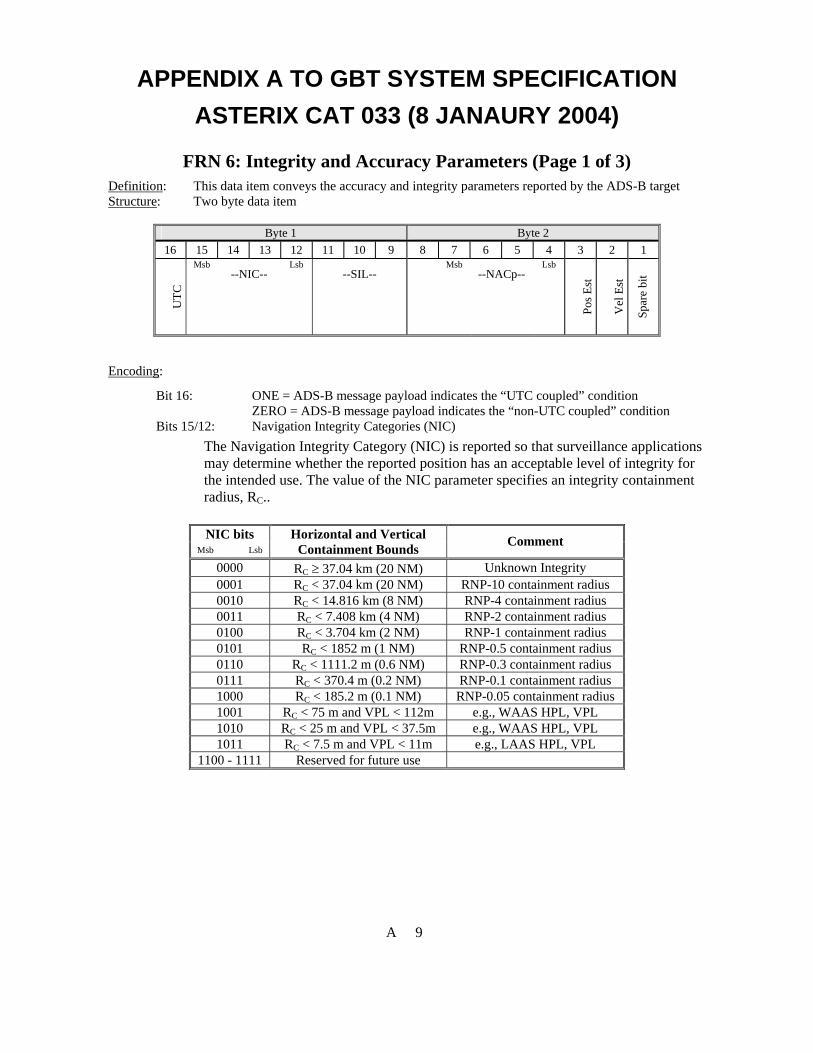
APPENDIX A TO GBT SYSTEM SPECIFICATION ASTERIX CAT 033 (8 JANAURY 2004)
FRN 6: Integrity and Accuracy Parameters (Page 1 of 3) Definition: This data item conveys the accuracy and integrity parameters reported by the ADS-B target Structure: Two byte data item
Byte 1 Byte 2 16 15 14 13 12 11 10 9 8 7 6 5 4 3 2 1
UTC
Msb --NIC--
Lsb --SIL--
Msb --NACp--
Lsb
Pos E
st
Vel
Est
Spar
e bi
t
Encoding:
Bit 16: ONE = ADS-B message payload indicates the “UTC coupled” condition ZERO = ADS-B message payload indicates the “non-UTC coupled” condition
Bits 15/12: Navigation Integrity Categories (NIC) The Navigation Integrity Category (NIC) is reported so that surveillance applications may determine whether the reported position has an acceptable level of integrity for the intended use. The value of the NIC parameter specifies an integrity containment radius, RC..
NIC bits
Msb Lsb Horizontal and Vertical
Containment Bounds Comment
0000 RC ≥ 37.04 km (20 NM) Unknown Integrity 0001 RC < 37.04 km (20 NM) RNP-10 containment radius 0010 RC < 14.816 km (8 NM) RNP-4 containment radius 0011 RC < 7.408 km (4 NM) RNP-2 containment radius 0100 RC < 3.704 km (2 NM) RNP-1 containment radius 0101 RC < 1852 m (1 NM) RNP-0.5 containment radius 0110 RC < 1111.2 m (0.6 NM) RNP-0.3 containment radius 0111 RC < 370.4 m (0.2 NM) RNP-0.1 containment radius 1000 RC < 185.2 m (0.1 NM) RNP-0.05 containment radius 1001 RC < 75 m and VPL < 112m e.g., WAAS HPL, VPL 1010 RC < 25 m and VPL < 37.5m e.g., WAAS HPL, VPL 1011 RC < 7.5 m and VPL < 11m e.g., LAAS HPL, VPL
1100 - 1111 Reserved for future use
A 9

APPENDIX A TO GBT SYSTEM SPECIFICATION ASTERIX CAT 033 (8 JANAURY 2004)
FRN 6: Integrity and Accuracy Parameters (Page 2 of 3) Bits 11/9: Surveillance Integrity Levels (SIL)
The value of the SIL parameter specifies the probability of the true position lying outside the NIC-specified containment radius, RC, without alerting, including the effects of the airborne equipment condition, which airborne equipment is in use, and which external signals are used. SIL is a static (unchanging) value that depends on the position sensor being used on the aircraft.
SIL Bits Bit 11 Bit 10 Bit 9
Probability of Unknowingly Exceeding the RC Integrity Containment Radius
0 x x SIL Not Available in this Reporting Interval 1 0 0 SIL Reported as Unknown 1 0 1 1 × 10⁻³ per flight hour or per operation 1 1 0 1 × 10⁻⁵ per flight hour or per operation 1 1 1 1 × 10⁻⁷ per flight hour or per operation
Bits 8/4: Navigation Accuracy Categories for Position (NACp)
The Navigation Accuracy Category for Position (NACp) is reported so that surveillance applications may determine whether the reported position has an acceptable level of accuracy for the intended use. The Estimated Position Uncertainty (EPU) is a 95% accuracy bound on horizontal position. EPU is defined as the radius of a circle, centered on the reported position, such that the probability of the actual position being outside the circle is 0.05. When reported by a GPS or GNSS system, EPU is commonly called HFOM (Horizontal Figure of Merit). Likewise, Vertical Estimated Position Uncertainty (VEPU) is a 95% accuracy limit on the vertical position. VEPU is defined as a vertical position limit, such that the probability of the actual vertical position differing from the reported vertical position by more than that limit is 0.05. When reported by a GPS or GNSS system, VEPU is commonly called VFOM (Vertical Figure of Merit).
A 10

APPENDIX A TO GBT SYSTEM SPECIFICATION ASTERIX CAT 033 (8 JANAURY 2004)
FRN 6: Integrity and Accuracy Parameters (Page 3 of 3) NACp Bits
Bits 7-4 Bit 8 Msb Lsb
95% Horizontal and Vertical Accuracy Bounds (EPU and VEPU)
Comment
0 xxxx NACp not available in this reporting interval
1 0000 EPU ≥ 18.52 km (10 NM) 1 0001 EPU < 18.52 km (10 NM) RNP-10 accuracy 1 0010 EPU < 7.408 km (4 NM) RNP-4 accuracy 1 0011 EPU < 3.704 km (2 NM) RNP-2 accuracy 1 0100 EPU < 1852 m (1NM) RNP-1 accuracy 1 0101 EPU < 926 m (0.5 NM) RNP-0.5 accuracy 1 0110 EPU <555.6 m ( 0.3 NM) RNP-0.3 accuracy 1 0111 EPU < 185.2 m (0.1 NM) RNP-0.1 accuracy 1 1000 EPU <92.6 m (0.05 NM) e.g., GPS (with SA) 1 1001 EPU < 30 m and VEPU < 45 m e.g., GPS (SA off) 1 1010 EPU < 10 m and VEPU < 15 m e.g., WAAS 1 1011 EPU < 3 m and VEPU < 4 m e.g., LAAS 1 1100-
1111 Reserved for future use.
Bit 3: Position Estimated: Set to ZERO when position reported is measured data; set to
ONE when position data reported is estimated data. Bit 2: Velocity Estimated: Set to ZERO when velocity reported is measured data; set to
ONE when velocity reported is estimated data. Bit 1 Spare bit always be set to ZERO
A 11
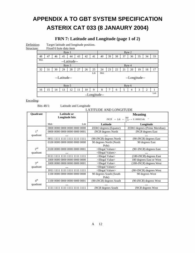
APPENDIX A TO GBT SYSTEM SPECIFICATION ASTERIX CAT 033 (8 JANAURY 2004)
FRN 7: Latitude and Longitude (page 1 of 2) Definition: Target latitude and longitude position. Structure: Fixed 6 byte data item
Byte 1 Byte 2 48 47 46 45 44 43 42 41 40 39 38 37 36 35 34 33 Msb --Latitude--
Byte 3 Byte 4 32 31 30 29 28 27 26 25 24 23 22 21 20 19 18 17
--Latitude-- Lsb Msb
--Longitude--
Byte 5 Byte 6 16 15 14 13 12 11 10 9 8 7 6 5 4 3 2 1
--Longitude-- Lsb
Encoding:
Bits 48/1: Latitude and Longitude LATITUDE AND LONGITUDE
Latitude or Longitude bits
Meaning °=== 00002146.0
2360
24LsbINCR
Quadrant
Msb Lsb Latitude Longitude 0000 0000 0000 0000 0000 0000 ZERO degrees (Equator) ZERO degrees (Prime Meridian)
1st 0000 0000 0000 0000 0000 0001 INCR degrees North INCR degrees East quadrant … … …
0011 1111 1111 1111 1111 1111 (90-INCR) degrees North (90-INCR) degrees East 0100 0000 0000 0000 0000 0000 90 degrees North (North
Pole) 90 degrees East
2nd 0100 0000 0000 0000 0000 0001 <Illegal Values> (90+INCR) degrees East quadrant … <Illegal Values> …
0111 1111 1111 1111 1111 1111 <Illegal Value> (180-INCR) degrees East 1000 0000 0000 0000 0000 0000 <Illegal Value> 180 degrees East or West
3rd 1000 0000 0000 0000 0000 0001 <Illegal Value> (180-INCR) degrees West quadrant … <Illegal Values> …
1011 1111 1111 1111 1111 1111 <Illegal Values> (90+INCR) degrees West 1100 0000 0000 0000 0000 0000 90 degrees South (South
Pole) 90 degrees West
4th 1100 0000 0000 0000 0000 0001 (90-INCR) degrees South (90-INCR) degrees West quadrant … … …
1111 1111 1111 1111 1111 1111 INCR degrees South INCR degrees West
A 12

APPENDIX A TO GBT SYSTEM SPECIFICATION ASTERIX CAT 033 (8 JANAURY 2004)
FRN 7: Latitude and Longitude (page 2 of 2) Notes: 1. This encoding is consistent with that of GPS/GNSS avionics providing Latitude/Longitude inputs to ADS-
B (ARINC data labels 110, 111, 120,121). It is also illustrated in the figure below.
A 13

APPENDIX A TO GBT SYSTEM SPECIFICATION ASTERIX CAT 033 (8 JANAURY 2004)
FRN 8: Pressure Altitude Definition: Barometric Aircraft altitude referenced to standard atmospheric pressure of 29.92 Structure: Fixed two byte data item
Byte 1 Byte 2 16 15 14 13 12 11 10 9 8 7 6 5 4 3 2 1
RES
Spar
e
Msb
--Pressure Altitude-- Lsb
Encoding: Bit 16 Resolution of altitude encoding (ZERO=100 feet; ONE=25 feet) Bit 15 Spare bit always set to ZERO Bits14/1 Binary 2’s compliment encoding of altitude with 25’ Lsb
PRESSURE ALTITUDE Pressure Altitude bits
Msb Lsb Meaning
10 0000 0000 0000 No pressure altitude information available 10 0000 0000 0001 -204775 feet 10 0000 0000 0010 -204750 feet
*** 11 1111 1111 1110 -50 feet 11 1111 1111 1111 -25 feet 00 0000 0000 0000 ZERO feet 00 0000 0000 0001 25 feet 00 0000 0000 0010 50 feet
*** 01 1111 1111 1110 204750 feet 01 1111 1111 1111 >204775 feet
Notes:
Airborne ADS-B transmitters are restricted to a range of values for Pressure Altitude of –1000 feet to + 101, 325 feet.
A 14

APPENDIX A TO GBT SYSTEM SPECIFICATION ASTERIX CAT 033 (8 JANAURY 2004)
FRN 9: Velocity (Airborne)(page 1 of 2) Definition: The Velocity reported by the aircraft indicated by the North/South and East/West Velocity and
vertical rate of change. Structure: Fixed five byte data item
Byte 1 Byte 2 40 39 38 37 36 35 34 33 32 31 30 29 28 27 26 25 sb
VV
Src
SO NS Msb
--N/S Velocity-- Lsb
Byte 3 Byte 4 24 23 22 21 20 19 18 17 16 15 14 13 12 11 10 9 EW Msb
--E/W Velocity-- Lsb U
D Msb
Byte 5 8 7 6 5 4 3 2 1
--Vertical Rate-- Lsb
Encoding: Bit 40 Spare bit, always set to ZERO Bit 39 VV Src: Indicates the source of vertical velocity (ZERO=GNSS; ONE=Baro) Bit 38 SO: Indicates the scale factor to be used for N/S and E/W velocities
(ZERO=Subsonic--0.25 kt Lsb; ONE=Supersonic—2 kt Lsb) Bit 37 NS Indicates the direction of the N/S velocity (ZERO=North; ONE=South). Bits 36/25 N/S Velocity (Ground Referenced)
NORTH/SOUTH VELOCITY (Ground Referenced) N/S Velocity bits
Msb Lsb
Meaning (when “SO”=ZERO) (N/S Velocity in knots)
Meaning (when “SO”=ONE)
(N/S Velocity in knots) 0000 0000 0000 No Information available 0000 0000 0001 ZERO 0000 0000 0010 0.25 2 0000 0000 0011 0.5 4
*** *** *** 1111 1111 1110 1023.25 8186 1111 1111 1111 > 1023.375 > 8187
The encoding shown in the table represents Positive Magnitude data only. Direction is given completely by the North/South Direction Bit.
A 15

APPENDIX A TO GBT SYSTEM SPECIFICATION ASTERIX CAT 033 (8 JANAURY 2004)
FRN 9: Velocity (Airborne) (page 2 of 2) Bit 24 EW Indicates the direction of the E/W velocity (ZERO=East; ONE=West). Bits 23/12 E/W Velocity (Ground Referenced)
EAST/WEST VELOCITY (Ground Referenced) E/W Velocity bits Msb Lsb
Meaning (when “SO”=ZERO)
(E/W Velocity in knots)
Meaning (when “SO”=ONE)
(E/W Velocity in knots) 0000 0000 0000 No Information Available 0000 0000 0001 ZERO 0000 0000 0010 0.25 2 0000 0000 0011 0.5 4
*** *** *** 1111 1111 1110 1023.25 8186 1111 1111 1111 > 1023.375 > 8187
The encoding shown in the table represents Positive Magnitude data only. Direction is given completely by the East/West Direction Bit.
Bit 11 UD Indicates vertical rate direction (ZERO=Up; ONE=Down). Bits 10/1 Vertical rate of change with 32 fpm Lsb
VERTICAL RATE Vertical Rate bits
Msb Lsb
Meaning (VERTICAL RATE in feet / minute)
00 0000 0000 No Information Available 00 0000 0001 ZERO 00 0000 0010 32 00 0000 0011 64
*** *** 11 1111 1110 32,672 11 1111 1111 >32,688
The encoding shown in the table represents Positive Magnitude data only. Direction is given completely by the Vertical Rate Sign Bit.
A 16

APPENDIX A TO GBT SYSTEM SPECIFICATION ASTERIX CAT 033 (8 JANAURY 2004)
FRN 10: Velocity (Surface) (page 1 of 2) Definition: Velocity format reported when target is known to be ON GROUND Structure: Fixed three byte data item
Byte 1 24 23 22 21 20 19 18 17
Trk/
Hdg
V
alid
Trk/
Hdg
True
/Mag
Msb --Grnd Trk/Hdg--
Byte 1 Byte 2
16 15 14 13 12 11 10 9 8 7 6 5 4 3 2 1
--Grnd Trk/Hdg-- Lsb Msb --Ground Speed-- Lsb
Encoding: Bit 24 Track/Hdg Valid (ZERO = Ground Track/Hdg data is NOT Valid; ONE = Ground
Track/Hdg data is Valid Bit 23 Track/Heading bit (ZERO= Track; ONE=Heading) Bit 22 True/Magnetic bit (ZERO=True; ONE=Magnetic) Bits 21/12 Ground Track represented as a binary number
GROUND TRACK/HEADING Grnd Trk/Hdg bits
Msb Lsb Meaning
°=== 3515625.02360
10LsbINCR
00 0000 0000 ZERO degrees 00 0000 0001 INCR degrees
*** 01 1111 1111 (180-INCR) degrees 10 0000 0000 180 degrees 10 0000 0001 (180+INCR) degrees
*** 11 1111 1111 (360-INCR) degrees
A 17

APPENDIX A TO GBT SYSTEM SPECIFICATION ASTERIX CAT 033 (8 JANAURY 2004)
FRN 10: Velocity (Surface) (page 2 of 2) Bits 11/1 Binary encoding (linear) of Ground Speed with 0.125 kt Lsb
GROUND SPEED Ground Speed bits Msb Lsb
Meaning
000 0000 0000 Ground Speed Not Available 000 0000 0001 ZERO 000 0000 0010 0.125 kts
000 0000 0011 0.250 kts *** ***
111 1111 1110 255.625 kts 111 1111 1111 > 255.750 kts
Notes: 1. Surface (polar) format is different from airborne format because the ability to discern a track angle from the
Airborne (cartesian) format suffers at low speeds. Also use of polar format allows for a heading input if available. Heading (if available) can provide more reliable information on aircraft orientation on the surface when stationary or moving very slowly.
2. Aircraft are allowed to report velocity in this format when it is known for certain they are on the surface. It is also used by surface vehicles.
3. When a TIS-B report is received with speeds greater than or equal to 255.750 knots, set the field to Ground Speed Not Available.
A 18

APPENDIX A TO GBT SYSTEM SPECIFICATION ASTERIX CAT 033 (8 JANAURY 2004)
FRN 11: Mode 3/A Code Definition: Aircraft’s Mode-3/A code assigned to the aircraft. Structure: Fixed two byte data item
Byte 1 Byte 2 16 15 14 13 12 11 10 9 8 7 6 5 4 3 2 1
Spar
e B
it
Spar
e B
it
Spar
e B
it
Mod
e-3/
A
valid
ity b
it Msb
Mode-3/A Code Lsb
Encoding:
Bits 16/14 Spare. Bit 13 Mode-3/A Validity. 1 = VALID_CODE and 0 = INVALID_CODE Bits 12/1 Mode-3/A code.
Notes:
1. Having ADS-B transmit this information has been proposed as a convenient way for existing ATC automation systems to correlate ADS-B targets with their filed flight plans as is currently done with SSR. This data item responds to Alaska Capstone Program desire to add a Mode-A code reporting capability to ADS-B in Alaska. (Provisions for this requirement are under coordination with SC-186/WG6 for possible inclusion in a future version of the ADS-B MASPS.(DO-242A). (See RTCA Paper Number SC-186-WG5/UAT-WP-14-02A, dated 14 January 2004, by Mosher, Jennings, Pagano, Furr.) SC186 WG3 is considering whether to add the Mode A code to the 1090 MHz ES system
2. “Validity” refers to whether the GBT detects when the reported Mode 3/A code is out of bounds.
A 19

APPENDIX A TO GBT SYSTEM SPECIFICATION ASTERIX CAT 033 (8 JANAURY 2004)
FRN 12: Target Identification (page 1 of 2) Definition: Target Identification (in 8 characters) reported by the aircraft/vehicle. This is generally the
radio call sign. Structure: Six byte fixed length data item
Byte 1 Byte 2 48 47 46 45 44 43 42 41 40 39 38 37 36 35 34 33 Msb (b6) --Char 1--
Lsb (b1)
Msb (b6) --Char 2--
Lsb (b1)
Msb (b6) --Char 3--
Byte 3 Byte 4 32 31 30 29 28 27 26 25 24 23 22 21 20 19 18 17
Lsb (b1)
Msb (b6) --Char 4--
Lsb (b1)
Msb (b6) --Char 5--
Lsb (b1)
Msb (b6)
Byte 5 Byte 6 16 15 14 13 12 11 10 9 8 7 6 5 4 3 2 1
--Char 6-- Lsb (b1)
Msb (b6) --Char 7--
Lsb (b1)
Msb (b6) --Char 8--
Lsb (b1)
Encoding:
Bits 48/1 Characters 1-8, coded as 6 bits per character CHARACTER ENCODING
b6 0 0 1 1 Character N bits b5 0 1 0 1
b4 b3 b2 b1 0 0 0 0 P sp 0 0 0 0 1 A Q 1 0 0 1 0 B R 2 0 0 1 1 C S 3 0 1 0 0 D T 4 0 1 0 1 E U 5 0 1 1 0 F V 6 0 1 1 1 G W 7 1 0 0 0 H X 8 1 0 0 1 I Y 9 1 0 1 0 J Z 1 0 1 1 K 1 1 0 0 L Illegal Values 1 1 0 1 M 1 1 1 0 N 1 1 1 1 O
A 20

APPENDIX A TO GBT SYSTEM SPECIFICATION ASTERIX CAT 033 (8 JANAURY 2004)
FRN 12: Target Identification (page 2 of 2) Notes: 1. Character 1 is leftmost 2. Characters must be left justified using <space> fill if less than 8 characters are used
A 21

APPENDIX A TO GBT SYSTEM SPECIFICATION ASTERIX CAT 033 (8 JANAURY 2004)
FRN 13: Emitter Category Definition: The target’s category code for the current position report. Structure: Fixed one byte data item
Byte 1 8 7 6 5 4 3 2 1
Msb
--Category Code-- Lsb
sb
Encoding:
Bits 8/3 Category Code CATEGORY CODE
Category Code bits (decimal) Msb Lsb
Meaning
0 00 0000 No aircraft type information 1 00 0001 Light (< 15 500 lbs) 2 00 0010 Small (15 500 to 75 000 lbs) 3 00 0011 Large (75 000 to 300 000 lbs) 4 00 0100 High Vortex Large 5 00 0101 Heavy (> 300 000 lbs) 6 00 0110 High Performance (> 5G acceleration) 7 00 0111 Rotocraft 8 00 1000 (Unassigned) 9 00 1001 Glider/sailplane 10 00 1010 Lighter than air 11 00 1011 Parachutist/sky diver 12 00 1100 Ultra light/hang glider/paraglider 13 00 1101 (Unassigned) 14 00 1110 Unmanned aerial vehicle 15 00 1111 Space/transatmospheric vehicle 16 01 0000 (Unassigned) 17 01 0001 Surface vehicle—emergency vehicle 18 01 0010 Surface vehicle—service vehicle 19 01 0011 Fixed ground or tethered obstruction 20 01 0100 Cluster Obstacle 21 01 0101 Line Obstacle
22-63 (Unassigned)
Bits 2/1 Spare Bits always set to ZERO
A 22

APPENDIX A TO GBT SYSTEM SPECIFICATION ASTERIX CAT 033 (8 JANAURY 2004)
FRN 14: Target Status Definition: Status information currently being reported by the target. Structure: Fixed one byte data item byte data item
Byte 1 8 7 6 5 4 3 2 1
Rec
eivi
ng A
TC
Serv
ices
IDEN
T
Spar
e bi
t
Spar
e bi
t
Msb Status Code
Lsb
Encoding:
Bit 8 ONE indicates the airspace user is receiving ATC services; ZERO indicates the airspace user is NOT receiving ATC services
Bit 7 ONE indicates the avionics is in the IDENT condition; ZERO indicates the avionics is NOT in the IDENT condition
Bits 6/5 Spare bits always set to ZERO Bits 4/1 Status Code
STATUS CODES Status Code bits
(decimal) Msb Lsb Meaning
0 0000 No emergency/Not reported 1 0001 General emergency 2 0010 Lifeguard/medical emergency 3 0011 Minimum fuel 4 0100 No communications 5 0101 Unlawful interference (hijacking) 6 0110 Downed Aircraft
7-15 0111-1111 (Reserved for future definition
A 23

APPENDIX A TO GBT SYSTEM SPECIFICATION ASTERIX CAT 033 (8 JANAURY 2004)
FRN 15: Geometric Altitude Definition: Aircraft altitude derived from GNSS, INS or ground-based measurement (e.g., Multilateration)
represented as Height Above Ellipsoid (HAE) Structure: Fixed two byte data item
Byte 1 Byte 2 16 15 14 13 12 11 10 9 8 7 6 5 4 3 2 1 Msb
--Geometric Altitude (HAE)-- Lsb
Encoding:
Bits16/1 Binary 2’s compliment encoding of altitude with 6.25’ Lsb ALTITUDE (GEOMETRIC)
Geometric Altitude bits Msb Lsb
Meaning
1000 0000 0000 0000 No geometric altitude information available 1000 0000 0000 0001 -204793.75 feet 1000 0000 0000 0100 -204775 feet 1000 0000 0000 1000 -204750 feet
*** 1111 1111 1111 1000 -50 feet 1111 1111 1111 1100 -25 feet 1111 1111 1111 1111 -6.25 feet 0000 0000 0000 0000 ZERO feet 0000 0000 0000 0001 6.25 feet 0000 0000 0000 0100 25 feet 0000 0000 0000 1000 50 feet
*** 0111 1111 1111 1000 204750 feet 0111 1111 1111 1100 204775 feet 0111 1111 1111 1111 >204793.75 feet
Notes:
1.
Encoding consistent with Pressure Altitude item with the exception of two additional bits of precision which appear here.
A 24

APPENDIX A TO GBT SYSTEM SPECIFICATION ASTERIX CAT 033 (8 JANAURY 2004)
FRN 16: Reserved for Future Data Item
A 25

APPENDIX A TO GBT SYSTEM SPECIFICATION ASTERIX CAT 033 (8 JANAURY 2004)
FRN 17: Time of Message Transmission Definition: The time at which the ADS-B message was transmitted from the aircraft/vehicle expressed as
fractional seconds from the UTC second. Structure: Fixed four byte data item
Byte 1 Byte 2 32 31 30 29 24 18 28 27 26 25 23 22 21 20 19 17 Msb --Time of Message Transmission--
Byte 3 Byte 4 16 15 12 11 9 6 4 3 14 13 10 8 7 5 2 1
--Time of Message Transmission-- Lsb
Encoding:
Bits 32/1 Time of message transmission encoded as nanoseconds elapsed after the UTC 1 second time mark.
TIME OF MESSAGE TRANSMISSION Time of Message Transmission bits
Msb Lsb
Meaning nanosecond2328.0
2sec1
32 === LsbINCR
0000 0000 0000 0000 0000 0000 0000 0000 Message transmitted on the UTC second 0000 0000 0000 0000 0000 0000 0000 0001 Message transmitted on the UTC
second plus INCR
… … 1111 1111 1111 1111 1111 1111 1111 1111 Message transmitted on the UTC second
plus (1- INCR)
Notes: 1. This data item, in conjunction with FRN 18 (Time of Message Reception) can be used to derive a range to
target that is independent of the ADS-B-derived range. This can be used to provide a degree of added surveillance integrity
2. FRN #4 (Time of Applicability) defines the whole second part to which this fractional second measurement applies
3. This data item will have to be derived within the GBT based on protocols specific to a particular ADS-B data link.
A 26
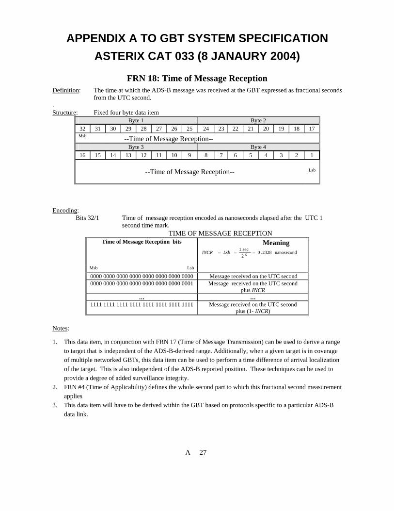
APPENDIX A TO GBT SYSTEM SPECIFICATION ASTERIX CAT 033 (8 JANAURY 2004)
FRN 18: Time of Message Reception Definition: The time at which the ADS-B message was received at the GBT expressed as fractional seconds
from the UTC second. . Structure: Fixed four byte data item
Byte 1 Byte 2 32 31 30 29 28 27 26 25 24 23 22 21 20 19 18 17 Msb --Time of Message Reception--
Byte 3 Byte 4 16 15 14 13 12 11 10 9 8 7 6 5 4 3 2 1
--Time of Message Reception-- Lsb
Encoding:
Bits 32/1 Time of message reception encoded as nanoseconds elapsed after the UTC 1 second time mark.
TIME OF MESSAGE RECEPTION Time of Message Reception bits Meaning
nanosecond2328.02sec1
32 === LsbINCR
Msb Lsb 0000 0000 0000 0000 0000 0000 0000 0000 Message received on the UTC second 0000 0000 0000 0000 0000 0000 0000 0001 Message received on the UTC second
plus INCR … …
1111 1111 1111 1111 1111 1111 1111 1111 Message received on the UTC second plus (1- INCR)
Notes:
1. This data item, in conjunction with FRN 17 (Time of Message Transmission) can be used to derive a range to target that is independent of the ADS-B-derived range. Additionally, when a given target is in coverage of multiple networked GBTs, this data item can be used to perform a time difference of arrival localization of the target. This is also independent of the ADS-B reported position. These techniques can be used to provide a degree of added surveillance integrity.
2. FRN #4 (Time of Applicability) defines the whole second part to which this fractional second measurement applies
3. This data item will have to be derived within the GBT based on protocols specific to a particular ADS-B data link.
A 27


APPENDIX B TO GBT SYSTEM SPECIFICATION ASTERIX CAT 023 (8 JANUARY 2004)
B.1 General
The format for target reports is based on the ASTERIX message standard adopted by Eurocontrol for surveillance data exchange. For background information on the ASTERIX structure and encoding see the document entitled, “Eurocontrol Standard Document for Surveillance Data Exchange, Part 1, ASTERIX,” SUR.ET1.ST05.2000-STD-01-01, November 1997. This document is available at http://www.eurocontrol.be/projects/eatchip/asterix.
A User Application Profile (UAP) is a mechanism for assigning Data Item to Data Fields of ASTERIX messages and containing all necessary information which needs to be standardized for the successful encoding and decoding of the messages. An ASTERIX Data Category (CAT) is defined by a set of Data Items that could be included in valid messages of that category. The ASTERIX Data Category for periodic Status reports from the GBT has been given the assignment “023”8. This value, which is normally the first Data Item in a Data Block, is also interpreted to be the BSDU ID field (Section 3.2).
The Field Reference Number (FRN) establishes the order of the items in the FSPEC, and along with the Category code serves to uniquely identify each data item. In order to maximize compatibility with future versions of this category, these data items will retain the same FRN and order in the FSPEC while new items may be added onto the end of the FSPEC.
8 This category number is being established for use within the NAS; this category definition has not been approved by Eurocontrol
B -1

APPENDIX B TO GBT SYSTEM SPECIFICATION ASTERIX CAT 023 (8 JANUARY 2004)
B.2 Target Report Construction Example
TimeFSPEC FRN 1 Version Number FRN 2
Data Source ID
FRN 3 Time of Status Report
FRN 4 GBT Status
FRN 5 Internal GPS Integrity and Accuracy Params
FRN 6 Latitude/Logitude
FRN 7 ADS-B messages Discarded
FRN 8 TIS-B reports Discarded
FRN 9 Uplink Data Blocks Discarded
F1 F2 F3 F4 F5 F6 F7 FX F8 F9 F10 F11 F12 F13 F14 FX 1 1 1 1 1 1 1 1 1 1 0 0 0 0 0 0
3. Within each Data Item, Byte 1 is transmitted first 4. “FX” is the Field Extension bit. A ONE in this bit indicates the field extends into the next byte.
B -2

APPENDIX B TO GBT SYSTEM SPECIFICATION ASTERIX CAT 023 (8 JANUARY 2004)
B.3 User Application Profile and Construction for Cat 023 Target Reports Table B-2. Cat 023 (V 1) User Application Profile and Construction
FRN Data Item Length in Bytes (when present)
1 Version Number 1 2 Data Source Identifier 2 3 Time of Status Report 3 4 GBT Status 1 5 Internal GPS Integrity and Accuracy
Paramters 2
6 Latitude/Longitude 6 7 ADS-B Messages Discarded 2 8 TIS-B Reports Discarded 2 9 Uplink Data Blocks Discarded 2
Note: Systems receiving Cat 023 reports must parse the FSPEC for proper decoding since some Data Items are optional in any given report.
B -3

APPENDIX B TO GBT SYSTEM SPECIFICATION ASTERIX CAT 023 (8 JANUARY 2004)
B.4 Format and Encoding of Cat 023 (V 1.0) Data Items
FRN 1: Version Number Definition: Version of this Cat 033 format. Structure: One byte fixed length data item
Byte 1 8 7 6 5 4 3 2 1
Spar
e bi
t
Spar
e bi
t
Ver
sion
Sta
tus Msb
Version Number
Lsb
Encoding: Bits 8/7: Spare bits always set to ZERO Bit 6: ZERO=Version for operational use; ONE=Version is for experimental use only
Notes
Bits 5/1: Cat 023 version number encoded as binary numeral in the range of 1 to 31 (Value of ZERO represents “unknown” version regardless of “Version Status”.
Category 023 messages conforming to this document shall be encoded
with the value ONE in the Version Number field (Bits 5/1).
: 2. This provides an upgrade path for evolution of this Category without incrementing the Category number
modulo 32.
B -4

APPENDIX B TO GBT SYSTEM SPECIFICATION ASTERIX CAT 023 (8 JANUARY 2004)
FRN 2: Data Source Identifier Definition: Identification of the system supplying surveillance data. Structure: Two byte fixed length data item
Byte 1 Byte 2 16 15 14 13 12 11 10 9 8 7 6 5 4 3 2 1
Msb --SAC--
Lsb Msb --SIC--
Lsb
Encoding: bits 16/9: (SAC)System Area Code (0 → 255) bits 8/1: (SIC)System Identification Code (0 → 255)
Notes: 3. The SAC is used to identify regions of the world. 4. The SIC is used to identify individual systems (e.g., ADS-B receiver or TIS-B transmitter, radar/beacon
sensor, multisensor fusion processor, etc)
B -5

APPENDIX B TO GBT SYSTEM SPECIFICATION ASTERIX CAT 023 (8 JANUARY 2004)
FRN 3: Time Of Status Report Definition: Time at which the Status report information was recorded Structure: Three byte fixed data item
Byte 1 24 23 22 21 20 19 18 17
Msb --Time of Status Report--
Byte 2 Byte 3
16 15 14 13 12 11 10 9 8 7 6 5 4 3 2 1
--Time of Status Report-- Lsb
Encoding:
Bits 24/8 whole seconds elapsed since UTC midnight binary encoded Bits 7/1 fractional seconds elapsed since UTC midnight binary encoded
Notes: 3. The time of the day value is reset to 0 at every midnight. The time of the day is specified in UTC. 4. The Lsb represents 1/128 of a second
B -6

APPENDIX B TO GBT SYSTEM SPECIFICATION ASTERIX CAT 023 (8 JANUARY 2004)
FRN 4: GBT Status Definition: Reports the status of the GBT functional elements Structure: One byte fixed length data item
Byte 1 8 7 6 5 4 3 2 1
GB
T Ti
min
g St
atus
Rec
eive
r Sta
tus
Tran
smitt
er S
tatu
s
Ala
rm
Msb
GB
T St
ate
Lsb
Ale
rt
Encoding:
Bit 8: GBT Timing Status: ONE = UTC coupled; ZERO = non-UTC coupled (i.e., coasting)
Bit 7: Receiver Status: ONE = Normal; ZERO = Alarm condition (i.e., GBT-detected fault) Bit 6: Transmitter Status: ONE = Normal; ZERO = Alarm condition (i.e., GBT-detected
fault) Bit 5: Alarm Status: ONE = Normal; ZERO = Alarm Bits 4/3 GBT State: (see table below)
GBT State bits
Msb Lsb Meaning
000 Off Line State 001 On Line State 010 (Reserved) 011 (Reserved) 100 (Reserved) 101 (Reserved) 110 (Reserved) 111 (Reserved)
Bit 1: Alert Status: ONE = Normal; ZERO = Alert.
Notes: 1. Only two of the GBT states are reportable in a Status report since all other states result in no data
output on the Ground Interface.
B -7

APPENDIX B TO GBT SYSTEM SPECIFICATION ASTERIX CAT 023 (8 JANUARY 2004)
FRN 5: Internal GPS Indicators of GPS System Health Status (Page 1 of 2) Definition: This data item conveys the GPS system health parameters reported by the GBT internal GPS
timing source. Structure: Fixed two byte data item
Byte 1 Byte 2 16 15 14 13 12 11 10 9 8 7 6 5 4 3 2 1
Msb Lsb Msb Lsb Msb Lsb sb RCVR Status Antenna Geometry sb
Encoding:
Bits 16-14: GPS Receiver Status
Status bits
Msb Lsb Meaning
111 3D Fix 110 2D Fix 101 Propagate Mode 100 Position Hold 011 Acquiring Satellites 010 Bad Geometry 001 Reserved 000 GBT Not Receiving Status
Message from GPS Module (ignore remainder of FRN 5)
Ant. Sense
Bits 13-12 Antenna Sense
Msb Lsb Meaning
00 OK 01 Over Current 10 Under Current 11 No Voltage
B -8

APPENDIX B TO GBT SYSTEM SPECIFICATION ASTERIX CAT 023 (8 JANUARY 2004)
FRN 5: Internal GPS Indicators of GPS System Health Status (Page 2 of 2) Bits 11-2: Geometry (PDOP for 3D fix, HDOP for 2D fix)
Geometry Msb Lsb
Meaning
0000000000 0.0 0000000001 0.1 0000000010 0.2
… … 1111100101 99.7 1111100110 99.8 1111100111 99.9
Bit 1: Spare bit always set to ZERO.
B -9

APPENDIX B TO GBT SYSTEM SPECIFICATION ASTERIX CAT 023 (8 JANUARY 2004)
FRN 6: Latitude and Longitude (page 1 of 2) Definition: GBT latitude and longitude position as determined from the GBT internal GPS sensor. Structure: Fixed 6 byte data item
Byte 1 Byte 2 48 47 46 45 44 43 42 41 40 39 38 37 36 35 34 33 Msb --Latitude--
Byte 3 Byte 4 32 31 30 29 28 27 26 25 24 23 22 21 20 19 18 17
--Latitude-- Lsb Msb --Longitude-- Byte 5 Byte 6
16 15 14 13 12 11 10 9 8 7 6 5 4 3 2 1
--Longitude-- Lsb
Encoding:
Bits 48/1: Latitude and Longitude
LATITUDE AND LONGITUDE
Latitude or Longitude bits
Meaning °=== 00002146.0
2360
24LsbINCR
Quadrant
Msb Lsb Latitude Longitude 0000 0000 0000 0000 0000 0000 ZERO degrees (Equator) ZERO degrees (Prime Meridian)
1st 0000 0000 0000 0000 0000 0001 INCR degrees North INCR degrees East quadrant … … …
0011 1111 1111 1111 1111 1111 (90-INCR) degrees North (90-INCR) degrees East 0100 0000 0000 0000 0000 0000 90 degrees North (North
Pole) 90 degrees East
2nd 0100 0000 0000 0000 0000 0001 <Illegal Values> (90+INCR) degrees East quadrant … <Illegal Values> …
0111 1111 1111 1111 1111 1111 <Illegal Value> (180-INCR) degrees East 1000 0000 0000 0000 0000 0000 <Illegal Value> 180 degrees East or West
3rd 1000 0000 0000 0000 0000 0001 <Illegal Value> (180-INCR) degrees West quadrant … <Illegal Values> …
1011 1111 1111 1111 1111 1111 <Illegal Values> (90+INCR) degrees West 1100 0000 0000 0000 0000 0000 90 degrees South (South
Pole) 90 degrees West
4th 1100 0000 0000 0000 0000 0001 (90-INCR) degrees South (90-INCR) degrees West quadrant … … …
1111 1111 1111 1111 1111 1111 INCR degrees South INCR degrees West
B -10

APPENDIX B TO GBT SYSTEM SPECIFICATION ASTERIX CAT 023 (8 JANUARY 2004)
FRN 6: Latitude and Longitude (page 2 of 2) Notes: 2. This encoding is consistent with that of GPS/GNSS avionics providing Latitude/Longitude inputs to ADS-
B (ARINC data labels 110, 111, 120,121). It is also illustrated in the figure below.
B -11

APPENDIX B TO GBT SYSTEM SPECIFICATION ASTERIX CAT 023 (8 JANUARY 2004)
FRN 7: ADS-B Messages Discarded Definition: A count of ADS-B messages that were discarded this Status reporting interval. Structure: Fixed two byte data item
Byte 1 Byte 2 16 15 14 13 12 11 10 9 8 7 6 5 4 3 2 1 Msb
--Discard Count-- Lsb
Encoding: Bit 16/1 Count of discarded ADS-B messages this Status reporting interval binary encoded
B -12

APPENDIX B TO GBT SYSTEM SPECIFICATION ASTERIX CAT 023 (8 JANUARY 2004)
FRN 8: TIS-B Reports Discarded Definition: A count of TIS-B reports that were discarded this Status reporting interval. Structure: Fixed two byte data item
Byte 1 Byte 2 16 15 14 13 12 11 10 9 8 7 6 5 4 3 2 1 Msb
--Discard Count-- Lsb
Encoding: Bit 16/1 Count of discarded TIS-B reports this Status reporting interval binary encoded
B -13
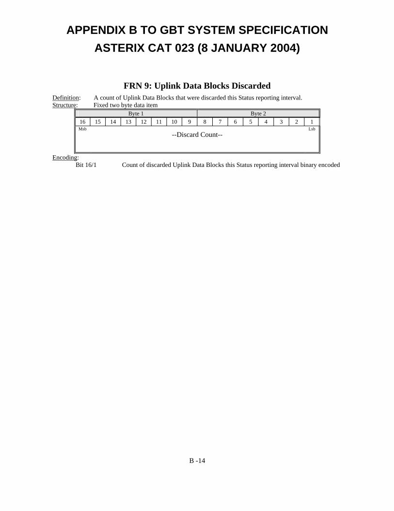
APPENDIX B TO GBT SYSTEM SPECIFICATION ASTERIX CAT 023 (8 JANUARY 2004)
FRN 9: Uplink Data Blocks Discarded Definition: A count of Uplink Data Blocks that were discarded this Status reporting interval. Structure: Fixed two byte data item
Byte 1 Byte 2 16 15 14 13 12 11 10 9 8 7 6 5 4 3 2 1 Msb
--Discard Count-- Lsb
Encoding: Bit 16/1 Count of discarded Uplink Data Blocks this Status reporting interval binary encoded
B -14