Greenfield Gateway Phase II SR9 Median Hardscape Elements
233
000101 - 1 Greenfield Gateway Phase II SR9 Median Hardscape Elements Department of Engineering Greenfield, Indiana Chuck Fewell – Mayor Jason Koch – City Engineer PROJECT MANUAL \ Hitchcock Design Group 363 North Illinois Street, Suite 2 Indianapolis, Indiana 46204 Phone: 317.536.6161 Web Site: www.hitchcockdesigngroup.com Issued: 11/05/2021 Copyright 2020 Hitchcock Design Group. All rights reserved.
-
Upload
khangminh22 -
Category
Documents
-
view
0 -
download
0
Transcript of Greenfield Gateway Phase II SR9 Median Hardscape Elements

000101 - 1
Greenfield Gateway Phase II SR9 Median Hardscape Elements
Department of Engineering Greenfield, Indiana
Chuck Fewell – Mayor
Jason Koch – City Engineer
PROJECT MANUAL
\
Hitchcock Design Group
363 North Illinois Street, Suite 2 Indianapolis, Indiana 46204
Phone: 317.536.6161 Web Site: www.hitchcockdesigngroup.com
Issued: 11/05/2021 Copyright 2020 Hitchcock Design Group. All rights reserved.

Greenfield Gateway Phase II – SR9 Median Hardscape Elements Hitchcock Design Group
SEALS PAGE 00 0107 - 1
DOCUMENT 00 0107 - SEALS PAGE
1.1 DESIGN PROFESSIONALS OF RECORD
A. Landscape Architect:
1. Hitchcock Design Group 2. IN20000005 3. Responsible for Divisions 00, 04, 10, 31, 32 Sections except where indicated as
prepared by other design professionals of record.
B. Civil Engineer:
1. American Structurepoint 2. PE 11800845 3. Responsible for Divisions regarding Maintenance of Traffic details. INDOT
Standards Chapter 503 shall be referenced and followed.
C. Structural Engineer:
1. McComas/O’Donnell & Naccarato Structural Engineers 2. PE 60860325 3. Responsible for Division 3.
D. Electrical Engineer:
1. Loftus Engineering, Inc. 2. PE 19400288 3. Responsible for Division 26.
E. Landscape Irrigation Designer:
1. Irrigation Design Source 2. 012984 3. Responsible for Division 32 8000.
END OF DOCUMENT 000107

Greenfield Gateway Phase II – SR9 Median Hardscape Elements Hitchcock Design Group
TABLE OF CONTENTS 000115 - 1
DOCUMENT 000115 – TABLE OF CONTENTS
1.1 LIST OF DRAWINGS
A. Drawings: Drawings consist of the Contract Drawings and other drawings listed on the Table of Contents page of the separately bound drawing set titled Greenfield Gateway Phase II – SR9 Median Hardscape Elements, dated August 27, 2021, as modified by subsequent Addenda and Contract modifications.
1.2 SPECIFICATION SECTIONS
Section No. Section Title
Division 00 / 01 – Procurement / General Requirements
00 0001 City of Greenfield Contract Documents
Division 3 – Concrete
03 3000 Cast-in-Place Concrete
Division 4 – Masonry
04 4313.13 Anchored Stone Masonry Veneer
Division 10 – Specialties
10 0001 Decorative Light Beacons
Division 26 – Electrical
26 0001 Basic Electrical Requirements
26 0002 Common Work Results for Electrical
26 0526 Grounding and Bonding
26 0533 Raceways and Fittings
26 0553 Electrical Identification
26 0943 Lighting Control Systems
26 2101 Conductors and Cables
26 2300 Enclosed Switches and Circuit Breakers
26 2416 Panelboards

Greenfield Gateway Phase II – SR9 Median Hardscape Elements Hitchcock Design Group
TABLE OF CONTENTS 000115 - 2
26 2725 Boxes and Enclosures
26 2726 Wiring Devices
26 2813
26 4313
Fuses
Surge Protection Systems
26 5100 Lighting Equipment
26 5113 Luminaires List
Division 31 – Earthwork
31 2000 Site Grading and Earthwork
Division 32 Exterior Improvements
32 1316 Decorative Concrete Paving
32 1373 Concrete Paving Joint Sealants
32 8400 Planting Irrigation
32 9200 Soil Preparation
32 9300 Plants
END OF DOCUMENT 00 0115

Bv1 - 08/2018
SUBJECT PAGES NOTICE TO BIDDERS NTB-1 INSTRUCTIONS TO BIDDERS ITB-1 BIDDER’S ITEMIZED PROPOSAL AND DECLARATIONS BID-1 POST BID SUBMITTAL POST-BID-1 BID BOND BB-1 WARRANTY BOND WB-1 PAYMENT BOND PMB-1 PERFORMANCE BOND PFB-1 AGREEMENT A-1 ADDITIONAL REQUIREMENTS AR-1 SPECIAL CONDITIONS SC-1 TECHNICAL SPECIFICATIONS - MATERIAL WORKMANSHIP TS-1

Bv1 - 08/2018 NTB-1
NOTICE TO BIDDERS City of Greenfield
Department: Department of Engineering 10 S. State Street Greenfield, Indiana 46140 Project/Work: Greenfield Gateway Phase II – SR9 Median Hardscape Elements
Notice is hereby given that the City of Greenfield will receive sealed bids for the above described “Project/Work” at Clerk-Treasurer’s Office, 10 S. State Street, Greenfield, Indiana, until 10:00 a.m. prevailing local time, 10 S. State Street, on December 14, 2021, and commencing as soon as practicable thereafter on the same date such bids will be publicly opened. No late Bids will be accepted.
A Bid Bond or certified check in an amount not less than five percent (5%) of the amount bid must be submitted with each Bid. A one hundred percent (100%) Performance and Payment Bond will also be required of the successful Bidder.
The Work consists of, but is not necessarily limited to the following:
Median landscape improvements along SR9 from Opportunity Parkway to McKenzie Road. The improvements include concrete aprons and curbing, custom light beacons, banner poles, landscape plantings and irrigation. The project does include two alternates.
Contract Documents for the Project/Work have been assembled into one or more bound Project
Manuals which, together with Drawings, may be examined the Clerk-Treasurer’s Office or the Department of Engineering at 10 S. State Street, Greenfield, Indiana 46140. Electronic copies of the Drawings and Project Manuals will be available on the City of Greenfield website at https://www.greenfieldin.org/government/engineering. Bidders will be responsible to contact the Clerk-Treasurers office to be added to the plan-holders list if downloading electronic contract documents.
Bidders shall assure that they have obtained complete sets of drawings and Contract Documents and shall assume the risk of any errors or omissions in Bids prepared in reliance on incomplete sets of drawings and Contract Documents.
A pre-bid conference for discussion of the Work is MANDATORY for bidders of the project
and will be held on November 16, 2021 at 2:30 pm at Larry Breese Conference Room in City Hall. All prospective Bidders are required to attend the pre-bid conference to learn about the project. If you cannot be present at the pre-bid conference, reach out to Shannon Creasy at Hitchcock Design Group ([email protected]) by Monday, November 15, 2021, at noon for a link to access the conference virtually.
For accommodations needed by persons with disabilities to attend the public bid opening meeting, please call (317) 477-4320.
The City of Greenfield reserves the right to reject any or all bids or to waive any informalities
and to accept the bid which it deems most favorable to the interests of the City after all bids have been examined and canvassed.
Bv1 - 08/2018 ITB-1
INSTRUCTIONS TO BIDDERS City of Greenfield Department (“Owner”): Department of Engineering
10 S. State Street Greenfield, Indiana 46140
Project/Work: Greenfield Gateway Phase II – SR9 Median Hardscape Elements Owner’s Representative: Jason Koch Landscape Architect: Hitchcock Design Group 1. GENERAL 1.1 Submission of a Bid shall constitute an unconditional agreement and acknowledgment by the
Bidder to be bound by all terms and conditions set forth herein and in any of the documents assembled or referred to in the bound Project Manual of which these Instructions to Bidders are a part.
1.2 Sample forms are included in the Project Manual to acquaint Bidders with the form and
provisions of various Bid Documents and other documentation required by the Contract Documents to be executed, completed and submitted by some or all Bidders, either as part of a Bid Submission or after the Bid Date. Such sample forms are not to be detached from the Project Manual or filled out or executed. Separate copies of such forms and any other required documentation prescribed by the Contract Documents have been or will be furnished separately by the Owner and must be obtained directly from the City.
1.3 Instructions and requirements printed on any sample form included in the Project Manual or any
form not so included but required to be completed, signed or furnished by a Bidder as part of a Bid Submission or after receipt and opening of Bids shall be deemed requirements established by these Instructions to Bidders to the same extent as if fully restated herein.
1.4 By submitting bid the Bidder agrees the bid proposal and price(s) contained herein shall be valid
for ninety (90) days from bid opening. 2. DEFINITIONS
The following definitions shall apply to these Instructions to Bidders (ITB): 2.1 Bidder - Any person or entity who submits a Bid. 2.2 Bid - A written proposal submitted by a Bidder as part of the form prescribed herein offering to
perform and complete the Work and to fulfill all other requirements of the Contract Documents for one or more specified prices.
2.3 Bid Documents - All documents and completed forms required to be submitted by a Bidder with
and as integral parts of a Bid Submission, whether or not included as sample forms assembled in the Project Manual of which these Instructions to Bidders are a part. Such Bid Documents are listed and more fully described in ITB Section 5.3 hereof.

Bv1 - 08/2018 ITB-2
2.4 Bid Date - The date when Bids are to be received, opened and publicly read aloud as established
by the Notice to Bidders as may be modified by Addenda. 2.5 Bid Submission - All documents presented by a Bidder for receipt and opening on the Bid Date. 2.6 Contract Documents - The Agreement and any exhibits thereto, Addenda (which pertain to the
Contract Documents), Instructions to Bidders, Advertisement, Notice to Bidders, Bidder’s Bid (including documentation accompanying the Bid and any post-Bid documentation submitted prior to the Notice of Award), Notice to Proceed, the Bonds, the General Conditions, the Additional Requirements Section, any supplemental or special conditions, the Specifications and the Drawings, as the same are more specifically identified in the Agreement.
2.7 E-Verify Program - An electronic verification of work authorization program of the Illegal
Immigration Reform and Immigration Responsibility Act of 1996 (P.L. 104-208), Division C, Title IV, s.403(a), as amended, operated by the United States Department of Homeland Security or successor work authorization program designated by the United States Department of Homeland Security or other federal agency authorized to verify the work authorization status of newly hired employees under the Immigration Reform and control Act of 1986 (P.L. 99-603).
2.8 Owner - The City of Greenfield acting by and through the Department or other agency
designated above. 2.9 Project Manual - The bound set of documents, sample forms, and Contract Documents
(excluding plans and Addenda) approved by the Owner for the Work and/or Project described in the Notice to Bidders and of which these Instructions to Bidders are a part.
In all other respects, terms used herein shall have the meanings as stated in the General Conditions or other Contract Documents. 3. EXAMINATION OF SITE AND DOCUMENTS 3.1 Before the Bid Date, all Bidders shall carefully and thoroughly examine and inspect the entire
site of the proposed Work and adjacent premises and the various means of approach and access thereto by means of a site inspection visit, and make all necessary investigations to inform themselves thoroughly as to the facilities necessary for delivering, placing and operating the necessary construction equipment, and for delivering and handling materials at the site, and shall inform themselves thoroughly as to any and all actual or potential difficulties, hindrances, delays and constraints involved in the commencement, prosecution and completion of the proposed Work in accordance with the requirements of the Contract Documents.
3.2 It shall be the sole responsibility of Bidders to make borings, test pits and to conduct such other
investigations at or near the site of the proposed Work as they deem necessary to determine the character, location, and amount of materials to be encountered or other subsurface conditions which could affect the manner, cost or time required to perform the Work.
3.3 Bidders shall carefully and thoroughly examine the plans, specifications and other Contract
and/or Project Manual Documents and shall assume the full risk of their own judgments as to the nature, quality and amount of the whole of the Work to be done, and for the price bid must assume all risk of any and all variances or errors in any computation or statement of amounts or quantities necessary to complete the Work in strict compliance with the Contract Documents.

Bv1 - 08/2018 ITB-3
3.4 Elevations of the existing ground surface or structures at the site of the Work as shown on the
plans are believed to be reasonably correct, but are not guaranteed to be absolutely so and are presented only as an approximation. Bidders shall satisfy themselves as to the correctness of all elevations.
3.5 Information stated or depicted on plans concerning the location, dimensions, depth and other
characteristics of underground structures and utilities is given only as general information and shall not be construed or relied upon by Bidders as a representation or assurance that such structures or utilities will be found or encountered as plotted, or that such information is complete or accurate. Bidders, therefore, shall satisfy themselves by such means as they may deem proper as to the location of all structures and utilities that may be encountered in construction of the Work and shall bear the risk of the number, type, location, dimensions and depth of all structures and utilities thus encountered.
3.6 The City of Greenfield Standard General Conditions for Construction Contracts, August 2018, is
incorporated by reference as part of this bid. Copy of General Conditions are available at https://www.greenfieldin.org/government/engineering.
4. CLARIFICATIONS AND ADDENDA 4.1 If a Bidder finds conflicts, errors, discrepancies or ambiguities in the Contract Documents or any
sample form, or if the Bidder is in doubt as to the intended meaning of any portion or provision therein, the Bidder shall at once give written notice thereof to the Owner’s Representative, at least seven (7) consecutive calendar days prior to the Bid Date. No Bidder shall be allowed any extra compensation or time extension by reason of any conflict, error, discrepancy or ambiguity of which the Bidder had actual knowledge or reasonably should have known and which he/she failed to report within the period and in the manner required by these Instructions to Bidders.
4.2 No material changes, clarifications or interpretations of the Contract Documents will be issued
except by written or graphic Addenda mailed or delivered to record holders of Contract Documents not less than three (3) days prior to the Bid Date. All such Addenda must be acknowledged by the Bidder and will become a part of the Contract Documents. The Owner will not be responsible for or bound by any oral or written interpretations or clarifications of the Contract Documents which anyone presumes to make on its behalf, except by an Addendum issued in accordance with this Section.
5. BID SUBMISSION 5.1 All Bid Documents shall be placed within a sealed envelope which shall be plainly labeled on the
outside with the name and address of the Bidder, Project name and number (if applicable) and Due Date. If forwarded by mail, the sealed envelope must be enclosed in another envelope addressed to: City of Greenfield, Clerk-Treasurer, 10 S. State Street, Greenfield, Indiana 46140.
5.2 All Bid Documents as herein prescribed must be submitted with and as integral parts of each Bid
Submission and shall be subject to all requirements of the Contract Documents, including drawings and these Instructions to Bidders. Bid Documents must be properly filled in and completed in every material respect and without interlineations, excisions, special conditions, qualifications or exceptions. Each Bid Document requiring a signature shall be signed by an individual duly authorized to execute such document on Bidder’s behalf. A bid executed by a corporation, joint venture, or other entity with an assumed name shall have the legal and correct

Bv1 - 08/2018 ITB-4
name thereof followed by the word “by” and the signature and title of the officer or other person authorized to sign for it.
5.3 The Bid Documents to be thus submitted by each Bidder shall consist of all of the following
(5.3.1, 5.3.2, 5.3.3):
.1 Bidder’s Itemized Proposal and Declarations. A sample of this form is included in the Project Manual and must be utilized by all Bidders. Such document includes and consists of the following constituent “Parts”:
“Part 1 - Bidder Information”
“Part 2 - Proposal (Bid)” “Part 3 - Contract Items and Unit Prices” “Part 4 - Contract Documents and Addenda” “Part 5 - Exceptions” “Part 6 - Nepotism Disclosure Form” “Part 7 - Additional Declarations, including certification required by IC 5-22-16.5” “Part 8 - Drug Testing” “Part 9 - Non-Collusion Affidavit” “Part 10 - E-Verify Affidavit” “Part 11 - Signatures”
.2 Bid Security in the form of a Bid Bond or Certified Check in an amount not less than five
percent (5%) of the bid price. Such Bid Security shall serve as security to insure the execution of the Agreement and the furnishing of other required documents by the successful Bidder, including Performance and Payment Bonds. A sample Bid Bond form is included in the Project Manual and such form, or such other form as may be approved in advance by Owner, shall be utilized if such a bond is furnished as Bid Security. A Bid Bond shall be executed by a surety company licensed to transact such business in the State of Indiana and qualified as a surety under the underwriting limitations on the current list of “Surety Companies Acceptable on Federal Bonds” as published in the U.S. Treasury Department Circular No. 570; the Bidder shall also furnish as part of the Bid Submission a signed power of attorney establishing the authority of the person executing such Bid Bond on behalf of the surety. Bid Security shall be held until the Contract is executed with the successful Bidder. In the event that all bids are rejected, the Bid Security of all Bidders will be returned upon request. No “Annual” bid bonds, cash deposits or cashiers’ checks will be accepted.
.3 Contractor’s Bid for Public Work (State Form 96). Such form is included in this Project
Manual on pages BID-10 to BID-15 and shall be used in consideration of a Bidder’s ability to perform its obligations under the terms of the contract Documents and in determining other material factors bearing upon a Bidder’s responsibility. If Bid is under $150,000 either of these forms may be submitted as a Post-Bid submittal under Section 6, Post Bid Requirements.
5.4 Bids may be withdrawn in person by a Bidder during normal hours of business prior to the time
fixed for opening of Bids. In the event of a valid withdrawal of a Bid, the Bid Security of the withdrawing Bidder will be returned promptly. No Bid may be withdrawn after opening of Bids has commenced except after expiration of such period following the Bid Date as specifically provided by law, plus any extension thereof as provided elsewhere in these Instructions to

Bv1 - 08/2018 ITB-5
Bidders. Bidder’s failure to provide all completed documentation as required in ITB Section 5.3 may result in Bid being deemed non-responsive.
6. POST-BID REQUIREMENTS Within five (5) business days of notification by Owner, the apparent lowest responsive Bidder will be required to submit additional documents and satisfy additional requirements as conditions to such Bidder being found by the Owner to be a responsible Bidder, as follows: 6.1 Proof of Insurability. The Bidder shall furnish: (1) proof of insurance showing existing coverage
in accordance with the terms and amounts stated in the General Conditions, or (2) a letter or statement certifying that, in the event that the bid is awarded by the Owner, an insurance company will provide the required coverage to the Bidder submitting the bid. Such proof of insurance or the letter/statement shall be issued by a financially responsible insurance company authorized to do business in the State of Indiana.
6.2 Surety Letter of Intent. The Bidder shall furnish a written statement or letter from a Surety
company licensed to transact such business in the State of Indiana and qualified as a surety under the underwriting limitations on the current list of “Surety Companies Acceptable on Federal Bonds” as published in U.S. Treasury Department Circular No. 570, which assures the Owner that, in the event the Bid is accepted and a contract is awarded by Owner, said Surety will execute and deliver both a Performance Bond and Payment Bond as required by the Contract Documents.
6.3 Joint Venture Agreement. If the Bidder is a joint venture, partnership or other combination of
two or more persons or entities, the Bidder shall submit a copy of the joint venture or other agreement by which such joint venture, partnership or other association has been formed, executed by all such participating persons or entities. If the Bid is signed by less than all parties that comprise the Bidder, suitable written evidence of the authority of such signing party to bind all such parties must also be furnished.
6.4 Subcontractor/Supplier List. The Bidder shall submit all subcontactors and suppliers that will be
used on the project, as required (POST-BID-1). 6.5 Manufacturers List. The Bidder shall submit a complete list of all equipment and supplies that
are listed in the Manufacturer’s List (POST-BID-2). 6.6 E-Verify Documentation. - The Bidder shall submit verification that it is enrolled in and
participating in the E-Verify program (POST-BID-3). 7. BID EVALUATION AND AWARD 7.1 Award of the Contract will be made to the lowest, responsive and responsible Bidder,
where the Bid is reasonable and does not exceed the funds available for the project. The Owner reserves the right to reject all Bids and may waive or allow a Bidder to correct errors, omissions or other irregularities in Bid Documents that are found not to have afforded the Bidder a substantial competitive advantage over other Bidders.

Bv1 - 08/2018 ITB-6
7.1.1 OWNER reserves the right to award the Project based on the lowest responsive and responsible bid in any combination of the above prices for the base bid and alternatives.
7.2 The Owner shall have the right to reject any Bid if investigation of the Bidder fails to satisfy the
Owner that such Bidder is properly qualified to carry out the obligations and complete the Work. Any or all Bids will be rejected if there is reason to believe that collusion exists among Bidders.
7.3 For unit price Contract Items, estimated quantities and unit prices will serve as the basis for
determining the proposed price of each Bid. Patent math errors in statements of Bid prices or totals may be corrected by the Owner or Engineer, in which case the corrected amounts will be used for the purpose of Bid evaluation, comparison and other award considerations. However, neither the Owner nor the Engineer shall be required to discover or correct any error or omission in a Bid and the Bidder shall assume the risk of and be bound to the consequences of any such error or omission.
7.4 The Owner may, at its sole option, award the Contract to a Bidder on a conditional basis to
afford the Bidder additional time and opportunity to submit required documents or to fulfill other requirements. In such case, the Owner will furnish to the Bidder a notice of conditional award which will establish (i) the additional conditions to be fulfilled for the award to become effective, and (ii) the time limit within which such conditions shall be satisfied. If the Bidder fails to satisfy the conditions in the manner and within the time specified in such notice, the Owner may declare such Bidder to be non-responsible and award the Contract, conditionally or unconditionally, to another Bidder. Time limitations governing the Owner’s award of the Contract shall be extended for such additional period as may be required to effectuate the conditional award procedure set forth in this sub-section, and no Bid may be withdrawn during such period of extension.
8. CONTRACT EXECUTION; SUBMITTALS 8.1 Within five (5) business days after the award notice, the successful Bidder shall sign and deliver
at least three (3) counterparts of the Agreement, utilizing the form thereof included in the Project Manual and make delivery thereof to the Owner, along with other documents as prescribed by the Contract Documents. After execution and delivery of the Agreement and other required documents, and acceptance thereof by the Owner, the Bid Security furnished by each Bidder will be returned to the respective Bidders upon request.
8.2 If the Bidder fails or neglects to execute and deliver the Agreement and other required
documents as prescribed by the preceding sub-section, the Bidder shall be deemed to have repudiated the Contract and thereupon the award shall be null and void; and the Bid Security provided by the Bidder shall be forfeited to and retained by the Owner as liquidated damages for such failure of the Bidder to execute the Contract, it being understood and agreed that the character and amount of actual damages sustained by the Owner cannot reliably be ascertained and measured and that the amount of the Bid Security is intended as a reasonable prospective estimate of such actual damages.
8.3 Concurrently with the execution and delivery of the Agreement to the Owner, or within such
other period as the Owner may prescribe, the successful Bidder (Contractor) shall submit the following as conditions to the Bidder’s right to proceed with and receive payment for any Work:
.1 Proof of all required insurance coverage, a one hundred percent (100%) Performance
Bond and a one hundred percent (100%) Payment Bond as prescribed by the General

Bv1 - 08/2018 ITB-7
Conditions or other Contract Documents. Such bonds shall be executed utilizing the sample forms included in the Project Manual or alternative forms approved in advance by the Owner. Indemnification clauses between successful Bidder and the Surety shall not be binding upon the Owner;
.2 The preliminary schedules required by Paragraph 2.7 of the General Conditions; .3 Other Post-Bid submittals required by the Contract Documents.
9. LIQUIDATED DAMAGES 9.1 The Contract Documents provide for the payment of liquidated damages in the event of
unexcused failure by the Contractor to complete the Work within the time required by the Contract Documents. Such liquidated damages are to be assessed and recovered at the rate of $100 per day for delay in achieving the Substantial Completion date of October 31, 2022.
9.2 The per diem rate(s) of liquidated damages established by the preceding sub-section have been
determined and are intended as reasonable prospective estimate(s) of the type and amount of actual damages which the Owner may sustain in the event of such delay(s). Submission of a Bid shall constitute an unconditional acknowledgment and agreement by the Bidder that such liquidated damages are fair and reasonable and do not and will not constitute a penalty, and that such liquidated damages may be assessed and recovered by the Owner as against the successful Bidder/Contractor and its Surety in lieu of actual damages for delayed completion.
10. CHANGE ORDERS 10.1 During the course of the Work, should the Owner or Bidder determine that additional work
which was foreseeable is required, such work shall not be automatically awarded through change orders. However, the Owner reserves the right to award additional work which was foreseeable to the original Bidder where doing so is in the best interest of the Owner. All such awards are and will remain subject to necessary approvals.
END OF INSTRUCTIONS TO BIDDERS

Bv1 - 08/2018 BID-1
PART 1 BIDDER’S ITEMIZED PROPOSAL
AND DECLARATIONS City of Greenfield
Instructions to Bidders: This form shall be utilized by all Bidders. Except as otherwise specifically provided, all Parts shall be fully and accurately filled in and completed and notarized. Project: Greenfield Gateway Phase II – SR9 Median Hardscape Elements Proposal For Construction of:
Median landscape improvements along SR9 from Opportunity Parkway to McKenzie
Road. The improvements include concrete aprons and curbing, custom light beacons, decorative light/banner poles, landscape plantings and irrigation. The project does include one alternate. Date: ___________________ To: City of Greenfield, Department of Engineering 10 S. State Street, Greenfield, Indiana 46140 PART 1 BIDDER INFORMATION (Print) 1.1 Bidder Name: 1.2 Bidder Address: Street Address: City: State: Zip: Phone #: ( ) Fax #: ( ) 1.3 Former Business names of Bidder: ____________________________________________________ 1.4 Bidder is a/an [mark one]: ___ Individual ___ Partnership ___ Indiana Corporation ___ Foreign (Out of State) Corporation ___ Joint Venture
Other: ___________________________________________
Bv1 - 08/2018 BID-2
PART 2 PROPOSAL (BID)
2.1 The undersigned Bidder proposes to furnish all necessary labor, machinery, tools, apparatus,
materials, equipment, service and other necessary supplies, and to perform and fulfill all obligations incident thereto in strict accordance with and within the time(s) provided by the terms and conditions of the Contract Documents for the above described Work and Project, including any and all addenda thereto, for the total lump sum of ______________________ Dollars ($_____________) for the BASE BID.
2.2 The undersigned Bidder proposes to furnish all necessary labor, machinery, tools, apparatus,
materials, equipment, service and other necessary supplies, and to perform and fulfill all obligations incident thereto in strict accordance with and within the time(s) provided by the terms and conditions of the Contract Documents for the above described Work and Project, including any and all addenda thereto, for the total lump sum of ______________________ Dollars ($_____________) for ALTERNATIVE #1.
2.3 The undersigned Bidder proposes to furnish all necessary labor, machinery, tools, apparatus,
materials, equipment, service and other necessary supplies, and to perform and fulfill all obligations incident thereto in strict accordance with and within the time(s) provided by the terms and conditions of the Contract Documents for the above described Work and Project, including any and all addenda thereto, for the total lump sum of ______________________ Dollars ($_____________) for ALTERNATIVE #2.
2.4 By submitting bid the Bidder agrees the bid proposal and price(s) contained herein shall be
valid for ninety (90) days from bid opening. 2.5 OWNER reserves the right to award the Project based on the lowest responsive and
responsible bid in any combination of the above prices for the base bid and alternatives.

Bv1 - 08/2018 BID-3
PART 3 CONTRACT ITEMS AND UNIT PRICES
Base Bid
Item No. Description Unit Estimated Quantity Unit Price Total Price
Hardscape Pay Items
1 Demolition / Site Preparation LS 1
2 Sleeving LF 600
3 Decorative Concrete Paving SYS 558
4 Concrete Curb LF 2457
5 Banner Pole EA 11
6 Topsoil / Planting Soil CYS 870
7 Intermediate Mulch, Shredded Hardwood Bark CYS 30
Planting Pay Items
8 Zelkova serrata ‘City Sprite’ TM, 2.5” Cal. EA 42
9 Rhus aromatica ‘Gro-Low’, 3 gal. EA 106
10 Panicum virgatum ‘Heavy Metal’, 1 gal. EA 105
11 Liatris spicata ‘Kobold’, 1 gal. EA 565
12 Carex pennsylvanica, 4” pot EA 4503
13 Liriope spicata, 1 gal. EA 938
14 Final Mulch, Shredded Hardwood Bark CYS 30
Irrigation Pay Items
15 Irrigation System LS 1
16 Irrigation, Water Meter and Tap EA 6
Maintenance of Traffic Pay Items
17 Construction Sign, Type A EA 26
18 Construction Sign, Type B EA 24
19 Flashing Arrow Sign DAYS 120
20 Type III-A Barricade LFT 276
21 Temp. Pavement Marking, Removable, 6 in., Black LFT 200
TOTAL BASE BID:

Bv1 - 08/2018 BID-4
Alternate #1 – North Island Improvements -Unit pricing for items 2-17 to match Base Bid pricing
Item No. Description Unit Estimated Quantity Unit Price Total Price
Hardscape Pay Items
1 Demolition / Site Preparation LS 1
2 Sleeving LF 100
3 Decorative Concrete Paving SYS 265
4 Concrete Curb LF 1195
5 Standard Concrete Infill SYS 436
6 Banner Pole EA 4
7 Topsoil / Planting Soil CYS 514
8 Intermediate Mulch, Shredded Hardwood Bark CYS 30
Planting Pay Items
9 Zelkova serrata ‘City Sprite’ TM, 2.5” Cal. EA 27
10 Rhus aromatica ‘Gro-Low’, 3 gal. EA 42
11 Panicum virgatum ‘Heavy Metal’, 1 gal. EA 72
12 Liatris spicata ‘Kobold’, 1 gal. EA 331
13 Carex pennsylvanica, 4” pot EA 4401
14 Liriope spicata, 1 gal. EA 154
15 Final Mulch, Shredded Hardwood Bark CYS 30
Irrigation Pay Items
16 Irrigation System LS 1
17 Irrigation, Water Meter and Tap LS 1
TOTAL ALT #1 BID:
Alternate #2 – Lights Beacons
Item No. Description Unit Estimated Quantity Unit Price Total Price
Hardscape Pay Items
1 Light Beacons LS 5
TOTAL ALT #2 BID:

Bv1 - 08/2018 BID-5
PART 4 CONTRACT DOCUMENTS AND ADDENDA
4.1 The Bidder agrees to be bound by the terms and provisions of all Contract Documents as defined
in the General Conditions and incorporates such Contract Documents herein by reference 4.2 The Bidder acknowledges receipt of the following addenda: Addendum Number Date _______________ _______________ _______________ _______________ _______________ _______________ _______________ _______________

Bv1 - 08/2018 BID-6
PART 5 EXCEPTIONS Instructions to Bidders: 5.1 The Bidder shall fully state each exception taken to the Specifications or other Contract
Documents in Section 5.3 of this Part. 5.2 Bidder is cautioned that any exception taken by Bidder and deemed by Owner to be a material
qualification or variance from the terms of the Contract Documents may result in this Bid being rejected as non-responsive.
5.3 Exceptions: ____________________________________________________________ _____________________________________________________________ ____________________________________________________________ ____________________________________________________________ ____________________________________________________________ ____________________________________________________________

Bv1 - 08/2018 BID-6
PART 6
NEPOTISM DISCLOSURE
Contractor: Project: For purposes of compliance with Indiana Code Chap. 36-1-21, please specify below whether Contractor (individual), or a person who wholly or partially owns Contractor (business), is a relative, as that term is defined by Indiana Code § 36-1-21-3, of either the Mayor of Greenfield, Indiana, or a member of the City Council of Greenfield, Indiana. Contractor (individual) or Contractor (business) does NOT have a relative who is either the Mayor of Greenfield, Indiana or a member of the City of Greenfield, Indiana. Contractor (individual) or Contractor (business) DOES have a relative who is either the Mayor of
Greenfield, Indiana or member of the City Council of Greenfield, Indiana (must specify all relatives below):
Mayor Chuck Fewell City Councilor [please specify name of Councilor(s)] Name of Authorized Representative (Printed) Signature of Authorized Representative: Date:
Bv1 - 08/2018 BID-7
PART 7 ADDITIONAL DECLARATIONS
7.1 Bidder certifies for itself and all its subcontractors’ compliance with existing laws of the City of
Greenfield, the State of Indiana and the United States regarding (a) prohibition of discrimination in employment practices on the basis of race, sex, disability, religion, national origin, disabled veteran status and Vietnam-era veteran status.
7.2 Bidder certifies that it has thoroughly examined the site of the Work and informed itself fully
regarding all conditions under which it will be obligated to operate and that in any way affect the Work, and knows, understands and accepts the existing conditions. Bidder further certifies that it has thoroughly reviewed the Contract Documents, including all Addenda, and has had the opportunity to ask questions and obtain interpretations or clarifications concerning Contract Documents.
7.3 Hiring Practices. The Bidder shall, upon request of the Owner, make available its policies,
practices and standards for the hiring of applicants, except as prohibited under Indiana Code section 22-2-17-3, to the extent such information is related to the provision of services under this Bid.
7.4 Bidder Qualifications. Bidder certifies to Owner the following: .1 That Bidder is eligible to work in the State of Indiana.
.2 That Bidder’s labor force participates in apprenticeship or training programs approved by and registered with the United States Department of Labor’s Office of Apprenticeship, or its successor organization.
3. That Bidder has implemented an employee drug testing plan that meets, or
exceeds, the requirements set forth in IC 36-1-12-24. .4 That Bidder will utilize project managers and superintendents with sufficient
relevant management experience to complete bidder’s scope of work. .5 That Bidder and its management personnel possess any and all professional trade
licenses required by law for any trade or specialty area in which Bidder is seeking a contract award, and said licensures have not been suspended or revoked within the previous five (5) years.
.6 That Bidder is utilizing a surety company which is on the United States
Department of Treasury’s listing of approved sureties. .7 For contracts estimated to be over $300,000.00, that Bidder and sub-contractors
expected to be awarded at least $300,000 for the project are qualified under IC 4-13.6-4 or IC 8-23-10.
Violation of this certification shall constitute a material breach of the contract to result from this Bid, and upon such a violation Owner may terminate the contract. In addition, upon a violation of this certification, Owner shall report such violation to the City Legal Department who may, at its discretion, debar the Bidder from eligibility for future city purchasing, bids, contracts, quotes and/or projects.

Bv1 - 08/2018 BID-8
PART 8 DRUG PROGRAM
8.1 Pursuant to IC 4-13-18-5, the Bidder must submit with the Bid a written plan for a program to
test the Bidder’s employees for drugs. A contractor that is subject to a collective bargaining agreement that establishes an employee drug testing program shall only submit a copy of the relevant part of the collective bargaining agreement establishing the program. Failure to submit a written plan for an employee drug testing program, or relevant parts of a collective bargaining agreement establishing an employee drug testing program shall result in the Bid being rejected as non-responsive.
8.2 Attach a copy of your drug testing program or the relevant parts of your collective bargaining
agreement establishing a drug testing program to this page.

Bv1 - 08/2018 BID-8
PART 9 NON-COLLUSION AFFIDAVIT
The individual person(s) executing this Proposal, being first duly sworn, depose(s) and state(s) that the Bidder has not directly or indirectly entered into a combination, collusion, undertaking or agreement with any other bidder or person (i) relative to the price(s) proposed herein or to be bid by another person, or (ii) to prevent any person from bidding, or (iii) to induce a person to refrain from bidding; and furthermore, this Bid Proposal is made and submitted without reference to any other bids and without agreement, understanding or combination, either directly or indirectly, with any persons with reference to such bidding in any way or manner whatsoever.
PART 10 E-VERIFY PROGRAM
Pursuant to Indiana Code 22-5-1.7-11.1, the contractor awarded the Bid is required to enroll in and verify the work eligibility status of all its newly hired employees through the E-Verify program. The contractor who is awarded the Bid is not required to verify the work eligibility status of all its newly hired employees through the E-Verify program if the E-Verify program no longer exists. The individual person(s) executing this Proposal, being first duly sworn, depose(s) and state(s) that the Bidder does not knowingly employ an unauthorized alien. The undersigned further affirms that, prior to entering into an agreement for this Bid, the undersigned business entity will enroll in and agrees to verify the work eligibility status of all its newly hired employees through the E-Verify program.

Bv1 - 08/2018 BID-9
PART 11
SIGNATURES [Signature by or on behalf of the Bidder in the spaces provided below shall constitute execution of each and every Part of this Itemized Proposal and Declarations document. SIGNATURE MUST BE PROPERLY NOTARIZED.] Written Signature: Printed Name: Title:
Important - Notary Signature and Seal Required in the Space Below STATE OF SS: COUNTY OF Subscribed and sworn to before me this day of , 20 . My commission expires: (Signed) Residing in County, State of

Bv1 - 08/2018 BID-10
CONTRACTOR’S BID FOR PUBLIC WORK – FORM 96
State Form 52414 (R2 / 2-13) / Form 96 (Revised 2013) Prescribed by State Board of Accounts
PART I (To be completed for all bids. Please type or print)
Date (month, day, year):
1. Governmental Unit (Owner): City of Greenfield, Indiana
2. County: Hancock
3. Bidder (Firm):
Address: City/State/ZIPcode:
4. Telephone Number:
5. Agent of Bidder (if applicable): Pursuant to notices given, the undersigned offers to furnish labor and/or material necessary to complete
the public works project of (Governmental Unit) in accordance with plans and specifications prepared by and dated for the sum of $ The undersigned further agrees to furnish a bond or certified check with this bid for an amount specified in the notice of the letting. If alternative bids apply, the undersigned submits a proposal for each in accordance with the notice. Any addendums attached will be specifically referenced at the applicable page.
If additional units of material included in the contract are needed, the cost of units must be the same as
that shown in the original contract if accepted by the governmental unit. If the bid is to be awarded on a unit basis, the itemization of the units shall be shown on a separate attachment.
The contractor and his subcontractors, if any, shall not discriminate against or intimidate any employee, or
applicant for employment, to be employed in the performance of this contract, with respect to any matter directly or indirectly related to employment because of race, religion, color, sex, national origin or ancestry. Breach of this covenant may be regarded as a material breach of the contract.
CERTIFICATION OF USE OF UNITED STATES STEEL PRODUCTS
(If applicable)
I, the undersigned bidder or agent as a contractor on a public works project, understand my statutory obligation to use steel products made in the United States (I.C. 5-16-8-2). I hereby certify that I and all subcontractors employed by me for this project will use U.S. steel products on this project if awarded. I understand that violations hereunder may result in forfeiture of contractual payments.

Bv1 - 08/2018 BID-11
ACCEPTANCE
The above bid is accepted this day of , 20 , subject to the following conditions: Contracting Authority Members:
PART II (For projects of $150,000 or more - IC 36-1-12-4)
Governmental Unit: City of Greenfield, Indiana Bidder (Firm): Date (month, day, year):
These statements to be submitted under oath by each bidder with and as a part of his bid.
Attach additional pages for each section as needed.
SECTION I EXPERIENCE QUESTIONNAIRE
1. What public works projects has your organization completed for the period of one (1) year prior to the date of the current bid?
Contract Amount Class of Work Completion
Date Name and Address of Owner
2. What public works projects are now in process of construction by your organization?
Contract Amount Class of Work Expected
Completion Date
Name and Address of Owner

Bv1 - 08/2018 BID-12
3. Have you ever failed to complete any work awarded to you? If so, where and why?
4. List references from private firms for which you have performed work.
SECTION II PLAN AND EQUIPMENT QUESTIONNAIRE
1. Explain your plan or layout for performing proposed work. (Examples could include a narrative of when you could begin work, complete the project, number of workers, etc. and any other information which you believe would enable the governmental unit to consider your bid.)
2. Please list the names and addresses of all subcontractors (i.e. persons or firms outside your own firm
who have performed part of the work) that you have used on public works projects during the past five (5) years along with a brief description of the work done by each subcontractor.

Bv1 - 08/2018 BID-13
3. If you intend to sublet any portion of the work, state the name and address of each subcontractor, equipment to be used by the subcontractor, and whether you will require a bond. However, if you are unable to currently provide a listing, please understand a listing must be provided prior to contract approval. Until the completion of the proposed project, you are under a continuing obligation to immediately notify the governmental unit in the event that you subsequently determine that you will use a subcontractor on the proposed project.
4. What equipment do you have available to use for the proposed project? Any equipment to be used by
subcontractors may also be required to be listed by the governmental unit. 5. Have you entered into contracts or received offers for all materials which substantiate the prices used in
preparing your proposal? If not, please explain the rationale used which would corroborate the prices listed.
SECTION III CONTRACTOR'S FINANCIAL STATEMENT Attachment of bidder's financial statement is mandatory. Any bid submitted without said financial
statement as required by statute shall thereby be rendered invalid. The financial statement provided hereunder to the governing body awarding the contract must be specific enough in detail so that said governing body can make a proper determination of the bidder's capability for completing the project if awarded.

Bv1 - 08/2018 BID-14
SECTION IV CONTRACTOR'S NON - COLLUSION AFFIDAVIT
The undersigned bidder or agent, being duly sworn on oath, says that he has not, nor has any other member, representative, or agent of the firm, company, corporation or partnership represented by him, entered into any combination, collusion or agreement with any person relative to the price to be bid by anyone at such letting nor to prevent any person from bidding nor to include anyone to refrain from bidding, and that this bid is made without reference to any other bid and without any agreement, understanding or combination with any other person in reference to such bidding.
He further says that no person or persons, firms, or corporation has, have or will receive directly or
indirectly, any rebate, fee, gift, commission or thing of value on account of such sale.
SECTION V OATH AND AFFIRMATION
I HEREBY AFFIRM UNDER THE PENALTIES FOR PERJURY THAT THE FACTS AND INFORMATION CONTAINED IN THE FOREGOING BID FOR PUBLIC WORKS ARE TRUE AND CORRECT.
Dated at this day of , 20
(Name of Organization)
By
(Title of Person Signing)
ACKNOWLEDGEMENT
STATE OF ) ) SS
COUNTY OF ) Before me, a Notary Public, personally appeared the above-named and swore that the statements contained in the foregoing document are true and correct. Subscribed and sworn to before me this day of , 20 .
Notary Public
My Commission Expires: County of Residence:

Bv1 - 08/2018 BID-15

Bv1 - 08/2018 POST-BID-1
POST-BID SUBMITTAL SUBCONTRACTOR/SUPPLIER PARTICIPATION A. SUBCONTRACTORS AND SUPPLIERS LIST Instructions to Bidders: The Bidder shall submit a completed Subcontractor/Supplier list (see below) as required in ITB 6.4.
The Bidder shall enter the names, the type of work to be done, and the price, in the Subcontractors/Suppliers List for each subcontractor/supplier that the Bidder proposes to use for any part of the Work for the Project at an agreed price of $10,000.00 or greater, as part of the total amount bid as stated above in Part 2.
Only one subcontractor/supplier shall be listed for each line. Upon award of a contract, the named
subcontractors/suppliers shall be employed to perform the work, unless changes are specifically authorized by the Owner. Failure to furnish all information requested may render the bid non-responsive if it is determined that such omission materially affords the Bidder a substantial advantage over other Bidders.
Except as otherwise specifically stated by the Bidder in this Part, omission of any names of subcontractors/suppliers herein shall constitute an affirmative representation and statement that the Bidder proposes to use its own work force for that portion of the Work
Bidder’s attention is directed to paragraphs 6.8, 6.9, and 6.11 of the City of Greenfield Standard General Conditions for Construction Contracts as they relate to use of subcontractors/suppliers.
Subcontractor Name Work Price $ $ $ $ $ $ Supplier Name Work Price $ $ $ $ $ $
(please duplicate and use this form, if additional sheets are necessary)

Bv1 - 08/2018 POST-BID-2
POST-BID SUBMITTAL MANUFACTURERS LIST
Instructions to Bidders: The Bidder shall enter, in the spaces provided below, the name of the manufacturer for ALL
material and equipment listed below, to be incorporated into the Work. Failure to furnish all information for each listed material or equipment item(s) may render
the bid non-responsive. Preliminary acceptance of equipment listed by the manufacturer’s name shall not in any way
constitute a waiver of the Drawing and Specification requirements covering such equipment. Acceptance will be based on full conformity with the Drawings and Specifications covering the equipment.
The information submitted on this Post-Bid-2 page does not alleviate the Bidder from
submitting the required Subcontractor/Supplier Information on the Post-Bid-1 page.
Material/Equipment Item Manufacturer ___________________________________ ______________________________________ ___________________________________ ______________________________________ ___________________________________ ______________________________________ ___________________________________ ______________________________________ ___________________________________ ______________________________________ ___________________________________ ______________________________________ ___________________________________ ______________________________________ ___________________________________ ______________________________________ ___________________________________ ______________________________________ ___________________________________ ______________________________________ ___________________________________ ______________________________________ ___________________________________ ______________________________________

Bv1 - 08/2018 POST-BID-3
POST BID SUBMITTAL E-VERIFY DOCUMENTATION
SEE ITB SECTION 6.6
Pursuant to Indiana Code 22-5-1.7-11.1 the Contractor shall provide documentation that it has enrolled and is participating in the E-Verify program. Contractor is required to submit proof from the E-Verify Program that it is currently enrolled in the Program. An example of confirmation is the confirmation e-mail received from E-Verify that the Contractor has successfully enrolled in E-Verify.

Bv1 - 08/2018 BB-1
BID BOND City of Greenfield Instructions to Bidders Bidders may use this form or other form containing the same material conditions and provisions as approved in advance by Owner/Obligee. Bidder/Surety must attach a signed, certified and effective dated copy of the Power of Attorney or Attorney-In-Fact establishing the authority of the person(s) signing this Bid Bond on behalf of the Surety. Surety company executing this bond shall appear on the most current list of “Surety Companies Acceptable on Federal Bonds” as specified in the U.S. Treasury Department Circular 570, as amended, and be authorized to transact business in the State of Indiana. KNOW ALL MEN BY THESE PRESENTS, that the undersigned “Bidder”: and “Surety”: [Name] [Address] , a corporation chartered and existing under the laws of the State of
______________________________, and authorized to do business in the State of Indiana,
are held and firmly bound unto the City of Greenfield, Indiana (“Owner/Obligee”) in the full and just sum equal to five percent (5%) of the price stated in the Bid Proposal described below, including accepted alternates, if any, to be paid upon demand of the Owner/Obligee, together with interest at the maximum legal rate from date of demand and any attorney fees and court costs incurred by Owner/Obligee to enforce this instrument, to which payment well and truly to be made we bind ourselves, our heirs, executors, administrators, successors, and assigns, jointly and severally and firmly by these presents. WHEREAS, the Owner/Obligee has solicited bids for certain Work for or in furtherance of construction of public improvements described generally as Greenfield Gateway Phase II – SR9 Median Hardscape Elements pursuant to plans, specifications and other “Contract Documents” included as parts of and designated by such solicitation; and

Bv1 - 08/2018 BB-2
WHEREAS, the Bidder has submitted to the Owner/Obligee a Bid Proposal to perform such Work. NOW THEREFORE: The conditions of this obligation are such that if the Bid Proposal be accepted, with or without conditions, the Bidder shall within such time thereafter as prescribed by the Contract Documents (i) fulfill all conditions of such award that remain to be fulfilled, (ii) execute a Contract in accordance with the Bid Proposal and in the form and manner required by the Contract Documents, and (iii) thereafter provide all bonds, and other documentation required by the Contract Documents to be delivered to Owner/Obligee prior to commencing Work, including without limitation a sufficient and satisfactory Performance Bond and Payment Bond payable to Owner/Obligee, each in an amount of one hundred percent (100%) of the total Contract price as awarded and in form and with surety satisfactory to said Owner/Obligee, then this obligation to be void; otherwise to be and remain in full force and virtue in law, and the Surety shall, upon failure of the Bidder to comply with any or all of the foregoing requirements within the time specified above and as prescribed by the Contract Documents, immediate pay to the Owner/Obligee, upon demand, the amount hereof, in good and lawful money of the United States of America, not as a penalty, but as liquidated damages. IN TESTIMONY THEREOF, the Bidder and Surety have caused this instrument to be duly signed and sealed this day of , 20 . This Bid Bond shall bind the undersigned Surety whether or not also signed by the Bidder. “Bidder” “Surety” By: By: Printed: Printed:

Bv1 - 08/2018 WB-1
WARRANTY BOND City of Greenfield Instructions: Successful Bidder must use this form or other form containing the same material conditions and provisions as approved in advance by Owner. Date of Bond must not be prior to date of Contract. If Contractor is a Partnership, all partners should execute bond. Surety company executing this bond shall appear on the most current list of “Surety Companies Acceptable on Federal Bonds” as specified in the U.S. Treasury Department Circular 570, as amended, and be authorized to transact business in the State of Indiana. KNOW ALL MEN BY THESE PRESENTS: that “Contractor”: and “Surety”: [name] ___________________________________________ [Address] ___________________________________________ ___________________________________________
a corporation chartered and existing under the laws of the State of________________________, and authorized to do business in the State of Indiana,
are held and firmly bound unto the City of Greenfield, Indiana hereinafter called Owner/Obligee, in the penal sum of ____________________________________ Dollars, ($______________) in lawful money of the United States, for the payment of which sum well and truly to be made, together with interest at the maximum legal rate from date of demand and any attorney fees and court costs incurred by Owner/Obligee to enforce this instrument, we bind ourselves, successors, and assigns, jointly and severally, firmly by these presents. WHEREAS, the Contractor has entered into a certain Agreement with the Owner/Obligee, dated as of the ______ day of _____________________, 20 ____, by which Contractor has agreed to perform and furnish certain Work for or in furtherance of construction of public improvements described generally as Greenfield Gateway Phase II – SR9 Median Hardscape Elements which Agreement, and the “Contract Documents” as referred to therein, are hereby incorporated herein by reference; WHEREAS, Contractor has installed and completed and met all improvements, installations and requirements applicable to the above described Work, but said improvements and installations have not yet been accepted for public maintenance; and WHEREAS, the Owner/Obligee requires a guarantee from the Contractor against defective materials and workmanship in connection with such maintenance.

Bv1 - 08/2018 WB-2
NOW, THEREFORE, Contractor warrants the workmanship and all materials used in the construction, installation and completion of said Work, including all improvements and installations thereof, to be of good quality and constructed and completed in a workmanlike manner in accordance with the Agreement and Contract Documents and all local, state and federal laws, ordinances, rules, standards and regulations applicable to said Work; FURTHERMORE, the conditions of the Surety’s obligation hereunder are such that if Contractor at his own expense, for a period of 3 years, commencing on the date of Substantial Completion, shall make all repairs or replacements thereto which may become necessary by reason of improper or defective workmanship or materials, or any failure thereof to conform to the provisions of the Agreement or Contract Documents, then Surety’s obligation is to be null and void; otherwise such obligation shall remain in full force and effect. Any repairs or replacements made under this Bond shall in like manner be subject to the terms and conditions hereof. Contractor and Surety covenant that all action required by law to be taken by them to authorize the execution and delivery of this bond have been previously taken, that the officers whose signatures appear below have been fully empowered to execute and deliver this instrument and that once executed and delivered, it shall represent the lawful and binding obligation of the parties. IN WITNESS WHEREOF, this instrument is executed in ______ (number) counterparts, each one of which shall be deemed an original, this the _____ day of ________________, 20_____. CONTRACTOR: [name] By: [signature] [printed name] ATTEST: _______________________________________, Secretary [signature] SURETY: [name] By: ___________________________________, Attorney-in-Fact [signature] [printed name] [address]

Bv1 - 08/2018 PFB-1
PAYMENT BOND City of Greenfield Instructions: Successful Bidder must use this form or other form containing the same material conditions and provisions as approved in advance by Owner. Date of Bond must not be prior to date of Contract. If Contractor is a Partnership, all partners should execute bond. Surety company executing this bond shall appear on the most current list of “Surety Companies Acceptable on Federal Bonds” as specified in the U.S. Treasury Department Circular 570, as amended, and be authorized to transact business in the State of Indiana. KNOW ALL MEN BY THESE PRESENTS: that “Contractor”: ___________________________________________________________ and “Surety”: [name] ______________________________________________ [Address] ______________________________________________ ______________________________________________ a corporation chartered and existing under the laws of the State of________________________, and authorized to do business in the State of Indiana, are held and firmly bound unto the City of Greenfield, Indiana hereinafter called Owner/Obligee, in the penal sum of ____________________________________ Dollars, ($______________) in lawful money of the United States, for the payment of which sum well and truly to be made, plus interest at the maximum legal rate from date of demand and any attorney fees and court costs incurred by Owner/Obligee to enforce this instrument, we bind ourselves, successors, and assigns, jointly and severally, firmly by these presents. WHEREAS, the Contractor has entered into a certain Agreement with the Owner/Obligee, dated as of the ______ day of _____________________, 20 ____, by which Contractor has agreed to perform and furnish certain Work for or in furtherance of construction of public improvements described generally as Greenfield Gateway Phase II – SR9 Median Hardscape Elements which Agreement, and the “Contract Documents” as referred to therein, are hereby incorporated herein by reference; NOW, THEREFORE, the conditions of this obligation are such that if the Contractor shall promptly make payments of all amounts due to all Claimants, then this obligation shall be void; otherwise to remain in full force and effect. “Claimant” shall mean any subcontractor, material supplier or other person, firm, or corporation furnishing materials or equipment for or performing labor or services in the prosecution of the Work provided for in such Agreement, including lubricants, oil, gasoline, coal and coke, repairs on machinery, and tools, whether consumed or used in connection with the construction of such work, and all insurance premiums on said work, and for all labor, performed in such work.

Bv1 - 08/2018 PFB-2
PROVIDED, FURTHER, that the said Surety, for value received, hereby stipulates and agrees: 1. that no defect or irregularity in the contract or in the proceedings preliminary to the letting of the
contract will operate to release or discharge Surety. 2. that no change, omission, extension of time, alteration or addition to the terms of the Agreement,
Contract Documents or to any Work to be furnished thereunder, and no delay by the Owner/Obligee in enforcement of the Agreement or this Bond shall in any way affect its obligation on this Bond, and it does hereby waive notice of any such change, extension of time, alteration or addition to the terms of the Agreement, Contract Documents or to the Work.
3. that no final settlement between the Owner/Obligee and the Contractor shall abridge any right of
the Owner/Obligee hereunder as to any claim that may remain unsatisfied. 4. that this Payment Bond and Surety shall not be released until one (1) year after the
Owner/Obligee’s final settlement with the Contractor. IN WITNESS WHEREOF, this instrument is executed in ______ (number) counterparts, each one of which shall be deemed an original, this the _____ day of ________________, 20_____. CONTRACTOR: [name] By: [signature] [printed name] ATTEST: _______________________________________, Secretary [signature] SURETY: [name] By: ___________________________________, Attorney-in-Fact [signature] [printed name] [address]

Bv1 - 08/2018 PFB-3
PERFORMANCE BOND City of Greenfield
Instructions: Successful Bidder must use this form or other form containing the same material conditions and provisions as approved in advance by Owner. Date of Bond must not be prior to date of Contract. If Contractor is a Partnership, all partners should execute bond. Surety company executing this bond shall appear on the most current list of “Surety Companies Acceptable on Federal Bonds” as specified in the U.S. Treasury Department Circular 570, as amended, and be authorized to transact business in the State of Indiana. KNOW ALL MEN BY THESE PRESENTS: that “Contractor”: ______________________________________________________ and “Surety”: [name] _________________________________________ [Address] _________________________________________ _________________________________________
a corporation chartered and existing under the laws of the State of ________________________, and authorized to do business in the State of Indiana,
are held and firmly bound unto the City of Greenfield, Indiana hereinafter called Owner/Obligee, in the penal sum of ____________________________________ Dollars, ($______________) in lawful money of the United States, for the payment of which sum well and truly to be made, together with interest at the maximum legal rate from date of demand and any attorney fees and court costs incurred by Owner/Obligee to enforce this instrument, we bind ourselves, successors, and assigns, jointly and severally, firmly by these presents. WHEREAS, the Contractor has entered into a certain Agreement with the Owner/Obligee, dated as of the ______ day of _____________________, 20 ____, by which Contractor has agreed to perform and furnish certain Work for or in furtherance of construction of public improvements described generally as Greenfield Gateway Phase II – SR9 Median Hardscape Elements which Agreement, and the “Contract Documents” as referred to therein, are hereby incorporated herein by reference; NOW, THEREFORE, the conditions of this obligation are such that if the Contractor shall well, truly and faithfully perform his duties, all the undertakings, covenants, terms and conditions of said Agreement whether during the original term thereof, and any extensions thereof which may be granted by the Owner/Obligee, with or without notice to the Surety and during any period of guaranty or warranty provided therein or arising thereunder, and if he shall satisfy all claims and demands incurred under such contract, and shall fully indemnify and save harmless the Owner/Obligee from all costs and damages which he may suffer by reason of failure to do so, and shall reimburse and repay the

Bv1 - 08/2018 PFB-4
Owner/Obligee all outlay and expense which the Owner/Obligee may incur in making good any default, then this obligation shall be void; otherwise to remain in full force and effect. PROVIDED, FURTHER, that the said Surety, for value received, hereby stipulates and agrees: 1. that no defect or irregularity in the contract or in the proceedings preliminary to the letting of the
contract will operate to release or discharge Surety. 2. that no change, omission, extension of time, alteration or addition to the terms of the Agreement,
Contract Documents or to any Work to be furnished thereunder, and no delay by the Owner/Obligee in enforcement of the Agreement or this Bond shall in any way affect its obligation on this Bond, and it does hereby waive notice of any such change, extension of time, alteration or addition to the terms of the Agreement, Contract Documents or to the Work.
3. that no final settlement between the Owner/Obligee and the Contractor shall abridge any right of
the Owner/Obligee hereunder as to any claim that may remain unsatisfied. 4. that this Performance Bond and Surety shall not be released until one (1) year after the Owner
/Obligee’s final settlement with the Contractor. IN WITNESS WHEREOF, this instrument is executed in ______ (number) counterparts, each one of which shall be deemed an original, this the _____ day of ________________, 20_____. CONTRACTOR: [name] By: [signature] [printed name] ATTEST: _______________________________________, Secretary [signature] SURETY: [name] By: ___________________________________, Attorney-in-Fact [signature] [printed name] [address]
Bv1 - 08/2018 A-1
AGREEMENT City of Greenfield THIS AGREEMENT is made and entered into as of the _______ day of _______________________________, 20_____. by and between “OWNER”: City of Greenfield, Indiana, by and through its Board of Public Works 10 S. State Street, Greenfield, Indiana 46140 and “CONTRACTOR”: concerning the following: “PROJECT”: Greenfield Gateway Phase II – SR9 Median Hardscape Elements “WORK”: Median landscape improvements along SR9 from Opportunity Parkway to
McKenzie Road. The improvements include concrete aprons and curbing, custom light beacons, decorative light/banner poles, landscape plantings and irrigation. The project does include one alternate.
“ENGINEER”: Hitchcock Design Group RECITALS: A. The OWNER has heretofore caused to be prepared certain plans, specifications and other
“Contract Documents” as hereinafter listed pertaining to the above described Project and Work, and the CONTRACTOR has filed Proposal to furnish said labor, tools, material, equipment, services, and perform said Work upon the terms and for the price(s) therein fully stated and set forth;
B. The said Contract Documents accurately and fully describe the terms and conditions upon which
the CONTRACTOR is willing to furnish the labor, tools, material, equipment, services, and perform the Work called for by the Contract Documents and in the manner and time and for the price(s) set forth herein.

Bv1 - 08/2018 A-2
THE OWNER AND CONTRACTOR AGREE AS FOLLOWS: 1. Contract Documents 1.1 This Agreement consists of the following Contract Documents all of which are as fully a part of
this Agreement as if set out verbatim herein or attached hereto and the same do in all particulars become the Agreement between the parties hereto in all matters and things set forth herein and described:
.1 This Agreement; .2 All Addenda issued prior to receipt of Bids, whether or not receipt thereof has been
acknowledged by CONTRACTOR in its Bid; .3 Special Conditions; .4 General Conditions; .5 CONTRACTOR’s Itemized Proposal and Declarations; .6 Technical Specifications; .7 Plans; .8 City Standards and Specifications; .9 INDOT Standard Drawings; effective for letting on or after September 1, 2021. .10 INDOT Supplemental Specifications Section 200 Series through Section 900 Series;
September 2021 Edition .11 2022 INDOT Standard Specifications Sections 200 Series through Sections 900 Series; .12 Additional Requirements Section of the Bid Documents (change order forms, Indiana
Code 5-16-13, etc.); .13 Instructions to Bidders; .14 Advertisement or Notice to Bidders; and .15 Performance, Payment and Warranty Bonds.
1.2 In resolving conflicts, errors, discrepancies and disputes concerning the nature, character, scope
or extent of Work to be performed or furnished by the CONTRACTOR, or other rights and obligations of the OWNER and CONTRACTOR, arising from or prescribed by one or more of the Contract Documents, the following rules shall govern:
.1 A requirement occurring in one Contract Document is as binding as though occurring in all
Contract Documents; .2 Calculated dimensions shall govern over scaled dimensions;

Bv1 - 08/2018 A-3
.3. The Contract Documents shall be given precedence in the order listed in Paragraph 1.1
above; and .4. In documents of equal priority, if any such conflict, error, discrepancy or dispute cannot be
resolved or reconciled by application of the rules stated in Subparagraphs 1.2.1 through 1.2.3, then the provision expressing the greater quantity, quality, or scope of work, or imposing the greater obligation upon the CONTRACTOR or affording the greater right or remedy to the OWNER shall govern, without regard to the party who drafted such provision.
2. Contract Price 2.1 The CONTRACTOR shall, in strict conformity with the Contract Documents, furnish all labor,
tools, materials, equipment, services, assume and fulfill all obligations and perform all Work required to construct, complete, and make ready for use by the OWNER for the lump sum of ___________________________________ Dollars ($________________).
*****OR****
The CONTRACTOR shall, in strict conformity with the Contract Documents, furnish all labor, tools, materials, equipment, services, assume and fulfill all obligations and perform all Work required to construct, complete, and make ready for use by the OWNER for at the Unit Prices as quoted in the above described Bid Proposal the total not to exceed _______________________________________________ Dollars ($______________), subject to any additions or deletions based on actual approved quantities of the respective unit price items, which sum the CONTRACTOR agrees to accept as full payment for all such Work actually performed and accepted as described in the Contract Items specification and other Contract Documents. The CONTRACTOR agrees that each unit price shall be deemed full and complete compensation for all direct and indirect costs for each respective item of Work, including without limitation all materials, labor, supervision, equipment, transportation, warranties, repairs, replacement, overhead and profit for the item, complete and in place.
2.2 The above stated Contract Sum will be paid to the CONTRACTOR in the manner and at such
times as set forth in the Contract Documents. 3. Contract Time 3.1 It is hereby understood and mutually agreed, by and between the CONTRACTOR and OWNER,
that the date of commencement and the time for completion of the Work as specified in the Contract Documents are ESSENTIAL CONDITIONS of this Agreement.
3.2 The CONTRACTOR agrees that the Work shall be commenced no later than the date indicated
in the Notice to Proceed and that the Work shall be prosecuted regularly, diligently and uninterruptedly at such a rate of progress as will ensure Substantial Completion on or before October 31, 2022.
All Maintenance of Traffic devices shall be removed within 24 hours following Substantial
Completion. Maintenance of Traffic devices shall be placed again within 24 hours prior to necessary work in Spring 2022 for the remainder of work required for Final Completion date.

Bv1 - 08/2018 A-4
Mobilization and demobilization of these devices will not be measured for payment, but shall be included in the Maintaining Traffic pay item.
3.3 The CONTRACTOR and OWNER acknowledge and agree that the time allotted by this
Agreement for the performance and completion of the Work is reasonable and takes into account any and all risks and adverse conditions assumed by CONTRACTOR hereunder.
4. Liquidated Damages The CONTRACTOR and OWNER recognize and contemplate that unexcused failure by the
CONTRACTOR to complete the Work within the Contract Time will cause the OWNER and the Public to suffer financial losses or inconvenience the full and exact extent and character of which cannot be measured as a basis for recovery by the OWNER of actual damages, and that liquidated damages as prescribed in the Contract Documents represent a fair, reasonable, and appropriate estimate thereof. Accordingly, the CONTRACTOR agrees that such liquidated damages may be assessed and recovered by the OWNER, as against CONTRACTOR and its Surety, in the event of delayed completion and without the OWNER being required to present any evidence of the amount or character of actual damages sustained by reason thereof. Such liquidated damages shall be assessed and recovered at the rate of $100.00 per day for delay in achieving Intermediate Substantial Completion, $500.00 per day for delay in achieving Substantial Completion and at the rate of $100.00 per day in achieving Final Completion of the Work.
5. Effective Date This Agreement shall be deemed effective as of the date and year first above written
notwithstanding the date on which this Agreement has been executed by the respective parties or their representatives as stated below.
[REST OF PAGE INTENTIONALLY LEFT BLANK]

Bv1 - 08/2018 A-5
“CONTRACTOR” SIGNATURE: IN TESTIMONY THEREOF, the CONTRACTOR has hereunder set his hand this ______ day of _______________________, 20____. Firm Name _____________________________________________________________ Address _____________________________________________________________ Telephone No. __________________ Fax No. _____________________ By: ______________________________________ Signature Printed: ________________________________ Title: ________________________________ “OWNER” SIGNATURES: IN WITNESS WHEREOF, the OWNER does hereby accept the foregoing Agreement, and has herewith set his/her hand this ______ day of ______________________, 20____. For and on behalf of the City of Greenfield by its Board of Public Works. Chuck Fewell, Mayor, Kelly McClarnon, Member Larry J. Breese, Member Katherine N. Locke, Member Glenna Shelby, Member ATTEST: Lori Elmore, Clerk Treasurer Date:

Bv1 - 08/2018 AR-1
ADDITIONAL REQUIREMENTS
TABLE OF CONTENTS City of Greenfield Sample Change Order Forms AR-2 Additional Indiana Code (IC) Requirements AR-7 IC 5-16-13 AR-7 IC 4-13-18 AR-9 Following are specimen forms proposed to be used for the issuance of change orders, field orders, and work directive changes. Procedure for the development, submittal and processing of these forms will be discussed during the preconstruction conference.

Bv1 - 08/2018 AR-2
CITY OF GREENFIELD OWNER: CITY OF GREENFIELD FIELD ORDER NUMBER: DATE: PROJECT NAME: PROJECT NO: _________________________________________________________________________________ You are hereby directed to execute promptly this Field Order which interprets the Contract Documents or orders minor changes in the Work without change in Contract Sum or Contract Time. If you consider that a change in Contract Sum or Contract Time is required, please submit your itemized proposal to the Engineer immediately and before proceeding with this Work. If your proposal is found to be satisfactory and in proper order, this Field Order will in that event be superseded by a Change Order. __________________________________________________________________ Description: Attachments: __________________________________________________________________ PROJECT MANAGER: By: ___________________________________ Date: ________________________________

Bv1 - 08/2018 AR-3
CITY OF GREENFIELD TO: WORK DIRECTIVE CHANGE NO. DATE: PROJECT NAME: PROJECT NO.: Specification Reference: ____________________________________________________________ Drawing Reference: ________________________________________________________________ DESCRIPTION OF WORK COVERED BY THIS DIRECTIVE CHANGE: REASON FOR THIS ORDER: AUTHORIZATION: THIS WORK DIRECTIVE CHANGE AUTHORIZES THE WORK TO BE COMPLETED AS OUTLINED. A Contract Change Order in the amount of $______________ will be issued to you in the near future to cover this Work Directive Change. PROJECT COMPLETION DATE: ADD/DEDUCT/UNCHANGED ___________ DAYS. By: By: Project Manager City Engineer

Bv1 - 08/2018 AR-4
CITY OF GREENFIELD TO: REQUEST FOR PROPOSAL NO.: DATE: PROJECT NAME: PROJECT NO.: Specification Reference: ___________________________________________________________ Drawing Reference: _____________ Drawing Date: ____________ Identification of Attachments: _______________________________ Please submit within fifteen calendar days of this request date a proposal showing increase, decrease or no change in contract price and/or contract time. Proposal shall be accompanied by four (4) copies of breakdown showing quantities, cost of material, equipment, labor, overhead, profit and basis for the additional time if any. DESCRIPTION OF PROPOSED CHANGE COVERED BY THIS REQUEST: REASON FOR CHANGE: SPECIAL INSTRUCTIONS: THIS REQUEST DOES NOT AUTHORIZE YOU TO PROCEED WITH THE ABOVE WORK NOR STOP PREVIOUSLY SCHEDULED WORK. Upon approval a Contract Change Order and a Notice to Proceed will be issued. Please state in your proposal the effect the acceptance of this REQUEST will have on the project completion, if accepted within ___ days of proposal due date. YOUR PROPOSAL DUE DATE: _____________________________________ By: _______________________________ ______ ____________ Project Manager Date

Bv1 - 08/2018 AR-5
CITY OF GREENFIELD TO: CONTRACT CHANGE REQUEST NO.: DATE: PROJECT NAME: FROM: ________________________ IT IS REQUESTED THAT A CONTRACT CHANGE BE MADE TO THE ABOVE REFERENCED CONTRACT. 1. SCOPE OF WORK (USE ADDITIONAL PAGES IF REQUIRED. ALSO LIST OTHER
CONTRACTS INVOLVED.) __________________________________________________________ __________________________________________________________ 2. REASON FOR CHANGE: _____________________________________________________________ _____________________________________________________________ 3. APPROXIMATE COST CHANGE TO CONTRACT PRICE: ________________________ 4. WILL THE CONTRACT NEED ADDITIONAL CONTRACT TIME TO COMPLETE THE
CHANGE IN WORK SCOPE? _____ -YES _____ -NO _____ -(CALENDAR DAYS) 5. WILL THE CONTRACTOR NEED ADDITIONAL PERSONNEL TO COMPLETE THE
CHANGE IN WORK SCOPE? _____ -YES _____ -NO IF NO, TRADE(S):_____________________________________ NO. OF PERSONNEL: _________________________________ DURATION: _________________________________________ 6. IDENTIFICATION OF ATTACHMENTS: ___________________________________________________________ ___________________________________________________________ DATE: _______________________ DATE: ________________________ PREPARED BY: REVIEWED BY: ________________________ Project Manager Comments and Recommendation: ____________________________________________________________________

Bv1 - 08/2018 AR-6
CITY OF GREENFIELD TO: CONTRACT CHANGE ORDER NO.:
DATE: PROJECT NAME: ORIGINAL CITY P.O. NO.:
___________________________________________________________________________________ I. You are directed to make the following changes in this contract: SCHEDULED ADJUSTMENT
ITEM AMOUNT (+) OR (-) DAYS
II. The following referenced documents further describe the changes outlined in Paragraph I, and are to be considered a part of this Change Order:
R.F.P.: ___________ W.D.C.: __________
The changes result in the following adjustment of Contract Price and Contract Time: Contract Sum prior to this Change Order $_________________ Contract Sum will be increased/decreased by this Change Order $_________________ New Contract Sum including this Change Order $_________________ Contract Time Prior to this Change Order ____________________ Substantial Completion Date ____________________ Final Completion Date Net increased/decreased resulting from this Change Order ____ Days Current Contract Time including this Change Order ____________________ Substantial Completion Date ___________________ Final Completion Date
This Change Order is for full and final settlement of all direct, indirect, impact costs and time extension incurred at any time resulting from the performance of the changed work. The Above Changes Are The Above Changes Are Approved: Recommended: Accepted: Engineer Contractor Owner Address Address Address City/State/Zip City/State/Zip City/State/Zip By By By Phone Phone Phone Date Date Date

Bv1 - 08/2018 AR-7 [Type here]
INDIANA CODE (IC) ADDITIONAL REQUIREMENTS I. IC 5-16-13 1. The definitions in IC 5-16-3 are incorporated by reference into this Section. 2. In accordance with IC 5-16-13-9, the Bidder, as a “Tier 1 contractor” (as defined in IC 5-16-3-4), if
awarded a contract for the Work contemplated by this Bid must contribute: (a) Work performed by the tier 1 contractor’s employees; (b) Materials supplied directly by the tier 1 contractor; (c) Services supplied directly by the tier 1 contractor’s employees; or (d) Any combination of subdivisions (a) through (d); at least fifteen percent (15%) of the tier 1 contractor’s total contract price as determined at the time the contract is awarded.
NOTE: In accordance with Subsection 6.8.1 of the City of Greenfield Standard General Conditions for Construction Contracts (August 2018), the successful Bidder is required to perform with its own organization Work amounting to not less than thirty percent (30%) of the original or revised contract amount, whichever is less.
3. In accordance with IC 5-16-13-10, if awarded a contract for the Work contemplated by this Bid, the
Bidder, as a “Tier 1 contractor”, and each “Tier 2 contractor” and “Tier 3 contractor” (as defined in IC 5-16-3-4 (i.e., subcontractors and sub-subcontractors)) employed to perform Work on the Project must maintain general liability insurance in at least the following amounts: (a) For the each occurrence limit, one million dollars ($1,000,000). (b) For the general aggregate limit, two million dollars ($2,000,000).
NOTE: The successful Bidder, its subcontractors and sub-subcontractors, are required to maintain all insurance coverage as provided for in Article 5 of the City of Greenfield Standard General Conditions for Construction Contracts (August 2018).
4. In accordance with IC 5-16-13-11, if awarded a contract for the Work contemplated by this Bid, the
Bidder as a “Tier 1 contractor” and each “Tier 2 contractor” and “Tier 3 contractor” employed to perform Work on the Project: (a) Shall submit, before Work begins, the E-Verify case verification number for each individual who is
required to be verified under IC 22-5-1.7. An individual who is required to be verified under IC 22-5-1.7 whose final case result is final non-confirmation may not be employed on the Project.
(b) May not pay cash to any individual employed by the contractor for Work done by the individual on the Project.
(c) Must be in compliance with the federal Fair Labor Standards Act of 1938, as amended (29 U.S.C. 201-209) and IC 22-2-2-1 through IC 22-2-2-8.
(d) Must be in compliance with IC 22-3-5-1 and IC 22-3-7-34. (e) Must be in compliance with IC 22-4-1 through IC 22-4-39.5. (f) Must be in compliance with IC 4-13-18-1 through IC 4-13-18-7. (g) Must comply with IC 5-16-13-12, if applicable.
5. In accordance with IC 5-16-13-12, if awarded a contract for the Work contemplated by this Bid, the
Bidder as a “Tier 1 contractor” and each “Tier 2 contractor” employed to perform Work on the Project, if they employ fifty (50) or more journeymen:
Bv1 - 08/2018 AR-8
(a) Must provide access to a training program applicable to the tasks to be performed in the normal course of the employee’s employment with the contractor.
(b) Shall participate in an apprenticeship training program that meets the standards established by the United States Department of Labor, Bureau of Apprenticeship and Training.
(c) May comply with this section through any of the following: (1) An apprenticeship program. (2) A program offered by Ivy Tech Community College of Indiana. (3) A program offered by Vincennes University. (4) A program established by or for the contractor. (5) A program offered by an entity sponsored by the United States Department of Labor, Bureau of
Apprenticeship and Training. (6) A program that results in the award of an industry recognized portable certification.
6. In accordance with IC 5-16-13-13, if awarded a contract for the Work contemplated by this Bid, the
payroll and related records of the Bidder as a “Tier 1 contractor” and each “Tier 2 contractor” and “Tier 3 contractor” employed to perform Work on the Project, must be: (a) Preserved by the contractor for a period of three (3) years after completion of the Project Work; and (b) Open to inspection by the Indiana Department of Workforce Development (DWD). In accordance with IC 5-16-13-14, if the City of Greenfield suspects a misclassification of one (1) or more workers by a contractor in any contractor tier working on the Project may request in writing that DWD investigate the suspected worker misclassification, and in so doing shall provide to DWD any information or records that the City has concerning the misclassification. DWD may investigate such a request, and if it finds information or records that support a finding that worker misclassification has occurred, DWD may refer the matter to the appropriate agency or official for further action.
7. In accordance with IC 5-16-13-15, if the City of Greenfield reasonably suspects the Bidder awarded a
contract for the Work contemplated by this Bid or any “Tier 2 contractor” and “Tier 3 contractor” employed to perform Work on the Project has violated a provision of IC 5-16-13, the City is required to do one (1) of the following: (a) If the suspected violation concerns or is related to any of the following provisions, the City shall refer
the matter to the appropriate agency as follows: (1) For a suspected violation of IC 5-16-13-11(1) (E-Verify), the Indiana Department of Labor. (2) For a suspected violation of IC 5-16-13-11(3) (the federal FLSA or state minimum wage law),
the Indiana Department of Labor. (3) For a suspected violation of IC 5-16-13-11(4) (worker’s compensation or occupational diseases),
the Worker’s Compensation Board of Indiana. (4) For a suspected violation of IC 5-16-13-11(5) (unemployment insurance), the Department of
Workforce Development. (b) If the suspected violation concerns a provision of IC 5-16-13 other than a provision listed in
subdivision (a), the City shall require the contractor to remedy the violation not later than thirty (30) days after the City notifies the contractor of the violation in accordance with IC 5-16-13-15(b)(2). During the thirty (30) day period, the contractor may continue to work on the Project; however, if the contractor fails to remedy the violation within the thirty (30) day period, the City shall find the contractor not responsible and shall determine the length of time the contractor is considered not responsible by the City based on the severity of the violation. The period during which a contractor is considered not responsible: (1) May not exceed forty-eight (48) months; and

Bv1 - 08/2018 AR-9
(2) Begins on the date of substantial completion of the Project. A finding by the City that a contractor is not responsible under this section may not be used by
another public agency in making a determination as to whether the contractor is responsible for purposes of that public agency’s award of a public works contract to that contractor.
II. IC 4-13-18 (A response to “Part 11—Drug Testing” of the “Bidder’s Itemized Proposal and Declarations” fulfills this requirement) 1. IC 4-13-18 applies if the Bid is one hundred fifty thousand dollars ($150,000) or more. 2. The definitions in IC 4-13-18 are incorporated by reference into this Section. 3. In accordance with IC 4-13-18-5, the Bidder must submit with the Bid a written plan for a
program to test the Bidder’s employees for drugs. A contractor that is subject to a collective bargaining agreement that establishes an employee drug testing program shall only submit a copy of the relevant part of the collective bargaining agreement establishing the program. Failure to submit a written plan for an employee drug testing program, or relevant parts of a collective bargaining agreement establishing an employee drug testing program shall result in the Bid being rejected as non-responsive.
4. The Bidder’s employee drug testing program must satisfy all of the following requirements:
(a) In accordance with IC 4-13-18-4, if the Bidder’s employee drug testing program is established by a collective bargaining agreement it shall include the following:
(1) Provides for the random testing of the contractor’s employees. (2) Contains a five (5) drug panel that tests for the following substances:
(A) amphetamines; (B) cocaine; (C) opiates (2000 ng/ml); (D) PCP; (E) THC
(3) Imposes disciplinary measures on an employee who fails a drug test which includes at a minimum all of the following: (A) the employee is subject to suspension or immediate termination; (B) the employee is not eligible for reinstatement until the employee tests negative on a
five (5) panel test certified by a medical review officer; (C) the employee is subject to unscheduled sporadic testing for at least one (1) year after
reinstatement; and (D) the employee successfully completes a rehabilitation program recommended by a
substance abuse professional if the employee fails more than one (1) drug test. (b) In accordance with IC 4-13-18-5, if the Bidder has its own employee drug testing program
(which is not included as part of a collective bargaining unit), the Bidder’s program shall include the following: (1) Subject each of the contractor’s employees to a drug test at least one (1) time each year. (2) Provide for random employee testing, with at least two percent (2%) of the contractor’s
employees randomly selected each month for testing. (3) Contain at least a five (5) drug panel that tests for:
(A) amphetamines; (B) cocaine; (C) opiates (2000 ng/ml); (D) PCP; (E) THC.

Bv1 - 08/2018 AR-10
(4) Impose progressive discipline on an employee who fails a drug test with at least the following progression: (A) after the first positive test, an employee must be:
(i) suspended from work for 30 days; (ii) directed to a program of treatment or rehabilitation; and
(iii)subject to unannounced drug testing for one (1) year from the day the employee returns to work.
(B) after a second positive test, an employee must be: (i) suspended from work for 90 days;
(ii) directed to a program of treatment or rehabilitation; and (iii) subject to unannounced drug testing for one (1) year from the day the employee
returns to work. (C) after a third or subsequent positive test, an employee must be:
(i) suspended from work for one (1) year; (ii) directed to a program of treatment or rehabilitation; and (iii) subject to unannounced drug testing for one (1) year from the day the employee
returns to work. The program may require dismissal of the employee after any positive drug test or other discipline more severe than described above. An employer complies with the requirement to direct an employee to a program of treatment or rehabilitation if the employer either advised the employee of any such program covered by employer-provided insurance, or, if the employer’s insurance does not provide insurance coverage, the employer advises the employee of agencies that provide such programs.
5. In accordance with IC 4-13-18-7, if awarded a contract for the Project, the Bidder must implement
the employee drug testing program as described in the plan or collective bargaining agreement. The City of Greenfield shall cancel the contract with the successful Bidder if it:
(a) Fails to implement its employee drug testing program during the term of the contract; (b) Fails to provide information regarding implementation of the employee drug testing program
at the request of the City; or (c) Provides the City with false information regarding the contractor’s employee drug testing
program. III. IC 8-23-10 or IC 4-13.6-4 1. The requirements of this Section III are effective for Bids awarded by the City of Greenfield after
December 31, 2016. 2. The definitions in IC 5-16-3 are incorporated by reference into this Section. 3. In accordance with IC 8-23-10-0.5, if the total amount of the contract awarded under this Bid is
three hundred thousand dollars ($300,000) or more and the Project is for the construction, improvement, alteration, repair, or maintenance of a road (as defined by IC 8-23-1-23), highway, street, or alley, then the Bidder, as a “Tier 1 contractor” (as defined in IC 5-16-3-4), and each “Tier 2 contractor” and “Tier 3 contractor” (as defined in IC 5-16-3-4 (i.e., subcontractors and sub-subcontractors)) employed to perform Work on the Project must be qualified by the Indiana Department of Transportation under IC 8-23-10 before performing any Work on the Project.
4. In accordance with IC 4-13.6-4-2.5, if the total amount of the contract awarded under this Bid is
three hundred thousand dollars ($300,000) or more and the Project is for any work other than for the construction, improvement, alteration, repair, or maintenance of a road (as defined by IC

Bv1 - 08/2018 AR-11
8-23-1-23), highway, street, or alley, then the Bidder, as a “Tier 1 contractor” (as defined in IC 5-16-3-4), and each “Tier 2 contractor” and “Tier 3 contractor” (as defined in IC 5-16-3-4 (i.e., subcontractors and sub-subcontractors)) employed to perform Work on the Project must be qualified under IC 4-13.6-4 by the Indiana Certification Board established by IC 4-13.6-3-3 before performing any Work on the Project.

Greenfield Gateway Phase II – SR9 Median Hardscape Elements Greenfield, Indiana SECTION 03 3000 – Cast-In-Place Concrete
CAST-IN-PLACE CONCRETE 033000 Page 1 of 9
CAST-IN-PLACE CONCRETE
PART 1 - GENERAL
1.1 SUMMARY
A. This Section specifies cast-in place concrete, including formwork, reinforcement, concrete materials, mixture design, placement procedures, and finishes.
1.2 SUBMITTALS
A. Design Mixtures: For each concrete mixture.
B. Shop Drawings: For steel reinforcement.
C. Material test reports and certificates if requested by Owners Representative.
D. Prepare 4’ x 4’ wall mock-up of board-form texture for approval by landscape architect prior to pouring permanent walls
1.3 QUALITY ASSURANCE
A. Manufacturer Qualifications: A firm experienced in manufacturing ready-mixed concrete products and that complies with ASTM C 94/C 94M requirements for production facilities and equipment.
1.4 FIELD CONDITIONS
A. Cold-Weather Placement: Comply with ACI 306.1. 1. Do not use calcium chloride, salt, or other materials containing antifreeze agents or
chemical accelerators unless otherwise specified and approved in mixture designs.
B. Hot-Weather Placement: Comply with ACI 301.
PART 2 - PRODUCTS
2.1 CONCRETE, GENERAL
A. ACI Publications: Comply with the following unless modified by requirements in the Contract Documents:

Greenfield Gateway Phase II – SR9 Median Hardscape Elements Greenfield, Indiana SECTION 03 3000 – Cast-In-Place Concrete
CAST-IN-PLACE CONCRETE 033000 Page 2 of 9
1. ACI 301 (ACI 301M). 2. ACI 117 (ACI 117M).
2.2 FORM-FACING MATERIALS
A. Smooth-Formed Finished Concrete: Form-facing panels that will provide continuous, true, and smooth concrete surfaces. Furnish in largest practicable sizes to minimize number of joints.
B. Board-Formed Finished Concrete: use 6” wide lumber with significant grain to create interest in finished concrete wall.
2.3 STEEL REINFORCEMENT
A. Reinforcing Bars: ASTM A 615/A 615M, Grade 60, deformed.
1. Galvanized Reinforcing Bars: ASTM A 767/A 767M, Class I zinc coated after fabrication and bending.
B. Plain-Steel Welded Wire Reinforcement: ASTM A 185, plain, fabricated from as-drawn steel wire into flat sheets.
C. Deformed-Steel Welded Wire Reinforcement: ASTM A 497, flat sheet.
D. Bar Supports: Bolsters, chairs, spacers, and other devices for spacing, supporting, and fastening reinforcing bars and welded wire reinforcement in place. Manufacture bar supports from steel wire, plastic, or precast concrete according to CRSI's "Manual of Standard Practice."
2.4 CONCRETE MATERIALS
A. Proportion normal weight concrete mix as follows: 1. Compressive Strength (28 Days): 4,000 psi for all concrete. 2. Maximum Slump: 5 inches +/- 1 inch 3. Maximum Slump for Concrete Containing High-¬Range Water¬-Reducing Admixture: 8
inches +/- 1 inch at point of deposit. Concrete shall arrive at job site at a maximum slump of 4 inches, be verified, then high range water reducing admixture added. Plant addition of admixture is subject to approval of Structural Engineer. Concrete shall not be placed if slump exceeds 9 ¬inches.
4. Maximum Water-Cement Ratio: 0.45
B. Cementitious Materials: 1. Portland Cement: ASTM C 150/C 150M, Type I gray. 2. Fly Ash: ASTM C 618. 3. Slag Cement: ASTM C 989/C 989M, Grade 100 or 120.

Greenfield Gateway Phase II – SR9 Median Hardscape Elements Greenfield, Indiana SECTION 03 3000 – Cast-In-Place Concrete
CAST-IN-PLACE CONCRETE 033000 Page 3 of 9
4. Blended Hydraulic Cement: ASTM C 595/C 595M, Type IP, portland-pozzolan, Type IL, portland-limestone, or Type IT, ternary blended cement.
C. Normal-Weight Aggregates: ASTM C 33/C 33M, graded. 1. Maximum Coarse-Aggregate Size: 1 inch (25 mm) nominal. 2. Fine Aggregate: Free of materials with deleterious reactivity to alkali in cement.
D. Air-Entraining Admixture: ASTM C 260/C 260M.
E. Chemical Admixtures: Certified by manufacturer to be compatible with other admixtures and that do not contribute water-soluble chloride ions exceeding those permitted in hardened concrete. Do not use calcium chloride or admixtures containing calcium chloride. 1. Water-Reducing Admixture: ASTM C 494/C 494M, Type A. 2. Retarding Admixture: ASTM C 494/C 494M, Type B. 3. Water-Reducing and Retarding Admixture: ASTM C 494/C 494M, Type D. 4. High-Range, Water-Reducing Admixture: ASTM C 494/C 494M, Type F. 5. High-Range, Water-Reducing and Retarding Admixture: ASTM C 494/C 494M, Type G. 6. Plasticizing and Retarding Admixture: ASTM C 1017/C 1017M, Type II.
F. Water: ASTM C 94/C 94M and potable.
2.5 WATERSTOPS
A. Chemically Resistant Flexible Waterstops: Thermoplastic elastomer rubber waterstops with factory-installed metal eyelets, for embedding in concrete to prevent passage of fluids through joints; resistant to oils, solvents, and chemicals. Factory fabricate corners, intersections, and directional changes.
B. Self-Expanding Butyl Strip Waterstops: Manufactured rectangular or trapezoidal strip, butyl rubber with sodium bentonite or other hydrophilic polymers, for adhesive bonding to concrete, 3/4 by 1 inch (19 by 25 mm).
2.6 RELATED MATERIALS
A. Expansion- and Isolation-Joint-Filler Strips: ASTM D 1751, asphalt-saturated cellulosic fiber.
2.7 CONCRETE MIXTURES
A. Provide Portland Cement Concrete mix design according to the Standard Specifications.
2.8 FABRICATING REINFORCEMENT
A. Fabricate steel reinforcement according to CRSI's "Manual of Standard Practice."

Greenfield Gateway Phase II – SR9 Median Hardscape Elements Greenfield, Indiana SECTION 03 3000 – Cast-In-Place Concrete
CAST-IN-PLACE CONCRETE 033000 Page 4 of 9
2.9 CONCRETE MIXING
A. Ready-Mixed Concrete: Measure, batch, mix, and deliver concrete according to ASTM C 94/C 94M, and furnish batch ticket information.
1. When air temperature is between 85 and 90 deg F, reduce mixing and delivery time from 1-1/2 hours to 75 minutes; when air temperature is above 90 deg F, reduce mixing and delivery time to 60 minutes.
PART 3 - EXECUTION
3.1 FORMWORK
A. Design, erect, shore, brace, and maintain formwork according to ACI 301 to support vertical, lateral, static, and dynamic loads, and construction loads that might be applied, until structure can support such loads.
B. Construct formwork so concrete members and structures are of size, shape, alignment, elevation, and position indicated, within tolerance limits of ACI 117.
3.2 EMBEDDED ITEMS
A. Place and secure anchorage devices and other embedded items required for adjoining work that is attached to or supported by cast-in-place concrete. Use setting drawings, templates, diagrams, instructions, and directions furnished with items to be embedded.
3.3 VAPOR RETARDERS
A. Plastic Vapor Retarders: Place, protect, and repair vapor retarders according to ASTM E 1643 and manufacturer's written instructions.
1. Lap joints 6 inches and seal with manufacturer's recommended tape.
3.4 STEEL REINFORCEMENT
A. General: Comply with CRSI's "Manual of Standard Practice" for placing reinforcement.
1. Do not cut or puncture vapor retarder. Repair damage and reseal vapor retarder before placing concrete.

Greenfield Gateway Phase II – SR9 Median Hardscape Elements Greenfield, Indiana SECTION 03 3000 – Cast-In-Place Concrete
CAST-IN-PLACE CONCRETE 033000 Page 5 of 9
3.5 JOINTS
A. General: Construct joints true to line with faces perpendicular to surface plane of concrete.
B. Construction Joints: Install so strength and appearance of concrete are not impaired, at locations indicated or as approved by Owners Representative.
1. Grooved Joints: Form contraction joints after initial floating by grooving and finishing each edge of joint to a radius of 1/8 inch. Repeat grooving of contraction joints after applying surface finishes. Eliminate groover tool marks on concrete surfaces.
2. Sawed Joints: Form contraction joints with power saws equipped with shatterproof abrasive or diamond-rimmed blades. Cut 1/8-inch- wide joints into concrete when cutting action will not tear, abrade, or otherwise damage surface and before concrete develops random contraction cracks.
3.6 CONCRETE PLACEMENT
A. Before placing concrete, verify that installation of formwork, reinforcement, and embedded items is complete and that required inspections have been performed.
B. Deposit concrete continuously in one layer or in horizontal layers of such thickness that no new concrete will be placed on concrete that has hardened enough to cause seams or planes of weakness. If a section cannot be placed continuously, provide construction joints as indicated. Deposit concrete to avoid segregation.
1. Consolidate placed concrete with mechanical vibrating equipment according to ACI 301.
C. Cold-Weather Placement: Comply with ACI 306.1.
D. Hot-Weather Placement: Comply with ACI 301.
3.7 FINISHING FORMED SURFACES
A. Board-Formed Finish: As-cast concrete texture imparted by form-facing material with tie holes and defects repaired and patched. Remove fins and other projections that exceed specified limits on formed-surface irregularities. Texture to be approved by landscape architect via mock-up prior to installation of final walls.
B. Smooth-Formed Finish: As-cast concrete texture imparted by form-facing material, arranged in an orderly and symmetrical manner with a minimum of seams. Repair and patch tie holes and defects. Remove fins and other projections that exceed specified limits on formed-surface irregularities.

Greenfield Gateway Phase II – SR9 Median Hardscape Elements Greenfield, Indiana SECTION 03 3000 – Cast-In-Place Concrete
CAST-IN-PLACE CONCRETE 033000 Page 6 of 9
C. Rubbed Finish: Apply the following to smooth-formed finished as-cast concrete to all planter and water feature walls that will not have a brick veneer:
1. Smooth-Rubbed Finish: Not later than one day after form removal, moisten concrete surfaces and rub with carborundum brick or another abrasive until producing a uniform color and texture. Do not apply cement grout other than that created by the rubbing process.
D. Related Unformed Surfaces: At tops of walls, horizontal offsets, and similar unformed surfaces adjacent to formed surfaces, strike off smooth and finish with a texture matching adjacent formed surfaces. Continue final surface treatment of formed surfaces uniformly across adjacent unformed surfaces, unless otherwise indicated.
3.8 CONCRETE PROTECTING AND CURING
A. General: Protect freshly placed concrete from premature drying and excessive cold or hot temperatures. Comply with ACI 306.1 for cold-weather protection and ACI 301 for hot-weather protection during curing.
B. Evaporation Retarder: Apply evaporation retarder to unformed concrete surfaces if hot, dry, or windy conditions cause moisture loss approaching 0.2 lb/sq. ft. x h before and during finishing operations. Apply according to manufacturer's written instructions after placing, screeding, and bull floating or darbying concrete, but before float finishing.
C. Cure concrete according to ACI 308.1, by one or a combination of the following methods:
1. Moisture Curing: Keep surfaces continuously moist for not less than seven days. 2. Moisture-Retaining-Cover Curing: Cover concrete surfaces with moisture-retaining cover
for curing concrete, placed in widest practicable width, with sides and ends lapped at least 12 inches, and sealed by waterproof tape or adhesive. Cure for not less than seven days. Immediately repair any holes or tears during curing period using cover material and waterproof tape.
3. Curing Compound: Apply uniformly in continuous operation by power spray or roller according to manufacturer's written instructions. Recoat areas subjected to heavy rainfall within three hours after initial application. Maintain continuity of coating and repair damage during curing period.
4. Curing and Sealing Compound: Apply uniformly to floors and slabs indicated in a continuous operation by power spray or roller according to manufacturer's written instructions. Recoat areas subjected to heavy rainfall within three hours after initial application. Repeat process 24 hours later and apply a second coat. Maintain continuity of coating and repair damage during curing period.

Greenfield Gateway Phase II – SR9 Median Hardscape Elements Greenfield, Indiana SECTION 03 3000 – Cast-In-Place Concrete
CAST-IN-PLACE CONCRETE 033000 Page 7 of 9
3.9 CONCRETE SURFACE REPAIRS
A. Defective Concrete: Repair and patch defective areas when approved by Owners Representative. Remove and replace concrete that cannot be repaired and patched to Owners Representative’s approval.
3.10 FIELD QUALITY CONTROL
A. Testing Agency: A qualified independent testing and inspecting agency shall sample materials, perform tests, and submit test reports during concrete placement. Refer to Division 1 Specification Sections. Sampling and testing for quality control shall include those specified in this Article.
B. Testing Agency Services:
1. Observation of excavations by geotechnical engineer. Any condition encountered which may necessitate excavation beyond the limits indicated on the drawings shall be brought to the immediate attention of the engineer and architect of record.
2. Density testing of compacted subgrade after compaction of each soil lift.
3. Periodic inspection of reinforcing steel placement prior to concrete placement.
4. Inspect bolts and embedded plates to be installed in concrete prior to and during placement of concrete.
5. Periodic inspection to verify use of required mix design.
6. Continuous inspection for sampling of fresh concrete and performing slump, air content, water content and other required field tests.
7. Continuous inspection of concrete placement for proper application techniques.
8. Periodic inspection for maintenance of specified curing temperature and techniques.
C. Testing Services: Testing of composite samples of fresh concrete obtained according to ASTM C 172 shall be performed according to the following requirements:
1. Testing Frequency: Obtain one composite sample for each day's pour of each concrete mix
exceeding 5 cu. yd., but less than 25 cu. yd., plus one set for each additional 50 cu. yd. or fraction thereof.
a. When frequency of testing will provide fewer than five compressive-strength tests for
each concrete mix, testing shall be conducted from at least five randomly selected batches or from each batch if fewer than five are used.

Greenfield Gateway Phase II – SR9 Median Hardscape Elements Greenfield, Indiana SECTION 03 3000 – Cast-In-Place Concrete
CAST-IN-PLACE CONCRETE 033000 Page 8 of 9
2. Compression Test Specimens: ASTM C 31; cast and laboratory cure one set of six standard
cylinder specimens for each composite sample. Cylinders shall be taken for each 50 cubic yards or fraction thereof of each class of concrete placed each day.
3. Slump: ASTM C 143;
a. Conduct one slump test per truckload of ready mixed concrete. b. When high-range water reducer is added at jobsite, initial slump must be verified by
Testing Agency. c. For pumped concrete conduct one test at point of placement for each truckload.
4. Air Content: ASTM C 231, pressure method, for normal weight concrete; or ASTM C173,
volumetric method, for lightweight concrete;
a. Sample freshly mixed concrete at point of final placement in accordance with ASTM C 172 and conduct one air content test per truckload of ready mixed concrete delivered to Project.
5. Concrete Temperature: ASTM C 1064; one test hourly when air temperature is 40 deg F and
below and when 80 deg F and above, and one test for each composite sample. 6. Compressive-Strength Tests: ASTM C 39; test two laboratory-cured specimens at 7 days and
two at 28 days. Retain two specimens as spares.
a. A compressive-strength test shall be the average compressive strength from two spec-imens obtained from same composite sample and tested at age indicated.
D. Strength of each concrete mix will be satisfactory if every average of any three consecutive compressive-strength tests equals or exceeds specified compressive strength and no compressive-strength test value falls below specified compressive strength by more than 500 psi.
E. Test results shall be reported in writing to Architect, concrete manufacturer, and Contractor within 48 hours of testing. Reports of compressive-strength tests shall contain Project identification name and number, date of concrete placement, name of concrete testing and inspecting agency, location of concrete batch in Work, design compressive strength at 28 days, concrete mix proportions and materials, compressive breaking strength, and type of break for both 7 and 28day tests.
F. Non-Compliant Test Reports: All test reports indicating noncompliance should be faxed immediately to all parties on the test report distribution list. Copies shall be on different colored paper.

Greenfield Gateway Phase II – SR9 Median Hardscape Elements Greenfield, Indiana SECTION 03 3000 – Cast-In-Place Concrete
CAST-IN-PLACE CONCRETE 033000 Page 9 of 9
G. Nondestructive Testing: Impact hammer, sono-scope, or other nondestructive device may be permitted by Structural Engineer but will not be used as sole basis for approval or rejection of concrete.
H. Additional Tests: Testing and inspecting agency shall make additional tests of concrete when test results indicate that slump, air entrainment, compressive strengths, or other requirements have not been met, as directed by Structural Engineer. Testing and inspecting agency may conduct tests to determine adequacy of concrete by cored cylinders complying with ASTM C 42 or by other methods as directed by Structural Engineer.
END OF SECTION 033000

Greenfield Gateway Phase II – SR9 Median Hardscape Elements Greenfield, Indiana SECTION 04 4313.13 – Anchored Stone Masonry Veneer
ANCHORED STONE MASONRY VENEER 044313.13 Page 1 of 7
SECTION 04 4313.13 - ANCHORED STONE MASONRY VENEER
PART 1 - GENERAL
1.1 SUMMARY
A. Section Includes: 1. Stone masonry anchored to steel frame.
1.2 ACTION SUBMITTALS
A. Product Data: For each variety of stone, stone accessory, and manufactured product.
B. Samples:
1. For each stone type indicated. 2. For each color of mortar required.
1.3 FIELD CONDITIONS
A. Protection of Stone Masonry: During construction, cover tops of walls, projections, and sills with waterproof sheeting at end of each day's work.
B. Cold-Weather Requirements: Do not use frozen materials or materials mixed or coated with ice or frost. Do not build on frozen substrates. Comply with cold-weather construction requirements contained in ACI 530.1/ASCE 6/TMS 602.
1. Cold-Weather Cleaning: Use liquid cleaning methods only when air temperature is 40 deg F and above and will remain so until masonry has dried.
C. Hot-Weather Requirements: Comply with hot-weather construction requirements contained in ACI 530.1/ASCE 6/TMS 602.
PART 2 - PRODUCTS
2.1 LIMESTONE
A. Material Standard: Comply with ASTM C 568.
B. Varieties and Sources: Subject to compliance with requirements, available stone varieties that may be incorporated into the Work include, but are not limited to, the following:
1. Beacon Pedestal Cap – Natural Limestone a. Supplied By:
Greenfield Gateway Phase II – SR9 Median Hardscape Elements Greenfield, Indiana SECTION 04 4313.13 – Anchored Stone Masonry Veneer
ANCHORED STONE MASONRY VENEER 044313.13 Page 2 of 7
a) Indiana Limestone Company or Equal T: 812-824-2621
b. Size: See plans c. Color: Full Color Blend d. Finish: Smooth
2. Beacon Pedestal Trim – Natural Limestone a. Supplied By:
Indiana Limestone Company or Equal T: 812-824-2621
b. Size: See Plans c. Color: Full Color Blend d. Finish: Smooth
3. Beacon Pedestal Body – Natural Limestone or Equal a. Supplied By:
a) Indiana Limestone Company T: 812-824-2621
b. Size: See Plans c. Color: Full Color Blend d. Finish: Smooth
4. Beacon Masonry Base
a. Vanderbilt Classic Split Face b. Supplied By:
a) Indiana Limestone Company or Equal T: 812-824-2621
c. Size: See Plans d. Color: Full Color Blend e. Finish: Split Face, Hand Pitched Edges
2.2 MORTAR MATERIALS
A. Portland Cement: ASTM C 270, Type I or Type II, except Type III may be used for cold-weather construction; natural color or white cement may be used as required to produce mortar color indicated.
1. Low-Alkali Cement: Not more than 0.60 percent total alkali when tested according to ASTM C 114.
B. Hydrated Lime: ASTM C 207, Type S.
C. Masonry Cement: ASTM C 91.
D. Mortar Pigments: Natural and synthetic iron oxides and chromium oxides, compounded for use in mortar mixes and complying with ASTM C 979. Use only pigments with a record of satisfactory performance in stone masonry mortar.
E. Colored Portland Cement-Lime Mix: Packaged blend of portland cement, hydrated lime, and mortar pigments. Mix shall produce color indicated or, if not indicated, as

Greenfield Gateway Phase II – SR9 Median Hardscape Elements Greenfield, Indiana SECTION 04 4313.13 – Anchored Stone Masonry Veneer
ANCHORED STONE MASONRY VENEER 044313.13 Page 3 of 7
selected from manufacturer's standard colors to match architects color sample. Pigments shall not exceed 10 percent of portland cement by weight.
F. Colored Masonry Cement Mix: Packaged blend of masonry cement and mortar pigments. Mix shall produce color indicated or, if not indicated, as selected from manufacturer's standard colors to match architects color sample. Pigments shall not exceed 5 percent of masonry cement by weight.
G. Aggregate: ASTM C 144 and as follows:
1. For pointing mortar, use aggregate graded with 100 percent passing No. 16 sieve.
2. Colored Aggregates: Natural-colored sand or ground marble, granite, or other sound stone; of color necessary to produce required mortar color.
H. Water: Potable.
2.3 VENEER ANCHORS
A. Materials: All stone anchors shall be stainless steel.
2.4 EMBEDDED FLASHING MATERIALS
A. Metal Flashing: Provide metal flashing, where flashing is exposed or partly exposed and where indicated, complying with SMACNA's "Architectural Sheet Metal Manual" and as follows:
1. Stainless Steel: ASTM A 240/A 240M, Type 304, 0.016 inch thick.
2.5 MISCELLANEOUS MASONRY ACCESSORIES
A. Cementitious Damp proofing for Limestone: Cementitious formulation recommended by ILI and non-staining to stone, compatible with joint sealants, and noncorrosive to veneer anchors and attachments.
B. Asphalt Damp proofing: Cut-back asphalt complying with ASTM D 4479, Type I or asphalt emulsion complying with ASTM D 1227, Type III or Type IV.
C. Weep/Vent Products: Use the following unless otherwise indicated: 1. Round Plastic Tubing: Medium-density polyethylene, 1/4 -inch OD by thickness
of stone masonry.
2.6 MASONRY CLEANERS
A. Masonry Cleaner: Manufacturer's standard-strength cleaner designed for removing mortar and grout stains, efflorescence, and other new construction stains from stone masonry surfaces without discoloring or damaging masonry surfaces; expressly approved for intended use by cleaner manufacturer and stone producer.

Greenfield Gateway Phase II – SR9 Median Hardscape Elements Greenfield, Indiana SECTION 04 4313.13 – Anchored Stone Masonry Veneer
ANCHORED STONE MASONRY VENEER 044313.13 Page 4 of 7
2.7 FABRICATION
A. Cut / Split stone to produce pieces of thickness, size, and shape indicated, including details on Drawings. Dress joints (bed and vertical) straight and at right angle to face unless otherwise indicated.
1. Shape stone specified to be laid in three-course, random range ashlar pattern with sawed beds.
B. Thickness of Stone: Provide thickness indicated.
C. Finish exposed stone faces and edges to comply with requirements indicated for finish and to match approved samples.
2.8 MORTAR MIXES
A. General: Do not use admixtures unless otherwise indicated.
1. Do not use calcium chloride. 2. Use portland cement-lime mortar unless otherwise indicated. 3. Mixing Pointing Mortar: Thoroughly mix cementitious and aggregate materials
together before adding water. Then mix again, adding only enough water to produce a damp, unworkable mix that will retain its form when pressed into a ball. Maintain mortar in this dampened condition for one to two hours. Add remaining water in small portions until mortar reaches required consistency. Use mortar within 30 minutes of final mixing; do not retemper or use partially hardened material.
B. Mortar for Stone Masonry: Comply with ASTM C 270, Proportion Specification.
1. Mortar for Setting Stone: Type S. 2. Mortar for Pointing Stone: Type N.
C. Pigmented Mortar: Use colored cement product.
1. Pigments shall not exceed 10 percent of portland cement by weight.
PART 3 - EXECUTION
3.1 PREPARATION
A. Accurately mark stud centerlines on face of weather-resistant sheathing paper before beginning stone installation.
B. Coat concrete and unit masonry backup with asphalt damp proofing.

Greenfield Gateway Phase II – SR9 Median Hardscape Elements Greenfield, Indiana SECTION 04 4313.13 – Anchored Stone Masonry Veneer
ANCHORED STONE MASONRY VENEER 044313.13 Page 5 of 7
3.2 SETTING STONE MASONRY
A. Perform necessary field cutting and trimming as stone is set.
1. Use power saws to cut stone that is fabricated with saw-cut surfaces. 2. Use hammer and chisel to hand pitch edges of split face stones.
B. Sort stone before it is placed in wall to remove stone that does not comply with requirements relating to aesthetic effects, physical properties, or fabrication, or that is otherwise unsuitable for intended use.
C. Arrange stones in range ashlar pattern with course heights as indicated, uniform lengths, and uniform joint widths, with offset between vertical joints as indicated.
D. Arrange stones with color and size variations uniformly dispersed for an evenly blended appearance.
E. Maintain uniform joint widths except for variations due to different stone sizes and where minor variations are required to maintain bond alignment if any. Lay walls with joints not less than 3/8 inch at narrowest points or more 1/2 inch at widest points.
F. Provide sealant joints of widths and at locations indicated.
1. Keep sealant joints free of mortar and other rigid materials.
G. Install embedded flashing and weep holes as needed. Contractor to provide shop drawings for approval prior to installation.
H. Coat limestone with cementitious damp proofing as follows:
1. Stone at Grade: Beds, joints, and back surfaces to at least 12 inches above finish-grade elevations.
2. Stone Extending below Grade: Beds, joints, back surfaces, and face surfaces below grade.
3.3 CONSTRUCTION TOLERANCES
A. Variation from Plumb: For vertical lines and surfaces, do not exceed 1/4 inch in 10 feet, 3/8 inch in 20 feet, or 1/2 inch in 40 feet or more. For external corners, expansion joints, control joints, and other conspicuous lines, do not exceed 1/4 inch in 20 feet or 1/2 inch in 40 feet or more.
B. Variation from Level: For bed joints and lines of exposed lintels, sills, parapets, horizontal grooves, and other conspicuous lines, do not exceed 1/4 inch in 20 feet or 1/2 inch in 40 feet or more.
C. Variation of Linear Building Line: For position shown in plan, do not exceed 1/2 inch in 20 feet or 3/4 inch in 40 feet or more.

Greenfield Gateway Phase II – SR9 Median Hardscape Elements Greenfield, Indiana SECTION 04 4313.13 – Anchored Stone Masonry Veneer
ANCHORED STONE MASONRY VENEER 044313.13 Page 6 of 7
3.4 INSTALLATION OF ANCHORED STONE MASONRY
A. Anchor stone masonry to steel frame with stainless steel strap anchors. Secure anchor bases to steel frame with power actuated fasteners, (2) per anchor.
B. Embed veneer anchors in mortar joints of stone masonry at least halfway, but not less than 1-1/2 inches, through stone masonry and with at least a 5/8-inch cover on exterior face.
C. Space anchors at frame members vertically and 24 inches o.c. horizontally. Install additional anchors within 12 inches of openings, sealant joints, and perimeter at intervals not exceeding 12 inches.
D. Set stone in full bed of mortar with full head joints unless otherwise indicated. Build anchors into mortar joints as stone is set.
E. Fill collar joint with mortar as stone is set.
F. Rake out joints for pointing with mortar to depth of not less than 1/2 inch before setting mortar has hardened. Rake joints to uniform depths with square bottoms and clean sides.
3.5 POINTING
A. Prepare stone-joint surfaces for pointing with mortar by removing dust and mortar particles. Where setting mortar was removed to depths greater than surrounding areas, apply pointing mortar in layers not more than 3/8 inch deep until a uniform depth is formed.
B. Point stone joints by placing and compacting pointing mortar in layers of not more than 3/8 inch deep. Compact each layer thoroughly and allow to it become thumbprint hard before applying next layer.
C. Tool joints, when pointing mortar is thumbprint hard, with a smooth jointing tool to produce the following joint profile:
1. Joint Profile: Smooth, flat face slightly below edges of stone.
3.6 ADJUSTING AND CLEANING
A. In-Progress Cleaning: Clean stone masonry as work progresses. Remove mortar fins and smears before tooling joints.
B. Final Cleaning: After mortar is thoroughly set and cured, clean stone masonry as follows:
1. Remove large mortar particles by hand with wooden paddles and nonmetallic scrape hoes or chisels.

Greenfield Gateway Phase II – SR9 Median Hardscape Elements Greenfield, Indiana SECTION 04 4313.13 – Anchored Stone Masonry Veneer
ANCHORED STONE MASONRY VENEER 044313.13 Page 7 of 7
2. Test cleaning methods on mockup; leave one-half of panel uncleaned for comparison purposes. Obtain Architect's approval of sample cleaning before cleaning stone masonry.
3. Protect adjacent stone and non masonry surfaces from contact with cleaner by covering them with liquid strippable masking agent, polyethylene film, or waterproof masking tape.
4. Wet wall surfaces with water before applying cleaner; remove cleaner promptly by rinsing thoroughly with clear water.
5. Clean stone masonry by bucket and brush hand-cleaning method described in BIA Technical Note No. 20, Revised II, using job-mixed detergent solution.
6. Clean stone masonry with proprietary acidic cleaner applied according to manufacturer's written instructions.
7. Clean limestone masonry to comply with recommendations in ILI's "Indiana Limestone Handbook."
3.7 EXCESS MATERIALS AND WASTE
A. Excess Stone: Stack excess stone where directed by Owner for Owner's use.
B. Disposal as Fill Material: Dispose of clean masonry waste, including mortar and excess or soil-contaminated sand, by crushing and mixing with fill material as fill is placed.
1. Do not dispose of masonry waste as fill within 18 inches of finished grade.
END OF SECTION
Greenfield Gateway Phase II – SR9 Median Hardscape Elements Greenfield, Indiana SECTION 10 0001 – Decorative Light Beacons
DECORATIVE LIGHT BEACON 10 0001- 1
SECTION 10 0001 – DECORATIVE LIGHT BEACONS Description. Work under this item shall consist of providing all labor, tools, equipment and materials necessary to furnish, deliver and install the Decorative Light Beacons, including all brackets / support, exterior metal components, art glass panels, internal LED lighting components, lighting controls and mounting hardware as shown in the Contract Plans and as herein specified. Said improvements shall be complete and subject to the terms and conditions of the Contract, and as directed by the City Engineer. General Requirements. Fabricator Qualifications: Provide ornamental metal fabrications by a firm specializing in the type of ornamental metal work shown on the Contract Plans and described herein.
A. Certifications: Manufacturer will have ISO 9001:2008 certifications supporting design and engineering work as well as quality assurance.
B. Experience: Manufacturer must be able to demonstrate and discuss relevant experience with projects of similar scope and intent. Upon request, the fabricator must submit such required evidence to the City Engineer establishing compliance with the specified experience.
Preferred fabricators or approved equal (Decorative Light Beacons): D&V Precision Sheet Metal, Inc. 205 S. 400 W. Greenfield, IN 46140 Contact: Dan Mattingly Jr. Tel.: 317.462.2601 Bo-mar Industries Inc. 3838 S. Arlington Avenue Indianapolis, IN 46203 Contact: Adam Skelton Tel.: 317.899.1240 Preferred fabricator or approved equal (Art Glass): GRT Glass Design 6400 Brookville Road, Suite B Indianapolis, IN 46219 Contact: Greg Thompson Tel: 317.353.6369 Fabricator Responsibilities: Provide ornamental metal fabrications and accessories of the assembly by a firm having undivided responsibility for the design, fabrication and installation as shown on the Contract Plans and specified herein. Source Limitations: Obtain ornamental metal fabrications through one source from a single manufacturer. Obtain art glass fabrications through one source from a single manufacturer.

Greenfield Gateway Phase II – SR9 Median Hardscape Elements Greenfield, Indiana SECTION 10 0001 – Decorative Light Beacons
DECORATIVE LIGHT BEACON 10 0001- 2
Powder Coat Finisher Qualifications: A firm experienced in successfully applying powder coat finishes of type indicated and employing component control personnel to conduct continuing, effective quality-control program to ensure compliance with requirements. Codes and Standards: Comply with all applicable federal, state and local structural and electrical codes and standards. DECORATIVE LIGHT BEACON Definitions:
A. Decorative Light Beacon: Entire ornamental metal assembly including internal structural brackets / supports, exterior metal components, art glass panels and internal LED lights.
B. Art Glass Panels: Custom art glass panels to be installed in each light beacon. C. Internal LED Lighting: LED light fixtures that are to be internally mounted in the
decorative light beacon behind the art glass panels. (See Special Provision Section 265100, Lighting Equipment)
D. LED Controller: Multi-color lighting control device. (See Special Provision Section
260943, Lighting Control Systems) Assembly Description.
A. Ornamental Metal Assembly: Provide metal frame and components fabricated as indicated on the Contract Plans and as specified in this section.
1. Provide shop drawings for review and comment prior to fabrication of the
Decorative Light Beacons. 2. Materials: Metal materials for Decorative Light Beacon are to be as follows
a. Exterior Metal Coverings: T6061 Aluminum, Grade 33 b. Brackets attached to Metal Coverings: T6061 Aluminum, Grade 33 c. Brackets for installation of art glass panels: Grade 36 Steel
3. Connections: All welded connections to conform to contract drawings in type and geometry and conform to AWS D1.5
4. Corrosion Control:
a. All structural steel components of Decorative Light Beacons to be hot dip galvanized. b. Insulating spacers are to be placed between points of contact between steel and aluminum to prevent galvanic action. c. Prevent galvanic action and other forms of corrosion by insulating metals and other materials from direct contact with incompatible materials. d. Finish: Finish shall be a powder coated, color to mimic the color of Corten Steel.
Burst Rust (9016-8336) by TCI Powder Coatings or approved equal. (800.533.9067)

Greenfield Gateway Phase II – SR9 Median Hardscape Elements Greenfield, Indiana SECTION 10 0001 – Decorative Light Beacons
DECORATIVE LIGHT BEACON 10 0001- 3
B. Art Glass Panels: Provide art glass panels fabricated as indicated on the Contract Plans and as specified in this section.
1. Materials: All glass should be low iron. Each panel should be constructed of 3 sheets of ½” glass. Finished glass panels should be 1 ½” thick. The exterior and middle sheets of glass should be fused together and then laminated to the back sheet of tempered, etched glass with polyurethane resin. 2. The exterior surface of each art glass panel should be finished with the “Indiana Rain” texture by GRT Glass Design or equal.
3. Place rubber neoprene spacers between glass and metal supports.
4. Caulk all joints between glass panels with clear silicone caulk.
5. Provide shop drawings for approval.
6. Other Requirements:
a. Provide a 1” lip lengthwise along each side of the glass as shown in contract drawings b. Glass panel side support is to be installed by hand and installed snug tight. Neoprene or similar is to be provided between glass panel rests and glass panel for cushioning.
C. Internal LED Lighting and controls: Provide LED light fixtures, wiring and controls
per (See Special Provision Section 265100, Lighting Equipment and Section 260943, Lighting Control Systems)
1. Provide shop drawings showing the bracket connections for the LED lights to the internal structural columns.
Submittals. The Contractor is required to develop a complete list of the required submittals, mock-ups, certifications and any other items requiring review and acceptance by the Landscape Architect, Structural and Electrical Engineer, in order to expedite the review and acceptance process. The list must show dates when submittals will be provided, and the dates the Contractor expects to obtain acceptance of the items. It is the responsibility of the Contractor to develop this submittal schedule such that adequate notifications, review time and successive iterations of submittals do not delay the work. Submittals will be reviewed only after this schedule has been agreed upon in writing by the Landscape Architect , Structural and Electrical Engineer. Product Data: For each product specified herein or on Contract Plans, including finishing materials and methods. Shop Drawings: Detail fabrication and installation of Decorative Light Beacons, including plans, elevations, sections and details of components and their connections. Indicate metal and glass

Greenfield Gateway Phase II – SR9 Median Hardscape Elements Greenfield, Indiana SECTION 10 0001 – Decorative Light Beacons
DECORATIVE LIGHT BEACON 10 0001- 4
fabrication members and fitting, joinery, finishes, fasteners, anchorages and accessory items. These drawings must be entirely new and not mark-ups or reproductions of Contract Plans or copies thereof. Samples:
A. Metal finish: Prepare a 6-inch square sample of metal of the same thickness, material and powder coat finish indicated for the Work. If finishes involve normal color and texture variations, include sample sets showing the full range of variations expected.
B. Decorative Glass: provide a 6-inch square sample of the decorative glass indicated for the Work.
C. Fasteners: Provide samples for each type of fastener indicated and proposed to be incorporated into the Work.
Maintenance Data: For installed products, including precautions against harmful cleaning material and methods. Mockups: Before installing the Decorative Light Beacons, Contractor shall build a mockup to verify selections made under sample Submittals, and to demonstrate aesthetic effects and qualities of materials, mounting materials and execution. Build mockups to comply with the following requirements, using materials indicated for the completed Work:
A. Notify Landscape Architect seven days in advance of dates and times when mockups will be constructed.
B. Obtain Landscape Architect’s approval of mockups before starting fabrication.
C. Approved mockups may become part of the completed Work.
Materials. Fasteners: Bolts used in the decorative light masts shall be ASTM A325 steel, and finished to match in color and texture, unless otherwise specified. Comply with Federal Specification (GSA) FF-S-92 for machine screws. Do not use metals that are corrosive or incompatible with joined materials. Provide brackets, plates, straps and couplings with each fabricated assembly, as may be required for proper support and anchorage to the construction and for other work. Cut, reinforce, drill land tap fabricated metal work as may be required to receive other items of work. Fabrication. Fabricate and assemble all items in the shop and mark each item to ensure proper installation at the project site. Disassemble for shipment only to the extent required by shipping limitations.
A. Carefully match parts of the fabrication to maintain continuity of line and design. Joint all parts with hairline contact, flush and smooth with adjacent surfaces. Form joints

Greenfield Gateway Phase II – SR9 Median Hardscape Elements Greenfield, Indiana SECTION 10 0001 – Decorative Light Beacons
DECORATIVE LIGHT BEACON 10 0001- 5
exposed to weather to be watertight. Remove all mold marks so as to produce smooth, even surfaces, free of blemishes and surface shadows.
B. Form metal fabrications to required shapes and sizes, with true curves, lines and angles. Provide components in sizes and profiles indicated, but not less than that required to support structural loads.
C. Provide necessary anchors and accessories for assembly of units. Use concealed fasteners wherever possible.
D. Finish exposed surfaces to smooth, sharp, well-defined lines.
E. Sheet Metal Substrate: Sheet metal substrates shall be machine fabricated in accordance with approved shop drawings and shall exhibit straight lines, square corners and/or smooth bends, and shall be free of twists, kinds, warps, dents and other imperfections which may affect appearance or serviceability.
F. Holes and Cutouts: The cutting of any holes shall be made by mechanical equipment. Shear and punch metals cleanly and accurately. Remove burrs from exposed cut edges.
G. Coordinate dimensions and attachment methods of formed-metal fabrications with those of adjoining construction to produce integrated assemblies with closely fitting joints and with edges and surfaces aligned, unless otherwise indicated.
H. Build in straps, plates and brackets as needed to support and anchor fabricated items to adjoining construction. Reinforce formed-metal units as needed to attached and support other construction.
I. Provide support framing, mounting and attachment clips, splice sleeves, fasteners and accessories needed to install formed-metal and glass fabrications.
Finishes. Metal Finish: Comply with NAAMM’s “Metal Finishes Manual for Architectural and Metal Products” for recommendations for applying and designating finishes.
A. Powder Coat Finish:Surface Preparation: Mechanically or chemically abrade
surface to establish a surface profile similar to medium grit sandpaper finish.
1. If chemically abraded, use a concentrated, water-reducible phosphoric acid and detergent blend formulated to clean and profile. Dilute with water before use.
2. Acceptable product: “Great Lakes Laboratories: Clean ‘n Etch” or approved equal.

Greenfield Gateway Phase II – SR9 Median Hardscape Elements Greenfield, Indiana SECTION 10 0001 – Decorative Light Beacons
DECORATIVE LIGHT BEACON 10 0001- 6
B. Coating: i. Prime coat: Per Powder Coat manufacturer’s recommendation. ii. Finish coat: Per Powder Coat manufacturer’s recommendation.
C. The powder coat manufacturer’s product data sheets must be submitted to the
Commissioner prior to the start of work and the requirements as outlined in the data sheets must be followed.
Protection: Protect fabrication surfaces and corners by covering with padding and draft paper or plastic covering prior to shipment from the fabrication shop. Delivery and Handling. Deliver fabrications to the project site clearly marked for proper identification. Wrap fabrications to protect finish from damage during delivery, storage and handling. Deliver to site when supporting construction is completed and prepared for fabrication installation. Handle materials at the job site in such a manner as to prevent damage. Immediately remove from the job site damaged or otherwise unsuitable material when so ascertained. Examination and Preparation. The Contractor must examine all parts of supporting structures and conditions under which ornamental work is to be erected, and notify the Landscape Architect in writing of conditions detrimental to proper and timely completion of the work. Correct conditions that affect the proper installation of the ornamental metal fabrications. Fabrication and/or installation of decorative light masts and associated items constitutes acceptance of the existing conditions by the Contractor. Field Measurements: Where ornamental fabrications are indicated to fit to other construction, verify dimensions of other construction by field measurements before fabrication and indicate measurements on Shop Drawings. Coordinate fabrication schedule with construction progress to avoid delaying the work. Installation. Examine existing site conditions of the installation to receive the Decorative Light Beacon. Installation of the Decorative Light Beacons and associated construction constitutes acceptance of the existing materials and conditions. Verify dimensions and conditions of the supporting structures at the project site. Provide protection of in-place construction, surfaces and materials which can be damaged during the installation of this work. Patch, repair or replace any such construction damaged during the work of this section as reviewed and approved by the City Engineer at no additional cost to the City. Fit exposed connections accurately together to form tight, hairline joints or, where indicated, with uniform reveals and spaces for sealants and joint fillers. Where cutting, welding and grinding are required for proper shop fitting and jointing of metal fabrications, restore finishes to eliminate any evidence of such corrective work. Do not cut or abrade finishes which cannot be completely restored in the field. Return units with such finishes to the shop for required alterations, followed by complete refinishing.

Greenfield Gateway Phase II – SR9 Median Hardscape Elements Greenfield, Indiana SECTION 10 0001 – Decorative Light Beacons
DECORATIVE LIGHT BEACON 10 0001- 7
Install concealed gaskets, as the work progresses, to make exterior formed-metal fabrications weatherproof. Corrosion protection: Coat concealed surfaces of aluminum, zinc-coated and nonferrous metals that will come into contact with grout, concrete, masonry, wood or dissimilar metals with a heavy coat of bituminous paint. Remove protective coverings when there is no longer any danger of damage to the Decorative Light Beacons from other work yet to be performed in the same location. Restore protective coverings which have been removed or damaged during shipment or installation of the work, or if such other work is yet to be performed. Repair and refinish all damaged surfaces of fabrications that will affect the appearance and performance of finish coatings. Submit materials and methods of surface repair and repainting to the Landscape Architect for review prior to application. Damaged surfaces will be repaired and refinished at no additional cost to the project. Remove and replace or remove and factory refinish any fabrication which, if after review and decision by the Landscape Architect, cannot be successfully field repaired at no additional cost to the project. WARRANTY
A. Decorative Light Beacons Warranty 1. Submit to the Owner a 3-year written warranty (effective the date of final
acceptance) covering the Decorative Light Beacons (metal work and glass), notarized by the Contractor and Installer (if Sub-Contractor is used), agreeing to repair or replace the defective components. Upon notification of such defective components within the warranty period, make necessary repairs or replacement at the convenience of the Owner’s Representative.
B. Powder Coat Finish Warranty
1. Submit to the Owner a 5 year written warranty, warranting that the factory-applied powder coat finishes will not develop excessive fading or excessive non uniformity of color or shade, and will not crack, peel, pit, corrode or otherwise fail as a result of Defects in materials or workmanship within the following defined limits. Upon notification of such defects within the Warranty Period, make necessary repairs or replacement at the convenience of the Owner.
C. “Excessive Fading”
1. A change in appearance which is perceptible and objectionable as determined when visually compared with the original color range standards.
D. “Excessive Non-Uniformity”
1. Non-uniform fading to the extent that adjacent panels have a color difference greater than the original acceptable range of color.
D. “Will Not Pit or Otherwise Corrode” END OF SECTION

Greenfield Gateway Phase II – SR9 Median Hardscape Elements Greenfield, Indiana SECTION 26 0001 – Basic Electrical Requirements
BASIC ELECTRICAL REQUIREMENTS 26 0001-1
SECTION 26 0001 BASIC ELECTRICAL REQUIREMENTS
PART 1 - GENERAL
1.1 RELATED DOCUMENTS
A. Drawings and general provisions of the Contract, including General and Supplementary Conditions and Division 1 Specification Sections, apply to this Section.
1.2 SUMMARY
A. This Section includes basic electrical requirements for the project.
B. This Section applies to all contractors performing work under Division 26.
1.3 MANUFACTURERS
A. Design Basis Manufacturer: Where listed in each respective Division 26 Section, the “Design Basis Manufacturer” model series number shall serve to indicate the level of quality and minimum requirements for the equipment to be furnished.
B. Acceptable Manufacturers: Where acceptable manufacturers are listed in each respective Division 26 Section, this shall be interpreted to mean that equipment by the listed manufacturers will be acceptable as equivalent to the “Design Basis Manufacturer” equipment provided that the manufacturer demonstrates full compliance with all of the requirements contained in these specifications.
1.4 DEFINITIONS
A. Concealed: Indicates item shall be hidden from sight in trenches, chases, furred spaces, shafts, suspended ceilings, encased in construction, underground, under slab, in crawl spaces, etc.
B. Concealed Space: All furred spaces, pipe chases, spaces above finished ceilings, crawl spaces, and other areas not generally accessible to the occupants.
C. Exposed: Indicates item shall not be installed “Concealed” (i.e. not hidden from sight) as defined in this Section.
D. Equipment: Any manufactured item (e.g. luminaire, panelboard, switchgear, wiring device, etc.).
E. Electrical Space: Any space designated primarily for the installation of electrical equipment.

Greenfield Gateway Phase II – SR9 Median Hardscape Elements Greenfield, Indiana SECTION 26 0001 – Basic Electrical Requirements
BASIC ELECTRICAL REQUIREMENTS 26 0001-2
F. Finished Space: Any space designated for the general or specific used of the occupants.
G. NFPA 70 (National Electrical Code): All references to NFPA 70 on drawings or specifications shall refer to the currently adopted NFPA 70 code with all amendments in the state having jurisdiction.
H. Provide: Furnish and install the specific item, equipment, and/or system.
I. Furnish: Furnish and install the specific item, equipment, and/or system.
J. Install: Furnish and install the specific item, equipment, and/or system unless specifically noted to be furnished by others.
K. Rough-In: Suitable conduits terminated at each end in a suitable box.
L. Work: Labor and installation including materials, equipment, systems, etc. required for completion of any or all portions of the project.
M. Underground: That portion of work that is located below grade or under any building floor slab on compacted fill whether concrete encased or not.
1.5 ABBREVIATIONS
A. The following abbreviations where used on the electrical drawings shall be defined as follows:
1. A or AMP: Amperes or Ampacity.
2. AFF: Above Finished Floor.
3. AV: Audio-Visual.
4. C: Conduit.
5. CB: Circuit Breaker.
6. CCTV: Closed Circuit Television System.
7. CKT: Circuit.
8. COMB: Combination.
9. CU: Copper.
10. E-G: Engine-Generator.
11. EC: Electrical Contractor.
12. EM: On Emergency Circuit.

Greenfield Gateway Phase II – SR9 Median Hardscape Elements Greenfield, Indiana SECTION 26 0001 – Basic Electrical Requirements
BASIC ELECTRICAL REQUIREMENTS 26 0001-3
13. EMT: Electrical Metallic Tubing.
14. FA: Fire Alarm.
15. FDS: Fusible Disconnect Switch.
16. FMC: Flexible Metal Conduit.
17. GC: General Contractor.
18. G: Green Grounding Conductor.
19. GND or GRND: Ground.
20. HP: Horsepower.
21. IMC: Intermediate Metal Conduit.
22. JB: Junction Box.
23. kV: Kilovolts.
24. kVA: Kilovolt-Amperes
25. kW: Kilowatts.
26. LFMC: Liquidtight Flexible Metal Conduit.
27. MATV: Master Antenna Television System.
28. MC: Mechanical Contractor.
29. MCC: Motor Control Center.
30. MH: Manhole.
31. MTR: Motor.
32. NEC: National Electrical Code.
33. NEMA: National Electrical Manufacturers Association.
34. NIC: Not In This Contract.
35. NL: Night Light.
36. PH or Φ: Phase.
37. PBS: Pushbutton Station.
38. PNL: Panel.

Greenfield Gateway Phase II – SR9 Median Hardscape Elements Greenfield, Indiana SECTION 26 0001 – Basic Electrical Requirements
BASIC ELECTRICAL REQUIREMENTS 26 0001-4
39. PVC: Polyvinylchloride.
40. RM: Room.
41. RMC: Rigid Metal Conduit.
42. RNC: Rigid Nonmetallic Conduit.
43. STD: Standard.
44. STR: Motor Controller.
45. SS: Stainless Steel.
46. TV: Television.
47. TYP: Typical.
48. UG: Underground.
49. UL: Underwriters’ Laboratories, Inc.
50. UNO: Unless Noted Otherwise.
51. V: Volts.
52. W: Watts.
53. WP: Weatherproof.
1.6 GENERAL
A. The electrical drawings are diagrammatic only and are intended to convey the scope of work and indicate general arrangement of equipment, conduits, devices, fixtures, etc. The electrical drawings shall not be scaled for purposes of equipment installation. All measurements shall be verified as required to install all equipment in a neat and workmanlike manner.
B. The physical size, arrangement and capacities of equipment indicated on the drawings corresponds to the particular manufacturer named on the drawings or one of the manufacturers listed in the specification. If this contractor elects to use equipment by another manufacturer named in the specifications, it shall be this contractor's responsibility to adjust his work and to compensate the other contractors for additional work that may be required by them to accommodate or serve this contractor's equipment.
C. The Engineer reserves the right to make changes in the locations of receptacles, apparatus and equipment up to the time of rough-in or setting without additional cost to the project. The contractor shall, without extra charge, make reasonable modifications to the electrical layout for the following:

Greenfield Gateway Phase II – SR9 Median Hardscape Elements Greenfield, Indiana SECTION 26 0001 – Basic Electrical Requirements
BASIC ELECTRICAL REQUIREMENTS 26 0001-5
1. As needed to prevent conflict with the work of other trades or for proper execution of the work.
2. As directed by the Engineer in writing, prior to component installation, for minor revisions to electrical installation.
D. This contractor shall cooperate and coordinate work with other trades so as to not delay the completion date of the project. This contractor will study and be familiar with the work of other trades as required for proper coordination.
E. Certain electrical work is indicated on the drawings and specifications of other trades and may not be repeated on the electrical drawings and specifications. This contractor shall examine the documents of other trades and include all electrical work in the bid as required for a complete electrical system(s), unless specifically noted as provided by others.
F. Complete rough-in requirements of all equipment to be wired or connected under this project are not shown on the drawings. This contractor shall verify all requirements with the contractor furnishing the equipment or with the owner where the equipment is owner furnished, for the exact installation requirements.
G. This contractor shall examine the architectural drawings and verify sufficient wall thickness for proper recessing depth for all flush mounted equipment. All instances of inadequate depth shall be brought to the attention of the Engineer before the bid date or provided for by this contractor.
H. Coordinate location of access panels and doors for electrical items that are behind finished surfaces or otherwise concealed.
1.7 CODES, FEES, AND PERMITS
A. Codes: All work shall be installed in strict accordance with the currently adopted NFPA 70, National Electrical Code with all amendments. The contractor shall provide a copy at the job site at all times.
B. Codes and Standards: All work shall be installed in accordance with codes as currently adopted and in accordance with standards as referenced elsewhere in these specifications. Applicable codes, standards and publications by professional agencies shall include but not be limited to the following:
1. ANSI – American National Standards Institute, Inc.
2. ASTM – American Society for Testing and Materials.
3. IEEE – Institute of Electrical and Electronics Engineers.
4. IESNA – Illuminating Engineering Society of North America.
5. IPCEA – Insulated Power Cable Engineers Association.
6. JIC – Joint Industrial Council.
Greenfield Gateway Phase II – SR9 Median Hardscape Elements Greenfield, Indiana SECTION 26 0001 – Basic Electrical Requirements
BASIC ELECTRICAL REQUIREMENTS 26 0001-6
7. NBS – National Bureau of Standards.
8. NEC – National Electrical Code.
9. NECA – National Electrical Contractors Association.
10. NESC – National Electrical Safety Code.
11. NEMA – National Electrical Manufacturers Association.
12. NFPA – National Fire Protection Association.
13. OSHA – Occupational Safety and Health Act.
14. UL – Underwriters’ Laboratories, Inc.
C. Permits: The contractor shall obtain and pay for all necessary permits required by authorities having jurisdiction.
D. U.L. Label: All materials provided under this contract shall bear the Underwriters Laboratories label where available to the specific item of equipment.
E. OSHA: The contractor shall adhere to all applicable requirements of the Occupational Safety and Health Act of 1970 and latest editions.
F. Utility Companies:
1. The contractor shall make arrangements with the local utility company for permanent electrical service and metering and shall include all costs chargeable to the owner by the utility company. See Division 26 Section “Secondary Electrical Service Outline” for additional information.
2. All work shall be provided in compliance with respective utility company requirement in instances where the utility company has jurisdiction.
1.8 SUBMITTALS
A. Provide all submittals as indicated in each specific specification section and as required by Submittal Section in Division One. Submittals required for performance of the work include the following:
1. Shop Drawings.
2. Product Data.
3. Samples.
4. Other submittals as required by respective specification sections.
B. Contractor’s Responsibility: Submittals are the sole responsibility of the Contractor. The Contractor is solely responsible for providing submittals demonstrating full
Greenfield Gateway Phase II – SR9 Median Hardscape Elements Greenfield, Indiana SECTION 26 0001 – Basic Electrical Requirements
BASIC ELECTRICAL REQUIREMENTS 26 0001-7
compliance with the Contract Documents including completeness, accuracy, and coordination.
C. All submittals shall comply with the following:
1. Organized by specification sections and submitted complete for all manufactured items within the same specification section; partial submittals or submittals from multiple specification sections combined into a common submittal will not be permitted and will be returned un-reviewed or rejected.
2. Be submitted with the following information included:
a. Date submitted.
b. Project title and project number.
c. Name, address, and telephone number of the Contractor.
d. Name, address, and telephone number of the Architect.
e. Name, address, and telephone number of the Engineer.
f. Name, address, and telephone number of the supplier, manufacturer and/or subcontractor.
g. Number and title of the appropriate specification section.
h. Notification of deviations from the Contract Documents.
i. Contractor’s stamp signed and dated by the contractor as required elsewhere in these specifications.
3. Be submitted with each item of equipment, component, etc., for review clearly marked and indicated where included with product data sheets.
4. Collated; where multiple cut sheets are submitted for the same components and multiple items are included in that section, the submittals shall be collated into the required number of sets of shop drawings as required in other sections of this specification.
5. Include wiring diagrams, riser diagrams, floor plans, etc. showing the quantity and types of cables and respective conduit sizes required for special systems such as Fire Alarm, Nurse Call, Sound Systems, Access Control, etc. as elsewhere required in these specifications. Note: drawings will be returned for completion if the locations and routings of all devices, conduits, and cables are not shown. Delays in the construction schedules due to incomplete drawings shall be the responsibility of this contractor.
6. Be drawn by competent draftspersons.
7. Be drawn in accordance with applicable Owner drawing standards when required under Divisions 0 or 1.

Greenfield Gateway Phase II – SR9 Median Hardscape Elements Greenfield, Indiana SECTION 26 0001 – Basic Electrical Requirements
BASIC ELECTRICAL REQUIREMENTS 26 0001-8
D. Engineer’s Review:
1. The Engineer’s review of submittals is for determining general compliance with the Contract Documents and is performed as a courtesy to the Contractor and as required by contractual obligation to the owner.
2. Corrections and comments made by the Engineer during review of submittals may not be all inclusive and do not relieve the contractor from full compliance with the Contract Documents. The Engineer reserves the right to re-review submittal information at any time and for any reason and to provide additional or supplemental comments at any time.
3. The contractor is solely responsible for determining all quantities and dimensions; selecting fabrication processes and techniques of construction; coordination of his work with the work of other trades, the owner, and existing conditions; performing all work in a safe and satisfactory manner.
1.9 PRODUCT SAMPLES
A. The Engineer reserves the right to request an engineering sample product of each and every item of equipment for inspection. Samples submitted shall be in full compliance with the specifications including but not limited to construction, design, visual appearance, and performance. The manufacturer shall have previously built the item and it shall be a production item. The sample shall remain on file as comparison with the materials furnished on the project. Materials not equal to the approved sample will be rejected.
1.10 COORDINATION
A. Contractor is responsible for all coordination with Public Utilities, City of Greenfield, INDOT, State and other entities Owning, or otherwise controlling existing underground and overhead site utilities.
B. Coordinate arrangement, mounting, and support of electrical equipment:
1. To allow maximum possible headroom unless specific mounting heights that reduce headroom are indicated.
2. To provide for ease of disconnecting the equipment with minimum interference to other installations.
3. To allow right of way for piping and conduit installed at required slope.
4. So connecting pathways, cables, wireways, cable trays and enclosed buss assemblies, will be clear of obstructions and of the working and access space of other equipment.
C. Coordinate installation of required supporting devices and set sleeves in cast-in-place concrete, masonry walls, and other structural components as they are constructed.

Greenfield Gateway Phase II – SR9 Median Hardscape Elements Greenfield, Indiana SECTION 26 0001 – Basic Electrical Requirements
BASIC ELECTRICAL REQUIREMENTS 26 0001-9
1.11 VERIFICATION
A. This contractor shall visit the proposed project site and shall verify all existing conditions relative to the project requirements.
B. Work shown on the drawings as “existing” is assumed to be in place and suitable for modifications and additions as indicated on the drawings. This contractor shall field verify these items prior to bid and shall make all necessary provisions required for proper installation as required by the drawings and specifications. This contractor shall submit any questions requiring clarification in writing to the Engineer not less than ten days prior to the bid date.
C. Where existing underground and overhead site utilities are shown on Drawings, or otherwise indicated, such information is based upon previous projects and is for indication of intent. Contractor shall not rely upon such existing underground and overhead site utilities for purposes of installation of new work.
D. Contractor is responsible for locating all existing underground and overhead site utilities in vicinity of project and protecting existing underground and overhead site utilities during the work.
E. Completed work shall leave existing underground and overhead site utilities in place and undisturbed.
F. This contractor shall verify available recessing depths for luminaires (light fixtures) against luminaire catalog reference material prior to furnishing submittals for review to the Engineer.
G. This contractor shall verify all necessary vertical and horizontal clearances for the installation of electrical equipment and shall share this information with all associated parties as necessary for proper coordination.
1.12 ELECTRICAL POWER OUTAGES AND CUTOVERS
A. All necessary power outages for installation of new electrical service and distribution equipment, modifications to existing electrical distribution equipment, shall be at a time scheduled with the Owner and approved by the Owner.
B. All necessary power outages shall be of the shortest possible duration.
C. The Electrical Utility will determine the extent of shutdown of the electrical system required to comply with the safety standards. This shutdown may include upstream power distribution equipment and feeders. The Contractor shall coordinate the extent of the shutdown with the Electrical Utilities Representatives prior to performing any work requiring shutdowns.
D. The contractor is advised that necessary shutdowns may occur at times outside of normal working or operating schedule. The Contractor shall include costs in his bid any costs for overtime work or work performed outside of normal working or operating hours.

Greenfield Gateway Phase II – SR9 Median Hardscape Elements Greenfield, Indiana SECTION 26 0001 – Basic Electrical Requirements
BASIC ELECTRICAL REQUIREMENTS 26 0001-10
1.13 MATERIALS AND WORKMANSHIP
A. All materials to be furnished for this project shall be new and of the class and quantity as shown, noted and/or scheduled on the drawings and/or specified in these specifications.
B. All work and workmanship for this project shall be first quality as approved by the Owner’s Representative, or Engineer. NECA 1-2006 “Good Workmanship in Electrical Construction” shall be used as a minimum requirement and shall be improved upon as outlined on the drawings and specifications.
1.14 GUARANTEE
A. This Contractor shall guarantee all electrical work to be free from defect in material and/or installation for a period of one (1) year from the date of final acceptance. This guarantee shall not deprive the owner of other rights or other extended guarantees required in other sections of these specifications.
B. The contractor shall agree to correct, repair and/or replace any deficiencies of any part of the installation under the direction of the Engineer or Owner’s Representative for the duration of the guarantee period.
1.15 MOUNTING HEIGHTS
A. The contractor shall verify all mounting heights with the Engineer or Owner’s Representative where not noted or where in conflict prior to rough-in.
B. Mounting heights shall be in accordance with Code and as indicated on the Drawings.
PART 2 - PRODUCTS
2.1 NOT APPLICABLE
PART 3 - EXECUTION
3.1 NOT APPLICABLE
END OF SECTION 26 0001

Greenfield Gateway Phase II – SR9 Median Hardscape Elements Greenfield, Indiana SECTION 26 0002 – Common Work Results for Electrical
COMMON WORK RESULTS FOR ELECTRICAL 26 0002-1
SECTION 26 0002 COMMON WORK RESULTS FOR ELECTRICAL
PART 1 - GENERAL
1.1 RELATED DOCUMENTS
A. Drawings and general provisions of the Contract, including General and Supplementary Conditions and Division 1 Specification Sections, apply to this Section.
1.2 SUMMARY
A. Section Includes:
1. Branch circuit requirements.
2. Wiring Methods.
3. Coordination.
4. Concrete work.
5. Grout.
6. Installation of work
7. Alterations and additions to existing work.
8. Cutting and patching.
9. Painting.
10. Testing.
1.3 SUBMITTALS
A. Product Data: For all manufactured items.
1.4 BRANCH CIRCUIT REQUIREMENTS
A. Provide a suitable branch circuit for each and every luminaire (light fixture), receptacle, utilization equipment, etc. inside or outside of the building whether or not specifically noted on the electrical drawings and specifications, including the drawings and specifications of other trades.
B. Provide a full size neutral for each 120 volt branch circuit.

Greenfield Gateway Phase II – SR9 Median Hardscape Elements Greenfield, Indiana SECTION 26 0002 – Common Work Results for Electrical
COMMON WORK RESULTS FOR ELECTRICAL 26 0002-2
C. Permanently and effectively identify and tape together each neutral conductor with its respective phase conductor in each junction box, outlet box and panelboard where two or more neutrals are installed within the same conduit. Provide markers on the neutral wire numbered the same as the respective branch circuit conductor.
D. Provide an insulated grounding conductor in each branch circuit conduit and each feeder conduit.
E. Provide separate conduit system for each different power systems, and for power systems and control systems.
1.5 WIRING METHODS
A. Branch Circuits: Wiring for all 120/240 volt branch circuits shall be installed in conduits in accordance with Division 26 Section “Raceways and Fittings”.
B. Feeder Circuits: Wiring for all 120/240 volt feeder circuits shall be installed in conduits in accordance with Division 26 Section “Raceways and Fittings”.
C. Low Voltage Systems: Wiring for all low voltage communications and signaling systems shall be installed in conduits in accordance with Division 26 Section “Raceways and Fittings”. This requirement shall apply to the following systems:
1. Division 26, Section “Lighting Control Systems”.
2. Other Systems specified elsewhere in these specifications.
1.6 COORDINATION
A. Contractor is responsible for all coordination with Public Utilities, City of Greenfield, INDOT, State and other entities Owning, or otherwise controlling existing underground and overhead site utilities.
B. Coordinate arrangement, mounting, and support of electrical equipment:
1. To allow maximum possible headroom unless specific mounting heights that reduce headroom are indicated.
2. To provide for ease of disconnecting the equipment with minimum interference to other installations.
3. To allow right of way for piping and conduit installed at required slope.
4. So connecting raceways, cables, wireways, cable trays, and enclosed bus assemblies will be clear of obstructions and of the working and access space of other equipment.
C. Coordinate, check, and verify rough-in heights and locations of all equipment, devices, receptacles, etc. with the drawings, existing conditions, and the work of other trades.

Greenfield Gateway Phase II – SR9 Median Hardscape Elements Greenfield, Indiana SECTION 26 0002 – Common Work Results for Electrical
COMMON WORK RESULTS FOR ELECTRICAL 26 0002-3
D. Coordinate installation of required supporting devices and set sleeves in cast-in-place concrete, masonry walls, and other structural components as they are constructed.
E. Coordinate location of access panels and doors for electrical items that are behind finished surfaces or otherwise concealed.
1.7 VERIFICATION
A. This contractor shall visit the proposed project site and shall verify all existing conditions relative to the project requirements.
B. Work shown on the drawings as “existing” is assumed to be in place and suitable for modifications and additions as indicated on the drawings. This contractor shall field verify these items prior to bid and shall make all necessary provisions required for proper installation as required by the drawings and specifications. This contractor shall submit any questions requiring clarification in writing to the Engineer not less than ten days prior to the bid date.
C. Where existing underground and overhead site utilities are shown on Drawings, or otherwise indicated, such information is based upon previous projects and is for indication of intent. Contractor shall not rely upon such existing underground and overhead site utilities for purposes of installation of new work.
D. Contractor is responsible for locating all existing underground and overhead site utilities in vicinity of project and protecting existing underground and overhead site utilities during the work.
E. Completed work shall leave existing underground and overhead site utilities in place and undisturbed.
PART 2 - PRODUCTS
2.1 CONCRETE
A. Concrete for Exterior Construction:
1. For use for equipment pads, lighting pole bases, concrete encased ducts and conduits.
2. Concrete shall be:
a. 4 inch maximum slump.
b. 4000 p.s.i. compressive strength.
c. Maximum of ¾ inch aggregate crushed Indiana Limestone.
d. Class 4A LS.

Greenfield Gateway Phase II – SR9 Median Hardscape Elements Greenfield, Indiana SECTION 26 0002 – Common Work Results for Electrical
COMMON WORK RESULTS FOR ELECTRICAL 26 0002-4
2.2 GROUT
A. Nonmetallic, Shrinkage-Resistant Grout: ASTM C 1107, factory-packaged, nonmetallic aggregate grout, noncorrosive, non-staining, mixed with water to consistency suitable for application and a 30-minute working time.
PART 3 - EXECUTION
3.1 PAINTING
A. Provide painting where required for rustproofing only. Paint cut ends of galvanized channel or angle supports utilizing spray aluminum or similar after suitable cleaning.
3.2 CONCRETE BASES
A. Exterior Equipment Pads/Bases:
1. Compact the sub-base as required.
2. Provide forms, etc. as required to form the pad to the proper dimensions.
3. Provide reinforcing steel as detailed or as required.
4. Unless shown otherwise on the drawings, pad shall be a minimum of 6 inches thick and shall extend a minimum of 3 foot in front of direction(s) of access to the equipment and 6 inches larger on the remaining sides than the footprint of the equipment.
5. Pad shall have 1” chamfer all around outer edge of pad.
6. Pad shall have float finished top surface.
7. Place and secure anchorage devices. Use supported equipment manufacturer's setting drawings, templates, diagrams, instructions, and directions furnished with items to be embedded.
8. Install anchor bolts to elevations required for proper attachment to supported equipment.
9. Install anchor bolts according to anchor-bolt manufacturer's written instructions.
10. Provide equipment pads/bases as further detailed on the drawings.
B. Concrete Envelopes:
1. Provide for encased conduits and ducts where shown on the drawings or as required in these Specifications.
2. Compact the sub-base as required.
3. Provide forms, etc. as required.

Greenfield Gateway Phase II – SR9 Median Hardscape Elements Greenfield, Indiana SECTION 26 0002 – Common Work Results for Electrical
COMMON WORK RESULTS FOR ELECTRICAL 26 0002-5
4. Provide reinforcing steel as detailed or as required.
5. Encase conduits minimum 3” thickness all around.
3.3 LOAD BALANCING
A. Upon completion of work, disconnect and reconnect branch lighting circuits at panelboards to obtain as near load balance on circuits as possible. Demonstrate all results to the Owner’s Representative and/or Engineer with digital ammeter.
B. Provide written record of load balance for each panelboard with the closeout documents.
3.4 TESTING
A. Testing shall be performed in accordance with the provisions of this Section and in accordance with specific provisions contained in each respective Section in these Specifications.
B. All testing shall be performed in the presence of the Owner’s Representative and/or Engineer. Notify all necessary parties in writing a minimum of thirty (30) days in advance of each test.
C. All testing results shall be recorded in writing and submitted with the closeout documents.
D. Provide all meters, apparatus, and equipment necessary to perform all testing.
E. Provide only qualified technicians trained for each system to be tested. Provide factory certification for specialty systems, where applicable and as further outlined in these specifications, documenting technician’s credentials and expertise in the system being tested and/or demonstrated.
F. Replace all work determined during testing to be non-compliant with the requirements of the Contract Documents.
G. Wiring Installation:
1. Test all wiring after wires, cables, and bus ducts are in place and before being connected to equipment.
2. Test the wiring installation for short circuits, “grounds” and grounded neutrals by means of an approved type of constant potential “megger”.
3. Provide a voltage test on the last outlet of each circuit. Repair or replace any high resistance splice resulting in excessive drop in potential.
END OF SECTION 26 0002

Greenfield Gateway Phase II – SR9 Median Hardscape Elements Greenfield, Indiana SECTION 26 0002 – Common Work Results for Electrical
COMMON WORK RESULTS FOR ELECTRICAL 26 0002-6

Greenfield Gateway Phase II – SR9 Median Hardscape Elements Greenfield, Indiana SECTION 26 0526 – Grounding and Bonding
GROUNDING AND BONDING FOR ELECTRICAL SYSTEMS 26 0526-1
SECTION 26 0526 GROUNDING AND BONDING FOR ELECTRICAL SYSTEMS
PART 1 - GENERAL
1.1 RELATED DOCUMENTS
A. Drawings and general provisions of the Contract, including General and Supplementary Conditions and Division 01 Specification Sections, apply to this Section.
1.2 SUMMARY
A. This Section includes methods and materials for all grounding and bonding of systems and equipment as follows:
1. All required secondary grounding.
2. Miscellaneous grounding as required by NFPA 70, National Electrical Code.
3. All bonding as required by NFPA 70, National Electrical Code, Article 250.
1.3 SUBMITTALS
A. Product Data: For each type of product indicated.
B. Other Informational Submittals: Plans showing dimensioned as-built locations of grounding features specified in Part 3 "Field Quality Control" Article, including the following:
1. Ground rods.
2. Grounding for sensitive electronic equipment.
C. Field quality-control test reports.
1.4 QUALITY ASSURANCE
A. Electrical Components, Devices, and Accessories: Listed and labeled as defined in NFPA 70, Article 100, by a testing agency acceptable to authorities having jurisdiction, and marked for intended use.
B. Comply with UL 467 for grounding and bonding materials and equipment.

Greenfield Gateway Phase II – SR9 Median Hardscape Elements Greenfield, Indiana SECTION 26 0526 – Grounding and Bonding
GROUNDING AND BONDING FOR ELECTRICAL SYSTEMS 26 0526-2
PART 2 - PRODUCTS
2.1 CONDUCTORS
A. Insulated Conductors: Copper wire or cable insulated for 600 V unless otherwise required by applicable Code or authorities having jurisdiction.
B. Grounding Bus:
1. In Panelboards where not specified elsewhere: Rectangular bars of annealed copper, 1/4 by 1 inches (6 by 25 mm in cross section installed across the width of the enclosure and secured to the tub or enclosure in rigid manner.
2. In Control Cabinets and Enclosures where not specified elsewhere: Rectangular bars of annealed copper, 1/4 by 1 inches (6 by 25 mm in cross section installed across the width of the enclosure and secured to the tub or enclosure in rigid manner.
2.2 CONNECTORS
A. Listed and labeled by a nationally recognized testing laboratory acceptable to authorities having jurisdiction for applications in which used, and for specific types, sizes, and combinations of conductors and other items connected.
B. Welded Connectors: Exothermic-welding kits of types recommended by kit manufacturer for materials being joined and installation conditions.
2.3 GROUNDING ELECTRODES
A. Ground Rods: Copper-clad steel, 3/4 inch in diameter by 10 feet in length (19 mm by 3 m).
PART 3 - EXECUTION
3.1 APPLICATIONS
A. General: Except where otherwise shown or noted, all grounding conductors shall be insulated and enclosed in a raceway. Bare conductors will not be permissible.
B. Conductors: Install solid conductor for No. 8 AWG and smaller, and stranded conductors for No. 6 AWG and larger, unless otherwise indicated.
C. Underground Grounding Conductors: Install insulated copper conductors, sized as indicated on the Drawings, in non-metallic conduit.
1. Bury a minimum of 36 inches (600 mm) below grade.

Greenfield Gateway Phase II – SR9 Median Hardscape Elements Greenfield, Indiana SECTION 26 0526 – Grounding and Bonding
GROUNDING AND BONDING FOR ELECTRICAL SYSTEMS 26 0526-3
D. Grounding Bus:
1. Install in each control cabinet and enclosure, and elsewhere as indicated.
a. Install bus on insulated spacers 1 inch (25 mm), minimum, from wall, unless otherwise indicated.
2. Install in panelboards and switchboards.
E. Conductor Terminations and Connections:
1. Pipe and Equipment Grounding Conductor Terminations: Bolted connectors.
2. Underground Connections: Welded connectors, except at test wells and as otherwise indicated.
3. Connections to Ground Rods: Welded connectors.
4. Connections to Structural Steel: Welded connectors.
3.2 EQUIPMENT GROUNDING
A. Install insulated equipment grounding conductors in conduit with all feeders and branch circuits.
B. Install insulated equipment grounding conductors with the following items, in addition to those required by NFPA 70, National Electrical Code:
1. Feeders and branch circuits:
a. Size grounding conductors in accordance with NFPA 70, National Electrical Code; Table 250.122.
b. Feeders: Bond conductor to each end of enclosing raceway.
c. Branch Circuits: Bond conductor at each termination.
2. Lighting Fixtures:
a. Recessed and Surface Mounted Lighting Fixtures: A separate grounding conductor shall not be required where the fixture is mechanically connected in a permanent and effective manner as specified in NFPA 70, National Electrical Code; Article 250.
3. Receptacles: Install self-grounding type receptacles in all locations. Provide Raco #983 series or equal grounding pigtail from box to receptacle. Provide wired ground where required for isolation of positive grounding
4. Flexible raceway runs.
Greenfield Gateway Phase II – SR9 Median Hardscape Elements Greenfield, Indiana SECTION 26 0526 – Grounding and Bonding
GROUNDING AND BONDING FOR ELECTRICAL SYSTEMS 26 0526-4
3.3 INSTALLATION
A. Grounding Conductors: Route along shortest and straightest paths possible, unless otherwise indicated or required by Code. Avoid obstructing access or placing conductors where they may be subjected to strain, impact, or damage.
B. Ground Rods: Drive rods until tops are 2 inches (50 mm) below finished floor or final grade, unless otherwise indicated.
1. Interconnect ground rods with grounding electrode conductor below grade and as otherwise indicated. Make connections without exposing steel or damaging coating, if any.
C. Bonding Straps and Jumpers: Install in locations accessible for inspection and maintenance, except where routed through short lengths of conduit.
1. Bonding to Structure: Bond straps directly to basic structure, taking care not to penetrate any adjacent parts.
2. Bonding to Equipment Mounted on Vibration Isolation Hangers and Supports: Install so vibration is not transmitted to rigidly mounted equipment.
3. Use exothermic-welded connectors for outdoor locations, but if a disconnect-type connection is required, use a bolted clamp.
D. Grounding and Bonding for Conduits: Install double locknuts on all Rigid Metal Conduit (RMC) and Intermediate Metal Conduit (IMC).
E. Grounding for Structure: Install a driven ground rod at base of each structure.
3.4 FIELD QUALITY CONTROL
A. Perform the following tests and inspections and prepare test reports:
1. After installing grounding system but before permanent electrical circuits have been energized, test for compliance with requirements.
2. Test completed grounding system at each location where a maximum ground-resistance level is specified, at service disconnect enclosure grounding terminal and at individual ground rods. Make tests at ground rods before any conductors are connected.
a. Measure ground resistance not less than two full days after last trace of precipitation and without soil being moistened by any means other than natural drainage or seepage and without chemical treatment or other artificial means of reducing natural ground resistance.
b. Perform tests by fall-of-potential method according to IEEE 81.
3. Prepare dimensioned drawings locating each ground rod and ground rod assembly, and other grounding electrodes. Identify each by letter in alphabetical

Greenfield Gateway Phase II – SR9 Median Hardscape Elements Greenfield, Indiana SECTION 26 0526 – Grounding and Bonding
GROUNDING AND BONDING FOR ELECTRICAL SYSTEMS 26 0526-5
order, and key to the record of tests and observations. Include the number of rods driven and their depth at each location, and include observations of weather and other phenomena that may affect test results. Describe measures taken to improve test results.
B. Report measured ground resistances that exceed the following values:
1. Power and Lighting Equipment or System with Capacity 500 kVA and Less: 10 ohms.
C. Excessive Ground Resistance: If resistance to ground exceeds specified values, notify Architect promptly and include recommendations to reduce ground resistance.
3.5 METHOD OF MEASUREMENT
A. Work under this item will be measured for payment in place as part of the electrical feeder to each BEACON PEDESTAL furnished and installed.
3.6 BASIS OF PAYMENT
A. Under this item will be paid for at the lump sum contract price for electrical work for all BEACON PEDESTALS which will include all labor, furnishing and installation, equipment, mounting hardware and any incidental work necessary to complete the work as specified.
END OF SECTION 26 0526
Greenfield Gateway Phase II – SR9 Median Hardscape Elements Greenfield, Indiana SECTION 26 0533 – Raceways and Fittings
RACEWAYS AND FITTINGS 26 0533-1
SECTION 26 0533 RACEWAYS AND FITTINGS
PART 1 - GENERAL
1.1 RELATED DOCUMENTS
A. Drawings and general provisions of the Contract, including General and Supplementary Conditions and Division 01 Specification Sections, apply to this Section.
1.2 SUMMARY
A. This Section includes raceways, wireways and fittings for electrical wiring.
1.3 DEFINITIONS
A. EMT: Electrical Metallic Tubing: An unthreaded thinwall raceway of circular cross section designed for the physical protection and routing of conductors and cables and for use as an equipment grounding conductor when installed utilizing appropriate fittings.
1. Steel (ferrous) with protective coatings.
2. NFPA 70, National Electrical Code, Article 358.
B. RMC: Rigid Metal Conduit: A threadable raceway of circular cross section designed for the physical protection and routing of conductors and cables and for use as an equipment grounding conductor when installed with its integral or associated coupling and appropriate fittings.
1. Steel (ferrous) with protective coatings.
2. NFPA 70, National Electrical Code, Article 344.
C. RNC: Rigid Nonmetallic Conduit: A nonmetallic raceway of circular cross section, with integral or associated couplings, connectors, and fittings for the installation of electrical conductors and cables.
1. NFPA 70, National Electrical Code, Article 352.
D. FMC: Flexible Metal Conduit: A raceway of circular cross section made of helically wound, formed, interlocked metal strip.
1. NFPA 70, National Electrical Code, Article 348.
Greenfield Gateway Phase II – SR9 Median Hardscape Elements Greenfield, Indiana SECTION 26 0533 – Raceways and Fittings
RACEWAYS AND FITTINGS 26 0533-2
E. LFMC: Liquidtight Flexible Metal Conduit: A raceway of circular cross section having an outer jacket over an inner flexible metal core with associated couplings, connectors, and fittings for the installation of electric conductors.
1. NFPA 70, National Electrical Code, Article 350.
1.4 SUBMITTALS
A. Product Data: For conduits, wireways, and fittings.
B. Shop Drawings: For the following raceway components. Include plans, elevations, sections, details, and attachments to other work.
1. Custom enclosures and cabinets.
a. Duct entry provisions, including locations and duct sizes.
b. Enclosure and cover design.
c. Grounding details.
d. Dimensioned enclosure details.
C. Coordination Drawings: Conduit routing plans, drawn to scale, on which the following items are shown and coordinated with each other, based on input from installers of the items involved:
1.5 QUALITY ASSURANCE
A. Electrical Components, Devices, and Accessories: Listed and labeled as defined in NFPA 70, Article 100, by a testing agency acceptable to authorities having jurisdiction, and marked for intended use.
B. Comply with NFPA 70.
PART 2 - PRODUCTS
2.1 METAL CONDUIT AND TUBING
A. Manufacturers: Subject to compliance with requirements, provide products by one of the following of U.S. manufacture only:
1. Allied Tube & Conduit; a Tyco International Ltd. Co.
2. Anamet Electrical, Inc.; Anaconda Metal Hose.
3. Electri-Flex Co.

Greenfield Gateway Phase II – SR9 Median Hardscape Elements Greenfield, Indiana SECTION 26 0533 – Raceways and Fittings
RACEWAYS AND FITTINGS 26 0533-3
4. Manhattan/CDT/Cole-Flex.
5. Maverick Tube Corporation.
6. O-Z Gedney; a unit of General Signal.
7. Republic Corporation.
8. Western Tube and Conduit Corporation.
9. Wheatland Tube Company.
B. Conduits:
1. Electrical Metallic Tubing (EMT): Conduit shall:
a. Be listed per UL 797.
b. Comply with ANSI C80.3.
c. Be steel with electro-galvanized zinc exterior coating.
d. Have lacquer coating on interior.
2. Rigid Metal Conduit (RMC): Conduit shall:
a. Be listed per UL 6.
b. Comply with ANSI C80.1.
c. Be steel with hot-dipped galvanized exterior coating.
d. Have enamel or lacquer coating on interior.
3. Flexible Metal Conduit (FMC): Conduit shall:
a. Be listed per UL 1.
b. Be steel with hot-dipped galvanized exterior coating.
c. Have interlocking design.
4. Liquidtight Flexible Metal Conduit (LFMC): Conduit shall:
a. Be listed per UL 360.
b. Be steel with hot-dipped galvanized exterior coating.
c. Have interlocking design.
d. Have moisture, oil, and sunlight resistant overall outer PVC jacket.

Greenfield Gateway Phase II – SR9 Median Hardscape Elements Greenfield, Indiana SECTION 26 0533 – Raceways and Fittings
RACEWAYS AND FITTINGS 26 0533-4
C. Conduit Fittings:
1. General:
a. NEMA FB 1; listed for type and size raceway with which used, and for application and environment in which installed
2. Electrical Metallic Tubing (EMT): Fittings for use with EMT shall:
a. Be listed per UL 514B.
b. Be electroplated steel set screw type, concrete tight couplings and connectors.
c. Be OZ/Gedney #4000/5000 Series or equal of Appleton or Thomas & Betts.
d. Be furnished with insulated throats for connectors when used for conductors #6 AWG and larger.
3. Rigid Metal Conduit (RMC): Fittings for use with RMC shall:
a. Be all threaded fittings, set screw or compression fittings will not be acceptable.
b. Be three-piece concrete tight couplings (Erickson) in lieu of running threads.
c. Be Allied “Kwik-Couple” at contractor’s option for conduits installed indoors, exposed, or above ceilings, not permitted for conduits to be installed underground or in concrete.
d. Be installed with double locknuts and bushings except for threaded hubs.
e. Be installed with joints sealed with conductive, waterproof, conduit joint compound equal to Thomas & Betts “KOPR-SHIELD” or Sherwin Williams “Zinc Clad” where installed underground or in concrete.
4. Flexible Metal Conduit (FMC): Fittings for use with FMC shall:
a. Be UL listed for grounding.
b. Be squeeze type, malleable iron with one or two screws; set screw, die-cast or screw-in type fittings will not be acceptable.
5. Liquidtight Flexible Metal Conduit (LFMC): Fittings for use with LFMC shall:
a. Be UL listed for grounding.
b. Be ferrule and sleeve type with hot-dipped galvanized malleable iron body and zinc electroplated steel ferrule.

Greenfield Gateway Phase II – SR9 Median Hardscape Elements Greenfield, Indiana SECTION 26 0533 – Raceways and Fittings
RACEWAYS AND FITTINGS 26 0533-5
c. Be liquidtight, raintight, oiltight and concretetight.
d. Have insulated throat.
2.2 NONMETALLIC CONDUIT AND TUBING
A. Manufacturers: Subject to compliance with requirements, provide products by one of the following:
1. Allied Tube & Conduit; a Tyco International Ltd. Co.
2. Lamson & Sessions; Carlon Electrical Products.
B. Conduits:
1. Rigid Nonmetallic Conduit (RNC): Conduit shall:
a. Be listed per UL 651.
b. Comply with NEMA TC 2.
c. Be rigid, heavywall, polyvinyl chloride (PVC) Schedule 40.
d. Be equal to Carlon “Plus 40”.
C. Fittings:
1. Rigid Nonmetallic Conduit (RNC): Fittings for use with RNC shall:
a. Compy with NEMA TC 3.
b. Match conduit type and material.
c. Be solvent cemented in accordance with manufacturer’s instructions.
2.3 METAL WIREWAYS
A. Available Manufacturers: Subject to compliance with requirements, manufacturers offering products that may be incorporated into the Work include, but are not limited to, the following:
B. Manufacturers: Subject to compliance with requirements, provide products by one of the following:
1. Cooper B-Line, Inc.
2. Hoffman.
3. Square D; Schneider Electric.
Greenfield Gateway Phase II – SR9 Median Hardscape Elements Greenfield, Indiana SECTION 26 0533 – Raceways and Fittings
RACEWAYS AND FITTINGS 26 0533-6
C. Description: Sheet metal sized and shaped as indicated, NEMA 250, Type [1] [12] [3R], unless otherwise indicated.
D. Fittings and Accessories: Include couplings, offsets, elbows, expansion joints, adapters, hold-down straps, end caps, and other fittings to match and mate with wireways as required for complete system.
E. Wireway Covers: Screw-cover type.
F. Finish: Manufacturer's standard enamel finish.
2.4 SLEEVES FOR RACEWAYS
A. Cast-Iron Pipe Sleeves: Cast or fabricated "wall pipe," equivalent to ductile-iron pressure pipe, with plain ends and integral waterstop, unless otherwise indicated.
2.5 CONDUIT FITTINGS
A. Conduit Fittings:
1. Cast ferrous for exterior, watertight, vaportight and similar locations with gaskets for covers.
2. “LBD” and mogul size required for 1” and larger conduits.
3. As manufactured by Appleton, Crouse Hinds, Killark or Pyle National.
B. Expansion Fittings:
1. Furnished complete with bonding straps.
2. Selected by manufacturer for each specific application for the correct movement required.
3. As manufactured by O.Z./Gedney or approved equal.
PART 3 - EXECUTION
3.1 GENERAL RACEWAY APPLICATION
A. All conductors for each and every electrical system shall be installed in a raceway.
B. Minimum Allowable Sizes (increased as necessary for installation conditions):
1. ¾” minimum.
2. ½” minimum will be permitted for FMC.

Greenfield Gateway Phase II – SR9 Median Hardscape Elements Greenfield, Indiana SECTION 26 0533 – Raceways and Fittings
RACEWAYS AND FITTINGS 26 0533-7
C. Separate conduit systems shall be provided for the following:
1. Each lighting system.
2. Convenience outlets.
3. Each power system.
4. Each feeder and equipment branch circuit.
5. Special and different systems such as normal power, low voltage systems, control systems, etc.
D. Common Conduits: Permitted for
1. Branch circuits originating from the same panel for lighting and receptacles or motor circuits.
E. All conduits shall be concealed in new construction except as permitted below:
1. Where specifically noted otherwise on the drawings or permitted by the Engineer.
3.2 SPECIFIC RACEWAY APPLICATION
A. Electrical Metallic Tubing (EMT); Apply raceway products as follows:
1. For use inside control cabinets and enclosures.
B. Rigid Metal Conduit (RMC); Apply raceway products as follows:
1. For all conduits 3/4” size and larger except where permitted otherwise in these specifications.
2. For use in concrete and poured walls; 1” minimum cover required.
3. For use in all exposed exterior locations.
4. For use for all above grade feeder conduits.
5. For use in all exterior masonry construction.
6. For use where exposed to mechanical injury.
7. For use for all “vaportight” and “watertight” installations.
8. For use where entering or exiting a concrete slab; extend a minimum of 36” before adapting to another conduit type permitted for the application.
C. RNC: Rigid Nonmetallic Conduit (RNC); Apply raceway products as follows:
1. For all underground feeder condutis.

Greenfield Gateway Phase II – SR9 Median Hardscape Elements Greenfield, Indiana SECTION 26 0533 – Raceways and Fittings
RACEWAYS AND FITTINGS 26 0533-8
2. For all underground branch circuit and control conduits.
D. Flexible Metal Conduit (FMC); Apply raceway products as follows:
1. For final connections to transformers and vibrating equipment; 3’ maximum length permitted.
2. For final connections to all recessed luminaires (light fixtures); 6’ maximum length.
a. Length of FMC shall be adequate for servicing and convenient removal.
b. FMC shall be supported within 6’ of fixture.
E. Liquidtight Flexible Metal Conduit (LFMC); Apply raceway products as follows:
1. To be provided in lieu of FMC in damp and wet locations including but not limited to exterior locations, connection to water softener, and equipment located within air chamber of air handling equipment.
3.3 INSTALLATION
A. Comply with NECA 1 for installation requirements applicable to products specified in Part 2 except where requirements on Drawings or in this Article are stricter.
B. Coordinate all conduit locations with other trades prior to rough-in.
C. Keep raceways at least 24 inches away from parallel runs of steam or water pipes. Install horizontal raceway runs above water and steam piping.
D. Ream all conduits after cutting.
E. Complete raceway installation before starting conductor installation.
F. Arrange stub-ups so curved portions of bends are not visible above the finished slab.
G. Install no more than the equivalent of three (3) 90-degree bends in any conduit run except for communications conduits, for which fewer bends are allowed.
H. Install conduits such that there is a maximum of 100 feet between pulling points in any conduit run except for communications conduits, for which decreased pulling distance is allowed.
I. Install conduits underground, or concealed within structures, except where conduits enter existing panelboards. 1. Where conduits are permitted to be exposed, run exposed conduits parallel and
plumb with adjacent surfaces.
J. All conduit bends shall be as specified in the National Electrical Code except where long sweeps are required for special installation conditions.

Greenfield Gateway Phase II – SR9 Median Hardscape Elements Greenfield, Indiana SECTION 26 0533 – Raceways and Fittings
RACEWAYS AND FITTINGS 26 0533-9
K. Hickey bends will not be acceptable and are not permitted for 1-¼” and larger conduits.
L. All ends of conduits shall butt solidly in couplings.
M. Raceway Terminations at Locations Subject to Moisture or Vibration: Use insulating bushings to protect conductors, including conductors smaller than No. 4 AWG.
N. Install pull wires in empty raceways. Use polypropylene or monofilament plastic line with not less than 200-lb (90-kg) tensile strength. Leave at least 12 inches (300 mm) of slack at each end of pull wire.
O. Install expansion fittings of the proper type in each run of conduit that crosses a structure expansion joint, outside or within structural slabs.
P. Install raceway sealing fittings at suitable, approved, and accessible locations and fill them with listed sealing compound. For concealed raceways, install each fitting in a flush steel box with a blank cover plate having a finish similar to that of adjacent plates or surfaces. Install raceway sealing fittings at the following points:
1. Where conduits are installed in walls that enter/leave below grade.
2. Where otherwise required by NFPA 70.
Q. Horizontal runs of conduit will not be permitted in masonry construction.
R. All conduit runs shall be securely fastened three feet from all termination points. Securely fastened shall mean that an additional support or caddy is installed within three feet of every box and before the conduit passes through any framing member. Framing members alone do not satisfy the term securely fastened.
S. Open ends of conduits shall be protected during construction with Steel City “Space Caps” or equal to prevent entrance of foreign material and maintain spacing.
3.4 INSTALLATION OF UNDERGROUND CONDUIT
A. Excavation:
1. All excavation and backfill for conduits (whether encased in concrete or not) under buildings, streets, walks, drives, etc. shall be performed in accordance with Division 31 Section “Earth Moving” or as elsewhere specified in these specifications.
B. Direct-Buried Conduit:
1. Excavate trench bottom to provide firm and uniform support for conduit. Prepare trench bottom as specified in Division 31 Section "Earth Moving" for pipe less than 6 inches (150 mm) in nominal diameter.
2. Install backfill as specified in Division 31 Section "Earth Moving."

Greenfield Gateway Phase II – SR9 Median Hardscape Elements Greenfield, Indiana SECTION 26 0533 – Raceways and Fittings
RACEWAYS AND FITTINGS 26 0533-10
3. After installing conduit, backfill and compact. Start at tie-in point, and work toward end of conduit run, leaving conduit at end of run free to move with expansion and contraction as temperature changes during this process. Firmly hand tamp backfill around conduit to provide maximum supporting strength. After placing controlled backfill to within 12 inches (300 mm) of finished grade, make final conduit connection at end of run and complete backfilling with normal compaction as specified in Division 31 Section "Earth Moving."
4. Install manufactured rigid steel conduit elbows (RMC or IMC) for stub-ups at poles and equipment and at building entrances through the floor. Encase elbows with 3 inches (75 mm) of concrete for stub-up conduits throughout the length of the elbow.
a. For stub-ups at equipment mounted on outdoor concrete bases, extend steel conduit horizontally a minimum of 60 inches (1500 mm) from edge of equipment pad or foundation. Install insulated grounding bushings on terminations at equipment.
5. Warning Planks: Bury warning planks approximately 12 inches (300 mm) above direct-buried conduits, placing them 24 inches (600 mm) o.c. Align planks along the width and along the centerline of conduit.
6. All feeder and/or underground circuit conduits shall be RMC encased in three inches minimum concrete all around where installed underground. Conduits for site lighting branch circuits shall be permitted to be RNC without concrete encasement.
7. All underground conduits shall be installed a minimum of 36” below finished grade.
C. Conduits under slab:
1. Excavate trench bottom to provide firm and uniform support for conduit. Prepare trench bottom as specified in Division 31 Section "Earth Moving" for pipe less than 6 inches (150 mm) in nominal diameter.
2. Install backfill in accordance with the following:
a. Fill under floor slabs, including backfill around conduit, concrete encasements, etc., under slabs to be granular fill. No earth from the excavation shall be used for filling inside the building.
1) Before placing fill, remove all forms and debris.
2) Place materials in horizontal layers not in excess of 6” in depth, loose measurement, with content such that the required degree of compaction may be obtained.
3) Compact each layer by mechanical equipment to a maximum dry density of at least 95% ot the Standard Proctor maximum dry density (ASTM D-698).

Greenfield Gateway Phase II – SR9 Median Hardscape Elements Greenfield, Indiana SECTION 26 0533 – Raceways and Fittings
RACEWAYS AND FITTINGS 26 0533-11
3. Under no circumstances will conduits be permitted to be installed within the concrete slabs.
3.5 SLEEVE INSTALLATION FOR ELECTRICAL PENETRATIONS
A. Concrete Slabs and Walls: Install sleeves for penetrations unless core-drilled holes or formed openings are used. Install sleeves during erection of slabs and walls.
B. Use pipe sleeves.
C. Cut sleeves to length for mounting flush with both surfaces of walls.
D. Extend sleeves installed in floors 2 inches (50 mm) above finished floor/grade level.
E. Size pipe sleeves to provide 1/4-inch (6.4-mm) annular clear space between sleeve and raceway unless sleeve seal is to be installed.
F. Seal space outside of sleeves with grout for penetrations of concrete and masonry.
G. Aboveground, Exterior-Wall Penetrations: Seal penetrations using sleeves and mechanical sleeve seals. Select sleeve size to allow for 1-inch (25-mm) annular clear space between pipe and sleeve for installing mechanical sleeve seals.
H. Underground, Exterior-Wall Penetrations: Install cast-iron "wall pipes" for sleeves. Size sleeves to allow for 1-inch (25-mm) annular clear space between raceway and sleeve for installing mechanical sleeve seals.
3.6 PROTECTION
A. Provide final protection and maintain conditions that ensure coatings, finishes, and cabinets are without damage or deterioration at time of Substantial Completion.
1. Repair damage to galvanized finishes with zinc-rich paint recommended by manufacturer.
2. Repair damage to PVC or paint finishes with matching touchup coating recommended by manufacturer.
3.7 METHOD OF MEASUREMENT
A. Work under this item will be measured for payment in place as part of the electrical feeder to each BEACON PEDESTAL furnished and installed.
3.8 BASIS OF PAYMENT
A. Under this item will be paid for at the lump sum contract price for electrical work for all BEACON PEDESTALS which will include all labor, furnishing and installation,

Greenfield Gateway Phase II – SR9 Median Hardscape Elements Greenfield, Indiana SECTION 26 0533 – Raceways and Fittings
RACEWAYS AND FITTINGS 26 0533-12
equipment, mounting hardware and any incidental work necessary to complete the work as specified.
END OF SECTION 26 0533

Greenfield Gateway Phase II – SR9 Median Hardscape Elements Greenfield, Indiana SECTION 26 0553 – Electrical Identification
ELECTRICAL IDENTIFICATION 26 0553-1
SECTION 26 0553 ELECTRICAL IDENTIFICATION
PART 1 - GENERAL
1.1 RELATED DOCUMENTS
A. Drawings and general provisions of the Contract, including General and Supplementary Conditions and Division 1 Specification Sections, apply to this Section.
1.2 SUMMARY
A. This Section includes the following:
1. Identification for raceways.
2. Identification for conductors and communication and control cable.
3. Underground-line warning tape.
4. Warning labels and signs.
5. Instruction signs.
6. Equipment identification labels and nameplates.
7. Panelboard directories.
8. Miscellaneous identification products.
1.3 SUBMITTALS
A. Product Data: For each electrical identification product indicated.
1.4 QUALITY ASSURANCE
A. Comply with NFPA 70.
B. Comply with 29 CFR 1910.145.
1.5 COORDINATION
A. Coordinate identification names, abbreviations, colors, and other features with requirements in the Contract Documents, Shop Drawings, manufacturer's wiring diagrams, and the Operation and Maintenance Manual, and with those required by

Greenfield Gateway Phase II – SR9 Median Hardscape Elements Greenfield, Indiana SECTION 26 0553 – Electrical Identification
ELECTRICAL IDENTIFICATION 26 0553-2
codes, standards, and 29 CFR 1910.145. Use consistent designations throughout Project.
B. Coordinate installation of identifying devices with completion of covering and painting of surfaces where devices are to be applied.
C. Coordinate installation of identifying devices with location of access panels and doors.
D. Install identifying devices before installing acoustical ceilings and similar concealment.
PART 2 - PRODUCTS
2.1 RACEWAY IDENTIFICATION MATERIALS
A. Comply with the specific requirements of other sections of these Specifications.
2.2 CONDUCTOR AND COMMUNICATION- AND CONTROL-CABLE IDENTIFICATION MATERIALS
A. Marker Tapes: Vinyl or vinyl-cloth, self-adhesive wraparound type, with circuit identification legend machine printed by thermal transfer or equivalent process, equal to Thomas and Betts #WBC Series.
2.3 UNDERGROUND-LINE WARNING TAPE
A. Description: Permanent, bright-colored, continuous-printed, polyethylene tape.
1. Not less than 6 inches (150 mm) wide by 4 mils (0.102 mm) thick.
2. Compounded for permanent direct-burial service.
3. Embedded continuous metallic strip or core.
4. Printed legend shall indicate type of underground line.
2.4 WARNING LABELS AND SIGNS
A. Comply with NFPA 70 and 29 CFR 1910.145.
B. Self-Adhesive Warning Labels: Factory printed, multicolor, pressure-sensitive adhesive labels, configured for display on front cover, door, or other access to equipment, unless otherwise indicated.
C. Warning label and sign shall include, but are not limited to, the following legends:
1. Multiple Power Source Warning: "DANGER - ELECTRICAL SHOCK HAZARD - EQUIPMENT HAS MULTIPLE POWER SOURCES."

Greenfield Gateway Phase II – SR9 Median Hardscape Elements Greenfield, Indiana SECTION 26 0553 – Electrical Identification
ELECTRICAL IDENTIFICATION 26 0553-3
2. Workspace Clearance Warning: "WARNING - OSHA REGULATION - AREA IN FRONT OF ELECTRICAL EQUIPMENT MUST BE KEPT CLEAR FOR 36 INCHES (915 MM)."
D. Arc Flash warning labels shall include, but are not limited to, the following information:
1. As required by NFPA 70 where an Arc Flash Study is not available or information is not provided by the Owner’s Representative.
2.5 INSTRUCTION SIGNS
A. Engraved, laminated acrylic or melamine plastic, minimum 1/16 inch (1.6 mm) thick for signs up to 20 sq. in. (129 sq. cm) and 1/8 inch (3.2 mm) thick for larger sizes.
1. Engraved legend with black letters on white face.
2. Punched or drilled for mechanical fasteners.
3. Framed with mitered acrylic molding and arranged for attachment at applicable equipment.
2.6 EQUIPMENT IDENTIFICATION LABELS AND NAMEPLATES
A. Adhesive Film Label: Machine printed, with black letters on clear background, by thermal transfer or equivalent process. Minimum letter height shall be 3/16 inch (5 mm).
B. Engraved, Laminated Acrylic or Melamine Label: Punched or drilled for screw mounting. White letters on a dark-gray background. Minimum letter height shall be 3/8 inch (10 mm) where not specifically indicated otherwise in this Section.
2.7 MISCELLANEOUS IDENTIFICATION PRODUCTS
A. Cable Ties: Fungus-inert, self-extinguishing, 1-piece, self-locking, Type 6/6 nylon cable ties.
1. Minimum Width: 3/16 inch (5 mm).
2. Tensile Strength: 50 lb (22.6 kg), minimum.
3. Temperature Range: Minus 40 to plus 185 deg F (Minus 40 to plus 85 deg C).
4. Color: Black, except where used for color-coding.
B. Fasteners for Labels and Signs: Self-tapping, stainless-steel screws or stainless-steel machine screws with nuts and flat and lock washers.

Greenfield Gateway Phase II – SR9 Median Hardscape Elements Greenfield, Indiana SECTION 26 0553 – Electrical Identification
ELECTRICAL IDENTIFICATION 26 0553-4
PART 3 - EXECUTION
3.1 APPLICATION
A. Accessible Raceways of Auxiliary Systems: Identify the following systems as directed elsewhere in these Specifications:
1. Control Wiring.
B. Device and Junction Box Identification:
1. In finished rooms: Provide a pressure sensitive, adhesive film label on the exterior of each wiring device or junction box cover plate, indicate the panelboard and circuit number of each circuit serving the box.
a. Mark receptacle cover plate with a clear label with black lettering indicating panel and circuit; Example: “Panel PR2-B4, Cir. #3”.
b. Mark switch cover plate with a clear label with black lettering indicating panel and circuit; Example: “Panel PL3-A2, Cir. #13”.
2. In non-finished rooms and junction boxes above ceilings: Provide on the exterior of each junction box coverplate, indicate the panelboard and circuit number of each circuit serving the box with permanent marker (Black, Blue or Red) for above ceilings only.
C. Pull and Junction Boxes, Feeder Bus Taps:
1. Identify by stenciling on the boxes, system use, etc., as directed by the Owner’s Representative.
2. Covers for pull and junction boxes shall be marked with felt tip pen, crayon, or other approved permanent marking means, indicating system type (i.e. lighting, power, emergency, etc.), panel and circuit number, if applicable destination, etc. (e.g. EM RM. #213, Panel E-1, Cir. #1,3,5).
D. Branch-Circuit Conductor Identification: Use marker tape. Identify each ungrounded conductor according to source and circuit number.
E. Conductors to Be Extended in the Future: Attach write-on tags tape to conductors and list source and circuit number.
F. Auxiliary Electrical Systems Conductor Identification: Identify field-installed control and signal connections.
1. Identify conductors, cables, and terminals in enclosures and at junctions, terminals, and pull points. Identify by system and circuit designation.
2. Use system of marker tape designations that is uniform and consistent with system used by manufacturer for factory-installed connections.

Greenfield Gateway Phase II – SR9 Median Hardscape Elements Greenfield, Indiana SECTION 26 0553 – Electrical Identification
ELECTRICAL IDENTIFICATION 26 0553-5
3. Coordinate identification with Project Drawings, manufacturer's wiring diagrams, and Operation and Maintenance Manual.
G. Locations of Underground Lines: Identify with underground-line warning tape for power, lighting, communication, and control wiring and optical fiber cable.
H. Warning Labels for Indoor Cabinets, Boxes, and Enclosures for Power and Lighting: Comply with 29 CFR 1910.145 and apply self-adhesive warning labels. Identify system voltage with black letters on an orange background. Apply to exterior of door, cover, or other access.
1. Equipment with Multiple Power or Control Sources: Apply to door or cover of equipment including, but not limited to, the following:
a. Power transfer switches.
b. Controls with external control power connections.
2. Equipment Requiring Workspace Clearance According to NFPA 70: Unless otherwise indicated, apply to door or cover of equipment but not on flush panelboards and similar equipment in finished spaces.
I. Instruction Signs:
1. Operating Instructions: Install instruction signs to facilitate proper operation and maintenance of electrical systems and items to which they connect. Install instruction signs with approved legend where instructions are needed for system or equipment operation.
J. Equipment Identification Labels: On each unit of equipment, install unique designation label that is consistent with wiring diagrams, schedules, and Operation and Maintenance Manual. Apply labels to disconnect switches and protection equipment, central or master units, control panels, control stations, terminal cabinets, and racks of each system. Systems include power, lighting, control, communication, signal, monitoring, and alarm systems unless equipment is provided with its own identification.
1. Labeling Instructions:
a. Indoor and Protected Equipment: Engraved, laminated acrylic or melamine label. Unless otherwise indicated, provide a single line of text with 1/2-inch- (13-mm-) high letters on 1-1/2-inch- (38-mm-) high label; where 2 lines of text are required, use labels 2 inches (50 mm) high.
b. Outdoor Equipment: Engraved, laminated acrylic or melamine label.
c. Elevated Components: Increase sizes of labels and letters to those appropriate for viewing from the floor.
2. Equipment to Be Labeled:
a. Disconnect Switches, Branch Switches, Starters, Etc.:

Greenfield Gateway Phase II – SR9 Median Hardscape Elements Greenfield, Indiana SECTION 26 0553 – Electrical Identification
ELECTRICAL IDENTIFICATION 26 0553-6
1) Provide an engraved laminated acrylic or melamine label with 3/16” high letters, securely attached to the exterior of the device.
2) Label shall include the name of the load it serves and the source of power; Example: “ACP-20 fed from MCC-20, Cubicle 5A located in Room #B64”.
b. Control Panels:
1) Provide an engraved laminated acrylic or melamine label with 1/2” high letters, securely attached to the interior of the panel cover or on the exterior of the panel for panels without doors, identifying the control panel function and circuits(s) feeding it.
3.2 INSTALLATION
A. Verify identity of each item before installing identification products.
B. Location: Install identification materials and devices at locations for most convenient viewing without interference with operation and maintenance of equipment.
C. Apply identification devices to surfaces that require finish after completing finish work.
D. Self-Adhesive Identification Products: Clean surfaces before application, using materials and methods recommended by manufacturer of identification device.
E. Attach nonadhesive signs and plastic labels with screws and auxiliary hardware appropriate to the location and substrate.
F. Color-Coding for Conductor Identification, 600 V and Less:
1. Color shall be factory applied to the full length of the insulation.
2. Colors for 120/240-V Circuits:
a. Phase A: Black.
b. Phase B: Red.
c. Neutral – Phase A: White with Black colored stripe.
d. Neutral – Phase B: White with Red colored stripe.
e. Ground: Green.
G. All transformers, feeders, etc., shall be completely phased out as to sequence and rotation and so labeled.

Greenfield Gateway Phase II – SR9 Median Hardscape Elements Greenfield, Indiana SECTION 26 0553 – Electrical Identification
ELECTRICAL IDENTIFICATION 26 0553-7
H. Phase sequence shall be N-A-B, proceeding in direction of left to right, front to back, top to bottom. All phases and neutral shall be identified with 1” Brady wrap-on wire markers.
I. Identify conductors of different systems at each junction box; pull box, and termination with tags as approved by the Owner’s Representative.
J. Where two or more neutrals are included in the same conduit, at each panel, junction box, etc., the proper neutral wire shall be permanently and effectively identified with its branch circuit conductor(s) taped together and labeled with circuit number(s).
K. Underground-Line Warning Tape: During backfilling of trenches install continuous underground-line warning tape directly above line at 6 to 8 inches (150 to 200 mm) below finished grade. Use multiple tapes where width of multiple lines installed in a common trench or concrete envelope exceeds 16 inches (400 mm) overall.
3.3 PANELBOARD DIRECTORIES
A. Directories: The contractor shall provide a completed protected typewritten panelboard directory card in each panelboard. The directory shall be approximately 5”x8” and shall indicate load designations with the Owner’s associated room numbers for each circuit.
3.4 METHOD OF MEASUREMENT
A. Work under this item will be measured for payment in place as part of the electrical feeder to each BEACON PEDESTAL furnished and installed.
3.5 BASIS OF PAYMENT
A. Under this item will be paid for at the lump sum contract price for electrical work for all BEACON PEDESTALS which will include all labor, furnishing and installation, equipment, mounting hardware and any incidental work necessary to complete the work as specified.
END OF SECTION 26 0553
Greenfield Gateway Phase II – SR9 Median Hardscape Elements Greenfield, Indiana SECTION 26 0943 – Lighting Control Systems
LIGHTING CONTROL SYSTEMS 26 0943-1
SECTION 26 0963 LIGHTING CONTROL SYSTEMS
PART 1 - GENERAL
1.1 RELATED DOCUMENTS
A. Drawings and general provisions of the Contract, including General and Supplementary Conditions and Division 1 Specifications, apply to this Section.
1.2 DEFINITIONS
A. The term “Manufacturer” or ”Lighting Control Equipment Manufacturer” as used herein shall be defined as the manufacturer responsible for fabrication, assembly, and shipping of all specialty LED architectural lighting and control equipment as covered in these specifications and related drawings.
B. The term “Specialty LED Lighting Equipment Supplier” shall be defined as the manufacturer’s factory authorized sales agency and/or factory authorized service center.
C. The term Owner as used herein shall refer to the organization(s), individuals and their representatives as typically defined.
D. Technical terms pertinent to architectural type lighting control equipment, dimming equipment and related work shall be construed in the following order, in accordance with:
1. Notes and details on drawings.
2. General recognized industry usage.
3. Relevant usage and definitions of handbooks, guidebooks, or trade group recommendations by manufacturer’s associations or professional and engineering societies including but not limited to the following:
a. Underwriters Laboratories (UL).
b. Illuminating Engineering Society of North America (IESNA).
c. National Fire Protection Association (NFPA).
d. National Electrical Code (NEC).
e. National Electrical Manufacturer’s Association (NEMA).
1.3 SCOPE

Greenfield Gateway Phase II – SR9 Median Hardscape Elements Greenfield, Indiana SECTION 26 0943 – Lighting Control Systems
LIGHTING CONTROL SYSTEMS 26 0943-2
A. The work required under this specification section consists of providing all specialty DMX-512 based lighting and control equipment, networking, and related accessories for this project as shown on the drawings. This system to control:
1. Mast and beacon lighting along SR-9, as indicated in the Contract Documents.
B. The scope of this specification section includes all necessary labor, materials, equipment, storage, handling, transportation and services required for the installation and service of a complete and operating specialty lighting and control system.
C. The manufacturer, in conjunction with the contractor, shall provide the following:
1. Submittals for review by the Engineer prior to fabrication.
2. Verification of dimensions and conditions in Contract Documents prior to equipment installation; coordination with associated trades through the Electrical Contractor.
3. Field coordination through the Electrical Contractor.
4. Submission of recorded drawings, service and operational data, test certificates and warranties.
5. Owner instruction and training as outlined in Part 3 – Execution of these specifications.
1.4 STANDARDS AND QUALITY ASSURANCE
A. All Equipment and Work shall comply with applicable NFPA 70, National Electrical Code (NEC) requirements.
B. All equipment shall comply with applicable National Electrical Manufacturers Association (NEMA) and American National Standards Institute (ANSI) standards.
C. All equipment shall be Underwriters Laboratories (U.L.) listed and labeled. Proof of listing shall be provided.
D. System risers, schedules, conduit and wiring shown on drawings are for estimating purposes only. All items of minor equipment required for a complete and operating installation shall be provided even if not specifically mentioned in these specifications. No claim or extra charge will be accepted for any variation from data shown on drawings or descriptions in specifications.
E. To assure compatibility and provide a single source of responsibility, all control, networking, and lighting equipment shall be furnished by a single supplier.
F. Manufacturer Qualifications and Requirements:
1. Experience: The manufacturer shall have been continuously engaged in the manufacture of commercial LED lighting and controls for no less than ten years.
2. ISO Certification: The Manufacturer shall be ISO-9001 certified.

Greenfield Gateway Phase II – SR9 Median Hardscape Elements Greenfield, Indiana SECTION 26 0943 – Lighting Control Systems
LIGHTING CONTROL SYSTEMS 26 0943-3
3. Professional Affiliations: The manufacturer shall be an active member of the following related professional organizations:
a. Lighting Controls Association (LCA).
b. Illuminating Engineering Society of North America (IESNA).
4. Support:
a. The manufacturer shall maintain a web based technical service site, an 800 technical service telephone number and a staff of factory direct service representatives that are capable of responding to a service request within eight hours of notification.
b. The manufacturer shall maintain a factory authorized service center within 100 miles of the project site. The factory authorized service center shall:
1) Be staffed by factory trained and authorized service technicians.
2) Be capable of responding within 24 hours to a field service request.
3) Employ full time factory trained technicians and proficient in installation, programming and repair of systems and products specified in this Section.
c. The manufacturer shall manufacture programming software package(s) specifically produced for the lighting and control equipment to be furnished under this section.
5. Testing: The manufacturer shall perform 100 percent functional testing of all components to confirm proper operation prior to shipment; sample testing will not be acceptable.
6. The manufacturer shall maintain a web site to make bulletins, complete manuals, and application assistance available. The website shall offer online technical support and troubleshooting assistance.
G. Specialty LED Lighting Equipment Supplier Qualifications and Requirements:
1. The Specialty LED Lighting Equipment Supplier shall be a factory authorized service center for the LED lighting, control, and networking equipment to be furnished under this section.
2. The Supplier shall maintain a staff of qualified engineering specialists and technicians for the design and engineering assistance of the lighting control, networking, and dimming equipment to be furnished under this section.
3. The Supplier shall be factory trained in the application, installation, programming and adjustment of the equipment to be furnished under this section.

Greenfield Gateway Phase II – SR9 Median Hardscape Elements Greenfield, Indiana SECTION 26 0943 – Lighting Control Systems
LIGHTING CONTROL SYSTEMS 26 0943-4
4. The Supplier be located within 50 miles of the installation and shall employ full time service personnel and be capable of responding within 24 hours to a field service request.
1.5 MANUFACTURERS
A. The specialty LED lighting and control equipment specified in this section is based upon equipment manufactured by the “Basis of Design” manufacturer and indicates the level of quality and minimum requirements for the lighting and control equipment to be furnished for this project.
1. Where devices and material are mentioned by name and/or model number, it shall be interpreted as referring to that particular item as completely specified in the manufacturer’s published data as though that data and literature were printed herein in their entirety.
B. Specialty LED lighting and control equipment by the following manufacturers will be acceptable subject to pre-approval by the Engineer and addition by written addendum:
1. Other manufacturers as pre-approved by the Engineer.
C. Pre-Approval: Submittals for pre-approval by the Engineer shall be made in accordance with the following:
1. Pre-approval packages must be submitted no later than 10 calendar days prior to bid.
2. All manufacturer and equipment supplier requirements must be in full compliance with all of the provisions contained in this specification section. Detailed information shall be provided to demonstrate full compliance including all certifications and references for review and approval by the Engineer.
3. All equipment shall be in full compliance with all of the provisions contained in this specification section. Detailed technical information including but not limited to a complete Bill of Material, catalog data sheets, system riser diagrams, and a line by line comparison with the specifications shall be provided for the Engineer’s use in determining compliance with the specifications.
4. All exceptions with the requirements of the Contract Documents shall be brought to the attention of the Engineer in writing. Means to provide technical compensation for those exceptions shall be fully detailed in writing for review and approval by the Engineer.
5. The Engineer shall reserve the right to request an engineering sample product of each and every item of equipment for inspection. Samples submitted shall be in full compliance with the specifications including but not limited to construction, design, visual appearance, and performance. The manufacturer shall have previously built the item of equipment and the item shall be a production item.
6. Supporting data shall be furnished with the submittal that shall include a list of representative installations similar in function and scope to that specified. Such

Greenfield Gateway Phase II – SR9 Median Hardscape Elements Greenfield, Indiana SECTION 26 0943 – Lighting Control Systems
LIGHTING CONTROL SYSTEMS 26 0943-5
listing shall include the names, addresses and telephone numbers of persons associated with the operation and knowledgeable about the referenced installations.
1.6 SUBMITTALS
A. Submit in accordance with Division 1 requirements.
B. Product Data: Provide manufacturer’s data for products and materials as indicated.
C. Installation Instructions: For each component.
D. Shop Drawings: Submit drawings and schedules detailing:
1. Complete Bill of Materials.
2. Complete system riser diagram.
3. Device wiring diagrams and interconnection details.
4. Device termination diagrams.
5. System programming information including addresses, schedules, and presets where information has been made available by the Engineer.
E. Submit drawings prepared by competent draftsmen specifically for this project, generic drawings will not be accepted. Provide the following:
1. Separate system wiring riser diagrams for each and every system showing each major item of equipment and connections.
2. Identification codes scheduled herein and shown on the drawings shall be maintained in submittals and installed work.
F. Product Certificates: Signed by manufacturers of equipment certifying that products furnished comply with specified requirements.
G. Specialty LED Lighting Equipment Supplier Certificates: Signed by the manufacturer certifying that the Specialty LED Equipment Supplier is an authorized service center and meets all of the requirements contained in these specifications.
H. Guarantees: The manufacturer shall furnish a certificate for all guarantees required under subsequent requirements of this section.
1.7 “AS-BUILT” DRAWINGS
A. Documentation: Provide two (2) complete of “As-Built” drawings with two (2) complete copies of the Operation and Maintenance manuals.
1.8 OPERATIONAL AND MAINTENANCE DATA
A. Field Test Reports: Indicate and interpret test results for tests specified in Part 3 –

Greenfield Gateway Phase II – SR9 Median Hardscape Elements Greenfield, Indiana SECTION 26 0943 – Lighting Control Systems
LIGHTING CONTROL SYSTEMS 26 0943-6
Execution.
B. Maintenance Data: For equipment to include in maintenance manuals specified in Division 1.
1.9 STORAGE AND PROTECTION
A. Storage and Protection: The Electrical Contractor shall be responsible for providing proper storage, protection and handling of all equipment until it is installed, connected and placed into operation. Materials shall be stored in a secure location away from exposure to construction and weather. The equipment shall be stored at a location with the temperature and humidity requirements as recommended by the manufacturer.
1.10 WARRANTY
A. General Warranty: Special warranty specified in this Article shall not deprive the Owner of other rights the Owner may have under other provisions of the Contract Documents and shall be in addition to, and run concurrent with, other warranties made by the Contractor under requirements of the Contract Documents.
B. Guarantee: All equipment furnished under this section shall be warranted to be free from defects in material or workmanship.
C. Manufacturer’s Special Warranties:
1. All systems, including all parts and labor, shall be under full warranty for a period of not less than two (2) years from the date of substantial completion.
PART 2 - PRODUCTS
A. MANUFACTURERS
1. Design Basis Manufacturer:
a. Where devices and material are mentioned by name and/or model number, it shall be interpreted as referring to that particular item as completely specified in the manufacturer’s published data as though that data and literature were printed herein in their entirety.
b. Design Basis corresponds with Design Basis manufacturer listed for lighting fixtures on the Luminaire (Light Fixture) Schedule on Drawing E001 and as contained in this Section. If a different manufacturer is provided, the controls manufacturer and specific equipment shall meet the requirements of the provided light fixture manufacturer and shall provide equivalent control and functionality to the equipment specified herein.
2. Acceptable Manufacturers: Where acceptable manufacturers are listed, this shall be interpreted to mean that products by the listed manufacturers will be acceptable as equals to the “Design Basis Manufacturer” products provided that

Greenfield Gateway Phase II – SR9 Median Hardscape Elements Greenfield, Indiana SECTION 26 0943 – Lighting Control Systems
LIGHTING CONTROL SYSTEMS 26 0943-7
the manufacturer demonstrates full compliance with all of the requirements contained in these specifications. Lighting control equipment by the following manufacturers will be acceptable subject to full compliance with the requirements of the specifications:
a. Other manufacturers as listed on the Luminaire (Light Fixture) Schedule on Drawing E001 and in this Section.
b. Other manufacturers as pre-approved by the Engineer and added by written addendum.
3. Pre-Approval: Submittals for pre-approval by the Engineer shall be made in accordance with the following:
a. Pre-approval packages must be submitted prior to issuance of the final addendum.
b. All manufacturer requirements must be in full compliance with all of the provisions contained in this specification section. Detailed information shall be provided to demonstrate full compliance including all certifications and references for review and approval by the Engineer.
c. All equipment must be in full compliance with all of the provisions contained in this specification section. Detailed technical information including but not limited to a complete Bill of Material, catalog data sheets, a system riser diagram, and a line by line comparison with the specifications shall be provided for the Engineer’s use in determining compliance with the specifications.
d. All exceptions with the requirements of the Contract Documents shall be brought to the attention of the Engineer in writing. Means to provide technical compensation for those exceptions shall be fully detailed in writing for review and approval by the Engineer.
e. The Engineer shall reserve the right to request an engineering sample product of each and every item of equipment for inspection. Samples submitted shall be in full compliance with the specifications including but not limited to construction, design, visual appearance, and performance. The manufacturer shall have previously built the item of equipment and the item shall be a production item.
4. Supporting data shall be furnished with the submittal that shall include a list of representative installations similar in function and scope to that specified. Such listing shall include the names, addresses and telephone numbers of persons associated with the operation and knowledgeable about the referenced installations.
2.2 EXISTING LIGHTING CONTROL ENCLOSURE
A. MEDIA CONVERTER: Converter from Ethernet over UTP copper to Ethernet over multi-mode fiber optic cable.

Greenfield Gateway Phase II – SR9 Median Hardscape Elements Greenfield, Indiana SECTION 26 0943 – Lighting Control Systems
LIGHTING CONTROL SYSTEMS 26 0943-8
1. Ethernet: 10/100 Fast Ethernet.
2. Copper Connection: RJ-45.
3. Fiber: Fixed ST/SC connector with Tx and Rx. 2 Kilometers over 50/125 micron fiber.
4. Power: 5VDC from external supply.
5. Operating Environment: 0-Deg C. to 70-Deg C. 10% to 90% RH.
6. Design Basis: Perle Model S-110P-M2SC2, Fibertronics Model EMC-1100-SC, IFS Model MC100FX-TX-PoE.
7. Provide with external power supply.
2.3 FIBER OPTIC CABLE
A. MULTI-MODE FIBER: OSP fiber optic cable.
1. Fiber Type: 6-strand, 50/125-micron. OM3.
2. Maximum Attenuation: 3.0 dB/km at 850 nm; 1.0 dB/km at 1330 nm.
3. Jacket: Black, indoor/outdoor premises distribution, plenum, harsh environment.
4. Inner Construction: Tight buffer, water block core.
5. Minimum Bending Radius: 3.9-inches.
6. Design Basis: Berk-Tek Model PDP006EB3010/25-HE(BLA).
7. Acceptable Manufacturers: Belden, Corning or General Cable.
2.4 BEACON CONTROL ENCLOSURE
A. ENCLOSURE: Stainless steel with cover:
1. Dimensions: Hight – 24”, width – 24”, depth – 8”.
2. Cover: Screw held.
3. Material: Stainless Steel.
4. Rating: NEMA 4X.
5. Design Basis: Wiegmann Model 242408GSCSS.
6. Acceptable Manufacturers: nVent (Hoffman).
B. POWER SPD: Parallel connected surge suppression device:

Greenfield Gateway Phase II – SR9 Median Hardscape Elements Greenfield, Indiana SECTION 26 0943 – Lighting Control Systems
LIGHTING CONTROL SYSTEMS 26 0943-9
1. Voltage: 120/240VAC.
2. MCOV: 150/320V.
3. Protection Modes: L-G, L-L.
4. Voltage Protection: 700V L-G, 1200V L-L.
5. Surge Current Rating: 50,000 A.
6. SCCR: 10kA.
7. Operating Environment: -35-Deg C. to 80-Deg C.
8. Listing: UL1449 4th Edition.
9. SPD Type: Type 1.
10. Warranty: 10-years.
11. Design Basis: Ditek Model DTK-120/240CM+.
C. TRANSFORMER: Single-Phase dry-type transformer.
1. Rating: 500VA.
2. Primary Voltage: 240V.
3. Secondary Voltage: 120V.
4. Phase: Single.
5. Primary and Secondary Protection: Integral fuses.
6. Weight: 12 lbs.
7. Design Basis: Square D Model 9070TF500DI.
8. Acceptable Manufacturers: Eaton, Siemens.
9. Provide with NEMA-1 enclosure.
D. GROUND BUS BAR: Copper grounding bar.
1. Material: ¼” thick copper.
2. Size: 2” by 12”.
3. Mounting: Fiberglass standoffs.
4. Fasteners: 304 stainless steel.

Greenfield Gateway Phase II – SR9 Median Hardscape Elements Greenfield, Indiana SECTION 26 0943 – Lighting Control Systems
LIGHTING CONTROL SYSTEMS 26 0943-10
5. Design Basis: ERITECH Model EGBA Sereis.
6. Acceptable Manufacturers: Square D, Panduit, Hubbell.
E. CABINET HEATER: Compact resistance heater with integral thermostat.
1. Material: Extruded aluminum.
2. Heater Size: 75 Watts.
3. Voltage: 115V-240V.
4. Mounting: DIN Rail.
5. Design Basis: Wiegmann Model RH115230V.
6. Acceptable Manufacturers: nVent (Hoffman).
F. MEDIA CONVERTER: Refer to Paragraph 2.2 A.
G. DMX ENGINE: DMX end-point show server for replaying and looping previously uploaded shows, and following input from other Master DMX Engine. Engine shall be capable of running under user interface control, or playing recorded shows from memory. Unit to be able to operate in stand-alone configuration using WEB interface.
1. Housing: DIN rail mounted housing with terminal block connections.
2. Size: 3.15” W by 6.3” H by 0.43” D,
3. Input: User DMX Interface, RS-232, RDM, and 8 optically isolated digital inputs.
4. Output: DMX on RJ-45.
5. File Storage/Upload Media: MicroSD card reader.
6. Playlists: 99.
7. Channels: 1024 DMX/RMD, scalable up to 16,384.
8. Protection Class: IP20.
9. Operating Temperature Range: 32 Deg. To 104 Deg. F.
10. Operating Humidity Range: 0 to 80% non-condensing.
11. Design Basis: Traxon Technologies e:cue Model Butler S2.
12. Acceptable Manufacturers: As approved by Engineer prior to Bid.
13. Provide with external power supply.
H. DATA INJECTOR: Data injector and power supply for Beacon LED fixture.

Greenfield Gateway Phase II – SR9 Median Hardscape Elements Greenfield, Indiana SECTION 26 0943 – Lighting Control Systems
LIGHTING CONTROL SYSTEMS 26 0943-11
1. Input Voltage: 120/230/277V, 1-Phase.
2. Design Basis Manufacturer: Traxon Technologies Allegro.Model XB.AC.3100001.
3. Acceptable Manufacturers: As approved by Engineer prior to Bid.
I. INSIDE ENCLOSURE CAT6: Single 4-pair, Category 6, unshielded twisted pairs, 23 gauge, bare copper, polyethylene insulated conductors, with overall “Blue” PVC flame retardant jacket, CMP rated.
1. Basis of Design: Belden DataTwist 3600, #3633 002A1000.
2. Acceptable Manufacturers: CommScope, BerkTek, General Cable.
J. OUTSIDE AND BELOW GRADE CAT6: OSP type, single 4-pair, Category 6, unshielded twisted pairs, 23 gauge, bare copper, polyethylene insulated conductors, with 100% gel-filled, overall “polyethylene retardant jacket.
1. Basis of Design: Belden #2143A 0101000.
2. Acceptable Manufacturers: CommScope, BerkTek, General Cable.
PART 3 - EXECUTION
3.1 INSTALLATION
A. The electrical contractor shall install all equipment per specifications and in full compliance with the manufacturer’s instructions. The system shall be initially energized when authorized by and in the presence of the manufacturer and/or manufacturer’s Specialty LED Lighting Equipment Supplier.
3.2 RESPONSIBILITY OF THE ELECTRICAL CONTRACTOR
A. The Electrical Contractor shall:
1. Protect products and equipment from damage during all phases of construction including storage, preparation, testing and cleanup.
2. Furnish and install all properly sized conduits, outlet boxes, junction boxes, terminal cabinets, etc., sized as required for installation of all equipment.
3. Furnish and install all control, electrical power and grounding conductors and all connectors as required and as shown on the drawings.
4. Completely test for continuity and shorts each and every high and low voltage conductor that comprises the lighting control system.
5. Receive, unload, and provide secure storage for materials delivered to the project by the manufacturer and be responsible for materials whether installed or not until accepted by the Owner.

Greenfield Gateway Phase II – SR9 Median Hardscape Elements Greenfield, Indiana SECTION 26 0943 – Lighting Control Systems
LIGHTING CONTROL SYSTEMS 26 0943-12
6. Install all lighting and control equipment in accordance with the manufacturer’s directions.
7. Make all final connection to all equipment as shown on the manufacturer’s drawings and as directed.
8. Coordinate complete installation of all lighting and control systems with the Specialty LED Lighting Equipment Supplier and Manufacturer including installation of all equipment, enclosures, conduits, and wiring.
9. Notify the Specialty LED Lighting Equipment Supplier and Manufacturer that the system is ready for commissioning and testing. Notification shall be provided a minimum of twenty-one (21) days prior to the date for testing. Power shall not be applied to the system prior to testing except as permitted in writing by the Supplier.
3.3 RESPONSIBILITY OF THE SPECAILTY LED LIGHTING EQUIPMENT SUPPLIER
A. The Specialty LED Lighting Equipment Supplier shall:
1. Be responsible for coordination with the manufacturer for the design of a complete and operating system and shall provide all components necessary for proper operation of each system even if component is not specifically listed in these Specifications.
2. Coordinate complete installation of all lighting and controls systems with the Manufacturer and Electrical Contractor including installation of all equipment, enclosures, conduits, and wiring.
3. Be available as a technical reference for the Electrical Contractor to respond to any questions relating to the installation and/or adjustment of lighting and control equipment.
4. Provide all initial programming for each lighting system per the Owner and/or Architect/Engineer’s written directions or as shown and scheduled on the Contract Documents.
5. Provide engineers and/or technicians fully experienced in the programming requirements of the specialty LED lighting systems specified in this Section.
6. Demonstrate the system in the presence of the Owner as directed, proving it to be operating properly and shall provide instructions in the use and in the Owner performed maintenance of the system.
7. Provide instruction in system programming, operation and maintenance; a minimum four hour period separate from the demonstration and offered at the convenience of the Owner’s schedule.
3.4 TESTING AND DEMONSTRATION
A. Testing: The Electrical Contractor in conjunction with the Manufacturer and Specialty
Greenfield Gateway Phase II – SR9 Median Hardscape Elements Greenfield, Indiana SECTION 26 0943 – Lighting Control Systems
LIGHTING CONTROL SYSTEMS 26 0943-13
LED Lighting Equipment Supplier shall test each and every item of equipment prior to demonstration and shall provide a signed report to the Owner certifying proper operation of each item of equipment. Testing shall be performed after installation of all equipment, wiring, and connections are complete and after all lamps have been installed in lighting fixtures.
B. Standard factory test of manufacturer shall be performed and typewritten copies submitted to the owner for record purposes.
C. Demonstration: The Electrical Contractor and Manufacturer shall provide a demonstration of all lighting control equipment and software to the Architect, Engineer, and Owner’s personnel.
3.5 INSTRUCTION
A. The Electrical Contractor shall provide instruction to the Owner’s personnel in the adjustment, care, maintenance and operation of each item of equipment.
3.6 METHOD OF MEASUREMENT
A. Work under this item will be measured for payment in place as part of the lighting package for each BEACON PEDESTAL furnished and installed.
3.7 BASIS OF PAYMENT
A. Under this item will be paid for at the lump sum contract price for electrical work for all BEACON PEDESTALS which will include all labor, furnishing and installation, equipment, mounting hardware and any incidental work necessary to complete the work as specified.
END OF SECTION 26 0963

Greenfield Gateway Phase II – SR9 Median Hardscape Elements Greenfield, Indiana SECTION 26 2101 – Conductors and Cables
CONDUCTORS AND CABLES 26 2101-1
SECTION 26 2101 CONDUCTORS AND CABLES
PART 1 - GENERAL
1.1 RELATED DOCUMENTS
A. Drawings and general provisions of the Contract, including General and Supplementary Conditions and Division 1 Specification Sections, apply to this Section.
B. Related Sections include the following:
1. Division 26 Section “Basic Electrical Requirements.”
2. Division 26 Section “Grounding and Bonding for Electrical Systems.”
3. Division 26 Section “Electrical Identification.”
1.2 SUMMARY
A. This Section includes building wires and cables and associated connectors, splices, and terminations for wiring systems rated 600 V and less.
1.3 DEFINITIONS
A. Isolated circuit: A branch circuit installed separately from all other wiring in a separated conduit.
B. Dedicated circuit: A branch circuit installed specifically for a single particular appliance or outlet. Conductors may be installed in a common conduit with wiring serving other devices.
1.4 SUBMITTALS
A. Product Data: Provide submittal for all conductor and cables indicating compliance with this section.
1.5 QUALITY ASSURANCE
A. Listing and Labeling: Provide wires and cables specified in this Section that are listed and labeled.
1. The Terms "Listed" and "Labeled": As defined in NFPA 70, Article 100.
B. Comply with NFPA 70.

Greenfield Gateway Phase II – SR9 Median Hardscape Elements Greenfield, Indiana SECTION 26 2101 – Conductors and Cables
CONDUCTORS AND CABLES 26 2101-2
C. All wire shall be new; the use of salvaged conductors is expressly prohibited.
1.6 DELIVERY, STORAGE, AND HANDLING
A. Deliver wires and cables according to NEMA WC 26.
1.7 COORDINATION
A. Coordinate layout and installation of cables with other installations.
B. Revise locations and elevations from those indicated, as required to suit field conditions and as approved by Engineer or Owner’s Representative.
PART 2 - PRODUCTS
2.1 MANUFACTURERS
A. Manufacturers: Subject to compliance with requirements, provide products by one of the following:
1. Wires and Cables:
a. American Insulated Wire Corp.; Leviton Manufacturing Co.
b. Carol Cable Co., Inc.
c. Encore Wire Corp.
d. Essex Group, Inc.
e. General Wire & Cable.
f. Okonite.
g. Phelps Dodge.
h. Republic Wire & Cable.
i. Southwire Company.
2. Connectors for Wires and Cables:
a. Blackburn.
b. Burndy Products, FCI.
c. Dossert.

Greenfield Gateway Phase II – SR9 Median Hardscape Elements Greenfield, Indiana SECTION 26 2101 – Conductors and Cables
CONDUCTORS AND CABLES 26 2101-3
d. O-Z/Gedney.
e. Ideal Industries.
f. Ilsco.
g. Kupler.
h. NSI Industries.
i. Penn-Union
j. Sherman
k. 3M Company; Electrical Products Division.
l. Thomas & Betts.
2.2 BUILDING WIRES AND CABLES
A. UL-listed building wires and cables with conductor material, insulation type, cable construction, and rating as specified in Part 3 "Wire and Insulation Applications" Article.
B. Thermoplastic Insulation Material: Comply with NEMA WC 5.
1. Feeders and Branch Circuits 800 amps and Smaller: 600 volt insulation rated at 75 degrees C.
2. Feeders and Branch Circuits Larger Than 800 amp: 600 volt insulation rated at 90 degrees C.
3. Control Circuits: Solid conductor 600 volt insulation rated 60 degrees C.
4. Insulation shall be new, not greater than two years old.
C. Conductor Material: Copper.
D. Provide conductors as follows:
1. Provide solid conductors for wire sizes #14 through #10.
2. Provide stranded conductors for wire sizes #8 and larger.
2.3 CONNECTORS AND SPLICES
A. UL-listed, factory-fabricated wiring connectors of size, ampacity rating, material, type, and class for application and service indicated. Comply with requirements and as specified in Part 3 "Conductor Joints and Connections" Article.

Greenfield Gateway Phase II – SR9 Median Hardscape Elements Greenfield, Indiana SECTION 26 2101 – Conductors and Cables
CONDUCTORS AND CABLES 26 2101-4
PART 3 - EXECUTION
3.1 EXAMINATION
A. Examine raceways and building finishes to receive wires and cables for compliance with requirements for installation tolerances and other conditions affecting performance of wires and cables. Do not proceed with installation until unsatisfactory conditions have been corrected.
3.2 APPLICATION - DESIGN
A. The contractor shall coordinate all conduit sizes, base on fill capacities of currently adopted NFPA 70. Where indicated on the drawings, conduit sizes indicated on the construction documents are based on Type THHN and THWN wire. If other types of approved wiring are to be installed, the conduit sizes indicated shall be revised and based on the exact Type of wire to be installed.
B. Drawings may indicate panelboards and other devices with conductors larger than the factory installed terminals. The oversize conductors reduce the voltage drop of the feeders. The contractor shall review the project before submitting shop drawings and utilize one of the following means to terminate feeders with oversize conductors.
1. Conductors which are oversized for the lugs or terminals to which they are to be connected to, shall be reduced in size by splicing on a conductor of equal type and voltage rating, having a length less than 10 feet and an ampacity equal to or greater than the overcurrent protection for the conductors. This splice shall only be made by using a compression type connector, properly insulated and located as permitted by the applicable code. Conductor sizes shall not be reduced by cutting strands.
2. Provide panelboards or devices of larger ratings with larger factory installed terminals. The contractor shall be responsible for verifying that the increase in size of the components does not cause a conflict with other components being installed at the facility.
3.3 APPLICATIONS - WIRE AND INSULATION
A. Feeders: Type THHN/THWN, in raceway.
B. Branch Circuits: Type THHN/THWN, in raceway.
C. Exterior Branch Circuits, Below Grade: Type THHW, in raceway.
D. Class 1 Control Circuits: Type THHN/THWN, in raceway.
E. Class 2 Control Circuits: Type THHN/THWN or type as specified elsewhere in these specifications in raceway.

Greenfield Gateway Phase II – SR9 Median Hardscape Elements Greenfield, Indiana SECTION 26 2101 – Conductors and Cables
CONDUCTORS AND CABLES 26 2101-5
3.4 GENERAL METHODS
A. Use no wire smaller than 12 AWG for power and lighting circuits, and no smaller than 14 AWG for control wiring.
B. All 20 ampere, 120 volt branch circuit home run conductors (from panelboard to first junction box used for device or lighting connection) shall conform with the following schedule:
Distance Conductor Sizes0-50 Feet #12/#12 Grnd.
51-84 Feet #10/#10 Grnd.85-124 Feet #8/#10 Grnd.
125-199 Feet #6/#10 Grnd.200-300 Feet #4/#8 Grnd.
Conductor Size Schedule
C. Grouping of Conductors: Conduits shall be limited to a maximum of nine branch circuit conductors of which a maximum of four phase conductors shall be permitted. Grounding conductors shall not be included in the count.
D. Each 120 volt branch circuit shall have a neutral the same size as the respective phase conductor.
3.5 CONNECTIONS
A. Conductor Splices: Keep to minimum. Splice branch circuits only in accessible junction or outlet boxes. Splicing of feeders will not be permitted except where allowed by the engineer in writing by special permission for specific application.
1. Use solderless pressure connectors with insulating covers for copper wire splices and taps, 8 AWG and smaller. For 10 AWG and smaller, use insulated spring wire connectors with plastic caps.
2. Use split bolt connectors for copper wire splices and taps, 6 AWG and larger. Tape-uninsulated conductors and connectors with electrical tape to 150 percent of the insulation value of conductor.
B. Thoroughly clean wires before installing lugs and connectors.
C. Install splices and tapes that possess equivalent or better mechanical strength and insulation ratings than conductors being spliced.
D. Use splice and tap connectors compatible with conductor material.
E. Wiring at Outlets: Install conductor at each outlet, with at least 12 inches of slack.
F. Connect outlets and components to wiring and to ground as indicated and instructed by manufacturer.

Greenfield Gateway Phase II – SR9 Median Hardscape Elements Greenfield, Indiana SECTION 26 2101 – Conductors and Cables
CONDUCTORS AND CABLES 26 2101-6
G. Terminate spare conductors with electrical tape.
H. Tighten electrical connectors and terminals according to manufacturer's published torque-tightening values. If manufacturer's torque values are not indicated, use those specified in UL 486A and UL 486B.
3.6 INSTALLATION
A. Install wires and cables as indicated, according to manufacturer's written instructions and NECA's "Standard of Installation."
B. Identify wires and cables according to Division 26 Section "Electrical Identification.”
C. Neatly train and lace wiring inside boxes, equipment, and panelboards.
D. Make Conductor lengths for parallel circuits equal.
E. Neutral conductors shall be of same size as phase conductors, unless specifically noted otherwise.
F. Pull Conductors: Use manufacturer-approved pulling compound or lubricant for #4AWG and larger conductors, or where necessary. Compound used must not deteriorate conductor or insulation. Do not exceed manufacturer's recommended maximum pulling tensions and sidewall pressure values.
G. Use pulling means; including fish tape, cable, rope, and basket-weave wire/cable grips, that will not damage cables or raceway.
H. Raceway Requirements:
1. Run conductors of different voltage systems in separate conduits.
2. Install wire in raceway after interior of building has been physically protected from the weather and all mechanical work likely to damage conductors has been completed.
3. Completely and thoroughly swab raceway system before installing conductors.
3.7 CONDUCTOR JOINTS AND CONNECTIONS
A. #10 and Smaller Conductors
1. Pigtail conductors together before insulating.
2. Insulate with tape, insulated scotchlocks, or equal as approved by the Superintendent (copper sleeves not acceptable).
3. Fixture Connections: Mechanical type as approved by the Superintendent, where within fixture channel.
Greenfield Gateway Phase II – SR9 Median Hardscape Elements Greenfield, Indiana SECTION 26 2101 – Conductors and Cables
CONDUCTORS AND CABLES 26 2101-7
4. Solid Conductors
a. Terminate under screws, wrap conductor two-thirds to three-quarters of the distance around the screw post, in the direction of the screw tightening, and tighten to proper torque.
b. Terminate in lug type connector with pressure screw terminal and tighten to proper torque.
c. Pigtail and insulate solid conductors with twist-on, pressure type, self-insulated connectors as Ideal Wire Nuts, Scotch-Locks or equal installed per manufacturer’s recommendations, to proper torque.
5. Stranded Conductors
a. T & B “STA-KON” terminals with nylon self-insulated, insulation grip, fork type where under captive screws, ring type for bolted connections, installed with proper ratchet type hand tool, and torque the screws or bolts.
b. “STA-KON” terminals not required where stranded conductors are terminated in a lug type connector with pressure screw terminal, tightened to proper torque.
c. Pigtail and insulate stranded conductors with twist-on, pressure type, self-insulated connectors as Ideal Wire Nuts, Scotch-Locks or equal installed per manufacturer’s recommendations, to proper torque.
B. Lugs and Gutter Taps for #8 and Larger Connections
1. All lugs shall be as follows:
a. Listed for “CU/AL” or “CU” only.
b. Aluminum or Copper alloy construction.
c. Mechanical screw type or pressure indenting type with two indents when possible.
d. Two-hole type where for 250 MCM and larger where installed on Bolted Pressure Contact switches.
e. Complete with machined contact surfaces.
f. Only one conductor permitted for each barrel of lug.
g. UL listed with equipment where installed on switches, motor controllers, transformers, and other equipment where required by UL testing procedures.
2. Torque all lug connections to cables and to bus per manufacturer’s recommendations.

Greenfield Gateway Phase II – SR9 Median Hardscape Elements Greenfield, Indiana SECTION 26 2101 – Conductors and Cables
CONDUCTORS AND CABLES 26 2101-8
3. Gutter Taps: #8 and larger parallel gutter taps shall be Silicon Bronze or copper alloy, tee or parallel gutter taps, with a minimum of two bolts and a separate section for each conductor. Burndy QPX, Dossert GT, Kupler KUL-L-TAP, OZ/Gedney XTP or PMX, PENN-UNION VX, or equal with insulating cover or heavy tape insulation.
C. Shop Drawing Submittals:
1. Submit catalog cut sheets and a listing of lugs proposed to be furnished with the shop drawings for each and every piece of equipment requiring lugs.
2. Submit samples of proposed lugs for approval when requested.
D. Tape
1. For 600-volt Insulated Conductors
2. Normal temperature installations: Scotch #33, 88.
3. For wet locations: Self-vulcanizing rubber insulating tape equal to Scotch #2210 with vinyl tape outer coat.
3.8 FIELD QUALITY CONTROL
A. Inspect wire and cable for physical damage and proper connection.
B. Torque test conductor connections and terminations to manufacturer’s recommended values.
C. Perform continuity test on all power and equipment branch circuit conductors. Verify proper phasing connections.
D. Procedures: Perform each visual and mechanical inspection and electrical test stated in NETA ATS, Section 7.3.1. Certify compliance with test parameters.
E. Correct malfunctioning conductors and cables at Project site, where possible, and retest to demonstrate compliance; otherwise, remove and replace with new units and retest.
3.9 METHOD OF MEASUREMENT
A. Work under this item will be measured for payment in place as part of the electrical feeder and control wiring to each BEACON PEDESTAL furnished and installed.
3.10 BASIS OF PAYMENT
A. Under this item will be paid for at the lump sum contract price for electrical work for all BEACON PEDESTALS which will include all labor, furnishing and installation,

Greenfield Gateway Phase II – SR9 Median Hardscape Elements Greenfield, Indiana SECTION 26 2101 – Conductors and Cables
CONDUCTORS AND CABLES 26 2101-9
equipment, mounting hardware and any incidental work necessary to complete the work as specified.
END OF SECTION 26 2101

Greenfield Gateway Phase II – SR9 Median Hardscape Elements Greenfield, Indiana SECTION 26 2300 – Enclosed Switches and Circuit Breakers
ENCLOSED SWITCHES AND CIRCUIT BREAKERS 26 2300-1
SECTION 26 2300 ENCLOSED SWITCHES AND CIRCUIT BREAKERS
PART 1 - GENERAL
1.1 RELATED DOCUMENTS
A. Drawings and general provisions of the Contract, including General and Supplementary Conditions and Division 1 Specification Sections, apply to this Section.
B. Related Sections include the following:
1. Division 26 Section "Basic Electrical Requirements.”
2. Division 26 Section “Grounding and Bonding for Electrical Systems.”
3. Division 26 Section “Electrical Identification.”
1.2 SUMMARY
A. This Section includes individually mounted enclosed switches and circuit breakers used for the following:
1. Service disconnecting means.
2. Feeder and branch-circuit protection.
3. Motor and equipment disconnecting means.
4. Circuit breakers and fusible switches installed in existing electrical equipment.
1.3 DEFINITIONS
A. GFI: Ground-fault interrupter - personnel.
B. GFPE: Ground-fault protector - equipment.
C. RMS: Root mean square.
D. SPDT: Single pole, double throw.
1.4 SUBMITTALS
A. Product Data: For each type of switch, circuit breaker, accessory, and component indicated. Include dimensions and manufacturers' technical data on features, performance, electrical characteristics, ratings, and finishes.

Greenfield Gateway Phase II – SR9 Median Hardscape Elements Greenfield, Indiana SECTION 26 2300 – Enclosed Switches and Circuit Breakers
ENCLOSED SWITCHES AND CIRCUIT BREAKERS 26 2300-2
B. Shop Drawings: For each switch and circuit breaker.
1. Dimensioned plans, elevations, sections, and details, including required clearances and service space around equipment. Show tabulations of installed devices, equipment features, and ratings. Include the following:
a. Enclosure types and details for types other than NEMA 250, Type 1.
b. Current and voltage ratings.
c. Short-circuit current rating. Features, characteristics, ratings, and factory settings of individual overcurrent protective devices and auxiliary components.
C. Restricted Space Product Selection: Where equipment submitted is larger than indicated on the drawings, provide drawings indicating maximum dimensions for enclosed switches and circuit breakers, including clearances between enclosures, and adjacent surfaces and other items.
D. Maintenance Data: For enclosed switches and circuit breakers and for components to include in maintenance manuals specified in Division 1. In addition to requirements specified in Division 1 Section "Closeout Procedures," include the following:
1. Routine maintenance requirements for components.
2. Manufacturer's written instructions for testing and adjusting switches and circuit breakers.
3. Time-current curves, including selectable ranges for each type of circuit breaker.
1.5 OPERATION AND MAINTENANCE DATA
A. Submit written test reports as required by in Part 3 and include the following:
1. Test procedures used.
2. Test results that comply with requirements.
3. Results of failed tests and corrective action taken to achieve test results that comply with requirements.
1.6 QUALITY ASSURANCE
A. Electrical Components, Devices, and Accessories: Listed and labeled as defined in NFPA 70, Article 100, by a testing agency acceptable to authorities having jurisdiction, and marked for intended use.
B. Comply with NEMA AB 1 and NEMA KS 1.
C. Comply with NFPA 70.

Greenfield Gateway Phase II – SR9 Median Hardscape Elements Greenfield, Indiana SECTION 26 2300 – Enclosed Switches and Circuit Breakers
ENCLOSED SWITCHES AND CIRCUIT BREAKERS 26 2300-3
1.7 PROJECT CONDITIONS
A. Environmental Limitations: Rate equipment for continuous operation under the following conditions, unless otherwise indicated: 1. Ambient Temperature: Not less than minus 22 deg F (minus 30 deg C) and not
exceeding 104 deg F (40 deg C).
B. Existing Utilities: Do not interrupt utilities serving facilities occupied by Owner or others unless permitted under the following conditions and then only after arranging to provide temporary utility services:
C. Notify Owner at least two days in advance of proposed utility interruptions. Identify extent and duration of utility interruptions.
D. Indicate method of providing temporary utilities.
E. Do not proceed with utility interruptions without Owner's written permission.
1.8 COORDINATION
A. Coordinate layout and installation of switches, circuit breakers, and components with other construction, including conduit, piping, equipment, and adjacent surfaces. Maintain required workspace clearances and required clearances for equipment access doors and panels.
PART 2 - PRODUCTS
2.1 MANUFACTURERS
A. Manufacturers: Subject to compliance with requirements, provide products by one of the following:
1. General Electric Co.; Electrical Distribution & Control Division.
2. Siemens Energy & Automation, Inc.
3. Square D Co.
2.2 ENCLOSED SWITCHES
A. Fusible and Nonfusible Switches: Switch mechanism shall have a visible blade design with double break wiping contacts.
B. Enclosed, Nonfusible Switches: NEMA KS 1, Type HD “Heavy Duty”, with lockable handle with three padlocks, and interlocked with cover in the closed position.
Greenfield Gateway Phase II – SR9 Median Hardscape Elements Greenfield, Indiana SECTION 26 2300 – Enclosed Switches and Circuit Breakers
ENCLOSED SWITCHES AND CIRCUIT BREAKERS 26 2300-4
C. Enclosed, Fusible Switches: NEMA KS 1, Type HD “Heavy Duty”, with clips to accommodate specified fuses, lockable handle with three padlocks, and interlocked with cover in closed position.
D. Switches shall be:
1. Square D Class 3110
2. Siemens “VBII” Series
3. General Electric “Type TH”
2.3 ENCLOSURES
A. NEMA AB 1 and NEMA KS 1 to meet environmental conditions of installed location.
1. Outdoor Locations: NEMA 250, Type 3R.
2.4 FACTORY FINISHES
A. Manufacturer's standard prime-coat finish ready for field painting.
B. Finish: Manufacturer's standard gray paint applied to factory-assembled and -tested enclosures before shipping.
2.5 SHORT CIRCUIT RATINGS
A. Provide components with the following minimum interrupting capacity or higher ratings as indicated on the drawings:
1. All fusible equipment: 100,000 AIC
B. Components shall be fully rated for available fault current; series rated components are not acceptable.
PART 3 - EXECUTION
3.1 EXAMINATION
A. Examine elements and surfaces to receive enclosed switches for compliance with installation tolerances and other conditions affecting performance.
1. Proceed with installation only after unsatisfactory conditions have been corrected.

Greenfield Gateway Phase II – SR9 Median Hardscape Elements Greenfield, Indiana SECTION 26 2300 – Enclosed Switches and Circuit Breakers
ENCLOSED SWITCHES AND CIRCUIT BREAKERS 26 2300-5
3.2 APPLICATIONS
A. Provide service entrance rated equipment for all electrical services or separately derived systems disconnects.
B. Provide NEMA 3R rated components where installed on the exterior.
C. Provide fused switches and non-fused switches at locations as indicated on the drawings. Where unit is to be installed in existing electrical equipment, provide unit compatible with the existing equipment.
D. Provide fused switches or non-fused switches as required by NFPA 70 at each piece of equipment.
3.3 CONNECTIONS
A. Install equipment grounding connections for switches and circuit breakers with ground continuity to main electrical ground bus.
B. Tighten electrical connectors and terminals according to manufacturer's published torque-tightening values. If manufacturer's torque values are not indicated, use those specified in UL 486A and UL 486B.
3.4 FIELD QUALITY CONTROL
A. Prepare for acceptance tests as follows:
1. Test insulation resistance for each enclosed switch and component.
2. Test continuity of each line- and load-side circuit.
B. Testing: After installing enclosed switches and circuit breakers and after electrical circuitry has been energized, demonstrate product capability and compliance with requirements.
1. Procedures: Perform each visual and mechanical inspection and electrical test indicated in NETA ATS, Section 7.5 for switches and Section 7.6 for molded-case circuit breakers. Certify compliance with test parameters.
2. Correct malfunctioning units on-site, where possible, and retest to demonstrate compliance; otherwise, replace with new units and retest.
3.5 IDENTIFICATION
A. Identify components as specified in Division 16/26 Section "Electrical Identification."

Greenfield Gateway Phase II – SR9 Median Hardscape Elements Greenfield, Indiana SECTION 26 2300 – Enclosed Switches and Circuit Breakers
ENCLOSED SWITCHES AND CIRCUIT BREAKERS 26 2300-6
3.6 CLEANING
A. On completion of installation, inspect interior and exterior of enclosures. Remove paint splatters and other spots. Vacuum dirt and debris; do not use compressed air to assist in cleaning. Repair exposed surfaces to match original finish.
3.7 METHOD OF MEASUREMENT
A. Work under this item will be measured for payment in place as part of the electrical feeder to each BEACON PEDESTAL furnished and installed.
3.8 BASIS OF PAYMENT
A. Under this item will be paid for at the lump sum contract price for electrical work for all BEACON PEDESTALS which will include all labor, furnishing and installation, equipment, mounting hardware and any incidental work necessary to complete the work as specified.
END OF SECTION 26 2300

Greenfield Gateway Phase II – SR9 Median Hardscape Elements Greenfield, Indiana SECTION 26 2416 – Panelboards
PANELBOARDS 26 2416 - 1
SECTION 26 2416 PANELBOARDS
PART 1 - GENERAL
1.1 RELATED DOCUMENTS
A. Drawings and general provisions of the Contract, including General and Supplementary Conditions and Division 1 Specification Sections, apply to this Section.
B. Related Sections include the following:
1. Division 26 Section "Basic Electrical Requirements.”
2. Division 26 Section “Electrical Identification.”
3. Division 26 Section “Grounding and Bonding for Electrical Systems.”
4. Division 26 Section “Surge Protection Systems.”
1.2 SUMMARY
A. This Section includes overcurrent protective devices, and associated auxiliary equipment rated 600 V and less for the following types:
1. Lighting and appliance branch-circuit panelboards.
2. Transient voltage surge suppressor panelboards.
1.3 DEFINITIONS
A. EMI: Electromagnetic interference.
B. GFI: Ground-fault interrupter - personnel.
C. GFPE: Ground-fault protector - equipment.
D. RFI: Radio-frequency interference.
E. RMS: Root mean square.
F. SPDT: Single pole, double throw.
G. TVSS: Transient voltage surge suppressor.

Greenfield Gateway Phase II – SR9 Median Hardscape Elements Greenfield, Indiana SECTION 26 2416 – Panelboards
PANELBOARDS 26 2416 - 2
1.4 SUBMITTALS
A. Product Data: For each type of panelboard, overcurrent protective device, accessory, and component indicated. Include dimensions and manufacturers' technical data on features, performance, electrical characteristics, ratings, and finishes.
B. Shop Drawings: For each panelboard and related equipment.
C. Dimensioned plans, elevations, sections, and details. Show tabulations of installed devices, equipment features, and ratings. Include the following:
1. Enclosure types and details.
2. Bus configuration, current, and voltage ratings.
3. Short-circuit current rating of panelboards and overcurrent protective devices.
4. Features, characteristics, ratings, and factory settings of individual overcurrent protective devices and auxiliary components.
5. Wiring Diagrams: Diagram power, signal, and control wiring and differentiate between manufacturer-installed and field-installed wiring.
1.5 OPERATION AND MAINTENANCE DATA
A. Submit written test reports as required by in Part 3 and include the following:
1. Test procedures used.
2. Test results that comply with requirements.
3. Results of failed tests and corrective action taken to achieve test results that comply with requirements.
1.6 QUALITY ASSURANCE
A. Electrical Components, Devices, and Accessories: Listed and labeled as defined in NFPA 70, Article 100, by a testing agency acceptable to authorities having jurisdiction, and marked for intended use.
B. Comply with NEMA PB 1.
C. Comply with NFPA 70.
1.7 PROJECT CONDITIONS
A. Existing Utilities: Do not interrupt utilities serving facilities occupied by Owner or others unless permitted under the following conditions and then only after arranging to provide temporary utility services:

Greenfield Gateway Phase II – SR9 Median Hardscape Elements Greenfield, Indiana SECTION 26 2416 – Panelboards
PANELBOARDS 26 2416 - 3
1. Notify the Owner’s Representative at least five (5) days in advance of proposed utility interruptions. Identify extent and duration of utility interruptions.
2. Indicate method of providing temporary utilities.
3. Do not proceed with utility interruptions without the Architect's or Owner’s Representative’s written permission.
1.8 COORDINATION
A. Coordinate layout and installation of panelboards and components with other construction that including electrical and other types of equipment, raceways, piping, and encumbrances to workspace clearance requirements.
PART 2 - PRODUCTS
2.1 MANUFACTURERS
A. Design Basis Manufacturers: Where listed in each respective product specification or as listed below, the “Design Basis Manufacturer” product series number or name shall serve to indicate the level of quality and minimum requirements for the product to be furnished.
1. 225 Ampere and smaller circuit breaker panelboards:
a. Siemens “P-Series”.
b. Square D “NQOD” or “NF” Series.
2. Other equipment and devices: See respective specifications.
B. Acceptable Manufacturers: Where acceptable manufacturers are listed in each respective product specification or as listed below, this shall be interpreted to mean that products by the listed manufacturers will be acceptable as equals to the “Design Basis Manufacturer” product provided that the manufacturer demonstrates full compliance with all of the requirements contained in these specifications.
1. General Electric Co.; Electrical Distribution & Control Div.
2. Other manufacturers as pre-approved by the Engineer and added by written addendum.
2.2 APPLICATION
A. Provide circuit breaker type panelboards where shown on the drawings utilizing the following guide:
Greenfield Gateway Phase II – SR9 Median Hardscape Elements Greenfield, Indiana SECTION 26 2416 – Panelboards
PANELBOARDS 26 2416 - 4
1. “225” Ampere panelboards shall accept up to 100 ampere devices without subfeed type installation.
2.3 FABRICATION AND FEATURES
A. Branch Overcurrent Protective Devices: Bolt-on circuit breakers or fusible switches as indicated, replaceable without disturbing adjacent units.
B. Phase, Neutral and Equipment Ground Bus: Hard-drawn copper, 98 percent conductivity rated at 1000 amps per square inch, tin or silver plated.
C. Directory Card: With transparent protective cover, mounted inside metal frame, inside panelboard door.
D. Front: Secured to box with concealed trim clamps. For surface-mounted panelboards, match box dimensions; for flush-mounted panelboards, overlap box a minimum of ¾”. Two section panels shall utilize two piece fronts of the same height with either front section separately removable.
E. Doors: For all panelboards rated at less than 425 amperes, provide with front mounted door with concealed hinges; with flush latch and tumbler lock keyed all alike.
F. Door: Circuit breaker type panelboards shall utilize a door in hinged front arrangement as follows:
1. The door shall allow access to the circuit breakers and shall be mounted in the panel front.
2. The front shall have either a continuous piano hinge or three concealed hinges that shall allow access to the entire interior, gutter space, and circuit breakers of the panelboard.
3. The door that allows access to the circuit breakers shall be hinged and lockable by two self-latching locks: one located approximately 1/3 of the way up the door height and the second approximately 2/3 of the way up the door height.
4. The front that allows access to the panelboard interior shall be secured to the box.
5. The door and front assembly shall be designed such that the locked door must be opened in order to access the screws to open the panelboard front. It shall require the following two operations to access the interior of the panelboard:
a. Use of a key to unlock the door.
b. Use of a hand held tool to open the hinged front.
G. Locks: All locks shall be flush latch and tumbler and shall be keyed all alike. Provide a minimum of two keys for each panel.
H. Enclosures

Greenfield Gateway Phase II – SR9 Median Hardscape Elements Greenfield, Indiana SECTION 26 2416 – Panelboards
PANELBOARDS 26 2416 - 5
1. Boxes shall be a minimum of 20” wide and increased as required.
2. Boxes shall be constructed of not less than #14 gauge galvanized steel.
3. Suitable for surface or flush mounting as indicated on the drawings.
4. Indoor Locations: NEMA PB 1, Type 1, to meet environmental conditions at installed location.
5. Outdoor Locations: NEMA 250, Type 4X..
I. Equipment Ground Bus: Of adequate ampacity and quantity of positions to terminate feeder and branch-circuit equipment ground conductors individually; bonded to box. The ground bus shall be rectangular bars of annealed copper, minimum ¼ x 1 inches (6 x 25 mm) in cross section. Refer to Division 26 Section “Grounding and Bonding for Electrical Systems” for additional requirements.
J. Finish: Manufacturer's standard enamel finish over corrosion-resistant treatment or primer coat.
K. Future Devices: Mounting brackets, bus connections, and necessary appurtenances required for future installation of devices.
L. Spare Devices: Where spare device is indicated on the drawings, provide an overcurrent device ready for connection of load side wiring complete with neutral and ground lug.
M. Main and Neutral Lugs: Suitable for use with conductor material and as specified elsewhere in these specifications.
N. Where indicated on the drawings or required by NFPA 70, provide the following features:
1. Service Equipment Label: UL labeled for use as service equipment for panelboards with main service disconnect switches.
2.4 SHORT-CIRCUIT RATING
A. Fully rated to interrupt symmetrical short-circuit current available at terminals.
B. Short Circuit Ratings: Provide a the following minimum interrupting capacity or higher ratings as indicated on the drawings:
1. 208/120 volt circuit breaker panelboards: 22,000 AIC.
2. 480/277 volt circuit breaker panelboards: 35,000 AIC
2.5 MOLDED-CASE CIRCUIT BREAKERS
A. General Requirements:

Greenfield Gateway Phase II – SR9 Median Hardscape Elements Greenfield, Indiana SECTION 26 2416 – Panelboards
PANELBOARDS 26 2416 - 6
1. Units shall meet NEMA AB 1, in standard frame sizes, trip ratings, and number of poles as indicated, with interrupting capacity to meet specification requirements.
2. Provide options and features as indicated on the drawings or other specification sections. Features shall meet the requirements as described in this subparagraph.
3. Lugs: Mechanical or compression style, suitable for number, size, trip ratings, and material of conductors.
4. Application Listing: As indicated in the construction documents, required by codes, appropriate for the application, or recommended by the manufacturer for the application.
a. Switching lighting loads (SWD)
b. Heating, Air-conditioning, and refrigeration loads (HACR).
c. HID lighting loads.
d. Fluorescent lighting loads.
e. High inrush current loads.
f. Ground-fault person protection.
g. Ground-fault equipment protection.
h. Arc- fault protection.
B. Provide the following features where indicated on the drawings:
1. Ground-Fault Protection: Integrally mounted relay and trip unit with adjustable pickup and time-delay settings, push-to-test feature, and ground-fault indicator.
2. Shunt Trip: 120-V trip coil energized from separate circuit, set to trip at [55] [75] percent of rated voltage.
C. Thermal-Magnetic Circuit Breakers: Inverse time-current element for low-level overloads, and instantaneous magnetic trip element for short circuits.
1. Circuit breakers for “400A” and smaller branch circuit panelboards.
a. 120/208 volt branch circuit panelboards, Design Basis Manufacturers and type:
1) 22,000 AIC Minimum Interrupting Capacity:
a) Siemens Type “BLH”.
b) Square D Type “QOB-VH”.

Greenfield Gateway Phase II – SR9 Median Hardscape Elements Greenfield, Indiana SECTION 26 2416 – Panelboards
PANELBOARDS 26 2416 - 7
c) General Electric Type “THHQB”.
b. 277/480 volt branch circuit panelboards, Design Basis Manufacturers and type:
1) 35,000 AIC Minimum Interrupting Capacity:
a) Siemens Type “NEB”.
b) Square D Type “EGB”.
c) General Electric Type “THED”.
D. General Circuit Breaker Requirements:
1. GFI Personel Circuit Breakers: Single- and two-pole configurations with 5-mA trip sensitivity.
2. GFPE Equipment Circuit Breakers: Single- and two-pole configurations with 30-mA trip sensitivity.
3. Adjustable Instantaneous-Trip Circuit Breakers: Magnetic trip element with front-mounted, field-adjustable trip setting.
4. Current-Limiting Circuit Breakers: Frame sizes 400 A and smaller; let-through ratings less than NEMA FU 1, RK-5.
PART 3 - EXECUTION
3.1 INSTALLATION
A. Install panelboards and accessories according to NEMA PB 1.1.
B. Mounting Heights: Top of trim 74 inches above finished floor or finished grade, unless otherwise noted.
C. Mounting: Plumb and rigid without distortion of box. Mount recessed panelboards with fronts uniformly flush with wall finish.
D. Circuit Directory: Create a directory to indicate installed circuit loads after balancing panelboard loads. Use a computer or typewriter to create directory; handwritten directories are not acceptable.
E. Wiring in Panelboard Gutters: Arrange conductors into groups and bundle and wrap with wire ties after completing load balancing.
F. Install filler plates in unused spaces.
G. Provision for Future Circuits at Flush Panelboards: Stub six (6) spare 1-inch empty conduits from panelboard into accessible ceiling space or space designated to be

Greenfield Gateway Phase II – SR9 Median Hardscape Elements Greenfield, Indiana SECTION 26 2416 – Panelboards
PANELBOARDS 26 2416 - 8
ceiling space in the future. Stub two (2) 1-inch empty conduits into raised floor space or below floor slab unless slab on grade. Terminate each spare conduit in 4” square box with blank cover (maximum of two (2) conduits per box).
H. Arc Flash Warning Label: Field install arc flash hazard warning label on panelboard in an approved location.
3.2 CONNECTIONS
A. Install equipment grounding connections for panelboards with ground continuity to main electrical ground bus.
B. Tighten electrical connectors and terminals according to manufacturer's published torque-tightening values. If manufacturer's torque values are not indicated, use those specified in UL 486A and UL 486B.
3.3 FIELD QUALITY CONTROL
A. Prepare for acceptance tests as follows:
1. Test insulation resistance for each panelboard bus, component, connecting supply, feeder, and control circuit.
2. Test continuity of each circuit.
3.4 TESTING
A. Testing: After installing panelboards and after electrical circuitry has been energized, demonstrate product capability and compliance with requirements.
1. Procedures: Perform each visual and mechanical inspection and electrical test indicated in NETA ATS, Section 7.5 for switches and Section 7.6 for molded-case circuit breakers. Certify compliance with test parameters.
2. Correct malfunctioning units on-site, where possible, and retest to demonstrate compliance; otherwise, replace with new units and retest.
B. Balancing Loads: After Substantial Completion, but not more than 60 days after Final Acceptance, measure load balancing and make circuit changes as follows:
1. Measure as directed during period of normal system loading.
2. Perform load-balancing circuit changes outside normal occupancy/working schedule of the facility and at time directed. Avoid disrupting critical 24-hour services such as fax machines and on-line data-processing, computing, transmitting, and receiving equipment.
3. After circuit changes, recheck loads during normal load period. Record all load readings before and after changes and submit test records.
Greenfield Gateway Phase II – SR9 Median Hardscape Elements Greenfield, Indiana SECTION 26 2416 – Panelboards
PANELBOARDS 26 2416 - 9
4. Tolerance: Difference exceeding 20 percent between phase loads, within a panelboard, is not acceptable. Rebalance and recheck as necessary to meet this minimum requirement.
3.5 ADJUSTING
A. Set field-adjustable switches and circuit-breaker trip ranges.
3.6 IDENTIFICATION
A. Identify components as specified in Division 26 Section "Electrical Identification."
3.7 CLEANING
A. On completion of installation, inspect interior and exterior of panelboards. Remove paint splatters and other spots. Vacuum dirt and debris; do not use compressed air to assist in cleaning. Repair exposed surfaces to match original finish.
END OF SECTION 26 2416

Greenfield Gateway Phase II – SR9 Median Hardscape Elements Greenfield, Indiana SECTION 26 2725 – Boxes and Enclosures
BOXES AND ENCLOSURES 26 2725-1
SECTION 26 2725 BOXES AND ENCLOSURES
PART 1 - GENERAL
1.1 RELATED DOCUMENTS
A. Drawings and general provisions of the Contract, including General and Supplementary Conditions and Division 1 Specification Sections, apply to this Section.
1.2 SUMMARY
A. This Section includes boxes, enclosures, and cabinets for electrical wiring.
B. Related Sections include the following:
1. Division 26 Sections “Raceways and Fittings” for raceways, wireways, and fittings.
1.3 GENERAL
A. Every switch, luminaire (light fixture), receptacle, signal device, telecommunications outlet, etc. shall be provided with an outlet box.
B. All boxes shall be of suitable size as required by NFPA 70; National Electrical Code (N.E.C.).
C. All boxes shall be U.L. listed.
D. All sheet metal boxes shall be constructed of not less than #14 U.S. Gauge galvanized steel and shall have “hot dipped” finish where available.
1.4 SUBMITTALS
A. Product Data: For outlet boxes, pull boxes, hinged-cover enclosures, and cabinets.
B. Shop Drawings: For the following components. Provide plans, elevations, sections, details, and attachments to other work.
1. Custom enclosures and cabinets.
2. For handholes and boxes for underground wiring, including the following:
a. Duct entry provisions, including locations and duct sizes.
b. Frame and cover design.
c. Grounding details.
d. Dimensioned locations of cable rack inserts, and pulling-in and lifting irons.

Greenfield Gateway Phase II – SR9 Median Hardscape Elements Greenfield, Indiana SECTION 26 2725 – Boxes and Enclosures
BOXES AND ENCLOSURES 26 2725-2
e. Joint details.
1.5 QUALITY ASSURANCE
A. Electrical Components, Devices, and Accessories: Listed and labeled as defined in NFPA 70, Article 100, by a testing agency acceptable to authorities having jurisdiction, and marked for intended use.
B. Comply with NFPA 70, National Electrical Code (N.E.C.).
PART 2 - PRODUCTS
2.1 BOXES, ENCLOSURES, AND CABINETS
A. Manufacturers: Subject to compliance with requirements, provide products by one of the following:
1. Cooper Crouse-Hinds; Div. of Cooper Industries, Inc.
2. EGS/Appleton Electric.
3. Erickson Electrical Equipment Company.
4. Hoffman.
5. Hubbell Incorporated; Killark Electric Manufacturing Co. Division.
6. O-Z/Gedney; a unit of General Signal.
7. RACO; a Hubbell Company.
8. Thomas & Betts Corporation.
9. Wiremold Company (The).
B. Sheet Metal Outlet and Device Boxes: NEMA OS 1.
C. Cast-Metal Outlet and Device Boxes:
1. NEMA FB 1.
2. Zinc electroplate galvanized.
3. Type FD.
4. Ferrous alloy with gasketed cover.
5. Epoxy spray finish.
D. Nonmetallic Outlet and Device Boxes:
1. NEMA OS 2.

Greenfield Gateway Phase II – SR9 Median Hardscape Elements Greenfield, Indiana SECTION 26 2725 – Boxes and Enclosures
BOXES AND ENCLOSURES 26 2725-3
E. Small Sheet Metal Pull and Junction Boxes:
1. NEMA OS 1.
2. #14 U.S. gauge galvanized steel minimum.
3. Hot-dipped galvanized finish.
F. Cast-Metal Access, Pull, and Junction Boxes:
1. NEMA FB 1
2. Zinc electroplate galvanized.
3. Cast iron with gasketed cover.
4. Epoxy spray finish.
G. Hinged-Cover Enclosures: NEMA 250, Type 1, with continuous-hinge cover with flush latch, unless otherwise indicated.
1. Metal Enclosures: Steel, finished inside and out with manufacturer's standard enamel.
H. Cabinets:
1. NEMA 250, Type 1, galvanized-steel box with removable interior panel and removable front, finished inside and out with manufacturer's standard enamel.
2. Hinged door in front cover with flush latch and concealed hinge.
3. Key latch to match panelboards.
4. Metal barriers to separate wiring of different systems and voltage.
5. Accessory feet where required for freestanding equipment.
2.2 HANDHOLES AND BOXES FOR EXTERIOR UNDERGROUND WIRING
A. Description: Comply with SCTE 77.
1. Color of Frame and Cover: Gray.
2. Rating: Tier 15.
3. Configuration: Units shall be designed for flush burial and have integral closed bottom, unless otherwise indicated.
4. Cover: Weatherproof, secured by tamper-resistant locking devices and having structural load rating consistent with enclosure.
5. Cover Finish: Nonskid finish shall have a minimum coefficient of friction of 0.50.

Greenfield Gateway Phase II – SR9 Median Hardscape Elements Greenfield, Indiana SECTION 26 2725 – Boxes and Enclosures
BOXES AND ENCLOSURES 26 2725-4
6. Cover Legend: Molded lettering, "LIGHTING” and “LIGHTING CONTROLS”.
7. Conduit Entrance Provisions: Conduit-terminating fittings shall mate with entering ducts for secure, fixed installation in enclosure wall.
B. Polymer-Concrete Handholes and Boxes with Polymer-Concrete Cover: Molded of sand and aggregate, bound together with polymer resin, and reinforced with steel or fiberglass or a combination of the two.
1. Available Manufacturers: Subject to compliance with requirements, manufacturers offering products that may be incorporated into the Work include, but are not limited to, the following:
2. Manufacturers: Subject to compliance with requirements, provide products by one of the following:
3. Basis-of-Design Product: Subject to compliance with requirements, provide or a comparable product by one of the following:
a. Quazite (Hubbell).
b. Highline Products.
c. Oldcastle.
2.3 SOURCE QUALITY CONTROL FOR UNDERGROUND ENCLOSURES
A. Handhole and Pull-Box Prototype Test: Test prototypes of handholes and boxes for compliance with SCTE 77. Strength tests shall be for specified tier ratings of products supplied.
1. Tests of materials shall be performed by a independent testing agency.
2. Strength tests of complete boxes and covers shall be by either an independent testing agency or manufacturer. A qualified registered professional engineer shall certify tests by manufacturer.
3. Testing machine pressure gages shall have current calibration certification complying with ISO 9000 and ISO 10012, and traceable to NIST standards.
PART 3 - EXECUTION
3.1 OUTLET AND PULL BOX APPLICATION
A. Interior Surface Mounted Luminaires: Boxes shall:
1. Be four inch octagonal or square as required.
2. Have minimum depth of 2-1/8”.
3. Be provided with ¾” minimum deep square cut tile ring in suspended ceilings.

Greenfield Gateway Phase II – SR9 Median Hardscape Elements Greenfield, Indiana SECTION 26 2725 – Boxes and Enclosures
BOXES AND ENCLOSURES 26 2725-5
4. Be furnished with fixture studs as applicable.
5. Be supported for suspended ceilings utilizing bar hangers or 1-1/4” lathers channel, securely attached to the building construction.
6. Be 3-1/2” – 4” deep cast box for poured concrete ceiling construction wherever slab depth permits.
B. Exterior Surface Mounted Luminaires: Boxes shall:
1. Cast ferrous type, zinc electroplate with epoxy spray finish for all vaportight and watertight fixtures in tunnels, exterior, vaults.
2. Furnished with flush mounting adapter (Crouse Hinds #FS-031 or equal) where located in finished walls.
C. Interior Switch, Receptacles and Wall Bracket Fixtures: Boxes shall:
1. Be four inch octagonal or square as required.
2. Have minimum depth of 2-1/8”.
3. Be furnished complete with welded square cut tile ring or square drawn tile ring for all flush locations.
a. The depth of the ring shall be such that the ring is flush with the finished surface.
b. All cracks and fillets between the wall surface and the ring shall be filled and/or patched.
c. Rings shall be equal to RACO #768, 769, 773-796.
4. Properly supported and complete with fixture studs for wall bracket fixtures.
5. Located at top or bottom of masonry course.
6. Staggered approximately 12” apart where located back to back to prevent sound transmission.
D. Exterior Switch, Receptacles and Wall Bracket Fixtures: Boxes shall:
1. Cast ferrous type, zinc electroplate with epoxy spray finish for all vaportight and watertight fixtures in tunnels, exterior, vaults.
E. Pull and Junction Boxes: Boxes shall:
1. Be installed in all runs of conduit exceeding the equivalent of three (3) 90 degree bends for building wiring and cabling.
2. Be installed in all runs of conduit more than 100 feet in length.

Greenfield Gateway Phase II – SR9 Median Hardscape Elements Greenfield, Indiana SECTION 26 2725 – Boxes and Enclosures
BOXES AND ENCLOSURES 26 2725-6
3. Be installed in locations that are entirely accessible.
4. Be furnished complete with covers of the same gauge as the boxes. Covers shall be secured to the boxes with screws.
5. Have reinforcement as required due to size.
6. Be #14 gauge minimum hot dipped galvanized steel for sizes up to 12” by 12”.
7. Be #12 gauge minimum hot dipped galvanized steel for sizes over 12” by 12”.
3.2 INSTALLATION
A. Comply with NECA 1 for installation requirements applicable to products specified in Part 2 except where requirements on Drawings or in this Article are stricter.
B. All unused conduit openings shall be closed with knockout closures.
3.3 INSTALLATION OF UNDERGROUND HANDHOLES AND BOXES
A. Install handholes and boxes level and plumb and with orientation and depth coordinated with connecting conduits to minimize bends and deflections required for proper entrances.
B. Unless otherwise indicated, support units on a level bed of crushed stone or gravel, graded from 1/2-inch (12.5-mm) sieve to No. 4 (4.75-mm) sieve and compacted to same density as adjacent undisturbed earth.
C. Elevation: In paved areas, set so cover surface will be flush with finished grade. Set covers of other enclosures 1 inch (25 mm) above finished grade.
D. Install handholes and boxes with bottom below the frost line, or minimum of 36-inches below grade.
E. Install removable hardware, including pulling eyes, cable stanchions, cable arms, and insulators, as required for installation and support of cables and conductors and as indicated. Select arm lengths to be long enough to provide spare space for future cables, but short enough to preserve adequate working clearances in the enclosure.
F. Field-cut openings for conduits according to enclosure manufacturer's written instructions. Cut wall of enclosure with a tool designed for material to be cut. Size holes for terminating fittings to be used, and seal around penetrations after fittings are installed.
3.4 PROTECTION
A. Provide final protection and maintain conditions that ensure coatings, finishes, and cabinets are without damage or deterioration at time of Substantial Completion.
1. Repair damage to galvanized finishes with zinc-rich paint recommended by manufacturer.
Greenfield Gateway Phase II – SR9 Median Hardscape Elements Greenfield, Indiana SECTION 26 2725 – Boxes and Enclosures
BOXES AND ENCLOSURES 26 2725-7
2. Repair damage to PVC or paint finishes with matching touchup coating recommended by manufacturer.
3.5 METHOD OF MEASUREMENT
A. Work under this item will be measured for payment in place as part of the electrical feeder to each BEACON PEDESTAL furnished and installed.
3.6 BASIS OF PAYMENT
A. Under this item will be paid for at the lump sum contract price for electrical work for all BEACON PEDESTALS which will include all labor, furnishing and installation, equipment, mounting hardware and any incidental work necessary to complete the work as specified.
END OF SECTION 26 2725

Greenfield Gateway Phase II – SR9 Median Hardscape Elements Greenfield, Indiana SECTION 26 2726 – Wiring Devices
WIRING DEVICES 26 2726-1
SECTION 26 2726 WIRING DEVICES
PART 1 - GENERAL
1.1 RELATED DOCUMENTS
A. Drawings and general provisions of the Contract, including General and Supplementary Conditions and Division 1 Specification Sections, apply to this Section.
B. Related Sections include the following:
1. Division 26 Section "Basic Electrical Requirements".
2. Division 26 Section “Raceways and Fittings”.
3. Division 26 Section “Boxes and Enclosures”.
4. Division 26 Section “Conductors and Cables”.
5. Division 26 Section “Electrical Identification”.
1.2 SUMMARY
A. This Section includes the following:
1. Device & Wall Plates.
2. Receptacles.
3. Switches
1.3 DEFINITIONS
A. GFCI: Ground-fault circuit interrupter.
1.4 SUBMITTALS
A. Product Data: For each product specified.
B. Shop Drawings: Legends for receptacles and switch plates.
C. Maintenance Data: For materials and products to include in maintenance manuals specified in Division 1.
1.5 QUALITY ASSURANCE
A. Electrical Components, Devices, and Accessories: Listed and labeled as defined in NFPA 70, Article 100, by a testing agency acceptable to authorities having jurisdiction.
B. Comply with NEMA WD 1.
Greenfield Gateway Phase II – SR9 Median Hardscape Elements Greenfield, Indiana SECTION 26 2726 – Wiring Devices
WIRING DEVICES 26 2726-2
C. Comply with NFPA 70.
D. All devices shall be UL listed for stranded conductors, see Division 16/26 Section “Conductors and Cables” for approved wiring methods.
1.6 COORDINATION
A. Receptacles for Owner-Furnished Equipment: Match plug configurations.
PART 2 - PRODUCTS
2.1 MANUFACTURERS
A. Manufacturers: Subject to compliance with the specifications, provide products by one of the following:
1. Devices, general wiring devices:
a. Cooper/Arrow Hart Wiring Devices.
b. Hubbell, Inc.; Wiring Devices Div.
c. Leviton Manufacturing Co., Inc.
d. Pass & Seymour/Legrand; Wiring Devices Div.
2.2 DEVICE & WALL PLATES
A. Interior General Use Wall Plates:
1. Single and combination types shall match corresponding wiring devices.
a. Plate-Securing Screws: Metal with head color to match plate finish.
2. Plates shall be Stainless Steel:
a. 0.040 thick stainless steel, Type 302.
b. Smooth brushed finish.
3. Surface boxes: Galvanized cover plate.
2.3 EXTERIOR DEVICES
A. Exterior devices shall be installed utilizing weatherproof components as follows:
1. Duplex Receptacle, “While-In-Use” Coverplate:
a. Description: Cast aluminum, vertical mounted, 6.13” high by 3.38” wide by 3.5” deep maximum dimensions, NEMA 3R.
b. Design Basis Manufacturer: Hubbell #WP8M.

Greenfield Gateway Phase II – SR9 Median Hardscape Elements Greenfield, Indiana SECTION 26 2726 – Wiring Devices
WIRING DEVICES 26 2726-3
2. GFCI Duplex Receptacle, “While-In-Use” Coverplate:
a. Description: Cast aluminum, vertical mounted, 6.13” high by 3.38” wide by 3.5” deep maximum dimensions, NEMA 3.
b. Design Basis Manufacturer: Hubbell #WP26M.
3. Single Receptacle, “While-In-Use” Coverplate:
a. Description: Cast aluminum, vertical mounted, 6.13” high by 3.38” wide by 5.00” deep maximum dimensions, NEMA 3R.
b. Design Basis Manufacturer: Hubbell #WP7 Series.
4. Duplex Receptacle, Standard Coverplate:
a. Description: Zinc die-cast, vertical mounted, 4.58” high by 2.82” wide by 0.57” deep maximum dimensions, UL listed for wet locations with cover closed.
b. Design Basis Manufacturer: Hubbell #RW51470.
5. GFCI Duplex Receptacle, Standard Coverplate:
a. Description: Zinc die-cast, vertical mounted, 4.58” high by 2.82” wide by 0.57” deep maximum dimensions, UL listed for wet locations with cover closed.
b. Design Basis Manufacturer: Hubbell #RW51040.
6. Light Switch:
a. Clear bubble plate.
b. Design Basis Manufacturer: Hubbell #HBL1795.
B. Devices installed in exterior walls or on grade shall be installed with the following components:
1. Weatherproof gasket on coverplate.
2.4 RECEPTACLES
A. General Use Duplex Receptacles:
1. Contractor’s Option: General duplex receptacles shall be either back and side wired type or modular terminal type as specified below at the contractor’s option. Receptacles shall be all of one type throughout the project.
2. Back and Side Wired Type: NEMA 5-20R, 20A, 120 volt, three wire grounding type, heavy duty, specification grade, nylon face, back and side wired, one piece brass mounting strap, U.L. listed, Fed. Spec. WC596F listed.

Greenfield Gateway Phase II – SR9 Median Hardscape Elements Greenfield, Indiana SECTION 26 2726 – Wiring Devices
WIRING DEVICES 26 2726-4
a. Manufacturer: Cooper/Arrow Hart #AH5362; Hubbell #HBL5362; Leviton #5362; Pass & Seymour #5362A.
3. Modular Terminal Type: NEMA 5-20R, 20A, 120 volt, three wire grounding type, heavy duty, specification grade, nylon face, modular terminal with 6” pre-stripped solid copper leads, one piece brass mounting strap, U.L. listed, Fed. Spec. WC596F listed.
a. Manufacturer: Hubbell #SNAP8300 with #SNAP6R1; Leviton #M5362 with #MSTWL-SDA; Pass & Seymour #PT8300 with #PTx6SOL.
B. Tamper/Weather Resistant Ground Fault Interrupter (GFCI) Duplex Receptacles:
1. Description: NEMA 5-20R, 20A, 120 volt, three wire grounding type, heavy duty, specification grade, nylon face, back and side wired, steel mounting strap, tamper-resistant, weather-resistant, power indicator light, reverse wiring protection, UL943 Class A and UL498 listed.
2. Manufacturer: Cooper/Arrow Hart #TWRVGF20; Hubbell #GFR5362SG; Pass & Seymour #2095TRWR.
C. Colors: Colors for all receptacles shall be:
1. Ivory for all receptacles.
2.5 SWITCHES
A. General Use Switches:
1. 20A, 120/277 volt AC, heavy duty, back and side wired, U.L. listed, Fed. Spec. WS896E listed. Provide single pole, double pole, three way and/or four way switches as required and/or as shown on the drawings.
2. Single Pole Switches: Cooper/Arrow Hart #AH1221; Hubbell #HBL1221; Leviton #1221-2; Pass & Seymour #PS20AC1.
3. Double Pole Switches: Cooper/Arrow Hart #AH1222; Hubbell #HBL1222; Leviton #1222-2; Pass & Seymour #PS20AC2.
B. Momentary Three Position Switches:
1. Manufacturer: Cooper/Arrow Hart #1995; Hubbell #HBL1557; Leviton #1257; Pass & Seymour #1251.
C. Single Pole Double Throw (SPDT)-Center Off Switches:
1. Manufacturer: Cooper/Arrow Hart #2225; Hubbell #HBL1385; Leviton #1285; Pass & Seymour #1225.
D. Colors: Colors for all switches shall be:
1. Ivory for all switches.

Greenfield Gateway Phase II – SR9 Median Hardscape Elements Greenfield, Indiana SECTION 26 2726 – Wiring Devices
WIRING DEVICES 26 2726-5
PART 3 - EXECUTION
3.1 INSTALLATION
A. General Requirements:
1. Install devices and assemblies level and secure. Unless otherwise indicated, mount flush, with long dimension vertical.
B. Back and Side Wired Devices: Only side wiring will be permitted for lighting switches and receptacles that are designed to be suitable for back and side wiring. Back wiring of these devices will not be permitted.
C. Lighting Switch Requirements:
1. Install wall switches with OFF position down.
2. Group adjacent switches under single, multi-gang wall plates.
D. Receptacle Requirements:
1. Install grounding terminal of receptacles on top.
2. Install specific-use receptacles at heights shown on Drawings or as required by equipment shop drawings.
3. Install Tamper/Weather Resistant Ground Fault Interrupter (GFCI) Duplex Receptacles for all exterior and wet location locations.
E. Provide momentary light switches for control of mechanically held relays, unless specifically noted otherwise.
3.2 CONNECTIONS
A. Connect wiring device grounding terminal to branch-circuit equipment grounding conductor.
B. Tighten electrical connectors and terminals according to manufacturer’s published torque-tightening values. If manufacturers torque values are not indicated, use those specified in UL 486A and UL 486B.
3.3 FIELD QUALITY CONTROL
A. Test wiring devices for proper polarity and ground continuity. Operate each device at least six times.
B. Test GFCI operation with both local and remote fault simulations according to manufacturer's written instructions.
C. Replace damaged or defective components.

Greenfield Gateway Phase II – SR9 Median Hardscape Elements Greenfield, Indiana SECTION 26 2726 – Wiring Devices
WIRING DEVICES 26 2726-6
3.4 IDENTIFICATION
A. Comply with Division 26 Section "Electrical Identification."
3.5 CLEANING
A. Internally clean devices, device outlet boxes, and enclosures. Replace stained or improperly painted wall plates or devices.
3.6 METHOD OF MEASUREMENT
A. Work under this item will be measured for payment in place as part of the electrical feeder to each BEACON PEDESTAL furnished and installed.
3.7 BASIS OF PAYMENT
A. Under this item will be paid for at the lump sum contract price for electrical work for all BEACON PEDESTALS which will include all labor, furnishing and installation, equipment, mounting hardware and any incidental work necessary to complete the work as specified.
END OF SECTION 26 2726

Greenfield Gateway Phase II – SR9 Median Hardscape Elements Greenfield, Indiana SECTION 26 2813 – Fuses
FUSES 26 2813-1
SECTION 26 2813 FUSES
PART 1 - GENERAL
1.1 RELATED DOCUMENTS
A. Drawings and general provisions of the Contract, including General and Supplementary Conditions and Division 01 Specification Sections, apply to this Section.
1.2 SUMMARY
A. Section Includes:
1. Cartridge fuses rated 600-V ac and less for use in control circuits, enclosed controllers.
1.3 SUBMITTALS
A. Product Data: For each type of product indicated. Include construction details, material, dimensions, descriptions of individual components, and finishes for spare-fuse cabinets. Include the following for each fuse type indicated:
1. Ambient Temperature Adjustment Information: If ratings of fuses have been adjusted to accommodate ambient temperatures, provide list of fuses with adjusted ratings.
a. For each fuse having adjusted ratings, include location of fuse, original fuse rating, local ambient temperature, and adjusted fuse rating.
b. Provide manufacturer's technical data on which ambient temperature adjustment calculations are based.
2. Dimensions and manufacturer's technical data on features, performance, electrical characteristics, and ratings.
3. Current-limitation curves for fuses with current-limiting characteristics.
4. Time-current coordination curves (average melt) and current-limitation curves (instantaneous peak let-through current) for each type and rating of fuse. Coordination charts and tables, selectivity ratio guide, and related data.
B. Operation and Maintenance Data: For fuses to include in emergency, operation, and maintenance manuals. In addition to items specified in Division 01 Section "Operation and Maintenance Data," include the following:

Greenfield Gateway Phase II – SR9 Median Hardscape Elements Greenfield, Indiana SECTION 26 2813 – Fuses
FUSES 26 2813-2
1. Ambient temperature adjustment information.
2. Current-limitation curves for fuses with current-limiting characteristics.
3. Time-current coordination curves (average melt) and current-limitation curves (instantaneous peak let-through current) for each type and rating of fuse.
4. Coordination charts and tables, selectivity ratio guide and related data.
1.4 QUALITY ASSURANCE
A. Source Limitations: Obtain fuses, for use within a specific product or circuit, from single source from single manufacturer.
B. Electrical Components, Devices, and Accessories: Listed and labeled as defined in NFPA 70, by a qualified testing agency, and marked for intended location and application.
C. Comply with NEMA FU 1 for cartridge fuses.
D. Comply with NFPA 70.
1.5 PROJECT CONDITIONS
A. Where ambient manufacturer's ambient temperature adjustment factors to fuse ratings. temperature to which fuses are directly exposed is less than 40 deg F (5 deg C) or more than 100 deg F (38 deg C), apply
1.6 COORDINATION
A. Coordinate fuse ratings with utilization equipment nameplate limitations of maximum fuse size and with system short-circuit current levels.
B. Fuses shall be selectively coordinated before bidding. No additional compensation will be approved after bidding for fuses necessary to complete the selective coordination.
PART 2 - PRODUCTS
2.1 MANUFACTURERS
A. Manufacturers: All fuses shall be of one manufacturer and shall be subject to compliance with the specifications:
1. Cooper Bussmann, Inc.
2. Ferraz Shawmut, Inc.

Greenfield Gateway Phase II – SR9 Median Hardscape Elements Greenfield, Indiana SECTION 26 2813 – Fuses
FUSES 26 2813-3
3. Littelfuse, Inc.
2.2 CARTRIDGE FUSES
A. Characteristics: NEMA FU 1, nonrenewable cartridge fuses with voltage ratings consistent with circuit voltages.
B. Fuses shall be:
1. Class L Fuses:
a. 601-6000 Amps, Time-Delay Type.
b. Minimum operating time of 4 seconds at 500% rated current.
c. 300,000 RMS Symmetrical A.I.C.
d. 99.9% pure silver fuselinks.
e. Current Limiting.
f. Equal to Cooper Bussman “Low-Peak” #KRP-C.
2. Class RK1 Fuses:
a. 1/10-600 Amps, Dual-Element Time-Delay Type.
b. Minimum operating time of 10 seconds at 500% rated current.
c. 300,000 RMS Symmetrical A.I.C.
d. Current Limiting.
e. Equal to Cooper Bussman “Low-Peak” #LPN-RK/LPS-RK.
3. Class RK5 Fuses:
a. 1/10-600 Amps, Dual-Element Time-Delay Type.
b. Minimum operating time of 10 seconds at 500% rated current.
c. 200,000 RMS Symmetrical A.I.C.
d. Current Limiting.
e. Equal to Cooper Bussman “Fusetron” #FRN-R/FRN-S
C. Fuses shall meet or exceed the “Selectivity Ratio Guide” below:
Load Side Fuse

Greenfield Gateway Phase II – SR9 Median Hardscape Elements Greenfield, Indiana SECTION 26 2813 – Fuses
FUSES 26 2813-4
Line Side Fuse Class L Class RK1 Class RK5
Class L 2:1 2:1 4:1
Class RK1 -- 2:1 8:1
Class RK5 -- -- 2:1
PART 3 - EXECUTION
3.1 EXAMINATION
A. Examine fuses before installation. Reject fuses that are moisture damaged or physically damaged.
B. Examine holders to receive fuses for compliance with installation tolerances and other conditions affecting performance, such as rejection features.
C. Examine utilization equipment nameplates and installation instructions. Install fuses of sizes and with characteristics appropriate for each piece of equipment.
D. Evaluate ambient temperatures to determine if fuse rating adjustment factors must be applied to fuse ratings.
E. Proceed with installation only after unsatisfactory conditions have been corrected.
3.2 FUSE APPLICATIONS
A. Cartridge Fuses:
1. Feeders: Class RK1, time delay.
2. Other Branch Circuits: Class RK5, time delay.
3. Control Circuits: Class CC, fast acting.
3.3 INSTALLATION
A. Provide and install proper fuses for fusible equipment. Arrange fuses so rating information is readable without removing fuse.
B. Single fuses shall be provided for each and every use. Parallel fuses will not be acceptable in any switch installation.

Greenfield Gateway Phase II – SR9 Median Hardscape Elements Greenfield, Indiana SECTION 26 2813 – Fuses
FUSES 26 2813-5
3.4 IDENTIFICATION
A. Install labels complying with requirements for identification specified in Division 26 Section “Electrical Identification" and indicating fuse replacement information on inside door of each fused switch and adjacent to each fuse block, socket, and holder.
3.5 METHOD OF MEASUREMENT
A. Work under this item will be measured for payment in place as part of the electrical feeder to each BEACON PEDESTAL furnished and installed.
3.6 BASIS OF PAYMENT
A. Under this item will be paid for at the lump sum contract price for electrical work for all BEACON PEDESTALS which will include all labor, furnishing and installation, equipment, mounting hardware and any incidental work necessary to complete the work as specified.
END OF SECTION 26 2813
Greenfield Gateway Phase II – SR9 Median Hardscape Elements Greenfield, Indiana SECTION 26 4313 – Surge Protection Systems
SURGE PROTECTION SYSTEMS 26 4313-1
SECTION 26 4313 SURGE PROTECTION SYSTEMS
PART 1 - GENERAL
1.1 RELATED DOCUMENTS
A. Drawings and general provisions of the Contract, including General and Supplementary Conditions and Division 01 Specification Sections, apply to this Section.
1.2 SUMMARY
A. Section includes field-mounted SPDs for low-voltage (600 V and less) power distribution and control equipment.
B. Related Requirements:
1. Division 26 Section "Panelboards" for factory-installed SPDs.
1.3 DEFINITIONS
A. Inominal: Nominal discharge current.
B. MCOV: Maximum continuous operating voltage.
C. Mode(s), also Modes of Protection: The pair of electrical connections where the VPR applies.
D. MOV: Metal-oxide varistor; an electronic component with a significant non-ohmic current-voltage characteristic.
E. OCPD: Overcurrent protective device.
F. SCCR: Short-circuit current rating.
G. SPD: Surge protective device.
H. VPR: Voltage protection rating.
1.4 REFERENCES
A. SPDs to be provided in accordance with the latest edition of the following:
1. NFPA 70 – National Electrical Code.
2. ANSI/UL 1449, Standard for Safety for Surge Protective Devices
3. ANSI/IEEE C62.41.1, Guide on the Surge Environment in Low Voltage AC Power Circuits

Greenfield Gateway Phase II – SR9 Median Hardscape Elements Greenfield, Indiana SECTION 26 4313 – Surge Protection Systems
SURGE PROTECTION SYSTEMS 26 4313-2
4. ANSI/IEEE C62.41.2, Recommended Practice on Characterization of Surges in Low Voltage AC Power Circuits
5. ANSI/IEEE C62.45, Recommended Practice on Surge Testing for Equipment Connected to Low Voltage AC Power Circuits
6. IEEE C62.62, Test Specifications for Surge Protective Devices for Low Voltage AC Power Circuits
7. IEEE C62.72, Guide for the Application of Surge-Protective Devices for Low-Voltage AC Power Circuits
1.5 ACTION SUBMITTALS
A. Product Data: For each type of product.
1. Include rated capacities, operating characteristics, electrical characteristics, and furnished specialties and accessories.
2. Copy of UL Category Code VZCA certification, as a minimum, listing the tested values for VPRs, Inominal ratings, MCOVs, type designations, OCPD requirements, model numbers, system voltages, and modes of protection.
1.6 INFORMATIONAL SUBMITTALS
A. Field quality-control reports.
B. Sample Warranty: For manufacturer's special warranty.
1.7 CLOSEOUT SUBMITTALS
A. Maintenance Data: For SPDs to include in maintenance manuals.
1.8 WARRANTY
A. Manufacturer's Warranty: Manufacturer agrees to replace or replace SPDs that fail in materials or workmanship within specified warranty period.
1. Warranty Period: Five years from date of Substantial Completion.
PART 2 - PRODUCTS
2.1 GENERAL SPD REQUIREMENTS
A. SPD with Accessories: Listed and labeled as defined in NFPA 70, by a qualified testing agency, and marked for intended location and application.
B. Comply with NFPA 70.
C. Comply with UL 1449.
D. MCOV of the SPD shall be the nominal system voltage.

Greenfield Gateway Phase II – SR9 Median Hardscape Elements Greenfield, Indiana SECTION 26 4313 – Surge Protection Systems
SURGE PROTECTION SYSTEMS 26 4313-3
2.2 BRANCH CIRCUIT SURGE PROTECTORS
A. Manufacturers: Subject to compliance with requirements, provide an externally mounted Surge Protective Devices (SPD) by:
1. Design Basis Manufacturer:
a. Advanced Protection Technologies #TEXBS.
2. Acceptable Manufacturers:
a. Mersen.
b. Current Technology.
B. SPD shall be UL 1449 labeled as Type 1 or Type 4 intended for Type 1 or Type 2 applications, verifiable at UL.com, without need for external or supplemental overcurrent controls. Every suppression component of every mode, including N-G, shall be protected by internal overcurrent and thermal overtemperature controls. SPD shall be factory installed integral to electrical distribution equipment.
C. SPD shall be UL labeled with 20kA I-nominal (I-n)
D. SPD shall be UL labeled with 200kA Short Circuit Current Rating (SCCR).
E. Standard 7 Mode Protection paths: SPD shall provide surge current paths for all modes of protection: L-N, L-G, L-L, and N-G for Wye systems; L-L, L-G in Delta and impedance grounded Wye systems
F. SPD shall be connected to the buss of the distribution equipment with an appropriately sized 200kA SCCR rated disconnect.
G. SPD shall meet or exceed the following criteria:
1. Maximum 7-Mode surge current capability shall be 500kA per phase.
2. UL 1449 - Third Edition Revision; effective September 29, 2009 Voltage Protection Ratings shall not exceed the following:
VOLTAGE
L-N L-G N-G L-L MCOV
480Y/277 1,200V 1,200V 1,200V
1200V 320V
H. UL 1449 Listed Maximum Continuous Operating Voltage (MCOV) (verifiable at UL.com):

Greenfield Gateway Phase II – SR9 Median Hardscape Elements Greenfield, Indiana SECTION 26 4313 – Surge Protection Systems
SURGE PROTECTION SYSTEMS 26 4313-4
System Voltage Allowable System Volt Fluctuation (%) MCOV
480Y/277 25% 320V
I. SPD shall incorporate a UL 1283 listed EMI/RFI filter with minimum attenuation of - 50dB at 100 kHz.
J. Suppression components shall be heavy duty ‘large block’ MOVs, each exceeding 30mm diameter.
K. SPD shall include a serviceable, replaceable module.
L. SPD shall be equipped with the following diagnostics:
1. Visual LED diagnostics including a minimum of one green LED indicator per phase, and one red service LED.
2. Audible alarm with on/off silence function and diagnostic test function (excluding branch).
3. Form C dry contacts
4. Surge Counter
M No other test equipment shall be required for SPD monitoring or testing before or after installation.
N SPD shall have a response time no greater than 1/2 nanosecond.
O SPD shall have a 10 year warranty.
2.3 PANEL SUPPRESSORS
A. Manufacturers: Subject to compliance with requirements, provide an internally mounted Surge Protective Devices (SPD) furnished and installed by the panelboard manufacturer:
1. Acceptable Manufacturers:
a. Eaton, Cutler-Hammer.
b. General Electric Co.
c. Siemens.
d. Square D.
B. SPDs: Comply with UL 1449, Type 2.
1. Include LED indicator lights for power and protection status.

Greenfield Gateway Phase II – SR9 Median Hardscape Elements Greenfield, Indiana SECTION 26 4313 – Surge Protection Systems
SURGE PROTECTION SYSTEMS 26 4313-5
2. Internal thermal protection that disconnects the SPD before damaging internal suppressor components.
3. Include Form-C contacts rated at 5 A and 250-V ac, one normally open and one normally closed, for remote monitoring of protection status.
C. Peak Surge Current Rating: The minimum single-pulse surge current withstand rating per phase shall not be less than 100kA. The peak surge current rating shall be the arithmetic sum of the ratings of the individual MOVs in a given mode.
D. Comply with UL 1283.
E. Protection modes and UL 1449 VPR for grounded wye circuits with 480Y/277 V and 208Y/120 V, three-phase, four-wire circuits shall not exceed the following:
1. Line to Neutral:
a. 1200 V for 480Y/277 V
2. Line to Ground:
a. 1200 V for 480Y/277 V
3. Neutral to Ground:
a. 1200 V for 480Y/277 V
4. Line to Line:
a. 2000 V for 480Y/277 V.
F. SCCR: Equal or exceed 200 kA.
G. Nominal Discharge Current Rating: 20 kA.
2.4 ENCLOSURES
A. Indoor Enclosures: NEMA 250, Type 1.
2.5 CONDUCTORS AND CABLES
A. Power Wiring: Same size as SPD leads, complying with Division 26 Section "Conductors and Cables."
PART 3 - EXECUTION
3.1 INSTALLATION
A. Comply with NECA 1.
B. Install an OCPD or disconnect as required to comply with the UL listing of the SPD.

Greenfield Gateway Phase II – SR9 Median Hardscape Elements Greenfield, Indiana SECTION 26 4313 – Surge Protection Systems
SURGE PROTECTION SYSTEMS 26 4313-6
C. Install SPDs with conductors between suppressor and points of attachment as short and straight as possible, and adjust circuit-breaker positions to achieve shortest and straightest leads. Do not splice and extend SPD leads unless specifically permitted by manufacturer. Do not exceed manufacturer's recommended lead length. Do not bond neutral and ground.
D. Use crimped connectors and splices only. Wire nuts are unacceptable.
E. Wiring:
1. Power Wiring: Comply with wiring methods in Section 260519 "Low-Voltage Electrical Power Conductors and Cables."
2. Controls: Comply with wiring methods in Section 260519 "Low-Voltage Electrical Power Conductors and Cables."
F. Switchboards and Distribution Panelboards: install SPDs in separate enclosures mounted on top of switchboards or panelboards. Keep length of conductors as short as possible.
G. Branch Circuit Panelboards: SPDs to be integrally mounted in panelboard by manufacturer. Provide metal barrier between SPD and remainder of panelboard interior.
3.2 FIELD QUALITY CONTROL
A. Perform the following tests and inspections with the assistance of a factory-authorized service representative.
1. Compare equipment nameplate data for compliance with Drawings and Specifications.
2. Inspect anchorage, alignment, grounding, and clearances.
3. Verify that electrical wiring installation complies with manufacturer's written installation requirements.
B. An SPD will be considered defective if it does not pass tests and inspections.
C. Prepare test and inspection reports.
3.3 STARTUP SERVICE
A. Complete startup checks according to manufacturer's written instructions.
B. Do not perform insulation-resistance tests of the distribution wiring equipment with SPDs installed. Disconnect SPDs before conducting insulation-resistance tests, and reconnect them immediately after the testing is over.
C. Energize SPDs after power system has been energized, stabilized, and tested.

Greenfield Gateway Phase II – SR9 Median Hardscape Elements Greenfield, Indiana SECTION 26 4313 – Surge Protection Systems
SURGE PROTECTION SYSTEMS 26 4313-7
3.4 DEMONSTRATION
A. Train Owner's maintenance personnel to operate and maintain SPDs.
END OF SECTION 26 4313

Greenfield Gateway Phase II – SR9 Median Hardscape Elements Greenfield, Indiana SECTION 26 5100 – Lighting Equipment
LIGHTING EQUIPMENT 26 5100-1
SECTION 26 5100 LIGHTING EQUIPMENT
PART 1 - GENERAL
1.1 RELATED DOCUMENTS
A. Drawings and general provisions of the Contract, including General and Supplementary Conditions and Division 01 Specification Sections, apply to this Section.
1.2 SUMMARY
A. This Section includes the following:
1. Lighting fixtures and components, general requirements.
2. Lighting fixture supports.
3. Light Emitting Diode (LED) Luminaires
4. LED Drivers.
B. Related Sections include the following:
1. Division 26 Section "Lighting Control Systems" for manual or programmable control systems with low-voltage control wiring or data communication circuits.
2. Division 26 Section "Luminaire List" for luminaires (light fixtures).
1.3 DEFINITIONS
A. Color-rendering index (CRI): The measure that a light source has on perceived color of objects and surfaces.
B. Coefficient of utilization (CU): Ratio of luminous flux (lumens) calculated as received on the work plane to the total luminous flux (lumens) emitted by the lamp alone. The value is obtained from the luminaire manufacturer published data.
C. Light Loss Factor (LLF): The ratio of illuminance for a given area to the value that would occur if lamps operated at their rated lumens and if no system variation or depreciation had occurred.
D. Lamp Lumen Depreciation (LLD): The fractional loss of lamp lumens at rated operating conditions that progressively occurs during lamp operation. The value is obtained from lamp manufacturer published data.
E. Luminaire Dirt Depreciation (LDD): The fractional loss of task illuminance due to luminaire dirt accumulation.

Greenfield Gateway Phase II – SR9 Median Hardscape Elements Greenfield, Indiana SECTION 26 5100 – Lighting Equipment
LIGHTING EQUIPMENT 26 5100-2
F. Luminaire efficacy rating (LER): The ratio of luminous flux (lumens) emitted by a luminaire to that emitted by the lamp or lamps used therein.
G. Luminaire (light fixture): A complete lighting unit consisting of a lamp or lamps and ballast(s) (when applicable) together with the parts designed to distribute the light, to position and protect the lamps, and to connect the lamps to the power supply.
H. Luminaire (light fixture) LED: A complete lighting unit consisting of a light emitting diode (LED) chip or die mounted to a circuit board with thermal management and driver(s) (when applicable) together with the parts designed to distribute the light, to position and protect the lamps, and to connect the lamps to the power supply.
I. Room cavity ratio (RCR): A number indicating room cavity proportions, calculated from the length, width and height.
1.4 SUBMITTALS
A. Product Data: For each type of lighting fixture, arranged in order of fixture designation. Include data on features, accessories, finishes, and the following:
1. Detailed product data and installation instructions for each type of luminaire, lamp, ballast, and any other components that comprise the complete lighting installation.
2. A catalog data sheet for each and every type of luminaire. Catalog cut sheet shall contain the following:
a. Complete photometric data certified by an independent testing laboratory including but not limited to:
1) Luminous intensity distribution represented in graphical and tabular formats. Candlepower data shall be presented in 5 degree increments (0 degree, 5 degree, 10 degree, etc.). Data shall be presented for both up and down light, normal, parallel, and at 22.5 degree, 45 degree and 67.5 degree when light output is asymmetrical.
2) Zonal summary stated numerically at 0-30 degrees, 0-40 degrees, 0-60 degrees, and 0-90 degrees. Where applicable data shall be provided for 90-120 degrees, 90-130 degrees and 90-180 degrees.
3) Coefficients of uniformity in tabular form.
4) Visual comfort probability in tabular form.
5) Luminaire efficiency data when used in conjunction with the appropriate lamp and ballast combination.
3. Luminaire dimensional data.

Greenfield Gateway Phase II – SR9 Median Hardscape Elements Greenfield, Indiana SECTION 26 5100 – Lighting Equipment
LIGHTING EQUIPMENT 26 5100-3
4. Complete scaled factory construction drawings from the manufacturer for each and every custom luminaire.
5. Detailed drawings and bill of materials for all accessories and mounting hardware.
6. Photometric data, in IESNA format, based on laboratory tests of each lighting fixture type, outfitted with lamps, light emitting diodes (LEDs), ballasts, drivers, and accessories identical to those indicated for the lighting fixture as applied in this Project. When requested, photometric .ies files for each luminaire shall be written to a compact disc and be provided to the engineer for evaluation.
B. A catalog data sheet for each and every type of lamp. Catalog cut sheet shall contain the following:
1. Manufacturer and catalog model number.
2. Complete technical data including initial and maintained lumens, rated life, correlated color temperature (CCT) and color rendering index (CRI).
C. A catalog data sheet for each and every type of LED driver. Catalog cut sheet shall contain the following:
1. Manufacturer and catalog model number.
2. Complete technical data including input watts, dimming capabilities, and all other data required to determine compliance with the product requirements stated in this section.
D. Shop Drawings: Show details of nonstandard or custom lighting fixtures. Indicate dimensions, weights, methods of field assembly, components, features, and accessories.
1. Wiring Diagrams: Power and control wiring.
E. Samples for Verification: The Engineer reserves the right to request an engineering sample product of each and every luminaire, lamp, ballast, or other component comprising the complete lighting system for inspection. Samples submitted shall be in full compliance with the specifications. Each sample luminaire shall be furnished complete with the following when applicable:
1. Lamps: Specified units installed.
2. Accessories: Cords and plugs.
F. Qualification Data: For agencies providing photometric data for lighting fixtures.
G. Field quality-control test reports.
H. Operation and Maintenance Data: For lighting equipment and fixtures to include in emergency, operation, and maintenance manuals.
Greenfield Gateway Phase II – SR9 Median Hardscape Elements Greenfield, Indiana SECTION 26 5100 – Lighting Equipment
LIGHTING EQUIPMENT 26 5100-4
I. Warranties: Special warranties specified in this Section.
1.5 QUALITY ASSURANCE
A. Luminaire Photometric Data Testing Laboratory Qualifications: Provided by manufacturers' laboratories that are accredited under the National Volunteer Laboratory Accreditation Program for Energy Efficient Lighting Products.
B. Luminaire Photometric Data Testing Laboratory Qualifications: Provided by an independent agency, with the experience and capability to conduct the testing indicated, that is an NRTL as defined by OSHA in 29 CFR 1910.7.
C. Electrical Components, Devices, and Accessories: Listed and labeled as defined in NFPA 70, National Electrical Code (N.E.C.), Article 100, by a testing agency acceptable to authorities having jurisdiction, and marked for intended use.
D. Comply with the applicable requirements of NFPA 70, National Electrical Code (N.E.C.).
1.6 COORDINATION
A. Coordinate layout and installation of lighting fixtures and suspension system with other construction that penetrates ceilings or is supported by them, including HVAC equipment, fire-suppression system, and partition assemblies.
1.7 WARRANTY
A. Special Warranty for Light Emitting Diode (LED) Luminaires: Manufacturer's standard form in which the manufacturer agrees to repair or replace LED luminaires, including LED arrays, drivers, etc.,that fail in materials or workmanship within specified warranty period.
1. Warranty Period for Light Emitting Diode (LED) Luminaires: Five (5) years from date of Substantial Completion.
1.8 EXTRA MATERIALS
A. Furnish extra materials described below that match products installed and that are packaged with protective covering for storage and identified with labels describing contents.
1. Plastic Diffusers and Lenses: 1 for every 100 of each type and rating installed. Furnish at least one of each type.
2. LED Drivers: 1 for every 100 of each type and rating installed. Furnish at least one of each type.
Greenfield Gateway Phase II – SR9 Median Hardscape Elements Greenfield, Indiana SECTION 26 5100 – Lighting Equipment
LIGHTING EQUIPMENT 26 5100-5
PART 2 - PRODUCTS
2.1 MANUFACTURERS
A. Acceptable manufacturers for respective products shall be as listed in respective Part 2 articles in this section.
2.2 LIGHTING FIXTURES AND COMPONENTS, GENERAL REQUIREMENTS
A. General: Provide all luminaires as specified in Division 26 Section "Luminaire List". Each luminaire shall be furnished complete with all necessary components including but not limited to housing, lamps, lamp holders, light emitting diodes (LEDs), reflectors, ballasts, drivers, starters and wiring. Each luminaire shall be shipped complete with all components factory installed and assembled for a complete and operating unit.
B. All Luminaires:
1. Shall bear the Underwriter’s Laboratories (U.L.) label. See the individual luminaire specifications in Division 26 Section "Luminaire List" for specific requirements such as “wet locations”, etc.
2. Shall have all metal parts bonded for a common grounding connection.
3. Utilizing lamp ballast(s) or LED driver(s) shall be designed and constructed to minimize noise generated by ballast(s) or driver(s).
4. Shall have doors secured utilizing concealed spring loaded cam latches except where specified otherwise in Division 26 Section "Luminaire List". Doors shall be smooth operating, free of light leakage under operating conditions, and designed to permit re-lamping without use of tools.
5. Shall be designed to prevent doors, frames, lenses, diffusers, and other components from falling accidentally during re-lamping and when secured in operating position.
6. Shall be provided complete with appropriate flanges, trims, and other parts as required for the respective ceiling types.
7. Shall have sheet metal components of steel, unless otherwise indicated, formed and supported to prevent warping and sagging.
8. Shall have metal parts free of burrs and sharp corners and edges.
9. Shall have all ferrous metal parts, except cadmium plated hardware, rust proofed by a five stage phosphate pre-painting hot process after fabrication.
10. Shall have all metal parts painted after fabrication.
11. Shall be manufactured to tight tolerances and have closed and tight fitting connections with no light leaks.

Greenfield Gateway Phase II – SR9 Median Hardscape Elements Greenfield, Indiana SECTION 26 5100 – Lighting Equipment
LIGHTING EQUIPMENT 26 5100-6
12. Constructed with aluminum housings shall have minimum 1/8 inch thick aluminum.
13. Shall be pre-wired unless specifically noted otherwise.
14. Shall have reflecting surfaces shall have minimum reflectance as follows, unless otherwise indicated:
a. White Surfaces: 85 percent.
b. Specular Surfaces: 83 percent.
c. Diffusing Specular Surfaces: 75 percent.
d. Laminated Silver Metallized Film: 90 percent.
C. Light Emitting Diode (LED) Luminaires shall:
1. Be furnished complete with all light emitting diodes (LEDs), electronic drivers, housing, reflectors, etc. for a complete and operating unit as specified in Division 26 Section “Luminaire List”.
2. Be furnished complete with integral dimming driver capable of the dimming range specified for the respective luminaire as specified in Division 26 Section “Luminaire List”. The dimming driver shall be entirely compatible with dimming switches, dimming systems, etc. as specified or shown on the drawings. Proof of compatibility shall be furnished with the submittals.
3. Shall provide a continuous light output. Fixture lumen output shall be in accordance with the specifications and shall not depreciate more than 20 percent after 10,000 hours of use. The rated lumen output for LED fixtures to operate in ambient temperature of -30 deg. C to 55 deg. C.
4. Be equipped with appropriate thermal management technology to ensure that operating temperatures do not exceed the limits established by the LED chip manufacturer. Fixtures shall be provided with thermal cutoff circuitry to prevent damage to the luminaire.
5. Have either signal based or power based control as follows:
a. Signal Based Control: For LED systems with controllable attributes such as color and/or output, the communications protocol shall be in accordance with the respective luminaire specification and compatible with the system shown on the Contract Documents. For data communications driven systems, each fixture shall have the capability to set a unique address for the network through an on-board address setting device.
b. Power Based Control: Variable output LED fixtures that are dimmed by direct modification of the input power shall dim from 100%-10% unless specified otherwise in Division 26 Section “Luminaire List”. LED fixtures shall dim with no flicker and shall be provided with circuitry to cease light

Greenfield Gateway Phase II – SR9 Median Hardscape Elements Greenfield, Indiana SECTION 26 5100 – Lighting Equipment
LIGHTING EQUIPMENT 26 5100-7
output at the low end of the dimming range prior to flicker occurring. Means of control shall be as specified on the Contract Documents by conventional dimming equipment.
6. Have light color for color changing LED luminaires selectable through stand-alone modes on board the luminaire or through data communications.
7. Have light color for white LED fixtures as specified in Division 26 Section “Luminaire List” for each respective luminaire. Color variation between each chip shall not exceed 100 deg. K. White LED luminaires shall utilize chip-integral or remote phosphor technology.
8. Have all connections to fixtures reverse polarity protected and have high voltage protection.
9. Be furnished with all power supply outputs either fuse protected or PTC-protected as per Class 2 U.L. listing. All fixtures will have built-in circuit protection.
Have warranty for the complete unit as specified elsewhere in this Section.
10. Comply with DOE “Energy Star” requirements for LED lighting.
11. Be furnished complete with photometric reports certified by an approved DOE laboratory in accordance with IESNA LM-79.
12. Be furnished complete with a lumen depreciation report from the manufacturer. The Lumen depreciation report shall support the LED chip manufacturer’s IESNA LM-80 test data.
13. Have the entire assembly U.L. listed.
D. Exterior Location Luminaires:
1. Shall be furnished complete with hollow section, high compliance, extruded, silicon gasket as required by the respective luminaire specification for damp or wet location listing.
E. Luminaire Wiring:
1. Shall be suitable for connection to respective branch circuit.
2. Shall be NEC Type SF-2 for 120 and 277 volt applications.
3. Shall be a minimum of #18 AWG.
F. Plastic Diffusers, Covers, and Globes:
1. Acrylic Lighting Diffusers: 100 percent virgin acrylic plastic. High resistance to yellowing and other changes due to aging, exposure to heat, and UV radiation.
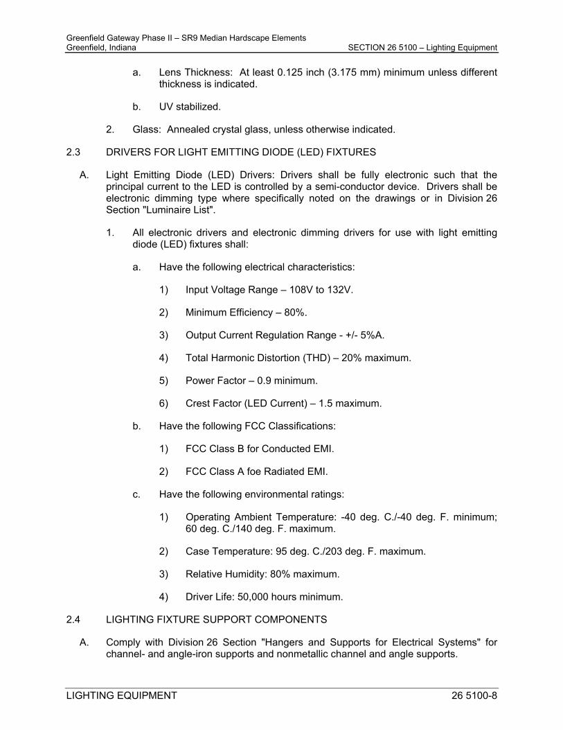
Greenfield Gateway Phase II – SR9 Median Hardscape Elements Greenfield, Indiana SECTION 26 5100 – Lighting Equipment
LIGHTING EQUIPMENT 26 5100-8
a. Lens Thickness: At least 0.125 inch (3.175 mm) minimum unless different thickness is indicated.
b. UV stabilized.
2. Glass: Annealed crystal glass, unless otherwise indicated.
2.3 DRIVERS FOR LIGHT EMITTING DIODE (LED) FIXTURES
A. Light Emitting Diode (LED) Drivers: Drivers shall be fully electronic such that the principal current to the LED is controlled by a semi-conductor device. Drivers shall be electronic dimming type where specifically noted on the drawings or in Division 26 Section "Luminaire List".
1. All electronic drivers and electronic dimming drivers for use with light emitting diode (LED) fixtures shall:
a. Have the following electrical characteristics:
1) Input Voltage Range – 108V to 132V.
2) Minimum Efficiency – 80%.
3) Output Current Regulation Range - +/- 5%A.
4) Total Harmonic Distortion (THD) – 20% maximum.
5) Power Factor – 0.9 minimum.
6) Crest Factor (LED Current) – 1.5 maximum.
b. Have the following FCC Classifications:
1) FCC Class B for Conducted EMI.
2) FCC Class A foe Radiated EMI.
c. Have the following environmental ratings:
1) Operating Ambient Temperature: -40 deg. C./-40 deg. F. minimum; 60 deg. C./140 deg. F. maximum.
2) Case Temperature: 95 deg. C./203 deg. F. maximum.
3) Relative Humidity: 80% maximum.
4) Driver Life: 50,000 hours minimum.
2.4 LIGHTING FIXTURE SUPPORT COMPONENTS
A. Comply with Division 26 Section "Hangers and Supports for Electrical Systems" for channel- and angle-iron supports and nonmetallic channel and angle supports.

Greenfield Gateway Phase II – SR9 Median Hardscape Elements Greenfield, Indiana SECTION 26 5100 – Lighting Equipment
LIGHTING EQUIPMENT 26 5100-9
B. Single-Stem Hangers: 1/2-inch (13-mm) steel tubing with swivel ball fittings and ceiling canopy. Finish same as fixture.
C. Twin-Stem Hangers: Two, 1/2-inch (13-mm) steel tubes with single canopy designed to mount a single fixture. Finish same as fixture.
D. Wires: ASTM A 641/A 641M, Class 3, soft temper, zinc-coated steel, 12 gage (2.68 mm)
E. Wires for Humid Spaces: ASTM A 580/A 580M, Composition 302 or 304, annealed stainless steel, 12 gage (2.68 mm).
F. Rod Hangers: 3/16-inch (5-mm) minimum diameter, cadmium-plated, threaded steel rod.
G. Hook Hangers: Integrated assembly matched to fixture and line voltage and equipped with threaded attachment, cord, and locking-type plug.
PART 3 - EXECUTION
3.1 INSTALLATION
A. General:
1. Lighting fixtures: Set level, plumb, and square with ceilings and walls. Install lamps in each fixture.
2. All luminaires shall be installed and adjusted in accordance with the manufacturer’s written directions.
3. All luminaires shall be clean and in first class condition prior to acceptance by the owner.
All luminaire lenses, diffusers, louvers, etc. shall be handled with clean white gloves during installation and cleaning.
4. Surface mounted luminaires shall be secured to building structure utilizing appropriate anchors, hangers, straps, etc. specifically designed for support of the respective type of luminaire. Specific support requirements shall be as follows:
a. Surface mounted luminaires installed on a lay-in grid type ceiling system shall be secured utilizing independent support clips with four (4) No. 12 gauge pre-stretched galvanized carbon steel hanger wires from clip to the building structure above the ceiling. Clips shall be equal to Caddy “IDS” Series.
5. Each luminaire shall be secured utilizing two (2) safety wires from the luminaire housing to the building structure. The safety wires shall be No. 12 gauge galvanized carbon steel hanger wires, pre-stretched with Class I coating.

Greenfield Gateway Phase II – SR9 Median Hardscape Elements Greenfield, Indiana SECTION 26 5100 – Lighting Equipment
LIGHTING EQUIPMENT 26 5100-10
6. Install at least one independent support rod or wire from structure to a tab on lighting fixture. Wire or rod shall have breaking strength of the weight of fixture at a safety factor of 3.
7. Luminaire Circuit Connections:
a. Final connections to luminaires shall be made utilizing Flexible Metal Conduit (Type FMC) installed per the requirements of Division 26 Section “Raceways and Fittings”. A continuously insulated green grounding conductor shall be furnished in each Flexible Metal Conduit.
b. Flexible Metal Conduit to recessed lay-in fluorescent luminaires shall be of adequate length to reposition the luminaire to one side. The intent of this provision is to allow the area of the luminaire to act as an access to the space above the ceiling.
8. Suspended Lighting Fixture Support:
a. Pendants and Rods: Where longer than 48 inches (1200 mm), brace to limit swinging.
b. Stem-Mounted, Single-Unit Fixtures: Suspend with twin-stem hangers.
c. Continuous Rows: Use tubing or stem for wiring at one point and tubing or rod for suspension for each unit length of fixture chassis, including one at each end.
B. Application Specific Installation:
1. Continuous Luminaire Installations:
a. Luminaires shall be mounted in continuous lengths and patterns as shown on the drawings.
b. Luminaire patterns shall be furnished with a fabricated corner piece where run continuously around inside or outside corners. Luminaire lenses and louvers shall be continuous with the luminaire and shall be mitered and/or fanned at corners or angles. Exposed housings shall have cast corner or angle piece as shown on the drawings or as required.
c. Where a continuous run of luminaires terminates at a wall or fascia, the luminaire installation shall be continuous from wall to wall.
d. Where a continuous run of luminaires does not terminate at a wall or fascia, an end plate with no visible fasteners or holes shall be provided.
e. Quantity sizes of lamps shall be furnished as required to completely fill the continuous luminaire installation with lamps. Lamps shall be staggered as required to eliminate socket
2. Adjust aimable lighting fixtures to provide required light intensities.

Greenfield Gateway Phase II – SR9 Median Hardscape Elements Greenfield, Indiana SECTION 26 5100 – Lighting Equipment
LIGHTING EQUIPMENT 26 5100-11
3.2 FIELD QUALITY CONTROL
A. Prepare a written report of tests, inspections, observations, and verifications indicating and interpreting results. If adjustments are made to lighting system, retest to demonstrate compliance with standards.
3.3 METHOD OF MEASUREMENT
A. Work under this item will be measured for payment in place as part of the lighting package for each BEACON PEDESTAL furnished and installed.
3.4 BASIS OF PAYMENT
A. Under this item will be paid for at the lump sum contract price for electrical work for all BEACON PEDESTALS which will include all labor, furnishing and installation, equipment, mounting hardware and any incidental work necessary to complete the work as specified.
END OF SECTION 26 5100

Greenfield Gateway Phase II – SR9 Median Hardscape Elements Greenfield, Indiana SECTION 26 5113 – Luminaire List
LUMINAIRE LIST 26 5113-1
SECTION 26 5113 LUMINAIRE LIST
1.1 RELATED DOCUMENTS
A. Drawings and general provisions of the Contract, including General and Supplementary Conditions and Division 01 Specification Sections, apply to this Section.
1.2 SUMMARY
A. This Section includes the following:
1. Exterior lighting surface mounted luminaires.
B. Related Sections include the following:
1. Division 26 Section "Lighting Equipment" for lamps, ballasts, accessories and mounting requirements.
C. DEFINITIONS
1. Luminaire (light fixture): A complete lighting unit consisting of a lamp or lamps and ballast(s) (when applicable) together with the parts designed to distribute the light, to position and protect the lamps, and to connect the lamps to the power supply.
1.3 SUBMITTALS
A. Submittals shall be provided in accordance with the conditions of contract and Division 26 Section “Lighting Equipment”.
1.4 PRODUCT SAMPLES
A. The Engineer reserves the right to request an engineering sample product of each and every luminaire for inspection. Samples submitted shall be in full compliance with the specifications including but not limited to construction, design, visual appearance, and performance. The manufacturer shall have previously built the luminaire and the luminaire shall be a production item. The sample shall remain on file as comparison with the materials furnished on the project. Materials not equal to the approved sample will be rejected.
PART 2 - PRODUCTS
2.1 MANUFACTURERS
A. Design Basis Manufacturer: Where listed in each respective luminaire specification, the “Design Basis Manufacturer” model series number shall serve to indicate the level of quality and minimum requirements for the luminaire to be furnished.

Greenfield Gateway Phase II – SR9 Median Hardscape Elements Greenfield, Indiana SECTION 26 5113 – Luminaire List
LUMINAIRE LIST 26 5113-2
B. Acceptable Manufacturers: Where acceptable manufacturers are listed in each respective luminaire specification, this shall be interpreted to mean that luminaires by the listed manufacturers will be acceptable as equals to the “Design Basis Manufacturer” luminaire provided that the manufacturer demonstrates full compliance with all of the requirements contained in these specifications.
2.2 LUMINAIRE LIST:
A. Refer to Luminaire (Light Fixture) Schedule on Sheet E-01 for all luminaire (light fixture) specifications.
PART 3 - EXECUTION
A. GENERAL FIXTURE INSTALLATION
1. Luminaires shall be installed in accordance with the manufacturer’s recommendations and the provisions of Division 26 Section “Lighting Equipment” and Division 26 Section “Emergency Lighting Equipment”.
END OF SECTION 26 5113

Greenfield Gateway Phase II – SR9 Median Hardscape Elements Greenfield, Indiana SECTION 31 2000 – Site Grading and Earthwork
Site Grading and Earthwork 31 2000 - 1
SECTION 31 2000 - SITE GRADING AND EARTHWORK
PART 1 - GENERAL
1.1 SUMMARY
A. This Section includes the following:
1. Site grading including importing and distributing materials, removal and off-site disposal of materials for the preparation of the existing sub-grade to meet the lines and grades as shown on the proposed plans. Preparing subgrades for walks and pavements.
3. Subbase course for walks and pavements.
B. Conform with requirements as outlined in the Project Specifications and the 2020 Indiana Department of Transportation Standard Specifications effective September 1, 2019, Division 200, Sections 201 – Clearing and Grubbing, 202 – Removal of Structures and Obstructions, 203 – Excavation and Embankment.
1.2 PROJECT CONDITIONS
A. Existing Utilities: Do not interrupt utilities serving facilities occupied by Owner or others unless permitted in writing by Owners Representative and then only after arranging to provide temporary utility services according to requirements indicated.
PART 2 - PRODUCTS
2.1 SOIL MATERIALS
A. According to the Standard Specifications.
PART 3 - EXECUTION
3.1 PREPARATION
A. Protect structures, utilities, sidewalks, pavements, and other facilities from damage caused by settlement, lateral movement, undermining, washout, and other hazards created by earthwork operations.
B. Preparation of subgrade for earthwork operations including removal of vegetation, topsoil, debris, obstructions, and deleterious materials from ground surface is specified in Division 31 Section "Site Clearing."
C. Protect and maintain erosion and sedimentation controls, which are specified in Section "Temporary Facilities and Controls" during earthwork operations.

Greenfield Gateway Phase II – SR9 Median Hardscape Elements Greenfield, Indiana SECTION 31 2000 – Site Grading and Earthwork
Site Grading and Earthwork 31 2000 - 2
3.2 EXCAVATION
A. Unclassified Excavation: Excavate to subgrade elevations regardless of the character of surface and subsurface conditions encountered. Unclassified excavated materials may include rock, soil materials, and obstructions. No changes in the Contract Sum or the Contract Time will be authorized for rock excavation or removal of obstructions.
1. If excavated materials intended for fill and backfill include unsatisfactory soil materials and rock, replace with satisfactory soil materials.
3.3 EXCAVATION FOR WALKS AND PAVEMENTS
A. Excavate surfaces under walks and pavements to indicated lines, cross sections, elevations, and subgrades.
3.4 EXCAVATION FOR UTILITY TRENCHES
A. Excavate trenches to indicated gradients, lines, depths, and elevations.
B. Excavate trenches to uniform widths to provide the following clearance on each side of pipe or conduit. Excavate trench walls vertically from trench bottom to 12 inches higher than top of pipe or conduit, unless otherwise indicated.
1. Clearance: 12 inches each side of pipe or conduit.
C. Trench Bottoms: Excavate and shape trench bottoms to provide uniform bearing and support of pipes and conduit. Shape subgrade to provide continuous support for bells, joints, and barrels of pipes and for joints, fittings, and bodies of conduits. Remove projecting stones and sharp objects along trench subgrade.
1. Excavate trenches 6 inches deeper than elevation required in rock or other unyielding bearing material, 4 inches deeper elsewhere, to allow for bedding course.
3.5 SUBGRADE INSPECTION
A. Proof-roll subgrade below the pavements with heavy pneumatic-tired equipment to identify soft pockets and areas of excess yielding. Do not proof-roll wet or saturated subgrades.
B. Reconstruct subgrades damaged by freezing temperatures, frost, rain, accumulated water, or construction activities, as directed by Architect, without additional compensation.
3.6 UNAUTHORIZED EXCAVATION
1. Fill unauthorized excavations under other construction or utility pipe as directed by Owners Representative.
3.7 STORAGE OF SOIL MATERIALS
A. Stockpile borrow soil materials and excavated satisfactory soil materials without intermixing. Place, grade, and shape stockpiles to drain surface water. Cover to prevent windblown dust.

Greenfield Gateway Phase II – SR9 Median Hardscape Elements Greenfield, Indiana SECTION 31 2000 – Site Grading and Earthwork
Site Grading and Earthwork 31 2000 - 3
1. Stockpile soil materials away from edge of excavations. Do not store within drip line of remaining trees.
3.8 UTILITY TRENCH BACKFILL
A. Place backfill on subgrades free of mud, frost, snow, or ice.
B. Place and compact bedding course on trench bottoms and where indicated. Shape bedding course to provide continuous support for bells, joints, and barrels of pipes and for joints, fittings, and bodies of conduits.
C. Backfill trenches excavated under footings and within 18 inches of bottom of footings with satisfactory soil; fill with concrete to elevation of bottom of footings. Concrete is specified in Division 03 Section “Cast-in-Place Concrete”.
D. Provide 4-inch- thick, concrete-base slab support for piping or conduit less than 30 inches below surface of roadways. After installing and testing, completely encase piping or conduit in a minimum of 4 inches of concrete before backfilling or placing roadway subbase.
E. Place and compact initial backfill of subbase material, free of particles larger than 1 inch in any dimension, to a height of 12 inches over the utility pipe or conduit.
1. Carefully compact initial backfill under pipe haunches and compact evenly up on both sides and along the full length of utility piping or conduit to avoid damage or displacement of piping or conduit. Coordinate backfilling with utilities testing.
F. Place and compact final backfill of satisfactory soil to final subgrade elevation.
G. Install warning tape directly above utilities, 12 inches below finished grade, except 6 inches below subgrade under pavements and slabs.
3.9 SOIL FILL
A. Plow, scarify, bench, or break up sloped surfaces steeper than 1 vertical to 4 horizontal so fill material will bond with existing material.
B. Place and compact fill material in layers to required elevations as follows:
1. Under grass and planted areas, use satisfactory soil material. 2. Under walks and pavements, use satisfactory soil material. 3. Under steps and ramps, use engineered fill. 4. Under footings and foundations, use engineered fill.
3.10 SOIL MOISTURE CONTROL
A. Uniformly moisten or aerate subgrade and each subsequent fill or backfill soil layer before compaction to within 2 percent of optimum moisture content.
1. Do not place backfill or fill soil material on surfaces that are muddy, frozen, or contain frost or ice.

Greenfield Gateway Phase II – SR9 Median Hardscape Elements Greenfield, Indiana SECTION 31 2000 – Site Grading and Earthwork
Site Grading and Earthwork 31 2000 - 4
2. Remove and replace or scarify and air dry otherwise satisfactory soil material that exceeds optimum moisture content by 2 percent and is too wet to compact to specified dry unit weight.
3.11 COMPACTION OF SOIL BACKFILLS AND FILLS
A. Place backfill and fill soil materials in layers not more than 8 inches in loose depth for material compacted by heavy compaction equipment, and not more than 4 inches in loose depth for material compacted by hand-operated tampers.
B. Place backfill and fill soil materials evenly on all sides of structures to required elevations, and uniformly along the full length of each structure.
C. Compact soil materials to not less than the following percentages of maximum dry unit weight according to ASTM D 698:
1. Under structures, steps, and pavements, scarify and recompact top 12 inches of existing subgrade and each layer of backfill or fill soil material at 95 percent.
2. Under walkways, scarify and recompact top 6 inches below subgrade and compact each layer of backfill or fill soil material at 92 percent.
3. Under lawn or unpaved areas, scarify and recompact top 6 inches below subgrade and compact each layer of backfill or fill soil material at 85 percent.
4. For utility trenches, compact each layer of initial and final backfill soil material at 85 percent.
3.12 GRADING
A. General: Uniformly grade areas to a smooth surface, free of irregular surface changes. Comply with compaction requirements and grade to cross sections, lines, and elevations indicated.
B. Site Grading: Slope grades to direct water away from buildings and to prevent ponding. Finish subgrades to required elevations within the following tolerances:
1. Lawn or Unpaved Areas: Plus or minus 1 inch. 2. Walks: Plus or minus 1 inch.
3.13 SUBBASE AND BASE COURSES
A. Place subbase and base course on subgrades free of mud, frost, snow, or ice.
B. On prepared subgrade, place subbase and base course under pavements and walks as follows:
1. Shape subbase and base course to required crown elevations and cross-slope grades. 2. Compact subbase and base course at optimum moisture content to required grades,
lines, cross sections, and thickness to not less than 95 percent of maximum dry unit weight according to ASTM D 698.
3.14 FIELD QUALITY CONTROL
A. Testing Agency: If required, owner will engage a qualified independent geotechnical engineering testing agency to perform field quality-control testing.

Greenfield Gateway Phase II – SR9 Median Hardscape Elements Greenfield, Indiana SECTION 31 2000 – Site Grading and Earthwork
Site Grading and Earthwork 31 2000 - 5
B. Allow testing agency to inspect and test subgrades and each fill or backfill layer. Proceed with subsequent earthwork only after test results for previously completed work comply with requirements.
C. Testing agency will test compaction of soils in place according to ASTM D 1556, ASTM D 2167, ASTM D 2922, and ASTM D 2937, as applicable.
D. When testing agency reports that subgrades, fills, or backfills have not achieved degree of compaction specified, scarify and moisten or aerate, or remove and replace soil to depth required; recompact and retest until specified compaction is obtained.
3.15 PROTECTION
A. Protecting Graded Areas: Protect newly graded areas from traffic, freezing, and erosion. Keep free of trash and debris.
B. Repair and reestablish grades to specified tolerances where completed or partially completed surfaces become eroded, rutted, settled, or where they lose compaction due to subsequent construction operations or weather conditions.
C. Where settling occurs before Project correction period elapses, remove finished surfacing, backfill with additional soil material, compact, and reconstruct surfacing.
1. Restore appearance, quality, and condition of finished surfacing to match adjacent work, and eliminate evidence of restoration to greatest extent possible.
3.16 DISPOSAL OF SURPLUS AND WASTE MATERIALS
A. Disposal: Remove surplus satisfactory soil and waste material, including unsatisfactory soil, trash, and debris, and legally dispose of it off Owner's property.
END OF SECTION 31 2000

Greenfield Gateway Phase II – SR9 Median Hardscape Elements Greenfield, Indiana SECTION 32 1316 – Decorative Concrete Paving
DECORATIVE CONCRETE PAVING 32 1316 - 1
SECTION 32 1316 - DECORATIVE CONCRETE PAVING
PART 1 - GENERAL
1.1 SUMMARY
A. Section includes sand-release finished concrete paving.
1.2 ACTION SUBMITTALS
A. Product Data: For each type of product.
B. Samples for Initial Selection: For each type of product, ingredient, or admixture requiring color, pattern, or texture selection.
C. Samples for Verification: For each type of exposed color, pattern, or texture indicated.
D. Design Mixtures: For each decorative concrete paving mixture. Include alternate design mixtures when characteristics of materials, Project conditions, weather, test results, or other circumstances warrant adjustments.
E. Qualification Data: For qualified Installer
F. Material Certificates: For the following, from manufacturer:
1. Cementitious materials\ 2. Steel reinforcement and reinforcement accessories 3. Admixtures 4. Curing compounds 5. Joint fillers
G. Field quality-control reports.
1.3 QUALITY ASSURANCE
A. Installer Qualifications: An employer of workers trained and approved by manufacturer of decorative concrete paving systems.
B. Ready-Mix-Concrete Manufacturer Qualifications: A firm experienced in manufacturing ready-mixed concrete products and that complies with ASTM C94/C94M requirements for production facilities and equipment.
C. Testing Agency Qualifications: Qualified according to ASTM C 1077 and ASTM E 329 for testing indicated.

Greenfield Gateway Phase II – SR9 Median Hardscape Elements Greenfield, Indiana SECTION 32 1316 – Decorative Concrete Paving
DECORATIVE CONCRETE PAVING 32 1316 - 2
1. Personnel conducting field tests shall be qualified as ACI Concrete Field Testing Technician, Grade 1, according to ACI CP-1 or an equivalent certification program.
D. Mockups: Build mockups to verify selections made under Sample submittals and to demonstrate aesthetic effects and set quality standards for materials and execution.
1. Build mockups of full-thickness sections of decorative concrete paving to
demonstrate typical joints; surface color, pattern, and texture; curing; and standard workmanship.
2. Build mockups of decorative concrete paving in the location and of the size indicated or, if not indicated, build mockups where directed by Architect and not less than 60-inches by 60-inches. Building two mockups demonstrating full range of decorative finishes.
3. Approval of mockups does not constitute approval of deviations from the Contract Documents contained in mockups unless Architect specifically approves such deviations in writing.
4. Approved mockups may become part of the completed work if undisturbed at time of Substantial Completion.
E. Preconstruction Testing: Engage a qualified independent testing agency to perform preconstruction testing on decorative concrete paving mixtures.
F. Field Conditions:
1. Traffic Control: Maintain access for vehicular and pedestrian traffic as required for other construction activities.
2. Cold-Weather Concrete Placement: Protect concrete work from physical damage or reduced strength that could be caused by frost, freezing, or low temperatures. Comply with ACI 306.1 and the following:
a. When air temperature has fallen to or is expected to fall below 40 deg F,
uniformly heat water and aggregates before mixing to obtain a concrete mixture temperature of not less than 50 deg F and not more than 80 deg F at point of placement.
b. Do not use frozen materials or materials containing ice or snow. c. Do not use calcium chloride, salt, or other materials containing antifreeze
agents or chemical accelerators unless otherwise specified and approved in design mixtures.
3. Hot-Weather Concrete Placement: Comply with ACI 301 and as follows when hot-weather conditions exist: a. Cool ingredients before mixing to maintain concrete temperature below 90
deg F at time of placement. Chilled mixing water or chopped ice may be used to control temperature, provided water equivalent of ice is calculated in total amount of mixing water.
b. Using liquid nitrogen to cool concrete is Contractor’s option. c. Cover steel reinforcement with water-soaked burlap, so steel temperature
will not exceed ambient air temperature immediately before embedding in concrete.

Greenfield Gateway Phase II – SR9 Median Hardscape Elements Greenfield, Indiana SECTION 32 1316 – Decorative Concrete Paving
DECORATIVE CONCRETE PAVING 32 1316 - 3
d. Fog-spray forms, steel reinforcement, and subgrade just before placing concrete. Keep subgrade moisture uniform without standing water, soft spots, or dry areas.
PART 2 - MATERIALS
2.1 CONCRETE, GENERAL
A. ACI Publications: Comply with ACI 301 unless otherwise indicated.
2.2 FORMS
A. Form Materials: Plywood, metal, metal-framed plywood, or other approved panel-type materials to provide full-depth, continuous, straight, and smooth exposed surfaces.
B. Use flexible or uniformly curved forms for curves of a radius of 100 feet or less. Do not use notched and bent forms.
C. Form-Release Agent: Commercially formulated form-release agent that will not bond with, stain, or adversely affect concrete surfaces and that will not impar subsequent treatments of concrete surfaces.
2.3 STEEL REINFORCEMENT
A. Reinforcing Bars: ASTM A 615/A 615M, Grade 60; deformed.
B. Steel Bar Mats: ASTM A 184/A 184M: with ASTM A 615/A 615M, Grade 60 deformed bars; assembled with clips.
C. Joint Dowel Bars: ASTM A 615/A 615M, Grade 60 plain-steel bars. Cut bars true to length with ends square and free of burrs.
D. Bar Supports: Bolsters, chairs, spaces, and other devices for spacing, supporting, and fastening reinforcing bars, welded-wire reinforcement, and dowels in place. Manufacture bar supports according to CRSI’s “Manual of Standard Practice” from steel wire, plastic, or precast concrete og greater compressive strength than concrete specified, and as follows:
1. Equip wire bar supports with sand plates or horizontal runners where base
material will not support chair legs.
E. Source Limitations: Obtain each type or class of cementitious material of the same brand from the same manufacturer's plant, obtain aggregate from single source, and obtain admixtures from single source from single manufacturer.
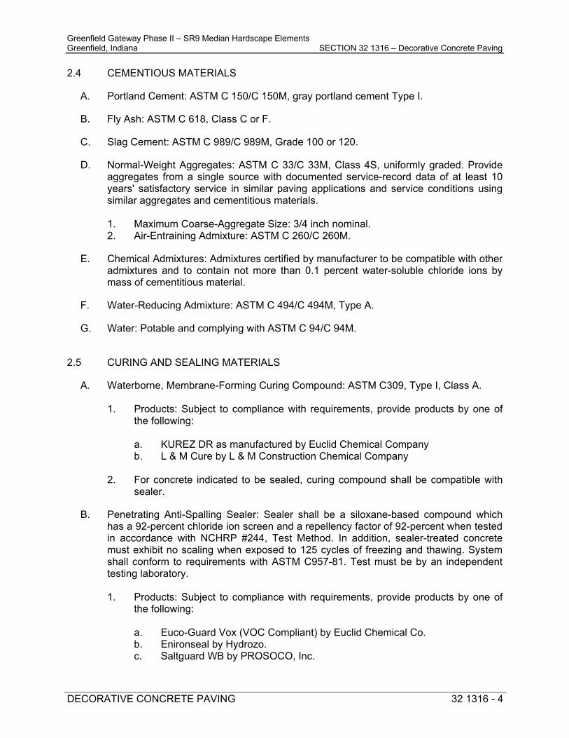
Greenfield Gateway Phase II – SR9 Median Hardscape Elements Greenfield, Indiana SECTION 32 1316 – Decorative Concrete Paving
DECORATIVE CONCRETE PAVING 32 1316 - 4
2.4 CEMENTIOUS MATERIALS
A. Portland Cement: ASTM C 150/C 150M, gray portland cement Type I.
B. Fly Ash: ASTM C 618, Class C or F.
C. Slag Cement: ASTM C 989/C 989M, Grade 100 or 120.
D. Normal-Weight Aggregates: ASTM C 33/C 33M, Class 4S, uniformly graded. Provide aggregates from a single source with documented service-record data of at least 10 years' satisfactory service in similar paving applications and service conditions using similar aggregates and cementitious materials.
1. Maximum Coarse-Aggregate Size: 3/4 inch nominal. 2. Air-Entraining Admixture: ASTM C 260/C 260M.
E. Chemical Admixtures: Admixtures certified by manufacturer to be compatible with other admixtures and to contain not more than 0.1 percent water-soluble chloride ions by mass of cementitious material.
F. Water-Reducing Admixture: ASTM C 494/C 494M, Type A.
G. Water: Potable and complying with ASTM C 94/C 94M.
2.5 CURING AND SEALING MATERIALS
A. Waterborne, Membrane-Forming Curing Compound: ASTM C309, Type I, Class A.
1. Products: Subject to compliance with requirements, provide products by one of the following: a. KUREZ DR as manufactured by Euclid Chemical Company b. L & M Cure by L & M Construction Chemical Company
2. For concrete indicated to be sealed, curing compound shall be compatible with
sealer.
B. Penetrating Anti-Spalling Sealer: Sealer shall be a siloxane-based compound which has a 92-percent chloride ion screen and a repellency factor of 92-percent when tested in accordance with NCHRP #244, Test Method. In addition, sealer-treated concrete must exhibit no scaling when exposed to 125 cycles of freezing and thawing. System shall conform to requirements with ASTM C957-81. Test must be by an independent testing laboratory.
1. Products: Subject to compliance with requirements, provide products by one of
the following:
a. Euco-Guard Vox (VOC Compliant) by Euclid Chemical Co. b. Enironseal by Hydrozo. c. Saltguard WB by PROSOCO, Inc.

Greenfield Gateway Phase II – SR9 Median Hardscape Elements Greenfield, Indiana SECTION 32 1316 – Decorative Concrete Paving
DECORATIVE CONCRETE PAVING 32 1316 - 5
d. Aquapel Plus by L & M Construction Chemical Co.
C. Concrete Silane Sealer: 100-percent reactive, 40-percent solids by with, deep penetrating alkyl polymer silane, non-staining, invisible, 10-year performance guarantee for protection of concrete subject to severe environmental conditions with frequent exposure to de-icing slats complying with National Cooperative Highway Research Program No. 244 and ASTM C672 with a rating of 0, no scaling, the highest rating with the following physical properties:
Yellowing: No. Surface Darkening: No. Film Forming: No. NCHRP 244 Series II: Absorption: 93-percent reduction, minimum. NCHRP 244 Series IV: Total Chloride Reduction: 98-percent reduction, minimum. Resistance to Chloride-Ion Penetration: AASHTO-T259: - ½-inch depth: 98-percent minimum. - 1-ich depth: 98-percent minimum.
20-percent soluble solutions are not acceptable.
1. Products: Subject to compliance with requirements, provide products by one of the following:
a. Penetrating Sealer 40 by Sonneborn. b. Baracade Silane 40 by Tamms. c. Pentane 40 or Penaten 40 WB by L & M Construction Chemical Co. d. Weather Worker 8-40 by Dayton Superior.
2.6 RELATED MATERIALS
A. Chemical Surface Retarder: Water-soluble, liquid set retarder without color dye for horizonal concrete surface application, capable of temporarily delaying final hardening of concrete to a depth of 1/16-inch to 1/8-inch.
1. Products: Subject to compliance with requirements, provide products by one of
the following:
a. True Etch Surface Retarder; Burke Group, LLC. b. Exposee; Chemmasters. c. Delay S; Conspec Marketing and Manufacturing Co., Inc. d. Concrete Surface Retarders; Euclid Chemical, Co. e. Expose; Kaufman Products, Inc. f. Surftard; Metalcrete Industries. g. Crete-Nox TA; Non-Crete Products Group. Kinsman Corporation. h. Lithotex; L.M. Scofield Co. i. Rugasol-S; Sika Corporation. j. Certi-Vex Envoiset; Vexcon Chemicals, Inc.
B. Joint Fillers: ASTM D1751, asphalt-saturated cellulosic fiber in preformed strips.

Greenfield Gateway Phase II – SR9 Median Hardscape Elements Greenfield, Indiana SECTION 32 1316 – Decorative Concrete Paving
DECORATIVE CONCRETE PAVING 32 1316 - 6
C. Bonding Agent: ASTM C 1059/C 1059M, Type II, non-redispersible, acrylic emulsion or styrene butadiene.
D. Epoxy-Bonding Adhesive: ASTM C 881/C 881M, two-component epoxy resin capable of humid curing and bonding to damp surfaces; of class suitable for application temperature, of grade complying with requirements, and of the following types:
1. Types IV and V, load bearing, for bonding hardened or freshly mixed concrete to
hardened concrete.
2.7 CONCRETE MIXTURES
A. Obtain each color, size, type, and variety of concrete mixture from single manufacturer with resources to provide concrete of consistent quality in appearance and physical properties.
B. Prepare design mixtures, proportioned according to ACI 301, for each type and strength of normal-weight concrete, and as determined by either laboratory trial mixtures or field experience.
C. Use a qualified independent testing agency for preparing and reporting proposed concrete design mixtures for the trial batch method.
D. Cementitious Materials: Limit percentage, by weight, of cementitious materials other than portland cement in concrete as follows:
1. Fly Ash or Pozzolan: 25 percent. 2. Slag Cement: 50 percent. 3. Combined Fly Ash or Pozzolan, and Slag Cement: 50 percent, with fly ash or
pozzolan not exceeding 25 percent.
E. Add air-entraining admixture at manufacturer's prescribed rate to result in normal weight concrete at point of placement having an air content as follows:
1. Air Content: 6 percent plus or minus 1.5 percent for 3/4-inch nominal maximum
aggregate size.
F. Limit water-soluble, chloride-ion content in hardened concrete to 0.15 percent by weight of cement.
G. Chemical Admixtures: Use admixtures according to manufacturer's written instructions.
H. Use water-reducing admixture in concrete as required for placement and workability.
I. Concrete Mixtures: Normal-weight concrete. 1. Compressive Strength (28 Days): 4000 psi. 2. Maximum W/C Ratio at Point of Placement: 0.45. 3. Slump Limit: 4 inches, plus or minus 1 inch.

Greenfield Gateway Phase II – SR9 Median Hardscape Elements Greenfield, Indiana SECTION 32 1316 – Decorative Concrete Paving
DECORATIVE CONCRETE PAVING 32 1316 - 7
2.8 CONCRETE MIXING
A. Ready-Mixed Concrete: Measure, batch, and mix concrete materials and concrete according to ASTM C 94/C 94M. Furnish batch certificates for each batch discharged and used in the Work.
B. When air temperature is between 85 and 90 deg F, reduce mixing and delivery time from 1-1/2 hours to 75 minutes; when air temperature is above 90 deg F, reduce mixing and delivery time to 60 minutes.
PART 3 - EXECUTION
3.1 EXAMINATION
A. Proof-roll prepared subbase surface below decorative concrete paving to identify soft pockets and areas of excess yielding.
3.2 PREPARATION
A. Remove loose material from compacted subbase surface immediately before placing concrete.
3.3 EDGE FORMS AND SCREED CONSTRUCTION
A. Set, brace, and secure edge forms, bulkheads, and intermediate screed guides to required lines, grades, and elevations. Install forms to allow continuous progress of work and so forms can remain in place at least 24 hours after concrete placement.
3.4 STEEL REINFORCEMENT INSTALLATION
A. Comply with CRSI's "Manual of Standard Practice" for fabricating, placing, and supporting reinforcement.
3.5 JOINTS
A. General: Form construction, isolation, and contraction joints and tool edges true to line, with faces perpendicular to surface plane of concrete. Construct transverse joints at right angles to centerline unless otherwise indicated.
B. Construction Joints: Set construction joints at side and end terminations of paving and at locations where paving operations are stopped for more than one-half hour unless paving terminates at isolation joints.

Greenfield Gateway Phase II – SR9 Median Hardscape Elements Greenfield, Indiana SECTION 32 1316 – Decorative Concrete Paving
DECORATIVE CONCRETE PAVING 32 1316 - 8
C. Isolation Joints: Form isolation joints of preformed joint-filler strips abutting concrete curbs, catch basins, manholes, inlets, structures, walks, other fixed objects, and where indicated.
D. Contraction Joints: Form weakened-plane contraction joints, sectioning concrete into areas as indicated. Construct contraction joints for a depth equal to at least one-fourth of the concrete thickness.
E. Edging: After initial floating, tool edges of paving, gutters, curbs, and joints in concrete with an edging tool to a 1/4-inch radius. Repeat tooling of edges after applying surface finishes. Eliminate edging-tool marks on concrete surfaces.
3.6 SAND RELEASE FINISHING
A. Approved mock-up shall be used as the measure of quality for sand-release finished decorative concrete paving. Final appearance shall resemble a sand-blast finish achieved through application of surface retarder.
B. Immediately after float finish, spray apply chemical surface retarder to pavement according to manufacturer’s written instruction.
C. Cover with plastic sheeting, sealing laps with tape and remove when ready to continue finishing operations.
D. When concrete has taken its initial set, and after the finishing operations are completed, direct a fine spray of water at an approximate angle of 15-degrees to the surface of the concrete.
E. Wash the laitance and retarder from the surface without both disturbing the small aggregate and causing sand runs to appear.
F. Remove laitance, retarder residue and dirty wash water from finished surfaces as soon as washing operations are complete.
G. Apply a dilute solution acid wash as required to kill the efflorescence.
H. Later applications may be stronger.
I. Design consolidation and finishing methods to avoid uneven settlement of aggregate above reinforcing bar locations. Uneven settlement results in uneven surface when combined with retarder application.
END OF SECTION 321316

Greenfield Gateway Phase II – SR9 Median Hardscape Elements Greenfield, Indiana SECTION 32 1373 – Concrete Joint Sealants
CONCRETE PAVING JOINT SEALANTS 32 1373 - 1
SECTION 321373 - CONCRETE PAVING JOINT SEALANTS
PART 1 - GENERAL
1.1 SUMMARY
A. Section Includes:
1. Cold-applied joint sealants. 2. Hot-applied joint sealants. 3. Joint-sealant backer materials. 4. Primers.
1.2 ACTION SUBMITTALS
A. Product Data: For each type of product.
B. Samples: For each kind and color of joint sealant required.
C. Paving-Joint-Sealant Schedule: Include the following information:
1. Joint-sealant application, joint location, and designation. 2. Joint-sealant manufacturer and product name. 3. Joint-sealant formulation. 4. Joint-sealant color.
1.3 INFORMATIONAL SUBMITTALS
A. Product certificates.
PART 2 - PRODUCTS
2.1 MATERIALS, GENERAL
A. Compatibility: Provide joint sealants, backing materials, and other related materials that are compatible with one another and with joint substrates under conditions of service and application, as demonstrated by joint-sealant manufacturer, based on testing and field experience.
2.2 COLD-APPLIED JOINT SEALANTS
A. Single-Component, Nonsag, Silicone Joint Sealant: ASTM D5893/D5893M, Type NS.

Greenfield Gateway Phase II – SR9 Median Hardscape Elements Greenfield, Indiana SECTION 32 1373 – Concrete Joint Sealants
CONCRETE PAVING JOINT SEALANTS 32 1373 - 2
B. Single-Component, Self-Leveling, Silicone Joint Sealant: ASTM D5893/D5893M, Type SL.
C. Multicomponent, Nonsag, Urethane, Elastomeric Joint Sealant: ASTM C920, Type M, Grade NS, Class 25, for Use T.
D. Single Component, Pourable, Urethane, Elastomeric Joint Sealant: ASTM C920, Type S, Grade P, Class 25, for Use T.
E. Multicomponent, Pourable, Urethane, Elastomeric Joint Sealant: ASTM C920, Type M, Grade P, Class 25, for Use T.
2.3 HOT-APPLIED JOINT SEALANTS
A. Hot-Applied, Single-Component Joint Sealant: ASTM D6690, Type I.
B. Hot-Applied, Single-Component Joint Sealant: ASTM D6690, Type I or Type II.
C. Hot-Applied, Single-Component Joint Sealant: ASTM D6690, Type I, II, or III.
2.4 JOINT-SEALANT BACKER MATERIALS
A. Backer Strips for Cold- and Hot-Applied Joint Sealants: ASTM D5249; Type 2; of thickness and width required to control joint-sealant depth, prevent bottom-side adhesion of sealant, and fill remainder of joint opening under sealant.
2.5 PRIMERS
A. Primers: Product recommended by joint-sealant manufacturer where required for adhesion of sealant to joint substrates indicated.
PART 3 - EXECUTION
3.1 INSTALLATION OF JOINT SEALANTS
A. Comply with joint-sealant manufacturer's written installation instructions for products and applications indicated unless more stringent requirements apply.
B. Cleaning of Joints: Clean out joints immediately to comply with joint-sealant manufacturer's written instructions.
C. Joint Priming: Prime joint substrates where indicated or where recommended in writing by joint-sealant manufacturer.
D. Joint-Sealant Installation Standard: Comply with recommendations in ASTM C1193 for use of joint sealants as applicable to materials, applications, and conditions.
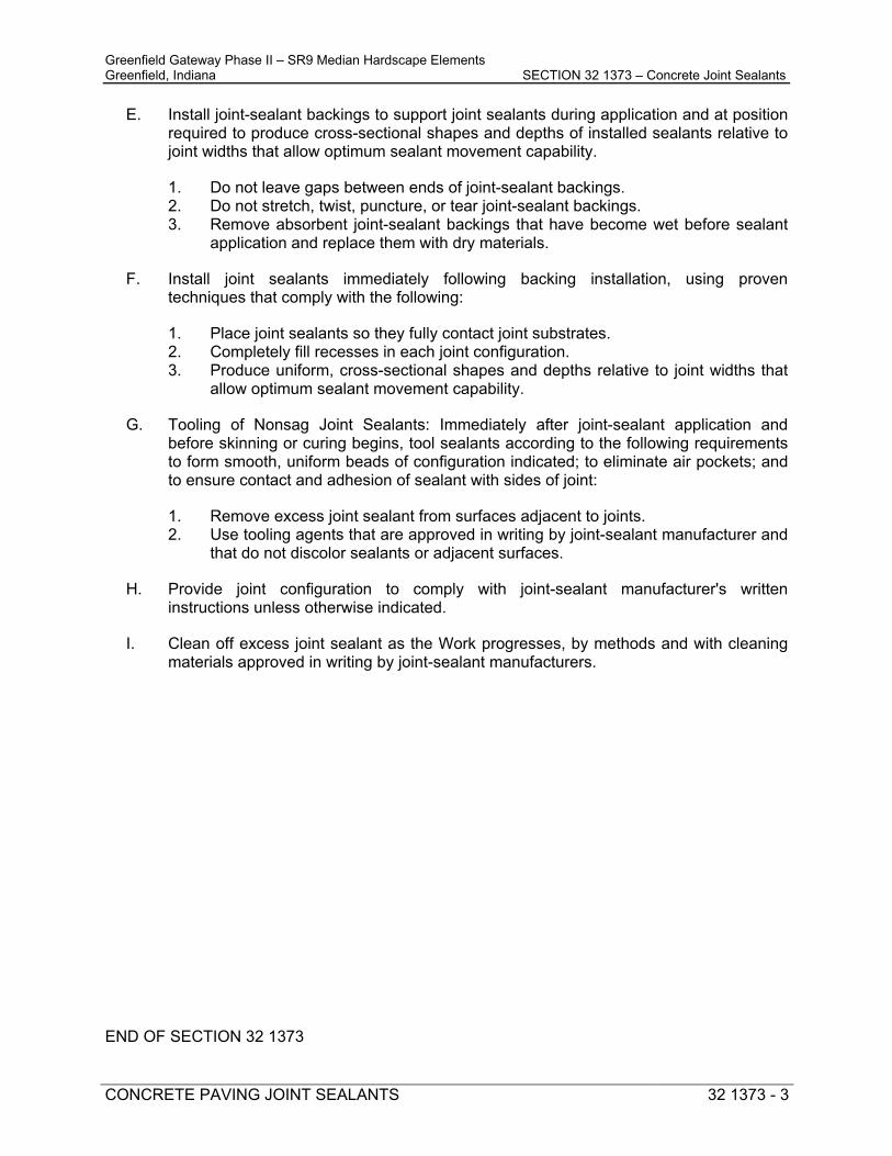
Greenfield Gateway Phase II – SR9 Median Hardscape Elements Greenfield, Indiana SECTION 32 1373 – Concrete Joint Sealants
CONCRETE PAVING JOINT SEALANTS 32 1373 - 3
E. Install joint-sealant backings to support joint sealants during application and at position required to produce cross-sectional shapes and depths of installed sealants relative to joint widths that allow optimum sealant movement capability.
1. Do not leave gaps between ends of joint-sealant backings. 2. Do not stretch, twist, puncture, or tear joint-sealant backings. 3. Remove absorbent joint-sealant backings that have become wet before sealant
application and replace them with dry materials.
F. Install joint sealants immediately following backing installation, using proven techniques that comply with the following:
1. Place joint sealants so they fully contact joint substrates. 2. Completely fill recesses in each joint configuration. 3. Produce uniform, cross-sectional shapes and depths relative to joint widths that
allow optimum sealant movement capability.
G. Tooling of Nonsag Joint Sealants: Immediately after joint-sealant application and before skinning or curing begins, tool sealants according to the following requirements to form smooth, uniform beads of configuration indicated; to eliminate air pockets; and to ensure contact and adhesion of sealant with sides of joint:
1. Remove excess joint sealant from surfaces adjacent to joints. 2. Use tooling agents that are approved in writing by joint-sealant manufacturer and
that do not discolor sealants or adjacent surfaces.
H. Provide joint configuration to comply with joint-sealant manufacturer's written instructions unless otherwise indicated.
I. Clean off excess joint sealant as the Work progresses, by methods and with cleaning materials approved in writing by joint-sealant manufacturers.
END OF SECTION 32 1373

Greenfield Gateway Phase II – SR9 Median Hardscape Elements Greenfield, Indiana SECTION 32 8400 – Irrigation
IRRIGATION 32 8400 - 1
Section 32 8400 - IRRIGATION PART 1 – GENERAL
1.01 Related Documents: A. The work shall consist of providing and installing the automatic irrigation system in
accordance with these specifications and as shown on the plans. 1.02 Description:
A. General:
1. The extent of landscape irrigation system is shown on the drawings.
2. Unless otherwise specified, the plans and special provisions are intended to include everything obviously requisite and necessary for the proper installation and completion of the work, whether or not each necessary item is mentioned herein, including permits and tapping fees. The plans and special provisions are intended to be cooperative and any item called for in one and not the other shall be binding as if called for in both.
B. The irrigation systems shall provide for points of connection into the water supply for
automatic irrigation of all planted areas and perform as required by the plans and special provision:
C. Provide an underground automatic irrigation system as shown on the drawings and in
accordance required by these special provisions. 1. Automatic irrigation systems including taps, controllers, piping, fittings, backflow
preventers and protective covers, valves, sprinkler heads and accessories, and coordination with local utilities for metering.
2. Excavating and backfilling irrigation system work. 3. Testing and adjusting the system. 4. As-Built drawings. 5. Winterization shutdown and spring start-up.
D. All work required by the plans and special provisions shall be accomplished by the
Contractor even though minor items required may not be specifically mentioned in the above listing.
E. Drawings: The system layout is diagrammatic. Exact locations of taps, meters,
controllers, piping, fittings, backflow preventers, valves, sprinkler heads, and other components may need to be coordinated with the Engineer and modified by the Contractor in the field at the time of installation to allow for actual on-site conditions. Minor adjustments in the system layout will be permitted to clear fixed obstructions. Any major revisions to the irrigation system shall be submitted in writing to the Engineer for approval.
F. Verification of Plans and Special Provisions: The Contractor shall carefully examine the
plans and special provisions relating to this work for completeness, accuracy, and clarity. Any conflict, errors or clarifications request shall be immediately brought to the attention of the Engineer for written interpretation or instructions.
G. Permits: The Contractor is responsible for obtaining all permits required for the
installation of this work.

Greenfield Gateway Phase II – SR9 Median Hardscape Elements Greenfield, Indiana SECTION 32 8400 – Irrigation
IRRIGATION 32 8400 - 2
PART 2 – PRODUCTS 2.01 MATERIALS
A. General:
1. Prior to beginning work, the Contractor shall submit for approval three copies (or one
combined PDF file) of the complete list of materials proposed to be installed for approval by the Engineer. No work shall occur before approval.
B. Components/Manufacturers:
1. Sprinklers:
All sprinklers shall be twelve-inch high-pop models by one of the following manufacturers with high-efficiency nozzles:
a) Rainbird #1812 with HE nozzles b) Hunter #PROS-12 with PRO fixed or adjustable nozzles c) Toro #570Z-12HP with Precision Spray nozzles
2. Valve Boxes:
All valve boxes shall be a commercial-grade, fiberglass valve box with locking cover manufactured by one of the following companies:
a) Rainbird (VB Series) b) Hydro-Rain (1419 Series) c) Carson (Spec Grade)
All valve boxes shall be filled with a minimum of six inches of washed pea gravel below pipe level to ensure adequate drainage. Controller station numbers shall be marked on the valve box cover in a permanent manner.
3. Meter box and Curb Valve:
(a) Ford Meter Box Co. (b) Rhino Meter Box of Sweetwater TN (c) Brooks Meter Box of Memphis TN
4. Backflow Preventers:
The backflow preventers shall meet or exceed specifications and standards set by the State and USC Foundation for Cross-Connection Control and Hydraulic Research, and shall be manufactured by one of the following companies:
a) Wilkins of Paso Robles CA / Model 975XL (1”) RPZ b) Febco of Fresno CA / Model 825Y (1”) RPZ c) WATTS of North Andover MA / (1”) RPZ
The contractor shall check with local authorities for code compliance. The backflow shall be sized as shown on drawings. All exposed standpipe and fittings shall be copper or galvanized pipe to eighteen inches below grade. The backflows will be enclosed with an aluminum enclosure from the list of manufacturers above. The contractor shall pour a four-inch thick concrete base foundation, or install a preformed pad, around the backflow preventer on which the enclosure can be mounted.
5. Main Line Piping:
All piping shall be Cl 200 PVC SDR 21 standard weight. All mainline that is one inch or bigger shall be solvent welded. Pipe shall carry the N.S.F. seal of approval and meet the following specifications: ASTM D2241, or latest revisions. Size shall be as indicated on drawings. Piping shall be manufactured by one of the following:
a) Cresline of Evansville IN

Greenfield Gateway Phase II – SR9 Median Hardscape Elements Greenfield, Indiana SECTION 32 8400 – Irrigation
IRRIGATION 32 8400 - 3
b) 2. Eagle Pipe of Hastings NE c) 3. Cantex Pipe of Ft Worth Texas
6. Lateral Line Piping:
All lateral lines downstream of the valves shall be CL 200 PVC SDR 21 for 1-2 inch pipe. Pipe shall carry the N.S.F. seal of approval and meet the following specifications: ASTM D2241, or latest revision. Size shall as indicated on drawings. Sleeves shall be Schedule 40 PVC, ASTM D1785, and shall be twice the nominal size of the pipe to be carried. The manufacturer shall be the same as the selected mainline and lateral pipe.
7. Pipe Fittings:
All PVC fittings one inch or bigger shall be solvent weld schedule 40 standard weight. The attachment shall be made with both a primer and a solvent cement as approved by the manufacturer. Glue type saddles may be used so long as they are 3/4 round type units which grip the pipe. Saddles shall be bored or cut with appropriate equipment and holes shall not be burned into the pipe. The manufacturer shall be the same as the selected pipe manufacturer.
All fittings four inches and larger shall be ductile iron with PVC gasket and hub configuration and retaining rings as manufactured by Harco or Leemco. Provide Leemco joint restraints or concrete thrust blocks where necessary on all three inches and larger fittings. Install per the manufacturer’s recommendations.
8. Automatic Valves:
Automatic valves shall be manufactured by one of the following companies: a) Rain Bird: #100-PGA b) Toro: #254-06-04 c) Hunter: #PGV101G
The valves shall be normally closed, 24 VAC 50/60 cycle solenoid-actuated globe design capable of having a flow rate of the gallons per minute (GPM) indicated in the drawings. The valve pressure rating shall not be less than 150 psi.
Refer to the irrigation plan for specific valve size and installation detail. Install per manufacturer's specifications in a commercial-grade 12-inch valve box with locking cover from the selected valve box manufacture.
9. Communication/Control Wire:
Communication between the controller and the valves shall be accomplished with copper wire with an exterior jacket which is U.L. listed for direct burial and sprinkler control. The Contractor shall be responsible for correct wire sizing for distance and voltage loss. A minimum of 14 gauge wire will be used for ‘common’ wire and #18-gauge multi-strand wires for control valves/kits. Common wire color shall be white. Station wires shall be of different colors and number marked at all splices and connections. All field connections shall be accomplished with wire nuts and shall be made watertight and oxidation-resistant through the use of 3M Scotchlok DBR-6/DBY-6 electrical insulating resin packs. Use of sealant without container package will not be permitted.
10. Automatic Controller:
The controller shall be a bluetooth battery operated controller. Flexible programming shall include cycle/soak, programmable valve delay, sensor override by the station, master valve by the station, calendar day off and total program and valve run times. Other options shall include Contractor programming default, seasonal adjust and battery back-up protection. Subject to compliance with requirements, the automatic controller shall the model listed by one of the following manufacturers:
a) Rain Bird Model TBOS-BT
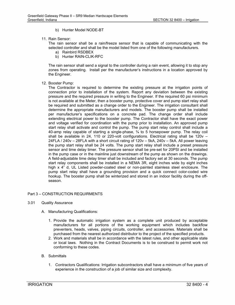
Greenfield Gateway Phase II – SR9 Median Hardscape Elements Greenfield, Indiana SECTION 32 8400 – Irrigation
IRRIGATION 32 8400 - 4
b) Hunter Model NODE-BT
11. Rain Sensor: The rain sensor shall be a rain/freeze sensor that is capable of communicating with the selected controller and shall be the model listed from one of the following manufacturers.
a) Rainbird RSDBEX b) Hunter RAIN-CLIK-RFC
The rain sensor shall send a signal to the controller during a rain event, allowing it to stop any zones from operating. Install per the manufacturer’s instructions in a location approved by the Engineer.
12. Booster Pump:
The Contractor is required to determine the existing pressure at the irrigation points of connection prior to installation of the system. Report any deviation between the existing pressure and the required pressure in writing to the Engineer. If the required 60 psi minimum is not available at the Meter, then a booster pump, protective cover and pump start relay shall be required and submitted as a change order to the Engineer. The irrigation consultant shall determine the appropriate manufacturers and models. The booster pump shall be installed per manufacturer’s specifications on a concrete pad. The change order shall include extending electrical power to the booster pump. The Contractor shall have the exact power and voltage verified for coordination with the pump prior to installation. An approved pump start relay shall activate and control the pump. The pump start relay control shall include a 40-amp relay capable of starting a single-phase, ¾ to 5 horsepower pump. The relay coil shall be available in 24, 110 or 220-volt configurations. Electrical rating shall be 120v – 24FLA / 240v – 28FLA with a short circuit rating of 120v – 5kA, 240v – 5kA. All power leaving the pump start relay shall be 24 volts. The pump start relay shall include a preset pressure sensor and time delay timer. The pressure sensor shall be pre-set for 20PSI and be installed in the pump case or in the mainline just downstream of the pump as shown on the drawings. A field-adjustable time delay timer shall be included and factory set at 30 seconds. The pump start relay components shall be installed in a NEMA 3R, eight inches wide by eight inches high x 4” d, UL Listed powder-coated steel or non-painted stainless steel enclosure. The pump start relay shall have a grounding provision and a quick connect color-coded wire hookup. The booster pump shall be winterized and stored in an indoor facility during the off-season.
Part 3 – CONSTRUCTION REQUIRMENTS 3.01 Quality Assurance
A. Manufacturing Qualifications: 1. Provide the automatic irrigation system as a complete unit produced by acceptable
manufacturers for all portions of the working equipment which includes backflow preventers, heads, valves, piping circuits, controller, and accessories. Materials shall be purchased from the nearest authorized distributor to the project of the specified products.
2. Work and materials shall be in accordance with the latest rules, and other applicable state or local laws. Nothing in the Contract Documents is to be construed to permit work not conforming to these codes.
B. Submittals
1. Contractors Qualifications: Irrigation subcontractors shall have a minimum of five years of
experience in the construction of a job of similar size and complexity.

Greenfield Gateway Phase II – SR9 Median Hardscape Elements Greenfield, Indiana SECTION 32 8400 – Irrigation
IRRIGATION 32 8400 - 5
A list of five equivalent irrigation system installations, performed in the last five years, incorporating the following information, shall be submitted to the Engineer: a) Name and address of the project. b) Name and address of Owner and contact person. c) Name and address of the prime contractor and contact person
C. Requirements of regulatory agencies and utilities:
1. The system shall comply with the latest requirements of all state and local codes and ordinances.
2. The system shall comply with the latest rules and requirements by all utility companies involved.
3. Nothing in the contract documents is to be constructed to permit work not conforming to these rules, codes and ordinances.
D. Electrical devices shall carry Underwriters’ Laboratory labels.
E. Required pressure testing shall be the responsibility of the Contractor.
F. Materials, equipment, and methods of installation shall comply with the following codes and
standards: 1. National Fire Protection Association (NFPA) 2. American Society for Testing and Materials (ASTM) 3. The Irrigation Association (IA) 4. American Water Works Association (AWWA)
G. Manufacturer's Data:
Manufacturer's specifications and instructions for all manufactured materials and products if other than those specified herein shall be submitted to the Engineer for approval.
H. Record Drawings:
After completion of the work and before final acceptance, a set of scaled, reproducible record drawings, and two sets of prints showing the location of the complete work shall be submitted to the Engineer. Final payment and any retainage will not be released until these drawings are submitted and accepted by the Engineer.
Submit a weekly irrigation schedule based on annual evapotranspiration rates, average rainfall etc.
I. Construction Schedule:
Submit a construction schedule to the Engineer for approval prior to beginning work.
J. Operations and Maintenance Manual: Submit three complete manuals to Engineer.
3.02 Warranty
A. The contractor shall furnish a manufacturer's written warranty to the effect that all heads, valves, and controllers will be warranted for a period of no less than two years to be free from defects and faulty workmanship, and that any defective heads, valves, or controllers shall be promptly repaired or replaced without additional cost in accordance with that warranty.
B. The Contractor shall furnish a written warranty to the effect that all materials and work are
warranted for at least one year, shall be free from defects and faulty workmanship and that any defective material or work shall be promptly repaired or replaced without additional cost.

Greenfield Gateway Phase II – SR9 Median Hardscape Elements Greenfield, Indiana SECTION 32 8400 – Irrigation
IRRIGATION 32 8400 - 6
C. The Contractor shall furnish a written warranty to the effect that all installation labor used on this
project will be warranted for one full year from date of final acceptance by the Engineer.
D. Protection: Protect structures, streets, curbs, sidewalks, fences, walls, trees and other existing features from damage.
E. Utilities: Contractor is responsible for verifying the location of all site utilities and making the
necessary adjustments to the irrigation system to accommodate the infrastructure.
H. Sequencing and Scheduling:
1. The irrigation system shall be installed and made operable in a coordinated effort with the installation of the plant materials.
2. In all affected areas, the ground shall be restored to the proposed finished grade upon
completion of installation. 3.03 Operation and Maintenance
Contractor shall provide Operation and Maintenance manuals with complete instructions covering full operation, care, and maintenance of system and controls. Manufacturers’ parts catalogs shall be provided.
A. Water Supply:
The water supply shall be from an existing water line. Supply shall be from multiple water meters as shown on the plans. The taps and installation of the meters shall be the responsibility of the contractor. All work must be done in coordination with the water utility company. Install per local code and in accordance with the water purveyors requirements.
B. System Design:
1. Layout work as accurately as possible based on the drawings. The drawings, though carefully drawn, are generally diagrammatic to the extent that all offsets, fittings, and finished site conditions may not be shown.
2. The Contractor shall be responsible for full and complete coverage of all irrigated areas
as to spacing and precipitation rates being matched and shall make any necessary adjustments to the system at no additional charge. Tube spacing as shown on the drawings is predicated on the water supply being a minimum of 45 psi at the point of connection. Contractor shall verify said pressure before beginning the installation. Any deviation between the said pressure and the specified pressure shall be reported to the Engineer. Head spacing shall not exceed fifty-five percent of the manufacturer’s stated diameter.
3. Any major revisions to the irrigation system must be submitted to the Engineer in written
form for approval.
C. Trenching and Backfilling:
1. Pulling, Excavating, and Trenching: 2. Perform all excavations as required for the installation of the work included under this
section, including shoring of earth banks to prevent cave-ins. All trenching, backfilling and compacting shall conform to the requirements of the INDOT Standard Specifications, this special provision, and the drawings.

Greenfield Gateway Phase II – SR9 Median Hardscape Elements Greenfield, Indiana SECTION 32 8400 – Irrigation
IRRIGATION 32 8400 - 7
3. All pipes that are two inches and smaller may be pulled with a vibratory plow.
4. If trenching, trenches shall be wide enough to allow a minimum of six inches between parallel pipelines. If pulling, the same lateral distance shall be observed.
D. Underground Obstructions:
1. Any unforeseen underground obstructions which might be encountered during the installation shall be brought to the attention of the Engineer immediately and work on that portion of the installation shall be suspended.
2. Any additional expense involved in removing those obstructions or the re-routing of lines shall
be submitted to the Inspecting Engineer in writing and approved prior to continuing the installation.
E. Underground Utilities:
It shall be the responsibility of the Contractor to locate or have located all existing underground utilities, whether public or private, on that portion of the site which is affected by their work. The Contractor shall contact the Owner for verification that all private utilities have been located prior to construction. The Contractor shall be responsible for the repair of any cuts or breaks in these utilities, which are a result of their work.
F. Minimum Cover:
An absolute minimum of eighteen inches cover shall be held over all main lines and control lines. A minimum of twelve inches of cover shall be maintained over all lateral lines.
G. Backfill:
1. All irrigation trenches shall be back-filled and compacted by mechanical means in six-inch lifts to a minimum of 90 percent of the original density. Backfill material shall be of the same soil mix as excavated and free of any rocks or debris larger than 1/2 inch in diameter. It shall be the Contractor's responsibility to remove all larger debris from the premises and to furnish any additional soil which may be necessary to level the trenches. All disturbed areas are to be re-seeded directed by the Engineer.
2. The Contractor shall be responsible for the repair of any irrigation trench settling which occurs during the first year after final acceptance.
3. Where pipe is pulled into the ground, all domes shall be compacted to original grade after pulling.
H. Sleeves under pavements:
1. All mainline and lateral piping under any pavement or structure shall be installed in separate sleeves unless noted otherwise. Sleeves shall be a minimum of twice the diameter of the pipe to be sleeved unless otherwise noted. Sleeves shall be a minimum Schedule 40 PVC material in the pedestrian areas and minimum Schedule 80 PVC in roadway conditions unless noted otherwise. Mainline sleeves shall be a minimum of twenty-four inches below finish grade and lateral sleeves shall be a minimum of eighteen inches below finish grade. Extend sleeves into landscape area a minimum of twelve inches beyond the edge of the paved surface. Provide less than six inches of clearance between each lateral line and not less than eighteen inches of clearance between lateral lines and main lines.
2. All piping under existing pavement and walkways will be bored with appropriate equipment
unless otherwise noted. Where roadway cuts are required, the asphalt is to be saw cut, the sleeve installed, and surface restored to original by professionals engaged in this business.
3. All communication wire will be placed in separate sleeves under all pavement, walks, etc. that
are in excess of six feet in width.

Greenfield Gateway Phase II – SR9 Median Hardscape Elements Greenfield, Indiana SECTION 32 8400 – Irrigation
IRRIGATION 32 8400 - 8
4. If sleeves are not immediately used, then securely cap the ends with duct tape and mark with wooden stakes for future designation.
3.04. Installation
1. Unless otherwise indicated, the installation shall comply with the requirements of the Local Plumbing Code.
2. Install piping, valves, controls, and sprinklers in accordance with manufacturer’s written
instructions.
3. Use only Teflon tape for sealing all heads and riser assemblies.
A. Circuit Valves: 1. Install in a valve box arranged for easy adjustment and removal.
2. Adjust automatic control valves to provide flow at rated operating pressure required for each
sprinkler circuit. If an overpressure condition exists, Contractor shall install, at his expense, such pressure compensation devices as are necessary to bring the circuit or heads into proper operating range.
B. Piping
1. Lay pipe on solid sub-base, uniformly sloped without humps or depressions.
2. When the pipe is pulled into the ground, all PVC pipe shall be solvent welded at least 24 hours before pulling.
3. All trenches shall be snaked, or the pipe snaked within the trench to allow for expansion and
contraction.
4. A single strand of 14-1 wire, yellow in color, shall be run with all mainline from the point of connection to the end of the mainline. This single strand of wire shall be available for mainline tracking.
5. Install thrust blocks or Leemco Joint Restraints behind elbows/tees and gate valves along
three inches or larger mainlines.
C. Dielectric Protection: Use dielectric fittings at the connection where pipes of dissimilar metal are joined.
D. Closing of Pipe and Flushing Lines
1. Cap or plug all openings as soon as lines have been installed to prevent the entrance of materials that would obstruct the pipe. Leave in place until removal is necessary for completion of the installation.
2. Thoroughly flush out all main water lines before installing valves.
3. Thoroughly flush out all lateral lines after installation and before attaching heads.
E. Communication Circuitry: 1. All communication circuitry shall be run, wherever possible, with the main pipeline.

Greenfield Gateway Phase II – SR9 Median Hardscape Elements Greenfield, Indiana SECTION 32 8400 – Irrigation
IRRIGATION 32 8400 - 9
2. All splices shall be made at a valve box for easy access.
3. A minimum of twelve inches of control wire shall be coiled at each valve for slack.
F. Automatic Controllers: 1. Connect remote control valves to the controller in a sequence corresponding with station
settings, as denoted on the plan.
2. Communication circuitry shall be run, wherever possible, along with the mainline pipe.
3. Contractor shall be responsible for the correct programming and data input required by the automatic controller. The input information card included with the controller shall be filled out and kept for backup information after that is loaded onto the controller.
G. Control Valves:
1. All valves shall be enclosed in a ten-inch diameter round fiberglass valve box with locking cover.
2. All valve boxes are to be filled with a minimum of six inches of washed pea gravel. The top of
the pea gravel shall be below a level required to remove the valve if a replacement is required.
3. Valve box lid shall be flush with finished grade.
H. Backflow Preventer:
1. Install the backflow preventer per all applicable codes. 2. Quick Coupling Valves for Winterization of the Systems: 3. A quick coupling valve shall be installed in the pipe directly downstream from the backflow
preventer to provide a point of injection for compressed air with a maximum of 40 psi to purge the system of water in preparation for winter shut-down of the system.
I. Rain Sensor
1. Install a rain sensor according to the manufacturer’s instructions in a location near the automatic controller as approved by the Engineer.
3.05 Testing and Training
A. Operational Testing: 1. Perform operational testing after backfill is completed and heads are adjusted to the final
position.
2. Demonstrate to the Engineer that the system meets coverage requirements and that automatic controls function properly.
3. Coverage requirements are based on the operation of one circuit at a time unless noted
differently.
B. Personnel Training: 1. The Contractor shall be responsible for the training of as many personnel as the Engineer
shall deem necessary.
2. The Contractor shall be responsible for one starting and one winterizing of the system during the appropriate times of the year after final acceptance by the Engineer as part of the training of the Owner’s personnel.

Greenfield Gateway Phase II – SR9 Median Hardscape Elements Greenfield, Indiana SECTION 32 8400 – Irrigation
IRRIGATION 32 8400 - 10
3. The training conducted by the Contractor shall include general troubleshooting and operation of the system with reference to head, valve, and automatic controller operation.
4. The Contractor shall furnish a complete operation and maintenance manual to the Engineer.
This manual shall include repair parts lists, assembly instructions, trouble-shooting guides, programming instructions, and recommended precipitation rates.
C. Spare Parts
1. Submit spare parts as pertains to warranted materials, described by manufacturers’ warranties.
2. Provide three keys for quick coupling valves.
3. Provide operational manuals for the controller, heads, and valves.
D. Clean Up
Remove debris, resulting from work of this Section, from the site.
E. Adjustment 1. After completion of planting, the Contractor shall return to the job site to perform any final
adjustments to the system which might be deemed necessary.
2. The Contractor shall be responsible for any pressure testing and startup of the system when construction is complete. The Contractor shall also be responsible for the winterization of the system after the first season of operation.
END OF SECTION 328400

Greenfield Gateway Phase II – SR9 Median Hardscape Elements Greenfield, Indiana SECTION 32 9200 – Soil Preparation
SOIL PREPARATION 32 9200 - 1
SOIL PREPARATION DESCRIPTION This special provision includes the following:
• Testing and preparation of topsoil. • Preparation of subgrades below areas to receive topsoil • Topsoil placement, grading, and compaction. • Fertilizers, soil amendments and amendment testing.
Related Sections: The following Special Provisions contain requirements that relate to this Section:
• Plants DEFINITIONS Finish Grade: Elevation of finished surface of plant bed. Topsoil: Naturally occurring native mineral soils that is rich in organic matter and nutrients and is found within the topsoil horizon. Amended Topsoil: Topsoil that has been mixed with various organic materials including but not limited to peat moss, compost, lime, composed manure, and granulated sulfur to improve structure or nutrient values of the topsoil. Subgrade: Surface or elevation of subsoil remaining after completing excavation, or top surface of a fill or backfill immediately beneath topsoil. QUALITY ASSURANCE Installer Qualifications: The Contractor shall engage a qualified landscape subcontractor who has completed soil preparation work similar in material, design and extent to that indicated for this Project, with 5 years minimum experience in finish grading work, and with a record of successful landscape establishment. The Contractor shall require landscape subcontractor to maintain an experienced full-time supervisor on the Project site during times that soil preparation work and planting operations are in progress. Soil-Testing Laboratory Qualifications: The Contractor shall use an independent laboratory, recognized by the State Department of Agriculture, with the experience and capability to conduct the testing indicated and that specializes in types of tests to be performed, such as, A & L Great Lakes Laboratories, Inc., Fort Wayne, IN, (260) 483-4759, www.algreatlakes.com. Topsoil Analysis: The Contractor is responsible for providing topsoil as specified and shall conduct all necessary collection of soil samples and forward samples for analysis to confirm soil content. The Contractor shall provide the following analysis to be forwarded to the Landscape Architect for recommendations: Not less than thirty (30) days prior to delivery of the topsoil, provide a written soil analysis to the Engineer for approval of amendment recommendations. All reports shall state the source location of the topsoil being provided. The analysis shall be made by a certified independent soil testing agency recognized by the State Department of Agriculture and shall state percentage of organic material, mechanical analysis and gradation of sand, silt and clay content, pH and pH buffer, magnesium, iron, phosphorus, potassium, total calcium and soluble salt content in parts per million or pounds per acre (ppm or lbs./acre). Testing shall be equivalent to A&L Great Lakes Soil Test Package S1 or approved equal.

Greenfield Gateway Phase II – SR9 Median Hardscape Elements Greenfield, Indiana SECTION 32 9200 – Soil Preparation
SOIL PREPARATION 32 9200 - 2
The analysis shall report suitability of topsoil for specified plant(s) and include soil testing laboratories’ recommendations for soil amendments to be added to produce topsoil that meets the specifications. Top Soil Sampling and Testing: One composite soil sample shall be submitted for every 185 cubic yards of top soil to be placed. Each composite soil sample submitted for analysis shall be taken from no less than ten 1/2 cup samples at random from each 185 cubic yards of topsoil. Each sample shall be extracted from a 6” deep core. The ten samples shall be mixed together to form a composite sample from which a pint sample shall be extracted, air-dried and submitted for testing. Results of the soil tests shall be sent, in writing, to the Landscape Architect for approval of soil amendment recommendations. It will be the responsibility of the Contractor to implement the recommendations of the soil testing as approved by the Landscape Architect. In-place Amended Soil Sampling and Testing: After soils have been amended and spread, random non-composite tests throughout the site will be taken. Each sample shall be extracted from a 6” deep core. Testing and sampling must be completed under the supervision of the Landscape Architect. Results of the soil tests shall be sent, in writing to the Engineer for review. It will be the responsibility of the Contractor to implement the recommendations made by the Landscape Architect. Compost Analysis: The Contractor shall provide testing of the compost prepared by the same laboratory. Testing results shall contain the following minimum results: Kjeldahl nitrogen, available nitrogen, phosphorus, and potassium, electrical conductivity, percentage organic matter and C/N ratio. Testing shall be equivalent to A&L Great Lakes Test Package C6 or approved equal. Required Soil Amendments: The Contractor shall incorporate the soil amendments recommended by the soil testing laboratory then retest the amended soils to verify that they meet the requirement. This shall continue until test results indicate that the amended topsoil meets the specifications. Topsoil not in compliance with this Special Provision will be rejected. The Contractor shall remove, legally dispose of off-site and replace unsuitable topsoil at no additional cost to the Owner. SUBMITTALS General: Submit each item in this Article according to the General Conditions. Product Type C certificates in accordance with INDOT Standard Specifications Section 916 signed by manufacturers certifying that their products comply with specified requirements. Label data substantiating that soil amendment materials comply with specified requirements. Name of topsoil supplier and location of source. Qualification Data: For Landscape Subcontractor, Contractor shall submit certification Type C in accordance with INDOT Standard Specifications Section 916. Material Test Reports: For existing surface soil and imported topsoil, Contractor shall submit certification Type C in accordance with INDOT Standard Specifications Section 916. PRODUCT DELIVERY, STORAGE AND HANDLING Packaged Materials: Deliver packaged materials in original, unopened containers showing weight, analysis and name of manufacturer. Protect materials from deterioration during delivery and while stored at site.

Greenfield Gateway Phase II – SR9 Median Hardscape Elements Greenfield, Indiana SECTION 32 9200 – Soil Preparation
SOIL PREPARATION 32 9200 - 3
Coordinate delivery of topsoil to allow timely placement and spreading in destination locations as specified. If stockpiling is necessary, place materials only in approved locations, as directed by the Engineer. Maintain stockpiles in a manner required to prevent unnecessary loss due to erosion from wind or rain. In no case shall stockpiles remain in excess of 14 days. Following the completion of all soil placement, immediately remove from the site all excess materials. Return stockpile area to original condition, at no additional cost to the owner. PROJECT CONDITIONS Utilities: Determine location of above grade and underground utilities and perform work in a manner which will avoid damage. Hand-excavate, as required. Contractor shall be responsible for damages and repairs as a result of failure to locate utilities. Maintain grade stakes until the Landscape Architect agrees upon removal. COORDINATION AND SCHEDULING Coordinate with all other trades operations necessary to remove unsuitable soils and to deliver and stockpile as necessary, and place topsoil and amendments as specified. MATERIALS Soils:Subject to compliance with specified material requirements, provide soil from one of the following suppliers:
• Greendell Mulch & Mix, 749 West State Road 42, Mooresville, IN 46158, 888-237-7331, www.greendellmulch.com
• Soilmaker, 2000 South River Road, West Lafayette, IN 47906, 765-414-5788, www.soilmaker.biz
• Filbrun Peat Moss, LLC, 3253 West Angle Rd., Pendleton, IN, 765.778.2311
Topsoil: Topsoil shall be natural, fertile, friable, and pervious soil. Topsoil shall be black or a darker shade of brown than underlying subsoil and clean and free of stones ¾ of an inch or larger in any dimension, roots, plants, sods, clay lumps, brush, weeds and other extraneous materials harmful to plant growth. Topsoil shall not be pulverized. Topsoil shall comply with ASTM D 5268.
Topsoil shall meet the following composition: Mechanical Analysis: Loam or Sandy Loam pH Range: 5.5-7.0 Organic Matter Content: Minimum 6% and maximum 15% Chemical Analysis: Magnesium: 100-250 ppm and 10-15% base saturation Phosphorus: P1 (weak Bray) 20-30 ppm / P2 (strong Bray) 40-60 ppm Potassium: 175-250 ppm and 5-20% base saturation Calcium: 1600 ppm and 65-75% base saturation Soluble Salts: Shall not exceed .75 mmhos/cm
Topsoil Source: Import topsoil from off-site local sources. Obtain topsoil from naturally well-drained local or regional sites, where topsoil occurs at least 4 inches deep; topsoil shall not be obtained from bogs or marshes. Provide source information for topsoil as required in this specification. Source area for topsoil shall not have been under active cultivation for a

Greenfield Gateway Phase II – SR9 Median Hardscape Elements Greenfield, Indiana SECTION 32 9200 – Soil Preparation
SOIL PREPARATION 32 9200 - 4
period of 5 years minimum or from a commercial processing facility specializing in production of sands, gravels and stones.
Soil Amendments: Subject to the compliance with the other requirements if it is necessary to amend the topsoil to meet the specification the following amendments shall be used:
Peat Moss: Shall be composed dried
Compost: Well-composted, stable, and weed-free organic matter. The compost shall meet the following values; pH range of 5.5 to 8; moisture content 35 to 55 percent by weight; 100 percent passing through 1-inch sieve; soluble salt content of 5 to 10 decisiemens/m; organic matter Content of 50 to 60 percent of dry weight. Compost shall not contain feedstock, food, industrial residuals, biosolids, mixed solid waste. It shall not exceed 0.5 percent inert contaminants and shall be completely free of substances toxic to plantings.
Lime: ASTM C 602, agricultural limestone containing a minimum 80 percent calcium carbonate equivalent and in the form of dolomitic limestone. Acidifying Agents: Acidifying agents shall consist of flours of sulfur or granular sulfur with iron sulfate. The acidifying agents shall be unadulterated and shall be delivered in containers with the name of the manufacturer, material analysis and net weight appearing on each container.
Sulfur: Granular, biodegradable, containing a minimum of 90 percent sulfur, with a minimum 99 percent passing through No. 6 sieve and a maximum 10 percent passing through No. 40 sieve. Agricultural Gypsum: Finely ground, containing a minimum of 90 percent calcium sulfate.
EXECUTION Examination: Prior to placing topsoil, the Contractor shall remove all excessively compacted subsoil, hardpan, stone or gravel used for roads, parking, access, or base and return the subgrade to a condition approximating natural subsoil. The Contractor shall examine areas to receive landscaping for compliance with requirements and for conditions affecting performance of work of this Section. The Contractor shall not proceed with installation until unsatisfactory conditions have been corrected. Notify the Landscape Architect, in writing, of any conditions, which might prevent satisfactory completion. Do not place topsoil before subgrade elevations have been inspected by Landscape Architect. If topsoil is placed by Contractor, the Landscape Subcontractor shall inspect topsoil placed by Contractor and verify quality and depth. Commencement of Landscape Work indicates Landscape Subcontractor’s acceptance of Contractor’s earthwork operations. Preparation: The Contractor shall confirm location of all existing irrigation lines and other utilities. Grading shall not be done when the soil is frozen or when at or above field capacity. Excavate and fill where necessary to bring sub-soil to required levels, profiles and contours. Make changes in grade gradual. Blend slopes into level areas. Cultivate sub-grade to depth of 6 inches where topsoil is to be placed. Repeat cultivation in areas where equipment used for hauling and spreading topsoil has compacted subsoil.

Greenfield Gateway Phase II – SR9 Median Hardscape Elements Greenfield, Indiana SECTION 32 9200 – Soil Preparation
SOIL PREPARATION 32 9200 - 5
Compacted materials to meet the following minimum percentages of modified proctor density, ASTM D698. Compact subsoil to the following: Comply with 85% standard proctor under lawn areas. If the sub-soil is 2 pH units higher than the desired level, apply acidifying agents based on the subsoil test results. Acidifying agents shall be tilled into the upper 6 inches of subsoil. SOIL PLACEMENT AND GRADING Prior to soil placement, composite soil samples shall be taken as described in Section 1.3, C. Extent of topsoil placement work is either indicated on drawings, schedules or herein. The Contractor shall furnish and deliver additional borrowed topsoil to the jobsite in quantities as necessary and protect from erosion. The contractor shall place, tamp and finish grade topsoil. Subgrade: Loosen subgrade to a minimum depth of 4 inches. Remove stones larger than 1 inch in any dimension and sticks, roots, rubbish, existing vegetation, and other extraneous matter and legally dispose of them off site. Spread topsoil to fully cover entire planting area, apply soil amendments and fertilizer on surface, and blend to a minimum depth of 6 inches using a sulky type rototiller. Delay mixing fertilizer with planting soil if planting will not proceed within a few days. Mix lime with dry soil before mixing fertilizer. Spread planting soil mix to a minimum depth of 12 inches in plant bed areas but not less than required to meet finish grades after light rolling and natural settlement. Do not spread if planting soil or subgrade is frozen, muddy, or excessively wet. Spread approximately one-half the thickness of planting soil mix over loosened subgrade. Mix into top 2 inches of subgrade. Spread remainder of planting soil mix. Do not compact topsoil. Allow for at least 20% topsoil settlement during initial placement; install excess topsoil as needed. FINISH GRADING General: Smooth finished surface within specified tolerances, with uniform levels or slopes between points where elevations are indicated, or between such point and existing grades as indicated on Grading Plans. Topsoil Grading: Grade planting areas to a smooth, uniform surface plane with loose, uniformly fine texture. Grade to within plus or minus 1/2 inch of finish elevation. Roll and rake, remove ridges, and fill depressions to meet finish grades. Limit fine grading to areas that can be planted in the immediate future. Finish grade the areas receiving topsoil and establish finished surface at grades indicated. Reduce elevation of planting soil in lawn areas to allow for soil thickness of sod. Reduce elevation of planting soil in plant bed areas to allow for thickness of mulch. Grading adjacent to property line: Grade areas adjacent to construction limits or property lines to avoid surface water from draining off-site or onto adjacent property unless this condition existed prior to construction activities.

Greenfield Gateway Phase II – SR9 Median Hardscape Elements Greenfield, Indiana SECTION 32 9200 – Soil Preparation
SOIL PREPARATION 32 9200 - 6
Provide and maintain temporary or permanent drainage swales as applicable. Compaction: Once final grade has been approved by the Engineer, compact soil sufficiently such that a standard 1” soil sampling tube meets at least 15 pounds of resistance when inserted into the soil. Compaction should only be sufficient so that it will show a shallow heal mark when walked upon and will allow water to penetrate at a rate of 1” per hour. Over compaction will require remediation as directed by the Engineer. MAINTENANCE Protection of graded areas: Protect newly graded areas from traffic and erosion. Keep free of trash and debris. Eliminate all undesirable vegetation growth (i.e. weeds, grass, etc.) from within construction limits. Repair and re-establish grades in settled, eroded, and rutted areas to specified tolerances. Reconditioning compacted areas: Where completed compacted areas are disturbed by subsequent construction operations or adverse weather, scarify surface, re-shape, and compact to required density prior to further construction. Settling: Where settling is measurable or observable at excavated areas during general project warranty period, remove surface (lawn or plant bed), add backfill material, compact as necessary, and replace surface treatment. Restore appearance, quality, and condition of surface or finish to match adjacent work, and eliminate evidence of restoration to greatest extent possible CLEANUP AND PROTECTION During fine grading, soil preparation and planting operations, keep pavements and surrounding areas clean, and maintain work area in an orderly condition. Promptly remove soil from paved areas. Clean wheels of vehicles before leaving site to avoid tracking soil onto roads, walks, or other paved areas. Planting areas shall be protected at all times against trespassing and damage of all kinds for the duration of the maintenance period. If any plants or lawn areas become damaged or injured, they shall be treated or replaced as directed by the Landscape Architect at no additional cost to the Owner. Protect all other work and materials from damage due to earthwork operations, operations by other contractors and trades and trespassers. Correct damage at no additional cost. DISPOSAL OF SURPLUS AND WASTE MATERIALS Remove surplus soil and waste material, including excess subsoil, unsuitable soil, trash, and debris, and legally dispose of it off site.

Greenfield Gateway Phase II – SR9 Median Hardscape Elements Greenfield, Indiana SECTION 32 9200 – Soil Preparation
SOIL PREPARATION 32 9200 - 7
END OF SECTION

Greenfield Gateway Phase II – SR9 Median Hardscape Elements Greenfield, Indiana SECTION 32 9300 – Plants
PLANTS 32 9300 - 1
SECTION 32 9300 – PLANTS
PART 1 – GENERAL
1.1 SUMMARY A. Section Includes:
1. Trees 2. Shrubs 3. Ground covers 4. Perennials 5. Mulch
1.2 DEFINITIONS
A. Backfill: The earth used to replace or the act of replacing earth in an excavation. B. Finish Grade: Elevation of finished surface of planting soil. C. Manufactured Topsoil: Soil produced off-site by homogeneously blending mineral soils or
sand with stabilized organic soil amendments to produce topsoil or planting soil. D. Planting Soil: Native or imported topsoil, manufactured topsoil, or surface soil modified to
become topsoil; mixed with soil amendments. E. Subgrade: Surface or elevation of subsoil remaining after completing excavation, or top
surface of a fill or backfill, before placing planting soil. F. Subsoil: All soil beneath the topsoil layer of the soil profile, and typified by the lack of
organic matter and soil organisms.
1.3 SUBMITTALS A. Product Data: For each type of product indicated.
B. Soils: Include source locations, soil agronomic (fertility - N, P, K, etc.), physical (% sand,
silt and clay, %OM, etc.) and chemical tests (pH, CEC, etc.), along with 2 quarts of each soil required. Provide types and quantities of amendment that will be required to bring soils into compliance with requirements listed below.
C. Samples of mulch, sand and other amendments – small ziplock bag each. D. Product certificates. E. Planting Schedule: Indicating anticipated procurement, submittals, and planting dates for
exterior plants. Update regularly on General Contractor’s project schedule. F. All submittals to be submitted and approved one month prior to the start of landscape
construction. G. Maintenance Instructions: Recommended procedures to be established by Owner for
maintenance of exterior plants during a calendar year.
1.4 QUALITY ASSURANCE

Greenfield Gateway Phase II – SR9 Median Hardscape Elements Greenfield, Indiana SECTION 32 9300 – Plants
PLANTS 32 9300 - 2
A. Installer's Field Supervision: Require Installer to maintain an experienced full-time supervisor on Project site when planting is in progress.
B. Topsoil Analysis: Furnish soil analysis by a qualified soil-testing laboratory.
1. Report suitability of topsoil for plant growth. State-recommended quantities of nitrogen, phosphorus, and potash nutrients and soil amendments to be added to produce satisfactory topsoil.
C. Provide quality, size, genus, species, and variety of exterior plants indicated, complying
with applicable requirements in ANSI Z60.1, "American Standard for Nursery Stock." D. Select plant material grown in the same USDA Hardiness Zone as the project site.
Obtain Owner approval, prior to plant selection, for each species not grown in the same hardiness zone.
E. Tree planting mock-up: Contractor to provide a fully planted tree, including excavation,
placement of tree relative to finish grade and root flare, watering in, mulching for review and approval as the accepted standard for the project, prior to the planting of other trees on site. This tree may remain as part of the work if accepted.
F. Contractor to provide proof that the plant materials and sizes specified are being pre-
grown or a procurement order has been placed 2-months before planting to ensure the production and delivery of plant material at the correct time of planting.
1.5 DELIVERY, STORAGE, AND HANDLING
A. Do not prune trees and shrubs before delivery. Protect bark, branches, and root systems
from sun scald, drying, sweating, whipping, and other handling and tying damage. Do not bend or bind-tie trees or shrubs in such a manner as to destroy their natural shape. Provide protective covering of exterior plants during delivery. Do not drop exterior plants during delivery and handling.
B. Handle planting stock by root ball. C. Deliver exterior plants after preparations for planting have been completed and install
immediately. If planting is delayed more than six hours after delivery, set exterior plants and trees in shade, protect from weather and mechanical damage, and keep roots moist.
1.6 WARRANTY
A. Special Warranty: Installer's standard form in which Installer agrees to repair or replace
plantings that fail in materials, workmanship, or growth within specified warranty period.
1. Failures include, but are not limited to, the following: a. Death and unsatisfactory growth, except for defects resulting from lack of
adequate maintenance, neglect, abuse by Owner, or incidents that are beyond Contractor's control.
b. Structural failures including plantings falling or blowing over.
2. Warranty Periods from Date of Final Acceptance: a. Trees and Shrubs: One year. b. Ground Cover and Perennials: One year.
1.7 MAINTENANCE SERVICE

Greenfield Gateway Phase II – SR9 Median Hardscape Elements Greenfield, Indiana SECTION 32 9300 – Plants
PLANTS 32 9300 - 3
A. Initial Maintenance Service: Provide full maintenance by skilled employees of landscape Installer. Maintain as required in Part 3. Begin maintenance immediately after each area is planted and continue until plantings are acceptably healthy and well established, but for not less than maintenance period below.
1. Maintenance Period for Trees and Shrubs: From initial installation until Final
Acceptance. 2. Maintenance Period for Ground Covers and Plants: From initial installation until
Final Acceptance. Plantings must be weed-free from Substantial Completion through Final Acceptance or they will be rejected at Final Acceptance.
PART 2 – PRODUCTS
2.1 TREE AND SHRUB MATERIAL
A. General: Furnish nursery-grown trees and shrubs complying with ANSI Z60.1, with
healthy root systems developed by transplanting or root pruning. Provide well-shaped, fully branched, healthy, vigorous stock free of weeds, disease, insects, eggs, larvae, and defects such as knots, sun scald, injuries, abrasions, and disfigurement.
B. Root-Ball Depth: Furnish trees and shrubs with root balls measured from top of root ball,
which shall begin at root flare according to ANSI Z60.1. Root flare shall be visible before planting.
C. Provide plants matched in form when arranged in groups. D. Provide balled and burlapped trees. E. Provide balled and burlapped or container grown shrubs. F. Shrub sizes indicated on Drawings are sizes after pruning.
2.2 GROUND COVER PLANTS A. Ground Cover: Provide ground cover of species indicated, established and well rooted in
pots or similar containers, and complying with ANSI Z60.1.
2.3 PERENNIAL PLANTS A. Perennials: Provide healthy, field-grown plants from a commercial nursery, of species
and variety shown or listed, complying with requirements in ANSI Z60.1. 2.4 MULCHES
A. Organic Mulch: Hardwood Mulch: Six-month old, well-rotted, shredded, uncolored,
native hardwood bark mulch, not larger than 4” in length and ½” in width, free of wood chips and sawdust.
PART 3 – EXECUTION
3.1 PLANTING BED ESTABLISHMENT
A. Remove all construction debris from planting areas. Loosen subgrade of planting beds to
a minimum depth of 6 inches. Remove stones larger than 1 inch in any dimension and

Greenfield Gateway Phase II – SR9 Median Hardscape Elements Greenfield, Indiana SECTION 32 9300 – Plants
PLANTS 32 9300 - 4
sticks, vegetation, roots, rubbish, and other extraneous matter and legally dispose of them off Owner's property.
1. Apply fertilizer directly to subgrade before loosening. 2. Thoroughly blend planting soil mix off-site before spreading; or spread topsoil,
apply soil amendments and fertilizer on surface, and thoroughly blend planting soil mix.
3. Spread planting soil mix 24” depth (min.) to a depth per the plans, but not less than required to meet finish grades after natural settlement. Do not spread if planting soil or subgrade is frozen, muddy, or excessively wet.
B. Finish Grading: Grade planting beds to a smooth, uniform surface plane with loose,
uniformly fine texture. Roll and rake, remove ridges, and fill depressions to meet finish grades.
3.3 TREES AND SHRUBS
A. Excavation of Pits and Trenches: Excavate circular pits with sides sloped inward. Trim
base leaving center area raised slightly to support root ball and assist in drainage. Do not further disturb base. Scarify sides of plant pit smeared or smoothed during excavation.
1. Excavate at least 12 inches wider as ball diameter.
B. Before planting, verify that root flare is visible at top of root ball according to ANSI Z60.1. C. Stock with Root Balls: Set trees and shrubs plumb and in center of pit or trench with top
of root ball 2 inches above adjacent finish grades.
1. Balled and Burlapped: Remove burlap and wire baskets from tops of root balls and partially from sides, but do not remove from under root balls. Remove pallets, if any, before setting. Do not use planting stock if root ball is cracked or broken before or during planting operation.
2. Container Grown: Carefully remove root ball from container without damaging root ball or plant.
3. Place planting soil mix around root ball in layers, tamping to settle mix and eliminate voids and air pockets. When pit is approximately one-half backfilled, water thoroughly before placing remainder of backfill. Repeat watering until no more water is absorbed. Water again after placing and tamping final layer of planting soil mix.
3.4 TREE AND SHRUB PRUNING
A. Remove only dead, dying, or broken branches. Do not prune for shape. B. Prune, thin, and shape trees and shrubs according to standard horticultural practice.
Prune trees to retain required height and spread. Do not cut tree leaders; remove only injured or dead branches from flowering trees. Prune shrubs to retain natural character.
3.5 GROUND COVER AND PLANT PLANTING
A. Set out and space ground cover and plants as indicated. B. Dig holes large enough to allow spreading of roots and backfill with planting soil.

Greenfield Gateway Phase II – SR9 Median Hardscape Elements Greenfield, Indiana SECTION 32 9300 – Plants
PLANTS 32 9300 - 5
C. Work soil around roots to eliminate air pockets and leave a slight saucer indentation around plants to hold water.
D. Water thoroughly after planting, taking care not to cover plant crowns with wet soil. E. Protect plants from hot sun and wind; remove protection if plants show evidence of
recovery from transplanting shock.
3.6 PLANTING BED MULCHING A. Intermediate Substantial Completion – Apply 2-inch thickness of shredded hardwood
bark mulch to all planting areas and finish 2” below the adjacent curbs.
B. Substantial Completion – Install plant material in previously mulched planting areas and provide a 2inch topcoat of shredded hardwood bark mulch upon completion of plant installation. Finish mulch 1-inch below adjacent curbs. Do not place mulch against plant stems. Take care to not bury foliage or branches of groundcovers and perennials.
3.7 PLANT MAINTENANCE
A. Tree and Shrub Maintenance: Maintain plantings by pruning, cultivating, watering,
weeding, fertilizing, restoring planting saucers, and resetting to proper grades or vertical position, as required to establish healthy, viable plantings. Spray or treat as required to keep trees and shrubs free of insects and disease. Plantings must be weed-free from Substantial Completion through Final Acceptance or they will be rejected at Final Acceptance.
B. Ground Cover and Plant Maintenance: Maintain and establish plantings by watering,
weeding, fertilizing, mulching, and other operations as required to establish healthy, viable plantings.
C. Protect exterior plants from damage due to landscape operations, operations by other
contractors and trades, and others. Maintain protection during installation and maintenance periods. Treat, repair, or replace damaged plantings.
END OF SECTION