Gradient-based approximation methods applied to the optimal design of vehicle suspension systems...
23
Gradient-based approximation methods applied to the optimal design of vehicle suspension systems using computational models with severe inherent noise P.S. Els, P.E. Uys, J.A. Snyman and M.J. Thoresson Abstract The principal aim of this paper is to evaluate the feasibility of using gradient-based approximation methods for the optimisation of the spring and damper characteristics of an off-road vehicle, for both ride comfort and handling. The Sequential Quadratic Programming algorithm and the relatively new Dynamic-Q method are the two successive approximation methods used for the optimisation. The determination of the objective function value is performed using computationally expensive numerical simulations that exhibit severe inherent numerical noise. The use of forward finite differences and central finite differences for the determination of the gradients of the objective function within Dynamic-Q is also investigated. This is done in investigating methods for overcoming the difficulties associated with the optimisation of noisy objective functions. A recreational off-road vehicle is modelled in ADAMS, and coupled to MATLAB for the execution of the optimisation process. The full vehicle ADAMS model includes suspension kinematics, a load-dependent tyre model, as well as non-linear springs and dampers. Up to four design variables are considered in modelling the suspension characteristics. It is found that both algorithms perform well in optimising handling. However, difficulties are encountered in obtaining improvements in the design process when ride comfort is considered. Nevertheless, meaningful design configurations are still achievable through the proposed optimisation process, at a relatively low cost in terms of the number of simulations that have to be performed. Article Outline 1. Introduction 2. Optimisation algorithms 2.1. The Dynamic-Q method 2.2. The SQP method 2.3. Gradient approximation methods 3. Vehicle model 4. Vehicle suspension unit 5. Optimisation
-
Upload
independent -
Category
Documents
-
view
1 -
download
0
Transcript of Gradient-based approximation methods applied to the optimal design of vehicle suspension systems...
Gradient-based approximation methods applied to the optimal design of vehicle suspension systems using computational models with severe inherent noise
P.S. Els, P.E. Uys, J.A. Snyman and M.J. Thoresson
Abstract
The principal aim of this paper is to evaluate the feasibility of using gradient-based approximation methods for the optimisation of the spring and damper characteristics of an off-road vehicle, for both ride comfort and handling. The Sequential Quadratic Programming algorithm and the relatively new Dynamic-Q method are the two successive approximation methods used for the optimisation. The determination of the objective function value is performed using computationally expensive numerical simulations that exhibit severe inherent numerical noise. The use of forward finite differences and central finite differences for the determination of the gradients of the objective function within Dynamic-Q is also investigated. This is done in investigating methods for overcoming the difficulties associated with the optimisation of noisy objective functions.
A recreational off-road vehicle is modelled in ADAMS, and coupled to MATLAB for the execution of the optimisation process. The full vehicle ADAMS model includes suspension kinematics, a load-dependent tyre model, as well as non-linear springs and dampers. Up to four design variables are considered in modelling the suspension characteristics.
It is found that both algorithms perform well in optimising handling. However, difficulties are encountered in obtaining improvements in the design process when ride comfort is considered. Nevertheless, meaningful design configurations are still achievable through the proposed optimisation process, at a relatively low cost in terms of the number of simulations that have to be performed.
Article Outline
1. Introduction 2. Optimisation algorithms 2.1. The Dynamic-Q method 2.2. The SQP method 2.3. Gradient approximation methods 3. Vehicle model 4. Vehicle suspension unit 5. Optimisation
5.1. Design variables 5.2. Two-variable case 5.3. Four-variable case 5.4. Definition of objective functions 5.5. Design space 5.6. Preliminary sensitivity investigations 5.7. Handling results 5.8. Ride comfort results 6. Conclusion Acknowledgements References
1. Introduction
In today’s competitive world, the need to develop a vehicle in the most efficient manner is of utmost importance. In particular, the need exists for robust and efficient optimisation algorithms for determining the optimal spring and damper characteristics of a vehicle for both ride comfort and handling. This optimisation is difficult to perform for two reasons. First of all the objective functions used in the optimisation are determined via computationally expensive simulations. Secondly, because of inaccuracies in the numerical procedures used in the computation, as well as the model dynamics, serious numerical noise may be present in the objective function. Both these factors, namely computational expense and the presence of noise, have seriously inhibited the general use of mathematical programming methods in the optimal design of mechanical systems. This paper investigates the feasibility of using gradient-based successive approximation methods to overcome these problems. The two approximation methods applied here are the recently proposed Dynamic-Q optimisation algorithm [1] and the industry-standard Sequential Quadratic Programming (SQP) algorithm.
The published work on vehicle suspension optimisation concentrates mainly on the use of a gradient-based successive approximation algorithm [2], [3], [4] and [5], a computationally expensive direct gradient-based optimisation algorithm [6] and [7], or stochastic methods [8], [9] and [10]. In a few studies [11], [12] and [13] different versions of the gradient-based successive approximation SQP algorithm have been compared to the performance of stochastic methods, such as Genetic Algorithms (GA’s). The inherent problem associated with stochastic methods is that they are much more expensive in terms of the number of function evaluations. This paper aims to provide the reader with more information regarding the Dynamic-Q successive approximation algorithm, that may be used as an alternative to the more established SQP method. Both algorithms are evaluated for effectiveness and efficiency in determining optimal spring and damper characteristics for both ride comfort and handling of a vehicle.
The study shows that both the algorithms considered performed well for handling optimisation. However, difficulty was experienced in obtaining an improved design for ride comfort. This is attributed to the very noisy nature of the ride comfort objective function, which incorporates computed vertical accelerations.
2. Optimisation algorithms
The following optimisation algorithms are evaluated in this paper:
• The Dynamic-Q method which constructs a sequence of simple spherical quadratic approximations to the original problem, and successively solves these subproblems via the LFOPC (Leap-Frog) algorithm [14]. The gradients used by the algorithm are evaluated using forward finite differences, or using central finite differences, with sufficiently large steps to smooth out the numerical noise.
• The Sequential Quadratic Programming (SQP) method with Broyden–Fletcher–Goldfarb–Shanno approximations to the Hessian matrix and one-dimensional minimisation by quadratic polynomial interpolation in the search directions. This method is invoked by the MATLAB m-file fmincon, which also uses forward finite difference approximations for the gradients.
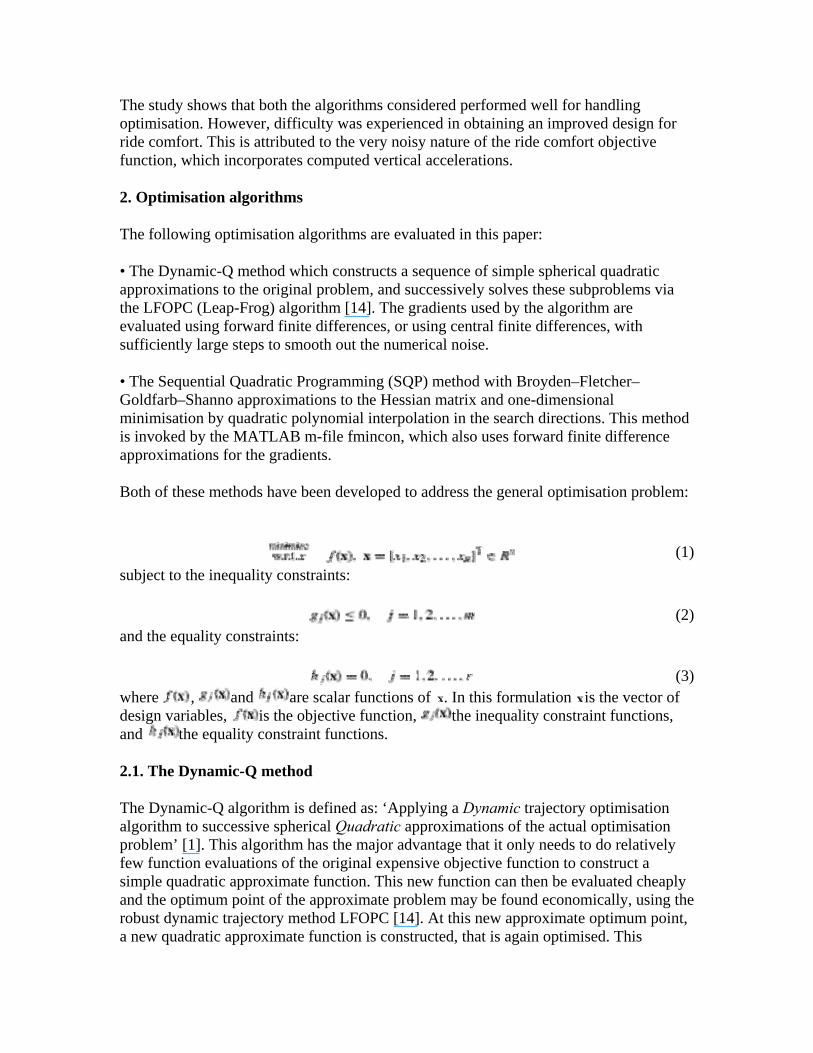
Both of these methods have been developed to address the general optimisation problem:
(1)subject to the inequality constraints:
(2)and the equality constraints:
(3)where , and are scalar functions of . In this formulation is the vector of design variables, is the objective function, the inequality constraint functions, and the equality constraint functions.
2.1. The Dynamic-Q method
The Dynamic-Q algorithm is defined as: ‘Applying a Dynamic trajectory optimisation algorithm to successive spherical Quadratic approximations of the actual optimisation problem’ [1]. This algorithm has the major advantage that it only needs to do relatively few function evaluations of the original expensive objective function to construct a simple quadratic approximate function. This new function can then be evaluated cheaply and the optimum point of the approximate problem may be found economically, using the robust dynamic trajectory method LFOPC [14]. At this new approximate optimum point, a new quadratic approximate function is constructed, that is again optimised. This
procedure is iteratively repeated until convergence is obtained. This method is very efficient for optimising objective functions that require an expensive computer simulation for their evaluation. In standard form Dynamic-Q makes use of forward finite differences to obtain gradient information required for the generation of the approximations. The details of the method can be found in the publications by Snyman and Hay [1] and Els and Uys [15] where it was applied to a vehicle similar to that in this study. A basic outline of the algorithm is set out below.
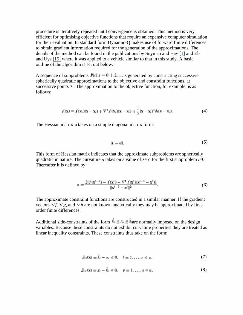
A sequence of subproblems is generated by constructing successive spherically quadratic approximations to the objective and constraint functions, at successive points . The approximation to the objective function, for example, is as follows:
(4)
The Hessian matrix takes on a simple diagonal matrix form:
(5)
This form of Hessian matrix indicates that the approximate subproblems are spherically quadratic in nature. The curvature a takes on a value of zero for the first subproblem i=0. Thereafter it is defined by:
(6)
The approximate constraint functions are constructed in a similar manner. If the gradient vectors f, g, and h are not known analytically they may be approximated by first-order finite differences.
Additional side-constraints of the form are normally imposed on the design variables. Because these constraints do not exhibit curvature properties they are treated as linear inequality constraints. These constraints thus take on the form:
(7)
(8)
To obtain stable and controlled convergence of the solutions of successive subproblems, a move limit is set which takes on the form of an inequality:
(9)
where δ corresponds to the specified maximum magnitude of the move limit. The subproblem at can now be solved using the dynamic trajectory ‘Leap-Frog’ optimisation algorithm for constrained optimisation LFOPC. This solution is taken as , the point at which the next approximate subproblem is constructed. This process is continued until convergence is obtained.
2.2. The SQP method
The Sequential Quadratic Programming (SQP) optimisation algorithm is well known and is considered the industry-standard method for constrained optimisation problems if the number of variables is not too large. The version used here is found in MATLAB’s Optimisation Toolbox [16]. SQP also finds the solution via successive quadratic approximations of the objective function. In constructing these approximations second-order differential information is required, in the form of the Hessian matrix. The Hessian matrix is approximated by making use of the Broyden–Fletcher–Goldfarb–Shanno (BFGS) approximation. The BFGS method also relies on forward finite differences to approximate the gradient of the objective function. The Hessian matrix does, however, require updating if the problem behaves poorly, requiring an extra n+1 function evaluations per iteration.
2.3. Gradient approximation methods
Most gradient-based optimisation algorithms require the determination of the first- and/or second-order gradient information for the objective and constraint functions with respect to the design variables. In most engineering optimisation problems this gradient information is not analytically available. The only information available to the designer is the values of objective and constraint functions obtained via expensive simulations. This research investigates the use of forward and central finite differences in the Dynamic-Q optimisation algorithm, for the determination of the first-order gradient information.
• Forward finite difference (ffd): This is the simplest and most economic method for approximating the gradients of the objective and constraint functions, required by gradient-based mathematical optimisation algorithms. This method approximates the first-order gradient information of a multi-variable function , by evaluating the change in the function for a small change in each of the design variables xk, k=1,2,…,n, as illustrated in Fig. 1. Thus, in order to carry out the full gradient vector evaluation, a total number of n+1 function evaluations are required for each iteration, where n is the total number of design variables. The forward finite difference approximation to the component of the gradient at is defined as follows:
(10)
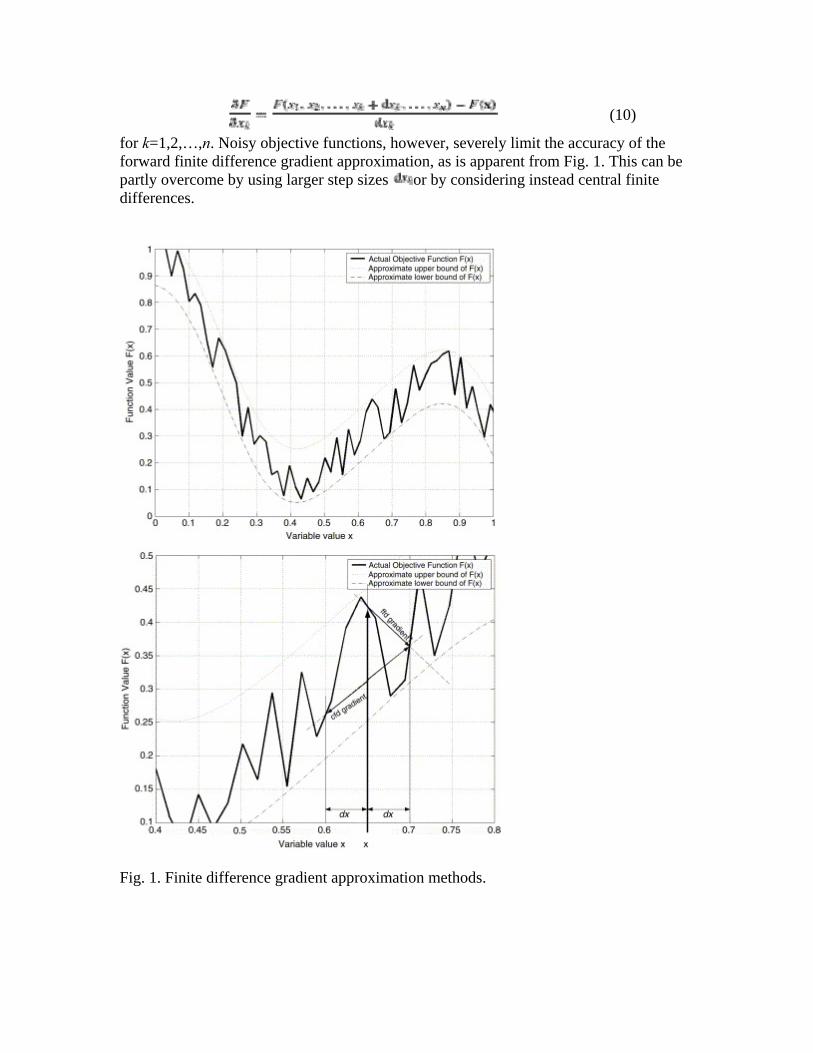
for k=1,2,…,n. Noisy objective functions, however, severely limit the accuracy of the forward finite difference gradient approximation, as is apparent from Fig. 1. This can be partly overcome by using larger step sizes or by considering instead central finite differences.
Fig. 1. Finite difference gradient approximation methods.
• Central finite difference (cfd): Central finite differences make use of a function evaluation on either side of the current iteration point , resulting in a better approximation to the gradient of the underlying smooth function in the presence of noise. Although this method requires 2n+1 function evaluations per gradient vector evaluation, it may result in fewer optimisation iterations to obtain a minimum.
The central finite difference procedure is defined as follows:
(11)
for k=1,2,…,n. In this way the gradient is evaluated by looking at information behind and ahead of the current iteration point, while the forward finite difference only looks ahead of the current iteration point. This results in a more accurate approximation to the function gradient, when noise is present, as illustrated for the case depicted in Fig. 1. The effects of noise cannot be completely eliminated by this method, but it certainly yields gradient approximations that are superior to those given by forward finite differences.
3. Vehicle model
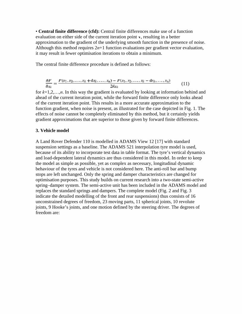
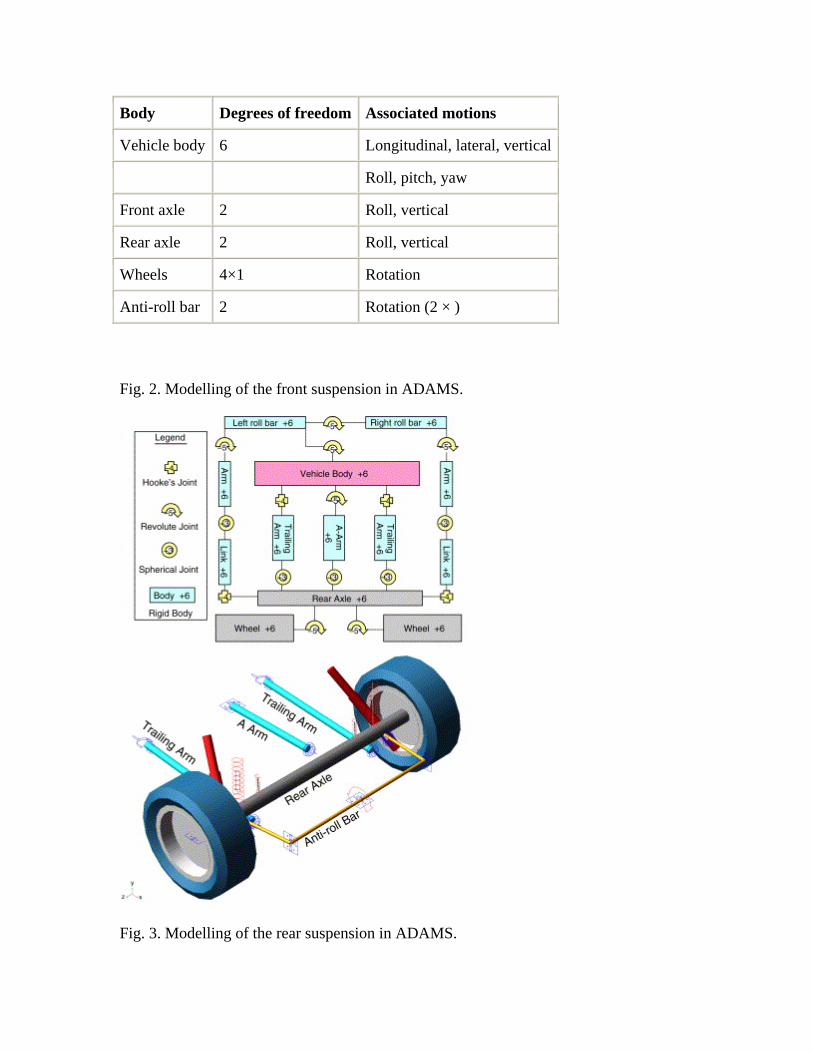
A Land Rover Defender 110 is modelled in ADAMS View 12 [17] with standard suspension settings as a baseline. The ADAMS 521 interpolation tyre model is used, because of its ability to incorporate test data in table format. The tyre’s vertical dynamics and load-dependent lateral dynamics are thus considered in this model. In order to keep the model as simple as possible, yet as complex as necessary, longitudinal dynamic behaviour of the tyres and vehicle is not considered here. The anti-roll bar and bump stops are left unchanged. Only the spring and damper characteristics are changed for optimisation purposes. This study builds on current research into a two-state semi-active spring–damper system. The semi-active unit has been included in the ADAMS model and replaces the standard springs and dampers. The complete model (Fig. 2 and Fig. 3 indicate the detailed modelling of the front and rear suspensions) thus consists of 16 unconstrained degrees of freedom, 23 moving parts, 11 spherical joints, 10 revolute joints, 9 Hooke’s joints, and one motion defined by the steering driver. The degrees of freedom are:
Body Degrees of freedom Associated motions
Vehicle body 6 Longitudinal, lateral, vertical
Roll, pitch, yaw
Front axle 2 Roll, vertical
Rear axle 2 Roll, vertical
Wheels 4×1 Rotation
Anti-roll bar 2 Rotation (2 × )
Fig. 2. Modelling of the front suspension in ADAMS.
Fig. 3. Modelling of the rear suspension in ADAMS.
The vehicle direction of heading is controlled by a simple steering driver, adjusting the steering wheel rotation according to the difference of the desired course from the current course at a preview distance ahead of the vehicle.
The drive to the wheels is modelled as a variable torque depending on the difference between the instantaneous speed and desired speed. This ADAMS model is then linked to MATLAB through a Simulink block that requires as inputs the spring and damper design variable values, returning outputs of vertical accelerations and vehicle body roll angle.
4. Vehicle suspension unit
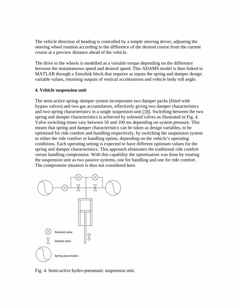
The semi-active spring–damper system incorporates two damper packs (fitted with bypass valves) and two gas accumulators, effectively giving two damper characteristics and two spring characteristics in a single suspension unit [18]. Switching between the two spring and damper characteristics is achieved by solenoid valves as illustrated in Fig. 4. Valve switching times vary between 50 and 100 ms depending on system pressure. This means that spring and damper characteristics can be taken as design variables, to be optimised for ride comfort and handling respectively, by switching the suspension system to either the ride comfort or handling option, depending on the vehicle’s operating conditions. Each operating setting is expected to have different optimum values for the spring and damper characteristics. This approach eliminates the traditional ride comfort versus handling compromise. With this capability the optimisation was done by treating the suspension unit as two passive systems, one for handling and one for ride comfort. The compromise situation is thus not considered here.
Fig. 4. Semi-active hydro-pneumatic suspension unit.
5. Optimisation
5.1. Design variables
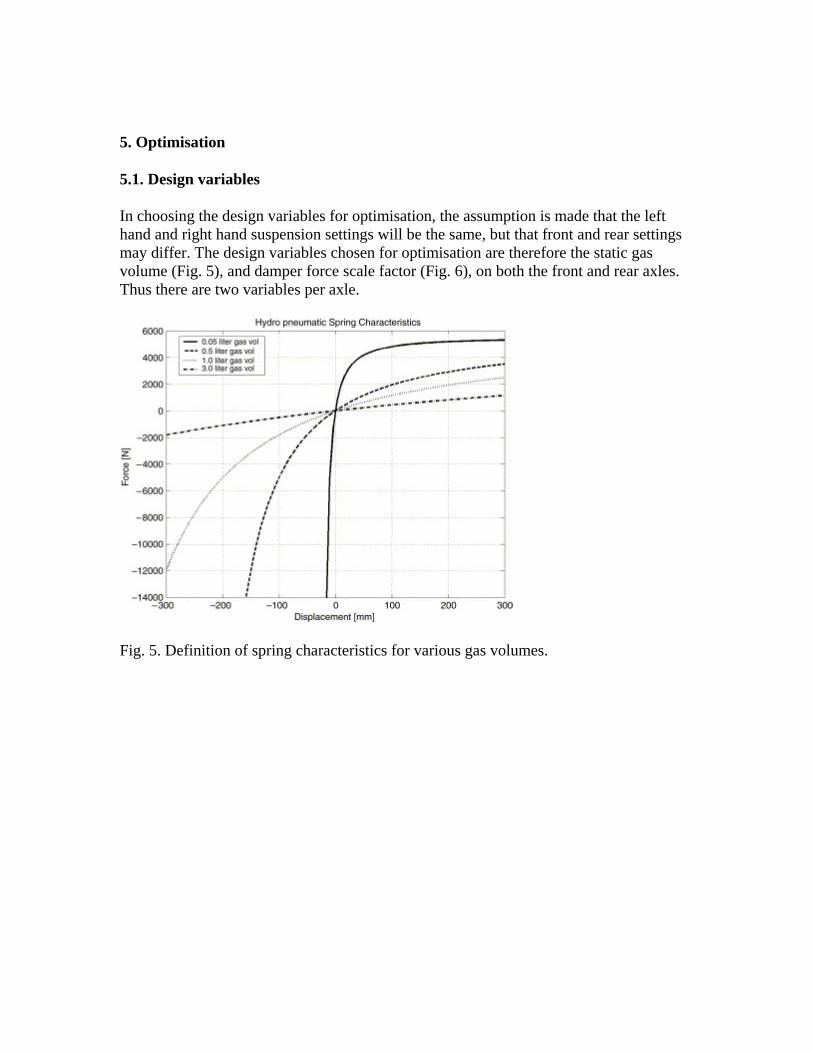
In choosing the design variables for optimisation, the assumption is made that the left hand and right hand suspension settings will be the same, but that front and rear settings may differ. The design variables chosen for optimisation are therefore the static gas volume (Fig. 5), and damper force scale factor (Fig. 6), on both the front and rear axles. Thus there are two variables per axle.
Fig. 5. Definition of spring characteristics for various gas volumes.
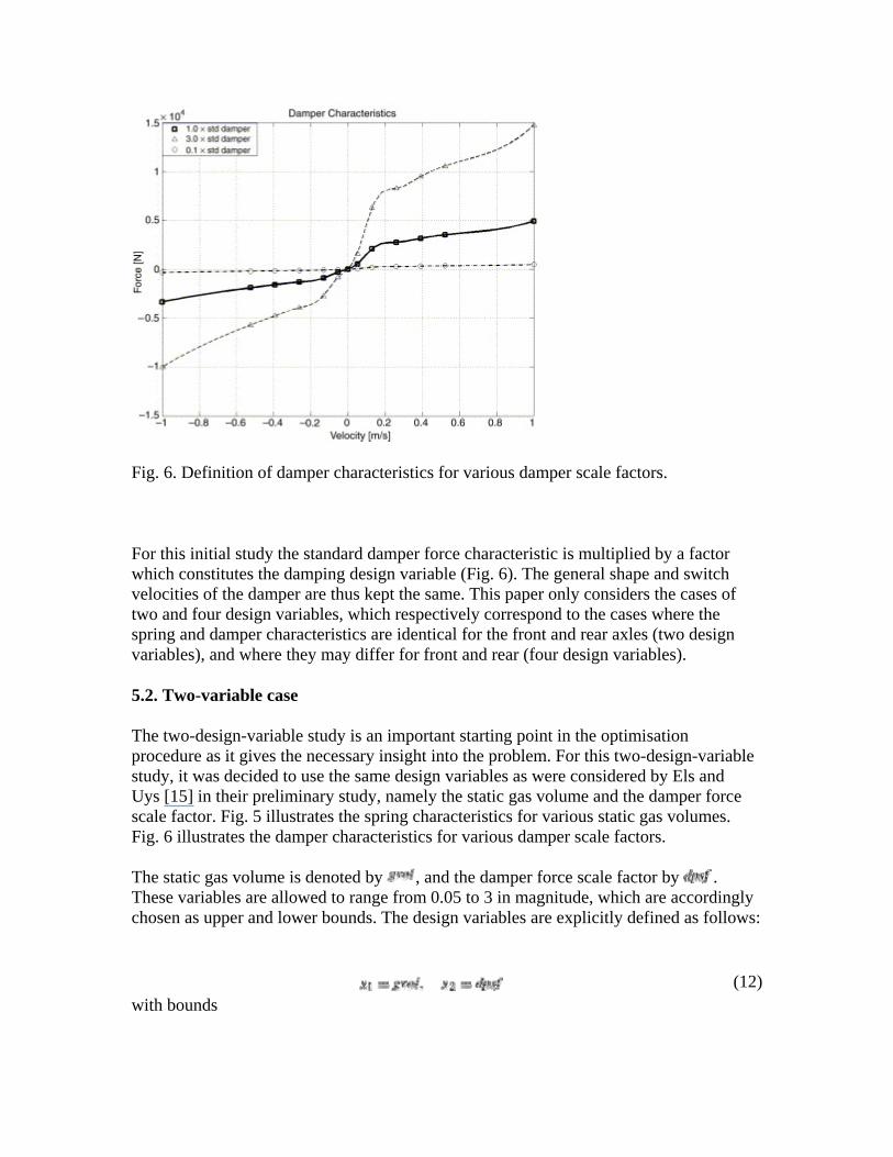
Fig. 6. Definition of damper characteristics for various damper scale factors.
For this initial study the standard damper force characteristic is multiplied by a factor which constitutes the damping design variable (Fig. 6). The general shape and switch velocities of the damper are thus kept the same. This paper only considers the cases of two and four design variables, which respectively correspond to the cases where the spring and damper characteristics are identical for the front and rear axles (two design variables), and where they may differ for front and rear (four design variables).
5.2. Two-variable case
The two-design-variable study is an important starting point in the optimisation procedure as it gives the necessary insight into the problem. For this two-design-variable study, it was decided to use the same design variables as were considered by Els and Uys [15] in their preliminary study, namely the static gas volume and the damper force scale factor. Fig. 5 illustrates the spring characteristics for various static gas volumes. Fig. 6 illustrates the damper characteristics for various damper scale factors.
The static gas volume is denoted by , and the damper force scale factor by . These variables are allowed to range from 0.05 to 3 in magnitude, which are accordingly chosen as upper and lower bounds. The design variables are explicitly defined as follows:
(12)
with bounds
(13)
5.3. Four-variable case
For the four-design-variable problem the front and rear settings are uncoupled. This means that there are separate front and rear damper scale factors and front and rear spring static gas volumes. This results in two design variables describing the front and two describing the rear, giving four design variables in total.
The front damper scale factor is denoted by , the front static gas volume by , the rear damper scale factor by , and the rear static gas volume by . These variables are also allowed to range from 0.05 to 3 in magnitude. Thus the design variables are defined explicitly as follows:
(14) with bounds
(15)
5.4. Definition of objective functions
For ride comfort the motion of the vehicle is simulated for travelling in a straight line over the Belgian paving and the sum of driver and rear passengers British Standard 6841 weighted root mean square (RMS) vertical accelerations [19] are used for the objective function. The motion sickness component was ignored as it requires long run times and the Belgian paving test track is not long enough for evaluating motion sickness. No additional measures were used for the ride comfort objective function, despite numerous studies [20], [21], [22] and [23] where the tyre deflection or force is used as a measure of road holding, when considering a quarter-car model. This was ignored as the suspension system has the ability to switch to the handling setting should a handling condition be detected. Kim and Ro [24] also suggest that tyre deflection is insufficient for evaluating handling parameters. This afforded the optimisations for ride comfort and handling to be done separately.
For handling, the vehicle performs a double lane change manœuvre at 80 km/h and the maximum body roll angle of the first peak [15] is used as the objective function. Roll angle is used as a measure of handling as suggested by Uys et al. [25].
The optimisation is done with limited constraints, so as to allow for a better understanding of the performances of the semi-active unit in attempting to achieve the
optimisation objectives. The bounds on the design variables were the only constraints considered in this study.
5.5. Design space
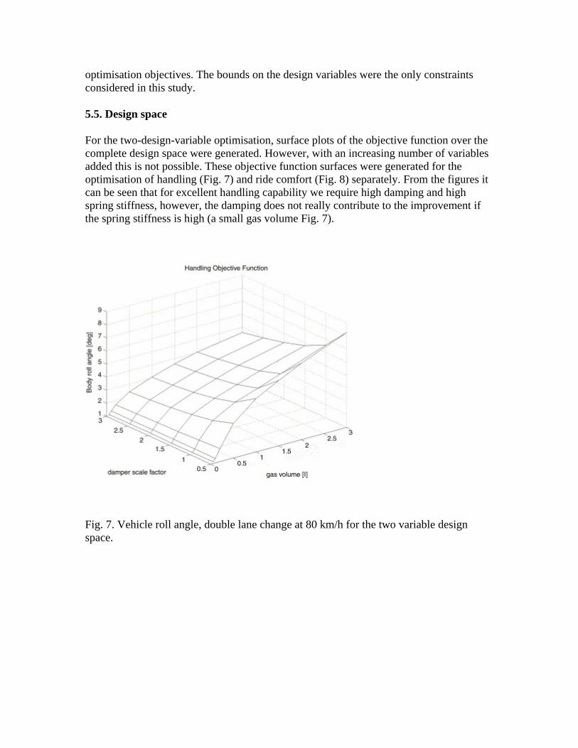
For the two-design-variable optimisation, surface plots of the objective function over the complete design space were generated. However, with an increasing number of variables added this is not possible. These objective function surfaces were generated for the optimisation of handling (Fig. 7) and ride comfort (Fig. 8) separately. From the figures it can be seen that for excellent handling capability we require high damping and high spring stiffness, however, the damping does not really contribute to the improvement if the spring stiffness is high (a small gas volume Fig. 7).
Fig. 7. Vehicle roll angle, double lane change at 80 km/h for the two variable design space.
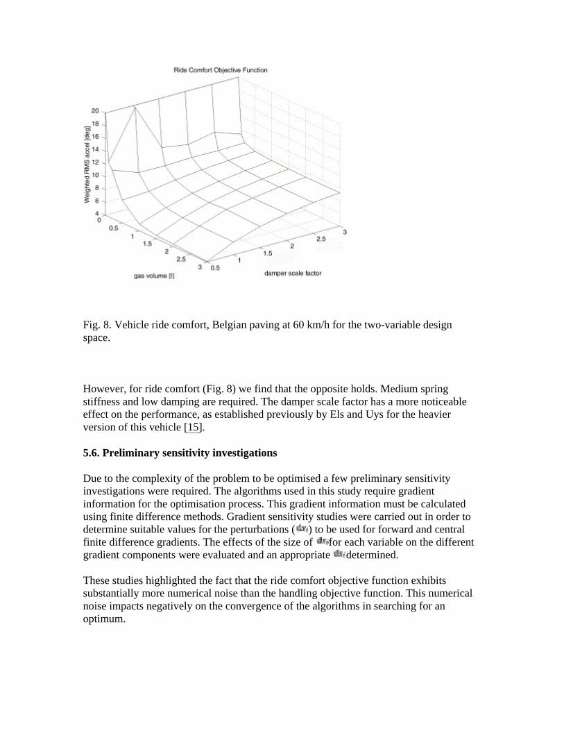
Fig. 8. Vehicle ride comfort, Belgian paving at 60 km/h for the two-variable design space.
However, for ride comfort (Fig. 8) we find that the opposite holds. Medium spring stiffness and low damping are required. The damper scale factor has a more noticeable effect on the performance, as established previously by Els and Uys for the heavier version of this vehicle [15].
5.6. Preliminary sensitivity investigations
Due to the complexity of the problem to be optimised a few preliminary sensitivity investigations were required. The algorithms used in this study require gradient information for the optimisation process. This gradient information must be calculated using finite difference methods. Gradient sensitivity studies were carried out in order to determine suitable values for the perturbations ( ) to be used for forward and central finite difference gradients. The effects of the size of for each variable on the different gradient components were evaluated and an appropriate determined.
These studies highlighted the fact that the ride comfort objective function exhibits substantially more numerical noise than the handling objective function. This numerical noise impacts negatively on the convergence of the algorithms in searching for an optimum.
5.7. Handling results
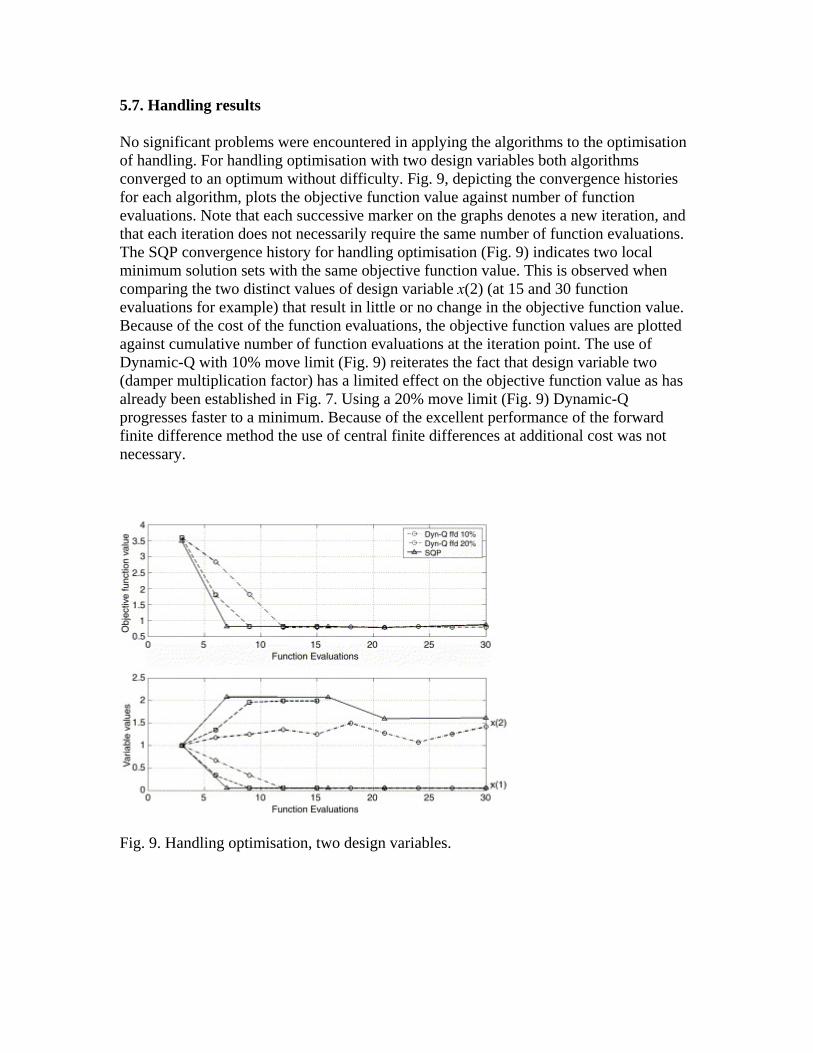
No significant problems were encountered in applying the algorithms to the optimisation of handling. For handling optimisation with two design variables both algorithms converged to an optimum without difficulty. Fig. 9, depicting the convergence histories for each algorithm, plots the objective function value against number of function evaluations. Note that each successive marker on the graphs denotes a new iteration, and that each iteration does not necessarily require the same number of function evaluations. The SQP convergence history for handling optimisation (Fig. 9) indicates two local minimum solution sets with the same objective function value. This is observed when comparing the two distinct values of design variable x(2) (at 15 and 30 function evaluations for example) that result in little or no change in the objective function value. Because of the cost of the function evaluations, the objective function values are plotted against cumulative number of function evaluations at the iteration point. The use of Dynamic-Q with 10% move limit (Fig. 9) reiterates the fact that design variable two (damper multiplication factor) has a limited effect on the objective function value as has already been established in Fig. 7. Using a 20% move limit (Fig. 9) Dynamic-Q progresses faster to a minimum. Because of the excellent performance of the forward finite difference method the use of central finite differences at additional cost was not necessary.
Fig. 9. Handling optimisation, two design variables.
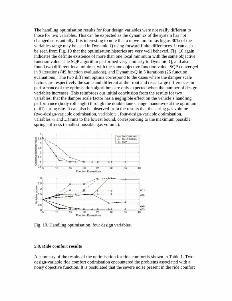
The handling optimisation results for four design variables were not really different to those for two variables. This can be expected as the dynamics of the system has not changed substantially. It is interesting to note that a move limit of as big as 30% of the variables range may be used in Dynamic-Q using forward finite differences. It can also be seen from Fig. 10 that the optimisation histories are very well behaved. Fig. 10 again indicates the definite existence of more than one local minimum with the same objective function value. The SQP algorithm performed very similarly to Dynamic-Q, and also found two different local minima, with the same objective function value. SQP converged in 9 iterations (49 function evaluations), and Dynamic-Q in 5 iterations (25 function evaluations). The two different optima correspond to the cases where the damper scale factors are respectively the same and different at the front and rear. Large differences in performance of the optimisation algorithms are only expected when the number of design variables increases. This reinforces our initial conclusion from the results for two variables: that the damper scale factor has a negligible effect on the vehicle’s handling performance (body roll angle) through the double lane change manœuvre at the optimum (stiff) spring rate. It can also be observed from the results that the spring gas volume (two-design-variable optimisation, variable x1, four-design-variable optimisation, variables x2 and x4) runs to the lowest bound, corresponding to the maximum possible spring stiffness (smallest possible gas volume).
Fig. 10. Handling optimisation, four design variables.
5.8. Ride comfort results
A summary of the results of the optimisation for ride comfort is shown in Table 1. Two-design-variable ride comfort optimisation encountered the problems associated with a noisy objective function. It is postulated that the severe noise present in the ride comfort
objective function, as opposed to the smooth nature of the handling objective function, is related to the fact that for ride comfort, accelerations are used, while for handling, angle displacement is used for the objective function measure. Multi-body dynamics solvers in general first solve for the accelerations, which are then integrated to obtain velocities and displacements. This integration acts as a low pass filter, helping to eliminate the noise content of the signal. In a study performed by Els [26], it was found that the BS6841 weighted RMS vertical acceleration corresponds well to subjective responses on ride comfort in off-road vehicles. For this reason the weighted RMS vertical accelerations will be used for the objective function, when considering ride comfort optimisation.
Table 1.
Ride comfort optimisation results
Algorithm Move Figure Iterations Function Optimum
limit (%) number evaluations value
Two design variables
SQP – Fig. 11 8 33 2.7
Dynamic-Q central 10 Fig. 11 9 (4) 50 (25) 4.1
finite differences 20 Fig. 11 6 30 3.1
Four design variables
Dynamic-Q forward 10 Fig. 12 12 65 3.8
finite differences 5 Fig. 13 6 35 3.9
Dynamic-Q cfd 10 Fig. 13 4 45 3.6
SQP – Fig. 13 8 65 3.5
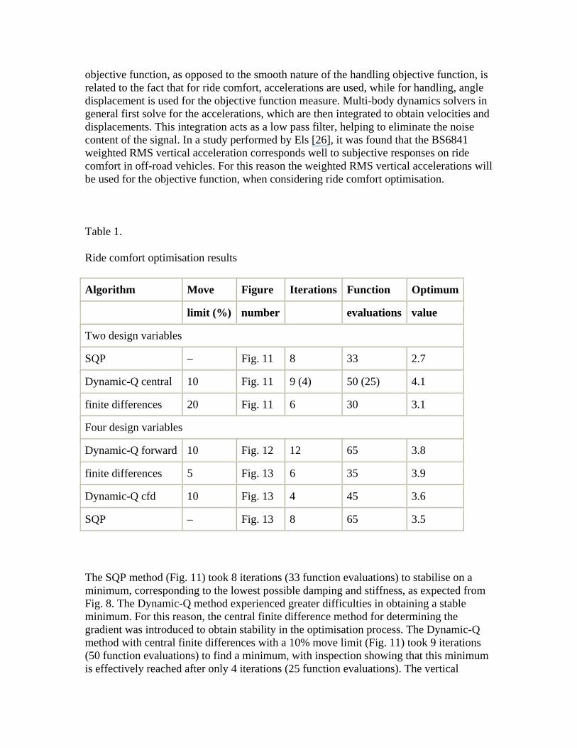
The SQP method (Fig. 11) took 8 iterations (33 function evaluations) to stabilise on a minimum, corresponding to the lowest possible damping and stiffness, as expected from Fig. 8. The Dynamic-Q method experienced greater difficulties in obtaining a stable minimum. For this reason, the central finite difference method for determining the gradient was introduced to obtain stability in the optimisation process. The Dynamic-Q method with central finite differences with a 10% move limit (Fig. 11) took 9 iterations (50 function evaluations) to find a minimum, with inspection showing that this minimum is effectively reached after only 4 iterations (25 function evaluations). The vertical
acceleration at this point is, however, significantly higher than that found with SQP indicating the existence of a separate interior local minimum. A 20% move limit (Fig. 11) took 6 iterations (30 function evaluations), finding a local minimum not far off the SQP minimum. The Dynamic-Q minimum design variable values are not at the extrema found by the SQP method, reinforcing the fact that the ride comfort design space has a flat plateau of local minima.
Fig. 11. Ride comfort optimisation, two design variables.
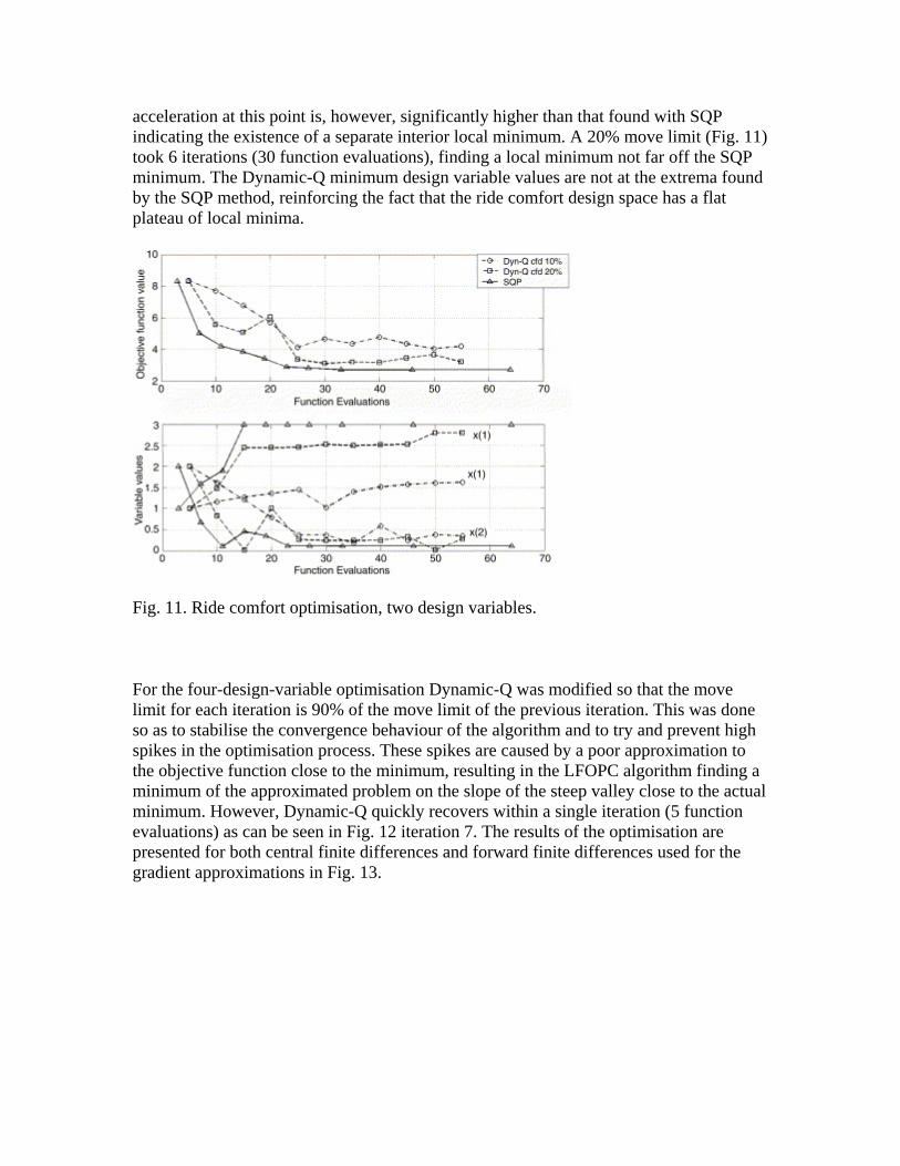
For the four-design-variable optimisation Dynamic-Q was modified so that the move limit for each iteration is 90% of the move limit of the previous iteration. This was done so as to stabilise the convergence behaviour of the algorithm and to try and prevent high spikes in the optimisation process. These spikes are caused by a poor approximation to the objective function close to the minimum, resulting in the LFOPC algorithm finding a minimum of the approximated problem on the slope of the steep valley close to the actual minimum. However, Dynamic-Q quickly recovers within a single iteration (5 function evaluations) as can be seen in Fig. 12 iteration 7. The results of the optimisation are presented for both central finite differences and forward finite differences used for the gradient approximations in Fig. 13.
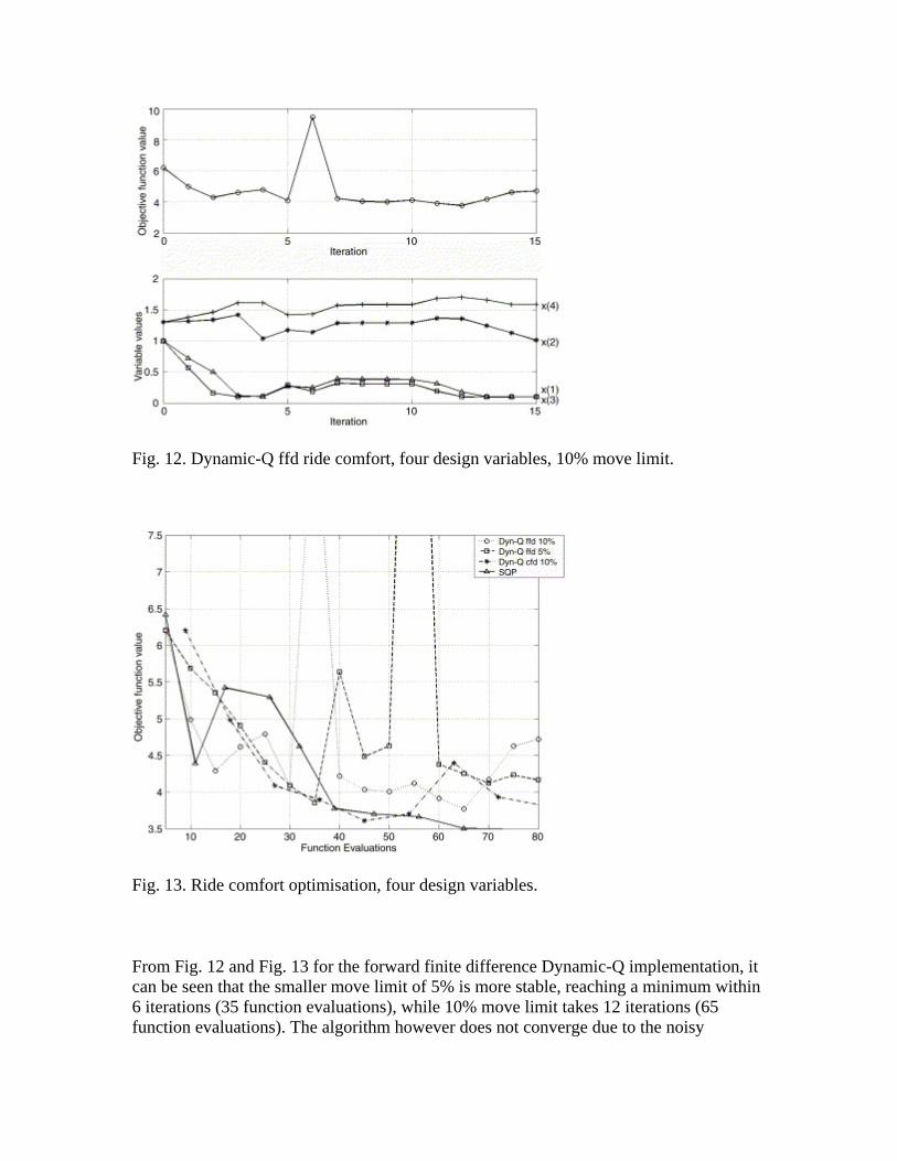
Fig. 12. Dynamic-Q ffd ride comfort, four design variables, 10% move limit.
Fig. 13. Ride comfort optimisation, four design variables.
From Fig. 12 and Fig. 13 for the forward finite difference Dynamic-Q implementation, it can be seen that the smaller move limit of 5% is more stable, reaching a minimum within 6 iterations (35 function evaluations), while 10% move limit takes 12 iterations (65 function evaluations). The algorithm however does not converge due to the noisy
objective function with a steep valley. The convergence behaviour for central finite differences coupled to Dynamic-Q is shown in Fig. 13 requiring 4 iterations (45 function evaluations). Again it has been determined that the smaller move limit is beneficial to finding the minimum. The central finite difference gradient evaluation builds into the system a level of robustness. From the results it can be seen that around 1.5 l gas volume and limited damping returns the best results. The central finite difference results show that by increasing the rear gas volume with minimal damping, a better overall ride can be achieved (Fig. 13).
SQP also found similar good results within 8 iterations (65 function evaluations; Fig. 13). From Table 1 it is concluded that Dynamic-Q with forward finite differences does not reach the same minimum as Dynamic-Q with central finite differences. Dynamic-Q with central finite differences is also similarly economical to SQP, finding a minimum within 5% of the SQP minimum objective function value.
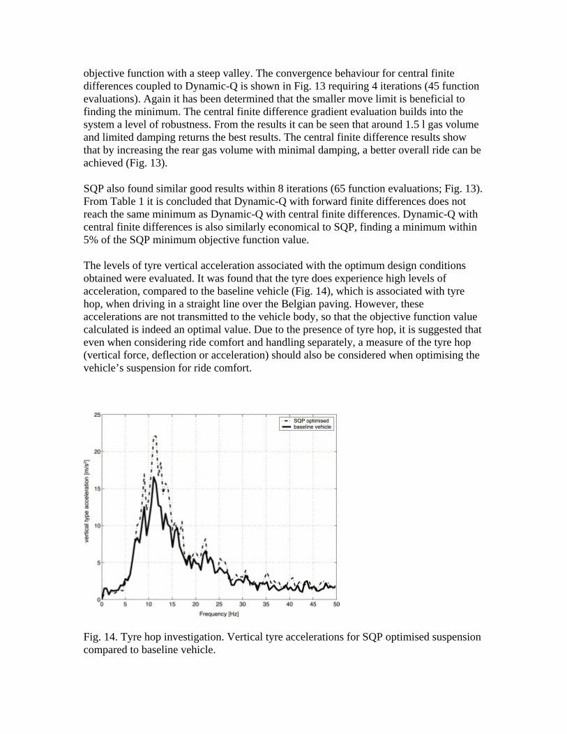
The levels of tyre vertical acceleration associated with the optimum design conditions obtained were evaluated. It was found that the tyre does experience high levels of acceleration, compared to the baseline vehicle (Fig. 14), which is associated with tyre hop, when driving in a straight line over the Belgian paving. However, these accelerations are not transmitted to the vehicle body, so that the objective function value calculated is indeed an optimal value. Due to the presence of tyre hop, it is suggested that even when considering ride comfort and handling separately, a measure of the tyre hop (vertical force, deflection or acceleration) should also be considered when optimising the vehicle’s suspension for ride comfort.
Fig. 14. Tyre hop investigation. Vertical tyre accelerations for SQP optimised suspension compared to baseline vehicle.
6. Conclusion
The feasibility of using gradient-based approximation methods for the optimal design of a vehicle’s suspension was investigated. An industry-standard version of the SQP method, and the relatively new Dynamic-Q method, were evaluated. The determination of the objective function was performed using a full multi-body vehicle simulation model that was both computationally expensive, and exhibited severe inherent numerical noise when considering, in particular, ride comfort. The goal was to determine the vehicle’s optimal spring and damper characteristics for both ride comfort and handling.
It is concluded that both methods work exceptionally well when optimising for handling. Although difficulties were experienced in the ride comfort optimisation due to the severe noise inherent in the objective function, both methods sufficiently overcame this problem by yielding locally optimal feasible solutions. It was found that for the Dynamic-Q algorithm the use of central finite differences for the gradient approximations, at the cost of 2n+1 function evaluations per iteration, achieved meaningful optima at a lower cost, in terms of total number of function evaluations (simulations), than the SQP method. This can be attributed to the inherent stability that the central finite differencing technique introduces by considering information ahead and behind the current iteration point.
The gradient-based approximation methods considered here prove to be feasible optimisation methods when noisy objective functions are to be optimised. These methods have the distinct advantage of requiring relatively few function evaluations, each of which corresponds to an expensive numerical simulation, before reaching an optimal design. Although this paper has touched on only a small aspect of vehicle suspension design, and more variables should be considered in the future, the study does justify the future use of the approximation methods considered here. These methods can be taken as useful tools for the designer requiring results in a limited time frame.
References
[1] J.A. Snyman and A.M. Hay, The dynamic-Q optimisation method: An alternative to SQP?, Computers and Mathematics with Applications 44 (2002), pp. 1589–1598.
[2] P. Eriksson and O. Friberg, Ride comfort optimisation of a city bus, Structural and Multidisciplinary Optimisation 20 (2000), pp. 67–75.
[3] P. Eberhard, D. Bestle and U. Piram, Optimisation of damper characteristics in nonlinear dynamic systems, First World Congress of Structural and Multidisciplinary Optimisation (1995), pp. 863–870.
[4] L.F.P. Etman, R.C.N. Vermeulen, J.G.A.M. van Heck, A.J.G. Schoofs and D.H. van Campen, Design of a stroke dependent damper for the front axle suspension of a truck using multibody system dynamics and numerical optimisation, Vehicle System Dynamics 38 (2002), pp. 85–101.
[5] D. Andersson and P. Eriksson, Handling and ride comfort optimisation of an intercity bus, Vehicle System Dynamics Supplement 41 (2004), pp. 547–556.
[6] A.F. Naude and J.A. Snyman, Optimisation of road vehicle passive suspension systems. Part 1. optimisation algorithm and vehicle model, Applied Mathematical Modelling 27 (2003), pp. 249–261.
[7] A.F. Naude and J.A. Snyman, Optimisation of road vehicle passive suspension systems. Part 2. Qualification and case study, Applied Mathematical Modelling 27 (2003), pp. 263–274.
[8] M. Gobbi, G. Mastinu and C. Doniselli, Optimising a car chassis, Vehicle System Dynamics 32 (1999), pp. 149–170.
[9] M. Gobbi, G. Mastinu, C. Doniselli, L. Guglielmetto and E. Pisino, Optimal and robust design of road vehicle suspension system, Vehicle System Dynamics Supplement 33 (1999), pp. 3–22.
[10] J. Schuller, I. Haque and M. Eckel, An approach for optimisation of vehicle handling behaviour in simulation, Vehicle System Dynamics Supplement 37 (2002), pp. 24–37.
[11] A.E. Baumal, J. McPhee and P.H. Calamai, Application of genetic algorithms to the optimisation of an active vehicle suspension design, Computer Methods in Applied Mechanics and Engineering 163 (1998), pp. 87–94.
[12] P. Eberhard, W. Schiehlen and D. Bestle, Some advantages of stochastic methods in multi-criteria optimisation of multibody systems, Archive of Applied Mechanics 69 (1999), pp. 543–554.
[13] S. Datoussaid, O. Verlinden and C. Conti, Application of evolutionary strategies to optimal design of multibody systems, Multibody System Dynamics 8 (2002), pp. 393–408.
[14] J.A. Snyman, The LFOPC Leap-Frog algorithm for constrained optimisation, Computers and Mathematics with Applications 40 (2000), pp. 1085–1096.
[15] P.S. Els and P.E. Uys, Investigation of the applicability of the dynamic-Q optimisation algorithm to vehicle suspension design, Mathematical and Computer Modeling 37 (2003), pp. 1029–1046.
[16] MATLAB Optimisation Toolbox Users Guide version 2.2, Mathworks (2000).
[17] Getting Started Using ADAMS View, Version 12, Mechanical Dynamics (2002).
[18] C.L. Giliomee and P.S. Els, Semi-active hydro pneumatic spring and damper system, Journal of Terramechanics 35 (1998), pp. 109–117.
[19] British Standards Institution, British Standard guide to Measurement and Evaluation of Human Exposure to Whole-Body Mechanical Vibration and repeated Shock, BS6841 (1987).
[20] A. Alleyne and J.K. Hedrick, Nonlinear adaptive control of active suspensions, IEEE Transactions on Control Systems Technology 3 (1995) (1), pp. 94–101.
[21] C. Kim and P.I. Ro, A sliding mode controller for vehicle active suspension systems with non-linearities, Proceedings of International Mechanical Engineers 212 (1998) (D), pp. 79–92.
[22] C. Pilbeam and R.S. Sharp, Performance potential and power consumption of slow-active suspension systems with preview, Vehicle System Dynamics 25 (1996), pp. 169–183.
[23] L.R. Miller, Tuning passive, Semi-active, and fully active suspension systems, in: Proceedings of the 27th Conference on Decision and Control, Austin, Texas, December 1998.
[24] C. Kim and P.I. Ro, An accurate model for vehicle handling using reduced-order model techniques, Society of Automotive Engineering Technical Paper Series, SAE 2001-01-2520 (2001).
[25] P.E. Uys, P.S. Els and M.J. Thoresson, Criteria for handling measurement, Journal of Terramechanics 43 (2006) (1), pp. 43–67.
[26] P.S. Els, The applicability of ride comfort standards to off-road vehicles, Journal of Terramechanics 42 (2005) (January), pp. 47–64.