Transient containment response and inherent retention capability
17
Nuclear Englneering and Design 42 (1977) 1-186 151 ©North-Holland Publishing Company TRANSIENT CONTAINMENT RESPONSE AND INHERENT RETENTION CAPABILITY E. L. Gluekler, A. Dayan, F. Hayes and C. T. Kline General Electric Company, Fast Breeder Reactor Department, Sunnyvale, California For safety assessments of early sodium cooled fast breeder reactors, hypothetical events such as loss of flow or transient overpower sequences combined with the failure of the reactor protective systems have been evaluated. The intent of these evaluations was to demonstrate that even extremely unlikely combinations of failures which could lead to meltdown of a portion of the reactor core would not propagate into events harmful to the public. This paper investigates the consequences of a meltdown event. In general, reactor vessels and the primary sodium systems have an adequate inherent retention capability to retain dispersed or molten core debris and remove decay heat. For certain vessel designs, large core debris masses may penetrate through the vessel wall and drain into the reactor cell. Although significant uncertain- ties exist in the evaluations of debris retention and heat removal capabilities of the containment, there is indication that criteria for radiological limits can well be met. If the accident pro- gression can be controlled in-vessel, consequences would be minimized. i. Introduction The question of maximum consequences of reactor accidents has been a concern of reactor designers since reactors have first been built. Although the reliabil- ity of the reactor protective systems has been much improved over early designs so that core melt-down and disruption events may be deleted from the reactor design basis, the evaluation of consequences of low probability events has remained an important aspect of safety and risk asses- ments. At the present time, reactor de- signs still reflect vastly differing ap- proaches in dealing with the problem of residual risk of low probability events. The solutions range from (a) concepts in which the inherent in-vessel core debris retentions is sufficient (FFTF), [i] over (b) designs with some additional in-vessel retention devices - a plate underneath the core support structure - (PFR), [2] to (c) engineered ex-vessel retention concepts (SNR-300). [3] Figures 1 to 3 illustrate concepts a, b and c, respec- tively. A general trend in the application of concepts can be observed: for reactors with large volume ratios of reactor sodium to fuel (FFTF, PFR), in-vessel retention concepts have been favored; for those with small ratios (SNR-300), ex-vessel reten- tion has been selected. In this paper, a loop type reactor (i000 MW t) with a small vessel is inves- tigated. The scenario following a core meltdown is briefly described, and in- vessel and ex-vessel debris retention ca- pabilities are discussed. 2. Accident Scenario Although redundant and very reliable reactor protective systems are available in LMFBRs, hypothetical loss of flow (LOF) accidents or transient overpower (TOP) coupled with the failure of the shutdown system to scram have been included in safety assessments. The selected events envelop the consequences of other postu- lated transient events such as the pro- pagation of a fuel assembly flow blockage without scram and a large gas bubble pass- ing through the core without scram. An LOF scenario can lead to the most severe melt- down conditions. In an LOF type accident, the decrease in sodium flow would cause sodium boiling in the core region, flow reversal, coolant channel voiding, cladding and fuel melting, and molten core material relocation under the influences of gravity and vapor-flow shear forces. The dispersal of fuel away from the active core region results in neutronic shutdown. The axial direction is favored for material flow due to low \ inertial resistance forces. Massivestruc- tures prevent dispersion in the radial di- rection. Freezing of molten core debris in contact with the cool lower core struc- ture promotes vapor driven ejection in the upward direction. In contact with liquid sodium, molten core debris will fragment into small particles because of hydrody- namic forces and thermal stresses that
-
Upload
independent -
Category
Documents
-
view
1 -
download
0
Transcript of Transient containment response and inherent retention capability

Nuclear Englneering and Design 42 (1977) 1-186 151 ©North-Holland Publishing Company
TRANSIENT CONTAINMENT RESPONSE AND INHERENT RETENTION CAPABILITY
E. L. Gluekler, A. Dayan, F. Hayes and C. T. Kline Genera l E l e c t r i c Company, Fas t Breeder Reac tor Depar tment , S u n n y v a l e , C a l i f o r n i a
For safety assessments of early sodium cooled fast breeder reactors, hypothetical events such as loss of flow or transient overpower sequences combined with the failure of the reactor protective systems have been evaluated. The intent of these evaluations was to demonstrate that even extremely unlikely combinations of failures which could lead to meltdown of a portion of the reactor core would not propagate into events harmful to the public.
This paper investigates the consequences of a meltdown event. In general, reactor vessels and the primary sodium systems have an adequate inherent retention capability to retain dispersed or molten core debris and remove decay heat. For certain vessel designs, large core debris masses may penetrate through the vessel wall and drain into the reactor cell. Although significant uncertain- ties exist in the evaluations of debris retention and heat removal capabilities of the containment, there is indication that criteria for radiological limits can well be met. If the accident pro- gression can be controlled in-vessel, consequences would be minimized.
i. Introduction
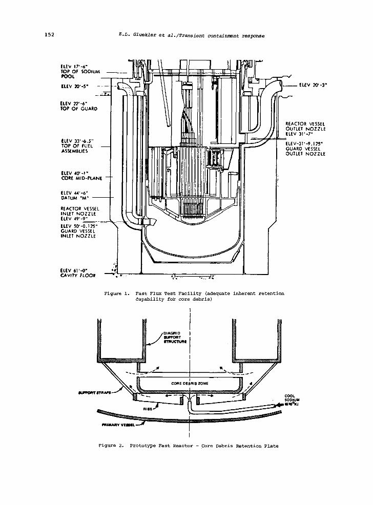
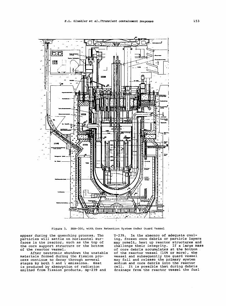
The question of maximum consequences of reactor accidents has been a concern of reactor designers since reactors have first been built. Although the reliabil- ity of the reactor protective systems has been much improved over early designs so that core melt-down and disruption events may be deleted from the reactor design basis, the evaluation of consequences of low probability events has remained an important aspect of safety and risk asses- ments. At the present time, reactor de- signs still reflect vastly differing ap- proaches in dealing with the problem of residual risk of low probability events. The solutions range from (a) concepts in which the inherent in-vessel core debris retentions is sufficient (FFTF), [i] over (b) designs with some additional in-vessel retention devices - a plate underneath the core support structure - (PFR), [2] to (c) engineered ex-vessel retention concepts (SNR-300). [3] Figures 1 to 3 illustrate concepts a, b and c, respec- tively.
A general trend in the application of concepts can be observed: for reactors with large volume ratios of reactor sodium to fuel (FFTF, PFR), in-vessel retention concepts have been favored; for those with small ratios (SNR-300), ex-vessel reten- tion has been selected.
In this paper, a loop type reactor (i000 MW t) with a small vessel is inves- tigated. The scenario following a core meltdown is briefly described, and in-
vessel and ex-vessel debris retention ca- pabilities are discussed.
2. Accident Scenario
Although redundant and very reliable reactor protective systems are available in LMFBRs, hypothetical loss of flow (LOF) accidents or transient overpower (TOP) coupled with the failure of the shutdown system to scram have been included in safety assessments. The selected events envelop the consequences of other postu- lated transient events such as the pro- pagation of a fuel assembly flow blockage without scram and a large gas bubble pass- ing through the core without scram. An LOF scenario can lead to the most severe melt- down conditions.
In an LOF type accident, the decrease in sodium flow would cause sodium boiling in the core region, flow reversal, coolant channel voiding, cladding and fuel melting, and molten core material relocation under the influences of gravity and vapor-flow shear forces. The dispersal of fuel away from the active core region results in neutronic shutdown. The axial direction is favored for material flow due to low \ inertial resistance forces. Massivestruc- tures prevent dispersion in the radial di- rection. Freezing of molten core debris in contact with the cool lower core struc- ture promotes vapor driven ejection in the upward direction. In contact with liquid sodium, molten core debris will fragment into small particles because of hydrody- namic forces and thermal stresses that
152 E.L. Glueklei et al./Transient containment response
ELEV 17'-6" TOP OF SODIL POOL
ELEV 20'-5" ~ ' - 3 "
ELEV 22'-6" TOP OF GUAR
ELEV 33' --6.5" TOP OF FUEL ASSEMBLIES
~ESSEL OZZLE
.125" SSEL OZZLE
ELEV 40' - I " CORE MID-PL~
ELEV 44'-6" DATUM '*M" "
REACTOR VESS INLET NOZZLI ELEV 49' -9"
ELEV 50' -0. t ?., GUARD VESSEL INLET NOZZLI
ELEV 61"-0" CAVITY FLOO~ - ~ : " - 4,. L. :, .. : .- .;{"
Figure i. Fast Flux Test Facility (adequate inherent retention ~apability for core debris)
oo..o,....,o.. H . , / / ~ , ~ ~ ~ ............. l#.,x/
V I M I L " ~ .. . . . . . . . . . . . . . . . . . . . . . ....~....... . . . . . . . . . . I'll111m, Al~W /
I
Figure 2. Prototype Fast Reactor - Core Debris Retention Plate
E.L. Gluekler et al./Transient containment response 153
Figure 3. SNR-300, with Core Retention System Under Guard Vessel
appear during the quenching process. The particles will settle on horizontal sur- faces in the reactor, such as the top of the core support structure or the bottom of the reactor vessel.
After neutronic shutdown the unstable materials formed during the fission pro- cess continue to decay through several stages by both 8 and y emissions. Heat is produced by absorption of radiation emitted from fission products, Np-239 and
U-239. In the absence of adequate cool- ing, frozen core debris or particle layers may remelt, heat up reactor structures and challenge their integrity. If a large mass of core debris accumulates at the bottom of the reactor vessel (10% or more), the vessel and subsequently the guard vessel may fail and release the primary system sodium and core debris into the reactor cell. It is possible that during debris drainage from the reactor vessel the fuel

154 E.L. GluekleI et al./Transient containment response
TABLE i. CRITICAL DIMENSIONS FOR SIMPLE FUEL GEOMETRIES
GEOMETRY
Layer
Cylln~r
Cone
Sphere
Spherical Segment
CONFIGURATION
Ta. ,b. ,C.
A
BOUNDARY CONDITION
Top Layer Na Bottom Layer
a. UO 2 (natural) b. tCjO c. Graphite
Bottom Surface
CRITICAl. DIHENSION (ca)
a. 14 b. 6
c. 4.3
UO 2
Dry 34 Na 30
" Na
Bottom Surface
UO 2
a. 1 tuNa- Reflector
b. ZO cm UO 2 Reflector
Stainless steel vessel, steel and sodium layers above fuel, concrete wails of reactor cell. a fuel only b. fuel + blanket~
SO
a. 42.8
b. 34.9
a. 14
b. 30
could attain a configuration in which sec- ondary criticality would occur. The geo- metries that should be avoided are sum- marized in Table i.
The sequence of events after the hypothetical accident is shown in Table 2. With the formation of coolable in- vessel particle layer, the accident se- quence would end. The formation of a stable ex-vessel particle layer on the liner would also terminate the sequence, if adequate heat removal under asymptotic conditions prevents sodium boiloff and the liner stays intact. Accident progres- sion beyond the liner initiates exothermic chemical reactions between sodium, metal-
lic debris components and concrete con- stituents such as Si02, H20 and C02. The
loss of sodium by chemical reaction, and boiloff, promoted by the decay heat source and reaction energies, can ultimately lead to sodium dryout from the reactor and remelting of core debris. The molten oxides may penetrate into the concrete structure. Radioactive materials may, in form of aerosols and vapors, be trans- ported to the environment through flow paths or leak paths formed as a conse- quence of structural failures. It is evident that radiological consequences are reduced if the accident progression can be stopped early. This could be

EoL. Gluekler et al,/Transient containment response 155
TABLE 2. SEQUENCE OF EVENTS AFTER A POSTULATED MELTDOWN ACCIDENT
I~ Loss Qf FlowAccldent
I Core Dispersal and Neutronic Shutdown
I 'Debris Fragmentation and Particle Settlin~ I
[Sta~le Particle ..elting of ~articles I a~er
I Intact Vessel v " I essei and Guard Vessel Fai!ure
ILiner Intact ~ - ~ . Liner Failure I
I Coolable Particle Layer~ IChemical Reaction wit,
I Concrete Water Release and Ventin9 I LL°ss °f S°dium I
Liner Failure I INaOH romatl;n After Dryout ) l(Sec. Reactions) 1
-[Debris Remeltl ng )
I Limited Melting A t t a c k ~ . . . . . ncrease Leakage of I Debris Resolldlflcation I R d . . . . . . I
I . . . . . . I ) a loac l : lve M a t e r i a l )
~"T j" (Concrete Me~t+Bq. ) (Termination of.Seque;c I
I Debris Resol idificatlon l I
~< Optimistic Scenario Pessimistic Scenario ~

156 E.L. Gluekler et &l./Transient containment response
accomplished by preventing remelting of core debris (See Table 2).
Significant uncertainties exist in the entire post-accident scenario, from the initial core debris dispersion to the final stage of debris resolidification. Uncertainties are apparent in the mech- anism of debris dispersion, heated par- ticle/sodium interactions, and most im- portantly in the mass and state of the debris generated during the transient.
3. In-Vessel Retention Capability
The core debris generated during the postulated accident sequence fragments into small particles in contact with so- dium. [4] These particles resolidify and disperse in the sodium pool. From an engineering standpoint it would be desir- able to take advantage of the naturally occurring porcesses to control the in- vessel accident progression. The follow- ing mechanisms seem to be important
a. particle dispersion and settling characteristics
b. particle bed formation and heat transfer
c. molten layer formation and heat transfer, and
d. the structural integrity of re- tainer walls
Most emphasis in research work has been given so far to mechanisms (b) and (c); some work has been performed to assess structural responses, (d), but very little information is available in area (a).
It appears that the basic requirement for successful in-vessel debris retention is to keep the particles dispersed so that decay heat can be adequately removed by sodium to prevent remelting. It has been shown experimentally that layers of inter- nally heated particles which have settled at the bottom of a pool of fluid are stable up to a certain critical depth. If this depth is exceeded, the vapor generation rate is greater than the rate at which gravity can maintain a steady flow through the particle bed so that fluid dryout would occur.[5,6] Based on this information it has been shown that for typical early sized loop type LMFBRs approximately 8 to 10% of core debris would remain as a particle bed at the bottom of the reactor vessel. [7]
If larger masses were present, debris bed dryout and fuel debris remelting could occur. Three phases can be distinguished during this process as the materials heat up:
a. steel remelting phase (solid fuel particles)
b. fuel remelting phase c. molten steel and fuel layer strat-
ification
The mode of heat transport to the reactor vessel changes from an initial transient
conduction phase when both solid fuel and steel particles are present to a phase with steel natural convection in a fuel particle bed and finally to a steel and fuel natural convection phase. A two di- mensional heat transfer model was devel- oped for the hemispherical segment repre- senting the bottom of the reactor vessel. [8]
The structural response of the reactor vessel depends on the heat transport to the vessel and heat losses by thermal radiation to the guard vessel and liner. If the be- havior of the materials in the vessel wall is described by Miller's creep equation [9], the load carrying capability of the vessel for any given temperature distribu- tion is L
1 f ault (z,T) d z s (t)=
0 L 1
exp(-Q/RT(z))]ndz (i, 0 L r
where z = dimensionless thickness coordin- ate, T(z) = temperature distribution, Q = activation energy for steel self-diffusion, R~= gas constant, t = time, e r = rupture
strain, t = rupture time, c and n mate- r
rials parameters. If the entire mass of the active core
should accumulate at the bottom of the reactor vessel, failure by creep rupture would occur within approximately 20 minutes before any appreciable melting of the wall takes place. At the time of failure, the melt isochrones indicate a significant ex- tension of the melting in the radial di- rection, i.e. the bottom of the vessel heats fairly uniformly and failure by for- mation of a large diameter hole (80 cm) could be expected under the postulated conditions. Table 3 provides a summary of a sensitivity study in which model as- sumptions, uncertainties in initial con- ditions, and configuration changes were examined. It appears that core debris crust formation significantly affects heat transfer and failure times.
No melting attack of the reactor vessel or failure was predicted for the postulated scenario when the outer vessel surface was assumed to be cooled to I150°K. This temperature corresponding to the boil- ing point of sodium at atmospheric pressure is assumed to be maintained by boiling or forced convection. It can be concluded that a horizontal plate located underneath the core support structure would have a similar retention capability.
Debris retention in trays located underneath the core support structure has been investigated. Table 4 summarizes applicable heat transfer correlations. The convective heat transfer coefficients (h I

TABLE 3.
SENSITIVITY AND PARAMETRIC
STUDIES
Case
1 2 3 4 5 6 7 8
Properties
Thickness2(cm)
and
~out
RV
Na
Failure 4 Debris
Debris Melt Time6(Min)
Bed
Assumptions
Time
Initial Final
Cooling 3
Time
Tempp(OK)
Steel
~02
Nominal
60
8.25
5.15
No
19
2730
7.8
29.3
~XO.l(nominal) 1 60
8.25
8.25
No
..
..
.
7.8
26.8
~Xl0(nominal) I
60
8.25
4.02
No
17
2700
7.8
29.7
Nominal
30
8.25
5.04
No
17
2900
6.5
25.6
Nominal
180
8.25
7.43
No
27
2900
i0.i
34.5
Nominal(AT=0) 8
60
8.25
0.009
No
16
2448
7.8
30.3
Nominal
60
16.50
14.54
No
..
..
.
7.8
29.5
Nominal
60
8.25
8.25
Yes
..
..
.
7.8
29.9
RV M
~x.
TempT(°K)
Inside
Outside
1700
1584
1594
1480
1700
16o5
1700
1584
1700
1552
1700
1698
1700
1458
1629
llO0
q
1.
2.
3.
4.
5
6.
7.
8.
9.
Variation in m
olten layer v
iscosity
Reactor Vessel (R
V) centerline thickness
Na cooling at OD of R
eactor Vessel (R
V)
Centerline failure time m
easured f
rc~ b
ed dryout time, mode of failure=creep rupture
Centerline temperature at failure
At centerline location, measured from b
ed dryout time in m
inutes
Steady-state temperature reached w
hen Q
v decreased sufficiently to allow qdown=O
The temperature difference between the u
pper and l
ower debris pool boundaries is
zero after steel debris melting
Complete m
elt-through of the reactor vessel in 37.8 minutes

158 E.L. Gluekler et al./Transient cont~nmentresponse
TABLE 4. HEAT TRANSFER CORRELATIONS FOR CORE DEBRIS TRAYS
Flow Condition Heat Transfer Coefficient
Natural Convection Horizontal Plates
Natural Convection Inclined Plates
Forced Convection
k 0.25 h I = 0.27 ~ (Ral)
h 2 = 0.15 ~k (Ra2) 0.25
k[ Pr 2 ] hl, 2 = 0.667 E ~.952+Pr J
k Re Pr hl, 2 =
0.775
0.25 0.25 (Gr sin e)
P~ + 1.545 / 0.372-0.15 Pr
(2)
(3)
(4)
(5)
above the debris and h 2 below the steel
retainer plate) can be expressed as a func- tion of Rayleigh number (Ra), Prandtl num- ber (Pr), Grashof number (Gr), Reynolds number (Re), vertical distance between trays (h), length of tray (L), angle of inclination (8), and thermal conductivity of sodium (k). Typical temperature dis- tributions in core debris and the steel tray under various cooling conditions are shown in Figure 4. It appears that dis- persion of core debris into layers results in low structural and debris layer tempera- tures. Significant uncertainties still exist in dispersion characteristics of core debris. Additional experimental and analytical work would be required to de- termine effective tray designs which would keep the core debris in a uniformly dis- persed configuration.
4. Transient Containment Response
MO~EL
After reactor vessel and guard ves- sel failure, core debris and reactor so- dium are released to the reactor cell. With the failure of the vessel, the major heat sinks--heat removal by the primary system and vessel backup cooling systems-- are lost. Evaluations of the reactor cell energy balance [i0] indicated that decay heat transfer into the concrete structure and through the vessel head is not suffi- ent to keep the sodium below the boiling point (880°C at 1 atm). Thus, in the absence of cell cooling systems, contin- uous sodium boiling is inevitable.
In addition to the decay heat source, energy would also be produced by exothermic chemical reactions between sodium and con- crete constituents such as Si02, H20 and
C02, if the cell liner fails. The chemi-
cal reactions are discussed in more detail in ref. [ii]. These reactions accelerate the sodium boiloff from the reactor cell and also consume sodium. A model has been developed to investigate the transient con- tainment response of an early sized (i000 MW ) LMFBR including pressure and tempera- tu~e histories and conditions for loss of sodium from the reactor cell. The CACEO code [12] was used to perform the analysis.
The model included four cells, the reactor cell, the primary heat transfer cells (3 cells combined into i), the head access area and the containment cell and their internals. A schematic of the contain- ment is shown in Figure 5. Flow and leak- age paths exist between the individual cells, as shown in Figure 6. All concrete structures were assumed to consist of limestone aggregate and Portland cement which release water and carbon dioxide at elevated temperatures. All cells have steel liners which prevent chemical inter- actions between concrete constituents and provided the liners intact. All gases and vapors are vented to the containment cell, but the case where the liner fails they are vented directly into the respective cell. Four phases in reactor cell history can be distinguished:
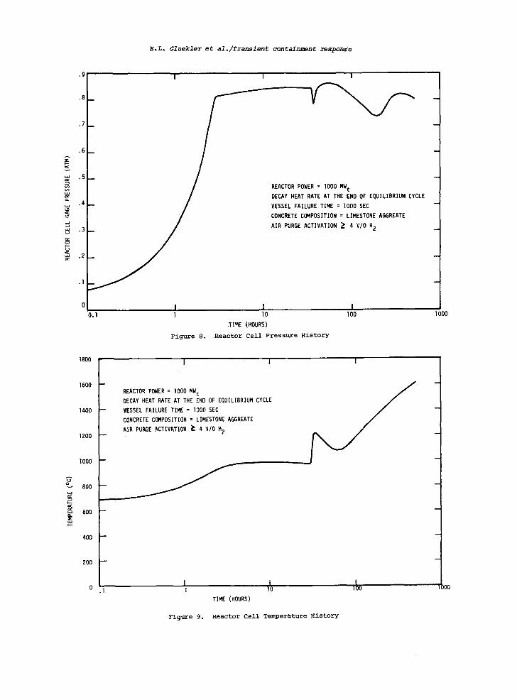
a. Sodium boiling phase: The cell temperature during this phase stabilizes at the boiling point of sodium. The loss of sodium is rapid (34 hours) when liner failure occurs. (See Figure 7)
b. Post-dry out reaction phase: The cell temperature increases rapidly after the loss of sodium. The chemical reactions reach a state of completion in the sustain- ed H20, C02 environment (i0 hours).
c. Post-dryout radiative equilibrium phase: First, the cell temperature de- creases after exothermic chemical reactions have ceased. The core debris layer will be in radiative equilibrium with the cell walls, and the cell temperature will in- crease again to approximately the concrete melting point.
d. Post-reactor cell failure phase: During any of the preceeding phases struc- tural failure of the reactor cell may occur, opening convection paths and radiation windows to adjacent cells. This could sig- nificantly decrease the reactor cell tem- perature (to approximately II00°C), but increase the heat load on the outer contain- ment. Typical pressure and temperature histories for phase a, b and c are shown in Figures 8 and 9 respectively. The cell temperature reaches the melting point of

E.L. Gluekler et al./Transient containment response
|TE
N 0
INCLIPd|D THAYll ~ • l i ~ WiTH FREE CONVECTION
Ii:m
FORCEO CONVECTION , V - 30era/me
L - 4~lem
HON IZONTAL T N A ~ , NATUHAL CONVIEC?I(~i H - 30aW
m
476
46O
426
D|BRIE
I~0 0.6
J'rAIN I.,EN I l l E L
I I I
DISTANCE FROM INTERFACE lat~)
2.0
Figure 4. Comparison of Temperature Profiles in Trays of 2 Centimeter Stainless Steel and 1 Centimeter of Debris, Under Various Conditions of Cooling

160 E.L. Gluekler et al./Transient containment response
HAA V = 7.36 X 10²m 3
t*
REACTOR PHTS CELL V = 9.06 X 10³m 3
V = 1 . 1 6 X l ~ m 3 -' ' '-
SODIUM - - POOL LEVEL
. . . . "~ DENOTES LEAKAGE PATHS BETWEEN CELLS ;.~ , DENOTES CONCRETE WATER RELEASE
* DENOTES CONCRETE WATER V E N T E D TO CONDENSER AND D R A I N E D
Figure 5. Reactor Containment Response Model
REACTOR CELL
CONCRETE ! INTER.
ACTIONS
NOZZLEFLOW:
IN)
fNI
N~, H 2
INI
PRIMARY {LI
HEAT TRANSr ER [~X~]
SYSTE~.I CI t I Na. H 2
NO CONCf~ETE.SODIUM INTEfiACTIONS
Na.H 2
LI"IE;I G H20"CO2 i CONTAINMENT CELL VENTING
I I HEAO ACCESS AREA
I NO CONCRETE.SODIUM INTERACTIONS
100% V PER DAY AT 1 l i ra
NOZZLE FLOW FOR ~ p - 0 6 8 aim
~P <_ 0 68 a~m
(L) F~LTER
(I)-" ENVIRONMENT
AIR.SODIUM REACTIONS
Na, H 2
[ ~ NOZZLE F LOW f:OR ; ,p - 0 68 e~m (L} 100% V PER DAY AT 1 aim
L n • 1 6 2 x 10⁶ChArt Y~-~-P LEAKAGE FLOW: L c - C, ~ p ~ ;
L n = LEAK RATE. kg h "1 (LI L c = LEAK RATE kq h .1
C n " NOZZLE COEFFICIENT • 0.817 C( " LEAKAGE COEFFICIENT 2 An= NOZZLE F LOW AREA. m
• {3 - DENSITY OF ATMOSPHERE. kg m "3
AP - DIFFERENTIAL PRESSURE. alto
Figure 6. Containment Mass Flow After Accident

E.L. Gluekler et ~l./Transient containment response 161
340,000
300,000
250,000
200,000
150.000
100,0(~
50.000
- - - ' ' " ' ' ° ' "
- X / /
TIMF !h) 55
Figure 7. Sodium Inventory as a Function of Time for Complete Cell Liner Failure
steel and concrete between i00 and 200 hours. It is possible that major struc- tural failures would occur during their period if no mitigation of consequences ' is provided.
GOVERNING PARAMETERS AND MI~GA~ON OF CONSEQUENCES
A sensitivity study has been perform- ed to identify (a) parameters which most strongly affect the containment response, and (b) areas in which mitigation would be most efficacious.
Before the individual parameters are discussed it is preferable to discuss and describe how release rates from the con- tainment and radiological consequences depend on the thermodynamic state of the containment atmosphere.
The radionuclides that escape from the reactor cell during the sodium boil- off phase are noble gases, volatile fis- sion products (Cs and Rb), sodium soluble elements, aerosol sized particles of fuel and non-soluble radionuclides suspended in the sodium. After leak paths from the reactor cell are established (failure of seals under excessive temperatures or fail- ~re of rupture disks under cell pressure), substantial transport of radioactive ma- terials* would occur, with noble gases, Cs Ind Rb that are more volatile than sodium • t a fractionally higher rate than the so- dium. The filtration rate of radionuolides
*Fuel particles and solid fission products in the 3ubmicron range may be not important because their ~xpected release fraction for the postul~ted ac- zident conditions is in the range of 10-- to 10 -3 .
from the reactor cell is proportional to (pressure difference). The discharge
pressure is mainly due to sodium vapor and gases such as H 2 generated in chemi-
cal reactions. It is evident that a fast pressure rise on H 2 buildup may require
early venting of the containment building. If the objective is to minimize radiolog- ical consequences, pressure buildup rates and H 2 generation should be minimized and
sodium dryout should be avoided. The con- tainment response has been evaluated in terms of these targets.
Table 5 provides a summary of the parametric study. The time to liner fail- ure, area of failure and the rate of water release in the case of a failed liner can be identified as major parameters affect- ing the containment response. The PHTS cell appears to be a major heat sink.
5. Containment Inherent Retention Capability
Retention of core debris within the reactor cell is possible only if (a) the rate of heat removal exceeds the rate of heat generation and (b) the structural responses to cell pressures and tempera- tures are acceptable. Of particular con- cern are concrete crack formation and pen- etration of fuel particles, liquid fuel and fission products through the concrete walls.
The evaluation of structural responses of the concrete requires an investigation of the concrete behavior at elevated tem- peratures. The following behavior is ex- pected:
E.L. Gluekler et al./Transient containment response
.9
.8
v
| I
.7
.6
.5
.4
.3
.2
.I
A
u~
ua
-H,
I
REACTOR POWER = lO00 MW t
DECAY HEAT RATE AT THE END OF EQUILIBRIUM CYCLE
VESSEL FAILURE TIME = lO00 SEC
CONCRETE COMPOSITION = LIMESTONE AGGREATE
AIR PURGE ACTIVATION ~ 4 V/O H 2
I 0.1 1
Figure 8.
I I I0 I00
TIME (HOURS)
Reactor Cell Pressure History
1800 I I I
1600
1400
1200
lO00
800
600
400
200
REA~TOR POWER = 1000 MW t
DECAY HEAT RATE AT THE END OF EQUILIBRIUM CYCLE
YESSEL FAILURE TIME = lO00 SEC
CONCRETE COMPOSITION = LIMESTONE AGGREATE
AIR PURGE ACTIVATION ~ 4 V/O H 2
I L 1~o .,~ 1 lO TIME (HOURS)
Figure 9. Reactor Cell Temperature History
1000
I
I
I
I
JO0

TABLE 5.
TRANSIENT
CONTAINMENT
RESPONSE PARAMETRIC
STUDY
~t~X
IMU
M R
EA
CTO
R
~X
I~U
M RE
ACTO
R R
ATE
OF
TIM
E O
F SO
DIU
M
PA
~E
TE
~
VAR
IATI
O?~
C
ELL
PRE
SSUR
E C
ELL
TEM
PERA
TURE
PR
ESSU
RE
It:CR
EASE
DRY
OUT
[atm
] [
c]
[arm
/hi
[h]
Ti~
e t
o S
idew
all
Lin
er
Failu
re
[h].
O
.O*
2.7
9
986
.151
28
10.0
2.
61
9a~
.100
34
20.0
2.s
g
987
.085
38
Sid
ew
all
Lin
er
2.5
2
988
.085
47
Inta
ct
Entir
e
Lin
er
Inta
ct
I.g
0
952
.018
96
Sod
ium
Reflu
x 2.7
9
9B6
,150
85
- 7.
51
1159
.2
11
31
No
React
or
Con
tain
men
t B
uild
ing
Ventin
g
NO H
ydro
gen
Air
Pur
ge
- 2.6
5
2.1
7
Con
cret
e w
ater
re
leas
e ra
te
Gua
rd V
ess
el
Failu
re
Tim
e (h
)
Fre
e P
ress
ure
C
omm
unic
atio
n B
etw
een
Cells
Dec
reas
ed
One
Ord
er
of
Mag
nitu
de
1.25
24.2
5
2.8
0
2.5
9
2.0g
986
.127
26
960
.111
49
986
982
946
.169
.130
.206
29
41
28
*BA
SE
cas
e fo
r pa
ram
etri
c st
udy
k=
{D c.
I-. ~r
f~
(b w

164 E.L. Gluekler et al./Transient containment response
a. degradation of material proper- ties because of microcracking caused by water vapor pressure in pores and dehydra- tion (loss of hydraulic bonds),
b. concrete spallation (crack for- mation parallel to heated surface) because of tensile failure under vapor pressure in pores,
c. concrete crushing because of com- pressive failure of the heated surface layer, and
d. concrete cracking under tempera- ture gradients caused by differential thermal expansions between hot and cold zones, concrete and steel reinforcement, aggregate and cement.
Since the vaporization of water in concrete significantly affects the high temperature structural behavior of concrete and, as indicated in Section 4., water release rates from concrete strongly influence the thermodynamic state of the reactor cell, a model for water release from concrete was developed at GE-FBRD.
CONCRE~ W A ~ R RELEASE
an energy equation
a 2
e--at [ ~ 1 S p i e i + ( 1 - S ) p l e l ] i =
+ (1 - ~)Po ~ + - - (uPi + Ji)hi + UlPlhl %t ax =
a aT = - - ( K - - )
ax ax
and two state equations
pi=PiRi T (i = 1,2)
(8)
(9)
p = a T - b exp ( -c /T ) (i0) Z
The water release model treats con- crete, treated as a porous material con- taining water, water vapor and air. In the heating process, the pore constituents pressurize the pores and consequently mi- grate. The mass transport mechanisms are diffusion (under concentration gradients) and filtration (under pressure gradients). Evaporation of water takes place at an interface which separates a layer of con- crete where water has been completely e- vaporated from a colder zone which con- tains water. Some recondensation of water vapor occurs in the wet portion of the concrete. The water transport phenonemon has been described by two species equations.
± % +W = o at ax
(6)
~(SPz.) a a(sp=) ,., *-- (u,p,*-p*i)=~
at ax Z - "Z ~)t (7)
where e denotes porosity, t=time, S=volume fraction of gases within pores, p=density, x=spatial coordinate, normal to surface, u=velocity (Darcy's law), j~=diffusive mass flux of the i specie, ~=specific en- ergy, h=specific enthalpy, k=thermal con- ductivity of concrete, T=absolute tempera- ture, p=pressure, R=gas constant of the i species. The subscript 1 designates air, 2=water vapor, l=liquid and o=solid; a,b and c are constants. Temperature, pres- sure and moisture distribution were det- ermined from a numerical solution of the equations. Typical results for the cases of lined and unlined concrete walls, ex- posed to a reactor cell bulk temperature of 650 ° C, are shown in Figure i0. This figure indicates (a) the amount of water to be vented from behind the liner and (b) the amount of water available for chemical reactions.
CONCRETE STRUCTURAL RESPONSES
In general, concrete temperatures are limited to 93°C locally for normal opera- tions and 177°C for transient conditions. [13] Only sparse information is available for the temperatures expected in a post meltdown scenario. Calculations have been initiated using fracture surface models [14,15] to determine crack formation and propagation in concrete structures under accident conditions and temperature limits required to meet safety requirements.

E.L. Gluekler et al./Transient containment response 165
6.
3°1i -'- 20~ ' \ , ,r
N I
° \ v
o= 10
I I
Figure i0.
I I UNLINED CONCRETE
LINED CONCRETE
t
1 m = ~ ~ m(t )d t t , f
o
m -- mass f l u x T = time
-
~ ~ -
In order to predict the radiological consequences of core melt-through it is generally assumed that all of the inven- tory of volatile fission products (I, Br, Cs, Rb, Se, Cd, As) are released from the fueland are distributed uniformly in the primary sodium which drains from the re- actor vessel. Experimental evidence in- dicates that only the volatile fission products exhibit appreciable release frac- tions from boiling sodium. [16]
Sodium vapor which leaks into the containment cell is assumed to burn and the Na20 and Na202 formed become airborne
as an aerosol. It is this sodium vapor converted to aerosol that is the means of fission product transport from the reactor cell to the site boundary. Only a few of the fission products are radiologically significant. For Cs-137, the most impor- tant, the half-life is so long that its dose effect is nearly independent of its release rate.
The HAA-3 code [17] can be used to predict the clean-up factors for the RCB due to fallout and plateout of the aerosol source. These values provide input to radiological consequences assessments with the COMRADEX code. [18] The following
Radiological Consequences and Accident Mitigation
assumptions are usually made:
a. Aerosol materials are assumed to leak like gases.
b. Dispersion parameters are based on observed site meteorology.
c. No fallout of aerosol is assumed in transit from the containment cell to the site boundary.
d. Dose conversion factors for the isotopes are based on the values quoted in Regulatory Guide 1.109.
Typical results of the radiological con- sequence assessments for a case with in- itial failure of the reactor cellfloor liner and delayed sidewall liner failure (i0 hours) are presented in Table 6. Ex- amination of the total 2-hour site boundary and 30-day LPZ doses with only 2 noted without any filtration of release products shows the doses are well below the i0 CFR 100 guideline limit. The most critical dose obtained is the 30-day LPZ thyroid dose which is approximately 15% of the 10 CFR i00 limit. Insertion of a filter lowered this dose to 3% of the allowable guideline limit.
A strategy for consequence mitigation can be derived from the conclusions reached in Sections 4 and 5. The goals may be summarized as follows:
.I I I I 3 1000 2000 3000 4000 5000 TIME (s)
Average rate of water vapor emission from lined and unlined concrete walls.

166 E.L. Gluekler et al./Transient containment response
TABLE 6. RADIOLOGICAL CONSEQUENCES OF CORE MELT-THROUGH
"2-h Slte Boundary (675.78 m/O.42mi) No f i l t e r
TOTAL DOSES; REM
with f i l t e r
Bone 1.53-4 1.53-4
Thyroid 1.16-4 1.16-4
Lung 3.61-4 3.6l-4
Whole Body, b 4.59-2 4.59-2
Beta Skin 3.17-3 3.17-3
30-d LPZ
(8045m/5mi)
Bone 1.51-I 2.73-2
Thyroid 4.62+I 7.62+0
Lung 1.95+0 3.20-I
Whole Body, b 4.77-I 3.19-I
Beta ~kin 1.80+0 1.80+0
a1.53-4 = 1.53 x lO -4
'bincludes direct shine, whole body inhalation and cloud gamma
a. assure that sodium boil-off does not occur
b./ assure that liner failure does not result in significant chemi- cal reactions
c. assure structural integrity of reactor cell walls (limited dam- age acceptable)
The following design option~ are available to meet these goals. They could be con- sidered individually or collectively.
a. ceramic insulation behind the liner
b. protected vapor barrier in con- crete
c. cooling system in reactor cel I , or
d. cooling system in concrete e. reactor cell structures without
water release or with low water release.
The use of these design options would depend on requirements obtained from ra- diological criteria. As shown above, for
the selected LMFBR design, none of the listed option s is required to meet i0 CFR 100 limits. However, some options may be considered to alleviate final clean up operations.
7. Concluding Remarks
Although the evaluations presented have been performed for a 1000 MW t loop type LMFBR, the general phenomena may be characteristic of all LMFBRs. Pool type reactors with large volumes of sodium present would have a better in-vessel re- tention capability than the concept eval- uated. A very favorable conclusion is that for a worst scenario, radiological criteria would well be met. Although there are still large uncertainkies in these assessments it is reassuring that simple design options for the mitigation of consequences are available when needed to meet safety and licensing requirements An engineered core retention concept as included in SNR-300 is not considered es- Sential in future LMFBRs because the in- herent retention capability of the con-

E.L. Gluekler et al./Transient containment response 167
tainment should be sufficient to assure health and safety of the public.
8. Acknowledgement
This work was performed under U. S. Order Contract EY-76-03-0893 Task 19, under the direction of D. C. Newton of Fast Reactor Safety Branch.
References
[i] G.R. Armstrong, "Post-Accident Heat Removal Assessment for the FFTF" HEDL-TME 75-60 (1974).
[2] H. Hubel, M. K~hler, L. Lange, E.C. Cobb and K.M. Leigh, "Design of the Primary Containment for Pool and Loop Arrangements of LMFBRs", Nuclear Engineering and Design, 27 (1974).
[3] C.B. McGough, Monthly Report No. 2 October 1975, TID-26883-2 (1975).
[4] T.R. Johnson, J.R. Pavlik, and L. Baker Jr., "Post-accident Heat Removal: Large-Scale Molten-Fuel Sodium Interaction Experiments", ANL-75-12 (1975).
[5] Y. K. Dhir, I. Catton., "Dryout of Heat Generating Particulate Beds Under Sodium", Trans. Am. Nucl. Soc. 22, 445 (1976).
[6] J.D. Gabor, E.S. Sowa, L. Baker, Jr., J.C. Cassulo, "Studies and Experiments on Heat Removal from Fuel Debris in Sodium", Proc. Fast Reactor Safety Meeting, Los Angeles, California CONF-740041 (1974).
[7] Advanced Safety Analysis, Fifth Quar- terly Report, September-November 1975, GE-FBRD, GEAP-14038-5 (1975).
[8] E.L. Gluekler, R.V. Clever, E.T. Rumble, III, "Investigation of the Structural Integrity of a Reactor Vessel for A Postulated Core Meltdown Accident", 4th SMiRT Conference, San Francisco, CA. Paper Gl0/e to be published.
[9] A. Miller, "An Inelastic Constitutive Model for Monotomic, Cyclic, and Creep Deformation: Part II - Application to Type 304 Stainless Steel", Eng. Materials and Technology, Vol. 98, Series H, No. 2 (1976).
[i0] Advanced Safety Analysis, Fifth Quar- terly Report, September to November 1975, GE-FBRD, GEAP-14038-5 (1975).
[ii] L. Baker, Jr., "Core Debris Behavior and Interactions with Concrete," This Seminar.
[12] R.D. Peak and D.D. Stepnewski, "Com- putational Features of the CACECO Containment Analysis Code," HDEL-SA- 922 (1975).
[13] Criteria for Reinforced Concrete Nu- clear Power Containment Structures, ACI/ASME, Title No. 69-2 (1972).
[14] E. Chwalla, "Einf~hrung in die Baus- tatik", Stahlbauverlag, K61n, (1954).
[15] D. Linse, "Strength of Concrete Under Biaxial Sustained Load", ACI-SP-34 Concrete for Nuclear Reactors (1972).
[16] A.W. Castleman, Jr., "LMFBR Safety, I. Fission Product Behavior in Sodium", J. Nuclear Safety, II (1970).
[17] R.S. Hubner, E.V. Vaughan and L. Banwash, "HAA-3 Users' Report", AI-AEC-13038 (1973).
[18] J.M. Otter and P.A. Conners, "Descrip- tion of the COMRADEX-III code, AI-TI- 001-130-053, (1975).