GL2200 - Allen & Heath
8
GL2200 MIXING CONSOLE SYS-LINK EXPANDER OPTION This option connects a GL2200 console as a channel expander to a second console with just one or two interconnecting cables. Publication AP3622 ISSUE 1 JAN 99 FITTING INSTRUCTIONS Kit GL2200-SL1 = SINGLE Single option to install SYS-LINK to one GL2200 console to allow interconnection to a second console already fitted with SYS-LINK. Interconnecting cables not supplied. For information on using SYS-LINK please refer to APPLICATIONS NOTE AP3623
-
Upload
khangminh22 -
Category
Documents
-
view
0 -
download
0
Transcript of GL2200 - Allen & Heath

GL2200MIXING CONSOLE
SYS-LINK EXPANDEROPTION
This option connects a GL2200 console as a channel expander to asecond console with just one or two interconnecting cables.
Publication AP3622ISSUE 1 JAN 99
FITTING INSTRUCTIONS
Kit GL2200-SL1 = SINGLESingle option to install SYS-LINK to one GL2200 console to allowinterconnection to a second console already fitted with SYS-LINK.
Interconnecting cables not supplied.
For information on using SYS-LINK please refer to APPLICATIONSNOTE AP3623

2 GL2200 SYS-LINK OPTION ALLEN & HEATH
FITTING THE GL2200 SYS-LINK EXPANDEROPTION
1) CHECK THE CONTENTS:
GL2200-SL1 KIT
fig. 1
Contents: 1x SYS-LINK circuit board assembly with interconnecting harness and mountingsalready fitted.1x SYS-LINK Fitting Instructions (AP3622)1x SYS-LINK Application notes (AP3623)1x IDC Harness (AL3616)2x Snap-In Pillar (AB2233)1x 8K2 Resistor (AC0045)
2) TOOLS REQUIRED: SLIM BODIED SOLDERING IRON WITH SMALL TIP
SOLDER
1pt CROSS POINT
LONG NOSE PLIERS
5mm NUT DRIVER
BLUE
ORANGE
RED , VIOLET, YELLOW, BLUE (ALL) GREEN
RED
SYS-LINKPCB
IDC HARNESS
SNAP-IN PILLARS

ALLEN & HEATH GL2200 SYS-LINK OPTION 3
3) PRELIMINARY:To fit the SYS-LINK option it is not necessary to remove any of the circuit boardassemblies as access to the SYS-LINK solder pads can be made with the circuit boardsin place.
4) REMOVE THE CONSOLE BASE:Before inverting the console to remove the base, remove the two screws next to the endstereo input channel on the console front panel. Then invert the console and remove thebase as shown in fig. 9.
5) REPLACE ‘R45’ RESISTOR:Referring to fig. 2 and fig. 3; if R45 is a 22K resistor (bands: red, red, orange) then thisneeds to be replaced by the supplied 8K2 resistor (bands: grey, red, red). However, ifR45 is already a 8K2 resistor (bands: grey, red, red) then do not replace.
6) REMOVE THE BLANKING PLATE & POWER SUPPLYBRACKETThe SYS-LINK blanking plate is located on the rear panel. Unscrew the retaining screwsand remove the blanking plate. The power supply bracket is located under the PSU.Unscrew the two screws (A) and remove the bracket as shown in fig. 3.
OSC/Noise PCBfig. 2
R45

4 GL2200 SYS-LINK OPTION ALLEN & HEATH
7) DISCONNECTING THE HARNESS ASSEMBLIES:Disconnect the MAIN HARNESS (B) plugged into the connectors mounted alongthe edge of the circuit boards. Disconnect the flexible flat cables (C) plugged intothe GROUP circuit boards.
8) FITTING THE SYS-LINK IN HARNESS:Remove the two screw fixings from the harness ‘D’ Type connector. Mount the ‘D’Type connector onto the rear panel with the fixings. Mount the other connectoronto the straight molex connector on the Osc/Noise PCB as shown in fig. 4.
A
CONSOLE FRONT
GL2200 inverted with the base cover removed.fig. 3
C
B
OSC/Noise PCB
Osc/Noise PCB
Stereo Input PCB
Grou p 1 PCB
Harness
fig. 4

ALLEN & HEATH GL2200 SYS-LINK OPTION 5
9) POSITIONING THE SYS-LINK ASSEMBLY:Fit the bracket to the SYS-LINK circuit board assembly with the 2 nylon snap-in pillars(D) as shown in fig. 5. Place the SYS-LINK and bracket assembly on the console asshown ready for soldering the wires.
GL2200 with power supply bracket fitted to SYS-LINK assembly.
fig. 5
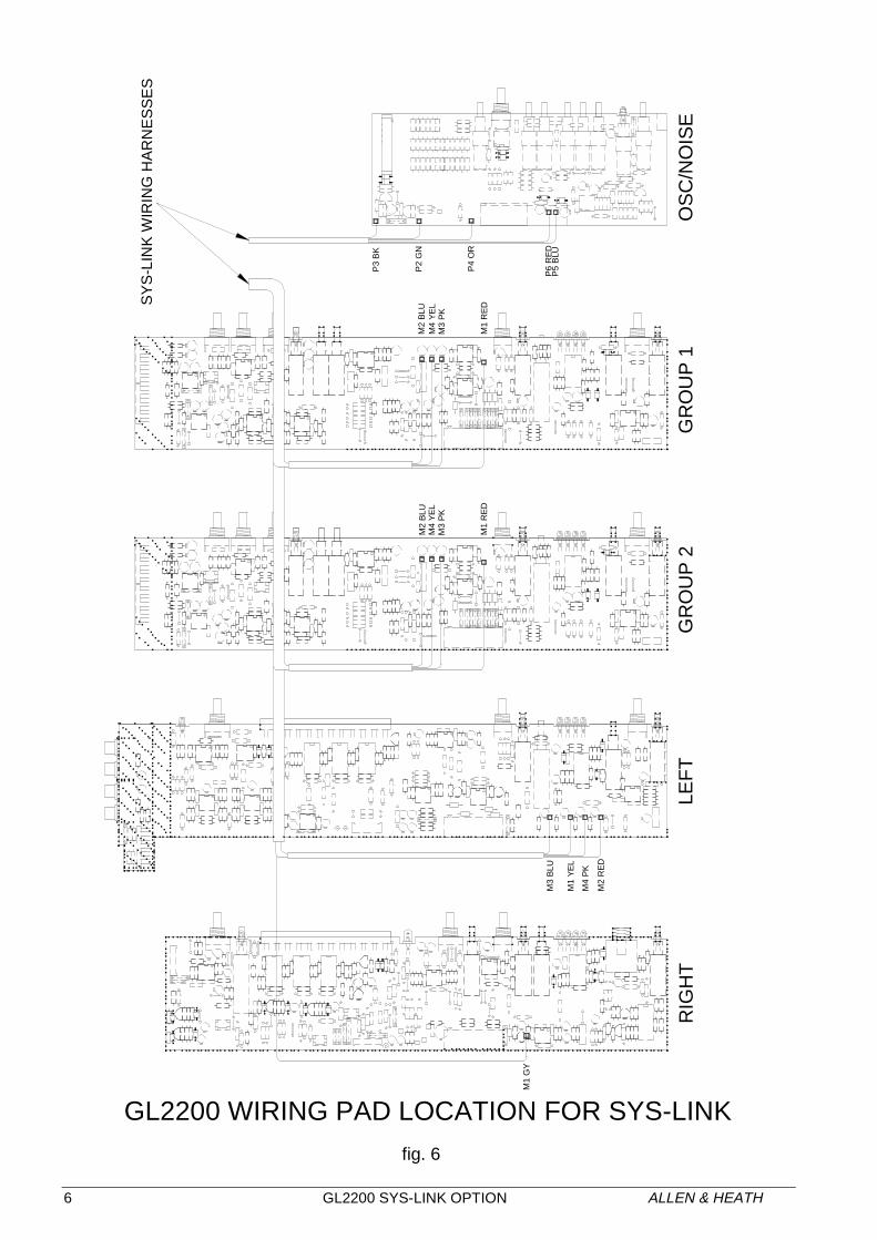
10) SOLDERING THE SYS-LINK HARNESS ASSEMBLY:Referring to fig. 6, prepare the solder pads on the circuit boards with new solder to easethe soldering of the SYS-LINK wires.
Note, the wires for the Group, Left & Right PCBs are soldered to the trackside ofthe circuit boards and not the component side.
The wires to the OSC/Noise PCB go through the PCB.
It is recommended that the wires in the SYS-LINK harness are soldered to each circuitboard in the following order:
OSC/Noise, GROUP 3, GROUP 1, LEFT and then finally the RIGHT circuit boardassembly.
SYS-LINK PCB
Powersupplybracket
D
OSC/NoisePCBStereoInput PCB
Group 1PCB
Group 3PCB
6 GL2200 SYS-LINK OPTION ALLEN & HEATH
fig. 6
M2
BLU
M4
YE
LM
3 P
K
M1
RE
D
M2
BLU
M4
YE
LM
3 P
K
M1
RE
D
M1
YE
L
M2
RE
D
M3
BLU
M4
PK
M1
GY
P3
BK
P2
GN
P4
OR
P6
RE
DP
5 B
LU
GL2200 WIRING PAD LOCATION FOR SYS-LINK
SY
S-L
INK
WIR
ING
HA
RN
ES
SE
S
RIG
HT
LEF
TG
RO
UP
2G
RO
UP
1O
SC
/NO
ISE

ALLEN & HEATH GL2200 SYS-LINK OPTION 7
11) FITTING THE SYS-LINK OUT ASSEMBLY:When all the SYS-LINK wires have been soldered, remove the 2 screw fixings from the‘D’ Type Connector and manoeuvre the SYS-LINK circuit board and power supplybracket assembly into the console chassis as shown in fig. 7. Mount the ‘D’ TypeConnector onto the rear panel with the 2 fixings.
SYS-LINK and power supply bracket fitted into GL2200 console. fig. 7
fig. 8
OSC/NoisePCB
StereoInput PCB
Group 1PCB
Group 3PCB
SYS-LINKPCB Inposition
C
B

8 GL2200 SYS-LINK OPTION ALLEN & HEATH
12) REFIT THE POWER SUPPLY BRACKET:Carefully stand the console on its rear panel and re-fit the two front panel powersupply bracket screws next to the end stereo input channel. Support the consoleduring this process. Place the console on its control surface and fit the two powersupply sub chassis screws.
13) REFIT THE HARNESSES:Referring to fig. 8, re-fit the MAIN HARNESS (B) onto the circuit boards. Check theharness is correctly aligned onto the circuit board connectors with pin 1 aligned withthe red stripe of the ribbon harness. Reconnect the two flexible flat cables (C) tothe GROUP circuit board assembly. Ensure that all harnessing is tidy.
14) REFIT THE BASE:
fig. 9
Refit the base. Locate the two screws for the power supply bracket before fittingthe other screws.
15) PLUG ON THE INTERCONNECTING CABLES:SYS-LINK connectors are 25way ‘D’ Type female. Use 25way ‘D’ Type male tomale connector cables. Connect pin one to pin one on all connectors. Connectshield (screen) to 0V. Standard cables are available from electronic suppliers orcomputer shops. It is advised that the cable is a screened type less than 10metres. Use professional quality locking connectors.
When connecting to equipment other than the GL Series link all unused audioinputs to 0V earth at the SYS-LINK input.
16) TEST THE SYSTEM:Test all SYS-LINK inputs and outputs for correct signal level and quality by probingthe ‘D’ Connector pins or by interconnecting two consoles with SYS-LINK fitted.Test the PFL/AFL system for correct DC buss switching. The SYS-LINK circuitdiagram and technical details are included for reference.
The SYS-LINK Applications Note AP3623 is included separately with these fittinginstructions. Provide this note to the user as applicable.
Please refer any queries to your Allen & Heath appointed service agent.