Brain–computer interface for autonomous vehicles - Chalmers ...
Upload
khangminh22Category
view
1download
0
GettinG the arch back into architecture
Master Thesis at Chalmers Architecture, 2014-05-13
MSc Design for Sustainable Development
Karl Robin Nilsson
Image: KR. Nilsson
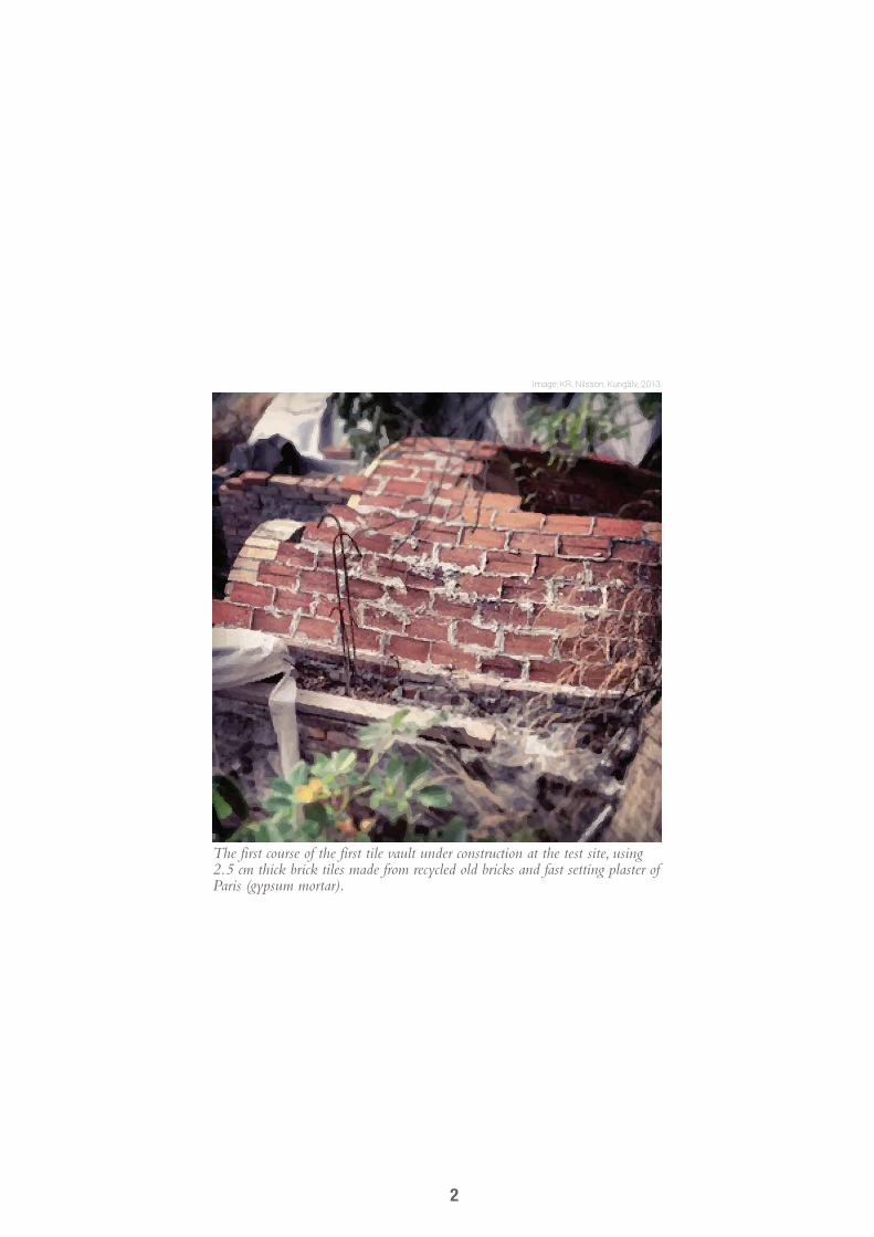
The first course of the first tile vault under construction at the test site, using 2.5 cm thick brick tiles made from recycled old bricks and fast setting plaster of Paris (gypsum mortar).
Image: KR. Nilsson, Kungälv, 2013.
2

abstractKeywords: tile vault, catalan vault, timbrel vault, thin shell masonry, form
finding, masonry analysis, computer aided masonry, digital masonry tools
The aim of this thesis is to enrich the architects tool set for sustainable building design by combining recent advancements in digital tools with traditional handicraft and show how an old building technique, the Catalan vault (or tile vault), can be updated and adapted to improve the feasibility to make complex double curved masonry vaults today. This is done by evaluating the use of a few digital tools aiding site specific design with structural integrity and by a here presented novel way of achieving precision using computer controlled laser guidance.
The old building technique, here referred to as tile vault, is especially interesting because it answers to challenges of sustainable development in several ways. On a physical level it opens the possibility to create large spans with durable materials of low environmental impact and excellent fire resistance without creating building waste. On a social level it can offer a high level of builder autonomy, bringing back handicraft and a better understanding of our cultural heritage.
In support of small scale architectural practice, and promoting a more wide spread use, the digital tools used here was selected because they are relatively inexpensive and often familiar in the field of architecture. The tools enable architects to overcome difficulties like structural analysis and precision in handicraft when designing and constructing brick tile masonry vaults. Methods for form optimization and analysis, such as Finite Element Analysis, Dynamic relaxation, Thrust Network Analysis are discussed and evaluated and tested in relation to tile vaults.
The demonstrated design work flow uses a low cost 3D scanning technique, multiray photogrammetry, which is here tested as a tool to analyze the site and to apply a site specific design. This is done on important tile vault case studies as well as on a 1:1 test project. The test puts theory to use employing the evaluated tools. It was then built during a workshop where it provides insights in practical execution as well as presenting and testing a novel way of eliminating the need for conventional blueprints, while ensuring precision, using computer controlled laser guidance assembled from inexpensive components.
3
table of contentsGetting the arch back into architecture
Abstract 3
Foreword 6
Acknowledgments 7
Structure of the thesis 8
Introduction 10Sustainability of arches, vaults and domes 10Different techniques 11Tile vaults 11
Problem formulation 12Problems and proposed solutions 12Conclusion 12
Part 1.Theory and history
Case studies 16Contemporary projects and origins 16Santa Maria Del Mar, Barcelona, Spain 17Teatro La Massa, Villassar de Dalt, Spain, by Raphael Guastavino 18The big names, Gaudi and Guastavino 19Casa Milá ‘La Pedrera’, Barcelona, Spain by Gaudi 19Vapor Aymerich, Amat i Jover, Terassa, Spain by Lluís Moncunill 20Oyster Bar, New York City, USA 1913 by Raphael Guastavino 21Escoles de la Sagrada Famiglia 22Other adaptations 23Conclusion of case studies 23
Theory of masonry vaults 24General behavior of masonry vaults 24Horizontal thrust and boundary conditions 27Comparing flexural strength between tile- and voussoir vaults 28Tile vault materials 30
Part 2. Digital tools
Theory and evaluation 34Software referred to in this text 34Connecting reality to digital 3D 35Multiray photogrammetry test 36Analyzing forms 39Problems with Finite Element Method analysis and masonry 39FEM analysis using the 3D scan 40Form finding 41
4

Thrust Network Analysis 41Dynamic Relaxation 42Finite Element Analysis 42
Connecting digital 3D to reality 44Digital Blueprints 44Laser guidance 44
Part 3. The test site
Full scale practical test 48First test - barrel vault 48Masonry technique 48Use of dynamic relaxation 48Adjustable form 49First findings 50Workshop - asymmetric double curved vault 51Use of thrust network analysis software 51Design work flow 52Adjustable guide work 55Reflections and findings from the workshop 56
Final reflections 58
Referenced literature 60Book 60Paper 60Web page 60Online lecture 60Journal 60Other 60
Appendix A 62
Appendix B 64
Appendix C 67
Appendix D 67
Appendix E - Film 67
5

forewordWith a lifelong interest in sustainable development and a background in the film industry, where I worked with parametric digital tools to create visually authentic settings and moods in films, I knew that as an architect I wanted to work with restoration and adaptation of old buildings.
I have always been intrigued by older buildings and how concept artists in the film industry excel at visually combining them with new settings, creating interesting adaptations. My main drive and focus throughout the education in architecture has been to analyze and overcome obstacles around using old building methods today. I believe that some of these methods are worth preserving and might help us deal with some contemporary demands and ideas, especially concerning sustainable development. To bridge the gap in my knowledge between contemporary and old architecture without losing track of authenticity or efficiency, I have tried to gather knowledge in different architectural areas; styles, tools, construction, electronics, sustainable building and materials. This has made me confident that technology has finally caught up with the complexity of old building design and our contemporary demand for structural predictability, and that sustainable development provides the incentive for further research in this area.
Unreinforced MasonryWhen I became involved in a project to build a root cellar I found the area of research regarding
unreinforced masonry to be particularly challenging and initially intended to investigate this in
Image: J. Ohlsson, E. Ordell, A. Arvidsson, S. Aboamir and K.R. Nilsson, 2013.
Automating complexity. Parametrically designed building with interlocking building blocks tessellated over a form found compression shape.
Karl Robin Nilsson, born 1982, studied architecture at Chalmers University of Technology (Gothenburg, Sweden) starting 2009 and received Master degree in 2014. Interests in digital tools, physics and our historical built environment lead to a focus on compression structures.
Photo: Viktor Isaksson
6

my bachelor thesis. As this was not possible due to the structure of the education, I put this research on hold until I found a way to incorporate it into my master design studios. In one studio, named Sustainable Building Design, I worked in a team with an aim to create a process for creating parametrically designed compression structures. There we used a form found shell structure which was tessellated into building blocks generating interlocking pieces that were to be produced in cellular glass using a digitally controlled wire cutter.
Developing a design methodBuilding on the knowledge in parametric modeling I made a parametric model for the root cellar project
optimizing a single curved vault structure to the more complex load conditions found underground and built the first part using an interesting vaulting technique, the tile vault.
The root cellar has complex boundary conditions and is built using in situ granite stones and recycled old brick. As masonry geometry is often hard to capture on digital blueprints, I started using knowledge from my background in film. I knew about 3D scanning and the most inexpensive way to do it, multiray photogrammetry, used in most advanced film editing softwares to stabilize shaky film footage and to be able to place objects into film in post production. When free software, to make more detailed scans using this technique, emerged recently I started using it to aid design in geometrically complex environments such as detailed masonry structures, for which this technique is especially apt.
GoalsBased on extensive recent research about unreinforced masonry by the Block Research Group, which i
find intriguing, the new international interest in this old vaulting technique using tiles combined with my experience working with it, I saw the potential of developing it further in this Master Thesis. The thesis focus is on construction efficiency and accuracy for complex geometries, using digital tools (and my hobby interest in electronics). Ultimately I want this thesis to be a cornerstone of what I set out to do at the beginning of the education, to let me confidently work in the field of restoration and adaptation of old buildings, and work in a sustainable manner.
acknowledGementsMany thanks to everyone that contributed and helped me to write this thesis. I am very grateful to everyone
attending the workshop, helping me proofread, giving me advice on electronics, to the people in the Block Research group, to the people helping me at the field trip and to my tutors Emilio Brandao and Maja Kovacs all constructive criticism. I could never have done it without all that help. Special thanks to my parents who always supported and helped me and to my siblings, siblings in “law,” and good friends for all love and support throughout the project. Innumerable thanks to my girlfriend to whom I owe everything and more.
7

structure of the thesisThe two things that have been researched most extensively are the use of 3D scanning as an analysis tool and the development of a laser guidance controlled by an interactive digital blueprint, which is also explained in Appendix E, which is a film. But, on the whole, these two elements are just components in the overall thesis structure, which is briefly described below: Field trip examining important case studies, their details and geometry while
practicing using a 3D scanning technique.
Overview of theory for:Masonry VaultsHorizontal thrustTile vault specific behavior
Compressive and tensile capacityMaterials used in tile vaults
The introduction gives a brief overview of vaults that do not require form work, specifically tile vaults, and how they are connected to sustainable development.
Theory and evaluation of digital tools that aid the design process and provide a link between digital models and reality
Tools
MeasuringTesting the efficiency of 3D scanning as a method to analyze the site and vault
geometry.
AnalysisTools that can be used to analyze arbitrary forms.
Design and staticsMaking a structurally informed design
Interactive blueprintsInteractive parametric blueprints that can control an electronic laser guidance,
connecting digital 3D to reality.
Guide work evaluationRegular form workAdaptable form workGuide workLaser guidance
Comparison of the construction of different vault types.
Full scale tests applying the findings from the theory and digital tools at a workshop on a test site
Practical test
Theory of masonry and historical context of tile vaulting
Summing up the evaluations from the digital tools, the design tools and interactive blueprint, the ease of use of the proposed tile vaulting technique in relation to the abstract and the potential to attenuate the problem formulation regarding vaults and dome construction today.
Reflections
Theory and background
Introduction
8

Field trip examining important case studies, their details and geometry while practicing using a 3D scanning technique.
Overview of theory for:Masonry VaultsHorizontal thrustTile vault specific behavior
Compressive and tensile capacityMaterials used in tile vaults
The introduction gives a brief overview of vaults that do not require form work, specifically tile vaults, and how they are connected to sustainable development.
Theory and evaluation of digital tools that aid the design process and provide a link between digital models and reality
Tools
MeasuringTesting the efficiency of 3D scanning as a method to analyze the site and vault
geometry.
AnalysisTools that can be used to analyze arbitrary forms.
Design and staticsMaking a structurally informed design
Interactive blueprintsInteractive parametric blueprints that can control an electronic laser guidance,
connecting digital 3D to reality.
Guide work evaluationRegular form workAdaptable form workGuide workLaser guidance
Comparison of the construction of different vault types.
Full scale tests applying the findings from the theory and digital tools at a workshop on a test site
Practical test
Theory of masonry and historical context of tile vaulting
Summing up the evaluations from the digital tools, the design tools and interactive blueprint, the ease of use of the proposed tile vaulting technique in relation to the abstract and the potential to attenuate the problem formulation regarding vaults and dome construction today.
Reflections
Theory and background
Introduction
9
introductionBuildings will never have zero embodied energy and that is why it is important that they can serve their purpose for a very long time, working closely with their inhabitants and the nature around it. Resource scarcity might soon lead to a renewed interest in local materials with low environmental impact, working in compression, like stone or brick. It is the aim of this thesis to suggest a potential work flow to efficiently build compression structures today using digital tools and an old efficient vaulting technique, the tile vault.
Sustainability of arches, vaults and domesArches, vaults and domes have been used for a
very long time. The oldest known use of true arches are by the Etruscans in the fourth century BC (M. Como, 2013). They can be made from many different materials that are good in compression. Structures working mainly in compression have traditionally used vernacular materials and design. They were built to last, with crafted quality and design and used arches and vaults to bridge spaces in
a durable, resource efficient way. An advantage of tile vaults is that all components
are light weight which means anyone can participate in the construction phase and that allows a social environment and an opportunity for people to come together.
Keeping old building traditions alive can increase awareness of our cultural heritage and simplify the preservation of it.
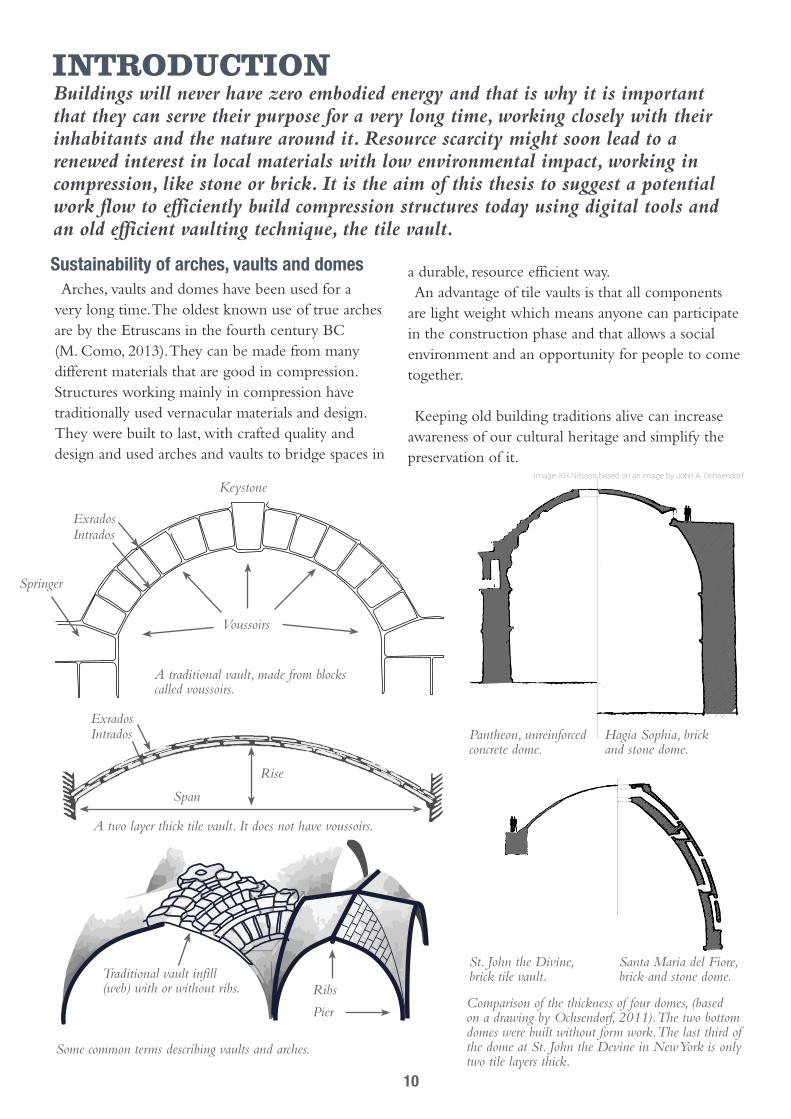
Some common terms describing vaults and arches.
Comparison of the thickness of four domes, (based on a drawing by Ochsendorf, 2011). The two bottom domes were built without form work. The last third of the dome at St. John the Devine in New York is only two tile layers thick.
Pantheon, unreinforced concrete dome.
Hagia Sophia, brick and stone dome.
Santa Maria del Fiore, brick and stone dome.
St. John the Divine, brick tile vault.
Voussoirs
Exrados
Exrados
Rise
Span
Intrados
Intrados
Keystone
Springer
Traditional vault infill (web) with or without ribs.
A traditional vault, made from blocks called voussoirs.
A two layer thick tile vault. It does not have voussoirs.
Ribs
Pier
Image: KR Nilsson based on an image by John A. Ochsendorf
10

Different techniquesThere are many different ways to construct vaults,
from intricate voussoir constructions of stone or even earth blocks to reinforced or unreinforced concrete. Most of them require extensive use of form work which poses an unrealistic hindrance both for speed, costs and material use. But there are several ways to construct vaults and especially domes without or with very little form work. They all work by cantilevering the blocks in some way during the construction, relying on the tensile resistance of the mortar.
The igloo depends on its circular form. The inward curvature creates horizontal compression forces around the dome keeping the pieces in place. Pieces of snow slid into place create friction, glueing the pieces in place like a mortar.
Nubian vault, Mexican vault, or leaning brick vault is a technique that works by leaning the courses of bricks. The friction then becomes great enough for the mortar to quickly hold the brick in place (Minke, 2000).One drawback is that for shallow vaults the horizontal thrust is very large.
Tile vault, the most material efficient technique and works by cantilevering light tiles, strengthened by adding more layers.
Tile vaultsThe tile vaulting technique is also known as a
timbrel vault, Catalan vault, laminated vault, flat vault, layered vault or Guastavino vault. What is special about this technique is that the tiles are light enough to be cantilevered in position by the small tensile capacity of a fast setting mortar like gypsum (plaster of Paris).
BenefitsIt can be built very thin and has been used as
replacement for reinforced concrete in recent history in areas where material resources are scarce, for example in Cuba.Apart from its material efficiency it has other
benefits, it is largely fireproof, does not require physical strength since the building blocks are light, it has freeform possibilities (within the limits of compression geometries) that are hard to match with concrete and other vaulting techniques (Lara Davis, Philippe Block, 2012) and can be used with local materials. These are all probable reasons to why tile vaults have recently become popular in architectural research.
DrawbacksDrawbacks are for example that you need advanced
computer models to predict how vaults work (which is true for any kind of vaulting technique) and a fair amount of skilled labor, making it costly and impractical (López-Almansa et al. 2010). Another factor is that in earthquake prone areas, unreinforced structures are generally discouraged but there are examples where this technique has been used in conjunction with reinforcement. In Sweden the risk of earthquakes is low compared to many places where tile vaults have been built.
A map of known tile vaults in the world (blue) and earthquake hazard (red). Based on a map by Lopez & Rodríguez, 2012 and a map of seismic activity from 1960 to 2000.
Meridional forces
Hoop forces
Construction path
11

Problem formulationThis is an overview of the questions that this thesis investigates and their proposed answers.
Problems and proposed solutions The following arguments are often presented as
what is currently inhibiting the construction of arches, vaults and domes. They have influenced the proposals of this thesis.
Complex calculations and assessmentThe first problem has to do with the high
complexity of calculating the structural stability of vaults and that quality assessment of the finished structure is hard. Now the design tools to help create vaults with good structural stability available for both engineers and architects are becoming easy to use and 3D scanning enables accurate quality assessment of the built structure. This is especially true for tile vaults since the shape seen from inside is often an extrusion of the outer shape. In addition the tile vaults have a more isotropic (homogeneous) structure than other vaults which opens up for the use of a wider plethora of analytical tools.
Skilled laborComplex masonry structures require a lot of skilled
labor which is scarce or expensive today. Skill can be replaced by computer aided design and either time or computer aided guidance. The tools to do this are also readily available to architects. Low cost parametric design tools can be directly connected to guide the construction process using new cheap micro computer controlled electronics. This will be tested later in one of the experiments performed in this thesis using a computer controlled laser guide.
A lengthy processVault construction is heavy and time consuming.
However, for tile vaults the individual weight of the building blocks is inherently low, mostly around 1 kg, as is the amount of material required and the use of the aforementioned computer controlled aids could potentially speed up the process.
High costsTile vaults are cost effective in relation to
traditional vaults, but concrete thin shells can compete with an even lower cost. While this has been true due to increased labor costs in at least the united states for the last 60 years (Ochsendorf, 2010), in parts of the world where resources are scarce and labor is available, like in Cuba, it is comparatively inexpensive. Also from a long-term perspective it is even less expensive as the use of concrete releases more greenhouse gases. In addition, since tile vaulting does not require form work (or reinforcement under certain conditions), it produces less waste.
Tile vaults also have the potential to expand freedom of form and, since it is handicrafted, the visual appearance can become very personal.
ConclusionThe proposed answers to the problems stated
here mainly involve tile vaulting which is why this technique was chosen for the research. The other parts of the proposed answers involve improving efficiency and accuracy of the design and construction using digital tools and electronics.
A picture of the first vault constructed during the experiments. The pattern has a resemblance to patterns seen on wooden ship hulls.
12

13

Image: KR Nilsson based on an image by William V. Thayer
14

Part 1, theory and historyThis part puts tile vaulting in a theoretical and historical context
15

case studiesThe tile vault technique has been employed at different places around the globe, especially by exploring architecture and where resources were scarce. The technique has often developed and adapted to local demands. In order to get a better understanding of the vault technique, study details, geometries and to gain experience in working with 3D scanning, I made a field trip to scan some of the key buildings by different architects in Catalonia, that used this technique.
Contemporary projects and origins Right now the interest in the technique is
high, for example there were workshops at an architectural convention, Smart Geometry 2013, and a temporary asymmetrical installation named Brictopia in Barcelona later that year. Unfortunately this installation was removed before the field trip reported here. Also notable is the 2009 World Building of the Year (Mapungubwe National Park Interpretive Center, South Africa, by Peter Rich architects) which was built using unreinforced tile vaults out of cement stabilized earth tiles rather than ceramic tiles.The Block Research Group of ETH and MIT is
responsible or involved in much of the latest research and projects. They are developing intuitive design tools that work well with vaulted structures.
But the technique has been known in Catalonia since at least the 15th century. Since then it has
spread from there to South America and throughout southern Europe and was sometimes used as a cheap infill between for example the ribs in Gothic churches, as is the case in Santa Maria Del Mar, in Barcelona (Huerta 2003). A benefit of this was that, where as roman or voussoir vaults needed centering under the entire vault, here centering would only be needed for the ribs (M. F. Luna V. L. Bernal, 2003).
A 3D point cloud of the ceiling in Santa Maria del Mar, with a view from the apse towards the rose window.
13 meters
16

The ceiling of Santa Maria del Mar, viewed from the outside. Roughly the same geometry is reflected on the exterior roof. Here, the scanned point cloud has been converted into a mesh surface with good results.
Above: Plan view of a vault.
Right: Sections through of one of the ceiling vaults, shown in the plan above, 1.7 meters apart.
32 meters
Santa Maria Del Mar, Barcelona, SpainConstruction years of the vault: 1341 to 1360 (Murcia, 2008)Role of Tile Vault: Roof cover and as infill between the Gothic
stone rib system.Main isle vault span: 13 meters.Main isle vault rise: 15 meters from the top of the pillars.Tile Dimensions: Around 400 mm * 200 mm
17

Teatro La Massa, Villassar de Dalt, Spain, by Raphael GuastavinoConstruction year: 1881Dome span: 17 mDome rise: 3 mDome thickness: 5-10 cmDiameter of occulus: 4 mBrick dimensions: 292 mm * 140 mm * 19 mmNumber of tile layers: 2
In this building, the tile vault is taken to its pure engineering extreme. The unreinforced dome is only 50 millimetres thick with 17 radial ribs of 50 mm extra thickness. This light but shallow dome lands on an iron tension ring, dealing with the horizontal thrust. The load is then transferred down trough iron columns and horizontal movements are stabilized by vaults perpendicular to the base of the dome.
Detail of the dome. The brick courses are laid in concentric circles around the occulus.
Three sections from the scan through the dome 2 meters apart (in colour) are here screened over a blueprint section of the dome (black). The area in blue shows the discrepancy between the blueprint and the scan, around 500 mm at the top. A clear example of the need to be meticulous about which blueprint is chosen if it is to be used for analysis.
Photo
18

Casa Milá ‘La Pedrera’, Barcelona, Spain by GaudiConstruction year: 1910Brick dimensions (wall): 282 mm * 139 mm * 16 mmBrick dimensions (arches): 282 mm * 139 mm * 52 mmMortar thickness between layers: Around 9 mmMortar thickness between tiles: 15 mm to 20 mmNumber of tile layers: 2, 3 or 4
The big names, Gaudi and GuastavinoThe most famous architect to use tile vaults is probably
Gaudi. The freedom of form with tile vaults helped him realize many of his asymmetrical buildings as is found in for example Casa Míla, ‘La Pedrera’.
A master builder named Raphael Guastavino from Barcelona brought the technique to the US east coast in 1881 just as his Teatro La Massa was being finished. He started the Guastavino company focusing on tile vaulting and developed the technique further filing numerous patents. Guastavino vaults can be found in many older prestige buildings but the company was closed in 1960 when concrete became more inexpensive and the formal language of the time changed (Ochsendorf, 2010).
Top right: A 100 years old hand prints on the tiles. Hand prints are common on old brick but usually hidden within the masonry.
Bottom right: Detail from a 90 degree angle at an opening in the vault and a shift from three to two tiles.
The versatility of the tile vault technique becomes clear in this project where it is the staple technique to realize whatever the funicular design requires. The walls follow a catenary curve until they reach the point below the flat roof terrace, after which they become straight until they reach the flat terrace floor. The terrace floor is divided into different sized boxes, supported from below by a web of catenary tile vault arches.
Photo
19
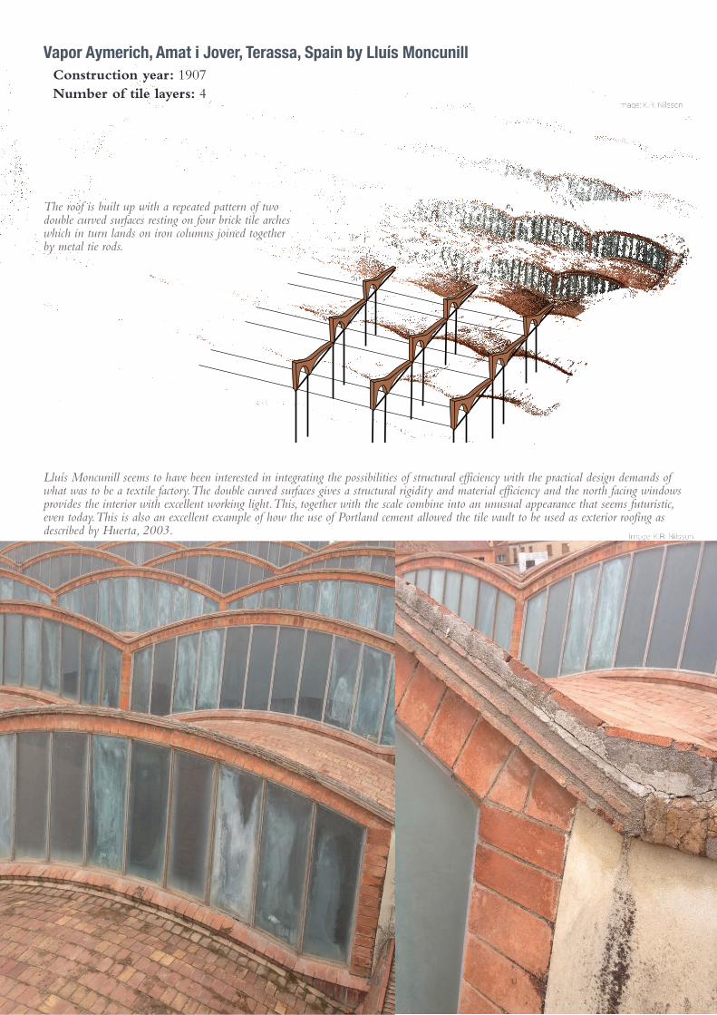
Vapor Aymerich, Amat i Jover, Terassa, Spain by Lluís MoncunillConstruction year: 1907Number of tile layers: 4
Lluís Moncunill seems to have been interested in integrating the possibilities of structural efficiency with the practical design demands of what was to be a textile factory. The double curved surfaces gives a structural rigidity and material efficiency and the north facing windows provides the interior with excellent working light. This, together with the scale combine into an unusual appearance that seems futuristic, even today. This is also an excellent example of how the use of Portland cement allowed the tile vault to be used as exterior roofing as described by Huerta, 2003.
The roof is built up with a repeated pattern of two double curved surfaces resting on four brick tile arches which in turn lands on iron columns joined together by metal tie rods.
Photo
20

Oyster Bar, New York City, USA 1913 by Raphael GuastavinoConstruction year: 1913
Whereas earlier vaults were originally often covered with plaster to hide the tiles, here is an example of how Guastavino changed this and used the tile vault structure as an ornamentation. The interior layer of ceramic tiles was added from the inside and was recently renovated after a fire causing some tiles to delaminate and fall out.
Image: Patric Holm
Image: Patric Holm and K.R. Nilsson
21

Escoles de la Sagrada FamigliaReconstruction year: 2001Number of tile layers: 2
The building is a reconstruction of a building by Gaudi which was situated nearby. What is really interesting about this building is that every part of it, down to the window framing, is done using flat tiles.
22

Other adaptationsResource scarcityAnother remarkable tile vault project was Cuba’s
National Art Schools (Escuelas Nacionales de Arte) sporting a small city of vaults with spans of up to 30 meters (Ochsendorf, 2010).This is a project from the early time of the blockade by the US. Since resources were scarce, the tile vault technique provided a way to create a new Cuban style using local materials. However politics and contemporary architectural trends in the world put the construction to a halt in 1965 (www.archdaily.com, 2013-08-12).
Reinforced vaultsThe Uruguayan engineer Elao Dieste’s constructions
are an interesting example on how the tile vault can be combined with reinforced thin shell concrete. He constructed reinforced brick tile vaults with spans of up to 50 meters and only a 12 cm thickness, pushing the limits of the materials through geometrical efficiency (López-Almansa et al. 2010).
Conclusion from the case studiesIt was found that tile vaults can have a long lifespan
and that they work both at small and large scales. There were also examples of how it was combined with other techniques to accommodate certain demands, such as the combination with stone for increased load capacity in the church Santa Maria del Mar or with iron pillars in Vapor Aymerich to achieve slender supports.
DetailsDetails for tile vaults were found to be surprisingly
simple. And unless there are sharp changes in the topology of the vault, the shape of the bricks can be left unchanged as small differences can be handled within the mortar joints.
GeometryTile vaulting seems to be a straightforward technique
that can be formed according most geometrical wishes as long as it conforms to a compression only system. Either for the engineering perfection, like in La Massa, or the funicular/programmatic forms, as in La Pedrera, used to create industrial scales as in Vapor Aymerich and also used as ornamentation like in Oyster Bar.
Above and below: A project in Havana by Porro, Gottardi and Garatti abandoned in 1965 because “Cuba’s new ally, the Soviet Union, preferred anonymously pragmatic, functional architecture, which stood in contrast to this organic, craft oriented, site specific design.” - Arch Daily
Below: Example of how a vault by Dieste was reinforced.Based on a drawing by Remo Pedreschi, 2000.
23

theory of masonry vaultsThis chapter is meant to give an overview of the statics and behavior of masonry vaults with focus on tile vaults. It also provides a brief introduction of some of the tools available for vault design and analysis, suitable for architects.
General behavior of masonry vaultsAll structurally sound unreinforced masonry builds
on a system where forces are balanced in a way which yields compression but no tension.
Geometry The most important thing for the structural
stability of a vault is therefore that the geometry can accommodate this. The line of thrust is the center of where the forces seem to act, and to avoid tensile forces it should be contained within the thickness of the vault. Funicular forms are always under pure tension, and when inverted, pure compression. Many older vaults are based on geometrical forms which are actually not optimal for compression, for
example, the hemispherical form has tensile hoop forces forming around 51.8 degrees from the apex. Many of the pathologies in traditional geometries are explained in Statics of Historic Masonry Structures, by M. Como 2013.
Double curvature3-dimensional geometries can be made thinner as
double curvature makes the structure stiffer (Block, 2009) as the effective structural thickness increases. For symmetrical structures, this can be examined using traditional methods but for asymmetrical vaults, newer computational methods are required (Rippman, Block, 2011).
For a barrel vault, the effective thickness would equal the thickness of the material, but in a double curved surface the thrust forces have more possible routes. Image based a diagram by Rippman, Block, 2011.
Diagram from a Guastavino Patent. Fill material on the vault increase the dead load and any additional loads will have a smaller impact on the line of thrust.
Line of thrust
Line of thrust Line of thrust
Line of thrust
Side pressureSide pressure
Earth load
Cracks forming
Cracks forming
Cracks forming
Asymmetrical load
Asymmetrical load
For a hemispherical dome, tensile forces will be present below 51.8 degrees which is why buttressing is often seen there. Older vaults are often based on geometrical symmetry like the semicircle, which is sub optimal when it comes to compression statics.
In an underground situation the thrust line can look very different depending on uneven soil loads and side pressures. The thrust line shows the ideal shape of the tunnel. Automated approximation of a thrust line for a vault in a complex load condition like this is shown later in this text. Image K.R. Nilsson, based on an image Ruiz et al. 2010 explaining cracks in an arch shaped cut-and-cover tunnel in Mitholz, Switzerland, 2004.
The line of thrust in a uniformly loaded catenary arch runs trough its centre.
51.8 degrees
Buttressing
24

For single curved barrel vaults stiffening diaphragm walls are often built at regular distances, allowing the trust line to be contained within the overall structure when the vault is exposed to asymmetrical loads.
Similarly to diaphragm walls, stiffening arches within can be added, as is the case in the Casa Mila attic underneath the roof terrace.
Patents by the Guastavino Company for reinforced vaults. Above: Tension rods added between the layers dealing with the pathologies that arise when the geometry is sub optimal for compression. In this instance a hemispherical geometry was used which means tensile forces will appear at around 51.8 degrees from the apex. The occulus is reinforced to support the asymmetrical load of a lantern structure above.
Below: Beams and trusses integrated completely within the vault together with concrete making the tile vault more of a decoration or form work for the concrete.
Asymmetrical loadsWhen a vault is loaded in other ways than it was
designed for, its line of thrust changes corresponding to the new load. The important thing is that as soon as the line of thrust can not be found within the structure, tensile forces will arise, with the risk of crack formation. In double curved vaults, it is quite possible that the new thrust line can still be contained within the structure. If not, there are a number of ways to achieve this. A common way to do this is using stiffening elements like diaphragm walls. A fill material between a floor an the vault increases the total weight and thus, reduces the relative magnitude of additional loads. This non-uniform load of the fill should be taken into account at the initial design as it affects the thrust line of the dead load.
ReinforcementLastly, reinforcement could be added as a
redundancy system to deal with temporary asymmetrical loads. The Guastavino patent drawings to the right show ways that they included reinforcements, but this was mainly to accommodate a shape that is sub optimal for pure compression, like the hemisphere, without using buttressing. It can be argued whether this actually defeats many of the benefits of the technique.
Line of thrustAsymmetrical load
25

Compressive and tensile capacity of tile vaultsAll masonry handles stress very well and the
compressive limit is unlikely to be reached. In many theories, for the sake of simplicity stress resistance is treated as infinite. The Guastavino Company stated that the compressive strength of their tile vaults was 14 MPa after 5 days and 20MPa after 365 days (Atamtuktur, 2006), similar results were found when tested by (Saliklis, Kurtz & Furnbach, 2003).To put those numbers in perspective it was found in an analysis of a Guastavino barrel vault under self weight that it was 100 times less strained than the stated compressive limit (Reese 2010).
Common misconceptionsOne of the most often communicated properties
about tile vaults is about their high tensile capacity. Rafael Guastavino often referred to a cohesive force, by which he meant the tensile strength from lamination. There is a misconception, still sometimes asserted in articles, that tile vaults because of this cohesive force does not have any horizontal thrust. This was started by a man named Comte d’Espie in the late 18th century (Ochsendorf, 2010) and has led to confusion and arguments regarding the tensile resistance of tile vault, even by Raphael Guastavino.
Tile vaults actually produce the same horizontal thrust as other vaults but since they are usually light, it is comparatively small. Guastavino domes display a linearly elastic shell behavior provided that they are free from cracks (Atamturktur, 2006).
All materials can undergo an elastic deformation where the material regains its original form after the deformation. Different types of vaults have different tensile resistance but since the materials used in masonry are mostly brittle (i.e. have no malleability) and susceptible to micro fracturing, their tensile capacity is highly unreliable in a long term perspective. According to some researchers tile vaults do not have any more tensile capacity than more common voussoir vaults of what is sometimes called ‘the gravity system’ (Reese, 2010). In the event of failure, the same pathologies will be seen in all types of vaults, which is why this tensile resistance is generally justifiably discounted. (Reese 2010 , Block 2009)
Statically determinateAn intact vault is statically indeterminate and
possibly has an infinite number of thrust lines (possible routes for compression forces)(Block, 2009). Because of their brittle nature and low tensile capacity, masonry vaults crack to support movement. This is not necessarily dangerous but makes it statically determinate, i.e. the thrust line can then be known as it will go through the ‘hinges’ located at the cracks. (Reese 2010, Como, 2013)
Stress and strainBenfratello et al. 2012 performed tests on old tile
vault samples that show how the vaults have an elastic behavior that varies with the mason’s quality of precision and with the thickness of the mortar. This test also shows the weakness in the connection between mortar and brick. As the surface area of this connection is greater in tile vaults, this could predict that they are even stronger, which the results of an experimental test later in the text also indicates.
Graph showing elastic deformation (also plastic deforma-tion and failure) of 2-4 layer thick tile vault sections. The small dents are suggested to be caused by small defects in the lamination, causing a micro crack and a subsequent redistribution of forces. Images: Benfratello, 2012.
Cracks form along bonding surfaces between the brick and mortar. Photo: Benfratello, 2012.
26

The Benfratello tests also found revealed the samples to behave differently depending on the number of layers which was explained:
“The presence of geometric, technological and mechanical irregularities surely increases with the number of layers and strongly influences the results” - Benfratello, 2012.
Tensile resistance of a traditional archM. Como (2013) describes the failure mechanisms
of a traditional brick arch in an experiment, to be divided in two parts. In the first part, the tensile resistance of the material was twice as high as those predicted by limit analysis.
Limit analysis is a common way to describe arch
mechanisms. It disregards tensile capacity and counts the connection between elements as hinges, forming a ductile mechanism. As the arch cracked, at 4 places in the connection between mortar and brick, it turned into a ductile mechanism which was hinged at the points of the cracks. The resistance of the arch then became similar to the values predicted by limit analysis.
The test by Como shows that the strength of the arch is considerably greater when you account for its tensile resistance. However, he points out that this resistance would commonly not be present in old structures as they might have had cracks form and have weaker or degraded mortar.
Since the material properties of a tile vault depend on several variable factors including mortar type, brick type and perfection of the masonry, accurate figures can only be produced by testing samples in each case. To get a rough estimation however, it can be useful to look at figures found in older tests.
Horizontal thrust and boundary conditionsThe main reason for vault failure or crack
propagation is movement or deflection of its supports (Block 2009). It is necessary to make sure that the horizontal thrust of the vault is not greater than the support can handle.Horizontal thrust in vaults increase with the weight
of the vault and with smaller height/span ratio. Tile vaults are generally very light compared to other types, but since they can be made shallow, they can produce a significant horizontal thrust.
Containing the thrustThere are several ways to contain the thrust if the
walls are not alone strong enough.
Examples of this include:
• Adding weight to the walls by adding floors. The top floor can then have a high height/span ratio, to produce as little horizontal thrust as possible.• Buttressing the walls. • Tie rods connecting the supports, like in
Vapor Aymerich. Or a suspension ring as in Teatro La Massa.• Concealed tie rods within the adjacent walls.• Cantilevering another structure providing a
counteracting moment at the support.
Density Young's Modulus Poisson's Ratio Ultimate Tensile Strength Compressive Strength Yield Strength Bending Strength
!!!1.98 N/mm214.2 and 22.67 N/mm2 *!0.62 N/mm2
1764 kg/m37.4 GPa0,26!!!!
!1.7 GPa!1.7, 2.5 and 2.9 MPa**!1.5 ! 2.5 MPa!
Guastavino, 1892 Atamturktur, 2006 Benfratello, 2012
**For 2, 3 and 4 layers respectively.*after 5 and 365 days respectively.
27

Comparing flexural strength between tile- and voussoir vaults
The tensile capacity of masonry is unreliable and should not be used in a way that anything which is not temporary depends on it. Even so, as an added safety factor it could still be valuable, especially during the construction phase.
Since the flexural strength, modulus of rupture or the tensile strength of a brittle material, is often communicated to be higher in a tile vault than other vaults but no tests directly show this except by R. Guastavino in 1983, there is a reason to device a new test.
R. Guastavino reported a 0.62 N/mm2 result from tests to find the flexural strength of his tile vaults.
The new test will repeat this test on a small scale using beams, two tile layers thick rotated 90 degrees, and the same test with corresponding voussoir beams. To make it comparable the samples will be made with a similar thickness using the same gypsum mortar and bricks made at the same time. The test is not meant to produce precise or conclusive results since it has too few samples to be statistically accurate and is only a scale model. It is only meant to provide an indication of the validity of Guastavino’s results and what further investigations might show.
Tests done by R. Guastavino, 1893, to compare the flexural strength of a tile vault section to a voussoir ditto.
Results 4 tile beams and 4 voussoir beams were tested. The
tile beams were mostly much stronger. Test 1 and 5 broke splitting both the brick tiles and mortar.The voussoir beams tended to fail wherever the
adhesion was weakest, even if that was far from the center where the moment forces are weaker, test 6 only managed to carry its own weight. The worst tile beam, test 3, had the worst quality of handicraft, with little overlap between the tiles, and still matched the strongest voussoir counterpart.
Interestingly test 7 shows the unique tile vault crack behavior, described by Reese 2010, where a tile debonded completely. Reese states that this unique behavior arises from the lamination and that if a tile would laminate, because of crack propagation or wear due to leakage etc., it might fall down. This does not pose a threat to the vault itself, but can cause harm to anyone standing below.
ConclusionThe adhesion between brick and mortar is much
more reliable in the tile beams. It is sometimes so strong that the crack forms through both brick and mortar, closer to the behavior of an isotropic material, which the voussoir beams clearly is not. The quality of handicraft affected both beams considerably as the forces concentrate around the weakest points.
In order to get more reliable results, more tests with better precision would be needed. As Como, 2013 shows, an arch becomes a ductile mechanism after it cracks. This is why it would be interesting to compare tile arches to voussoir arches instead of beams and perhaps also comparing different numbers of layers.
The test is performed on scale models using bricks scaled 1:10.
28

Test results, test number encircled. Tile beams on the left and reciprocal voussoir beams on the right. The fracture load (water) is shown in decilitre. To this load an additional 0.3 kg from the equipment should be added. Notes at the bottom indicate the distance of the crack from the edge of the loaded area.
F is the load (force) at the fracture point (N)
L is the length of the support span = 130 mm
b is width = 24 mm
d is thickness = 12 mm
Li is the length of the loading (inner) span = 5 mm
The highest flexural strength found in this experiment can be derived from the results of test 5:
F = (4.9kg+0.3kg)*9.8m/s2 = 51N
Flexural Strength = (3*51N*(130mm-5mm))/(2*24mm*12mm*12mm) = 2.8 N/mm2 = 2.8MPa
The lowest flexural strength for the tile beams, test 3, roughly equates the highest strength of the voussoir beam:
F = (2.8kg+0.3kg)*9.8m/s2 = 30N
3*30N*(130mm-5mm))/(2*24mm*12mm*12mm) = 1.6 N/mm2 = 1.6MPa
F F=
L
L
d
2 2
i
3F(L - L )
2bdi
2
29

Tile vault materialsThere are many possible choices of material when
working with tile vaults. As mentioned earlier, Peter Rich Architects, have worked with a project of stabilized earth tiles, as was the case with the Sustainable Urban Dwelling Unit at EiABC. There have even been experiments with cellular glass (smartgeometry.org, 2013-04-29). Only the first layer requires light and porous properties in order to settle fast enough to cantilever. Subsequent layers can be set in conventional mortars and thus be made out of heavy or more weather proof materials like stone or glazed tiles, widely used by Guastavino Company. However, the most common and hence most researched material is brick, which is why it will be the material referred to in this thesis. Brick comes in many forms though, and for tile vaults there are some types that are easier to work with than others.
Brick tilesThe most obvious property of tile vault bricks is
that they are usually only between 1.5 cm to 3 cm thick. The closest to this brick formatting that has been used in Sweden, is brick tiles for flooring or special bricks for facade cladding or for leveling uneven masonry courses (reverteringstegel & klinttegel)(Paulsson, 1936).Guastavino used light bricks in order to reduce
the moment of the cantilevered tiles during construction. In some countries light bricks are often made by making holes in them, but in countries with a large forest industry, like Sweden, light weight bricks are traditionally made by mixing the clay with saw dust (Spåntegel), creating a lightweight and solid brick (Paulsson, 1936).
Another improvement to the technique that was used by Guastavino was the undulating pattern on one side of the surface of the tiles, which improves the adhesion between the mortar and tiles in between the layers.
MortarMost commonly there are two types of mortar
used, one fast setting (commonly gypsum) mortar between the tiles in the first layer and a conventional slow setting water proof mortar in subsequent layers
and in between layers.Gypsum mortar (known as gypsum plaster or
Plaster of Paris) has some properties which are good to be aware of. Gypsum (CaSO4·4H2O) is burned at a 150 C forming gypsum mortar (CaSO4·H2O) which when mixed with water reforms into gypsum. Often a retarding agent is added in commercially available gypsum mortar causing a, for tile vaulting purposes, unwanted prolongation of the setting time to anything between 12 and 45 minutes.If gypsum is exposed to temperatures above 200 C,
the H2O is slowly released, which lowers its strength properties. A relative humidity kept continuously at high levels for several months can also affect the strength of gypsum negatively and cause it to swell, why it is good to keep its use at a minimum (Guastavino 1890).
Brick tile production for model building, scaled 1:10, during the drying process before being burned in a kiln at 900 degrees Celsius.
Patent drawing by Guastavino company showing how gypsum use is minimised, only using it to connect the bricks in the first layer.
Flat tiles from Teatro la Massa and a sketch of hollow bricks with undulating sides used in a test by Block Research Group.
30

31

32

Part 2, diGital toolsA combination of user friendly digital tools can improve the feasibility of new vault design
33

theory and evaluationThis part includes theory and evaluation of digital tools that are suggested to aid the design and analysis of vaults and provide a link between digital models and reality.
Software referred to in this textThe softwares were selected because they meet up
well with the criteria of ease of use, low cost and familiarity within the architectural field. The criteria was deemed a prerequisite for the feasibility of use in small scale architectural practice.
1. VisualSFM - A free program that creates point clouds from photographies using multiray photogrammetry.
2. MeshLab - A free software that has advanced tools to convert and analyze point clouds and meshes.
3. Rhinoceros 3D - This is a nurbs (3D described by mathematical functions) and mesh (3D described by connected coordinates) modeling software for industrial and architectural design.
I. Rhino Vault - This is a plug-in for Rhinoceros which uses Thrust Network Analysis (explained on page 41 and 51) to generate funicular forms. These forms are accompanied with a reciprocal force polygon mapping the forces within the geometry. It is also possible to change the geometry by changing the force polygon.
II. SmartForm - Another Rhinoceros Plug in that enables rapid form finding using Dynamic Relaxation (explained on page 42).
III. Scan and Solve - A plug-in that performs fast Finite Element Analysis directly on solid complex 3D geometries within Rhinoceros.
IV. Grasshopper - A plug-in environment to Rhinoceros which enables geometries within Rhinoceros to be controlled parametrically. It has a number of tools to organize data and analyze geometries and a large online community making new tools for it.
i. Firefly - This is a tool within Grasshopper that acts as a bridge between Grasshopper and electronic hardware connected to the computer via USB (cable) or WLAN (wireless). This includes the Arduino microcomputer which is good at managing electronic devices.
ii. Kangaroo - This is a physics engine for Grasshopper which uses Dynamic Relaxation (explained later) and displays iteration results in real time.
iii. Karamba - Tool for Finite Element Analysis within the Grasshopper environment. It can be combined with a genetic algorithm tool within Grasshopper in order to perform optimizations.
34

Connecting reality to digital 3DAnother common problem with complex
geometries is that they are hard to measure accurately using traditional techniques. Analysis is often based on original blueprints or old CAD models which can differ significantly from the actual geometry, either because of changes during construction or later because of deformations.
3D Scanning3D scanning is a field that is developing rapidly and
will soon be included in smart phones. It provides the means to rapidly get accurate measurements of spaces. Common for different 3D scanning technologies is that they generate a point cloud, where each point is a point which coordinates and color corresponds to a point measured from a real point in real space. Whether an old vault is to be analyzed or there is a site upon which a vault is about to be constructed, it is potentially very helpful to have a 3D scan of it. This helps accuracy and digital modeling and simplifies use of computer aided guidance during the construction or restoration. But tools to do this have traditionally been very expensive.
LidarFor 3D scanning, Lidar is the state of the art and
rather expensive. It measures distance by illuminating a target with a laser dot and analyzing the reflected light.
Stereoscopic cameraAnother technology uses a stereoscopic camera
to create a depth map which can be translated into a 3D point cloud. A common product that use this technology is Kinect, a real time 3D scanner originally designed for console gaming. It works best in darker conditions and at a range of up to a few meters.
Multiray photogrammetryMultiray Photography, traces points found in
multiple images and calculates their position in three dimensions. It is not as accurate as lidar but it works well with masonry structures and it is free and easy to use by anyone as long as you have access to a digital camera and a computer. This is the main reason why this technique was chosen for tests and application in this thesis. A guide on how this technique is executed is included in appendix A.
A sparse point cloud from a scan of Teatro la Massa made using Visual SFM. The several hundred images used in the 3D reconstruction are visible at the place and angle they were shot and can also be used to generate a texture on a mesh reconstruction in MeshLab.
35
Multiray photogrammetry testIn order to properly test the accuracy and usability
of the technique, it is here tested in a number of ways.
During the field trip it was used on all case studies in which all had different light conditions. It is far from a flawless method but under the right circumstances it can produce good results. Using the knowledge acquired at the field trip, the technique was tested again in order to determine its precision more closely. This was also done as a preparation for the design of the full scale test vault described later. MethodsOn the field trip, the cameras that were used was
a Nikon D90, a digital single-lens reflex camera, and a HVX200 video camera using maximum HD resolution 1080p and minimum image compression and lastly a smart phone photo camera. Anything from 60 to 1500 photographs were used depending on the size and complexity of the scanned object. The more angles and hidden spaces the object had, the more images were captured.
Based on the experience gained from the field trip, the method described in Appendix A was devised. That method was then used to scan the site of the full scale test, described in part 3. At the full scale test site the accuracy of the scanning technique was tested by cross referencing 3 different scans and comparing them to traditional measuring methods.
One scan was performed with a DSLR camera in harsh sunlight, the second in overcast conditions and the third with a smart phone under ideal light conditions.
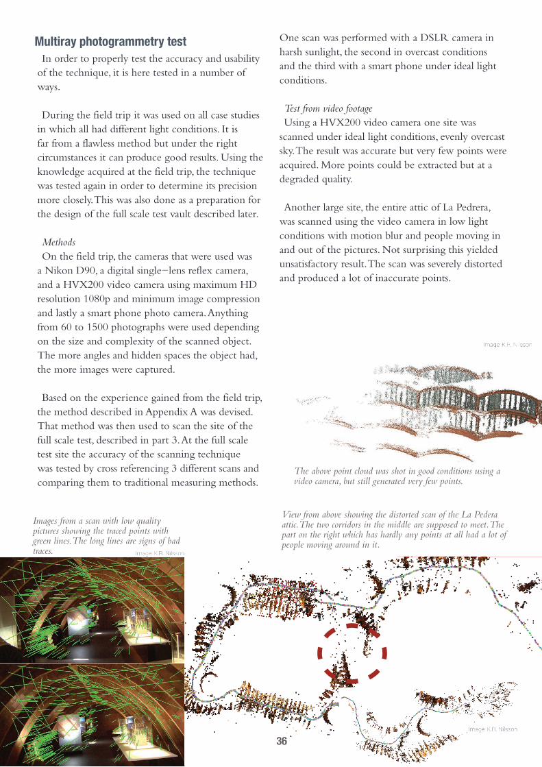
Test from video footageUsing a HVX200 video camera one site was
scanned under ideal light conditions, evenly overcast sky. The result was accurate but very few points were acquired. More points could be extracted but at a degraded quality.
Another large site, the entire attic of La Pedrera, was scanned using the video camera in low light conditions with motion blur and people moving in and out of the pictures. Not surprising this yielded unsatisfactory result. The scan was severely distorted and produced a lot of inaccurate points.
Images from a scan with low quality pictures showing the traced points with green lines. The long lines are signs of bad traces.
View from above showing the distorted scan of the La Pedera attic. The two corridors in the middle are supposed to meet. The part on the right which has hardly any points at all had a lot of people moving around in it.
The above point cloud was shot in good conditions using a video camera, but still generated very few points.
36
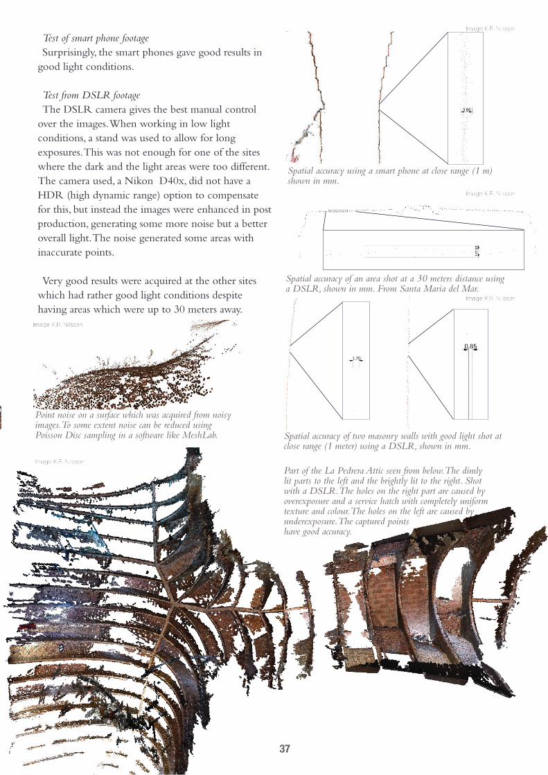
Test of smart phone footageSurprisingly, the smart phones gave good results in
good light conditions.
Test from DSLR footageThe DSLR camera gives the best manual control
over the images. When working in low light conditions, a stand was used to allow for long exposures. This was not enough for one of the sites where the dark and the light areas were too different. The camera used, a Nikon D40x, did not have a HDR (high dynamic range) option to compensate for this, but instead the images were enhanced in post production, generating some more noise but a better overall light. The noise generated some areas with inaccurate points.
Very good results were acquired at the other sites which had rather good light conditions despite having areas which were up to 30 meters away.
Part of the La Pedrera Attic seen from below. The dimly lit parts to the left and the brightly lit to the right. Shot with a DSLR. The holes on the right part are caused by overexposure and a service hatch with completely uniform texture and colour. The holes on the left are caused by underexposure. The captured points have good accuracy.
Spatial accuracy of two masonry walls with good light shot at close range (1 meter) using a DSLR, shown in mm.
Spatial accuracy of an area shot at a 30 meters distance using a DSLR, shown in mm. From Santa Maria del Mar.
Point noise on a surface which was acquired from noisy images. To some extent noise can be reduced using Poisson Disc sampling in a software like MeshLab.
Spatial accuracy using a smart phone at close range (1 m) shown in mm.
37

Conclusion from the testsUnder the right circumstances the method
produces a fairly accurate precision of around 0.5 cm if the photographs are taken at a 2 m distance. At longer distances the precision depends a lot on the texture and light but does not necessarily degrade considerably.
Compared to other techniques it has the advantage of being inexpensive and easy to use as all you need is a camera and access to a computer.
The method is limited to places which are accessible with a camera and that have enough room to take good pictures. It is highly dependent on local
light conditions but perhaps this could be enhanced with an external flash. However, harsh sunlight distorts the images seemingly because shadows move slightly in between the shots. Uniform textures as well as very dark or bright areas will hardly work at all. Noisy or out of focus images produce a lot of imprecise points and shiny or mirroring surfaces generate points which are completely wrong. Compressed images from video proved hard to use.
The technique produces good results on stone, brick and wood. Generally it is the same with anything with a detailed but not glossy texture. For masonry it has provided excellent result.
Comparative testThree different scans were done on the site and
cross referenced in Rhinoceros then compared with measurements using traditional tools (measuring tape). All three generated good scans that were within 1 cm of each other. The exception was the scan done in harsh sunlight in which the areas that were in shadow were off by another 2 cm. Now skew or other distortion was found using traditional measuring.
Final dense 3d scan acquired by the smart phone scan.
Image of the scan that used smart phone images. Images are displayed at the location where they were shot.
Image from the smart phone, under ideal light conditions.
Image from the DSLR camera. Harsh sunlight.
Image from DSLR camera. Better light conditions.
38
Analyzing formsIn order to analyze the forces in a given form the
options are fewer than for form finding, although new tools are under development.
Traditionally arches, vaults and domes were analyzed in 2 dimensional slices, which yields satisfying results as long as the overall geometry is symmetric. For vaults and domes this gives a more conservative result which largely discounts the overall three dimensional system.
Analyzing simple forms is very easy using graphic statics and has been used historically to assess very large structures. Other methods include membrane theory and limit analysis, but they are constrained to symmetrical or simple geometries.
The options to analyze the forces in complex asymmetrical masonry domes are quite limited. A reliable funicular approach is on the horizon (Block Lachauer, 2013). The main option is FEM, Finite Element Method, which has the benefit of having a plethora of tools, some which are very easy to use.
Problems with Finite Element Method analysis and masonry
There is a debate on whether using FEM as a method to analyze tile vaults is practical. Since it is the only commercially available way to visualize the forces within a vault, it has been used in many experiments in the past. Research of its accuracy is currently being investigated by David Lopez Lopez. There are two main points in the criticism.
Brittle Material ProblemThe first one has to do with the brittle nature of
masonry. Simplified (and therefore readily available to architects) FEM models assume that the material has some linear tensile and compressive resistance.Tile vaults without cracks exhibit linear elastic
behavior (Atamturktur, 2006) and can be analyzed. But the tensile resistance is highly unreliable and easy to use FEM modeling software is unable to analyze the geometry post cracking because of non linear and inelastic behavior. Even the elastic
compressing can be non linear as high stress levels may cause irreversible softening effects (Atamturktur, 2006).
Orthotropic Material ProblemAn orthotropic material is one that has different
material properties or strengths in different orthogonal directions (e.g., wood). Most FEM modeling software treats the volume as having an isotropic (homogeneous) material and does not account for the different properties of the brick and the mortar within the masonry.
In traditional vaults, due to the orientation of the mortar joints, the material is truly anisotropic and inhomogeneous, but because of the lamination of rotated layers, tile vaults do not have joints that go directly from the intrados to the extrados. This makes it possible to approximate it as an isotropic material. Atamturktur (2006) argues that in cases where the mortar and tile properties are known, a simple formula can be used to homogenize the two. Another option is to test samples of the combination of the two.
ReflectionsMy conclusion is that FEM can be used at least
for quick and rough analysis but not (yet) for safety assessment, at least not within a practical timeframe and simplicity. The safety of a vault can be quickly be rated by measuring the distance of the thrust line from the edge of the thickness of the vault given that the joints are more or less perpendicular to the thrust line (Block, Lachauer, 2013). Because the line of thrust of the vault is not showing in a FEM model, the safety is also not easily discernible, making it a less appropriate way of safety assessment than for example graphic statics (Reese, 2010). However, for complex asymmetrical structures, FEM might currently be the only available option.
As a means of producing a 3D geometry for FEM analysis, multiray photogrammetry 3D scanning seems to have a to great variation of quality to produce trustable geometry unless the conditions for the photography are very good.
39
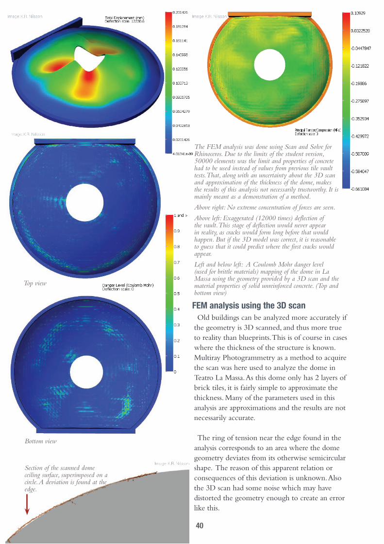
The FEM analysis was done using Scan and Solve for Rhinoceros. Due to the limits of the student version, 50000 elements was the limit and properties of concrete had to be used instead of values from previous tile vault tests. That, along with an uncertainty about the 3D scan and approximation of the thickness of the dome, makes the results of this analysis not necessarily trustworthy. It is mainly meant as a demonstration of a method.
Above right: No extreme concentration of forces are seen.
Above left: Exaggerated (12000 times) deflection of the vault. This stage of deflection would never appear in reality, as cracks would form long before that would happen. But if the 3D model was correct, it is reasonable to guess that it could predict where the first cracks would appear.
Left and below left: A Coulomb Mohr danger level (used for brittle materials) mapping of the dome in La Massa using the geometry provided by a 3D scan and the material properties of solid unreinforced concrete. (Top and bottom view)
FEM analysis using the 3D scanOld buildings can be analyzed more accurately if
the geometry is 3D scanned, and thus more true to reality than blueprints. This is of course in cases where the thickness of the structure is known. Multiray Photogrammetry as a method to acquire the scan was here used to analyze the dome in Teatro La Massa. As this dome only has 2 layers of brick tiles, it is fairly simple to approximate the thickness. Many of the parameters used in this analysis are approximations and the results are not necessarily accurate.
The ring of tension near the edge found in the analysis corresponds to an area where the dome geometry deviates from its otherwise semicircular shape. The reason of this apparent relation or consequences of this deviation is unknown. Also the 3D scan had some noise which may have distorted the geometry enough to create an error like this.
Section of the scanned dome ceiling surface, superimposed on a circle. A deviation is found at the edge.
Bottom view
Top view
40
Form findingThere are several tools available to analyze and
optimize new vaults. The low tech option is to use hanging chains and make scale model crash tests but this can also be done using digital tools that are familiar to many architects. The tools suggested can all be used in the popular CAD software Rhinoceros 3D and its plug-in software Grasshopper. They all have their strengths and weaknesses and are briefly explained here.
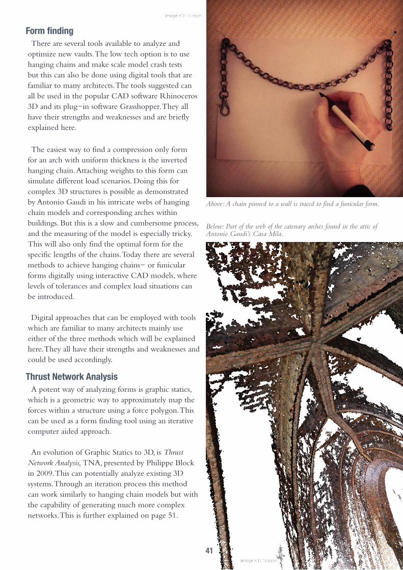
The easiest way to find a compression only form for an arch with uniform thickness is the inverted hanging chain. Attaching weights to this form can simulate different load scenarios. Doing this for complex 3D structures is possible as demonstrated by Antonio Gaudi in his intricate webs of hanging chain models and corresponding arches within buildings. But this is a slow and cumbersome process, and the measuring of the model is especially tricky. This will also only find the optimal form for the specific lengths of the chains. Today there are several methods to achieve hanging chains- or funicular forms digitally using interactive CAD models, where levels of tolerances and complex load situations can be introduced.
Digital approaches that can be employed with tools which are familiar to many architects mainly use either of the three methods which will be explained here. They all have their strengths and weaknesses and could be used accordingly.
Thrust Network AnalysisA potent way of analyzing forms is graphic statics,
which is a geometric way to approximately map the forces within a structure using a force polygon. This can be used as a form finding tool using an iterative computer aided approach.
An evolution of Graphic Statics to 3D, is Thrust Network Analysis, TNA, presented by Philippe Block in 2009. This can potentially analyze existing 3D systems. Through an iteration process this method can work similarly to hanging chain models but with the capability of generating much more complex networks. This is further explained on page 51.
Above: A chain pinned to a wall is traced to find a funicular form.
Below: Part of the web of the catenary arches found in the attic of Antonio Gaudi’s Casa Mila.
41

Rhino Vault for Rhinoceros 3D provides tools to quickly optimize the force network grid as well as finding either an optimized solution for minimum forces, or optimize according to a design. At the moment it will try to find funicular solutions to a given boundary condition but can not analyze or adjust arbitrary 3D solids, which is a lot more difficult. However, that possibility is currently being researched with good results (Block, Lachauer, 2013).
Dynamic RelaxationDynamic relaxation works like a network of
digital springs which can stretch both positively and negatively (contract). Using a physics engine they can be iterated into a shape where the forces are at an equilibrium. Forces can be approximated using Hooke’s law by comparing the initial length of the spring to the stretched length.
Using the plug-in Kangaroo, very complex networks can be tested in real time in Grasshopper. This is the most customizable option as it runs in the regular Grasshopper environment.
SmartFORM by Smart Solutions is another
software, a plug-in for Rhinoceros 3D, that uses dynamic relaxation. It can be used real time for complex meshes and has an option to map force density using colors.
Finite Element AnalysisThe Finite Element Method is probably the
most known computer aided method to analyze structures. It can be used to produce an optimal form, although this is a very slow process for complex shapes. For form finding there are various other methods to use it, one interesting way is by using it in conjunction with another algorithm. For example one that works by trying several forms, choosing the best of them, and based on that one make new models with a few adjustments, choosing the best one of those and so on.
The FEM Grasshopper plug-in Karamba can in conjunction with Galapagos, a genetic algorithm part of Grasshopper, be turned into a form finding tool. It can, for example, be set to find solutions that minimize the deflection in a structure. It is not fast compared to the other tools, but it can be set up to use real material properties, and work with highly customized optimization targets. Whether this is a sound form finding method for unreinforced masonry structures given the problems associated with FEM and masonry is beyond this text.
‘‘Hooke’s law states that the force exerted by a spring is directly proportional to the amount its length differs from its natural or rest length.’’
Graphic statics analysis of the line of thrust for a given load. In an optimal arch this line would be at the centre of its thickness.
The force vectors can be represented in a force polygon where the forces at each point are represented with the length proportional to their magnitude.
42

43

connectinG diGital 3d to realityDigital Blueprints
With new design tools providing complex forms the need arises to simplify the process of translating it into reality. The use of digital tools is often limited by the
need to convert 3D to 2D blueprints and by approximating the real world using crude means of measurement. A few methods will therefore be suggested and tested.
Adaptable form workA form or a guide that can be adjusted to complex
forms is faster and generates less waste than a traditional form would. The required adjustments to the form can be easily extracted from a parametric model.
Microcomputer electronicsWith a parametric model another option is to
couple the blueprint with an electronic device that aids the mason.
A common problem for modern layman tile vault builders is that without a form or skill of a master mason, it is hard to know where to put the brick. This slows down the process by the need to make guide work or creates low quality masonry that is structurally unsound. Even adjustable forms are built for a certain scale or span and making them takes time.
Microcomputers such as Arduino have a big open source community and provides a simple mean to control electric devices. They nowadays also sport a simple link between Grasshopper using Firefly,
which can be used to directly control the electronic devices. This direct control can be incredibly useful to circumvent blueprints and project the digital 3D directly in place with high precision. A workshop at smart geometry 2013 displayed a technique where a Kinect real time 3D scanner was coupled with a projector that gave immediate feedback on the masonry on regarding the accuracy.
Laser guidanceProblems with for example using a projector is
that it has to be done in dark conditions. Another problem is that 3D scanning solutions like Kinect
A parametric model of a vault where measurements can be extracted at any point and follow changes in the geometry.
Below left: A form which can be adjusted to form any desired arch curvature.
Below right: A guide that can be adjusted and moved with relative ease.
44

have a very limited range, barely 3 meters. A solution to these issues is a novel approach, here presented, involving lasers guiding the mason. The laser guidance device in described in Appendix B. Connected directly to Grasshopper using the Firefly plug-in it can be set up to point where in space to put the bricks.
The idea is that the two laser rays intersect at a point corresponding to the reciprocal point in the 3D-program. This allows for high precision guidance with no build waste. And the material cost for the device is around 1300 SEK (140 Euro), a cost that could be much lower with further design.
The lasers are placed at a distance on a spot that has been previously 3D-scanned and is defined within the digital 3D
model in Grasshopper. They are then connected and calibrated by focusing them on a known point at the base of the vault. The lasers can then move to converge at points in space guiding where to put the brick tiles according to a pattern defined in Grasshopper. By using an Open Sound Control OSC listener and transmitter in Firefly, commands controlling the laser can be transmitted wirelessly from a smart phone using a customizable application like TouchOSC. An explanation of the Grasshopper definition is found in Appendix D.
The laser is located in the top left corner. The laser beams pointing from it can be traced to the parametric blueprint model which is modelled on top of the 3D scan of the site. Where they intersect is the exact location of the next brick as designated by the blueprint.
An evening shot reveals the laser beams intersecting at the designated point.
45

46

Part 3, the test siteThis part of the thesis will put the theory to use in a real demonstration of the process. Suitable methods are employed demonstrating a possible digitally enhanced work flow
47
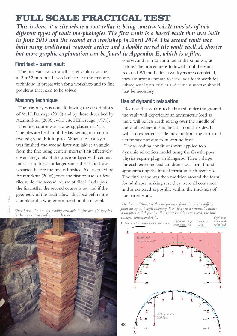
full scale Practical testThis is done at a site where a root cellar is being constructed. It consists of two different types of vault morphologies. The first vault is a barrel vault that was built in June 2013 and the second at a workshop in April 2014. The second vault was built using traditional voussoir arches and a double curved tile vault shell. A shorter but more graphic explanation can be found in Appendix E, which is a film.
First test - barrel vaultThe first vault was a small barrel vault covering
a 2 m*2 m room. It was built to test the masonry technique in preparation for a workshop and to find problems that need to be solved.
Masonry techniqueThe masonry was done following the descriptions
of M. H. Ramage (2010) and by those described by Atamturktur (2006), who cited Etheredge (1971). The first course was laid using plaster of Paris.
The tiles are held until the fast setting mortar on two edges holds it in place. When the first layer was finished, the second layer was laid at an angle from the first using cement mortar. This effectively covers the joints of the previous layer with cement mortar and tiles. For larger vaults the second layer is started before the first is finished. As described by Atamturktur (2006), once the first course is a few tiles wide, the second course of tiles is laid upon the first. After the second course is set, and if the geometry of the vault allows this load before it is complete, the worker can stand on the new tile
courses and lean to continue in the same way as before. The procedure is followed until the vault is closed. When the first two layers are completed, they are strong enough to serve as a form work for subsequent layers of tiles and cement mortar, should that be necessary.
Use of dynamic relaxationBecause this vault is to be buried under the ground
the vault will experience an asymmetric load as there will be less earth resting over the middle of the vault, where it is higher, than on the sides. It will also experience side pressure from the earth and temporary pressure from ground frost.Those loading conditions were applied to a
dynamic relaxation model using the Grasshopper physics engine plug-in Kangaroo. Then a shape for each extreme load condition was form found, approximating the line of thrust in each scenario. The final shape was then modeled around the form found shapes, making sure they were all contained and as centered as possible within the thickness of the barrel vault.
Since brick tiles are not readily available in Sweden old recycled bricks was cut in half into brick tiles.
The lines of thrust with side pressure from the soil is different from an equal length catenary. It is closer to a semicircle, under a uniform soil depth but if a point load is introduced, the line changes correspondingly.Vertical and horizontal load thrust vectors
Optimum shape with earth load
Catenary shape
Optimum shape with point load
Adding another 500 here.
Earth load approximation
48
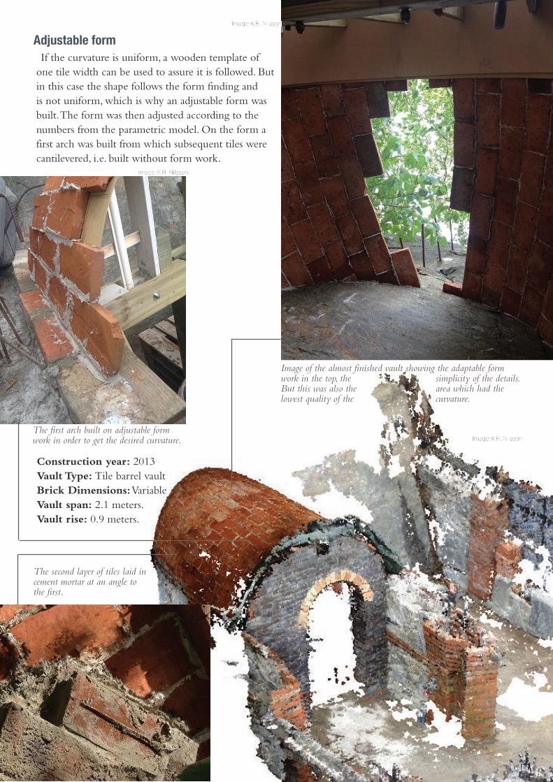
Adjustable formIf the curvature is uniform, a wooden template of
one tile width can be used to assure it is followed. But in this case the shape follows the form finding and is not uniform, which is why an adjustable form was built. The form was then adjusted according to the numbers from the parametric model. On the form a first arch was built from which subsequent tiles were cantilevered, i.e. built without form work.
Image of the almost finished vault showing the adaptable form work in the top, the simplicity of the details. But this was also the area which had the lowest quality of the curvature.
The first arch built on adjustable form work in order to get the desired curvature.
The second layer of tiles laid in cement mortar at an angle to the first.
Construction year: 2013Vault Type: Tile barrel vaultBrick Dimensions: Variable Vault span: 2.1 meters.Vault rise: 0.9 meters.
49

First findingsThe use of dynamic relaxation within Kangaroo
proved to be highly customizable and a good option when designing for asymmetric load conditions.
All details were very simple to produce and the masonry technique seemed to be fast compared to regular masonry construction. But since no traditional vault was built at this stage, this was only a conjecture. The fact that the tiles were of slightly different sizes sometimes meant thicker mortar joints were needed, causing the mortar to set slower and where the joints were to thick shrinkage cracks would form (depending on the type of gypsum plaster used).
The adjustable form has to support the weight of the arch, which adds up quickly even though the tiles are only half the weight of regular tiles. Therefore it is very robust and thus rather heavy, which limits its use.
Geometric analysisThe finished vault was later 3D scanned in order to
examine the quality of the geometry. This revealed that the adjustable form managed to translate the shape from the dynamic relaxation to reality and that further away from the form, the quality of the shape degraded. A conclusion of this is that it was hard as an inexperienced vault builder to maintain the shape by only tactile and visual means.
The top section is taken where the adjustable form was set up. The blue dashed line overlaying it represents the shape which was form found. It is evident that the part which was not close to the form work showed signs of low quality masonry. One part of it has a negative curvature, even when counting the slight double curvature at the end of the vault, which gives the compression forces alternative routes. An area of 400 mm * 400 mm was determined to have negative or zero curvature in all directions. Negative curvature is hard to remedy with extra reinforcement, since it has to be put on the inside.
Sections
Desired shape
Area with negative curvature
Perpendicular section, showing a close to zero curvature.
50

Workshop - asymmetric double curved vaultUsing the findings from the first vault and the
findings of the thesis research a second test was devised as a workshop that took place during 5 days in April 2014. In contrast to the first vault this one only have symmetrical load conditions, but the shape is more complex, double curved and asymmetrical.
The workshop was a way of demonstrating possible work flow using the tools or case studies described in the thesis and a chance to compare different methods of construction. It also tested translating digital 3D to reality using digitally controlled laser guidance using parametric blueprints, and backed up by an adjustable guide, adjusted according to the same digital blueprint.
Use of thrust network analysis softwareThe Kangaroo Grasshopper definition created in the
first test is useful for cases of unusual loading but not nearly fast enough for prototyping. And not necessary for the second vault which will have a uniform load. Prototyping was done in another dynamic relaxation tool, SmartForm and also using a thrust network tool, RhinoVault. By adjusting the force polygon of the thrust network in RhinoVault, the shape of the vault can be controlled. This was done here to adjust the rise of the openings of the vault without changing the overall rise.
Just like graphic statics the thrust network has a reciprocal force polygon. The length of the force vectors in the force polygon corresponds to the magnitude of the force they represent. By knowing the dead load of the vault, the exact force can be found for each vector. By increasing the magnitudes of the forces, the shape can be changed.
The shape might look symmetric at first glance but it is actually distorted by the different heights of its perimeter arches and because the supporting piers were not following precise measurements in either height or in relation to each other. This is all accounted for within the thrust network.
Plan view
Perimeter arch shapes
Graphic Statics (made using Active Statics)Plan view of the thrust network form diagram.
Increasing the length (magnitude) of the vectors in the force polygon affect the shape.
Manipulating the force polygon changes the shape at the place from which they are derived.
The force polygons for the outermost arches in the
thrust network are similar to the one seen in the graphic statics analysis.
Force polygon
Form diagram
Reciprocal thrust network force polygon.
Pier
Piers
Pier
51

Design work flow
1. Idea: combining two techniques, voussoir arches at the perimeter of the tile vault. They act like stiffening arches as seen in La Pedrera. They will also create a good perimeter from which the tile vault can be built.
2. The maximum and minimum heights for the arches and vault was determined, and brick pattern decided upon.
3. The site is scanned and vault construction workshop announced!
4. Boundary conditions for the form finding is determined using the point cloud.
5. Fast form finding prototypes are done in SmartForm (Dynamic Relaxation).
8. Horizontal thrust is determined and using that, the need for wall reinforcements calculated.
9. Parametric Blueprints are built in Grasshopper. Bricks generated over the surface and their coordinates connected to the laser guidance.
6. A final version is made and adjusted using TNA with RhinoVault.
7. Arches are designed as catenary curves geometries containing the edges of the thrust network.
52

Construction year: 2014Vault Type: Catenary voussoir archBrick Dimensions: 250mm*120mm*60mm Span: 2.2 meters.Rise: 0.55 to 0.7 meters.
The measurements for the four different arches were extracted from the parametric model (which in turn was based on the 3D scan) and cut out from OSB boards from which form work was made. The forms ended up having a snug fit.
Construction of voussoir archesThe curvature was determined by making a
simple catenary curve between the supports using the 3D scan. The four arches are all different, as they are adjusted according to program and to the supports scanned at the site. Because conventional bricks are much heavier than tile bricks, having twice the thickness, the adaptable form could not be used and conventional forms were made for each arch.
The arches were erected on the form work.
53

Construction of a domical tile vaultDue to extensive rain the tile vault phase was not finished
during the workshop, but enough work on it was done in order to test the guidance techniques and to get some results about their accuracy. In contrast to the first test, bricks of the same dimensions were here used.
Construction year: April 2014- August 2014Vault Type: Funicular asymmetrical double curved tile vaultBrick Dimensions: 250mm*120mm*30mm Span: 2.2 meters (3.6 meter diagonally).Rise: 1.1 meters.
A lot of pre work had to be done. The tiles were salvaged from a refurbishment in an old house in Gothenburg and some from a demolished 19th century service building (Swedish: brygghus) and brought in by truck. All bricks were then cut into tiles.
A technology control point was rigged in the room under the first vault, close enough to the laser to reach it with a USB cable.
The bricks had to be cleaned to ensure a good adhesion with the mortar. Then dried for the same reason and to make them as light as possible, although only a few of them were of the light weight type made by mixing in saw dust in the clay.
Although several options that automated the laser movement were tested, it was found to be easiest when it moved on command, which in this case meant someone sitting by the computer. Only then the mortar could be applied, called “Lareado” in Catalonia.
The tile was aligned in accordance to the laser and put in place, letting go a few seconds later as the mortar dried and held the tile in place.
Laser device
Technology control point
54

The laser was placed into position on top of the first vault and the site was scanned again getting the position of the laser and updating the old scan with the new arches. The different scans were aligned using key features present in both scans.
Laser guidanceThe laser beams intersect at the coordinates
where the brick is supposed to be. A point in the top middle of the brick was here chosen in order to make sure the lasers had a line of sight to the bricks. A smoke machine was tested to see if the laser beams would be visible, and this worked but only during the evening when the wind did not blow.
View from the lasers towards the vault. One of the modules has started to behave erratic because of a calibration error but the other one points at the proper point on the brick selected.
The alignment process involves moving the tile so the dots converge at the designated position of the brick.
A close up of the digital model and the scanned new built tiles reveals the accuracy.
Adjustable guide workThe adjustable guide work with measurement from the
blueprints complemented the lasers and made sure they . were accurate. It also worked as a standalone solution. . Further explained in Appendix C.
Laser beams Digital blueprints
55
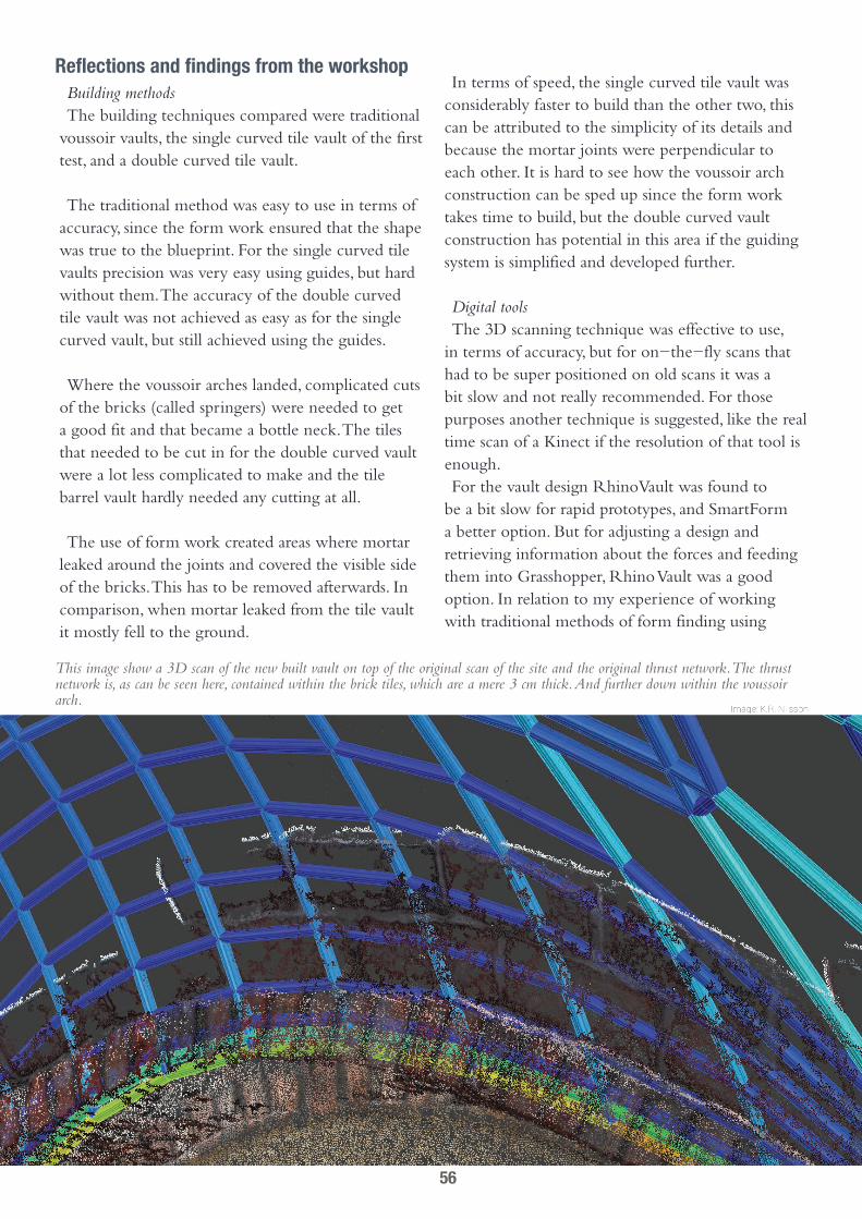
This image show a 3D scan of the new built vault on top of the original scan of the site and the original thrust network. The thrust network is, as can be seen here, contained within the brick tiles, which are a mere 3 cm thick. And further down within the voussoir arch.
Reflections and findings from the workshopBuilding methodsThe building techniques compared were traditional
voussoir vaults, the single curved tile vault of the first test, and a double curved tile vault.
The traditional method was easy to use in terms of accuracy, since the form work ensured that the shape was true to the blueprint. For the single curved tile vaults precision was very easy using guides, but hard without them. The accuracy of the double curved tile vault was not achieved as easy as for the single curved vault, but still achieved using the guides.
Where the voussoir arches landed, complicated cuts of the bricks (called springers) were needed to get a good fit and that became a bottle neck. The tiles that needed to be cut in for the double curved vault were a lot less complicated to make and the tile barrel vault hardly needed any cutting at all.
The use of form work created areas where mortar leaked around the joints and covered the visible side of the bricks. This has to be removed afterwards. In comparison, when mortar leaked from the tile vault it mostly fell to the ground.
In terms of speed, the single curved tile vault was considerably faster to build than the other two, this can be attributed to the simplicity of its details and because the mortar joints were perpendicular to each other. It is hard to see how the voussoir arch construction can be sped up since the form work takes time to build, but the double curved vault construction has potential in this area if the guiding system is simplified and developed further.
Digital toolsThe 3D scanning technique was effective to use,
in terms of accuracy, but for on-the-fly scans that had to be super positioned on old scans it was a bit slow and not really recommended. For those purposes another technique is suggested, like the real time scan of a Kinect if the resolution of that tool is enough.For the vault design RhinoVault was found to
be a bit slow for rapid prototypes, and SmartForm a better option. But for adjusting a design and retrieving information about the forces and feeding them into Grasshopper, Rhino Vault was a good option. In relation to my experience of working with traditional methods of form finding using
56

hanging chains, the digital tools were orders of magnitude faster.
Digital blueprintsThe parametrically controlled digital blueprints
were not easy to produce but they can now be applied on other projects with other shapes and needs, reusing the Grasshopper definition.
The blueprints worked well for making the traditional form work, for giving measurements to the adjustable guide and especially for controlling the laser.
An improvement in relation to the laser would have been to be able to remotely control the parameters in the blueprint controlling it. That could be done using Firefly via the wireless connection between a computer and a smart phone. This would also remedy the big downside of needing the computer very close to the site.
Adjustable guideThe guide worked but it was not a fast process.
As each move of the guide had to be mimicked on the computer, it was necessary to have the computer on site. Also, a very precisely measured frame on the floor had to be drawn. Its use to evaluate the accuracy of the laser guide was very good and allowed the laser to be useful even after one of the two laser modules started to malfunction. Improving it with automated height adjustment from grasshopper would be interesting to try, as that would greatly improve both speed and precision for adjusting it. But it will always be limited to its size.
Form workThe traditional form work was easy to use but
took very long to build and generated a lot of waste material. The blueprints were extracted from the model which in turn was based on the 3D scan and that gave them a very precise fit.
Laser guidanceThe laser guidance technique is promising, but it
would be good to try it again using a more robust design, one which can handle wind and rain. The laser guidance prototype was, because of its bulky
design and unpredictable material (wood), not user friendly but served as a proof of concept. Further, the technology was shown to work in full sunlight and at long distances as long as the angle between the laser beams are not too oblique or acute. More laser beams would also make the technique more robust and allow calibration errors to be immediately visible. More beams would also help with the line of sight requirement of the laser.
Laser shortcomingsThe laser was not designed to stand at an
inclination. Calibration of errors of the shape of the laser device did not work properly for one of the lasers after a few hours. Although the use of plywood gives the device an interesting appearance, its form changed with humidity and thus, hardly a clever choice of material for an instrument requiring precision. Even if one of the lasers malfunctioned slightly (a few percent), it was easy enough to see that the technique worked as one of the lasers kept pointing at the right spots. That is known thanks to the adjustable guide.
For improving the precision it would have worked better if the stand was included in the original point cloud. Aligning a new point cloud to the old one takes a lot of time.
Laser benefitsIt was easy to align the brick when the lasers
intersected properly. The dots were visible even in sunlight. Using a smoke machine, the laser beams became visible and from that you could get a feel for the size of the geometry before it was built. Also, virtually no building waste was produced (except for superfluous mortar, caused by inexperience in estimating the needed amount when mixing).
The resolution was good enough to give precision at at least 6 meters. This is dependent on the angle at which the laser beams intersect as well as the thickness of the beams. The further the lasers are apart, the better the angle of intersection, until it reaches 90 degrees. Although the laser was designed to aid masonry, it could probably have other uses as well.
57

final reflectionsReflections of the findings of the thesis in relation to the introduction and to the problem formulation.
The old construction method can be updated because the digital tools for optimization allow more advanced forms to be designed than in the past and at a faster pace. It can be adapted to the fact that there are very few vault masons today by aiding laymen with computer guided precision. It can also be adapted to stricter rules for safety assessment than was needed in the past using the proper digital tools.
Complex calculations for form and assessmentFor designing new vaults, architectural tools using
Dynamic Relaxation and Thrust Network Analysis are good at optimizing and statics for different demands and calculating forces. Optimized forms are especially good for tile vaults since these are thinner than conventional vaults. The digital form finding methods allowed a site specific vault design, instead of adjusting the supports to accommodate the vault, the vault could be shaped to accommodate the supports which also reduced time spent on drawing and building details.
But for analyzing non-form found vaults, only simple symmetrical forms have good analysis possibilities, and mainly using traditional analysis methods. The only automated option there is Finite Element Method Analysis, which is unsuitable for traditional masonry and for tile vaults debated and not (yet) recommended to be used to draw definite conclusions. However, theoretical tools using Thrust Network Analysis, which are able to produce a geometric safety factor for arbitrary shapes, have been developed and may soon be made more accessible (Block, Lachauer, 2013).
SpeedThe speed of the design phase was greatly improved
by the 3D scan, as taking measurements of complex geometry using traditional tools is a very long and inaccurate process. But the 3D scanning technique, multiray photogrammetry, was found to be highly dependent on light conditions. By heeding to their limits, sufficiently accurate scans was produced to approximate vault geometries and to finding areas with unsound curvature. But, using it as a definite
proof of structural stability by automated conversion to a solid on which FEM analysis can be done is not recommended. Noise in the scan introduces errors in the solid generated from it which in turn is picked up by the FEM software. A suggestion here is to use a more accurate technology like LIDAR. Another limit is that, usually only one side of the vault can be scanned. This requires an assumption for the thickness, which should be relatively easy for tile vaults as the thickness is often even.
At this point it cannot be determined whether the computer controlled guides can speed up the con-struction phase and should be investigated further. But compared to traditional vaults using form work the tile vault technique was found to be faster. However, in Sweden, where brick tiles are not common, the need to cut bricks in two was very time consuming. This could be avoided if local brick manufacturers could be convinced to create bricks in the tile format.
Unskilled laborThe tile vault technique has very simple details,
requiring virtually no stereotomy (complex cutting of masonry blocks). Masonry precision without form work is hard for laymen, as shown in the practical test, the use of aids is necessary to ensure proper curvature. Even for complex double curved shapes precision can be achieved with very good results, as demonstrated, using parametric blueprints in conjunction with either physical guide work or a laser guidance.
CostsVery little waste material was produced building
the tile vault compared to the traditional voussoir vaults. The physical requirements to use the tile vault technique was found to be a lot less straining than for the regular brick vaults. Especially when using old light weight bricks made using saw dust (spåntegel). This could potentially speed up the construction even more and if that can turn the construction phase into a social gathering, much is won.
58

The (asymmetrical) domical vault was finished after the completion of this thesis, during the summer of 2014.
59
referenced literatureBook
Ochsendorf J. (2010) Guastavino vaulting, the are of structural tile New York City: Princeton Architectural PressReese M. (2010) Structural assessment of and analysis of Guastavino vaulting Vilassar De Dalt: Impremta El
VaixellComo M. (2013) Statics of historic masonry constructions Berlin Hidelberg: Springer VerlagPedreschi R. (2000) The engineer’s contribution to contemporary architecture: Eladio Dieste London: Thomas
TelfordPaulsson G. (1936) Hantverkets bok, 4, Mureri, Stockholm: Lindfors Minke G. (2000) Earth Construction Handbook Southampton: WIT PressHuerta S. (2003) The mechanics of timbrel vaults: A historical outline Berlin: Birkheuser Verlag
PaperBlock P. (2009) Thrust Network Analysis - Exploring Three-dimensional Equilibrium [Journal Paper] Boston:
Massachusetts Institute of Technology, Department of ArchitectureLópez D., Rodríguez M. (2012) Structural Analysis of Tile Vaulting: Method and Variables Barcelona: Universitat
Politècnica de CatalunyaAtamturktur H. (2006) Structural assessment of Guastavino domes [Master Thesis] The Pennsylvania State
University, Department of Architectural Engineering Saliklis E., Kurtz S.,Furnbach S. (2003) Finite element modeling of Guastavino tiled arches Pennsylvania:
Lafayette College, Deptartment of Civil and Environmental. EngineeringBlock P., Lachauer L. (2013) Three-dimensional funicular analysis of masonry vaults Zürich: ETH, Institute of
Technology in ArchitectureRippman. M, Block P. (2011) Digital Stereotomy: Voussoir geometry for freeform masonry-like vaults informed by
structural and fabrication constraints Zürich: ETHGuastavino R. (1883) Essay on the theory and history of cohesive construction applied especially to the timbrel vault
Boston: Massachusetts Institute of Technology, Society of artsBenfratello et al. (2012) Tradition and modernity of Catalan vaults: Historical and structural analysis Palermo: Università degli Palermo
Web PageOrganization/Author (year) Title. Orgainization. http://www.somewhere.com (Day Month Year)SmartGeometry (2013) Computer Vision and Freeform Construction SmartGeometry http://smartgeometry.
org/index.php?option=com_community&view=groups&groupid=34&task=viewgroup (2013-04-29)
ArchDaily/Gill Merin (2013) AD Classics: The National Art Schools of Cuba ArchDaily http://www.archdaily.com/427268/ad-classics-the-national-art-schools-of-cuba-ricardo-porro-vittorio-garatti-robert-gattardi/ (2013-08-12)
Online lectureOchsendorf , J (2011) Form and Forces, http://www.youtube.com/watch?v=r-tG68WvNDM [youtube] (12
Feb. 2012)
JournalDavis L., Block P. (2012) Earthen masonry vaulting Ethiopia: Ethiopian Institute of Architecture, Building
Construction and City DevelopmentBlock P., Ochsendorf J. (2007) Thrust Network Analysis: A new methodology for three-dimensional equilibrium
Madrid: J. IASS
60
Lôpez-Almansa et al. (2010) Experiments on reinforced brick masonry vaulted light roofs Michigan: ACI Structural Journal May/June 2010Ruiz et al. (2010) Interaction between Bond and Deviation Forces in Spalling Failures of Arch-Shaped Members
without Transverse Reinforcement Michigan: ACI Structural Journal May/June 2010Ramage M. Ochsendorf J., Rich P, Bellamy J., Block P. (2010) Design and Construction of the Mapungubwe
National Park Interpretive Centre, South Africa Lusaka: African Technology Development Forum JournalLuna M., Bernal V. (2003) The timbrel vault (Extremaduran vault) Madrid: Proceedings of the First
International Congress on Construction History
OtherGuastavino R. (1890) Construction of tiled arches for stairs and ceilings [Patent] New York: United states patent
office
61
aPPendix aMultiray photogrammetry technique
Whether an old vault is to be analyzed or there is a site upon which a vault is about to be constructed, it is very helpful to have a 3D scan of it. This helps accuracy and digital modeling and simplifies use of computer aided guidance during the construction.The technique of multiray photogrammetry has
been tested in this thesis.
The tool requirements are:• A digital camera. In many cases a mobile phone
camera or film camera will suffice but the most accurate results will be acquired by a DSLR camera (digital single-lens reflex camera) with manual control options.
• A reasonably fast computer (as of 2014).• A software that is able to convert the images
into a 3D object. There are many options here. Some web pages offer a free fully automated process, like my3Dscanner.com, and there is a free cloud based service called 123 catch from Autodesk. The problem with these services is that they are sometimes offline and limited in terms of allowed amount of input data. The most versatile option is therefore to use a free open source software like VisualSFM (SFM stands for Structure From Motion), made by Changchang Wu at the University of Washington in Seattle.
• A 3D program dealing with point clouds. A 3D scan will always yield a point cloud and in order to manipulate and prepare them for a regular 3D program, it can be useful to do that with a tool made specifically for that purpose, like MeshLab, another free open source program developed at the University of Pisa.
• Image to 3D software, VisualSFM• Point Cloud Manipulation Software, Meshlab
Photographing, best results.The SFM software works best when being feed
sharp noise free and high resolution images with no pitch black or over exposed areas and now movements in the scene. It is not always possible to fulfill all these criteria but often the results can be good enough anyway.
Camera settingsOther than low quality optics, there are two kinds
of blurring that can make the scan less accurate. The first one is motion blur which is caused by camera movement or shake. There are two ways of mitigating this. Either by putting the camera on a stand or by increasing the shutter speed, for a hand held camera this should be set to more than 1/60th of a second. The second type of blur has to do with the depth of field, DOF. This is the distance between the closest object and the object furthest away that still appears sharp in the image. DOF is affected by many things but most importantly by the relative aperture, or f-number. For the desired long DOF set the f-number as low as possible, usually good results are found between f/8 and f/20. There are also specialized cameras which has an infinite DOF at all f-numbers, called light field camera, which might be worth a try.
The two main things that introduce noise into the picture are the image compression and the electronic signal amplification of the sensor (often called the ISO setting or ‘gain’). The compression setting should ideally be low but it might still be a good idea to use jpg compression rather than completely uncompressed because of compatibility issues with uncompressed formats and the impractical amount of data that they generate. The ISO setting, or gain, should be as low as possible.
Some cameras have the option to take photos with a High Dynamic Range, HDR, and which will ensure that no parts of the images will be completely black or completely white, which will otherwise decrease accuracy dramatically in these areas. If some areas become to dark it is sometimes good to increase the brightness of the dark parts afterwards, in a image processing software, albeit this will introduce more noise and some bad points.
Lastly to avoid colors changing between the pictures the camera needs to be set at a fixed white balance.
62

Scene conditionsIn order to get a good read of points, try to take as
few pictures as possible where for example people are moving in the way. If that is impossible, a much larger number of pictures are needed. A similar issue can appear if the shadows move because a built in flash is used or because the sun moves. The software will then likely calculate more inaccurate points.
TechniqueTo get the best possibilities for the software to
triangulate or trilaterate the points, move between ever picture and make sure every point is visible in minimum 4 images captured from different locations. Taking at least 60 when moving around an object is a good rule of thumb and when capturing the inside of rooms, moving around it with the back against a wall gives a good read.
In short:Good opticsNo motion blurLong Depth of FieldLow ISOHDR if possibleFixed White BalanceFew reflective surfacesFew large surfaces without detailsNo moving objects in the sceneNo moving shadows in the sceneTake pictures with good overlapMove between each pictureAbsolutely minimum of 5 images on each side of the sceneTake at least 30 pictures and several hundreds to capture many sides and details These two scans yielded good results and
display the location and angles of the images used.
63
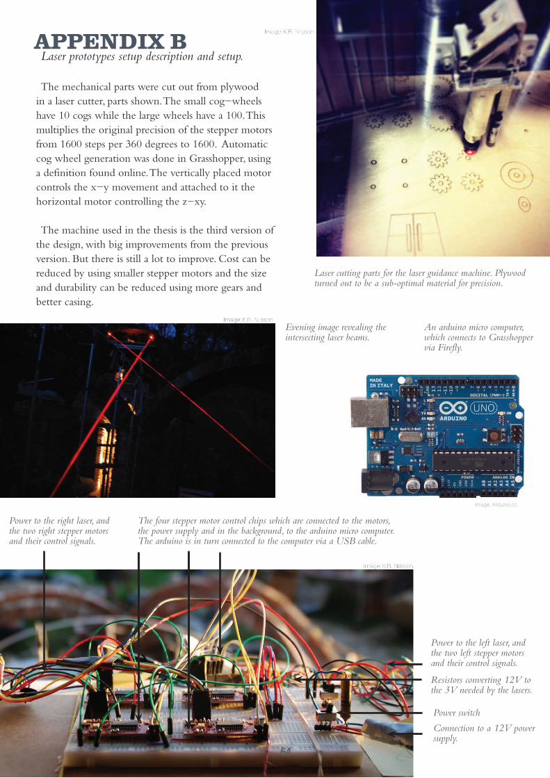
aPPendix bLaser prototypes setup description and setup.
The mechanical parts were cut out from plywood in a laser cutter, parts shown. The small cog-wheels have 10 cogs while the large wheels have a 100. This multiplies the original precision of the stepper motors from 1600 steps per 360 degrees to 1600. Automatic cog wheel generation was done in Grasshopper, using a definition found online. The vertically placed motor controls the x-y movement and attached to it the horizontal motor controlling the z-xy.
The machine used in the thesis is the third version of the design, with big improvements from the previous version. But there is still a lot to improve. Cost can be reduced by using smaller stepper motors and the size and durability can be reduced using more gears and better casing.
Power switch
Connection to a 12V power supply.
Power to the left laser, and the two left stepper motors and their control signals.
Power to the right laser, and the two right stepper motors and their control signals.
The four stepper motor control chips which are connected to the motors, the power supply and in the background, to the arduino micro computer. The arduino is in turn connected to the computer via a USB cable.
Resistors converting 12V to the 3V needed by the lasers.
Laser cutting parts for the laser guidance machine. Plywood turned out to be a sub-optimal material for precision.
Evening image revealing the intersecting laser beams.
An arduino micro computer, which connects to Grasshopper via Firefly.
Image: Arduino.cc
64

Stepper motor and laser cut casing.
Wheel with 10 cogs.
Wheel with a 100 cogs, holes for wires and guidelines for
the second stepper motor and its gear.
Wheel with guides for attaching the 2,5 mW output red laser module.
Supports holding the second cog wheel.
65

Version OneThe previous versions demonstrated some of the
difficulties with making a machine like this. The first prototype used servo motors, which are easy to control and moves fast, but only gives a resolution of 360 steps per 360 degrees rotation.
Version TwoThe second prototype which used stepper motors
for greater accuracy and CDs in order to get precise measurements. It had a resolution of 56000 steps per 360 degrees but since it used rubber bands and lacked cogs, it would never return to the exact same spots.
Version Two
Version Two
Version One
66

aPPendix cThe adjustable guide-work.
The guide work was used to guide the masonry without forms. It is made from nine telescope shafts connected to a metal frame. The shafts can be adjusted to the height given by the blueprints. A flexible plastic rail is connected to the top of the shafts forming a smooth curve corresponding to the blueprint model.
A plumb is attached on each side to ensure straightness and to be able to pinpoint the exact location above the floor of the guide. That can then be used to find out the heights of the telescope shafts using the digital blueprint model. The floor has a reference frame painted onto it, corresponding to a frame in the digital, model. Measurements can then be fed into the digital model.
Plumb bell and the reference frame painted on the floor.
The guide work which has a digital copy within the digital blueprint displaying the required heights of the shafts at any given position.
Plastic rail on top of the shaft.
67

aPPendix dA walk through of parts of the Grasshopper definition
Most parts of the definition Grasshopper is made by me but for example the part where the Arduino connection is made is largely based on an example found at the Firefly plug-in homepage. To see how it works interactively, look at the film in Appendix E.
This is how the horizontal thrust vector is found. The direction and magnitude of the forces at the points where the thrust network lands are extracted from RhinoVault and added together.
The thrust network is first converted to a surface (which is in this case subtracted by the catenary boundary arches). This is used as the input surface. The dimensions of the bricks and the mortar joints are specified. (The dimensions of the actual bricks used in the workshop was twice the size specified below.)
Future researchIt would be desirable to make the laser device wireless and
more stand alone from the computer. Also immediate feedback on the precision using a real time 3d scanner or laser range meter is desirable. This is very possible as Firefly has an option to upload a Grasshopper script to the Arduino directly, instead of being controlled by the computer.
68

To obtain the curves upon which the bricks are distributed, the surface boundary curves are used as starting point for an offset over the surface by intersecting semicircles with radius equal to the width of the bricks. And then this process is repeated from the new line created, over and over until the dome is covered.
As the curves are truncated to a desired distance, tiles are distributed and angled according to the surface.
The tiles are organised in rows (a veritable spaghetti not shown here) and compiled to a long sequence. A timer can be turned on in order to get an automated movement at specified time intervals. Using a recorder node the previously selected bricks can also be visualised in Grasshopper. A manual stepping can also be done using the nodes at the bottom.
In order to acquire a target point for the laser, the tiles are exploded into lines and an appropriate point on these are selected. Here, the middle of the upper corner of the brick (shown in green) was selected as target, and forwarded to the laser.
69

The incoming angle to be rotated is converted into steps. A full rotation of the motor used here has 200 steps and this is amplified tenfold by the cogwheels to 2000 and then the stepper has an additional 8 micro steps per step, giving a total of 16000 steps per 360 degrees (or 2Pi). Additional steps from the calibration are added and then feed to the stepper motor node and sent to the motor via the Arduino.
The user interface enables calibration by manually stepping the individual cogwheels. Also the speed, acceleration and activation is controlled here.
The angles between the aim vectors of the cogwheels and the x & y component vectors of the target vector are used. These angles to be rotated in order to aim at the target is sent to the Arduino control. There are actually some more operations needed in order to make it more versatile and calibrated to account for imperfections in the physical device and its placement angle, but in principle this is how it works.
The the cogwheel surfaces are given planes and upon these planes aim vectors are defined, giving the direction of the laser beam. The top cogwheel is rotated along with the bottom one. A vector between the laser target point and the rotational centre of the laser device is found and broken up into x and y components.
The digital model of the laser is placed on the exact location of the real laser within the 3d scanned landscape.
70
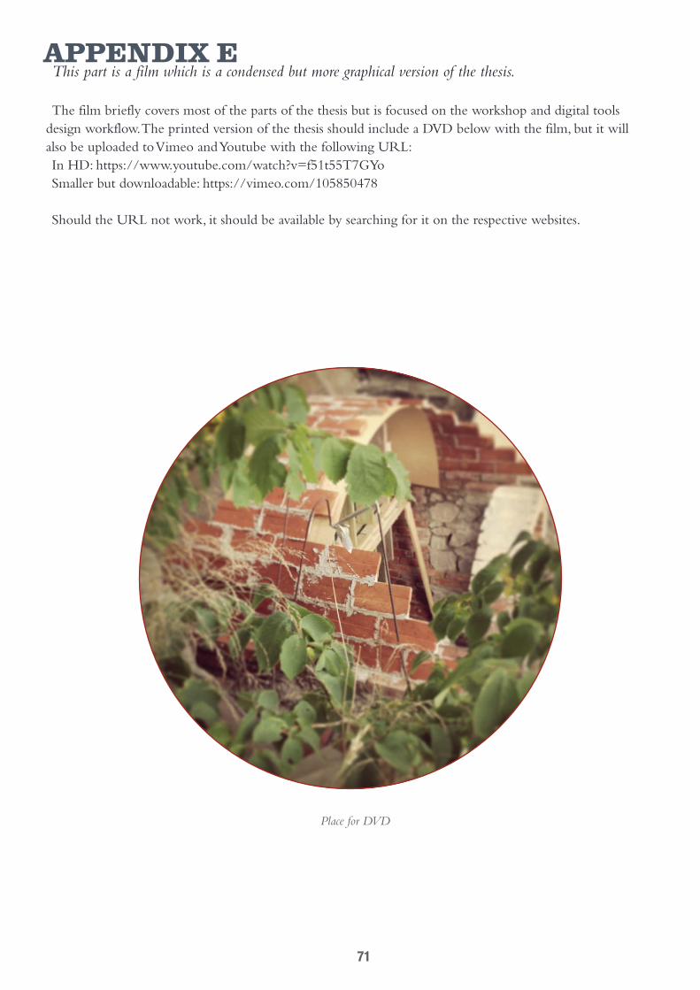
aPPendix eThis part is a film which is a condensed but more graphical version of the thesis.
The film briefly covers most of the parts of the thesis but is focused on the workshop and digital tools design workflow. The printed version of the thesis should include a DVD below with the film, but it will also be uploaded to Vimeo and Youtube with the following URL:In HD: https://www.youtube.com/watch?v=f51t55T7GYoSmaller but downloadable: https://vimeo.com/105850478
Should the URL not work, it should be available by searching for it on the respective websites.
Place for DVD
71

72
Copyright © 2022 FDOKUMEN