Volvo Car Corporation - Chalmers Open Digital Repository
75
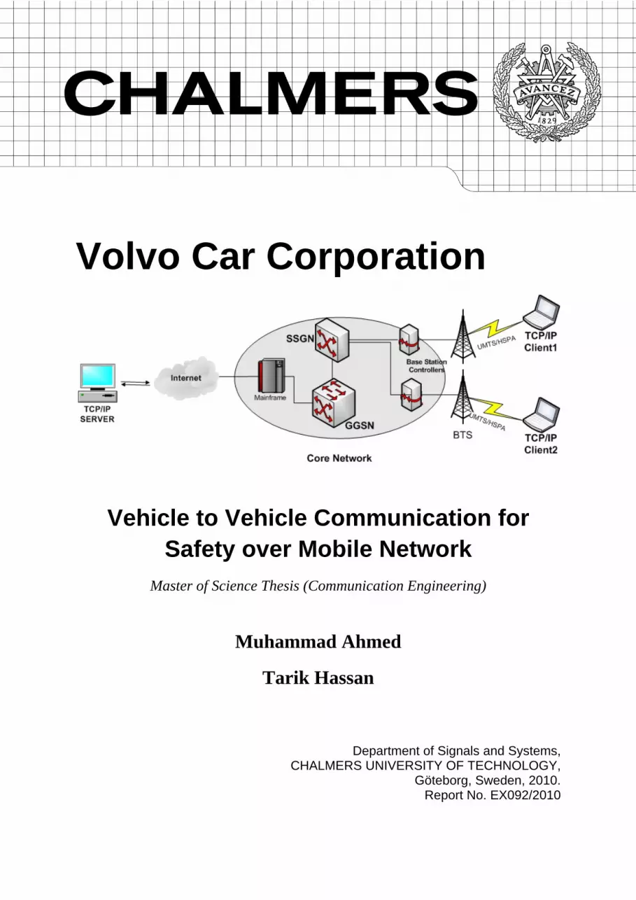
Volvo Car Corporation Vehicle to Vehicle Communication for Safety over Mobile Network Master of Science Thesis (Communication Engineering) Muhammad Ahmed Tarik Hassan Department of Signals and Systems, CHALMERS UNIVERSITY OF TECHNOLOGY, Göteborg, Sweden, 2010. Report No. EX092/2010
-
Upload
khangminh22 -
Category
Documents
-
view
0 -
download
0
Transcript of Volvo Car Corporation - Chalmers Open Digital Repository
Volvo Car Corporation
Vehicle to Vehicle Communication for Safety over Mobile Network
Master of Science Thesis (Communication Engineering)
Muhammad Ahmed
Tarik Hassan
Department of Signals and Systems,
CHALMERS UNIVERSITY OF TECHNOLOGY, Göteborg, Sweden, 2010.
Report No. EX092/2010
Vehicle to Vehicle Communication for Safety over Mobile Network Muhammad Ahmed, Tarik Hassan ©Volvo Car Corporation, 2010 Technical Report No: EX092/2010 CHALMERS UNIVERSITY OF TECHNOLOGY SE – 412 96, Göteborg Sweden Telephone: +46 (0) 31-772 1000 Cover: Design and implementation of vehicle to vehicle communication over mobile network. See chapter 5 for results and discussion. Volvo Car Corporation Göteborg, Sweden

Page | I
Abstract
One of the main reasons of the road accidents is the distraction along with the driver error, which is the major accident causation factor. If the driver can be informed about the road conditions as well as information of the forward traffic condition it would be beneficial from safety aspects. This master thesis investigates and develops a system which will enable transmission of warning message from one car to another car. We developed a central database server in SQL, which receives warning messages along with GPS information, from one car and transfers it to other cars. It also stores the information in database. Java Socket Programming has been used to enable TCP/IP communication between cars and the central server. Delays and latencies are calculated in both Wi-Fi and 3G network for connection time, standard data transmission time and warning message transmission time. In Wi-Fi network, average connection time is 10 milliseconds and warning message transmission time is 180 milliseconds. While in 3G network, connection time is 1 second and warning message transmission time is 400 milliseconds.
Keywords: TCP/IP Communication, UMTS/HSPA Network, Vehicle to Vehicle Communication

Page | II
Acknowledgements
My foremost thanks to GOD, who is most gracious and mercifulness and without HIS help nothing would have been possible.
First of all, we would like to thank our supervisor Henrik Lind, for believing and providing us the opportunity to work on this project. During the entire project, his depth of knowledge in the topic, suggestions for continuous improvement, encouragement and supervision helped us to conduct this research work productively. Besides, he has been very concerned about project progress, which has made this project successful. We would also like to thank our examiner Lennart Sevensson, for various constructive suggestions and ideas about the report. Last but not least, we are deeply thankful and express our honest appreciations to our dear friends who helped us time to time with problem solving, idea generation, and providing required project related information. We appreciate our family members in Sweden and back home for supporting us throughout the study period in Sweden. Finally, we pay our deepest gratitude to our parents for their strong support in every stage of our life.

Page | III
List of Abbreviations
3GPP AU ACK ASCII CAN CSD DBMS DSRC EDGE FCC GGSN GNSS GPRS GTP
Third Generation Partnership Project Application Unit Acknowledgement American Standard Code for Information Interchange Controller Area Network Circuit Switched Data Database Management System Dedicated Short Range Communication Enhanced Data Rates for GSM Federal Communication Commission Gateway GPRS Support Node Global Navigation Satellite System General Public Radio Service GPRS tunneling Protocol
GPS HSPA HSDPA HSUPA
Global Positioning System High Speed Packet Access High Speed Downlink Packet Access High Speed Uplink Packet Access
ICT IP ITS LTE M2M MME NMEA OBU RSU SGSN SRIS SYN TCP UDP UMTS
Information and Communication Technologies Internet Protocol Intelligent Transport System Long Term Evaluation Machine to Machine Mobility Management Entity National Marine Electronics Association On-Board Unit Road Side Unit Serving GPRS Support Node Slippery Road Information System Synchronize Sequence Number Transport Control Protocol User Datagram Protocol Universal Mobile Telecommunication System
V2I Vehicle to Infrastructure V2V Vehicle to Vehicle

Page | IV

Page | V
Table of Contents
Chapter 1: Telematics & V2V Communication ................................................................................ 1
1.1. Telematics .................................................................................................................................. 1
1.2. Vehicle To Vehicle Communication ...................................................................................... 2
1.3. Thesis Motivation ..................................................................................................................... 5
1.4. Research Question .................................................................................................................... 5
1.5. Thesis Organization ................................................................................................................. 5
Chapter 2: Background Theory ...................................................................................................... 7
2.1. Global Positioning System (GPS) ........................................................................................... 7
2.1.1. GPS Tracking System ....................................................................................................... 7
2.1.2. GPS Tracking Units .......................................................................................................... 9
2.1.3. GPS Output or String ..................................................................................................... 10
2.2. Mobile Networks .................................................................................................................... 12
2.2.1. Universal Mobile Telecommunication System (UMTS) ............................................ 13
2.2.2. High Speed Packet Access (HSPA) .............................................................................. 14
2.3. Packet Data Communication ................................................................................................ 14
2.3.1. Circuit Switched ............................................................................................................. 16
2.3.2. Packet Switched .............................................................................................................. 16
Chapter 3: Theoretical Framework .............................................................................................. 20
3.1. Machine to Machine (M2M) .................................................................................................. 20
3.1.1. Slippery Road Information System (SRIS) .................................................................. 21
3.2. Database ................................................................................................................................... 22
3.2.1. Database Management System ..................................................................................... 22
3.2.2. Database Layer ................................................................................................................ 23
3.2.3. Data Independence ......................................................................................................... 24
3.2.4. Database Models ............................................................................................................. 24
3.3. Virtual Com Port .................................................................................................................... 27
3.3.1. Port Enumeration ........................................................................................................... 28
3.3.2. Opening a COM Port ..................................................................................................... 28
3.3.3. Read/Write Data ............................................................................................................ 29
Chapter 4: Methodology ............................................................................................................... 30
4.1. Why Java? ................................................................................................................................ 30
4.2. Database Design ..................................................................................................................... 30

Page | VI
4.3. Layered Architecture ............................................................................................................. 33
4.4. Server ........................................................................................................................................ 33
4.4.1. Presentation Layer .......................................................................................................... 34
4.4.2. Service Layer ................................................................................................................... 34
4.4.3. Data Access Layer .......................................................................................................... 35
4.4.4. Data Flow Diagram ........................................................................................................ 35
4.5. Client ........................................................................................................................................ 37
4.5.1. Presentation Layer .......................................................................................................... 37
4.5.2. Service Layer ................................................................................................................... 37
4.5.3. Data Access Layer .......................................................................................................... 38
4.5.4. Dataflow Diagram .......................................................................................................... 38
Chapter 5: Results & Discussion .................................................................................................. 40
5.1. Overview ................................................................................................................................. 40
5.2. Results ...................................................................................................................................... 40
5.2.1. System Setup ................................................................................................................... 40
5.2.2. Scenarios and Results ..................................................................................................... 42
5.3. Discussion ................................................................................................................................ 49
5.3.1. Performance Constraint ................................................................................................. 49
5.3.2. Applications .................................................................................................................... 51
Chapter 6: Conclusions & Future Work ..................................................................................... 53
Appendix A: Telit’s 3G Module .......................................................................................................... I
Appendix B: Software Setup Guide ................................................................................................... II
Appendix C: System Setup Guide .................................................................................................. VII

Page | VII
List of Tables
Table 1 : Meanings of $GPGGA String Fields ................................................................................ 12 Table 2: Comparison of Data Rate and Latency ............................................................................. 14

Page | VIII
List of Figures
Figure 1: Basic Diagram of ecall system (6) ...................................................................................... 2 Figure 2: Basic System Architecture of DSRC (9) ............................................................................. 3 Figure 3: Layered Architecture for Vehicular Communication (9) ............................................... 4 Figure 4: Galileo Constellation (12) .................................................................................................... 8 Figure 5: USB GPS Device ................................................................................................................... 9 Figure 6: GPS Strings ......................................................................................................................... 11 Figure 7: Format of $GPGGA String ................................................................................................ 12 Figure 8: Time Line of Mobile Communication Evolution (13) ................................................... 13 Figure 9 : Basic Diagram of Packet Data Network ........................................................................ 15 Figure 10: Mechanism of TCP Communication ............................................................................. 17 Figure 11: Three Way Hand Shake for Connection Establishment ............................................. 18 Figure 12: Three Way Hand Shake for Connection Termination ................................................ 19 Figure 13: M2M Communication via GSM (16) ............................................................................. 20 Figure 14: Five Year Trend of M2M Devices (16) ........................................................................... 21 Figure 15 : Basic Architecture of Database (20) .............................................................................. 23 Figure 16: Flat File System (20) ......................................................................................................... 24 Figure 17 : Hierarchal Model Structure ........................................................................................... 25 Figure 18: Basic Structure of Network Model ................................................................................ 25 Figure 19: Relational Model Structure ............................................................................................. 26 Figure 20: Relational Model File System ......................................................................................... 26 Figure 21: Virtual COM Port Data Flow Model ............................................................................. 27 Figure 22: Entity Relationship Diagram of Database .................................................................... 31 Figure 23: Layered Architecture (Server Side) ............................................................................... 33 Figure 24 : Data Flow Diagram (Server Side) ................................................................................. 36 Figure 25: Layered Architecture (Vehicle Side) ............................................................................. 37 Figure 26: Data Flow Diagram (Vehicle Side) ................................................................................ 39 Figure 27: Wi-Fi Test Environment .................................................................................................. 41 Figure 28: 3G Test Environment ....................................................................................................... 41 Figure 29: Test Scenarios ................................................................................................................... 42 Figure 30: Connection Time in Wi-Fi Network .............................................................................. 43 Figure 31: Connection Time in 3G Network ................................................................................... 44 Figure 32: Car2Server Standard Data Latency ............................................................................... 45 Figure 33: Car2Car Warning Message Situation ............................................................................ 45 Figure 34: Car2Car Warning Message Latency Old Algorithm ................................................... 46 Figure 35: Server2Car Warning Message Latency ......................................................................... 47 Figure 36: Car2Server Warning Message Latency ......................................................................... 47 Figure 37: Car2Car Warning Message Latency with Improved Algorithm ............................... 48 Figure 38: Car2Car Warning Message Comparison between Old and Improved Algorithm . 49

Vehicle to Vehicle Communication over Mobile Network for Volvo Car Corporation
Page | 1
Chapter 1: Telematics & V2V Communication
1.1. Telematics
Telematics is a word which is used for the applications that utilize both telecommunication and informatics. Information and Communication technology (ICT) term is also used very often for the same kind services. So far, a number of applications and commercial products have been developed which lies in telematic category. All these applications use communication technologies, depending on their need and requirements. But the basic goal is to transfer the information by any mean which works well under present environment. Telematics technology is useful for following applications,
Transmission and reception of information from remote objects for the purpose of storing it or to control the remote object.
Integration of telecommunication and informatics for vehicular environment.
Integration of GPS with telecommunication services for navigation systems.
Recently, active safety system in vehicles, open the door for the researchers to investigate new methods and techniques for the safety of derivers and pedestrian. This lay down the foundation for applications like intelligent vehicle technologies, emergency warning systems for vehicles, vehicle safety systems over wireless communication. To implement these systems via telematics, one needs to investigate and select communication technology that could be used for such critical applications. Dedicated Short-Range Communication (DSRC) is the one of the biggest candidate for the future vehicle to vehicle (V2V) and Vehicle to Infrastructure (V2I) communication. DSRC is highly under investigation for vehicular communication (1). Before deploying it commercially, DSRC requires a lot of research, time and money. So right now it is not an ideal and cost effective method for V2V communication.
On the other hand, already deployed mobile infrastructure has a great opportunity to be used as a medium for communication by the vehicles. Now the mobile companies and vendors are trying to exploit the mobile network to utilize it for telemetics services. For this many corporations are joining hands with each other to make it work. Vendors need to develop products to support telematics services and operators need device new ways to incorporate these services in their systems. To provide such services Qualcomm and Telenor Connexion signs an international telematics agreement (2).Similarly Airbiquity and Telenor Connexion also sign a joint strategic partnership that will allow vehicles to be connected for services like portable navigation and fleet solutions in Europe (3). But just developing the product and enabling the services is not enough. Companies need to utilize it and develop cost effective applications for end users. Following paragraph discusses commercially available product which utilizes the concept of telematics.

Vehicle to Vehicle Communication over Mobile Network for Volvo Car Corporation
Page | 2
European Union research organization “ERTICO” is investigating the feature of ecall in vehicles. Ecall is the emergencies call system, will be used in future cars. Whenever a car is in trouble, ecall unit will dial emergency number that is 112 and the call will be directed to closest emergency station or response unit. The call will be either generated by the person or automatically by the sensors, when accidents occur (4). The call will transfer information like GPS position of the vehicle, driver’s identity and the direction of the vehicle. It is believed that this system will save lot of lives but practically system is far from the implementation. ERTICO believe that it will be deployed in 2012. For this GSM Association has signed EU’s eCall Memorandum of Understanding (5). Figure below shows the basic fucntionality of ecall system (6).
Figure 1: Basic Diagram of ecall system (6)
1.2. Vehicle To Vehicle Communication
In October 1999, Federal Communications Commission (FCC) allocated the 75 Mhz bandwith of 5.9 Ghz in USA for Dedicated Short Range Communication (DSRC) (7). The motive for this is to use this frequency for Intelligent Transport System (ITS). Later in August 2008, Europe dedicated the 30 Mhz bandwidth of 5.9 Ghz for the ITS (8). The idea is to motivate the researchers and developers to use the allocated frequency band and develop communication system to enable cars to communicate with other cars or with the road side infrastructure module. It will reduce the accidents and fatal injuries by conveying the messages about adverse road condition or about an accident that just happened.
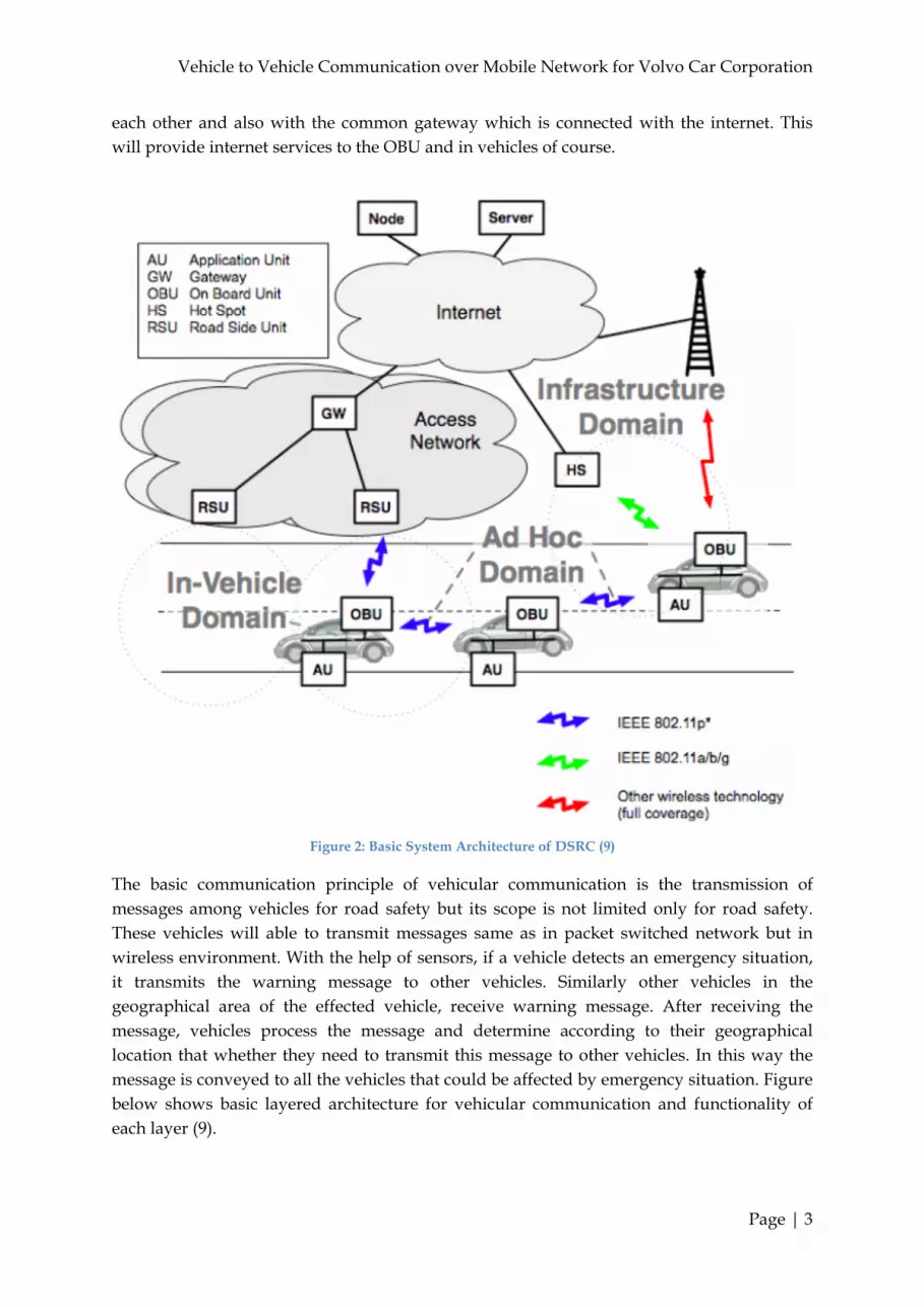
Figure below shows the basic system architecture of DSRC (9). It consists of on-board units (OBU) and application units (AU). AU is a device that basically executes the applications to drive OBU and its communication capability. OBU along with the AU are installed in vehicle for the communication between cars and with the infrastructure. AU could be connected to OBU via wireless or wired connection. OBU connect with the road side unit (RSU) by vehicular Ad hoc network. Although, Car can communicate with other cars via OBU through wireless communication but in case where distant OBU is out of reach, OBU can communicate with RSU. As you can see in the figure, RSU can also communicate with other RSUs by same protocols standards and distant OBUs can exchange messages with each other. RSU and OBU act in a same way as the nodes in ad hoc network. RSU are connected with the network that comprises of RSUs that enable them to communicate with
Vehicle to Vehicle Communication over Mobile Network for Volvo Car Corporation
Page | 3
each other and also with the common gateway which is connected with the internet. This will provide internet services to the OBU and in vehicles of course.
Figure 2: Basic System Architecture of DSRC (9)
The basic communication principle of vehicular communication is the transmission of messages among vehicles for road safety but its scope is not limited only for road safety. These vehicles will able to transmit messages same as in packet switched network but in wireless environment. With the help of sensors, if a vehicle detects an emergency situation, it transmits the warning message to other vehicles. Similarly other vehicles in the geographical area of the effected vehicle, receive warning message. After receiving the message, vehicles process the message and determine according to their geographical location that whether they need to transmit this message to other vehicles. In this way the message is conveyed to all the vehicles that could be affected by emergency situation. Figure below shows basic layered architecture for vehicular communication and functionality of each layer (9).

Vehicle to Vehicle Communication over Mobile Network for Volvo Car Corporation
Page | 4
Figure 3: Layered Architecture for Vehicular Communication (9)
Application Layer: This layer provides services to several application processes like central database at central machine, applications running at OBU to support communication and for processing the messages.
Transport Layer: This layer will control the transmission of the messages. This layer will utilize TCP or UDP protocols. Which protocol has to be used and when, is still under discussion but it is highly desirable that both the protocols will be utilized as they have their own benefits in different scenarios.
Network Layer: This layer uses the Internet Protocol (IP) to distribute the message. Due to small bandwidth, broadcasting of messages has to be restricted in a particular affected geographical area. This layer will determine the need of the transmission of messages as multicast, unicast or broadcast.
Physical Layer: Physical layer will decide which radio interface has to be utilized for the transmission of the messages. Now many wireless technologies are available like IEEE 802.11 a/b/g, European wireless access in vehicular environment 802.11p and other radio interfaces (GPRS, UMTS, and HSPA).

Vehicle to Vehicle Communication over Mobile Network for Volvo Car Corporation
Page | 5
1.3. Thesis Motivation
One of the main reasons of the road accidents are the existing traffic system and road conditions. Driver error has been found to be a major accident causation factor. A future vehicle may therefore require safety and assistance systems that monitors the objects in the environment and assists the driver by information, warning or intervention when the driver fails to react to threats. If the driver can be informed of the status of the road and road conditions as well as information of the forward traffic it would be beneficial from safety aspects. This may lead to lower exposure to accidents and reduce the consequences of the accident, or even in some cases assist to avoid the accidents completely. This master thesis will investigate and develop a system which will enable car to car communication. To make this work, following areas need investigation and implementation,
Collection of information from the cars Storage the collected data Communication by utilizing network and transport layer for information
transmission Completion of above tasks and assembling them in a proper order will allow the transmission of information from one vehicle to another and trigger the selected vehicle. Once the system will be developed and running, we will be able to measure the latency and delay in Wi-Fi and in mobile network.
1.4. Research Question This thesis could lead to many research questions but our only emphasis is to inspect the following
Finding out the possibility to use the already deployed mobile network that can facilitate communication at network and transport layer
Measuring the latency and delay in mobile network and evaluate whether mobile
network could be used for the transmission of warning messages in emergency situations.
1.5. Thesis Organization
Thesis work consists of three major parts. All three parts are independent and built separately. Chapter 4 describes the detailed implementation of this project. In the first part, a program has been developed to read GPS strings from GPS device which is interfaced with the computer via USB port. The code is developed by using Java programming language. These GPS strings will be utilized by car to transmit its current location to the central database server. The second part deals with formation of database in server machine to store
Vehicle to Vehicle Communication over Mobile Network for Volvo Car Corporation
Page | 6
different types of information which it receives from several cars. SQL server has been used for the implementation of database. The received information could be car current location, its speed, its direction and different warning messages. The third part dealt with the communication between the car and the server machine. Internet Protocol (IP) based communication has been implemented between car and the server. Again java programming language is used to program the TCP/IP communication.
Last but not least, all the above separate parts are combined together in a way that enabled the communication between vehicles. Netbeans has been used to combine the all the codes and for execution of the project. Chapter 2 gives some overview related to background theory which forms the basis of the master thesis. Information related to working of the GPS and different types of GPS strings are also covered in this chapter. It also describes detailed working theory about packet switched network and TCP/IP communication. Some comparison is also explained between different kind mobile technologies like GPRS, UMTS and HSPA for the sake of overview.

Vehicle to Vehicle Communication over Mobile Network for Volvo Car Corporation
Page | 7
Chapter 2: Background Theory
2.1. Global Positioning System (GPS) Global Positioning System (GPS) is a satellite based navigation system. GPS receiver device can ascertain the latitude and longitude of that particular device on the earth. Latitude and longitude are used to find out the position of that device. Now a days, the whole GPS consists of approximately 24 satellites which are orbiting the Earth 24×7. GPS was first developed and established to create a satellite navigation system to provide special services to the military applications by the United States (US) Department of Defense (DoD) (10). Each and every satellite orbiting the Earth transmits radio signals towards Earth. This radio signals are used to determine the location, heading and speed of a moving vehicle or people equipped with or caring a GPS receiver. GPS can determine the position of the receiver device in almost any weather condition and anywhere in the whole world 24×7. To ensure the whole Earth is covered, GPS satellites are positioned around the Earth orbit that four satellites are positioned in each of six orbital planes. GPS satellites are solar powered and they are circling the Earth to complete two rotations on a daily basis at a speed of 12000 miles per hour.
2.1.1. GPS Tracking System
The most important exercise of GPS tracking system has been in the area of security. The concept of GPS tracking system was developed in 1970’s by the United States (US) Department of Defense (DoD) (10). GPS tracking system made available for the civilians when a commercial civil aircraft was shot down in 1983 by military when it was wandering into a protected airspace because it had no authority to enter (11). GPS tracking system consists of a device which uses the GPS to determine the precise location of a GPS signal receiver. GPS receiver evidences the position of that device on a regular interval. GPS tracking system works in different ways. Some systems recorded the location data within the tracking device, or the tracking device uses the wireless network like the telecom network, radio frequency or satellite modem to transmit the data to a central database. These GPS data are used to display the GPS receiver against a map on a regular interval or in real time. GPS tracking systems are capable of viewing the moving object in real-time and have a map in the background to display the current location of an object. Position tracking plays a significant function in many applications. These days radio resource management and location based services are playing an important role in our daily life. Position tracking uses different kind of algorithms. An improved location tracking algorithm uses the Kalman filtering with the velocity renovation process (11). In Our day to day lives, GPS tracking and monitoring system are used, which can be classified into several categories. These categories could include services like, car navigation systems, wildlife monitoring, assisted living for the elderly people and traffic monitoring & fleet management system.
Vehicle to Vehicle Communication over Mobile Network for Volvo Car Corporation
Page | 8
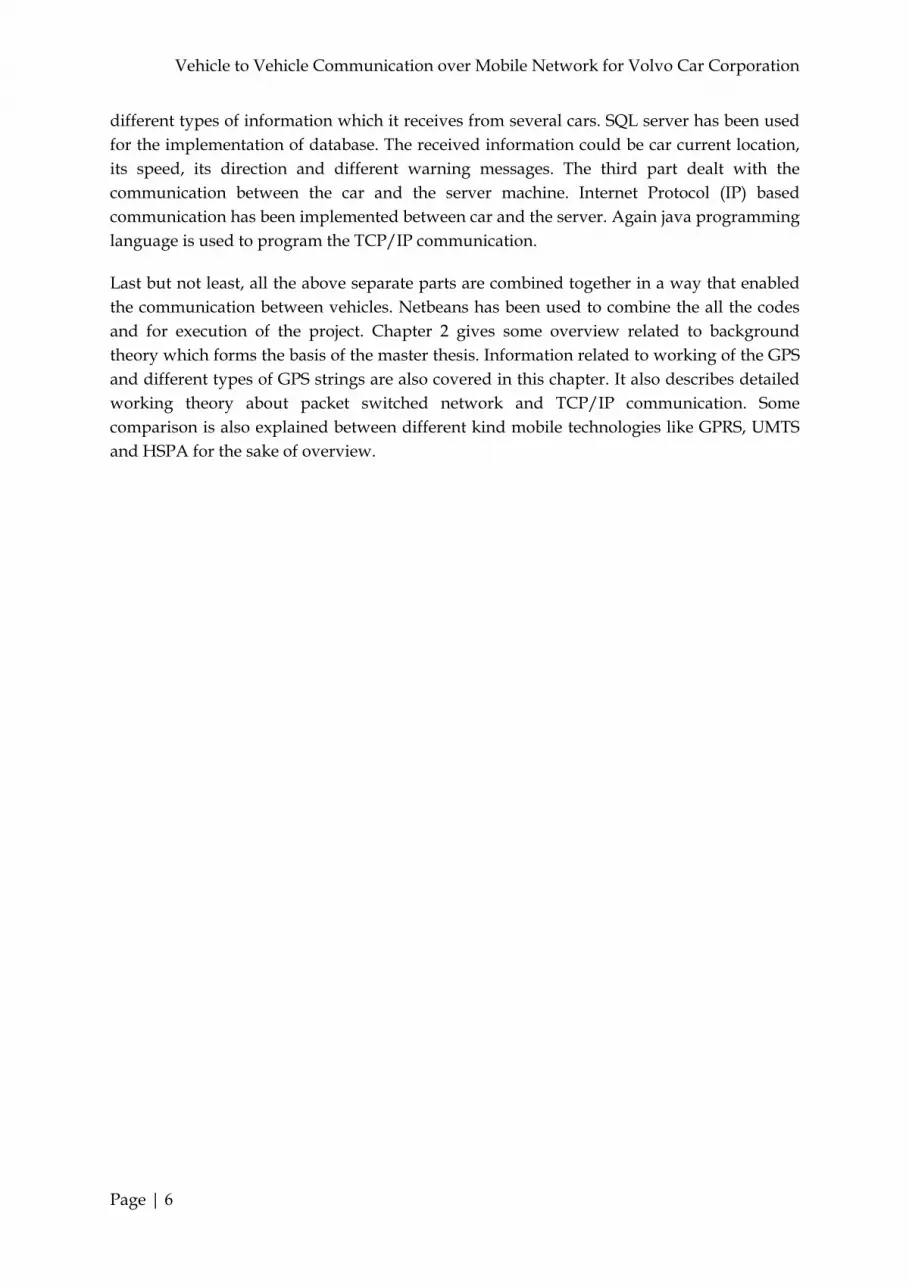
Figure 4: Galileo Constellation (12)
All GPS tracking system around the world uses the Global Navigation Satellite System (GNSS) network for tracking an object. GNSS network has a versatile range of satellites that’s uses the microwave signals. These microwave signals are transmitted to the GPS signal receivers to provide the information about the specific location, speed, time, direction of that object. With the help of the GNSS network, a GPS tracking system is competent of giving real time or momentous navigation data on any kind of voyage an object makes. A GPS tracking system can work in a diverse ways. Typically GPS devices are used to evidence the position of an object or objects progress in their journeys. There are two types of GPS tracking system, 1. Passive GPS tracking system 2. Active GPS tracking system
1. Passive GPS Tracking System A passive GPS tracking system will store the tracking data within the GPS tracking device. Passive GPS tracking system will monitor the different data like location, speed, time etc of a moving object and also store these data. This type of tracking system starts working on a triggering event like turning the ignition on/off or opening/closing the doors of a vehicle. The data on this type of tracking devices are stored in internal memory or in a memory card. These data can be downloaded to a computer for further analysis. Today’s contemporary passive tracking system is competent of downloaded the stored data to a central system or database at a predetermined points or stations via a wireless or wired system.

Vehicle to Vehicle Communication over Mobile Network for Volvo Car Corporation
Page | 9
2. Active GPS Tracking System An active GPS tracking system is better known as real time tracking system. Active GPS tracking system sends the GPS information to a centralized tracking system or database. To transmit the information, active tracking system uses the modem assembles within the GPS tracking device, on a regular interval. Active tracking system automatically sends the GPS information instantaneously to a central system or database as it happens. Commercially available active GPS tracking systems are better know for fleet tracking and individual vehicle tracking. Active GPS tracking permits the company to know precisely, where the vehicle is located. It also permits the company to know whether their vehicles are on time or whether they are at the location, where they supposed to be.
2.1.2. GPS Tracking Units
GPS tracking units are divided into three main categories. These categories are divided based on the functionality like how these devices collect, store and retrieve the stored data. These categories are, 1. Data Logger. 2. Data Pusher. 3. Data Puller.
Figure 5: USB GPS Device
1. Data Logger GPS data logger is typically the most fundamental type of GPS tracking device. A GPS data logger basically logs the position of the object at regular intervals. Data logger stores the logged positions in internal memory of the tracking device. Generally all GPS loggers have flash memory inside the device to stored data that is logged. The stored data can be retrieved and accessed from the flash memory using the Universal Serial Bus (USB) connectivity. GPS data loggers are more appropriate and used for sports and hobby activities. The long distance hikers and cycling enthusiasts can make use of the logging information to facilitate the future routes that might be followed.

Vehicle to Vehicle Communication over Mobile Network for Volvo Car Corporation
Page | 10
2. Data Pusher GPS data pushers are very popular for application in security purposes. A GPS data pusher tracking device sends the GPS data from the tracking device to a central system or database at regular intervals. A GPS data pusher updates the central database about the location, direction, speed and distance of the objects. Around the world GPS data pusher are commonly used in fleet management services to control and manage trucks and other vehicles. Vehicles can be located instantly in order to deliver goods also their progress can be tracked. Different goods delivery and courier companies uses data pusher, which helps in quick supervision, order delivery and also prevent thefts. Some companies use data pusher to monitor and track valuable assets. If valuable goods or assets are being transported or even if they are relocated to a precise location, they can be continuously monitored to avoid theft or being lost. A GPS data pusher tracking device is also used in espionage type tasks. This particular type of GPS tracking has become a significant concern in the field of GPS.
3. Data Puller The 3rd category of GPS tracking device is data puller tracking device. Data puller GPS tracking devices allow the user to ‘pull’ data from the tracking device as frequently as required. Data puller also pushes or sends the GPS data when the tracking units reaches a specific location or at specific time intervals. The data puller devices also have the capability to act as a data pusher device. Data puller device remains at the active mode all the times and continuously monitoring the object location. Though data puller is not as frequently used as the data pusher device, it is particularly useful for tracing stolen goods.
4. How GPS Works A GPS tracking is truly achieved by the GPS receiver device. A GPS receiver first find out the GPS satellite signals. After that, GPS receiver uses at least three satellite or more of these satellite signals to find out the distance of each satellites. Then GPS receiver uses all these distances to calculate its position. This operation is based on a simple mathematical principle called trilateration. These days GPS receiver uses the 3D trilateration process to visualize and detect the receiver position. In 3D trilateration process, it uses the spheres and at least three GPS satellite signals to form spheres around the predefined points in three dimensional spaces. With reference to the intersecting point of three spheres the location of an object has to be defined. To use the trilateration process a GPS receiver analyzing the radio signals from the GPS satellites. A sophisticated GPS receiver has more number of receivers, so that signals from a superior number of satellites are taken into account while calculating the receiver positions.
Consecutively make a simple calculation of the location a GPS receiver has to know two things:
1. The location of at least three satellites above the object to be located or tracked. 2. The distance between the object and each of these satellites.
2.1.3. GPS Output or String
The National Marine Electronics Association (NMEA) defines a communication standard for all the devices including GPS receivers. Around the world all GPS receivers followthe

Vehicle to Vehicle Communication over Mobile Network for Volvo Car Corporation
Page | 11
specific format and standard for message structure, prescribed by NMEA. GPS receiver gives output with latitude and longitude of geographical location, time, headings and others information relevant for navigation. GPS message strings are consists of all the information in the form of American Standard Code for Information Interchange (ASCII) with comma enclosed.
Figure 6: GPS Strings
The picture above illustrates the message strings output of a GPS receiver. The NMEA standard directs how each GPS string is formed, starting with a dollar sign ($) in each GPS messages. Each GPS receiver can give no less than of seven different standard message strings. The seven standard message strings are,
$GPGLL Geographical position with latitude and longitude. $GPGSA GPS dilution of precision and active satellites. $GPGSV GPS satellite in view. $GPGGA GPS fixed data. $GPRMC Recommended minimum specific GPS/TRANSIT data. $GPVTG Track made good and ground speed. $GPZDA Time and date.
Among these all seven message strings, $GPGGA is the most important and commonly used in GPS tracking. $GPGGA contains the fixed GPS data with all the necessary information used for tracking purpose.
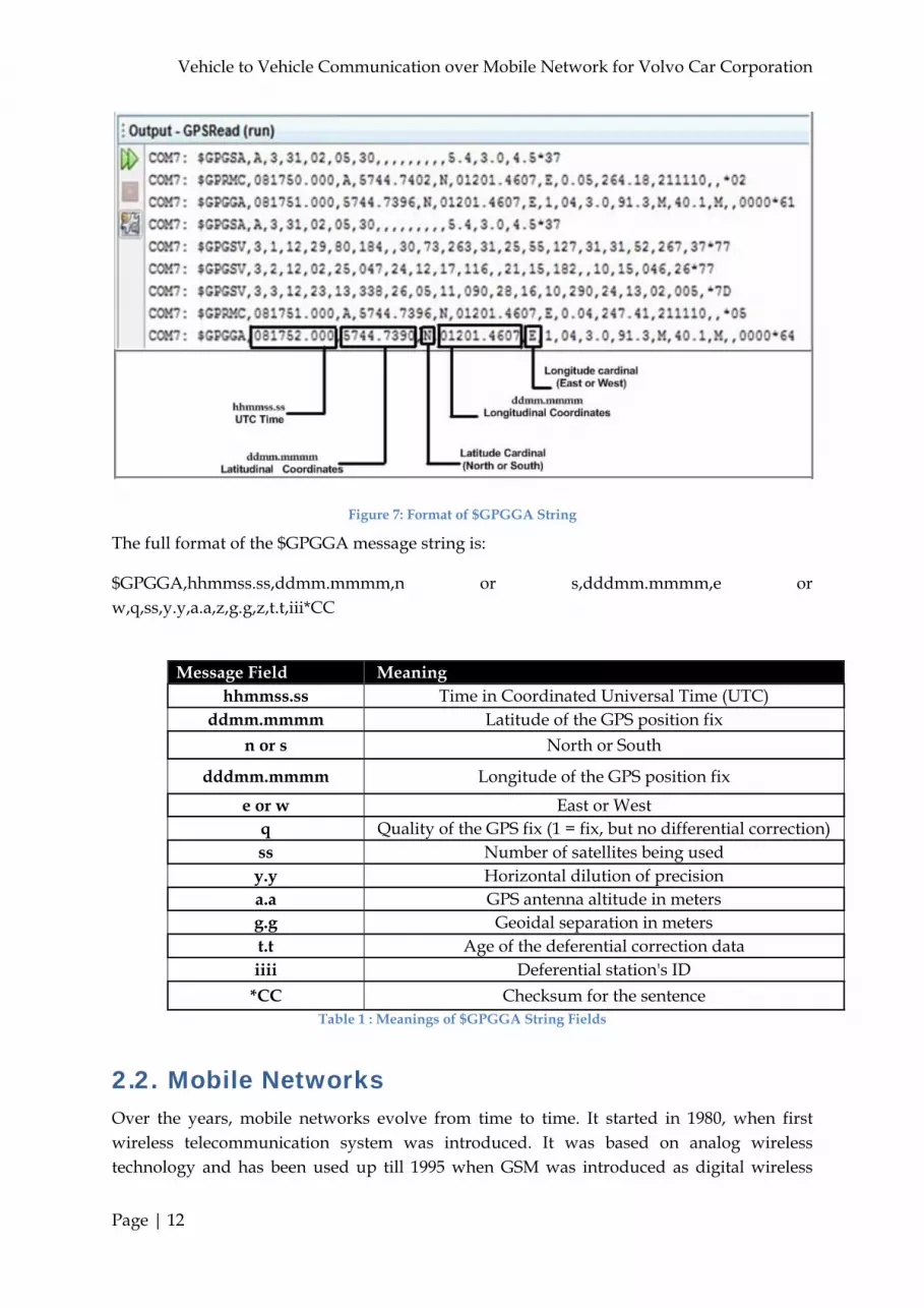
1. $GPGGA GPS string $GPGGA is popular one among other strings because it contains navigational data and it is most common among the other seven strings. The string starts with the GPS satellite universal time. The latitude is the second field of the message and longitude is the fourth field. The latitude and longitude has no significance without the third field, which is marked as N (north) or S (south) for latitude and at the fifth field, E (east) or W (west) for longitude.
Vehicle to Vehicle Communication over Mobile Network for Volvo Car Corporation
Page | 12
Figure 7: Format of $GPGGA String
The full format of the $GPGGA message string is:
$GPGGA,hhmmss.ss,ddmm.mmmm,n or s,dddmm.mmmm,e or w,q,ss,y.y,a.a,z,g.g,z,t.t,iii*CC
Message Field Meaning
hhmmss.ss Time in Coordinated Universal Time (UTC) ddmm.mmmm Latitude of the GPS position fix
n or s North or South
dddmm.mmmm Longitude of the GPS position fix
e or w East or West q Quality of the GPS fix (1 = fix, but no differential correction) ss Number of satellites being used y.y Horizontal dilution of precision a.a GPS antenna altitude in meters g.g Geoidal separation in meters t.t Age of the deferential correction data iiii Deferential station's ID
*CC Checksum for the sentence Table 1 : Meanings of $GPGGA String Fields
2.2. Mobile Networks Over the years, mobile networks evolve from time to time. It started in 1980, when first wireless telecommunication system was introduced. It was based on analog wireless technology and has been used up till 1995 when GSM was introduced as digital wireless

Vehicle to Vehicle Communication over Mobile Network for Volvo Car Corporation
Page | 13
technology. Figure below shows the evolution of mobile networks, starts with GSM technology while excluding first generation mobile network (13).
Figure 8: Time Line of Mobile Communication Evolution (13)
2.2.1. Universal Mobile Telecommunication System (UMTS)
Universal Mobile Telecommunication System (UMTS) is being developed as a third generation mobile system in Europe. The release99 (R99) architecture is the first deployment of the UMTS. It is standardized by 3GPP and it is part f the ITU-IMT2000 standard. The most common form of UMTS is WCDMA. Originally, frequency bands for the UMTS was specified as 1885-2025 MHz for the uplink and 2110- 220 MHz for downlink but in US 1710-1755 MHz and 2110-2155 MHz have being used instead, as 1900 MHz band is already in use (14). Some countries also using the 850 MHz or 1900 MHz meaning the both uplink and downlink are in the same frequency band. UMTS requires separate base stations from GSM for its operation. But most of the headset supports both GSM and UMTS operations. This allows seamless dual mode operation.
A Precursor to UMTS is 2G, an ordinary GSM system. It is based on circuit switched telephone network and supports up to 14.4 Kbit/s of data transfer rate. The CSD is connection oriented technology. It is established in a way that all the devices that are involved in between, are transparent and both the parties are not connected directly to each other. It is a very time consuming procedure which require up to a minute for connection initiation. During the late 1990s the Packet Data over mobile system became reality by the introduction of General Public Radio Service (GPRS) also known as 2.5G. Theoretically, it supports data rate up to 140.8 Kbit/s but close to 56 Kbit/s has been measured practically. The enhancement in GSM is EDGE (Enhanced Data Rates for GSM). The goal of introducing EDGE in GSM is to increase the higher end-user data rate by adapting higher order modulations in GSM for both circuit switched and GPRS. Later the focus moved to Enhanced GPRS (EGPRS) and various radio interface components have been added like link adaptation, advanced scheduling techniques and hybrid ARQ. So GSM became first cellular

Vehicle to Vehicle Communication over Mobile Network for Volvo Car Corporation
Page | 14
system to include these kinds of techniques and later followed by WCDMA/HSPA and CDMA2000 (15). But GSM is narrow band technology than WCDMA/HSPA. So peak data rate by GSM is not achievable in comparison to WCDMA/HSPA. The GSM/EDGE standard is developed in 3GPPP and the idea is to include the Voice-over-IP (VOIP) services. The target of EDGE system is to improve the 50% spectrum efficiency, 100% increase of the data rate (15). Latency is usually defined as round trip time of radio network. It is considered the most influential factor for the user experience. Services like voice and video require low latency. The major parameter that impacts the latency is the transmission time interval (TTI). Latency cannot be improved without TTI.
2.2.2. High Speed Packet Access (HSPA)
The first step in the evolution of WCDMA/UMTS radio access is the addition of High-Speed Downlink Packet Access (HSDPA) in Release 5 of the 3GPP WCDMA specification. Although, packet data transmission is already supported by WCDMA, but packet data access brings further enhancements in packet data services in WCDMA. It increased the performance of the system and end user experience. The HSPDA is complemented by HSUPA (High-Speed Uplink Packet Access) and combining both the technologies is referred as High-Speed Packet Access (HSPA).
The important requirements for mobile systems, to provide packet data service at low delay and high data rate as well as at the same time offer high capacity and coverage area (13). To achieve this, HSPA introduced many techniques in WCDMA like adaptive modulation techniques, fast scheduling, rate control and hybrid ARQ with soft combining. By combining all these techniques, HSPA is able to provide 7.2 Mbps downlink and 5.2 Mbps uplink while improving the round trip time and capacity of the systems. Table below summarize and compare different digital mobile communication systems in terms of data rate and latency.
Technology Data Rate Theoretical/Actual
Latency (msec)
CSD 57.6/14.4 Kbps 1000-2000 GPRS 140/56 Kbps 700
EDGE 384/200 Kbps 450
UMTS 2.4/0.384 Mbps 150-200 HSPA 14/7.2 Mbps 70-100
Table 2: Comparison of Data Rate and Latency
2.3. Packet Data Communication Communication in our daily life can take many different forms in different environments. For every communication there are different expectations from the network. For example, during chatting via internet or watching online video, one expects the network to behave according to his requirements. Before starting the conversation one needs to define the set of rules. These rules could be changed according to the requirements of the communication
Vehicle to Vehicle Communication over Mobile Network for Volvo Car Corporation
Page | 15
parties and for different scenarios. These techniques are the same for both the network communication and human communication. They follow the same set of rules, for instance,
Identification of sender and receiver Selection of communication method Common language Speed and timing Acknowledgements
The only method to determine that whether the communication was successful is when the receiver gained the exact meaning of the message, the one that sender wanted him to understand. There are different internal and external factors that affect the communication between both the parties.
External Factors Quality of the link Speed of the link Time of the message to reach the receiver
Internal Factors Message size Message complexity Message importance
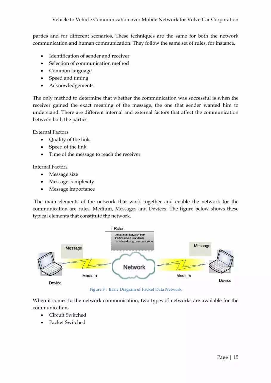
The main elements of the network that work together and enable the network for the communication are rules, Medium, Messages and Devices. The figure below shows these typical elements that constitute the network.
Figure 9 : Basic Diagram of Packet Data Network
When it comes to the network communication, two types of networks are available for the communication,
Circuit Switched Packet Switched

Vehicle to Vehicle Communication over Mobile Network for Volvo Car Corporation
Page | 16
2.3.1. Circuit Switched
Circuit switched is basically a connection oriented where both the parties are not directly connected to each other. It is a very time consuming process to initiate and establish the connection. When a person wants to connect to another party, he initiates a request for the connection. All the switching locations which come in the way to the other party are identified but only one link is selected for the communication, however, many existed. After that, a temporary path is created which go through all the switching devices which come in the way between the sender and receiver. If the connection fails during the transmission, it follows the same way to reinitiate and establish the connection.
2.3.2. Packet Switched
On the other hand packet switched network works in a total different way. In this kind of network, a message could be broken down into smaller blocks, which contain the sender’s and receiver’s address along with the sequence number of the block. These blocks are called packets. They follow different paths to reach the receiver and it is possible to re-assemble them to make the transferred message. During the transmission, the involved devices are unaware of the contents of the packet. Only destination address and the address of the next device in the patch are visible. At each location, routing decision are made to forward the packet towards the destination. Because the message is sent in packets, if any packet is lost during transmission, re transmission has been called out by the receiver. If we examine the OSI layer model, the layer in packet switched network which is responsible for the transmission and reception of the packet, is the transport layer. The primary responsibility of transport layer can be summarized as follows,
Keep track of the communication of each application between the sender and the receiver
Divides the data into packets and manage each packet Re-assembles the packets into streams and vice versa recognize different applications running on a single machine
Furthermore, transport layer protocol can support a method for reliable delivery of data. When we say reliable transmission it means it can track the transmitted data, allow acknowledgement for the received data and retransmits the unacknowledged data. On the basis of above described functions, transport layer can be further divided into two categories. Both support all the basic functions of transport layer. The difference lies in supporting functions for reliable communication described initially. Usage of these protocols depends on the need and requirement of the communication. These two protocols are,
Transport Control Protocol (Connection Oriented) User Datagram Protocol (Connectionless)
1. Transport Control Protocol (TCP) Transport Control Protocol (TCP) communication ensures the reliability of the transmitted data by establishing the session with the destination. TCP is the connection oriented and it
Vehicle to Vehicle Communication over Mobile Network for Volvo Car Corporation
Page | 17
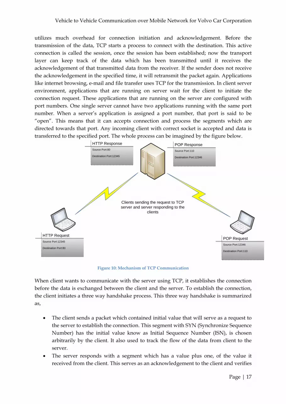
utilizes much overhead for connection initiation and acknowledgement. Before the transmission of the data, TCP starts a process to connect with the destination. This active connection is called the session, once the session has been established; now the transport layer can keep track of the data which has been transmitted until it receives the acknowledgement of that transmitted data from the receiver. If the sender does not receive the acknowledgement in the specified time, it will retransmit the packet again. Applications like internet browsing, e-mail and file transfer uses TCP for the transmission. In client server environment, applications that are running on server wait for the client to initiate the connection request. These applications that are running on the server are configured with port numbers. One single server cannot have two applications running with the same port number. When a server’s application is assigned a port number, that port is said to be “open”. This means that it can accepts connection and process the segments which are directed towards that port. Any incoming client with correct socket is accepted and data is transferred to the specified port. The whole process can be imagined by the figure below.
HTTP Request
Source Port:12345
Destination Port:80
POP Request
Source Port:12346
Destination Port:110
HTTP Response
Source Port:80
Destination Port:12345
POP Response
Source Port:110
Destination Port:12346
Clients sending the request to TCP server and server responding to the
clients
Figure 10: Mechanism of TCP Communication
When client wants to communicate with the server using TCP, it establishes the connection before the data is exchanged between the client and the server. To establish the connection, the client initiates a three way handshake process. This three way handshake is summarized as,
The client sends a packet which contained initial value that will serve as a request to the server to establish the connection. This segment with SYN (Synchronize Sequence Number) has the initial value know as Initial Sequence Number (ISN), is chosen arbitrarily by the client. It also used to track the flow of the data from client to the server.
The server responds with a segment which has a value plus one, of the value it received from the client. This serves as an acknowledgement to the client and verifies

Vehicle to Vehicle Communication over Mobile Network for Volvo Car Corporation
Page | 18
that server has active service and accepting the connection at specified port. Until now one way connection has been establish which is from the client to the server. To make it two way connection, now server send the SYN flag to the client with an arbitrarily sequence number.
Now client responds to this segment with an acknowledgement which contains the sequence number plus one, which it received from the server. Now this sequence number will be used to track the data from the server to the client.
Figure 11: Three Way Hand Shake for Connection Establishment
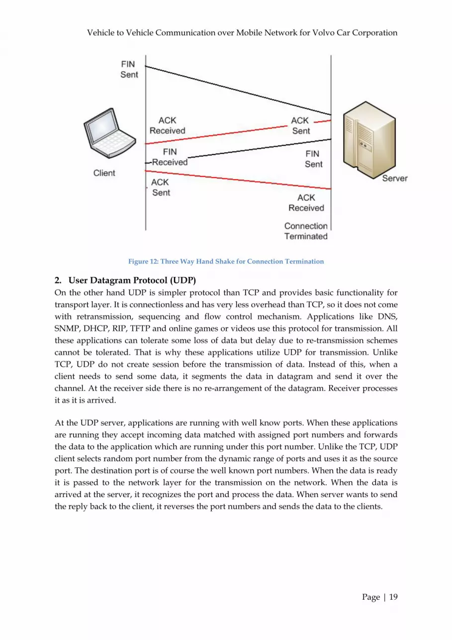
After the data has been exchanged between the client and the server, the termination of the connection is requested. For this FIN (Finish) and ACK flags are used. Here it’s worth to mention that for one way TCP connection, two messages have to be exchanged. So total of four exchanges are needed. The process is described below,
When client does not have any data to send, it sends a segment with a FIN flag. The server sends ACK segment to finish the session which was initiated by the client
to the server. Now server sends the FIN segment to the client to terminate the session which was
initiated by the server to the client. The client sends ACK flag to terminate the connection.
Vehicle to Vehicle Communication over Mobile Network for Volvo Car Corporation
Page | 19
Figure 12: Three Way Hand Shake for Connection Termination
2. User Datagram Protocol (UDP) On the other hand UDP is simpler protocol than TCP and provides basic functionality for transport layer. It is connectionless and has very less overhead than TCP, so it does not come with retransmission, sequencing and flow control mechanism. Applications like DNS, SNMP, DHCP, RIP, TFTP and online games or videos use this protocol for transmission. All these applications can tolerate some loss of data but delay due to re-transmission schemes cannot be tolerated. That is why these applications utilize UDP for transmission. Unlike TCP, UDP do not create session before the transmission of data. Instead of this, when a client needs to send some data, it segments the data in datagram and send it over the channel. At the receiver side there is no re-arrangement of the datagram. Receiver processes it as it is arrived.
At the UDP server, applications are running with well know ports. When these applications are running they accept incoming data matched with assigned port numbers and forwards the data to the application which are running under this port number. Unlike the TCP, UDP client selects random port number from the dynamic range of ports and uses it as the source port. The destination port is of course the well known port numbers. When the data is ready it is passed to the network layer for the transmission on the network. When the data is arrived at the server, it recognizes the port and process the data. When server wants to send the reply back to the client, it reverses the port numbers and sends the data to the clients.

Vehicle to Vehicle Communication over Mobile Network for Volvo Car Corporation
Page | 20
Chapter 3: Theoretical Framework
3.1. Machine to Machine (M2M)
We all are surrounded by machines, comprises of electrical, mechanical, electronic equipments or combination of these parts called mechatronic device. As more and more machines are connecting with the network, according to the Harbor Research, at the end of 2010, around 1.5 billion machines will be connected to the internet worldwide (16). Machines are very intelligent and beautiful devices, which do their work according to their design. But how wonderful will it be, when machines will start talking with each other and with the humans. M2M enabled machines will not only gather data but also transmit it to other machines and make decisions by analyzing the trend in data. For examples, M2M could be used to monitor traffic in a city and transmit data to the central traffic authority so that they can better maintain the traffic situation. Similarly, it could also be used by technicians to monitor the machines operation and faults remotely, by analyzing the received data from the machines.
Before the concept of M2M, Supervisory Control and Data Acquisition System (SCADA) was used for monitoring and maintenance purpose (16). It was based on prosperity system, so its implementation cost was high and it was used to monitor the information at the node itself. It was not able to push the data to main server. But unlike SCADA, standardization of M2M became the reason of its popularity. Furthermore, the main reason for its cost effectiveness is because vendors are integrating radio chips and modules. This enables them to attach with any device or machines seamlessly. Figure below gives a bird eye view about the operation of wireless M2M enabled devices (16). But to give you an overview, Machine’s sensor is connected with the GSM module which transmits the information via GSM network, either by TCP/IP services or via SMS. The information passes through the operator’s data network and delivered to the already connected internet machine. In this case it is shown a central server as a computer. It can process the information and generate commands according to the implemented protocol. These commands can follow the same way to reach the machine to be executed.
Figure 13: M2M Communication via GSM (16)

Vehicle to Vehicle Communication over Mobile Network for Volvo Car Corporation
Page | 21
It is not necessary the wireless M2M uses the GSM system for the transmission. Because of the day by day advancement of wireless technologies with respect to performance, reliability and functionality as well as reduction in the cost, several wireless M2M devices are available for industrial purpose like IEEE 802.11 a/b/g/n/p, Bluetooth; which is generally used for short range communication, IEEE 802.15.4; used for low rate transmission and for short range communication, Zigbee; works on the same principle of IEEE 802.15.4 with low power consumption, RFID; uses the electromagnetic waves for the transmission and utilize electrostatic coupling to identify tagged devices. As more and more devices are connecting with the internet, network is becoming more valuable for the end user and corporations. As the wireless modules are becoming easier to integrate to the sensors at the same time, installation and operation cost is going down, companies are relying on M2M for their operation. The figure below shows a 5 year trend of utilization of M2M devices in the industry (16).
Figure 14: Five Year Trend of M2M Devices (16)
A well known industrial application of M2M is the wireless smart grid sensor system. The system is implemented by the collaboration between AT&T and Cooper Power Systems (17). The operating companies will be able to receive real time data of their electric grids. This will reduce the personal identification and availability at the site. The persons sitting in the control room will be able to monitor the grids, problems that cause the outages and will be able to solve those problems. This will increase the efficiency and reduce the operating cost for the company.
3.1.1. Slippery Road Information System (SRIS)
In first quarter of 2006, Intelligent Vehicle Safety Systems (IVSS) start a project called Slippery Road Information System (SRIS) (18). The aim of the project is to search and implement a system that can detect slippery road condition. Project was completed in fourth quarter of 2008. The total investment of the project was SEK 32.7 million. The ultimate goal of the project is to research and develop a system that will help in reducing a number of accidents in extreme weather conditions by transmitting specific information to the driver and also to the road authorities. They will be provided with the up to date information about the road conditions and help them to better utilize their man hours (19). Currently,

Vehicle to Vehicle Communication over Mobile Network for Volvo Car Corporation
Page | 22
road authorities collect information from road weather stations, which cannot provide information about the road slipperiness. They are only capable to provide weather conditions. Today, vehicles are already equipped with sensors like Electronics Stability Control (ESC) and Anti-Lock Braking System (ABS). The idea is to collect information from ESC, ABS, in-car temperature and windshield wipers along with the road weather station and transmit it to central database. The central data base system is the main processing unit; it collects all the data and analyzes it. On the basis of its analysis, it could be able to send the information to the road authorities and also to the drivers in real time. The system hasn’t been introduced in real market, which could be for several reasons.
3.2. Database
A database comprises of data items which are interrelated and describe different attributes of single entity. Roughly thirty five years ago, database was only used in research institutes where scientist and publishers were struggling hard to maintain their research findings in a proper manner. But now it is the major part of information technology. To understand the concepts of database, we have to understand the terminologies used in database. Database Object is a naming convention used in database structure. These naming procedures vary from software to software and it entirely depends on the person who is designing the database. Database Model is a way to organize the data in a database. It is the schema which describes the database structure. A Database File comprises of database records stored as a single file on the computer. To grasp the concepts of database one has to look very deep into the following areas,
1. Database Management Systems 2. Database Layers 3. Data Independence
3.2.1. Database Management System
Database Management System (DBMS) is software provided by a vendor or a company who created the database software. The DBMS provides an interface to create and manage the database. Very well know database softwares are Microsoft Access, My SQL and Oracle. DBMS can provide many functionalities but most common are,
Transfer of data to and from physical form Provision to manage the data by multiple users and updates simultaneously without
any conflict Operable by a query language like SQL, by which a data can be retrieved or added Provides an efficient way to back up the database Provides security mechanism from unauthorized access.
Vehicle to Vehicle Communication over Mobile Network for Volvo Car Corporation
Page | 23
3.2.2. Database Layer
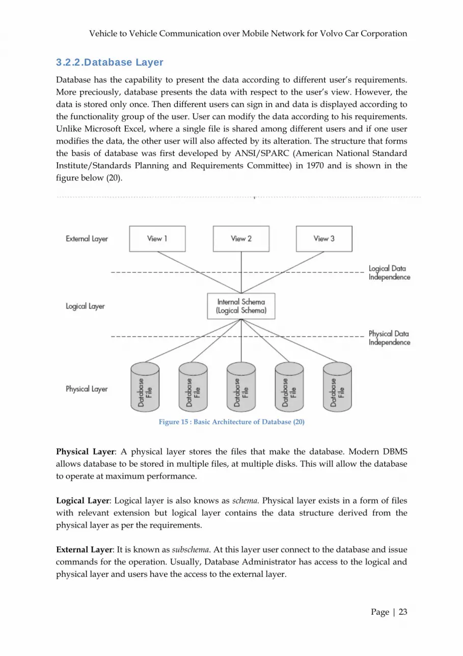
Database has the capability to present the data according to different user’s requirements. More preciously, database presents the data with respect to the user’s view. However, the data is stored only once. Then different users can sign in and data is displayed according to the functionality group of the user. User can modify the data according to his requirements. Unlike Microsoft Excel, where a single file is shared among different users and if one user modifies the data, the other user will also affected by its alteration. The structure that forms the basis of database was first developed by ANSI/SPARC (American National Standard Institute/Standards Planning and Requirements Committee) in 1970 and is shown in the figure below (20).
Figure 15 : Basic Architecture of Database (20)
Physical Layer: A physical layer stores the files that make the database. Modern DBMS allows database to be stored in multiple files, at multiple disks. This will allow the database to operate at maximum performance. Logical Layer: Logical layer is also knows as schema. Physical layer exists in a form of files with relevant extension but logical layer contains the data structure derived from the physical layer as per the requirements. External Layer: It is known as subschema. At this layer user connect to the database and issue commands for the operation. Usually, Database Administrator has access to the logical and physical layer and users have the access to the external layer.

Vehicle to Vehicle Communication over Mobile Network for Volvo Car Corporation
Page | 24
3.2.3. Data Independence
Data independence can be divided in two groups according to the figure 15.
Physical Independence: The ability to change data structure of the database at physical layer without any effect on the user’s data files or process. To better understand the concept, we can define it as the changing capability of the physical file system of the database without any effect on the logical view of the database. In the figure above, physical layer independence is provided by a separation between the physical layer and the logical layer.
Logical Independence: Similarly logical independence can be described as the ability to change the logical design without any effect on the user operation. It is also worth mentioning that, any changes in logical level will also change the physical layer data.
3.2.4. Database Models
Architecture to store and relate the database objects with each other used by DBMS is Database Model. Many models are in use these days. Some are really very simple and some are complex. But every model has pros and cons which depend on many factors. Following some of the models have been explained for basic idea about the different models.
1. Flat Files Flat files are not the database in reality because it does not fulfill any criteria discussed previously. But one needs to understand it as database is evolved from the flat file system and it was used before the database. Also, DBMS has the capability to translate the flat files into physical and logical layer. Flat file is like an excel file which do not posses any kind of record of relationship with the other files and do not communicate with the other files. In this model the data is stored in an actual file and at that particular machine. Figure below shows an example for flat file system (20). For this kind model, you have to manage each data type separately as shown below.
Figure 16: Flat File System (20)
The biggest drawback of flat file system is that you have to explain the contents and the relation between the multiple files in each file. This increase the complexity as the data increases.

Vehicle to Vehicle Communication over Mobile Network for Volvo Car Corporation
Page | 25
2. The Hierarchal Model The early database system was based on this type of model. It replaced the file system model. In this model each record type is connected with the other record type by means of pointer. The operating system locates the physical location of the record with the help of pointers. Each pointer direction represents the parent child relationship and every child can only have one parent but a parent can have many children. The most common hierarchal model is Information Management System (IMS) developed by IBM. Figure below shows the hierarchal model (20). Here you may notice that Employee and Product record are connected with order and order details with the dotted line. This is the major drawback of hierarchal model. Because Order and Order detail already have parent and therefore we cannot connect Employee record with the Order. Same is the case with the Product field.
Figure 17 : Hierarchal Model Structure
3. The Network Model The network model was designed in the same age as the hierarchal model and works in the same way as the hierarchal models, the records are stored in separate file system and those files are linked by pointers using one to may relationships, called sets in network model. In network model, Physical address pointers are used to direct the DBMS from one record to another and in this way child record can participate with multiple relations in database. In figure equivalent network model of hierarchal model is shown. You will notice that parent child relationship is shown by different type of line color and Employee and Product record can also participate in the database.
Figure 18: Basic Structure of Network Model

Vehicle to Vehicle Communication over Mobile Network for Volvo Car Corporation
Page | 26
4. The Relational Model The relational model was evolved because network and hierarchal model were still not up to the mark. Both the models are inflexible. One must has to follow predefined path to locate the desired record. Ad-hoc quarries are not supported by both the models. For example, if one wants to find all the orders that were shipped in particular month, he must have to search all the record to locate those records. This was not desirable by the scientist and this is one thing that researcher want to avoid.
The relational model allows user to relate record with each other when required rather than stick to the relationship when the database was designed. Relational model also accepts queries such as all the order processed by particular employee rather than search manually as it was the case in network and hierarchal model. The relational model presents data much like flat file system. But data may not be stored in tabular form. In this model one can relate the tables with other tables. Lines are used to present one to many relationship within the tables as shown in the figure. This technique is called entity relationship diagram (ERD) (20).
Figure 19: Relational Model Structure
Figure 20: Relational Model File System

Vehicle to Vehicle Communication over Mobile Network for Volvo Car Corporation
Page | 27
3.3. Virtual Com Port
Before the inventions of several computer ports, it was heck of a job to communicate with the computers. Especially for end users, you have to be a Phd. to interface a peripheral with the computer. Com ports provide very flexible method to end users to read or write data from the computer. The traditional comport is RS-232 which comes in every desktop computer and almost every laptop came with RS-232 port. But now laptop manufacturers skip RS-232 port in favor of USB port. The reason is very simple, why include a RS-232 port if USB can work in similar fashion as RS-232. Yes, that’s right; USB port can be controlled like RS-232 port. With the right firmware, a USB device can appear as virtual com port, which can be accessed via RS-232 serial port classes or libraries (21). Virtual com port enables your computer to communicate with the interfaced device as a COM port regardless of the lower layer hardware communication. When a USB device is plugged in a PC, it could appear like a real serial port. Com port can be utilized for many different applications like, USB mouse, read data from GPS and to drive a GSM modem with Hayes AT commands. But all the applications require the same method to interface device with com port. To understand the operation of the virtual com port, we have to look into the data flow of virtual com port which is shown below (22).
Figure 21: Virtual COM Port Data Flow Model
When a USB device is plugged in, device driver performs several steps before the USB device is ready to read or write data. The following three simple steps enable the com port communication,
1. Port Enumeration
2. Opening a COM Port
3. Read/Write Data

Vehicle to Vehicle Communication over Mobile Network for Volvo Car Corporation
Page | 28
3.3.1. Port Enumeration
Computer is a hardware made up of solid stuff. It has no brain of its own and it needs a firmware or driver to function. It has many ports like parallel, serial and USB ports. New laptop even comes with several new ports to provide ease to end users when it comes to the device interface. So how will it handle several ports? Port enumeration process finds all the ports in a system one by one, until there are no more ports left in the system. In this way a programmer can select his desired port for interfacing. It depends on the programmer, whether he requires parallel port or serial port. But the truth is port enumeration process access all kinds of ports and it’s entirely on the programmer to handle it properly.
3.3.2. Opening a COM Port
Now as you have chosen your desired port, you have to open the port for the communication. Opening a port is not a simple process. It involves several steps like,
Find out the name of the port and identify the port
Opening the Selected Port
Setting the Correct Parameters
Every human being has a name or a personal number that identifies it from other persons in a same category. Similarly the first step in opening a port is to identify that port and get its name from the port enumeration process. Once the port is identified and selected, a routine has to be called to open the port. The opening a port has to go through several steps before setting up the communication parameters. These steps include the availability of the port by the driver for communication, defining the port ownership status. This is to check that port is not owned by some other program. If the port is in use then one should resolve the ownership issue. It should also handle the events if ownership has changed during the operation.
Finally before reading/writing from the port, some set of rules have to be defined by which a port could be utilized. These rules are the set of parameters which must be set before communication. Without these parameters a device cannot be interfaced with the computer. These rules are defines the basics for the device interface. These rules are described as (23),
SPEED: To communicate with the device, one needs to set speed which should be matched with the device operating speed. If there is a mismatch between then it would not be possible for a computer to interact with the device. Speed is often mentioned in baud rate. Serial port uses two level binary signaling, it means that data rate in bits/sec is equal to the symbol rate in bauds.
DATA BITS: Serial port uses different kinds of data bits in each character set. But most commonly used data bits is 8 bits in each character set. As 8 bits equal to the one byte. In most serial communication LSB (Least significant Bit) is the first bit of a byte. This is
Vehicle to Vehicle Communication over Mobile Network for Volvo Car Corporation
Page | 29
standard is called “little endian” but “big endian” is also used in which MSB (Most Significant Bit) is the first bit of a byte.
PARITY: Parity is a method to detect errors during transmission. Even the device is directly connected with the computer. But still there is a chance of hardware failure and data could be corrupted. Parity method does not provide any way to correct this error it is just used to detect the errors. To facilitate this method, an extra bit is transferred with each byte. The motivation behind this is to make the even or odd number of 1’s in that particular byte. When the byte is received and if for example, even parity check was used and odd 1’s were received. It means the data is corrupted or vice versa. Different states of parity bits exist, like NONE (N), ODD (O), EVEN (E), MARK (M) and SPACE (S). If NONE is selected, the error control and correction would be handled by the program. Normally ODD parity check is used in serial port to ensure that there will be always one state transition in each character. MARK and SPACE are rarely used.
STOP BIT: At the end of each character stop bit is always sent to notify the receiver about the ending of a character and to synchronization. Usually one stop bits is used in serial communication.
FLOW CONTROL: It is used for handshaking mechanism between transmitter and the receiver. It enables the transmitter to pause and resume the data during the transmission. There are two kinds of ways by which data can be controlled during transmission. One is the hardware control and the other is software control. In hardware control signal like CTS (Clear to Send)/RTS (Ready to Send) or DTR (Data Terminal Ready)/DSR (Data Set Ready) are used to control the transmission. In software XON/XOFF are used. XON is used to inform the transmitter that receiver is ready to receive more data and XOFF is used to tell the sender to stop the transmission until the next signal.
3.3.3. Read/Write Data
Once everything set and all the parameters are specified, computer is good to read and write data from the port. Now the channel is open and the all the rules has been set, reading and writing data is not a big deal. A programmer just needs to put the data on the channel. Different applications have different functions to read and write data from the com port. A data can be read in real time manner or it could be stored in a buffer reader and then it could be fetched when required. Data could be read in the following fashion,
Read continuously from the port
Read when the data is available on the port i.e. event driven

Vehicle to Vehicle Communication over Mobile Network for Volvo Car Corporation
Page | 30
Chapter 4: Methodology
This chapter covers several sections which describe the development and implementation of the project. Initially the chapter talks about why java has been chose for the implementation of this project. It describes some pros and cons about java programming language. The chapter is divided in two major sections. First section describes the server side application, its architecture and data flow. The later section explains the client side application, its architecture and data flow.
4.1. Why Java?
Sun Microsystems identifies java as "Write once, run anywhere" [1]. Platforms independent is the core value intention of the Java. The motivation of the Sun Microsystems to use Java technology is, one needs to write the application once in Java platform and then he will be able to run it everywhere.
Java support is becoming omnipresent in these days. It is incorporated, or being incorporated into nearly all major operating systems in the world. Java is the integral part of every web browser, which places java on practically every Internet connected computer around the world. In recent times java is also incorporated with consumer electronic devices, such as PDA, television, mobile phones. This is one of the main reasons to choose java because ultimately our application will be operated in vehicles (24).
Classes are the main strength of java. They are organized in modular object oriented units in java and are stored in separate files. They could be loaded into the Java virtual machine whenever they are needed. This means that an application can decide as it is running that what classes it needs and is capable to load them, when required. It also means that a java program can dynamically expand itself by loading different classes and also expands the functionality of the program.
Our application has two parts. One part is running on the client side. Another part is running on the server side. To complete the whole system these two parts of our application must run simultaneously but separately on client and server side. In the beginning of our project it has been decided to use existing mobile network as a medium for data transfer. One of the main goals of this master thesis is to transfer data from vehicle to central server and from central server to other vehicle. It was also decided to use TCP/IP as a connection protocol for our application. TCP/IP is the most reliable method for communication.
4.2. Database Design One of the main objectives of the master thesis is to find out the possibility to transfer and store vehicle information in a central database. To do so, a database is designed with minimal complexity as possible. This database should store the GPS information along with

Vehicle to Vehicle Communication over Mobile Network for Volvo Car Corporation
Page | 31
the different vehicle information. It is supposed to store large amount of data in every second. The main reason to build this database is to store the vehicle information and later utilize this information for different purposes. For example, Right now this database has three warning events, slippery warning, forward collision warning and blind spot warning. If the database is storing these event and later slippery warning table could be utilized in a survey on road traffic system and several different events that occur on the road. In this way one can get the slippery road condition with the specific location on the particular road.
In this project we try to design the databases as simple as possible. The main objective of this work is to test the concept of utilizing the existing mobile network, and development of a warning message transmission system for vehicles. Using this database all kind of accidents and warning reports can be generated. The database could also be used to track particular car before any accident or to analyze the behavior of the driver. The database is designed in MySQL database. The main reason for choosing MySQL, is open source system under GNU General Public License which helps to cut down initial cost in the project. MySQL has hardware expenditures and also cutting systems downtimes. Using MySQL it helps to get around the clock supports and indemnification available through MySQL Network. MySQL has Plug-in libraries to embed MySQL database support into nearly any application. There are five tables in the database. Four of the tables are connected to each other and one independent table. The database design and table’s names are shown in the figure below,
Figure 22: Entity Relationship Diagram of Database
1. Car_Information. 2. Trip_Information. 3. CAN_GPS_Information.
Vehicle to Vehicle Communication over Mobile Network for Volvo Car Corporation
Page | 32
4. Events. 5. GPS_Reference.
Car_Information This table contains all the basic information about the car details. It conations the car registration number as car ID and it is the primary key of this table. This table also stores the type of the car and the driver name. Table variables name and types are Car_Reg_Num VARCHAR (10), Car_Type VARCHAR (20), Driver_name VARCHAR (45). Trip_Information This table contains all the basic information about the trip details. It has a primary key named trip_id and it is connected with three other tables of the database. This table contains a foreign key named Car_Reg_Num from the Car_Information table. Trip_Information is connected with CAN_GPS_Information and Events. Table variables name and types are Trip_ID INT, Car_Reg_Num VARCHAR (10), Trip_Date DATE, Trip_Start_Time TIME, Trip_End_Time TIME. CAN_GPS_Information It is the main table in the database which contains all the necessary information about the GPS information and car details information coming from the CAN network. This table contains two foreign keys one from the Car_Information table and one from the Trip_Information table. Table variables name and types are Car_Reg_Num VARCHAR (10), Trip_ID INT, Indicator INT, Dist_Veh_Ahead FLOAT, Lateral_Acceleration FLOAT, Long_Acceleration FLOAT, Vehicle_Speed FLOAT, Steering_Angel FLOAT, Yaw_Rate FLOAT, Vel_Ov_Grnd VARCHAR(45), Time TIME, GPS_Time TIME, GPS_Latidute VARCHAR(45), GPS_Longitude VARCHAR(45), GPS_Heading VARCHAR(5), GPS_Sat_Number INT, GPS_Whole VARCHAR(200), Slippery_Warning BOOLEAN, ForwardCollision_Warning BOOLEAN, BlindSpot_Warning BOOLEAN. Events It is also an important table which contains all types of events experience by a car. Whenever an event is occurred, it will be stored into the event table. Event table is connected with two other table in the database like the CAN_GPS_Information table. Event table has a primary key named event_id and two foreign key. Table variable names and types are Event_ID INT, Car_Reg_Num VARCHAR (10), Trip_ID INT, Event_Name VARCHAR (30), Event_Type VARCHAR(20), Event_Time TIME, Event_Date DATE. GPS_Reference GPS Reference table is an independent table in the database. It is not connected with other tables in the database. This table only stores the GPS information which is coming from the fixed GPS post. It could be central server or it could be a stationary road side unit to calculate the position error as a reference. This table information could only be used for the error calculation and reference purpose. Table variables name and types are Time TIMESTAMP, GPS_Time TIMESTAMP, GPS_Longitude VARCHAR (45), GPS_Latidute

Vehicle to Vehicle Communication over Mobile Network for Volvo Car Corporation
Page | 33
VARCHAR (45), GPS_Sat_Number VARCHAR (45), GPS_Whole VARCHAR (150), Date DATE.
4.3. Layered Architecture
The master thesis is using a powerful and very widely used technique to design and develop this application. This technique is called layered architecture and it’s a multilayered architecture used for allocating the responsibilities of an application to different layers. Layered architecture is used in designing computer software, hardware and even in communications. In this type of architecture, functions or components are isolated in layers and changes can be made in one layer without affecting the others. Any applications will be able to reuse the functionality of the other applications. Maintenance and modification of an application is easier because of the low pairing between layers. Modification could be done without disturbing the other layers. The application is using the most extensive used multi-tier architecture called “Three Tier Architecture” (25).
The layers are,
1. Presentation layer: provides the application user interface. 2. Service layer: implements all logics that involve collaborate with several domain
classes or even other process classes. 3. Data access layer: provides access to determined storage.
4.4. Server
Application will be running on the central server for developing the safety system for the vehicle. Being a central server, application must perform some important tasks. To perform these tasks, java classes and functions have been created. As layered architecture has been utilized to design the application, server side application is divided according to that. These are the three major classes. You will find several other functions and classes inside these layers to perform different tasks which are necessary to execute this project successfully.
Figure 23: Layered Architecture (Server Side)

Vehicle to Vehicle Communication over Mobile Network for Volvo Car Corporation
Page | 34
1. Presentation layer: Server.java 2. Service layer: Client thread.java 3. Data access layer: Databasesave.java
4.4.1. Presentation Layer
Most but not essentially all the application requires some level of user interaction. Distributed application system in these days is the part of the code which manages the user interaction is in the presentation layer. In application design architecture, presentation layer is at the front end of the designed application. Programmer uses this layer to get or set the data back and forth. Nearly all straightforward presentation layers contain user interface components. These components normally contain functions such as configuring the visual manifestation of controls, accepting and validating the user input. In presentation layer occasionally user interface process components perform some tasks that are not directly concerned with user interactions. In our application we use this type of application layer, which organize the flow of control between forms in the presentation layer and synchronize some background responsibilities such as state management and handling of simultaneous user activities.
In our application we created a class named ‘server.java’ for handling the task of presentation layer. The application has to perform some tasks simultaneously. To do so, we have implemented threads in java program. The Java Virtual Machine (JVM) allows an application to have multiple threads; this allows the implementation of different tasks and run them concurrently. Each thread has its own priority and higher priority is executed in preference to threads with lower priority (26).
When we running our server side application it first allocate some memory to store the clients. After that it creates some virtual ports for the TCP/IP networking. On these ports client will connect with the server and transfer their data to server. When a client made some request to connect with the server on this port, Server first accept that request and permits that client to connect with the server. After permitting the client to connect, Server creates a new thread for that particular client and passes that client to that new thread to the service layer for further processing. For simplicity we design server to serve 10 clients at a time.
4.4.2. Service Layer
Functionality to the application is provided through service layer. It is important for an application that it separates all the functionality into a separate service layer. In this way it is easier to include some other functions or make some changes. Inside the service layer, it defines and implements the service interface where all the procedure is coded. Service layer are typically involved with coordinating logic between the two domain classes like the application layer and the data access layer. Given the nature of functionality of the application, service layer should have the capability to accept the changes in operational behavior.

Vehicle to Vehicle Communication over Mobile Network for Volvo Car Corporation
Page | 35
In our application we created a class named ‘clientthread.java’ for implementing all the required methods to handles the task of our server. In the service layer we implements to give access to the particular client and pass the received information or the car data to the data access layer. In this layer we are running a one thread inside another thread for each and every client connected with the server. After the application layer passes the client to the service layer, service layer starts two different threads for each client. One thread is to receive the client data and pass it to the data access layer to store in the database. Another thread checks the receive message for any kind of warnings message inside that received data. If there is any warnings message inside that received data it generates two messages. One message is passed to the data access layer to store in the database. Another is warning message which will be transmitted to all the clients who are connected with the server.
4.4.3. Data Access Layer
The data access layer includes all the fundamental function of the application that stores all the received car data into the database. This layer is self possessed by a database management system. For storing the car data any kind of storage system could be used which have the capability to interchange information with the next layer in the layered architecture. A main task of the data layer is to store, update, retrieve and delete the stored data. For simplification of our application we just implemented the store and update function in our data access layer. Data access layer maintain a reliable connection with the services layer. This connection is a key issue because the accomplishment of total autonomy between both these layers. We created a java class named ‘database.java’ to implements all the required methods needed in our application. This java class interacts with the service layer java class ‘clientthread.java’. When it gets any inputs from the service layer it first opens a secured connection with the database. It uses the special class built in java to communicate with the database called java database connectivity (JDBC). JDBC is an application programming interface (API) for the Java programming language that defines how a client may communicate to access the database. JDBC endow with methods for querying data in the database. We use JDBC because it is oriented towards our relational database management system (RDBMS). After creating a connection with the databases it just execute the service layer request or inputs. In case data access fails to connect with the database it shows a failure message.
4.4.4. Data Flow Diagram
When the server application starts, it firsts open a TCP/IP port and waits for client to join with the server. When a client sends a connection request, server application first permits it to join with the server and assign the client a new port number. After accepting a new client, server will go back to the previous port to wait for another client request. Accepted client then transmit the car data and server will receive those data and stores into the database continuously. Server also looking for the any warning message hidden into those received message. If there is any warning message hidden in those received message, server will starts a new process to generate warning message. After generating warning message for
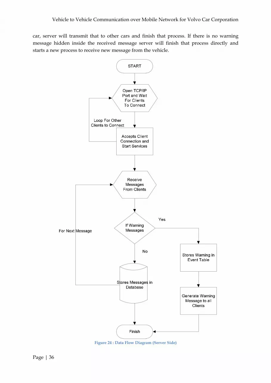
Vehicle to Vehicle Communication over Mobile Network for Volvo Car Corporation
Page | 36
car, server will transmit that to other cars and finish that process. If there is no warning message hidden inside the received message server will finish that process directly and starts a new process to receive new message from the vehicle.
Figure 24 : Data Flow Diagram (Server Side)
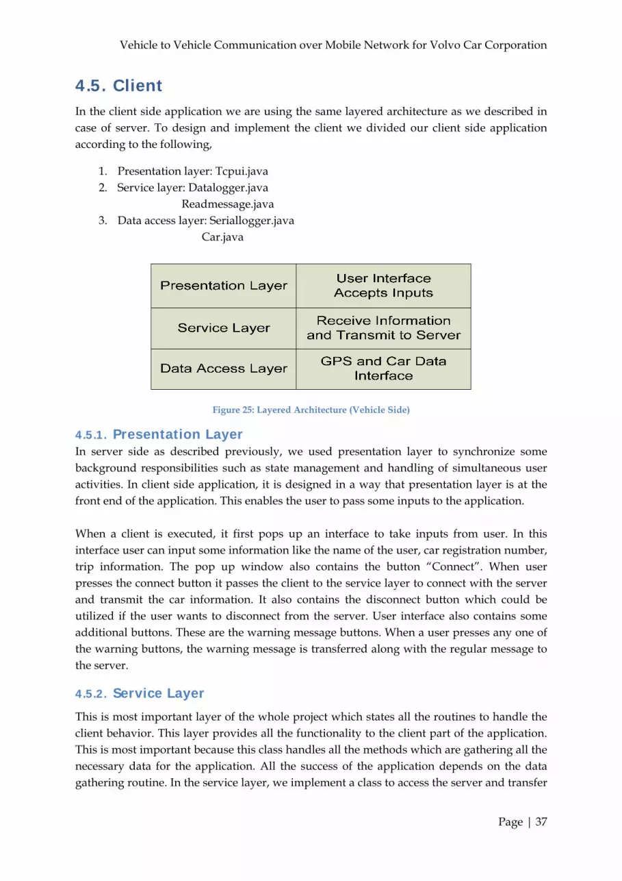
Vehicle to Vehicle Communication over Mobile Network for Volvo Car Corporation
Page | 37
4.5. Client In the client side application we are using the same layered architecture as we described in case of server. To design and implement the client we divided our client side application according to the following,
1. Presentation layer: Tcpui.java 2. Service layer: Datalogger.java
Readmessage.java 3. Data access layer: Seriallogger.java
Car.java
Figure 25: Layered Architecture (Vehicle Side)
4.5.1. Presentation Layer In server side as described previously, we used presentation layer to synchronize some background responsibilities such as state management and handling of simultaneous user activities. In client side application, it is designed in a way that presentation layer is at the front end of the application. This enables the user to pass some inputs to the application. When a client is executed, it first pops up an interface to take inputs from user. In this interface user can input some information like the name of the user, car registration number, trip information. The pop up window also contains the button “Connect”. When user presses the connect button it passes the client to the service layer to connect with the server and transmit the car information. It also contains the disconnect button which could be utilized if the user wants to disconnect from the server. User interface also contains some additional buttons. These are the warning message buttons. When a user presses any one of the warning buttons, the warning message is transferred along with the regular message to the server.
4.5.2. Service Layer
This is most important layer of the whole project which states all the routines to handle the client behavior. This layer provides all the functionality to the client part of the application. This is most important because this class handles all the methods which are gathering all the necessary data for the application. All the success of the application depends on the data gathering routine. In the service layer, we implement a class to access the server and transfer

Vehicle to Vehicle Communication over Mobile Network for Volvo Car Corporation
Page | 38
the information or the vehicle data to the server. Service layer is involved in coordinating all logics and functions between the two domain classes. Data from the data access layer reaches to the application layer and pass through the service layer.
Inside the service layer another class has been implemented to handle the warning message which will be received from server. Whenever a vehicle transmits a warning message to server, that message will retransmit to other client via the server. This class named ‘readmessage.java’ running a thread inside the client application. It is always watches any message coming from server. If such a message is transmit from server it will received that message and that message will pop up on the client window.
4.5.3. Data Access Layer
Client side does not store any data to the database directly in our application. Therefore it does not need the special class built in java to communicate with the database called java database connectivity (JDBC). This class is created to gather all the necessary data of the car which will transfer to the server for storing into the central database. In the client side we get data from two different interfaces. One is from the GPS receiver, about the car position and another one from the car network. It contains the internal car data like speed, break, warnings etc. Inside this layer there are two different classes for gathering information from two different interfaces. In the data access layer two different classes are built. One is the ‘Seriallogger.java’ and the other is ‘car.java’. ‘Seriallogger.java’ implements all the required methods needed to gather the GPS strings in every second. It grabs the GPS string in every second and breaks that string into several parts depending on the different variables. From those variables it takes the required variables and passes it to the ‘car.java’ classes for further processing. On other hand ‘car.java’ prepare all the necessary car data manually like the lateral acceleration, long acceleration, steering angle, velocity over ground etc. After preparing all the necessary car information it combines the car information along with the GPS inputs and transfer it to the server for storing into the database.
4.5.4. Dataflow Diagram
When a client starts the program it will pop up a user interface. After user inputs the required data and hits the connect button it will try to connect to server and initialize the GPS receiver device to get the GPS string. If the device is missing or not connected with the computer it shows an error message. After successful connection, it prepares the GPS receiver to take the GPS string via com port and break that string into several parts. It also prepares different car data received from the CAN device. It combines both the car data and the GPS string in one message and transfer it to the server. On other hand it always checks for any message that could be delivered from the server. If no message is transferred from the server then it will go back to previous step to take new inputs from GPS and prepare car data. This process will continue until the user hits the disconnect button. If any message is

Vehicle to Vehicle Communication over Mobile Network for Volvo Car Corporation
Page | 39
received from the server, it stars a new process to display that warning message from the server. After displaying the server message it finishes this new process. If user presses the warning message at user interface, it adds this warning message along with the other information of the vehicle before the transmission of the message.
START
User Interface Manual Input From
The User
Press Connect To Start
The Client
Is GPS Device Available
Error
Get GPS
Position
Part GPS String and Prepare for Transmission
Make Connection With the Client
Send Information To The Server
Did Server Transmit Warning
Message
Display Warning Message
Yes
No
Any Warning Messages
No
Yes
Get Event Information
No
Yes
Figure 26: Data Flow Diagram (Vehicle Side)

Vehicle to Vehicle Communication over Mobile Network for Volvo Car Corporation
Page | 40
Chapter 5: Results & Discussion
5.1. Overview
In this chapter we present you results, imperial findings and usage of the developed system that we have mentioned in previous chapter. This chapter is organized in a way that first we show some results obtained from real time testing environment. Later in this chapter we will discuss some findings and constraints that limit the system performance. In the last of this chapter we will discuss the applications for the implemented system.
5.2. Results Before we present you our results and findings let’s just recall the research question that we stated in the first chapter of this report. Where we clarified that this master thesis will examine the two following scenarios,
Finding out the possibility to use the already deployed mobile network that can facilitate communication by utilizing network and transport layer
Measuring the latency and delay in mobile network and evaluate whether mobile
network could be used for the transmission of warning messages in emergency situations.
So as far as first point is concerned, we can assure that this system has successfully accessed the mobile network for the transmission of warning messages from one client to another. How it became possible? We have mentioned in chapter 4, which describes the implementation of the system and how we able to transmit messages between client and server by utilizing TCP/IP communication.
5.2.1. System Setup As we mentioned that this project is designed to enable the transmission of warning massages from one client to another client. Where in between them, there is a server machine which diagnoses the message and identifies the clients and route the message to those particular clients. We have tested our system in two different environments, IEEE 802.11, which is known as Wi-Fi. Another one is already deployed mobile network’s UMTS/HSPA technology. The results are collected and critiqued for both the technologies. So to make it short, figures below describes the overall built environment that we used to test the developed application.
1. IEEE 802.11 (Wi-Fi) Environment In this environment, both the clients and the server are connected to a Wi-Fi router. All the machines are in the range of Wi-Fi. The figure below illustrates the situation more then it could be described. This atmosphere has been created to test the application before its inspection in real 3G network.

Vehicle to Vehicle Communication over Mobile Network for Volvo Car Corporation
Page | 41
Figure 27: Wi-Fi Test Environment
2. UMTS/HSPA Environment After successful tests and results in Wi-Fi environment, we moved our clients and server in 3G network. The figure below gives a bird’s-eye view about the deployed network structure and its elements.
Figure 28: 3G Test Environment
Here in this figure, the server is connected with the internet through a live IP. By live IP, we mean that server is not in private network it is connected by public IP address given by an ISP. It facilitated the tests in a way that, if the server would be in private network than for sure, it would be behind a firewall and a gateway router. Which means that its IP address would be given by private router and if that would be the case then a NAT have to be implemented in that router to cater several clients in that network. So NAT will introduce an extra delay in measuring the connection and trip time latency. Two clients have been used for this tests and results have been collected for both of the clients. Both the clients are connected to the internet via IP address provided by GGSN of the mobile company as they connect to it through HSPA modules. GPS device is also connected to the each client to acquire the exact position of each client.

Vehicle to Vehicle Communication over Mobile Network for Volvo Car Corporation
Page | 42
To collect the delays and latency, we use the time stamp function. When a message is transferred from a client to the server it acquires its machine time and transfers it to the server. The server receives the data along the time when the message was transferred. Then server acquires its own machine time and compares it with time when the message was transferred from the client. In this way delays and latency are extracted. This is just one scenario. But for every situation we examined delays in the same fashion. The results do have the error of ± 200msec. The reason is, we cannot set the system time up to millisecond of accuracy and that’s why all the machines could not be synchronized up to millisecond of time but the application collects the system time up to millisecond so the results do have some errors.
5.2.2. Scenarios and Results In this section we will describe different scenarios by which results are collected. Results have been examined for both Wi-Fi and 3G network. They are investigated and critiqued as much as possible. But to understand different results, following diagram clarify about different situations.
Figure 29: Test Scenarios
1. Connection Time Connection time is the time taken by a client to connect to the server. We have collected a number of data samples for both Wi-Fi and 3G. 3G data has been acquired while we were on the move and collected at different times and places. Below we have presented two figures which shows the connection time for each client in both the environments.

Vehicle to Vehicle Communication over Mobile Network for Volvo Car Corporation
Page | 43
Figure 30: Connection Time in Wi-Fi Network
If we look at the figures of both clients in Wi-Fi, one can notice a number of variations in time taken by the clients to connect to the server. But for both the cars, connection time is always in milliseconds. Furthermore, if we look at the figure of car1, we see that most of time connection time is zero. Here it is true, as the car1 was very close to the Wi-Fi router than the other car, which never reached zero connection time. But as we mentioned that there is an error possibility of ± 200msec. So we can say that, the connection time is still in 200msec and one can imagine the processing time of the application, which must be within 200msec.
Now look at the connection time collected by utilizing in 3G network, which is shown in next figure. First of all, notice that most of the time, recorded delay is around zero for both the cars. But in reality it is not zero. Theses connection times are in milliseconds which showed up near to zero. To understand the reason behind different variations in connection time in sec and milliseconds, one needs to go deep in the theory of network or more specifically routing fundamentals. Routers regularly update their routing table to keep track of the several routes across the different links. To keep track of the accurate route and to make the routing tables small, router continuously updates its routing table. This will minimize the look up time for a route during the routing process. It solely depends on the network administrator, who set the update time of the routing table. It could be from seconds up to minutes, varies by network, router and routing protocol. So when we connect and disconnect the client continuously, the connection time always showed up in milliseconds. But when we disconnect the client and wait some time to initiate a new connection, it always showed up in seconds which perfectly follows routing concepts. Also, there are three high peaks, which mean that client took around 10sec to connect to the

Vehicle to Vehicle Communication over Mobile Network for Volvo Car Corporation
Page | 44
server. Handoff is the most appropriate reason recognized behind such a large delay. In handoff, a mobile device moves away from serving base station to a region of new base station. This enables the serving base station to transfer the control of the mobile resources to the new base station. We collected data while we were moving around in the city. So we believe that there is a possibility that we initiated the connection while the mobile device was in the phase of handoff. Another reason could be packet loss in TCP/IP communication. Once the connection has been initiated, it must connect to the server. If a packet is lost during transmission it should transmit and retransmit the connection initiation until it is connected to the server. So it might be due to packet loss in the network.
Figure 31: Connection Time in 3G Network
2. Car2Server Standard Data Latency Car2Server Standard Data is the combined data that the car transfer regularly to the server. This data does not contain any warning message information. It regularly transmits its position, which it acquire from GPS connected to the machine and the CAN data, which it gets from the car CAN device. The application combines both the data and sends it to the server. For Wi-Fi environment, the data has reached within 50msec of delay. It means that application collects data from GPS and CAN several times in one sec and transmits it to the server. This also shows the processing and execution time of the client side application. Similarly, normal data transmission time from car2server in 3G network is also reached around 100msec, it is hardly possible to distinguish the latency in 3G network and in Wi-Fi from the figure below. These are very promising results.

Vehicle to Vehicle Communication over Mobile Network for Volvo Car Corporation
Page | 45
Figure 32: Car2Server Standard Data Latency
3. Car2Car Warning Message Delay Warning message is generated by a car to trigger the other car about any emergency situation. A vast range of warnings could be included into the warning message, for example, forward collusion warning (FWD), slippery road condition, car breakdown status etc. When a warning message is generated by a car, first it received by the central server, which then re-route it towards the other cars. This situation could not be described well than the following figure.
Figure 33: Car2Car Warning Message Situation

Vehicle to Vehicle Communication over Mobile Network for Volvo Car Corporation
Page | 46
When the application was developed and tested for warning message transmission delay, the results were unusual for both, Wi-Fi and 3G network, as shown in figure below. The problem is quite obvious, as the number of warning messages increased; the transmission delay from one car to another has also increased. You may notice that for Wi-Fi, after 50th warning message, the graph fell down suddenly. It is because at this point we disconnected the client and reconnected it again to the server. This is to find out that which client is responsible for increasing delay. After resetting the connection, the message delay again came down to one second but started increasing again. This clarified us that the problem is in the client application which is sending the messages. But we further disintegrate the system for more analysis. The system has investigated by the dividing the car2car warning message scenario into two parts as shown in the figure above.
Figure 34: Car2Car Warning Message Latency Old Algorithm
1. Server2Car Warning Message Delay As the warning message is generated by a car it reaches the central server to be transferred to the other cars. But as the server receives warning message, it disintegrate the message, extract the received data and stores it into database. It also generates the warning message to alarm the other cars about the emergency situation and its location. Server should consume some time to process everything. But the results were quite astonishing for both Wi-Fi and 3G network. As for both the networks, as long as the warning message is generated by the car and received by the server, it is processed and received by the other car in time of milliseconds. Furthermore, the delay time was almost constant for several warning messages. So from this investigation, it is clarified that processing time taken by the Server and the other car to receive the warning message is not the cause of the above mentioned problem.

Vehicle to Vehicle Communication over Mobile Network for Volvo Car Corporation
Page | 47
Figure 35: Server2Car Warning Message Latency
2. Car2Server Warning Message Delay Now, in this scenario we measured the warning message transmission time from car which generates the warning message, while the server receives it. As we tested this half of the project, we identified that the car that generate the warning message is taking a long time to transmit the warning message as the number of warning messages are increased. The result is shown in the figure below.
Figure 36: Car2Server Warning Message Latency

Vehicle to Vehicle Communication over Mobile Network for Volvo Car Corporation
Page | 48
By further investigation, we came to know that as long we hit the warning message button, car generates the warning message and transmits it. But server took longer time to receive it. So the TCP/IP mechanism is examined carefully. After detailed consideration, we find that it is the TCP/IP buffer which is the cause of the whole trouble. TCP/IP protocol utilizes a buffer for data transmission. As we mentioned before, the client is generating hell of a data in one second. So client starts and generates the first data. Before that data is completely received by the server, client generates many more data and places them into buffer. So when a warning message is produced, it is queued into the buffer. This causes the server to receive warning message after some time. So we revised the algorithm of the client’s side application. After each time normal data is sent, client flushes the buffer and check for warning message. This has greatly improved the overall performance of the system as shown in the figure below. As long as the warning message is generated by the client, it is received by the other client in millisecond of time for both Wi-Fi and 3G network.
Figure 37: Car2Car Warning Message Latency with Improved Algorithm
Following figure demonstrate a good comparison between the old and the improved algorithm. As you can see, for both the networks, efficiency of the system has increased dramatically. Many messages have been generated and the car2car warning message transmission time is always in millisecond of time for both networks as shown by above figure.

Vehicle to Vehicle Communication over Mobile Network for Volvo Car Corporation
Page | 49
Figure 38: Car2Car Warning Message Comparison between Old and Improved Algorithm
5.3. Discussion
5.3.1. Performance Constraint
We worked on this system from the concept generating up till the final delivery of the application. When we started working on this project, our only focus was on the operational side of this application. But after the completion, we come up some constraints that limit the functionality of the system. The system is working exactly as expected. But to use this system for commercial project, some areas needs special attention to make it successful in the market. Below, we highlight some of the area that needs to be addressed and modifications are required according to the requirements.
Warning Messages Generation: Right now the system is designed in a way that it does not detect warning message from the vehicle automatically. We have provided warning buttons at the control panel of the application where user can generate warning message by his own. Well, obviously it is not the right way to do it. If it founds any warning then immediately it should inform the server automatically. All this should be transparent from the driver’s perspective.
Active Clients: One of the most important thing to mention is, only active client can communicate with the server. By active clients we mean clients which are connected to the server via TCP/IP link. The clients who are not connected to the server neither able to

Vehicle to Vehicle Communication over Mobile Network for Volvo Car Corporation
Page | 50
transfer the warning messages to the server nor receive the messages from the server. So connection has to be established to log the data into the central server.
Max Number of Clients: We developed this system by considering the available machine’s processing powers. So we have restricted the number of clients that can connect to the server by 10. So if eleventh client try to connect with the server he will be asked to wait by the server. If some slot will be available soon then eleventh client will be allowed to connect to the server. Otherwise he will be remaining in waiting mode.
Searching Algorithm: When a client transmits the alert message server first stores that message and at the same time it forwards that message to other clients. Some modifications are needed in forwarding the messages to other clients. In this application, as long as the server receives the warning message, it forwards that warning message to all the active clients connected with the server. It does this routine without any consideration that whether a particular client needs this warning message or not. So the system is consuming extra bandwidth and is not efficient. A searching algorithm needs to be introduced on the server side. This algorithm will be activated and look for the cars from the database which really need warning message or could be affected by an emergency situation. An intelligent algorithm should be advised and inserted on server side in a way that it does not increase the overall delay and latency of the warning message from one car to other cars. Because time so very critical here. Even msec of delay can be responsible for many fatal injuries. But this algorithm will definitely reduce the bandwidth utilization of the system and increase the efficiency.
Server Performance: If one analyzes the server’s performance by the working methodology, he will know that there are many procedures that need to update or correct to make it perform better. First and far most thing is to increase the efficiency of the server. This can be done in many ways. Right now, every second client is transmitting its information along with the warning messages if there are any. For the moment, we have two clients and server is handling them very precisely and efficiently. But as this application will be utilized for large scale of vehicles, so this routine has to be adjusted to entertain many numbers of clients. If all the clients transmitting the information every second then server needs to be capable to handle that much data from hundreds or thousands of clients without introduction of the queuing theory.
Another very important issue that needs to be addressed is the way application provides data to the database for storage. When clients transmit the data to the server application it provides the received data to the database one by one. So every time one client’s information could be stored to the database. For this, there s a possibility that any warning message that has higher priority will be processed later and the vehicles that need that warning message immediately will receive it after some time. This is not desire able. So the server application should be modified in a way that it entertains all the received data from the clients in one time instant, see if there any warning message and store it into the data base. This will definitely increase the system efficiency.

Vehicle to Vehicle Communication over Mobile Network for Volvo Car Corporation
Page | 51
Security: As the server and clients are connected to the internet, so there is a need of security protocols against several attacks. The server is containing many public and private data about the cars and its drivers which need to be protected. Several security measures are required to protect the data. Also the functionality of this whole application depends on the server performance. Server also needs to be protected against Daniel of Service (DoS) attack because it could slow down the performance of the server or in worst case, could cause the server to crash.
5.3.2. Applications
The implemented system can be used for many different applications by changing the application layer according to the requirement without any changes at the lower layers of the architecture. Some of the applications are mentioned below. However, there are countless applications which can be benefitted from the system.
1. Forward Collusion Warning The first and most applicable application is the forward collusion warning. This system has been developed by considering this application. To summarize, whenever a car is involved in an accident it will transmit its information to the server and then server will transmit the warning message to the cars that could be affected by that accident. In this way accidents that involve multiple cars because of the lack of the driver’s intentions or response could be prevented. The system will inform the driver in advance about the accident that just happened in its way. The driver may alert himself for unusual situation.
2. Slippery Warning This is one of the major applications of the implemented system. In countries like Sweden, Denmark and Norway which are close to North Pole, in severe weather conditions, driving becomes a hectic and dangerous for the people and for the driver himself. So what this is can do is, it can collect the slippery road condition from the car’s CAN system. Then it will transmit this information to the server. Where server will analyze the data and transfer the warning messages to the vehicles which are traveling on the same road. In this way driver can be informed in advance about the road condition. This collected data could also be utilized by the road management authorities to better understand the real time situation. It is not necessary that every road has slippery condition. So if road authorities know exact condition then they can better utilize their work force by deploying them at the road which needs more attention than others. This help to reduce their work and increase their efficiency. 3. Transport Authority The system can be utilized in many ways by transport authorities. One of those many ways is by analyzing the collected data, the road authorities can actually assisted for better traffic management. They can monitor real time traffic situation. By knowing the actual traffic condition, they can find out more congested roads and where they need to construct new roads. It will also provide a hint for the installation and controlling of the traffic signals or deployment of traffic controlling personal to adjust the real time congestion. Similarly they

Vehicle to Vehicle Communication over Mobile Network for Volvo Car Corporation
Page | 52
can be aware of locations where the frequencies of the accidents are higher. This will help them to take necessary actions to prevent the accidents and could save many human lives.
4. On-Board Entertainment Last but not least, as the system is already equipped with the internet connection via UMTS/HSPA module. Many entertaining and informing applications can be provided by the car manufacturers. Driver will always be connected to the internet. Passengers can check their emails, watch YouTube videos and can video conference while moving around the city. If someone likes to find a nice restaurant for the lunch, he can Google his location and in return Google will provide information and location of different restaurants and coffee shop around him. This idea can generate so much revenue for advertising companies. Advertising companies can actually advertise different products and offers according the location of the moving vehicle. The advertisements can pop up at the LCD and you will always be aware of the current offers around you. Even you don’t live in that city.

Vehicle to Vehicle Communication over Mobile Network for Volvo Car Corporation
Page | 53
Chapter 6: Conclusions & Future Work
In this Master Thesis project a several possibilities have been investigated for the transmission of warning messages from one vehicle to another. After careful consideration one method has been identified and implemented in this project. The application based on the fact that, warning messages are transferred from one car to another through a central server machine. It acts as a router, which receives a message from client and routes to another. This is achieved by implementing the communication protocol at transport and network layer. Client and Server communication implemented via TCP/IP communication. Server receives the warning message from client through TCP/IP via already deployed UMTS/HSPA network. Up on which it examines the targeted client which may require that warning message. The current positions of the clients help the server in routing decisions. Which it stores in database, designed using SQL server. The whole system has been built and assembled in Java.
As mentioned in discussion, the whole system is conceptualized and delivered successfully. So there is a lot space available for improvement. In the “Results and Discussion”, we have critiqued in detail. If one remodeled and repaired the system, still there will always be a possibility to enhance the features of the system, because this system has just laid down the foundation. By utilizing this basic foundation one can build many features and integrate them with the existing implemented system.

Vehicle to Vehicle Communication over Mobile Network for Volvo Car Corporation
Page | 54
1. Frank, Randy. The TU 10: Next Year’s Top 10 Disruptive Telematics Technologies. www.Telematicsupdate.com. [Online] December 18, 2009. [Cited: October 15, 2010.] http://social.telematicsupdate.com/industry-insight/tu-10-next-year%E2%80%99s-top-10-disruptive-telematics-technologies.
2. Precksha Saksena-Sood. Qualcomm signs international telematics connectivity agreement with Telenor Connexion. www.telematicsupdate.com. [Online] May 11, 2009. [Cited: October 21, 2010.] http://social.telematicsupdate.com/content/qualcomm-signs-international-telematics-connectivity-agreement-telenor-connexion.
3. Precksha Saksena-Sood. Airbiquity and Telenor Connexion announce strategic partnership. www.telematicsupdate.com. [Online] June 2, 2009. [Cited: October 21, 2010.] http://social.telematicsupdate.com/content/airbiquity-and-telenor-connexion-announce-strategic-partnership.
4. ERTICO. eCall Toolbox. www.esafetysupport.org. [Online] ERTICO, 2007. [Cited: October 29, 2010.] http://www.esafetysupport.org/en/ecall_toolbox/index.html.
5. Tolve, Andrew. Has eCall’s Moment Finally Arrived? www.telematicsupdate.com. [Online] April 16, 2010. [Cited: October 21, 2010.] http://social.telematicsupdate.com/industry-insight/has-ecall%E2%80%99s-moment-finally-arrived.
6. ERTICO. eCall Toolbox. www.esafetysupport.org. [Online] ERTICO, 2007. [Cited: October 29, 2010.] http://www.esafetysupport.org/en/ecall_toolbox/index.html.
7. Federal Communications Commission. FCC ALLOCATES SPECTRUM IN 5.9 GHz RANGE FOR INTELLIGENT RANSPORTATION SYSTEMS. www.fcc.gov. [Online] October 21, 1999. [Cited: October 10, 2010.] http://www.fcc.gov/Bureaus/Engineering_Technology/News_Releases/1999/nret9006.html.
8. Martin Arndt. Cars ‘Talking and Hearing in Harmony' - a Smart Move for ETSI! www.etsi.org. [Online] September 30, 2008. [Cited: October 15, 2010.] http://www.etsi.org/WebSite/NewsandEvents/2008_09_Harmonizedstandards_ITS.aspx.
9. Car-to-Car. C2C-CC Manifesto. s.l. : Car-to-Car, 2007.
10. LOCATION TRACKING IN GPS USING KALMAN FILTER THROUGH SMS. Zahaby, M., Gaonjur, P. and Farajian, S. St.-Petersburg : IEEE, 2009. 978-1-4244-3860-0.
11. An Improved Location Tracking Algorithm with Velocity Estimation in Cellular Radio Networks. Lee, Jemin, et al. Melbourne : IEEE, 2006. 1-7803-9392-9/1550-2252 .
12. Huart, ESA-J. Galileo constellation. [Image] s.l. : European Space Agency. ESATTGG18ZC.
13. Sesia, Stefania, Toufik, Issam and Baker, Matthew. LTE – The UMTS Long Term Evolution. s.l. : Wiley, 2009. 9780470697160.

Vehicle to Vehicle Communication over Mobile Network for Volvo Car Corporation
Page | 55
14. Federal Communications Commission. Advanced Wireless Services (AWS) Spectrum. www.fcc.org. [Online] May 20, 2006. [Cited: October 12, 2010.] http://wireless.fcc.gov/services/aws/data/awsbandplan.pdf.
15. Erik Dahlman, Stefan Parkvall, Johan Sköld and Per Beming. 3G Evolution; HSPA and LTE for Mobile Broadband. s.l. : Elsevier, 2008. 978-0-12-374538-5.
16. Machine-to-machine technology gears up for growth . Lawton, G. 9, s.l. : IEEE, 2004, Vol. 37. 0018-9162 .
17. Precksha Saksena-Sood. AT&T and Cooper Power Systems to offer wireless smart grid sensors. www.telematicsupdate.com. [Online] June 25, 2009. [Cited: September 9, 2010.] http://social.telematicsupdate.com/content/att-and-cooper-power-systems-offer-wireless-smart-grid-sensors.
18. IVSS Project Portfolio – Approved Projects, Status March 2008. Swedish Road Administration. Göteborg : Swedisch Road Administration, 2008. 1401-9612.
19. Per-Olof Sjölander, Swedish Road Administration. SRIS – Slippery Road Information System. s.l. : IVSS, 2008.
20. Oppel, Andrew J. Databases:A Beginner’s Guide. s.l. : McGraw-Hill, 2009. 978-0-07-160847-3.
21. Axelson, Jan. Create A USB Virtual COM Port. www.circuitcellar.com. [Online] August 2008. [Cited: July 3, 2010.] http://www.lvr.com/usb_virtual_com_port.htm.
22. Philips Semiconductor. USB virtual COM port on LPC214x. Netherland : Philips Semiconductor, 2006.
23. Wikipedia. Serial port. www.wikipedia.org. [Online] November 6, 2010. [Cited: July 3, 2010.] http://en.wikipedia.org/wiki/Serial_port.
24. Oracle. Java Technology. www.oracle.com. [Online] Oracle . http://www.oracle.com/us/technologies/java/index.html.
25. Fidel CACHEDA, Alberto PAN, Lucía ARDAO, Ángel VIÑA. A Layered Architecture based on Java for Internet and Intranet Information Systems. [Document] CORUÑA : CiteSeerx, CiteSeerX, 1999.
26. Oracle . java.lang.Thread. www.download.oracle.com. [Online] Oracle. http://download.oracle.com/javase/1.4.2/docs/api/java/lang/Thread.html.
27. Machine-to-Machine communication in LTE-A. Yu Chen, Wei Wang. Ottawa, ON : IEEE, 2010. 978-1-4244-3574-6/1090-3038 .
28. Miyahara, K. Jay. LTE OvervieLTE Overview. [Presentation] s.l. : NEC, 2008.
Vehicle to Vehicle Communication over Mobile Network for Volvo Car Corporation
Page | 56
29. Precksha Saksena-Sood. 4G: A Turning Point for Telematics? www.telematicsupdate.com. [Online] February 22, 2010. [Cited: October 30, 2010.] http://social.telematicsupdate.com/industry-insight/4g-turning-point-telematics.

Vehicle to Vehicle Communication over Mobile Network for Volvo Car Corporation
Page | I
Appendix A: Telit’s 3G Module
Telit’s 3G module, GT864-3G UMTS/HSDPA modem provides the complete solution for wireless machine-to-machine (m2m) communication. The module operates at single band 2100 MHz. It is also fully backward compatible with EDGE/GPRS network. So it could operable in countries where UMTS/HSDPA network is not available or hasn’t been deployed yet. It supports all of its functions at very extreme temperature ranges that is, from -20oC to +55oC. The modules can be controlled through serial RS232 or USB interface and can be connected to the computer via mini-USB 2.0 cable. The module has built-in TCP/IP stack and could be configured via AT-commands. The main features of the modem can be summarized as following.
Product Feature Data HSDPA 7.2 Mbps HSDPA
- Downlink up to 7.2 Mbps - Uplink up to 384 Kbps
UMTS/HSDPA (WCDMA/FDD) 2100 MHz WCDMA - Downlink/Uplink 384 Kbps
Quad-band EGSM 850/900/1800/1900 MHz
EDGE - Downlink up to 236.8 Kbps - Uplink up to 118 Kbps
GPRS/EDGE GPRS - Downlink up to 85.6 Kbps - Uplink up to 42.8 Kbps
Control via AT-commands according to the GSM 07.05, 07.07 and Telit’s enhancements
CSD - Downlink/Uplink 14.4 Kbps
Access to TCP/IP stack via AT-commands Mini USB 2.0 and Serial RS-232 interfaces

Vehicle to Vehicle Communication over Mobile Network for Volvo Car Corporation
Page | II
Appendix B: Software Setup Guide
For both clients and the server, NetBeans can be downloaded and installed from the following location for free,
http://netbeans.org/downloads/index.html
The procedure to install the NetBeans is described in the following YouTube’s video,
http://www.youtube.com/watch?v=MdJadSToxiU
After installation, Client and Server applications, both need to be ready. For this you need to copy “TCPIPClIENT” and “TCPIPSERVER” to,
C:\Documents and Settings\”Your Computer Name”\My Documents\NetBeansProjects
Then you need to “Open Project” in NetBeans. As shown in the figure below, same procedure should be followed for both client application and the server application

Vehicle to Vehicle Communication over Mobile Network for Volvo Car Corporation
Page | III
For Client:
After adding opening the “TCPIPCLIENT” go to the “Libraries” and add “javaxcomm.zip” file provided with the software. The procedure is illustrated in the figures below.

Vehicle to Vehicle Communication over Mobile Network for Volvo Car Corporation
Page | IV
Once the file has been added in “Libraries” then open the “Javaxcomm.zip” file and follow these three steps to copy the files in mentioned folders.
1. Place “comm..jar” in C:\Program Files\Java\jdk1.6.0_20\lib C:\Program Files\Java\jdk1.6.0_20\jre\lib\ext
2. Place “win32com.dll” in
C:\Program Files\Java\jdk1.6.0_20\bin C:\Program Files\Java\jdk1.6.0_20\jre\bin C:\WINDOWS\system32
3. Place “javax.comm.properties” in
C:\Program Files\Java\jdk1.6.0_20\lib C:\Program Files\Java\jdk1.6.0_20\jre\lib
Now the Client Program is ready to be executed. But don’t forget to plug in the GPS device in USB port.
For Server:
Before preparing the server application we need one more thing to run the whole application. We now need the database to store the client data. Follow the following procedure to setup and configure the database.
For database in the server we use MySQL community server. MySQL can be downloaded and installed from the following location for free,

Vehicle to Vehicle Communication over Mobile Network for Volvo Car Corporation
Page | V
http://dev.mysql.com/downloads/mysql/
The procedure to install the MySQL is described in the following YouTube’s video,
http://www.youtube.com/watch?v=oylVvq-3Tfk
When installing the database server give the password “volvo” and the user is “root”.
After install the database servers create a database with the user id and password. While creating the database follow the architecture given in this report above in the methodology section.
The procedure to create tables in MySQL database is described in the following YouTube’s video,
http://www.youtube.com/watch?v=aJVnYlRpET0
Once the database is installed, now open the “TCPIPSERVER” in Netbeans same as the client. Now go to the “Libraries” and add “javaxcomm.zip” file provided with the software. The procedure is illustrated in the figures below.
Once the library is added the server program is ready to be executed. Follow the next procedure to run the server program.

Vehicle to Vehicle Communication over Mobile Network for Volvo Car Corporation
Page | VI

Vehicle to Vehicle Communication over Mobile Network for Volvo Car Corporation
Page | VII
Appendix C: System Setup Guide
Once the Client and Server are installed and ready to be executed, following steps have to be taken to taken for normal execution of the application.
1) Server should be connected to the internet via public IP. 2) Plug-in and install the broadband modules in client computers. Once the installation of
the software is completed, connect to the internet. 3) Open the NetBeans and go to
“TCPIPCLIENT>Source Packages>client.car_data>DataLogger.java
And change the IP address of the server by the current acquired IP address at. The procedure is shown in the figure below. Procedure should be followed for both the clients.
4) When the IP address is changed, attach the USB devices with both the clients and execute
TCPIPCLIENT>Source Packages>client.UI>Tcpui.java
Procedure is also shown in figure. Before running the application, make sure that GPS device is connected to the client’s USB. Otherwise application will give an error and it will not be executed. Once the file is executed, a window will pop up where you can input deriver’s name, car’s name, car’s model and car’s registration number. To connect to the server press “Connect”.

Vehicle to Vehicle Communication over Mobile Network for Volvo Car Corporation
Page | VIII
5) Before you press “Connect”, run the server side application by executing
TCPIPServer>Source Packages>tcpipserver>server.java

Vehicle to Vehicle Communication over Mobile Network for Volvo Car Corporation
Page | IX
Once the server is up and running, you should see something like following figure in the bottom of the program.