Prestress in Nature and Technics - Chalmers Research
83
THESIS FOR THE DEGREE OF LICENTIATE OF ARCHITECTURE Prestress in Nature and Technics ALEXANDER SEHLSTR ¨ OM Department of Architecture and Civil Engineering Division of Architectural Theory and Methods Architecture and Engineering Research Group CHALMERS UNIVERSITY OF TECHNOLOGY G¨ oteborg, Sweden 2019
-
Upload
khangminh22 -
Category
Documents
-
view
1 -
download
0
Transcript of Prestress in Nature and Technics - Chalmers Research
THESIS FOR THE DEGREE OF LICENTIATE OF ARCHITECTURE
Prestress in Nature and Technics
ALEXANDER SEHLSTROM
Department of Architecture and Civil EngineeringDivision of Architectural Theory and MethodsArchitecture and Engineering Research Group
CHALMERS UNIVERSITY OF TECHNOLOGY
Goteborg, Sweden 2019

Prestress in Nature and TechnicsALEXANDER SEHLSTROM
c© ALEXANDER SEHLSTROM, 2019
Thesis for the degree of Licentiate of ArchitectureSeries name: Lic /Architecture and Civil Engineering / Chalmers University of TechnologyDepartment of Architecture and Civil EngineeringDivision of Architectural Theory and MethodsArchitecture and Engineering Research GroupChalmers University of TechnologySE-412 96 GoteborgSwedenTelephone: +46 (0)31-772 1000
Cover:Prestressed torus with the thicker bars in compression and the thinner in tension. Imagecredits Chris Williams.
Chalmers ReproserviceGoteborg, Sweden 2019

Prestress in Nature and TechnicsThesis for the degree of Licentiate of ArchitectureALEXANDER SEHLSTROMDepartment of Architecture and Civil EngineeringDivision of Architectural Theory and MethodsArchitecture and Engineering Research GroupChalmers University of Technology
Abstract
To direct the forces of nature is a central task in the creation of spaces and load-carryingstructures for architecture. This research investigates how prestress can be used as adesign tool for the creation of material efficient and well-functioning structures, and inearly design stages contribute to sustainable, functional and beautiful architecture.
The thesis begins with a discussion about central concepts such as stress and stiffness.Stiffness can be understood as the sum of elastic stiffness and geometric stiffness and thelatter is differently influenced by the presence of tensile or compressive stresses. Onlystructures that are statically indeterminate are possible to prestress so that the stresspattern is affected. The terms externally-equilibrated and auto-equilibrated prestressedstructures are introduced.
The design of load-bearing structures for architecture requires a collaboration betweenarchitects and engineers and the conditions for a successful collaboration is reflectedupon. Prominent design cultures are highlighted and the one this research is linked to isdescribed.
A collection of historic and contemporary examples of prestressed structures is pre-sented. The focus is architectural applications but examples from other realms are alsoincluded. From this collection, a framework for prestressed structures is proposed anddiscussed which considers five perspectives. The first explores the historical knowledgedevelopment. The second is devoted to structural mechanical modes of actions wherematerial behaviour, member actions and structural systems are discussed. The thirdhighlights computational strategies and those appropriate for early stage design aredistinguished from those suitable for late stage verification. The fourth perspective seeksto establish objectives for why prestress is used. The fifth perspective leads to suggestionsfor strategies for how the prestress is achieved.
Three papers are included. Paper A presents a numerical method for the form findingof prestressed gridshells consisting of both compressed and tensioned members. Paper Bdescribes a structural design process where methods usually applied by architects are usedby structural engineers. The work resulted in the construction of a temporary pavilionconsisting of a post-tensioned wooden gridshell called the Wood Fusion Pavilion. Paper Cexplores under what conditions an unloaded shell formed of a closed surface unattached toany supports can contain a state of membrane stress which can be induced by prestressing.It is concluded that a torus can be prestressed, but there must almost certainly be moreto explore.
Keywords: Prestress, Geometrical stiffness, Stress pattern, Conceptual design, Structuraldesign, Form finding, Architecture, Engineering
i
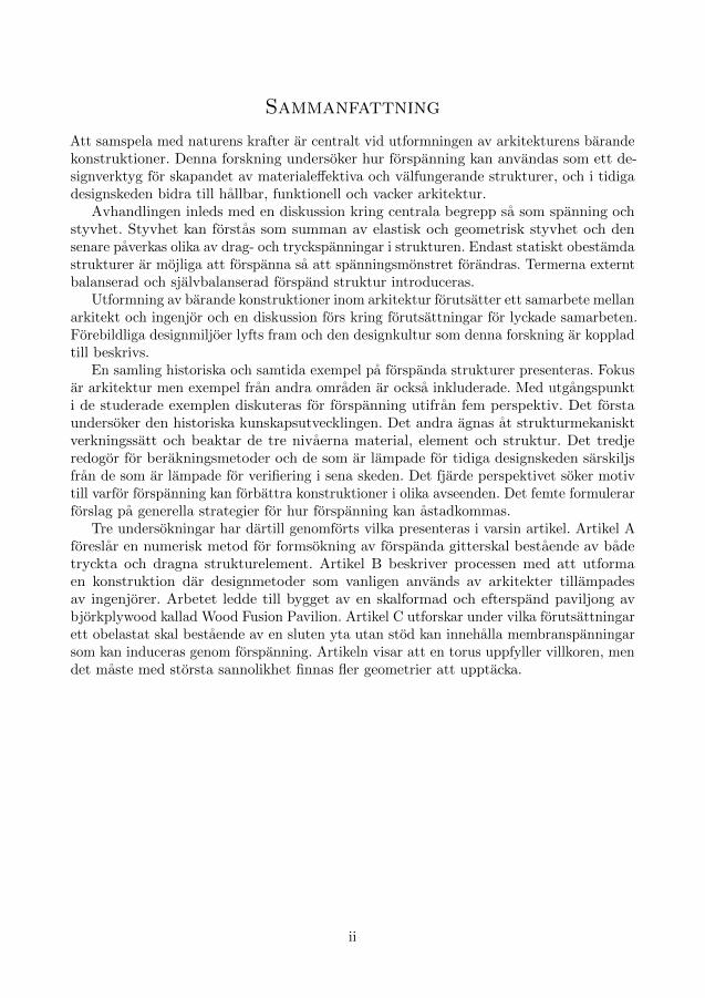
Sammanfattning
Att samspela med naturens krafter ar centralt vid utformningen av arkitekturens barandekonstruktioner. Denna forskning undersoker hur forspanning kan anvandas som ett de-signverktyg for skapandet av materialeffektiva och valfungerande strukturer, och i tidigadesignskeden bidra till hallbar, funktionell och vacker arkitektur.
Avhandlingen inleds med en diskussion kring centrala begrepp sa som spanning ochstyvhet. Styvhet kan forstas som summan av elastisk och geometrisk styvhet och densenare paverkas olika av drag- och tryckspanningar i strukturen. Endast statiskt obestamdastrukturer ar mojliga att forspanna sa att spanningsmonstret forandras. Termerna externtbalanserad och sjalvbalanserad forspand struktur introduceras.
Utformning av barande konstruktioner inom arkitektur forutsatter ett samarbete mellanarkitekt och ingenjor och en diskussion fors kring forutsattningar for lyckade samarbeten.Forebildliga designmiljoer lyfts fram och den designkultur som denna forskning ar koppladtill beskrivs.
En samling historiska och samtida exempel pa forspanda strukturer presenteras. Fokusar arkitektur men exempel fran andra omraden ar ocksa inkluderade. Med utgangspunkti de studerade exemplen diskuteras for forspanning utifran fem perspektiv. Det forstaundersoker den historiska kunskapsutvecklingen. Det andra agnas at strukturmekanisktverkningssatt och beaktar de tre nivaerna material, element och struktur. Det tredjeredogor for berakningsmetoder och de som ar lampade for tidiga designskeden sarskiljsfran de som ar lampade for verifiering i sena skeden. Det fjarde perspektivet soker motivtill varfor forspanning kan forbattra konstruktioner i olika avseenden. Det femte formulerarforslag pa generella strategier for hur forspanning kan astadkommas.
Tre undersokningar har dartill genomforts vilka presenteras i varsin artikel. Artikel Aforeslar en numerisk metod for formsokning av forspanda gitterskal bestaende av badetryckta och dragna strukturelement. Artikel B beskriver processen med att utformaen konstruktion dar designmetoder som vanligen anvands av arkitekter tillampadesav ingenjorer. Arbetet ledde till bygget av en skalformad och efterspand paviljong avbjorkplywood kallad Wood Fusion Pavilion. Artikel C utforskar under vilka forutsattningarett obelastat skal bestaende av en sluten yta utan stod kan innehalla membranspanningarsom kan induceras genom forspanning. Artikeln visar att en torus uppfyller villkoren, mendet maste med storsta sannolikhet finnas fler geometrier att upptacka.
ii

To Andreas
iii

iv

Preface
Though I always have been curious and had an urge to understand things, the topic ofthis thesis was not self-evident. In my application to become a PhD student I imaginedI would study concrete shell structures. Six months later, when I began my studies inOctober 2016, this had changed to timber shell structures. During the first months of mystudies I was suggested to study the Grand Louvre Pyramid which consists of a cablesupported steel frame supporting the glass panes. From these studies the interest inprestress as a design tool emerged, which eventually became the topic of my licentiatethesis. It appears to me that the concept has a large potential in making structures moreefficient and contribute to sustainable, functional and beautiful architecture, but littleliterature is devoted to the concept.
Reading about the Grand Louvre Pyramid also introduced me to the structuralengineer Peter Rice (1935-1992). His book An Engineer Imagines (Rice 1996) fascinatedme and showcased an approach towards engineering that I believe more engineers couldapply in their work to make the world a better place. In the book, Rice discusses hiscollaboration with architects from the very early stages to the completion of the buildings.Rice was involved in many notable buildings, for example the Sydney Opera House (1957)and Centre Pompidou (1971), and it is evident that his collaborations were fruitful.
Another structural engineer who embraced collaboration was Frei Otto (1925-2015),who is known for his many tensile membrane structures. Throughout his entire career,Otto worked extensively with physical models (Vrachliotis et al. 2017). Using soap film,hanging chain models and stretched fabric, he explored the geometry and behaviour ofprestressed minimal surfaces of a given boundary whilst architectural qualities such asspace, light and proportions could be understood. At the many institutes he chaired,Otto surrounded himself with architects, engineers, biologists, philosophers, historians,naturalists and environmentalists (The Hyatt Foundation 2015). All these professions,or even individuals, had their own way of thinking of the same problem; Otto thoughtthrough modelling, engineers through algebra, computer scientists through programming,biologist through evolution and so on. Together they published their findings, and thebook ‘Pneu in nature and technics’ (IL9: Pneus in Natur und Technik 1977) has inspiredthe title of this licentiate thesis: ‘Prestress in nature and technics’. In addition, thecreative environment Otto setup around himself lead to many notable projects such asthe German pavilion at Expo 67, Olympiastadion in Munich (1972, see fig. 1.1 on page4), Mannheim Multihalle (1975), Umbrellas for Pink Floyd’s 1977 concert tour and theJapan Pavilion at Expo 2000 (see fig. 2.18c on page 26).
But the environments surrounding both Rice and Otto are rare exceptions. Insteadthere seem to be a general lack of communication between architects and engineers and thedesign process is fragmented into specialities. Architect Eugene-Emmanuel Viollet-le-Duc,who designed the recently burnt down spire at Notre-Dame de Paris, dwelled on thematter in the late 1800s concluding that ‘the interests of the two professions will be bestsaved by their union’ (Viollet-le-Duc 1881, p. 72). To confront this issue, a symposiumentitled ‘Bridging the Gap’ was held in 1989 in New York (Gans 1991). Many renownedpractitioners and academics participated and contributed to a three-day long explorationof the history of the split between our professions, their current relationship, and discussedmodels for future interaction. Perhaps can the existence be explained by the different
v

perceptions of the same reality that architects and engineers tend to have (Charlesonand Pirie 2009). It follows that the gap can be closed, or at least made smaller, if theprofessions understand one another’s perception better.
It is my hope that, through the exploration of prestress as a design tool, I can contributeto the quest of bridging the gap. It has indeed affected the way my research has beenconducted and I have put an effort in trying to make the thesis interesting for bothpractising architects and engineers whilst still appealing to my academic peers.
Goteborg, August 2019Alexander Sehlstrom
vi

Acknowledgements
First of all, I would like to thank my examiner, Prof. Dr. Karl-Gunnar Olsson, for helpingme to see the big picture and being an amazing mentor. I strongly value his endlessassistance, input and confidence in me and my studies. Karl-Gunnar wants his studentsto excel and he do the utmost to create an environment to support his students. It is aprivilege and a true honour to be one of his students.
I also thank my supervisors, Dr. Chris Williams, Dr. Mats Ander and Joel Gustafsson,for their continuous support, constructive feedback and insightful comments, which havepushed this thesis that one step further. I want to thank Chris especially for pushingme into the fascinating world of prestress, his endless new perspectives and referencesfrom outside the world of architecture, and for being such an inspiration. I am gratefulfor Mats’ ability to simplify and explain new concepts and topics, his enthusiasm andability to give confidence that you will cope with the tasks at hand. Finally, I am thankfulfor Joel’s help with prioritising among the many exiting endeavours I have encounteredduring my studies. Without his help, I would not have made it in one piece.
I am forever grateful for the support I have gotten from my industrial partner WSP. Iwould like to especially thank Marten Sandell for providing the opportunity to performmy PhD studies. In addition, I would like to thank all my fantastic colleagues at WSP,especially Linda Leijonberg, Karin Stagemyr, Par Gustafsson and Docent Dan Engstrom,for their interest in what I am doing whilst away from the office.
I want to thank several people for their feedback, comments, inspiring discussions orhelp, including Morten Lund, Peter Christensson, Jonas Carlsson, Peter Lindblom, TabitaNilsson, Maja Kovacs, Dr. Paul Shepherd, Dr. Caitlin Mueller, Paul Mayencourt, PierreCuvilliers, Ian Liddell, Jurg Conzett, Andrew Weir, Prof. Dario Gasparini and last, butcertainly not least, my fellow PhD colleagues at Chalmers, Erica Henrysson, Jens Olsson,Emil Adiels, Lic. Elke Miedema, Saga Karlson, Anita Ollar, Sofie Anderson and GiliamDokter.
During spring 2018, I had the honour to act as master’s thesis supervisor for JohannaIsaksson and Mattias Skeppstedt. Their project made the Wood Fusion Pavilion possible,and I am forever grateful for their fine work. Furthermore, the project was dependent onthe trust and efforts of Stefan Sundqvist and his colleagues at the Swedish Exhibition &Congress Centre and for that I thank them.
I have the many brilliant people of the Swedish Federation of Young Scientists to thankfor planting the very concept of research and PhD studies in my mind. A special thanksto Daniel Langkilde, Anders Lundberg, Joni Lindgren, Theresia Silander Hagstrom, JohanPacamonti and Anna-Maria Wiberg. I am looking forward to meating you all soon again
I could never have done this without the unconditional love and support from myfamily. I am especially thankful to my fantastic husband Andreas Tengstrom. I love youall.
vii

viii

Thesis
This thesis consists of an extended summary and the following appended papers:
Paper AM. Ander et al. (2017). “Prestressed gridshell structures”. Pro-ceedings of the International Association for Shell and SpatialStructures (IASS) Symposium 2017
Paper BA. Sehlstrom, J. Isaksson, et al. (To be submitted). Embracingdesign methods from architects for conceptual design of structures
Paper C
A. Sehlstrom and C. J. K. Williams (Submitted and accepted;awaits publication). “Unloaded prestressed shell formed from aclosed surface unattached to any supports”. Proceedings of theInternational Association for Shell and Spatial Structures (IASS)Symposium 2019
Other publications related to this thesis:
Publication I
A. Sehlstrom, H. Johansson, and M. Ander (2016). “On multiobjective topology optimization and tracing of Pareto optimalstructures”. Proceedings of 29th Nordic Seminar on Computa-tional Mechanics – NSCM29. Ed. by R. Larsson. Forskningsrap-porter (Tillampad mekanik). 3. Goteborg: Chalmers Universityof Technology
Publication II
E. Adiels et al. (2018). “The use of virtual work for the formfind-ing of fabric, shell and gridshell structures”. Proceedings of theAdvances in Architectural Geometry conference 2018. Ed. byL. Hesselgren et al. Klein Publishing, pp. 286–315. isbn: 978-3-903015-13-5
Publication IIIJ. Larsson et al. (2017). “Moving Mesh and Image Registration inFEniCS”. Proceedings of 30th Nordic Seminar on ComputationalMechanics – NSCM30, pp. 180–183
My, the author of this licentiate thesis, contribution to the appended papers and publica-tions are as follows:
Paper A was written in cooperation with the other authors. I helped with the literaturereview, execution of numerical examples and the writing and editing of the paper, whichI also presented at the IASS 2017 symposium.
Paper B was written by me and I also acted as master’s thesis supervisor for JohannaIsaksson and Mattias Skeppstedt, which thesis project the paper discusses. Morten Lund,Dr. Mats Ander, Joel Gustafsson, Dr. Chris Williams and Prof. Dr. Karl-Gunnar Olssonprovided input during the project and later during the writing of the paper. The appendedpaper is a preprint (author’s original manuscript) and will be sent to a journal soon.
ix

Paper C was mainly written by Dr. Chris Williams and I supported with the finalediting of the paper. I will present the paper at the IASS 2019 symposium in Barcelona,Spain in October 2019.
Publication I was written by me with input from Dr. Mats Ander and Docent HakanJohansson. I presented the paper at the NSCM 29 symposium in 2016.
Publication II was written by Dr. Chris Williams with input from the rest of theauthors. I provided help with some of the figures and the final editing of the paper.
Publication III was written in collaboration with the other authors on my initiative.The theoretical basis was provided by Docent Klas Modin. Me and Jenny Larsson wrote animplementation in FEniCS and conducted the numerical experiments. Prof. Dr. AndersLogg provided input on the FEniCS software.
x

Contents
Abstract i
Sammanfattning ii
Preface v
Acknowledgements vii
Thesis ix
Contents xi
I Extended Summary 1
1 Introduction 31.1 Preliminary concepts of prestress . . . . . . . . . . . . . . . . . . . . . . . . . 41.2 Design culture . . . . . . . . . . . . . . . . . . . . . . . . . . . . . . . . . . . 61.3 Aims, limitations and research approaches . . . . . . . . . . . . . . . . . . . . 7
2 Examples of prestress usage 92.1 Prestress in nature . . . . . . . . . . . . . . . . . . . . . . . . . . . . . . . . . 92.2 Prestress in technics . . . . . . . . . . . . . . . . . . . . . . . . . . . . . . . . 112.2.1 Early development: to ensure basic needs . . . . . . . . . . . . . . . . . . . 112.2.2 Ancient vessels: to secure the shape . . . . . . . . . . . . . . . . . . . . . . 112.2.3 Stretched strings: to store energy and control vibration . . . . . . . . . . . 112.2.4 Compressing with weight: to increase stability . . . . . . . . . . . . . . . . 132.2.5 Joining timber members: to increase span width . . . . . . . . . . . . . . . 142.2.6 Post tensioned timber frames: for improved ductility . . . . . . . . . . . . . 182.2.7 Prestressed wheels: to make them light and stiff . . . . . . . . . . . . . . . 192.2.8 Compressed concrete: to master creep . . . . . . . . . . . . . . . . . . . . . 212.2.9 Pneumatic structures: for form stability . . . . . . . . . . . . . . . . . . . . 232.2.10 Prestressed cable nets: for form stability and transparency . . . . . . . . . 242.2.11 Restrained arches: to avoid buckling . . . . . . . . . . . . . . . . . . . . . . 262.2.12 Principles for equilibrium: stressed for stability . . . . . . . . . . . . . . . . 272.2.13 Tensegrity: for material efficiency . . . . . . . . . . . . . . . . . . . . . . . 28
3 Framework for prestress 333.1 Historical knowledge development . . . . . . . . . . . . . . . . . . . . . . . . 333.2 Structural mechanical modes of actions . . . . . . . . . . . . . . . . . . . . . 343.2.1 Material behaviour . . . . . . . . . . . . . . . . . . . . . . . . . . . . . . . . 363.2.2 Member action . . . . . . . . . . . . . . . . . . . . . . . . . . . . . . . . . . 383.2.3 Structural systems . . . . . . . . . . . . . . . . . . . . . . . . . . . . . . . . 39
xi

3.3 Computation strategies . . . . . . . . . . . . . . . . . . . . . . . . . . . . . . 403.3.1 Early stages . . . . . . . . . . . . . . . . . . . . . . . . . . . . . . . . . . . . 413.3.2 Verification . . . . . . . . . . . . . . . . . . . . . . . . . . . . . . . . . . . . 443.4 Objectives for prestressing . . . . . . . . . . . . . . . . . . . . . . . . . . . . . 443.5 Design strategies for how to achieve prestress . . . . . . . . . . . . . . . . . . 473.6 Theoretical context of the Wasserfallbrucke . . . . . . . . . . . . . . . . . . . 49
4 Summary of papers and publications 514.1 Paper A . . . . . . . . . . . . . . . . . . . . . . . . . . . . . . . . . . . . . . . 514.2 Paper B . . . . . . . . . . . . . . . . . . . . . . . . . . . . . . . . . . . . . . . 524.3 Paper C . . . . . . . . . . . . . . . . . . . . . . . . . . . . . . . . . . . . . . . 524.4 Publication I . . . . . . . . . . . . . . . . . . . . . . . . . . . . . . . . . . . . 534.5 Publication II . . . . . . . . . . . . . . . . . . . . . . . . . . . . . . . . . . . . 534.6 Publication III . . . . . . . . . . . . . . . . . . . . . . . . . . . . . . . . . . . 53
5 Discussion and future research 55
References 59
II Appended Papers A–C 71
III Other Publications 115
xii

Part I
Extended Summary
1

2

1 Introduction
Prestressing is simply the introduction of stresses in a structure to improve its performanceduring service. Since prehistoric times humans have employed the concept in structuresand everyday objects, for example in tents and bows. Today it is used in string instruments,sports equipment, sailing boats, bicycle wheels et cetera, but the concept is perhapsmostly associated with prestressed concrete. In nature prestress is ubiquitous and canfor example be found in cells and proteins (Edwards, Wagner, and Grater 2012; Krieg,Dunn, and Goodman 2014) but also in structures made by animals, such as birds nestsand spiders webs (Kullmann, Nachtigall, and Schurig 1975; Mortimer et al. 2016). Inall of these examples, prestress is used to make the structure more efficient in differentaspects. For many examples, prestress commonly lead to a weight reduction and to anefficient material usage.
Frei Otto devoted much of his work to lightweight structures where prestress was acentral concept (e.g. Burkhardt et al. 1978; Hennicke and Schauer 1974; IL12: ConvertiblePneus 1975; IL15: Lufthallenhandbuch 1983; IL9: Pneus in Natur und Technik 1977;Kullmann, Nachtigall, and Schurig 1975; Otto 1954, 1963, 1995; Otto and Rasch 1995;Otto and Schleyer 1966). Otto took inspiration from nature and argued that pneu, alightweight structural membrane filled with air or fluid, was tied to the origin of life —‘Am Anfang war der Pneu’ (‘in the beginning was the pneu’) he wrote, and it was ‘theessential basis of the world of forms of living nature’ (Fabricius 2016, p. 1264; IL9: Pneusin Natur und Technik 1977, p. 5). A living cell is an example of a pneu in which theturgor pressure, which can be as small as 0.1–0.4 MPa yet can also exceed 2–3 MPa, playsan important role in key processes such as growth, development, mechanical support,signalling, organ movement, flowering and responses to stress (Beauzamy, Nakayama, andBoudaoud 2014; Luchsinger, Pedretti, and Reinhard 2004). The effect can be substantial,such as in trees where the prestress, generally referred to as growth stresses, can be largeenough to cause significant problems in the conversion of felled trees to timber (Wilkins1986).
Much of the prestress terminology has its etymological roots in the development ofprestressed concrete during late 19th and early 20th century, highlighting the importanceof prestressed concrete for our society. One of the key player in the early development ofprestressed concrete was Eugene Freyssinet (Menn 1990), who, on the matter of prestressas a concept, summarised in the foreword of (Guyon 1965): ‘This idea is of an extremesimplicity in its foundation, even if it is not in the execution’. There are those whoargue that prestress ‘has only been completely understood [sic! ] and implemented in thepast century’ (Sanabra-Loewe and Capella-Llovera 2014, p. 93). Perhaps this is true forconcrete structures, even though there is still research conducted on the topic providingmore knowledge. However in general, this is not true even though there are those whohave a deep understanding of the concept. For example, structural engineer Jorg Schlaichhas designed many prestressed structures including the Munich Olympic stadium (fig. 1.1;Kullmann, Nachtigall, and Schurig 1975; Tomlow 2016), cable net facades (J. Schlaich,Schober, and Moschner 2005), bridges, towers, and solar power collectors (J. Schlaich1999). But most architects and engineers lack enough conceptual understanding and toolsfor mathematical modelling of the structural behaviour to be able to with ease design
3

and analyse prestressed structures. One has to understand the interplay between formand forces, how materials behave, how to formulate and use suitable analysis methods,careful detailing and precise construction and assessments methods to successfully designprestressed structures.
Figure 1.1: Olympiastadion in Munich (1972) by Frei Otto, Jorg Schlaich, Rudolf Berger-mann, et al.
Source: Taxiarchos228, Munich: Olympic Stadium, 2016-08-01. https: // de. wikipedia. org/ . Copy-left: This is a free work, you can copy, distribute, and modify it under the terms of the Free Art Licensehttp: // artlibre. org/ licence/ lal/ en/
1.1 Preliminary concepts of prestress
A key to understanding and be able to design with prestress is to understand how theinternal stress distribution, or stress pattern, and the stiffness of an object is modifiedwhen it is prestressed.
Stress is a physical quantity measured as the resistive force per unit area in a materialobject that arises due to applied loading. The stress will either be a tensile stress or acompressive stress. Tensile stresses are related to material extensions whereas compressivestresses are related to material shortenings. All materials respond differently to stresses.The strength of the material is the limit under which the stress is considered to be safenot causing (local) failure or plastic deformation. Materials that fails without undergoingany plastic deformation are called brittle, whereas those which do are called ductile; thelatter failure is considered more safe than the former in construction since it gives somewarnings before collapse.
Stiffness is the extent to which a material or structural object resists deformation inresponse to an applied force. It is usually measured in terms as of how much force hasto be applied to the object to deform it a unit length. For structural objects, stiffnesscan be understood as the sum of elastic stiffness, which depends on material properties,geometry (shape, topology, cross sections) and boundary conditions of the object, andgeometric stiffness, which depends on the internal stress state of the object. Compressivestresses result in a negative geometric stiffness contribution (weakening) whereas tensile
4

stresses result in a positive geometric stiffness contribution (stiffening) (K.-G. Olssonand Dahlblom 2016). It must be ensured that the geometric stiffness does not weakenthe elastic stiffness to such an extent that stiffness is completely lost, or instabilityphenomenons may occur leading to partial or full collapse of the structure.
A structure has to be statically indeterminate to be possible to prestress so that thestress pattern is affected (F. W. Maxwell and Benson 1937). This means that the staticequilibrium equations are insufficient for determining all the unknown inner forces and/orreaction forces; there is at least one more unknown reaction force than there are equationsof equilibrium. This gives the possibility to ‘choose’ the stress state by prestressing, whichintroduces more equations so that the reaction forces can be determined. To illustratethis, one can compare the effect of shortening a leg of a tripod (statically determinant)and a quadpod (statically indeterminate), both composed of inextensible members pinnedto the ground (Pellegrino and Calladine 1986). In the tripod, the legs will be stress-freeand the top joint will move to compensate for the shortening of one leg. In the quadpod,on the other hand, there will be stress (prestress) in all four legs and the top joint willstay in its original position as the length of one leg is altered.
Figure 1.2 depicts three prestressed structures which are similarly shaped but havedifferent resulting properties. Both the cable in fig. 1.2a and arch in fig. 1.2b are prestressedwith their own weight. The cable is in tension, resulting in a positive geometric stiffnesscontribution (stiffening), and the arch is in compression, resulting in a negative geometricstiffness contribution (weakening); there is a risk of buckling if the compressive stressesare two high. At the same time, if the thrust line is well adapted to the geometry, thecompressive stresses in the arch reduces the sensitivity for live loads causing stabilityproblems and collapse. The cable and the arch are externally-equilibrated structuresmeaning that an increase in prestress results in an increase in the reaction forces at thesupports. Structures may also be auto-equilibrated and such do not depend at all onany external support to maintain the prestress. Figure 1.2c depicts such an exampleconsisting of an arched member compressed by an internally symmetrically arrangedtendon put in tension. The negative geometric stiffness in the arch is counteracted by thepositive geometric stiffness in the tendon. While the geometric stiffness of the individualmembers may be largely influenced by the prestress, the net effect on the geometricstiffness contribution is relatively low.
(a) Cable (b) Arch (c) Arch + Tendon
Figure 1.2: Prestressed arches.
Properties including load bearing capacity, deformation pattern and dynamic responseof a structure is controlled through the choice of material, geometry and boundaryconditions. In addition, prestress can be used to obtain the desired properties. A keyto understand how is to understand how (1) the stress pattern and (2) the stiffness is
5

modified by the addition of prestress. And though the two are inseparable usually oneor the other will be used as the primary control parameter in order to achieve higherobjectives:
• Material efficiency (1): Bicycle wheel, cable roofs, growth stresses
• Stability (2): Remove internal mechanisms, e.g. tensegrities
• Form stability (1/2): Tension in cable or textile, pneumatic structures
• Efficient joinery (1): Masonry, traditional timber joints, birds nests
• Ductile behaviour (1/2): Masonry, concrete, frames and arches under earthquakeloading
• Energy storage (2): Bows and racket
• Frequency (2): String instruments
The examples will be discussed in detail in chapter 2 and the objectives in section 3.4.
1.2 Design culture
To successfully use prestress as a tool to develop or improve structures in architecture—and design in general—requires more than mere an understanding of central structuralphenomenons. Vitruvius proposed two thousand years ago that architecture shouldexhibit the three qualities of utilitas, firmitas, venustas — that is, utility/functionality,stability/sustainability, beauty (Vitruvius, Morgan, and Warren 1914). Architecture thatpossesses these qualities are characterised by holistic solutions of which the structure isjust one of many contributing parts. For a structural engineer, responsible for the loadbearing capacity, it is thus essential to be able to talk in conceptual terms about prestressto meet and interact with the architect and contribute to the whole. Renowned structuralengineer Peter Rice talked about humanity, tactility and scale (Rice 1996), which is allabout what the structure ‘communicates’, not at all about physical phenomenons. Forexample, a tensegrity (section 2.2.13) is often a highly material efficient type of prestressedstructure, but tend to have a messy and confusing appearance which might not at all fitwith the overall architectural idea — perhaps an airy, lightweight prestressed cable netis a better solution if the need for a sturdy rim can be accepted. Such reasoning anddiscussions takes place if the design culture allows creative ideas to nourish and develop.
This in turn requires a collaboration between architects and engineers which, however,tend to have different perceptions of the same reality making successful collaborationa challenge (Charleson and Pirie 2009). This has since long been recognised and thepower of good collaboration was stressed already in the late 1800s by the architectEugene-Emmanuel Viollet-le-Duc who concluded that ‘the interests of the two professionswill be best saved by their union’ (Viollet-le-Duc 1881, p. 72). Architect Renzo Piano,unlike many architects, includes engineers and other relevant professionals as part ofhis process from the start (Tusa et al. 2018). For many years Piano worked with Peter
6

Rice who noted that ‘engineers are associated with unimaginative dull solutions’ andargued that exploration and innovation are the keys for engineers to contribute to thework of architects (Rice 1996, p. 71). His view is confirmed by (Uihlein 2015) who,based on interviews with architects and engineers, claims that, in general, architectsprefer to work with structural engineers who can engage with the architectural design anddesign process. Further studies suggests that, in order to increase the opportunities forcollaboration, consideration must be ‘given to the exclusion of architecture in the training... of structural engineers’ (Uihlein 2017, p. 6). Similar ideas has been put forward byothers as well, for example at a conference which proceedings are entitled ‘Bridging theGap’ (Gans 1991). The importance of the conceptual design development, as a key todevelop integrated qualitative architecture and sound engineering solutions, is stressedby for instance (Corres-Peiretti 2013; Larsen and Tyas 2003), and evident in the waystructural engineer Jorg Schlaich works (Holgate 1997).
The ‘Matter Space Structure’ architecture studio at Chalmers University of Technologyteaches such a design culture. Rooted in the matter, phenomenons are investigated andexplored with the attention of people and the space we inhabit (M. Lund 2018). Thestructure (methodology) is iterative, where matter and space are explored in continuousloops covering four phases: concepts, prototypes, proposals and narratives. The transitionbetween each phase is supported by a seminar—a crit (Doidge, Sara, and Parnell 2016)—where qualities and weaknesses of the design is highlighted and the next steps discussedand prioritised.
1.3 Aims, limitations and research approaches
This research aim to investigate how prestress can be used as a design tool for the creationof material effective and well-functioning structures, and in early design stages contributeto sustainable, functional and beautiful architecture. More specifically, the objective is toanswer the following questions:
1. What can be learnt from historic and contemporary examples about how prestresshas been and can be used?
2. Can, from these examples, general objectives with prestressing be established?
3. Can, from these examples, basic strategies for prestressing be established?
4. How can this knowledge be utilised and applied in a design process?
To answer these questions, mixed research approaches have been used and somelimitations have been introduced.
The first question requires a collection of examples to be answered and these were com-piled using literature studies and presented in chapter 2. No limitations were introducedin terms of applications, resulting in examples from both nature and technics. However,with architectural applications in mind, there is an emphasis on examples found in thebuilt environment. All types of references were accepted (journal articles, conferencearticles, books, magazines, electronic resources et cetera) and key words such as ‘prestress’,
7
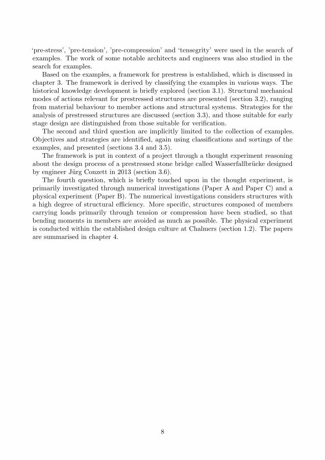
‘pre-stress’, ’pre-tension’, ’pre-compression’ and ‘tensegrity’ were used in the search ofexamples. The work of some notable architects and engineers was also studied in thesearch for examples.
Based on the examples, a framework for prestress is established, which is discussed inchapter 3. The framework is derived by classifying the examples in various ways. Thehistorical knowledge development is briefly explored (section 3.1). Structural mechanicalmodes of actions relevant for prestressed structures are presented (section 3.2), rangingfrom material behaviour to member actions and structural systems. Strategies for theanalysis of prestressed structures are discussed (section 3.3), and those suitable for earlystage design are distinguished from those suitable for verification.
The second and third question are implicitly limited to the collection of examples.Objectives and strategies are identified, again using classifications and sortings of theexamples, and presented (sections 3.4 and 3.5).
The framework is put in context of a project through a thought experiment reasoningabout the design process of a prestressed stone bridge called Wasserfallbrucke designedby engineer Jurg Conzett in 2013 (section 3.6).
The fourth question, which is briefly touched upon in the thought experiment, isprimarily investigated through numerical investigations (Paper A and Paper C) and aphysical experiment (Paper B). The numerical investigations considers structures witha high degree of structural efficiency. More specific, structures composed of memberscarrying loads primarily through tension or compression have been studied, so thatbending moments in members are avoided as much as possible. The physical experimentis conducted within the established design culture at Chalmers (section 1.2). The papersare summarised in chapter 4.
8

2 Examples of prestress usage
This chapter presents examples of prestressed structures found in both nature and intechnics, the part of human activity wherein, by an energetic organisation of the processof work, man controls and directs the forces of nature for own purposes (Mumford 2000).The collection of examples is compiled in order to answer what historic and contemporaryexamples can tell about how prestress have been used. This overview serve as a basis forthe framework for prestress presented in chapter 3.
2.1 Prestress in nature
Prestress is ubiquitous in nature and plays a central role in many vital functions in nature.
A simple, yet essential application of prestress is the turgor pressure in living cellswhich, similarly as a balloon filled with air, gains its structural rigidity when the cell wallis stretched by the pressurised fluid it contains. The turgor pressure, which can be assmall as 0.1–0.4 MPa yet can also exceed 2–3 MPa (a bike tire is around 0.2–0.6 MPa),plays an important role in key processes such as growth, development, mechanical support,signalling, organ movement, flowering and responses to stress (Beauzamy, Nakayama, andBoudaoud 2014; Luchsinger, Pedretti, and Reinhard 2004).
A special case of turgor pressure causing substantial effects can be seen in trees. Thephenomenon, generally referred to as growth stresses, can be large enough to cause signif-icant problems in the conversion of felled trees to timber (Wilkins 1986). Understandingthese stresses provides not only a knowledge of how prestress can be used to overcomematerial weaknesses, but also why timber deform after it has been sawn (bow, crock, cup,twist).
The stresses arise as a response to effectively resist external forces, primarily from wind.Due to the high risk fibre buckling in wood (Boyd 1950), the longitudinal compressivestrength is only about half of the tensile strength. When the growth stresses (fig. 2.1a)and temporary external stresses (fig. 2.1b) are acting simultaneous, a more even utilisationof the wood strength (fig. 2.1c) is obtained and thus a much higher overall load bearingcapacity than if there were no prestress present (Mattheck and Kubler 1995).
(a) Growth stresses (b) Bending stresses (c) Resulting stresses
Figure 2.1: Longitudinal stresses in tree trunk
9

The growth stresses, which are orthotropically distributed (see e.g. Mattheck andTesari 2004), originate when wood cells in the outer part of the trunk contract inthe longitudinal direction and expand in the transverse direction (Munch 1938). Thelongitudinal contraction is restrained by older cells, putting the new cells in tension(Kubler 1987). This causes a compression of the adjacent interior layers that reduces thetension of older cells (Jacobs 1938) leading to severe compression near the pith (fig. 2.1a)(Cassens and Serrano 2004).
A complex application of prestress can also be found in some proteins. The proteinubiquitin has a ‘tensegrity-like pattern of prestress’ and that such knowledge could beused to create tailor made proteins with special mechanical properties for applications inmedicine, material design and nanotechnology (Edwards, Wagner, and Grater 2012, p. 4).The sensation of mechanical forces depends on a continuous, prestressed spectrin proteininside neurons (Krieg, Dunn, and Goodman 2014).
Animals use prestress when building structures. For instance, birds bend grass andbranches as they build their nests, effectively inducing stresses in the members that, withthe help of friction, is restrained against one another and thus kept in place. Spidersprestress their webs (fig. 2.2) in order to make them stiff enough to support the weight ofthemselves and their prey without substantial deflection using a minimum of material(Kullmann, Nachtigall, and Schurig 1975). The induced prestress also effects the sonicproperties of the web which transmits vibratory information to the spider; by alternatingthe tension the spider can tune its web (Mortimer et al. 2016).
Figure 2.2: A typical orb web constructed by an Araneus spider.
Source: Image distributed under CC BY-SA 3.0 licence; https: // commons. wikimedia. org/ wiki/ File:Typical-orb-web-photo. jpg
10

2.2 Prestress in technics
Humans have used prestress to construct objects since prehistoric time, and some ofthe applications are presented in this section. The examples are grouped according tocommon structural characteristics and what the prestress has made possible. The groupsare presented in a somewhat chronological order and with an ambition to showcase aprogress in terms of how advanced the applications are.
2.2.1 Early development: to ensure basic needs
Prestress has since prehistoric time been used to ensure basic needs such as shelter andfood. The design concepts were simple, yet clever enough to make robust joinery andachieve a high degree of material efficiency, resulting in lightweight objects.
Though impossible to date due to its simplicity, tents are one of the oldest exampleswhere prestress has been used. It is plausible that hide was supported by slender branchesrestrained against one-another by the prestress induced as the branches were bent intoplace (active-bending), much like in a bird’s nest. With the development of ropes andtextiles, which also require prestress for their making, the tents developed further intoportable lightweight structures such as the yurt and tipi.
In parallel, boats for fishing and transportation utilising prestress were developed.Boats used in the Arctic and Subarctic zones, dating back at least 10,000 years, had askin membrane wrapped and stretched around a timber frame (Evguenia 2016).
2.2.2 Ancient vessels: to secure the shape
One of the earliest records of an advanced usage of prestress dates back to c. 2,700 BCEin ancient Egypt (Leonhardt 1964). Reliefs depicts boats and barges in which a systemof struts and ropes from stern to bow prevents the vessel from hogging. The ropes wereentwined and by twisting the ropes the level of prestress could be adjusted and, thus, keepthe deck in level (Casson 1971; Torr 1895). The mightiest is perhaps the barge depictedon the wall of Queen Hatshepsut’s temple at Deir el-Bahri. Loaded with two obelisks,each weighing around 375 t, it was towed on the river Nile 213 km from the quarry inAswan to the temple in Karnak (fig. 2.3).
Figure 2.3: c. 1470 BCE Hatshepsut’s barge.
2.2.3 Stretched strings: to store energy and control vibration
A simple strategy to induce prestress is to stretch a string and attach it to an anvil. Thespider web and the Egyptian barges are some of the examples all ready discussed where
11

this strategy is used. The objective is for these structures primarily related to structuralintegrity, that is, the ability to hold together under a load, including its own weight,without breaking or deforming excessively. But the same strategy can be used to achieveother objectives as well.
A stretched string will loose its prestress as soon as it is released from its anvil ina search to minimise the stored energy within it. This phenomenon is utilised in bows,initially developed for hunting but later warfare. By bending the bowstave and attachthe string, strain (deformation) energy is stored in the bow which is further increased asthe archer pulls the string backwards. On release, the bow seek to minimise the energyleading to a rapid acceleration of the arrow which shoots of the bow forward. As thebow were developed, more and more elaborate designs of the bowstave were developedeventually leading to the powerful medieval English longbow with a range of up to 315meters (Oakeshott 1960).
The very same thing happens in sports rackets (Kullmann, Nachtigall, and Schurig1975), with two main differences. First, multiples strings are used in a net instead of asingle string. This provides a large area making it easier to hit the ball with the racket.Secondly, the strings are not deformed by an active pull exerted from the player, but bythe impact energy released upon the collision between the moving ball and racket. Thiscauses more strain energy to be induced in the racket, which is quickly minimised by theconversion into kinetic (movement) energy in the ball which springs off the net.
Similar energy conversion processes takes place in a string instrument such as theviolin, piano or guitar, but the deformations of the strings are smaller. And while thestrings in the bow and racket are tensioned to provide as much energy to the arrow andball, respectively, string instruments are tensioned to be tuned to a specific frequency, ortone. The first natural frequency fn of a stretched string with length L may, assumingsmall displacements, be computed from
fn =1
2L
√T
ρA, (2.1)
where T is the (constant) tension in the string, ρ the density of the string and A itscross-sectional area. As string instruments are played, for instance by plucking or bowing,the musician influences the pitch by pressing the fingertips on the strings, effectivelyshortening the length of the string while the tension in the string is retained. Fromeq. (2.1) it is thus evident that a shortening of L to, say, half its length results in a higherpitch, in this case it is doubled. Equation (2.1) is derived from the partial differentialequation describing the vibration mode at time t of the string
T∂2y
∂x2− EI ∂
4y
∂x4= ρA
∂2y
∂t2,
where y is the lateral displacement of the string at longitudinal position x and EI theelastic bending stiffness—which in this case has been neglected. The equation can beused to derive the Euler buckling formula by setting the right hand side to 0 and solvingfor T , which would then correspond to the critical buckling load usually denoted Pcr.
12

2.2.4 Compressing with weight: to increase stability
The tensile strength of masonry is mainly related to the strength of the joints; whiledry-mortar joints have none, mortar joints have some tensile strength. Regardless of jointtype, its low strength constitutes a challenge, especially if the structure is tall and light.The bending moment due to wind may cause tensile stresses to arise surpassing the tensilecapacity of the masonry. This must of course be avoided, so that the structure doesn’tfall over. According to (Heyman 1966), who introduced a rigorous framework of limitstate analysis applied to masonry structures, the masonry is safe if the thrust line liewithin the cross section for all possible load cases. The thrust line represents the path ofthe compressive resultants of the stresses acting within the structure.
Though the Romans didn’t know about Heyman’s theory, they effectively controlledthe the thrust line by prestressing their masonry structures (Todisco 2016). For example,the attic of Colosseum in Rome, Italy (70–80 CE) adds extra weight to the lower part ofthe wall to counteract wind load causing tensile stresses. At Pantheon in Rome, Italy(118–128 CE), varying density of the concrete together with step-rings were used tofine-tune the thrust line. The Mausoleum of Centcelles in Tarragona, Spain relies on theback fill for its rigidity.
The technique relies on the elaboration of density and weight distributions to controlthe stress state. Later, during the medieval, the technique was refined to enabled theconstruction of Gothic cathedrals, where pinnacles adds weight to steer outward thrustsin the flying buttresses down into the buttresses (fig. 2.4a). Though the loads on heavymasonry buildings can be considered constant, this is not the case in the flying buttresses(Addis 2007). The upper tier of flying buttresses carries primarily wind loads exerted on
(a) Load paths of thrusts from main vault andbuttresses, due to gravity.
(b) Load paths of thrusts due to gravity and windon the roof and the walls.
Figure 2.4: Cross section of the Boruges Cathedral (c. 1230); geometry derived from(Bork 2014) and load paths adopted from (Addis 2007).
13

the roof, and their size and weight need be only the minimum necessary to perform thisfunction (fig. 2.4b). For structural analysis of flying buttresses based on the strength ofmaterials concepts, see (Quintas 2016).
Similarly, the grass and stone roofs of traditional timber houses, such as the Swedishfabod, contributes with additional weight preventing the logs from separating at the bedjoints when the building is subjected to overturning wind loads.
A more recent example, designed by structural engineer Peter Rice, is the Pavilion ofthe Future (fig. 2.5). Rice used a series of tie-rods to lift up the weight of an adjacentroof and apply it radially to the stone arches of the facade (Addis 1994; Lenczner 1994;Rice 1996). The originally catenary shaped thrust line was in this way transformed intoa more semi-circular trajectory that can be contained within the structural depth. Byadjusting the level of post-tensioning force, the intensity of the thrust can be controlledto compensate for the low self-weight of the arch and reducing the sensitivity for varyinglive loads imposed by wind and earthquake.
Figure 2.5: Elevation of parts of the facade of Pavilion of the Future, Seville (1992).
2.2.5 Joining timber members: to increase span width
Joints under tension are more troublesome to design than joints under compression sincethey risk to separate. In bio-mechanical structures, for example where bone and tendonsor tendons and muscles are joined, this is solved by an intergrown transition between theparts (Benjamin et al. 2006). But such solutions are hard to obtain in technics and othersolutions have been developed and many can be found in timber structures.
14

Timber has been used for thousands of years and a vast range of methods along withsuitable tools have been developed to join timber members together (Zwerger 2000). Fora long time, mechanical joints dominated, but today adhesives are widely used in fingerjoints, glulam beams, cross laminate timber panels and for glue-in metals rods and plates.Most mechanical joints requires some kind of weakening in the timber, for example notchesto fit wedges or holes for dowels, bolts and screws. Adhesive joints requires large enoughsurface areas for the transmission of forces. Without proper care, these joints may lead tolocal stress concentration (G. Larsson, Gustafsson, and Crocetti 2017) easily exceedingthe strength limit of the timber causing failure.
A common traditional joinery technique developed before metal fasteners were readilyavailable is the usage of wedges, for example as in joint f in fig. 2.6 (Krauth and Meyer1893). As the wedge is driven in between the members, it pushes the members apartand locks the connection by means of friction and a prestressing normal force. Thetechnique enabled the construction of large span timber structures (James 1982) of whichsome of the most notable designs were made by members of the Grubenmann family inSwitzerland (Brunner 1921, 1924; James 1982; Killer 1942; Weinand 2016).
Figure 2.6: Various types of lapped joint designed to transfer tension between two members.Published in (Krauth and Meyer 1893).
The Grubenmanns engaged in large span roof trusses, but are perhaps most famousfor their bridges, especially one erected by the Grubenmann brothers Johannes (1707-1771) and Hans Ulrich (1709-1783) at Wettingen in 1765 (fig. 2.7). The bridge arousedadmiration of their contemporaries almost immediately and were, partly due to theexplosion of architectural research, travel and publication starting in the 1750s (Bergdoll2000), already widely known in 1770 (Angelo and Maggi 2003). The novelty of the bridgewas the use of timber arches as the primary load bearing structure (S. Samuelsson 2015);prior to the Wettingen bridge only polygon shaped arches had been used. The arches, oneat each side of the bridge deck raising 7.5 meters, were made of a lamination of severallayers of heavy oak timber members wrapped by iron straps. Depending on source, six,
15

seven or eight layers were used (James 1982). The timber members had notches andsloping surfaces along their lengths, and wooden wedges were put at each notch (Killer1942). As the wedges were installed, the members slipped against one another causing aprestress both locally and at the iron straps which were tightened (fig. 2.8), altogetherensuring a high degree of composite action of the arch. Recent studies has provided someinsights into the design and analysis of straight beams laminated using wedges (Miller2009).
Figure 2.7: Wettingen brucke (1765) by J. and H. U. Grubenmann.
(a) Before installation of wedges. (b) After installation of wedges.
Figure 2.8: Laminated timber beams using wedges and metal wraps.
Little more than half a century later, the timber building technology took a new leapforward when Stephen Harriman Long (1784-1864) in 1829 completed the ‘Jackson Bridge’in the U.S. The railway timber truss bridge was patented (fig. 2.9; Long 1830) and hadshape similarities with one depicted in (Navier 1826). The patent contained an importantclaim about the ‘counterbraces’, which normally would have been in tension, but bythe use of wedges were prestressed into compression, thus avoiding tension connections(Gasparini and Provost 1989). The patent also introduced mathematical principles ofengineering to American bridge building that prior to this had relied upon empiricalmethods (Christianson and Marston 2015). Long continued to file for patents for variationsof his bridge design. In the (Long 1839) patent, he had altered the connection detailputting the wedge between the chord and the vertical rendering compression in theverticals and tension in the diagonals (Gasparini and Provost 1989).
Long’s 1830 and 1839 patents defined the two basic designs for parallel-chord trusses.Even though the contemporary German Carl Culmann devoted many pages to Long’sbridges in a paper (Culmann 1851), Long’s contribution was not widely recognised becauseof the rapid changes that occurred in material technology between 1840 and 1870. Bysubstituting vertical members of timber with iron, William Howe’s 1840 patent (fig. 2.10;Howe 1840) facilitated prestressing and eliminated the main weakness in Long’s trusses,quickly making Long’s 1830 design obsolete (Christianson and Marston 2015). Thomasand Caleb Pratt’s 1844 patent (fig. 2.11; T. W. Pratt and C. Pratt 1844) made Long’sfirst 1839 design practical through the use of pre-tensioned iron diagonals and counters(Sutherland 1997).
16
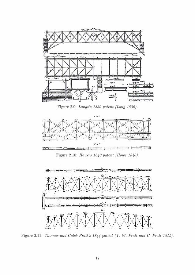
Figure 2.9: Longs’s 1830 patent (Long 1830).
Figure 2.10: Howe’s 1840 patent (Howe 1840).
Figure 2.11: Thomas and Caleb Pratt’s 1844 patent (T. W. Pratt and C. Pratt 1844).
17

2.2.6 Post tensioned timber frames: for improved ductility
The prestressed timber trusses discussed in section 2.2.5 were indeed post-tensioned, butsuch timber and timber-iron structures are nowadays superseded by better performingsteel and concrete structures. However, there has recently been a renewed interest inpost-tensioned timber (e.g. beams (D’Aveni and D’Agata 2017; McConnell, McPolin, andTaylor 2014), stress-laminated decks (Ekholm 2013; Oliva et al. 1990)) with post-tensionedframes perhaps being the most promising.
An early example, completed in 1995, is the post-tensioned bridge in Mursteg, Austria(fig. 2.12) by Jurg Conzett (S. Samuelsson 2015). The bridge has a 47 meters span, whichconnects a variety of routs in an almost urban situation, and is made of glue laminatedtimber beams and built-up timber panels. The decision to create a Vierendeel like truss
Figure 2.12: Bridge in Mursteg (1995).
18

with displaced shear panels from the central longitudinal axis, offered not only spatialpossibilities to create multiple routs across the bridge, but also made it possible to fixthese elements to the chords using simple connections with screw rods and ductile dowels(Conzett, Mostafavi, and Reichllin 2006; Federation internationale du beton 2005). Atmid-span, where a 23.8 meters wide ‘window’ sits disabling any shear connection betweenthe upper and lower chord, the bridge is very flexible. To compensate for the lack ofstiffness inherent in the structure and thus avoiding large deformations, Conzett has placeda post-tensioned steel tendon in the centre of the lower glulam chord which counteractsthe tensile forces in the timber .
Since 2005, the concept of post-tensioned timber frames have been investigated further(Palermo et al. 2005), taking advantage of un-bonded post-tensioned steel tendons passingthrough internal ducts through timber members to create moment-resisting connections(Granello et al. 2018). In New Zealand a system know as Pres-Lam, where the tendonpasses through timber box beams, frames, or walls, have been developed at the Universityof Canterbury (Buchanan, Deam, et al. 2008; Newcombe 2011) and built (Buchanan,Palermo, et al. 2011; Curtain et al. 2012). The system usually requires steel fastenersin the beam-column joint to protect the timber that is loaded perpendicular to grain(Granello et al. 2018). To overcome this, a system called Flexframe using hardwoodreinforcement (ash wood) of glulam beams with internal tendons has been developed inSwitzerland and a prototype building, named the ETH House of Natural Resources, waserected in 2014 (Granello et al. 2018; Wanninger and Frangi 2014, 2016; Wanninger 2015).Regardless of system, the post-tensioned timber frames have shown favourable seismicbehaviour, being able to prevent residual deformations after earthquakes (Wanninger andFrangi 2014).
2.2.7 Prestressed wheels: to make them light and stiff
The concept of the wheel is simple, but making a rigid yet lightweight wheel, that canwithstand the forces and wear exerted as they are used, is a challenge. A solid disk wouldwork as a wheel, but is heavy. By dissolving the disk into discrete elements, weight canbe reduced but then joinery becomes an issue as well as the potential risk of buckling anyof the elements if they are compressed too much.
Traditional wooden wagon wheels are made of a hub, spokes and rim segments thatare bound together on the exterior of the rim. Early constructions relied on wet rawhidefor the binding which would shrink whilst drying, compressing and binding the woodworktogether. Later the wheels where either fitted with an iron hoop or straked with iron,compressing the woodwork and protecting against wear from the ground (fig. 2.13). Usinghoops for the binding of wheels has similarities with barrels consisting of wooden stavesbound by wooden or metal hoops.
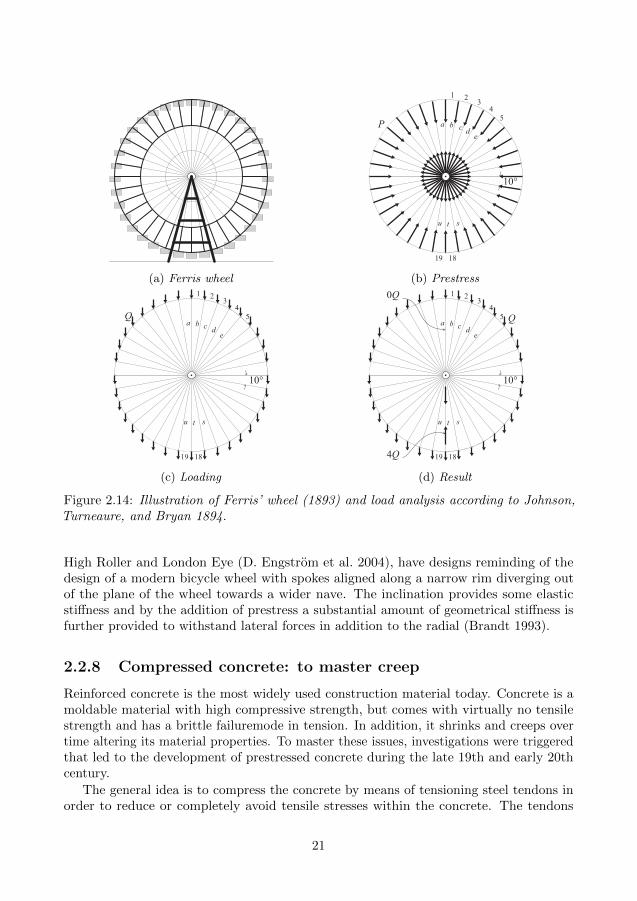
Another kind of wheel is the Ferris wheel. In the shadows of Eiffel’s tower for the1889 Paris Exposition, George Washington Gale Ferris Jr., a 33-year-old engineer fromPittsburgh, U.S., suggested to build a huge revolving iron wheel for the 1893 WorldColumbian Exposition in Chicago. U.S. After thorough design work and testing, muchpaid for by Ferris himself, the 76 meter wheel with 36 cars, each designed for sixtypersons on a two-revolution twenty-minute ride, was approved and built. Ferris’ wheel
19

Figure 2.13: Plate depicting two methods of shoeing a wheel. In the centre the labourersare using hammers and ”devils” to fit a hoop onto the rim, and on the right they’rehammering strakes into place. Published in a volume of Encyclopedie in 1769 Diderotand Rond d’Alembert 1769.
had an inner layer of cable spokes connected to an outer layer of bars and was prestressedby post-tensioning the cable spokes (fig. 2.14a). Ferris’s wheel has not survived untiltoday, but the Wiener Riesenrad in Vienna, Austria, built just a few years later in 1897(Kullmann, Nachtigall, and Schurig 1975), has a similar structure and is still operating.
Until this point, designers of prestressed structures understood the concept sufficientlyand applied it ‘effectively and safely, albeit without analyses based on structural mechanics’(Gasparini, Bruckner, and Porto 2006, p. 418). Johnson, Turneaure, and Bryan 1894presented, in their third edition of the book The theory and practice of modern framedstructures – Designed for the use of schools and for engineers in professional practice,an early and realistic mathematical model for the analysis of the effects of prestressing,live load and the sum of all in the context of a Ferris wheel. Assuming linear relationsthey showed, by superposition of load cases and a symmetry argument, that the prestressforce P in each cable (fig. 2.14b) has to be twice the weight of each car Q (fig. 2.14c),i.e. P = 2Q. Then there will be 0 force in cable a and the maximum tensile force 4Qwill occur in cable t (fig. 2.14d). This can be compared to the case without prestressingwhere the cables are replaced with bars that can take compression. Then a maximumcompression force of 5.68Q occurs in bar a and a maximum tensile force of 11.48Q in bart.
Since the original Ferris’ Wheel, a large number of successors have been constructed,one taller than the other. The High Roller in Las Vegas, U.S. is since 2014 the tallestreaching a height of 167.6 meters. With few exceptions, all Ferris wheels rely on prestressto carry the load from the rim to the nave effectively. Many Ferris wheels, such as the
20
(a) Ferris wheel
10°
a
1
1819
2 34
5
tu s
b c de
P
(b) Prestress
10°
a
1
1819
2 34
5
tu s
b c de
Q
(c) Loading
10°
a
1
1819
2 34
5
tu s
b c de
Q
4Q
0Q
(d) Result
Figure 2.14: Illustration of Ferris’ wheel (1893) and load analysis according to Johnson,Turneaure, and Bryan 1894.
High Roller and London Eye (D. Engstrom et al. 2004), have designs reminding of thedesign of a modern bicycle wheel with spokes aligned along a narrow rim diverging outof the plane of the wheel towards a wider nave. The inclination provides some elasticstiffness and by the addition of prestress a substantial amount of geometrical stiffness isfurther provided to withstand lateral forces in addition to the radial (Brandt 1993).
2.2.8 Compressed concrete: to master creep
Reinforced concrete is the most widely used construction material today. Concrete is amoldable material with high compressive strength, but comes with virtually no tensilestrength and has a brittle failuremode in tension. In addition, it shrinks and creeps overtime altering its material properties. To master these issues, investigations were triggeredthat led to the development of prestressed concrete during the late 19th and early 20thcentury.
The general idea is to compress the concrete by means of tensioning steel tendons inorder to reduce or completely avoid tensile stresses within the concrete. The tendons
21

used to compress the concrete are usually embedded—bonded or un-bonded—within theconcrete section, but there are some rare cases where externally located tendons havesuccessfully been used as well. The effect of prestressing is un-cracked concrete sections,with higher flexural capacity, greater resistance to corrosion and better liquid retainingproperties compared to cracked reinforced concrete sections. Furthermore, it improves theshear resistance and makes it possible to reduce the cross sections with savings in materialsand weight as a result (Kaylor 1961). But most importantly, prestressed concrete enableslonger spans and offers a way to control creep deformations.
A short summary about the development of prestressed concrete follows, primarilybased on (Leonhardt 1964; Menn 1990; Sanabra-Loewe and Capella-Llovera 2014) andto some extent (B. Engstrom 2011; Haegermann, Huberti, and Moll 1964; Hellstrom,Granholm, and Wasterlund 1958).
The concept of prestressed concrete started to be investigated in the late nineteenthcentury. Peter H. Jackson received in 1886, preceded by at least three patents for systemsof applying prestress to building construction, the first patent on prestressed concretein which tie-rods were used to compress the concrete (Jackson 1886). It was followed bya number of patents by others over the next coming four decades, for example one bythe Norwegian Jens Lund (J. G. F. Lund 1912), however few of these systems had anypractical application. It was only when the french engineer Eugene Freyssinet (1879-1962)recognised the full potential that the concept became applicable at large scale.
In 1907 Freyssinet built a reinforced concrete bridge across the Allier river in France.Jacks were used at the crown of the three-hinge arches for easy removal of the formwork.The jacking also helped to avoid initial deflections due to elastic deformations. However,soon after completion, creep, at that time a little-known phenomenon, caused a 130 mmdeflection. Again jacks were used to restore the original profile and the gap was concretedturning it into a two-hinged arch. By using the jacks, Freyssinet effectively induceda prestress in terms of a compressive thrust acting within the concrete in the bridge.The same method was later used for the 1934 Traneberg bridge (fig. 2.15) in Stockholm(Kasarnowsky 1936).
Figure 2.15: Traneberg bridge, Stockholm (1934)
Source: Holger Ellgaard (2008); image distributed under CC BY-SA 3.0 licence; https: // commons.
wikimedia. org/ wiki/ File: Tranebergsbron_ panorama_ 2008. jpg
The deflection phenomenon observed at the Allier bridge made Freyssinet, beginningin 1911, study the subject of creep in concrete. It eventually lead to a number of patentsin 1928 where he stressed the importance of having full prestressing in the steel, that is,
22

prestressing to such a level that all tensile stresses in the concrete are removed underservice load, to prevent creep. His design philosophy dominated the prestressed concreteindustry for many years. It eventually became clear, however, that full prestressing wastoo restrictive and uneconomical. In 1946, P. W. Abels made an argument about theadvantages of reducing the prestress in the tendons and to combine prestressed tendonswith unstressed tendons. Ables showed that you could achieve approximately the sameload-carrying capacity for fully prestressed and partially prestressed beams. Since thelate 1960s, partial prestressing is the dominating design philosophy where resistance atultimate limit state is determined considering both prestressing steel and mild reinforcingsteel.
During the late 1940s, the Swedish company Strangbetong AB successfully implementedand developed a system based on a patent by German E. Hoyer. By pre-stressing thinhigh-strength steel wires, cast the concrete, let it harden and then release the jacks, theconcrete is set into permanent compression (Hellstrom, Granholm, and Wasterlund 1958).
Prestress is however not only applied to new concrete structures. With ageing concretestructures comes a need to enhance the performance of existing buildings and bridgesto prolong their technical lifespan. Since the early 1990s investigations have been maderegarding post-tensioned externally bonded carbon fibre reinforced polymers to improvethe performance of existing concrete structures. The increased performance can be seen interms of increased elastic bending stiffness, smaller crack openings and improved ultimatecapacity (Yang 2019).
2.2.9 Pneumatic structures: for form stability
Nature provides rigidity, or form stability, to biological structures by the use of fluidpressure (Luchsinger, Pedretti, and Reinhard 2004) and air can be used in the same wayfor man-made structures. The balloon is a simple example, where the gas pressure pushesthe enclosing membrane outwards. As the membrane is stretched, it gains geometricstiffness making it stiffer. The sports ball can be seen as a special type of balloon. It isdesigned to, when bounced, transform its kinetic energy into strain energy which, due tothe geometric stiffness, again is transformed into kinetic energy when it springs off fromthe ground or racket.
Much work in the exploration of the potential of pneumatic structures, also beyondarchitecture, was done by Frei Otto beginning in the 1960s leading to several IL publicationson the theme (IL12: Convertible Pneus 1975; IL15: Lufthallenhandbuch 1983; IL9: Pneusin Natur und Technik 1977; Otto 1995). At the Expo’ 70 in Osaka, many pioneeringpneumatic buildings were shown, but since then no substantial development has beenmade other than the use of the airhouse to cover tennis courts and large sport arenas(Luchsinger, Pedretti, and Reinhard 2004). Pneumatic structures are however often usedas components of building envelopes, such as the ETFE foil cushions used at the EdenProject (2001) in the UK, the Beijing Olympic Aquatics Centre (2007) and Roof AnnexLutherhaus (2010) in Germany (fig. 2.16; Liu, Zwingmann, and M. Schlaich 2015). In thelatter, the cushions are supported by slender circular steel beams which in turn are cablesupported both below and above themselves to withstand gravity and wind uplift.
There are also examples of where balloons, or pneus as Frei Otto called them, have
23

Figure 2.16: Lutherhaus, Germany (2010). Pressurised transparent foil cushions supportedby cable supported steel beams.
Source: Copyright schlaich bergermann partner. Reproduced with permission.
been used as load bearing components (Otto 1995). For instance, the patented Tensairitysystem in which a long slender balloon is used to provide stiffness to plates used as beamsor bridges (Luchsinger, Pedretti, and Reinhard 2004; Pedretti and Luscher 2007). FIDU– Freie Innen Druck Umformung, or internal pressure-forming, have been developed atCAAD, ETH Zurich leading to the construction of a 6 meters long steel-skin balloonbridge weighing 170 kg with a capacity to hold a load of up to 1,800 kg (Zieta, Dohmen,and Teutsch 2008).
2.2.10 Prestressed cable nets: for form stability and transparency
The most material efficient way to carry a load is by tension. But a single cable looselyhung between two supports has virtually no stiffness and easily changes shape for only thesmallest pertubation. If the cable is stretched, it gains geometric stiffness and withstandspertubations with very little change in its form. A network of several such cables haseven higher form stability, and the spiderweb is an example from nature of such. If givenan anticlastic shape (curved in two opposite ways; saddle-shaped), the cable net becomeseven stiffer.
24

A typical application of prestressed cable nets are roofs covering cover large areas.There are, for instance, evidence suggesting that ropes supported textiles covering thestands at the Colosseum in Rome, Italy (70–80 CE). But it took until the 1950s until anymajor advancements in the constructions of cable roofs took place (Krishna and Godbole2013) and a collection of cable roof structures built until 1975 is presented in (Kullmann,Nachtigall, and Schurig 1975). The Dorton arena (1953) in Raleigh, U.S. is often, eventhough there are a some earlier examples, seen as the turning point after which substantialprogress have taken place in the advancement of cable roof structures (fig. 2.17).
Figure 2.17: Dorton arena (1953). Drawing (left) and view from inside (right).
Source: Photos are courtesy of the N.C. State Fairgrounds.
Since then, similar roofs have been built, for example the arena Scandinavium (1971) inGoteborg, Sweden (Karrholm and A. Samuelsson 1972) and the London 2012 Velodrome(Arnold et al. 2011). In these examples, the cable net is post-tensioned against a ringsituated along the perimeter of the roof which together forms an auto-equilibrated system.And while the cable net gains geometric stiffness due to the pre-tension, the ring loosesgeometric stiffness due to pre-compression and has to be designed to resist buckling.
Cable roof structures can not be discussed without mentioning Frei Otto. He devotedhis doctoral dissertation — ‘Das hangende Dach’ (‘The hanging Roof’) — to such structures(Otto 1954) and founded the Institute for Lightweight Structures (IL) at the University ofStuttgart which he directed from 1964 to 1994 (Aldinger 2016). At IL, extensive work wascarried out regarding hanging roof structures (Kullmann, Nachtigall, and Schurig 1975).The work was closely linked to the form finding of compression shells, which can be seenas an inverted hanging chain (Hennicke and Schauer 1974; I. Liddell 2015), eventuallyleading to the design of the 1975 Mannheim Multihalle (Burkhardt et al. 1978; Happoldand W. I. Liddell 1975; Vrachliotis 2017). One of Otto’s major contributions is the workon the design of the 1972 Olympiastadion in Munich (fig. 1.1; Tomlow 2016). On thedesign team was also, among others, Jorg Schlaich and Rudolf Bergermann, who sincethen at their own practice schlaich bergermann partner (SBP) have contributed to thedevelopment of prestressed cable net structures (M. Schlaich 2018).
Due to the efficiency of the nets, almost transparent structures can be constructedwhich still can withstand large forces. The spiderweb is once again a good example fromnature, and from techniques there is the 25× 40 meters glass facade for the Hilton Hotel(1993) at Munich Airport (Schober and Schneider 2004). The facade, which is designed
25

by SBP, consists of horizontal and vertical cables spanning between the building’s twowings as well as between the ground and roof trusses, forming a planar net with a meshsize of 1.5× 1.5 meters. The glass panels are hung at the intersections of the net usingclamp plates which also secures the cables to one another. The cable net is prestressed,similarly as a tennis racket, providing geometric stiffness that reduces the out-of-planedeformations of the net, which under wind can be up to 90 centimetres at the centre ofthe facade (Barkhofen and Bogle 2010).
2.2.11 Restrained arches: to avoid buckling
The cable roofs are often provided with a sturdy rim which provides a stiff anvil for thetensile forces acting within the roof surface. But one can also do the opposite, lettingthe cables provide stiffness for the rim. By connecting cables to an arch or a ring, thestructure’s mode of action is transformed from in-plane bending to a combination ofbending and truss action. This is an effective approach where the reduction of weight is ofbig importance, as in transverse bracing of Zeppelines compensating for the lifting forcesat the upper ring half and the load forces at the lower ring half (Kullmann, Nachtigall,and Schurig 1975). There are similarities with how the bicycle wheel the and Ferris wheelwork (section 2.2.7) enabling the use of very slender lightweight load bearing components.Therefore the approach is well suited for the construction of glass roofs.
A pioneer on lightweight shell structures was Vladimir Shukhov (M. Wells 2010),who stiffened the glass roof of the Moscow GUM department store (1890-1893) and thePushkin Museum (1898–1912) using cables springing from the ends connecting once tothe arch (Graefe and Tomlow 1990). Eugene Freyssinet used the same topology for thecables stiffening a 7.5 meters wide mobile timber frame on which slipform plywood mouldscould slide used for the construction of the Orly airship hangars outside Paris in 1923(fig. 2.18a; Frampton 2007; Frampton and Futagawa 1983). More recently, Peter Ricelet, for the glass roof of the bus terminal in Chur, Switzerland (1988), all cables radiatetowards the roof arch from a central nave located just above the focal point of the arch(Addis 1994; Rice 1996). Jorg Schlaich used the same principle for the glass roof at the1989 Museum of Hamburg History (Barkhofen and Bogle 2010) and later reused the ideafor the glass roof at the 1998 DZ-Bank in Berlin (J. Schlaich, Schober, and Helbig 2001).
These cable typologies are effective in restraining the arch, however, the cables interfere
(a) Orly Hangar (b) Berlin Hauptbahnhof (c) Japan Pavilion
Figure 2.18: Examples of topology of cable systems for the stiffening of arches (not toscale).
26

with the space below. For the design of the shallow glass roof covering the upper traintracks and platforms of Berlin Hauptbahnhof (2006) another cable topology was sought.Here Jurg Schlaich let a post-tensioned cable trace the tension side of the moment diagramof the supporting arches leaving enough space below (fig. 2.18b; “Berlin Hauptbahnhof –Lehrter Bahnhof” 2005). The cable and arch are connected using compression struts andcable bracing (Falk and Buelow 2009). Another example is the Japan Pavilion at Expo2000 where Shigeru Ban, who collaborated with Frei Otto on the project, let the cablesspring from the ends and connect multiple times to the arches (fig. 2.18c; Ban 2000).
The degree of prestress in these systems is rather low, just enough tensile stress isinduced to make sure that the cables never run slack which would cause them to loosetheir stiffness completely. Such a loss would lead to an increase of the buckling length ofthe arch, making it more susceptible to instability phenomenons.
2.2.12 Principles for equilibrium: stressed for stability
While the examples in section 2.2.4 are examples of extenrally-equilibrated structures,Wasserfallbrucke (2013) by Swiss engineer Jurg Conzett is an example of a auto-equilibrated-strucutre (fig. 2.19). The bridge sits along a trail that at times takes hikers throughnarrow gorge landscapes just along the river Flem and at others offers panoramic viewsof the alps. It consists of a shallow semi-circular arch made from locally quarried gneiss,has a span of 18 meters, a rise of 1 meter and a cross sectional depth of 0.2 meters. Twosteel plates are placed on top of the arch to which the handrail is welded. The plates arepost-tensioned against the stone arch with initially a force of 400 kN each, but now it isexpected to have decreased to 85 % of the initial value due to relaxation1. The effect ofpost-tensioning the steel plates is the exertion of a uniformly distributed radial actingload on the stone arch in a similar manner as in Pavilion of the Future.
Figure 2.19: Wasserfallbrucke, Flims (2013).
Source: Photo courtesy of Linnea Jansson.
1E-Mail correspondence with Jurg Conzett, 7-8 November 2018.
27

Another example is the stone arches supporting the roof of Padre Pio PilgrimageChurch (2004) in San Giovanni Rotondo, Italy. Here the arches are not semi-circular, butcatenary shaped with deeper cross-sections at the base than at the crown. The arches arestable under normal service conditions (Rice 1996), yet they are prestressed by means oftwo internally placed steel tendons similarly as in fig. 1.2c. Their purpose is to ensure thestability of the structure during earthquakes which, due to large dynamic forces, otherwisewould impose tension at the joints in-between the stones forming mechanism that couldlead to collapse.
So far upright standing masonry arches have been discussed, where gravity in combina-tion with prestress sets the arch in compression. It is, however, with the use of prestresspossible to construct upside-down masonry arches. By providing enough pre-compressionto the stone arch it can be ensured that the tension stress caused by gravity and liveloads dose not put the joints under tension. One such example is Conzett’s bridge Puntda Suransuns (1999) in Thusis, Switzerland (Conzett 2012). The pedestrian bridge is sus-pended 40 meters between rock anchored foundations and is thus externally-equilibrated.Prestress was applied by post-tensioning two steel plates placed under the stone archupon which you walk, effectively raising the pathway and compressing the stones together(Conzett, Mostafavi, and Reichllin 2006). Over time, steel relaxes and (M. Wells 2010)argue that the loss in this case is substantial so that the stiffening effect of the prestressis more or less lost.
2.2.13 Tensegrity: for material efficiency
Tensegrity structures offers perhaps the most sophisticated use of prestress. Tensegritystructures are mechanical pin-jointed structures which consist of simple dedicated members,that is compressed struts and tensioned ties (Wroldsen 2007). Through the clear distinctionbetween compression and tension, tensegrities gain a high mechanical efficiency (Ashwear2016). The prestress induced is necessary to remove mechanisms and thus ensuring therigidity of the structure. The word tensegrity, which is a contraction of tensile andintegrity, was coined by Buckminster Fuller in a patent (Fuller 1962). There is, however,a dispute regarding the true inventor and the origins of the idea (Snelson 2012), but theartist Kenneth Snelson’s X-Piece structure from 1948 (fig. 2.20) is generally regarded asthe birth of the tensegrity concept (Tibert 2002). A more extensive exploration of theorigins of the concept is provided through a series of articles and responses in a specialissue of International Journal of Space Structures (Lalvani 1996).
Definitions
There is no consensus on the definition of tensegrity structures. Fuller defined in hispatent tensegrity as ‘an assemblage of tension and compression components arrangedin a discontinuous compression system...’ (Fuller 1962). In line with Fuller, (Pugh1976) extends the definition stating that ‘a tensegrity system is established when aset of discontinuous compressive components interacts with a set of continuous tensilecomponents to define a stable volume in space.’ (Hanaor 1994) highlights the needfor prestress by defining tensegrity as ‘internally pre-stressed, free standing pin-jointednetworks, in which the cables [...] are tensioned against a system of bars [...].’ (Skelton
28

Figure 2.20: Illustration of Early X-Peice (1948) by Kenneth Snelson
et al. 2001) defines a class k tensegrity structure as ‘a stable equilibrium of axially-loadedelements, with a maximum of k compressive members connected at the node(s).’ (Motroand Raducanu 2003) employ a rather strict definition with for example limitations onelement size: ‘Tensegrity systems are spatial reticulate systems in a state of self-stress. Alltheir elements have a straight middle fibre and are of equivalent size. Tensional elementshave no rigidity in compression and constitute a continuous set. Compressed elementsconstitute a discontinuous set. Each node receives one and only one compressed elements.’Miura and Pellegrino interprets a tensegrity structure as ‘any structure realised fromcables and struts, to which a state of prestress is imposed that imparts tension to allcables’ and adds that ‘as well as imparting tension to all cables, the state of prestressserves the purpose of stabilising the structure, thus providing first-order stiffness to itsinfinitesimal mechanisms’ (Tibert 2002; Tibert and Pellegrino 2003a).
Many definitions limit the possible element types to use to networks of struts and ties.However, relying on Fuller’s more poetic definition of tensegrity ‘islands of compression ina sea of tension’ (Safaei 2012), one could argue that other kinds of element are possibleto use in a tensegrity structure (Motro and Raducanu 2003), such as continuous fabricstretched against discontinuous struts.
Some examples
Kenneth Snelson devoted much of his life to tensegrity, leading to an amazing collectionof artwork exhibited in different parks and museums, many depicted in his book Artand ideas (Snelson 2013). Cecil Balmond has also made use of the concept in 2006 forhis H Edge structure (fig. 2.21; Balmond 2007). In 2003, Snelsson’s record of highesttensegrity structure was ousted by the 62.3 m tensegrity tower in Rostock, Germanydesigned by SBP relying on pre-tension forces up to 1,100 kN for its rigidity (M. Schlaich2004).
The tensegrity concept has shown hard to implement in its pure form — if there is
29

Figure 2.21: H Edge (2006) by Cecil Balmond.
Source: Image reproduced by permission of BALMOND STUDIO; http: // www. balmondstudio. com/
news/ history-of-h_ edge. php
such a thing — within architecture and civil engineering (M. Schlaich 2004). However,there are structures that have tensegrity-like features, such as large domes, temporarystructures, tents (Safaei 2012) and stadium roofs but also glass facades and roofs (cf.section 2.2.10). Both the Olympiastadion in Munich (fig. 1.1) and the Millennium Dome(1999) by Richard Rogers and Buro Happold (fig. 2.22; I. Liddell and Westbury 1999) aresuch examples with their tensile membranes, cables and so-called flying masts (Wroldsen2007). The concept has also inspired bridge designs, such as the Royal Victoria DockBridge (1998) in London, UK by Techniker and Lifschutz Davidson, and the KurilpaBridge (2009) in Brisbane, Australia by Ove Arup & Partners.
Examples of facades with tensegrity features were designed by Rice Francis Ritchie(RFR) (Rice 1996), who during the 1980s were considered the best engineering firm inglassed tensed structures worldwide (S. Samuelsson 2015). With the Glass Walls (LesSerres) at the Parc de la Villette, Paris (1982-86) in their portfolio (Patterson 2011), RFRwere consulted for the design of the Grand Pyramid (1989) and the Inverted Pyramid(1993) at the Louvre in Paris (fig. 2.23). Architect Ieoh Ming Pei asked the engineersto create a ‘structure as transparent as technology could reach’ (Knoll 1989; NCK n.d.).The Grand Pyramid consists of steel beams stiffened by post-tensioned steel cables andcompression struts. These are placed in two directions parallel to the pyramid edgesto support the glass panels and handle the wind pressure. To handle wind suction, thepyramid has been equipped with several horizontal cable rings redistributing suction forcesfrom one side of the pyramid to the opposite (D. Engstrom et al. 2004). The InvertedPyramid takes advantage of structural glass and post-tensioned rods rendering the needfor a supporting frame unnecessary.
More successfully, the tensegrity concept has been applied within art and furnituredesign, leading to lightweight new designs. It can also be used to understand biomechanics
30

Figure 2.22: Millennium Dome, London, UK (1999) by Richard Rogers and Buro Happold.
Source: James Jin (2004); image distributed under CC BY-SA 2.0 licence; cropped and black and white;https: // www. flickr. com/ photos/ 44768990@ N00/ 58712717
Figure 2.23: Grand Pyramid (1989; left) and Inverted Pyramid (1993; right) at the Louvre,Paris.
Source: Babyaimeesmom (2018); image distributed under CC BY-SA 4.0 licence; cropped and convertedto black and white; https: // commons. wikimedia. org/ wiki/ File: Louvre_ Palace. jpg . Lucas Lima(2017); image distributed under CC BY-SA 2.0 licence; cropped; https: // www. flickr. com/ photos/
lucasnave/ 34167423466/
and biology inspiring developments in robotics (Ashwear 2016; Safaei 2012). It is, due tothe lightweight nature of the structures and the possibility to unfold them by adjustingthe length of cables, applied in the design of deployable space structures (Tibert 2002).
31

32

3 Framework for prestress
Building on the collection of examples presented in chapter 2, this chapter proposesa framework for prestress in a search for answers to the first three research questions(section 1.3). This is done using various ways of classifying the examples, so that similaritiescan be identified and differences be distinguished. In the “1970 Key speech”, Ove Arupnoted that though classification is ‘arbitrary and rough’, it ‘may nevertheless be usefulas a help for understanding and discussion, if its imperfections and incompleteness areborne in mind’ (Arup 1985, p. 34).
The first three classifications are related to the first question about what historic andcontemporary examples tell about how prestress have been used. The first classificationsorts all examples chronologically to provide an understanding of how the concept ofprestress has been used over time. The time line is in addition divided into four agesenabling the exploration of the overall knowledge development and related challenges ateach given time. The second classification takes its departure in structural mechanicalmodes of action to provide an understanding of how prestressed structures work. Threelevels are considered: material behaviour, member action and the assembled structure.The third classification concerns strategies for the analysis and design of prestressedstructures. Strategies suitable for early stage design are distinguished from those suitablefor verification at the end of the design process.
The fourth classification seek to derive general objectives with prestressing, pursuingto clarify what it means to improve the performance and make a structure more efficient.
The fifth classification is made to be able to propose design strategies for how prestressis achieved.
The chapter is ended with a thought experiment about the design of the Wasser-fallbrucke (recall fig. 2.19) where some of the aspects discussed in the chapter arehighlighted in the context of the bridge.
3.1 Historical knowledge development
Regardless of the objective for using prestress the usage requires knowledge about materials,structures, design, analysis and construction. The state of the art is the sum of a historicaldevelopment of knowledge and (Sanabra-Loewe and Capella-Llovera 2014) suggest thatthe historical evolution of prestressed structures can be understood through four maindesign ages, or phases (table 3.1): I. Intuition, II. Optimistic engineering, III. Strugglingto minimise losses, and IV. Effective prestressing. This approach gives an understandingof the level of knowledge and related unsolved challenges at a given age.
It also gives an insight of how the knowledge has been used and it is possible todistinguish between qualitative and quantitative approaches. During all ages, qualitativeapproaches have been used, which is characterised by a conceptual understanding ofthe physical phenomenons. For example, one may know that stretching a rope willmake it stiffer, but can not predict how much stiffer it will get. As time evolved,quantitative approaches was developed, which are characterised by mathematical modelstargeted to describe aspects of the physical phenomena. This is done by combining
33

Table 3.1: Four ages of prestress according to (Sanabra-Loewe and Capella-Llovera 2014)with related examples.
Age Examples
I. IntuitionBenefits of prestress understood intuitive by de-signer
Tents (section 2.2.1), bows (section 2.2.3),Gothic cathedrals (section 2.2.4)
II. Optimistic engineeringMain principle rationally understood and imple-mented: preloads are designed to act in opposi-tion to service loads
Timber truss bridges (section 2.2.5), FerrisWheel (section 2.2.7), Moscow GUM depart-ment store (section 2.2.11)
III. Struggling to minimise lossesRecognition that losses exist but are not easilyquantifiable or effectively controlled
Bridge across Allier river and Traneberg bridge(section 2.2.8)
IV. Effective prestressingComplete understanding of the long-term be-haviour of materials and of engineering solu-tions able to overcome the effect of losses
Pres-lam/Flexframe (section 2.2.6), prestressedconcrete (section 2.2.8), London 2012 Velo-drome (section 2.2.10)
assumptions regarding equilibrium (forces), constitutive (material) and kinematic relations(deformations). Quantitative methods, such as those based on geometric nonlinear elasticbar theory, enables the prediction of how much stiffer the rope used by a rope-dancer willget when it is stretched.
Empirical approaches have at all time been used and, depending on how it is used, canbe both classified as a qualitative approach providing an understanding and a quantitativeapproach providing measurements and verification of analytic models.
3.2 Structural mechanical modes of actions
In an article called ‘Fundamental concepts of structures’ (Otto 1963), Frei Otto wrote‘structures are means of transmitting forces and moments’ (Roland 1972). In the samearticle, Otto published a diagram in which he attempts to sort out how structures gaintheir ability to do so. In addition, Otto’s purpose was to sort existing structures, but alsomake opportunities for new structures visible. In the diagram (fig. 3.1), which may seemcomplex at first, three primary levels may be distinguished.
The first level concerns material properties (solids, non-solids) and immaterial proper-ties (magnetism). The second level is about member action where, on one hand, the typeof loading is considered (material: tension, bending, compression; immaterial: attraction,rotation, repulsion) and, on the other, the direction of the load is considered (mono-, bi-and triaxial). The third level describes structural systems, that is, assemblies of strucutralmembers, where three main characteristics are distinguished: (1) the dimension (one-,two- or three-dimensional) and if they consist (2) of only one type of member action (basic
34
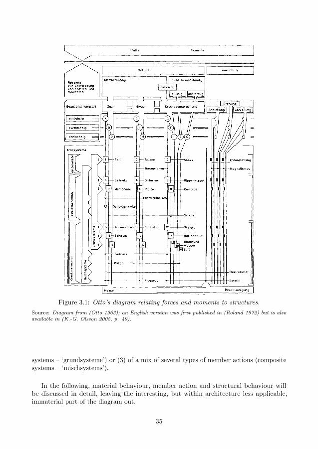
Figure 3.1: Otto’s diagram relating forces and moments to structures.
Source: Diagram from (Otto 1963); an English version was first published in (Roland 1972) but is alsoavailable in (K.-G. Olsson 2005, p. 49).
systems – ‘grundsysteme’) or (3) of a mix of several types of member actions (compositesystems – ‘mischsystems’).
In the following, material behaviour, member action and structural behaviour willbe discussed in detail, leaving the interesting, but within architecture less applicable,immaterial part of the diagram out.
35

3.2.1 Material behaviour
The examples in chapter 2 make it clear that a prestressed object consists not of one,but usually several materials. Materials are combined in such a way that they contributewith their best qualities, while their weaknesses are tried to be avoided. To understandhow this is done in the best way, an understanding of material behaviour is essential.Stress-strain relations, material strength and failure modes are, along with the density,key factors for the understanding.
In general the stress-strain relation of a material is non-linear and may in additionbe effected by temperature, moisture content and time. Idealised stress-strain relations,known as constitutive models, are used to model the behaviour of materials (see fig. 3.2).Usually only stresses that are within the elastic range of the stress-strain relation areallowed and the strength of the material is thus defined as where that range ends.Furthermore, two primary fracture modes of materials can be identified: brittle failure,where the fracture is sudden (figs. 3.2a and 3.2b), and ductile failure, where the fractureis preceded by extensive plastic deformations (figs. 3.2c and 3.2d). In general brittlefailure is avoided and considered unsafe; no warning signs are given before failure thusnot allowing safety precautions to take place. This is especially true for material undertension where a brittle failure may cause structures to collapse, whereas compressed brittlematerial that fails, i.e. is crushed, usually has some reduced capacity even after failure.Materials often have different failure modes in compression and in tension.
ε
σft
εt
(a) Brittle tension
ε
σ
fc
εc
(b) Brittle compression
ε
σft
εt
(c) Ductile tension
ε
σ
fc
εc
(d) Ductile compression
Figure 3.2: Idealised characteristic constitutive models
Within the built environment the most common load bearing materials are masonry,concrete, timber and steel. Masonry and concrete have a brittle failure mode at very lowtensile stresses, whereas they have a ductile failure at high compressive stresses. Timberis about twice as strong in tension than in compression if loaded parallel to the graindirection and has a brittle failure in tension and a ductile in compression. Steel is anexception and has a ductile failure mode in both compression and tension. Their idealisedconstitutive models are shown in table 3.2.
With only a few exceptions dating long back, the materials used in the examples inchapter 2 are used in such a way that they will undergo ductile failure if stresses exceedtheir strength. In addition, a combination of materials is more common than using onlyone material for the entire structure. When materials that have brittle failure in tensionare used, they are always put into compression by the prestress so that they will haveductile failure instead.
36

Table 3.2: Typical constitutive models for metal, timber and concrete.
Material Constitutive model
Metal ε
σfy
εy
−fy
−εy fy: yield strengthεy: yield strain
Timber parallel to grain ε
σft,t
εt,t
−ft,c
−εt,cft,t: tension strengthft,c: compression strengthεt,t: tension strainεt,c: compression strain
Concrete in tension
ε
σfc,t
εc,t
Crack softeningfc,t: tension strengthεc,t: cracking strain
Concrete in compressionε
σ
−fc,c
−εc,0−εc,ufc,c: compressive strengthεc,0 = 0.002εc,u = 0.0035
Most materials have properties that are stress and time dependent. Much of thedevelopment of prestressed concrete is related to the creep phenomenon of concrete, whichreduces the elastic stiffness of the material over time. Eventually the creep effect declinesand the elastic stiffness reaches a steady state. By prestressing the concrete, the creepprocess can be accelerated and the steady state can be reached faster and long-term creepdeformations can be avoided. Steel and timber have similar time-dependent behaviour,though by different underlying reasons. For steel, the phenomena is called relaxation,and will cause a steel tendon under tension to loose some of its prestress over time whichhas to be accounted for in the design. Steel is also susceptible to fatigue failure, which iseasily demonstrated by bending a metal paper clip at the same point many times so thatit finally breaks. The failure is related to a cyclic change between compression stressesand tension stresses. By prestressing the steel, the fluctuation point can be adjusted sothat the steel is always in tension and the risk of fatigue failure reduced.
In some early examples, like the Colosseum and Gothic cathedrals, weight was addedto prestress parts of the structure. High density materials, such as stone, masonry, soil
37

and gravel, were used so that small quantities of additional materials were needed. Withthe invention of steel, the same prestressing effect could be achieved with virtually noadditional weight, despite the fact that steel has a very high density. Steel has a highstrength and high modulus of elasticity making it possible to strain the material to ahigh degree without failure. Specific strength, which is the quota between strength anddensity, can be used to compare material efficiency in terms of how much material isneeded to support a given load. Wood and timber products obtain high specific strength,even if the effect of buckling is considered, while concrete has a comparatively low specificstrength. Various material properties are listed in table 3.3 for wood, steel and concrete,but also for carbon fibre reinforced polymers (CFRP). Due to its high cost, CFRP israrely used today within the built environment, but may very well be a more commonlyused material in the future since it has both high strength end elasticity and unchallengedspecific strength.
Table 3.3: Typical material properties for common construction materials.
Material Strength Density Elasticity Specific strengtha Specific strength
f [MPa] ρ modulus f/ρ w.r.t. buckling
[kg/m3] E [GPa] (f/ρ)1/3
Softwood 20–30 350–450 9–13 44–85 3–3.3
Hardwood 30–50 450–750 7–12 56–78 3.8–4.3
Carbon steel 235–355 7800 210 30–45 3
Concrete 30–50 2500 30 1–2b 2.3
CFRPc 500–1400 1600 70–300 300–900d 5–6
a In case of compression, members are assumed to be restrained against buckling.b Applies only for member in compression.c Carbon Fibre Reinforced Polymerd Applies only for member in tension.
3.2.2 Member action
At member level, forces and moments are resisted by tension/compression, bending andtwisting.
For one-dimensional members, which are characterised by being long in one principaldirection and comparatively short in the other two, there is bar action, beam action andtwisting action. Bar action transmits forces acting in the axial direction (e.g. cable intension, strut in compression), beam action transmits loads acting laterally to the axis(e.g. beam, bow stave, flagpole), and twisting action resists loads that twists the axis (e.g.crankshaft, stairwell).
For two-dimensional members, which are characterised by being long in two principaldirections and comparatively short in the other one, there is membrane action and plateaction. Membrane action transmits forces acting in the normal plane of the surface (e.g.textile in tension, wall and vault in compression) whereas plate action transmits forces
38

acting perpendicular to the surface (e.g. slab).
For three-dimensional members, where all principal direction have about the samedimension, solid action describes the transmission of loads (e.g. masonry; contact regionsbetween members). Concepts such as normal force, bending moment, shear force andtorque, which are used to quantify the actions in one- and two-dimensional members,can no longer be used. Instead the action within the solid is quantified in terms of a(discretized) strain field with an associated stress field. Worth noting is that one- andtwo-dimensional members may be considered with solid action as well with accurateresults. However, such an approach removes the possibility to distinguish the underlyingmode of action dominating the stress field, reducing the opportunity to make wise designdecisions, especially in early stage design.
Among the examples in chapter 2, bar action (1D) and membrane action (2D) are themost common member actions, while beam action (1D) and plate action (2D) are lesscommon. For bar and membrane action, an even utilisation of the material strength acrossthe cross-section is obtained (fig. 3.3a), possibly utilising the full strength. For beamsand plates, however, the material strength can, due to the un-even stress distribution,only be fully utilised in the outer parts of the cross-section (fig. 3.3b).
σ
ft
(a) Normal stresses in a bar.
σ
fc
ft
(b) Bending stresses in a beam.
Figure 3.3: Stresses σ due to external loading and material strengths f in a bar and beam
3.2.3 Structural systems
For the structural systems (i.e. assemblies of one or several structural members), Otto sortsstructures according to their geometry (one-, two-, three-dimensional). Linking memberstogether along one direction gives a one-dimensional structure, along two directions atwo-dimensional structure, and along all three directions a three-dimensional structure.
Structural systems consisting of members of one type of action is called basic systemsin Otto’s diagram. Assemblies of bar member action can thus form systems such as cable(1D), cable net (2D), cable net (3D), strut (1D), ribbed dome (2D) and skeleton (3D).Beam action gives beam (1D), beam grillage (2D) and roof frame (3D).
Structural systems consisting of members with different types of action are calledcomposite systems. Combining bar and beam action gives systems such as tree trunk(1D), lattice girder (2D) and cable pole (3D), while the combination of membrane andplate action results in shells (2D).
So far, Otto’s diagram has been used to discuss how structures transmits forces and
39

moments, but three are other ways as well which could be used in parallel. One suchsystem is provided by (Engel 1997), who published his first version of the book StructureSystems just a few years after Otto’s was published. Engel’s system, which just a Otto’sdiagram takes its departure in how the transmission of forces and moments are dealt withby the structure, sorts structures into to ‘families’ and ‘types’, see table 3.4. For each ofthese, there are distinct characteristics regarding the internal flow of forces but also thegeometry of the structure. By classifying the examples in chapter 2 according to Engel’ssystem, it is evident that the form active and vector active families are the most commonfamilies for prestress structures, while section active and surface active families seldomare prestressed. Furthermore, hybrid action is common, in which a combination of two ormore families or their types are used (e.g. prestressed concrete beam: form/vector active+ section active).
Structure family Structure type
1 Form activeSystems of flexible, non-ridgid matter, in which the redirection offorces is effected by particular FORM design and characteristicFORM stabilisation.
1.1 Cable structures1.2 Tent structures1.3 Pneumatic structures1.4 Arch structures
2 Vector activeSystems of short, solid, straight linear members (bars), in whichthe redirection of forces is effected by VECTOR partition, i.e. bymulti-directional splitting of single forces (compressive or tensilebars).
2.1 Flat trusses2.2 Transmitted flat trusses2.3 Curved trusses2.4 Space trusses
3 Section activeSystems of rigid, solid linear elements – including their compactedform as slab –, in which the redirection of forces is effected bymobilisation of SECTIONAL (inner) forces.
3.1 Beam structures3.2 Frame structures3.3 Beam grid structures3.4 Slab structures
4 Surface activeSystems of flexible, but otherwise rigid planes (=resistant to com-pression, tension, shear), in which the redirection of forces iseffected by SURFACE resistance and particular SURFACE form.
4.1 Plate structures4.2 Folded plate structures4.3 Shell structures
Hybrid actionSystems consisting of a combination of families.
Table 3.4: Structure families and types according to (Engel 1997).
3.3 Computation strategies
In order to design the structure, various computation strategies can be used. Some aremore suitable in the early stage design, were understanding of structural behaviour andstructural optimisation is needed, whereas others are are suitable in verification stages,where numerical results for code checks are required.
40

3.3.1 Early stages
There exists many tools suitable for early stage design. Some are targeted to providean understanding of the structural behaviour providing qualitative measures for designdecisions. Others are targeted for structural optimisation especially applicable whenseeking to reduce bending moments, as in vector active structures and form activestructures.
Graphic statics
Graphic statics is a graphical method for determining the forces in two-dimensional axiallyloaded members such as trusses, cables and arches. It was was developed during 18th-and 19th-century through the works of (Varignon 1725; Culmann 1866; Cremona 1872;J. C. Maxwell 1864b, 1870; Rankine 1858) and others. The chronology is described by(Kurrer 2008) and Form and forces: designing efficient, expressive structures (Allen andZalewski 2009) is a popular book introducing the method.
The method relies on the reciprocal relation between a form diagram representingthe geometry of the structure and a force diagram representing the external and internalforces using vectors. To find the internal force of a member, one simply measures thelength of the corresponding, parallel vector, in the force diagram, which has to be drawnto scale. Any change in either the form or force diagram is reflected in the other, providinga visual understanding of form and forces.
Recently graphic statics has been extended to three dimensions (Akbarzadeh, VanMele, and Block 2013, 2015; Block and Ochsendorf 2007) and applied to the design ofstructural masonry (Fraternali 2010; Rippmann, Van Mele, et al. 2016). Methods toapply graphic statics on post-tensioned funiculars are presented in (Todisco 2016) andgraphic statics has been combined with structural optimisation in (Beghini et al. 2014).Computer implementations have been developed making the drawing of the diagramsfaster (Greenwold and Allen 2003; Rippmann, Lachauer, and Block 2012; Van Mele,Brunier-Ernst, and Block 2009). A general algebraic implementation of graphic statics ispresented in (Van Mele and Block 2014) which given a form diagram allows the directgeneration of a force diagram. Alic and D. Akesson extends algebraic statics to bebi-directional allowing changes in the force diagram to generate the form diagram (Alicand D. Akesson 2017); an example of a prestress funicular arch is provided, much similarto the Wasserfallbrucke, where alterations of the prestressing force generates changes inthe form diagrams.
Canonical stiffness
The concept of canonical stiffness, which is a scalar representation of the global stiffnessof a structure, was introduced by (K.-G. Olsson 2005). By solving a static eigenvalueproblem, canonical stiffnesses λ (eigenvalues) and associated deformation patterns x(eigenmodes) can be found from
(K− λI) x = 0 (3.1)
41

where I is the identity matrix. Effects of prestress can be considered using geometricnonlinearity by including the geometric stiffness in the stiffness matrix K. The canonicalstiffness can be interpreted as being indicative of the inherent global stiffness of thestructure. The deformation pattern indicates weaknesses of the structure providing anunderstanding of how it may respond to external forces. The concept is implementedusing first order theory in the computer program ‘pointSketch’ (P. Olsson 2006).
Mechanics of bar frameworks and Maxwell’s rule
A bar framework is a theoretical model of bars connected with friction less joints which canbe used to model many structures, for example trusses, tensegrities, gridhsells, cable nets.There exists a simple condition for the rigidity of such frameworks, initially presentedin (Mobius 1837): a general plane framework consisting of j frictionless joints, has tohave at least 2j − 3 bars in order to be rigid, while a space framework needs 3j − 6.Mobius were aware of exceptions to this rule, and observed that this happens when thedeterminant of the equilibrium equations of the nodes vanishes. Mobius also notes that ifyou remove a bar from a framework that has the minimum number of bars, accordingto the rule, the framework in general transforms from a rigid structure into a finitemechanism. Furthermore he points out that the removal of a bar does not introduceany further degree of internal mobility, if the bar length is either minimum or maximum.However, Mobius’s findings were to general and its presentation to abstract, and his workremained unknown to engineers for a long time (Pellegrino 1986).
About 30 years later, Mobius’ rule was rediscovered (J. C. Maxwell 1864a) and the ruleis nowadays widely known as Maxwell’s rule for the construction of rigid three-dimensionalframeworks,
3j − b− c = 0, (3.2)
where j is the number of joints, b the number of bars and c the number of kinematicconstraints (c ≥ 6 in three dimensions, c ≥ 3 in two dimensions). Just as Mobius, Maxwellanticipated exceptions to the rule (Calladine 1978; J. C. Maxwell 1864a): (i) ‘In thosecases which stiffness can be produced with a smaller number of lines, certain conditionsmust be fulfilled, rendering the case one of a maximum or minimum value of one ormore of its lines.’ and (ii) ‘The stiffness of such frames (i) is of inferior order, as a smalldisturbing force may produce a displacement infinite in comparison with itself.’
In 1978, Calladine went back to the paper by Maxwell in order to explain BuckminsterFuller’s tensegrity structures (Calladine 1978). Calladine’s paper presents rigorous deriva-tions of a tensegrity structure with 12 joints and 24 bars which should be loose with 6degrees of freedom, according to Maxwell’s rule; yet, it is stiff (Tibert 2002). Calladine’skey finding is an extended version of Maxwell’s rule, dealing with all possible special cases:
3j − b− c = m− s, (3.3)
where m is the number of internal mechanisms and s the number of states of self-stress.Equation (3.3) dose not by itself solve m and s of a general bar framework, but itintroduces a clear explanation of the fundamental mechanics of bar frameworks. Thevalues of m and s depend not only on the number of bars and joints, nor even on the
42

topology of the connections, but on the complete specification of the framework (Pellegrinoand Calladine 1986).
Making use of the linear-algebraic relationships of equilibrium and kinematic as wellas the principle of virtual work gives, together with the rank r of the equilibrium matrixand its transpose—the kinematic matrix—, the following expressions (Calladine 1978;Pellegrino and Calladine 1986)
s = b− r, m = 3j − c− r. (3.4)
Topology optimisation
Topology optimisation (Bendsøe and Sigmund 2004; Sigmund and Maute 2013) is used forthe optimisation of material layouts allowing the design to attain any shape within a givendesign space. It is a numerical method that minimises some performance objective undera set of loads, boundary conditions and constraints. Topology optimisation problemscan be solved in several ways, for example in a discrete sense by discretizing the designdomain into finite elements. Though targeted to the design of solids, the methods may beapplied to find the topology of a dissolved vector active structures such as space framesand trusses.
Form finding
Form finding, or shape optimisation as it is called in a more general sense outside thedomain of architecture, is used to determine the global form of a structure and is especiallysuitable for form active structures. Form finding can either be done using a physical modelor a numerical model. In both cases, the equilibrium equations are solved by adjustingthe shape – the form – of the structure. The model used for the form finding has to be amechanism in order to be able to deform from some initial state to the form found state.As the real structure can not be a mechanism, the form found structure has to be ‘frozen’when constructed either by adding bending stiffness or bracing.
Most numerical methods for form finding simulate a physical model which has to bestable in order to achieve equilibrium. The physical model might involve hanging chainswhich will be inverted to form a compression structure as explained by (Hooke 1675), atechnique used by for example Antoni Gaudı (Huerta 2006). The model may also involvea combination of soap film and cotton threads in tension as well as masts in compressiondescribed by (Otto and Rasch 1995), in which the tension elements stabilises the masts.
Two of the more commonly used numerical methods are the force density method(Linkwitz and Schek 1971; Schek 1974) and the dynamic relaxation method (Day 1965).Recent development has also lead to the thrust network analysis method targeted towardsthe design of compression shells (Block and Lachauer 2014; Block and Ochsendorf 2007).The book Shell structures for architecture: form finding and optimization (S. Adriaenssenset al. 2014) provides a comprehensive introduction to these and other form finding methodswithin the context of designing shell structures. (Tibert 2002) classifies form findingmethods into two groups, kinematic and static methods, where dynamic relaxation isan example of the former class and force density method the latter. A review of thesemethods, within the context of designing tensegrity structures, can be found in (Tibert
43

and Pellegrino 2003b). A compact summary of tensegrity form finding methods is providedby (Safaei 2012), who concludes that ‘most of the proposed methods for form-finding donot consider self-weight and external forces’.
3.3.2 Verification
To verify that a design complies with regulations and other demands, mathematical analysisis primarily used, even though physical testing occasionally occurs. The mathematicalanalysis may be done analytically with simplified models for early stage design, however,for complex problems, final design and code checks, numerical approaches dominates.
Mathematical analysis approaches are based on either rigid body theory or theory ofelasticity. In the former, deformations are neglected while they are accounted for in thelatter by considering the constitutive relation between stress and strain. In rigid bodytheory and theory of elasticity of first order, the equilibrium equation is written for theundeformed state of the structure. Though there are methods for analysing prestressedstructures using rigid body theory, for example (Alic and D. Akesson 2017; Todisco 2016),as well as first order theory, these do not include the influence prestress has on the stiffnessof the structure. This is, however, accounted for by higher order theory of elasticity(geometric nonlinear theory). Both second and third order theory are nonlinear and theequilibrium equations are written for the deformed state of the structure. In third ordertheory, the geometry is also updated in each computation step. Second order theory is inmost case sufficient for the analysis of prestressed structures. Figure 3.4 maps the relationbetween established theories.
For the numerical computation matrix methods such as the finite element method isoften used even though there are examples where dynamic methods are used. Dynamicrelaxation was for example used to considered dynamic earthquake loading of the Pavilionof the Future (Rice 1996), but also for stress analysis for the London 2012 Velodromeroof1.
3.4 Objectives for prestressing
It has already been noted that prestress is used to improve the performance of a structureduring service and offers a vast range of possibilities of making structures more efficient.But what does improve the performance and more efficient means? Among the examplesin chapter 2, some general objectives for prestressing has been identified which are listedin order of commonness in table 3.5 and will be discussed more in detail in the following.
In most examples material efficiency is sought. For instance, in the Ferries Wheel andbicycle wheel, prestress ensures that buckling in spokes could be avoided by putting themall in tension. The growth stresses in living trees reduces the compressive stresses due toexternal forces (primarily from wind) so that the stresses better comply with the strengthof the wood fibres. In these examples, the more efficient use of the material results in thepossibility to use more slender cross sections to withstand the same amount of force.
1E-Mail correspondence with Andrew Weir, Director Expedition Engineering, 7 March 2019
44
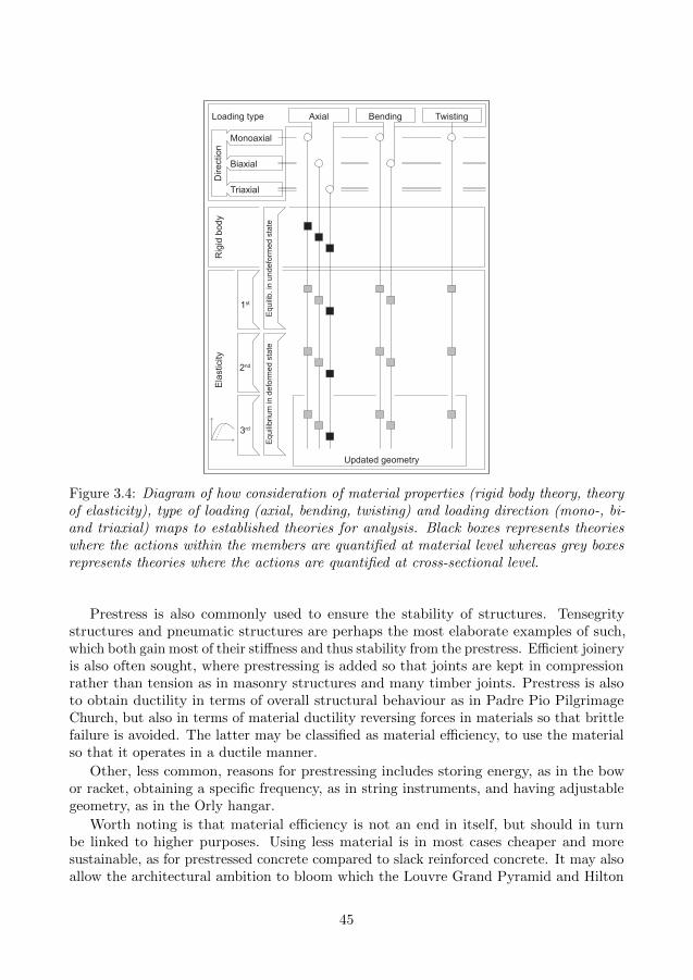
Monoaxial
Loading type Axial Bending Twisting
Dire
ctio
n
Updated geometry
Biaxial
Triaxial
1st
2nd
3rd
Rig
id b
ody
Elas
ticity
Equi
lib. i
n un
defo
rmed
sta
teEq
uilib
rium
in d
efor
med
sta
te
Figure 3.4: Diagram of how consideration of material properties (rigid body theory, theoryof elasticity), type of loading (axial, bending, twisting) and loading direction (mono-, bi-and triaxial) maps to established theories for analysis. Black boxes represents theorieswhere the actions within the members are quantified at material level whereas grey boxesrepresents theories where the actions are quantified at cross-sectional level.
Prestress is also commonly used to ensure the stability of structures. Tensegritystructures and pneumatic structures are perhaps the most elaborate examples of such,which both gain most of their stiffness and thus stability from the prestress. Efficient joineryis also often sought, where prestressing is added so that joints are kept in compressionrather than tension as in masonry structures and many timber joints. Prestress is alsoto obtain ductility in terms of overall structural behaviour as in Padre Pio PilgrimageChurch, but also in terms of material ductility reversing forces in materials so that brittlefailure is avoided. The latter may be classified as material efficiency, to use the materialso that it operates in a ductile manner.
Other, less common, reasons for prestressing includes storing energy, as in the bowor racket, obtaining a specific frequency, as in string instruments, and having adjustablegeometry, as in the Orly hangar.
Worth noting is that material efficiency is not an end in itself, but should in turnbe linked to higher purposes. Using less material is in most cases cheaper and moresustainable, as for prestressed concrete compared to slack reinforced concrete. It may alsoallow the architectural ambition to bloom which the Louvre Grand Pyramid and Hilton
45

Table 3.5: Objectives for prestressing.
Objective Examples
1. Material efficiencyPrestress to avoid compression/buckling
Ferries wheel (section 2.2.7), cable roofs (sec-tion 2.2.10), growth stresses (section 2.1)
2. Ensure stabilityPrestress to provide positive geometric stiffnessand remove internal mechanisms
Tensegrities (section 2.2.13)
3. Provide form stabilityPrestress to maintain geometry
Tensile membranes, pneumatic structures (sec-tion 2.2.9), Ferris Wheel & bicycle wheel (sec-tion 2.2.7), spiderweb (section 2.1), Egyp-tian barges (section 2.2.2), cable roofs (sec-tion 2.2.10)
4. Efficient joineryPrestress to secure connections (avoid tensionin joints)
Masonry structures (section 2.2.4), traditionaltimber joints (section 2.2.5), birds nest (sec-tion 2.1)
5. Ductile behaviour
Prestress to use material ductile stress-strainbehaviour
Masonry (section 2.2.4), concrete (section 2.2.8)
Prestress to achieve global ductilityPres-lam/Flexframe (section 2.2.6), Padre PioPilgrimage Church (section 2.2.12)
6. Storing energyPrestress to store strain energy
Bow & racket (section 2.2.3)
7. Obtain frequencyPrestress to tune (often slender) members to aspecific frequency
String instruments (section 2.2.3), bicyclespokes (during truing of wheel; section 2.2.7)
8. Adjustable geometryPrestress adjusted frequently during operationto adjust the geometry
Egyptian barges (section 2.2.2), Cables at Orlyhangar (section 2.2.11)
9. Easy operationPrestress to reduce weight
Tents, boats & weaving (section 2.2.1), sportsequipment (section 2.2.3), wheels (section 2.2.7)
hotel at Munich Airport are examples of where the vision was to create invisible structures.In everyday objects such as the bow, tent, boat, and sports racket, the material efficiencyis linked to an urge of making the object lightweight and thus easier to carry around anduse.
46

3.5 Design strategies for how to achieve prestress
In section 3.4 reasons for why prestress is used were discussed. As soon as the reason forprestressing is clarified in a design process, the question about how the prestressing canbe achieved arises. Once again the examples in chapter 2 are examined and this time inthe search for general strategies for how to acheive the prestress.
Two main strategies are found, linking back to the discussion in section 1.1 about howthe prestressing forces in the structure are equilibrated: either (1) externally-equilibratedor (2) auto-equilibrated. The main strategies are further divided in a number of substrategies. In the first case the type of reaction forces obtained are considered whereas inthe second case the division is base on how the prestress is balanced within the structure.The strategies and some associated examples are presented in table 3.6.
Table 3.6: Design strategies for how to achieve prestress.
How Examples
1. Externally-equilibrated systemInner forces balanced by reaction forces atboundary; prestress increases reaction forces
1a. Tensile reaction forcesInner stresses balanced by tensile reactions
Spiderweb (section 2.1) and Hilton hotel atMunich Airport (section 2.2.10)
1b. Compressive reaction foresInner stresses balanced by compressive reactions
Gothic Cathedrals & timber buildings withheavy roofs (section 2.2.4)
1c. Mixed reaction foresInner stresses balanced by both tensile and com-pressive reactions
Suspension bridges, cable-stayed radio masts
2. Auto-equilibrated systemTension and compression internally in balance;prestress do not affect reaction forces
2a. InflationMembrane in tension enclosing compressed fluid
Pneu & turgor pressure (section 2.1), airhouse& ETFE cushions (section 2.2.9)
2b. Active bendingPrestress induced by active bending, usually re-strained by string or membrane in tension
Birds nest (section 2.1) bow, tents & skin onframe boat (section 2.2.1), hull of Egyptianbarges (section 2.2.2)
2c. Aligned tension/compressionTension and compression member along a mu-tual line of action
Prestressed concrete beam (section 2.2.8), Pres-lam/Flexframe (section 2.2.6), Wasserfallbrucke& Padre Pio Pilgrimage Church (section 2.2.12)
2d. Distributed tension/compressionTension and compression members along indi-vidual lines of actions
Egyptian barges (section 2.2.2), string instru-ments & racket (section 2.2.3), cable roofs& nets (section 2.2.10), Restrained arches& wheels (section 2.2.7), tensegrities (sec-tion 2.2.13)
2e. Local prestressPushing parts away/together
Timber joinery with wedges (section 2.2.5)
47

All strategies have their strengths, but also their weaknesses, and some of these willbe discussed briefly.
The two main strategies results in, for the same level of prestress force, differentsupport reaction magnitudes. In externally-equilibrated systems (1) the reaction forcesare modified with a change in prestress, while they are unchanged for auto-equilibratedsystems (2). If there are good ground conditions, like solid bedrock, an increase in supportreactions is perhaps not an issue and can be accepted. But increases in reaction forcesmay be challenging for less good conditions, for example clay, especially if there aretensile reaction forces. The construction of auto-equilibrated systems offers the possibilityfor complete off-site manufacturing and pre-stressing whereas externally-equilibratedsystems requires on-site prestressing. Among the examples, it is evident that most auto-equilibrated systems consists of a combination of several materials, for example steel intension and masonry, concrete and timber in compression. Externally-equilibrated areoften constructed from a single material.
Inflated structures (2a) rely on a constant high-enough internal pressure to make surethe membrane is under tension and do not wrinkle. The internal pressure needs, due toleakage and change of surrounding air pressure, temperature and loading, to be constantlymonitored and adjusted throughout the life of the structure, for instance by using pumpsor fans. This becomes an issue of redundancy, the structure should for instance notcollapse due to a power failure. However, for temporary structures, such as inflatablechildren playgrounds, this offers a convenient way to quickly erect and take down thestructure—just plug in or out the fan and wait.
Active bending (2b) is also convenient for temporary structures. Light-weight flexibleelements can easily be designed for the bending stresses induced when bending andadditional live loads for small structures such as a camping tent. But for larger spanstructures, the forces in each member increases resulting in larger elements which aremore challenging to bend, both in terms of the required force and in terms of practicalities.Recently Quinn investigated inflation as a method to erect active bending gridshells(Quinn 2018), effectively combining strategy (2a) and (2b).
Aligned (2c) and distributed (2d) tension/compression are similar to one another. Bothrely on equilibrium at joints where tension and compression elements meet. What differsis the geometrical configuration. These two strategies are perhaps the most commonones and are usually prestressed by post-tensioning one or several members, which theninfluences the stress pattern of the entire system.
Local prestress (2e) is local in the sense that one seeks to achieve some action at aspecific part of the structure, like at a timber joint. However, it should not be forgottenthat a locally induced prestress will affect the entire system, if only to a small degree.
Finally, it should be observed that it may be hard to make a clear distinction betweenthe various strategies. Consider for example cable net structures, which both can beclassified as externally-equilibrated or auto-equilibrated depending on where the systemboundary is set. In table 3.6 the facade of the Hilton hotel at Munich Airport is listed asstrategy (1a), whereas cable roofs and nets are listed as strategy (2d) while not muchdistinguishes the systems. In the former case, the large roof truss, adjacent buildingsand the foundation are not considered to be part of the cable net structure while thecompression ring of the roofs is, which explains why they may be classified differently.
48

3.6 Theoretical context of the Wasserfallbrucke
The Wasserfallbrucke in Flims (2013) (recall section 2.2.12 and fig. 2.19 on 27) is remotelysituated and spans across a gorge. Locally quarried stone was to be used as the mainload bearing material to root the bridge in its surroundings. With the site and chosenmaterial in mind, the design could evolve. How is however not known, but the followingdescription is a plausible illustration of the design process.
Masonry has virtually no tensile strength, so the shape of the bridge has to follow theflow of the compressive forces thus the arch shape. At member level, forces are transmittedprimarily through bar action, tough it is possible to consider it as one-dimensional solidaction as well.
The remoteness of the site makes transportation of materials and equipment a challenge.Reducing the weight would thus not only be beneficial in terms of transportation ofmaterials, but would also require less sturdy false work. Setting the width of the bridgeto a minimum, one meter, leaves the cross-sectional depth of the bridge as the nextparameter to minimise in order to cut weight. However, with a reduced self weight, liveloads will dominate the flow of forces, just as wind loads dominates the force flow in theupper tier of the flying buttresses of Gothic cathedrals (section 2.2.4, fig. 2.4b), withstability issues as a result.
To be able to reduce the weight to a minimum and obtain a light weight, slenderexpression of the bridge and yet secure the stability, prestress was added. The prestresswas induced by placing post-tensioned steel plates on top of the arch which pushed thearch downwards whilst providing restraints at its ends, resulting in the stone arch beingcompressed. Together it forms an auto-equilibrated system. With the added prestress,equivalent to 3-4 times as much stone as was used, the permanent stresses dominates theflow of forces instead of stresses caused by live loads. The bridge was built recently, inthe current era of efficient prestressing (Sanabra-Loewe and Capella-Llovera 2014), andexpected relaxation of the steel was accounted for during design2.
During the design, different analysis approaches may have been used at different stages.As a very first approach, rigid body mechanics in terms of graphic statics, for exampleadopting the method presented by (Alic and D. Akesson 2017), may have been used tofind the (walk friendly) height of the arch and a suitable initial guess for the prestressforce. During this stage, the Heyman stability condition for masonry (Heyman 1966)could have been used to position the thrust line.
Using graphic statics does, however, not provide any insights on the deflections ofthe bridge. These could be captured using by modelling the stone arch in 2D usingfirst order linear elasticity bar members. The influence on the internal forces caused byprestressing can in such a model be accounted for by adding the equivalent external forcesacting perpendicular to the arch. Such a model is easy to construct and analyse using forexample a finite element analysis software.
As the stone arch deflects, the prestress force will be reduced since the steel plateswill get less stretched. First order linear elasticity is unable to capture this, but secondorder nonlinear geometric elasticity is. An analysis where the steel plates are modelled as
2E-Mail correspondence with Jurg Conzett, 7-8 November 2018.
49
bar members and coupled to the stone arch bar members with constraints can be used.The deflection also leads to a rotation of the arch members which influences the
geometry, so loading directions should be updated accordingly using third order theory.Such deformations are however most likely too small to cause any significant influence ofthe bridge.
During construction, the prestress was applied using jacks at one side of the bridge,adjusting the length of the steel plates by stretching them.
50
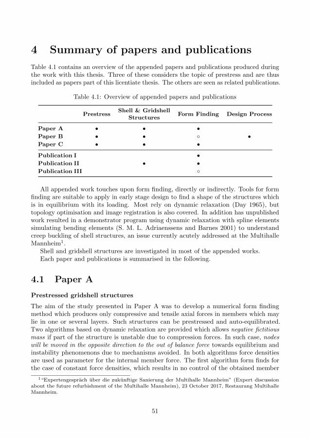
4 Summary of papers and publications
Table 4.1 contains an overview of the appended papers and publications produced duringthe work with this thesis. Three of these considers the topic of prestress and are thusincluded as papers part of this licentiate thesis. The others are seen as related publications.
Table 4.1: Overview of appended papers and publications
PrestressShell & Gridshell
StructuresForm Finding Design Process
Paper A • • •Paper B • • ◦ •Paper C • • •Publication I •Publication II • •Publication III ◦
All appended work touches upon form finding, directly or indirectly. Tools for formfinding are suitable to apply in early stage design to find a shape of the structures whichis in equilibrium with its loading. Most rely on dynamic relaxation (Day 1965), buttopology optimisation and image registration is also covered. In addition has unpublishedwork resulted in a demonstrator program using dynamic relaxation with spline elementssimulating bending elements (S. M. L. Adriaenssens and Barnes 2001) to understandcreep buckling of shell structures, an issue currently acutely addressed at the MultihalleMannheim1.
Shell and gridshell structures are investigated in most of the appended works.Each paper and publications is summarised in the following.
4.1 Paper A
Prestressed gridshell structures
The aim of the study presented in Paper A was to develop a numerical form findingmethod which produces only compressive and tensile axial forces in members which maylie in one or several layers. Such structures can be prestressed and auto-equilibrated.Two algorithms based on dynamic relaxation are provided which allows negative fictitiousmass if part of the structure is unstable due to compression forces. In such case, nodeswill be moved in the opposite direction to the out of balance force towards equilibrium andinstability phenomenons due to mechanisms avoided. In both algorithms force densitiesare used as parameter for the internal member force. The first algorithm form finds forthe case of constant force densities, which results in no control of the obtained member
1“Expertengesprach uber die zukunftige Sanierung der Multihalle Mannheim” (Expert discussionabout the future refurbishment of the Multihalle Mannheim), 23 October 2017, Restaurang MultihalleMannheim.
51

lengths. The second algorithm provides such control by prescribed required length forsome members. The length requirement is met by adjusting the force density duringform finding, again using dynamic relaxation in an inner loop. Finally, case studies arepresented where the applied load and the prestress is used to govern the form found shape.
4.2 Paper B
Embracing design methods from architects for conceptual design of structures
Paper B describes and discusses the development and outcome of a structural engineeringproject which design process were enriched by a conscious use of working methods appliedby architects. The project is rooted in an environment that aims to bridge a gap betweenarchitects and engineers which makes successful collaboration a challenge. Two MScstudents in Structural Engineering designed and built a pavilion enclosing a seminar spaceat a wood technology fair as their master’s thesis project (Isaksson and Skeppstedt 2018).The design process, which is taught in an architectural design studio (recall section 1.2),was iterative allowing numerous viable solutions to be explored and successively refinedinto a design proposal. The early stages resemble work usually performed by architects,whereas the later are such work undertaken by engineers daily. The research by designproject (Megahed 2017) led to the construction of the The Wood Fusion Pavilion; anactive-bending geodesic gridshell prestressed by means of an external post-tension cablesystem. This project has proven that, given suitable processes and tools, engineers can becreative and come up with imaginative solutions. With the gained experience, the studentswill most likely be able to help bridging the gap and be active co-creative participants intheir future careers.
The appended paper is the Author’s Original Manuscript (AOM)/Preprint version ofthe paper, which soon will be submitted to a journal.
4.3 Paper C
Unloaded prestressed shell formed from a closed surface unattached to anysupports
The aim of the study presented in Paper C was to begin to answer the question, ‘underwhat conditions can an unloaded shell formed of a closed surface unattached to anysupports contain a state of membrane stress which can be induced by prestressing?’ Thestudy is limited to unloaded shell surfaces with inextensional deformation and membraneaction. Using Maxwell’s rule, it is shown that a pin-jointed representation of a spherecannot be prestressed, but a torus can be. A fine triangulated pin-jointed frameworkbehaves very much like a continuous shell, and a particular state of stress is for a torus isexamined. However there must almost certainly be more, and this is the topic of futureresearch.
Paper C is a conference paper which will be presented at the IASS 60th AnniversarySymposium (IASS Symposium 2019) in October, 2019 and thereafter published in itsproceedings.
52

4.4 Publication I
On multi objective topology optimization and tracing of Pareto optimal struc-tures
The publication explores multi-objective topology optimisation as a way to find topologicalconfigurations of matter yielding high elastic stiffness under mass and eigenfrequencyconstraints. The principles of topology optimisation may be applicable on prestressedstructures prior to any form finding, but has not been explored further.
4.5 Publication II
The use of virtual work for the formfinding of fabric, shell and gridshellstructures
With differential geometry and statics as the theoretical basis, just as in Paper C, theprinciple of virtual work for form finding of fabric, shell and gridshell structures isinvestigated.
4.6 Publication III
Moving Mesh and Image Registration in FEniCS
The potentials of image registrations is investigated, where a transformation that warps asource image into a target image is sought matching gross features. An implementationwas done in the Finite Element Method solver FEniCS (Logg, Mardal, G. N. Wells, et al.2012) using a moving mesh to solve the governing elliptic, vector valued partial differentialequation. Ideas of how to use the method for form finding applied in architectural andstructural design is presented, but has not been explored further.
53

54

5 Discussion and future research
This licentiate thesis reports research that investigates how prestress can be used as adesign tool for the creation of material efficient and well-functioning structures, and inearly design stages contribute to sustainable, functional and beautiful architecture. Thishas been done through the search for answers to four main questions.
The first question is about what can be learnt from historic and contemporary examplesabout how prestress have been and can be used. For this, a collection of examples ispresented in chapter 2. This has been compiled searching broadly for historic andcontemporary applications and showcases a diverse range of applications of prestress. Innature the pressurised cell—the pneu—is interesting and the effect of the prestress can besubstantial as with the growth-stresses in trees. The spiderweb has most likely inspiredthe creation of tensile cable net structures used in architecture. In technics, history learnabout sophisticated applications such as the skin-on-frame boat. It is also possible totrack the development from historic prestressed spoked wooden wheels to contemporarybicycle wheels and modern Ferris wheels such as the Millennium wheel in London, UK.When looking at the collection, it is clear that the common notion that prestressinghas only to do with concrete is wrong. Contrary, prestress is ubiquitous in nature andcommonly applied within technics. Furthermore, it is evident that the stress level neededfor prestress to be effective can be very small, as in living cells, but also large, as in thehigh strength steel tendons used for prestressed concrete.
Based on the examples, a framework for prestress is derived and presented in chapter 3.The historical development is considered in section 3.1, shedding some light on designchallenges that has been overcome. Structural mechanical modes of actions that canbe used to understand the effect of prestress are discussed in section 3.2 consideringthree levels: material, member and structure. Computational strategies suitable for earlystage design and verification in late stages are exemplified in section 3.3. These threeperspectives then support the search for answers to the next two research questions, whichalso are included in the framework.
The second question seeks for general objectives with prestressing, and suggestions forsuch are presented in table 3.5 and discussed in section 3.4. The objectives answer what issought after with prestress pursuing to clarify what it means to improve the performanceand make a structure more efficient.
The third question is if it is possible to establish design strategies for how to achievethe prestress. Two main strategies are discussed in section 3.5, externally-equilibrated andauto-equilibrated, and further divided into sub-strategies. The strategies are presented intable 3.6 and discussed, and answers how the prestress is achieved.
The fourth question explores how the gained knowledge about prestress can be utilisedand applied in a design process. To answer the question, three studies has been performedfrom which the following can be observed:
1. In Paper A an effort is made to provide numerical form finding tools for prestressedpin jointed frameworks. The tools are suitable to use in early stage design. Usingdynamic relaxation, force densities and allowing negative fictitious masses, analgorithm is provided allowing equilibrium configurations to be found, even though
55

the structure is a mechanism and unstable. The real structure must of course bestable, which can be achieved by providing moment stiff joints or add bracing tothe form found structure.
2. Paper B describes a case study focusing on the design process and to some extentthe construction of a post tensioned timber shell pavilion. It was found that iterativedesign processes used by architects, which successively increases the complexity ofassociated investigations, are suitable also for conceptual structural design. Suchprocesses are strengthened by oscillating between creative explorations and criticalevaluations. Preferably, the critical evaluations are performed inviting peers andothers not directly involved in the project who can provide new perspectives onthe suggestions at hand. In addition, the process offers the possibility to performresearch by design in practice by successfully search for and develop tools that canenforce qualitative and quantitative evaluations. Such an approach is especiallyhelpful for concepts with few precedents to learn from. Iterative design process ofthis kind is not limited to the design of prestressed structures, but can be appliedon any conceptual design development, even outside the field of architecture. Itallows for a successful development of skills, knowledge and tools and is likely toease the application of challenging concepts such as prestress.
3. In Paper C work has begun exploring what geometric requirements there are to beable to prestress shells. It has been concluded that a sphere can not be prestressed,but a tours can. Further work may result in constraints which may be used for formfinding of prestressed shells using virtual work, similarly as in Publication II.
While literature exists with the aim to explain concepts of structures, for exampleby Freio Otto (Otto 1963) and Heino Engel (Engel 1997), no literature has been foundspecifically targeted to prestress. The findings presented in chapter 3 and especiallyin sections 3.4 and 3.5 has the potential to be developed further and complement theliterature.
Some of the research presented herein relies on calculations based on existing as wellas in the research group newly developed computational models.
The work presented herein opens up for some possible future work.To begin with, the examples presented in chapter 2 and the linked framework in
chapter 3 could be completed and improved to make it qualitative enough to publish it asa journal article. Such work would strengthen the discussion related to the first threequestions of this thesis.
Also, further work could be done related to the fourth question and two subsequentquestions arises relevant to seek answers to:
1. How much do prestress actually help? The question could be answered throughcomparative studies where designs without prestress are compared with designs withprestress given the same design scope. There is, for instance, ongoing initiativesto replace a large flat roof in a shopping mall in Goteborg with a glass roofand a ‘conventional’ glass shell could be compared with a prestressed one. Suchinvestigations could be a suitable continuation of the work presented in Paper C.
56

2. When you have your design, how do you apply the prestress during construction?This question became relevant during the construction of the Wood Fusion Paviliondiscussed in Paper B. Due to the many applications points of the prestress, it waschallenging to find the correct order of prestressing and level of prestress not causingthe geometry to deviate to much.
Both of these questions could possibly be answered applying existing computationalmethods and models in new ways. It may also be so that new computational methodsneeds to be developed to better answer such questions.
57

58

References
Addis, B. (1994). The Art of the Structural Engineer. Ed. by A. Bridges. London: ArtemisLondon Limited. isbn: 1874-056-41-2.
— (2007). Building: 3000 years of design engineering and construction. London ; NewYork: Phaidon.
Adiels, E. et al. (2018). “The use of virtual work for the formfinding of fabric, shelland gridshell structures”. Proceedings of the Advances in Architectural Geometryconference 2018. Ed. by L. Hesselgren et al. Klein Publishing, pp. 286–315. isbn:978-3-903015-13-5.
Adriaenssens, S. M. L. and M. R. Barnes (2001). Tensegrity spline beam and grid shellstructures. Engineering Structures 23.1, 29–36. doi: 10.1016/S0141-0296(00)00019-5.
Adriaenssens, S. et al., eds. (2014). Shell structures for architecture: form finding andoptimization. London: Taylor & Francis - Routledge.
Akbarzadeh, M., T. Van Mele, and P. Block (2013). “Equilibrium of spatial structuresusing 3-D reciprocal diagrams”. Proceedings of the International Association for Shelland Spatial Structures (IASS) Symposium 2013.
— (2015). On the equilibrium of funicular polyhedral frames and convex polyhedral forcediagrams. Computer-Aided Design 63, 118–128. doi: 10.1016/j.cad.2015.01.006.
Akesson, B. (1989). Strukturmekanik - ett forsok till definition och oversikt. Third edition.Skrift U32, Hallfasthetslara, Chalmers tekniksa hogskola.
Aldinger, I. L. (2016). Frei Otto: heritage and prospect. International Journal of SpaceStructures 31.1, 3–8.
Alic, V. and D. Akesson (2017). Bi-directional algebraic graphic statics. Computer-AidedDesign 93, 26–37. doi: 10.1016/j.cad.2017.08.003.
Allen, E. and W. Zalewski (2009). Form and forces: designing efficient, expressive struc-tures. John Wiley and Sons. isbn: 978-0-470-17465-4.
Angelo and N. N. Maggi (2003). John Soane and the Wooden Bridges of Switzerland;Architecture and the culture of technology from Palladio to the Grubenmanns. Archiviodel Moderno, Acacemia die architettura, Mendriso / Sir John Soane’s Museum. isbn:88-87624-24-0.
Arnold, R. et al. (2011). “Delivering London 2012: the Velodrome”. Proceedings of theInstitution of Civil Engineers - Civil Engineering. Vol. 164. 6, pp. 51–58.
Arup, O. N. (1985). 1970 Key speech. The Arup Journal 20.1, 34–36.Ashwear, N. (2016). “Vibration-based assessment of tensegrity structures”. PhD thesis.
Stockholm, Sweden: Royal Institute of Technology.Balmond, C. (2007). Informal. Prestel.Ban, S. (2000). Japanese pavilion at the EXPO in Hanover. Detail 40.6, 1012–1017. issn:
0011-9571.Barkhofen, E.-M. and A. Bogle (2010). High Energy. Ingenieur - Bau - Kultur - Structural
Art - Jorg Schlaich Rudolf Bergermann. Akademie der Kunste.Beauzamy, L., N. Nakayama, and A. Boudaoud (2014). Flowers under pressure: ins and
outs of turgor regulation in development. Annals of Botany 114.7, 1517–1533.
59

Beghini, L. L. et al. (2014). Structural optimization using graphic statics. Structural andMultidisciplinary Optimization 49.3, 351–366. doi: 10.1007/s00158-013-1002-x.
Bendsøe, M. P. and O. Sigmund (2004). Topology optimization : theory, methods andapplications. 2. ed., corr. pr. Berlin: Springer.
Benjamin, M. et al. (2006). Where tendons and ligaments meet bone: attachment sites(’entheses’) in relation to exercise and/or mechanical load. Journal of Anatomy 208.4,471–490. doi: 10.1111/j.1469-7580.2006.00540.x.
Bergdoll, B. (2000). European Architecture 1750-1890. Oxford University Press.Berlin Hauptbahnhof – Lehrter Bahnhof (2005). Detail Magazine 12, 1449–1455.Block, P. and L. Lachauer (2014). Three-dimensional funicular analysis of masonry vaults.
Mechanics Research Communications 56, 53–60. doi: 10.1016/j.mechrescom.2013.11.010.
Block, P. and J. Ochsendorf (2007). Thrust network analysis: a new methodology forthree-dimensional equilibrium. Journal Of The International Association For ShellAnd Spatial Structures 48.3, 167–173.
Bork, R. (2014). The geometry of Bourges Cathedral. Architectural Histories 2.1. doi:10.5334/ah.bz.
Boyd, J. D. (1950). Tree growth stresses. II. The development of shakes and other visualfailures in timber. Australian Journal of Applied Science 1.3, 269–312.
Brandt, J. (1993). The bicycle wheel. 3rd. Avocet. isbn: 9780960723669.Brunner, J. (1921). Der Schweizerische Holzbruckenbau von 1750 bis 1850. Schweizerische
Bauzeitung 78.12, 139–141.— (1924). “Beitrag zur geschichtlichen Entwicklung des Bruckenbaues in der Schweiz”.
PhD thesis. ETH Zurich.Buchanan, A., B. Deam, et al. (2008). Multi-storey prestressed timber buildings in New
Zealand. Structural Engineering International 18.2, 166–173.Buchanan, A., A. Palermo, et al. (2011). Post-tensioned timber frame buildings. The
Structural Engineer 89.17, 24–30.Burkhardt, B. et al., eds. (1978). IL13: Multihalle Mannheim. Vol. 13. Institut for Leichte
Flachentragwerke (IL). Institut for Leichte Flachentragwerke (IL).Calladine, C. R. (1978). Buckminster Fuller’s ”Tensegrity” structures and Clerk Maxwell’s
rules for the construction of stiff frames. International Journal of Solids and Structures14.2, 161–172. doi: 10.1016/0020-7683(78)90052-5.
Cassens, D. L. and J. R. Serrano (2004). “Growth Stress in Hardwood Timber”. Proceedingsof the 14th Central Hardwood Forest Conference. Ed. by D. A. Yaussy et al. Wooster,OH. Gen. Tech. Rep. NE-316. Newtown Square, PA: U.S. Department of Agriculture,Forest Service, Northeastern Research Station, pp. 106–115.
Casson, L. (1971). Ships and seamanship in the Ancient World. Princeton, New Jersey:Princeton University Press. isbn: 0-691-03536-9.
Charleson, A. W. and S. Pirie (2009). An investigation of structural engineer-architectcollaboration. Journal of the Structural Engineering Society of New Zealand 22.1,97–104.
Chilton, J. and G. Tang (2017). Timber gridshells: architecture, structure and craft.Routledge. isbn: 9781138775305.
60

Christianson, J. and C. H. Marston (2015). Covered bridges and the birth of Americanengineering. Historic American Engineering Record National Park Service. isbn: 978-0-578-17106-7.
Conzett, J. (2012). Landschaft und kunstbauten. Scheidegger & Spiess. 272 pp. isbn:978-3-85881-360-2.
Conzett, J., M. Mostafavi, and B. Reichllin (2006). Structure as Space: Engineering andArchitecture in the Works of Jnrg Conzett. Ed. by M. Mostafavi. AA Publications.
Corres-Peiretti, H. (2013). Sound engineering through conceptual design according to thefib Model Code 2010. Structural Concrete 14.2, 89–98.
Cremona, L. (1872). Le figure reciproche nella statica grafica. ita. Tipografia di GiuseppeBernardoni. doi: 10.3931/e-rara-18757.
Culmann, C. (1851). Der Bau der holzernen Brucken in den Vereinigten Staaten vonNordamerika. Allgemeine Bauzeitung 16, 69–129.
— (1866). Die graphische Statik. ger. Zurich: Meyer & Zeller. doi: 10.3931/e-rara-20052.
Curtain, B. et al. (2012). “Design of Carterton Event Centre: An example of innovativecollaboration between architecture and timber engineering”. Proceedings of the 12thWorld Conference on Timber Engineering WCTE, Auckland, New Zealand.
D’Aveni, A. and G. D’Agata (2017). Post-tensioned timber structures: New perspectives.Construction and Building Materials 153, 216–224.
Day, A. S. (1965). An introduction to dynamic relaxation. The Engineer 219, 218–221.Diderot, D. and J. le Rond d’Alembert, eds. (1769). Encyclopedie. Andre le Breton et al.Doidge, C., R. Sara, and R. Parnell (2016). The crit: an architecture student’s handbook.
Second edition. Routledge.Edwards, S. A., J. Wagner, and F. Grater (2012). Dynamic Prestress in a Globular Protein.
PLoS Computational Biology 8.5. Ed. by R. Nussinov.Ekholm, K. (2013). “Performance of stress-laminated-timber bridge decks”. PhD thesis.
Chalmers University of Technology.Engel, H. (1997). Structure Systems. Hatje Cantz Publishers. isbn: 3-7757-0706-9.Engstrom, B. (2011). Design and analysis of prestressed concrete structures. Goteborg:
Chalmers University of Technology.Engstrom, D. et al. (2004). Arkitektur och barverk. Ed. by D. Engstrom. Stockholm:
Formas.Evguenia, V. A. (2016). “Open passage ethno-archaeology of skin boats and indigeneous
maritime mobility of North-American Arctic”. PhD thesis. University of Southampton.Fabricius, D. (2016). Architecture before architecture: Frei Otto’s ‘Deep History’. The
Journal of Architecture 21.8, 1253–1273.Falk, A. and P. von Buelow (2009). “Combined timber plate and branching column
systems – variations and development of system interaction”. Proceedings of theInternational Association for Shell and Spatial Structures (IASS) Symposium 2009,Valencia, pp. 999–1010.
Federation internationale du beton (2005). Guidelines for the Design of Footbridges:Guide to Good Practice. Bulletin (fib Federation internationale du beton). Lausanne,Switzerland: International Federation for Structural Concrete.
61

Frampton, K. (2007). Modern Architecture: A Critical History. Fourth Edition. World ofArt. Thames & Hudson.
Frampton, K. and Y. Futagawa (1983). Modern Architecture 1851-1945. Rizzoli.Fraternali, F. (2010). A thrust network approach to the equilibrium problem of unreinforced
masonry vaults via polyhedral stress functions. Mechanics Research Communications37.2, 198–204. doi: 10.1016/j.mechrescom.2009.12.010.
Fuller, R. B. (1962). “Tensile-integrity structures”. U.S. pat. 3063521.Gans, D., ed. (1991). Bridging the gap: rethinking the relationship between architect and
engineer. Van Nostrand Reinhold. isbn: 0-442-00135-5.Gasparini, D. A., J. Bruckner, and F. da Porto (2006). Time-dependent behavior of
posttensioned wood Howe bridges. Journal of Structural Engineering 132.3, 418–429.Gasparini, D. A. and F. da Porto (2003). “Prestressing of the 19th century wood and
iron truss bridges in the U.S.” Proceedings of the First International Congress onConstruction History. Ed. by S. Huerta. Vol. III. Madrid: Instituto Juan de Herrera,SEHC, COAC, CAATC, pp. 977–986.
Gasparini, D. A. and C. Provost (1989). Early nineteenth century developments in trussdesign in Britain, France and the United States. Construction History 5.
Gasparini, D. A. and D. Simmons (1997). American Truss Bridge Connections in the19th Century. I: 1829—1850. Journal of Performance of Constructed Facilities 11.3,119–129.
Graefe, R. and J. Tomlow (1990). Vladimir G. Suchov 1853-1939; Die Kunst DerSparsamen Konstruktion. Stuttgart: Deutsche Verlags-Anstalt. isbn: 3-421-02984-9.
Granello, G. et al. (2018). Design approach to predict post-tensioning losses in post-tensioned timber frames. Journal of Structural Engineering 144.8.
Greenwold, S. and E. Allen (2003). Active statics. url: http://acg.media.mit.edu/people/simong/statics/data/ (visited on 02/06/2019).
Guyon, Y. (1965). Hormigon pretensado: estudio teoretico y experimental. Translated byManuel Osset and Renato Bardin. Originally published as Beton Precontraint. EtudeTheorique et Experimentale (Paris: Editions Eryolles, 1951). Madrid, Spain: Dossat.
Haegermann, G., G. Huberti, and H. Moll (1964). Vom Caementum zum Spannbeton.Ed. by G. Huberti. Vol. 1. part A-C. Berlin: Bauverlag.
Hanaor, A. (1993). Double-layer tensegrity grids as deployable structures. InternationalJournal of Space Structures 8.1 & 2, 132–143.
Hanaor, A. (1994). Geometrically rigid double-layer tensegrity grids. International Journalof Space Structures 9.4, 227–238.
Happold, E. and W. I. Liddell (1975). Timber lattice roof for the Mannheim Bundes-gartenschau. The Structural Engineer 53.3, 99–135.
Harding, J. E. et al. (2017). “The UWE research pavilion 2016”. Proceedings of theInternational Association for Shell and Spatial Structures (IASS) Symposium 2017.
Harding, J. et al. (2014). “The Ongreening pavilion”. Advances in Architectural Geometry2014. Ed. by P. Block et al. Springer International Publishing, pp. 295–308. doi:10.1007/978-3-319-11418-7_19.
Hellstrom, B., H. Granholm, and G. Wasterlund, eds. (1958). Betong - del 1. 2nd ed.Natur och Kultur.
62

Hennicke, J. and E. Schauer, eds. (1974). IL10: Gitterschalen. Vol. 10. Institut for LeichteFlachentragwerke (IL). Institut for Leichte Flachentragwerke (IL).
Heyman, J. (1966). The stone skeleton. International Journal of Solids and Structures2.2, 249–279.
Holgate, A. (1997). The art of structural engineering: the work of Jorg Schlaich and histeam. Edition Axel Menges. isbn: 3-930698-67-6.
Hooke, R. (1675). A description of helioscopes, and some other instruments. London.Howe, W. (1840). “Manner of constructing the truss-frames of bridges and other structures.”
U.S. pat. 1711.Huerta, S. (2006). Structural design in the work of Gaudı. Architectural Science Review
49.4, 324–339. issn: 0003-8628. doi: 10.3763/asre.2006.4943.IL12: Convertible Pneus (1975). Vol. 12. Institut for Leichte Flachentragwerke (IL).
Institut for Leichte Flachentragwerke (IL).IL15: Lufthallenhandbuch (1983). Vol. 15. Institut for Leichte Flachentragwerke (IL).
Institut for Leichte Flachentragwerke (IL).IL9: Pneus in Natur und Technik (1977). Vol. 9. Institut for Leichte Flachentragwerke
(IL). Institut for Leichte Flachentragwerke (IL).Isaksson, J. and M. Skeppstedt (2018). “Stressing timber: An exploration of the use of
prestressing in timber structures through the design of a lecture pavilion”. 2018:23.MA thesis. Department of Architecture and Civil Engineering, Chalmers University ofTechnology.
Jackson, P. H. (1886). “Forming artificial-stone or concrete arches”. English. U.S. pat.US339296.
Jacobs, M. R. (1938). The fiber tension of woody stems with special reference to thegenus Eucalyptus. Commonwealth Forestry Bureau 22.
James, J. G. (1982). The evolution of wooden bridge trusses to 1850. Journal of theInstitute of Wood Science, 116–135, 168–193. issn: 0020-3203.
Johnson, J. B., F. E. Turneaure, and C. W. Bryan (1894). The theory and practiceof modern framed structures – Designed for the use of schools and for engineers inprofessional practice. Third edition. New York: John Wiley & Sons.
Karrholm, G. and A. Samuelsson (1972). Analysis of a prestressed cable-roof anchored ina space-curved ring beam. IABSE congress report 9.
Kasarnowsky, S. (1936). “The arches of the Traneberg bridge in Stockholm”. IABSESecond Congress Report: English Edition, pp. 809–818.
Kaylor, H. (1961). Prestressed concrete simply explained. London: Contractors Record.Killer, J. (1942). “Die Werke der Baumeister Grubenmann: eine baugeschichtliche und
bautechnische Forschungsarbeit”. PhD thesis. ETH Zurich.Knoll, F. (1989). “La pyramide du Grand Louvre”. IABSE Periodica P131/89. Vol. 1.
IABSE.Krauth, T. and F. S. Meyer (1893). Die Bau- und Kunstzimmerei - Erster Band : Text.
Kanter & Mohr.Krieg, M., A. R. Dunn, and M. B. Goodman (2014). Mechanical control of the sense of
touch by β-spectrin. Nature Cell Biology 16.3, 224–233.Krishna, P. and P. Godbole (2013). Cable-suspended roofs. Second edition. Tata Mcgraw
Hill Education Private Limited. isbn: 9781259028472.
63

Kubler, H. (1987). Growth stresses in trees and related wood properties. Forestry abstracts48, 131–189.
Kullmann, E., W. Nachtigall, and J. Schurig (1975). IL8: Netze in Natur und Tech-nik. 1st ed. Vol. 8. Institut for Leichte Flachentragwerke (IL). Institut for LeichteFlachentragwerke (IL).
Kurrer, K.-E. (2008). The history of the theory of structures: from arch analysis tocomputational mechanics. Ernst & Sohn. isbn: 978-3-433-01838-5.
Origins of tensegrity: views of Emmerich, Fuller and Snelson (1996). International Journalof Space Structures 11.1–2. Ed. by H. Lalvani, 27–55.
Larsen, O. P. and A. Tyas (2003). Conceptual structural design: bridging the gap betweenarchitects and engineers. Thomas Telford Publishing. isbn: 0727732358.
Larsson, G., P. J. Gustafsson, and R. Crocetti (2017). Use of a resilient bond line toincrease strength of long adhesive lap joints. European Journal of Wood and WoodProducts 76.2, 401–411. doi: 10.1007/s00107-017-1264-x.
Larsson, J. et al. (2017). “Moving Mesh and Image Registration in FEniCS”. Proceedingsof 30th Nordic Seminar on Computational Mechanics – NSCM30, pp. 180–183.
Lenczner, E. A. R. (1994). The design of the stone facade to the Pavilion of the Future,Expo ’92, Seville. The Structural Engineer 72.11, 171–177.
Leonhardt, F. (1964). Prestressed Concrete; Design and Construction. Second. Berlin:Wilhelm Ernst and Sohn.
Liddell, I. (2015). Frei Otto and the development of gridshells. Case Studies in StructuralEngineering 4.Supplement C, 39–49. issn: 2214-3998.
Liddell, I. and P. Westbury (1999). Design and construction of the Millennium Dome, UK.Structural Engineering International 9.3, 172–175. doi: 10.2749/101686699780482023.
Linkwitz, K. and H.-J. Schek (1971). Einige Bemerkungen zur Berechnung von vorges-pannten Seilnetzkonstruktionen. Ingenieur-Archiv 40.3, 145–158.
Liu, Y., B. Zwingmann, and M. Schlaich (2015). Carbon fiber reinforced polymer for cablestructures—a review. Polymers 7.10, 2078–2099. doi: 10.3390/polym7101501.
Logg, A., K.-A. Mardal, G. N. Wells, et al. (2012). Automated Solution of DifferentialEquations by the Finite Element Method. Springer. isbn: 978-3-642-23098-1. doi:10.1007/978-3-642-23099-8.
Long, S. H. (1830). “Wooden-framed brace-bridges”. English. U.S. pat. 5862X.— (1839). “Improvement in wooden-framed brace-bridges”. English. U.S. pat. US1398.Luchsinger, R. H., M. Pedretti, and A. Reinhard (2004). Pressure induced stability: from
pneumatic structures to Tensairity. Journal of Bionic Engineering 1.4, 141–148. doi:10.1007/bf03399470.
Lund, J. G. F. (1912). “Means for positioning building parts or elements”. English. U.S.pat. US1028578.
Lund, M. (2018). Matter Space Structure. url: https : / / www . chalmers . se / en /
departments/ace/School-of-Architecture/Courses-and-projects/Masters-
thesis/masters- thesis- directions/Pages/Matter- Space- Structure.aspx
(visited on 10/15/2018).Mattheck, C. and H. Kubler (1995). Wood - The Internal Optimization of Trees. Springer
Series in Wood Science. Springer. isbn: 3540593187.
64

Mattheck, C. and I. Tesari (2004). “The mechanical self-optimisation of trees”. Designand Nature II. Ed. by M. Collins and C. A. Brebbia. Vol. 73. WIT Transactions onEcology and the Environment. WIT Press, pp. 197–206.
Maxwell, F. W. and W. J. Benson (1937). Theory of statically indeterminate structures.Second Edition. McGraw-Hill.
Maxwell, J. C. (1864a). L. On the calculation of the equilibrium and stiffness of frames.Philosophical Magazine Series 4 27.182, 294–299.
— (1864b). On reciprocal figures and diagrams of forces. The London, Edinburgh, andDublin Philosophical Magazine and Journal of Science 27.182, 250–261. doi: 10.1080/14786446408643663.
— (1870). On reciprocal figures, frames, and diagrams of forces. Transactions of the RoyalSociety of Edinburgh 26.1, 1–40. doi: 10.1017/s0080456800026351.
McConnell, E., D. McPolin, and S. Taylor (2014). Post-tensioning of glulam timber withsteel tendons. Construction and Building Materials 73, 426–433.
Megahed, Y. (2017). On research by design. Architectural Research Quarterly 21.04,338–343. doi: 10.1017/S1359135518000179.
Menn, C. (1990). Prestressed concrete bridges. Ed. by P. Gauvreau. Basel: Birkhauser.isbn: 978-3-0348-9920-8.
Miller, J. F. (2009). “Design and analysis of mechanically laminated timber beams usingshear keys”. PhD thesis. Michigan Technological University.
Mobius, A. F. (1837). Lehrbuch der statik. Vol. 2. Leipzig: G.J. Goschen.Mortimer, B. et al. (2016). Tuning the instrument: sonic properties in the spider’s web.
Journal of The Royal Society Interface 13.122, 20160341. doi: 10.1098/rsif.2016.0341.
Motro, R. and V. Raducanu (2003). Tensegrity systems. International Journal of SpaceStructures 18.2, 77–84.
Mumford, L. (2000). Art and technics. Columbia University Press. 178 pp. isbn: 9780231121057.Munch, E. (1938). Statik und Dynamik des schraubigen Baues der Zellwand, besonders
des Druck- und Zugholzes. Flora oder Allgemeine Botanische Zeitung 132.4, 357–424. issn: 0367-1615. doi: 10.1016/S0367-1615(17)31909-2. url: http://www.sciencedirect.com/science/article/pii/S0367161517319092.
Navier, C. L. M. H. (1826). Resume des lecons a l’Ecole des ponts et chaussees surl’application de la mecanique a l’etablissement des constructions et des machines. Paris,France: Chez Carilian-Goeury.
NCK (n.d.). NCK: Pyramide du Grand Louvre. Accessed: 2016-12-02. url: http://www.nck.ca/fr/projects/pyramide_louvre.php.
Newcombe, M. P. (2011). “Seismic design of post-tensioned timber frame and wallbuildings”. PhD thesis. University of Canterbury.
Oakeshott, R. E. (1960). The archeology of weapons: arms and armour from prehistory tothe age of chivalry. London: Lutterworth Press.
Oliva, M. G. et al. (1990). Stress-laminated wood bridge decks: experimental and analyticalevaluations. Res. pap. FPL-RP-495. U.S. Department of Agriculture, Forest Service,Forest Products Laboratory.
65

Olsson, K.-G. (2005). “Strukturmekanik & arkitektur: om strukturmekanisk forstaelse igestaltningsprocessen”. PhD thesis. Chalmers University of Technology. isbn: 91-7291-649-4.
Olsson, K.-G. and O. Dahlblom (2016). Structural mechanics: Modelling and analysis offrames and trusses. John Wiley and Sons Ltd.
Olsson, P. (2006). “Conceptual studies in structural design: pointSketch - a computer-based approach for use in early stages of the architectural design process”. PhD thesis.Goteborg, Sweden: Chalmers University of Technology. isbn: 91-7291-753-9.
Otto, F. (1954). Das hangende Dach: Gestalt und Struktur. Bauwelt verlag.— (1963). Grundbegriffe der konstruktionen. Bauwelt 54.44/45, 1302–1304. issn: 0931-
6590.— (1995). IL35: Pneu and Bone. Ed. by F. Klenk. Vol. 35. Institut for Leichte Flachen-
tragwerke (IL). Stuttgart: Karl Kramer Verlag. isbn: 3-7828-2035-5.Otto, F. and B. Rasch (1995). Frei Otto, Bodo Rasch : finding form : towards an
architecture of the minimal. [Stuttgart]: Axel Menges.Otto, F. and F.-K. Schleyer (1966). Zugbeanspruchte konstruktionen - Band 2. Ullstein
Fachverlag.Palermo, A. et al. (2005). “Seismic design of multi-storey buildings using laminated
veneer lumber (LVL)”. Proceedings of New Zealand Society for Earthquake EngineeringConference. Wairakei, New Zealand.
Patterson, M. (2011). Structural glass facades and enclosures. Wiley. isbn: 978-0-470-50243-3.
Pedretti, M. and R. Luscher (2007). Tensairity-patent - Eine pneumatische tenso-struktur.Stahlbau 76.5, 314–319. doi: 10.1002/stab.200710037.
Pellegrino, S. (1986). “Mechanics of kinematically indeterminate structures”. PhD thesis.University of Cambridge.
Pellegrino, S. and C. R. Calladine (1986). Matrix analysis of statically and kinematicallyindeterminate frameworks. International Journal of Solids and Structures 22.4, 409–428.
Pratt, T. W. and C. Pratt (1844). “Truss-frame of bridges”. U.S. pat. 3523.Pugh, A. (1976). An introduction to tensegrity. The Dome series. University of California
Press.Quinn, G. (2018). “Pneumatic erection of elastic gridshells”. PhD thesis. Universitat det
Kunste Berlin.Quinn, G. and C. Gengnagel (2014). A review of elastic grid shells, their erection meth-
ods and the potential use of pneumatic formwork. WIT Transactions on The BuiltEnvironment 136. doi: 10.2495/MARAS140111.
Quintas, V. (2016). Structural analysis of flying buttresses. European Journal of Environ-mental and Civil Engineering 21.4, 471–507. doi: 10.1080/19648189.2015.1131201.
Rankine, W. J. M. (1858). A manual of applied mechanics. Encyclopaedia metropolitana.London and Glasgow: Richard Griffin and CO.
Rice, P. (1996). An Engineer Imagines. 2nd ed. London: Elipsis.Rippmann, M., L. Lachauer, and P. Block (2012). Interactive vault design. International
Journal of Space Structures 27.4, 219–230. doi: 10.1260/0266-3511.27.4.219.
66

Rippmann, M., T. Van Mele, et al. (2016). “The Armadillo Vault: computational designand digital fabrication of a freeform stone shell”. Advances in Architectural Geometry2016, pp. 344–363.
Roland, C. (1972). Frei Otto - structures. Translation from German by C. V. Amerongen.Longman. isbn: 0-582-50708-1.
Safaei, S. D. (2012). “Stiffness and vibration properties of slender tensegrity strucutres”.PhD thesis. Stockholm: Royal Institute of Technology. isbn: 978-91-7501-461-6.
Samuelsson, S. (2015). Ingenjorens konst. Balkong forlag.Sanabra-Loewe, M. and J. Capella-Llovera (2014). The four ages of early prestressed
concrete structures. PCI Journal 59.4, 93–121.Schek, H.-J. (1974). The force density method for form finding and computation of general
networks. Computer Methods in Applied Mechanics and Engineering 3.1, 115–134.Schlaich, J. (1999). Tension structures for solar electricity generation. Engineering Struc-
tures 21.8, 658–668.Schlaich, J., H. Schober, and T. Helbig (2001). Eine verglaste Netzschale: Dach und
Skulptur - DG bank am Pariser Platz in Berlin. Bautechnik 78.7, 457–463.Schlaich, J., H. Schober, and T. Moschner (2005). Prestressed cable-net facades. Structural
Engineering International 15.1, 36–36.Schlaich, M. (2004). The Messeturm in Rostock – a tensegrity tower. Journal of the
International Association for Shell and Spatial Structures 45.2. n. 145, 93–98.— (2018). Frei Otto – reverberation at schlaich bergermann partner. Journal of the
International Association for Shell and Spatial Structures 59.1. n. 195, 43–54. doi:10.20898/j.iass.2018.195.902.
Schober, H. and J. Schneider (2004). Developments in structural glass and glass structures.Structural Engineering International 14.2, 84–87. doi: 10.2749/101686604777964044.
Schraner, G. (1999). The art of wheelbuilding: A bench reference for neophytes, pros &wheelaholics. Buonpane Pubns. isbn: 9780964983533.
Sehlstrom, A., H. Johansson, and M. Ander (2016). “On multi objective topology optimiza-tion and tracing of Pareto optimal structures”. Proceedings of 29th Nordic Seminaron Computational Mechanics – NSCM29. Ed. by R. Larsson. Forskningsrapporter(Tillampad mekanik). 3. Goteborg: Chalmers University of Technology.
Sigmund, O. and K. Maute (2013). Topology optimization approaches. Structural andMultidisciplinary Optimization 48.6, 1031–1055. doi: 10.1007/s00158-013-0978-6.
Skelton, R. E. et al. (2001). “An introduction to the mechanics of tensegrity struc-tures”. Proceedings of the 40th IEEE Conference on Decision and Control (Cat.No.01CH37228). IEEE.
Snelson, K. (2012). The art of tensegrity. International Journal of Space Structures 27.2-3,71–80.
— (2013). Art and ideas. Web Publication: Kenneth Snelson. url: http://www.lulu.com/shop/kenneth-snelson/kenneth-snelson-art-and-ideas/ebook/product-
21038507.html.Soriano, E. (2017). Low-Tech Geodesic Gridshell: Almond Pavilion. Archidoct 4, 29.Sutherland, R. J. M. (1997). Structural iron 1750–1850. Routledge. isbn: 9780860787587.The Hyatt Foundation (2015). Frei Otto biography. url: https://www.pritzkerprize.
com/laureates/frei-otto (visited on 07/16/2019).
67

Tibert, G. (2002). “Deployable tensegrity structures for space applications”. PhD thesis.Stockholm: Royal Institute of Technology.
Tibert, G. and S. Pellegrino (2003a). “Deployable tensegrity masts”. 44th AIAA/ASME/ASCE/AHS/ASCStructures, Structural Dynamics, and Materials Conference. American Institute ofAeronautics and Astronautics. doi: 10.2514/6.2003-1978.
— (2003b). Review of form-finding methods for tensegrity structures. InternationalJournal of Space Structures 18.4, 209–223. issn: 0956-0599.
Todisco, L. (2016). “Funicularity and equilibrium for high-performance conceptual struc-tural design”. PhD thesis. Technical University of Madrid, School of Civil Engineering.url: http://oa.upm.es/39733/.
Tomlow, J. (2016). Designing and constructing the Olympic roof (Munich 1972). Interna-tional Journal of Space Structures 31.1, 62–73.
Torr, C. (1895). Ancient ships. Cambridge: University Press. url: https://archive.org/details/ancientships00torruoft.
Tusa, J. et al. (2018). Renzo Piano: The art of making buildings. Royal Academy of Arts.160 pp. isbn: 1910350710.
Uihlein, M. S. (2015). Characteristics of structural and architectural integration asidentified by U.S. architectural practitioners. Journal of Architectural and PlanningResearch 32.3, 258–270.
— (2017). Structural engineering participation in integrated design. Practice Periodicalon Structural Design and Construction 22.1. doi: 10.1061/(ASCE)SC.1943-5576.0000302.
Van Mele, T. and P. Block (2014). Algebraic graph statics. Computer-Aided Design 53,104–116. doi: 10.1016/j.cad.2014.04.004.
Van Mele, T., C. Brunier-Ernst, and P. Block (2009). eQUILIBRIUM - interactive, graphicstatics-based structural design. url: https://block.arch.ethz.ch/equilibrium/(visited on 02/06/2019).
Varignon, P. (1725). Nouvelle mecanique ou statique: dont le projet fut donne en M.DC.LXXXVII / ouvrage posthume de ... Varignon. 1st ed. Paris: Claude Jombert.
Veenendaal, D. and P. Block (2012). An overview and comparison of structural formfinding methods for general networks. International Journal of Solids and Structures49.26, 3741–3753. doi: 10.1016/j.ijsolstr.2012.08.008.
Viollet-le-Duc, E.-E. (1881). Lectures on architecture. Vol. 2. Lectures on Architecture.Sampson Low, Marston, Searle and Rivington.
Vitruvius, M., M. H. Morgan, and H. L. Warren (1914). Vitruvius: The Ten Books onArchitecture. Cambridge: Harvard University Press.
Vrachliotis, G. (2017). Frei Otto, Carlfried Mutschler: Multihalle. Spector Books. isbn:978-3-95905-192-7.
Vrachliotis, G. et al., eds. (2017). Frei Otto: thinking by modeling. 1st ed. Spector Books.isbn: 978-3-95905-089-0.
Wanninger, F. and A. Frangi (2014). Experimental and analytical analysis of a post-tensioned timber connection under gravity loads. Engineering Structures 70, 117–129.
— (2016). Experimental and analytical analysis of a post-tensioned timber frame underhorizontal loads. Engineering Structures 113, 16–25.
68
Wanninger, F. (2015). “Post-tensioned timber frame structures”. PhD thesis. ETH Zurich.Weinand, Y. (2016). Projekt Grubenmann / Grubenmann Project. Ed. by S. Grubenmann-
Sammlung. Verlagsgenossenschaft St. Gallen. isbn: 978-3-7291-1153-0.Wells, M. (2010). Engineers: a history of engineering and structural design. Routledge.
isbn: 0-415-32526-9.Wilkins, A. P. (1986). Nature and origin of growth stresses in trees. Australian Forestry
49.1, 56–62.Williams, C. and A. McRobie (2016). Graphic statics using discontinuous Airy stress
functions. International Journal of Space Structures 31.2-4, 121–134. doi: 10.1177/0266351116660794.
Wroldsen, A. S. (2007). “Modelling and control of tensegrity structures”. PhD thesis.Norwegian University of Science and Technology.
Yang, J. (2019). “Flexural strengthening of reinforced concrete beams using externallybonded CFRP: An innovative method for the application of prestressed CFRP lami-nates”. licthesis. Goteborg: Chalmers University of Technology.
Zieta, O., P. Dohmen, and U. Teutsch (2008). Verformtes Blech. TEC21 134.17-18, 35–39.doi: 10.5169/seals-108919.
Zwerger, K. (2000). Wood and wood joints : building traditions of Europe and Japan.Birkhauser. isbn: 3-7643-6333-9.
69