Getting Started With Use Case Modeling - Oracle
19
Getting Started With Use Case Modeling An Oracle White Paper May 2007
-
Upload
khangminh22 -
Category
Documents
-
view
2 -
download
0
Transcript of Getting Started With Use Case Modeling - Oracle

Getting Started With Use Case Modeling
An Oracle White Paper
May 2007

Getting Started With Use Case Modeling Page 2
Getting Started With Use Case Modeling
INTRODUCTION .......................................................................................... 3 WHAT IS USE CASE MODELING ........................................................... 3
Use Cases ....................................................................................................... 3 Actors ............................................................................................................. 4
A TEXT FORM................................................................................................ 4 Scenarios ........................................................................................................ 4 Extensions...................................................................................................... 5 Use Case Properties...................................................................................... 6 Use Case Templates...................................................................................... 6
SCOPE AND LEVEL..................................................................................... 8 Design Scope................................................................................................. 8 Business and System Use Cases.................................................................. 8 Use Case Level .............................................................................................. 8
PRECONDITIONS AND GUARANTEES .............................................. 9 USE CASE DIAGRAMS .............................................................................. 10
Actors and Use Cases................................................................................. 10 Use Case Inclusions.................................................................................... 10 Use Case Extensions .................................................................................. 11 Generalized Use Cases and Actors .......................................................... 12
ORGANIZING USE CASES...................................................................... 12 WRITING IN ITERATIONS...................................................................... 14 RELATION WITH OTHER UML ARTIFACTS ................................... 16 USE CASES VERSUS FUNCTION HIERARCHY............................... 16 MORE INFORMATION............................................................................. 17

Getting Started With Use Case Modeling Page 3
Getting Started With Use Case Modeling
INTRODUCTION
These days use case modeling is often associated with UML, although it has been
introduced before UML existed. Ivar Jackobson has been credited with inventing
use cases which appeared in the object-oriented community somewhere in 1992.
If you have seen even the smallest thing
of use cases, it is likely that this has
been a use case diagram with a figure
like shape from which an line goes to an
ellipse with a few words in it.
“This is not a use case”
And you may have been told that this is how functional specifications are created
in UML. Everyone who has ever written functional specifications that consisted of
pages of text will then at least raise an eyebrow and think this cannot be true. And
you will be very right to do so!
In this paper it will be explained what use case modeling really is about and you
will find out that it is fundamentally a text form for which a use case diagram is not
much more than an index. It will also describe an effective way to create use cases
and to record them with JDeveloper 10.1.3, and Oracle Consulting’s best practices
with that.
For those familiar with traditional Structured Analysis use case modeling is
compared with using a Function Hierarchy.
The contents of this paper are greatly inspired by the book “Writing Effective Use
Cases” from Alistair Cockburn. Whenever you start creating uses cases on your
project it is highly recommended you keep his book at hand.
WHAT IS USE CASE MODELING
The core items of use case modeling are use cases and actors.
Use Cases
Whenever we discuss the requirements of a system we recognize one or more
people or things that have an interest in the behavior of that system. These are
called the stakeholders of that system.

Getting Started With Use Case Modeling Page 4
A use case describes how the system should respond under various conditions to
a request from one of the stakeholders to deliver a specific goal. This is primarily
done in the form of a scenario that describes a sequence of steps. Each use case
captures a “contract” for the behavior of the System under Discussion (SuD) to
deliver a single goal.
Ultimately, the functional requirements of a system can be captured by describing
how the SuD should respond to all possible requests as a series of use cases. In this
way you can specify an important part of, but not all requirements. Requirements
you cannot capture this way are non-functional requirements, business rules, the
user interface and other requirements that are not suitable to be described as a
scenario.
Actors
An actor is anyone or anything with behavior. The primary actor is the
stakeholder that interacts with the SuD to achieve a specific goal. The primary
actor is often, but not always the one who triggers the use case. It is not, when the
use case is actually triggered by an actor who does this on behalf of the real
primary actor, or when the use case is triggered by time.
Sometimes an (external) actor needs to provide a service to the SuD. Such an actor
is called a supporting actor. An actor can be the primary actor for one use case
and the supporting actor for another.
In general an actor is a role rather than a specific person, job title or thing,
although incidentally it can be. The SuD is also an actor. Not every stakeholder will
directly interact with the SuD and will show up as an actor. An example might be
the board of directors of the company or the Tax and Customs Administration,
which also may require things from the system that must be taken into account. It
is important to discover these “hidden” actors at an early stage as it may reveal
requirements that may be missed otherwise.
A TEXT FORM
As said in the introduction, are use cases fundamentally a text form. They serve to
communicate from one person to another, which are often people with no training
in the field of systems development. Therefore in most cases a simple text is the
best form. Use case modeling is not about making it complete and pretty; sufficient
is good enough. There is no harm in using business terminology that is familiar to
everyone involved or that is documented in a glossary. Ideally a use case will fit on
one paper.
Scenarios
The main part of a use case is its scenario. A scenario describes a sequence of steps
that are executed in order to fulfill the goal the use case is supposed to deliver. For
example, the scenario that describes how to get a parking ticket from a machine
could look like this:
Stakeholders have an interest in the
delivery of the goal of a use case. A use
case describes how the system should
respond to a request from the primary
actor, which in most cases triggers the use
case.
A use cases are fundamentally a text form
and are used to specify the functional
requirements of a system, primarily as a
scenario. The scenario describes how the
system should respond to a request of a
primary actor to deliver a specific goal of
that actor.
Getting Started With Use Case Modeling Page 5
Buy Parking Ticket
1. The Car Driver enters a coin in the Ticket Machine
2. The Ticket Machine indicates until when the Car Driver can park
3. The Car Driver continues with step 1 and 2 until satisfied
4. The Car Driver presses the button to retrieve the parking ticket
5. The Ticket Machine prints the parking ticket
The scenario must be easy to read. Therefore you should avoid scenarios of more
than nine steps and you should always use the active voice, stating exactly who or
what is doing what. This includes the SuD itself.
In the scenario above everything goes as planned, which therefore is called a main
success scenario. But in many cases there are exceptions that require a deviation
from the planned scenario. In this example exceptions may consist of the Car
Driver entering a coin of invalid currency or aborting the transaction. Exceptions
are documented as extensions.
Extensions
An exception is documented by specifying an alternate route in the scenario, which
is called an extension (related to, but not the same as an extension use case, which
will be discussed later on). Extensions can be added to the main success scenario
as follows:
Buy Parking Ticket
Main Success Scenario:
1. The Car Driver enters a coin in the Ticket Machine
2. The Ticket Machine validates the coin
3. The Ticket Machine indicates until when the Car Driver can park
4. …
Extensions:
2a Invalid coin:
2a1 The Ticket Machine returns an invalid coin
2a2 Return to step 1
3a Car Driver aborts transaction:
3a1 The Ticket Machine returns the coins that have been entered
3a2 The scenario ends
The scenario of a use case consists of a
main success scenario to which one or
more extensions may apply. An extension
describes an alternate path, which results
from an exception to the main success
scenario.

Getting Started With Use Case Modeling Page 6
There is no standard for the layout of a scenario, let alone how to add extensions.
It is good practice to number the steps of the main scenario and to put the
extensions after that instead of in between in order to keep the scenario readable.
Number the extensions in such a way that it is clear at what step it exits from the
main success scenario and what point it returns. For example, a third extension
that also exits at step 2 would be numbered as 2b1, 2b2, etc.
Use Case Properties
Although it is the core the scenario is not the only thing there is to say about a use
case. Other aspects (or properties as you may call them) of a use case may consist
of the following:
• Scope: the name of the (part of the) system the use case belongs to
• Stakeholder: someone or something that has an interest in the goal
the use case delivers
• Primary Actor: the stakeholder who or which initiates the use case to
achieve a goal
• Brief Description: a brief description of the goal the use case is
supposed to deliver
• Level: at what level the use case has been written (to be discussed in
“Scope and Level”)
• Preconditions: what conditions must be met before the scenario can
start (to be discussed in “Preconditions and Guarantees”)
• Postconditions: what conditions must be met for a valid end of the
scenario, to be divided into minimal guarantee(s) and success
guarantee(s) (to be discussed in “Preconditions and Guarantees”)
• Trigger: the event or sequence of events that initiate the use case.
Use Case Templates
There is also no standard that dictates what properties need to be included in a use
case. What you need to write down for use cases depends on the situation,
especially on who is writing it and for what purpose. For example, if an on-site
team performs the requirements definition and analysis, while the design and
implementation is done remotely, you need to be very explicit and you probably
specify all these properties and even more. On the other hand, a small team that
performs the requirements definition up to the implementation in one and the
same room may suffice with specifying only a few properties, perhaps only the
Brief Description.
Number the steps of the scenario and make
explicit where an extension exists and
returns to the main success scenario.
Getting Started With Use Case Modeling Page 7
Before you start your project you should decide upon templates that are going to
be used. In practice it suffices to use two templates for each project. You use a
simple one with only a few properties for use cases that do not need to be worked
out in detail. You use a more extensive one that has all properties that are relevant,
for the other use cases. The first template is commonly called the Casual version
and the second one the Fully Dressed version. JDeveloper also comes with a
Casual and Fully Dressed template. Review and modify the templates to fit the
needs of your project. You may want to add properties like Brief Description,
Number, Priority or Status.
In the appendix an example is provided that is based on the Casual.html template
that comes with JDeveloper to which the property “Brief Description” has been
added. This property is specifically useful when you start use case modeling by
setting up a User-Goal list (as will be discussed in “Writing In Iterations”).
The JDeveloper use case templates Casual.xhtml_usc and FullyDressed.xhtml_usc
can be found in [JDEV_HOME]\jdev\system\oracle.bm.XYZ\templates\
usecase, where XYZ refers to the build version of JDeveloper, for example
system10.1.3.44.66. The following example shows how the property “Brief
Description” has been added to either the Casual or FullyDressed template, just
before the </td> and </tr> tag of the “Stakeholder(s)” property:
</uml:usecase_communicates>
</td>
</tr>
<tr>
<td width="30%" class="UseCaseTableCellTitle" align="right"
valign="top">
<h3>Brief:</h3>
</td>
<td width="70%" class="UseCaseTableCellContents" valign="top">
<!-- Brief Description, as a short descriptive text about
the goal of the use case -->
</td>
</tr>
Consider changing both templates to set the default of the Level property to “User
Goal” rather than “Summary” as most use cases will be of that level.
You can also add a new template by copying an existing one and modify that to
your purpose. You can then create a new Component Palette page where you can
add your new template as a component (see also the subject Creating Use Case
Component Palette Pages in the JDeveloper help).
On the average project it suffices to work
with two different templates for use cases:
Casual, which has the minimal set of
properties, and Fully Dressed, which has all
relevant properties. Agree upon the
templates before you start the project. Add
at least the properties Brief Description and
Number to the JDeveloper templates.
Getting Started With Use Case Modeling Page 8
SCOPE AND LEVEL
Use cases can be written for different purposes. They can be written to describe a
business process, to describe the functional requirements of a system or to document the
design of a system. Use cases can also be written at different levels of detail, from
high to low level.
Design Scope
The design scope of a use case can be the enterprise, a specific system or a
subsystem. Use cases that are used to describe the business process are typically of
scope “enterprise”. The design scope is not a specific property of a use case (thus
not be confused with the “scope” property) but something you should consider
carefully to make sure you understand what is inside and what is outside the
boundary of the use case. Something that is essential for the use case but outside
its boundary, must be covered either by another actor (which may be a supporting
actor) or another use case. For instance, if some other system delivers data that is
essential to the use case, you do not model how that system works but model it as
an actor.
Business and System Use Cases
Business people write Business uses cases that have the business as subject and are
used to document business processes. Software developers write System use cases
that have the system as subject and describe how actors communicate with the
system to achieve their goals. “Sell Books” will be a business use case, where
“Browse Catalogue” will be a system use case.
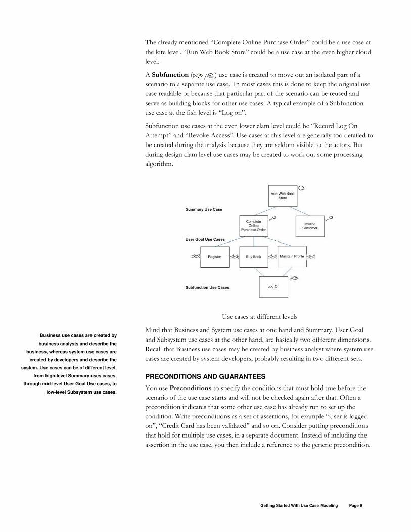
Use Case Level
Cockburn distinguishes three main levels of use cases, being Summary, User Goal
and Subfunction. Furthermore he uses a sailboat analogy with corresponding
symbols. Summary use cases are at cloud or kite level, User Goal use cases
at sea level and Subfunction use cases are under water at a fish or clam level.
A User Goal ( ) use case addresses the question: “Can the primary actor go
away happily after the use case finished?” The use cases “Complete Online
Purchase Order” or “Log On” do not generally count as user goals. The first one
does not because it may take days to complete an online purchase order and the
second one does not because logging on will not be user goal as such. “Buy Book”
or “Register Customer” are more likely to be User Goal use cases.
A Summary ( / ) use case outlines the context of a set of User Goal use
cases. The Summary use case may have a step in its scenario for each User Goal
use case. The time frame of a summary use cases is typically in terms of hours,
days, weeks or more. Recognizing Summary use cases can be a valuable aid while
determining the high-level requirements, but will not provide the functional
requirements.
Carefully consider the scope of a use case.
If something is essential for the use case
but outside its scope, it must be covered by
an actor or another use case.
Getting Started With Use Case Modeling Page 9
The already mentioned “Complete Online Purchase Order” could be a use case at
the kite level. “Run Web Book Store” could be a use case at the even higher cloud
level.
A Subfunction ( / ) use case is created to move out an isolated part of a
scenario to a separate use case. In most cases this is done to keep the original use
case readable or because that particular part of the scenario can be reused and
serve as building blocks for other use cases. A typical example of a Subfunction
use case at the fish level is “Log on”.
Subfunction use cases at the even lower clam level could be “Record Log On
Attempt” and “Revoke Access”. Use cases at this level are generally too detailed to
be created during the analysis because they are seldom visible to the actors. But
during design clam level use cases may be created to work out some processing
algorithm.
Use cases at different levels
Mind that Business and System use cases at one hand and Summary, User Goal
and Subsystem use cases at the other hand, are basically two different dimensions.
Recall that Business use cases may be created by business analyst where system use
cases are created by system developers, probably resulting in two different sets.
PRECONDITIONS AND GUARANTEES
You use Preconditions to specify the conditions that must hold true before the
scenario of the use case starts and will not be checked again after that. Often a
precondition indicates that some other use case has already run to set up the
condition. Write preconditions as a set of assertions, for example “User is logged
on”, “Credit Card has been validated” and so on. Consider putting preconditions
that hold for multiple use cases, in a separate document. Instead of including the
assertion in the use case, you then include a reference to the generic precondition.
Business use cases are created by
business analysts and describe the
business, whereas system use cases are
created by developers and describe the
system. Use cases can be of different level,
from high-level Summary uses cases,
through mid-level User Goal Use cases, to
low-level Subsystem use cases.

Getting Started With Use Case Modeling Page 10
With Minimal Guarantees you specify what, from the viewpoint of the
stakeholders, at least must hold true in case neither the main success scenario nor
any alternate rout has successfully finished. The most common Minimal Guarantee
is “The System has logged how far it got”. Minimal Guarantees are written as a set
of assertions that must be satisfied at the end of any path of the scenario, for
example “All entered information must have been stored”.
With Success Guarantees you specify what must have been achieved at the end
of the main success scenario or any alternate route. Success Guarantees are also
written as a set of assertions that describe what would satisfy any of the interests of
the stakeholders. These assertions add to the Minimal Guarantees.
Mind that Preconditions and Guarantees may be related to, but are not the same as
business rules.
USE CASE DIAGRAMS
A use case diagram provides an index to use cases. The following gives an
overview of the conventions you should apply when drawing use case diagrams.
Actors and Use Cases
In a diagram you include actors as people-like figures and use cases as ellipses and
draw lines that indicate the relationships, or communications between them.
It is custom to draw the primary actor and other stakeholders that communicate
with the use case to the left and secondary actors to the right. Put the primary
actor at the top, as in the following example.
Actors, use cases and communications
Use Case Inclusions
Higher-level use cases may call lower-level use cases (that is: require the behavior of
lower-level use cases). In UML-speak it is said that the higher-level use case includes
the lower-level one, hence the term “inclusion”. A typical example is a Summary
use case that includes User Goal use cases. Another typical example is a User Goal
use case that includes some reusable Subfunction use case, like “Log On”.
If you want to express this in the scenario of the Summary use case, you underline
the name of the lower-level use case, as in the following example:
Preconditions describe what needs to be
true before the use case can start. Minimal
Guarantees describe what at least should
hold true when the goal is not met, whereas
Success Guarantees describe what would
satisfy the goal.
A use case inclusion is another way to say
that one use case calls the other.
Getting Started With Use Case Modeling Page 11
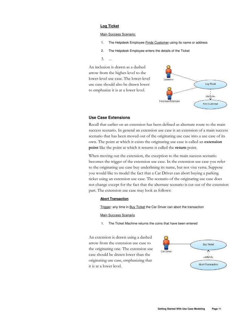
Log Ticket
Main Success Scenario:
1. The Helpdesk Employee Finds Customer using its name or address
2. The Helpdesk Employee enters the details of the Ticket
3. …
An inclusion is drawn as a dashed
arrow from the higher-level to the
lower-level use case. The lower-level
use case should also be drawn lower
to emphasize it is at a lower level.
Use Case Extensions
Recall that earlier on an extension has been defined as alternate route to the main
success scenario. In general an extension use case is an extension of a main success
scenario that has been moved out of the originating use case into a use case of its
own. The point at which it exists the originating use case is called an extension
point like the point at which it returns is called the return point.
When moving out the extension, the exception to the main success scenario
becomes the trigger of the extension use case. In the extension use case you refer
to the originating use case buy underlining its name, but not visa versa. Suppose
you would like to model the fact that a Car Driver can abort buying a parking
ticket using an extension use case. The scenario of the originating use case does
not change except for the fact that the alternate scenario is cut out of the extension
part. The extension use case may look as follows:
Abort Transaction
Trigger: any time in Buy Ticket the Car Driver can abort the transaction
Main Success Scenario
1. The Ticket Machine returns the coins that have been entered
An extension is drawn using a dashed
arrow from the extension use case to
the originating one. The extension use
case should be drawn lower than the
originating use case, emphasizing that
it is at a lower level.

Getting Started With Use Case Modeling Page 12
There are a few situations in which you create extension use cases, being:
• To leave details out of the originating use case that otherwise would
clutter its scenario.
• As a way to add to requirements that are fixed and you are not
allowed to change the originating use case.
• When the extension concerns an isolated piece of functionality that
may be implemented by a different team. In this case you may want
to be able to estimate both use cases separately.
Generalized Use Cases and Actors
In UML you can generalize use cases. When use case A specializes use case B (or B
generalizes A) you express that A is “a kind of” B, implying that whatever applies
to B also applies to A. A adds to or may override behavior of B.
Use case generalizations are drawn
by drawing an open arrow from
the specialized use cases to the
general one. The specialized use
cases are drawn below the general
one.
It is imperative that use cases are easy to read, while specializing some generic
scenario is conceptually a difficult thing to understand. In practise you probably are
best off by leaving the scenario of the generic use case empty and using
generalization only to share common stakeholders, triggers, conditions or other
properties between specialized use cases. However, the larger the system, the
more advantageous using the mechanism of generalizing use cases may become.
Actors can be specialized too, but that may also introduce confusion and should be
done scarcely. There are not that many properties to share between actors anyway.
ORGANIZING USE CASES
When there are more than just a few, organizing use cases becomes imperative for
several reasons, among them to be able to find them back.
As applies to many things giving a use case a proper name is a good start. A good
name generally has the form “Do Something” (active verb phrase) and expresses
the goal of the primary actor as clear as possible. Another good thing to do is to
number the use cases. In most situations a generic, hierarchical numbering will suit
best. For example, when the summary use case has number 1, use cases that detail
this are numbered as 1.1, 1.2 and so on.
An extension to the main success scenario
can be moved out to an extension use case,
to prevent the use case from becoming too
complex. Other reasons to create extension
uses cases can be to add to fixed
requirements or when a different
development team implements the
extension.
Use case and actor generalizations may be
too complex for targeted audience to
understand. Use them with care.

Getting Started With Use Case Modeling Page 13
UML provides the package construct to organize modeling elements, which can
also be used for use cases. With JDeveloper versions up to 10.1.3 you cannot
change the package of sets of use cases at a time, only one at a time1. This will
change in some future release, but even then diagrams must be redrawn after you
moved use cases, which can take a considerable amount of time. Therefore, before
you start recording use cases you should carefully think about how you want to
organize them, trying to prevent a future need to move use cases.
There are a couple of alternatives to organize use cases:
• By primary actor
• By summary use case
• By development team and release
• By subject area
• Combinations of the above
Cockburn states that from 80 to 100 use cases, organizing them by primary actor
looses effectiveness, as you end up with too many use cases per primary actor.
Whenever you write Summary use cases, organizing by Summary use case is a
natural thing to do. If there is more than one team, then organize them by
development team. This also makes (re)estimating and progress monitoring easier.
Coburn states that from 100 use cases or more, people naturally start clustering use
cases by subject area.
When you decided to organize the use cases by primary actor, you can create a
package structure for example as follows:
mycompany.myproject.usecases.actor1
mycompany.myproject.usecases.actor2
…
JDeveloper supports two “Subjects”, being “System Boundary” and “Milestone”.
The System Boundary typically is used to organize use cases by (sub)system but
can also be used for other subject areas you might recognize. Milestones can be
used for example when the system is developed in increments to organize use
cases per development team and release, or other types of delivery dimensions. A
use case can appear in more that one Subject, for example in both a System
Boundary and a Mile Stone.
The following figure shows an example of using System Boundaries to identify to
what subsystems use cases belong to.
1 You can move a use case from one package to another by selecting it, right-click -> Display Properties -> check “Show Package” and change the package manually. For readability you need to uncheck “Show Package” afterwards.
Give use cases a name that expresses the
goal clearly and number them. Use cases
can be organized by primary actor,
Summary use case, development team and
release, or subject area.

Getting Started With Use Case Modeling Page 14
Consider creating one package “mycompany.myproject.allactors” that contains one
diagram to drop actors on and include them in other diagrams. This enforces that
actor names are unique (as they should). You can include actors in another diagram
by either right-clicking the diagram, or by copy-paste.
Also consider putting activity diagrams that detail a use cases (see also “Relation
With Other UML Artifacts”) in a sub package of the package the related use case is
in, for example “mycompany.myproject.usecases.actor1.activities”.
WRITING IN ITERATIONS
Use cases are written in iterations. A good way to start is with identifying all actors
and their goals. If your work with a high-level MoSCoW-list2 to define the scope of
the project you may consider setting it up as an Actor-Goal List that lists all actors
with their named goals, a brief description of each goal and the priority it has.
Actor-Goals List starts with naming the actors with their goals. When you have the
feeling the list is pretty complete, you start adding Brief Descriptions. You may
find new goals and actors when doing so. After the Actor-Goal List is verified and
complete, it can be prioritized. Keep in mind that the priority of each goal should
have been determined by the customer.
The next step is to create initial use cases out of the Actor-Goal List. Many of the
goals will turn out to be User Goal level use cases. In many cases you can use the
goal as name for the use case and copy the Brief Description.
After that you write the main success scenario for all use cases. Next you identify
the exceptions there may be to the main success scenario of each use case and you
write extension to that. It is very important to work out these exceptions, as new
actors, classes (see also “Relation to Other UML Artefacts”) and business rules
may be discovered.
2 MoSCoW stands for Must Have, Should Have, Could Have and Won’t Have and is used to prioritize functionality. You can find more about MoSCoW at http://na.dsdm.org/en/about/moscow.asp.

Getting Started With Use Case Modeling Page 15
The following table is an example Actor-Goal List with MoSCoW prioritization:
Actor Goal Brief Description Prio
Customer Place Order Use the web store to purchase one or
more books.
M
Receive Purchased
Books
Receive books in good order and sign for
it.
M
Sales Staff Process Order Receive an online order and initiate the
delivery process.
M
Notify Customer
Offerings
Send an email to customers about special
offers.
S
Book Store
Staff
Prepare Shipment Collect all books for one order and prepare
it for shipment to the customer.
M
Track Shipment View the delivery status of the shipment C
Do not yet try to optimize the scenarios at this point by generalizing use cases,
creating inclusions or extensions. By now you should have a pretty complete set of
User Goal use cases. Verify this with the customer before you move on!
Finally you may optimize the use cases by using generalization, creating
Subfunction use cases use inclusions and even extensions.
The short recipe for creating use cases is as follows:
1. Identify the actors
2. List their goals
3. Add brief descriptions to the goals
4. Create an initial use case for each goal
5. Describe the main success scenario for each use case
6. Identify the exceptions to the main success scenarios and work them
out as extensions
7. Validate the use cases
8. Optimize the use cases

Getting Started With Use Case Modeling Page 16
RELATION WITH OTHER UML ARTIFACTS
At some point when writing the main scenario, you start documenting the classes
that support the requirements that have been captured by the use cases. To clearly
express the relationship with the classes, you refer to them in the scenario using
their exact name.
Complex scenarios can be documented using an Activity Diagram. The Activity
Diagram is then a graphical representation of the scenario of the use case,
including its extensions. Activity Diagrams are generally created to detail User Goal
use cases, but you can use them detail any use case at any level.
When timing aspects of scenario are important, you can document that using a
Sequence Diagram. Whenever there is the need to document the relationship
between use cases and classes, you can use a Collaboration Diagram.
More information about Activity, Sequence or Collaboration Diagrams can be
found at the UML site. A very pragmatic view on using UML diagrams is provided
by Scott Ambler, whose site is mentioned at the end of this paper.
USE CASES VERSUS FUNCTION HIERARCHY
Use cases are the object-oriented equivalent of the function hierarchy of the
traditional structured analysis, though there are some notable differences.
A User Goal use case can be compared to an elementary function (for which you
record Create, Retrieve, Update and Delete usages or CRUD for short) that are
candidate to be transformed to screen, report or batch modules. The Summary use
case can be compared to a master function (that is the parent of two or more
elementary functions), while the Submodule use case can be compared to a
supporting function.
In general a function hierarchy is created by clustering functionality from a
functional point of view, whereas with use cases functionality is organized from
the point of view of user goals. Structured analysis tends to optimize from day one
by trying to avoid duplicate functionality, while with use case modeling this is not a
prime concern. It is likely that, when both are being performed in a proper way, in
the end the result of both approaches will deliver comparable results. Personally I
tend to believe that with use case modeling this result will be delivered more
efficiently, especially because of the focus on the user goals.
This section started to state that use cases are the object-oriented equivalent of a
function hierarchy, but there is nothing object-oriented about use cases as such.
The requirements that have been captured with use cases still need to be mapped
to an object-oriented design. Use cases may just as well be mapped to a relational
design. Unlike a function hierarchy, use cases can be used at any level of the
analysis and design including a technical design, although the latter is rarely done .
Use cases can be detailed by Activity
Diagrams, Sequence Diagrams,
Collaboration Diagrams, or whatever other
technique is appropriate.

Getting Started With Use Case Modeling Page 17
With a function hierarchy you explicitly record how entities are used. With use
cases you do not explicitly record how objects are used. As a result, checks for
completeness and impact analysis are more difficult with use cases.
MORE INFORMATION
A book that you want to have at hand when creating use cases is “Writing
Effective Uses Cases”, by Alistair Cockburn (ISBN 978-0201702255). This book
contains many examples that clearly illustrate good use cases. Cockburn also has a
website that can be reached at http://alistair.cockburn.us/.
More interesting information about object-oriented analysis and design in general,
including use case modeling, can be found at Parlez|UML: http://parlezuml.com.
The official UML site can be found at http://www.uml.org/. A short and very
pragmatic reference on how to use UML modeling techniques, can be found at the
site of Scott W. Ambler:
http://www.agilemodeling.com/essays/umlDiagrams.htm
Other papers in the Getting Started With series are:
Getting Started With Class Modeling
Getting Started With Use Case Modeling
Getting Started With Unit-Testing
Getting Started With CVS

Getting Started With Use Case Modeling Page 18
Example of a modified JDeveloper Casual use case template
Extends : Specializes : Goal of Primary Actor : Level : User Goal Scope : Ticket Machine Stakeholder(s) : Car Driver Traffic Police Brief Description : A Car Driver buys a parking ticket from the Ticket Machine. Precondition : The Ticket Machine must be functioning Postcondition :
Minimal Guarantee(s) :
Success Guarantee(s) :
The Car Driver has been provided with a printed ticket.
Trigger : The Car Driver enters a coin in the Ticket Machine. Scenario :
1. The Car Driver enters a coin in the Ticket Machine.
2. The Ticket Machine validates the coin
3. The Ticket Machine indicates until when the Car Driver can park.
4. The scenario continues with step 1 and 2 until the Car Driver is satisfied
5. The Car Driver presses the button to retrieve the parking ticket.
6. The Ticket Machine prints the parking ticket.
Extensions
2a Invalid coin:
2a1 The Ticket Machine returns an invalid coin;
2a2 Return to step 1
3a Car Driver aborts transaction:
3a1 The Ticket Machine returns the coins that have been entered
3a2 The scenario ends.
Open Issue(s) :... Referenced By :

Getting Started With Use Case Modeling
May 2007
Author: Jan Kettenis
Oracle Corporation
World Headquarters
500 Oracle Parkway
Redwood Shores, CA 94065
U.S.A.
Worldwide Inquiries:
Phone: +1.650.506.7000
Fax: +1.650.506.7200
oracle.com
Copyright © 2005-2007, Oracle. All rights reserved.
This document is provided for information purposes only and the
contents hereof are subject to change without notice.
This document is not warranted to be error-free, nor subject to any
other warranties or conditions, whether expressed orally or implied
in law, including implied warranties and conditions of merchantability
or fitness for a particular purpose. We specifically disclaim any
liability with respect to this document and no contractual obligations
are formed either directly or indirectly by this document. This document
may not be reproduced or transmitted in any form or by any means,
electronic or mechanical, for any purpose, without our prior written permission.
Oracle is a registered trademark of Oracle Corporation and/or its affiliates.
Other names may be trademarks of their respective owners.