Geometrical and graphical essays, containing a general ...
546
-
Upload
khangminh22 -
Category
Documents
-
view
0 -
download
0
Transcript of Geometrical and graphical essays, containing a general ...
THE LIBRARYOF
THE UNIVERSITYOF CALIFORNIALOS ANGELES
GIFT OF
John S.Prell


J^^Knielit
• /
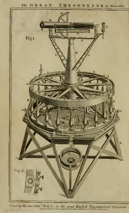
tA/'Grea.t Theodolite, *y Ramsden
Used Iftf the late Gm ^.Roil iv- in the great Eiiglisli Tr,\/a7wnuttna1 OveroUon^

GEOMETRICALAND
GRAPHICAL ESSAYS,CONTAI NIXG,
A GENERAL DESCRIPTION
OF THE
MATHEMATICAL INSTRUMENTS
USED IN
GEOMETRY, CIVIL AND MILITARY SURVEYING,LEVELLING, AND PERSPECTIVE;
WITH MANY NEW
PRACTICAL PROBLEMS.
ILLUSTRATED BY THIRTY-FOUR COPPER PLATE;,
BY THE LATE
GEORGE ADAMS,MATHEMATICAL INSTRUMENT MAKER. TO HIS MAJESTV, &C.
THE SECOND EDITION,
CORRECTED AND ENLARGED BY
WILLIAM JONES,
MATHEMATICAL INSTRUMENT MAKER,
LONDON:PRINTED BY J. DILLON, AND CO.
AND SOLD BY W. AND S. JONES, OPTICIANS,HOLBORN, LONDON.
JOH^I S. Pf^ELLCivil & Mcchardcal En-rineer.
SAN FkAMnTon/^ .. ^

TO
THE MOST NOBLE
CHARLES, DUKE of RICHMOND,AND LENNOX,
Master General of the Ordnance, &c.
THESE ESSAYS
ARE
V,
WITH GREAT RESPECT,
JUSTLY INSCRIBED,
BY HIS grace's
Most obedient.
Humble Servant,
GEORGE ADAMS.
to
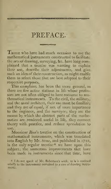
PREFACE.
1 HOSE who have had much occasion to use themathematical ijnstrumcnts constructed to facilitate
the arts of drawing, surveying, &c. have Iqng com-plained that a treatise was wanting to explain
their use, describe their adjustments, and give
such an idea of their construction, as might enable
them to select those that are best adapted to their
respective purposes.
This complaint has been the more general, as
there are few active stations in life whose profes-
sors are not often obliged to have recourse to ma-thematical instruments. To the civil, the military,
and the naval architect, their use must be familiar;
and they are of equal, if not of more importance
to the engineer, and the surveyor; they are the
means by which the abstract parts of the mathe-matics are rendered useful in life, they connect
theory with practice, and reduce speculation to
use.
Monsieur Bions treatise on tlic construction of
mathematical instruments, which was translated
into English by Mr. Stone, and published in 172^3,
is the only regular treatise* we have upon this
subject; the numerous improvements that have
been made in instruments since that time, have
* I do not speak of Mr. Robertson's work, as it Is confined
wholly to the instruments contained in a case of drawing instru-
ments.

11 PREFACE.
rendered this work but of little use. It has beenmy endeavour by the following Essays to do awaythis complaint; and I have spared no pains to
render them intelligible, and make them useful.
Though the materials, of which they are com-posed, lie in common, yet it is presumed, that
essential improvements will be found in almost
evciy part.
These Essays begin by defining the necessary
terms, and stating a few of those first principles
on which the v/hole of the work is founded: they
then proceed to describe the mathematical draw-ing instruments; among these, the reader will find
an account of an improved pair of triangular com-passes, a small pair ofbeam compasses with a micro-
meter screw, four new parallel rules, and other ar-
ticles not hitherio described : these are followed bya large collection of useful geometrical problems;
I flatter mvsclf, that the practitioner will find manythat are new, and which are well adapted to lessen
labour and promote accuracy. In describing the
manner of cHviding large quadrants, I have first
given the methods used by instrument makers,
previous to the publication of that of Mr. Bird^
subjoining his mode thereto, and endeavouring to
render it more plain to the artist by a different ar-
rangement. This is succeeded by geomel^rical andmechanical methods of describing circles of every
possible magnitude; for the greater part of whichI am indebted to Joseph Priestley, Esq. of Bradford,
Yorkshire, whose merit has been already noticed
by an abler pen than mine.*' From this, I pro-
ceed to give a short view of elliptic and other com-passes, and a description of Suanli's geometric pen,
an instrument not known in this country, and
* Pr -tlcy's Perspecti\e,
PREFACE. Ill
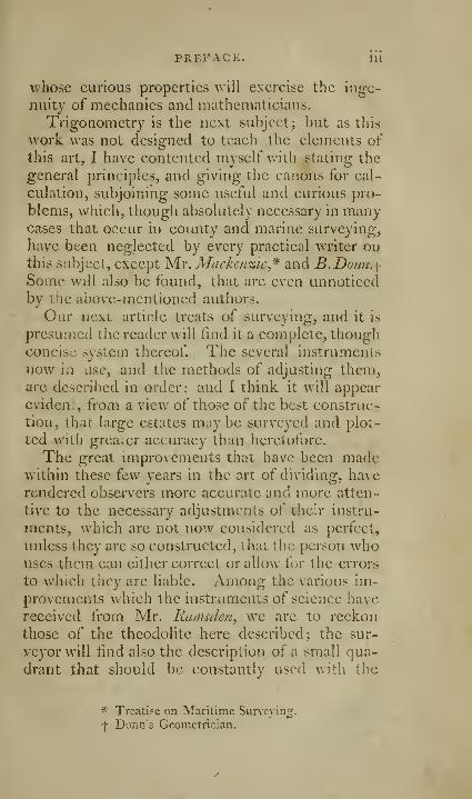
whose curious properties will exercise the inge-
nuity of mechanics and mathematicians.
Trigonometry is the next subject; but as this
work was not designed to teach the elements of
this art, I have contented myself with stating the
general principles, and giving the canons for cal-
culation, subjoining some useful and curious pro-
blems, which, though absolutely necessary in manycases that occur in county and marine surveying,
have been neglected by every practical writer oathis subject, except Mr. Mackenzie,* and B.Donn,\Some will also be found, that are even unnoticedby the above-mentioned authors.
Our next article treats of surveying, and it is
presumed the reader will find it a complete, thoughconcise system thereof. The several instruments
now in use, and the methods of adjusting them,are described in order; and I think it will appear
evidem, from a view of those of the best construc-
tion, that large estates maybe surveyed and plot-
ted with greaier accuracy than heretofore.
The great improvements that have been madewithin these few years in the art of dividing, have
rendered observers more accurate and more atten-
tive to the necessary adjustments of their instru-
ments, which are not now considered as perfect,
unless they are so constructed, that the person whouses them can either correct or allow for the errors
to which they are liable. Among the various im-
provements which the instruments of science have
received from Mr. Ramsden, we are to reckon
those of the theodolite here described; the sur-
veyor will find also the description of a small qua-
drant that should be constantly used with the
* Treati?e on Maritime Suneyin^.
f Donn's Geometrician,
IV PREFACE.
chain, improvements in the circumferentor, plain-t
table, protractor, &c. In treating of surveying,
I thought to have met with no ditHculty ; havinghad however no opportunity of practiee myself,
I had recourse to books; a multiplicity have beenwritten upon this subject, but they are for the
most part imperfect, irregular, and obscure. I
have endeavoured (with what success must be left
to the reader's judgment) to remove their obscu-
rities, to rectify their errors, and supply their defi-
ficiencies; but whatever opinion he may form of
my endeavours, I can venture to say, he will behighly gratified with the valuable communicationsof Mr. Gale,* and Mr. Milne, here inserted, andwhich I think will contribute more to the im-
provement of the art of surveying, than any thing
it has received since its original invention.
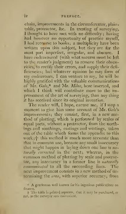
The reader will, I hope, excuse me, if I stop a
moment to give him some account of Mr. Gale's
improvements; they consist, first, in a new me-thod of plotting, which is performed by scales of
equal parts, without a protractor, from the north-
ings and southings, eastings and westings, taken
out of the table which forms the appendix to this
work;-)- this method is much more accurate than
that in common use, because any small inaccuracy
that might happen in laying down one line is mj-
turally corrected in the next; whereas, in the
common method of plotting by scale and protrac-
tor, any inaccuracy in a former line is tuiturally
communicated to all the succeeding lines. Thenext improvement consists in a new method of de-
termining the area, with superior accuracy, from
•'' A gentleman well known for his ingenious publications on
finance.
-fThe table is printed separate, that it may be purchaccd^ oi
not; as the surveyor sees convenient.
PREFACE. V
the northings, southings, castings, and westings,
without any regard to the plot or draught, by aneasy computation.
As the measuring a strait hnc with exactness is
one of the greatest difficulties in surveying, I wasmuch surprised to find many land surveyors using
only a chain ; a mode in which errors are multiplied
without a possibility of their bein^ discovered, or
corrected. I must not forget to mention here,
that I have inserted in this part Mr. Break's me-thod of surveying and planning by the plain table,
the bearings being taken and protracted at the
same instant in the held upon one sheet of paper;
thus avoiding the trouble and inconvenience ofshifting the paper: this is followed by a small
sketch of maritime surveying; the use of the pan-tographer, or pantagraph ; the art of levelling, anda few astronomical problems, with the manner ofusing Hadley's quadrant and sextant; even here
some suggestions will be found that are new anduseful.
I have now to name another gentleman, who has
contributed to render this work more perfect thanit would otherwise have been, and it is with plea-
sure I return my best thanks to Mr. La?i(iman,
Professor of fortification and artillery to the RoyalAcademy at Woolwich, for his communications,
more particularly for the papers from which the
course of practical geometry on the ground wasextracted. If the professors of useful sciences
would thus liberally co-operate for their advance-
ment, the progress thereof would be rapid and ex-
tensive. This course will be found useful not only
to the military officer, but would make a useful
and entertaining part of every gentleman's educa-tion. I found it necessary to abridge the papers
JNIr. Landnian lent me_, and leave out the calcula-
VI PREFACE,
tions, as the work had already swelled to a larger
size than was originally intended, though printed
on a page unusually full.
The woi'k iinishes with a small tract on perspec-
tive, and a description of two instruments designed
to promote and facilitate the practice of that use-
ful art. It is hoped, that the publication of these
will prevent the public froiTft being imposed uponby men, who, under the pretence of secresy, en-
hance the value of their contrivances. I knev,- aninstance where 40 1. was paid for an instrument
inferior to the most ordinary of the kind that are
sold in the shops. Some pains have been taken,
and no small expense incurred, to offer somethingto ihe public superior in construction, and easier
to use, than any instrument of the kind that has
been hiihcrto exhibited.
I have been anxious and solicitous not to neg-lect any thing that might be useful to the practi-
tioner, or acceptable to the intelligent. In a workwhich embraces so many subjects, notwithstand-
ing all the care that has been taken, many defects
may still remain; I shall therefore be obliged to
any one who will favour me with such hints or
observations, as may tend towards its improve-
ment.
A list of the authors I have seen is subjoined to
this Preface. I beg leave to return my thanks to
the following gentlemen for their hints and va-
luable communications, the Rev. Mr. HawkhiSy
J. Piieslley, Esq. Mr. Gak, Mr. Milne, Dr. Rother^
ham, Mr. Heywood, Mr. Landman, and Mr. Becky
a very ingenious artist.
ADVERTISEMENTBT
THE EDITOR.
JL HE first edil'mi of these Essays havings like the
rest of the late ingenious Author"s ijuorks^ received
viuch share of public approbation and encourage-
ment \ and being myself a joint proprietor with wyhrother, S. Jones, of the copyright of all his publi-
cations, I conceive, that I ca?inot employ the few lei-
sure moments, after the business of the day, better,
than by revising, correcting, and improving those
works that require reprintn/g. The present is thefirst
of my editing: considerable errors in the former edi-
tion have been corrected; more complete explanations
of instruments given, a)id many particulars ofnew anduseful articles, not noticed by the Author, with noteSy
^c. are inserted in their proper places. The additions
and amendments are, upon the vohole, such, as Ipre-sume, without any pretension to superior abilities on
my part, will again render the work deserving of the
notice of all students and practitioners in the aiffercnt
professional branches of practical geometry. Theprincipal additions I have made are the following:
Description of a new pair of pocket Compasses,
containing the ink and pencil points in its twolegs—Improved Pei-ambulator—Way Wiser—Im-proved Surveying Cross—Improved Circumferen-
tor-^Complete portable Theodolite—Great Theo-dolite, by Ramsden—Pocket box Sextant—Artifi-
cial Horizon—Pocket Spirit Levels—A Pair of
Perspective Compasses
—
Keiilis improved Parallel
Scale—New Method of Surveying and keeping a
Field Book—Gunner's Callipers—Gunner's Qua-drant—Gunner's Level, he.
March 30, JV. JONES.1797-
LISTOF AUTHORS,
CONSULTED FOR THIS WORK.
Pion Construction, &c. of Mathematical
Instruments, London, 1/23
Break Systeni of Land Surveying, London, 1/73
Bonnycastle . . Introduction to Mensuration London, 1/87
Cunn Treatise on the Sector, London, 1729
Clavius Astrolabium Tribus Libris Expli-
catum, Moguntioe, 161
1
Cagnoli Traite de Trigonometric, Paris, 1/85
De la Grive . . INIanuel de Trigonometric Paris, 1 /j-i
Donn Geometrician London, \']'J5
Daudet Introduction a la Geometric, Paris, 178O
Dalrymple . . . Essay on Nautical Surveying, .... London, 1786
Eckhardt .... Description d'unGraphometre,. . Ala Haye, 17/8
Gardner Practical Surveying, London, 1737
Gibson Treatise of Surveying, Dublin, 17O3
Hutton Treatise on Mensuration, . London, 1788
Hume Art of Surveying, London, 1763
Hammond . . . Practical Surveyor, London, 1765
LeFebvre. . . . Oeuvres Complettes, . . . .• Maestricht, 1778
liOve Art of Surveying, London, 178(5
Mackenzie . . . Treatise of Maritime Surveying, . . London, 17/4
Mandey Marrow of Measuring, London, 1717
Nicholson . . . Navigator's Assistant, London, 1784
Noble Essay on Practical Surveying, .... London, 1774
Payne Elements of Geometry, London, I'i^'J
Trigonometry, London, 1773
Picard Traite du Nivelment, Paris, 1784
Robertson . . . Treatise of Mathematical Instal-
ments, London, 1775
Spiedell Geometrical Extraction, London, i6j7
Talbot Complete Art of Land Measuring, London, 1784
Hutton's Mathematical and Philosophical Dicticnary, 4to. I'J^^.
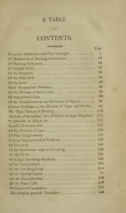
A TABLE
CONTENTS.
Page
Necessary Definitions and First Principles 1
Of Mathematical Drawing Instruments 10
Of Drawing Compasses •14
Of Parallel Rules 21
Of the Protractor 30
Of the Plain Scale 32
Of the Sector 40
Select Geometrical Problems 52
Of the Division of Strait Lines 59
Of Proportional Lines oO
Of the Transformation and Reduction of Figures 81
Curious Problems on the Division of Lines and Circles . . 93
Mr. Bird's Method of Dividing 108
Methods of describing Arcs of Circles of large Magnitude 134
To Describe an Ellipse, &:c 153
Suardi's Geometric Pen 157
Of the Division of Land l60
Of Plain Trigonometry 171
Curious Trigonometrical Problems 17^
Of Suri'eying 194
Of the Instruments used in Surveying 199
Of the Chain 202
Of King's Surveying Quadrant 205
Of the Perambulator 208
Of the Levelling Cross 214
Of the Optical Square '^•
Of the Circumferentor 210
Of the Plain Table 2^6
Of Improved Theodolites 231
The complete portable Theodolite 243
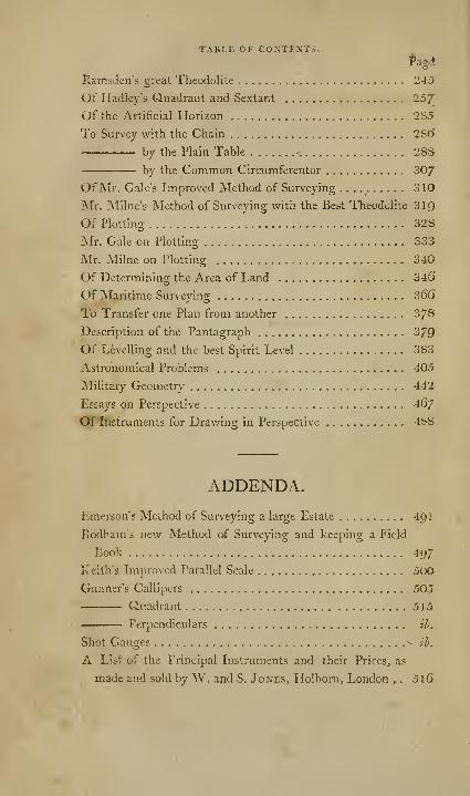
TABLE OF CONTENTS.#agc»
llamsden's great Theodolite 243
i)i Hadley's Quadrant and Sextant 25/
Of the Artificial Horizon 285
To Survey with the Chain 28(5
by the Plain Table -. 28S
by the Common Circumferentor 307
Of Mr. Gale's Improved Metliod of Surveying 310
jNIr. ]\1 line's JNIethod of Surveying with the Best Theodolite 319
Of Plotting 328
Mr. Gale on Plotting 333
jNIr. Milne on Plotting 340
Of Determining the Area of Land 346'
Of Maritime Survwing 36G
To Transfer one Plan from another 3/8
Description of the Pantagraph 379
Of Levelling and the best Spirit Level 383
Astronomical Problems 405
jNIilitary Geometry 442
Essays on Perspective 46j
Of instruments for Drav/ing in Perspective 48S
ADDENDA.
Emerson's Method of Surveying a large Estate 4gi
Jlodbam's new Method of Surveying and keeping a Field
Book 41)7
Keith's Improved Parallel Scale 500
Gunner's Callipers 505
Quadrant 515
• Perpendiculars il?.
Shot Gauges ^ iL
A List of the Principal Instruments and their Prices, as
made and sold by W. and S. Jones, Holborn, London , . 5lG
Uoil & Mechanical EngineerSAN FRANCHSCO, OAL. '
GEOMETRICALAND
GRAPHICAL
ESSAYS.
NECESSARY DEFINITIONS, and FIRST
PRINCIPLES.
vXEOMETRY Originally signified, according to
the etymology of the name, the art of measuringthe earth ; but is now the science that treats of,
and considers the properties of magnitude in ge-
neral—In other words, extension and figure are
the objects of geometry. It is a science, in whichhuman reason has the most ample field, and cango deeper, and with more certainty, than in anyother. It is divided into two parts, theoretical
.and practical.
Theoretical geometry considers and treats of
first principles abstractedly. Practical geometryapplies these considerations to the purposes of life.
By practical geometry many operations are per-
formed of the utmost importance to society andthe arts. " The effects thereof are extended
through the principal operations of human skill:
it conducts the soldier in the field, the seaman onB
2 NECESSARY DEFINITIONS,
the ocean : it gives strength to the fortress^ and.elegance to the palace."
The invention of geometry has been, by all themost eminent writers on the science, attributed
to the Egyptians; and, that to the frequent inun-dations of the river Nile upon the country, we owethe rise of this sublime branch of human know-ledge; the land-marks and boundaries being in
this Wily destroyed, the previous knowledge of thefigure and dimensions was the only method of as-
certaining individual property again. But, surelv,
it is not necessary to gratify learned curiosity
b^ such accounts as these; for geometry is an art
that must have grown with man; it is, in a great
measure, natural to the human mind; we wereborn spectators of the universe, which is the king-dom Tf geometry, and are continually obliged to
judge of heights, measure distances, ascertain the
iigure, and estimate the bulk of bodies.
The fu'st definition in geometry is a point, whichis considered by geometricians, as that v/hjeh ha3
no parts or magnitude.
A line is length v/ithout breadth.
A strait line is that which lies evenly betweenits extreme points or ends.
A superficies is that which has only length andbreadth.
K plane angle \^ an opening, or corner, made bytwo strait liilies meeting one another.
When a strait line AB,^^. 1, plate A, standing
upon another C D, m.akes angles A B C, A B D,on each side equal to one another; each of these
angles is called a right angle; and the line A B is
said to ho. perpetidieular to the line C D.It is usual to express an angle by three letters,
that placed at the angular point being ahvays in
the middle; as B is the angle of AB C.

AND FIRST PRINCIPLES. S
An ohtnse angle is that which is greater than a
right angle. ,
. An acute an^le is that which is less than a rio-ht
angle.
A line A B,^o-. 2, plate A, cutting another line
CD in E, will make the opposite angles equal,
namely, the angle AEC equal to B E D, andAEDequaltoBEC.A line A B, Jig. 3, plate 4, standing any-way
upon another CD, makes two angles CBA, AB'D,which, taken together, are equal to two right
angles.
A plane tna??gle is a figure bounded by three
right lines. -
An equilateral tr'uingle is that whichhas three equal sides.
An isosceles triangle is that which has
only two equal sides.
A scalene triangle is that which has
all its sides unequal.
A right-angled triangle is that which
has one rirht ano-le.
In a riglit-angled triangle, the side opposite to
the right angle is called the liyprAlienuse.
An chlique-angled triangle is that /which has no rit>ht ano-le. /
In the same triangle, opposite to the greater
side is the greater angle; and opposite to the
greater angle is the greater side.
B 2
4 NECESSARY DEFINITIOXS^
Ifany side of a plane triangle be produced, thtf
outward angle will be equal to both the inward
remote angles.
The three angles of any plane triangle takers
together, are equal to two right angles.
Parallel lines are those which have no inclina-
tion towards each other, or which are every-where
equidistant.
All plane figures, bounded by four right lines,
are called quadrangles, or quadrilaterals.
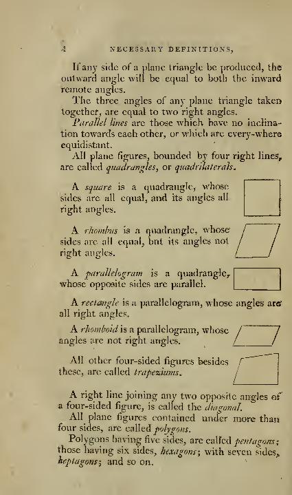
A square is a quadrangle, whose
sides are all equals and its angles all
right angles.
A rhomhus is 3 quadrangle, whose
sides are all equal, but its angles not
right angles.
A parallelogram is a quadrangle,- 1
|
whose opposite sides are parallel.| j
A rectangle is a parallelogram, whose angles are"
all right angles.
A rhomboid is a parallelogram, whose / 7angles arc not right angles. / /
All other four-sided figures besides
these, are called trapeziums,j
A right line joining any two opposite angles ofa four-sided figure, is called the dwgoiial.
All plane figures contained under more thanfour sides, are iz^Vnt^ polygons.
Polygons having five sides, are q,^\^^ pentagans%those having six sides, hexagons \ with seven sides^
heptagons-^ and so on.
AND FIRST PRIXCIPLES. 5,
A regular polygon is that whose angles and sides
.are all equal.
The base of any figure is that side on whichit is supposed to stand, and the altitude is the
perpendicular falling thereon from the opposite
angle.
Parallelograms upon the same base, and be-
tween the same parallels, are equal.
Parallelograms having the- same base, and equal
altitudes, are equal.
Parallelograms having equal bases, and equal
altitudes, arc equal.
If a triangle and parallelogram have equal bases
and equal altitudes, tKe triangle is half the paral-
lelogram.
A circle is a plane figure, bounded by a curve
line called the circumference, every part, whereof is
equally distant from a point within the same figure,
called the center.
Any part of the circumference of a circle is
called an arch.
Any right line drawn from the center to the cir-
cumference of a circle, is called a radius.
All the radii of the same circle are equal.
The circumference of every circle is supposed
to be divided into 36o equal parts, called J^?^r^^j
;
each degree into 6o equal parts, called minutes, &c.
A quadrant of a circle will therefore contain 90degrees, being a fourth part of 360.
Equal angles at the centers of all circles, will
intercept equal numbers of degrees, minutes, &c,
in their circumferences.
The measure of every plane angle is an arch of
a circle, whose center is the angular point, and is
said to be of so many degrees, minutes, &c. as are
contained in its measurinaiarch.
O NECESSAE.Y DEFINITIONS,
All right angles, therefore, are of go degrees,
or contain QO degrees, because their measure is a
quadrant.
The three angles of every plane triangle taken
together, contain 180 degrees, being equal to tworight angles.
In a right-angled plane triangle, the sum of its
two acute angles is 90 degrees.
The cGmplcmcnt of" an arch, or of an angle, is
its difi'erence from a quadrant or a right angle.
The supplement of an arch, or of an angle, is
its difference from a semicircle, or two right
angles.
The magnitudes of arches and angles are deter-
mined by certain strait lines, appertaining to a
circle, called chords, sines, tangents, &c.
The cliord of an arch is a strait line, joining its
extreme noinls.
A diameter is a chord passincr throuo:h the center.
A segment is any part of a circle bounded by an
arch and its chord.
A sector is any part of a circle bounded by an
arch, and two radii drawn to its extremities.
The sine of an arch is a line drawn from either
end of it, perpeiKlicular to a diameter meeting the
other end.
The iierscd slue of an arch is that part of the di-
ameter intercepted between the sine and the endofthe said arch.
The tangent of an arch is a line proceeding fromeither end, perpendicular to the radius joining it;
its length is limited by a line drawn from the
center, through the other end.
The secant of an arch is the line proceeding
from the center, and limiting the tangent of the
same arch.
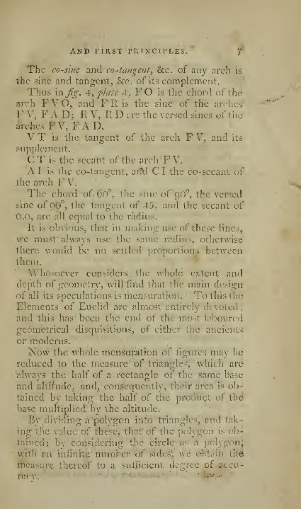
AND FIRST PRINCIPLES. 7
The co-sine and co-tangent, &c. of any arch is
the sine and tangent, 8cc. of its complement.Thus '\x\fg. A, plate 4, FO is the chord of the
arch FVO, and FR is the sine of the arches
F V, FAD; K V, II D arc the versed sines of the
arches FV, FAD.V T is the tangent of the arcli F V/ and its
supplement.
C T is the secant of the arch FV.A I is the co-tangent, ai'^1 C I the co-sccant of
the arch F V. '.
The chord of 6o°, the sine of ()0°, the versed
sine of 90°, the tangent of 45, and the secant of
0.0, arc all equal to the radius.
It is obvious, that in making use of these lines,
we must alwnys use the same radius, otherwise
there would be no settled proportions betweenthem.
Whosoever considers tlie whole extent anddepth of geometry, will find that the main design
of all its speculations is mensuration. ' To this the
Elements of Euclid arc almost entirely devoted
,
and this has been the end of the most laboured
geometrical disquisitions, of either the ancients
or moderns.
Now the whole mensuration of figures may be
reduced to the measure' of triairgle'?j which are
alwavs the half of a reetan2:le of the sarnie Base
and ahirude, and, consequently, theii' area is ob-
tained by taking the half of the product of the
base multiplied by the altitude.
By dividing a polygon into triangles, and tak-
ing the value: of t'feese, that 6{ the polygon is ob-f
taincd; by considering the circle as' a\])blygon^
with an infinitb' number of sideS^ we o-bt;»in the
measure thereof to a sufficient degree of accu-
nicv. ^

8 NECESSARY DEFINITIONS,
The theory of triangles is, as it were, the hingeupon which all geometrical knowledge turns.
All triangles are more or less similar, accordingas their angles are nearer to, or more remote from,equality.
The similitude is perfect, when all the angles
of the one are equal respectively to those of theother; the sides are then also proportional.
The angles and the sides determine both the
relative and absolute .size, not only of triangles,
but of all things.
Strictly speaking, angles only determine therelative size ; equiangular triangles may be of veryunequal magnitudes, yet perfectly similar.
But, when they are also equilateral, the onehaving its sides equal to the homologous sides ofthe other, they are not only similar and equian->
gled, but are equal in every respect,
The angles, therefore, determine the relative
species of the triangle; the sides, its absolute size,
and, consequently, that of every other figure, as
all are resolvible into triangles.
Yet tlie essence of a triangle seems to consist
much more in the angles than the sides; for theangles are the true, precise, and determined boun-daries thereof: their equation is always fixed andlimited to two right angles.
The sides have no fixed equation, but may beextended from the infinitely little, to the infinitely
great, without the triangle changing its natureand kind.
It is in the theory of isoperimetrical figures*
that we feel how efficacious angles are, and howinefficacious lines, to determine not only the kind,
|)ut the size ofthe triangles, and all kinds of figures.
* Isoperimetrical figures are such as have equal circumferencea.
AND FIRST PRINCIPLES. g
For, the lines stili subsisting the same, we see
how a square decreases, in proportion as it is
changed into a more obHque rhomboid; and thusacquires more acute angles. The same observa-
tion holds good in all kinds of figures, whetherplane or solid.
Of all isoperimetrical figures, the plane triangle
and solid triangle, or pyramid, are the least capa-
cious; and, amongst these, those have the least
capacity, whose angles arc most acute.
But curved surfaces, and curved bodies, and,
among curves, the circle and sphere, arc those
whose capacity are the largest, being formed, if
we may so speak, of the most obtuse angles.
The theory of geometry may, therefore, be re-
duced to the doctrine of angles, tor it treats only
of the boundaries of things, and by angles the ul-
timate bounds of all things are formed. It is the
angles which give them their figure.
Angles are measured by the circle; to these wemay add parallels, which, according to the signi-?
fication of the term, arc the source of all geome-trical similitude and comparison.
The taking and measuring of angles is the chief
operation in practical geometry, and of great use
and extent in surveying, navigation, geography,
astronomy, &e. and the instruments generally
used for this purpose, are quadrants, sextants, the-
odolites, cireumf'erentors, &g. as described in the
following pages. It is necessary for the learner
first to be acquainted with the names and uses
pf the drawing instruments; which are as follow.

10 DRAWING INSTRUMENTS.
OF MATHEMATICAL
DRAWING INSTRUMENTS.
Couimon Names of the frhicipal Insinuneiils, as
represented in Plates \, 2, and 3.
Plate \fjig. Aj is a pair of proportional com-passes, without an adjusting screw.
B, a pair of best drawing compasses; /', the
plain point with a joint; c, the ink point; r/, the
dotting point; e, the pencil or crayon point;
PQ, additional pieces fitting into the place of
the moveable point /', and to which the other parts
are fitted.
Fj a pair of bow compasses for ink; G, a ditto
for a pencil; H, a pair of ditto with a plain point
for stepping minute divisions; ///a screw to oneof the legs thereof, which acts like the spring leg
of the hair compasses.
L, the hair compasses ; ;/, the screw that acts
upon the spring leg.
I K, the drawing-pen; I, the upper part; /', the
protracting pin thereof; K, the lov\'er, or pen part.
N, a pair of triangular compasses.
V, a pair of portable compasses which contains
the ink and pencil points within its two legs.
O, the feeder and tracing point.
R, a pair of bisecting compasses, called wholes
and halves.
S, a small protracting pin.
T, a knife, screw-driver, and key, in one piece.
Plate 1,fig. A;, the common parallel rule.
-B_, the double barred ditto.

DRAWING INSTRUMENTS. 11
C, the improved double barred parallel rule. >
D, the cross barred parallel rule. Of these'
rules, that figured at C is the most pcrfeeL
E, Eekhardts, or the rolling parallel rule.
F G H, the reetangular parallel rule.
I K L, the protraeting parallel rule.
M N O, Haywood's parallel rule.
Plate :i,fg. 1, the German parallel rule.
Fig. 2, a somieireular protraetor; fg. 2, a reet-
angular ditto.
Fig. '1 and 5, the two f:iccs of a sector.
Fig. (J, Jackson's parallel rule.
Fig. 7 and 8, two views of a pair of proporti-
onable compasses, with an adjusting screw.
Fig. 9, a pair bf sectoral compasses. In this in-
strument are combined the sector, beam elliptical,
and calliper compasses; /z]^. Q, a, the sc[uare for
ellipses; /r, the points to work therein; d c, the
calliper points.
Fig. 10, a pair of beam c6mpa?sc.-.
Fig. 1 1, Sisson's protracting- scale.
Fig. 12, improved triangular compa.-.-c>.
Fig. 13, a pair of small compasses with a beamand micrometer.
The strictness of geometrical dciiK/i.-ii-iiuii
admits of no other instruments, than a rule and a
pair of compasses. But, in proportion as the
practice of geometry was extended to the different
arts, either connected with, or dependent upon it,
new instruments became necessary, some ,to an-
swer peculiar purposes, some to facilitate opera-
tion, and others to promote accuracy.
It is the business of this work to describe these
instruments, and explain their various uses. In
performing this. task, a dii^ieulty arose relative to
the arrangement of the subject, whether- each
instrument, with its application,- should be de-
11 DRAWING INSTRUMENTS.
scribed separately, or whether the description
should be iiitrodvieed under those problems, for
whose performance they were peculiarly designed.
After some consideration, I determined to adoptneither rigidly, but to use either the one or the
other, as they appeared to answer best the pur-
poses of science.
As almost every artist, whose operations are
•connected with mathematical designing, furnishes
himself with a case of drawing instruments suited
to his peculiar purposes, they are fitted up in va-
rious modes, some containing more, others, fewer
instruments. The smallest collection put into a
case, consists of a plane scale, a pair of compasses
with a moveable leg, aud two spare points, whichmay be applied accasionally to the compasses; onefef these points is to hold ink; the other, a porte
crayon, for holding a piece ofblack-lead pencil.
What is called a full pocket case, contains the
following instruments.
A pair of large compasses with a moveablepoint, an ink point, a pencil point, and one for
dotting; either of these points may be inserted in
the compasses, instead of the moveable leg,
A pair of plain compasses, somewhat smaller
than those with the moveable leg.
A drawing pen, with a protracting pin in the
upper part.
A pair of bow cojnpasses,
A sector."' A plain scale.
' A protractor.
A parallel rule.
A pencil.
The plain scale, the protractor, and parallel
rule, are sometimes so constructed, as to form but
one instrument; but it is a construction not to be
DRAWING IXSTllUMEXTS. 13
fccommenclcd, as it injures the plain scale, andlessens the accuracy of the protractor. In a case
with the best instruments, the protractor and plain
scale are always combined. The instruments in
most general use arc tho.-e of six inches; instru-
ments are seldom made longer^ but often smaller.
Those of SIX inches are, however, to be preferred,
in general, before any other size; they will effect
all that can be performed with the shorter ones,
while, at the same time, they are better adapted tolarge work.
Large collections ate called, magazine cases ofinstruments; these generally contain
A pair of six inch compasses with a moveableleg, an ink point, a dotting point, the crayon
point, so contrived as to hold a whole pencil, twoadditional pieces to lengthen occasionally one leg
of the compasses, and thereby enable them to
measure greater extents, and describe circles of a
larger radius.
A pair of hair compasses.
A pair of bow compasses.
A pair of triangular compasses.
A sector.
A parallel rule.
A protractor.
A pair of proportional compasses, either with
or without an adjusting screw.
A pair of wholes and halves.
Two drawing pens, and a pointril.
A pair of small hair compasses, with a head si-
milar to those of the bow compasses.
A knife, a file, key, and screw-driver for the
compasses, in one piece.
A small set of fine water colours.
To these some of the following instruments arc
often added.
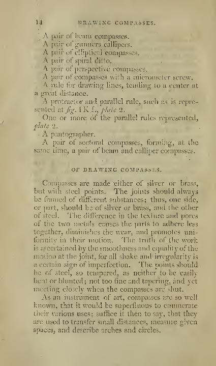
14 DRAWING COMTAsSES.
' A pair of beam compasses.
A pair of gunners callipers.
A pair of elliptical c,ompasscs.
A pair of spiral ditto,
A pair of perspective compasses.
A pair of compasses with a micrometer screw,
A rule for drawing lines, tending to a center at
a great distance.
A protractor and parp.Ilel rule, such as is repre-
sented v.tj/o-, I K L, fic/te 1.
One or more of the parallel rules represented,
plate 2.
A pantographer.
A pair of sectoral compasses, forming, at thesame time, a pair of beam and calliper compasses.
OP DRAWING COMPASSES.
Compasses are made cither of silver or brass,
but with steel points. The joints should always
be framed of different substances; thus, one side,
cr part, should be of silver or brass, and the other
of steel. The diifcrenee in the texture and pores
of the two metnls causes the parts to adhere less
together, diminishes the v/ear, and promotes uni-
formity in their motion. The truth of the workis ascertained by the smoothness and equality of the
motion at the joint, for all shake and irregularity is
a certain sign of imperfection. Tlie points sliould
l^e of steel, so tempered, as neither to be easily
beat or blunted; not too fine and tapering, and yet
meeting closely when the compasses arc shut.
As an instrument of art, compasses arc so well
known, that it would be superfluous to enumeratetheir various uses; suffice it then to say, that theyare used to transfer small distances, measure Q-ivcn
spaces, and describe arches and circles.

DRAWING COMPASSES. 15
If the arch or circle is to be described obscurely,
the steel points arc best adapted to the purpose;
if it is to be in ink or black lead., either the cLraw-
ing pen, or crayon points are to be used.
To use a pair of con)fusses. Place the thumb and
middle fmger of the right hand in ^thc opposite .^
hollows ill the shanks of the. compasses, theii press .'"li2X<^
the compasses, arid'thc legs will c;pen a little way;this being done, push the inncrniobt leg with the
third finger, elevating, at the' same tirn(^, the fur-
thermost, with the nail of the middtc finger^ till
the compasses are suflicicntly opened to receive
the middle and third finger; they may then be ex-
tended at pleasure, by pushing the furthermost leg
out^\'ards with the middle, or pres.'^ing it inwards
with the fore finger. In describing circles, or
arches, set one foot of the com})asics on the cen-
ter, and then roll the head of the compasses be-
tween the middle and fore finger, the other point
pressing at tlie same time upon the paper. Theyshoidd be held, as upright as possible, and care
should be taken not to press forcibly upcn them,bat rather to let them act by their own weight;
the legs should never be so far extended, as to tbrm
an obtuse angle with the paper or plane, on whichthey are used.
I'hc ink and crayon points liave a joint just un-
der that part which tits into tlic compasses, by this
tlicy may be always ?o placed, as to be set nearly
perpendicular to the paper; the end of the shank,
of the best compasses is fram'6d so as to form a
strong spring, to bind firmly the moveable points,
and prevent them from shaking, Thi^ is found
to be a more effectual method than that by a scrc^w
Fig. B, plate 1, reprcsbnts a pair of t]:!e best
compasses, with the plain point, t:, the ink, d, the
dotting, c^ the crayon point.
id Drawing compassEI.
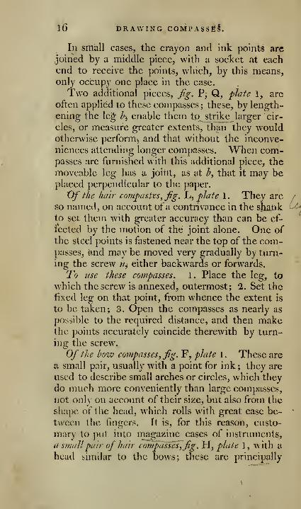
In srhall cases, the crayon and ink points are
joined by a middle piece, with a socket at eachend to receive the points, which, by this means,only occupy one place in the case.
Two additional pieces, Jig. P, Q, plate 1, are
often applied to these compasses; these, by length-
ening the le^ Aj enable them tq strike larger cir-
cles, or measure greater extents, than they wouldotherwise perform, and that without the inconve-
niences attending longer compasses. When com-passes are furnished with this additional piece, the
moveable leg has a joint, as at h, that it may beplaced perpendicular to the paper.
Of the hah- compasses, Jig. L, plate 1 . They are /
so named, on account of a contrivance in the shank ^to set them with greater accuracy than can be ef-
fected by the motion of the joint alone. One of
the steel points is fastened near the top of the com-passes, and may be moved very gradually by turn-
ing the screw n^ either backwards or forwards.
To use these crmipasses. 1. Place the leg, to
which thcscfew is annexed, outermost; 2. Set the
fixed leg on that point, from whence the extent is
to be taken; 3. Open the compasses as nearly as
possible to the required distance, and then makethe points accurately coincide therewith by turn-
ing the screw.
Of the bow compasses, fig. F, plate 1. These are
a small pair, usually with a point for ink; they are
used to describe small arches or circles, which they
do much more conveniently than large compasses,
not onlv on account of their size, but also from the
shape of the head, which rolls with great ease be- *
tvvecn the fingers. It is, for this reason, custo-
mary to put into magazine cases of instruments,
a smallpair of hair compasses,fig. Yi, plate 1, with a
head similar to the bows; these are principally

DRAWING COMPASSES. ~ 17
used for repeating divisions of a small but equal
extent, a practice that has acquired the name ofstepping.
Of the drawing p671 and protracting pin, fg. I K,plate 1. The pcn^art of this instrument is used
to draw strait Hues; it consists of two blades with
steel points fixed to a handle, the blades are so
bent, that the ends of the steel points meet, and yet
leave a sufficient cavity for the ink; the blades maybe opened more or less b}'- a screw, and, beingproperly set, will draw a line of any assigned thick-
ness. One of the blades is framed with a joint,
that the points may be separated, and thus cleaned
more conveniently; a small quantity only of ink
should be put at one time into the drawing pen,
and this should be placed in the cavity, betweenthe blades, by a common pen, or the feeder; the
drawing pen acts better, if the feeder, or pen, bywhich the ink is inserted, be made to pass throughthe blades. To use the drawing pen, first feed it
with ink, then regulate it to the tliickness o{ the
required line by the screw. In drawing lines, in-
cline the pen a small degree, taking care, however,
that the edges of both the blades touch the paper,
keeping the pen close to the rule and in the samedirection during the v/hole operation; the blades
should always be wiped very clean, before the penis put away.
These directions are equally applicable to the
ink point of the compasses, only observing, that
when an arch or circle is to be described, of morethan an inch radius, the point should be so bent,
that ihe blades of the pen may be nearly perpen-
dicular to the paper, and both of them touch it at
the same time.
The protracting pin k, is onlv a short piece ({
5teel wire, with a very fine point, fixed at one end
c
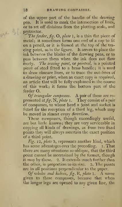
18 DRAWING COMPASSES.
of the upper part of the handle of the drawing
pen. It is used to mark the intersection of Hues,
or to set off divisions from the plotting, scale^ andprotractor.' The feeder, fig. O, flate 1, is a thin flat piece of
metal ; it sometimes forms one end of a cap to fit
on a pencil, or it is framed at the top of the tra-
cing point, as in the figure. It serves to place the
ink between the blades of the drawing pens, or to
pass between them when the ink does not flow
freely. The tracing point, or pointrel, is a pointed
piece of steel fitted to a brass handle; it is used
to draw obscure lines, or to trace the out-lines of
a drawing or print, when an exact copy is required,
an article that will be fully explained in the course
of this work; it forms the bottom part of the
feeder O.
Of triangular compasses. A pair of these are re-
presented 'dXfig. N, plate 1 . They consist of a pair
of compasses, to whose head a joint and socket is
fitted for the reception of a third leg, which maybe moved in almost every direction.
These compasses, though exceedingly useful,
are but little known; they are very serviceable in
copying all kinds of drawings, as from two fixed
points they will always ascertain the exact position
of a third point.
Fig. \2, plate 3, represents another kind, whichhas some advantages over the preceding. 1 . Thatthere are many situations so oblique, that the third
point cannot be ascertained by the former, thoughit may by these. 2. It extends much further than
the other, in proportion to its size. 3. The points
are in all positions perpendicular to the paper.
Of wholes arid halves, fig. R, plate 1 . A namegiven to these compasses, because that whenthe longer legs are opened to any given line, the
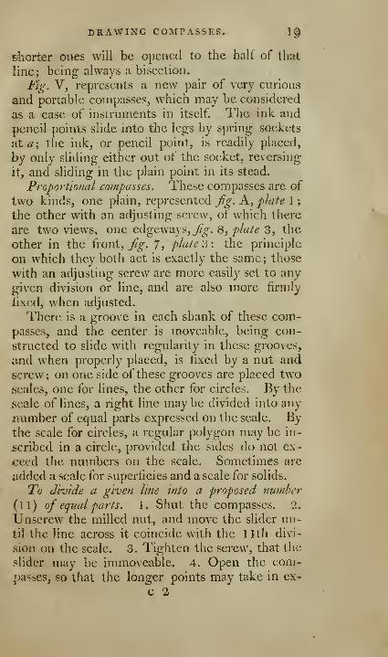
DRAWING COMPASSES. 1^
d'iOrter ones will be opened to the half of thut
line; being always a bisection.
Fig. V, represents a new pair of very curious
and portable compasses, which may be considered
as a case of instruments in itself. The ink and
pencil points slide into the legs by spring sockets
at a-, the ink, or pencil point, is readily placed,
by only sliding either out of the socket, reversing
it, and sliding in the plain point in its stead.
Proportional compasses. These compasses are of
two kinds, one plain, represented Jig. A, plate 1
;
the other with an adjusting screw, of which there
are two views, one edgeways, 7?^. 8, plate 3, the
other in the front, 7?^. 7j plate '6-. the principle
on which they both act is exactly the same; those
with an adjusting screw are more easily set to any
given division or line, and are also more firmly
fixed, when adjusted.
There is a groove in each shank of these com-passes, and the center is moveable, being con-
structed to slide with regularity in these grooves,
and when properly placed, is fixed by a nut ancj
screw; on one side of these grooves arc placed twoscales, one for lines, the other for circles. By the
scale of lines, a right line may be divided into any
number of equal parts expressed on the scale. Bythe scale for circles, a regular polygon may be in-
scribed in a circle, provided the sides do not ex-
ceed the numbers on the scale. Sometimes arc
added a scale for superficies and a scale for solids.
To divide a given line into a proposed number
(11) of equal parts. 1. Shut the compasses. 2.
Unscrew the milled nut, and move the slider un-
til the line across it coincide with the 11th divi-
sion on the scale. 3. Tighten the scre\v, that the
slider may be immoveable. 4. Open the com-passesj so that the longer points may take in cx-
c 2
90 DRAWING COMPASSES.
actly the given line, and the shorter will give youTrth of that line.
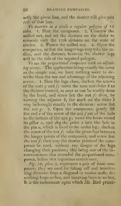
To inscrlhe in a circle a regular 'polygon of \1
sides. 1. Shut the compasses. 2. Unscrew the
milled nut, and set the division on the slider to
coincide with the l^th division on the scale of
circles. 3. Fasten the milled nut. 4. Open the
compasses, so that the longer legs may take the ra-
dius, and the distance between the shorter legs
•will be the side of the required polygon.
To use the proportional compasses with an adjust-
ing screw. The application being exactly the same
as the simple one, we have nothing more to de-
scribe than the use and advantage of the adjusting
screw. 1 . Shut the legs close, slacken the screws
of the nuts g and/; move the nuts and slider k to
the division wanted, as near as can be readily done
by the hand, and screw fast the nut /; then, byturning the adjuster h, the mark on the slider k
may be brought exactly to the division : screw fast
the nut^. 2. Open the compasses; gently lift
the end e of the screw of the nut /out of the hole
in the bottom of the nut ^; move the beam roundits pillar a, and slip the point e into the hole in
the pin ?/, which is fixed to the under leg ; slacken
the screw ofthe nut/; take the given line betweenthe longer points of the compasses, and screw fast
the nut/; then may the shorter points of the com-passes be used, without any danger of the legs
changing their position; this being one of the in-
conveniences that attended the proportional com-<
passes, before this ingenious contrivance.
Fig. 10, plate 3, represents a pair of beam com-^
passes ; they are used for taking off and transfer-
ring divisions from a diagonal or nonius scale, de-
scribing large arches, and bisecting lines or arches.
It is the instrument upon which Sir. Bird princi*
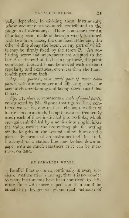
PARALLEL RULES. 21
pally depended, in dividing those instruments,
whose accuraey has so much contributed to the
progress of astronomy. These compasses consist
of a long beam made of brass or wood, furnished
with two brass boxes, the one fixed at the end, the
other sliding along the beam, to any part of whichit may be firmly fixed by the screw P. An ad-
justing screw and micrometer are adapted to the
box A at the end of the beam ; by these, the point
connected therewith may be moved with extremeregularity and exactness, even less than the thou-sandth part of an inch.
Fig. 13, plate 3, is a small pair of beam com-*
passes, with a micrometer and adjusting screw, for
accurately ascertaining and laying down small dis-
tances.
Fig. 11, plate 3, represents a scale of equal parts
^
constructed by Mr. Sisson ; that figured here con-
tains two scales, one of three chains, the other of
four chains in an inch, being those most frequently
used; each of these is divided into 10 links, whichare again subdivided by a nonius into single links;
the index can'ies the protracting pin for setting
off the lengths of the several station lines on the
plan. By means of an instrument of this kind,
the length of a station line may be laid down onpaper with as much exactness as it can be mea-sured on land.
OP PARALLEL RULES.
Parallel lines occur so. continually in every spe-
cies of mathematical drawing, that it is no wonderso many instruments have been contrived to deli-
neate them w^ith more expedition than could be
effected by the general geometrical methods ; of

ti'i PARALLEt RULES",
the various contrivances for this purpose, the {ot"
lowing are those most approved.
1
.
T/ie common parallel nile^fig. A, flate 2. Thisconsists of two strait rules, which are connectedtogether, and always maintained in a parallel posi-
tion by the two equal and parallel bars, whichmove very freely on the center, or rivets, by whichthey are fastened to the strait rules.
2. The double parallel rule, fig. B, plate 2. This?
instrument is constructed exactly upon the sameprinciples as the foregoing, but with this advan-tage, that in using it, the moveable rule mayalways be so placed, that its ends may be exactly
over, or even with, the ends of the fixed rule,
whereas, in the former kind, they are always shift-
ing away from the ends of the fixed rule.
This instrument consists of two equal flat rules,
and a middle piece; they are connected together
by four brass bars, the ends of two bars are ri-
vetted on the middle line of one of the strait rules
;
the ends of the other two bars are rivetted on the
middle line of the other strait rule; the other ends:
of the brass bars are taken two and two, and rivet-
ted on the middle piece, as is evident from thefigure; it would be needless to observe, that thebrass bars itiove freely on their rivets, as so manycenters.
3. Of Ilie improved doidde pai-allel rule, fig. Q,plate 2. The motions of this rule are more regular
than those of the preceding one, but with some-what more friction; its construction is evident
from the figure ; it was contrived by the ingenious
mechanic, Mr. Haywood.4. The cross barred parallel rule, fig. D, plate 2«
In this, two strait rules are joined by two brass bars^
which cross each other, and turn on their inter-
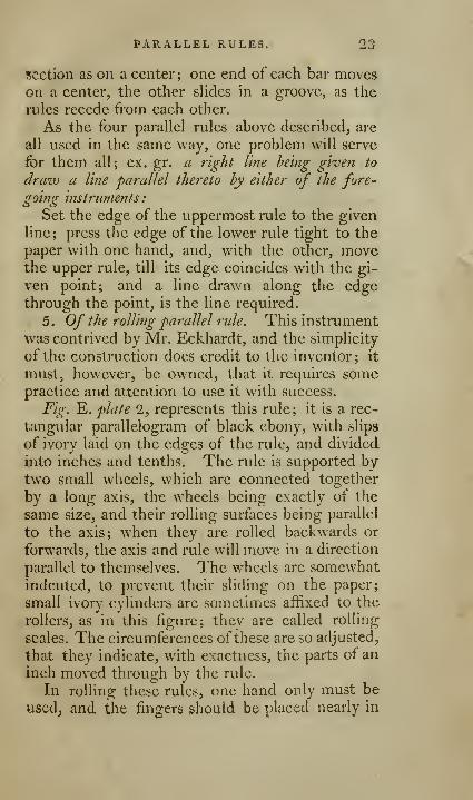
t»ARALLEL RULES. 23
sfection as on a center; one end of each bar moveson a center, the other sHdes in a groove, as the
lules recede from each other.
As the four parallel rules above described, are
all used in the same way, one problem will serve
for them all; ex. gr. a right line being given to
draw a line parallel thereto by either of the fore-
going instruments
:
Set the edge of the uppermost rule to the given
line; press the edge of the lower rule tight to the
paper with one hand, and, with the other, movethe upper rule, till its edge coincides with the gi-
ven point; and a line drawn along the edgethrough the point, is the line required.
5. Of the rolling parallel rule. This instrument
was contrived by Mr. Eckhardt, and the simplicity
of the construction does credit to the inventor ; it
must, however, be owned, that it requires somepractice and attention to use it with success.
Fig. E. plate 2, represents this rule; it is a rec-
tangvdar parallelogram of black ebony, with slips
of ivory laid on the edges of the nde, and divided
into inches and tenths. The nde is supported bytwo small wheels, which are connected together
by a long axis, the wheels being exactly of the
same size, and their rolling surfaces being parallel
to the axis; when they are rolled backwards or
forwards, the axis and rule will move in a direction
parallel to themselves. The wheels are somewhatindented, to prevent their sliding on the paper;
small ivory cylinders are sometimes affixed to the
rollers, as in this figure; they are called rolling
scales. The circumferences ofthese are so adjusted,
that they indicate, with exactness, the parts of an
inch moved through by the rule.
In rolling these rules, one hand only must be
used, and the fingers should be placed nearly in
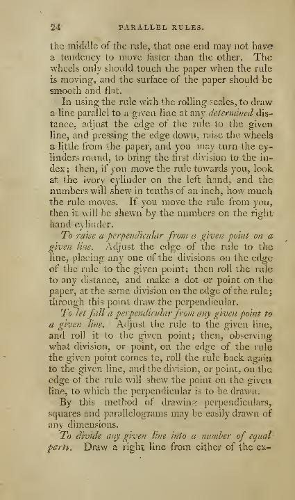
14 PARALLEL RULES.
the middle of the rule, that one end may not have?
a tendency to move faster than the other. Thewheels only should touch the paper when the rule
is moving, and the surface of the paper should besmooth and fiat.
In using the rule with the rolling scales, to drawa line parallel to a given line at any determined dis-
tance, adjust the edge of the ride to the given
line, and pressing the edge down, raise the wheels
a little fi'om the piiper, and you may turn the cy-
linders round, to bring the first division to the in-
dex ; then, if you move the rule towards you, look
at the ivory cylinder on the left hnnd, and the
numbers will shew in tenths of an inch, how muchthe rule moves. If you move the rule from you^
then it will be shewn by the numbers on the right
hand cylinder.
To raise a perpendicular from a given point on agiven line. Adjust the edge of the rule to the
line, placing any one of the divisions on the edgeof the rule to the given point; then roll the rule
to any distance, and make a dot or point on the
paper, at the same division on the edge of the rule;
through this point draw the perpendicular.
To let fall a perpendicidarfrom any given point to
a given Vme. Adjust the rule to the given line,
and roll it to the given point; then, observing
what division, or point, on the edge of the rule
the given point comes to, roll the rule back again
to the given line, and the division, or point, on the
edge of the rule will shew the point on the given
line, to which the perpendicular is to be draMai.
By this method of drawinsr perpendiculars,
squares and parallelograms may be easily drawn of
any dimensions.
To divide any given line into a numher of equal-
parts. Draw a right line from either of the ex-
PARALLEL RULES. 25
treme points of the given line, making any angle
with it. By means of the rolling scales, divide
that line into as many inches, or parts of an inch,
as will equal the number of parts into which the
giv^en line is to be divided. Join the last point ofdivision, and the extreme point of the given line:
to that line draw parallel lines through the other
points of division, and they will divide the given
line into equal parts.
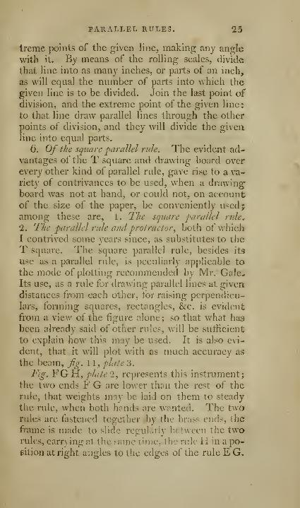
6. Of the square parallel rule. The evident ad-vantages of the T square and drawing board overevery other kind of parallel rule, gave rise to a va-
riety of contrivances to be used, when a drawing'
board was not at hand, or could not, on accountof the size of the paper, be conveniently used;,
among these are, 1. The square parallel rule,
1. The parallel rule and protractor, both of whichI contrived some years since, as substitutes to the
T square. The square parallel rule, besides its
use as a parallel rule, is peculiarly applicable to
the mode of plotting recommended by Mr. Gale.*
Its use, as a rule for drawing parallel lines at given
distances from each other, for raising perpendicu-
lars, forming squares, rectangles, &c. is evident
from a view of the figure alone; so that what has
been already said of other rules, will be sufficient
to explain how this may be used. It is also evi-
dent, that it will plot with as much accuracy as
the beam, fig. 1 1 ,plate o.
Fig. FGH, plate 2, represents this instrument;
the two ends F G are lov/er thou the rest of the
rule, that weights may be laid on them to steady
the rule, when both h;^nds are w;vnted. The twarules are fastened together .by the brass ends, the
frame is made to slide regularly between the two-
rules, carr\ ing at the same cime, the rule 11 'u a po-sition at right angles to the edges of the rule E G,
26 t-ARALLEL tlULE§.
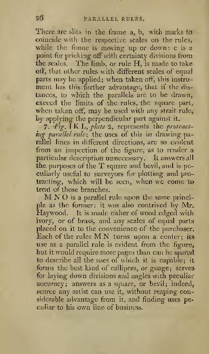
There are slits in the frame a, b, with marks iiy
coincide with the respective scales on the rules,
while the frame is moving up or down: c is a
point for pricking off with certainty divisions fromthe scales. The limb, or rule H, is made to take
off, that other rules with different scales of equal
parts may be applied; when taken off, this instru-
ment has this further advantage, that if the dis-
tanceSj to which the parallels are to be drawn,
exceed the limits of the rules, the square part,
when taken off, may be used with any strait rule^
by applying the perpendicular part against it.
7. -Fig. \}L1j, plate 1, represents the, protract-
ing parallel rule ; the uses of this in drawing pa-
rallel lines in different directions, are so evident
from an inspection of the figure, as to render a
particular description unnecessary. It answers all
the purposes of the T square and bevil, and is pe-
culiarly useful to surveyors for plotting and pro-
tracting, which will be seen, when we come to
treat of those branches.
M N O is a parallel rule upon the same princi-
ple as the former: it was also contrived by Mr.Haywood. It is made either of wood edged with
ivory, or of brass, and any scales of equal parts
placed on it to the convenience of the purchaser.
Each of the rules MN turns upon a center; its
use as a parallel rule is evident from the figure,
but it would require more pages than can be spared
to describe all the uses of which it is capable; it
forms the best kind of callipers, or guage; scrved-
for laying down divisions and angles with peculiar
accuracy; answers as a square, or bevil; indeed,
gcarce any artist can use it, without reaping con-
siderable advantage from it, and finding uses pe-
culiar to his own line of business.
PARALLEL RULES. TJ
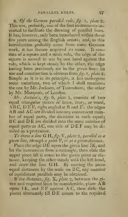
8. Of the German parallel rule, fig. 1, flate 3^
This was, probably, one of the first instruments in-
vented to tacihtate the drawing of parallel lines.
It has, however, only been introduced within these
few years among the English artists; and, as this
introduction probably came from some Germanwork, it has thence acquired its name. It con-sists of a square and a strait rule, the edge of the
square is moved in use by one hand against the
rule, which is kept steady by the other, the edgehaving been previously set to the given line: its
use and construction is obvious {xoxnfig. 1, plate 3..
Simple as it is in its principle, it has undergonesome variations, two of which I shall mention;the one by Mr. Jackson, of Tottenham; the other
by Mr. Marquois, of London,Mr. Jackson s, fig. 6, plate 3, consists of two
equal triangular pieces of brass, ivor\ , or wood,AB C, D E F, right angled at B and E; the edgesAB and AC are divided into any convenient num-ber of equal parts, the divisions in each equal;
B C and D E are divided into the same number ofequal parts as AC, one side of DEE may be di-
vided as a protractor.
To draw a line G H, jfo-. V, plate 2, parallel to agiven line, through a point P, or at a given distance..
Place the edge DE upon the given line IK, andlet the instrument form a rectangle, then slide the
upper piece till it come to the given point or dis-
tance, keeping the other steady with the left hand,
and draw the line G H. By moving the piece
equal distances by the scale on B C, any numberof equidistant parallels may be obtained.
If the distance, T^V. ^, plate 2, between the gi-
ven and required lines be considerable, place A Bupon I K, and E F against A C, then slide the
pieces alternately till D E comes to the required

2$ * PARALLEL RULES.
point; in this manner it is easy also to construct
any square or rectangle^ he.
From any grceti point or angle V, Jig. S, plate 2,
to let fall or raise a perpendicular oti a givm li?ie»
Place either of the edges AC upon GP, and slide
AB upon it, till it comes to the point P, anddraw PH.To divide a line into any proposed number of
equal pnrts, fig. T, plate 2. Find the proposed
number in the scale BC, and let it terminate at G^then place the rules in a rectangular form, andmove the whole about the point G, till the side
D E touches H ; now move D one, two, or three
divisions, according to the number and size of the
required divisions, down B C, and make a dot at I,
where DE cuts the line for the first part; then
move one or more divisions as before, make a se-
cond dot, and thus proceed till the whole be com-pleted.
Of Marquois^s parallel scales. These consist ofa
right angled triangle,whose hypothenuse,or longest
side, is three times the length of the shortest, andtwo rectangular scales. It is from this relative
length of the hypothenusc that these scales derive
their peculiar advantages, and it is this alone that
renders them different from the common Germanparallel rule: for this we are much indebted to
Mr. Marquois.
A¥hat has been already said of the German rule,
applying equally to those of Mr. Marquois's, I shall
proceed to explain their chief and peculiar excel-
lence. On each edge of the rectangular rule are
placed two scales, one close to the a^gc, the other
within this. The outer scale, Mr. Marquois terms
the artificial scale, the inner one, the natural scale:
the divisions "on the outer are always^rce times
longer than those on the inner scale, as, to derive
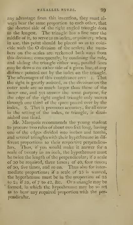
TAPvALLEL RULES. 29
any advantage from this invention, they must al-
ways bear the same proportion to each other, that
the shortest side of the right angled triangle does
to the longest. The triangle has a line near the
middle of it, to serve as an index, or pointer; whenin use, this point should be placed so as to coin-
cide with the O division of the scales; the num-bers on the scales are reckoned both ways from
this division ; consequently, by confining the rule,
and sliding the triangle either way, parallel lines
may be drawn on either side of a given line, at anydistance pointed out by the index on the triangle.
The advantages of this contrivance are: l. Thatthe sight is greatly assisted, as the divisions on the
outer scale are so much larger than those of the
inner one, and yet answer the same pui'pose, for
the edge of the right angled triangle only movesthrough one third of the space passed over by the
index. 2. That it promotes accuracy, for all error
in the setting of the index, or triangle, is dimi-
nished one third.
Mr. Marquois recommends the young student
to procure two rules of about two feet long, having
one of the edges divided into inches and tenths,
and several triangles with their hypothenuse in dif-
ferent proportions to their respective perpendicu-
lars. Thus, if you would make it answer for a
scale of twenty to an inch, the hypothenuse mustbe twice the length of the perpendicular; if a scale
of 30 be required, three times; of 40, four times;
of 50, five times, and so on. Thus also for inter-
mediate proportions; if a scale of 25 is wanted,
the hypothenuse must be in the proportion of 25
to 2 ; if 35, of 7 to 42, &c. Or a triangle may be
formed, in which the hypothenuse may be so set
as to bear any required proportion with the per-
pendicular.

30 THE PROTRACTOR.
OF THE PROTRACTOR.
This Is an instrument used to protract, or lay
down an angle containing any number of degrees,
or to find how many degrees are contained in anygiven angle. There are two kinds put into cases
of mathematical drawing instruments; one in the
form of a semicircle, the other in the form of a pa-
rallelogram. The circle is undoubtedly the only
natural measure of angles; when a strait line is
therefore used, the divisions thereon are derived
from a circle, or its properties, and the strait line
is made use of for some relative convenience: it is
thus the parallelogram is often used as a protrac-
tor, instead of the semicircle, because it is in somecases more convenient, and that other scales, &c.may be placed upon it.
The semicircular 'protractor, fig. 1, plate 3, is di-
vided into 180 equal parts or degrees, which are
numbered at every tenth degree each way, for the
conveniency of reckoning either from the right
towards the left, or from the left towards the right;
or the more easily to lay down an angle fromcither end of the line, beginning at each end with
10, 20, &c. and proceeding to 180 degi-ees. Theedge is the diameter of the semicircle, and the
mark in the middle points out the center. Fig. 3,
plate 3, is a protractor in the form of a parallelo-
gram: the divisions arc here, as in the semicircular
one, numbered both ways; the blank side repre-
sents the diameter of a circle. The side of the
protractor to be applied to the paper is made flat,
and that whereon the degrees are marked, is cham-fered or sloped away to the edge, that an angle
may be more easily measured, and the divisions set
off with greater exactness.
THE PROTRACTOR. 31
Profraclors of horn arc, from their transparency,
very convenient in measuring angles, and raising
perpendiculars. When they are out of use, they
should be kept in a book to prevent their warping.
Upon some protractors the numbers denoting
the angle for regular polygons are laid down, to
avoid the trouble of a reference to a table, or the
operation of dividing; thus, the number 5, for a
pentagon is set against 72°; the number 6, for a
hexagon, against ()0°; the number 7:, for a hepta-
gon, against 51i°; and so on.
Protractors for the purposes of surveying will bedescribed in their proper place.
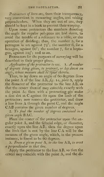
Application of the protractor to use. 1 . A number
of degrees being given, to protract, or lay doivn anangle, whose measure shall be'fqual thereto.
Thus, to lay down an angle of 6o degrees from
the point \ of the line AB,Jjg. 14, plate 3, apply
.the diameter of the protractor to the line AB, so
that the center thereof may coincide exactly with
the point A; then with a protracting pin makea fine dot at C against Oo upon the limb of the
protractor; now remove the protractor, and drawa line from A through the point C, and the angle
CAB contains the given number of degrees.
2. To fml the number of degrees contained in a
o-iven anole BAC.o oPlace the center of the protractor upon the an-
gular point A, and the fiducial edge, or diameter,
exactly upon the line AB; then the degree uponthe limb that is cut by the line C A will be the
measure of the given angle, which, in the present
instance, is found to be do degrees.
3. From a given point A, /// (he line AB, to erect
a perpendicular to that line.
Apply the protractor to the line AB, so that the
center may coincide with the point A, and the di-
32 THE PLAIN SCALE.
vision marked go maybe cut by the line A B, thena line DA drawn against the diameter of the pro-
tractor will be perpendicular to A B.
Further uses of this instrument will occur in
most parts of this work, particularly its use in con-
structing polygons, which will be found undertheir respective heads. Indeed, the general use
being explained, the particular application must beleft to the practitioner, or this work would be un-necessarily swelled by a tedious detail and conti-
nual repetitions.
OF THE PLAIN SCALE.
The divisions laid down on the plain scale are
of two kinds, the one having more immediate
relation to the circle and its properties, the other
being merely concerned with dividing strait
lines.
It has been already observed, that though arches
of a circle are the most natural measures of an an-
gle, yet in many cases right lines were substituted,
as being more convenient; for the comparison ofone right line with another, is more natural and
easy, than the comparison of a right line with a
curve; hence it is usual to measure the quantities
of angles not by the arch itself, which is described
on the angular point, but by certain lines described
about that arch. See definitions.
The lines laid down on the plain scales for the
measuring of angles, or the protracting scales, are,
1. A line of chords marked cho. 2. A line o^ s'mes
marked sin. of tangents marked tan. q{ semltan^
tangents marked st. and of secants marked sec.
this last is often upon the same line as the sines,
because its gradations do not begin till the sines
end.

THE PLAIN SCALEi 33t
There are two other scales, namely, the rhumhs,
marked ru. and long, marked lon. Scales of*
latitude and hours are sometimes put upon the
plain scale; but, as dialling is now but very little
studied, they are only made to order.
The divisions used for measuring strait lines are
called scales of equal 'parts, and are of various
lengths for the convenience of delineating any fi-
gure of a large or smaller size, according to the
fancy or purposes of the draughts-man. They arc,
indeed, nothing more than a measure in miniature
for laying down upon paper, &c. any known mea-sure, as chains, yards, feet, &c. each pajl on the
scale answering to one foot, one yard, &c. and the
plan will be larger or smaller, as the scale contains
a smaller or a greater number of parts in an inch.
Hence a variety of scales is useful to lay down lines
of any required length, and of a convenient pro-
portion with respect to the size of the drawing.
If none of the scales happen to suit the purpose,
recourse should be had to the line of lines on the
sector; for, by the diiFerent openings of that 'in-
strument, a line of any length may be divided into
as many equal parts as any person chuscs.
Scales of equal parts are divided into two kinds,
the one simple, the other diagonally divided.
Six of the simply divided scales arc generally
placed one above another upon the same rule;
they are divided into as many equal parts as the
length of the rule will admit of; the numbers
placed on the right hand, shew how many parts in
an inch each scale is divided into. The upper
scale is sometimes shortened for the sake of in-
troducing another, called the line of chords.
The first of the larger, or primary divisions, onevery scale is subdivided into 10 equal parts, which
small parts are those which give a name to th«
M TUB PLAIN SCALE,
scale; thus it is called a scale of 20, when 10 ofthese divisions are equal to one inch. If, there-
fore, these lesser divisions be taken as units, andeach represents one league, one mile, one chain,
or one yard, &c. then will the larger divisions beso many tens ; but if the subdivisions are supposedto be tens, the larger divisions will be hundreds.
To illustrate this, suppose it were required to
set off from either of the scales of equal parts 41-,
36, or 360 parts, either miles or leagues. Set onefoot of your compasses on 3, among the larger or
primary divisions, and open the other point till it
falls on the 6th subdivision, reckoning backwardsor towards the left hand. Then will this extent
represent -fJ, 36, or 36o miles or leagues, &c. andbear the same proportion in the plan as the line
measured docs to the thing represented.
To adapt these scales to feet and inches, the
first primary division is often duodeeimally divided
by an upper line; therefore, to lay down any num-ber of feet and inches, as for instance, eight feet
eight inches, extend the compasses from eight ofthe larger to eight of the upper small ones, andthat distance laid down on the plan will represent
eight feet eight inches.
Of the scale of equal parts diagonally divided.
The use of this scale is the same as those already
described. But by it a plane may be more accu-rately divided than by the former; for any one ofthe larger divisions may by this be subdivided into
300 equal parts; and, therefore^ if the scale con-tains 10 of the larger divisions, any number under1000 may be laid down with accuracy.
The diagonal scale is seldom placed on the sameside of the rule with the other plotting scales.
The first division of the diagonal scale, if it be a;
foot long, is generally an inch divided into 100-

THE PLAIN SCALE. 35
equal parts, and at the opposite end there Is usu-ally half an inch divided into 100 equal parts. If
the scale be six inches long, one end has com-monly half an inch, the other a quarter of an inch
subdivided into 100 equal parts.
The nature of this scale will be better under-stood by considering its construction. For this
purpose
:
First. Draw eleven parallel lines at equal dis-
tances; divide the upper of these lines into such anumber of equal parts, as the scale to be expressedis intended to contain; from each of these divi-
sions draw perpendicular lines through the eleven
parallels.
Secondly. Subdivide the first ofthese divisions in-
to ten equal parts, both in the upper and lower lines.
Thirdly. Subdivide again each of these subdi-
visions, by drawing diagonal lines from the 10th
below to the gth above; from the 8th below to
the 7th above; and so on, till from the first belowto the above: by these lines each of the small
divisions is divided into ten parts, and, conse-
quently, the whole first space into 100 equal parts;
for, as each of the subdivisions is one tenth part of
the whole first space or division, so ca^h parallel
above it is one tenth of such subdivision, 'and, con-sequently, one hundreth part of the whole first
space ; and if there be ten of the larger divisions,
one thousandth part of the whole space.
li] therefore, the larger divisions be accountedas units, the first subdivisions will be tenth parts
of an unit, and the second, marked by the diago-
nal upon the parallels, hundredth parts of the
unit. But, if we suppose the larger divisions to
be tens, the first subdivisions will be units, and the
second tenths. If the larger are hundreds, then
\Aill the first be tens, and the second units.
D 2

36 THE PLAIN SCALE.
The numbers, therefore, 576, 57,6, 5,76, nre
all expressible by the same extent ofthe compasses
:
thus, setting one foot in the number five of the
larger divisions, extend the other along the sixth
parallel to the seventh diagonal. For, if the five
larger divisions be taken for 500, seven of the first
subdivisions will be 70, which upon the sixth pa-
rallel, taking in six of the second subdivisions for
units, makes the whole number 576. Or, if the
five larger divisions be taken for five tens, or 50,
seven of the first subdivisions will be seven units,
and the six second subdivisions upon the sixth pa-
rallel, will be six tenths of an unit. Lastly, if the
five larger divisions be only esteemed as five units,
then will the seven first subdivisions be seven
tenths, and the six second subdivisions be the six
hundredth parts of an unit.
Of the use of Ihe scales of equal parts. Thoughwhat I have already said on this head may bedeemed sufficient, I shall not scruple to introduce
a few more examples, in order to render the young-
practitioner more perfect in the management ofan instrument, that will be continually occurring
to him in practical geometry. He will have al-
ready observed, that by scales of equal parts lines
may be laid down, or geometrical figures con-fitructed, whose right-lined sides shall be in the
same proportion as any given numbers.Example 1. To take off the number 4,JQ from
a diagonal scale. Set one foot of the compasseson the point where the fourth vertical line cuts
the seventh horizontal line, and extend the other
foot to the point where the ninth diagonal cuts the
seventh horizontal line.
Example 2. To take off the nnmher 76,4. Ob-serve the points where the sixth horizontal cuts
THE PLAIN SCALE. 37
tlie seventh vertical and fourth diagonal line, the
extent between these points will represent the
number 76,4.
In the first example each primary division is
taken for one, in the second it is taken for ten.
Exatuple 3. To lay dovjn a line of 7,85 chains
hy the dlagojial scale. Set one point of your
compasses where the eighth parallel, counting up-
wards, cuts the seventh vertical line; and extend
the other point to the intersection of the sameeighth parallel with the fifth diagonal. Set off the
iixtent 7j85 thus found on the line.
Rxaniple 4. To measure hy the diagonal scale
^ line that is already laid doivn. Take the extent
of the line in your compasses, place one foot onthe first vertical line that will bring the other foot
among the diagonals; move both feet upwards till
one of them fall into the point where the diagonal
from the nearest tenth cuts the same parallel as is
cut by the other on the vertical line; then onefoot shews the chain, and the other the hundredthparts or odd links. Thus, if one foot is on the
eighth diagonal of the fourth parallel, while the
other is on the same parallel, but coincides with
the twelfth vertical, we hav^e 12 chains, 48 links,
or 12,48 chains.
Example 5. Three adjacent parts of any right-
lined triangle being given, to form the plan thereof.
Thus, suppose the base of a triangle, fig. \b, plate 3^
40 chains, the angle ABC equal 36 deg. and angle
BAG equal 4 1 deg.
Draw the line AB, and from any of the
scales of equal parts take off 40, and set it
on the same line from A to B for the base of
the triangle; at the points A, B, make the angle
ABC equal to 36 degrees, and BAC to 41, andthe triangle will be formed; then take in your

3S THE PROTRACTING SCALES,
compasses the length of the side AC, and apply
it to the same scale, and you will find its length
to be 24 chains; do the same by the side BC, andyou will find it measure 27 chains, and the pro-
tractor will shew that the angle ACB contains
103 degrees.
Example Q. Given the hase AB, Jig. l6,pJa/e3,
of a triangle 2,1"] yards, the angle CAB 44°, 30',
and the side AC 20d, yards, to constitute the said tri-
angle, andfind the length of the other sides.
Draw the line AB at pleasure, then take 327parts fi'om the scale, and lay it fi-om A to B ; set
the center of the protractor to the point A, lay
ofF44°30', and by that mark draw AC; then
take with the compasses from the same scale
208, and lay it from A to C, and join C B, andthe parts of the triangle in the plan will bear the
same proportion to each other as the real parts in
the field do.
OF THE REMAINING LINES ON THE• PLAIN SCALE,
OF THE PROTRACTING SCALES.
1 . Of the line of chords. This line is used to set
off an angle from a given point in any right line,
or to measure the quantity of an angle alreadylaid down.Thus to draw a line KC,fig. 14, plate 3, that
shall make with the line AB an angle, contain-
ing a given number of degrees, suppose 40 de-grees.
Open your compasses to the extent of 6o de-
grees upon the line of chords_, (which is always

THE PROTRACTING SCALES. 3g
equal to the radius of the circle of projection,)
and setting one foot in the angular point, with
that extent describe an arch; then taking the ex-
tent of 40 degrees from the said chord hne, set it
off from the given line on the arch described; a
right line drawn from the given point, through
the point marked upon the arch, will form the
required angle.
The degrees contained in an angle already laid
down, arc found nearly in the same manner; for
instance, to measure the angle CAB. From the
center describe an arch with the chord of 6o de-
grees, and the distance C B, measured on the
chords, will give the number of degrees contained
in the angle.
If the number of degrees arc more than 90,they must be measured upon the chords at twice:
thus, if 120 degrees were to be practised, 60 maybe taken from the chords, and those degrees belaid off twice upon the arch. Degrees taken fromthe chords are always to be counted from the be-
ginning of the scale.
Of the rhumb line. This is, in. fact, a line ofchords construeted to a quadrant divided into
eight parts or points of the compass, in order to
facilitate the work of the navigator in laying downa sliip's course.
Tlius, supposing the ship's course to be N N E,
and it be required to lay down that angle. Draw-
the lineAB,jf«-. \A^ plate 3, to represent the me-ridian, and about the point A sweep an arch with
the chord of 60 degrees; then take the extent to
the second rhumb, from the line of rhumbs, andset it off on the arch from B to e, and draw the
line A e, and the angle BAe will represent the
chip's course. The second rhumb was taken, be
cause NNE is the second point from the north.

40 THE SECTOR.'
Of the Vine of longitudes. The line of longi-
tudes is a line divided into sixty unequal parts,
and so applied to the line of chords, as to shewby. inspection, the number of equatorial miles
contained in a degree on any parallel of latitude.
The graduated line of chords is necessary, in or-
der to shew the latitudes; the line of longitude
shews the quantity of a degree on each parallel in
sixtieth parts of an equatorial degree, that is,
miles. The use of this line will be evident from
the following example. A ship in latitude 44°
12'N. sails E. 79 miles, required her difference of
longitude. Opposite to 44i, nearest equal to the
latitude on the line ofchords, stands 43 on the line
oflongitude, which is therefore the number ofmiles
in a degree of longitude in that latitude. Whenceas 43 : 6o : : 79 : 110 miles the difference of Ion-,
gitude.
The lines of tangents, semitangents, and secants
serve to find the centers and poles of projected
circles in the stereographical projection of the
sphere.
The Vine of sines is principally used for the ortho-
graphic projection of the sphere; but as the appli-
cation of these lines is the same as that of similar
lines on the sector, we shall refer the reader to the
explanation of those lines in our description of
that instrument.
The lines of latitudes and hours are used con-r
jointly, and serve very readily to mark the hourlines in the construction of dials; they are gene-
rally on the most complete sorts of scales and see-
tors; for the uses of which see treatises on dialling,
OP THE SECTOR.
Amidst the variety of mathematical instruments
that have been contrived to facilitate the art of
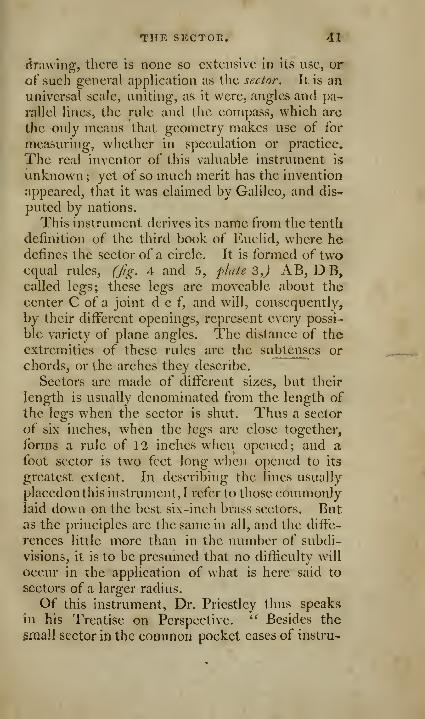
THE SECTOR. 41
(drawing, there Is none so extensive in its use, or
of such general application as the sector. It is an
universal scale, uniting, as it were, angles and pa-
rallel lines, the rule and the compass, which are
the only means that geometry makes use of for
measuring, whether in speculation or practice.
The real inventor of this valuable instrument is
unknown;yet of so much merit has the invention
appeared, that it was claimed by Galileo, and dis-
puted by nations.
This instrument derives its name from the tentli
definition of the third book of Euclid, where hedefines the sector of a circle. It is formed of twoequal rules, (Jig. 4 and 5, plate 3,) AB, DB,called legs; these legs are moveable about the
center C of a joint d c f, and will, consequently,
by their different openings, represent every possi-
ble variety of plane angles. The distance of the
extremities of these rules are the subtenses or
chords, or the arches they describe.
Sectors are made of different sizes, but their
length is usually denominated from the length of
the legs when the sector is shut. Thus a sector
of six inches, when the legs are close together,
forms a rule of 12 inches when opened; and a
foot sector is two feet long when opened to its
greatest extent. In describing the lines usually
placed on this instrument, I refer to those commonlylaid down on the best six-inch brass sectors. Butas the principles are the same in all, and the diffe-
rences little more than in the number of subdi-
visions, it is to be presumed that no difficulty will
occur in the application of what is here said to
sectors of a larger radius.
Of this instrument, Dr. Priestley thus speaks
in his Treatise on Perspective. " Besides the
^mall sector in the common pocket cases of instru-

4''3 THE SIECTOR,
ments, I would advise a person who proposes to
learn to draw, to get another of one foot radius.
Two sectors are in many cases exceedingly useful,
if not absolutely necessary ; and I would not ad-
vise a person to be sparing of expense in procur-
ing a very good instrument, the uses of which are
so various and important."
The scales, or lines graduated upon the/aces of
the instrument, and which are to be used as sec-
toral lines, proceed from the center; and are,
1. Two scales of equal parts, one on each leg,
marked lin. or l. each of these scales, from the
great extensiveness of its use, is called the line oflines. 2. Two lines of chords, marked cho. or c.
3. Two lines of secants, marked sec. of s. A line
of polygons, marked pol. Upon the other face,
the sectoral lines are, 1 . Two lines ofsines, markedsin. or s. 2. Two lines of tangents, marked tan.
3. Between the lines oftangents and sines, there is
another line of tangents to a lesser radius, to sup-
ply the defect of the former, and extending from45° to 75°.
Each pair of these lines (except the line of po-
lygons) is so adjusted as to make equal angles at
the center, and consequently at whatever distance
the sector be opened, the angles will be always
respectively equal. That is, the distance between
10 and 10 on the line of lines, will be equal to Qoand 6o on the line of chords, ()0 and 90 on the
line of sines, and 45 and 45 on the line of tan-
gents.
Besides the sectoral scales, there are others on
each face, placed parallel to the outward edges,
and used as those of the common plain scale.
There are on the face, j^^. 5, 1. A line of inches.
2. A line of latitudes. 3. A line of hours. 4. Aline of inclination of meridians. 5- A line of
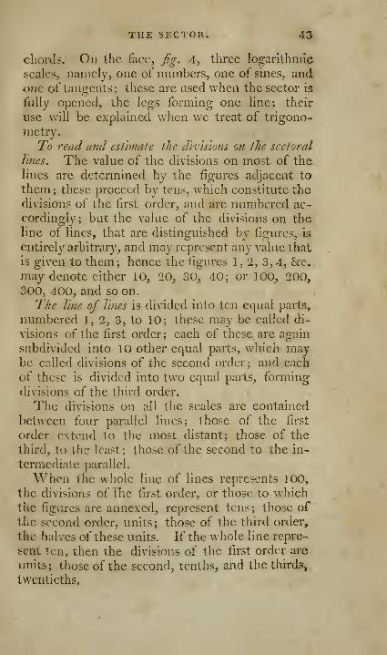
THE SECTOR. 43
chords. On the face, fg. A, three logarlthmici
scales, namely, one of numbers, one of sines, andone of tangents; these arc used when the sector is
fully opened, the legs forming one line; their
use will be explained when wc treat of trigono-
metry.
To rend and estlmale the drc'isions on the sectoral
lines. The value of the divisions on most of thelines are dctennined by the figures adjacent to
them; these proceed by tens, which constitute the
div^isions of the first order, and are numbered ac-
cordingly; but the value of the div^isions on theline of lines, that are distinguished by figures, is
entirely arbitrary, and may represent any value that
is given to them; hence the figures 1, 2, 3,4, &c.may denote cither 10, 20, 30, 40; or 100, 200,
300, 400, and so on.
The line of Tines is divided into ten equal parts,
numbered 1, 2, 3, to 10; these may be called di-
visions of the first order; each of these are again
subdivided into 10 other equal parts, which may-
be called divisions of the second order; and each
of these is divided into two equal parts, forming
divisions of the third order.
The divisions on all the scales are contained
between four parallel lines; those of the first
order extend to the most distant; those of the
third, to the least; those of the second to the in-
termediate parallel.
When the whole line of lines repre?'::nts 100,
the divisions of the first order, or those to whichthe figures are annexed, represent tens ; those of
the second order, units; those of the third order,
the halves of these units. If the whole line repre-
sent ten, then the divisions of the first order are
units; those of the second, tenths, and the thirds,
twentieths.

44 ^HE FOUNDATION
Jn the Tine of tangents, the divisions to which thenumbers are affixed, are the degrees expressed bythose numbers. Evxry fifth degree is denoted bya hne somewhat longer than the rest; betweenevery number and each fifth degree, there are four
divisions, longer than the intermediate adjacent
ones, these are whole degrees ; the shorter ones^
or those of the third order, are 30 minutes.
From the center, to 60 degrees, the line of sines
is divided like the line of tangents; from 60 to 70,
it is divided only to every degree; from 70 to 80,
to every two degrees ; from 80 to 90, the division
jnust be estimated by the eye.
The divisions on the line of chords are to be esti-
mated in the same manner as the tangents.
The lesser line of tangents is graduated every twodegrees from 45 to 50; but from 50 to 60, to
every degree; from 60 to the end, to half degrees.
The line of secants from O to 10, is to be esti-
mated by the eye; from 20 to 50 it is divided to
every two degrees; from 50 to 60, to every degree
;
and from 60 to the end, to every half degree.
OF THE GENERAL LAW OR FOUNDATION OPSECTORAL LINES.
Let C A, C B, fig. 17, plate 3, represent a pair
of sectoral lines, (ex. gr. those of the line of lines,)
forming the angle AC B; divide each of these lines
into four equal parts, in the points H, D, F ;
I, E, G; draw the lines H I, D E, F G, AB. Thenbecause C A, C B, are equal, their sections are also
equal, the triangles are equiangular, having a com-mon angle at C, and equal angles at the base; andtherefore, the sides about the equal angles will be
jM'oportional ; for as CH to CA, so is H I to AB»and, therefore, as CA to C H, so is AB to H I, and,
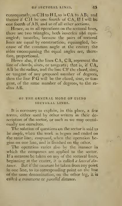
OP SECTORAL LINES. 45
consequently, as C H to H I, so is CA to AB ; andthence if CH be one fourth of CA, HI will beone fourth of AB, and so of all other sections.
Hence, as in all operations on the sectoral lines,
there are two triangles, both isosceles aijid equi-
angled; isosceles, because the pairs of sectoral
lines are equal by construction; equiangled, be-
cause of the common angle at the center; the
sides encompassing the equal angles are, there-
fore, proportional.
Hence also, if the lines CA, C B, represent the
line of chords, sines, or tangents; that is, if CA,AB be the radius, and the Hue CF the chord, sine,
or tangent of any proposed number of degrees,
then the line F G will be the chord, sine, or tan-
gent, of the same number of degrees, to the ra-
dius AB.
OP THE GENERAL MODE OP USING-
SECTORAL LINES.
It is necessary to explain, in this place, a fewterms, either used by other writers in their de-
scription of the sector, or such as we may occasi-
onally use ourselves.
The solution of questions on the sector is said to
Ixj simple^ when the work is begun and ended onthe same line; compound^ when the operation be-
gins on one line, and is finished on the other.
The operation varies also by the manner in
which the compasses are applied to the sector.
If a measure be taken on any of the sectoral lines,
beginning at the center, it is called a lateral dis-
tance. But ifthe measure be taken from any point
in one line, to its corresponding point on the line
of the same denomination, on the other leg, it is
called a transverse or parallel distance*

46 THE MODE OP USING
The divisions of each sectoral line are boundedby three parallel lines; the innermost of these if5
that on which the points of the compasses are to
be placed, because this alone is the line whichgoes to the center, and is alone^ therefore, the sec-
toral line.
We shall now proceed to give a few general in-
stances ofthe manner of operating with the sector,
and then proceed to practical geometry, exempli-
fying its use further in the progress of the work,
as occasion offers.
Alult'iplication by the line of lines. Make the
lateral distance of one of the factors the parallel
distance of 10; then the parallel distance of the
other factor is the product.
Exaniple. Multiply 5 by 6, extend the com-passes from the center of the sector to 5 on the
primary divisions, and open the sector till this dis-
tance become the parallel distance from 10 to 10
on the same divisions; then the parallel distance
from 6 to 6, extended from the center of the see-
tor, shall reach to 3, which is now to be reckoned
30. At the same opening of the sector, the pa-
rallel distance of 7 shall reach from the center to
35, that of8 shall reach from the center to 40, &c.
Division by the line of lines. Make the lateral
distance of the dividend the parallel distance of
the divisor, the parallel distance of 10 is the quo-
tient. Thus, to divide 30 by 5, make the lateral
distance of 30, viz. 3 on the primary divisions, the
parallel distance of 5 of the same divisions; then
the parallel distance of 10, extended from the
center, shall reach to 6.
Proportion by the line of Vines. Make the lateral
distance of the second term the parallel distance
of the first term ; the parallel distance of the third
term is the fourth proportional. Example. To

SECTORAL LINES. 47
find a fourth proportional to 8, 4, and 6, take tlic
lateral distance of 4, and make it the parallel dis-
tance of 8; then the parallel distance of 6, ex-
tended from the center, shall reach to the fourth
proportional 3.
In the same manner a third proportional Is
found to two numbers. Thus, to find a third
proportional to 8 and 4, the sector remaining as
in the former example, the parallel distance of 4,
extended from the center, shall reach to the third
proportional 2. In all these cases, if the numberto be made a parallel distance be too gi'cat for the
sector, some aliquot part of it is to be taken, andthe answer multiplied by the number by whichthe first number was divided. Thus, if it wererequired to find a fourth proportional to 4, 8,
I'.nd 6; because the lateral distance of the second
term 8 cannot be made the parallel distance of the
first term 4, take the lateral distance of 4, viz. the
half of 8, and make it the parallel distance of the
tirst term 4 ; then the parallel distance of the third
term 6, shall reach from the center to 6, viz. the
half of 12. Any other aliquot part of a numbermay be used in the same way. In like manner, if
the number proposed be too small to be made the
parallel distance, it may be multiplied by somenumber, and the answer is to be divided by the
same number.To protract angles hy the line of chords. Case 1
.
When the given degrees are under 6o. 1 . Wiihany radius \^,fig. 14, plate 3, on A as a center,
describe the arcJi B G. 2. Make the same radius
a transverse distance between 6o and 60 on the
line of chords., 3. Take out the transverse dis-
tance of the given degrees, and lay this on the
arch from B towards G, which will mark out the
angular distance required.

43 USES OP SECTORAL SCALED
Case 2. When the given degrees are more ihatt
60. 1 . Open the sector, and describe the arch as
before. 2. Take i or i of the given degrees, andtake the transverse distance of this h or I, and lay
it off from B towards G, twice, if the degrees werehalved, three times if the third was used as a
transverse distance.
Case 3. When the required angle is less than
6 degrees; supposes. 1. Open the sector to the
given radius, and describe the arch as before.
2. Set off the radius from B to C. 3. Set off the
chord of 57 degrees backward from C to f, whichwill give the arc fb of three degrees.
SOME USES OF THE SECTORAL S(*ALES OF SINES,
TANGENTS, AND SECANTS.*
Given the radius of a circle^ (suppose equal to
two inches^) required the sine and tangent ofl'^ 30to that radius.
Solution. Open the sector so that the trans-
verse distance of 90 and 90 on the sines, or of 45and 45 on the tangents, may be equal to the given
radius, viz. two inches; then will the transverse
distance of 28° 30', taken from the sines, be the
length of that sine to the given radius; or if taken
from the tangents, will be the length of that tan-
gent to the given radius.
But if the secant oflS° 30' was required?
Make the given radius, two inches, a transverse
distance to O and 0, at the beginning of the line
of secants; and then take the transverse distance
ofthe degrees wanted, viz. 28° 30'.
* Robertson on Mathematical Instrumenta,
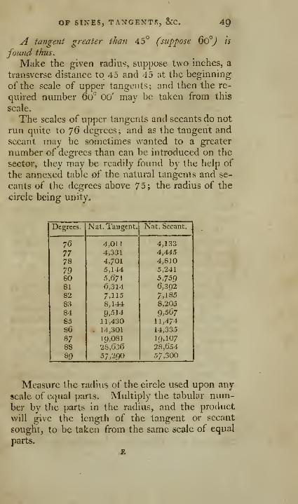
OF SINES, TANGENTS, &C. 49
A tangent greater than 45° (suppose 6o°J is
found thus.
Make the given radius, suppose two inches, a
transverse distance to 45 and 45 at the beginning
of the scale of upper tangents; and then the re-
quired number 60^ 00' may be taken from this
scale.
The scales of upper tangents and secants do not
run quite to 76 degrees; and as the tangent andsecant may be sometimes wanted to a greater
number of degrees than can be introduced on the
sector, they may be readily found by the help of
the annexed table of the natural tangents and se-
cants of the degrees above 75; the radius of the
circle being unity.
Degrees.

50 USES OP SECTORAL SCALES
Example. Required the length of the tangent
and secant of 80 degrees to a circle, whose radius,
measured on a scale of lb parts to an inch, is 47 5 ofthose parts?
tangent. secant.
Against 80 degrees stands 5jd7l 5,759The radius is 47,5 47,5
28355 2879539697 40313
22Ci84 23036
269,3725 273,5525
So the length of the tangent on the twenty-fifth scale will be 269-3 nearly. And that of thesecant about 273^.
Or thus. The tangent of any number of de-
grees may be taken from the sector at once; ifthe
radius of the circle can be made a transverse dis-
tance to the complement of those degrees on the
lower tangent.
Example. To find the tangent of "JS degrees to
a radius of two inches.
Make two inches a transverse distance to 12 de-
grees on the lower tangents; then the transverse
distance of 45 degrees will be the tangent of 78degrees.
In like manner the secant of any number of de-
grees may be taken from the sines, if the radius of
the circle can be made a transverse distance to theco-sine of those degrees. Thus making twoinches a transverse distance to the sine of twelve
degrees; then the transverse distance of 90 and 90will be the secant of 78 degrees.
From hence it will be easy to find the degrees
answering to a given lincj expressing the length
OP SINES, TANGENTS, &C. 51
of a tangent or secant, which is too long to bemeasured on those scales, when the sector is set to
the, given radius.
Thus, for a tangent, make the given line a
transverse distance to 45 and 45 on the lower tan-
gents; then take the given radius, and apply it to
the lower tangents ; and the degrees where it be-
comes a transverse distance is the co-tangent of
the degrees answering to the given line.
And for a secant; make the given line a trans-
verse distance to QO and 90 on the sines. Thenthe degrees answering to the given radius, applied
as a transverse distance on the sines, will be the
co-sine of the degrees answering to the given se-
cant line.
Given the length of the sine, tangent, or secant, ofany degrees-, to find the letigth of the radius to that
sine, tangent, or secant.
Make the given length a transverse distance to
its given degrees on its respective scale: then,
In the sines. The transverse distance of 90 and
90 will be the radius sought.
In the lower ta?igents. The transverse distance
of 45 and 45, near the end of the sector, will bethe radius sought.
In the upper tangents. The transverse distance
of 45 and 45, taken towards the center of the
sector on the line of upper tangents, will be the
center sought.
In the secant. The transverse distance ofO and O,
or the beginning of the secants, near the center of
the sector, will be the radius sought.
Given the radius and any line representing a sine,
tangent, or secant; to find the degrees corresponding
to that line.
Solution. Set the sector to the given radius,
according as a sine^ or tangent^ or secant is con-
cerned.
.. E 2
5'Z SELECT PROBLEMS
Take the given line between the compasses;
apply the two feet transversely to the scale con-cerned, and slide the feet along till they both rest
on like divisions on both legs; then will those di-
visions shew the degrees and parts corresponding
to the given line.
To find the length of a versed sine to a given
number of degrees, and a given radius.
Make the transverse distance of gO and 90 onthe sines, equal to the given radius.
Take the transverse distance of the sine com-plement of the given degrees.
If the given degrees are less than 90, the diffe-
rence between the sine complement and the ra-
dius gives the versed sine.
If the given degrees are more than 90, the sumof the sine complement and the radius gives the
versed sine.
To open the legs of the sector, so that the corres-
ponding double scales of lines, chords, sines, and tan-
gents^ may malie each a right angle.
On the lines, make" the lateral distance ]^, adistance between eight on one leg, and six on theother leg.
On the sines, make the lateral distance QO, atransverse distance from 45 to 45; or from 40 to
50; or from 30 to 60; or from the sine of any de-grees to their complement.
Or on the sines, make the lateral distance of 45a transverse distance between 30 and 30.
SELECT GEOMETRICAL PROBLEMS.
Science may suppose, and the mind conceive
things as possible, and easy to be effected, in
which art and practice often find insuperable dif-»
IN GEOMETRY. 53
jfrculties. " Pure science has to do only with
ideas; but in the application of its laws to the use
of life, we are constrained to submit to the imper-
fections of matter and the influence of accident.'*
Thus practical geometry shews how to perform
what theory supposes; in the theory, however, it
is sufficient to have only a right conception of the
objects on which the demonstrations are founded;
drawing or delineations being of no further use
than to assist the imagination, and lessen the exer-
tions of the mind. But in practical geometry^, wenot only consider the things as possible to be ef-
fected, but are to teach the ways, the instruments,
and the operations by which they may be actually
performed. It is not sufficient here to shew, that
a right line may be drawn between two points, or
a circle described about a center, and then de-
monstrate their properties; but we must actually
delineate them, and exhibit the figures to the
senses: and it will be found, that the drawing of
a strait line, which occurs in all geometrical ope-
rations, and which in theory is conceived as easy
to be effected, is in practice attended with consi-
derable difficulties.
To draw a strait line between two points upona plane, we lay a rule so that the strait edge thereof
may just pass by the two points; then movinga fine pointed needle, or drawing pen, along this
edge, we draw a line from one point to the other,
which for common purposes is sufficiently exact;
but where great accuracy is required, it will be
found extremely difficult to lay the rule equally,
with respect to both the points, so as not to be
nearer to one point than the other. It is difficult
also so to carry the needle or pen, that it shall nei-
ther incline more to one side than the other of the

54 SELECT PROBLEMS
rule; and thirdly, it is very difficult to find aniTethat shall be perfectly strait. If the two points bevery far distant, it is almost impossible to drawthe line with accuracy and exactness; a circular
line may be described more easily, and more ex-
actly, than a strait, or any other line, though eventhen many difficulties occur, when the circle is
required to be of a large radius.
It is from a thorough consideration of these dif-
ficulties, that geometricians will not allow those
lines to be geometrical, which in their description
require the sliding of a point along the edge of a
rule, as in the ^ellipse, and several other curvelines, whose properties have been as fully inves-
tigated, and as clearly demonstrated, as those of
the circle.
From hence also we may deduce some of those
•maxims which have been introduced into practice
by Bird and Smeaion, which will be seen in their
proper place. And let no one consider these re-
flections as the effect of too scrupulous exactness,
or as an unnecessary aim at precision; for as the
foundation of all our knowledge in geography,
navigation and astronomy, is built on observation,
and all observations are made with instruments, it
follows, that the truth of the observations, and the
accuracy of the deductions therefrom, will princi-
pally depend on the exactness with which the in-
struments are made and divided; and that these
sciences will advance in proportion as those are
less difficult in their use, and more perfect in the
performance of their respective operations.
There is scarce any thing which proves moreclearly the distinction between mind and body,
and the superiority of the one over the other, thart
a reflection on the rigid exactness of speculative
IN GEOMETRY. 55
geometn'', and the inaccuracy of practice, that is
not directed by theory on one hand, and its ap-
proximation to perfection on the other, whenguided by a just theory.
In theory, most tigurcs may be measured to anahnost infinite exactness, yet nothing can be moreinaccurate and gross, than the ordinalr) methods of
mensuration; but an intelligent practice finds a
medium, and corrects the imperfection of our me-chanical organs, by the resources of the mind. If
we were more perfect, there would be less roomfor the exertions of our mind, and our knowledgewould be less.
If it had been easy to measure all things with
exactness, we should have been ignorant of manycurious properties in numbers, and been dej)rived
of the advantages we derive from logarithms, sines,
tangents, &c. If practice were perfect, it is doubt-
ful whether we should have ever been in possession
of theory.
We sometimes consider with a kind ofenvy, the
mechanical perfection and exactness that is to befound in the works of some animals; but this per-
fection, which does honor to the Creator, does
little to them; they are so perfect, only because
they are beasts.
The imperfection of our organs is abundantly
made up by the perfection of the mind, of whichwe are ourselves to be the artificers.
If any wish to see the difRcullies of rendering
practice as perfect as theory, and the wonderful re-
sources of the mind, in order to attain this degree
of perfection, let him consider the operations of
General Roy, at Hounslow-hcath; operations that
cannot be too much considered, nor too muchpraised by every practitioner in the art of geo-
metry. See Fhilosoplh Trans, vol. 80^ et seq.
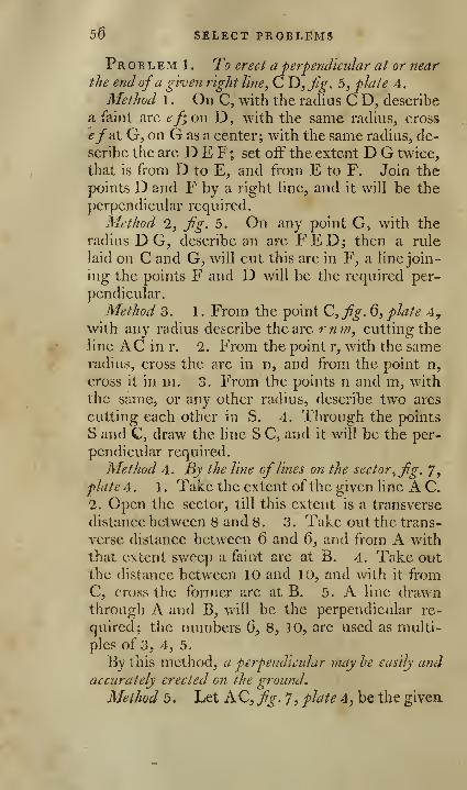
56 SELECT PROBLEMS
Pr b l em 1 . To erect a perpendicular at or nearthe end ofa given right line, C D, Jig. 5, plate 4.
Method 1 . On C, with the radius C D, describe
a faint arc ef; on D , with the same radius, cross
ef'At G, on G as a center; with the same radius, de-
scribe the arc D E F; set off the extent D G twice,
that is from D to E, and from E to F. Join the
points D and F by a right Hne, and it will be the
perpendicular required.
Method '2, fg. 5. On any point G, with the
radius D G, describe an arc FED; then a rule
laid on C and G, will cut this arc in F, a line join-
ing the points F and D will be the required per-
pendicular.
Method 3. 1 . From the point C, fig. 6, plate 4,with any radius describe the arc r n in, cutting the
line AC in r. 2. From the point r, with the sameradius, cross the arc in n, and from the point n,
cross it in m. 3. From the points n and m, with
the srime, or any other radius, describe two arcs
cutting each other in S. 4. Through the points
S and C, draw the line S C, and it will be the per-
pendicular required.
Method 4. By the line of lines on the sector, fig. 7,
plate A. 1 . Take the extent of the given line A C.
2. Open the sector, till this extent is a transverse
distance between 8 and 8. 3. Take out the trans-
verse distance between 6 and 6, and from A withthat extent sweep a faint arc at B. 4. Take outthe distance between 10 and 10, and with it fromC, cross the former arc at B. 5. A line drawnthrough A and B, will be the perpendicular re-
quired; the numbers 6, 8, 10, are used as multi-
ples of 3, 4, 5.
By this method, a perpendicular may he easily andaccurately erected on the ground.
Method 5. Let AC, fig. 7, plate 4, be the givea
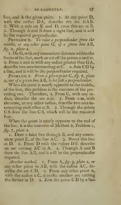
IN GEOMETRY. 5/
line, and A the given point. 1 . At any point D,with the radius DA, describe the arc EAB.2. With a rule on E and D, cross this arc at B.
3. Through A and B draw a right Hne, and it will
be the required perpendicular.
Problem 2. To raise a perpendicular from the
middle, or any other point G, of a given line AB,fg. 8, plate 4.
1 . On G, with any convenient distance within the
limits ofthe line, mark or set oiFthe points n and m.2. From n and m with any radius greater than GA,describe two arcs intersecting at C. 3. Join CG by
a line, and it will be the perpendicular required.
Problem 3. Froin a givenpoint C,fig. Q, plate
4. out of a given line K^i toletfall a perpendicular.
When the point is nearly opposite to the middle,
of the line, this problem is the converse of the pre-
ceding one. Therefore, 1 . From C, with any ra-
dius, describe the arc n m. 2. From n m, with
the same, or any other radius, describe two arcs in-
tersecting each other at S. 3. Through the points
C S draw the line C S, which will be the required
line.
When the point is nearly opposite to the end of
the line, it is the converse of Method 5, Problem 1,
fig' 1, plate A.
1 . Draw a faint line through B, and any conve-
nient point E, of the line AC. 2. Bisect this line
at D. 3. From D with the radius DE describe
an arc cutting AC at A. 4. Through A and Bdraw the line AB, and it will be the perpendicular
required.
Another method. 1 . From A, fig. Q, plate 4, or
any other point in AB, with the radius AC, de-
scribe the arc CD. 2. From any other point n,
with the radius n C, describe another arc cutting
the former in D. 3. Join the point C D by a line
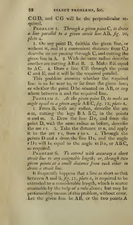
58 SELECT l^ROBtEMS, 8cC.
C G D, and C G will be the perpendicular re-
quired.
Problem 4. Through a given point C, to drawa line parallel to a given strait line AB, fg. 10,
plate A.
1. On any point D, (within the given line, or
without it, and at a convenient distance from C,)
,describe an arc passing: through C, and cutting the
given line in A. 1. With ihe same radius describe
another arc cutting AB at B. 3. Make BE equal
to AC. 4. Draw a line CE through the point
C and E, and it will be the required parallel.
This problem answers whether the required
line is to be near to, or far from the given line;
or whether the point D be situated on AB, or anywhere between it and the required line.
Problem 5. At the given point D, to make an
angle equal to a given angle AB C,Jig, \'2, plate 4.
1. From Bj with any radius, describe the arc
n m, cutting the legs B A B C, in the points
n and m. 2. Draw the line D r, and from the
point D, with the same radius as before, describe
the arc rs. 3. Take the distance m n, and apply
it to the arc rs, from r to s. 4. Through the
points D and s draw the line D s, and the angle
r D s will be equal to the angle m B n, or AB C,
as required.
Problem 6. To extend with accuracy a short
strait line to any assignable length ; or, through two•given points at a small distance from each other to
draw a strait line.
It frequently happens that a line as short as that
between A and B, j^>. 1 1, plate 4, is required to beextended to a considerable length, which is scarce
attainable by the help of a rule alone ; but may be
performed by means of this problem, without error.
^Let the given line be AB, or the two points A
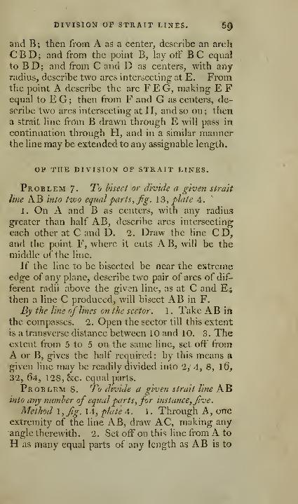
DIVISION OF* STRAIT LINES. 6^
and B; then from A as a center, describe an arch
CBD; and from the point B, lay otF BC equal
to B D ; and from C and D as centers, with anyradius, describe two arcs intersecting at E. Fromthe point A describe the arc F E G, making E Fequal to E G ; then from F and G as centers, de-
scribe two arcs intersecting at H, and so on ; then
a strait line from B drawn through E will pass in
continuation through H, and in a similar mannerthe line may be extended to any assignable length.
OP THE DIVISION OF STRAIT LINES.
Problem 7. To bisect or divide a given strait
line AB into two equal partSyfg. 13, plate 4.
1, On A and B as centers, with any radius
greater than half AB, describe arcs intersecting
each other at C and D. 1. Draw the line C D,and the point F, where it cuts A B, will be the
middle of the line.
If the line to be bisected be near the extremeedge of any plane, describe two pair of arcs of dif-
ferent radii above the given line, as at C and E;then a line C produced, will bisect AB in F.
By the line of lines on the sector. 1. Take AB in
the compasses. 2. Open the sector till this extent
is a transverse distance between 10 and 10. 3. Theextent from 5 to 5 on the same line, set off from
A or B, gives the half required : by this means a
given line may be readily divided into 2, 4, 8, 16,
32, 64, 128, &c. equal parts.
Problem S. To divide a given strait line ABinto any number of equal parts, for instance,five.
Method I, fig. 14, plate 4. 1. Through A, oneextremity of the line AB, draw AC, making anyangle therewith. 2. Set off on this line from A to
H as many equal parts of any length as AB is to
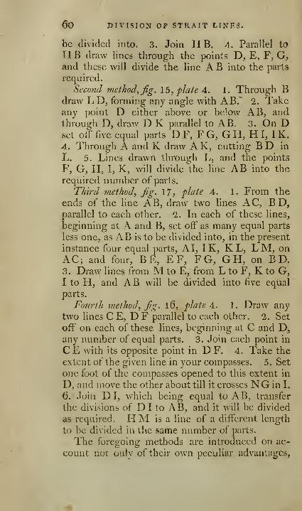
60 DIVISION OF STRAIT LINE3.
be divided into. 3. Join H B. 4. Parallel to
H B draw lines through the points D, E, F, G,and these will divide the line A B into the parts
required.
Second method, j^g. 15, plate 4. 1. Through Bdraw LD, forming any angle with AB."" 2. Takeany point D either above or below AB, andthrough D, draw D K parallel to AB. 3. On Dset otF five equal parts D F, F G, G H, HI, IK.4. Through A and K draw A K, cutting BD in
L. 5. Lines drawn through L, and the points
F, G, H, I, K, will divide "the line AB into the
required number of parts.
Third method, jig. 1/, plate 4. 1. From the
ends of the line AB, draw two lines AC, B D,parallel to each other. 2. In each of these lines,
beginning at A and B, set off as many equal parts
less one, as AB is to be divided into, in the present
instance four equal parts, AI, IK, K L, LM, onAC; and four, BE, E F, FG, GH, on B D.3. Draw lines from M to E, from L to F, K to G,I to H, and AB will be divided into five equal
parts.
Fourth method, fg. l6, plate A. 1. Draw anytwo lines C E, D F parallel to each other. 2. Set
off on each of these lines, beginning at C and D,any number of equal parts. 3. Join each point in
C E with its opposite point in D F. 4. Take the
extent of the given line in your compasses. 5. Set
one foot of the compasses opened to this extent in
D, and move the other about till it crosses NG in I.
6. Join DI, which being equal to AB, transfer
the divisions of D I to AB, and it will be divided
as required. HM is a line of a different length
to be divided in the same number of parts.
The foregoing methods are introduced on ac-
count not only of their own peculiar advantages.
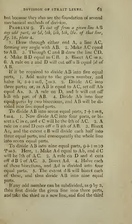
DIVISION OF STRAIT LINES. 6l
but because they also are the foundation of several
mechanical methods of divi'-ion.
Problem 9- To cut; off from a given line ABany odd part, as yd, \th, ^th, yth, &c. of that line,
fig. \Q, plate 4.
1. Draw through either end A, a line AC,forming any angle with AB. 2. Make AC equal
to AB. 3. Through C and B draw the line CD.4. Make B D equal to C B. 5. Bisect AC in a.
6. A rule on a and D will cut off a B equal id of
AB.If it be required to divide AB into five equal
parts, 1 . Add unity to the given number, andhalve it, 5+ 1=6, ^=3. 2. Divide AC into
three parts; or, as AB is equal to AC, set off Abequal A a. 3. A rule on D, and b will cut off
bB rth part of AB. 4. Divide Ab into four
equal parts by two bisections, and AB will be di-
vided into five equal parts.
To divide AB into seven equal parts, 7-f-i=8,T=4. 1. Now divide AC into four parts, or bi-
sect a C in c, and c C will be the ^th of AC. 2. Arule on c and D cuts off' c B fth of AB. 3. Bisect
Ac, and the extent cB will divide each half into
three equal parts, and consequently the whole line
into seven equal parts.
To divide AB into nine equal parts, 9-|-l = 10•^=5. Here, 1. Make Ad equal to Ab, and d Cwill be Ith of AC. 2. A rule on D and d cuts
off dB i of AC. 3. Bisect Ad. 4. Halve each
of these bisections, and Ad is divided into four
equal parts. 5. The extent d B will bisect each
of these, and thus divide AB into nine equal
parts.
Ifany odd number can be subdivided, as Q by 3,
tben first divide the given line into three parts,
ar>d take the third as a new line, and find the third
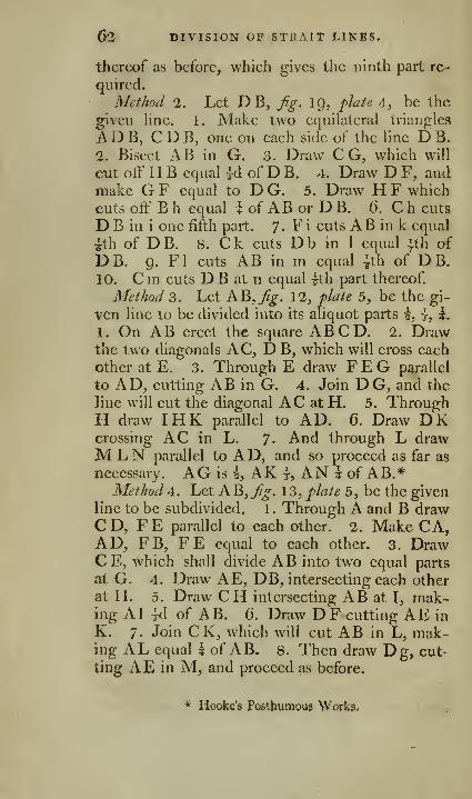
62 DIVISION OF STRAIT LINES.
thereof as before, which gives the ninth part re-
quired.
Method 2. Let DB, fg. 19, plate A, be the
given Hne. 1. Make two equilateral triangles
ADB, CDB, one on each side of the line D B.
2. Bisect AB in G. 3. Draw C G, which will
cut off H B equal id of D B. 4. Draw D F, andmake GF equal to D G. 5. Draw H F which
cuts off B h equal k of AB or D B. 6. C h cuts
D B in i one fifth part. 7- F i cuts AB in k equal
^th of DB. 8. Ck cuts Db in 1 equal |th of
DB. 9. Fl cuts AB in m equal ^th of DB.10. Cm cuts D B at n equal ^th part thereof.
Method 3. Let KB, Jig. 12, flate 5, be the gi-
ven line to be divided into its aliquot parts h, t, i.
1. On AB erect the square ABCD. 2. Drawthe two diagonals AC, D B, which will cross each
other at E. 3. Through E draw FEG parallel
to AD, cutting AB in G. 4. Join D G, and the
line will cut the diagonal AC at H. 5. ThroughH draw IHK parallel to AD. 6. Draw DKcrossing AC in L. 7- And through L drawMLN parallel to AD, and so proceed as far as
necessary. AG is h, AK |, AN \ of AB.*Method 4. Let AB,/^. 13, plate 5, be the given
line to be subdivided. 1 . Through A and B drawC D, F E parallel to each other. 2. Make CA,AD, FB, FE equal to each other. 3. DrawCE, which shall divide AB into two equal parts
at G. 4. Draw A E, DB, intersecting each other
at H. 5. Draw CH intersecting AB at I, mak-ing AI id of AB. 6. Draw DF cutting AE in
K. 7. Join CK, which will cut AB in L, mak-ing AL equal \ of AB. 8. Then draw Dg, cut-
ting AE in M, and proceed as before.
* Hooke's Posthumous Works.
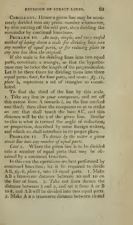
DIVISION OF STRAIT LINES. 63
Corollary. Hence a given line may be accu-
rately divitied into any prime number whatsoever,
by lirst cutting oti the odd part, then dividing the
remainder by continual bisections.
Problem 10. An eusy\ sii/ij)Ie, and ve7y useful
method of laying down a scale for di-v'id'wg lines Into
any number of equal 'parts, or for reducing -plans to
any size less than the original.
If the scale is for dividing lines into two equal
parts, constitute a triangle, so that the h) pothe-
nuse may be twice the length of the perpendicular.
Let it be three times for dividing them into three
equal parts; four, for four parts, and so on : Jig. 11,
plate 5, represents a set of triangles so consti-
tuted.
To find the third of the line by this scale.
1. Take any line in your compasses, and set off
this extent from A towards I, on the line markedone third; then close the compasses so as to strike
an arc that shall touch the base AC, and this
distance will be the t of the given line. Similar
to this is w^hat is termed the angle of reduction,
or proportion, described by some foreign writers,
and which we shall introduce in its proper place.
Problem 11. To divide by the sector a given
strait line into any nundjer of equal parts.
Case 1. Where the given line is to be divided
into a number of equal jiarts that may be ob-
tained by a continual bisection.
In this case the operations arc best performed bycontinual bisection; let it be required to divide
A^, fig. Q, plate o, into l6 equal parts. 1. MakeAB a transverse distance betw^een 10 and 10 onthe line of lines. 1. Take out from thence the
distance between 5 and 5, and set it from A or Bto 8, and AB will be divided into two equal parts.
3. Make A 8 a transverse distance between 10 and

64 DIVISION OP STRAIT L1NES»
10, and 4 the transverse distance between 5 and 5,
will bisect 8 A, and 8 B at 4 and 12; and thus ABis divided into four equal parts in the points 4, 8,
and 12. 4. The extent A 4, put between 10 and
10, and then the distance between 5 and 5 applied
from A to 2, from 4 to 6, from 8 to 10, and from
12 to 14, will bisect each of those parts, and divide
the whole line into eight equal parts. 5. To bi-
sect each of these, we might take the extent of
A 2, and place it between 10 and 10 as before;
but as the spaces are too small for that purpose,
take three of them in the compasses, and open the
sector at 10 and 10, so as to accord with this mea-sure. 6. Take out the transverse measure between5 and 5, and one foot of the compasses in A will
give the point 3, in 4 will fall on 7 and 1, on 8will give 5 and 11, on 12 gives 9 and 15, and onB will give 13. Thus we have, in a correct andeasy manner divided AB into 16 equal parts by a
conthiual .bisection.
If it were required to bisect each of the forego-
ing divisions, it would be best to open the sector
at 10 and 10, with the extent of five of the divi-
sions already obtained ; then take out the trans-
verse distance between 5 and 5, and set it off fromthe other divisions, and they will thereby be bi--
sected, and the line divided into 32 equal parts.
Case 2. When the given line cannot be di-
vided by bisection.
Let the given line be AB, fy. 7, pJate 4, to bedivided into 14 equal parts, a number which is nota multiple of 2.
1. Take the extent AB, and open the sector to
it on the terms 10 and 10, and the transverse dis-
tance of 5 and 5, set from A or B to 7, will divide
AB into two equal parts, each of which are to besubdivided into 7, which maybe done by dividing

- blVISIO^r OP StRAlT LINES. 65
A 7 into 6 and 1, or 4 and 3, which last is pre-
ferable to the first, as by it the operation may befinished with only two bisections.
2. Therefore open the sector in the terms 7 and
7, with the extent A 7; then take out the trans-
verse distance between 4 and 4, this laid off fromA, gives the point 4, from 7 gives 3 and 11, andfrom B gives 10.
3. Make A4 a transverse distance at 10 and10, then the transverse distance between 5 and 5
bisects A b, and lOB in 2 and 12, and gives thepoint 6 and 8; then one foot in 3 gives 1 and 5,
and from 11, 13 and Q: lastly, from 4 it gives 6,
and from 10, 8; and thus the line AB is divided
into 14 equal parts.
Problem 12. To make a scale of equal j>arts
containing any given number in an inch.
Example. To construct a scale of feet and inches
in such a manner, that 25 of the smallest parts shall
be equal to one inch, and 12 of them represent
one foot.
By the line of lines on the sectoi . 1 , Multiply the
given numbers by 4, the products will be 100, and48. 2. Take one inch between your compasses,
and make it a transverse distance between 100 and100, and the distance between 48 rnd 48 will
be 12 of these 25 parts in an inch; this extent set
off from A to l,fg. 3, plate 5, from 1 to 2, &c. to
12 at B divides AB into a scale of 12 feet. 3, Set
off one of these parts from A to a, to be subdi-
vided into 12 parts to represent inches. 4. Tothis end divide this into three parts; thus tr.ke the
extent A 2 of two of these parts, and make it a
transverse distance between 9 and 9. 5. Set the
distance between 6 and 6 from b to e, the sameextent from 1 gives g, and from e gives n, thu^
dividing A a into three equal parts in the points n

06 PROPORTIONAL LINES'.
-and g. 6. By two bisections each of these may besubdivided into four equal parts, and thus the
whole space into 12 equal parts.
When a small number of divisions are required,
as I, 2, or 3, instead of taking the transverse dis-
tance near the center of the sector, the division
will be more accuYately performed by using the
following method.Thus, if three parts are required from A, of
which the whole line contains QO, make AT),Jjg. 4,
plate 5, a transverse distance between 90 and c}0;
then take the distance between 87 and 87, whichset off from D to E backwards,^ and AE will con-tain the three desired parts.
Example 2. Supposing a scale of six inches to
contain 140 poles, to open the sector so that it
may answer for such a scale; divide 140 by 2,
which gives 70, the half of 6 equal to 3 ; because140 was too large to be set off on the line of lines-.
Make three inches a transverse distance between70 and 70, and your sector becomes the required
scale.
Example 3. To make a scale of seven inches
tliat shall contain 180 fathom; •^=9.-^=3^,therefore make 3§ a transverse between 9 and 9,and you have the required scale..
OF PROPORTIONAL LINES.
Problem 13. To cut a given line A D, fig. 1 4
,
jilale 5, Into tivo iinequal parts that shall have any
given proportion, ex. gr. of C to D.1, Draw AG forming any angle with AD.
2. From A dn AG set off AC equal to C, andCE equal to D. 3. I>aw ED, and parallel to it
C B, which will cut AD at B in the required pro-portion.

PROPORTIONAL LINESi 6}
To divide by the sector the line AB, fg. 1,
if^hite 5, in the proportion of 3 to 2. Now as 3 and"2 would fall near the center, multiply them by 2,
thereby forming 6 and 4, which use instead of 3
and 2. As the parts are to be as 6 to 4, the wholeline will be 10; therefore make AB a transverse
distance between 10 and 10, and then the trans*
verse distance between 6 and 6, set off from B to
e, is Iths of AB; or the distance between 4 and 4will give Ae iths of AB; therefore AB is cut in
the proportion of 3 to 2.
Example 2. To cut AB, Jig. 2, plate 5, in theproportion of 4 to 5 ; here we may use the num-^
b^rs themselves ; therefore with A B open the sec-
tor at 9 and Q, the sum of the two numbers; then
the distance between 5 and 5 set off from B to c,
or between 4 and 4, set off A to c, and it divides
AB in the required proportion.
No/€. If the numbers be too small, use their
equimultiples; if too large, subdivide them.Corollary. From this problem we obtain ano-
ther mode of dividing a strait line into any numberof equal parts.
Problem 14. To estimate the proportion he'
tween two or more given Vines, as AB, CD, EF,fig' 9^ Plated.
Make AB a transverse distance between 10 and10, then take the extents severally of CD and EF^and carry them along the line of lines, till both
points rest exactly upon the same number; in the
first it will be found to be 85, in the second Qt ^
Therefore AB is to CD as 100 to 85, to EF as
100 to idj, and of C D to E F as 85 to Q7
.
Problem 15. To find a third proportional ta
two given right lines A and B,fig. 15, plate 5.
1 . From the point D draw two right lines D E,
D F, making any angle whatever. 2. In these
p 2

08 PROPORTIONAL LINES,
lines take DG equal to the first term A, and DC,DH, each equal to the second term B. 3. Join
GH, and draw CF parallel thereto; then DFwill be the third proportional required, that is^
DG (A) to D C, (B,) so is D H (B) to D F.
By the sector. 1. Make AB, fg. 5, flate 5, a
transverse distance between 100 and 100. 2. Find
the transverse distance of E F, which suppose 50.
3. Make EF a transverse distance betw^een 100 and
100. 4. Take the.extent between 50 and 50, and
it will be the third proportional C D required.
Pr o b l em 1 6. To find a fourth proportional to
three given right lines A, B, C,fig. l6, flate 5.
1. From the point a draw two right lines, mak*ing any angle whatever. 2. In these lines makea b equal to the first term A3 a c equal to the se-
cond B, and a d equal to the third C. 3. Join be,
and draw de parallel thereto, and ae will be the
fourth proportional required ; that is, a b (A) is ta
a c (B,) so is a d (C) to a e.
By the sector, 1 . Make the line A a transverse*-
distance between 100 and 100. 2. Find the trans-
verse measure of B, which is 60. 3. Make c the
third line a transverse measure between 100 and100. 4. The measure between 60 and 60 will be?
the fourth proportional.
Problem 17. To find a mean proportional he"-
tween t-zvo given strait lines A and B,fig. 1 7 ,plate 5.
1 . Draw any right line, in wliich take C E equal
to A, and EA equal to B. 2. Bisect AC in B, andwith BA, or B C as a radius, describe the semi-
circle ADC. 3. From the point E draw EGperpendicular to AC, and it will be the mean pro-
portional required.
By the sector. Join the lines together, (sup-
pose them 40 and f)0) and get the sum of them,-
130? then find the half of this sum 05, and half
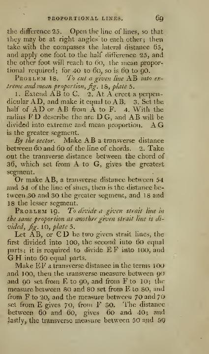
PROPORTIONAL LINES. 6g
the difference 25. Open the line of lines, so that
they may be at right angles' to each other; then
take with the compasses the lateral distance 65,and apply one foot to the half difference 25, andthe other foot will reach to (io, the mean propor-
tional required; for 40 to 6o, so is 6o to QO.
Problem 18. T'o cut a g'l-ven line AB into ex-
treme and mean froport'ion^jig. 18, flate 5.
1. Extend AB to C. 2. At A erect a perpen-
dicular AD, and make it equal to AB. 3. Set the
half of AD or AB from A to F. 4. With the
radius FD describe the arc D G, and AB will bedivided into extreme and mean proportion. A Gis the greater segment.
By the sector. Make AB a transverse distance
between 6o and 6o of the line of chords. 2. Takex)ut the transverse distance between the chord of
36, which set from A to G, gives the greatest
segment.
Or make AB, a transverse distance between 54
and 54 of the line of sines, then is the distance be-
tween 30 and 30 the greater segment, and 18 and
18 the lesser segment.
Problem IQ. To divide a given strait line In
the same proportion as anotlur given strait line is di-
vided, jig. 10, plate 5.
Let AB, or GD be two given strait lines, the
first divided into 100, the second into (X) equal
parts; it is required to divide EF into 100, and
GH into 60 equal parts.
Make EF a transverse distance in the terms lOOand 100, then the transverse measure between p<)
and go set from E to 90, and from F to 10; the
measure between 80 and 80 set from E to 80, and
from F to 20, and the measure between 70 and 70set from E gives 70, from F 30. The distance
between 60 and 60, gives 60 and 40 i and
lastly, the transverse measure between 50 ajid 5Q

70 PROPORTIONAL LINES.
bisects the given line in the point 50, and we shall,
by five transverse extents, have divided the line
EF into 10 equal parts, each of which are to be
subdivided into 10 smaller divisions by problems
11 and 12.
To divide G H into 6o parts, as we have sup-
posed CD to be divided, make GH a transverse
distance in the terms of 6o, then work as before.
Problem 20. To find the angular poiJit of two
^iven lines AK, c P, fig. 22, plate 5, which incline
to each other without producing either of them.
Through A draw at pleasure AN, yet so as not
to cut c P too obliquely,
1. Draw the parallel lines A-, Gf, K^. 2. Takeany number of times the extents, AN, GO, K P,
and set them on their respective lines, as from N to
y and I/, from o to (3 and £, from P to a and (J, anda line through ^, £, u, and another through «, P, y,
tv'ill tend to the same point as the lines AB, c P.
Method 2. 1. Through AB and CD, /^. 21,
plate 5, draw any two parallel lines, as GH andFE. 2. Set off the extent B D twice, from B to
G, and D to H; and the extent AC twice, from
A to F, and from C to E. 3. A line passing
through F and G will intersect another line pass-
ing through E and H in I, the angular point re-
quired.
The extent FA, G B, may be multiplied or di -
vided, so as to suit peculiar circumstances.
Corollary. Hence, if any two lines be given that
tend to the same angular point, a third, or morelines may be drawn that shall tend to the samepoint, and yet pass through a given point.
Solution by the sector. Case 1. When the pro-
posed point e is between the two given lines VLand a h^fig. 23, plate 5.
Through e dniw a line a v, cutting ab at a, andVL at V^, then from any other point b, in ab, the

PROPORTIONAL LINES. 71
ftirtlier the better, draw b x parallel to a V, andcutting VL in x, make av a transverse distance
between 100 and 100, on the line of Hnes; take
the extent ev, and find its transverse measure,which suppose to be 60; now make xb a transverse
distance between 100 and 100, and take out the
transverse distance of the terms 6o, which set off
from X to f, then a line drawn through the points
e arid f, shall tend to the same inaccessible point qwith the given lines ab, VL.
Case 1. When the proposed point e is withoutthe given lines ab and VL, fg. 24.
Through e draw any line ev, cutting ab in a, andVL in v; and from any other point b in ab draw-
ee F parallel to ev, and cutting VL in x, mak:e
ve a transverse distance in the terms of 100; find
the transverse measure of av, which suppose 72;make xb a transverse measure of 7'2, and take outthe distance between the terms of 100, which set
off from X to f, and a line ef drawn through e andf, will tend to the same point with the line ab.
If the given or required lines fall so near each
other, that neither of them can be measured on the
terms of 100, then use any other number, as 80,
70, 60, &c. as a transverse measure, and work with
that as you did with 100.
This problem is of considerable use in manygeometrical operations, but particularly so in per-
spective; for we may consider VL as a vanishing
line, and the other two lines as images on the pic-
-ture; hence having any image given on the picture
that tends to an inaccessible vanishing [)oint, as
many more images of lines tending to the samepoint as may be required, are readily drawn. This
problem is more fully illustrated, and all the va-
rious cases investigated;, in another part of this
work.
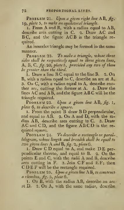
72 PROPORTIONAL LINES,
Problem 21. Upon a given right line AB, Jig,
19, plate 5, to make an equilateral triangle.
1. From A and B, with a radius equal to AB,describe arcs cutting in C. 2. Draw AC andBC, and the figure ACB is the triangle re-
quired.
An isosceles triangle may be formed in the samemanner.Problem 22. To make a triangle., whose three
sides shall he respectively equal to three given lines,
A, B, C, fig. 20, plate 5, provided any two of them
]?e greater than the third.
1 . Draw a line B C equal to the line B. 2. OnB, with a radius equal to C, describe an arc at A,3. On C, with a radius equal to A, describe ano-
ther arc, cutting the former at A. 4. Draw the
lines AC and AB, and the figure AB C will be the
triangle required.
Problem 23. Upoti a given line AB, fig. I,
plate 6, to describe a square.
1 . From the point B draw B D perpendicular,
and equal to AB. 2. On A and D, with the ra-
dius AB, describe arcs cutting in C. 3. DrawAC and CD, and the %ure ABCD is the re-
quired square.
Problem 24. To describe a rectangle or paral-
lelogram, ivhose length and breadth shall be equal to
two given lines A and B, fig. 2, plate 6.
1 . Draw C D equal to A, and make D E per-
pendicular thereto, and equal to B. 2. On the
])oints E and C, with the radii A and B, describe
arcs cutting in F. 3. Join C F and EF; theaC D E F will be the rectangle required.
Problem 25, Upon a given line AB, to construct
a rhombus., fig. 3, plate 6.
1. On B, with the radius AB, describe an arc
at D. 2. On A, with the same radius, describe
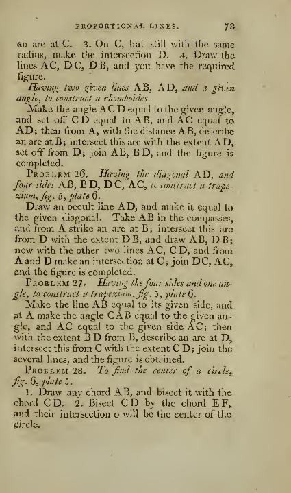
?ROPORTIONAi. LINES. 73,
an arc at C. 3. On C, but still with the sameradius, make the intersection D. 4. Draw thelines AC, DC, DB, and you have the required
figure.
Having two given lines AB, AD, and a given,
anghy to construct a rhomhoides.
Make the angle AC D equal to the given angle,
and set off CD equal to AB, and AC equal to
AD; then from A, with the distance AB, describe
an arc atB; intersect this arc with tlie extent AD,set off from D; join AB, B D, and the figure is
completed.
Problem 2(5. Having the diagonal AD, andfour sides AB, B D, DC, AC, to construct a trape-
zium^fig. b^ plate 0.
Draw an occult line AD, and make it equal to
the given dicigonal. Take AB in the compasses,and from A strike an arc at B; intersect this arc
from D with the extent DB, and draw AB, DB;now with the other two lines AC, CD, and fromA and D make an intersection at C ; join DC, AC,and the figure is completed.
Pr o B L EM 27 • Having thefour sides and one an-
gle, to construct a trapezium, fg. 5, plate d.
M ike the fine AB equal to its given side, andat A make the angle CAB equal to the given an-gle, and iVC equal to the given side AC; thenwith the extent B D from B, describe an arc at D,intersect this from C with the extent C D; join theseveral lines, and the figure is obtained.
Problem 28. To find the center of a circle^
fg. Q, plate b.
1. Draw any chord AB, and bisect it with the
chord CD. 2. Bisect CD by the chord EF„and their intersection o will be the center of thecircle.
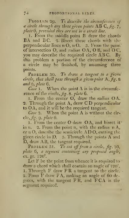
74 PROPORTIONAL LINES.
Problem 29. To describe the circumference ofa circle through any three given fo'ints AB 0,fg. 7,^late 6, provided they are not in a strait line.
1. From the middle point. B draw the chords'
EA and B C. 2. Bisect these chords with the
perpendicuhir lines n O, n O. 3. From the point
of intersection O^ and radius OA, OB, and O C,
you may describe the required circle ABC. Bythis problem a portion of the circumference of
a circle may be finished, by assuming three
points.
Problem 30. To draw a tangent to a given
circle^ that shall pass through a givenpoint A, fg. 8
and Q, plate 6.
Case 1. When the point A is in the circumfe-
rence of the Q\vc\c,fg. 8. plate 6.
1. From the center O, draw the radius OA.1. Through the point A, draw C D perpendicular
to O A, and it will be the required tangent,
Case 2. When the point A is without the cir-
cle, ^j^. 0,//<r//^ 6.
1. From the center O draw OA, and bisect it"
in n. 2. From the point n, with the radius n A,or n Oj describe the semicircle AD O, cutting the
given circle in D. 3. Through the points A andD, draw AB, the tangent required.
Problem 31. To cut offfrom a circle, fg. 10,
plate 0, a segment containing any proposed angle,
ex. gr. 120°.
Let F be the point from whence it is required (o
draw a chord which shall contain an angle of 120^'.
1. Through F draw FR a tangent to the circle.
2. From F draw FA, making an angle of 60 de-
grees, with the tangent FR, and FCA is the
segment required.

FOR THE PENTAGON, ScC. 75
Problem 32. On a given line AB to describe
the segment of a circle caj^able of cotitaining a given
Single, fjg. 1 \, plate 6.
Draw AC and B C, making the angles ABC,BAC, each equal to the given angle. Draw ADperpendicular to AC, and BD perpendicular to
B C; with the center D, and radius DA, or DB,describe the segment AEB, and any angle madein this segment will be equal to the given angle.
A more easy solution of thi? problem will be given
when we come to apply it to practice.
Problem 33. I^j describe an arc of a circle
that shall contain any number ofdegrees^ voithout com-
pulses, or vjithout finding the center of the circle^
fg. \2, plate 6.
Geometrically by finding points through which
the arc is to pass, let AB be the given chord.
1. Draw AF, making any angle with BA.2. At any point F, in AF, make the angle E F G,equal to the given angle. 3. Through B draw BEparallel to F G, and the intersection gives the
point E, in the same manner as many points D,C, i&c. may be found, as will be necessary to com-plete the arc. *
This subject will be found fully investigated
hereafter.
Problem 34. To inscribe a circle in a given
triangle, ABC,fg 13, plate 0.
1 . Bisect the angles A and B with the lines A Oand B O. 2. From the point of intersection O,let fall the perpendicular ON, and it will be the.
radius of the required circle.
Pro B L eM 3 5 . To inscribe a pentagon, a hexagon
y
or a decagon, in a given circle, fig. 1 5, plate 6,
1. Draw the diameters AB and CE at right
angles to each other. 2. Bisect DB at G. 3. On(j, with the radius GC, describe the arc CF,
75 FOR THE OCTAGON, kc,
4. Join C and F, and the line C F will be one side
of the required pentagon.
The two sides DC, FDof the triangle F DC,enable us to inscribe a hexagon or decagon in the
same circle; for D^ is the side of the hexagon,
D F that ofthe decagon.
Problem 36. To inscribe a square or an octagon
in a given circle, fig. l6, plate 6.
1. Draw the diameters AC, B D, at right angles
to each other. 2. Draw the lines AD, BA, BC,C D, and you obtain the required square.
FOR THE OCTAGON.
Bisect the arc AB of the square in the point F,
and the line AE being carried eight tirties round,
•will form the octagon required.
Problem 37. In a given circle to inscribe an
equilateral triangle, an hexagon, or a dodecagon^
Jig. \7, plated.
FOR THE EQUILATERAL TRIANGLE.
1 . From any point A as a center, with a distance
equal to the radius AO, describe the arc FOB.2. Draw the line B F, and make B D equal to B F.
3. Join DF, and DBF will be the equilateral triT.
angle required.
FOR THE HEXAGON.
Cany the radius AO six times round the cir-
cumference, and you obtain a hexagon.
FOR THE DODECAGON.
Bisect the arc A B ofthe hexagon in the point n,
and the line An being carried twelve times round
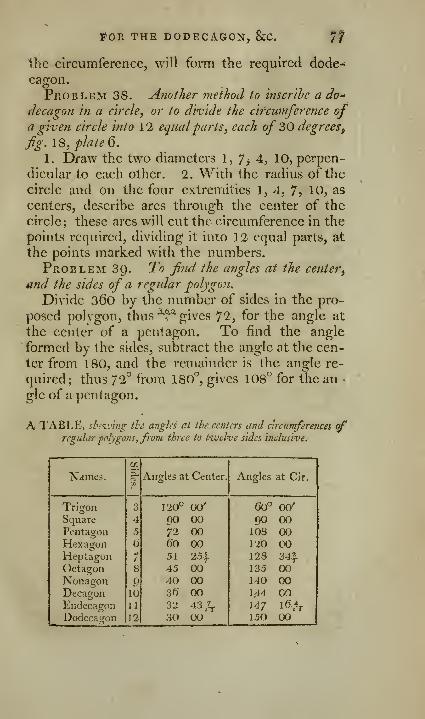
IfOR THE DODECAGON, ScC. If
the circumference, will form the required dode-*
cagon.
Problem 38. Another method to inscrihe a do"
decagon in a circle, or to divide the circumference ofa given circle into 1 2 equalfarts, each of 30 degrees^
fig. 18, plated.
1. Draw the two diameters 1, 7^ 4, 10, perpen-
dicular to each other. 2. With the radius of the
circle and on the four extremities 1, 4, 7^ 10, as
centers, describe arcs through the center of the
circle; these arcs will cut the circumference in the
points required, dividing it into 12 equal parts, at
the points marked with the numbers.
Problem 39. To find the angles at the center^
and the sides of a regular -polygon.
Divide 360 by the number of sides in the pro-
posed polygon, thus^ gives 7*25 for the angle at
the center of a pentagon. To find the angle
formed by the sides, subtract the angle at the cen-
ter from 180, and the remainder is the angle re-
quired; thus 72° from 180'^, gives 108*^ for the an •
gle of a pentagon.
A TABLE, sbtiv'nig the angles at the centers and circumferences ofregular polygons, from three to tivelvc sides inclusive
^
fS FOR POLYGONS^
This table is constructed by dividing 36o, tfi«
clcgrecs in a circumference, by the number of sides
in each polygon, and the quotients are the angles
at the centers ; the angle at the center subtracted
from 1 80 degrees, leaves the angle at the circum-ference.
Problem 40. In a given circle to inscribe a,ny
regular polygon^ fig. 14, plate 6.
1 . At the center c make an angle equal to the
center of the polygon, as contained in the pre-
ceding table, and join the angular points AB.2. The distance AB will be one side ofthe polygon,
which being carried round the circumference, the
proper number oftimes will complete the figure.
Another method, which approximates very nearly
the truth, fig. IQ, plate 6.
li Divide the diameter AB into as many equal
parts as the figure has sides. 2. From the center
O raise the.
perpendicular Om. 3. Make m ii
equal to tinec fDurths ofOm, 4. From n draw nC^through the second division of the diameter. 5.
Join the points AC, and the line AC will be the
side of the required polygon, in this instance a
pentagon.
Problem 41. Ahont any given triangle ABC,io circamscrihe a circle, fig. 21, plate 6.
1. Bisect any two sides AB, BC, by the per-
pendiculars mo, no. 2. From the point of inter-
section o, with the distance OA or OB, describe
the required circle.
Problem 42. About a given circle to circum-
scribe a pentagon, fig. 20, plate ().
1. Inscribe a pentagon within the circle, 2.
Through the middle of each side draw the lines
O A, O B, O C, O D, and O E. 3. Through the
point n draw the tangent AB, meeting OA andOB in A and B. 4. Through the points A and m.
FOR POLYGONS-. ^^
eli'aw the line AmC, meeting OC in C. 5. In
like manner draw the Hnes C D, D E, E B, andAB C D E will be the pentagon required.
In the same manner you may about a given cir-
cle circumscribe any polygon.
Problem 43. About a given square to circum^
scribe a circle, f.g. 22, flate £).
1. Draw the two diagonals AD, B C, intersect-
ing each other atO. 2. From O, with the distance
OA or OB, describe the circle ABCD, whichwill circumscribe the square.
Problem 44. 0;/ a givefi line A.^ to make it
regular hexagon, fig. 1A, flute 6.
1. On AB make the equilateral triangle AOB,2. From the point O, with the distance OA or
OB, describe the circle ABCDEF. 3. Carry
AB six times round the circumference, and it will
form the required hexagon.
PrOBLEM45. On a given line AB toform a re--
gular polygon ofany proposed nwnber ofsides, fig. l-4»
plate ().
1. Make the angles CAB, CBA each equal to-
half the angles at the circumference; see the pre-
ceding table. 2. From the point of intersection c,,
with the distance CA, describe a circle. 3. Applythe chord AB to the circumference the proposed
number of times, and it will form the required po-lygon.
Problem 46. On a giveji line AB, fig. 25,plate 6, to form a regular octagon.
1. On the extremities of the given line ABerect the indefinite perpendiculars AF and BE,-
2. Produce AB both ways to s and w, and bisect
the angle nAs and oBw by the lines AH, B C.
3. Make AH and BC each equal to AB, anddraw the line H C. 4. Make ov equal to on, andthrough V draw GD parallel to HC. 5. Draw
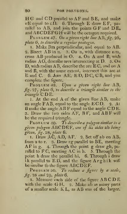
60 **0R POLYGONS.
H G and C D parallel to AF and B E, and makecE equal to cD. 6. Through E draw E F, pa-^
rallel to AB, and join the points GF and DE,and ABCDEFGH will be the octagon required.
Problem 47. On a given right line KE,Jig. 26^
^Jate 6, to describe a regular pentagon.
1. MakeBm perpendicular, and equal to AB.1. Bisect AB in n. 3. On n, with distance n m,cross AB produced in O. 4. On A and B, with
radius AO, describe arcs intersecting at D. 5. OnD, with radius A B, describe the arc E C, and on Aand B, with the same extent, intersect this arc at
E and C. 6. Join AE, E D, D C, CB, and youcomplete the figure.
Problem 48. Upon a given right line AB,jig. 27, plate 6, to describe a triangle similar to the
triangle C D E.
1. At the end A of the given line AB, makean angle FAB, equal to the angle E C D. 2. AtB make the angle AB Y equal to the angle C D E,
3. Draw the two sides AF, BF, and ABF will
be the required triangle.
Pro b l em 49. To describe a polygon similar to a
given polygon ABCDEF, one of its sides ab being
given^ Jig. 1Q, plate 6.
1. Draw AC, AD, AF. 2. Set off ab on AB,from a to r. 3. Draw rg parallel to BE, meeting
AF in g. 4. Through the point g draw gh, pa-
rallel to FC, meeting AC in h. 5. Through the
point h draw the parallel hi. 6. Through i drawi k parallel to E D, and the figure A r g h i k will
be similar to the figure ABCDIeF.Problem 50. To reduce a figure by a scale
^
fig. 28 and 29, plate 6.
1. Measure each side of the figure AB C D Ewith the scale G H. 2. Make ab as many parts
of a smaller scale K L, as AB was of the larger.

DEDUCTION OF FIGURES. 81
3. be as many of K L, as B C of G H, and ac ofK L, AC, &c. by which means the figure will be
rxiduced to a smaller one.
OF THE TRANSFORMATION AND REDUCTIONOF FIGURES.
Pro b l em 5 1 . To change a tnaugle into another
of equal extent, hut different height, fg. 1, 2, 3, 4,
jilate 7.
Let AB C be the given triangle, D a point at
the given height.
Case 1. Where the point T),fig. l and 2, plate
7, is either in one of the sides, or in the prolonga-
tion of a side. 1 . Draw a line from D to the oppo-site angle C. 2. Draw a line AE parallel thereto
from x\, the summit ofthe given triangle. 3. Join
D E, and B D E is the required triangle.
Case 2. When the point Y>,fg. 3 and 4, plate 7,
is neither in one of the sides, nor in the prolonga-
tion thereof. 1. Draw an indefinite line BDa,from B through the point D. 2. Draw from A,the summit of the given triangle, a line A a, pa-
rallel to the base BC, and eutting the line BD in a.
3. Join aC, and the triangle B a C is equal to the
triangle B AC; and the point D being in the sameline with B a. 4. By the preceding case, find a
triangle from D, equal to BaC; i.e. join DC,draw a E parallel thereto, then join D E, and
B D E is the required triangle.
Corollary. If it be required to change the tri-
angle BAC into an equal triangle, of which the
height and angle BDE are given: 1. Draw the
indefinite line B DA, niaking the required anglewith B C. 2. Take on B 13 a a point D at the
given height; and, 3. Construct the triangle bythe foregoing rules.
G

82 TRANSFORMATION AND
Prob LEM 52. To make an isosceles triangle AEB^Jig. 5, plate 7, equal to the scaletie triangle AC B.
1. Bisect the base in D. 2. Erect the perpen-
dicular DE. 3. Draw CE parallel to AB. 4.
Draw AE;, EB, and AEB is the required tri-
angle.
Problem 53. To make an equilateral triangle
equal to a given scalene triangle AB C, fg. 7 ,plate 7
.
1. On the base AB make an equilateral triangle
ABD. 2. Prolong BD towards E. 3. DrawCE parallel to AB. 4. Bisect DE at I, on D I
describe the semicircle D F E. 5. Draw B F^ the
mean proportional between BE, B D. 6. WithB F from B, describe the arc F G H ; with the
same radius from G, intersect this arc at H, draw
B H, G H, and B G H is the triangle required.
Corollary. If you want an equilateral triangle
equal to a rectangle, or to an ispsceles triangle
;
find a scalene triangle respectively equal to each,
and then work by the foregoing problem.
Problem 54. To reduce a rectilinear figure
ABCDE,j^^-. 8 and g, plate J, to another equal to
ity hut with one side less.
1 . Join the extremities E, C, of two sides D E,D C, of the same angle D. 2. From D draw a
line DF parallel to E"C. 3. Draw EF, and youobtain a new polygon ABFE, equal to ABCDE,but with one side less.
Corollary. Hence every rectilinear figure maybe reduced to a triangle, by reducing it succes-
sively to a figure with one side less, until it is
^brought to one with only three sides.
For example; let it be required to reduce thepolygon ABCDEF, fig. lO and ll, plate 7, into
a triangle IAH, with its summit at A, in the cir-
cumference of the polygon, and its base on the
base thereof prolonged.
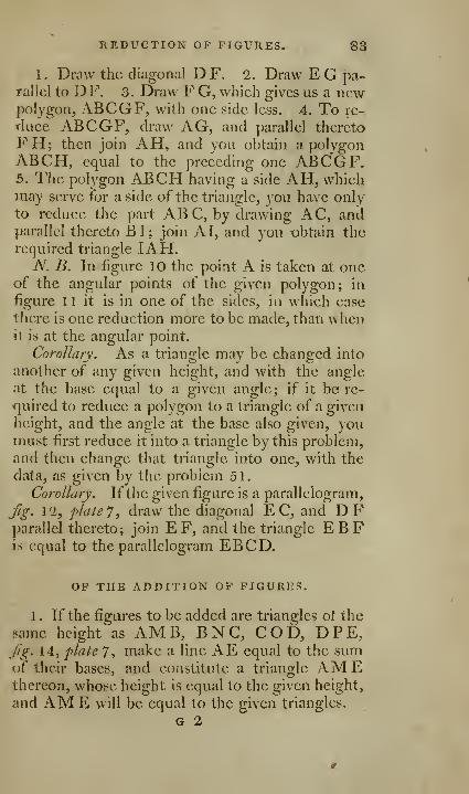
REDUCTION OP FIGURES, 83
1. Draw the diagonal DF. 2. Draw EG pa-rallel to DF. 3. Draw F G, which gives us a newpolygon, ABCGF, with one side less. 4. To re-
duee ABCGF, draw AG, and parallel thereto
FH; then join AH, and you obtain a polygonABCH, equal to the preceding one ABCGF.5. The polygon ABCH having a side AH, whichmay serve for a side of the triangle, you have onlyto reduce the part ABC, by drawing AC, andparallel thereto BI; join A I, and you obtain therequired triangle IAH.
N. B. In figure 10 the point A is taken at oneof the angular points of the given polygon; in
figure 11 it is in one of the sides, in which case
there is one reduction more to be made, than whenit is at the angular point.
Corollary. As a triangle may be changed into
another of any given height, and with the angle
at the base equal to a given angle; if it be rc-
fjuired to reduce a polygon to a triangle of a given
height, and the angle at the base also given, youmust first reduce it into a triangle by this problem,
and then change that triangle into one, with the
data, as given by the problem 51.
Corollary. Ifthe given figure is a parallelogram,
Jig. 12, plate 7, draw the diagonal EC, and DFparallel thereto; join EF, and the triangle EBFjs equal to the parallelogram EBCD-
OP THE ADDITION OP FIGURES.
1 . If the figures to be added are triangles ot the
same height as AMB, BNC, COD, DPE,Jig. 14, plate 7, make a line AE equal to the sumof their bases, and constitute a triangle AMEthereon, whose height is equal to the given height,
and AM E will be equal to the given triangles.
G 2

84 MULTIPLICATION, &C. OP FIGURES.
2. If the given figures are triangles of different
heights, or difTerent polygons^ they must first be
reduced to triangles of the same height, and then
these may be added together.
3. If the triangle, into which they are to besummed up, is to be of a given height, and with a
given angle at the base, they must first be reduced
into one triangle, and then that changed into an-
other by the preceding rules.
4. The triangle obtained may be changed into
a parallelogram by the last corollary.
MULTIPLICATION OF FIGURES.
1. To multiply AMB, /^. 13, plate 7, by a
given number, for example, by 4 ; or more accu-
rately, to find a triangle that shall be quadruple the
triangle AMB. Lengthen the base AE, so that
it may be four times AB ; join M E, and the trian-
gle AM E will be quadruple the triangle AMB,2. By reducing any figure to a triangle, we mayobtain a triangle which may be multiplied in the
same manner.
SUBTRACTION OF FIGURES,
1. If the two triangles BAG, dac, fg. 15,
plate 7, are of the same height, take from the base
B C of the first a part D C, equal to the base d c
of the other, and join AD; then will the triangle
ABD be the difference between the two triangles.
If the two triangles be not of the same height,
they must be reduced to it by the preceding rules,
and then the difference may be found as above;
or if a polygon is to be taken from another, and a
triangle found equal to the remainder, it may beeasily effected, by reducing them to triangles of
the same height.

iJIVISiON OP FIGURES. 85
2. A triangle may be taken from a polygon bydrawing a line within the polygon, from a given
point F on one of its sides. To effect this, let us
suppose the triangle, to be taken from the polygon
ABCDE, ^^g. 16, plate 7, has been changed into
a triangle MOP, Jig. 26, whose height above its
base M P is equal to that of the given point F,
above AB offg. l6; this done, on AB (prolonged
if necessary) lay off AG equal to O P, join F G,and the triangle AFG is equal to the triangle
MOP. There are, however, three cases in the
solution of this problem, which we shall therefore
notice by themselves.
If the base MP does not exceed AB, Jig. l6,
flate 7, the point G will fall thereon, and the pro-
blem will be solved.
But if the base M P exceeds the base AB, Gwill be found upon AB prolonged, ^^. 17 and 18,
f/a/e 7 ;join F B, and draw G H parallel thereto
;
from the situation of this point arise the other twocases.
G/se 1. When the point H, Jig. 17, pliite 7, is
found on the side BC, contiguous to the side AB,joinFH, and the quadrilateral figure FAB Hisequal to the triangle MOP.
Case 2. When H, fg. 18, plate 7, meets BCprolonged, from F draw FC and HI parallel
thereto; then join FI, and the pentagon FABC I is equal to the triangle MOP.
DIVISION OF RECTILINEAR FIGURES.
1 . To divide the triangle AM E,^g. 13, plate 7,
into four equal parts; divide the base into four
equal parts by the points B, C, D; draw M D,M C, M B, and the triangle will be divided into
four equal parts.
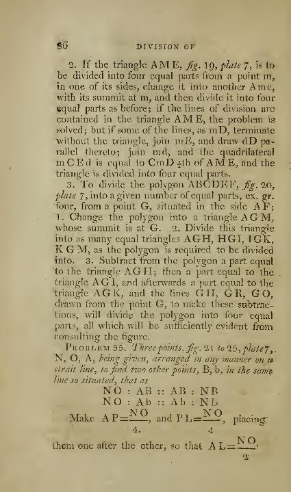
S6 DIVISION OP
2. If the triangle AME, fig. \g, plate 7, is to
be divided into four equal parts from a point m,in one of its sides, change it into another Ame,•with its summit at m, and then divide it into four
equal parts as before; if the lines of division are
contained in the triangle AME, the problem is
solved; but if some of the lines, as mD, terminate
without the triangle, join mE, and draw dD pa-
rallel thereto; join md, and the quadrilateral
m C E d is equal to CmD ith ofAM E, and thetriangle is divided into four equal parts.
3. To divide the polygon ABCDEF, fig. 10,plate 7, into a given number of equal parts, ex. gr.
four, from a point G, situated in the side AF;1. Change the polygon into a triangle AGM,whose summit is at G. 2. Divide this triangle
into as many equal triangles AGH, HGI, IGK,K G M, as the polygon is required to be divided
into. 3. Subtract from the polygon a part equal*to the triangle AGH; then a part equal to thetriangle AG I, and afterwards a part equal to thetriangle AGK, and the lines GH, GR, GO,drawn from the point G, to make these subtrac-
tions, will divide the polygon into four equalparts, all which will be sufficiently evident fromconsulting the figure.
Problem 55. J^hreepoints, fig. 21 to 15,pJate7,N, O, A, being given, arranged in any manner on astrait line, to find two other poitits, B_, b, in the sam^line so situated, that as
NO : AB :: AB : NBNO : Ab :: Ab : N 1>
Make AP= , and PL= , placing4. 4
them one after the other, so that A L= .

RECTILINEAR FIGURES. 87
Observing, 1. That in the two figures 21 and22, A is placed between N and O; and that APis taken on A O, prolonged if necessary.
2. In Jig. '23, where the point O is situated be-
tween N and A, AP should be put on the side
opposite to AO.3. In^g. 24, where the point N is situated be-
tween A and O, if AP be smaller than AN, it
must be taken on the side opposite to AN.4. In Jig. 25, where the point N is also placed
between A and O, if AP be greater than A N, it
must be placed on AN prolonged.
Now by problem 17 make M N in all the five
figures a mean proportional between NO, N P,and carry this line from L to B, and from L to b.
and NO will be : AB : : AB : NBNO : Ab :: Ab : NL.
Problem 56. Two lines EF, GH, ^^. 27,
28, 29, plale 7, intersecting each other at A, being
given, to draw from C a third line B D, which shall
form with the other two a triangle DAB equal to a
given triangle X.1 . From C draw CN parallel to EF. 2. Change
the triangle X into another C N O, whose summitis at the point C. 3. Find on GH a point B, so
that N O : AB : : AB : N B, and from this point
B, draw the line CB, and DAB shall be the re-
quired triangle.
Scholium. This problem may be used to cut off
one rectilinear figure from another, by drawing a
line from a given point.
Thus, if from a point C, without or within the
triangle E A ll,j7g. 30, a right line is required ta
be drawn, that shall cut off a part DAB, equal to
the triangle yL,Jig. 30 ; it is evident this may bft
effected by the preceding problem.

SS DIVISION OF FIGURES,
If it be required to draw a line B D from a
point c, which shall cut off from the quadrilateral
figure E F G H„ a portion D F G B,^^^. 31, equal
to the triangle Z; if you are sure, that the right
line BD will cut the two opposite sides EF, GH,proloni>; E F, GH, till they meet; then form a
triangle Z, equal to the two triangles Z and FAG;and then take Z from AEH by a line BD from
the point C, which is etfected by the preceding
problem.
If it be required to take from a polygon Y, a
part DFIHB equal to a triangle X; and that
the line BD is to cut the two sides EF, GH;prolong these sides till they meet in A; then makea triangle Z, equal to the triangle X, and the fi-
gure AF I H ; and then retrench from the triangle
E A G the triangle DAB equal to Z, by a line
B D, from a given point C.
As all rectilinear figures may be reduced to tri-
angles, we may, by this problem, take one rec-
tilinear figure from another by a strait line drawnfrom a given point.
Problem 57. To f?iake a triangle equal to anygiven quadrilateralfigure ABCD,_;?^. 2>2>, plate"]
,
1. Draw the diagonal B D. 2. Draw CE pa-
rallel thereto, intersecting AD produced in E.3. Join AC, and ACE is the required triangle.
Problem 58. To maize a rectangle^ or paralle-
logram equal to a given triangle ACE, j^^. 33,plate y.
1. Bisect the base AE in D. 1. Throus:h Cdraw CB parallel to AD. 3. Draw CD, "BA,parallel to each other, and either perpendicular to
A E, or making any angle with it. And the rect-
angle or parallelogram ABCD v/ill be equal to X\\e
given triangle.
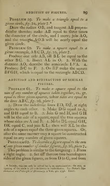
ADDITION OF FIGUKES. SQ
"Problem 59. To make a triangle equal to aghefi circle, ^g. ^4, plate 7.*
Draw the rudius OB, and tangent AB perpen-
dicular thereto; make AB equal to three times
the diameter of the cirele, and f more; join AO,and the triangte^OB will be nearly equal the
given eirele.
Problem 6o. To make a square equal to agiven rectangle, AB C D, fig. 35, plate 7.
Produce one side AB, till B L be equal to theother BC. 2. Bisect A.L in O. 3. With the
distance AO, describe the semicircle LFA. 4.
Produce B C to P\ 5. On BP" make the squareBFGH, which is equal to the rectangle ABCD.
ADDITION AND SUBTRACTION OF SIMILARFIGURES.
Problem 61. To make a square equal to the.
sum of any number of squares taken together, ex. gr.
equal to three gl-veii squares, whose sides are equal to
the lines AB C,fig. 36, plate 7.
1. Draw the indefinite lines ED, DF, at right
angles to each other. 2. Make D G equal to A,and D H equal to B. 3. Join G and H, and G PI
will be the side of a square, equal the two squares
whose sides are A and B. 4. Make DL equal GPI,DK equal C, and join K L; then will KL be theside of a square equal the three given squares. Or,
after the same manner may a square be constructed
equal to any number of given squares.
Pr o b l em 62. To describe afigure equal to the sum
•fany given number ofsimilarfigures, fig. 3Q, plate 7 ,
This problem is similar to the foregoing : 1 . P'orma right angle. 2. Set off thereon two homologoussides of the given figures, as from D to G, and from
* Strictly, thii can only be solved but by an approximation ; the area, oj
sfjuaiiiig of the circle is yet a desiderata in mathematics. See Huttun' s l^/(^•
thcmuii.al and I'kiks-jphktil J)ictionarj-, > Vols. 4to. 1 796. Edit.
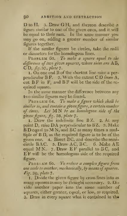
00 ADDITION AND Sl/BTRACTION
D to H. 3. Draw GH, and thereon describe a
ligure similar to one of the giv^en ones, and it will
be equal to their sum. In the same manner youmay go on, adding a greater number of similar
figures together.
If the similar figures be circles, take the radii
or diameters for the homologous lines.
Problem 63. To 7?iake a square equal to the
difference of two given squares^ whose sides are AB,CD, fg.^T, plate T.
1 . On one end B of the shortest line raise a per-
pendicular B F. 2. With the extent C D from A,cut B F in F, and B F will be the side of the re-
quired square.
In the same manner the difference between anytwo similar figures may be found.
Problem 64. To make a figure which shall he
similar to^ and contain a givenfigure^ a certain mimher
of times. Let ^^ he an homologous side of the.
givefi figure, fig. ^iS, plate J.
1. Draw the indefinite line BZ. 2. At any
point D, raise DA perpendicular to BZ. 3. MakeB D equal toM N, and BC as many times a mul-tiple of B D, as the required figure is to be of the
given one. 4. Bisect BC, and describe the semi-
circle BAC. 5. Draw AC, BC. 6. Make AEequal M N. 7. Draw EF parallel to BC, andE F will be the homologous side of the required
figure.
Problem 65. To reduce a complex figure fromone scale to another, mechanically, by means ofsquares.
Fig. 3C), plate 7.
1 . Divide the given figure by cross lines into as
many squares as may be thought necessary. '2. Di-
vide another paper into the same number of
squares, either greater, equal, or less, as required.
3. Draw in every square what is contained in th«

OP SIMILAR FIGURES. Ql
correspondent square of the given figure, and youwill obtain a copy tolerably exact.
Problem 66. To enlarge a map or plan, andmake it twice, three, four, or five, &c. times larger
than the original, fig. 12, plate 8.
1 . Draw the indefinite line ab. 2. Raise a' per-
pendicular at a. 3. Divide the original plan into
squares by the preceding problem, 4. Take the
side ofone of the squares, which set off from a to d,
and on the perpendicular from a to e, finish the
square aefd, which is equal to one of the squares
of the proposed plan. 5. Take the diagonal d e,
set it off from a to g, and from a to I ; completethe square al n g, and it will be double the square
a e f d. To find one three times greater, take d g,and with that extent form the square amoh, whichwill be the square required. With d h you mayform a square that will contain the given one aefdfour times. The line d 1 gives a square five times
larger than the original square.
Problem 6^ . To reduce a map ^, \d, \th, \th,
"^c. of the original, fig. b, plate 8.
1 . Divide the given plan into squares by pro-
blem 65. 2. Draw a line, on which set off from
A to B one side of one ofthese squares. 3. Divide
this line into two equal parts at F, and on F as acenter, with FA or FB, describe the semicircle
AHB.4. To obtain \ the given square, at F erect thc
perpendicular F H, and draw the right line AH^which will be the side of the required square,
5. For id, divide AB into three parts; take oneof these parts, set it off from A to C, at C raise the
perpendicular C I, through I draw AI, and it will
be the side of the required square. 6. For vth, di-
vide AB into four equal parts, set off one of these
from B to E, at E make E G perpendicular to AB^.
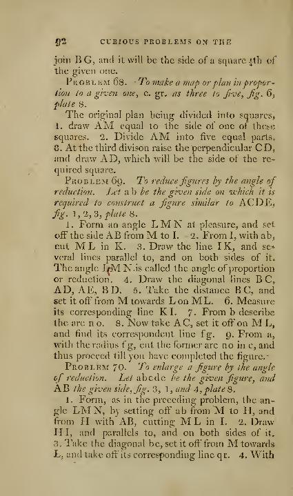
§2 CURIOUS PKOBLEMS ON THE
join B G, and it will be the side of a square |th ofthe given one.
Problem 68- To malie a map orplan hi propor-
tion lo a given one^ e. gr. as three to froe, Jig. 6^
plate 8.
The original plan being divided into squares,
1. draw AM equal to the side of one of these
squares. 2. Divide AM into five equal parts,
8. At the third divison raise the perpendicular CD,and draw AD, which will be the side of the re-
quired square.
Problem 69. To reduce figures hy the angle ofreduction. Let a b he the given side on •which it is
required to construct a figure similar to ACDE,fig. \,rL,'i, plate 8.
1 . Form an angle LM N at pleasure, and set
off the side AB from M to I. 2. From I, with ab,
cut ML in K. 3. Draw the line IK, and se=-
veral lines parallel to, and on both sides of it*
The angle Lr^l Nis called the angle of proportion
or reduction. 4. Draw the diagonal lines B C,AD, AE, BD. 5. Take the distance B C, andset it off from M towards L on ML. 6. Measureits corresponding line KL 7- From b describe
the arc no. 8. Now take AC, set it off on M L,and find its correspondent line ig. 9. From a,
with the radius ( g, cut the former arc no in c, andthus proceed till you have completed the figure.
-
Problem 70- To enlarge a figure by the angle
of reduction. Let abcde he the given figure, andAB the given side, fig. 3,1, and A, plate 8.
1. Form, as in the preceding problem, the an-gle LMN, by setting off ab from M to H, andfrom H with AB, cutting M L in L 2. DrawH I, and parallels to, and on both sides of it.
3. Take the diagonal be, set it ofi'from M towardsL, and take off" its corresponding line qr. 4. With

^ DIVISION OF LINES AND CIRCLflS. QS
qr as a radius on B describe the arc mn. 5. Takethe same correspondent line to ac, and on A cut
mn in c, and so on for the other sides.
CURIOUS PROBLEMS ON THE DIVISION OPLINES AND CIRCLES.
Problem 71. To cut offfrom a?iji given arc of
a circle a third., a fifth., a se-vetith, &c. add parts
j
(ind thence to divide that arc i?ito anjy number of equal
partsJ fig. 7 J
plate 8.
Exaniple 1. To divide the arc AK B into three
equal parts, CA being the radius, tind C the cen-
ter ofthe arc.
Bisect AB in K, draw the two radii CK, C B,
and the -chord AB; produce AB at pleasure, andmake BL equal AB; bisect AC at G; then a
rule on G and L will cut CB in E, and B E will
be id, and C E ^ Js of the radius C B; on CB with
C E describe the arc Eed; lastly, set off the extent
E e or D e from B to a, and from a to b, and the
arc AK B will be divided into three equal parts.
Corollary. Hence having a sextant, quadrant,
&c. accurately divided, 2 the chord of any arc set
off upon any other arc of h that radius will cut off
an arc similar to the first, and containing the samenumber of degrees.
Also id, ith, tth, &c. of a larger chord will
constantly cut similar arcs on a circle whose radius
is yd, ;^th, fth, &c. of the radius of the first arc.
Example 2. Let it be required to divide the arc
AKB into live equal parts, or to find the ^t\\
part of the arc AB.Having bisected the given arc AB in K, and
drawn the three radii CA, CK, CB, and having
found the fifth part of I B of the radius C B, with
radius C I describe the arc I n M, which will be
V

P4 CURIOUS PROBLEM^ ON THR
bisected in n, by the line CK; then take the ex-
tent I n, or its equal M n, and set it off twice fromA to B ; that is, first, from A to d, and from d to o,,
and oB will be ith of the arc AB. Again, set off
the same extent from B to m, and from m to c, andthe arc AB will be accurately divided into five
equal parts. '
Example 3. To divide the given arc AB into
seven equal parts. AB being bisected as before,
and the radii CA, C K, C B, drawn, find by pro-
blem 9 the seventh part of PB of the radius CB,and with the radius CP describe the arc PrN;then set off the extent P r twice from A to 3, andfrom 3 to 6, and 6 B will be the seventh part of
the given arc AB; the compasses being kept to
the same opening P r, set it from B to 4, from 4to 1 ; then the extent Al will bisect 1, 3 into 2,
and 4, 6 into 5 ; and thus divide the given arc into
seven equal parts.
Problem 7-- T^o inscribe a regular heptagon
in a circle, jig. 8, 'plate 8.
In j?ir. 8, let the arc B D be ?th part of the gi-
ven circle, and AB the radius of the circle. Di-vide AB into eight equal parts, then on center A,with radius AC, describe the arc CE^ bisect the
arc B D in a, and set off' this are Ba from C to b,
and from b to c; then through A and c draw Ace,cutting BD in e, and Be will be |th part of thegiven circle.
Corollary 1. Hence we have a method of find-
ing the seventh part of any given angle; for, if
from the extremities of the given arc radii bedrawn to the center, and one of these be divided
into eight equal parts, and seven of these parts be
taken, and another arc described therewith, the
greater arc will be to the lesser_, as 8 to 7j and sa
of any other proportion.

BIYISION OF LINES AND CIRCLES. 05
Corollary 2. If an arc be described with the
radius, it will be equal to the ^th part of a circle
whose radius is AB, and to the seventh part of a
circle whose radius is AC, and to the sixth part
of a circle whose radius is AL, &c.
Corollary 3. Hence also a pentagon may bederived from a hexagon, fig. 9, plale 8. Let the
given circle be ABCDEF, in which a pentagon
is to be inscribed ; with the radius AC set off AFequal ith of the circle, divide AC into six equal
parts; then cG will be five of these parts; with
radius CG describe the arc GH, bisect AF in q,and make GP and PH each equal to A q; thenthrough C and H draw the semi-diameter C w,
cutting the given circle in w, join Aw, and it will
be one side of the required pentagon.
Corollary 4. PIcnce as radius divides a circle
into six equal parts, each equal Go degrees, twice
radius gives 120 degrees, or the third part of the
circumference. .
Once radius gives 60 degrees, and that arc bi-
sected gives 30 degrees, which, added to 60, di-
vides the circumference into four equal parts;
whence we divide it into two, three, four, five, six
equal parts; the preceding corollary divides into
five equal parts, the arc of a quadrant bisected di-
vides it into eight equal parts. By problem 71 weobtain the seventh part of a circle, and by this me-thod divide it into any number of equal parts, even
a prime number; for the odd unit may be cut off
by the preceding problem, and the remaining part
be subdivided by continual bisection, till another
prime number arises to be cut off in the samemanner.
Problem 73. To divide a given right line, or
an arc of a circle, into any number of equal farts hy
the help of a fair of heani, or other compasses, the
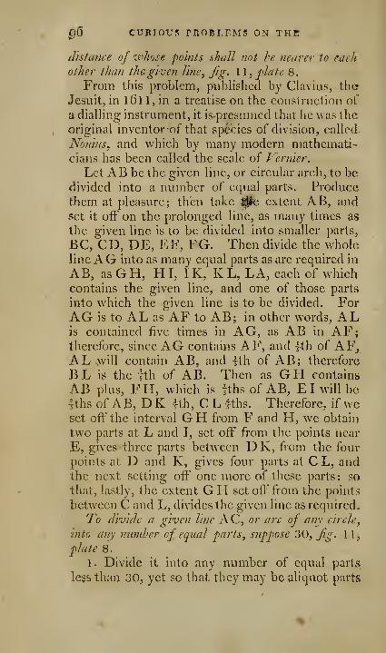
p6 CURIOUS PROBLEMS ON THE
distance of whose pohits shall not he nearer to each
other than the given line, fig. \\, plate 8.
From this problem, published by Clavius, theJesuit, in l6l 1, in a treatise on the construction of
a dialling instrument, it is'presunicd that he was the
original inventor of that species of division, called
No7/ms, and which by many modern mathemati-
cians has been called the scale of Fernier.
Let AB be the given line, or circular arch, to bedivided into a number of equal parts. Producethem at pleasure; then take ^c extent AB, andset it off on the prolonged line, as many times as
the given line is to be divided into smaller parts,
BC, CD, DE, EF, FG. Then divide the wholelineAG into as many equal parts as are required in
AB, asGH, HI, IK, KL, LA, each of whichcontains the given line, and one of those parts
into which the given line is to be divided. ForAG is to AL as AF to AB; in other words, ALis contained live times in AG, as AB in AF;therefore, since AG contains AF, and ith of AF,AL .will contain AB, and \\h of AB; therefore
BL is the fth of AB. Then as GH contains
AB plus, FH, which is fths of AB, EI will beIths of AB, D K Ith, C L l^ths. Therefore, if weset ofi'the interval GH from F and H, wc obtain
two parts at L and I, set off from the points near
E, gives three parts between D K, from the four
points at D and K, gives four parts at CL, andthe next setting off one more of these parts; so
that, lastly, the extent G H set off from the points
between C and L, divides the given line as required.
To divide a given line AC, or arc of any circle,
into any number of equal parts, suppose 30, fig. 1 1
,
plate 8.
1. Divide it into any number of equal parts
less than 30, yet so that they may be aliquot parts

'DIVISION OP LIXES AND CIRCLES. Q7
of 30; as for example, AG is divided into six equal
parts, A B, BC, CD, DE, EF, FG, each of whichare to be subdivided into five equal parts. 2. Di-
vide the first part AB into five parts, by means of
the interval AL or GH, as taught in this problem.
If, now, one foot of the compasses be put into the
point A, (the extent AL remaining between themunaltered) and then into the point next to A, andso on to the next succeeding point, the whole line
AG will be divided by the other foot of the com-passes into 30 equal parts.
Or if the right line, or arc, be first divided into
five equal parts, each of these must be subdivided
into six parts, which may be effected by bisecting
each part, and then dividing the halves into three
parts.
Or it may be still better to bisect three of the
first five parts, and th-en to divide four of these
into three, which being set off from every point,
will complete the division required.
Corollary. It frequently happens that so manysmall divisions are required, that, notwithstanding
their limited number, they can be hardly taken
between the points of the compasses without error;
in this case use the following method.
If the whole number of smaller parts can be
subdivided, take so many of the small parts in the
given line, as each is to be subdivided into, yet so
that they may together make up the whole of the
given line. For if the first of these parts be cut
into as many smaller parts as the proposed numberrequires every one of them to contain, and the
same is also done in the remaining parts, we shall
obtain the given number of smaller parts.
If 84 parts are to be taken in the proposed line,
first bisect it, and each half will contain 42 ; bisect
these again, and you have four parts^ each of whichK

Q8 CL'RIOUS FROBtEMS OX THE
is to contain 21 ; and these, divided into thrce^
give 12 parts, each of which is to contain seven
parts; subdivide these into seven each.
But if the proposed number of small parts can-
not be thus subdivided, it will be necessary to take
a number a little less or greater, that will be capa-
ble of subdivision ; for if the superfluous parts are
rejected, or those wanting, added, we shall obtain
the proposed number of ])art3. Thus if 74 parts
are to be cut from any given line of 80 parts; 1.
Bisect the given line, and each ^ will contain 40.
2. Bisect these again, and you have four parts to
contain 20 each. 3. Each of these bisected, youhave eight parts to contain 10 each. 4. Bisect
these, and you obtain l6 parts, each to be divided
into five parts. 6. llejcct six of the parts, andthe remainder is the 74 parts proposed.
Or if 72- parts be proposed; divide the line into
24 equal parts, and each of these into three parts,
and you obtain 72; to which adding two, youwill obtain the number of 74.
Problem 74. To cut offfrom the c'lrcumfer-eiice
of any given arc ofa circle unj number ofdegrees anci
minutes, jig. 3, plate Q.
1. Let it be proposed to cut off from any arc 57degrees; with the radius ofthe given arc, or circle,
describe a separate arc as AB, and having set off
the radius from A to C, bisect AC in E, then AEand EC will be each of them an arc of 30 deo-rees.
Make CB equal to AE, and AB will be a qua-
drant, or QO degrees, and will also be divided into
three equal parts; next, divide each of these into
three by the preceding rules, and the quadrantwill be divided into nine equal parts, each contain-
ing 10 degrees. Lastly, divide the first of these
into 10 degrees, then set one loot of the compasses
into the seventh single degree, and extend the

DIVISION OF LINES ANb CIRCLES. QQ
Other to the 50th, and the distance between the
points of the compasses will contain 57 degrees,
which transfer to the given arc. Or at two ope-
rations; first, take 50 degrees, and then from the
first 10 take seven, and you have 57 degrees.
2. Let it be required to cut off from any given
arc of a circle 45 degrees, 53 minutes, f^. 3,
plafe Q.
Divide the arc of 53 degrees of the quadrant
AB, whose radius is AC (or rather its equal arc
FG) into 6o equal parts, first into 5, and thenone of these into three; or first into three, andone of these into five. Again, one of these bi-
sected, and this bisection again bisected, gives the
6oth part of an arc of 53 degrees.
For the 5th part of the arc F G is F H, con-
taining 12 parts; its third part is FI, containing
four parts; the 2 of FI is N, which contains twoparts; and FN again bisected in K, leaves FK the
60th part of the arc FG; consequently, FK com-prehends 53 minutes; therefore, add the arc FKto 45 degrees, and the arc AF will contain 45 de-
grees 53 minutes.
Corollary. If w^e describe a separate arc LMwith the radius AC, and set off thereon the extent
LM of Ol degrees of the given arc AB, and divide
LM into 60 equal parts; thus, first into two, then
both of these into three, and then the first of these
three into 10 by the former rules, which gives the
60th part of the arc L M. And as one division
of the arc LM contains by construction one de-
gree of the quadrant AB, and one sixtieth part of a
degree more, that is one minute, therefore two di-
visions of LM contain two degrees, and two mi-
nutes over; three divisions exceed three degrees by
three minutes, and so of all the rest.
H 2

100 CURIOUS PROBLEMS ON THE
Whence if one division ofLM be set off froiil-
any degree on AB, it will add one minute to that
degree; two adds two minutes; three, three mi-
nutes, and so on.
When the division is so small that the compasses
will hardly take it in without error, take two,
t-hree, four, or more of the parts on L, set them off
from as many degrees back from the degree in-
tended, and you will obtain the degree and minute
required.
Problem 75. To diviile a circle into any uneven
number of equal 'parts.
Example 1 . Let it be required to divide a circle
into 34dT equal parts.
Reduce the whole into 3d parts, which gives us
1040; find the greatest multiple of 3 less than 1040,which may be bisected; this number will be foundin a double geometrical progression, whose first
term is 3, as in the margin ; 7G8 the ninth immber,is the number sought, as in the margin. Subtract
768 from 1040, the remainder is 27 '2, then
find how many degrees and minutes this
remainder contains by the rule of three.
As 1040 is to 3(i0 degrees, so is 272 to
94° 9' 23". Now set off 94° 9' 23" ujjon
the circle to be divided, and divide, the
remaining part of that circle by continual
bisections, till you come to the mimbcr 3,
which will be one of the required divisions 768of the 34(3 equal parts, by which dividing the. arc
of 94° 9' 23" you will have the whc^lc circle di-
vided into 346| equal parts; for there will be 25(i
divisions in the greatest arc, and 9OT in the other.
Exainph 2. Let it be rc(}uired to divide a circle
into 179 e(|unl jjarts. Find the grciitest nun:iber
not excec'ding 179> which may be continually bi-
3

DIVISION OP LINES AND CIRCLES. 101
sectcd to unity, which you will find to be 128.
Subtract 128 from 179, the remainder is 51 ; thenfind what part of the circle this remainder will
occupy by the following proportion, as 179 is to
360, so is 51 to 10'2°34' ll''; set off' from the
circle an arcof 102" 34' ll", and divide the re-
maining part of the circle by continual bisections,
seven of which will be unity in this example; bywhich means this part of the circle will be divided
into 128 equal parts, and the remaining 51 may beobtained by using as many of the former bisections
as the space will contain, so that the whole cir-
cumference will be divided into 1 79 equal parts.
ExiDiiple 3 . Let it be required to divide a circle
into 29^ equal parts, to rej)resent the days of the
moon's age.
Reduce the given number into halves, whichgives 59 parts; seek tlie greatest lunnbcr, not ex-
ceeding 59, which may be continually bisected to
unity, which you will find to be 32. Subtract this
from 59, the remainder is 27 ; and find, as before,
the angle equal to the remainder by this propor-
tion, as 59 is to 3()0, so is 27 to l64° 44' 44"; set
off 164° 44' 44", divide the remaining part of the
circle by continual bisections, \\hich will divide
this portion into 32 parts, and from that, the rest
into 27^, making 29^ parts, as required.
Example 4. Let it be required to divide a circle
into 365" o 49" e(|ual parts, the length of a tropi-
cal yeal\
Reduce the whole into minutes, \\hich will be
525949; then seek the greatest multiple of 1440,
the minutes in a solar day, that may be halved, and
is at the same time less than 525949; this you will
firftl to be 368640, which subtracted from 525949,leaves 157309. To find the number of degrees
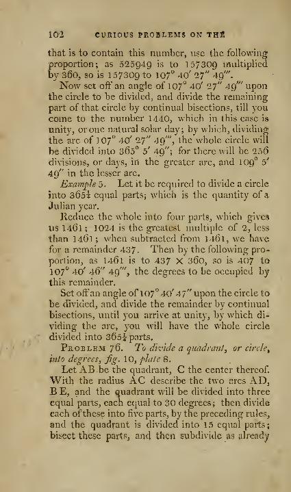
102 CURIOUS PROBLEMS ON THfi
that is to contain this number, use the following;
proportion; as 525949 is to 157309 multiplied
by 360, so is 157309 to 107° 40' if A^"
.
Now set off an angle of 107" 40' 27" 49''' uponthe circle to be divided, and divide the remaining
part of that circle by continual bisections, till youcome to the number 1440, which in this case is
unity, or one natural solar day; by which, dividing
the arc of 107° 40' 27'' 49'", the whole circle will
be divided into 365° b' 49"; for there will be 256divisions, or days, in the greater arc, and 109° b'
49" in the lesser arc.
Example 5. Let it be required to divide a circle
into 365i equal parts; which is the quantity of a
Julian year.
Reduce the whole into four parts, which gives
tis 1461 ; 1024 is the greatest multiple of 2, less
than 1461 ; when subtracted from 1461, we have
for a remainder 437- Then by the following pro-
portion, as 1461 is to 437 X360, so is 407 to
107° 40' 46" 49'", the degrees to be occupied bythis remainder.
Set offan angle of 107° 40' 47" upon the circle to
be divided, and divide the remainder by continual
bisections, until you arrive at unity, by which di-
viding the arc, you will have the whole circle
divided into 365^ parts.
Problem 76. To divide a quadranty or circle
^
into degrees, fig. 10, flaie 8.
Let ABbe the quadrant, C the center thereof.
With the radius AC describe the two arcs AD,B E, and the quadrant will be divided into three
equal parts, each equal to 30 degrees; then divide
each ofthese into five parts, by the preceding rules,
and the quadrant is divided into 15 equal parts;
bi^iect these parts^ and then subdivide as already
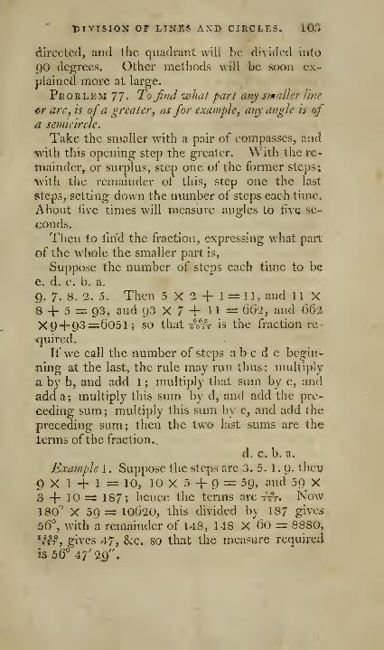
tUVISlO^ OP LINES AXD CIRCLES. 105
directed, and the quadrant will be divided into
90 degrees. Other methods will be soon ex-
plained more at large.
Problem 77- To find what part any smaller line
or arc, is ofa greater, as for exa)nple, any angle is ofa semicircle.
Take the smaller with a pair of compasses, and
with this opening step the greater. With the re-
mainder, or surplus, step one of the former steps;
with the remainder of this, step one the last
steps, setting down the number of steps each time.
About five times will measure angles to five se-
conds.
Then to find the fraction, expressing what part
of the whole the smaller part is,
Suppose the number of steps each time to be
e. d. c. b. a.
9. 7. 8. 1. 5. Then 5 X 2 -|- 1 = 11, and 11 X8 4- 5 = 93, and 93 X 7 + 1 1 = 6(52, and 662
X 94-93=6051; so that Si-ix is the fraction re-
<]uired.
If we call the number of steps ab c d e begin-
ning at the last, the rule may run thus : multiply
a by b, and add 1 ; multiply that sum by c, and
add a; multiply this sum by d, and add the pre-
ceding sum ; multiply this sum by e, and add the
preceding sum; then the two last sums arc the
terms ofthe fraction.,
d, c. b. a.
Example 1 . Suppose thc'Stcps are 3. 5. 1. 9. then
^ X 1 H- 1 = 10, 10 X 5 -}- 9 = 59, and 59 X3 4- 10 =: 187; hence the terms are -frr. Now180^ X 59 = 10620, this divided by 187 gives
56°, with a remainder of 148, 148 X 60 = 8880,
*wT, gives 47, &c. so that the measure required
is 56° 47' 2j^".
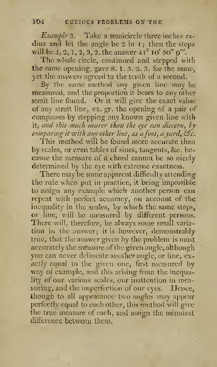
104 CURIOUS PROBLEMS ON THE
Example 3. Take a semicircle three inches ra-
dius and let the angle be 2 in 1 ; then the steps
will be 4, 2, 1, 1, 3, 2."the answer 41° lo' 50" g"\
The whole circle, continued and stepped with
the same opening, gave 8. 1. 3. 2. 3. for the same,yet the answers agreed to the tenth of a second.
By the same method any given line may bemeasured, and the proportion it bears to any other
strait line found. Or it will give the exact value
of any strait line, ex. gr. the opening of a pair of
compasses by stepping any known given line with
it, a?id this much riearer than the eye can discern, hy
comparing it with any other line, as afoot, ayard, &c.This method will be found more accurate than
by scales, or even tables of sines, tangents, &c. be-
cause the measure of a chord cannot be so nicely
determined by the eye with extreme exactness.
There may be some apparent difficulty attending
the rule when put in practice, it being impossible
to assign any example which another person canrepeat with perfect accuracy, on account of the
inequality in the scales, by which the same steps,
or line, will be measured by different persons.
There will, therefore, be always some small varia-
tion in the answer; it is however, demonstrably
true, that the answer given by the problem is mostaccurately the measure ofthe given angle, although
you can never delineate another angle, or line, ex-
actly equal to the given one, first measured byway of example, and this arising from the inequa-
lity of our various scales, our inattention in mea-suring, and the imperfection of our eyes. Hence,though to all appearance two angles may apj^ear
perfectly equal to each other, this method will give
the true measure of each, and assign the minutest
difference between them.
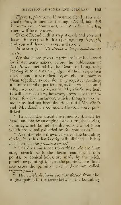
DIVISION OF LINES AND CIRCLES. 103
Figure I, plate g, will illustrate clearly this me-thod; thus, to measure the angle AG B, take ABbetween your compasses, and step Bii, a b, be,there will be c D over.
Take c D, and with it step Ae, ef, and you will
have'fB over; with this opening step Ag, gh,and you will have h e over, and so on.
Problem 78. To divide a large quadrant or
circle.
We shall here give the principal methods usedby instrument-makers, before the pu})]ication ofMr. Bird's method by the Board of Longitude,leaving it to artists to judge of their respcclive
merits, and to use them separately, or combinethem together, as occasion may require; avoiding
a minute detail of particulars, as that will be foundwhen we come to describe Mr. Bird's method.It will be necessary, however, pre\iousIv to men-tion a few circumstances, \\'hich, though in com-mon use, had not been described until Mr. /ii/v/'s
and Mr. Ludlam\ comment thereon were pub-iished.
" In all mathematical instruments, divided by-
hand, and not by an engine, or pattern, the circles,
or lines, which bound the divisions are not those
which are actually divided by the compasses."" A faint circle is drawn very near the boundino;
circle; it is this that is originally divided. It has
been termed the priinili-ve circled*' The divisions made upon this circle arc faint
arcs, struck with the beam compasses; fine
points, or conical holes, are made by the prick
punch, or pointing tool, at the points wliere these
arcs cross the primitive circle; these arc called
original points
^
" The visible divisions are transferred from the
original points to the space between the bounding
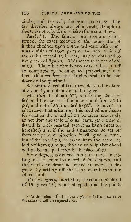
106 CURIOUS PROBLEMS ON THE
circles, and are cut by the beam compasses ; theyare therefore always arcs of a circle, though so
short, as not to be distinguished from strait lines."
Method 1. The faint or primitive arc is first
fetruck; the exact measure of the radius thereof
is then obtained upon a standard scale with a no-nius division of 1000 parts of an inch, which if
the radius exceed 10 inches, may be obtained to
live places of figures. This measure is the chord
of 6o. The other chords necessary to be laid off
are computed by the subjoined proportion,* andthen taken off from the standard scale to be laid
down on the quadrant.
Set off the chord of 6o°, then add to it the chordof 30, and you obtain the goth degree.
Mr. Bird, to obtain 90°, bisects the chord of60°, and then sets off the same chord from 30 to
90°, and not of 30 from 6o° to 90°. Some of the
advantages that arise from this method are these;
for whether the chord of 30 be taken accurately
or not from the scale of equal parts, yet the arc of
60 will be truly bisected, (see remarks on bisection
hereafter) and if the radius unaltered be set off
from the point of bisection, it will give 90 true;
but if the chord 30, as taken from the scale, belaid off from 60 to 90, then an error in that chordwill make an equal error in the place of ^(f.
Sixty degrees is divided into three parts by set'
ting off the computed chord of 20 degrees, andthe whole quadrant is divided to every 10 de-
grees, by setting off the same extent from the
other points.
Thirty degrees, bisected by the computed chord
of 15, gives 15°, which stepped from the points
* As the radius Is to the given angle, so is the measure of
the radius to half the required chord.
DIVISION OP LINES AND CIRCLES. 107
already fouiKl, divides the quadrant to every fifth
degree.
The computed chord of 6" being laid off, di-
vides 30 degrees into five parts; and set otr'froni
the other divisions, subdivides the quadrant into
single degrees.
Thus with five extents of the beam compasses,
and none of them less than six degrees, the cpia-
drant is divided into 90 degrees.
Fifteen degrees bisected, gives 7° 30', \\Jiieh set
off from the other divisions, divides the quadrantinto half degrees.
The chord of d° 40' divides 20'^ into tln-ce })ans,
and set off from the rest of the divisions, divides
the whole instrument to every ten minutes.
The chord of 10° 5' divides the degrees into
12 parts, each equal to five minutes of a degree.
Method 1. The chords are here supposed to l^e
computed as before, and taken ofi' from the noniuis
scale.
1. Radius bisected divides the quadrant inio
three parts, each equal to 30 degrees.
2. The chord of 10° gives nine parts, each equal
to 10 degrees.
3. Thirty degrees bisected and set off, gives 18
parts, each equal to five degrees.
4. Thirty degrees into five, by the chord of 6"^;
then set oft'' as before gives QO parts, each cf[ual to
1 degree.
5. The chord of 6° 40' gives 270 parts, each
equal to 20 minutes.
(1 The chord of 7° 30' gives 540 parL^, cacll
equal to 10 minutes.
7. The chord of 7'' 45' gives 1080 parts, cacll
equal to five minutes.
Qx M<ilhod?j. The computed chords supposed.
108 MR. BIRD S METHOD
1
.
60 into i gives 3 parts, equal 30*^
2. 30 i equal J3 6 15"
3. 15 3 equal 5 18 5"^
4. 20 5 equal () 90 l''
5. 20 3 equal 6"" 40' 270 20'
6. 15 i equal 7° 30' 540 lO'
7. 15, 30 5 equal 7"" 45' 1080 5'
• Thus may the praetitioncr vary his numbers for
any division whatsoever, and yet preserve a suffi-
cient extent between the points of his com-passes.
If the quadrant be divided as above, to every 1
5
degrees, and then the computed arc of 1 6 degrees
set off, this arc may be divided by continual bisec-
tion into single degrees. If from the arc of 45°,
2° 20' be taken, or 1° lo' from 22° 30', we mayobtain every fifth minute by continual bisection.
If to the arc of 7° lO' be added the arc of 62 mi-
nutes, the arc of every single minute may be hadby bisection.
Op Mr. Bird's method of dividing.Fig. 2, p/ate 9.
In 1767 the Commissioners of Longitude pro-
posed an handsome reward to Mr. Bin/, on con-
dition, among other things, that he should publish
an account of his method of dividing astronomicai
instruments; which was accordingly done: and a
tract, describing his method of dividing, was writ-
ten by him, and published by order of the Com-missioners of Longitude in the same year; somedefects in this publication were supplied by the
Rev. Mr. Ludiam, one of the gentlemen who at-
tended Mr. Bird to be instructed by him in his
method of dividing, in consequence of the Board's
OP DIVIDI]^G. 109
agreement with him. Mr. Ludlams tract waspublished in 1787, in 4to,
I shall use my endeavours to render t]iis methodstill clearer to the practitioner, by combining andarranging the subject ofboth tracts.
Mr. Bird's method.
1 . One ofthe first requisites is a scale of inches,
each inch being subdivided into 10 equal parts.
1. Contiguous to this line of inches, there mustbe a nonius, in which 10.1 inches is divided into
100 equal parts, thus shewing the lOOOndth part
of an inch. By the assistance of a magnifyingglass of one inch focus, the SOOOndth part may beestimated.
3. Six beam compasses are necessary, furnished
witli magnifying glasses of not more than one inch
focus. The longest beam is to measure the radmsor chord of 60 ; the second for the chord of 42.40;the third for the chord of 30; the fourth for 10.20;
the fifth for 4.40; the sixth for the chord of 15
degrees.
4. Compute the chords by the rules given, andtake their computed length from the scale in the
different beam compasses.
5. Let these operations be performed in the
evening, and let the scale and the different beamcompasses be laid upon the instrument to be di-
vided, and remain there till the next morning.
6. The next morning, before sun-rise, examinethe compasses by the scale, and rectify them, if
they are either lengthened or shortened by anychange in the temperature of the air.
7. The quadrant and scale being of the sametemperature, describe the faint arc bd, or primi-
tive circle; then with the compasses that are set

no ani. bird's Method.
to the rftclius and nitli a line prick punch, make a
point at a, which is to be the O point of the qua-drant; SCQ Jjg.'l, plate g.
8. With the same beam compasses unalterecf
lay off from a to cthc chord of 60°^ making a fin«
point at c.
9. Bisect the arc ac with the chord of 30°.
10. Then from the point c, \vilh the beam com-passes containing 60, mark the point v, which is
that of 90 degrees.
1 1
.
Next, with the beam compasses containing
15°, bisect the arc er in n, which gives Jo^.
12. Lay off from n towards r the chord of10° 10', and from r towards n the chord of 4° 40';
these two ought to meet exactly at the point g of85° 20'.
13. Now as in larp-e instruments each dcQ-ree is
generally subdivided into 12 equal parts, of five
minutes each, we shall find that 85° 20' contains
10.24 such parts, because 20' equal 4 of these
parts, and 85X12 makes 1020; now 1024 is anumber divisible by continual bisection.
The last computed chord was 42° 40', with
which a g was bisected in o, and a o, o g, werebisected bv trials. Though Mr. Bird seems to
have used this method himself, still he thinks it
more adviseable to take the computed chord of21° 20', and by it find the point g; then proceed
by continual bisections till you have 1024 parts.
Thus the arc 85° 20', by ten bisections, will give
vs the arcs 42° 40', 21° 80', 10° 40', 5° 20', 2° 40',
1°20', 40', 20', 10', 5'.
14. To fill up the space between g and r, 85*
•20', and 00°, which is 4° 40', or 4X12+ 8 equal to
60 divisions; the chord of ()4 divisions was laid oft"
from g towards d, and divided like the rest by con-
tinual bisections,, as was also from a towards- b;

MR. BIRD S METHOfi. Ill
If the work is well performed, you will again find
the points 30, 45, ()0, 75, and gO, without anysensible difference. It is evident that these arcs,
as well as those of 15°, are multiples of the arc
of 5'; for one degree contains 12 arcs of 5' each,
ofwhich 15° contains 180; the arc of 30° containa
360; the arc of 6o°, 720; that of 75°, QOO; and,
therefore, 90° contains 1080.
Mr. Graham, in 1725 applied to the quadrant
divided into 90°, or rather into 1080 parts of fivo
minutes each, another quadrant, which he divided
into 96 equal parts, subdividing each of these into
16 equal parts, forming in all 1536. This arc is a
severe check upon the divisions of the other; butBird says, that if his instructions be strictly fol-
lowed, the coincidence betwech them will be sur-
prising, and their difference from the truth exceed-
ingly small.
The arc of 96° is to be divided first into three
equal parts, in the same manner as the arc of 90°;
each third contains 512 divisions, which number is
divisible continually by 2, and gives 16 in each
96th part of the whole.
The next step is to cut the linear divisions from
the points obtained by the foregoing rules. Forthis purpose a pair of beam compasses is to beused, both of whose points are conical and very
is^harp. Draw a tangent to the arc b d, suppose at
e, it will intersect the arc xy in q, this will be the
distance between the points of the beam compasses
to cut the divisions nearly at right angles to the arc.
The point of the beam compasses next the right
hand is to be placed in the point r, the other point
to fall freely into the arc x y ; then pressing gently
upon the screw head which fastens the socket, cut
the divisions with the point towards the right hand.

113 FOU THE NONIUS.
proceeding thus till you have finished all the dm*sions of the limb.
POR THE NONIUS.-
1. Chuse any part of the arc where there h acoincidence of the 90 and Qb arcs; for example,
at e, the point of 6()°. Draw the faint arc s t andik, which may be continued to any length towards
A; upon these the nonius divisions are to be di-
vided in points. The original points for the no-
nius of the goth arc are to be made upon the arc
St; the original points for the nonius of the g()th
arc are to be made upon the are i k.
Because go is to g6, as 15 to 16, there will be a.
coincidence at 15° and l6pts, 30° and 32pts, 45°
and 4Spts; 6o° and 64pts, go° and g()pts.
2. Draw a tangent line to the primitive circle as
before, intersecting the are d, which gives the dis-
tance of the points of the beam compasses, with
which the nonius of the goth arc must be cut.
3. Let us suppose then that the nonius is to
subdivide the divisions ofthe limb to halfa minute,
which is eifected bv makino; 10 divisions of the^ . . .
nonius equal to 11 chvisions of the limb; measurethe radius ofthe arc, and compute the chord of 16,
or rather 32 of the nonius division, which may ea-
sily be obtained by the following proportion; if
10 divisions of the nonius plate make 55 minutes
of a degree, what will 32 of those divisions make ?
the answer is 2*^ 56', the chord of which must becomputed and taken from the scale of equal parts;
but as different subdivisions bvthe nonius mav berequired, let ;/ be the number of nonius divisions,
h the number of minutes taken in bv the nonius b,
id, 32 or (34, and X the arc sought; then as u :
m :; b : X.

FOR THE NONIUS. 113
4. Lay off with the beam compasscSj having the
length of the tangent ()() between the points, the
point q from c, q being a point in the arc s t, andG an original point in the primitive circle, and the
chord of 32 from q towards the left hand, (the
chord of32 being the chord which subtends 32 di-
visions on the nonius plate, or the chord of 2° 56';
this chord to be computed from the radius withwhich the faint arc s t was struck, and taken off
the scale of equal parts,) and divide by continual
bisections; ten of those divisions, counting from
q to the left, will be the required points.
The nonius belonging to the 96th arc is subject
to no difficulty, as the number should always be
16, 32, &c. that the extremes may be laid off from
the divisions of the limb without computation.
To be more particular, the length of the tangent
line, or radius, with which the divisions of the
nonius of the 96 arc arc to be cut, must be foundin the way before directed for the nonius of the
90 arc; the ark ik standing instead of the arc st.
Having the tangental distance between the points
of the compasses from one of the original points
in the primitive 96, lay off a point on the faint arc
i k towards the left hand ; count from that point
on the ])rimitive 96 circle 17 points to the left
hand, and lay off from thence another point on the
faint arc i k; the distance between those two points
in the faint arc i k is to be subdivided by bisec-
tions into 16 parts, and those parts pointed; from
these points the visible divisions of the nonius are
to be cut.
Mr. LiuTlam thinks, that instead of laying the
extent of the nonius single, it would be better to
lay it off double or quadmple; thus, instead of 17
points to the left hand, count 34 or 68, and that
both ways, to the riglit and to the left^ and lay off
1
114 FOR THE NONIUS.
a point from each extreme on the faint arc ik;subdivide the whole between these extreme points
by continual bisections, till you get l6 points toge-
ther on the left hand side of the middle, answering^
to the extent of the nonius. No more of the sub-
divisions are to be completed than are necessary to
obtain the middle portion of l6 points as before.
The nonius points obtained, the next process is to
transfer them on the nonius plate, which plate is
chamfered on both edges; on the inner edge is
the nonius for the 90 arc, on the outer edge is the
nonius for the9t)arc,in the middle between the twochamfers is a flat part parallel to the under sm-face
of the nonius plate; upon the flat part the faint
line of the next operation, is to be drawn.
To find the place 'where the ?ionius is to begin upon
the chamfered edge of the nonius plate, measure the
distance of the center of the quadrant from the
axis of the telescope; this distance from the axis
of the telescope at the eye end, will be the place
for the first division of the nonius; then draw a
faint line from the center on the flat part of the
nonius plate.
Fasten the nonius plate to the arc with twopair ofhand voices; then with one point of the beamcompasses in the center of the quadrant, and the
other at the middle of the nonius plate, draw a
faint arc from end to end ; where this arc cuts the
faint line before-mentioned, make a fine point;
from this point lay off on each side another point,
which may be at any distance in the arc, only
care must be taken that they be equally distant
from the middle point; from the two last make a
faint intersection as near as possible to either of
the chamfa'ed edges of the nonius plate; through
this intersection the first division of tlic nonius
must be cut.

[115]
Mr. Bird's method op dividing his scaleop equal parts.
Let us suppose that we have 90 inches to divide
into 900 equal parts, take the third of this number,or 300; now, the first power of 2 above this is
512; therefore, take Wths of an inch in one pair
of beam compasses, r-i in another, W in a third,
and T^ in a fourth ; then lay the scale from whichthese measures were taken, the scale to be divided,
and the beam compasses near together, in a roomfacing the north; let them lie there the wholenight; the next morning correct your compasses,
and lay off W three times ; then with the com-passes Vs , W, Tff, bisect these three spaces as ex-
peditiously as possible; the space 64 is so small
that there is no danger from any partial or unequalexpansion, therefore the remainder may be finished
by continual bisections. The linear divisions are
to be cut from the points with the beam compasses
as before described.
The nonius of this scale is Wths of an inch long,
which is to be divided into 100 equal parts, as
100 is to 101, so is 256 : 258,56 tenths of an inch,
the integer being t^. Suppose the scale to be
numbered at every inch from left to right; then
make a fine point exactly against -r^, to the left of o,
from this lay off 258,56 to the right hand, whichdivide after the common method.
Ifyou are not furnished with a scale long enoughto lay off 258,50, then set off ¥0°, and add 8,56,
from a diagonal scale.
Op Mr. Bird's pointing tool, and methodof pointing.
The pointing tool consisted of a steel wire ^o
inch diameter, inserted into a brass wire i inch
I 2

Il6 Mil. bird's pointing tool, &c.
diameter, the brass part 1^ long, the steel part
stood out f, whole length 3^ inches. The angle
of the conical point about 20 or 25 degrees, some-what above a steel temper; the top of the brass
part was rounded oft', to receive the pressure of
the fmger; the steel point should be first turned,
hardened, and tempered, and then whetted on the
oil-stone, by turning the pointril round, and at
the same time drawing it along the oil-stone, not
against, but from the point; this will make a sharp
point, and also a kind ofvery fine teeth along the
slant side of the cone, and give it the nature of a
very fine countersink.
In striking the primitive circle by the beamcompasses, the cutting point raises up the metal a
little on each side the arc ; the metal so throw^n
up forms what is called the bur. When an arc
is struck across the primitive circle, this bur will
be in some measure thrown down; but if that cir-
cle be struck again ever so lightly, the bur will be
raised up again ; the arcs struck across the primi-
tive circle have also their bur. Two such rasurcs
or trenches across each other, will of course havefour salient, or prominent angles within ; and as
the sides ofthe trenches slope, so do also the lines
which terminate the four solid angles. You maytherefore, /^^/ what you cannot see; when the co-
nical points bear against all four solid angles, they
will guide, and keep the point of the tool in the
center of decussation, while keeping the tool up-right, pressing it gently with one hand, and turn-
ing it round with the other, you make a conical
hole, into which you can at any time put the point
of the beam compasses, and feel, as well as see,
when it is lodged there.
[ H7]
RULES OR MAXIMS LAID DOWX BY Mr. BiRD.
1. The points of the beam compasses should
never be brought nearer together than two or three
inches, except near the end of the line or arc to bedivided ; and there spring dividers with roundmoveable points had best be used.
2. The prick-punch, used to mark the points,
should be very sharp and round, the conical point
being formed to a very acute angle; the point to
be made by it ought not to exceed the one thou-sandth of an inch. When lines, or divisions, are
to be traced from these points, a magnifying glass
of ^ an inch focus must be used, which will render
the impression or scratch made by the beam com-passes sufficiently visible; and if the impression be
not too faint, feeling will contribute, as well as
seeing, towards making the points properly.
3. The method of finding the principal points
by computing the chords, is preferable to other
methods; as by taking up much less time, there
is much less risk of any error from the expansion
of the instrument, or beam compasses.
4. To avoid all possible error from expansion,
Mr. Bird never admitted more than one person,
and him only as an assistant; nor suftbred any fire
in the room, till the principal points were laid
down.Mr. 5/V<^ guards, by this method, against any
inequality that might possibly happen among the
original points, by first setting out a few capital
points, distributed equally through the arc, leaving
the intervals to be filled up afterwards; he could
by this method check the distant divisions with
respect to each other, and shorten the time of thtj
most ^sential operations.

118 KULE3 OR MAXIMS,
5. Great care is to be observed in pointing in-
tersections, which is more difficult than in points
ing from a single line, made by one point of the
compasses. For in bisections, the place to bepointed is laid off from the right to the left, andfrom the left to the right. If any error arises froman alteration of the compasses, it will be shewndouble; even if the chord be taken a little toalong, or too short, it will not occasion any ine^
quality, provided the point be made in the middle,
between the two short lines traced by the com-passes.
NoAv, as Mr. Ludlam observes, if the bisecting
chord be taken exactly, the two fore-mentioned
faint arcs will intersect each other in the primi-
tive circle, otherwise the intersection will fall
above or below it. In either case, the eye, assisted
by a magnifier, can accurately distinguish on the
primitive circle the middle between these twoarcs, and a point may be made by the pointing tool.
In small portions of the prmiitive circles, the
two faint arcs will intersect in so acute an angle,
that they will run into one another, and form as
it were a single line; yet even here, though the
bisecting chord be not exact, if the intersection bepointed as before, the point Vv^ill fall in the middle
of the portion to be bisected.
If, in the course of bisecting, you meet with a
hole already made with the pointril, the point of
the compasses should fall exactly into that hole,
both from the right and left hand, and you mayreadily feel what you cannot see, whether it
fit or no ; if it fits, the point of the compasses will
have a firm bearing against the bottom of the
conical hole, and strike a solid blow against it; if
it does not exactly coincide with the center of the
hole, the slant part of the point will slide down tb?
LAID DOWN BY MR. BIRD. 1 ig
slant side of the hole, drawing, or pushing the
other point of the compasses from its place.
Mr. Bird's method of transferring the divisions
by the beam compasses from the original points, is
founded on this maxim, that a right tins cannot be
cut upon hrasSy so as accurately to pass through twogiven points; but that a circle may be described
from any center to pass with accuracy througli a
given point. It is exceeding difficult, in the nrst
place, to fix the rule accurately, and keep it firmlv
to the two points; and, secondly, supposing it
could be held properly, yet, as the. very point ofthe knife which enters the metal and ploughs it
out, cannot bear against the rule, but some other
part above that point will bear against it; it fol-
lows, that if the knife be held in a different situa-
tion to or from the rule, it will throw the cutting
point out or in; besides, any hardness or ine-
quality of the mxtal will turn the knife out of its
course, for the rule does not oppose the knife in
departing from it, and the force of the hand can-
not hold it to it. For these reasons it is almost
impossible to draw a knife a second time against
the rule, and cut within the same line as before.
On the other hand, an arc of a circle may al-
ways be described by the beam compasses so as to
pass through a given point, provided both points
of the compasses be conical. Let one point of
the compasses be set in the given point or con.ical
hole in the brass plain; make the other point,
whatever be its distance, the central, or still point;
with the former point cut the arc, and it will be
sure to pass through the given point in the brass
plain, and the operation may be repeated safely,
and the stroke be strengthened by degrees, as the
moving point is not likely to be shifted out of i\s>
4clir.ection, nor the cutting point to be broken.
120 !IULE3 OR MAXIM5, &:C.
The visible divisions on a large quadrant are
always the arcs of a circle, though so short as not
to be distinguished from strait lines; they should
be perpendicular to the arc that bounds them, andtherefore the still or central point of the beamcompasses must be somewhere in the tangent to
that arc; the bounding circle of the visible divi-
sions, and the primitive circle should be very near
each other, that the arc forming the visible divi-
sions may be as to sense perpendicular to both
circles, and each visible division shew the original
point from which it was cut.
Another maxim of Mr. Bird's, attributed to
Mr. Graham, That it Is possible practically to bisect
an arc, or right Vuie, but not to trisect, quinquisect,
^c. The advantages to be obtained by bisection
have been already seen; we have now to shew the
objections against trisecting, &c.
1. That as the points of triscction in the primi-
tive circle must be made by pressing the point of
the beam compasses down into the metal, the least
extuberance, or hard particle, will cause a deviation
in the first impression of a taper point, and force
the point of the compasses out of its place;
when a point is made by the pointing tool, the
tool is kept turning round while it is pressed down,and therefore drills a conical hole.
1. Much less force is necessary to make ascratch or faint arc, than a hole by a pressure
downwards of the point of the compasses.
3. So much time must be spent in trials, that a
partial expansion would probably tiikc place; and,
perhaps, many false marks, or holes made, whichmight occasion considerable error.
Another maxim of Mr. Bird's was this, that
stepping was liable to great uncertainties, and not
to be trusted; that iS;, if the chord of l6° W9S aS"

BIRD S SCALE OF EQUAL PART?. 121
snnied, and laid down five times in siicecssion, bj
turning the compasses over upon the primitive cir-
cle, yet the ares so marked would not,, in his opi-
nion be ecjual.
DE^CRIPTIOX OF Mr. BiRD^S SCALE OFEQUAL PARTS.
It consists of a scale of inches, each divided into
tenths, and numbered at every incli from the lelt
to the right, thus, O, 1,2, 3, &c. in the order ofthe
natural numbers. The nonius scale is below this,
but contiguous to it, so that one common line ter-
minates the bottoms of the divisions on the scale
of inches, and the tops of the divisions on the
nonius; this nonius scale contains in length 101
tenths of an inch, this length is divided into 100
equal parts, or visible divisions; the left hand di-
vision of this scale is set off from a point -rs of an
inch to the left of 0, on the scale of inches; there-
fore, the right hand end of the scale reaches to,
and coincides with the 10th inch on the scale of
inches. Every tenth division on this nonius scale
is figured from the right to the left, thus, 100. C)0.
80. 70. (JO. 50. 40. 30. 20. 10. O. and thus on
the nonius coincides with 10 on the inches; and
100 on the nonius falls against the first subdivision
(oftenths) to the left hand ofoon the inches; and
these two, viz. the first and last, are the only two
strokes that do coincide in the two scales.
To take off any given number of inches, deci-
mals, and millesimals of an inch; for example,
42,7()4, observe, that one point of the beam com-
pass must stand in a (j)ointed) division on the no-
nius, and the other point of the compasses in a
pointed division on the scale of inches;.
122 DESCRIPTION OF MR. BIRD 5
The left hand point of the compasses mii5t
stand in that division on the nonius \vhich ex-
presses the number of millesimal parts j this, in our
example, is (i4.
To find where the other point must stand in the
scale of inches and tenths, add 10 to the given
number of inches and tenths (exclusive of the twomillesimal figures;) from this sum subtract the
two millesimal figures, considered now as units
and tenths, and the remainder will shew in whatdivision, on the scale of inches, the other point of
the compasses must stand; thus, in our example,
add 10 to 42,7, and the sum is 52,7; from this
subtract 6,4 and the remainder is 46,3. Set then
one point of the compasses in the 64th division onthe nonius, and the other point in 46,3 on the scale
of inches, and the two points will comprehend be-
tween them 42,764 inches.
This will be plain, if we consider that the junc-
tion of the two scales is at the 10th inch on the
scale of inches; therefore, the compasses will
comprehend 36,3 inches on the scale of inches;
but it will likewise comprehend 64 divisions onthe nonius scale. Each of these divisions is onetenth and one millesimal part of an inch ; there-
fore, 64 divisions is 64 tenths, and 64 millesimal
parts, or 6,464' inches; to 6,464 inches taken onthe nonius, add 36,3 inches taken on the scale of
inches, and the whole length is 42,764 inches; andthus the whole is taken from two scales, viz. inches
and the nonius; each subdivision in the former is
tV of an inch, each subdivision in the latter is -r^-j-
WcTsth of an inch. By taking a proper number of
each sort of subdivisions (the lesser and the greater)
the length sought is obtained.
The business of taking a given length will be
expedited, and carried on with far less danger of

SCALE OF EQUAL PARTS. 123
injaring the scale, if the proposed length be first
of all taken, nearly^ on the scale of inches onlv,
guessing the millesimal parts; thus, in our case,
we ought to take off from the scale of inches 42,7,
and above half a tenth more; for then ifone point
be set in the proper division on the nonius, the
other point will fall so near the proper division onthe scale of inches, as to -point it out; and the
point of the compasses may be brought, by the
regulating screw, to fall exactly into the true di-
vision.
If, when the points of the compasses are set, they
do not comprehend an integral number of mille-
simal parts, they will not precisely fall into anytwo divisions, but will cither exceed, or fall short;
let the exact distance ofthe points of the compasses
be 42,7645; if, as before, the left hand point beset in the 64th division of the nonius, then the
right hand point will exceed 46,3 among the
inches; if the left hand point be carried one divi-
sion more to the left, and stand in 65 ofthe nonius,
then the right hand point will fall short of 46,2 in
the scale of inches; the excess in the former case
being equal to the defect in the latter. By ob-
serving whether the difference be equal, or as
great again in one case as the other, we may esti-
mate to 4d part of a millesimal. See Mr. Binfs
Tract, p. 2.
It may be asked, why should the nonius scale
cxDmmence at the lOth inch; why not at 0, and so
the nonius scale lay wholly on the left hand of the
scale ofinches? and, in this case, both scales might
be in one right line, and not one under the other;
but, in such a case, a less distance than 10 inches
could not always be found upon the scale, as ap-
pears from the rule before given. The number 10
must not, in this case, be added to the inches and

124 DE^CRIPIOX OF MR. BIBd's, &C.
tenths, and then the subtraction before directed
would not always be possible.
Yet, upon this principle, a scale in one conti*
nued line may be constructed for laying ofl' inches,
tenths, and hundredths of an inch, for any length
above one inch ; at the head of the scale of inches,
to the left hand of 0, and in the same line, set off
eleven tenths of an inch (or the multiple,) whichsubdivide in Mr. Birds way, into ten equal parts.
Such a compound scale would be far more exact
than the common diagonal scale; for the division*
being pointed, you may feel far more nicely than
you can see, when the points of the beam compasses
are set to the exact distance. But to return to
Mr. Bird's Tract.
The nature of Mr. Bird's scale being known,there will be no difficulty in understanding his
directions how to divide it. A scale of this kind
is far preferable to any diagonal scale; not only
on account of the extreme difficulty of drawing the
diagonals exactl)', but also because there is nocheck upon the errors in that scale; here the uni-
form manner in which the strokes of one scale se-
parate from those of the other, is some evidence ofthe truth of both ; but Mr. Bird's method of as-^
suming a much longer line than what is absolutely
necessary for the scale, subdividing the whole bya continual bisection, and pointing the divisions as
before explained, and guarding against partial ex-r
pansions of the metal, is sure to render the divi-
sions perfectly equal. The want of such a scale
of equal parts (owing, perhaps, to their ignorance
of constructing it) is one reason why Mr. Bird's
method of dividing is not in so great estimation
among mathematical instrument makers, as it
justly deserves.

I 125 J
An OBSERVATION", OR METHOD OF GRADUA-TION, OF Mr. Smeaton's.
As it is my intention to collect in this place
whatever is valuable on this subject, I cannot
refrain from inserting the following remark ofMr. Smeaton^, though it militates strongly against
one of Mr. Blnfs maxims. He advises us to com-pute from the measured radius the chord of 16 de-
grees only, and to take it from an excellent plain
scale, and lay it off five times in succession fromthe primary point of given, this would give 80degrees; then to bisect each of these arcs, and to
lay off one of them beyond the SOth, which wouldgive the 88th degree; then proceed by bisection,
till you come to an arc of two degrees, which laid
off from the 88th degree, will give the 90 degrees;
then proceed again by bisection, till you have re-
duced the degrees into quarters, or every fifteen
minutes. Here Mr. Smeaton would stop, being
apprehensive that divisions, when over close, can-
not be accurately obtained even by bisection.
If it were necessary to have subdivisions uponthe limb equivalent to five minutes, he advises us
to compute the chord of 21° 10' only, and to lay it
oft' four times from the primary point; the last
would give 85° 20', and then to supply the re-
mainder from the bisected divisions as they rise,
not from other computed cliords.
Mr. 5i/v/ asserts, that after he had proceeded bythe bisections from the arc of 85° 20', the several
points of 30. 60. 75. ^Q. fell in without sensible ine-
quality, and so indeed they might, though they
were not equally true in their places; for whatever
error was in them would be communicated to all
connected with, or taking their departure from

126 GRADUATIOXj B Y* SMEATO^'.
them. Every heterogeneous mixture should beavoided.
It is not the same thing whether you t-ivlce take
a measure as nearly as you can, and lay it oft'
separately, or lay oft^ two openings of the com-passes in succession unaltered^ for though thesame opening, carefully taken oft" from the samescale a second time, will doubtless fall into the
holes made by the first, without sensible error;
yet, as the sloping sides of the conical cavities
made by the first points, will conduct the points
themselves to the center, there may be an error,
which, though insensible to the sight, would havebeen avoided by the more simple process of laying
oft^ the opening twice, without altering the com-passes.
As the whole of the QO arc may now be divided
by bisection, it is equally unexceptionable with
the ()6 arc; and, consequently, if another arc of
90, upon a different radius, was laid down, they
would be real checks upon each other.
Mr. Ramsde7i, in laying down the original divi-
sions on his dividing engine, divided his circle
first into five parts, and each of these into three;
these parts were then bisected four times; butbeing apprehensive some error might arise fromquinquiscction, and triscction, in order to examinethe accuracy of the divisions, he described another
circle tV inch within the former, by continual bi-
sections, but found no sensible difiTerence betweenthe two sets of divisions. It appears also, that
Mr. Bird, notwithstanding all his objections to,
and cteclamations against the practice of stepping,
sometimes used it himself.
[ 1^7 J
OF THE NONIUS DIVISIONS.
It will be necessary to give the young practiti-
oner some account of the nature and use of that
admirable contrivance commonly called a nonius,
by which the divisions on the limbs of instruments
are subdivided.
The nonius depends on this simple circum-stance, that if any line be divided into equal parts,
the length of each part will be greater, the fewerdivisions there are in the original ; on the contrary,
the length of each division will be less in propor-
tion, as the divisions are more numerous.
Thus, let us suppose the limb of Hadley's quad-rant divided to every 20 minutes, which are the
smallest divisions on the quadrant; the two ex-
treme strokes on the nonius contain seven degrees,
or 21 of the afore-mentioned small divisions, butthat it is divided only into 20 parts; each of these
parts will be longer than those on the arc, in the
proportion of 21 to 20; that is to say, they will beone-twentieth part, or one minute longer than the
divisions on the are; consequently, if the first, or
index division of the nonius, be set precisely oppo-site to any degree, the relative position of the no-
nius and the are must be altered one minute be-
fore the next division on the nonius will coincide
with the next division on the arc, the second di-
vision vv'ill require a change of two minutes; the
third, of three minutes/ and so on, till the 20th
stroke on the nonius arrive at the next 20 minutes
on the arc; the index division will then have movedexactly 20 minutes from the division whence it set
out, and the intermediate divisions of each minutehave been regularly pointed out by the divisions of
the nonius.
128 OF THE XOXIUS DIVISIOXs.
To render this still plainer, we must observe
that the index, or counting division of the nonius,
is distinguished by the mark 0, uhich is placed onthe extreme right hand division; the numberslimning regularly on thus, 20, 15, 10, 5, O.
The index division points out the entire degreesand odd 20 minutes, subtended by the objects ob-served; but the intermediate divisions arc shewnby the other strokes of the nonius; thus, look
umong the strokes ofthe nonius for one that stands
directly opposite to, or perfectly coincident with
some one division on the limb; this division reck-
oned on the nonius, shews the number of minutesto be added to what is pointed out by the index
division.
To illustrate this subject, let us suppose twocases. The first, when the index division perfectly
coincides with a division on the limb of the quad-rant : here there is no difficulty, for at whatsoever
division it is, that division indicates the required
angle. If the index divisions stand at 40 degrees,
40 degrees is the measure of the required angle.
If it coincide with the next division beyond 40 onthe right hand, 40 degrees 20 minutes is the angle.
If with the second division beyond 40, then 40 de-
grees 40 minutes is the angle, and so in every otherinstance.
The second case is, when the index line docs
not coincide with any division on the limb. Weare, in this instance, to look for a division on the
tionius that shall stand directly opposite to one onthe limb, and that division gives us the odd mi-
nutes, to be added to those pointed out by tlic
index division: thus, suppose the index division
does not coincide with 40 dcsrrecs, but that the
next division to it is the first coincident division,
then is the required an^lc 40 degrees 1 minute.
VALUE OF ANY NONIUS. 12Q
If it had been the second division, the angle wouldhave been 40 degrees 2 minutes, and so on to 20minutes, when the index division coincides withthe first 20 minutes from 40 degrees. Again, let
us suppose the index division to stand between30 degrees, and 30 degrees 20 minutes, and that
the Itith division on the nonius coincides exactly
with a division on the limb, then the angle is
30 degrees \6 minutes. Further, let the indexdivision stand between 35 degrees 20 minutes,and 35 degrees 40 minutes, and at the same timethe 1 2th division on the nonius stand directly op-posite to a division on the arc, then the angle will
be 35 degrees 32 minutes.
A GENERAL RULE FOR KNOWING THE VALUEOF EACH DIVISION, ON ANY NONIUS WHAT-SOEVER.
1. Find the value of each of the divisions, or
subdivisions, of the limb to which the nonius is
applied. 2. Divide the quantity of minutes or
seconds thus found, by the number of divisions
on the nonius, and the quotient will give the va-
lue of the nonius division.
Thus, suppose each subdivision of the limb be30 minutes, and that the nonius has 1 5 divisions,
then 4f gives two minutes for the value of the
nonius. If the nonius has 10 divisions, it wouldgive three minutes; if the limb be divided to
every 12 minutes, and the nonius to 24 parts,
then 12 minutes, or 720 seconds divided by 24,
gives 30 seconds tor the required value.
130 OP INSTRUMENTS FOR
OF INSTRUMENTS FOR DESCRIBING CIRCLESOF EVERY POSSIBLE MAGNITUDE.
As there are many cases where arcs are required
to be drawn of a radius too large for any ordinary
compasses, Mr. lieywood and myself contrived
several instruments for this purpose; the mostperfect of these is delineated iat Jig. 5, plate 11.
It is an instrumenjt that must give great satisfac-
tion to every one who uses it, as it is so extensive
in its nature, being capable of describing arcs from
an infinite radius, or a strait line, to those of twoor three inches diameter. When it was first
contrived, both Mr. Heywood and myself wereignorant of what had been done by that ever to
be celebrated mechanician. Dr. Hooke.
Since the invention thereof, I have received
some very valuable communications from different
gentlemen, who saw and admired the simplicity
of its construction; among others, from Mr. Ni-
cholsofi, author of several very valuable w^orks;
Dr. Rotherhim, Earl Stanhope, and /. Priestley^
Esq. of Bradford, Yorkshire; the last gentlemanhas favoured me with so complete an investigation
of the subject, and a description of so many admi-rable contrivances to answer the purpose of the
artist, that any thing I could say ^vould be alto-
gether superfluous; I shall, therefore, bo v^ery brief
in my description of the instrument, represented
Jig. 5, plate 11, that I may not keep the reader
ti'om Mr. Priestley''^ valuable essay, subjoining
Dr. Plooke'n account of his own contrivance to that
of ours. Much is always to be gained from an
attention to this great man; and I am sure myreader will think his time well employed in pe-
rusing the short extract I shall here insert.

DESCRIBING LARGE CIRCLES. IS!
The branches A and ^, Jig. 5, plate \\, carry-
two independent equal wheels C, D. The pencil^
or point E, is in a line drawn between the center
of the axis of the branches, and equidistant fromeach; a weight is to be placed over the pencil
when in use. When all the wheels have their
axes in one line, and the instrument is moved in
rotation, it will describe an infinitely small circle;
in this case the instrument will overset. Whenthe two wheels C, D, have their horizontal axes
parallel to each other, a right line, or infinitely
large circle will be described; when these axes are
inclined to each other, a circle of finite magni-tude will be described.
The distance between one axis and the center,
(or pencil,) being taken as unity, or the commonradius, the numbers 1, 2, 3, 4, &c. being soughtfor in the natural tangents, will give arcs of incli-
nation for setting the nonii, and at which cir-
cles of the radii of the said numbers^ multiplied
into the common radius, will be described.
The com-mon radius
multiplied
by
0.1
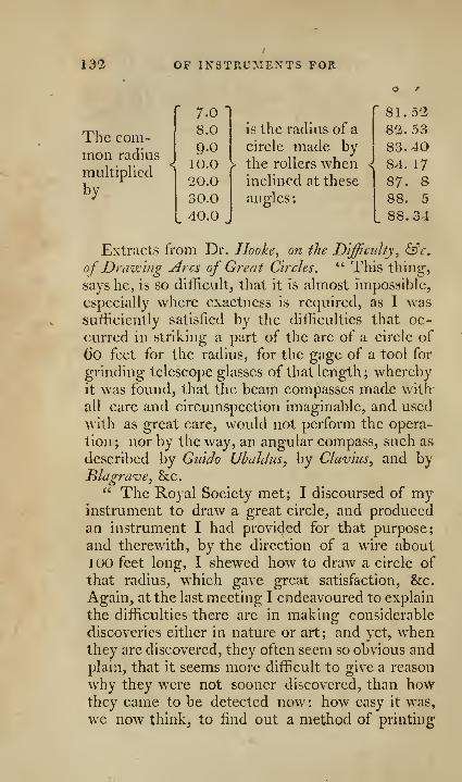
132 OF INSTRUMENTS FOR
The com-mon radius
multiplied
by
" 7.0-
DESCRIBING LARGE CIRCLES. 133
letters, and yet, except what may have happened
in China, there is no specimen or history of any
thing of that kind done in this part of the Avorld.
How obvious was the vibration of pendulous bo-
dies ? and yet, we do not find that it was madeuse of to divide the spaces of time, till Galileo dis-
covered its isochronous motion, and thought of
that proper motion for it, &c. And though it
may be difficult enough to find a way before it beshewn, every one will be ready enough to say
when done, that it is easy to do, and was obvious
to be thought of and invented."
To illustrate this, the Doctor produced an in-
strument somewhat similar to that described,^?^-. 5,
flate 11, as appears from the journal of the RoyalSociety, where it is said, that Dr. Hooke producedan instrument capable of describing very large cir-
cles, by the help of two rolling circles, or truckles
in the two ends of a rule, made so as to be turned
ill their sockets to any assigned angle. In another
place he had extended his views relative to this in-
strument, that he had contrived it to draw the arc
of a circle to a center at a considerable distance,
where the center cannot be approached, as from
the top of a pole set up in the midst of a wood, or
from the spindle of a vane at the top of a tower, or
from a point on the other side of a river ; in all
which cases the center cannot be conveniently ap-
proached, otherwise than by the sight. This he
performed hy two telescopes, so placed at the
truckles, as thereby to see through both of themthe given center, and by thus directing them to
the center, to set the truckles to their true incli-
nation, so as to describe by their motion, any part
of such a circle as shall be desired.

134 Priestley's method
Methods of describing arcs of circlesOF LARGE MAGNITUDE. By J. PrIESTLEY,Esti. OF Bradford, Yorkshire.
In the projection of the sphere, perspective andarchitecture, as well as in many other branches of
practical mathematics, it is often required to drawarcs of circles, whose radii are too great to admitthe use of common, or even beam compasses; andto draw lines tending to a given point, whosesituation is too distant to be brought upon the plan.
The following essay is intended to furnish somemethods, and describe a few instruments that mayassist the artist in the performance of both these
problem.s.
OF finding points in, and describing arcsOF LARGE CIRCLES.
The methods and instruments I shall propose for
this purpose, will chiefly depend on the following
propositions, which I shall premise as principles.
Principle 1 . The angles in the same segment of
a circle, are equal one to another.
Let AC T>^,fig. \, plate 10, be the segment of
a circle; the angles formed by lines drawn fromthe extremitiesAand B, ofthe base ofthe segment,
to any points C and D in its arc, as the angles
ACB, ADB, are equal.
This is the 31st proposition of EuclicVs third
book of the Elements of Geometry.
Principle 1. If upon the ends AB, Jig.^, plate 10,
of a right line AB as an axis, two circles or rollers
CD and EF be firmly fixed, so that the said
line shall pass throiigh the centers, and at right
angles to the plains of the circles ; and the whole
be suffered to roll upon a plain without sliding ;

OP DESCRIBING LARGE CIRCLES. 135
1. If the rollers CD and EF be equal in dia-
meter, the lines, described upon the plain by their
circumferences, will be parallel right lines; andthe axis AB, and every line DF, drawn between,
contemporary points of contact of the rollers andplain, will be parallel among themselves.
2. If the rollers CD and EF be unequal, then
lines formed by their circumferences upon the
plain will be concentric circles; and the axis AB,and also the Hues DF, will, in every situation,
tend to the common center of those circles.
Principle 3. If there be two equal circles or rol-
lers A and ^,fg. 3, plate 10, each separately fixed
to its own axis, moveable on pivots; and these
axes placed in a proper frame, so as to be in the
same plain, and to maintain the situation given
them with respect to each other; and if the appa-
ratus be rolled upon a plain without sliding:
1
.
If the axes C D and E F, be placed in a pa-
rallel situation, the circumferences of the rollers
A and B will trace upon the plain strait lines;
which will be at right angles to the axes C Dand EF.
2. If the axes CD and EF, continuing as be-
fore in the same plain, be inclined to each other,
so as if produced to meet in some point G, the
rollers A and B will describe in their motions upon
the plain arcs of the same, or of concentric cir-
cles, whose center is a point H, in that plain per-
pendicularly under the point of intersection G of
the two axes.
I shall not stop to demonstrate the truth of the
two last principles, it will easily appear on seeing
the operations performed.
r 136. ]
OF THE SIMPLE BEVEL.
In the performance of some of the following
problems, an instrument not vmlike jig, 4, plate
10, will be found useful. It consists of two rulers,
moveable on a common center, like a carpenter's
rule, with a contrivance to keep them fixed at any
required angle. The center C must move on a
very fine axis, so as to lie in a line with the
fiducial edges CB, CD of the rulers, and project
as little as possible before them. The fiducial
edges of the legs represent the sides of any given
angle, and their intersection or center C its an-
gular point.
A more complete instrument of this kind,
adapted to various uses, will be described here-
after.
N. B. A pin fixed in the lower rule, passes
through a semicircular groove in the upper, andhas a nut A which screws upon it, in order to fix
the rulers or legs, when placed at the desired
angle.
Problem 1 . Given the three po'mts A, B and C,
sup-posed to be in the circumference of a circle too
Jarge to he described by a fair of compasses ; to find
any number of other points in that circumference.
This may be performed various ways. As for
example, fig. 5, plate 10.^
1. Join AC, which bisect with the line FM Gat right angles; from B, draw BD parallel to
AC, cutting FG in E; and making ED=:EBD will be a point in the same circumference, in
which are A, B and C.
By joining AB, and bisecting it at right angles
with IK; and from C drawing C a parallel to AB,cutting IK in L, and making La =:LCj a will
be another of the required points,

THE SIMPLE BEVEL. 137
Continuing to draw from the point, last found,
lines alternately parallel to AC and AB; those
lines will be cut at right angles by F G and I Krespectively; and by making the parts equal oneach side of F G and I K, they become chords of
the circle, in which are the original points A, B,
and C, and, of consequence^ determine a series
of points on each side of the circumference.
It is plain from the construction, (which is too
evident to require a formal demonstration,) that
the arcs AD, A a, C c, &c. intercepted betweenthe points A and D, A and a, C and c, &c. are
equal to the arc B C, and to one another.
In like manner, joining BC, and bisecting it
at right angles Avith PQ; drawing A c' parallel to
B C, and making R c'=AR, (c/) is another of the
required points; and, from (c') the point last
found, drawing c'a' parallel to C A, and makinga'N^Nc', (a') is another point in the same cir-
cumference; and the arcs comprehended between
C c' and A a' are equal to that between AB.Hence, by means of the perpendiculars P Q. andFG, any number of points in the circumference
of the circle, passing through the given ones, A,
B and C may be found, whose distance is equal to
AB, in the same manner, as points at the distance
of B C were found by the help of the perpendi-
culars I K and F G.Again, if A, C and (c) or A, C and (c') betaken
as the three given points, multiples of the arc
AC may be found in the same manner as those of
the arc AB were found as above described.
2. Another method of performing this problem,
is as follows, ^g. 6, p/afe 10. Produce CB andCA; and with a convenient radius on C, describe
the arc D E ; on which set off the parts I^^ G, G E,
kc. each equal to DF; draw CG^ C E, &c. con-
138 PROBLEMS BY
tinucd out. beyond G and E if necessary ; take the
distance AB, and wiih one foot of the compasses
in A, strike an arc to cut CG produced in H;and H is a point in the circumference of the circle
that passes through the given points ABC; with
the same opening AB, and center H, strike an
arc to cut C E produced in I, which will be ano-
ther of the required points, and the process maybe continued as far as is necessary.
The reason of this construction is obvious ; for
since the angles, BCA, ACH, H C I, &c. are
equal, they must intercept equal arcs BA, AH, HIof the circumference.
If it were required to find a number of points
K, L, &c. on the other side, whose distances wereequal to B C, lay down a number of angles CAK,KAL, &c. each equal to BiVC, and make the dis-
tances CK^ KL, &;c. each equal to B C.
BY THE BEVEL.
This problem is much easier solved by the help
of the bevel above described, as follows. SeeJig. 5.
Bring the center of the bevel to the middle B,
of the three given points A, B and C, and holding
it there, open or shut the instrument till the
fiducial edges of the legs lie upon the other twopoints, and fix them there, by means of the screw
A, fjig. A) ; this is called setting the bevel to the
given points. Then removing the center of the
bevel, to any part between B and A or C, the legs
of it being at the same time kept upon A and C,
that center will describe (or be always found in)
the arc which passes through the given points, andwill, by that means, ascertain as many others as
may be required witliin the limits of A and C.
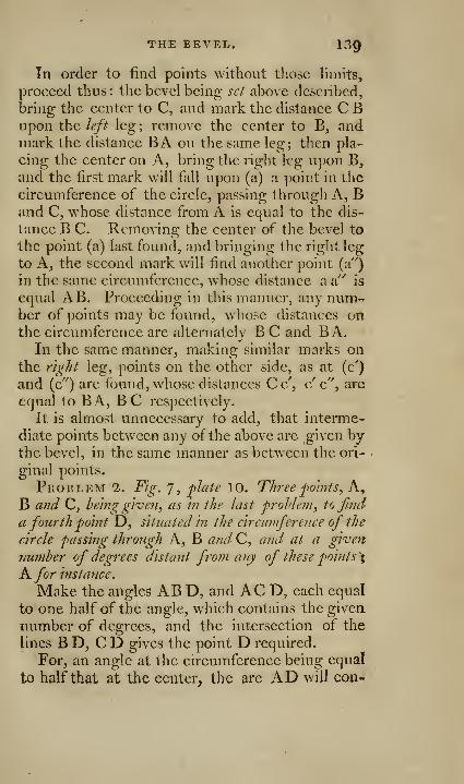
THE BEVEL. 139
In order to find points without those limits,
proceed thus : the bevel being set above described,
bring the center to C, and mark the distance C Bupon the left leg ; remove the center to B, andmark the distance BA on the same leg; then pla-
cing the center on A, bring the right leg upon B,
and the first m.ark will fall upon (a) a point in the
circumference of the circle, passing through A, Band C, whose distance from A is equal to the dis-
tance B C. Removing the center of the bevel to
the point (a) last found, and bringing the right leg
to A, the second mark will find another point (a")
in the same circumference, whose distance a a"" is
equal AB. Proceeding in this manner, any num-r
ber of points may be found, whose distances onthe circumference are alternately B C and BA.
In the same manner, making similar marks onthe right leg, points on the other side, as at (c')
and (c") are found, whose distances C c', c' c", are
equal to BA, B C respectively.
It is almost unnecessary to add, that interme-
diate points between any of the above are given bythe bevel, in the same manner as between the ori-
ginal points.
Problem 1. Fig. 7, plate 10. Three j)o'mis, K^
B and C, being given, as In the last problem, to find
a fourth point D, situated In the circumference of the
circle passing through A, B and C, and at a green
7iumber of degrees distant from any of these polnts\
A for instance.
Make the angles AB D, and AC D, each equal
to one half of the angle, which contains the given
number of degrees, and the intersection of the
lines B D, C D gives the point D required.
For, an angle at the circumference being equal
to half that at the center, the arc AD will con-
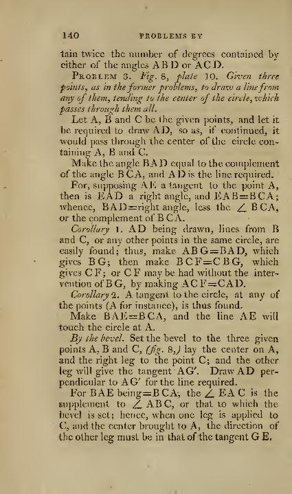
140 PROBLEMS BY
tain twice the number of degrees contained byeither of the angles ABD or ACD.Problem 3. Fig. Q, plale 10. Giveti three
points, as in the former problems, to draw a linefromany of them, tending to the center of the circle, which
passes through them all.
Let A, B and C be the given points, and let it
be required to draw AD, so as, if continued, it
would pass through the center of the circle con-taining A, B and C.
Make the angle BAD equal to the complementof the angle B CA, and AD is the line required.
For, supposing AE a tangent to the point A,then is EAD a right angle, and EAB=BCA;whence, BAD=: right angle, less the Z. B CA,or the complement of B C A.
Corollary 1. AD being drawn, lines from Band C, or any other points in the same circle, are
easily found; thus, make ABG=:BAD, whichgives BG; then make BCF=CBG, whichgives C F ; or C F may be had without the inter-
vention ofBG, by making ACF=CAD.Corollary 1. A tangent to the circle, at any of
the points (A for instance), is thus found.
Make BAE=BCA, and the line AE will
touch the circle at A.
By the bevel. Set the bevel to the three given
points A, B and C, (fg. Q,) lay the center on A,and the right leg to the point C; and the other
leg will give the tangent AG'. Draw AD per-
pendicular to AG'' for the line required.
For BAEbeing=BCA, the Z EA C is the
supplement to /_ ABC, or that to which the
bevel is set; hence, when one leg is applied to
C, and the center brought to A, the direction of
the other leg must be in that of the tangent G E.
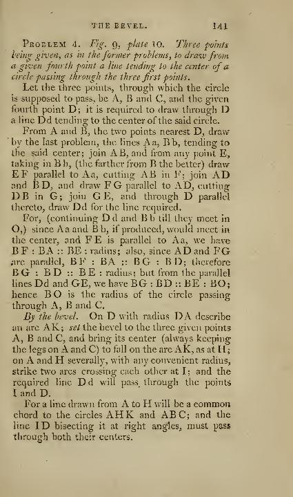
THE BEVEL. 141
Problem 4. Fig. g, plate 10. Three points
heing given, as in the former problems, to draw froma given fourth point a line tending to the center of acircle passing through the three first points.
Let the three points, through which the circle
is supposed to pass, be A, B and C, and the given
fourth point D; it is required to draw through Da Hne Dd tending to the center of the said circle.
From A and B, the two points nearest D, drawby the last problem, the lines Aa, Bb, tending to
the said center; join AB, and from any point E,taking in B b, (the farther from B the better) drawEF parallel to Aa, cutting AB in F; join ADand B D, and draw FG parallel to AD, cutting
DB in G; join GE, and through D parallel
thereto, draw Dd for the line required.
For, (continuing D d and B b till they meet in
O,) since A a and B b, if produced, would meet in
the center, and F E is parallel to A a, we haveB F : BA :: BE : radius; also, since AD and FGiire parallel, B F : BA :: B G : B D; therefore
BG : BD :: BE : radius; but from the parallel
lines Dd and GE, we have BG : BD :: BE : BO;hence B O is the radius of the circle passing
through A, B and C.
By the level. On D with radius DA describe
an arc AK; set the bevel to the three given points
A, B and C, and bring its center (always keeping
the legs on A and C) to fall on the arc AK, as at H
;
on A and H severally, with any convenient radius,
strike two arcs crossing each other at I; and the
required line Dd will pass through the points
I and D.For a line drawn from A to H will be a common
chord to the circles AHK and ABC; and the
line ID bisecting it at right angles, must pass
through both their centers.
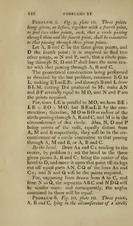
112 I'ROBLEMS BY
Problem 5. Fig. g, plate 10. Three po'mfs
heing give?i, as before^ together with a fourth point,
to jind two other 'points ^ such, that a circle passing
through them and the fourth point, shall he concentric
to that passing through three given points.
Let A, B and C be the three given points, andD the fourth point; it is required to find twoother points, as N and P, such, that a circle pass-
ing through N, D and P shall have the same cen-
ter with that passing through A, B and C.
The geometrical construction being performed,
as directed by the last problem, continue E G to
X<, making E L=E B; and through B and L drawBLM, cutting Dd produced in M; make ANand B P severally equal to M D, and N and P are
the points required.
For, since LE is parallel to MO, we have BE :
LE :: BO : MO; but BE=LE by the con-struction ; therefore, M O = B O = radius of the
circle passing through K, B and C, and M is in the
circumference of that circle. Also, N, D and Pbeing points of the radii, equally distant from
A, M and B respectively, they will be in the cir-
cumference of a circle concentric to that passing
through A, M and B, or A, B and C.
By the bevel. Draw Aa and C c tending to thecenter, by problem 3 ; set the bevel to the three
given points A, B and C; bring the center of the
bevel to D, and move it upon that point till its legs
cut off equal parts AN, CQ of the lines Aa andC c; and N and Q wall be the points required.
For, supposing lines drawn from A to C, andfrom N to Q, the segments ABC and N D Q will
be similar ones; and consequently, the angles
contained in them w^ill be equal.
Problem 6. Fig. 10, plate 10. Three points,
A, B and C, lying in the circumference of a circle^

THE BETEL. 143
hehtg given as hefore: and a fourth point D, to Jindanother point F, such, that a circle passing through
F and D shall touch the other passing through A, Ba7kl C, at any of these points \ as for instance^ B.
Draw BE a tangent to the arc ABC, by pro-
blem 3, corollary 2; and join BD; draw B F,
making the angle DBF=EBD, with the dis-
tance BD; on D strike an arc to cut BF in F;and F is the point sought.
Since DF=DB, theZDFB = DBF; butD B F=rD B E by construction ; therefore, D F B=D B Ej and E B is a tangent to the arc B D Fat B; but E B is also a tangent to the arc AB C(by construction) at the same point; hence, the
arc B D F touches AB C as required.
Problem 7. Fig- 13, plate 10. Two lines tend-
ing to a distant point being given, and also a point in
ene of them; to jjyid tiio other foints, (one of which
must he in the other given line,) such, that a circle
passing through those three points, may have its center
at the point of intersection of the given lines.
Let the given lines be AB and C D, and E the
given point in one of them ; it is required to find
two other points, as I and H, one of which (I)
shall be in the other line, such, that a circle HIEpassing through the three points, shall have its
center at O, where the given lines, if produced,
would meet.
From E, the given point, draw E H, crossing
AB at right angles in F; make FH=FE, and His one of the required points. From any point Din C D, the farther from E the better, draw G Dparallel to AB, and make the angle HE I equal
to half the angle GDE; and EI will cut AB in I,
the other required point.
For, since EH crosses AB at right angles, and
H F is equal to F E, I II will be equal to I E, and
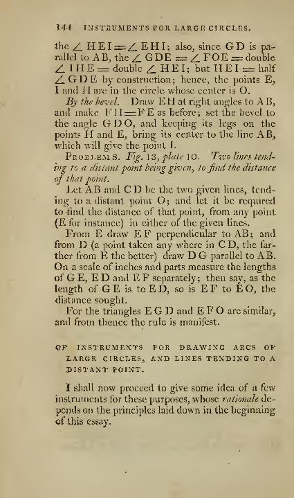
144 INSTRUMENTS FOR LARGE CIRCLES.
the /_ HEI=:Z.EHI; also, since GDIs pa-rallel to AB, the Z GDE = Z FOE= double
Z. IHEn= double Z.HEI; butHEI = half
/^GDE by construction; hence, the points E,I and H are in the circle whose center is O.By the bevel. Draw EH at right angles to AB,
and make FH=r:FE as before; set the bevel to
the angle G D O, and keeping its legs on the
points H and E, bring its center to the line AB,which will give the point I.
Problem 8. Fig. 13, plaie 10. Two lines tend'-
hig to a (listant point being given, to find the distatice
of that point.
Let AB and C D be the two given lines, tend-
ing to a distant point O; and let it be required
to tind the distance of that point, from any point
(E for instance) in either of the given lines.
From E draw E F perpendicular to AB ; andfrom D (a point taken any where in C D, the far-
ther from E the better) draw D G parallel to AB.On a scale of inches and parts measure the lengths
of G E, ED and E F separately ; then say, as the
length of GE is to ED, so is EF to EO, the
distance sought.
For the triangles E G D and E F O are similar,
and from thence the rule is manifest.
OP INSTRUMENTS FOR DRAWING ARCS OPLARGE CIRCLES, AND LINES TENDING TO ADISTANT POINT.
I shall now proceed to give some idea of a few
instruments for these purposes, whose rationale de-
pends on the principles laid down in the beginning
of this essay.

[ 1^15I
1. AM IMPROVED BEVEL.•
Fig. 12, p/a/e 10, is a sketch of an instrumentgrounded upon principle 1, p. 134, by which thearcs of circles of any radius, without the limits at-
tainable by a common pair of compasses, may bedescribed.
It consists of a ruler A B, composed oftwo pieces
rivetted together near C, the center, or axis,
and of a triangular part C F E D. The axis is ahollow socket, fixed to the triangular part, aboutwhich another socket, fixed to the arm C B of theruler AB, turns. These sockets are open in thefront, for part of their length upwards, as repre-
sented in the section at I, in order that the point
of a tracer or pen, fitted to slide in the socket,
may be more easily seen.
The triangular part is furnished with a gradu-ated arc D E, by which, and the vernier at B, the
angle D C B may be determined to a minute. Agroove is made in this arc, by which, and bythe nut and screw at B, or some similar contri-
vance, the ruler AB may be fixed in any required
position,
A scale of radii is put on the arm C B, by whichthe instrument may he set to describe arcs of given
circles, not less than 20 inches in diameter. In
order to set the instrument to any given radius,
the numbcn* expressing it in inches on C B is
brought to cut a fine line drawn on C D, parallel,
and near to the fiducial edge of it, and the arms
fastened in that position by the screw at B.
Two heavy pieces of lead or brass, G, G, madein form of the sector of a circle, the angular parts
being of steel and wrought to a true upright edge,
as shewn at H, are used with this instrument,
whose arms are made to bear against those edges
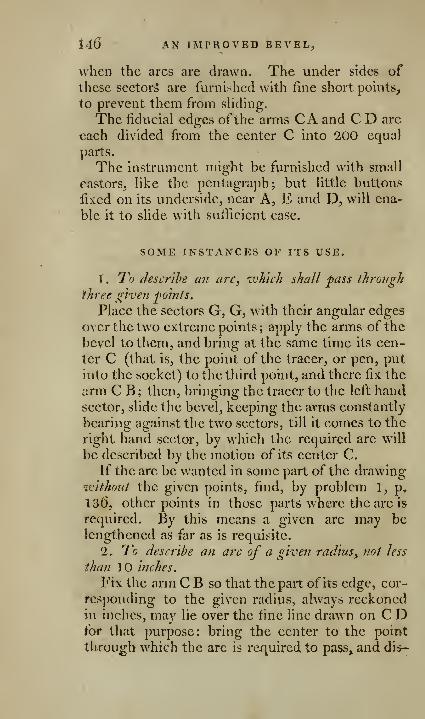
146 AN IMPROVED BEVEL,
when the arcs are drawn. The under sides ofthese sector^ are furnished with fine short points,
to prevent them from sHding.
The fiducial edges ofthe arms CA and C D are
each divided from the center C into 2,00 equal
parts.
The instrument might be furnished with small
castors^ like the pentagraph; but little buttons
fixed on its underside, near A, E and D, will ena-
ble it to slide with sufficient ease.
SOME INSTANCES OP ITS USE.
I. To describe an arc, which shall pass throvgli
three give?i joints.
Place the sectors G, G, with their angular edges
over the two extreme points ; apply the arms of the
bevel to them, and bring at the same time its cen-
ter C (that is, the point of the tracer, or pen, put
into the socket) to the third point, and there fix the
arm C B ; then, bringing the tracer to the left handsector, slide the bevel, keeping the arms constantly
bearing against the two sectors, till it comes to the
right hand sector, by which the required arc will
be described by the motion of its center C.
If the arc be wanted in some part of the drawingivithoiit the given points, find, by problem 1, p,
13(), other points in those parts where the arc is
required. By this means a giv^en arc may belengthened as far as is requisite.
'2.. To describe ati arc of a given radius, not less
than 10 inches.
Fix the arm C B so that the part of its edge, cor-
responding to the given radius, always reckonedin inches, may lie over the fine line drawn on C Dfor that purpose: bring the center to the point
through which the arc is required to pass^ and did-
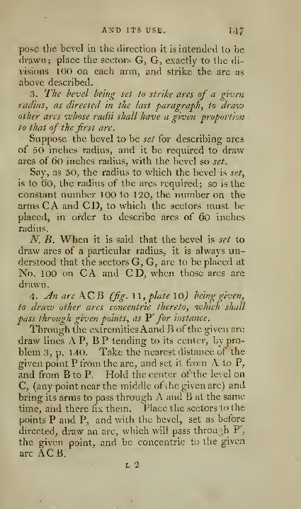
AXD ITS USE. 147
pose the bevel in the direction it is intended to bedrawn ;
plaee the sectors G, G, exactly to the di-
visions 100 on each arm^ and strike the arc as
above described.
3. The bevel being set to strike arcs of a given
radius, as directed in the last paragraph, to drazv
other arcs whose radii shall have a given proportion
to that of the first arc.
Suppose the bevel to be set for describing arcs
of 50 inches radius, and it be required to drawares of 60 inches radius, with the bevel so set.
Say, as 50, the radius to which the bevel is set,
is to 60, the radius of the arcs required; so is the
constant number 100 to 120, the number on the
arms CA and CD, to which the sectors must beplaced, in order to describe arcs of 60 inches
radius.
N. B. When it is said that the bevel is set to
draw arcs of a particular radius, it is always un-derstood that the sectors G, G, are to be placed at
No. 100 on CA and CD, when those arcs are
drawn
.
4. An arc AC B (fig. 11, plate \0) being given,
to draxv other arcs concentric thereto, which shall
pass through given points, as V for ijistance.
Through the extremitiesAand B of the given arc
draw lines A P, B P tending to its center, by pro-
blem 3, p. 140. Take the nearest distance of the
given point P from the arc, and set it from A to P,
and from B to P. Hold the center ofthe level on
C, (any point near the middle of the given arc) and
bring its arms to pass through A and B at the same
time, and there fix them. Place the sectors to the
points P and P, and with the bevel, set as before
directed, draw an arc, which will pass through P',
the given point, and be concentric to the given
arc ACB.L. 2
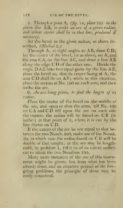
148 USE OP THE BEVEL,
5. Through a point K, (fig. 14, plate lo) in the
iriven line AB, to strike an arc of a given radius,
and whose center shall lie in that line, produced if
necessary.
Set the bevel to the given radius, as above dc-
seribed, (Method 2JThrough A, at right angles to AB, draw CD;
lay the eenter of the bevel, set as above, on A, andthe arm CA, on the line AC, and draw a line AEalong the edge C D of the other arm. Divide the
angle DAE into two equal parts by the line AF,jjlaee the bevel so, that its center being at A, the
arm CD shall lie on AF; while in this situation,
place the sectors at No. 100 on each arm, and then
strike the arc.
(). An arc being given, to find the length of its
radius.
Place the center of the bevel on the middle of
the arc, and open or shut the arms, till No. 100on CA and CD fall upon the are on each side
the center; the radius will be found on CB (in
inches) at that point of it, where it is cut by the
line drawn on C D.If the extent of the are be not equal to that be-
tween the two Numb. 100, make use of the Numb.50, in which case the radius found on C B will bedouble of that sought; or the arc may be length-
ened, by problem 1, till it be of an extent suffici-
ent to admit the two Numbers 100.
Many more instances of the use of this instru-
ment might be given; but from what has beenalready done, and an attentive perusal of the fore-
going problems, the principle of them may beeasily conceived.
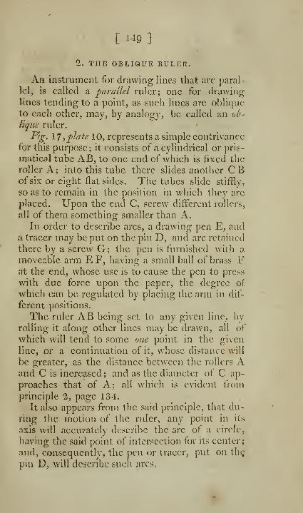
[ i^i9 ]
2. THE OBLIQUE RULER.
An instrument for drawing lines that are paral-
I'Cl, is called a parallel ruler; one for drawing-
lines tending to a point, as such lines are oblique
to each other, may, by analogy, be called an ob-
lique ruler.
Fig. \T ,plate 10, represents a simple contrivance
for this purpose; it consists of a cylindrical or pris-
matical tube AB, to one end of which is fixed theroller A; into this tube there slides another CBof six or eight flat sides. The tubes slide stiffly,
so as to remain in the position in which they are
placed. Upon the end C, screw different rollers,
all of them something smaller than A.In order to describe arcs, a drawing pen E, and
a tracer may be put on the pin D, and are retained
there by a screw G; the pen is furnished with a
moveable arm E F, having a small ball of brass Fat the end, whose use is to cause the pen to press
with due force upon the paper, the degree of
which can be regulated by placing the arm in dif-
ferent positions.
The ruler AB being set to any given line, byrolling it along other lines may be drawn, all of
which will tend to some one point in the given
line, or a continuation of it, whose distance will
be greater, as the distance between the rollers Aand C is increased; and as the diameter of C ap-
proaches that of A; all which is evident from
principle 2, page 134.
It also appears from the said principle, that du-
ring the motion of the ruler, any point in its
axis will accurately describe the are of a circle,
having the said point of intersection for its center;
and, consequently, the pen or tracer, put on the
pin D, will describe such arcs.
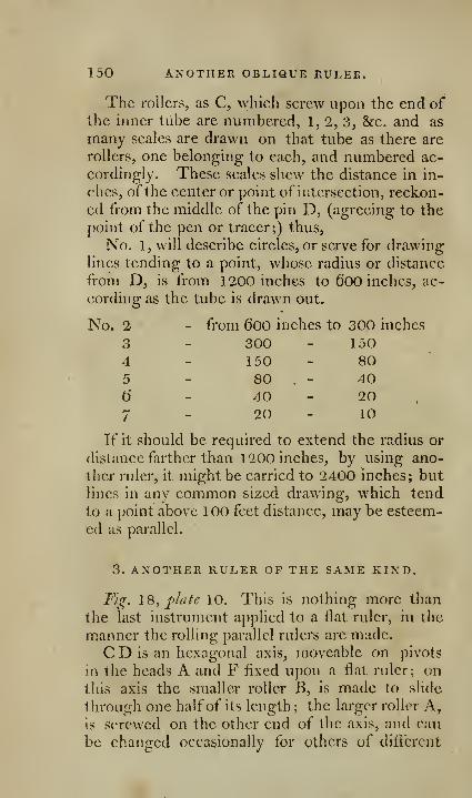
150 ANOTHER OBLIQUE RULEE.
The rollers, as C, which screw upon the end ofthe inner tube are numbered, 1, 2, 3, &c. and as
many scales are drawn on that tube as there are
rollers, one belonging to each, and numbered ac-
cordingly. These scales shew the distance in in-
ches, ofthe center or point of intersection, reckon-
ed from the middle of the pin D, (agreeing to the
point of the pen or tracer;) thus.
No. 1, will describe circles, or serve for drawinglines tending to a point, whose radius or distance
from D, is from 1200 inches to 600 inches, ac-
cording as the tube is drawn out.
No. 2 - from 6oo inches to 300 inches
3
45
6
7
If it should be required to extend the radius or
distance farther than 1200 inches, by using ano-
ther ruler, it might be carried to 2400 inches; but
lines in any common sized drawing, which tend
to a point above 100 feet distance, may be esteem-
ed as parallel.
3. ANOTHER RULER OF THE SAME KIND.
Tig. 18, pidfe 10. This is nothing more than
the last instrument applied to a fiat ruler, in the
manner the rolling parallel rulers are made.
C D is an hexagonal axis, moveable on pivots
in the heads A and F fixed upon a flat ruler; ontills axis the smaller roller B, is made to slide
through one half of its length ; the larger roller A,is screwed on the other end of the axis, and can
be changed occasionally for others of different
300
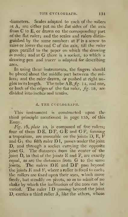
THE CYCLOGRAFH. 151
diameters. Scales adapted to each of the rollers
at A, are either put on the flat sides of the axis
from C to E^ or drawn on the correspondmg part
of the flat ruler; and the scales and rulers distin-
guished by the same number: at F is a screw to
raise or lower the end C of the axis, till the ruler
goes parallel to the paper on which the drawing;
is made; and at G there is a socket, to which a
drawing pen and tracer is adapted for describing
arcs.
In using these instruments, the fingers shouldbe placed about the middle part between the rol-
lers; and the ruler drawn, or pushed at right an-
gles to its length. The tube AB,J?^-. 14, and one,
or both of the edges of the flat ruler, fg. 18, are
divided into inches and tenths.
4. THE CYCLOGRAPH.
This instrument is constructed upon the
third principle mentioned in page 135, of this
Essay.
Fig. \6, plale 10, is composed of five rulers;
four of them DE, D F, GE and GF, forming
a trapezium, are moveable on the joints D, E, Fand G; the fifth ruler D I, passes under the joint
D, and through a socket carrying the opposite
joint G. The distances from the center of the
joint D, to that of the joints E and F, arc exactly
equal, as are the distances from G to the same
joints. The rulers DE and DF pass beyond
the joints E and F, where a roller is fixed to each;
the rollers are fixed upon their axes, wliich movefreely, but steadily on pivots, so as to admit of no
shake by which the inclination of the axes can be
varied. The ruler I D passing beyond the joint
D, carries a third roller A, like the others, whose

152 THE CYCLOGRAPH OF
axis lies precisely in the direction of that ruler;
the axes of B and C extend to K and L.
A scale is put on the ruler D I, from H to G,shewing, by the position of the socket G thereon,
the length of the radius of the arc in inches, that
would be described by the end I, in that position
of the trapezium. When the socket G is brought
to the end of the scale near I, the axes of the tworollers B and C, the ruler D I, and the axis of the
roller A, arc precisely parallel ; and in this posi-
tion, the end I, or any other point in D I, will de-
scribe strait lines at right angles to DI; but onsliding the socket G towards H, an inclination is
given to the axes of B and C, so as to tend to
some point in the line I D, continued beyond D,whose distance from I is shewn by the scale.
A proper socket, for holding a pen or tra^
cer, is made to put on the end I, for the pur-
pose of describing arcs; and another is made for
lixing on any pnrt of the ruler D I, for the moreconvenient description of concentric arcs, where a
number are \^'anted.
It is plain from this description, that the middle
ruler D I in this instrument, is a true oblique ruler,
by which lines may be drawn tending to a point,
whose distance from I is shcA^ n by the position of
the socket G on the scale; and the instrument is
made sufficiently large, so as to answer this pur-
pose as well as the other.
5. A DIFFERENT CONSTRUCTION OF THE SAMEINSTRUMENT.
In Fig. 16, phite 10, the part, intended to beused in drawing lines, lies within the trapezium,
whi^'h is made large on that account: but this is
not necessary; ixndjig. 15^ f^/d/e 10, >\ill give an
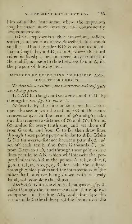
A DIFFERENT CONSTPvUCTIOX. 153
3(1c;i ot' a like instrument, wlicrc the trapezium
may be made much smaller, and consequcntlj
less cumbersome.DBEC represents such a trapezium, rollers,
socket, and scale as above described, but muchsmaller. Here the ruler E D is continued a suf-
jlicient length beyond D, as to A, where the third
roller is fixed; a pen or tracer may be fitted to
the end E, or made to slide between D and A^ for
the purpose of drawing arcs.
METHODS OF DESCEIBING AN ELLIPSE, ANDSOME OTHER CURVES.
To describe an ellipse, the transverse and conjugate
axes hein^r s'lven.
Let AB be the given transverse, and CD the
conjugate axis, 7^^. \3,plate 13.
Method I. By the line of sines on the sector,
open the sector with the extent AG of the semi-
transverse a,xis in the terms of 90 and 90 ; take
out the transverse distance of 70 and 70, (io and
60, and so for every tenth sine, and set them off
from G to A, and from G to B ; then draw lines
through these points perpendicular to AB. MakeG C a ti'ansverse distance between 90 and 90, andset off each tenth sine from G towards C, andfrom G towards D, and through these points drawlines parallel to AB, which will intcrsebt the per-
pendiculars to AB in the points A, a, b, c, d, e, f,
g, h, i, k, 1, m, n, o, p, q, B, for half the ellipse,
through which points and the intersections of the
other half, a curve being drawn with a steady
hand, will complete the ellipse.
Method 2. V^'xxh. the elliptical compasses, /[^. 3,
flate 1 1, apply the transverse axis of the elliptical
rompasses to the lijie AB, and discharge the
screws of both the sliders; set the beam over the
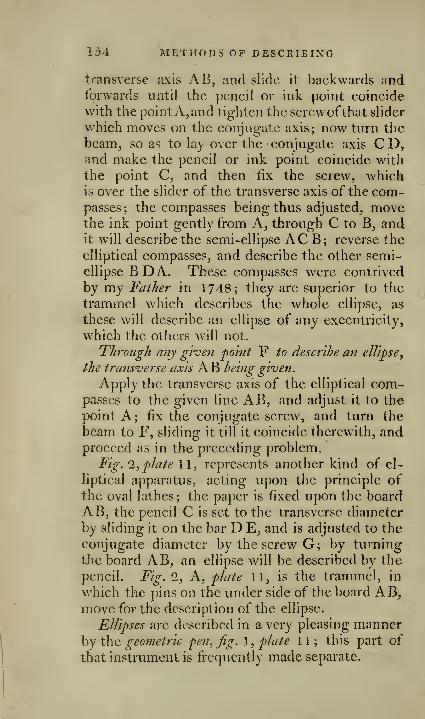
154 METHODS OP DESCRIBING
transverse axis AB, and slide it backwards andforwards until the pencil or ink point coincide
with the pointAj and tighten the screwofthat slider
which moves on the conjugate axis; now turn the
beam, so as to lay over the conjugate axis C D,and make the pencil or ink point coincide with
the point C, and then fix the screw, whichis over the slider of the transverse axis of the com-passes ; the compasses being thus adjusted, movethe ink point gently from A, through C to B, andit will describe the semi-ellipse A C B ; reverse the
elliptical compasses, and describe the other semi-
ellipse B D A. These compasses were contrived
by my Father in 1748; they are superior to the
trammel which describes the whole ellipse, as
these will describe an ellipse of any excentricity,
which the others will not.
Through any given 'point F to describe an ellipse
^
ihe transverse axis AB being given.
Apply the transverse axis of the elliptical com-passes to the given line AB, and adjust it to the
point A; fix the conjugate screw, and turn the
beam to F, sliding it till it coincide therewith, andproceed as in the preceding problem.
Fig. 2, plate 11, represents another kind of el-
liptical apparatus, acting upon the principle ofthe oval lathes; the paper is fixed upon the board
AB, the pencil C is set to the transverse diameter
by sliding it on the bar D E, and is adjusted to the
conjugate diameter by the screw G; by turning
the board AB, an ellipse will be described by the
pencil. Fig. 2, A, plate 11, is the trammel, in
which the pins on the under side of the board AB,move for the description of the ellipse.
Ellipses are described in a very pleasing mannerhy the geofnetric fen, Jig. I, plate 11; this part of
that instrument is frequently made separate.
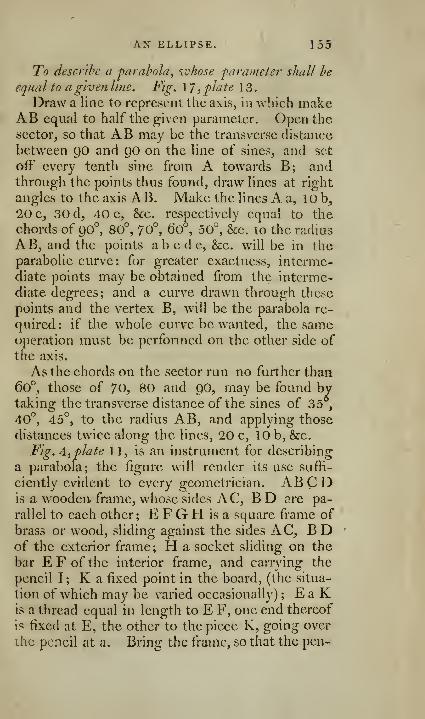
AX ELLIPSE. 155
To describe a parabola, ivhose parameter shall he
equal to a given line. Fig. 1 7 ,plate 1 3
.
Draw a line to represent the axis, in which makeAB equal to half the given parameter. Open the
sector, so that AB may be the transverse distance
between QO and go on the line of sines, and set
off every tenth sine from A towards B; andthrough the points thus found, draw lines at right
angles to the axis AB. Make the lines A a, 10 b,
20 c, 30 d, 40 e, &c. respectively equal to the
chords of 90°, 80°, 70°, 60°, 50°, &c. to the radius
AB, and the points abcde, &:c. will be in theparabolic curve: for greater exactness, interme-
diate points may be obtained from the interme-
diate degrees; and a curve drawn through these
points and the vertex B, will be the parabola re-
quired : if the whole curve be wanted, the sameoperation must be performed on the other side of
the axis.
As the chords on the sector run no further than60°, those of 70, 80 and 90, may be found bytaking the transverse distance of the sines of 35 ,
40°, 45°, to the radius AB, and applying those
distances twice along the lines, 20 c, 10 b, &c.
Fig. A, plate 11, is an instrument for describing
a parabola; the figure will render its use suffi-
ciently evident to every geometrician. ABCDis a w^ooden- frame, whose sides AC, B D are pa-
rallel to each other; E FGH is a square frame of
brass or wood, sliding against the sides AC, B Dof the exterior frame; H a socket sliding on the
bar EFofthe interior frame, and carrying the
pencil I ; K a fixed point in the board, (the situa-
tion of which may be varied occasionally) ; E a Kis a thread equal in length to E F, one end thereof
is fixed at E, the other to the piece K, going over
ihc pencil at a. Bring the frame, so that the pen-
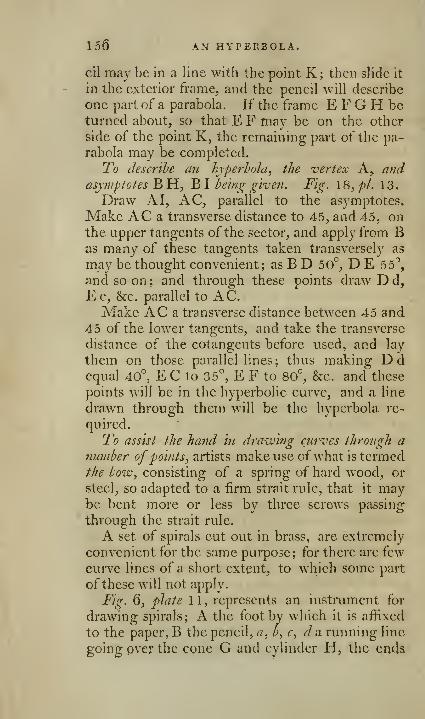
156 AN HYPERBOLA.
cil may be in a line with the point K ; then slide it
in the exterior frame, and the pencil will describe
one part of a parabola. If the frame E F G H beturned about, so that EF may be on the other
side of the point K, the remaining part of the pa-
rabola may be completed.
To describe an hyperhoJa^ the vertex A,. a?id
asymptotes BH, BI being given. Fig. 18, pi. 13.
Draw A I, AC, parallel to the asymptotes.
Make AC a transverse distance to 45, and 45, onthe upper tangents of the sector, and apply from Bas many of these tangents taken transversely as
may be thought convenient; as B D 50°, D E 55'',
and so on ; and through these points draw D d,
Ec, &c. parallel to AC.Make AC a transverse distance between 45 and
45 of the lower tangents, and take the transverse
distance of the cotangents before used, and lay
them on those parallel lines; thus making Ddequal 40°, E C to 35°, E F to 80°, &e. and these
points will be in the hyperbolic curve, and a line
drawn through them will be the hyperbola re-
quired.
To assist the hand in drawing curves through anumber ofpoints^ artists make use ofwhat is termedthe bow., consisting of a spring of hard wood, or
steel, so adapted to a firm strait rule, that it maybe bent more or less by three screws passing
through the strait rule.
A set of spirals cut out in brass, are extremely
convenient for the same purpose; for there are few
curve lines of a short extent, to which some part
of these will not apply.
Fig. 6, plate 11, represents an instrument for
drawing spirals; A the foot by which it is affixed
to the paper, B the pencil, a, b, c, da running line
going pver the cone G and cylinder H, the ends

GEOMETRIC PEN. 157
being fastened to the pin e. On turning the frameK N O, the thread carries the pencil progressively
from the cone to the cylinder, and thus describes
a spiral. The size of the spiral may be varied, byplacing the thread in different grooves, by puttingit on the furthermost cone, or by putting on alarger cone.
OF THE GEOMETRIC PEN.
The geometric pen is an instrument in which,by a circular motion, a right line, a circle, an el-
lipse, and a great variety of geometrical figures,
may be described.
This curious instrument was invented and de-
fcribed by John Baptist Suanli, in a work entitled
]\'uovo Istromenti per la Ddscrizzione di diverse
Curve Antichi e Moderne, &c. Tec (^i>- :^:-' ./'.'">'.,
Though several writers have taken notice of the
curves arising from the compound motion of twocircles, one moving round the other, yet no oneseems to have realized the principle, and reducedit to practice, before /. B. Suardi. It has lately
been happily introduced into the steam engine byMessieurs Watt and Bolton^ a proof, among manyothers, not only of the use of these speculations,
but ofthe advantages to be derived from the higher
parts of the mathematics, in the hands of an inge-
nious mechanic. There never was, perhaps, anyinstrument which delineates so many curves as the
geometric pen; the author enumerates 1273, as
possible to be described by it in the simple form,
and with the few wheels appropriated to it for the
present work.
Fig 1, plate 11, represents the geometric pen%
A. B, C, the stand by which it is supported; the
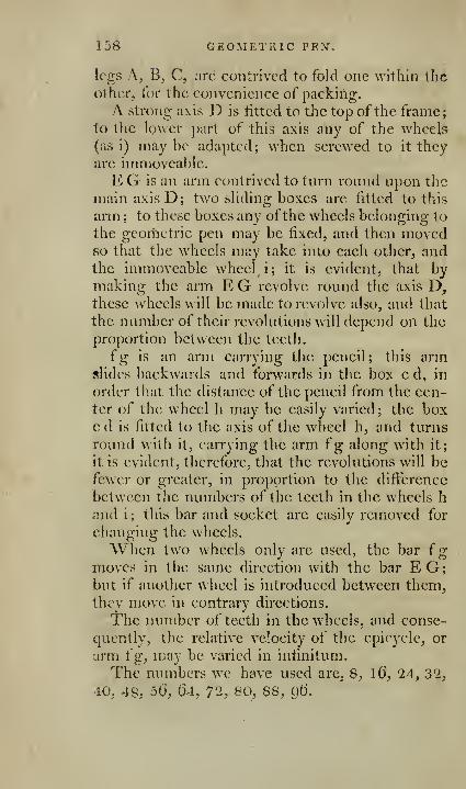
158 GEOMETRIC PEX.
legs A, B, C, are contrived to fold one within theother, for the convenience of packing.
A strong axis D is fitted to the top of the frame;
to the lower part of this axis any of the wheels(as i) maybe adapted; when screwed to it they
arc immoveable.
E G is an arm contrived to turn round upon the
main axis D; two sliding boxes are fitted to this
arm ; to these boxes any ofthe wheels belonging to
the geoilietric pen may be fixed, and then movedso that the wheels may take into each other, andthe immoveable wheel i; it is evident, that bymaking the arm E G revolve round the axis D,these wheels will be made to revolve also, and that
the number of their revolutions will depend on the
proportion between the teeth.
fg is an arm carrying the pencil; this armslides backwards and forwards in the box c d, in
order that the distance of the pencil from the cen-ter of the wheel h may be easily varied; the boxc d is fitted to the axis of the wheel h, and turns
round with it, carrying the arm fg along with it;
it is evident, therefore, that the revolutions will befewer or greater, in proportion to the difi:erencc
between the numbers of the teeth in the wheels h
and i; this bar and socket are easily removed for
changing the wheels.
When two wheels only are used, the bar {
g
moves in the same direction with the bar EG;but if another wheel is introduced between them,they move in contrary directions.
The number of teeth in the wheels, and conse-
quently, the relative velocity of the epicycle, or
arm {g, may be varied in infinitum.
The numbers we have used arc, 8, \6, 24, 32,
40, 48; 5(i, 64, 72, 80, 88, Qt).
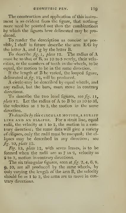
GEOMETRIC PEN. ISg
The construction and application of this instru-
ment is so evident from the figure, that nothinjr
more need be pointed out than the combinations
by which the ligures here dehneated may be pro-
duced.
To render the description as concise as pos-
sible, I shall in future describe the arm E G bythe letter A, and fg by the letter B.
To describe Jig. 1, plale 12. The radius of Ajnust be to that of B, as 10 to 5 nearly, their velo-
<'ities, or the numbers of teeth in the wheels, to beequal, the motion to be in the same direction.
If the length of B be varied, the looped figure,
delineated atJig. 12, will be produced.
A circle -may be described by equal wheels, andany radius, but the bars, must move in contrary
directions.
To describe the two level figures, see Jig. 11,
ph/fe 12. Let the radius of A to B be as 10 to 3f,
the velocities as 1 to 2, the motion in the samedirection.
To describe by this circ
u
lar mo t i
o
n , A s t r
a
itLINE AND AN ELLIPSE. For a strait line, equal
radii, the velocity as 1 to 2, the motion in a con-
trary direction ; the same data will give a variety
of ellipses, only the radii must be unequal; the el-
lipses may be described in any direction; see
fg. 10, plate 13.
Fig. 13, plate 12, with seven leaves, is to be
formed when the radii are as 7 to 2, velocity as
2 to 3, motion in contrary directions.
The six triangular figures, seen aXjig. 2, 4, 6, 8,
9, 10, are all produced by the same wheels, by
only varying the length of the arm B, the velocity
$hould be as 1 to 3, the arms are to move in con-
trary directions.
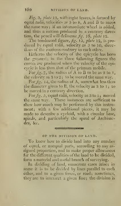
l60 DIVISION OP LAXD.
Fig, 3, f)Ja/c 12, ^^'ith eight leaves, is formed byequal radii, veloeitics as 5 to S, A and B to movethe same wav; if an intermediate wheel is added,
and thus a motion produced in a contrary direc-
tion, the pencil will delineate j'fi'-. l6, flute 12.
The ten-leaved tigure, fig. 15, flafe 12, is pro-
duced by equal radii, velocity as 3 to 10, direc-
tions of tlie motions contrary to each other.
Hitherto the velocity of the epicycle has beenthe greatest; in the three following figures the
CLirvcis arc produced when tlic velocity of the epi-
cycle is less than that of the pi-imimi mobile.
For jig. 7, the radius of A to B to be as 2 to 1,
the velocity as 3 to 2 ; to be moved the same way.
For Jig. 14, the radius of A, somewhat less than
the diameter given to B, the velocity as 3 to 1 ; to
be moved in a conti'ary direction.
ForJrg. 5, equal radii, velocity as 3 to 1 ; movedthe same way. These instances are sufficient to
shew how much may be performed by this instru-
ment; with a few additional pieces, it may bemade to describe a cycloid, with a circular base,
spirals, and particularly the spiral of Archime-des, &c.
OP THE DIVISION OP LAXD.
To know how to divide land into any numberof equal, or unequal parts, according to any as-
signed proportion, and to make proper allowances
for the different qualities ofthe land to be divided,
form a material and useful branch of surveying.
In dividing of land, numerous eases arise; in
some it is to be divided by lines parallel to each
other, and to a given fence, or road; sometimes,
they are to intersect a given line; the division is
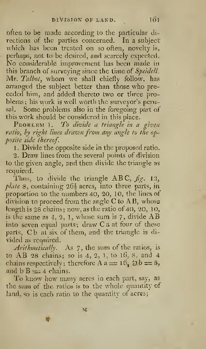
DiVISION OP LAND. l6l
often to be made according to the particular di-
rections of the parties concerned. In a subject
which has been treated on so often, novelty is,
perhaps, not to be desired, and scarcely expected.-
No considerable improvement has been made in.
this branch of surveying since the time of SpeidelL
Mr. Talbot, whom we shall chiefly follow, has
arranged the subject better than those who pre-
ceded him, and added thereto two or three pro-
blems ; his work is well worth the surveyor's peru-
sal. Some problems also in the foregoing part of
this work should be considered in this place.
Problem l. To divide a triangle in a given
ratio, hy right lifies drawnfrom any angle to the op-
posite side thereof.
1
.
Divide the opposite side in the proposed ratio.
2. Draw lines from the several points of division
to the given angle, and then divide the triangle as
required.
Thus, to divide the triangle K^C, fig. 13,
plate 8, containing 26^ acres, into three parts, in
proportion to the numbers 40, 20, 10, the lines of
division to proceed from the angle C to AB, whoselength is 28 chains; now, as the ratio of 40, 20, 10,
is the same as 4, 2, 1, whose sum is 7, divide ABinto seven equal parts; draw Ca at four of these
parts, Cb at six of them, and the triangle is di-
vided as required.
Arithmetically. As 7? the sum of the ratios, is
to AB 28 chains; so is 4, 2, 1, to 1 6, 8, and 4
chains respectively; therefore A a= 1(3, 'jh= 8,
and b B irz: 4 chains.
To know how many acres in each part, say, as
the sum of the ratios is to the whole quantity of
land, so is each ratio to the quantity of acres;
M
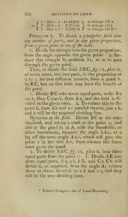
i6'2 DIVISION OF LAND.
7 : 26,5 :: 4 : 15,142857 ^ = triangle AC 3
7 : 26,5 :: 2 : 7,571428 > = triangle aCb7 : 2(3,5 :: 1 : 3,765714 J = triangle bCB,^'
Problem 2. To divide a triangular field into
any numher of parts, and in any given proportio?!,
froju a given point in one of the sides.
1 . Divide the triangle into the given proportion,
from the angle opposite the given point. 2. Re-duce this triangle by problem 51, so as to pass
through the given point.
Thus, to divide the field ABC, fig. \4, plate 8,
of seven acres, into two parts, in the proportion of
2 to 5, for two different tenants, from a pond b,
in B C, but so that both may have the benefit of
the pond.
1
.
Divide B C into seven equal parts, make B a= 5, then Ca= 2, draw A a, and the field is di-
vided in the given ratio. 2. To reduce this to the
point b, draw Ab and ac parallel thereto, join cb,
and it will be the required dividing line.
Operation in the field. Divide BC in the ratio
required, and set up a mark at the point a, andalso at the pond h; at A, with the theodolite, or
other instrument, measure the angle bAa; at a
lay off the same angle A a c, which will give the
point e in the side A c, from whence the fence
must go to the pond.
2. To divide ABC,^^-. 15, plate 8, into three
equal parts from the pond c. 1. Divide AB into
three equal parts, A a, a b, b B, and C a C b will
divide it, as required, from the angle A^ reduce
these as above directed to c d and c e, and they
will be the true dividing lines.
* Talbot's Complete Art of Land Measuring.

DIVISION OP LAND. l63
Problem 3. To dhide a triangular Jield in anyrequired ratio ^ hy lines drawn parallel to one side^
and cutting the others.
Let ABC, fig, 16, fdate 8, be the given tri-
angle to be divided into three equal parts, by lines
paraUcl to AB, and cutting AC, BC.Ride 1. Divide one of the sides that is to be cut
by the parallel lines, into the given ratio. 2. Finda mean proportional between this side, and the first
division next the parallel side. 3. Draw a line
parallel to the given side through the mean pro-
portional. 4. Proceed in the same manner withthe remaining triangle.
Example 1 . Divide B C into three equal parts
B D, D P, P C. 1. Find a mean proportional be-
tween B C and DC. 3. Make C G equal to thi>;
mean proportional, and draw GH parallel to AB.Proceed in the same manner with the remaining
triangle CH G, dividing G C into twO equal p:irt5
at I, finding a mean proportional between C Gand CI; and then making C L equal to this meanproportional, and drawing LM parallel to AB,the triangle will be divided as required.
A square, or rectangle^ a rhombus, or rhomho'ides^
may he divided into any given ratio, hy lines cutting
two opposite parallel sides, hy dividing the sides into
the proposed ratio, a?id joining the faints of division.
Problem 4. To divide a right-linedfigure into
any proposed ratio, by linesproceedingfrom one angle.
Problem 5. To divide a right-linedfigure into
miy proposed ratio, by lines proceeding from a given
point in one of the sides.
Problem (3. To divide a right-lined figure into
aiiv proposed ratio, by right lines proceeding from a
given point within the saidfigure orfield.
It would be needless to enter into a detail of
the mode of performing the three foregoing pro-
M 2

1(54 DltlSION OF LAND.
blems, as the subject has been already sufficiently
treated of in pages 84, 85, &c.
Problem 7-"^ " ^^ is required to divide any given
qttavtity of ground into any given nujnher of farts,
and inprojyortio?! as any given numbers
^
Rule. " Divide the given piece after the rule of
Fellowship, by dividing the whole content by the
sum of the numbers expressing the proportions of
the several shares, and multiplying the quotient
severally by the said proportional numbers for the
respective shares required."
Example. It is required to divide 300 acres ofland among A, B, C and D, whose claims uponit are respectively in proportion as the numbers 1 ..
3,6, 10, or whose estates may be supposed lOOl.
300l. 600l. and lOOOl. per annum.The sum of these proportional numbers is 20,
by which dividing 300 acres, the quotient is 1
5
acres, which being multiplied by each of the num-bers 1,3, 6, 10, we obtain for the several shares
as follows:
a.
A's share = 15 ;
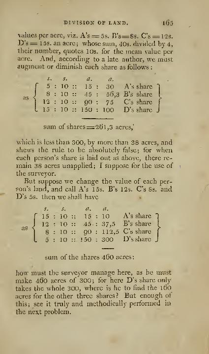
DIVISION OP LAND. i65
v^-ilues per acre, viz. A's= 5s. B's=:8s. C's= l2s.
D's= 1 5s. an acre; whose sum, 40s. divided by 4,their number, quotes 10s. for the mean value peracre. And, according to a late author, we mustaugment or diminish each share as follows :
as
s.
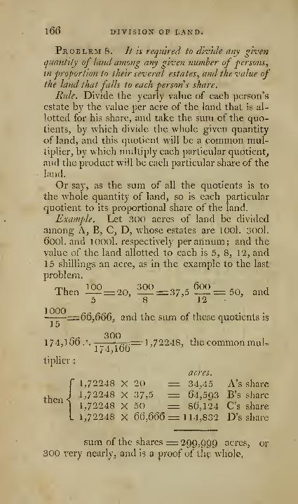
l66 DITISIOX OP LAND.
Problem 8. // is required to diviile any gwenquantity of land among any given number of fersons,
in proportion to their several estates^ and the value ofthe land that falls to each persons share.
Rule. Divide the yearly value of each person's
estate by the value per acre of the land that is al-
lotted for his share, and take the sum of the quo-tientSj by which divide the whole given quantity
of land, and this quotient will be a common mul-tiplier, by which multiply each particular quotient,
and the product will be each particular share of the
land.
Or say, as the sum of all the quotients is to
the whole quantity of land, so is each particular
quotient to its proportional share of the land.
Example, Let 300 acres of land be divided
among A, B, C, D, whose estates are lOOl, 300l.
t)00l. and lOOOl. respectively per annum; and the
value of the land allotted to each is 5, 8, 12, and15 shillings an acre, as in the example to the last
problem.
rp, 100 ^^ 300 ^^ „ 600 .^ ,
Ihen = 20, =:=:37,D =50, and5 8 12
—
—
-=^^^,^0^, and the sum of these quotients is
r^ 3001 74, 1 6o .
• . -z—rrr-^==-- 1 ,1224 8, the common muL1/4,100
tiplicr
:
acres,
1,72248 X 20 zzz: 34,45 A's share
then ^ 1^72248 X 37,5 = 64,593 B's sharemen's
1^7^248 X 50 = 86,124 C's share
1,72248 X 6(3,66(5= 114,832 D's share
sum of the shares= 299,999 acres, or300 very nearly, and is a proof of thf whole,
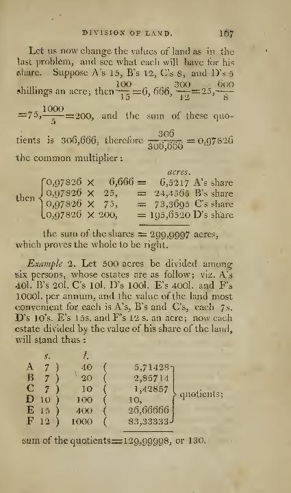
DIVISION OF LAND. 1^7
Let us now change the values of land as In the
last problem, and see what each will have tor his
6hare. Suppose A's 15, B's 12, C's 8, and D's 5
100 ^ ^^^ 300 (iooshilhngs an acre; then-— =6, 666, —-r^Qo,——
-
1 1
Z
o
^' 1000, ,=7o,—:—=200, and the sum of these quo-
tients is 306,666, therefore
—
,. ,.,.,> =0,Q7826
the common multiplier
:
I?then
acres,
0,97826 X QfiQQ = 6,5217 A's share
97826 X 25, = 24,4565 B's share
0,97826 X 75, — 73,3695 C's share
.0,97826 X 200, = 195,6520 D's share
the sum of the shares = 299,9997 acres,
which proves the whole to be right.
Exajnph 2. Let 500 acres be divided amongsix persons, whose estates areas follow; viz. A's40l. B's 20I. C's lOl. D's lOOl. E's 4001. and F's
lOOOl. per annum, and the value of the land mostconvenient for each is A's, B's and C's, each 7s.
D's lO's. E's 15s. and F's 12 s. an acre; now each
estate divided by the value of his share of the land,
will stand thus :
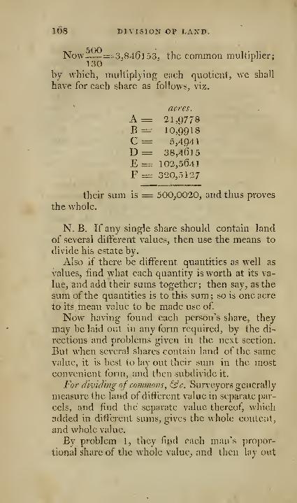
ids DIVISION OP LAND.
Now =3.846153, the common multiplier;130
by which, multiplying each quotient, we shall
have for each share as follows, viz.
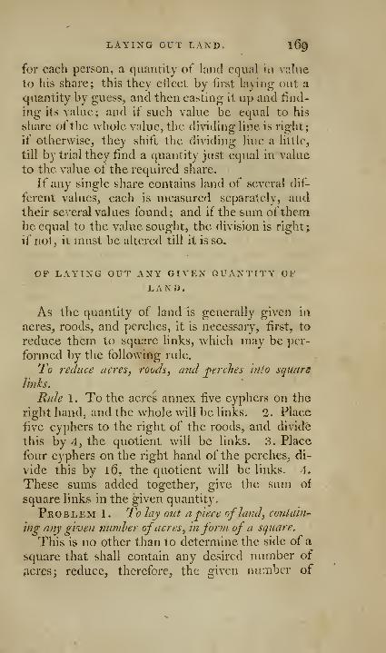
LAYING OUT LAND. I69
for each person, a quantity of land equal in value
to his share; this they eiiect by first laying out a
quantity by guess, and then casting it up and find-
ing its value; and if such value be equal to his
share ofthe whole value, the dividing line is right;
if otherwise, they shift the dividing line a little,
till by trial they find a quantity just equal in value
to the value of the required share.
If any single share contains land of several dif-
ferent values, each is measured separately, andtheir several values found; and if the sum ofthembe equal to the value sought, the division is right;
if not, it must be altered till it is so.
OF LAYING OUT ANY GIVEN QUANTITY OFLAND,
As the quantity of land is generally given in
acres, roods, and perches, it is necessary, first, to
reduce them to square links, which may be per-
formed by the following rule.
To reduce acres, roods, and perches into square
links.
Rule 1 . To the acres annex five cyphers on the
right hand, and the whole will be links. 2. Place
five cyphers to the right of the roods, and divide
this by 4, the quotient will be links. 3. Place
four cyphers on the right hand of the perches, di-
vide this by l6, the quotient will be links. 4.
These sums added together, give the sum of
square links in the given quantity.
Problem 1. To Jay out a piece ofland, contain-
mg any given number ofacres, inform of a square.
This is no other than to determine the side of a
square that shall contain any desired number of
Acres; reduce, therefore;, the given number of

ITO LAYING OUT LAND.
acres to scjiiare links, and the square root thereof
will be the side ofthe square required.
Problem 2. To lay out any desired quantity ofland in form of ,a parallelogram^ having either its
base or altitude given.
Divide the content, or area, by the given base,
and the quotient is the altitude; if divided by the
altitude, the quotient is the base; by the samerule a rectangle may be laid out.
Problem 3. To lay out a?iy desired quantity ofland inform of a parallelogram, whose hase shall he
2, 3, 4, &'c. times greater than its altitude.
Divide the ^area by the number of times the
base is to be greater than the altitude, and extract
the square root of the quotient; this square root
will be the required altitude, which being multi-
plied by the number oftimes that the base is to begreater than the altitude, will give the length of
the required base.
Problem 4. To lay out a given quantity of land
in form of a triangle, having either the base or the
ferpendicidar given.
Divide the area by half the given base, if the
base be given ; or by half the given perpendicular,
if the perpendicular be given ; and the quotient
will be the perpendicular, or base required.
Problem 5. To lay out any given quantity ofland in a regular polygon.
1 . Find in the following table, the area of a
polygon of the same name with that required, the
side of which is 1. 2. Divide the proposed area
by that found in the table. 3. Extract the square
root of the quotient, and the root is the side of the
polygon recjuired.

TLATN TRIGONOMETRY. 171
No.sides

172 PLAIN TRIGONOMETJRY.
measure tlic quantities of angles, not by the arc it-
self, which is described on the angular point, butby certain lines described about that arc.
If any three parts* of a plain triangle be given,
any required part may be found both by construc-
tion and calculation.
If two angles of a plain triangle are known in
degrees, minutes, &c. the third angle is found by-
subtracting their sum from 180 degrees.
In a right-angled plain triangle, if either acute
angle (in degrees) be taken from go degrees, the
remainder will express the other acute angle.
When the sine of an obtuse angle is required,
subtract such obtuse angle frorn 1 80 degrees, andtake the sine of the remainder, or supplement.
If two sides of a triangle are equal, a line bisect-
ing the contained angle, will be perpendicular to
the remaining side, and divide it equally.
Before the required side of a triangle can befound by calculation, its opposite angle must first
be given, or found.
The required part of a triangle must be the last
term of four proportionals, written in order underone another, whereof the three first are given or
known.In four proportional quantities, either of them
may be made the last term ; thus, let A, B, C, D,be proportional quantities.
As first to second, so is third to fourth, A:B::C:D.As second to first, so is fourth to third, B :A : : D ; C.
As third to fourth, so is first to second,C :D :: A : B.
As fourth to third, so is second to first,D : C : : B : A.
Against the three first terms of every propor-
tion, or stating, must be written their respective
values taken from the proper tables.
* This is imperfectly stated by several writers. One of the
given parts must be a side. A triangle consists of six parts^ via.
three sides and three angles. Edit.

If the value of the first term be taken from the.
sum of the second and third, the remainder will
be. the value of the fourth term or thing required ;
because the addition and subtraction of loearithms,
corresponds with the multiplication and division
of natural numbers.
If to the complement ofthe first value, be addedthe second and third values, the sum, rejecting the
borrowed index, \vill be the tabular number ex-
pressing the thing required : this method is gene-rally used when radius is not one of the propor-
tionals.
The complement of any logarithm, sine, or tan-
gent, in the common tables, is its diflerence fromthe radius 10.000.000 , or its double 20.000.000.
CANONS FOR TRIGONOMETRICALCALCULATION,
1. The following proportion is to be used whentwo angles of a triangle, and a side opposite to oneof them, is giv'Cn to find the other side.
As the sine of the angle opposite the given side,
is to the sine of the angle opposite the required
side ; so is the given side to the required side.
2. When two sides and an angle opposite to
one of them is given, to find another angle; use
the following rule
:
As the side opposite the given angle, is to the
side opposite the required angle ; so is the sine of
the given angle, to the sine of the required angle.
The memory will be assisted in the foregoing
cases, by observing that when a side is wanted, the
proportion must begin with an aiigle; and when an
arigle is wanted, it must begin with a side.
3. When two sides of a triangle and the inclu-
ded angle are given, to find the other angles and
side.

174 CANOTsTS.
As the sum of the two o-ivcn sides is to tlieJf
difiereiiee; so is the tangent of half the sum of
the two unknown angles, to the tangent of half
their difFerenee.
Half the difference thus found, added to half
their sum, gives the greater of the two angles,
whieh is the angle opposite the greatest side. If
the third side is wanted, it may be found by solu-
tion 1.
4. The following steps and proportions are to beused when the three sides of a triangle are given,
and the angles required.
Let ABC, plate 9, fg. 30, be the triangle;
make the longest side AB the base; from C the
angle opposite to the base, let fall the perpen-
dicular C D on AB, this will divide the base into
two segments AD, BD.The difFerenee between the two sei^ments is
found by the following proportion:
As the base AB, or sum of the two segment •?;;
is to the sum of the other sides (AC-f-B C) ; so is
the difference of the sides (AC— B C), to the dif-
ference of the segments of the base (AD—D B).
Halfthe difference of the segments thus found,
added to the half of AB, gives the greater seg-
ment AD, or subtracted, leaves the less DB.In the triangle ADC, find the angle AC D by
solution 2; for the two sides AD and AC arc
known, and the right angle at D is opposite to
one of them.
The complement of ACD, gives the angle A.
Then in the triangle ABC, you have two sides
AB, BC, and the angle at A, opposite to one of
them, to find the angles C and B.
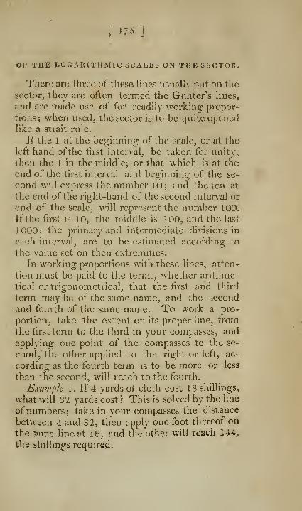
I"175 ]
©P THB LOGARITHMIC SCALES ON THE SECTOR,
There arc three of these lines usually put on the
sector, they arc often termed the Guntcr's lines,
and are made use of for readily working propor-
tions; when used, the sector is to be quite openedlike a strait rule.
If the 1 at the beginning of the scale, or at thft
left hand ofthe first interval, be taken for unity,
then the 1 in the middle, or that which is at the
end of the first interval and beginning of the se-
cond will express the number 10; and the ten at
the end of the right-hand of the second interval or
end of the scale, will represent the number 100.
if the first is 10, the middle is 100, and the last
1000; the primary and intermediate divisions in
each interval, are to be estimated according to
the value set on their extremities.
In working proportions with these lines, atten-
tion must be paid to the terms, whether arithme-
tical or trigonometrical, that the first and third
term may be of the same name, and the second
and fourth of the same name. To work a pro-
portion, take the extent on its proper line, from
the first term to the third in your compasses, andapplying one point of the compasses to the se-
cond, the other applied to the right or left, ac-
cording as the fourth term is to be more or less
than the second, will reach to the fourth.
Example 1. If 4 yards of cloth cost 18 shillings,
what will 32 yards cost ? This is solved by the line
of numbers; take in your compasses the distance
between 4 and 32, then apply one foot thereof on
the same line at 18, and th« other will reach 144,
the shillings required.

17^ CURIOUS AND USEFUL.
Example 2. As radius to the hypothcnuse 120,so is the sine of the angle opposite the base 30°
17' to the base. In this example, radius, or the
sine of 90, and the sine of 30° \f taken from theline of sines, and one foot being then applied to
120 on the line of numbers, and the other foot onthe left Avill reach to 6o| thelength of the required
base. The foot was applied to the left, because the
legs of a right-angled triangle are less than the
iiypothenuse.
Example "i. As the cosine of the latitude 51°
oO', (cqual-thc sine of 38° 30') is to radius, so is
tlie sine of the sun's declination 20° 14', to the
sine of the sun's amplitude. Take the distance
between the sines of 38° 30' and 20° 14' in yourcompasses; set one foot on the radius, or sine of90°, and the other will reach to 33 ;°, the sun's
amplitude required.
CURIOUS AND USEFUL TRIGONOMETRICAL-PROBLEMS.
The following problems, though of the greatest
use, and sometimes of absolute necessity to the
surveyor, arc not to be found in any of the com-mon treatises on surveying. The maritime sur-
veyor can scarce proceed \vithout the kno\Adedge
of them ; nor can a kingdom, province, or countybe accurately surveyed, unless the surveyor is well
acquainted with the use and application of them.
Indeed, no man should attempt to survey a county,
or a sea coast, who is not master ofthese problems.
The second problem, which is peculiarly useful
for determining the exact situation of sands, or
rocks, within sight of three places upon land,
whose distances arc well known, was first proposed

GEOMETRICAL PROBLEMS. 177
by Mr. Tozvnly, and solved by Mr. Collins^ Philo-
sophical Transactions, No. 69. There is " noproblem more useful in surveying, than that bywhich we find a station, by observed ang-les ofthree or more objects, whose reciprocal distances
are known; but distance, and bearing from theplace of observation are unknown,
" Previous to the resolution of these problems,
another problem for the easy finding the segmentof a circle, capable of containing a given ang^le,
is necessary, as will be clear from the followingobservation.
" Two objects can only be seen under the sameangle, from some part of a circle passing throughthose objects, and the place of observ^ation.
" If the angle under which those objects appear,
be less than 90°, the place of observation will besomewhere in the greater segment, and those ob-jects will be seen under the same angle from every
part of the segment." If the angle, under which those objects are
seen, be more than 90°, the place of observation
will be somewhere in the lesser segment, and those
objects will be seen under the same angle fromevery part of that segment*." Hence, from the
situation of three known objects, we are able to
determine the station point with accuracy.
Problem. To describe on a given line VtQ, fig,
29, plate 9, a segment of a circle, capable ofcontain-
ing a given angle.
Method 1 . Bisect B C in A. 2. Through the
point of bivseetion, draw the indefinite right line
DE perpendicular to B C. 3. Upon B C, at the
point C, constitute the angles DCB, FCB, G C B,
* Dalrymple's Essay on Nautical Surveying, in which ano-
ther mode of solving this problem is given.
N

178 CURIOUS AXD USEFUL
II C B, respectively equal to the difference of theangles of the intended segments and 90 degrees:
the angle to be formed on the same side with the
segment, if the angle be less than 9O; but on the
opposite, if the angle is to be greater than go de-
grees. 4. The points D, F, G, H, where the an-
gular lines CD, CF, CG, CH, &e. intersect
the line D E, will be the centers of the intended
segments.
Thus, if the intended segment is to contain anangle of 120°, constitute on B C, at C, (on the op-
posite side to which you intend the segment to be
tleseribed,) the angle D C B equal to 30°, the dif-
ference between go° and 120°; then on center D,and radius DC, describe the segment C, 120, B,
in every part of which, the two points C and Bwill subtend an angle of 120 degrees.
HI want the segment to contain 80 degrees at
O, on B C make an angle B C G, equal 10 degrees,
and on the same side of B C as the intended seg-
jnent; then on G, with radius G C, describe seg-
ment C 80 B, in every part of w hich C and B will
subtend an angle of 80 degrees.
Method 2. By the sector. Bisect B C as before,
and draw the indefinite line D E, make AC radilis,
and with that extent open the sector at 45 on the
line of tangents, and set off on the line DE, the
tangent of the difference between the observed
angle and po degrees, on the same side as the in-
tended segment, if the observed angle is less than
QO; on the contrary side if more than 90 degrees.
If the angle is of pO degrees, A is the center of
the circle, and AC the radius.
The intersection of the line D E with any cir-
cle, is the center of a segment, corresponding to
Juiif the angle of the segment in the first eircle.
Hence, if the difference between tlie obse;-vcd
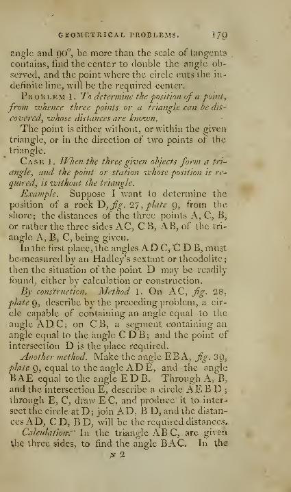
GEOMETRICAL PROBLEMS. l/C)
angle and QO'', be more than the scale of tangcntv««
contains, find the center to double the angle ob-
served, and the point where the circle cuts the in-
definite line, will be the required center.
Problem 1. To determine the position of a po'inl^
from whence three points or a triangle can be dis-
covered, whose distances are hiown.
The point is either without, or within the given
triangle, or in the direction of two points of the
triangle.
Case 1. Iflien the three given objects form a trl~
angle, ami the point or station whose position Is re-
quired, Is without the triangle.
Example. Suppose I ^\ant to determine the
position of a rock T>,fg. IJ, plate Q, from the
shore; the distances of the three points A, C, B,
or rather the three sides AC, CB, iVB, of the tri-
angle A, B, C, being given.
In the first place, the angles AD C, C D B^ mustbe measured by an Hadley's sextant or theodolite;
then the situation of the point D may be readily
found, cither by calculation or construction.
By construction. Method 1. On AC, fg. 28,
plate 9, describe by the preceding problem, a cir-
cle capable of containing an angle equal to the
angle ADC; on CB, a segment containing anangle equal to the angle CDB; and the point of
intersection D is the place required.
Another method. Make the angle EB A, fg. 3g,/>/tf/«? 9, equal to the angle ADE, and the an2:le
BAE equal to the angle E D B. Through A,^B,
and the intersection E, describe a circle AEB D ;
through E, C, draw E C, and produce it to inter-
sect the circle at D; join AD. B D, and the distan-
ces AD, C D, B Dj will be the required distances.
Calculation: ' In the triangle ABC, are given
the three sides, to find the angle BAC. In the
N 2
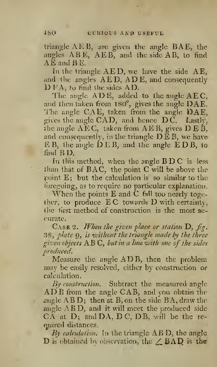
180 CUllIOUS AND USEFUL
triangle AE B, arc given the angle BAE^ the
angles ABE, AEB, and the side A B, to find
AEandBE.In the triangle AED, we have the side AE,
and the angles AED, AD E, and consequently
D FA, to find the sides AD.The angle ADE, added to the angle AEC,
and then taken from 180°, gives the angle DAE.The angle CAE, taken from the angle DAE,gives the angle CAD, and hence D C. Lastl}',
the angle AEC, taken from AE B, gives D E B^,
and consequently, in the triangle DEB, we have
E B, the angle DEB, and the angle E D B, to
iind B D.In this method, when the angle B D C is less
than that of BAC, the point C will be above the
}3oint E; but the calculation is so similar to the
foregoing, as to require no particular explanation.
When the points E and C fall too nearly toge-
ther, to produce E C towards D with certainty,
the first method of construction is the most ac-
curate.
Case 2. When the gwen place or station D, fig.
38, plate Q, is ivithoiit the triangle made by the three
given objects ABC, but in a line "with one of the sides
produced.
Measure the angle AD B, then the problemmay be easily resolved, either by construction or
calculation.
By construction. Subtract the measured angle
ADB from the angle CAB, and you obtain the
angle A B D; then at B, on the side BA, draw the
angle ABD, and it will meet the produced side
CA at D; and DA, DC, DB, will be the re-
tyiired distances.
By calcidation. \\\ the triangle ABD, the angle
D is obtained by obsciTation, the ^ BAD is the
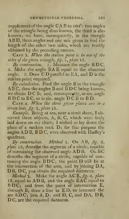
GEOMETRICAL PROBLEMS. 181
supplement ofthe angle CAB to 180°: two angles
of the triangle being thus knovvn^ the third is also
known; we have, consequently, in the triangle
AB D, three angles and one side given to find the
length of the other two sides, which are readily
obtained by the preceding canons.
Case 3. When the station po'mt is in one of the
sides of the give?! triangle. Jig. \, flate 13.
By construction. 1 . Measure the angle B D C.
1. Make the angle BAE equal to the observed
angle. 3. Draw C D parallel to EA, and D is the
station point required.
By calculation. Find the angle B in the triangle
ABC, then the angles B and B D C being known,we obtain D C B ; and, consequently, as sin. angle
B D C to B C, so is sin. angle D C B to B D.Case 4. JVhen the three given places are in a
strait line, jig. 2, flate 13.
Example. Being at sea, near a strait shore, I ob-
served three objects, A, B, C, which were truly
laid down on my chart; I wished to lay down the
place of a sunken rock D ; for this purpose the
angles AD B, B D C, were observed with Hadlcy's
quadrant.
By comtruction. Method 1. On AB, jig. 3,
plate 13, describe the segment of a circle, capable
of containing the observed angle AD B. On BCdescribe the segment of a circle, capable of con-
taining the angle BDC; the point D will be at
the intersection of the arcs, and by joining DA,D B, DC, you obtain the required distances.
Method 2. Make the angle AC E,7%-. 4, flate
13, equal to ADB, and the angle EAC equal to
BDC; and from the point of intersection E,
through B, draw a line to E D, to intersect the
arc ADC; join A, D; and D, C, and DA, DB,D C, are the required distances.

182 CURIOUS AND USEFUL
By calculation. 1. In the triangle CAE, Jig. 4,
plate 13, we have all the angles, and the side AC,to find AE. 2. In the triangle ABE, AB, AE,and the included angle are given, to find the an-
gles AE B, ABE. 3. In the triangle B D C, the
angle B D C and D C B (=AB E) are given, andconsequently the angle D C B, and the side B C
;
henee it is easy to obtain D B.
Case 5. When the station falls within the tri-^
angle, formed hy the three giveti objects, fg. 19,
plate 13.
Let ABC represent three towers, whose dis-
tance from each other is known; to find the dis-
tance fi-om the tower D, measure the angles ADC,BDC, ADB.
Construction. On two ofthe given sides AC, AB,fig. 20 plate \o, describe segments of circles capa-
ble ofcontaining the given angles, and the point Dof their intersection will be the required place.
Another method. Or, we may proceed as in someof the foregoing cases; making the angle ABE,fig.21, plate 13, equal to the angle ADE, andBAE equal B D E; and describe a circle through
the three points A, B, E, and join E, C, by the line
EC; and the point D, where BC intersects the
circle E, A, D, B, E, will be the required station.
Case 6. When the station point I),fg. 7, plate
13, falls without the triangle AB C, but the point Cfalls towards D.
Thus, let AB C,fig. 7, plate 13, represent three
towers, whose respective distances from each other
are known ; required their distance from the point
D. Measure the angles ADC, BDC, and to prove
the truth of the observations, measure also ADB.Then, bj construction, method 1. On AC, fig.
8, plate 13, describe a circle capable of containing
the angle BDC, and on AB, one capable oi conr
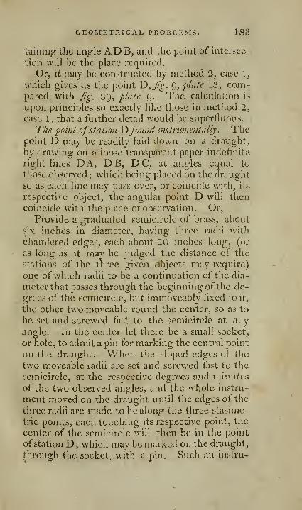
GEOMETRICAL PROBLEMS. 183
taining the angle AD B, and the point of intersec-
tion will be the plaee required.
Or, it may he constructed by method 2, case 1,
which gives us the point Yy^Jig. g, plate 13, com-pared with Jig. 3Cj, plate 0. The calculation is
upon principles so exactly like those in method 2,
case 1, that a further detail would be superfluous.
The point ofstation Yifound instrumentally. Thepoint D may be readily laid down on a draught,
by drawing on a loose transparent paper indefinite
right lines DA, D B, DC, at angles equal to
those observed ; which being placed on the draught
so as each line may pass over, or coincide with, it*i
respective object, the angular point D will then
coincide with the place ofobservation. Or,
Provide a graduated semicircle of brass, about
six inches in diameter, having three radii with
chamfered edges, each about 20 inches long, (or
as loug as it may be judged the distance of the
stations of the three given objects may require)
one ofwhich radii to be a continuation of the dia-
meter that passes through the beginning of the de-
grees of the semicircle, but immoveably fixed to it,
the other two moveable round the center, so as to
be set and screwed fast to the semicircle at any
angle. In the center let there be a small socket,
or hole, to admit a pin for marking the central point
on the draught. When the sloped edges of the
two moveable radii are set and screwed fast to the
semicircle, at the respective degrees and minutes
of the two observed angles, and the whole instru-
ment moved on the draught uptil the edges of the
three radii are made to lie along the thrpe stasime-
trie points, each touching its resp.ectiye point, the
center of the semicircle will then be in the point
of station D; which may be marked on the draught,
{through the socket, with a pin. Such an instru-

184 CURIOUS AND USEFUL
ment as this may be called a station-pointer; andwould prove convenient for finding the point ofstation readily and accurately, except when thegiven objects were near; when the breadth of thearc, and of the radii, and of the brass about thecenter of the semicircle, might hinder the points
from being seen, or the radii so placed as to com-prehend a very small angle between them.
The three succeedingp'ohlems may occur at sea, in
finding the distances and position of the rocks, sands,
&c. from the shore, In many cases of maritime sur-
veylng; they are also very serviceable In making a
Tiiap of a country, from a series of triangles derived
from one or more measured hases.
Problem 1. Given the distance of two oh'iects
KB, fig. 5, plate Q, and the angles ADB, B JD C,
BCA, to find the distance of the two stations D, C,
from the objects A, B.
By construction. Assume d c any number at plea-
sure, and make the angles b d c, a d c, &c. respec-
tively equal to the angles B D C, AD C, &c. andjoin a b; it is plain that this figure must be similar
to that required; therefore draw AB, fig. 4, plate
0, equal the given distance, and make AB C equal
to a b c, BAG to bac, and so on respectively;
join the points, and you have the distances re-
quired.
By calculatlo7i. in the triangle a d c, we have
do, a d c, and a c d, to find a d, a c ; in b c d, wehave in like malnner the three angles, and d c, to
find d b, d c.
In the triangle a d b, we have ad, b d, and the
angle a d b, to find a b. Hence by the nature of
similar figures, as ab to AB :: dc : DC :: ad; AD :: bd : BD ::bc : BC.Problem 2. The distances of three objects A, B,
C, from each other^ and the angles ADC, CDE^
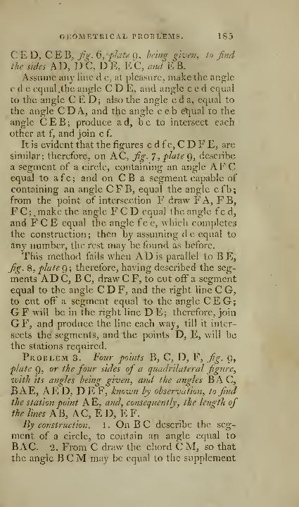
GEOMETRICAL PROBL'EMS. 1S5
C E D, C E B^ fi(. 6, fuify- 9, hem^ g'roen, to find
the sides AD, DC, D E, EC, WE B.
Assume any line d c, at pleasure, make the angle
c d e equal .the angle C D E, and angle c e d equal
to the angle C E D; also the angle c d a, equal to
the angle CD A, and the angle ccb etjual to the
angle C E B ;produee ad, be to interseet each
other at f, and join c f.
It is evident that the figures c d {^,Q, D F E, are
similar; therefore, on AC, fig. 7, phte 9, describe
a segment of a circle, containing an angle AFCequal to afc; and on C B a segment capable of
containing an angle CFB, equal the angle cfb;from the point of intersection F draw FA, FB,F C
;. make the angle F C D equal the angle fed,
and F C E equal the angle fc e, which completes
the construction ; then by assuming d e equal to
any number, the rest may be found as before.
This method fails when AD is parallel to BE,fig. 8, flate 9 ; therefore, having described the seg-
ments ADC, B C, draw C F, to cut off a segmentequal to the angle CDF, and the right line C G,to cut off a segment equal to the angle C E G
;
G F vv'ill be in the right line D E; therefore, join
GF, and produce the line each way, till it inter-
sects the segments, and the points D, E, will be
the stations required.
Problem 3. Four points B, C, D, F, fig. 9,
plate 9, or the four sides of a quadriluteral figure,
with its ayigles being given, and the angles BA C,
3AE, AED, DE F, known by observation, to findthe station point A E, and, consequently, the length ofthe lines AB, AC, E D, E F.
By construction. 1 . On B C describe the seg-
ment of a circle, to contain an angle equal to
BAC. 2. From C draw the chord CM, so that
the angle B CM may be equal to the supplement
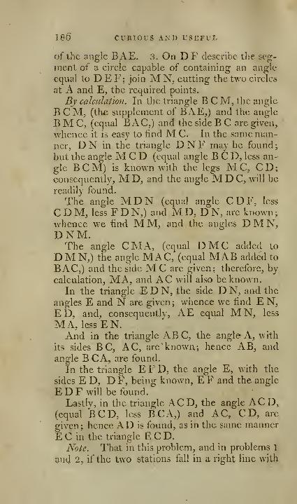
186 CURIOUS AND USEFUL
of the angle BAE. 3. On T)F describe the seg-
ment of a circle capable of containing an angle
equal to D E F; join M N^ cutting the two circles
at A and E, the required points.
By calculation. In the triangle B C M, the angle
B C M, (the supplement of BAE,) and the angle
BMC, (equal BAC,) and the side B C are given,
whence it is easy to find M C. In the same man-ner, DN in the triangle DNF may be found;
but the angle M C D (equal angle B C D, less an-
gle BCM) is known with the legs M C, CD;consequently, M D, and the angle M D C, will be
readily found.
The angle MDN (equal angle CDF, less
CDM, less FDN,) and MD, DN, are known;whence we find M M, and the angles DM N,DNM.The angle CM A, (equal DMC added to
DMN,) the angle MAC, (equal MAB added to
BAC,) and the side M C are given; therefore, bycalculation, MA, and AC will also be known.
In the triangle E D N, the side D N, and the
angles E and N are given ; whence we find E N,ED, and, conscquentlv, AE equal MN, less
MA, less EN.And in the triangle ABC, the angle A, with
its sides B C, AC, are known; hence AB, and
angle B CA, are found.
In the triangle E F D, the angle E, with the
sides E D, D F, being known, E F and the angle
E D F will be found.
Lastly, in the triangle ACD, the angle ACD,(equal BCD, less BCA,) and AC, CD, are
given ; hence AD is found, as in the same manner
E C in the triangle E C D.
Note. That in this problem, and in problems 1
jjnd 2, if the two stations fall in a right line with
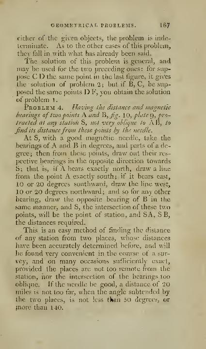
GEOMETRICAL PROBLEMS. 187
either of the given objects, the problem Is inde-
terminate. As to the other cases of this problem,
they fall in with what has already been said.
The solution of this problem is general, andmay be used for the two preceding ones: for sup-
pose C D the same point in the last figure, it gi\''es
the solution of problem 2 ; but if B, C, be sup-
posed the same points D F, you obtain the solution
of problem 1.
Problem 4. Havhio; iJic distance and mafrjieUc
hearings oftwo 'points A and ^,Jjg. 10, plaie p, pro-
tracted at any station S, not very ohliqiie to AB, lo
Jindits distancefrom these points hy the needle.
At S, with a good magnetic needle, take the
bearings of A. and B in degrees, and parts of a de-
gree; then from these points, draw out their res-
pective bearings in the opposite direction towards
S; that is, if A bears exactly north, draw a line
from the point A exactly south; if it bears east,
10 or 20 degrees southward, draw the line west,
10 or 20 degrees northward; and so for any other
bearing, draw the opposite bearing of B in the
same manner, and S, the intersection of these twopoints, will be the point of station, and SA, SB,the distances required.
This is an easy method of finding the distance
of any station from two places, whose distances
have been accurately determined bcfbrc, and will
be found very convenient in the course of a sur-
vey, and on many occasions sufficiently exact,
provided the places are not too remote from the
station, nor the intersection of the bearings too
oblique. If the needle be good, a distance of 20miles is not too far, when the angle subtended bythe two places, is not less tkxin 50 degrees, or
?nore than 140.

188 CURIOUS AND USEFUL
Problem 5. To reduce angles to the center ofthe station.
In surveys of kingdoms, provinces, counties,
&c. where signals, churches, &c. at a distance are
used for points of observation, it very often hap-pens that the instrument cannot be placed exactly
at the center of the signal or mark ofobservation;
consequently, the angle observed will be either
greater, less, or equal to that which would havehave been found at the center. This problemshews how to reduce them to the center; the cor-
rection seldom amounts to more than a few se-
conds, and is, therefore, seldom considered, unless
where great accuracy is required.
The observer may be considered in three dif-
ferent positions with respect to the center, and the
objects; for he is either in a line with the center,
and one of these objects, or in an intermediate one,
that is, a line from this center to the observer pro-
duced, would pass between the objects; or he is,
lastly, in an oblique direction, so that a line fromthe center to him would pass without the objects.
In the first position, 7?^. l\, plate 9, where the
observer is at 0, between the center and one ofthe
objects, the exteiior angle m o n is greater than the
angle men, at the center, by the angle emo;therefore, taking emo from the observed angle,
you have that at the center.
If the observer is at ^^fg- H, plate g, the exte-
rior angle m a n is greater than that of m e n at the
center, by the value of n; therefore, taking this
from the observed angle, you obtain the angle at
the center. But if the observer is further from the
objects than the center, as at i, the observed angle
m i n is less than that at the center m e n, by the
pngle m; therefore, by adding m to the observed

GEOMETRICAL PROBLEMS. IS^
angle, you obtain the angle m e n at the center.
In the same manner, if the observer is at u, weshould add the angle n to the observed m u n, in
order to have the angle men at the center.
Case 2. When the observer is at o,Jig. \1, plate
9, draw a o, and the exterior angle d exceeds the
angle ii at the center by the angle m, and the ex-
terior angle c exceeds the angle at the center a,
by the angle n ; therefore, m o n exceeds the angle
at the center, by the value of the two angles mand n : these, therefore, must be subtracted fromit to obtain the central angle. On the contrary,
if the observer is at a, the two angles m and nmust be added to the observed angle.
Case 3. Fig. 13, plate g. When the observer is
at o, having measured the angles m o n, m o e, the
angle i is exterior to the two triangles m o i, n e i;
therefore, to render men, equal to m i n, wemust add the angle n ; and to render the exterior
angle m i n, equal to the observed angle m o n,
we must take away the angle m ; therefore, add-
ing m to the observed angle, and subtracting wfrom the total, we obtain the central angle men.From what has been said, it is clear, that in the
first case, you are to add or subtract from the ob-
served angles, that of the angles m or n, whichis not in the direction of the observer.
In the second position, you have either to sub-
tract or add the two angles men.In the third position, you add to the observed
angle, that of the two m or n, which is of the
same side with the observer, and subtract the
other.
To know the position of the observer, care mustbe taken to measure the distance of the instru-
strument from the center, and the angle this cen-
ter makes with the objects.
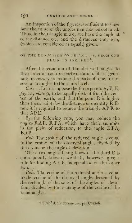
IQO CURIOUS AND USEFUL
An inspection of the figures is sufficient to shewhow the value of the angles m n may be obtained.
Thus, in the triangle ni o e, we have the angle at
o, the distance o e, and the distances c in, o m,(which are considered as equal,) given.
OP THE llEDUCTIOX OP TRIANGLES, FROM ONEPLAIN TO ANOTHER *
After the reduction of the observed angles to
the center of each respective station, it is gene-rally necessary to reduce the parts of one, or of
several triangles to the same level.
Case 1. Let us suppose the three points A, P, E,
^g. 15, plate g, to be equally distant from the cen-
ter of the earth, and that the point R is higher
than these points by the distance or quantity RE;now it is required to reduce the triangle AP R to
that APE.By the following rule, you may reduce the
angles RAP, R PA, which have their summitsin the plain of reduction, to the angle EPA,EAP.
Rule The cosine of the reduced angle is equal
to the cosine of the observed angle, divided bythe cosine of the angle of elevation.
These two angles being known, the third E is
consequently known; we shall, however, give a
rule for finding AEP, independent of the other
two.
Rule. The cosine of the reduced angle is equal
to the cosine of the observed angle, lessened bythe rectangle of the sines of the angles of eleva-
tion, divided by the rectangle of the cosine of the
same ana:les.^b'
* Traite de Trigonometrie, par Cagnoli.
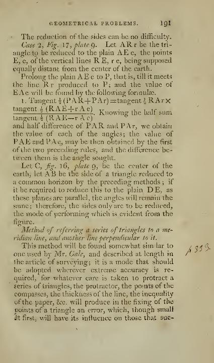
GEOMETRICAL PROBLEMS. IQl
The reduction of the sides can be no difEculty.
Case 1, Fig. 17, plate 9. Let ARr be the tri-
angle to be reduced to the plain AE e, the points
E, e, ofthe vertical lines R E, r e, being supposed
equally distant from the center of the earth.
Prolong the plain AE e to P, that is, till it meets
the line Rr produced to P; and the value of
Ex\e will be found by the following formulae.
1. Tangent \ (PAR+PAr)=tangenti Rx\rXtan£jent i (RAE+ r Ae) x^ • .1 i ir _—£ :—
^
! L. Knowms: the hair sumtangent ^ (RAE— r A c)
^
and half difterence of PAR and PAr, we obtain
the value of each of the angles; the value of
PAE and PAe, may be then obtained by the first
of the two preceding rules, and the difference be-
tween them is the angle sought.
Let C, fg. 16, 'plate 9, be the center of the
earth, let AB be the side of a triangle reduced to
a common horizon by the preceding methods ; if
it be required to reduce this to the plain DE, as
these planes are parallel, the angles will remain the
same; therefore, the sides only are to be reduced,
the mode of performing which is evident from the
figure. ... 7
Method of referring a series of triangles to a me-
riclian line, and another line perpendicular to it.
This method will be found somewhat sim lar to
one used l)y Mr. Gale, and described at length in
the article of surveying; it is a mode that should
be adopted wherever extreme accuracy is re-
quired, for whatever care is taken to protract a
series of triangles, the protractor, the pouits of the
compasses, the thickness of the line, the inequality
of the paper, &c. w^ill produce in the fixing of the
points of a triangle an error, which, though small
^ first, will have its influence on those thai sue-
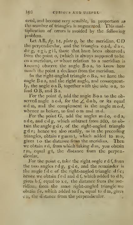
ig2 CURlOirs AND USEFUL
ceed, and become very sensible, in proportion asthe number of triangles is augmented. This nuil-
tiplieation of errors is avoided by tlie followingproblem.
Let AB,77^. 14, plate Qy be the meridian, CDthe perpendicular, and the triangles oad, d a e,
d e g, e g i, g i 1, those that have been observed ;
from the point o, (which is always supposed to beon a meridian, or whose relation to a meridian is
known) observe the angle Boa, to know howmuch the point a declines from the meridian.
In the right-angled triangle o B a, we have theangle Boa, and the right angle, and consequent-ly, the angle o a B, together with the side o a, toiind O B, and B a.
For the point d, add the angle B o a to the ob-served angle a o d, for the ^ d o b, or its equal
odm, and the complement is the angle mod^whence as before, to fmd om and m d.
For the point G, add the angles m d o, o d a,
a d e, and e d g, which subtract from sOo, to ob-tain the angle g d r, of the right-angled triangle
gd r; hence we also readily, as in the preceding
triangles, obtain rg=m t, which added to mo,gives to the distance from the meridian. Thenwe obtain r d, from which taking d m, you obtain
rm, equal gt, the distance from the perpen-dicular.
For the point e, take the right angle r d f, fromthe two angles rdg, gde, and the remainder is
the angle fd e of the right-angled triangle dfe;hence we obtain f"e d and d f, which added to d b,
gives b f, equal to x e, the distance from the me-ridian.; from the same right-angled triangle weobtain fe, which added to f n, equal to d m, gives
c a, the distance from the perpendicular.
GEOMETRICAL PROBLEMS. lg3
For the point i, add together the angles rgd^d g e, e g i, and from the sum subtract the right
angle rg h, and you obtain the angle g h i of the
right-angled triangle h g i_, and consequently the
angle i; hence also we get hi, equal tp, whichadded to t o^ gives o p distance from the meridian^
and g h^ from which subtracting gt, we obtain t h,
equal p i distance from the perpendicular.
For the point 1, the angle g h i, added to the
angle 1 g i, gives the angle 1 g k ofthe right-angled
triangle g k 1, and ofcourse the angle g 1 k, whencewe obtain k 1 or t y, which added to t o, gives o ydistance from the meridian ; hence we also obtain
gk, which taken from gt, gives kt, equal ly dis-
tance from the perpendicular.
If, before the operation, no fixed meridian wasgiven, one may be assumed as near as possible
from the point o; for the error in its position will
not at all influence the respective position of the
triangles.
To the mathematical student, who may have a desire to proceed on a com-
plete course of the mathematical sciences, the following eminent authors are
recommended.
Algebra, by Simpson, 8vo. 1755; Maclaurin, 8vo. 1771; Bonnycastle's
Introduction, lamo. 1796.-
(Jtometiy. Euclid's Elements, by Dr. Simson, 8vo. 1791 ; Elements, bySimpson, 8vo. 1768, and Emerson, 8vo. 1763.
Trigon-jmetry, by Simpson, 8vo. 1 765; Emerson, 8vc), 1788; Traite, byCngnoli, 410. Paris, 1786; and a Treatise now in the press, 8vo. bj' T. Keith.
Conic Sections, by Hamilton, 4to. 1758; Hutton, 8vo, 1787; Elements, by
Vince, 8vo. 1781, and Newton, 8vo. 1794.Fluxions, by Simpson, i\o. I'j'jd, and Maclaurin, 4to. 2 vols. 1742; Intro-
iluction, by Rowe, ^wo. 1767, and Emerson, 8vo, 1768.
Logarithmic Tables, by Taylor, to every second of the quadrant, 4to, 1792;and Hutton, 8vo. 1794.^MenMration, by Hutton, 8vo, I788.
Mathematical Dictionary, by Hutton, in i voU. 4to. 1 796.
To these may be .added, Emerson's Mathematical Works, in lO vols. i\9,
HQd a aunt now piwiuhinji at C^mbxid^e by Vi.nv;« and Wood, in— vol*. 8vo.
i m ]
OF
SURVEYING.
The practice of surveying may be considered
as consisting of four parts. 1. Measuring strait
lines. 2. Finding the position of strait lines with
respect to each other. 3. Laying down, or plan-
ning upon paper these positions and measures.
4. Obtaining the superficial measure of the land
to be surveyed.
We may, therefore, define land surveying to bethe art which teaches us to find how many times
any customary measure is contained in a given
piece of ground, and to exhibit the tiiie boun-daries thereof in a plan or map.A station line is a strait line, whose length is ac-
curately ascertained by a chain, and the bearing-
determined by some graduated instrument.
An offset is the distance of any angular point in
the boundary from the station line, measured bya line perpendicular thereto.
The curvature of the earth within the limits of
an ordinary survey, is so inconsiderable, that its
surface may be safely considered by the land sur-
veyor as a plain. In a large extent, as a province,
or a kingdom, the curvature of the earth's surface
becomes very considerable, and due allowance
must be made for it.
All plains, how many sides soever they consist
of, may be reduced into triangles, and may there-
fore be considered as composed thereof; and, con-
sequently, what is required in surveying, arc such
instruments as will measure the length of a side,
and the quantity of an angle of a triangle.

E 195]
GENERAL RULES.
A few general observations, or hints, can only
be expected in this place; for, after all that we can
s'ay, the surveyor must depend on his own judg-ment for contriving his work, and his own skill in
discriminating, among various methods^ that whichis best.
The first business of the surveyor is to take
$uch a general view of the ground to be surveyed,
as will fix a map thereof in his mind, and thencedetermine the situations for his station lines, andthe places where his instruments may be used to
the greatest advantage.
Having settled the plan of operations, his next
business is to examine his instruments, and see
that they are all in proper order, and accurately
adjusted. He should measure carefully his chain,
-and if there be any errors therein, correct them
;
prepare staves, marks, &c. for distinguishing the
several stations.
The fewer stations that can be made use of, the
less will be the labour of the survey; it will also bemore accurate, less liable to mistakes while in the
jield, or errors when plotting the work at home.The station lines should always be as long as
possible, where it can be done without rendering
the offsets too large; where great accuracy is re-
quired, these lines should be repeatedly measured,
the first great point being the careful mensuration
of your station lines; the second, to determine the
situation of places adjoining to them. For every
station line is the basis of the succeeding opera-
tions, and fixes the situation of the different parts.
The surveyor should so contrive his plan, as to
avoid the multiplication of small errors, and par*
o %
igQ GENERAL RULE^
ticularly those that by communication will extend
themselves through th^ whole operation. If the
e'statc be large, or if it be subdivided into a great
number of fields, it would be improper to survey
the fields singly, and then put them together, nor
could a survey be accurately made by taking all
the angles and boundaries that inclose it. If pos-
sible, fix upon, for station points, two or moreeminent situations in the estate, from whence the
principal parts maybe seen; let thefe be as far
distant from each other as possible; the work will
be more accurate when but few of these stations
are made use of, and the station lines will be moreconvenient, if they arc situated near the bounda-
ries of the estate.
Marks should be erected at the intersection of
all hedges with the station line, in order to knowwhere to measure from, when the fields are sur-
veyed. All necessary angles between the mainstations should be taken, carefully measuring in a
right line the distance from each station, noting
down, while measuring, those distances where the
lines meet a hedge, a ditch, &c If any remark-
able object be situated near the station line, its
perpendicular distance therefrom should be ascer-
tained; in the same manner, all offsets from the
ends of hedges, ponds, houses, &c. from the mainstation line should be obtained, care being taken
tliat all observations from the station line, as the
measure of angles, &c. be always made frompoints in the station line.
When the main stations, and every thing ad-
joining to them, have been found, then the estate
may be subdivided into two or three parts by newstation lines, fixing the stations where the best
views can be obtained ; these station lines must beaccurately measured, and the places where they
Ton SURVEYING. ip7
intersect hedges be exactly ascertained, and all the
necessary offsets determined.
This effected, proceed to snrvey the adjoining
fields, by observing the angles that the sides makevvich the station lines at their intersections there-
with ; the distances of each corner of the held
from these intersections, and that of all necessary
offsets.
Every thing that could be determined fromthese stations being found, assume more internal
stations, and thus continue to divide and sub-
divide, till at last you obtain single fields, repeat-
ing the same operations, as well for the inner as
for the exterior work, till all be finished.
Every operation performed, and every observa-
tion made, is to be carefully noted down, as the
data for fixing the situations upon the plan. Thework should be closed as often as convenient, andin as few lines as possible; what is performed in
one day shoidd be carefully laid down every
night, in order not only to discover the regular
process of the work, but to iind whether any cir-
cumstance has been neglected, or any error com-rnitted, noticing in the field-book, how one field
lies by another, that they may not be displaced in
the draft.
If an estate be so situated, that the whole can-
not be surveyed together, because one part can-
not be seen from the other, divide it into three or
four parts, and survey them separately, as if they
were lands belonging to different persons, and at
last join them together.
As it is thus necessary to lay down the work as
you proceed, it will be proper to find the most
convenient scale for this purpose: to obtain this,
measure the whole length of the estate in chains,
th.en consider how many inches long your plao

"igS ADVANTAGEOUS CIRCUMSTANCES
is to be, and from these conditions, you will as-
certain how many chains you have in an inch, and
thence choose your scale.
In order that the surveyor may prove his work,
and see daily that it goes on right, let him choose
some conspicuous object that may be seen from
all, or 2;reater part of the estate he is surveying,
and then measure with accuracy the angle this
object makes, with two of the most convenient
stations in the first round, entering them in the
iield-book or sketch where they were taken ; whenyou plot your first round, you will find the true
situation of this object by the intersection of the
angles. .Measure the angle this object makes,
with one of your station lines in the second, third,
&c. rounds: these angles, when plotted one day af-
ter anotlier, will intersect each other in the place of
the object, if the work be right; otherwise somemistake has been committed, which must be cor-
rected before the work is carried any further.
Fields plotted from measured lines only, are aUways plotted nearest the truth, when those lines
form at their meeting, angles nearly approaching
to right angles.
OF THE MOST ADVANTAGEOUS CIRCUMSTANCESFOR A SERIES OF TRIANGLES.
>
, The three angles of every triangle should al-
ways, if possible, be measured.• As it isimpossibleto avoid some degree of error
in taking of angles, we should be careful so to or-
iler Qur operations, 'that this error may have the
least possible infiuence on the sides, the exact
measure of which is the end of the operations.
Now, in a right-lined triangle, it is necessary to
h^ve at least one side measured mediately or ini"
FOR A SERIES OF TRIANGLES. IQQ
TTicdiately; the choice of the base is therefore the
fiindainental operation; the detenninations will
be most accurate to find one side, when the base
is equal to the side required; to find two sides, anequikiteral triangle is most advantageous.
In general, when the base cannot be equal to
the side or sides sought, it sliould be as long as
possible, and the angles at the base should be
equal.
In any particular case, where only tAvo angles
of a triangle can be actually observed, they should
be each of them as near as possible to 45°; at anyrate their sum should not differ much from 90°, for
the less the computed angle differs from 90°; the
less chance there will be of any considerable error
in the intersection.
.DESCJRIPTION OF THE VARIOUS INSTRUMENTSUSED IN SURVEYING, AND THE METHOD OPAPPLYING THEM TO PRACTICE, AND EX-AMINING THEIR ADJUSTMENTS-
The variety of instruments that are now madeuse of in surveying is so great, and the improve-
ments that have been made within these few years
are so numerous, that a particular description of
each is become necessary, that by seeing their re-
spective merits or defects, the purchaser may be
enabled to avail himself of the one, and avoid the
other, and be also enabled to select those that arc
best adapted to his purposes.
The accuracy of geometrical and trigonometri-
cal mensuration, depends in a great degree on the
exactness and perfection of the instruments madeuse of; if these are defective in construction, or
difficult in use, the surveyor will either be subject
to error, or embarrassed with continual obstacles.
If the adjustments, by which they are to be ren-
^00 LIST OF INSTRUMENTS
dered fit for observation, be troublesome and in-
convenient, they will be taken upon trust, and the
instrument will be used without examination, and
thus subject the surveyor to errors, that he can
neither account for, nor correct.
In the present state of science, it may be laid
down as a maxim, that every instrument should
be so contrived, that the observer may easily ex-
amine and rectify the principal parts; for how^ever
careful the instrument-maker may be, howeverperfect the execution thereof, it is not possible
that any instrument should long remain accurate-
ly fixed in the position in which it came out ofthe
maker's hands, and therefore the principal parts
should be moveable, to be rectified occasionally
by the observer.
AN ENUMERATION OP INSTRUMENTS NECESrSARY FOR A SURVEYOR;
Fewer or more of which will be wanted, ac-
cording to the extent of his work, and the accu-
racy required.
A case of good pocket Instruments.
A pair of beam compasses.
A set of feather-edged plotting scales.
Three or four parallel rules, either those o(Jjg.
A, B and C, plate 2, or fg. F G H, plate 2,
A pair of proportionable compasses.
A pair of triangular ditto.
A pantagraph.
A cross staff.
A circumfcrcntor.
An Hadlcy's sextant,
An artificial horizon.
A theodolite.
A surveying compass,

FOR A SURYEYOn. 201
Measuring chains, and measuring tapes.
King's surveying quadrant.
A perambulator, or measuring wheel.
A spirit level with telescope.
Station staves, used with the level.
A protractor, with or without a nonius. •
7(9 he addedfor county and marine surveying:
An astronomical quadrant, or circular instru-
ment.A good refracting and reflecting telescope.
A copying glass.
For marine surveying.
A station pointer.
An azimuth compass.
One or two boat compasses.
Besides these, a number of measuring rods, iron
pins, or arrows, &c. will be found very convenient,
and two or three offset staves, which are strait
pieces of wood, six feet seven inches long, andabout an inch and a quarter square; they should
be accurately divided into ten equal parts, each of
which will be equal to one link. These are used
for measuring offsets, and to examine and adjust
the chain.
Five or six staves of about five feet in length,
and one inch and an half in diameter, the upperpart painted white, the lower end shod with iron,
to be struck into the ground as marks.
Twenty or more iron arrow^s, ten of which are
always wanted to use with the chain, to count the
number of links, and preserve the direction of the
chain, so that the distance measured may be really
m a strait line.
The pocket measuring tapes, in leather boxes,
jire often very convenient and useful. They arc

202 XNSTKUMENTS FOR
made to the different lengths of one, two, three,
four poles, or sixty-six feet and 100 feet; di-
vided, on one side into feet and inches, and on the
other into links of the chain. Instead of the lat-
ter, are sometimes placed the centesimals of a
yard, or three feet into 100 equal parts.
OF THE INSTRUMENTS USED IN MEASURINGSTRAIT LINES.
OF THE CHAIN.
The length of a strait line must be found me-chanically by the chain, previous to ascertaining
any distance by tri2;onomctry: on the exactness
of this mensuration the truth of the operations
will depend. The surveyor, therefore, cannot betoo careful in guarding against, rectifying, or
making allowances for every possible error; andthe chain should be examined previous and subse-
quent to evei-y operation.
For the chain, however useful and necessary, is
not infallible, it is liable to many errors. 1. In
itself. 2. In the method of using it. 3. In the
uncertainty of pitching the arrows; so that the
surveyor, who wishes to obtain an accurate survey,
will depend as little as possible upon it, using it
only where absolutely necessary as a basis, andthen with every possible precaution.
If the chain be stretched too tight, the rings
will give, the arrow incline, and the measured base
will appear shorter than it really is; on the other
hand, if it be not drawn sufficiently tight, the
measure obtained will be too long. I have been
informed by an accurate ajid very intelligent sur-
vcyor, that when the chain has been much used,

MEASCEIXG &TRAIT LINES. *203
lie lias gcnc]-ally tbund it necessary to shorten it
every second or third day. Chains made ofstrong wire are preferred.
Gmiters chain is the measure universally adopted
in this kingdom for the purpose of land surveying,^
being exceedingly well adapted for the mensura-tion of land, and affording very expeditious me-thods of casting up what is measured. It is sixty-
six feet, or four poles in length, and is divided into
100 links, each link with the rings between themis 7.92 inches long, every tenth link is pointed outby pieces of brass of different shapes, for the morereadily counting of the odd links.
The English acre is 4840 square yards, andGuntej*'s chain is 22 yards in length, and divided
into 100 links; and the square chain, or 22 mul-tiplied by 22, gives 484, exactly the tenth part of
an acre; and ten chains squared are equal to oneacre; consequently, as the chain is divided into
100 links, every superficial chain contains 100multiplied by 100, that is 10.000 square links;
and 10 superficial chains, or one acre, contains
100.000 square links.
If, therefore, the content of a field, cast up in
square links, be divided by 100.000, or (which is
the same thing) if from the content we cutoff the
five last figures, the remaining figure towards the
left hand gives the content in acres, and conse-
quently the number of acres at first sight; the
remaining decimal fraction, multiplied by 4, gives
the roods, and the decimal part of this last pror-
duct multiplied by 40, gives the poles or perches.
Thus, if a field contains l6,54321 square links,
we see immediately that it contains 16 acres.
54321 multiplied by 4, gives 2,17284, or 2 roods
and 17284 parts; these, multiplied by 40, produce
lt5,013{)O^ or 6 poles, 91 3(io parts.

204 INSTRUMENTS FOR STRAIT LINKS*
Direcfirms for using the chain. Marks are first t{>
be set up at the places whose distances are to be
obtained ; the place where you begin may be called
your first station; and the station to which youmeasure, the second station. Two persons are to
hold the chain, one at each end; the foremost, or
chain leader, must be provided with nine arrows,
one of which is to be put down perpendicularly at
the end of the chain when stretched out, and to
be afterwards taken up by the follower, by way of
keeping an account of the number of chains.
When the arrows have been all put down, the
leader must wait till the follower brings him the
arrows, then proceeding onwards as before, butwithout leaving an arrow at the tenth extention of
the chain. In order to keep an account of the
number of times which the arrows are thus ex-
changed, they should each tie a knot on a string,
carried for that purpose, and which may be fas-
tened to the button, or button-hole of the coat;
they should also call out the number of those ex-
changes, that the surveyor may have a check onthem.
It is very necessary that the chain bearers should
proceed in a strait line; to this end, the second,
and all the succeeding arrows, should always be
?o placed, that the next foregoing one may be in
a line with it, the place measured from, and that
to which you are advancing; it is a very goodmethod to set up a staff at every ten chains, as well
for the purpose of a guide to preserve the rectili-
near direction, as to prevent mistakes.
All distances of offsets from the chain line to
any boundary which are less than a chain, are
most conveniently measured by the offset staff;
the measure must always be obtained in a direct,
lion perpendicular to the chain.
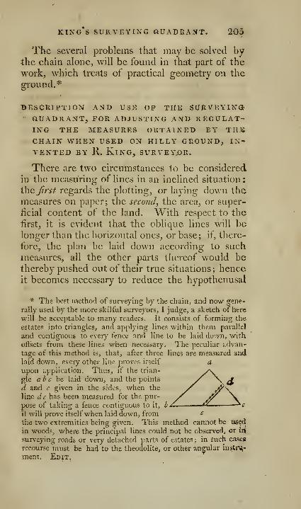
king's surveying quadrant. 205
The several problems that may be solved bythe chain alone, will be found in that part of the
work, which treats of practical geometry on the
ground.*
BESCRIPTION AND USE OP THE SURVEYING• aUADRANT, FOR ADJUSTING AND REGULAT-ING THE MEASURES OBTAINED BY THSCHAIN WHEN USED ON HILLY GROUND, IN-
VENTED BY R. King, surveyor.
There are two circumstances to be considered
in the measuring of lines in an inclined situation
:
ihcjirst regards the plotting, or laying down the
measures on paper; tlie second, the area, or super-
ficial content of the land. With respect to the
first, it is evident that the oblique lines will belonger than the horizontal ones, or base; if, there-
fore, the plan be laid down according to such
measures, all the other parts thereof would bethereby pushed out of their true situations; henceit becomes necessary to reduce the hypothenusal
* The best method of surveying by the chain, and now gene-
rally used by the more skilful surveyors, I judge, a sketch of here
will be acceptable to many readers. It consists of forming the
estates into triangles, and applying lines within them parallel
and contiguous to eveiy fence and line to be laid down, with
offsets from these lines when necessary. The peculiar advan-
tage of this method is, that, after three lines are measured andlaid down, every other line proves itself aupon application. Thus^ if the trian-
gle ah c he. laid down, and the points
d and c given in the sides, when the
line lie has been measured for the pur-
pose of taking a fence contiguous to it,
it will prove itselfwhen laid down, from ^
the two extremities being given. This method cannot be used
in woods, where the principal lines could not be observed, or \vi
surveying roads or very detached parts of estates ; in such cases
recourse must be had to the theodolite, or other angular instru,'
ment. Edit,

20a KING S SURVEYING QUADRANT.
lines to liorizontal, which is easily effected byMr. Kmg'a quadrant.
With respect to the area, tlicre is a difference
aiTionx surveyors; sonic contending that it should
be made according to the hypothenusal ; others,
accordino- to the horizontal lines: but, as i\l\ have
agreed to the necessity of the reduction for the lirst
purpose, we need not enter minutely into their
reasons liere; for, .even if we admit that in somecases more may be grown on the hypothenusal
plain than the horizontal, even then the area
should be given according to both suppositions, as-
the hill}' and uneven ground requires more labour
in the working.
The quadrant AB, Jig. \, plate 14, is fitted to a
wooden square, which slides upon an offset staff,
and may be fixed at any height by means of the
§crcw C, which draws in the diagonal of the staff^
thus embracing the four sides, and keeping the
limb of the square perpendicular to the staff; the
staff should be pointed with iron to prevent wear;
when the staff is fixed in the ground on the station
line, the square answers the purpose of a cross
staff, and may, if desired, have sights fitted to it.
The quadrant is three inches radius, of brass, is
furnished with a spirit level, and is fastened to the
liinb D E of the square, by the screw G.When the several lines on the limb of the quad-
rant have their first division coincident with their
respective index divisions, the axis of the level is
parallel to the staff.
The first line next the edge of the quadrant is
numbered from right to left, and is divided into
100 parts, which shews the number of links in the
horizontal line, which are completed in 100 links
On the hypothenusal line, and in proportion for
any lesser number.
king's SUVEYINQ aUADRANT. 207
The second, or middlemost line, shews the
number of links the chain is to be drawn forward,
to render the hypothenusal measure the same a^
the horizontal.
The third, or uppermost line, gives the perpen-
dicular height, when the horizontal line is equal
to 100.
To use the quadrant. Lay the staff along thechain line on the ground, so that the plain of the
(juadrant may be upright, then move the quad^rant till the bubble stands in the middle, and outhe several lines you will have, 1. The horizontal
length gone forward in that chain. 2. The linka
to be drawn forward to complete the horizontal
chain. 3. The perpendicular height or descent
made in going forward one horizontal chain.
The two first lines are of the utmost impoitance
in surveying land, which cannot possibly be plan-
ned with any degree of accuracy without having
the horizontal line, and this is not to be obtained
by any instrument in use, without much loss of
time to the surveyor. For with this, he has only
to lay his staff on the ground, and set the quadrant
till the bubble is in the middle of the space, whichis very soon performed, and he saves by it moretime in plotting his survey, than he can lose in the
iicld ; for as he completes the horizontal chain as
he goes forwards, ihe offsets are aliz^ays m their right
places, and the field-book being kept by horizon-
tal measure, his lines are always sure to close.
If the superficial content by the hypothenusal
measure be required for any particular purpose, he
has that likewise by entering in the margin of his
iield-book the links drawn forward in each chain,
having thus the hypothenusal and hori;2;oataL
length of every line.
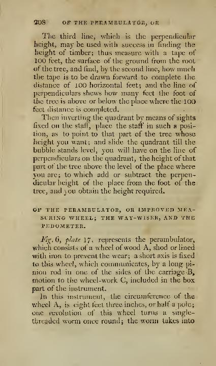
208 OF THE PERAMEULATOR, OR
The third lino, which is the perpencHcuIar
height, may be used with success in finding the
height of timber; thus measure with a tape of100 feet, the surface of the ground from the root
of the tree, and find, by the second fine, how muchthe tape is to be drawn forward to complete thedistance of 100 horizontal feet; and the line ofperpendiculars shews how many feet the foot of
the tree is above or below the place where the 100feet distance is completed.
Then inverting the quadrant by means of sights
fixed on the stafi"', place the staff in such a posi-
tion, as to point to that part of the tree whoseheight you want; and slide the quadrant till the
bubble stands level, you will have on the line ofperpendiculars on the quadrant, the height ofthat
part of the tree above the level of the place whereyou are J to which add or subtract the perpen-
dicular height of the place from the foot of the
tree, and ) ou obtain the height required.
OP THE TERAMBULATOR, OR IMPROVED MEA-SURING WHEEL; THE WAY-WISER, AND THEPEDOMETER.
Fijr, (), pJaie 1 7 , represents the perambulator,
which consists of a wheel ofwood A, shod or lined
with iron to prevent the wear; a short axis is fixed
to this wheel, which communicates, by a long pi-
nion rod in one of the sides of the carriage B,
motion to the wheel-work C, included in the boxpart of the instrument.
In this instrument, the circumference of the
wheel A, is eight feet three inches, or half a pole;
one revolution of this wheel turns a single-
tlire;}dccl worm once round; the worm takes into
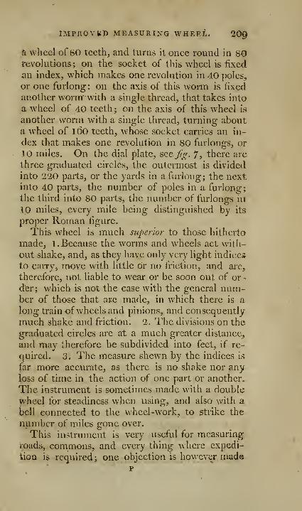
IMPROVED MEASURING WHEEL. 200
a wliccl of 80 teeth, and turns it once round in 80tevolutions ; on the socket of this wheel is fixed
an index, which makes one revolution in 40 poles,
or one furlong: on the axis of this worm is fixed
another worm with a single thread, that takes into
a wheel of 40 teeth ; on the axis of this wheel is
another worm with a single thread, turning abouta wheel of l6o teeth, whose socket carries an in-
dex that makes one revolution in 80 furlongs, or
10 miles. On the dial plate, see. Jig. 7, there are
three graduated circles, the outermost is divided
into 220 parts, or the yards in a furlong; the nextinto 40 parts, the number of poles in a furlong;
the third into 80 parts, the number of furlongs in
10 miles, every mile being distinguished by its
proper Roman figure.
This wheel is much superior to those hitherto
made, 1. Because the worms and wheels act with-
out shake, and, as they have only very light indices
to carry, move with little or no friction, and arc,
therefore, not liable to wear or be soon out of or -
dfer; which is not the case with the general num-ber of those that ace made, in which there is a
long train of wheels and pinions, and consequently
much shake and friction. 2. The divisions on the
graduated circles arc at a much greater distance,
and may therefore be subdivided into feet, if re-
quired. 3. The measure shewn by the indices is
far more accurate, as there is no shake nor anyloss of time in the action of one part or another.
The instrument is sometimes made with a double
wheel for steadiness when using, and also with a
bell connected to the wheel-work, to strike the
number of miles gone over.
This instrument is v<iry useful for measuringroads, commons, and every thing where expedi-
tion is required; one objection is however madep
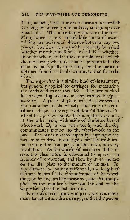
210 THE WAY-WISER AND PEDOMETER.
to it, namely, that it gives a measure somewhat:too long by entering into hollows, and going over
small hills. This is certainly the ease; the mea'-
siiring wheel is not an infallible mode of ascer-
taining the horizontal distance between any twoplaces: but then it may with propriety be askedwhether any other method is less fallible? whether,
upon the whole, and in the circumstances to whichthe measuring wheel is usually appropriated, the
chain is not equally uncertain, and the measureobtained from it as liable to error, as that from the
wheel.
The ivay-wiser is a similar kind of instrument,
but generally applied to carriages for measuringthe roads or distance travelled. The best methodfor constructing such a one is represented in jf^. 8,
plate 17. A piece of plate iron A is screwed to
the inside nave of the wheel; this being of a cur-
vilineal shape, in every revolution of the coach-
wheel B it pushes againSt the sliding bar C, which,
at the other end, withinside of the brass box of
wheel-work D, is cut with teeth, and thereby
communicates motion to the wheel-work in the
box. The bar is re-acted upon by a spring in the
box, so as to drive it out again for the fresh im-pulse -from the iron piece on the nave, at every
revolution. As the wheels of carriages differ in
size, the wheel-work is calculated to register thenumber of revolutions, and shew by three indices
on the dial plate to the amount of '20,000. In
any distance, or journey performed, the length offeet and inches in the circumference of the wheelmust be first accurately measured, and that multi-
plied by the number shewn on the dial of the
way-wiser gives the distance run.
By means of rods, universal joint, &c. it is often
made to act within the carriage, so that the person

THE SURVEYING CROSS. 21
1
may at any moment, without the trouble ofgetting
out, see the number of the revolutions of the
wkeel. If the instrument is to be always applied
to one wheel, a table may easily be constructed to
shew the distance in miles and its parts by inspec-
tion only.
The pedometer is exactly the same kind of in-
strument as the way-wiser. The box containing
the wheels is made of the size of a watch case, andgoes into the fob, or breeches pocket; and, bymeans of a string and hook fastened to the waist-
band or at the knee, the number of steps a mantakes in his regular paces are registered, from the
action of the string upon the internal wheel-work,
at every step, to the amount of 30,000. It is ne-
cessary to ascertain the distance walked, that the
average length of one pace be previously known,and that multiplied by the number of steps regis-
tered on the dial plate.
OP THE SURVEYING CROSS, ^g. 2, p/ate 14.
TJ>e cross consists. of two pair of sights, placed
at right angles to each other: these sights are
sometimes pierced out in the circumference of a
thick tube of brass about 22 inches diameter, see
Jig. 3, plate 14. Sometimes it consists of four
sights strongly fixed upon a brass cross; this is,
when in use, screwed on a staff having a sharp
jpoint at the bottom to stick in the ground; one of
this kind is represented at ^g. 2, plate 14. Thefour sights screw off to make the instrument con-
venient for the pocket, and the staff which is about
Ah or five feet in length (for both the crosses) un-
screwsinto three parts to go into a portmantcau,&c.
The surveying cross is a very useful instrument
for placing of offsets, or even for measuring §mall
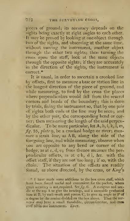
21'2 THE SURVEYING CROSS,
pieces of ground; its accuracy depends on the
sights being exactly at right angles to each other.
It may be proved by looking at one object throughtwo of the sights, and observing at the same time,
without moving the instrument, another object
through the other two sights; then turning the
cross upon the staff, look at the same objects
through the opposite sights; if they are accurately
in the direction of the sights, the instrument is
correct.*
It is usual, in order to ascertain a crooked line
by offsets, iirst to measure abase or station line in
the longest direction of the piece of ground, andwhile measuring, to find by the cross the places
where perpendiculars would fall from the several
corners and bends of the boundary; this is doneby trials, fixing the instrument so, that by one pair
of sights both ends of the line may be seen ; andby the other pair, the corresponding bend or cor-
ner; then measuring the length of the said perpen-
dicular. To be more particular, let A, h, i, k, 1, m,jig. 35, plate g, be a crooked hedge or river; mea-sure a strait line, as AB, along the side of the
foregoing line, and w hile measuring, observe whenyou are opposite to any bend or corner of the
hedge, as at c, d, e; from thence measure the per-
pendicular offsets, as at c h, d i, &c. with the
offset staff", if they arc not too long; if so, with the
chain. The situation of the offsets are readily
-found, as above directed, by the cross, or King's
* I have mack some additions to the box cross staft", whichhave been found useful and convenient for the pocket, where
great accuracy is not, required. Seejf^. 6. A compass and nee-
dle at the top A to give the bearings, aud a moveable graduated
base at B, by rack -work and pinion C, to give aii angle to 5' of
;<i degree by the nonius divided on the box above. Thus the sur-
veyor may have a small theodolite, circumferentor, and cross
staff all in one insti'ument. Edit.

IMPROVED BY JOXES. 213
surveying quadrant; they arc to be registered in
the field-book.
Of surveying with the chain and cross. Whathas been denominated by many writers, surveyingby the chaiyi oily, is in fact surveying by the cross
and chain; for it is necessary to use the cross, or
optical square", for determining their perpendicu-
lar lines, so that all that has been said, even bythese men, in favour of the chaitt alone, is foundedin fallacy. To survey the triangular field AB C,
Jig. 22, plate 9, by the chain and cross : 1 . Set upmarks at the corners of the field. 2. Bcirinnincr,
suppose at A, measure on in a right line till youare arrived near the point D, where a perpendicu-
lar will fall from the angle, let the chain lie in the
direction or line AB. 3. Fix the cross over AB,so as to see through one pair of sights the mark at
A or B, and through the other, the mark at C; if
\t does not coincide at C with the mark, the cross
must be moved backwards or forwards, till bytrials one pair of the sights exactly coincide with
the mark at C, and the other with A or B. 4. Ob-serve how many chains and links the point D is
from A, suppose 3. O. 3. which must be entered in
the field-book. 5. Measure the perpendicular D C,
643. 7. finish the measure of the base line, and the
work is done. This mode is used at present by many
surveyors, prohahly because there is no check whereby
to discover their errors, which must be very great, if
the survey is of any extent.
To plot this, make AB equal 1 1 . 41. AD equal
to 3. 0. 3. on the point D erect the perpendicular
PC, and make it equal 6.43. then draw AC,3 C, and the triangle is formed.

[ 214 ]
OF THE OPTICAL SQUARE, J^^. Ay plate 14.
This instrument has the two principal glasses of
Hadleys quadrant, 7,was contrived by my father; it
is in most, if not in all respeofe, superior to the
common surv^cying cross, because it requires nostaff, may be used in the hand, and is of course of
great use to a military officer. It consists of twoplain mirrors, so disposed, that an object seen byreflexion from both, will appear to coincide with
another object seen by direct vision whenever thdtwo objects subtend a right angle from the center
of the instrument, and serves therefore to raise or
let fall perpendiculars on the ground, as a square
does on paper, of which we shall give some exam-ples. Its application to the purposes of surveying
will be evident from these, and what has been al-
ready said concerning the cross.
Fig. 4, plate 14, is a representation of the instru-
ment without its cover, in order to render the con-
struction more evident. There is a cover with a
slit or sight for viewing the objects; the object
seen directly, always coincides with the object seen
by reflexion, when they are at right angles to each
other*.
From a given point in a given line, to raise A
Perpendimlar. 1. The observer is to stand with
this instrument over the given point, causing a
person to stand with a m^rk, or fixing one at someconvenient distance on the given line. 2. An as-
sistant must be placed at a convenient distance,
with a mark somewhere near the line in wbich it
is supposed the perpendicular will fall; then if onlooking at one of the objects, the other be seen in
* See the description of a considerable improvement upon it,
after the description of the Hadley's sextant^ /^/u^t; 19^ edit.
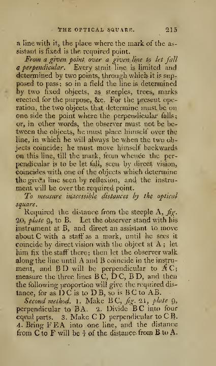
^HE OPTICAL SQUARE. 215
a line with it, the place where the mark of the as-
sistant is fixed is the required point.
From a given point over a given line to let fall
a perpendicular. Every strait line is limited anddetermined by two points, through which it is sup-
posed to pass; so in a field the line is determinedby two fixed objects, as steeples, trees, markserected for the purpose, &c. For the present ope-
ration, the two objects that determine must be onone side the point where the perpcndiculai* falls;
or, in other words, the observer must not be be-
tween the objects, he must place himself over the
Hue, in which he will always be when the two ob-jc:cts coincide; he must move himself backwardson this line, till the mark, from whence the per-
pendicular is to be let fall, seen by direct vision,
coincides with one of the objects which determine
the givcj line seen by reflexion, and the instru-
ment will be over the required point.
To measure huicesslble distances by the optical
square.
Required the distance from the steeple A, fig.
20, plate 9, to B. Let the observer stand with his
instrument at B, and direct an assistant to moveabout C with a staff as a mark, until he sees it
coincide by direct vision with the object at A ; let
Jiim fix the staff there; then let the observer walk
along the line until A and B coincide in the instru-
ment, and BD will be perpendicular to AC;measure the three lines B C, D C, B D, and then
the following proportion will give the required dis-
tance, for as D C is to D B, so is B C to AB.Second method. 1. Make B C, /^. 21, plate Q,
perpendicular to BA. 2. Divide BC into four
equal parts. 3. Make C D perpendicular to CB.4. BringFEA into one line, and the distance
from C to F will be t of the distance from B to A.
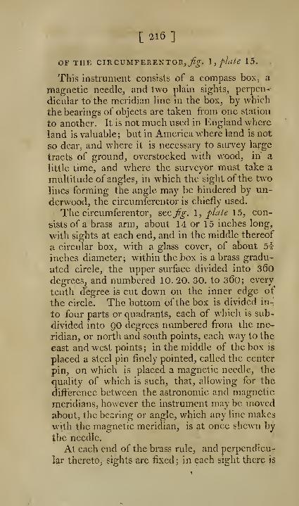
C 216 ]
OF THE CIRCUMFERENTOR,^^. \, plate 15.
This instrument consists of a compass box, a
magnetic needle, and two plain sights, perpen-
dicular to the meridian line in the box, by which
the bearings of objects are taken from one station
to another. It is not much used in England where
land is valuable; but in America where land is not
so dear, and where it is necessary to survey la|-ge
tracts of ground, overstocked with wood, in a
little time, and where the surveyor must take a
multitude of angles, in which the sight of the two
lines forming the angle may be hindered by un-
derwood, the circumferentor is chiefly used.
The circum.ferentor, sttfg. \, plate \5, con-
sists of a brass arm, about 14 or 15 inches long,
with sights at each end, and in the middle thereof
a circular box, with a glass cover, of about 51-
inches diameter; within the box is a brass gradu-
ated circle, the upper surface divided into 36odegrees, and numbered 10. 20. 30. to 360; every
tenth degree is cut down on the inner edge of
the circle. The bottom of the box is divided in-
to four parts or quadrants, each of which is sub-
divided into QO degrees numbered from the me«-
ridian, or north and south points, each way to the
east and west points; in the middle of the box is
placed a steel pin finely pointed, called the center
pin, on which is placed a magnetic needle, the
quality of which is such, that, allowing for the
difference between the astronomic and magnetic
meridians, however the instrument may be movedabout, the bearing or angle, which any line makeswith the magnetic meridian, is at once shewn by
the needle.
At each end of the brass rule, and perpendicu-
lar thereto, sights are fixed ; in each sight there is

THE CIP>.CUMFERENTOR. 'Jl/
& large and small aperture, or slit, one over the
other, these arc alternate; that is, if the aperture
be uppermost in one sight, it will be lowest in
the other, and so of the small ones; a fine piece
of sewing silk, or a horse hair runs through the
middle of the large slit. Under the compass boxis a socket to fit on the pin of the staff; the in-
strument ma}' be turned round on this pin, or
fixed in any situation by the milled screw; it mayalso be readily fixed in an horizontal direction bythe ball and socket of the staff, moving for tliis
purpose the box, till the ends of the needle amequidistant from the bottom, and traverse or play
with freedom.
Occasional variations in the construction of this
instrument, are, 1 . In the sights, which are some-times made to turn down upon an hinge, in
order to lessen the bulk of the instrument, andrender it more convenient for carriage; sometimesthey are made to slide on and off with a dovetail;
sometimes to fit on with a screw and two steady
pins. 2. In the box, which in some instruments
has a brass cover, and very often a spring is placed
within the box to throw the needle off" the cen-
ter pin, and press the cap close against the glass,
to preserve the point of the center pin from being
blunted by the continual friction of the cap of the
needle. 3. In the needle itself, which is made of
diflcrent forms. 4. A further variation, and for
the best, will be noticed under the account of the
improved circumferentor.
The surveying compass represented at J^g. 3,
plate 15, is a species of circumferentor, which has
hitherto been only applied to military purposes;
it consists of a square box, within which theie is
a brass circle divided into 36o degrees; in the
center of the box is a pin to carry a magnetic
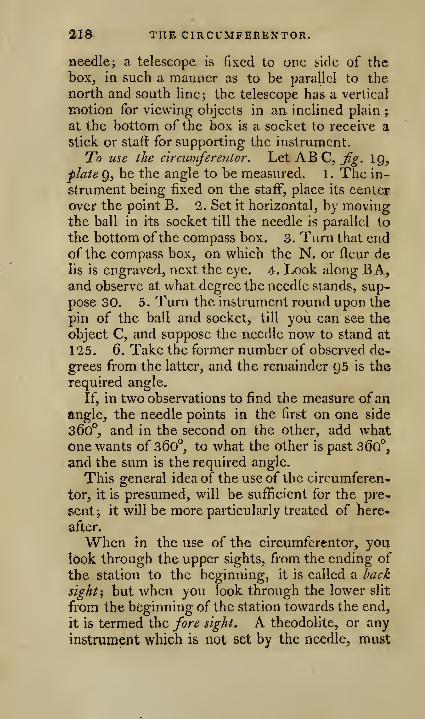
31S THE CIRCUMFEREI^TOR.
needle; a telescope is fixed to one side of thebox, in such a manner as to be parallel to the
north and south line; the telescope has a vertical
motion for viewing objects in an. inclined plain ;
at the bottom of the box is a socket to receive a
stick or staft for supporting the instrument.
To use the c'lrcumferentor. Let ABC, 7?^'. 19,
flate 9, be the angle to be measured. 1 . The in-
strument being fixed on the staff, place its center
over the point B. 1. Set it horizontal, by movingthe ball in its socket till the needle is parallel to
the bottom ofthe compass box. 3. Turn that endof the compass box, on which the N. or fleur delis is engraved, next the eye. 4. Look along BA,and observe at what degree the needle stands, sup-
pose 30. 5. Turn the instrument round upon the
pin of the ball and socket, till you can see the
object C, and suppose the needle now to stand at
1*25. 6. Take the former number of observed de-
grees from the latter, and the remainder 95 is the
required angle.
If, in two observations to find the measure ofanangle, the needle points in the first on one side
360°, and in the second on the other, add whatone wants of 36o", to what the other is past 36o°,
and the sum is the required angle.
This general idea of the use of the circumferen-
tor, it is presumed, will be suf^cient for the pre-
sent; it will be more particularly treated of here-
after.
When in the use of the circumferentor, youl6ok through the upper sights, from the ending of
the station to the beginning, it is called a back
sights but when you look through the lower slit
from the beginning of the station towards the end,
it is termed the fore sight. A theodolite, or any
instrument which is not set by the needle^ must
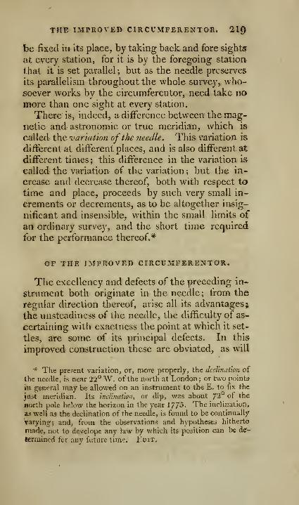
THte IMPROVED CIRCUMFERENTOH. 2,19
be fixed in its place, by taking back and fore sights
at every station, for it is by the foregoing station
that it is set parallel ; but as the needle preserves
its parallelism throughout the whole survey, who-soever works by the circumferentor, need take nomore than one sight at every station.
There is, indeed, a difference between the mag-netic and astronomic or true meridian, which is
called tho, 'variation of the needle. This variation is
different at different places, and is also different at
different times; this difference in the variation is
called the variation of the variation; but the in-
crease and decrease thereof, both with respect to
time and place, proceeds by such very small in-
crements or decrements, as to be altogether insig-
nificant and insensible, within the small limits of
an ordinary survey, and the short time required
for the performance thereof.*
OF THE IMPROVED CIRCUMFERENTOR.
The excellency and defects of the preceding in-
strument both originate in the needle; from the
regular direction thereof, arise all its advantages;
the unsteadiness of the needle, the difficulty of as-
certaining with exactness the point at which it set-
tles, arc some of its principal defects. In this
improved construction these are obviated, as will
* The present variation, or, more properly, the dccVmaUon of
the needle, is near 22" W. of the north at London; or two points
in general may be allowed on an instrument to the E. to fix the
just meridian. Its hidhiahoii, or dip, was about 72° of the
north pole below the horizt)n in the year 17/5. The inclination,
as well as the declination of the needle, is found to be continually
Varying:; and, from the observations and h^'potheses hitherto
made, not to develope any law by which its petition can be dc-
tenjiined for any future time, ilpix..

220 THE IMTROVED CIRCUMFERENTOR.
be evident from the following description. One ofthese instruments is represented ?itfg.1, plate 15.
A- pin of about three quarters of an inch diame-ter goes through the middle of thebox^ and forms
as it were a vertical axis, on which the instrument
may be turned round horizontally ; on this axis
an index AB is fastened, moving in the inside of
the box, having a nonius on the outer end to cut,
and subdivide the degrees on the graduated circle.
By the help of this index, angles may be taken
with much greater accuracy than by the needle
alone; and, as an angle may be ascertained by the
index with or without the needle, it of course re-
moves the difficulties, which would otherwise arise
if the needle should at any time happen to be acted
upon, or drawn out of its ordinary position by ex-
traneous matter; there is a pin beneath, wherebythe index may be fastened temporarily to the bot-
tom of the box, and a screw, as usual, to fix the
whole occasionally to the pin of the ball and socket,
so that the body of the instrument, and the index,
may be either turned round together, or the oneturned round, and the other remain fixed, as oc-
casion shall require. A further improvement is
that ofpreventing all hori%ontal motion of the ball in
the socket; the ball has a motion in the socket every
possible way, and every one of these possible mo-tions is necessary, except the horizontal one, whichis here totally destroyed, and every other possible
motion left perfectly free.*
* The instrument is made to turn into a vertical position, andby the addition of a spirit level to take altitudes and depression*.
The index AB has been found to interfere too much with the
free play of the needle. In the year 179^ I contrived an external
nonius piece a, jig. 6, to move against and round the graduated
circ'e h, either with or without rack-work or pinion. The cir-
cle and compass plate are fixed, and the nonius piece and outside
rim and sight carried round together when in use. This has
been generally approved of. Edit,
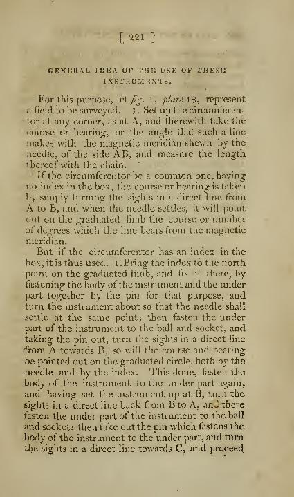
l 221 ]
GENERAL IDEA OF THE USE OP THESEINSTRUMENTS.
For this purpose, Ictj^^'-. 1, plate 18, represent
a lield to be surveyed. 1 . Set up the eircumferen-
tor at any corner, as at A, and therewith take the
course or bearing, or the angle that such a Hnemakes with the magnetic meridian shewn by the
needle, of the side AB, and measure the length
thereof with the chain.
If the circumferentor be a common one, havingno index in the box, the course or bearing is takenby simply turning the sights in a direct line fromA to B, and when tlie needle settles, it will point
out on the graduated limb the course or numberof degrees which the line bears from the magnetic
meridian.
But if the circumferentor has an index in the
box, it is thus used. 1 . Bring the index to the north
point on the graduated limb, and tix it there, by-
fastening the body of the instrument and the underpart together by the pin for that purpose, andturn the instrument about so that the needle shall
settle at the same point; then fasten the underpart of the instrument to the ball and socket, andtaking the pin out, turn the sights in a direct line
from A towards B, so will the course and bearing
be pointed out on the graduated circle, both by the
needle and by the index. This done, fasten the
body of the instrument to the under part again,
and helving set the instrument up at B, turn the
sights in a direct line back from B to A, anU there
fasten the under part of the instrument to the ball
and socket; then take out the pin which fastens the
body of the instrument to the under part, and turn
the sights in a direct line towards C, and proceed

^2 USES OF THE CiRCUMFEREXTOR, kc,
in the same manner all round the survey; so will
the courses or bearings of the several lines bepointed out both by the needle and the index, un-less the needle should happen to be drawn out of
its course by extraneous matter; but, in this case,
•theindex will not only shew the course or bearing,
'but will likewise shew how much the needle is so
ilrawn aside. After this long digression to explain
more minutely the use of the instruments, we mayproceed. 2. Set the circumferentor up at B, take
the course and bearing of B C, and measure the
length thereof, and so proceed with the sides C D,fDE, EF, FG, GA, all the way round to the
place of beginning, noting the several courses or
bearings, and the lengths of the several sides in a
field-book, which Icl, us suppose to be as the fol-
lowing :
1.
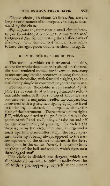
THE COMMON THEODOLITE. Q23
The 21 chains, 18 chains 20 links, &c. are the
lengths or distances of the respective sides, as mea-sured by the chain.
Fig. A, plate 15, represents a small circumferen-
tor, or theodolite; it is a kind that was much used
by General Roy, for delineating the smaller parts of
a survey. The diameter is 4 inches. It is better
to have the sight pieces double, as shewn in^^, 2.
OP THE COMMON THEODOLITE.
The error to which an instrument is liable^
where the whole dependance is placed on the nee-
dle, soon rendered some other hivention necessary
to measure angles with accuracy; among these, the
common theodolite, with four plain sights, took the
lead, being simple in construction, and easy in use.
The common theodolite is represented Jjg. 5,
pl-ate 14; it consists of a brass graduated circle, a
moveable index AB; on the top of the index is acompass with a magnetic needle, the compass boxis covered with a glass, two sights, C, D, are fixed
to the index, one at each end, perpendicular to the
plain of the instrument. There arc two more sights
£ F, which are fitted to the graduated circle at the
points of 360^ and 1 80° ; they all take on and off
for the convenicncy of packing. In each sight
there is, as in the circumferentor, a large and asmall aperture placed alternately, the large aper-
ture in one sight being always opposed to the nar-
row aperture in the other; underneath the brass
circle, and in the center thereof, is a sprang to fit
on the pin of the ball and socket, which fixes on a.
three-legged staff.
The circle is divided into degrees, which are
all numbered one way to 36o°, usually from the
left to the right, supposing yourself at the center
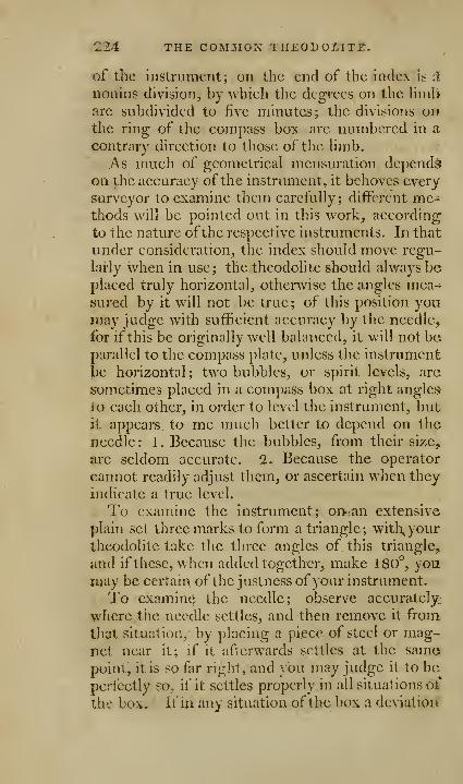
224 THE COMMON TIIEOD OHLlT]?.
of the instrument; on the end of the index is ^
nonius division, by which the degrees on the liml>
are subdivided to five minutes; the divisions onthe ring of the compass box are numbered in a
contrary direction to those of tlie Hmb.As much of geometrical mensuration depends
on the accuracy of the instrument, it behoves every
surveyor to examine them carefully ; different me-thods v^'ill be pointed out in this work, according
to the nature ofthe respective instruments. In that
under consideration, the index should move regu-
larly when in use; the theodolite should always beplaced truly horizontal, otherwise the angles mea-sured by it will not be true; of this position youmay judge with sufficient accuracy by the needle^
for if this be originally well balanced, it will not beparallel to the compass plate, unless the instrument
be horizontal ; two bubbles, or spirit levels, are
sometimes placed in a compass box at right angles
Lo each other, in order to level the instrument, butit appears, to me much better to depend on the
needle : 1 . Because the bubbles, from their size,
are seldom accurate. 2. Because the operator
cannot readily adjust them, or ascertain when they
indicate a true level.
To examine the instrument; oi>,an extensive
plain set three marks to form a triangle; with, your
theodolite take the three angles of this triangle,
and if these, when added together, make 180°, youmay be certain of the justness of your instrument.
To examine the needle; observe accurately
wPiere the needle settles, and then remove it from
that situation, by placing a pieee of steel or mag-net near it; if it afterwards settles at the samepoint, it is so far right, and you may judge it to be
perfectly so., if it settles properly in all situations of
the box. If in any situation of the box a deviatioit
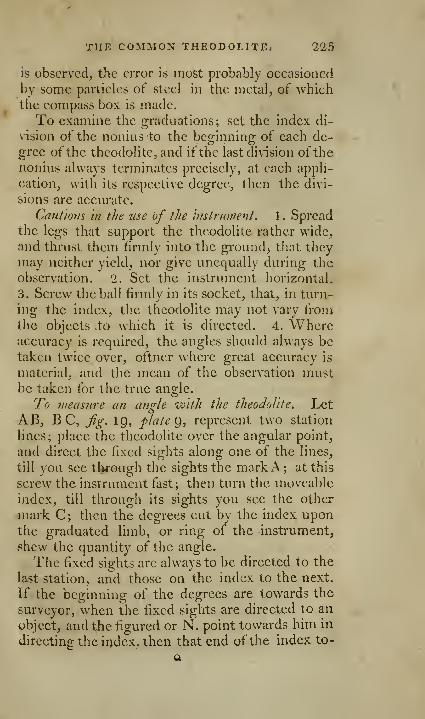
THE COMMON THEODOLITE, 225
is observed, the error is most probably occasioned
by some particles of steel in the metal, of whichthe compass box is made.
To examine the graduations; set the index di-
vision of the nonius to the beginning of each de-
gree of the theodolite, and ifthe last division ofthe
nonius always terminates precisely, at each appli-
cation, with its respective degree, then the divi-
sions are accurate.
Cautions in the use of the Instrument . 1 . Spreadthe legs that support the theodolite rather wide,
and thrust them firmly into the ground^ that they
may neither yield, nor give unequally during the
observation. 2. Set the instrument horizontal.
3. Screw the ball firmly in its socket, that, in turn-
ing the index, the theodolite may not vary fromthe objects to which it is directed. 4. Whereaccuracy is required, the angles should always betaken twice over, ot'tner where great accuracy is
material, and the mean of the observation mustbe taken for the true angle.
To measure an angle with the theodolite. LetAB, B C, Jig. IQ, plate g, represent two station
lines; place the theodolite over the angular point,
and direct the fixed sights along one of the lines,
till you see tl>rough the sights the markA ; at this
screw the instrument fast; then turn the moveable
index, till through its sights you see the other
mark C; then the degrees cut by the index uponthe graduated limb, or ring of the instrument,
shew the quantity of the angle.
The fixed sights are always to be directed to the
last station, and those on the index to the next.
If the beginning of the degrees are towards the
surveyor, when the fixed sights are directed to an
object, and the figured or N. point towards him in
directing the index, then that end of the index to-

I'lG THE COMMON PLAIN TABLET.
wards the surveyor will point out the anglc^ andthe south end of the needle the bearing; the ap-
plication of the instrument to various cases that
may occur in surveying, will be evident from whatwe shall say on that subject in the course of this
v.ork..
OF THE com:\ion PLAIN T Ai&LE, Jrg.l,plate 17.
The tabular part of this instrument is usually
made of two well-seasoned boards^, forming a pa-
rallelogram of about 15 inches long^ and 12 inches
broad; the size is occasionally varied to suit the
intentions of the operator.
The aforesaid parallelogram is framed with a
ledge on each side to support a box frame, whichframe confines the paper on the table, and keeps
it close thereto; the frame is therefore so contrived,
that it may be taken off and put on at pleasure,
either side upwards. Each side of the frame is
graduated; one side is usually divided into scales
of equal parts, for drawing lines parallel or per-
pendicular to the edges of the table, and also for
inore conveiviently shifting the paper; the other
face, or side of the frame, is divided into 3()0°, from
a brass center in the middle of the table, in order
that angles may be measured as with a theodolite;
on the same face of the frame, and on two of the
edges, fu-e graduated 180°; the center of thescr
degrees is exactly in the middle between the twoends, and about ith part of the breadth from oneof the sides.
A magnetic needle and compass box, covered
with a glass and spring ring, slides in a dovetail onthe under side of the tabkyand is fixed there by a
finger screw; it serves to point out the direction)
ijndbe a check ti])on the sights. ' -
drltE COMMOX PLAIN TABLE. 227
There is also a brass index somewhat larger than
the diagonal ot the table, at each end of which a
sight is fixed ; the vertical hair, and the middle of
the edge of the index, are in the same plain; this
edge is chamfered, and is usually called the fiducial
edge of the index. Scales of different parts in an
inch are usually laid down on one side ofthe index.
Under the table is a sprang to fit on the pin of
the ball and socket, by which it is placed upon a
thrce-le2:2:ed staff.
7o place the pap-er on the table. Take a sheet of
paper that will cover it, and wet it to make it ex-
pand, then spread it fiat upon the table, pressing
down the frame upon the edges to stretch it, andkeep it in a fixed situation ; when the paper is dry
it will by contracting become smooth and flat.
To shift thepaper on the plain table. When the
paper on the table is full, and there is occasion for
more, draw a line in any manner through the far-
thest point of the last station line, to which the
work can be conveniently laid down; then take
off the sheet of paper, and fix another on the table
;
draw a line upon it in a part most convenient for
the rest of the work; then fold, or cut the old
sheet of paper by the line drawn on it, apply the
edge to the line on the new sheet, and, as they lie
in that position, continue the last station line uponthe new paper, placing upon it the rest of the
measures, beginning where the old sheet left off,
and so on from sheet to sheet.
To fasten all the sheets of paper together, and
thus form one rough plan, join the aforesaid lines
accurately together, in the same manner as whenthe lines were traiuterred from the old sheets to
the new one. But if the joining lines upon the
old and new sheets have not the same inclination to
the i^ide of the table, the needle will not point to
Q 2
'228 THE COMMON PLAIX TABLE.
the original degree when the table is rectified. If
the needle therefore should respect the same de-
gree of the compass the easiest way of drawing
the line in the same position is to draw them both
parallel to the same sides of the table, by means of
the scales of equal parts on the two sides.
7\ use the plain table. Fix it at a convenient
part of the ground, and make a point on the paper
to represent that part of the ground.
Run a tine steel pin or needle through this
})oint into the table, against \\'hieh you must ap-
ply the fiducial edge of the index, moving it roundtill you perceive some remarkable object, or markset up for that purpose. Then draw a line from
the station point, along the fiducial edge of the,
index.
Now set the sights to another mark, or object,
and draw that station line, and so proceed till youhave obtained as many angular lines as are neces-
sarv from this station.
Tlie next requisite, is the measure or distance
from tile station to as many objects as may be ne-
cessary by the chain, taking at the same time the
offsets, to the required corners or crooked parts of
the hedges; setting off all the measures upon their
respective lines upon the table.
Now remove the table to some other station,
whose distance from the foregoing was previously
measured; then lay down the objects which ap-
pear from thence, and continue these operations
till your work is finished, measuring such lines as
are necessary, and determining as many as youcan by intersecting lines of direction, drawn from
different stations.
It seems to be the universal opinion of the best
surveyors, that the plain table is not an instrument
to be trusted to in large survxys, or on hilly situa-
THE IMPROVED PLAIX TABLE. 22^
tions; that it can only be used to advantage in
planning the ground plot of buildings, gardens, or
a tew small pareels of land nearly on a level.
Mr. Gardiner, whose authority as a surveyor is
inferior to no one, asserts, that the plain table sur-
veyors, when they find their work not to close
right, do often close it wrong, not only to save time
and labour, but the acknowledgement of an error;
which they are not sure they can amend-In uneven ground, where the table cannot in all
stations be set horizontal, or uniformly in any oneplace, it is impossible the work should be true in
all parts.
The contraction and expansion of the paper ac-
cording to the state of moisture in the air, is a
source of many errors in plotting; for betweena dewy morning and the heat of the sun at noon,
there is a great difference, which may in some de-
gree be allowed for in small w^ork, but cannot beremedied in surveys of considerable extent.
OF THE IMPROVED PLAIN T A.'Rl.'E,fg\2, plate IJ
.
To remedy some of the inconveniences, andcorrect some of the errors to which the commonplain table is liable, that Mhich we are now going
to describe has been constructed. It is usually
called Be'ightons plain table, though differing in
many respects from that described by him in the
rh'tlosophica I Transactions
.
It is a plain board, l6 inches square, with a
frame of box or brass round the edge, for the pur-
pose of being graduated. On the sides, AB, C D,are two grooves and holdfasts for confining.#i-mly,
or easily removing the paper; they are disengaged
by turning the screws under the table from the
right towards the l«ft, and drawn down and madt;
230 THE IMPROVED PLAIN TABLE.
to press on the paper by turning the screws the
contrary way. When the holdfasts are screwed
down, their surface is even with that of the table.
There are two pincers under the table, to hold
that part of the paper, which in some cases lies
beyond the table, and prevent its flapping about
with the wind.
The compass box is made to fit either side of
the table, and is fixed by two screws, and does
not, when fixed, project above one inch and an
half from the side of the table.
There is an index with a semicircle, and teles-
copic sight, EFG; it is sometimes so con-
structed, as to answer the purpose of a parallel
rule. The figure renders the whole so evident_,
that a greater detail would be superfluous.
The papers, or charts for this table, are to beeither of fine thin pasteboard, fine paper pasted oncartridge paper, or two papers pasted together,
cut as square as possible, and of such a length that
they may slide in easily, between the upright
parts, and under the flat part of the holders.
Any one of these charts may be put into the table
at any of the four sides, be fixed, taken out, andchanged at pleasure; any two ofthem maybe joined
together on the table, by making each of themmeet exactly at the middle, whilst near one half of
each will hang over the sides of the table; or, bydoubling them both ways through the middle, four
of them may be put on at one time meeting in the
6enter of the table. For this purpose, each chart
is always to be crossed quite through the middle;
by these means the great trouble and inaccuracy
in shifting the papers is removed. **-•
The charts thus used, are readily laid together
by corresponding numbers on their edges, andthus make up the whole map in one view; and,

nvIPROVED THEODOLITES. 231
bciiif^ in squares, arc portable, easily copied, en-
larged, or contracted.
The line of sight in viewing objects may, if that
method be preferred, be always over the center of
the tabic, and the station lines drawn parallel to
those measured on the land. Underneath the ta-
ble is a sprang to fit on the socket of a staff, with
parallel plates and adjusting screws.
Mr. Searle contrived a plain table, whose size
(which renders it convenient, while it multiplies
every error) is only five inches square, and con-sists of two parts, the table and the frame; the
frame, as usual, to tighten the paper observed
upon. In the center of the table is a screw, onMJiich the index sight turns; this screw is tightened
after taking an obscrvatiou.
THEODOLITES WITH TELESCOPIC SIGHTS.
In proportion as science advances, we find our-
selves standing upon higher ground, and are ena-
bled to see further, and distinguish objects better
than those that went before us : thus the great
advances in dividing of instruments have rendered
observers more accurate, and more attentive to the
necessary adjustments of their instruments. In-
struments arc not now considered as perfect, unless
they are so constructed, that the person who uses
them may either correct, or allow for the errors to
wliich they arc liable.
Theodolites with telescopic sights arp, without
jdoubt, the most accurate, commodious, and uni-
versal instruments -for the purposes of surveying,
and have been recommended as such by the mostexpert practitioners and best wa-iters on the sub-
ject, as Gardiner, Hammond^ Ciom, IStoney IVjUl^
fVudd'mgton, &c.
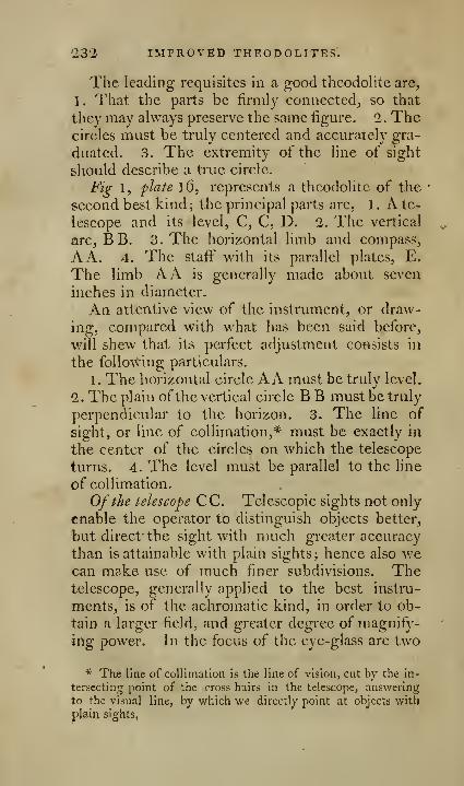
'232 IMPROVED THEODOLITES.
The leading requisites in a good theodolite are,
1. That the parts be limily eonneeted^, so that
they may always preserve the same figure. 1. Thecircles must be truly centered and accurately gra-
duated. 3. The extremity of the line of sight
should describe a true circle.
Fig 1, plate l6, represents a theodolite of the
second best kind; the principal parts are, 1 . A te-
lescope and its level, C, C, D. 1. The vertical
arc, BB. 3. The horizontal limb and compass,
A A. 4. The staff with its parallel plates, E.
The limb AA is generally made about seven
inches in diameter.
An attentive view of the instrument, or draw-
ing, compared with what has been said before,
will shew that its perfect adjustment consists in
the following particulars.
1 . The horizontal circle AA must be truly level.
1. The plain ofthe vertical circle B B must be truly
perpendicular to the horizon. 3. The line of
sight, or line of collimation,* must be exactly in
the center of the circles on which the telescope
turns. 4. The level must be parallel to the line
of collimation.
Of the telescope CC. Telescopic sights not only
enable the operator to distinguish objects better,
but direct the sight with much greater accuracy
than is attainable with plain sights; hence also wecan make use of much finer subdivisions. Thetelescope, generally applied to the best instru-
ments, is of the achromatic kind, in order to ob-
tain a larger field, and greater degree of magnify-
ing power. In the focus of the eye-glass are two
* The line of collimation is the line of vision, cut by the in-
tersecting point of the cross hairs in the telescope, answering
to the visual line, by which we directly^ point at objects with
plain sights,
IMPROVED THEODOLITES. ^233
very fine hairs, or wires, at right angles to each
other, whose ititersection is in the plain of the ver-
tical arc. The object glass may be moved to
different distanecs from the eye glasses, by turn-
ing the milled nut a, and may by this means beaccommodated to the eye of the observer, and tlic
<listance of the object. The screws for moving-and adjusting the cross hairs are sunk a little
within the eye tube, and at about one inch fromthe eye end: there are four of these screws, twoof which arc exactly opposite to each other, andat right angles to the other two. By easing oneof the screws, and tightening the opposite one,
the wire connected with it may be moved in op-posite directions. On the outside of the telescope
are two metal rings, which are ground perfectly
true; these rings are to lay on the su})porters c, c,
called Y's, which are fixed to the vertical arc.
Of the verl'ical arc B B. This arc is finnly fixed
to a long axis which is at right angles to the plain
of the arc. This axis is sustained by, and movea-ble on the two supporters, which are fixed firmly
to the horizontal plate: on the upper part of the
vertical arc are the two Y's for holding the teles-
cope; the inner sides of these Y's are so framed,
as to be tangents to the cylindrie rings of the te-
lescope, and therefore bear only on one part.
The telescope is confined to the Y's bv two loops,
which turn on a joint, and may therefore be rea-
dily opened and turned back, when the two pins
are taken out.
One side of the vertical arc is graduated to
every half degree, which are subdi\ ided to every
minute of a degree by the nonius. It is numberedeach way from O to C)0°, towards the eve end, for
angles of altitude; from O to 50°, towards the ob-
ject end, for angles of depression. On the other

234 IMPROVED THEODOLITES.
Side of the vertical arc are two ranges of divisions,
the lowermost for taking the upright heiglit oftimber in 100th parts of the distance the instru-
ment is placed at from the tree at the time of ob-
servation. The uppermost circle is for reducing
hypothenusal lines to horizontal, or to shew the
difference between the hypothenuse and base of a
right-angled triangle, always supposing the hypo-thenuse to consist of 100 equal parts; conse-
quently, it gives by inspection the number of links
to be deducted from each chain's length, in mea-suring up or down any ascent or descent, in order
to reduce it to a true horizontal distance^ simitar
to those on K'mg's quadrant, p. 205.
The vertical arc is cut with teeth, or a rack,
and may be moved regularly and wdth ease, byturning the milled nut b; there is sometimesplaced about the nonius a steady pin, by which it
may be fixed when at the o, or zero point of the
divisions.
Of the compass. The compass is fixed to the
upper horizontal plate; the ring of the compass is
divided into 36o°, which are numbered in a direc-
tion contrary to those on the horizontal limb.
The bottom of the box is divided into four parts,
or quadrants, each of which is subdivided to every
10 degrees, numbered from the meridian, or north
and south points each way to the east and west
points. In the middle of the box is a steel pin
jSnely pointed, on which is placed the magneticneedle; there is a Avire trigger for throw^ing the
needle off its point when not in use.
Of the hofhontal limh A A. This limb consist^
of two plates, one moveable on the other; the
outside edge of the upper plate is chamfered, to
serve as an index to the degrees on the lower.
The upper plate, together with the compass, ver-
IMPROVED THEODOLITES. *235
tica! arc, and telescope, arc easily turned round bya pinion fixed to the screw c; d is a nut lor fixing
the index to any part of' the hmb, and thereby
making it so secure, that there is no danger of its
being moved out of its place, while the instrument
is removed from one station to another. The ho^
rizontal limb is divided to half degrees, and num-bered from the right hand towards the left, 10,
'20, 30, &c. to 360 ; the divisions are subdivided bythe nonius scale to every minute of a degree.
On the upper plate, opposite to the nonius, arc
a few divisions similar to those oil the vertical arc,
giving the 100th parts for me^isuring the diameter
of trees, buildings, &c.
The whole instrument fits on the conical ferril
of a strong brass headed staff', with three substan-
tial wooden legs; the top, or head of the staff^
consists of two brass plates E, parallel to eachother; four screws pass through the upper plate,
and rest on the lower plate; by the action of these
screws the situation of the plate may be varied, so
as to set the horizontal limb truly level, or in a
plain parallel to the horizon; for this purpose, a
strong pin is fixed to the underside of the plate,
this pin is connected with a ball that fits into a
socket in the lower plate; the axis of the pin andball arc so framed, as to be always perpendicular to
the plate, and, consequently, to the horizontal
limb.
To adjust the theodolile. As so much of survey-
ing depends on the accuracy of the instruments,
it is absolutely necessary that the sur\'eyor should
be very expert in their adjustments, without whichhe cannot expect the instruments will properly
answer the purposes they were designed for, or
that his surveys will have the requisite exactness.
236 IMPROVED THEODOLITES.
The necessary adjustments to the theodolite,
which we have just described, are, 1 . That the line
of sight, or colliination, be exactly in the center
of the cylindric rings round the telescope, andwhich lie in the Y's. 2. That the level be paral-
lel to this line, or the axis of the above-mentioned
rings. 3. The horizontal limb must be so set,
that when the vertical arc is at zero, and the up-
per part moved round, the bubble of the level will
remain in the middle of the open space.
Previous to the adjustments, place the' instru-
ment upon the staff, and set the legs thereof firmly
upon the ground, and at about three feet from
each other, so that the telescope may be at a pro-
per height for the eye, and that two of the screws
on the staff that are opposite to each other may be
nearly in the direction of some conspicuous anddistant object.
To adjust the Tine of coUimatloii. Having set upthe theodolite agreeable to the foregoing direction,
direct the telescope to some distant object, pla-
cing it so that the horizontal hair, or wire, mayexactly coincide with some well defined part of the
object; turn the telescope, that is, so that the
tube of the spirit level D may be uppermost, andobserve whether the horizontal hair still coincides
with the object; if it does, the hair is in its right
position; if not, correct half the difference bymoving the hair, or wire, which motion is effected
by easing one of the screws in the eye tube, andtightening the other; then turn the telescope
round to its former position, with the tube of the
spirit level lowermost, and make the hair coincide
with the object, by moving the vertical arc; re-
verse the telescope again, and if the hair docs not
coincide with the same part of the object, you must
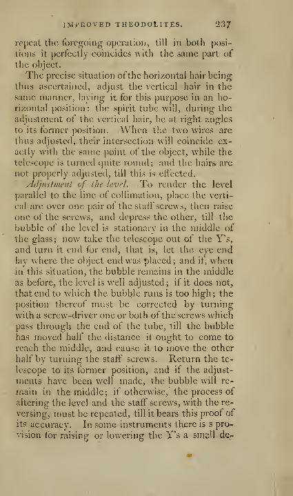
IMPROVED THEODOLITES. 237
repeat the foregoing operation, till in both posi-
tions it perfectly coincides with the same part of
the object.
The precise situation ofthe horizontal hair being
thus ascertained, adjust the vertical hair in the
same manner, laying it for this purpose in an ho-
rizontal position: the spirit tube will, during the
adjustment of the vertical hair, be at right angles
to its former position. When the two wires are
thus adjusted, their intersection will coincide ex-
actly with the same point of the object, while the
telescope is turned quite round; and the hairs are
not properly adjusted, till this is effected.
ylJjusIntent of the level. To render the level
parallel to the line of collimation, place the verti-
cal arc over one pair of the staff screws, then raise
one of the screws, and depress the other, till the
bubble of the level is stationary in the middle of
the glass; now take the telescope out of the Y's,
and turn it end for end, that is, let the eve endlay where the ol^ject end was placed ; and it", whenin this situation, the bubble remains in the middle
as before, the level is well adjusted; if it does not,
that end to which the bubble runs is too high; the
position thereof nuist be corrected by turning
with a screw-driver one or both ofthe screws whichpass through the end of the tube, till the bubble
has moved half the distance it ought to come to
reach the middle, and cause it to move the other
half by turning the staff' screws. Return the te-
lescope to its former position, and if the adjust-
ments have been well made, the bubble will re-
main in the middle; if otherwise, the process of
altering the level and the staff" screws, with the re-
versing, nmst be repeated, till it bears this proof of
its accuracy. In some instruments there is s pro-
vision for raising- or lowering the Y's a small de-
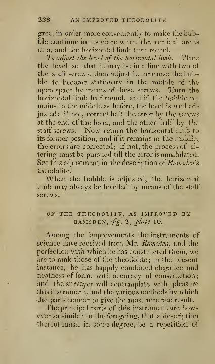
238 Ajsr IMPROVED theodolitf:
grcc, in order more conveniently to make the bub-ble continue in its place when the vertical arc is
at o, and the horizontal limb turn round.
To adjust ihe level of the horizontal Ihiih. Place
the level so that it may be in a line with two of
the staff screws, then adjust it, or cause the bub-ble to become stationary in the middle of the
open space by means of these screws. Turn the
horizontal limb half round, and if the bubble re-
mains in the middle as before, the level is well ad-
justed; if not, correct half the error by the screws
at the end of the level, and the other half bv the
staff screws. Now return the horizontal limb to
its former position, and if it remains in the middle,
the errors are corrected; if not, the process of al-
tering must be pursued till the error is annihilated.
See this adjustment in the description oi Ramsclen&
theodolite.
When the bubble is adjusted, the horizontal
limb may always be levelled by means of the staff
screws.
OF THE THEODOLITE, AS IMPROVED BYRAMSDEX, fg. 2, flale 16.
Among the improvements the instruments ofscience have received from Mr. Ramsdeii, and the
perfection with which he has constructed them, wearc to rank those of the theodolite; in the present
instance, he has happily combined elegance andneatness of form, with accuracy of construction
;
and the surveyor will contemplate with pleasure
this instrument, and the various methods by whichthe parts concur to give the most accurate result.
The principal parts of this instrument are how-ever so similar to the foregoing, that a description
thereof must, in some degree, be a repetition of

BY RAMSDEM. 239
what has been ah'cady described, and requires less
detail here.
F F represents the horizontal limb, of six,
seven, or eight inehes in diameter, but gene-
rally of seven inches, so called, because when in
use, it ought always to be placed parallel to the
horizon. It consists, like the former, oftw^o plates,
the edges of these two are chamfered, so that the
divisions and the nonius are in the same plaiii,
which is oblique to the plain of the instrument.
The limb is divided into half degrees, and subdi-
vided by the nonius to every minute; it is num-bered to 3()0° from the north towards the east: be-
sides these, the tangents to 100 of the radius are
laid down thereon.
The upper plate is moved by turning the
pinion G: on this plate are placed, at right angles
to each other, two spirit levels for adjusting moreaccurately the horizontal limb.
N O P is a solid piece fitted on the upper hori-
zontal plate, by means of three capstan headed
screws, passing through three similar screws. Bythe action of these, the vertical arc may be set per-
pendicular to the horizontal limb, or be made to
move in a vertical plain. On this solid piece, are
fixed two stout supports, to carry the axis of the
vertical arc, which arc is moveable by the pinion
E. On the upper part of the vertical arc, are the
Y's and loops to support and confine the tele-
scope; the Y's arctangents to the cylindric rings
ofthe telescqpe, which rings are turned, and then
ground as true as possible, and are prevented from
tnoving backwards or forwards, by nieans of two
shoulders. The telescope is achromatic, and
about twelve inehes in length, and may be ad-
justed to the eye of the observer, or the distance,
of the object, by turning the milled nut B. The
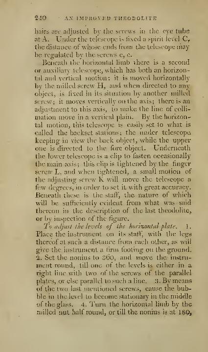
240 ' AX mntovED theodolite
Imirs are adjusted by the screws in the eye tube
at A. Under the teleseopc is fixed a spirit level C^the distance of whose ends from the telescope maybe rcQ-ulated bv tlie screws c, c.
Beneath the horizontal limb there is a second
or auxiliary telescope, w hieh has both an horizon-
tal and vertical motion: it is moved horizontally
by the milled screw H, and wdien directed to any
object, is fixed in its situation by another milled
screw; it moves vertically on the axis; there is an
adjustment to this axis, to make the line of colli-
mation move in a vertical plain. By the horizon-
tal motion, this telescope is easily set to what is
called the backset stations; the under telescopa
keeping in view the back object, while the upper
one is directed to the fore object. Underneath
the lower telescope is a clip to fasten occasionally
the main axis; this clip is tightened by the finger
sci'cw L, and when tightened, a small motion of
the adjusting screw K will move the telescope a
few degrees, in order to set it with great accuracy.
Beneath these is the stafl^", the nature of which
will be sufficiently evident from w hat w^as said
thereon in the description of the last theodolite,
or by inspection of the figure.
To a{]just the levels of the horizontal plate. 1.
Place the instrument on its staff, with the legs
thereof at such a distance from each other, as will
give the instrument a firm footing on the ground.
2. Set the nonius to 36o, and move the instru-
ment roun.d, till one of the levels is either in a
right line with two of the screws of the parallel
plates, or else parallel to such a line. 3. By meansof the two last mentioned screws, cause the bub-
ble in the level to become stationary in the middle
of the glass. 4. Turn the horizontal limb by the
milled nut half round, or till the nonius is at 180,
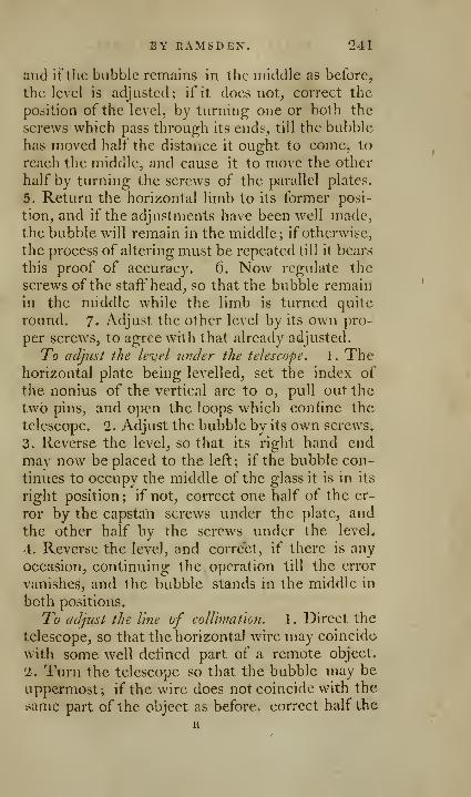
BY RAMS DEN. 241
and if the bubble remains in the middle as before,
the level is adjusted; if it does not, correct the
position of the level, by turning one or both the
screws which pass through its ends, till the bubble
has moved half the distance it ought to come, to
reach the middle, and cause it to move the other
half by turning the screws of the parallel plates.
5. Return the horizontal limb to its former posi-
tion, and if the adjustments have been well made,the bubble will remain in the middle; if otherwise,
the process of altering must be repeated till it bears
this proof of accuracy. 6. Now regulate the
screws of the staff head, so that the bubble remainin the middle while the limb is turned quite
round. 7- Adjust the other level by its own pro-
per screws, to agree with that already adjusted.
To adjust the level under the telescope. 1 . Thehorizontal plate being levelled, set the index of
the nonius of the vertical arc to o, pull out the
two pins, and open the loops which confine the
telescope. 2. Adjust the bubble by its own screws.
3. Reverse the level, so that its right hand endmay now be placed to the left; if the bubble con-
tinues to occupy the middle of the glass it is in its
right position ; if not, correct one half of the er-
ror by the capsttfn screws under the plate, and
the other half by the screws under the level.
4. Reverse the level, and correct, if there is any
occasion, continuing the operation till the error
vanishes, and the bubble stands in the middle in
both positions.
To adjust the line of coU'miation. 1 . Direct the
telescope, so that the horizontal wire may coincide
with some well defmed part of a remote object.
2. Turn the telescope so that the bubble may be
uppermost; if the wire does not coincide with the
same part of the object as before, correct half the
R

242 VARIATION IN THEODOLITES.
difference by moving the vertical circle, and the
other half by moving the wire, which is effected
by the screws in the eye tube of the telescope;
and so on repeatedly, till the difference wholly
disappears. Lastly, adjust the vertical wire in the
same manner; when the two wires are properly
adjusted, their intersection will coincide exactly
with the same point of an object, while the teles-
cope is turned quite round.
VARIATIONS IN THE CONSTRUCTION OF THEO-DOLITES WITH TELESCOPIC SIGHTS.
To accommodate those who may not wish to goto the price of the foregoing instruments, others
have been made with less w^ork, in order to be af-
forded at a lower price; one of these is represented
2iXfig. 5, pJate 15. It is clear from the figure, that
the difference consists principally in the solidity
of the parts, and in there being no rack-work to
"•ive motion to the vertical are and horizontal limb.
The mode of using it is the same with the other,
and the adjustment for the line of collimation, andthe level under the telescope, is perfectly similar
to the same adjustments in the instruments already
described, a further description is therefore un-necessary.
A larger kind is also made without rack-work,
similar to j/f^. l, plate l6.
A small one, about four inches in diameter,
was invented by the late Mr. Be?ij. Martin, in
which the telescope, about six inches in length,
with a level, has no vertical motion, but the ho-
rizontal motion is given by a pinion; and it maybe turned into a vertical position to take angles
of altitudes or depressions. The divisions by the
nonius arc to five minutes.

[ 243 ]
THE Following account of theobolitesIS ADDED BY THE EDITOR.
It generally happens, that the observer has oc-
casion to take the vertical and horizontal angles at
the same time, by portable as well as by larger theo-dolites; the following is,therefore, recommended as
themost complete and portable instrument hitherto
made, and is in truth almost the best theodolite in
miniature. Its construction renders it somewhatmore expensive than those before described. It
is the one that the late author alluded to in a note,
page 315 of the former edition of this book, buthad not time to describe it.
Fig.y,p/A 4, IS a representationof theinstrumcnt.
The graduated limb and index plate A, A, arc
about four inches in diameter, and move by rack
and pinion B; it reads off by means of the nonius
to three minutes of a degree; If the observer
should not object to very fine divisions, it may beto two minutes of a degree. The achromatic te-
lescope C is about six inches in length, and con-
tains a small spirit bubble at C, partly sunk into
the tube; it turns upon a long axis, and is
moved very accurately by rack and pinion on the
arc at D. This arc is necessarily of a short length,
but adm.its about 30 degrees motion on each side
of 0, for altitudes or depressions. The staff^
which from one piece opens into a tripod, is about
five feet in length, and has the parallel plates of
adjustment at the top. A small screw from these
screws into a socket under the limb A, and by an
external rim of metal, the horizontal motion only
of the theodolite is produced, when the plates are
properly set by the screws. The telescope rests
upon a cradle, and by opening the two semicircles
R 2
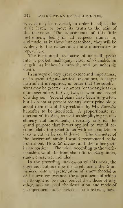
144 DESCRIPTION OF THEODOLITES,
a, a, it may be reversed, in order to adjust thespirit level, or prove its truth to the axis of
the telescope. The adjustments of this little
instrument, being in all respects similar to^
and made, as in those just described, they will beevident to the reader, and quite unnecessary to
repeat here.
The instrument, exclusive of its staff, packsinto a pocket mahogany case, of 6 inches in
length, 4t inches- in breadth, and sf inches in
depth.
In surveys of very great extent and importance,
or in great trigonometrical operations, a larger
instrument is required, in order that the subdivi-
sions may be greater in number, or the angle taken
more accurately, to five, two, or even one second
of a degree. Several plans have been suggested,
but I do' not at present see any better principle to
adopt than that of the great one by Mr. Ramsdenhereafter to be described. A proportionate re-
duction of its size, as well as simplifying its ma-chinery and movements, necessary only for the
grand purpose that it was applied to, would ac-
commodate the practitioner with as complete an
instrument as he could desire. The diameter of
the horizontal circle I would recommend to be
from about 15 to 20 inches, and the other parts
in proportion. The price, according to the work-manship, would be from about 6o to 120 guineas,
stand, cases, &c. included.
In the preceding impression of this work, the
ingenious author^ now deceased, made the fron-
tispiece plate a representation of a new theodolite
of his own contrivance, the adjustments of whichhe thought to be more perfect than those of anyother, and annexed the description and mode of
its adjustments to his preface. Future trials, how-

BY THE EDITOR. 245
ever, on his own part, as well as by the hands of
others, gave me reason to conclude that it wasnot answerable to the intended improvements;although more complicated and costly than that
represented onfg. 1, plate l6, yet it was less sus-
ceptible of accuracy, and not so simple and easy
in the adjustments; I have, therefore, thoughtproper to dispense with it here, and substitute a
short description ofthe largest, most accurate andelegant theodolite ever made.
It is hardly necessary to acquaint the intelligent
reader, that the theodolite is a kind of general,
angular instrument, not useful merely to ascertain
angles for the surveyor, but also for many pur-
poses in practical astronomy, and other sciences
that have trigonometry as their fundamental basis.
Some years ago it was found necessary to in-
stitute a course of trigonometrical operations in
this country and in France, in order to determine
with precision the distance between the RoyalObservatories of Greenwich and Paris. The late
General Roy was deputed as the chief manager in
this country. A very accurate theodolite to take
angles, and other instruments, were essentially ne-
cessary; and the General was fortunate enough to
obtain the best articles and assistance that wasever afforded in any mathematical undertaking
whatever.
The frontispiece to this book gives a general
view of the theodolite, the reader must not ex-
pect from this a complete representation of all the
minuter parts. In the General's account in the
Philosophical Transactions, containing 26 quarto
pages, and six large plates, replete with explanatory
figures, he confined himself only to the describ-
ing of the principal parts ; and the limits of this
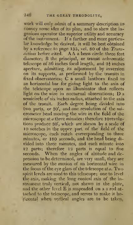
'24(5 THE GREAT THEODOLITE,
work will only admit of a summary description to
convey some idea of its plan, and to shew the in-
genious operator the superior utility and accuracyof the instrument. If a further and more particu-
lar knowledge be desired, it will be best obtainedby a reference to page 135, vol. 80 of the Trans-actions before cited. A A. a brass circle three feet
diameter; B the principal, or transit achromatic
telescope of 36 inches focal length, and 2^ inches
aperture, admitting its adjustment by inversion
on its supports, as performed by the transits in
fixed observatories; C a small lanthorn fixed to
an horizontal bar for giving light to the axis ofthe telescope upon an illuminator that reflects
light on the wire in nocturnal observations; D a
semicircle of six inches radius, attached to the axis
of the transit. Each degree being divided into
two parts, or 30', and one revolution of the mi-crometer head moving the wire in the field of the
microscope at a three minutes : therefore lOrevolu-
tions produce 30', which are shewn by a scale of
10 notches in the upper part of the field of the
microscope, each notch corresponding to three
minutes, or 180 seconds, and the head being di-
vided into three minutes, and each minute into
12 parts; therefore 12 parts is exjual to five
seconds. When the angles of altitude and de-
pression to be determined, are very small, they are
measured by the motion of an horizontal wire in
the focus of the eye glass of the telescope at^. Twospirit levels are used to this telescope; one to level
the axis, making the long conical axis of the in-
strument truly vertical, not shewn in the plate,
and the other level E is suspended on a a rod at-
tached to the telescope, and serves to make it ho-
rizontal when vertical angles arc to be taken,
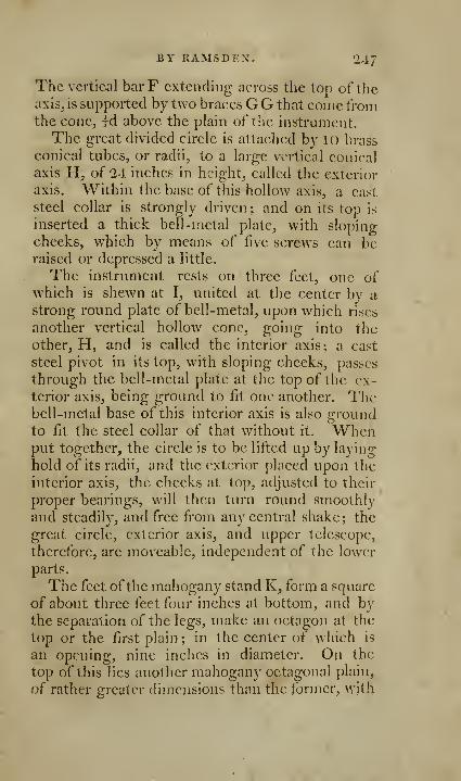
BY nAMSDEX. 24/
The vertical bar F extending across the top of theaxis, is supported by two braces GG that come fromthe cone, Id above the plain of the instrument.
The great divided circle is attached by 10 brass
conical tubes, or radii, to a large vertical conical
axis H, of 24 inches in height, called the exterior
axis. Within the base of this hollow axis, a cast
steel collar is strongly driven ; and on its top is
inserted a thick bell-metal plate, with sloping
cheeks, which by means of five screws can beraised or depressed a little.
The instrument rests on three feet, one ofwhich is shewn at I, united at the center by astrong round plate of bell-metal, upon which rises
another vertical hollow cone, going into the
other, H, and is called the interior axis; a cast
steel pivot in its top, with sloping cheeks, passes
through the bell-metal plate at the top of the ex-
terior axis, being ground to fit one another. Thebell-metal base of this interior axis is also groundto fit the steel collar of that without it. Whenput together, the circle is to be lifted up by laying-
hold of its radii, and the exterior placed upon the
interior axis, the cheeks at top, adjusted to their
proper bearings, will then turn round smoothly
and steadily, and free from any central shake ; the
great circle, exterior axis, and upper telescope,
therefore, are moveable, independent of the lower
parts.
The feet ofthe mahogany stand K, form a square
of about three feet four inches at bottom, and by
the separation of the legs, make an octagon at the
top or the first plain; in the center of which is
an opening, nine inches in diameter. On the
top of this lies another mahogany octagonal plain,
of rather greater dimensions than the former, with
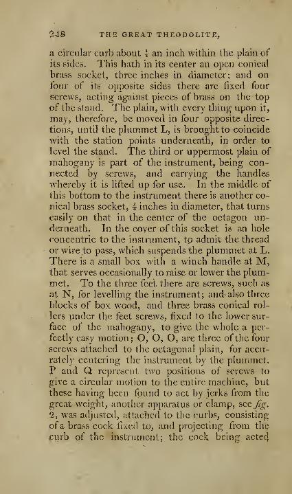
0,48 THE GREAT THEODOLITE,
a circular curb about -'- an inch within the plain of
its sides. This hath in its center an open conical
brass socket, three inches in diameter; and onfour of its opposite sides there are fixed four
screws, acting against pieces of brass on the top
of the stand. The plain, with every thing upon it,
may, therefore, be moved in four opposite direc-
tions, until the plummet L, is brought to coincide
with the station points underneath, in order to
level the stand. The third or uppermost plain of
mahogany is part of the instrument, being con-
nected by screws, and carrying the handles
whereby it is lifted up for use. In the middle of
this bottom to the instrument there is another co-
nical brass socket, i inches in diameter, that turns
easily on that in the center of the octagon un-derneath. In the cover of this socket is an hole
concentric to the instrument, to admit the thread
or wire to pass, which suspends the plummet at L.
There is a small box with a winch handle at M,that serves occasionally to raise or lower the plum-met. To the three feet there are screws, such as
at N, for levelling the instrument; and also three
blocks of box wood, and three brass conical rol-
lers under the feet screws, fixed to the lower sur-
face of the mahogany, to give the whole a per-
fectly eavSy motion; O, O, O, are three of the four
screws attached to the octagonal plain, for accu-
rately centering the instrument by the plummet.P and Q represent two positions of screws to
give a circular motion to the entire machine, but
these having been found to act by jerks from the
great weight, another apparatus or clamp, see Jig.
,2, was adjusted, attached to the curbs, consisting
of a brass cock fixed to, and projecting from the
curb of the instrument; the cock being acte4

BY RAMSDEX. 249
upon by two screws working in opposite direc-
tions, and which arc clamped to the curb of the
octagon.
The curb upon which the feet of the instru-
ment rest, carries the mahogany balustrade R R,fitted to receive a mahogany cover, that guards
the whole instrument. In this cover are four
small openings, one for each of the vertical mi-
croscopes S, S, one for the clamp of the circle,
and one for the socket of the Hook's, joint. Thiscover secures the circles and its cones from dirt,
and serves conveniently for laying any thing upon,that may be wanted near at hand ; and particu-
larly lanthorns used at night, for reading off the
divisions on the limb of the instrument.
There is a lower telescope T, lying exactly un-der the center of the instrument, and directed
through one of the openings on the balustrade,
and used only for terrestrial objects, requires buta small elevation, and has an axis of 17 inches in
length, supported by the braces attached to the
feet. It is moved by rack-work, by turning the
pinion at V. There is a small horizontal motionthat can be given to the right hand of the axis of
the end of this telescope. The whole instrument
being nicely levelled, the upper telescope at zero,
and likewise on its object, the lower telescope
by help of this adjustment is brought accurately
to the same object, from the point of commence-ments from which the angles are to be measured.
There are three flat arms, one of which is re-
presented at U, fixed by screws to the edge of the
bell-metal plate. These arms are also braced to
the feet of the instrument, rising as they project
outwards towards the circumference of the circle,
going beyond it about li inches. One arm, lying
directly over one of the fect_, is that to which is at-
tached wheels and screws moved by Hook's joint.

250 THE GREAT THEODOLITE,
not seen in the figure, and also a clamp to the
circle. It is this that produces the accurate motionof the circle. The other two arms, one of whichalso lies over a foot, and the other directly oppo-site to it, become the diameter of the circle, hav-
ing their extremities terminated on a kind of
blunted triangular figure, forming the bases of
pedestals, whereon stand the vertical microscopes
S, S. The arms, braces, base, &c. are every wherepierced, in order to lessen weight without di-
minishing strength.
The angles are not read off in this instrument
by a nonius as common to others, but with micros-
copes, and which form the most essential part of
the instrument. But a short account of them can
be given here, an adequate idea can only be ob-
tained by a reference to the Philosophical Trans-
actions, page 145 and 149. That horizontal mi-croscope for the vertical angles has been already
mentioned. The two vertical ones S, S, are usedfor reading off the divisions on the opposite sides
ofthe circle immediately under them. Each mi-
croscope contains two slides, one over the other,
their contiguous surfaces in the foci of the eye-
glasses. The upper one is a very thin brass plate,
at its lower surface is attached a fixed wire, having
no other motion than what is necessary for adjust-
ment, by the left hand screw to its proper dot, as
hereafter to be explained. The other slide is of
steel of one entire piece, directly under the for-
mer, of sufficient thickness to permit a micro-
meter screw of about 72 threads in an inch to
be formed of it. To its upper surface is fixed the
immoveable wire, which changes its place by the
motion of the micrometer head. This head is di-
vided into 60 equal parts, each ofwhich represents
one second or angular motion of the telescope.
This steel slide is attached by a chain to the
BY BAMSDEX. ^51
spring of a watch coiled up within a small barrel
adjacent to it in the frame. By this no time what-
ever is lost, the smallest motion of the head being:
instantly shewn by a proportionable motion of
the wire in the field of the microscope.
Each microscope is supported between its pil-
lars, and can be a little raised or depressed in re-
spect to the plain of the circle by two levers. Bythis motion distinctness is obtained of the wires,
and by the motion of the proper screw of the ab-
ject lensc, which follows that given to the wholemicroscope, the scale is so adjusted, that ] 5 revo-
lutions of the head shall move the wire over 15',
or one grand division of the limb, equal to 900",
each degree on the circle being only divided into
four parts. To effect this, at the same time the
fixed wire must bisect the dot on a gold tongue,
the moveable wire must also bisect the dot at 180°
on the limb, as well as a first notch in the magni-fied scale at the bottom of the plate. In this ad-
justment there is another circumstance to be at-
tened to, viz. that 60 on the micrometer headshould stand nearly vertical, so as to be conveni-
ently seen ; a few seconds of inclination are of noconsequence, because the dart, or index, being
brought to that position, whatever it may be, mustalways remain there, any derangement of the in-
strument excepted. But if, when the wires coin-
cide with their respective dots, and the first notch
60 on the micrometer head should happen to be
underneath, or so far from the vertex side as to be
seen with difficulty, then the gold tongue is to be
moved a little by capstan head screws, which act
against each other on the opposite extremities of
the axis. Thus, by repeated trials the purpose
will be effected, viz. the 60, to which the dart is
to be set, will stand in a place easily seen. It is
not to be expected that each microscope will give
2.52 THE GREAT THEODOLITE.
just 900 seconds for the run of 15 minutes; with-
out loss of time this cannot be done; besides, twoobservers will adjust the microscopes differently.
After several trials ofthe runs in measuring 15 mi-
nutes in the different parts of the limb, one mi-
croscope gave S96", while the other gave at a me-dium 901''; in a year afterwards, the former gave
900", while the latter gave 894". These ^.iffe
rences were allowed for in the estimation of angles
for computation.
The gold tongue mentioned is extremely thin,
and goes close to the surface of the circle. This
contrivance of a tongue with a dot was to guard
against any error from any accidental motion given
to the instrument between the observations, andif any, it immediately detected them. This was also
a severe check upon the divisions of the instru-
ment. General Roy observes, that it rarely hap-
pens that two observers, reading off with the op-
posite m.icroscopes, differ more than half a second
from each other at the first reading; and judges,
that in favourable weather for repeating the observa-
tion with the telescope, a wonderful degree of accu-
racy in the measure of the angles may be obtained.*
For the auxiliary apparatus, such as the \00feetsteel chain, portable scaffold, tripod ladder, common
ffag-staff, tripodfor white lights, portable crane, &c.
the reader will see the account of in the Trans-
actions before cited. The horizontal angles taken
by the instrument as regulated by the General,
since deceased, are to the tenth of a second.
* The weighr of the whole instrument was about 200 pounds, and the
price, as 1 have been informed, about 350 guineas. By the completion of the
measurements and the necessary calculations, the difference of the two meri-
dians made <)' z6", as before fixed by Dr. Maske/ync.
A second instrument has since been made, and is now using by Col. !Vi:liiims,
Cap. jMucige, and Mr. Dnlby, from whose skill and ingenuity it is expected a
very arrwute survey of this country will be made. In this instrument, the
great circle is divided to 10 minutes, improvements made in the microscopes,
Ac. by Mr. Ranfsden. Sec Philos^jphicai Traruactions for 1 795.
[ ^53 J
DESCRIPTION, USE,
AND METHOD OF ADJUSTING
IIADLEY's QUADRANT.*
" At the appointed time, when it pleased the
Supreme Dispenser ot' every {^ood gift to restore
light to a bewildered world, and more particularly
to manifest his wisdom in the simplicity, as well
as in the grandeur of his works, he opened theglorious scene with the revival of sound astro-
nomy." This observ^ation of an excellent philo-
sopher and physician -|- is verified in every instance
of the progress of science; in each of which wemay trace some of the steps of that vast plan ofDivine Providence to which all things arc con-
verging, namely, the bringing all his creatures to
a state of truth, goodness, and consequent happi-
ness; an end worthy of the best and wisest of
beings, and which we may perceive to be gradu-
ally effecting, by the advancement of knovvledge,
the diffusion of liberty, and the removal of error,
that truth and virtue may at last shine forth in all
the beauty of their native colours.
It is thus that the discovery of the compass gave
rise to the present art of navigation; and whenthis art grew of more importance to mankind,Divine Providence blessed them w^ith the invention
of Hadleys quadrant, and in our own day and our
own time has further improved both it and the art
* This account of Hadley's quadrant, &c. is extracted from,
a small tract I published thereon sometime since, 8vo.
f Sir John Pringle's Six Discourses to the Royal Society,
254 iiadley's quadrant.
of navigation, by the present method of finding
the longitude, which enables the mariner to ascer-
tain with certainty his situation on the unvariedface of the ocean.
Hadley's quadrant or sextant is the only knowninstrument, on which the mariner can depend for
determining with accuracy and precision his lati-
tude and longitude. It is to the use of this instru-
ment that navigation is indebted for the very great
and rapid advances it has made within these few
years. It is easy to manage, and of extensive use,
requiring no peculiar steadiness of hand, nor anysuch fixed basis as is necessary to other astrono-
mical instruments. It is not the science of navi-
gation only which is indebted to this instrument,
but its uses are so extensive in astronomy, that it
may, accompanied with an artificial horizon, with
propriety be called 2iportable ohservafory, and in this
work we shall exemplify its application to surveying.
Mankind are ever desirous of knowing to whomthey are indebted for any peculiar or useful disco-
very; it. is the tribute of gratitude, and a rewardto merit. In the present instance there is no dif-
ficulty in giving the information; the respective
claims of the inventors arc easily decided. Thefirst thought originated with the celebrated Dr.Hooke, it was completed by Sir Isaac Newton, andpublished by Mr. Hadley.
Notwithstanding, however, the manifest supe-
riority of this instrument over those that were in.
use at the time of its publication, it was manyyears before the sailors could be persuaded to
adopt it, and lay aside their imperfect and inaccu-
rate instruments: so great is the difficulty to re-
move prejudice, and emancipate the mind from
the slavery of opinion.

PROPERTIES OF HADLEy's QUADRANT. 255
No instrument has undergone, since the origi-
nal invention, more changes than the quadrant of
Hadley; of the various aherations, many have hadno better foundation than the conceit and caprice
of the makers, who by these attempts have often
rendered the instrument more complicated in con-
struction and more difficult in use, than it was in
its original state.
ESSEXTIAL PROPERTIES OF HADLEy'sQ.UADRANT.
It is not my intention under this head to enu-merate all the advantages of this instrument; butbarely to point out one or two of those essential
properties which distinguish it from every other
instrument of the kind, and rank it among one of
the greatest improvements in the practice of navi-
gation.
It is an essential property of this instrument,
derived from the laws of reflection, that half de-
grees on the arc answer to whole ones in the an-
gles measured: hence an octant, or the eighth
part of a circle, or 45 degrees on the arc, serves to
measure QO degrees ; and sextants will measure an
angular distance of 120 degrees, though the arc of
the instrument is no more than 6o degrees.* It
is from this property that foreigners term that in-
strument an octant, which we usually call a qua-
drant, and which in etlect it is. This property
reduces indeed considerably the bulk of the in-
strument ; but at the same time it calls for the
utmost accuracy in the divisions, as every en'or
on the arc is doubled in the observation.
* For a concise explanation of the theory, Sec, see my pam-phlet on this instrumtnt. 8\-o. Kdit.

136 DESCRIPTION OP
Another essential, and indeed an invaluable pra*
perty of this instrument, whereby it is rendered
peculiarly advantageous in marine observations, is,
that it does not require any peculiar steadiness ot
the hand, nor is liable to be disturbed by the
ship's motion ; for, provided the mariner can see
distinctly the two objects in the field of his in-
strument, no motion nor vacillation of the ship
will hinder his observation.
Thirdly, the errors to which it is liable are easily
discovered, and readily rectified, while the appli-
cation and use of it is facile and plain.
The principal requisites in a good sextant or
quadrant, are, 1. That it be strong, and* so con-
structed as not to bend across the plain. 2. Thatit be accurately divided. 3. That the surfaces of
the glasses be perfectly plain and parallel to each
other. 4. That the index turn upon a long axis.
5. That the motion be free and easy in every part,
and yet without the least shake or jerk.
DESCRIPTION OF HADLEy's QUADRANT.
Fjg. I, ^late 19, represents a quadrant, or oc-
tant, ofthe common construction. The following
parts are those which require the particular atten-
tion of the observer.
I. BC the arc.
II. A D the index, a b the nonius scale.
III. E the index-glass.
IV. F the fore horizon-Q-lass.
V. G the back horizon-fflass.oVI. K the dark glasses or screens.
VII. H I the vanes or sights.
VIII. The arcBC is called the //"/«/' or qtiadrantal
arc, the arc cd lying from o, towards
the right is called the arc of excess.
[ 257 ]
OF THE QUADRANT.
The quadrant consists of an arc B C^ firmly at-
tached to two radii, or bars, AB, AC, which are
strengthened and bound together by the twobraces LM.Of the mdex. The index D is a flat tar of
brass, that turns on the center of the octant; at
the lower end of the index there is an oblong
opening, to one side of this opening a nonius scale
is fixed to subdivide the divisions of the arc ; at
the bottom or end of the index there is a piece of
brass, which bends under the arc, carrying a
spring to make the nonius scale lie close to the
divisions; it is also furnished with a screw to fix
the index in any desired position.
The best instruments have an adjusting screwfitted to the index, that it may be moved moreslowly, and with greater regularity and accuracy
than by the hand. It is proper however to ob-
serve, that the index must be previously fixed
near its right position by the abov^e-mentioned
screw, before the adjusting screw is put in motion.
SeeBC,7%-. 4.
The circular arcs on the arc of the quadrant
are drawn from the center on which the index
turns: the smallest excentricity in the axis of the
index would be productiv^e of considerable errors.
The position of the index on the arc, after an ob-
servation, points out the number of degrees andminutes contained in the observed angle.
Of the index-glass E. Upon the index, and near
its axis, is fixed a plain speculum, or mirror of
glass, quicksilvered. It is set in a brass frame, andis placed so that the face of it is perpendicular to
the plain of the instrument; this mirror being
s
258 DESCEIPTION' OF
fixed to the index^ moves along with it, and has
its direction changed by the motion thereof.
This glass is designed to receive the image of
the sun, or any other object, and reflect it uponeither of the iwo horizon glasses F and G, accord-
ing to the nature of the observation.
The brass frame with the glass is fixed to the
index by the screw c; the other screw serves to
replace it in a perpendicular position, if by anyaccident it has been deranged, as will be seen
hereafter.
The index glass is often divided into two parts,
the one silvered, the other black, with a small
screen in front. A single black surface has indeed
some advantages; but if the glasses be well se-
lected, there is little danger to be apprehended of
error, from a want of parallelism ; more is to be
feared from the surfaces not being flat.
Of the horizon glasses F, G. On the radius
AB of the octant, are two small speculums. Thesurface of the upper one is parallel to the index
glass, when the counting division of the index is at
o on the arc; but the surface of the lower one is
perpendicular to the index glass, when the index is
at o degrees on the arc: these mirrors receive the
reflected rays from the object, and transmit themto the obsei-ver.
The horizon glasses are not entirely quicksil-
vered; the upper one F, is only silvered on its
lower part, or that half next the quadrant, the
other half being transparent, and the back part of
the frame is cut away, that nothing may impedethe sight through the unsiivered part of the glass.
The (^i\gG, of the foil of this glass is nearly parallel
to the plane of the instrument, and ought to b^very sharp, and without a flaw.
Ihadley's quadrant. Ibg
The other horizon glassG is silvered atboth endfi;
in the middle there is a transparent slit, through
which the horizon, or other object, may be seen.
Each of these glasses is set in a brass frame, to
which there is an axis; this axis passes through the
wood-work, and is fitted to a lever on the under
side of the quadrant ; by this lever the glass maybe turned a few degrees on its axis, in order to set
it parallel to the index glass. The lever has a
contrivance to turn it slowly, and a button to fix
it. To set the glasses perpendicular to the plane
of the quadrant, there are two sunk screws, onebefore and one behind each glass; these screws
pass through the plate, on which the frame is fixed,
into another plate, so that by loosening one, and
tightening the other of these screws, the direction
of the frame, with its mirror, may be altered, and
thus be set perpendicular to the plane of the in-
strument. For the lever, &c. seeJig. 13.
Ofthe shades^ or dark glasses^ K. There are t\A'o
red or dark glasses, and one green one; they are
used to prevent the bright rays of the sun, or the
glare of the moon, from hurting the eye at the
time of observation. They are each of them set
in a brass frame, which turns on a center, so that
they may be used separately, or together, as the
brightness of the sun may require. The green
glass may be used also alone, if the sun be
very faint ; it is also used for taking the altitude
of the moon, and in ascertaining her distance
from a fixed star.
When these glasses are used for the fore obser-
vation, they are fixed as atK in/^. 1 ; when used
for the back obsei-vation, they are removed to N.
Of the tivo sight vanes H, I. Each of these vanes
is a perforated piece of brass, designed to direct
the sight parallel to the plane of the quadrant.
s 2

Q,60 DESCRIPTION OF
That which is fixed at I is used for the fore^ the
other for the back observation.
The vane I has two holes, one exactly at the
height of the quicksilvered edge of the horizon
glass, the other somewhat higher, to direct the
sight to the middle of the transparent part of the
mirror, for those objects which are bright enoughto be reflected from the unsilvered part of the
mirror.
Of the divisions o?i the limh of the quadrant, and ofthe nonius on the index. For a description of these
divisions, see page 127-
Directio7is to hold the instrument. It is recom-mended to support the weight of the instrument
by the right hand, and reserve the left to govern
the index. Place the thumb of the right handagainst the edge of the quadrant, under the swel-
ling part on which the fore sight I stands, extend-
ing the fingers across the back of the quadrant,
so as to lay hold on the opposite edge, placing the
fore finger above, and the other fingers below the
swelling part, or near the fore horizon glass; thus
you may support the instrument conveniently, in
a vertical position, by the right hand only; byresting the thumb of the left hand against the side,
or the fingers against the middle bar, you maymove the index gradually either way.
In the back observation, the instrument should
be supported by the left band, and the index begoverned by the right.
Of the axis of vision, or line of sight. Of the twoobjects which are made to coincide by this instru-
ment, the one is seen directly by a ray passing
through, the other, by a ray reflected from^ the
same point of the horizon glass to the eye. This
ray is called the visual ray ; but when it is consi-
dered merely as a line drawn from the middlQ of
HADLEy's QUADRA.NT. 26
1
the horizon glass to the eye-hole of the sight vane,
it is called the axis of vision.
The axis of a tube, or telescope, used to direct
the sight, is also called the axis of vision.
The quadrant, if it be held as before directed,
may be easily turned round between the fingers
and thumb, and thus nearly on a line parallel to
the axis of vision ; thus the plane of the quadrant
will pass through the two objects when an obser-
vation is made, a circumstance absolutely neces-
sary, and which is more readily effected when the
instrument is furnished-with a telescope; within
the telescope are two parallel wires, which byturning the eye glass tube may be brought paral-
lel to the plane of the quadrant, so that by bring-
ing the object to the middle between them, youare certain of having the axis of vision parallel to
the plane of the quadrant.
OF THE NECESSARY ADJUSTMENTS.
It is a peculiar excellence of Hadlcy's quadrant,
that the errors to which it is liable are easily de-
tected, and soon rectified; the obseryer may,
therefore, if he will be attentive, always put his
instrument in a state fit for accurate observation.
The importance of this instrument to navigation
is self-evident; yet much of this importance de-
pends on the accuracy with which it is made, and
the necessary attention of the observer; and one
would hardly think it possible that any observer
would, to save the trifling sum of one or two gui-
neas, prefer an imperfect instrument to one that
was rightly constructed and accurately made; or
that any consideration should induce him to neg-
iect the adjustments of an instrument, on whose

'^6'2 ADJUSTMENTS OP
truth he is so highly interested. But such is the
nature of man ! he is too apt to be lavish on bau-bles, and penurious in matters of consequence;active about trifles, indolent where his v/elfare andhappiness are concerned. The adjustments for
the fore observation are, 1. To set the fore horizon
glass parallel to the index glass; this adjustment
is of the utmost importance, and should alv^^ays bemade previous to actual observation. The second
is, to see that the plane of this glass is perpendi-
cular to the plane of the quadrant. 3. To see
that the index glass is perpendicular to the plane
of the instrument.
To adjust the fore horizon glass. This rectifica-
tion is deemed of such importance, that it is usual
to speak of it as if it included all the rest, and to
call it ADJUSTING THE INSTRUMENT. It is SO
to place the horizon glass, that the index may shewupon the arc the true angle between the objects
:
for this purpose, set the index line of th'6" nonius
exactly against o on the limb, and fix it there bythe screw at the under side. Now look through
the sight I at the edge of the sea, or some very
distant well-defined small object. The edge of
the sea will be seen directly through the unsilvered
part of the glass, but by reflection in the silvered
part. If the horizon in the silvered part exactly
meets, and forms one continued line with that seen
through the unsilvered part, then is the instrument
said to be adjusted, and the horizon glass to be
parallel to the index glass. But if the horizons
do not coincide, then loosen the milled nut on
the under side of the quadrant, and turn the ho-
rizon glass on its axis, by means of the adjusting
lever, till you have made them perfectly coincide;
then fix the lever firmly in the situation thu^

HADLEy's QUADr.AXT. 263
obtained, by tightening the milled nut. Thisadjustment ought to be repeated before and after
every astronomical observation.
So important is this rectification, that experi-
enced observers, and those who are desirous of
being very accurate, will not be content with the
preceding mode of adjustment, but adopt another
method, which is usually called finding the index
error; a method preferable to the foregoing both
for ease and accuracy.
7(9 find the index error. Instead of fixing the
index at o, and moving the horizon glass, till the
image of a distant object coincides with the sameobject seen directly; let the horizon glass remain
fixed^ and move the index till the image and object
coincide; then observe whether the index division
on the nonius agrees with the o line on the arc;
if it does not, the number by which they differ is a
quantity to be added to the observation, if the
index line is beyond the o on the limb; but if the
index line of the nonius stands between o and 90degrees, then this error is to be subtracted from
the observation.*
We have already observed, that the part of the
arc beyond o, towards the right hand, is called
the arc of excess; and that the nonius, when at
that part, must be read the contrary way, or, which
is the same thing, you may read them off in the
usual way, and then their complement to 2,0 min.
will be the real number of degrees and minutQS to
be added to the observation. '•'jt
* This adjustment may be made more accurately, or the
error better found, by using the sun instead of the horizon 3 but
this method requires another set of dark glasses, to darken the
direct rays of the sun; such a set is applied to the best instru-
ments, and this method of adjustment is explained in the follow-
icg description of the sextant.

2^4 ADJUSTMEK'TS OP
To make the index glass and fore horizon glass
perpendicular to theplane of the instrument . Thoughthese adjustments are neither so necessary norimportant- as the preceding one; yet, as after beingonce performed, they do not require to be repeated
for a considerable time, and as they add to the
accuracy of observation, they ought not to beneglected; and further, a knowledge of them ena-
bles the mariner to examine and form a proper
judgment of his instrument.
To adjust the index glass. This adjustment con-
sists in setting the plane of the index glass perpen-
dicular to that of the instrument.
Method 1. By means of the two adjusting
tools, represented at fig. 2 and 3, which are twowooden frames, with two lines on each, exactly
at the same distance from the bottom.
Place the quadrant in an horizontal position ona table, put the index about the middle of the arc,
turn back the dark glasses, place one of the above-
mentioned tools near one end of the arc, the other
at the opposite end, the side with the lines towards
the index glass ; then look down the index glass,
directing the sight parallel to the plane of the in-
strument, you will see one of the tools by direct
vision, the other by reflection in the mirror; bymoving the index a little, they may be broughtexactly together. If the lines coincide, the mirror
is rightly fixed ; if1iot, it must be restored to its
proper situation by loosening the screw c, andtightening the screw d; or, ^vice versa, by tighten-
ing the screw c, and releasing the screw d.
' Method 2. Hold the quadrant in an, horizontal
position, with the index glass close to the eye;
look nearly in a right line down the glass, and in
such a manner; that you may sec the arc of the
quadrant by direct vicWp and by reflection at tbc
hadley's quadrant. 265
same time. If they join in one direct line, and
the arc seen by reflection forms an exact plane
with the arc seen by direct view, the glass is per-
pendicular to the plane of the quadrant; if not,
the error must be rectified by altering the posi-
tion of the screws behind the frame, as directed
above.
To ascertain whether the fore horizon glass he
'perpendicular to theplane of the instrument. Havingadjusted the index and horizon glasses agreeable
to the foregoing^ directions, set the index division
of the nonius exactly against o on the limb ; hold
the plane of the quadrant parallel to the horizon,
and observe the image of any distant object at
land, or at sea the horizon itself; if the image of
the horizon at the edge of the silvered part coin-
cide with the object seen directly, the glass is
perpendicular to the plane of the instrument. If
it fall above or below, it must be adjusted. If the
image seen by reflection be higher than the object
itself seen directly, release the fore screw andtighten the back screw; and, 'v'lce versa, if the
image seen by reflection be lower, release the back
screw and screw up the fore one; and thus pro-
ceed till both are of an equal height, and that by
moving the index you can make the image and
the object appear as one.
Or, adjust the fore horizon glass as directed in
page 262; then incline the quadrant on one side
as much as possible, provided the horizon con-
tinues to be seen in both parts of the glass. If,
when the instrument is thus inclined, the edge oi
the sea continues to form one unbroken line, the
quadrant is perfectly adjusted; but if the reflected
horizon be separated from that seen by direct
vision,' the speculum is not perpendicular to the
plane of the quadrant. And if the observer is in-
^66 ADjrSTMENTS OP
clined to the right, with tlie face of the quadrantupwards, and the reflected sea appears higher than
,the real sea, you must slacken the screw before
the horizon glass, and tighten that which is be-
hind it; but if the reflected sea appears lower, the
contrary must be performed.
Care must be always taken in these adjustments
to loosen one screw before the other is screwed up,
and to leave the adjusting screws tight, or so as to
draw with a moderate force against each other.
This adjustment may be also made by the sun,
moon, or star; in this case the quadrant may beheld in a vertical position; if the image seen byreflection appears to the right or left of the object
seen directly, then the glass must be adjusted as
before by the two screws.
OF THE ADJUSTMENTS FOR THE BACKOBSERVATION.
The back observation is so called, because the
back is turned upon one of the two objects whoseangular distance is to be measured.
The adjustment consists in making the reflected
image of the object behind the observer coincide
with another seen directly before him, at the sametime that the index division of the nonius is di-
rectly against the o divison of the arc.
The method, therefore, of adjusting it consists
in measuring the distance of two objects nearly
1 80 degrees apart from each other ; the arc passing
through each object must be measured in both its
parts, and if the sum of the parts be 36o degrees,
the speculums are adjusted; but, if not, the axis
of the horizon glass must be moved till this sumis obtained.
hadley's quadrant. 267
Set the index as far behind o as twice the dip* ofthe horizon amounts to; then look at the horizonthrough the slit near G, and at the same time the
opposite edge of the sea will appear by reflection
inverted, or upside down. By moving the lever
of the axis, if necessary, the edges may be madeto coincide, and the quadrant is adjusted.
There is but one position in which the quadrantcan be held with the limb downwards, withoutcausing the reflected horizon to cross the part seenby direct vision.
If, on trial, this position be found to be that in
which the plane of the quadrant is perpendicular
to the horizon, no farther adjustment is necessary
than the fore-mentioned one; but if the horizons
cross each other when the quadrant is held up-right, observe which part of the reflected horizon
is lowest.
If the right-hand part be lowest, the sunkscrew which is before the horizon glass must betightened after slackening that which is behind the
glass; but if the right hand is highest, the con-r
trary must be performed: this adjustment is,
however, of much less importance than the pre^
ceding, as it does not so much aflcct the angle
measured.
INCONVENIENCIES AND IXACCURACIES OF THEBACK OBSERVATION.
The occasions on w^hich the back observation is
to be used are, when the altitude of the sun or a
star is to be taken, and the fore horizon is broken
by adjacent shores; or when the angular distance
between the moon and sun, or a star, exceeds 90
* This is according to the height of the obseiver's eye above
fjiesee. Sec liobcrimii Navi^i'iio'i.
268 DEFECTS IN BACK OBSERVATIONS.
degrees, and is required to be measured for obtain-
ing the longitude at sea: but there are objections
to its use in both cases; for if a known land lie a
few miles to the north or southward of a ship, the
latitude may be known from its bearing and dis-
tance, without having recourse to observation:
and again, if the distance of the land in miles ex-
ceed the number of minutes in the dip, as is almost
always the case in coasting along an open shore,
the horizon will not be broken, and the fore obser-
vation may be vised; and lastly, if the land be too
near to use the fore observation, its extreme points
will in general be so far asunder, as to prevent the
adjustment, by taking away the back horizon. In
the case of measuring the angular distances of the
heavenly bodies, the very great accuracy required
in these observations, makes it a matter of impor-
tance that the adjustments should be well made,and frequently examined into. But the quantity
of the dip is varied by the pitching and rolling of
the ship; and this variation, which is perceptible
in the measuring altitude by the fore observation,
is doubled in the adjustment for the back observa-
tion, and amounts to several minutes. It is like-
wise exceeding difficult, in a ship under way, to
hold the quadrant for any length of time, so that
the two horizons do not cross each other, and in
the night the edge of the sea cannot be accurately
distinguished. All these circumstances concur to
render the adjustment uncertain ; the fore obser-
vation is subject to none of these inconveni-
encies,*
* Nicholson's Navigator's Assistant.
[ 269 ]
DESCRIPTION, USE,
AND METHOD OF ADJUSTING
HADLEY's SEXTANT.
As the taking tlie angular distances of the
moon and the sun, or a star, is one of the best andmost accurate methods of discovering the longi-
tude, it was necessary to enlarge the arc of the
octant to the sixth part of a circle; but as the ob-
servations for determining the longitude must bemade with the utmost accuracy, the framing of the
instrument was also altered, that it might be
rendered more adequate to the solution of this
important problem. Hence arose the present
construction of the sextant, in the description of
which, it is presumed that the foregoing pages have
been read, as otherwise we should be obliged to
repeat the same observations.
Sextants are mostly executed (some trifling
variations excepted) on two plans ; in the one, all
the adjustments are left to the observer: he has it
in his power to examine and rectify every part of
his instrument. This mode is founded on this
general principle, that the parts of no instrument
can be so fixed as to remain accurately in the same
position they had when first put out of the maker's
hands; and that therefore the principal parts should
be made moveable, that their positions may be
examined and rectified from time to time by the
observer.
In the second construction, the principal ad-
justment, or that of the horizon glass for the
index error, is rejected; and this rejection i$
grounded upon, two reasons
;
270 T5ESCRIPTI0N OP
l.That from the nature of the adjustment it
frequently happens that a sextant will alter evenduring the time of an observation, without anyapparent eause whatever, or without being sensi-
ble at what period of the observation such altera-
tion took plaee, and consequently the observer is
unable to allow for the error of adjustment.
2. That this adjustment is not in itself sufh-
ciently exact, it being impossible to adjust a sex-
tant with the same accuracy by the coincidence of
two images of an object, as by the contact of the
limbs thereof; and hence experienced and accu-
rate observers have always directed the index error
to be found and allowed for, which renders the
adjustment of the horizon glass in this direction
useless; for it is easy to place it nearly parallel to
the index glass, when the instrument is made, andthen to fix it firmly in that position by screws.
The utility of this method is confirmed by expe-
rience: many sextants, whose indices had been
determined previous to their being carried out to
India, have been found to remain the same at their
return.
Notwithstanding the probable certainty of the
horizon glass remaining permanently in its situa-
tion, the observer ought from time to time to
examine the index error of his instrument, to sec
if it remains the same; or make the proper allow-
ances for it, if any alteration should have takenplace.
One material point in the formation af a sextant
is so to construct it, that it may support its ownweight, and not be liable to bend by any inclina-
tion ofthe plane of the instrument, as every flexure
would alter the relative position of th^ mirrors, onwhich the determi-nation of an angle depends.
hadley's sextant. tJ7f
Besides the errors now mentioned, to which the
sextant or quadrant, &c. is Uable, there is another
which seems inseparable from the construction
and materials of the instrument, and have beennoticed by several skilful observers. It arises
from the bending and elasticity of the index, andthe resistance it meets with in turning round its
center.
To obviate this error, let the observer be care-
ful alwajs to finish his observations, by moving theindex in the same direction which was used in
setting it to o for adjusting, or in finding the index
error.
The direction of the motion is indeed indiffe-
rent; but as the common practice in observing is
to finish the observations by a motion of the index
in that direction which increases the angle, that
is, in the fore observ^ation from o towards 90, it
would be well if the observer would adopt it as a
general rule, to finish the motion of the index, bypushing it from him, or turning the screw in that
direction which carries it farther from him. Byfinishing the motion of the index, we mean that
the last motion of the index should be for someminutes of a degree at least in the required direc-
tion.
DESCRIPTION OF THE SEXTANT.
Fig. 4, j^late IQ, represents the sextant so
framed, as not to be liable to bend. The arc A A,
is divided into 120°, each degree is divided into
three parts, of course equal to 20 minutes, which
are again subdivided by the nonius into every half
minute, or 30 seconds: see the nature of the
nonius, and the general rule for estimating the
value thereof, in the preceding part ofthese Essays.
Every second division or minute on the nonius, is

272 DESCRIPTION OP
cut longer than the intermediate ones. Thenonius is numbered at every fifth of these longer
divisions, from the right towards the left, with
5, 10, 15, and 20, the first division towards theright hand being to be eonsidered as the indexdivision.
In order to observe Avith aceuracy, and makethe images come precisely in contact, an adjusting
screw B is added to the index, which may be movedwith greater accuracy than it can by hand; butthis screw does not act until the index is fixed bythe finger screw C. Care should be taken not to
force the adjusting screw when it arrives at either
extremity of its adjustment. When the index is
to be moved any considerable quantity, the screwC at the back of the sextant must be loosened;
but when the index is brought nearly to the di-
vision required,this back screwshouldbe tightened,
and then the index may be moved gradually bythe adjusting screw. iV small shade is sometimesfixed to that part of the index where the nonius is
divided, this being covered with white paper, re-
fleets the light strongly upon the divisions.
There are four tinged glasses at D, each ofwhichis set in a separate frame turning on a center: theyare used to screen and save the eye from the
brightness of the solar image, and the glare of the
moon, and may be used separately, or together,
as occasion requires.
There are three more such glasses placed behindthe horizon glass at E, to weaken the rays of thesun or moon, when they are viewed directly
through the horizon glass. The paler glass is
sometimes used in observing altitudes at sea, to
take off the strong glare of the horizon.
The frame of the index glass I, is firmly fixed
by a strong cock to the center plate of the index.
HADLEY S SEXTANT. 2^3
rhc horizon glass F, is fixed in a frame that turns
on the axes or pivots, which move in an exterior
frame: the holes in which the pivots move may betightejied by four screws in the exterior frame ; Gis a screw by which the horizon glass may be set
perpendicular to the plane of the instrument
;
should this screw become loose, or move too easv,
it may be easily tightened by turning the capstan
headed screw H, which is on one side the socket,
through which the stem of the finger screwpasses.
The sextant is furnished with a plain tube, ^f^. 7,
without any glasses; and to render the objects still
more distinct, it has also two achromatic telescopes,
one, Jig. 5, shewing the objects erect, or in their
natural position ; the longer one, jig. (J, shewsthem inverted. It has a large field of view, andother advantages; and a little use will soon
accustom the observer to the inverted position,
and the instrument will be as readily managed byit as by the plain tube only. By a telescope, the
contact of the images is more perfectly distin^
guished; and by the place of the images in the
field of the telescope, it is easy to perceive whetherthe sextant is held in the proper plane for observa-
tion. By sliding the tube that contains the eye
glasses in the inside of the other tube, the imageof the object is suited to different eyes, and madeto appear perfectly distinct and well defined.
The telescopes arc to be screwed into a circular
ring at K ; this ring rests on two points against
an exterior ring, and is held thereto by two screws
:
by turning one, and tightening the .other, the
axis of the telescope may be set parallel to the
plane of the sextant. The exterior ring is fixed
T

^74 DESCRIPTION OP
on a triangular brass stem that slides in a socket,
and by means of a screw at the back of the sex-
tant, may be raised or lowered so as to move the
center of the telescope to point to that part of thehorizon glass which shall be judged the most fit
for observation. Fig. 8, is a circular head, with
tinged glasses to screw on the eye end of either of
the telescopes, or the plain tube. The glasses are
contained in a circular plate, which has four holes;
three of these are fitted with tinged glasses, the
fourth is open. By pressing the finger against the
projecting edge of this circular plate, and turningit round, the open hole, or any of the tinged
glasses, may be brought between the eye glass of
the telescope and the eye.
Fig. g, a small screw driver. Fig. 10, a mag-nifying glass, to read oflfthe divisions by.
To find the index error of the sextant. To find
the index error, is, in other words, to shew whatimmber of degrees and minutes' is indicated bythe nonius, \vhen the direct and rcfiected images
of an object coincide with each other.
The most general and most certain method of
asccrtainino- this error, is to measure the diameter
of the sun, by bringing the limb of its image to
coincide with the limb of the sun itself seen di-
rectly, hoth on the quadrantal arc, and on the arc
of excess.
If the diameter taken by moving the index for-
ward on the quadrantal arc be greater than that
taken on the arc of excess, then half the difilTcnce
is to be snbtracted\ but if the diameter taken onthe arc of excess be greater than that by the qua-
drantal arc, half the difference is to be added. If
the numbers shewn on the arc be the same in both
cases, the glasses arc truly parallel, and there is no
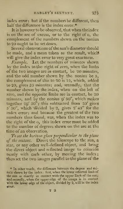
HADLEY S SEXTAXT. ^75
index error; but if the numbers be different^ then
half the differenec is the index error.*
It is however to be observed, that when theindex
is on the arc of excess, or to the right of o, the
complement of the numbers shewn on the nonius
to 20 ought to be set down.Several observations ofthe sun's diameter should
be made, and a mean taken as the result, whiclf
will give the index error to very great exactness.
Example. Let the numbers of minutes shewnby the index to the right of zero, when the limbs
of the two images are in contact, be 20 minutes,
and the odd number shewn by the nonius be 5,
the complement of this to 20 is 15, which, addedto 20, gives 35 minutes; and, secondly, that the
number shewn by the index, when on the left of
zero, and the opposite limbs are in contact, be 20minutes, and by the nonius 9' 30", which makestogether 29' 30"; this subtracted from 35' gives5' 30", which -divided by 2, gives I' Ao" for the
index error; and because the greatest of the twonumbers thus found, was, when the index was to
the right of the o, this index error must be added
to the number of degrees shewn on the arc at the
timeof an observation.
To set the horizon glass perpendicular to the plane
of the sextant. Direct the telescope to the sun, a
star, or any other well-defined object, and bring
the direct object and reflected image to coincide
nearly with each other, by moving the index;
then set the two images parallel to the plane of the
* In other words, the difference between the degree and mi-
nute shewn by the index : first, when the lower retiected limb of
the sun is exactly in contact with the upper limb of the sun;
and secondly, when the upper edge of the image is in contact
with the lower edge of the object, divided by 2, will be the index
frror.
T 2
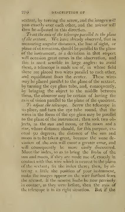
2/6 DESCRIPTION OF
sextant, by turning the screw, and the images will
pass exactly over each other, and the mirror will
then be adjusted in this direction.
To set the axis of the telescope parallel to the pla7ic
of the sextimt. We have already observed, that in
measuring angular distances, the line of sight, or
plane of oLssrvation, should be parallel to the plane
of the instrum-ent, as a deviation in that respect
will occasion great errors in the observation, andthis is most sensible in large angles: to avoid
these, a telescope is made use of, in whose field
there are placed two wires parallel to each other,
and equidistant from the center. These wires
may be placed parallel to the plane of the sextant,
by turning the eye glass tube, and, consequently,
by bringing the object to the middle betweenthem, the observer may be certain of having the
axis of vision parallel to the plane of the quadrant.
To adjust the telescope. Screw the telescope in
its place, and turn the eye tube round, that the
wires in the focus of the eye glass may be parallel
to the plane of the instrument; then seek two ob-
jects, as the sun and moon, or the moon and a
j^tar, whose distance should, for this purpose, ex-
ceed QO degrees; the distance of the sun andmoon is to be taken great, because the same de-
viation of the axis will cause a greater error, andwill consequently be more easily discovered.
Move the index, so as to bring the limbs of the
sun and moon, if they are made use of, exactly in
contact with that wire which is nearest to the plane
of the sextant; fix the index there; then, by al-
tering a little the position of your instrument,
make the images appear on the wire furthest fromthe sextant. If the nearest limbs be now precisely
in contact as they were before, then the axis of
the telescope is in its right situation. But if the

hadley's sextaxt. 277
limbs of the two objects appear to separate at the
wire that is furthest from the plane of the instru-
ment, it shews that the objeet end of the telescope
incHnes towards the plane of the instrument, and
must be rectified by tightening the screw nearest
the sextant, having previously unturned the screw
furthest from it. If the images overlap each
other at the wire furthest from the sextant, the
object end of the telescope is inclined from the
plane of the sextant, and the highest screw mustbe turned towards the right, and the lowest screw
towards the left: by repeating this operation a
few times, the contact will be precisely the sameat both wires, and consequently the axis of the
telescope will be parallel to the plane of the in-
strument.
To examine the glasses of a sexta?it, or quadrant.
1 . To find whether the two surfaces of any one of
the reflecting glasses be parallel, apply your eye
at one end of it, and observe the image of someobject reflected very obliquely from it; if that
image appears singly, and well defined about the
edges, it is a proof that the surflices are parallel
;
on the contrary, if the edge of the reflected image
appears misted, as if it threw a shadow from it,
or separated like two edges, it is a proof that the
two surfaces of the glass are inclined to each
other: if the image in the specukim, particularly
ifthat image be the sun, be viewed through a small
telescope, the examination will be more perfect.
2. To find whether the surface of a reflecting
glass be plane. Chusetwo distant objects, nearly
on a level with each other; hold the instrument
in an horizontal position, view the left hand object
directly through the transparent part of the hori-
zon glass, and move tlie index till the reflected
ijnage of the other is seen below it in the silvered

278 DESCRIPTION OP
part; make the two images unite just at the line
of separation, then turn the instrument roundslowly on its own plane, so as to make the united
images move along the line of separation of the
horizon glass. If the images continue united
without receding from each other, or varying their
respective position, the reflecting surface is a goodplane. The observer must be careful that hedoes not give the instrument a motion about the
axis of vision, as that will cause a separation if the
planes be perfect.
3. To find if the two surfaces of a red or dark-
ening glass are parallel and perfectly plane. It is
diffiicult, nay, almost impossible, to procure the
shades perfectly parallel and good; they will
therefore, according to their different combina-tions, give difl'erent altitudes or measures of the
sun and moon.The best way to discover the error of the shades,
is to take the sun's diameter with a piece of
smoaked glass before your telescope, all the vanes
being removed; then take away the smoakedglass, and view the sun through each shade andthe several combinations thereof If the twoimages still remain in contact, the glasses are good;but if they separate, the error is to be attributed to
the dark glasses, which must either be changed,or the error found in each combination must beallowed for in the observations. If you use the
same dark glasses in the observation as in the ad-
justment, there will be no error in the observed
angle,*
* The dark glasses are generally left to turn in their cells ; 50
that, alter one observation has been made, turning either of themhalf round, after another observation^ half the ditFerence thus
given is the error. Edit.

[ 279 J
OF HADLEY S SEXTANT, AS USED IN'
SURVEYING.
No instrument can be so conveniently used for
taking anc^lcs in maritime surveying as Hadley's
sextant. It is used with equal facility at the masthead, as upon deck, by which its sphere of obser-
vation is much extended: for, supposing manyislands to be visible from the mast head, and onlyone from deck, no useful observation can be madeby any other instrument. But by thi-, angles maybe taken at the mast head from the one visible
object with great exactness; and further, taking
angles from heights, as hills, or a ship's masthead, is almost the only way of exactly describing
the figure and extent of the shoals.
It has been objected to the use of Hadley's sex-
tant for surveying, that it docs not measure the
horizontal angles, by which alone a plan can belaid down. This observation, however true in
theory, may be obviated in practice by a little
caution.
If an angle be measured between an object on
an elevation, and another near to it in a holloA\
.
the difference between the base, which is the hori-
zontal angle, and the hypothenuse, which is the
angle obsen'cd, mav be very great; but if these
objects are measured, not from eacli other, but
from some very distant object, the difi'erence be-
tween the angles of each fVom the very distant
object, will be very near the same as the horizon-
tal angle. This may be still further corrected, by
measuring the angle not between an object on a
plane and an object on an elevation, but between
the object on a plane and some object in the same
direction as the elevated objectj of which the eye
is suliicicntly able to judge.

280 OF hadley's sextaxt,
How to ohsewc the hor'i%onial angle^ or angular
distance^ hetiveen Hvo objects. First adjust thesextant, and if the objects are not small, fix ona sharp top, or corner, or some small distinct part
in each to observe; then, having set the index to
o deg. hold the sextant horizontally, as abovedirected, and as nearly in a plane passing throughthe two objects as you can; direct the sight
through the tube to the left hand object, till it is
seen directly through the transparent part of thehorizon glass; keeping that object still in sight,
then move the index till the other object is seen
by reflection in the silvered part of the horizon
glass; then bring both objects together by the
index, and by the inclination of the plane of the
sextant when necessary, till they unite as one, or
appear to join in one vertical line in the middle of
the line ^^hich divides the transparent and reflect-
ing parts of the horizon glass; the two objects
thus coinciding, or one appearing directly belowthe other, the index then shews on the limb the
angle which the two objects subtend at the nakedeye. This angle is always double the inclination
of the planes of the two reflecting glasses to oneanother; and, therefore, every degree and minutethe index is actually moved from o, to bring the
two objects together, the angle subtended bythem at the eye will be twice that number of de-
grees and minutes, and is accordingly numberedso on the arc of the sextant; which is really an
arc of 60 degrees only, but graduated into 120
degrees, as before observed.
The angle found in this manner between twoobjects that are near the observer, is not precise;
and may be reckoned exact only when the objects
ure above half a mile off. For, to get the angle
truly exact, the objects should bevicwedfroni th$

A3 USED IX SURVEYING. 281
center of the index glass, and not where the sight
vane is plaeed; therefore, except the objects are so
remote, that the distance between the index glass
and sight vane vanishes, or is as nothing comparedto it, the angle will not be quite exact. This in-
accuracy in the angle between near objects is called
the parallax of the instrument, and is the angle
which the distance between the index glass andsight vane subtends at any near object. It is so
small, that a surveyor will seldom have occasion
to regard it; but if it shall happen that great ac-
curacy is required, let him choose a distant object
exactly in a line with each of the near ones, andtake the angles between them, and that will bethe true angle between the near objects. Or, ob-serve the angle between near objects, when the
sextant has been first properly adjusted by a dis-
tant object; then adjust it by the left hand object,
which will bring the index on the arc of excess
beyond o degrees; add that excess to the angle
found between the objects, and the sum will bethe true angle between them. If one of the ob-
jects is near, and the other distant, and no re-
mote object to be found in a line with the near
one, adjust the sextant to the near object, and then
take the angle between them, and the parallax
will be found.
Example. To measure the horizontal angle
K^Q,Jig. \Qf, plate 9, with the sextant.
1. Set up such marks at A and C, as mav beseen when you are standing at B. 2. Set o onthe index to coincide \\ithoon the quadrantal
arc. 3. Hold the sextant in an horizontal posi-
tion, look through the sight and horizon glass at
the mark A, and observe whether the image is di-
rectly under the object; if not, move the index
till they coincide. 4. if the index division of the

1S1 OF hadley's sextant.
nonius is on the arc of excess, the indicated quan-tity is to be added to the observed angle ; but if it
be on the quadrantal arc, the Quantity indicated is
to be subtracted: let us suppose five to be added.
5. Now direct the sight through the transparent
part of the horizon glass to A, keep that object in
view, move the index till the object C is seen byreflection in the silvered part of the horizon glass.
6. The objects being now both in view, move the
index till they unite as one, or appear in one ver-
tical line, and the index will shew the angle sub-
tended at the eye by the two objects: suppose
75.20, to which add 5 for the index error, andyou obtain 75.25, the angle required; if the angle
be greater than 120°, which seldom happens in
practice, it may be subdivided by marks, and thenmeasured.
No instrument can be more convenient or ex-
peditious than the sextant, for setting of offsets.
Adjust the instrument, and set the index to 90 de-
grees; walk along the station line with the octant
in your hand, always directing the sight to the
farther station staff; let the assistant walk along
the boundary line; then, if you wish to make anoffset from a given point in the station line, stop at
that place, and wait till you see your assistant byreflection, he is then at the point in the boundarythrough which that offset passes; on the other
hand, if you wish an ofl'set from a given point or
bend in the boundary, let the assistant stop at that
place, and do you walk on in the station line till
you see the assistant by reflection in the octant,
and that will be the point where an offset from the
proposed point or bend will fall.
The manner of using this instrument for the
solution of those astronomical problems that are
necessary in surveying, will be shewn in its proper
place.
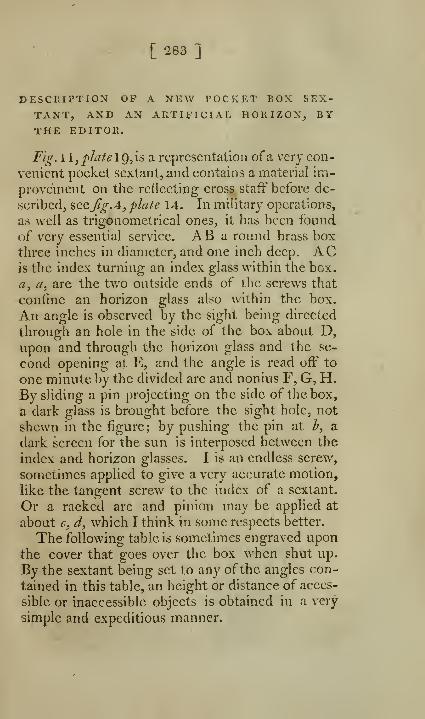
[283 ]
DESCRIPTION OP A NEW I'OCKET BOX SEX-
TANT, AND AN ARTIFICIAL HORIZOX, BYTHE EDITOR.
Fig. 1 1 ,plate 1 9, is a representation of a very con-
venient pocket sextant, and contains a material im-
provement on the retiecting cross staff" before de-
scribed, ?,Q.Qjig.A,plate 14. In military operations,
as well as trigonometrical ones, it has been found
of very essential service. AB a round brass boxthree inches in diameter, and one inch deep. ACis the index turning an index glass within the box.
a, a, arc the two outside ends of the screws that
confine an horizon glass also within the box.
An angle is observed by the sight being directed
through an hole in the side of the box about D,upon and through the horizon glass and the se-
cond opening at E, and the angle is read off to
one minute by the divided arc and nonius F, G, H.By sliding a pin projecting on the side of the box,
a dark glass is brought before the sight hole, not
shewn in the figure; by pushing the pin at h^ a
dark screen for the sun is interposed between the
index and horizon glasses. I is an endless screw,
sometimes applied to give a very accurate motion,
like the tangent screw to the index of a sextant.
Or a racked arc and pinion may be applied at
about c, d, which I think in some respects better.
The following table is sometimes engraved uponthe cover that goes over the box when shut up.
By the sextant being set to any of the angles con-
tained in this table, an height or distance of acces-
sible or inaccessible objects is obtained in a very
simple and expeditious manner.

128* TABLE USED WITH THE
Mul.
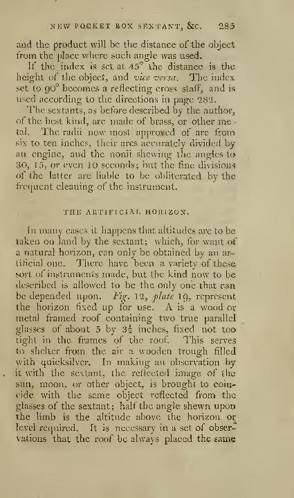
NEW POCKET BOX SEXTANT, &C. 285
and the product will be the distance of the object
from the place where such angle was used.
If the index is set at 45° the distance is th-e
height of the object, and vice versa. The index
set to 90° becomes a reflecting cross staff, and is
used according to the directions in page 282.
The sextants, as before described by the author,
of the best kind, are made of brass, or other me •
tal. The radii now most approved of are fromsix to ten inches, their arcs accurately divided byan engine, and the nonii shewing the angles to
30, 15, or even 10 seconds; but the fine divisions
of the latter are liable to be obliterated by the
frequent cleaning of the instrument.
THE ARTIFICIAL HORIZON.
In many cases it happens that altitudes are to betaken on land by the sextant; which, for want ofa natural horizon, can only be obtained by an ar-
tificial one. There have been a variety of these,
sort of instruments made, but the kind now to bedescribed is allowed to be the only one that canbe depended upon. Fig. 12, plate 19, represent
the horizon fixed up for use. A is a wood or
metal framed roof containing two true parallel
glasses of about 5 by 3 2 inches, fixed not too
tight in the frames of the roof This serves
to shelter from the air a wooden trough filled
with quicksilver. In making an observation byit with the sextant, the reflected image of the
sun, moon, or other object, is brought to coii>-
cide with the same object reflected from the
glasses of the sextant; half the angle shewn uponthe limb is the altitude above the horizon or
level required. It is necessary in a set of obser-
vations that the roof be always placed th^ same

285 TO SURVEY WITH
way. When done with, the roof folds up fiat-
ways, and, with the quicksilver in a bottle, &c.is packed into a portable flat case.
TO SURVEY WITH THE CHAIN ONLY.
The difficulties that occur in measuring with
accuracy a strait line, render this method of sur-
veying altogether insufficient for measuring a
piece of ground of any extent; it would be not
only extremely tedious, but liable to many errors
that could not be detected; indeed there are very
few situations where it could be used without
King's surveying quadrant, or some substitute for
it. The method is indeed in itself so essentially
defective, that those who have praised it most,
have been forced to call in some instrument, as
the surveying cross and optical square, to their
aid. Little more need be said, as it is evident, as
well from the nature of the subject, as from the
practice of the most eminent surveyors, that the
measuring of fields by the chain can only be pro-
per for level ground and small inclosures ; and that
even then, it is better to go round the field andmeasure the angles thereof, taking offsets fromthe station lines to the fences. That this workmay not be deemed imperfect, we shall introduce
an example or two selected from some of the best
writers on the subject; observing, however, that
fields that are plottedfrom measured lines ^ are always
plotted nearest to the truth, ivhen those lines form at
their junction angles that approach nearly to a right
antrle.
Example 1. To survey the triangular field
AB Cjfig. 2,2, plate Q, by the chain and cross. Set
up marks at the corners, then begin at one ofthem,
and measure from A to B, till you imagine that
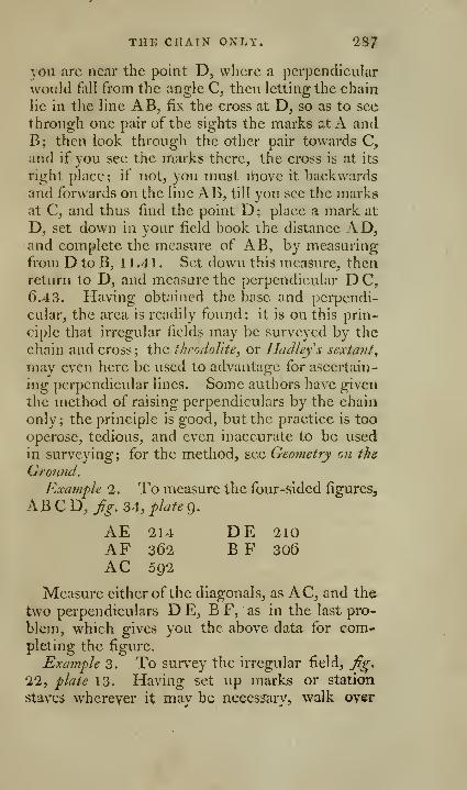
THE CHAIN ONLY. 287
you are near the point D, where a perpendicular
would fall from the angle C, then letting the chain
lie in the line AB, fix the cross at D, so as to see
through one pair of the sights the marks at A andB; then look through the other pair towards C,and if you see the marks there, the cross is at its
right place; if not, you must Uiove it backwardsand forwards on the line AB, till you see the marksat C, and thus find the point D; place a mark at
D, set down in your field book the distance AD,and complete the measure of AB, by measuringfrom D to B, 11 .4 1 . Set down this measure, thenreturn to D, and measure the perpendicular D C,
6.43. Having obtained the base and perpendi-
cular, the area is readily found: it is on this prin-
ciple that irregular fields may be surveyed by the
chain and cross; the theodolite, or Hadleys sextant
,
may even here be used to advantage for ascertain-
ing perpendicular lines. Some authors have given
the method of raising perpendiculars by the chain
only; the principle is good, but the practice is too
operose, tedious, and even inaccurate to be used
in surveying; for the method, see Geometry on the
Ground.
Example 2. To measure the four-sided figures,
AB C D, Jig. 34, plate 9.
AE
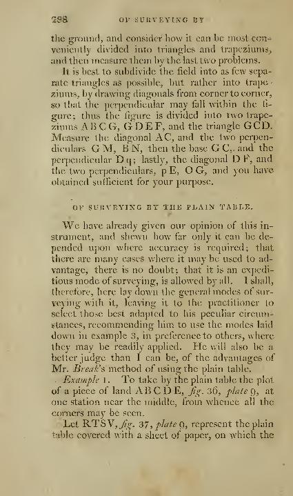
283 OP SURVEYING BT
the ground, and consider how it can be most con-i
vcniently divided into triangles and trapeziums^
and then measure them by tlic last two problems.
It is best to subdivide the field into as few sepa-
rate triangles as possible, but rather into trape -
ziums, by drawing diagonals from corner to corner,
so that the perpendicular may fall within the fi-
gure; thus the fi2:ure is divided into two trape-
ziums AB C G, G^D E F, and the triangle GCD.Measure the dbgonal AC, and the two perpen-
diculars GM, BN, then the base GC,. and the
perpendicular Dq; lastly, the diagonal D F, and
the two perpendiculars, p E, O G, and you have
obtained sufficient for your purpose.
OF SURVEYING BY THE PLAIN TABLE.
We have already given our opinion of this in-
strument, and shewn how far only it can be de-
pended upon where accuracy is required; that
there are many cases where it may be used to ad-
vantage, there is no doubt; that it is an expedi-
tious mode of surveying, is allowed by all. I shall,
therefore, here lay down tlic general modes of sur-
veying with it, leaving it to the practitioner to
select those best adapted to his peculiar circum-
stances, recommending him to use the modes laid
down in example 3, in preference to others, wherethey may be readily applied. Fie will also be a
better judge than I can be, of the advantages of
Mr. Break's method of using the plain table.
. Example 1 . To take by the plain table the plot
of a piece of land AB C D E, fg. 36, plate 9, at
one station near the middle, from whence all the
corners may be seen.
Let RTSV,j^^. 37,plafeg, represent the plain
table covered \\'ith a sheet of paper, on which the
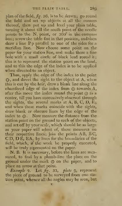
THE PLAIN TABLE. !28()
plan of the field, j^^. 36, is to be drawn; go roundthe field and set up objects at all the corners
thereof, then put up and level your plain table,
turning it about till the south point of the needle
points to the N. point, or 3dO° in the compassbox ; screw the table fast in that position, and then
draw a line P p parallel to one of the sides for a
meridian line. Now choose some point on the
paper for your station line, and make there a fine,
hole with a small circle of black lead round it;
this is to represent the station point on the land,
and to this the edge of the index is to be applied
when directed to an object.
Thus, apply the edge of the index to the point
O, and direct the sight to the object at A, whenthis is cut by the hair, draw a blank line along the
chamfered edge of the index from © towards A,after this move the index round the point as a
center, till you have successively observed through
the sights, the several marks at A, B, C, D, E;and when these marks coincide with the sights,
draw blank or obscure lines by the edge of the
index to . Now measure the distance from the
station point on the ground to each of the objects,
and set off by your scale, which should be as large
as your paper will admit of, these measures on
their respective lines; join the points AB, B C,
CD, D E, EA, by lines for the boundaries of the
field, which, if the work be properly executed,
will be truly represented on the paper.
N. B. It is necessary, before the lines are mea-sured, to find by a plumb-line the place on the
ground under the mark on the paper, and to
place an arrow at that point.
Example 2. Let Jig. 33, plate C), represent
the piece of ground to be surveyed from one sta-
tion point, whence all the angles may be seen, but
u
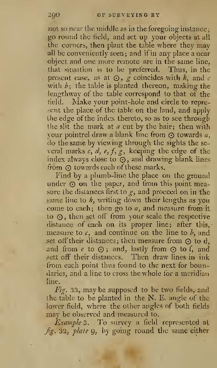
igO OF SURVEYING BY
not so near the middle as in the foregoing instance;
go round the lield, and set up your objects at all
the corners, then plant the table where they mayall be conveniently seen; and if in any place a near
object and one more remote are in the same line,
that situation is to be preferred. Thus, in the
present case, as at O, ^" coincides with //, and (
with I?; the table is planted thereon, making the
lengthway of the table correspond to that of the
lield. Make your point-hole and circle to repre-
>-cnt the place of the table on the land, and apply
tlie edge ofthe index thereto, so as to see throughthe slit the mark at a cut by the hair; then with
your pointrcl draw a blank line from © towards a,
do the same by viewing through the sights the se-
veral marks c, d, e,f, g, keeping the edge of the
index always close to O, and drawing blank lines
from O towards each ofthese marks.
Find by a plumb-line the place on the groundunder O on the paper, and from this point mea-sure the distances first to g, and proceed on in the
same line to //, writing down their lengths as youcome to each ; then go to a, and measure from it
to O , then set oft' from your scale the respective
distance of each on its proper line; after this,
measure to c, and continue on the line to /', andset oft" their distances; then measure from © to d,
and from ^ to © ; and, lastly from © to f, and.sett off" their distances. Then draw lines in ink
from each point thus found to the next for boun-daries, and a line to cross the whole for a meridian
line.
Fig, v33, may be supposed to be two fields, andthe table to be planted in the N. E. angle of the
lower field, where the other angles of both fields
may be observed and measured to.
Example 3. To survey a field represented at
Jrg. 32, phjte g, by going round the same either
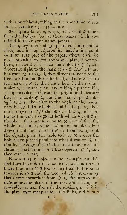
THE PLAIN TABLE. 201
\vltliln or without, taking at the same thne offsets
to the boundaries; suppose inside.
Set up marks at a, b, c, d, at a small distance
from the hedges, but at those places which youintend to make your station points.
Then, beginning at ©, plant your instrument
there, and having adjusted it, make' a fine point
O 1 on that part of the paper, where it will bemost probable to get the whole plan, if not too
large, in one sheet; place the index to O 1, anddirect the sight to the mark at 6, draw a blankline from © 1 to O 6, then direct the index to the
tree near the middle of the field, and afterwards to
the mark at 2, then dig a hole in the groundunder 1 in the plan, and taking up the table,
set up an object in it exactly upright, and measurefrom it towards 2, and find that perpendicular
against 218, the offset to the angle at the boun-dary is 157 links, which set off in the plan; then
measuring on at 375 the offset is but 6, and con-
tinues the same to 698, at both which set off 6 in
the plan ; then measure on to 2, and find the
whole 1041 links, which set off in the blank line
drawn for it, and mark it 2; then taking out
the object, plant the table to have 2 over the
hole, when placed parallel to what it was on 1
;
that is, the edge of the index-ruler touching both
stations, the hair must cut the object at © 1, andthen screw it fast.
Now setting up objects in the by-angles a and h,
first turn the index to view that at a, and draw a
blank line from 2 towards it; then do the sametowards h, Q 3 and the tree, which last crossing
that drawn towards it from 1, the intersection
determines the place of the tree, which being re-
markable, as seen from all the stations, mark it in
the plan; then measure to a 412 links, and from h
V 2

igl OP SURVEYING BY
353, and set them off in the blank lines drawntowards them; then set off the distance to the
boundaries in the two station lines produced, viz.
151 in the next produced backwards, and 15 in
the first produced forwards; after this, draw the
boundaries from the angle where the first offset
was made to the next, and so on round by a, h,
through the 151 to the next angle; then, taking
up the table, fix again the object as before, andmeasure on the O 3, which set oft' 564 links, andthe offset to the angle in the boundary 27, andthen draw the boundary from it through the 15 to
the angle at meeting that last drawn.
Now, taking out the object at © 3, plant the
table so as to have O 3 over the hole, whenplaced parallel to what it was at the former sta-
tions, and screwed fast; then turn the index to
make the edge touch the place of the tree and O3 in the plan, and finding the hair cuts the tree,
turn the index to view © 4, and draw a blank line
towards it; then taking up the table, fix the object
as before^ and measure on to © 4, which set oft"
471 links, and the offset 23, and draw the boun-dary from the last angle through it to the next;
then measure on in the station line produced to
the next boundary 207 links, -and the distance of
© 4, from the nearest place in the same boundary
173, both which set off and draw the boundaryfrom this last through the 207 to the angle.
Now taking out the mark, plant the table to
have © 4 over the hole, when screwed fast in the
same parallelism as at the other stations; then,
after viewing again the tree, turn the index to
view © 5, and draw a blank line towards it; then
taking up the table, fix the object as before, andmcp^SLiring on towards © 5, at 225 the nearest
place of the boundary is distant 121, which set
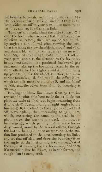
THE PLAIN TABLE. 293
off bearing forwards, as the figure shews; at 388the perpendicular offset is t), and at 712 it is I'i,
both which set off in your plan ; then measure onto O 5, and set it off at 912 links.
Take out the mark, plant the table to have 5
over the hole, when screwed fast in the same pa-
rallelism as before; then set up objects in the
by-angles c and J, and after viewing the tree,
turn the index to view the objects at c, d^ and 6,
and draw a blank line towards each ; then measureto c 159, and from J 245, both which set off in
your plan, and also the distance to the boundaryill the next station line produced backward 95
;
and now make up the boundary round by the se-
veral offsets to the angles c and d\ then taking
up your table, fix the object as before, and mea-suring towards 6, find at l()2 the offset is 32,
w^hich set off; measure on to 6, and set it off
at 7 08, and the offset from it to the boundary is
36 links.
Finding the blank line drawn from 1 to in-
tersect the point-hole here made for 6, do not
plant the table at 6, but begin measuring from
it towards 1, and finding at right angles to the
line at 6, the offset to the angle is 42, set that
off in your plan; then measuring to 1, 582,
which, measuring the same by the scale in the
plan, proves the truth of the work; the offset is
here also 42, which set off, and draw the boun-dary from J, round by the several oflsets, through
this last to the angle; then measure on in the sta-
tion line produced to the next boundary 88 links,
and set that off also, and draw the boundary from
the angle at the first offset, taken through it at
the angle at meeting the last boundary;. .and then
if a meridian line be drawn, as in the former, the
rough plan is completed.

294 OF SURVEYING BY
But if O 6 had not met in the intersection, or
its distance from 1 been too much, or too little,
you would very likely have all your work, exceptthe offsets, to measure and plot over again.
'' The plain table surveyors, says Mr. Gard'mer,
when they find their work not to close right, dooften close it wrong, not only to save time andlabour, but the acknowledging an error to their
assistants, which they are not sure they can amend,because in many cases it is not in their power,
and may be more often the fault of the instrument
than the surveyor; for in uneven land, where the
table cannot at all stations be set horizontal, or in
any other one plane, it is impossible the workshould be true in all parts: but to prevent great
errors, at every © after the second, view whereverit is possible, the object at some former ©, besides
that which the table was last planted at; because
if the edge of the index ruler do not quite touch,
or but very little covers that in the plan, whilst
it touches the you are at, the error may beamended before it is more increased, and if it va-
ries much, it may be examined by planting again
the table at the former station, or stations.
If a field is so hilly, that you cannot, withoutincreasing the number of stations, see more than
one object backward, and another forward, andthere is nothing fit within the field, as the sup-
posed tree in f(r, 32, then set up an object onpurpose to be viewed from all the stations, if pos-
t:^ible, for such a rectifier.
The lengthening and shortening of the paper,
as the weather is moister or drier, often causes no&mall error in plotting on the plain table; for be-
tween a dewy morning, and the sun shining hot
at noon day, there is great difference, and care
should be taken to allov/ for it; but that cannot
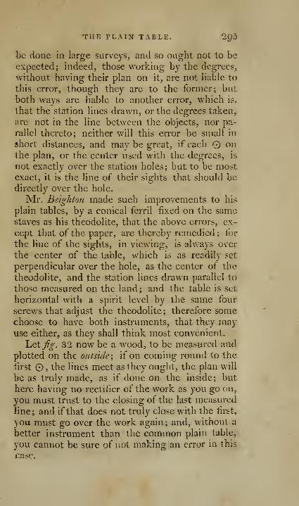
THE PLAIN TABLE. 2Q5
be done in large surveys, and so ought not to be
expected; indeed, those working by the degrees,
without having their plan on it, are not hable to
this error, though they are to the former; but
both ways are liable to another error, which is,
that the station lines drawn, or the degrees taken,
are not in the line between the objects, nor pa-
rallel thereto; neither will this error be small in
short distances, and may be great, if each O onthe plan, or the center used with the degrees, is
not exactly over the station holes; but to be mostexact, it is the line of their sights that should bedirectly over the hole.
Mr. Beighton made such improvements to his
plain tables, by a conical ferril fixed on the samestaves as his theodolite, that the above errors, ex-
cept that of the paper, are thereby remedied ; for
the line of the sights, in viewing, is always over
the center of the table, which is as readily set
perpendicular over the hole, as the center of the
theodolite, and the station lines drawn parallel to
those measured on the land; and the table is set
horizontal with a spirit level by the same four
screws that adjust the theodolite; therefore somechoose to have both instruments, that they mayuse either, as they shall think most convenient.
Let j'^o-. 32 now be a wood, to be measured and
plotted on the outside \ if on coming round to the
iirst O, the lines meet as they ought, the plan will
be as truly made, as if done on the inside; but
here having no rectifier of the work as you go on,
you must trust to the closing of the last measured
line; and if that does not truly close with the first,
you must go over the work again ; and, without a
better instrument than the common plain table,
you cannot be sure of not making an error in this
case.

'^9^ OF SURVEYING BY
Suppose the table planted at 1 on the out-
side, with paper fixed on it, and objects set up at
all the other stations on the outside, and dry blank
lines drawn from l on the paper towards dand 2; these done, take up the table, and set
up an object at 1 ; then, measuring from it to-
wards 2, you find at 20 the offset to the first
angle is 38, then at 280 the offset to the next an-
gle is 26 links, both of which set off in the plan
;
then at 394 the perpendicular offset to the next
angle is 206 ; then at 698 the distance of the sameangle is 366 bearing backward, as may be seen
in the figure, that by the intersection of these
two ofiset lines the angle may be more truly
plotted; then measure the distance from this an-
gle to the next 323, and from that to 698 place in
the station line 280, which is the perpendicular
offset; then by the intersection of these, that an-
gle will be well plotted; then at 77^ the offset
to angle a is 48, and at 1012 the offset to b is 22,
both which set off' in the plan, and at 1306 youmake 2; now draw the boundaries from the
first offset to the next, &V, to the angle b. Asthere is no difiiculty in taking the offsets fromthe other station lines, we shall not proceed far-
ther in plotting it on the outside; for a sight of
the figure is sufficient.
Some surveyors would plant their table at a
place between 394 and 698 in the first station
line, and take the two angles, which are here
plotted by the intersection of lines, as the by-
angles (2 and /-were taken at 2 within the
field; but if the boundary should not be a strait
line from one angle to the other, then their dis-
tance should be measured, and offsets taken to
the several bends in it,
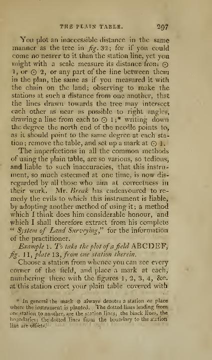
THE PLAIN TAELfi. IQ?
You plot an Inaccessible distance in the samemanner as the tree in Jjg. 32; for if you could
come no nearer to it than the station line, yet youmight with a scale measure its distance from O1, or 2, or any part of the line between themin the plan, the same as if you measured it withthe chain on the land; observing to make thestations at such a distance from one another, that
the lines drawn towards the tree may intersect
each other a& near as possible to right angles,
drawing a line from each to O 1 ;* writing downthe degree the north end of the needle points to,
as it should point to the same degree at each sta-
tion ; remove the table, and set up a mark at l.
The imperfections in all the common methodsof using the plain table, are so various, so tedious,
and liable to such inaccuracies, that this instru-
ment, so much esteemed at one time^ is now dis-
regarded by all those who aim at correctness in
their work. Mr. Break has endeavoured to re-
medy the evils to which this instrument is liable,
by adopting another method of using it; a methodwhich I think docs him considerable honour, andwhich I shall therefore extract from his complete" System of Land Surveying^'' for the inforijiation
of the practitioner.
Example 1. To lake the plot ofafeld KQQT>^Y,Jjg. 1 1, plate \3, from one station therein.
Choose a station from whence you can see every
corner of the field, and place a mark at each,
numbering these with the figures 1, 2, 3, 4, &c.
at this station erect your plain table covered with
* In general the mark © always denotes a station or place
where the instrument is planted. The dotted lines leading fromone station to another, are the station lines; the l)lack lines, the
boundaries; the dotted lines frunl the boundary to the station
line ai'« cffsets.

298 OP SURVEYING BY
paper, and bring the south point of the needle to
the flower-de-luce in the box; then draw a circle
O P Q R upon the paper, and as large as the pa-
per will hold.
Through the center of this circle draw the
line NS parallel to that side of the table which is
parallel to the meridian line in the box, and this
will be the meridian of the plan.
Move the chamfered edge of the index on ,
till you observe through the sights the several
marks A, B, C, and the edge thereof will cut the
circle in the points 1, 2, 3, &c. Then having
taken and protracted the several bearings, the dis-
tances must be measured as shewn before.
To draw the plan. Through the center©and the
points 1, 2, 3, &c. draw lines © A, © B, © C,
© D, © E, © F, and make each of them equal
to its respective measure in the field; join the
points A, B, C, &c. and the plan is finished.
Example 2. To take the plot of a field AB C D,&c.from several stations, fig. 14, plate 13.
Having chosen the necessary stations in the
field, and drawn the circle P QR, which youmust ever observe to do in every case, set upyour instrument at the first station, and bring the
needle to the meridian, which is called adjusting
the instrument; move the index on the center
© , and take an observation at yl, B, C, © 2, H,and the fiducial edge thereof will intersect the
circle in 1,2, 3, &c. Then remove your instru-
ment to the second station in the field, and ap-
plying the edge of the index to the center © andthe mark © 2 in the circle, take a back sight to
the first station, and fasten the table in this posi-
tion; then move the index on the center ©, anddirect the sights to the remaining angular marks,
so will the fiducial edge thereof cut the circle in
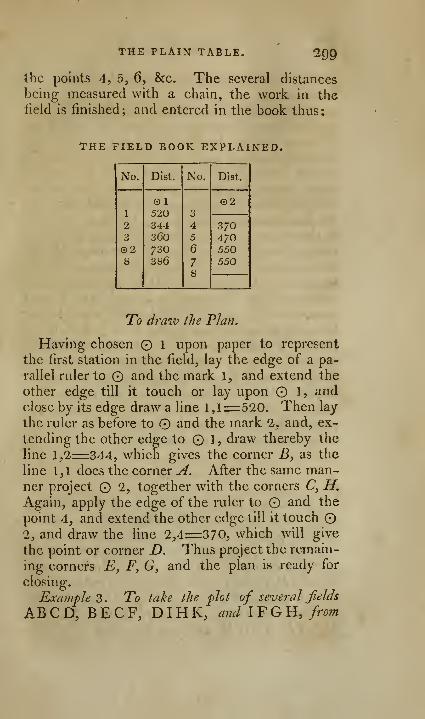
THE PLAIN TABLE. mthe points 4, 5, 6, &c. The several distances
being measured with a chain, the work in thelield is finished; and entered in the book thus:
THE FIELD BOOK EXPLAINED.
No.

300 OF SURVEYIXG BY
Stations chosen at or 7iear the jniddle of each, fig.
15, plate 13.
Adjust your plain table at the first station in
Jl BCD, and draw the protracting circles and me-ridians N S; then by proposition 1, project the an-
gles, or corners o^AB CD, B E FC, and also the
second station, into the points 1, 2, © 2, 3, 4, 5, 6.
Again, erect your instrument at the first station,
and lay the index on the center and the mark2, and direct the sights by turning the table
to the second station, then move the index till youobserve the third station, and the edge thereof
will cut the circle in 3. Then remove the in-
strument to the third station, lay the index on the
center and the mark 3, and take a backobservation to the first station ; after which by the
last proposition find the points 7j 8? 4, 9, in the
circle P QR. As to the measuring ofdistances,
both in this andthe two succeeding propositions that
shall be passed over in silence, having sufficiently
displayed the same heretofore; what I intend to
treat of hereafter, is the method of taking andprotracting the bearings in the field, Avith the man-ner of deducing a plan therefrom.
To draw the Plan.
Choose any point 1 for your first station;
apply the edge of a parallel ruler to the center
and the point I, and having extended the other
edge to 1, draw the line 1,1 ==370, which will
give the corner A. In like manner find the other
corners jB, C,D, together with 2; which beingjoined, finishes the field AB CD. After the same
.
method construct the other fields B E F C^
DIRK, IFGII, and you have done.

THE PLAN TABLE. 301
THE FIELD BOOK.
REMARKS.

302 OP SURVEYING BT
station ; then directing the index on the center (£)
to the third, or next station, the edge thereof will
cross the circle in the point 2. In like manner the
instrument being planted at every station, a backsight taken to the last preceding one, and the in-
dex directed forward to the next succeeding sta-
tion, will giv^e the protracted points 3, 4, 5> 6.
THE FIELD BOOK.
REMARKS.
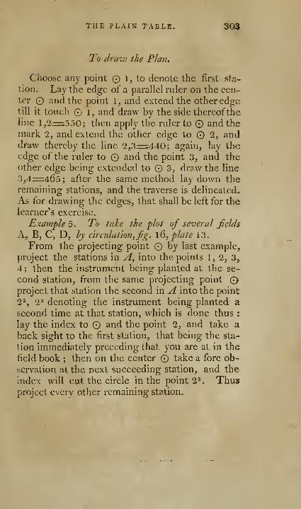
THE PLAIN TABLE. 303
To draw the Plan,
Choose any point 1, to denote the first sta-
tion. Lay the edge of a parallel ruler on the cen-ter O and the point 1, and extend the other edgetill it toueh 1, and draw by the side thereoftheline 1,2=550; then apply the rider to and the
mark 2, and extend the other edge to 1, anddraw thereby the line 2,3=440; again, lay the
edge of the ruler to and the point 3, and theother edge being extended to 3, draw the line
3,4=463 ; after the same method lay down theremaining stations, and the trav^erse is delineated.
As for drawing the edges, that shall be left for the
learner's exercise.
Example 5 . To take the plot of several fields
A, B, C, D, hy circidation,fig. \Q, plate 13.
From the projecting point by last example,
project the stations in A, into the points 1, 2, 3,
4 ; then the instrument being planted at the se-
cond station, from the same projecting point
project that station the second in A into the point
2^, 2^ denoting the instrument being planted a
second time at that station, which is done thus :
lay the index to and the point 2, and take a
back sight to the first station, that being the sta-
tion immediately preceding that you are at in the
field book ; then on the center take a fore ob-
servation at the next succeeding station, and the
index will cut the circle in the point 2^. Thusproject every other remaining station.
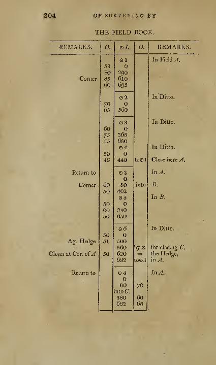
304 OF SURVEYING BY
THE FIELD BOOK.
REMAPxKS.

THE PLAIN TABLE. ;o5
THE FIELD BOOK.
REMARKS.
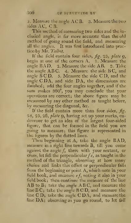
>06 OP SURVEYING BY
i. Measure the angle ACB. 3. Measure the twosides AC, C B.
This method of measurins; two sides and the in-
cluaed angle, is far more accurate than the old
method of going round the field, and measuringall the angles. It was first introduced into prac-
tice by Mr. Tallwt.
If the field contain four sides. Jig. 23, plale 9,
begin at one of the corners A. 1. Measure the
angle BAD. 2. Measure the side AB. 3. Takethe angle ABC. 4. Measure the side BC, andangle BCD. 5. Measure the side C D, and the
angle CDA, and side DA, the dimensions arc
finished; add the four angles together, and if the
sum makes 360", you may conclude that youroperations are correct; the above figure may bemeasured by any other method as taught before,
by measuring the diagonal, &c.
If the field contain more than four sides, Jig.
24, 25, 26, pJafe 9, having set up your marks, en-
deavour to o;ct an idea of the laro;est four-sided
figure, that can be formed in the field you are
going to measure; this figure is represented in
the figures by the dotted lines.
Then beginning at A, take the angle BAD,measure in a right line towards B, till you comeagainst the angle/, there with your sextant, or
cross, let fall the perpendicular/^, as taught in the
method of the triangle, observing at how manychains and links this offset or perpendicular falls
from the beginning or point A, which note in yourfield book, and measure ef, noting it also in yourfield book; then continue the measure of the line
AB to B; take the angle ABC, and measure the
line B C; take the angle BCD, and measure the
line CD; take the angle CDA, and measure the
line DA; observing as you go round, to let fall

THE PLAIN TABLE. 307
perpendiculars where neeessary, and measure themas specified in the line AB.
E-xamplc tofg:. 26, containing seven sides.
FIELD BOOK.
IA=
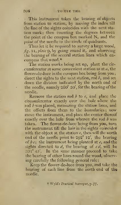
30§ TO USE THE
This instrument takes the bearing of objects
from station to station, by moving the index till
thcHneof the sights coincides with the next sta-
tion mark; then counting the degrees between
the point of the compass box marked N, and the
point of the needle in the circle of quadrants.
Thus let it be required to survey a large wood,
fg. 31, pidte g, by going round it, and observing
the bcarmg of the several station lines which en-
compass that wood.*The station marks being set up, plant the cir-
cumferentor at some convenient station as at a, the
flower-de-luce in the compass box being from you
;
direct the sights to the next station, rod /', and set
down the division indicated by the north end of
the needle, namely 26o° 30', for the bearing ofthe
needle.
Remove the station rod b to r, and place the
circumfcrentor exactly over the hole where the
rod h was placed, measuring the station lines, andthe oifscts from them to the boundaries ; nowmove the instrument, and place the center thereof
exactly over the hole from whence the rod i? was
taken. The flower-de-luce being from you, turn
the instrument till the hair in the sights coincides
with the object at the station c, then will the north
end of the needle point to 292° 12', the bearing
o{ b c\ the instrument being planted at c, and the
sights directed to d, the bearing of ccl, will be
33 1*^45'. In the same manner proceed to take
the bearing of other lines round the wood, observ-
ing carefully the following general rule
:
Keep the flower-de-luce from you, and take the
bearing of each line from the north end of the
needle.
* Wyld's Practical Surveyor, p. 77'
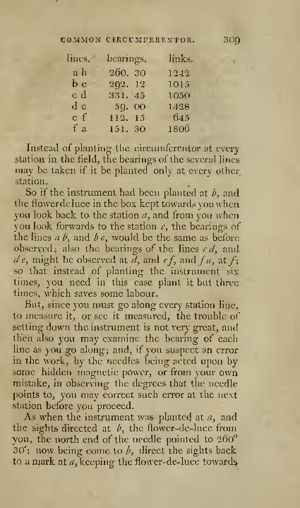
COMMON CIRCUMFEREXTOR. 300
lines.

310 OF MR. GALE S METHOD BY
you: so shall the north end of the needle point to
260^ 30', as before at a^ and then you may besure the bearing ofthe line ah\% truly observed.
But if the needle doth not point to the samenumber of degrees, &c, there hath been some error
in that observation, which must be corrected.
OF THE IMPROVED CIRCUMFERENTOR, WITHMR. gale's METHOD OF USING IT; A ME-THOD THAT IS APPLICABLE WITH EQUALADVANTAGE TO THE THEODOLITE, &C.
For the ^ake of perspicuity, it will be necessary
to give again the example before used in page 222,and that not only because it will exhibit moreclearly the advantages of Mr. Gales method,* butbecause we shall have occasion to refer to it whenwe come to his improved method of plotting; andfurther, because I have thought this mode so ad-
vantageous, and the tables so conducive to accu-
racy and expedition, that I have caused occasio-
nally the traversing quadrant to be engraved in
smaller figures under the usual one of the limb of
the theodolite.
Set the circumferentor up at B,j^^. 1, plate 18,
take the course and bearing of B C, and measurethe length thereof, and so proceed with the sides
CD, D E, E F, F G, GA, all the way round to
the place of be^ginning, noting the several courses
or bearings, and the lengths ofthe several sides in a
field book, which let us suppose to be as follow
:
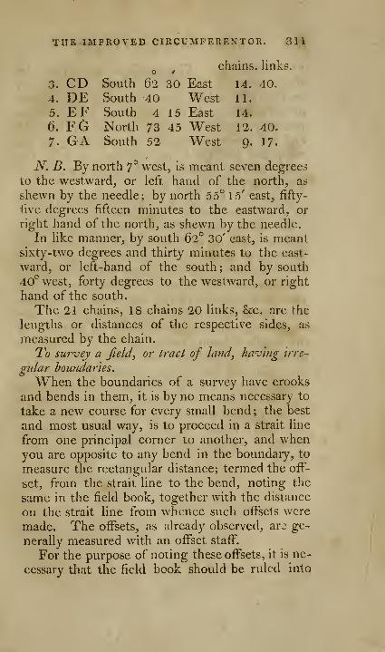
THE IMPROVED CIKCUMFERENTOR. 311
chains, links.
3.
312 OF MR. gale's method BY
FIVE COLUMNS. The middle columii to contaiii
the courses and distances; the adjoining columnson the right and left hand to contain the measureof the offsets, made to the right or left hand res-
pectively; and the outside columns on the right
and left hand, to contain remarks made on the
right and left hand, respectively, such as the
names of the adjoining fields, or the bearing of
any remarkable object, &c.
Example. \j€i.fig. 3, plate 18, represent afield
to be surveyed, whose boundaries are crooked.
Set up the instrument at, or near any conve-nient corner, as at 1, and take the course, andbearing, as before directed, north 7° west, notethis down in the middle column of the field book,and measure with the chain as before directed, till
you come opposite to the first bend, so that thebend be at right angles to the station line; notethe distance thus measured, 3 chains 6o links, in
the middle column, and measure the offset fromthence to the bend 40 links, noting the same in
the adjoining left hand column, because theboundary is on the left hand of the station line,
and note in the outside column, the name or ownerof the adjoining field, proceeding in the samemanner all round the field, noting the courses,
distances, offsets, and remarks, as in the fol-
lowing :
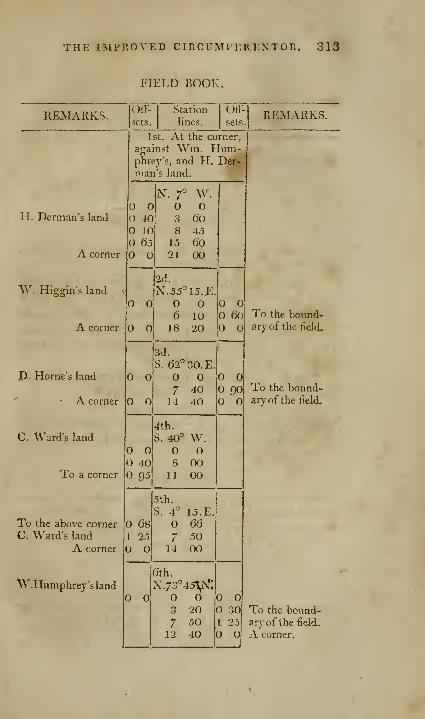
THE IMPROVED CIRCUMFEREXTOR. 313
FIELD BOOK.
REMARKS.
H. Derman's land
A corner
W. Higgln's land
A corner
D. Home's land
A corner
C, Ward's land
To a corner
To the above a:)rner
C. Ward's land
A corner
W.Humphrey's land
Oft-
sets.
Station
lines.
Otl-
sets.
1st. At the corner,
against Wni. Hum-phreys, and H. Bar-man's land.
REMjVRKS.
O40
O 10O 65
O O3 608 45
15 60O 21 00
O
2d.
N.55°15.E.O O6 1018 20
O6o
o o
o
o
O 4095
681 2.5
O
3d.
S. 62°30.E
7 4014 40
4th.
S. 40° W.o o8 00
11 00
90
5th.
S. 4° 15.
E
O 66
7 5014 00
6th.
X.73''4oV^^o
3 207 50
12 40
To the bound-ary of the field.
To the bound-ary of the field-
O O30 To the bound-
1 25 arj'of the field,
O O A corner.
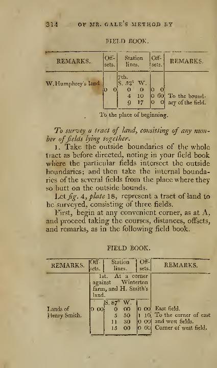
314 OF MR. GALE S METHOD BY
FIELD BOOK.
REMARKS. Off-
sets.
Station
lines.
Off-
sets.REMARKS.
W.Humphrey's landO O
7th.
S. 52°
O4
9
W.O10
17
oo 60 To the bound-
ary of the field.
To the place of beginning.
To survey a tract of land, consisting of any nuni-
her offields lying together.
1. Take the outside boundaries of the wholetract as before directed, noting in your field bookwhere the particular fields intersect the outside
boundaries; and then take the internal bounda-ries ofthe several fields from the place where they
so butt on the outside bounds.
\j^\fig. A^ plate 18, represent a tract of land to
be surveyed, consisting of three fields.
First, begin at any convenient corner, as at A,and proceed taking the courses, distances, offsets,
and remarks, as in the following field book.
FIELD BOOK.
REMARKS.

THE IMPROVED CIRCUMPERENTOE. 315
FIELD BOOK.
REMARKS.
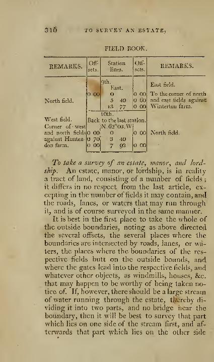
310 TO SURVEY AN ES
FIELD BOOK.
MANOR, AND LORDSHIP. 317
thereof: if the stream be of an irregular breadth,
both its banks forming boundaries to several fields
should be surveyed, and its breadth, where it en-
ters, and where it leaves the estate, be determinedby the rules oftrigonometry.
In the next place, take the lanes or roads, (if
any such there be) that go through the estate,
noting in the same manner as before, where the
divisions betw^een the several fields butt on those
lanes or roads, and where the gates enter into
those fields, and what other objects there may be
worth noticing. Where a lane runs through anestate, it is best tQ survey in the lane, because in
so doing, you can take the offsets and remarks
both on the rio;ht hand and the left, and therebv
carrv on the boundaries on each side at once. If
a large stream run through and separate the estate,
it should be surveyed as above-mentioned; but
small brooks running through a meadow, require
only a few offsets to be taken from the nearest sta-
tion line, to the principal bends or turning in
the brook.
In the last place take the internal divisions or
boundaries between the several fields, beginning
at any convenient place, before noted in the field
book, where the internal divisions butt on the out-
side of the grounds, or on the lanes, &c. noting
ahvays every remarkable object in the field
book.
Example. Let fg. 5, plate 18, represent an
estate to be surveyed; begin at any convenient
place as at A, where the two lanes meet, proceed
noting the courses, distances, &c. as before di-
rected from A to B, from B to C, and so on to
D, E, F, G, H, I, K, L, M and A, quite roundthe estate.
313 TO SUkVEY AN ESTATE,
Then proceed along the lane from A to N, Oand I, setting the courses, distances, offsets, andremarks, as before.
This done, proceed to the internal divisions,
beginning at any convenient place, as at O, andproceed, always taking your notes as before direct-
ed, from O to P, Q and R, so will you have with
the notes previously taken, the dimensions of thenorth lield; go back to Q, and proceed from Gl
to H, and you ol)tain the dimensions of the copse.
Take E S and S P, and you will have the dimen-sions of the home field; go back to S, and take
S T, and you W'ill have the dimensions of the land,^
. applied to domestic purposes of buildings, yards^
gardens, and orchards, the particulars and sepa-
rate divisions of which being small, had better betaken last of all
;go down to N, and take N D,
noting the offsets as well to the brook, as to the
fences, which divide the meadow from the south
and west fields, so will you have the dimensions
of the long meadow, together with the minutesfor laying down the brook therein; go back to U,and take U B, and you obtain the dimensions of
the west field, and also of the south field; goback again to N, and take N W, noting the off-
sets as well to the brook as to the fence whichdivides the meadow from the east field, thus will
you have the dimensions of the east field, and the
minutes for laying down the brooks in the mea-dow; then goto L, and take LX, which gives
you the dimensions of the east meadow, and of
the great field ; and lastly, take the internal divi-
sions of the land, appropriated to the domestic
purposes ofbuildings, yards, orchards, gardens, &c.
The method of taking the field notes is so in-
tirely similar to the examples already given,that they
xyould be altogether unnecessary to repeat hei-c.
MANOR, AND LORDSHIP. 31^
To the surveyor there can need no apology for
introducing, in this place, the method used byMr. Milne, one of the most able and expert sur-
veyors ofthe present day; and I think he will con-sider hmiself obliged to Mr. Milne, for communi-cating, with so much liberality, his deviations froin
the common practice, as those who have hitherto
made any improvements in the practical part of
surveying, have kept them as profound secrets, to
the detriment of science and the young practi-
tioner. As every man can describe his own me-thods, in the clearest and most intelligible manner,
'
I have left Mr. Milne's in his own language.
Mr. Milne's method of surveying.
" The method I take to keep my field notes in
surveying land, differing materially from those yet
published; if, upon examination, you shall think it
may be useful or worthy of adoption, you may, if
you please, give it a place in your treatise ou sur-
veying.
What I, as well as all surveyors aim at, in goingabout a survey, is accuracy and dispatch ; the first
is only to be acquired by care and good instru-
ments, the latter by diligence and long practice.
From twenty years experience, in the course of
which I have tried various methods, tlie following
is what I at last adopted, as the most eligible for
carrying on an extensive survey, either in England,
Scotland, or any other cleared country.
Having taken a cursory view of the ground that
I am first to proceed upon, and observed the
plainest and clearest tract, upon which I can mea-sure a circuit of three or four miles, I begin at a
point convenient for placing the theodolite upon,and making a small hole iu the ground, as at A^
3'ia MR. MILXe's METHOD
pliife 20, one assistant leading the chain, the other
having a spade for making marks in the ground, I
measure in a direct line from the hole at A to B,noting down, as I go along, on the field sketch
the several distances from place to place, andsketching in the figure of the road, as 75 links to
the east side of the avenue, 400 links, touching the
south side of the road, with an ofi'set of 40 links to
the other side, 500 links to the corner of a wood,and 817 to the corner of another wood; whichlast not allowing me to carry the line farther, I
make a mark at B, where I mean to plant the in-
strument, and beginning a new line, measure along
the side of the road 885 links to C, where I makea mark in the gfound, writing the same in my field
sketch, taking care always to stop at a place fromwhich the last station can be seen, when a pole is
placed at it. Beginning a new^ line, and measur-ing in a direct line towards D, I have 345 links to
a line of trees, SQO links opposite a corner of paled
inclosurcs, wliere I make a mark to have recourse
to, and 8C)3 links to the end of the line, where \make a mark in the ground at D; from thencemeasuring in a direct line to E, I here have 600links of steep ground, therefore make a mark in
the ground at the bottom of the steepness, so that
when I come to take the angles with the theodo-
lite, I may take the depression thereof; continuing
out the line, I have 1050 links to a bridge, with
an offset of 20 links to the bridge, and 80 links to
the paling; at 1247 there is a line of trees on th^left, and here also the line comes to the north
side of the road, and 1388 links to the end of the
line at E, and so proceed in like manner round the
circuit to F, G, H, I, K, L, M, N ; and from thenceto A where I began. 'J'he holes, or marks madein the ground, are represented by round dots on

OF SURVEYING. 3'li
the field sketch ; steepness of ground is expressed
on the sketch by faint strokes of the pen, as at
D, F, &c. Figures ending a station line are writ-
ten larger than the intermediate ones; offsets arc
written down opposite the places they were taken
at, and are marked either to the right, or left of
the line on the field sketch, just as they happen to
be on the ground. If the field sketch here given
was enlarged, so as to fill a sheet of paper, there
would then be room for inserting the figures of all
the offsets, which the smallness of this does notadmit of.
In measuring these circuits, or station lines, too
much care cannot be taken by the surveyor to
measure exact; I therefore, in doing them, always
choose to hold the hindermost end of the chain
myself.
The next thing to be done is to take the angles
or bearings of the above described circuit, and also
the altitude or depression of the different decli-
vities that have been measured up or down.
Having previously prepared a sheet of Dutchpaper with meridian lines drawn upon it, as in
f>lafe 21, also a horn protractor with a scale of
chains upon the edge thereof, and a small ruler
about a foot in length ; and having two assistants
provided with a pole each, to which are attached
plumb lines for keeping them perpendicular, anda third assistant for carrying the theodolite; I pro-
ceed to plant the instrument where I began to
measure, or at any other angular point in the cir-
cuit; if the wind blows high, I choose a point to
begin at, that is sheltered from it, so that the nee-
dle may settle steady at the magnetic north, whichis indispensably necessary at first setting off, at
the same time taking: care that no iron is so near
the place as to attract the needle.
321 MR. MILNE S METHOD
The best theodolite for this purpose is the large
onej set Jig. 2, plate l6, the manner of using of
which I shall here describe.
The spirit level C, having been previously ad-
justed to the telescope A, and the two telescopes
pointing to the same object, I begin by levelling
the instrument, by means of the four screws Macting between the two parallel plates N, first in
a line with the magnetic north, and then at right
angles thereto. This accomplished, I turn the
moveable index, by means of the screw G, till it
coincides with 180° and 36o°, and with the mag-netic north nearly, screwing it fast by means of the
nut H, and also the head of the instrument by
means of the pin L; I make the north point in
the compass box coincide with the needle very ex-
actly, by turning the screw K; both telescopes
being then in the magnetic meridian, I look
through the lower one I, and notice what distant
object it points to.
Then unscrewing the moveable index by the
aforesaid nut H, the first assistant having beenpreviously sent to the station point marked N,I turn about the telescope A, or moveable index,
by means of the nut G, till it takes up the pole
now placed at N, raising or depressing the teles-
cope by means of the nut E, till the cross hairs or
wires cut the pole near the ground. This done,
I look through the lower telescope to see that it
points to the same object it did at first; if so, the
bearing or angle is truly taken, and reading it uponthe limb of the instrument F, find it to be 40*^ 55'
JS. AV. I then take my sheet of paper, and placing
the horn protractor upon the point A, plate 21,
along the meridian line, passing through it, I prick
off the same angle, and with the first ruler draw a
faint line with the pen, and by the scale set off

OF SURVEYING. 323
the length of the linc^ which I find to be, by myfirst sketch, f>lale '20, 7690 Hnks ; and writing both
bearing and distance down, as in plate "Zl, andagain reading otf the angle to compare it with
what I have wrote down, I then make a signal to
the first assistant to come forward with his pole;
in the mean time I turn the moveable index about,
till the hair or wire cut the pole which the second'
assistant holds up at B, and looking through thelower telescope, to see that it points on the sameobject as at first, I read the angle upon the limbof the theodolite, 48° 5b' S. E. and plotting it off
upon the sketch with the horn protractor, .draw a
strait line, and prick off by the scale the length to
B, 8I7 links; writing the same down on the field
sketch, and again reading the angle, to see that I
have wrote it down right, I screw fast the move-able index to the limb, by means of the screw H,and making a signal to the second assistant to pro-
ceed with his pole, and plant it at the third sta-
tion C, wliile I with the theodolite proceed to B,
leaving the first assistant with his pole where the
instrument stood at h.Planting the instrument by means of a plumb-
line over the hole, which the pole made in tlie
ground at the second station, and holding the
moveable index at 48° 55' as before, and the limb
levelled, I turn the limb till the vertical wire in
the telescope cuts the pole at A nearly, and there
screw it flist. I then make the vertical wire cut
the pole very nicely by means of the screw K ; then
looking through the lower telescope to see and re-
mark what distant object it points on, I loosen
the index screw, and turn the moveable index till
the vertical hair in the telescope cuts the pole at Cnearly, and, making the limb fast, I make it do so
very nicely by means of the screw K, and then fix
Y 2

.1'24 Mil. MILNE S METHOD
the index. Reading the degrees and minuter;
which the index now points to on the Hmb, I plot
it in my field sketch as before, the bearing or angle
being 48° 30', and the length 885 links. Sendingthe theodolite to the next station C, the same ope-
ration is repeated; coming to D, besides taking the
bearing of the line D E, I take the depression from
D, to the foot of the declivity 600 links below it,
which I perform thus: Having the instrument
and the double quadrant level, I try what part of
the body of the assistant, who accompanies mefor carrying the instrument, the telescope is
against, and then send him to stand at the markiit the bottom of the declivity, and making the
cross wires ofthe telescope cut the same part of his
body equal the height of the instrument, I find
the depression pointed out upon the quadrant to
])e f of a link upon each chain, which upon six
chains is four links to be subtracted from 1388
links, the measured length of the line, leaving
1384 links for the horizontal length, which I
mark down in my field sketch, plafti 2, in the
manner there written. Also from the high groundat D, seeing the temple O, I take a bearing to it
and plotting otFthe same in my field sketch, 'draw
a strait line; the same temple being seen from
station L, and station M, I take bearings to it;
from each; and from the extension of these three
bearings intersecting each other in the point O, is
a proof that the lines have been truly measured,
and the angles right taken.
. Again, from station E to station F, the groundrises considerably, therefore, besides the bearing,
I take the altitude in the same manner I did the
tlepression ; and do the same with every consi-
derable rise and fall round the circuit*

OF SURVEYING. 325
Coming to station N, and havino: the moveableindex at dl° 15' N. W. taking up the pole at M,and making fast the limb, I loosen the index serew,
and turn it till I take up the pole at the first star
tion A. This bearing ought to be 40° 55' N. E.being the same number of degrees and minutes it
bore from A south-west, and if it turn out so, or
within a minute or two, we eall it a good closure of
the circuit, and is a proofthat the angles have been
accurately taken.
But if a greater error appears, I rectify the move-able index to 40° 55', and taking up the pole at A,make fast the limb, and take the bearing to M,and so return back upon the the circuit again,
till I find out the error. But an error will seldomor never happen with such an instrument as here
described, if attention is paid to the lower teles-
cope; and besides, the needle will settle at the
same degree (minutes by it cannot be counted)
in the box, as the moveable index will point out
on the limb, provided it is a calm day, and noextraneous matter to attract it. If it does not, I
then suspect some error has been conmiitted, andreturn to the last station to prove it, before I gofarther.
With regard to plotting off the angles with the
horn protractor in the field, much accuracy is not
necessary; the use of it being only to keep the
field sketch regular, and to preserve the figure of
the ground nearly in its just proportion.
Coming home, I transfer from the first field
sketch, plate 20, all the intermediate distances,
offsets, and objects, into the second, plate 2\,
nearly to their just proportions; and then I amready to proceed upon surveying the interior parts
of the circuit. For doing this, the little light
theodolite represented at Jig. 4, plate 15, or the
jnore complete one, Jig, 7, plate M, will be suffi-

326 MR. Milne's method
ciently accurate for common surveying. It is un-necessary for me to describe farther the taking the
angles and mensurations of the interior subdivi-
sions of the circuit, but in doing of \\hich, the
young surveyor had best make use of the hornprotractor and scale; because, if he mistakes a
chain, or takes an angle wrong, he will be soon
sensible thereof by the lines not closing as he goes
along; the more experienced will be able to fill
in the work sufficiently clear and distinct withoutthem. The field sketch will then be such as is
given in plate 22, which indeed appears rather
confused, owing to the small ness of the scale
made use of to bring it within compass; but if
this figure was enlarged four times, so as to fill a
sheet of pciper, there would then be room for en-
tering all the figures and lines very*distinctly.
Having finished this first circuit; before I begin
to measure another, I examine the chain I havebeen using, by another that has not been in use,
and find that it has lengthened more or less, as
the ground it has gone through was rugged or
smooth, or as the wire of which it is made is thick
or small; the thick or great wire drawing or
lengthening more than the small.
The careful surveyor, if he has more than twoor three days chain work to do, will take care to
have a spare chain, so that he may every now andthen correct the one by the other. The offset
staff is inadequate for this purpose, being too
short. For field surveying, when no uncommonaccuracy is required, cutting a bit off any link onone side, 50 links, and as much on the other side,
answers the purpose better than taking away the
rings. •
The above method is what I reckon the best for
taking surveys to the extent of 100,000 acres
;
beyond this^ an error from small beginnings in the

OF SURVEYING. 327
mensuration becomes very sensible, notwitlistand-
ing the utmost care; therefore, surveying hu-gcr
tracts ofcountiy, as counties or kingdoms, requires
ii different process. Surveys of this kind are madefrom a judicious scries of triangles, proceedingfrom a base line, in Icn^rth not less than three
miles, measured upon an horizontal plane with the
greatest possible accuracy. Thomas Milne^
The folLowiu^ Tables are inserted for the occasiorral use of the
yomig Surveyor.
1. A Tabic of Long Jllcasura.
7.g2 inch

[ 328 ]
OF
PLOTTING,OR MAKING A DRAUGHT OF THE LAND FROM
THE FIELD NOTES,
OP PLOTTING, AND OF THE INSTRUMENTSUSED IN PLOTTING.
By plotting, we mean the making a draught ofthe land from the field notes. As the instruments
necessary to be used by the surveyor in taking the
dimensions of land, are sueh wherewith he maymeasure the length of a side, and the quantity of
an angle in the field; so the instruments eom-inonly used in making a plot or draught thereof,
are such wherewith he may lay down the length
of a side, and the quantity of an angle on paper.
They therefore consist in scales of equal parts for
laying down the lengths or distances, ^n^ protrac-^
tors for laying down the angles.
Scales of equal parts are of different lengths anddifferently divided; the scales commonly used bysurveyors, are called feather-edge scales; these are
made of brass, ivory, or box; in length about 10or I'l inches, but may be made longer or shorter
at pleasure. Each scale is decimally divided, the
whole length, close by the edges, which are madesloping in order to lay close to the paper, and num-bered 0, I, 2, 3, 4, &c. which are called chains,
and every one of the intermediate divisions is ten
links, the numbers are so placed as to reckon
backwards and forwards; the commencement of
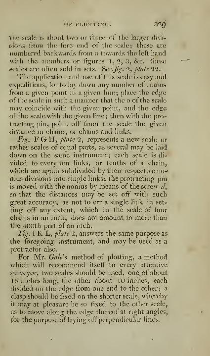
OF PLOTTING. 32^
tlie scale is about two or three of tlie larger divi-
sions from the fore end of tlie scale; these are
numbered backwards from o towards the left handwith the iRimbers or figures 1, 2, 3, &c. these
scales are often sold in sets. Sccj^g. 2, plt^tt; 22.
The application and use of this scale is easy andexpeditious, for to lay down any number of chains
from a given point in a given line; place the edgeofthe scale in such a manner that the o ofthe scale
may coincide with the given point, and the edgeof the scale with the given line; then with the pro-
tracting pin, point off from the scale the given
distance in chains, or chains and links.
Fig. F G H, f/ate 2, represents a new scale or
rather scales of equal parts, as several may be laid
down on the same instrument; each scale is di-
vided to every ten links, or tenths of a chain,
which are again subdivided by their respective no^nius divisions into single links; the protracting pin
is moved with the nonius by means of the screw ^,
so that the distances may be set off with such
great accuracy, as not to err a single link in set-
ting off any extent, which in the scale of four
chains in an inch, does not amount to more than
the 400th part of an inch.
F/g. I K L, plate 2, answers the same purpose as
the foregoing instrument, and may be used as a
j)rotractor also.
For Mr. Gales method of plotting, a methodwhich will recommend itself to every attentive
surveyor, two scales should be used, one of about
15 inches long, the other about 10 inches, each
divided on the edge from one end to the other; a
clasp should be fixed on the shorter scale, w hereby
it may at pleasure be so lixed to the other scale,
as to move along the edge thereof at right angles,
for the purpose of laying off perpendicular lines.

S30 OF PLOTTING.
Fi^.F GH, plaU 2, represents an instrument
for this purpose, with different scales on the part
F G; boih thiS; and that represented at Jig. IK L,
form excellent parallel rules. They arc also madeonly with the clasp, if desired.
The protractor is a circle or semicircle of thin
brass, divided into degrees, and parts of a degree,
on the outer edge.
The common semicircular protractor, Jig. 2,
^hite 3, is of six or eight inches diameter, the limb
divided into 180 dcgTees, and numbered both
ways, 10, 20, 30, &c, to 180; each degree is sub-
divided mto two parts. In the middle of the dia-
meter is a small mark, to indicate the center of the
protractor; this mark must be always placed onthe given angular point.
The common circular protractor is more useful
then the semicircular one; the outside edge is di-
vided into 360 degrees, and numbered 10, 20, 30,
to 360 ; each degree is subdivided into halves.
In the middle of the diameter is a small mark,which is to be placed on the angular point, whenan angle is to be protracted; the diameter, repre-
senting a meridian, must be placed on the meri-
dian of any plan, where the bearing of any object
is to be laid down. The application of this instru-
ment is so easy and simple, that examples of its
use are unnecessary here.
Fig. 7,p^iiic 1 1 J and 4 and 5, pJafe 17, represent
the three best circular protractors; the principle
is the same in all ; the difference consists in supe-
riority of execution, and the conveniences that
arise from the construction. Fig. 4, plate 17, is
a round protractor, the limb accurately divided to
360°, each degree is divided into two parts, whichare again subdivided to every minute by the no-
nius^ which moves round the limb of the protrac-

OP PLOTTING. 331
tor, on <i conical center; that part of the index
"beyond the limb has a steel point tixed at the end,
Avhosc use is to prick oif the angles; it is in a di-
rect line with the center of the protractor, and the
index division of the nonius, all which is evident
from an inspection of the figure.
OF PLOTTING, OR MAKING A DRAUGHT OP THELAND FROM THE FIELD NOTES.
The common method of plotting is this : t:ikc a
sheet of paper of convenient size, draw a line
thereon, to represent the magnetic meridian, andas^ign any convenient point therein to represent
the place where the survey commenced; lay the
edge of the protractor on this meridian line, andbringing the center thereof to the point so assigned
to represent the place of beginning, mark off the
defrrces and minutes of the first course or bearins:
by the limb of the protractor, and draw a line
from the place of beginning through the point so
marked, laying off its proper length or distance
by the scale ofequal parts; this line will reprcseiit
the first line of the survey. Through the point or
termination of the said first line of the survey,
draw another line, representing the magnetic me-ridian, parallel to the former; and lay off the
course or bearing of the second line of the survey
by the protractor, and its length by the scale of
equal parts, as before; and so proceed, till the
whole be laid down; and 3-ou will have a plot or
draught of the survey.
For example. Let it be required to make a plot
or draught of the field notes.
1st. Draw any line, as NAS, fg. 1, plate 18,
to represent the magnetic meridian, and assiga
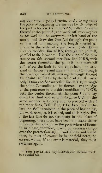
33^ bP^ rLOTTING.
any convenient point therein, as A, to represent
the place of beginning the survey; lay the edge of
the protractor on the line NAS, with the center
thereof at the point A, and mark oW seven degrees
on the limb to the westward, or left hand of the
north, and draw the line AB through the point
so marked off, making the length thereof 21
chains by the scale of equal parts. 2nly. Drawanother meridian line N B S, through the point B,
parallel to the former.* Lay the edge of the pro-
tractor on this second meridian line N B S, with
the center thereof at the point B, and mark off
55" 15' on the limb to the right hand, or east-
ward of the north; and draw the line B C throughthe point so marked off, making the length thereof
18 chains 20 links by the scale of equal parts.
3dly. Draw another meridian line N C S, throughthe point C, parallel to the former; lay the edgeof the protractor to this third meridian line N C S,
with the center thereof at the point C, and lay
down the third course and distance C D, in the
same manner as before; and so proceed with all
the other lines, D E, E F, F G, GA; and if the
last line shall terminate in the place of beginning,
the work closes, as it is called, and all is right. Butif the last line do not terminate in the place ofbeginning, there must have been a mistake either
in taking the notes, or in the protraction ofthem
:
in such case, therefore, it will be necessary to goover the protraction again, and if it be not founrl
then, it must of course be in the field notes, to
correct which, if the error is material, they mustbe taken again.
"^ These parallel lines m^y be drawn with the least tronble
by a parallel rule.

[ 333 ]
Mr. Gale s method op plotting.
The foregoing method of plotting is liable to
sonic inaccuracies of practice, on account of hav-ing a new meridian for every particular line of thesurvey, and on account of hiying off every newImcfrof/i the point of term'mat'vm of the preceeding
oiie, whereby any httle inaccuracy that may hap-pen in laying down of one line is communicatedto the rest. But there is a second method of plot-
ting, by which these inconveniences are avoided,
and by which also the accuracy or inaccuracy ofthe field work is decided with precision and cer-
tainty; I would, therefore, recommend this secondmethod to the practitioner, as far preferable to anyother I have seen.
'id Method. Take out from the first table in the
j4ppcndix to this Work the northings^ southings^ enst-
wgs, and zvestings, made on each of the several lines
of the survey, placing them in a kind of table in
their respective columns; and, if the sum of the
northings be equal to the sum ofthe southings, andthe sum of the eastings equal to the sum of the
westings, the work is right, otherwise not.*
Then in an additional column put the wholequantity of northing or of southing made at the
termination of each of the several lines ofthe sur-
* The truth of this observation cannot but appear self-evi-^
dent to the reader. For the meridians within the limits of an
ordinary survey having no sensible difference from parallelism,
it must necessarily follow, that if a person travel any way soe-
ver with such small limits, and at length come round to the
'place where he sat out, he must have travelled as far to the
northward as to the southward, and to the eastward as to the
westward, though the practical surveyor will always find it
difficult to make his work close with this perfect degree of t^actnesa.

334 MR. gale's method
vey; which will be determined by adding or sub-tracting the northing or southing made on each
particular line, io ov from the northing or southing
made on the preceding line or lines. And in
another additional column, put the whole quantity
of easting or westing made at the termination of
each of the several lines of the survey, which will
be determined in like manner by adding or sub-
tracting the easting or westing made on each par-
ticular line, to orfrom the easting or westing madeon the preceding line or lines.
The whole quantity of the northings or south-
ings, and of the eastings or ^vcstings, made at the
terminations ofeach of the several lines, being thus
contained in these two additional columns, the
plot may be easily laid down from thence, by a
scale of equal parts, without the help of a pro-
tractor.
It is best, however, to use a pair ofscales with a
clasp,,* whereby the one may at pleasure be so fas-
tened to the other, as to move along the edgethereof at right angles, so that the one scale mayrepresent the meridian, or north and south line,
the other, an east and west line. It may also beobserved, that in order to avoid taking the scales
apart during the work, it will be necessary that
the whole of the plot lay on one side of that scale
which represents the meridian ; or, in other words,
the stationary scale should represent an assiuned
merid'um, laying wholly on one side of the survey.
On this account it will be necessary to note in a
third additional column of the preparatory table,
the distances of each of the corners or termina-
tions of the lines of the survey, east or west from
such assumed meridian. In practice, it is rather
" Or one of those at f^. F G H, or IK L, plats 2.
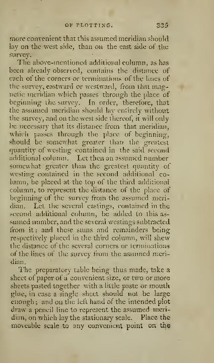
OF PLOTTING. 335
more convenient that this assumed meridian should
lay on the west side, than on the east side of the
survey.
The above-mentioned additional column, as has
been already observed, contains the distance ofeach of the corners or terminations of the lines of
the survey, eastward or westward, from that mag-netic meridian which passes through the place of
beginning the survey. In order, therefore, that
the assumed meridian should lav entirely withoutthe survey, and on the west side thereof, it will only
be necessary that its distance from that meridian,
which passes through the place of beginnina:,
should be somcwjiat greater than the greatest
quantity of westing contained in the said secondadditional column. Let then an assumed numbersomewhat greater than the greatest quantity ofwesting contained in the second additional co-
lumn, be placed at the top of the tliird additional
column, to represent the distance of the place of
beginning of the survey from the assumed meri-
dian. Let the several eastings, contained in the
second additional colun^in, be added to this as-
sumed number, and the several westings subtracted
from it ; and these sums and remainders being
respectively placed in the third column, will shewthe distance of the several corners or terminations
of the lines of the survey from the assumed meri-
dian.
The preparatory table being thus made, take a
sheet of paper of a convenient size, or tv/o or moresheets pasted together with a little paste or mouthglue, in case a single sheet should not be large
enough ; and on the left hand of the intended plot
draw a pencil line to represent the assumed meri-
dian, on Y/hich lay the stationary scale. Place the
moveable scale to any convenient point on th^

33G Mk. GALE S METH01>
edge of the former, and point off by the edge of
the latter, at^cording to any desired number ofchains to an ineh, the assumed distance or num-ber of chains contained at the top of the above-
mentioned third column of the preparatory table.
Move tlic moveable seale along the edge of the
stationary one, to the several north or south dis-
tances contained in the first of the above-menti-
oned additional colunms; so will the points thus
marked off represent the several corners or termi-
nations of the lines of the survey; and lines being
drawn fi-om one point to the other, will of course
represent the several lines of the survey.
Exanij>le. Let it be required to make a plot or
drdught of the field notes, p. 222, according to
Mr. Gules method.
The preparatory table will be as follows
:
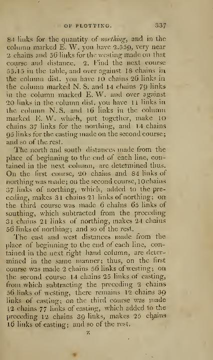
OF PLOTTING. 33/
84 links for the quantity of northing, and in the
coknnn marked E. W. you have '2.559, very near
1 ehains and 5(3 links for the westing made on that
course and distance. 2. Find the next course
55.15 in the table, and over against 18 ehains ia
the column dist. you have 10 chains 26 links in
the column marked N. S. and 14 chains 79 links
in the column marked E. W. and over against
20 links in the column dist. you have 1 1 links in
the column N. S. and l6 links in the columnmarked E, W. which, put together, make 10
chains 37 links for the northing, and 14 chains
95 links for the easting made on the second course;
and so of the rest.
The north and south distances made from the
place of beginning to the end of each line, con-
tained in the next column, are deteVmined thus.
On the first course, 20 chains and 84 links of
northing was made; on the second course, lOchains
37 links of northing, which, added to the pre-
ceding, makes 31 chains 21 links of northing; on
the third course was made 6 chahis Qo links of
southing, which subtracted from the preceding
31 chains 21 links of northing, makes 24 chains
56 links of northing; and so of the rest.
The east and west distances made from the
place of beginning to the end of each line, con-
tained in the next right hand column, are deter-
mined in the same manner; thus, on the first
course Avas made 2 chains 56 links of westing; on
the second course 14 chains 25 links of easting,
from which subtracting the preceding 2 chains
56 links of westing, there remains 12 chains 39links of easting; on the third course was made12 chains 77 links of easting, which added to the
preceding 12 chains 39 links, makes 25 ctiains
16 links of easting; and so of the rest.
338 MR. GALE S METHOD
The distances of the end of each line from theassumed meridian, contained in the next right
hand coUimn, are thus determined. The first as-
sumed nuniber may be taken at pleasure, provided
only that it exceeds the greatest quantity of west-ing contained in the preceding column, wherebythe assumed meridian shall be entirely out of the
survey. In the foregoing example, the greatest
quantity of westing contained in the preceding
column is 2 chains 5(5 links; the nearest wholenumber greater than this is 3 chains, which is ac-
cordingly taken and placed at the top, to repre-
sent the distance between the assumed meridian
and the place of beginning of the survey; fromthis 3 chains subtract 2 chains 56 links of west-
ing, there remains 44 links for the distance be-
tween the terminations of the first line and the
assumed meridian. The 12 chains SQ links of
casting in the next step, is added to the assumed3 chains, which make 15 chains 3() links for the
distance of the termination, by the second line
from the assumed meridian. The 25 chains l6links of casting in the next step, being added in
like manner to the assumed 3 chains make 28chains 1(3 links for the distance of the termination
of the third line from the assumed meridian ; andso on, alu'ays adding the eastings and subtracting
the westinu-s from the first assumed number.The preparatory table being completed, take a
sheet of paper or more, joined together if neces-
sary, and near the left hand edge thereof rule aline as N. S. fig. 2, flate 18, to represent the as-
sumed meridian ; on this line lay the stationary
scale, and assuming a as a convenient point therein
to represent the point directly west from the place
of beginning, bring the moveable scale to the
point a^ and lay off the first number contained in

OP PLOTTING. 339
the last-mentioned column of the preparatory ta-
ble, viz. 3 chains, from a to A, and A will represent
the place of beginning of the survey. Move the
moveable scale along the stationary one to the first
north and south distance from the place of begin-ning, viz. 20.84 from a to b, and lay off the cor-
responding distance from the assumed meridian,
0.44, from b to B, and draw AB, so will AB re-
present the first line of the survey; again, movethe moveable scale along the stationary one, to the
third north and south distance from the place ofbeginning, viz. N. 31.21 from a to c; and lay off
the corresponding distance from the assumed me-ridian, viz. 15.39, f^om c to C, and draw BC, so
will B C represent the second line of the survey.
Again move the moveable scale along the station-
ary one to the third north and south distance
from the place of beginning, viz. 24.56, from a
to d, and lay off the corresponding distance from
the assumed meridian, viz. 28.16, and draw CD,which will be the third line of the survey. Pro-
ceed in the same manner till the whole be laid
down, and ABCDEFG will be the required
plot.
This inethod ofph/thig is hy far the most perfect^
a)id the least liahle to error of any that has been con-
trived. It may appear to some to require morelabour than the common method, on account of
the computations required to be made for the
preparatory table. These computations are how-ever made with so much ease and expedition, by
the help of the table in the appendix^ that this ob-
jection would vanish, even if the computation were
of no other use hut merely for plotting^ hut it must he
observed that these computatiojis are of much further
use in determining the area or quantity of land
contained in the survey, which cannot be J^scer-
z 2
310 OBSERVATIONS ON PLOTTING,
taincd with equal accuracy in any other way.When this is considered, it will be found that this
method is not only preferable on account of its
superior accuracy, but is attended with less labour
on the whole than the common method.If a pair of scales, such as are above recom-
mended, be not at hand, the work may be laid
down from a single scale, by first marking off the
N. and S. distance on the line N. S. and after-
wards laying off the corresponding east distances
at right angles thereto.
To plot the field notes^ p. 313. 1. Lay down all"
the station lines, viz. 7° W. 21 chains, N. 55. 15,
E. 18. 20, &c. contained in the middle column of
the field book, as before directed, without paying
any regard to the offsets, until all the station lines,
represented \nfig, 3, pl.lQ, by dotted lines, be laid
down ; then lay off the respective offsets at right
angles from the station line, at the respective dis-
tances at which they were taken, as is done at
fig. 3, a bare inspection of which will make the
work perfectly plain.
Toplot the field notes, p. 314. 1. Lay down the
whole of the outside boundaries, the station lines
first, the offsets afterwards, as directed in the pre-
ceding articles; and then lay down the internal
divisions or boundaries of the respective fields, in
the same manner as is done in j*?^. 4.
OBSERVATIONS ON PLOTTING, BY Mr. MiLNE.
The protractor, whether a whole or a semicir-
cle, ought not to be less in diameter than seven
or eight inches, to insure the necessary degree of
accuracy in plotting the angles of a survey. Thedegrees on the limb are numbered various ways,
but most commonly from 10° 20"^ &c. to 36o°.
BY MR. MILNE. 341
It would be right to repeat the numbers the con-
trary way, when the breadth of the limb will ad-
mit of it. Others are numbered 10° 20°, &c. to
180°, and the contrary. Surveyors will suit them-
selves with that kind best adapted to their modeof taking angles in the field; so that in whichever way the limb of the instrument they survey
with is graduated, the protractor had best be the
same.
It is true, a surveyor of much practice will read
off an angle mentally very readily, in which ever
way the instrument happens to be graduated.
For instance, I have in the field taken the an-
gles made with the magnetic meridian, in whichcase I count no angle above 89° 59'; if the angle
comes to 90° O', I call it due E. or due W. if it is
89° 59', I write to it N. E. or S. E. or else N. W.or S. W. as it happens to turn out.
Now 89° 59' N. E. upon a protractor numberedto 360° O', and placina: 36o to the north, reads the
same; but 89° 59' S. E. reads 90° V, and 8Q° 59'
S. W. reads '269° 59'; and lastly, 89° 59' N. W.reads 270° T.
Again, if the angle or bearing is due south, it
reads on this protractor 180°; if 0° T S. E. it reads
179° 59'; and if 0° l' S. W. it is 180° l'; and so
of any other intermediate angle or bearing.
The great inducement to surveyors for taking
the angles by the bearings the lines make with
the magnetic meridian, is the having the r^eedle as
a check in the course of the survey ; and when the
circuit comes to be plotted, having it in his power
to prick off all the angles, or bearings of the cir-
cuit, at once planting of the protractor.
This mode of sui-veying, or taking angles, is
also more expeditious, and more accurate than
any other, provided the index of the instrument
342 OBSERVATIONS ON PLOTTING,
is furnished with a clamp for making it fast to
the limb, while it is carrying from one station to
another.
The protractor for plotting this way of survey-
ing had best be graduated 10, 20, &c. to 180, onthe right hand, and the same repeated on the left,
and again repeated contrary to the former; but as
protractors for general use are graduated 10, 20,
&c. to 360, I shall here describe a very useful andconvenient one of this latter kind, and then pro-
ceed to give an example of plotting all the angles
of a circuit by it from one station.
This protractor is represented at j^^-. 5, plate 17.
Its diameter, from pointer to pointer, is 9^ inches;
the center point is formed by two lines crossing
each other at right angles, which are cut on a
piece of glass. The limb is divided into degrees
and half degrees, having an index with a nonius
graduated to count to a single minute, and is fur-
nished with teeth and pinion, by means of which
the index is moved round, by turning a small nut.
It has two pointers, one at each end of the index,
furnished with springs for keeping them suspended
while they are bringing to any angle; and being
brought, applying a finger to the top of the poin-
ter, and pressing it down, pricks off the angle.
There is this advantage in having two pointers,
that all the bearings round a circuit may be laid,
or pricked off, although the index traverses but
one half of the protractor.*
* The protractor, represented^. T, plate 11, is circular, and
of the same diameter as the foregoing j the center is also formed
by the intersection of two lines at right angles to each other,
which are cut on glass, that all parallax may thereby be avoided j
the index is moved round by teeth and pinion. The limb is
divided into degrees and half degrees, and subdivided to eveiy
minute by the nonius 5 the pointer maybe set at any convenient
distance from the center^ as the socket which carries it moves

BY MR. MILXE. 343
Let^?^-. 5, plate 13, be the circuit to be plotted.
I draw the magnetic meridian N. S.Jig.6, plate\3,
and assigning a point therein for station 1, place
the center of the above described protractor uponit, with 360° exactly to the north, and 180° to the
south of the magnetic meridian line N. S. Forthe conveniency of more easily reading off" de-
grees and minutes, I bring the nonius to the south
side of the protractor, or ^ide next to me; andseeing by the field sketch, or eye draught, j^^)-. 5,
that the bearing from station 1 to station 2 is 87"30' S. E. I readily conceive it wanting 2° 30' ofbeing due east, or 90° o'; therefore, adding men-tally 2° 30' to 90° O', I make 92° 30' on this pro-
tractor, to which I bring the nonius, and thenmake a prick by pressing down the pointer of the
protractor, and with my lead pencil mark it 1.
The bearing from station 2 to station 3 being 10°
15' N. E. sec Jig. 5, I bring the nonius, for the
sake of expedition and ease of reading off, to 10°
15' S. W. which is upon this protractor 190^ 15',
and pressing down the north pointer, it will prick
off 10° 15' N.E. which I mark with my pencil, 2.
The bearing from station 3 to station 4 being85° 13' N. E. I readily see this is wanting 4° 47'
of being due east; therefore I bring the nonius to
within that of due west, which upon this protrac-
tor is 265° 13', and pressing down the N.E.pointer, it will prick off 85° 13' N.E. which I
mark 3.
upon the bar B C, and is fixed thereto by the nut D, At right
angles to the bar B C, and moveable with it, there is another bar
E F; on this bar different scales of equal parts are placed, ^othat
by moving a square against the inner edge thereof, angles maybe transferred to any distance from the center, containing the
same number of degrees marked out by the index; the use of
which will be evident from Mr. Milne's observations.

344 OBSERVATIONS ON PLOTTING^
The bearing from station 4 to station 5 being1 1° 5' N. W. I bring the nonius to l68° 55', andwith the opposite, or north-west pointer, prick off
1 1° 5' N. W. which I mark 4.
In like manner I prick off the bearings fromstation 5 to 6, from 6 to 7, and from 7 to 1 , whichcloses the circuit; marking them severally with
my pencil 5, 6, 7.
Then laying aside the protractor, and casting
jny eye about the tract traced by the pointer of
the protractor for the bearing from station 1,
marked 1, I apply the ruler to it and station 1, anddrawing a line, mark off' its length by compassesand scale, eight chains, which fixes station 2.
Again, casting my eye about the tract traced bythe pointer of the protractor, for the 1 bearing,
marked 2, I apply the parallel ruler to it andstation 1, and moving the ruler parallel eastward,
till its edge touches station 2, I from thence drawa line northward, and by scale and compasses markits length, five chains, to station 3. Thus the
bearing 10° 15' N. E. at station 1, is transferred to
station 2, as will easily be conceived by supposing
the points a, b, moved eastward, preserving their
parallelism till they fall into the points of station
2 and 3, forming in fig. 6, the parallelogram
a, b, 3, 2.
It is evident this bearing of 10° 15' N. E. is bythis means as truly plotted as if a second meridian
line had been drawn parallel to the first from sta-
tion 2, and the bearing 10° 15' N. E. laid off' from
it, as was the common method of plotting previ-
ous to the ingenious Mr. WiUiam Gardiner com-municating this more expeditious and more accu-
rate mode to the ])ublic. However, its accuracy
depends entirely upon using a parallel ruler that
moves truly parallel, which the artist will do well

BY MR. MILXE. 345
to look to, before he proceeds to this way of
plotting.
Station 3 being thus fixed, to find station 4,
I cast my eye about the tract traced by the pointer
ofthe protractor for the bearing marked 3, and ap-
plying the parallel ruler to it and station 1, movethe ruler parallel thereto northward, till it touchstation 3 ; and from thence draw a line north-east-
ward, and by scale and compasses marking its
length, three chains, station 4 is found.
Now conceive the points c, d, moved north-
ward, preserving their parallelism till they fall into
the points of stations 3 and 4; and thus station 4has the same bearing from station 3, as c or d has
from station 1.
In the same manner I proceed to the next bear-
ing 4 ; and placing the ruler to the point made bythe pointer of the protractor at 4 and station 1,
and moving the ruler parallel till its edge touchstation 4 ; from thence dravv' a line, and mark off
its length, 5 chains, to station 5. Here e, f, is
transferred to 4th and 5th stations, and the 5th
station makes the same angle with the meridian
from tlie 4th station, as e, or f, docs with the me-ridian from the first station.
In like manner, applying the parallel ruler to
station 1, and the several other bearings of the cir-
cuit 5, 6, and 7 ; the points g, h, will be transferred
to 5th and 6th, and i, k, to 6th and 7th; and lastly,
the bearing from the 7th station will fall exactly
into the first, which closes the plot of the circuit.
It is almost unnecessary to observe, that the
dotted lines marked a, b, c, &c. fig. 6, are drawnthere only for illustrating the operation: all that
is necessary to mark in ])ractice are the figures
1, 2, 3, &e. round the tract traced by the pointer
pf the protractor. T. Milne.
[ 346 ]
OF DETERMINING
THE AREA OR CONTENT
OF LAND,
1. The area or content of land is denominated
by acres, roods, and perches.
Forty square perches make a rood.
Four roods, or l6o square perches, make an
English acre.
And hence 10 square chains, of four perches
each, make an Enghsh acre.
2. The most simple surface for admensuratiorv
is the rectangidar parallelogram, which is a plane
four-sided figure, having its opposite sides equal
and parallel, and the adjacent sides rectangular to
one another; if the length and breadth be equal,
it is called a square \ but, if it be longer one waythan the other^ it is commonly called an ohlong.
TO DETERMINE THE AREA OF A RECTANGULARPARALLELOGRAM.
Rule. Multiply the length by the breadth, and
that product will be the area.*
It has been already observed, that the best me-thod of taking the lengths is in chains and links
\
hence, the above-mentioned product will give the
area in chains and decimal parts of a chain. Andas 10 square chains make an acre, the area in acres
will be shewn by pointing off one place of the de-
cimals more in the product than there arc both in
the multiplicand and multiplier', which answers the
Bame purpose as dividing the area into chains bylO;
* Euclid, Book i. Prop. 35 Scholium.
TO DETERMINE THE AREA, ScC. 347
and the roods and perches will be determined bymultiplying the decimal parts by 4 and by 40.
Example. Suppose the side of the foregoing
square be 6 chains and 75 links; what is the area?
Multiply 6.75by Q.ys
337547254050
Acres 4.55(325
4 Roods In an acre.
Roods 2.2250040 Perches in a rood.
Perches 9.00000
Acres, Roods. Perches.
Ans. 4 2 Q.
Suppose the length of the foregoing oblong be
9 chains and 45 links, and the breadth 5 chains and15 links; how many acres doth it contain?
Multiply 9.45by 5.15
4725
4725
Acres 4.866754
Roods 3,4670040
Perches 18.68000
A, R, P.
Ans. 4 3 18. (The decimal parts .QQ arc not
worth regarding.)
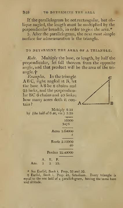
548 TO DETERMINE THE AREA
If the parallelogram be not rectangular, but ob-
lique angled, the length must be multiplied by the
perpendicular breadth, in order to give the area.*
3. After the parallelogram, the next most simple
surface for admensuration is the triangle.
TO DETERMINE THE AREA OF A TRIANGLE.
Rule. Multiply the base, or length, by half the
perpendicular, let fall thereon from the opposite
angle, and that product will be the area of the tri-
angle.-|~
Examples. In the triangle
ABC, right angled at B, let
the base A B be 8 chains and25 links, and the perpendicu-
lar BC 6 chains and 40 links;
C
how many acres doth it con-
tain ? A
by (the

OF A TRIANGLE. 349
In the oblique an-
gled triangle D E F,
let the base D E be
12chainsancl25links,
and the perpendicu-
lar FG, let fall onthe base DEfrom the 33
ooposite angle F, be 7 chains and 30 links; howmany acres doth it contain ?
Multiply 12.25
by (the half of 7.30, viz.) 3.65
61257350
60'75
Acres 4.471254
Roods 1.8850040
Perches 35.40000
A. R. P.
Ans. 4 1 35.
It would be the same thing, if the perpendicu-
lar were to be multiplied by half the base; or, if
the base and perpendicular were to be multiplied
together, and half the product taken for the area.
4. The next most simple surface for admensu-ration is a four-sided figure, broader at one endthan at the other, but having its ends parallel to
one another, and rectangular to the base. Its area
is determined by the following
Rule. Add the breadths at each end together,
and multiply the base by half their sum, and that
product will be the area. Or otherwise, multiply
ihe base by the whole sum of the breadths at each

350 TO DETERMINE THE AREA
end, and that product will be double the area, thehalf of which will be the area required.
Example. Let the base be 10 chains and golinks, the breadth at the one end 4 chains and75 links, and the breadth at the other end 7 chains
and 35 links; what is the area?

OP A TRIANGLE. 351
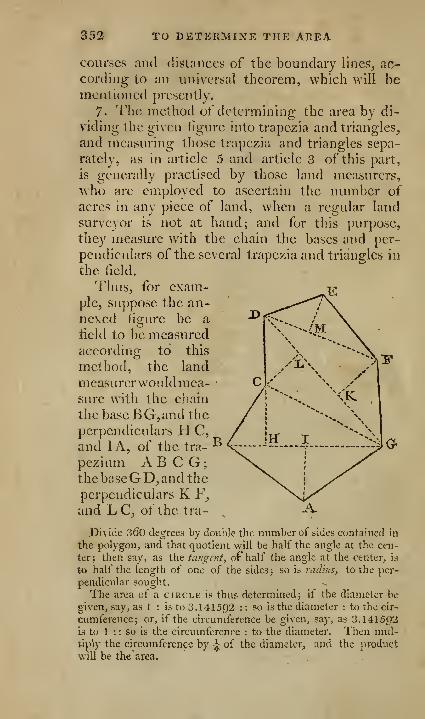
352 TO DETERMINE THE AREA
courses and distances of the boundary lines, ac-
cording to an universal theorem, which will bementioned presently.
7. The method of determining the area by di-
viding the given figure into trapezia and triangles,
and measuring those trapezia and triangles sepa-
rately, as in article 5 and article 3 of this part,
is generally practised by those land measurers,
who are employed to ascertain the number of
acres in any piece of land, when a regular land
surveyor is not at hand; and for this purpose,
they measure with the chain the bases and per-
pendiculars of the several trapezia and triangles in
the field.
Thus, for exam-ple, suppose the an-nexed figure be a
field to be measuredaccording to this
method, the land
measurerwouldraea-sure with the chain
the base BG, and the
perpendiculars H C,
and lA, of the tra-
^
pezium A B C G;the baseGD, and the
perpendiculars K F,
and LC, of the tra-
Divide 360 degrees by double the number of sides contained In
the polygon, and that quotient will be half the angle at the cen-
ter: then say, as the tangent, of half the angle at the center, is
to half the length of one of the sides j so is radius, to the per-
pendicular sought.
The area of a circle is thus determined j if the diameter be
given, say, as 1 : is to 3.141592 : : so is the diameter : to the cir-
cumference j or, if the circumference be given, say, as 3.14I5C)2
is to 1 :: so is the circumference : to the diameter. Then mul-tiply the circumference by ^ of the diameter, and the product
will be the area.
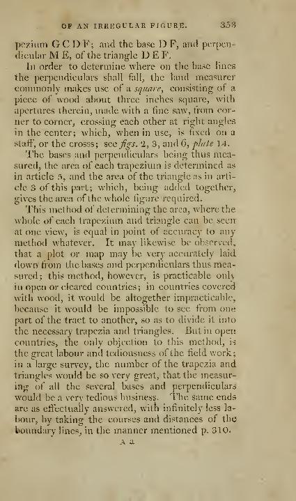
of AN IRREGULAR FIGURE. 3.53
pczium G C D F; and the base D F, and perpen-
dicular M E, of the triangle D E F.
In order to determine where on the base lines
the perpendiculars shall fall^ the land measurer
commonly makes use of a square, consisting of a
piece of wood about three inches square, with
apertures therein, made with a fine saw, from cor-
ner to corner, crossing each other at right angles
in the center; which, when in use, is fixed on a
staff, or the crosss; sccfgs. 2, 3, and 6, plale 14.
The bases and perpendiculars being thus mea-sured, the area of each trapezium is determined as
in article 5, and the area of the triangle as in arti-
cle 3 of this part; which, being added together,
gives the area of the whole figure required.
This method of determining the area, \vhcrethe
whole of each trapezium and triangle can be seen
at one view, is equal in point of accuracy to any
method whatever. It may likewise be observed,
that a plot or map may be very accurately laid
down from the bases and perpendiculars thus mea-sured; this method, however, is practicable only
in open or cleared countries; in countries covered
with wood, it would be altogether im])racticablc,
because it would be impossible to see from one
part of the tract to another, so as to divide it into
the necessary trapezia and triangles. But in open
countries, the only objection to this method, is
the great labour and tediousness of the field work;
in a large survey, the number of the trapezia andtriangles would be so very great, that the measur-
ing of all the several bases and perpendiculars
would be a very tedious business. The same ends
are as effectually answered, with infinitely less la-
bour, by taking the courses and distances of the
boundary lines^ in the manner mentioned p. 310.
A a
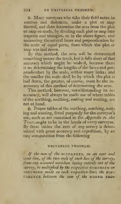
354 AX UNIVETxSAL THEOREM.
8. Many surveyors who take their field notes in-
courses and distances, make a plot or mapthereof, and then determine the area from the plot
or map so made, by dividing such plot or map into
trapezia and triangles, as in the above figure, andmeasuring the several bases and perpendiculars bythe scale of equal parts, from which the plot or
map was laid down.By this method, the area will be determined
something nearer the truth, but it falls short of that
accuracy which might be wished, because there
is no determining the lengths of the bases and per-
pendiculars by the scale, within many links; andthe smaller the scale shall be by which the plot is
laid down, the greater, of course, must be the in-
accuracy of this method of determining the area.
This method, however, notwithstanding its in-
accuracy, will always be made use of where tables
of the northing, southing, easting and westing, are
not at hand.
9. Proper tables of the northing, southing, east-
ing and westing, fitted purposely for the surveyor's
use, such as are contained in the Appendix to this
Tract, ought to be in the hands of every surveyor.
By these tables the area of any survey is deter-
mined with great accuracy and expedition, by aneasy computation from the following
UNIVERSAL THEOREM.
If the sum of the distances, on an east and•west line, of the two e7ids of each line of the survey,
front any assumed meridian laying entireh out of the
survey, be midtiplied by the respective northing or
SOUTHING made on each respective line', the dif-ference between the sum of the north pro-
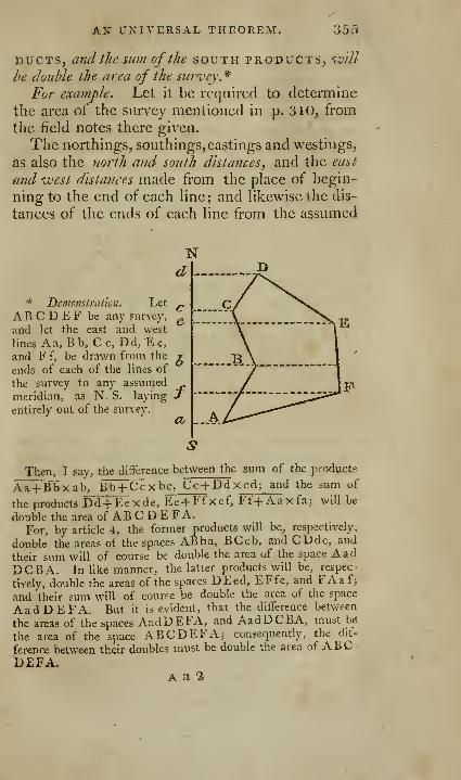
An universal theorem. !55
DUCTS, and the swn of the south products, 'lcv'//
be double the area of the survey *
For example. Let it be required to determine
the area of the survey mentioned in p. 310, from
the field notes there given.
The northings, southings, eastings and westings,
as also the north and south distances, and the east
mid west distances made from the place of begin-
ning to the end of each line; and likewise the dis-
tances of the ends of each line from the assumed
* DcmpnstraUou. Let
AB C D E F be any survey,
and let the east and west
lines Aa, B b, C c, Dd, E e,
and F f, be drawn from the
ends of each of the lines of
the survey to any assumed_^
meridian, as N. S. laying Jentirely out of the survey.
Then, I say, the difference between the sum of the products
Aa+Bbxab, Bb+ Ccxb c, Cc+Dd xcd; and the sum of
the products Dd+ Eexde, Ee+ Et"xef, Ff+Aaxfaj will be
double the area of AB C D E FA.For, by article 4, the former products will be, respectively,
double the areas ot the spaces ABba, BCcb, and CDdc, and
their sum will of course be double the area of the space AadDCBA. In like manner, the latter products will be, respec-
tively, double the areas of the spaces DEed, EFfe, and FAaf>and their sum will of course be double the area of the space
AadDEFA. But it is evident, that the diiference between
the areas of the spaces AadDEFA, and AadDCBA, must be
the area of the space ABCDEFA5 consequently, the dit-
ference between their doubles must be double the area of ABCBEFA.
A a 2
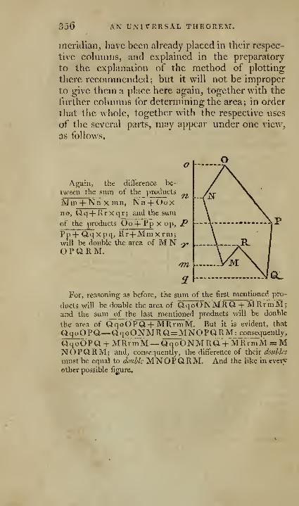
3D6 AN UNITERSAL THEOREM.
meridian, have been already placed in their respec-
tive columns, and explained in the preparatory
to the explanation of the method of plotting;
there recommended; but it will not be improper
to give them a place here again, together with the
further columns for determining the area; in order
that the whole, together with the respective uses
of the several parts, may appear under one view,
as follows.
Again, the diflerence be-
tween the sum of the products
Min + Nn X mn, Nn + Ooxno, Qq+ Rrxqr; and the sum
of the products Oo + Ppxop, /^
Pp+ Qqxpq, Rr+Mmxrm;will be double the area of M N ^O P Q R M.
'721
For, reasoning as before, the sum of the first mentioned pro-
ducts will be double the area of QqoONMRQ + MRrmM;and the sum of the last mentioned products will be double
the area of QqoOPQ-|- MRrmM. But it is evident, that
QqoOPQ—QqoQNMRQ=MNQPQRM: consequently,
QqoOPQ-l- MRrmM— QqoONMRa-l- MRrmM = MNOPQ.RM; and, consequently, the difference of their baulks
must be equal to double MNOPQRM. And the like in every
©ther possible figure.
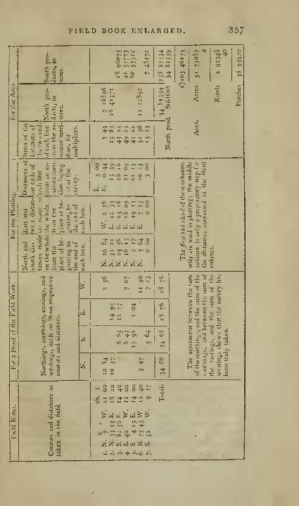
FIELD BOOK EXI-ARGED. 357
';" '

358 EXPLANATION OP
The three last columns relating to the areay are
the only ones that rpmain to be explained.
The first of these three columns contains the
sums of the distances of the two ends of each line
of the survey from the assumed meridian ; which,
according to the foregoing universal theorem, are
7nultipliers for determining the area. These are
formed by adding each two of the successive num-bers in the preceding left hand column together.
Thus 3.00 is the distance of the place of beginning
from the assumed meridian, and 0.44 is the dis-
tance of the end of the first line from the assumed
meridian; and their sum is 3,44 for the first mul-tiplier. Again 0.44 added to 15.39 makes 15.83
for the second multiplier; and 15.39 added to
28.16 makes 43.55 for the third multiplier; and
so of the rest.
The north products contained in the next co-
lumn, are the products of the multiplication of
the several norihhigs contained in the columns
marked N, by their corresponding multipliers in
the last mentioned column. Thus 7.1 6896 is the
product of the multiplication of 20.84 by 3.44;
an additional place of decimals being cut off, to
give the product in acres.
The south products contained in the next right
hand column are, in like manner, the products of
the multiplication of the several southings in the
column marked S, by their corresponding multi-
pliers. Thus 28.96075 is the product of the muUtiplication of 6.65 by 43.55; an additional place
of decimals being cut oiF, as before, to give the
product in acres; and so of the rest.
The north products being then added together
into one sum, and the south products into another
sum, and the lesser of these sums being subtracted
frpm the greater, the remainder, by the above
THE FIELD BOOK. 35()
universal theorem, is drjiihle the area of the survey
:
which being divided by 2, gives the area required:
viz. 51.73087, equal, when reduced, to 51 acres,
2 roods, and 36 perches 9-IO.*
Nothing can be more simple or easy in the ope-
ration, or more accurate in answering the desired
ends, both with respect to the proof of the work,
the plotting, and the computation of the area,
than this process. The northings, southings, east-
ings and westings, which give the most decisive
proof of the accuracy or inaccuracy of the field
work, are shewn by inspection in table 1. Fromthese the numbers or distances for the plotting are
formed by a simple addition or subtraction. Andthe multipliers, for determining tlie area, are
formed from thence, by a simple addition, with
much less labour, than by the common method of
dividing the plot into trapezia, and taking the mul-tipliers by the scale of equal parts.
The superior accuracy and ease with whichevery part of the process is performed, cannot, it
is imagined, fail to recommend it to every practi-
tioner, into whose hands this tract shall fall.
10. If the boundary lines of the survey shall
have crooks and bends in them, which is gcnerall}''
the case in old settled countries, those crooks andbends are taken by making offsets from the station
lines; as explained in page 311. In these cases,
the area comprehended within the station lines is
determined as in the last example; and the areas
* It must be observed, that, in order to tktermine the area
by this method of computation, it is indispensibly necessary that
the several lines of the survey be arranged regularly, one after
another, all the way round the survey, in case they should not
have been so taken in the field, because, without such arrange-
ment, the northings, or southings made on each line, and the
distances from the assumed meridian, would not correspond withjL»ue another.
3f50 EXAMPLE TO THE
comprehended between the station lines and the
boundaries are determined separately, as in thethird 'd\\(\ fourth articles of this part, from the off-
sets and base lines, noted in the field book; andare added or subtracted respectively, according as
the station lines shall happen to be •within or with-
out the field surveyed; which, of course, gives the
area required.
For example. Let it be required to determine
the area of the survey mentioned in the example,
page 312, from the field book there given.*
The bearings and lengths oi '^Q, station lines arc
the same as in the last example; and, conse-
quently, the area comprehended within those sta-
tion lines must be the same; viz. 51.73087-
Then, for the area comprehended between the
first station line and the boundary of the field, wehave (see the field book, page 313) first, a base
line 3.6o, and a perpendicular oflset 0.40; which,
according to article 3 of this part, contains an area
of 0.07200. Secondly, a base line 4.85, (being the
diiFerence between 3.6o and 8.45 on the station
line, at which points the offsets were taken,) andan offset or breadth at the one end 0.40, and at
the other end 0.10; which, according to article 4of this part, contains an area of 0. 1 2 1 25 . Thirdly^
a base line 7-15, (being the difference between8.45 and 15.6o on the station line,) and an offset
or breadth at the one end 0.10, and at the other
end 0.65; which according to the 4th article of
this part, contains an area of 0.26812. Fourthly^
a base line 5.40, (being the difibrence between]5.60 and 21.00 on the station line,) and a per-
pendicular offset 0.65 ; which, according to the
3d article of this part, contains an area of 0.17550,
These added together make 0.63687 for the area
•(* A plot of this survey is given in fig, 3, pJaie 18,

UNIVERSAL THEOREM. 361
of the offsets on the first station line; and, as this
station Hne is within the survey, this area must, of
coui-se, be added to the above-mentioned area com-prehended within the station hues.
Next, for the area comprehended between the
second station Hne and the boundary of the fit Id,
we have a base Hne 18.20, and a perpendicular or
offset 0.60 ; which, according to article 3 of this
part, contains an area of 0.54600. And, as this
station line is without the survey, this area must of
course hcsuhtracted (voin the above-mentioned area.
The areas of all the other ofisets are determined
in the same manner, and are respectively as fol-
lows; viz.
On \.\\cjirst station line
On the sttond -
On the third
On the fourlb -
On ihcjiftb
On the sixth
On the scvL7itb -
Totals - -
The area comprehended within the station lines,
as above A 51.7308/
Otisets to be added 2.06S12
Sum 53.81bC).9
Offsets to be subtracted 2.15660
Remains the area of the survey required A 51.6623p4
Roods 2.6495640
Perches .. 25.^8240
Areas ot" the ( )tiscts. j
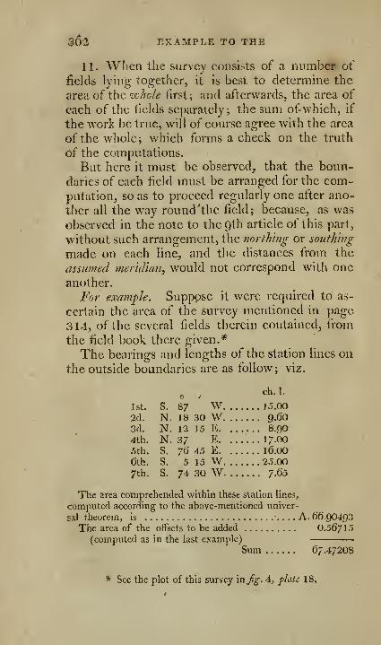
36*2 EXAMPLE TO THE
II. When the survey consists of a number ot
fields lying together, it is best to determine the
area of the whole first; and afterwards, the area of
each of the fields separately; the sum of-whieh, if
the work be true, will of course agree with the area
of the whole; which forms a check on the truth
of the computations.
Bat here it must be observed, that the boun-
daries of each field must be arranged for the com-putation, so as to proceed regularly one after ano-
ther all the way round 'the field; because, as was
observed in the note to the Qth article of this part,
without such arrangement, the northing or southing
made on each line, and the distances from the
assumed meridian, would not correspond with one
another.
For example. Suppose it were required to as-
certain the area of the survey mentioned in page
314, of the several fields therein contained, from
the field book there given.*
The bearings and lengths of the station lines on
the outside boundaries are as follow; viz.
ch. I.o /
1st. S. 87 W 15.00
2d. N. 18 30 W 9.603d. N. 12 15 E 8.90
4th. N. 37 E 17.00
5th. S. 76 45 E l6.(X)
6th. S. 5 15 W 25.00
7th. S. 74 30 W 7.(55
The area comprehended within these station llne.1,
computed according to the above-mentioned univer-
sal theorem, is A. 66.90493The area of the offsets to be added 0.56"/ \5
(computed as in the last example)
Sum 67.4720s
* See the plot of this survey mfg. 4, plate 18,
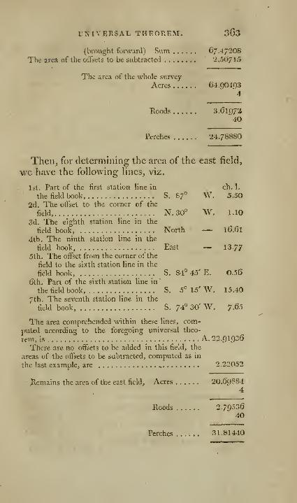
UNIVERSAL THEOREM. 363
(brought forward) Sum 67.472O8
The area of the offsets to be subtracted 2.50/15
The area of the whole surv'cy
Acres 64.904934
Roods 3.6197340
Perches 24.78880
Then, for determining the area of the east field,
\vc have the following lines, viz.
1st. Part of the first station line In ch. 1.
the field book, S. 87° W. 5.50
2d. The offset to the corner of the
field, N. 30° \V. 1.10
3d. The eighth station line in the
field book, North — 16.61
4th. The ninth station line in the
Held book, East — 13-77
5th, The offset from the corner of the
field to the sixth station line in the
field book, S. 84° 45' E. 0.56
Gth. Part of the sixth station line in
the field book, S. 5° 15' W, 15.40
7th. The seventh station line in the
field book, S. 74° 30' W. 7.65
The area comprehended within these lines, com-
jmted according to the foregoing universal theo-
rem, is A. 22.91936
There are no offsets to be added in this field, the
areas of the offsets to be subtracted, computed as in
the last example, are ^ 2.22052
Hemains the area of the east field. Acres '20.6g3S4
4
Roods 2.7903640
Perches ...... 31.81440
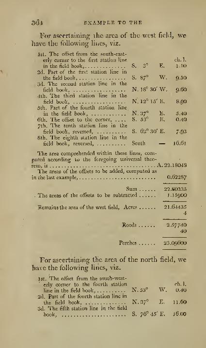
304 EXAMPLE TO THE
For ascertaining the area of the west field_, \vc
have the following lines, viz.
1st. The offset from the south-east-
erly corner to the first station line ch.l.
in the field book, S. 3' E. 1.10
2d. Part of the first station line in
the field book, S. 87° W. Q.SO
3d. The second station line in the
field book, N. 18° 30' W. 9.60
4th. The third station line in the
field book, N. 12° 15' E. 8.9O
5th. Part of the fourth station line
in the field book, N. 37° E. 5.40
eth. The offset to the comer, S. 53° E. 0.40
7th. The tenth station line in the
field book, reversed, S. 62° 30' E. 7.92
6th. The eighth station line in the
field book, reversed, South — 16.61
The area comprehended within these lines, com-
puted according to the foregoing universal theo-
rem, is A. 22.18048
The areas of the offsets to be added, computed as
in che last example, 0.6228/
Sum 22.80335
- The areas of the offsets to be subtracted 1 .159OO
Remains the area of the west field. Acres 21.644354
Roods 2.5774040
Perches 23.O96OO
For ascertaining the area of the north jfield, wehave the following lines, viz.
Jst. The offset from the south-west-
erly corner to the fourth station ch. 1,
line in the field book, N. 53° W, 0.40
2d. Part of the fourth station line in
the field book, N.37° E. II.60
3d. The fifth station line in the field
book, S. 76=45'E. 16.00
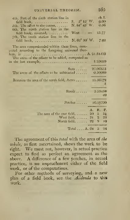
UNIVERSAL THEOREM. 365
4th. Part of the sixth station line in ch.l.
field book, S. 5° 15' W. g.tjO
.'Jth. The offset to the corner, N. 84° 45' W. 0,5(5
0"th. The ninth station line in the
field book, reversed, West — 13.77
7th. The tenth station line in the
field book, N. 62° 30' W. 7.92
The area comprehended within these lines, com-puted according to the foregoing universal theo-
rem, is . A. 21 .81422
The areas of the offsets to be added, computed as
in the last example, 1 .25030
Sum 23.064o2
The areas of the offsets to be subtracted 0.5()08O
Eemains the area of the north field. Acres 22.5637'i
4
Roods 2.2548840
Perches 10.1C)520
A. R. P-
The area of the east field, 20 2 3^West field, 21 2 23North field, 22 2 lO
Total A. 64 3 24
The agreement of this total with the area of the
whole, as first ascertained, shews the work to be
right. We must not, however, in actual practice
expect to find so perfect an agreement as the
above. A difference of a few perches, in actual
practice, is no impeachment either of the field
work, or of the computations.
For other methods of surveying, and a newplan of a field book, see the jiddejida to this
work.
[ 366 J
OF
MARITIME SURVEYING.
It was not my intention at first to say any thing
concerning maritime surveying, as that subject
had been already very well digested by Mr. Mur-doch Alacketizie, whose treatise on marit'pne survey-
ing ought to be in every person's hands who is
engaged in this branch of surveying, a branchwhich has been hitherto too much neglected. Afew general principles only can be laid down in
this work; these, however, it is presumed, will befound sufficient for most purposes; when the prac-
tice is seen to be easy, and the knowledge thereof
readily attained, it is to be hoped, that it will con-
stitute a part of every seaman's education, and the
more so, as it is a subject in which the safety of
shipping and sailors is very much concerned.
1 . Make a rough sketch of the coast or harbour,
and mark every point of land, or particular varia-
tion ofthe coast, with some letter of the alphabet;
either walk or sail round the coast, and fix a staff
with a white rag at the top at each of the places
marked with the letters of the alphabet. If there
be a tree, house, white cliff, or other remarkable
object at any of these places, it may serve instead
of a station staff.*
Q,. Choose some level spot ofground upon whicha right line, called a fundamental base, may bemeasured either by a chain, a measuring pole, or
a piece of log-line marked into feet; generally
speaking, the longer this line is, the better; its
* See Nicholson's Navigator's Assistant,

MARITIME SURVEYING. 067
situation must be such, that the whole, or mostpart of the station-staves may be seen from both
ends thereof; and its length and direetion must,
if possible, be sueh, that the bearing of any station-
staif, taken from one of its ends, may ditfcr at
least ten degrees from the bearing of the same staff
taken from the other end; station-staves must be
set at eaeh end of the fundamental base.
If a convenient right line cannot be had, twolines and the interjacent angles may be measured,
and the distance of their extremes found by con-
struction, may be taken as the fundamental base.
Ifthe sand measured has a sensible and gradual
declivity, as from high-water mark to low-w^ater,
then the length measured may be reduced to the
horizontal distance, which is the proper distance,
])y making the perpendicular rise of the tide oneside of a right-angled triangle; the distance mea-sured along the sand, the hypothcnuse; and from
thence finding the other side trigonometrically, or
by protraction, on paper; which will be the true
length of the base line. If the plane measured beon the. dry land, and there is a sensible decliviry
there, the height of the descent must be taken bya spirit-level, or by a quadrant, and that made ths
perpendicular side of the triangle.
If in a bay one strait line of a sufficient length
cannot be measured, let two or three lines, form-
ing angles with each other, like the sides of a po-
lygon, be measured on the sand along the circuit
of the bay ; these angles carefully taken with a
theodolite, and exactly protracted and calculated,
will give the strait distance betweeen the two far-
thest extremities of the first and last line.
3. Find the bearing of the fundamental base bythe compasses, as accurately as possible, with Had-Icy's quadrant, or any other instiument equally
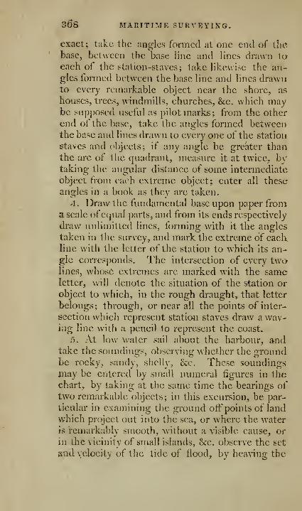
368 MAniTIME SURVEYING.
exact; take the angles formed at one end of thebase, between the base line and lines drawn taeaeh of the station-staves; take likewise the an-gles fonned between the base line and lines drawnto every remarkable object near the shore^ as
houses, trees, windmills, eharches, &e. which maybe supposed useful as pilot marks; from the other
end of the base, take the angles formed betweenthe base and lines drawn to every one of the station
staves and objects; if any angle be greater thanthe arc of the quadrant, measure it at twice, bytaking the angular distance of some intermediate
object from each extreme object; enter all these
angles in a book as they are taken.
4. Draw the fundamental base upon paper froma scale ofequal parts, and from its ends respectively
draw unlimitted lines, forming with it the angles
taken in tlie survey, and mark the extreme of eachline with the letter of the station to which its an-gle corresponds. The intersection of every twolines, whose extremes are marked with the sameletter, will denote the situation of the station or
object to which, in the rough draught, that letter
belongs; through, or near all the points of inter-
section which represent statioji staves draw a wav-ing line with a pencil to represent the coast.
5. At low water sail about the harbour, andtake the soundinij-s, obscrvino: whether the groundbe rocky, sandy, shelly, &:c. These soundingsjnay be entered by small numeral figures in thecharty by taking at the same time the bearings oftwo remarkable objects; in this excursion, be par-
ticular in examining the ground off points of land
which project out into the sea, or where the wateris remarkably smooth, "without a visible cause, or
in the vicinity of small islands, &:e. observe the set
jiud velocity of the tide of flood, by heaving the
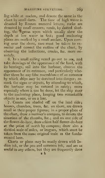
MARITIME SURVE'i'ING. 3$^
log while at anchor, and denote the same in the
chart by small darts. The time of high water is
denoted by Roman numeral letters; rocks are
denoted by small crosses; sands, by dotted shad-
ing, the TigurGS upon which usually shew the
depth at low water in feet; good anchoring
places are marked by a small anchor. Upon com-ing near the shore, care must be taken to ex-
amine and correct the outline of the chart, byobserving the inflections, creeks, &c. more mi-nutely.
6. In a small sailing vessel go out to see,, andtake drawings of the appearance of the land, with
its bearings; sail into the harbour, observe the
appearance of its entrance, and particularly whe-ther there be any false resemblance of an entrance
by which ships may be deceived into danger; re-
mark the signs or objects, by attending to which,
the harbour may be entered in safety; moreespecially where it can be done, let the ship steer
to the anchoring place, keeping two remarkable
objects in one, or on a line.
7. Coasts are shaded off on the land side;
houses, churches, trees, &c. on shore, are drawnsmall in their proper figures; in a proper place of
the chart, draw a mariner's compass, to denote the
situation of the rhumbs, &c. ; and on one side of
the flower-de-luce, draw a faint half flower-de-luce
at the point of north by compass; draw also a
divided scale of miles, or leagues, which must betaken from the same original scale as the funda-
mental base.
Charts or plans may be neatly drawn with In-
dian ink, or the pen and common ink, and are as
useful as any others, but they are frequently doneBb
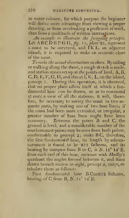
370 MARITIME SURVEYING.
in water colours; for which purpose the beginnerwill derive more advantage from viewing a proper
drawing, or from overlooking a proficient at work,than from a multitude of written instructions.
An example to illustrate the foregohig precepts.
Let AB C D E F G H, fig. 1 1 ,plate 23, represent
a coast to be surveyed, and I K L, an adjacent
island; it is required to make an accurate chart
of the same.
Tb make the actual ohserval'ions on shore. By sailing
or walking along the shore, a rough sketch is made,and station staves set up at the points of land, A, B,C, D, E, F, G, H, and also at I, K, L, on the island,
precept 1. During this operation, it is observed,
that no proper place offers itself at which a fun-
damental base can be drawn, so as to commandat once a view of all the stations; it will;, there-
fore, be necessary to survey the coast in two se-
parate parts, by making use of two base lines; if
the coast had been more extended, or irregular, a
greater number of base lines might have beennecesscuy. Between the points B and C, the
ground is level, and a considerable number of the
southernmost points may be seen from both points,
conformable to precept 2; make B C, therefore,
the first fundamental base, its length by admea-surement is found to be 812 fathoms, and its
bearing by compass from B to C, is N. 11° 14' E.
from each end of this ])ase, measure with Hadley^quadrant the angles formed between it, and lines
drawn to each station in -sight, precept 3, cntf'r,'6r
tabulate them as follows:
First fundamental base B 0=812 fathoms,
bearing of C from B, N. 11° 14' E.
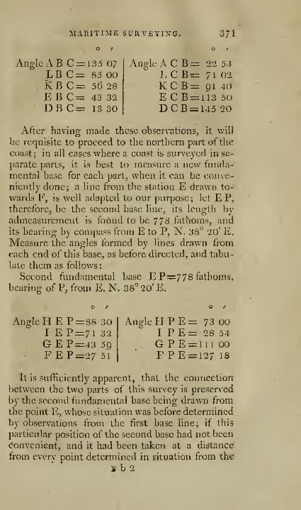
MARITIME SURVEYING. 371
Angle A B C = i35 07LB C=: 85 00KB C=: 56 28
EB C= 43 32DBC= 13 30
Angle A C B = 22 5>i
LCB=: 71 02KC B= 91 40EC B = 113 50DCB= 145 20
After having made these observations, it will
be requisite to proceed to the northern part ofthe
coast; in all cases where a coast is surveyed in se-
parate parts, it is best to measure a new funda-
mental base for each part, when it can be conve-niently done; a line from the station E drawn to-
wards F, is well adapted to our purpose; let E P,
therefore, be the second base line, its length byadmeasurement is found to be 778 fathoms, andits bearing by compass from E to P, N. 38° 20' E.
Measure the angles formed by lines drawn from
each end of this base, as before directed, and tabu-
late them as follows:
Second fundamental base E P= 77 8 fathoms,
bearing of P, from E. N. 38°20'E.
Angle H E P=8S 30I EP=7l 32GEP=43 59FEP=27 5l
Angle PI P E = 73 00I PE= 28 54
G P E = 1 1 1 00F PE = 127 18
It is sufficiently apparent, that the connection
between the two parts of this survey is preserved
by the second fundamental base being drawn from
the point E, whose situation was before determined
by observations from the first base line; if this
particular position of the second base had not been(Convenient, and it had been taken at a distance
from every point determined in situation from the
B b 2

372 GEOMETRICAL CONSTRUCTION.
first base, the connection would have required anobservation of the bearing of one of the said points
from each end of the second base: thiis^ suppose
the line I P to be the second base line, instead of
E P; the position of I P with respect to the given
point E, may be known by taking the bearings of
E, from I and P.
All the observations which are required to bemade on shore, being now completed, it will beadvihcable to construct the chart before we pro-
ceed to the other observations on the water, for,
by this method, an opportunity is offered of draw-
ing the waving line of the coast with more correct-
ness than could otherwise be obtained.
GEOMETRICAL CONSTRUCTION,^^. 12, pi. 23.
On the point B as a center, describe the circle
T) e s w, the diameters n s and w e being at right
angles to each other, and representing the meri-
dian and parallel ; from n set off the arc n N,equal to the quantity of the variation of the com-pass ; draw the diameter N S, and the diameter
W E at right angles to the same; these lines will
represent the magnetic meridian, and its parallel
of latitude.
From the center B, draw the first base line
BC=81-2 fathoms, N. 11° 14' E. by compass;from one extremity B, draw the unlimited line»-
Ba, Bl, Bk, Be, Bd, forming, respectively with
the base, the angles observed from thence ; fromthe other extremity C, draw the unlimited lines
C a, CI, C k, C e, C d, forming, respectively with
the base, the angles observed from thence ; the
intersections of lines terminated by the same let-
ter, will give the stations A, L, K, E, D, pre-
cept 4.

GEOMETRICAL CONSTRUCTION. 373
Draw the line B Q, N. 38° 10' E. by compass,
and from E, draw EP=778 fathoms in the samedirection or parallel to it, E P will be the second
base line; from one extremity E, draw the un-limited lines Eh, Ei, Eg, E f, forming, respec-
tively with the base, the angles observed from
thence; from the other extremity P, draw the un-
limited lines Ph, Pi, Pg, Pf; the intersections
of lines terminated by the same letter will give
the stations H, I, G, F, precept 4.
Near the points A, B, C, D, E, F, G, H, draw
a waving or irregular line to represent the coast
;
draw also by the help of the points I, K, L, a line
to represent the coast of the island.
The chart being thus far delineated, it will be
proper to make the observations which are re-
quired on the water.
TO MAKE THE ACTUAL OBSERVATIONS ON THEWATER.
Precept 5, sufficiently explains the business to
which it is necessary to attend on the water ; no-
thing more, therefore, need be added here, except
an elucidation of the method, by the place at
which any observation is made, may be found on
the chart; the place of an observer may be deter-
mined by the bearings of two known objects; the
intelligent practitioner will find reasons for oc-
casionally preferring each of these methods; but,
as the distance in the second method is knownonly by estimation, we have given the preference
to the first, in the present example; all the sound-
ings, &c. are supposed to be laid down by these
methods, but, to prevent confusion and prolixity,
the lines of bearing are drawn only from the points
M, N, and O.
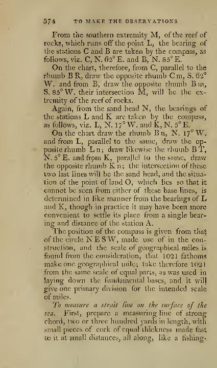
374 TO MAKE THE OBSERVATIONS
From the southern extremity M, of the reef of
rocks, which runs off the point L, the bearing of
the stations C and B are taken by the compass^ as
follows, viz. C, N. 62° E. and B, N. 85° E.
On the chart, therefore, from C, parallel to the
rhumb B R, draw the opposite rhumb C m, S. 6'2°
W. and from B, draw the opposite rhumb B m,S. 85° W. their intersection M, will be the ex-
tremity of the reef of rocks.
Again, from the sand head N, the bearings of
the stations L and K are taken by the compass,
as follows, viz. L, N. 17° W. and K, N. 5° E.
On the chart draw the rhumb B n, N. 17° W.and from L, parallel to the same, draw the op-
posite rhumb Ln; draw likewise the rhumb BT,N. 5° E. and frpm K, parallel to the same, drawthe opposite rhumb K n; the intersection ofthese
two last lines will be the sand head, and the situa-
tion of the point of land O, which lies so that it
cannot be seen from either of these base lines, is
determined in like manner from the bearings of Land K, though in practice it may have been moreconvenient to settle its place from a single bear-
ing and distance of the station A.
The position of the compass is given from that
of the circle NESW, made use of in the con-
struction, and the scale of geographical miles is
found from the consideration, that 1021 fathomsmake one geographical mile; take therefore 1021from the same scale of equal parts, as was used in
laying down the fundamental bases, and it will
give one primary division for the intended scale
of miles.
7^0 measure a strait Vine on the surface of the
sea. First, prepare a measuring line of strong
chord, two or three hundred yards in length, with
small pieces of cork of equal thickness made fast
to it at small distances, all along, like a fishing-

ON THE WATER. 375
net, SO that it may float strait on the surface of
the water: if the line has been well stretched, or
much used before, it is the better; also prepare
two ropes somewhat longer than the greatest
depth of the water to be measured, with a pig of
lead or iron ballast, which we call an anchor, 50or 60 pounds weight, tied by the middle to oneend of each rope, that when it is at the bottom it
may be able to anchor a boat, and bear to bestretched strait without shifting the place of the
anchor. Let the measuring line be thoroughly
wet immediately before you begin to use it, andthen stretched on the water close by the shore,
and its length measured there with a pole. Then,in the direction intended to be measured, take tworemarkable sharp objects on the land in a line,
one near the shore, the other as far up in the coun-try as you can: if such are not to be had, place
buoys on the water at proper distances in that
direction.
2. Take the objects, or buoys, in a line, andholding one end of the measuring line fast on the
shore, carry out the other in a boat, in that direc-
tion, till it is stretched strait at its full length byone man in the boat, and exactly at the end of the
line let another man drop the anchor, which will
mark one length of it. There keep the boat, andthe end of the measuring line, close to the anchorrope, drawn tight up and down, till another boat
takes in the other end which was on the shore, androws farther on, and lays it strait in the direction
of the land marks, or buoys, and there drops ano-
ther anchor, which will mark the second length
of the measuring line. Go on thus till the wholeproposed distance is measured; and immediately
after let the measuring line be again measured with
a pole on the water near the shore, as at first, and\[ the lengths differ, take the mean between them

87^ TO MAKE THE OBSERVATIONS
for the true length. It is obvious, that to measure
with any exactness this way, the sea must not only
be smooth, but void of a swell, and of all stream of
tide; either ofwhich will hinder the line from ly-
ing strait. This method ofmeasuring a strait line
miay be convenient on some occasions; and if care
is taken to keep the anchor rope right up anddown when the measuring line is applied to it,
will be found sufficiently exact for many purposes,
but not for a fundamental base line from whichpther distances are to be deduced.
There is another way of measuring a strait line,
mechanically, on the sea, which is so well knownto seamen, that it is needless to describe it partis
cularly here: and that is, by heaving the log over
a ship's stern while she is under sail, and observ-
ing how many knots of the log line run out in half
a minute; for the line is so divided that the ship
will run, or is supposed to run, so many miles in
an hour, in a strait course; and twice as much in
two hours, and so on. But this conclusion is
founded on three suppositions, neither of which is
certain, viz. that the log remains in the sameplace during the whole half minute that the line is
running out from the ship's stern; that the ship
continues to sail with the same velocity, and also
in the same direction, during an hour, or two,
that she did during the halfminute; the contrary
of which is more likely in most cases. For the
log line may shrink, or stretch, while it is runningout; or may drag after the vessel by the weightof the line, or by not running easily and readily
off the reel ; the swell of the sea may alter the place
of the log; and currents, or streams of tide,
stronger orweaker below the surface than on it, anlunsteady helm, lee-way, and varying winds, maychange the direction, or celerity of the ship's mo-t}on; for neither of which can any certain allov,-
ON THE WATER. 377
ance be made. This way, therefore^ of measuring
a .strait line, or distanee, is not to be depended onas exact; but is mentioned here, because rocks,
shoals, or islands, sometimes lie so far from the
coast, that there is no other way of forming any
notion of their distance. If any such distance is
to be measured after this manner, let the log-line
be thoroughly wet when it is measured; let the
length between each knot be 51 feet, which is the
1 '20th part of a geometrical mile, as half a minute
is ri^th part of an hour. Choose neap-tide, as
much slack water as can be got, and a moderatebreeze of following wind; let the line be run off
the reel so as never to be stretched quite strait;
and if the half minute is measured by a watch that
shews seconds, rather than by a glass, it will ge-
nerally be more exact. Perhaps one second should
be allowed for the loss of time in callina: out at
the beginning, and stopping it at the end of the
time; except the person who holds the watch can
contrive to observe the going out of the red rag at
the beginning, and also to stop the line himself at
the end of the time; which does not seem a diffi-
cult matter.
To find the distance of two 'places hy the flash and
report ofa gun. Sound moves 1142 English feet
in one second of time, or 6l20 feet, which makesa geographical mile, in 5t"' nearly ; therefore, let
a gun be fired at one place at an appointed time,
and observe the time that elapses between the
flash and report, and so many seconds as you ob-
serve, so many times 1142 feet are you distant
from the place; the operation should be repeated
two or three times for greater certainty. The dis-
tance to be measured in this way should never be
less than two miles, on account of errors that mayftjrise in taking the time.
L 378 ]
TO TRANSFER A PLAN FROM ONE PAPER TOANOTHER.
Method 1 . By points. Lay the rough plan uponthe clean paper, on which you intend to draw the
fair copy, press them close together by weights,
and keep them as flat as possible; then with a
' pointrel, or needle point, prick through all the
corners of the plan to be copied; separate the
papers, and join by lines the points on the clean
paper. This metho^l can only be used in plans,
whose figures are small, regular, and bounded byStrait lines.
Method 2. By tracing faper. Rub the back of
the rough plan with black-lead powder, and having
wiped off the superfluous lead, lay the blacked
part upon the clean paper, or place a sheet of
black tracing paper between the rough plan andthe clean paper; weights are to be placed as in
the former method, to maintain the papers in the
same position.
Then, with a blunt point of brass, steel, or
ivory, trace exactly the lines of the plan, pressing
the paper so much, that the black lead under the
lines maybe transferred to the clean paper; whenthe whole of the plan has been thus delineated, goover the black-lead marks with common, or Indian
ink.
Method"^. By squares. See prob. 65, page 90.
-
Method A. By a copying glass. This is a large
square, or rectangular piece of looking glass, fixed
in a frame of wood, which can be raised to any
angle, like a desk, the lower end resting upon the
table; a screen of blue paper fits to the upper edge,
and stands at right angles to it.

TO TRANSFER A PLAN. 37^
Place this frame at a convenient angle against a
strong light: fix the old plan and clean paper
firmly together by pins, the clean paper upper-
most, and on the face of the plan to be copied;
liiy them with the back of the old plan next the
glass, namely, that part which you intend to copyfirst. The light through the glass will enable youto perceive distinctly every line of the plan uponthe clean paper, and you can easily trace over themwith a pencil ; and having finished that part whichcovers^ the glass, slide another part over it, andcopy t3ii^, and thus continue till the whole becopied.
Method 0. By tlie assistance ofproporl'ionahle andtriangular compasses, Jig. A and N, plate 1, and
fig. 12, plates. These will, in many instanstan-
ces, assist the draughtsman v(-'ry much, and lessen
the labour of copying.
Method 6. By the pantographcr. There is nomethod so easy, so expeditious, nor even so accu-
rate, as the pantographcr. It is an instrument as
useful to the experienced draughtsman, as to those
who have made but little progress in the art. It
saves a great deal of time cither in reducing, en-
larging, or copying of the same size, giving the
outlines of any drawing, however crooked or com-plex, with the utmost exactness; nor is it confined
to any particular kind, but may with equal facility
be used tor copying figures, plans, sea charts,
maps, proliles, landscapes, &c.
DESCRIPTION AND USE OF THE PANTOGRA-PHER, OR PANTAGRAPH.
I have not been able to ascertain who was the
inventor of this useful instrument. The earliest
account I find, is that of the Jesuit Scheiuer^ about

380 DESCRIPTION AND USE
the year l631, in a small tract entitled, Fantagra-
fh'ice, s'lve Ars nova DeUneaiidi. The principles
are self-evident to every geometrician; the mecha-nical construction was first improved by my fa-
ther, about the year i730. It is one, amongother scientific improvements completed by him,
that others have many years after, assumed to
themselves.
The pantographer is usually made of wood, or
brass, from 12 inches to two feet in length, andconsists of four flat rules, Jig. IQ, plate^^, twoof them long and two short. The two longer
are joined at the end A by a double pivot,
which is fixed to one of the rules^ and works in
two small holes placed at the end of the other.
Under the joint is an ivory castor to support this
end of the instrument. The two smaller rules are
fixed by pivots at E and H, near the middle ofthe
larger rules, and are also joined together at their
other end, G.By the construction of this instrument, the four
\ rules always form a parallelogram. There is a
^ sliding box on the longer arm, and another on the
shorter arm. These boxes may be fixed at anypart of the rules by means of their milled screws;
each of these boxes are furnished with a cylindric
tube, to carry either the tracing point, crayon,
or fulcrum.
The fulcrum, or support K, is a leaden weight;
on this the whole instrument moves when in use.
To the longer instruments are sometimes placed
two moveable rollers, to support and facilitate the
motions of the pantographer; their situation maybe varied as occasion requires.
The graduations are placed on two of the rules,
B and D, with the proportions of t^ t; i, &c. to tV,
marked on them,

OP THE PANTOGRAPHER. 381
The pencil holder, tracer, and fulcrum, must in
all cases be in a right line, so that when they are
set to any number, if a string be stretched over
them, and they do not coincide with it, there is
an error either in the setting or graduations.
The long tube which carries the pencil, or
crayon, moves easily up or down in another tube;
there is a string affixed to the long, or inner tube,
passing afterwards through the holes in the three
small knobs to the tracing point, where it may, if
necessary, be fastened. By pulling this string, the
pencil is lifted up occasionally, and thus pre-
vented from making false or improper marks uponthe copy.
To reduce in any of the froport'ions t, i, i, I, &c,as marked on the two bars B, and D. Suppose, forexample, i is required. Place the two sockets at -s
on the bars B and D. Place the fulcrum, or lead
weight at B, the pencil socket, with pencil at D,and the tracing point at C. Fasten down upon asmooth board, or table, a sheet of white paper un-der the pencil D, and the original map, &;c. underthe tracing pointC, allowing yourself room enoughfor the various openings of the instrument. Thenwith a steady hand carefully move the tracing point
C over the outlines of the map, and the pencil at Dwill describe exactly the same figure as the origi-
nal, but 2 the size. In the same manner for anyother proportion, by only setting the two sockets
to the number of the required proportion.
The pencil-holder moves easily in the socket, togive way to any irregularity in the paper. Thereis a cup at the top for receiving an additional
weight, either to keep down the pencil to the pa-
per, or to increase the strength of its mark.
There is a silken string fastened to the pencil-
holder, in order that the pencil may be drawn up

382 TO USE THE PAXTOGHAPHER.
off the paper, to prevent false marks when cross*
ing the original in the operation.
If the original should be so large, that the in-
strument will not extend over it at any one opera:-'
tion, two or three points must be marked on the
original, and the same to correspond upon the
copy. The fulcrum and copy may then be removedinto such situations, as to admit the copying of the
remaining part of the original; first observing,
that when the tracing point is applied to the three
points marked on the original, the pencil falls onthe three corresponding points upon the copy. In
this manner, by repeated shiftings, a pentagraph
may be made to copy an original of ever so large
dimensions.
To enlarge in ayiy of the proportions i^ t, t, &V.Suppose 2. You set the two sockets at h, as before,
and have only to change places between the pencil
and tracing point, viz. to place the tracing point
at D, and the pencil at C.
To copy of the same size, }>iU reversed. Place
the two sockets at •§, the fulcrum at D, and the
pencil at B.
There are sometimes divisions of 100 unequal
parts laid down on the bars B and D, to give anyintermediate proportion, not shewn by the frac-
tional numbers commonly placed.
Pentagraphs of a greater length than \\\o feet
are best made of hard wood, mounted in brass,
with steel centers, upon the truth of which de-
pends entirely the equable action of this useful
instrument.
[ 383 ]
OF
LEVELLING.
The necessity of finding a proper channel for
conveying water occurs so often to the surveyor,
that any work on that subject, which neglected to
treat on the art of levelling, would be manifestly
imperfect; I shall therefore endeavour to give the
reader a satisfactory account of the instruments
used, and the mode of using them.
A DESCRIPTION OF THE BEST SPIRIT LEVEL.
Fig. 3, plate 17, represents one of the best con-
structed spirit levels, mounted on the most com-plete staves, similar to those affixed to a best the-
odolite.
The achromatic telescope, A, B, C, is movea-ble, either in the plane of the horizon, or with a
small inclination thereto, so as to cut any object
whose elevation, or depression, from that plane,
does not exceed \1 degrees; the telescope is about
two feet long, is furnished with fine cross wires,
the screws to adjust which are shewn at a, for de-
termining the axis of the tube, and forming a just
line of sight. By turning the milled screw B,
on the side of the telescope, the object glass is
moved outwards, and thus the telescope suited to
different eyes.
The tube c c with the spirit bubble is fixed to
the telescope by a joint at one end, and a capstan
headed screw at the other, to raise or depress it for
the adjustment. The two supporters D, E, on
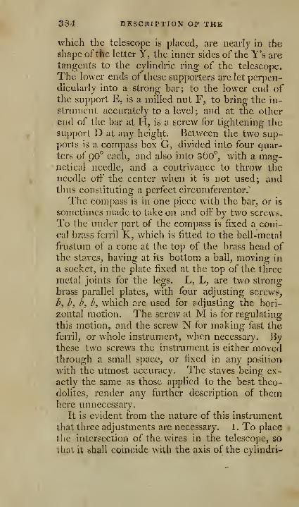
384 DESCRIPTION OP THE
which the telescope is placed, are nearly in theshape of the letter Y, the inner sides of the Y's aretangents to the cyHndric ring of the telescope.
The lower ends of these supporters are let perpen-dicularly into a strong bar; to the lower end ofthe support E, is a milled nut F, to bring the in-
strument accurately to a level; and at the other
end of tlie bar at H, is a screw for tightening thesupport D at any height. Betw^een the two sup-ports is a compass box G, divided into four quar-ters of 90° each, and also into 36o°, with a mag-neticul needle, and a contrivance to throw the
needle off the center when it is not used; andthus constituting a perfect circumferentor.
The compass is in one piece with the bar, or is
sometimes made to take on and off by two screws.
To the under part of the compass is fixed a coni-
cal brass fcrril K, which is fitted to the bell-metal
frustum of a cone at the top of the brass head ofthe staves, having at its bottom a ball, moving in
a socket, in the plate fixed at the top of the three
metal joints for the legs. L, L, are two strong
brass parallel plates, with four adjusting screws,
h, h, h, b, which arc used for adjusting the hori-
zontal motion. The screw at M is for regulating
this motion, and the screw N for making fast the
ferril, or whole instrument, when necessary. Bythese two screws the instrument is either movedthrough a small space, or fixed in any position
with the utmost accuracy. The staves being ex-
actly the same as those applied to the best theo-
dolites, render any further description of themhere unnecessary.
It is evident from the nature of this instrument
that three adjustments are necessary. 1 . To place
tlie intersection of the wires in the telescope, so
that it shall coincide with the axis of the cylindri-
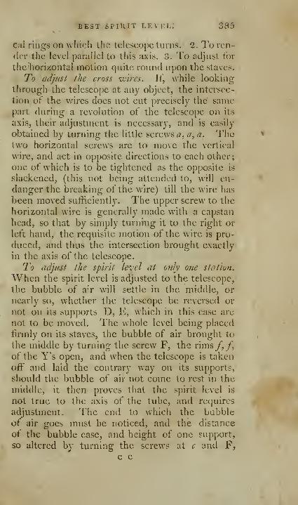
BEST SPIlllT LEVEL^ 385
cal rings on which the telescope turns. 2. To ren-
der the level parallel to this axis. 3. To adjust for
the horizontal motion quite round upon the staves.
To adjust the cross ivin's. It, while looking
through the telescope at any object, the intersec-
tion of the v/ires does not cut precisely the" samepart during a revolution of the telescope on its
axis, their adjustment is necessary, and is easily
obtained by turning the little screws a, a, a. Thetwo horizontal screws are to move the vertical
wire, and act in opposite directions to each other;
one of which is to be tightened as the opposite is
slackened, (tliis not being attended to, will en-
danger the breaking of the wire) till the wire has
been moved sufficiently. The upper screw to the
horizontal wire is generally made with a capstan
head, so tliat by simply turniug it to the right or
letl hand, the requisite motion of the wire is pro-
duced, and thus the intersection brought exactly
in the axis of the telescope.
To adjust the spirit level at only one station.
When the spirit level is adjusted to the telescope,
the bubble of a^r will settle in the middle, or
nearly so, whether the telescope be reversed or
not on its supports D, E, which in this case are
uot to be moved. The whole level being placed
firmly on its staves, the bubble of air brought to
the middle by turning the screw F, the rims/,/,
of the Y's open, and when the telescope is taken
off and laid the contrary way on its supports,
should the bubble of air not come to rest in the
middle, it then proves that the spirit level is
not true to the axis of the tube, and requires
adjustment. The end to which the bubbleof air goes must be noticed, and the distance
of the bubble case, and height of one support,
so altered by turning the screws at c and F,
c c
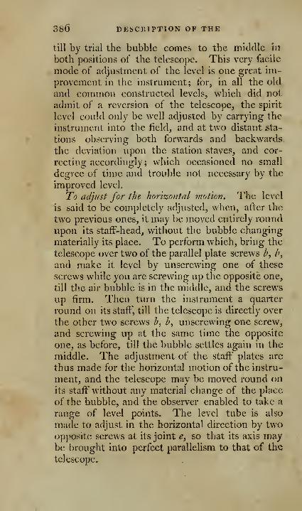
380 DESCRIPTION OF THE
till by trial the bubble comes to the middle hi
both positions of the telescope. This very facile
mode of adjustment of the level is one great im-
provement in the instrument; for, in all the old
and common constructed levels, which did not
admit of a reversion of the telescope, the spirit
level could only be well adjusted by carrying the
instrument into the field, and at two distant sta-
tions observing both forwards and backwards
the deviation upon the station staves, and cor-
recting accordingly; which occasioned no small
degree of time and trouble not necessary by the
improved level.
To adjust for the lior'izontal motion. The level
is said to be completely adjusted, when, after the
two previous ones, it may be moved entirely round
upon its staft-head, without the bubble changing
materially its place. To perform which, bring the
telescope over two of the parallel plate screws ^, l\
and make it level by unscrewing one of these
screws while you are screwing up the opposite one,
till the air bubble is in the middle, and the screws
up firm. Then tm-n the instrument a quarter
round on its staff, till the telescope is directly over
the other two screws h, h, unscrewing one screw,
and screwing up at the same time the opposite
one, as before, till the bubble settles again in the
middle. The adjustment of the staff plates are
thus made for the horizontal motion of the instru-
ment, and the telescope may be moved round onits staff without any material change of the place
of the bubble, and the observer enabled to take a
range of level points. The level tube is also
made to adjust in the horizontal direction by twoopposite screws at its joint e, so that its axis maybe brought into perfect parallelism to that of the
telescope.
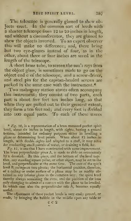
BEST SPIRIT LEVEL. 38^^
The telescope is generally glassed to shew ob-jects erect. In the common sort of levels witha shorter telescope from 12 to 20 inches in length,
and without a circumferentor, they are glassed to
shew the objects inverted. To an expert observ^er
this will make no difference; and, there beingbut two eye-glasses instead of four, as in the
other, about three or four inches are saved in the
length of the telescope.
A short brass tube, to screen the sun's rays fromthe object glass, is sometimes made to go on the
object end c of the telescope, and a screw-driver,
and steel pin for the capstan-headed screws arc
packed in the same case with the instrument.*
Two mahogany station staves often accompanythis instrument; they consist of two parts, each
part is about five feet ten inches long, so that
when tliey are pulled out to their greatest extent,
they form a ten feet rod; and every foot is divided
into 100 equal parts. To each of these staves
* F/g. 10, is a representation of a brass mounted pocket spirit
level, about six inches in length, with sights, having a groundbottom, intended for ordinary purposes either in levelling a
plane or determining level points. When about 12 inches in
length, with double sights and adapted to a staff, it may serve
for conducting small parcels of water, or draining a field, &c.Fig. 1 1, is one that 1 have constructed with some improvement.
The brass perpendicular piece A, is made to slide on occasionally
by a dovetail. By this piece, and the bottom of the level toge
ther, any standing square pillar, or other object, may be set to the
level, and perpendicular at the same time. The case of the spirit
level B, swings on two pivots; the horizontal position, therefore,
of a ceiling or under surface of a plane may be as readily ob-
tained as any inferior plane in the common way ; the spirit level
thereby always remaining the same, and the position of the base
only changing to admit cf a contact with the plane to be levelled.
In which case also the perpendicular side A, becomes equally
useful.
The adjustment of these pocket levels is very easily proved, oi*
made, by bringing the bubble in the middle i;pon any table or
C C 2
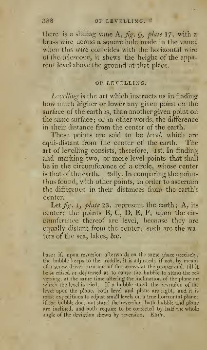
38S OF LEVELLING. ''
there is a sliding vane A, fig. Q, plate 17, with a
brass wire across a square hole made in the vane;
when this wire coincides with the horizontal wire
ot" the telescope, it shews the height of the appa-
I'ent level above the ground at that place.
OF LEVELLING.
Levelling is the art which instructs us in finding
how much higher or lower any given point on the
surface of the eaith is, than another given point onthe same surface; or in other words, the difference
in their distance from the center of the earth.
Those points are said to be level, which are
cqui-distant from the center of the earth. Theart of levelling consists, therefore, 1st. In finding
and marking two, or more level points that shall
be in the circumterence of a circle, wdiose center
is that of the earth. 2dly. In comparing the points
thus found, with other points, in order to ascertain
the difference in their distances from the earth's
center.
hctfig. 1, plate 23, represent the earth; A, its
center; the points B, C, D, E, F, upon the cir-
cumference thereof are level, because they are
equally distant from the center; such are the wa-ters of the sea, lakes^ &c.
base; if, upon reversion afterwards on the same place precisely,
the bubble keeps to the middle, it is adjusted; if not, by meansof a screw-driver turn one of the screws at the proper end, till it
be so raised or depressed as to cause the bubble to stand the re-
versing, at the same time altering the inclination of the plane onwhich the level is tried. If a bubble stand the reversion of the
level upon the plane, both level and plane are right, and it is
most expeditious to adjust small levels on a true horizontal plane;
if the bubble does not stand the reversion, both bubble and plane
are inclined, and both require to be corrected by half the wholeangle of the deviation shewn by reversion. Edit.
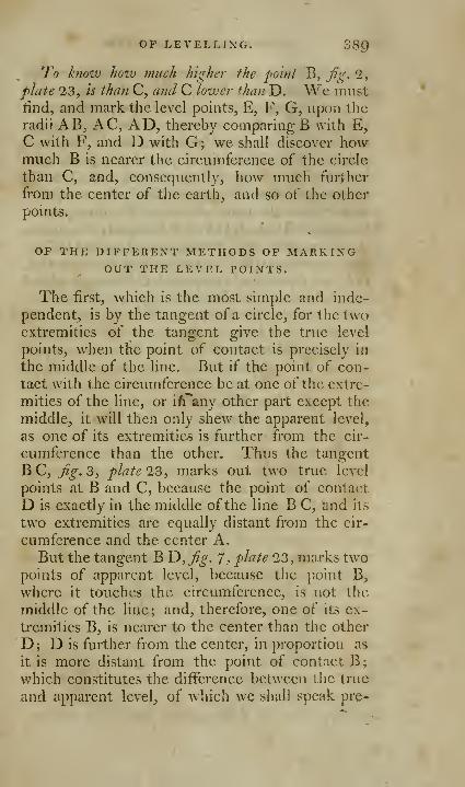
OF LEVELLING. 38Q
To know Jiozv much higher the fo'inl B, fig. 2,
flate 23, is than C, and C lower ^han D. We mustlind, and mark the level points, E, F, G, upon the
radii AB, AC, AD, thereby comparing B with E,C with F, and D with G; we shall discover howmuch B is nearer the circumference of the circle
than C, and, consequently, how much further
from the center of the earth, and so of the other
points.
OF THE DIFFEREXT METHODS OF MARKINGOUT THE LEVEL POINTS.
The first, which is the most simple and inde-
pendent, is by the tangent of a circle, for the twoextremities of the tangent give the true level
points, wdien the point of contact is precisely in
the middle of the line. But if the point of con-
tact with the circumference be at one of the extre-
mities of the line, or i/Tany other part except the
middle, it will then only shew the apparent level,
as one of its extremities is further from the cir-
cumference than the other. Thus the tangent
BC, j^^. 3, plate 23, marks out two true level
points at B and C, because the point of contact
D is exactly in the middle of the line B C, and its
two extremities arc equally distant from the cir-
cumference and the center A.
But the tangent B T>,fig. 7, plate 23, marks twopoints of apparent level, because the point B,
where it touches the circumference, is not the
middle of the line; and, therefore, one of its ex-
tremities B, is nearer to the center than the other
D; D is further from the center, in proportion as
it is more distant from the point of contact B
;
which constitutes the difference between the true
and apparent level, of w hich we shall speak pre-
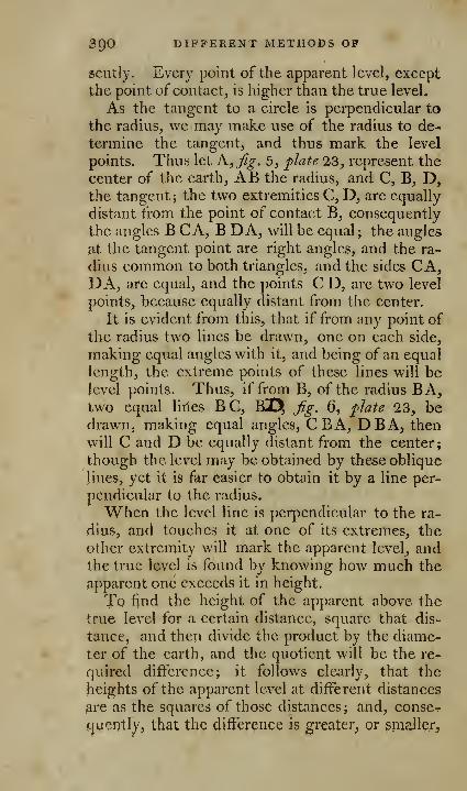
SQO DIFFERENT METHODS OP
gently. Every point of the apparent level, except
the point of contact, is higher than the true level.
As the tangent to a circle is perpendicular to
the radius, we may make use of the radius to de-
termine the tangent, and thus mark the level
points. Thus let A,fy. 5, ^late 23, represent the
center of the earth, AB the radius, and C, B, D,the tangent; the two extremities C, D, are equally
distant from the point of contact B, consequently
the angles B CA, B DA, will be equal ; the angles
nt the tangent point are right angles, and the ra-
dius common to both triangles, and the sides CA,DA, are equal, and the points C D, are two level
points, because equally distant from the center.
It is evident from this, that if from any point of
the radius two lines be drawn, one on each side,
making equal angles with it, and being of an equal
length, the extreme points of these lines will belevel points. Thus, if from B, of the radius BA,two equal lilies BC, KDt, fig, 6, '^late 23, bedrawn, making equal angles, CBA, DBA, then
w^ill C and D be equally distant from the center;
though the level may be obtained by these oblique
lines, yet it is far easier to obtain it by a line per-
pendicular to the radius.
When the level line is perpendicular to the ra-
dius, and touches it at one of its extremes, the
other extremity will mark the apparent level, andthe true level is found by knowing how much the
apparent one exceeds it in height.
To find the height of the apparent above the
true level for a certain distance, square that dis-
tance, and then divide the product by the diame-
ter of the earth, and the quotient will be the re-
quired difference; it follows clearly, that the
heights of the apparent level at different distances
^re as the squares of those distances; and, conse^.
icjucntly, that the difference is greater, or smaJIerj
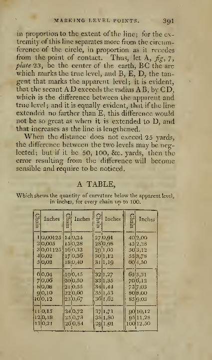
MARKING LEVEL POINTS. 391
in proportion to the extent ofthe line; for the ex-
tremity of this line separates more from the circum-ference of the circle, in proportion as it recedes
from the point of contact. Thus, let A, fg, 7,plate 23, be the center of the earth, BC the arc
which marks the true level, and B, E, D, the tan-
gent that marks the apparent level; it is evident,
that the secantAD exceeds the radius AB, by CD,which is the difference between the apparent andtrue level; and it is equally evident, that if the line
extended no farther than E, this difference wouldnot be so great as when it is extended to D, andthat increases as the line is lengthened.
When the distance does not exceed 25 yards,
the difference between the two levels may be neg-lected; but if it be 50, 100, &c. yards, then theerror resulting from the difference will becomesensible and require to be noticed.
A TABLE,
Which shews the quantity of curvature below the apparent level,
in inches, for every chain up to 100.
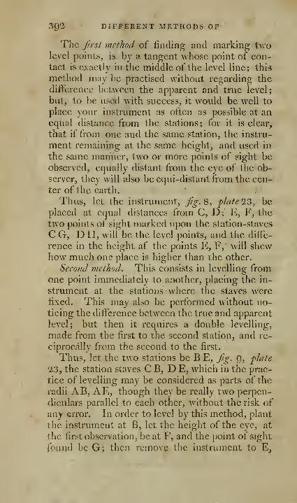
392 DIFFERENT METHODS OP
The first method of finding and marking twolevel points, is by a tangent whose point of con-tact is exactly in the middle of the level line; this
metliod may be practised without regarding the
difference between the apparent and true level;
but, to be used wdth success, it would be well to
place your instrument as often as possible at anequal distance from the stations; for it is clear,
that if from one and the same station, the instru-
ment remaining at the same height, and used in
the same manner, two or more points of sight beobserved, equally distant from the eye of the ob-
server, they will also be equi-distant from the cen-
ter of the earth.
Thus, let the instrument, jig. 8, flate 23, beplaced at equal distances from C, D; E, F, the
two points of sight marked upon the station-staves
C G, DH, will be the level points, and the diffe-
rence in the height af the points E, F," will shewhow much one place is higher than the other.
Second method. This consists in levelling fromone point immediately to another, placing the in-
strument at the stations where the staves werelixed. This may also be performed without no-ticing the difference between the true and apparent
level; but then it requires a double levelling,
made from the first to the second station, and re-
ciprocally from the second to the first.
Thus, let the two stations be B E, jig. g, fhte0,3, the station staves C B, D E, which in the prac-
tice of levelling may be considered as parts of the
radii AB, AE, though they be really two perpen-
diculars parallel to each other, without the risk of
any error. In order to level by this method, plant
the instrument at B, let the height of the eye, at
the first observation, beat F, and the point of sight
found be G; then rcmovp the instrument to Ej
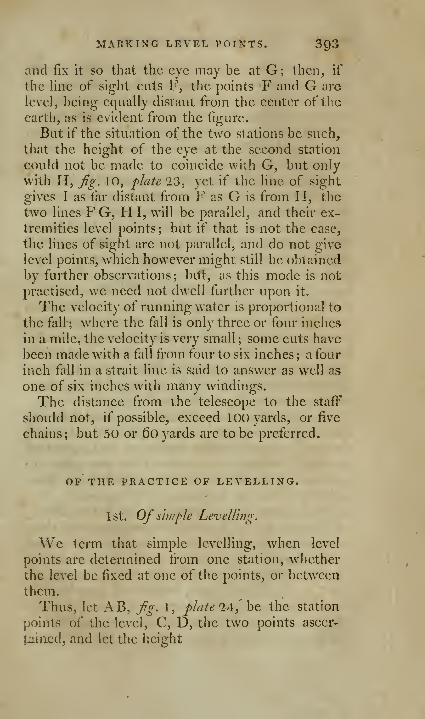
MARKING LEVEL POINTS. 393
and fix it so that the eye may be at G; then, if
the Hne of sight cuts F, the points F and G are
level, being equally distant from the center of the
earth, as is evident from the figure.
But if the situation of the two vStations be such,
that the height of the eye at the second station
could not be made to coincide with G, but only
with H, fig. 10, flate '23, yet if the line of sight
gives I as far distant from F as G is from H, the
two lines F G, H I, will be parallel, and their ex-
tremities level points ; but if that is not the case,
the lines of sight are not parallel, and do not give
level points, which however might still be obtained
by further observations; bitt, as this mode is notpractised, we need not dwell further upon it.
The velocity of running water is proportional to
the fall ; where the fall is only three or four inches
in a mile, the velocity is very small ; some cuts have
been made with a fall tVom four to six inches ; a four
inch fall in a strait line is said to answer as well as
one of six inches with many windings.
The distance from the telescope to the staff
should not, if possible, exceed 100 yards, or five
chains; but 50 or 6o yards are to be preferred.
OF THE PRACTICE OF LEVELLING.
1st. Of s'nuple Levelling.
We term that simple levelling, when level
points are determined from one station, whether
the level be fixed at one of the points, or between
them.
Thus, let AB, fig. l, plate 2A,^h^. the station
points of the level, C, D, the two points ascer-
tained, and let the height
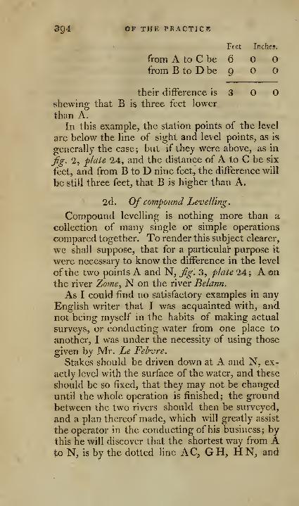
394 OF THE PRACTICE
Feet Inches.
from A to C be 6 O Ofrom B to D be 9 O O
their difference is 3 Oshewing that B is three feet lower
than A.In this example, the station points of the level
are below the line of sight and level points, as is
generally the case ; but if they were above, as in
jig. 2, plate 24, and the distance of A to C be six
feet, and from B to D nine feet, the difference will
be still three feet, that B is higher than A.
2d. Of compound Levelling.
Compound levelling is nothing more than a
collection of many single or simple operations
compared together. To render this subject clearer,
we shall suppose, that for a particular purpose it
were necessary to know the difference in the level
of the two points A and N, Jig. 3, plate 24 ; A onthe river Zome^ N on the river Belann.
As I could find no satisfactory examples in any
English writer that I was acquainted with, andnot being myself in the habits of making actual
Surveys, or conducting water from one place to
another, I was under the necessity of using those
given by Mr. Le Fehvre.
Stakes should be driven down at A and N, ex-
actly level with the surface of the water, and these
should be so fixed, that they may not be changed
until the whole operation is finished; the groundbetween the two rivers should then be surveyed,
and a plan thereof made, which will greatly assist
the operator in the conducting of his business; bythis he will discover that the shortest way from Ato N, is by the dotted line AQ GH^ H N, and

OP LEVELLING. 3^5
he will from hence also determine the necessary
number of stations, and distribute them properly,
some longer than the others, accordmg to the na-
ture of the case, and the situation of the ground.
In this instance 12 stations are used; stakes should
then be driven at the limits of each station, as at
A, B, C, D, E, F, &c. they should be driven
about 18 inches into the ground, and be about twoor three inches above its surface; stakes should also
be driven at each station of the instrument, as at
1, 2, 3, 4, he.
Things being thus prepared, he may begin his
work; the first station will be at 1, equi-distant
from the two limits A, B; the distance from A to
B, l66 yards; and, consequently, the distance oneach side of the instrument, or from the station
stake, will be 83 yards.
Write down in the first column, the first limit
A; in the second, the number of feet, inches, andtenths, the points of sight, indicated on the station
staff at A, namely, 7.6.0. In the third column,the second limit B; in the fourth, the height in-
dicated at the station staff B, namely, 5. O. O.
Lastly, in the fifth column, the distance from onestation staff to the other, in this instance l66 yards.
Now remove the level to the point marked 2,
which is in the middle between B and C, the twoplaces where the station staves are to be held, ob-
serving that B, which was the second limit in the
former operation, is the first in this; then write
down the observed heights as before, in the first
column B; in the second 4. 6. 0; in the third, C;in the fourth, 5. 6. 2; in the fifth, 56o, the dis-
tance between B and C.
As, from the inequality of the ground at the
third station, it is not possible to place the instru-
j]icnt in the middle between the two station staves.

3g6 OF THE PRACTICE, hc.
find the most convenient point for your station, as
at 3 ; then measure exactly how far this is from
each station staif, and you will find from 3 to C,
160 yards; from 3 fo D, 80 yards: the remainder
of the operations will be as in the preceding station.
In the fourth operation, it will be necessary to
fix the station, so as to compensate for any error
that might arise from the inequality of the last
;
therefore, mark out 80 yards from the station staff"
D, to the point 4; and 160 yards from 4 to E;and this must be carefully attended to, as by such
compensations the work may be much facilitated.
Proceed in the same manner with the eight re-
maining stations, as in the four former, observing
to enter every thing in its respective column ;
when the whole is finished, add the sums of each
column together, and then subtract the less from
the greater, thus from 82 : 2 : 5, take 76 : 9 : 7,
and the remainder 5:4: 8, is what the ground at
N is lower than the ground at A.

[ 397 ]
OF THE PROFILE OP THE LEVEL.
The next thing to be obtained is a section of
this level; for this purpose draw a dotted Hnc, as
o o, fig. 4, flate 24, either above or below the
plan, which line may be taken for the level or ho-
rizontal line; then let fall perpendiculars uponthis line from all the station points and places,
where the station staves were fixed.
Beginning at A, set off seven feet six inches
upon this line from A to a; for the height of the
level point determined on the staff at this place,
draw a line through ^/, parallel to the dotted line
o o, which will cut the third perpendicular at b,
the second station staff; set off from this point
downwards six feet to B, which shews the second
limit of the first operation, and that the ground at
B, is one foot six inches higher than at A; place
your instrument between these two lines at the
height of the level line, and trace the ground ac-
cording to its different heights.
Now set off on the second station staff B, four
feet six inches to C, the height determined by the
level at the second station ; and from c, draw a line
parallel to o o, which will cut the fifth perpen-
dicular at d, the third station staff from this point
set off 5 feet 6 inches fV downwards to C, whichwill be our second limit with respect to the pre-
ceding one, and the third with respect to the
first; then draw your instrument in the middle
between B and C, and delineate the ground with
its different inequalities. Proceed in the samemanner, from station to station, to the last N, andyou will have the profile of the ground over whichthe level was taken.

2Q8 OP THE PROFILE
To trace more 'particularly the profile of each
station. It is necessary to observe in this place,
that if the object of the operation be only to knowthe reciprocal height of the two extreme terms, as
in the preceding example, then the method there
laid down for the profile or section will be suffi-
cient; but if it be necessary to have an exact de-
tail of the ground between the said limits, theforegoing method is too general; we shall, there-
fore, institute another example, in which we shall
suppose the level to have been taken from A to Nby another route, but on more uniform ground,and less elevated above the level of the two rivers,
in order to form a canal, marked O, P, Q, R, S, T,U, X, Y, for a communication from one river to
the other.
Draw at pleasure a line Z Y,fig. 5, plate 14, to
represent the level line and regulate the rest; thenlet fall on this line, perpendiculars to represent the
staves at the limits of each station, taking care
that they be fixed accurately at their respective
tlistances from each other.
As the difference between the extreme limits
ought to be the same as in the former example, is
5 feet 4 inches to, set off this measure upon the
perpendicular at o, the first limit, and from o, pro-
longing the perpendicular, mark offat a, the height
determined at the first station staff, as in the pre-
ceding example; then do the same with the se-
cond and third, and so on with the following, till
this part of the work is finished; there then re-
mains only to delineate in detail the ground be-
tween the station staves; the distances are as-
sumed larger in this instance on account of the
detail.
To get the section ofthe ground between O andP, place your instrument at one of the limits as P,
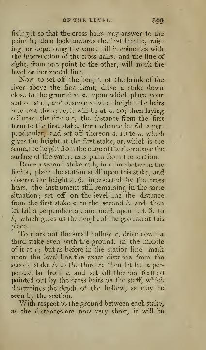
OP THE LEVEL. ^QQ
fixing It so that the cross hairs may answer to the
point b; then look towards the first limit o, rais-
ing or depressing the vane, till it coincides with
the intersection of the cross hairs, and the line of
^ight, from one point to the other, will mark the
level or horizontal line.
Now to set off the height of the brink of the
river above the first limit, drive a stake downclose to the ground at a, upon which place yourstation staff, and observe at what height the hairs
intersect the vane, it will be at 4. 10; then laying
off upon the lirte o z, the distance from the first
term to the first stake, from whence let fall a per-
pendicular, and set oft' thereon 4. 10 to a, whichgives the height at the first stake, or, which is the
same, the height from the edge oftherivcrabove the
ftvu-face of the water, as is plain from the section.
Drive a second stake at b, in a line between the
limits; place the station staff' upon this stake, andobserve the height 4. 6. intersected by the cross
hairs, the instrument still remaining in the samesituation; set off on the level line the distance
from the first stake a to the second b, and thenlet fall a perpendicular, and mark upon it 4. 6. to
/', which gives us the height of the ground at this
place.
To mark out the small hollow c, drive down a
third stake even with the ground, in the middle
of it at t'; but as before in the station line, markupon the level line the exact distance from the
second stake /», to the third c; then let fall a per-
pendicular from c, and set off thereon 6:8:0pointed out by the cross hairs on the staff, which
determines the depth of the hollow, as may be
seen by the section.
With respect to the ground between each stake,
as the distances are now very shorty it will be
400 OP THi: PROFILK
easily expressed by the operator, whose judgmentwill settle the small inequalities by a comparison
with those already ascertained.
Proceed thus with the other stations, until yonarrive at the last, and you will obtain an accurate
section in detail of your work; by such a section,
it is easy to form a just estimation of the land to
be dug away, in order to form the canal, by adding
thereto the depth to be given to the canal.
Another exiunph of coinpowui Jevellhig. In the
levelling exhibited m plate 25, we have an exam-ple taken wliere the situation was so steep andmountainous, that it was impossible to place the
staves at equal distances from the instrument, or
even to make a reciprocal levelling from one sta-
tion to another.
Such is the ease between the first point A, taken
from the surface of a piece of water, which falls
from the mountains, and the last point K, at the
bottom of a bason, where it is proposed to make a
fountain, and the height is required, at which a
jet d'eau will play by conducting the water from
the reservoir A, to the point K of the bason, bytubes or pipes properly made, and disposed with
all the usual precaution.
From the manner in which the operator mustproceed in this instance, it is evident, that the in-
strument should be adjusted with more than or-
dinary care, as the true distance from one moun-tain to the other cannot be attained without muchtrouble.
The height is here so great, that it will be ne-
cessary to go by small ascents from A to D, and
it will probably be commodious in some part of
the work to use a smaller instrument; underneath
is a table of the different level points as ascertain-
ed, which, widi the profile and plan, render this
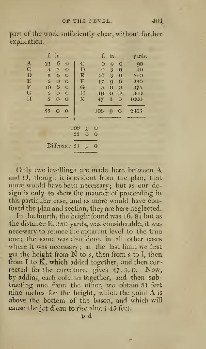
OF THE LEVEL. 401
part of the worL sufficiently clear, without further
explication.
402 OP THE PROFILE
Thegeneral seclion of this operation Is delineated
under the plan at j^^^. '2, and is suffieicntly plain
from what has been already said in the preeeding
instances. But an exact profile of the mountainis not so easy, as it would require many opera-
tions, as may be seen in the section; some of these
niigjit however be obtained, by measuring fromthe level line already mentioned, without movingthe instrument, as 'dtj^g. 3.
Example 3, fg. \, plate 26, Mr. Le Febirre
gives us in that of a river, being one part of the
river Haynox, from Ltgnehruk to Vtllelmrg, andthe mode he observed in taking this level.
The first operation was that of having stakes
driven at several parts of the river, even with the
water's edge; the first stake A, a little above the
mills at L'lgnehruk, shews the upper w^ater markwhen the water is highest, and is our first limit
;
the stake h shews the low water mark at the samemills, the stake B is the second limit.
The stakes C and D, above and below the mills
of Mazurance, shew the height of the waters
when at the highest and lowest, and their dif-
ference; these stakes form our third and fourth
limits. Lastly, the stakes at E and F, above andbelow the mills at ViUehoiirg, mark as before the
difference between the highest and lowest stations
of the water, and are also the last limits of the
operation.
Particular care was taken, that the marks should
iill be made exactly even with the edge of the
water, and they were all made at the different
parts of the river, as nearly as possible at the sameinstant of time.
The principal limits of the levelling being nowdetemaincd and fixed, it only remains to bind the
level between the limits, according to the methods
OF THE LEVEL. 403
already pointed out, using every advantage that
may contribute to the success of the work, and at
the same time avoiding all obstacles and difficul-
ties that might retard, or injure the operations.
The first rule is always to take the shortest pos-
sible way from one limit to the other.
However, this rule must not be followed if
there are considerable obstacles in the way, as
hills, woods, marshy ground, &c. or, if by going
aside, any advantage can be obtained ; thus, in the
present instance, it was found most convenient to
go from A 2 to B, by the dotted line A c d e fg h
i k B, which, although it appears the longest, wasin effect the shortest, as you have only to level
from one pond to the other, at Ac, d e, {g, h i,
k B (at the top of the plate,) the distances c d, c f,
gh, i k, the surfaces of the several ponds being
assumed as level lines, thereby abridging the workwithout rendering it less exact ; more so, as it was
not the length of the river that was required, but
only the declivity.
Having levelled from A to B, proceed from Bto C, following the dotted line B I m n o C, whencewe obtain the difFerence in height between the
surface of the water at A, and that at C.
The next step was to level between C and D,above and below the mills, to fmd the difi'crence
between the water when at its highest and lowest
situations. From D, levels were taken across the
countr)^ to p; leaving y) on account of the pond or
lake which was assumed as level, we began at q,
from thence to r, where we left off; beginning
again at s, then levelling from thence to /, and so
on to L, above the mills at ViUcbourg, and finished
at F, below them.By these operations we obtained the knowledge
of how much the v/aters above and below the mills
D d 2
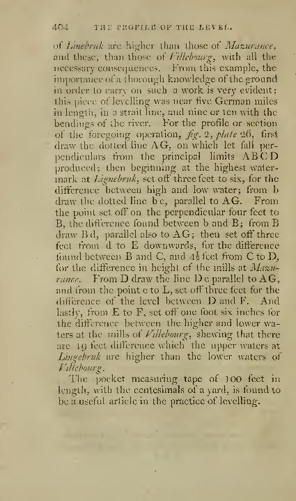
404 THj; PiioFiJ.r. of the level.
of Lifiehrnk arc higher than those of Mazurance^mid these, than those of Vlllebourg, with all the
necessary conse(]uences. From this example, the
importance of a thorough knowledge of the groundin order to carry on such a work is very evident;
this piece of levelling was near five German miles
in lengiii, in a strait line, and nine or ten with the
bendings of the river. For the profile or section
of the foregoing operation, fg. 2, flate 26, first
dra^v the dotted line AG, on which let fall per-
pendiculars from the principal limits ABCDproduced; then beginning at the highest water-
mark 'dt Lig}iehruk^ set off three feet to six, for the
difference between high and low water; fi'om b
draw the dotted line be, parallel to AG. Fromthe point set off on the perpendicular four feet to
B, the difference found between b and B; from BdrawBd, parallel also to AG; then set off' three
feet from d to E downwards, for the difference
found between B and C, and A\ feet from C to D,for the difference in height of the mills at Mazu-rance. From D draw the line D e parallel to AG,and from the point c to L, set off three feet for the
difference of the level between D and F. Andlastly, from E to F, set off one foot six inches for
the difference between the higher and lower wa-ters at the mills of ViUehoiirg^ shewing that there
are 1() feet difference which the upper waters at
Lingebriik are higher than the lower waters of
f-lllehourg.
The pocket measuring tape of 100 feet in
length, with the centesimals of a yard, is found to
be a useful article in the practice of levelling.
[ 'i03 ]
ASTRONOMICAL OBSERVATIONS AT LAND, WITHHADLEy's OCTANT AND SEXTANT.
The portability of the scxtaiU, its cheapness com-pared with other instruments, the ease with whichit is used, the accuracy of the observations madewith it, strongly recommend it to the attention of
surveyors, &c. the only addition necessary to em-ploy it advantageously in astronomical observations
at lipid, is an artificial or reflecting horizon.
The best artificial horizon is quicksilver or water;
but as these arc always more or less afieeted bv theair, the trough which contains them should becovered with a roof, consisting of two parallel
planes of glass. Sec page '285.
If these are parallel, it matters little at what ang\c they are set, and if any error be suspected, the
frame may be placed sometimes with one side,
sometimes with the other, foremost, taking a mean-of the observations.
Reflecting surfaces, whether of glass or metal,
circidar levels, floating planes of glass, &c. arc not
to be depended upoji, as they always give a differ-
ent altitude or diameter from that observed from
the surface of the mercury, orwater, proved by tak-
ino- the sun's meridian altitude, or its diameter
successively from these different surfaces; this
arises from the imperfection of the surface of me-tal or glass, which has never been ground j)er-
fectly/^/.
Tlie parallelism of a glass may be readily exa-
mined, and its defects easily discovered; whereas
the want of a fiat surfice has scarce been suspected.
The parallelism of a glass may be discovered by
looking at the moon with it, and receiving her
rays in a very oblicjue manner, so as to make the
angle between the direct and reflected rays as ob-
tuse as possible; if it appears single and well de-
406 ASTTvOXOMICAL OBSERVATIONS
fined, the glass is parallel. Or a glass may be ae-
CLirately examined by laying it on a pieee of paper,
and viewing the top of a wall or chimney, &e.
about 15 or 20 yards distant ; for, if the two sur-
faces be not parallel, the object will appear double
and surrounded with a light fringe, and thus mayevery part of the glass be examined, and its de-
fects discovered; the examination will be moreperfect if a small telescope be used.
To examine whether a surface be a perfect
plane, take the sun's diameter very accurately
with your sextant, when its altitude is considera-
ble; then examine in the surface you wish to try
the two images, without altering the index ; if it
be concave, the two images will lap over, if con-
vex, they will separate, and the quantity of this
error may be found by the sextant. If, therefore,
you use glass, &c. as a reflecting surface for anartificial horizon, you must either allow for the
error, which makes the given altitude too great, if
the glass be convex, and too small, if concave, or
you must make both your adjustments and obser-
vations from the same reflecting surface. But this
will not entirely obviate the difficulty, as the sur-
face is apt to vary from the sun's heat during a
long course of observations.
The angle, observed by means of the artificial
horizon, is always double the altitude of the star,
&c. above the horizon ; consequently, you cannot
take an altitude of more than 45° with an octant_,
or of 6o° by the sextant.
Every thing being ready, and the instrument
properly adjusted, move backward, till you sec the
reflected image of the sun in the water. If this
image be bright, turn one or more of the dark
glasses behind the horizon glass.

WITH HADLEY S 5EXTAXT. 407
Hold now the sextant in a vertical plane, anddirect the sight to the sun's image in the artificial
horizon. Then move the index tell you see theother image reflected from the mirrors come downto the sun's image seen in the horizon, so as to
touch, but not pass it; then bring the edges in
contact in the middle, between the wires of the
telescope, as before directed, and the divisions onthe arc will shew the double altitude.
Correct the double altitude for the index error,
before you halve it. Then to this half altitude addthe sun's semi-diameter, and subtract the correc-
tion for refraction, and you will have the true alti-
tude of the sun's center above the real horizon.
The altitude of a star must betuken in the samemanner as that of the sun: the double altitude
must be corrected for the index error, if any, thenhalved, and this half corrected for refraction gives
the true altitude above the real horizon.
In taking the sun's altitude, whether for the
purpose of calculating time, or for double alti-
tudes, it is best to fix the index to some particular
division of the instrument with great nicety, andthen wait till the sun is risen or fallen to that al-
titude.
This is much better than observing its altitude
and moving the screw to it, as the screw when thus
suddenly moved is very apt to alter a small trifle
by the inequality and pressure of the threads, after
the hand is removed from it; whereas, when it is
iixed to some division previous to the observation,
it may be repeatedly tried and examined before
the observation is taken.
An accurate observer will And that the error of
his sextant will vary according as he takes it, bymoving the index backwards or forwards in taking
the O's (sun's) diameter on the quadrantal arc of

408 ASTRONOMICAL OBSERVATIONS, &C.
excess; this is owing to some spring in the index,
or inequality in the adjusting screw, which it is
very difficult totally to obviate.
The best way to correct this, is always to movethe index the same way in making your observa-
tions, as you did in taking the error of adjust-
ment; though, where a great number of observa-
tions are taken, it were best both to settle the ad-
justment, and take the observations alternately bymoving the index backwards and forwards, or bysetting the objects open, and making them lap
over alternately. A mean of all these will cer-
tainly be the most free from error, as the errors
w^ill counteract each other.
This may also correct a faulty habit which an
observer may have contracted, in terming the con-
tact between the two objects; and though there
may seem to be some impropriety in the mode,yet, a mean of them will be much nearer the truth
than any single observation, where a person pre-
fers seeming to real accuracy.
The lower limb of the O or C always comesfirst into contact, when you move the index for-
ward, and the index shews the double altitude of
the O's upper limb, if the moveable sun is upper-
most, but of the lower limb when the moveablesun is lowermost.
At sea, they generally take the altitude of the
0's lower limb, because it is most natural to bring
that to sweep the horizon. But, by land, it is
most correct to take the altitude of the 0's upperlimb; ]. Because it is highest, and less liable to
be affected by refraction. '1. Because the semi-
diameter and refraction are both subtractive, andthe operation is more direct than when one is plus,
the other minus.
[ 409 ]
TO TAKE THE ALTITUDE OF THE SUN BYTHE FORE OBSEllVATION.
Observations taken by means of the fore horizon
glass arc called fore obsenations, because in themboth objects are before the observer.
Previous to every observation, the insti'ument
should be examined, in order to see whether theindex or horizon glasses be firm, or whether anyof the screws be loose; the horizon glass must also
be adjusted.
One or two of the dark glasses should be placed
before the horizon" glass, always proportioning thestrength of the shades to the lirightness ofthe sun's
rays, that the image may be looked at without in-
juring the eye.
Hold the quadrant in a vertical position, the arc
downwards, either by the braces or the radii, as
may be most convenient, or still better according
to the foregoing directions. Let the eye be at the
upper hole in the sight vane, and the lower part of
the limb against the breast.
Turn yourself towards the sun, and direct the
sight to that part of the horizon that lies directly
under it, keeping the quadrant, as near as you canjudge, in a plane passing through the sun's center
and the nearest part of tlie horizon, moving at the
same time the index a\ ith the left hand, so as to
bring the image of the sun down towards tlic ho-
rizon; then swing the quadrant round in a line
parallel to the line of sight; by this means the
image of the sun may be made to describe tlie arc
of a circle, with the convex side downwards.
Now if that edge of the sun which is observed,
just grazes upon the horizon, or if the horizon just
touches it like a tangent, without cutting it, the

410 TO TAKE A
observation is rightly made, and the degrees andminutes pointed out by the nonius on the arc
shew the apparent altitude of the sun. But if the
sun's edge dip below, or cut the horizon, the in-
dex must be moved backward; if, on the contrary,
it falls short of it, the index must be moved for-
ward, until it just grazes the horizon.
Dr. Maskelyne gives the following advice: that
in taking the sun's altitude, the observer should
turn his quadrant round upon the axis of vision,
and at the same time turn himself upon his heel,
so as to keep the sun always in that part of the
horizon glass which is at the same distance as the
eye from the plane of the quadrant; and that un-less care be taken to observe the objects in the
proper part ofthe horizon glass, the measured an-
gles cannot be true. In this method the reflected
sun will describe an arc of a parallel circle roundthe true sun, whose convex side will be down-wards, and consequently when by moving the in-
dex, the lowest point of the arc is made to touch
the horizon, the quadrant will stand in a vertical
plane, and the altitude above the visible horizon
Avill be properly observed.
Great care should be taken that the situation of
the index be not altered, before the quantity it
makes is read off.
The observed or apparent altitude of the sunrequires three corrections, in order to obtain the
true altitude of the sun's center above the ho-
rizon.
1 . The first correction is to obtain the observed
altitude of the sun's center.
All astronomical calculations respecting the
heavenly bodies, are adapted to their centers; butin taking altitudes of the sun, it is usual to bring
his lower limb in apparent contact with the hori-
fOTLE OBSERVATION- 411
zon. In this case it is evident, that a quantity
eqnal to the scmidiamcter of the sun must l)e ad-
ded to the observed altitude, to give the altitude
of his center. But if on any occasion, as fromclouds, the altitude of the upper limb betaken, the
semidiametcr of the sun must be subtracted.
The mean semidiametcr of the sun is l6 mi-
nutes, which may be taken as a constant quantity
in common o1)servations, as the greatest variation
from this quantity scarcely exceeds one quarter of
a minute.
2. The second correction is, to rectity the er-
rors arising from refraction.
One of the principal objects of astronomy is to
fix the situation of the several heavenly bodies.
It is necessary, as a first step, to understand the
causes which occasion a variation in the appear-
ance of the place of those objects, and make us
suppose them to be in a different situation fromwhat they really are: among these causes is to bereckoned the following. *=
The rays of light, in their passage from the ce-
lestial luminaries to our eyes, are bent from their
true direction by the atmosphere; this bending is
called refraction, and they are more or less re-
fracted, according to the degree of obliquity with
which they enter the atmosphere, that is accord-
ing to the altitude of the object; from this cause,
their apparent altitude is always too great ; the
quantity to be subtracted from the observed alti-
tude may be found in any treatise on navigation.
The following pleasing and easy experiment
will give the reader an idea of what is mcfmt bythe refraction of the rays of light; a wonderful
* Adams's Astronomical and Geographical Essaj-s.
412 TO TAKE A FORE OBSERVATIOX.
property, to which we are indebted for nil the
advantages of vision, and the assistance we receive
from telescopes, &c.
Experiment. Into any shallow vessel, a bason,
put a shilling, and retire to such a distance, as
that you can just see the farther edge of the shil-
ling, but no more; let the vessel, the shilling, andyour eye, remain in the same situation, while an
assistant fills up the vessel with water, and the
whole shilling will become visible, the rays com-ing from the shilling being lifted or bent upwardsin their passage through the water. For the samereason, a strait stick put partly into water appears
bent.
3. The third correction is for the dip, or de-
pression of the horizon.
The dip of the horizon is the quantity that the
apparent horizon appeal's below the true horizon,
and is principally occasioned by the height of the
observer's eye above the water; for, as he is ele-
vated above the level of the sea, the horizon he
views is belov/ the true one, and the observed alti-
tude is too great, by a quantity proportioned to the
height of the eye above the sea: the quantity to besubtracted from the altitude will be found in anyTreatise upon Navigation.*
Mr. Nicholson says, that observers at sea gene-rally choose to stand in the ship's waist when they
take altitudes, because the height of the eye above
the water is not so much altered by the motion of
the ship; but this is of no consequence, for in
rough vveather the edge of the sea beheld from a
small elevation is made uneven by waves, whosealtitudes amount to two or three minutes, or more;
* See W. Jones's Description of the Hadley's Quadrant,
MERIDIONAL ALTITUDES, &C. 413
which circumstance prochiccs as great an uncer-tainty as the -rise and fall of the object seen fromthe poop, when the ship pitches. These are mi-nute causes of erro.r, but not to be disregarded bythose who wish to obtain habits of accuracy andexactness.*
MERIDIONAL ALTITUDES.
Tlie meridian altitude of the suii'i' is found byattending a few minutes before noon, and taking
his altitude from time to time; when the sun's
altitude remains for some time without any con-siderable increase, the observer must be attentive
to mark the coincidence of the limb of the sunwith the horizon, till it perceptibly dips below the
edge of the sea. The quantity thus observed is
the meridional altitude.
TO TAKE THE ALTITUDE OF A STAR.
Before an observer attempts to take the altitude
of a star, it will be proper for him to exercise him-self by viewing a star with the quadrant, and learn-
ing to follow the motion of the reflected imagewithout losing it, lest he should take the image of
some other star, instead of that whose altitude heis desirous to obtain. His quadrant being properly
adjusted, let him turn the dark glasses out of the
way, and then,
1
.
Set the index of the nonius to the o line of
the limb,
2. Hold the quadrant in a vertical position,
agreeable to the foregoing directions.
3. Look, through the sight vane and the trans-
parent part of the horizon glass, strait up to the
star, which will coincide with the image seen in
- Nicholson's Navigators Assistant.
t At places where it rises and sets.
414 RULES FOP. FIXDIXG
the silvered part, and form one star; but, as soonas you move the index forward, the reflected imagewill descend below the real star; you must follow
this image, by moving the whole body of the qua-
drant downwards, so as to keep it in the silvered
part of the horizon glass, as the motion of the in-
dex depresses it, until it comes down exactly to the
edge of the horizon.
It is reckoned better to observe close than open ;
that is, to be well assured that the objects toucheach other; and this opinion is well founded, as
many persons are near-sighted without knowingit, and see distant objects a little enlarged, by the
addition of a kind of pemimbra, or indistinct shad-
ing off into the adjacent air.
There are but two corrections to be made to
the observed altitude of a star, the one for the dip
of the horizou, the other f(3r refraction.
RULES FOR PINDI>XG THE LATITUDE; THE SUn's
ZENITH, DISTAXCE, AND DECLIXATION AI'
NOON BEING GIVEN.
The first subject for consideration is, whetherthe sun's declination be north or south ; and, se-
condly, whether the required latitude be north or
south. If the latitude, or declination, be both
north, or both south, they are said to be of the
same denomination; but if one be north, and the
other south, they are said to be of different deno-
minations. Thirdly, take the given altitude
from 90° to obtain the zenith distance.
Rule 1. If the zenith distance and declination
be of the same name, then their difference will
give the latitude, whose demomination is the sam&with the declination, if it be greater than the ze-
nith distance; but the latitude is of a contrary
THE LATITUDE. 415
denomination, if the zenith distance be less than
the declination.
Rule 2. If the zenith distance and declination
have contrary names, their sum shews the required
latitude, whose name will be the same as the de-
clination.
Or, by the two following rules you may find the
latitude of the place from the altitude and decli-
nation ffiven.
Rule 1. If the altitude and declination are of
different names, that is, the one north, the other
south, add QO degrees to the declination; fromthat sum subtract the meridian altitude, the re-
mainder is the latitude, and is of the same name as
the declination.
Rule 2. If the meridian altitude and declina-
tion are of the same denomination, that is, bothnorth or both south, then add the declination andaltitude together, and subtract that sum from godegrees, if it be less, and the remainder will be the
latitude, but of a contrary name. But if the sumexceeds 90 degrees, the excess will be the latitude,
of the same name with the declination and al-
titude.
EXAMPLES FOR FINDING THE LATITUDE BYMERIDIAN OBSERVATION.*
Example 1. Being at sea, July 29, 1779? the
meridian altitude of the sun's lower limb was ob-
served to be 34° 10' N. the eye of the observer
being 25 feet above the sea. The latitude of the
place is required.
* Nicholson's Navigator's Assistant,

4l6 TO FIXD THE lATITUDE EY
The sun's declination for the third year * after
leap year on Julv 2g, is found in Table IIlT'to'^e
18" 46' N. the dip for 25 feet elevation is live mi-
nuteS;, the refraction for 34" is one minute; there-
fore,
Altitude of sun's lower limb 34°10'N.Add semidiaiueter l(>
34 26Subtract dip and refraction 0'
Correct altitude 34 20
Zenith distance or co-alt. 55 40Subtract declination IS 46 N.
Remains latitude 36 54 S. or of the contrary
name to the declin.
Example 1. October 26, 1780, sun's meridi-
onal altitude, lower limb 62° 09' S. required the
latitude. Height of the eye 30 feet.
17 80 is leap year, and the sun's declination in
October 26, is 12° Ao S. The dip for 30 feet
elevation is six minutes, the refraction for 62° is
5 minute. Therefore,
* The annual course of the seasons, or the natural year, con-
sisting of nearly 305 days six hours, and the current year being
reckoned 3t)o days, it is evident that one whole day would be
lost in four years if the six hours were constantly rejected. Toavoid this inconvenience, which, if not attended to, would cause
the seasons to ^;hift in process of time through all the months of
the year, an additional day is added to the month of P'ebruary
every fourth yearj this fourth year is termed leap year, and is
found by dividing the year of our Lord by 4; leap year leaves noremainder; other years are called the hrst, second, or third years
after leaj) year, according as the remainder is 1,2, or 3.
The Nautical Ahnanack, and Robirtsoii's Treatise on Naingahon^
contain tlie best tables uf the sun's decliuation, Sec. &:c,.
MERIDIONAL OBSERVATION. 417
Sun's apparent alt. 1. I, 62° Og' S.
-f semidiam.---dip and refrac,f)i
Correct alt, 62 18 i
Zenith dis. 27 41 ^ S.
Sun's declination 12 45 S.
Difference is lat. 14 56 ^ N. or of the con-
trary name.
Examples. Jan. 7, 1776, altitude of sun's
lower limb at noon 87° lO' S. height of the eye
30 feet, required the latitude.
Sun's apparent alt. 1.1. 87° 10'
+ semidiam.—dip. 10 refraction being inconsl-
derablo.
Correct alt. 87 20
Zenith distance 2 40 S.
Sun's declinat. I9 13 N.
Sum is latitude 21 53 N.
Example 4. In the year 1778, July 30, the
sun's meridian altitude lower limb was 84° 10' N.required the latitude, the height of the eye being
30 feet.
Sun's apparent alt. 1. 1, 84° 10'
+ semidiam.— 10
Correct alt. 84 20
Zenith dist. 5 40 N.Sun's declination 18 28 N.
Difference is lat. 12 48 N.
Example 5. Being at sea in the year 1777>close weather prevented tjie meridian observation
of the sun, but the night proving clear, the nor-
thermost star in the square of the constellation of
E e
41S TO TAKE THE MOON S ALTITUDE.
the Great Bear was observed to come to its least
altitude 30"" lO'. Required the latitude; the
height of the eye being 20 feet.
Star's altitude apparent 30° 10'
— dip and refraction 6 i
Correct altitude 30 03 i
Star's co-declination 2/ 03 N.
Sum is latitude 57 06 i N. by Prob. II,
Example Q. June 11, 1770, the sun's meri-
dian altitude of the upper limb below the pole
was observed to be 2° 08'. The height of the ob-
server's eye being l6 feet; required the latitude.
Sun's apparent altitude upper limb 2° 08'
— dip, retraction^ and semidiam. 38
Correct alt. 1 30Sim's declin. 23°08'N. its comp. QQ 52 N.
Sum is latitude 68 22 N,
TO TAKE THE ALTITUDE OF THE MOON AT SEA,
The enlightened edge of the moon, or that
edge which is round and well defined, must be
brought in contact with the horizon, whether it
be the upper or under edge; in other respects, the
same method is to be used in taking the altitude of
the moon as was directed for the sun.
Between new and full moons the enlightened
limb is turned towards the west; and durinsr the
time from the full to the new moon, the enligh-
tened limb is turned towards the east.
If that telescope, which shews "objects inverted,
be used, then the upper edge or limb of the moonwill appear the lower, the left side will appear the
night, and the contrary.
to TAKE THE MOON S ALTITUDE. 4l()
VThe wires of the telescope should be turned
parallel to the plane ofthe instrument, as by keep-
ing them in a perpendicular direction, they will
serve at night as a guide for holding the sextant
in a vertical position, which cannot otherwise at
that time be readily ascertained.
The moon is generally bright enough to beseen by reflection from the unsilvered part of the
glasses; if not, the telescope must be removednearer to the plane of the instrument.
The observed altitude of the moon requires fouf
corrections, in order to obtain the true altitude of
her center above the horizon.
Correction \. For the semi-diameter. This is
to be found in the Nautical Almanac, page 7,
of every month for ev^ry noon and midnight at
Greenwich. If the lower limb was observed, addthe semi-diameter thus found. If the upper limb
was observed, it must be subtracted.
Correction 2. For the dip of the horizon to be
subtracted.
Correction 3. For refraction. This is to be
subtracted.
Correction 4. The moon's parallax in altitude
This is to be added in the observed altitude. It
is to be found in the Requisite Tables to the Nau-tical Almanac.
TO DETERMINE THE LONGITUDE AT SEA, BYTAKING THE ANGULAR DISTANCE BETWEENTHE MOON AND ANY CELESTIAL OBJECT.
The latitude is obtained at sea without diffi-^
culty, and with as much accuracy as is requisite for
nautical purposes; but the motion of th6 earth on
its axis prevents our ascertaining the longitude
with the same facility ; and hence it is that most
E e 2
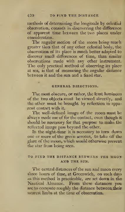
4'iO TO FIND THE DISTANCE
methods of determining the longitude by celestial
observation, consists in discovering the difference
of apparent time between the two places underconsideration.
The angular motion of the moon being muchgreater than that of any other celestial body, the
observation of its place is much better adapted to
discover small differences of time, than similar
observations made with any other instrument.
The only practical method of observing its place
at sea, is that of measuring the angular distance
between it and the sun and a fixed star.
GENERAL DIRECTIONS.
The most obscure, or rather, the least luminousof the two objects must be viewed directly, andthe other must be brought by reflection in appa-
rent contact with it.
The well-defined image of the moon must bealways made use of for the contact, even though it
should be necessary for that purpose to make the
reflected image pass beyond the other.
In the night-time it is necessary to turn downone or more of the green screens, to take oft' the
glare of the moon, which would otherwise prevent
the star from being seen.
TO FIND THE DISTANCE BETWEEN THE MOONAND THE SUN.
The central distances of the sun and moon every
three liours of time, at Greenwich, on such days
as this method is practicable, are set down in the
Nautical Almanac. From these distances youare to compute roughly the distance between^theiF
nearest limbs at the time of observation.
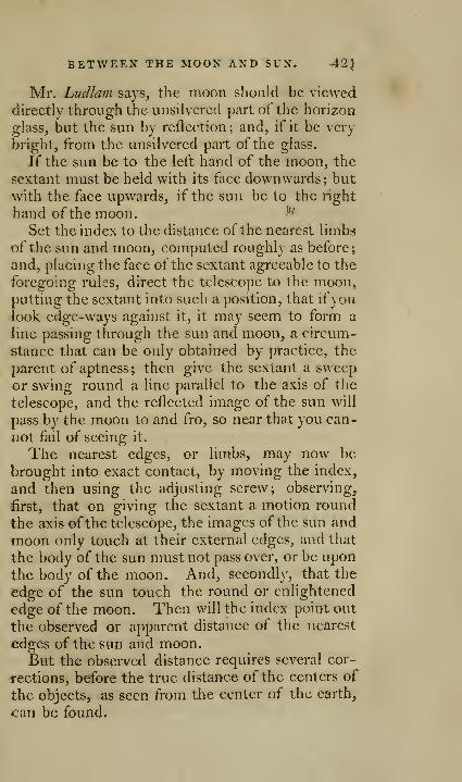
BETWEEN THE MOON AND SUN. A2}
Mr. Ludlani says, the moon should be viewed
directly through the unsilverecl part of the horizon
glass, but the sun by reflection; and, if it be very
bright, from the unsilvered part of the glass.
If the sun be to the left hand of the moon, the
sextant must be held with its face downwards; but
with the face upwards, if the sun be to the right
hand of the moon. ^^'
Set the index to the distance of the nearest limbs
of the sun and moon, computed roughly as before;
and, placing the face of the sextant agreeable to the
foregoing rules, direct the telescope to the moon,putting the sextant into such a position, that ifyoulook edge-ways against it, it may seem to form a
line passing through the sun and moon, a circum-
stance that can be only obtained by practice, the
parent of aptness ; then give the sextant a sweep
or swing round a line parallel to the axis of the
telescope, and the reflected image of the sun \\\\\
pass by the moon to and fro, so near that you can-
not fail oi seeing it.
The nearest edges, or limbs, may now be
brought into exact contact, by moving the index,
and then using the adjusting screw; observing,
first, that on giving the sextant a motion round
the axis ofthe telescope, the images of the sun and
moon only touch at their external edges, and that
the body of the sun must not pass over, or be upon
the body of the moon. And, secondly, that the
edge of the sun touch the round or enlightened
edge of the moon. Then will the index point out
the observed or apparent distance of the nearest
edges of the sun and moon.But the obsei-ved distance requires several cor-
rections, before the true distance of the centers of
the objects, as seen from the center of the earthy
can be found.

42'2 TO TAKE THE DISTANCE
Correction 1. Is the sam, or their semi-diame-
ters, which is to be added, to give the apparent
distance of the centers of the sun and moon.The semi-diameter ofthe sun for every sixth day,
and of the moon for every noon and midnight, at
Greenwich, are to be found in the Nautical Ahna-nac; from these their semi-diameters are to becomputed at the time of observation, by the rules
to be found in the same work.
Correction 1. Is to free the apparent distance
of the effect of refraction and parallax, which will
then be the true distance of the centers of the sunand moon, as seen from the earth.
For this purpose, two sets of tables, with direc-
tions how to use them, are to be found among the
Requisite Tables to the Nautical Almanac; being
a set of tables published for that purpose by the
Board of Longitude. 8 vo. 1781.
TO TAKE THE DISTANCE BETWEEN THE MOONAND SUCH STARS AS ARE SELECTED IN THENAUTICAL ALMANAC, FOR THE PURPOSE OFFINDING THE LONGITUDE AT SEA.
The distance of these stars from the moon'scenter for every three hours at Greenwich, is given
in the Nautical Almanac, from whence their dis-
tance from the enlightened edge may be roughly
computed as before.
The star must be viewed directly; the moon is
generally bright enough to be seen by reflection
from the unsilvered part of the glass; the proper
shade to take oflT the glare of the moon is soon
found. When the star is to the left hand of the
moon, the sextant must be held with its face up--
wards; but if the star be to the right hand of the
piopn, with its face downwards.
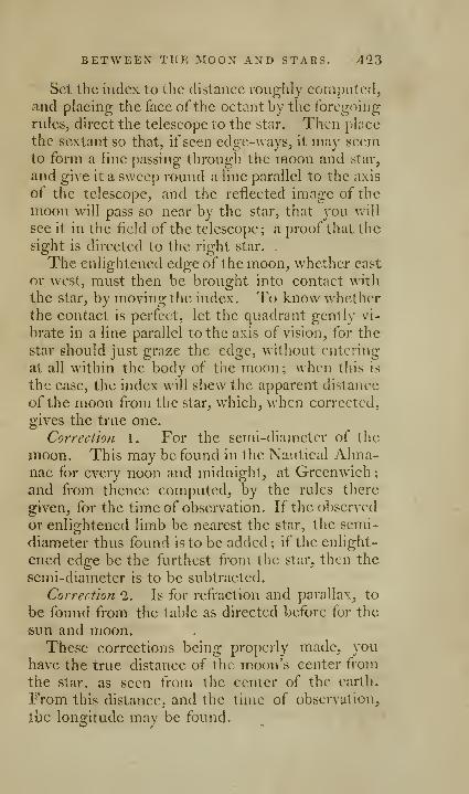
BETWEEN THE MOON AND STARS. 423
Set the index to the distance roughly computed,and placing the face ofthe octant by the foregoing
rules, direct the telescope to the star. Then place
the sextant so that, if seen edge-ways, it may seemto form a line passing through the moon and star,
and give it a sweep round a line parallel to the axis
of the telescope, and the reflected image of the
moon will pass so near by the star, that you will
see it in the field of the telescope; a proof that the
sight is directed to the right star. -
The enlightened edge of the moon, whether east
or west, must then be brought into contact with
the star, by moving the index. To know whetherthe contact is perfect, let the quadrant gently vi-
brate in a line parallel to the axis of vision, for the
star should just graze the edge, without entering
at all within the body of the moon ; when this is
the case, the index will shew the apparent distance
of the moon from the star, which, when corrected,
gives the true one.
Correction 1. For the semi-diameter of the
moon. This may be found in the Nautical Alma-nac for every noon and midnight, at Greenwich
;
and from thence computed, by the rules there
given, for the time of observation. If the observed
or enlightened limb be nearest the star, the semi-
diameter thus found is to be added; if the enlight-
ened edge be the furthest from the star, then the
semi-diameter is to be subtracted.
Correction 2. Is for refraction and parallax, to
be found from the table as directed before for the
sun and moon.These corrections being properly made, you
have the true distance of the moon's center from
the star, as seen from the center of the earth.
From this distance, and the time of observation,
tlic longitude may be found.
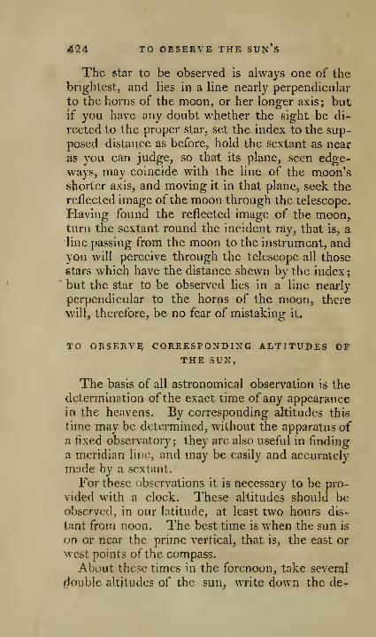
424 TO OBSERVE THE SUN S
The star to be observed is always one of thebrightest, and lies in a line nearly perpendicular
to the horns of the moon, or her longer axis; butif you have any doubt whether the sight be di-
rected to the proper star, set the index to the sup-
posed distance as before, hold the sextant as near
as you can judge, so that its plane, seen edge-ways, may coincide with the line of the moon'sshorter axis, and moving it in that plane, seek the
reflected image of the moon through the telescope.
Having found the reflected image of the moon,turn the sextant round the incident ray, that is, a
line passing from the moon to the instrument, andyou will perceive through the telescope all those
stars which have the distance shewn by the index;" but the star to be observed lies in a line nearly
perpendicular to the horns of the moon, there
will, therefore, be no fear of mistaking it.
TO OBSERVE CORRESPONDING ALTITUDES OPTHE SUN,
The basis of all astronomical observation is the
determination ofthe exact time of any appearancein the heavens. By corresponding altitudes this
time may be determined, without the apparatus ofa fixed observatory; they are also useful in finding
a nieridian line, and may be easily and accurately
made by a sextant.
For these observations it is necessary to be pro-
vided with a clock. These altitudes should beobserved, in our latitude, at least two hours dis-
tant from noon. The best time is when the sun is
on or near the prime vertical^ that is, the east or
west points of the compass.
About these times in the forenoon, take several
Rouble altitudes of the sun^ write down the dcr
CORRESPONDING ALTITUDES. 425
grces, minutes, and seconds shewn on the arc, andalso the exact time shewn by the clock at each ob-
servation; and let the different observations madein the forenoon be written one below the other in
the order they are made.In the afternoon, set the index to the same de-
gree and minute as the last morning observation ;
note very exactly the time shewn by the clock
when the sun is come down to the same altitude,
and write down the time on the right hand of the
last morning observation; proceed in the samemanner to find the time by the clock of all the al-
titudes corresponding to those taken in the morn-ing, and write down each opposite to that morn-ing one to which it corresponds.
Take now the first pair of corresponding alti-
tudes, add them together, and to half their sumadd six hours; this being corrected for the changeof the sun's declination between the morning andevening observations, you will have the time ofsolar noon derived from this pair of observations.
Do the same for each pair, and take the mean of
the times thus found from each pair, and you\vill have the exact time shewn by the clock at
solar noon.
The time by the clock of solar or apparent noonbeing thus obtained, the time of mean noon maybe had by applying the proper equation of time.
Or thus. Add 12 hours to the time of the
afternoon observation, from which subtract the
time of the forenoon one,* and add half the diffe-
rence to the time of the forenoon or morning ob-
* This gives the whole interval betwreen the obsen^ations, to
which, if your clock is known to vary much in that time, youmust add the clock's loss, or subtract its gain, during that interval,
and halt this corrected (if necessary) interval n-.ust be added to the
time of forenoon. Sec.

426 TO OBSERVE THE SUn's^ &C.
servatioii; this will give the time of apparent noonnearly.
Having this time nearly, it must be corrected bythe table of equations for equal altitudes, on ac-
count of the sun's change in declination, in the
interval between the observations; and you mustalso apply the equation of time found in the Nau-tical Almanac with contrary signs, subtracting
when it is +, and adding when it is —
.
Example. Equal altitudes taken June 1782.
East Azlmu
( 427 )
MERIDIONAL PROBLEMS BY THE STARS, ANDVARIATION OP THE MAGNETIC NEEDLE BYTHE SUN.*
To fix a meridian Vine by a star, when it can
be seen at its greatest elongation on each side of the
pole.
Provide two plummets. Let one hang from a
fixed point; let the other hang over a rod, sup-
ported horizontally about six or eight feet above
the ground, or floor in a house, and so as to slide
occasionally along the rod: let the moveableplummet hang four or five feet northward of the
iixed one. Sometime before the star is at its
greatest elongation, follow it in its motion with the
moveable plummet, so as a person a little behind
the fixed plummet may always see both in one, andjust touching the star. When the star becomesstationary, or moves not beyond the moveable
plummet, set up a light on a staff, by signals, about
half a mile off, ]jreeisely in the direction of both
the plummets. Near 12 hours afterwards, whenthe star comes towards its greatest elongation onthe other side of the pole, with your eye a foot or
two behind the fixed plummet, follow it with the
moveable plummet, till you perceive it stationary
as before; mark the direction of the plummetsthen by a light put up precisely in that line: take
the angle between the places of the two lights with
Hadleys quadrant, or a good theodolite; the cen-
ter of the instrument at the fixed plummet, and a
pole set up in day-light, bisecting that angle, will
be exactly in the meridian seen from the fixe4
plummet.
' ]VIackcnzie"s ^Maritime Siirveying, p. -i/.
428 MERIDIONAL PROBLEMS.
This observation will be more accurate if theeye is steadied by viewing the plumb-lines and staf
through a small slit in a plate of brass stuck up-right on a stool, or on the top of a chair-back.
This problem depends on no former observa-
tions whatever; and, as there is nothing in the
operation, or instruments, to affect its accuracy,
but what any one may easily guard against, it maybe reckoned the surest foundation for all subse-
quent celestial observations that require an exact
meridian line. The only disadvantage is, that it
cannot be performed but in winter, and when the
stars may be seen for 12 hours together; whichrequires the night to be about 15 hours long.
To Jix a meridian line by two circimipolar
stars that have the same right ascension, or differ
precisely 180 degrees.
Fix on two stars that do not set, and whoseright ascensions are the same, or exactly 1 SO de-
grees different: take them in the same vertical
circle by a plumb-line, and at the same time let a
light be set up in that direction, half a mile, or a
mile off, and the light and plummet will be ex-
actly in the meridian.
In order to place a distant light exactly in the
direction of the plumb-line and stars, proceed in
the following manner. Any night before the ob-
servation is to be made, when the two stars ap-
pear to the eye to be in a vertical position, set upa staff in the place near which you would have the
plummet to hang; and placing your eye at that
staff, direct an assistant to set another staff up-
right in the ground, 30 or 40 yards off', as near in
a line with the stars as you can. Next day set
the two staffs in the same places; and in their
direction at the distance of about a mile, or half a
mile northward, cut a small hole in the ground.

MERIDIONAL PROBLEMS. 42Q
for the place where the light is to stand at night;
and mark the hole so, that a person sent there at
night may find it.
Then choose a calm night, if the observation is
to be made without doors; if it is moon-light, so
much the better, and half an hour before the stars
appear near the same vertical, have a lighted Ian-
thorn ready tied to the top of a pole, and set up-right in the distant hole marked for it the night
before; and the light will then be very near the
meridian, seen from the place marked for the
plumnlet. At the same time, let another pole, or
rod, six or eight feet long, be supported hori-
zontally where the plummet is to hang, six or
seven feet from the ground, and hang the plumb -
line over it, so as to slip easily along it, either to
one hand or the other, as there may be occasion,
or tie a staff firmly across the top of a pole, six or
seven feet long ; fix the pole in the ground, andmake the plumb-line hang over the cross staff.
Let the weight at the end of the line be pretty
heavy, and swing in a tub of water, so that it maynot shake by a small motion of the air. Thenshift the plumb-line to one hand or the other, till
one side of the line, when at rest, cut the star
which is nearest the pole of the world, and the
middle of the light together: as that star moves,
continue moving the plumb-line along the rod,
so as to keep it always on the light and star, till
the other star comes to the same side of the plumbline also; and then the plummet and light will
be exactly in the meridian.
There are not t\yo remarkable stars near the
north pole, with the same right ascension pre-
cisely, or just a semi-circle's difference: but there
are three stars that are very nearly so, viz. the pole
star, s in Ursa Major, and y in Casiopeia. If
430 MERIDIONAL PROBLEMS.
either of the two last, particularly f, Jvre taken in
the same vertical with the pole star, they will
then he so very near the meridian, that no greater
exactness need he desired for any purpose in sur-
veying. At London y is about l' west of the
meridian then; and s. much nearer it, on the westside likewise. Stars towards the S. pole proper
for this observation are, 7, in the head of the
cross; fj, in the foot of the cross; and c, in thehead of the phenix.
To find a meridian line hy a circimipoJar star,
•when it is at its greatest azimuth from the pole. Bya circumpolar star is here meant, a star wdiose
distance from the pole is less than either the lati-
tude, or co-latitude of the place of observation.
1. Find the latitude of the place in which youarc to observe the star.
2. Fix on a star whose declination is known,and calculate its greatest azimuth from the north,
or elevated pole.
3. Find at what time it will be on the meridian
the afternoon you are to observe, so as to judgeabout what time to begin the observation.
4. Prepare two plummets, and follow the star
with one of them, as directed in page 427, nntil
the star is stationary; then set up a light half a
mile, or a mile off, in the direction of the plumb-line and star, and mark the place of the light in
the ground, and also of the plumb-line.
5. Next day set up a pole where the light stood,
with a flag flying at it : tlKni with a theodolite,
or HadJeys quadrant, set the index to the degreeand minute of the star's azimuth from the north,
fountl before; direct, by waving to one hand or
the other, an assistant to set up a staff on the
same side of the pole with a fiag, as the pole of
the world was from it, so as at the plumb-line these

MERIDIONAL PROBLEMS. 431
two lines may make an angle equal to the azimuthof the star, and the plumb-line and staff will thenbe in the meridian.
When any star is^ descending, it is on the west-
side of the pole of the world; while it ascends, it
is on the east-side of it.
The pole of the world is always between the
pole star and Ursa-Major: so that when Ursa-IMajor is W. or E. of the pole star, the pole oftheworld is W. or E. of it likewise.
To find the greatest azimuth of a circumpolar
star from the meridian, use the following pro-
portion.
As co-sine of the lat. : R :: S. of the star's dis-
tance from the pole : S. of its greatest azimuth.
The greatest azimuth is when the star is abovethe horizontal diameter of its diurnal circle.
On the N. side of the equator, the pole star is
the most convenient for this observation ; for the
time when it is at its greatest "elongation from the
pole, may be known sufficiently near by the eye,
by observing when f, in Ursa-Major, and y, in
Casiopeia, appear to be in a horizontal line, or
parallel to the horizon ; for that is nearly the time.
Or, the time may be found more precisely bymaking fast a small piece of wood along the plumb-line when extended, with a cross piece at right
angles to the top of the upright piece, Hke the let-
ter T; when the plummet is at rest, and both
stars are seen touching the upper edge of the cross
piece, then they are both horizontal. It is ano-
ther conveniency in making use of this star, that
it changes its azimuth much slower than other
stars, and therefore affords more time to take its
direction exact.
On the south side of the equator, the head of
the cross is the most convenient for this observa-
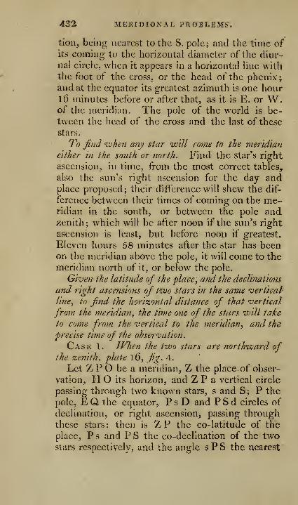
422 MEKIDIOXAL PROBLEMS.
fion, being nearest to the S. pole; and the time ofits coming to the horizontal diameter of the diur-
nal circle, when it appears in a horizontal line withthe foot of the cross, or the head of the phcnix;and at the equator its greatest azimuth is one hour16 minutes before or after that, as it is E. or W.of the meridian. The pole of the world is be-tween the head of the cross and the last of these
stars.
7o find when any star will come to the meridian
either in the south or north. Find the star's right
ascension, in time, from the most correct tables,
also the sun's right ascension for the day andplace proposed; their difference will shew the dif-
ference between their times of coming on the me-ridian in the south, or between tlie pole andzenith; which will be after noon if the sun's right
ascension is least, but before noon if greatest.
Eleven hours 58 minutes after the star has beenon the meridian above the pole, it will come to the
meridian north of it, or below the pole.
Given the latitude of the place, and the decimations
and right ascensions of two stars in the same vertical
line, to find the horizontal distance of that vertical
from the meridian, the time one of the stars will take
to come from the vertical to the meridian, ami the
precise time of the observation.
Case 1. JVlien the two stars are northward ofthe zenith, plate 16, fig. 4.
Let Z P O be a meridian, Z the place of obser-
vation, H O its horizon, and 2iF a vertical circle
passing through two known stars, s and S; P the
pole, E Q the equator, P s D and P S d circles of
declination, or right ascension, passing throughthese stars: then is ZP the co-latitude of the
place, P s and P S the co-declination of the twostars respectively, and the angle s P S the nearest

MERIDIONAL PROBLEMS. 433
distance of their cireles of right ascension ; VO the
arc of the horizon between the vertical circle andthe meridian; and d Q the arc of the equator be-
tween the star S and the meridian. When, in the
triangle PZs, the angles PZs and sPZ, mea-sured by the arcs VO and D E, are found, the
problem is solved.
Solution 1. Begin with the oblique-angled tri-
angle P s S, in which are given two sides P s andP S, the co-declinations of the two stars respec-
tively, and the included angle SPs; which angle
is the difterence of their right ascensions when it
is less than 180 degrees; but if their difference is
more than 1 80 degrees, then the angle S P s is
equal to the lesser rigjht ascension added to whatthe p-reater wants of 36o deg-rees. From hence
find the angle S s P by the following proportions
:
As radius is to the co-sine of the given angle
SPs, so is the tan. of the side opposite the re-
quired angle P s, to the tangent of an an 2:1 e, whichcall M.M is like the side opposite the angle sought, if
the given angle is acute; but unlike that side, if
the given angle is obtuse.*
Take the difference between the side P S, adja-
cent the required angle, and M; call it N. Then,Sine N : sine M :: tan. of the given angle SPs
: tan. of the required angle S s P, which is like the
given angle, ifM is less than the side P S adjacent
to the required angle; but unlike the given angle,
ifM is greater than P S.
* Two arcs or angles are said to be like, or of the same kind,
when both are less than 90°, or both more than t)0^; but are said
to be unlike, when one is greater, and the other less than pO°i
and are made like, or unlike to another, by taking the supple-
ment to 180° degrees of the arc, or angle, produced in like pro-
Jjortion, in pla«e of what the proportion brings out.
F f
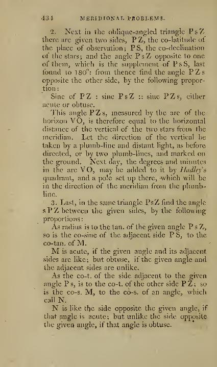
431 MEniDIONAL PROBLEMS.
2. Next ill the oblique-angled triangle PsZthere arc given two sides, P Z, the co-latitude of
the place of observation ; P S, the co-deelination
of the stars ; and the angle P s Z opposite to oneof them, which is the supplement of P s S, last
found to 180°: from thence iind the angle PZsopposite the other side, by the following propor-
tion :
Sine of PZ : sine PsZ :: sine PZs, either
acute or obtuse.
This angle PZs, measured by the arc of the
horizon VO, is therefore equal to the horizontal
distance of the vertical of the two stars from the
meridian. Let the direction of the vertical be
taken by a plumb-line and distant light, as before
directed, or by two plumb-lines, and marked onthe ground. Next day, the degrees and minutes
in the arc VO, may be added to it by Hudlefsquadrant, and a pole set up there, which will bein the direction of the meridian from the plumb-line.
3. Last, in the same triangle PsZ find the angle
s P Z between the given sides, by the following
proportions:
As radius is to the tan. of the given angle PsZ,so is the co-sine of the adjacent side P S, to the
co-tan. of M.M is acute, if the given angle and its adjacent
sides are like; but obtuse, if the given angle andthe adjacent sides are unlike.
As the co-t. of the side adjacent to the given
angle Ps, is to the co-t. of the other side PZ; so
is the co-s. M, to the c6-s. of an angle, whichcall N.N is like tl^e side opposite the given angle, if
that angle is acute; but unlike the side opposite
the givei> angle, if that angle is obtuse.
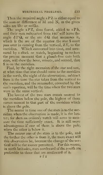
MERIDIONAL PROBLEMSi 435
Then the required angle s P Z is either equal to
the sum or difference ofM and N? as the given
sides are like or unlike.
The angle sPZ, thus found, added to s P S,
and their sum subtracted from 180'^ will leave the
angle d P Q, or the arc d Q that measures it,
which is the arc of the equator the star S mustpass over in coming from the vertical, ZV, to the
meridian. Which converted into time, and mea-sured by a clock or watch, beginning to reckon
the precise moment that a plumb-line cuts both
stars_, will shew the hour, minute, and second, that
S is on the meridian.
Find, by the right ascension of the star and sun,
at what time that star should come to the meridian
in the north, the night ofthe observation ; subti-act
from it the time the star takes from the vertical to
the meridian, and the remainder, corrected by the
sun's equation, will be the time when the two stars
were in the same vertical.
The lowest of the two stars comes soonest to
the meridian below the pole, the highest of themcomes soonest to that part of the meridian which
is above the pole.
The nearer in time one of the stars is to the me-
ridian when the observation is made, it is the bet-
ter; for then an ordinary watch will serve to mea-
sure the time sufficiently exact. It is still more
advantageous if one of them is above the pole,
when the other is below it.
The nearer one of the stars is to the pole, and
the farther the other is from it, the more exact will
this observation be, because the change of the ver-
tical will be the sooner perceived. For this reason,
in north latitudes, stars northward ofthe zenith are
preferable to those that are southward of it»
F f 2

436 MERIDIONAL PROBLEMS.
If the two stars are past the meridian when they
are observed in the same vertical, then the arc d Qgi,ves the time S took to come from the meridian
to the vertical, and must be added to the time
when that star was on the meridian, to give the
time of the obseiTation ; and the arc of the horizon
VO must be marked on the ground on the side of
the vertical, contrary to what it would have been
in the foregoing supposition ; that is, eastward l;e-
loiv the pole, and westward above it.
When two stars come to the vertical line near
the meridian, it maybe difficult to judge on whichside of it they are at that time; for determining
this, the following rules may serve.
The right ascension of two stars may be either
each less, or each mo?-e than 180 degrees, or one
more and the othe?- less.
When the right ascension of each of the stars
is either less, or more, than 180 degrees, they will
come to the same vertical on the east-side of the
meridian when the star, with the greatest right
ascension is the lowest-, but on the ivest-side o^ the
meridian when it is highest.
IVlien the right ascension of one of the stars is morethaii 1 80 degrees, and that of the other less.
If the right ascension of the highest is less than180°, but greater than the excess of the other's
right ascension above 180°, then they come to the
vertical on the east-side of the meridian. But if
the right ascension of the higher star is less thanthat excess, they come to the vertical on the west-
side of the meridian.
, If the right ascension of the higher star is inore
than 180 degrees, and that excess is less than the
right ascension ofthe lower star, then they come to
the vertical on the west-side of the meridian : but if
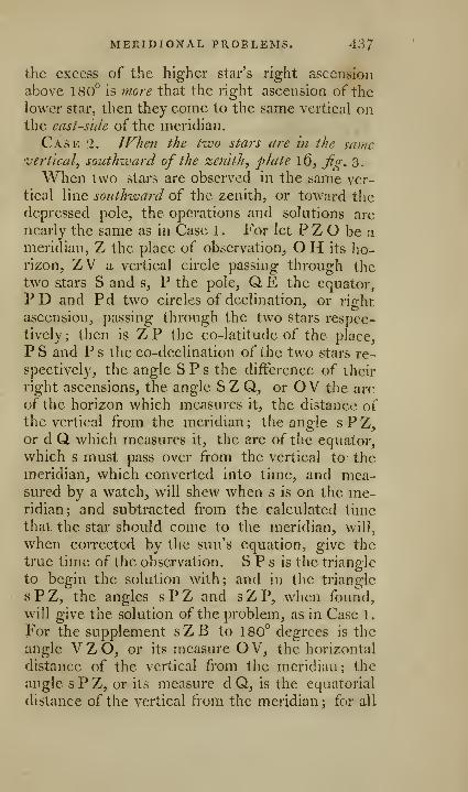
MERIDIONAL PROBLEMS. 437
the excess of the higher star's right ascension
above 180° is more that the right ascension of the
lower star, then they come to the same vertical onthe east-side of the meridian.
Case 2. When the two stars are in the samevertical, southward of the zenith, plate \Q, Jig. 3,
When two stars are observed in the same ver-
tical line southzvard of the zenith, or toward the
depressed pole, the operations and solutions are
nearly the same as in Case 1 . For let P Z O be ameridian, Z the place of observation, O H its ho-rizon, ZV a vertical circle passing through thetwo stars S and s, P the pole, Q E the equator,
PD and Pd two circles of declination, or ri^rht
ascension, passing through the two stars respec-
tively; then is ZP the co-latitude of the place,
P S and P s the co-declination of the tvi^o stars re-
spectively, the angle S P s the difference of their
right ascensions, the angle S Z Q, or O V the arc
of the horizon which measures it, the distance ofthe vertical from the meridian ; the angle s P Z,or d Q which measures it, the arc of the equator,
which s must pass over from the vertical to the
meridian, which converted into time, and mea-sured by a watch, will shew when s is on the me-ridian; and subtracted from the calculated timethat the star should come to the meridian, will,
when corrected by the sun's equation, give the
true time of the observation. S P s is the triangle
to begin the solution with; and in the triangle
s P Z, the angles s P Z and s Z P, when foimd,
will give the solution of the problem, as in Case 1
.
For the supplement sZB to 180° degrees is the
angle VZO, or its measure OV, the horizontal
distance of the vertical from the meridian; the
angle sPZ, or its measure d Q, is the equatorial
distance of the vertical from the meridian; for all

438 TO FIND THE VAEIATION-
which the solution in Case 1, properly applied,
will serve.
On the south-side ofthe zenith, when the highest
of the two stars has the least right ascension, they
come to the same vertical on the east-side of the
meridian; but when the highest star has the
greatest right ascension, they come to the samevertical on the ivest-sicle of the meridian.
Problem. To find the suns ampUtude at ris-
ing, or setting, and from thence the variation of the
magnetic needle, with an azimuth compass.
Make the needle level with the graduated cir-
cle in the box. Then, when the sun's loAver edgeis a semi-diameter above the horizon, take the
bearing of its center, from the N. or S. whichever
is nearer, through the sights making the thread
bisect the sun's disk, and that subtracted from 90°,
will be the sun's magnetic amplitude, or distance,
from the E. or W. points by the needle
Next, calculate the sun's true amplitude for
that day, by the following proportion:
As the co-sine of the latitude is to radius, so is
the sine of the sun's declination at setting or ris-
ing to the sine of his amplitude from the W. or E.Which will be N. or S. as the sun's declination
is N. orS: and the distance in degrees and mi-nutes between the true E. or W. and the mag-netic, is the variation of the needle.
An easy and sure way to prevent mistakes,
which the unexperienced are liable to in this cal-
culation, is, to draw a circle by hand, representing
the visible boundary of the horizon, and on it to
mark the several data by guess; then, by inspect-
ing the figure, it will easily appear how the varia-
tion is to be found, whether by addition or sub-
traction, and on which side of the north it lies.
f'/or example:
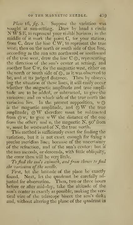
OF THE MAGNETIC XEEDLE. 43Q
Plate 16, Jig. 5. Suppose the variation wasBought at sun-setting. Draw bv hand a circle
NW S E, to represent your visible horizon ; in the
middle of it mark the point C, for your station;
from C, draw the line C W, to represent the true
Avest; then on the north or south side of that line^
according as the sun sets northward or southward
of the true west, draw the line C 0, representing
the direction of the sun's center at setting, andanother line C w, for the magnetic west, cither onthe north or south side of © ? as it was observed to
be, and at its judged distance. Then by observ-
ing the situation of these lines, it will easily occur
whether the magnetic amplitude and true ampli-
tude are to be added, or subtracted, to give the
variation ; and on which side of the true north the
variation lies. In the present supposition, wis the magnetic amplitude, and 0W the true
amplitude; ©W therefore must be subtracted
from © w, to give wW the distance of the onefrom the other; and n, the magnetic N. QO^fromw, must be westward of N, the true north.
This method is sufficiently exact for finding the
variation, but it is not exact enough for fixing a
precise meridian line; because of the uncertainty
of the refraction, and of the sun's center: but if
the sun ascends, or descends, with little obliquity,
the error then will be very little.
To f7id the Sim s a%hnuth^ andfrom thence to find
the variation of the needle.
First, let the latitude of the place be exactly
found- Next, let the quadrant be carefully ad-
justed for observation. Then, two or three hours
before or after mid-day, take the altitude of the
sun's center as exactly as possible, making the ver-
tical wire of the telescope bisect the sun's disk;
and, without altering the plane of the quadrant m
440 TO FIND THE VARIATION
the least, move the telescope vertically till you sec
some distant sharp object on the land, exactly at
the vertical wire; and that object will be in the
direction of the sun's azimuth when the altitude
of its center was taken. If no such object is to beseen, let a pole be set up in that direction, abouthalf a mile off, or as far as can be seen easily.
Next calculate the sun's azimuth by the follow-
ing rule.
Add the complement of the latitude, the com-plement of the altitude, and the complement of
the sun's declination to QO'' together, and take the
half of that sum, and note it down ; subtract the
complement of the declination from the half sum,and take the remainder; then take the comple-
ment arithmetical * of the sines of the comple-ment of the altitude, and of the complement of the
latitude, and add them together, and to them addthe sines of the fore-mentioned half sum and re-
mainder: half the sum of these four logarithms is
the co-sine of half the azimuth required. There-fore, find by the tables what angle that co-sine an-
swers to, double that angle, and that will be the
sun's azimuth from the north.
If the sun's declination is S. in north latitude, or
IS. south latitude^ in place of taking the comple-ment of the declination to 90°, add 90° to it, andproceed as before.
In south latitudes the azimuth is found in the
same manner; only, the sun's azimuth is foundfrom the S.
•' The complement arithmetical of a logarithm is found thus
:
begin at the left hand of the logarithm, and subtract each figure
from p, and the last figure from 10, setting down the several re-
mainders in a line; and that number will be the arithmetical
complement renuired.
OP THE MAGNETIC NEEDLE. 441
Then, to find the variation, pkicc your needle
below the center of the quadrant, set it level, andfind how many degrees the pole, or object, in the
sun's azimuth, bears from the north by the needle;
and the difference between that and the azimuthfound by calculation, is the variation of the needle
sought.
If the sun ascends, or descends with little obli-
quity, a meridian line may be fixed pretty exactly
this way, because a small inaccuracy in the altitude
of the sun's center will not be sensible in the azi-
muth. But, when the sun does not rise high onthe meridian, this method is not to be relied on,
when great exactness is necessary; for then every
inaccuracy in latitude, altitude, and refraction,
occasions severally a greater error in the azimuth.
To mark the meridian line on the ground, place
the center of a theodolite, or Hadley & quadrant,
where the center of the quadrant was when the
sun's altitude was taken, and putting the index to
the degree and minute of the azimuth, direct, bywaving your hat towards one side, or the other, a
pole to be set up, making an angle with the former
pole placed in the azimuth, equal to the sun's
azimuth found ; and that last-placed pole will be
in the meridian, seen from the center of the
quadrant.
N. B. The sun's declination in the tables mustbe corrected by the variation arising from the dif-
ference of the time between your meridian and
that of the tables; and also for the variation of
declination for the hours before, or after noon, at
which the sun's altitude was taken.
The two last problems are constructed and fully
explained in Roherisons, Moore Sy and other trea-
tises on navigation; it is, thercfoi'c needless to be
inore particular here.

[ 442 ]
A COURSE
O F
PRACTICAL GEOMETRY*ON THE GROUND,
BY ISAAC LANDMAN,,PROFESSOR OF FORTIFICATION- AND ARTILLERY TO TKt
ROYAL MILITARY ACADEMY AT WOOLWICH.
It is as easy to trace geometrical figures on the
ground, as to describe them on paper; there is,
however, some small difference in the mode of
operation, because the instruments are dift'erent.
A rod, or chain, is here used instead of a scale;
the spade, instead of a pencil; a cord fastened to
two staves, and stretched between them, instead of
a rule; the same cord, by fixing one of the staves
in the ground, and keeping the other moveable,
answers the purpose of a pair of compasses ; andwith these few instruments every geometrical fi-
gure necessary in practice, may be easily traced onthe ground.
Problem 1 . To draw upon the ground a strait
Tine through two given points, A, ^,Jig. 1 ,plate 27.
Plant a picket, or staff, at each of the given
points A, B, then fix another, C, between them,
in such manner, that when the eye is placed so as
* I have been obliged to omit in this Course, so liberally
communicated by Mr. I-andman, the calculations that illustrate
the examples} this, I hope, will not in the least lessen its use, a.s
this work will tall into the hands of very few who are ignorant
of the nature and application of logarithms.
PRACTICAL GEOMETRY. 443
to sec the edge of the staff A, it may coincide
with the edges of the staves B and C.
The line may be prolonged by taking out thestaff A, and planting it at D, in the direction of
B and C, and ^o on to any required length. Theaccuracy of this operation depends greatly uponfixing the staves upright, and not letting the eyebe too near the staff, from whence the observationis made.
Problem 2. To measure a strait Vine.
We have already observed, that there is nooperation more difficult than that of measuring astrait line accurately; when the line is short, it is
generally measured with a ten feet rod; for this
purpose, let two men be furnished each with a ten
feet rod, let the first man lay his rod down on theline, but not take it up till the second has laid his
down on the line, so that the end may exactly co-
incide with that of the first rod ; now let the first
man lift up his, and count one^ and then lay it
down at the end of the second rod; the second
man is now to lift up his, and count two ; and thus
continue till the whole line is measured. Staves
should be placed in a line at proper distances fromeach other by Problem 1, to prevent the operators
from going out of the given line.
When the line is very long, a chain is generally
used; the manner of using the chain has beenalready describc<I, page 204.
Problem 3. To measure distances hy pacing,
and to make a scale erf paces, ivhich shall agree with
ajiother, containing fathoms, yards, ox feet.
In military concerns, it is often necessary to
take plans, form maps, or procure the sketch of a
field of battle, and villages of cantonment, or to re-
connoitre fortified places, where great accurac}' is
not required, or where circumstances will not al-
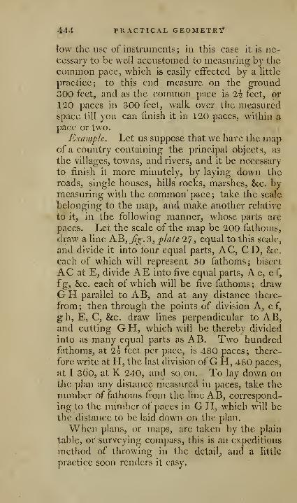
444 PRACTICAL GEOMETRf
low the use of instruments ; in this case it is ne-
cessary to be well accustomed to measuring by the
common pace, which is easily eifccted by a little
practice; to this end measure on the ground300 feet, and as the common pace is ih. feet, or
120 paces in 300 feet, walk over the measuredspace till you can finish it in 120 paces, within a
pace or two.
Example. Let us suppose that we have the mapof a country containing the principal objects, as
the villages, towns, and rivers, and it be necessary
to finish it more minutely, by laying down the
roads, single houses, hills rocks, marshes, &c. bymeasuring with the common pace; take the scale
belonging to the map, and make another relative
to it, in the following manner, whose parts are
paces. Let the scale of the map be 200 fathoms,
draw a line AB,^^.3, plate 27, equal to this scale,
and divide it into four equal parts, AC, CD, &c.
each of which v^dll represent 50 fathoms; bisect
AC at E, divide AE into five equal parts, Ae, ef,
fg, &c. each of which will be five fathoms; drawGH parallel to AB, and at any distance there-
from; then through the points of division A, ef,
gh, E, C, &c. draw lines perpendicular to AB,and cutting G H, which will be thereby divided
into as many equal parts as AB. Two hundredfathoms, at l\ feet per pace, is 480 paces; there-
fore v^^rite at H, the last division ofG H, 480 paces,
at I 360, at K 240, and so on. To lay down onthe plan any distance measured in paces, take the
number of fathoms from the line AB, correspond-
ing to the number of paces in G H, which will bethe distance to be laid down on the plan.
When plans, or maps, are taken by the plain
table, or surveying compass, this is an expeditious
method of throwing in the detail^ and a little
practice soon renders it easy.
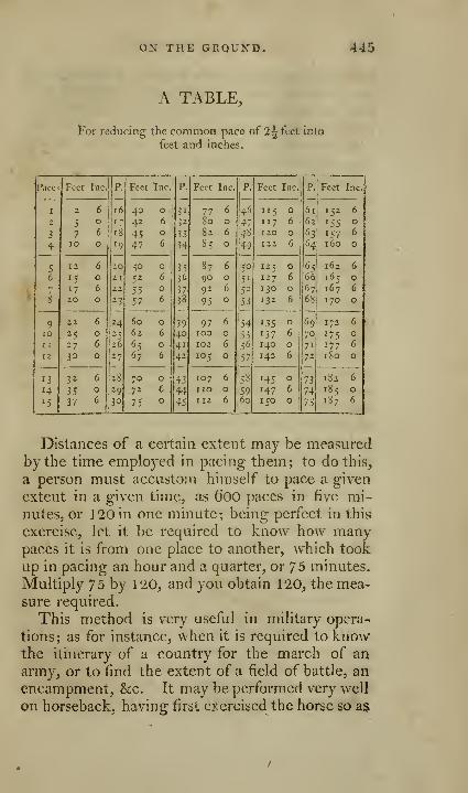
ON THE GROUND. 445
A TABLE,
For reducing the common pace of 2^ feet Into
feet and inches.
446 PRACTICAL GEOMETRY
to make him pace a given space in a determinate
time, and this may be elFectcd in more or less
time, according as he is trained to walk, trot, or
gallop the original space.
Problem 4. To iralk hi a strait line from aproposedpoint to a given object, Jig. 2, plate IT
,
Suppose the point A to be the proposed point
from whence you are to set out, B the given ob-
ject; fix upon another point C, as a bush, a stone,
or any mark that you can find in a line with B;then step on in the direction of the two objects
B, C; when you are come within 10 or 15 paces
of C, find another object D, between C and B, butin a line with them; it is always necessary to have
two points constantly in view, in order to walk in
a strait line.
This problem is of great use in measuring dis-
tances, and surveying by the pace; particularly in
reconnoitring either on foot or on horseback. It
may also be used when a battalion is ordered to
take a position at the distance of 3 or 400 paces,
and parallel to that in which it is standing; to ef-
fect this, let two non-commissioned officers, whoare well exercised in the practice of this problem,
step out from the extremities, or wings of the
battalion, place themselves square with the front
of the battalion, then fix upon two objects strait
before them, and on a signal given, set out andstep the required number of paces, then halt, thus
becoming two guides for placing the battalion.
Prob LEM 5. To place a troop E F, hetijoeen twogille7i points A, B, fig. 4, plate 27-
To perform this, let two persons, each with a
pole in his hand, separate about 50 or 6o paces
from each other; and then move on till the poles
are situated in the direction A, B, i. e. so that the
person at C may see the point D in a direction
ON THE GROUND. 44/
with B, at the same time that the person at D sees
C in a direction with the object A.Method %^ jig. 5. To perform the same with
one person. Take a staff C F, fig. 5, plate 27,three or four feet long, sht the top thereof, andplace a strait rule, six or seven inches long, in this
slit; place this instrument between the two points,
and see if A and B coincide with E, then view Dfrom B, and if A coincides therewith, all is right;
if not, move the rale forward or backward till it is
in the direction of D, E.
Problem 6. To raise a perpericficuJar from apoint C, to the give?i line AB, fig. 6, plate 2^
.
Set off two points E, D, in AB, equally distant
from C; fold a cord in two equal parts, place aslafJ'in the middle at F, fasten the two ends to the
staves E and D; then stretch the cord tight, andthe point F will be the required point, and the
line CF will be perpendicular to AB.Problem 7* Froin a given point F, out of the
l/ne AB, to letfall a perpendicular C Yyfig.J^pl.'lJ.
Fold your cord into two equal parts, and fix the
middle thereof to the point F, stretch the twohalves to A, B, and where they meet that line plant
two staves, as at E, D, divide the distance EDinto two equal parts at C, and the line C F will beperpendicular to AB.Problem 8. To raise a perpendicular B C r?/
the end B of the line B F, fig. 8, plate 27.
From D taken at pleasure, and with the length
D B, plant a staff at the point A, in the direction
F B; with the same length set off from D towards
C, plant a stafi^'C in the direction DA, and BCw ill be perpendicular to F B.
Method 2, fig. 9, plate 27- By the numbers 3,
4, 5, or any multiple thereof. Set off from C to
D, in the direction C A, four feet or four yards, an^
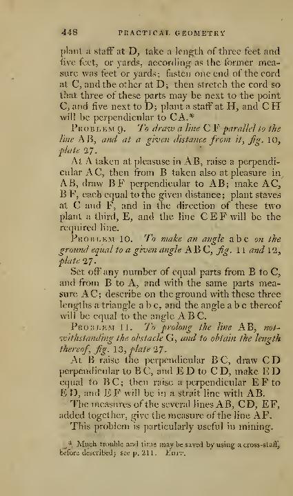
448 PRACTICAL GEOMETRY
plant a staff at D, take a length of three feet andfive fcetj or yards, aceording as the former mea-sure was feet or yards; fasten one end of the cord
at C, and the other at D; then stretch the cord so
that three of these parts may be next to the point
C, and five next to D; plant a staff at H, and CHwill be perpendicular to CA.*Prob LEM (). To draw a line C F parallel to the
line AB, and at a given distance from it, jig. 10,
p>}ate 27.
At A taken at pleasuse in AB, raise a perpendi-
cular AC, then from B taken also at pleasure in
AB, draw BF perpendicular to AB; make AC,B F, each equal to the given distance; plant staves
at C and F, and in the direction of these twoplant a third, E, and the line C E F will be the
required line.
Problem 10. To make an angle abc on the
ground equal to a given angle ABC, fig. 1 1 and 12,
plate 27.
Set off any number of equal parts from B to C,and from B to A, and with the same parts mea-sure AC; describe on the ground with these three
lengths a triangle a b c, and the angle abc thereof
will be equal to the angle ABC.Problem 11. To prolong the line AB, 7Tot~
ivithstanding the ohstacle G, and to obtain the length
thereof, fig. I'i, plate 'I7
.
At B raise the perpendicular B C, draw C Dperpendicular to B C, and E D to C D, make E Dequal to BC; then raise a perpendicular EFtoE D, and E F will be in a strait line with AB.The measures of the several lines A B, CD, EF,
added together, give the measure ofthe line AF.This problem is particularly useful in mining.
J''.Much traiible and lime viiay be saved by using across-staff,
before describedJseep, 211. }Li)ir.
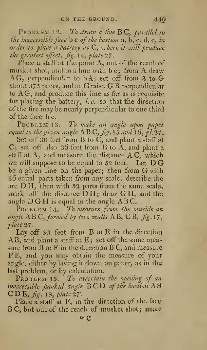
ON THE GROUND. 44Q
Problem 12. To draw a line B C, 'parallel to
the inaccessibleface b c of the bastion a, b, c, d, e, morder to place a battery at C, 'where it will produce
the greatest effect^ jig. 14, plate 2/.
Place a staff at the point A, out of the reach ofmusket shot^ and in a line with be; from A drawAG, perpendicular to bA; set off from A to Gabout 375 paces, and at G raise GB perpendicular
to AG, and produce this line as far as is requisite
for placing the battery, i. e. so that the direction
of the fire may be nearly perpendicular to one third
of the face b c.
Problem 13. To make an angle upon paperequal to the given angle AB C,fg.l5 and l6, pl.27.
Set off 36 feet from B to C, and plant a staff at
C; set off also 36 feet from B to A, and plant a
staff at A, and measure the distance A C, whichwe will suppose to be equal to 52 feet. Let D Gbe a given line on the paper; then from G with
36 equal parts taken from any scale, describe the
arc D H, then with 52 parts from the same scale,
mark off the distance DH; draw GH, and the
angle D G H is equal to the angle ABC.Problem 14. To measure from the outside an
angle AB Q,, formed by tvco walls AB^ CBj fig. 17,
platel"].
Lay off 30 feet from B to E in the direction
AB, and plant a staff at E; set off" the same mea-sure from B to F in the direction B C, and measure
FE, and you may obtain the measure of your
angle, either by laying it down on paper, as in the
last problem, or by calculation.
Problem 15. To ascertain the opening of an
inaccessible flanked angle BCD of the bastion ABC D E, fig. 18, plate 'if.
Place a staff at F, in the direction of the face
B C, but out of the reach of musket shot; makeG g
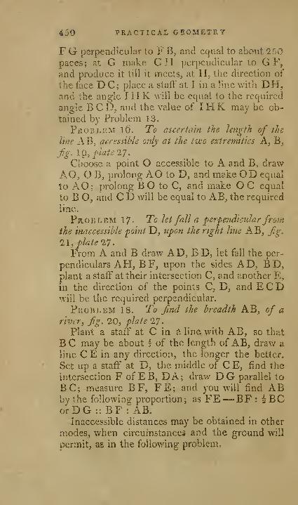
450 PRACTICAL GEOMETIvY
F G perpendicular to F B, and equal to about 250paces; at G make GH perpendicular to GF,and produce it till it meets, at H. the direction of
the face DC; place a staff at I in a line with DH,and the angle I H K v^'ill be equal to the required
angle B C D, and the value of I H K may be ob-
tained by Problem 13.
PfioBi.EM lO. To ascerla'in the length of the
line A Bj acressihle only at the P'jco extremities A, B,
Jig. m, plate 27.
Choose a point O accessible to A and B, draw
AO, OB, prolong AO to D, and make OD equal
to AO; prolong B O to C, and make O C equal
to B O, and C D will be equal to AB, the required
line.
Problem 17- To let fall a perpe7idicutarfromthe inaccessible 'point D, upon the right line AB, fg,1\, plate 17.
From A and B draw AD, B D, let fall the per-
pendiculars AH, BF, upon the sides AD, BD,plant a staff at their intersection C, and another E,
in the direction of the points C, D, and E C Dwill be the required perpendicular.
Problem 18. To find the breadth AB, of ariver, fg. 20, plate 17
.
Plant a staff at C in a line; with AB, so that
BC may be about I of the length of AB, draw a
line C E in any direction, the longer the better.
Set up a staff at D, the middle of C E, find the
intersection F of EB, DA; draw DG parallel to
BC; measure BF, FE; and you will find ABby the following proportion; as FE— BF : 5BCo'rDG :i BF : AB.
Inaccessible distances may be obtained in other
modes, when circuin stances and the grouud will
permit, as in the following problem.
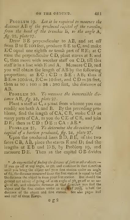
ON THE GJROUNT). 461
Problem I9. Let it he required to measure the
distance AB of the produced capital of the ravelin^
from the head of the trenches B, to the angle A,
fig. 11, flate IT.
Draw BE perpendicular to AB, and set off
from B to E 100 feet, produce B E to C, and makeE C equal one eighth or tenth part of B E ; at Craise the perpendicular C D, plant staves at E andC, then move with another staff on C D, till this
staff is in a line with E and A. Measure C D, andyou will obtain the length of AB by the following
proportion; as EC : CD :: BE : AB; thus if
B E = 100 feet, E C= 10 feet, and C D = 38 feet,
then as 10 : 100 :: 3$ : 380 feet, the distance ofAB.Problem 20. To measure the inaccessible dis-
tance AB, fg. '23, flate 27.
Plant a staff at C, a paint from whence you canreadily see both A and B. By the preceding pro-
blems, find the length of CA, C B, make C D as
many parts of C A, as you do C E of C B, and join
DE; then as CD : DE :: CA ; AB.*Problem 21. To determine the direction of the
capital of a hastion 'produced, fig. 24, plate 27.
Upon the produced lines B D, B E, of the twofaces C B, AB,- place the staves E and D; find the
lengths of EB and DB, by Problem IQ, and
measure D E. Then as the capital G B divides
* A7i easy method offinding the distance offorts or other ohjects.—
If vou go off at any angle, as gO, and continue in that direction
until you bring the object and your first station under an angle
of 63, the distance measured from the first station is'equal to half
the distance the object is from your first station. But should the
ground not admit of going od' at an angl^ of gOj go off at an an-
gle of 45, and whatever distance in that direction you find the
object and the first station under an ang^fcbf 10S:|, is half the
distance of the object and first station. See aUo pag^i 215
and 263 of these Essays.
G g2
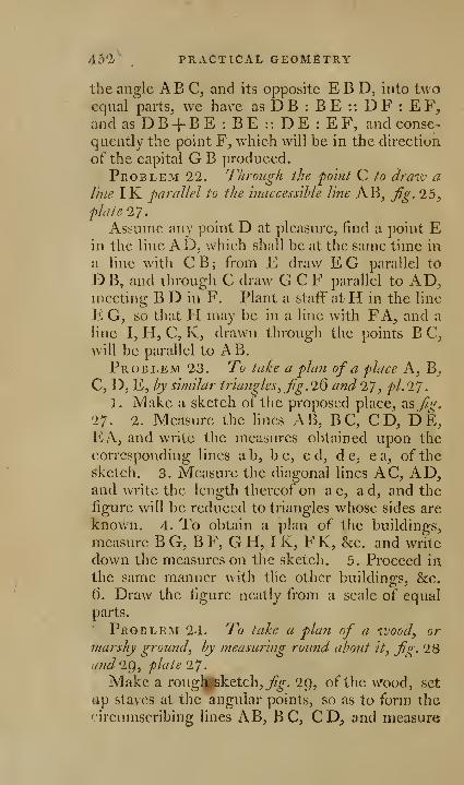
Aol',
PRACTICAL GEOMETRY
the angle ABC, and its opposite E B D, into twoequal parts, we have as D B : B E : : D F : E F,
and as D B + B E : B E : : D E : E F, and conse-
quently the point F, whieh will be in the direction
of the capital G B produced.
Problem 22. Through the 'po'mt C to draiv a
line IK parallel to the inaccessible line AB, Jig. 25,
plate 27.
Assume any point D at pleasure, find a point Ein the line AD, which shall be at the same time in
a line with CB; from E draw EG parallel to
DB, and through C draw GCF parallel to AD,meeting B D in F. Plant a staff atH in the line
E G, so that H may be in a line with FA, and a
line I, H, C, K, drawn through the points B C,
will be parallel to AB.Problem 23. To take a plan of a place A, B,
C, D, E, hy similar triangles, fg. 26 and 27, pi. IJ
.
1. Make a sketch of the proposed place, us Jig.
27. 2. Measure the lines AB, BC, CD, DE,EA, and write the measures ol^tained upon the
corresponding lines a b, b c, c d, d e, e a, of the
sketch. 3. Measure the diagonal lines AC, AD,and write the length thereof on a c, ad, and the
figure will be reduced to triangles whose sides are
known. 4. To obtain a plan of the buildings,
measure B G, B F, G H, I K, F K, &c. and write
down the measures on the sketch. 5. Proceed in
the same manner with the other building-s, &c.
6. Draw the figure neatly from a scale of equal
parts.
Problem 24. To take a plan of a wood, or
marshy ground, by measuring roimd about it. Jig. 28and-lQ, plate 27.
Make a rouglifsketch, j?^. 2p, of the wood, set
Jip staves at the angular points, so as to form the
circumscribing lines AB, BC, CDj and measure

ON THE GROUND. 453
these lines^ and set down the measures on tlie cor-
responding lines in the sketch, then find the value
of the angles by Problems 13 and 14.
ProB L KM 25 . To take a plan of a river, fg. 3
O
a?id:M, plate 17.
1 . Draw a sketch ofthe river. 2. Mark out a line
AB,j^^.30. 3. At C, upon AB, raise the perpendi-
cular CH. 4. Measure AC, CH. 5. Measurefrom C to D, and at D make D I perpendicular to
AB, and measure D I. 6. Do the same the wholelength of AB, till you have obtained the principal
bendings of the river, writing down every measurewhen taken on its corresponding line in the sketch,
and you w^ill thus obtain sufficient data for draw-ing the river according to any proportion.
Problem 26. To take aphm of the. neck ofland^
A, B, C, D, E, F, G,/^. 32 and 33, plate 27.
Take a sketch of the proposed spot, divide the
figure into triangles AB C, AC D, AD E, AE G,by staves or poles placed at the points A, B, C, D,E, F, G, measure the sides AB, B C, AC, CD,AD, AE, AF, F G, AG of the triangles, writing
down these measures upon the corresponding lines
ab, be, ac, &c. then measure AH on AB, andatH raise the perpendicular H I, and measure its
length; do the same at K, M, &c. writing downthe measures obtained on their corresponding lines
ah, hi, ik, kl, &c. Proceeding thus, you will
ascertain a sufficient number of points for laying-
down your plan by a scale of equal parts.
PRACTICAL TRIGONOMETRY.
Problem 27. To ascertain the height of a
building, fig. 34, plate 28.
Measure a line F E, from the foot of the build-
ing, so that the angle C DA may be neither too

454 PRACTICAL TRIGONOMETRY
acute nor ohtuse; thus suppose EF=130 fee\j
place your theodolite at D, and measure the angle
ADC=34°56^ '
Then as radius to tangent 34'' 56', so is E F=130 feet, to AC.Which, by workingthe proportion, you will find
to be 89 feet 156 parts, or 89 feet 7-92 inches, to
which adding four feet for D E, or its equal C F,
you obtain the whole height 93 feet 7-92 in-^hes.
Problem 28. To find the angle formed hy the
line of aim, and the axis of a 'piece of ordnance pro-
duced, the caliber and dimensions of the piece being
hiown, fig. 35, plate 28.
Suppose the line B I to he drawn through B,
the summit of the swelling of the muzzle, and pa-
rallel to C D, the axis of the piece ; the angle AB
I
will be equal to the angle AE C, formed by the
line of aim A F, and the axis CD; then in the
right-angled triangle AI B, we have the sides AIend BI to find the ang-le ABI, which we obtain
by this proportion; as I B : A I :: radius, tangent
of angle ABI equal to AE C required.
Problem 29. The elevation, three degrees, ofalight twdve-pounder being given, to find the height
to which the line of aim rises at the distance of 1200yards, which is about the range of a twelve-pounder,
with an elevation of three degrees, fig. 35, plate 38.
The line of aim, which we suppose to be foundby the preceding problem, forming with the axis
of a light twelve-pounder \° 24', will make withthe horizon an angle of 1° 36'; thus the height at
the horizontal di|tance of 1200 yards will be the
second side of a^ght-angied triangle, where theangle adjacent to the side of 1200 yards is 1° 36',
and may therefore be obtained by the followmgproportion; as radius to the tangent of 1" 36', so is
1200 to 33 yards 1 foot 6 inches=FO,
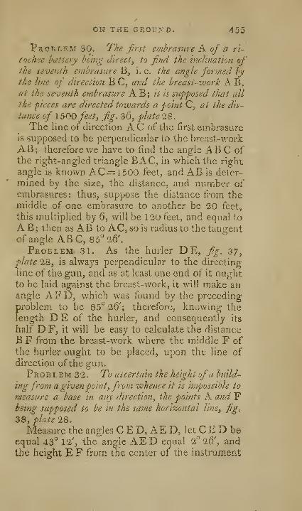
ON THE GROU>TD» 455
Problem 30. The first embrasure K of a r'l-
cochee battery being direct, to find the inclination ofthe seventh embrasure B, i. e. the angle formed by
the line of direction B C, and the breast-zvork A B,at the seventh embrasure A B ; it is supposed that all
the pieces are directed towards a point Q, at the dis-
tance of 1500 feet, fi.g. 36, plate 28.
The line of direction A C of the first embrasureis supposed to be perpendicular to the bre.ist-work
AB; therefore we have to find the angle AB C ofthe right-angled triangle BAG, in which the right
angle is known AC:=1500 feet, and AB is deter-
mined by the size, the distance, and number ofembrasures: thus, suppose the distance from themiddle of one em-brasure to another be 20 feet,
this multiplied by 6, will be 120 feet, and equal to
A B; then as AB to AC, so is radius to the tangentof angle ABC, 85'' 26',
Problem 31. As the hurler DE, fig. 37,plate 28, is always perpendicular to the directing
line of the gun, and as at least one end of it ouj^ht
to be laid against the breast-work, it will make anangle AFD, which was found by the preceding
problem to be 85° 26'; therefore, knowing the
length D E of the hurler, and consequently its
half D F, it will be easy to calculate the distance
BF from the breast-work where the middle F of
the hurler ought to be placed, upon the line ofdirection ofthe gun.
PplOBLEM 32. To ascertain the height ofa build-
ing from a givenpoint, front whence it is impossible to
measure a base in any direction, the points A and Fbeing supposed to be in the same horizontal line, fig,
38, plate 'IS.
Measure the angles C E D, AE D, let C E D beequal 43° 12', the angle AED equal 2° 26', and
the height EF from the center of the instrument
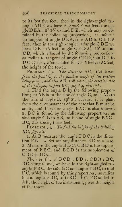
456 PRACTICAL TRIGONOMETRY
to its foot five feet; then in the right-angled tri-
angle ADE we have AD=:zEF=5 feet, the an-
gle D EA=2'' 26' to find D E, which may be ob-
tained by the following proportion ; as radius :
co-tangent of angle DEA, so is AD to DE 118
feet; then in the right-angled triangle CDE wehave DE 118 feet, angle C ED 33° 12' to find
CD, which is found by the following proportion;
as radius to tangent of angle C E D, join D E to
D C 77 feet, which added to E F 5 feet, is 82 feet,
the height of the tower.
Problem 33. The distance AC, 135 toiseSy
from the point C, to the fianked angle of the bastion
beinggiven, and also AB, 186 toises, the extefior side
of the polygon, to find B C, fg. SQ, plate 28.
1. Find the angle B by the following propor-
tion; as AB is to the sine of angle C, so is AC to
the sine of angle B, 39° 8'; because it is plain
from the circumstances of the case that B must beacute, and therefore angle BAC is also known.2. B C is found by the following proportion ; a$
sine angle C is to AB, so is sine of angle BAC :
B C, 213 toises, three feet.
Pro B L EM 34 . To find the height of the building
AC, fg. 40.
1. At B measure the angle FBC in the direc-
tion F B. 2. Set off any distance B D as a base.
3. Measure the angle B D C, C B D is the supple-
ment of F B C, and B C D is the supplement of
CBD-f-BDC.Then as sin. ZBCD : BD :: CDB : BC,
B C being found, we have in the right-angled tri-
angle FBC, the side B C and angle F B C, to find
F C, which is found by this proportion ; as radius
to sin. angle F B C, so is B C : F C, F C added to
AF, the height of the instrument, giycs the height
pf the tower.

ON THE GROUND. 457
Problem 35. To ascertain the distance hetwecn
Hvo inaccessible objects, C D, jig. 41, plate 28.
\. Measure a base AB, from whose extremities
you can see the two objects C, D. 2. Measurethe angles CAB, DAB, DBA, CBA, CBD.3. In the triangle BAC we have the side AB andangles ABC, BAC, to find B C, which is foundby the following proportion; as sine angle ACB :
AB :: sine BAC : B C. 4. The angles CAB,CBA, added together and subtracted from 180,
gives the angle AC B. 5. In the triangle ABDwe have the angles DAB, ABD, and conse-
quently ADB, and the side AB to find B D,which is found by the following proportion ; as the
sine of angle AD B is to AB, so is the sine ofangle
DAB : B D. 6. In the triangle CBD we havethe two sides B C, B D, and the angle CBD, to
find the angle C D B, and the side CD; to find
CDB we use this proportion; as the sum of the
two given sides is to their difference, so is the tan-
gent of half the sum of the two unknown angles
to the tangent of half their difference; the angle
CDB being found, the following proportion will
give CD; as sine angle CDB to B C, so is sine
angle CBD to CD.Problem 36. To draw a line through the point
B, parallel to the inaccessible line C D, fg. 41, pi. 28.
Find the angle B C D by the preceding problem,
and then place your instrument at B, and with
B C make an angle C B E equal BCD, and E
B
will be parallel to C D.Problem 37- To ascertain severalpoints in the
same direction, though there are obstacles ivhich pre-
'vent one extremity of the line being seenfrom the other,
fg. 42, plate 28.
1. Assume a point C at pleasure, from which
J:he two extremities of the line AB may be seen.
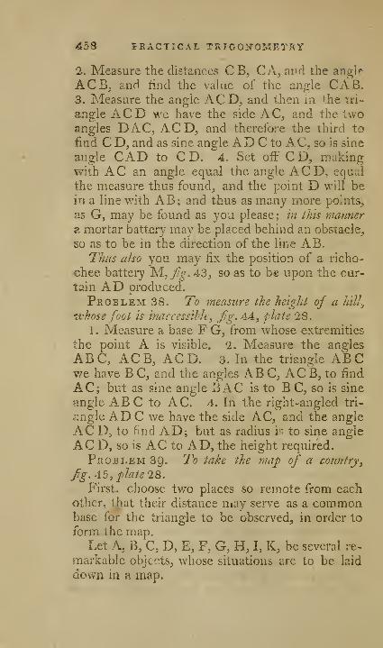
458 PRACTICAL TRIGONOMETRY
2. Measure the distances CB, CA, ai'd the angle
ACBj and find the value of the angle CAB.3. Measure the angle ACD, and then m the tri-
angle AC D we have the side AC, and the twoangles DAC, ACD, and therefore the third to
find C D, and as sine angle AD C to AC, so is sine
angle CAD to CD. 4. Set off CD, makingwith AC an angle equal the angle ACD, equal
the measure thus found, and the point D will bein a line with AB; and thus as many more points,
as G, may be found as you please; in this manner
a mortar battery may be placed behind an obstacle,
so as to be in the direction of the line AB.Thus also you may fix the position of a richo-
chee battery M, fig, 43, so as to be upon the cur-
tain AD produced.
Problem 38. To measure the height of a hill^
•whose foot is inaccessihle, fig.AA^ plate 28.
1 . Measure a base F G, from whose extremities
the point A is visible. 2. Measure the anj^Ies
ABC, ACB, ACD. 3. In the triangle ABCwe have B C, and the angles ABC, ACB, to find
AC; but as sine angle BAC is to BC, so is sine
angle ABC to AC. 4. In the right-angled tri-
angle ADC we have the side AC, and the angle
AC D, to find AD; but as radius is to sine angle
AC D, so is AC to AD, the height required.
Problem 39. To take the map of a country
y
fig. A5, plate 28.
First, choose tv/o places so remote from eachother, that their distance niay serve as a commonbase for the triangle to be observed, in order to
form the map.Let A, B, C, D, E, F, G, H, I, K, be several re-
markable objtr-ts, whose situations are to be laid
down in a map.
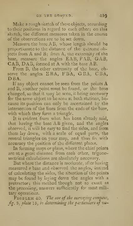
ON THE GfiOUND,. 45^
Make a rough sketch of these objects, according
to their positions in regard to each other; on this
sketch, the different measures taken in the course
of the observations are to be set down.
Measure the base A B, whose length should beproportionate to the distance of the extreme ob-
jects from A and B; from A, the extremity of the
base, measure the angles EAB, Fx\B, GAB.CAB, DAB, formed at A with the base AB,From B, the other extremity of the base, ob-
serve the angles EBA, FBA, GEA, CBA,DBA.
If any object cannot be seen from the points Aand B, another point must be found, or the base
changed, so that it may be seen, it being necessary
for the same object to be seen at both stations, be-
cause its position can only be ascertained by the
intersection of the lines from the ends of the base,
with which they form a triangle.
It is evident from what has been already said,
that having the base AB given, and the angles
observed, it will be easy to find the sides, and from
them lay down, with a scale of equal parts, the
several triangles on your map, and thus fix with
accuracy the position of the different places.
In forming maps or plans, where the chief points
are at a great distance from each other, trigono-
metrical calculations are absolutely necessary.
But where the distance is moderate, after having
measured a base and observed the angles, instead
of calculating the sides, the situation of the points
may be found by laying down the angles with a
protractor; this method though not so exact as
the preceding, ansv/ers sufficiently for most mili-
tary operations.
Problem 40. The use of the sur-veying compass,
fS' ^i i>^'^i^ 15; in determining the particulars of va-
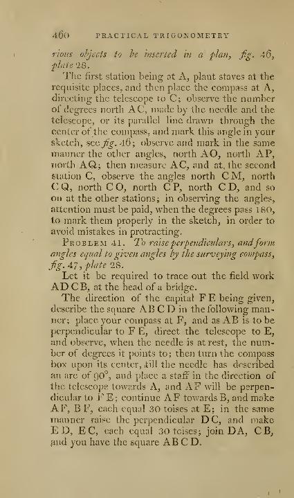
460 PRACTICAL TRIGONOMETRY
rious ohjects to he inserted in a plan, fig. 46,plate 28.
The first station being at A, plant staves at therequisite places, and then place the compass at A,directing the telescope to C; observe the numberof degrees north AC, made by the needle and the
telescope, or its parallel line drawn through the
center of the compass, and mark this angle in yoursketch, seej^^, 46; observe and mark in the samemanner the other angles, north AO, north AP,north AQ; then measure AC, and at the secondstation C, observe the angles north C M, north
C Q, north C O, north C P, north C D, and so
on at the other stations; in observing the angles,
attention must be paid, when the degrees pass 180,
to mark them properly in the sketch, in order to
avoid mistakes in protracting.
Problem 41. To raise •perpendiculars^ andformangles equal to given angles by the surveying compass
,
fg.AJ, plate 1Q.
Let it be required to trace out the field workAD C B, at the head of a bridge.
The direction of the capital F E being given,
describe the square AB CD in the following man-ner; place your compass at F, and as AB is to beperpendicular to F E, direct the telescope to E,and observe, when the needle is at rest, the num.-
ber of degrees it points to; then turn the compassbox upon its center, till the needle has described
an arc of 90°, and place a staff in the direction of
the telescope towards A, and AF will be perpen-
dicular to F E; continue AF towards B, and makeAF, BF, each equal 30 toises at E; in the samemanner raise the perpendicular D C, and makeED, EC, each equal 30 toises; join DA, CB,^nd you have the square AB C D.

ox THE GROUND. 4.6l
Make CG, DK, each equal to § of AB,through G and K draw the line GK, set ofFGH,K I, each equal to i: of AB or C D, draw the lines
of defence I C, H D, place the compass at I, andthe telescope in the direction I H ; observe wherethe needle points when at rest, and turn the com-pass till the needle has described an arc of 100, the
value of the angle L IH of the flank, place a staff
at L in the direction of the telescope, and at the
same time in the line I H, which gives the length
of the face D L and the flank I L; the face CMand flank HM are ascertained in the same manner.Make B Q equal to i of AB, and AR equal to
\ R, and draw D R, C Q, through Z the middle
ofAD, draw OZ, make RT equal to t AB; at
T and with T D, form an angle DTU, equal to
105°; plant a staff" at U, so that it may be in the
line Z O, and at the same time in the direction
T U, which gives the flank TU and face O U.Make QS equal y A B, at S form an angle CSP
equal to 120°, draw the line S P, meeting the river,
and the lines O, U, T, D, L, I, H, will be the line
of the tete de pont required.
THE USE OF THE PLAIN TABLE IN MILITAPyYOPERATIONS.
Problem 42. To fake theflan ofa caiiip, fig. 2,
fhte 29.
Place the table at A, where you can conveniently
seethe greater part of the field, and having madea scale on it, fix a fine needle perpendicular to the
table at the place that you fix upon to represent
the point A; the fiducial edge of the index is al-
ways to be applied against the needle.
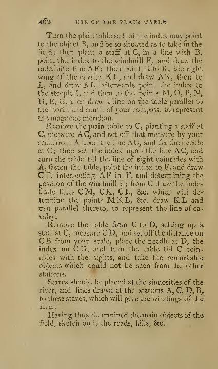
462 USE OF THE PLAIN TABLE
Turn the plain table so that the index may point
to the object B, and be so situated as to take in the
field; then plant a staff at C, in a line with B,
point the index to the windmill F, and draw the
indefinite line AF; then point it to K, the right
wing of the cavalry K L, and draw AK, then to
L, and draw AL, afterwards point the index to
the steeple I, and then to the points M, O^ P, N,H, E, G, then draw a line on the table parallel to
the north and south of your compass, to represent
the magnetic meridian.
Remove the plain table to C, planting a staff at
Q, measure x\C, and set off that measure by yourscale from A upon the line AC, and fix the needle
at C; then set the index upon the line AC, andturn the table till the line of sight coincides with
A, fasten the table, point the index to F, and drawCF, intersecting AF in F, and determining the
position of the windmill F; from C diawthe mde-finite lines CM, CK, CL, &c. which will de--
tcrmine the points M K L, &c. draw K L andm n parallel thereto, to represent the line of ca-
valry.
Remove the table from C to D, setting up a
staff at C, measure C D, and set off the distance onCB from your scale, place the needle at D, the
index on CD, and turn the table till C coin-
cides with the sights, and take the remarkable
objects which could not be seen from the other
stations.
Staves should be placed at the sinuosities of the
river, and lines drawn at the stations A, C, D, B,to these staves, which will give the windings of the
river.
Having thus determined the main objects of the
field, sketch on it the roads, hills, &c.

IN MILITARY OPERATIONS, 4^3
Problem 43. Ti> talie a pla?i of the irenchss ofan attack. Jig. I, plate ig.
The plan of trenches, taken with accuracy, gives
a just idea of the objects, and shews how you mayclose more and more upon the enemy, and be co-
vered from their enfilade fire, and also how to pro-
ceed in the attack without multiplying useless
works, which increase expense, augment the la-
bour, and occasion a ereat loss of men.Measure a long line AB, parallel to the front of
the attack D F, place the table at A, and set up astaff at B, point the index to B, and draw a line to
represent AB, fasten the table, and fix a needle
at the point A, direct the line of sights to theflanked angle of the ravelin C, and draw AC;proceed in the same manner v/ith the flanked an-gles D, Ej F, G, to draw the lines at the openingof the trenches, plant staves at H and R, from Adraw a line on the table in the direction AH, mea-sure AH, and set off that measure from your scale
upon the line AH on the table.
Remove the plain table from A to B, set up a
staffat A, lay the fiducial edge of the index against
the line AB, and turn the table about till the staff
at A coincides v/ith the line of sight, then fasten
the table, direct the sights to C, . and draw B C,
intersecting A at C; in the same manner ascertain
the flanked angles D, E, F, G, draw a line in the
direction B R, and set off the measure thereof
from your scale.
Remove the table from B to R, and set up a
staff at B where the plain table stood, lay the index
upon the line corresponding with RB, then turn
the table about till the line of sight is in the direc-
tion BR, screw the table fast, direct the sights to-
wards P, and draw on the table the line R P, andby the scale lay off its measure on that line.

464. OF LEVELLIXC.
Remove tlic plain table from R to P, lay the
index upon the line P R, and turn the table about
till the line of sight coincides with R, screw the
table fast, and draw a line upon it in the direction
PQ.; measure PQ, and take the same number of
parts from your scale, and set it off on the line, and
so on with the other station Q.Having removed the table to the station S, and
duly placed it with regard to Q, from the point S,
draw the lines S V, ST, SU, setting off from your
scale their lengths, corresponding to their measures
on the ground.
Having thus taken the zigzags RPQ, STW,and the parts U UWZ of the parallels, you removethe plain table to H, and proceed in like mannerto take the zigzags H I K, &c. as above, which
will represent on your plain table the plan of the
attack, required.
OP LEVELLING, J/g. 48, plclfe 2S.
Levelling is an operation that shews the height
ofone place in respect to another; one place is said
to be higher than another, when it is more distant
from the center of the earth than the other; whena line has all its points equally distant from the
center, it is called the line of true level; whence,
because the earth is round, that line must be a
curve, and make a part of the earth's circumfe-
rence, as the line ABE D, all the points of which
are equally distant from the center C of the earth;
but the line of sight AG, which the operation of
levelling gives, is a right line perpendicular to the
semi-diameter of the earth CA raised above the
true level, denoted by the curvature of the earth,
and this in proportion as it is more extended; for
which reason, the operations which wc shall give^
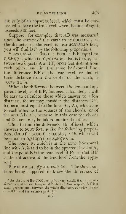
OF LEVELLINGi 465
arc only of an apparent level, which must be cor-
rected to have the true level, when the line of sight
exceeds 300 feet.
Suppose, for example, that AB was measuredupon the surface of the earth to be 600O feet, a9
the diameter of the earth is near 42018240 feet,
you will find B F by the following proportions.
* 42018240 : 60OO :: 60OO : BF equal to
0,85677 f. which is 10,28124 in. that is to say, be-
tween two objects A and F, 60OO feet distant fromeach other, and in the same horizontal line,
the difference B F of the true level, or that of
their distance from the center of the earth, is
10,28124 in.
When the difference between the true and ap-
parent level, as of B F, has been calculated^ it will
be easy to calculate those which answer to a less
distance; for we may consider the distances E F,
b f, as almost equal to the lines A I, A i, which are
to each other as the squares of the chords, or of
the arcs AB, a b, because in this ease the chords
and the arcs may be taken one for the other.
Thus to find the diiferenee fb of level, which
answers to 5000 feet, make the following propor-
tion; 6000 f. : 5000 f. :: 0,85^77 : fb, which will
be equal to 0,71399 f. or 8,56788 in.
The point F, which is in the siime horizontal
line with A, is said to be in the apparent level ofA,and the point B is the true level of F; so that B Fis the difference of the true level from the appa-
rent.
Problem 44, ^^.49, j^lafe 28. The above no-
tion.s being supposed to know the difference of
* As the arc AB= CiOOO feet is hut very small, it may be con-
sidered equal to the tangent AF, and in this respect, AF is a
mean proportional between the whole diametei';, or twice tlia ra-
dius B C, and the exterior part B F.
H h
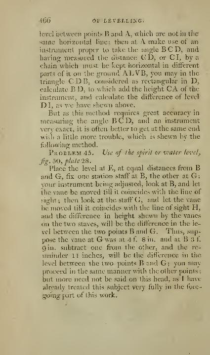
466 dF LEVELLING.
level between points B and A, which are not in the
same horizontal line; then at A make use of arv
instrument proper to take the angle BCD, andhaving measured tlie distance G D, or C I, by a
chain which must be kept horizontal in different
parts of it on the ground ALVB, you may in the
triangle C D B^ considered as rectangular in D^calculate B D, to which add the height CA of the
instrument, and calculate the difference of level
D I, as we have shewn above.
But as this method requires great accuracy in
measuring the angle BCD, and an instrument
very exact, it is often better to get at the same end
with a little more trouble, which is shewn by the
following method.
Problem 45. Use of the sp'irli or ivate)- level
,
fig. 50, plate 2S.
Place the level at E, at equal distances from Band G, fix one station staff" at B, the other at G;vour iiistrument being adjusted, look at B, and let
the vane be moved till it coincides with the line of
sight ; then look at the staff G, and let the vane
be moved till it coincides with the line of sight H,and the difference in height shewn by the vanes
on the two staves, will be the difference in the le-
vel between the two points B and G. Thus, sup-
pose the vane at G was at 4 f. 8 in. and at B 3 f.
gin. subtract one from the other, and the re-
mainder 1 1 inches, will be the difference in the
level between the two points B and G; you mayproceed in the same manner with the other points;
but more need not be said on this head, as I have
already treated this subject very fully in the fore-
going part of this work.

AN
Essay on perspective;
AND A DESCRIPTION OF
SOME INSTRUMENTS,
JPOR FACILITATING THE PRACTICE OP TPIAT
USEFUL ART.
DEFINITIONS.
Definition 1. Perspective is the art of delineating
the representations of bodies upon a plane^ andhas two distinct branches, linear and aerial.
Definition 1. Linear perspective shews the me-thod of drawing the visible boundary lines of ob-
jects upon the plane of the picture, exactly wherethose lines would appear if the picture were trans-
parent; this drawing is called the outline of those
objects it represents.
Definition Z. Aerial perspective gives rules to
fill up this drawing with colours, lights, and
shades, such as the objects themselves appear to
have, when viewed at that point where the eye of
the spectator is placed.
To illustrate these definitions, suppose the pic-
ture to be a plate of glass Inclosed in a frame
PLN, fig. I, flate 30, through which let the
eye of the spectator, placed at E, view the object
QRST; from the given point E, let the visual
lines E Q, E R, E S, &c. be drawn, cutting ^:he
glass, or picture, in q, r, s, &c. these points of
intersection will be the perspective representations
n h 2
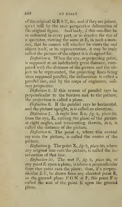
46s AN^ ESSAt
of the oris2:ii]al Q R S T, &c. and if they arc joinetL
qrst will be the true pcrspeetive delineation of
the original figure. And lastly, if this out-line beso coloured in cverv part, as to deceive the eye ofa spectator, viewing the same at E, in such a man-ner, that he cannot tell whether he views the real
object itself, or its representation, it may be truly
called the picture of the object it is designed for.
Definition A. When the eye, or projecting pointy
is supposed at an indefinitely great distance, com-pared with the distance of the picture and the ob-
ject to be represented, the projecting lines being
then supposed parallel, the delineation is called a
parallel one, and by the corps of engineers, niili-
tary perspective.
Definilion 5. If this system of parallel rays beperpendicular to the horizon and to the picture,
the projection is called a plane.
Defifiifion 6. If the parallel rays be horizontal,
and the picture upright, it is called an elevation.
Definition 7. A right line Ee, fig. 2, plate 30,from the eye, E, cutting the plane of the picture
at right angles, and terminating therein, ate, is
called the distance of the picture.
Definition 8. The point e, where this central
ray cuts the picture, is called the center of the
picture.
Definition Q. The point X, fig. 2, plate 30, \Ahere
any original line cuts the picture, is called the in-
tersection of that line.
Definition 10. The scat F, fig. 2, plate 30, of
any point E upon a plane, is where a perpendicular
from that point cuts the plane; thus, if a perpen-
dicular E F, be drawn from any elevated point E,
to the ground plane F G N at F, this point F is
called the seat of the point E upon the groundplane.

ON PERSrECTIVE. 46p
Defimt'ion 11. Apparent niagnitudc is iriCnsured
by the degree of opening of two radials passing
through the extremes of bodies whose apparent
magnitudes are eompared; thus, the apparent
magnitude of Q R, fg. 3, plate 30, to an eye at E,is measured by the optic angle Q E R. Hence it
is evident, tliat all objects viewed under the sameiingle, have the same apparent magnitude.
Definition 12. The intersection GN, fg-1,plate 30, of the picture with the ground plane, is
called the ground line.
Definition 13. A plane passing through the eve,
and every where parallel to the ground (or groundplane, as it is commonly called, because it is sup^-
posed ev^ery where flat and level) is called the ho-
rizontal plane, as E h n, fig. 2, plate 30.
Definition 14. The intersection of the horizon-
tal plane with the picture is called the horizontal
Tine; thus h e n, fig. 1, plate 30, is called the hori-
zontal line, being the intersection of the horizontal
plane E h e n, parallel to the ground plane F G N.Definition 15. The center of any line is where a
perpendicular from the eye cuts it.
Definition l6. A plane i E Fgh^ fig.1, no. 2,
plate 30, passing through the eye E, perpendicu-
lar to the ground, is called XXie 'vertical plane; andthat part of the ground plan gfN which lies to
the left hand, is called amplitudes to the left, andall that lying on the other side, amplitudes to the
right, their measures being taken on the base line
GFN, or its parailels., as depths are hv ^g, or its
parallels.
Proposition 1. Parallel aad equal strait lines ap-
pear less, as they are farther removed from the eye.
Let O P, Q R, J%.3, plate 30, be t^ o equal andparallel strait lines, viewed at the point E; QI^t;eing the farthest off, will appear the least.
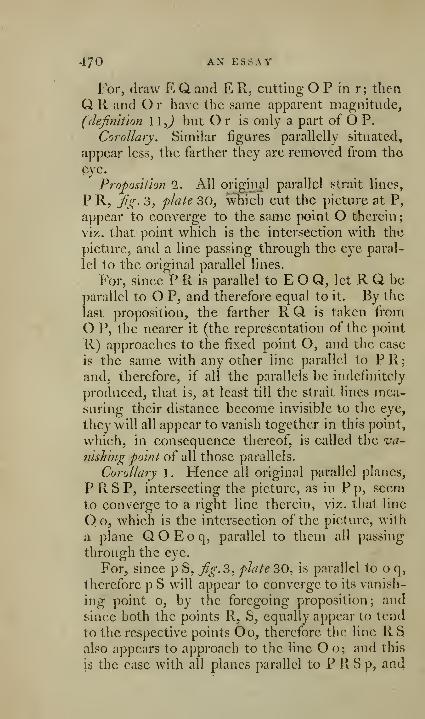
470 AN ESSAY
For, draw E Q and E R, cutting O P in r; then
Q R and O r have the same apparent magnitude,
(definition 1 1J but O r is only a part of O P.
Corollary. Similar figures parallelly situated,
appear less, the farther they are removed from the
eye.
Proposition 1. All original parallel strait lines,
P R, Jig. 3, plate 30, which cut the picture at P,
appear to converge to the same point O therein;
viz. that point which is the intersection with the
picture, and a line passing through the eye paral-
lel to the original parallel lines.
For, since P R is parallel to E O Q, let R Q be
parallel to O P, and therefore equal to it. By the
last proposition, the farther R Q is taken from
O P, the nearer it (the representation of the point
R) approaches to the fixed point O, and the case
is the same with any other line parallel to PR;and, therefore, if all the parallels be indefinitely
produced, that is, at least till the strait lines mea-suring their distance become invisible to the eye,
they will all appear to vanish together in this point,
w^hich, in consequence thereof, is called the va-
nishing point of all those parallels.
Corollary 1. Hence all original parallel planes,
PRSP, intersecting the picture, as in Pp, seemto converge to a right line therein, viz. that line
Oo, which is the intersection of the picture, with
a plane QOEoq, parallel to them all passing
through the eye.
For, since p S, fig.^, plate 30, is parallel to o q,
therefore p S will appear to converge to its vanish-
ing point o, by the foregoing proposition; and
since both the points R, S, equally appear to tend
to the respective points Oo, therefore the line R Salso appears to approach to the line Oo; and this
is the case with all planes parallel to P R S p, and
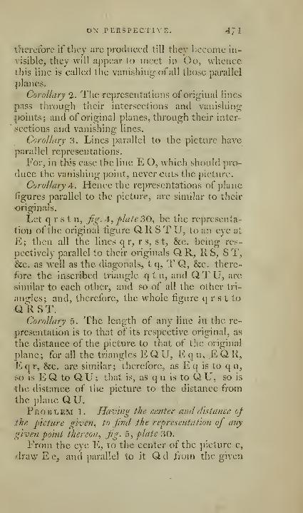
ON .rERSPECTlYE. 4^1
iherctbrc if they are produced till thev l)Cconic in-
visible, they will appear to meet in Oo, whciicc
this line is called the vanishing ofall those parallel
planes.
Corollary 2. The representations of original lines
pass through their intersections and vanishing-
points; and of original planes, through their inter-
sections and vanishing lines.
Corollary 3. Lines parallel to the picture have
parallel representations.
For, in this case the line E O, which should pro-
duce the vanishing point, never -cuts the picture.
Corollary A. Hence the representations of plane
figures parallel to the picture, are similar to their
originals.
Let q r s t u, fig. 4, plate 30., be the representa-
tion of the original figure Q R S T U, to an eye at
E; then all the lines q r, r s, st, &c. being res-
pectively parallel to their originals Q R, R S, S T,&c. as well as the diagonals, t q, T Q, &c. there-
fore the inscribed triangle q t u, and QTU, are
similar to each other, and so of all the other tri-
angles; and, therefore, the whole figure q r s t to
QRST.Corollary 5. The length of any line in the re-
presentation is to that of its respective original, as
the distance of the picture to that of the original
plane; for all the triangles E Q U, E q u, E Q R,
P2 q r, &e. ar,e similar; therefore, as E q is to q u,
so is E Q. to QU; that is, as q u is to Q U, so is
the distance of the picture to the distance from
the plane QU.Problem 1. Having the center ami distance of
.the picture given., to find the representation of any
given point thereon., fig. 5. plate 30.
From the eye E, to the center of the picture e,
,4ravy E e, and parallel to it Q d ii om the given

47'2 AN ESSAY
point Q, cutting the picture in d; join ed, anddraw E Q., intersecting e d in q, the perspective
place of the original point Q.For, e d is the representation of the original line
d Q, indefinitely produced from its intersection q,
till it appears to vanish in e; therefore q must besomewhere in this line, ^r. 1, cor. 2 ; it must also
be somewhere in EQ, and therefore in the point q,
where they intersect.
Problem 2. Tke center and distance of the
picture being given, to find the representation of a
given line Q R, fig. 6, plate 30.
Produce R Q, to intersect the picture in X,draw EV parallel to R Q X, cutting the picture
in V, the vanishing point of the line RX; drawE R and E Q, cutting V X the indefinite repre-
sentation of R X, in r and q, and r q is the repre-
sentation of R Q.This needs no demonstration.
Pkoblem 3. Having the center and distance ofthe picture, to find the representation of an original
plane, whose positiofi with respect to the picture is
given.
Draw any two lines, except parallel ones, uponthe plane, and find their vanishing points by the
last problem; through these points a line being
drawn will be the vanishing line required.
This is evident from prop. 2, cor. 1
.
Problem 4. Having the center and distance ofthe picture given, to find the vanishing point of lines
perpendicidar to a plane whose representation is
given, fig. 7, plate 30.
Let P L be the vanishing line of the given re-
presentation, X its center, e that of the picture,
and cE its distance; join EX, and perpendicular
to it dra\v E f^ cutting X e in f.
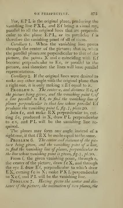
ox PERSPECTIVE. 473
For, EPL is the original plane, producing the
Vanishing line PXL, and Ef being a visual ray,
parallel to all the original lines that are perpendi-
cular to the plane EPL, or its parallels; f is
therefore the vanishing point of all of li'ieni.
Corollary 1. When the vanishing line passes
through the center of the picture; that is, wJ:en
the parallel planes are perpendicular to that of the
picture, the points X and e coinciding with £,i
become perpendicular to E e, or parallel to the
picture, and therefore the lines will have parallel
representations.
Corollary 2. If the origirjal lines were desired to
make any other angle with the original plane thana right one, it is only making xEf equal to it.
PnoBLEM 5. The center e, aiul distance Ee, ofthe picture being given, and the vanishing point f, ofa line parallel to E f, to find the vanishing line ofplanes perpendicular to that line whose parallel E f
produces the vanishing point f, fig. 7, plate 30.
Join f e, and make E X perpendicular to, cut-
ting fe, produced in X, draw P L perpendicular
to ex, and PL will be the vanishing line re-
quired.
The planes may form any angle instead of a
right one, if that fE X be made equal to the same.
Pro B L EM (5. The center and distance of the pic-
ture being given, and the vanishing point of a line,
to find the vanishing line ofplanes, perpendicular to
the line whose vanishing point is given, fig. J ,pi. 30.
From f, the given vanishing point, through c,
the center of the picture, draw feX, and throughthe eye E draw E f, perpendicular to which drawEX, cutting fe in X; make PXL i)erpendicular
to X e f, and P L will be the vanishing line.
Problem 7- Having given the center and dis-
tance of the picture, the inclination of two planes, the

.47-1 AN ESSAY, &V.
'vanishing line of one of them^ and the -vanishing point
of their common i}i.tersection^ tofind the vanishing line
of the other plane.
Case 1. Let the inclination of the ])lancs be a
right angle, and let PL be the vanishing line, Pthe vanishing point of their common intersection.
By Problem 5 find f, the vanishing point of lines
perpendicular to the plane, whose vanishing line
is PL; join Pf, which is the vanishing line re-
quired.
For, since this last plane is perpendicular to the
former, f will be the vanishing point ofone line in
it, (prop. 1) and P being the vanishing point of
another, therefore Pf is the vanishing line.
Case '1. When the inclination n c m, fg. 8,
plate 30, is greater or less than a right angle.
Let N X be the vanishing line of one plane, x the
vanishing point of its intersection with the other
plane; from the eye E draw Ex, and perpendi-
cular thereto, the plane N EM intersecting xNin N, and the picture in NfM, make the angle
NEM equal to n e m the given inclination, join
X M, which will be the required vanishing line.
For, the planes being parallel to the original
planes by construction, M x, N x are their vanish-
ing lines, cor. '1, pr. 2.
Problem 8. To find the projection of any solid
figure.
Find the representation of any one of its faces
bv Problem 3, and of the others by the last; if anyside be convex or concave, a number of points
may be found therein by Problem 1, and curves
<lrawn evenly through them will represent the
curved superficies required; or squares, or other
regular figures may be inscribed or circumscribed
about the original figures, and these plain figures
being projected by the foregoing methods, together

GENERAL REMARK. 475
^^ ith a few points therein, by which means the
curves may be similarly drawn about or within
these projected squares, &c. by this means also maytangents be ch'awn to the representations of" all
kinds of curve lines, in all kinds of situations.
GENERAL REMARK.
So far I have endeavoured to render tlie prin-
ciples of perspective obvious by a mere inspection
of the figures. For the voung artist, whose mindseldom conforms to mathematical reasoning,
may, in all the foregoing problems, suppose theplane of the picture placed upright upon thai ofthe paper, which paper he mav consider as the
ground plane, the operator's eye E, being al-
ways in its proper situation with respect to
the picture, as well as to the planes of the original
objects. The dnta, or things required to be knownbefore objects can be put into pci'spectivc, arc
their plans and elevations, see Deiin. 5 and 6,
which must be actually laid down by a convenient
scale adapted to the size you mean your picture
should be, which maybe v^ery easily accomplished;
for you must remember, that the two extreme vi-
sual rays, that is, those which pass from the eye to
the two opposite borders of the picture, must not
make an angle less than t\i:o-t}iirth, or greater than
three-fourths of a right one. With respect to the
distance of the picture, it must be remembered,that objects cannot be seen distinctly nearer to a
common eye than six inches, and therefore in the
smallest miniature pieces the distance must exceed
that qunntit}^; the height of the eye should be
about half the distance of the picture, and about
the third part of the picture's whole height. Forexample, if the whole height of the piclurc be
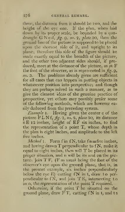
476 GENERAL REMARK.
three, the distance from It should be two, and the
height of the eye one. If the plan, when laid
down by its proper scale, be bounded by a qua-
drangle G N c d, jig. 9, 710. 2, plate 30, then the
ground line of the picture is supposed to be placed
upon the shortest side of it, and upright to its
plane; therefore this side of the figure should be
made exactly equal to the breadth of the picture,
and the other two adjacent sides should, if pro-
duced, meet at the distance of the picture, as at Fthe foot ofthe observer, as is represented in^^. p,
no. 3. The problems already given are sufficient
for all cases that can happen in putting objects in
whatsoever position into perspective; and thoughthey are perhaps solved in such a manner, as to
give the clearest ideas of the genuine practice of
perspective, yet others may possibly prefer someof the following methods, which are however ea-
sily deduced from the preceding system.
Exainph 1. tiaving given the center e of the
picture P LN f, jig. 2, no. 2, plate 30, its distance
eE 12 inches, height of EF six inches, to find
the representation of a point T, whose depth in
the plan is eight inches, and amplitude to the left
five inches.
Method 1. Form fin fN, take fn=five inches,
and having drawn T perpendicular to fN, make it
equal to eight inches, then will T be placed in its
proper situation, and n will be its scat on the pic-
ture: join T F, (F as usual being the foot of the
observer's eye upon the ground plane, that is, in
the present example, six inches perpendicularly
below the eye E) cutting fN in t, draw to per-
pendicular to fN, and join TE, intersecting toin o, the representation of the point T required.
Otherwise, if the point T be situated on the
ground plane, draw FT, cutting fN in t, and ts
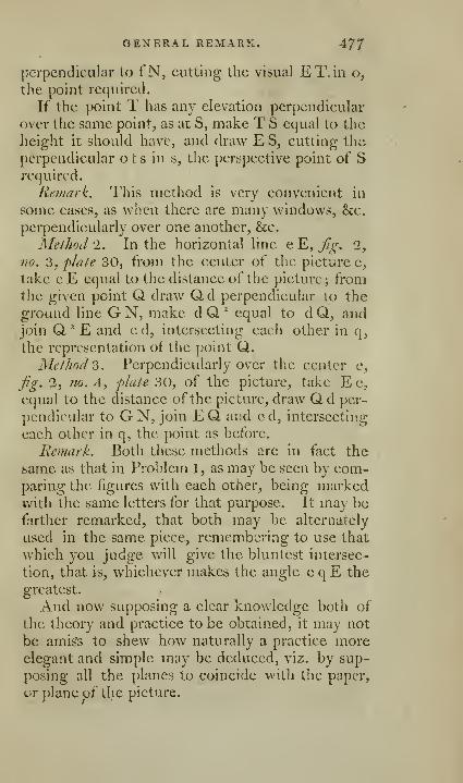
GEXERAL REMARK, 47/
perpendicular to i"N, cutting the visual ET.in o^
the point required.
If the point T has any elevation perpendicular
over the same point, as at S, make T S equal to the
Jieight it should have, and draw E S, cutting the
perpendicular o t s in s, the perspective point of Srequired.
Remark. This method is very convenient in
some cases, as when there are many windows, &c.
perpendicularly over one another, &c.
Method 2. In the horizontal line e E, Jig. 2,
fio. 3, phite 30, from the center of the picture e,
take e E equal to the distance of the picture; fromthe given point Q. draw Q,d perpendicular to the
ground line G N, make d Q "^ equal to d Q, andjoin Q. "" E and ed, intersecting each other in q,the representation of the point Q.
Md/Jiod3. Perpendicularly over the center e,
Jig. 2, no. 4, p/ate 30, of the picture, take E e,
equal to the distance of the picture, draw Qd per-
pendicular to G N, join E Q. and e d, intersecting
each other in q, the point as before.
Remark. Both these methods are in fact the
same as that in Problem 1, as may be seen by com-paring the figures with each other, being markedwith the same letters for that purpose. It may befiirther remarked, that both may be alternately
used in the same piece, remembering to use that
which you judge will give the bluntest intersec-
tion, that is, whichever makes the angle e q E the
greatest.
And now supposing a clear knowledge both of
the theory and practice to be obtained, it may not
be amis's to shew how naturally a practice moreelegant and simple may be deduced, viz. by sup-
posing all the planes to coincide with the paper,
or plane uf the picture.
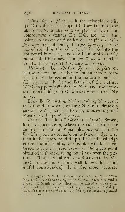
478 GENERAL REMARK.
Thus, y/g. 5, plafe 30, if the triaiifrlcs q e E^
q d Q. revolve roiiiul d q c till thc}' full into the
plane PLN, no change takes place in any of the
comparative distances E e, E Q, &:c. and the
point q preserves its situation on the picture, as in
Jig. 2, no. 4; and again, if \njjg. 2, 7io. 4, cE bemoved round on the point e, till it falls into the
horizontal line at n, and dQ be moved similarly
round, till it becomes, as in fg. 3, no. 3, parallel
to e E, the point q still remains unaltered.
Method A. Let m N f s r, fg. '2, no. 5, ^late 30,be the ground line, f e E perpendicular to it, pass-
ing through the center of the picture e, and let
fE ^ equal to fN, be the distance of the picture^
N P being perpendicular to N F, and the repre-
sentation of the point Q, \vhose distance from Nris rQ.Draw E "" Q, cutting Nr in s, taking Nm equal
to Qr, and draw em, cutting N P in o, draw oqparallel to N r, and s q to N o, intersecting each
other in q, the point required.
Remark. The lines E ^ Q e m need not be drawn,
but a dot made at s, where the ruler crosses n r
and e m ; a T square * may also be applied to the
line N s r, and a dot made on its fiducial edge at s
;
then if the square be slid up till the fiducial edgecrosses the mark at o, the point s will be trans-
ferred to q, the representation of the given point
obtained without drawing any lines over the pic-
ture. (This method was first discov^cred by Mr.Beck, an ingenious artist, well known for manyuseful contrivances.) It is also more accurate
* ^ccfig. 20, pLiic31. This is a ver}' useful article in draw-ing; a iiilcr a, is fixed as a square to f'; there i* also a moveable
piece c. This ruler applied close to the side of a true drawing
board, will admit of parallel lines being drawn, as well as oblique
ones, with more ease and expedition than by the common parallel
rulers. Ei>it.

. GENERAL REMARK". 47p
tliaii the last method in general, as the intersec-
tions arc more obtuse.
But nevertheless, when the two points in repre-
sentation are projected very near together, it is
l!ie best way to work by the intersections and va-
nishing points of the original lines; for then hav-
ing the full extent of the representation, its true
directions may be ascertained very correctly. Thevanishing points by this method are thus found;
suppose for instance of the line I Q intersecting
ihe ground line in I, in fe E ^ take eE equal to
E " f, tliat is, equal to the distance of the picture;
draw E V parallel to I Q, intersecting the horizon-
tal line h o in V the vanishing point of I Q and all
its ])arallcls.
Rxamplel. To put any plane figure, as QRST,or M N O P, into perspective, flate 30, Jig. 9.
This is, in fiict, only a repetition of the last; for
by finding the projections of the several points, as
before, nothing remains but to join them properly,
and the thing is done; thus the points m, n, o, p,
projected from M, N, O, P, being joined, give
m p o n, the representation of the quadrangle
M PON, &e. But if any line, as p o, happens
to be very short, so that a small error in point owould considerably alter the direction of it, iind
the intersection and vanishing point of its origi-
nal; or, if the vanishing point falls at too great a
distance, as it very frequently does in practice,
tind the intersection E '', and vanishing point Z of
any other line passing through the point O, as the
diagonal O M, and the truth of the projection
may be depended upon. All the three last me-thods may be made use of in projecting the same
figure; thus the point p, by the second method,
that is, make e E in the horizontal line equal to
E ^ k, the distance of the picture, draw FY per-
pendicular to S X, and take Y k equal to Y P, join
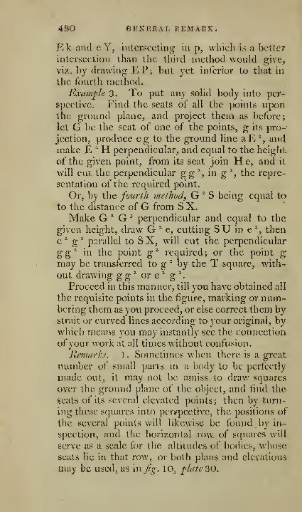
480 GENERAL P.EMArxK.
Ek and c Y, intersecting in p, which is a better
intersection than the third method would give,
viz. by drawing EP; but yet inferior to that in
the fourth method.
Example 3. To put any sohd body into per-
spective. Find the seats of all the ])oints uponthe ground plane, and project them as before;
let G be the seat of one of the points, g its pro-'
jection, produce eg to the ground line aE % andmake E " H perpendicular, and equal to the height
of the given point, from its seat join He, and it
will cut the perpendicular g g '^, in g % the repre-
sentation of the required point.
Or, by the fourth method, G ^ S being equal to
to the distance of G from S X.Make G "^ G ^ perpendicular and equal to the
given height, draw G ^ e, cutting S U in e ^, then
e^ g* parallel to SX, will cut the perpendicular
^g^ in the point g^ required; or the point gmay be transferred to g " by the T square, with-
out drawing gg^ or e ^ g ^.
Proceed in this manner, till you have obtained all
the requisite points in the figure, marking or num-bering them as you proceed, or else correct them bystrait or curved lines according to your original, bywhich means you may instantly see the connectioa
ofyour work at all times without confusion.
Remarks. 1 . Sometimes when there is a great
number of small parts in a body to be perfectly
made out, it may not be amiss to draw squares
over the ground plane of the object, and iiud the
seats of its several elevated points; then by turn-
ing these squares into persspective, the positions of
the several points will likewise be found by in-
spection, and the horizontal row of squares will
serve as a scale for the altitudes of bodies, wiiose
seats lie in that row, or both plans and elevations
may be used, as in Jig. 10, ^late 30.

GENERAL REMARK!. 481
1. Perspective may also be practised without
having any recourse to ground plans; for, by tak-
ing the horizontal angles, the amplitudes of objects
are to be ascertained, and by vertical ones their
heights and depths in the picture; the angles thus
taken may be entered in a table of this form,
Vert.

r 482
OF SHADOWS.
Luminous bodies, as the sun, moon, lamps, &c.arc generally considered as points; b^it the artist
takes the advantage of their not being perfectly
so, by softening the extremities of his shadows,
which are so softened in nature, and for this rea-
son, which may be thus explained.
Let R S, fig. 11, no. 2, flatb 3 1, be the radius ofa luminous body, whose scat is rs, and center is S;
from the opaque body O, draw x r, touching the
extremities of both the bodies on both sides, bywhich means a penumbra, or semi-shade, qxn,will be formed on each side of the main shadow,
which becomes extremely tender towards the outer
extremity, and from thence gradually strengthens
till it blends with the uniform shadow, which will,
if the diameter of the luminous be greater thanthat of the opaque one, measured in the direction
of their centers, converge to a point, as n n, fig. i\,
plate 3\.
N. B. The opaque body which casts the sha-
dow is called the shading body; and those that
are immersed in the shadow, arc called shadowedbodies.
Problem C). To find the shado-w of any object
npon a plane.
Through the luminous body diaw planes touch-
ing all the illumined planes of the object, and the
intersections of these planes with the given plane,
will give the boundary of the shadow required.
RxauLple \ . Let the luminous point be the sun,
the plane of jtrojection ARSB, fig. I'i, plate 2>\,
and the object the parallelogram ABCD,The sun's rays, on account of his distance, may
be supposed parallel, therefore the planes O K A,
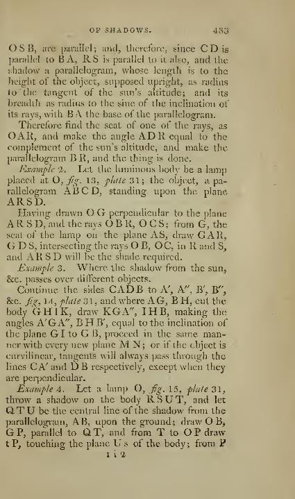
OP SHADOWS. 483
O S B, arc parallel ; and^ therefore, since C D is
parallel to B A, R S is parallel to it also, and the
shadow a parallelogram, whose length is to the
height of the object, supposed upright, as radius
to the tangent of the sun's altitude; and its
breadth as radius to the sine of the inclination ofits rays, with BA the base of the parallelogram.
Therefore find the seat of one of the rays, as
OAR, and make the angle ADR equal to thecomplement of the sun's altitude, and make theparallelogram B R, and the thing is done.
Example 1. Let the luminous body be a lampplaced at O, fg. 13, plate 31; the object, a pa-
rallelogram ABCD, standing upon the plane
ARSD.Having drawn O G perpendicular to the plane
ARSD, and the rays O B R, O C S ; from G, the
seat of the lamp on the plane AS, draw GAR,G D S, intersecting the rays OB, OC, in R and S,
and ARSD will be the shade required.
Example 3. Where the shadow from the sun^
&c, passes over different objects.
Continue the sides CADB to A', A'', B', B",
&c. f^, 14, plate o\, and where AG, BH, cut the
body GHIK, draw KG A", I H B, making the
angles A'GA", BH B', equal to the inclination of
the plane G I to G B, proceed in the sam.e man-ner with every new plane M N; or if the object is
curvilinear, tangents will always pass through the
lines CA' and D B respectively, except when they
are perpendicular.
Example 4. Let a lamp O, fig. 15, flate 31,
throw a shadow on the body RSUT, and let
QTU be the central line of the shadow from the
parallelogram, AB, upon the ground; draw O B^
GP, parallel to QT, and from T to O P drawtP, touching the plane Us of the body; from P
I i 2
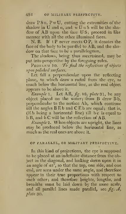
484 OF MILITARY PERSFECTIVE.
draw PSu, PwU, cutting the extremities of the
shadow in U and ii, and w U u S will be the sha-
dow of AB upon the face US; proceed in like
manner with all the other illumined faces.
N. B. If t P never meets O P, it denotes the
face of the body to be parallel to AB, and the sha-
dow on that face to be a parallelogram.
The shadows, being thus ascertained, may beput into perspective by the foregoing rules.
Problem 10. To find the reflections of ohjecis
upon polished sufaces.
Let fall a perpendicular upon the reflecting
plane, to which draw a radial from the eye, as
much below the horizontal line, as the real object
appears to be above it.
Example 1. Let AB, fg. 18, plate 31, be anyobject placed on the water; from B draw Bb,perpendicular to the surface Ab, which continue
till the angles BEb and CEb are equal; that is,
(Eb being a horizontal line) till be is equal to
b B, and b C will be the reflection of AB.Example 2. When objects are upright, the lines
may be produced below the horizontal line, as
much as the real ones are above it.
OF PARALLEL, OR MILITARY PERSPECTIVE.
In this kind of projections, the eye is supposed
to be placed at an indefinite distance from the ob-
ject in the diagonal, and looking down upon it in
an angle of 45°, so that the top, one side, and oneend, are seen under the same angle, and therefore
appear in their true proportions with respect to
each other; and therefore heights, lengths, andbreadths must be laid down by the same scale,
and all parallel lines made parallel, see flg. A^plate 30.
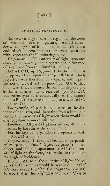
[ 485 ]
OF AERIAL PERSPECTIVE.
Before we can give rules for regulating the force
of lights and shades in a picture, we must consi-
der what degree of it the bodies themselves are
endued with, according to their several positions
with respect to the illuminating body.
Proposition 3. The intensity of light upon any
plane is reciprocally as the square of the distance
of that plane from the illuminating body.
Let AB C D, /^. l6, plate 3 1, be the shadow of
the square abed upon a plane parallel to it, whichprojection will therefore be a square, and in pro-
portion to abed as the square upon O A to that
upon O a; therefore since the real quantity of light
is the same as would be received upon ABCD,the intensity of it is reciprocally as the square
upon AB to the square upon ab, or as square OAto square O a.
For example, if parallel planes are at the dis-
tance of one, two, and three feet from a luminous
point, the intensity of light upon them would be
one, one-fourth, one-ninth, &c.
Corollary, All parallel planes are equally illu-
minated by the sun at the same moment.For, his rays being parallel, the squares abed,
and AB C D arc equal.
Proposition 4. If the sun's beams fall perpendi-
cular upon one face AB, fg. 17, plate "il, of an
object, and inclined upon another AC, the inten-
sity of light on the faces, is 'as radius to the sine of
the angle of incidence.
Produce AB to b, the quantity of light Ab re-
ceives is the same as w^ould be received on AC if
bA were away; therefore the brightness is as AC.to Ab, that is, the brightness of Ab, or AB is tq

4S6 OF AERIAL PERSPECTIVE.
that of AC as AC to Ab, or as radius to sine ofthe angle of incidence ACb.
Proposition 5. A plane uniformly enlightened,
does not appear so to an eye in different situations.
For, as all bodies are porous, the little exube-rances will have their light and dark sides, andthe eye will view more of the former, as it is morenearly situated in a line with the rays of light, andmore of the latter, the more it faces them.The subject of this proposition is one great
cause of the graduation of light upon the faces of
buildings and other planes, and not altogether
owing to a greater teint of air, as the artists call it,
on that part which is the farthest off.
Remark, It is very necessary to observe, that
transparent and polished bodies are not included
among those mentioned in this proposition, for
they seem most illuminated in that part whichjnakes the angle of reflection equal to that of in-
cidence; but if bodies of this kind are not flat, as
water when just broken by small rippling waves,
then the light is reflected from some part of al-
most every wave, and so is extended to a great
space, but is strongest perpendicular under the lu-
minary, and gradually decreases on each side.
The case is the same in the sky, which is
brightest near the sun's apparent place, and gra-
duates into a deeper azure as it retires farther off',
land for a reason nearly the same; for the pellucid
particles floating above us, having large interstices
between them, act in the same manner as the rip-
pling waves in disturbed water; and, therefore,
the more obliquely the light strikes upon them,the more united their force will be to an eye situ-
ated in the proper angle of reflection.
Proposition^. All shades and shadowing objects
would be equally dark and indistinguishable, if
they received no secondary or reflected li^ht.
OF AERIAL PERSPECTIVE. 48/
For, light is not visible of itself, but by striking
upon other bodies renders them so, and these en-
lightened bodies serve as lights to bodies other-
wise in shade, and such lights are called secondary
or reflected ones, thcchief of which is the sky.
Proposiiio7i 7. Every body participates of the
colour of the light by which it is illumined; for,
blue rays thrown upon a yellow body will produce
a green; red rays, purple; and purple rays, that
is, blue and red, black.
Corollary. Hence shadows arc often observed
green in the morning or evening, for the sky is
always very green at those times compared with
other times of the day, owing to the warm rays
being more copiously reflected downwards by the
sun's beams striking more obliquely on the at-
mosphere, which partly acts as a prism, andthe shadows become more blue, as the sky be-
comes so; but clouds are of all colours, and as
they are denser than the blue part of the sky, they
throw stronger reflections, and cause many acci-
dental teints in the shadows of bodies; therefore,
as the shadow of every body is partially enlight-
ened by all the bodies surrounding it, it must par-
take of the colours of all of them; and this is the
grand source of harmony in painting, of whichsystem the colour of the original light serves as a
key, and is to be attended as nicely to in painting,
as in nuisic.
Proposition 8. Bodies partake more ofthe colour
of the skv, as they are farther ofl"".
For, the sky being only a body of air every
where surrounding us, its natural colour supposed
to be blue, the farther off" any body is, the moreof this blue air is intercepted between us and the
body, and therefore tlie bluer it is, and that in
proportion to its distance.
488 INSTRUMENTS FOR
OP INSTRUMENTS FOR DRAWING IN
PERSPECTIVE.
Various have been the methods used to facilitate
the practice of perspective, as well for those whounderstand, as those who are ignorant of that art;
and, though some have supposed that the warmthof imagination and luxuriance of fancy, which im-
pels the mind to the cultivation of the fine arts, is
not to be confined to mechanical modes, yet uponenquiry they will find, that the most able and ac-
complished artists are often obliged to have re-
course to some rules, and to use some mechanical
contrivances to guide and correct their pencil. Sogreat is the difficulty, and so tedious the operation
of putting objects in true perspective, that they
trust mostly to their eye and habit for success;
how well they succeed, we may decide from the
portraits drawn by the best artists, and the dif-
ferent judgments formed concerning them. Mr.Eckhirdt has well observed, that there is no artist
who will be hardy enough to say, that he can deli-
neate by the eye the same object twice with ex-
actness, arijd preserve a just and similar proportion
of parts in each. In one of the figures, we shall
find some of the parts larger than in the other
—
both cannot be right: yet, supposing them per-
fectly the same, neither may be conformable to
nature. Add to this, many situations of an object
occur, which no eye, however habituated, can re-
present with accuracy.
On this account, I have a long time endea-
voured to complete an instrument that should give
the out-line of an object with accuracy. TheseEssays have now swelled so far beyond my inten-
tions, that I must be as concise as possible. I nuist,
however, acknowledge the valuable hints commu-»jested by M.vMej'woodj and other ingenious men.

DRAWING IN PErvSPECTIYE. 48^
The methods most generally in use arc, 1. Thecamera obscura. 1. The glass medium or plane.
3. A frame of squares. The inconveniences andinaccuracies which attend these expedients, in-
duced Sir Christopher IVren, Mr. Fergrxson, Mr.Hirst, My Father, Mr. IVatt, Mr. Eckhardt, Fere
Toussaint, and others, to have recourse to different
contrivances to remedy their defects; of whichthose by the Rev. Mr. Hirst, My Father, Mr. JFatt,
and Mr. Eckhardt, are undoubtedly the best;
Mr. Eckhardfs and Mr. Hirsfs vary but little
from each other.
Those represented ?itfg. 1 and 1, plate 32, ap-
pear to me far superior to any that have beenhitherto contrived; the object is delineated- on anhorizontal plane, the pencil B,may be moved in anydirection, whether curved or strait, v^ith the ut-
most freedom. By cither, the artist may be sure
of obtaining the measure of every part of the ob-
ject with exactness; and this is performed without
any loss of time. The instrument may be movedfrom any place, and brought back to the same with
great exactness; and the outline may be formedeither of a number of points, or one continued
line, at the pleasure of the draftsman.
That represented u.tjig. 2, is the simplest of the
two instruments: j'?^. 1, though more complex,
merits, for its contrivances and motions, the at-
tention of the mechanic, as well as the draftsman.
They both move with facility in every direction,
find the whole operation consists in looking
through the sight C, which may be placed in anyconvenient situation, and moving the pencil B, so
that the apex A, of the triangle may go over the
object,whose outline will be delineated at the sametune by the pencil B.
To lessen the expense, and render the instru-
ment more portable, I have consti'uctcd an instru-
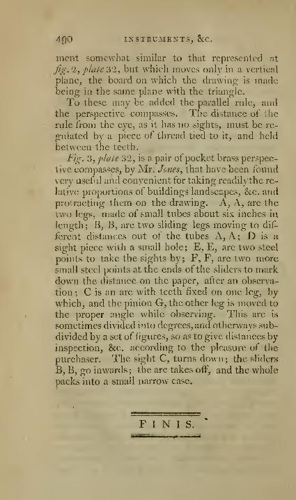
4Q0 INSTRUMENTS, ScC.
mcnt somewhat similar to that represented at
fig. 1j plate 2>'l, but which moves only in a vertical
plane, the board on which the drawing is madebeing in the same plane with the triangle.
To these may be added the parallel rule, andthe perspectiv^c compasses. The distance of the
rale from the eye, as it has no sights, must be re-
gulated by a piece of thread tied to it, and held
between the teeth.
Fig. 3, plate 32, is a pair of pocket brass perspec-
tive compasses, by Mr. Jones, that have been found
very useful and convenient for taking readilythe re-
lative proportions of buildings landscapes, &c. andprotracting them on the drawing. A, A, are the
two legs, made of small tubes about six inches in
length; B, B, are two sliding legs moving to dif-
ferent distances out of the tubes A, A; D is a
sight piece with a small hole ; E, E, are two steel
points to take the sights by ; F, F, are two moresmall steel points at the ends ofthe sliders to markdown the distance on the paper, after an observa-
tion ; C is an arc with teeth fixed on one leg, bywhich, and the pinion G, the other leg is moved to
the proper angle while observing. This arc is
sometimes divided into degrees, and otherways sub-
divided by a set of figures, so as to give distances byinspection, &c. according to the pleasure of the
purchaser. The sight C, turns down; the sliders
B,B, go inwards; the arc takes oiF, and the wholepacks into a small narrow case.
FINIS.

ADDENDA
THE EDITOR.
As this treatise is designed to comprehend a ge-
neral collection ot' the most approved methods of
surveying, I tJiink the following method of sur-
veying a large estate by Mr. Eincrson, and the
new method of surveying and keeping a field
book by Mr. Rodhum, as publislied in Dr. Hultoiis
Mathematical Dictionary , 1 vols. 4to. IZQO, will be
of real information to many surveyors ; and, in myopinion, as deserving of practice as any other me-thod I am acquainted with.
" TO SURVEY A LORDSHIP, OR LARGE ESTATEOF LAND.
'• If the estate be very large, and contains a
great number of lields, it cannot be done by sur-
veying all the fields singly, and then putting themtogether; nor can it be done by taking all tlie an^
gles and boundaries that inclose it. For in these
cases, any small errors will be so multiplied as to
render it very much distorted.
. 1. Walk over the lordship two or three times,
in order to get a perfect idea of it, and till you can.
carry the map of it in your head. And to help

-iQI Emerson's method
your memory, draw an eye draught of it on paper,
to guide you, or at least of the prineipal part^
of it.
2. Choose two or more eminent places in the
estate for your stations, from whenee you ean see
all the principal parts of it; and the fewer stations
you have to command the whole, the more exact
your work will be; and let these stations be as far
distant from one another as possible; and they will
be fitter for your purpose, if these stationary lines
be in or near the boundaries of the ground, andespecially if two lines or more proceed from onestation.
3. Take what angles, between the stations, youthink necessary, and measure the distances fromstation to station, always in a right line; these
things must be done, till you get as many angles
and lines as are sufficient for determining all your
points of station. And in measuring any of these
stationary distances, mark accurately where these
lines meet with any hedges, ditches, roads, lanes,
paths, rivulets, &c. and where any remarkable ob-
ject is placed, by measuring its distance from the
stationary line; and where a perpendicular from it
cuts that line. And always mind, in any of these
observations, that you be in a right line, which youwill know by taking backsight and foresight, along
your stationary line; which you must never omit.
And thus as you go along any main stationary line,
take offsets to the ends of all hedges, and to anypond, house, mill, bridge, &c. omitting nothing
that is remarkable, and all these things must benoted down, for these are your data, by which the
places of such objects are to be determined uponyour plan. And be sure to set marks up at the
intersections of all hedges with the stationary line,
that you may know where to measure from, when
OP SURVEYING. 4^3
you come to survey these particular fields, whichmust immediately be doue, as soon as you have
measured that stationary line, whilst they are fresh
in memory. By these means all your stationary
lines are to be measured, and the situation of all
places adjoining to them determined, which is the
tirst grand point to be obtained. I would have
you lay down 'your work upon paper every night,
when you go home, that you may see how yougo on.
4. As to the inner parts of the estate, they mustbe determined in like manner by new stationary
lines. For, after the main stations are determined,
and every thing adjoining to them ; then the estate
must be subdivided into two or three parts by newstationary lines; takmg inner stations at proper
places, where you can have the best view; andmeasure these stationary lines as you did the first,
and all their intersections with hedges, and all off-
sets to such objects as appear; then you may pro-
ceed to survey the adjoining fields, by taking the
angles that the sides make with the stationary line,
at the intersections, and measuring the distances to
each corner, from the intersections. For every
stationary line will be a hash to all the future ope-
rations; the situation of all parts being entirely de-
pendent thereon; and therefore they should betaken as long as possible; and are best to runalono* some of the hedsres or boundaries of one or
more fields, or to pass through some oftheir angles.
All things being determined for these stations, youmust take more jnner stations, and continue to di-
vide and subdivide; till at last you come to single
iields; repeating the same work for the inner sta-
tions, as for the outer ones, till all be done. Andclose the work as oft as you can, and in as few
lines as possible. And as it may require some
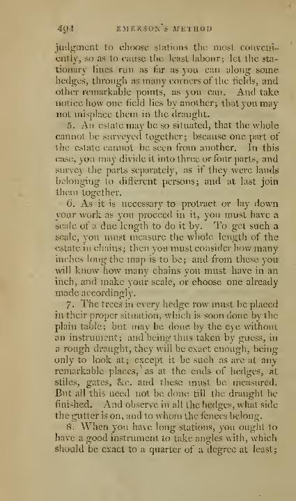
4^4 EMERSOI^ S JfETHOD
JQcigmcnt to choose stations the most conveni-
ently, so as to cause the least labour; let the sta-
tiontiry lines run as far as you can along somehedges, through as many corners of the iielcls, andother remarkable points, as you can. And take
notice how one iield lies by another; that you maynot misplace them in the draught.
5. An estate may be so situated, that the wholecannot be surveyed together; bscause one part of
the estate cannot be seen from another. In this
case, yoa may divide it into three or four parts, andsurvey the parts separately, as if they were lands
belonging to different persons; and at last join
them together.
6. As it is necessary to protract or lay downyour work as you proceed in it, you must have a
acale of a due length to do it by. To get such ascale, you must measure the whole length of the
estate in chains; then you must consider hov/ manyinches long tlie map is to be; and from these youwill know how many chains you must have in an
inch, and make your scale, or choose one already
made accordingly.
7. The trees in every hedge row must be placed
in their j)roper situation, which is soon done by the
plain table; but may be done by the eye without
an instrument; and being thus taken by guess, in
a rough draught, they will be exact enough, beingonly to look at; except it be such as are at any
remarkable places, as at the ends of hedges, at
stiles, gates, &e. and these must be measured.
But all this need not be done till the draught befinished. And observe in all the hedges, what side
the gutter is on, and to whom the fences belong.
8. When you have long stations, you ought to
have a srood instrument to take angles with, whichshould be exact to a quarter of a degree at least
j
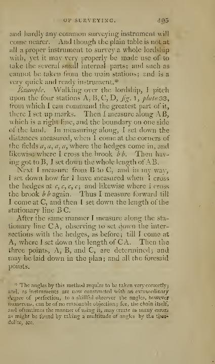
OF SURVEYING. 405
and hardly any common surveying Instrument will
come nearer. And though the plain table is not at
all a proper instrument to survey a whole lordship
with, yet it may very properly be made use of to
take the several small internal parts; and such as
cannot be taken from the main stations; and is a
very quick and ready instrument.*
Example. Walking over the lordship, I pitch
upon the four stations A, B, C, D, fg. 1, phite 33,
from which I can conuiiand the greatest part of it,
there I set up marks. Then I measure along AB,which is a right line, and the boundary on one side
of the land. In measuring along, I set down the
distances measured, when 1 come at the corners of
tjic fields a, a, a, a, where the hedges come in, andlikewise where I cross the brook bh. Then bav-
in"; ffot to B, I set down the whole lenjjth ofAB.Next I measure from B to C, and in my way,
I set down how far I have measured when I cross
the hedges at c^ c^c^c; and likewise where I cross
the brook h h again. Thus I measure forward till
1 come at C, and then I set down the length of the
stationary line B C.
After the same manner I measure along the sta-
tionary line CA, observing to set down the inter-
sections with the hedges, as before; till I come at
A, where I set down the length of C A. Then the
three points, A, B, and C, are determined; andmay be laid down in the plan; and all the foresaid
points.
"'• The angles by this method require to be taken very' correctly;
and, as instruments are now constructed with an extraordinary
degree of perfection, to a skillful observer the angles, howevernumerous, can be of no reasonable objection; for, the chain itself,
and oftentimes the manner of using it, may create as many errors
as might be found by taking a multitude of angles by the tUeQ'
dolite^ bic.

4g6 Emerson's method
Being come to A again, I go from A towards B,
and in my way I survey every single field adjoin-
ing to the stationary line AB. To do which the
shortest way, I take the angles at every intersec-
tion a, that the sides of each field make with the
stationary line AB; and then I measure their
lengths; by which every field is easily laid down.
In the same manner I proceed from B to C, and
measure every field adjoining to BC. And then I
go to A, and measure every field in my way thither.
Next I go from A towards D, and set down, as
before, all my crossing of the hedges; and the
length AD, when I come at D. And in like
manner I measure along D C, setting down all the
crossings of the hedges as before, with whatever
else is remarkable, as where a highway crosses at d.
Having finiiihed all the main stations, we mustbegin to make inner stations. Therefore I take Fand G for two stations, being in the lines AB andB C, the hedges from F to G running almost
straight; then I measure from F towards G, andat/, I find a hedge going to the left, and going onto^, I find another hedge going to the right; andat //, I cross the burn. At /", there is an angle, to
which I make an offset. Going on further, I comeat a cross hedge /, going to the right; and then
measure on to G, the end of the station. Now in
going from F to G, we can take all the angles that
the sides of the fields make with the stationary
line FG, and then measure their lengths; bywhich these fields may be laid down on paper.
Then I take another inner station at I, and mea-suring from A to 0, I come to the opposite corner
of the field; then measuring on to p, 1 cross a
hedge; then I proceed to my station I. Then I
i^easure from 1 to F, and take an offset to «, wherethe hedge crosses the brook. Then I come to the
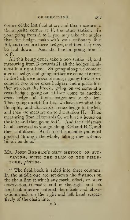
Op SUfvVEYING. 497
corner of the last field at m\ and then measure to
the opposite corner at F, the other station. In
your going from A to I, you may take the angles
that the hedges make with your stationary line
A I, and measure these hedges, and then they maybe laid down. And the like in going from I
toF.All this being done, take a new station H, and
measuring from B towards H, all the hedges lie al-
most in a right line. So going along we come at
a cross hedge, and going further we come at a tree,
in the hedge we measure along; going further wecome at tw^o other cross hedges; and a piece fur-
ther we cross the brook; going on we come at a
cross hedge; going on still we come to another
cross hedge; all these hedges are to the left.
Then going on still further, we have a windmill to
the right; and afterwards a cross hedge to the left,
and then we measure on to the station H. Thenmeasuring from H towards C, we have a house onthe left; and then go on to C. And the fields maybe all surveyed as you go along BH and H C, andthen laid down. And after this manner you mustproceed through the whole, taking new stations,
till all be done."
Mr. John Rodham's new method of sur-veying, WITH THE PLAN OF THE FIELD-BOOK, fhte 34.
" The field book is ruled into three columns.
In the middle one are set down the distances onthe chain line at which any mark, off'set, or other
observation is made; and in the right and left
hand columns are entered the offsets and obser-
vations made on the right and left hand respec-
tively of the chain line.
K k

498 Rodham's new method
It is of great advantage, both for brevity andperspicuity, to begin at the bottom of the leaf andwrite upwards; denoting the crossing of fences,
by hues drawn across the middle column, or only
a part of such a line on the right and left opposite
the figures, to avoid confusion; aud the corners
of iields, and other remarkable turns in the fences
where offsets are taken to, by lines joining in the
manner the fences do, as will be best seen by com-paring the book with the plaiT annexed to the
licld-book, as shewn in plate 34.
The marks called, a, b, c, &c. are best madein the fields, by making a small hole with a spade,
and a chip or small bit ofwood, with the particular
letter upon it, may be put in, to prevent one markbeing taken for another, on any return to it. Butin general, the name of a mark is very easily hadby referring in the book to the line it was made in.
After the small alphabet is gone through, the ca-
pitals may be next, the print letters afterwards, andso on, which answer the purpose of so many dif-
ferent letters; or the marks may be numbered.The letter in the left hand corner at the be-
ginning of every line, is the mark or place mea-sured /ro;/z; and, that at the right hand corner at
the end, is the mark measured to: but when it is
not convenient to go exactly from a mark, the
place measured from, is described such a distance
from one ?;/^r^ towards anotlier:, and where a markis not measured to, the exact place is ascertained
by saying, turn to the right or left hand, such a dis-
tance to such a mark, it being always understood
that those distances are taken in the chain line.
The characters used, are P for tuni to the
right hand,~\ for turn to the left hand, and a placed
over an offset, to shew that it is not taken at right
angles with the chain line, but in the line with
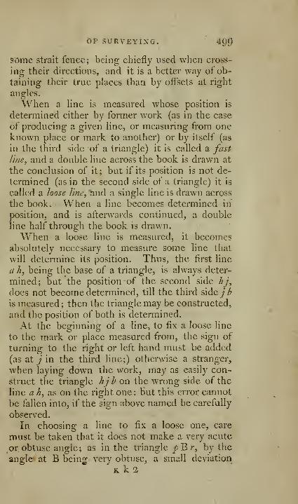
OF SURVEYING. ' 49^
some strait fence; being chiefly used when cross-
ing their directions, and it is a better way of ob-
taining their true places than by offsets at right
angles.
When a line is measured whose position is
determined either by former work (as in the case
of producing a given line, or measuring from oneknown place or mark to another) or by itself (as
in the third side of a triangle) it is called a fast
line, and a double line across the book is drawn at
the conclusion of it; but if its position is not de-
termined (as in the second side of a triangle) it is
called a loose line, ^nd a single line is drawn across
the book. When a line becomes determined in
position, and is afterwards continued, a double
line half through the book is drawn.
When a loose line is measured, it becomesabsolutely necessary to measure some line that
will determine its position. Thus, the first line
a h, being the base of a triangle, is always deter-
mined; but the position of the second side hj,
does not become determined, till the third &\^ejb
is measured; then the triangle may be constructed,
and the position of both is determined.
At the beginning of a line, to fix a loose line
to the mark or place measured from, the sign of
turning to the right or left hand must be added
(as at ; in the third line;) otherwise a stranger,
when laying down the work, may as easily con-
struct the triangle hjh on the wrong side of the
line a h, as on the right one: Hut this error cannot
be fallen into, if the sign above named be carefully
observed.
In choosing a line to fix a loose one, care
must be taken that it does not make a very acute
or obtuse angle; as in the triangle pB r, by the
angle at B bein^ very obtuse, a small deviation,
K k 2
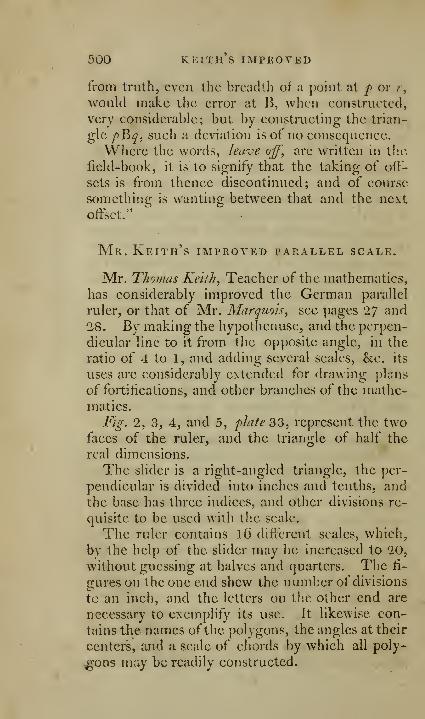
500 KEITH S IMPROVED
from truth, even the breadth of a point at f or r,
would make the error at B, when constructed,
very considerable; but by constructing the trian-
gle />B^, such a deviation is of no consequence.
Where the words, leave off, are written in the
field-book, it is to signify that the taking of off-
sets is from thence discontinued; and of course
something is wanting between that and the next
offset."
Mr. Keith's improved parallel scale.
Mr. Thomas Keith, Teacher of the mathematics,
has considerably improved the German parallel
ruler, or that of Mr. Marquois, see pages 27 and
28. By making the hypothenuse, and the perpen-
dicular hne to it from the opposite angle, in the
ratio of 4 to 1, and adding several scales, he. its
uses are considerably extended for drawing plans
of fortifications, and other branches of the mathe-matics.
Fig. 2, 3, 4, and 5, plale 33, represent the twofaces of the ruler, and the triangle of half the
real dimensions.
The slider is a right-angled triangle, the per-
pendicular is divided into inches and tenths, andthe base has three indices, and other divisions re-
quisite to be used with the scale.
The ruler contains lO different scales, which,
bv the help of the slider may be increased to 20,
without guessing at halves and quarters. The fi-
gures on the one end shew the number of divisions
to an inch, and the letters on the other end are
necessary to exemplify its use. It likewise con-
tains the names of the pol vgons, the angles at their
centers, and a scale of chords by which all poly-
gons may be readily constructed.

PARALLEL SCALE. 501
ITS USE AS A COMMOX PARALLEL RULEK.
To draw a i'lne 'parallel to the slider. Lay the
hypothenuse, or sloped edge of the triaiig-le in the
position you intend to have your line, place the
scale against the base of the triangle, and draw a
line along the slope edge, keep the scale fixed,
and mrve the slider to the left or right hand, ac-
cording as you want a parallel line above or below
the other.
To draw a line parallel to the scale. Lay the
scale in the position you intend to have your lines,
and draw a line along the edge of it. Place the
base of the triangle against this edge, the middle
index standing at O on the scale, and make a
mark against any one division on the perpendi-
cular; turn the triangle the other side uppermost,
and make a mark against the same division; join
these marks, and this line will be parallel to the
former. The same may be done by sliding the
triangle, without turning it, if the lines are not
required to be very long.
To draw a Tine parallel to the slider at a great
distance. Draw a line along the slope edge of the
triangle, and fix the scale as before, make a markagainst 2 on the perpendicular; the index being
at O, turn the triangle the other side uppermost,
and make a mark against the same division, take
away the triangle, and move the scale to these
marks, apply the triangle again ; proceed thus till
you have got the proper distance, then draw a line
along the slope edge, and it will be parallel to the
former.
To draw a line parallel to the scale at a great
distance. Draw a line along the edge ofthe scale,
place the base of the triangle against that edge.

501 Keith's improved
the middle index being at O, and make a markagainst 2 on the perpendicular; turn the triangle
the other side uppermost, and make a mark against
the same division; takeaway the triangle, andmove the scale to these marks; proceed thus till
you have got the proper distance, then draw a
line along the scale, and it will be parallel as re-
quired..
ITS USE IN ERECTING PERPENDICULARS.
If a line is wanted perpendicular to the scale,
apply the base of the slider to it, and draw a line
from the scale along the perpendicular of the tri-
angle; should a longer perpendicular be wanted,
apply the perpendicular of the triangle to the scale,
and draw a line along the base.
If a perpendicular is wanted to a line, which has
been drawn along the hypothenuse ofthe triangle,
keep the scale fixed, and apply the hypothenuseof the triangle to it, then draw a line along the
perpendicular of the triangle,
ITS USE IN CONSTRUCTING POLYGONS
Having made choice of any one scale, take the
side of your polygon from it. Take the degrees
under the name of your polygon, and subtract
them from 180 ; at each end of the above side of
your polygon, make angles equal to half the re-
mainder, and the distance from the intersection of
the lines, which form the angles, to either end of
the side of your polygon, will give the radius of its
circumscribing circle.
Or, the three angles, and one side being given
of a triangle, the radius, or remaining sides, maybe found by trigonometry.

PARALLEL SCALE. 503
JTS USE IN DRAWING PARALLEL LINES AT ANYGIVEN DISTANCE, WITHOUT THE ASSIST-
ANCE OP A PAIR OF COMPASSES.
If the side of your polygon zvas taken from th'
scale C. Move the slider from O to 1, 2, 3, &c.
on the scale D, and you will draw a parallel \u\c of
the width of 1, 2, 3, &c. divisions on the scale C.
This scale is 20 fathoms to an inch.
In a similar manner the scales G, L^ and P, arc
to be used.
If the side of your polygon was taken from the
scale C, calling the divisions two each. Move the
slider from O, on the scale A, to 1, 2, 3, &c. onthe same scale, and you will draw a parallel line of
half the width of 1, 2, 3, &c. divisions on the scale
C. This scale is 40 fathoms to an inch.
Similar instructions may be applied to the scales
G, L, and P.
If the side of "your polygon was taken from the
scale C, calling the divisions three each. When the
middle index stands at O, the divisions marked Con the slider will make straight lines with 5 and 6on the scale D. By moving the slider to the
right or left till the other divisions thereon makestraight lines successively with 5, 6, &c. you will
draw a parallel line of one-third of the width of
1, 2, 3, &c. divisions on the scale C. This scale
is 6o fathoms to an inch.
Similar directions must be observed in using the
scales G, L, and P.
If the side of your polygon was takeyi from the
scale A. Move the slider from O, to 1, 2, 5, &c.
on the scale B, and you will draw a parallel line of
the width of 1, 2, 3, &c. divisons on the scale A.This scale is 10 fathoms to an inch'.

504 KEITH S IMPROVED
Similar directions must be observed in using the
scales E, I, and N.
If the side of your polygon was taken from the
scale D. Move the slider from O, to 2, 4, 6, &c.
on the scale B, and you will draw a parallel line of
the width of 1^ 2, 3, &c. divisions on the scale D.This scale is five fathoms to an inch.
In making use of H, M, and Q, similar direc-
tions must be observed.,
Note. There is no absolute necessity for always
moving the slider from O, and it may be used ei-
ther side uppermost. Any one of the three in-
dices may likewise be made use of, &c.
To render the scale still more perfect;, Mr.Keith has made the following additions.
1
.
The divisions on the scale A, and the fourth
scale from A, have been subdivided for the purpose
of constructing sections, &c. Ten of the divi-
sions on the scale A make one inch ; if, therefore,
you call these divisions six each, the small divisions
on the same scale, nearest to the left hand, will beone each ; if you call the large divisions on the
scale A, five, four, or three each, then the sets of
smaller divisions in a successive order from the
left hand division above mentioned, towards the
right, will be one each.
2. Five ofthe divisions on the fourth scale fromthe edge make an inch; if, therefore, you call
these divisions 3, 5, 7? 9? oi' H each, then each
of the sets of small divisions, from the left handtowards the right, will be subdivided into parts of
one each. Thus you have a scale divided into
2i 5, 10, 15, 20, 25, 30, 35, 40, 45, 50, 55, and6o equal parts to an inch, exclusive of the scales
on the three other edges of the ruler.
3. The line P on the slider stands for polygons;
R, radius; the figures in this line being the radii
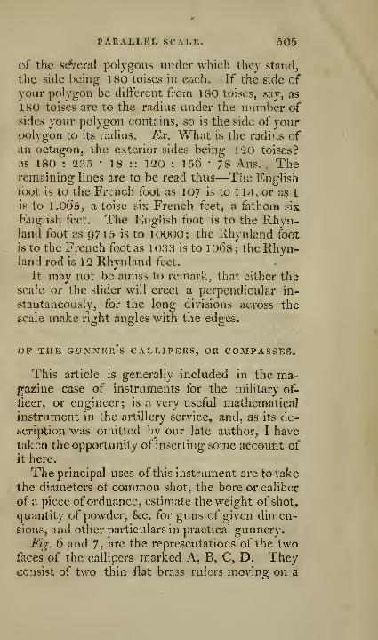
PARALLEL SCALE. 505
of the sdVcral polygons under which they stand,
tlic side being 180 toises in each. If the side of
your polygon be different from 180 toises, say, as
180 toises are to the radius under the number ofsides your polygon contains, so is the side of yourpolygon to its radius. Ex. What is the radius ofan octagon, the exterior sides being 120 toises?
as 180 : 235 • 18 :: 120 : 156 ' 78 Ans. . Theremaining lines are to be read thus—The English
foot is to the French foot as 107 is to 114, or as 1
is to l.oOs, a toise six French feet, a fathom six
English feet. The English foot is to the Rhyn-land foot as 9715 is to 10000; the Rhynland foot
is to the French foot as 1033 is to 1068; the Rhyn-land rod is 12 Rhynland feet.
It may not be amiss to remark, that cither the
scale or the slider will erect a perpendicular in-
stantaneously, for the long divisions axrross the
scale make right angles with the edges.
OF THE G.UXNER's CALLIPERS, OR COMPASSES.
This article is generally included in the ma-gazine case of instruments for the military of-
ficer, or engineer; is a very useful mathematical
instrument in the artillery service, and, as its de-
scription was omitted by our late author, I have
taken the opportunity of inserting some account of
it here.
The principal uses of this instrument are to take
the diameters of common siiot, the bore or caliber
of a piece ofordnance, estimate the weight of shot,
quantity of powder, &c. for guns of given dimen-sions, and other particulars in practical gunnery.
Fig. 6 and 7, are the representations of the twofaces of the callipers marked A, B, C, D. Theyconsist of two thin flat bra3s rulers moving on a
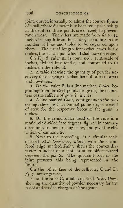
506 DESCRIPTION OF
joint, curved internally to admit the convex figure
ofa ball, whose diameter is to be taken by the points
at the end A; these points are of steel, to prevent
much wear. The rulers are made from six to 12inches in length from the center, according to the
number of lines and tables to be engraved uponthem. The usual length for pocket cases is six
inches, the scales upon which I shall now describe.
On Fig. 6, ruler A, is contained, 1. A scale of
inches, divided into tenths, and continued to 12
inches on the ruler B.
2. A table shewing the quantity of powder ne-
cessary for charging the chambers of brass mortars
and howitzers.
3. On the ruler B, is a line marked Inches, be-
ginning from the steel point, for giving the diame-ters of the calibers of guns in inches.
4. A line marked Guns, contiguous to the pre-
ceding, shewing the nominal pounders, or weight
of shot for the respective bores of the guns in
inches.
5. On the semicircular head of the rule is a
semicircle divided into degrees, figured in contrary
directions, to measure angles by, and give the ele-
vation of cannon, &c.
6. Next to the preceding, is a circular scale
marked Shot Diameters, which, with the cham-fered edge marked Index, shews the convex dia-
meter in inches of a shot, or other object placed
between the points. The quadrant part of the
joint prevents this being represented in the
figure.
On the other face of the callipers, C and D,
Jig. 7, are engraved,
7- on the ruler C, a table marked Brass Guns,
shewing the quantity of powder necessary for the
proof and service charges of brass guns.

THE gunner's callipers. 507
8. The line of lines, marked Lin.
9. Two circular scales on the head of the rider,
marked Shot, shewing the weights of iron shot, as
taken by the points of the callipers.
On the ruler D, besides another corresponding
line of lines,
10. A table shewing the quantity of pow^lcr
necessary for proof and service charges of iron
guns, from \ to 42 pounders.
11. To these are sometimes added various fi-
gures of a circle, cube, &c. with numbers.
12. A table of the weights and specific gravi-
ties of a cubic foot of various metals, ivory, wood,waters, &c.
EXPLANATION OF THE LINES AND TABLES.
1. The line of inches, graduated contiguous
to the exterior edj^es of the sides A and B,
Jig. 6, when opened to a straight line, makes a
measure of 12 inches and tenths for the purposeof a common rule.
2. The table shewing the quantity of powdernecessary for mortars and howitzers. This table
is adapted for both sea and land. Thus, by in-
spection merely is shewn that a 13 inch brass
mortar at sea requires 30 pounds of powder; byland only 10 pounds. Mortars and howitzers
under 10 inches have only the land quantities
inserted.
3. The line of inches for concave diameters.
It commences from the steel point at 2 inches, andcontinues on to 1 inches, and is subdivided to
halves and quarters. When used, the legs are
placed across each other, and the steel points
brought to a contact with the internal concave
surface of the gun, at the diametrical, or greatest
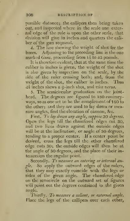
50S DESCRIPTION OF
possible distance; the callipers then being taken
out, and inspected \^'hcrc in the scale one exter-
nal edge of the rule is upon the other scale, that
division will give in inches and quarters the cali-
ber of the gun required.
4. The line shewing the weight of shot for the
bores. Adjoining to the preceding line is the onemarked Guns^ proceeding from 1^ to 42 pounds.
It is therefore evident, that at the same time the
caliber in inches is given, the weight of the shot
is also given by inspection on the scale, by the
side of the ruler crossing both; and, from the
weight of the shot, the caliber in inches. Thus4i inches shews a 9-inch shot, and i-'ice versa.
5. The semicircular graduation on the joint-
head. The degrees are figured to ISO contrary-
ways, so as one set to be the complement of 180 to
the other; and they are used to lay down or mea-sure angles, find the elevation of cannon, &c.
First. Jo lay down any angle, suppose 30 degrees.
Open the legs till the chamfered edges cut 30,
and two lines drawn against the outside edges
will be at the inclination, or angle of 30 degrees,
tending to a proper center. If a center point be
desired, cross the legs till the other chamfered
edge cuts 30; the outside edges will then be at
the angle of 30 degrees, and the place of their in-
teiseclion the angular point.
Secondly. To measure an entering or internal an^
gle. So apply the outward edges of the rulers,
that they may exactly coincide with the legs or
sides of the given angle. The chamfered edgeon the semicircle on the outward set of figures
"will point out the degrees contained in the given
angle.
Tiiirdly. To measure a salient, or external angle.
Place the legs of the callipers over each other_,
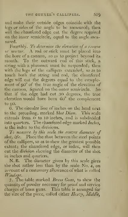
THE GUNXEll S CALLIPERS. 50^
and make their outside edges coincide with the
legs or sides of the angle to be measured; thenwill the chamfered edge cut the degree required
on the inner semicircle, equal to the angle mea-sured.
Fourthly. To deternime the elevation of a cannon
or mortar. A rod or stick must be placed into
the bore of a cannon, so as to project beyond its
mouth. To the outward end of this stick, a
string with a plummet must be suspended; thenwith t;he legs of the callipers extended, so as to
touch both the string and rod, the chamferedtCi^Q, will cut the degrees equal to the comple-ment of 90° of the true angle of the elevation ofthe cannon, figured on the outer semicircle. Sothat if tlje edge had cut 30 degrees, the true
elevation would have been ()0° the complement
6. The circular line of inches on the head next
to the preceding, marked Shot D'lam. This scale
extends from O to 10 inches, and is subdivided
into quarters. The cjhamfered edge marked Inches^
is the index to the divisions.
To measure by this scale the convex diameter ofsliot^ &c. Place the shot between the steel points
of the callipers, so as to shew the greatest possible
extent; the chamfered edge, or index, will then
cut the division shewing the diameter of the shot
in inches and quarters.
N. B. The diameter given by this scale gives
the shot rather less than by th|e scale No. 4, onaccount of a customary allowance of what is called
Windage.
7
.
The table marked Brass Guns, to shew the
quantity of powder necessary for proof and service
charges of brass guns. This table is arranged for
the size of the piece, called either Heavy, Middle^
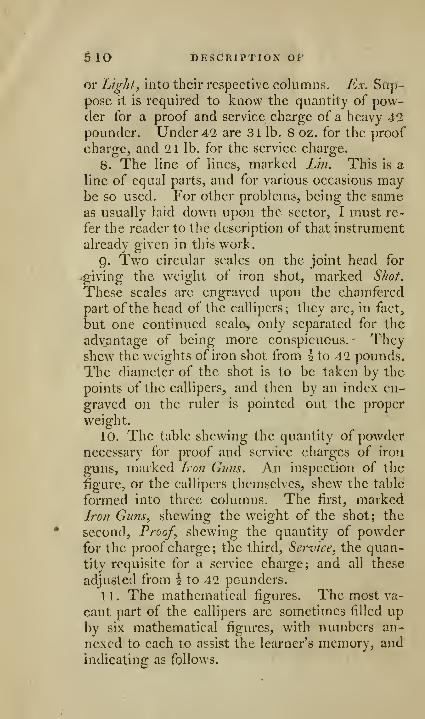
5 10 DESCRIPTION OF
or Light, into their respective columns. Ex. Sap-pose it is required to know the quantity of pow-der for a proof and service charge of a heavy 42pounder. Under 42 are 31 lb. 8 oz. for the proof
charge, and 21 lb. for the service charge.
8. The line of lines, marked L'm. This is a
line of equal parts, and for various occasions maybe so used. For other problems, being the sameas usually laid down upon the sector, I must re-
fer the reader to the description of that instrument
already given in this work.
g. Two circular scales on the joint head for
/giving the weight of iron shot, marked Shot.
These scales are engraved upon the chamfered
part of the head of the callipers; they are, in fact,
but one continued scaler only separated for the
adv_antage of being more conspicuous. Theyshew the weights of iron shot from h to 42 pounds.
The diameter of the shot is to be taken by the
points of the callipers, and then by an index en-
graved on the ruler is pointed out the proper
weight.
10. The table shewing the quantity of powdernecessary for proof and service charges of iron
guns, marked Iron Guns. An inspection of the
figure, or the callipers themselves, shew the table
formed into three columns. The first, markedIron Guns, shewing the weight of the shot; the
second. Proof, shewing the quantity of powderfor the proof charge; the third, Service, the quan-
tity requisite for a service charge; and all these
adjusted from \ to 42 pounders.
11. The mathematical figures. The most va-
cant part of the callipers are sometimes filled upby six mathematical figures, with numbers an-
nexed to each to assist the learner's memory, and
indicating as follows.

THE GUNNEll S CALLIPERS. 511
1. A circle with two diametrical lines, about
which are the numbers 7- 22, and 113. 355; they
both are the proportion of the diameter to the cir-
cumference, the latter being nearer the truth thanthe former. The following examples may betherefore readily worked by them.
Required the circnmfere7ice ofa circle to any giroen
diameter.
As 7 : 22 :: given diameter : the circumference
required.
Or 113 : 355 :: diameter : the circumference
jnore exactly.
And the converse of these.
As 22 : 7 '•'• circumference : the diameter.
As 355 : 113 :: circumference : the diameter
more exactly.
2. A circle with an inscribed and circumscribed
square, and inscribed circle to this smaller square.
To this figure are annexed the numbers 28. 22.
14. 11. denoting that the larger square is 28, the
inscribed circle is 22. The area inscribed at the
square in that circle 14, and the area of the
smaller inscribed circle 11.
Both the proportion of the squares and circles
are in the proportion of 2 to 1 ; and from them the
area of any circle may be found, having its diame-ter given. For example.
Required the area of a circle whose diameter
is 12.
Now the square of 12 is 144.
Then as 28 : 22 :: 144 : 113.1, the area.
Or as 14 : 11 :: 144 : 113.1.
3. Represents a cube inscribed in a sphere; the
affixed number 89! shews that a cube of iron in-
scribed in a sphere of 12 inches in diameter, weighs
BQt pounds.
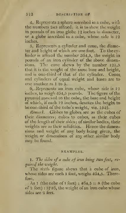
51'2 DESCRIPTION 0S»
4, Represents a sphere inscribed in a cube, witll
the numl3ers 243 affixed; it is to shew the weightin pounds of an iron globe 12 inches in diameter,
or a globe inscribed in a cube, whose side is 12inches.
5, Represents a cylinder and cone, the diame-
ter and height of which are one foot. To the cy-
linder is affixed the number 3()4,5, the weight in
pounds of an iron cylinder of the above dimen-sions. The cone shewn by the number 121,5
that it is the weight of the same base and height,
and is one-third of that of the cylinder. Conesand cylinders of equal weight and bases are to
one another as 1 to 3.
d, > Represents an iron cube, whose side is 12
inches, to weigh 4()4,5 pounds. The figure of the
pyramid annexed to the cube, the base and height
of which, if each 12 inches, denotes the height to
be one-third of the cube's weight, viz. 154f.
Remark. Globes to globes are as the cubes oftheir diameters; cubes to cubes, as their cubesof the length of their sides; of similar bodies, their
weights are as their solidities. Hence the dimen-sions and weight of any body being given, the
weight or dimensions of any other similar bodymay be found.
EXAMPLES.
1 . The sides of a ciibe of iron being two feet, re^
quired the iveight.
The sixth figure shews that a cube of iron,
whose sides are each 1 foot, weighs 4()4,5. There-
fore,
As 1 (the cube of 1 foot) : 464,5 :: 8 (the cube
of 2 feet) : 37 1 6, the weight ofan iron cube whose•sides are 2 feet.

THE GUNNER S CALLIPERS. 513
2. The diameter of an iron shot being six inches,
required the weight.
By the fourth figure a one foot iron ball weighs
243 pounds^ and 6 inches=;,5 the tV of a foot.
Therefore, as 1 (the cube of 1 foot) : 243 (the
weight) :; ,125 (cube of ,5 orrV) : 30,375 pounds,
the weight required.
Another rule. Take \ the cube of the diameter
in inches, and \ ofthat eighth, and their sum will bethe weight required in pounds exactly. Or, the
weight ofa four inch shot being nine pounds, the
proportions 64 : Q may be used with equal ex-
actness.
3. The tveight of an iron hall heing given, to find
its diameter.
This rule is the converse of the preceding, the
same numbers being used; as 243 (the weight) : 1
(cube of 1 foot;) or, as 9 pounds : 64 (cube of 4.)Another rule. Multiply the weight by 7? ^nd
to the product add h of the weight, and the cuberoot of the sum will be the diameter in inches.
Thus, an iron ball of 12 pounds weight will befound to be 4,403 inches. The methods of this
rule are too evident to require worked examples.
4. The following example will make up a suffi-
cient number, by which the learner may knowhow to apply readily any number from the figures
just desbribed.
A parcel of shot and cannon weighing fii>e tons, or
1 1 200 founds is to he melted, and cast into shot ofthree andfive inches diameter, and weight of each
sort to he the same ; required the tmniber there will
he of each.
1st. Half of 11200 is 560 pounds.
2d. Cube of 3 inches, or cube i of a foot =:-sV.
Then, as 1 (cube of 1 foot) : 243 (the weight
of a 1 football) :: 1/4 : 3,793 weight of a 3 inch
iron shot.
l1

514 DESCRIPTION OF
N. B. In this proportion 64 divides 143 on ac-
count of the fraction.
Now 5 inches =T2r of a foot, its cube -iW^.
Therefore, as I : 243 :: tW? : 17,(^7, weight of
an iron 5 inch shot.
Dividing 5000 by 3,79 gives 1504, the numberrequired of the 3 inch shot.
Dividing 5600 by 17357 gives 313, the required
number of the 5 inch shot.
A table of specific gravities and weights of bo-dies is added, or not, at the pleasure of the
purchaser. It is not essential to the general uses
of the callipers, although many curious and useful
problems relative to the weights and dimensions
of bodies may be obtained from it in the most ac-
curate manner. =^
The quantity of lines placed upon the callipers
may be increased or arranged at pleasure. Thefollowing 19 WTre the greatest number that I ever
knew of being placed upon them.
1. The measures of convex diameters in inches.
2. The measures of concave diameters in inches.
3. The weights of iron shot from given diameters.
4. The weight of iron shot proper to given gunbores. 5. The degrees of a semicircle. 6. Theproportion ofTroy and Averdupoise weight. 7 • Theproportion of English and French feet and pounds.
8. Factors useful in circular and spherical figures.
9. Tables of the specific gravity and weights of
bodies. 10. Tables of the quantity of powder ne-
cessary for proofand service of brass and iron guns.
11. Rules for computing the number of shot or
shells in a finished pile. 12. Rules concerning the
fall of heavy bodies. 13. Rules for the raising of
water. 14. The rules for shooting with cannon
* See Mr. Adams's Lectures, five vols. 8vo. a new and im-proved edition of which is now in the press, and under my cor-
riEction and augmentation.
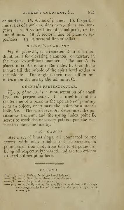
GUNNER*S QUADRANT^ &C. 5l5
or mortars. 15. A line of inches. l6. Logarith-
mic scales of numbers, sines, versed sines, and tan-
gents. 17. A sectoral line of equal parts^ or the
line of lines. 18. A sectoral line of plans or su-
perficies. 19. A sectoral line of solids.
gunner's guadrant.
Fig. 8, plate 33, is a representation of a qua-
drant used for elevating a cannon, or mortar, in
the most expeditious manner. The bar A, is
placed in at the mouth ; the index B, brought to
the arc till the bubble of the spirit level settles in
the middle. The angle is then read off to mi-
nutes upon the arc by the nonius at C.
gunner's perpendicular.
Fig. 9, plate 33, is a representation of a small
level and perpendicular. It is used to find the
center line of a piece in the operation of pointing
it to an object, or to mark the point for a breech
hole, &c. The spirit level A, determines the po-
sition on the gun, and the spring index point B,
serves to mark the necessary points upon the sur-
face to obtain the line by.
SHOT GAUGES.
Are a set of brass rings, all connected to one
center, with holes suitable to the diameters, or
pounders of iron shot, from four to 42 pounders;
being all respectively marked, and are too evident
to need a description here.
err a t a.
Page 6, line 2, Preface, for desighed read designed.
• 89, — 2, Note, for desiderata read desideratum.• 380, — II, for plate 28 read plate 31.•— 500, — 14, for By making, &c. read By raaking the base of the triangJe
and a perpendicular liae lo it, drawn fro;.-: the opp?si-e angle, in ti.e
ratio of 4 to i
,

A LIST
Oftbi; pr'mdpal Listrtiments described hi this Work, and ibeir Prias,
as made and sold hy W. atid S. Jones, Holborn, London.
PLATE I.
Pahtial, or complete magazine cases of instruments,
as represented in the plate, from ll. 18s. to — 10 10 O
PLATE IL
Parallel rulers, jig. A, B, C, D, and E, according to
the length and mounting, from 2s. fid. each, to 2 12 6
N. B. Oifgs. A, or B, or C, or D, or E, one ofthem
is included in the cases above, to order.
Improved ruler, FGH — — — — — —Ditto IKL — — — — — — — —Ditto represented at M, from 10s. 6d. to — —
PLATE III.
F:g. 1. Marquols's parallel scales — — — —2 and 3. Protractors, wood or ivory, from 2s. to
4. Sectors, according tp the length and mate-
.rials they are made of, from 2s. 6d. to —/. Brass proportional compasses — — —
Without the adjusting rod. Jig. A, flate 1
^ and 9 a. Elliptical, sector, and beam compasses 3 13
10. Beam compasses from ll. 4s. to — —11. Sisson's beam compasses — — — —
——12. Triangular compasses— — — — —Ditto represented at./^. N, flate 1 — —
13. Calliper and beam, small size — — —PLATE X.
Bevel, &c. rulers, Jigs. 4, 12, 15, iG, 17, and 18, va-
rious prices from 10s. 6d. to — — — — 3 13 6
PLATE XI.
Kg. 1. Suardi's geometric pen — — — — — 4 40Ditto, with a great variety of .vt'heels, &c. to 7 7
1

[ 517 ]
Fig. 2. Elliptical drawing board — — — —3. Elliptical brass compasses — — — —4. Parabolic drawing machine— — — —5. Cyclograph for drawing circles of large radii
Q. Spiral machine — — — — — —7- Protractor, perpendicular, &c. — — —
PLATE XIV.
Fig. 1 . King's surA'eying quadrant with sights —2. Portable surveying brass cross and staff" —
' 3. Brass pocket. box cross and staff" — —Improved ditto, from ll. lis. 6d. to
—
—Optical squares — — — — — —
5. Ten inch common theodolite and staves —7- ^sst universal pocket theodolite — — —
PLATE XV.Fig. X. Common circumferentor and staves — —
2. Improved ditto 4l. 14. 6d. to — — —3. Surveying compass with telescope — —1. Six inch pocket common theodolite and staves
5. Six inch theodolite by rack work and staves 12 12
Ditto without rack work, common — —PLATE XVI..
Fig. 1. Second best 7 or 8 inch theodolite and staves 22
2. Very best improved ditto, ditto — — — 31
N. B. For large theodolite see the frontis-
piece, from sol. to — — — — 300
PLATE X^ai.
Fig. 1. Plane table and staves in a box — — — 4 4
2. Beighton's improved ditto — — — — 6 6 O
3. Spirit level of the best kind with telescope
and staves, according to the adjustments
and finishing, from 8l. Ss. to — — 12 12 O
Common ditto, without compass, from
31. 13. 6d. to — — — — — — 6 6 O-- " •i. Six inch circular protractors ll. 18s. to — 3 10 Q
2 12
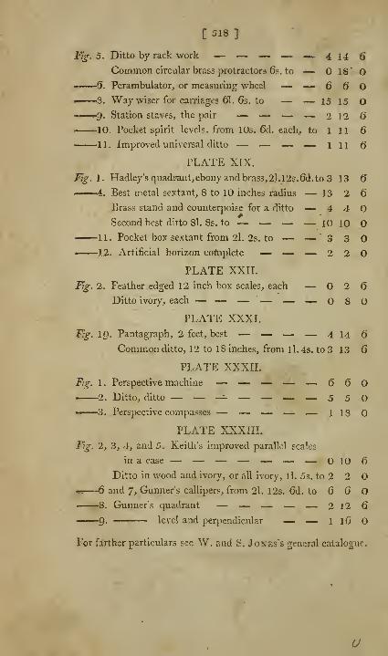
[ 518 ]
Fig. 5. Ditto by rack work — — — — — 4 14 6
Common circular brass protractors 6s. to — 18' O» ' (j. Perambulator, or measuring wheel — — 6 6 O• 3. Way wiser for carriages 61. 6s. to — — 15 15 O1 <^g. Station staves, the pair — — — — 212 6
10. Pocket spirit levels, from 10s. 6d. each, to 1 11 6
1 1 . Improved universal ditto — — — — 1116PLATE XIX.
Fig. I. HadIey'squadpant,ebonyandbrass,2l.l2s.6d.to3 13 6
1 . Best metal sextant, 8 to 10 inches radius — 13 2 6
Brass stand and counterpoise for a ditto — 4 4
Second best ditto 8l, 8s. to — — — — 10 10
11. Pocket box sextant from 2l. 2s. to — — 3 3
12. Artificial horizon coftiplete — — — 2 2
PLATE XXII.
Fig. 2. Feather edged 12 inch box scales, each — 2 6
Ditto ivory, each — — — "— — — 080PLATE XXXI.
F,g. 19. Pantagraph, 2 feet, best — — — — 414 6
Common ditto, 12 to 18 inches, from ll. 4s. to 3 13 6
PLATE XXXII.
Fig. 1 . Perspective machine — — — — — 6602. Ditto, ditto — — -^ — — — — 550
w 3. Perspective compasses — — — — — 118
PLATE XXXIII.
Fig. 2, 3, 4, and 5. Keith's improved parallel scales
in a case — — — — — — — OIO6Ditto in wood and ivory, or all ivory, ll. 5s. to 2 2 O
•K 6 and 7, Gunner's callipers, from 2l. 12s. 6d. to 6 6
8. Gunner's quadrant — — — — — 212 6
9- \t\t\ and perpendicular — — 1 16 O
For farther particulars see W. and S. Jones's general catalogue.
U


UNIVERSITY OF CALIFORNIA LIBRARYLos Angeles
This book is DUE on the last date stamped below.
Form L9-lC0m-9,'52(A3105)444
EaiisMriBg
Librvy