
Generation and Applications of Extra-Terrestrial Environments ...
318
Generation and Applications of Extra-Terrestrial Environments on Earth Daniel A. Beysens and Jack J.W.A. van Loon (Editors) River Publishers Series in Standardisation
-
Upload
khangminh22 -
Category
Documents
-
view
1 -
download
0
Transcript of Generation and Applications of Extra-Terrestrial Environments ...

Generation and Applications of
Extra-Terrestrial Environments on Earth
Daniel A. Beysens and Jack J.W.A. van Loon (Editors)
River Publishers Series in Standardisation

Generation and Applicationsof Extra-Terrestrial
Environments on Earth

RIVER PUBLISHERS SERIES IN STANDARDISATIONVolume 6
Series Editor
Anand R. PrasadNEC, Japan
The “River Publishers Series in Standardisation” is a comprehensive series addres-sing the pre-development related standards issues and standardized technologiesalready deployed. The focus of this series is also to examine the application domains ofstandardised technologies. This series will present works of fora and standardizationbodies like IETF, 3GPP, IEEE, ARIB, TTA, CCSA, WiMAX, Bluetooth, ZigBee etc.
Other than standards, this book series also presents technologies and conceptsthat have prevailed as de-facto.
Scope of this series also addresses prevailing applications which lead to regulatoryand policy issues. This may also lead towards harmonization and standardization ofactivities across industries.
For a list of other books in this series, visit www.riverpublishers.comhttp://riverpublishers.com/bookspubseries.php?sn=Standardisation

Generation and Applicationsof Extra-Terrestrial
Environments on Earth
Editors
Daniel A. Beysens
CEA-Grenoble and ESPCI-Paris-Tech,Paris, France
Jack J. W. A. van Loon
VU-University, Amsterdam,The Netherlands

Published, sold and distributed by:River PublishersNiels Jernes Vej 109220 Aalborg ØDenmark
River PublishersLange Geer 442611 PW DelftThe Netherlands
Tel.: +45369953197www.riverpublishers.com
ISBN: 978-87-93237-53-7 (Hardback)978-87-93237-54-4 (Ebook)
©2015 River Publishers
All rights reserved. No part of this publication may be reproduced, stored ina retrieval system, or transmitted in any form or by any means, mechanical,photocopying, recording or otherwise, without prior written permission ofthe publishers.

Contents
Preface xv
List of Contributors xvii
List of Figures xxiii
List of Tables xxix
List of Abbreviations xxxi
Introduction 1Daniel A. Beysens and Jack J. W. A. van Loon
1. The Space Environment
1 The Space Gravity Environment 5Daniel A. Beysens and Jack J. W. A. van Loon1.1 Open Space . . . . . . . . . . . . . . . . . . . . . . . . . . 51.2 Satellites and Rockets . . . . . . . . . . . . . . . . . . . . . 51.3 Typical Gravity at Some Celestial Objects . . . . . . . . . . 81.4 Conclusion . . . . . . . . . . . . . . . . . . . . . . . . . . 9
2 Cosmos: Violent and Hostile Environment 11Sébastien Rouquette2.1 Introduction . . . . . . . . . . . . . . . . . . . . . . . . . . 112.2 Beliefs and Truths . . . . . . . . . . . . . . . . . . . . . . . 112.3 Where Space Begins . . . . . . . . . . . . . . . . . . . . . 122.4 Satellite Environment . . . . . . . . . . . . . . . . . . . . . 12
2.4.1 Temperature . . . . . . . . . . . . . . . . . . . . . 132.4.2 Atmospheric Drag . . . . . . . . . . . . . . . . . . 13
v

vi Contents
2.4.3 Outgassing . . . . . . . . . . . . . . . . . . . . . . 132.4.4 Atomic Oxygen Oxidation . . . . . . . . . . . . . . 14
2.5 Conclusions . . . . . . . . . . . . . . . . . . . . . . . . . . 14
3 Radiation, Space Weather 17Marco Durante3.1 Facilities for Space Radiation Simulation . . . . . . . . . . 193.2 Protons . . . . . . . . . . . . . . . . . . . . . . . . . . . . 203.3 Neutrons . . . . . . . . . . . . . . . . . . . . . . . . . . . . 213.4 Heavy Ions . . . . . . . . . . . . . . . . . . . . . . . . . . 223.5 Facilities Planned . . . . . . . . . . . . . . . . . . . . . . . 233.6 Conclusions . . . . . . . . . . . . . . . . . . . . . . . . . . 23
4 Interstellar Chemistry 25Pascale Ehrenfreund
5 Celestial Bodies 31Inge Loes ten Kate and Raheleh Motamedi5.1 Introduction . . . . . . . . . . . . . . . . . . . . . . . . . . 315.2 General Planetary Simulation Facilities . . . . . . . . . . . 31
5.2.1 The Centre for Astrobiology Research (CAB),Madrid, Spain . . . . . . . . . . . . . . . . . . . . . 31
5.2.2 Deutsches Zentrum fur Luft-und Raumfahrt (DLR),Berlin, Germany . . . . . . . . . . . . . . . . . . . 33
5.2.3 The Open University, Milton Keynes, UK . . . . . . 335.2.4 Mars Environmental Simulation Chamber (MESCH),
Aarhus University, Denmark . . . . . . . . . . . . . 335.2.5 The Planetary Analogues Laboratory for Light,
Atmosphere and Surface Simulations (PALLAS),Utrecht University, The Netherlands . . . . . . . . . 34
5.3 Mars Wind Tunnels . . . . . . . . . . . . . . . . . . . . . . 355.3.1 The Planetary Aeolian Laboratory (PAL),
NASA Ames Research Center, Moffett Field,CA, USA . . . . . . . . . . . . . . . . . . . . . . . 35
5.3.2 The Arizona State University Vortex Generator(ASUVG), Moffett Field, CA, USA . . . . . . . . . 36
5.3.3 The Aarhus Wind Tunnel Simulator (AWTS),Aarhus, Denmark . . . . . . . . . . . . . . . . . . . 37

Contents vii
5.4 Instrument Testing Facilities . . . . . . . . . . . . . . . . . 385.4.1 ChemCam Environmental Chamber . . . . . . . . . 385.4.2 SAM Environmental Chamber . . . . . . . . . . . . 38
2. Facilities to Alter Weight
6 Drop Towers 45Claus Lämmerzahl and Theodore Steinberg6.1 Introduction . . . . . . . . . . . . . . . . . . . . . . . . . . 456.2 Drop Tower Technologies . . . . . . . . . . . . . . . . . . . 466.3 Vacuum (or Drop) Tubes . . . . . . . . . . . . . . . . . . . 466.4 Experiment Inside Capsule (Drag Shield) . . . . . . . . . . 476.5 Drop Tower Systems . . . . . . . . . . . . . . . . . . . . . 49
6.5.1 Guided Motion . . . . . . . . . . . . . . . . . . . . 506.6 Enhanced Technologies . . . . . . . . . . . . . . . . . . . . 51
6.6.1 Free Flyer System . . . . . . . . . . . . . . . . . . 516.6.2 Catapult System . . . . . . . . . . . . . . . . . . . 516.6.3 Next-Generation Drop Towers . . . . . . . . . . . . 52
6.6.3.1 Ground-based facility’s typical operationalparameters . . . . . . . . . . . . . . . . . 53
6.7 Research in Ground-Based Reduced Gravity Facilities . . . 556.7.1 Cold Atoms . . . . . . . . . . . . . . . . . . . . . . 556.7.2 Combustion . . . . . . . . . . . . . . . . . . . . . . 556.7.3 Fluid Mechanics/Dynamics . . . . . . . . . . . . . 566.7.4 Astrophysics . . . . . . . . . . . . . . . . . . . . . 566.7.5 Material Sciences . . . . . . . . . . . . . . . . . . . 576.7.6 Biology . . . . . . . . . . . . . . . . . . . . . . . . 576.7.7 Technology Tests . . . . . . . . . . . . . . . . . . . 58
7 Parabolic Flights 61Vladimir Pletser and Yasuhiro Kumei7.1 Introduction . . . . . . . . . . . . . . . . . . . . . . . . . . 617.2 Objectives of Parabolic Flights . . . . . . . . . . . . . . . . 627.3 Parabolic Flight Maneuvers . . . . . . . . . . . . . . . . . . 637.4 Large Airplanes Used for Parabolic Flights . . . . . . . . . . 64
7.4.1 Europe: CNES’ Caravelle and CNES-ESA’s AirbusA300 ZERO-G . . . . . . . . . . . . . . . . . . . . 64
7.4.2 USA: NASA’s KC-135, DC-9 and Zero-GCorporation . . . . . . . . . . . . . . . . . . . . . . 66

viii Contents
7.4.3 Russia: Ilyushin IL-76 MDK . . . . . . . . . . . . . 667.5 Medium-Sized Airplanes Used for Parabolic Flights . . . . . 67
7.5.1 Europe: TU Delft-NLR Cessna Citation II . . . . . . 677.5.2 Canada: CSA Falcon 20 . . . . . . . . . . . . . . . 677.5.3 Japan: MU-300 and Gulfstream-II . . . . . . . . . . 677.5.4 Other Aircraft . . . . . . . . . . . . . . . . . . . . . 68
7.6 Small Airplanes and Jets Used for Parabolic Flights . . . . . 697.6.1 Switzerland: Swiss Air Force Jet Fighter F-5E . . . 697.6.2 Other Aircraft . . . . . . . . . . . . . . . . . . . . . 70
7.7 Conclusions . . . . . . . . . . . . . . . . . . . . . . . . . . 70
8 Magnetic Levitation 75Clement Lorin, Richard J. A. Hill and Alain Mailfert8.1 Introduction . . . . . . . . . . . . . . . . . . . . . . . . . . 758.2 Static Magnetic Forces in a Continuous Medium . . . . . . . 76
8.2.1 Magnetic Forces and Gravity, Magneto-GravitationalPotential . . . . . . . . . . . . . . . . . . . . . . . 76
8.2.2 Magnetic Compensation Homogeneity . . . . . . . . 778.3 Axisymmetric Levitation Facilities . . . . . . . . . . . . . . 78
8.3.1 Single Solenoids . . . . . . . . . . . . . . . . . . . 788.3.2 Improvement of Axisymmetric Device
Performance . . . . . . . . . . . . . . . . . . . . . 818.3.2.1 Ferromagnetic inserts . . . . . . . . . . . 818.3.2.2 Multiple solenoid devices and special
windings design . . . . . . . . . . . . . . 818.4 Magnetic Gravity Compensation in Fluids . . . . . . . . . . 828.5 Magnetic Gravity Compensation in Biology . . . . . . . . . 83
9 Electric Fields 91Birgit Futterer, Harunori Yoshikawa, Innocent Mutabaziand Christoph Egbers9.1 Convection Analog in Microgravity . . . . . . . . . . . . . 91
9.1.1 Conditions of DEP Force Domination . . . . . . . . 929.1.2 Equations Governing DEP-Driven TEHD
Convection . . . . . . . . . . . . . . . . . . . . . . 939.2 Electric Gravity in the Conductive State for Simple
Capacitors . . . . . . . . . . . . . . . . . . . . . . . . . . . 949.2.1 Linear Stability Equations and Kinetic Energy
Equation . . . . . . . . . . . . . . . . . . . . . . . 96

Contents ix
9.3 Results from Stability Analysis . . . . . . . . . . . . . . . . 979.3.1 Plane Capacitor . . . . . . . . . . . . . . . . . . . . 979.3.2 Cylindrical Capacitor . . . . . . . . . . . . . . . . . 989.3.3 Spherical Shell . . . . . . . . . . . . . . . . . . . . 99
9.4 Conclusion . . . . . . . . . . . . . . . . . . . . . . . . . . 100
10 The Plateau Method 103Daniel A. Beysens10.1 Introduction . . . . . . . . . . . . . . . . . . . . . . . . . . 10310.2 Principle . . . . . . . . . . . . . . . . . . . . . . . . . . . . 10310.3 Temperature Constraint . . . . . . . . . . . . . . . . . . . . 10510.4 Other Constraints . . . . . . . . . . . . . . . . . . . . . . . 10610.5 Concluding Remarks . . . . . . . . . . . . . . . . . . . . . 106
11 Centrifuges 109Jack J. W. A. van Loon11.1 Introduction . . . . . . . . . . . . . . . . . . . . . . . . . . 10911.2 Artifacts . . . . . . . . . . . . . . . . . . . . . . . . . . . . 110
11.2.1 Coriolis . . . . . . . . . . . . . . . . . . . . . . . . 11011.2.2 Inertial Shear Force . . . . . . . . . . . . . . . . . . 11211.2.3 Gravity Gradient . . . . . . . . . . . . . . . . . . . 112
11.3 The Reduced Gravity Paradigm (RGP) . . . . . . . . . . . . 113
3. Facilities to Mimic Micro-Gravity Effects
12 Animals: Unloading, Casting 123Vasily Gnyubkin and Laurence Vico12.1 Introduction . . . . . . . . . . . . . . . . . . . . . . . . . . 12312.2 Hindlimb Unloading Methodology . . . . . . . . . . . . . . 12512.3 Recommendations for Conducting Hindlimb Unloading
Study . . . . . . . . . . . . . . . . . . . . . . . . . . . . . 12712.4 Casting, Bandaging, and Denervation . . . . . . . . . . . . 12812.5 Conclusions . . . . . . . . . . . . . . . . . . . . . . . . . . 129
13 Human: Bed Rest/Head-Down-Tilt/ Hypokinesia 133Marie-Pierre Bareille and Alain Maillet13.1 Introduction . . . . . . . . . . . . . . . . . . . . . . . . . . 13313.2 Experimental Models to Mimic Weightlessness . . . . . . . 134
13.2.1 Bed Rest or Head-Down Bed Rest? . . . . . . . . . 134

x Contents
13.2.2 Immersion and Dry Immersion . . . . . . . . . . . . 13513.3 Overall Design of the Studies . . . . . . . . . . . . . . . . . 136
13.3.1 Duration of the Studies . . . . . . . . . . . . . . . . 13613.3.2 Design of the Bed-Rest Studies . . . . . . . . . . . 13713.3.3 Number of Volunteers . . . . . . . . . . . . . . . . 13713.3.4 Number of Protocols . . . . . . . . . . . . . . . . . 13813.3.5 Selection Criteria . . . . . . . . . . . . . . . . . . . 138
13.4 Directives for Bed Rest (Start and End of Bed Rest, ConditionsDuring Bed Rest) . . . . . . . . . . . . . . . . . . . . . . . 13913.4.1 Respect and Control of HDT Position . . . . . . . . 13913.4.2 Activity Monitoring of Test Subjects . . . . . . . . 13913.4.3 First Day of Bed Rest . . . . . . . . . . . . . . . . . 13913.4.4 Physiotherapy . . . . . . . . . . . . . . . . . . . . . 140
13.5 Operational/Environmental Conditions . . . . . . . . . . . . 14013.5.1 Housing Conditions and Social
Environment . . . . . . . . . . . . . . . . . . . . . 14013.5.2 Sunlight Exposure, Sleep/Wake Cycles . . . . . . . 14113.5.3 Diet . . . . . . . . . . . . . . . . . . . . . . . . . . 14113.5.4 Testing Conditions . . . . . . . . . . . . . . . . . . 14313.5.5 Medications . . . . . . . . . . . . . . . . . . . . . 143
14 Clinostats and Other Rotating Systems—Design, Function,and Limitations 147Karl H. Hasenstein and Jack J. W. A. van Loon14.1 Introduction . . . . . . . . . . . . . . . . . . . . . . . . . . 14714.2 Traditional Use of Clinostats . . . . . . . . . . . . . . . . . 14814.3 Direction of Rotation . . . . . . . . . . . . . . . . . . . . . 14814.4 Rate of Rotation . . . . . . . . . . . . . . . . . . . . . . . . 14814.5 Fast- and Slow-Rotating Clinostats . . . . . . . . . . . . . . 14914.6 The Clinostat Dimension . . . . . . . . . . . . . . . . . . . 15014.7 Configurations of Axes . . . . . . . . . . . . . . . . . . . . 153
15 Vibrations 157Daniel A. Beysens and Valentina Shevtsova15.1 Introduction . . . . . . . . . . . . . . . . . . . . . . . . . . 15715.2 Thermovibrational Convections . . . . . . . . . . . . . . . 15815.3 Crystal Growth . . . . . . . . . . . . . . . . . . . . . . . . 15815.4 Dynamic Interface Equilibrium . . . . . . . . . . . . . . . . 159

Contents xi
4. Other Environment Parameters
16 Earth Analogues 165Inge Loes ten Kate and Louisa J. Preston16.1 Planetary Analogues . . . . . . . . . . . . . . . . . . . . . 165
16.1.1 The Moon . . . . . . . . . . . . . . . . . . . . . . . 16516.1.2 Mars . . . . . . . . . . . . . . . . . . . . . . . . . 16616.1.3 Europa and Enceladus . . . . . . . . . . . . . . . . 16616.1.4 Titan . . . . . . . . . . . . . . . . . . . . . . . . . 167
16.2 Semipermanent Field-Testing Bases . . . . . . . . . . . . . 16716.3 Field-Testing Campaigns . . . . . . . . . . . . . . . . . . . 167
17 Isolated and Confined Environments 173Carole Tafforin
5. Current Research in Physical Sciences
18 Fundamental Physics 185Greg Morfill18.1 Introduction . . . . . . . . . . . . . . . . . . . . . . . . . . 18518.2 The Topics . . . . . . . . . . . . . . . . . . . . . . . . . . . 18618.3 Fundamental Physics in Space . . . . . . . . . . . . . . . . 187
18.3.1 Fundamental Issues in Soft Matter and GranularPhysics . . . . . . . . . . . . . . . . . . . . . . . . 189
19 Fluid Physics 193Daniel A. Beysens19.1 Introduction . . . . . . . . . . . . . . . . . . . . . . . . . . 19319.2 Supercritical Fluids and Critical Point Phenomena . . . . . . 193
19.2.1 Testing Universality . . . . . . . . . . . . . . . . . 19419.2.2 Dynamics of Phase Transition . . . . . . . . . . . . 19419.2.3 New Process of Thermalization . . . . . . . . . . . 19519.2.4 Supercritical Properties . . . . . . . . . . . . . . . . 195
19.3 Heat Transfer, Boiling and Two-Phase Flow . . . . . . . . . 19519.3.1 Two-Phase Flows . . . . . . . . . . . . . . . . . . . 19519.3.2 Boiling and Boiling Crisis . . . . . . . . . . . . . . 196
19.4 Interfaces . . . . . . . . . . . . . . . . . . . . . . . . . . . 19619.4.1 Liquid Bridges . . . . . . . . . . . . . . . . . . . . 19619.4.2 Marangoni Thermo-Solutal-Capillary Flows . . . . . 197

xii Contents
19.4.3 Interfacial Transport . . . . . . . . . . . . . . . . . 19719.4.4 Foams . . . . . . . . . . . . . . . . . . . . . . . . . 19819.4.5 Emulsions . . . . . . . . . . . . . . . . . . . . . . . 19819.4.6 Giant Fluctuations of Dissolving Interfaces . . . . . 199
19.5 Measurements of Diffusion Properties . . . . . . . . . . . . 19919.6 Vibrational and Transient Effects . . . . . . . . . . . . . . . 199
19.6.1 Transient and Sloshing Motions . . . . . . . . . . . 20019.6.2 Vibrational Effects . . . . . . . . . . . . . . . . . . 200
19.7 Biofluids: Microfluidics of Biological Materials . . . . . . . 201
20 Combustion 205Christian Chauveau20.1 Introduction . . . . . . . . . . . . . . . . . . . . . . . . . . 20520.2 Why Combustion Is Affected by Gravity? . . . . . . . . . . 20620.3 Reduced Gravity Environment for Combustion Studies . . . 20720.4 Conclusions . . . . . . . . . . . . . . . . . . . . . . . . . . 208
21 Materials Science 211Hans-Jörg Fecht21.1 Introduction . . . . . . . . . . . . . . . . . . . . . . . . . . 21121.2 Scientific Challenges . . . . . . . . . . . . . . . . . . . . . 21221.3 Specifics of Low-Gravity Platforms and Facilities
for Materials Science . . . . . . . . . . . . . . . . . . . . . 21321.3.1 Parabolic Flights . . . . . . . . . . . . . . . . . . . 21421.3.2 TEXUS Sounding Rocket Processing . . . . . . . . 21521.3.3 Long-Duration Microgravity Experiments
on ISS . . . . . . . . . . . . . . . . . . . . . . . . . 21621.4 Materials Alloy Selection . . . . . . . . . . . . . . . . . . . 217
6. Current Research in Life Sciences
22 Microbiology/Astrobiology 221Felice Mastroleo and Natalie Leys22.1 Radiation Environment . . . . . . . . . . . . . . . . . . . . 22122.2 Change in Gravity Environment . . . . . . . . . . . . . . . 22222.3 Space Flight Experiments and Related Ground
Simulations . . . . . . . . . . . . . . . . . . . . . . . . . . 224

Contents xiii
23 Gravitational Cell Biology 233Cora S. Thiel and Oliver Ullrich23.1 Gravitational Cell Biology . . . . . . . . . . . . . . . . . . 23323.2 Studies Under Simulated Microgravity . . . . . . . . . . . . 23323.3 Effects of Simulated Microgravity on Algae, Plant Cells,
and Whole Plants . . . . . . . . . . . . . . . . . . . . . . . 23423.4 Mammalian Cells in Simulated Microgravity . . . . . . . . 234
24 Growing Plants under Generated Extra-TerrestrialEnvironments: Effects of Altered Gravity and Radiation 239F. Javier Medina, Raúl Herranz, Carmen Arena, Giovanna Aronneand Veronica De Micco24.1 Introduction: Plants and Space Exploration . . . . . . . . . 23924.2 Cellular and Molecular Aspects of the Gravity Perception
and Response in Real and Simulated Microgravity . . . . . . 24124.2.1 Gravity Perception in Plant Roots:
Gravitropism . . . . . . . . . . . . . . . . . . . . . 24124.2.2 Effects on Cell Growth and Proliferation . . . . . . 24324.2.3 Effects of Gravity Alteration on Gene
Expression . . . . . . . . . . . . . . . . . . . . . . 24424.3 Morpho-Functional Aspects of the Plant Response to Real
and Simulated Microgravity Environments . . . . . . . . . . 24424.3.1 From Cell Metabolism to Organogenesis . . . . . . 24424.3.2 Indirect Effects of Altered Gravity to
Photosynthesis . . . . . . . . . . . . . . . . . . . . 24524.3.3 Constraints in the Achievement of the Seed-to-Seed
Cycle in Altered Gravity . . . . . . . . . . . . . . . 24624.4 Plant Response to Real or Ground-Generated Ionizing
Radiation . . . . . . . . . . . . . . . . . . . . . . . . . . . 24724.4.1 Variability of Plant Response to Ionizing
Radiation . . . . . . . . . . . . . . . . . . . . . . . 24724.4.2 Effects of Ionizing Radiation at Genetic, Structural,
and Physiological Levels . . . . . . . . . . . . . . . 24724.5 Conclusions—Living in a BLSS in Space: An Attainable
Challenge . . . . . . . . . . . . . . . . . . . . . . . . . . . 248
25 Human Systems Physiology 255Nandu Goswami, Jerry Joseph Batzel and Giovanna Valenti25.1 Introduction . . . . . . . . . . . . . . . . . . . . . . . . . . 255

xiv Contents
25.2 Complications of Space-Based Physiological Research . . . 25525.3 Ground-Based Analogs of Spaceflight-Induced
Deconditioning: Bed Rest and Immersion . . . . . . . . . . 25625.4 Types of Bed Rest, Durations, and Protocols . . . . . . . . . 25725.5 Physiological Systems Affected by Spaceflight
and Bed Rest . . . . . . . . . . . . . . . . . . . . . . . . . 25825.6 Is Bed Rest a Valid Analog for Microgravity-Induced
Changes? . . . . . . . . . . . . . . . . . . . . . . . . . . . 26125.7 Bed Rest: A Testing Platform for Application of
Countermeasures to Alleviate Effects of Microgravity—Induced Deconditioning . . . . . . . . . . . . . . . . . . . . 262
25.8 Perspectives . . . . . . . . . . . . . . . . . . . . . . . . . . 263
26 Behavior, Confinement, and Isolation 267Carole Tafforin
Conclusions 275Daniel A. Beysens and Jack J. W. A. van Loon
Index 277
Editor’s Biographies 281

Preface
This book has been prepared under the auspice of the European Low GravityResearch Association (ELGRA). As a scientific organization the main taskof ELGRA is to foster the scientific community in Europe and beyond inconducting gravity and space related research.
This publication is dedicated to the science community, and especially tothe next generation of scientists and engineers interested in space researches.ELGRA provides here a comprehensive description of space conditions andmeans that have been developed on Earth to perform space environmental and(micro-)gravity related research.
We want to thank all our colleagues who contributed to the interesting andhopefully inspiring content of this book. It is the first in its kind to addressinga comprehensive overview of ground-based technologies and sciences relatedto (micro-)gravity, radiation and space environment simulation research.
Daniel A. Beysens and Jack J. W. A. van Loon
xv


List of Contributors
Dr. Carmen Arena University of Naples Federico II, Dept. Biology,Naples, ItalyEmail: [email protected]
Prof. dr. Giovanna Aronne University of Naples Federico II, Dept. Agricul-tural and Food Sciences, Portici (Naples), ItalyEmail: [email protected]
Miss Marie-Pierre Bareille PharmD MEDES, Toulouse, FranceEmail: [email protected]
Prof. dr. Jerry Joseph Batzel, PhD Gravitational Physiology and MedicineResearch Unit, Institute of physiology, Medical University of Graz, AustriaEmail: [email protected]
Prof. dr. Daniel A. Beysens CEA-Grenoble and ESPCI-Paris-Tech, Paris,FranceEmail: [email protected]
Christian Chauveau CNRS – INSIS – ICARE, Orléans, FranceEmail: [email protected]
Prof. dr. Marco Durante GSI Helmholtzzentrum für Schwerionenforschungand Technische Universität Darmstadt, Darmstadt, GermanyEmail: [email protected]
Prof. dr. Christoph Egbers Brandenburg University of Technology Cottbus,GermanyEmail: [email protected]
Prof. dr. Pascale Ehrenfreund Leiden Observatory Leiden, The NetherlandsEmail: [email protected]
xvii

xviii List of Contributors
Prof. dr. Hans-Jörg Fecht Ulm University, Ulm, GermanyEmail: [email protected]
Dr. Birgit Futterer Brandenburg University of Technology Cottbus,Germany/Otto von Guericke Universität Magdeburg, GermanyEmail: [email protected]
Dr. Vasily Gnyubkin, INSERM U1059, LBTO, Faculty of Medicine, Univer-sity of Lyon, Saint-Etienne, FranceEmail: [email protected]
Prof. dr. Nandu Goswami M.D., PhD Gravitational Physiology andMedicine Research Unit, Institute of physiology, Medical University of Graz,AustriaEmail: [email protected]
Prof. dr. Karl H. Hasenstein Biology Dept., University of Louisiana atLafayette, Lafayette, LA – USAEmail: [email protected]
Dr. Raúl Herranz Centro de Investigaciones Biológicas (CSIC) Madrid,SpainEmail: [email protected]
Dr. Richard J. A. Hill School of Physics and Astronomy, University ofNottingham, UKEmail: [email protected]
Dr. ir. Inge Loes ten Kate Department of Earth Sciences, Utrecht University,The NetherlandsEmail: [email protected]
Prof. dr. Yasuhiro Kumei Tokyo Medical and Dental University, JapanEmail: [email protected]
Prof. dr. Claus Lämmerzahl Center of Applied Space Technology andMicrogravity (ZARM), University of Bremen, Bremen, GermanyEmail: [email protected]

List of Contributors xix
Dr. Natalie Leys Unit for Microbiology, Belgian Nuclear Research Center(SCK•CEN), Mol, BelgiumEmail: [email protected]
Dr. Ing. Jack J. W. A. van Loon DESC (Dutch Experiment Support Center):Dept. Oral and Maxillofacial Surgery/Oral Pathology, VU University MedicalCenter & Dept. Oral Cell Biology, Academic Centre for Dentistry Amsterdam(ACTA) Amsterdam, The NetherlandsEmail: [email protected]
Dr. Clement Lorin Mechanical Engineering Department, University ofHouston, USAEmail: [email protected]
Dr. Alain Mailfert Laboratoire Géoressources, CNRS-Université deLorraine, FranceEmail: [email protected]
Dr. Alain Maillet MEDES, Toulouse, FranceEmail: [email protected]
Dr. Felice Mastroleo Unit for Microbiology, Belgian Nuclear ResearchCenter (SCK•CEN), Mol, BelgiumEmail: [email protected]
Dr. F. Javier Medina Centro de Investigaciones Biológicas (CSIC) Madrid,SpainEmail: [email protected]
Dr. Veronica De Micco University of Naples Federico II, Dept. Agriculturaland Food Sciences Portici (Naples), ItalyEmail: [email protected]
Prof. dr. Greg Morfill Max Planck Institute for Extraterrestrial Physics,Garching, GremanyEmail: [email protected]
Dr. Raheleh Motamedi Department of Earth and Life Sciences, VU Univer-sity, Amsterdam, The NetherlandsEmail: [email protected]

xx List of Contributors
Dr. Innocent Mutabazi LOMC, UMR 6294, CNRS-Université du Havre,FranceEmail: [email protected]
Dr. Ir. Vladimir Pletser Astronauts and ISS Utilisation Dept, Directorateof Human Space Flight and Operations, European Space and Technol-ogy Reseach Center (ESTEC), European Space Agency (ESA), Noordwijk,The NetherlandsEmail: [email protected]
Dr. Louisa. J. Preston Department of Physical Sciences, The Open Univer-sity, Milton Keynes, United KingdomEmail: [email protected]
Sébastien Rouquette CNES—CADMOS, Toulouse, FranceEmail: [email protected]
Prof. dr. Valentina Shevtsova Université Libre de Bruxelles, BelgiumEmail: [email protected]
Prof. dr. Theodore Steinberg School of Chemistry, Physics and MechanicalEngineering, Science and Engineering Faculty, Queensland University ofTechnology, Brisbane, AustraliaEmail: [email protected]
Dr. Carole Tafforin M.D. Ethospace, Research and Study Group in Humanand Space Ethology, Toulouse, FranceEmail: [email protected]
Dr. Cora S. Thiel Institute of Anatomy, Faculty of Medicine, University ofZurich, Zurich, SwitzerlandEmail: [email protected]
Prof. Dr. Oliver Ullrich Institute of Anatomy, Faculty of Medicine, Univer-sity of Zurich, Zurich, SwitzerlandEmail: [email protected]
Prof. dr. Giovanna Valenti, PhD Biotechnology and Biopharmaceutics,University of Bari, ItalyEmail: [email protected]

List of Contributors xxi
Prof. dr. Laurence Vico M.D. INSERM U1059, LBTO, Faculty of Medicine,University of Lyon, Saint-Etienne, FranceEmail: [email protected]
Dr. Harunori Yoshikawa LOMC, UMR 6294, CNRS-Université du Havre,FranceEmail: [email protected]


List of Figures
Figure 1.1 The quasi-steady microgravity environment on theorbiter Columbia shows the effects of variations inEarth’s atmospheric density. The primary contributionto the variation is the day/night difference in atmo-spheric density. The plot shows that the drag on theorbiter varies over a ninety-minute orbit . . . . . . . . 6
Figure 1.2 Example of the accelerations measured by theaccelerometers of the 2nd version of the Micrograv-ity Vibration Isolation Mount (MIM-2) stator (non-isolated) and of the MIM-2 flotor (isolated) duringthe STS-85 shuttle mission. The accelerations werefiltered by a 100-Hz low-pass filter and sampled at1,000 samples per second. The time traces thus havefrequency content up to 100 Hz. The MIM-2 controllerwas set to isolate above a cutoff frequency of 2 Hz forthis run . . . . . . . . . . . . . . . . . . . . . . . . . 7
Figure 1.3 Self-gravitation in the International Space Station(ISS). Depending on the location with the ISS mass per-ceives a gravitational pull ranging from 0 to 3 × 10⁻⁶ gfrom the total mass of the ISS itself . . . . . . . . . . . 8
Figure 2.1 Vertical variation of temperature and pressure inEarth’s atmosphere (model MSISE-90) . . . . . . . . . 13
Figure 3.1 Irradiation facility in cave A (left) and cave M (right)from the SIS18 synchrotron of the GSI HelmholtzCenter in Darmstadt, Germany. Cave A is equippedwith a robotic arm for remote control of the samples.Cave M is equipped with a couch used in 1997–2008for treatment of cancer patients with C-ions and iscurrently dedicated to experiments in animals or other3D targets. Image from the GSI Web site . . . . . . . . 18
xxiii

xxiv List of Figures
Figure 3.2 Irradiation facility at NSRL in Upton, NY, USA. Thefacility is dedicated to the NASA Space RadiationHealth Program, the largest research program in thefield of simulation of cosmic radiation effects. Thephotograph showing three large monitor chambers, aplastic target, the egg chamber used for dose mea-surements, and the digital beam analyzer to checkbeam position and uniformity. Image from the NSRLWeb site . . . . . . . . . . . . . . . . . . . . . . . . . 19
Figure 3.3 Measured spectra of fragments produced by a beam of1 GeV/n Fe-ions on a target of 26 mm Al. Fragmentsat 0 degree are measured by a Si-telescope. Eachpeak correspond to a fragment of a different atomicnumber Z. Measurement performed at the BrookhavenNational Laboratory (NY, USA), courtesy of JackMiller and Cary Zeitlin, Lawrence Berkeley NationalLaboratory, CA, USA. . . . . . . . . . . . . . . . . . 20
Figure 5.1 The Mars environmental simulation chamber . . . . . 34Figure 5.2 The Planetary Analogues Laboratory for Light,
Atmosphere and Surface Simulations, UtrechtUniversity . . . . . . . . . . . . . . . . . . . . . . . . 35
Figure 5.3 The Planetary Aeolian Laboratory . . . . . . . . . . 36Figure 5.4 The Aarhus wind tunnel simulator . . . . . . . . . . 37Figure 5.5 The SAM environmental chamber . . . . . . . . . . 39Figure 6.1 Use of drag shield to eliminate aerodynamic drag on
experiment to produce reduced gravity conditions . . . 48Figure 7.1 Airbus A300’s parabolic flight maneuver . . . . . . . 63Figure 7.2 The Airbus A300 in pull-up . . . . . . . . . . . . . . 64Figure 7.3 Experimenters during µg parabolic flights on the airbus
A300 (Photograph ESA) . . . . . . . . . . . . . . . . 65Figure 7.4 Typical µg flight trajectories of the Gulfstream-II (top)
and the MU-300 (bottom) . . . . . . . . . . . . . . . . 68Figure 7.5 The F-5E Tiger II jet fighter aircraft and parabolic flight
characteristics . . . . . . . . . . . . . . . . . . . . . . 70Figure 8.1 MGE (blue curves) and inhomogeneity ε (black
arrows) in an arbitrary volume surrounding both pointsof perfect compensation along the solenoid axis, for

List of Figures xxv
two different currents. Dimensions are those ofsolenoid HyLDe used at the French Atomic EnergyCommission (CEA Grenoble) for LH2. The stablepoint (plus symbol) is at the bottom of a local potentialwell, and the unstable point (multipication symbol) isa saddle point in the potential . . . . . . . . . . . . . . 79
Figure 8.2 Variations of first three spherical harmonics (C1, C2,C3) of the scalar potential W of the field, alongthe upper part of the axis of the solenoid (HyLDe)at a given current. The red dotted line is the amplitudeof the vector G (proportional to C1 times C2). On theaxis are located the first levitation point (V) and threeother specific levitation points (S, E, H). The levi-tations occur, respectively, at zV = 0.085 m, zS =0.092 m, zE = 0.101 m, and zH = 0.113 m at differentcurrent values IV, IS /IV = 1.012, IE /IV = 1.060, andIH /IV = 1.111. The theoretical shapes of the MGpotential wells surrounding the levitation points aswell as the resulting acceleration (black arrows) areplotted . . . . . . . . . . . . . . . . . . . . . . . . . . 80
Figure 8.3 Comparison of magnetic compensation quality withinthe bore of a single solenoid with and without insert.On the left is an overview of the system. Adding aninsert modifies the force configuration. The levitationpoints are changed as well as the current needed toreach the levitation. Thus, there are two differentworking zones: A (no insert, JA = 218.28 A mm−2)and B (insert, JB = 251.94 A mm−2). Working zonelocation and current are defined so as to get the largestlevitated volume at given homogeneity. The resultingacceleration (black arrows) shows that levitation isstable inside both of the cells A and B. Isohomogeneity(color curves) is provided from 1 to 5 % by step of1 % in figures A1 and B1. MGE iso-ΣL (blue curves)are elongated by the insert in the vertical direction asshown in figure B2 w.r.t. figure A2 . . . . . . . . . . . 81
Figure 9.1 Flow configurations: plane capacitor, cylindrical annu-lus, and spherical shell . . . . . . . . . . . . . . . . . 94

xxvi List of Figures
Figure 9.2 Diagram of basic gravity orientation in the sphericalshell. C & C means that the gravity is centripetaland centrifugal in the inner and the outer layers,respectively . . . . . . . . . . . . . . . . . . . . . . . 96
Figure 9.3 Critical electric Rayleigh number Lc for the annulargeometry (B = 10−4) . . . . . . . . . . . . . . . . . . 99
Figure 10.1 The Plateau principle. I: inclusion phase. H: host phase,made of miscible liquids whose density is adjustedby varying its concentration to match the inclusiondensity . . . . . . . . . . . . . . . . . . . . . . . . . . 104
Figure 11.1 Two examples of research centrifuges. Left Themedium-diameter centrifuge for artificial gravityresearch (MidiCAR) is a 40-cm-radius system for(mainly) cell biology research. Right The large-diameter centrifuge (LDC) is an 8-meter-diametersystem used for life and physical sciences andtechnological studies. Both centrifuges are located atthe TEC-MMG Lab at ESA-ESTEC, Noordwijk, TheNetherlands . . . . . . . . . . . . . . . . . . . . . . . 110
Figure 11.2 View of the outside structure that accommodates theenvisaged human hypergravity habitat (H3). The H3
is a large-diameter (∼175 m) ground-based centrifugewhere subjects can be exposed to higher g-levels forperiods up to weeks or months. The H3 can be usedin preparation for future human exploration programsas well as for regular human physiology research andapplications . . . . . . . . . . . . . . . . . . . . . . . 113
Figure 12.1 Hindlimb unloading model . . . . . . . . . . . . . . 125Figure 12.2 Partial weight suspension model . . . . . . . . . . . 127Figure 13.1 This shows the fluid shift from the lower to the upper
part of the body induced by bed rest. (A) On Earth(1 g), the main part of the blood is located in the legs.(B) In Head-down bed rest (–6◦), the thoraco-cephalicfluid shift stimulates central volume carotid, aortic andcardiac receptors inducing an increase in diuresis andnatriuresis and a decrease in plasma volume. (C) Whilestanding, this venous part of the blood falls to the lowerpart of the body (abdomen and legs). To come backto the heart, the blood has to go against the gravity.

List of Figures xxvii
In that case, less blood comes back to the heart,the blood pressure tends to decrease. As in space-flight, cardiovascular deconditioning characterized byorthostatic intolerance is observed at the end ofbed rest . . . . . . . . . . . . . . . . . . . . . . . . . 135
Figure 14.1 Log/log plot of radius and angular velocity (expressedas revolutions per minute and radians per second).The different lines define the centrifugal force indu-ced by the respective rate of rotation. The rectanglesexemplify usable dimensions and angular velocityranges for slow-rotating (gray) and fast-rotating (blue)clinostats. The relative acceleration based on angularvelocity and radius is shown as g-equivalent . . . . . . 149
Figure 14.2 Projected traces of a surface point on a sphere thatrotates with the same frequency for two perpendi-cular axes (left). Changing the frequency of one axisproduces a distribution that covers the entire surfaceof the sphere. Calculations were performed afterKaurov . . . . . . . . . . . . . . . . . . . . . . . . . 152
Figure 14.3 Drawing of a gearhead that translates the relativemotion of a vertical shaft into a rotational motion oflateral axes. If the two center wheels rotate at the samerate, the horizontal axes function as a centrifuge andonly yaw rotation applies. If the horizontal wheels spinat unequal rates, the lateral axes rotate and can drive a1D clinostat with variable yaw and roll . . . . . . . . . 153
Figure 15.1 Interface position in liquid–vapor hydrogen for thevibration case a = 0.83 mm and f = 35 Hz and gravitylevel 0.05g (directed vertically). The interface looksfuzzy as it pulsates at the vibration frequency . . . . . 160
Figure 15.2 Experimental stability map in the plane (a, f ) formiscible liquid/liquid interface (mixtures of water–isopropanol of different concentrations). Diamonds:no instability. Circles: instability. The black dashedcurve is a guideline for eyes between stable and unsta-ble regions. Inset: Typical shape of the frozen waveswith horizontal vibration . . . . . . . . . . . . . . . . 160
Figure 17.1 Tara expedition in Arctic . . . . . . . . . . . . . . . 175Figure 17.2 Concordia station in Antarctica . . . . . . . . . . . . 176

xxviii List of Figures
Figure 17.3 Mars Desert Research Station in Utah/USA . . . . . . 177Figure 17.4 Mars-500 experiment in Moscow/Russia . . . . . . . 178Figure 19.1 Boiling and bubble spreading under zero gravity (SF6,
MIR, 1999). (a): t = 0, no heat flux at the wall; (b): t =11 s under heat flux, vapor spreads at the contact linelocation due to the recoil force . . . . . . . . . . . . . 196
Figure 21.1 A wide range of fundamental events during casting ofcomplex components, here a car engine with varyinglocal temperatures . . . . . . . . . . . . . . . . . . . . 213
Figure 21.2 Volume and enthalpy of a glass-forming alloy as afunction temperature and undercooling . . . . . . . . . 214
Figure 21.3 Atomic structure in an MD simulation of a Or-Cuglass . . . . . . . . . . . . . . . . . . . . . . . . . . . 214
Figure 21.4 (a) Video image of a fully spherical liquid sample of aNiAl alloy in EML obtained on a parabolic flight forsurface tension and viscosity measurements of liquidmetallic alloys, (b) Surface tension of a drop of moltenNi-75 at.% Al . . . . . . . . . . . . . . . . . . . . . . 215
Figure 21.5 Temperature-time profile of Fe-C alloys processedon the TEXUS 46 EML-III sounding rocked flightwith temperature scale (left) and heater and positionervoltage (right ordinate) . . . . . . . . . . . . . . . . . 216
Figure 21.6 Schematic presentation of (a) the Materials Sci-ence Laboratory, and (b) the electromagnetic levitatorreaching temperatures up to 2200 C . . . . . . . . . . 218
Figure 24.1 Seedlings of Arabidopsis thaliana. The upper imageshows the wild type and the lower image the agrav-itropic aux 1.7 mutant. Seedlings of the wild typeshow conspicuous gravitropic behavior, with the rootsaligned in the direction of the gravity vector; how-ever, aux 1.7 mutant seedlings show evident alter-ations of gravitropism with roots growing in randomdirections . . . . . . . . . . . . . . . . . . . . . . . . 241
Figure 25.1 Typical configuration of the 6◦ head down tilt bed restparadigm. (Image: ESA) . . . . . . . . . . . . . . . . 256

List of Figures xxix
Figure 26.1 Collective attendance at the morning meal, mid-day meal and evening meal, at Concordia station inAntarctic, according to the days (mission DC2,2006) . . . . . . . . . . . . . . . . . . . . . . . . . . 271
Figure 26.2 Collective time at the evening meal, at Concordiastation in Antarctic, according to the days (missionDC2, 2006) . . . . . . . . . . . . . . . . . . . . . . . 271


List of Tables
Table 1.1 Gravity in units of g on some celestial objects . . . . 8Table 3.1 Medical facilities for deep proton therapy (energy
>200 MeV) worldwide in operation (at March 2013)and planned or under construction . . . . . . . . . . . 22
Table 3.2 High-energy quasi-monoenergetic neutron facilities inoperation . . . . . . . . . . . . . . . . . . . . . . . . 22
Table 5.1 Selected surface and atmospheric parameters ofselected solar system bodies . . . . . . . . . . . . . . 32
Table 6.1 Characteristics of a large and a small ground-basedreduced gravity . . . . . . . . . . . . . . . . . . . . . 54
Table 8.1 Order of magnitude of some fluid features for magneticcompensation of gravity . . . . . . . . . . . . . . . . 77
Table 8.2 Volume susceptibility χ and approximate density ρ ofsome biological materials and tissues, including themagnitude of the effective gravity ε = Γg and itsdirection (up or down with respect to gravity, indi-cated by arrows), calculated at the levitation point ofwater . . . . . . . . . . . . . . . . . . . . . . . . . . 84
Table 9.1 Basic conductive states in different electrode configu-rations. Parameter B = αEΔT has been introduced . . . 95
Table 13.1 Categories for bed-rest study duration . . . . . . . . 136Table 17.1 Isolation and confinement facilities implemented for
such simulations . . . . . . . . . . . . . . . . . . . . . 174Table 19.1 Main parameters in fluid physics . . . . . . . . . . . 194Table Main advantages and unconvenients of the current
means used to recreate space conditions on Earth . . . 276
xxxi


List of Abbreviations
3D three-dimensionalAMASE Arctic Mars Analog Svalbard ExpeditionARC Ames Research CentreASC Atmospheric Sample ChamberASUVG Arizona State University Vortex GeneratorAWTS Aarhus Wind Tunnel SimulatorBDC Baseline Data CollectionBEC Bose–Einstein condensationBISAL Boulby International Subsurface Astrobiology LaboratoryBLSS Bioregenerative Life Support SystemsBMI Body Mass IndexBR Bed restCAB Centro de AstrobiologíaCAFE Concepts for Activities in the Field for ExplorationCAPSULS Canadian Astronaut Program Space Unit Life SimulationCCD Charge-Coupled DeviceCHF critical heat fluxCNES Centre National d’Etudes Spatiales (French Space
Agency)Desert RATS Desert Research and Technology StudiesDLR DeutschesZentrum fur Luft-und RaumfahrtDNA Deoxyribonucleic AcidESA European Space AgencyEVA Extra Vehicular ActivityEXEMSI EXperimental campaign for European Manned Space
InfrastructureFMARS Flashline Mars Arctic Research Stationg Earth acceleration (9.81 m/s2)HDBR Head-down bed restHDT Head-down tiltHERA Human Exploration Research AnalogHI-SEAS Hawaï Space Exploration Analog and SimulationHUBES HUman Behavior in Extended Space flightHZE High-energy and charge
xxxiii

xxxiv List of Abbreviations
IAA International Academy of AstronautsIMBP Institute for BioMedical ProblemsIR infraredISEMSI Isolation Study for European Manned Space InfrastructureISS International Space StationIVA Intra Vehicular ActivityJAXA Japan Aerospace Exploration AgencyLET High-linear energy transferLSMMG low-shear modeled microgravityMARSWIT Mars Surface Wind TunnelMDRS Mars Desert Research StationMESCH Mars Environmental Simulation ChamberMG MagnetogravitationalMGE MagnetogravitationalequipotentialsMIM Microgravity Isolation MountMSF Mars Simulation FacilityNASA National Aeronautics and Space AdministrationNEEMO NASA Extreme Environment Mission OperationsPAL Planetary Aeolian LaboratoryPALLAS Planetary Analogues Laboratory for Light, Atmosphere
and Surface SimulationsPS PhotosystemQS quorum sensingR RecoveryRGA residual gas analyzerROS Reactive oxygen speciesRPM Random positioning machineRWV rotating wall vessels secondSAM Sample Analysis at Mars instrument suiteSFINCSS Simulation of Flight International Crew on Space StationTQCM thermoelectric quartz crystal microbalanceUSA United States of AmericaUSSR Union of Soviet Socialist RepublicsUV ultravioletμg micro-gravity

Introduction
Daniel A. Beysens1 and Jack J. W. A. van Loon2
1CEA-Grenoble and ESPCI-Paris-Tech, France2VUmc, VU-University, Amsterdam, The Netherlands
The middle of the twentieth century has been the time where mankind gotaccess to space. It has been the beginning of an exciting adventure forcosmonauts/astronauts, engineers, and scientists, where the very specificenvironment of space led to novel and questioning situations. In the domainof life science, the situation of near weightlessness has strong incidence on,for example, the vestibular system, blood circulation, or bone and muscledegradation. In addition, long stays in space in relatively small confinedspacecraft lead for humans to specific psychological conditions that might becompromising for long-duration missions such as to Mars. For physicists, thecancellation of buoyancy in fluids emphasizes the other non-gravity-relatedforces such as capillary and diffusion effects. Space is also an environmentwhich is characterized by, especially beyond the Van Allen belt, strongradiation and high vacuum.
A large number of studies concerning the comportment of humans, ani-mals, plants, or cells have been conducted in space, as the behavior of matterin the process of solidification, fluid behavior, combustion, etc. However, theaccess to space is a costly and long process, especially if human presenceis required, because either human is the object of study or he is running theexperiment. This is why a number of substitutes to space have been elaboratedon Earth to prepare or replace the envisaged in-flight experiments.
The basic function of this book is to review and discuss advantages andinconveniences of these ground-based technologies with respect to a real spaceenvironment. For this purpose, the first section is dedicated to the description ofthe space environment: low gravity and weightlessness, atmosphere (vacuum,temperature), radiation and space weather and interstellar chemistry with someconsiderations on the surface properties of asteroids, moons, and planets.Then,the means to alter weight on Earth are discussed: free fall (drop towers),
1

2 Introduction
parabolic flights with planes and sounding rockets, compensation by volumeforces such as magnetic field gradients and electric fields, density-matchedliquid mixtures (Plateau method) and the use of centrifuges to increase therange of gravity effects.
Zero gravity can also be mimicked by compensating its effects. Regardingthe blood circulation and musculoskeleton unloading, animals suspended bytheir tails or humans in a bed rest, head down tilt are typical means that canbe used. Clinostats and random positioning machines are mechanical deviceswhere the orientation of a small sample (e.g., cells, plants, or small animals)is randomly changed with respect to the horizontal, at a timescale smallerthan the expected timescale of evolution of the sample. In the same kind ofphenomena, vibrating fluids with time period much smaller than the timescaleof fluid evolution lead to mean flows that can counterbalance buoyancy-drivenflows.
Facilities have been constructed to recreate the conditions of irradiation,or the atmosphere of the space environment in so-called Earth analogues. Thepsychological problems that individual human beings of a group of personscan undergo in the long periods of confinement in space can be reproduced innear-inaccessible areas such as submarines or on Antarctic stations.
All these means suffer from one or several drawbacks that are analyzed indetail. This is particularly important for the reader who wants to use a dedicatedmean to appreciate whether/how the result of the study can be affected.
This book also offers a short summary of the current areas of research thatcan benefit of these Earth-bound means. Concerning physical sciences, theseareas are fundamental and fluid physics, combustion and materials science.Life science is concerned with cell biology, microbiology, astrobiology, plantsciences, animal/human physiology, radiation, and psychology. Research inground-based facilities in these disciplines will provide new insights in thefundamental processes of life.

1
The Space Environment


1The Space Gravity Environment
Daniel A. Beysens1 and Jack J. W. A. van Loon2
1CEA-Grenoble and ESPCI-Paris-Tech, Paris, France2VUmc, VU-University, Amsterdam, The Netherlands
It is generally thought that gravity is zero on an object travelling at constantvelocity in space. This is not exactly so. We detail in the following those causesthat make space gravity not strictly zero.
1.1 Open Space
An object (spacecraft or celestial bodies in general) travelling in the openspace is obviously subjected to acceleration forces coming from the spacecraftitself (see below in Section 1.2). The spacecraft is also submitted to gravityforces resulting from the other massive objects, planets, stars, etc. To give anexample, Earth’s gravity is reduced by a factor 106 at a distance of 6 × 10⁶ kmfrom Earth. The Sun’s gravity is reduced by the same amount at a distance of3.7 × 109 km [1].
In addition to these gravity effects, at least in the solar system, a phe-nomenon of friction due to the solar wind and radiation pressure inducesdeceleration in the direction of Sun. Basically, absolutely zero gravity doesnot exist within the universe. All solar systems, nebulas, and galaxies are allunder the influence of gravitational fields generated by the mass present andacting over astronomical distances.
1.2 Satellites and Rockets
The means to go into space, that is, going into weightlessness, are classically(sounding) rockets, which follow a parabolic trajectory to generate a freefall or for low-orbit satellites going around Earth where the centrifugal force
5

6 The Space Gravity Environment
compensates the gravity attraction. Such spacecrafts are submitted to the aboveopen space effects (Section 1.1). However, there are also effects due to gravityinteractions between objects. A mass of 1,000 kg generates 0.007 μg at a1 m distance. At low orbital altitudes from 185 to 1,000 km, for example,for the International Space Station (ISS), friction effects due to the verysparse molecules in the thermo- and exosphere orbiting the day or night partof an Earth’s orbit influence the ISS (Figure 1.1). This atmosphere causes
Figure 1.1 The quasi-steady microgravity environment on the orbiter Columbia shows theeffects of variations in Earth’s atmospheric density. The primary contribution to the variationis the day/night difference in atmospheric density. The plot shows that the drag on the orbitervaries over a ninety-minute orbit (Courtesy NASA, 1997 [2]).

1.2 Satellites and Rockets 7
Figure 1.2 Example of the accelerations measured by the accelerometers of the 2nd versionof the Microgravity Vibration Isolation Mount (MIM-2) stator (non-isolated) and of the MIM-2flotor (isolated) during the STS-85 shuttle mission. The accelerations were filtered by a 100-Hzlow-pass filter and sampled at 1,000 samples per second. The time traces thus have frequencycontent up to 100 Hz. The MIM-2 controller was set to isolate above a cutoff frequency of2 Hz for this run (data courtesy CSA). See also [3].
deceleration, which can be compensated by a small continuous thrust, but inpractice, the deceleration is only compensated from time to time, so the smallg-force of this effect is not eliminated.
Other effects increase the level of gravity. Even at rest, all the space-crafts are subjected to vibrations coming from the inboard instrumentation,re-ignition of thrusters, human movement within the module, etc (g-jitter). Thevibration frequency spectrum depends on the mechanical architecture of thespacecraft. For instance, in the ISS, the frequency spectrum of vibration in the10−2–103 Hz range varies from 1 to 103 µg (g = 9.81 ms−2 is Earth’sacceleration constant).
In satellites, the weight compensation is located only at the center of mass.At a distance d from it, gravity rises in the ratio d /z, where z is the distancebetween the spacecraft and Earth’s center of mass. To give an example, atd = 1 m from the spacecraft mass center, the residual gravity is steady andequal to 0.17 µg. In addition, in low Earth orbit, the force of gravity decreasesupward (by 0.33 μg/m), which can make a variation of about 0.5 µg/m.
Free floating objects in the spacecraft can also be submitted to gravityeffects. Such objects orbit Earth in different orbital planes and their distance

8 The Space Gravity Environment
Figure 1.3 Self-gravitation in the International Space Station (ISS). Depending on thelocation with the ISS mass perceives a gravitational pull ranging from 0 to 3 × 10⁻⁶ g fromthe total mass of the ISS itself [4] (Image courtesy NASA).
oscillates, with the same period as the orbit, corresponding to an inwardacceleration of 0.17 μg/m. One has also to consider the effects of the solarwind and radiation pressure whose effect is similar to air, but directed awayfrom Sun.
1.3 Typical Gravity at Some Celestial Objects
Gravity amplitude at the surface of some, nearby, celestial objects as asteroids,moons, and planets are listed in Table 1.1, together with their radii. See alsoChapter 5 for more information.
Table 1.1 Gravity in units of g on some celestial objectsName Radius (km) Gravity (in g)Earth 6,370 1.0Moon 1,740 0.165Mars 3,396 0.371Europa 1,561 0.134Callisto 2,410 0.126Io 1,822 0.183Enceladus 252 0.011433 Erosa 34–11 6.0 × 10⁻⁴
ISS ∼0.07 × 0.10 0–3 × 10⁻⁶b
a433 Eros is a near Earth stony asteroid by some mentioned as a possible source for asteroidmining. Estimated mass of the object is 6.7 × 10¹⁵ kg (Wikipedia)bMass of the ISS is around 420,000 kg (date: June 2014)

References 9
1.4 Conclusion
The situation of pure weightlessness is thus never encountered in space.What is rather met is a mean low gravity showing at best values expressedin ppm (microgravity), with gravity peaks due to spacecraft maneuvers andhuman activity. Over the years, various vibration isolation systems have beendeveloped, improving the level of weightlessness, with, however, limitationson (long) times and (small) frequency.
For a typical low Earth orbit, like for the ISS, the altitude is some 350 km.However, the level of gravity is still 9.04 m/s2 at this height. This is only 8 %less than the gravitational field on Earth’s surface.
In this publication, as in many others, the term “microgravity” (µg) is used.Strictly speaking, this term is wrong since, seen the example above, objectsare still in a gravitational field, but are in free fall. It is better to use the termweightlessness, or even better, near weightlessness. However, seen the broaduse of the term microgravity, we will also apply it in this book.
References
[1] http://en.wikipedia.org/wiki/Micro-g environment[2] Microgravity—A Teacher’s Guide with Activities in Science Mathe-
matics and Technology EG-1997-08-110-HQ.[3] http://www.asc-csa.gc.ca/eng/sciences/mimtech.asp#Mir[4] ISS Design Analysis Cycle & Environment Predictions: Section18.
NASA Glenn Research Center, March 5–7, 2002.


2Cosmos: Violent and Hostile Environment
Sébastien Rouquette
CNES—CADMOS, Toulouse, France
2.1 Introduction
Space attracts, worries, and questions human being for ages, as a frontierset between us and farther horizons to discover. Successive steps were madeto unveil its mysteries, before the exploration really started fifty years ago.At the dawn of twentieth century, its main characteristics were not knownand we had to wait until the early fifties to get the first data, with the help ofballoons, sounding rockets, satellites, and finally human spaceflight to have abetter view on this impalpable and elusive place.
2.2 Beliefs and Truths
Scientific description of space started in the middle of the second millennium,at a period when Copernic description of the solar system began to be accepted.Space was then seen as a medium where gods, stars, and comets reside. InEurope, it was described as successive spheres that symbolize way to paradise.
But, after Galileo Galilei (1564–1642), Tycho Brahe (1546–1601), andCopernicus (1473–1543) particularly, scientists started to determine whetherspace between bodies was empty or filled with a certain invisible fluid.René Descartes (1596–1650) thought that planetary motion was due to etherhurly-burly. Christian Huygens (1629–1695), then James Clerk Maxwell(1831–1879), suggested that light and other electromagnetic waves propagatewithin “light ether.”At the beginning of the twentieth century, ether hypothesisvanished with the help of Einstein’s theory.
By now, cosmologists have to deal with another puzzling story about darkmatter and dark energy, a kind of a new step. But our subject is closer to Earthfor now. . .
11

12 Cosmos: Violent and Hostile Environment
In the early fifties, some balloons and sounding rockets started to belaunched at high latitude in order to study both the edge of the atmosphereand polar aurora phenomenon [1]. It brought the first data on the compositionof upper atmosphere, ionosphere, and magnetosphere.
Then, the first human spaceflights sent men out of the protective shelter ofEarth [1–4]. Again, these events were a way to answer a variety of questions.Particularly, it was believed that the space environment and weightlessnesscould deeply affect health and cause some irreversible damages to brain.Gagarin flight was not only a very unique event in a technical point of view,but also for the knowledge it brought on the brain behavior and adaptation inspace.
We could now have the slight feeling that everything has been discoveredon space. But many challenges are still facing us. We do not know how to safelysend a crew to Mars. History of space exploration learnt that the cosmos is aviolent and hostile environment!
2.3 Where Space Begins
Earth is wrapped up in a protective shell made of atmosphere and magne-tosphere. The atmosphere protects us from neutral particles and high-energylight waves. The magnetosphere extends at a long distance from Earth andacts as a shield against charged particles from solar wind and cosmic rays.
The Kármán line lies at an altitude of 100 km and commonly representsthe boundary between Earth’s atmosphere and outer space. This definitionwas endorsed by the Fédération Aéronautique Internationale (FAI), which isa standard setting and record-keeping international entity for aeronautics andastronautics.
At higher altitude, satellites can travel in radiation belts or out of themagnetosphere. This subject is detailed in other sections.
2.4 Satellite Environment
Figure 2.1 shows vertical variation of temperature and pressure from sealevel to 900 km. Above 100 km, the atmosphere becomes too thin to supportaeronautical flight. There is also an abrupt increase in atmospheric temperatureand interaction with solar wind.
Even if the density is lower than 10−5 kg/m3 at satellite altitude, space isnot a complete vacuum. It has four major consequences that affect lifetime ofsatellites. See [5] for further details.

2.4 Satellite Environment 13
Figure 2.1 Vertical variation of temperature and pressure in Earth’s atmosphere (modelMSISE-90).
2.4.1 Temperature
In space, heat exchanges can only occur by conduction or radiation, asconvection is not efficient anymore. Particles’ temperature in the environmentis around 1,000 K. But it has low effect on satellites by conduction due to lowdensity/pressure of the atmosphere. Heating of materials is mainly controlledby radiation. It leads to the surprising thing that objects facing to Sun areheated to temperature close to 180 ◦C, while their shadowed face can have atemperature as low as –180 ◦C. It might create strong mechanical constraintson structures.
2.4.2 Atmospheric Drag
Considering high velocity of satellites (several km/s depending on altitude andshape of orbit), the residual neutral atmosphere creates a drag that continuouslydecreases the altitude of orbit. Ground controllers have to correct it regularly.For example, ISS altitude decreases by 50–100 m each day. The orbit has tobe corrected 4–6 times a year.
2.4.3 Outgassing
The third effect is due to pressure reduction that creates outgassing ofvarious materials. Moisture, sealants, lubricants, and adhesives are the mostcommon sources, but even metals and glasses can release gases from cracks or

14 Cosmos: Violent and Hostile Environment
impurities. Outgassing products can condense onto optical elements, thermalradiators, or solar cells and obscure them. Space agencies maintain a list oflow-outgassing materials to be used for spacecraft. Method of manufactureand preparation can reduce the level of outgassing significantly. Cleaningsurfaces or baking individual components or the entire assembly before usecan drive off volatiles.
ESA-NASA’s Cassini–Huygens space probe has suffered reduced imagequality due to a contaminant that condensed onto the CCD sensor of thenarrow-angle camera. It was corrected by repeatedly heating the systemto 4 ◦C.
2.4.4 Atomic Oxygen Oxidation
The fourth consequence is due to high-velocity impacts of oxygen atoms onsatellite structures. Atomic oxygen density is significant until 1,000 km, andhigh-energy collisions increase the oxidation power of atoms. For example,oxidation of silver creates an insulating material. Solar array efficiencycan be sharply decreased due to interaction between electrical circuit andoxygen.
2.5 Conclusions
The space environment affects the lifetime of satellites. For all the reasonslisted in this section, we can conclude that man-made technology is not simpleto bring safely into space.
For 50 years, engineers and space specialists in various domains havedeveloped unique skills in order to make spaceships more resistant totemperature contrasts, low pressure, atomic oxygen collisions, and radiations.
The story is still on the way. Not only propulsion will be the key to sendmore specialized robotic missions and manned spaceships to Mars and beyond.We have to go further in terms of materials innovation and development tobuild stronger vessels that will be able to protect experiments and crews andsend them back safely to Earth.
References
[1] Collective work. “50 ans de conquête spatiale”. Ciel et espace, Vol. 1,1999.
[2] Collective work. “Les débuts de la recherche spatiale française au tempsdes fusées sondes”. Institut Français d’histoire de l’espace, e/dite, 2007.

References 15
[3] Villain, J., and S. Gracieux. “50 années d’ère spatiale”. CépaduèsEditions, 2007.
[4] Von Braun, W., and F.I. Ordway. “Histoire mondiale de l’astronautique”.Paris Match—Larousse, 1966.
[5] Collective work. “Cours de technologie spatiale, Techniques et tech-nologies des véhicules spatiaux”. Conseil Internationnal de la langueFrançaise, PUF, Vol. 1, Module 3, 2002, pp. 323–371.


3Radiation, Space Weather
Marco Durante
GSI Helmholtzzentrum für Schwerionenforschung and Technische Univer-sität Darmstadt, Darmstadt, Germany
Space radiation has long been acknowledged as a major showstopper for long-term space missions, especially interplanetary, exploratory-class missions[1]. Space radiation is generally divided into three components: trappedradiation, solar particle events (SPEs), and galactic cosmic radiation (GCR).Trapped radiation is the main source of exposure in low Earth orbit (e.g.,on the International Space Station), and SPEs are a cause of great concernbecause they may potentially cause acute radiation syndromes in unprotectedcrews. However, this type of radiation is mostly composed of protons atenergies below 100–200 MeV, and it is therefore relatively easy to shield withconventional bulk materials. On the other hand, GCR contains high-chargeand high-energy (HZE) nuclei.
These particles are very penetrating and have high relative biologicaleffectiveness for several late effects. Therefore, energetic heavy ions fromthe GCR represent the major source of health risk in long-term manned spacemissions [2].
Cosmic radiation effects could be studied directly in space. This approachhas the advantage of including all other space environment factors (microgr-avity, stress, vibration, etc.) in the experiment. Several radiobiological studieshave been carried out during spaceflights [3], but most of the results gatheredthus far have been inconclusive. Several factors contribute to the difficul-ties in interpretation of charged particle radiation effects from spaceflightexperiments. The average dose rate in low Earth orbit, though substantiallyhigher than that on Earth, is still fairly low (≤1 mSv/day). The resultantbiological effects are small and are often below the detection threshold of mostassays, even for long-term missions on the International Space Station. For thisreason, radiobiology experiments in space often include high-dose radiation
17

18 Radiation, Space Weather
exposure of the sample preflight or onboard, which further complicates theexperiment and its interpretation. Second, flight experiments are expensive,difficult to control, restricted to limited sample sizes, and hard to repeat. Veryfew radiobiology experiments in flight have been repeated, and in the rarecases where this was possible, results were often not confirmed.
It can be safely stated that most of our current knowledge of the healtheffects of cosmic radiation exposures has been obtained from ground-basedexperiments at high-energy accelerators [4]. The evaluation of candidate mate-rials for space radiation shielding as well as the effects on microelectronics isalso commonly performed by accelerators [5]. Space radiation experimentalprograms were run at the BEVALAC at the Lawrence Berkeley NationalLaboratory in Berkeley, CA, USA; the SIS18 at the GSI Helmholtzzentrum fürSchwerionenforschung in Darmstadt, Germany (Figure 3.1) [6]; the HIMACat the National Institute for Radiological Sciences in Chiba, Japan; and atthe NASA Space Radiation Laboratory (NSRL) at the Brookhaven NationalLaboratory in Upton, NY, USA (Figure 3.2) [7]. Many other experimentsrelevant to extrapolate space radiation effects were performed in otheraccelerators around the world.
Figure 3.1 Irradiation facility in cave A (left) and cave M (right) from the SIS18 synchrotronof the GSI Helmholtz Center in Darmstadt, Germany. Cave A is equipped with a robotic armfor remote control of the samples. Cave M is equipped with a couch used in 1997–2008 fortreatment of cancer patients with C-ions and is currently dedicated to experiments in animalsor other 3D targets. Image from the GSI Web site [6].

3.1 Facilities for Space Radiation Simulation 19
Figure 3.2 Irradiation facility at NSRL in Upton, NY, USA. The facility is dedicated to theNASA Space Radiation Health Program, the largest research program in the field of simulationof cosmic radiation effects. The photograph showing three large monitor chambers, a plastictarget, the egg chamber used for dose measurements, and the digital beam analyzer to checkbeam position and uniformity. Image from the NSRL Web site [7].
3.1 Facilities for Space Radiation Simulation
Protons are by far the most abundant component in the space radiationenvironment (see later). In addition, secondary neutrons are produced inspace and they can contribute an important fraction of the equivalent dosein shielded areas. Finally, HZE at very high energy can only be properlysimulated in large-scale accelerator facilities. It is important to stress thathaving an accelerator and a cave is not enough to define a “facility” forspace radiation research. Specialized infrastructure is necessary—from targethandling to beam dosimetry, and including large and expensive tissue cultureand animal laboratories for radiobiology experiments.
Accelerators can hardly reproduce the complex space radiation field inspace. Generally, only one particle at one defined energy is accelerated.
Often protons around 200 MeV (typical in trapped radiation or SPE) orFe at 1 GeV/n (representative of the HZE component in the GCR) are used.Moreover, experiments are generally conducted at high dose rate (around1 Gy/min) and relatively high doses (>0.1 Gy) in most biology experiments.At NSRL (Figure 3.2), an SPE simulator is available that provides protonsat different energies simulating energy spectra of past, very intense SPE.

20 Radiation, Space Weather
Figure 3.3 Measured spectra of fragments produced by a beam of 1 GeV/n Fe-ions on a targetof 26 mm Al. Fragments at 0 degree are measured by a Si-telescope. Each peak correspond to afragment of a different atomic number Z. Measurement performed at the Brookhaven NationalLaboratory (NY, USA), courtesy of Jack Miller and Cary Zeitlin, Lawrence Berkeley NationalLaboratory, CA, USA.
An incubator can also be used on the beamline, thus allowing low-doserate exposures, even though these experiments are obviously expensivebecause they burn extended beamtime. Finally, the new electron beam ionsource (EBIS) at NSRL allows fast switching between different species andtherefore a realistic simulation of the GCR spectrum. Fast energy change is alsopossible at GSI (Figure 3.1), where a beamline microscope for live microscopyis also available. It should also be noted that a simple simulation of a GCR-like spectrum can be easily obtained using shielding. Using very heavy ionsat high energy on a thick target, a fragmentation spectrum is produced whichcan be modified changing projectile mass and velocity or target material andthickness. An example is shown in Figure 3.3.
A comprehensive review of the facilities for space radiation research waspublished by the IBER Study Group and supported by the European SpaceAgency in 2006 [8]. Here, updated information on this topic is summarized.
3.2 Protons
Virtually all electrostatic accelerators and cyclotrons can produce protons atenergies below 30 MeV. Moving to the range of 150–250 MeV, there are anumber of facilities specialized for proton therapy in oncology which can be

3.4 Heavy Ions 21
used for space radiation research as well. In fact, this is the energy rangetypical for trapped radiation and SPEs.
Protons are nowadays widely used in cancer treatment [9], thanksto their favorable depth–dose distribution compared to X-rays which canlead to a reduced exposure of the normal tissue with the same confor-mal coverage of the target. Protons are often used for pediatric tumors,prostate cancers, and head-and-neck tumors. Recently, their use is rapidlyincreasing also for breast and lung cancers. In June 2014, a total of105,743 patients had been treated with protons in different facilities inUSA, Europe, and Asia [10]. Proton therapy facilities are perfectly equippedwith beam delivery and dosimetry systems and often have biology lab-oratories available, used for preclinical studies. However, availability ofbeamtime for research is sometimes difficult, because the facilities arevery busy treating patients. Currently, very little space-related researchhas been conducted in clinical proton therapy centers, with the possibleexception of Loma Linda in California, where several NASA-supportedexperiments have been completed. The geographical distribution of thecurrent facilities and those planned or under construction is given inTable 3.1. Facilities for simulation of galactic protons require high-energymachines described in Section 3.4.
3.3 Neutrons
While thermal and fission spectrum neutrons have been studied for manyyears for radiation protection on Earth, fast neutrons are less characterizedand the facilities able to provide reference quasi-monoenergetic neutron fieldsat energies >20 MeV are only a few.
A recent EURADOS report [11] identified six quasi-monoenergeticneutron facilities in operation worldwide (Table 3.2). These operate inless-than-optimal conditions, especially when seen from the viewpoint ofdosimetry. All six facilities make use of the 7Li(p,n) reaction for neu-tron production. The resulting neutron energy distributions consist of apeak close to the energy of the incoming proton and a broad and roughlyeven distribution down to zero energy. Each of these components gen-erally contains about half the neutron intensity. A new facility (Neutronfor Science (NFS)) is currently under construction in GANIL, France,and is expected to produce quasi-monoenergetic high-energy neutrons from2014.

22 Radiation, Space Weather
Table 3.1 Medical facilities for deep proton therapy (energy >200 MeV) worldwide inoperation (at April 2015) and planned or under construction [10]
Location In Operation PlannedUSA 15 13Europe 9 16Russia 3 1Japan 6 3China 2 2South Africa 1 –Taiwan – 1Saudi Arabia – 1Australia – 1
Table 3.2 High-energy quasi-monoenergetic neutron facilities in operation [11]Name Country Energy Range (MeV)iThemba South Africa 35–197TSL Sweden 11–175TIARA Japan 40–90CYRIC Japan 14–80RCNP Japan 100–400NPI Czech Republic 18–36
3.4 Heavy Ions
For the simulation of protons and HZE ions in the GCR, large accelerator facil-ities are necessary. These facilities are generally synchrotrons, and their mainuse is either nuclear physics or heavy ion therapy. We will only consider hereaccelerator facilities capable of providing HZE ions at energies >200 MeV/n.Iron ions are often chosen by space radiation investigators because they arethe most abundant specie among the HZE nuclei. The contribution in doseequivalent of Fe alone in deep space is comparable to that of protons.
At March 2013, three facilities deliver both protons and carbon ions in theenergy range 200–400 MeV/n for cancer therapy: HIT (Heidelberg, Germany),CNAO (Pavia, Italy), and HIBMC (Hyogo, Japan). These centers, however,are not presently involved in space radiation experiments, even though theyhave the capability to run this program. On the other hand, the NationalInstitute for Radiological Sciences in Chiba (Japan) and the Institute of ModernPhysics of the Chinese Academy of Sciences in Lanzhou (China) treat patientswith deep tumors using C-ions and also run extensive space radiation research

3.6 Conclusions 23
programs. Both facilities can deliver Fe-ions at energies around 500 MeV/n,and have strong local research groups dedicated to space radiation biologyand physics research.
The main research facilities involved in high-energy cosmic ray simulationexperiments are NSRL in USA (Figure 3.2) and GSI in Germany (Figure 3.1).The maximum energy available in these facilities is 1–2 GeV/n, dependingon the particle mass. Ions up to Au and U have been accelerated at NSRLand GSI, respectively. Most of the space radiation simulation experimentsin these facilities, supported by NASA (Space Radiation Health Program)or ESA (IBER program), were however performed with Fe 1 GeV/n. Somespace-related studies were also performed at the RIKEN cyclotron in Japan(Z 6, E 135 MeV/n) and at the Joint Institute for Nuclear Research in Dubna,Russia (mass up to Fe, and maximum energy for protons around 6 GeV).
3.5 Facilities Planned
In addition to the new proton therapy centers planned or under construction(Table 3.1), a few new medical centers designed to treat cancer patients withheavy ions are planned or under construction (e.g., MedAustron in Austria:SAGA-HIMAT in Japan, and the Shanghai Proton and Heavy Ion TherapyHospital in China). However, as noted above, it is unclear how much beamtimecan be allocated in these medical facilities to space research.
At least two research facilities are planned in Europe where space radiationresearch is part of the plans. GSI is now building the facility and antiprotonand ion source (FAIR), a double synchrotron with magnetic rigidities of100 and 300 Tm which will use the current SIS18 as injector [12]. FAIR,which should start operations in 2018, is planning extensive cosmic radiationsimulated, extending the ESA support to the current GSI facility. CERN(Geneva, Switzerland) is also considering an experimental biomedical facilitybased at the low energy ion ring (LEIR) accelerator [13]. Such a new facilitycould provide beams of light ions (from protons to neon ions) for both cancertherapy and space radiation research projects.
3.6 Conclusions
Ground-based space radiation simulation facilities require large acceleratorsand dedicated infrastructures. The two main research programs in the fieldare run at NSRL (NY, USA) with NASA support and GSI (Darmstadt,

24 Radiation, Space Weather
Germany) with ESA support. Both facilities have limitations in beamtime andsuffer by financial problems in the laboratories (possible RHIC shutdown inBrookhaven; the construction of FAIR in Darmstadt). Particle therapy centerscould be used, but access to beamtime is limited in facilities dedicated topatient treatment. New facilities (such as FAIR, NFS, and LEIR in Europe) ormore beamtime at therapy centers is needed to run physics, electronics, andbiology experiments relevant for space exploration, that is, energetic protons,neutrons, and heavy ions.
References
[1] Radiation Hazards to Crews of Interplanetary Missions. Washington,D.C.: NationalAcademyPress, 1996.
[2] Durante, M., and F.A. Cucinotta, “ Heavy Ion Carcinogenesis and HumanSpace Exploration.” Nature Reviews Cancer 8, no. 6 (2008): 465–472.
[3] Horneck, G. “Impact of Microgravity on Radiobiological Processes andEfficiency of DNA Repair.” Mutation Research 430, (1999): 221–222
[4] Durante, M., and A. Kronenberg. “Ground-Based Research with HeavyIons for Space Radiation Protection.” Advances in Space Research 35,no. 2 (2005): 180/184.
[5] Durante, M., and F.A. Cucinotta. “Physical Basis of Radiation Pro-tection in Space Travel.” Reviews of Modern Physics 83, no.4 (2011):1245–1281.
[6] GSI webpage-http://www.gsi.de/biophysik[7] NSRL webpage-http://www.bnl.gov/medical/NASA/[8] Investigation on Biological Effects of Radiation (IBER). Final report.
ESA Publication CR(P)-4585, 2006.[9] Loeffler, J.S., and M. Durante, “Charged Particle Therapy-Optimization,
Challenges and Future Directions.” Nature Reviews Clinical Oncology10, no.7 (2013): 411–424.
[10] PTCOG webpage-http://http://ptcog.web.psi.ch/[11] High-Energy Quasi-Monoenergetic Neutron Fields: Existing Facilities
and Futureneeds. EURADOS Report 2013–02, Braunschweig, May2013.
[12] FAIR webpage–http://www.fair-center.eu/[13] Abler, D., A. Garonna, C. Carli, M. Dosanjh, and K. Peach. “Feasibility
Study for a Biomedical Experimental Facility Based on LEIR at CERN.”Journal of Radiation Research 54, Suppl. 1 (2013): i162–i167.

4Interstellar Chemistry
Pascale Ehrenfreund
Leiden Observatory, Leiden, The Netherlands
The space between the stars, called the interstellar medium (ISM), is composedprimarily of H and He gases incorporating a small percentage of small micron-sized particles. Interstellar clouds constitute a few per cent of galactic massand are enriched by material ejected from evolved dying stars. Astronomicalobservations of interstellar clouds have shown dust and molecules widespreadin our Milky Way galaxy, as well as distant galaxies [1–3]. The fundamentalcloud parameters such as temperature and density can vary substantially.Two main types of interstellar clouds drive molecular synthesis. Cold darkclouds are characterized by very low temperatures (∼10 K) leading to afreeze out of practically all species (except H2 and He). The higher densityof dark clouds (∼106 atoms cm−3) attenuates UV radiation offering anenvironment where molecules can efficiently form through gas-phase andsurface reactions. Surface catalysis on solid interstellar particles enablesmolecule formation and chemical pathways that cannot proceed in the gasphase owing to reaction barriers [4]. Many molecules have been identifiedthrough infrared spectroscopy in ice mantles covering small interstellar dustparticles (see Gibb et al. 2004 for a review [5]). Dominated by H2O, thoseice mantles also contain substantial amounts of CO2,CO and CH3OH, withsmaller admixtures of CH4, NH3, H2CO and HCOOH [6, 7]. The median icecomposition H2O:CO:CO2:CH3OH:NH3:CH4:XCN is 100:29:29:3:5:5:0.3and 100:13:13:4:5:2:0.6 towards low- and high-mass protostars, respectively,and 100:31:38:4:-:-:- in cloud cores [8]. Laboratory simulations indicate thatthermal and UV radiation processing close to the protostars results in icedesorption, ice segregation and the formation of complex organic moleculessuch as quinones and even dipeptides [9, 10].
Diffuse interstellar clouds are characterized by low densities (∼103 atomscm−3) and temperatures of ∼100 K. Ion–molecule reactions, dissociative
25

26 Interstellar Chemistry
recombination with electrons, radiative association reactions and neutral–neutral reactions contribute to gas-phase processes and influence moleculeformation in those regions. Many small molecules, including CO, CH, CN,OH, C2, C3 and C3H2, have been observed [11, 12], together with a highfraction of polycyclic aromatic hydrocarbons (PAHs) [2]. Dust particles con-tain macromolecular aromatic networks evidenced by a ubiquitous strong UVabsorption band at 2175 Å [13].Amorphous carbon, hydrogenated amorphouscarbon, diamonds, refractory organics and carbonaceous networks such ascoal, soot and graphite and quenched carbonaceous condensates have beenproposed as possible carbon compounds [14, 15]. In diffuse interstellar clouds,dust interacts with hot gas, UV radiation and cosmic rays, and evolves orgets destroyed in shocks and by sputtering. Strong differences in the dustcomponent of dense and diffuse interstellar clouds exclude rapid cycling ofcloud material [16].
In summary, a large number of complex molecules in the gas phasehave been identified through infrared, radio, millimetre and sub-millimetreobservations. Currently, > 180 molecules are detected in the interstellar andcircumstellar gas although some of them are only tentatively identified andneed confirmation. More than 50 molecules are found in extragalactic sources(http://www.astro.uni-koeln.de). H2 is by far the most abundant moleculein cold interstellar regions, followed by CO, the most abundant carbon-containing species, with CO/H2 ∼10−4. The chemical variety of moleculesincludes nitriles, aldehydes, alcohols, acids, ethers, ketones, amines andamides, as well as long-chain hydrocarbons.
Circumstellar envelopes, regarded as the largest factories of carbonchemistry in space, are where small carbon compounds are converted tolarger species and into solid aromatic networks such as soot [17]. Processesanalogous to soot formation on terrestrial environments are assumed to formrobust coal-like material. Laboratory simulations showed that the temperaturein the circumstellar condensation zone determines the formation pathway ofcarbonaceous particles with lower temperatures (<1700K) producing PAHswith three to five aromatic rings [18] compared to temperatures above 3500 Kthat favour the production of fullerene compounds. The detection of C60 andC70 fullerene molecules was recently reported in a protoplanetary nebulaby Cami et al. [19]. Molecular synthesis may occur in the circumstellarenvironment on timescales as short as a few hundred years.
Interstellar chemistry shapes the raw material for the formation of stars andplanets. The gravitational collapse of an interstellar cloud led to the formationof the protosolar nebula approximately 4.6 billion years ago. From this solar

References 27
nebula, planets and small bodies formed within less than 50 million years. Datafrom recent space missions, such as the Spitzer telescope, Herschel, Stardustand Deep Impact, show a dynamic environment of the solar nebula with thesimultaneous presence of gas, particles and energetic processes, includingshock waves, lightning and radiation. The carbonaceous inventory of oursolar system has therefore experienced a variety of conditions and containsa mixture of material that was newly formed in the solar nebula as well asinterstellar material that experienced high temperatures and radiation. Somepristine cloud material with significant interstellar heritage has survived asevidenced from laboratory studies of extraterrestrial material. Understandingthe evolution of interstellar material and dust cycling provides importantinsights into the nature of the material that is later incorporated into planetand small bodies. The latter, including comets, asteroids and their fragments,carbonaceous meteorites and micrometeorites, contain a variety of moleculesincluding biomarkers that transported raw material for life to the young planetsvia impacts in the early history of the solar system [20]. Experiments in lowEarth orbit enable to simulate true space conditions and have contributedimportant results on the stability and photochemistry of organic compounds,biomarkers and microbes in space environment in the last decade.
References
[1] Snow, T.P., and B.J. McCall. “Diffuse Atomic and Molecular Clouds.”Annual Review of Astronomy and Astrophysics 44 (2006): 367–414.
[2] Tielens, A.G.G.M. “Interstellar Polycyclic Aromatic HydrocarbonMolecules.” Annual Review of Astronomy and Astrophysics 46 (2008):289–337.
[3] Harada, N., T.A. Thompson, and E. Herbst. “Modeling the MolecularComposition in an Active Galactic Nucleus Disk.” The AstrophysicalJournal 765 (2013): 26.
[4] Cuppen, H.M., and E. Herbst. “Simulation of the Formation andMorphology of Ice Mantles on Interstellar Grains.” The AstrophysicalJournal 668 (2007): 294–309.
[5] Gibb, E., D. Whittet, A. Boogert, and A.G.G.M. Tielens. “InterstellarIce: The Infrared Space Observatory Legacy.” The Astrophysical JournalSupplement Series 151 (2004): 35–73.
[6] Boogert, A., et al. “The c2d Spitzer Spectroscopic Survey of Ices AroundLow-Mass Young Stellar Objects. I. H2O and the 5–8 mm Bands.” TheAstrophysical Journal 678 (2008): 985–1004.

28 Interstellar Chemistry
[7] Pontoppidan, K.M., A.C.A. Boogert, H.J. Fraser, E.F. van Dishoeck,G.A. Blake, F. Lahuis, K.I. Öberg, N.J. Evans II, and C. Salyk. “Thec2d Spitzer Spectroscopic Survey of Ices Around Low-Mass YoungStellar Objects. II. CO2.” The Astrophysical Journal 678 (2008):1005–1031.
[8] Öberg, K., et al. “The Spitzer Ice Legacy: Ice Evolution from cores toprotostars.” The Astrophysical Journal 740 (2011): 16 pp.
[9] Bernstein, M.P., S.A. Sandford, L.J. Allamandola, J.S. Gillette, S.J.Clemett, and R.N. Zare. “UV Irradiation of Polycyclic Aromatic Hydro-carbons in Ices: Production of Alcohols, Quinones, and Ethers.” Science283 (1999): 1135–1138.
[10] Kaiser, R.I., A. Stockton, Y. Kim, E. Jensen, and R.A. Mathies. “On theFormation of Dipeptides in Interstellar Model Ices.” The AstrophysicalJournal 765 (2013): 9 pp.
[11] Liszt, H., and R. Lucas. “The Structure and Stability of InterstellarMolecular Absorption Line Profiles at Radio Frequencies.” Astronomyand Astrophysics 355 (2000): 333–346.
[12] Liszt, H., P. Sonnentrucker, M. Cordiner, and M. Gerin. “The Abundanceof C3H2 and Other Small Hydrocarbons in the Diffuse InterstellarMedium.” The Astrophysical Journal 753 (2013): 5.
[13] Mennella, V., L. Colangeli, E. Bussoletti, P. Palumbo, and A. Rotundi,“A New Approach to the Puzzle of the Ultraviolet Interstellar ExtinctionBump.” The Astrophysical Journal 507 (1998): 177–180.
[14] Henning, T., and F, Salama. “Carbon in the Universe.” Science 282(1998): 2204–2210.
[15] Pendleton, Y.J., and L.J. Allamandola. “The Organic Refractory Mate-rial in the Diffuse Interstellar Medium: Mid-Infrared SpectroscopicConstraints.” Astrophysical Journal Supplement Series 138 (2002):75–98.
[16] Chiar, J.E., and Y. Pendleton. “The Origin and Evolution of InterstellarOrganics.” Organic Matter in Space, Proceedings of the InternationalAstronomical Union, IAU Symposium, vol. 251, pp. 35–44. Cambridge,UK: Cambridge University Press, 2008.
[17] Kwok, S. “Delivery of Complex Organic Compounds from PlanetaryNebulae to the Solar System.” The International Journal of Astrobiology8 (2009): 161–167.
[18] Jäger, C., F. Huisken, H. Mutschke, I. Llamas Jansa, and Th. Henning.“Formation of Polycyclic Aromatic Hydrocarbons and Carbonaceous

References 29
Solids in Gas-Phase Condensation Experiments.” The AstrophysicalJournal 696 (2009): 706–712.
[19] Cami, J., J. Bernard-Salas, E. Peeters, and S.E. Malek. “Detection of C60and C70 in a Young Planetary Nebula.” Science 329 (2010): 1180.
[20] Ehrenfreund, P., et al. “Astrophysical andAstrochemical Insights into theOrigin of Life.” Reports on Progress in Physics 65 (2002): 1427–1487.


5Celestial Bodies
Inge Loes ten Kate1 and Raheleh Motamedi2
1Utrecht University, Utrecht, The Netherlands2VU University, Amsterdam, The Netherlands
5.1 Introduction
The previous paragraphs have described several parameters that play a rolein space. In this paragraph, we focus on conditions occurring on planetarysurfaces that are reproducible in a laboratory setting, which include some ofthe parameters described earlier. Most simulation facilities are designed toreproduce atmospheric pressure and composition, ultraviolet (UV) radiation,and surface temperature. Table 5.1 gives an overview of the surface conditionson several terrestrial bodies, as well as the Moon and Titan. So far, there areno simulation facilities known that focus on other solar system bodies.
The majority of the simulation facilities focuses on a range of planetarysurface conditions either for scientific studies or for instrument testing, andexamples of these are described below. Some also focus on more specificscenarios, including wind tunnels that are described below as well.
5.2 General Planetary Simulation Facilities
5.2.1 The Centre for Astrobiology Research (CAB), Madrid, Spain
CAB houses a versatile environmental simulation chamber capable of repro-ducing atmospheric compositions and surface temperatures for most planetaryobjects. This 50 × 40 cm chamber was specifically developed to subjectsamples to in situ irradiation. The internal pressure can be varied between 5and 5 × 10⁻⁹ mbar. The required atmospheric composition is regulated usinga residual gas analyzer with ppm precision. Temperatures can be set from4 K to 325 K UV radiation is provided by a combination of a deuterium
31

32 Celestial Bodies
Table 5.1 Selected surface and atmospheric parameters of selected solar system bodies(adapted from [1])
Solar System Body Mercury Venus EarthMass (1024 kg) 0.33 4.87 5.97Radius (km) 2,439.7 6,051.8 6,378.14Density (g cm−3) 5.43 5.24 5.52Surface gravity (m s−2) 3.70 8.87 9.80Temperature (K) 100–700 737 184–330Escape velocity (km s−1) 4.25 10.36 11.18Length of day (h) 4,222.6 2,802.0 24.0Atmospheric pressure(mbar)
10−11 95.6 × 10³ 1,000
Atmospheric composition 42 % O(molecular)
96.5 % CO2 78.08 % N2
29 % Na 3.5 % N2 20.95 % O2
22 % H 0.015 % 0.93 % ArSO2
6 % He 0.007 % Ar 0.036 %CO2
Traces Na, K, 0.002 % ∼1 % H2OCa, Mg H2O (vapor) (vapor)Mars Moon Titan
Mass (1024 kg) 0.64 0.07 0.13Radius (km) 3,396.2 1,738.1 2,575.5Density (g cm−3) 3.93 3.35 1.88Surface gravity (m s−2) 3.71 1.62 1.35Temperature (K) 130–308 100–390 93.7Escape velocity (km s−1) 5.03 2.38 2.65Length of day (h) 24.7 708.7 382.7Atmospheric pressure(mbar)
10 10−9(day)–10−12(night)
1,467
Atmospheric composition 95.32 % CO2 Ar 82–99 % N2
2.7 % N2 H 1–6 % CH4
1.6 % Ar Na Traces of0.13 % O2 H Ar, H2,0.08 % CO K C2H2, C2H4,0.03 % H2O C2H6, C3H4,(vapor) C3H8, C4H2,
HCN, HC3N,C6H6, C2H2
lamp and a noble gas discharge lamp. The chamber has in situ analyticalcapabilities in the form of UV spectroscopy and infrared spectroscopy (IR).This chamber is especially suitable for following the chemical changes induced

5.2 General Planetary Simulation Facilities 33
in a particular sample by irradiation in a controlled environment. Therefore,it can be used in different disciplines such as planetary geology, astrobiology,environmental chemistry, and materials science as well as for instrumentationtesting [2].
5.2.2 Deutsches Zentrum fur Luft-und Raumfahrt (DLR), Berlin,Germany
There are two planetary simulation chambers in the Planetary Emissivity Lab-oratory at DLR. One is a vacuum chamber (approximately 40 × 30 × 30 cm)and simulates conditions on Venus and Mercury. Samples can reach 773 K andbeyond, while keeping the rest of the chamber relatively cold [3]. The secondchamber is a Mars simulation facility (MSF). The MSF laboratory consistsof a cold chamber with a cooled volume of 80 × 60 × 50 cm. The effectiveoperational experimental chamber, which is cooled within the cold chamber,is a cylinder with inner diameters of 20.1 × 32.4 cm. This chamber operatesat 6 mbar CO2 pressure at 198 K [4].
5.2.3 The Open University, Milton Keynes, UK
This Mars simulation facility consists of a large chamber (90 × 180 cm),providing pressure and temperature conditions representative of the surfaceconditions on Mars. This chamber is configured with the capability to incor-porate large-scale regolith experiments not usually possible within standardvacuum systems. Another chamber is a small Mars chamber (70 × 100 cm)providing a simulated Martian environment with a solar illumination facilitydesigned for instrument qualification and astrobiology experiments. Thefacility is also configured to permit automated variation of the environment,such as thermal diurnal cycling [5].
5.2.4 Mars Environmental Simulation Chamber (MESCH),Aarhus University, Denmark
MESCH (Figure 5.1) is a dynamic simulation facility, providing low tem-perature (down to 133 K), low atmospheric pressure (5–10 mbar), and agas composition like that of Mars during long-term experiments. The mainchamber is cylindrical cryogenic environmental chamber, with a double wallproviding a cooling mantle through which liquid N2 can be circulated. Thechamber is equipped with an atmospheric gas analyzer and a xenon/mercurydischarge source for UV generation. Exchange of samples without changing

34 Celestial Bodies
Figure 5.1 The Mars environmental simulation chamber. Image credit Mars SimulationLaboratory, Aarhus University.
the chamber environment is possible through a load lock system consistingof a small pressure-exchange chamber that can be evacuated. Within theMESCH, up to 10 steel sample tubes can be placed in a carousel that iscontrolled by an external motor to allow any desired position. A wide varietyof experiments is possible through computer logging of environmental data,such as temperature, pressure, and UV exposure time, and automated feedbackmechanisms [6].
5.2.5 The Planetary Analogues Laboratory for Light, Atmosphereand Surface Simulations (PALLAS), Utrecht University,The Netherlands
PALLAS (Figure 5.2) is designed to study organic processes in a planetarysurface environment, simulating ultraviolet radiation, surface temperature,humidity, and atmospheric composition. PALLAS is a 50 × 50 × 50 cm stain-less steel vacuum chamber equipped with a differentially pumped samplingvolume for real-time atmospheric measurements, the atmospheric samplechamber (ASC). The ASC is equipped with a turbo pump attached to adiaphragm pump, a mass spectrometer, and a pressure gauge. A xenon arcdischarge lamp provides the desired solar spectrum and irradiates the samplesthrough a UV-transparent fused-silica window. An airtight tube is mountedbetween the lamp housing and the fused-silica window and can be filledwith N2 to minimize UV loss and ozone formation. Samples are placed ontemperature-controlled tables and can variably be irradiated in the beam spot

5.3 Mars Wind Tunnels 35
Figure 5.2 The Planetary Analogues Laboratory for Light, Atmosphere and SurfaceSimulations, Utrecht University.
of the UV source. The temperature of the sample tables is controlled usinga refrigerated heating circulator. Three gas inlet valves are connected to thechamber to insert atmospheric gases. One inlet is connected to a N2 line,used to vent the chamber while preventing atmospheric water from entering.Gases can be either premixed or mixed inside the chamber to obtain thedesired atmospheric conditions. Atmospheric pressures inside the chamberare monitored with a pressure gauge [1].
5.3 Mars Wind Tunnels
Dust devils and dust storms occur on a regular basis on the Martiansurface, leading to a range of processes. The abrading effect of duston landers and rovers is one important process, albeit more more engi-neering than astrobiology. More interesting from an astrobiological per-spective are the effects of dust abrasion on mineralogy [7] and thegeneration of an electric field by dust interaction, a process detectedin terrestrial dust storms (e.g., [8]). Martian dust storms have further-more been related to oxygen enhancement [9] and methane destructionin the atmosphere [10]. A selection of wind tunnel facilities is describedbelow.
5.3.1 The Planetary Aeolian Laboratory (PAL), NASA AmesResearch Center, Moffett Field, CA, USA
PAL (Figure 5.3) is a pentagon-shaped, concrete chamber 30 m high, witha floor area of 164 m2 and a total chamber volume of 4,058 m3. The entirechamber can be evacuated to a minimum pressure of 3.8 mbar.A7.6 m × 7.9 m

36 Celestial Bodies
Figure 5.3 The Planetary Aeolian Laboratory. Image credit NASA Ames Research Center.
door permits large experimental apparatus to be placed inside the chamber.PAL contains three separate facilities: the Venus Wind Tunnel [11, 12], theArizona State University Vortex Generator (see below), and the Mars SurfaceWind Tunnel (MARSWIT), the first Mars wind tunnel, established in the 1960sat NASA Ames Research Center [13–16]. MARSWIT occupies the center ofthe PAL with an overall length of 14 m. The tunnel walls are constructedof 2.4-cm-thick clear Plexiglas to enabling ready viewing, and a 1.1-m2 testsection is located 5 m from the entrance. The tunnel is driven by a networkejector system consisting of 72 equally spaced 1.6-m nozzles located in thediffuser section. High-pressure air (up to 9.86 kg/cm2) is forced through thenozzles to induce flow of air through the tunnel. The maximum attainable freestream airspeed is 13 m/s at atmospheric pressure, increasing to 180 m/s at5 mbar (500 Pa) [17].
5.3.2 The Arizona State University Vortex Generator (ASUVG),Moffett Field, CA, USA
The ASUVG was built to simulate dust devils in the laboratory and consistsof three components. The vortex generator includes a cylinder (45 cm indiameter by 1.3 m long) with a “bell mouth” to alleviate boundary effects atthe edge of the cylinder, a motor drive, and a fan blade system. To vary thegeometry of the simulated dust devil, the generator is mounted to a frameso that it can be lowered or raised above the test table. The table is 2.4 by

5.3 Mars Wind Tunnels 37
2.4 m, mounted independent of the frame so that potential motor vibrations areisolated from the test bed. The table can be raised or lowered, moved laterallyto simulate motion of a dust devil across terrain features, and tilted to simulatea vortex that is not perpendicular to the surface. The facility is equipped withinstruments enabling real-time measurements of the ambient temperature,relative humidity, and wind speeds and surface pressures on the test bedbeneath the vortex. The generator can be dismantled for, for example, transportinto the field for conducting experiments on natural surfaces and use in theMARSWIT for tests under Martian atmospheric conditions [15, 16, 18, 19].
5.3.3 The Aarhus Wind Tunnel Simulator (AWTS), Aarhus,Denmark
The AWTS (Figure 5.4) consists of a recirculating wind tunnel housed insidean environmental chamber and is designed to reproduce the environmentalconditions observed at the surface of Mars, specifically the atmosphericpressure and composition, the temperature, wind conditions, and the transportof airborne dust. The environmental chamber is 0.8 m wide and 3 m long andcan be evacuated to around 0.03 mbar and repressurized and held at Mars-like pressures (typically 6–10 mbar). The central wind tunnel is cylindrical,0.4 m in diameter, and 1.5 m long. To maximize the available open windtunnel area (cross section) while maintaining smooth fluid flow, an axiallymounted fan driven by an electric motor draws gas down the central windtunnel and returns it in an outer cylindrical cavity. Mechanical obstructionsthat may create excessive turbulence are avoided, and smooth surfaces areused wherever possible [7, 20–24].
Figure 5.4 The Aarhus wind tunnel simulator. Image credit Mars Simulation Laboratory,Aarhus University.

38 Celestial Bodies
5.4 Instrument Testing Facilities
To test planetary instruments under realistic conditions, several chambershave been developed specifically for instrument testing. These facilities mimicplanetary conditions as well, but are in general not used for science, but solelyfor instrument testing.
5.4.1 ChemCam Environmental Chamber
The ChemCam environmental chamber was developed at the University ofToulouse, France, to reproduce the Martian environment to test the firstlaser-induced breakdown spectroscopy instrument sent into space as part ofChemCam on the Curiosity Rover [25]. The chamber has a volume of 70 l.The chamber is pumped to 10−3 mbar and then filled with 95.7 % CO2, 2.7 %N2, and 1.6 % Ar to mimic the Martian atmosphere. In each experiment, fivesamples are placed in the chamber and the ChemCam instrument is installed3 m from the sample. The chamber is kept at room temperature, which is adifference compared to flight mode conditions, but this should be generallyof no importance for laser-induced breakdown spectroscopy (LIBS) analysisbecause of the high temperature of the plasma ∼8,000 ◦C [26].
5.4.2 SAM Environmental Chamber
The Sample Analysis at Mars instrument suite (SAM) environmental chamber(Figure 5.5) was developed at NASA Goddard Space Flight Center to carryout both thermal testing and qualification and calibration in an environmentthat could simulate the thermal conditions in the rover on the surface of Mars.The design of the chamber enables simultaneous instrument suite qualification,through thermal cycling, and calibration, utilizing both solid samples andatmospheric samples introduced into SAM through chamber feedthroughsfrom a gas processing system external to the chamber. The SAM chamber isa ∼91 cm electro-polished stainless steel cube fitted with an internal thermalshroud, with an internal test volume of 66 × 56 × 41 cm. This volumeconsists of six independent thermal zones, where the temperature can becycled between 233 and 323 K. The pressure in the chamber can be variedfrom 10−6 to 1,000 mbar. The Mars chamber is equipped with a dedicated120-channel thermocouple data acquisition system and standard contami-nation control and monitoring systems to include a thermoelectric quartzcrystal microbalance (TQCM), residual gas analyzer (RGA) and scavengerplate [27].

References 39
Figure 5.5 The SAM environmental chamber. Image credit NASA Goddard Space FlightCenter.
References
[1] ten Kate, I.L. and M. Reuver. “PALLAS: PlanetaryAnalogues Laboratoryfor Light, Atmosphere, and Surface Simulations”. Netherlands Journalof Geosciences (2015, in press).
[2] Mateo-Martí, E., O. Prieto-Ballesteros, J.M. Sobrado, J. Gómez-Elviraand J.A. Martín-Gago. “A chamber for studying planetary environ-ments and its applications to astrobiology”. Measurement Science andTechnology 17, no. 8 (2006): 2274–2280.
[3] Maturilli,A., J. Helbert and M. D’Amore. “Dehydration of Phyllosilicatesunder Low Temperatures: An Application to Mars”. In 41st Lunar andPlanetary Science Conference, abstract 1533, 2010.
[4] De Vera, J.P., D. Möhlmann, F. Butina, A. Lorek, R. Wernecke and S. Ott.“Survival Potential and Photosynthetic Activity of Lichens under Mars-Like Conditions: A Laboratory Study”. Astrobiology 10, no. 2 (2010):215–227.
[5] Patel, M.R., K. Miljkovic, T.J. Ringrose and M. R. Leese. “The Hyper-velocity Impact Facility and Environmental Simulation at the OpenUniversity”. In 5th European Planetary Science Congress, 655, 2010.
[6] Jensen, L.L., J. Merrison,A.A. Hansen, K.A. Mikkelsen, T. Kristoffersen,P. Nørnberg, B.A. Lomstein and K. Finster. “A Facility for Long-TermMars Simulation Experiments: The Mars Environmental SimulationChamber (MESCH)”. Astrobiology 8 (2008): 537–548.

40 Celestial Bodies
[7] Merrison, J.P., H.P. Gunnlaugsson, S. Knak Jensen and P. Nørnberg.“MineralAlteration Induced by Sand Transport:ASource for the ReddishColor of Martian Dust”. Icarus 205, no. 2 (2010): 716–718.
[8] G. Freier. “The Electric Field of a Large Dust Devil”. Journal ofGeophysical Research 65, no. 10 (1960): 3504–3504.
[9] Atreya, S.K., A. Wong, N. Renno, W. Farrell, G. Delory, D. Sentman,S. Cummer, J. Marshall, S. Rafkin and D. Catling. “Oxidant Enhance-ment in Martian Dust Devils and Storms: Implications for Life andHabitability”. Astrobiology 6, no. 3 (2006): 439–450.
[10] Farrell, W., G. Delory and S. K. Atreya. “Martian Dust Storms as aPossible Sink of Atmospheric Methane”. Geophysical Research Letters33, no. 21 (2006): L21203.
[11] Greeley, R., J. Iversen, R. Leach, J. Marshall, B. White and S. Williams.“Windblown Sand on Venus—Preliminary Results of Laboratory Simu-lations. Icarus 57 (1984): 112–124. doi:10.1016/0019-1035(84)90013-7.
[12] Greeley, R., J.R. Marshall and R.N. Leach. “Microdunes and OtherAeolian Bedforms on Venus—Wind Tunnel Simulations”. Icarus 60(1984): 152–160.
[13] Greeley, R., R. Leach, B. White, J. Iversen and J. Pollack. “ThresholdWindspeeds for Sand on Mars—Wind-Tunnel Simulations”. Geophysi-cal Research Letters 7, no. 2 (1980): 121–124.
[14] Greeley, R., G. Wilson, R. Coquilla, B. White and R. Haberle. “Wind-blown Dust on Mars: Laboratory Simulations of Flux as a Function ofSurface Roughness”. Planetary and Space Science 48, no. 12–14 (2000):1349–1355.
[15] Greeley, R. “Saltation Impact as a Means for Raising Dust on Mars”.Planetary and Space Science 50, no. 2 (2002): 151–155.
[16] Greeley, R., M.R. Balme, J.D. Iversen, M. Metzger, R. Mickelson,J. Phoreman and B. White. “Martian Dust Devils: Laboratory Simulationsof Particle Threshold”. Journal of Geophysical Research 108 (2003):5041.
[17] Greeley, R., B.R. White, J.B. Pollack, J.D. Iversen and R.N. Leach. “DustStorms on Mars: Considerations and Simulations”. NASA TechnicalMemorandum 78423 (1977): 1–32.
[18] Neakrase, L.D.V., R. Greeley, J.D. Iversen, M.R. Balme and E.E.Eddlemon. “Dust Flux Within Dust Devils: Preliminary LaboratorySimulations”. Geophysical Research Letters 33, no. 19 (2006): L19S09.
[19] Neakrase, L.D.V. and R. Greeley. “Dust Devil Sediment Flux on andMars: Laboratory Simulations”. Icarus 206, no. 1 (2010): 306–318.

References 41
[20] Merrison, J.P., P. Bertelsen, C. Frandsen, P. Gunnlaugsson, J.M. Knudsen,S. Lunt, M.B. Madsen, L.A. Mossin, J. Nielsen, P. Nørnberg, K.R.Rasmussen and E. Uggerhoj. “Simulation of the Martian Dust Aerosolat Low Wind Speeds”. Journal of Geophysical Research—Planets 107(2002): 5133.
[21] Merrison, J.P., J. Jensen, K. Kinch, R. Mugford and P. Nørnberg. “TheElectrical Properties of Mars Analogue Dust”. Planetary and SpaceScience 52, no. 4 (2004): 279–290.
[22] Merrison, J.P., H. Gunnlaugsson, P. Nørnberg, A. Jensen and K. Ras-mussen. “Determination of the Wind Induced Detachment Threshold forGranular Material on Mars Using Wind Tunnel Simulations”. Icarus 191,no. 2 (2007): 568–580.
[23] Merrison, J.P., H. Bechtold, H. Gunnlaugsson, A. Jensen, K. Kinch,P. Nørnberg and K. Rasmussen. “An Environmental Simulation WindTunnel for Studying Aeolian Transport on Mars”. Planetary and SpaceScience 56 (2008): 426–437.
[24] Merrison, J.P., H.P. Gunnlaugsson, M.R. Hogg, M. Jensen, J.M. Lykke,M. Bo Madsen, M.B. Nielsen, P. Nørnberg, T.A. Ottosen, R.T. Pedersen,S. Pedersen and A.V. Sørensen. “Factors Affecting the Electrification ofWind-Driven Dust Studied with Laboratory Simulations”. Planetary andSpace Science 60, no. 1 (2012): 328–335.
[25] Cousin, A., O. Fornia, S. Maurice, O. Gasnault, C. Fabre, V. Satter, R.C.Wiens and J. Mazoyer. “Laser Induced Breakdown Spectroscopy Libraryfor the Martian Environment”. Spectrochimica Acta Part B: AtomicSpectroscopy 66, no. 11–12 (2011): 805–814.
[26] Cremers, D. and L. Radziemski. “Hystory and Fundamentals of LIBS”.In Laser Induced Breakdown Spectroscopy: Fundamentals and Applica-tions. (Cambridge University Press, 2006), 9–16.
[27] Mahaffy, P.R., et al. “The Sample Analysis at Mars Investigation andInstrument Suite”. Space Science Reviews 170, no. 1–4 (2012): 401–478.


2
Facilities to Alter Weight


6Drop Towers
Claus Lämmerzahl1 and Theodore Steinberg2
1University of Bremen, Bremen, Germany2Queensland University of Technology,Brisbane, Australia
6.1 Introduction
While the utilization of space-based or flight-based facilities can providelonger-duration test times than can be provided by Earth-based facilities,access to these facilities comes with an associated significant increase incost and often an associated decrease in availability. These problems aresomewhat mitigated by the use of ground-based facilities that are oftenable to provide very good levels of reduced gravity coupled with lowcost (per test) and significantly better access (than flight-based or space-based facilities). This section provides a brief overview of ground-basedfacilities that are able to provide periods of reduced gravity for the testingof various phenomena in many diverse disciplines. Described in detail arethe different types of facilities available and the principle used in thesefacilities to produce low-gravity conditions. A short description of the variousdiscipline areas currently utilizing these ground-based facilities is included forcompleteness.
Ground-based methods permit (with low cost, good access, and hightest rate) the conduct of complex experiments. Experiments useful in manydiverse discipline areas have been, and will continue to be, conducted in thereduced gravity environment produced inside a drop tower. These disciplineareas include materials, fluids, astrophysics, phase transitions, combustion,fire safety, fundamental physics, biology and life sciences, heat transfer,mechanics, and technology development.
45

46 Drop Towers
6.2 Drop Tower Technologies
The first drop test performed, attributed to Galileo (in the late 1500s), suppos-edly occurred from the Leaning Tower of Pisa to demonstrate that objects fall,independent of their mass, at the same acceleration in the Earth’s gravitationalfield. That is, an object in free fall is essentially in zero gravity. A problem fora falling object in a fluid medium such as air, however, is the developmentof aerodynamic drag, which results in the slowing down of the falling object,thus reducing (or eliminating) the reduced gravity conditions as the objectapproaches its terminal velocity. A ground-based facility that is providingreduced gravity conditions must, in some fashion, reduce or eliminate thepresence of Earth’s gravity and the effects of this body force on the phenomenabeing investigated while, at the same time, eliminating the detrimental effectsof aerodynamic drag. This is accomplished by accelerating the experiment, at1 g, in a vector parallel to Earth’s gravity relative to the Earth’s centered frameof reference. Matching the Earth’s acceleration essentially produces a free fallenvironment within which the experiment is in a zero-gravity condition inthe freely falling reference frame. The precision to which the experiment’sacceleration is matched to Earth’s gravity level dictates the quality of thereduced gravity that is obtained.
The drag produced, and its effects, on an object moving through a fluid,has been well studied and characterized over many years, and this work iswell documented in publications due to its relevance to many disciplines.Drag coefficients have been developed and allow researchers to predict andplan for the effects of the aerodynamic drag, as required, as a function of anobject’s geometry and the flow conditions present.
There are several options available to eliminate the aerodynamic drag, andthe method selected often dictates (constrains) many of the other operationalaspects of the drop tower. The options available to reduce or eliminatethe aerodynamic drag include a) dropping in a vacuum, b) dropping insidea drag shield, c) guided motion where the falling object’s acceleration ismatched to Earth’s gravity, and certain other d) enhanced technologies (freeflyers, catapults, etc.). These various methods and their specific attributes arediscussed below.
6.3 Vacuum (or Drop) Tubes
Some of the earliest vacuum (or drop) tubes were used to produce commercialoutcomes in the late eighteenth century for the production of high-qualityspherical lead shot. Within a drop tube, the effects of aerodynamic drag are

6.4 Experiment Inside Capsule (Drag Shield) 47
typically removed by evacuating the entire tube. This evacuation eliminatesthe possibility of any air drag developing on the test sample, thus allow-ing it to continually accelerate at 1 g during the drop. While the sampleor experimental platform is in free fall, it is weightless and the effectsof gravity on the phenomena being investigated can then be determined.Some drop tubes are relatively small (<1 m) in diameter and drop the testsample itself (without an experimental package), while other drop tubesare relatively big (several meters in diameter) and able to drop very large,complex experimental platforms which, however, may require a long pretesttime to remove the atmosphere (air) present so that the aerodynamic drag iseliminated.
The duration of the free fall provided within a specific drop tube isdirectly related to the initial height of the drop through Newton’s law asfollows:
x = x0 + v0t +12at2 (6.1)
where t is the time of free fall, x is the distance travelled, a is the acceleration(in our case, a is the Earth’s acceleration of g), and x0 and v0 are the initialheight and velocity (v0 is typically zero). This relation shows why all ground-based drop facilities (including vacuum tubes) are only designed to provideshort durations (2–10 s) of reduced gravity. For free fall with zero initialvelocity, the free fall duration is given by
t =
√2h
g(6.2)
where h = x – x0 is the total distance dropped. This shows that doublingthe height increases the free fall time by a factor of
√2 only. In a catapult
mode, where the experiment is initially launched upward, the free fall timedoubles.
6.4 Experiment Inside Capsule (Drag Shield)
Another way to eliminate or reduce the aerodynamic drag on an object,and the operational principle some ground-based facilities are based upon,is the utilization of a “drag shield.” In this configuration, shown schemat-ically in Figure 6.1, the experimental platform is placed in a capsule ordrag shield. During a test, the capsule experiences the aerodynamic dragdeveloped as it drops through the air; however, the experiment that is inside
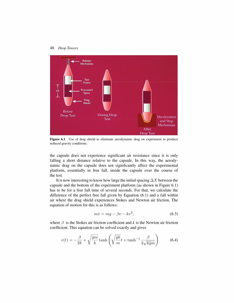
48 Drop Towers
Figure 6.1 Use of drag shield to eliminate aerodynamic drag on experiment to producereduced gravity conditions.
the capsule does not experience significant air resistance since it is onlyfalling a short distance relative to the capsule. In this way, the aerody-namic drag on the capsule does not significantly affect the experimentalplatform, essentially in free fall, inside the capsule over the course ofthe test.
It is now interesting to know how large the initial spacing ΔX between thecapsule and the bottom of the experiment platform (as shown in Figure 6.1)has to be for a free fall time of several seconds. For that, we calculate thedifference of the perfect free fall given by Equation (6.1) and a fall withinair where the drag shield experiences Stokes and Newton air friction. Theequation of motion for this is as follows:
mv = mg − βv − kv2, (6.3)
where β is the Stokes air friction coefficient and k is the Newton air frictioncoefficient. This equation can be solved exactly and gives
v(t) = − β
2k+
√gm
ktanh
(√gk
mt + tanh−1 β
2√
kgm
)(6.4)

6.5 Drop Tower Systems 49
where g := g(1 + β2
4kmg
). This is the velocity of the drag shield as function
of time. The terminal velocity is v∞ := limt→∞ v(t) = − β2k +
√gmk from
which we recover the well-known cases for β → 0 and k → 0. For the positionof the drag shield, we then obtain
x(t) = − β
2kt +
m
kln
(√1 − β2
4kgmcosh
(gk
mt + tanh−1 β
2√
kgm
))(6.5)
The spacing between the drag shield and the free flyer (test frame) then isΔx(t) = 1
2gt2 − x(t). An expansion for short times gives
Δx(t) =βg
6mt3 +
g2k
12m
(1 − β2
2gkm
)t4 + σ(t5). (6.6)
The maximum possible time of flight is given by Δx(tmax) = ΔX . The resultdepends on the coefficients β and k which also depend on the air viscosity andthe geometry of the drag shield. According to this result, most ground-baseddrop facilities are only designed to provide short durations of reduced gravitysince the spacing required for long drops becomes much larger as drop timeincreases.
6.5 Drop Tower Systems
As drop towers permit entire experimental systems/platforms to be dropped,they can vary considerably in their size ranging from small drop corridors(of about 1 m diameter) to very large dimensions (of several meters indiameter). A drop tower facility, in general, will consist of (a) a drop corridorwithin which the experiment resides during the period of reduced gravity,(b) experimental system(s) mounted on an experimental rack unique to thephenomena being investigated and the facility the test is to be conducted in,(c) some method to produce reduced gravity conditions for the experimentalplatform, (d) a lifting mechanism for the experimental platform, (e) a holdingand release mechanism for the experimental platform, (f) a decelerationdevice to stop the experimental package at the conclusion of a test, and (g)space to prepare experiments and interact with/provide access to the dropcorridor.
The drop corridor is the vertical extent within which the experiment isdropped to obtain free fall conditions. Access to the drop corridor is necessary

50 Drop Towers
at some location to allow the experiment to be inserted and removed, asrequired, and this often is associated with a laboratory area for researchersto prepare their experiments. Typically, access to the experiment within thedrop corridor is provided at the start of the test. In an evacuated system suchas in a drop tube, special considerations are often necessary to ensure thevacuum level in the drop corridor is not lost as the experimental system ismoved into the drop corridor. The experimental system is used to contain allaspects of the test being conducted. As the experiments are typically in freefall within the drop corridor, all aspects (power, data and image acquisition,device controllers, switches, etc.) of the testing are performed remotely afterthe test is initiated (dropped). In the case of a system utilizing a drag shield,the experiment must be loaded into the drag shield and the resulting packagereadied for (and recovered from) the drop corridor as a single item. If required,a lifting mechanism is utilized for raising (pretest) or recovering (post-test) theexperiment and/or experiment and drag shield. At the initiation of a test, theexperiment (and drag shield, if used) must be held and released, as required,consistent with the facility requirements for test initiation. One of the most crit-ical things during test initiation is the minimization of any unwanted vibrations(g-jitter) that may be imparted to the experiment as this unwanted accelerationcan, depending upon the experiment, detrimentally affect the results. At theconclusion of a drop test, a deceleration device is essential to bring theexperimental system (and drag shield, if used) to a controlled stop in a safefashion.
6.5.1 Guided Motion
An alternative to the basic drop tower configuration described above isprovided by a “guided motion” drop system. In a guided motion drop system,there is no need for a drag shield as the experiment is contained in a capsulethat is then propelled downward at an acceleration of 1 g. The guided motionof the capsule is typically obtained by rail guides and/or levitated drivedevices (similar to high-speed trains). By matching the Earth’s gravitationalacceleration, the capsule is essentially in free fall and in a 0 g environment.The matching of the capsules’ acceleration to Earth’s gravity vector is nor-mally accomplished by having the capsule move along a predefined velocityprofile (easily derived through the use of Equation 6.1). Since the velocity(and, therefore, the associated distance travelled) increases significantly withtime, these facilities are typically limited to between 5 and 10 s of testtime.

6.6 Enhanced Technologies 51
6.6 Enhanced Technologies
Several technologies are used to further increase either the duration (time) orquality (level of reduced gravity) of the test environment within the systemsdescribed above and are presented here.
6.6.1 Free Flyer System
Precise experiments often require an enhanced environment which sometimesexceeds the given quality level of reduced gravity in an evacuated drop tubeor in a drag shield. In general, the quality of reduced gravity depends on theresidual air pressure present. These drop systems will typically have severalhundreds up to a few thousands of cubic meters of air to evacuate. Froman operational point of view, since the vacuum pumps utilized have limitedpump speeds, there will often remain a pressure of a few mbar in the dropcorridor. For the drop tower Bremen, there is about 0.1 mbar present thatallows excellent microgravity conditions of about 10−6 g to be produced. Inorder to further reduce the gravity level for special precision experiments,a free flyer system is applied [1]. The concept of the free flyer is based onthe utilization of a drag-shielded experiment as previously described whichis dropped inside an evacuated drop tube. In this application, the free flyersystem effectively minimizes residual disturbances being caused by the low-level aerodynamic drag still present. At the drop tower Bremen, experimentsutilizing the free flyer system can achieve reduced gravity conditions ofabout 10−7 g.
6.6.2 Catapult System
An increase in the time of reduced gravity available in a drop tower canobviously be obtained by simply building a higher drop tower or longer dropshaft. Due to the fact that, however, the time of reduced gravity available is afunction of the distance dropped to the ½ power (Equation 6.2), construction ofdrop towers or drop shafts does not seem to be very economical after reachinga certain drop distance. A less utilized approach that essentially doubles thetest time for a given drop distance is to catapult the experiment upward fromthe bottom of the drop corridor to make both the way up and the way downavailable (this is an especially attractive option in an existing drop facility sinceno further height is required). Although the experiment is initially acceleratedafter its detachment from the acceleration unit (i.e., the catapult), it performsa free fall in a vertical parabola (comparable to parabolic flights). Either in an

52 Drop Towers
evacuated drop tube or in a drag shield configuration, a catapulted experimentbecomes a free-falling body and is weightless.
Accelerating an experiment capsule carrying hundreds of kilograms ofpayload requires a powerful drive coupled with precise control and handlingof the capsule movement which is essential during the acceleration phase andto ensure exact capsule alignment during the flight phase within the confinesof the drop corridor.At the moment, the drop tower Bremen is the only ground-based facility with a catapult system [2]. This world unique catapult system isinstalled in a chamber below the basement and utilizes a combined hydraulic–pneumatic drive to accelerate an experimental capsule (with a total mass ofover 400 kg) to the top of the evacuated drop tube on a vertical parabola. Thepressure difference between the vacuum level present inside the drop tubeand the compressed air below the catapult piston (stored in pressurized airtanks) is utilized as the driving force of the catapult system. The accelerationlevel of the catapult (with up to 30 g’s achieved within about 300 ms) isadjustable by a servo-hydraulic braking system that provides smooth controlof both the overall piston velocity and the final transition of the experimentto microgravity at release. Typically, an experimental capsule will leave thecatapult system with a lift-off speed of the about 48 m/s at 10−6 g with minimalvibration from the catapult.
6.6.3 Next-Generation Drop Towers
Drop facilities represent an important economic alternative with straightfor-ward and permanent access to weightlessness on Earth in comparison withthe other possible flight opportunities. In recent years, numerous demandsof higher repetition rates for experiments under weightlessness have beenobserved at the available ground-based facilities. The reasons are, on the onehand, that current experiments become more and more complex and theyrequire, therefore, higher repetition rates to generate the specific number ofexperiment parameters for their success. On the other hand, experiments needreliable statistics in their experimental results which have been achieved so far.Both scientific aspects and additionally the continuous technological progressin the present experiment developments (i.e., fully autonomous computeroperations) lead to a magnitude of demand that exceeds the given capabilitiesafforded by existing drop facilities. The limiting factors of achieving higherrepetition rates and thus laboratory-closed conditions at the present dropfacilities include the time it takes to evacuate the drop tube and experimentcapsule recovery and preparation for the next drop. At the drop tower Bremen,
6.6 Enhanced Technologies 53
a second drop facility is currently planned which offers repetition rates of over100 experiments per day in a semi-continuous laboratory operation. This next-generation drop tower system, the so-called GraviTower Bremen, combinesthe technological benefits of the catapult system of the drop tower Bremenwith a guided electromagnetic linear drive. The new facility concept is basedon the operation of a commercial elevator in which the distance betweenpassenger (i.e., the experimental payload a free flyer) and cabin walls (dragshield) is actively regulated. After each initial acceleration, and subsequentdetachment, the experimental payload becomes a free-flying body and isweightless. In order to smoothly accelerate and decelerate an experimentalpayload of several hundred kilograms on a vertical parabola in such a guidedcatapult system, it is essential to work with a both powerful and preciselycontrollable drive.An electromagnetic linear drive commonly utilized in rollercoasters represents a commercially available and well-tested solution for thesemi-continuous experiment operation. As currently planned, the GraviTowerBremen will have a height of about 70 m and will provide fall durations of6 s at microgravity conditions. The different free fall durations will dependon the selectable acceleration/deceleration drive mode with a range availablebetween 1.5 and 4.0 g. Only very low initial experiment disturbances areexpected during the acceleration phase. The accuracy in power and control ofthe applied electromagnetic linear drive allows also a novel operation modewith a fixed “free flyer.” In this case, experiments under partial gravity (atgravity levels from 0.1 to 0.4 g with an expected accuracy of 10−2 g) canbe conducted. The duration of partial gravity available at the GraviTowerBremen ranges from 5.5 to 7.8 s and depends on both the partial g-level anddrive mode selected. Finally, the dimensions of the GraviTower’s free flyerare planned to handle much larger volume and mass than in other existingfacilities.
6.6.3.1 Ground-based facility’s typical operational parametersIn the characterization of a ground-based facility, four factors are most sig-nificant: test time, magnitude of reduced gravity (quality), size of experimentthat can be accommodated, and cost. Other parameters are sometimes con-sidered such as facility location, deceleration experienced at test conclusion,and technical assistance available. These characteristics are function of thefacility being considered and the methodology it uses to produce the reducedgravity. Examples of these characteristics are provided and contrasted inTable 6.1.

54 Drop Towers
Tabl
e6.
1C
hara
cter
istic
sof
ala
rge
and
asm
allg
roun
d-ba
sed
redu
ced
grav
ity
Faci
lity
Loc
atio
nTe
stT
ime
(s)
g-L
evel
(g’s
)A
ppro
xim
ate
Size
ofE
xper
imen
tA
ppro
xim
ate
Cos
t
Dec
eler
atio
nL
evel
atTe
stC
oncl
usio
n
ZA
RM
Bre
men
,G
erm
any
4.7
or9.
3(w
ithca
tapu
lt)
10−
6/1
0−7
(with
free
flyer
)
Cyl
.:up
to0.
8m
dia.
,up
to1.
7m
long
,ab
out3
00kg
(dif
fere
ntex
p.ca
psul
es)
Var
ies
Up
to50
g(t
ypic
al40
g)
NA
SAC
leve
land
,U
SA5.
210
−6
Cyl
.:up
to1
mdi
a.,
upto
1.6
mhi
gh,u
pto
455
kg(i
ncl.
drop
vehi
cle)
Var
ies
upto
65g
(mea
n35
g)
NM
LB
eijin
g,C
hina
3.6
10−
3/1
0−5
(with
free
flyer
)
Var
ies
Var
ies
15g
QU
TB
risb
ane,
Aus
tral
ia2.
010
−4–1
0−6
Cyl
.:0.
9m
dia
×1.
5m
long
€40
0–€
600
15–2
0g
’sfo
r∼0
.25
s

6.7 Research in Ground-Based Reduced Gravity Facilities 55
6.7 Research in Ground-Based Reduced Gravity Facilities
There are many scientific discipline areas that currently use ground-basedfacilities to produce reduced gravity test conditions to study relevant phenom-ena. A short description of some of the work being conducted is presented.
6.7.1 Cold Atoms
Quantum objects show interference: If a beam of quantum objects is splitcoherently and the two beams are moving along different paths, then afterrecombination of both beams, interference will occur. The interference patternis influenced by external influences like acceleration or rotation of the wholeinterferometer or by the influence of other external forces. The important issueis that the effect on the interference scales with the square of the time the atomsmove within the interferometer. While on ground, the atoms will fall down thetable within a tenth of a second, we can increase the time if the interferometerwill fall together with the atoms. In a free fall environment, interferometersbecome much more sensitive. Since after a few seconds, the coherence of thetwo beams disappears due to imperfect isolation against disturbances, droptowers are currently ideal facilities to perform such experiments [3, 4]. Afuture goal of this ground-based work is to bring cold atoms to space, that is,on the ISS or on dedicated spacecraft. This work supports fundamental physicsexperiments such as quantum tests of the equivalence principle, tests of thelinearity of quantum mechanics, or practical applications such as geodesy andEarth sciences.
6.7.2 Combustion
Combustion experiments in many diverse areas are being studied. Somestudies are aiming at a thorough investigation of the self-ignition of droplets ofdifferent types of fuel, including modern biofuel of the second generation [5].These investigations form the foundations of the understanding of the physicalprocesses underlying spray ignition needed for efficient and ecologicallycompatible combustion. The unique heterogeneous (liquid phase) burning ofbulk metallic materials in oxygen-enriched atmospheres is also being studiedwith specific applications to fire safety and fundamental combustion science[6, 7]. For these experiments, weightlessness is of big advantage because(i) convection then does not occur, (ii) the system is simplified due to thespherical symmetry of the liquid-phase droplets, and (iii) one can study largerdroplets which often permit a more detailed observation of the processes

56 Drop Towers
being studied. One main result from the obtained data is input to assistthe development of a computer simulation for the detailed study of thecomplete spray ignition process. This has a big impact on the constructionof energetically efficient and ecologically compatible engines.
6.7.3 Fluid Mechanics/Dynamics
It is obvious that fluids behave differently according to whether gravity ispresent or not. One effect is related to the surface tension which makes itpossible, in the absence of gravity, for large liquid balls to be formed. Anothereffect is related to capillarity: For very weak gravity, the effect of adhesionof water at surfaces becomes dominant with the effect that a fluid will movealong surfaces. A particular topic being investigated is the behavior of freesurfaces [8]. Such an effect can be used for propellant management devicesor life support systems in satellites.
Special topics under investigation include multiphase systems and cryo-genic fluids including the capillary channel flow (CCF) project, a two-phasesystem which has been utilized under microgravity conditions on the ISS andwhich required a significant number of preparatory investigations conductedin drop tower experiments [9, 10]. Cryogenic propellants will be used in theAriane V upper stage; therefore, it is very important to explore the behaviorof these fluids in microgravity to elucidate the underlying physical principles.These principles will be used to develop a computer simulation tool for theconstruction of thrusters.
Another active area of research is related to the investigation of boiling andheat transfer under microgravity conditions [11]. Novel configurations of bub-ble suspensions and heat transfer mediums (some incorporating nanoparticlesuspensions) are created to study coalescence, phase change dynamics, andheat exchange in general in a turbulent medium under controlled conditions.This combines the physics of two-phase flows and thermal control whichhas importance for technology applications in both space and terrestrialapplications.
6.7.4 Astrophysics
A main task of the experiments supporting astrophysics work is to determineparameters needed to estimate the characteristic time for the formation ofplanets, moons, and other solar system objects [12]. In particular, studies areconducted about the conditions under which elastic and inelastic scattering ofdust particles, granular particles, small ice particles, or others occurs to form

6.7 Research in Ground-Based Reduced Gravity Facilities 57
larger constituents (agglomeration). This phenomenon depends on the sizeand mass of the particles, their temperature, etc. Other external influences,such as light or thermal radiation, are also being investigated. Microgravityexperiments revealed that the surface of Mars is efficient in cycling gas throughlayers, at least centimeters above and below the soil, with a turnover time ofonly seconds to minutes [13]. Clearly, such experiments must be conductedunder microgravity conditions to properly simulate the conditions in space—planets and other objects that form under weightlessness condition. Besidesthis type of experiment’s relevance to planetary sciences, this work may alsohave impact on material sciences, in particular, on the physics of granularmaterials.
6.7.5 Material Sciences
Particular problems in the area of material sciences such as the physics ofgranular gases, synthesis of nanomaterials, or the transport of fluids in porousmaterials are also being studied in microgravity environments. One aspect is todiscover fundamental properties and synthesis pathways within these systemswhich are relevant for producing novel materials not able to be synthesizedin normal gravity and supporting theoretical/statistical descriptions of thesesystems (and/or validating corresponding numerical simulations) [14, 15].Another application of this work is for the transport of granular gases and ofthe transport of fluids through granular or porous media which has indus-trial applications including satellite technology. For satellite technologies,cryogenic fluids must be considered and properly characterized. This workis conducted in microgravity conditions in order to explore the fundamentalphysical principles without the disturbing gravitational force. The impact andrelevance for industrial applications is obvious.
6.7.6 Biology
The experimental study of biological systems under microgravity or reducedgravity is in some cases of general interest but mainly for applications inspace, on Moon, or on Mars to better understand how do organisms behaveand how the nervous system reacts. In drop towers, only phenomena occurringon a short timescale can be investigated and this tends to limit biologicalapplications. This includes the general behavior of microorganisms or theinfluence of microgravity on the orientation capabilities of complex organisms[16]. This work supports a better understanding of the general functioning ofthe nervous system but also is very important for estimating the reaction of life

58 Drop Towers
during long space travel or for its behavior under variable gravity conditions(Moon, Mars, etc.).
6.7.7 Technology Tests
Drop towers are also used for technology tests to operate and validate varioussystems prior to deployment in operational environments. Examples are testsof the behavior of heat pipes, the performance of accelerometers, or thefunctioning of release mechanisms. The full performance of high-precisionaccelerometers can only be explored under weightlessness conditions. Atthe drop tower Bremen, testing is conducted in support of the differentialaccelerometers for the French mission MICROSCOPE, aimed at testing theuniversality of free fall (also called weak equivalence principle), with anaccuracy of 10−15, which is two orders of magnitude better than what ispossible on Earth. The accelerometers, built by ONERA in Paris, have aperformance of 10−14 m/s2/sqrt(Hz). For these accelerometers, the catapult ofthe Bremen drop tower with a free fall time of almost 10 s is used [17]. Also,the accelerometers to be used in the GRACE Follow-On geodesy mission willbe tested in the Bremen drop tower.
Another technology validation program is the asteroid lander MINERVA(MIcro/Nano Experimental Robot Vehicle for Asteroid) of the JapaneseHayabusa 2 mission tested in the Bremen drop tower. The actual mechanismfor taking soil samples that are planned to be brought to Earth has been testedand validated for functionality. In addition, the functioning of the releasemechanism of mobile lander MASCOT (Mobile Asteroid Surface Scout) hasbeen proven in the Bremen drop tower as cooperation projects between theGerman Aerospace Center DLR and the Japanese space agency JAXA. Alast example of technology validation would include the tests of the heatpipes designed to cool the eROSITA camera system at a temperature of–95 ◦C. The validation testing demonstrated that the heat pipe system that wasbased on capillary forces is working very well and should perform well oncedeployed.
References
[1] Selig, H., H. Dittus and C. Lämmerzahl. “Drop Tower MicrogravityImprovement Towards the Nano-g Level for the MICROSCOPE PayloadTests”. Microgravity Science Technology 22 (2010): 539.

References 59
[2] von Kampen, P., U. Kaczmarczik and H.J. Rath. “The New Drop TowerCatapult System”. Acta Astronautica 59 (2006): 278.
[3] van Zoest, T. et al. “Bose–Einstein Condensation in Microgravity”.Science 328 (2010): 1540.
[4] Müntinga, H. et al. “Interferometry with Bose Einstein Condensates inMicrogravity”. Phys. Rev. Lett. 110 (2013): 093602.
[5] Burkert, A., W. Paa, M. Reimert, K. Klinkov and C. Eigenbrod.“Formaldehyde LIF Detection with Background Subtraction AroundSingle Igniting GTL Diesel Droplets”. Fuel 111, no. 8 (2013).
[6] Lynn, D.B., O. Plagens, M. Castillo, T. Paulos and T.A. Steinberg.“The Increased Flammability of Metallic Materials Burning in ReducedGravity”, In Proceedings of the 4th International Association forthe Advancement of Space Safety Conference: Making Safety Matter,ESA-SP Volume 680, (2010), pp. 1–7.
[7] Ward, N.R. and T.A. Steinberg. “Iron Burning in Pressurised OxygenUnder Microgravity Conditions.” Microgravity Science and Technology21, no. 1–2 (2009): 41–46.
[8] Diana, A., M. Castillo, D. Brutin and T. Steinberg. “Sessile Drop Wet-tability in Normal and Reduced Gravity”. Microgravity Science andTechnology 24, no. 3 (2012): 195–202.
[9] Canfield, P.J., P.M. Bronowicki, Y. Chen, L. Kiewidt, A. Grah, J. Klatte,R. Jenson, W. Blackmore, M.M. Weislogel, and M.E. Dreyer. “TheCapillary Channel Flow Experiments on the International Space Sta-tion: Experiment Set-Up and First Results”. Experiments in Fluids 54,no. 1519 (2013): 1.
[10] Conrath, M., P.J. Canfield, P.M. Bronowicki, M.E. Dreyer, M.M. Weis-logel and A. Grah. “Capillary Channel Flow Experiments Aboard theInternational Space Station”. Physcal Review E 88 (2013): 063009.
[11] Diana, A., M. Castillo, T.A. Steinberg and D. Brutin. “AsymmetricInterface Temperature During Vapor Bubble Growth”. Applied PhysicsLetters 103, no. 3 (2013).
[12] Blum, J. “Astrophysical Microgravity Experiments with Dust Particles”.Microgravity Science Technology 22 (2010): 51.
[13] de Beule, C., G. Wurm, T. Kelling, M. Kuepper, T. Jankowski andJ. Teiser. “The Martian Soil as a Planetary Gas Pump”. Nature Physics10 (2014): 17.
[14] Bánhidi V., and T.J. Szabo. “Detailed Numerical Simulation of Short-Term Microgravity Experiments to Determine Heat Conductivity ofMelts”. Materials Science Forum 649 (2010): 23.

60 Drop Towers
[15] Hales, M.C., T.A. Steinberg and W.N. Martens. “Synthesis and Char-acterization of Titanium Sol–Gels in Varied Gravity”. Journal ofNon-Crystalline Solids 396–397 (2014): 13–19.
[16] Anken, R. and R. Hilbig. “Swimming Behaviour of the Upside-Down Swimming Catfish (Synodontis nigriventris) at High-QualityMicrogravity—A Drop-Tower Experiment”. Advances in SpaceResearch 44 (2009): 217.
[17] Seilg, H. and C. Lämmerzahl. “Sensor Calibration for theMICROSCOPE Satellite Mission”. Advanced Astronomical Science 148(2013).

7Parabolic Flights
Vladimir Pletser1 and Yasuhiro Kumei2
1ESA-ESTEC, Noordwijk, The Netherlands2Tokyo Medical and Dental University, Tokyo, Japan
7.1 Introduction
Aircraft parabolic flights are useful for performing short-duration scientificand technological experiments in reduced gravity. Their principal value isin the verification tests that can be conducted prior to space experiments inorder to improve their quality and success rate, and after a space missionto confirm (or invalidate) results obtained from space experiments. Parabolicflight experiments might also be sufficient as stand-alone, addressing a specificissue.
The levels of reduced gravity that can be attained during parabolic flightsvary between 0 and 1 g (where g is the acceleration created by gravity atEarth’s surface, on average 9.81 m/s2). Near weightlessness at micro-g (μg)levels is commonly achieved during ballistic parabolic flights for microgravityresearch since more than 30 years. Recent years have seen more and moreemphasis on partial-g flight profiles allowing to obtain gravity levels similarto those on the Moon (0.16 g) and on Mars (0.38 g) to prepare for future spaceexploration.
This section introduces the objectives of parabolic flights for research andthe flight profiles to achieve µg and partial-g environments. The various air-planes used throughout the world to create these reduced gravity environmentsare introduced. These airplanes can be grouped in three categories: (1) largeairplanes allowing to embark several tens of passengers and several largeexperiments; (2) medium-sized airplanes usually used for single experimentwith several operators and/or subjects; and (3) small airplanes and jetsembarking single passengers and small experiments.
61

62 Parabolic Flights
7.2 Objectives of Parabolic Flights
A large aircraft in parabolic flight provides investigators with a laboratory forscientific experimentation where the g-levels are changed repetitively, givingsuccessive periods of either 0.38 g for up to 32 s, or 0.16 g for up to 25 sor µg for 20 s, preceded and followed by periods of 20 s at approximately1.8 g-level.
Parabolic flight objectives pursued by scientists are usually multifold:(1) to perform short experiments for which the reduced gravity is low enoughfor qualitative experiments of the “look-and-see” type, using laboratory-typeequipment to observe and record phenomena, and quantitative experimentsto measure phenomena in reduced gravity, yielding direct quantitativeexploitable results; (2) to allow experimenters to perform by themselves theirown experiments in reduced gravity with the possibility of direct interventionson the experiment in progress during the low g periods and direct interactionby changing experiment parameters between the reduced gravity periods; and(3) to study transient phenomena occurring during changeovers from high-to-low and low-to-high g-phases. Additionally, for space mission experiments,preliminary results can be obtained prior to a space mission and experimentswith conflicting results can be repeated shortly after a space mission, helpingin data interpretation. For space human physiology experiments on astronauts,a broader data baseline can be obtained in μg prior to or after a space missionby conducting parts of the space experiments on a group of subjects other thanastronauts.
From a technical point of view, in preparing experiment hardware formanned spaceflight or robotic missions, the following objectives can also beachieved: (1) test of equipment hardware in reduced gravity; (2) assessmentof the safety aspects of an instrument operation in reduced gravity; and(3) training of science astronauts to experiment procedures and instrumentoperation.
Furthermore, aircraft parabolic flights are the only suborbital carrier toprovide the opportunity to carry out medical and physiological experimentson human subjects in μg or partial gravity at Moon and Mars g-levels, toprepare for extraterrestrial planetary exploration.
Finally, other g-levels achieved during flights can be used by investigators:Pull-up and pullout maneuvers yield periods of hypergravity (from 1.8 g toseveral g’s); spiral turn maneuvers provide for longer periods of other levelsof high g’s.

7.3 Parabolic Flight Maneuvers 63
7.3 Parabolic Flight Maneuvers
For μg parabolic flights, the μg environment is created in a large aircraft flyingthe following maneuvers (see Figure 7.1, example given for the Airbus A300ZERO-G):
• from steady horizontal flight, the aircraft climbs at approximately 45◦(pull-up) (see Figure 7.2) for about 20 s with accelerations between 1.8and 2 g;
• all aircraft engine thrust is then strongly reduced for about 20 to 25 s,compensating the effect of air drag (parabolic free fall);
• the aircraft dives at approximately 45◦ (pullout), accelerating at about1.8 to 2 g for approximately 20 s, to come back to a steady horizontalflight.
Alternatively, for partial g parabolas, the engine thrust is reduced suffi-ciently to a point where the remaining vertical acceleration in the cabin isapproximately 0.16g for approximately 25 s or 0.38 g for approximately 32 swith angles at injection of 42◦ and 38◦, respectively, for Moon and Marsparabolas. These maneuvers can be flown consecutively (in a roller coastermanner) or separated by intervals of several minutes to allow investigators toprepare for their experiments.
For µg parabolas, the residual accelerations sensed by experimental setupsattached to the aircraft floor structure are typically in the order of 10−2 g, whilefor a setup left free floating in the cabin, the levels can be improved to typically10−3 g for 5 to 10 s.
Figure 7.1 Airbus A300’s parabolic flight maneuver (Credit: Novespace).

64 Parabolic Flights
Figure 7.2 The Airbus A300 in pull-up (Photo: Novespace - Eric Magnan/Airborne Films).
7.4 Large Airplanes Used for Parabolic Flights
Large airplanes used for parabolic flights are defined as those aircraft used forflying several (typically ten or more) experiments and embarking several tensof passengers, either for research purposes or for discovery reduced gravityflights for paying passengers.
7.4.1 Europe: CNES’ Caravelle and CNES-ESA’s Airbus A300ZERO-G
From 1988 till 1995, the European Space Agency (ESA) and the “CentreNational d’Etudes Spatiales” (CNES, French Space Agency) have used aCaravelle aircraft for several tens of campaigns [1].
From 1997 till 2014, the Airbus A300 ZERO-G was used in Europe byESA, CNES, and the “Deutsches Zentrum für Luft- und Raumfahrt e.V.,”DLR, the German Aerospace Center, and industrial users for µg and partial-gflights. The Airbus A300 was the largest airplane in the world used for thistype of experimental research flight.
Since 2015, an Airbus A310 is used to replace the A300 ZERO-G. TheFrench company Novespace, a subsidiary of CNES, based in Bordeaux,France, is in charge of the organization of Airbus A300 and A310 flights.
Prior to a campaign with an Airbus ZERO-G, space agencies and Noves-pace provide support in the experiment equipment design and in all relatedsafety aspects. All experiments are reviewed by experts several monthsbefore a campaign from the structural, mechanical, electrical, safety, andoperational points of view. Technical visits are made to the experimenters’institutions to review equipment. A safety review is held one month beforethe campaign. A safety visit is made in the aircraft prior to the first flight

7.4 Large Airplanes Used for Parabolic Flights 65
to verify that all embarked equipment complies with the safety standards.The campaign in itself takes place over two weeks. The first week is devotedto the experiment preparation and loading in the aircraft. During the secondweek, on the Monday, a safety visit takes place to assess that all safetyrecommendations have been implemented and a flight briefing is organized inthe afternoon to present the flight maneuvers, the emergency procedures andmedical recommendations, and the experiments on board. The three flightsof 30 parabolas each take place on the mornings of the Tuesday, Wednesday,and Thursday followed each time by a debriefing during which the needsand requests of investigators are reviewed and discussed. Due to bad weatheror technical problems, a flight can be postponed from the morning to theafternoon or to the next day. Downloading of all experiments takes place onthe afternoon after the last flight.
A typical flight duration with the Airbus ZERO-G is about two and halfhours, allowing for 30 parabolas to be flown per flight, in sets of five withtwo-minute intervals between parabolas and with four to six minutes betweensets of parabolas. Parabolas are flown in dedicated air zones over the Gulf ofBiscay or the Mediterranean Sea.
Since 1984, a total of 132 European campaigns were performed (61 ESA,48 CNES, 23 DLR) for more than 1500 selected experiments in humanphysiology and medicine, biology, physics, astrophysics, technological tests,and launcher technology proposed by researchers and students [2–5] (seeFigure 7.3). In addition to µg campaigns, two joint European partial-gcampaigns were organized by ESA, CNES, and DLR in 2011 and 2012 forexperiments at μg and lunar and Martian gravity levels [6].
Figure 7.3 Experimenters during µg parabolic flights on the airbus A300 (Photograph ESA).
66 Parabolic Flights
Since 2013, the Airbus A300 and A310 ZERO-G are used for discoveryflights open to the public.
7.4.2 USA: NASA’s KC-135, DC-9 and Zero-G Corporation
A review of the aircraft used by NASA for parabolic flights since the early1950 is given in [6].
NASA has operated several KC-135 aircraft (modified Boeing 707 jetaircraft) for reduced gravity research and astronaut training. The KC-135A/930, named “Weightless Wonder IV” (and nicknamed “Vomit Comet”),was the longest operated aircraft (1973–1995) [7]. ESA used the KC-135Aaircraft for its first six µg research campaigns (1984–1988) [8], and DLR con-ducted nine campaigns (1987–1992) in preparation for the German SpacelabD2 mission. The replacement aircraft, the KC-135A/931, was used until itsretirement in 2004 [9].
NASA operated also a DC-9 to allow researchers to perform their exper-iments in a reduced gravity environment. A flight lasts typically 2.5 h,with 40–60 parabolas, during which µg and partial gravity levels (0.16,0.38 g) and sustained hyper-g (1.6 g) can be achieved according to researcherrequirements [10].
The private company Zero Gravity Corporation operated a modifiedBoeing 727-200, named “G-FORCE ONE” in the USA from 2004 until2014 for discovery flights open to the public. NASA had a microgravityservice contract with Zero Gravity Corporation from 2008 until 2014 to flyNASA’s sponsored experiments [11]. The flight maneuver is quite similar tothe one described in earlier sections. From an horizontal flight at an altitudeof approx. 8000 m, the pull-up up to 1.8 g lasts about 10 to 17 s up to analtitude of approx. 11300 m, and the aircraft is injected into the parabola for aduration of approx. 20 s until the pullout takes place. A flight includes 12–15parabolas for public discovery flights or 25–40 parabolas for research flights.Moon-g and Martian-g flight maneuvers can also be performed [12].
7.4.3 Russia: Ilyushin IL-76 MDK
The Ilyushin IL-76 MDK (MDK stands for “latest modifications” in Russian)is a four-jet-engine cargo aircraft of the last modified version [13] and operatedby the Russian Yu. Gagarin Cosmonaut Training Centre (CTC) from StarCity near Moscow and used for parabolic flights for astronaut training, spaceequipment tests, and paying passenger flights. The main aircraft features arethe double-floor cockpit and a large cabin, separated into two parts: The front

7.5 Medium-Sized Airplanes Used for Parabolic Flights 67
includes several work stations for experimenters conducting tests on largeequipment, while the aft part is an empty cabin space with attachment pointson the cabin floor. ESA and DLR conducted parabolic flight campaigns withthis aircraft in 1992 and 1994 [14]. The Ilyushin IL-76 MDK is marketed sincethe nineties by several private operators for discovery flights open to the public.
7.5 Medium-Sized Airplanes Used for Parabolic Flights
Medium-sized airplanes are defined as those aircraft used for flying singleexperiments with several operators and/or subjects.
7.5.1 Europe: TU Delft-NLR Cessna Citation II
The Cessna Citation II is a twinjet aircraft, a research aircraft owned andoperated jointly by the Technology University of Delft and the Dutch NationalAerospace Laboratory in the Netherlands. It has been extensively modified toserve as a versatile airborne research platform. The flight envelope with amaximum altitude of more than 13 km allows a wide range of operations tobe performed, including flying at quite low speeds. It can accommodate amaximum of eight observers in addition to the two-pilot cockpit crew [15].Among other research flights, it is used for aerospace student practical training,for parabolic flights for single experiments, and for discovery flights open tothe public.
7.5.2 Canada: CSA Falcon 20
The Falcon 20 is a twin-engine business jet, capable of relatively high-speedand altitude operations with a small complement of instrumentation andresearch crew. It had been modified for μg experiments requiring parabolicflight trajectories [16]. The aircraft, owned and operated by the NationalResearch Council’s Institute for Aerospace Research (NRC/IAR), was useduntil 2014 by the Canadian Space Agency (CSA) for Canadian investigators.
7.5.3 Japan: MU-300 and Gulfstream-II
In Japan, a MU-300 jet aircraft operated by Diamond Air Service since 1990[18] provides parabolic flights with up to 20 s of weightlessness. Besidescreating conventional µg conditions, the parabolic flight using this MU-300has many advantages. Since only one or two research themes are conducted inthis medium-sized aircraft, the flight maneuver can be customized flexibly so

68 Parabolic Flights
as to make the most suitable condition for the study. Experiments have beenconducted on rodents and cell cultures since 2007, using not only Martian(0.38 g) and lunar (0.16 g) gravity levels but also 0.6, 0.5, 0.4, 0.3, 0.2, 0.1,and 0.05 g [19]. Other unique studies were also realized by using partialgravity conditions [20, 21]. A set of original parabolic trajectories was usedto avoid interference of the “pull-up” phase-induced hypergravity into thegenuine response to low gravities. After a certain time in the 1 g-level flight,the aircraft enters into the “pull-up” phase that lasts approximately 20∼40 sat 1.3 g, followed by a sudden descent that generates a target partial gravitycondition lasting 15∼40 s and then pulls up again into the “recovery” phasethat lasts 20 s at 1.3 g (see Figure 7.4).
Diamond Air Service operates also a jet aircraft “Gulfstream-II” since1996 in Nagoya. The cockpit crew includes two pilots and one engineerwho support the in-flight experiments. A total of 5.5-hour flight is possible
Figure 7.4 Typical µg flight trajectories of the Gulfstream-II (top) and the MU-300 (bottom)(Credit: Diamond Air Service).

7.6 Small Airplanes and Jets Used for Parabolic Flights 69
with 5 or 6 researchers and up to 2.4 t of payload. To date, a total of1480 flights with MU-300 and 350 flights with Gulfstream-II have beenconducted so far, and 845 studies have been accomplished with JAXAsupport.
7.5.4 Other Aircraft
Ecuador: The Ecuadorian Air Force (FAE) and the Ecuadorian Civilian SpaceAgency (EXA) adapted jointly T-39 Sabreliner to perform µg parabolic flights[22]. In 2008, two flights took place and a fluid experiment was performed.
Austria: The company Pauls Parabelflüge organized since 2002 a series offlights in Germany, Austria, and Slovakia with several medium-sized aircraft(Casa 212, Short Skyvan SC7, Cessna Grand Caravan, Let 410) and recentlywith a glider (SARA-Mercury) yielding parabolas of 10 to 15 s of µg fordiscovery flights for paying passengers and students [22].
7.6 Small Airplanes and Jets Used for Parabolic Flights
Small airplanes and jets used for parabolic flights are defined as those aircraftused for flying single passengers and small experiments.
7.6.1 Switzerland: Swiss Air Force Jet Fighter F-5E
A jet fighter F-5E Tiger II aircraft was used in Switzerland from EmmenAir Force Base for biological research contained in a small experimentalapparatus installed in the cannon ammunition box [23]. The military fighterjet aircraft Northrop F-5E “Tiger II” is a light supersonic fighter aircraftwith two axial straight turbines, able to reach a maximum speed of Mach1.64, with a maximum climb rate of 571 ft/s and a maximum altitude of51,800 ft.
Single parabolas of up to 45 s are executed during military training flights(see Figure 7.5). After a 1 g control phase, the parabolic maneuver starts at13,000 ft. and at Mach 0.99 airspeed, with a 22-s climb with an accelerationof 2.5 g up to an angle of 60◦ at an altitude of 18,000 ft., followed by afree fall ballistic trajectory lasting 45 s of 0.05 g in all axes with an apogeeof 27,000 ft. at Mach 0.4 airspeed. The pullout is initiated when the aircraftreached 60◦ nose down with an acceleration of 2.5 g (up to 3.5 g) and lasts forapproximately 13 s. Access time is 30 min before takeoff, and retrieval timeis 30 min after landing.

70 Parabolic Flights
Figure 7.5 The F-5E Tiger II jet fighter aircraft and parabolic flight characteristics (from[22]).
7.6.2 Other Aircraft
Spain: In Barcelona, the Universitat Politecnica de Catalunya with the AeroClub Barcelona Sabadell proposes since 2007 parabolic flights on board aMudry Cap10B aircraft, a two-seat training aerobatic aircraft. Up to tenparabolas of 5 to 8 s of µg each, with pull-ups and pullouts up to 3.5 g, canbe performed by researchers and students with small experiments (typically30 × 20 × 20 cm, max. 10 kg).
Belgium: In the early 1990s, a two-seat Fouga Magister from the Brustembase of the Belgian Air Force was used, as part of aerobatics training, toperform parabolic flights of duration between 15 and 24 s. It was used toconduct fluid physics and technology development experiments from theUniversity of Brussels [24].
7.7 Conclusions
Aircraft parabolic flight maneuvers are a very useful tool to investigategravity related phenomena, whether in complete weightlessness or at partial-g levels. As any small or large airplane could basically be used to undergo aparabolic trajectory, it is important to choose carefully which aircraft wouldbe best suited for scientific investigations, in terms of quality and durationof reduced gravity level but also ease of access and technical support fromthe integration team. In this respect, this section introduced the main aircraft

References 71
used throughout the world to conduct research in reduced gravity. This surveyis probably not exhaustive as no information could be obtained on similarparabolic flight program for reduced gravity research and practical trainingfrom emerging space-faring nations like China, India, Brazil, and possiblyother countries.
References
[1] Clervoy, J.F., J.P. Haigneré, V. Pletser, and A. Gonfalone. “Microgravitywith Caravelle.” Proceedings of the VIIth European Symposium Materi-als & Fluid Sciences in Microgravity, ESASP-295, Noordwijk, 685–691,1990.
[2] Pletser, V., D. Thiérion, and B. Boissier, eds. “Experiment Results of ESAand CNES Campaigns, Tenth Anniversary of First ESA Parabolic FlightCampaign.” ESA WPP-90, Noordwijk, 1995.
[3] Pletser, V. “Short Duration Microgravity Experiments in Physical andLife Sciences During Parabolic Flights: The First 30 ESA Campaigns”.Acta Astronautica 55 (2004): 829–854.
[4] Pletser, V., A. Pacros, and O. Minster. “International Heat and MassTransfer Experiments on the 48th ESA Parabolic Flight Campaign ofMarch 2008.” Microgravity Science and Technology, special Issue Two-Phase Systems 20 (2008): 177–182.
[5] Pletser, V., Pacros A., Minster O. “The ESA Parabolic Flight Pro-gramme for Physical Sciences.” 3rd International Symposium PhysicalSciences in Space (ISPS), Nara.” Journal Japan Society of MicrogravityApplication 25-3 (2008): 635–640.
[6] Pletser, V., J. Winter, F. Duclos, U. Friedrich, J.F. Clervoy, T. Gharib,F. Gai, O. Minster, and P. Sundblad. “The First Joint European Partial-gParabolic Flight Campaign at Moon and Mars Gravity Levels for Scienceand Exploration.” Microgravity Science and Technology, special IssueELGRA 2011, 24–6 (2012): 383–395.
[7] Gerathewohl, S.J. ed. “Zero-G Devices and Weightlessness Simulators.”Report for the Armed Forces—NAS-NRC Committee on BioastronauticsPanel on Acceleration, National Academy of Sciences USA, NationalResearch Council, Publication 781, 1961.
[8] “The History of KC-135A Reduced Gravity Research Program”,NASA/JSC Aircraft Operations website, http://jsc-aircraft-ops.jsc.nasa.gov/Reduced Gravity/KC 135 history.html, Last accessed 09/04/2013.

72 Parabolic Flights
[9] Frimout D., and A. Gonfalone. “Parabolic Aircraft Flights, an Effec-tive Tool in Preparing Microgravity Experiments.” ESA Bulletin 42,Noordwijk (1985): 58–63.
[10] “NASA/JSC Aircraft Operations: The History of KC-135A Re-duced Gravity Research Program.” http://jsc-aircraft-ops.jsc.nasa.gov/Reduced Gravity/KC 135 history.html. Last accessed 24/02/2013
[11] “About The C-9B Aircraft.” NASA/JSC Aircraft Operations website,http://jsc-aircraft-ops.jsc.nasa.gov/Reduced Gravity/about.html. Lastaccessed 24/02/2013
[12] “G-Force One, NASA/JSC Reduced Gravity Office with Zero GravityCorporation.” Nasa Flight Opportunities website, https://flightopportunities.nasa.gov/platforms/parabolic/gforce-one/, Last accessed 09/04/2013.
[13] “Zero-G Corporation: How it works.” Zero-G Corporation websi-te, http://www.gozerog.com/index.cfm?fuseaction=Experience.How itWorks, http://www.gozerog.com/index.cfm?fuseaction=Research Programs.welcome, Last accessed 24/02/2013
[14] “IL-76MD”, Ilyushin website, http://www.ilyushin.org/eng/products/military/76md.html, last accessed 09/04/2013.
[15] Pletser, V., and C. Cornuejols. “Micro-accelerometric measurementson board the Russian Ilyushin IL-76 MDK during parabolic flights”,Proceedings of the Joint ESA-CNES Workshop Experiment Results ofESA and CNES Parabolic Flight Campaigns, ESA WPP-090, 203–219,1995.
[16] “Cessna Citation Laboratory Aircraft.” TU Delft Aerospace Engineeringwebsite, http://www.lr.tudelft.nl/en/organisation/departments/control-and-operations/control-and-simulation/facilities-and-institutes/cessna-citation-laboratory-aircraft/, last accessed 09/04/2013.
[17] “Flight test and evaluation–Falcon 20.” NRC website, http://www.nrc-cnrc.gc.ca/eng/solutions/advisory/flight test.html, last accessed 09/04/2013.
[18] “Micro-Gravity Experiment.” DiamondAir Service website, http://www.das.co.jp/new html e/service/01-1.html, last accessed 09/04/2013.
[19] Zeredo, J.L., K. Toda, M. Matsuura, Y. Kumei. “Behavioral Responsesto Partial Gravity Conditions in Rats.” Neuroscience Letters 529 (2012):108–111.
[20] Zeredo, J.L., K. Toda, and Y. Kumei. “Neuronal Activity in the Subthala-mic Cerebrovasodilator Area Under Partial-Gravity Conditions in Rats.”Life 4 (2014): 107–116.

References 73
[21] Hasegawa, K., P.S. de Campos, J.L. Zeredo,Y. Kumei. “CineradiographicAnalysis of Mouse Postural Response to Alteration of Gravity and Jerk(gravity deceleration rate).” Life 4 (2014): 174–188.
[22] “EXA and FAE develops first Zero-G plane in Latin America.” AgenciaEspacial Civil Ecuatoriana website, http://exa.ec/bp16/index-en.html,last accessed 09/04/2013.
[23] “Astronautentraining/Schwerelosigkeit für Alle !!! ”, Pauls Parabelflügewebsite, http://www.bierl.at/, last accessed 09/04/2013.
[24] Studer, M., G. Bradacs,A. Hilliger, E. Hurlimann, S. Engeli, C.S. Thiel, P.Zeitner, B. Denier, M. Binggeli, T. Syburra, M. Egli, F. Engelmann, andO. Ullrich. “Parabolic Maneuvers of the Swiss Air Force Fighter Jet F-5Eas a Research Platform for Cell Culture Experiments in Microgravity.”Acta Astronautica 68 (2011): 1729–1741.
[25] Pletser V., P. Queeckers, O. Dupont, J.C. Legros. “Parabolic Flights withthe Fouga Magister aircraft.” Proceedings of the Joint ESA-CNES Work-shop Experiment Results of ESA and CNES Parabolic Flight Campaigns,ESA WPP-090, 221–231, 1995.


8Magnetic Levitation
Clement Lorin1, Richard J. A. Hill2 and Alain Mailfert3
1Mechanical Engineering Department, University of Houston,Houston, TX, USA2School of Physics and Astronomy, University of Nottingham,Nottingham, UK3Laboratoire Géoressources, CNRS-Université de Lorraine,Nancy, France
8.1 Introduction
To compensate gravity magnetically, one generates at all points within anobject—at the molecular scale—magnetic forces that counterbalance the forceof gravity. This form of magnetic levitation, distinct from levitation of aferromagnet or superconductor, or flotation, exploits the fact that a diamagneticor paramagnetic medium is subjected to a magnetic body force in a non-uniform magnetic field. Suitable magnetic field sources for levitation includewindings carrying continuous currents and in some cases permanent magnets.The first simulations of space conditions by levitation in fluids or biologi-cal systems were reported using water-cooled or superconducting magnets[1–4]. Magnetic compensation of gravity has many advantages compared toother ways to access weightlessness, such as unlimited experimentation time,ground-based experiments, and easily adjustable level of simulated gravity.It is the only way to directly compensate gravity at the molecular level,on the ground. Partial gravity compensation allows simulation of the grav-ity on Moon or Mars [5]. Here, we discuss the accuracy with whichone can compensate gravity using magnetic levitation, for fluids and forbiology.
75

76 Magnetic Levitation
8.2 Static Magnetic Forces in a Continuous Medium
8.2.1 Magnetic Forces and Gravity, Magneto-GravitationalPotential
Windings carrying electrical currents with a volume density J (A m−2) ormagnetized magnetic media [magnetization density M (A m−1)] generatea magnetic field of excitation H (A m−1). Experimentally, one measuresthe magnetic flux density B (T or Wb m−2). In free space, B = μ0H whereμ0 = 4π × 10−7 H m−1 is the vacuum permeability. The relations betweenthese quantities are, in stationary (time-independent) conditions, as follows:
curl (H) = J ; div (B) = 0 (8.1)
in a current-free domain:curl (H) = 0 (8.2)
A magnetic field H applied to any homogeneous material (solid or fluid)produces a magnetization density:
M (H) = χH . (8.3)
The dimensionless magnetic susceptibility χ can be positive (paramagnetism)or negative (diamagnetism). We will take into account non-hysteretic mediawith χ considered as a constant when the magnetic field varies. That is neitherferromagnetic media nor colloidal suspensions of particles, namely ferrofluids.
In these media, the flux density is as follows: B = μ0 (H + M ) =μ0 (1 + χ)H, where μ0(1 + χ) is the medium magnetic permeability.
The above relations give unique solutions for H and B, given distributionsfor J and M. However, the “designers” of a levitation magnet have to solvethe “inverse problem”: Which configurations of J and M can create givendistributions of H and B inside a finite 3D domain? This problem hasnumerous possible solutions.
A magnetic energy is associated with the magnetization that appears inmaterials. If the field H varies spatially, the magnetic energy varies spatially,too. A magnetic material is thus subjected to a volume force that can be writtenas follows:
fm =μ0
2χgrad(H2)
In materials that are considered for magnetic levitation, |χ| � 1, that is μ0(1 + χ)∼μ0. Therefore, the magnetic volume force can likewise be expressedas follows:
fm =1
2μ0χG (8.4)

8.2 Static Magnetic Forces in a Continuous Medium 77
Table 8.1 Order of magnitude of some fluid features for magnetic compensation of gravity
Fluid (P = 1 bar, g = 9.81 m s−2) O2 (90 K) H2 (20 K)H2O(293 K) He (4.2 K)
Magnetic susceptibility (10−6) +3,500 –1.8 –9.0 –0.74Density (kg m−3) 1,140 71 998 125G1 (T2 m−1) +8 –990 –2,720 –4,140
where G = grad (B2). The principle of magnetic gravity compensation is basedon relation (8.4). The magnetic force must be opposite to the force applied bygravity g (m s−2): fG = ρg.
Therefore, the condition of magnetic compensation at any point within amedium of susceptibility χ and density ρ is
grad(B2) = −2μ0ρ
χg = G1 (8.5)
where (χ/ρ) (m3 kg−1) is the mass susceptibility. It is also useful to considerthe total resulting potential energy ΣL (J m−3), named magneto-gravitationalpotential (MG potential), at a given height z (m) [3].
ΣL =χB2
2μ0− ρgz
From relation (8.5), Table 8.1 gives some algebraic values of G1 neededto compensate gravity for various fluids commonly used in aerospaceengineering.
8.2.2 Magnetic Compensation Homogeneity
There is a fundamental constraint for magnetic compensation of gravity.A given B distribution leads to a unique force distribution, but an arbitraryforce distribution cannot be obtained. Indeed, in a 3D domain, small withrespect to the size of Earth, the terrestrial acceleration is independent ofposition, that is G should be uniform to satisfy (8.5). Since magnetic fluxdensity B obeys (8.1) and (8.2), G cannot be simultaneously nonzero anduniform in the whole 3D domain [6]; it follows that it is impossible to obtainperfect compensation of gravity at every point in space! However, there existmagnetic field distributions where compensation is perfect in several points,or along a vertical segment line, or on a horizontal plane. It follows from theprevious theorem that it is impossible to magnetically compensate any forcefield with a zero divergence. But it has been shown theoretically [7] that for

78 Magnetic Levitation
diamagnetic materials, gravity can be compensated exactly, in the whole 3Ddomain with translational invariance, by combination of both magnetic andcentrifugal forces Ω (note than div (Ω) �= 0). No experimental verificationof this last property has been carried out yet. In the absence of Ω, we definea (dimensionless) inhomogeneity vector ε which represents the relative errorbetween the G produced by the magnet and that required for perfect gravitycompensation G1,
ε =G − G1
G1
Here, G1 is the algebraic value of G1; that is, G1 is positive for paramagneticmaterials and negative for diamagnetic ones (G1 is written G1 up to the endof the section). The quality of the compensation can be directly visualizedby mapping the vector field ε. Indeed, the latter represents the residualacceleration Γ = gε, which can be interpreted as an effective gravitationalfield Γ. In order to use magnetic compensation method, one first has todefine what approximation to the exact compensation is needed inside theworking zone.
8.3 Axisymmetric Levitation Facilities
Levitation devices are usually made of axisymmetric windings. An analysis isfirst developed for a single vertical-axis solenoid and then extended to morecomplex systems.
8.3.1 Single Solenoids
Figure 8.1 shows the magnetic compensation obtained using a solenoid currentI high enough to for the magnetic force to balance gravity at two points, onestable (+) and one unstable (×), on the solenoid axis. In the right-hand panel,I is larger than in the left, showing that the axial location of the points (+, ×),the shape of the MG equipotentials (MGE), and the resulting acceleration εdepend on I.
Using Taylor polynomial approximations of the relevant quantities, onecan establish relations between the components of the inhomogeneity vector(εr and εz in cylindrical coordinates) at a point a distance R from the perfectmagnetic compensation point (+) and the norm B of the magnetic flux densityat this point for a given fluid (G1 constant). The first-order approximation inaxisymmetric levitation facilities such as the above solenoid leads to

8.3 Axisymmetric Levitation Facilities 79
Figure 8.1 MGE (blue curves) and inhomogeneity ε (black arrows) in an arbitrary volumesurrounding both points of perfect compensation along the solenoid axis, for two differentcurrents. Dimensions are those of solenoid HyLDe used at the French Atomic EnergyCommission (CEA Grenoble) for LH2. The stable point (plus symbol) is at the bottom ofa local potential well, and the unstable point (multipication symbol) is a saddle point in thepotential.
B =12
[3 |G1| R2εr + εz
] 12
It is worth noticing that R/ε varies as the square of the magnetic flux density fora given fluid. Therefore, high magnetic field facilities are used to reach bettermagnetic compensation or larger levitated volumes. This expression showsthat the levitation in a 1-mm-radius sphere, with a maximal isotropic homo-geneity of 99 %, that is εr = εz = 1 %, requires a magnetic flux density of 5.0 Tfor hydrogen (G1 = –990 T2 m−1) and 8.3 T for water (G1 = –2,740 T2 m−1).But the shape of isohomogeneity zones near the compensation point is notnecessarily spherical: They may be ellipsoidal, as it will be shown below.A spherical harmonic analysis of the magnetic field allows one to determineanalytically the resulting acceleration around the perfect stable compensationpoint; the results are given in Figure 8.2, encapsulating the diamagneticcompensation performance of the superconducting single solenoid HyLDe.The Cn coefficient (C1, C2, or C3 in Figure 8.2) is the nth spherical harmoniccoefficient of the magnetic scalar potential W : Wn = CnrnPn (cos θ) where Wn
is the nth harmonic of the magnetic scalar potential inside the magnetic fieldsources, r is the radius, θ is the polar angle of the spherical coordinate system,and Pn is the nth-degree Legendre polynomial. The magnetic field derivesfrom this potential: H = grad(–W ). The Cn coefficients vary depending onthe origin of the coordinate system along the axis as shown in Figure 8.2.

80 Magnetic Levitation
Figure 8.2 Variations of first three spherical harmonics (C1, C2, C3) of the scalar potentialW of the field, along the upper part of the axis of the solenoid (HyLDe) at a given current.The red dotted line is the amplitude of the vector G (proportional to C1 times C2). On theaxis are located the first levitation point (V) and three other specific levitation points (S, E,H). The levitations occur, respectively, at zV = 0.085 m, zS = 0.092 m, zE = 0.101 m, andzH = 0.113 m at different current values IV, IS /IV = 1.012, IE /IV = 1.060, and IH /IV = 1.111.The theoretical shapes of the MG potential wells surrounding the levitation points as well asthe resulting acceleration (black arrows) are plotted.
The red dotted line gives, along the solenoid axis, the vertical componentof the volume force f m, which is proportional to the square of the solenoidcurrent, I. At a value I = IV of the current, the first levitation point is reachedfor liquid hydrogen (LH2), at a point V on the axis. For I > IV , two levitationpoints exist along the axis; only the upper one is stable in the vertical direction.Increasing the current further, one successively goes through various MGpotential well configurations around the successive stable levitation points.The well shapes are, respectively, prolate ellipsoids (between V and S), spheres(point S), oblate ellipsoids (between S and H), and horizontal planes (pointH). The example here is for LH2, but the same is true of other liquids, suchas water [8]. For a single solenoid, the residual forces around the stablecompensation point can only be modified if the position of this point is changedand consequently the current too. Practically, there can be a technologicallimitation due to the maximal current value, resulting from the cooling ofresistive magnets, or the critical surface of superconducting magnets. Sincethe spherical harmonic coefficients of the magnetic field and so the field B atany point in the working zone are uniquely related to the spatial derivativesof B along the axis, for a single solenoid as well as for any axisymmetric setof windings, the above analysis can be applied if B along the symmetry axisis known.

8.3 Axisymmetric Levitation Facilities 81
8.3.2 Improvement of Axisymmetric Device Performance
8.3.2.1 Ferromagnetic insertsMagnetic force field distributions and thus MGE configurations can bechanged by means of ferromagnetic inserts located close to the working zone.Figure 8.3 shows a ring-shaped insert that could be used to enlarge the 1 %inhomogeneity levitation zone (equivalent insert has been manufactured atCEA Grenoble, HyLDe facility). Elongation of the ellipsoidal MG well wasobtained, using this insert. If the ferromagnetic insert becomes saturated, thenorm of G (hence the magnetic force magnitude) is no longer proportional tothe square of the solenoid current.
8.3.2.2 Multiple solenoid devices and special windings designAs of 1999, multiple solenoid devices were designed to increase field, magneticforces, and improve magnetic compensation quality [9, 10], but without MGEtuning. A control of the different currents in multiple coil levitation devicesshould allow for continuous tuning of the MGE around perfect levitationpoints. As far as we know, the best device for MGE tuning should be aset of harmonic coils where each coil would be fed by independent current.
Figure 8.3 Comparison of magnetic compensation quality within the bore of a singlesolenoid with and without insert. On the left is an overview of the system. Adding an insertmodifies the force configuration. The levitation points are changed as well as the currentneeded to reach the levitation. Thus, there are two different working zones: A (no insert,JA = 218.28 A mm−2) and B (insert, JB = 251.94 A mm−2). Working zone location andcurrent are defined so as to get the largest levitated volume at given homogeneity. The resultingacceleration (black arrows) shows that levitation is stable inside both of the cells A and B.Isohomogeneity (color curves) is provided from 1 to 5 % by step of 1 % in figures A1 andB1. MGE iso-ΣL (blue curves) are elongated by the insert in the vertical direction as shownin figure B2 w.r.t. figure A2.

82 Magnetic Levitation
This multicoil device allowing arbitrary control of the first three harmonicswould enable quick variation of gravity by rapid current variation in onecoil, as well as easy adjustment of residual forces [11]. Such a design hasnot been built yet. This approach leads to device design dedicated to thecreation of useful magnetic force distributions for specific applications. Forexample, an axisymmetric distribution of B varying as B0 (z – z0)1/2 on thevertical axis of symmetry, generated by an appropriate current distributionin the windings, gives a constant norm of G along a vertical segment (butnot in a whole 2D axisymmetric domain); here, B0 and z0 are constants.Besides axisymmetric coils, the development of saddle coils for particle accel-erator magnets should allow for new types of levitators with a long workingzone. The general theory for axisymmetric systems can be easily transposed tothese magnets. It is worth noticing that the theoretical development presentedhere can be applied to permanent magnet systems. High-coercivity magnetsare in any way equivalent to high value of surface current density (A m−1),leading to high magnitude of G in narrow zones, near magnet edges. Suchpermanent magnet systems have been designed for free-contact handling ofdiamagnetic microdroplets (biomedical applications). Levitation is observedif the integrated magnetic volume force over the whole droplet volumecounterbalances the droplet weight since the surface tension is very high atthose dimensions (levitation similar to that of a rigid body); therefore, thequality of local compensation is not an issue.
8.4 Magnetic Gravity Compensation in Fluids
Many experiments in magnetic gravity compensation focus on fluid mechan-ics, especially on gas bubbles, liquid drops, and diphasic fluids with or withouttemperature gradient [3, 8, 12–18]. An important issue when levitating adrop or bubble is the stability of mechanical equilibrium. Drops and bubblesare stable when they are trapped within a well of the MG potential. Stablediamagnetic levitation of droplets inside a vertical-axis single solenoid ispossible in the upper region of the solenoid (marked “+” on Figure 8.1).Conversely, paramagnetic levitation of bubbles occurs in the lower part ofthe solenoid, and only the lowest levitation point is stable in the verticaldirection. In stable mechanical equilibrium, the center of a vanishingly smalland spherical bubble, or droplet, is located at the local minimum of theMG potential ΣL. For finite-sized droplets or bubbles, both its shape andits equilibrium position depend on various parameters: surface tension ofthe liquid/gas interface, the MG potential well shape, and demagnetization

8.5 Magnetic Gravity Compensation in Biology 83
energy. The latter is due to the magnetic field modification because thegas/liquid interface shape always tends to elongate paramagnetic bubbles ordiamagnetic droplets in the magnetic field direction. This effect has beenrevealed [13] and then analyzed [14] in paramagnetic liquid oxygen. Fora diamagnetic gas/liquid interface, this effect can be neglected due to theweakness of the magnetic susceptibility. Interface shape is then given byequilibrium of surface tension and MG potential [8, 15]. When diamagneticliquids are close enough to their critical point, the interface shape tends to thatof the MGE [18]. In paramagnetic fluids, patterning effects of the liquid/gasinterface may be observed when the magnetic field is perpendicular to theinterface [19]. This effect, well known for ferrofluids, can make levitationuseless in paramagnetic diphasic systems such as liquid/gas oxygen. Thermalexchanges have been studied in various boiling regimes [13]. Observedphenomena, bubble size and growth rate, are far different from those undernormal gravity but rather similar to what happens in real weightlessness.Magneto-convection can appear in paramagnetic monophasic fluid due to thesusceptibility dependency on the temperature. This effect has been observedand investigated by means of a magnetic Rayleigh number [20]. All of theseexamples of bubble shape stability, gas/liquid interface modifications, andthermal convection demonstrate that the microgravity environment generatedby magnetic field can, in many ways, closely mimic true weightlessness.However, the strong magnetic field can produce other effects not observedin weightlessness. Some of these effects can be mitigated by magnet design,through the harmonic contents of the field.
8.5 Magnetic Gravity Compensation in Biology
Since Geim and coworkers [2] demonstrated levitation of a live frog and Valleset al. [4] studied a levitating frog’s egg in 1997, diamagnetic levitation hasbeen used in experiments on a variety of biological organisms, including, forexample, Paramecia [21], yeast [22, 23], Arabidopsis plants [23–25] and cellcultures [26–28], bacteria [29–31], bone cells [32–36], a live mouse [37], andfruit flies [38, 39].
Since the diamagnetic force is a body force, like the gravitational force,we can write the net force acting on the object in the magnetic field in termsof an effective gravitational field, Γ = gε = g + (χ/ρ)G/(2μ0); ε, g, and Gare as defined above. The ratio χ/ρ is constant for a homogeneous substancesuch as water or a well-mixed solution. Spatial variations in Γ owing tospatial variation of the magnetic field exert weak tidal forces on an object in

84 Magnetic Levitation
the magnetic field: variation in Γ is typically ∼0.5 m s−2 per cm in currentexperiments [8], but can be made as small as one like along a line segmentusing a suitable solenoid design [40].
For biological material, χ/ρ cannot be taken as a constant: Itvaries depending on the tissue type. For most soft biological tissues,–11.0 × 10⁻⁶ < χ < –7.0 × 10⁻⁶ [41], close to the value for water,–9 × 10⁻⁶. Iron-rich tissues have slightly more positive susceptibility owingto the paramagnetism of the Fe ion. However, even an iron-rich organ suchas liver has susceptibility only slightly more positive than water. Table 8.2gives the susceptibilities of a few biological materials, along with approximatedensities ρ. Variations in χ/ρ between different material types give rise tovariations in the effective gravity Γ throughout the organism, generatingphysical stresses akin to the above-mentioned tidal forces. Values of ε = Γ/g atthe stable levitation point of water are given in the table, to enable comparison.At the levitation point of the organism, determined by its mean susceptibility(usually close to that of water) and density, the magnitude of Γ may beslightly smaller: Experiments on freely levitating frogs’ eggs determined themagnitude of Γ acting on three main constituents of the egg fractioned bycentrifugation—the cytosol, a protein-rich pellet, and lipids—to be 0.02 g,0.075 g, and 0.06 g, respectively [4].
Table 8.2 suggests that relatively dense materials, such as bone and starch,will experience a significant fraction of g even in a freely levitating organism.Substantiating this, experiments show that a growing plant root can readilyestablish the direction of real gravity when levitating [23, 25], consistentwith the theory that plants use the position of starch-rich statoliths withinthe cells at the root tip to sense which way is down. The buoyancy of a
Table 8.2 Volume susceptibility χ and approximate density ρ of some biological materials
and tissues, including the magnitude of the effective gravity ε = |Γ|/g and its direction (up ordown with respect to gravity, indicated by arrows), calculated at the levitation point of water
χ (10−6) ρ (kg m−3) ε (at lev. pt. water)Water (37 ◦C) –9.05 [41] 993 [41] 0Cytosol of a frog’s egg –9.09 [4] 1,030 [4] 0.03↓Stearic acid (20 ◦C) –10.0 [41] 940 [42] 0.18↑Starch –10.1 [43] 1,530 [42] 0.27↓Whole blood, human (deoxyg.) –7.90 [41] 1,040 [44] 0.16↓Liver, human (healthy) –8.8 [41] 1,050 [41] 0.08↓Cortical bone, human –8.9 [41] 1,900 [44] 0.49↓Cholesterol –7.61 [45] 1,020 [45] 0.18↓
Acknowledgments 85
statolith within a root cell is altered by the field gradient G, through themagneto-Archimedes effect [19, 46]. The magnitude of G required to keep astatolith neutrally buoyant within the cell is 3–4 times as large as that requiredto levitate water [23]. Such differences in G required for flotation can also beexploited for separation of biological [45] and non-biological materials [19].Magneto-Archimedes buoyancy can also be responsible for magneto-convection in liquid microbiological cultures [30].
In order to differentiate between effects of levitation and any other effectsof the strong magnetic field, at least two chambers containing the biologicalsamples are usually placed in the magnetic field, one enclosing the pointwhere the sample levitates and another enclosing the geometric center of thesolenoid, where G = 0. The central chamber is used to control for othereffects of magnetic field, besides levitation. Chambers may be placed at otherpoints in the field to simulate Martian or lunar gravity for example [5], orto simulate hypergravity. The confinement of the chamber may be used torestrict the range of effective gravities to which the organism is exposed andis made as small as required for this purpose. Comparing levitating sampleswith those in 2 g hypergravity can reveal the relative influence of stressesinduced by differences between Γ acting on different tissue types; if suchstresses dominate, results from levitation and 2 g would be expected to besimilar [39]. Using this technique, the movements of levitating fruit flies werefound to be consistent with those observed in true weightlessness, with noother effects of the strong magnetic field observed [39]. In other experiments,effects of the strong field (∼10 T) are observed, besides that of levitation; see,for example, Refs. [31, 38, 47, 48].
The evidence emerging from experiments on a variety of different organ-isms suggests that levitation can compensate gravity quite effectively. Instudies on frogs’eggs, for example, the authors find [4], “the reduction in bodyforces and gravitational stresses achieved with magnetic field gradient levita-tion. . . has not been matched by any other ground-based, low-gravity simula-tion technique.” One should be aware, however, of the variation in effectivegravity between different tissue types, particularly for higher-density materialssuch as bone, and that the strong magnetic field may influence the organismthrough other mechanisms, which may mask the effect of altered gravity.
Acknowledgments
We would like to thank the SBT-CEA-Grenoble for data about HyLDe facility.

86 Magnetic Levitation
References
[1] Beaugnon, E. and R. Tournier. “Levitation of Organic Materials.” Nature349(1991): 470.
[2] Berry, M.V. and A.K. Geim. “Of Flying Frogs and Levitrons.” EuropeanJournal of Physics. 18 (1997): 307–313.
[3] Weilert, M.A., D.L. Whitaker, H.J. Maris and G.M. Seidel. “Mag-netic Levitation and Noncoalescence of Liquid Helium.” PhysicalReview Letters. 77 (1996): 4840 and “Magnetic Levitation of Liq-uid Helium.” Journal of Low Temperature Physics, 106 (1997):101–131.
[4] Valles, J.M., Jr., J.M. Denegre and K.L. Mowry. “Stable MagneticField Gradient Levitation of Xenopus laevis: Toward Low-GravitySimulation.” Biophysical Journal 731130-1133 (1997): 1130–1133.
[5] Valles, J.M., Jr., H.J. Maris, G.M. Seidel, J. Tang and W. Yao. “MagneticLevitation-Based Martian and Lunar Gravity Simulator”. Advances inSpace Research 36 (2005): 114–118.
[6] Quettier, L., et al. “Magnetic Compensation of Gravity in Liquid/GasMixtures: Surpassing Intrinsic Limitations of a Superconducting Magnetby Using Ferromagnetic Inserts.” European Physical Journal AppliedPhysics 32, no. 3 (2005): 167–175.
[7] Lorin, C. and A. Mailfert. “Magnetic Compensation of Gravity andCentrifugal Forces.” Microgravity Science and Technology 21 (2009):123–127.
[8] Hill, R.J.A. and L. Eaves. “Vibrations of a Diamagnetically LevitatedWater Droplet.” Physical Review E 81(2010): 056312; ibid. 85 (2012):017301.
[9] Bird, M.D. and Y.M. Eyssa. “Special Purpose High Field ResistiveMagnets.” IEEE Transactions on Applied Superconductivity 10 (2000):451–454.
[10] Ozaki, O., et al.. “Design Study of Superconducting Magnets for Uniformand High Magnetic Force Field Generation.” IEEE Transactions onApplied Superconductivity 11 (2001): 2252–2255.
[11] Lorin, C. and A. Mailfert. “Design of a Large Oxygen MagneticLevitation Facility.” Microgravity Science and Technology 22 (2010):71–77.
[12] Nikolayev, V., D. Chatain, D. Beysens and G. Pichavant. “Magnetic Grav-ity Compensation.” Microgravity Science and Technology 23(2011):113–122.

References 87
[13] Pichavant, G., B. Cariteau, D. Chatain, V. Nikolayev and D. Bey-sens. “Magnetic Compensation of Gravity: Experiments with Oxygen.”Microgravity Science and Technology 21 (2009): 129–133.
[14] Duplat, J. and A. Mailfert. “On the Bubble Shape in a MagneticallyCompensated Gravity Environment.” Journal of Fluid Mechanics 716(2013): R11.
[15] Chatain, D. and V. Nikolayev. “Using Magnetic Levitation to ProduceCryogenic Targets for Inertial Fusion Energy: Experiment and Theory.”Cryogenics 42 (2002): 253–261.
[16] Beaugnon, E., D. Fabregue, D. Billy, J. Nappa and R. Tournier. “Dynam-ics of Magnetically Levitated Droplets.” Physica B 294–295 (2001):715–720.
[17] Hill, R.J.A. and L. Eaves. “Nonaxisymmetric Shapes of a MagneticallyLevitated and Spinning Water Droplet.” Physical Review Letters 101(2008): 234501.
[18] Lorin, C., et al. “Magnetogravitational Potential Revealed Near a Liquid–Vapor Critical Point.” Journal of Applied Physics 106 (2009): 033905.
[19] Catherall, A.T., L. Eaves, P.J. King and S.R. Booth. “Floating Gold inCryogenic Oxygen.” Nature 422 (2003): 579.
[20] Braithwaite, D., E. Beaugnon and R. Tournier. “Magnetically ControlledConvection in a Paramagnetic Fluid.” Nature 354 (1991): 134–136.
[21] Guevorkian, K. and J.M. Valles, Jr. “Swimming Paramecium in Mag-netically Simulated Enhanced, Reduced, and Inverted Gravity Environ-ments.”’ Proceedings of the National Academy of Sciences of the UnitedStates of America 35 (2006): 13051–13056.
[22] Coleman, C.B., et al. “Diamagnetic Levitation Changes Growth, CellCycle, and Gene Expression of Saccharomyces cerevisiae.” Biotechno-logy and Bioengineering 98 (2007): 854–863.
[23] Larkin, O.J. “Diamagnetic Levitation: Exploring the Effects of Weight-lessness on Living Organisms.” Ph.D. Thesis, University of Nottingham(2010).
[24] Brooks J.S., et al. “New Opportunities in Science, Materials, and Bio-logical Systems in the Low-Gravity (magnetic levitation) Environment(invited).” Journal of Applied Physics 87 (2000): 6194–6199.
[25] Herranz, R., et al. “Ground-Based Facilities for Simulation of Micro-gravity: Organism-Specific Recommendations for their Use, and Rec-ommended Terminology.” Astrobiology 13 (2012): 1–17.
[26] Babbick, M., et al. “Expression of Transcription Factors After Short-Term Exposure of Arabidopsis thaliana Cell Cultures to Hypergravity

88 Magnetic Levitation
and Simulated Microgravity (2-D/3-D Clinorotation, Magnetic Levita-tion).” Advances in Space Research 39 (2007): 1182–1189.
[27] Manzano, A.I., et al. “Gravitational and Magnetic Field Variations Syn-ergize to Cause Subtle Variations in the Global Transcriptional State ofArabidopsis In Vitro Callus Cultures.” BMC Genomics 13 (2012): 105.
[28] Herranz, R., A.I. Manzano, J.J.W.A van Loon, P.C.M. Christianenand F.J. Medina. “Proteomic Signature of Arabidopsis Cell CulturesExposed to Magnetically Induced Hyper- and Microgravity Environ-ments.” Astrobiology (2013). doi:10.1089/ast.2012.0883 (online beforeprint).
[29] Beuls, E., R. Van Houdt, N. Leys, C.E. Dijkstra, O.J. Larkin andJ. Mahillon. “Bacillus thuringiensis Conjugation in Simulated Micro-gravity.” Astrobiology 9 (2009): 797–805.
[30] Dijkstra, C.E., et al. “Diamagnetic Levitation Enhances Growth of LiquidBacterial Cultures by Increasing Oxygen Availability.” Journal of theRoyal Society Interface 6 (2011): 334–344.
[31] Liu, M., et al. “Magnetic Field is the Dominant Factor to Induce theResponse of Streptomyces avermitilis in Altered Gravity Simulated byDiamagnetic Levitation.” PLoS One 6 (2011): e24697.
[32] Hammer, B.E., L.S. Kidder, P.C. Williams and W.W. Xu. “MagneticLevitation of MC3T3 Osteoblast Cells as a Ground-Based Simula-tion of Microgravity”. Microgravity Science and Technology 21(2009):311–318.
[33] Qian, A., et al. “cDNA Microarray Reveals the Alterations ofCytoskeleton-Related Genes in Osteoblast Under High Magneto-Gravitational Environment.” Acta Biochimica et Biophysica Sinica(Shanghai) 41 (2009): 561–577.
[34] Qian, A.R., et al. “High Magnetic Gradient Environment Causes Alter-ations of Cytoskeleton and Cytoskeleton-Associated Genes in HumanOsteoblasts Cultured In Vitro.” Advances in Space Research 46 (2010):687–700.
[35] Wang, L., et al. “Diamagnetic Levitation Cases Changes in the Mor-phology, Cytoskeleton, and Focal Adhesion Proteins Expression inOsteocytes.”’ IEEE Transactions on Biomedical Engineering 59 (2012):68–77.
[36] Qian, A.-R., et al. “Large Gradient High Magnetic Fields AffectOsteoblast Ultrastructure and Function by Disrupting Collagen I orFibronectin/αβ1 Integrin.” PLoS One 8e51036 (2013): e51036.

References 89
[37] Liu, Y., D.-M. Zhu, D. M. Strayer and U.E. Israelsson. “Magnetic Levi-tation of Large Water Droplets and Mice.” Advances in Space Research45 (2010): 208–213.
[38] Herranz, R., et al. “Microgravity Simulation by Diamagnetic Levitation:Effects of a Strong Gradient Magnetic Field on the Transcriptional Profileof Drosophila melanogaster.” BMC Genomics 13 (2012): 52.
[39] Hill, R.J.A., et al. “Effect of Magnetically Simulated Zero-Gravity andEnhanced Gravity on the Walk of the Common Fruit Fly.” Journal of theRoyal Society Interface 9 (2012): 1438–1449.
[40] Lorin, C., A. Mailfert, C. Jeandey and P.J. Masson. “Perfect MagneticCompensation of Gravity Along a Vertical Axis.” Journal of AppliedPhysics 113 (2013).
[41] Schenck, J.F. “The Role of Magnetic Susceptibility in Magnetic Reso-nance Imaging: MRI Magnetic Compatibility of the First and SecondKinds.” Medical Physics 23 (1996): 815–850 (and references therein).
[42] Haynes, W.M. (ed.), Handbook of Chemistry and Physics. 93rd edition.Boca Raton, FL, CRC Press, 2012.
[43] Kuznetsov, O.A. and K.H. Hasenstein. “Intracellular Magnetophoresisof Amyloplasts and Induction of Root Curvature.” Planta 198 (1996):87–94.
[44] Cameron, J.R., J.G. Skofronick and R.M. Grant. “Physics of the Body”.Madison WI, Medical Physics Publishing, 1992.
[45] Hirota, N., et al. “Magneto-Archimedes Separation and its Applicationto the Separation of Biological Materials.” Physica B 346-347 (2004):267–271.
[46] Ikezoe, Y., et al. “Making Water Levitate,.” Nature 393 (1998): 749.[47] Denegre, J.M., J.M. Valles Jr., K. Lin, W.B. Jordan and K.L. Mowry.
“Cleavage Planes in Frog Eggs are Altered by Strong Magnetic Fields.”Proceedings of the National Academy of Sciences of the United States ofAmerica 95 (1998): 14729–14732.
[48] Iwasaka, M., J. Miyakoshi and S. Ueno. “Magnetic Field Effectson Assembly Pattern of Smooth Muscle Cells.” In Vitro Cellular &Developmental Biology—Animal 39 (2003): 120–123.


9Electric Fields
Birgit Futterer1,2, Harunori Yoshikawa3, Innocent Mutabazi3
and Christoph Egbers1
1Brandenburg University of Technology, Cottbus, Germany2Otto von Guericke Universität, Magdeburg, Germany3LOMC, UMR 6294, CNRS-Université du Havre, Le Havre, France
9.1 Convection Analog in Microgravity
Thermal convection within fluids is ubiquitous in nature and engineering.It plays a major role in heat transfer and is a main driver for geophysicaland atmospheric structures. This thermally driven convection is conjoinedwith Archimedean buoyancy force due to the variation of the density with thetemperature T in the gravitational field �g. In most of the fluids, the densitydecreases with the temperature and its behavior can be modeled by a linearrelation for a small temperature variation: ρ(T) = ρ0[1 – α(T – Tref )], whereρ0 = ρ (Tref ), Tref is the reference temperature, and a is the volume thermalexpansion coefficient. The Archimedean buoyancy force reads
�F = − ρ0 α (T − Tref ) �g (9.1)
Thermal convection induced by Archimedean buoyancy in the fluid layer con-fined between two parallel horizontal plates has been widely investigated sincelong time and is known as Rayleigh-Bénard convection [1]. It develops with acritical wave number qc = 3.117, when the Rayleigh number Ra = αΔTgd3/νκexceeds its critical value Ra = 1707.8 (ΔT: temperature difference betweenthe plates, ν and κ: kinematic viscosity and thermal diffusivity of a fluid, andd : the gap between the plates).
When gravity is absent, that is in microgravity conditions, may occur nophenomena related to the Archimedean buoyancy. However, it is possibleto provoke thermal convection by using an electric field coupled with a
91

92 Electric Fields
temperature gradient applied to a fluid. This convection is often referred to asthermo-electrohydrodynamic (TEHD) convection. In fact, a dielectric fluid inthe electric field �E pertains to a ponderomotive force, the density of which isgiven by [2]
�F = ρf�E − 1
2�E2�∇ε + �∇
[ρ
(∂ε
∂ρ
)T
�E2
2
](9.2)
where ρf is the free charge density. The first term is the Coulomb forcedensity, the second term is called dielectrophoretic (DEP) force density, andthe last one is the electrostriction force density. In case of incompressible fluidmotion without interface, the last term can be lumped into the pressure termof the momentum equation. Thermo-electrohydrodynamics has been used asan active method for heat transfer enhancement [3, 4].
9.1.1 Conditions of DEP Force Domination
The spatial distribution of free charges varies under an electric field. Thisvariation process occurs with a timescale τ e = ε/σ called the charge relaxationtime, where σ is the electric conductivity of the fluid. In dc electric field or acelectric field with a frequency f < τ e
−1, free charges accumulate at locationswhere σ varies in space, for example, at the surface of the fluid, and theCoulomb force density is often dominant component in (9.2). When the electricfield is alternating at frequency f >> τ e
−1, then no free charge accumulationoccurs. If the frequency is also higher than the inverse of the viscous relaxationtimescale τν = d2/v, only the time-averaged components of (9.2) are concernedwith the electrohydrodynamics so that the Coulomb force has no influence onit. Then, the DEP force, which always contains a static component, drives theelectrohydrodynamics. For electric field frequency f = 50 Hz, the relaxationtimes τ e and τν should be larger than 0.02 s.
Assuming the linear variation of the dielectric permittivity with tempera-ture, that is ε(T) = εref [1 – αe(T – Tref )], the dielectrophoretic force can bereduced, after removing a gradient force component, to
�F = − ρ0 αe (T − Tref ) �ge (9.3)
where we have introduced the electric gravity given by [5, 6]
�ge = ∇[
εrefαe�E2
2ρ0α
]. (9.4)

9.1 Convection Analog in Microgravity 93
The electric gravity represents the gradient of the electrostatic energy storedin the dielectric fluid.
This TEHD convection driven by the DEP force in microgravity is thesubject of this chapter. The chapter is organized as follows: After introducingthe physical basis of the TEHD convection, we will discuss the electricgravity in three classic shapes of capacitors and then equations governingthe convection development from the quiescent conductive state of the fluid.The chapter will end on some results from stability analysis and open questionsand, additionally, will give a short summary on application in extendedmicrogravity experiments.
9.1.2 Equations Governing DEP-Driven TEHD Convection
We consider a dielectric fluid confined inside a capacitor with applied alternat-ing voltage V(t) =
√2 V0 · sin(2πft). The TEHD convection in microgravity
conditions may be described by mass and momentum equations coupled toenergy and electric field equations. The assumption f >> τ e
−1, τν−1allows
for use of the time-averaged description; that is, the electric field and, hence,the electric gravity can be averaged over a period in the governing equations.In the Boussinesq approximation, the equations for TEHD convection read
�∇.�u = 0 (9.5)
∂�u
∂t+(�u.�∇
)�u = − �∇ Π + ν �∇2�u − α (T − Tref )�ge (9.6)
∂T
∂t+(�u.�∇
)T = κ�∇2T (9.7)
�∇ ·[ε(T )�∇ϕ
]= 0 with �E = − �∇ϕ (9.8)
where ϕ is the electrostatic potential.In the energy Equation (9.7), the viscous dissipation and Joule heating
have been neglected, following the arguments developed by [7]. The reducedpressure Π is given by
Π =p
ρ0− αeεref (T − Tref ) �E2
2ρ0−(
∂ε
∂ρ
)T
�E2
2. (9.9)
These equations must be solved together with appropriate boundary conditionsat surfaces Si of electrodes (i = 1, 2):

94 Electric Fields
�u = 0 T = T1; φ = V0 at S1, (9.10)
�u = 0 T = T2; φ = 0 at S2. (9.11)
From now on, we will consider T2 as the reference temperature, that is Tref = T2,and correspondingly, εref will be referred to as ε2 = ε (T = T2).
9.2 Electric Gravity in the Conductive State for SimpleCapacitors
Consider a dielectric fluid at rest between electrodes in simple geometricalconfigurations, that is plane, cylindrical, or spherical, with a temperaturedifference ΔT = T1 – T2 and an alternative tension V0 between the electrodesS1 and S2 (Figure 9.1). The temperature and electric fields can be computedanalytically from the Equations (9.5–9.8), whereby the electric gravity can bederived by (9.4). Table 9.1 gives the expressions for these three configurations.
In plane capacitor, the gravity is due to the thermoelectric couplingthrough the thermoelectric parameter B = αeΔT; it is always oriented alongthe temperature gradient, that is �ge ↑↑ �∇T . In cylindrical and sphericalcapacitors, the gravity is a product of two contributing factors: The firstg0 (∼r−n, n = 3 for cylindrical annulus and n = 5 for spherical shell)comes from the inhomogeneity of the electric field due to the curvature,and the second F(B, η, r) is the thermoelectric coupling. Moreover, theelectric gravity can be either centripetal, that is �ge ↑↓ �er, or centrifugal
Figure 9.1 Flow configurations: plane capacitor, cylindrical annulus, and spherical shell.

9.2 Electric Gravity in the Conductive State for Simple Capacitors 95
Tabl
e9.
1B
asic
cond
uctiv
est
ates
indi
ffer
ente
lect
rode
confi
gura
tions
.Par
amet
erB
=αEΔ
Tha
sbe
enin
trod
uced
Cap
acito
rSh
ape
Tem
pera
ture
Fiel
dE
lect
ric
Fiel
dE
lect
ric
Gra
vity
Plan
eca
paci
tor
T(x
)=
T2
+( 1
−x d
) ΔT
� E(x
)=
E(x
)�ex;
E(x
)=
−E
2[ 1
−B
( 1−
x d
)] −1
E2
=B
ln(1
−B
)V0 d
�g(x
)=
−g0F
(B,x
)�ex;
g 0=
ε2α
EB
ρ0α
d
( V0 d
) 2
F=
[B
ln(1
−B
)
] 21
[1−
B(1
−x
/d)]
3
Cyl
indr
ical
annu
lus
T(r
)=
T2
+ln
(r/R
2)
lnη
ΔT
� E(r
)=
E(r
)�er;
E(r
)=
−E2
[ 1−
Bln
(r/R
2)
lnη
] −1
R2 r
E2
=−
Bln
(1−
B)
V0
R2
lnη
�g(r
)=
−g0F
(B,η,r)
�er;
g 0=
ε2α
E
ρ0α
(ln
η)2
V2 0
r3
F=
[B
ln(1
+B
)
] 21−
(B/ln
η)[
1+
ln(r
/R2)]
[1−
(B/ln
η)
ln(r
/R2)]
3
Sphe
rica
lsh
ell
T(r
)=
T2
+η
1−
η
( R2 r
−1) Δ
T
� E(r
)=
E(r
)�er;
E(r
)=
E2( R
2 r
) 2[ 1
−B
η
1−
η
( R2 r
−1)]
−1
E2
=−
Bln
(1−
B)
η
1−
η
V0
R2
�g(r
)=
−g0F
(B,η
,r)
�er;
g 0=
2ε2α
Eρ0α
(η
1−
η
) 2V
2 0R
2 2r5
F=
[B
ln(1
−B
)
] 2[ 1
−( R
22r
−1)
Bη
1−
η
]/[ 1
−( R
2 r−
1)B
η
1−
η
] 3

96 Electric Fields
�ge ↑↑ �er, depending upon the sign of the function F(B, η, r). The orien-tation of the basic electric gravity in the spherical shell is summarized inFigure 9.2. A detailed discussion of the electric gravity in cylindrical annuluscan be found in [6].
9.2.1 Linear Stability Equations and Kinetic Energy Equation
The characteristic scales can be used to introduce non-dimensional controlparameters. For timescale, we chose the viscous relaxation time τν , the gap dbetween the electrodes is chosen as length scale, and ΔT is the temperaturescale. The resulting control parameters are the Prandtl number Pr = v/κ andthe electric Rayleigh number L = αeΔTgmd3/vk, where gm is the electricgravity at the mid-gap and the thermoelectric parameter B.
The linearized equations near the quiescent conducting state (�u = 0) areas follows:
�∇.�u = 0 (9.12)
∂�u
∂t+(�u.�∇
)�u = − �∇ Π + �∇2�u − L
Pr[(T − T2)�g′
e + θ�ge
](9.13)
Pr[∂θ
∂t+(�u.�∇
)T
]= �∇2θ (9.14)
�∇{
[1 − B (T − T2)] �∇φ − B θ�∇ϕ}
= 0 (9.15)
where ϑ and φ denote the perturbation temperature and electric poten-tial, respectively. Two components have been distinguished in the electric
Figure 9.2 Diagram of basic gravity orientation in the spherical shell. C & C means that thegravity is centripetal and centrifugal in the inner and the outer layers, respectively.

9.3 Results from Stability Analysis 97
gravity: �ge in the basic conductive state and �g′e related to the perturbation
electric field. The latter arises through the thermoelectric coupling (9.15).The equation of the perturbation kinetic energy is obtained straightforward
from the previous equations and reads [6, 8]:
dK
dt= WBC + WPC − Dv (9.16)
where
K =∫V
�u2
2dV ; Pr WBG = − L
∫V
θ�u.�gedV ;
Pr WPG = − L
∫V
[(T − T2) �u.�g′
e + θ�u.�g′e
]dV.
9.3 Results from Stability Analysis
9.3.1 Plane Capacitor
The TEHD convection in a dielectric fluid between two plates in microgravityhas been investigated by many authors [9–13]. It has been found that the criticalmodes are stationary and the corresponding critical values are Lc = 2128.696and qc = 3.226, where q is the wave number of the perturbations in the plane ofinvariance. These values, which have been confirmed by different authors, aredifferent from the critical parameters of the Rayleigh-Bénard (RB) instability:Rac = 1707.8 and qc = 3.117, where Ra =αΔTgd3/vk is the Rayleigh numberbased on the Earth’s gravity �g. Stiles has shown that application of electricpotential to a stable configuration of fluid between two plates with an upwardtemperature gradient leads to an instability with a threshold Lc that increaseswith the value of –Ra [12].
Recently, Yoshikawa et al. [8] revisited the problem of TEHD in a planecapacitor in microgravity by solving linear stability equations with considera-tion of the feedback effect of the temperature on the electric field. They showedthat the difference in the critical parameters from the RB instability arises fromstabilizing effects of the thermoelectric feedback through the perturbationelectric gravity �g′
e; that is, WPG takes a non-negligible negative value. Thesensitivity of Lc and qc to the thermoelectric parameter B has also been found:

98 Electric Fields
Lc decreases as B exceeds the value of 0.3, while the critical wave numberincreases.
In this work, they reported that just above the threshold of TEHD convec-tion, the heat transfer coefficient is given by Nu = 1 + 0.78 (L/Lc – 1), whilefor Rayleigh-Bénard convection, it is given by Nu = 1 + 1.43(Ra/Rac – 1).This difference has been explained by the negative contribution of WPG tothe kinetic energy evolution: The thermoelectric feedback coupling impedesconvective flow.
9.3.2 Cylindrical Capacitor
The TEHD convection in annulus has interested some researchers by thecentral nature of the electric buoyancy force (Table 9.1) and by its poten-tial applications in heat transfer enhancement [3–5, 7–14]. Linear stabilitystudies have been developed assuming the axisymmetry of convection flow.Sensitivity of the critical parameters to the direction of the temperaturegradient has been found [13]. However, most of these studies assumedthe small gap approximation (i.e., η ∼ 1) and neglected the thermoelectricfeedback.
In a recent study, Yoshikawa et al. [7] have released the small gapapproximation and the assumption of axisymmetry of perturbations. Theyinvestigated the critical conditions of thermal convection for a large range ofradius ratio (0.02 < η < 0.999) with the complete feedback effect. They foundthat the critical modes are non-axisymmetric stationary modes, although theyare neither toroidal nor columnal. The critical value Lc varies significantlywith η. For positive thermoelectric parameter B, the critical parameter Lc
recovers the value Rac = 1707.8 of the RB instability at large η, while itconverges to Lc of the plane electrode geometry (Figure 9.3). The computationof the energy generation terms WBG and WPG for critical modes has ledto the conclusion that the basic electric gravity �ge is the driving force ofthe convection: The TEHD convection is analogue to the ordinary thermalconvection. The thermoelectric feedback through the perturbation gravity�g′
e has stabilizing effects and it becomes significant as η → 1. The sensitivity ofthe critical parameters on curvature is analogous to that of thermal convectionwith centrifugal gravity in differentially heated annulus with solid rotation[15]. The TEHD convection in cylindrical annulus was observed in theexperiment [5] for a small value of Ra and in a recent experiment on parabolicflight [16].

9.3 Results from Stability Analysis 99
Figure 9.3 Critical electric Rayleigh number Lc for the annular geometry (B = 10−4).
9.3.3 Spherical Shell
Rayleigh-Bénard convection in spherical shells with the condition of a radiallydirected gravitational buoyancy force is a general basis in geophysical flows,for example, for convective attributes in the inner Earth’s mantle or core[17, 18]. Spherical laboratory experiments involving this configuration ofa “self-gravitating” force field [19] will always be dominated by “natural”gravity, which is then vertically downward rather than radially inward. Onealternative is to conduct the experiment in microgravity, thereby switchingoff the vertically upward buoyancy force. Supplementary, the application ofthe electric field as introduced above allows realizing a DEP-driven TEHDexperiment as Rayleigh-Bénard analogue.
Travnikov et al. [20] perform a linear stability analysis for such a setupin microgravity environment varying the radius ratio h from 0.1 to 0.9.As a result, the eigenvalues are real, therewith delivering the independence ofthe Prandtl number (as non-dimensional parameter of the physical propertiesof the liquid). A lower curvature with η → 0.9 leads to the higher criticalonset of convection Lc and higher critical l-modes (e.g., η = 0.3, l = 2;η = 0.5, l = 4; η = 0.7, l = 7; η = 0.9, l = 12). Critical values for higher η arecloser nearby each other. This leads to the specific design of a microgravityexperiment with η = 0.5 to avoid a critical slowing down during reachinga stable convective state. Furthermore, symmetry-breaking bifurcations bymeans of simulations together with path-following techniques and stabilitycomputations have been applied for η = 0.5 in [21]. The patterns of convectionproduce different symmetries in the form of axisymmetry, octahedral, andfivefold ones. Transition to time periodic states captures a remnant tetrahedralpattern symmetry before irregular flow appears.

100 Electric Fields
In both studies [20, 21], the critical Lc is referenced to the outer radius ratio.To compare it with values from the literature, we can refer to, for example,mantle models. In a very recent work, we discuss this extensively [22]. Themain objective for the comparison is the r−5 dependency of the electricfield, which is in contrast to the geophysical models. In mantles of planetarybodies, however, the gravity is taken to be constant, whereas hydrodynamicconvective modes in the Earth’s liquid outer core are considered with a lineardependency. But in [21–23], we conclude that the spatial dependency is notsuch of relevance and that the whole scenario from the onset of convectionvia transition to chaos is generic.
9.4 Conclusion
The thermo-electrohydrodynamic convection in dielectric fluids represents asimple way of realizing thermal convection under microgravity conditions.The present chapter has explained the main physical mechanism underlyingthis convection. The key role of the electric gravity was highlighted forthree simple geometries of capacitors. The critical parameters depend on thegeometry parameters (curvature) and on the thermoelectric parameter. Forlarge values of thermoelectric parameter, the perturbation gravity increasesthe threshold of the thermal convection. The thermo-electrohydrodynamicconvection in dielectric oils has been observed in experiments and mightplay a growing role in the heat transfer enhancement of aerospaceequipment.
Acknowledgment
The authors are grateful for the bilateral PROCOPE program. The “GeoFlow”project is funded by ESA (Grant No. AO-99-049) and by the GermanAerospace Center DLR (Grant No. 50WM0122 and 50WM0822). The authorswould also like to thank ESA for funding the “GeoFlow” Topical Team (GrantNo. 18950/05/NL/VJ). B.F. thanks the financial support by the BrandenburgMinistry of Science, Research and Culture (MWFK) as part of the InternationalGraduate School at Brandenburg University of Technology (BTU) and thefunding at the Otto von Guericke Universität Magdeburg through the Saxony-Anhalt Ministry of Culture (MK HGB/BFP). I.M thanks the financial supportfrom CNES (French Space Agency) and the CPER-Haute Normandie underthe program THETE. H.Y and I.M. acknowledge the financial support by

References 101
the french Agence Nationale de la Recherche (ANR), through the program“Investissements d’Avenir” (ANR-10 LABX-09-01), LABEX EMC3.
References
[1] Chandrasekhar, S. Hydrodynamic and Hydromagnetic Stability. DoverPublications, 1981.
[2] Landau L., and E. Lifshitz. Course of Theoretical Physics—Electrodynamics of Continuous Media, Vol. 8. Oxford: Butterworth-Heinemann, 1984.
[3] Paschkewitz, J.S., and D.M. Pratt. “The Influence of Fluid Propertieson Electrohydrodynamic Heat Transfer Enhancement in Liquids UnderViscous and Electrically Dominated Flow Conditions. ExperimentalThermal and Fluid Science 21 (2000): 187–197.
[4] Laohalertdecha, S., P. Naphon, and S. Wongwises. “AReview of Electro-hydrodynamic Enhancement of Heat Transfer.” Renewable SustainableEnergy Reviews 11 (2007): 858–876.
[5] Chandra, B., and D. Smylie. “A Laboratory Model of Thermal Convec-tion Under a Central Force Field.” Geophysical Fluid Dynamics 3 (1972):211–224.
[6] Yoshikawa, H.N., O. Crumeyrolle, and I. Mutabazi. “DielectrophoreticForce-Driven Thermal Convection in Annular Geometry.” Physics ofFluids 25 (2013): 024106.
[7] Yavorskaya, I.M., N.I. Fomina, and Y.N. Belyaev. “A Simulationof Central Symmetry Convection in Microgravity Conditions.” ActaAstronautica 11 (1984): 179.
[8] Yoshikawa, H.N., M. Tadie Fogaing, O. Crumeyrolle, and I. Mutabazi.“Dielectrophoretic Rayleigh-Bénard Convection Under MicrogravityConditions.” Physical Review. E, Statistical, Nonlinear, and Soft MatterPhysics 87, no. 4 (2013): 043003.
[9] Roberts, P.H. “Electrohydrodynamic Convection.” The Quarterly Jour-nal of Mechanics and Applied Mathematics 22 (1969):211–220.
[10] Turnbull, R.J., and J. R. Melcher. “Electrohydrodynamic Rayleigh-TaylorBulk Instability.” Physics of Fluids 12 (1969): 1160.
[11] Melcher, J.R. Continuum Electromechanics. Massachusetts: The MITPress, 1981.
[12] Stiles, P.J. “Electro-Thermal Convection in Dielectric Liquids.” Chemi-cal Physics Letters 179 (1991): 311–315.

102 Electric Fields
[13] Takashima, M. “Electrohydrodynamic Instability in a Dielectric FluidBetween Two Coaxial Cylinders.” The Quarterly Journal of Mechanicsand Applied Mathematics 33 (1980): 93–103.
[14] Stiles, P.J., and M. Kagan. “Stability of Cylindrical Couette Flow of aRadially Polarised Dielectric Liquid in a Radial Temperature Gradient.”Physica A 197 (1993): 583–592.
[15] Busse, F.H., M.A. Zaks, and O. Brausch. “Centrifugally Driven ThermalConvection at High Prandtl Numbers.” Physica D 184 (2003): 3–20.
[16] Dahley, N., B. Futterer, C. Egbers, O. Crumeyrolle, and I. Mutabazi.“Parabolic Flight Experiment ‘Convection in a Cylinder’ ConvectionPatterns in Varying Buoyancy Forces.” Journal of Physics: ConferenceSeries 318 (2011): 082003.
[17] Schubert, G., and D. Bercovici. Treatise on Geophysics—MantleDynamics. Elsevier, 2009.
[18] Schubert, G., and P. Olson, Treatise on Geophysics—Core Dynamics.Elsevier, 2009.
[19] Busse, F.H. “Convective Flows in Rapidly Rotating Spheres and TheirDynamo Action.” Physics of Fluids 14 ( 2002): 1301–1313.
[20] Travnikov, V., C. Egbersand, R. Hollerbach. “The GEOFLOW-Experiment on ISS (Part II): Numerical Simulation.” Advances in SpaceResearch 32 (2003): 181–189.
[21] Feudel, F., K. Bergemann, L. Tuckerman, C. Egbers, B. Futterer,M. Gellert, and R. Hollerbach. “Convection Patterns in a Spherical FluidShell.” Physical Review E 83 (2011): 046304.
[22] Futterer, B., A. Krebs, A.-C. Plesa, F. Zaussinger, D. Breuer, andC. Egbers. “Sheet-Like and Plume-Like Thermal Flow in a SphericalConvection Experiment Performed Under Microgravity.” Journal ofFluid Mechanics 735, (2013): DOI: 10.1017/jfm.2013.507.
[23] Futterer, B., N. Dahley, S. Koch, N. Scurtu, and C. Egbers. “From Iso-viscous Convective Experiment GeoFlow I to Temperature-DependentViscosity in GeoFlow II: Fluid Physics Experiments on-board ISS for theCapture of Convection Phenomena in Earth’s Outer Core and Mantle.”Acta Astronautica 71 (2012): 11–19.

10The Plateau Method
Daniel A. Beysens
CEA-Grenoble and ESPCI-Paris-Tech, Paris, France
10.1 Introduction
The Plateau method has been called from the Belgium physicist JosephPlateau. The method originates from an accidental event in 1840, when anassistant leaked some oil into a container filled with a mixture of water andalcohol. Plateau observed that the drops of oil shaped into perfect spheres inthe mixture. The densities of both water–alcohol and oil phases were indeedmatched by chance, thus cancelling by buoyancy the weight of the oil drop.
10.2 Principle
The method of density matching between two immiscible phases was origi-nally devoted to mixture of oil (the inclusion) in fully miscible water–alcoholmixtures (the host phase) [1–2]. Density of the water–alcohol host phase canbe finely adjusted by varying the concentration of alcohol.
This method can be directly generalized to any method of density matchingbetween two immiscible or partially miscible phases. Solid phases in a liquid(host) phase can also be compensated by buoyancy. The host phase has thusto be finely adjusted by different means as e.g. using completely misciblemixtures with variable concentration.
In the method, weight is compensated by buoyancy such that
g�ρ = ε. (10.1)
with �ρ = ρI −ρH the difference of density between the levitated, inclusionphase (density ρI ) and the density-varied liquid host phase (density ρH ). ε isa constant which has to be made as small as possible. g is the Earth’s gravityacceleration constant.
103

104 The Plateau Method
In order to give an example, let us consider an investigation that needs asteady milli-g environment with two phases of density difference on order�ρ ∼ 100 kg m−3. Here, ε ∼ 1 N m−3 and the same environment inEarth-bound situation will correspond to a steady density matching on order�ρ ∼ 0.1 kg m−3.
The host phase is made with two components 1, 2 whose mass concentra-tion of component 1, c, is varied to have density ρH of the host phase adjusted.Assuming the additivity of volume, which is valid for small c, one obtains
1ρH
=c
ρ1+
1 − c
ρ2(10.2)
The accurateness of the weight compensation can also be estimated by thevalue of the Bond number Bo. It compares the capillary to gravity forcesand can be expressed by comparing the typical size R of the inclusion to thecapillary length lc = ( σ
g�ρ)1/2 (σ is the interfacial tension):
Bo = (R
lc)2
=�ρR2
σg (10.3)
Small values of the Bond number thus correspond to a high efficiency of theweight compensation. It is worth noting that for the same Bond number value,one can either reduce g or Δρ such that the product g or �ρ keeps constant,in a way similar to buoyancy reduction as in Equation (10.1).
Figure 10.1 The Plateau principle. I: inclusion phase. H: host phase, made of miscible liquidswhose density is adjusted by varying its concentration to match the inclusion density.

10.3 Temperature Constraint 105
Density matching has thus to be carefully and finely adjusted by varyingthe concentration of a component of the host liquid. This gives a numberof constraints on the method. They are concerned with temperature, agingdue to the miscibility of one of the components with another (e.g., oil inalcohol), preferential evaporation of one of a component, and the generalrequirement of having the smallest possible variation of key parameters, forexample, hydrodynamic, thermodynamic, or optical properties when varyingconcentration. To face these difficulties, a number of improvements havebeen considered. They are mainly concerned with using sets of isomericand homologous organic compounds to match the density of pure water [3],mixtures of isotopes (cyclohexane and deuterated cyclohexane [4], water andheavy water [5]). These constraints have to be matched with other constraintsspecific to the experiment concerning, for example, the values of surfacetension, viscosity, refractive index, etc. This method has been successfullyused in the past to study the stability of liquid bridges [6], the influence ofsedimentation on colloidal coagulation [5], or phase transition very near aliquid–liquid critical point [4].
10.3 Temperature Constraint
In order to achieve a density control on order of 0.1 kg m−3, temperaturehas to be maintained constant. Typically, the temperature density varia-tion is on order 1 kg m−3 K−1, which means that a temperature controlon order ±0.1 ◦C is needed. Note that this temperature constraint givesalso a further limitation on the study of phenomena where larger tem-perature variations are observed, for example boiling and thermocapillarymotion.
In order to keep levitated the inclusion phase over a larger temperaturerange, one can try to also fit the temperature density variation of both inclusionand host phases. With αi = ( ∂ρ
∂T )p
the density thermal expansion coefficientfor component i = 1, 2), one has
ρi = ρi0 + αi (T − T0) (10.4)
Here, T0 is a reference temperature, where component density is ρi0. FromEquation (10.2), one gets the thermal derivative of the host phase:
αH = c
(ρ
ρ1
)2
α1 + (1 − c)(
ρ
ρ2
)2
α2 (10.5)

106 The Plateau Method
Making αH = αI necessitates a careful choice of the host components to fulfillboth density matching over a large range of temperature.An example is knownin a partially miscible liquid mixture of methanol and partially deuteratedcyclohexane. The levitation of the methanol (inclusion) phase is ensured overa large range of temperature in a cyclohexane +5.5% partially deuteratedcyclohexane mixture (host phase) as αH = –0.96 kg m−3 K−1 and αI =–0.95 kg.m−3 K−1.
10.4 Other Constraints
In the classical Plateau method where three components are present (oil, water,alcohol), there is a significant change of density matching with time as alcoholeither evaporates or mixes with the oil phase. To overcome this difficulty, anumber of improvements have been proposed:
Using only two immiscible liquids of equal density. A large numberof transparent organic liquid pairs immiscible with water have been listedwith their physical data in Refs. [3, 7]. Such compounds are numer-ous, but most show some miscibility with water (e.g., dibutyl phthalateor isobutyl benzoate). However, with only two components, fine densityadjustment can be made only by temperature changes to improve thetuning.
Using sets of isomeric and homologous organic compounds. The com-positional change with time can be diminished by using sets of iso-meric and homologous organic compounds to match the density of purewater [3].
10.5 Concluding Remarks
The Plateau method, based on density matching, is appealing by its sim-plicity for compensating buoyancy on Earth. It is, however, limited tomixture of immiscible liquids and to solids in liquids. A number of dif-ficulties have to be overcome to obtain reliable data, for example, thedifference of temperature variation of host and inclusion phase densities,weak miscibility between phases, and differential evaporation of phases.These difficulties can in general be solved, which makes the Plateau methoda very useful and largely employed technique for compensating gravity onEarth.

References 107
References
[1] Plateau, J., “Experimental and Theoretical Researches on the Figures ofEquilibrium of a Liquid Mass Withdrawn from the Action of Gravity.”Annual Report of the Board of Regents of the Smithsonian Institution(1863): 207–285.
[2] Plateau, J., Statique Expérimentale et Théorique des Liquides Soumis auxSeules Forces Moléculaires. Paris: Gauthier-Villars, 1873.
[3] Lowry, B.J., and P. H. Steen, “On the Density Matching of LiquidsUsing Plateau’s Method.” Proceedings of the 32nd Aerospace SciencesMeeting & Exhibit, AIAA 94-0832, 1994; DOI: 10.2514/6.1994–832
[4] Houessou, C., P. Guenoun, R. Gastaud, F. Perrot, and D. Beysens. “Crit-ical Behavior of the Binary Fluids Cyclohexane-Methanol, DeuteratedCyclohexane-Methanol and of Their Isodensity Mixture. Application toMicrogravity Simulations and Wetting Phenomena.” Physical Review A32 (1985): 1818–1833.
[5] Liu, Ji., Zhi Wei Sun, and AA Yan. “Non Gravitational Effects withDensity Matching in Evaluating the Influence of Sedimentation onColloidal Coagulation.” Chinese Physics Letters 22 (2005): 3199–3202.
[6] Lowry, B.J., and P. H. Steen. “Stability of Slender Liquid BridgesSubjected to Axial Flows.” Journal of Fluid Mechanics 330 (1997):189–213.
[7] Smedley, G., and D. Coles. “Some Transparent Immiscible Liquid Pairs.”Journal of Colloid and Interface Science 138 (1990): 42–60.


11Centrifuges
Jack J. W. A. van Loon
VU Medical Center, Amsterdam, The Netherlands
11.1 Introduction
Research in orbital space flight is using to a large extent the fact that gravity iscompensated by the spacecraft’s free fall around the globe. Reducing gravityto a minimum (weightlessness) has great advantages with respect to thedecrease in mechanical forces, decreased convection, buoyancy, hydrostaticpressure, etc. Minimizing these phenomena also provides opportunities tostudy processes otherwise obscured at terrestrial gravity acceleration levels(1g) such as Marangoni convection or studies involving materials phase shiftphenomena.
The use of centrifuges in this field of research is motivated by interest inthe impact of weight on systems. One thus needs to explore the full range ofthe gravity spectrum, from the theoretical zero g up until a certain maximum,whatever that maximum is for the system under study.
When we consider physical parameters acting upon a system, the factorweight is basically not any different from, for example, temperature orpressure, and in order to understand how the systems respond to environmentalvariables, we need to modulate them. For many systems, it is thereforeas relevant to look at hypergravity (any value above Earth 1g) as well ashypogravity (between 1 and µg) or even near weightlessness.
Gravity generated in a centrifuge is caused by inertia where an object inmotion will move at the same speed in the same direction unless forced tochange its direction. This is exactly what a centrifuge does; it forces the objectto constantly change its direction. This causes acceleration or when comparedto acceleration brought about by, for example, the mass of Earth, artificialgravity.
109

110 Centrifuges
In a constantly rotating centrifuge, the object moves with a constantvelocity. However, since the orientation is constantly changed, the object issubmitted to the centripetal acceleration ac = ω2r, where ω is the angularvelocity (rad s−1) and r the centrifuge arm radius. An object thus experiencesthe centripetal force Fc = mac = mω2r.
Centrifuges/hypergravity is used in both life and physical sciences. Surely,in the process industry and laboratories, centrifuges are widely applied to sep-arate substances from different specific densities being it particles in liquids,liquids with different specific densities [1] or radioisotopes [2]. Sometimes,centrifuges are even helpful to shed light on geological historical events withbiblical significance [3]. In diamond synthesis research, both microgravity [4]and hypergravity [5] are used and both environments have their specificbenefits.
Over the years, operating the large-diameter centrifuge (LDC)(Figure 11.1 right [6]) at ESA-ESTEC (Noordwijk, The Netherlands), wehave performed experiments in both life and physical sciences’ domains.These range from, for example, cell biology [7], plant [8] and animal phys-iology [9, 10] to granular matter [11], geology/planetary sciences [12], andfluid [13] or plasma physics [14]. In all these studies, the impact of weightwas explored from 1 up to 20g. Doing so, one could also try to explorethe influence of gravity at lower g levels by extrapolating the hypergravitydata. Such extrapolation has been proposed earlier via the so-called gravity
Figure 11.1 Two examples of research centrifuges. Left The medium-diameter centrifugefor artificial gravity research (MidiCAR) is a 40-cm-radius system for (mainly) cell biologyresearch [16]. Right The large-diameter centrifuge (LDC) [6] is an 8-meter-diameter systemused for life and physical sciences and technological studies. Both centrifuges are located atthe TEC-MMG Lab at ESA-ESTEC, Noordwijk, The Netherlands.

11.2 Artifacts 111
continuum [15]. See for a great publication on artificial gravity in humanresearch the book by Clement and Bukley [16].
11.2 Artifacts
11.2.1 Coriolis
One of the side effects, or artifacts, of rotating systems, like gravity generatedin a centrifuge, is the Coriolis effect. Some call it the Coriolis force, butactually it is not a force.
These Coriolis accelerations are experienced by objects which movewithin a rotating system. It is an effect of rotation that contributes to theimpurity of gravity generated by the rotating system.
aCorliolis = (2υ × ω)g
where aCoriolis is the Coriolis acceleration expressed in units of g, υ = velocityof the moving object, and ω = angular velocity of the rotating system. Whenthe angular velocity is expressed in revolutions per minute (rpm),
aCorliolis = (2πυ × ω)g.
The extend of the Coriolis effect on a sample depends on the axes alongwhich the object moves with respect to the rotation axes. The largest impactis when the motion of the sample occurs in a plane at a 90◦ angle withrelation to the rotation axes. The impact of the effect is relatively larger in fastrotating systems. Therefore, one likes to work with large-diameter centrifugesin order to keep this variable as small as possible. Two rotating systems withdifferent radii but spinning at similar speeds would generate the same Coriolisaccelerations on an object that moved with the same speed within such rotatingsystems. For more details regarding life sciences, see, for example, van Loon[18], and for physical sciences, see, for example, Battaile et al. [19].
Particularly, in vestibular research, the phenomena of cross-coupled angu-lar acceleration is apparent. This occurs while a person rotates the head inanother plain than that of the rotating device. This results in an apparentrotation in a direction unrelated to what is actually happening and is perceivedas tumbling, rolling, or yawing. The phenomenon results from simultaneousrotation about two perpendicular axes, and the magnitude of this type ofacceleration is the product of the two. Cross-coupled acceleration is one ofthe main courses of motion sickness in rotating systems. See also Antonuttoet al. [20] and Elias et al. [21].

112 Centrifuges
11.2.2 Inertial Shear Force
Another quite common artifact in rotating systems is inertial shear. This effectis mainly experienced by samples that are attached to a flat surface fixed ina centrifuge. Since a centrifuge, clinostat, or RPM is describing curved orround trajectories, also the surfaces used, for example to culture cells, need tobe shaped to the same curvature as the rotating device. This means cells on aflat surface in a large-radius rotating system experience less inertial shear as thesame cells on the same surface in a smaller-diameter system both generatingthe same g-level. The laterally directed inertial shear confounds the actualcentrifugal force which acts perpendicular to a sample. This phenomenonand artifact was identified in 2003 [22]. Although we predicted an impact ofthis artifact for biological systems, no in situ evidence had been shown untilrecently. It became clear that using large flat surfaces in a fast rotating system(a clinostat) generated inertial shear forces within the cell layers studied [23].
For completeness, we need to mention that inertial shear force is, however,not restricted to rotating system but should also be taken into account withfast accelerating or decelerating linear systems or in vibration studies.
11.2.3 Gravity Gradient
Besides the inertial shear due to lateral forces, one also has to take into accountan artifact in the axial direction: the gravity gradient. A volume exposed togravity within a centrifuge experiences more acceleration further from thecenter of rotation. Also here, the larger the centrifuge, the smaller the impactof this artifact. Centrifuges are not only used on-ground but also in-flight.In-flight systems are either used to generate an in-flight 1g control in order todiscriminate between, for example, launch and operations effects and cosmicradiation [24]. In a facility such as the European Modular Cultivation System(EMCS) tailored for plant studied, full-grown plants will have a huge g-gradient of +40 and –40 % around the 1g center due to its limited radius[24]. This also applies for the application of small-radii human centrifugesthat are currently explored as a possible in-flight countermeasure [25]. Thegravity gradient in such centrifuges can be as much as over 300 %. Again,large radii would be the credo. A novel and challenging project explores thepossible applications for a large ground-based human hypergravity habitat(H3) that focuses on a centrifuge diameter of some 150–200 m. In this H3
facility, where humans can live in for periods of weeks or month at constanthypergravity, both the Coriolis and body g-gradient are reduced to a minimum[26, 27].

11.3 The Reduced Gravity Paradigm (RGP) 113
Figure 11.2 View of the outside structure that accommodates the envisaged human hyper-gravity habitat (H3). The H3 is a large-diameter (∼175 m) ground-based centrifuge wheresubjects can be exposed to higher g-levels for periods up to weeks or months. The H3 canbe used in preparation for future human exploration programs as well as for regular humanphysiology research and applications [26, 27]. (Image c© BERTE bvba/van Loon et al. 2012).
11.3 The Reduced Gravity Paradigm (RGP)
Particularly, in life sciences cells, tissues or whole organisms respond togravity based on, most likely, their mass and mechanical properties by changesin, for example, morphology. We see this in cells which change their growth,morphology, and extracellular matrix when cultured at high g loads (e.g. [28]).Also, the cytoskeleton protein actin is increased at increased g-level [29], whileactin fiber levels are decreased in real microgravity [30]. In human being, wesee an increase in vertebral disk height with decreased gravity loads [31],while disk height decreases with an increased mechanical load [32]. But alsoin plants, we see an increase in the structural component lignin at higherg-levels compared to 1g controls [33].
Based on these observations, I would like to introduce the “reduced gravityparadigm (RGP)”. The paradigm would provide insight on the changes seenwhile going into space (from 1g to µg) based on the observations while goingfrom hyper-g to 1g condition.
The premise for this paradigm is that the system under study should havereached some sort of steady state at a higher g-level before transferring toa lower g-level. In practice, this would imply starting the experiment in a
114 Centrifuges
centrifuge and after some time stop centrifugation, or reducing the centrifugalforce to some level. The sample will adapt to the reduced g force. Thepresumption is that the adaptations during this period are the same, or atleast similar, to changes seen while going into real microgravity coming fromterra firma. Basically, we use centrifuges for microgravity simulation.
A first indication for this paradigm was from a very simple cell biologicalexperiment we did in 2002 where we exposed bone cells to high g forces in theMidiCAR centrifuge [34]. After some time, the centrifuge was stopped, andthe cells retrieved and fixed. They were analyzed for cell height. From theseexperiments, we initially concluded that cell heights increased with increasingg-levels. However, we expected cell heights to decrease with increasing g.To verify this hypothesis, we also conducted a more sophisticated experimentwhere we measured cell height by means of an atomic force microscope (AFM)accommodated inside a centrifuge. Cell heights were measured while goingthrough three g-levels, 1, 2, and 3g [35]. The AFM data showed that thecells were indeed flattened at higher g-levels, verifying our initial hypothesis.However, this did not explain the initial increase in cell heights from the firstexperiments. What might have happened is that the cells in the initial studywere indeed flattened at high g but displayed a kind of overshoot recoveryafter stopping the centrifuge and before fixation. This response to a reducedgravity might indicate what might happen when cells are exposed to realmicrogravity.
Such experimental designs could be applied in all fields of research andespecially in life sciences where cells and tissues respond, in general, in amore gradual manner than, for example, in purely physical sciences phe-nomena. Prerequisite for such a “microgravity simulation”—“reduced gravityparadigm” experiment would be that one starts to enter the reduced gravityphase coming from a steady state at a higher g-level. The applicability of thisRGP is especially useful for relatively rapid processes. In such processes, wecan study the response to a lower g load, while on slower processes, the signalsare fainted by the present 1g environment. Many, if not all, hypergravitystudies are terminated by quickly stopping the centrifuge after which samplesare fixed and processed. One might consider to add some additional groupsto hyper-g studies and carefully study the readaptation process after thehypergravity loads. The paradigm was introduced at the COSPAR meetingin 2010 [36].
Besides the indication of the RGP by the cell biological experimentmentioned earlier, there has also been a very nice indication of this paradigmfrom a human physiology study. Quite some astronauts experience motion

References 115
sickness symptoms referred to as space adaptation syndrome (SAS). Spacelab-D1 crew members together with researchers from TNO (Soesterberg, TheNetherlands) were able to “reproduce” these specific in-flight phenomena byexposing astronauts to a 1.5-h +3g supine centrifuge run which evoked asickness induced by centrifugation (SIC) [37, 38]. It appeared that this SICprotocol very closely resembles the in-flight experience by the crew members.So also here the immediate post-centrifuge period displays phenomena similaror even the same as seen in real microgravity, supporting this reduced gravityparadigm.
This RGP might also shed some light on experiments conducted inparabolic flights where we have a series of cyclings from 1g to hyper-g, to micro-g to hyper-g and back to 1g again. The data gathered in thevarious gravity stages might be “contaminated” by the previous g history.So measuring an effect in micro-g might be the actual effect at micro-g, butit there might also include some contribution from the transition from ∼1.8gto a lower g period.
There is quite some debate on the reliability of ground-based facilitiesto simulate a real microgravity environment. Discussions are focused on theone hand on fluid motions and shear stress within clinostats and RPMs androtating wall vessels (e.g., [39, 40]) or on the other hand on the impact of themagnetic field in levitation studies (e.g., [41]). The advantage of the reducedgravity paradigm is that such artifacts are not present in such studies, otherthan possible post-rotation effects. The first indication of the applicability ofthe RGP or “relative microgravity” in a biological study is shown in a zebrafish study by Aceto et al. [42].
References
[1] Parker, P.M. The 2013–2018 World Outlook for Laboratory Centrifuges.France: ICON Group International Inc., 2013.
[2] Malonet, J.O. “Centrifugation”. Industrial and Engineering Chemistry(1948).
[3] Haigh, S.K. and S.P.G. Madabhushi. “Dynamic Centrifuge Modellingof the Destruction of Sodom and Gomorrah”. In Proceedings of Interna-tional Conference on Physical Modelling in Geotechnics. Newfoundland,Canada: St John’s, July, 2002.
[4] Ishikawa, M., S. Kamei, Y. Sato, N. Fujimori, N. Koshikawa,K. Murakami and T. Suzuki. “A Diagnostic Study of Plasma CDV Under

116 Centrifuges
Microgravity and its Application to Diamond Deposition”. Advances inSpace Research 24 (1999): 1219–1223.
[5] Abe,Y., G. Maizza, S. Bellingeri, M. Ishizuka,Y. Nagasaka and T. Suzuki.“Diamond Synthesis by High-Gravity dc Plasma CDV (HGCDV) withActive Control of the Substrate Temperature”. Acta Astronautica 48(2001): 121–127.
[6] van Loon, J.J.W.A., J. Krause, H. Cunha, J. Goncalves, H. Almeida andP. Schiller. “The Large Diameter Centrifuge, LDC, for Life and PhysicalSciences and Technology”. In Proceedings of the ‘Life in Space for Lifeon Earth Symposium’, Angers, France, 22–27 June 2008. ESA SP-663.
[7] Ciofani, G., L. Ricotti, J. Rigosa, A. Menciassi, V. Mattoli andM. Monici. “Hypergravity Effects on Myoblast Proliferation and Differ-entiation”. Journal of Bioscience and Bioengineering 113, no. 2 (2012):258–261.
[8] Chebli, Y., L. Pujol, A. Shojaeifard, L. Brouwer, J.J. van Loon andA. Geitmann. “Cell Wall Assembly and Intracellular Trafficking in PlantCells are DirectlyAffected by Changes in the Magnitude of GravitationalAcceleration”. PLoS One 8, no. 3 (2013): e58246.
[9] Fraser, P.J., D.K. Reynolds, F.E. O’Callaghan and J.J.W.A. van Loon.“Effects of Hypergravity up to 20g on Eye Motor Neurones of the CrabCarcinus maenas (L.) During Oscillation Around the Horizontal AxisUsing the ESA Large Diameter Centrifuge”. Journal of GravitationalPhysiology 17, no. 1 (2010): P1–P2.
[10] Serrano, P., J.J.W.A. van Loon, F.J. Medina and R. Herranz. “RelationBetween Motility Accelerated Aging and Gene Expression in SelectedDrosophila Strains Under Hypergravity Conditions”. Microgravity Sci-ence and Technology 25 (2013): 67–72.
[11] Dorbolo, S., L. Maquet, M. Brandenbourger, F. Ludewig, G. Lumay,H. Caps, N. Vandewalle, S. Rondia, M. Melard, J.J. van Loon,A. Dowsonand S. Vincent-Bonnieu. “Influence of the Gravity on the Discharge of aSilo”. Granular Matter 15, (2013): 263–273.
[12] Gibbings, A., E. Komninou and M. Vasile. “Investigation and Modelingof Large Scale Cratering Evens—Lessons Learnt from ExperimentalAnalysis”. AIAC-11.E1.8.5. 62nd IAC, Cape Town, South Africa, 2011.
[13] Lioumbas, J.S., J. Krause and T.D. Karapantsios. “Hypergravity toExplore the Role of Buoyancy in Boiling in Porous Media”. MicrogravityScience and Technology 25, no. 1 (2013): 17–25.
[14] Sperka, J., P. Soucek, J.J.W.A. van Loon, A. Dowson, C. Schwarz,J. Krause, G. Kroesen and V. Kudrle. “Hypergravity Effects on

References 117
Glide Arc Plasma”. The European Physical Journal D 67 (2013):261.
[15] Plaut, K., R.L. Maple, C.E. Wade, L.E. Baer, A.E. Ronca. “Effectsof Hypergravity on Mammary Metabolic Function: Gravity Acts as aContinuum”. Journal of Applied Physiology 95 (2003): 2350–2354.
[16] Clement, G. and A. Bukley, eds. Artifical Gravity. Springer, 2006.[17] van Loon, J.J.W.A., L.C. van den Bergh, R. Schelling, J.P. Veldhuijzen
and R.H. Huijser. “Development of a Centrifuge for AccelerationResearch in Cell and Developmental Biology”. In 44th InternationalAstronautical Congress, IAF/IAA-93-G.4.166, Gratz, Austria, October1993.
[18] van Loon, J.J.W.A. Chapter-1 “The gravity environment in space experi-ments”. In Biology in Space and Life on Earth, edited by E. Brinckmann.Weinheim, Germany: Whiley,. 2007, pp. 17–32.
[19] Battaile, C.C., R.N. Grugel, A.B. Hmelo and T.G. Wang. “The Effect ofEnhanced Gravity Levels on Microstructural Development in Pb50 wt pctSn Alloys During Controlled Directional Solidification”. Metallurgicaland Materials Transactions A 25, no. 4 (1994): 865–870.
[20] Antonutto, G., D. Linnarsson, C.J. Sundberg and P.E. di Prampero.“Artificial Gravity in Space Vestibular Tolerance Assessed by HumanCentrifuge Spinning on Earth”. Acta Astronautica 27 (1992): 71–72.
[21] Elias, P., T. Jarchow and L.R. Young. “Modeling Sensory Conflict andMotion Sickness in Artificial Gravity”. Acta Astronautica 62 (2007):224–231.
[22] van Loon Jack, J.W.A., Erik H.T.E. Folgering, Carlijn V.C. Bouten,J. Paul Veldhuijzen and Theo H. Smit. “Inertial Shear Forces andthe Use of Centrifuges in Gravity Research. What is the Proper Con-trol?” ASME Journal of Biomechanical Engineering 125, no. 3 (2003):342–346.
[23] Warnke, E., J. Pietsch, M. Wehland, J. Bauer, M. Infanger, M. Görög, R.Hemmersbach, M. Braun, X. Ma, J. Sahana and D. Grimm. “SpheroidFormation of Human Thyroid Cancer Cells Under Simulated Micro-gravity: a Possible Role of CTGF and CAV1”. Cell Commun Signal 12(2014): 32.
[24] van Loon, J.J.W.A., E.H.T.E. Folgering, C.V.C. Bouten and T.H. Smit.“Centrifuges and Inertial Shear Forces”. Journal of GravitationalPhysics. 11, no. 1 (2004): 29–38.
[25] Iwase, S., J. Sugenoya, N. Nishimura, W.H. Paloski, L.R. Young,J.J.W.A. van Loon, F. Wuyts, G. Clément, J. Rittweger, R. Gerzer and

118 Centrifuges
J. Lackner. “Artificial Gravity with Ergometric Exercise on Interna-tional Space Station as the Countermeasure for Space Deconditioningin Humans”. In 31st Annual ISGP Symposium, 11th ESA Life SciencesSymposium, 5th ISSBB Meeting, ELGRA Symposium, Trieste, Italy, June2010.
[26] van Loon, J.J.W.A. “The Human Centrifuge”. Microgravity Science andTechnology 21 (2009): 203–207.
[27] van Loon, J.J.W.A., J.P. Baeyens, J. Berte, S. Blanc, L. Braak, K. Bok,J. Bos, R. Boyle, N. Bravenboer, E.M.W. Eekhoff, A. Chouker, G.Clement, P. Cras, E. Cross, M.-A. Custaud, M. De Angelis, T. Delavaux,R. Delfos, C. Poelma, P. Denise, D. Felsenberg, D. Delavy, K. Fong,C. Fuller, S. Grillner, E. Groen, J. Harlaar, M. Heer, N. Heglund,H. Hinghofer-Szalkay, N. Goswami, M. Hughes-Fulford, S. Iwase,J.M. Karemaker, B. Langdahl, D. Linnarsson, C. Lüthen, M. Monici,E. Mulder, M. Narici, P. Norsk, W. Paloski, G.K. Prisk, M. Rutten,P. Singer, D.F. Stegeman, A. Stephan, G.J.M. Stienen, P. Suedfeld,P. Tesch, O. Ullrich, R. van den Berg, P. Van de Heyning, A. Delahaye,J. Veyt, L. Vico, E. Woodward, L.R. Young and F. Wuyts. “A LargeHuman Centrifuge for Exploration and Exploitation Research”. AnnalesKinesiologiae 3, no. 1 (2012): 107–121.
[28] Croute, F., Y. Gaubin, B. Pianezzi and J.P. Soleilhavoup. “Effectsof Hypergravity on the Morphology, the Cytoskeleton, the Synthe-sis of Extracellular Macromolecules and the Activity of DegradativeEnzymes”. Life Sciences in Space Research. ESA SP-366 (1994): 31–24.
[29] Li, S., Q. Shi, G. Liu, W. Zhang, Z. Wang, Y. Wang andK. Dai. “Mechanism of Platelet Functional Changes and Effects ofAnti-Platelet Agents on In Vivo Hemostasis Under Different Grav-ity Conditions”. Journal of Applied Physiology 108, no. 5(2010):1241–1249.
[30] Vassy, J., S. Portet, M. Beil, G. Millot, F. Fauvel-Lafeve, A. Karniguian,G. Gasset, T. Irinopoulou, F. Calvo, J.P. Rigaut and D.S. “The Effectof Weightlessness on Cytoskeleton Architecture and Proliferation ofHuman Breast Cancer Cell Line MCF-7”. FASEB J 15 (2001):1104–1106.
[31] Macias, B.R., P. Cao, D.E. Watenpaugh and A.R. Hargens. “LBNPTreadmill Exercise Maintains Spine Function and Muscle Strength inIdentical Twins During 28-Day Simulated Microgravity”. Journal ofApplied Physiology 102, no. 6(1985): 2274–2278.

References 119
[32] Hämäläinen, O., H. Vanharanta, M. Hupli, M. Karhu, P. Kuronen andH. Kinnunen. “Spinal Shrinkage due to +Gz Forces”. Aviation, Space,and Environmental Medicine 67, no. 7(1996): 659–661.
[33] Wakabayashi, K., K. Soga, S. Kamisaka and T. Hoso. “Increase in theLevel of Arabinoxylan–Hydroxycinnamate Network in Cell Walls ofWheat Coleoptiles Grown Under Continuous Hypergravity Conditions”.Physiologia Plantarum 125, no. (2005): 127–134.
[34] van Laar Meie, C. “Influence of Gravity on Cells”. Master thesis,VU-University Amsterdam, August 2002.
[35] van Loon, J.J.W.A., M.C. Van Laar, J.P. Korterik, F.B. Segerink,R.J. Wubbels, H.A.A. De Jong and N.F. Van Hulst. “An Atomic ForceMicroscope Operating at Hypergravity for In Situ Measurement ofCellular Mechano-response”. Journal of Microscopy 233, no. 2 (2009):234–243.
[36] Van Loon, J. “The Application of Centrifuges in “Reduced Gravity”Research”. In Session F12-0018-10 38th Assembly of the Committee onSpace Research (COSPAR), Bremen, Germany, July 2010.
[37] Ockels, W.J., R. Furrer and E. Messerschmid. “Simulation of Space-Adaptation Syndrome on Earth”. ESA Journal 13, no. 3 (1989): 235–239.
[38] Bles, W., B. de Graaf, J.E. Bos, E. Groen and J.R. Krol. “A Sus-tained Hyper-g Load as a Tool to Simulate Space Sickness”. Journalof Gravitational Physiology 4, no. 2 (1997): P1–P4.
[39] Leguy, C.A.D., R. Delfos, M.J.B.M. Pourquie, C. Poelma, J. Krooneman,J. Westerweel and J.J.W.A. van Loon. “Fluid Motion for MicrogravitySimulations in a Random Positioning Machine”. Gravitational and SpaceBiology 25, no. 1 (2011): 36–39.
[40] Olson, W.M., D.J. Wiens, T.L. Gaul, M. Rodriguez and C.L. Hauptmeier.“Xenopus Development from Late Gastrulation to Feeding Tadpole inSimulated Microgravity”. The International Journal of DevelopmentalBiology 54, no. 1 (2010): 167–174.
[41] Moes, M.J.A., J.C. Gielen, R.-J. Bleichrodt, J.J.W.A. van Loon, P.C.M.Christianen and J. Boonstra. “Simulation of Microgravity by Mag-netic Levitation and Random Positioning: Effect on Human A431 CellMorphology”. Microgravity Science and Technology 23, no. 2 (2011):249–261.
[42] Aceto, J., R. Nourizadeh-Lillabadi, M. Marée, N. Jeanray, L. Wehenkel,P. Aleström, J.J.W.A. van Loon and M. Muller. “Gravitational Effects onZebrafish Bone and General Physiology are Revealed by HypergravityStudies”. 2014 (submitted).


3
Facilities to Mimic Micro-GravityEffects


12Animals: Unloading, Casting
Vasily Gnyubkin and Laurence Vico
INSERM U1059, LBTO, Faculty of Medicine, University of Lyon,Saint-Etienne, France
12.1 Introduction
The aim of this section is to provide description of techniques of on-groundmicrogravity simulation based on animal models such as hindlimb unloading,casting, and denervation.
It is well known that exposure to microgravity leads to notable restrictionsin general movement and mechanical loading in astronauts. Conditions ofspaceflight together with spacecraft environment, confinement, altered dietand altered ambient atmosphere, and relatively high radiation result in signifi-cant alterations in normal physiological processes. Existing countermeasures,based on physical exercises, are not able to completely substitute normalEarth gravity loading. It is undoubtedly true that the development of newcountermeasures is a crucial step on a way to the long-term space missions.
One of the problems with spaceflight experiments is that opportunities tocarry them out are expensive and rare. That is where animal ground-basedmodels come into play. With ground-based models, there are no limitationsrelated to number of animals. What is also important is that there is no idealimitation of all conditions of long-term spaceflight. Even techniques suchas head-down-tilt bed-rest studies and water immersion which are generallyaccepted as the gold standard imitate only some of the spaceflight conditions[see also Chapter 13]. At the same time, parabolic flights and drop towersprovide weightlessness, but only for very short periods of time [see alsoChapter 6 and Chapter 7].
In the past, varieties of mammalian species, including monkeys, dogs, andrabbits, were used for research purposes. Nowadays, rodents have becomeone of the most used animals in all areas of scientific studies. There are
123

124 Animals: Unloading, Casting
many reasons in favor of using them instead of primates or rabbits: miceand rats grow fast and reproduce quickly, and it is easy to house and maintainthem. Also, with rats and especially mice, it is possible to conduct uniformstudies with genetically identical animals. As it is easier for the mice to begenetically modified, it is also easier to breed either transgenic or knockoutanimals.
In order to develop an acceptable ground-based model for the simulationand study of spaceflight aspects, NASA-Ames Research Center has formu-lated the following requirements: experimental animals should demonstratephysiological response similar to that during spaceflight; the model shouldprovide thoraco-cephalic fluid shift; the model should unload limbs withoutmotion restriction or paralysis, and provide ability to recover; and the modelshould not be stressful for animals. Such technique would be valuable forpredicting the effects of spaceflight, studying possible mechanisms of theseeffects, and developing countermeasures [1].
Nowadays, different immobilization techniques are widely used for thesimulation of mechanical unloading. Immobilization itself can be combinedwith dietary or pharmaceutical intervention. Generally, methods can bemerged into two groups: conservative (bandaging, casting, hindlimb unload-ing, and confinement) and surgical (nerve resection, denervation with botulintoxin, spinal cord resection, and tendon resection). Immobilization providedby casting, denervation, and tendon resection is widely used for the quickdevelopment of disuse osteopenia or muscle atrophy. Therefore, these modelsare useful for studying different countermeasures against bone or muscleloss. However, this approach has serious limitations: surgical interventionor casting does not mimic effects of spaceflight on cardiovascular system,nervous system, and immune system. In addition, with the existing surgicalmodels, recovery from disuse is impossible or difficult. Such surgical modelsmay also result in inflammation, altered trophic, perfusion, and innervation ofimmobilized limb [2].
Among microgravity simulation models, hindlimb unloading fits most ofthe NASA requirements. It induces muscle atrophy and alterations in bonestructure similar to physiological consequences observed in humans afterspaceflight or bed rest. Other physiological changes similar to spaceflightsuch as synaptic plasticity changes [3] and immune system suppression havealso been reported in this model [4]. In cardiovascular functions, rodent head-down-tilt simulates cephalic fluid redistribution and hypovolemia. It also leadsto vessel’s structural and functional adaptations and alters baroreflex function[5]. Putting all these factors together, it is clear why the use of tail traction in

12.2 Hindlimb Unloading Methodology 125
the hindlimb unloading model has become the technique of choice for studyingspaceflight-like changes in rats and mice.
12.2 Hindlimb Unloading Methodology
Emily R. Morey-Holton has done significant work on the development andstandardization of hindlimb unloading. The review of technical aspects of themethod produced in 2002 has been widely used as a base for microgravitysimulation studies [2]. Here we provide the description of the method basedon this review. Before the experiment, animals are acclimated to their cagesfor at least two days prior to the hindlimb unloading. First, a strip of tractiontape, pre-attached to the plastic tab, is attached to the pre-cleaned tail justabove the hair line. Then, the traction tape is fixed by two strips of filamenttape placed around the base of the tail and on about half-way up the tractiontape. To protect the traction tape, gauze bandage can be wrapped around thetail. The gauze bandage should not cover the whole tail, because the tail playsan important role in thermoregulation. Daily health checks confirmed that theexposed tip of the tail remained pink, indicating adequate blood flow [6]. Theanimal is then attached to the top of the cage. Such way of harnessing aims todistribute the load along the length of the tail and avoid excessive tension ona small area.
The body of the animal makes about a 30◦ angle with the floor of a cage, andthus the animal does not touch the grid floor with its back feet (Figure 12.1).
Figure 12.1 Hindlimb unloading model.

126 Animals: Unloading, Casting
At this position, 50% of rat’s body weight applies to its forelimbs. A 30◦ angleof unloading is recommended because it provides normal weight bearing onthe forelimbs, unloads the lumbar vertebrae but not the cervical vertebrae,and induces a cephalic fluid shift [2]. The angle and height of the animalsare checked, and then adjusted if necessary, on a daily basis. In order to use thesystem on animals with different behavioral pattern and smaller size of thebody, such as mice, some adjustments to the hindlimb unloading systemare needed. These include the use of smaller cages, and inclusion of a deviceto prevent mice from climbing the harness and chewing it. As the mice aregenerally weaker than rats and have smaller body weight in relation to the totalweight of the unloading system, they find it difficult to freely move around thecage and have access to food and water. Therefore, a significant adjustmentto the friction is needed between the roller and the wire.
There are some disadvantages of the method: tail examination can bedifficult due to the size of gauze bandage; animals can chew the tractiontape and release themselves; and tail can undergo inflammation or necrosis[7]. Therefore, in the literature, several modified techniques are suggested toharness fixation based on minimally invasive surgery. As one of the methods,the authors have made a harness for hindlimb unloading by inserting a surgicalsteel wire through intervertebral disc space of the tail. After that, the wire wasring shaped and used for suspension. Detailed step-by-step video descriptionis publicly available on the Internet [7].
Similar method was proposed for long-term studies on adult rats. Contin-uous hindlimb unloading for longer than 3 weeks can be complicated in ratswith high body weight (350 g or more). Animals come down from suspensionbecause of sloughing of tail skin. Even very short periods of reloading inducechanges in muscle physiology. Therefore, frequent release of animals fromsuspension apparatus can compromise a study [8]. In such case, after passinga steel cable through rat’s tail skin and wrapping it loosely with gauze, authorsused a 5-ml syringe cut in half longitudinally together with orthopedic castingto provide strong structural integrity. This was performed to ensure that thetail remained in a straight line with respect to the body once the animal washindlimb suspended [8].
These methods are principally close to the “classical” tail suspension.Interestingly, there is a new method that uses a different unloading model.Partial weight suspension was described in Erica B. Wagner’s paper in2010 [9]. The main difference is that this system allows the distribution ofgravitation loading among hindlimbs and forelimbs in a desired proportionbetween 10 and 80% of total weight bearing, with an accuracy of ±5%.

12.3 Recommendations for Conducting Hindlimb Unloading Study 127
Figure 12.2 Partial weight suspension model.
With such a technique, animals have linear freedom of motions; feeding andcleaning are easy; and animals can be exposed to quadrupedal unloading forat least three weeks Figure 12.2. Also, this system allows for a full recoveryof animals after an experiment [9].
To fix an animal in the desired position, two harnesses are used. One isa ring of bandage put around the tail’s base. The second one is a flexible,breathable “jacket” secured around the chest cage. The tail’s and the chest’sharnesses are connected to adjustable chains and hollow metal rod. Withthis model, researchers performed a fascinating study where they imitatedgravitational conditions of Mars planet [9]. Possible disadvantages of thismodel of microgravity simulation include an absence of head-down-tilt andphysiological changes related to it.
12.3 Recommendations for Conducting HindlimbUnloading Study
While conducting the research on animal models, it is important to rememberthat any interference of normal life activity is a stress for animals. Hindlimbunloading, restraint stress, and social isolation cause significant perturbationsin blood pressure, heart rate levels, [5] and plasma corticosterone level [10].

128 Animals: Unloading, Casting
Therefore, it is recommended to use minimal restraints and avoid unneces-sary manipulations during preparatory period and period of tail suspension.Physiological and environmental parameters, including body weight, roomtemperature, and angle of unloading, should be monitored on a dailybasis [11].
Animals from a control group should be kept in identical cages. Behavioralor physiological modifications produced by environmental variables can causefalse results or give wrong hypothesis [11].Another important factor related tocontrol group is feeding. Unloaded animals lose weight during the experimentdespite easy access to food and water because of the alterations in energybalance. The difference in weight between experimental and control groups,both fed ad libitum, can be from 5 to 20% in adult rats [2]. Hence, it isrecommended to either feed control group with average amount of foodconsumed by suspended group or reduce caloric intake for control group.However, the latter can result in physiological and behavioral alterations[2]. Although some authors argue that forelimbs can be used as an internalcontrol [2], we would advise considering possible systemic effects of hindlimbunloading and being careful when applying it. It is also relevant to otherimmobilization techniques where one of the limbs remains “unaffected” andcould be used as an internal control.
12.4 Casting, Bandaging, and Denervation
Different surgical techniques such as nerve or tendon ectomies have beenused in the past for the reproduction of microgravity effects by induction oflocalized extremities disuse. For instance, commonly used sciatic neurectomyis a visually confirmed resection of 3–4 mm of sciatic nerve that leads toefficient denervation of all regions of the hindlimb [12]. These techniqueslead to not only irreversible immobilization and significant bone loss andmuscle atrophy but also multiple side effects.
Non-invasive methods such as casting, bandaging, and injection ofClostridium botulinum toxin have become more popular in the recent years.Clostridium botulinum toxin type A is a bacterial metalloprotease causingmuscle paralysis and therefore limb disuse by the inhibition of neuro-transmitter release. The injection is done into the posterior lower limbmusculature. The major advantage of this technique compared to neurectomyis non-invasiveness and possibility of complete recovery within severalmonths [13].

12.5 Conclusions 129
Bandaging and casting are methods of immobilization based on fixationof extremities in constant position by applying either elastic tape (bandag-ing) or hard orthopedic plaster (casting). During bandaging procedure, ahindlimb of anesthetized animal is immobilized against the abdomen withfew layers of elastic bandages. Ankle joints and the knee are placed inextension, and the hip joint is placed in flexion [14]. The immobilizedlimb should not touch the floor of the cage during animal’s movement. Thegravitational loading, normally distributed between both hindlimbs, restson the free limb. Animals are free to move and can easily reach foodand water. The bandage should be examined daily and replaced twice aweek [14].
Casting is very similar to bandaging but it allows to fix animal’s extremitiesin desirable positions with precise adjustment of joint angles and musclestraitening. This feature of casting techniques allows to get either plan-tarflexion or dorsiflexion cast immobilization. Dorsiflexion of the anklejoint at an angle of 35◦ by casting of a limb was used by Nemirovskaya[15] in her study of adaptation mechanisms to microgravity in combinationwith tail suspension model. Casting can be not only unilateral but alsobilateral. This model was recommended as a reliable cast immobilizationparticularly for mice because small size of animals is a technical challenge[16]. Casting is performed on anesthetized animals. The cast covers bothhindlimbs and the caudal fourth of the body. A thin layer of padding isrecommended to be placed underneath the cast to prevent abrasions. Tominimize freedom of movement of limbs, slight pressure should be appliedwhen wrapping the casting tape. To resist the cast against chewing on,fiberglass material can be applied over the cast. The animals can move usingtheir forelimbs to reach food and water. The mice should be monitoreddaily for abrasions, chewed plaster, venous occlusion, and problems withambulation [16].
12.5 Conclusions
Nowadays, hindlimb unloading is the only technique which imitates morephysiological alterations relevant to spaceflight than any other on-groundmodel. Social isolation is not a common case for experiments conductedin space but it is a significant source of stress for animals subjected tounloading. This aspect should be taken into account when comparing resultsfrom spaceflights to results from on-ground models. Future development ofhindlimb unloading could help tackle this issue.

130 Animals: Unloading, Casting
References
[1] Morey-Holton, Emily R. and Ruth K. Globus. “Hindlimb Unloading ofGrowing Rats: A Model for Predicting Skeletal Changes During SpaceFlight.” Bone 22, no. 5 (1998): 83–88.
[2] Morey-Holton, Emily R. and Ruth K. Globus. “Hindlimb UnloadingRodent Model: Technical Aspects.” Journal of Applied Physiology 92,no. 4 (2002): 1367–1377.
[3] Dupont, Erwan, Laurence Stevens, Laetitia Cochon, Maurice Falempin,Bruno Bastide, and Marie-Helene Canu. “ERK is Involved in the Reor-ganization of Somatosensory Cortical Maps in Adult Rats Submitted toHindlimb Unloading.” PLoS ONE 6, no. 3 (2011): e17564.
[4] Aviles, Hernan, Tesfaye Belay, Monique Vance and Gerald Sonnen-feld. “Effects of Space Flight Conditions on the Function of theImmune System and Catecholamine Production Simulated in a RodentModel of Hindlimb Unloading.” Neuroimmunomodulation 12 (2005):173–181.
[5] Tsvirkun, Darya, Jennifer Bourreau, Aurélie Mieuset, Florian Garo,Olga Vinogradova, Irina Larina, Nastassia Navasiolava, GuillemetteGauquelin-Koch, Claude Gharib and Marc-Antoine Custaud. “Contribu-tion of Social Isolation, Restraint, and Hindlimb Unloading to Changesin Hemodynamic Parameters and Motion Activity in Rats.” PLoS ONE7, no. 7 (2012): e39923.
[6] Riley, Danny A., Glenn R. Slocum, James L. Bain, Frank R. Sedlak andJames W. Mellender. “Rat Hindlimb Unloading: Soleus Histochemistry,Ultrastructure, and Electromyography.” Journal of Applied Physiology69 (1990): 58–66.
[7] Ferreira, Andries J., Jacqueline M. Crissey and Marybeth Brown. “AnAlternant Method to the Traditional Nasa Hindlimb Unloading Model inMice.” Journal of Visualized Experiments no. 49 (2011): e2467.
[8] Knox, Micheal, James D. Fluckey, Patrick Bennett, Charlotte A. Peter-son and Esther E. Dupont-Versteegden. “Hindlimb Unloading in AdultRats Using an Alternative Tail Harness Design.” Aviation, Space, andEnvironmental Medicine 75, no. 8 (2004): 692–696.
[9] Wagner, Erika B., Nicholas P. Granzella, Hiroaki Saito, Dava J. Newman,Laurence R. Young and Mary L. Bouxsein. “Partial Weight Suspension:A Novel Murine Model for Investigating Adaptation to Reduced Mus-culoskeletal Loading.” Journal of Applied Physiology 109, no. 2 (2010):350–357.

References 131
[10] Halloran, Bernard P., Daniel D. Bikle, Charlotte M. Cone, Emily Morey-Holton. “Glucocorticoids and Inhibition of Bone Formation Induced bySkeletal Unloading.” American Journal of Physiology Endocrinologyand Metabolism 255 (1988): 875–879.
[11] Blottner, Dieter, Najet Serradj, Michele Salanova, Chadi Touma, RupertPalme, Mitchell Silva, Jean Marie Aerts, Daniel Berckmans, LaurenceVico, Yi Liu, Alessandra Giuliani, Franco Rustichelli, Ranieri Canceddaand Marc Jamon. “Morphological, Physiological and Behavioural Eval-uation of a ‘Mice in Space’ Housing System.” Journal of ComparativePhysiology 179, no. 4 (2009): 519–533.
[12] Kodama, Yoshiaki, Peter Dimai, John E. Wergedal, Matilda Sheng,Rashmi Malpe, Stepan Kutilek, Wesley Beamer, Leah R. Donahue,Clifford J. Rosen, David J. Baylink and John R. Farley. “Cortical TibialBone Volume in Two Strains of Mice: Effects of Sciatic Neurectomy andGenetic Regulation of Bone Response to Mechanical Loading.” Bone 25,no. 2 (1999): 183–190.
[13] Manske, Sarah L., Steven K. Boyd and Ronald F. Zernicke. “Muscleand Bone Follow Similar Temporal Patterns of Recovery from Muscle-Induced Disuse Due to Botulinum Toxin Injection. Bone 1, no. 46 (2010):24–31.
[14] Ma, Yanfei, Webster S.S. Jee, Zhongzhi Yuan., Wei Wei, Hongka Chen,Sunwah Pun, Haohai Liang and Chaohua Lin. “Parathyroid Hormone andMechanical Usage have a Synergistic Effect in Rat Tibial DiaphysealCortical Bone.” Journal of Bone and Mineral Research 14 (1999):439–448.
[15] Nemirovskaya, Tatiana L., Boris S. Shenkman, Anna Muchina, YaroslavVolodkovich, Maria Sayapina, Olesya Larina and Elena Bratcseva. “Roleof Afferent Control in Maintaining Structural and Metabolic Character-istics of Stretched Soleus in Rats Exposed to Hindlimb Suspension.”Journal of Gravitational Physiology 9, no. 1 (2002): 121–122.
[16] Frimel, Tiffany N., Kapadia Fatema, Gabriel S. Gaidosh, Ye Li, GlennA. Walter and Krista Vandenborne. “A Model of Muscle Atrophy UsingCast Immobilization in Mice.” Muscle Nerve 32 (2005): 672–674.


13Human: Bed Rest/Head-Down-Tilt/
Hypokinesia
Marie-Pierre Bareille and Alain Maillet
MEDES, Toulouse, France
13.1 Introduction
Many space agencies and in some cases even individual investigator teamsaround the world are involved in organizing bed-rest studies. However, theconditions in which these studies are performed are quite diverse. Differenceslie, for example, not only in the organization and the environmental conditionsof studies (duration of studies, angle of the bed, sunlight exposure, sleep/wakecycles, nutritional standards and control, etc.) but also in the scientific mea-surements taken. Indeed, like in a spaceflight, several scientific experimentsare always carried out in the framework of ground-based studies. Thus, thescientific results of such studies may be affected by all these factors, and thiscomplicates drawing overall conclusions and comparing results between thedifferent studies. Furthermore, the experimental conditions are not alwaysfully detailed in the scientific publications, and sometimes the authors reporttheir results as if their experiment was the only one conducted in the study.
Therefore, in the past ten years, efforts were gradually made by thespace agencies, the teams conducting bed-rest studies and the scientists tostandardize as far as possible the design, the format, support and conduct ofthe studies. Recently, in order to achieve better standardization of bed-reststudies in the spaceflight context, an International Academy of Astronauts(IAA) study group was initiated, including members from most of the entitieswho are actively pursuing this type of activity.
This chapter focuses on the study design and logistics of bed-rest studiesas used in the main facilities conducting studies around the world trying toemphasize the factors affecting the results and why.
133

134 Human: Bed Rest/Head-Down-Tilt/Hypokinesia
13.2 Experimental Models to Mimic Weightlessness
The most used methods to simulate microgravity on Earth include immersion,bed rest, chair rest, isolation, hyperbaric environments and immobilizationof animals. None of these techniques precisely duplicate near weightlessnessbecause gravity cannot be entirely eliminated on Earth. However, two separateapproaches, head-out water immersion and bed rest, have provided possi-bilities for long-term exposures and produce changes in body composition(including body fluid redistribution) and cardiovascular and skeletal musclecharacteristics that resemble the effects of microgravity [1]. The commonphysiological denominator is the combination of a cephalad shift of bodyfluids and reduced physical activity.
13.2.1 Bed Rest or Head-Down Bed Rest?
Toward the end of the 1960s, Soviet investigators evolved a new method ofbed rest in which the subject was positioned with the head lower than thefeet, rather than horizontal, after having analyzed subjective comments ofcosmonauts received after flight. Indeed, they complained to their medicalstaff that on their return from space they had a hard time sleeping becausethey had the sensation that they were slipping off the foot of the bed.They tried to correct the situation by raising the foot of the bed until itfelt horizontal and they could get back to sleep. Every night they loweredthe foot of the bed a little until lying horizontal felt normal again. Theyalso suggested that the head-down-tilt position more closely reproduced thefeelings of head fullness and awareness experienced during flights. Russianresearchers took note of this observation and surmised that perhaps the head-down position on Earth was closer to what it felt like to be in space. Thehead-down bed-rest (HDBR) simulation model was born (Figure 13.1). Thefirst study compared responses from horizontal bed rest and –4◦ head-downtilt. Since then, additional studies have been conducted with head-downpositions ranging from –2◦ to –15◦ and lasting for 24 hours to 370 days [2].In general, head-down bed rest induces findings more rapidly and profoundlythan its horizontal counterpart [1]. The Soviets tested –15◦, –10◦ and –5◦ forcomfort, acceptability and magnitude of response and decided –6◦ was thebest compromise. In many ways, HDBR made it in fact more comfortablefor the subjects. They could lean over the side of the bed to eat. They couldraise their knees as well since that only increased the head-ward fluid shift. In1977/1978 joint USA/USSR 7-day studies done both at the IMBP (Institute

13.2 Experimental Models to Mimic Weightlessness 135
Figure 13.1 This shows the fluid shift from the lower to the upper part of the body inducedby bed rest. (A) On Earth (1 g), the main part of the blood is located in the legs. (B) In Head-down bed rest (–6◦), the thoraco-cephalic fluid shift stimulates central volume carotid, aorticand cardiac receptors inducing an increase in diuresis and natriuresis and a decrease in plasmavolume. (C) While standing, this venous part of the blood falls to the lower part of the body(abdomen and legs). To come back to the heart, the blood has to go against the gravity. In thatcase, less blood comes back to the heart, the blood pressure tends to decrease. As in spaceflight,cardiovascular deconditioning characterized by orthostatic intolerance is observed at the endof bed rest.
for BioMedical Problems) in Moscow and at ARC (Ames Research Centre)in Moffett Field, CA, compared HDBR with horizontal bed rest and confirmedthe added value of HDBR [3].
13.2.2 Immersion and Dry Immersion
With the advent of human spaceflight in 1961, immersion in water wasused as a logical model for reducing the pull of gravity on the mass of thebody. But it soon proved impractical because remaining in water for morethan a day brought on unpleasant consequences. Therefore, this experimen-tal model was used mainly for short-term studies and especially for fluidregulation [4–6].
Because the Soviets wanted to investigate on the long term in preparationof their spaceflights, they developed the dry immersion model. This modelgave the possibility to the IBMP to conduct studies up to 57 days [2, 7]. Onlya few number of these dry immersion systems were existing in Russia; todayIBMP and a private company propose these systems for some rehabilitation

136 Human: Bed Rest/Head-Down-Tilt/Hypokinesia
centers [8]. A recent collaboration between the French Space Agency (CNES)and IBMP was initiated, and two of these systems have been installed atMEDES (Toulouse, France) to develop this experimental model in Europeand allow comparison with head-down bed rest. A first experiment is plannedfor 2015.
13.3 Overall Design of the Studies
13.3.1 Duration of the Studies
Since the end of the 1960s, many bed rest studies have been conductedlasting from several hours to a maximum of 370 days. The shortest studiesare appropriate to investigate cardiovascular changes (4 hours to 1 week)while longer-term studies are needed to study other physiologicalchanges, in particular bone loss and muscle atrophy (minimum of threeweeks).
In the United States, the long-term studies were of 60, 70 or 90 d. In Russia,120-day bed-rest studies have also been conducted and of course the 370 daysof the Moscow study went way beyond anything that had been done beforeand since then.
After the first long-term bed-rest experiment performed in Europe in2001–2002 (i.e. 90 days of head-down bed rest with human subjects), theduration of the bed-rest studies has been standardized to 5 d for short-term,21 d for medium-term and 60 d for long-term studies.
The IAAStudy Group has started writing guidelines for the standardizationof bed-rest studies. The length of bed rest will be categorized into 3 differentdurations with associated pre- and post-bed-rest phases. The table belowdescribes these categories.
The bed-rest studies are divided into three phases: (1) a pre-bed-rest phasefor acclimation and baseline data collection, (2) a bed rest phase, and (3) a
Table 13.1 Categories for bed-rest study duration
CategoryPre-Bed-Rest BaselineData Collection (BDC)
Head-Down-Tilt(HDT)
Post-Bed-RestRecovery (R)
Short-Duration BedRest
5–7 days 5–14 days 3–6 days
Medium-DurationBed Rest
7–14 days 15–59 days 7–14 days
Long-Duration BedRest
14 days (or more) 60 days (or more) 14 days (or more)

13.3 Overall Design of the Studies 137
post-bed-rest recovery phase for post-bed-rest testing and reconditioning. Forscheduling consistency, each study day is referred to with a conventionalnaming system. Pre-bed-rest days began at BR-X and ended on BR-1.Days in bed rest began at BR1. Post-bed-rest days began at BR +0 and subjectswere released on BR +X.
Obviously, the standardization of the bed-rest experiment is of majorimportance both for the bed-rest phase and for the control phase (i.e. pre-and post-bed-rest phases).
The pre-bed-rest phase to collect baseline data is of particular importancebecause the deconditioning of the subjects can start during the pre-bed-restphase. Indeed, keeping the subjects in normal daily life condition is reallychallenging, and significant changes can occur among subjects if habits arechanged too much (mainly in term of exercise level and diet). The goal of thispre-bed-rest period is to homogenize the subjects’ pool.
13.3.2 Design of the Bed-Rest Studies
The long-term bed-rest studies use obviously a parallel design, and themedium- or short-term bed-rest studies can have a parallel or a crossoverdesign. Of course, in that case the influence of confounding covariates isreduced because each crossover subject serves as his/her own control, andcrossover designs require fewer subjects than do non-crossover designs.Nevertheless, the washout period between the two treatment periods has tobe carefully evaluated, and the planning for sufficiently long washout periodsdoes require expert knowledge of the dynamics of the recovery. Then, for a testsubject, a study with a crossover design is longer and the risk of withdrawalis higher.
13.3.3 Number of Volunteers
Determining the optimal sample size for a study assures an adequate powerto detect statistical significance. Hence, it is a critical step in the design of aplanned research protocol. Using too many participants in a study is expensiveand exposes more number of subjects to the procedure. Similarly, if the studyis underpowered, it will be statistically inconclusive and may make the wholeprotocol a failure. In addition, even in well-designed and well-conductedstudies, it is unusual to finish with a dataset, which is complete for all thesubjects recruited, in a usable format. The reason could be subject factors likesubjects may fail to particular questions, physical measurements may suffer

138 Human: Bed Rest/Head-Down-Tilt/Hypokinesia
from technical problems, and in high-demanding studies dropouts before thestudy ends are not unlikely.
Calculation of sample size requires precise specification of the primaryhypothesis of the study and the method of analysis. Usually, several protocolsare implemented on the same bed-rest study and this calculation cannot oftenbe done. So the bed-rest studies include usually 8–12 subjects per group.There is always a control group used as a standard for comparison and oneor two intervention groups depending on the number of countermeasures tobe tested. The sample size in each group at the end of the study is of coursepositively correlated with the statistical power of the study. In total, the numberof subjects for a study with one control and one intervention group is from 16 to24 (i.e. 8–12 per group). Thus, a larger sample size at the beginning of the studygives a better chance to keep greater power, especially in high-demandingstudies like long-term bed-rest studies or in crossover studies running on along time with a higher risk of dropouts.
13.3.4 Number of Protocols
What is specific in bed-rest studies in comparison with classical clinical trialsis the number of protocols implemented on the same study. Indeed, bed-reststudies are complex, high-demanding and expensive studies. Usually severalprotocols investigating different fields are selected to be implemented on thesame study. The planning is then a crucial issue because it is usually very tightand the interferences between the different tests have to be anticipated andavoided as far as possible. But amazingly, publications report the results ofeach experiment as if the experiment was the only one implemented on thestudy. The hypothesis that some results may have been affected by some othertests or other activities of the subjects is almost never raised.
13.3.5 Selection Criteria
Of course the general selection criteria to be included in a bed-rest study arein principle the same for all the studies wherever they are conducted. Potentialsubjects have to be healthy and should not have any history of cardiovascularor other major diseases, and all undergo an extensive medical examinationbefore being included in the study. Nevertheless, there are sometimes somediscrepancies in the main criteria like the range of ages or body mass index(BMI) which have a matter of particular importance. The studies carried out inthe United States screen people aged 24–55 to match the age of most astronauts,while in Europe the range was 25–45 and now 20–45. Regarding the BMI, the

13.4 Directives for Bed Rest 139
studies carried out in the United States screen people with a BMI between 21and 30 and in Europe the range was 20–26.
In the international guidelines for standardization of bed-rest studies, thegeneral age range is now 20–55 years and it is stated that smaller ranges shouldbe defined prior to each study. The BMI has been fixed to 20–26 kg/m2. Theinternational recommendation for the fitness level remains vague: “in general,it should be defined which activity level/fitness level the subjects should haveor should not have. There is a high variability of fitness levels between differentindividuals”. Indeed this decision may be more or less important dependingon the main research question for each study. However, it should be taken intoaccount that the performance level itself prior to the study as well as the abilityto adapt to training/detraining may have a significant impact on the results ofa study, especially in the context of bed rest. It is therefore mandatory, besidesthe decision whether trained or untrained subjects will be needed for the study,to select a group of test subjects that is as homogeneous as possible regardingtheir fitness level.
13.4 Directives for Bed Rest (Start and End of Bed Rest,Conditions During Bed Rest)
13.4.1 Respect and Control of HDT Position
The conditions of the bed-rest phase and how the –6◦ HDT position ismaintained and controlled could also give rise to variability. Some reportsstate that the subjects were allowed to use the bathroom or a bedside pot—standing from squatting is an excellent orthostatic test—or sat on a bedpan onthe bed, presumably as an acceptable compromise.
13.4.2 Activity Monitoring of Test Subjects
To document compliance of the subjects with the requirements, their activityshall be monitored. This should be done by redundant methods such asvideo control, pressure sensors, by subject monitors in person or activitymeasurements by an actimeter. Activity during the bed-rest period can also berecorded with telemetric electromyography on randomized study days.
For video control, the rooms of the subjects are equipped with videocameras. Video recording shall be continuous. To respect the subject privacy,the cameras should point only to their upper body. The period of non-videocontrol should be documented in a specific form.

140 Human: Bed Rest/Head-Down-Tilt/Hypokinesia
13.4.3 First Day of Bed Rest
It had been the custom among those running bed-rest studies in the early daysto call ‘bed-rest day one’ (BR1) a day when subjects did not get out of bedafter waking up but continued to stay in bed. This produced a very gradualresponse. When HDBR studies became popular, subjects were allowed to getout of bed in the morning, shower and eat breakfast while the foot of thebed was raised producing the head-down angle of –6◦ vs. horizontal position.Subjects would then go back to bed at 9 am to begin BR1. This routine producesa maximum possible posture change (1–0 Gz), inducing a full head-ward fluidshift that triggers a significant and consistent sequence of events lasting about24 hours, leading subsequently to all the changes we have become so familiarwith. If one stays in bed on awakening on BR1, and the foot of the bed ismerely raised to the –6◦ angle, the initial physiological response is dampened.No significant cardiovascular and endocrine changes occur during the first24 hours of bed rest that would normally accompany the maximal posturalchange [3].
How the first day of BR (BR1) begins is frequently not mentioned inpublished paper methodology, but can make all the difference to the timecourse and magnitude of changes. This is particularly true if the duration ofthe study is relatively short. There are very good scientific reasons (i.e. forfluid shift and initial volume regulation) for using HDBR especially if on BR1the subject goes from standing upright to head down, in other words uses themaximum postural change to mark the beginning of bed rest [9–11].
13.4.4 Physiotherapy
Immobilization through bed rest can cause side effects, for example, neckpain, back pain or headaches. Physiotherapy can provide relief in some casesand should be considered by the medical doctors as treatment before usingdrugs. The aim of these massages is to prevent the muscular pain and theoccurrence of thrombophlebitis. These massages will last 30 minutes and willbe planned in order to avoid interference with the scientific protocols (intensityand frequency of these massages should be carefully handled in order not tobe considered as countermeasures).
If allowed, stretching regimen or deep breathing exercises which are one ofthe most effective and easiest techniques of self-regulation have to be carefullymonitored because they can respectively affect muscle and cardiovasculartesting.

13.5 Operational/Environmental Conditions 141
13.5 Operational/Environmental Conditions
13.5.1 Housing Conditions and Social Environment
Housing conditions are site- or protocol specific depending on the facilityinfrastructure: Participants can be accommodated one or more by room;in this latter case, subjects are matched as roommate pairs (or more) uponpsychological criteria.
The social environment, visitors, communication with the outside worldand access to news can all become sources of comfort or irritation. DuringBR studies, the participants are usually allowed to freely communicate witheach other, to watch television and video, to listen to radio, to read books andmagazines, to work on computer and to use the Internet. The main differencebetween the studies regarding the social environment is based on the possibilityto receive visitors or not. In the studies conducted in Europe, at MEDES andat DLR as well, visitors (family or friends) are not allowed for the obviousreasons of the impact on the mood and psychology of the volunteers andthe disparity it could create between them. Confinement and the environmentcould alter the physiological baseline through anxiety, loneliness, unwantedinteraction with staff or strangers or lack of privacy. All or any of these couldaffect the results [3].
The other environmental conditions like temperature, pressure and humid-ity are controlled and maintained to allow physiological comfort of the testsubjects.
13.5.2 Sunlight Exposure, Sleep/Wake Cycles
Subjects are expected to wake at lights on and to cease activity at lightsout. Depending on the facility, the standard sleep/wake schedule lights areturned on at 06:00 or 07:00 and are turned off at 22:00 or 23:00. Nevertheless,sometimes it is necessary to interrupt the sleep period for early-morning orlate-evening test procedures. Light/dark cycles can affect circadian rhythmsand therefore result in lack of sleep as well.
The exposure to daylight should be controlled as it elicits physiologicalreactions in the human body that may influence the results of bed-rest studies.Especially if study campaigns take place during different seasons, differentexposure to daylight may jeopardize the results of the study. The exclusiveuse of artificial light would be the easiest way to control daylight. Howeverthen, supplementation of Vitamin D would be mandatory.

142 Human: Bed Rest/Head-Down-Tilt/Hypokinesia
13.5.3 Diet
Dietary consistency and control is of paramount importance to the reliabilityof the results. Performance conditions of bed-rest protocols depend on theinvestigations performed (diet was sometimes controlled or sometimes justmonitored, depending on whether nutrition protocols were included or not).Some studies strictly control diet, others feed subjects ad libitum.
Because nutrition is the source of energy and substrates used as precursorsfor synthesizing the functional body units (cells and their core constituents,macromolecules, proteins, DNA, etc.), and the numerous co-factors, such asmicronutrients, to support enzyme activity and detoxification/repair mecha-nisms, nutrition is central to the functioning of the body. Conversely, poornutrition can compromise many of the physiological systems and also moodand performance [12]. Dietary consistency and control is of paramount impor-tance to the reliability of the results of any clinical studies. This is obviousnot only for metabolic studies but also for bone, muscle and cardiovascularstudies. First, the choice of the ratio of macronutrients is of crucial importanceduring the control pre-bed-rest period to maintain the volunteers in situationsclose to their usual daily life conditions. To achieve this aim, it is importantthat the volunteers do not have very different dietary habits. The macronutrientcomposition of the diet also influences the bed-rest outcomes. In a crossoverdesign, 60-h bed rest in eight males (2 days of washout) with either a high-carbohydrate diet (70% of energy intake) or a high-saturated-fat diet (45%of energy intake as fat and 60% of saturated fatty acid) [13] showed thatinsulin sensitivity decreased by 24% with the high-saturated-fat diet but didnot change with the high-carbohydrate diet.
Until recently in most HDBR experiments, energy intake was adjustedso that the body mass was clamped to the pre-bed-rest values [14, 15].Of course during head-down bed rest (HDBR), body composition is altered[16], muscle mass decreases due to disuse and fat mass varies according todiet prescription. The mass clamping approach leads, however, to a positiveenergy balance and an increase in fat mass without changes in body mass[14, 17]. A positive energy balance due to overfeeding is a confounding factorthat exaggerates the deleterious effects of physical inactivity, and the effectsof overfeeding cannot be dissociated from those of simulated weightlessness.Indeed positive energy balance during inactivity is also associated with greatermuscle atrophy and with activation of systemic inflammation and antioxidantdefense [18, 19]. Other observations suggest that nutrition may also play a

References 143
role in the cardiovascular deconditioning syndrome as observed in Muslimarmy pilots.
An adequate nutrient supply to accurately derive the true effects of bed restalone is of particular importance. In order to standardize bed-rest experimentsin a way that controls energy balance, one needs to adjust in real time energyintake to energy expenditure. Two long-term bed-rest studies [20, 21] duringwhich the diet was tightly controlled confirmed that clamping fat mass may bepossible [22], yet more technical precision is needed. Nevertheless, measuringdaily energy expenditure remains a technical challenge, particularly whenan exercise protocol is chosen to counteract any muscle and bone atrophybecause it is more difficult to match total energy expenditure. The objective ofa very recent study conducted by European researchers at MEDES (Toulouse,France) is to validate the minimum set of techniques mandatory to match totalenergy expenditure in future studies including physical exercise.
13.5.4 Testing Conditions
Considering how important the elimination of posture change by bed rest is tothe fidelity of the results to microgravity, it is amazing that published papersoften do not mention the position in which tests are performed. Closer scrutinymay reveal that plasma volume was measured in the seated position, or thatsubjects were allowed to use the bathroom [3].
13.5.5 Medications
Other factors that may interfere with the results of a bed-rest study but that aretransparent to an investigator include clinical aspects of a study. For instance,a mild laxative may routinely be prescribed. Those that work by drawing fluidinto the gut to soften stools may well interfere with the results. Headachesoften of a sinus nature are not uncommon. Headaches may also be triggeredby overhead lighting.
References
[1] Sandler, H., and Vernikos, J. Inactivity: Physiological effects. Orlando:Academic Press, 1986.
[2] Atkov, O.Y., and V.S. Bednenko. Hypokinesia and Weightlessness: Clin-ical and Physiologic Aspects. Madison: International Universities Press,Inc„ 1992.

144 Human: Bed Rest/Head-Down-Tilt/Hypokinesia
[3] Pavy-Le Traon, A., M. Heer, M.V. Narici, J. Rittweger, and J. Vernikos.“From Space to Earth: Advances in Human Physiology from 20 years ofBed Rest Studies (1986–2006).” European Journal of Applied Physiology101, no. 2 (2007): 143–194.
[4] Epstein, M. “Renal Effects of Head-Out Water Immersion in Humans:Implications for an Understanding of Volume Homeostasis.” Physiolog-ical Reviews 58 (1978): 529–581.
[5] Epstein, M. “Renal Effects of Head-Out Water Immersion inHumans: a 15-year Update.” Physiological Reviews 72, no. 2 (1992):563–621.
[6] Norsk, P. “Gravitational Stress and Volume Regulation.” Clinical Phys-iology 12 (1992): 505–526.
[7] Koryak, Y. “Mechanical and Electrical Changes in Human Muscle AfterDry Immersion.” European Journal of Applied Physiology 74 (1996):133–140.
[8] Navasiolava, N.M., et al. “Long-term dry immersion: review andprospects.” European Journal of Applied Physiology 111, no. 7 (2011):1235–1260.
[9] Maillet, A., et al. “Hormone Changes Induced by 37.5-h Head-Down Tilt(–6◦) in humans.” European Journal of Applied Physiology, 68 (1994):497–503.
[10] Hughson, R.L., et al. “Investigation of Hormonal Effects During 10-hHead Down Tilt on Heart Rate and Blood Pressure Variability.” Journalof Applied Physiology 78, no. 2 (1995): 583–596.
[11] Diridollou, S., et al. “Characterisation of Gravity-Induced Facial SkinOedema Using Biophysical Measurement Techniques.” Skin Researchand Technology 6 (2000): 118–127.
[12] Blanc, S., et al. “THESEUS–Cluster 1: Integrated Systems Physiology-Report. Strasbourg, EC FP7 Grant 242482, 2012.
[13] Stettler, R., et al. Interaction between dietary lipids and physical inactivityon insulin sensitivity and on intramyocellular lipids in healthy men.Diabetes Care 28, 6 (2005):1404–1409.
[14] Gretebeck, R.J., D.A. Schoeller, E.K. Gibson, and H.W. Lane. “EnergyExpenditure During Antiorthostatic Bed Rest (simulated microgravity).”Journal of Applied Physiology 78, no. 6 (1995): 2207–2211.
[15] Bergouignan, A., F. Rudwill, C. Simon, and S. Blanc. “Physical Inac-tivity as the Culprit of Metabolic Inflexibility: Evidence from Bed-RestStudies.” Journal of Applied Physiology 111 (2011): 1201–12010.

References 145
[16] Stein, P.T. “The Relationship Between Dietary Intake, Exercise, EnergyBalance and the Spacecraft Environment.” Pflugers Archiv 441, no. 2–3Suppl. (2000): R21–R31.
[17] Krebs, J.M., V.S. Schneider, H. Evans, M.-C. Kuo, and A.D. LeBlanc.“Energy absorption, lean body mass, and total body fat changes during5 weeks of continuous bed rest.” Aviation Space and EnvironmentalMedicine 61, no. 4 (1990): 314–318.
[18] Biolo, G., et al. “Calorie Restriction Accelerates the Catabolism of LeanBody Mass During 2 Week of Bed Rest.” American Journal of ClinicalNutrition 82, no. 2 (2007): 366–372.
[19] Biolo, G., et al. “Positive Energy Balance is Associated with AcceleratedMuscleAtrophy and Increased Erythrocyte Glutathione Turnover During5 Week of Bed Rest.” American Journal of Clinical Nutrition 88 (2008):950–958.
[20] Bergouignan, A., et al. “Effect of Physical Inactivity on the Oxidationof Saturated and Monounsaturated Dietary Fatty Acids: Results of aRandomized Trial.” PLoSClin Trials 1 (2006): e27.
[21] Bergouignan, A., et al. “Physical Inactivity Differentially Alters DietaryOleate and Palmitate Trafficking.” Diabetes 58 (2009): 367–376.
[22] Bergouignan, A., et al. “Regulation of Energy Balance During Long-Term Physical Inactivity Induced by Bed Rest with and Without ExerciseTraining.” Journal of Clinical Endocrinology and Metabolism 95 (2010):1045–1053.


14Clinostats and Other Rotating
Systems—Design, Function, and Limitations
Karl H. Hasenstein1 and Jack J. W. A. van Loon2
1University of Louisiana at Lafayette, Lafayette, LA 70504, USA2VUmc, VU-University, Amsterdam, The Netherlands
14.1 Introduction
Clinostats are rotational devices that have been in use ever since Julius Sachsinvented a clockwork-driven device that rotated growing plants around theirgrowth axis at the end of the 19th century [1]. The initial clinostat systems weremostly used in plant studies and rotated with a relatively slow frequency on theorder of one rotation per couple of hours up to about 10 revolutions per minute.Seeds or adult plants were fixed to the clinostat within some semisolid or soilsubstrates. Although mostly used to simulate microgravity, there are someinteresting adaptations of these systems made over the years. For instance,clinorotation was combined with centrifugation to generate a partial gravityin order to establish the gravity threshold of various systems [2–4]. In the1960s, Briegleb [5] introduced the concept of a fast-rotating (on the order of60 rpm) clinostat dedicated for liquid cell culture studies. Other improvementswere implemented over time, and the most recent modification resulted in theso-called 3D clinostat [6] and the random positioning machine (RPM) [7, 8].The widespread use of clinostats and the often-found notation that all it takesto eliminate gravitational effects on organism is to rotate them prompt thisdescription of the purpose, goals, and limits of these devices. The most impor-tant message may well be the simple statement that clinostats, albeit intendedfor this purpose, do not simulate microgravity. The detailed assumptions andconsequences of rotational movements in a static force field, such as Earth’sgravity, are often overlooked and may result in questionable or downrightincorrect statements. Since clinostats can also be used to mimic fractional
147

148 Clinostats and Other Rotating Systems—Design, Function, and Limitations
gravitational loads, their usefulness goes beyond averaging the gravity vectorover time; they can also be used to study the effects of hypogravity.
14.2 Traditional Use of Clinostats
The most important constraints have been recognized early on and were iden-tified as centrifugal forces (Z = rω2, product of radius and angular velocity),phase shifts of mobile particles as a consequence of rotation (tan φ = –ω m/f,the offset between the angular displacement of the rotating structure and therotation of a cellular particle), and friction experienced by a mass as a result ofrotation (Vf = g/((f /m)2 + ω2)1/2, the sedimentation of a particle as a functionof its mass and the viscosity of the medium) [9]. In addition, the direction ofrotation is relevant, and related concerns led to the development of randompositioning machines whose sole purpose is to not generate constant forcesin any particular direction. Let us consider the significance of each of theseparameters.
14.3 Direction of Rotation
The intended averaging of the gravity vector can be accomplished by rotatingan object such as a plant, bacterium, or (small) animal around a horizontal axis.However, the direction of the object is also important. While traditionallyplants were rotated around their longitudinal axis (i.e., the shoot–root axisis positioned horizontally), gravity averaging is also possible by rotatingthe long (i.e., shoot–root) axis of a plant perpendicularly to a horizontalaxis (aka vertical clinorotation). While the extended size of this axis limitsstudies to relatively short seedlings, studies have shown that plants are moresensitive to this latter type of rotation as the growth rate decreases more thanafter horizontal clinorotation [10]. Thus, the direction of rotation affects thephysiology of biological objects, especially when the biological objectsthemselves are rotating such as tendrils or circumnutating stems [11].
14.4 Rate of Rotation
Rotating a physical object such as a growing plant regardless of the orientationrelative to the horizontal axis of rotation shows that the radius is not constant.Horizontal rotation affects stems to a lesser extent than leaves that have a largerradius than stems. Thus, the centrifugal force varies within the organism basedon the distance from the rotational axis. If a biological object (plant, seedling,

14.5 Fast- and Slow-Rotating Clinostats 149
Figure 14.1 Log/log plot of radius and angular velocity (expressed as revolutions per minuteand radians per second).The different lines define the centrifugal force induced by the respectiverate of rotation. The rectangles exemplify usable dimensions and angular velocity rangesfor slow-rotating (gray) and fast-rotating (blue) clinostats. The relative acceleration basedon angular velocity and radius is shown as g-equivalent.
or other organism) is offset from the rotational axis, the centrifugal forceis minimized (zero) only for structures that are aligned with the rotationalaxis. However, because gravity may be averaged but is never eliminated,elastic bending of the stem or leaves ensues and the center of rotationconstantly shifts. Thus, the changing weight distribution causes bending stressand non-random mechanostimulation because structures such as leaves andpetioles have a specific load-bearing design. A similar process might occurwith mammalian cells [8]. However, simplifying the complexities of bodystructure and adjusting the rotational speed such that even larger dimensionsare not exposed to more than the minimal centrifugal force require a carefulconsideration of applicable rotational speeds (Figure 14.1).
14.5 Fast- and Slow-Rotating Clinostats
While the slow-rotating clinostat simply considers the overall geometry andestablishes a rotational regiment that fulfills predetermined conditions (e.g.,centrifugal forces less than 10−3g, Figure 14.1), the fast-rotating clinostatalso considers the path of sedimentation in a fluid, typically an aqueous

150 Clinostats and Other Rotating Systems—Design, Function, and Limitations
growth medium for small (<1 mm) organisms. In aqueous conditions, sedi-mentation and (slow) rotation result in appreciable side effects such as spiralcombinations of movements stemming from sedimentation, centrifugation,and viscosity-dependent Coriolis force gf = 2ωϕ, where g is gravity, ω isthe angular velocity, and ϕ is the angle per unit time. When the frequency ofrotation is increased, sedimentation of a particle will be less than the movementof the liquid, leading to a reduced radius that eventually becomes smaller thanthe size of the particle or a cell. Under those conditions, the rotation stabilizesthe fluid around the particle, effectively eliminating gravity effects [5, 8, 12].
Related to the fast-rotating clinostat as introduced by Briegleb is therotating wall vessel (RWV), which is mostly used in cell biology and tissueengineering [13]. Basically, the RWV is a relatively large (5–20 cm diameter)liquid-filled container that rotates around a horizontal axis at 10–20 rpm [14].Samples within the container are prevented from settling by matching therotation speed to the sedimentation velocity of the sample. This velocitydepends on the specific density of the sample (cells, nodules, or others), theirvolume and shape, as well as the density and viscosity of the suspendingmedium. In the fast-rotating clinostat, cells rotate around their own centerand experience no direct fluid shear force; in contrast, cells and tissues in theRWV are constantly falling within the fluid. The sedimentation velocity anddirection combined with the rotation of the fluid generate spiral trajectorieswithin the vessel [15]. The samples’ motion relative to the fluid generatesshear forces on a particle surface ranging from 180 to 320 mPa for 50-µmparticles [14], up to 780 mPa for 300-µm spherical particles [16]. These aresignificant shear forces compared to physiologically relevant shear values, forexample, endothelial cell responses that are on the order of 500–1000 mPa[17, 18]. Also, when the mass distribution within the particle is anisotropic,the particle may retain its orientation with respect to the gravity vector whichis to be avoided if one wants to simulate microgravity.
14.6 The Clinostat Dimension
Tradition subdivides clinostats into 1D, 2D, and 3D (three-dimensional)systems. Of course since even the 1D clinostat operates as a three-dimensionalsystem, the traditional naming is totally incorrect. Rather than referring todimensions, clinostats may be better described by the number of rotating axes.Thus, a one-axis (or 1D) clinostat rotates around one axis. The orientation ofthis axis determines its properties. Under the correct conditions (dimensionand rotational speed), it compensates or averages the vectorial character of

14.6 The Clinostat Dimension 151
gravity. In a vertical position, it moves an object but the gravity vector isconsistently experienced toward the basal (Earth-facing) side of the object.Positioning the axis at an angle in between the horizontal and vertical positionresults in a net proportion of Earth’s gravity such that the experienced orvirtual gravity gv is equal to the sin α (the angle from the horizontal) times g.A simulation of Moon’s gravity (1/6 g) therefore requires an angle of about10 degrees; Mars’ gravity (∼0.37 g) could be simulated by tilting the axis by22 degrees. The advantage of using a single-axis clinostat lies in its simplicityof establishing virtual conditions.
Things become considerably more complicated when more than one axis isemployed. However, a true rendition of all spatial orientation requires rotationaround the three axes of space; adapting aviation terminology, pitch, yaw, androll represent rotation around the horizontal (x) axis, the vertical (y) axis, andthe z axis, respectively. This definition only applies when the rotation center islocated inside the object of interest. Under these conditions, movement aroundthe three axes is described by the rotation matrix R* = Rx(α) Ry(β) Rz(γ),where α, β, and γ represent pitch, yaw, and roll angles.
Rx(α) =
⎛⎝1 0 0
0 cos α −sin α0 sin α cos α
⎞⎠, Ry(β) =
⎛⎝ cosβ 0 sinβ
0 1 0−sinβ 0 cos β
⎞⎠,
Rz(γ) =
⎛⎝cos γ −sin γ 0
sin γ cos γ 00 0 1
⎞⎠
This complete set of operation is in contrast to the two axes used in the so-called 3D clinostat or the random positioning machine (RPM). So what isthe justification of calling a two-axis system a 3D clinostat? The simplestexplanation relates to the ability to observe the entire three-dimensional spaceby moving, for example, a camera (or head) around only two axes (up/downand left/right). This concept was illustrated using a “ball RPM,” which consistsof a sphere resting on three support points, one of which consists of a wheelthat drives the sphere by rotating in one or several directions (e.g., vertical orhorizontal). The remaining support points are passive but omnidirectionallyrotating spheres [7]. Alternatively, two drive wheels rotate around the normalaxis of the sphere at different rates. Either system can rotate the ball in one ormore planes, thus simulating a single-axis clinostat or an RPM. Regardless ofthe drive mechanisms, the distance between the surface of the sphere and therotational axis varies and thus centrifugal accelerations can change.
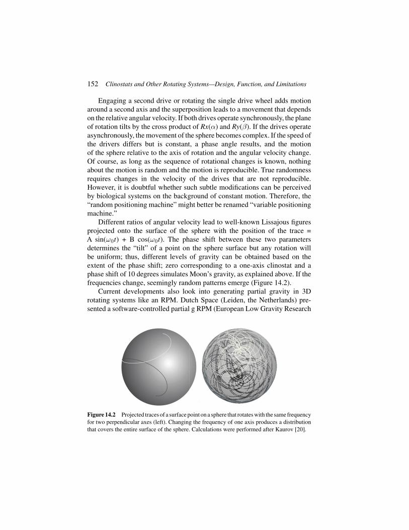
152 Clinostats and Other Rotating Systems—Design, Function, and Limitations
Engaging a second drive or rotating the single drive wheel adds motionaround a second axis and the superposition leads to a movement that dependson the relative angular velocity. If both drives operate synchronously, the planeof rotation tilts by the cross product of Rx(α) and Ry(β). If the drives operateasynchronously, the movement of the sphere becomes complex. If the speed ofthe drivers differs but is constant, a phase angle results, and the motionof the sphere relative to the axis of rotation and the angular velocity change.Of course, as long as the sequence of rotational changes is known, nothingabout the motion is random and the motion is reproducible. True randomnessrequires changes in the velocity of the drives that are not reproducible.However, it is doubtful whether such subtle modifications can be perceivedby biological systems on the background of constant motion. Therefore, the“random positioning machine” might better be renamed “variable positioningmachine.”
Different ratios of angular velocity lead to well-known Lissajous figuresprojected onto the surface of the sphere with the position of the trace =A sin(ω0t) + B cos(ω0t). The phase shift between these two parametersdetermines the “tilt” of a point on the sphere surface but any rotation willbe uniform; thus, different levels of gravity can be obtained based on theextent of the phase shift; zero corresponding to a one-axis clinostat and aphase shift of 10 degrees simulates Moon’s gravity, as explained above. If thefrequencies change, seemingly random patterns emerge (Figure 14.2).
Current developments also look into generating partial gravity in 3Drotating systems like an RPM. Dutch Space (Leiden, the Netherlands) pre-sented a software-controlled partial g RPM (European Low Gravity Research
Figure 14.2 Projected traces of a surface point on a sphere that rotates with the same frequencyfor two perpendicular axes (left). Changing the frequency of one axis produces a distributionthat covers the entire surface of the sphere. Calculations were performed after Kaurov [20].

14.7 Configurations of Axes 153
Association in Vatican City in 2013) and a group from Switzerland publisheda comparable design [19].
14.7 Configurations of Axes
The previous example refers to two axes that rotate around a single point.However, the arrangement of rotational axes can be more complicated. Fora single axis, no modifications are possible. Two rotational axes can beconfigured according to the description of the hypothetical sphere above; thatis, they are part of a gimbal suspension. A second mode of arranging two axesconsists of arranging the second axis perpendicular to the first axis of rotation.Such a device (Figure 14.3) has been implemented to examine the accelerationsensitivity of shoots and roots [4]. The relative rotation of the vertical axis oftwo wheels is used to turn “spokes” that extend from the center of the axis(Figure 14.3). This arrangement allows the entire system to function as acentrifuge if both upper and lower wheels rotate at the same angular velocity.If the lower wheel remains fixed and the top gear rotates, the experimentalchambers that comprise the spokes rotate around their horizontal axis and arethus clinorotated as explained above for the 1-axis clinostat. Any additionalmovement by the lower wheel rotates the clinorotating chambers. This setupwas used to determine the acceleration threshold of roots and shoots to about10−3 and 10−4 g, respectively [4].
Figure 14.3 Drawing of a gearhead that translates the relative motion of a vertical shaft into arotational motion of lateral axes. If the two center wheels rotate at the same rate, the horizontalaxes function as a centrifuge and only yaw rotation applies. If the horizontal wheels spin atunequal rates, the lateral axes rotate and can drive a 1D clinostat with variable yaw and roll.

154 Clinostats and Other Rotating Systems—Design, Function, and Limitations
The creative arrangement of axes can be applied to the variable positioningsystem. If the lateral axes in Figure 14.3 contain a two-gimbal-supportedsuspension, a constant yaw acceleration is possible that averages all othermotions relative to g. The constant yaw rotation generates a centrifugal forcethat is superimposed onto (1D) clinorotation. The effect of the angular velocityallows for the determination of a g-threshold value [4].
The data in Figure 14.1 indicate that the clinostatting of plants should notinduce effects that are related to residual gravitational effects as long as theradius of rotation is less than the calculated values. However, recent studiesclearly indicate that the rate of rotation over the magnitude of an octave (10-fold increase in frequency) affects induced curvature after gravistimulation.Brassica roots that were horizontally placed for 5 min and monitored for twohours of clinorotation between 0.5 and 5 rpm showed stronger curvature athigher frequency although the effective radius was less than 3 cm [10]. Thisobservation, in addition to many others [21–25], indicates that the clinostat-associated mechanostimulation exerts largely unknown effects that preventlabeling clinorotation even in its most sophisticated form “microgravitysimulation.” The effects of mechanical unloading that are the hallmark offree-fall and orbital conditions do not apply to clinorotation. Nonetheless,the fascinating possibilities of manipulating organisms relative to the gravityvector for various times and under various conditions are bound to shed lighton important aspects of sensory biology.
Acknowledgement
This work was supported by NASA grant NNX10AP91G to KHH and ESAgrant TEC-MMG/2012/263 and Netherlands Space Office NSO/NWO grantto JvL.
References
[1] von Sachs, J. “Über Ausschliessung der geotropischen und heliotropis-chen Krümmungen wärend des Wachsthums.” Würzburger Arbeiten 2(1879): 209–225.
[2] Galland, P., H. Finger, and Y. Wallacher. “Gravitropism in Phycomyces:Threshold Determination on a Clinostat Centrifuge.” The Journal of PlantPhysiology 161 (2004): 733–739.
[3] Laurinavicius, R., D Svegzdiene, B Buchen, and A. Sievers.“Determination of the Threshold Acceleration for the Gravitropic
References 155
Stimulation of Cress Roots and Hypocotyls.” Advances in SpaceResearch 21 (1998): 1203–1207.
[4] Shen-Miller, J., R. Hinchman, and S.A. Gordon. “Thresholds for Geore-sponse to Acceleration in Gravity-Compensated Avena Seedlings.” PlantPhysiology 43 (1968): 338–344.
[5] Briegleb, W. “Ein Modell zur Schwerelosigkeits-Simulation an Mikroor-ganismen.” Naturwissenschaften 54 (1967): 167–167.
[6] Hoson, T., S. Kamisaka, Y. Masuda, M. Yamashita, and B. Buchen.“Evaluation of the Three-Dimensional Clinostat as a Simulator ofWeightlessness.” Planta 203 (1997): S187–S197.
[7] Borst,A.G., and J. van Loon. “Technology and Developments for the Ran-dom Positioning Machine, RPM.” Microgravity Science and Technology21 (2009): 287–292.
[8] van Loon, J.J.W.A. “Some History and Use of the Random Position-ing Machine, RPM, in Gravity Related Research.” Advances in SpaceResearch 39 (2007): 1161–1165.
[9] Albrecht-Buehler, G. “The Simulation of Microgravity Conditions on theGround.” ASGSB Bulletin 5 (1992): 3–10.
[10] John, S.P., and K.H. Hasenstein. “Effects of Mechanostimulation onGravitropism and Signal Persistence in Flax Roots.” Plant Signaling &Behavior 6 (2011): 1–6.
[11] Israelsson, D., and A. Johnsson. “A Theory for Circumnutations inHelianthus annuus.” Physiologia Plantarum 20 (1967): 957–976.
[12] Briegleb,W. “Ein Beitrag zur Frage physiologischer Schwerelosigchkeit.”DVL Cologne (1967): 7–42.
[13] Schwarz, R.P., T.J. Goodwin, and D.A.Wolf. “Cell Culture for Three-Dimensional Modeling in Rotating-Wall Vessels: An Application ofSimulated Microgravity.” Journal of Tissue Culture Methods 14, no. 2(1992): 51–57.
[14] Liu, T., X. Li, X. Sun, X. Ma, and Z. Cui. “Analysis on Forces andMovement of Cultivated Particles in a Rotating Wall Vessel Bioreactor.”Biochemical Engineering Journal 18, no. 2 (2004): 97.
[15] Hammond, T.G., and J.M. Hammond. “Optimized Suspension Culture:The Rotating-Wall Vessel.” American Journal of Physiology 281(1)(2001): F12.
[16] Nauman, E.A., C.M. Ott, E. Sander, D.L. Tucker, D. Pierson, J.W. Wilson,and C.A. Nickerson. “Novel Quantitative Biosystem for ModelingPhysiological Fluid Shear Stress on Cells.” Applied and EnvironmentalMicrobiology 73, no. 3 (2007): 699.

156 Clinostats and Other Rotating Systems—Design, Function, and Limitations
[17] Galie, P.A., D.H. Nguyen, C.K. Choi, D.M. Cohen, P.A. Janmey, and C.S.Chen. “Fluid Shear Stress Threshold Regulates Angiogenic Sprouting.”Proceedings of the National Academy of Sciences of the United States ofAmerica 111, no. 22 (2014): 7968–7973.
[18] Zeng Y., Y. Shen, X.L. Huang, X.J. Liu, and X.H. Liu. “Roles of Mechan-ical Force and CXCR1/CXCR2 in Shear-Stress-Induced Endothelial CellMigration.” European Biophysics Journal 41, no. 1 (2012): 13–25.
[19] Wuest, S.L., S. Richard, I. Walther, R. Furrer, R. Anderegg, J. Sekler,and M. Egli. “A Novel Microgravity Simulator Applicable for Three-Dimensional cell Culturing.” Microgravity Science and Technology 26(2014): 77–88.
[20] Kaurov, V. “Lissajous Patterns on a Sphere Surface.” http://demonstrations.wolfram.com/LissajousPatternsOnASphereSurface/WolframDemonstrations Project Published: July 1, 2011.
[21] Anken, R.H., U. Baur, and R. Hilbig. “Clinorotation Increases the Growthof Utricular Otoliths of Developing Cichlid Fish.” Microgravity Scienceand Technology 22 (2010): 151–154.
[22] Barjaktarovic, Z.,A. Nordheim, T. Lamkemeyer, C. Fladerer, J. Madlung,and R. Hampp. “Time-Course of Changes inAmounts of Specific ProteinsUpon Exposure to Hyper-g, 2-D Clinorotation, and 3-D Random Posi-tioning of Arabidopsis cell cultures.” Journal of Experimental Botany 58(2007): 4357–4363.
[23] De Micco, V., M. Scala, and G. Aronne. “Effects of Simulated Micro-gravity on Male Gametophyte of Prunus, Pyrus, and Brassica species.”Protoplasma 228 (2006): 121–126.
[24] Wei, N., C. Tan, B. Qi, Y. Zhang, GX Xu, and H.Q. Zheng. “Changesin Gravitational Forces Induce the Modification of Arabidopsis ThalianaSilique Pedicel Positioning.” Journal of Experimental Botany 61 (2010):3875–3884.
[25] Zyablova, N.V., Y.A. Berkovich, A.N. Erokhin, and A.Y. Skripnikov.“The gravitropic and phototropic responses of wheat grown in a spacegreenhouse prototype with hemispherical planting surface.” Advances inSpace Research 46 (2010): 1273–1279.

15Vibrations
Daniel A. Beysens1 and Valentina Shevtsova2
1CEA-Grenoble and ESPCI-Paris-Tech, Paris, France2Université Libre de Bruxelles, Brussels, Belgium
15.1 Introduction
Vibrating a fluid corresponds to submitting it to a periodic acceleration. Wedescribe below how, in addition to the periodic displacements that result fromthe vibration, mean movements can follow. Such movements can produce inspace the same effects as gravity do on Earth [1] or, alternatively, compensateon Earth the gravity-induced flows as if the fluid were in space. It is this latteraspect that we emphasize in the following.
A vibration can be decomposed into its Fourier harmonic components.For the sake of simplicity, we thus only consider linearly polarized, harmonicvibration whose amplitude X varies with time t as
X = a cos ωt. (15.1)
Here a is amplitude, ω = 2πf is the angular frequency, with f the frequency.When submitted to such a vibration, homogeneous matter is subjected toperiodic displacements and acquires periodic velocity u = –aω sin ωt andacceleration g = −ω2 X . A fluid, however, is in general not homogeneousin density because it exhibits several phases and/or is involved in mass/heattransfer processes where density gradients are the result of thermal gradients.Likewise, density gradients can be caused by concentration gradients arisingfrom e.g. diffusive process, mixing or rejection/incorporation of solute at thesolidifying interface. External accelerations thus act on density gradients andcan couple with other gravity-induced flows. Local fluid velocity depends onthe local density by inertial effect. It results in local velocity gradients, shearflows and Bernoulli pressure difference, especially across interfaces. Mean
157

158 Vibrations
displacements, convective flows and instabilities, similar to those induced bybuoyancy, can thus follow. They combine with gravity-induced flows and cancancel them.
Phenomena will be different according to the relative importance ofthe vibration period, 1/f, and the typical hydrodynamic times, τ (viscousrelaxation, thermal diffusion, etc.). What also matters is the relative amplitudevibration with respect to the fluid container size, e. The most interestingsituation is the high frequency and small amplitude limit, τ f � 1 and a/e � 1where local fluid inhomogeneities undergo small vibrations around theirmean position while mean flow and interface ordering take place. Typically,a = 0.1–2 mm and f = 1–100 Hz.
15.2 Thermovibrational Convections
Of particular importance is the effect of vibration on a fluid submitted toa temperature gradient. The latter results in a density gradient sensitiveto the vibration. Let us thus consider a fluid submitted to a vibrationalacceleration in a thermal gradient in the Rayleigh–Bénard configuration (twoparallel plates with a temperature difference ΔT separated by distance e).According to Gershuni and Lubimov [2], vibrational Rayleigh number(ρ is density, p is pressure, T is temperature, DT is thermal diffusivity) iswritten as:
Rav =
[aω(
∂ρ∂T
)pΔTe
]2
2πDT. (15.2)
The convection threshold depends on the angle between the thermal gradientand the vibration direction. There is no convection for a temperature gradientparallel to the vibration. The most unstable situation corresponds to a temper-ature gradient perpendicular to the vibration direction. Here, convection startswhen Rav is larger than a few thousands.
15.3 Crystal Growth
These thermovibrational flows can annihilate thermogravitational flow suchas buoyancy and/or thermocapillary (Marangoni) convection when an inter-face is present, depending on the mutual orientation of vibration axis andthermal or compositional gradient. In the system with free interface thermo-(soluto-) capillary (Marangoni) and thermovibrational mechanisms can

15.4 Dynamic Interface Equilibrium 159
produce motion in opposite directions. This is particularly the case in asolidification process. Appropriate combination of these mechanisms can thenbe used to counteract the usual convective flows inherent in crystal growthprocesses from the liquid phase.
Efficient control of heat and mass transfer during real industrial applica-tions of crystal growth from the liquid phase can be envisaged. The possibleutilization of such a strategy for the floating zone crystal growth techniquehas been addressed [3, 4].
15.4 Dynamic Interface Equilibrium
Harmonic vibrations can considerably deviate the equilibrium position of aninterface from its normally horizontal position under gravity acceleration,g, and attain large enough angles [5]. The situation is similar with that ofsimple mechanical systems under vibration. For example, a simple pendulumof length L can be stabilized in an upside down position by vertically vibratingits support at a frequency much larger than the natural frequency of thependulum, that is, when aω ≥ √
2gL [6]. When the support of the pendulumis vibrated horizontally at frequencies much larger than the natural frequencyof the pendulum and vibrational velocity amplitudesaω higher than a thresholdvalue (aω ≥ √
2gL), the equilibrium position of the pendulum is no morevertical and makes an angle with respect to the horizontal.
Vibration of a fluid interface can demonstrate similar phenomena. Usingvibration, it is possible to stabilize two-fluid configurations, generally unstablewhen the vibration is absent. For example, a heavier fluid floating over a lighterfluid under terrestrial gravity field is unstable (Rayleigh–Taylor configura-tion) under normal conditions. Application of strong vertical vibration candynamically stabilize the above configuration [5]. When subjected to stronghorizontal vibration, the interface of an initially horizontal fluid interface canattain a dynamic equilibrium at an angle to the horizontal plane.
Beyond a threshold value of vibrational velocity aω, the interface attainsan equilibrium position at an angle α with vertical (Figure 15.1). The resultsdepend on gravity acceleration g, vibration amplitude and frequency [5].With L the dimension of the interface the angle can be written as
sin α =2gL
πa2ω2ρ�+ρv
ρ�−ρv(15.3)
When the density difference between phases is small, the interface canexhibit instability of Kelvin–Helmholtz type called “frozenwave” [7]. It is

160 Vibrations
Figure 15.1 Interface position in liquid–vapor hydrogen for the vibration case a = 0.83 mmand f = 35 Hz and gravity level 0.05g (directed vertically). The interface looks fuzzy as itpulsates at the vibration frequency.
Figure 15.2 Experimental stability map in the plane (a, f ) for miscible liquid/liquid interface(mixtures of water–isopropanol of different concentrations). Diamonds: no instability. Circles:instability. The black dashed curve is a guideline for eyes between stable and unstable regions.Inset: Typical shape of the frozen waves with horizontal vibration.

References 161
characterized by an interface modulation perpendicular to vibration directionthat keeps immobile in the sample reference frame. This instability is alsopresent when two miscible liquids of similar (but nonidentical) viscositiesand densities are present [8]. While it was shown experimentally that surfacetension can be nonzero between miscible liquids [9], its value is, however,quite small. From the experimental results [8], the values of the criticalamplitude were determined as a function of critical frequency as shown inFigure 15.2. In this phenomenon, gravity is in competition with vibrationaleffect as surface tension does not play a role.
References
[1] Beysens, D. “Critical Point in Space: A Quest for Universality.”Microgravity Science and Technology 26 (2015): 201–218.
[2] Gershuni, G.Z., and D.V. Lyubimov. Thermal Vibrational Convection,New York, NY: Wiley, 1998.
[3] Lyubimov, D.V., T.P. Lyubimova, S. Meradji, and B. Roux. “VibrationalControl of Crystal Growth from Liquid Phase.” Journal of CrystalGrowth 180 (1997): 648–659.
[4] Lappa, M. “Review: Possible Strategies for the Control and Stabili-zation of Marangoni Flow in Laterally Heated Floating Zones.” FluidDynamics & Materials Processing (FDMP) 1, no. 2 (2005): 171.
[5] Landau, L.D., and E. M. Lifschitz. Mechanics. Moscow: Mir, 1973.[6] Gandikota, G., D. Chatain, T. Lyubimova, and D. Beysens. “Dynamic
Equilibrium Under Vibrations of H2 Liquid-Vapor Interface at Variousg-levels.” Physical Review E 89 (2014): 063003–7.
[7] Gandikota, G., D. Chatain, S. Amiroudine, T. Lyubimova, andD. Beysens. “Frozen Wave Instability in Near Critical Hydrogen Sub-jected to Horizontal Vibration Under Various Gravity Fields.” PhysicalReview E 89 (2014): 012309–1.
[8] Gaponenko, Y.A., M. Torregrosa, V. Yasnou, A. Mialdun, andV. Shevtsova. “Dynamics of the Interface Between Miscible LiquidsSubjected to Horizontal Vibrations.” Journal of Fluid Mechanics(accepted, 2015).
[9] Lacaze, L., P. Guenoun, D. Beysens, M. Delsanti, P. Petitjeans, andP. Kurowski. “Transient Surface Tension in Miscible Liquids.” PhysicalReview E 82 (2010): 041606.


4
Other Environmental Parameters


16Earth Analogues
Inge Loes ten Kate1 and Louisa J. Preston2
1Utrecht University, Utrecht, The Netherlands2The Open University, Milton Keynes, UK
Terrestrial analogue environments are places on Earth with geological orenvironmental conditions that are similar to those that exist on an extrater-restrial body [1]. The purpose of using these terrestrial analogue sites forplanetary missions can be divided into four basic categories: (i) to learnabout planetary processes on Earth and elsewhere; (ii) to test methodologies,protocols, strategies, and technologies; (iii) to train highly qualified personnel,as well as science and operation teams; and (iv) to engage the public, spaceagencies, media, and educators [1, 2]. A recent ESA study, CAFE—Conceptsfor Activities in the Field for Exploration [3], resulted in a catalogue of allplanetary analogue sites used and currently in use [4]. This catalogue containsin-depth descriptions of each of these field sites, including location, geologicalcontext, environmental information, and infrastructure, and is currently themost extensive and up-to-date catalogue. A very comprehensive overviewof analogue sites grouped per planetary surface feature can be found in [5].Current analogue activities focus on five planetary bodies: the Moon, Mars,Europa and Enceladus, andTitan. Below we highlight a few planetary analoguesites for these five bodies summarized from [5], as well as field-testingcampaigns and semipermanent field-testing bases.
16.1 Planetary Analogues
16.1.1 The Moon
The lunar surface features that can be studied in terrestrial analogues arecraters, lava fields, and the lunar dust. The Vredefort dome in South Africawas studied as an analogue for the fine-grained granulite facies rocks that werereturned from the Moon by the Apollo astronauts [6]. Most lunar analogue
165

166 Earth Analogues
sites, however, are chosen to study mission concepts and test instruments.This already started with the Apollo astronaut training in the Lava Mountains,California [7], and the volcanic fields around Flagstaff, Arizona. Specificprerequisites here are aridity, low temperature, and the presence of abrasivedust. Another example of a lunar analogue is the Haughton Impact Structurein Canada [8].
16.1.2 Mars
Most analogue sites are devoted to Mars. These analogue sites can be dividedinto three categories: early Mars, middle Mars, and present Mars. Early Mars ishere defined as roughly the first billion years of its lifetime, when liquid waterwas still presumed to be present on the surface. Example analogue sites are thePilbara region in Australia as an analogue for flood basalts, water-related min-erals, and preservation of early life [9], Rio Tinto in Spain as an analogue forpast rivers, iron oxides, and sulfates [10], and Yellowstone as an analogue forsilica-rich soils, hydrothermal activity, and extremophiles [11]. Middle Mars isdefined as the second billion years where a large drop in temperature and lossof water led to a global cryosphere and subsurface ice. The Antarctic DryValleys [12] and Antarctic permafrost [13] serve as analogues for the PolarLayered Deposits and the Northern Highlands as well as for potential lifepreserved in ice deposits. Iceland [14] and the Bockfjord Volcanic Complex onSvalbard, Norway [15], serve as analogues for subglacial volcanism. PresentMars starts about 2.5 billion years ago and is characterized by a hyperaridclimate. The Antarctic Dry Valleys are a good analogue for present-day Marsand is the closest terrestrial analogue to Mars. Additionally, the AtacamaDesert [16], the Egyptian Desert [17], and the Hawaiian volcanoes, forexample, Mauna Kea [18], are well-studied Mars analogue sites.
16.1.3 Europa and Enceladus
Both Europa and Enceladus are characterized by a planet-wide ocean coveredwith a thick ice-crust. Hydrothermal activity at the ocean floor is hypothesizedas an energy source to keep the oceans liquid. Analogue sites for all three partsof planets can be found on Earth. Ocean floor analogues can be found in thehydrothermal vents of Lost City on the Mid-Atlantic Ridge [19] and the high-pressure low-temperature environments of the Mariana Trench in the PacificOcean [20]. Mono Lake in California, USA, and the Dead Sea in Israel areanalogues for the alkaline and saline brine oceans expected on these icy moons.Lake Vostok on Antarctica is one example of a surface ice analogue [21].

16.3 Field-Testing Campaigns 167
16.1.4 Titan
Like the Earth, Titan has a thick atmosphere and diverse geology with land andlakes. These lakes, however, are composed of hydrocarbons, making terrestrialtar fields good analogues for the Titan surface, for example, Pitch Lake inTrinidad and Tobago [22].
16.2 Semipermanent Field-Testing Bases
Long-term field-testing campaigns with some more permanent infrastructureare established to provide a base for multidisciplinary field research as wellas for the development of new technologies for planetary missions. Mostof these sites are very much technology and mission development focused;however, they do offer the opportunity to carry out scientific campaigns aspart of the technology-driven frameworks. These sites include the AquariusUndersea Research Station at the Florida Keys established in 1993 and host to114 underwater missions up to 2012, primarily studying coral reefs [23]; theHaughton-Mars Project Research Station at Devon Island, Canada, focusingon “developing new technologies, strategies, and operational protocols gearedto support the future exploration of the Moon, Mars, and other planets” [8, 24];the Pavilion Lake Research Project, a “science and exploration effort to explainthe origin of freshwater microbialites in Pavilion Lake, British Columbia,Canada” [25]; the Pacific International Space Center for Exploration Systems(PISCES) at Hawai’i [26, 27]; the Ibn Battuta Centre for exploration andfield activities in Morocco, established in 2006 to support the explorationof Mars and others planets, and to provide opportunities for scientists andthe public for experiencing the exploration on Earth and in the Solar System[28]; and the recently (2013) established Boulby International SubsurfaceAstrobiology Laboratory, BISAL, in the UK, the world’s first permanentsubsurface astrobiology lab, focusing on deep subsurface geochemistry andbiology, as well as instrument testing for robotic and human planetarymissions [29].
16.3 Field-Testing Campaigns
Long-term field-testing campaigns have been established to provide a frame-work for planetary instrument and mission testing. The Desert Research andTechnology Studies (Desert RATS) field-testing campaigns started in 1997in support of future manned mission scenarios. The Desert RATS campaignshave taken place in various locations, including Mauna Kea, HI, and Black

168 Earth Analogues
Point Lava Flow, AZ. These locations were selected based on their physicalresemblance of lunar and martian surface. The scope of these campaigns hasvaried widely over the years from testing single space suit configurations tomulti-day integrated mission scenarios [30]. Even though the focus is mainlyon technology-related testing, integrating science into these technology-drivenscenarios and getting scientists and engineers to communicate is an importantaspect. The NASAExtreme Environments Mission Operations campaigns [31]started in 2001 and 16 missions have been undertaken since then. NEEMOuses theAquarius Station, since the station habitat and its surroundings providea convincing analogue for space exploration. Like Desert RATS, NEEMOis rather technology and mission oriented. The Arctic Mars Analog SvalbardExpedition (AMASE) at Svalbard, Norway [32], is an astrobiology- and Mars-focused science and technology campaign taking place on Svalbard, Norway.This campaign is specifically focused on the understanding of Svalbard in anastrobiological context. Technology that is taken along is tested in support ofthe science and not the other way around, as is merely the case in, for example,Desert RATS and NEEMO.
References
[1] Leveille, R. “Validation of Astrobiology Technologies and InstrumentOperations in Terrestrial Analogue Environments.” Comptes RendusPalevol 8, no. 7 (2009): 637–648.
[2] Lee, P. “Haughton-Mars Project 1997–2007: A Decade of Mars AnalogScience and Exploration Research at Haughton Crater, Devon Island,High Arctic.” In Proceedings of 2nd International Workshop on Explor-ing Mars and its Earth Analogs. Pescara, Italy: International ResearchSchool of Planetary Sciences (IRSPS), 2007.
[3] Preston, L.J., S. Barber and M. Grady. CAFE—Concepts for Activitiesin the Field for Exploration—Executive Summary Report. ESA Contract# 4000104716/11/NL/AF, 2013. Last visited on November 15, 2013.http://esamultimedia.esa.int/docs/gsp/C4000104716ExS.pdf.
[4] Preston, L.J., S. Barber and M. Grady. CAFE—Concepts for Activitiesin the Field for Exploration—TN2: The Catalogue of Planetary Analo-gues, 2013. Last visited on November 15, 2013. http://esamultimedia.esa.int/docs/gsp/The Catalogue of Planetary Analogues.pdf.
[5] Preston, L.J. and L.R. Dartnell. “Planetary Habitability: Lessons Learnedfrom Terrestrial Analogues”. International Journal of Astrobiology13,no. 01 (2014): 81–98.

References 169
[6] Gibson, R.L., W.U. Reimold, A.J. Ashley and C. Koeberl. “Metamor-phism on the Moon: A Terrestrial Analog in the Vredefort Dome, SouthAfrica?” Geology 30, no. 5 (2002): 475–478.
[7] Hinze, W.J., R. Ehrlich, H.F. Bennett, D. Pletcher, E. Zaitzef and O.L.Tiffany. “Use of an Earth Analog in Lunar Mission Planning”. Icarus 6,no. 1–3 (1967): 444–452.
[8] Osinski, G.R., P. Lee, C.S. Cockell, K. Snook, D.S.S. Lim and S.Braham. “Field Geology on the Moon: Some Lessons Learned from theExploration of the Haughton Impact Structure, Devon Island, CanadianHigh Arctic. Planetary and Space Science 58, no. 4 (2010): 646–657.
[9] Allwood, A.C., M.R. Walter, I.W. Burch and B.S. Kamber. “3.43Billion-Year-Old Stromatolites Reef from the Pilbara Craton of WesternAustralia: Ecosystem-Scale Insights to Early Life on Earth”. Precam-brian Research 158 (2007): 198–227.
[10] Amils, R., E. González-Toril, D. Fernández-Remolar, F. Gómez, Á.Aguilera, N. Rodríguez, M. Malki, A. García-Moyano, A.G. Fairen, V.de la Fuente and J. Luis Sanz. “Extreme Environments as Mars Terres-trial Analogs: The Rio Tinto Case”. Planetary and Space Science 55,no. 3(2007): 370–381.
[11] Barns, S.M., R.E. Fundyga, M.W. Jeffries and N.R. Pace. “RemarkableArchaeal Diversity Detected in a Yellowstone National Park Hot SpringEnvironment”. PNAS 91 (1994): 1609–1613.
[12] Wentworth, S.J., E.K. Gibson, M.A. Velbel and D.S. McKay. “AntarcticDry Valleys and Indigenous Weathering in Mars Meteorites: Implicationsfor Water and Life on Mars”. Icarus 174, no. 2 (2005): 383–395.
[13] Dickinson, W.W. and M.R. Rosen. “Antarctic Permafrost: An Analogfor Water and Diagenetic Minerals on Mars”. Geology 31, no. 3 (2003):199–202.
[14] Cousins, C.R. and I.A. Crawford. “Volcano–Ice Interaction as a MicrobialHabitat on Earth and Mars”. Astrobiology 11 (2011): 695–710.
[15] Treiman, A.H., H.E.F. Amundsen, D.F. Blake and T. Bunch. “Hydrother-mal Origin for Carbonate Globules in Martian Meteorite ALH84001: aTerrestrial Analogue from Spitsbergen (Norway)”. Earth and PlanetaryScience Letters 204 (2002): 323–332.
[16] Navarro-Gonzalez, R., et al. “Mars-Like Soils in the Atacama Desert,Chile, and the Dry Limit of Microbial Life.” Science 302, no. 5647(2003): 1018–1021.
[17] Heggy, E. and P. Paillou. “Probing Structural Elements of Small BuriedCraters Using Ground-Penetrating Radar in the Southwestern Egyptian

170 Earth Analogues
Desert: Implications for Mars Shallow Sounding”. Geophysical ResearchLetters 33, no. 5 (2006): L05202.
[18] ten Kate, I.L., R. Armstrong, B. Bernhardt, M. Blumers, J. Craft, D.Boucher, E. Caillibot, J. Captain, G.M.T. D’Eleuterio, J.D. Farmer, D.P.Glavin, T. Graff, J.C. Hamilton, G. Klingelhöfer, R.V. Morris, J.I. Nuñez,J.W. Quinn, G.B. Sanders, R.G. Sellar, L. Sigurdson, R. Taylor andK. Zacny. “Mauna Kea, Hawai’i, as an Analogue Site for Future Plan-etary Resource Exploration: Results from the 2010 ILSO-ISRU Field-Testing Campaign”. Journal of Aerospace Engineering 26, no. 1(2013):183–196.
[19] Kelley, D.S., et al. “An Off-Axis Hydrothermal Vent Field DiscoveredNear the Mid-Atlantic Ridge at 30◦N”. Nature 412(2001): 145–149.
[20] Sharma, A., J.H. Scott, G.D. Cody, M.L. Fogel, R.M. Hazen, R.J. Hemleyand W.T. Huntress. “MicrobialActivity at Gigapascal Pressures”. Science295 (2002): 1514–1516.
[21] Ellis-Evans, J.C. and D. Wynn-Williams. “A Great Lake Under the Ice”.Nature 381 (1996): 644–646.
[22] Meckenstock, R.U., et al. “Water Droplets in Oil are Microhabitats forMicrobial Life”. Science 345, no. 6197(2014): 673–676.
[23] Todd, B. and M. Reagan. “The NEEMO Project: A Report on HowNASA Utilizes the “Aquarius” Undersea Habitat as an Analog for Long-Duration Space Flight”. Engineering, Construction, and Operations inChallenging Environments(2004): 751–758.
[24] Lee, P. and G.R. Osinski. “The Haughton-Mars Project: Overview ofScience Investigations at the Haughton Impact Structure and SurroundingTerrains, and Relevance to Planetary Studies”. Meteoritics and PlanetaryScience 40, no. 12(2005): 1755–1758.
[25] Lim, D.S.,A.L. Brady and Pavilion Lake Research Project (PLRP) Team.“A Historical Overview of the Pavilion Lake Research Project—AnalogScience and Exploration in an Underwater Environment”. Special Paper483. Boulder, CO: Geological Society of America, 2011, 85–116.
[26] Schowengerdt, F., R. Fox, M. Duke, N. Marzwell and B. McKnight.“PISCES: Developing Technologies for Sustained Human Presence onthe Moon and Mars.” In Proceedings, 3rd AIAA Space Conferenceand Ex-position. Reston, VA: American Institute of Aeronautics andAstronautics (AIAA), 2007, 3029–3038.
[27] Duke, M.B., et al. “PISCES: Hawaii Facility for Simulation and Train-ing.” In Proceedings of 38th Lunar and Planetary Science Conferency.Houston: Lunar and Planetary Institute (LPI), 2007.

References 171
[28] Cavalazzi, B., R. Barbieri and G.G. Ori. “Chemosynthetic Microbialitesin the Devonian Carbonate Mounds of Hamar Laghdad (Anti-Atlas,Morocco)”. Sedimentary Geology 200 (2007): 73–88.
[29] www-1: http://www.astrobiology.ac.uk/research/bisal/. Last visited onDecember 5, 2014.
[30] Ross, A., J. Kosmo and B. Janoiko. “Historical Synopses of Desert RATS1997–2010 and a Preview of Desert RATS 2011”. Acta Astronautica 90,no. 2(2013): 182–202.
[31] Thirsk, R., D. Williams and M. Anvari. “NEEMO 7 Undersea Mission”.Acta Astronautica 60, no. 4–7(2007): 512–517.
[32] Steele, A., H.E.F. Amundsen and AMASE 07 Team. “Arctic MarsAnalog Svalbard Expedition 2007”. In 38th Lunar and Planetary ScienceConference. Houston: Lunar and Planetary Institute (LPI), 2007.


17Isolated and Confined Environments
Carole Tafforin
Ethospace, Toulouse, France
Characteristics of space analogue environments with regard to human per-formance concern the crew adaptation in a socio-psychological context andin a temporal dynamics. Isolation, confinement and time are major featureson Earth to reproduce an extra-terrestrial environment for manned missionsimulations. In the current space missions (low Earth orbit, LEO) and in theperspective of interplanetary missions (near-Earth asteroid, Moon, Mars), menand women will have to adapt to social constraints (crew size, multinationality,mixed-gender) and spatial restrictions (volume, multi-chambers, life-support)on short-term, medium-term and long-term durations. The crewmembers alsowill have to perform intra-vehicular activities (IVA) and extra-vehicular activ-ities (EVA). For training, preventing and optimizing such tasks, simulationsof living and working together in isolated and confined environments, andsimulations of operating with a space suit on geological surfaces are the newrequirements.
During the two decades (1991–2011), space simulators (confinement)and analogue settings (isolation) were adequately developed on Earth withthe ultimate goal of walking on Mars. Time periods extended up to500 days. Space analogue environments are located worldwide (Canada,United States, Russia, Europe, Antarctica and Arctic). Mission durationsin space analogue environments cover days, weeks and years. Isolationand confinement facilities implemented for such simulations are listed inTable 17.1.
Over a 7-day duration, the Canadian Astronaut Program Space Unit LifeSimulation (CAPSULS) was an Earth-based initiative that simulated a typicalspace shuttle or space station mission [1]. CAPSULS provided the Canadianastronaut participants with space mission training. The facility was a solid
173

174 Isolated and Confined Environments
Tabl
e17
.1Is
olat
ion
and
confi
nem
entf
acili
ties
impl
emen
ted
for
such
sim
ulat
ions
Nam
eTy
peSi
teY
ear
Cre
wSi
zeN
atio
nalit
yG
ende
rV
olum
eD
urat
ion
ISE
MSI
Mul
ti-ch
ambe
rB
erge
n,N
orw
ay19
906
Eur
opea
nM
ales
118
m3
28da
ys
EX
EM
SIM
ulti-
cham
ber
Col
ogne
,G
erm
any
1992
4E
urop
ean
Mal
es95
m3
60da
ys
HU
BE
SM
ulti-
cham
ber
Mos
cow
Rus
sia
1994
3R
ussi
anM
ales
100
m3
135
days
BIO
SPH
ER
E2
Des
erts
tatio
nA
rizo
na,U
SA19
918
Mul
ti-M
ixed
1.27
ha73
0da
ys
1994
7M
ulti-
Mix
ed(s
urfa
ce)
6m
onth
s
CA
PSU
LS
Hyp
erba
ric
cham
ber
Toro
nto
Can
ada
1994
4C
anad
ian
Mix
ed33
m3
7da
ys
SFIN
CSS
Mul
ti-ch
ambe
rM
osco
wR
ussi
a19
99–2
000
33×2
Rus
sian
Mul
ti-M
ales
Mix
ed10
0m
3
200
m3
240
days
110
days
FM
AR
SPo
lar
stat
ion
Dev
onIs
.C
anad
a20
00–2
007
6–7
Mul
ti-M
ixed
416
m3
7da
ys-4
mon
ths
NE
EM
OU
nder
sea
mis
sion
sFl
orid
a,U
SA20
01–2
004
6–9
Am
eric
anM
ixed
401
m3
6–12
days
MD
RS
Des
erts
tatio
nU
tah,
USA
2002
6–8
Mul
ti-M
ixed
500
m3
15da
ys
CO
NC
OR
DIA
Pola
rst
atio
nD
ome
C,
Ant
arct
ic20
06–
10Fr
ench
,It
alia
nM
ixed
1,50
0m
28
mon
ths
TA
RA
Pola
rsh
ipIc
epa
ck,
Arc
tic20
0810
Mul
ti-M
ixed
36m
507
days
MA
RS-
500
Mul
ti-ch
ambe
rM
osco
w,
Rus
sia
2010
–201
16
Mul
ti-M
ales
550
m3
520
days

Isolated and Confined Environments 175
steel hyperbaric chamber that was comprised of two primary modules, thehabitat module and the experiment module, which were connected by asmaller transfer chamber. During the simulation, crew inside monitored andcontrolled life-support parameters (temperature, humidity, pressure of oxygen,carbon dioxide, nitrogen and water vapor). CAPSULS involved national(Canadian) mixed-gender and small-size crew for short-term simulations.They emphasized social and personality issues of adaptation.
Over a 6- to 12-day duration, NASA Extreme Environment MissionOperations (NEEMO) project was an analogue mission that sent groups ofastronauts, engineers and scientists to live in Aquarius, the world’s onlyundersea research station [2]. The Aquarius habitat and its surroundingsprovide a hostile environment with the risk of decompression sickness indepth immersion. NEEMO crewmembers, named Aquanauts, experiencedsome of the same challenges that they would on a distant asteroid or on Moon.During NEEMO missions, the aquanauts simulated living on a spacecraftand tested spacewalk techniques. Crew size was equivalent to a real spacecrew. Like CAPSULS, there were mainly national (USA) but mixed-gendercrew and for short-term simulations. Underwater condition had the additionalbenefit to simulate a microgravity environment by buoyancy. The peculiarity
Figure 17.1 Tara expedition in Arctic (Image c© F. Latreille/Tara expédition).

176 Isolated and Confined Environments
of NEEMO is that crewmembers participated in undersea sessions of EVA andused autonomous life-support systems during IVA (Kanas et al. 2010).
Over a 15-day duration, Mars Research Desert Station (MDRS) was oneof four stations planned by the International Mars Society [3] which hasestablished a number of prototype Mars Habitat Units around the world.MDRS is a 2-deck facility providing a comprehensive living and workingenvironment for a Mars or Moon crew. The upper deck includes sleepingquarters, a communal living area, a small galley, exercise area and hygienefacilities with closed-circle water purification. The lower deck includes theprimary working space for the crew: small laboratory areas for carrying outgeology and life science research, storage space for samples, airlocks forreaching the surface of planets, and a suiting-up area where crewmembers pre-pare for surface operations. MDRS also involved small-size but multinationaland mixed-gender crews, for longer-term simulations. They thus emphasizedcultural issues. The specificity is EVA while walking in a desert landscapemimicking a Mars landscape.
Over a 28-day duration, Isolation Study for the European Manned SpaceInfrastructure (ISEMSI) was one of three European campaigns implementedas precursor flights regarding medium-term orbital stays [4]. ISEMSI was aconfined habitat in multi-chamber facilities composed of 6 modules. Two smallmodules served as sleeping chambers, the larger module served as workingand living chamber, one module was used as sanitary, one module acted as atransfer lock and storage and one module was a rescue chamber fully equippedto maintain life-support functions under pressure. As in NEEMO and MDRS,the crew size was as expected for space mission and space exploration but
Figure 17.2 Concordia station in Antarctica (Image c© IPEV).

Isolated and Confined Environments 177
with only male crewmembers. ISEMSI campaign was specifically designedfor psychological and physiological issues on long-duration manned spacemission.
Over a 60-day duration, Experimental Campaign for the European MannedSpace Infrastructure (EXEMSI) prolonged ISEMSI campaign, thus doublingthe time spent in a confined habitat. The overall facility consisted of two mainmodules serving respectively as the habitat and the laboratory module forcarrying out scientific investigations and teleoperations, completed with twotransfer and storage modules [5]. The living quarters containing bunks and atable were used for sleeping, eating and leisure time. In the panel of confinedand isolated settings, ISEMSI had the smallest volume and the smallest crewsize. It differed from NEEMO and MDRS because it provided only IVA butpromoted further advances on long-duration manned space mission.
Over a 135-day duration, Human Behavior in Extended Spaceflight(HUBES) prolonged ISEMSI and EXEMSI campaigns and was definitelyconsidered as a space simulator for extended periods [6]. The confined habitatwas designed as a unique module, thus sharing living area, working areaand storage area in a small volume compared to CAPSULS. HUBES hadthe benefit to reproduce real mission aboard the Mir orbital station and crewtransfer flight considering the very small crew size consisting of Russian andmale-only crewmembers. HUBES was a ground-based simulation aimed atcomparing and validating psychological issues in crew selection, training,monitoring and in-orbit support flight.
Over a 4-month duration, Flashline Mars Arctic Research Station(FMARS) hosted a long-duration mission that quadrupled the in situ sim-ulation of both confinement and isolation. Its geographic location, the polar
Figure 17.3 Mars Desert Research Station in Utah/USA (Image c© Ethospace).

178 Isolated and Confined Environments
desert, is the largest uninhabited island in the world [7]. The 24-h daylight isanalogous to that of a polar Moon or Mars mission. FMARS and MDRS havethe same Mars Habitat Unit. The difference is the simulation of Mars-Earthlatency to a 20-min delay and the tightly life-support since water use wasrestricted and monitored. However, the facility was not hermetically lockedas enforced during NEEMO mission. Important analogue features of FMARSwere EVAs and the hostile surroundings in Arctic. The multinational andmixed-gender composition of the crew properly simulated future isolated andconfined crews who would land on asteroids, Moon or Mars.
Over a 110 to 240-day duration, Simulation for Flight of InternationalCrew on Space Station (SFINCSS) was devoted to determine the extentto which monotony may impair individual performance, physical rate andtranscultural crew performance. The facilities consisted of either one mainchamber or two chambers; separated groups lived on a schedule typical forMir station crews then on a fixed work–rest schedule mimicking InternationalSpace Station (ISS) assembly operations [8]. Specific feature of SFINCSSwas the participation of several small-size and multinational crews. Lessonslearned from ISEMSI, EXEMSI, HUBES and SFINCSS provided an overviewof issues involved in the design and habitability of simulators and simulationcampaigns.
Figure 17.4 Mars-500 experiment in Moscow/Russia (Image c© Ethospace).

Isolated and Confined Environments 179
Over an 8-month duration, Concordia South Pole station hosted winterersin high isolation and confinement conditions approaching those found invery long-term interplanetary flights. The facility consisted of two cylindricalstructures designed as a space architecture [9]. Antarctica is the farthest andmost hostile environment on Earth because of the lowest outside temperatures,the windy and sunny conditions that require the crew being strictly isolatedand confined for safety reasons. The inner volume of habitat is very largecompared to all other space simulators. Concordia station is furnished witha life-support system analogous to that implemented onboard the EuropeanColumbus module in the ISS. Such extreme environment addresses socio-psychological and medical issues of a relatively large-size and binational(French and Italian) crew.
Over a 507-day duration, Tara expedition in Arctic was a polar schoonerthat once embedded in the ice, drifted on the pack until reaching the freeoceanic waters [10]. Tara was not originally devoted to space researches butthe drift was analogous to a flight to Mars and return to Earth. The very smallvolume of habitat and the very hostile surrounding in North Pole were actuallyrelevant features of a confined and isolated environment. The crewmembers,named Taranauts, experienced continuous polar night (the sun disappearedfor more than 4 months) and continuous polar day for more than 3 months,like at Concordia. The large-size crew was multinational and mixed-genderand composed of scientists, technicians, medical doctor, artist, photographer,sailor and diver. The heterogeneity of the crew was specific to Tara expedition.The dangerous nature of such mission in real conditions addressed stress andcoping issues.
Over a 520-day duration, Mars-500 experiment was the longest designedanalogue Mars mission of the world [11]. This experiment was conductedentirely in confinement scheduled on a 250-day interplanetary flight fromEarth to Mars, a 30-day Mars orbital stay and surface operations, and a240-day interplanetary flight from Mars to Earth. Furthermore, a 20-minutedelay communication was simulated with unexpected tests of loss of com-munication. Mars-500 facilities were composed of four hermetically sealedchambers for ensuring life-support functions: the habitable module, the med-ical module, the storage module and the Mars-landing module. They wereconnected to an external module: Martian surface simulator. The Marsionautswere only males but involved Russian, European and Chinese cultural back-grounds. They were separated into orbital crew and landing crew, the latterone simulating EVAs while walking on the Mars surface. Mars-500 provided a

180 Isolated and Confined Environments
unique insight into human factor and cultural factor issues for future explorersof distant planets. The emphasis was on crew autonomy.
Over a 730-day duration, Biosphere 2 was a concept similar to the housingstructure on extra-terrestrial environment. It was the longest experience in thefield. The facilities were built to mainly be an artificial, materially closedecological system and to explore human colonization of other planets. Thewide landscape integrated fauna, flora, mountain area, desert area, water areaand any atmospheric parameters in order for the crew to survive. The crewwas specifically composed on a male/female quota. Biosphere 2 project wasa full-scale life-support model and the adaptation of crews to isolated andconfined environment beyond two years opened new issues for creating newground-based simulations devoted to space science.
Other older settings about polar missions at Vostok and Mac Murdo,for instance, are permanent Antarctic stations which particularly emphasizedthe isolation parameter whereas submarine missions were relevant to theconfinement parameter. Designing and building environments for humans inouter space is the main challenge to ensure and study isolated and confinedcrews’ behavioral health [12]. New programs are being launched today.Several 7-day missions in the Human Exploration Research Analog (HERA)habitat at NASA Johnson Space Center in Houston, Texas, are planned toemulate what might be required on a mission to an asteroid. The currentHawaii Space Exploration Analog and Simulation (HI-SEAS) in a sealedDome near Mauna Loa volcano is conducted for the next 8 months, to trainfor what conditions would be like on Mars.
In the future, the replication of such protocols would be needed for salientscientific outcomes. We could consider a continuous study, on a permanentsite, within a unique facility, with a crew change every 500 days.
Acknowledgement
Special thanks to Pr. Christian Tamponnet for his support.
References
[1] Canadian SpaceAgency–CAPSULS. www.asc-csa.gc.ca/eng/astronauts/osm capsuls.asp
[2] NASA–NEEEMO. www.nasa.gov/mission pages/NEEMO/index.html[3] Mars Desert Research Station–The Mars Society mdrs.marssociety.org

References 181
[4] Collet, Jacques. “The first European simulation of a long-durationmanned space mission.” In Advances in Space Biology and Medicine,edited by Sjoerd L. Bonting. Greenwich London: JAI Press Inc., 1993.
[5] Vœrnes, Ragnar J. “EXEMSI: descriptive of facilities, organization, crewselection, and operational aspects.” In Advances in Space Biology andMedicine, edited by Sjoerd L. Bonting. Greenwich London: JAI PressInc., 1996.
[6] Tafforin, Carole, and Alessandro Bichi. “Global Analysis of ScientificData from the three experimental campaigns for European Manned SpaceInfrastructure.” In Proceeding of the 26th International Conferenceon Environmental Systems. Monterey, California, United States. SAEInternational # 961442, July 1993.
[7] Flashline Mars Artic Research Station–The Mars Society. http://www.fmars.marssociety.org
[8] Mohanty, Susmita, Sue Fairburn, Babara Imhof, Stephen Ransom, andAndreas Volger. “Survey of past, present and planned human spacemission simulators.” In Proceeding of the 38th International Conferenceon Environmental Systems. San Francisco, California, United States. SAEInternational # 2008-01-2020, June 2008.
[9] Institut Paul EmileVictor–Concordia. http://www.institut-polaire.fr/ipev/bases et navires/station concordia dome c
[10] Home–Tara. http://arctic.taraexpeditions.org[11] European SpaceAgency–Mars500. www.esa.int/Our Activities/Human
Spaceflight/Mars500[12] Harrison, Albert A. “Humanizing Outer Space: Architecture, Habi-
tability, and Behavioral Health.” Acta Astronautica 66 (2010): 890–896.


5
Current Research in Physical Sciences


18Fundamental Physics
Greg Morfill
Max Planck Institute for Extraterrestrial Physics, Garching, Germany
18.1 Introduction
In the late 1800s, physics appeared too much as a field that had reached itslimit. It was thought that given enough perseverance everything could beunderstood, based on established laws like electromagnetics, mechanics andhydrodynamics.
Then came a revolution—new fields, for example, quantum mechanics,relativity, elementary particles and later deterministic chaos, nanophysics,changed the way the world was perceived.
As is so often (practically always in research) the case, these fundamentaldiscoveries raised more questions than they could answer, and new branchesof research emerged.
Now after about 100 years, there is a conviction that the next “big frontier”is Biology—understanding cells, cell interactions, the genome, proteins,enzymes, etc. There is clearly a lot of truth in this and physics has playedan important part in making this possible by developing the fundamentalsof electron microscopy, cryotomography, etc.—the tools needed to makeadvances in biology possible.
But is physics at its fundamental level really understood today? Hasthe discovery of the Higgs Boson tied up the missing link in elementaryparticle physics and field theory? Are there serious questions still unansweredor is physics now entering an era of incremental advances with no majorbreakthrough to be expected?
In this section, we will summarize some of these outstanding major issues,the approaches made towards tackling these and, in particular, the role playedby microgravity and space research.
185

186 Fundamental Physics
18.2 The Topics
Some of the most intriguing issues in fundamental physics today are thefollowing:1. On cosmic scales
• The incompatibility of quantum mechanics and general relativity• Quantum entanglement and action at a distance• The nature of “dark matter” and “dark energy”• Constancy of “fundamental constants” in time and space• Compatibility of inertial and gravitational mass• Physics inside black holes• Origin of the universe—quantum gravity
2. On more everyday scales
• Nature of the onset of cooperative phenomena• Atomistic understanding of fluids• Origin and onset of instabilities• Origin and onset of turbulence• Limits of hydrodynamics—transition to nanofluidics• Phase transitions (equilibrium/non-equilibrium)• Critical point phenomena• Renormalization group theory at the particle level
In other words, the behavior and self-organization of matter at the indi-vidual particle level appears to be one of the most interesting regions ofcontemporary research. This is driven not only by the pure quest of knowledge,but there are also application interests involved as systems get smaller andsmaller.
Where does “Space” and in particular “microgravity” enter in our quest tolearn more about these fundamental issues? And why is it important to probethese topics further?
To provide an answer to the second question is to look at history. Withoutquantum mechanics, we would not have semiconductors, computers of a qual-ity provided by the smart phone processors would occupy an indoor basketballcourt, most medical diagnostic and therapeutic devices (e.g., tomography,pacemakers and hearing aids) would not exist—too large and prohibitivelyexpensive—and many other devices we have become used to, like satellitenavigation (which would be useless within hours without knowledge ofgeneral relativity), lasers, smart phones and telecommunication, would stillbe science fiction. So to conclude, every major physics breakthrough has the

18.3 Fundamental Physics in Space 187
potential at some point in the future to become utilized for the benefit ofhumanity (but also for our detriment, if used wrongly). But this is commonwisdom, and the ethics of utilizing or refraining from utilizing knowledgeis always going to be with us—whether it is throwing a stone, deploying anatomic bomb or manipulating the genome. Whatever it is, if enough researchis done to understand the consequences, then well-founded decisions arepossible. If the understanding is faulty, decisions are very likely faulty, too.
So basic research is necessary and (mostly) beneficial if used correctly.The answer to the second question, “Where does space research play an
important or even a decisive role in fundamental physics?” will be summarizednext with a few examples. There is not enough scope in this chapter for acomplete treatment of all the interesting topics, so some selection has to bemade.
18.3 Fundamental Physics in Space
We have listed some of the major outstanding questions in fundamental physicsabove. Now the utilization of the special conditions offered by space has tobe evaluated. Experiments in space are difficult and costly, so the return (interms of knowledge) has to be correspondingly great. Otherwise the economicreality will soon overcome the scientists’ dreams.
• Space offers a world without gravity. Since gravity is one of the funda-mental topics, this fact alone makes space a very attractive propositionfor new and novel experiments that cannot be performed on Earth.
• Space is huge. Distance is of great relevance in many fundamentalexperiments, so here again space provides an attractive environment.
• Space is undisturbed. On Earth many environmental effects “con-taminate” measurements, especially as the precision gets increasinglyimportant.
It is not surprising, therefore, that proposals for utilizing the uniquespace environment have received a strong support throughout the scientificcommunity. Highly rated fundamental research topics are as follows:
• Quantum communication• Wave-particle duality• Quantum gases/Bose–Einstein condensation (BEC)• Atom interferometry• Constancy of fundamental constants• Critical point studies in colloids and complex plasmas

188 Fundamental Physics
• Solidification of colloids in space: Structure and dynamics of crystal, geland glassy phases
Such a broad and technologically novel approach using the specialconditions for research offered by space—promising giant steps in our under-standing of physics—was last seen at the beginning of the twentieth century.Today the “enabling factor” is the availability of research under microgravityconditions, in particular the ISS.
One of the major puzzles—perhaps even the major puzzle in physics—is the incompatibility between “General Relativity Theory” and “QuantumTheory”. Both theories have been tested and verified to typically 1 part in1010 quantitatively, and must be regarded as very sound. Nevertheless, theyare incompatible. A great deal of research effort is spent to understand this,but so far no convincing explanation is forthcoming. One possible resolutionof this puzzle is self-gravity, which could destroy the particle wave function.Experiments to test this (e.g., massive particle interferometry, massive BECinteractions) need microgravity.
Another major question concerns the fundamental constants, for example,the gravitational constant, the fine structure constant, Planck’s constant, theelementary charge, the proton/electron mass and speed of light. Are these“constants” really universally constant, or do they vary with time on timescales (and accordingly length scales) of the age of the universe? A possibilityto test this requires enormously precise and stable clocks. These are usuallybased on atomic or optical processes. Comparisons can provide new thresholdsof constancy or perhaps even measure possible time effects. Stable clocksrequire microgravity.
Then there is the issue of “gravitational mass” and “inertial mass”, asdiscussed in the famous “equivalence principle.” Are they really the same?And how precisely can we measure the predicted gravitational redshift? Suchexperiments can only be conducted in space if we wish to push the limits ofdetection to new records.
And last but not least, there is the topic of “mesoscopic quantum states”and the issue of the “wave–particle duality”. On the one hand, this concernsBose–Einstein condensates of comparatively huge (billions of elementary)masses, the interactions between such mesoscopic quantum states and thepossible effect of self-gravitation and quantum entanglement. Such massiveBECs require microgravity in order to grow (and cool) them. On Earth, theycannot be trapped long enough. On the other hand, one would like to investigatewave properties of large particles using modern versions of the “double-slit”

18.3 Fundamental Physics in Space 189
experiment. Since the de Broglie wavelength of particles is inversely pro-portional to their mass and proportional to their velocity, going to largerparticles requires lower velocities (and consequently longer time scales whilethe particles are moving)—an impossible constraint to maintain on Earth undergravity.
18.3.1 Fundamental Issues in Soft Matter and Granular Physics
“Soft matter” is a name given by the 1991 Nobel Prize Laureate Pierre-Gillesde Gennes to a class of substances (e.g., polymers, colloids, gels and foams)that exhibit macroscopic softness and whose structure and dynamics is notgoverned by quantum effects (e.g., mesoscopic and supramolecular materialsand material assemblies). “Soft matter” describes a broad interdisciplinaryfield covering physics, chemistry and biology, with applications as disparateas paints, new and extreme materials, functionalized (bio) surfaces, etc. Two“recent additions” to this field of soft matter are “complex plasmas” and“granular matter”.
The need for experiments in space again stems from the gravity-freeenvironmental conditions. Under microgravity, some systems are easier toproduce, and fragile structures can survive longer. Processes such as con-vection are absent and therefore cannot inhibit delicate structure formation.Finally, there is the topic of self-organization and dynamical processes at theatomistic level.
Experiments in complex plasma physics have been conducted on the ISSsince the very beginning, a period covering 14 years so far. During this longtime, the research focus has evolved considerably.
In the early years, the emphasis was on researching the properties ofthis “new state of matter”—the structure of plasma crystals, propagation ofwaves, domain boundaries, dislocations, crystallization fronts, melting, etc.—all at the “atomistic” level of the motion of individually resolved interactingmicroparticles, with a temporal resolution fine enough to investigate thedynamics all the way into the range of, for example, the Einstein frequenciesin crystals, thus providing access to a physical regime that was previously notaccessible for studies at this level. In the last few years, it has been realized that“active” experiments can provide an even bigger and more ambitious scope.The focus now includes the following (remember all studies at the most basic“atomistic” level):
• Fundamental stability principles governing fluid and solid phases.• Non-equilibrium phase transitions (e.g., electro-rheology).

190 Fundamental Physics
• Phase separation of binary liquids.• The principles of matter self-organization.• Universality concepts at the kinetic level in connection with critical
phenomena (with the long-term aim of understanding the kinetic origin ofrenormalization group theory, as developed by a Nobel Laureate KennethWilson)
• The physics (structure and dynamics) on approaching the onset ofcooperative phenomena in “small” nano-systems.
• The kinetic origin of turbulence.• Non-Newtonian physics effects.
So far it has been demonstrated that complex plasmas—with their uniqueproperties of visualization of individual particles and comparatively slow(10−2 s) dynamic time scales—can contribute enormously to all these areasof research. On Earth, these studies are complemented by two-dimensionalsystems since gravity forces acting on the (comparatively heavy) micropar-ticles lead to flat membrane-like assemblies. Two-dimensional studies are ofgreat interest too, so that this complementarity is very valuable. The tasksahead are to utilize existing and new laboratories on the ISS for dedicatedexperiments to study these basic strong coupling phenomena and to linkthe observations to the complementary 3D research carried out in complexfluid studies. The two fields—complex plasmas and complex fluids—maybe thought of as different states of soft matter (relating to the “gaseous”or “plasma” state and “liquids” respectively) with correspondingly differentproperties.
In most of the research topics in dust physics, microgravity provides aunique even essential environment. For one thing, interstellar, protostellarand planetary ring dust phenomena occur under weightlessness (so it appearsreasonable to also use such conditions in experiments) but in addition, someprocesses require adequate observation time and controlled environmentsthat cannot be achieved in the Earth’s gravitational field.
At first glance, it seems strange for “granular matter”—close packedassemblies of near-identical and/or size distributed particles—to be resear-ched in space under microgravity conditions, especially when vibrations areemployed to create an artificial gravity. What is mostly not realized is theenormous scope of granular matter in industry (sand, gravel, grains, etc.are the most obvious, and on the finer scale are toner particles, colloids,paints, etc.) and the surprisingly complex issues involved in size sorting,storage, stability, transport, filling, etc. Size sorting can be achieved under

References 191
gravity by, for example, vibration, and the larger particles then migrate to thesurface—somewhat counterintuitive since they are heavier.
In order to study the processes involved in granular matter physics tounderstand and model them for the benefit of better and more controlledapplication on Earth, it is imperative to vary the parameters influencing theseprocesses. One of these parameters, on Earth a constant, is gravity. In space,gravity is absent (or very small). This has several benefits for fundamentalstudies:
• bigger particles can be used• time scales for experiments are larger• the role of fluctuating forces (e.g., vibration) can be studied without
“interference” by a macroscopic directed force• processes can be studied under controlled and variable conditions• reliable models can be developed that can benefit industrial processes
While all of this seems very “application oriented,” there is also afundamental aspect to this research. This has to do with the self-organizationof “hard sphere” matter. In complex plasmas and complex fluids, wediscussed strongly interacting systems with a soft interaction potential (aDebye–Hückel potential in the case of complex plasmas) on the one handand an overdamped hard sphere potential (complex fluids) on the other hand.Granular matter closes a “systemic gap” by providing a virtually undampedhard sphere system. In this sense, a new regime of parameter space becomesavailable for studying self-organization processes.
References
Fundamental Interactions—Quantum Physics in Space Time
[1] Connecting Quarks with the Cosmos: Eleven Science Questions for theNew Century. Board on Physics andAstronomy, The NationalAcademiesof Press, 2003.
[2] Assessment of Directions in Microgravity and Physical SciencesResearch at NASA. Space Studies Board, The National Academies ofPress, 2003.
[3] European Physics Society (EPS) Position Paper. The Need for SpaceFlight Opportunities in Fundamental Physics. EPS, 2005.
[4] Schutz, B.F. Fundamental Physics in ESA’s Cosmic Visions Pan(PDF).ESA Publication SP-588, 2005.

192 Fundamental Physics
[5] Revealing the Hidden Nature of Space and Time: Charting the Coursefor Elementary Particle Physics. Board on Physics and Astronomy, TheNational Academies of Press, 2006.
Complex Plasma Physics
[1] H. Thomas, et al. Physical Review Letters 73 (1994): 652.[2] Vladimirov, S.V., K. Ostrikov, A.A. Samarian. Physics and Application
of Complex Plasmas. World Scientific Press, 2005.[3] Fortov, V.E., et al. Physics Reports. 421 (2005): 1.[4] Morfill, G.E. and A.V. Ivlev. Reviews of Modern Physics 81 (2009):
1353.
Vibrations and Granular Matter Physics
[1] Hinrichsen, Haye and Dietrich E. Wolf, eds. The Physics of GranularMedia. Wiley-VCH Verlag GmbH & Co, 2004.
[2] Hofmeister, P., J. Blum and D. Heißelmann. “The flow of granular matterunder reduced-gravity conditions.” In Powders & Grains, 2009.
[3] Beysens, D. and P. Evesque. “Vibrational phenomena in near-critical flu-ids and granular matter.” In Topical Teamsinthe Life & Physical Sciences,Towards New Research Applications in Space, SP 1281. Noordwijk, TheNetherlands: ESA, Publication Division.
[4] Beysens, D., D. Chatain, P. Evesque and Y. Garrabos. “High-FrequencyDriven Capillary Flows Speed Up the Gas–Liquid Phase Transition inZero-Gravity Conditions”. Physical Review Letters 95 (2005): 034502.
Dust Physics
[1] Güttler, C., M. Krause, R.J. Geretshauser, R. Speith and J. Blum.“The Physics of Protoplanetesimal Dust Agglomerates. IV. Towards aDynamical Collision Model”. The Astrophysical Journal. 701 (2009):130–141.
[2] Salter, D.M., D. Heißelmann, G. Chaparro, G. van der Wolk, P. Reißaus, E.de Kuyper, P. Tuijn, R.W. Dawson, M. Hutcheon, G. Drinkwater, B. Stoll,K. Gebauer, F.J. Molster, H. Linnartz, G. Borst, H.J. Fraser and J. Blum.“A Zero-Gravity Instrument to Study Low Velocity Collisions of FragileParticles at Low Temperatures”. The Review of Scientific Instruments80 (2009): 074501.

19Fluid Physics
Daniel A. Beysens
CEA-Grenoble and ESPCI-Paris-Tech, Paris, France
19.1 Introduction
The investigations in fluid physics aim at predicting the new behavior of fluidsin space and explaining intriguing observations. Fluids (gas, liquid) are presenteverywhere, that is why many problems of fluid physics are also discussed inthe other fields of research discussed in this Book. Fluid behavior is actuallymarkedly different in the space environment than on Earth. Instead of beingsubmitted to the steady Earth gravitational acceleration, fluids in space have toface low gravity and time-dependent acceleration. Forces, as capillary forces,which are usually small or negligible and are generally ignored on Earth,become dominant and lead to unexpected and counterintuitive behavior. Oth-ers, as buoyancy forces, disappear or are greatly reduced, making other pro-cesses (diffusion, thermocapillary motion) prevailing on buoyancy-inducedconvection.
In the following, we give an overview of the main fields of research. Moreinformation can be found in the references and books [1–3].
19.2 Supercritical Fluids and Critical Point Phenomena
The critical point is the starting point of a new state for gas and liquids.Here pressure and temperature become high enough such that liquid and gasmix together as a dense gas, a “supercritical fluid”. In the vicinity of thecritical point, all fluids behave in a similar manner. Studying one fluid enablesthe properties of all fluids to be deduced, this is the so-called critical pointuniversality. Kenneth G. Wilson got the Nobel Prize in 1982 for this discovery.The study of pure fluids near their critical point and, to a lower extent,
193

194 Fluid Physics
Table 19.1 Main parameters in fluid physicsNumber Definition Meaning OthersCapillary Ca = σ
ηVcapillary velocity/fluid velocity
η: dynamic (shear) viscosity;V: fluid velocity
Peclet Pe = V LD
fluid velocity/diffusion
D, diffusion coefficient(thermal or solutal)
Marangoni Ma = σT ΔTLηD
surface tension forces/viscous forces
σT , surface tension thermalderivative; ΔT, temperaturedifference; D, thermaldiffusivity; L, characteristiclength
Weber We = ρLV 2
σinertial energy/capillary energy
ρ, fluid density
liquid mixtures near their dissolution critical point exhibits several exceptionalfeatures: very large compressibility, making fluids become compressed undertheir own weight on Earth, very large thermal expansion, thus even minutetemperature gradients produce large density gradients. The fluid becomessubjected to strong turbulent convective flows even under extremely smalltemperature difference. Vapor–liquid phase transition is mostly governed bybuoyancy, bubbles (or droplets) being convected upward (or downward).When nearing the critical point, the Bond number tends to zero; the closest tothe critical point, the largest the influence of gravity.
The large sensitivity of near-critical fluids emphasizes the effects. Then,the utilization of the weightless environment allows data to be obtained verynear their critical point. This close vicinity enables several investigations tobe made [3–5].
19.2.1 Testing Universality
Pure fluids, binary liquids or polymer blends all belong to the same universalityclass as the Ising system for the ferromagnetism transition. A number ofimportant properties as susceptibility and specific heat obey, asymptoticallyclose to the critical point, universal scaling laws with universal exponents.
19.2.2 Dynamics of Phase Transition
Domains of one phase nucleate and grow at the expense of the other phase.The process, once buoyancy has been suppressed, has been shown to obeyuniversal master laws.

19.3 Heat Transfer, Boiling and Two-Phase Flow 195
19.2.3 New Process of Thermalization
The “Piston effect” has been discovered. In a closed sample submitted toa temperature rise or heat flux at a border wall, temperature rises veryrapidly due to the adiabatic heating by the expansion (heating) or contrac-tion (cooling) of the thermal boundary layer [3]. In contrast to the criticalslowing down of the thermal diffusion, this process is all the more rapidas the critical point is neared, leading to “critical speeding-up” instead. OnEarth, this phenomenon competes with buoyancy flows to fasten thermalequilibration.
19.2.4 Supercritical Properties
Fluids like oxygen and hydrogen are also used in space under supercriticalconditions because they show up as a homogeneous fluid whatever the space-craft or satellite accelerations are, including the absence of accelerations, andin whatever way the gravity vector is oriented. In addition, supercritical fluidsshow very interesting environmental properties, for instance, supercriticalcarbon dioxide is a very powerful (and harmless for health and environment)solvent of organic matter. It is also possible to burn dangerous wastes,like ammunitions, in supercritical water in a very efficient and safe way.Experiments in space have just started in this area [6].
19.3 Heat Transfer, Boiling and Two-Phase Flow
Heat transfer classically uses convection and phase change (condensation,evaporation). In the latter case, two-phase flow (vapor and liquid) occurs. Inspace, the absence of buoyancy can considerably lower the performances ofheat transfer. The investigations into low gravity are then concerned with themechanisms involved in the process: evaporation, condensation, boiling andtwo-phase fluid flow.
19.3.1 Two-Phase Flows
Configurations close to an industrial process are mainly considered. A two-phase loop experiment with capillary pumping is used [7]. Capillary forcesefficiently pump the liquid in a porous medium, preventing the use of amechanical device. The basic mechanisms (convection in an evaporatingphase, drop evaporation, evaporation in a porous medium) are addressed,together with more technical investigations.

196 Fluid Physics
Figure 19.1 Boiling and bubble spreading under zero gravity (SF6, MIR, 1999). (a): t = 0,no heat flux at the wall; (b): t = 11 s under heat flux, vapor spreads at the contact line locationdue to the recoil force (from Ref. [9]).
19.3.2 Boiling and Boiling Crisis
Boiling is a highly efficient way to transfer heat. Although boiling has beenstudied extensively, a basic theory of boiling is still lacking, in particularconcerning the phenomena very close to the heating surface. The efficiency ofindustrial heat exchangers increases with the heat flux. However, there is a limitcalled critical heat flux. It corresponds to a transition from nucleate boiling(boiling in its usual sense) to film boiling where the heater is covered by aquasi-continuous vapor film and the heat transfer efficiency drops sharply. Thistransition is called “burnout,” “departure from nucleate boiling” or “boilingcrisis”.
Starting from low-gravity investigations (Figure 19.1), a vapor recoilmechanism for the boiling crisis has been proposed where a fluid moleculeleaving the liquid interface causes a recoil force analogous to that createdby the gas emitted by a rocket engine. At high enough heat flux, a growingbubble can forcefully push the liquid entirely away from the heating element.The evaporation is particularly strong in the vicinity of the contact line of abubble, inside the superheated layer of the liquid [8].
19.4 Interfaces
Interfaces play a key role in many areas of science and technology: evap-oration, boiling, solidification, crystallization, combustion, foam and thinfilm drainage, thermocapillary motion, rheology of suspensions and emulsionstability. All these domains benefit from the low-gravity environment.
19.4.1 Liquid Bridges
A liquid bridge is a volume of liquid that is surrounded by another fluid andis attached to more than one solid wall. The most studied bridge [10] is thecylindrical bridge spanning between two coaxial solid disks. Many works

19.4 Interfaces 197
have been devoted to statics (equilibrium shape and stability) and dynam-ics. In this aspect, one must consider the behavior without thermal effects(disk vibration, rotation, stretching), with thermal gradients (thermocapillaryMarangoni flows), diffusion of species (solutal Marangoni flows), phasechange (unidirectional solidification—floating zone process), electric andmagnetic effects (shape stabilization, convection suppression) and reactiveprocesses (cylindrical flames).
19.4.2 Marangoni Thermo-Solutal-Capillary Flows
Capillary (Marangoni) flows develop when surface tension, σ, varies alongthe liquid–gas interface, from low surface tension region to high surfacetension region [11]. The gradient of surface tension induces a surface flowthat tends to drag the underlying bulk liquid with it. The gradient can beinduced by a temperature difference, inducing a thermocapillary motionproportional to dσ/dT, or a difference in concentration, c, of a surface-activespecies. In this case, the motion is proportional to dσ/dc. The resulting flowvelocity can be large, increasing or diminishing the buoyancy-induced flowson Earth. When liquid droplets or gas bubbles are submitted to a temperature orconcentration gradient, the surface flow makes the drop or bubble move, oftenrapidly.
Such Marangoni flows appear naturally during phase transition wherebubbles or drops migrate toward the hottest wall (if dσ/dT > 0) and convectiveflows appear on a solid–liquid interface. This is why most of the studies havebeen performed in configurations close to encountered in material sciences,for example, in the molten zone crystallization process (liquid bridge). Thereis indeed a direct link between the quality of crystals and the flow properties inthe liquid phase. Other investigations are classically concerned with an opentank where the free surface is submitted to a temperature gradient betweentwo parallel rigid walls.
19.4.3 Interfacial Transport
The dynamics aspect of adsorption of soluble surface-active species (sur-factants) benefits from the low-gravity environment [12]. Real-time mea-surements of liquid–liquid and gas–liquid surface tension give a betterunderstanding of the very nature of the interfacial transport process, inparticular diffusion in the bulk toward the interface, exchange of matter anddilatational rheology of the interface.

198 Fluid Physics
19.4.4 Foams
A liquid foam exhibits a cellular structure made up of gas bubbles surroundedby liquid. The latter is in the form of a thin film wherever two bubbles presstightly together. The foam is not entirely static, unless it has been solidified,for example, polystyrene or metallic foams. As long as the liquid componentis present, the foam evolves under the action of three processes. (i) Drainage isthe motion of liquid through the foam by gravity. An equilibrium with heightis reached, with “dry” foam above and “wet” foam (more than 15% liquidfraction) near the underlying liquid. (ii) Coarsening is the increase with timeof the bubble size. This process is due to the diffusion of gas through the thinfilm as induced by the pressure difference between gas and liquid. Smallerbubbles (larger pressure) are thus eliminated in favor of the larger bubbles(lower pressure). (iii) Rupture. Coarsening ends by the rupture of thin filmsthat causes foam to collapse.
Low-gravity experiments have led to understand the wet foam properties[13]. Some of these experiments, in addition, addressed the quite difficulttechnology process of metallic foam fabrication without the additives thatweaken the materials elaborated on Earth.
19.4.5 Emulsions
Once vigorously shaken, immiscible liquids, like oil and vinegar or oil andwater, form a dispersion of small droplets of one liquid in the other phase, thatis, an emulsion. The control of the stability of emulsions is one of the mostimportant problems in emulsion science and technology. The main factorsare the following: (i) Aggregation. Different droplets of the dispersed phaseaggregate in clusters. (ii) Coalescence. Two or more droplets at contact fusetogether. (iii) Oswald ripening. The liquid in a small droplet diffuses to aneighboring larger droplet due to the pressure difference corresponding to thedifferent radii of curvature. Although Brownian motion is effective to put verysmall drops into contact, it is mainly the gravitational forces that eventually“cream” to the surface or “settle” to the bottom.
Experiments in microgravity permit to remove the influence of gravita-tional forces and highlight the other destabilization causes as the dynamics ofsurfactant adsorption at the interface, the study of drop–drop interactions andthe dynamics of phase inversion in model emulsions (from oil in water to waterin oil). Experiments with metallic emulsions have shown that other processesthan those described just above, like Marangoni effects, can destabilizeemulsions [14].

19.6 Vibrational and Transient Effects 199
19.4.6 Giant Fluctuations of Dissolving Interfaces
Large spatial fluctuations in concentration can take place during a freediffusion process, as the one occurring at the interface of liquids undergoinga mixing process [15]. Such fluctuations of concentration (and density) aredue to a coupling between velocity and concentration fluctuations in the non-equilibrium state. As the amplitude of the fluctuations is limited by gravity,experiments indeed observe the fluctuations increase (“giant” fluctuations)when gravity is not present. The experiment is performed at the interfacebetween two partially miscible liquids. The observation of such giant fluctu-ations influences other types of microgravity research, such as the growth ofcrystals.
19.5 Measurements of Diffusion Properties
In the concept developed by Fick law, diffusion is the tendency of speciesto spread uniformly in solutions. For a binary liquid solution, a component isalways diffusing from high to low concentration points. It is a slow process, forexample, it lasts 104–105 s to homogenize a solution over 1 cm length. Whena temperature gradient is present, thermodiffusion—the “Soret effect”—takesplace, with typical times on the order of diffusion. These long characteristictimes mean that slow convection, as those encountered in Earth-bound mea-surements, can seriously perturbate the concentration field [16]. High-qualitylow-gravity measurements eliminate such disturbing motions inside the non-homogeneous samples. Many experiments have been conducted in materialsof scientific or industrial interest as molten salts, metallic alloys and organicmixtures. They led to values that are significantly lower than those measuredon Earth, leading to discriminate between the many different complex theoriesthat aim at predicting the diffusion behavior. Reliable data are also obtainedfor the computer industry (solidification, crystallization of materials) and oilcompanies (diffusion coefficient of crude oils).
19.6 Vibrational and Transient Effects
Most experiments which are performed under space microgravity conditionsare selected because of their sensitivity to gravity effects. They are thus alsosensitive to acceleration variations that correspond to maneuvers, leadingsometimes to unwanted sloshing motions and also to erratic or non-erraticvibrations (“g-jitters”).

200 Fluid Physics
19.6.1 Transient and Sloshing Motions
During the cutoff or re-ignition phase of a spacecraft engine, or during theorbiting maneuvers of a satellite, the motion of two-phase fluids (e.g., oxygenand hydrogen in equilibrium with their vapor) in the reservoirs can exhibitsevere sloshing motion that can even lead to stop the alimentation of theengines. The physics of the problem is complicated by the fact that the liquid-free surface is not simply flat. In addition, when the fluids and the solidmass are comparable in magnitude, the dynamics of the system are coupled[17]. Experiments to validate three-dimensional computational fluid dynamicssimulation have been carried out mostly on model fluids, by using scaling withthe Bond and Weber numbers, the main numbers involved in the problem. Onlyvery few experiments were performed in real spacecrafts’ tanks or with realcryogenic fluids (oxygen, hydrogen).
19.6.2 Vibrational Effects
Knowledge, prediction and minimization of vibration effects are often anecessity when dealing with the control of space experiments. Dependingon the vibration amplitude and frequency, the density inhomogeneities (dueto thermal gradients or vapor and liquid inclusions) tend to orientate parallelor perpendicular to the vibration direction. Vibrations applied to mechanicalsystems can induce destabilization or stabilization, depending on the charac-teristic features of the vibrations (frequency, amplitude) and the direction ofvibration with respect to the density gradient orientation. Many equilibriumand non-equilibrium phenomena can then be affected by the presence ofhigh-frequency vibrations.
Vibrations can easily provoke average motions in fluids with densityinhomogeneities, counterbalancing or emphasizing the gravitational flows onEarth and inducing in space effects that are similar to those provoked bygravity. In particular, thermal instabilities similar to the one encountered onEarth, as the well-known Rayleigh–Bénard instabilities, can be induced byvibrations [18]. Vibrations can then be of interest for the management of fluidsand can be considered as a mean to create an “artificial” gravity in space (seeChapter 15).
A number of investigations have been conducted under weightlessnessduring phase transition, especially near a vapor–liquid critical point [19].Thermo-vibrational aspects have been the object of experiments with liquidand liquid solutions [20] to evaluate the effect of vibration on the Soretcoefficients (thermodiffusion) and in homogeneous, supercritical fluids near

References 201
their critical point where the effects are magnified. Experiments have alsobeen conducted in material science (solidification). They all conclude thatvibrations can induce large effects on fluid behavior.
19.7 Biofluids: Microfluidics of Biological Materials
Although the basic constituents of a biological fluid, for example blood, are ofthe order of micrometers, gravity and its absence can deeply affect the behaviorof biofluids [21]. The other length scales (diameter and length of the vessel) areindeed large. Investigations into weightlessness of vesicles, which are goodmodels for blood cells, show that vesicles can undergo temporal oscillationsunder the influence of shear flow. These studies have also industry relevance asmicron-sized particles that are very close to blood compounds (red blood cells,white blood cells) can be separated by a hydrodynamic focusing method (theso-called split technique). Microgravity environment is mandatory to improvethe process.
References
[1] Monti, R. Physics of Fluids in Microgravity. London and New York:Taylor and Francis, 2001.
[2] Seibert, G. A World Without Gravity–Research in Space for Health andIndustrial Processes. Noordwijk: ESA Publication Division, 2001.
[3] Zappoli, B., D. Beysens, and Y. Garrabos. “Heat Transfers andRelated Effects in Supercritical Fluids.” Dordrecht Heidelberg New-YorkLondon: Springer, 2015.
[4] Barmatz M., and I. Hahn. “Critical Phenomena in Microgravity: Past,Present, and Future.” Review of Modern Physics 79 (2007): 1–52.
[5] Shen, B., and P. Zhang. “An Overview of Heat Transfer Near the Liquid-Gas Critical Point Under the Influence of the Piston Effect: Phenomenaand Theory.” International Journal of Thermal Sciences 71 (2013):1–19.
[6] Pont, G., S. Barde, B. Zappoli, Y. Garrabos, C. Lecoutre, D. Beysens,M. Hicks, U. Hegde, I. Hahn, N. Bergeon, B. Billia, R. Trivedi, andA. Karma. “DECLIC, now and tomorrow.” Proceedings of 64th Interna-tional Astronautical Congress (IAC), Pékin, Chine, (23–27 Sept. 2013),IAC-13,A2,5,5,x19013.
[7] Lebaigue, O., C. Colin, andA. Larue de Tournemine. “Forced ConvectionBoiling and Condensation of Ammonia in Microgravity.” Annals of [20]

202 Fluid Physics
the Assembly for International Heat Transfer Conference 13 (2006):250–259.
[8] Nikolayev, V.S., D. Chatain, Y. Garrabos, and D. Beysens. “Experimen-tal Evidence of the Vapour Recoil Mechanism in the Boiling Crisis.”Physical Review Letters 97 (2006): 184503-1–184503-4.
[9] Garrabos, Y., C. Chabot, R. Wunenburger, J.-P. Delville, and D. Beysens.“Critical Boiling Phenomena Observed in Microgravity.” Journal deChimie Physique 96 (1999): 1066–1073.
[10] Martinez, I., and J. Perales. “Mechanical behavior of liquid bridges inmicrogravity.” In Physics of Fluids in Microgravity, edited by R. Monti,21–45. London and New York: Taylor and Francis, 2001.
[11] Castagnolo, D., and R. Monti. “Thermal Marangoni flows.” In: Physicsof Fluids in Microgravity, edited by R. Monti, 78–125, London andNew York, NY: Taylor and Francis, 2001.
[12] Passerone, A., L. Liggieri, and F. Ravera. “Interfacial Phenomena.” InPhysics of Fluids in Microgravity, edited by R. Monti, 46–77. Londonand New York: Taylor and Francis, 2001.
[13] Saint-Jalmes, A., S. Marze, H. Ritacco, D. Langevin, S. Bail, J. Dubail,G. Roux, L. Guingot, L. Tosini, and P. Sung. “Diffusive Liquid Transportin Porous and Elastic Materials: The Case of Foams in Microgravity.”Physical Review Letters 98 (2007): 058303-1–058303-4.
[14] Miller, R., and L. Liggieri. Interfacial Rheology. Leiden: Brill, 2009.[15] Vailati,A., and M. Giglio. “Giant fluctuations in a free diffusion process.”
Nature 390 (1997): 262–265.[16] Van Vaerenbergh, S., and J.-C. Legros. In Physics of Fluids in Micro-
gravity, edited by R. Monti, 178–216. London and New York: Taylorand Francis, 2001.
[17] Vreeburg, J.P.B., andA.E.P. Veldman. “Transient and sloshing motions inan unsupported container.” In Physics of Fluids in Microgravity, editedby R. Monti, 293–321. London and New York, NY: Taylor and Francis,2001.
[18] Gershuni, G.Z., D.V. Lyubimov, “Thermal Vibrational Convection.”New York, NY: Wiley, 1998.
[19] Beysens, D., D. Chatain, P. Evesque, and Y. Garrabos. “High FrequencyDriven Capillary Flows Speed Up the Gas-Liquid Phase Transition inZero-Gravity Conditions.” Physical Review letters 95 (2005): 034502-1–034502-4.

References 203
[20] Mialdun, A., I.I. Ryzhkov, D.E. Melnikov, and V. Shevtsova. “Experi-mental Evidence of Thermovibrational Convection in Low Gravity.”Physical Review Letter 101 (2008) 084501-1–084501-4.
[21] Mader, M., C. Misbah, and T. Podgorski. “Dynamics and Rheologyof Vesicles in a Shear Flow Under Gravity and Micro-Gravity.” Micro-gravity Science and Technology 18 (2006): 199–2003.


20Combustion
Christian Chauveau
CNRS–INSIS–ICARE, Orléans, France
20.1 Introduction
Combustion is a rapid, self-sustaining chemical reaction that releases asignificant amount of heat and as such involves elements of chemical kinetics,transport processes, thermodynamics and fluid mechanics.
Combustion is a key element in many technological applications inmodern society. In itself, combustion is one of the most important processesin the world economy. Combustion underlies almost all systems of energygeneration, domestic heating and transportation propulsion. It also plays amajor role at all stages in the industrial transformation of matter, rangingfrom the production of raw materials to the complex assembly of industrialproducts. Although combustion is essential to our current way of life, it posesgreat challenges to society’s ability to maintain a healthy environment andto preserve vital resources for future generations. Improved understandingof combustion will help us to deal more effectively with the problems ofpollution, global warming, fires, accidental explosions and the incinerationof dangerous waste. In spite of extensive scientific research since morethan a century, many fundamental aspects of combustion are still poorlyunderstood.
The objectives of scientific research on microgravity combustion areinitially to increase our knowledge of the fundamental combustion phenomenathat are affected by gravity, then to use the research results to advancescience and technology related to combustion in terrestrial applications andfinally to tackle questions of security related to fires on board spacecraft. Thefollowing review articles [1–5] are to be consulted, for those who wouldbe interested to look further into the role of microgravity in combustionresearch.
205

206 Combustion
20.2 Why Combustion Is Affected by Gravity?
Microgravity combustion scientists undertake experiments both in ground-based microgravity facilities and in orbiting laboratories and study how flamesbehave under microgravity conditions.
Microgravity research allows the conduct of new experiments in whichbuoyancy-induced flows and sedimentation are virtually eliminated. Combus-tion usually involves large temperature increases resulting in a consequentreduction in density, ranging from a factor of two to ten depending onthe situation. As a result of this density change, the combustion processesin normal gravity are usually strongly influenced by natural convection.The rise of hot gas creates a buoyancy-induced flow favoring gas mix-ing from the fuel, oxidizer and combustion products. Under conditions ofreduced gravity, natural convection is cancelled (or greatly reduced), andtherefore the characteristics of combustion processes can be profoundlyaltered.
The reduction of buoyancy-induced flows has several features that are par-ticularly useful for fundamental and applied scientific research on combustion.By eliminating the effects of natural convection, a quiescent environment iscreated, conducive to more symmetrical results. This facilitates comparisonswith numerical modeling results and with theories. Furthermore, the elimina-tion or drastic reduction of buoyancy-induced flows can reveal and highlightweaker forces and flows that are normally masked, such as electrostatics,thermocapillarity and diffusion. Lastly, the elimination of disturbances causedby buoyancy forces can increase the duration of experiments, thus allowingthe examination of the phenomena over larger time scales.
For purposes of simplification, the numerical models developed in com-bustion research often assumed that the mixture of the initial componentsis homogeneous. Sedimentation affects combustion experiments involvingdrops or particles, since the components with the highest density will bedriven down into the gas or liquid, and hence their movement relative to otherparticles creates an asymmetric flow around the falling particle. The presenceof these concentration gradients in the mixture before combustion compli-cates the interpretation of experimental results. In normal gravity conditions,experimenters must implement devices to stabilize and homogenize dispersedmedia, for example, supports, levitators or stirring devices. In microgravity,gravitational settling is nearly eliminated, allowing the stabilization of freedroplets, particles, bubbles, fog and droplet networks for fundamental studieson ignition and combustion in heterogeneous media.

20.3 Reduced Gravity Environment for Combustion Studies 207
To date, scientific research in combustion has shown major differencesin the structure of different flames burning either in microgravity or undernormal gravity. Besides the practical implications of these results in terms ofcombustion efficiency, pollutant control and flammability, these studies haveestablished that a better understanding of the sub-mechanisms involved in theoverall combustion process is possible by comparing the results obtained inmicrogravity with those obtained in normal gravity.
20.3 Reduced Gravity Environment for CombustionStudies
While microgravity is the operational environment related to Earth-orbitingspace laboratories, it is important to note that “ground-based facilities”allowing gravity reduction also serve the scientific community and enablerelevant combustion studies to be carried out. Experiments conducted insuborbital sounding rockets, during the parabolic trajectory of an aircraftlaboratory, and free-fall drop towers, significantly complement the limitedtesting opportunities available aboard the International Space Station. Infact, the contributions of research conducted in these so-called ground-based microgravity facilities have been essential to the acknowledged successof microgravity combustion research. These helpful facilities allow us toconsider microgravity as a tool for combustion research, in the same wayas an experimenter can vary pressure or temperature; microgravity can alsoact on the gravitational acceleration parameter. Additional contributions ofhigh value to microgravity combustion research come from “normal-gravity”reference ground tests and from analytical modeling.
Some results can be cited here to illustrate how so many combustion pro-cesses are affected by gravity. As an example of spectacular results, stationarypremixed spherical flames (i.e., flame balls), whose existence was predictedby theory but had never been confirmed by any experiments in normal gravity,were observed uniquely in microgravity [6]. Recently, flame extinguishmentexperiment conducted on droplet combustion has demonstrated radiative anddiffusive extinction, combustion instabilities, lower flammability limits andunexplained vaporization after visible flame extinction. This behavior everbrought back before leads to the possible existence of cool-flame chemistry[7]. The inhibition of flame spreading along both solid and liquid surfaces is ofprimary importance in fire safety. Experimental studies have revealed majordifferences between normal and reduced gravity conditions, concerning theignition and flame spreading characteristics of solid and liquid fuels.

208 Combustion
While most microgravity combustion experiments have been conductedin dedicated and unique experimental apparatus, the recent commissioning ofthe Combustion Integrated Rack (CIR) in the FCF experimental rack (FluidCombustion Facility) aboard the ISS should enable more investigators to haveaccess to this microgravity environment [8].
20.4 Conclusions
Compared to experimental combustion studies in laboratories, the number ofmicrogravity experiments is small. Nevertheless, important discoveries havealready emerged from microgravity combustion investigations. The numerousfacilities existing now, both “ground-based” microgravity facilities and onboard the ISS, made available to the scientific community by space agencies,suggest that new microgravity combustion experiments will significantlyadvance fundamental understanding in combustion science. It is hoped thatthis will help to maintain a healthy environment and preserve vital resourcesfor future generations.
References
[1] Law, C.K., and G.M. Faeth. “Opportunities and Challenges of Combus-tion in Microgravity.” Progress in Energy and Combustion Science 20,no. 1 (1994): 65–113.
[2] Williams, F.A., “Combustion Processes Under Microgravity Condi-tions.” In Materials and Fluids Under Low Gravity, Lectures Notes inPhysics, edited by L. Ratke, H. Walter, and B. Feuerbacher, pp. 387–400,Berlin: Springer, 1995.
[3] Microgravity Combustion Science: 1995 Program Update, TechnicalMemorandum NASA/TM-106858, 1995.
[4] Ronney, P.D. “Understanding Combustion Processes Through Micro-gravity Research.” Symposium (International) on Combustion 27, no. 2(1998): 2485–2506.
[5] Friedman, R., S.A. Gokoglu, and D.L. Urban. Microgravity combus-tion research: 1999 Program and results, Vol. NASA/TM-1999-209198,NASA, Glenn Research Center, Cleveland, Ohio, 1999.
[6] Ronney, P.D., M.S. Wu, H.G. Pearlman, and K.J. Weiland. “ExperimentalStudy of Flame Balls in Space: Preliminary Results from STS-83.” AiaaJournal 36, no. 8 (1998): 1361–1368.

References 209
[7] Nayagam, V., D.L. Dietrich, P.V. Ferkul, M.C. Hicks, and F.A. Williams.“Can Cool Flames Support Quasi-Steady Alkane Droplet Burning?”Combustion and Flame 159, no. 12 (2012): 3583–3588.
[8] O’Malley, T. F., and K.J. Weiland. The FCF Combustion IntegratedRack: Microgravity Combustion Science Onboard the InternationalSpace Station, WU-398-20-0C-00, Vol. NASA/TM—2002-210981,Cape Canaveral, FL; United States 2001.


21Materials Science
Hans-Jörg Fecht
Ulm University, Ulm, Germany
21.1 Introduction
Materials science is an interdisciplinary field dealing with the propertiesof matter and its applications to various areas of science and engineering.This science investigates basically the relationship between the structure ofmaterials and their various properties. It includes elements of applied physicsand chemistry, as well as chemical, mechanical and electrical engineering.With significant attention to nanoscience and nanotechnology in recent years,materials science has been propelled to the forefront [1].
The research—from a fundamental and applied point of view—is con-cerned with the synthesis, atomic structure, chemical element distributionand various favorable properties of materials and structures. The basic under-standing and optimization of properties and structures is further supported bysophisticated computer models from the nano- to the macroscale and leadsto a manifold of applications in industrial products. Prominent examples arefound in the aerospace, automotive, biomedical, energy and microelectronicsindustries.
The interactive feedback between experiments and sophisticated computersimulations developed within the last ten years that now drives the design andprocessing of materials is reaching performances never been seen in the past.Thus, it becomes possible to control and optimize the defect and grain structureat critical patches of components. In this regard, two major aspects are mostessential:
• the reliable determination of the thermophysical properties of metallicmelts for industrial process design in order to understand the fundamen-tals of complex melts and their influence on the nucleation and growthof ordered phases, together with
211

212 Materials Science
• the reliable determination of the formation and selection mechanisms atmicrostructure scales in order to develop new materials, products andprocesses.
As a result, fresh insights into alloy solidification/processing can be gainedwith the potential of producing novel materials and structures, i.e., materialsprocessed and designed in space [2, 3].
21.2 Scientific Challenges
Casting is a non-equilibrium process by which a liquid alloy is solidified.The liquid–solid transition is driven by the departure from thermodynamicequilibrium where no change can occur. From the standpoint of physics,casting thus belongs to the vast realm of out-of-equilibrium systems, whichmeans that rather than growing evenly in space and smoothly in time, the solidphase prefers to form a diversity of microstructures.
Actually, the relevant length scales in casting are widespread over 10 ordersof magnitude. At the nanometer scale, the atomic processes determine thegrowth kinetics and the solid–liquid interfacial energy, and crystalline defectssuch as dislocations, grain boundaries and voids are generally observed.Macroscopic fluid flow driven by gravity or imposed by a stimulus (elec-tromagnetic field, vibration, etc.) occurs in the melt at the meter scaleof the cast product. The characteristic scales associated with the solid-ification microstructures are mesoscopic, i.e., intermediate, ranging fromdendrite tip/arm scale (1–100 µm) to the grain size (mm–cm). It follows thatthe optimization of the grain structure of the product and inner microstructureof the grain(s) during the liquid-to-solid phase transition is paramount for thequality and reliability of castings, as well as for the tailoring of new advancedmaterials for specific technological applications.
On this basis, the quantitative numerical simulation of casting and solid-ification processes is increasingly demanded by manufacturers, compared tothe well-established but time-consuming and costly trial-and-error procedure.It provides a rapid tool for the microstructural optimization of high-qualitycastings, in particular where process reliability and high geometric shapeaccuracy are important (see, for example, Figure 21.1 exhibiting cast structuralcomponents and the temperature distribution during casting of a car engineblock). Any improvement of numerical simulation results in an improvedcontrol of fluid flow and cooling conditions that enables further optimizationof the defect and grain structure as well as mechanical stress distribution.

21.3 Specifics of Low-Gravity Platforms and Facilities for Materials Science 213
Figure 21.1 A wide range of fundamental events during casting of complex components,here a car engine with varying local temperatures.
During processing from the melt crystal nucleation and growth is in mostsituations the first step achieved by cooling of liquid below its thermodynamicequilibrium solidification (liquidus) temperature. Alternatively, when theformation of nuclei fails, or the growth of nuclei is very sluggish, there isformation of a metallic glass at the glass transition temperature. If the crystalnucleation rate is sufficiently low and if the growth of nuclei is sufficientlyslow over the entire range/state of the undercooled liquid below the liquidustemperature, eventually the liquid freezes to a non-crystalline solid—a glass.
In particular, new metallic glasses that can be produced in large dimensionsand quantities now—the so-called bulk metallic glass or super metals—areemerging as an important industrial and commercial material, superior toconventional Ti, Al- or Fe-based alloys. They are characterized by severaltimes the mechanical strength (up to 5 GPa) in comparison with conventionalmaterials, excellent wear properties and corrosion resistance due to the lackof grain boundaries (see Figures 21.2, 21.3).
21.3 Specifics of Low-Gravity Platforms and Facilitiesfor Materials Science
Fresh insight into the stable and metastable undercooled liquid state andmetallic alloy solidification can be gained with the potential of engineering

214 Materials Science
Figure 21.2 Volume and enthalpy of a glass-forming alloy as a function temperature andundercooling.
Figure 21.3 Atomic structure in an MD simulation of a Or-Cu glass [1].
novel microstructures. To perform these experiments, it is important to haveaccess to extended periods of reduced gravity.
21.3.1 Parabolic Flights
Parabolic flights generally provide about 20 seconds of reduced gravity.For materials science experiments at high temperatures, this time is barelysufficient for melting, heating into the stable liquid and cooling to solidi-fication of most metallic alloys of interest in a temperature range between10,000–2,000◦C. Surface oscillations can be excited by a pulse of the heatingfield, and the surface tension and viscosity are obtained from the oscillation

21.3 Specifics of Low-Gravity Platforms and Facilities for Materials Science 215
Figure 21.4 (a) Video image of a fully spherical liquid sample of a NiAl alloy in EMLobtainedon a parabolic flight for surface tension and viscosity measurements of liquid metallic alloys,(b) Surface tension of a drop of molten Ni-75 at.% Al.
frequency and damping time constant of the oscillations, respectively.Processing must be performed in a gas atmosphere under convective coolingconditions. Under these conditions, however, thermal equilibrium of the meltcannot be reached.
Using the Electromagnetic Levitator, surface oscillations of the liquid hotdrop with diameter of 8 mm (Figure 21.4a) can be, for instance, introducedby an electromagnetic pulse and the results analyzed by a high-speed high-resolution video camera. Among the results, Figure 21.4b shows the surfacetension as a function of temperature in the range 1050–1450◦C of liquid Ni–75at.% Al processed under low gravity on four parabolic flights with 10 secondsof processing time each.
21.3.2 TEXUS Sounding Rocket Processing
TEXUS sounding rockets offer a total of 320 seconds of reduced gravity whichis typically split between two different experiments. As compared to parabolicflights, the microgravity quality is improved by far. Stable positioning andprocessing of metallic specimen with widely different electrical resistivityand density was achieved in different sounding rocket flights with an adaptedelectromagnetic levitation device. In Figure 21.4, the temperature-time profileof the Fe alloy processed successfully in TEXUS 46 EML-III is shown as anexample. However, also under these conditions thermal equilibrium or steady-state conditions of the liquid phase cannot be attained due to the limitationsin processing time.

216 Materials Science
21.3.3 Long-Duration Microgravity Experiments on ISS
A series of microgravity research is now commencing onboard the ISS ina number of multiuser facilities afforded by major space agencies, suchas the European Space Agency (ESA) in the Columbus module. The shortmicrogravity time on parabolic flights and TEXUS sounding rocket experi-ments necessitates forced convective cooling to solidify the specimen beforethe end of the microgravity time. As a consequence, long-duration micrograv-ity measurements are needed for accurate calorimetric and thermal transportproperty measurements over a large temperature range. It can be expected thatthe following properties necessary for a full and thorough analysis of solidifi-cation processes will be performed at varying temperatures (ThermoLab-ISSprogram: an international effort sponsored by several national agenciesincluding ESA, DLR, NASA, JAXA, SSO).
Furthermore, in Materials Science both directional and isothermal solid-ification experiments will be performed in the Materials Science Laboratory(MSL, see Figure 21.5) using dedicated furnace inserts, with the possibilityof applying external stimuli such as a rotating magnetic field to force fluidlow in a controlled way. The electromagnetic levitator (EML) will enable
Figure 21.5 Temperature-time profile of Fe-C alloys processed on the TEXUS 46 EML-IIIsounding rocked flight with temperature scale (left) and heater and positioner voltage (rightordinate).

21.4 Materials Alloy Selection 217
containerless melting and solidification of alloys and semiconductor samples.The EML is equipped with highly advanced diagnostic tools (Figure 21.6).
21.4 Materials Alloy Selection
For a wide range of new products in the industrial production chain, solidi-fication processing of metallic alloys from the melt is a step of uppermostimportance. On this basis, several types of alloys have been selected forthe following fields of usage, for example, turbine blades for land-basedpower plants and for jet engines sustaining high temperatures and highstress levels, low-emission energy-effective engines for cars and aerospace,functional materials with improved performance, the so-called super metals(bulk metallic glass) with ultimate strength to weight ratio and new low-weightand high-strength materials for space exploration and future space vehicles.

218 Materials Science
Figure 21.6 Schematic presentation of (a) the Materials Science Laboratory, and (b) theelectromagnetic levitator reaching temperatures up to 2200 C.
Acknowledgements
The financial support from ESAand DLR and the scientific cooperation withinthe International ThermoLab Team (MAPs and Topical Teams) is gratefullyacknowledged.
References
[1] Beysens, D., L. Carotenuto, J. vanLoon, and M. Zell, eds. LaboratoryScience with Space Data. Berlin: Springer, 2011 (ISBN 978-3-642-21144-7).
[2] Fukuyama, H., and Y. Waseda. eds. Advances in Materials Research,High-Temperature Measurements of Materials, Berlin: Springer, 2009(ISBN 978-3-540-85917-8).
[3] Fecht, H.-J., and B. Billia. “ASM Handbook.” In Metals Process Simu-lation, edited by D. Furrer, and S.L. Semiatin, Vol. 22B. Materials Park:ASM International, 2010.

6
Current Research in Life Sciences


22Microbiology/Astrobiology
Felice Mastroleo and Natalie Leys
Belgian Nuclear Research Center (SCK·CEN), Mol, Belgium
Since the advent of space flight and the establishment of long-duration spacestations in Earth’s orbit, such as Skylab, Salyut, Mir, and the ISS, the upperboundary of our biosphere has extended into space. Such space missionsexpose humans and any other organisms to living conditions not encounteredon Earth.
22.1 Radiation Environment
Life on Earth, throughout its almost four billion years of history, has beenshaped by interactions of organisms with their environment and by numerousadaptive responses to environmental stressors.Among these, radiation, both ofterrestrial and of cosmic origin, is a persistent stress factor that life has to copewith [7]. Radiation interacts with matter, primarily through the ionizationand excitation of electrons in atoms and molecules. These matter–energyinteractions have been decisively involved in the creation and maintenance ofliving systems on Earth. Because it is a strong mutagen, radiation is considereda powerful promoter of biological evolution on the one hand and an account ofdeleterious consequences to individual cells and organisms (e.g., by causinginactivation or mutation induction) on the other.
In response to harmful effects of environmental radiation, life hasdeveloped a variety of defense mechanisms, including the increase in theproduction of stress proteins, the activation of the immune defense system,and a variety of efficient repair systems for radiation-induced DNA injury.Radiobiologists have long believed that ionizing radiation, such as gammarays, kills cells by shattering DNA. Recently, Daly [12] and Frederikson [17]showed that proteins—not DNA—are the most sensitive targets, at least insome radiation-sensitive bacteria. In cells, oxidatively damaged DNA repairenzymes generated by sublethal ionizing radiation doses would be expected
221

222 Microbiology/Astrobiology
to passively promote mutations by misrepair. Oxidized proteins, however,might also actively promote mutation by transmitting damage to other cellularconstituents, including DNA [16, 36].
22.2 Change in Gravity Environment
Microbes have the ability to sense and respond to mechanical stimuli. Theresponse of microbes to certain mechanical stimuli has profound effects ontheir physiology [19, 38, 39, 46, 52]. The response of a cell to mechanicalstimulation, such as stretch or shear force, is called mechano-adaptationand is important for cell protection in both prokaryotes and eukaryotes[19, 24, 25]. A great deal of progress has been made in understanding certainaspects of microbial mechano-adaptation, for example, mechanisms used bybacteria to respond to changes in osmotic gradients [9, 19, 41]. Studies havealso documented that microbes can sense and respond to changes in cultureconditions when grown in the buoyant, low-fluid-shear environment of micro-gravity [14, 26, 38, 39, 52]. It has been hypothesized that cells sense changesin mechanical forces, including shear and gravity, at their cell surface [24, 46].
Mechanical culture conditions in the quiescent microgravity environmentof space flight are characterized by significant reductions in fluid shear [20].This is because convection currents are essentially absent in microgravity [27].
The most commonly used microgravity simulator is the rotating wall vessel(RWV) culture apparatus (Synthecon; Texas, USA) developed by the NASAbiotechnology group at Johnson Space Centre in Texas. This apparatus consistsof a rotor, a culture vessel, and a platform on which the vessel is rotated. TheRWV has separable front and back faces; the front face contains two samplingports, and the back is provided with a semipermeable membrane for aeration.The assembled vessel is filled to capacity (zero headspace) with medium andinoculum, and air bubbles are removed to eliminate turbulence and ensure asustained low-shear environment (<0.01 Pa).
In the vessel rotating around a horizontal axis, the liquid moves as a singlebody of fluid in which the gravitational vector is offset by hydrodynamic,centrifugal, and Coriolis (circular movement) forces resulting in the mainte-nance of cells in a continuous suspended orbit. In fact, this system “confuses”the biosystems (e.g., cells growing culture) perception of gravity’s direction.By placing cells along the axis of rotation and spinning them perpendicularto the gravity vector, they rotate through the vector. Because the cell spins ata constant rate and gravity remains constant, the gravity vector is nulled fromthe cell’s perspective [21]. Thus, the RWV does not generate microgravity as

22.2 Change in Gravity Environment 223
on the ISS, rather it randomizes gravity vectors and mimics the low turbulenceof a space environment. Since the RWV apparatus provides a low-shearculture environment that simulates the aspects of space (and therefore “modelsmicrogravity”), Nickerson et al. [39] have adopted the terminology low-shearmodeled microgravity (LSMMG) to refer to the RWV culture environment.
Albrecht-Buehler [1] suggested that reduced gravity suppresses buoyancy-driven convection and thus limiting the mechanism of mixing of fluid todiffusion. Along similar lines, McPherson [34] suggested that the lack ofconvective mixing under reduced gravity conditions created a quiescentenvironment that resulted in a “depletion zone” around a growing proteincrystal, which favored the formation of a crystal with better quality. Basedon these studies, it was hypothesized that this same type of phenomenonmight occur around a growing bacterial cell under reduced gravity conditions[28, 45]. Similarly, a few studies have speculated that bacteria may indirectlyrespond to reduced gravity conditions because of changes in their immediateenvironment resulting either from changes in mass diffusion or from otherchemical alterations, such as accumulation of toxic by-products [28], orlimitations in the availability of nutrients [3–5, 52]. Gene expression studiesperformed on Escherichia coli K12 under modeled reduced gravity conditionssupport the hypothesis that bacteria are actively responding to the changesin nutrient availability, imposed by the altered mass transport under theseconditions [49, 52]. Creation of zones of nutrient depletion over-time intheir immediate surroundings makes these bacteria respond in a way thatis similar to their entrance into stationary phase (starvation). Stationary phasecells are generally characterized by the expression of starvation induciblegenes and genes associated with multiple stress responses. Microgravity-exposed bacteria appeared, for example, better able to handle subsequentstressors including osmolarity, pH, temperature, and antimicrobial challenge.More recently it was reported that the fluid quiescence and reduced mixingcould enhance the accumulation of quorum sensing (QS) molecules in thebacterium’s surroundings and thus promoting QS-related gene expression,independently of change in cell concentration [22, 31].
Another microgravity simulator the random positioning machine (RPM)or three-dimensional clinostat is a laboratory instrument to randomlychange the position of an accommodated (biological) experiment in three-dimensional space [23]. The layout of the RPM consists of two framesand experiment platform. The frames are driven by means of belts and twoelectromotors. Both motors are controlled on the basis of feedback signalsgenerated by encoders, mounted on the motor-axes, and by “null position”

224 Microbiology/Astrobiology
sensors on the frames. On the RPM, the samples are fixed as close as possibleto the center of the inner rotating frame. This frame rotates within anotherrotating frame. The RPM has been extensively use to study cytoskeletonstructure and motility of human cells [35, 53] and plant gravitropism [6, 23]and more recently the RPM has been used to study bacterial cultivation [8, 13,30–33]. Comparing LSMMG to RPM cultivation, the two simulators appearedto induce a similar response in Rhodospirillum rubrum [31] while Pseu-domonas aeruginosa only responded to cultivation in LSMMG comparedto the control conditions [11] and Cupriavidus metallidurans proteome washighly affected only by RPM cultivation [30]. Therefore, one should becautious to conclude which of the two simulators induced the higher responsewhen cultivating bacteria.
The use of magnetic levitation has also been introduced to balance theforce of gravity on a levitating object [10, 50]. However, a major constrainin using diamagnetic levitation is the requirement for large magnetic fieldsgradients at the levitation point that may influence biological systems. Inaddition, oxygen dissolved in the liquid culture medium is similarly attractedby the magnetic field [2]. Since oxygen in the liquid is consumed by thebacteria and replaced at the liquid–air interface (from the oxygen in the airabove the liquid), an oxygen concentration results, producing a correspondinggradient in the magnetic force density that can cause convection in the liquidmedium. Therefore, for diamagnetic levitation to be a useful model of space-related microgravity, where density-driven convective transport is absent,paramagnetically driven convection of oxygen should be prevented.This couldbe achieved by performing experiment in anaerobic conditions or in nonliquidculture [15]. Beuls et al. [8] compared 3 microgravity simulators, LSMMG,RPM, and diamagnetic levitation, and found no differences in the capacityof Bacillus thuringiensis to perform plasmid transfer compared to the controlcondition. In this case of Gram-positive bacterium, this ability to exchangeplasmids in microgravity, as efficiently as occurring on Earth, could be seenas highly relevant in the frame of potentially increasing antibiotic resistancesand bacterial virulence in space [8].
22.3 Space Flight Experiments and Related GroundSimulations
In general, one could conclude that space flight has been shown not to hinderbacterial growth, on the contrary, it can enhance the growth of planktonicbacterial cultures, possibly through its influences on fluid dynamics [28].

22.3 Space Flight Experiments and Related Ground Simulations 225
Biofilm formation can also occur in microgravity [33, 42], an issue that, forexample, must be addressed during the design of air and water recyclingsystems for long-term space flights [40].
Various experiments suggested that antibiotics are less efficient in spaceflight conditions [29, 48]. Bacteria exposed to space flight stresses may becomemore resistant to antibiotics over a short, introductory period, while losingmost but not all of that resistance over the long term [29]. For the future,this possibly changing response of bacteria to antibiotics in space flight mayimply that disinfection may be problematic. In addition, it may be difficultto treat an illness or injury with antibiotics on short-term missions, dueto the tendency of bacteria to resist them. On long-term missions, such asperiods spent on space stations or trips to other planets, it may be difficult topredict the response of bacteria to a certain antibiotic. While most bacteriaseem to become more susceptible to antibiotics after long-term space flightexposure [29], a few may retain resistance, leading to potential hazard for theall crew.
Recently, Wilson et al. [54] provided the first direct evidence that growthduring space flight can alter the virulence of a pathogen; in this study,Salmonella enterica serovar Typhimurium grown in space flight displayedincreased virulence in a murine infection model compared with identicalground controls. Importantly, these results correlate with previous findings inwhich the same strain displayed increased virulence in the murine model aftergrowth in the low-shear microgravity-like conditions of the RWV bioreactor[37, 55]. In agreement with the increased virulence observed for the spaceflight samples, bacteria cultured in flight exhibited cellular aggregation andextracellular matrix formation consistent with biofilm production. More-over, several Salmonella genes associated with biofilm formation changedexpression in flight [54].
Very few attempts were made to mimic space-ionizing radiation on groundand compare it to actual space flight experiment involving microorganisms.Rea et al. [43] studied the effect of ionizing radiation on photosyntheticorganisms including the cyanobacterium Arthrospira platensis that appearedto maintain the highest photosynthetic efficiency in flight experiments. Theauthors concluded that in space, the effect of ionizing radiation is enhancedcompared to that observed in ground facilities with a single beam of radiation.Our group had a more complete approach trying to match the actual dosimetrymeasurements inside the ISS meaning about 2 mGy over 10 days [18] atthe time of our space experiment involving R. rubrum on agar plates andcombining it with ground simulation of microgravity using the RPM [32].

226 Microbiology/Astrobiology
We could put forward the importance of medium composition and culturesetup on the response of the bacterium to space flight-related environmentalconditions but low overlap was obtained for both the microgravity simu-lation and the ionizing radiation experiments compared to the space flightexperiments.
One must be aware that space experiments are always subject to theinconveniences of access to space. Space biology researchers face manylimitations; include sample preparation long before the flight with pro-longed storage, a strictly limited number of samples and repetitions, strongacceleration during take-off, and a second storage period before recov-ery and analysis of the samples. In addition, during space flight cells areexposed to many more changing factors than just the reduced gravity (e.g.,increased gravity/acceleration during launch and landing, increased radi-ation doses, different electromagnetic fields, pressures changes, enclosedenvironment) and ionizing radiation. These constraints always impose acertain degree of caution when drawing conclusions on the effects of spaceon cells and organisms [45]. It could be therefore difficult to detect thesubtle effects caused by the low dose of space radiation inside the ISSwhile drastic effects on liquid samples due to change in gravity conditionscould be easily put forward. As a consequence, these studies did indicatethat the effects observed in space flight experiments are partially (poten-tially even largely) due to the low-shear environment typical of the spaceenvironment.
Contrary to open environments, confinement conditions can influence theprevalence, ecology and diversity of the microbial communities via unusualconditions of atmospheric humidity, water condensation, or accumulation ofbiological residues [51]. Confined habitats such asAntarctic Concordia Stationare used as a model environment for long-duration space flights to studyhuman adaptation to isolated and confined extreme environmental situationsas they allow to map and monitor the dynamics of airborne bacteria over acertain period of time. In a recent study, Shiwon et al. [44] detected resistancesof up to five antibiotics in several staphylococcal and enterococcal strainsfrom ISS and Concordia. On the other hand, Timmery et al. [47] identifiedputative pathogens able to perform horizontal gene transfer and potentiallyable to acquire new DNA and sharing genetic material in Concordia. Becausemost of the microorganisms originate from the crew, continuous evaluationof the bacterial ecological status in such confined environment was highlyrecommended [47].

References 227
References
[1] Albrecht-Buehler, G. “Possible Mechanisms of Indirect Gravity Sensingby Cells.” ASGSB Bull 4, no. 2 (1991): 25–34.
[2] Aoyagi, S., et al. “Control of Chemical Reaction Involving DissolvedOxygen Using Magnetic Field Gradient.” Chemical Physics 331, no. 1(2006): 137–141.
[3] Baker, P.W., and L. Leff. “The Effect of Simulated Microgravity on Bac-teria from the Mir Space Station.” Microgravity Science and Technology15, no. 1 (2004): 35–41.
[4] Baker P.W., and L. Leff. “Mir Space Station Bacteria Responses toModeled Reduced Gravity Under Starvation Conditions.” Advance inSpace Research 38 (2006): 1152–1158.
[5] Baker, P.W., M.L. Meyer, and L.G. Leff. “Escherichia Coli Growth UnderModeled Reduced Gravity.” Microgravity Science and Technology 15,no. 4 (2004): 39–44.
[6] Barjaktarovic, Z., et al. “Changes in the Effective Gravitational FieldStrength Affect the State of Phosphorylation of Stress-Related Proteinsin Callus Cultures of Arabidopsis Thaliana.” Journal of ExperimentalBotany 60, no. 3 (2009): 779–789.
[7] Benton, E.R., and E.V. Benton. “Space Radiation Dosimetry in Low-Earth Orbit and Beyond.” Nuclear Instruments and Methods in Physics184, no. 1–2 (2001): 255–294.
[8] Beuls, E., et al. “Bacillus Thuringiensis Conjugation in SimulatedMicrogravity.” Astrobiology 9, no. 8 (2009): 797–805.
[9] Blount, P., and P.C. Moe. “Bacterial Mechanosensitive Channels: Inte-grating Physiology, Structure and Function.” Trends Microbiology 7,no. 10 (1999): 420–424.
[10] Braithwaite, E., E. Beaugnon, and R. Tournier. “Magnetically Con-trolled Convection in a Paramagnetic Fluid.” Nature 354 (1991):134–136.
[11] Crabbe, A., et al. “Response of Pseudomonas Aeruginosa PAO1 to LowShear Modelled Microgravity Involves AlgU Regulation.” Environmen-tal Microbiology 12, no. 6 (2010): 1545–1564.
[12] Daly, M.J. “Death by Protein Damage in Irradiated Cells. DNA Repair(Amst), 11, no. 1 (2012): 12–21.
[13] de Vet, S.J., and R. Rutgers. “From Waste to Energy: First Experi-mental Bacterial Fuel Cells Onboard the International Space Station.”Microgravity Science and Technology 19, no. 5–6 (2007): 225–229.

228 Microbiology/Astrobiology
[14] Demain, A.L., and A. Fang. “Secondary Metabolism in SimulatedMicrogravity.” The Chemical Record 1, no. 4 (2001): 333–346.
[15] Dijkstra, C.E., et al. “Diamagnetic Levitation Enhances Growth of LiquidBacterial Cultures by Increasing Oxygen Availability.” Journal of theRoyal Society Interface 8, no. 56 (2011): 334–344.
[16] Du, J., and J.M. Gebicki. “Proteins are Major Initial Cell Targetsof Hydroxyl Free Radicals.” The International Journal of Biochem-istry & Cell Biology 36, no. 11 (2004): 2334–2343.
[17] Fredrickson, J.K., et al. “Protein Oxidation: Key to Bacterial DesiccationResistance?” ISME Journal 2, no. 4 (2008): 393–403.
[18] Goossens, O., et al. “Radiation Dosimetry for Microbial Experimentsin the International Space Station Using Different Etched Track andLuminescent Detectors.” Radiat Prot Dosimetry 120, no. 1–4 (2006):433–437.
[19] Hamill, O.P., and B. Martinac. “Molecular Basis of Mechanotransductionin Living Cells.” Physiological Review 81, no. 2 (2001): 685–740.
[20] Hammond, T.G., et al. “Mechanical Culture Conditions Effect GeneExpression: Gravity-Induced Changes on the Space Shuttle.” Physio-logical Genomics 3, no. 3 (2000): 163–173.
[21] Hammond, T.G., and J.M. Hammond. “Optimized Suspension Culture:The Rotating-Wall Vessel.” American Journal of Physiology 281, no. 1(2001): F12–F25.
[22] Horswill, A.R., et al. “The Effect of the Chemical, Biological, andPhysical Environment on Quorum Sensing in Structured Microbial Com-munities.” Analytical and Bioanalytical Chemistry 387, no. 2 (2007):371–380.
[23] Hoson, T., et al. “Evaluation of the Three-Dimensional Clinostat as aSimulator of Weightlessness.” Planta 203 no. Suppl (1997): S187–S197.
[24] Ingber, D. “How Cells (might) Sense Microgravity.” FASEB Journal 13Suppl (1999): S3–S15.
[25] Ingber, D.E. “Integrins, Tensegrity, and Mechanotransduction.” Gravitand Space Biology Bulletin 10, no. 2 (1997): 49–55.
[26] Johanson, K., et al. “Saccharomyces Cerevisiae Gene ExpressionChanges During Rotating Wall Vessel Suspension Culture.” TheJournal of Applied Physiology 93, no. 6 (2002): 2171–2180.
[27] Klaus, D.M., P. Todd, and A. Schatz. “Functional Weightlessness Dur-ing Clinorotation of Cell Suspensions.” Advances Space Research 21,no. 8–9 (1998): 1315–1318.

References 229
[28] Klaus, D., et al. “Investigation of Space Flight Effects on Escherichiacoli and a Proposed Model of Underlying Physical Mechanisms.”Microbiology 143, no. Pt 2 (1997): 449–455.
[29] Lapchine, L., et al. “Antibiotic activity in space.” Drugs Under Experi-mental and Clinical Research 12 no. 12 (1986): 933–938.
[30] Leroy, B., et al. “Differential Proteomic Analysis Using Isotope-CodedProtein-Labeling Strategies: Comparison, Improvements and Applica-tion to Simulated Microgravity Effect on Cupriavidus MetalliduransCH34.” Proteomics 10, no. 12 (2010): 2281–2291.
[31] Mastroleo, F., et al. “Modelled Microgravity Cultivation Modulates N-acylhomoserine Lactone Production in Rhodospirillum Rubrum S1HIndependently of Cell Density.” Microbiology 159, no. Pt 12 (2013):2456–2466.
[32] Mastroleo, F., et al. “Experimental Design and Environmental ParametersAffect Rhodospirillum Rubrum S1H Response to Space Flight.” ISMEJournal 3, no. 12 (2009): 1402–1419.
[33] Mauclaire, L., and M. Egli. “Effect of Simulated Microgravity on Growthand Production of Exopolymeric Substances of Micrococcus LuteusSpace and Earth Isolates.” FEMS Immunology and Medical Micro-biology 59, no. 3 (2010): 350–256.
[34] McPherson, A. “Effects of a Microgravity Environment on the Crystal-lization of Biological Macromolecules.” Microgravity Science and Tech-nology 6, no. 2 (1993): 101–109.
[35] Meloni, M.A., et al. “Cytoskeleton Changes and Impaired Motility ofMonocytes at Modelled Low Gravity.” Protoplasma 229, no. 2–4 (2006):243–249.
[36] Nauser, T., W.H. Koppenol, and J.M. Gebicki. “The Kinetics of Oxidationof GSH by Protein Radicals.” Biochemical Journal 392, no. Pt 3 (2005):693–701.
[37] Nickerson, C.A., et al. “Microgravity as a Novel Environmental Sig-nal Affecting Salmonella Enterica Serovar Typhimurium Virulence.”Infection and Immunity 68, no. 6 (2000): 3147–3152.
[38] Nickerson, C.A., et al. “Low-Shear Modeled Microgravity: A GlobalEnvironmental Regulatory Signal Affecting Bacterial Gene Expression,Physiology, and Pathogenesis.” The Journal of Microbiological Methods54, no. 1 (2003): 1–11.
[39] Nickerson, C.A., et al. “Microbial Responses to Microgravity andOther Low-Shear Environments.” Microbiology and Molecular BiologyReviews 68, no. 2 (2004): 345–361.

230 Microbiology/Astrobiology
[40] Novikova, N., et al. “Survey of Environmental Biocontamination onBoard the International Space Station.” Research in Microbiology 157,no. 1 (2006): 5–12.
[41] Pivetti, C.D., et al. “Two Families of Mechanosensitive Channel Pro-teins.” Microbiology and Molecular Biology Reviews 67, no. 1 (2003):66–85.
[42] Pyle, B., M. Vasques, and R. Aquilina. “The Effect of Microgravityon the Smallest Space Travelers.” Bacterial Physiology and Virulenceon Earth and in Microgravity. 2002: National Aeronautics and SpaceAdministration (NASA).
[43] Rea, G., et al. “Ionizing Radiation Impacts Photochemical QuantumYieldand Oxygen Evolution Activity of Photosystem II in PhotosyntheticMicroorganisms.” International Journal Radiation Biology 84, no. 11(2008): 867–877.
[44] Schiwon, K., et al. “Comparison of Antibiotic Resistance, Biofilm For-mation and Conjugative Transfer of Staphylococcus and EnterococcusIsolates from International Space Station and Antarctic Research StationConcordia. Microbial Ecology 65, no. 3 (2013): 638–651.
[45] Thevenet, D., R. D’Ari, and P. Bouloc. “The SIGNAL Experiment inBIORACK: Escherichia coli in Microgravity.” Journal of Biotechnolgy47, no. 2–3 (1996): 89–97.
[46] Thomas, W.E., et al. “Bacterial Adhesion to Target Cells Enhanced byShear Force.” Cell 109, no. 7 (2002): 913–923.
[47] Timmery, S., X. Hu, and J. Mahillon. “Characterization of Bacilli Isolatedfrom the Confined Environments of the Antarctic Concordia Stationand the International Space Station.” Astrobiology 11, no. 4 (2011):323–334.
[48] Tixador, R., et al. “Study of Minimal Inhibitory Concentration of Antibi-otics on Bacteria Cultivated In Vitro in Space (Cytos 2 experiment).”Aviation, Space, and Environmental Medicine 56, no. 8 (1985): 748–751.
[49] Tucker, D.L., et al. “Characterization of Escherichia coli MG1655Grown in a Low-Shear Modeled Microgravity Environment.” BMCMicrobiology 7 (2007): 15.
[50] Valles, Jr. J.M., et al. “Stable Magnetic Field Gradient Levitation ofXenopus Laevis: Toward Low-Gravity Simulation.” Biophysical Journal73, no. 2 (1997): 1130–1133.
[51] Van Houdt, R., et al. “Evaluation of the Airborne Bacterial Popula-tion in the Periodically Confined Antarctic Base Concordia.” MicrobialEcology 57, no. 4 (2009): 640–648.

References 231
[52] Vukanti, R., E. Mintz, and L. Leff. “Changes in Gene Expression ofE. coli Under Conditionss of Modeled Reduced Gravity.” MicrogravityScience and Technology 20 (2008): 41–57.
[53] Walther, I., et al. “Simulated Microgravity Inhibits the Genetic Expres-sion of Interleukin-2 and its Receptor in Mitogen-Activated T Lympho-cytes.” FEBS Letter 436, no. 1 (1998): 115–118.
[54] Wilson, J.W., et al. “Space Flight Alters Bacterial Gene Expression andVirulence and Reveals a Role for Global Regulator Hfq.” Proceedingsof the National Acadamic Science of the United States of America 104,no. 41 (2007): 16299–16304.
[55] Wilson, J.W., et al. “Low-Shear Modeled Microgravity Alters theSalmonella Enterica Serovar Typhimurium Stress Response in an RpoS-Independent Manner.” Applied and Environmental Microbiology 68,no. 11 (2002): 5408–5016.


23Gravitational Cell Biology
Cora S. Thiel and Oliver Ullrich
University of Zurich, Zurich, Switzerland
23.1 Gravitational Cell Biology
The evolution of life on Earth has been subject to a range of influences, whereasgravity was the only constant and universal force during all times of Earth’shistory. Since the last decades, a lot of evidence has been obtained suggestingthat the function of mammalian cells and of small unicellular organisms isdifferent under conditions of microgravity. Consequently, the question aroseof how normal gravity may play a role in “normal” cellular function and ifgravity may provide important signals for the cell. It is a common method toinvestigate the effects of forces by using systems in which these forces can beeliminated. In the case of gravity, this means that experimental environmentshave to be created where no or only minor gravitational forces prevail. Avariety of platforms exist where these conditions can be achieved. Experimentscan be performed under microgravity conditions of different length varyingbetween seconds (drop tower or parabolic flights), minutes (sounding rockets)until up to permanent microgravity (ISS).
23.2 Studies Under Simulated Microgravity
However, the accessibility of these platforms is limited and cannot fully coverthe needs of the research community. Therefore, platforms providing accessto simulated microgravity are of great interest because they offer almostunlimited experimental capacity. The most frequently used ground-basedfacilities for these purposes (described in detail in Chapters 8 and 14) are the2D clinostat, the random positioning machine (RPM), the rotating wall vessel(RWV), and the diamagnetic levitation [1]. These devices were not only used
233

234 Gravitational Cell Biology
for experiments with unicellular organisms such as Euglena, Paramecium, orLoxodes, but also for experiments with whole plants, animals, or plant andanimal cell cultures. Simulated gravity studies with protists showed valuableresults concerning their gravitaxis and gravikinesis [2, 3]. A comparison ofthe ground-based facilities used in experiments with the protists Euglena andParamecium showed that simulated microgravity conditions generated by thefast rotating 2D clinostat are well suited, whereas the organisms experience achange in positive and negative acceleration forces when they are exposedto simulated microgravity on the RPM [1]. Experiments using magneticlevitation are less recommended, because of the strong effects of the magneticfield acting on these two types of protists [1, 4, 5].
23.3 Effects of Simulated Microgravity on Algae,Plant Cells, and Whole Plants
Simulated gravity is also used in experiments with algae, plant cell cultures,and whole plants. In Chara, the statolith-based gravity-sensing system in therhizoids has been intensively investigated by 2D and 3D clinorotation as wellas by magnetic levitation [6–8]. The comparison of the experimental outcomesshowed that when Chara is used as a study object, the fast-rotating 2D clinostatis the preferred equipment to be applied for simulated microgravity, followedby the 3-D clinostat and the random positioning machine. In contrast, magneticfields were not sufficient to generate the required simulated microgravityconditions [1].
Arabidopsis thaliana is a frequently used study object because of itsexcellent characterization on the molecular level. Gene expression analysisperformed with whole plants on a 3D clinostat described the identificationof new simulated microgravity stress-induced transcription factors [9]. Inves-tigations performed with Arabidopsis cell cultures on 2D and 3D clinostatsas well as under magnetic levitation showed altered gravity-related signalingcascades in the undifferentiated cultured cells [10].
23.4 Mammalian Cells in Simulated Microgravity
Mammalian cell cultures are frequently employed to study the direct effectsof microgravity on the fundamental processes in the cells of our body. Celllines, especially with fibroblast characteristics, are often used because of theeasy handling and experiment preparations. It could be shown that under realand simulated microgravity conditions (2D clinostat or RPM), the epidermal

23.4 Mammalian Cells in Simulated Microgravity 235
growth factor (EGF)-induced signaling pathway is affected and that cellschanged their morphology to a roundish shape due to modifications affectingthe cytoskeleton [11–13]. New experimental designs allow also for the use ofthe RPM to expose cells or even small organisms to simulated partial gravity[presented by Dutch Space (Leiden, The Netherlands) at the European LowGravity Research Association in Vatican City in 2013 and in reference [14]].
Numerous comparative studies between real and simulated micrograv-ity have also been performed with semi-adherent or non-adherent cells ofthe immune system. Semi-adherent NR8383 macrophages show a similarbehavior under real and simulated microgravity conditions. The macrophagealoxidative burst reaction is one of the key functions in innate immuneresponse. The associated phagocytosis-mediated reactive oxygen species(ROS) production is rapidly and reversely decreased upon reduced gravitation.The direct comparison between ground based and investigations under realmicrogravity during parabolic flights using a 2D clinostat combined witha one-axis clinostat fitted with a photo multiplier tube showed for bothexperimental setups a pronounced reduction in the ROS production andtherefore of the reactivity of the cells [15]. Comparative studies have beenalso performed on U937 cells, a human myelomonocytic cell line. For both,real and simulated microgravity, a decreased proliferation rate was observed[16, 17]. Furthermore, a reduced locomotion was identified in monocytesmost likely due to cytoskeletal modifications such as a reduced density of theactin filaments and impaired ß-tubulin architecture [18, 19]. T lymphocytesalso strongly react to microgravity: They show an activation failure uponstimulation with ConA (for a review, see [20]). This effect was reproducibleunder simulated microgravity conditions in the RPM [21, 22]. In line withthese results, stimulation of Jurkat T cells with PMA resulted in an increasedexpression of the cell cycle-regulating protein p21Waf1/Cip1 after 15min of2D clinorotation. Real-time PCR experiments confirmed these results on geneexpression level [23]. Importantly, differential gene expression studies fromRPM experiments revealed that impaired induction of early genes regulatedprimarily by transcription factors NF-kappaB, CREB, ELK, AP-1, and STATafter T-cell receptor cross-linking contributed to T-cell dysfunction in alteredgravity, associated with down-regulation of the PKA pathway [24].
Taken together, ground-based facilities for simulated microgravity are ofgreat value and should be frequently used for preparation and/or validationof real microgravity experiments, where time and sample numbers are oftenlimited. Several studies could show that 2D clinostats and the random posi-tioning machine (RPM) are suitable to perform these ground-based simulation

236 Gravitational Cell Biology
experiments. However, during the experiment design phase, special attentionshall be paid on choosing the most suitable system.
References
[1] Herranz, R., R. Anken, J. Boonstra, M. Braun, P.C.M. Christianen, M. deGeest, J. Hauslage, R. Hilbig, R. J.A. Hill, M. Lebert, F. J. Medina, N.Vagt, O. Ullrich, J. J.W.A. van Loon, and R. Hemmersbach. “Ground-Based Facilities for Simulation of Microgravity: Organism-SpecificRecommendations for Their Use, and Recommended Terminology.”Astrobiology 13 (2013): 1–17.
[2] Hemmersbach, R., and D.-P. Haeder. “Graviresponses of Certain Ciliatesand Flagellates.” FASEB Journal 13 (1999): S69–S75.
[3] Hemmersbach, R., S.M. Strauch, D. Seibt, M. Schuber. “ComparativeStudies on Gravisensitive Protists on Ground (2D and 3D Clinostats)and in Microgravity. Microgravity Science and Technology XVIII-3/4(2006): 257–259.
[4] Guevorkian, K., and J.M. Valles, Jr. “Aligning Paramecium Caudatumwith Static Magnetic Fields.” Biophysical Journal 90 (2006): 3004–3011.
[5] Guevorkian, K., J.M. Valles, Jr. “Swimming Paramecium in MagneticallySimulated Enhanced, Reduced, and Inverted Gravity Environments.”Proceedings of the National Academy of Sciences of the United States ofAmerica 103 (2006): 13051–13056.
[6] Cai, W., M. Braun, and A. Sievers. “Displacement of statoliths in Chararhizoids during horizontal rotation on clinostats.” Shi Yan Sheng Wu XueBao 30 (1997): 147–155.
[7] Braun, M., B. Buchen, and A. Sievers. “Actomyosin-Mediated Sta-tolith Positioning in Gravisensing Plant Cells Studied in Microgravity.”The Journal of Plant Growth Regulation 21 (2002): 137–145.
[8] Limbach, C., J. Hauslage, C. Schafer, and M. Braun. “How to Activatea Plant Gravireceptor. Early Mechanisms of Gravity Sensing Studied inCharacean Rhizoids During Parabolic Flights.” Plant Physiology 139(2005): 1030–1040.
[9] Soh, H., Y. Choi, T.-K. Lee, U.-D. Yeo, K. Han, C. Auh, and S. Lee.“Identification of Unique Cis-Element Pattern on Simulated Micrograv-ity Treated Arabidopsis by in Silico and Gene Expression.” Advances inSpace Research 50 (2012): 397–407.
[10] Babbick, M., C. Dijkstra, O.J. Larkin, P. Anthony, M.R. Davey, J.B.Power, K.C. Lowe, M. Cogoli-Greuter, and R. Hampp. “Expression

References 237
of Transcription Factors After Short-Term Exposure of ArabidopsisThaliana Cell Cultures to Hypergravity and Simulated Microgravity (2-D/3-D clinorotation, magnetic levitation). Advances in Space Research39 (2007): 1182–1189.
[11] Boonstra. J. “Growth Factor-Induced Signal Transduction in AdherentMammalian Cells is Sensitive to Gravity.” FASEB Journal 13 (1999):S35–S42.
[12] Moes, M., J. Boonstra, and E. Regan-Klapisz. “Novel Role ofcPLA(2)Alpha in Membrane and Actin Dynamics.” Cellular and Molec-ular Life Sciences 67 (2010): 1547–1557.
[13] Pietsch, J., X. Ma, M. Wehland, G. Aleshcheva, A. Schwarzwälder,J. Segerer, M. Birlem, A. Horn, J. Bauer, M. Infanger, and D. Grimm.“Spheroid Formation of Human Thyroid Cancer Cells in an AutomatedCulturing System During the Shenzhou-8 Space mission.” Biomaterials34, no. 31 (2013): 7694–7705.
[14] Wuest, S.L., S. Richard, S. Kopp, D. Grimm, and M. Egli. “Sim-ulated Microgravity: Critical Review on the Use of Random Posi-tioning Machines for Mammalian Cell Culture.” Bio Med ResearchInternational, 2015, Article ID 971474, (2014): 8 pp.
[15] Adrian, A., K. Schoppmann, J. Sromicki, S. Brungs, M. von der Wiesche,B. Hock, W. Kolanus, R. Hemmersbach, and O. Ullrich. “The Oxida-tive Burst Reaction in Mammalian Cells Depends on Gravity.” CellCommunication and Signaling 11 (2013): 98.
[16] Hatton, J. P., F. Gaubert, M. L. Lewis, Y. Darsel, P. Ohlmann,J. P. Cazenave, and D. Schmitt. “The Kinetics of Translocation andCellular Quantity of Protein Kinase C in Human Leukocytes are Mod-ified During Spaceflight.” FASEB Journal 13, (supplement) (1999):S23–S33.
[17] Villa, A., S. Versari, J. A.Maier, S. Bradamante. “Cell Behavior inSimulated Microgravity: A Comparison of Results Obtained with RWVand RPM.” Gravitational and Space Biology Bulletin 18 no. 2 (2005):89–90.
[18] Meloni, M.A., G. Galleri, P. Pippia, and M. Cogoli-Greuter. “Cytoskele-ton Changes and Impaired Motility of Monocytes at Modelled LowGravity.” Protoplasma 229, no. 2–4 (2006): 243–249.
[19] Meloni, M.A., G. Galleri, G. Pani, A. Saba, P. Pippia, and M. Cogoli-Greuter. “Space Flight Affects Motility and Cytoskeletal Structures inHuman Monocyte Cell Line J-111.” Cytoskeleton 68, no. 2 (2011):125–137.

238 Gravitational Cell Biology
[20] Cogoli-Greuter, M. “The Lymphocyte Story—An Overview of SelectedHighlights on the In Vitro Activation of Human Lymphocytes in Space.”Microgravity Science and Technology, 25, no. 6 (2014): 343–352.
[21] Walther, I., P. Pippia, M. A. Meloni, F. Turrini, F. Mannu, and A. Cogoli.“Simulated Microgravity Inhibits the Genetic Expression of Interleukin-2 and its Receptor in Mitogen-Activated T Lymphocytes.” FEBS Letters436, no. 1 (1998): 115–118.
[22] Schwarzenberg, M., P. Pippia, M.A. Meloni, G. Cossu, M. Cogoli-Greuter, and A. Cogoli. “Signal Transduction in T Lymphocytes—AComparison of the Data from Space, the Free Fall Machine and theRandom Positioning Machine.” Advances in Space Research 24, no. 6(1999), 793–800.
[23] Thiel, C.S., K. Paulsen, G. Bradacs, K. Lust, S. Tauber, C. Dumrese,A. Hilliger, K. Schoppmann, J. Biskup, N. Goelz„ C. Sang,U. Ziegler,K. H. Grote, F. Zipp, F. Zhuang, F. Engelmann., R. Hemmersbach, A.Cogoli, and O. Ullrich. “RapidAlterations of Cell Cycle Control Proteinsin Human T Lymphocytes in Microgravity.” Cell Communication andSignaling 10 (2012): 1.
[24] Boonyaratanakornkit, J.B., A. Cogoli, C.F. Li, T. Schopper, P. Pippia,G. Galleri, M.A. Meloni, M. Hughes-Fulford. “Key Gravity-SensitiveSignaling Pathways Drive T Cell Activation.” FASEB Journal 19, no. 14(2005): 2020–2.

24Growing Plants under Generated
Extra-Terrestrial Environments: Effectsof Altered Gravity and Radiation
F. Javier Medina1, Raúl Herranz1, Carmen Arena2,Giovanna Aronne3 and Veronica De Micco3
1Centro de Investigaciones Biológicas (CSIC) Madrid, Spain2University of Naples Federico II, Department of Biology, Naples, Italy3University of Naples Federico II, Department of Agricultural and FoodSciences, Portici (Naples), Italy
24.1 Introduction: Plants and Space Exploration
The coming enterprises of space exploration will surely require the cultivationof plants, not only as part of Bioregenerative Life Support Systems (BLSS), butalso as a source of psychological well-being for space travelers. Consideringthat gravity plays a unique role in the configuration of a normal plant devel-opmental pattern, only comparable with the effect of light, weightlessness isa major stress condition that should be fully understood.
More than 50 years have passed since the first experiments performedin Space demonstrated that seed germination and plant growth can happenunder conditions of altered gravity. Although with sometimes-contrastingresults, data from experiments in real or simulated weightlessness indicatethat microgravity itself does not prevent plant growth and reproduction;besides, the seed-to-seed cycle can be accomplished for several consecutivegenerations [1]. Indeed, during the evolution, being non-migrating organisms,plants have developed a high plasticity to adapt to changing environmentalconditions. Such a high plasticity is the basis for coping with the limitingfactors of extra-terrestrial environments. Morpho-functional changes dueto microgravity at different plant levels have been attributed to the directeffect of microgravity on common metabolic pathways and on subcellularprocesses. Moreover, the interaction between microgravity and other factors,
239

240 Growing Plants under Generated Extra-Terrestrial Environments
either Space-related (e.g., high levels of radiation) or distinctive of BLSS(e.g., atmospheric composition of the closed systems), can be more effectivein determining growth and reproductive aberrations than the sole alteredgravity [2].
Such environmental factors include quantity and quality of light, atmo-sphere composition of the pressurized modules, availability of water andnutrients, which may occur at suboptimal levels and would act synergisti-cally to gravity alteration, enhancing the effects of gravitational stress. Themechanism of this synergistic effect in microgravity environments is onlypartially understood although a number of model systems have been success-fully exposed to both real spaceflight and simulated microgravity conditions[reviewed by 3]. In fact, those effects are even more obscure under fractionalgravity conditions, like the ones on Mars (0.37 g) or the Moon (0.17 g) surface.In fractional gravity conditions, some of the mechanisms that are disturbed inmicrogravity could still be affected (e.g., reduced graviresistance in cell walls)but others would remain unaltered (e.g., still working gravitropic responses atthose gravity levels). It has been hypothesized that the two components of thegravity vector, namely direction and magnitude, could be sensed differentiallyin these conditions [4].
In terms of research, to generate on Earth a reduced-gravity environmentis also not straightforward and requires a comparable compromise betweengood quality of simulation and side effects of the technology used formicrogravity simulation. For instance, magnetic levitation of samples providesa very stable partial-gravity environment, but adds a new layer of complex-ity due to the presence of high magnetic fields in the equation. Researchon plant gravitropic responses has also profited by experiments in hyper-gravity conditions simulated through centrifuges [5–7]. It should be remindedhere the usefulness of hypergravity research in other biological systemsto learn about diseases as osteoporosis or sport training under overloadingenvironments.
The accurate identification of stress factors, and the strategy followed byplants in their adaptation to an extra-terrestrial environment, will be necessaryfor achieving a successful cultivation of plants on board of spaceships and,in general, outside the Earth environment, which is essential to make mannedspace exploration possible.
In this section, we report an overview of the current knowledge aboutplant’s responses to altered gravity from molecular to the whole organismlevel. In the light of long-lasting experimentation in space, or in simulatedspace conditions, the influence of ionizing radiation and possible interferences
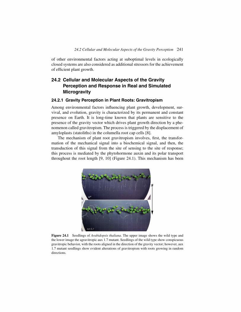
24.2 Cellular and Molecular Aspects of the Gravity Perception 241
of other environmental factors acting at suboptimal levels in ecologicallyclosed systems are also considered as additional stressors for the achievementof efficient plant growth.
24.2 Cellular and Molecular Aspects of the GravityPerception and Response in Real and SimulatedMicrogravity
24.2.1 Gravity Perception in Plant Roots: Gravitropism
Among environmental factors influencing plant growth, development, sur-vival, and evolution, gravity is characterized by its permanent and constantpresence on Earth. It is long-time known that plants are sensitive to thepresence of the gravity vector which drives plant growth direction by a phe-nomenon called gravitropism. The process is triggered by the displacement ofamyloplasts (statoliths) in the columella root cap cells [8].
The mechanism of plant root gravitropism involves, first, the transfor-mation of the mechanical signal into a biochemical signal, and then, thetransduction of this signal from the site of sensing to the site of response;this process is mediated by the phytohormone auxin and its polar transportthroughout the root length [9, 10] (Figure 24.1). This mechanism has been
Figure 24.1 Seedlings of Arabidopsis thaliana. The upper image shows the wild type andthe lower image the agravitropic aux 1.7 mutant. Seedlings of the wild type show conspicuousgravitropic behavior, with the roots aligned in the direction of the gravity vector; however, aux1.7 mutant seedlings show evident alterations of gravitropism with roots growing in randomdirections.

242 Growing Plants under Generated Extra-Terrestrial Environments
mainly elucidated by experiments consisting of changing the orientation ofgrowing seedlings. It was shown that a short time after seedling re-orientation,the root changes the direction of its growth according to the gravity vector.Root bending associated with the change in growth direction is caused by thealteration of the auxin polar transport, leading to the lateral re-distribution ofauxin in the distal regions of the root, which eventually results in a differentrate of elongation of cells located at both sides of the root in a specificzone (elongation zone) [11]. This morphological event is accompanied bya substantial reorganization of gene expression [12].
An important source of information on the mechanisms of gravitropismcomes from studies performed in the absence of gravity. On Earth, realweightlessness is obtained by free fall; however, values of the gravity vectornear zero (lower than 10−6 g) occur in long-duration missions, in spaceshipsorbiting the Earth, such as the International Space Station (ISS), or, previously,the Space Shuttle.
In early experiments in the Spacelab, it was shown that lentil root cellstatoliths did not distribute at random, but they accumulated in the proximalregion of columella cells [13]. In fact, statoliths are attached to actin filamentsby means of myosin, and this greatly affects their displacement within thecell [14]. Otherwise, the use of starchless Arabidopsis mutants in space-flight experiments provided support to the starch-statolith model for gravitysensing [15].
Space experiments have provided support to the role of auxin polartransport as a fundamental mediator of the transduction of the gravitysignal. Seedlings grown in space showed alterations in the auxin polartransport [16], and genes related to this process have been found to bedifferentially regulated in spaceflight- or parabolic-flight-grown samples[17–19].
The intrinsic constraints of space experimentation, mostly the limitationsof the general access to spaceflights, induced the development of ground-based devices capable of a reliable simulation of microgravity conditions.For this purpose, devices capable of counteracting the perception of the Earthgravity vector by plants, called clinostats, were designed and constructed.The first classical clinostats were introduced by Sachs in 1879 and allowed towork with simulated microgravity on Earth [reviewed by 3]. It is importantto emphasize, however, that these devices, including the most modern ones,such as the random positioning machine (RPM), do not suppress the gravityvector, but they only act at the level of the mechanism by which living beingsperceive it. In addition, recent technologies such as diamagnetic levitation can

24.2 Cellular and Molecular Aspects of the Gravity Perception 243
be used to produce a weightlessness environment for plants. This technologytakes advance of the major presence of diamagnetic materials in organisms(mostly water): by producing a high gradient of magnetic field into the smallvolume of the sample container in the magnet bore (a tube of around 5 cc), astrong levitation force is produced, which is capable of counteracting gravity.Although this technology has the advance of producing a continuous (notaveraged) effect, even detectable at the molecular level, it has the disadvantageof adding side effects, mostly the magnetic field itself, into the equation.On the other hand, it allows performing several partial g experiments (inthe gravity range between 0 and 2 g) at the same time and in the sameenvironment [3].
Ground-based facilities for microgravity simulation have demonstratedtheir usefulness in gravity-related research. In some cases, differences betweenthe statolith position in clinostats and in space have been reported [13], but,in general, results are largely comparable [20].
24.2.2 Effects on Cell Growth and Proliferation
Altered gravity produces changes in plant development, which are closelyassociated with modifications in the activities of meristems, specifically cellgrowth and cell proliferation/cell cycle. All adult plants contain meristematictissues, composed by populations of undifferentiated, highly proliferatingcells, capable of forming any specialized tissue at any time in the life span ofthe plant. Indeed, plant development greatly depends on the balance betweencell proliferation and cell differentiation in the meristems; these phenomenaare controlled, in turn, by the auxin [21]. Results obtained in space experimentsshowed altered cell proliferation rate in both lentil [22] and Arabidopsis[23]. Under microgravity conditions, cell proliferation and cell growth appearuncoupled, losing their coordinated progress which is called “meristematiccompetence” and is the main feature of these cells under normal ground gravityconditions [9, 23, 24].
It should be pointed out that spaceflight not only causes gravitational stress,but it also involves additional environmental modifications with respect to theEarth conditions, such as the confinement, the lack of gas convection, and thecosmic radiation, which may be sensed by plants, causing additional stresses[25]. For this reason, the results obtained in real microgravity have to besustained by studies carried out on ground, using the available facilities formicrogravity simulation [3] in combination with some of the stressors thatcould be present in extraterrestrial habitats.

244 Growing Plants under Generated Extra-Terrestrial Environments
24.2.3 Effects of Gravity Alteration on Gene Expression
A few studies on gene expression have been carried out in real or sim-ulated microgravity, by performing an overall transcriptomic analysis ofseedlings or solid cell cultures (calluses), to search for gravity-regulated genes.Experiments included reorientation of seedlings [12], cell cultures grown inground-based facilities for microgravity simulation [26, 27], and growth ofseedlings during parabolic flights [19] or in spaceflight conditions [17, 18].These studies have revealed a complex response of plants to gravity alteration,including changes in the expression of genes involved in general responses toother stresses, such as drought, cold, light, and biotic stimulation by pathogens.Heat shock-related genes, cell wall remodeling, and cell expansion genes, aswell as genes involved in oxidative burst and plant defense, are outstandingexamples of transcriptomic alterations shared by different kinds of plantstresses, including the gravitational one, and commonly reported in differentexperiments. However, in most studies, the existence of a specific responseto gravity alteration was suggested or postulated. Specific alterations affectgenes involved in the gravitropic response, such as those related to hormonesignaling, particularly auxin [17–19], and also a number of genes of unknownfunction. Furthermore, there is some specificity in the process of adaptationto spaceflight environment by different organs of the plant, which engagesdifferent genes, even though the general strategy of response is shared in allcases [18].An additional specific feature of gravity, as a permanent componentof the environment, is that it is capable of altering the perception and responseof living organisms to other environmental factors [26, 28].
24.3 Morpho-Functional Aspects of the Plant Responseto Real and Simulated Microgravity Environments
24.3.1 From Cell Metabolism to Organogenesis
Organogenesis is a complex phenomenon requiring a precise coordinationof cell proliferation, enlargement, and differentiation, which are regulated bygene expression and signaling biologically active molecules. The mechanismslinking cell division and the whole plant development have not been com-pletely understood yet [29]. As reported above, microgravity surely affectscell proliferation which is the first step for plant growth; in addition, cellenlargement and differentiation can be modified in altered gravity conditions.Most of the knowledge about the effect of microgravity on morphogenesis inhigher plants derives from experiments where seedlings, being the smallest

24.3 Morpho-Functional Aspects of the Plant Response 245
yet complete form of a plant, have been used as models due to volume andtime constraints. The whole plant life cycle has been investigated only in afew plant species characterized by small size, such as Arabidopsis spp. andBrassica spp. [2]. Indeed, vegetal systems characterized by reduced size bettermatch with volume constraints in the experimental facilities in space and donot encounter bending problems during clinorotation. The interest in studyingseedlings also derives from their high nutritional value which makes themsuitable candidates to reintegrate the crew’s diet with fresh food [30].
Morpho-anatomical changes detected in plants growing under real or sim-ulated microgravity have been often considered primarily as the consequenceof altered cytoskeleton organization, increased production of reactive oxygenspecies (ROS), and modifications in starch and phenylpropanoid metabolism.Cortical microtubule organization has been demonstrated to be affected byreduced or increased gravity levels in both gravisensing cells and in cells notspecialized to gravity perception in isolated protoplasts, root, and other organs[31–33]. The alteration of spatial organization of cytoskeleton microtubuleshas influence on cell growth because it not only regulates the cytoplasmexpansion, but also affects cellulose microfibrils orientation during cell walldevelopment, which in turn controls protoplast expansion [34, 35]. Increasedor decreased cell enlargement, sometimes ascribed to the accumulation ofethylene in the experiment containers during spaceflight, have been relatedto changes in seedling size [36]. The size of roots or hypocotyls was foundto increase, decrease, or remain unchanged in seedlings of various speciesexposed to clinorotation or real microgravity (see, for example, [37, 38]).Relatively few studies have focused on leaf development in space also withcontrasting results. Stutte et al. [39] showed that the minimal space-inducedmodifications in leaf structure (e.g., reduced thickness, more dense mesophyll,and altered chloroplast morphology accompanied by unchanged contentsin starch, soluble sugars, and lignin) of Triticum aestivum did not causeany physiological changes. These authors suggested that severe alterationsin the (ultra)structure of tissues and organelles, found in early spaceflightexperiments, were caused by an inadequate environmental control in theexperimental chambers.
24.3.2 Indirect Effects of Altered Gravity to Photosynthesis
The maintenance of high photosynthetic rate is needed to optimize O2production and CO2 removal in BLSS. Experiments conducted on dwarfwheat on the ISS showed that microgravity does not alter the development

246 Growing Plants under Generated Extra-Terrestrial Environments
of the photosynthetic apparatus and the efficiency of photosynthesis [39].While no changes in chloroplasts membranes were found in flown Arabidopsisthaliana, changes in the thylakoid structure occurred in T. aestivum and B. rapa(reviewed in [31]). Moreover, a decrease in the electron transport rate ofphotosystem I (PSI), measured in B. rapa suggested the major susceptibilityof the PSI in comparison with PSII. It has been recently highlighted that someof the structural and physiological changes of the photosynthetic apparatus inspace should not be considered as the result of a direct effect of microgravity,but as the consequence of starch accumulation due to the delayed long-distancetransport of photosynthetic metabolites [31, 40].
24.3.3 Constraints in the Achievement of the Seed-to-SeedCycle in Altered Gravity
The reproductive cycle is characterized by a succession of highly specificphases where mitosis and meiosis, as well as cell enlargement, follow oneanother in a few specialized cells. Whatever the factor affecting cell cyclesand cell growth, it can also affect one or more reproductive phases, thusultimately endangering seed set.
There is a common agreement that the reproductive failure claimed in theearly experiments performed in space was triggered by inefficient environmen-tal control in the growth chambers resulting in too high humidity, accumulationof ethylene, and insufficient carbon supply (reviewed in [2]). Problems in ven-tilation have been considered responsible for the interruption of the plant lifecycle in different phases, such as the transition from vegetative to reproductivestage, microsporogenesis, female gametophyte formation, anther dehiscence,pollination, and embryo development. Recent advances in space-relatedtechnologies allowed better control of growth chambers, thus facilitatingthe completion of the seed-to-seed cycle in various model species [41, 42].However, there is evidence that the quality of seeds produced in microgravityis not optimal: seeds of B. rapa formed in microgravity were characterized bysmaller size and different composition of the reserves compared to controls,probably because microgravity affects the microenvironment inside the silique[42]. Finally, it cannot be disregarded that some reproductive phases are strictlycontrolled by the coordinate activity of intracellular components, particularlycytoskeleton, which is affected by microgravity. For example, pollen tubedevelopment in simulated microgravity is subjected to alterations which couldreduce its capacity of fertilization [43]. To conclude, alterations in differentreproductive phases, due to direct or indirect effects of microgravity, can either

24.4 Plant Response to Real or Ground-Generated Ionizing Radiation 247
completely interrupt the reproductive cycle or determine progressive loweringof the reproductive success.
24.4 Plant Response to Real or Ground-GeneratedIonizing Radiation
24.4.1 Variability of Plant Response to Ionizing Radiation
Space radiation represents a major barrier to human exploration of the solarsystem because of the biological effects of high-energy and charge (HZE)nuclei [44]. The degree of damage is associated with different radiationtypes. High-linear energy transfer (LET)-ionizing radiations (e.g., protonsand heavy ions) have lower penetrating capability but are more dangerousthan low-LET ones (e.g. X- and gamma-rays) for both plant and mammaliancells [45–47].
The current knowledge about the biological effects of radiation onphotosynthetic organisms comes from experiments performed in long- andshort-duration space missions. Additional sources of information derive fromground-based experiments conducted by means of accelerators testing differ-ent ions and energy ranges on diverse species. Despite the high variabilityin the results, which often makes data hardly comparable, a common viewis that ionizing radiation can have stimulatory effects at very low doses,harmful consequences at middle levels, and detrimental outcomes at highdoses on plant development [46]. The severity of the effects is dependentupon several factors including the species, cultivar, phenological phase, andgenome organization [48].
24.4.2 Effects of Ionizing Radiation at Genetic, Structural,and Physiological Levels
Radiation-induced alterations are generally ascribed to the interaction of theradiation itself with atoms and molecules, which causes the production ofROS [49].
At genomic level, the structural and functional changes in the DNA areresponsible for most of the damage expressed after the exposure to ionizingradiations. The nature of DNA modifications is variable and includes single-base alterations, base substitutions, base deletions, chromosomal aberrations,and epigenetic modifications. Generally, chronically irradiated samples showa higher genomic instability compared to acutely exposed samples [50].

248 Growing Plants under Generated Extra-Terrestrial Environments
Radiation-induced morpho-functional changes can be either the pheno-typical expression of DNA aberrations or the consequence of the structuraldamage of tissues. The main alterations include reduced germination, lethality,loss of apical dominance, induction of dwarf growth, altered leaf anatomy,sterility, and accelerated senescence [46, 51]. The degradation of cell wallmaterials determines tissue softening, due to the dissolution of middlelamellae, and the increase in seed germination, ascribed to increased waterabsorption due to augmented porosity of seed teguments [52, 53].
Among processes regulating plant life, photosynthesis is one of the mostsensitive to radiation. Several components of the photosynthetic machinerymay be altered: light-harvesting complexes, electron transport carriers, andenzymes of the carbon reduction cycle [51, 54]. The severity of damagedepends on dose; the loss of PSII functionality, and the generation of ROSthroughout the cell are observed at very high doses.
The exposure to low doses of ionizing radiation may induce radioresistance[55]. Plants are very radioresistant compared to animals. At cellular level,radioresistance is achieved through the occurrence of mechanical and chemicalbarriers (e.g., specialized and thickened cell walls, cuticle, pubescence, andphenolic compounds), as well as by increasing the level of ploidy [45, 56,57]. The chronic exposure to low doses of ionizing radiation also leads tosignificant differences in the expression of radical scavenging enzymes andDNA-repair genes as well as to an increase in the activity of several antioxidantenzymes in plant tissues [55].
24.5 Conclusions—Living in a BLSS in Space:An Attainable Challenge
More than 50 years of experiments with higher plants in space suggest thatalmost all developmental and reproductive phases can be successfully over-come, ultimately leading to accomplish the seed-to-seed cycle for successivegenerations. However, possible perturbations can happen at various levels,from molecular to organism, thus lowering the efficiency of growth andreproduction processes. Such perturbations can be ascribed to the interactionbetween space factors and other environmental factors not acting at optimallevels.
The incessant development of new agro-technologies is promising forthe development of BLSS with adequate environmental control to reduce theeffect of multiple stressors on plant growth. Ground-based research aimingto the development of BLSS heads for soilless systems to minimize other
References 249
potential stresses during plant cultivation [58]. However, in space, it isnecessary to minimize the use of resources (e.g., lighting, electric power,water, and nutrients consumption). Consequently, a compromise needs to bereached to minimize external supply of resources, still without overcoming thethreshold over which suboptimal levels of environmental factors may worsenthe effects of microgravity and other space factors on plants. While new agro-technologies progress, the ground-based research with facilities simulatingweightlessness, ionizing radiation, and confined environments also needs toadvance. Such studies are necessary to elucidate the plant’s sensitivity to spacefactors in the sight of wider space experimentation.
References
[1] Sycheva, V.N., M.A. Levinskikha, S.A. Gostimskyb, G.E. Binghamc,and I.G. Podolskya. “Spaceflight Effects on Consecutive Generations ofPeas Grown Onboard the Russian Segment of the International SpaceStation.” Acta Astronautica 60 (2007): 426–432.
[2] De Micco, V., S. De Pascale, R. Paradiso, and G. Aronne. “MicrogravityEffects on Different Stages of Higher Plant Life Cycle and Completionof the Seed-to-Seed Cycle.” Plant Biology (Stuttg) 16 Suppl 1 (2014):31–38.
[3] Herranz, R., R. Anken, J. Boonstra, M. Braun, P.C.M. Christianen, M.D.Geest, J. Hauslage, R. Hilbig, R.J.A. Hill, M. Lebert, F.J. Medina, N.Vagt, O. Ullrich, J.J.W.A. van Loon, and R. Hemmersbach. “Ground-Based Facilities for Simulation of Microgravity: Organism-SpecificRecommendations for their Use, and Recommended Terminology.”Astrobiology 13 (2013): 1–17.
[4] Herranz, R., and F.J. Medina. “Cell Proliferation and Plant Develop-ment Under Novel Altered Gravity Environments.” Plant Biology 16,Suppl. 1 (2014): 23–30.
[5] Musgrave, M.E., A. Kuang, J. Allen, and J.J. van Loon. “HypergravityPrevents seed Production in Arabidopsis by Disrupting Pollen TubeGrowth.” Planta 230, vol. 5 (2009): 863–870.
[6] Soga, K. “Perception Mechanism of Gravistimuli in Gravity ResistanceResponses of Plants.” Biolgical Sciences in Space 18, vol. 3 (2004):92–93.
[7] Tamaoki, D., I. Karahara, T. Nishiuchi, T. Wakasugi, K. Yamada, andS. Kamisaka. “Effects of Hypergravity Stimulus on Global Gene

250 Growing Plants under Generated Extra-Terrestrial Environments
Expression During Reproductive Growth in Arabidopsis.” Plant Biology(Stuttg) 16, Suppl 1 (2014): 179–86.
[8] Baldwin, K.L., A.K. Strohm, and P.H. Masson. “Gravity Sensing andSignal Transduction in Vascular Plant Primary Roots.” American Journalof Botany 100, no. 1 (2013): 126–142.
[9] Medina, F.J., and R. Herranz. “Microgravity Environment UncouplesCell Growth and Cell Proliferation in Root Meristematic Cells: TheMediator Role of Auxin.” Plant Signaling & Behavior 5, no. 2 (2010):176–179.
[10] Teale, W.D., I.A. Paponov, and K. Palme. “Auxin in Action: Signalling,Transport and the Control of Plant Growth and Development.” NatureReviews Molecular Cell Biology 7, no. 11 (2006): 847–859.
[11] Friml J., J. Wisniewska, E. Benkova, K. Mendgen, and K. Palme.“Lateral Relocation of Auxin Efflux Regulator PIN3 Mediates Tropismin Arabidopsis.” Nature 415, no. 6873 (2002): 806–809.
[12] Moseyko, N., T. Zhu, H.S. Chang, X. Wang, and L.J. Feldman. “Tran-scription Profiling of the Early Gravitropic Response in ArabidopsisUsing High-Density Oligonucleotide Probe Microarrays.” Plant Phys-iology 130 (2002): 720–728.
[13] Perbal, G., D. Driss-Ecole, J. Rutin, and G. Salle. “Graviperceptionof Lentil Roots Grown in Space (Spacelab D1 Mission).” PhysiologiaPlantarum 70 (1987): 119–126.
[14] Perbal, G., and D. Driss-Ecole. “Contributions of Space Experimentsto the Study of Gravitropism.” Journal of Plant Growth Regulation 21(2002): 156–165.
[15] Kiss, J.Z., W.J. Katembe, and R.E. Edelmann. “Gravitropism andDevelopment of Wild-Type and Starch-Deficient mutants of ArabidopsisDuring Spaceflight. Physiologia Plantarum 102 (1998): 493–502.
[16] Ueda, J., K. Miyamoto, T. Yuda, T. Hoshino, S. Fujii, C. Mukai, S.Kamigaichi, S. Aizawa, I. Yoshizaki, T. Shimazu, and K. Fukui. “STS-95Space Experiment for Plant Growth and Development, and Auxin PolarTransport.” Biological Sciences in Space 14, no. 2 (2000): 47–57.
[17] M.J. Correll, T.P. Pyle, K.D.L. Millar, Y. Sun, J. Yao, R.E. Edelmann, andJ.Z. Kiss. “Transcriptome Analyses of Arabidopsis Thaliana SeedlingsGrown in Space: Implications for Gravity-Responsive Genes. Planta(2013): 1–15.
[18] Paul, A.-L., A. Zupanska, E. Schultz, and R. Ferl. “Organ-SpecificRemodeling of the Arabidopsis Transcriptome in response to space-flight.” BMC Plant Biology 13, no. 1 (2013): 112.

References 251
[19] Aubry-Hivet, D., H. Nziengui, K. Rapp, O. Oliveira, I.A. Paponov,Y. Li, J. Hauslage, N. Vagt, M. Braun, F.A. Ditengou, A. Dovzhenko, andK. Palme. “Analysis of Gene Expression During Parabolic FlightsReveals Distinct Early Gravity Responses in Arabidopsis roots.” PlantBiology 16 (2014): 129–141.
[20] Kraft, T.F.B., J.J.W.A. van Loon, and J.Z. Kiss. “Plastid Positionin Arabidopsis Columella Cells is Similar in Microgravity and on aRandom-Position Machine.” Planta 211 (2000): 415–422.
[21] Perrot-Rechenmann, C. “Cellular Responses to Auxin: Division VersusExpansion.” Cold Spring Harbor Perspectives in Biology 2, no. 5 (2010):a001446.
[22] Yu, F., D. Driss-École, J. Rembur, V. Legué, and G. Perbal. “Effectof Microgravity on the Cell Cycle in the Lentil Root.” PhysiologiaPlantarum 105 (1999): 171–178.
[23] Matía, I., F. González-Camacho, R. Herranz, J.Z. Kiss, G. Gasset,J.J.W.A. van Loon, R. Marco, and F.J. Medina. “Plant Cell Proliferationand Growth are Altered by Microgravity Conditions in Spaceflight.”Journal of Plant Physiology 167 no. 3 (2010): 184–193.
[24] Mizukami, Y. “A Matter of Size: Developmental Control of Organ Sizein Plants.” Current Opinion in Plant Biology 4, no. 6 (2001): 533–539.
[25] Paul, A.-L., C. Amalfitano, and R. Ferl. “Plant Growth Strategies areRemodeled by Spaceflight. BMC Plant Biology 12, no. 1 (2012): 232.
[26] Manzano,A., J. van Loon, P. Christianen, J. Gonzalez-Rubio, F.J. Medina,and R. Herranz. “Gravitational and Magnetic Field Variations Synergizeto Cause Subtle Variations in the Global Transcriptional State of Ara-bidopsis In Vitro Callus Cultures.” BMC Genomics 13, no. 1 (2012):105.
[27] Martzivanou, M., M. Babbick, M. Cogoli-Greuter, and R. Hampp.“Microgravity-Related Changes in Gene Expression After Short-TermExposure of Arabidopsis Thaliana Cell Cultures.” Protoplasma 229,no. 2–4 (2006): 155–162.
[28] Millar, K.D.L., P. Kumar, M.J. Correll, J.L. Mullen, R.P. Hangarter, R.E.Edelmann, and J.Z. Kiss. “A Novel Phototropic Response to Red Light isRevealed in Microgravity.” New Phytologist 186, no. 3 (2010): 648–656.
[29] Machida, Y., H. Fukaki, and T. Araki. “Plant Meristems and Organogen-esis: The New Era of Plant Developmental Research.” Plant Cell Physiol54, no. 3 (2013): 295–301.
[30] De Micco, V., G.Aronne, G. Colla, R. Fortezza, and S. De Pascale. “Agro-Biology for Bio-Regenerative Life Support Systems in Long-Term Space

252 Growing Plants under Generated Extra-Terrestrial Environments
Missions: General Constraints and the Italian efforts.” Journal of PlantInteractions 4, no. 4 (2009): 241–252.
[31] Kordyum, E.L. “Plant Cell Gravisensitivity and Adaptation to Micro-gravity.” Plant Biology (Stuttg) 16, Suppl 1 (2014): 79–90.
[32] Sieberer, B.J., H. Kieft, T. Franssen-Verheijen, A.M. Emons, J.W. Vos.“Cell proliferation, cell shape, and microtubule and cellulose microfibrilorganization of tobacco BY-2 cells are not altered by exposure to nearweightlessness in space.” Planta 230, no. 6 (2009): 1129–1140.
[33] Skagen, E.B., and T.H. Iversen. “Simulated Weightlessness and Hyper-gResults in Opposite Effects on the Regeneration of the Cortical Micro-tubule Array in Protoplasts from Brassica Napus Hypocotyls.” PhysiolPlant 106, no. 3 (1999): 318–325.
[34] De Micco, V., and G. Aronne. “Biometric Anatomy of Seedlings Devel-oped Onboard of Foton-M2 in anAutomatic System Supporting Growth.”Acta Astronautica 62 (2008): 505–513.
[35] Shevchenko, G.V., I.M. Kalinina, and E.L. Kordyum. “InteractionBetween Microtubules and Microfilaments in the Elongation Zone inArabidopsis Root Under Clinorotation.” Advances in Space Research 39(2007): 1171–1175.
[36] Kiss, J.Z., W.J. Katembe, and R.E. Edelmann. “Gravitropism and Devel-opment of Wild-Type and Starch-Deficient Mutants of ArabidopsisDuring Spaceflight.” Physiol Plant 102, no. 4 (1998): 493–502.
[37] Levine, L.H., H.G. Levine, E.C. Stryjewski, V. Prima, and W.C. Piastuch.“Effect of Spaceflight on Isoflavonoid Accumulation in Etiolated Soy-bean Seedlings.” Journal of Gravitational Physiology 8, no. 2 (2001):21–27.
[38] Perbal, G. “The Role of Gravity in Plant Development.” In A worldwithout gravity, B. Fitton and B. Battrick edited by. Vol. SP-1251.European Space Agency pp. 121–136, 2001.
[39] Stutte, G.W., O. Monje, G.D. Goins, and B.C. Tripathy. MicrogravityEffects on Thylakoid, Single Leaf, and Whole Canopy Photosynthesis ofDwarf Wheat. Planta 223, no. 1 (2005): 46–56.
[40] Kochubey, S.M., N.I. Adamchuk, E.I. Kordyum, and J.A. Guikema.“Microgravity Affects the Photosynthetic Apparatus of Brassica rapa.”Plant Biosystems 138 (2004): 1–9.
[41] Link, B.M., S.J. Durst, W. Zhou, and B. Stankovic. “Seed-to-SeedGrowth ofArabidopsis Thaliana on the International Space Station SpaceLife Sciences: Gravity-Related Processes in Plants.” Advances in SpaceResearch 31 (2003): 2237–2243.

References 253
[42] Musgrave, M.E., A. Kuang, Y. Xiao, S.C. Stout, G.E. Bingham, L.G.Briarty, M.A. Levenskikh, V.N. Sychev, and I.G. Podolski. GravityIndependence of Seed-to-Seed Cycling in Brassica rapa. Planta 210,no. 3 (2000): 400–406.
[43] De Micco, V., M. Scala, and G. Aronne. “Effects of Simulated Micro-gravity on Male Gametophyte of Prunus, Pyrus, and Brassica Species.”Protoplasma 228, no. 1-3 (2006): 121–126.
[44] Cucinotta, F.A., M.H. Kim, L.J. Chappell, and J.L. Huff. “How Safe isSafe Enough? Radiation Risk for a Human Mission to Mars.” PLoS One8, no. 10 (2013): e74988.
[45] Arena, C., V. De Micco, E. Macaeva, and R. Quintens. “Space RadiationEffects on Plant and Mammalian Cells.” Acta Astronautica 104 (2014):419–431.
[46] De Micco, V., C. Arena, D. Pignalosa, and M. Durante. “Effects ofSparsely and Densely Ionizing Radiation on Plants.” Radiation and Envi-ronmental Biophysics 50, no. 1 (2011): 1–19.
[47] Wei, L.J., Q. Yang, H.M. Xia, Y. Furusawa, S.H. Guan, P. Xin, andY.Q. Sun. “Analysis of Cytogenetic Damage in Rice Seeds Induced byEnergetic Heavy Ions On-Ground and After Spaceflight.” The Journalof Radiation Research 47, no. 3-4 (2006): 273–278.
[48] Holst, R.W., and D.J. Nagel. “Radiation effects on plants.” In Plants forEnvironmental Studies. Boca Raton, FL: Lewis Publishers, 1997.
[49] Wi, S.G., B.Y. Chung, J.S. Kim, J.H. Kim, M.H. Baek, J.W. Lee, andY.S. Kim. “Effect of Gamma Irradiation on Morphological Changes andBiological Responses in Plants.” Micron 38 (2007): 553–564.
[50] Tanaka, A., N. Shikazono, and Y. Hase. “Studies on Biological Effectsof Ion Beams on Lethality, Molecular Nature of Mutation, MutationRate, and Spectrum of Mutation Phenotype for Mutation Breeding inHigher Plants.” The Journal of Radiation Research 51, no. 3 (2010):223–233.
[51] Arena, C., V. De Micco, and A. De Maio. “Growth Alteration and LeafBiochemical Responses in Phaseolus Vulgaris Exposed to DifferentDoses of Ionising Radiation.” Plant Biol (Stuttg) 16, Suppl 1 (2014):194–202.
[52] Hammond, E.C., K. Bridgers, and F.D. Berry. “Germination, GrowthRates, and Electron Microscope Analysis of Tomato Seeds Flown on theLDEF.” Radiation Measurements 26 (1996): 851–861.
[53] Kovács, E., G. Ball, andA. Nessinger. “The Effect of Irradiation on SweetCherries.” Acta Alimentaria 24 (1995): 331–343.

254 Growing Plants under Generated Extra-Terrestrial Environments
[54] Arena, C., V. De Micco, G. Aronne, M.G. Pugliese, A. Virzo, and A. DeMaio. “Response of Phaseolus vulgaris L. Plants to Low-LET IonizingRadiation: Growth and Oxidative Stress.” Acta Astronautica 91 (2013):107–114.
[55] Zaka, R., C.M. Vandecasteele, and M.T. Misset. “Effects of Low ChronicDoses of Ionizing Radiation on Antioxidant Enzymes and G6PDHActivities in Stipa capillata (Poaceae).” Journal of Experimental Botany53, no. 376 (2002): 1979–1987.
[56] De Micco, V., C. Arena, and G. Aronne. “Anatomical Alterations ofPhaseolus vulgaris L. Mature Leaves Irradiated with X-rays.” Plant Biol(Stuttg) 16, Suppl 1 (2014): 187–193.
[57] Esnault, M.A., F. Legue, and C. Chenal. “Ionizing Radiation: Advancesin Plant Response.” Environmental and Experimental Botany 68 (2010):231–237.
[58] Paradiso, R., V. De Micco, R. Buonomo, G. Aronne, G. Barbieri, andS. De Pascale. “Soilless Cultivation of Soybean for BioregenerativeLife-Support Systems: A Literature Review and the Experience of theMELiSSA Project–Food Characterisation Phase I.” Plant Biol (Stuttg)16, Suppl 1 (2014): 69–78.
25Human Systems Physiology
Nandu Goswami1, Jerry Joseph Batzel1
and Giovanna Valenti2
1Gravitational Physiology and Medicine Research Unit,Institute of Physiology, Medical University of Graz, Austria2Department of Biosciences, Biotechnologies and Biopharmaceutics,University of Bari, Aldo Moro, Italy
25.1 Introduction
The main objective of this chapter is to examine bed rest as a ground-basedanalog for the effects of microgravity on integrative physiological systems asencountered in space flight. Many effects of microgravity are well-known andare reviewed elsewhere in this volume. However, as longer space flights arecontemplated, it becomes ever more important to be able to carry out well-controlled repeatable studies that probe these effects and allow for counter-measure strategies to be developed to limit the negative effects of microgravity.The bed rest study protocol, involving subjects lying in supine position over atime interval, represents such a highly controllable experimental environmentthat can provide important opportunities to examine physiological functionin response to reduced gravitational stress. Bed rest studies also allow forrelatively easy implementation and testing of countermeasures to reduce thedetrimental effects of microgravity.
25.2 Complications of Space-Based PhysiologicalResearch
While it is in some sense obvious, it is important to emphasize that in-flightexperiments often suffer from a number of procedural complications that canimpair the utilization and application of data collected during space flight and
255

256 Human Systems Physiology
Figure 25.1 Typical configuration of the 6◦ head down tilt bed rest paradigm. (Image: ESA).
which can also complicate the comparison of data collected across missions[8]. These include the following:
• problems in experimental reproducibility such as limited size anduncoordinated astronaut sample populations;
• variations in quality and protocol of data measurements;• lack of coordination in measurements across missions;• lack of opportunity to carry out variations in experimental protocols based
on new information due to restricted flight availability;• possible usage of in-flight medication; and• possible interference in spaceflight data from other protocols.
Therefore, there is clearly a need to have ground-based analogs of space-flight which can be used to study spaceflight induced deconditioning and testnew and novel countermeasures.
25.3 Ground-Based Analogs of Spaceflight-InducedDeconditioning: Bed Rest and Immersion
Commonly used ground-based analogs include bed rest studies and waterimmersion. Clearly, both bed rest studies and immersion can avoid allthe above-outlined technical problems while altering various features ofgravitational loading. Water immersion involves either direct contact of thebody with water (“wet”), or with the body insulated from the water (“dry”).An interesting review of long-term water (dry) immersion as a model for

25.4 Types of Bed Rest, Durations, and Protocols 257
microgravity is given in Navasiolava et al. (2011), which also provides someparallel comparisons to bed rest [15]. Water immersion typically allows for onehygiene period out of immersion per day and long periods of immersion mustbe carried out as dry immersion, which is somewhat complicated to implementregarding experimental measurements and testing of countermeasures. As aconsequence, the technical problems of water immersion are more involvedthan for bed rest studies. In this chapter, emphasis will be placed on bed reststudies. Some description of the bed rest study protocol will be provided alongwith discussion of the key question as to whether the results obtained fromsuch studies reflect those that are obtained from spaceflight. Similarities anddifferences between bed rest and water immersion will also be consideredwhere relevant.
25.4 Types of Bed Rest, Durations, and Protocols
The first studies of bed rest related to space flight began soon after humanspace travel began. A book published in 1986 entitled “Inactivity: physiolog-ical effects” edited by Sandler and Vernikos [20] pointed to early researchas taking inactivity as a model of deconditioning and as a primary paradigmfor space flight effects [16]. Over time, a broader recognition of the manyinteracting effects of microgravity on the body viewed as a whole organismwas established as was the model of simulating microgravity via head downbed rest [12, 16, 19].
Over the years, researchers working in the area of gravitational andspaceflight physiology have used subjects who were bed-rested in the supineposition or at various levels of head down tilt such as 5◦, 10◦, or 15◦(referred to here as head down bed rest, HDBR). For the details of bed reststudies that have used different angles of tilt as well as varying durationsof bed rest, the reader is referred to Sandler and Vernikos [20]. To mimicthe effects of microgravity, 6-degree head down supine body position is thestandard implementation, which acts to equilibrate the distribution of bloodand tissue volume, simulating the lack of gravitational pull to the lowerbody [12, 16].
Bed rest studies can be adjusted to mimic various space flight durationsas well. Typical duration spans are short-term (5–7 days), medium-term(21 days), and long-term studies (60–90 days). Bed rest studies can berestricted to all male or all female studies such as a 90-day male bed reststudy in 2001/2002 and the 60-day female bed rest study WISE-2005 [12].

258 Human Systems Physiology
Recently, there have been initiatives to introduce some standardizationin bed rest study protocols to allow for greater cross-study exploitation ofdata [6, 12]. Such standardization would reduce confounding influences andallow for the comparison of different systems or different measurements undera common perturbation.
25.5 Physiological Systems Affected by Spaceflightand Bed Rest
Lack of gravity poses many challenges, which can impair the function of anumber of physiological systems. On the other hand, microgravity representsa unique window for observing the response of physiological systems becauseit represents the suspension of those evolutionary challenges that shapedsuch systems. Bed rest studies allow for more delicate, complex, and eveninvasive measurements, which may be difficult or impossible to implementor to accurately carry out in space such as bone marrow biopsies or complexsonographies.
Direct information on microgravitational effects in space flight and infor-mation from bed rest studies reenforce the understanding of effects in bothareas, and together, both sources of information can provide further novelinformation on physiological system function in general and in specificprocesses. For example, bed rest and spaceflight are both accompanied byloss of plasma volume and hemoconcentration, thus leading to a higher risk ofblood clotting with potential dire consequences. We are not aware, however,of any study that examined clotting changes during spaceflight. On the otherhand, there are several studies, which have examined the effects of physicalinactivity during bed rest on clotting [9].
Similarly, recovery from bed rest immobilization provides an importantsurrogate for astronaut recovery after flight as well. Deconditioning followingeither weightlessness or bed rest shares many effects and symptoms charac-terized by orthostatic intolerance (OI) [4]. Hence, studies that reflect on theorigin of OI and the efficacy of countermeasures in the bed rest context can beexpected to translate into countermeasures in space. The review by Convertino[4] provides useful examples of this observation. In addition, studies inboth microgravity and bed rest conditions can provide information on thephysiology and clinical problems related to OI and potential countermeasuresfor patients suffering from OI.
A great deal of research related to physiological effects of microgravity inspace and simulated microgravity during bed rest has been published, and

25.5 Physiological Systems Affected by Spaceflight and Bed Rest 259
review articles summarizing this research have appeared as well. In thissection, we mention several reviews in specific areas as well as generalreviews, which cumulatively set the context for taking bed rest as a valid surro-gate for space microgravity. We now discuss some key physiological systemswhere important parallels can be made between the physiological effects ofmicrogravity and bed rest. These areas include the autonomic nervous system,musculo-skeletal system, cardiovascular system, neuro-vestibular system,immune system, and the renal system.
Autonomic nervous system (ANS): The ANS is involved in the control ofcardiovascular, thermoregulatory, respiratory, metabolic, gastrointestinal, andmany other systems, and gravity influences these systems not only directlybut also through feedback control mechanisms involving autonomic functionwhich are thus impacted by a lack of gravitational stress from multiplesources. For example, sympathetic-vestibular links to blood pressure controlare influenced by bedrest [7] as have effects of microgravity on baroreceptorsensitivity [1].
Musculo-skeletal system: Due to a lack of gravitational loading on themusculoskeletal system, muscle loss and bone loss occur during bed rest andspaceflight [10]. Indeed, bed rest has been recognized as a very useful andappropriate model for bone loss observed in space flight and microgravity[6, 13, 24]. The effects during bed rest on bone mineral density, bone markers,and calcium balance, and excretion are qualitatively consistent (although oflesser magnitude) to those deleterious effects seen in space flight [13]. Bed resthas also been used to test countermeasures to mitigate these effects. The reviewby Leblanc et al (2007) provides an extensive comparison and assessment ofbed rest and space flight data on bone loss [13].
Cardiovascular system: The bed rest model can very effectively reflectthe effects of microgravity on the cardiovascular system and in particularcardiovascular deconditioning and orthostatic intolerance (see [4]). The effectof reduction in plasma volume induced by microgravity impacts cardiacfunction in a variety of ways and reduces baroreflex sensitivity as well [24].Many of these effects can also be seen in HDBR (see [16]), indicating theappropriateness of this model for studying the effects of microgravity aswell as potentially linking these effects with the deconditioning in aging(see below).
Neurovestibular system: This system integrates mechanisms related toposture, eye movements, spatial orientation, and higher cognitive processessuch as 3-D vision. This system also plays a role in the respiratory andcardiovascular systems, as well as many other regulatory mechanisms such

260 Human Systems Physiology
as circadian regulation. Weightlessness impacts vestibular function in manyways, and HDBR may also induce related effects. The study by Dyckmanet al (2012) indicates an impact of bed rest on the vestibulo-sympatheticresponse, which may influence blood pressure control and hence play a rolein orthostatic intolerance [7]. This study illustrates the point that, given thecomplexity of interacting systems, the parallels between microgravity andhead down bed rest need to be carefully considered when drawing inferencesin specific scenarios.
Immune system: This complex system is certainly influenced by spaceflightand can be be affected by many factors including stress and exposure toradiation [6]. Bed rest studies related to immune system effects can differfrom effects seen in space [6]. Hence, it is not clear how appropriate the bedrest model is for immune effects although it can serve as a comparison for othermodels [6]. The immune system response highlights again the fact that caremust be taken when considering parallels between space flight microgravityand bed rest.
Renal function, volume regulation and aquaporins: Body water balance isregulated by vasopressin. Vasopressin signaling promotes water reabsorptionin the renal collecting duct by triggering redistribution of the water channelsAquaporin-2 (AQP2) from intracellular vesicles into the plasma membrane[23]. AQP2 is partially excreted in the urine [22] and can represent a usefulnoninvasive biomarker for understanding the physiological renal response(and adaptation) to alteration in external gravity. AQP2 excretion has beenevaluated as a biomarker of renal adaptation to microgravity in both waterimmersion and HDBR models [22, 23].
In addition to the studies and reviews on specific physiological topicsreferenced above, several very useful general reviews have been pub-lished. Pavy-Le Traon et al (2007) provide a comprehensive review ofresearch over the last 20 years of important areas where the effects ofbed rest and microgravity overlap [16]. This review provides a convincingcase for viewing bed rest as a powerful research tool and useful ana-log for studying the effects of microgravity. The review by Vernikos andSchneider (2010) presents many parallels between physiological effects ofbed rest, microgravity, and aging, providing clear insight into how thesethree physiological conditions can be merged and coordinated to pro-vide a more global view of physiological function [24]. The review byNavasiolava et al (2011) provides a comparative look of bed rest and waterimmersion [15].

25.6 Is Bed Rest a Valid Analog for Microgravity-Induced Changes? 261
25.6 Is Bed Rest a Valid Analog for Microgravity-InducedChanges?
A key issue is the degree to which bed rest represents a useful surrogatefor microgravity, leading to knowledge reflecting the physiological responsesto microgravity in space flight and information transferable to the design ofeffective countermeasures against the negative effects of microgravity. HDBR(typically at 6◦) is the most commonly used protocol to mimic microgravityespecially for long-duration studies [5] and in relation to complex physiolog-ical effects [6]. Horizontal supine bed rest immobilization has also been usedto simulate spaceflight induced deconditioning. While both horizontal supinebed rest and HDBR cause deconditioning, cephalad fluid shifts, and the onsetof hemodynamic changes appear faster during HDBR (detailed in [20]).
The acceptance of HDBR as a valid surrogate for global and specificmicro-gravitational influences on human physiology emerged as a conse-quence of carrying out many bed rest studies focusing on specific physiologicalareas over a wide range of systems and comparing results to direct physiolog-ical studies of astronauts and cosmonauts. For example, OI is an importantproblem for returning astronauts [2] and bed rest subjects face similar problemsat the end of the experimental bed rest procedure. The review of the appli-cability of bed rest data to the problem of OI after space flight given in [4]illustrates the usefulness of the comparison between these two manifestationsof OI.
While HDBR has been widely accepted as a valid surrogate protocolfor microgravity in studying physiological systems, it is important to notethat the information from bed rest studies needs to be carefully assessed inits application to microgravity given that bed rest is not a perfect parallelfor microgravity. For example, some research suggests that certain immunesystem responses are affected by stresses seen in space flight rather thanas a direct result of microgravity [17, 24]. Hence, specific immune systemeffects may not always arise in bed rest-simulated microgravity [6] (see alsodiscussion above on immune system).
In addition, physiological responses can vary between ground-basedanalogs. As mentioned above, AQP2 excretion has been evaluated as abiomarker of renal adaptation to microgravity in both water immersion andHDBR models [22, 23]. These studies revealed that while AQP2 excretionis probably not a good biomarker to monitor renal fluid regulation duringacute water immersion, it could instead represent a reliable and informativeparameter during prolonged bed rest and possibly under chronic adaptation

262 Human Systems Physiology
to microgravity in space. Specifically, it has been found that bed rest inducesa biphasic response in AQP2 excretion which is in agreement with expectedfluid redistribution in microgravity: in the early phase the decrease in AQP2excretion is paralleled by an increase in hematocrit due to reduction in plasmavolume, whereas the subsequent increase in AQP2 excretion is paralleledby a partial restoration of hematocrit likely due to an AQP2-mediated waterreabsorption in an attempt to restore normal plasma volume. The increase inAQP2 excretion may be consequent to an increase in vasopressin (because ofreduced plasma volume) as also observed in astronauts during microgravity.These results make urinary AQP2 excretion a reliable biomarker of renalwater handling during prolonged bed rest and more appropriate in groundbased models to mimic chronic adaptation to microgravity.
Confounding factors and interrelated effects that could differ between themicrogravity of space and the simulated microgravity of bed rest (or waterimmersion) may be very difficult to analyze. For example, vestibular controldepends on position, orientation, movement, vision, and gravitational signals,and interacting effects may be very complex as seen in a study of vestibular-sympathetic response and its relation to OI in short-term and long-term bedrest [7]. One needs to clearly establish whether, when and how effects differbetween a fixed supine position mimicking microgravity compared to movingastronauts experiencing direct microgravity. Indeed, differences can arise inthe physiological effects among the three situations of true microgravity,HDBR, and water immersion. For example, each of these three situationsinvolves differing influences on tissue and vascular distribution of fluids[19]. Hence, for effective modeling of microgravity effects (or the effects ofaging for that matter), one needs to consider whether any differences betweentrue microgravity and microgravity surrogates can be ignored when drawingparallels for the specific phyiological mechanisms under study and when thesedifferences may distort conclusions.
25.7 Bed Rest: A Testing Platform for Applicationof Countermeasures to Alleviate Effectsof Microgravity—Induced Deconditioning
Countermeasures to microgravitational effects can be designed and incorpo-rated in bed rest studies to test many potential approaches including suchnovel methods as short-arm centrifuge, [3] which in addition can incorpo-rates ergometric exercise [14]. Such methods can be tested for preventing

References 263
or reducing spaceflight deconditioning impairing cardiovascular, bonemetabolism, musculoskeletal, autonomic, and other system functions. Infor-mation derived from tests of possible countermeasures for spaceflight decon-ditioning will be critical for microgravity exposures of long duration as willbe encountered, for example, during a mission to Mars. An example ofanalysis related to deconditioning and aerobic exercise during bed rest canbe found in Lee et al (2010) [14], and the implementation of centrifugationas a countermeasure implemented via bed rest is illustrated in Clément andPavy-Le Traon (2004) [3]. Combined exercise and nutrition countermeasureshave been discussed in Schneider et al (2009) [21].
25.8 Perspectives
In addition to the direct application to space flight, bed rest and otherimmobilization studies have been designed and carried out to study manyother physiological conditions related to a diverse set of situations such ashospital demobilization after surgery or injury, coma, paralysis, as well as tostudy the effects that arise due to aging. It is important to note that there is apotential for developing a powerful synergy of information relating broaderbed rest problems and the problem of microgravity. In particular, there are clearpotential parallels between microgravity, aging, and immobilization [24].
Bed rest (and water immersion) are global models for the effects ofmicrogravity, influencing a number of systems simultaneously. This is animportant advantage but it is also possible to consider models of microgravitythat influence individual systems or specific system levels. For example,specialized devices have been used for studying the effects of reduced gravityat the cellular level [11]. Hence, one always needs to keep in mind the researchgoals when considering appropriate surrogates for physiological effects ofmicrogravity and space flight.
References
[1] Natalia M. Arzeno, Michael B. Stenger, Stuart M. C. Lee, Robert Ploutz-Snyder and Steven H. Platts. Sex differences in blood pressure controlduring 6◦ head-down tilt bed rest. American Journal of Physiology HeartCirculation Physiology, 15, 304, 8: H1114–1123, 2013.
[2] Andrew P. Blaber, Nandu Goswami, Roberta L. Bondar and MohammedS. Kassam. Impairment of cerebral blood flow regulation in astronautswith orthostatic intolerance after flight. Stroke, 42, 7:1844–1850, 2011.

264 Human Systems Physiology
[3] Gilles Clément and Anne Pavy-Le-Traon. Centrifugation as a counter-measure during actual and simulated microgravity: a review. EuropeanJournal of Applied Physiology, 92, 3: 235–248, 2004.
[4] Victor A. Convertino. Insight into mechanisms of reduced orthostaticperformance after exposure to microgravity: comparison of ground-basedand space flight data. Journal of Gravitational Physiology, 5, 1: 85–88,1998.
[5] Victor A. Convertino and Caroline A. Rickards. Human models of spacephysiology. Chapter 48 In: Conn, P. Michael (ed,) Source book of modelsfor biomedical research, Humana Press- Springer, Trenton, pp 457–464,2008.
[6] Brian E. Crucian, Raymond P. Stowe, Satish K. Mehta, Deborah L.Yetman, Melanie J. Leal, Heather D. Quiriarte, Duane L. Pierson andClarence F. Sams. Immune status, latent viral reactivation, and stressduring long-duration head-down bed rest. Aviation Space EnvironmentalMedicine, 80(5 Suppl): A37–44, 2009.
[7] Damian J. Dyckman, Charity L. Sauder and Chester A. Ray. Effects ofshort-term and prolonged bed rest on the vastibulosympathetic reflex.American Journal of Physiology Heart Circulation Physiology 302, 1:H368–374, 2012.
[8] Nandu Goswami, Jerry J. Batzel, Gilles Clement, Peter T. Stein, Alan R.Hargens, Keith M. Sharp,Andrew P. Blaber, Peter G. Roma and Helmut G.Hinghofer-Szalkay. Maximizing information from space data resources:a case for expanding integration across research disciplines. EuropeanJournal of Applied Physiology, 113: 1645–1654, 2013.
[9] Gerhard Cvirn, James Elvis Waha, Gerhard Ledinski, Axel Schlagen-hauf, Bettina Leschnik, Martin Koestenberger, Erwin Tafeit, HelmutHinghofer-Szalkay and Nandu Goswami. Bed rest does not inducehypercoagulability. European Journal of Clinical Invesigation. 2014 Nov21. doi: 10.1111/eci.12383.
[10] Alan R. Hargens, Roshmi Bhattacharya and Susanne M. Schneider.Space physiology VI: exercise, artificial gravity, and countermeasuredevelopment for prolonged space flight. European Journal of AppliedPhysiology, 113: 2183–2192, 2013.
[11] Lifang Hu, Runzhi Li, Peihong Su, Yasir Arfat, Ge Zhang, Peng Shangand Airong Qian. Response and adaptation of bone cells to simulatedmicrogravity. Acta Astronautica, 104(1), 396–408, 2014.
[12] Peter D. Jost. Simulating human space physiology with bed rest.Hippokratia suppl 1: 37–40, 2008.

References 265
[13] Adrian D. LeBlanc, Elisabeth R. Spector, Harlan J. Evans andJean D. Sibonga. Skeletal responses to space flight and the bed restanalog: a review. Journal of Musculoskeletal Neuronal Interactions, 7,1:33–47, 2007.
[14] Stuart M. C. Lee, Alan D. Moore, Meghan E. Everett, Michael B. Stengerand Steven H. Platts. Aerobic exercise deconditioning and countermea-sures during bed rest. Aviation Space Environmental Medicine, 81,1,52–63, 2010.
[15] Nastassia M. Navasiolava, Marc-Antoine Custaud, Elena S. Tomil-ovskaya, Irina M. Larina, Tadaaki Mano, Guillemette Gauquelin-Koch,Claude Gharib and Inesa B. Kozlovskaya. Long-term dry immer-sion:review and prospects. European Journal of Applied Physiology,111, 7: 1235–1260, 2011.
[16] Anne Pavy-Le Traon, Martina Heer, Marco Narici, Joern Rittweger andJoan Vernikos. From space to earth: advances in human physiology from20 years of bed rest studies (1986–2006). European Journal of AppliedPhysiology, 101: 143–194, 2007.
[17] Duane L. Pierson, Satish K. Mehta and Raymond P. Stowe. Reactivationof latent herpes viruses in astronauts. In: Psychoneuroimmunology (4thed.), edited by Ader R., Felten D. L. and Cohen N. Philadelphia, PA:Elsevier, Inc., p. 851–868, 2007.
[18] Valerie V. Polyakov, Natasha G. Lacota and Alexander Gundel. Humanthermohomeostasis onboard “Mir” and in simulated microgravity stud-ies. Acta Astronauta, 49: 137–43, 2001.
[19] Jacques Regnard, Martina Heer, Christian Drummer and Peter Norsk.Validity of microgravity simulation models on earth. American Journalof Kidney Disease, 38, 3, 668–674, 2001.
[20] Harold Sandler and Joan Vernikos (eds.). Inactivity: physiologicaleffects. Academic Press, New York, 1986.
[21] Suzanne M. Schneider, Stuart M. C. Lee, Brandon R. Macias, Donald E.Watenpaugh and Alan R. Hargens. WISE-2005: exercise and nutritioncountermeasures for upright VO2pk during bed rest. Medicine ScienceSports and Exercise, 41: 2165–2176, 2009.
[22] Grazia Tamma, Annarita Di Mise, Marianna Ranieri, Maria Svelto, RadoPisot, Giancarlo Bilancio, Pierpaolo Cavallo, Natale G. De Santo, Mas-simo Cirillo and Giovanna Valenti. A decrease in aquaporin 2 excretion isassociated with bed rest induced high calciuria, Journal of TranslationalMedicine, 12, 133–134, 2014.

266 Human Systems Physiology
[23] Giovanna Valenti, Walter Fraszl, F. Addabbo, Grazia Tamma, Procino G.,E. Satta, Massimo Cirillo, Natale G. De Santo, Christian Drummer, L.Bellini L. et al., Water immersion is associated with an increase inaquaporin-2 excretion in healthy volunteers. Biochim Biophys Acta,1758, 8, 1111–1116, 2006.
[24] Joan Vernikos and Suzanne V. Schneider. Space, gravity and the phys-iology of aging: parallel or convergent disciplines? A mini-review.Gerontology, 56, 2:157–166, 2010.

26Behavior, Confinement, and Isolation
Carole Tafforin
Ethospace, Toulouse, France
With long-term space missions, behavioral scientists agree that the personaland interpersonal adaptive processes became of prime importance for crewperformance in isolation and confinement. Anecdotal reports from crewsof the Russian orbital station (Mir) and the International Space Station(ISS) indicated such psychosocial issues. The crewmembers thus have toadapt to a wide range of environmental factors: reduced and closed space,life-support restriction, group density, delayed communication, far fromcivilization, lack of variety of food, lack of natural light and surrounding,lack of privacy, and monotony of daily life. These include factors related tospace crew heterogeneity: interpersonality, crew demographics, value, culture,and language background. Effective procedures for selection, training, andpsychological support will help to determine the outcome of next spacemissions and space explorations. Psychosocial adaptation to a Mars missionis a new challenge [1] and involves temporal factor in a novel way. Time hasdefinitely an impact on behavior. For simulating those factors, generating onEarth an extra-terrestrial environment would help in getting better knowledgeof human factors with a focus on the behavior of confined and isolatedcrews.
Researches specifically relevant to confined crews concern underseahabitats including submarines campaigns and closed-tanks experiments inmulti-chamber facilities (i.e., the space simulators).
The current results in Capsule habitats state a positive psychology in termsof salutogenic adaptation [2] although inter-individual conflicts, changes ofmood, high levels of tension/anxiety, depression and mental disturbancesdue to deprivations, dangers, and stresses were detected. They have animpact on coping style, efficiency at work, motivation to the mission goal,
267

268 Behavior, Confinement, and Isolation
cognitive functioning, crew cohesion, and crewmember’s well-being as aresult.
During NEEMO1 missions for instance, the individuals that lived insidethe divers’ undersea habitat with strict life-support and worked outside fortesting equipment in buoyancy, experienced a powerful training that have anenduring value, a benefic effect, and an optimized success for their allottedspace missions. High crewmember autonomy would become the norm forfuture exploratory missions [3].
During submarine missions, the crew is confronted to additional envi-ronmental properties: crowding, schedule per quarters, absence of day/nightcues, no communication with Earth, no information on underway position, andprolonged dangerous operations. The rigorous and very long crew training thatoccurs before military deployments and the presence of strong hierarchicalrules lead to behavioral stereotypes and over-learned technical responses [4]that do not permit uncertain outcomes in the adaptive process.
Closed tank experiments were justly designed with the aim of studyingthe crewmembers’ behavioral strategies of adaptation. Ethological investiga-tions made during ISEMSI2, EXEMSI3, and HUBES4 experiments describedchanges in social behavior over time and according to the environmental situ-ation [5]. Within large or open areas, interindividual distances were constant.In reduced habitats, the frequency of personal distances, according to Hall’sclassification, decreased and the frequency of public distances increased withhigh levels of social distance and body mobility from the initial period to thefinal period of confinement. Over the campaigns, living and working togetherin closed tanks were more and more stressful and the long-term adaptiveprocess was not still achieved after 135 days. In the SFINCSS5 experiment,comparing one group confined for 240 days and two groups for 110 days,differences in culture and attitudes toward gender were factors identifiedas having a major impact on the intergroup relationship [6]. Other resultsindicated coping behaviors. Environmental stresses were identified alteringwell-being and human performance inside the multi-chamber facilities.
The Mars-500 experiment offered an exceptional paradigm that promotedfurther advances on crew behavior not only in confinement but also in extendedtime period and in high autonomy. Summarized results from multidisciplinary
1NASA Extreme Environment Mission Operations.2Isolation Study for European Manned Space Infrastructure.3EXperimental campaign for European Manned Space Infrastructure.4HUman Behavior in Extended Space flight.5Simulation of Flight International Crew on Space Station.

Behavior, Confinement, and Isolation 269
approaches [7] showed a progressive reduction in physical activities duringthe course of the simulation, disturbances in sleep quality and quantity,changes in patterns of language within the high autonomy phase and duringMars landing period, increased perceived homogeneity in personal values,consistency in the most salient personal goals, gain of positive strengthsfrom demanding situation, and increased loneliness particularly at the endof 520-day confinement. An ethological monitoring of the crew globallypointed out time effects, cultural preferences and individual differences in thecrew’s actions, interactions, expressions and communications during Mars-500 experiment. A personal account by the crewmembers who experiencedthis simulated interplanetary flight reported, for some of them, difficult periodswhen few contacts were arriving from outside, and for all of them, the lackof connection with nature, the lack of fresh and variety of food, and theimportance of communication channels. Psychological crew support pro-gram, implemented as countermeasure in the experiment, provided efficientcommunication sessions.
Such studies have demonstrated the interest to extend ground simulationsof the psychosocial environment encountered during very long-duration staysin isolation and confinement. This conducted to a focus on the isolation factor.
Researches specifically relevant to isolated crews concern polar regionsstays in Antarctica and in Arctic and dessertic lands (i.e., the analogueenvironments).
The most salient data collected from numerous winterovers in South Polestations led to propose four characteristics regarding psychosocial adaptationto isolation in extreme settings: adaptation is situational, adaptation is social,adaptation is cyclic, and adaptation is salutogenic according to Palinkas citedin [8]. However, a significant increase in depressed mood was emphasizedin men and women who spent a year at Mac Murdo Station and Amundson-Scott station in Antarctica [9], for example. All-female crews are rare andmixed-gender expeditions were developed. This provides evidence of theheterogeneous groundwork of a crew to cope, regulate, and adapt for abetter equilibrium in isolation conditions. Considering multi-cultural crews,cross-cultural comparisons have provided some findings that suggest a char-acteristic personality trait profile in the Antarctic expeditioner [10] that maybe considered in the future to select space explorer.
Studies performed at the FMAR6 in Devon Island, indicated differencesbetween individual coping styles across time. Stress decreased for females
6Flashline Mars Arctic Research Station.

270 Behavior, Confinement, and Isolation
while it increased for males who demonstrated higher levels of excitement,tiredness, and loneliness [11]. The results concluded that simulations ofprolonged real isolation and hostile natural environment appear to provoketrue demands for adaptation that actually approaches interplanetary missions.Depending on weather conditions, the crew stays for short-term (mimickingMoon landing) or for long-term missions (mimicking Mars landing). In bothcases, the adaptation is situational.
As test beds for field operations, studies at the MDRS7 in Utah desertinvestigated crew selection protocols, tested key habitat design features,replicated space food packages, compared mission crews with backup crews,analyzed the high workload on crew vigilance, and examined communicationsin multi-lingual crews, among other investigations. Preliminary works onlanguage skills revealed that verbal and nonverbal expressions were influencedby the cultural background such as native language, by their respective roleswithin the crew and the crewmembers’ spirit [12]. They contributed to showthat the adaptation is social.
The most recently built station in Polar Regions was Concordia at DomeC. This South Pole base serves as research laboratories with a particularinterest on space life sciences. The crews who stay there are considered aswinterers but also as interplanetary crewmembers because of similarities withthe personnel composition, architectural structure, and temporal scale. With anemphasis on the long-duration factor, ethological observations made weeklyduring a collective activity at meal times, allowed to describe and quantifiedcertain profiles of social behavior according to the mission day. Interesting datawere on the collective attendance and collective time. The results showed forinstance, periodic changes in the number of winterers attending the meals,over three periods of 13 weeks each (Figure 26.1) and cyclic variations inthe time spent altogether at meals, every 7 weeks (Figure 26.2). A Marsmission scenario on different crew organizations over time could be appliedin real mission. These findings further demonstrated that the adaptation iscyclic.
With the opportunity of Tara expedition in Arctic, the environmentalproperties became more and more stressful because of the combined isolationand confinement factors in synergy with the associated periods of winterovertotalizing 507 days in duration like a Mars mission. Preliminary results[13] showed that the irregularity of collective time and the variations ofinter-individual positions were behavioral indicators that would prevent the
7Mars Desert Research Station.

Behavior, Confinement, and Isolation 271
Figure 26.1 Collective attendance at the morning meal, midday meal and evening meal, atConcordia station in Antarctic, according to the days (mission DC2, 2006).
Figure 26.2 Collective time at the evening meal, at Concordia station in Antarctic, accordingto the days (mission DC2, 2006).

272 Behavior, Confinement, and Isolation
monotony of daily life. A complete study is in process. It should support thestatement that the adaptation is salutogenic.
These examples highlight the key issues relevant to researches on isolatedand confined crews’behavior in order to provide the space crews with the bestquality of life and success of missions. A synthesis on psychology of spaceexploration exhaustively reviewed contributions in the area [8].
Future researches might include further studies on cognitive issues interms of new crewmember’s representation of the crew and in terms of newcrewmember’s representation of the outsight.
Acknowledgement
The author would like to thank the French Space Agency for its financialsupport.
References
[1] Fiedler, Edna R., and Albert A. Harrison. “Psychosocial Adaptation to aMars Mission.” Journal of Cosmology 12 (2010): 3694–3710.
[2] Suedfeld, Peter and G. Daniel Steel. “The Environmental Psychology ofCapsule Habitats.” Annual Review of Psychology, 51 (2000): 227–253.
[3] Eid, Jarle, Bjorn H. Johnsen, Evelyn-Rose Saus, and Jan Risberg. “Stressand Coping in a Week-Long Disabled Submarine Exercise.” AviationSpace and Environmental Medicine 75, no. 7 (2004): 616–621.
[4] Kanas, Nick, Stephanie Saylor, Matthew Harris, et al. “High VersusLow Crewmember Autonomy in Space Simulation Environments.” ActaAstronautica 67 (2010): 731–738.
[5] Tafforin, Carole. “Ethological Indicators of Isolated and ConfinedTeams in the Perspective of Missions to Mars.” Aviation Space andEnvironmental Medicine 76 (2005): 1083–1087.
[6] Sandal, Gro. “Culture and Tension During an International SpaceStation Simulation: Results from SFINCSS’99.” Aviation Space andEnvironmental Medicine 75, no. 7 (2004): C44–C51.
[7] Gushin, Vadim, “Sessions on Psychological and Psycho-PhysiologicalIssues in Extended Space Flight and Isolation.” Mars-500 InternationalSymposium. Moscow, Russia, April 2012.
[8] Vakoch, Douglas A. “Psychology of Space Exploration. Contempo-rary Research in Historical Perspective.” The NASA History Series,Washington DC, NASA SP-2011-4411, 2011.

References 273
[9] Palinkas, Lawrence A., Jeffrey C. Johnson, and James S. Boster. “SocialSupport and Depressed Mood in Isolated and Confined Environments.”Acta Astronautica 54 (2004): 639–647.
[10] Musson, David M., Gro M. Sandal, Michael L. Harper, and RobertL. Helmreich. “Personality Testing in Antarctic Expeditioners; CrossCultural Camparisons and Evidence for Generalizability.” Proceeding of53rd International Astronautical Congress. The World Space Congress,Houston TX, United States. # IAC-02-G.4.08, October 2002.
[11] Bishop, Sheryl L., Ryan Kobrick, Melissa Battler, and Kim Binsted.“FMARS 2007: Stress and Coping in an Arctic Mars Simulation.” ActaAstronautica 66 (2009): 1353–1367.
[12] Mikolajczak, Marie, Carole Tafforin, and Bernard H. Foing. “Verbal andNon Verbal Communication.” EuroMoonMars campaign of crew 92. IAFInternational Global Lunar Conference, Beijing, China, June 2010.
[13] Tafforin, Carole. “The Ethological Approach as a New Way of Inves-tigating Behavioural Health in the Arctic.” International Journal ofCircumpolar Health 70, no. 2 (2011): 109–112.


Conclusions
Daniel A. Beysens1 and Jack J. W. A. van Loon2
1CEA-Grenoble and ESPCI-Paris-Tech, Paris, France2VUmc, VU-University, Amsterdam, The Netherlands
All the means that have been considered in this book exhibit advantages andinconvenience for recreating the space conditions on Earth. In order to helpthe reader to discern what the best means are for a given investigation, we havelisted and summarized in Table these means, their advantages, and drawbacksfor particular studies.
Despite the inconveniences and artifacts present for the various ground-based systems, a wealth of knowledge has been emerged from such facilities.These studies either were published as self-standing experiments or werereported as part of the preparatory process of an in-flight experiment. In anycase, it is recommended to verify, in due time, any ground-based microgravityor radiation simulation observation by in-flight studies. Often, also ground-based hypergravity studies add to our overall understanding of the effect ofweight onto systems.
275

276 Conclusions
Table Main advantages and unconvenients of the current means used to recreate spaceconditions on Earth
Mean Advantages InconveniencesDrop tower High micro-g quality Time (∼9 s)
Parabolic flight (plane) Easy access Time (∼20 s)Human subjects g-jitter (10−2 g)
Tunable g
Parabolic flight High micro-g quality Time (2–14 min.)(sounding rocket) Tunable g
Magnetic levitation Long Term g-compensation dependsEasy access on sample size
Possible biological effects
Plateau method Easy Liquid mixtures only
Centrifuge Easy access g-gradientsHuman subjects inertial shears
Tail suspension Easy access Animal stressOnly rodents
Bed rest Easy access Subset of organ systemsClinostat/ Easy Limited volumes
RPM Fluid shear / movementstress
Vibrations Easy Temperature gradient
Radiation Easy Limited particle spectrum/energies
Analogs Easy Only subset of actualHuman subjects flight stress
Atmosphere chambers Easy Size/radiation spectrum

Index
AAdaptation 12, 114, 147, 267Altered Gravity 85, 234, 239, 245Analogue environments 165, 173, 269Anatomy 248, 252Atomic Oxygen 14
BBacteria 83, 128, 221, 226Bed rest 123, 133, 139, 256Behavior 91, 193, 241, 267Biofluids 201Black holes 186Boiling 56, 105, 195, 196Bond number 104, 194Bose-Einstein condensation 187, 188
CCapillary number 194Carbon chemistry 26Cell cycle 235, 243, 246Cell proliferation 243, 244Colloids 187, 190Complex fluids 190, 191Complex plasmas 187, 191Confinement 85, 174, 267, 270Cosmos 11, 12Critical point 83, 105, 186, 193Cryotomography 185
DDark energy 11, 186Dark matter 11, 186de Broglie wavelength 189Density match 2, 103, 106Deterministic chaos 185Diamagnetic levitation 82, 224, 233, 242
Diffusion properties 199Dissolving interfaces 199
EElectron microscopy 185Elementary particles 185Emulsions 196, 198Extreme conditions 194, 226
FFoams 189, 198Fundamental constants 186, 188
GGene expression 223, 234, 242, 244Giant fluctuations 199G-jitter 199, 276Grad (B2) 77Granular matter 57, 110, 189, 190Gravity 5, 55, 113, 239Gravity level 46, 61, 160, 240ground simulation 224, 269
HHDBR 134, 256, 261HDT 136, 139Head-down bed rest 134, 136, 142Head-down tilt 123, 133, 136Heat transfer 45, 91, 157, 195Higgs Boson 185Hindlimb unloading 123, 125, 127Human factors 180, 267Hypokinesia 133
IImmiscible liquids 106, 198Immobilization 124, 134, 258, 263
277

278 Index
Inertial and gravitational mass 186Instrument field testing 165, 167Instrument testing facilities 31, 38, 167Interfaces 158, 196, 199Interfacial transport 197Interplanetary mission 173, 270Interstellar medium 25Ionizing radiation 221, 240, 247, 249Isolation 7, 127, 174, 267Isotope mixture 105, 110
KKármán line 12Kinetic origin of turbulence 190
LLiquid bridges 105, 196, 197Long-term 17, 122, 167, 267Low-gravity platforms 213LSMMG 223, 224
MMagnetic buoyancy 85, 98Magnetic field harmonics 80, 82Magnetic gravity compensation 77,
82, 83Magnetic levitation 75, 215, 233, 242Magneto-Archimedes effect 85Magneto-convection 83Magnetogravitational potential 87Marangoni 109, 158, 194, 197Marangoni number 194Mass susceptibility 77Materials science 33, 211, 213, 217Metallic glass 213, 217Microfluidics 201Microgravity 6, 91, 216, 233Miscible liquids 104, 160, 198Mission concept testing 166Molecules 6, 25, 142, 221Moon and Mars gravity 62, 151
NNanofluidics 186Nanophysics 185
Near critical fluids 192, 194Non-equilibrium phase transitions 189Non-Newtonian physics 190Nucleolus 194, 211, 247
OOpen Space 5, 6Outgassing 13, 14Oxidation 14
PParabolic flights 61, 62, 63, 214Partial gravity 53, 62, 147, 240Partial weight suspension model 126, 127Partially miscible liquids 103, 106Peclet number 194Phase transition 45, 186, 194, 212photosynthesis 225, 245, 248Piston effect thermalization 195Planetary analogue sites 34Planetary environment simulation
facilities 31, 33Psychology 2, 141, 267, 272
QQuantum communication 187Quantum entanglement 186, 188Quantum gravity 186Quantum mechanics 55, 185, 186
RRadiations 14, 247Relativity 185, 186, 188Renormalization group theory 186, 190RPM 147, 152, 223, 242RWV 150, 222, 233
SSatellites and Rockets 5Self-organization 186, 190Sloshing 199, 200Soft matter 189, 190Solar radiation simulation 19, 23Solenoid 78, 80, 85Soret 199, 200

Index 279
Space analog 173Space environment 3, 12, 193, 226Space flight 38, 109, 224, 255Space flight simulation 224Space simulators 173, 179, 267Supercritical fluids 193, 195, 200
TTemperature constraint 105Thermocapillary 105, 158, 193, 197Thermophysical properties 211Thermophysics 56
Thermo-solutal 197Two-Phase flow 56, 195
VVibration 7, 157, 192, 200Vibrations to compensate gravity
effects 7, 199
WWeber number 200Weightlessness 1, 8, 135, 260Wind tunnels 31, 35


Editor’s Biographies
Dr. Daniel A. Beysens is Director of Researches at Ecole Supérieure dePhysique et Chimie Industrielle - Paris Tech where he leads a research teamand scientific consultant at Commissariat à l’Energie Atomique at Grenoble(France) where he was Head of Institute from 1995 to 1999. He was between2003 and 2007 President of the European Low Gravity Research Associationwww.elgra.org and is since 1999 the President - founder of the OPUR Interna-tional Organization for Dew Utilization www.opur.fr. His area of expertise isphase transition: in space, improve the management of fluids, with emphasison near and supercritical conditions and on Earth, obtain water from the air bypassive radiative condensation. He is the author of more than 400 publicationsand 9 books in the above fields of research. The Physical Society (SFP) gavehim the Ancel Prize of Condensed Matter Physics in 1985, he was decoratedin 1995 as a knight of Palmes Académiques for outstanding data in educationand research, he shared in 2000 the Grand Prix of the French Academy ofscience for the discovery of a new thermalization process in space, receivedin 2007 the Prize of Innovative Technologies for the Environment, bestowedby ADEME. In 2008 he was given the Emergence award, bestowed by theMinistry of Research, in 2012 he obtained the Loyalty award by the SDEWESOrganization and in 2013 the ELGRA Medal from the European Low GravityAssociation for outstanding contributions to the field of microgravity research,in particular in the understanding of supercritical fluids.
Jack van Loon, VU-University Medical Center (VUmc) and AcademicCenter for Dentistry (ACTA), Amsterdam, The Netherlands, has experiencein space and gravity related research for more than a quarter century. In thistime he was Co-I and PI of several space experiments in Shuttle, Bion, Soyuzand ISS mainly on life sciences/bone experiments, but he also collaboratedwith colleagues from the plant kingdom or the physical sciences arena. Hewas experiment coordinator for all life sciences and education experimentsfor the Dutch Soyuz mission DELTA with astronaut André Kuipers in 2004.He also worked for some years in industry (Bradford Engineering) responsible
281

282 Editor’s Biographies
for the science implementation in microgravity payloads, e.g. MicrogravityScience Glovebox (MSG), Life Sciences Glovebox (LSG) and the ESAEMCSexperiment container. Here he also initiated the BioPack facility which flewon STS-107. Besides flight instruments he also developed instruments andpayloads for ground-based research. He manages the very first large andbench-top Random Positioning Machines (RPM). He is chairman of the DutchMicrogravity Platform and was a two terms President of the European LowGravity Research Association (ELGRA). He was involved in various Dutchand ESAeducational projects. He initiated and set the requirements of the ESALarge Diameter Centrifuge (LDC) and coordinates the activities regardingthe Human Hypergravity Habitat, H3, a centrifuge where humans can beexposed to mild levels of hypergravity. He authored or co-authored over 95peer reviewed papers and was a co-editor on several books regarding spaceand gravity related research.

This book has been prepared under the auspice of the European Low Gravity Research Association (ELGRA). ELGRA’s main task is to
foster the scientific community in Europe and beyond in conducting gravity- and space-related research.
This publication is dedicated to the science community and especially to the next generation of scientists and engineers who are interested
in space researches and in means to reproduce the space environment on Earth. The book provides a comprehensive description of space conditions and the means that have been developed, on Earth, to
perform space environmental and (micro-) gravity-related research. In addition, a review of present on-going space related research in
physical and life sciences is provided.
The book covers ground-based research instruments and environments for both life and physical sciences’ research. It discusses the opportunities and limitations of protocols and instruments to
compensate gravity or simulate microgravity (clinostats, random positioning machines, levitating magnets, electric fields, vibrations, tail suspension, or head-down tilt) as well as centrifuges for hyper-g studies. Other space environmental conditions like cosmic radiation or Mars atmospheric and soil properties to be replicated or simulated
on Earth are addressed. For future long-duration manned missions, personal well-being and crew interaction are major issues. The book also addresses various ground-based analogues used to explore the
best scenarios for future long-duration spaceflights.
Generation and Applications of Extra-Terrestrial Environments on Earth
Daniel A. Beysens and Jack J.W.A. van Loon (Editors)