General Specification for Mechanical Installation
16
General Specification for Mechanical Installation in Government Buildings of the Hong Kong Special Administrative Region 2017 Edition (Incorporating Corrigendum No. GSMI01-2017) The General Specification for Mechanical Installation in Government Buildings of the Hong Kong Special Administrative Region 2017 Edition (hereinafter referred to as “General Specification for Mechanical Installation 2017 edition”) is reviewed from time to time to ensure that requirements stipulated in the document are clear, concise and in pace with technological advancements. Corrigendum No. GSMI01-2017 is issued to incorporate updates and revisions to the General Specification for Mechanical Installation 2017 edition which are highlighted in the ensuing summary of major changes. Electronic version of the General Specification for Mechanical Installation 2017 edition incorporating Corrigendum No. GSMI01-2017 can be viewed on the ArchSD Internet website. After an introductory period of 3 months, the General Specification for Mechanical Installation 2017 edition (incorporating Corrigendum No. GSMI01-2017) shall apply to all tenders to be invited on or after 1 April 2020. (12/2019)
-
Upload
khangminh22 -
Category
Documents
-
view
1 -
download
0
Transcript of General Specification for Mechanical Installation

General Specification for Mechanical Installation
in Government Buildings of the Hong Kong Special Administrative Region
2017 Edition (Incorporating Corrigendum No. GSMI01-2017)
The General Specification for Mechanical Installation in Government Buildings of
the Hong Kong Special Administrative Region 2017 Edition (hereinafter referred to as
“General Specification for Mechanical Installation 2017 edition”) is reviewed from time to
time to ensure that requirements stipulated in the document are clear, concise and in pace
with technological advancements.
Corrigendum No. GSMI01-2017 is issued to incorporate updates and revisions to
the General Specification for Mechanical Installation 2017 edition which are highlighted
in the ensuing summary of major changes.
Electronic version of the General Specification for Mechanical Installation 2017
edition incorporating Corrigendum No. GSMI01-2017 can be viewed on the ArchSD
Internet website.
After an introductory period of 3 months, the General Specification for Mechanical
Installation 2017 edition (incorporating Corrigendum No. GSMI01-2017) shall apply to all
tenders to be invited on or after 1 April 2020.
(12/2019)

Page 1 of 4 MI_GS 2017 Edition
Major Changes GSMI01-2017
MAJOR CHANGES IN THE CORRIGENDUM (NO. GSMI01-2017) OF THE
GENERAL SPECIFICATION FOR MECHANICAL INSTALLATION
IN GOVERNMENT BUILDINGS OF THE HONG KONG SPECIAL ADMINISTRATIVE REGION
2017 EDITION
Old Ref. No. New Ref. No. Major Changes
PART C – TECHNICAL REQUIREMENTS
SECTION C1 – STEAM BOILER
C1.3.1 C1.3.1 At para. 1, replace “quadruple” by “quadruplicate”
C1.3.1.2(c) C1.3.1.2(c) Replace “….pre-and post-purge…” at 3rd sentence by “….pre-purge and post-purge…”
C1.3.2.2 C1.3.2.2 At last para., update the chemical composition as follows with latest information from Towngas
“The followings are typical properties and composition of towngas produced in Tai Po Gas Production
Plant for reference. Figures for pressure mentioned are gauge values unless otherwise specified.
Typical Chemical Composition of Gas
- Carbon Dioxide CO2 16.3 - 19.9%
- Carbon Monoxide CO 1.0 - 3.1%
- Methane CH4 28.2 - 30.7%
- Hydrogen H2 46.3 - 51.8%
- Air N2 + O2 0 - 3.3%
Wobbe Index
- (MSC dry) MJ/m3 24.0

Page 2 of 4 MI_GS 2017 Edition
Major Changes GSMI01-2017
Old Ref. No. New Ref. No. Major Changes
C1.3.6 C1.3.6 At para. 3, replace “…spira-tec…”” by “…trap…”
C1.4.6 C1.4.6 At last para, replace “…read pointer.” by “…red pointer.”
C1.5.7 C1.5.7 At para. 1, replace “…65m mm..” by “with 65mm dia….”
SECTION C4 – FUEL SUPPLY SYSTEM
C4.4.6 - Delete previous version Clause C4.4.6 as it was not applicable to Fuel Supply System.
C4.4.7 to C4.4.8 C4.4.6 to C4.4.7 Clause nos. rearranged.
SECTION C6 – GONDOLA
C6.2(a) C6.2(a) Replace “BS 6307-1:2005” by “BS 6307-1:2017”
- C6.2(c) Add clause C6.2(c) “Code of Practice for Safe Use and Operation of Suspended Working Platforms
issued by the LD.
C6.3.3.2(a) C6.3.3.2(a) At 2nd sentence, add “of” after “capable”.
C6.3.8(e) C6.3.8(e) At 1st sentence, replace “…cable restraint system…” by “…cradle restraint system…”.
C6.3.15(c) C6.3.15(c) At 1st sentence, replace “Anti-tiling…” with “Anti-tilting…”
At 2nd sentence, replace “…titling…” with “…tilting…”
- C6.3.16 Add new clause C6.3.16 as below:
C6.3.16 Special Requirement of Gondola Installation Against Adverse Weather
(a) The gondola installation in its operating position should be designed to
withstand the sustained wind speed up to 14 meters per second and gust up to
31 meters per second.
Page 3 of 4 MI_GS 2017 Edition
Major Changes GSMI01-2017
Old Ref. No. New Ref. No. Major Changes
(b) The gondola installation in its docked position should be designed to withstand
the wind pressure as given in the Code of Practice on Wind Effects in Hong
Kong. All loose items of the gondola installation should be securable to fixed
structure so that during the typhoon conditions, the items will not be
disintegrated or damaged.
(c) A warning label should be fixed at the cradle to remind operator that “Gondola
installation should not be used when there is thunder or storm in the vicinity,
during rainy periods or when the strong wind signal is hoisted. The cradle
should be returned to its docked position and be securely locked.”.
(d) All winches, climbers and other lifting appliances or similar devices are
required to be protected against the effect of weather, dust or material likely to
cause damage to them that could result in a malfunction. Lockable maintenance
access covers should be so fixed that they are not readily removable.
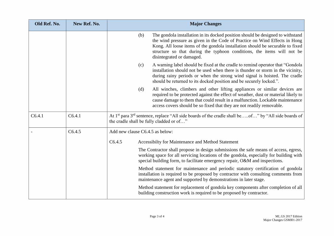
C6.4.1 C6.4.1 At 1st para 3rd sentence, replace “All side boards of the cradle shall be…..of…” by “All side boards of
the cradle shall be fully cladded or of…”
- C6.4.5 Add new clause C6.4.5 as below:
C6.4.5 Accessibilty for Maintenance and Method Statement
The Contractor shall propose in design submissions the safe means of access, egress,
working space for all servicing locations of the gondola, especially for building with
special building form, to facilitate emergency repair, O&M and inspections.
Method statement for maintenance and periodic statutory certification of gondola
installation is required to be proposed by contractor with consulting comments from
maintenance agent and supported by demonstrations in later stage.
Method statement for replacement of gondola key components after completion of all
building construction work is required to be proposed by contractor.

Page 4 of 4 MI_GS 2017 Edition
Major Changes GSMI01-2017
Old Ref. No. New Ref. No. Major Changes
C6.5.1 C6.5.1 Replace para 2 as below
“The track rail fixed onto the supporting concrete plinths shall be on the same level and in parallel
within the tolerance as recommended by the gondola manufacturer. The concrete plinths supporting
the track rail shall be at intervals between 2 m and 3 m depending on the wheels loading.”
SECTION C7 – HOT WATER SYSTEM
C7.4.3 C7.4.3 At Table C7.4.1, replace the 1st column heading “Size of Pipe/mm” by “Size of Pipe/mm Bore”.
C7.5.2 C7.5.2 At Table C7.5.1, add heading “Size of Pipe/mm Bore” for 1st column.
SECTION C10 – PNEUMATIC TUBE TRANSPORT SYSTEM
C10.6 C10.6 At para. 1, replace “…Health Technical Memorandum 2009…” by “…Health Technical
Memorandum 02…”
PART E - TRAINING, INSPECTION, ATTENDANCE, OPERATION AND MAINTENANCE DURING MAINTENANCE
PERIOD
SECTION E2 –TRAINING TO USERS AND OPERATION AND MAINTENANCE AGENTS
E2.2(d) E2.2(d) Replace “Description and operation principles all safety devices“ by “Description and operation
principles of all safety devices”
ANNEX I –LIST OF TECHNICAL STANDARDS QUOTED IN THIS GENERAL SPECIFICATION
Standard Number Description
BS 6037-1 Replace “BS 6037-1:2005” by “BS 6037-1:2017”

Page 1 of 11
MI_GS 2017 Edition
Corrigendum GSMI01-2017
ARCHITECTURAL SERVICES DEPARTMENT
BUILDING SERVICES BRANCH
GENERAL SPECIFICATION FOR
MECHANICAL INSTALLATION
IN GOVERNMENT BUILDINGS OF
THE HONG KONG SPECIAL ADMINISTRATIVE REGION
2017 EDITION
Corrigendum No. GSMI01-2017
(Effective from 1 April 2020)
The following clauses are amended in the above edition of General Specification for
Mechanical Installation.
Clauses
PART C – TECHNICAL REQUIREMENTS
SECTION C1
STEAM BOILER
C1.3 DESIGN
C1.3.1 Boiler
The steam boiler shall be constructed to BS 2790:1992 for a maximum
working pressure of 800 kPa gauge and tested to 1200 kPa gauge at the
manufacturer's works unless otherwise specified in the Particular
Specification. Manufacturer's test certificate in quadruplicate is
required. The boiler shall be of the genuine 3-pass wet back, radiant
heat type with a combustion chamber concentric with the horizontal
cylindrical shell and complete with a purpose made fully automatic
burner. Non 3-pass boilers are not acceptable and reverse flame is
counted as one pass only.
C1.3.1.2 Boiler Controls
Each boiler shall be equipped with a full set of automatic
controls in accordance with the requirements of the Boilers
and Pressure Vessels Ordinance and the following
protection controls:
Page 2 of 11
MI_GS 2017 Edition
Corrigendum GSMI01-2017
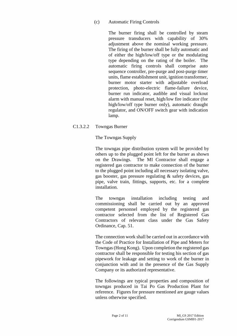
(c) Automatic Firing Controls
The burner firing shall be controlled by steam
pressure transducers with capability of 30%
adjustment above the nominal working pressure.
The firing of the burner shall be fully automatic and
of either the high/low/off type or the modulating
type depending on the rating of the boiler. The
automatic firing controls shall comprise auto
sequence controller, pre-purge and post-purge timer
units, flame establishment unit, ignition transformer,
burner motor starter with adjustable overload
protection, photo-electric flame-failure device,
burner run indicator, audible and visual lockout
alarm with manual reset, high/low fire indicator (for
high/low/off type burner only), automatic draught
regulator, and ON/OFF switch gear with indication
lamp.
C1.3.2.2 Towngas Burner
The Towngas Supply
The towngas pipe distribution system will be provided by
others up to the plugged point left for the burner as shown
on the Drawings. The MI Contractor shall engage a
registered gas contractor to make connection of the burner
to the plugged point including all necessary isolating valve,
gas booster, gas pressure regulating & safety devices, gas
pipe, valve train, fittings, supports, etc. for a complete
installation.
The towngas installation including testing and
commissioning shall be carried out by an approved
competent personnel employed by the registered gas
contractor selected from the list of Registered Gas
Contractors of relevant class under the Gas Safety
Ordinance, Cap. 51.
The connection work shall be carried out in accordance with
the Code of Practice for Installation of Pipe and Meters for
Towngas (Hong Kong). Upon completion the registered gas
contractor shall be responsible for testing his section of gas
pipework for leakage and setting to work of the burner in
conjunction with and in the presence of the Gas Supply
Company or its authorized representative.
The followings are typical properties and composition of
towngas produced in Tai Po Gas Production Plant for
reference. Figures for pressure mentioned are gauge values
unless otherwise specified.

Page 3 of 11
MI_GS 2017 Edition
Corrigendum GSMI01-2017
Typical Chemical Composition of Gas
- Carbon Dioxide CO2 16.3 - 19.9%
- Carbon Monoxide CO 1.0 - 3.1%
- Methane CH4 28.2 - 30.7%
- Hydrogen H2 46.3 - 51.8%
- Air N2 + O2 0 - 3.3%
Wobbe Index
- (MSC dry) MJ/m3 24.0
C1.3.6 Steam Trap Assemblies
All condensate connections from steam equipment shall be provided
with steam trap. Steam traps shall be capable of handling the full
volume of condensate discharged from the equipment, when starting
from cold.
Each trap set shall be preceded by a dirt pocket and shall comprise:
(a) Globe Valve
(b) Strainer
(c) Spira-tec or functionally equivalent Trap Failure Sensor
Chamber complete with Blanking Plug
(d) Float Operated Steam Trap
(e) Sight Glass
(f) Check Valve
(g) Gate Valve
(h) All Unions
All steam trap assemblies which are not readily accessible, e.g. ceiling
voids shall be provided with a remote test point complete with cable and
sensor wired to the trap.
C1.4 EQUIPMENT AND MATERIAL
C1.4.6 Pressure and Temperature Gauges
Pressure gauges fitted to equipment and pipework shall comply with
BS EN 837-1:1998 but shall have dials calibrated both in kPa from zero
to not less than 1.3 times and not more than twice the operating
pressure.
Page 4 of 11
MI_GS 2017 Edition
Corrigendum GSMI01-2017
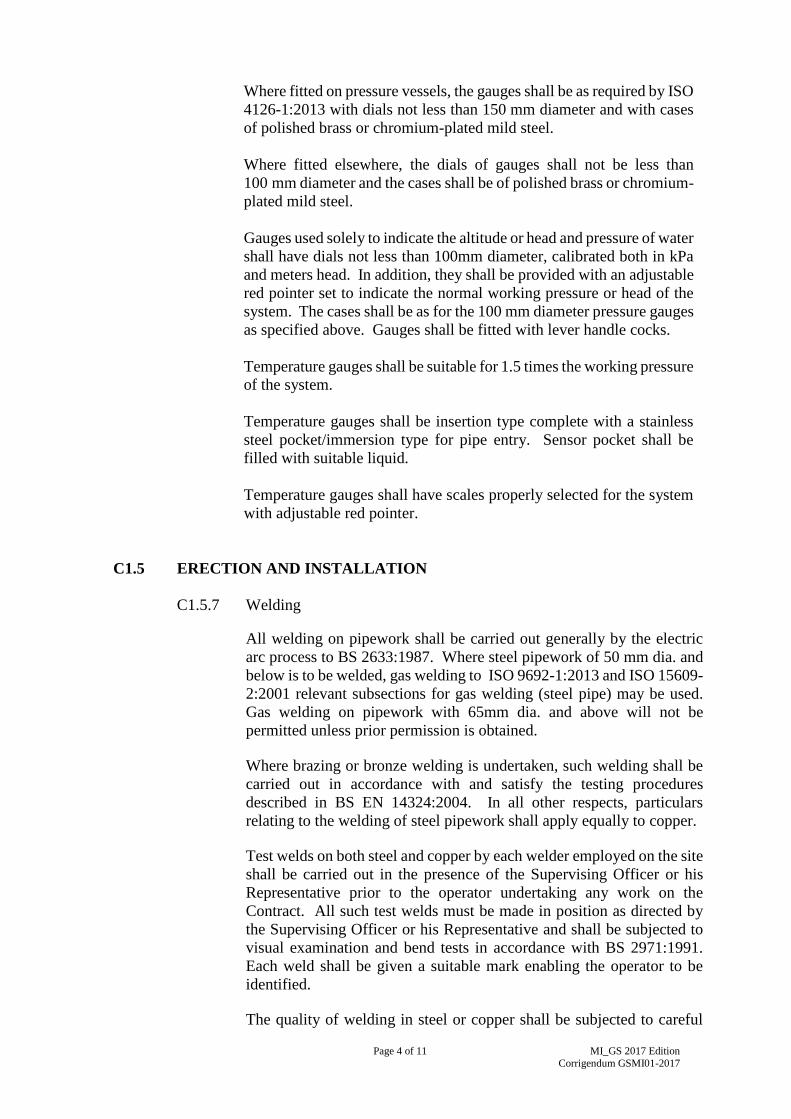
Where fitted on pressure vessels, the gauges shall be as required by ISO
4126-1:2013 with dials not less than 150 mm diameter and with cases
of polished brass or chromium-plated mild steel.
Where fitted elsewhere, the dials of gauges shall not be less than
100 mm diameter and the cases shall be of polished brass or chromium-
plated mild steel.
Gauges used solely to indicate the altitude or head and pressure of water
shall have dials not less than 100mm diameter, calibrated both in kPa
and meters head. In addition, they shall be provided with an adjustable
red pointer set to indicate the normal working pressure or head of the
system. The cases shall be as for the 100 mm diameter pressure gauges
as specified above. Gauges shall be fitted with lever handle cocks.
Temperature gauges shall be suitable for 1.5 times the working pressure
of the system.
Temperature gauges shall be insertion type complete with a stainless
steel pocket/immersion type for pipe entry. Sensor pocket shall be
filled with suitable liquid.
Temperature gauges shall have scales properly selected for the system
with adjustable red pointer.
C1.5 ERECTION AND INSTALLATION
C1.5.7 Welding
All welding on pipework shall be carried out generally by the electric
arc process to BS 2633:1987. Where steel pipework of 50 mm dia. and
below is to be welded, gas welding to ISO 9692-1:2013 and ISO 15609-
2:2001 relevant subsections for gas welding (steel pipe) may be used.
Gas welding on pipework with 65mm dia. and above will not be
permitted unless prior permission is obtained.
Where brazing or bronze welding is undertaken, such welding shall be
carried out in accordance with and satisfy the testing procedures
described in BS EN 14324:2004. In all other respects, particulars
relating to the welding of steel pipework shall apply equally to copper.
Test welds on both steel and copper by each welder employed on the site
shall be carried out in the presence of the Supervising Officer or his
Representative prior to the operator undertaking any work on the
Contract. All such test welds must be made in position as directed by
the Supervising Officer or his Representative and shall be subjected to
visual examination and bend tests in accordance with BS 2971:1991.
Each weld shall be given a suitable mark enabling the operator to be
identified.
The quality of welding in steel or copper shall be subjected to careful

Page 5 of 11
MI_GS 2017 Edition
Corrigendum GSMI01-2017
inspection and testing by the Supervising Officer or his Representative
and where so deemed necessary may be subject to non-destructive
and/or destructive tests under the supervision of the Supervising Officer
or his Representative.
SECTION C4
FUEL SUPPLY SYSTEM
C4.4 EQUIPMENT AND MATERIAL
C4.4.6 Hand Pump
A semi-rotary double acting hand pump shall be provided for each daily
service tank and consist of 25 mm diameter inlet and outlet and a 25 mm
diameter flexible oil resistant inlet pipe of adequate length to suit site
conditions.
C4.4.7 Pipeworks and Fittings
All pipes up to 80 mm diameter shall conform to ISO 65:1981 heavy
quality and pipes 80 mm diameter and above with BS 1600:1991 or
other technically equivalent national or international standards.
Flanges shall be of the slip-on-welding type in accordance with ISO
7005-1:2011 Class 150. Screwed fittings shall be made of malleable iron
and threads shall comply with ISO 7-1:1994/Corr 1:2007.
All screwed joints shall be cleaned, threaded and pulled up tightly. All
jointing materials shall be resistant to the type of fuel to be conveyed.
Gaskets made of rubber or compressed asbestos fibre shall not be used.
Square elbows shall not be used. Where practicable, long sweep bends
shall be used in preference to round elbows.
Valves shall be of the ‘full way’ type to allow free flow of fuel. A sample
valve shall be submitted to the Supervising Officer for approval before
installation. Valves shall be made of bronze or cast steel.
SECTION C6
GONDOLA
C6.2 COMPLIANCE WITH SPECIAL REGULATORY REQUIREMENTS AND
STANDARDS

Page 6 of 11
MI_GS 2017 Edition
Corrigendum GSMI01-2017
In addition to the Section A2.1, the Installations shall comply with all relevant
statutory regulations and standards, in particular
(a) BS 6037-1:2017 - Code of Practice for the Planning, Design, Installation
and Use of Permanently Installed Access Equipment. Suspended Access
Equipment; and
(b) BS EN 1808:2015 - Safety Requirements for Suspended Access
Equipment. Design Calculations, Stability Criteria, Construction,
Examinations and Tests.
(c) Code of Practice for Safe Use and Operation of Suspended Working
Platforms issued by the LD.
C6.3 DESIGN
C6.3.3 Travelling Operation on Roof
C6.3.3.2 Trackless type Gondola Installations
The requirements for trackless type Gondola Installations
shall be as follows:
(a) Guide rails shall be provided for trackless type
Gondola Installations. The roof carriage shall be
capable of travelling on the flat roof along the guide
rail within the travelling boundary limits;
C6.3.8 Cradle
The cradle shall include the following features:
(e) Suction cup system shall be provided to supplement the cradle
restraint system to prevent undue lateral movement of the cradle
during operation and to hold the gondola cradle close to the
curtain wall. Interlock shall be provided to stop the operation of
the gondola cradle during the engagement operation at the suction
cup onto the wall. The details of the system shall be submitted for
approval by the Supervising Officer; and
C6.3.15 Special Requirement for Dual Traction Hoist Type Gondola
The design on the dual traction hoist type Gondola Installations shall be
equipped with but not limited to the following features:
(c) Anti-tilting protection device shall be provided to stop the
traction hoists should the inclination of the cradle exceed
5 degrees from the horizontal position. Separate push buttons
shall be provided at the control panel such that function of the
push button that would cause further tilting of the cradle shall be
inactivated;
Page 7 of 11
MI_GS 2017 Edition
Corrigendum GSMI01-2017
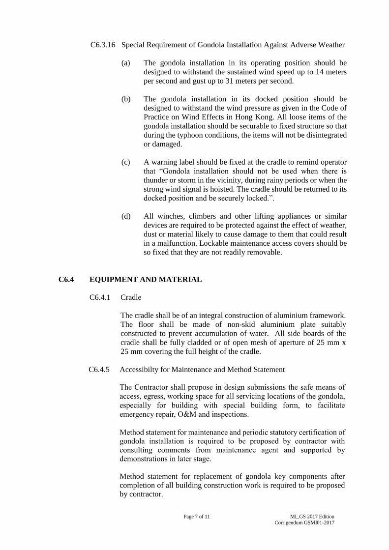
C6.3.16 Special Requirement of Gondola Installation Against Adverse Weather
(a) The gondola installation in its operating position should be
designed to withstand the sustained wind speed up to 14 meters
per second and gust up to 31 meters per second.
(b) The gondola installation in its docked position should be
designed to withstand the wind pressure as given in the Code of
Practice on Wind Effects in Hong Kong. All loose items of the
gondola installation should be securable to fixed structure so that
during the typhoon conditions, the items will not be disintegrated
or damaged.
(c) A warning label should be fixed at the cradle to remind operator
that “Gondola installation should not be used when there is
thunder or storm in the vicinity, during rainy periods or when the
strong wind signal is hoisted. The cradle should be returned to its
docked position and be securely locked.”.
(d) All winches, climbers and other lifting appliances or similar
devices are required to be protected against the effect of weather,
dust or material likely to cause damage to them that could result
in a malfunction. Lockable maintenance access covers should be
so fixed that they are not readily removable.
C6.4 EQUIPMENT AND MATERIAL
C6.4.1 Cradle
The cradle shall be of an integral construction of aluminium framework.
The floor shall be made of non-skid aluminium plate suitably
constructed to prevent accumulation of water. All side boards of the
cradle shall be fully cladded or of open mesh of aperture of 25 mm x
25 mm covering the full height of the cradle.
C6.4.5 Accessibilty for Maintenance and Method Statement
The Contractor shall propose in design submissions the safe means of
access, egress, working space for all servicing locations of the gondola,
especially for building with special building form, to facilitate
emergency repair, O&M and inspections.
Method statement for maintenance and periodic statutory certification of gondola installation is required to be proposed by contractor with consulting comments from maintenance agent and supported by demonstrations in later stage. Method statement for replacement of gondola key components after completion of all building construction work is required to be proposed by contractor.

Page 8 of 11
MI_GS 2017 Edition
Corrigendum GSMI01-2017
C6.5 ERECTION AND INSTALLATION
C6.5.1 Installation of Track Rail
The track rail installation for gondola system shall be supported on the
concrete plinth and secured by stainless steel foundation bolts. The size
of foundation bolt shall not be less than M16.
The track rail fixed onto the supporting concrete plinths shall be on the
same level and in parallel within the tolerance as recommended by the
gondola manufacturer. The concrete plinths supporting the track rail
shall be at intervals between 2 m and 3 m depending on the wheels
loading.
SECTION C7
HOT WATER SYSTEM
C7.4 EQUIPMENT AND MATERIAL
C7.4.3 Thermal Insulation
All materials supplied of the same type shall be supplied by a single
manufacturer to ensure uniformity of standards and appearance.
All materials delivered to site shall be new, and where appropriate,
colour coded and labelled at factory to identify different grades, sizes
and types.
Samples and a full specification of the insulation material shall be
submitted to the Supervising Officer for approval.
Before ordering any insulating materials, the co-efficient of the thermal
conductivity for each of the materials being supplied for the Installations
shall be stated. Tests shall be carried out on representative samples of
each material taken at Site and/or at makers' works as directed by the
Supervising Officer in accordance with the methods laid down in
International Standards. In the event of test results being not
satisfactory, the Supervising Officer shall have the right to order the
removal and replacement of all materials represented by the
unsatisfactory samples.
All equipment and materials used shall be fire resistant and shall comply
with all relevant regulations issued by the FSD.
All materials including the thermal insulation itself, together with
adhesives, paint, bands, sheeting, etc. shall be supplied with a reasonable
margin for cutting, wastage and making good damage and loss. All
materials shall be stored in a suitable manner so as to protect them from
damage or deterioration before fixing.

Page 9 of 11
MI_GS 2017 Edition
Corrigendum GSMI01-2017
All insulating, finishing and painting materials shall be suitable for the
surfaces to which they are applied and for the environmental conditions
in each area.
Thermal insulation materials and their finishes shall be asbestos free.
Thickness of thermal insulation for pipework carrying hot fluids shall be
in accordance with Table C7.4.1.
Table C7.4.1 - Thickness of Thermal Insulation
Declared Thermal Conductivity / (W/mK)
Hot Water Pipe
Size of Pipe/
mm bore
Up
To
0.040
0.041
to
0.055
0.056
to
0.070
Minimum Thickness of Thermal Insulation / mm
15
20
25
32
40
50
65
80
100
125
150
200
250
300
Flat Surface
25
25
32
32
32
32
32
32
38
44
44
44
63
63
63
32
32
32
32
32
32
32
44
44
44
63
63
63
63
63
32
32
32
32
32
38
38
44
44
63
63
75
75
75
75
C7.5 ERECTION AND INSTALLATION
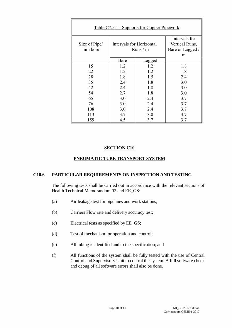
C7.5.2 Pipe Support
All pipework shall be adequately supported in such a manner as to
permit free movement due to expansion and contraction. Pipe supports
shall be arranged as near as possible to joints and changes in direction.
The spacing of the supports shall not exceed the centres given in the
Table C7.5.1. Where there are two or more sizes of pipes the common
support spacings shall be based on the centres required by the smallest
bore pipework.
Page 10 of 11
MI_GS 2017 Edition
Corrigendum GSMI01-2017
SECTION C10
PNEUMATIC TUBE TRANSPORT SYSTEM
C10.6 PARTICULAR REQUIREMENTS ON INSPECTION AND TESTING
The following tests shall be carried out in accordance with the relevant sections of
Health Technical Memorandum 02 and EE_GS:
(a) Air leakage test for pipelines and work stations;
(b) Carriers Flow rate and delivery accuracy test;
(c) Electrical tests as specified by EE_GS;
(d) Test of mechanism for operation and control;
(e) All tubing is identified and to the specification; and
(f) All functions of the system shall be fully tested with the use of Central
Control and Supervisory Unit to control the system. A full software check
and debug of all software errors shall also be done.
Table C7.5.1 - Supports for Copper Pipework
Size of Pipe/
mm bore
Intervals for Horizontal
Runs / m
Intervals for
Vertical Runs,
Bare or Lagged /
m
Bare Lagged
15
22
28
35
42
54
65
76
108
113
159
1.2
1.2
1.8
2.4
2.4
2.7
3.0
3.0
3.0
3.7
4.5
1.2
1.2
1.5
1.8
1.8
1.8
2.4
2.4
2.4
3.0
3.7
1.8
1.8
2.4
3.0
3.0
3.0
3.7
3.7
3.7
3.7
3.7

Page 11 of 11
MI_GS 2017 Edition
Corrigendum GSMI01-2017
E2.2 OTHER TRAINING REQUIREMENTS
The details of the training shall be subject to the approval of the Supervising
Officer. The training shall generally cover the following aspects:
(a) General description of the Installations;
(b) Operation procedures of the installation, including start-up and shut-
down procedures, safety precautions, etc.;
(c) Description of the controls;
(d) Description and operation principles of all safety devices;
(e) Emergency procedures; and
(f) Maintenance requirements, adjustment of operating parameters to
achieve optimum operating conditions, etc.
PART E – TRAINING, INSPECTION, ATTENDANCE, OPERATION
AND MAINTENANCE DURING MAINTENANCE PERIOD
SECTION E2
TRAINING TO USERS AND OPERATION AND MAINTENANCE AGENTS