Optimization of GaAs/AlGaAs staircase avalanche photodiodes ...
Upload
independentCategory
view
0download
0
Journal of Electroanalytical Chemistry 454 (1998) 15–31
General analytical solution for a catalytic mechanism in potential steptechniques at hemispherical microelectrodes: Applications to
chronoamperometry, cyclic staircase voltammetry and cyclic linearsweep voltammetry
Angela Molina *, Carmen Serna, Joaquın Gonzalez
Departamento de Quımica-Fısica. Uni6ersidad de Murcia, 30100 Murcia, Spain
Received 11 November 1997; received in revised form 1 June 1998
Abstract
An easy, general analytical solution, applicable to any multipotential step technique for a catalytic process in planar andspherical electrodes (including ultramicrohemispheres), is presented. The solution has been deduced rigorously using themathematical method described by Molina (A. Molina, J. Electroanal. Chem. 443 (1998) 163) based on the application of thesuperposition principle. In this paper it has been applied to multistep chronoamperometry, cyclic staircase voltammetry (CSCV)and cyclic linear sweep voltammetry (CLSV) by analysing the influence of the electrode radius and the equilibrium and ratechemical constants over the different I/t and I/E responses. Different voltammetric steady states (kinetic, microgeometrical andgeometrical-kinetic) can be distinguished and methods for calculating the kinetic parameters of the chemical reaction are alsoproposed. In the case of an irreversible chemical reaction in linear sweep voltammetry our results are in agreement with thoserecently deduced by Diao and Zhang (G. Diao, Z. Zhang, J. Electroanal. Chem. 429 (1997) 67). © 1998 Elsevier Science S.A. Allrights reserved.
Keywords: Catalytic mechanism; Multipotential step; Chronoamperometry; Cyclic voltammetry; Microelectrodes
1. Introduction
The use of microelectrodes offers great advantages.Better use can be made of the electrochemical tech-niques since high quality experimental data are ob-tained which are barely distorted by the ohmic drop orthe effects of the charge current [1–10]. Moreover, thestudy of a catalytic process in which the charge transferreaction is followed by a homogeneous chemical reac-tion that regenerates the electroactive species is of greatinterest, as shown in recent papers [1,11–17].
In a previous paper [11], we developed a mathemati-cal method based on the application of the superposi-
tion principle which gives a rigorous solution to themultistep problem for a catalytic process in planardiffusion. Thus, we deduced an easy, manageable ana-lytical solution applicable to any multipotential steptechnique and also to cyclic linear sweep voltammetry.
In this paper we extend the above treatment to thespherical diffusion field and deduce another generalanalytical solution which can be applied both to planarand spherical electrodes, including hemispherical mi-croelectrodes and ultramicroelectrodes. This equationpresents the following advantages:1. It permits a rigorous treatment of the catalytic
mechanism in hemispherical microelectrodes (with-out considering the reaction layer approximation)for any value of the equilibrium constant of thehomogeneous chemical reaction in any multistep
* Corresponding author. Fax: +34 68 364148; e-mail:[email protected]
0022-0728/98/$19.00 © 1998 Elsevier Science S.A. All rights reserved.PII S0022-0728(98)00251-4
A. Molina et al. / Journal of Electroanalytical Chemistry 454 (1998) 15–3116
electrochemical technique. Thus, our equation canbe applied to long potential step techniques (multi-step chronoamperometry), to any double, triple andmultipulse techniques (square wave and staircasevoltammetry) and also to linear sweep voltammetryand cyclic linear sweep voltammetry.
2. It consists of a simple sum of terms of the samegeneral expression, is easily programmable and isvalid for any value of the electrode radius in therange 05r05�, i.e., both for ultramicroelectrodes(r0�0) and for planar electrodes (r0��). More-over, the difference between planar and sphericaldiffusion affects only the last term corresponding tothe mth potential step applied in the general expres-sion of the current Im.
3. According to the geometry and the electrode size,three different steady states can be predicted. Thesewould be due to the homogeneous kinetics in planarelectrodes (kinetic voltammetric steady state), to theelectrode geometry and size, r0, in hemisphericalultramicroelectrodes (microgeometrical voltammet-ric steady state) and to the sum of both effects inconventional spherical electrodes (geometrical-ki-netic steady state).
4. When the rate constants and the equilibrium con-stant of the homogeneous chemical reaction tend tozero, our equation becomes that corresponding toan E process and is coincident with that previouslydeduced in reference [18].
We apply this equation here to the study of catalyticprocesses in multistep chronoamperometry, in cyclicstaircase voltammetry and cyclic linear sweep voltam-metry and we propose methods to determine the rateand equilibrium constants of the homogeneous chemi-cal reaction by using the above electrochemicaltechniques.
The curves corresponding to cyclic linear sweepvoltammetry have been obtained for a wide range ofsweep rates and for one and two complete cycles,evidencing the high utility of this technique and ofcyclic staircase voltammetry in the study of a catalyticprocess.
In the particular case of linear sweep voltammetry(first semicycle) our results are coincident with thoseobtained in a recent paper by Diao and Zhang [1], inwhich they give a solution for the catalytic mechanismwhich is applicable only to this technique and in theparticular case of an irreversible chemical reaction(K=0). This solution is given as a function of compli-cated integral equations and, therefore, cannot be con-sidered an analytical solution. Moreover, it has thedisadvantages that it is not applicable in cyclic linearsweep voltammetry and cannot predict the conditionsunder which the different voltammetric steady statesare reached.
2. Theory
Let us consider a catalytic mechanism which can bedescribed by the following scheme:
A+ne− ?B
B+Zk1%
?k2%
A+Products (I)
where A and B are the electroactive species and Z and‘Products’ are electroinactive species in the whole rangeof applied potentials, in such a way that k1=k1% cZ* andk2=k2% cProducts* are both pseudo first order rate con-stants (c i* being the bulk concentration of the i species).
The solution corresponding to the above mechanism,when a first potential step E1 is applied to a sphericalelectrode or microelectrode, has been deduced in theAppendix for a reversible charge transfer reaction andcan be written as,
I1
nFADj*=!� e−x11
px11
+erf(x11)�'k1+k2
D+
1r0
"1−KJ1
(1+K)(1+J1)(1)
where
x11= (k1+k2)t1 (2)
with t1 being the duration of the first potential step andk1 and k2 being the homogeneous pseudo first orderrate constants. Moreover,
K=k2/k1=cB* /cA* (3)
j*=cA* +cB* (4)
J1=exp [nF(E1−E0)/RT ] (5)
with r0 and A being the electrode radius and area,respectively.
Note that Eq. (1) is the exact solution to this problemand therefore is applicable for any value of the elec-trode radius. Thus, for example, for r0��, the secondterm in the brackets disappears and I1 correspondsunder these conditions to the solution for planar diffu-sion [11]. For smaller values of r0 the contribution ofboth terms inside the bracket must be carefully evalu-ated in order to analyse the weight of each of the twoaddends as a function of the values of x11, (k1+k2) andr0. Thus, for values of x11 or (k1+k2) for which the firstterm might be ignored with respect to the second(ultramicroelectrodes), it is fulfilled that,� I1
nFADj*�
r 0�0
=1−KJ1
r0(1+K)(1+J1)(6)
We can consider that this result is valid if, in agree-ment with reference [7], it is fulfilled that,
A. Molina et al. / Journal of Electroanalytical Chemistry 454 (1998) 15–31 17
10� e−x11
px11
+erf(px11)�'k1+k2
DB
1r0
(7)
If we suppose now that for t= t1 the potential issuddenly changed to a new value E2"E1, then byfollowing an identical procedure to that indicated in aprevious paper [11], we deduce:
I2
nFADj*= %
2
p=1
!� e−xp 2
pxp2
+erf(xp2)�'k1+k2
D+
1r0
"Zp
(8)
with
Z1=1−KJ1
(1+K)(1+J1)(9)
Z2=1
1+J2
−1
1+J1
J2=exp[nF(E2−E0)/RT ]
ÌÃ
Ã
Â
Å
(10)
xp2= (k1+k2)tp2 (11)
t12= t1+ t2
t22= t2
"(12)
If we take into account that, like the planar diffusioncase in reference [11], this is a linear problem and thatthe boundary value problem has the same general formfor any mth potential step applied (m]1) and also thatthis mth boundary value problem is independent of theprevious solutions corresponding to the above potentialsteps E1, E2, …, Em−1, we deduce that the currentcorresponding to the mth potential step can be ob-tained by applying the superposition principle asfollows,
Im
nFADj*= %
m
p=1
!� e−xpm
pxpm
+erf(xpm)�'k1+k2
D+
1r0
"Zp
(13)
with
Z1=1−KJ1
(1+K)(1+J1)
Zp=1
1+Jp
−1
1+Jp−1
; p\1
Jp=exp[nF(Ep−E0)/RT ]
ÌÃ
Ã
Ã
Ã
Â
Å
(14)
xpm= (k1+k2)tpm (15)
tpm= %m
k=p
tk (16)
Eq. (13) is the complete solution corresponding toany multistep problem for a catalytic mechanism inspherical diffusion. This equation converts to an even
simpler form after some manipulations. Thus, takinginto account that the second term inside the brackets isindependent of time, Eq. (13) becomes,
Im
nFADj*= %
m
p=1
!� e−xpm
pxpm
+erf(xpm)�'k1+k2
D"
Zp
+1−KJm
r0(1+K)(1+Jm)(17)
At certain times, it may be of interest to write theexpression for Im in a dimensionless form. In order toachieve this, both sides of Eq. (17) should be multipliedby r0 such that this equation becomes,
Fm= %m
p=1
! e−xpm
pxpm
+erf(xpm)" L Zp
+1−KJm
(1+K)(1+Jm)(18)
where
Fm=Imr0
nFADj*(19)
L=k1+k2
Dr0
2 (20)
Eq. (17) is of great importance since, as can be seen,it is clearly shown that the electrode radius affects onlythe term corresponding to the last potential pulse Em.This situation is analogous to that found by us in aprevious paper on the study of a reversible chargetransfer reaction in multipotential step techniques [18].This equation possesses the additional advantage of itssimplicity, making it very easily programmable, as weshall see below.
3. Results and discussion
In the first place, we will analyse some particularcases of interest of Eq. (17) which corresponds to therigorous solution for a catalytic mechanism in a multi-potential step problem. Thus, we will discuss the exis-tence of a steady state in planar geometry and inmicrohemispheres (Section 3.1), and we will compare itto the response obtained for a reversible E mechanism(Section 3.2).
In the following sections, we will apply Eq. (17) tomultistep chronoamperometry, cyclic staircase voltam-metry and cyclic linear sweep voltammetry (Section3.3). In the last case we will compare our results tothose deduced by Diao and Zhang in a recent paperand which were applicable only to a catalytic processwith K=0 in linear sweep voltammetry [1].
Finally, we propose methods for calculating the ki-netic parameters of the chemical reaction (Section 3.4).
A. Molina et al. / Journal of Electroanalytical Chemistry 454 (1998) 15–3118
3.1. Attachment of steady state at planar, sphericalelectrodes and hemispherical microelectrodes.
Eq. (17) presents the following interesting particularcases
3.1.1. Planar electrodes and kinetic steady state (kss)If we make r0�� in Eq. (17), the last term disap-
pears and we obtain,� Im
nFADj*�
planar
= %m
p=1
!� e−xpm
pxpm
+erf(xpm)�'k1+k2
D"
Zp (21)
This equation is identical to that previously obtainedby us (Eq. (62) in Ref. [11]).
It is interesting to point out that, by comparing Eqs.(21) and (17), it is quickly observed that the differencebetween the current time response of a catalytic processin planar and in spherical diffusion is due solely to theterm (1−KJm)/((1+K)(1+Jm)r0).
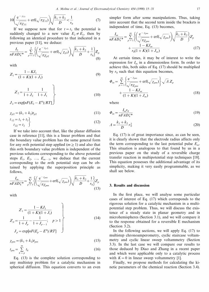
The function in the brackets in Eq. (21) fulfils thefollowing for xpm]1.27 (Fig. 1):
e−xpm
pxpm
+erf(xpm)�1 (22)
By introducing Eq. (22) in Eq. (21) we deduce, aftersome simple manipulations, the following simplerexpression:
� Im
nFADj*�
kss
='k1+k2
D1−KJm
(1+K)(1+Jm)(23)
From Eq. (23) we deduce that there exists a kineticsteady state which will be reached when the homoge-neous chemical reaction is fast enough.
Under these conditions, the I/E response will practi-cally correspond to a single sigmoid for any multipulseelectrochemical technique applied (single pulse voltam-metry, cyclic staircase or cyclic linear sweep voltamme-try) and whatever the number of cycles of the same(Section 3.3).
3.1.2. Con6entional spherical electrodes and mixedgeometrical-kinetic steady state (gkss)
From Eq. (17) corresponding to spherical diffusionwhen xpm]1.27 we obtain:� Im
nFADj*�
gkss
=1−KJm
(1+K)(1+Jm)!'k1+k2
D+
1r0
"(24)
Eq. (24) clearly shows that for a determined sphereor hemisphere the steady state in a given experiment is,in general, a function of two contributions, one due tothe spherical geometry for any value of the electroderadius and the other due to the rate of the homoge-neous chemical reaction. This equation coincides withthat deduced by Oldham [13] in the particular case of acathodic limiting current (Jm�0) and for an irre-versible chemical reaction (K=0).
3.1.3. Ultramicrohemispheres and microgeometricalsteady state (mgss)
In order to reach this steady state in a brief period oftime, a very small electrode which must be finite in bothdimensions is required.
This steady state can be obtained by making r0�0 inEq. (17) or Eq. (24). So we obtain,� Im
nFADj*�
mgss
=1r0
1−KJm
(1+K)(1+Jm)(25)
This equation shows that under these conditions weobtain a steady current dependent only on the potentialapplied in the mth step Em and on the equilibriumconstant of the homogeneous chemical reaction K.
Note that, for K=0, the I/E response deduced for acatalytic process is identical to that obtained under thesame conditions for a reversible charge transfer process(see Eq. (24) in Ref. [18]). For Eq. (7) to be fulfilled andfor the microgeometrical steady state to be reached, it isnecessary to reduce the size of the electrode to a greaterextent than in the case of a simple E mechanism(Section 3.2).Under any of the conditions of the threecases previously discussed, the I/t response of a givenpotential step is independent of the previous potentialstep sequence, i.e. the memory of the previous pulses islost.
Fig. 1. Dependence of f(xpm)CAT and f(xpm)E on xpm (Eqs. (28) and(29), respectively). The dotted line corresponds to the constant value1.
A. Molina et al. / Journal of Electroanalytical Chemistry 454 (1998) 15–31 19
3.2. Comparison between the steady state in a catalyticmechanism and in a re6ersible E process
The steady state, in agreement with Diao and Zhang[1], will be reached earlier in a catalytic process than ina simple E process, as will be seen below. This fact canbe easily deduced by comparing Eq. (17) of this paperwith that corresponding to an E process.
To deduce the equation for Im corresponding to an Eprocess it is sufficient to make xpm�0 and K=0 in Eq.(17), so we obtain (see Eq. (15)),� Im
nFADj*�
E
= %m
p=1
! 1
pxpm
'k1+k2
D"
Zp+1
r0(1+Jm)(26)
Note that now
Z1=1
1+J1
and
1
pxpm
'k1+k2
D=
1
pDtpm
ÌÃ
Ã
Ã
Ã
Â
Å
(27)
and Zp is given by Eq. (14) for p]2.If we compare Eqs. (17) and (26), it is clear that the
difference between an E process and a catalytic processwith K=0 (for the sake of simplicity) is merely that thefunction of the variable xpm (Eq. (15)), which multipliesto (k1+k2)/D in the brackets for a catalytic process,is
f(xpm)CAT=e−xpm
pxpm
+erf(xpm) (28)
while for an E process this function is given by,
f(xpm)E=1
pxpm
(29)
In Fig. 1 we have plotted Eqs. (28) and (29) versusxpm and from these plots it is clear that f(xpm)CAT
reaches a constant value for smaller values of xpm thandoes f(xpm)E, and this explains why in spherical elec-trodes the steady state is reached earlier for a catalyticmechanism (mixed geometrical-kinetic steady state),than for an E mechanism (microgeometrical steadystate).
On the other hand (and in agreement with Fig. 1),the microgeometrical steady state is more difficult toreach in a catalytic mechanism than in a pure E onesince, in the first case condition (7) must be verified,while in an E mechanism the condition given belowmust be verified for any value of Em [7],
10
pxpm
'k1+k2
DB
1r0
(30)
which is evidently reached for lower values of tpm (Eq.(15)).
In the case of planar diffusion from Eq. (26) withr0�� it is evident that the steady state cannot bereached in a brief period of time for an E process, whilea pure kinetic steady state can be obtained in the caseof a catalytic mechanism.
3.3. Multistep techniques
Eq. (17) is applicable to any multistep technique. Inthis paper we will analyse in greater detail its applica-tion to multistep chronoamperometry, cyclic staircasevoltammetry (CSCV) and cyclic linear sweep voltam-mentry (CLSV) both in conventional electrodes (planarand spherical) and also in hemispherical microelec-trodes and ultramicroelectrodes.
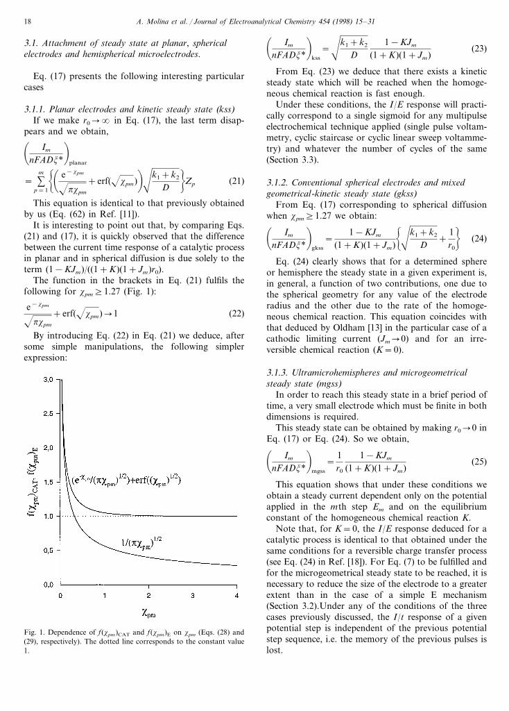
3.3.1. Multistep chronoamperometryIn order to show the application of Eq. (17) for
any duration of the potential steps, in Figs. 2 and 3 wehave represented the chronoamperograms correspond-ing to five potential steps obtained under conditions ofcathodic and anodic limiting currents. Under theseconditions, and taking into account that E1=E3=E5�−� and E2=E2�+�, the currents Im are lim-iting currents: I1,lim, I2,lim,…, I5,lim (I1,lim, I3,lim and I5,lim
being cathodic currents and I2,lim and I4,lim anodic ones)and are given in the following general form,
Im,lim
nFADj*=!� e−x1m
px1m
+erf(x1m)�'k1+k2
D" 1
1+K
+ %m
p=2
!� e−xpm
pxpm
+erf(xpm)�'k1+k2
D"
(−1)p+1
+2− (1+K)(1+ (−1)m)
2(1+K)r0
(31)
In this case we have varied m between 1 and 5, witht1= t2=…= t5=1s.
Note that Eq. (31) can be written in the followingdimensionless way,
Fm,lim=!� e−x1m
px1m
+erf(x1m)� L
" 11+K
+ %m
p=2
!� e−xpm
pxpm
+erf(xpm)� L
"(−1)p+1
+2− (1+K)(1+ (−1)m)
2(1+K)(32)
where L is given by Eq. (20) and
Fm,lim=Im,limr0
nFADj*(33)
A. Molina et al. / Journal of Electroanalytical Chemistry 454 (1998) 15–3120
Fig. 2. Influence of the rate constants k1+k2 on the (Im,lim/nFAD1/2
j*)/t curves registered for five potential steps (Eq. (31)) with E1=E3=E5�−� and E2=E4��. D/r0=3 s−1/2. t1= t2…= t5=1s. The values of the equilibrium constant of the chemical reaction Kare: (a) 0 and (b) 1. The values of the pseudo first rate constantk1+k2 (in s−1) are: (——) 0, (– — — –) 0.5, (— — —) 5, (----) 10,( · · · · ) 50 and (— · —) 100.
Fm,lim=Fm,diff= %m
p=1
! L
pxpm
+1"
(−1)p+1
= %m
p=1
! 1
pDtpm
+1"
(−1)p+1 (34)
Figs. 2 and 3 show the effects of the homogeneousrate constant (Fig. 2) and of the electrode radius (Fig.3) on the Im,lim/t curves (with m=1, 2, …, 5) for acatalytic process with K=0 (a) and K=1 (b). As canbe seen from these figures, an increase of K gives rise toan increase of the absolute value of the anodic currentsand to a decrease of the cathodic currents (due to the
Fig. 3. Influence of the electrode radius on the (Im,lim/nFAD1/2j*)/tcurves registered for five potential steps (Eq. (31)) with E1=E3=E5�−� and E2=E4��. k1+k2=1 s−1. The values of theequilibrium constant of the chemical reaction K are: (a) 0 and (b) 1.The values of D/r0 (in s−1/2) are: (——) 0, (----) 1, (— · —) 10and ( · · · · ) 100. Other conditions as in Fig. 2.
In the case of a simple E process (K=0 and xpm�0),Eq. (32) becomes that corresponding to the diffusioncurrents, which is given by,
A. Molina et al. / Journal of Electroanalytical Chemistry 454 (1998) 15–31 21
fact that when K increases, the concentration of speciesA decreases and that of species B increases in the bulkof the solution). Fig. 2 shows that when K"0, if thehomogeneous rate constants increase, then both anodicand cathodic currents increase in absolute value, whilefor K=0, the anodic currents slightly decrease when k1
increases and the cathodic ones increase more with therate constant than in the previous case. This behaviouris typical of a catalytic process and can be used tocharacterise it since, for example, in the case of anirreversible chemical reaction, the value of the rateconstant k1 can be varied by adding different amountsof the electroinactive species Z. Moreover, it can beobserved from this figure the tendency of the currentIm,lim to be independent of time as the sum (k1+k2)increases, in such a way that these chronoamperogramsare practically parallel to the time axis for k1+k2\10s−1. This fact can be used to determine experimentallythe value of (k1+k2) since under these conditions fromEq. (31) it can be easily deduced that the currentscorresponding to the cathodic and anodic plateaus aregiven by
�Im,lim�nFAj*D
=�k1+k2+
Dr0
� 11+K
for m=1, 3, 5, … (35)
and
�Im,lim�nFAj*D
=�k1+k2+
Dr0
� K1+K
for m=2, 4, … (36)
respectively.Therefore the calculation of k1 and k2 is immediate
due to the fact that the equilibrium constant can beobtained by dividing Eqs. (36) and (35) and the rateconstant can be obtained by taking into account thatthe sum of these equations is precisely (k1+k2+D/r0).
From Fig. 3 it is clear that for an irreversible cata-lytic process, the absolute value of the cathodic currentsdecreases with r0 while the anodic ones are not affectedby the value of the electrode radius in agreement withEq. (31) for even m (Fig. 3(a)). For a reversible cata-lytic process both anodic and cathodic currents increasein absolute value when r0 decreases (Fig. 3(b)).
We have also found that, in general, the I/t curvescorresponding to a catalytic process are similar to thosecorresponding to an E mechanism for r0B1.5×10−5
cm if D=7×10⁻⁶ cm2 s−1 and 15 (k1+k2)5100s−1.
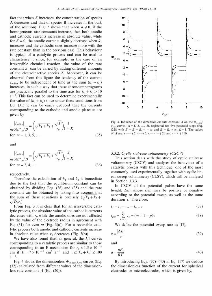
Fig. 4 shows the dimensionless Fm,lim/xpm curves (Eq.(32)) calculated from different values of the dimension-less rate constant L (Eq. (20)).
Fig. 4. Influence of the dimensionless rate constant L on the Fm,lim/xpm curves (m=1, 2, …, 5), registered for five potential steps (Eq.(32)) with E1=E3=E5�−� and E2=E4��. K=1. The valuesof L are: (——) 2, (----) 5, (— · —) 20 and ( · · · · ) 100.
3.3.2. Cyclic staircase 6oltammetry (CSCV)This section deals with the study of cyclic staircase
voltammetry (CSCV) and analyses the behaviour of acatalytic process with this technique, one of the mostcommonly used experimentally together with cyclic lin-ear sweep voltammetry (CLSV), which will be analysedin Section 3.3.3.
In CSCV all the potential pulses have the sameheight, DE, whose sign may be positive or negativeaccording to the potential sweep, as well as the sameduration t. Therefore,
t1= t1=…= tm=t (37)
tpm= %m
k=p
tk= (m+1−p)t (38)
We define the potential sweep rate as [17],
n=�DE �
t(39)
and
a=nFRT
n (40)
By introducing Eqs. (37)–(40) in Eq. (17) we deducethe dimensionless function of the current for sphericalelectrodes or microelectrodes, which is given by,
A. Molina et al. / Journal of Electroanalytical Chemistry 454 (1998) 15–3122
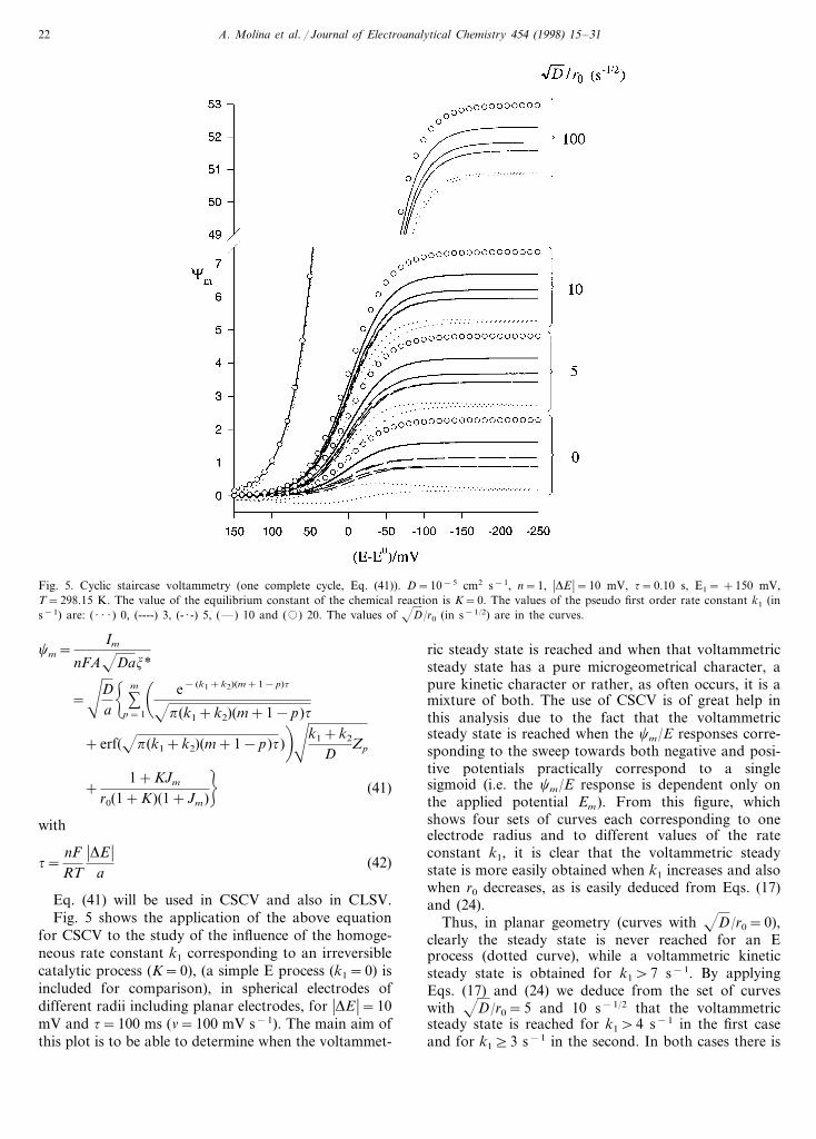
Fig. 5. Cyclic staircase voltammetry (one complete cycle, Eq. (41)). D=10−5 cm2 s−1, n=1, �DE �=10 mV, t=0.10 s, E1= +150 mV,T=298.15 K. The value of the equilibrium constant of the chemical reaction is K=0. The values of the pseudo first order rate constant k1 (ins−1) are: ( · · · ) 0, (----) 3, (- · -) 5, (—) 10 and (�) 20. The values of D/r0 (in s−1/2) are in the curves.
cm=Im
nFADaj*
='D
a! %
m
p=1
� e− (k1+k2)(m+1−p)t
p(k1+k2)(m+1−p)t
+erf(p(k1+k2)(m+1−p)t)�'k1+k2
DZp
+1+KJm
r0(1+K)(1+Jm)"
(41)
with
t=nFRT
�DE �a
(42)
Eq. (41) will be used in CSCV and also in CLSV.Fig. 5 shows the application of the above equation
for CSCV to the study of the influence of the homoge-neous rate constant k1 corresponding to an irreversiblecatalytic process (K=0), (a simple E process (k1=0) isincluded for comparison), in spherical electrodes ofdifferent radii including planar electrodes, for �DE �=10mV and t=100 ms (n=100 mV s−1). The main aim ofthis plot is to be able to determine when the voltammet-
ric steady state is reached and when that voltammetricsteady state has a pure microgeometrical character, apure kinetic character or rather, as often occurs, it is amixture of both. The use of CSCV is of great help inthis analysis due to the fact that the voltammetricsteady state is reached when the cm/E responses corre-sponding to the sweep towards both negative and posi-tive potentials practically correspond to a singlesigmoid (i.e. the cm/E response is dependent only onthe applied potential Em). From this figure, whichshows four sets of curves each corresponding to oneelectrode radius and to different values of the rateconstant k1, it is clear that the voltammetric steadystate is more easily obtained when k1 increases and alsowhen r0 decreases, as is easily deduced from Eqs. (17)and (24).
Thus, in planar geometry (curves with D/r0=0),clearly the steady state is never reached for an Eprocess (dotted curve), while a voltammetric kineticsteady state is obtained for k1\7 s−1. By applyingEqs. (17) and (24) we deduce from the set of curveswith D/r0=5 and 10 s−1/2 that the voltammetricsteady state is reached for k1\4 s−1 in the first caseand for k1]3 s−1 in the second. In both cases there is
A. Molina et al. / Journal of Electroanalytical Chemistry 454 (1998) 15–31 23
a mixed voltammetric steady state (Eq. (24)). The mi-crogeometrical voltammetric steady state should bereached at the limit r0�0. Thus, the set of curves inthis figure corresponding to D/r0=100 s−1/2 showsthat a catalytic process (with K=0) behaves like an Eprocess for this value of the electrode radius (r0$2.6×10⁻⁵ cm if D=7×10⁻⁶ cm2 s−1) for k1510 s−1,which is in agreement with Eqs. (17) and (25). There-fore, the microgeometrical voltammetric steady state isobtained under these conditions. For k1\10 s−1 thesteady state is also a mixed steady state. All thesevalues of k1 have been calculated with an average errormargin of less than 3%.
Moreover, it is also clear from this figure that thevoltammetric steady state (mixed) is reached earlier fora catalytic process than for an E process, whatever theelectrode size.
It can also be concluded that the current measured toa given potential in the case of a catalytic process isalways greater than that corresponding to a simple Eprocess. The difference is greater the higher the rateconstant of the homogeneous chemical reaction, exceptin the case of an ultramicroelectrode (r0B10−5 cm) forwhich both responses should be practically coincident(microgeometrical steady state).
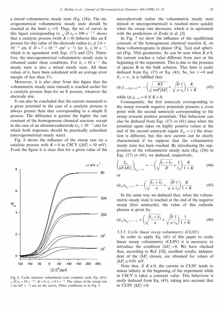
Fig. 6 shows the influence of the sweep rate on acatalytic process with K=0 in CSCV (�DE �=10 mV).From the figure it is clear that for a given value of the
microelectrode radius the voltammetric steady state(mixed or microgeometrical) is reached more quicklywhen the sweep rate decreases, which is in agreementwith the predictions of Zoski et al. [3].
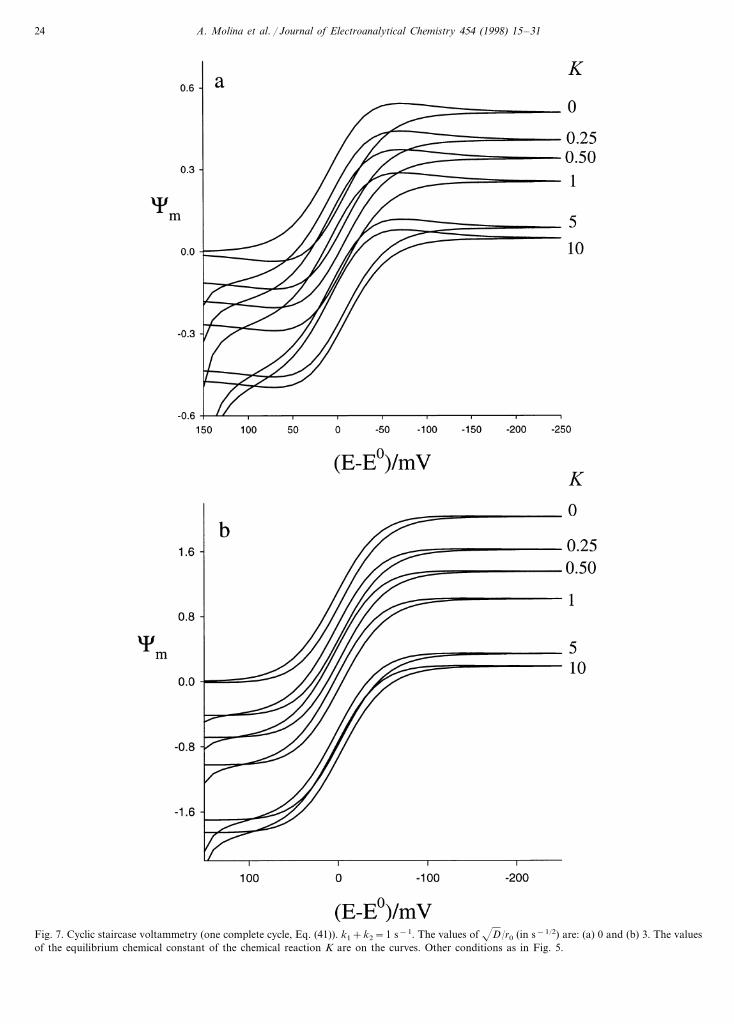
In Fig. 7 we show the influence of the equilibriumconstant of the homogeneous chemical reaction K, onthese voltammograms in planar (Fig. 7(a)) and spheri-cal (Fig. 7(b)) geometries. As can be seen when K"0,the current reaches a value different from zero at thebeginning of the experiment. This is due to the presenceof species B in the bulk solution. This limit is easilydeduced from Eq. (17) or Eq. (41). So, for t�0 andE1��, it is fulfilled that:
(c1)t�0,K\0= −�' RT
pnF �DE �+'D
a1r0
� K1+K
(43)
while (c1)t�0=0 if K=0.Consequently, the first semicycle corresponding to
the sweep towards negative potentials presents a crosspoint with the second semicycle corresponding to thesweep towards positive potentials. This behaviour canalso be deduced from Eqs. (17) or (41) since when thepotential again takes on highly positive values at theend of the second semicycle (again Em��) the situa-tion is different, but this new current can be clearlycharacterised if we suppose that the voltammetricsteady state has been reached. By introducing the sup-position of the voltammetric steady state (Eq. (24)) inEqs. (17) or (41), we deduced, respectively,� Im
nFADj
�Em��
= −�'k1+k2
D+
1r0
� K1+K
(44)
or
(cm)Em��= −
�'k1+k2
a+'D
a1r0
� K1+K
(45)
In the same way we deduced that, when the voltam-metric steady state is reached at the end of the negativesweep (first semicycle), the value of this cathodicplateau is given by,
(cm)Em�−�=�'k1+k2
a+'D
a1r0
� 11+K
(46)
3.3.3. Cyclic linear sweep 6oltammetry (CLSV)In order to apply Eq. (41) of this paper to cyclic
linear sweep voltammetry (CLSV) it is necessary tointroduce the condition �DE ��0. We have checkedthat, according to Ref. [18], excellent results, indepen-dent of the �DE � chosen, are obtained for values of�DE �50.01 mV.
Note that, if K"0, the current in CLSV tends tominus infinity at the beginning of the experiment whilein CSCV it takes a constant value. This behaviour iseasily deduced from Eq. (43), taking into account thatin CLSV �DE ��0.
Fig. 6. Cyclic staircase voltammetry (one complete cycle, Eq. (41)).D/r0=10 s−1/2, K=0, k1=0.5 s−1. The values of the sweep raten (in mV s−1) are on the curves. Other conditions as in Fig. 5.
A. Molina et al. / Journal of Electroanalytical Chemistry 454 (1998) 15–3124
Fig. 7. Cyclic staircase voltammetry (one complete cycle, Eq. (41)). k1+k2=1 s−1. The values of D/r0 (in s−1/2) are: (a) 0 and (b) 3. The valuesof the equilibrium chemical constant of the chemical reaction K are on the curves. Other conditions as in Fig. 5.
A. Molina et al. / Journal of Electroanalytical Chemistry 454 (1998) 15–31 25
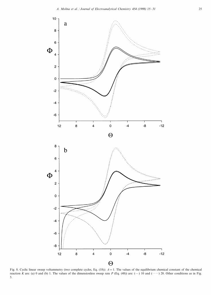
Fig. 8. Cyclic linear sweep voltammetry (two complete cycles, Eq. (18)). L=1. The values of the equilibrium chemical constant of the chemicalreaction K are: (a) 0 and (b) 1. The values of the dimensionless sweep rate P (Eq. (48)) are: (—) 10 and ( · · · · ) 20. Other conditions as in Fig.5.
A. Molina et al. / Journal of Electroanalytical Chemistry 454 (1998) 15–3126
In Fig. 8 we have represented the dimensionless cyclicvoltammograms F/U deduced from Eq. (18), with U=(nF/RT)(E−E0), with two complete cycles for K=0(Fig. 8(a)) and K=1 (Fig. 8(b)). These curves havebeen deduced for two different values of the so calleddimensionless sweep rate in reference [1], P, which isgiven by,
P=�nFnr0
2
RTD�1/2
=�nFn
RTL
(k1+k2)�1/2
(47)
As has been pointed out in Fig. 8 the use of succes-sive cycles in CLSV or in CSCV is advantageous, forexample, in determining whether the chemical reactionis irreversible or not, since by increasing the sweep ratethe differences between the first complete cycle and thesecond are shown both when K=0 (Fig. 8(a)) andwhen K"0 (Fig. 8(b)). To this extent, for a qualitativeexploration of the process, CLSV could be of greateradvantage than CSCV since these effects will be morenotable in the former.
Finally we have compared our simple Eqs. (17) and(18) in this paper with the integral Eq. (30) in reference[1], which cannot be considered as a general analyticalsolution of this kind of problem on account of thefollowing reasons:1. This equation has a very complicated expression
from which it is not possible to predict the generalbehaviour of the process (I) nor deduce limitingsituations like those shown in the Sections 3.1 and3.4 of this paper.
2. Secondly, this equation is applicable only in linearsweep voltammetry (LSV) and only when supposingthat K=0. This is a serious disadvantage since byusing cyclic techniques it is possible to knowwhether the steady state has been reached or notthrough a simple visual inspection of the I/E re-sponse (the properties of positive and negativesweeps are coincident).
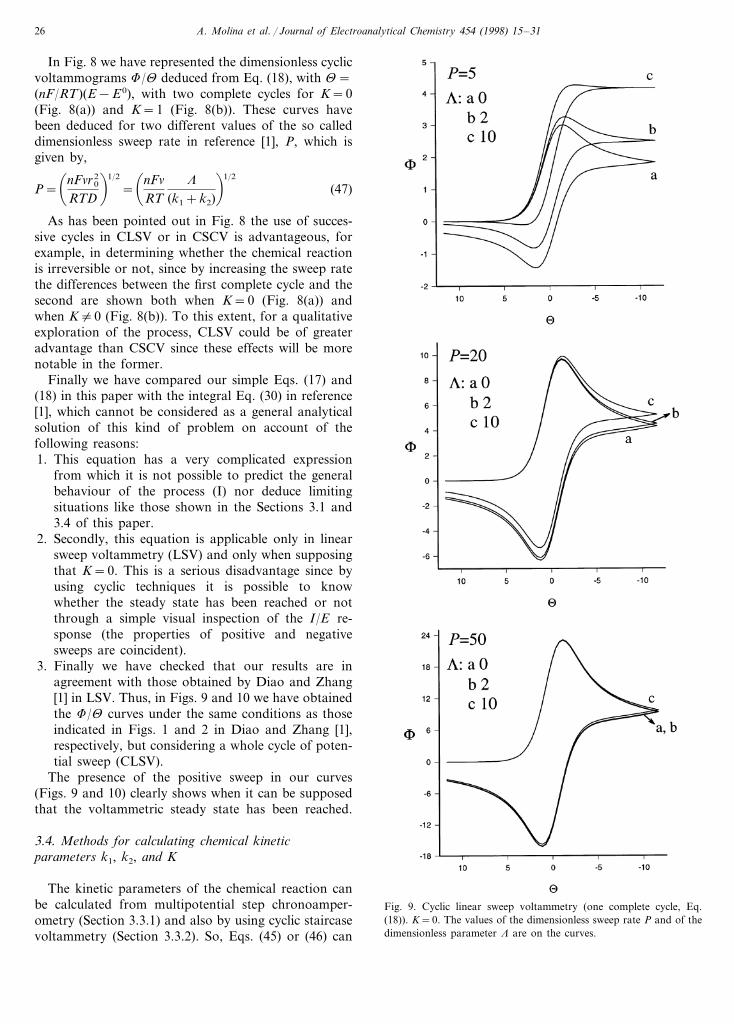
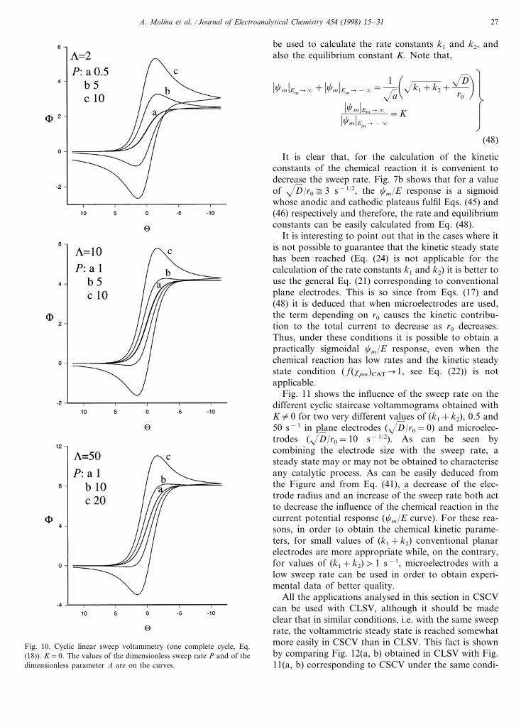
3. Finally we have checked that our results are inagreement with those obtained by Diao and Zhang[1] in LSV. Thus, in Figs. 9 and 10 we have obtainedthe F/U curves under the same conditions as thoseindicated in Figs. 1 and 2 in Diao and Zhang [1],respectively, but considering a whole cycle of poten-tial sweep (CLSV).
The presence of the positive sweep in our curves(Figs. 9 and 10) clearly shows when it can be supposedthat the voltammetric steady state has been reached.
3.4. Methods for calculating chemical kineticparameters k1, k2, and K
The kinetic parameters of the chemical reaction canbe calculated from multipotential step chronoamper-ometry (Section 3.3.1) and also by using cyclic staircasevoltammetry (Section 3.3.2). So, Eqs. (45) or (46) can
Fig. 9. Cyclic linear sweep voltammetry (one complete cycle, Eq.(18)). K=0. The values of the dimensionless sweep rate P and of thedimensionless parameter L are on the curves.
A. Molina et al. / Journal of Electroanalytical Chemistry 454 (1998) 15–31 27
be used to calculate the rate constants k1 and k2, andalso the equilibrium constant K. Note that,
�cm �Em��+ �cm �Em�−�=
1
a
�k1+k2+D
r0
��cm �Em��
�cm �Em�−�
=KÌÃ
Ã
Â
Å(48)
It is clear that, for the calculation of the kineticconstants of the chemical reaction it is convenient todecrease the sweep rate. Fig. 7b shows that for a valueof D/r0$3 s−1/2, the cm/E response is a sigmoidwhose anodic and cathodic plateaus fulfil Eqs. (45) and(46) respectively and therefore, the rate and equilibriumconstants can be easily calculated from Eq. (48).
It is interesting to point out that in the cases where itis not possible to guarantee that the kinetic steady statehas been reached (Eq. (24) is not applicable for thecalculation of the rate constants k1 and k2) it is better touse the general Eq. (21) corresponding to conventionalplane electrodes. This is so since from Eqs. (17) and(48) it is deduced that when microelectrodes are used,the term depending on r0 causes the kinetic contribu-tion to the total current to decrease as r0 decreases.Thus, under these conditions it is possible to obtain apractically sigmoidal cm/E response, even when thechemical reaction has low rates and the kinetic steadystate condition ( f(xpm)CAT�1, see Eq. (22)) is notapplicable.
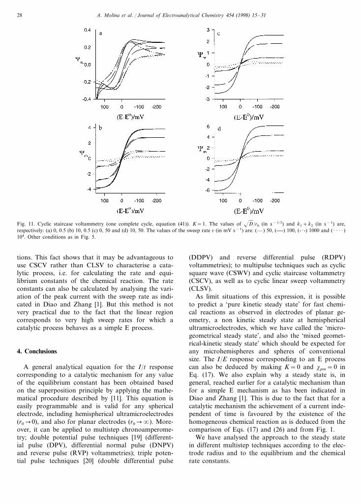
Fig. 11 shows the influence of the sweep rate on thedifferent cyclic staircase voltammograms obtained withK"0 for two very different values of (k1+k2), 0.5 and50 s−1 in plane electrodes (D/r0=0) and microelec-trodes (D/r0=10 s−1/2). As can be seen bycombining the electrode size with the sweep rate, asteady state may or may not be obtained to characteriseany catalytic process. As can be easily deduced fromthe Figure and from Eq. (41), a decrease of the elec-trode radius and an increase of the sweep rate both actto decrease the influence of the chemical reaction in thecurrent potential response (cm/E curve). For these rea-sons, in order to obtain the chemical kinetic parame-ters, for small values of (k1+k2) conventional planarelectrodes are more appropriate while, on the contrary,for values of (k1+k2)\1 s−1, microelectrodes with alow sweep rate can be used in order to obtain experi-mental data of better quality.
All the applications analysed in this section in CSCVcan be used with CLSV, although it should be madeclear that in similar conditions, i.e. with the same sweeprate, the voltammetric steady state is reached somewhatmore easily in CSCV than in CLSV. This fact is shownby comparing Fig. 12(a, b) obtained in CLSV with Fig.11(a, b) corresponding to CSCV under the same condi-
Fig. 10. Cyclic linear sweep voltammetry (one complete cycle, Eq.(18)). K=0. The values of the dimensionless sweep rate P and of thedimensionless parameter L are on the curves.
A. Molina et al. / Journal of Electroanalytical Chemistry 454 (1998) 15–3128
Fig. 11. Cyclic staircase voltammetry (one complete cycle, equation (41)). K=1. The values of D/r0 (in s−1/2) and k1+k2 (in s−1) are,respectively: (a) 0, 0.5 (b) 10, 0.5 (c) 0, 50 and (d) 10, 50. The values of the sweep rate 6 (in mV s−1) are: (—) 50, (----) 100, (- · -) 1000 and ( · · · · )104. Other conditions as in Fig. 5.
tions. This fact shows that it may be advantageous touse CSCV rather than CLSV to characterise a cata-lytic process, i.e. for calculating the rate and equi-librium constants of the chemical reaction. The rateconstants can also be calculated by analysing the vari-ation of the peak current with the sweep rate as indi-cated in Diao and Zhang [1]. But this method is notvery practical due to the fact that the linear regioncorresponds to very high sweep rates for which acatalytic process behaves as a simple E process.
4. Conclusions
A general analytical equation for the I/t responsecorresponding to a catalytic mechanism for any valueof the equilibrium constant has been obtained basedon the superposition principle by applying the mathe-matical procedure described by [11]. This equation iseasily programmable and is valid for any sphericalelectrode, including hemispherical ultramicroelectrodes(r0�0), and also for planar electrodes (r0��). More-over, it can be applied to multistep chronoamperome-try; double potential pulse techniques [19] (different-ial pulse (DPV), differential normal pulse (DNPV)and reverse pulse (RVP) voltammetries); triple poten-tial pulse techniques [20] (double differential pulse
(DDPV) and reverse differential pulse (RDPV)voltammetries); to multipulse techniques such as cyclicsquare wave (CSWV) and cyclic staircase voltammetry(CSCV), as well as to cyclic linear sweep voltammetry(CLSV).
As limit situations of this expression, it is possibleto predict a ‘pure kinetic steady state’ for fast chemi-cal reactions as observed in electrodes of planar ge-ometry, a non kinetic steady state at hemisphericalultramicroelectrodes, which we have called the ‘micro-geometrical steady state’, and also the ‘mixed geomet-rical-kinetic steady state’ which should be expected forany microhemispheres and spheres of conventionalsize. The I/E response corresponding to an E processcan also be deduced by making K=0 and xpm=0 inEq. (17). We also explain why a steady state is, ingeneral, reached earlier for a catalytic mechanism thanfor a simple E mechanism as has been indicated inDiao and Zhang [1]. This is due to the fact that for acatalytic mechanism the achievement of a current inde-pendent of time is favoured by the existence of thehomogeneous chemical reaction as is deduced from thecomparison of Eqs. (17) and (26) and from Fig. 1.
We have analysed the approach to the steady statein different multistep techniques according to the elec-trode radius and to the equilibrium and the chemicalrate constants.
A. Molina et al. / Journal of Electroanalytical Chemistry 454 (1998) 15–31 29
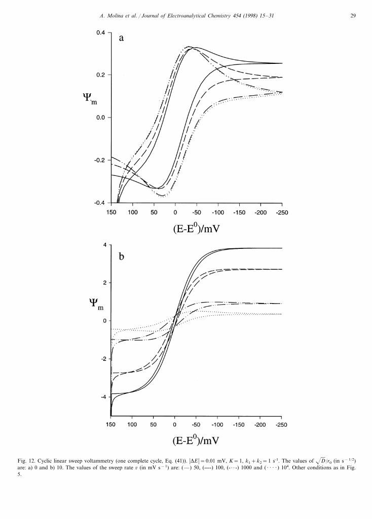
Fig. 12. Cyclic linear sweep voltammetry (one complete cycle, Eq. (41)). �DE �=0.01 mV, K=1, k1+k2=1 s-1. The values of D/r0 (in s−1/2)are: a) 0 and b) 10. The values of the sweep rate 6 (in mV s−1) are: (—) 50, (----) 100, (- · · -) 1000 and ( · · · · ) 104. Other conditions as in Fig.5.
A. Molina et al. / Journal of Electroanalytical Chemistry 454 (1998) 15–3130
We have compared the CSCV and CLSV techniquesat the same sweep rate and we have also analysed theinfluence of the sweep rate on the response correspond-ing to a catalytic process in these two cyclic techniques.The use of these cyclic techniques is of great impor-tance since through these we can ascertain whether thevoltammetric steady state has been reached by a simplevisual inspection of the I/E curves. In the case of linearsweep voltammetry (LSV) our results are in agreementwith those obtained from Eq. (30) in Diao and Zhang[1].
In order to obtain the rate and equilibrium constantof the homogeneous chemical reaction, for small valuesof (k1+k2) conventional planar electrodes are moreappropriate while on the contrary, for values of (k1+k2)\1 s−1, microhemispheres with a low sweep ratecan be used in order to obtain experimental data ofbetter quality
Acknowledgements
The authors greatly appreciate the financial supportprovided by the Direccion General de InvestigacionCientıfica y Tecnica (Project Number PB96-1905).
Appendix A
For the mechanism given by the reaction scheme (I),when a first potential step, E1, is applied to a sphericalelectrode, the differential equation system to solve isgiven by [21],
d. f1=d. j1=0 (A1)
where
d. = (
(t1
−D� (2
(r2+2r(
(rn
(A2)
and,
f1= [cB1 (r, t1)−KcA
1 (r, t1)]e(k1+k2)t1 (A3)
j1=cA1 (r, t1)+cB
1 (r, t1) (A4)
with K given by Eq. (3).In the above equations we have supposed that the
diffusion coefficients of species A and B are equal(DA=DB=D).
Taking into account that for a reversible chemicalreaction it is found that,
cA1 (r0, t1)−J1cB
1 (r0, t1) (A5)
with J1 given by Eq. (5) and that the sum of theconcentrations of A and B species remains constant forany values of the distance and time, i.e.
j1=j*=cA* +cB* (A6)
the boundary value problem can be expressed only interms of the variable f1 in the following way,
t=0; r]r0
t\0; r��"
f1=0 (A7)
t\0; r=r0
e− (k1+k2)t1f1(r0, t1)=1−KJ1
1+J1
j* (A8)
The current corresponding to this potential step isgiven by
I1
nFA=D
�(cA1 (r, t)(r
�r 0
= −De− (k1=k2)t1
1+K�(f1
(r�
r 0
(A9)
By introducing the dimensionless parameters
x11= (k1+k2)t1
s1=r−r0
2Dt1
z1=2Dt1
r0
ÌÃ
Ã
Ã
Ã
Â
Å
(A10)
and adopting for f1 a solution of the form,
f1=%i, j
si, j(s1)z1i x11
j (A11)
Eqs. (A1), (A7) and (A8) transform into
si, j%% (s1)+2s1si, j
% (s1)−2(i+2j)si, j(s1)= − %i−1
m=0
em(s1)si−m−1,i% (s1)
em=2(−1)ms1m with em=0 for i=0
ÌÃ
Ã
Â
Å
(A12)
s1��:
si, j=0 Ö i, j (A13)
s1=0:
s i, j(0)=0 Ö i]1
s0, j(0)=(1−KJ1)j*
1+J1
1j !ÌÃ
Ã
Â
Å
(A14)
Moreover, Eq. (A9) for the current becomes,
I1
nFA= −
e− (k1+k2)t1
1+KD
2t1
%i, j
s i, j% (0)z1i x11
j (A15)
A. Molina et al. / Journal of Electroanalytical Chemistry 454 (1998) 15–31 31
By solving Eq. (A12) with conditions (A13) and(A14) we have deduced the expressions for si, j(s1)functions and, from these expressions, those corre-sponding to the derivative in s1=0, which are thefollowing:
s0, j% (0)= −(1−KJ1)j*
1+J1
p2j
j !(A16)
s0, j% (0)= −(1−KJ1)j*
1+J1
1j !
(A17)
s0, j% (0)=0 for i]2 (A18)
with
p2j=2G(1+ j)
G�1+2j
2� (A19)
Note that the functions s i.j% (0) which contribute to thecurrent expression (equation (A15)) are null for i]2(spherical correction of higher order than the first).
By substituting Eqs. (A16)–(A18) in Eq. (A15) weobtain, for the current corresponding to the first poten-tial step applied to a spherical electrode, the followingexact expression,
I1
nFAD=
(1−KJ1)j*(1+K)(1+J1)
! e−x11
pDt1
+'k1+k2
Derf(x11)+
1r0
"(A20)
References
[1] G. Diao, Z. Zhang, J. Electroanal. Chem. 429 (1997) 67.[2] M.I. Montenegro, M.A. Queiros, S.L. Daschbach (Eds.), Mi-
croelectrodes: Theory and Applications, Kluwer, Dordrecht1991.
[3] C.G. Zoski, A.M. Bond, C.L. Colyer, J.C. Myland, K.B. Old-ham, J. Electroanal. Chem. 263 (1989) 1.
[4] M.A. Dayton, J.C. Brown, K.J. Sttuts, R.M. Wightman, Anal.Chem. 52 (1980) 946.
[5] J. Heinze, J. Electroanal. Chem. 124 (1981) 73.[6] K. Aoki, J. Osteryoung, J. Electroanal. Chem. 125 (1981) 315.[7] Z. Galus, Fundamentals of Electrochemical Analysis, Chapter
19, 2nd Edition, Chichester, Ellis Horwood, 1994.[8] K.B. Oldham, J.C. Myland, Fundamentals of Electrochemical
Science, Chapter 8, Academic Press, San Diego, 1994.[9] Z. Galus, J.O. Schenk, R.N. Adams, J. Electroanal. Chem. 135
(1982) 1.[10] A.M. Bond, K.B. Oldham, C.G. Zoski, Anal. Chim. Acta 216
(1989) 177.[11] A. Molina, J. Electroanal. Chem, J. Electroanal. Chem. 443
(1998) 163.[12] M. Seralathan, R.A. Osteryoung, J.G. Osteryoung, J. Elec-
troanal. Chem. 222 (1987) 69.[13] K.B. Oldham, J. Electroanal. Chem. 313 (1991) 3.[14] J. Wang, J.M. Lu, K. Olsen, Analyst 117 (1992) 1913.[15] R. Setiadji, J. Wang, G. Santana-Rios, Talanta 40 (1993) 845.[16] J. Zeng, R.A. Osteryoung, Anal. Chem. 58 (1986) 2766.[17] C.G. Phillips, J. Electroanal. Chem. 296 (1990) 255.[18] A. Molina, C. Serna, L. Camacho, J. Electroanal. Chem. 394
(1995) 1.[19] A.J. Bard, L.R. Faulkner, Electrochemical Methods, Chapter 5,
Wiley, New York, 1980.[20] A. Molina, F. Martınez-Ortiz, C. Serna, L. Camacho, J.J. Ruiz,
J. Electroanal. Chem. 408 (1996) 33.[21] J. Koutecky, J. Cızek, Collect. Czech. Chem. Commun. 21
(1956) 1063.
..
Copyright © 2022 FDOKUMEN