In situ forming, resorbable graft copolymer hydrogels providing controlled drug release
Upload
atespolymerCategory
view
6download
0
Turk J Chem30 (2006) , 401 – 418.c© TUBITAK
Electrochemical Synthesis of N-Methylpyrrole and
N-Methylcarbazole Copolymer on Carbon Fiber
Microelectrodes, and Their Characterization
A. Sezai SARAC∗, Erkan DOGRU, Murat ATES,Elif ALTURK PARLAK
Department of Chemistry, Polymer Science and Technology, Istanbul Technical University,Maslak, 34469, Istanbul-TURKEY
e-mail: [email protected]
Received 05.10.2005
Copolymer films of N-methylpyrrole (N-MPy) and N-methylcarbazole (N-MCz) were synthesized
electrochemically onto single carbon fiber microelectrodes (CFMEs). Deposition conditions on the
carbon fiber, influence of the monomer concentrations on the copolymerization of P[N-methylpyrrole-co-
N-methylcarbazole] P[N-MPy-co-N-MCz], and the electrochemistry of the resulting homopolymer and
copolymers were studied using cyclic voltammetry, FTIR-ATR, in-situ spectroelectrochemistry, a UV-
vis spectrophotometer, and a 4-point probe conductometer. The effects of current density, supporting
electrolyte type, temperature, and monomer concentrations on the formation of the film were studied.
Redox parameters and stability of charged films were obtained by cyclic voltammetry. The most stable
copolymer was obtained in lithium perchlorate-acetonitrile electrolytic solution (LiClO4/ ACN).
KeyWords: Electrocopolymerization, cyclic voltammogram (CV), carbon fiber microelectrode (CFME).
Introduction
The electrochemical deposition of conducting polymers on carbon fiber microelectrodes (CFMEs) has been
studied with the goal of improving the mechanical properties of these polymers, in order to use themas electrodes in different applications, such as electrochromic displays, batteries, sensors, and capacitors.Interaction and nano-characterization of thin conjugated polymeric films on carbon surfaces, especially on
micron-sized carbon fibers, have attracted great interest recently1,2, due to the need to modify their surfacesto understand the interfacial properties between the fiber and the matrix.
Polycarbazole, one of many conducting polymers, is known for its good electroactivity, and useful
thermal, electrical and photophysical properties3 . However, a π-π electron system along its backboneimparts rigidity to the polymer, and, therefore, makes it infusible and difficult to process. For this reason,it was not initially deployed as widely in devices when compared to other conducting polymers. However,
∗Corresponding author
401
Electrochemical Synthesis of N-Methylpyrrole and..., A. S. SARAC, et al.,
recent advances in synthesis methods have reinvigorated interest in polycarbazole4. Investigations relatedto chemical modification, or in copolymerization of carbazole with other monomers, have led to the use ofpolycarbazole and its derivatives as redox catalysts, photoactive devices, sensors, electrochromic display,
electroluminescent devices, and biosensors5,6.Copolymerization of carbazole and its derivatives with N-methylpyrrole has previously been studied
by chemical and electrochemical methods7. Due to the combined properties of alkyl substituted pyrrole and
carbazole monomers, N-MPy and ethylcarbazole have been copolymerized8. Results show that there is animprovement in the electrochemical properties of the copolymer with the incorporation of methylpyrrole.Use of N-methyl substituted pyrrole has the advantage of preventing polymerization through nitrogen, which
causes a decrease in conductivity (defect in conjugation of the copolymer is prevented).
In view of the wide spectrum of potential applications, it is clear that a further examination ofthe electropolymerization conditions, use of different substrates, and the stability of the resulting polymercan help to extend the scope of the technological applications of conducting polymers as thin films. Theelectrocoating of a range of copolymers with various monomer concentrations has been recently examined
using carbon fibers as the microelectrode9−12. Electropolymerization of 3-methyl-thiophene with carbazolehas been studied, and the surface morphology of the microelectrodes and the relationship between the
polymerization parameters have been established13.Since electronic properties are considered, copolymerization starts from two monomers that contain
an alkyl group. This arrangement seems more favorable. The presence of an alkyl group gives solubility
to copolymers obtained electrochemically14. Polymers containing N-alkyl-3-6-carbazole units were found
to be soluble in organic solvents15 and could be then easily processed. Electrochemical synthesis hasbecome the preferred method for preparing electrically conducting polymers because of its simplicity andreproducibility. The advantage of electrochemical polymerization is that the reactions can be carried out at
room temperature16 .Factors affecting the electrocopolymerization are investigated to control experimental conditions.
Electrocopolymerization is controlled by a variety of parameters, i.e. concentration, monomer feed ratio,temperature, electrolyte type, number of carbon fibers, and scan rate. Carbon fibers as micron-sizedelectrodes, the nature of copolymeric films, and their structure and compositions play an important rolein understanding the effect of the electrochemical conditions used for coating the fiber on the final properties
of the modified carbon surface17. With this aim in mind, we recently studied the electrografting of copolymers
with conductive and non-conductive portions onto carbon fibers18−21.In this work, the polymerization of N-methylpyrrole with N-methylcarbazole was achieved electro-
chemically. The electrocopolymerization of methylcarbazole with methylpyrrole was studied to improve
the electrochemical properties of N-MCz. The polymers (P[N-MPy], P[N-MCz] and P[N-MPy-co-N-MCz])
obtained in different solutions were analyzed using cyclic voltammetry (CV).
Experimental
Materials
N-methylpyrrole (N-MPy, >98%), sodium perchlorate (NaClO4, > 98%), lithium perchlorate (LiClO4, >
98%), propylene carbonate (PC, >99%), and acetone (99.7%, Purex PA) were obtained from Merck. Ace-
tonitrile (ACN) was from Carlo Erba. Potassium perchlorate (KClO4), tetrabutylammonium perchlorate
402
Electrochemical Synthesis of N-Methylpyrrole and..., A. S. SARAC, et al.,
(TBAP) and tetraethyl ammonium perchlorate were obtained from Aldrich. High Strength (HS) carbon
fibers C320000A (CA) (Sigri Carbon, Meitingen, Germany) containing 320,000 single filaments were used as
the working electrodes. Indium tin oxide (ITO) coated glass slides (0.7 cm x 5 cm, R ≤ = 10 ohm cm−2)
were from Delta Technologies (USA), and were used for some of the in-situ spectroelectrochemical studies.
All chemicals were high-grade reagents and were used as received.
Cyclic Voltammetry
Cyclic voltammograms of the polymers were obtained with a Parstat 2263 potentiostat, which is a self-
contained unit that combines potentiostatic circuitry with phase-sensitive detection (Faraday cage with
BAS Cell Stand C3), in a 3-electrode system setup employing CFME as the working electrode, platinum
wire as the counter electrode, and a silver wire pseudo-reference in LiClO4 / PC or NaClO4 / ACN (0.1
M). The pseudo-reference was calibrated externally using a 5 mM solution of ferrocene (Fc / Fc+) in the
electrolyte [E1/2(Fc / Fc+) = +0.13 V vs. silver wire in 0.1 M LiClO4/ PC]. Polymerization reactions were
also performed galvanostatically (0.2 A) in PC or ACN solution containing 0.1 M LiClO4 or NaClO4 andmonomers.
Preparation of the CFME
A single filament of the CFME was used as a working electrode. All the electrodes were prepared by using
a 3 cm length of the CFME (diameter ∼7 µm) attached to a copper wire with Teflon tape. Only 1.0 cm of
the carbon fiber was dipped into the solution to keep the electrode area constant (∼0.0022 cm2). The rest
of the fiber was covered with the Teflon tape.
The Solid State Conductivity Measurements
Electrochemical syntheses of films were performed galvanostatically on a Pt plate electrode with a surface
area of 1.68 cm2. Solid state electrical conductivity measurements were carried out for films removed fromthe electrode surface. A Keithley 617 electrometer was connected to a 4-point probe head with gold tips.Electrical conductivity was calculated from the following equation:
σ = V−1/ (ln2 / π.dn), where dn is thickness in cm, V is applied potential in V, and I is current in A.
FTIR-ATR and UV-vis Spectrophotometry
Electrografted CFMEs (with a single grafted CF) were analyzed by FT-IR reflectance spectrometry (Perkin
Elmer, Spectrum One B, with an ATR attachment Universal ATR-with ZnSe crystal).
UV-Visible spectra were obtained both for electrochemically coated ITO glass and oligomers wereformed in solution by using a Shimadzu 160 A recording spectrophotometer.
403

Electrochemical Synthesis of N-Methylpyrrole and..., A. S. SARAC, et al.,
Results and Discussion
Electropolymerization of N-MPy, N-MCz, and the monomer mixture by CV on
CFMEs
The cyclic voltammograms of N-MPy, N-MCz, and the monomer mixture of thin films electrochemically
deposited on CFME (at 100 mV s−1 scan rate) recorded in 0.1 M NaClO4 / PC are shown in Figures 1a-1c,
respectively. Current densities vs. potential changes were electrochemically obtained using alkyl-substituted
monomers, N-MPy and N-MCz (structures are given in Table 1). They intensified during repetitive scans,
indicating the doping-dedoping of the electroactive film. The oxidation potential of the co-monomer mixture
is obtained at 0.69 V, which is smaller than the oxidation potentials of N-MCz (1.04 V) and N-MPy (0.71 V)
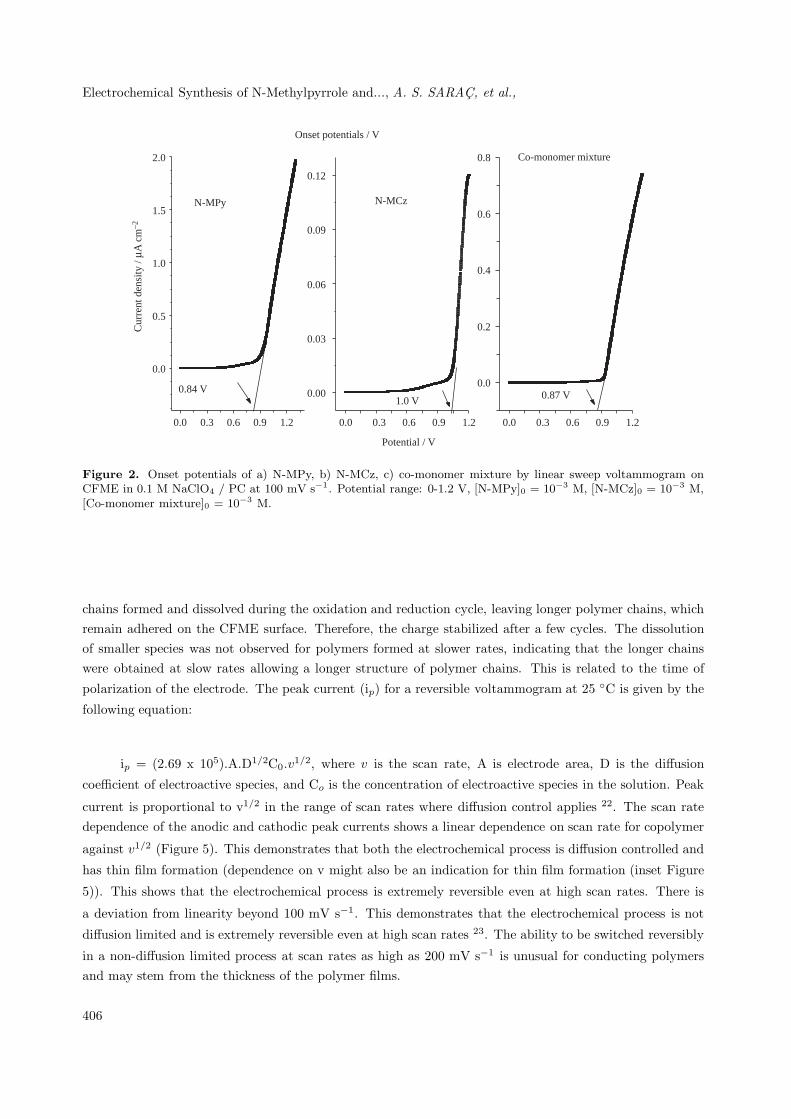
when using an electrogrowth mechanism. The onset potentials of N-methylpyrrole, N-methylcarbazole, and amixture of both monomers were obtained at 0.84, 1.00 and 0.87 V on CFMEs by linear sweep voltammogram,
respectively (Figure 2). CV of the monomer mixture shows different redox behavior, and oxidation potentials
than monomers.
0.0 0.5 1.0
-5
0
5
10
0.50 V
4.99 µA cm-2
0.71 V
a) N-MPy
0.0 0.5 1.0
-0.2
-0.1
0.0
0.1
0.2
0.93 V
0.08 µA cm-2
1.04 V
c)N-MCz
0.0 0.5 1.0
-5
0
5
10
0.33 V
6.05 µA cm-2
0.69 V
Potential / V (vs. Ag)
b) Co-monomer mixture
Cur
rent
den
sity
/ µA
cm
–2
Figure 1. CV for the oxidation of a) N-MPy, b) co-monomer mixture, c) N-MCz on CFME in 0.1 M NaClO4 /
PC at 100 mV s−1. Using multiple cycles (7), Potential range: 0-1.2 V, [MPy]0 = 10−3 M, [N-MCz]0 = 10−3 M,
[Co-monomer mixture]0 = 10−3 M.
Effect of scan rate on modified CFME in monomer free electrolyte Scan rate
dependence
The current density is linearly proportional to voltage, and the scan rate indicating all electroactive sites
are electrode supported. The cyclic voltammogram of P[N-MPy-co-N-MCz] coated CFME in monomer-free
electrolyte shows one oxidation potential at 0.7 V having linear dependence with the scan rate. In monomer
404

Electrochemical Synthesis of N-Methylpyrrole and..., A. S. SARAC, et al.,
Table 1. Structure and abbreviation of monomers and their polymers.
Structure
Mono
Polymers
N
CH3
N-MPy
CH3
NN
CH3
**
n
P[N-MPy]
N
CH3
N-MCz
N
CH3
N
CH3
( )n
*
*
P[N-MCz]
N
CH3
CH3
CH3
N(
N
CH3
)m)n
N
(
N-MCz,
N-MPy
P[N-methylpyrrole-
co-N-
methylcarbazole]
mers
free solution, the CV of P[N-MPy], P[N-MCz] (Figures 3a and b) and P[N-MPy-co-N-MCz] (Figure 4) are
recorded at 100 mV s−1. During the first few cycles for the copolymer, oligomeric species or small polymer
405
Electrochemical Synthesis of N-Methylpyrrole and..., A. S. SARAC, et al.,
0.0 0.3 0.6 0.9 1.2
0.0
0.5
1.0
1.5
2.0
Onset potentials / V
N-MPy
0.84 V 0.00
0.03
0.06
0.09
0.12
N-MCz
1.0 V
Potential / V
0.0
0.2
0.4
0.6
0.8 Co-monomer mixture
0.87 V
Cur
rent
den
sity
/ µA
cm
–2
0.0 0.3 0.6 0.9 1.2 0.0 0.3 0.6 0.9 1.2
Figure 2. Onset potentials of a) N-MPy, b) N-MCz, c) co-monomer mixture by linear sweep voltammogram onCFME in 0.1 M NaClO4 / PC at 100 mV s−1. Potential range: 0-1.2 V, [N-MPy]0 = 10−3 M, [N-MCz]0 = 10−3 M,[Co-monomer mixture]0 = 10−3 M.
chains formed and dissolved during the oxidation and reduction cycle, leaving longer polymer chains, whichremain adhered on the CFME surface. Therefore, the charge stabilized after a few cycles. The dissolutionof smaller species was not observed for polymers formed at slower rates, indicating that the longer chainswere obtained at slow rates allowing a longer structure of polymer chains. This is related to the time of
polarization of the electrode. The peak current (ip) for a reversible voltammogram at 25 ◦C is given by the
following equation:
ip = (2.69 x 10⁵).A.D1/2C0.v1/2, where v is the scan rate, A is electrode area, D is the diffusion
coefficient of electroactive species, and Co is the concentration of electroactive species in the solution. Peak
current is proportional to v1/2 in the range of scan rates where diffusion control applies 22. The scan ratedependence of the anodic and cathodic peak currents shows a linear dependence on scan rate for copolymer
against v1/2 (Figure 5). This demonstrates that both the electrochemical process is diffusion controlled and
has thin film formation (dependence on v might also be an indication for thin film formation (inset Figure
5)). This shows that the electrochemical process is extremely reversible even at high scan rates. There is
a deviation from linearity beyond 100 mV s−1. This demonstrates that the electrochemical process is not
diffusion limited and is extremely reversible even at high scan rates 23. The ability to be switched reversibly
in a non-diffusion limited process at scan rates as high as 200 mV s−1 is unusual for conducting polymersand may stem from the thickness of the polymer films.
406
Electrochemical Synthesis of N-Methylpyrrole and..., A. S. SARAC, et al.,
0.0 0.5 1.0 1.5-0.03
-0.02
-0.01
0.00
0.01
0.02
0.03
0.04
500
400
300 mV s-1
200
100
50
a) N-MCz
0.0 0.5 1.0 1.5-3
-2
-1
0
1
2
3 b) N-MPy
500
400
300 mV s-1
200
100
50
Potential / V (vs.Ag)
Cur
rent
den
sity
/ µA
cm
–2
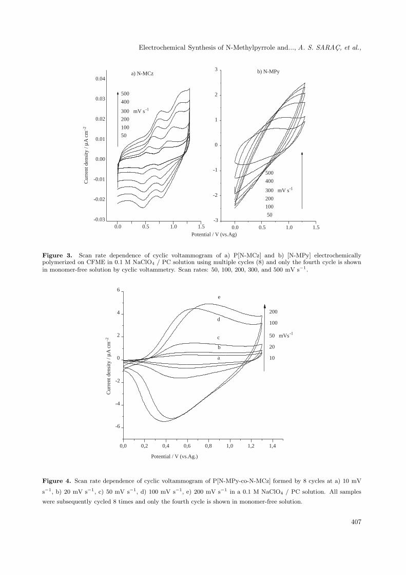
Figure 3. Scan rate dependence of cyclic voltammogram of a) P[N-MCz] and b) [N-MPy] electrochemicallypolymerized on CFME in 0.1 M NaClO4 / PC solution using multiple cycles (8) and only the fourth cycle is shownin monomer-free solution by cyclic voltammetry. Scan rates: 50, 100, 200, 300, and 500 mV s−1.
Cur
rent
den
sity
/ µA
cm
–2
0,0 0,2 0,4 0,6 0,8 1,0 1,2 1,4
-6
-4
-2
0
2
4
6
a
b
c
d
e
200
100
50 mVs-1
20
10
Potential / V (vs.Ag.)
Figure 4. Scan rate dependence of cyclic voltammogram of P[N-MPy-co-N-MCz] formed by 8 cycles at a) 10 mV
s−1, b) 20 mV s−1, c) 50 mV s−1, d) 100 mV s−1, e) 200 mV s−1 in a 0.1 M NaClO4 / PC solution. All samples
were subsequently cycled 8 times and only the fourth cycle is shown in monomer-free solution.
407
Electrochemical Synthesis of N-Methylpyrrole and..., A. S. SARAC, et al.,
Cur
rent
den
sity
/ µA
cm
–2
2 4 6 8 10 12 14 16-6
-4
-2
0
2
4
0 5 10 15 20-6
-4
-2
0
2
4
Scan rate, mV s -1
Anodic
Cathodic
(Scan rate)1/2
, (mV s-1
)1/2
Peak
cur
rent
den
sity
µA
/cm
2
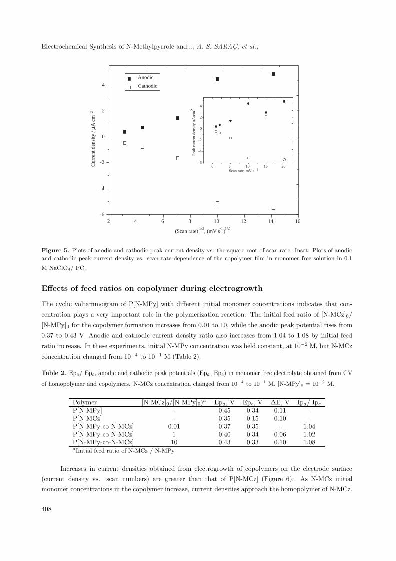
Figure 5. Plots of anodic and cathodic peak current density vs. the square root of scan rate. Inset: Plots of anodic
and cathodic peak current density vs. scan rate dependence of the copolymer film in monomer free solution in 0.1
M NaClO4/ PC.
Effects of feed ratios on copolymer during electrogrowth
The cyclic voltammogram of P[N-MPy] with different initial monomer concentrations indicates that con-
centration plays a very important role in the polymerization reaction. The initial feed ratio of [N-MCz]0/
[N-MPy]0 for the copolymer formation increases from 0.01 to 10, while the anodic peak potential rises from
0.37 to 0.43 V. Anodic and cathodic current density ratio also increases from 1.04 to 1.08 by initial feed
ratio increase. In these experiments, initial N-MPy concentration was held constant, at 10−2 M, but N-MCz
concentration changed from 10−4 to 10−1 M (Table 2).
Table 2. Epa/ Epc, anodic and cathodic peak potentials (Epa, Epc) in monomer free electrolyte obtained from CV
of homopolymer and copolymers. N-MCz concentration changed from 10−4 to 10−1 M. [N-MPy]0 = 10−2 M.
Polymer [N-MCz]0/[N-MPy]0)a Epa, V Epc, V ∆E, V Ipa/ Ipc
P[N-MPy] - 0.45 0.34 0.11 -P[N-MCz] - 0.35 0.15 0.10 -P[N-MPy-co-N-MCz] 0.01 0.37 0.35 - 1.04P[N-MPy-co-N-MCz] 1 0.40 0.34 0.06 1.02P[N-MPy-co-N-MCz] 10 0.43 0.33 0.10 1.08aInitial feed ratio of N-MCz / N-MPy
Increases in current densities obtained from electrogrowth of copolymers on the electrode surface
(current density vs. scan numbers) are greater than that of P[N-MCz] (Figure 6). As N-MCz initial
monomer concentrations in the copolymer increase, current densities approach the homopolymer of N-MCz.
408

Electrochemical Synthesis of N-Methylpyrrole and..., A. S. SARAC, et al.,
Cur
rent
den
sity
/ µA
cm
–2
0 1 2 3 4 5 6 7 8 9
0
1
2
3
4
5
6 N-MPy
[N-MPy]0 / [N-MCz] 0 : 1/1
[N-MPy]0 / [N-MCz] 0 : 1/2
[N-MPy]0 / [N-MCz] 0 : 1/5
[N-MPy]0 / [N-MCz] 0 : 1/10
N-MCz
Scan number
Figure 6. Electrochemical coating of N-MPy, N-MCz and N-MCz-co-N-MPy mixture at different initial feed ratios:
Current density vs. scan number.
Determination of number of carbon fibers
To study with a known number of single CFMEs, counting the number of CFME (diameter ∼7 µm) is very
difficult. The initial work was carried out by counting the fibers using a microscope. CV experiments wereperformed on counted carbon fibers and the current vs. carbon fiber numbers are plotted to determine thecurrent of each fiber during the electrogrowth of polymer. However, the limitation of this method is thatone has to always dip fibers to the same depth in the electrolyte solution. The currents are taken fromswitching potentials and for the determination of unknown CFME samples. One would be able to determinethe number of these fibers by simply dividing the current of several fibers by the current of a single fiber
(Figure 7).
Effects of monomer concentration on the yield and conductivity (Galvanostati-
cally)
Both the solid state conductivity and yield vs. initial monomer concentration for the homopolymer of P[N-
MCz] are given in Figure 8. The results indicate that an increase in N-MCz concentration from 10−3 to
10−2 M leads to an increase in the solid state conductivity. This increases the thickness of the thin polymer
film. Solid state conductivity increases from 1.21 ± 0.05 mS cm−1 to 3.50 ± 0.05 mS cm−1. Percent yield
was also increased from 9.7% to 59.1% by increasing initial monomer concentration. It could be observedthat the changes in the concentration caused a simultaneous increase in conductivity. In the case of the
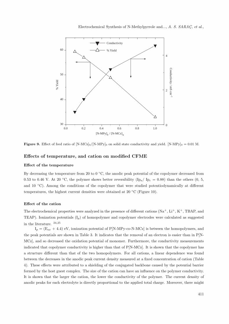
copolymer, conductivity decreased with the increase in N-MCz concentration (yields, feed ratios) (Figure
9). When N-MCz concentration increases 10-fold, conductivity decreases from 4.20 to 0.43 mS cm−1. An
increase in N-MCz initial concentration results in an increase in yield but a decrease in conductivity. The
409

Electrochemical Synthesis of N-Methylpyrrole and..., A. S. SARAC, et al.,
yield increase indicates that N-MCz is incorporated into the copolymer structure while the conductivity ofthe copolymer decreases.
Cur
rent
/ µA
0,0 0,2 0,4 0,6 0,8 1,0 1,2 1,4
-0,05
0,00
0,05
0,10
0,15
Isp1 = 0.043
Isp2 = 0.090
Isp3 = 0.140 Number of carbon fibers = 3
Number of carbon fibers = 2
Number of carbon fibers = 1
Potential / V (vs.Ag)
Figure 7. Electrochemical coating of P[N-MPy-co-N-MCz] by CV with different numbers of carbon fibers in 0.1 M
NaClO4 / ACN solution using multiple cycles and eighth cycle (Scan rate: 100 mV s−1, Potential range: 0-1.3 V).
0.000 0.002 0,004 0.006 0.008 0.01010
20
30
40
50
60
% Yield
Conductivity / m
S cm–1
% Y
ield
[N-MCz]0
1.0
1.5
2.0
2.5
3.0
3.5 Conductivity
Figure 8. Effect of initial monomer concentration [N-MCz]0 on P[N-MCz], conductivity and % yield.
410
Electrochemical Synthesis of N-Methylpyrrole and..., A. S. SARAC, et al.,
0.0 0.2 0.4 0.6 0.8 1.0
30
40
50
60
Conductivity
% Y
ield
0
2
4
% Yield
[N-MPy]0 / [N-MCz]0
Conductivity / m
S cm–1
Figure 9. Effect of feed ratio of [N-MCz]0/[N-MPy]0 on solid state conductivity and yield. [N-MPy]0 = 0.01 M.
Effects of temperature, and cation on modified CFME
Effect of the temperature
By decreasing the temperature from 20 to 0 ◦C, the anodic peak potential of the copolymer decreased from
0.53 to 0.46 V. At 20 ◦C, the polymer shows better reversibility (Ipa/ Ipc = 0.88) than the others (0, 5,
and 10 ◦C). Among the conditions of the copolymer that were studied potentiodynamically at different
temperatures, the highest current densities were obtained at 20 ◦C (Figure 10).
Effect of the cation
The electrochemical properties were analyzed in the presence of different cations (Na+, Li+, K+, TBAP, and
TEAP). Ionization potentials (Ip) of homopolymer and copolymer electrodes were calculated as suggested
in the literature. 24,25
Ip = (Eox + 4.4) eV, ionization potential of P[N-MPy-co-N-MCz] is between the homopolymers, and
the peak potentials are shown in Table 3. It indicates that the removal of an electron is easier than in P[N-
MCz], and so decreased the oxidation potential of monomer. Furthermore, the conductivity measurements
indicated that copolymer conductivity is higher than that of P[N-MCz]. It is shown that the copolymer has
a structure different than that of the two homopolymers. For all cations, a linear dependence was found
between the decreases in the anodic peak current density measured at a fixed concentration of cation (Table
4). These effects were attributed to a shielding of the conjugated backbone caused by the potential barrier
formed by the host guest complex. The size of the cation can have an influence on the polymer conductivity.It is shown that the larger the cation, the lower the conductivity of the polymer. The current density ofanodic peaks for each electrolyte is directly proportional to the applied total charge. Moreover, there might
411

Electrochemical Synthesis of N-Methylpyrrole and..., A. S. SARAC, et al.,
be a similar relation between the ionization potential of cations and anodic current density (CV results).
However, Na+ cation shows a distinctive property contrary to the relation (Table 4).C
urre
nt d
ensi
ty /
µA c
m–2
0 5 10 15 20
-4
-3
-2
-1
0
1
2
3
0 5 10 15 200.30
0.35
0.40
0.45
0.50
0.55
0.60
EpA
EpC
Pote
ntia
l / V
Temperature / oC
Temperature / o C
Ipa
Ipc
Figure 10. Anodic and cathodic current densities vs. temperature of copolymer coated electrochemically on CFME.
Inset: Graph of anodic and cathodic peak potentials vs. temperature.
Table 3. Epa, Epc, ∆E, Eox, Ip values of polymers in the range of 0 to 1.3 V.
Polymer Epa, V Epc, V ∆E, V Eox, V Ip, eVP[N-MPy] 0.75 0.50 0.25 0.10 4.50P[N-MCz] 1.02 0.94 0.08 0.90 5.30P[N-MPy-co-N-MCz] 0.74 0.33 0.41 0.26 4.66
Table 4. Relation of some electrolytes with total charge-anodic peak current density (coating and in monomer free)
- Ionization energy.
Electrolytes / ACN ∆Q (mC)a Ipa(µAcm−2)b Ipa (µAcm−2)c Ei(eV)d
NaClO4 12.77 8.46 1.92 5.14LiClO4 8.77 3.43 3.33 5.39KClO4 5.36 2.79 1.67 4.34TBAP 3.96 2.12 - -TEAP 3.46 1.66 - -a Total charge obtained in polymer growth.b Anodic peak current density obtained in polymer growth.c Anodic peak current density obtained in monomer free electrolyte at 50th cycle.d Ionization energy of cations.
412
Electrochemical Synthesis of N-Methylpyrrole and..., A. S. SARAC, et al.,
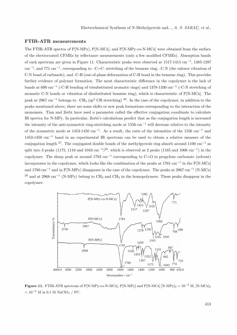
FTIR-ATR measurements
The FTIR-ATR spectra of P[N-MPy], P[N-MCz], and P[N-MPy-co-N-MCz] were obtained from the surface
of the electrocoated CFMEs by reflectance measurements (only a few modified CFMEs). Absorption bands
of each spectrum are given in Figure 11. Characteristic peaks were observed at 1517-1415 cm−1, 1385-1297
cm−1, and 771 cm−1, corresponding to –C=C- stretching of the benzene ring, -C-N (the valence vibration of
C-N bond of carbazole), and -C-H (out-of-plane deformation of C-H bond in the benzene ring). This provides
further evidence of polymer formation. The most characteristic difference in the copolymer is the lack of
bands at 690 cm−1 (-C-H bending of trisubstituted aromatic rings) and 1378-1330 cm−1 (-C-N stretching of
aromatic C-N bonds or vibration of disubstituted benzene ring), which is characteristic of P[N-MCz]. The
peak at 2967 cm−1 belongs to –CH3 (sp3 CH stretching) 26. In the case of the copolymer, in addition to the
peaks mentioned above, there are some shifts or new peak formations corresponding to the interaction of themonomers. Tian and Zerbi have used a parameter called the effective conjugation coordinate to calculateIR spectra for N-MPy. In particular, Zerbi’s calculations predict that as the conjugation length is increased
the intensity of the anti-symmetric ring-stretching mode at 1556 cm−1 will decrease relative to the intensity
of the symmetric mode at 1453-1450 cm−1. As a result, the ratio of the intensities of the 1556 cm−1 and
1453-1450 cm−1 band in an experimental IR spectrum can be used to obtain a relative measure of the
conjugation length 27. The conjugated double bonds of the methylpyrrole ring absorb around 1100 cm−1 as
split into 3 peaks (1175, 1116 and 1043 cm−1)28, which is observed as 2 peaks (1165 and 1066 cm−1) in the
copolymer. The sharp peak at around 1783 cm−1 corresponding to C=O in propylene carbonate (solvent)
incorporates in the copolymer, which looks like the combination of the peaks at 1761 cm−1 in the P[N-MCz]
and 1780 cm−1 and in P[N-MPy] disappears in the case of the copolymer. The peaks at 2967 cm−1 (N-MCz)29 and at 2968 cm−1 (N-MPy) belong to CH3 and CH2 in the homopolymers. These peaks disappear in the
copolymer.
2967
2968
1783
1517 1297
1761
1378 1330
1459P[N-MPy]
P[N-MCz]
3736
Tra
nsm
ittan
ce %
15561453
17801367
1352
1175
1116
11651105
1066
945
1043 774710
847
1041
768690
77111651415
1385
P[N-MPy–co-N-MCz]
Wavenumber / cm–1
4000.0 3600 3200 2800 2400 2000 1800 1600 1400 1200 1000 800 650.0
Figure 11. FTIR-ATR spectrum of P[N-MPy-co-N-MCz], P[N-MPy] and P[N-MCz] [N-MPy]0 = 10−2 M, [N-MCz]0
= 10−2 M in 0.1 M NaClO4 / PC.
413

Electrochemical Synthesis of N-Methylpyrrole and..., A. S. SARAC, et al.,
UV-vis Spectrophotometric Results
Ex-Situ Spectroelectrochemistry for coated polymer on ITO
P[N-MPy-co-N-MCz] films were deposited on ITO coated glass substrates potentiostatically at a constant
potential (1.4 V) from a mixture of N-MPy and N-MCz monomers in 0.1 M NaClO4/ PC solution over
30 min (initial concentrations of monomers were 0.05 M). The ex-situ spectroelectrochemical spectrum of
P[N-MPy-co-N-MCz] on ITO, by the formation of UV absorptions as the polymer becomes conducting and
shows fast switching times (10 s) for the large optical changes being attained, is shown in Figure 12. The
optical band gap of the film was 2.23 eV. In the fully reduced form at -1.2 V the polymer was yellow, but the
color gradually changes to green by applying oxidizing potential (0.1 V) and at a higher potential it turns
deep blue. This type of multicolor behavior is important for the preparation of electro-chromic materials.
The π - π* transition of P[N-MPy] showed a maximum absorbance (λmax) at 446 nm (2.78 eV)
(Figure 13a).The change in the band gap in the copolymer may stem from the incorporation of the N-MCz
in the resulting polymer. It should also be noted that in the case of P[N-MPy-co-N-MCz] the polymer
cannot be reduced completely as much as P[N-MPy], which also supports the incorporation of N-MPy in
the polymer. Moreover, UV-vis peaks at lower energies in the oxidized state of both polymers make themuseful for some applications in the near IR region. At this point, methylcarbazole brings an advantage, and
the incorporation of it in the structure makes the polymer more flexible 30. Electropolymerization of N-MCz
was a little soluble in organic solvents (ACN and PC), which is coated on CFME. However, it is almost
soluble in propylene carbonate, which is not coated on ITO.
+ 1.0
0.80
0.60
0.40
0.20
0.00
Abs
orba
nce
/ a.u
.
|
300|
300|
300|
300|
300|
300|
300|
300|
300
+ 1.2 V+ 1.0 V
+ 0.4 V
– 1.2 V
Wavelength / nm
Figure 12. Ex-situ spectroelectrochemistry of P[N-MPy-co-N-MCz] film was obtained at different potentials in the
range of -1.2 to +1.2 V on ITO [N-MCz]0/ [N-MPy]0 = 1.
Ex-Situ Spectroelectrochemistry for Soluble Species
The UV-visible spectrum of the copolymer with an increasing initial feed ratio of N-MCz indicated the use of
ex-situ spectroelectrochemistry for soluble species (Figure 14). The UV-vis spectrum of solution is followed
at one main peak (λ1 = 678-688 nm), which is probably due to co-oligomeric species. Therefore, as the
methylcarbazole content increases in the initial feed ratio, absorbencies at λ1 = 678-688 nm increase (inset
414

Electrochemical Synthesis of N-Methylpyrrole and..., A. S. SARAC, et al.,
of Figure 14). The maximum absorbance value of oligomers was also obtained for the copolymer at an initial
feed ratio of [N-MCz]0/[N-MPy]0=1 (Figure 14).
200 400 600 800 1000 1200-0.2
0.0
0.2
0.4
0.6
0.8
1.0
b
a
Abs
orba
nce
/ a.u
.
Wavelength / nm
Figure 13. Ex-situ spectroelectrochemistry of a) neutral P[N-MPy] and b) neutral P[N-MPy-co-N-MCz] film
obtained at different potentials in the range of -1.2 to +1.2 V. [N-MCz]0/[N-MPy]0 = 1; [N-MPy]0 = 5.10−2 M.
200 400 600 800 10000.0
0.5
1.0
1.5
2.0
2.5
1 2 3 4 50.4
0.6
0.8
1.0
1.2
1.4
1.6λ1 =680 nm
Abs
orba
nce
[MCz]0
/[MPy]0
[N-MCz]0 /[N-MPy] 0
a:1
b:2
c:3
d:4
e:5
e
d
c
b
a
Abs
oban
ce
Wavelength / nm
1.8
Figure 14. UV-vis spectrum of oligomeric species after polymerization with increasing amount of N-MCz. a)
[N-MCz]0/[N-MPy]0 = 1 b) [N-MCz]0/[N-MPy]0 = 2 c) [N-MCz]0/[N-MPy]0 = 3 d) [N-MCz]0/[N-MPy]0 = 4 e)
[N-MCz]0/[N-MPy]0 = 5.
415

Electrochemical Synthesis of N-Methylpyrrole and..., A. S. SARAC, et al.,
Stability of the Copolymer
The stability of the obtained copolymer, prepared in different electrolytes, was measured in a monomer-free
electrolyte by the application of 50 cycles (Figure 15). When cycling proceeds, the current density decreases
to a stable value. The polymer obtained in LiClO4 exhibited the most stable (minimum decreasing repetitive
cycling) behavior. The copolymer in LiClO4 / ACN has the highest stability according to the differences
∆Ipa, which is compared to NaClO4, and KClO4 electrolytes in ACN. ∆Ipa (LiClO4) = ∼0.75 µA cm−2,
∆Ipa (NaClO4) = ∼2.2 µA cm−2, ∆Ipa (KClO4) = ∼1.25 µA cm−2 (Figure 16).
0.0 0.5 1,0-5
-4
-3
-2
-1
0
1
2
3
4
5
a) NaClO4 / ACN
0.0 0.5 1.0-4
-3
-2
-1
0
1
2
3
4
b) KClO 4 / ACN
Potential / V-0.5 0.0 0.5 1.0
-4
-2
0
2
4
6
c) LiClO 4 / ACN
Cur
rent
den
sity
/ µA
cm
–2
Figure 15. Stability test for P[N-MPy-co-N-MCz] potentiodynamically on CFME, using multiple cycles (50) in
monomer free solution at 100 mV s−1.[N-MPy]0 = 10−3M, [N-MCz]0 = 10−3M.a) NaClO4/ACN, b) KClO4/ ACN,
c) LiClO4/ACN.
Conclusion
In this study, the electrocopolymerization of N-MCz with N-MPy was studied to improve the properties
of methylcarbazole. The oxidation potential of the copolymer film is lower than that of P[N-MCz] film.
Electrochemical synthesis of the copolymer of methylpyrrole and methylcarbazole was achieved on CFMEspotentiodynamically. Upon repeated scans, new redox processes appeared at lower potentials, indicating theformation of an electroactive polymer film. The solid state conductivity measurements indicated that for thecopolymer conductivity decreased with the increase in N-MCz concentration. The ex-situ UV-vis spectrumof the copolymer and 4-point probe conductivity measurements of the copolymer showed that when the
initial feed ratio of [N-MCz]0/[N-M-Py]0 increases to 5, due to the disordered increase in the chain length
of the polymer, conjugation decreases. This is shown in the conductivity (0.43 mS cm−1) (Table 5).
416

Electrochemical Synthesis of N-Methylpyrrole and..., A. S. SARAC, et al.,
Cur
rent
den
sity
/ µA
cm
–2
0 10 20 30 40 501.5
2.0
2.5
3.0
3.5
4.0
4.5
LiClO4
NaClO 4
KClO 4
Scan number
Figure 16. Anodic peak current densities of P[N-MPy-co-N-MCz] in different electrolytes using multiple cycles (50)
in monomer-free solution at 100 mV s−1, [N-MPy]0=10−3 M and [N-MCz]0 = 10−3M.
Table 5. UV-visible analysis of soluble copolymer or oligomers and 4-point probe conductivity measurement of
P[N-MPy-co-N-MCz] while the amount of N-MCz increases.
[N-MCz]0 / [N-MPy]0 (Absorbance at 680 nm)a Conductivity (mS cm−1)b
1 1.83 4.202 1.29 3.873 0.82 2.164 0.57 1.075 0.49 0.43
aOligomeric soluble species
bConductivities of copolymers are measured by obtaining free-standing film on stainless steel electrodes in 0.1 M
NaClO4 / ACN.
The choice of initial feed ratio, temperature and supporting electrolyte has an important influence on
the electropolymerization behavior, with LiClO4 / ACN being the most stable solvent of those tested (%
loss of current density is minimum, ∆Ipa = ∼0.75 µA cm−2).
References
1. A.S. Sarac, “Nanoscale spectroscopic characterization of conductive polymer electrocoated carbon
fiber surface”, in: HS. Nalwa (Ed.), Polymeric Nanostructures, 1st ed., (Chapter 16) American Scientific
Publishers; Valencia, CA, USA, 2006.
2. A.S. Sarac, in: Herman, F. Mark (Ed.), “Encyclopedia of Polymer Science and Technology”, vol. 9,
part 3, third ed., 2004.
417
Electrochemical Synthesis of N-Methylpyrrole and..., A. S. SARAC, et al.,
3. H. Nishino, G. Yu, A.J. Heeger, T.A. Chen, R.D. Rieke, Synth. Met. 68, 243-247 (1995).
4. H.Taoudi, J.C.Bernede, A.Bonnet, M.Morsli, and A.Goday, Solid Thin Films, 304, 48-55 (1997).
5. M.C. Castey, C. Olivero, A. Fischer, S. Mausel, J. Michelson, D. Ades, A. Siove, Appl. Surf. Sci. 822, 197-198
(2002).
6. S. Yapi.Abe, J.C. Bernede, M.A. Delvalle, Y. Tregouet, F. Ragot, F.R. Diaz, S. Lefrant, Synth. Met. 126,
1-6 (2002).
7. A.S. Sarac, M. Ates and E.A. Parlak, Int. J. Polym. Mater. 53, 785-798 (2004).
8. A.S. Sarac, M. Ates and E.A. Parlak, Int. J. Polym. Mater. 54, 883-897 (2005).
9. A. Bismarck, A. Menner, J. Barner, A.F. Lee, K. Wilson, J. Springer, J.P. Rabe, and A.S. Sarac, Surf. Coat.
Technol. 145, 164-175 (2001).
10. E. Kumru, J. Springer, A.S. Sarac and A. Bismarck, Synth. Met. 123, 391-402 (2001).
11. A.S. Sarac, A. Bismarck, E. Kumru and J. Springer, Synth. Met. 123, 411-423 (2001).
12. A. Bismarck, A. Menner, E. Kumru, A.S. Sarac, M. Bistriz and E. Shulz, J. Mater. Sci. 37, 461-471 (2002).
13. A.S. Sarac and J. Springer, Surf. Coat. Technol. 160, 227-238 (2002).
14. E. Sezer, B. Ustamehmetoglu, A.S. Sarac, Int. . Polym. Mater. 53, 105-118 (2004).
15. K. Faid, A. Siove, D. Ades, and C. Chevrot, and A. Siove, Synth. Met. 55, 845-850 (1993).
16. M. Gerard, A. Chaubey and B.D. Malhotra, Biosens. Bioelectron. 17, 345-359 (2002).
17. A.S. Sarac, U. Evans, M. Serantoni, J. Clohessy and V.J. Cunnane, Surf. Coat. Technol. 182, 7-13 (2004).
18. A.S. Sarac, A. Bismarck, E. Kumru, J. Springer, Synth. Met. 123, 411-423 (2001).
19. E. Kumru, J. Springer, A.S. Sarac, A. Bismarck, Synth. Met. 123, 391-402 (2001).
20. A. Bismarck, A. Menner, J. Barner, A.F. Lee, K. Wilson and J. Springer, Surf. Coat. Technol. 145, 164-175
(2001).
21. G. Sonmez, A.S. Sarac, Synth. Met. 135, 459-460 (2003).
22. J.F. Rusling and S.L.Suib, Adv. Mater. 6, 922-930 (1994).
23. A.S. Sarac, G. Sonmez and F.C. Cebeci, J. App. Electrochem. 33, 295-301 (2003).
24. D. Obrien, A. Blayer, D. G. Lidzey, D. D. C. Bradly, T. Tsutsui, J. Appl. Phys. 82, 2662-2672 (1997).
25. S. Janietz, D. D. C. Bradly, M. Grell, C. Giebeler, M. Inbasekaran, E.P. Woo, Appl. Phys. Letters, 73,
2453-2454 (1998).
26. A.S. Sarac, M. Ates, and E.A. Parlak, J. App. Electrochem. 36, 889-898 (2006).
27. J.T. Lei, Z. Cai and C.R. Martin, Synth.Met.46, 53-59 (1992).
28. G. Sonmez, A.S. Sarac, J. Mater. Sci. 37, 4609-4614 (2002).
29. E. Sezer, B. Ustamehmetoglu, A.S. Sarac, Synth. Met. 107, 7-17 (1999).
30. A.S. Sarac, G. Sonmez and B. Ustamehmetoglu, Synth. Met. 98, 177-182 (1999).
418
Copyright © 2022 FDOKUMEN