On-chip microelectrodes for electrochemistry with moveable PPy bilayer actuators as working...
6
Ž . Sensors and Actuators B 56 1999 73–78 On-chip microelectrodes for electrochemistry with moveable PPy bilayer actuators as working electrodes Edwin W.H. Jager a, ) , Elisabeth Smela b , Olle Inganas a ¨ a ( ) Laboratory of Applied Physics, Department of Physics and Measurement Technology IFM , Linkopings uniÕersitet, S-581 83, Linkoping, Sweden ¨ ¨ b Condensed Matter Department, Risø National Lab, FYS-124, P.O. Box 49, DK-4000, Roskilde, Denmark Received 27 November 1998; accepted 11 January 1999 Abstract We present electrochemical microactuators which have all the electrodes necessary for the actuation—the working, counter, and reference electrodes—on-chip. This is a first step towards an all-polymer system, i.e., a system that does not require a liquid electrolyte. The microactuators’ performance was as good as when standard, off-chip counter and reference electrodes were used. Specifically, the speed of actuation was the same. In addition, we obtained a good cyclic voltammogram, although the oxidation and reduction peaks were shifted and some noise was present. Apart from application in an all-polymer system, we will also use these microactuators for studies on the effect of mechanical stimulation of living cells. q 1999 Elsevier Science S.A. All rights reserved. Keywords: Actuator; Microfabrication; Microelectrode; Polypyrrole; Electrochemistry 1. Introduction Microactuators have been fabricated based on a variety of different physical principles, including thermal expan- w x wx wx sion 1,2 , magnetism 3 , and electrostatic forces 4 . In our laboratory, we have developed microactuators based on the reduction–oxidation reaction of the conjugated Ž . polymer polypyrrole PPy . Using these microactuators, moving paddles and self-assembling micrometer-sized wx boxes have been demonstrated 5 . Today, our polypyrrole microactuators have one draw- Ž back: they need to be operated in a liquid electrolyte a salt . solution . Although we have successfully operated the microactuators in a number of interesting salt solutions, including blood plasma, urine, and cell medium, they are still limited to liquid environments. We are now working on a dry system, i.e., microactuators that function in an air atmosphere without a liquid. Before explaining how we want to achieve such a dry system, we will first give a short introduction to our previous microactuators. For a more thorough description of their fabrication, we refer to wx Ref. 6 . ) Corresponding author. Tel.: q46-13-288914; fax: q46-13-288969; e-mail: [email protected] The microactuators are based on the volume changing ability of PPy. By applying a voltage, one can remove electrons from the PPy chains and switch the material from Ž 0 . Ž q . its neutral state PPy to its oxidised state PPy . This process is reversible: by adding electrons one can reduce PPy from its oxidised state back to its neutral state. The Ž oxidised state is often called the doped state and the . neutral state undoped in analogy to the doping of silicon. The reduction–oxidation leads to a change in conductivity wx wx wx 7 , colour 8 , and volume 9 . When PPy is combined with a non-volume changing layer into a bilayer structure, w x this volume change can be used to make actuators 10–14 . For the microactuator, we use a layer of Au for this purpose, which also acts as an electrode. The PPy is doped Ž . with dodecylbenzenesulfonate DBS anions. During re- duction of the PPy layer in a liquid electrolyte, cations, in q Ž our case Na surrounded by a layer of water molecules: w x. their hydration shell 15 , are inserted into the PPy to maintain charge neutrality in the PPy film. This causes swelling of the film and thus straightening of the bilayer. On oxidation the cations are expelled from the film, it shrinks and results in a bending motion. We can sum- marise this redox reaction as follows: PPy q DBS y q e y q Na q aq lPPy 0 DBS y Na q . Ž . Ž . Ž . 0925-4005r99r$ - see front matter q 1999 Elsevier Science S.A. All rights reserved. Ž . PII: S0925-4005 99 00159-8
Transcript of On-chip microelectrodes for electrochemistry with moveable PPy bilayer actuators as working...

Ž .Sensors and Actuators B 56 1999 73–78
On-chip microelectrodes for electrochemistry with moveable PPy bilayeractuators as working electrodes
Edwin W.H. Jager a,), Elisabeth Smela b, Olle Inganas a¨a ( )Laboratory of Applied Physics, Department of Physics and Measurement Technology IFM , Linkopings uniÕersitet, S-581 83, Linkoping, Sweden¨ ¨
b Condensed Matter Department, Risø National Lab, FYS-124, P.O. Box 49, DK-4000, Roskilde, Denmark
Received 27 November 1998; accepted 11 January 1999
Abstract
We present electrochemical microactuators which have all the electrodes necessary for the actuation—the working, counter, andreference electrodes—on-chip. This is a first step towards an all-polymer system, i.e., a system that does not require a liquid electrolyte.The microactuators’ performance was as good as when standard, off-chip counter and reference electrodes were used. Specifically, thespeed of actuation was the same. In addition, we obtained a good cyclic voltammogram, although the oxidation and reduction peaks wereshifted and some noise was present. Apart from application in an all-polymer system, we will also use these microactuators for studies onthe effect of mechanical stimulation of living cells. q 1999 Elsevier Science S.A. All rights reserved.
Keywords: Actuator; Microfabrication; Microelectrode; Polypyrrole; Electrochemistry
1. Introduction
Microactuators have been fabricated based on a varietyof different physical principles, including thermal expan-
w x w x w xsion 1,2 , magnetism 3 , and electrostatic forces 4 . Inour laboratory, we have developed microactuators basedon the reduction–oxidation reaction of the conjugated
Ž .polymer polypyrrole PPy . Using these microactuators,moving paddles and self-assembling micrometer-sized
w xboxes have been demonstrated 5 .Today, our polypyrrole microactuators have one draw-
Žback: they need to be operated in a liquid electrolyte a salt.solution . Although we have successfully operated the
microactuators in a number of interesting salt solutions,including blood plasma, urine, and cell medium, they arestill limited to liquid environments. We are now workingon a dry system, i.e., microactuators that function in an airatmosphere without a liquid. Before explaining how wewant to achieve such a dry system, we will first give ashort introduction to our previous microactuators. For amore thorough description of their fabrication, we refer to
w xRef. 6 .
) Corresponding author. Tel.: q46-13-288914; fax: q46-13-288969;e-mail: [email protected]
The microactuators are based on the volume changingability of PPy. By applying a voltage, one can removeelectrons from the PPy chains and switch the material from
Ž 0. Ž q.its neutral state PPy to its oxidised state PPy . Thisprocess is reversible: by adding electrons one can reducePPy from its oxidised state back to its neutral state. The
Žoxidised state is often called the doped state and the.neutral state undoped in analogy to the doping of silicon.
The reduction–oxidation leads to a change in conductivityw x w x w x7 , colour 8 , and volume 9 . When PPy is combinedwith a non-volume changing layer into a bilayer structure,
w xthis volume change can be used to make actuators 10–14 .For the microactuator, we use a layer of Au for thispurpose, which also acts as an electrode. The PPy is doped
Ž .with dodecylbenzenesulfonate DBS anions. During re-duction of the PPy layer in a liquid electrolyte, cations, in
q Žour case Na surrounded by a layer of water molecules:w x.their hydration shell 15 , are inserted into the PPy to
maintain charge neutrality in the PPy film. This causesswelling of the film and thus straightening of the bilayer.On oxidation the cations are expelled from the film, itshrinks and results in a bending motion. We can sum-marise this redox reaction as follows:
PPyq DBSy qeyqNaq aq lPPy 0 DBSyNaq .Ž . Ž . Ž .
0925-4005r99r$ - see front matter q 1999 Elsevier Science S.A. All rights reserved.Ž .PII: S0925-4005 99 00159-8

( )E.W.H. Jager et al.rSensors and Actuators B 56 1999 73–7874
Fig. 1. A sketch of a three-electrode electrochemical cell with a microac-Ž . Ž .tuator as the working electrode WE . The reference electrode RE is a
Ž .commercial AgrAgCl electrode and the counter electrode CE is an Aucoated Si wafer.
Ž .For PPy DBS we achieve the neutral state at an appliedvoltage of y1 V vs. AgrAgCl and the oxidised state at 0V. By holding the potential fixed at any potential within
Žthe two potential limits completely oxidised or completely.reduced , we can position the microactuators at any inter-
mediate position. It is also possible to move the actuatorsbetween intermediate positions, for instance by changingfrom y0.4 V to y0.6 V and returning to y0.4 V.
Because the principle for activation of the microactua-tors is a reduction–oxidation reaction, the devices areoperated in a three-electrode electrochemical cell. Such anelectrochemical cell consists of a working electrode, acounter electrode, and a reference electrode inserted in a
w xliquid electrolyte 16,17 . Fig. 1 shows a sketch of such acell. The working electrode is the microactuator, at whicha well defined potential is applied; this leads to a definedredox reaction, in our case the oxidation–reduction of PPy.Simultaneously, a counter redox reaction occurs at thecounter electrode. The reference electrode is necessary toset a defined potential. As the electrolyte we normally usea 0.1 M solution of NaDBS. The electrolyte functions as
an ion transport and storage medium. Until now, we haveŽalways used large counter electrodes for instance an Au
.wire or Au coated silicon wafer and a large commercialŽ .AgrAgCl reference electrode Bioanalytical Systems .
As mentioned before, we want to achieve a ‘dry sys-Ž .tem’ or ‘all-polymer system’ , i.e., without a liquid elec-
trolyte. To achieve a dry system we need to make twomodifications to the present design. First, we need toreplace the liquid electrolyte by another, non-liquid iontransporting and storing layer, for instance a solid polymer
Ž .electrolyte SPE or a gel. An SPE is a polymer that is ableto conduct ions. Unfortunately, a disadvantage of SPEs isthat the ion diffusion coefficients are low. This will makethe actuators slow. A gel is a polymer mesh containing aliquid, for instance water, which in its turn conducts theions. Because diffusion of the ions takes place in the liquidphase, diffusion coefficients are higher than for SPEs. Thesecond modification necessary for a dry system concernsthe positions of the working, counter, and reference elec-trodes. One option is to make a sandwich structure of theworking and counter electrodes with the non-liquid elec-trolyte between, as shown in Fig. 2a. In this ‘rockingchair’ configuration, the RE channel is connected to theCE, and ions are shuttled from one PPy layer across theSPE to the other as the oxidation levels are changed.Another option is to put the three electrodes parallel on asubstrate and cover them with a layer of the non-liquidelectrolyte as in Fig. 2b. The CE can optionally also becovered by PPy if greater ion storage capacity is required.
Recently, two groups have demonstrated all-polymerw xmacro-actuators 18,19 . Both groups have taken a similar
Ž .approach: a solid polymer electrolyte SPE sandwichedŽ .between two conducting polymer electrodes Fig. 2a .
w xSansinena et al. 18 used films of PPy doped with LiClO˜ 4Ž .as electrodes and poly epichlorohydrin-co-ethylene oxide
containing LiClO as the SPE. Although the electrolyte is4
an SPE, water is important in the conduction of the ionsbecause it only works well when the humidity is high
w x w xenough 20 . Lewis et al. 19 made the electrodes of PPydoped with pTS and NaClO . As the electrolyte they used4
polyacrylonitrile with ethylene carbonate, propylene car-bonate, and NaClO . In both cases, bending of 908 in both4
directions was achieved.
Ž . Ž .Fig. 2. Two possible electrode configurations for the dry system. a Sandwich structure in which the solid polymer electrolyte SPE or gel is sandwichedŽ .between WE and CE, both made of PPy. b Parallel configuration in which the WE, CE, and RE are placed side by side on a substrate and covered with
the SPE or gel.

( )E.W.H. Jager et al.rSensors and Actuators B 56 1999 73–78 75
We will try a different approach to achieve a drysystem. We have chosen to place the electrodes parallel onthe substrate because it is not possible to deposit a secondlayer of PPy on top of the electrolyte. Neither can we usethe fabrication method used in the macro-actuators, whichconsists of pressing together the separate layers to form thetriple layer. As an electrolyte we intend to use a hydrogel.
w xArquint 21 has presented a hydrogel that can be mi-cropatterned by photopolymerisation.
A spin-off application of having all electrodes on-chipcan be found in the field of cell biology. We are trying touse the microactuators as a tool for studying cells. Work-ing with the large counter and reference electrodes underthe microscope is quite cumbersome, so it would be conve-nient to have all the electrodes miniaturised on-chip. Also,in medicine there is a need for disposable microsensors.These microsensors require the electrodes to be on-chip.
2. Experimental
2.1. Fabrication of the electrodes
To form the electrodes, we started with a cleanedsilicon wafer on which a 1 mm thick silicon oxide hadbeen thermally grown to insulate the surface. On this, we
˚ ˚thermally evaporated 50 A Cr and 200 A Au. Thechromium layer is necessary as an adhesion promoter,because the gold itself adheres poorly to the silicon sub-strate. Using standard photolithographic techniques, we
Žetched windows in the chromium and gold layers see Fig..3a . These windows are necessary for the releasing step.
w xWe use a method called differential adhesion 6,22 ratherthan using a sacrificial layer to release the finished actua-
˚tors. Following that, we deposited a 1000 A thick struc-Ž .tural gold layer by thermal evaporation Fig. 3b .
Ž .Fig. 3. The process steps for the fabrication of the microactuator and the counter and reference electrodes. a Deposit and pattern the CrrAu adhesionŽ . Ž . Ž . Ž .layer. b Deposit the Au structural layer. c Deposit and pattern the AgrAgCl. d Deposit and pattern PPy. e Etch Au and Cr. Now all the electrodes,
Ž .leads, and contact pads not shown are defined.
( )E.W.H. Jager et al.rSensors and Actuators B 56 1999 73–7876
In the next step, we formed the AgrAgCl referenceelectrodes. We covered the gold with photoresist patternedwith openings to define the areas where we wanted toelectroplate Ag. In this way, we directly patterned the
Žsilver layer, without the need of an etch step. It isimportant to give the resist a thorough hardbake; other-wise, the electroplate solution will attack the resist: thecolour of the resist will turn dark red and cracks willappear. Also, the Ag structures will be deformed, leadingto bulges. We hardbaked the samples in an oven at 1258C
.for 15 min. We electroplated silver from a bath solutionw xof AgCN 40 grl, KCN 60 grl, K CO 20 grl 23 . We2 3
used our electrochemistry equipment in the galvanostaticŽ .mode constant current , hooked the sample to the working
electrode, and used an Ag wire as the counter electrode.We applied a current density of approximately y5mArcm2 for 10 or 15 min. After rinsing the sample withdeionized water, we partially converted the Ag layer toAgrAgCl electrochemically. We connected the sample tothe working electrode and inserted it in a 50 mM KCl
w xsolution using a Pt counter electrode 21 . We applied acurrent density of 0.5 mArcm2 for 5 min. The Ag layerturned dark grey, and the total thickness of the AgrAgCl
Ž . Žwas 4.7 mm 10 min Ag deposition or 5.7 mm 15 min Ag.deposition as measured with a Dektak surface profilome-
ter. Fig. 3c schematically shows the result after removingthe resist layer with acetone.
For the moveable working electrodes, we depositedŽ .polypyrrole, the active layer, see Fig. 3d . We patterned
the PPy layer by partially covering the wafer with photore-sist, similar to the AgrAgCl patterning. The polymer waselectropolymerized at the gold surface from a 0.1 Mpyrrole, 0.1 M NaDBS solution at a voltage of 0.55 V vs.AgrAgCl with an Au counter electrode. During the growth,the large DBSy anions are incorporated in the polymer
w xfilm, by which the polypyrrole becomes doped 15 .Next, we removed the excess Au and underlying Cr, see
Fig. 3e, to define the electrodes. To protect the PPy andAgrAgCl from the Au-etchant and especially the Cr-etchant, the photoresist overlapped these structures by 5mm.
Experiments showed that when the leads from the elec-Ž .trodes to the contact pads Fig. 3e were exposed to the
electrolyte solution, a residual current was present in thecyclic voltammogram. Therefore, these leads were insu-lated with a resist layer with openings over the electrodesets and contact pads. After the last etching step, themoveable working electrodesrmicroactuators are free butstill attached to the surface, ready to be released during the
w xfirst redox cycles 5 .
2.2. Measurements
The electrodes were contacted by probes on the contactpads in two different ways. The silicon chips were eithercompletely immersed in the electrolyte solution and the
manipulator tips were replaced by gold wires, or a dropletof the electrolyte was put on the chip covering only the
Želectrodes to prevent the droplet from running over the.contact pads, a rim of silicon grease was made and the
normal manipulator tips were used.To operate the microactuators, a triangular voltage wave
Ž .cyclic voltammetry was applied to the working elec-trodermicroactuator using an Eco Chemie potentiostat.We used a voltage from 0 to y1 V vs. the AgrAgClquasi-reference electrode on-chip, with a scan rate of 100mVrs. We call the on-chip AgrAgCl reference electrodea quasi-reference because there are no Cly ions in thesolution as is the case for a real reference electrode. Aftera few initial cycles, the microactuators released themselvesfrom the substrate.
3. Results and discussion
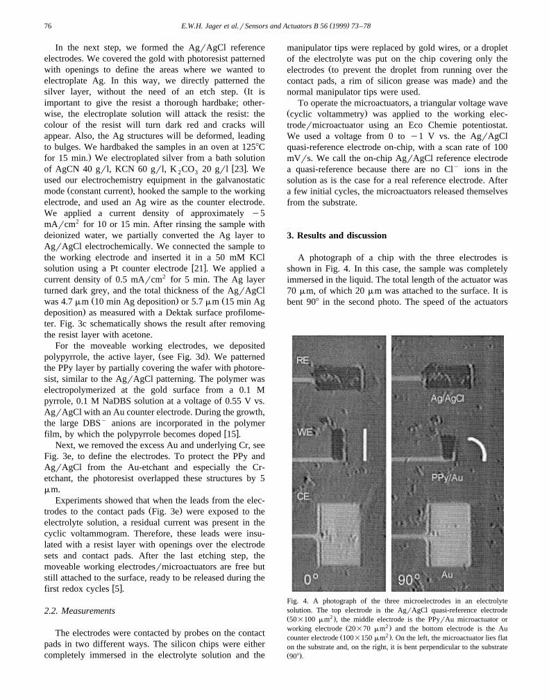
A photograph of a chip with the three electrodes isshown in Fig. 4. In this case, the sample was completelyimmersed in the liquid. The total length of the actuator was70 mm, of which 20 mm was attached to the surface. It isbent 908 in the second photo. The speed of the actuators
Fig. 4. A photograph of the three microelectrodes in an electrolytesolution. The top electrode is the AgrAgCl quasi-reference electrodeŽ 2 .50=100 mm , the middle electrode is the PPyrAu microactuator or
Ž 2 .working electrode 20=70 mm and the bottom electrode is the AuŽ 2 .counter electrode 100=150 mm . On the left, the microactuator lies flat
on the substrate and, on the right, it is bent perpendicular to the substrateŽ .908 .
( )E.W.H. Jager et al.rSensors and Actuators B 56 1999 73–78 77
with all the electrodes on-chip was the same as our normaldevices, which use large counter and reference electrodes.
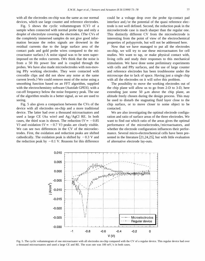
Ž .Fig. 5 shows the cyclic voltammogram CV of asample when connected with normal probe tips and only a
Ždroplet of electrolyte covering the electrodes. The CVs ofthe completely immersed samples do not give good infor-mation because the redox signals are drowned in theresidual currents due to the large surface area of thecontact pads and gold probe wires compared to the mi-
.croactuator surface. A noise signal was to be seen super-Žimposed on the redox currents. We think that the noise is
from a 50 Hz power line and is coupled through theprobes. We have also made microelectrodes with non-mov-ing PPy working electrodes. They were contacted withcrocodile clips and did not show any noise at the same
.current levels. We could remove most of the noise using asmoothing function based on an FFT algorithm, supplied
Ž .with the electrochemistry software Autolab GPES , with acut-off frequency below the noise frequency peak. The useof the algorithm results in a better signal, as we are used toseeing.
Fig. 5 also gives a comparison between the CVs of thedevice with all electrodes on-chip and a more traditionaldevice. The latter had over a thousand microactuators and
Ž .used a large CE Au wire and AgrAgCl RE. In bothŽcases, the third scan is shown. The reduction Vfy0.85
. Ž .V and oxidation Vfy0.7 V peaks are clearly visible.We can see two differences in the CV of the microelec-trodes. First, the oxidation and reduction peaks are shiftedcathodically. The oxidation peak is shifted by y0.3 V andthe reduction peak by y0.1 V. Reasons for this difference
could be a voltage drop over the probe tip-contact padinterface andror the potential of the quasi reference elec-trode is not well defined. Second, the reduction peak in themicroelectrode case is much sharper than the regular one.This distinctly different CV from the microelectrode isinteresting from the point of view of the electrochemicalproperties of polypyrrole, but will not be addressed here.
Now that we have managed to put all the electrodeson-chip, we will try to use these microactuators for cellstudies. We want to tap, or make physical contact with,living cells and study their responses to this mechanicalstimulation. We have done some preliminary experimentswith cells and PPy surfaces, and the use of large counterand reference electrodes has been troublesome under themicroscope due to lack of space. Having just a single chipwith all the electrodes on it will solve this problem.
The possibility to move the working electrodes out ofthe chip plane will allow us to go from 2-D to 3-D, hereextending just some 50 mm above the chip plane, analtitude freely chosen during the design process. This maybe used to disturb the stagnating fluid layer close to thechip surface, or to move closer to some object to becontacted.
We are also investigating the optimal electrode configu-ration and ratio of surface areas of the three electrodes. Wewant to find out which ratio of the areas gives the optimalperformance of the microelectrodesrmicroactuators, andwhether the electrode configuration influences their perfor-mance. Several micro-electrochemical cells have been pre-
w xsented in the literature 21,24,25 , but with little evaluationof alternative electrode lay-outs.
Fig. 5. The cyclic voltammogram of one microactuator with all electrodes on-chip compared with the CV of a regular device. This regular device had overa thousand microactuators and used a large CE and RE. The scan rate was 100 mVrs in both cases.

( )E.W.H. Jager et al.rSensors and Actuators B 56 1999 73–7878
4. Conclusion
We have demonstrated microactuators with all elec-trodes on-chip, a first step towards an all-polymer system.The microactuators work as well with the miniaturisedelectrodes on-chip as they do with large, off-chip counterand reference electrodes. The activation speed is similarand we can clearly see a good CV. Noise was present inthe CVs, but we did not observe any adverse effects of thisnoise on the mechanical behaviour. We can therefore nowelectrochemically control moving microelectrodes to ex-tend from a surface, and thus tap, approach and attachother objects in the electrolyte. Such tools we expect to beuseful for single cell studies and for neurophysiology.
Acknowledgements
E.J. is a PhD student in the graduate school ForumScientum and wishes to thank the Swedish Foundation for
Ž .Strategic Research SSF for its financial support. Themicromuscle project is supported by the Swedish Research
Ž .Council for Engineering Sciences TFR and the VolvoResearch Foundation, Volvo Educational Foundation, andthe Dr. Pehr G. Gyllenhammar Research Foundation.
References
w x1 G. Lin, C.-J. Kim, S. Konishi, H. Fujita, Design, fabrication, andtesting of a C-shaped Actuator, Transducers ’95, Stockholm, Swe-den, 1995, pp. 416–419.
w x2 T. Ebefors, E. Kalvesten, G. Stemme, Dynamic actuation of poly-imide V-grooves joints by electrical heating, Eurosensors XI,Warschaw, Poland, Sept. 21–24, 1997, pp. 1579–1582.
w x3 C. Liu, T. Tsao, Y.-C. Tai, C.-M. Ho, Surface Micromachinedmagnetic actuators, IEEE Workshop on Micro Electro MechanicalSystems, Oiso, Japan, 1994, pp. 57–62.
w x4 C.W. Storment, D.A. Borkholder, V. Westerlind, J.W. Suh, N.I.Maluf, G.T.A. Kovacs, Flexible, dry-released process for aluminum
Ž .electrostatic actuators, J. Microelectromech. Syst. 3 1994 90–96.w x5 E. Smela, O. Inganas, I. Lundstrom, Controlled folding of microme-¨ ¨
Ž .ter-size structures, Science 268 1995 1735–1738.w x6 E. Smela, Microfabrication of PPy microactuators and other conju-
gated polymer devices, accepted for publication in J. Micromech.Ž .Microeng., 1998 .
w x Ž .7 W.R. Salaneck, I. Lundstrom, B. Ranby Eds. , Conjugated Poly-¨ ˚mers and Related Materials: The Interconnection of Chemical andElectronic Structure, Oxford Science Publications, Oxford, 1993.
w x8 J.C. Gustafsson, B. Liedberg, O. Inganas, In situ spectroscopic¨Žinvestigations of electrochromism and ion transport in poly 3,4-eth-
.ylenedioxythiophene electrode in a solid state electrochemical cell,Ž .Solid State Ionics 69 1994 145–152.
w x9 Q. Pei, O. Inganas, Electrochemical applications of the bending¨beam method: 1. Mass transport and volume changes in polypyrrole
Ž .during redox, J. Phys. Chem. 96 1992 10507–10514.w x10 Q. Pei, O. Inganas, Electrochemical muscles: bending strips built¨
Ž .from conjugated polymers, Synth. Met. 55–57 1993 3718–3723.
w x11 R.H. Baughman, Conducting polymer artificial muscles, Synth. Met.Ž .78 1996 339–353.
w x12 T.F. Otero, J.M. Sansinena, Artificial muscles based on conductingŽ .polymers, Bioelectrochem. Bioenerg. 38 1995 411–414.
w x13 A. Della Santa, D. De Rossi, A. Mazzoldi, Characterization andmodelling of a conducting polymer muscle-like linear actuator,
Ž .Smart Mater. Struct. 6 1997 23–24.w x14 A.P. Lee, K.C. Hong, J. Trevino, M.A. Northrop, Thin film conduc-
tive polymer for microactuator and micromuscle applications, Dy-namic and Systems and Control Session, International MechanicalEngineering Congress, Chicago, USA, 1994, pp. 725–732.
w x15 R.M. Torresi, S.I. Cordoba de Torresi, T. Matencio, M.-A. De Paoli,Ionic exchanges in dodecylbenzenesulfonate doped polypyrrole: PartII. Electrochemical quartz crystal microbalance study, Synth. Met.
Ž .72 1995 283–287.w x16 J.F. Rusling, S.L. Suib, Characterizing materials with cyclic voltam-
Ž .metry, Adv. Mater. 6 1994 922–930.w x17 J. Heinze, M. Dietrich, Cyclic voltammetry as a tool for characteriz-
Ž .ing conducting polymers, Mater. Sci. Forum 42 1989 63–78.w x18 J.M. Sansinena, V. Olazabal, T.F. Otero, C.N. Polo da Fonseca, and˜
M.-A. De Paoli, A solid state artificial muscle based on polypyrroleand a solid polymeric electrolyte working in air, Chem. Commun.,Ž .1997 2217–2218.
w x19 T.W. Lewis, G.M. Spinks, G.G. Wallace, D.D. Rossi, M. Pachetti,Development an all polymer electromechanical actuators, Polymer
Ž .Reprints 38 1997 520–521.w x20 T. F. Otero, personal communication.w x21 P. Arquint, Integrated blood gas sensor for pO2 pCO2 and pH
based on silicon technology, PhD thesis, Institute of Microtechnol-ogy, University of Neuchatel, 1994.ˆ
w x22 E. Smela, O. Inganas, I. Lundstrom, Differential adhesion method¨ ¨for microstructure release: an alternative to the sacrificial layer,Transducers ’95, Stockholm, Sweden, 1995, pp. 218–219.
w x23 F.A. Lowenheim, Electroplating, McGraw-Hill, New York, 1978,pp. 257–263.
w x24 G.D.T. Bratten, P.H. Cobbold, J.M. Cooper, Micromachining sen-sors for electrochemical measurement in subnanoliter volumes, Anal.
Ž .Chem. 69 1997 253–258.w x25 H. Suzuki, A. Sugama, N. Kojima, Micromachined Clark oxygen
Ž .electrode, Sensors and Actuators B 10 1993 91–98.
Biographies
Edwin Jager received a M.Sc. degree in Applied Physics from theUniversity of Twente, the Netherlands, in 1996. Since 1996 he is workingas a Ph.D. student at the Laboratory of Applied Physics, Linkoping¨University in Sweden. His current research concerns applications andimprovements of conducting polymer microactuators.
Elisabeth Smela received a B.S. degree in Physics from MIT in 1985 anda PhD in electrical engineering from the University of Pennsylvania in1992. She worked at the Laboratory of Applied Physics, Linkoping¨University, Sweden until 1997 developing conducting polymer microactu-ators. She is continuing this work as a senior researcher at Risø NationalLaboratory, Denmark.
Olle Inganas did a M.Sc. in Technical Physics at Chalmers University of¨Technology and a B.Sc. in Economics and Philosophy at GothenburgUniversity in 1977, and his Ph.D. in Applied Physics at Linkoping¨University in 1984. He is now leading studies of conjugated polymers atApplied Physics, Linkoping University.¨