KJM 3110 Electrochemistry Chapters 1-15 Summary - UiO
90
KJM 3110 Electrochemistry Chapters 1-15 Summary Most figures from the textbook we use for the course, via its web resources:
-
Upload
khangminh22 -
Category
Documents
-
view
0 -
download
0
Transcript of KJM 3110 Electrochemistry Chapters 1-15 Summary - UiO
KJM 3110 Electrochemistry
Chapters 1-15 Summary
Most figures from the textbook we use for the course, via its web resources:

KJM 3110 Electrochemistry
Chapter 1. Electricity
We familiarised ourselves with the most fundamental concepts of electricity itself.
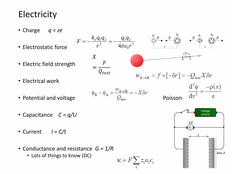
• Charge q = ze
• Electrostatic force
• Electric field strength
• Electrical work
• Potential and voltage Poisson
• Capacitance C = q/U
• Current I = C/t
• Conductance and resistance G = 1/R• Lots of things to know (DC)
Electricity
2
0
21
2
21
4 r
r
qqkF e
𝑋
=𝐹
𝑄𝑡𝑒𝑠𝑡
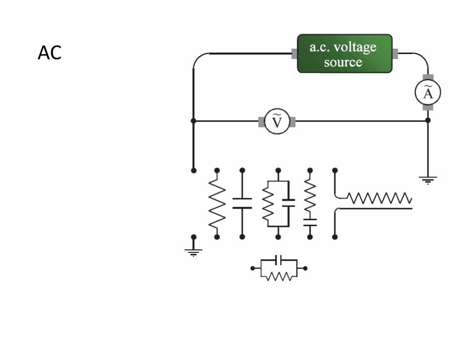
AC
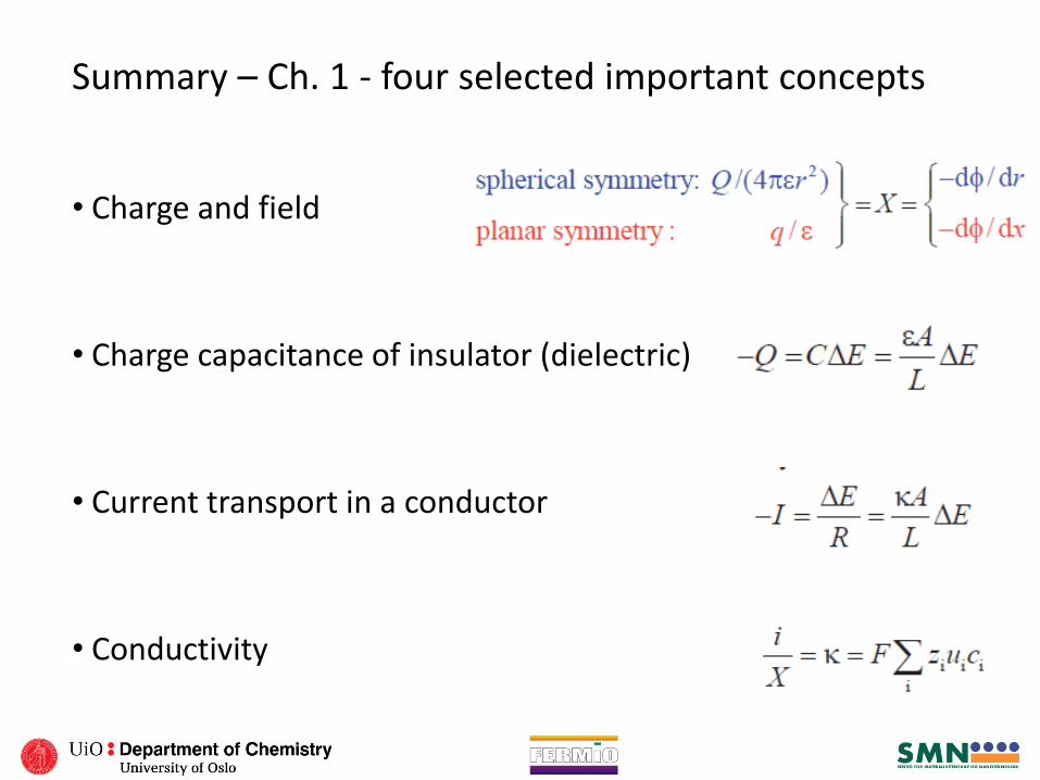
Summary – Ch. 1 - four selected important concepts
• Charge and field
• Charge capacitance of insulator (dielectric)
• Current transport in a conductor
• Conductivity
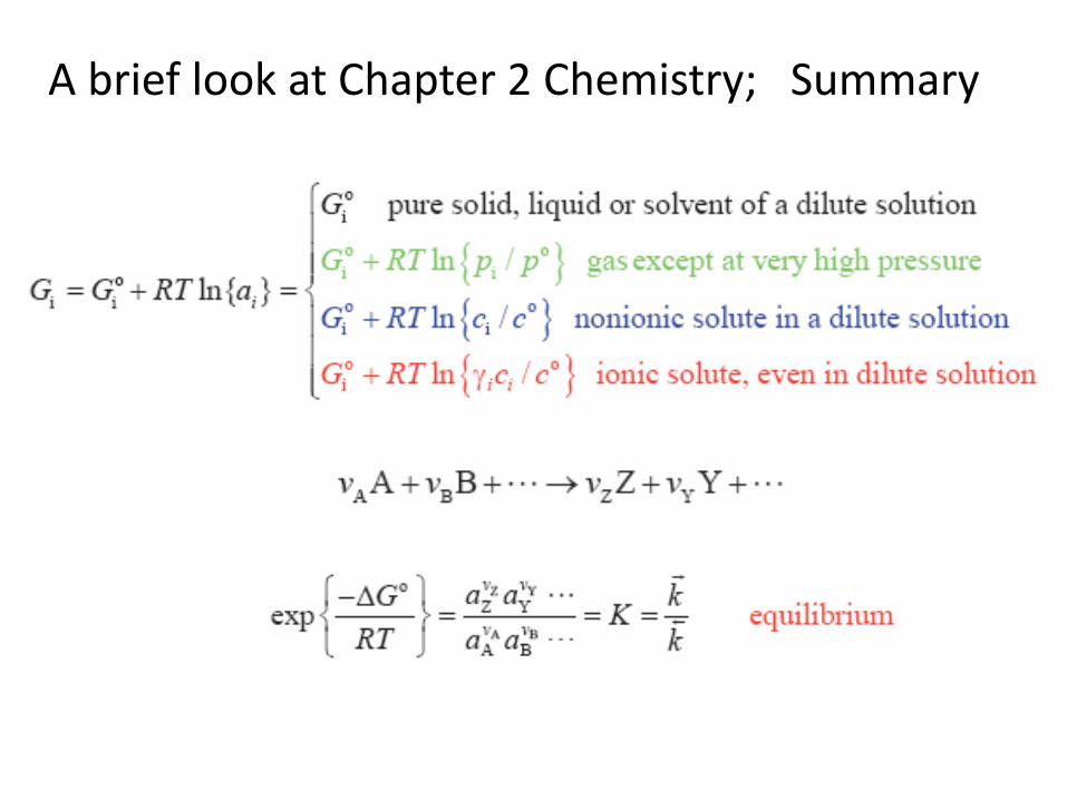
A brief look at Chapter 2 Chemistry; Summary
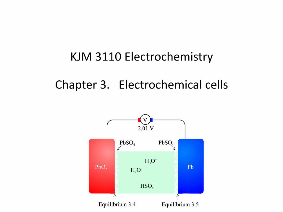
KJM 3110 Electrochemistry
Chapter 3. Electrochemical cells
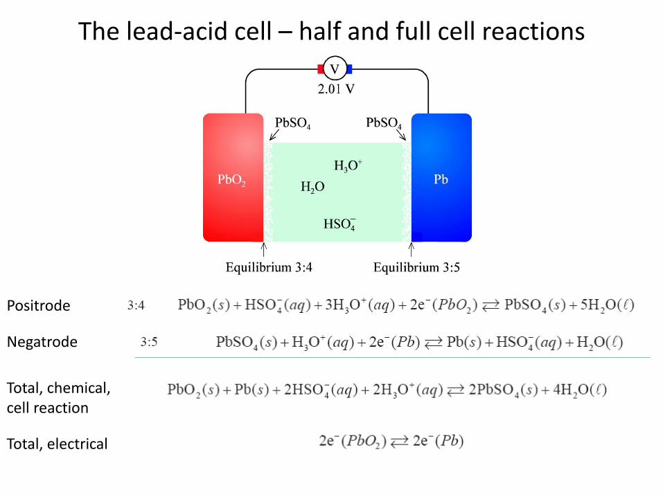
The lead-acid cell – half and full cell reactions
Positrode
Negatrode
Total, chemical, cell reaction
Total, electrical

The lead-acid cell – Gibbs energy change
The activity of pure condensed phases is defined as unity. Hence, for instance aPb(s) = 1
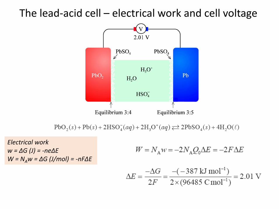
The lead-acid cell – electrical work and cell voltage
Electrical workw = ΔG (J) = -neΔEW = NAw = ΔG (J/mol) = -nFΔE

The lead-acid cell – cell voltage
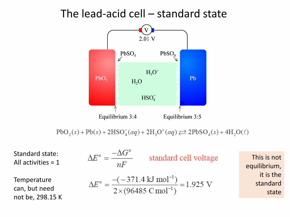
The lead-acid cell – standard state
Standard state: All activities = 1
Temperaturecan, but neednot be, 298.15 K
This is not equilibrium,
it is the standard
state
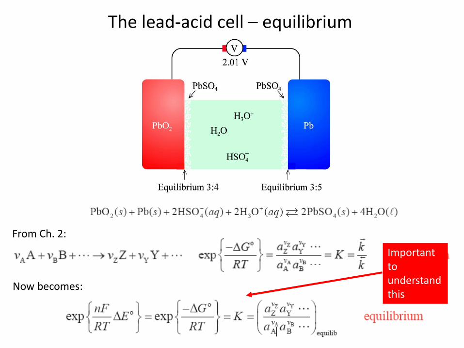
The lead-acid cell – equilibrium
From Ch. 2:
Now becomes:
Importantto understand this

The lead-acid cell – galvanic operation
Galvanic cell:The chemical potentialdifferences – thespontaneous changeaccording to ΔG – drives the cell.
Battery under discharge
Fuel cell
Cathode (positrode)
Anode (negatrode)

The lead-acid cell – electrolytic operation
Electrolytic cell:The applied electrical potential difference drives the cell against the spontaneous change according to ΔG.
Battery under charge
Electrolyser
Anode (positrode)
Cathode (negatrode)
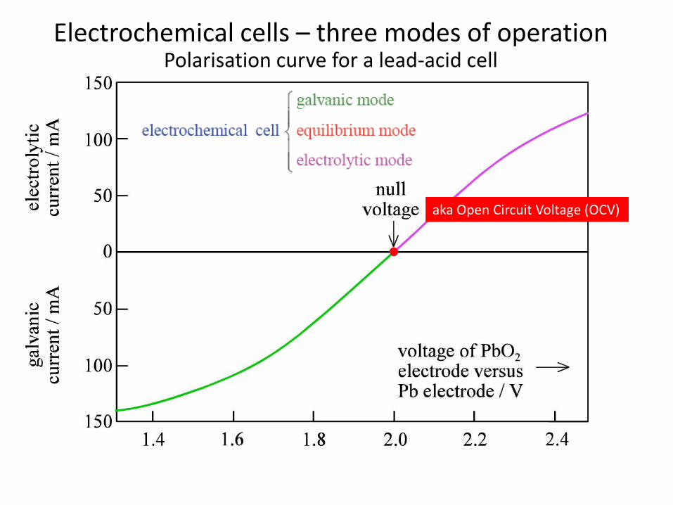
Electrochemical cells – three modes of operationPolarisation curve for a lead-acid cell
aka Open Circuit Voltage (OCV)
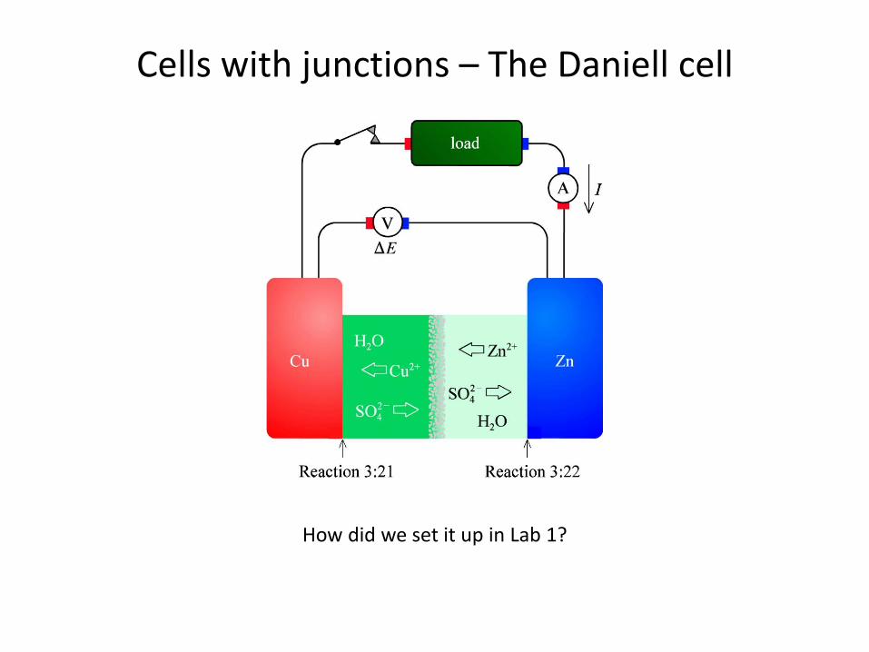
Cells with junctions – The Daniell cell
How did we set it up in Lab 1?

• Equilibrium
• I = 0
• Galvanic operation
• I > 0
• Electrolytic operation
• I < 0
Summary Ch. 3 Electrochemical cells

KJM 3110 Electrochemistry
Chapter 4. Electrosynthesis

Themes you need to know in electrosynthesis
• Al electrolysis Hall-Hèrault
• Chlor-alkali
• Water electrolysis; Aqueous acid and alkaline!
• Steam electrolysis; Solid-state
• Example of ion-selective membrane process
KJM 3110 Electrochemistry
Chapter 5. Electrochemical power
Storage & power
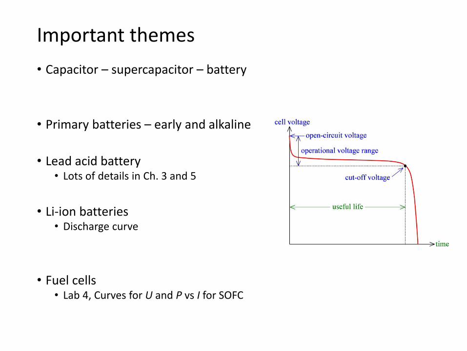
• Capacitor – supercapacitor – battery
• Primary batteries – early and alkaline
• Lead acid battery• Lots of details in Ch. 3 and 5
• Li-ion batteries• Discharge curve
• Fuel cells• Lab 4, Curves for U and P vs I for SOFC
Important themes
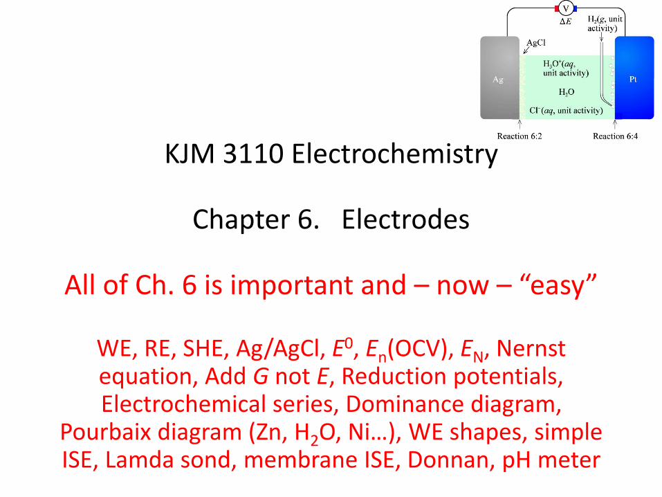
KJM 3110 Electrochemistry
Chapter 6. Electrodes
All of Ch. 6 is important and – now – “easy”
WE, RE, SHE, Ag/AgCl, E0, En(OCV), EN, Nernst equation, Add G not E, Reduction potentials, Electrochemical series, Dominance diagram,
Pourbaix diagram (Zn, H2O, Ni…), WE shapes, simple ISE, Lamda sond, membrane ISE, Donnan, pH meter

KJM 3110 Electrochemistry
Chapter 7. Electrode reactions
Faraday’s law
Kinetics full expression: Butler-VolmerSimplified expression: Tafel
Five important slides
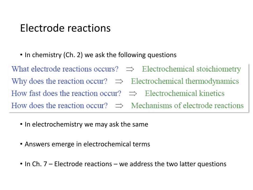
• In chemistry (Ch. 2) we ask the following questions
• In electrochemistry we may ask the same
• Answers emerge in electrochemical terms
• In Ch. 7 – Electrode reactions – we address the two latter questions
Electrode reactions
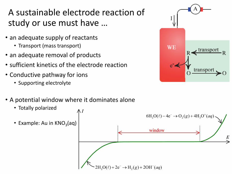
• an adequate supply of reactants• Transport (mass transport)
• an adequate removal of products
• sufficient kinetics of the electrode reaction
• Conductive pathway for ions• Supporting electrolyte
• A potential window where it dominates alone• Totally polarized
• Example: Au in KNO3(aq)
A sustainable electrode reaction of study or use must have …
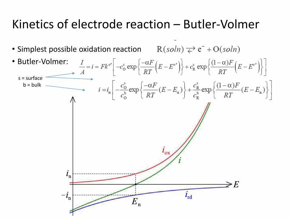
• Simplest possible oxidation reaction
• Butler-Volmer:
Kinetics of electrode reaction – Butler-Volmer
s = surfaceb = bulk

• ln|i| or log|i| vs E
• At large potentials, the oxidation or reduction dominates
• The current becomes exponentially dependent on E
Tafel plot

• Example reaction
• For reactant A, for reduction,
• General rate law
Reaction order

KJM 3110 Electrochemistry
Chapter 8. Transport
Migration, diffusion, convection
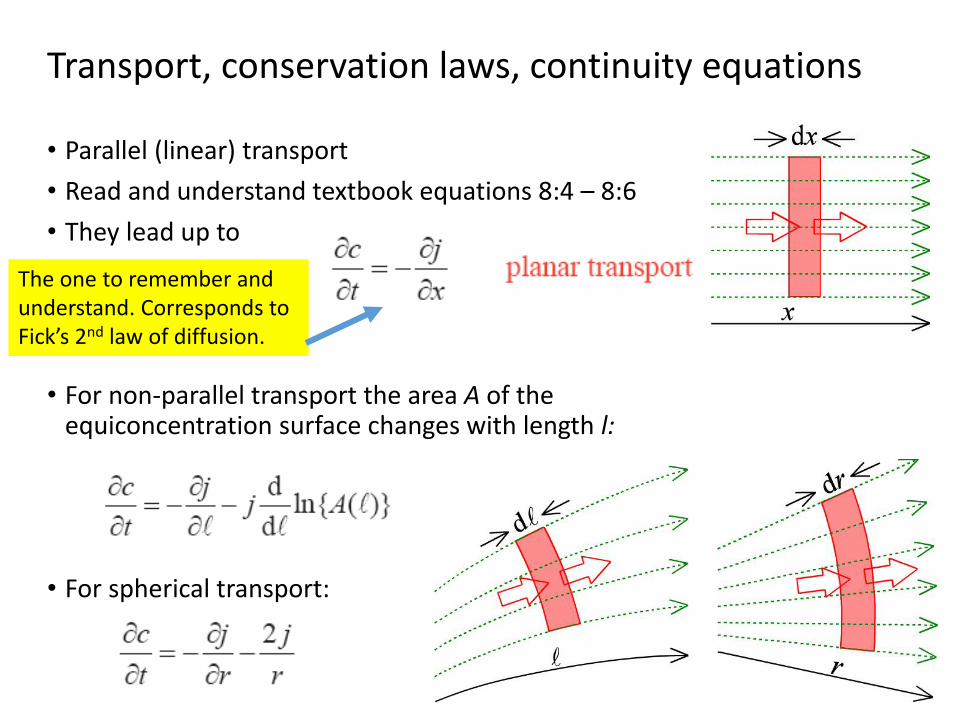
Transport, conservation laws, continuity equations
• Parallel (linear) transport
• Read and understand textbook equations 8:4 – 8:6
• They lead up to
• For non-parallel transport the area A of the equiconcentration surface changes with length l:
• For spherical transport:
The one to remember and understand. Corresponds to Fick’s 2nd law of diffusion.
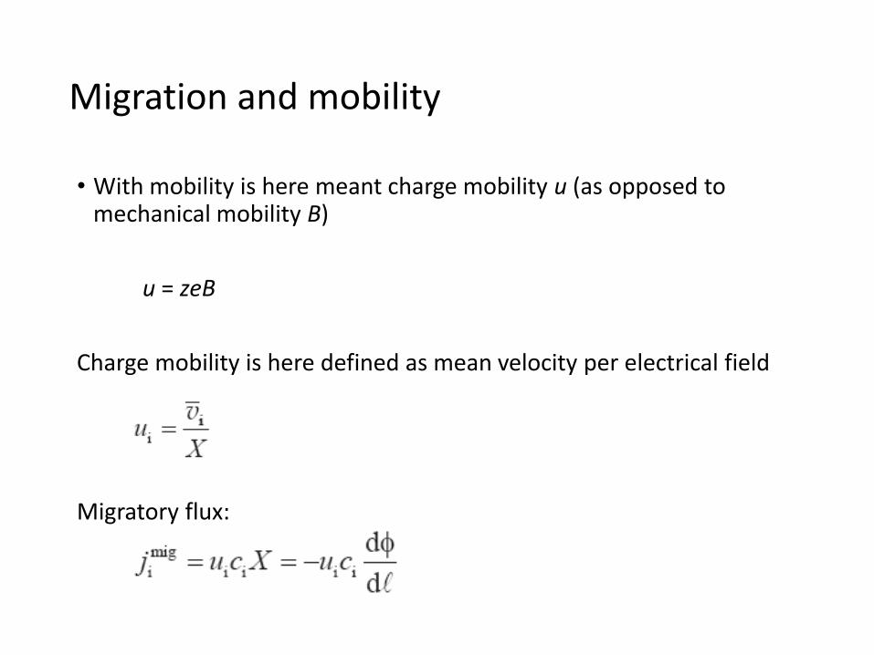
• With mobility is here meant charge mobility u (as opposed to mechanical mobility B)
u = zeB
Charge mobility is here defined as mean velocity per electrical field
Migratory flux:
Migration and mobility
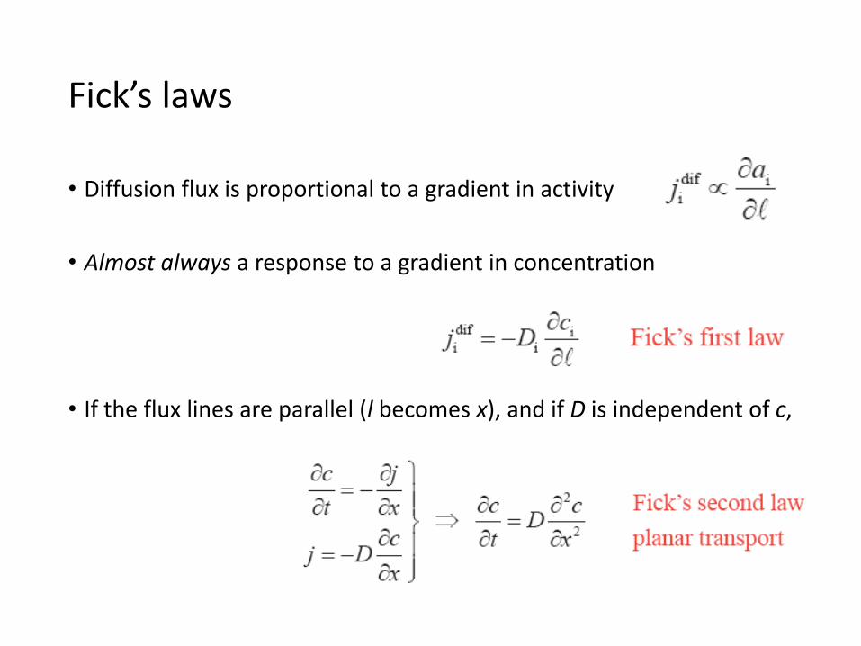
• Diffusion flux is proportional to a gradient in activity
• Almost always a response to a gradient in concentration
• If the flux lines are parallel (l becomes x), and if D is independent of c,
Fick’s laws
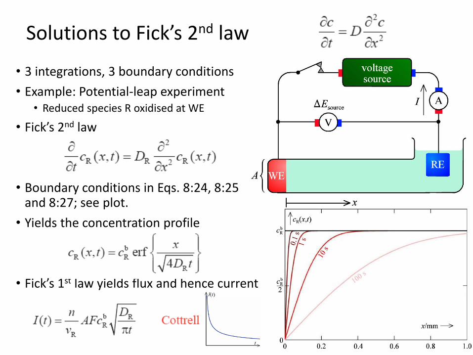
• 3 integrations, 3 boundary conditions
• Example: Potential-leap experiment• Reduced species R oxidised at WE
• Fick’s 2nd law
• Boundary conditions in Eqs. 8:24, 8:25 and 8:27; see plot.
• Yields the concentration profile
• Fick’s 1st law yields flux and hence current
Solutions to Fick’s 2nd law

• Diffusion and migration interact
• They are related to the same friction towards transport
• Nernst-Einstein equation
• Can be rewritten Di = RTui/ziF = RTBi where B is the mechanical mobility (Beweglichkeit)
• The combined forces and fluxes of diffusion and migration can – via the Nernst Einstein equation – be summed in the Nernst-Planck equation
Diffusion and migration

• Typically, Pt or glassy carbon embedded in insulating disk of teflon®.
• High rotating (angular) velocity.
• Same friction that stops flow in the tubular case creates flow here.
• Flow has contributions from convection and diffusion:
Rotating disk electrode
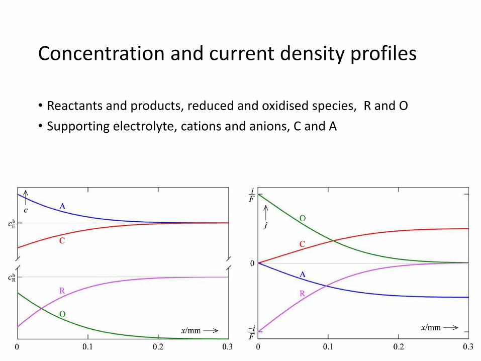
• Reactants and products, reduced and oxidised species, R and O
• Supporting electrolyte, cations and anions, C and A
Concentration and current density profiles
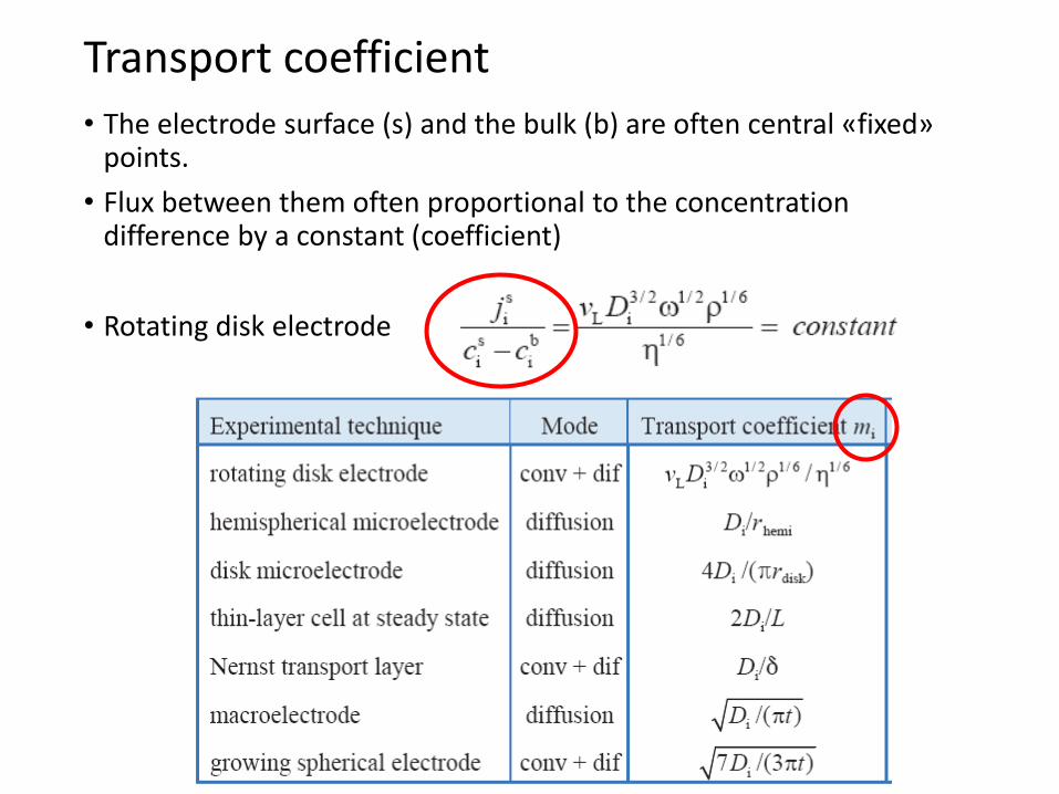
• The electrode surface (s) and the bulk (b) are often central «fixed» points.
• Flux between them often proportional to the concentrationdifference by a constant (coefficient)
• Rotating disk electrode
Transport coefficient
KJM 3110 Electrochemistry
Chapter 9. Green Electrochemistry
We don’t ask questions from this 2020

KJM 3110 Electrochemistry
Chapter 10. Electrode polarisation
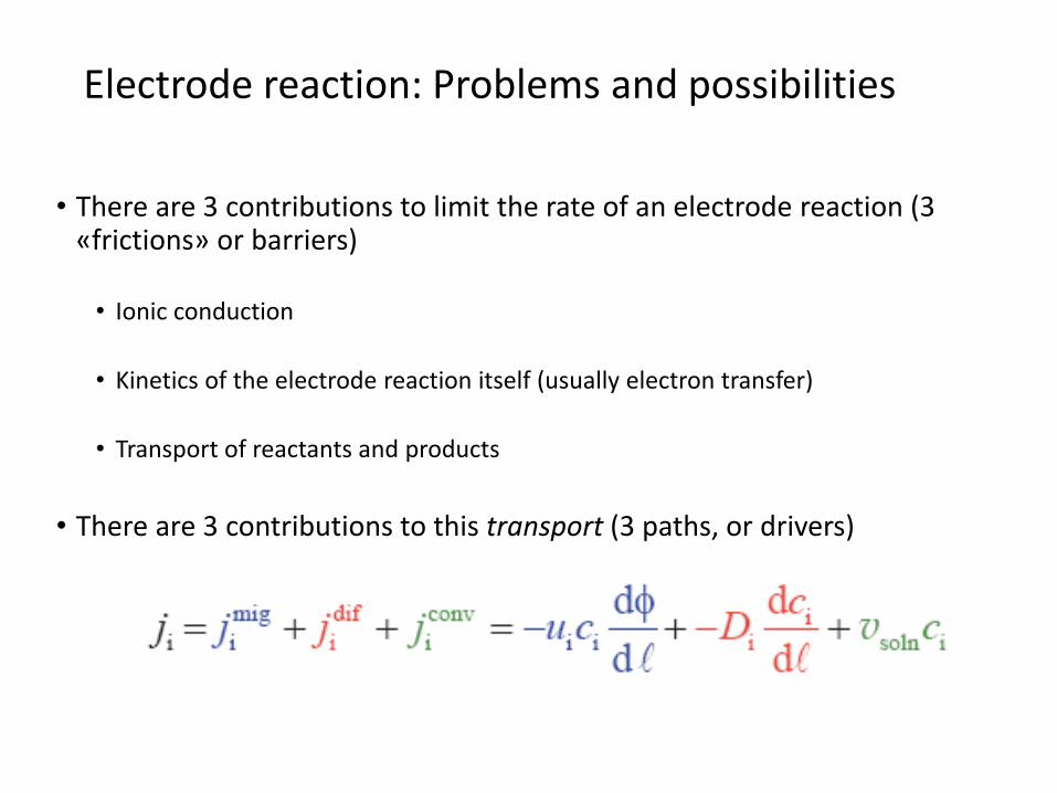
• There are 3 contributions to limit the rate of an electrode reaction (3 «frictions» or barriers)
• Ionic conduction
• Kinetics of the electrode reaction itself (usually electron transfer)
• Transport of reactants and products
• There are 3 contributions to this transport (3 paths, or drivers)
Electrode reaction: Problems and possibilities

Electrode polarisation, overvoltage
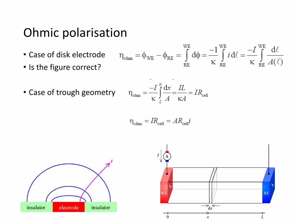
• Case of disk electrode
• Is the figure correct?
• Case of trough geometry
Ohmic polarisation

• Current density limited by electrode reaction rate
• If there is no concentration polarisation,
Kinetic polarisation
Driven by overpotential
Driven by thermal energyover the activation barrier
Requiresreactantsboth ways
α=0.35
α=0.50
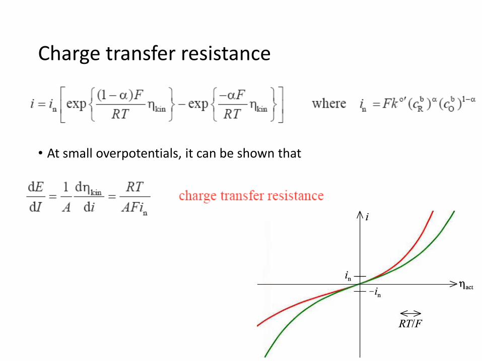
• At small overpotentials, it can be shown that
Charge transfer resistance
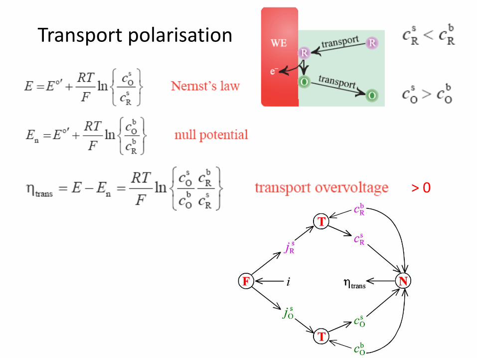
Transport polarisation
> 0
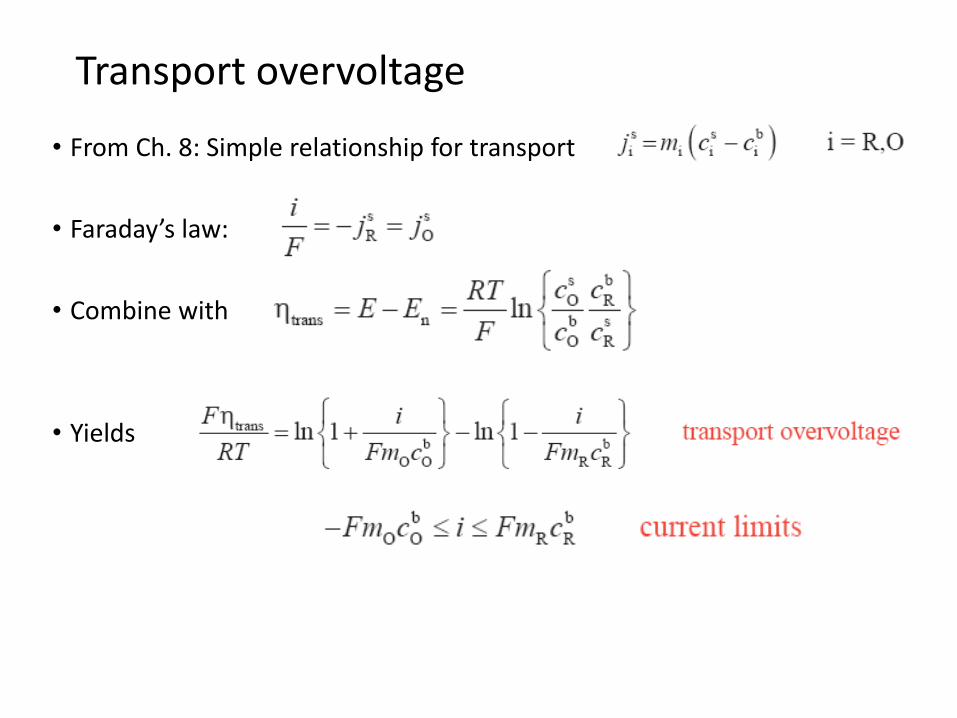
• From Ch. 8: Simple relationship for transport
• Faraday’s law:
• Combine with
• Yields
Transport overvoltage
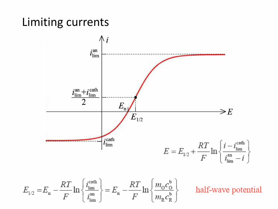
Limiting currents

• Overpotential sum with the ohmic one
• But kinetic and transport interact and do not sum in a simple manner
Ohmic + kinetic + transport limitations
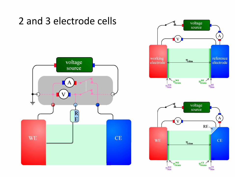
2 and 3 electrode cells

KJM 3110 Electrochemistry
Chapter 11. Corrosion
Know Fe corrosion!
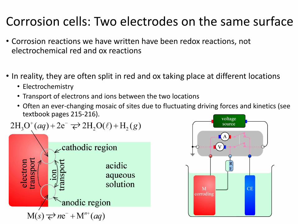
• Corrosion reactions we have written have been redox reactions, not electrochemical red and ox reactions
• In reality, they are often split in red and ox taking place at different locations• Electrochemistry
• Transport of electrons and ions between the two locations
• Often an ever-changing mosaic of sites due to fluctuating driving forces and kinetics (seetextbook pages 215-216).
Corrosion cells: Two electrodes on the same surface

Logarithmic (Tafel) plot

• Coatings
• Electropainting with carboxylate COO- groups• Negatively charged paint polymer particles migrate, are neutralised, and
adhere• Fe dissolves electrolytically and forms insoluble Fe carboxylates• Uniform
• Electroplating – electrochemical reduction of plating metal
• Electroless plating – chemical reduction of plating metal
• Corrosion inhibitors• Oxidising agents – forms protective film
• Nitric acid • Electrochemical anodisation (e.g. for aluminium)
• «Phosphating» - hot phosphoric acid or acidic phosphate solution
Corrosion protection+ Qualitatively cathodic and anodic protection

KJM 3110 Electrochemistry
Chapter 12. Steady-state voltammetry
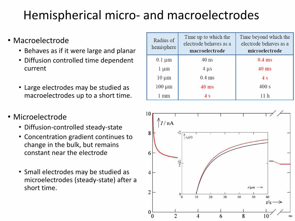
• Macroelectrode• Behaves as if it were large and planar
• Diffusion controlled time dependent current
• Large electrodes may be studied as macroelectrodes up to a short time.
• Microelectrode• Diffusion-controlled steady-state
• Concentration gradient continues to change in the bulk, but remainsconstant near the electrode
• Small electrodes may be studied as microelectrodes (steady-state) after a short time.
Hemispherical micro- and macroelectrodes
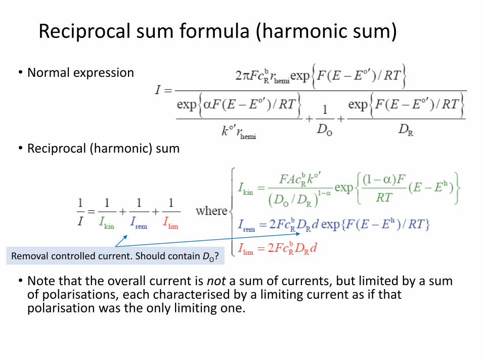
• Normal expression
• Reciprocal (harmonic) sum
• Note that the overall current is not a sum of currents, but limited by a sum of polarisations, each characterised by a limiting current as if thatpolarisation was the only limiting one.
Reciprocal sum formula (harmonic sum)
Removal controlled current. Should contain DO?

KJM 3110 Electrochemistry
Chapter 13
The Electrode Interface

• Different thickness of thecompact layers on the two sides
• Anions pack better (less hydrated)
Stern refinement
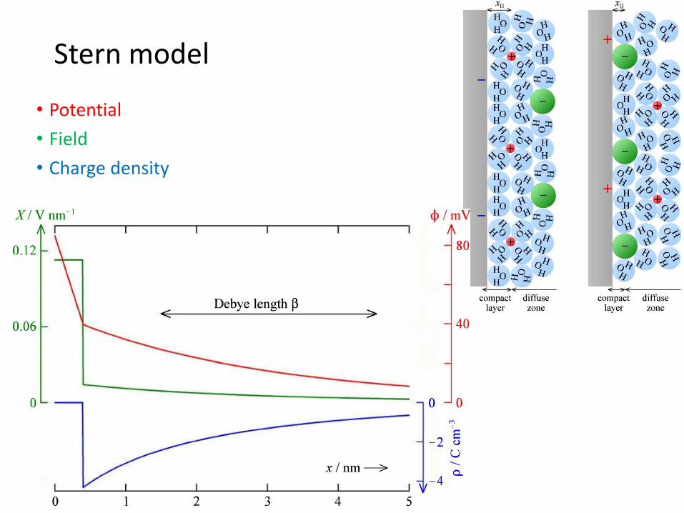
• Potential
• Field
• Charge density
Stern model
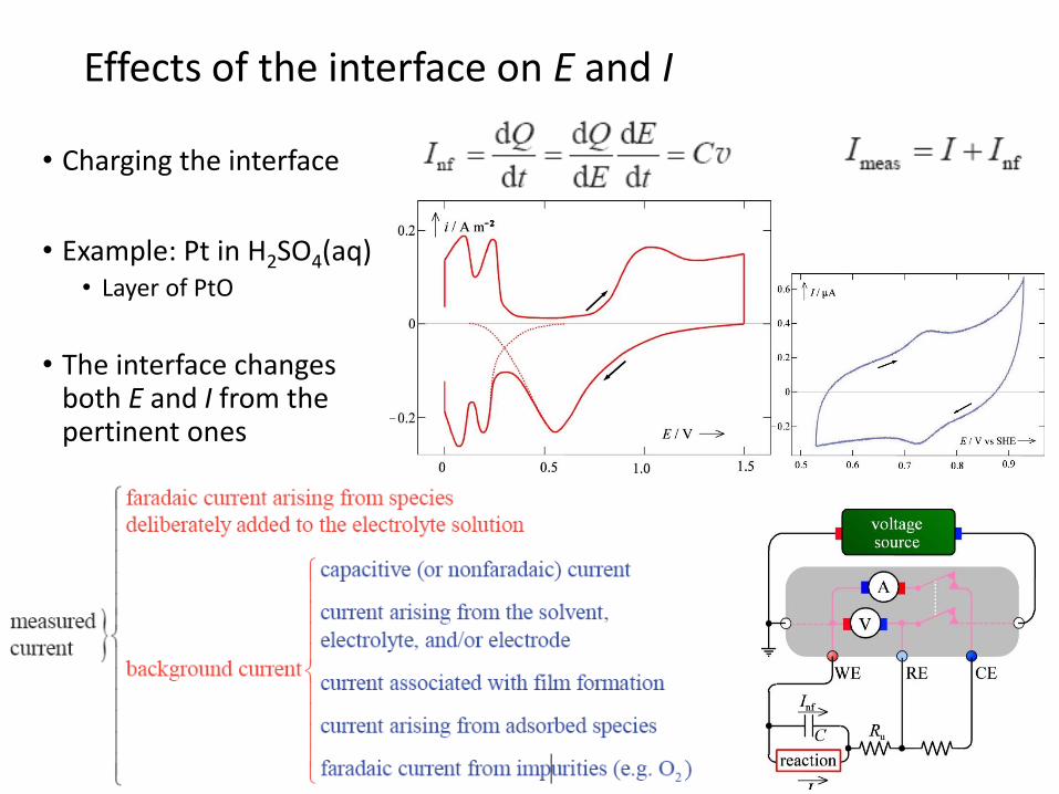
• Charging the interface
• Example: Pt in H2SO4(aq)• Layer of PtO
• The interface changesboth E and I from thepertinent ones
Effects of the interface on E and I
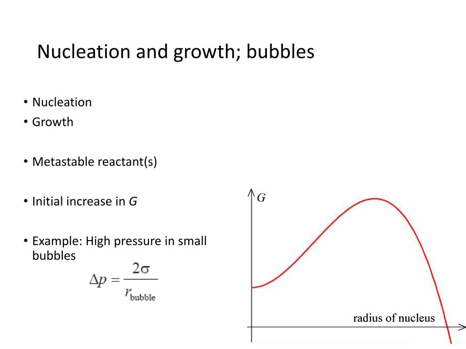
• Nucleation
• Growth
• Metastable reactant(s)
• Initial increase in G
• Example: High pressure in smallbubbles
Nucleation and growth; bubbles
KJM 3110 Electrochemistry
Chapter 14
Other interfaces
Most figures from the textbook we use for the course, via its web resources:
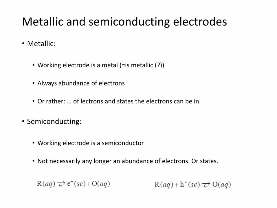
• Metallic:
• Working electrode is a metal (=is metallic (?))
• Always abundance of electrons
• Or rather: … of lectrons and states the electrons can be in.
• Semiconducting:
• Working electrode is a semiconductor
• Not necessarily any longer an abundance of electrons. Or states.
Metallic and semiconducting electrodes

Semiconductor electrodes - overview
• Semiconductor• Lattice
• Valence band = HOMO
• Conduction band = LUMO
• Band gap
• Fermio energy (chemical potential of electrons)
• Work function (to bring electrons to vacuum)
• n-type semiconductor• Donor-doped n = [e-] = [D+]
• Electrons e- in the conduction band
• p-type semiconductor• Acceptor-doped p = [h+] = [A-]
• Electron holes h+ in the valence band
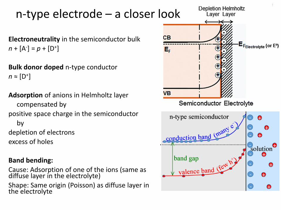
Electroneutrality in the semiconductor bulk
n + [A-] = p + [D+]
Bulk donor doped n-type conductor
n ≈ [D+]
Adsorption of anions in Helmholtz layer
compensated by
positive space charge in the semiconductor
by
depletion of electrons
excess of holes
Band bending:
Cause: Adsorption of one of the ions (same as diffuse layer in the electrolyte)
Shape: Same origin (Poisson) as diffuse layer in the electrolyte
n-type electrode – a closer look
-
--
--
-
-
-
+
++
+
+
+
+
+
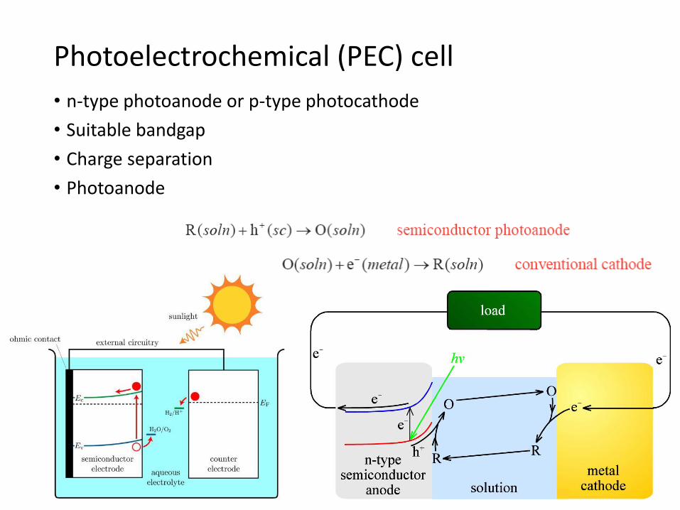
• n-type photoanode or p-type photocathode
• Suitable bandgap
• Charge separation
• Photoanode
Photoelectrochemical (PEC) cell

• Low efficiencies
• Photocorrosion of electrodes
• Cathode traditionally a noble (platinum group) metal• Research: Non-noble metals, oxides. Enzymes
• Sunlight cannot drive the reaction alone, just assist it• Research: Combine photoanode and photocathode. Combine PV and PEC.
• Reduce CO2 instead of H2O
• Solid-state electrolyte instead of aqueous
PEC water splitting, artificial photosynthesis
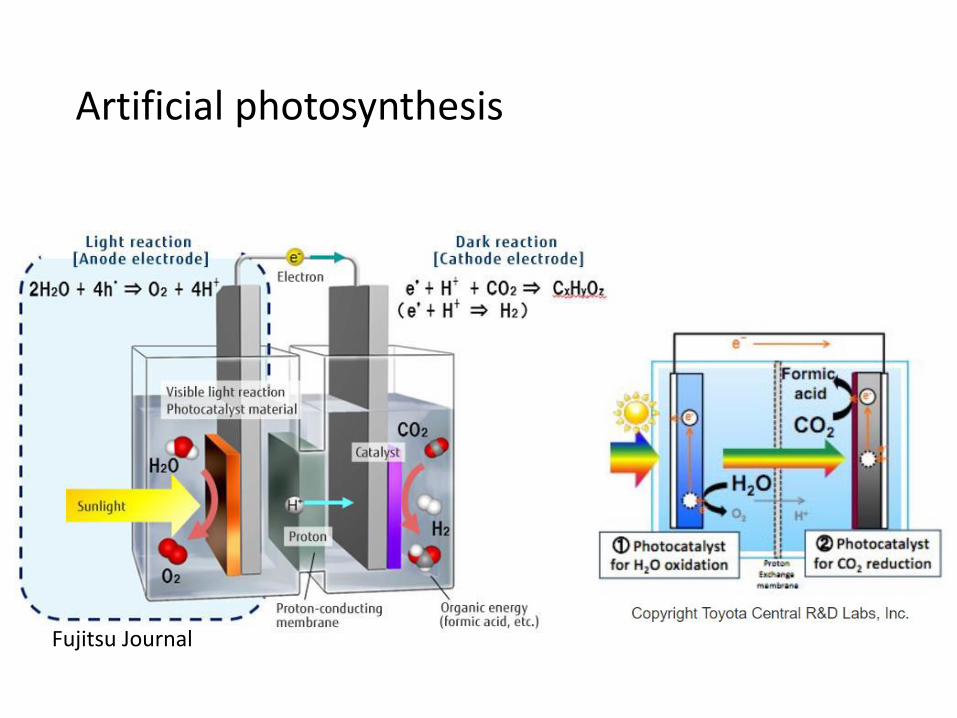
Artificial photosynthesis
Fujitsu Journal
KJM 3110 Electrochemistry
Chapter 15
Electrochemistry with Periodic Signals
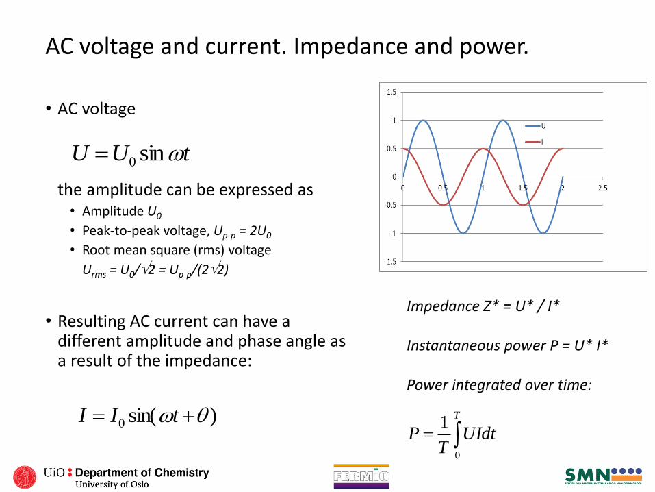
AC voltage and current. Impedance and power.
• AC voltage
the amplitude can be expressed as• Amplitude U0
• Peak-to-peak voltage, Up-p = 2U0
• Root mean square (rms) voltage
Urms = U0/2 = Up-p/(22)
• Resulting AC current can have a different amplitude and phase angle as a result of the impedance:
tUU sin0
)sin(0 tII
Impedance Z* = U* / I*
Instantaneous power P = U* I*
Power integrated over time:
T
UIdtT
P0
1
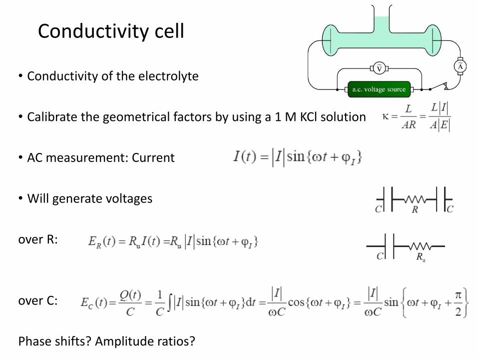
• Conductivity of the electrolyte
• Calibrate the geometrical factors by using a 1 M KCl solution
• AC measurement: Current
• Will generate voltages
over R:
over C:
Phase shifts? Amplitude ratios?
Conductivity cell
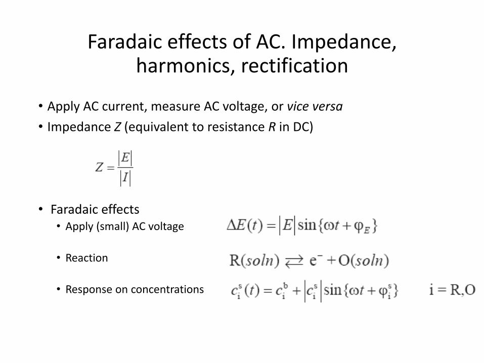
• Apply AC current, measure AC voltage, or vice versa
• Impedance Z (equivalent to resistance R in DC)
• Faradaic effects• Apply (small) AC voltage
• Reaction
• Response on concentrations
Faradaic effects of AC. Impedance, harmonics, rectification
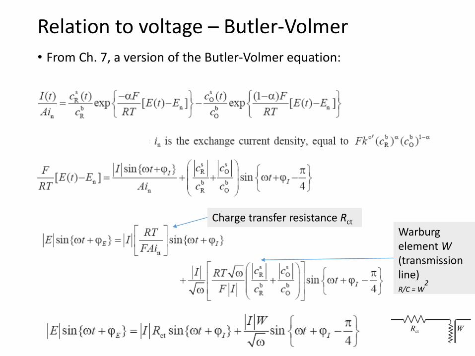
• From Ch. 7, a version of the Butler-Volmer equation:
Relation to voltage – Butler-Volmer
Charge transfer resistance Rct
Warburg element W(transmissionline)R/C = W
2
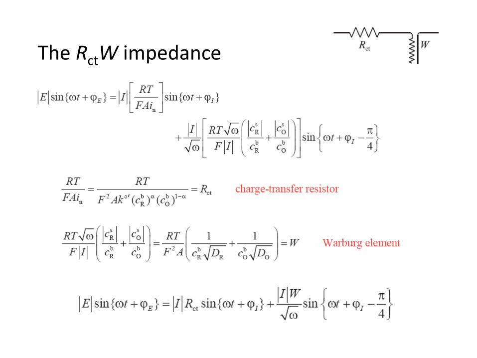
The RctW impedance

• W (unit of ohm s-1/2)
• Reflects a combination of • Diffusion• Chemical capacitance
• Appears in AC circuits to represent the impedance of mass transport• In series with the charge transfer resistance
• Imposes a complex impedance ZW(ohm) = W/√(2ω) - jW/√(2ω)
• Has a constant, frequency independent phase shift of –π/4 (-45°)
The Warburg impedance

• Electrochemical impedance spectroscopy (EIS)
• Impedance spectrometer (frequency response analysers)• E.g. Solartron SI 1260 FRA
• 0-3 V rms AC 0.01 mHz – 32 MHz, -42 - +42 V DC
• Electrode electrical elements• Ru uncompensated electrolyte resistance (ohmic)
• Rct charge transfer resistance (kinetics)
• W Warburg impedance (diffusion)
• C Capacitance (double layers)
AC impedance measurement

• Impedance has magnitude but also contains a phase angle between E and I
• Vector in 2-dimensional Z space
• In-phase and out-of-phase components
• Real part Z’
• Imaginary part jZ’’
• Z = Z’ + jZ’’ or Z* = Z’ + jZ’’ Complex numbers j =√-1 or j2 = -1
• The value of Z – often denoted |Z| – is the length of the vector:
|Z| = √(Z2) = √(Z’2+Z’’2) = √(Z’2–(jZ’’)2) = √((Z’+jZ’’)(Z’-jZ’’))
AC impedance representations
Z’
Z’’
Complex conjugate

Complex impedance Z* and admittance Y*
• Z* = U*/I* = Z/ + jZ// = R + jX• Z* Complex impedance
• |Z| Impedance
• R Resistance
• X Reactance
• Y* = 1/Z* = I*/U* = Y/ + jY// = G + jB• Y* Complex admittance
• |Y| Admittance
• G Conductance
• B Susceptance
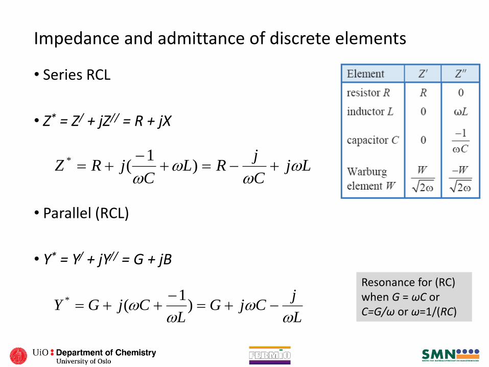
Impedance and admittance of discrete elements
• Series RCL
• Z* = Z/ + jZ// = R + jX
• Parallel (RCL)
• Y* = Y/ + jY// = G + jB
LjC
jRL
CjRZ
)
1(*
L
jCjG
LCjGY
)
1(*
Resonance for (RC) when G = ωC or C=G/ω or ω=1/(RC)
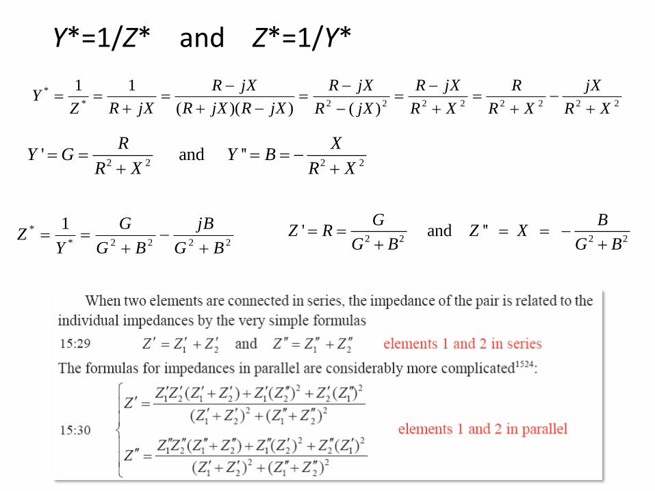
Y*=1/Z* and Z*=1/Y*
22222222*
*
)())((
11
XR
jX
XR
R
XR
jXR
jXR
jXR
jXRjXR
jXR
jXRZY
2222*
* 1
BG
jB
BG
G
YZ
2 2 2 2' and ''
R XY G Y B
R X R X
2 2 2 2' and ''
G BZ R Z X
G B G B
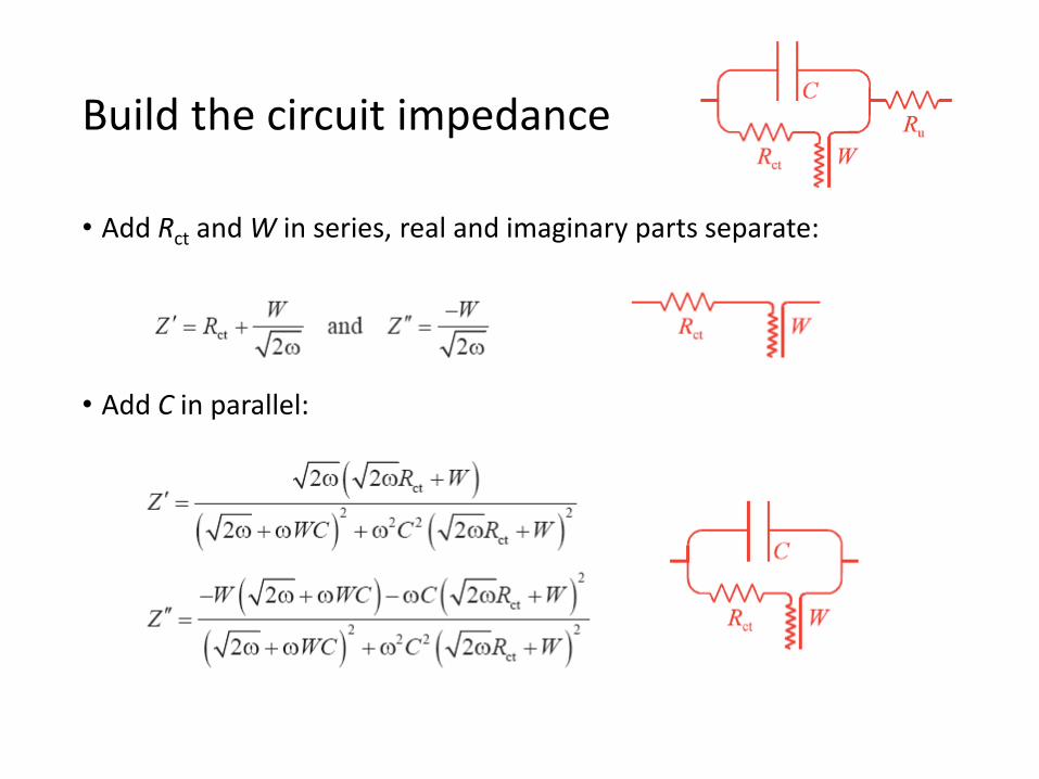
• Add Rct and W in series, real and imaginary parts separate:
• Add C in parallel:
Build the circuit impedance

• Add Ru in series (has only real part):
Build the circuit impedance
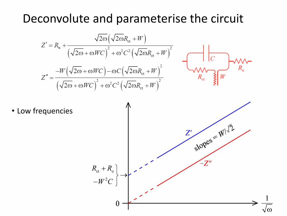
• Low frequencies
Deconvolute and parameterise the circuit
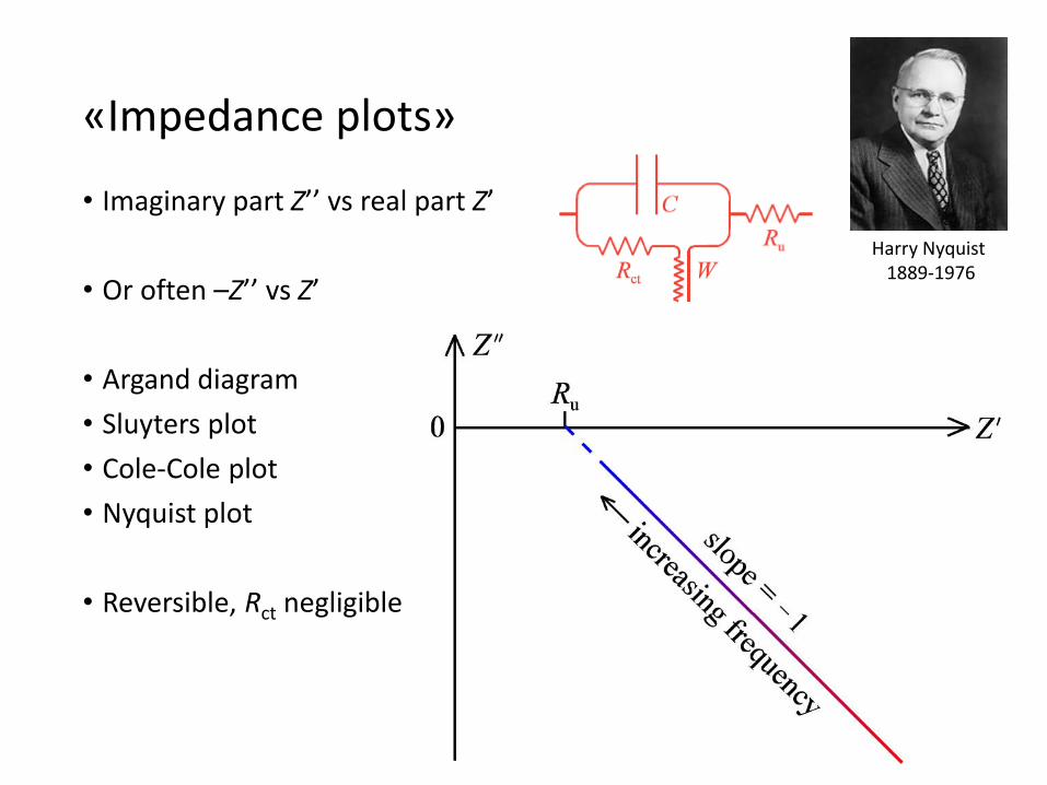
• Imaginary part Z’’ vs real part Z’
• Or often –Z’’ vs Z’
• Argand diagram
• Sluyters plot
• Cole-Cole plot
• Nyquist plot
• Reversible, Rct negligible
«Impedance plots»
Harry Nyquist 1889-1976
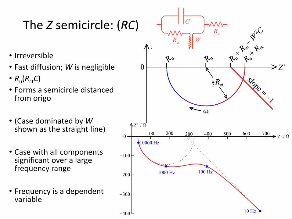
• Irreversible
• Fast diffusion; W is negligible
• Ru(RctC)
• Forms a semicircle distancedfrom origo
• (Case dominated by Wshown as the straight line)
• Case with all componentssignificant over a largefrequency range
• Frequency is a dependent variable
The Z semicircle: (RC)
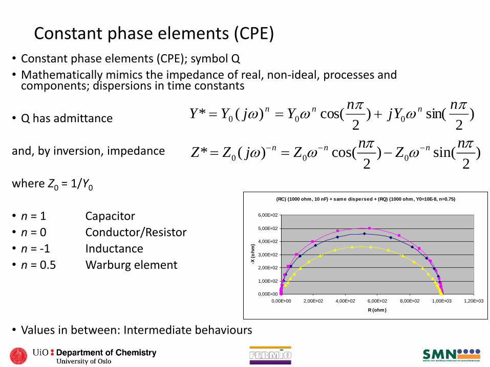
Constant phase elements (CPE)• Constant phase elements (CPE); symbol Q
• Mathematically mimics the impedance of real, non-ideal, processes and components; dispersions in time constants
• Q has admittance
and, by inversion, impedance
where Z0 = 1/Y0
• n = 1 Capacitor
• n = 0 Conductor/Resistor
• n = -1 Inductance
• n = 0.5 Warburg element
• Values in between: Intermediate behaviours
)2
sin()2
cos()(* 000
njY
nYjYY nnn
(RC) (1000 ohm, 10 nF) + same dispersed + (RQ) (1000 ohm, Y0=10E-8, n=0.75)
0,00E+00
1,00E+02
2,00E+02
3,00E+02
4,00E+02
5,00E+02
6,00E+02
0,00E+00 2,00E+02 4,00E+02 6,00E+02 8,00E+02 1,00E+03 1,20E+03
R (ohm)
-X (
oh
m)
0 0 0* ( ) cos( ) sin( )2 2
n n nn nZ Z j Z Z

Circuit elements overview table
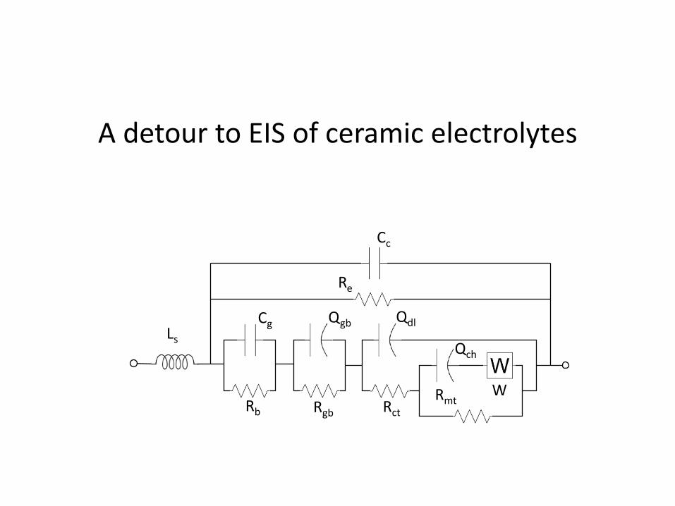
A detour to EIS of ceramic electrolytes
Cc
Re
Ls
Rb Rgb Rct
RmtW
Cg Qgb Qdl
Qch
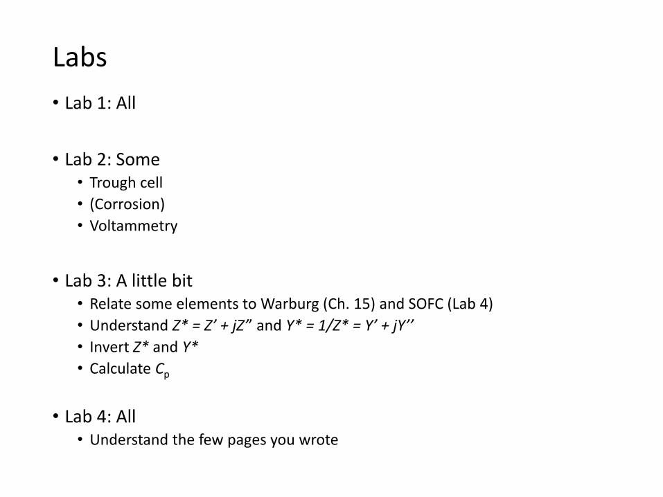
• Lab 1: All
• Lab 2: Some• Trough cell
• (Corrosion)
• Voltammetry
• Lab 3: A little bit• Relate some elements to Warburg (Ch. 15) and SOFC (Lab 4)
• Understand Z* = Z’ + jZ’’ and Y* = 1/Z* = Y’ + jY’’
• Invert Z* and Y*
• Calculate Cp
• Lab 4: All• Understand the few pages you wrote
Labs