GAS TRAIN EQUIPMENT - CPF Tecnocontrol GECA
300
GAS TRAIN EQUIPMENT RELEASE 48 TECHNICAL BOOK
-
Upload
khangminh22 -
Category
Documents
-
view
0 -
download
0
Transcript of GAS TRAIN EQUIPMENT - CPF Tecnocontrol GECA

G a s t r a i n e q u i p m e n t
R e l e a s e 4 8
T e c h n i c a l B o o k


3
We believe in Quality, we contribute to increase the Italian Technology
and the Style that countersigns the excellence of Italy all over the world.

SALES ALL OVER THE WORLD
EXPORTING TO 91 COUNTRIES
www.gecasrl.it

Our group began operating in 1949 in Northern Italy and has grown to become a world-leading producer of very high-quality gas products and systems.
Our Group has a long history of developing gas products and systems that solve real customer challenges and invent new ways of working. Our rapid response R&D infrastructure and collaboration with university partners allows us to create applied innovations.
Production process is entirely carried out in three buildings in Italy. Manufacturing process, provided by the most advanced techniques, equipment, tools and machines.
We are an ever-evolving company offering the newest solutions and always renewing its passion. Behind each product, an accurate work of research, projecting, manufacturing and testing is guaranteed by means of special technologically advanced tools, in order to offer new satisfying solutions to our customers.
We strongly believe in the importance of high quality standards and control and this allows us to reach the ability to provide our customers with high levels of service and lead time.
Our group operations are conducted through six business divisions:
- Gas TraIn EquIpmEnT
- Gas DETEcTIon EquIpmEnT
- combusTIon analysEr anD mEasurEmEnT InsTrumEnTs for Gas anD HVac applIcaTIons
- THErmorEGulaTIon componEnTs
- cylInDEr ValVEs for InDusTrIal GasEs
- ValVEs for fIrE ExTInGuIsHErs anD ValVEs & EquIpmEnT for fIxED supprEssIon sysTEms
Now, thanks to our experience, dedication to quality and technical excellence, gas companies, OEM partners, distributors and installers are confident their projects will achieve the highest level of safety and performance. Present in over 91 countries, our customers count on us to deliver the products and services they need wherever they are.
One more time we stand out as a dynamic, future-oriented company, which is able to combine its family traditions with its open-minded attitude, resulting in new market opportunities and innovative answers to the markets' demands.
About us
SALES ALL OVER THE WORLD
EXPORTING TO 91 COUNTRIES

6
equipmentgas train
Gas fIlTErs
Gas GoVErnors
rElIEf ValVEs
Gas solEnoID ValVEs manual rEsET

7
equipment
ball ValVEs
Gas rEGulaTors wITH slam sHuT ValVE InTEGraTED
prEssurE GuaGEs
auTomaTIc Gas ValVEs

8
Gas Train:
1. ball ValVE: to isolate the system from main supply or to isolate the either side of PRS.
2. solEnoID ValVE is made to guarantee the gas interception from gas detector in case of gas leaking.
3. JErk HanDlE ValVE are manually operated valves that allow the flow inside the piping while minimizing the pressure losses. With the possibility of remote interception operation; the closing operation is faster and safer than traditional ball devices.
4. prEssurE GauGE: To monitor upstream and downstream pressure, the pressure gauges are installed. Isolation valve is provided with each pressure gauge for easy replacement of pressure gauges in case of failure.
5. Gas fIlTEr: protects rest of the system from any debris or dust that may carried with gas stream. Debris may for example consist of parts accidently left in the pipe during construction. It could also result from swarf from drilling holes & taps or welding & sand from construction or fine iron oxide dust.
6. slam sHuT off ValVE: is installed after Filter & before pressure regulator. Slam shut off valve close the supply of gas when a downstream pressure exceeds a pre-determined limit.
7. Gas GoVErnor: is a control valve that reduces the input pressure of a fluid to a desired value at its output.
8. safETy rElIEf ValVE: is set at higher pressure than slam shut off valve so that the safety relief valve will operate when slam shut off valve fails to operate.
9. solEnoID ValVE for gas are designed for safeguarding and controlling the air and gas supply to gas burners and gas appliances.
10. prEssurE swITcH: are designed for switching a circuit on, off or over if the pressure actual value changes in relation to the setpoint.
11. Gas DETEcTor is a device that detects the presence of gases in an area.This type of equipment is used to detect a gas leak or other emissions and can interface with a control system so a process can be automatically shut down.
1 2 3
4
5 6
7
10
11
9
8

9
Installation and mounting
only trained and qualified person must be permitted to perform work on gas regulators and safety devices. Install the regulating train directly upstream of the gas-consuming devices. Install the regulating train so that the direction arrows point towards the filter, safety shut-off valve, pressure regulator and solenoid valves in the direction of gas flow. Normally, the gas passage is horizontally. The installation of the regulating trains is independent of position due to the spring loads. The device works therefore in any position. If necessary, readjust the output pressure. Position the pulse lines for SAV and pressure regulator so that you can monitor a steady output pressure (approx. 10 x DN). Designed with 12 mm dia. steel pipe and cutting ring unions. Take particular care that pulse lines are not damaged during mounting. Connect the vent lines to the vent connections and route them outdoors. Ensure that the sealing rings are inserted. Ensure that the connection lines and the devices are free from contamination to avoid damages and operational faults.
Commissioningslowly open the ball valve upstream of the regulating train and then the burner ball valve (if installed). Observe the output pressure at the manometer and, if necessary, readjust at the load spring. Ensure that there is no zero consumption, otherwise the closing pressure must also be measured. The output pressure in the pressure regulator, the switch-off pressure in the SAV and the vent pressure in the SBV are set at our factory to the values specified in the enclosed datasheet.
Output pressure adjustment The output pressure Pa must be higher than the sum of resistances of all downstream fittings and gas-consuming devices. If it is necessary to correct the output pressure, readjust the pressure regulator setting screw. Open the closing cover. Then change the pressure to the desired value by turning the setting screw. Pressure will increase by turning clockwise. This can be performed during operation since all gas-conveying chambers in the regulator are closed. If the SAV close due to a operating fault at the pressure regulator, you can manually open the SAV after elim- inating the fault.
Data for gas train calculation (in case you need fill the below table with details)
1 Gas type
2 Gas temperature (°C, K)
3 Density of Gas (kg/m3)
4 max. Operating pressure pmax
. [bar, mbar]
5 min. Inlet pressure [bar, mbar]
6 max. Inlet pressure [bar, mbar]
7 Outlet pressure at the end of the gas train [bar, mbar]
8 min. Gas volume flow (Nm3/h)
9 max. Gas volume flow (Nm3/h)
10 Electrical voltage (VAC, VDC, Hz)
11 Electrical degree of protection [IP]
12 Further information

10
Product Range

11
Conversion Table

12

1313
Gas Governors p. 15
Gas reGulator p. 87
Gas filters p. 101
automatic Gas valves - Brass Body p. 125
automatic Gas valves p. 129 fast opening / fast closing
automatic Gas valves p. 157 slow opening / fast closing
automatic Gas valves p. 173 normally open - vent valves
Pressure switches p. 177
relief valves p. 181
slam shut off valves - oPso p. 189
Jerk valves p. 201
Gas solenoid valves manual reset p. 211normally open
Gas solenoid valves manual reset p. 221normally close
Gas solenoid valves manual reset p. 233with cPi integrated
accessories for Gas train p. 239
measurement instruments p. 291
Inde
x

Gas Governors›› Spring-loaded governors, are designed and built according UNI EN 88 class A - group 2 specifications, can be used for all the types of natural gas LPG or not corrosive gases. These regulators are widely used in supply lines for mixed and combinated burners and in the piped distribution of methane gas and LPG in both industrial and non-industrial applications. Spring-loaded/ governors are self-acting type with balanced obturator and double safety diaphragm. The double diaphragm allow to use the device within the cabinet, without connecting an external pipe venting.

Gas Governor 500 mbar
Gas Governor ½” , ¾”, 1” – Pmax 500 mbar p. 16
Gas Governor ½” , ¾”, 1” - high capacity - Pmax 500 mbar p. 18
Gas Governor 1 ¼” , 1 ½” – Pmax 500 mbar p. 20
Gas Governor 2” – Pmax 500 mbar p. 22
Gas Governor dn656, dn80, dn100 – Pmax 500 mbar p. 24
Gas Governors Pmax 1 bar
Gas Governor ½”, ¾” and 1” – Pmax 1 bar p. 28
Gas Governor ½”, ¾” and 1” - high capacity - Pmax 1 bar p. 30
Gas Governor 1 ¼”, 1 ½” – Pmax 1 bar p. 32
Gas Governor 2” – Pmax 1 bar p. 34
Gas Governor dn65, dn80, dn100 - Pmax 1 bar p. 36
Gas Governors Pmax 2 bar
Gas Governor ½”, ¾” and 1”– Pmax 2 bar p. 40
Gas Governor ½”, ¾” and 1” - high capacity - Pmax 2 bar p. 42
Gas Governor 1 ¼”, 1 ½” – Pmax 2 bar p. 44
Gas Governor 2”– Pmax 2 bar p. 46
Gas Governor dn65, dn80, dn100 - Pmax 2 bar p. 48
Gas Governor Pmax 5 bar
Gas Governor ½”, ¾”, 1”– Pmax 5 bar p. 52
Gas Governor ½”, ¾”, 1” - high capacity - 5 bar p. 54
Gas Governor 1 ¼”, 1 ½” – Pmax 5 bar p. 56
Gas Governor 2”– Pmax 5 bar p. 58
Gas Governor dn65, dn80, dn100 - Pmax 5 bar p. 60
15
Gas G
over
nors

16
pmax inlet max – 500 mbar
setting outlet 5 – 300 mbar – Standard spring supplied 10 – 27 mbar – Other spring on request – Range as per below table
filtering ≤ 50μm – Plastic cartidge
Inlet - outlet Thread gas ½”, ¾”, 1” - ISO 228connection DN25 - Sliding Aluminium flange PN10
Test point 1/8” NPT
working Temperature - 20 °C – + 60 °C
use Not aggressive gases of three families – Natural Gas – LPG – Town Gas
approval UNI EN 88-1:2011 / PED / EAC
Materials:
complete body Die – Cast Aluminium Gd – AlSi12Cu – EN AB 46100
Diaphragms NBR 60Sh – DvGW EN 549
plastic components Yellow POM / Pa 66 + 25% Gf
GAS GOVERNOR ½”, ¾”, 1” – Pmax 500 mbar
TEcHnIcal fEaTurEs
G a s G o v e r n o r s
code Description Dimension pmax
rG015 Gas Governor ½” 500 mbar
rG020 Gas Governor ¾” 500 mbar
rG025 Gas Governor 1” 500 mbar
rGD25 Gas Governor DN25 500 mbar
rG015-fT Gas Governor with filter ½” 500 mbar
rG020-fT Gas Governor with filter ¾” 500 mbar
rG025-fT Gas Governor with filter 1” 500 mbar
rGD25-fT Gas Governor with filter DN25 500 mbar
rG015-TpIo Gas Governor with test point in/out ½” 500 mbar
rG020-TpIo Gas Governor with test point in/out ¾” 500 mbar
rG025-TpIo Gas Governor with test point in/out 1” 500 mbar
rGD25-TpIo Gas Governor with test point in/out DN25 500 mbar
rG015-fT-TpIo Gas Governor with filter and test point in/out ½” 500 mbar
rG020-fT-TpIo Gas Governor with filter and test point in/out ¾” 500 mbar
rG025-fT-TpIo Gas Governor with filter and test point in/out 1” 500 mbar
rGD25-fT-TpIo Gas Governor with filter and test point in/out DN25 500 mbar
Code: color range mbar spw1-5 White 5 - 14 mbar spy1-5 Yellow 6 - 22 mbar spn1-5 Neutral 10 - 27 mbarspr1-5 Red 28 - 70 mbarspbk1-5 Black 60 - 130 mbar spG1-5 Green 120 - 300 mbar

17
115 mm 100 mm
154
mm
79 m
m75
mm
Dimension ½” ¾” 1”
wEIGHT (kgs) 0,720 0,688 0,663
1 Seal cap 2 O ring 3 Spring compressor4 Washer 6 Screws7 Vent cap 8 Upper cover 9 Plastic Washer 10 Safety diaphragm 11 Calibrated nozzle 12 Washer 13 Disc14 Compensation diaphragm
15 Shaft 16 Upper bush 17 Disc 18 Working diaphragm 19 Lower bush 20 Body21 Sensing tube 22 Seal washer23 Plastic ring 24 Gasket 25 Cover 26 Nut 27 Filter cartidge
3
6
1
2
8
2425
20
14
10
726 13
15
16
22
18
17
119
23
21
12
4
19
27

18
pmax inlet max – 500 mbar
setting outlet 5 – 300 mbar – Standard spring supplied 10 – 27 mbar – Other spring on request – Range as per below table
filtering ≤ 50μm
Inlet - outlet Thread gas ½”, ¾”, 1” - ISO 228connection DN25 - Sliding Aluminium flange PN10
Test point 1/8” NPT
working Temperature - 20 °C – + 60 °C
use Not aggressive gases of three families – Natural Gas – LPG – Town Gas
approval UNI EN 88-1:2011 / PED / EAC
Materials:
complete body Die – Cast Aluminium Gd – AlSi12Cu – EN AB 46100
Diaphragms NBR 60Sh – DvGW EN 549
plastic components Yellow POM / Pa 66 + 25% Gf
GAS GOVERNOR ½”, ¾”, 1” - High Capacity - Pmax 500 mbar
TEcHnIcal fEaTurEs
G a s G o v e r n o r s
code Description Dimension pmax
rG015-Hc Gas Governor ½” 500 mbar
rG020-Hc Gas Governor ¾” 500 mbar
rG025-Hc Gas Governor 1” 500 mbar
rGD25-Hc Gas Governor DN25 500 mbar
rG015-Hc-fT Gas Governor with filter ½” 500 mbar
rG020-Hc-fT Gas Governor with filter ¾” 500 mbar
rG025-Hc-fT Gas Governor with filter 1” 500 mbar
rGD25-Hc-fT Gas Governor with filter DN25 500 mbar
rG015-Hc-TpIo Gas Governor with test point in/out ½” 500 mbar
rG020-Hc-TpIo Gas Governor with test point in/out ¾” 500 mbar
rG025-Hc-TpIo Gas Governor with test point in/out 1” 500 mbar
rGD25-Hc-TpIo Gas Governor with test point in/out DN25 500 mbar
rG015-Hc-fT-TpIo Gas Governor with filter and test point in/out ½” 500 mbar
rG020-Hc-fT-TpIo Gas Governor with filter and test point in/out ¾” 500 mbar
rG025-Hc-fT-TpIo Gas Governor with filter and test point in/out 1” 500 mbar
rGD25-Hc-fT-TpIo Gas Governor with filter and test point in/out DN25 500 mbar
Code: color range mbar spw1-5Hc White 5 - 14 mbar
spy1-5Hc Yellow 6 - 22 mbar
spn1-5Hc Neutral 10 - 27 mbar
spr1-5Hc Red 28 - 70 mbar
spbk1-5Hc Black 60 - 130 mbar
spb1-5Hc Blue 120 - 300 mbar

19
Dimension ½” ¾” 1”
wEIGHT (kgs) 0,980 0,955 0,915
1 Seal cap 2 O ring 3 Spring compressor4 Washer 6 Screws7 Vent cap 8 Upper cover 9 Plastic Washer 10 Safety diaphragm 11 Calibrated nozzle 12 Washer 13 Disc14 Compensation diaphragm
15 Shaft 16 Upper bush 17 Disc 18 Working diaphragm 19 Lower bush 20 Body21 Sensing tube 22 Seal washer23 Plastic ring 24 Gasket 25 Cover 26 Nut 27 Filter cartidge
175
mm
120 mm 135 mm
82 m
m93
mm
2
3
4
26 71310
1416
20
21
2324
25
22
8
911
615
18
17
27
1
12
19

20
pmax inlet max – 500 mbar
setting outlet 5 – 300 mbar – Standard spring supplied 10 – 27 mbar – Other spring on request – Range as per below table
filtering ≤ 50μm – Viledon cartridge
Inlet - outlet Thread gas 1 ¼” 1½” - ISO 228connection DN32 - DN40 - Sliding Aluminium flange PN10
Test point 1/8” NPT
working Temperature - 20 °C – + 60 °C
use Not aggressive gases of three families – Natural Gas – LPG – Town Gas
approval UNI EN 88-1:2011 / PED / EAC
Materials:
complete body Die – Cast Aluminium Gd – AlSi12Cu - EN AB 46100
Diaphragms NBR 60Sh – DvGW EN 549
plastic components White POM / Pa 66 + 25% Gf
GAS GOVERNOR 1 ¼”, 1 ½” – Pmax 500 mbar
TEcHnIcal fEaTurEs
G a s G o v e r n o r s
code Description Dimension pmax
rG032 Gas Governor 1 ¼ ” 500 mbar
rG040 Gas Governor 1 ½” 500 mbar
rGD32 Gas Governor DN32 500 mbar
rGD40 Gas Governor DN40 500 mbar
rG032-fT Gas Governor with filter 1 ¼ ” 500 mbar
rG040-fT Gas Governor with filter 1 ½” 500 mbar
rGD32-fT Gas Governor with filter DN32 500 mbar
rGD40-fT Gas Governor with filter DN40 500 mbar
rG032-TpIo Gas Governor with test point in/out 1¼” 500 mbar
rG040-TpIo Gas Governor with test point in/out 1½” 500 mbar
rGD32-TpIo Gas Governor with test point in/out DN32 500 mbar
rGD40-TpIo Gas Governor with test point in/out DN40 500 mbar
rG032-fT-TpIo Gas Governor with filter and test point in/out 1¼” 500 mbar
rG040-fT-TpIo Gas Governor with filter and test point in/out 1½” 500 mbar
rGD32-fT-TpIo Gas Governor with filter and test point in/out DN32 500 mbar
rGD40-fT-TpIo Gas Governor with filter and test point in/out DN32 500 mbar
Code: color range mbar spw2-5 White 5 - 14 mbar spy2-5 Yellow 6 - 22 mbar spn2-5 Neutral 10 - 27 mbarspr2-5 Red 28 - 70 mbarspbk2-5 Black 60 - 130 mbar spb2-5 Blue 120 - 300 mbar

21
1
2
3
4
26 7 1310
14
6
1615
20
212823
2425
2219
1817
27
8 1211
9
210 mm 194 mm
244
mm
142
mm
102
mm
Dimension 1 ¼” 1 ½”
wEIGHT (kgs) 3,140 3,060
1 Seal cap 2 O ring 3 Spring compressor4 Washer 6 Screws7 Vent cap 8 Upper cover 9 Plastic Washer 10 Safety diaphragm 11 Calibrated nozzle 12 Washer 13 Disc14 Compensation diaphragm
15 Shaft 16 Upper bush 17 Disc 18 Working diaphragm 19 Lower bush 20 Body21 Sensing tube 22 Seal washer23 Plastic ring 24 Gasket 25 Cover 26 Nut 27 Filter cartidge28 Screw cover

22
Code: color range mbar spw3-5 White 5 - 14 mbar spy3-5 Yellow 6 - 22 mbar spn3-5 Neutral 10 - 27 mbarspr3-5 Red 28 - 70 mbarspbk3-5 Black 60 - 130 mbar spb3-5 Blue 120 - 300 mbar
pmax inlet max – 500 mbar
setting outlet 5 – 300 mbar – Standard spring supplied 10 – 27 mbar – Other spring on request – Range as per below table
filtering ≤ 50μm – Viledon cartridge
Inlet- outlet Thread gas 2” - ISO 228connection DN50 - Sliding Aluminium flange PN10
Test point 1/8” NPT
working Temperature - 20 °C – + 60 °C
use Not aggressive gases of three families – Natural Gas – LPG – Town Gas
approval UNI EN 88-1:2011 / PED / EAC
Materials:
complete body Die – Cast Aluminium Gd – AlSi12Cu - EN AB 46100
Diaphragms NBR 60Sh – DvGW EN 549
plastic components White POM / Pa 66 + 25% Gf
GAS GOVERNOR 2” – Pmax 500 mbar
TEcHnIcal fEaTurEs
G a s G o v e r n o r s
code Description Dimension pmax
rG050 Gas Governor 2” 500 mbar
rGD50 Gas Governor DN50 500 mbar
rG050-fT Gas Governor with filter 2” 500 mbar
rGD50-fT Gas Governor with filter DN50 500 mbar
rG050-TpIo Gas Governor with test point in/out 2” 500 mbar
rGD50-TpIo Gas Governor with test point in/out DN50 500 mbar
rG050-fT-TpIo Gas Governor with filter and test point in/out 2” 500 mbar
rGD50-fT-TpIo Gas Governor with filter and test point in/out DN50 500 mbar

23
1
2
3
4
26 7 1310
14
6
9
11128
27
1817 15
16
20
21
23
2219
25 24
28
266 mm 234 mm
307
mm
122
mm
185
mm
1 Seal cap 2 O ring 3 Spring compressor 4 Washer 6 Screws7 Vent cap 8 Upper cover 9 Plastic Washer 10 Safety diaphragm 11 Calibrated nozzle 12 Washer 13 Disc14 Compensation diaphragm
15 Shaft 16 Upper bush 17 Disc 18 Working diaphragm 19 Lower bush 20 Body21 Sensing tube 22 Seal washer23 Plastic ring 24 Gasket 25 Cover 26 Nut 27 Filter cartidge28 Screw cover
Dimension 2"
wEIGHT (kgs) 5,8

24
GAS GOVERNOR DN65, DN80, DN100 - Pmax 500 mbar
G a s G o v e r n o r s
Spring Range: color range mbar spw4-5 White 5 - 14 mbar spw4-5 Yellow 6 - 22 mbar spw4-5 Neutral 10 - 27 mbarspr4-5 Red 28 - 70 mbarspbk4-5 Black 60 - 130 mbar spb4-5 Blue 120 - 300 mbar
pmax inlet max – 500 mbar
setting outlet 5 – 300 mbar – Standard spring supplied 10 – 27 mbar – Other spring on request
filtering ≤ 50μm – Viledon cartridge
Inlet - outlet Flanged connection DN65connection DN80 - DN100 - PN16
Test point Inlet / outlet on request – Test point 1/8” NPT
working Temperature - 20 °C – + 60 °C
use Not aggressive gases of three families – Natural Gas – LPG – Town Gas
approval UNI EN 88-2:2008 / PED / EAC
Materials:
complete body Die – Cast Aluminium Gd – AlSi12Cu - EN AB 46100
Diaphragms NBR 60Sh – DvGW EN 549
plastic components White POM / Pa 66 + 25% Gf
TEcHnIcal fEaTurEs code Description Dimension pmax
rGD65 Gas Governor DN65 500 mbar
rGD80 Gas Governor DN80 500 mbar
rGD100 Gas Governor DN100 500 mbar
rGD65-fT Gas Governor with filter DN65 500 mbar
rGD80-fT Gas Governor with filter DN80 500 mbar
rGD100-fT Gas Governor with filter DN100 500 mbar
rGD65-TpIo Gas Governor with test point in/out DN65 500 mbar
rGD80-TpIo Gas Governor with test point in/out DN80 500 mbar
rGD100-TpIo Gas Governor with test point in/out DN100 500 mbar
rGD65-fT-TpIo Gas Governor with filter and test point in/out DN65 500 mbar
rGD80-fT-TpIo Gas Governor with filter and test point in/out DN80 500 mbar
rGD100-fT-TpIo Gas Governor with filter and test point in/out DN100 500 mbar

25
427 mm Ø 320 mm
440
mm
260
mm
180
mm
Dimension DN65 DN80 DN100
wEIGHT (kgs) 16 15,3 14,6
1 Seal cap 2 O ring 3 Spring compressor4 Washer 6 Screws7 Vent cap 8 Upper cover 9 Plastic Washer 10 Safety diaphragm 11 Calibrated nozzle 12 Washer 13 Disc14 Compensation diaphragm
15 Shaft 16 Upper bush 17 Disc 18 Working diaphragm 19 Lower bush 20 Body21 Sensing tube 22 Seal washer23 Plastic ring 24 Gasket 25 Cover 26 Nut 27 Filter cartidge28 Screw cover
1
2
8
2425
20
14
10726 13
15
16
22
18
17
11 9
23
21
12
27
3
4
6
28
19

26
Gas Governors Pmax 1 bar

27
Gas Governor PmaX 1 Bar
Gas Governor ½”, ¾” and 1” – Pmax 1 bar p. 28
Gas Governor ½”, ¾” and 1” p. 30high capacity - Pmax 1 bar
Gas Governor 1 ¼”, 1 ½” – Pmax 1 bar p. 32
Gas Governor 2” – Pmax 1 bar p. 34
Gas Governor dn65, dn80, dn100 - Pmax 1 bar p. 36
27
Gas G
over
nors
Pmax
1 b
ar

28
pmax inlet max – 1 bar
setting outlet 6 – 480 mbar – Standard spring supplied 10 – 27 mbar – Other spring on request – Range as per below table
filtering ≤ 50μm –
Inlet - outlet Thread gas ½” , ¾” 1” - ISO 228connection DN25 - Sliding Aluminium flange PN10
Test point 1/8” NPT
working Temperature - 20 °C – + 60 °C
use Not aggressive gases of three families – Natural Gas – LPG – Town Gas
approval UNI EN 88-2:2008 / PED / EAC
Materials:
complete body Die – Cast Aluminium Gd – AlSi12Cu - EN AB 46100
Diaphragms NBR 60Sh – DvGW EN 549
plastic components Yellow POM / Pa 66 + 25% Gf
GAS GOVERNOR ½”, ¾” and 1” – Pmax 1 bar
TEcHnIcal fEaTurEs
G a s G o v e r n o r s
code Description Dimension pmax
rG015-1b Gas Governor ½” 1 bar
rG020-1b Gas Governor ¾” 1 bar
rG025-1b Gas Governor 1” 1 bar
rGD25-1b Gas Governor DN25 1 bar
rG015-fT-1b Gas Governor with filter ½” 1 bar
rG020-fT-1b Gas Governor with filter ¾” 1 bar
rG025-fT-1b Gas Governor with filter 1” 1 bar
rGD25-fT-1b Gas Governor with filter DN25 1 bar
rG015-1b-TpIo Gas Governor with test point in/out ½” 1 bar
rG020-1b-TpIo Gas Governor with test point in/out ¾” 1 bar
rG025-1b-TpIo Gas Governor with test point in/out 1” 1 bar
rGD25-1b-TpIo Gas Governor with test point in/out DN25 1 bar
rG015-fT-1b-TpIo Gas Governor with filter and test point in/out ½” 1 bar
rG020-fT-1b-TpIo Gas Governor with filter and test point in/out ¾” 1 bar
rG025-fT-1b-TpIo Gas Governor with filter and test point in/out 1” 1 bar
rGD25-fT-1b-TpIo Gas Governor with filter and test point in/out DN25 1 bar Code: color range mbar spy1-12 Yellow 6 - 22 mbar spn1-12 Neutral 10 - 27 mbarspr1-12 Red 28 - 70 mbar spG1 -12 Green 70 - 280 mbarspbr1-12 Brown 220- 480 mbar

29
115 mm 100 mm
154
mm
79 m
m75
mm
Dimension ½” ¾” 1”
wEIGHT (kgs) 0,720 0,688 0,663
1 Seal cap 2 O ring 3 Spring compressor4 Washer 6 Screws7 Vent cap 8 Upper cover 9 Plastic Washer 10 Safety diaphragm 11 Calibrated nozzle 12 Washer 13 Disc14 Compensation diaphragm
15 Shaft 16 Upper bush 17 Disc 18 Working diaphragm 19 Lower bush 20 Body21 Sensing tube 22 Seal washer23 Plastic ring 24 Gasket 25 Cover 26 Nut 27 Filter cartidge
3
6
1
2
8
2425
20
14
10
726 13
15
16
22
18
17
119
23
21
12
4
19
27

30
pmax inlet max – 1 bar
setting outlet 6 – 480 mbar – Standard spring supplied 10 – 27 mbar – Other spring on request – Range as per below table
filtering ≤ 50μm –
Inlet - outlet Thread gas ½” , ¾” 1” - ISO 228connection DN25 - Sliding Aluminium flange PN10
Test point 1/8” NPT
working Temperature - 20 °C – + 60 °C
use Not aggressive gases of three families – Natural Gas – LPG – Town Gas
approval UNI EN 88-2:2008 / PED / EAC
Materials:
complete body Die – Cast Aluminium Gd – AlSi12Cu - EN AB 46100
Diaphragms NBR 60Sh – DvGW EN 549
plastic components Yellow POM / Pa 66 + 25% Gf
GAS GOVERNOR ½”, ¾” and 1” - High Capacity - Pmax 1 bar
TEcHnIcal fEaTurEs
G a s G o v e r n o r s
code Description Dimension pmax
rG015-Hc-1b Gas Governor ½” 1 bar
rG020-Hc-1b Gas Governor ¾” 1 bar
rG025-Hc-1b Gas Governor 1” 1 bar
rGD25-Hc-1b Gas Governor DN25 1 bar
rG015-Hc-fT-1b Gas Governor with filter ½” 1 bar
rG020-Hc-fT-1b Gas Governor with filter ¾” 1 bar
rG025-Hc-fT-1b Gas Governor with filter 1” 1 bar
rGD25-Hc-fT-1b Gas Governor with filter DN25 1 bar
rG015-Hc-1b-TpIo Gas Governor with test point in/out ½” 1 bar
rG020-Hc-1b-TpIo Gas Governor with test point in/out ¾” 1 bar
rG025-Hc-1b-TpIo Gas Governor with test point in/out 1” 1 bar
rGD25-Hc-1b-TpIo Gas Governor with test point in/out DN25 1 bar
rG015-Hc-fT-1b-TpIo Gas Governor with filter and test point in/out ½” 1 bar
rG020-Hc-fT-1b-TpIo Gas Governor with filter and test point in/out ¾” 1 bar
rG025-Hc-fT-1b-TpIo Gas Governor with filter and test point in/out 1” 1 bar
rGD25-Hc-fT-1b-TpIo Gas Governor with filter and test point in/out DN25 1 bar
Code: color range mbar spy1-12Hc Yellow 6 - 22 mbar spn1-12Hc Neutral 10 - 27 mbarspr1-12Hc Red 28 - 70 mbarspG1-12Hc Green 70 - 280 mbarspbr1-12Hc Brown 220 - 480 mbar

31
1 Seal cap 2 O ring 3 Spring compressor4 Washer 6 Screws7 Vent cap 8 Upper cover 9 Plastic Washer 10 Safety diaphragm 11 Calibrated nozzle 12 Washer 13 Disc14 Compensation diaphragm
15 Shaft 16 Upper bush 17 Disc 18 Working diaphragm 19 Lower bush 20 Body21 Sensing tube 22 Seal washer23 Plastic ring 24 Gasket 25 Cover 26 Nut 27 Filter cartidge
175
mm
120 mm 135 mm
82 m
m93
mm
Dimension ½” ¾” 1”
wEIGHT (kgs) 0,980 0,955 0,915
1
2
3
4
26 71310
1416
20
2324
25
8
12
911
6
15 1817
21
22
27
19

32
pmax inlet max – 1 bar
setting outlet 6 – 480 mbar – Standard spring supplied 10 – 27 mbar – Other spring on request – Range as per below table
filtering ≤ 50μm – Viledon cartridge
Inlet - outlet Thread gas 1 ¼” 1½” - ISO 228connection DN32 DN40 - Sliding Aluminium flange PN10
Test point 1/8” NPT
working Temperature - 20 °C – + 60 °C
use Not aggressive gases of three families – Natural Gas – LPG – Town Gas
approval UNI EN 88-2:2008 / PED / EAC
Materials:
complete body Die – Cast Aluminium Gd – AlSi12Cu - EN AB 46100
Diaphragms NBR 60Sh – DvGW EN 549
plastic components White POM / Pa 66 + 25% Gf
GAS GOVERNOR 1 ¼”, 1 ½” – Pmax 1 bar
TEcHnIcal fEaTurEs
G a s G o v e r n o r s
code Description Dimension pmax
rG032-1b Gas Governor 1 ¼” 1 bar
rG040-1b Gas Governor 1 ½” 1 bar
rGD32-1b Gas Governor DN32 1 bar
rGD40-1b Gas Governor DN40 1 bar
rG032-fT-1b Gas Governor with filter 1 ¼” 1 bar
rG040-fT-1b Gas Governor with filter 1 ½” 1 bar
rGD32-fT-1b Gas Governor with filter DN32 1 bar
rGD40-fT-1b Gas Governor with filter DN40 1 bar
rG032-1b-TpIo Gas Governor with test point in/out 1 ¼” 1 bar
rG040-1b-TpIo Gas Governor with test point in/out 1 ½” 1 bar
rGD32-1b-TpIo Gas Governor with test point in/out DN32 1 bar
rGD40-1b-TpIo Gas Governor with test point in/out DN40 1 bar
rG032-fT-1b-TpIo Gas Governor with filter and test point in/out 1 ¼” 1 bar
rG040-fT-1b-TpIo Gas Governor with filter and test point in/out 1 ½” 1 bar
rGD32-fT-1b-TpIo Gas Governor with filter and test point in/out DN32 1 bar
rGD40-fT-1b-TpIo Gas Governor with filter and test point in/out DN40 1 bar
Code: color range mbar spy2-12 Yellow 6 - 22 mbar spn2-12 Neutral 10 - 27 mbarspr2-12 Red 28 - 70 mbarspbk2-12 Black 60 - 130 mbar spG2-12 Green 120 - 300 mbarspbr2-12 Brown 220 - 480 mbar

33
1
2
3
4
26 7 1310
14
6
1615
20
212823
2425
2219
1817
27
8 1211
9
210 mm 194 mm
244
mm
142
mm
102
mm
1 Seal cap 2 O ring 3 Spring compressor 4 Washer 6 Screws7 Vent cap 8 Upper cover 9 Plastic Washer 10 Safety diaphragm 11 Calibrated nozzle 12 Washer 13 Disc14 Compensation diaphragm
15 Shaft 16 Upper bush 17 Disc 18 Working diaphragm 19 Lower bush 20 Body21 Sensing tube 22 Seal washer23 Plastic ring 24 Gasket 25 Cover 26 Nut 27 Filter cartidge28 Screw cover
Dimension 1 ¼” 1 ½”
wEIGHT (kgs) 3,140 3,060

34
Code: color range mbar spy3-12 Yellow 6 - 22 mbar spn3-12 Neutral 10 - 27 mbarspr3-12 Red 28 - 70 mbarspbk3-12 Black 60 - 130 mbar spG3-12 Green 120 - 300 mbarspbr3-12 Brown 220 - 480 mbar
pmax inlet max – 1 bar
setting outlet 6 – 480 mbar – Standard spring supplied 10 – 27 mbar – Other spring on request – Range as per below table
filtering ≤ 50μm – Viledon cartridge
Inlet - outlet Thread gas 2” - ISO 228connection DN50 - Sliding Aluminium flange PN10
Test point 1/8” NPT
working Temperature - 20 °C – + 60 °C
use Not aggressive gases of three families – Natural Gas – LPG – Town Gas
approval UNI EN 88-2:2008 / PED / EAC
Materials:
complete body Die – Cast Aluminium Gd – AlSi12Cu - EN AB 46100
Diaphragms NBR 60Sh – DvGW EN 549
plastic components White POM / Pa 66 + 25% Gf
GAS GOVERNOR 2” – Pmax 1 bar
TEcHnIcal fEaTurEs
G a s G o v e r n o r s
code Description Dimension pmax
rG050-1b Gas Governor 2” 1 bar
rGD50-1b Gas Governor DN50 1 bar
rG050-fT-1b Gas Governor with filter 2” 1 bar
rGD50-fT-1b Gas Governor with filter DN50 1 bar
rG050-1b-TpIo Gas Governor with test point in/out 2” 1 bar
rGD50-1b-TpIo Gas Governor with test point in/out DN50 1 bar
rG050-fT-1b-TpIo Gas Governor with filter and test point in/out 2” 1 bar
rGD50-fT-1b-TpIo Gas Governor with filter and test point in/out DN50 1 bar

35
1
2
3
4
26 7 1310
14
6
1615
20
212823
2425
2219
1817
27
8 1211
9
266 mm 234 mm
307
mm
122
mm
185
mm
1 Seal cap 2 O ring 3 Spring compressor 4 Washer 6 Screws7 Vent cap 8 Upper cover 9 Plastic Washer 10 Safety diaphragm 11 Calibrated nozzle 12 Washer 13 Disc14 Compensation diaphragm
15 Shaft 16 Upper bush 17 Disc 18 Working diaphragm 19 Lower bush 20 Body21 Sensing tube 22 Seal washer23 Plastic ring 24 Gasket 25 Cover 26 Nut 27 Filter cartidge28 Screw cover
Dimension 2"
wEIGHT (kgs) 5,8

36
GAS GOVERNOR DN65, DN80, DN100 - Pmax 1 bar
G a s G o v e r n o r s
Spring Range: color range mbar spy4-12 Yellow 6 - 22 mbar spn4-12 Neutral 10 - 27 mbarspr4-12 Red 28 - 70 mbarspbk4-12 Black 60 - 130 mbar
pmax inlet max – 1 bar
setting outlet 6 – 130 mbar – Standard spring supplied 10 – 27 mbar – Other spring on request
filtering ≤ 50μm – Viledon cartridge
Inlet - outlet Flanged connection DN65connection DN80 - DN100 - PN16
Test point Inlet / outlet on request – Test point 1/8” NPT
working Temperature - 20 °C – + 60 °C
use Not aggressive gases of three families – Natural Gas – LPG – Town Gas
approval UNI EN 88-2:2008 / PED / EAC
Materials:
complete body Die – Cast Aluminium Gd – AlSi12Cu - EN AB 46100
Diaphragms NBR 60Sh – DvGW EN 549
plastic components White POM / Pa 66 + 25% Gf
TEcHnIcal fEaTurEs code Description Dimension pmax
rGD65-1b Gas Governor DN65 1 bar
rGD80-1b Gas Governor DN80 1 bar
rGD100-1b Gas Governor DN100 1 bar
rGD65-fT-1b Gas Governor with filter DN65 1 bar
rGD80-fT-1b Gas Governor with filter DN80 1 bar
rGD100-fT-1b Gas Governor with filter DN100 1 bar
rGD65-1b-TpIo Gas Governor with test point in/out DN65 1 bar
rGD80-1b-TpIo Gas Governor with test point in/out DN80 1 bar
rGD100-1b-TpIo Gas Governor with test point in/out DN100 1 bar
rGD65-fT-1b-TpIo Gas Governor with filter and test point in/out DN65 1 bar
rGD80-fT-1b-TpIo Gas Governor with filter and test point in/out DN80 1 bar
rGD100-fT-1b-TpIo Gas Governor with filter and test point in/out DN100 1 bar

37
427 mm Ø 320 mm
440
mm
260
mm
180
mm
Dimension DN65 DN80 DN100
wEIGHT (kgs) 16 15,3 14,6
1 Seal cap 2 O-Ring 3 Spring compressor4 Washer 6 Screws7 Vent cap 8 Upper cover 9 Plastic Washer 10 Safety diaphragm 11 Calibrated nozzle 12 Washer 13 Disc14 Compensation diaphragm
15 Shaft 16 Upper bush 17 Disc 18 Working diaphragm 19 Lower bush 20 Body21 Sensing tube 22 Seal washer23 Plastic ring 24 Gasket 25 Cover 26 Nut 27 Filter cartidge28 Screw cover
1
2
8
2425
20
14
10726 13
15
16
22
18
17
11 9
23
21
12
27
3
4
6
28
19

38
Gas Governors Pmax 2 bar

39
Gas Governor 2 Bar
Gas Governor ½”, ¾” and 1”– Pmax 2 bar p. 40
Gas Governor ½”, ¾” and 1” p. 42high capacity - Pmax 2 bar
Gas Governor 1 ¼”, 1 ½” – Pmax 2 bar p. 44
Gas Governor 2”– Pmax 2 bar p. 46
Gas Governor dn65, dn80, dn100 - Pmax 2 bar p. 48
39
Gas G
over
nors
Pmax
2 b
ar

40
Code: color range mbar spy1-12 Yellow 6 - 22 mbar spn1-12 Neutral 10 - 27 mbarspr1-12 Red 28 - 70 mbarspG1 -12 Green 70 - 280 mbarspbr1-12 Brown 220 - 480 mbar
pmax inlet max – 2 bar
setting outlet 6 – 480 mbar – Standard spring supplied 10 – 27 mbar – Other spring on request – Range as per below table
filtering ≤ 50μm –
Inlet - outlet Thread gas ½” , ¾” 1” - ISO 228connection DN25 - Sliding Aluminium flange PN10
Test point 1/8” NPT
working Temperature - 20 °C – + 60 °C
use Not aggressive gases of three families – Natural Gas – LPG – Town Gas
approval UNI EN 88-2:2008 / PED / EAC
Materials:
complete body Die – Cast Aluminium Gd – AlSi12Cu - EN AB 46100
Diaphragms NBR 60Sh – DvGW EN 549 - reinforced diaphragm
plastic components Yellow POM / Pa 66 + 25% Gf
GAS GOVERNOR ½”, ¾” and 1”– Pmax 2 bar
TEcHnIcal fEaTurEs
G a s G o v e r n o r s
code Description Dimension pmax
rG015-2b Gas Governor ½” 2 bar
rG020-2b Gas Governor ¾” 2 bar
rG025-2b Gas Governor 1” 2 bar
rGD25-2b Gas Governor DN25 2 bar
rG015-fT-2b Gas Governor with filter ½” 2 bar
rG020-fT-2b Gas Governor with filter ¾” 2 bar
rG025-fT-2b Gas Governor with filter 1” 2 bar
rGD25-fT-2b Gas Governor with filter DN25 2 bar
rG015-2b-TpIo Gas Governor with test point in/out ½” 2 bar
rG020-2b-TpIo Gas Governor with test point in/out ¾” 2 bar
rG025-2b-TpIo Gas Governor with test point in/out 1” 2 bar
rGD25-2b-TpIo Gas Governor with test point in/out DN25 2 bar
rG015-fT-2b-TpIo Gas Governor with filter and test point in/out ½” 2 bar
rG020-fT-2b-TpIo Gas Governor with filter and test point in/out ¾” 2 bar
rG025-fT-2b-TpIo Gas Governor with filter and test point in/out 1” 2 bar
rGD25-fT-2b-TpIo Gas Governor with filter and test point in/out DN25 2 bar

41
115 mm 100 mm
154
mm
79 m
m75
mm
Dimension ½” ¾” 1”
wEIGHT (kgs) 0,720 0,688 0,663
1 Seal cap 2 O ring 3 Spring compressor4 Washer 6 Screws7 Vent cap 8 Upper cover 9 Plastic Washer 10 Safety diaphragm 11 Calibrated nozzle 12 Washer 13 Disc14 Compensation diaphragm
15 Shaft 16 Upper bush 17 Disc 18 Working diaphragm 19 Lower bush 20 Body21 Sensing tube 22 Seal washer23 Plastic ring 24 Gasket 25 Cover 26 Nut 27 Filter cartidge
3
6
1
2
8
2425
20
14
10
726 13
15
16
22
18
17
119
23
21
12
4
19
27

42
Code: color range mbar spy1-12Hc Yellow 6 - 22 mbar spn1-12Hc Neutral 10 - 27 mbarspr1-12Hc Red 28 - 70 mbarspG1-12Hc Green 70 - 280 mbarspbr2-12Hc Brown 220 - 480 mbar
pmax inlet max – 2 bar
setting outlet 6 – 480 mbar – Standard spring supplied 10 – 27 mbar – Other spring on request – Range as per below table
filtering ≤ 50μm –
Inlet - outlet Thread gas ½” , ¾” 1” - ISO 228connection DN25 - Sliding Aluminium flange PN10
Test point 1/8” NPT
working Temperature - 20 °C – + 60 °C
use Not aggressive gases of three families – Natural Gas – LPG – Town Gas
approval UNI EN 88-2:2008 / PED / EAC
Materials:
complete body Die – Cast Aluminium Gd – AlSi12Cu - EN AB 46100
Diaphragms NBR 60Sh – DvGW EN 549 - reinforced diaphragm
plastic components Yellow POM / Pa 66 + 25% Gf
GAS GOVERNOR ½”, ¾” and 1” - High Capacity - Pmax 2 bar
TEcHnIcal fEaTurEs
G a s G o v e r n o r s
code Description Dimension pmax
rG015-Hc-2b Gas Governor ½” 2 bar
rG020-Hc-2b Gas Governor ¾” 2 bar
rG025-Hc-2b Gas Governor 1” 2 bar
rGD25-Hc-2b Gas Governor DN25 2 bar
rG015-Hc-fT-2b Gas Governor with filter ½” 2 bar
rG020-Hc-fT-2b Gas Governor with filter ¾” 2 bar
rG025-Hc-fT-2b Gas Governor with filter 1” 2 bar
rGD25-Hc-fT-2b Gas Governor with filter DN25 2 bar
rG015-Hc-2b-TpIo Gas Governor with test point in/out ½” 2 bar
rG020-Hc-2b-TpIo Gas Governor with test point in/out ¾” 2 bar
rG025-Hc-2b-TpIo Gas Governor with test point in/out 1” 2 bar
rGD25-Hc-2b-TpIo Gas Governor with test point in/out DN25 2 bar
rG015-Hc-fT-2b-TpIo Gas Governor with filter and test point in/out ½” 2 bar
rG020-Hc-fT-2b-TpIo Gas Governor with filter and test point in/out ¾” 2 bar
rG025-Hc-fT-2b-TpIo Gas Governor with filter and test point in/out 1” 2 bar
rGD25-Hc-fT-2b-TpIo Gas Governor with filter and test point in/out DN25 2 bar

43
1 Seal cap 2 O ring 3 Spring compressor4 Washer 6 Screws7 Vent cap 8 Upper cover 9 Plastic Washer 10 Safety diaphragm 11 Calibrated nozzle 12 Washer 13 Disc14 Compensation diaphragm
15 Shaft 16 Upper bush 17 Disc 18 Working diaphragm 19 Lower bush 20 Body21 Sensing tube 22 Seal washer23 Plastic ring 24 Gasket 25 Cover 26 Nut 27 Filter cartidge
175
mm
120 mm 135 mm
82 m
m93
mm
Dimension ½” ¾” 1”
wEIGHT (kgs) 0,980 0,955 0,915
1
2
3
4
26 71310
1416
20
2324
25
8
12
911
6
15 1817
21
22
27
19

44
Code: color range mbar spy2-12 Yellow 6 - 22 mbar spn2-12 Neutral 10 - 27 mbarspr2-12 Red 28 - 70 mbarspbk2-12 Black 60 - 130 mbar spG2-12 Green 120 - 300 mbarspbr2-12 Brown 220 - 480 mbar
pmax inlet max – 2 bar
setting outlet 6 – 480 mbar – Standard spring supplied 10 – 27 mbar – Other spring on request – Range as per below table
filtering ≤ 50μm – Viledon cartridge
Inlet - outlet Thread gas 1 ¼” 1½” - ISO 228connection DN32 DN40 - Sliding Aluminium flange PN10
Test point 1/8” NPT
working Temperature - 20 °C – + 60 °C
use Not aggressive gases of three families – Natural Gas – LPG – Town Gas
approval UNI EN 88-2:2008 / PED / EAC
Materials:
complete body Die – Cast Aluminium Gd – AlSi12Cu - EN AB 46100
Diaphragms NBR 60Sh – DvGW EN 549 - reinforced diaphragm
plastic components White POM / Pa 66 + 25% Gf
GAS GOVERNOR 1 ¼”, 1 ½” – Pmax 2 bar
TEcHnIcal fEaTurEs
G a s G o v e r n o r s
code Description Dimension pmax
rG032-2b Gas Governor 1 ¼” 2 bar
rG040-2b Gas Governor 1 ½” 2 bar
rGD32-2b Gas Governor DN32 2 bar
rGD40-2b Gas Governor DN40 2 bar
rG032-fT-2b Gas Governor with filter 1 ¼” 2 bar
rG040-fT-2b Gas Governor with filter 1 ½” 2 bar
rGD32-fT-2b Gas Governor with filter DN32 2 bar
rGD40-fT-2b Gas Governor with filter DN40 2 bar
rG032-2b-TpIo Gas Governor with test point in/out 1 ¼” 2 bar
rG040-2b-TpIo Gas Governor with test point in/out 1 ½” 2 bar
rGD32-2b-TpIo Gas Governor with test point in/out DN32 2 bar
rGD40-2b-TpIo Gas Governor with test point in/out DN40 2 bar
rG032-fT-2b-TpIo Gas Governor with filter test point in/out 1 ¼” 2 bar
rG040-fT-2b-TpIo Gas Governor with filter test point in/out 1 ½” 2 bar
rGD32-fT-2b-TpIo Gas Governor with filter test point in/out DN32 2 bar
rGD40-fT-2b-TpIo Gas Governor with filter test point in/out DN40 2 bar

45
1 Seal cap 2 O ring 3 Spring compressor 4 Washer 6 Screws7 Vent cap 8 Upper cover 9 Plastic Washer 10 Safety diaphragm 11 Calibrated nozzle 12 Washer 13 Disc14 Compensation diaphragm
15 Shaft 16 Upper bush 17 Disc 18 Working diaphragm 19 Lower bush 20 Body21 Sensing tube 22 Seal washer23 Plastic ring 24 Gasket 25 Cover 26 Nut 27 Filter cartidge28 Screw cover
210 mm 194 mm
244
mm
142
mm
102
mm
Dimension 1 ¼” 1 ½”
wEIGHT (kgs) 3,140 3,060
1
2
3
4
26 7 1310
14
6
1615
20
212823
2425
2219
1817
27
8 1211
9

46
Code: color range mbar spy3-12 Yellow 6 - 22 mbar spn3-12 Neutral 10 - 27 mbarspr3-12 Red 28 - 70 mbarspbk3-12 Black 60 - 130 mbar spG3-12 Green 120 - 300 mbarspbr3-12 Brown 220 - 480 mbar
pmax inlet max – 2 bar
setting outlet 6 – 480 mbar – Standard spring supplied 10 – 27 mbar – Other spring on request – Range as per below table
filtering ≤ 50μm – Viledon cartridge
Inlet - outlet Thread gas 2” - ISO 228connection DN50 - Sliding Aluminium flange PN10
Test point 1/8” NPT
working Temperature - 20 °C / + 60 °C
use Not aggressive gases of three families – Natural Gas – LPG – Town Gas
approval UNI EN 88-2:2008 / PED / EAC
Materials:
complete body Die – Cast Aluminium Gd – AlSi12Cu - EN AB 46100
Diaphragms NBR 60Sh – DvGW EN 549 - reinforced diaphragm
plastic components White POM / Pa 66 + 25% Gf
GAS GOVERNOR 2”– Pmax 2 bar
TEcHnIcal fEaTurEs
G a s G o v e r n o r s
code Description Dimension pmax
rG050-2b Gas Governor 2” 2 bar
rGD50-2b Gas Governor DN50 2 bar
rG050-fT-2b Gas Governor with filter 2” 2 bar
rGD50-fT-2b Gas Governor with filter DN50 2 bar
rG050-2b-TpIo Gas Governor with test point in/out 2” 2 bar
rGD50-2b-TpIo Gas Governor with test point in/out DN50 2 bar
rG050-fT-2b-TpIo Gas Governor with filter and test point in/out 2” 2 bar
rGD50-fT-2b-TpIo Gas Governor with filter and test point in/out DN50 2 bar

47
1
2
3
4
26 7 1310
14
6
1615
20
212823
2425
2219
1817
27
8 1211
9
266 mm 234 mm
307
mm
122
mm
185
mm
1 Seal cap 2 O ring 3 Spring compressor 4 Washer 6 Screws7 Vent cap 8 Upper cover 9 Plastic Washer 10 Safety diaphragm 11 Calibrated nozzle 12 Washer 13 Disc14 Compensation diaphragm
15 Shaft 16 Upper bush 17 Disc 18 Working diaphragm 19 Lower bush 20 Body21 Sensing tube 22 Seal washer23 Plastic ring 24 Gasket 25 Cover 26 Nut 27 Filter cartidge28 Screw cover
Dimension 2”
wEIGHT (kgs) 5,8

48
GAS GOVERNOR DN65, DN80, DN100 - Pmax 2 bar
G a s G o v e r n o r s
Spring Range: color range mbar spy4-12 Yellow 6 - 22 mbar spn4-12 Neutral 10 - 27 mbarspr4-12 Red 28 - 70 mbarspbk4-12 Black 60 - 130 mbar
pmax inlet max – 2 bar
setting outlet 6 – 130 mbar – Standard spring supplied 10 – 27 mbar – Other spring on request
filtering ≤ 50μm – Viledon cartridge
Inlet - outlet Flanged connection DN65connection DN80 - DN100 - PN16
Test point Inlet / outlet on request – Test point 1/8” NPT
working Temperature - 20 °C – + 60 °C
use Not aggressive gases of three families – Natural Gas – LPG – Town Gas
approval UNI EN 88-2:2008 / PED / EAC
Materials:
complete body Die – Cast Aluminium Gd – AlSi12Cu - EN AB 46100
Diaphragms NBR 60Sh – DvGW EN 549 - reinforced diaphragm
plastic components White POM / Pa 66 + 25% Gf
TEcHnIcal fEaTurEs code Description Dimension pmax
rGD65-2b Gas Governor DN65 2 bar
rGD80-2b Gas Governor DN80 2 bar
rGD100-2b Gas Governor DN100 2 bar
rGD65-fT-2b Gas Governor with filter DN65 2 bar
rGD80-fT-2b Gas Governor with filter DN80 2 bar
rGD100-fT-2b Gas Governor with filter DN100 2 bar
rGD65-2b-TpIo Gas Governor with test point in/out DN65 2 bar
rGD80-2b-TpIo Gas Governor with test point in/out DN80 2 bar
rGD100-2b-TpIo Gas Governor with test point in/out DN100 2 bar
rGD65-fT-2b-TpIo Gas Governor with filter and test point in/out DN65 2 bar
rGD80-fT-2b-TpIo Gas Governor with filter and test point in/out DN80 2 bar
rGD100-fT-2b-TpIo Gas Governor with filter and test point in/out DN100 2 bar

49
427 mm Ø 320 mm
440
mm
260
mm
180
mm
Dimension DN65 DN80 DN100
wEIGHT (kgs) 16 15,3 14,6
1 Seal cap 2 O-Ring 3 Spring compressor4 Washer 6 Screws7 Vent cap 8 Upper cover 9 Plastic Washer 10 Safety diaphragm 11 Calibrated nozzle 12 Washer 13 Disc14 Compensation diaphragm
15 Shaft 16 Upper bush 17 Disc 18 Working diaphragm 19 Lower bush 20 Body21 Sensing tube 22 Seal washer23 Plastic ring 24 Gasket 25 Cover 26 Nut 27 Filter cartidge28 Screw cover
1
2
8
2425
20
14
10726 13
15
16
22
18
17
11 9
23
21
12
27
3
4
6
28
19

50
Gas Governors Pmax 5 bar

51
Gas Governor PmaX 5 Bar
Gas Governor ½”, ¾”, 1”– Pmax 5 bar p. 52
Gas Governor ½”, ¾”, 1” - high capacity - 5 bar p. 54
Gas Governor 1 ¼”, 1 ½” – Pmax 5 bar p. 56
Gas Governor 2”– Pmax 5 bar p. 58
Gas Governor dn65, dn80, dn100 - Pmax 5 bar p. 60
51
Gas G
over
nors
Pmax
5 b
ar

52
pmax inlet max – 5 bar
setting outlet 6 – 480 mbar – Standard spring supplied 10 – 27 mbar – Other spring on request – Range as per below table
filtering ≤ 50μm –
Inlet - outlet Thread gas ½” , ¾” 1” - ISO 228connection DN25 - Sliding Aluminium flange PN10
Test point 1/8” NPT
working Temperature - 20 °C – + 60 °C
use Not aggressive gases of three families – Natural Gas – LPG – Town Gas
approval UNI EN 88-2:2008 / PED / EAC
Materials:
complete body Die – Cast Aluminium Gd – AlSi12Cu - EN AB 46100
Diaphragms NBR 60Sh – DvGW EN 549 - reinforced diaphragm
plastic components Yellow POM / Pa 66 + 25% Gf
GAS GOVERNOR ½”, ¾”, 1”– Pmax 5 bar
TEcHnIcal fEaTurEs
G a s G o v e r n o r s
code Description Dimension pmax
rG015-5b Gas Governor ½” 5 bar
rG020-5b Gas Governor ¾” 5 bar
rG025-5b Gas Governor 1” 5 bar
rGD25-5b Gas Governor DN25 5 bar
rG015-fT-5b Gas Governor with filter ½” 5 bar
rG020-fT-5b Gas Governor with filter ¾” 5 bar
rG025-fT-5b Gas Governor with filter 1” 5 bar
rGD25-fT-5b Gas Governor with filter DN25 5 bar
rG015-5b-TpIo Gas Governor with test point in/out ½” 5 bar
rG020-5b-TpIo Gas Governor with test point in/out ¾” 5 bar
rG025-5b-TpIo Gas Governor with test point in/out 1” 5 bar
rGD25-5b-TpIo Gas Governor with test point in/out DN25 5 bar
rG015-fT-5b-TpIo Gas Governor with filter and test point in/out ½” 5 bar
rG020-fT-5b-TpIo Gas Governor with filter and test point in/out ¾” 5 bar
rG025-fT-5b-TpIo Gas Governor with filter and test point in/out 1” 5 bar
rGD25-fT-5b-TpIo Gas Governor with filter and test point in/out DN25 5 bar Code: color range mbar spy1-12 Yellow 6 - 22 mbar spn1-12 Neutral 10 - 27 mbarspr1-12 Red 28 - 70 mbar spG1 -12 Green 70 - 280 mbarspbr1-12 Brown 220- 480 mbar

53
115 mm 100 mm
154
mm
79 m
m75
mm
Dimension ½” ¾” 1”
wEIGHT (kgs) 0,720 0,688 0,663
1 Seal cap 2 O ring 3 Spring compressor4 Washer 6 Screws7 Vent cap 8 Upper cover 9 Plastic Washer 10 Safety diaphragm 11 Calibrated nozzle 12 Washer 13 Disc14 Compensation diaphragm
15 Shaft 16 Upper bush 17 Disc 18 Working diaphragm 19 Lower bush 20 Body21 Sensing tube 22 Seal washer23 Plastic ring 24 Gasket 25 Cover 26 Nut 27 Filter cartidge
3
6
1
2
8
2425
20
14
10
726 13
15
16
22
18
17
119
23
21
12
4
19
27

54
pmax inlet max – 5 bar
setting outlet 6 – 480 mbar – Standard spring supplied 10 – 27 mbar – Other spring on request – Range as per below table
filtering ≤ 50μm –
Inlet - outlet Thread gas ½” , ¾” 1” - ISO 228connection DN25 - Sliding Aluminium flange PN10
Test point 1/8” NPT
working Temperature - 20 °C – + 60 °C
use Not aggressive gases of three families – Natural Gas – LPG – Town Gas
approval UNI EN 88-2:2008 / PED / EAC
Materials:
complete body Die – Cast Aluminium Gd – AlSi12Cu - EN AB 46100
Diaphragms NBR 60Sh – DvGW EN 549 - reinforced diaphragm
plastic components Yellow POM / Pa 66 + 25% Gf
GAS GOVERNOR ½”, ¾”, 1” - High Capacity - 5 bar
TEcHnIcal fEaTurEs
G a s G o v e r n o r s
code Description Dimension pmax
rG015-Hc-5b Gas Governor ½” 5 bar
rG020-Hc-5b Gas Governor ¾” 5 bar
rG025-Hc-5b Gas Governor 1” 5 bar
rGD25-Hc-5b Gas Governor DN25 5 bar
rG015-Hc-fT-5b Gas Governor with filter ½” 5 bar
rG020-Hc-fT-5b Gas Governor with filter ¾” 5 bar
rG025-Hc-fT-5b Gas Governor with filter 1” 5 bar
rGD25-Hc-fT-5b Gas Governor with filter DN25 5 bar
rG015-Hc-5b-TpIo Gas Governor with test point in/out ½” 5 bar
rG020-Hc-5b-TpIo Gas Governor with test point in/out ¾” 5 bar
rG025-Hc-5b-TpIo Gas Governor with test point in/out 1” 5 bar
rGD25-Hc-5b-TpIo Gas Governor with test point in/out DN25 5 bar
rG015-Hc-fT-5b-TpIo Gas Governor with filter and test point in/out ½” 5 bar
rG020-Hc-fT-5b-TpIo Gas Governor with filter and test point in/out ¾” 5 bar
rG025-Hc-fT-5b-TpIo Gas Governor with filter and test point in/out 1” 5 bar
rGD25-Hc-fT-5b-TpIo Gas Governor with filter and test point in/out DN25 5 bar
Code: color range mbar spy1-12Hc Yellow 6 - 22 mbar spn1-12Hc Neutral 10 - 27 mbarspr1-12Hc Red 28 - 70 mbarspG1-12Hc Green 70 - 280 mbarspbr2-12Hc Brown 220 - 480 mbar

55
1 Seal cap 2 O ring 3 Spring compressor4 Washer 6 Screws7 Vent cap 8 Upper cover 9 Plastic Washer 10 Safety diaphragm 11 Calibrated nozzle 12 Washer 13 Disc14 Compensation diaphragm
15 Shaft 16 Upper bush 17 Disc 18 Working diaphragm 19 Lower bush 20 Body21 Sensing tube 22 Seal washer23 Plastic ring 24 Gasket 25 Cover 26 Nut 27 Filter cartidge
175
mm
120 mm 135 mm
82 m
m93
mm
Dimension ½” ¾” 1”
wEIGHT (kgs) 0,980 0,955 0,915
1
2
3
4
26 71310
1416
20
2324
25
8
12
911
6
15 1817
21
22
27
19

56
pmax inlet max – 5 bar
setting outlet 6 – 480 mbar – Standard spring supplied 10 – 27 mbar – Other spring on request – Range as per below table
filtering ≤ 50μm – Viledon cartridge
Inlet - outlet Thread gas 1 ¼” 1½” - ISO 228connection DN32 DN40 - Sliding Aluminium flange PN10
Test point 1/8” NPT
working Temperature - 20 °C – + 60 °C
use Not aggressive gases of three families – Natural Gas – LPG – Town Gas
approval UNI EN 88-2:2008 / PED / EAC
Materials:
complete body Die – Cast Aluminium Gd – AlSi12Cu - EN AB 46100
Diaphragms NBR 60Sh – DvGW EN 549 - reinforced diaphragm
plastic components White POM / Pa 66 + 25% Gf
GAS GOVERNOR 1 ¼”, 1 ½” – Pmax 5 bar
TEcHnIcal fEaTurEs
G a s G o v e r n o r s
code Description Dimension pmax
rG032-5b Gas Governor 1 ¼” 5 bar
rG040-5b Gas Governor 1 ½” 5 bar
rGD32-5b Gas Governor DN32 5 bar
rGD40-5b Gas Governor DN40 5 bar
rG032-fT-5b Gas Governor with filter 1 ¼” 5 bar
rG040-fT-5b Gas Governor with filter 1 ½” 5 bar
rGD32-fT-5b Gas Governor with filter DN32 5 bar
rGD40-fT-5b Gas Governor with filter DN40 5 bar
rG032-5b-TpIo Gas Governor with test point in/out 1 ¼” 5 bar
rG040-5b-TpIo Gas Governor with test point in/out 1 ½” 5 bar
rGD32-5b-TpIo Gas Governor with test point in/out DN32 5 bar
rGD40-5b-TpIo Gas Governor with test point in/out DN40 5 bar
rG032-fT-5b-TpIo Gas Governor with filter test point in/out 1 ¼” 5 bar
rG040-fT-5b-TpIo Gas Governor with filter test point in/out 1 ½” 5 bar
rGD32-fT-5b-TpIo Gas Governor with filter test point in/out DN32 5 bar
rGD40-fT-5b-TpIo Gas Governor with filter test point in/out DN40 5 bar
Code: color range mbar spy2-12 Yellow 6 - 22 mbar spn2-12 Neutral 10 - 27 mbarspr2-12 Red 28 - 70 mbarspbk2-12 Black 60 - 130 mbar spG2-12 Green 120 - 300 mbarspbr2-12 Brown 220 - 480 mbar

57
1 Seal cap 2 O ring 3 Spring compressor 4 Washer 6 Screws7 Vent cap 8 Upper cover 9 Plastic Washer 10 Safety diaphragm 11 Calibrated nozzle 12 Washer 13 Disc14 Compensation diaphragm
15 Shaft 16 Upper bush 17 Disc 18 Working diaphragm 19 Lower bush 20 Body21 Sensing tube 22 Seal washer23 Plastic ring 24 Gasket 25 Cover 26 Nut 27 Filter cartidge28 Screw cover
210 mm 194 mm
244
mm
142
mm
102
mm
Dimension 1 ¼” 1 ½”
wEIGHT (kgs) 3,140 3,060
1
2
3
4
26 7 1310
14
6
1615
20
212823
2425
2219
1817
27
8 1211
9

58
pmax inlet max – 5 bar
setting outlet 6 – 480 mbar – Standard spring supplied 10 – 27 mbar – Other spring on request – Range as per below table
filtering ≤ 50μm – Viledon cartridge
Inlet - outlet Thread gas 2” - ISO 228connection DN50 - Sliding Aluminium flange PN10
Test point 1/8” NPT
working Temperature - 20 °C – + 60 °C
use Not aggressive gases of three families – Natural Gas – LPG – Town Gas
approval UNI EN 88-2:2008 / PED / EAC
Materials:
complete body Die – Cast Aluminium Gd – AlSi12Cu - EN AB 46100
Diaphragms NBR 60Sh – DvGW EN 549 - reinforced diaphragm
plastic components White POM / Pa 66 + 25% Gf
GAS GOVERNOR 2”– Pmax 5 bar
TEcHnIcal fEaTurEs
G a s G o v e r n o r s
code Description Dimension pmax
rG050-5b Gas Governor 2” 5 bar
rGD50-5b Gas Governor DN50 5 bar
rG050-fT-5b Gas Governor with filter 2” 5 bar
rGD50-fT-5b Gas Governor with filter DN50 5 bar
rG050-5b-TpIo Gas Governor with test point in/out 2” 5 bar
rGD50-5b-TpIo Gas Governor with test point in/out DN50 5 bar
rG050-fT-5b-TpIo Gas Governor with filter and test point in/out 2” 5 bar
rGD50-fT-5b-TpIo Gas Governor with filter and test point in/out DN50 5 bar
Code: color range mbar spy3-12 Yellow 6 - 22 mbar spn3-12 Neutral 10 - 27 mbarspr3-12 Red 28 - 70 mbarspbk3-12 Black 60 - 130 mbar spG3-12 Green 120 - 300 mbarspbr3-12 Brown 220 - 480 mbar

59
266 mm 234 mm
307
mm
122
mm
185
mm
1 Seal cap 2 O ring 3 Spring compressor 4 Washer 6 Screws7 Vent cap 8 Upper cover 9 Plastic Washer 10 Safety diaphragm 11 Calibrated nozzle 12 Washer 13 Disc14 Compensation diaphragm
15 Shaft 16 Upper bush 17 Disc 18 Working diaphragm 19 Lower bush 20 Body21 Sensing tube 22 Seal washer23 Plastic ring 24 Gasket 25 Cover 26 Nut 27 Filter cartidge28 Screw cover
Dimension 2”
wEIGHT (kgs) 5,8
1
2
3
4
26 7 1310
14
6
1615
20
212823
2425
2219
1817
27
8 1211
9

60
GAS GOVERNOR DN65, DN80, DN100 - Pmax 5 bar
G a s G o v e r n o r s
Spring Range: color range mbar spy4-12 Yellow 6 - 22 mbar spn4-12 Neutral 10 - 27 mbarspr4-12 Red 28 - 70 mbarspbk4-12 Black 60 - 130 mbar
pmax inlet max – 5 bar
setting outlet 10 – 300 mbar – Standard spring supplied 10 – 27 mbar – Other spring on request
filtering ≤ 50μm – Viledon cartridge
Inlet - outlet Flanged connection DN65connection DN80 - DN100 - PN16
Test point Inlet / outlet on request – Test point 1/8” NPT
working Temperature - 20 °C – + 60 °C
use Not aggressive gases of three families – Natural Gas – LPG – Town Gas
approval UNI EN 88-2:2008 / PED / EAC
Materials:
complete body Die – Cast Aluminium Gd – AlSi12Cu - EN AB 46100
Diaphragms NBR 60Sh – DvGW EN 549 - reinforced diaphragm
plastic components White POM / Pa 66 + 25% Gf
TEcHnIcal fEaTurEs code Description Dimension pmax
rGD65-5b Gas Governor DN65 5 bar
rGD80-5b Gas Governor DN80 5 bar
rGD100-5b Gas Governor DN100 5 bar
rGD65-fT-5b Gas Governor with filter DN65 5 bar
rGD80-fT-5b Gas Governor with filter DN80 5 bar
rGD100-fT-5b Gas Governor with filter DN100 5 bar
rGD65-5b-TpIo Gas Governor with test point in/out DN65 5 bar
rGD80-5b-TpIo Gas Governor with test point in/out DN80 5 bar
rGD100-5b-TpIo Gas Governor with test point in/out DN100 5 bar
rGD65-fT-5b-TpIo Gas Governor with filter and test point in/out DN65 5 bar
rGD80-fT-5b-TpIo Gas Governor with filter and test point in/out DN80 5 bar
rGD100-fT-5b-TpIo Gas Governor with filter and test point in/out DN100 5 bar

61
427 mm Ø 320 mm
440
mm
260
mm
180
mm
Dimension DN65 DN80 DN100
wEIGHT (kgs) 16 15,3 14,6
1 Seal cap 2 O-Ring 3 Spring compressor4 Washer 6 Screws7 Vent cap 8 Upper cover 9 Plastic Washer 10 Safety diaphragm 11 Calibrated nozzle 12 Washer 13 Disc14 Compensation diaphragm
15 Shaft 16 Upper bush 17 Disc 18 Working diaphragm 19 Lower bush 20 Body21 Sensing tube 22 Seal washer23 Plastic ring 24 Gasket 25 Cover 26 Nut 27 Filter cartidge28 Screw cover
1
2
8
2425
20
14
10726 13
15
16
22
18
17
11 9
23
21
12
27
3
4
6
28
19

62
G a s G o v e r n o r s
1 Seal cap 2 O ring 3 Spring compressor 4 Washer 6 Screws7 Vent cap 8 Upper cover 9 Plastic Washer
10 Safety diaphragm 11 Calibrated nozzle 12 Washer 13 Disc14 Compensation diaphragm 15 Shaft 16 Upper bush 17 Disc 18 Working diaphragm 19 Lower bush 20 Body21 Sensing tube 22 Seal washer23 Plastic ring 24 Gasket 25 Cover 26 Nut 27 Filter cartidge
1
2
3
4
6
9
10
11
12
15
16
17
18
19
21
20
22
23
24
25
27
26
13
14
7
8
ASSEmbly OVERVIEw

63
Gas governor pmax 500 mbar spw1-5 RG015 - RG020 - RG025 spw2-5 RG032 - RG040spw3-5 RG050spw4-5 RGD65 - RGD80 - RGD100
Gas governor 1 bar – 2 bar spw1 – 12 RG015 - 1B/2B – RG020 - 1B/2B – RG025 - 1B/2B spw2 – 12 RG032 - 1B/2B – RG040 - 1B/2Bspw3 – 12 RG050 - 1B/2Bspw4 – 12 RGD65 - 1B/2B – RGD80 - 1B/2B – RGD100 - 1B/2B
White spring – Range 5 – 14 mbar
Gas governor pmax 500 mbar spr1-5 RG015 - RG020 - RG025 spr2-5 RG032 - RG040spr3-5 RG050spr4-5 RGD65 - RGD80 - RGD100
Gas governor 1 bar – 2 bar spr1 – 12 RG015 - 1B/2B – RG020 - 1B/2B – RG025 - 1B/2B spr2 – 12 RG032 - 1B/2B – RG040 - 1B/2Bspr3 – 12 RG050 - 1B/2Bspr4 – 12 RGD65 - 1B/2B – RGD80 - 1B/2B – RGD100 - 1B/2B
Red spring –Range 28 – 70 mbar
Gas governor pmax 500 mbar spy1-5 RG015 - RG020 - RG025 spy2-5 RG032 - RG040spy3-5 RG050spy4-5 RGD65 - RGD80 - RGD100
Gas governor 1 bar – 2 bar spy1 – 12 RG015 - 1B/2B – RG020 - 1B/2B – RG025 - 1B/2B spy2 – 12 RG032 - 1B/2B – RG040 - 1B/2Bspy3 – 12 RG050 - 1B/2Bspy4 – 12 RGD65 - 1B/2B – RGD80 - 1B/2B – RGD100 - 1B/2B
Yellow spring – Range 6 – 22 mbar
Gas governor pmax 500 mbar spbk1-5 RG015 - RG020 - RG025 spbk2-5 RG032 - RG040spbk3-5 RG050spbk4-5 RGD65 - RGD80 - RGD100
Gas governor 1 bar – 2 bar spbk2 – 12 RG032 - 1B/2B – RG040 - 1B/2Bspbk3 – 12 RG050 - 1B/2Bspbk4 – 12 RGD65 - 1B/2B – RGD80 - 1B/2B – RGD100 - 1B/2B
Black spring – Range 60 – 130 mbar
Gas governor pmax 500 mbar spn1-5 RG015 - RG020 - RG025 spn2-5 RG032 - RG040spn3-5 RG050spn4-5 RGD65 - RGD80 - RGD100
Gas governor 1 bar – 2 bar spn1 – 12 RG015 - 1B/2B – RG020 - 1B/2B – RG025 - 1B/2B spn2 – 12 RG032 - 1B/2B – RG040 - 1B/2Bspn3 – 12 RG050 - 1B/2Bspn4 – 12 RGD65 - 1B/2B – RGD80 - 1B/2B – RGD100 - 1B/2B
Neutral spring –Range 10 – 27 mbar (Standard spring)
Gas governor pmax 500 mbar spb1-5 RG015 - RG020 - RG025 spb2-5 RG032 - RG040spb3-5 RG050spb4-5 RGD65 - RGD80 - RGD100
Others range on request
Blue spring – Range 120 – 300 mbar
SPRINGS RANGE

64
G a s G o v e r n o r s
GAS GOVERNORS - Standard version
Gas Governor - Pmax 500 mbar
code Description Dimension pmax
rG015 Gas Governor ½” 500 mbar
rG020 Gas Governor ¾” 500 mbar
rG025 Gas Governor 1” 500 mbar
rGD25 Gas Governor DN25 500 mbar
rG015-fT Gas Governor with filter ½” 500 mbar
rG020-fT Gas Governor with filter ¾” 500 mbar
rG025-fT Gas Governor with filter 1” 500 mbar
rGD25-fT Gas Governor with filter DN25 500 mbar
code Description Dimension pmax
rG032 Gas Governor 1 ¼ ” 500 mbar
rG040 Gas Governor 1 ½” 500 mbar
rGD32 Gas Governor DN32 500 mbar
rGD40 Gas Governor DN40 500 mbar
rG032-fT Gas Governor with filter 1 ¼ ” 500 mbar
rG040-fT Gas Governor with filter 1 ½” 500 mbar
rGD32-fT Gas Governor with filter DN32 500 mbar
rGD40-fT Gas Governor with filter DN40 500 mbar
code Description Dimension pmax
rG050 Gas Governor 2” 500 mbar
rGD50 Gas Governor DN50 500 mbar
rG050-fT Gas Governor with filter 2” 500 mbar
rGD50-fT Gas Governor with filter DN50 500 mbar
code Description Dimension pmax
rGD65 Gas Governor DN65 500 mbar
rGD80 Gas Governor DN80 500 mbar
rGD100 Gas Governor DN100 500 mbar
rGD65-fT Gas Governor with filter DN65 500 mbar
rGD80-fT Gas Governor with filter DN80 500 mbar
rGD100-fT Gas Governor with filter DN100 500 mbar
code Description Dimension pmax
rG015-Hc Gas Governor ½” 500 mbar
rG020-Hc Gas Governor ¾” 500 mbar
rG025-Hc Gas Governor 1” 500 mbar
rGD25-Hc Gas Governor DN25 500 mbar
rG015-Hc-fT Gas Governor with filter ½” 500 mbar
rG020-Hc-fT Gas Governor with filter ¾” 500 mbar
rG025-Hc-fT Gas Governor with filter 1” 500 mbar
rGD25-Hc-fT Gas Governor with filter DN25 500 mbar

65
code Description Dimension pmax
rG015-1b Gas Governor ½” 1 bar
rG020-1b Gas Governor ¾” 1 bar
rG025-1b Gas Governor 1” 1 bar
rGD25-1b Gas Governor DN25 1 bar
rG015-fT-1b Gas Governor with filter ½” 1 bar
rG020-fT-1b Gas Governor with filter ¾” 1 bar
rG025-fT-1b Gas Governor with filter 1” 1 bar
rGD25-fT-1b Gas Governor with filter DN25 1 bar
code Description Dimension pmax
rG032-1b Gas Governor 1 ¼” 1 bar
rG040-1b Gas Governor 1 ½” 1 bar
rGD32-1b Gas Governor DN32 1 bar
rGD40-1b Gas Governor DN40 1 bar
rG032-fT-1b Gas Governor with filter 1 ¼” 1 bar
rG040-fT-1b Gas Governor with filter 1 ½” 1 bar
rGD32-fT-1b Gas Governor with filter DN32 1 bar
rGD40-fT-1b Gas Governor with filter DN40 1 bar
code Description Dimension pmax
rG050-1b Gas Governor 2” 1 bar
rGD50-1b Gas Governor DN50 1 bar
rG050-fT-1b Gas Governor with filter 2” 1 bar
rGD50-fT-1b Gas Governor with filter DN50 1 bar
code Description Dimension pmax
rG015-2b Gas Governor ½” 2 bar
rG020-2b Gas Governor ¾” 2 bar
rG025-2b Gas Governor 1” 2 bar
rGD25-2b Gas Governor DN25 2 bar
rG015-fT-2b Gas Governor with filter ½” 2 bar
rG020-fT-2b Gas Governor with filter ¾” 2 bar
rG025-fT-2b Gas Governor with filter 1” 2 bar
rGD25-fT-2b Gas Governor with filter DN25 2 bar
code Description Dimension pmax
rG032-2b Gas Governor 1 ¼” 2 bar
rG040-2b Gas Governor 1 ½” 2 bar
rGD32-2b Gas Governor DN32 2 bar
rGD40-2b Gas Governor DN40 2 bar
rG032-fT-2b Gas Governor with filter 1 ¼” 2 bar
rG040-fT-2b Gas Governor with filter 1 ½” 2 bar
rGD32-fT-2b Gas Governor with filter DN32 2 bar
rGD40-fT-2b Gas Governor with filter DN40 2 bar
code Description Dimension pmax
rG050-2b Gas Governor 2” 2 bar
rGD50-2b Gas Governor DN50 2 bar
rG050-fT-2b Gas Governor with filter 2” 2 bar
rGD50-fT-2b Gas Governor with filter DN50 2 bar
code Description Dimension pmax
rGD65-1b Gas Governor DN65 1 bar
rGD80-1b Gas Governor DN80 1 bar
rGD100-1b Gas Governor DN100 1 bar
rGD65-fT-1b Gas Governor with filter DN65 1 bar
rGD80-fT-1b Gas Governor with filter DN80 1 bar
rGD100-fT-1b Gas Governor with filter DN100 1 bar
code Description Dimension pmax
rGD65–2b Gas Governor DN65 2 bar
rGD80–2b Gas Governor DN80 2 bar
rGD100–2b Gas Governor DN100 2 bar
rGD65–fT–2b Gas Governor with filter DN65 2 bar
rGD80–fT–2b Gas Governor with filter DN80 2 bar
rGD100–fT–2b Gas Governor with filter DN100 2 bar
Gas Governor - Pmax 2 barGas Governor - Pmax 1 bar
code Description Dimension pmax
rG015-Hc-1b Gas Governor ½” 1 bar
rG020-Hc-1b Gas Governor ¾” 1 bar
rG025-Hc-1b Gas Governor 1” 1 bar
rGD25-Hc-1b Gas Governor DN25 1 bar
rG015-Hc-fT-1b Gas Governor with filter ½” 1 bar
rG020-Hc-fT-1b Gas Governor with filter ¾” 1 bar
rG025-Hc-fT-1b Gas Governor with filter 1” 1 bar
rGD25-Hc-fT-1b Gas Governor with filter DN25 1 bar
code Description Dimension pmax
rG015-Hc-2b Gas Governor ½” 2 bar
rG020-Hc-2b Gas Governor ¾” 2 bar
rG025-Hc-2b Gas Governor 1” 2 bar
rGD25-Hc-2b Gas Governor DN25 2 bar
rG015-Hc-fT-2b Gas Governor with filter ½” 2 bar
rG020-Hc-fT-2b Gas Governor with filter ¾” 2 bar
rG025-Hc-fT-2b Gas Governor with filter 1” 2 bar
rGD25-Hc-fT-2b Gas Governor with filter DN25 2 bar

66
G a s G o v e r n o r s
GAS GOVERNORS - Standard versionGas Governor - Pmax 5 bar
code Description Dimension pmax
rG015-5b Gas Governor ½” 5 bar
rG020-5b Gas Governor ¾” 5 bar
rG025-5b Gas Governor 1” 5 bar
rGD25-5b Gas Governor DN25 5 bar
rG015-fT-5b Gas Governor with filter ½” 5 bar
rG020-fT-5b Gas Governor with filter ¾” 5 bar
rG025-fT-5b Gas Governor with filter 1” 5 bar
rGD25-fT-5b Gas Governor with filter DN25 5 bar
code Description Dimension pmax
rG032-5b Gas Governor 1 ¼” 5 bar
rG040-5b Gas Governor 1 ½” 5 bar
rGD32-5b Gas Governor DN32 5 bar
rGD40-5b Gas Governor DN40 5 bar
rG032-fT-5b Gas Governor with filter 1 ¼” 5 bar
rG040-fT-5b Gas Governor with filter 1 ½” 5 bar
rGD32-fT-5b Gas Governor with filter DN32 5 bar
rGD40-fT-5b Gas Governor with filter DN40 5 bar
code Description Dimension pmax
rG015-Hc-5b Gas Governor ½” 5 bar
rG020-Hc-5b Gas Governor ¾” 5 bar
rG025-Hc-5b Gas Governor 1” 5 bar
rGD25-Hc-5b Gas Governor DN25 5 bar
rG015-Hc-fT-5b Gas Governor with filter ½” 5 bar
rG020-Hc-fT-5b Gas Governor with filter ¾” 5 bar
rG025-Hc-fT-5b Gas Governor with filter 1” 5 bar
rGD25-Hc-fT-5b Gas Governor with filter DN25 5 bar
code Description Dimension pmax
rG050-5b Gas Governor 2” 5 bar
rGD50-5b Gas Governor DN50 5 bar
rG050-fT-5b Gas Governor with filter 2” 5 bar
rGD50-fT-5b Gas Governor with filter DN50 5 bar
code Description Dimension pmax
rGD65-5b Gas Governor DN65 5 bar
rGD80-5b Gas Governor DN80 5 bar
rGD100-5b Gas Governor DN100 5 bar
rGD65-fT-5b Gas Governor with filter DN65 5 bar
rGD80-fT-5b Gas Governor with filter DN80 5 bar
rGD100-fT-5b Gas Governor with filter DN100 5 bar

67
GAS GOVERNORS - TPIO code - Test point input / output
code Description Dimension pmax
rG032-TpIo Gas Governor with test point in/out 1¼” 500 mbar
rG040-TpIo Gas Governor with test point in/out 1½” 500 mbar
rGD32-TpIo Gas Governor with test point in/out DN32 500 mbar
rGD40-TpIo Gas Governor with test point in/out DN40 500 mbar
rG032-fT-TpIo Gas Governor with filter and test point in/out 1¼” 500 mbar
rG040-fT-TpIo Gas Governor with filter and test point in/out 1½” 500 mbar
rGD32-fT-TpIo Gas Governor with filter and test point in/out DN32 500 mbar
rGD40-fT-TpIo Gas Governor with filter and test point in/out DN32 500 mbar
code Description Dimension pmax
rG050-TpIo Gas Governor with test point in/out 2” 500 mbar
rGD50-TpIo Gas Governor with test point in/out DN50 500 mbar
rG050-fT-TpIo Gas Governor with filter and test point in/out 2” 500 mbar
rGD50-fT-TpIo Gas Governor with filter and test point in/out DN50 500 mbar
TEsT poInT
code Description Dimension pmax
rGD65-TpIo Gas Governor with test point in/out DN65 500 mbar
rGD80-TpIo Gas Governor with test point in/out DN80 500 mbar
rGD100-TpIo Gas Governor with test point in/out DN100 500 mbar
rGD65-fT-TpIo Gas Governor with filter and test point in/out DN65 500 mbar
rGD80-fT-TpIo Gas Governor with filter and test point in/out DN80 500 mbar
rGD100-fT-TpIo Gas Governor with filter and test point in/out DN100 500 mbar
code Description Dimension pmax
rG015-TpIo Gas Governor with test point in/out ½” 500 mbar
rG020-TpIo Gas Governor with test point in/out ¾” 500 mbar
rG025-TpIo Gas Governor with test point in/out 1” 500 mbar
rGD25-TpIo Gas Governor with test point in/out DN25 500 mbar
rG015-fT-TpIo Gas Governor with filter and test point in /out ½” 500 mbar
rG020-fT-TpIo Gas Governor with filter and test point in /out ¾” 500 mbar
rG025-fT-TpIo Gas Governor with filter and test point in /out 1” 500 mbar
rGD25-fT-TpIo Gas Governor with filter and test point in /out DN25 500 mbar
Gas Governor - Pmax 500 mbar
code Description Dimension pmax
rG015-Hc-TpIo Gas Governor with test point in/out ½” 500 mbar
rG020-Hc-TpIo Gas Governor with test point in/out ¾” 500 mbar
rG025-Hc-TpIo Gas Governor with test point in/out 1” 500 mbar
rGD25-Hc-TpIo Gas Governor with test point in/out DN25 500 mbar
rG015-Hc-fT-TpIo Gas Governor with filter and test point in/out ½” 500 mbar
rG020-Hc-fT-TpIo Gas Governor with filter and test point in/out ¾” 500 mbar
rG025-Hc-fT-TpIo Gas Governor with filter and test point in/out 1” 500 mbar
rGD25-Hc-fT-TpIo Gas Governor with filter and test point in/out DN25 500 mbar

68
G a s G o v e r n o r s
code Description Dimension pmax
rG015-1b-TpIo Gas Governor with test point in/out ½” 1 bar
rG020-1b-TpIo Gas Governor with test point in/out ¾” 1 bar
rG025-1b-TpIo Gas Governor with test point in/out 1” 1 bar
rGD25-1b-TpIo Gas Governor with test point in/out DN25 1 bar
rG015-fT-1b-TpIo Gas Governor with filter and test point in/out ½” 1 bar
rG020-fT-1b-TpIo Gas Governor with filter and test point in/out ¾” 1 bar
rG025-fT-1b-TpIo Gas Governor with filter and test point in/out 1” 1 bar
rGD25-fT-1b-TpIo Gas Governor with filter and test point in/out DN25 1 bar
code Description Dimension pmax
rG032-1b-TpIo Gas Governor with test point in/out 1 ¼” 1 bar
rG040-1b-TpIo Gas Governor with test point in/out 1 ½” 1 bar
rGD32-1b-TpIo Gas Governor with test point in/out DN32 1 bar
rGD40-1b-TpIo Gas Governor with test point in/out DN40 1 bar
rG032-fT-1b-TpIo Gas Governor with filter and test point in/out 1 ¼” 1 bar
rG040-fT-1b-TpIo Gas Governor with filter and test point in/out 1 ½” 1 bar
rGD32-fT-1b-TpIo Gas Governor with filter and test point in/out DN32 1 bar
rGD40-fT-1b-TpIo Gas Governor with filter and test point in/out DN40 1 bar
code Description Dimension pmax
rG050-1b-TpIo Gas Governor with test point in/out 2” 1 bar
rGD50-1b-TpIo Gas Governor with test point in/out DN50 1 bar
rG050-fT-1b-TpIo Gas Governor with filter and test point in /out 2” 1 bar
rGD50-fT-1b-TpIo Gas Governor with filter and test point in /out DN50 1 bar
code Description Dimension pmax
rG015-2b-TpIo Gas Governor with test point in/out ½” 2 bar
rG020-2b-TpIo Gas Governor with test point in/out ¾” 2 bar
rG025-2b-TpIo Gas Governor with test point in/out 1” 2 bar
rGD25-2b-TpIo Gas Governor with test point in/out DN25 2 bar
rG015-fT-2b-TpIo Gas Governor with filter and test point in/out ½” 2 bar
rG020-fT-2b-TpIo Gas Governor with filter and test point in/out ¾” 2 bar
rG025-fT-2b-TpIo Gas Governor with filter and test point in/out 1” 2 bar
rGD25-fT-2b-TpIo Gas Governor with filter and test point in/out DN25 2 bar
code Description Dimension pmax
rG032-2b-TpIo Gas Governor with test point in/out 1 ¼” 2 bar
rG040-2b-TpIo Gas Governor with test point in/out 1 ½” 2 bar
rGD32-2b-TpIo Gas Governor with test point in/out DN32 2 bar
rGD40-2b-TpIo Gas Governor with test point in/out DN40 2 bar
rG032-fT-2b-TpIo Gas Governor with filter test point in/out 1 ¼” 2 bar
rG040-fT-2b-TpIo Gas Governor with filter test point in/out 1 ½” 2 bar
rGD32-fT-2b-TpIo Gas Governor with filter test point in/out DN32 2 bar
rGD40-fT-2b-TpIo Gas Governor with filter test point in/out DN40 2 bar
code Description Dimension pmax
rG050-2b-TpIo Gas Governor with test point in/out 2” 2 bar
rGD50-2b-TpIo Gas Governor with test point in/out DN50 2 bar
rG050-fT-2b-TpIo Gas Governor with filter and test point in/out 2” 2 bar
rGD50-fT-2b-TpIo Gas Governor with filter and test point in/out DN50 2 bar
code Description Dimension pmax
rGD65-1b-TpIo Gas Governor with test point in/out DN65 1 bar
rGD80-1b-TpIo Gas Governor with test point in/out DN80 1 bar
rGD100-1b-TpIo Gas Governor with test point in/out DN100 1 bar
rGD65-fT-1b-TpIo Gas Governor with filter and test point in/out DN65 1 bar
rGD80-fT-1b-TpIo Gas Governor with filter and test point in/out DN80 1 bar
rGD100-fT-1b-TpIo Gas Governor with filter and test point in/out DN100 1 bar
code Description Dimension pmax
rGD65-2b-TpIo Gas Governor with test point in/out DN65 2 bar
rGD80-2b-TpIo Gas Governor with test point in/out DN80 2 bar
rGD100-2b-TpIo Gas Governor with test point in/out DN100 2 bar
rGD65-fT-2b-TpIo Gas Governor with filter and test point in/out DN65 2 bar
rGD80-fT-2b-TpIo Gas Governor with filter and test point in/out DN80 2 bar
rGD100-fT-2b-TpIo Gas Governor with filter and test point in/out DN100 2 bar
Gas Governor - Pmax 2 barGas Governor - Pmax 1 bar
code Description Dimension pmax
rG015-Hc-1b-TpIo Gas Governor with test point in/out ½” 1 bar
rG020-Hc-1b-TpIo Gas Governor with test point in/out ¾” 1 bar
rG025-Hc-1b-TpIo Gas Governor with test point in/out 1” 1 bar
rGD25-Hc-1b-TpIo Gas Governor with test point in/out DN25 1 bar
rG015-Hc-fT-1b-TpIo Gas Governor with filter and test point in/out ½” 1 bar
rG020-Hc-fT-1b-TpIo Gas Governor with filter and test point in/out ¾” 1 bar
rG025-Hc-fT-1b-TpIo Gas Governor with filter and test point in/out 1” 1 bar
rGD25-Hc-fT-1b-TpIo Gas Governor with filter and test point in/out DN25 1 bar
GAS GOVERNORS - TPIO code - Test point input / output
code Description Dimension pmax
rG015-Hc-2b-TpIo Gas Governor with test point in/out ½” 2 bar
rG020-Hc-2b-TpIo Gas Governor with test point in/out ¾” 2 bar
rG025-Hc-2b-TpIo Gas Governor with test point in/out 1” 2 bar
rG015-Hc-fT-2b-TpIo Gas Governor with filter and test point in/out ½” 2 bar
rG020-Hc-fT-2b-TpIo Gas Governor with filter and test point in/out ¾” 2 bar
rG025-Hc-fT-2b-TpIo Gas Governor with filter and test point in/out 1” 2 bar

69
Gas Governor - Pmax 5 bar
code Description Dimension pmax
rG015-5b-TpIo Gas Governor with test point in/out ½” 5 bar
rG020-5b-TpIo Gas Governor with test point in/out ¾” 5 bar
rG025-5b-TpIo Gas Governor with test point in/out 1” 5 bar
rGD25-5b-TpIo Gas Governor with test point in/out DN25 5 bar
rG015-fT-5b-TpIo Gas Governor with filter and test point in/out ½” 5 bar
rG020-fT-5b-TpIo Gas Governor with filter and test point in/out ¾” 5 bar
rG025-fT-5b-TpIo Gas Governor with filter and test point in/out 1” 5 bar
rGD25-fT-5b-TpIo Gas Governor with filter and test point in/out DN25 5 bar
code Description Dimension pmax
rG015-Hc-5b-TpIo Gas Governor with test point in/out ½” 5 bar
rG020-Hc-5b-TpIo Gas Governor with test point in/out ¾” 5 bar
rG025-Hc-5b-TpIo Gas Governor with test point in/out 1” 5 bar
rGD25-Hc-5b-TpIo Gas Governor with test point in/out DN25 5 bar
rG015-Hc-fT-5b-TpIo Gas Governor with filter and test point in/out ½” 5 bar
rG020-Hc-fT-5b-TpIo Gas Governor with filter and test point in/out ¾” 5 bar
rG025-Hc-fT-5b-TpIo Gas Governor with filter and test point in/out 1” 5 bar
rG025-Hc-fT-5b-TpIo Gas Governor with filter and test point in/out DN25 5 bar
code Description Dimension pmax
rG032-5b-TpIo Gas Governor with test point in/out 1 ¼” 5 bar
rG040-5b-TpIo Gas Governor with test point in/out 1 ½” 5 bar
rGD32-5b-TpIo Gas Governor with test point in/out DN32 5 bar
rGD40-5b-TpIo Gas Governor with test point in/out DN40 5 bar
rG032-fT-5b-TpIo Gas Governor with filter test point in/out 1 ¼” 5 bar
rG040-fT-5b-TpIo Gas Governor with filter test point in/out 1 ½” 5 bar
rGD32-fT-5b-TpIo Gas Governor with filter test point in/out DN32 5 bar
rGD40-fT-5b-TpIo Gas Governor with filter test point in/out DN40 5 bar
code Description Dimension pmax
rG050-5b-TpIo Gas Governor with test point in/out 2” 5 bar
rGD50-5b-TpIo Gas Governor with test point in/out DN50 5 bar
rG050-fT-5b-TpIo Gas Governor with filter and test point in/out 2” 5 bar
rGD50-fT-5b-TpIo Gas Governor with filter and test point in/out DN50 5 bar
code Description Dimension pmax
rGD65-5b-TpIo Gas Governor with test point in/out DN65 5 bar
rGD80-5b-TpIo Gas Governor with test point in/out DN80 5 bar
rGD100-5b-TpIo Gas Governor with test point in/out DN100 5 bar
rGD65-fT-5b-TpIo Gas Governor with filter and test point in/out DN65 5 bar
rGD80-fT-5b-TpIo Gas Governor with filter and test point in/out DN80 5 bar
rGD100-fT-5b-TpIo Gas Governor with filter and test point in/out DN100 5 bar

70
G a s G o v e r n o r s
code packaging Dimension (lxwxH) cm weight dimension (kg) packaging
RG015 – RG020 – RG025 63x24x18 7,4 10 units
RG015-HC – RG020-HC – RG025HC 66x30x23 10 10 units
RG032 – RG040 22x20x26 3,4 1 unit
RG050 27x28x32 6 1 unit
RGD65 – RGD80 – RGD100 44x34x46 16,2 - 15,5 - 14,8 1 unit
CODE DESCRIPTION
PACkING DImENSION
RG015-FT-1B- TPIO
1 2GAS GOVERNOR:
RG=Threaded connectionsRGD=Flanged connections
DIMENSIONS:
015 = 1/2”020 = 3/4”025= 1”25= DN25032= 11/4 ”32= DN32040= 11/2”40= DN40050= 2”50= DN5065 = DN6580 = DN80100 = DN100
3 OPTIONAL:-FT= With Filter
-Test point inlet /outlet
4 BAR: =500mbar-1B=1bar-2B=2bar-5B=5bar
1 2 3 4 5
5 TPIO:

71
GENERAl DESCRIPTION
PRESSuRE SETTING
Verify that the installation is performed according to the particular law in force and according to the valid technical rules; Verify that the data indicated on the regulator’s type plate, answer to the required terms from the instruments of combustion connected; Verify that regulator is installed according to the indications of this data sheet, and particularly: Verify the presence of an inlet and outlet stop valve; Verify the presence of a specific gas filter with suitable flow rate; Verify the correct assemblage position of governor.
To respect the direction of the flow as pointed out by the arrow on the governor.
For a correct assembly follow the mechanical diagram A. For any exhaust and/or vent pipes, remove the vent cap 1/4” or 1/2” (4) on the cover, using the union provided, connect 1/2” pipe, being careful to locate the outlet in a safe place
The possible varying of the setting is indicated in the plate.For increasing or decreasing, please unscrew the cap (1), turning clockwise the spring compressor (2) increase the pressure and counterclockwise to decrease it. When the adjustment is finished, secure cap (1) and seal it if necessary.
1 Upper cap
2 Spring compressor
3 Spring
4 Nickel-plated safety cap

72
G a s G o v e r n o r s
mAINTENANCE
INSTAllATION AND POSITIONING
Close the inlet and outlet valves and slowly depressurize the governor, ASSURE that there is no pressure inside the governor, then remove the screws on the cover. pos. 6. Remove the cover pos. 3, remove the filter cartridge pos. 5 and replace it with the new one. Place the new cartridge in its seat, and assure that the new cartridge fits perfectly inside the governor housing guide. CAREFULLY inspect the O-ring seal and replace it if necessary. Reassemble the cover, making sure that the cartridge fits perfectly in the cover seat, and tighten the screws crosswise. Pressurize the governor by SLOWLY open the inlet valve and check the seal around the cover and the screws, using foam or soapy water. After sucessful test, SLOWLY open the outlet valve.
The governor gas regulator can be mounted in a vertical and horizontal position with a maximun angle of 90°.Do not use the governor as a lever. Check the equipment condition periodically. Check the downstream pressure periodically. Verify that the whole system works perfectly (the smell of gas odour indicates a leak). Perform periodical maintenance to all the regulation equipments.
Max permitted agulation: 90°
3 6
5

73
Gas Governor 500 mbar - Air d=1 Pressure drops (mbar)

74
G a s G o v e r n o r s
Gas Governor 500 mbar - Natural Gas d=0,554 Pressure drops (mbar)

75
Gas Governor 500 mbar - Town Gas d=0,411 Pressure drops (mbar)

76
G a s G o v e r n o r s
Gas Governor 500 mbar - lPG d=1,56 Pressure drops (mbar)

77
Gas Governor 1 & 2 bar - Air d=1 Pressure drops (mbar)

78
Gas Governor 1 & 2 bar - Natural Gas d=0,554
G a s G o v e r n o r s
Pressure drops (mbar)

79
Gas Governor 1 & 2 bar - Town Gas d=0,411 Pressure drops (mbar)

80
Gas Governor 1 & 2 bar - lPG d=1,58
G a s G o v e r n o r s
Pressure drops (mbar)

81
Gas Governor 5 bar - Air d=1 Pressure drops (mbar)

82
G a s G o v e r n o r s
Gas Governor 5 bar - Natural Gas d=0,554 Pressure drops (mbar)
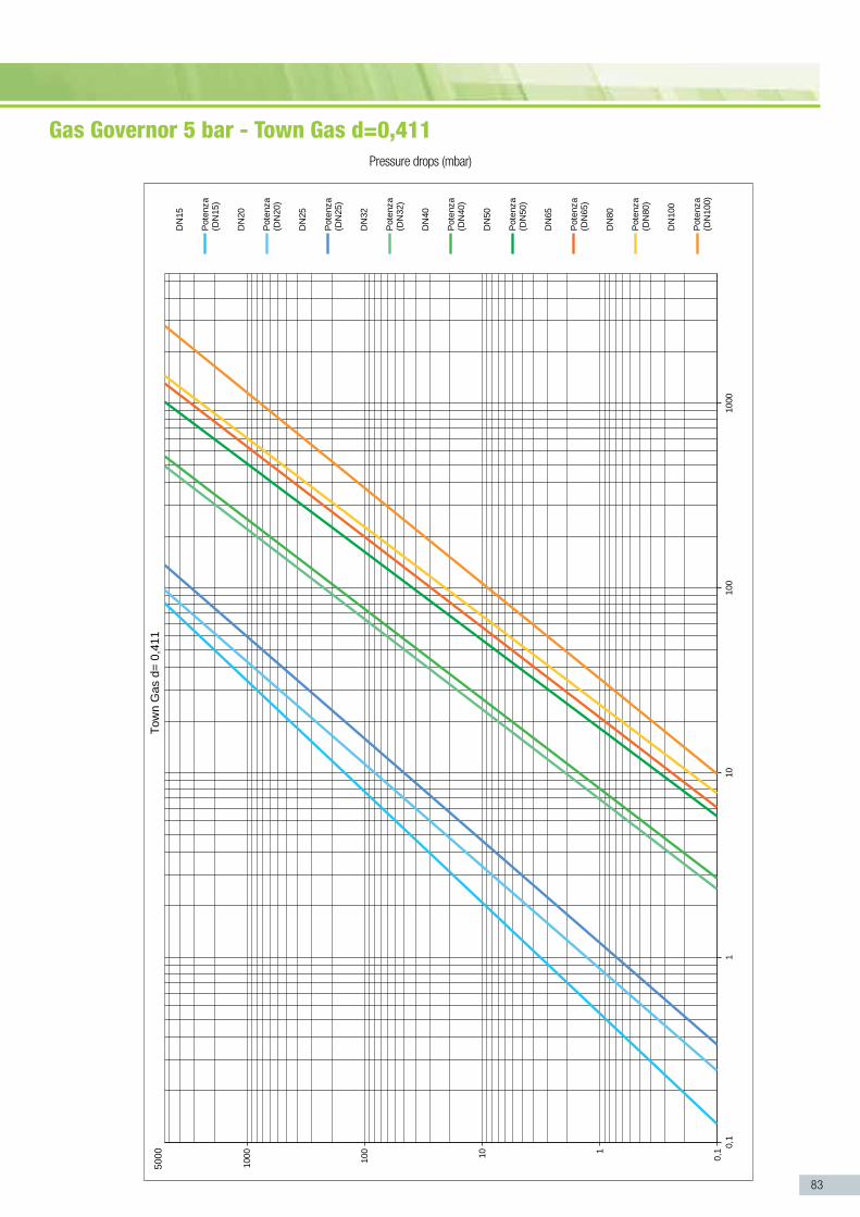
83
Gas Governor 5 bar - Town Gas d=0,411 Pressure drops (mbar)

84
G a s G o v e r n o r s
Gas Governor 5 bar - lPG d=1,58 Pressure drops (mbar)

85
Special versions
Electronic pressure gauge
Geca can produces gas governor with different connection specific for the different markets and applications. This solutions are on request.
Pressure gauges measure negative pressure, positive pressure and differential pressure of non-aggressive, gaseous. The manometer is used in production and extraction systems to measure different pressures or the pressure drop in gas flows. It is also used to check inlet and outlet pressure of gas governor, it is an ideal aid for adjusting burners, e.g. to check the burner pressure and the gas/air ratio etc.
power supply 4 AA batteries
battery life 25÷30 hours (constantly working)
range: 0 - 500 mbar
accuracy: ±1%
TEcHnIcal fEaTurEs

86
Gas Regulator with Slam Shut valve integrated for Over and under pressure›› The gas pressure regulators are spring-loaded gas regulators with balanced plug, diaphragm command and contrast action by spring, suitable for low and medium pressure. Regulator and shut-off device are supplied with internal sensing lines. Both regulator and shut-off device are preset for connection to an external sensor line by the customer. They are widely used either in civil or industrial plants, using natural gas or LPG or non-corrosive gas. This regulator is equipped with an integrated slam shut valve that closes in case pressure goes over or/and under the set point limit.

87
Gas regulator with slam shut valve integrated for over p. 88and under pressure - 1 ¼” , 1 ½” , 2” - Pmax 500 mbar
Gas Regulator with Slam Shut valve integrated for Over and under pressure
Gas R
egul
ator

88
Gas Regulator with Slam Shut valve integrated for Over and under pressure - 1 ¼” , 1 ½” , 2” - Pmax 500 mbar
G a s r e G U L a T o r s
pmax inlet max – 500 mbar
setting outlet 5 – 300 mbar – Standard spring supplied 10 – 27 mbar – Other spring on request
upso 10 - 60 mbar - Standar spring supplied 5 - 14 mbaropso 150 - 700 mbar - Standar spring supplied 150 - 250 mbar Others configuration on request
Inlet - outlet Thread gas 1 1⁄4” 11⁄2” - ISO 228 connection DN32 DN40 DN50 - connection Sliding Aluminium flange PN10
Test point Inlet / outlet on request – Test point 1/8” NPT
working Temperature - 20 °C – + 60 °C
use Not aggressive gases of three families – Natural Gas – LPG – Town Gas
approval UNI EN 88-1:2008 / PED
Materials:
complete body Die – Cast Aluminium Gd – AlSi12Cu - EN AB 46100
Diaphragms NBR 60Sh – DvGW EN 549
plastic components White POM / Pa 66 + 25% Gf
TEcHnIcal fEaTurEs code Description Dimension pmax
rG032-ssV Gas Regulator 1 1/4” 500 mbar
rG040-ssV Gas Regulator 1 1/2” 500 mbar
rG050-ssV Gas Regulator 2” 500 mbar
code Description Dimension pmax
rGD32-ssV Gas Regulator DN32 500 mbar
rGD40-ssV Gas Regulator DN40 500 mbar
rGD50-ssV Gas Regulator DN50 500 mbar
opso spring
Code: color range mbar spw2-5 White 5 - 14 mbar spy2-5 Yellow 6 - 22 mbar spn2-5 Neutral 10 - 27 mbarspr2-5 Red 28 - 70 mbarspbk2-5 Black 60 - 130 mbar spb2-5 Blue 120 - 300 mbar
Code: color range mbar spb2-o. Black 150 - 250 mbarspG2-o. Green 300 - 500 mbarspbr2-o. Brown 500 - 700 mbar
Other range on request
upso spring
Code: color range mbar spy2-u. Yellow 5 - 14 mbarspn2-u. Neutral 30 - 60 mbar

89
238 mm
223 mm
197
mm
415
mm
Dimension 1 ¼” 1 ½” 2”
wEIGHT (kgs) 4,57 4,52 4,4
1
6
9
14
15
17
2021
41
49
28
54
52
515042
4840 45
22
36
34
30
39
18
16
13
87
3
1 Seal cap 2 O-Ring 3 Spring compressor4 Washer 5 Screws6 Vent cap7 Upper cover 8 Plastic Washer 9 Safety diaphragm10 Calibrated nozzle 11 Washer 12 Disc 13 Compensation diaphragm 14 Upper Bush
15 Disc 16 Working diaphragm 17 Lower bush18 Cap 19 O-Ring20 Body21 Sensing Tube 22 Shaft 23 Seal washer24 Shaft-Insert Assembly 25 Spring 26 Nut27 Gasket 28 Cover
29 O-Ring 30 Release button 31 Spring32 Fitting 33 O-Ring34 Body 35 O-Ring 36 Reset knob 37 Seeger38 O-Ring 39 Release shaft 40 Levers assembly 41 Spring42 Shaft-membrane Assembly
43 O-Ring 44 Insert 45 Cap46 Screws 47 Washer48 Spring UPSO Min 49 Insert 50 Spring OPSO Max 51 Spring compressor UPSO52 Spring compressor53 O-Ring 54 Seal Cap

90
Gas Regulator with Slam Shut valve integrated for Over and under pressure - 5 bar

91
Gas regulator with slam shut valve integrated for over and under pressure - 1 ¼” , 1 ½” , 2” - Pmax 5 bar p. 92
91
Gas R
egul
ator

92
Gas Regulator with Slam Shut valve integrated for Over and Under pressure - 1 ¼” , 1 ½” , 2” - Pmax 5 bar
G a s R E G U L a T O R s
Pmax inlet max – 5 bar
Setting outlet 6 – 480 mbar – Standard spring supplied 10 – 27 mbar – Other spring on request
UPSO 10 - 60 mbar - Standar spring supplied 5 - 14 mbarOPSO 150 - 700 mbar - Standar spring supplied 150 - 250 mbar Others configuration on request
Inlet - Outlet Thread gas 1 1⁄4” 11⁄2” - ISO 228 connection DN32 DN40 DN50 - Connection Sliding Aluminium flange PN10
Test point Inlet / outlet on request – Test point 1/8” NPT
Working Temperature - 20 °C – + 60 °C
Use Not aggressive gases of three families – Natural Gas – LPG – Town Gas
Approval UNI EN 88-2:2008 / PED
Materials:
Complete Body Die – Cast Aluminium Gd – AlSi12Cu - EN AB 46100
Diaphragms NBR 60Sh – DvGW EN 549 Reinforced diaphragm
Plastic components White POM / Pa 66 + 25% Gf
TeChnICAl FeATUreS Code Description Dimension Pmax
rG032-5B-SSV Gas Regulator with SSV 1 1/4” 5 bar
rG040-5B-SSV Gas Regulator with SSV 1 1/2” 5 bar
rG050-5B-SSV Gas Regulator with SSV 2” 5 bar
Code Description Dimension Pmax
rGD32-5B-SSV Gas Regulator with SSV DN32 5 bar
rGD40-5B-SSV Gas Regulator with SSV DN40 5 bar
rGD50-5B-SSV Gas Regulator with SSV DN50 5 bar
Code: Color range mbar SPY2-12 Yellow 6 - 22 mbar SPn2-12 Neutral 10 - 27 mbarSPr2-12 Red 28 - 70 mbarSPBK2-12 Black 60 - 130 mbar SPG2-12 Green 120 - 300 mbarSPBr2-12 Brown 220 - 480 mbar
OPSO Spring
Code: Color range mbar SPB2-O. Black 150 - 250 mbarSPG2-O. Green 300 - 500 mbarSPBr2-O. Brown 500 - 700 mbar
Other range on request
UPSO Spring
Code: Color range mbar SPY2-U. Yellow 5 - 14 mbarSPn2-U. Neutral 30 - 60 mbar

93
238 mm
223 mm
197
mm
415
mm
1 Seal cap 2 O-Ring 3 Spring compressor4 Washer 5 Screws 6 Vent cap7 Upper cover 8 Plastic Washer 9 Safety diaphragm10 Calibrated nozzle 11 Washer 12 Disc 13 Compensation diaphragm 14 Upper Bush
15 Disc 16 Working diaphragm 17 Lower bush18 Cap 19 O-Ring20 Body21 Sensing Tube 22 Shaft 23 Seal washer24 Shaft-Insert Assembly 25 Spring 26 Nut27 Gasket 28 Cover
29 O-Ring 30 Release button 31 Spring32 Fitting 33 O-Ring34 Body 35 O-Ring 36 Reset knob 37 Seeger38 O-Ring 39 Release shaft 40 Levers assembly 41 Spring42 Shaft-membrane Assembly
43 O-Ring 44 Insert 45 Cap46 Screws 47 Washer48 Spring UPSO Min 49 Insert 50 Spring OPSO Max 51 Spring compressor UPSO52 Spring compressor53 O-Ring 54 Seal Cap
1
6
9
14
15
17
2021
41
49
28
54
52
515042
4840 45
22
36
34
30
39
18
16
13
87
3
Dimension 1 ¼” 1 ½” 2”
wEIGHT (kgs) 4,57 4,52 4,4

94
G a s r e G U L a T o r s
1 Seal cap
2 O-Ring
3 Spring compressor
4 Washer
5 Screws
6 Vent cap
7 Upper cover
8 Plastic Washer
9 Safety diaphragm
10 Calibrated nozzle
11 Washer
12 Disc
13 Compensation diaphragm
14 Upper Bush
15 Disc
16 Working diaphragm
17 Lower bush
18 Cap
19 O-Ring
20 Body
21 Sensing Tube
22 Shaft
23 Seal washer
24 Shaft-Insert Assembly
25 Spring
26 Nut
27 Gasket
28 Cover
29 O-Ring
30 Release button
31 Spring
32 Fitting
33 O-Ring
34 Body
35 O-Ring
36 Reset knob
37 Seeger
38 O-Ring
39 Release shaft
40 Levers assembly
41 Spring
42 Shaft-membrane Assembly
43 O-Ring
44 Insert
45 Cap
46 Screws M4
47 Washer
48 Spring UPSO Min
49 Insert
50 Spring OPSO Max
51 Spring compressor UPSO
52 Spring compressor
53 O-Ring
54 Seal Cap
ASSEmbly OVERVIEw
4
12
3
5
6
7
810
9
11
515
17 20
21
23 22
27
54
53
514829
5250494745
343736
35
32
30
5
28
25
24
19
18
16
14
13
12
26

95
48 50
52
54
53
514947
SETTINGS

96
G a s G o v e r n o r s
Gas Regulator 500 mbar & 5 bar - Air d=1 Pressure drops (mbar)

97
Gas Regulator 500 mbar & 5 bar - Natural Gas d=0,554 Pressure drops (mbar)

98
G a s G o v e r n o r s
Gas Regulator 500 mbar & 5 bar - Town Gas d=0,411 Pressure drops (mbar)

99
Gas Regulator 500 mbar & 5 bar - lPG d=1,58 Pressure drops (mbar)

Gas Filters›› Gas filters can be used for all the types of natural gas, LPG or not corrosive gases. These filters are widely used for protection of control devices, pressure regulators, meters and on systems that requiring an high degree of filtration.

101
Gas filter ½”, ¾”, 1” – small capacity – Pmax 6 bar p. 102
Gas filter ½”, ¾”, 1” – Pmax 6 bar p. 104
Gas filter 1 ¼”, 1 ½” and 2” – Pmax 6 bar p. 106
Gas filter dn65 – dn80 – dn100 – Pmax 6 bar p. 108
Gas filter dn125 – dn150 – Pmax 6 bar p. 110
Gas F
ilter
s

102
operation maximum pressure 6 bar / available version 10 bar
working Temperature - 20 °C – + 60 °C
filtration ≤ 50 Micron
use Non – aggressive gases – Family 1 – 2 – 3 and air
cartridge element Plastic cartidge PP
connection ½” – ¾” – 1” Wall boiler – ISO 228 complete body Die – Cast Aluminium Gd – AlSi12Cu – EN AB 46100
seals NBR
approval PED / EAC
GAS FIlTER ½”, ¾”, 1” – Small capacity – Pmax 6 bar
TEcHnIcal fEaTurEs
G a s F I L T e r s
code Description Dimension pmax
Gf015sc Gas filter small capacity ½” 6 bar
Gf020sc Gas filter small capacity ¾” 6 bar
Gf025sc Gas filter small capacity 1” 6 bar

103
Dimension ½” ¾” 1”
wEIGHT (kgs) 0,221 0,212 0,199
1
3
2
4
72 mm
60 m
m
65 m
m
1 Cover 2 Seal O ring 3 Filter cartridge 4 Body

104
operation maximum pressure 6 bar / available version 10 bar
working Temperature - 20 °C – + 60 °C
filtration 50 Micron
use Non – aggressive gases – Family 1 – 2 – 3 and air
cartridge element Viledon cartridge
Inlet - outlet Theread gas 1/2” – ¾” 1” – ISO 228connection DN25 - Sliding Aluminium flange PN10 complete body Die – Cast Aluminium Gd – AlSi12Cu - EN AB 46100
seals NBR
approval PED / EAC
Optional:
- Test point – NPT ¼”
- Screw – NPT ¼”
- Peters plug
- Manometer
- DP clogging indicator
›› .....
GAS FIlTER ½”, ¾”, 1” – Pmax 6 bar
TEcHnIcal fEaTurEs
G a s F I L T e r s
code Description Dimension pmax
Gf015 Gas filter ½” 6 bar
Gf020 Gas filter ¾” 6 bar
Gf025 Gas filter 1” 6 bar
GfD25 Gas filter DN25 6 bar
Gf015-TpIo Gas filter with test point in/out ½” 6 bar
Gf020-TpIo Gas filter with test point in/out ¾” 6 bar
Gf025-TpIo Gas filter with test point in/out 1” 6 bar
GfD25-TpIo Gas filter with test point in/out DN25 6 bar
Gf015-sp Gas filter with screw plugs ½” 6 bar
Gf020-sp Gas filter with screw plugs ¾” 6 bar
Gf025-sp Gas filter with screw plugs 1” 6 bar
GfD25-sp Gas filter with screw plugs DN25 6 bar

105
1
2
3
4
5
Dimension ½” ¾” 1”
wEIGHT (kgs) 0,806 0,795 0,786
116 mm
104
mm
119
mm
1 Test point connection 2 Seal O ring 3 Filter cartridge 4 Body5 Cover

106
GAS FIlTER 1 ¼”, 1 ½” and 2” – Pmax 6 bar
G a s F I L T e r s
operation maximum pressure 6 bar / available version 10 bar
working Temperature - 20 °C – + 60 °C
filtration 50 Micron
use Non – aggressive gases – Family 1 – 2 – 3 and air
cartridge element Viledon cartridge
Inlet - outlet Thread gas 1 ¼” 1 ½” 2” – ISO 228connection DN32 DN40 DN50 - Sliding Aluminium flange PN10 complete body Die – Cast Aluminium Gd – AlSi12Cu - EN AB 46100
seals NBR
approval PED / EAC
Optional:
- Test point – NPT ¼”
- Screw – NPT ¼”
- Peters plug
- Manometer
- DP clogging indicator
›› ..... TEcHnIcal fEaTurEs code Description Dimension pmax
Gf032 Gas filter 1 ¼” 6 bar
Gf040 Gas filter 1 ½” 6 bar
Gf050 Gas filter 2” 6 bar
GfD32 Gas filter DN32 6 bar
GfD40 Gas filter DN40 6 bar
GfD50 Gas filter DN50 6 bar
Gf032-TpIo Gas filter with test point in/out 1 ¼” 6 bar
Gf040-TpIo Gas filter with test point in/out 1 ½” 6 bar
Gf050-TpIo Gas filter with test point in/out 2” 6 bar
GfD32-TpIo Gas filter with test point in/out DN32 6 bar
GfD40-TpIo Gas filter with test point in/out DN40 6 bar
GfD50-TpIo Gas filter with test point in/out DN50 6 bar
Gf032-sp Gas filter with screw plugs 1 ¼” 6 bar
Gf040-sp Gas filter with screw plugs 1 ½” 6 bar
Gf050-sp Gas filter with screw plugs 2” 6 bar
GfD32-sp Gas filter with screw plugs DN32 6 bar
GfD40-sp Gas filter with screw plugs DN40 6 bar
GfD50-sp Gas filter with screw plugs DN50 6 bar

107
Dimension 1 ¼” 1 ½” 2”
wEIGHT (kgs) 1,63 1,55 1,45
155
164
132
1
2
4
3
5
164 mm
132
mm
155
mm
1 Test point connection 2 Seal O ring 3 Filter cartridge 4 Body5 Cover

108
operation maximum pressure 6 bar / available version 10 bar
working Temperature - 20 °C – + 60 °C
filtration 50 Micron
use Non – aggressive gases – Family 1 – 2 – 3 and air
cartridge element Viledon cartridge
connection Flanged PN16 – DN65 – DN80 – DN100 complete body Die – Cast Aluminium Gd – AlSi12Cu – ENAB46100
seals NBR
approval PED / EAC
Optional:
- Test point – NPT ¼”
- Screw – NPT ¼”
- Peters plug
- Manometer
- DP clogging indicator
GAS FIlTER DN65 – DN80 – DN100 – Pmax 6 bar
TEcHnIcal fEaTurEs
G a s F I L T e r s
›› ..... code Description Dimension pmax
GfD65 Gas filter DN65 6 bar
GfD80 Gas filter DN80 6 bar
GfD100 Gas filter DN100 6 bar
GfD65-TpIo Gas filter with test point in/out DN65 6 bar
GfD80-TpIo Gas filter with test point in/out DN80 6 bar
GfD100-TpIo Gas filter with test point in/out DN100 6 bar
GfD65-sp Gas filter with screw plugs DN65 6 bar
GfD80-sp Gas filter with screw plugs DN80 6 bar
GfD100-sp Gas filter with screw plugs DN100 6 bar

109
Dimension Dn65 Dn80 Dn100
wEIGHT (kgs) 7,90 7,80 6,80
1
2
4
3
5
350 mm
162
mm
220
mm
1 Test point connection 2 Seal O ring 3 Filter cartridge 4 Body5 Cover

110
operation maximum pressure 6 bar
working Temperature - 20 °C – + 60 °C
filtration 50 Micron
use Non – aggressive gases – Family 1 – 2 – 3 and air
cartridge element Viledon cartridge
connection Flanged PN16 – DN125 – DN150 complete body Aluminium EN AC 43100
seals NBR
approval PED / EAC
Optional:
- Test point – NPT ¼”
- Screw – NPT ¼”
- Peters plug
- Manometer
- DP clogging indicator
GAS FIlTER DN125 – DN150 – Pmax 6 bar
TEcHnIcal fEaTurEs
G a s F I L T e r s
›› ..... code Description Dimension pmax
GfD125 Gas filter DN125 6 bar
GfD150 Gas filter DN150 6 bar
GfD125-TpIo Gas filter with test point in/out DN125 6 bar
GfD150-TpIo Gas filter with test point in/out DN150 6 bar
GfD125-sp Gas filter with screw plugs DN125 6 bar
GfD150-sp Gas filter with screw plugs DN150 6 bar

111
445
350
335
Dimension Dn125 Dn150
wEIGHT (kgs) 23 21
1
2
4
3
5
443/445 mm
348
mm
330
mm
1 Test point connection 2 Seal O ring 3 Filter cartridge 4 Body5 Cover

112
1
2
3
5
4
G a s F I L T e r s
1 Body2 Filter3 O ring4 Cover5 Screws
ASSEmbly OVERVIEw

113
code packaging Dimension (lxwxH) cm weight dimension (kg) packaging
GF015SC – GF020SC – GF025SC 29,5x41x14 11,6 46 units
GF015 – GF020 – GF025 65x26x17 9,4 10 units
GF032 – GF040 – GF050 17x16x16,5 2 1 unit
GFD32 – GFD40 – GFD50 23,5x28,5x25 4,4 1 unit
GFD65 – GFD80 23,5x28,5x25 8,1 1 unit
GFD100 23,5x28,5x25 7,1 1 unit
GFD125 46x36x55 21,5 1 unit
GFD150 46x36x55 23,5 1 unit
CODE DESCRIPTION
PACkING DImENSION
1 3GF=GAS FILTER DIMENSIONS:
015SC =1/2”(Small Capacity)
020SC =3/4”(Small Capacity)
025SC = 1” (Small Capacity)
015 = 1/2”020 = 3/4”025= 1”25= DN25032= 1 1/4”32= DN32040= 11/2”40= DN40050= 2”50= DN5065= DN6580 = DN80100= DN100125= DN125150= DN150
4 OPTIONAL:
SP= Screw PlugsTPIO=Test Point IN/OUT
5 BAR:
= 6bar-10B= 10bar
GFD050-TPIO-10B
3 4 51 2
CONNECTION:
=ThreadedD= Flanged
2

114
G a s F I L T e r s
code Description Dimension pmax
Gf015 Gas filter ½” 6 bar
Gf020 Gas filter ¾” 6 bar
Gf025 Gas filter 1” 6 bar
GfD25 Gas filter DN25 6 bar
code Description Dimension pmax
Gf032 Gas filter 1 ¼” 6 bar
Gf040 Gas filter 1 ½” 6 bar
Gf050 Gas filter 2” 6 bar
GfD32 Gas filter DN32 6 bar
GfD40 Gas filter DN40 6 bar
GfD50 Gas filter DN50 6 bar
code Description Dimension pmax
GfD65 Gas filter DN65 6 bar
GfD80 Gas filter DN80 6 bar
GfD100 Gas filter DN100 6 bar
code Description Dimension pmax
GfD125 Gas filter DN125 6 bar
GfD150 Gas filter DN150 6 bar
GAS FIlTER Standard version

115
code Description Dimension pmax
Gf015-TpIo Gas filter with test point in/out ½” 6 bar
Gf020-TpIo Gas filter with test point in/out ¾” 6 bar
Gf025-TpIo Gas filter with test point in/out 1” 6 bar
GfD25-TpIo Gas filter with test point in/out DN25 6 bar
code Description Dimension pmax
Gf032-TpIo Gas filter with test point in/out 1 ¼” 6 bar
Gf040-TpIo Gas filter with test point in/out 1 ½” 6 bar
Gf050-TpIo Gas filter with test point in/out 2” 6 bar
GfD32-TpIo Gas filter with test point in/out DN32 6 bar
GfD40-TpIo Gas filter with test point in/out DN40 6 bar
GfD50-TpIo Gas filter with test point in/out DN50 6 bar
code Description Dimension pmax
GfD65-TpIo Gas filter with test point in/out DN65 6 bar
GfD80-TpIo Gas filter with test point in/out DN80 6 bar
GfD100-TpIo Gas filter with test point in/out DN100 6 bar
code Description Dimension pmax
GfD125-TpIo Gas filter with test point in/out DN125 6 bar
GfD150-TpIo Gas filter with test point in/out DN150 6 bar
GAS FIlTER Test Point Inlet / Outlet version - TPIO

116
G a s F I L T e r s
code Description Dimension pmax
Gf015-sp Gas filter with screw plugs ½” 6 bar
Gf020-sp Gas filter with screw plugs ¾” 6 bar
Gf025-sp Gas filter with screw plugs 1” 6 bar
GfD25-sp Gas filter with screw plugs DN25 6 bar
code Description Dimension pmax
Gf032-sp Gas filter with screw plugs 1 ¼” 6 bar
Gf040-sp Gas filter with screw plugs 1 ½” 6 bar
Gf050-sp Gas filter with screw plugs 2” 6 bar
GfD32-sp Gas filter with screw plugs DN32 6 bar
GfD40-sp Gas filter with screw plugs DN40 6 bar
GfD50-sp Gas filter with screw plugs DN50 6 bar
code Description Dimension pmax
GfD65-sp Gas filter with screw plugs DN65 6 bar
GfD80-sp Gas filter with screw plugs DN80 6 bar
GfD100-sp Gas filter with screw plugs DN100 6 bar
code Description Dimension pmax
GfD125-sp Gas filter with screw plugs DN125 6 bar
GfD150-sp Gas filter with screw plugs DN150 6 bar
GAS FIlTER Screw plugs version - SP

117
code Description Dimension pmax
Gf015-pp Gas filter with Peterson Plug ½” 6 bar
Gf020-pp Gas filter with Peterson Plug ¾” 6 bar
Gf025-pp Gas filter with Peterson Plug 1” 6 bar
GfD25-pp Gas filter with Peterson Plug DN25 6 bar
code Description Dimension pmax
Gf032-pp Gas filter with Peterson Plug 1 ¼” 6 bar
Gf040-pp Gas filter with Peterson Plug 1 ½” 6 bar
Gf050-pp Gas filter with Peterson Plug 2” 6 bar
GfD32-pp Gas filter with Peterson Plug DN32 6 bar
GfD40-pp Gas filter with Peterson Plug DN40 6 bar
GfD50-pp Gas filter with Peterson Plug DN50 6 bar
code Description Dimension pmax
GfD65-pp Gas filter with Peterson Plug DN65 6 bar
GfD80-pp Gas filter with Peterson Plug DN80 6 bar
GfD100-pp Gas filter with Peterson Plug DN100 6 bar
code Description Dimension pmax
GfD125-pp Gas filter with Peterson Plug DN125 6 bar
GfD150-pp Gas filter with Peterson Plug DN150 6 bar
GAS FIlTER Peterson plugs version - PP

118
G a s F I L T e r s
GAS FIlTER SC ½”, ¾”, 1”
Natural gas CH4 (d=
0,544)
Propane C3 H
8 (d=1,522)
Town gas (d=
0,411)
Air (d=1)
Pressure drops (mbar)Capacity Q (Nmc/h)

119
GAS FIlTER ½”, ¾”, 1”Pressure drops (mbar) Capacity Q (Nmc/h)
Prop
ane
C 3 H 8 (
d=1,
522)
Tow
n ga
s (d
=0,
411)
Air (
d=1)
Natu
ral g
as C
H 4 (d=
0,54
4)

120
G a s F I L T e r s
GAS FIlTER 1 ¼”, 1 ½”, 2”
Natural gas CH4 (d=
0,544)
Propane C3 H
8 (d=1,522)
Town gas (d=
0,411)
Air (d=1)
Pressure drops (mbar)Capacity Q (Nmc/h)

121
GAS FIlTER DN65, DN80, DN100
Cap
acity
Nat
ural
gas
Gas
di c
ittà
dv: 0
,45
Aria
dv:
1G
.P.L
. dv:
1,5
6
Δp
(mb
ar)

122
G a s F I L T e r s
GAS FIlTER DN125 -DN150
Natural gas CH4 (d=
0,544)
Propane C3 H
8 (d=1,522)
Town gas (d=
0,411)
Air (d=1)
Pressure drops (mbar)Capacity Q (Nmc/h)

123
G a s F I L T e r s
DP ClOGGING INDICATOR
FIlTER CARTRIDGE
Our filter cartridge is in Viledon with Metallic grid and textile filter element
DP ClOGGING INDICATOR
code Description connection range
DpI-150 Aluminium body - PN20 ¼” 0 – 150 mbar
DpI-300 Aluminium body - PN20 ¼” 0 – 300 mbar
DpI-600 Aluminium body – PN20 ¼” 0 – 600 mbar
DpI-1000 Aluminium body – PN20 ¼” 0 – 1000 mbar
FIlTER CARTRIDGE
code Description model
fc – 1 Filter cartridge 50 µm GF015SC - GF020SC - GF025SC
fc – 2 Filter cartridge 50µm GF015 - GF020 - GF025 –GFD25
fc – 3 Filter cartridge 50 µm GF032 - GF040 - GF050 –GFD version
fc – 4 Filter cartridge 50 µm GFD65 – GFD80
fc – 5 Filter cartridge 50 µm GFD100
fc – 6 Filter cartridge 50 µm GFD125 – GFD150
DP ClOGGING INDICATOR with reed switch.
code Description connection range
DpI-150-rs Aluminium body - PN20 ¼” 0 – 150 mbar
DpI-300-rs Aluminium body - PN20 ¼” 0 – 300 mbar
DpI-600-rs Aluminium body – PN20 ¼” 0 – 600 mbar
DpI-1000-rs Aluminium body – PN20 ¼” 0 – 1000 mbar

Automatic gas valve - Brass Body›› Automatic gas solenoid valves are used for safety and control of gas for shut-off in gas feed pipes. Suitable for various gasses, including Natural gas, Propane and LPG Gas solenoid valve normally closed solenoid that open automatically when the coil is powered and close automatically when there is no tension.

125
automatic Gas solenoid valve ½”, ¾” p. 126 Brass Body - PmaX 200 mBar
Auto
matic
gas v
alve -
Bra
ss B
ody

126
Automatic gas solenoid valve ½”, ¾” - brass body - pmax 200 mbar
a U T o M a T I C s o L e n o I D v a L v e s
Type connections flow (m3/h) max pressure
aV015 1/2" 4,5 200 mbar
aV020 3/4" 6 200 mbar
DImEnsIons (mm) and wEIGHT (kgs)
Dimension a b ø
aV015 59 107 DN15 - ½’’
aVo20 59 107 DN20 - ¾’’
AxB59x10759x107
φφφφφ
DN15 - 1/2”DN20 - 3/4”
Misure d’ingombro in mmAttacchi filettati secondo ISO 228/1Corpo in ottone.
Pmax/Max pressure: 1,5 BarElettrovalvole N.C.
1,5 Bar
Dimensioni
B
A
φφφφφ
pmax 200 mbar
Inlet connection - outlet Thread gas ½” ¾” and 1” - ISO 228
opening time <1 second closing time <1 second
max number of operations 30 per minute
supply voltage 230V (-15%+10%) 50-60Hz 110V (-15%+10%) 50-60Hz 24Vdc (-15%+10%) 50-60Hz
power 15 VA Coils to class F copper wire class H
use Non – aggressive gases – Family 1 – 2 – 3 and air
working Temperature - 20 °C – 60 °C
approval EN161 / PED / EAC
protection degree IP65
Materials:
complete body Brass ST-CW617N – EN 12420 – Yellow Painted
TEcHnIcal fEaTurEs
Dimension ½” ¾”
wEIGHT (kgs) 0,8 0,8

127
Capacity Q (Nmc/h)
Perdite di carico (mbar)
3
83
4
Port
ata
Q (S
m /h
)
Gas d
i citt
a' (d
=0.4
11)
Prop
ano
C H
(d=1
.522
)
Met
ano
CH (
d=0.
544)
Aria
(d=1
)
Perdite di carico (mbar)
3
83
4
Port
ata
Q (S
m /h
)
Gas d
i citt
a' (d
=0.4
11)
Prop
ano
C H
(d=1
.522
)
Met
ano
CH (
d=0.
544)
Aria
(d=1
)
Pressure drops (mbar)
Prop
ane
C 3 H 8 (
d=1,
522)
Tow
n ga
s (d
=0,
411)
Air (
d=1)
Natu
ral g
as C
H 4 (d=
0,54
4)

Automatic Gas Valves -Pmax 360 mbar›› Automatic gas solenoid valves are used for safety and control of gas for shut-off in gas feed pipes. Suitable for various gasses, including Natural gas, Propane and LPG Gas solenoid valve normally closed solenoid that open automatically when the coil is powered and close automatically when there is no tension.

automatic Gas valves fast opening / fast closing p. 130 ½”, ¾” and 1” – Pmax 360 mbar
automatic Gas valves - hiGh caPacity p. 132fast opening / fast closing ½”, ¾” and 1”Pmax 360 mbar
automatic Gas valves fast opening / fast closing p. 1341 ¼”, 1 ½” and 2” – Pmax 360 mbar
automatic Gas valves fast opening / fast closing p. 136coil encapsulated with fibre-glass reinforced polyamide 1 ¼”, 1 ½” – Pmax 360 mbar
automatic Gas valves fast opening / fast closing p. 138 dn65, dn80, dn100 – Pmax 360 mbar
129
Auto
matic
Gas
Valve
s

130
AuTOmATIC GAS VAlVES Fast Opening / Fast Closing ½”, ¾” and 1” – Pmax 360 mbar
a U T o M a T I C G a s v a L v e s
pmax 360 mbar
Inlet connection Thread gas ½” ¾” and 1” - ISO 228- outlet DN25 - Sliding Aluminium flange PN10
opening time <1 second closing time <1 second
max number of operations 20 per minute
Incorporated AISI 303 steel mesh filter on request
supply voltage 230V (-15%+10%) 50-60Hz 110V (-15%+10%) 50-60Hz 24Vdc (-15%+10%) 50-60Hz
power 15 VA Coils to class F copper wire class H
use Non – aggressive gases – Family 1 – 2 – 3 and air
Test point 2 connections - options 3 connections Screw ¼”
working Temperature - 20 °C – 60 °C
approval EN161 / PED / EAC
protection degree IP65
Materials:
complete body Die – Cast Aluminium Gd – AlSi12Cu - EN AB 46100
TEcHnIcal fEaTurEs code Description Dimension pmax
aV015fo Gas valve fast opening ½” 360 mbar
aV020fo Gas valve fast opening ¾” 360 mbar
aV025fo Gas valve fast opening 1” 360 mbar
aVD25fo Gas valve fast opening DN25 360 mbar
aV015fo-fr Gas valve fast opening Flow regulation ½” 360 mbar
aV020fo-fr Gas valve fast opening Flow regulation ¾” 360 mbar
aV025fo-fr Gas valve fast opening Flow regulation 1” 360 mbar
aVD25fo-fr Gas valve fast opening Flow regulation DN25 360 mbar
cpI-1 Control position indicator

131
149
mm
68 m
m
72 mm
1 Body 2 O-Ring3 Cover4 Gasket5 Plunger6 Spring7 O-Ring8 Pilot
9 O-Ring10 Coil11 O-Ring12 Washer13 Screw14 Connector
Dimension ½” ¾” 1”
wEIGHT (kgs) 0,8 0,8 0,8
1
3
4
7
9
10
12
13
11
8
6
5
2
14

132
AuTOmATIC GAS VAlVES - High Capacity - Fast Opening / Fast Closing½”, ¾”, 1” - Pmax 360 mbar
a U T o M a T I C G a s v a L v e s
pmax 360 mbar
Inlet connection Thread gas ½” ¾” and 1” - ISO 228- outlet DN25 - Sliding Aluminium flange PN10
opening time <1 second closing time <1 second
max number of operations 20 per minute
Incorporated AISI 303 steel mesh filter on request
supply voltage 230V (-15%+10%) 50-60Hz 110V (-15%+10%) 50-60Hz 24Vdc (-15%+10%) 50-60Hz
power 25W Coils to class F copper wire class H
use Non – aggressive gases – Family 1 – 2 – 3 and air
Test point 3 connections options 5 connections Screw ¼”
working Temperature - 20 °C – 60 °C
approval EN161 / PED / EAC
protection degree IP65
Materials:
complete body Die – Cast Aluminium Gd – AlSi12Cu - EN AB 46100
TEcHnIcal fEaTurEs code Description Dimension pmax
aV015fo-Hc Gas valve fast opening ½” 360 mbar
aV020fo-Hc Gas valve fast opening ¾” 360 mbar
aV025fo-Hc Gas valve fast opening 1” 360 mbar
aVD25fo-Hc Gas valve fast opening DN25 360 mbar
aV015fo-fr-Hc Gas valve fast opening Flow regulation ½” 360 mbar
aV020fo-fr-Hc Gas valve fast opening Flow regulation ¾” 360 mbar
aV025fo-fr-Hc Gas valve fast opening Flow regulation 1” 360 mbar
aVD25fo-fr-Hc Gas valve fast opening Flow regulation DN25 360 mbar
cpI-1-Hc Control position indicator

133133
173
mm
98 m
m
73 m
m
93 mm
115 mm
1 Body 2 O-Ring3 Cover4 Gasket5 Plunger6 Spring7 O-Ring8 Pilot
9 O-Ring10 Coil11 O-Ring12 Locking Ring13 Connector
Dimension ½” ¾” 1”
wEIGHT (kgs) 2,1 2 1,8
1
3
4
7
9
10
12
11
8
6
5
2
13

134
AuTOmATIC GAS VAlVES Fast Opening / Fast Closing 1 ¼”, 1 ½” and 2” – Pmax 360 mbar
a U T o M a T I C G a s v a L v e s
pmax 360 mbar
Inlet connection Thread gas 1 ¼”, 1 ½” and 2” - ISO 228-outlet DN32 DN40 DN50 - Sliding Aluminium flange PN10
opening time <1 second closing time <1 second
max number of operations 20 per minute
Incorporated AISI 303 steel mesh filter on request
supply voltage 230V (-15%+10%) 50-60Hz 110V (-15%+10%) 50-60Hz 24Vdc (-15%+10%) 50-60Hz
power 230Vac1 1/4"-11/2"-PeakPower40W- Maintain power4W 2"-Peakpower130W- Maintain power 1,5W Coils to class F copper wire class H
use Non – aggressive gases – Family 1 – 2 – 3 and air
Test point 5 connections Screw ¼”
working Temperature - 20 °C – 60 °C
approval EN161 / PED / EAC
protection degree IP65
Materials:
complete body Die – Cast Aluminium Gd – AlSi12Cu - EN AB 46100
TEcHnIcal fEaTurEs code Description Dimension pmax
aV032fo Gas valve fast opening 1 ¼” 360 mbar
aV040fo Gas valve fast opening 1 ½” 360 mbar
aV050fo Gas valve fast opening 2” 360 mbar
aVD32fo Gas valve fast opening DN32 360 mbar
aVD40fo Gas valve fast opening DN40 360 mbar
aVD50fo Gas valve fast opening DN50 360 mbar
aV032fo-fr Gas valve fast opening Flow regulation 1 ¼” 360 mbar
aV040fo-fr Gas valve fast opening Flow regulation 1 ½” 360 mbar
aV050fo-fr Gas valve fast opening Flow regulation 2” 360 mbar
aVD32fo-fr Gas valve fast opening Flow regulation DN32 360 mbar
aVD40fo-fr Gas valve fast opening Flow regulation DN40 360 mbar
aVD50fo-fr Gas valve fast opening Flow regulation DN50 360 mbar
cpI-2 Control position indicator

135
245
mm
155
mm
165 mm
Dimension 1 ¼” 1 ½” 2”
wEIGHT (kgs) 4,2 4,2 4,6
1 Body 2 Screw Plugs3 O-Ring4 Plunger5 Spring6 Cover7 Screw
8 O-Ring9 Pilot10 Coil11 O-Ring 12 Locking Ring13 Gasket14 Connector
1
3
4
7
9
10
12
14
13
11
86
5
2

136
AuTOmATIC GAS VAlVES Fast Opening / Fast Closing - Coil encapsulated with fibre-glass reinforced polyamide 1 ¼”, 1 ½” – Pmax 360 mbar
a U T o M a T I C G a s v a L v e s
pmax 360 mbar
Inlet connection Thread gas 1 ¼”, 1 ½” - ISO 228-outlet DN32 DN40 - Sliding Aluminium flange PN10
opening time <1 second closing time <1 second
max number of operations 20 per minute
Incorporated AISI 303 steel mesh filter on request
supply voltage 230V (-15%+10%) 50-60Hz
power 37W Coils to class F copper wire class H
use Non – aggressive gases – Family 1 – 2 – 3 and air
Test point 5 connections Screw ¼”
working Temperature - 20 °C – 60 °C
approval EN161 / PED / EAC
protection degree IP65
Materials:
complete body Die – Cast Aluminium Gd – AlSi12Cu - EN AB 46100
TEcHnIcal fEaTurEs code Description Dimension pmax
aV032fo-Ec Gas valve fast opening 1 ¼” 360 mbar
aV040fo-Ec Gas valve fast opening 1 ½” 360 mbar
aVD32fo-Ec Gas valve fast opening DN32 360 mbar
aVD40fo-Ec Gas valve fast opening DN40 360 mbar
cpI-2 Control position indicator

137
245
mm
155
mm
165 mm
Dimension 1 ¼” 1 ½”
wEIGHT (kgs) 4,0 4,0
1 Body 2 Screw Plugs3 O-Ring4 Plunger5 Spring6 Cover7 Screw
8 O-Ring9 Pilot10 Coil11 O-Ring 12 Locking Ring13 Gasket14 Connector
1
3
4
7
9
10
12
14
13
11
86
5
2

138
TEcHnIcal fEaTurEs
AuTOmATIC GAS VAlVES Fast Opening / Fast Closing DN65, DN80, DN100 – Pmax 360 mbar
a U T o M a T I C G a s v a L v e s
pmax 360 mbar
Inlet connection Flanged – DN65 – DN80 – DN100 – PN16outlet Flanged – DN65 – DN80 – DN100 – PN16
opening time <1 second closing time <1 second
max number of operations 15 per minute
Incorporated aIsI 303 steel mesh filter
supply voltage 230V (-15%+10%) 50-60Hz. 110V (-15%+10%) 50-60Hz. 24Vdc (-15%+10%) 50-60Hz
power 230Vac DN65 - DN80 - DN100 Peak power 400W - Maintain power 4W Coils to class F copper wire class H
use Non – aggressive gases – Family 1 – 2 – 3 and air
Test point 5 connections Screw ¼”
working Temperature - 20 °C – 60 °C
approval EN161 / PED / EAC
protection degree IP65
Materials:
complete body Aluminium EN AC 43100
TEcHnIcal fEaTurEs code Description Dimension pmax
aVD65fo Gas valve fast opening DN65 360 mbar
aVD80fo Gas valve fast opening DN80 360 mbar
aVD100fo Gas valve fast opening DN100 360 mbar
aVD65fo-fr Gas valve fast opening Flow regulation DN65 360 mbar
aVD80fo-fr Gas valve fast opening Flow regulation DN80 360 mbar
aVD100fo-fr Gas valve fast opening Flow regulation DN100 360 mbar
cpI-3 Control position indicator DN65-DN80
cpI-4 Control position indicator DN100

139
395
mm
220
mm
350 mm
1 Body2 Screw Plugs3 O-Ring4 Plunger5 Spring6 Cover7 Screw
8 O-Ring9 Pilot10 Coil11 O-Ring12 Locking Ring13 Gasket14 Connector
Dimension Dn65 Dn80 Dn100
wEIGHT (kgs) 9,6 9,6 15,8
1
3
4
7
9
10
12
13
1411
8 6
2
5
2

140
9
10
11
12
15
16
17
13
14
1
2
2
3
4
2
2
2
6
5
7
8
8
a U T o M a T I C G a s v a L v e s
1 Body2 Screw Plugs3 O-Ring4 Plunger5 Spring 6 Cover7 Screw8 O-Ring9 Pilot
10 Coil11 O-Ring12 Locking Ring13 Gasket14 Nut15 Insert16 O-Ring17 Washer
ASSEmbly OVERVIEw

141
SPARE PARTS – ACCESSORIES
CPI CONTROl POSITION INDICATOR
COIl
code Description model
20502719 Coil 230 Vac ½” - 3/4” – 1”
80501589 Coil 230 Vac 1 ¼” – 1 ½”
80501590 Coil 230 Vac 2”
80501591 Coil 230 Vac DN65 – DN80
80501592 Coil 230 Vac DN100
code Description model
cp1 – 1 Control position indicator ½” , ¾” , 1”
cp1 – 1Hc Control position indicator ½” , ¾” , 1”, HC
cp1 – 2 Control position indicator 1 ¼” , 1 ½” ,2”
cp1 – 3 Control position indicator DN65 –DN80
cp1 – 4 Control position indicator DN100
COIl – ElECTRONIC bOARD – PlASTIC COVER
code Description model
80521593 Coil – Electronic board – Plastic cover 1 ¼” – 1 ½”
80521594 Coil – Electronic board – Plastic cover 2”
80521595 Coil – Electronic board – Plastic cover DN65 – DN80
80521596 Coil – Electronic board – Plastic cover DN100
ElECTRONIC bOARD
code Description model
21802429 Electronic board 230 Vac ½” - 3/4” – 1”
81801620 Electronic board - 230 Vac 1 ¼” – 1 ½”
81801621 Electronic board - 230 Vac 2”
81801622 Electronic board - 230 Vac DN65 – DN80
81801623 Electronic board - 230 Vac DN100
FlOw RATE ADJuSTmENT:
INSTAllATION
The model FR is possible to adjust the gas flow.The flow setting is done by turning the “Regulation shaft" (1)
Remove the “Plastic cap”
1 1
To increase the flow unscrew the “Regulation shaft”: To decrease the flow screw the “Regulation shaft":
connEcTIon HorIzonTal posITIon VErTIcal posITIon oVErTurnED posITIon
from 1/2” to DN100 NONO

142
a U T o M a T I C G a s v a L v e s
CODE DESCRIPTION
1 Automatic Valves
mod:__=without Flow Regulation-FR=with Flow Regulation
___=360mbar-6B =6bar
Dimension:015 =1/2”020 =3/4”025= 1”032= 11/4”040= 11/2”050= 2”D65=DN65D80=DN80D100=DN100
FO=Fast Opening
Power supply:___ = 230Vac-110Vac-12Vac-12Vdc-24Vac-24Vdc
3 5
AV015FO-FR-6B-110Vac
1 2 3 4 5 6
2 4 6
code packaging Dimension (lxwxH) cm weight (kg) packaging
AV015FO – AV020FO – AV025FO 8x15x8 0,9 1 unit
AV032FO – AV040FO 16,5x16x26 4,4 1 unit
AV015FO-HC - AV020FOHC - AV025FO-HC 19x12x10 2,2 1 unit
AV032FO-EC – AV040FO-EC 16,5x16x26 4,0 1 unit
AV050FO 16,5x16x26 4,8 1 unit
AVD32FO – AVD40FO 23,5x28,5x25 6,8 1 unit
AVD32FO-EC – AVD40FO-EC 23,5x28,5x25 6,4 1 unit
AVD50FO 23,5x28,5x25 7,2 1 unit
AVD65FO – AVD80FO 41x22,5 9,8 1 unit
AVD100FO 29x26x46 16 1 unit
PACkING DImENSION

143
AuTOmATIC VAlVE ½”, ¾”, 1”Capacity Q (Nmc/h)Pressure drops (mbar)
Prop
ane
C 3 H 8 (
d=1,
522)
Tow
n ga
s (d
=0,
411)
Air (
d=1)
Natu
ral g
as C
H 4 (d=
0,54
4)

144
a U T o M a T I C G a s v a L v e s
AuTOmATIC VAlVE 1 ¼”, 1 ½”, 2”
Propane C3 H
8 (d=1,522)
Town gas (d=
0,411)
Air (d=1)
Natural gas CH4 (d=
0,544)

145
AuTOmATIC VAlVE DN65, DN80, DN100Capacity Q (Nmc/h)Pressure drops (mbar)
Prop
ane
C 3 H 8 (
d=1,
522)
Tow
n ga
s (d
=0,
411)
Air (
d=1)
Natu
ral g
as C
H 4 (d=
0,54
4)

Automatic Gas Valves - Pmax 6 bar›› Automatic gas solenoid valves are used for safety and control of gas for shut-off in gas feed pipes. Suitable for various gasses, including Natural gas, Propane and LPG Gas solenoid valve normally closed solenoid that open automatically when the coil is powered and close automatically when there is no tension.

147
automatic Gas valves fast opening / fast closing p. 148½”, ¾” and 1” – Pmax 6 bar
automatic Gas valves fast opening / fast closing p. 150 1 ¼”, 1 ½” and 2” – Pmax 6 bar
147
Auto
matic
Gas
Valve
s

148
AuTOmATIC GAS VAlVES Fast Opening / Fast Closing ½”, ¾” and 1” – Pmax 6 bar
a U T o M a T I C G a s v a L v e s
pmax 6 bar
Inlet connection - outlet Thread gas ½” ¾” and 1” - ISO 228 DN25 - Sliding Aluminium flange PN10
opening time <1 second closing time <1 second
max number of operations 20 per minute
Incorporated AISI 303 steel mesh filter on request
supply voltage 230V (-15%+10%) 50-60Hz 110V (-15%+10%) 50-60Hz 24Vdc (-15%+10%) 50-60Hz
power 15 VA Coils to class F copper wire class H
use Non – aggressive gases – Family 1 – 2 – 3 and air
Test point 2 connections - options 3 connections Screw ¼”
working Temperature - 20 °C – 60 °C
approval EN161 / PED / EAC
protection degree IP65
Materials:
complete body Die – Cast Aluminium Gd – AlSi12Cu - EN AB 46100
TEcHnIcal fEaTurEs code Description Dimension pmax
aV015fo-6b Gas valve fast opening ½” 6 bar
aV020fo-6b Gas valve fast opening ¾” 6 bar
aV025fo-6b Gas valve fast opening 1” 6 bar
aVD025fo-6b Gas valve fast opening DN25 6 bar
aV015fo-fr-6b Gas valve fast opening Flow regulation ½” 6 bar
aV020fo-fr-6b Gas valve fast opening Flow regulation ¾” 6 bar
aV025fo-fr-6b Gas valve fast opening Flow regulation 1” 6 bar
aVD025fo-fr-6b Gas valve fast opening Flow regulation DN25 6 bar
cpI-1-6b Control position indicator

149149
149
mm
68 c
m
72 mm
Dimension ½” ¾” 1”
wEIGHT (kgs) 0,8 0,8 0,8
1 Body 2 O-Ring3 Cover4 Gasket5 Plunger6 Spring7 O-Ring8 Pilot
9 O-Ring10 Coil11 O-Ring12 Washer13 Screw M514 Connector
1
3
4
7
9
10
12
13
11
8
6
5
2
14

150
AuTOmATIC GAS VAlVES Fast Opening / Fast Closing 1 ¼”, 1 ½” and 2” – Pmax 6 bar
a U T o M a T I C G a s v a L v e s
pmax 6 bar
Inlet connection - outlet Thread gas 1 ¼”, 1 ½” and 2” - ISO 228 DN32 DN40 DN50 - Sliding Aluminium flange PN10
opening time <1 second closing time <1 second
max number of operations 20 per minute
Incorporated AISI 303 steel mesh filter on request
supply voltage 230V (-15%+10%) 50-60Hz 110V (-15%+10%) 50-60Hz 24Vdc (-15%+10%) 50-60Hz
power 230Vac 11/4"-11/2"-PeakPower 40W-Maintain power 4W 2"-Peakpower 130W- Maintain power 1,5W Coils to class F copper wire class H
use Non – aggressive gases – Family 1 – 2 – 3 and air
Test point 5 connections Screw ¼”
working Temperature - 20 °C – 60 °C
approval EN161 / PED / EAC
protection degree IP65
Materials:
complete body Die – Cast Aluminium Gd – AlSi12Cu - EN AB 46100
TEcHnIcal fEaTurEs code Description Dimension pmax
aV032fo-6b Gas valve fast opening 1 ¼” 6 bar
aV040fo-6b Gas valve fast opening 1 ½” 6 bar
aV050fo-6b Gas valve fast opening 2” 6 bar
aVD32fo-6b Gas valve fast opening DN32 6 bar
aVD40fo-6b Gas valve fast opening DN40 6 bar
aVD50fo-6b Gas valve fast opening DN50 6 bar
aV032fo-fr-6b Gas valve fast opening Flow regulation 1 ¼” 6 bar
aV040fo-fr-6b Gas valve fast opening Flow regulation 1 ½” 6 bar
aV050fo-fr-6b Gas valve fast opening Flow regulation 2” 6 bar
aVD32fo-fr-6b Gas valve fast opening Flow regulation DN32 6 bar
aVD40fo-fr-6b Gas valve fast opening Flow regulation DN40 6 bar
aVD50fo-fr-6b Gas valve fast opening Flow regulation DN50 6 bar
cpI-2-6b Control position indicator

151
1
245
mm
155
cm
165 mm
34
7
9
10
12
13
11
8
6
5
2
Dimension 1 ¼” 1 ½” 2”
wEIGHT (kgs) 4,2 4,2 4,6
14
1 Body2 Screw Plugs3 O-Ring4 Plunger5 Spring6 Cover7 Screw
8 O-Ring9 Pilot10 Coil11 O-Ring12 Locking Ring13 Fitting Guide14 Connector

152
9
1011
12
13
1
2
23
4
2
2
2
6
5
7
8
8
a U T o M a T I C G a s v a L v e s
1 Body2 Screw Plugs3 O-Ring4 Plunger5 Spring 6 Cover7 Screw8 O-Ring9 Pilot
10 Coil11 O-Ring12 Locking Ring13 Fitting Guide
ASSEmbly OVERVIEw

153
SPARE PARTS – ACCESSORIES
CPI - CONTROl POSITION INDICATOR
COIl
code Description model
20502719 Coil 230 Vac ½” - 3/4” – 1”
80501589 Coil 230 Vac 1 ¼” – 1 ½”
80501590 Coil 230 Vac 2”
code Description model
cp1 – 1 – 6b Control position indicator ½” , ¾” , 1”
cp1 – 2 – 6b Control position indicator 1 ¼” , 1 ½” ,2”
COIl – ElECTRONIC bOARD
code Description model
80521593 Coil – Electronic board – Plastic cover 1 ¼” – 1 ½”
80521594 Coil – Electronic board – Plastic cover 2”
ElECTRONIC bOARD
code Description model
21802429 Electronic board 230 Vac ½” - 3/4” – 1”
81801620 Electronic board - 230 Vac 1 ¼” – 1 ½”
81801621 Electronic board - 230 Vac 2”

154
a U T o M a T I C G a s v a L v e s
AuTOmATIC VAlVE ½”, ¾”, 1”
Propane C3 H
8 (d=1,522)
Town gas (d=
0,411)
Air (d=1)
Capacity Q (Nmc/h) Pressure drops (mbar)
Natural gas CH4 (d=
0,544)

155
AuTOmATIC VAlVE 1 ¼”, 1 ½”, 2”Capacity Q (Nmc/h)Pressure drops (mbar)
Prop
ane
C 3 H 8 (
d=1,
522)
Tow
n ga
s (d
=0,
411)
Air (
d=1)
Natu
ral g
as C
H 4 (d=
0,54
4)

156
Automatic gas valves Slow Opening / Fast Closing - Pmax 360 mbar›› Automatic gas solenoid valves are used for safety and control of gas for shut-off in gas feed pipes. Suitable for various gasses, including Natural gas, Propane and LPG Gas solenoid valve normally closed solenoid that open automatically when the coil is powered and close automatically when there is no tension.

157
automatic Gas valves slow opening / fast closing p. 158½”, ¾” and 1” – Pmax 360 mbar
automatic Gas valves slow opening / fast closing p. 1601 ¼”, 1 ½” and 2” – Pmax 360 mbar
automatic Gas valves slow opening / fast closing p. 162dn65, dn80, dn100 – Pmax 360 mbar
157
Automatic gas valves Slow Opening / Fast Closing - Pmax 360 mbar
Autom
atic G
as Va
lves -
Slow
Ope
ning

158
AuTOmATIC GAS VAlVES Slow Opening / Fast Closing ½”, ¾” and 1” – Pmax 360 mbar
a U T o M a T I C G a s v a L v e s - s L o w o p e n I n G
pmax 360 mbar
Inlet connection Thread gas ½” ¾” and 1” - ISO 228- outlet DN25 - Sliding Aluminium flange PN10
opening time Adjustable - 0,5 to 25 secclosing time <1 second
adjustable Opening time / Rapid stroke / Flow regulation
Incorporated AISI 303 steel mesh filter on request
supply voltage 230V (-15%+10%) 50-60Hz 110V (-15%+10%) 50-60Hz 24Vdc (-15%+10%) 50-60Hz
power 15 VA Coils to class F copper wire class H
use Non – aggressive gases – Family 1 – 2 – 3 and air
Test point 2 connections - options 3 connections Screw ¼”
working Temperature - 20 °C – 60 °C
approval EN161 / PED
protection degree IP65
Materials:
complete body Die – Cast Aluminium Gd – AlSi12Cu - EN AB 46100
TEcHnIcal fEaTurEs code Description Dimension pmax
aV015so Gas valve Slow opening / Fast closing ½” 360 mbar
aV020so Gas valve Slow opening / Fast closing ¾” 360 mbar
aV025so Gas valve Slow opening / Fast closing 1” 360 mbar
aVD25so Gas valve Slow opening / Fast closing DN25 360 mbar
cpI-1 Control position indicator

159159
196
mm
68 m
m
72 mm
94 mm
Dimension ½” ¾” 1”
wEIGHT (kgs) 1,2 1,2 1,4
1 Body 2 Screw Plugs3 O-Ring4 Plunger5 Spring6 Cover7 Screw
8 O-Ring9 Pilot10 Coil11 Damping System12 Locking Ring13 Gasket14 Connector
12
11
8
6
5
2
10
14
7
3
4
13
1
9

160
AuTOmATIC GAS VAlVES Slow opening / Fast closing 1 ¼”, 1 ½” and 2” – Pmax 360 mbar
a U T o M a T I C G a s v a L v e s - s L o w o p e n I n G
pmax 360 mbar
Inlet connection Thread gas 1 ¼”, 1 ½” and 2” - ISO 228-outlet DN32 DN40 DN50 - Sliding Aluminium flange PN10
opening time Adjustable - 0,5 to 40 sec closing time <1 second
adjustable Opening time / Rapid stroke / Flow regulation
Incorporated AISI 303 steel mesh filter on request
supply voltage 230V (-15%+10%) 50-60Hz 110V (-15%+10%) 50-60Hz 24Vdc (-15%+10%) 50-60Hz
power 230Vac 11/4"-11/2"-PeakPower40W- Maintain power4W 2"-Peakpower130W- Maintain power 1,5W Coils to class F copper wire class H
use Non – aggressive gases – Family 1 – 2 – 3 and air
Test point 5 connections Screw ¼”
working Temperature - 20 °C – 60 °C
approval EN161 / PED
protection degree IP65
Materials:
complete body Die – Cast Aluminium Gd – AlSi12Cu - EN AB 46100
TEcHnIcal fEaTurEs code Description Dimension pmax
aV032so Gas valve Slow Opening / Fast Closing 1 ¼” 360 mbar
aV040so Gas valve Slow Opening / Fast Closing 1 ½” 360 mbar
aV050so Gas valve Slow Opening / Fast Closing 2” 360 mbar
aVD32so Gas valve Slow Opening / Fast Closing DN32 360 mbar
aVD40so Gas valve Slow Opening / Fast Closing DN40 360 mbar
aVD50so Gas valve Slow Opening / Fast Closing DN50 360 mbar
cpI-2 Control position indicator

161
320
mm
154
mm
Dimension 1 ¼” 1 ½” 2”
wEIGHT (kgs) 5,3 5,3 5,7
1 Body 2 Screw Plugs3 O-Ring4 Plunger5 Spring6 Cover7 Screw
8 O-Ring9 Pilot10 Coil11 Damping system 12 Locking Ring13 Gasket14 Connector
164 mm
12
6
5
2
10
14
7
3
4
13
1
9
11
8

162
TEcHnIcal fEaTurEs
AuTOmATIC GAS VAlVES Slow Opening / Fast Closing DN65, DN80, DN100 – Pmax 360 mbar
a U T o M a T I C G a s v a L v e s - s L o w o p e n I n G
pmax 360 mbar
Inlet connection Flanged – DN65 – DN80 – DN100 – PN16outlet Flanged – DN65 – DN80 – DN100 – PN16
opening time Adjustable - 0,5 to 40 sec closing time <1 second
adjustable Opening time / Rapid stroke / Flow regulation
Incorporated aIsI 303 steel mesh filter
supply voltage 230V (-15%+10%) 50-60Hz. 110V (-15%+10%) 50-60Hz. 24Vdc (-15%+10%) 50-60Hz
power 230Vac DN65 - DN80 - DN100 Peak power 400W - Maintain power 4W Coils to class F copper wire class H
use Non – aggressive gases – Family 1 – 2 – 3 and air
Test point 5 connections Screw ¼” NPT
working Temperature - 20 °C – 60 °C
approval EN161 / PED
protection degree IP65
Materials:
complete body Aluminium EN AC 43100
TEcHnIcal fEaTurEs code Description Dimension pmax
aVD65so Gas valve Slow Opening DN65 360 mbar
aVD80so Gas valve Slow Opening DN80 360 mbar
aVD100so Gas valve Slow Opening DN100 360 mbar
cpI-3 Control position indicator DN65-DN80
cpI-4 Control position indicator DN100

163
1 Body2 Screw Plugs3 O-Ring4 Plunger5 Spring6 Cover7 Screw
8 Pilot9 Coil10 Damping system11 Locking Ring12 Gasket13 Connector
Dimension Dn65 Dn80 Dn100
wEIGHT (kgs) 11,1 11,1 16,9
11
10
9
6
3
4
813
1
2
57
12
475
mm
220
mm
350 mm

164
a U T o M a T I C G a s v a L v e s - s L o w o p e n I n G
1 Body2 Screw Plugs3 O-Ring4 Cover5 Screw 6 Gasket7 Plunger8 Spring9 O-Ring
10 Pilot11 O-Ring12 Coil13 O-Ring14 Slow Motion15 O-Ring16 Spring-Coil17 O-Ring18 Washer19 Locking Ring
ASSEmbly OVERVIEw
19
15
14
13
12
17
16
10
11
9
20
5
8
4
18
7
6
3
1
2

165
SPARE PARTS – ACCESSORIES
CPI CONTROl POSITION INDICATOR
COIl
code Description model
20502719 Coil 230 Vac ½” - 3/4” – 1”
80501589 Coil 230 Vac 1 ¼” – 1 ½”
80501590 Coil 230 Vac 2”
80501591 Coil 230 Vac DN65 – DN80
80501592 Coil 230 Vac DN100
code Description model
cp1 – 1 Control position indicator ½” , ¾” , 1”
cp1 – 2 Control position indicator 1 ¼” , 1 ½” ,2”
cp1 – 3 Control position indicator DN65 –DN80
cp1 – 4 Control position indicator DN100
COIl – ElECTRONIC bOARD – PlASTIC COVER
code Description model
80521593 Coil – Electronic board – Plastic cover 1 ¼” – 1 ½”
80521594 Coil – Electronic board – Plastic cover 2”
80521595 Coil – Electronic board – Plastic cover DN65 – DN80
80521596 Coil – Electronic board – Plastic cover DN100
ElECTRONIC bOARD
code Description model
21802429 Electronic board 230 Vac ½” - 3/4” – 1”
81801620 Electronic board - 230 Vac 1 ¼” – 1 ½”
81801621 Electronic board - 230 Vac 2”
81801622 Electronic board - 230 Vac DN65 – DN80
81801623 Electronic board - 230 Vac DN100

166
a U T o M a T I C G a s v a L v e s - s L o w o p e n I n G
1 Protection cap for adjustments2 Damping system.3 Electrical connector4 Coil.5 Test point G 1/4”
6 Valve body7 Flow rate regulation8 Rapid stroke regulation9 Opening time regulation
1
English
GENERAL DESCRIPTION
SLOW OPENING
AV015-SO
321Automatic Valve Dimensions:
015 = 1/2”020 = 3/4”025 = 1”
SO=Slow Opening
All solenoid valves are automatic reset and normally closed.The automatic valves SLOW OPENING allow the regulation of:- Flow rate.- Rapid stroke.- Opening time.
Gas automatic valve normally closed open when the coil is powered and close when there is no tension.
WARNING: NOT SLACKEN OR REMOVE THE DAMPING SYSTEM WITH GAS PRESSURIZED.
1 � Protection cap for adjustments. 2 � Damping system.3 � Electrical connector4 � Coil.5 � Test point G 1/4”.6 � Valve body.7 � Flow rate regulation.8 � Rapid stroke regulation.9 � Opening time regulation.
INSTALLATION VALVES1 � The gas supply must be shut off before installation.
2 � They must be installed with the arrow facing towards the user appliance.
3 � During installation take care not to allow debris or scraps of metal to enter the device.
4 � Check the pressure in the line is not more then max pressure of the valve.
5 � Check the voltage is the same as the coil voltage.
6 � Always check that the system is gas-tight after installation.
Installation and maintenence must be carried out only by qualified technicians.
230V
C1+
C 2-
Identification symbol of the “rectifier” connectors. (see table coil marking)
Counter clockwiseClockwise
AUTOMATIC GAS VALVESSLOW OPENING
Counter clockwiseClockwise
0497
Counter clockwise Clockwise
2
4
5
6
3
87
9
connEcTIon HorIzonTal posITIon VErTIcal posITIon oVErTurnED posITIon
from 1/2” to DN100
INSTAllATION

167
English
GENERAL DESCRIPTION
SLOW OPENING
AV015-SO
321Automatic Valve Dimensions:
015 = 1/2”020 = 3/4”025 = 1”
SO=Slow Opening
All solenoid valves are automatic reset and normally closed.The automatic valves SLOW OPENING allow the regulation of:- Flow rate.- Rapid stroke.- Opening time.
Gas automatic valve normally closed open when the coil is powered and close when there is no tension.
WARNING: NOT SLACKEN OR REMOVE THE DAMPING SYSTEM WITH GAS PRESSURIZED.
1 � Protection cap for adjustments. 2 � Damping system.3 � Electrical connector4 � Coil.5 � Test point G 1/4”.6 � Valve body.7 � Flow rate regulation.8 � Rapid stroke regulation.9 � Opening time regulation.
INSTALLATION VALVES1 � The gas supply must be shut off before installation.
2 � They must be installed with the arrow facing towards the user appliance.
3 � During installation take care not to allow debris or scraps of metal to enter the device.
4 � Check the pressure in the line is not more then max pressure of the valve.
5 � Check the voltage is the same as the coil voltage.
6 � Always check that the system is gas-tight after installation.
Installation and maintenence must be carried out only by qualified technicians.
230V
C1+
C 2-
Identification symbol of the “rectifier” connectors. (see table coil marking)
Counter clockwiseClockwise
AUTOMATIC GAS VALVESSLOW OPENING
Counter clockwiseClockwise
0497
Counter clockwise Clockwise
flow raTE
flow DEcrEasInG flow IncrEasInG
With a flat screwdriver rotate the screw in the desired direction:
7
English
GENERAL DESCRIPTION
SLOW OPENING
AV015-SO
321Automatic Valve Dimensions:
015 = 1/2”020 = 3/4”025 = 1”
SO=Slow Opening
All solenoid valves are automatic reset and normally closed.The automatic valves SLOW OPENING allow the regulation of:- Flow rate.- Rapid stroke.- Opening time.
Gas automatic valve normally closed open when the coil is powered and close when there is no tension.
WARNING: NOT SLACKEN OR REMOVE THE DAMPING SYSTEM WITH GAS PRESSURIZED.
1 � Protection cap for adjustments. 2 � Damping system.3 � Electrical connector4 � Coil.5 � Test point G 1/4”.6 � Valve body.7 � Flow rate regulation.8 � Rapid stroke regulation.9 � Opening time regulation.
INSTALLATION VALVES1 � The gas supply must be shut off before installation.
2 � They must be installed with the arrow facing towards the user appliance.
3 � During installation take care not to allow debris or scraps of metal to enter the device.
4 � Check the pressure in the line is not more then max pressure of the valve.
5 � Check the voltage is the same as the coil voltage.
6 � Always check that the system is gas-tight after installation.
Installation and maintenence must be carried out only by qualified technicians.
230V
C1+
C 2-
Identification symbol of the “rectifier” connectors. (see table coil marking)
Counter clockwiseClockwise
AUTOMATIC GAS VALVESSLOW OPENING
Counter clockwiseClockwise
0497
Counter clockwise Clockwise
rapID sTrokE
slow rapID sTrokE fasT rapID sTrokE
With a wrench rotate the ferrule in the desired direction:
8
English
GENERAL DESCRIPTION
SLOW OPENING
AV015-SO
321Automatic Valve Dimensions:
015 = 1/2”020 = 3/4”025 = 1”
SO=Slow Opening
All solenoid valves are automatic reset and normally closed.The automatic valves SLOW OPENING allow the regulation of:- Flow rate.- Rapid stroke.- Opening time.
Gas automatic valve normally closed open when the coil is powered and close when there is no tension.
WARNING: NOT SLACKEN OR REMOVE THE DAMPING SYSTEM WITH GAS PRESSURIZED.
1 � Protection cap for adjustments. 2 � Damping system.3 � Electrical connector4 � Coil.5 � Test point G 1/4”.6 � Valve body.7 � Flow rate regulation.8 � Rapid stroke regulation.9 � Opening time regulation.
INSTALLATION VALVES1 � The gas supply must be shut off before installation.
2 � They must be installed with the arrow facing towards the user appliance.
3 � During installation take care not to allow debris or scraps of metal to enter the device.
4 � Check the pressure in the line is not more then max pressure of the valve.
5 � Check the voltage is the same as the coil voltage.
6 � Always check that the system is gas-tight after installation.
Installation and maintenence must be carried out only by qualified technicians.
230V
C1+
C 2-
Identification symbol of the “rectifier” connectors. (see table coil marking)
Counter clockwiseClockwise
AUTOMATIC GAS VALVESSLOW OPENING
Counter clockwiseClockwise
0497
Counter clockwise Clockwise
opEnInG TImE
opEnInG TImE DEcrEasInG opEnInG TImE IncrEasInG
With a flat screwdriver rotate the screw in the desired direction
9
SETTINGS

168
a U T o M a T I C G a s v a L v e s - s L o w o p e n I n G
CODE DESCRIPTION
1 Automatic Valves
-FR=with Flow Regulation
___=360mbar
Dimension:015 =1/2”020 =3/4”025= 1”032= 11/4”040= 11/2”050= 2”D65=DN65D80=DN80D100=DN100
SO= Slow Opening
Power supply:___ = 230Vac-110Vac-12Vac-12Vdc-24Vac-24Vdc
3 5
AV015SO-110Vac
1 2 3 4 5 6
2 4 61 Automatic Valves
-FR=with Flow Regulation
___=360mbar
Dimension:015 =1/2”020 =3/4”025= 1”032= 11/4”040= 11/2”050= 2”D65=DN65D80=DN80D100=DN100
SO= Slow Opening
Power supply:___ = 230Vac-110Vac-12Vac-12Vdc-24Vac-24Vdc
3 5
AV015SO-110Vac
1 2 3 4 5 6
2 4 6
code packaging Dimension (lxwxH) cm weight (kg) packaging
AV015FO – AV020FO – AV025FO 8x15x10 1,4 1 units
AV032FO – AV040FO 16,5x16x31 5,3 1 units
AV050FO 16,5x16x31 5,7 1 units
AVD32FO – AVD40FO 23,5x28,5x31 7,7 1 units
AVD50FO 23,5x28,5x31 8,1 1 units
AVD65FO – AVD80FO 41x22,5x40 11,1 1 units
AVD100FO 29x26x51 16,9 1 units
PACkING DImENSION
Voltage — 230 Vac110 Vac

169
AuTOmATIC VAlVE ½”, ¾”, 1”Capacity Q (Nmc/h)
Prop
ane
C 3 H 8 (
d=1,
522)
Tow
n ga
s (d
=0,
411)
Air (
d=1)
Pressure drops (mbar)
Natu
ral g
as C
H 4 (d=
0,54
4)

170
a U T o M a T I C G a s v a L v e s - s L o w o p e n I n G
AuTOmATIC VAlVE 1 ¼”, 1 ½”, 2”
Propane C3 H
8 (d=1,522)
Town gas (d=
0,411)
Air (d=1)
Natural gas CH4 (d=
0,544)

171
AuTOmATIC VAlVE DN65, DN80, DN100Capacity Q (Nmc/h)
Prop
ane
C 3 H 8 (
d=1,
522)
Tow
n ga
s (d
=0,
411)
Air (
d=1)
Pressure drops (mbar)
Natu
ral g
as C
H 4 (d=
0,54
4)

Automatic gas valves - Normally open - Vent valves›› Normally open solenoid valve is an automatic pressure relief valve for gas burners and gas appliances. The normally open gas solenoid valve is a safety device which quickly intercepts gas flow when the pressure it is monitoring reaches a pre-set limit due to any anomaly in the system

173
automatic Gas valves - normally oPen - vent valve p. 174 ½”, ¾” and 1” – 360 mbar – Pmax 6 bar
173
Norm
ally o
pen -
Vent
valve
s

174
AuTOmATIC GAS VAlVES - Normally Open - Vent valve ½”, ¾” and 1” – 360 mbar – Pmax 6 bar
a U T o M a T I C G a s v a L v e s
pmax 360 mbar - 6 bar
Inlet connection Thread gas ½” ¾” and 1” - ISO 228- outlet DN25 - Sliding Aluminium flange PN10
opening time <1 second closing time <1 second
max number of operations 20 per minute
Incorporated AISI 303 steel mesh filter on request
supply voltage 230V (-15%+10%) 50-60Hz 110V (-15%+10%) 50-60Hz 24Vdc (-15%+10%) 50-60Hz
power 15 VA Coils to class F copper wire class H
use Non – aggressive gases – Family 1 – 2 – 3 and air
Test point 3 connections Screw ¼” NPT
working Temperature - 20 °C – 60 °C
approval EN161 / PED
protection degree IP65
Materials:
complete body Die – Cast Aluminium Gd – AlSi12Cu - EN AB 46100
TEcHnIcal fEaTurEs code Description Dimension pmax
aV015no Gas valve fast opening ½” 360 mbar
aV020no Gas valve fast opening ¾” 360 mbar
aV025no Gas valve fast opening 1” 360 mbar
aVD25no Gas valve fast opening DN25 360 mbar
aV015no-6b Gas valve fast opening ½” 6 bar
aV020no-6b Gas valve fast opening ¾” 6 bar
aV025no-6b Gas valve fast opening 1” 6 bar
aVD25no-6b Gas valve fast opening DN25 6 bar

175175
AuTOmATIC VAlVE ½”, ¾”, 1”Capacity Q (Nmc/h)Pressure drops (mbar)
Prop
ane
C 3 H 8 (
d=1,
522)
Tow
n ga
s (d
=0,
411)
Air (
d=1)
Natu
ral g
as C
H 4 (d=
0,54
4)

176
Pressure Switches
›› Are designed for switching a circuit on, off or over if the pressure actual value changes in relation to the setpoint.

177
Pressure switches p. 178
177
Pres
sure
Switc
hes

178
base support Die-casted aluminium
Diaphragm NBR
Housing Brass
switch part Polycarbonate
Electrical rating 250V ac
pressure connection 1/4” BSP
ambient temperature -15 ÷ +60 °C
Enclosure IP54 - IP44 (differential)
adjustable tolerance +/- 15%
Electrical connection male fast – on 6,3 x 0,8 mm
air connection Silicone or polyamide, polyurethane hose ø4 x ø7 or ø5 x ø8 mm
approval CE according to EN 1854
models PS-PP Positive Pressure Switch PS-PP-DP Positive and Differetial Pressure Switch PS-DP Differential Pressure Switch
PRESSuRE SwITCHES
TEcHnIcal fEaTurEs
p r e s s U r e s w I T C h e s
code Description range pmax
ps003-pp Positive pressure 0,4 - 3 mbar 500 mbar
ps010-pp Positive pressure 2 - 10 mbar 500 mbar
ps050-pp Positive pressure 2,5 - 50 mbar 500 mbar
ps150-pp Positive pressure 30 - 150 mbar 500 mbar
ps500-pp Positive pressure 100 - 500 mbar 1 bar
ps003-pp-Dp Positive pressure & differential pressure 0,4 - 3 mbar 500 mbar
ps010-pp-Dp Positive pressure & differential pressure 2 - 10 mbar 500 mbar
ps050-pp-Dp Positive pressure & differential pressure 2,5 - 50 mbar 500 mbar
ps150-pp-Dp Positive pressure & differential pressure 30 - 150 mbar 500 mbar
ps500-pp-Dp Positive pressure & differential pressure 100 - 500 mbar 1 bar
ps002-Dp Differential pressure 0,2 - 2 mbar 100 mbar
ps003-Dp Differential pressure 0,3 - 3 mbar 100 mbar
ps005-Dp Differential pressure 0,5 - 5 mbar 100 mbar
ps010-Dp Differential pressure 1 - 10 mbar 100 mbar

179
prEssurE swITcH
0.4-3.0 mbar 2.0-10.0 mbar 2.5-50 mbar 30-150 mbar 100-500 mbar model p-max 500 mbar p-max 500 mbar p-max 500 mbar p-max 500 mbar p-max 1 bar
positive pressure PS003-PP PS010-PP PS050-PP PS150-PP PS500-PP
positive pressure and differential pressure PS003-PP-DP PS010-PP-DP PS050-PP-DP PS150-PP-DP PS500-PP-DP
DIffErEnTIal prEssurE swITcH
model pressure range Δp max pressure
ps003 - Dp 0.3 - 3.0 mbar ≤ 0.5 mbar 100 mbar
ps005 - Dp 0.5 - 5.0 mbar ≤ 0.6 mbar 100 mbar
ps010 - Dp 1 - 10 mbar ≤ 0.8 mbar 100 mbar
ps...-pp ps...-pp-Dp ps...-Dp
Relief Valves
›› This is a safety device which quickly intercepts gas flow when the pressure it is monitoring reaches a pre-set limit due to any anomaly in the system

181
relief valve ½”, ¾”, 1” - Pmax 1 bar p. 182
relief valve 1 ¼”, 1 ½”, 2” - Pmax 1 bar p. 184
181
Relie
f Valv
es

182
r e L I e F v a L v e s
pmax 1 bar
Inlet - outlet thread ½” , ¾” , 1” ISO228/1connection DN25 - Sliding Aluminium flange PN10
setting range 20 - 600 mbar - Standard spring supplied 200 - 600 mbar
Screw Plugs 1/8"
working Temperature - 20 °C - + 60°C
use Not aggressive gases of three families – Natural gas – LPG – Town gas – Air
approval PED / EAC
Materials:
complete body Die - Cast Aluminium Gd - AlSi12Cu - EN AB 46100
Diaphragms NBR 60Sh - DvGW EN 549
RElIEF VAlVE ½” , ¾” , 1” - Pmax 1 bar
TEcHnIcal fEaTurEs code Description Dimension pmax
rV015-1b Relief valve ½” 1 bar
rV020-1b Relief valve ¾” 1 bar
rV025-1b Relief valve 1” 1 bar
rVD25-1b Relief valve DN25 1 bar
Code: color range mbar spbk1-1rV Black 20 - 120 mbar spG1-1rV Green 100 - 450 mbarspbr1 - 1rV Brown 200 - 600 mbar

183
16
156
mm
101
mm
72 mm
1 Body 2 O ring3 Gasker 4 Shaft5 Flange adapter6 Working Diaphragm7 Disc 8 Nut
9 Safety diaphragm 10 Washer11 Upper cover 12 Safety vent13 Spring 14 Spring compressor 15 O ring 16 Seal cap
Dimension ½” ¾” 1”
wEIGHT (kgs) 0,8 0,7 0,5
14
12
10
8
7
5
2
1
3
4
6
9
11
13
15

184
r e L I e F v a L v e s
pmax 1 bar
Inlet - outlet thread 1 ¼” , 1 ½” , 2” ISO228/1connection DN32 /DN40/DN50- Sliding Aluminium flange PN10
setting range 20 - 600 mbar - Standard spring supplied 200 - 600 mbar
Screw Plugs 1/8"
working Temperature - 20 °C - + 60°C
use Not aggressive gases of three families – Natural gas – LPG – Town gas – Air
approval PED / EAC
Materials:
complete body Die - Cast Aluminium Gd - AlSi12Cu - EN AB 46100
Diaphragms NBR 60Sh - DvGW EN 549
RElIEF VAlVE 1 ¼” , 1 ½” , 2” - Pmax 1 bar
TEcHnIcal fEaTurEs code Description Dimension pmax
rV032-1b Relief valve 1 ¼” 1 bar
rV040-1b Relief valve 1 ½” 1 bar
rV050-1b Relief valve 2” 1 bar
rVD32-1b Relief valve DN32 1 bar
rV040-1b Relief valve DN40 1 bar
rV050-1b Relief valve DN50 1 bar
Code: color range mbar spbk1-1rV Black 20 - 120 mbar spG1-1rV Green 200 - 600 mbar

185
1 Seal cap 2 O ring 3 Spring compressor 4 Washer 5 Spring6 Vent cap 7 Upper cover 8 Plastic Washer 9 Safety diaphragm 10 Nut
11 Disc12 Working diaphragm 13 Screws 14 Flange adaptor15 O ring16 Shaft 17 Gasket18 Body19 Screw plugs
1
270
mm
197
mm
164 mm
Dimension 1 ¼” 1 ½” 2”
wEIGHT (kgs) 3,4 3,4 3,4
2
5
6
8
9
11
13
15
1617
19
18
14
12
10
7
4
3

186
1817
16
1514
7
13
12
11
10
9
8
7
6
4
5
3
21
r e L I e F v a L v e s
ASSEmbly OVERVIEw
1 Body 2 Screw plugs 3 O ring4 Gasker 5 Shaft6 Flange adapter7 Screw 8 Compensation Diaphragm9 Disc
10 Nut 11 Safety diaphragm 12 Washer13 Upper cover 14 Safety vent15 Spring 16 Spring compressor 17 O ring 18 Seal cap

187
CODE DESCRIPTION
RV015-1B
321Relief Valve
RV = Threaded connectionsRVD = Flanged connections
Dimension:015 = 1/2”020 = 3/4”025 = 1”25 = DN25032 = 1 1/4 ”32 = DN32040 = 1 1/2 ”40 = DN40050 = 2”
bar:-1B = 1bar
code packaging Dimension (lxwxH) cm weight (kg) packaging
RV015-1B – RV0201B – RV025-1B 12x12x16 0,7 1 units
RV032-1B – RV040-1B – RV050-1B 23,5x28,5x24 3,8 1 units
RVD32-1B – RVD40-1B – RVD50-1B 27x28x32 6,0 1 units
PACkING DImENSION

188
Slam Shut Off Valves – OPSO – Pmax 6 bar ›› Is installed after Filter & before pressure regulator. Slam shut off valve close the supply of gas when a downstream pressure exceeds a pre-determined limit.

189
slam shut off valves p. 190 ½”, ¾” and 1”– oPso – Pmax 6 bar
slam shut off valves p. 192 1 ¼”, 1 ½” and 2” – oPso – Pmax 6 bar
slam shut off valves p. 194 dn65, dn80, dn100 – oPso – Pmax 6 bar
189
Slam S
hut Of
f Valv
es - O
pSO - p
max 6
bar

190
SlAm SHuT OFF VAlVES ½” , ¾” , 1” – OPSO – Pmax 6 bar
s L a M s h U T o F F v a L v e s – o p s o
pmax 6 bar
Inlet connection Threaded gas ½”, ¾” and 1” - ISO 228
setting range: 60 - 700 mbar – Standard spring supplied 200 – 700 mbarclosing time <1 second
use Non – Aggressive gases – Family 1-2-3 and air
working Temperature - 15 °C / + 70 °C
approval PED
protection degree IP65
Materials:
body Brass ST-CW617N – EN 12420 – Yellow Painted
seals NBR
Internal componentes Brass
TEcHnIcal fEaTurEs code Description Dimension pmax
sV015- 6b - opso Slam shut off valve ½” 6 bar
sV020- 6b - opso Slam shut off valve ¾” 6 bar
sV025- 6b - opso Slam shut off valve 1” 6 bar
sVD25- 6b - opso Slam shut off valve DN25 6 bar

191191
Dimension ½” ¾” 1”
wEIGHT (kgs) 1,1 1,05 1,45
1 Body 2 Upper Body3 Gasket4 Insert5 Ring nut6 Spring7 Piston8 O-Ring9 Rearm handle
10 O-Ring11 Self-locking nut12 O-Ring13 O-Ring14 Piston15 Fitting16 O-Ring17 O-Ring
10 76
13 512
8 4 32
11
15
9
14
17
16
165
mm
78 mm
234 mm
1

192
SlAm SHuT OFF VAlVES 1 ¼” , 1 ½” , 2” – OPSO – Pmax 6 bar
s L a M s h U T o F F v a L v e s – o p s o
pmax 6 bar
Inlet connection Threaded gas 1 ¼” , 1 ½” , 2” – ISO228
setting range: 60 - 700 mbar – Standard spring supplied 200 – 700 mbarclosing time <1 second
use Non – Aggressive gases – Family 1-2-3 and air
working Temperature - 15 °C / + 70 °C
approval PED
protection degree IP65
Materials:
body Brass ST-CW617N – EN 12420 – Yellow Painted
seals NBR
Internal componentes Brass
TEcHnIcal fEaTurEs code Description Dimension pmax
sV032-6b-opso Slam shut off valve 1 ¼" 6 bar
sV040-6b-opso Slam shut off valve 1 ½" 6 bar
sV050-6b-opso Slam shut off valve 2” 6 bar
code Description Dimension pmax
sVD32-6b-opso Slam shut off valve DN32 6 bar
sVD40-6b-opso Slam shut off valve DN40 6 bar
sVD50-6b-opso Slam shut off valve DN50 6 bar

193193
Dimension 1 1/4” 1 1/2” 2”
wEIGHT (kgs) 2,85 2,65 3,80
245 mm
197
mm
2” = 205 mm
2” = 139 mm2” = 252 mm
114 mm
1 Body 2 Upper Body3 Gasket4 Insert5 Ring nut6 Spring7 Piston8 O-Ring9 Rearm handle
10 O-Ring11 Self-locking nut12 O-Ring13 O-Ring14 Piston15 Fitting16 O-Ring17 O-Ring
10 76
13 512
8 4 32
11
15
9
14
17
16
1

194
SlAm SHuT OFF VAlVES DN65, DN80, DN100 – OPSO – Pmax 6 bar
s L a M s h U T o F F v a L v e s – o p s o
pmax 6 bar
Inlet connection Flanged DN65 , DN80 , DN100 – PN16
setting range: 60 - 700 mbar – Standard spring supplied 200 – 700 mbarclosing time <1 second
use Non – Aggressive gases – Family 1-2-3 and air
working Temperature - 15 °C / + 70 °C
approval PED
protection degree IP65
Materials:
body Aluminium EN AC 43100
seals NBR
Internal componentes Brass
TEcHnIcal fEaTurEs code Description Dimension pmax
sVD65-6b-opso Slam shut off valve DN65 6 bar
sVD80-6b-opso Slam shut off valve DN80 6 bar
sVD100-6b-opso Slam shut off valve DN100 6 bar

195195
Dimension Dn65 Dn80 Dn100
wEIGHT (kgs) 11,23 12,65 13,12
1 Body 2 Cap3 Fitting4 Insert5 Gasket6 O-Ring7 O-Ring
8 Screws9 O-Ring10 Self-locking11 Piston12 O-Ring13 Spring14 Rearm handle
14
12
11
3
13
92
6 7 8
1
5 4
10
DN65 = 308 mmDN80 = 310 mmDN100 = 315 mm
DN65 = 246 mmDN80 = 265 mmDN100 = 265 mm
DN65 = 395 mmDN80 = 400 mmDN100 = 425mm

196
s L a M s h U T o F F v a L v e s – o p s o
Slam Shut off valve 1/2” to 2”
Propane C3 H
8 (d=1,522)
Town gas (d=
0,411)
Air (d=1)
Capacity Q (Nmc/h) Pressure drops (mbar)
Natural gas CH4 (d=
0,544)

197
Slam Shut off valve DN65 to DN100
Capacity Q (Nmc/h)Pressure drops (mbar)
Prop
ane
C 3 H 8 (
d=1,
522)
Tow
n ga
s (d
=0,
411)
Air (
d=1)
Natu
ral g
as C
H 4 (d=
0,54
4)

198
CODE DESCRIPTION
s L a M s h U T o F F v a L v e s – o p s o
EnglishSlam shut off valveMod. SV & SVD
The Slam shut off valves were designed for installation in any industrial gas system.The purpose of these valves is to block any excess gas flow and protect the entire system.When the gas flow pressure exceeds the calibration pressure the valve closes automatically and makes the plant safe.After the problem has been resolved rearm the valve. All the slam shut off valves are rearmed manually.
Unscrew the regulation cap (1) to access the spring presser (2) Fig.2. The outlet pressure is regulated by rotating the spring presser.Using a 10mm Allen key turn the spring presser clockwise to increase the pres-sure and anti-clockwise to reduce the pressure.After completing the regulation screw back the regulation cap.
PRESSURE CALIBRATION
We recommend checking the action of the valve regularly. Should the need arise make sure that there is no pressurised gas inside the valve before doing any work on it. All maintenance work must be done by qualified person-nel.
MAINTENANCE
DESCRIPTION
MANUAL REARM
SV015-6B-OPSO
1 32 4
1 2
3 4
SLAM SHUT OFF VALVE:
SV = Threaded connectionsSVD=Flanged connections
DIMENSIONS:
025= 1”25= DN25032= 1 1/4”32= DN32040= 1 1/2”40= DN40050= 2”50= DN5065= DN6580= DN80100= DN100
bar:
-6B = 6bar
MAXIMUM PRESSURE
OPSO = 200 - 700mbar Spring compressor
Spring
Safety diaphragm
Compensationdiaphragm
�������
������
21
Fig.2
The Slam shut off valves all have a data plate with the main technical specifi-cations of the particular model (Fig.1):
0497UNI EN 88/2 Body: 2"Pe max: 6 bar Class: A Pd: 200 � 700mbar Group : 2T. amb.: -20 +60°C S/N 162137001
MARKINGS
Fig.1
SV050-6B-OPSO
Slam shut off valve
Fig.3a
Regulation cap
3
Before installation, check that the network pressure is not higher than maximum pressure that the slam shut off valve can withstand.
The slam shut off valves must be installed upstream from the pressure regula-tor (Fig.1).The arrow printed on the body of the slam shut off valve must always be posi-tioned facing the user.
Connect the impulse line inlet (Fig.1) of the slam shut off valve with a copper tube using a G 1/8” connection which must then be connected to the piping downstream of the pressure regulator (Stabilisers) as shown in figure 1.
Make sure that no shavings or waste have been left inside the network pipeline. Carefully check the connections made and test the seal of the system.
This component must be installed in accordance with current laws. Before com-mencing installation make sure that the gas has been shut off.The slam shut off valves must be installed in a horizontal position with a maxi-mum angle of 90° and with the arrow printed on the body facing the user.
Read the instruction leaflet carefully before use.
If the slam shut off valves are installed following all the indications in the follow-ing document they do not represent a source of danger.Only in certain failure conditions can the slam shut off valves release flammable substances into the environment. If the valves are installed in a poorly ventilated environment we recommend removing the protective cap and connecting a small pipe with a M10X1 connection. Position the other end of the pipe outside the room. In this case the escaping gas will be expelled outside.
INSTALLATION
5
4
Make sure the flow downstream from the valve has been closed.For models (1”, DN25, 1”1/4, DN32, 1”1/2, 2”) (Fig.3a) push the rearm handle, for the flanged models (DN50, DN65, DN100) (Fig.3b) pull the rearm handle.
6 Impulse line inlet7 Protective cap
Stabiliser
Impulse line inlet
Fig.1
Fig.3b
rearm handle
rearm handle
INSTAllATION
This component must be installed in accordance with current laws. Before commencing installation make sure that the gas has been shut off. The slam shut off valves must be installed in a horizontal position with a maximum angle of 90° and with the arrow printed on the body facing the user. Read the instruction leaflet carefully before use. If the slam shut off valves are installed following all the indications in the following document they do not represent a source of danger. Only in certain failure conditions can the slam shut off valves release flammable substances into the environment. If the valves are installed in a poorly ventilated environment we recommend removing the protective cap and connecting a small pipe with a M10X1 connection. Position the other end of the pipe outside the room. In this case the escaping gas will be expelled outside. Before installation, check that the network pressure is not higher than maximum pressure that the slam shut off valve can withstand.The slam shut off valves must be installed upstream from the pressure regulator (Fig.1). The arrow printed on the body of the slam shut off valve must always be positioned facing the user. Connect the impulse line inlet (Fig.1) of the slam shut off valve with a copper tube using a G 1/8” connection which must then be connected to the piping downstream of the pressure regulator as shown in figure 1. Make sure that no shavings or waste have been left inside the network pipeline. Carefully check the connections made and test the seal of the system.
EnglishSlam shut off valveMod. SV & SVD
The Slam shut off valves were designed for installation in any industrial gas system.The purpose of these valves is to block any excess gas flow and protect the entire system.When the gas flow pressure exceeds the calibration pressure the valve closes automatically and makes the plant safe.After the problem has been resolved rearm the valve. All the slam shut off valves are rearmed manually.
Unscrew the regulation cap (1) to access the spring presser (2) Fig.2. The outlet pressure is regulated by rotating the spring presser.Using a 10mm Allen key turn the spring presser clockwise to increase the pres-sure and anti-clockwise to reduce the pressure.After completing the regulation screw back the regulation cap.
PRESSURE CALIBRATION
We recommend checking the action of the valve regularly. Should the need arise make sure that there is no pressurised gas inside the valve before doing any work on it. All maintenance work must be done by qualified person-nel.
MAINTENANCE
DESCRIPTION
MANUAL REARM
SV015-6B-OPSO
1 32 4
1 2
3 4
SLAM SHUT OFF VALVE:
SV = Threaded connectionsSVD=Flanged connections
DIMENSIONS:
025= 1”25= DN25032= 1 1/4”32= DN32040= 1 1/2”40= DN40050= 2”50= DN5065= DN6580= DN80100= DN100
bar:
-6B = 6bar
MAXIMUM PRESSURE
OPSO = 200 - 700mbar Spring compressor
Spring
Safety diaphragm
Compensationdiaphragm
�������
������
21
Fig.2
The Slam shut off valves all have a data plate with the main technical specifi-cations of the particular model (Fig.1):
0497UNI EN 88/2 Body: 2"Pe max: 6 bar Class: A Pd: 200 � 700mbar Group : 2T. amb.: -20 +60°C S/N 162137001
MARKINGS
Fig.1
SV050-6B-OPSO
Slam shut off valve
Fig.3a
Regulation cap
3
Before installation, check that the network pressure is not higher than maximum pressure that the slam shut off valve can withstand.
The slam shut off valves must be installed upstream from the pressure regula-tor (Fig.1).The arrow printed on the body of the slam shut off valve must always be posi-tioned facing the user.
Connect the impulse line inlet (Fig.1) of the slam shut off valve with a copper tube using a G 1/8” connection which must then be connected to the piping downstream of the pressure regulator (Stabilisers) as shown in figure 1.
Make sure that no shavings or waste have been left inside the network pipeline. Carefully check the connections made and test the seal of the system.
This component must be installed in accordance with current laws. Before com-mencing installation make sure that the gas has been shut off.The slam shut off valves must be installed in a horizontal position with a maxi-mum angle of 90° and with the arrow printed on the body facing the user.
Read the instruction leaflet carefully before use.
If the slam shut off valves are installed following all the indications in the follow-ing document they do not represent a source of danger.Only in certain failure conditions can the slam shut off valves release flammable substances into the environment. If the valves are installed in a poorly ventilated environment we recommend removing the protective cap and connecting a small pipe with a M10X1 connection. Position the other end of the pipe outside the room. In this case the escaping gas will be expelled outside.
INSTALLATION
5
4
Make sure the flow downstream from the valve has been closed.For models (1”, DN25, 1”1/4, DN32, 1”1/2, 2”) (Fig.3a) push the rearm handle, for the flanged models (DN50, DN65, DN100) (Fig.3b) pull the rearm handle.
6 Impulse line inlet7 Protective cap
Stabiliser
Impulse line inlet
Fig.1
Fig.3b
rearm handle
rearm handle
Governor

199
PRESSuRE SETTINGS
mANuAl RESET
Unscrew the regulation cap (1) to access the spring compressor (2) Fig.2. The outlet pressure is regulated by rotating the spring presser. Using a 10mm Allen key turn the spring presser clockwise to increase the pressure and anti-clockwise to reduce the pressure. After completing the regulation screw back the regulation cap.
Make sure the flow downstream from the valve has been closed. For models (1”, DN25, 1”1/4, DN32, 1”1/2, 2”) (Fig.3a) push the rearm handle, for the flanged models (DN50, DN65, DN100) (Fig.3b) pull the rearm handle.
EnglishSlam shut off valveMod. SV & SVD
The Slam shut off valves were designed for installation in any industrial gas system.The purpose of these valves is to block any excess gas flow and protect the entire system.When the gas flow pressure exceeds the calibration pressure the valve closes automatically and makes the plant safe.After the problem has been resolved rearm the valve. All the slam shut off valves are rearmed manually.
Unscrew the regulation cap (1) to access the spring presser (2) Fig.2. The outlet pressure is regulated by rotating the spring presser.Using a 10mm Allen key turn the spring presser clockwise to increase the pres-sure and anti-clockwise to reduce the pressure.After completing the regulation screw back the regulation cap.
PRESSURE CALIBRATION
We recommend checking the action of the valve regularly. Should the need arise make sure that there is no pressurised gas inside the valve before doing any work on it. All maintenance work must be done by qualified person-nel.
MAINTENANCE
DESCRIPTION
MANUAL REARM
SV015-6B-OPSO
1 32 4
1 2
3 4
SLAM SHUT OFF VALVE:
SV = Threaded connectionsSVD=Flanged connections
DIMENSIONS:
025= 1”25= DN25032= 1 1/4”32= DN32040= 1 1/2”40= DN40050= 2”50= DN5065= DN6580= DN80100= DN100
bar:
-6B = 6bar
MAXIMUM PRESSURE
OPSO = 200 - 700mbar Spring compressor
Spring
Safety diaphragm
Compensationdiaphragm
�������
������
21
Fig.2
The Slam shut off valves all have a data plate with the main technical specifi-cations of the particular model (Fig.1):
0497UNI EN 88/2 Body: 2"Pe max: 6 bar Class: A Pd: 200 � 700mbar Group : 2T. amb.: -20 +60°C S/N 162137001
MARKINGS
Fig.1
SV050-6B-OPSO
Slam shut off valve
Fig.3a
Regulation cap
3
Before installation, check that the network pressure is not higher than maximum pressure that the slam shut off valve can withstand.
The slam shut off valves must be installed upstream from the pressure regula-tor (Fig.1).The arrow printed on the body of the slam shut off valve must always be posi-tioned facing the user.
Connect the impulse line inlet (Fig.1) of the slam shut off valve with a copper tube using a G 1/8” connection which must then be connected to the piping downstream of the pressure regulator (Stabilisers) as shown in figure 1.
Make sure that no shavings or waste have been left inside the network pipeline. Carefully check the connections made and test the seal of the system.
This component must be installed in accordance with current laws. Before com-mencing installation make sure that the gas has been shut off.The slam shut off valves must be installed in a horizontal position with a maxi-mum angle of 90° and with the arrow printed on the body facing the user.
Read the instruction leaflet carefully before use.
If the slam shut off valves are installed following all the indications in the follow-ing document they do not represent a source of danger.Only in certain failure conditions can the slam shut off valves release flammable substances into the environment. If the valves are installed in a poorly ventilated environment we recommend removing the protective cap and connecting a small pipe with a M10X1 connection. Position the other end of the pipe outside the room. In this case the escaping gas will be expelled outside.
INSTALLATION
5
4
Make sure the flow downstream from the valve has been closed.For models (1”, DN25, 1”1/4, DN32, 1”1/2, 2”) (Fig.3a) push the rearm handle, for the flanged models (DN50, DN65, DN100) (Fig.3b) pull the rearm handle.
6 Impulse line inlet7 Protective cap
Stabiliser
Impulse line inlet
Fig.1
Fig.3b
rearm handle
rearm handle
EnglishSlam shut off valveMod. SV & SVD
The Slam shut off valves were designed for installation in any industrial gas system.The purpose of these valves is to block any excess gas flow and protect the entire system.When the gas flow pressure exceeds the calibration pressure the valve closes automatically and makes the plant safe.After the problem has been resolved rearm the valve. All the slam shut off valves are rearmed manually.
Unscrew the regulation cap (1) to access the spring presser (2) Fig.2. The outlet pressure is regulated by rotating the spring presser.Using a 10mm Allen key turn the spring presser clockwise to increase the pres-sure and anti-clockwise to reduce the pressure.After completing the regulation screw back the regulation cap.
PRESSURE CALIBRATION
We recommend checking the action of the valve regularly. Should the need arise make sure that there is no pressurised gas inside the valve before doing any work on it. All maintenance work must be done by qualified person-nel.
MAINTENANCE
DESCRIPTION
MANUAL REARM
SV015-6B-OPSO
1 32 4
1 2
3 4
SLAM SHUT OFF VALVE:
SV = Threaded connectionsSVD=Flanged connections
DIMENSIONS:
025= 1”25= DN25032= 1 1/4”32= DN32040= 1 1/2”40= DN40050= 2”50= DN5065= DN6580= DN80100= DN100
bar:
-6B = 6bar
MAXIMUM PRESSURE
OPSO = 200 - 700mbar Spring compressor
Spring
Safety diaphragm
Compensationdiaphragm
�������
������
21
Fig.2
The Slam shut off valves all have a data plate with the main technical specifi-cations of the particular model (Fig.1):
0497UNI EN 88/2 Body: 2"Pe max: 6 bar Class: A Pd: 200 � 700mbar Group : 2T. amb.: -20 +60°C S/N 162137001
MARKINGS
Fig.1
SV050-6B-OPSO
Slam shut off valve
Fig.3a
Regulation cap
3
Before installation, check that the network pressure is not higher than maximum pressure that the slam shut off valve can withstand.
The slam shut off valves must be installed upstream from the pressure regula-tor (Fig.1).The arrow printed on the body of the slam shut off valve must always be posi-tioned facing the user.
Connect the impulse line inlet (Fig.1) of the slam shut off valve with a copper tube using a G 1/8” connection which must then be connected to the piping downstream of the pressure regulator (Stabilisers) as shown in figure 1.
Make sure that no shavings or waste have been left inside the network pipeline. Carefully check the connections made and test the seal of the system.
This component must be installed in accordance with current laws. Before com-mencing installation make sure that the gas has been shut off.The slam shut off valves must be installed in a horizontal position with a maxi-mum angle of 90° and with the arrow printed on the body facing the user.
Read the instruction leaflet carefully before use.
If the slam shut off valves are installed following all the indications in the follow-ing document they do not represent a source of danger.Only in certain failure conditions can the slam shut off valves release flammable substances into the environment. If the valves are installed in a poorly ventilated environment we recommend removing the protective cap and connecting a small pipe with a M10X1 connection. Position the other end of the pipe outside the room. In this case the escaping gas will be expelled outside.
INSTALLATION
5
4
Make sure the flow downstream from the valve has been closed.For models (1”, DN25, 1”1/4, DN32, 1”1/2, 2”) (Fig.3a) push the rearm handle, for the flanged models (DN50, DN65, DN100) (Fig.3b) pull the rearm handle.
6 Impulse line inlet7 Protective cap
Stabiliser
Impulse line inlet
Fig.1
Fig.3b
rearm handle
rearm handle Reset handle
Reset handle

200
Jerk Valves
›› The Jerk Handle Valves are manually operated valves that allow the passage inside the piping while minimizing the pressure losses. With the possibility of remote interception operation; the closing operation is faster and safer than traditional ball valves.

201
Jerk valves ½”, ¾”, 1” – Pmax 6 bar p. 202
Jerk valves 1 ¼”, 1 ½”, 2” – Pmax 6 bar p. 204
201
Jerk
Valve
s

202
JERk VAlVES ½”, ¾”, 1” – Pmax 6 bar
J e r K v a L v e s
pmax 6 bar / available version 10 bar
Inlet connection Threaded gas ½”, ¾” and 1” - ISO 228
closing time <1 second
use Non – Aggressive gases – Family 1-2-3 and air
working Temperature - 15 °C / + 70 °C
approval PED
protection degree IP65
Materials:
body Die - Cast Aluminium Gd-AlSi12Cu -EN AB 46100
seals NBR
Handle Staineless steel
Internal parts Aluminim and brass
TEcHnIcal fEaTurEs code Description Dimension pmax
JV015-6b Jerk on/off valve ½” 6 bar
JV020-6b Jerk on/off valve ¾” 6 bar
JV025-6b Jerk on/off valve 1” 6 bar
JVD25-6b Jerk on/off valve DN25 6 bar

203203
Dimension ½” ¾” 1”
wEIGHT (kgs) 0,422 0,413 0,400
1 Body2 Spring3 Handle
4 Shaft5 Obtuator6 O-Ring
72 mm
132 mm
100
mm
68 c
m
3
6
5
1
2
4

204
JERk VAlVES 1 ¼”, 1 ½”, 2” – Pmax 6 bar
J e r K v a L v e s
pmax 6 bar / available version 10 bar
Inlet connection Threaded gas 1 ¼”, 1 ½” and 2” - ISO 228
closing time <1 second
use Non – Aggressive gases – Family 1-2-3 and air
working Temperature - 15 °C / + 70 °C
approval PED
protection degree IP65
Materials:
body Die- Cast Aluminium Gd-AlSi12Cu - EN AB 46100
seals NBR
Handle Staineless steel
Internal parts Aluminim and brass
TEcHnIcal fEaTurEs code Description Dimension pmax
JV032-6b Jerk on/off valve 1 ¼” 6 bar
JV040-6b Jerk on/off valve 1 ½” 6 bar
JV050-6b Jerk on/off valve 2” 6 bar
JVD32-6b Jerk on/off valve DN32 6 bar
JVD40-6b Jerk on/off valve DN40 6 bar
JVD50-6b Jerk on/off valve DN50 6 bar

205205
Dimension 1 ¼” 1 ½” 2”
wEIGHT (kgs) 2,845 2,925 3,045
164 mm
168 mm
170
mm
154
cm
3
6
5
1
2
4
1 Body2 Spring3 Handle
4 Shaft5 Obtuator6 O-Ring

206
J e r K v a L v e s
ASSEmbly OVERVIEw
1 Body2 Screw plugs 3 O-ring4 Cover 5 Screw6 Gasket7 Shutter plate 8 Rod9 O-ring
10 Spine11 O-ring 12 Spring13 Fitting hex 14 Nut Lock15 Screw 16 Lever
1
1416
15
13
9
5
4
12
11
8
7
610
3
2

207
CODE DESCRIPTION
Jerk Valve:
JV = Attacchi filettatiJVD=Attacchi flangiati
DIMENSION:015= 1/2"020= 3/4"025= 1”25= DN25032= 1 1/4”32= DN32040= 1 1/2”40= DN40050= 2”50= DN50
bar:
-6B = 6bar
1 2 3
JV015-6B
321
code packaging Dimension (lxwxH) cm weight (kg) packaging
JV015 - JV020 - JV025 18x7x10 0,5 1 units
JV032 - JV040 - JV050 16,5x16x26 3,2 1 units
PACkING DImENSION

208
J e r K v a L v e s
JERk VAlVES ½”, ¾”, 1” – Pmax 6 bar
Capacity Q (Nmc/h)
Propane C3 H
8 (d=1,522)
Town gas (d=
0,411)
Air (d=1)
Pressure drops (mbar)
Natural gas CH4 (d=
0,544)

209
JERk VAlVES 1 ¼”, 1 ½”, 2” – Pmax 6 bar
Capacity Q (Nmc/h)Pressure drops (mbar)
Prop
ane
C 3 H 8 (
d=1,
522)
Tow
n ga
s (d
=0,
411)
Air (
d=1)
Natu
ral g
as C
H 4 (d=
0,54
4)

Gas solenoid valves manual reset - Normally open›› GAS Solenoid Valves have been designed to be combined with any gas detection system. Shut off the main outlet when an emergency situation is detected.They have been installed at the gas piping and connected with a gas detector. Interrupt the gas flow in a danger situation.The electro-valve is normally located after a filter, upstream of the regulation apparatus and preferably outside the measurement zone. It has been installed with the arrow stamped on the body turned towards the user appliance.

Gas S
oleno
id Va
lves m
anua
l res
et Gas solenoid valve - manual reset - normally open - 550 mbar p. 212 ½” - ¾” - 1” - 1 ¼” - 1 ½” - 2
Gas solenoid valve - manual reset - normally open - 550 mbar p. 214 dn65 - dn80 - dn100
Gas solenoid valve - manual reset - normally open - 6 bar p. 216 ½” - ¾” - 1” - 1 ¼” - 1 ½” - 2”
Gas solenoid valve - manual reset - normally open - 6 bar p. 218 dn65 - dn80 - dn100
211
Gas s
oleno
id va
lves m
anua
l res
et

212
G a s s o L e n o I D v a L v e s - M a n U a L r e s e T
GAS SOlENOID VAlVE - manual reset - Normally open - 550 mbar - ½” - ¾” - 1” - 1 ¼” - 1 ½” - 2
power supply 230 Vac – 24 Vcc/Vac – 12 Vcc/Vac – 110 Vac
body Brass ST-CW617N – EN 12420 – Yellow Painted
working temperature -15°C / +70°C
closing time < 1 sec
max. pressure 550 mbar
protection level IP65
connections Thread ½”, ¾”, 1", 1" ¼, 1" ½”, 2" - ISO 228/1 Threads
approval PED / EAC Atex - II 3G Ex nA IIC T4 Gc
TEcHnIcal fEaTurEs code Description Dimension Type pmax
36700450 Manual solenoid valve ½” NO 550 mbar
36710452 Manual solenoid valve ¾” NO 550 mbar
36720454 Manual solenoid valve 1” NO 550 mbar
36730583 Manual solenoid valve 1 ¼” NO 550 mbar
36740584 Manual solenoid valve 1 ½” NO 550 mbar
36750585 Manual solenoid valve 2” NO 550 mbar

213
Dimension flow (mc/H) power a
(mm)b
(mm) approvals power supply
½” 4,5 19 W 65 125 Dir. 97/23/CE (PED) 12Vcc
½” 4,5 17 VA 65 125 Dir. 97/23/CE (PED) 230Vac
¾” 6 19 W 65 125 Dir. 97/23/CE (PED) 12Vcc
¾” 6 17 W 65 125 Dir. 97/23/CE (PED) 230Vac
1” 13 19 W 78 130 Dir. 97/23/CE (PED) 12Vcc
1” 13 17 VA 78 174 Dir. 97/23/CE (PED) 230Vac
1” ¼ 40 19 W 114 174 Dir. 97/23/CE (PED) 12Vcc
1” ¼ 40 17 VA 114 174 Dir. 97/23/CE (PED) 230Vac
1” ½ 50 19 W 114 174 Dir. 97/23/CE (PED) 12Vcc
1” ½ 50 17 VA 114 174 Dir. 97/23/CE (PED) 230Vac
2” 80 19 W 139 182 Dir. 97/23/CE (PED) 12Vcc
2” 80 17 VA 139 182 Dir. 97/23/CE (PED) 230Vac
A
B
5
6
7
8
4
3
1 Reset knob2 Magnetic shaft3 Coil4 Shaft 5 Upper body6 Spring7 Obturator8 Body
1
2

214
G a s s o L e n o I D v a L v e s - M a n U a L r e s e T
power supply 230 Vac – 24 Vac – 12 Vac
body Aluminium EN AC 43100
working temperature -15°C / +70°C
closing time < 1 sec
max. pressure 550 mbar
protection level IP65
connections flanged UNI 2223 - PN16
approval PED / EAC Atex - II 3G Ex nA IIC T4 Gc
GAS SOlENOID VAlVE - manual reset - Normally open - 550 mbar - DN65 - DN80 - DN100
TEcHnIcal fEaTurEs code Description Dimension Type pmax
36760699 Manual solenoid valve DN65 NO 550 mbar
36770701 Manual solenoid valve DN80 NO 550 mbar
36780703 Manual solenoid valve DN100 NO 550 mbar

215
Dimension flow (mc/H) power a
(mm)b
(mm) approvals power supply
Dn65 2” ½ 170 19 W 246 395 Dir.97/23/CE (PED) 12Vcc
Dn65 2” ½ 170 17 VA 246 395 Dir.97/23/CE (PED) 230Vac
Dn80 3” 170 19 W 265 395 Dir.97/23/CE (PED) 12Vcc
Dn80 3” 170 17 VA 265 395 Dir.97/23/CE (PED) 230Vac
Dn100 4” 280 19 W 265 420 Dir.97/23/CE (PED) 12Vcc
Dn100 4” 280 17 VA 265 420 Dir.97/23/CE (PED) 230Vac
5
6
7
8
1
4
2
3
A
B
1 Reset knob2 Coil3 Magnetic shaft4 Shaft 5 Upper body6 Spring7 Obturator8 Body

216
G a s s o L e n o I D v a L v e s - M a n U a L r e s e T
GAS SOlENOID VAlVE - manual reset - Normally open - 6 bar - ½” - ¾” - 1” - 1 ¼” - 1 ½” - 2”
power supply 230 Vca – 24 Vcc/Vca – 12 Vcc/Vca – 110 Vac
body Brass ST-CW617N – EN 12420 – Yellow Painted
working temperature -15°C / +70°C
closing time < 1 sec
max. pressure 6 bar
protection level IP65
connections Thread 1/2", 3/4", 1", 1" 1/4, 1" 1/2", 2" - ISO 228/1 Threads
approval PED / EAC Atex - II 3G Ex nA IIC T4 Gc
TEcHnIcal fEaTurEs code Description Dimension Type pmax
36700722 Manual solenoid valve ½” NO 6 bar
36710724 Manual solenoid valve ¾” NO 6 bar
36720726 Manual solenoid valve 1” NO 6 bar
36730728 Manual solenoid valve 1 ¼” NO 6 bar
36740730 Manual solenoid valve 1 ½” NO 6 bar
36750732 Manual solenoid valve 2” NO 6 bar

217
Dimension flow (mc/H) power a
(mm)b
(mm) approvals power supply
½” 4,5 19 W 65 165 Dir. 97/23/CE (PED) 12Vcc
½” 4,5 17 VA 65 165 Dir. 97/23/CE (PED) 230Vac
¾” 6 19 W 65 165 Dir. 97/23/CE (PED) 12Vcc
¾” 6 17 VA 65 165 Dir. 97/23/CE (PED) 230Vac
1” 13 19 W 78 170 Dir. 97/23/CE (PED) 12Vcc
1” 13 17 VA 78 170 Dir. 97/23/CE (PED) 230Vac
1”¼ 40 19 W 114 195 Dir. 97/23/CE (PED) 12Vcc
1”¼ 40 17 VA 114 195 Dir. 97/23/CE (PED) 230Vac
1”½ 50 19 W 114 195 Dir. 97/23/CE (PED) 12Vcc
1” ½ 50 17 VA 114 195 Dir. 97/23/CE (PED) 230Vac
2” 80 19 W 139 200 Dir. 97/23/CE (PED) 12Vcc
2” 80 17 VA 139 200 Dir. 97/23/CE (PED) 230Vac
A
B
4
5
6
7
3
1
2
8
1 Coil2 Magnetic shaft3 Shaft4 Upper body5 Spring6 Obturator7 Body8 Reset knob

218
G a s s o L e n o I D v a L v e s - M a n U a L r e s e T
GAS SOlENOID VAlVE - manual reset - Normally open - 6 bar - DN65 - DN80 - DN100
power supply 230 Vca – 24 Vcc/Vca – 12 Vcc/Vca
body Aluminium EN AC 43100
working temperature -15°C / +70°C
closing time < 1 sec
max. pressure 6 bar
protection level IP65
connections flanged UNI 2223 - PN16
approval PED / EAC Atex - II 3G Ex nA IIC T4 Gc
TEcHnIcal fEaTurEs code Description Dimension Type pmax
36760734 Manual solenoid valve DN65 NO 6 bar
36770736 Manual solenoid valve DN80 NO 6 bar
36780738 Manual solenoid valve DN100 NO 6 bar

219
Dimension flow (mc/H) power a
(mm)b
(mm) approvals power supply
DN65 2” ½ 170 17W 246 395 Dir.97/23/CE (PED) 230Vac
DN80 3” 170 17W 265 395 Dir.97/23/CE (PED) 230Vac
DN100 4” 280 17W 265 420 Dir.97/23/CE (PED) 230Vac
A
B
5
6
7
8
1
4
2
3
1 Reset knob2 Coil3 Magnetic shaft4 Shaft 5 Upper body6 Spring7 Obturator8 Body

Gas solenoid valves manual reset - Normally close

221
Gas S
oleno
id Va
lves m
anua
l res
et Gas solenoid valve - manual reset - normally close - 550 mbar p. 222 ½” - ¾” - 1” - 1 ¼” - 1 ½” - 2”
Gas solenoid valve - manual reset - normally close - 550 mbar p. 224 dn65 - dn80 - dn100
Gas solenoid valve - manual reset - normally close - 6 bar p. 226 ½” - ¾” - 1” - 1 ¼” - 1 ½” - 2"
Gas solenoid valve - manual reset - normally close - 6 bar p. 228 dn65 - dn80 - dn100
221
Gas s
oleno
id va
lves m
anua
l res
et

222
G a s s o L e n o I D v a L v e s
GAS SOlENOID VAlVE - manual reset - Normally close - 550 mbar - ½” - ¾” - 1” - 1 ¼” - 1 ½” - 2”
power supply 230 Vca – 24 Vcc/Vca – 12 Vcc/Vca – 110 Vac
body Brass ST-CW617N – EN 12420 – Yellow Painted
working temperature -15°C / +70°C
closing time < 1 sec
max. pressure 550 mbar
protection level IP65
connections Thread 1/2", 3/4", 1", 1" 1/4 , 1" 1/2", 2" - ISO 228/1 Threads
approval PED / EAC EN161 Atex - II 3G Ex nA IIC T4 Gc
TEcHnIcal fEaTurEs code Description Dimension Type pmax
36801258 Manual solenoid valve ½” NC 550 mbar
36811262 Manual solenoid valve ¾” NC 550 mbar
36821266 Manual solenoid valve 1” NC 550 mbar
36831270 Manual solenoid valve 1 ¼” NC 550 mbar
36841274 Manual solenoid valve 1 ½” NC 550 mbar
36851278 Manual solenoid valve 2” NC 550 mbar

223
Dimension flow (mc/H) power a
(mm)b
(mm) approvals power supply
½” 4,5 6 W 86 165 Dir.97/23/CE-EN161 12Vcc
½” 4,5 9 VA 86 165 Dir.97/23/CE-EN161 230Vac
¾” 6 6 W 86 165 Dir.97/23/CE-EN161 12Vcc
¾” 6 9 VA 86 165 Dir.97/23/CE-EN161 230Vac
1” 13 6 W 93 175 Dir.97/23/CE-EN161 12Vcc
1” 13 9 VA 93 175 Dir.97/23/CE-EN161 230Vac
1”¼ 40 6 W 114 200 Dir.97/23/CE-EN161 12Vcc
1”¼ 40 9 VA 114 200 Dir.97/23/CE-EN161 230Vac
1” ½ 50 6 W 114 200 Dir.97/23/CE-EN161 12Vcc
1” ½ 50 9 VA 114 200 Dir.97/23/CE-EN161 230Vac
2” 80 6 W 138 210 Dir.97/23/CE-EN161 12Vcc
2” 80 9 VA 138 210 Dir.97/23/CE-EN161 230Vac
4
5
6
7
8
A
B
1 Magnetic shaft2 Coil3 Shaft 4 Upper body5 Spring6 Obturator7 Body8 Reset knob
3
2
1

224
G a s s o L e n o I D v a L v e s
GAS SOlENOID VAlVE - manual reset - Normally close - 550 mbar - DN65 - DN80 - DN100
power supply 230 Vca – 24 Vcc/Vca – 12 Vcc/Vca
body Aluminium EN AC 43100
working temperature -15°C / +70°C
closing time < 1 sec
max. pressure 550 mbar
protection level IP65
connections Flanged UNI 2223 - PN16
approval PED / EAC EN161 Atex - II 3G Ex nA IIC T4 Gc
TEcHnIcal fEaTurEs code Description Dimension Type pmax
36860705 Manual solenoid valve DN65 NC 550 mbar
36870707 Manual solenoid valve DN80 NC 550 mbar
36880709 Manual solenoid valve DN100 NC 550 mbar
36891669 Manual solenoid valve DN125 NC 550 mbar
36891670 Manual solenoid valve DN150 NC 550 mbar

225
Dimension flow (mc/H) power a
(mm)b
(mm) approvals power supply
Dn65 2” ½ 170 6 W 246 395 Dir.97/23/CE-EN161 12Vcc
Dn65 2” ½ 170 9 VA 246 395 Dir.97/23/CE-EN161 230Vac
Dn80 3” 170 6 W 265 395 Dir.97/23/CE-EN161 12Vcc
Dn80 3” 170 9 VA 265 395 Dir.97/23/CE-EN161 230Vac
Dn100 4” 280 6 W 265 420 Dir.97/23/CE-EN161 12Vcc
Dn100 4” 280 9 VA 265 420 Dir.97/23/CE-EN161 230Vac
Dn125 5” 280 23W 445 500 Dir.97/23/CE-EN161 12Vcc
Dn125 5” 280 23W 445 500 Dir.97/23/CE-EN161 230Vac
Dn150 6” 280 23W 445 500 Dir.97/23/CE-EN161 12Vcc
Dn150 6” 280 23W 445 500 Dir.97/23/CE-EN161 230Vac A
B
4
5
6
7
8
3
2
1
1 Magnetic shaft2 Coil3 Shaft 4 Reset knob5 Upper body6 Spring7 Obturator8 Body

226
G a s s o L e n o I D v a L v e s
GAS SOlENOID VAlVE - manual reset - Normally close - 6 bar - ½” - ¾” - 1” - 1 ¼” - 1 ½” - 2"
power supply 230 Vca – 24 Vcc/Vca – 12 Vcc/Vca – 110 Vac
body Brass ST-CW617N – EN 12420 – Yellow Painted
working temperature -15°C / +70°C
closing time < 1 sec
max. pressure 6 bar
protection level IP65
connections Thread 1/2" , 3/4" , 1" , 1" 1/4 , 1" 1/2" , 2" - ISO 228/1 Threads
approval PED / EAC EN161 Atex - II 3G Ex nA IIC T4 Gc
TEcHnIcal fEaTurEs code Description Dimension Type pmax
36801260 Manual solenoid valve ½” NC 6 bar
36811264 Manual solenoid valve ¾” NC 6 bar
36821268 Manual solenoid valve 1” NC 6 bar
36831272 Manual solenoid valve 1 ¼” NC 6 bar
36841276 Manual solenoid valve 1 ½” NC 6 bar
36841280 Manual solenoid valve 2” NC 6 bar

227
Dimension flow (mc/H) power a
(mm)b
(mm) approvals power supply
½” 4,5 6 W 86 165 Dir.97/23/CE-EN161 12Vcc
½” 4,5 9 VA 86 165 Dir.97/23/CE-EN161 230Vac
¾” 6 6 W 86 165 Dir.97/23/CE-EN161 12Vcc
¾” 6 9 VA 86 165 Dir.97/23/CE-EN161 230Vac
1” 13 6 W 93 175 Dir.97/23/CE-EN161 12Vcc
1” 13 9 VA 93 175 Dir.97/23/CE-EN161 230Vac
1” ¼ 40 6 W 114 200 Dir.97/23/CE-EN161 12Vcc
1” ¼ 40 9 VA 114 200 Dir.97/23/CE-EN161 230Vac
1” ½ 50 6 W 114 200 Dir.97/23/CE-EN161 12Vcc
1” ½ 50 9 VA 138 210 Dir.97/23/CE-EN161 230Vac
2” 80 6 W 138 210 Dir.97/23/CE-EN161 12Vcc
2” 80 9 VA 138 210 Dir.97/23/CE-EN161 230Vac
4
5
6
7
8
A
B
1 Magnetic shaft2 Coil3 Shaft 4 Upper body5 Spring6 Obturator7 Body8 Reset knob
3
2
1

228
G a s s o L e n o I D v a L v e s
GAS SOlENOID VAlVE - manual reset - Normally close - 6 bar - DN65 - DN80 - DN100
power supply 230 Vca – 24 Vcc/Vca – 12 Vcc/Vca
body Aluminium EN AC 43100
working temperature -15°C / +70°C
closing time < 1 sec
max. pressure 6 bar
protection level IP65
connections flanged UNI 2223 - PN16
approval PED / EAC EN161 Atex - II 3G Ex nA IIC T4 Gc
TEcHnIcal fEaTurEs code Description Dimension Type pmax
36860752 Manual solenoid valve DN65 NC 6 bar
36870754 Manual solenoid valve DN80 NC 6 bar
36880756 Manual solenoid valve DN100 NC 6 bar
36891680 Manual solenoid valve DN125 NC 6 bar
36891681 Manual solenoid valve DN150 NC 6 bar

229
Dimension flow (mc/H) power a
(mm)b
(mm) approvals power supply
Dn65 2” ½ 170 6 W 246 395 Dir.97/23/CE-EN161 12Vcc
Dn65 2” ½ 170 9 VA 246 395 Dir.97/23/CE-EN161 230Vac
Dn80 3” 170 6 W 265 395 Dir.97/23/CE-EN161 12Vcc
Dn80 3” 170 9 VA 265 395 Dir.97/23/CE-EN161 230Vac
Dn100 4” 280 6 W 265 420 Dir.97/23/CE-EN161 12Vcc
Dn100 4” 280 9 VA 265 420 Dir.97/23/CE-EN161 230Vac
Dn125 5” 280 23W 445 500 Dir.97/23/CE-EN161 12Vcc
Dn125 5” 280 23W 445 500 Dir.97/23/CE-EN161 230Vac
Dn150 6” 280 23W 445 500 Dir.97/23/CE-EN161 12Vcc
Dn150 6” 280 23W 445 500 Dir.97/23/CE-EN161 230Vac
4
5
6
7
8
3
2
1
A
B
1 Magnetic shaft2 Coil3 Shaft 4 Reset knob5 Upper body6 Spring7 Obturator8 Body

230
G a s s o L e n o I D v a L v e s
Gas solenoid valves Normally close - from ½” to 2” - Pmax 550 mbar / 6 bar
Propane C3 H
8 (d=1,522)
Town gas (d=
0,411)
Air (d=1)
Capacity Q (Nmc/h) Pressure drops (mbar)
Natural gas CH4 (d=
0,544)

231
Gas solenoid valves Normally close - from DN65 to DN100 - Pmax 550 mbar / 6 bar
Capacity Q (Nmc/h)Pressure drops (mbar)
Prop
ane
C 3 H 8 (
d=1,
522)
Tow
n ga
s (d
=0,
411)
Air (
d=1)
Natu
ral g
as C
H 4 (d=
0,54
4)

Gas solenoid valves manual reset with CPI integrated

233
Gas S
oleno
id Va
lves m
anua
l res
et Gas solenoid valve - manual reset - normally close - 550 mbar p. 234 1 ¼” - 1 ½” - 2” - with control position - cPi
Gas solenoid valve - manual reset - normally close - 550 mbar/6 bar p. 236 dn65 - dn80 - dn100 - with control position - cPi
233
Gas s
oleno
id va
lves m
anua
l res
et

234
G a s s o L e n o I D v a L v e s
GAS SOlENOID VAlVE - manual reset - Normally close - 550 mbar - 1 ¼” - 1 ½” - 2” - with control position - CPI
power supply 230 Vac – 24 Vcc/Vac – 12 Vcc/Vac
body Brass ST-CW617N – EN 12420 – Yellow Painted
working temperature -15°C / +70°C
closing time < 1 sec
max. pressure 550 mbar
protection level IP65
connections Thread 1" 1/4 , 1" 1/2" , 2" - ISO 228/1 Threads
approval PED / EAC EN161 Atex - II 3G Ex nA IIC T4 Gc
TEcHnIcal fEaTurEs code Description Dimension Type pmax
36831287 Manual solenoid valve 1 ¼” NC 550 mbar
36841289 Manual solenoid valve 1 ½” NC 550 mbar
36851291 Manual solenoid valve 2” NC 550 mbar

235
Dimension flow (mc/H) power a
(mm)b
(mm) approvals power supply
1” ¼ 40 6 W 114 200 Dir.97/23/CE-EN161 12Vcc
1” ¼ 40 9 VA 114 200 Dir.97/23/CE-EN161 230Vac
1” ½ 50 6 W 114 200 Dir.97/23/CE-EN161 12Vcc
1” ½ 50 9 VA 114 200 Dir.97/23/CE-EN161 230Vac
2” 80 6 W 138 210 Dir.97/23/CE-EN161 12Vcc
2” 80 9 VA 138 210 Dir.97/23/CE-EN161 230Vac
A
B
9
8
7
5
6
1 Coil2 Upper body3 Obturator 4 Body5 Magnetic sensor for position control6 Magnetic shaft7 Shaft8 Spring9 Reset knob
2
3
4
1

236
G a s s o L e n o I D v a L v e s
GAS SOlENOID VAlVE - manual reset - Normally close - 550 mbar / 6 bar - DN65 - DN80 - DN100 - with Control position CPI
power supply 230 Vac – 24 Vcc/Vac – 12 Vcc/Vac
body Aluminium EN AC 43100
working temperature -15°C / +70°C
closing time < 1 sec
max. pressure 550 mbar/6bar
protection level IP65
connections Flanged UNI 2223- PN16
approval PED / EAC EN161 Atex - II 3G Ex nA IIC T4 Gc
TEcHnIcal fEaTurEs code Description Dimension Type pmax
36861293 Manual solenoid valve DN65 NC 550 mbar
36871294 Manual solenoid valve DN80 NC 550 mbar
36881295 Manual solenoid valve DN100 NC 550 mbar
36891773 Manual solenoid valve DN125 NC 550 mbar
36891775 Manual solenoid valve DN150 NC 550 mbar
36861301 Manual solenoid valve DN65 NC 6 bar
36871302 Manual solenoid valve DN80 NC 6 bar
36881303 Manual solenoid valve DN100 NC 6 bar
36891768 Manual solenoid valve DN125 NC 6 bar
36891769 Manual solenoid valve DN150 NC 6 bar

237
Dimension flow (mc/H) power a
(mm)b
(mm) approvals power supply
Dn65 2” ½ 170 6 W 246 395 Dir.97/23/CE-EN161 12Vcc
Dn65 2” ½ 170 9 VA 245 395 Dir.97/23/CE-EN161 230Vac
Dn80 3” 170 6 W 265 395 Dir.97/23/CE-EN161 12Vcc
Dn80 3” 170 9 VA 265 395 Dir.97/23/CE-EN161 230Vac
Dn100 4” 280 6 W 265 420 Dir.97/23/CE-EN161 12Vcc
Dn100 4” 280 9 VA 265 420 Dir.97/23/CE-EN161 230Vac
A
B
4
6
7
9
8
5
1 Magnetic sensor for position control2 Magnetic shaft3 Spring4 Reset knob5 Coil6 Upper body7 Obturator8 Shaft9 Body
3
2
1

Accessories for gas train
›› This section is for all accessories complementry to the gas train.

239
Gas S
oleno
id Va
lves m
anua
l res
et Gas Ball valves, full flow p. 240
flanGed cast iron Gas Ball valves p. 254
wafer Butterfly valves p. 256
y strainer
y strainers p. 267
nickel-Pl ated y strainers p. 270
Pressure GauGes
GuaGes for Gas with Bourdon sPrinG - m63-m80 p. 276
GuaGes for Gas with Bourdon sPrinG - m100 p. 277
Gas GuaGe, caPsule Pressure GauGes p. 278Bot tom connection, Gas -sPecific version, dn 63–80–100
accessories p. 279
Gas detection
Gas detectors & control units p. 282
Acce
ssorie
s for
gas t
rain

240
model Female threads. Lever handle in steel.
Inlet - outlet Female thread ISO 7/1 Rp parallelconnection (equivalent to DIN EN 10226-1 and BS EN 10226-1) NPT threads on request
working Temperature - 20° C, + 60° C.
approval EN 331
Materials:
complete body Body in nickel-plated brass.
GAS bAll VAlVES, Full FlOw
TEcHnIcal fEaTurEs
G a s b a L L v a L v e s
code packing Dimension pmax
bV008-ff 12/192 1/4" (DN 8) PN50
bV010-ff 12/192 3/8" (DN 10) PN50
bV015-ff 10/100 1/2" (DN 15) PN50
bV020-ff 8/64 3/4" (DN 20) PN40
bV025-ff 6/48 1" (DN 25) PN30
bV032-ff 4/32 1"1/4 (DN 32) PN30
bV040-ff 2/16 1"1/2 (DN 40) PN30
bV050-ff 2/14 2" (DN 50) PN25

241
B
D
C
E
A
F F
CH CH
DImEnsIons (mm)
Dimension Dn a b c D E f cH
¼” 8 49,5 23,5 37,3 80 10 11 18
10 52,4 24 37,3 80 10 11,4 21
½” 15 61 30,5 48,8 88,5 15 15 25
¾” 20 68 37 54,8 113 20 16,3 31
1” 25 85 45,5 56,8 113 25 19,1 38
1” ¼ 32 99,5 58 75 138 32 21,4 47
1” ½ 40 109 71 90,3 157,8 40 21,4 54
2” 50 130 85 97,3 157,8 50 25,7 66
1
2
3
5
7
9
6
4
8
pos. DEscrIpTIon n maTErIal
1 Screw 1 Zinc-plated steel Fe CB4
2 Lever handle 1 Zinc-plated and varnished steel Fe.P.04
3 O-Ring 1 VITON®
4 O-Ring 1 NBR
5 Stem 1 Brass CW614N
6 End adapter 1 Nickel-plated brass CW617N
7 Seat 1 P.T.F.E.
8 Ball 1 Chrome-plated brass CW617N
9 Body 1 Nickel-plated brass CW617N
83⁄ ”
1 Screw2 Lever handle3 O-RIng4 O-Ring5 Stem6 End adapter7 Seat8 Ball9 Body

242
model Male/female threads. Lever handle in steel.
Inlet - outlet Female thread ISO 7/1 Rp parallelconnection (equivalent to DIN EN 10226-1 and BS EN 10226-1)
working Temperature - 20° C, + 60° C.
approval EN 331
Materials:
complete body Body in nickel-plated brass.
GAS bAll VAlVES, Full FlOw
TEcHnIcal fEaTurEs
G a s b a L L v a L v e s
code packing Dimension pmax
bV008-mf 12/192 1/4" (DN 8) PN50
bV010-mf 12/132 3/8" (DN 10) PN50
bV015-mf 10/100 1/2" (DN 15) PN50
bV020-mf 8/64 3/4" (DN 20) PN40
bV025-mf 6/48 1" (DN 25) PN30
bV032-mf 4/24 1"1/4 (DN 32) PN30
bV040-mf 2/16 1"1/2 (DN 40) PN30
bV050-mf 2/14 2" (DN 50) PN25

243
067
B
D
C
E
A
F F
CH CH
DImEnsIons (mm)
Dimension Dn a b c D E f cH
¼” 8 56,9 23,5 37,3 80 8 11 18
10 58,9 24 37,3 80 10 11,4 21
½” 15 68 30,5 48,8 88,5 15 15 25
¾” 20 75,5 37 54,8 113 20 16,3 31
1” 25 90,5 45,5 56,8 113 25 19,1 38
1” ¼ 32 105 58 75 138 32 21,4 47
1” ½ 40 115,5 71 90,3 157,8 39 21,4 54
2” 50 135,5 85 97,3 157,8 50 25,7 66
1
2
3
5
7
6
4
9
8
pos. DEscrIpTIon n maTErIal
1 Screw 1 Zinc-plated steel Fe CB4
2 Lever handle 1 Zinc-plated and varnished steel Fe.P.04
3 O-Ring 1 VITON®
4 O-Ring 1 NBR
5 Stem 1 Brass CW614N
6 End adapter 1 Nickel-plated brass CW617N
7 Seat 1 P.T.F.E.
8 Ball 1 Chrome-plated brass CW617N
9 Body 1 Nickel-plated brass CW617N
83⁄ ”
1 Screw2 Lever handle3 O-RIng4 O-Ring5 Stem6 End adapter7 Seat8 Ball9 Body

244
model Female threads. Lever handle in aluminium.
Inlet - outlet Threads ISO 228connection (equivalent to DIN EN ISO 228 and BS EN ISO 228)
working Temperature - 20° C, + 60° C.
approval EN331
Materials:
complete body Body in nickel-plated brass.
GAS bAll VAlVES, Full FlOw
TEcHnIcal fEaTurEs
G a s b a L L v a L v e s
code packing Dimension pmax
bV065-ff 1/5 2"1/2 (DN 65) PN18
bV080-ff 1/3 3" (DN 80) PN16
bV100-ff 1/2 4" (DN 100) PN14

245
120GD
B
C
AF F
E
DImEnsIons (mm)
Dimension Dn a b c D E f
2” ½” 65 148 122 126,75 250 65 25
3” 80 168 142 135,75 250 80 27,5
4” 100 204 180 153,75 250 100 30
3
5
1
2
8
9
pos. DEscrIpTIon n maTErIal
1 Screw 1 Zinc-plated steel Fe CB4
2 Lever handle 1 Aluminium
3 O-Ring 1 VITON®
4 O-Ring 1 NBR
5 Stem 1 Brass CW614N
6 End adapter 1 Nickel-plated brass CW617N
7 Seat 1 P.T.F.E.
8 Ball 1 Chrome-plated brass CW617N
9 Body 1 Nickel-plated brass CW617N
4
6
7
1 Screw2 Lever handle3 O-RIng4 O-Ring5 Stem6 End adapter7 Seat8 Ball9 Body

246
model Male/female threads. Lever handle in aluminium.
Inlet - outlet Threads ISO 228connection (equivalent to DIN EN ISO 228 and BS EN ISO 228)
working Temperature - 20° C, + 60° C.
approval EN331
Materials:
complete body Body in nickel-plated brass.
GAS bAll VAlVES, Full FlOw
TEcHnIcal fEaTurEs
G a s b a L L v a L v e s
code packing Dimension pmax
bV065-mf 1/5 2"½ (DN 65) PN18
bV080-mf 1/3 3" (DN 80) PN16
bV100-mf 1/2 4" (DN 100) PN14

247
121GD
B
C
AG F
E
DImEnsIons (mm)
Dimension Dn a b c D E f G
2” ½” 65 155,5 122 126,75 250 63 25 21
3” 80 178 142 135,75 250 74 27,5 24
4” 100 208 180 153,75 250 97 30 23
3
5
1
2
8
9
pos. DEscrIpTIon n maTErIal
1 Screw 1 Zinc-plated steel Fe CB4
2 Lever handle 1 Aluminium
3 O-Ring 1 VITON®
4 O-Ring 1 NBR
5 Stem 1 Brass CW614N
6 End adapter 1 Nickel-plated brass CW617N
7 Seat 1 P.T.F.E.
8 Ball 1 Chrome-plated brass CW617N
9 Body 1 Nickel-plated brass CW617N
4
6
7
1 Screw2 Lever handle3 O-RIng4 O-Ring5 Stem6 End adapter7 Seat8 Ball9 Body

248
model Female/female threads. T handle in aluminium
Inlet - outlet Female thread ISO 7/1 Rp parallelconnection (equivalent to DIN EN 10226-1 and BS EN 10226-1)
working Temperature - 20° C, + 60° C.
approval EN 331
Materials:
complete body Body in nickel-plated brass.
TEcHnIcal fEaTurEs
G a s b a L L v a L v e s
code packing Dimension pmax
bV008-ff-TH 15/165 1/4" (DN 8) PN50
bV010-ff-TH 15/165 3/8" (DN 10) PN50
bV015-ff-TH 10/110 1/2" (DN 15) PN50
bV020-ff-TH 8/64 3/4" (DN 20) PN40
bV025-ff-TH 6/48 1" (DN 25) PN30
GAS bAll VAlVES, Full FlOw - T - HANDlE

249
DImEnsIons (mm)
Dimension Dn a b c D E f cH
1/4” 8 49,5 23,5 37,3 47 10 11 18
3/8” 10 52,4 24 37,3 47 10 11,4 21
1/2” 15 61 30,5 48,8 54 15 15 25
3/4” 20 68 37 54,8 62 20 16,3 31
1” 25 85 45,5 56,8 62 25 19,1 38
pos. DEscrIpTIon n maTErIal
1 Screw 1 Zinc-plated steel Fe CB4
2 T handle 1 Varnished aluminium
3 O-Ring 1 VITON®
4 O-Ring 1 NBR
5 Stem 1 Brass CW614N
6 End adapter 1 Nickel-plated brass CW617N
7 Seat 2 P.T.F.E.
8 Ball 1 Chrome-plated brass CW617N
9 Body 1 Nickel-plated brass CW617N
1 Screw2 T handle3 O-RIng4 O-Ring5 Stem6 End adapter7 Seat8 Ball9 Body
1
7
3
54
6
2
9
8
B
D
CE
A
F F
CH CH

250
model Male/female threads. T-handle in aluminium
Inlet - outlet Female thread ISO 7/1 Rp parallel - Male thread ISO 7/1 R taperconnection (equivalent to DIN EN 10226-1 and BS EN 10226-1)
working Temperature - 20° C, + 60° C.
approval EN 331
Materials:
complete body Body in nickel-plated brass.
GAS bAll VAlVES, Full FlOw - T - HANDlE
TEcHnIcal fEaTurEs
G a s b a L L v a L v e s
code packing Dimension pmax
bV008-mf-TH 15/165 1/4" (DN 8) PN50
bV010-mf-TH 15/165 3/8" (DN 10) PN50
bV015-mf-TH 10/130 1/2" (DN 15) PN50
bV020-mf-TH 8/64 3/4" (DN 20) PN40
bV025-mf-TH 6/48 1" (DN 25) PN30

251
DImEnsIons (mm)
Dimension Dn a b c D E f cH
1/4” 8 56,9 23,5 37,3 47 8 11 18
3/8” 10 58,9 24 37,3 47 10 11,4 21
1/2” 15 68 30,5 48,8 54 15 15 25
3/4” 20 75,5 37 46,8 62 20 16,3 31
1” 25 90,5 45,5 50,8 62 25 19,1 38
pos. DEscrIpTIon n maTErIal
1 Screw 1 Zinc-plated steel Fe CB4
2 T handle 1 Varnished aluminium
3 O-Ring 1 VITON®
4 O-Ring 1 NBR
5 Stem 1 Brass CW614N
6 End adapter 1 Nickel-plated brass CW617N
7 Seat 2 P.T.F.E.
8 Ball 1 Chrome-plated brass CW617N
9 Body 1 Nickel-plated brass CW617N
1 Screw2 T handle3 O-RIng4 O-Ring5 Stem6 End adapter7 Seat8 Ball9 Body
1
2
7
3
54
69
8
B
D
C
E
A
F F
CH CH

252
model Female/female threads Flat lever handle in lined steel
Inlet - outlet connection Threads NPT (ANSI B 1.20.1)
working Temperature -10°C, 120°C
approval UL
Materials:
complete body Body in brass
On request Yellow handle
GAS bAll VAlVES, Full FlOw - NPT VERSION
TEcHnIcal fEaTurEs
G a s b a L L v a L v e s
code packing Dimension pmax
bV010-ff-npT 12/192 3/8" (DN 10) 600 WOG
bV015-ff-npT 15/120 1/2" (DN 15) 600 WOG
bV020-ff-npT 8/64 3/4" (DN 20) 600 WOG
bV025-ff-npT 6/48 1" (DN 25) 600 WOG
bV032-ff-npT 4/32 1"1/4 (DN 32) 600 WOG
bV040-ff-npT 4/24 1"1/2 (DN 40) 600 WOG
bV050-ff-npT 2/12 2" (DN 50) 600 WOG

253
DImEnsIons (mm)
Dimension a b c D E f
3/8” 1,79 0,94 1,65 3,37 0,39 0,41
1/2” 2,07 1,14 1,74 3,37 0,55 0,55
3/4” 2,31 1,42 2,18 4,47 0,73 0,57
1” 2,95 1,79 2,37 4,47 0,98 0,69
1”1/4 3,23 2,24 2,98 5,43 1,26 0,69
1”1/2 3,54 2,48 3,1 5,43 1,46 0,69
2” 4,25 3,31 3,85 6,22 1,97 0,75
pos. DEscrIpTIon n maTErIal
1 End adapter 1 Brass CW617N
2 Seat 2 P.T.F.E.
3 Ball 1 Chrome-plated brass CW617N
4 Stem 1 Brass CW614N
5 O-ring 1 NBR
6 O-ring 1 VITON®
7 Body 1 Brass CW617N
8 Flat lever handle 1 Zinc-plated and plastic coated steel Fe.P.04
9 Screw 1 Zinc-plated steel Fe CB4
1 End adapter2 Seat3 Ball4 Stem5 O-ring6 O-ring7 Body8 Flat lever handle9 Screw
1
4
8
9
65
72
D
B
C
A
F F
E

254
FlANGED CAST IRON GAS bAll VAlVE
G a s b a L L v a L v e s
JDN125 -150
8
11
76
10
1
5
988
B
H1
H
A
C
32 8 4
E
P
Cat2011_B2.1_p3.drw1_sezdim+matD15-150Dis sezione per tabella dimensione e materiali DN15-15030/6/11 rev.1 5/7/11
ISO5211
S
n° x q
pos. DEscrIpTIon maTErIal
1 Body EN GJS 400-15 / EN GJL250*, epoxy coated
2 Flange EN GJS 400-15 / EN GJL250*, epoxy coated
3 Ball Brass CuZn40Pb2 chrome plated / AISI 304 / AISI 316 / EN GJL250**
4 Ball seat Reinforced PTFE
5 Stem Brass CuZn40Pb2 / AISI 304 / AISI 316
6 Sliding washer PTFE
7 Ring Brass CuZn40Pb2 / AISI 304 / AISI 316
8 O-Ring NBR /FKM (Viton®)
9 Lever Carbon steel, epoxy coated
10 Stop plate Galvanized carbon steel
11 Spring washer Galvanized carbon steel
code Dimension pmax
bVD15D DN15 PN16
bVD20D DN20 PN16
bVD25D DN25 PN16
bVD32D DN32 PN16
bVD40D DN40 PN16
bVD50D DN50 PN16
bVD65D DN65 PN16
bVD80D DN80 PN16
bVD100D DN100 PN16
bVD125D DN125 PN16
bVD150D DN150 PN16
bVD200D DN200 PN10

255
70% della dimensione fornita
Inside and outside epoxy coating, high temperature resistant.
Environmentally friendly, water-based paint.
1
2 Integrated flange, in accordance with ISO 5211.
3 Integrated flange, in
accordance with ISO 5211.
7 Ball with full and straight bore, in chromed brass or stainless steel.
6 Seat of ball in reinforced PTFE, as temperature changes, the torque remains constant.
Blow-out proof stem.5
The dynamic seal of the stem is guaranteed by a double O-ring, even in severe working conditions.
4
DImEnsIons (mm)
Dn 15 20 25 32 40 50 65 80 100 125 150 200
p 15 20 25 32 40 50 63 76 95 120 145 190
a EN 558/1-14 (ex DIN 3202 F4) 115 120 125 130 140 150 170 180 190 200 210 -
H 84 84 96 101 125 135 143 165 180 225 243 320
H1 50,5 52 59 64 78,5 87 95 118 132,5 165 182,5 230
b 160 160 170 170 230 230 230 280 360 450 560 1000
c EN1092/2 PN 16 95 105 115 140 150 165 185 200 220 250 285 340
Iso5211 F04 F04 F04 F04 F05 F05 F05 F07 F07 F10 F10 F12
J 42 42 42 42 50 50 50 70 70 102 102 125
n°x ø q 4X6 4X6 4X6 4X6 4X7 4X7 4X7 4X9 4X9 4X11 4X11 4X13
E 11,5 11,5 14,5 14,5 17,5 17,5 17,5 20 20 24,5 24,5 27
s 9 9 11 11 14 14 14 17 17 22 22 27
wEIGHT (kg)
2,6 3,3 4,2 5,8 7,5 9 10,5 15,5 18,5 28 38,5 93
opEraTInG TorquE (nm)
15 15 18 18 18 20 40 70 100 180 250 600

256
wAFER buTTERFly VAlVES
b U T T e r F L y v a L v e s
pos. DEscrIpTIon maTErIal
1 Body Ductile iron EN GJS 400 -15
2 DiscNickel plated <ductile iron EN GLS 400 - 15 / Stainless
steel ASTM A351 gr. CF8-M. Aluminium-bronze CuAl11Fe4ASTMB148C94500
3 Stem DN25-400 AISI 420
4 Stem DN450-600 AISI 416
5 Liner EPDM/NBR/FKM (VITON®) / PTFE
6 Bushing PTFE
7 Washer Galvanized carbon steel
8 O-Ring FKM (Viton®)
9 Lever DN25-150 Aluminium / Ductile iron Ductile iron EN GJS 400-15
10 Bolts Galvanized carbon steel
code Dimension pmax
wbVD15 DN15 PN16
wbVD20 DN20 PN16
wbVD25 DN25 PN16
wbVD32 DN32 PN16
wbVD40 DN40 PN16
wbVD50 DN50 PN16
wbVD65 DN65 PN16
wbVD80 DN80 PN16
wbVD100 DN100 PN16
wbVD125 DN125 PN16
wbVD150 DN150 PN16
wbVD200 DN200 PN16

257
DImEnsIons (mm)
Dn 25 32 40 50 65 80 100 125 150 200
a 33 33 33 43 46 46 52 56 56 60
øc 65 73 82 89 102 118 150 174 205 260
D 104 110 116 126 136 150 170 180 200 230
b 51 56 63 62 69 90 106 119 131 166
f1 192 192 170 170 170 206 206 285 285 400
z 58 68 50 50 50 69 69 90 90 72
r - 1 5 5 9 17 26 34 50 71
øy min pipe - 12 27 31 45 65 90 110 146 194
wEIGHT (kg)
Dn 25 32 40 50 65 80 100 125 150 200
1,7 1,7 1,8 2,1 2,4 3,2 4,3 6,3 7,8 15,0
R
Y
ZB
B
J
WJ
J9.1
/J9.
6 D
N25
-250
J9.1
DN
300-
600
DN450-600
A
C
E
D
F1
O
L
L1
D
F2
ISO5211
n° x q
DN25-400
G
Chiavetta / Parallel keyISO R773 / DIN6885A
E
S
E
S
L2
T
ISO5211
n° x q
G
R
Y
BB
J
W
J
J9.1
/J9.
6 D
N25
-250
J9.1
DN
300-
600
DN450-600
4
25
3 5
1
AC
9
D
O
L
L1
D
F2
ISO5211
n° x q
DN25-400
G
Chiavetta / Parallel keyISO R773 / DIN6885A
E
S
E
S
L2
T
ISO5211
n° x q
G
98
DN 25 32 40 50 65 80 100 125 150 200 250 300 350 400 450 500 600A 33 33 33 43 46 46 52 56 56 60 68 78 78 102 114 127 154ØC 65 73 82 89 102 118 150 174 205 260 318 376 406 471 539 594 695D 104 110 116 126 136 150 170 180 200 230 266 292 335 360 422 480 562B 51 56 63 62 69 90 106 119 131 166 202 235 257 292 318 355 444F1 192 192 170 170 170 206 206 285 285 400 530 - - - - - -Z 68 68 50 50 50 69 69 90 90 72 72 - - - - - -R - 1 5 5 9 17 26 34 50 71 91 112 128 144 163 182 219ØY min tubo/ min pipe - 12 27 31 45 65 90 110 146 194 241 291 324 379 428 475 573
DN 25 32 40 50 65 80 100 125 150 200 250 300 350 400 450 500 600ISO 5211 F05 F05 F05 F05 F05 F05 F05 F07 F07 F10 F12 F12 F12 F12 F14 F14 F16G 65 65 65 65 65 65 65 90 90 1 25 1 50 1 50 1 50 1 50 175 175 210J 50 50 50 50 50 50 50 70 70 1 02 1 25 1 25 1 25 1 25 140 140 165n x q 4 x 7 4 x 7 4 x 7 4 x 7 4 x 7 4 x 7 4 x 7 4 x 9 4 x 9 4 x 11 4 x 13 4 x 13 4 x 13 4 x 13 4 x 18 4 x 18 4 x 22S 7 7 9 9 9 11 1 1 1 4 1 4 1 7 27 27 27 27 38 41,15 50,65E 32 32 21 21 21 21 21 27 27 27 27 27 27 27 51,2 64,2 70,2
1: vedi anche "Istruzioni e avvertenze" / � 1: please see Instruction and Recommendations
Dimensioni (mm) / Dimensions (mm)
NOTA: le valvole con EPDM, NBR e FKM ≥ DN 300 e quelle con PTFE ≥ DN 125 verranno fornite con RIDUTTORE MANUALE/ � NOTE: valves with EPDM, NBR and FKM ≥ DN 300 and those with PTFE ≥ DN 125 will be supplied with MANUAL REDUCER

258
luG buTTERFly VAlVES
b U T T e r F L y v a L v e s
pos. DEscrIpTIon maTErIal
1 Body Ductile iron EN GJS 400 - 15
2 DiscDuctile iron nickel plated EN GJS 400 - 15 / Stainless
steel ASTM A351 gr. CF8-M / Aluminium-bronze CuAl11Fe4 ASTM B148 C94500
3 Stem Stainless Steel AISI 420
4 Liner EPDM / NBR / FKM (Viton®) / PTFE
5 Bushing PTFE
6 Washer Galvanized carbon steel
7 Circlip ISO3075 Spring steel
8 O-Ring FKM (Viton®)
9 Lever DN25-150 Aluminium / DN200-250 Ductile iron EN GJS 400-15
10 Bolts Galvanized carbon steel
code Dimension pmax
lbVD15 DN15 PN16
lbVD20 DN20 PN16
lbVD25 DN25 PN16
lbVD32 DN32 PN16
lbVD40 DN40 PN16
lbVD50 DN50 PN16
lbVD65 DN65 PN16
lbVD80 DN80 PN16
lbVD100 DN100 PN16
lbVD125 DN125 PN16
lbVD150 DN150 PN16
lbVD200 DN200 PN16

259
DImEnsIons (mm)
Dn 25 32 40 50 65 80 100 125 150 200
a 33 33 33 43 46 46 52 56 56 60
øc 65 73 82 89 102 118 150 174 205 260
D 104 110 116 126 136 150 170 180 200 230
b 51 56 63 62 69 90 106 119 131 166
f1 192 192 170 170 170 206 206 285 285 400
z 68 68 50 50 50 69 69 90 90 72
r - 1 5 5 9 17 26 34 50 71
øy min pipe - 12 27 31 45 65 90 110 146 194
wEIGHT (kg)
Dn 25 32 40 50 65 80 100 125 150 200
with lever 2,6 2,6 2,3 3,2 4,1 5,4 6,7 9,6 10,8 21,1
110
DN 25 32 40 50 65 80 100 125 150 200 250 300 350 400 450 500 600A 33 33 33 43 46 46 52 56 56 60 68 78 78 102 114 127 154ØC 65 73 82 89 102 118 150 174 205 260 318 376 438 489 539 594 695D 104 110 116 126 136 150 170 180 200 230 266 292 368 400 422 480 562B 51 56 63 62 69 90 106 119 131 166 202 235 267 297 318 355 444F1 192 192 170 170 170 206 206 285 285 400 530 - - - - - -Z 68 68 50 50 50 69 69 90 90 72 72 - - - - - -R - 1 5 5 9 17 26 34 50 71 91 112 128 144 163 182 219ØY min tubo/ min pipe - 12 27 31 45 65 90 110 146 194 241 291 324 379 428 475 573
1: vedi anche "Istruzioni e avvertenze" / � 1: please see Instruction and Recommendations
Dimensioni (mm) / Dimensions (mm)
J
BZ
B
J
R
Y
W
Chiavetta / Parallel key ISO R773 / DIN6885A E
S
ISO5211
n° x q
DN350-600
GL1
D
O
L
F2
L9 D
N25
-250
DN25-300
F1
D
n° x M
ISO5211
n° x q
G
C
E
A
L2
T
E
S
J
BB
J
R
Y
W
Chiavetta / Parallel key ISO R773 / DIN6885A E
S
ISO5211
n° x q
DN350-600
G
L1
D
O
L
F2
L9 D
N25
-250
DN25-300
D
ISO5211
n° x q
G
5
4
2
C
A
L2
T
E
S
DN 25 32 40 50 65 80 100 125 150 200 250 300 350 400 450 500 600n x M 4 x M12 4 x M16 4 x M16 4 x M16 4 x M16 8 x M16 8 x M16 8 x M16 8 x M20 12 x M20 12 x M24 12 x M24 16 x M20 16 x M24 20 x M24 20 x M24 20 x M27ISO 5211 F05 F05 F05 F05 F05 F05 F05 F07 F07 F10 F12 F12 F12 F14 F14 F14 F16G 65 65 65 65 65 65 65 90 90 1 25 1 50 1 50 1 50 175 175 175 210J 50 50 50 50 50 50 50 70 70 1 02 1 25 1 25 1 25 140 140 140 165n x q 4 x 7 4 x 7 4 x 7 4 x 7 4 x 7 4 x 7 4 x 7 4 x 9 4 x 9 4 x 11 4 x 13 4 x 13 4 x 13 4 x 18 4 x 18 4 x 18 4 x 22S 7 7 9 9 9 11 1 1 1 4 1 4 1 7 27 27 31,6 33,15 38 41,15 50,65E 32 32 21 21 21 21 21 27 27 27 27 27 45 51,2 51,2 64,2 70,2
NOTA: le valvole con EPDM, NBR e FKM ≥ DN 300 e quelle con PTFE ≥ DN 125 verranno fornite con RIDUTTORE MANUALE/ � NOTE: valves with EPDM, NBR and FKM ≥ DN 300 and those with PTFE ≥ DN 125 will be supplied with MANUAL REDUCER

260
G a s b a L L v a L v e s
GAS bAll VAlVES, Full FlOw - FROm ½” TO 2”p
si14,5
1
0,1
0,01
0,001
0,00010,001
0,01
0,010,1
0,11
10
1
10
100
10
1000100
100001000
1000100
m3/h
l/min
gp
m
0,11
110
10100
101
0,1
0,01
0,00145
bar
m H
2 OK
Pa
1/4”3/8”
1/2”
3/4”
1”
1”1/41”1/2
2”Flow
rate
Pressure drops

261
GAS bAll VAlVES, Full FlOw - FROm 2 ½” TO 4”p
si14
,51
0,1
0,01
0,00
1
0,00
010,
001
0,01
0,01
0,1
0,1
1
10
1
10
100
10
1000
100
1000
010
00
1000
100
m3 /
h
l/m
in
gp
m
0,1
1
110
1010
0
10 1
0,1
0,01
0,00
145
bar
m H
2OK
Pa
2”1/2
4”
3”
Art
: 120
- 1
21
Flow
rate
Pressure drops

262
DN 40m
c/h
DN 80
100
mm
H2O
/m
DN 32
101
100
1000
1000
DN 50
10
DN 65
DN 20
DN 25
DN 15
G a s b a L L v a L v e s
FlANGED CAST IRON GAS bAll VAlVE - FROm ½” TO DN80

263
FlANGED CAST IRON GAS bAll VAlVE - FROm DN100 TO DN200
mc
/h
DN 100
DN 125
DN 150
100
mm
H2O
/m
101
100
1000
1000
10
DN 250
DN 200

264
b U T T e r F L y v a L v e s
wAFER buTTERFly VAlVE
100
m H
2O
200
250
2
65
450
150
350
400
300
50
40
80
10000
10
1251000
3 5 6 8
50000
10,5
0,8
0,6
10m
c/h
100
600
500
Perd
ite d
i ca
rico
ad
ottura
tore
co
mp
leta
me
nte a
pe
rto / Loss of head w
ith fully open disc

265
luG buTTERFly VAlVE
100
m H
2O
200
250
2
65
450
150
350
400
300
50
40
80
1000
0
10
125
1000
3568
5000
0
1 0,5
0,8
0,6
10m
c/h
100
600
500
Perd
ite d
i ca
rico
ad
ott
ura
tore
co
mp
leta
me
nte
ap
ert
o /
Los
s of
hea
d w
ith fu
lly o
pen
disc

266
Y Strainers

267267
y strainer p. 268Y S
train
ers

268
model Female/female threads and inspection plug.
Inlet - outlet BSP ISO228connection
filter 1/4” through 2” 500μm; 2”1/2, 3”, 4” 800μm
working Temperature -20°C, 110°C in absence of steam
Materials:
complete body Body in brass.
y STRAINER
TEcHnIcal fEaTurEs
y s T r a I n e r s
code packing Dimension pmax
ys008 20/160 1/4" (DN 8) 20 bar
ys010 20/160 3/8" (DN 10) 20 bar
ys015 20/160 1/2" (DN 15) 20 bar
ys020 10/80 3/4" (DN 20) 20 bar
ys025 8/64 1" (DN 25) 20 bar
ys032 5/40 1"1/4 (DN 32) 20 bar
ys040 2/36 1"1/2 (DN 40) 20 bar
ys050 2/18 2" (DN 50) 20 bar
ys065 1/7 2"1/2 (DN 65) 16 bar
ys080 1/5 3" (DN 80) 16 bar
ys100 1/4 4" (DN 100) 16 bar

269
DImEnsIons (mm)
Dimension Dn a b c kg/cm2 bar
¼” 8 55 40 49,7 20
10 55 40 51,2 20
½” 15 58 40 53,25 20
¾” 20 70 48 64,6 20
1” 25 87 56 76,35 20
1” ¼ 32 96 64 87,7 20
1” ½ 40 106 73 100 20
2” 50 126 88,5 122 20
2” ½ 65 150 105 147,5 16
3” 80 169 120 168,5 16
4” 100 219 162 224,5 16
3
4
83⁄ ”
1 End adapter2 Body3 O-RIng4 Strainer
1
2
C
A
B

270
model Female/female threads and inspection plug.
Inlet - outlet ISO228connection
filter 50μm
working Temperature -20°C, 110°C in absence of steam
Materials:
complete body Body in nickel-plated brass.
NICkEl-PlATED y STRAINER
TEcHnIcal fEaTurEs
y s T r a I n e r s
code packing Dimension pmax
ys008 - np 20/160 1/4" (DN 8) 20 bar
ys010 - np 20/160 3/8" (DN 10) 20 bar
ys015 - np 20/160 1/2" (DN 15) 20 bar
ys020 - np 10/80 3/4" (DN 20) 20 bar
ys025 - np 8/64 1" (DN 25) 20 bar
ys032 - np 5/40 1"1/4 (DN 32) 20 bar
ys040 - np 2/36 1"1/2 (DN 40) 20 bar
ys050 - np 2/18 2" (DN 50) 20 bar

271
DImEnsIons (mm)
Dimension Dn a b c kg/cm2 bar
¼” 8 55 40 49,7 20
10 55 40 51,2 20
½” 15 58 40 53,25 20
¾” 20 70 48 64,6 20
1” 25 87 56 76,35 20
1” ¼ 32 96 64 87,7 20
1” ½ 40 106 73 100 20
2” 50 126 88,5 122 20
3
4
83⁄ ”
1 End adapter2 Body3 O-RIng4 Strainer
1
2
C
A
B

272
0,1 1
0,010,1
1Flow
rate [m3/h]
Pressure drop [kPa]
100010
10
100
1/4”
3/8”1/2”
3/4”
1”1”1/41”1/2
2”
2”1/23”
4”
y s T r a I n e r s
y STRAINER

273
PRESSuRE TEmPERATuRE DIAGRAmTEC
STRA
INER
S
PRESSURE- TEMPERATURE
DIAGRAM
Y STRAINERS
The values shown by the dropping lines state the maximum limit of employment of the valves.The shown valves are approximate.
32
10
68
20 30 40
104
50
140
60
176
8070
212
10090
248
120110
284
140130
302
150
°F
°C
1015 70
PSI BAR
145 10
0
290 20 PN20
PN16
PN10
435 30
580 40
725 50
870 60

274
Pressure Gauges

275
Pressure GauGes
GuaGes for Gas with Bourdon sPrinG - m63-m80 p. 276
GuaGes for Gas with Bourdon sPrinG - m100 p. 277
Gas GuaGe, caPsule Pressure GauGes p. 278Bottom connection, Gas-sPecific version, dn 63–80–100
accessories p. 279
275
Pres
sure
Gau
ges

276
applications Pressure gauges with red adjustable reference indicator to use on appliances and installations governed by I.S.P.E.S.L. regulations, suitable for measuring the pressure of liquid and gaseous fluids, provided they are not highly viscous, crystallizing or corrosive to copper and tin alloys.
main fields - plumbing equipment and systemsof application - heating systems - regulated equipment or subject to I.S.P.E.S.L. control
normative - EN 837-1 2.5 precision classreferences - according to I.S.P.E.S.L. normative - CE 1997-23 directive (PED) - degree of protection IP31 according to EN 60529
Operating limits
Temperatures On the body of the pressure gauge -40 ÷ +70 °C Of pressurized fl uid max 70 °C
pressure Up to 3/4 of the full scale value for static pressures Up to 2/3 of the full scale value for fl uctuating pressure Up to the full scale value for short periods
fluids Liquid or gaseous non-corrosive to copper alloys, not highly viscous, not crystallising Gauges not suitable for oxygen
construction features - shockproof ABS case - crystal clear methacrylate window - red adjustable indicator mounted on window - prepainted aluminium white dial - black graphics - available two different series of graduations: bar or mH2O (hydrometers) - black plastic indicator - brass coupling - "C" shaped Bourdon spring in copper alloy - movement in watch brass alloy (OT59) - weight 128 gr
Guages for Gas with bourdon spring - m63-m80
TEcHnIcal fEaTurEs code Description connection scale
Gm004-63-bs M 63 RP IR bar ¼” 4 bar
Gm006-63-bs M 63 RP IR bar ¼” 6 bar
Gm010-63-bs M 63 RP IR bar ¼” 10 bar
Gm016-63-bs M 63 RP IR bar ¼” 16 bar
Gm004-80-bs M 80 RP IR bar 3∕8” 4 bar
Gm006-80-bs M 80 RP IR bar 3∕8” 6 bar
Gm010-80-bs M 80 RP IR bar 3∕8” 10 bar
Gm016-80-bs M 80 RP IR bar 3∕8” 16 bar
p r e s s U r e G U a G e s
6328
5011 1/$"
ø14

277
applications Pressure gauges with red adjustable reference indicator to use on appliances and installations governed by I.S.P.E.S.L. regulations, suitable for measuring the pressure of liquid and gaseous fl uids, provided they are not highly viscous, crystallizing or corrosive to copper and tin alloys.
main fields - plumbing equipment and systemsof application - heating systems - regulated equipment or subject to I.S.P.E.S.L. control
normative - EN 837-1 2.5 precision classreferences - according to I.S.P.E.S.L. normative - CE 1997-23 directive (PED) - degree of protection IP31 according to EN 60529
Operating limits
Temperatures On the body of the pressure gauge -40 ÷ +70 °C Of pressurized fluid max 70 °C
pressure Up to 3/4 of the full scale value for static pressures Up to 2/3 of the full scale value for fl uctuating pressure Up to the full scale value for short periods
fluids Liquid or gaseous non-corrosive to copper alloys, not highly viscous, not crystallising Gauges not suitable for oxygen
construction features - painted steel black case - crystal clear methacrylate window - red adjustable indicator mounted on window - prepainted aluminium white dial - black graphics - available two different series of graduations: bar or mH2O (hydrometers) - black plastic indicator - brass coupling - "C" shaped Bourdon spring in copper alloy - movement in watch brass alloy (OT59) - weight 242 gr
Guages for Gas with bourdon spring - m100
TEcHnIcal fEaTurEs code Description connection scale
Gm004-100-bs M 100 RM IR bar ½” 4 bar
Gm006-100-bs M 100 RM IR bar ½” 6 bar
Gm010-100-bs M 100 RM IR bar ½” 10 bar
Gm016-100-bs M 100 RM IR bar ½” 16 bar
p r e s s U r e G U a G e s

278
applications Pressure gauges for measuring low pressures (max. 600 mbar). Particularly suitable for combustible gases (methane, propane and similar) or other non-corrosive to copper and tin alloys.
main fields - domestic distribution systems and use of fuel gasesof application - tests to verify pressure supply and gas usage - industrial and technical equipment
normative - EN 837-3references 1.6 precision class - CE 1997-23 directive (PED) - degree of protection IP31 according to EN 60529
Operating limits
Temperatures On the body of the pressure gauge -40 ÷ +70 °C Of pressurized fl uid max 70 °C
pressure Up to 3/4 of the full scale value for static pressures Up to 2/3 of the full scale value for fl uctuating pressure Up to the full scale value for short periods
fluids Liquid or gaseous non-corrosive to copper alloys, not highly viscous, not crystallising. Gauges not suitable for oxygen
construction - grey oven-painted steel casefeatures - crystal clear methacrylate window - prepainted aluminium white dial - black graphics - aluminium indicator - brass coupling - sensitive system: membrane in beryllium copper and brass alloy clockwork mechanism (OT59)
Gas guage, capsule pressure gauges, bottom connection, gas-specific version, DN 63–80–100
TEcHnIcal fEaTurEs
p r e s s U r e G U a G e s
code Description connection scale
Gm040-63 MP 63 RM ¼” 40 mbar
Gm060-63 MP 63 RM ¼” 60 mbar
Gm100-63 MP 63 RM ¼” 100 mbar
Gm160-63 MP 63 RM ¼” 160 mbar
Gm250-63 MP 63 RM ¼” 250 mbar
Gm400-63 MP 63 RM ¼” 400 mbar
Gm600-63 MP 63 RM ¼” 600 mbar
Gm040-80 MP 80 RM 3∕8” 40 mbar
Gm060-80 MP 80 RM 3∕8” 60 mbar
Gm100-80 MP 80 RM 3∕8” 100 mbar
Gm160-80 MP 80 RM 3∕8” 160 mbar
Gm250-80 MP 80 RM 3∕8” 250 mbar
Gm400-80 MP 80 RM 3∕8” 400 mbar
Gm600-80 MP 80 RM 3∕8” 600 mbar
Gm040-100 MP 100 RM ½” 40 mbar
Gm060-100 MP 100 RM ½” 60 mbar
Gm100-100 MP 100 RM ½” 100 mbar
Gm160-100 MP 100 RM ½” 160 mbar
Gm250-100 MP 100 RM ½” 250 mbar
Gm400-100 MP 100 RM ½” 400 mbar
Gm600-100 MP 100 RM ½” 600 mbar
D
G
q
h
b
a
DImEnsIons (mm) and wEIGHT (gr)
moD D G q a b h pEso/wEIGHT
mp 63 rm 63 R¼" 14x14 11 50 31 165
mp 80 rm 80 G 17x17 12 63 32 230
mp 100 rm 100 G½" 22x22 14 77 38 415
83⁄ "

279
a C C e s s o r I e s F o r p r e s s U r e G a U G e s
ACCESSORIES
prEssurE GauGE HolDEr ValVEs wITH sTuffInG boxTheir purpose is to isolate the pressure gauge from the rest of the system, whenever it is not necessary to check the pressure.The model with flange is also required when the pressure gauge is installed in systems, boilers or other equipment subject to control based on I.S.P.E.S.L. standards.Maximum permissible pressure: 10 bar
coD. fITTInG moD.
GH008-nf G 1/4" without flange
GH010-nf G 3/8" without flange
GH015-nf G 1/2" without flange
GH008-wf G 1/4" with flange
GH010-wf G 3/8" with flange
GH015-wf G 1/2" with flange
prEssurE GauGE HolDEr ValVE wITH pusHbuTTon for Gas
They protect the capsule pressure gauges, keeping them isolated from the system.To read the pressure gauge, press the valve button.
coD. fITTInG
GH008 G 1/4"
GH010 G 3/8"
GH015 G 1/2"
coD. fITTInG moD.
GH008-mb G 1/4" without flange
GH010-mb G 3/8" without flange
GH015-mb G 1/2" without flange
prEssurE GauGE HolDEr ValVEs wITH malE THrouGH bolT
Their purpose is to isolate the pressure gauge from the rest of the system, whenever it is not necessary to check the pressure.Maximum permissible pressure: 3 bar
coD. fITTInG moD.
Gc008 G 1/4" nickel-plated
Gc010 G 3/8" nickel-plated
Gc015 G 1/2" nickel-plated
Gc015-ss G 1/2" stainless steel
prEssurE GauGE coIls
In boilers and installations operating at high temperatures, they cool the fluid before it flows into the pressure gauge.Maximum permissible pressure: 25 bar for nickel-plated version (PN 25), 100 bar for the stainless steel version (PN 100).

280
Gas Detection

281
Gas detection
Gas detectors & control units p. 282
281
Gas D
etec
tion

282
G a s D e T e C T Ion
Control unit realized with microprocessor technology and printed circuits are SMD assembled. The sensor is integrated on the housing, to facilitate the installation.• Display by the LED bar placed at the front of the device• N° 3 relays for alarm and fault• TEST function• RESET function• N° 1 AUX input for electrovalves with magnetic sensor• N° 3 positive safety relay with alrm memory
CTR21
Power supply: 230Vac 50-60Hz 12-24Vcc - Installation: Wall
Absorption: 3,5Va - 1,5W
Alarm level: 10% LIE - 20% LEL - Measuring range: 0÷20% LEL
Sensor: Catalytic
Power supply: 230Vac 50-60Hz - Installation: Wall
Absorption: 3,5VA
Alarm level: 10% LEL - 20% LEL - Measuring range: 0÷20% LEL
To be connected to a remote sensor
A led bar indicate the reached gas concentration
N° 3 safety positive relay with alarm memory
Control unit with incorporated sensor
Control unit for 1 remote sensor
IP44
IP65
Type Detected gas Output Capacity Cylinder calibration Sensor life Storage time
CTR21 MethaneLPG
N° 3 relays 24V/1A SPDT 230Vac 3A SPDT BO200 5 years 5 years
Type Sensors Output Capacity Sensors
CTM21 MethaneLPG N° 3 relays 230Vac 3A SPDT ST441
SE193
Control unit realized with microprocessor technology and printed circuits are SMD assembled. External gas sensor to be installed in the conform place to detect gas.• Display by the LED bar placed at the front of the device• N° 3 relays for alarm and fault• TEST function• RESET function• N° 1 AUX input for electrovalves with magnetic sensor
CTM21

283
G a s D e T e C T Ion
Control unit is equipped with three led bars that indicate the reached gas concentration, The green led indicates fresh air, the first and second red leds indicate pollution and the third and fourth red leds indicate the switching on of the alarm relay. The yellow led indicate an anomaly of the system and it operate on the fault relay.
CTP21
Control unit for 3 remote sensors
Control unit with display for 3 remote sensors
Power supply: 110/230Vac 50-60Hz 12Vcc - Installation: Wall
Absorption: 10 VA
Alarm level: 10% LIE - 20% LEL - Measuring range: 0÷20% LEL
N° 3 safety positive relay with alarm memory for all sensors
A led bar indicate the reached gas concentration;1 for each sensor
IP65
Type Sensors Output Capacity Sensors (max 3)
CTP21 MethaneLPG
N° 3 relays 230V 3A SPDT
230Vac 3A SPDT
ST441SE193
Power supply: 110/230Vac 50-60Hz - 24Vdc - Installation: Wall
Absorpion: 15 VA
Alarm level: 10% LIE - 20% LEL - Measuring range: 0÷20% LEL
N° 3 safety positive relay with alarm memory for all sensors
Backlighted DISPLAY that indicate the reached gas concentration.
IP65
Type Sensors Output Capacity Sensors (max 3)
CTP23 MethaneLPG
N° 3 relays 230V 3A SPDT
230Vac 3A SPDT
ST441SE193
CTP23
Control unit is equipped with graphic backlighted DISPLAY that indicate the reached gas concentration. It is equipped with n° 3 inputs for sensors and n° 3 relays output for alarm and fault with alarms memory. Alarm levels are programmable via DIP-switch. TEST and RESET functions.

284
G a s D e T e C T Ion
Catalytic sensor to detect methane or LPG.In spite of its low price, this sensor stands out because of its high reliability and such a rating that makes it perfectly fit to be installed in heating plants and a number of industrial appliances.
Gas detector - IP44
ST441
power supply: 12Vdc
absorption: 1W
output: 4÷20 mA - Measuring range: 0÷20% LEL
sensor: Catalytic
IP44
Type Detected gas cylinder calibration average time sensors
sT441 Methane LPG BO200 5 years 5 years
The article SE 193K only differs for its explosion-proof case certified by ATEX, which makes it fit for industrial installations where the area classification requires this type of cases. It can be equipped with an (optional) explosion-proof joint Art.-Nr. ZT163 required for the connection to the cable raceway. Such connection is made easier by coupling terminals.Type of protection: II 2G Ex d IIC T6 - Certificazione CESI 03 ATEX 323
SE193K
ATEX
power supply: 12Vdc
absorption: 1W
output: 4÷20 mA - Measuring range: 0÷20% LEL
sensor: Catalytic
EXPLOSION PROOF
Type Detected gas cylinder calibration average time sensors
sE193kmsE193kG
Methane LPG BO200 5 years 5 years
Gas Detector - ATEx

285
G a s D e T e C T Ion
Power supply: 230Vca 50-60Hz - 12Vdc
Absorption: 9VA – 230V / 5W – 12Vdc
Sound intensity: 115db
Installation: Wall
On request: SE301B with power supply 24Vdc - 5W
IP43
Siren
Stand Alone industrial gas detector - with replaceable sensor
Piezoelectric modulated siren with flashing red light indication.
power supply: 12÷24Vdc - 110/230 Vac
Ip rating: IP65
No. 3 Alarm relays. MAX resistive load 24V/1A SPST
No. 1 Fault relay. MAX resistive load 24V/1A SPST
Alarm levels (relays) programmables via DIP-Switch
No. 1 linear 4÷20 mA current output
No. 5 LED shows the working conditions (red: alarms; green: normal; yellow: fault)
Terminals plug-in polarized type
SE237
SE301ASE301B
code Gas detected
cartridge replacement
measuring range
Electrical input
calibration cylinder
average lifein clean air
sE237km Methane ZSK01/IP-ZSK02/IP 0÷20% LEL 3 W BO200 5 anni/years
sE237kG LPG ZSK01/IP-ZSK02/IP 0÷20% LEL 3 W BO200 5 anni/years
sE237kI Hydrogen ZSK01/IP-ZSK02/IP 0÷20% LEL 3 W BO200 5 anni/years
sE237Eo Oxygen ZSEO/IP 0÷25% Vol. 2 W BO416 2 anni/years

286
GAMMA
The IMQ certification in accordance to the standards CEI EN50194 gurantees the perfect working of these gas detectors.In presence of gas concentration, the alarm spy is lighting, the buzzer emits a loud signal and thanks to the output relay, it is possible to manage the closing of the solenoid gas valve.
BETA detectors warn the gas presence in the environment where they are installed with an optical and acoustic signal. They are equipped with an output relay for controlling a solenoid valve for intercepting gas.After that period, an optical signal warns to replace the sensor, simply by removing a front plate and using the sensors parts supplied in blister packs.
BETA
Power supply: 230 Vac – 50÷60 Hz and 12Vdc
Absorption: 4,5VA max (230Vac) - 2,5W (12Vdc)
Alarm level: 10% L.E.L. - Measuring range: 0÷20% LEL
Sensor: Catalytic
Alarms: optical (red led) and acoustic (buzzer 85dB/1m)
Standards certified: EN 50194IP42
Power supply: 230 Vac (±10%) e 12Vdc
Absorption: 4VA (230Vca)
Sensor: Catalytic
Alarm level: 10% L.E.L. - Measuring range: 0÷20% LEL
Output relay: exchange contacts 3A 250Vac
Standards conformity: EN 50194IP42
G a s D e T e C T Ion
Gas detector with replaceable sensor
Gas detector with acoustic alarm and output relay
Type Detected gas Function Output Capacity Calibration Sensor life Storage time
BETA 752/M
BETA 752/G
Methane
LPGStand alone N°1 Relay
Buzzer 85dB (A) 1 m 8A 250Vac
30Vdc BO205 5 years 5 years
BETA 754/M
BETA 754/G
Methane
LPGCentral unit N°1 Relay
Buzzer 85dB (A) 1 m 8A 250Vac
30Vdc BO205 5 years 5 years
BETA 756/M
BETA 756/G
Methane
LPGRemote unit Buzzer 85 dB (A) 1 m NO BO205 5 years 5 years
Type Detected gas Outputs Function Capacity Calibration Sensor life Storage time
GAMMA 652/MGAMMA 652/G
MethaneLPG
N°1 RelayBuzzer 85dB (A) 1 m Stand alone 3(1)A 250Vac
2A 24Vcc. BO205 5 years 5 years
GAMMA 654/MGAMMA 654/G
MethaneLPG
N°1 RelayBuzzer 85dB (A) 1 m Central unit 3(1)A 250Vac
2A 24Vcc. BO205 5 years 5 years
GAMMA 656/MGAMMA 656/G
MethaneLPG Buzzer 85dB (A) 1 m Remote unit NO BO205 5 years 5 years

287
Through the use of electrochemical sensor, the detector BETA 762/CO for carbon mono-xide has excellent sensitivity and immunity from false alarms.It alert with optical and acoustic signal if there is presence of gas in the environment where it is installed. The higher the CO concentration, the quicker the device will give an alarm.The battery has an estimated life of 6 years as well as the sensor.This product is practical, portable, in addition, due to the lack of electrical wiring, it can be fixed to the wall or simply placed on tables, shelves, etc.
BETA 760/Co detectors warn the gas presence in the environment where they are installed with an optical and acoustic signal. They are equipped with an output relay for controlling a solenoid valve for intercepting gas. CO version are calibrated to detect the following con-centration: 50 ppm x 70 minutes / 100 ppm x 20 minutes / 300 ppm x 1 minute. This threshold are guaranteed for a maximum period of 5 years. After that period, an optical signal warns to replace the sensor, simply by removing a front plate and using the sensors parts supplied in blister packs.
BETA 760/CO
BETA 762/CO
Carbon monoxide detector
battery powered carbon monoxide detector
Type Detected gas Color Battery life Sensor life Storage time
BETA 762/CO Carbon monoxide White 6 years 6 years 3 months
Power supply: Lithium battery 3V
Self test: automatic every 10 min
Alarm level: 50ppm per 75 min - 100ppm per 16 min -
300ppm per 1 min
Sensor: Electrochemical
Alarms: optical (red led) and acoustic (buzzer 80dB/1m)
Product life: 6 years
Power supply: 230 Vac – 50÷60 Hz and 12Vdc
Absorption: 3VA (230Vac)
Alarm level: 50ppm per 70 min - 100ppm per 20 min -
300ppm per 1 min
Sensor: Electrochemical
Alarms: optical (red led) and acoustic (buzzer 85dB/1m)
Standards conformity: EN 50291IP42
Standards conformity: EN 50291IP42
Type Detected gas Color Output Capacity Calibration Sensor life Storage time
BETA 760/CO Carbon monoxide White N°1 RelayBuzzer 85dB (A) 1 m
8A 250Vac30Vdc BO210 6 years 3 months
G a s D e T e C T Ion
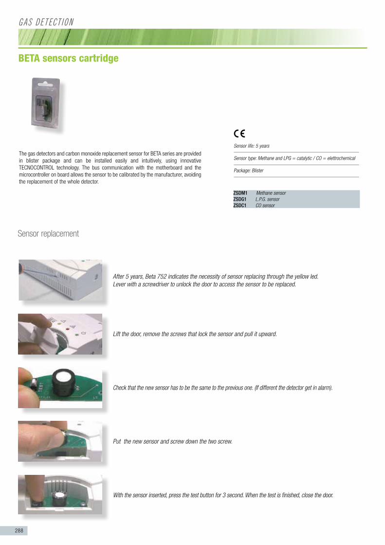
288
Sensor replacement
After 5 years, Beta 752 indicates the necessity of sensor replacing through the yellow led.Lever with a screwdriver to unlock the door to access the sensor to be replaced.
Lift the door, remove the screws that lock the sensor and pull it upward.
Check that the new sensor has to be the same to the previous one. (If different the detector get in alarm).
Put the new sensor and screw down the two screw.
With the sensor inserted, press the test button for 3 second. When the test is finished, close the door.
The gas detectors and carbon monoxide replacement sensor for BETA series are provided in blister package and can be installed easily and intuitively, using innovative TECNOCONTROL technology. The bus communication with the motherboard and the microcontroller on board allows the sensor to be calibrated by the manufacturer, avoiding the replacement of the whole detector.
ZSDM1 Methane sensorZSDG1 L.P.G. sensorZSDC1 CO sensor
Sensor life: 5 years
Sensor type: Methane and LPG = catalytic / CO = elettrochemical
Package: Blister
G a s D e T e C T Ion
bETA sensors cartridge

289
G a s D e T e C T Ion
Gas leak detector
+Solenoid valve230Vca Normally Open
Safety gas kit
Standard certifiedCEI EN 50194
Standard certifiedCEI EN 50194
BETA gas leak detectorreplaceable sensor
+Solenoid valve230Vca Normally Open
Gas Kit - Gas detector + Gas solenoid valves -
Gas Kit - Gas detector + Gas solenoid valves - Beta has replaceable sensor

Measurement Instruments
›› Measurement instrument for proper installation and maintenance of gas Installation

291
Gas S
oleno
id Va
lves m
anua
l res
et manometer for test Gas PiPelines p. 192 PortaBle Gas leak detectors
Meas
urem
ent I
nstru
ment
s

292
M e a s U r e M e n T I n s T r U M e n T s
PRESSURE PUMP
SEAL CONESPRINTER
complying with standard unI 11137:2012 / ± 15.000 pa
rEal ValuEs ranGE rEsoluTIon maxImum Error
Differential pressure ± 15.000 Pa 1 Pa ± 1 Pa or 3% reading
Chimney depression ± 15.000 Pa 1 Pa ± 1 Pa or 3% reading
Gas familyplant is
compliance with standards
safe plant but maintenance
required withing30 day
plant shutdown
I - II Q ≤1 dm3/h 1<Q≤5 dm3/h Q>5 dm3/h
III Q ≤0,4 dm3/h 0,4<Q≤2 dm3/h Q>2 dm3/h
calculaTED ValuEs• Differential pressure• Compensation in environment• Calculation of plant piping volume• Calculation of flow rate of dispersed air• Calculation of flow rate of dispersed gas
sofTwarE DaTa• Automatic zero calibration after switching on• Free programming of all parameters by operator
EquIpmEnT• Gate RS 232 for communication to PC• Power feed by lithium batteries rechargeable from network• Internal calendar and clock• 25 measure reports tat can be stored• Lithium batteries rechargeable
prIncIpal pErformancEs• It reads the “maximum drop-out”• Conversion into the different measure units (hPa, mmH
2O, mmBar, Psi) possible• Measuring of differential pressures• Measuring of room humidity by probe (optional SO390)• Displaying of testing time• Temperature compensation in environment• Storing of reports which can be personalised with users’ data• Operating range: 50h
The system performs pressure measurements, a direct tightness test and a leak rate test. The MA402PT provides several methods for you to test pipelines and gas trains that are filled with gas or air. The MA402PT standard leak procedure is particularly quick and easy for the user. There is no need to disassemble a gas meter or gas train The MA402PT uses the changes in pressure measured with and without the standard leak to determine the leakage rate and volume in the gas line in just 10 to 15 minutes! The serviceability check (gas safety check) meets the technical conditions of the new UNI 11137:2012. The leak test is fully automatic. In addition, the gas line to be tested is connected to the MA402PT via just one pressure measurement hose. The pressure in the gas line to be tested is automatically increased to 150 mbar by the measurement system. The stabilization and measurement times correspond to UNI 11137:2012
MA202PT
paramETErs To usE for THE classIfIcaTIon of Gas planTs
paramETErs ranGEs mEasurE prIncIplE
Pressure ± 15.000 Pa DMS bridge
T° air -15…100 °C Semiconductor
Humidity 0…100% Capacitive
Differential 0…100% Calculated
Volume 0…100% Calculated
It the plant proves to require maintenance or shutdown, then leak needs be searched, repaired and the plant tested again conforming to the Standard 7129-1.
manometer for test gas pipelines
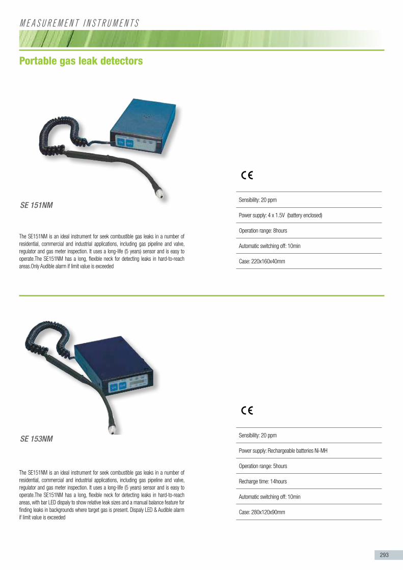
293
M e a s U r e M e n T I n s T r U M e n T s
The SE151NM is an ideal instrument for seek combustible gas leaks in a number of residential, commercial and industrial applications, including gas pipeline and valve, regulator and gas meter inspection. It uses a long-life (5 years) sensor and is easy to operate.The SE151NM has a long, flexible neck for detecting leaks in hard-to-reach areas.Only Audible alarm if limit value is exceeded
The SE151NM is an ideal instrument for seek combustible gas leaks in a number of residential, commercial and industrial applications, including gas pipeline and valve, regulator and gas meter inspection. It uses a long-life (5 years) sensor and is easy to operate.The SE151NM has a long, flexible neck for detecting leaks in hard-to-reach areas, with bar LED dispaly to show relative leak sizes and a manual balance feature for finding leaks in backgrounds where target gas is present. Dispaly LED & Audible alarm if limit value is exceeded
Portable gas leak detectors
SE 151NM
SE 153NM
Sensibility: 20 ppm
Power supply: 4 x 1.5V (battery enclosed)
Operation range: 8hours
Automatic switching off: 10min
Case: 220x160x40mm
Sensibility: 20 ppm
Power supply: Rechargeable batteries Ni-MH
Operation range: 5hours
Recharge time: 14hours
Automatic switching off: 10min
Case: 280x120x90mm

294
n o T e s

295
n o T e s

296
n o T e s

297
n o T e s

298
n o T e s


9584
015B
Our p
olic
y of
con
tinuo
us p
rodu
ct im
prov
emen
t, th
e fe
atur
es a
nd d
ata
show
n ar
e su
bjec
t to
chan
ge w
ithou
t not
ice.
The
imag
es o
f the
pro
duct
s an
d ac
cess
orie
s ar
e on
ly in
dica
tive.
Gra
phic
col
ors
of th
e pr
oduc
ts m
ay d
iffer
from
real
ity.
tecnocontrol s.r.l. Via Miglioli, 47 | 20090 Milano | ITALY Tel. +39 02 26922890Fax +39 02 2133734e-mail: [email protected]
GeCa s.r.l. Via E. Fermi, 98 | 25064 Gussago (BS) | ITALY Tel. +39 030 3730218Fax +39 030 3730228e-mail: [email protected]