G16B 50/40 (2019.01) (21) International Application Number
178
( (51) International Patent Classification: c/o Colorado State University Research Foundation, P . O. G16B 50/40 (2019.01) Box 483, Fort Collins, Colorado 80522 (US). (21) International Application Number: (74) Agent: POULSEN, Nathan W. et al.; Cooley LLP, 1299 PCT/US20 19/024057 Pennsylvania Avenue, NW, Suite 700, Washington, District of Columbia 20004 (US). (22) International Filing Date: 26 March 2019 (26.03.2019) (81) Designated States (unless otherwise indicated, for every kind of national protection av ailable) . AE, AG, AL, AM, (25) Filing Language: English AO, AT, AU, AZ , BA, BB, BG, BH, BN, BR, BW, BY, BZ, (26) Publication Language: English CA, CH, CL, CN, CO, CR, CU, CZ, DE, DJ, DK, DM, DO, DZ, EC, EE, EG, ES, FI, GB, GD, GE, GH, GM, GT, HN, (30) Priority Data: HR, HU, ID, IL, IN, IR, IS, JO, JP, KE, KG, KH, KN, KP, 62/648,201 26 March 2018 (26.03.2018) US KR, KW, KZ, LA, LC, LK, LR, LS, LU, LY, MA, MD, ME, 62/745,183 12 October 2018 (12. 10.2018) US MG, MK, MN, MW, MX, MY, MZ, NA, NG, NI, NO, NZ, 62/773,079 29 November 2018 (29. 11.2018) US OM, PA, PE, PG, PH, PL, PT, QA, RO, RS, RU, RW, SA, (71) Applicant: COLORADO STATE UNIVERSITY SC, SD, SE, SG, SK, SL, SM, ST, SV, SY, TH, TJ, TM, TN, RESEARCH FOUNDATION [US/US]; P . O. Box 483, TR, TT, TZ, UA, UG, US, UZ, VC, VN, ZA, ZM, ZW. Fort Collins, Colorado 80522 (US). (84) Designated States (unless otherwise indicated, for every (72) Inventors: PECCOUD, Jean; c/o Colorado State Univer¬ kind of regional protection available) . ARIPO (BW, GH, sity Research Foundation, P . O. Box 483, Fort Collins, Col¬ GM, KE, LR, LS, MW, MZ, NA, RW, SD, SL, ST, SZ, TZ, orado 80522 (US). KAR, Diptendu Mohan; c/o Colorado UG, ZM, ZW), Eurasian (AM, AZ, BY, KG, KZ, RU, TJ, State University Research Foundation, P . O. Box 483, Fort TM), European (AL, AT, BE, BG, CH, CY, CZ, DE, DK, Collins, Colorado 80522 (US). GALLEGOS, Jenna; c/o EE, ES, FI, FR, GB, GR, HR, HU, IE, IS, IT, LT, LU, LV, Colorado State University Research Foundation, P . O. Box MC, MK, MT, NL, NO, PL, PT, RO, RS, SE, SI, SK, SM, 483, Fort Collins, Colorado 80522 (US). RAY, Indrajit; (54) Title: APPARATUSES, SYSTEMS AND METHODS FOR GENERATING AND TRACKING MOLECULAR DIGITAL SIG¬ NATURES TO ENSURE AUTHENTICITY AND INTEGRITY OF SYNTHETIC DNA MOLECULES (57) Abstract: Systems and methods for generating and tracking molecular is¬ u¬ r¬ ct¬ n¬ ce on [Continued on next page]
-
Upload
khangminh22 -
Category
Documents
-
view
2 -
download
0
Transcript of G16B 50/40 (2019.01) (21) International Application Number

(
(51) International Patent Classification: c/o Colorado State University Research Foundation, P . O .G16B 50/40 (2019.01) Box 483, Fort Collins, Colorado 80522 (US).
(21) International Application Number: (74) Agent: POULSEN, Nathan W. et al.; Cooley LLP, 1299PCT/US20 19/024057 Pennsylvania Avenue, NW, Suite 700, Washington, District
of Columbia 20004 (US).(22) International Filing Date:
26 March 2019 (26.03.2019) (81) Designated States (unless otherwise indicated, for everykind of national protection av ailable) . AE, AG, AL, AM,
(25) Filing Language: EnglishAO, AT, AU, AZ, BA, BB, BG, BH, BN, BR, BW, BY, BZ,
(26) Publication Language: English CA, CH, CL, CN, CO, CR, CU, CZ, DE, DJ, DK, DM, DO,DZ, EC, EE, EG, ES, FI, GB, GD, GE, GH, GM, GT, HN,
(30) Priority Data: HR, HU, ID, IL, IN, IR, IS, JO, JP, KE, KG, KH, KN, KP,62/648,201 26 March 2018 (26.03.2018) U S KR, KW, KZ, LA, LC, LK, LR, LS, LU, LY, MA, MD, ME,62/745,183 12 October 2018 (12. 10.2018) U S MG, MK, MN, MW, MX, MY, MZ, NA, NG, NI, NO, NZ,62/773,079 29 November 2018 (29. 11.2018) U S OM, PA, PE, PG, PH, PL, PT, QA, RO, RS, RU, RW, SA,
(71) Applicant: COLORADO STATE UNIVERSITY SC, SD, SE, SG, SK, SL, SM, ST, SV, SY, TH, TJ, TM, TN,
RESEARCH FOUNDATION [US/US]; P . O . Box 483, TR, TT, TZ, UA, UG, US, UZ, VC, VN, ZA, ZM, ZW.
Fort Collins, Colorado 80522 (US). (84) Designated States (unless otherwise indicated, for every(72) Inventors: PECCOUD, Jean; c/o Colorado State Univer¬ kind of regional protection available) . ARIPO (BW, GH,
sity Research Foundation, P . O . Box 483, Fort Collins, Col¬ GM, KE, LR, LS, MW, MZ, NA, RW, SD, SL, ST, SZ, TZ,
orado 80522 (US). KAR, Diptendu Mohan; c/o Colorado UG, ZM, ZW), Eurasian (AM, AZ, BY, KG, KZ, RU, TJ,State University Research Foundation, P . O . Box 483, Fort TM), European (AL, AT, BE, BG, CH, CY, CZ, DE, DK,
Collins, Colorado 80522 (US). GALLEGOS, Jenna; c/o EE, ES, FI, FR, GB, GR, HR, HU, IE, IS, IT, LT, LU, LV,
Colorado State University Research Foundation, P . O . Box MC, MK, MT, NL, NO, PL, PT, RO, RS, SE, SI, SK, SM,
483, Fort Collins, Colorado 80522 (US). RAY, Indrajit;
(54) Title: APPARATUSES, SYSTEMS AND METHODS FOR GENERATING AND TRACKING MOLECULAR DIGITAL SIG¬NATURES TO ENSURE AUTHENTICITY AND INTEGRITY OF SYNTHETIC DNA MOLECULES
(57) Abstract: Systems and methods for generating and tracking molecularis¬u ¬
r¬ct¬n¬ceon
[Continued on next page]

Declarations under Rule 4.17:as to applicant's entitlement to apply for and be granted apatent (Rule 4.17(H))as to the applicant's entitlement to claim the priority of theearlier application (Rule 4 .17(iii))
Published:with international search report (Art. 21(3))before the expiration of the time limit for amending theclaims and to be republished in the event of receipt ofamendments (Rule 48.2(h))

APPARATUSES, SYSTEMS AND METHODS FOR GENERATING AND TRACKINGMOLECULAR DIGITAL SIGNATURES TO ENSURE AUTHENTICITY AND
INTEGRITY OF SYNTHETIC DNA MOLECULES
[0001] This application claims priority to and the benefit of: U.S. Provisional Application No.
62/648,201, filed March 26, 2018, U.S. Provisional Application No. 62/745,183, filed October 12,
2018, and U.S. Provisional Application No. 62/773,079, filed November 29, 2018; the entirety of
each of the aforementioned applications are herein expressly incorporated by reference for all
purposes. This application may contain material that is subject to copyright, mask work, and/or other
intellectual property protection. The respective owners of such intellectual property have no objection
to the facsimile reproduction of the disclosure by anyone as it appears in published Patent Office
file/records, but otherwise reserve all rights.
Background
[0002] Nucleotides are organic molecules that serve as the monomer units for forming nucleic acids.
Summary
[0003] This disclosure relates to the security and validation of nucleic acid ( A) molecules and their
sequence data. The term "nucleic acid," as used herein, refers to a molecule comprising one or more
nucleic acid subunits. A nucleic acid can include one or more subunits selected from adenosine (A),
cytosine (C), guanine (G), thymine (T) and uracil (U), and modified versions of the same. NA
molecules can include deoxyribonucleic acid (DNA), ribonucleic acid (RNA), combinations, and/or
derivatives thereof. Example systems and methods for cryptographically signing and authenticating
NA sequences are described herein. In some embodiments, a NA authentication system includes a
NA authentication device coupled to one or more user devices. The NA authentication device
includes, in an interconnected manner, a communicator configured to establish secure channels of
communication between the NA authentication device and the user device(s), input/output unit to
receive and send sequence information between the user device(s) and the NA authentication device,
at least one memory, and at least one processor. Also disclosed herein are methods for generating a
signed NA sequence and validating a signed NA sequence using a NA authentication system. A
signed NA sequence is generated by incorporating a signature NA sequence obtained from converting
a digital signature including an encrypted mapped value of the original NA sequence, and a unique
identifier that can later be used to decrypt the mapped value. The validating of a test NA sequence is

carried out by extracting the digital signature from the signature sequence, and using the unique
identifier to decrypt the mapped value, and comparing the mapped value to the test NA sequence.
0004] FIG. 1 is a schematic of a nucleic ac d authentication system, according to an embodiment.
[0005] FIG. 2 is a flowchart describing a method of using a NA system to generate a signed NA
sequence, according to an embodiment.
[0006] FIG. 3 is a flowchart describing an example workflow of generating a signed NA sequence
and validating a signed NA sequence, using a NA system according to an embodiment.
[0007] FIG. 4 is a flowchart describing a method of associating a NA sample with a signed digital
representation of the NA sample using a NA system according to an embodiment.
[0008] FIG. 5 is an example view of descriptive information associated with a NA sequence.
[0009] FIG. 6A is an example view of sequence information associated with a NA sample and FIG.
6B is an example view of sequence and descriptive information associated with a NA sample.
[0010] FIG. 7 provides an example view- of a signed digital DNA file.
[0011] FIG. 8A provides an example sign-share- validate workflow, according to some embodiments.
[0012] FIG. 8B provides an example fasta file for some embodiments.
[0013] FIG. 9A provides a comparison of expressi on of a reporter construct with and without a digital
signature, according to an implementation.
[0014] FIG. 9B illustrates algorithmic accuracy of algorithms as a percentage, according to an
implementation.
[0015] FIG. 0 illustrates the results of runtime analysis of various algorithms in milliseconds.
[0017] FIG. is a schematic of a nucleic acid authentication system, according to an embodiment.
[0018] FIG. 12 is a diagram showing interfacing aspects of a nucleic acid authenticating system,
according to an embodiment.
[0019] FIG. 13 is a flowchart describing a method for cryptographically marking a N A sequence to
generate a signed A sequence.
[0020] FIG. 14 is a flowchart describing a method generating a signature for a NA sequence.
[0021] FIG. 5 is a flowchart describing a method for validating a signed NA sequence.
[0022] FIG. 6 is an example illustration of an interface of a user application, according to an
embodiment.

[0023] FIG. 7 s a flowchart describing a workflow' of marking a NA sequence and authenticating
a second NA sequence.
[0024] FIG. 18 is an example illustration of a workflow.
[0025] FIGS. 19A and 19B are illustrations of example original and signed NA sequences of a
plasmid, respectively.
[0026] FIG. 20 is an example illustration of an interface of a user application, according to an
embodiment.
[0027] FIGS. 21, 22A, 22B, 23, 24A, 24B, and 24C are example illustrations of various aspects of a
user interface of the user application illustrated in FIG. 20.
0028 Systems, methods and apparatuses of the disclosure relate to providing physical and cyber
security of molecules, for example NA molecules. Methods and apparatus disclosed herein also relate
to authenticating and validating a source of synthetic NA molecules.
[0029] NA synthesis has become increasingly common, and many synthetic NA molecules can be
licensed intellectual property (IP). NA samples are shared between academic labs, ordered from NA
synthesis companies and/or manipulated for a variety' of different purposes, such as research needs
to study their properties and improve upon them. In some instances, N A sequences are configured to
store information in the form of NA samples. However, it is not uncommon for a sample to change
hands many times with very' little accompanying information and no proof of origin or proof of
mishandling. This poses significant challenges to the original source or inventor of a NA molecule,
trying to protect her IP rights. Furthermore, following the anthrax attacks of 2001, there is an
increased urgency to employ microbial forensic technologies to trace and track agent inventories,
especially those created and/or manipulated in laboratories. However, atribution of physical samples
s next to impossible with existing technologies.
[0030] Natural mutations, errors in labelling biological samples, sloppy laboratory processes, or
malicious actions could otherwise jeopardize the integrity of the relation between a physical NA
molecule and its description in the literature, vendor data sheets, or regulatory approval applications.
Undocumented modifications to the NA molecule could result in the loss of its described property.
Alternatively, it could also result the gain of undocumented and possibly undesirable, even
dangerous, functions.

0031 According to some embodiments, the disclosure provides for establishing the origin and
integrity of NA molecules. In some embodiments, the teachings of the disclosure provide verification
that a NA molecule (e.g. DNA) has not been modified after it has been fully characterized to ensure
that t behaves as expected or as predicted by the characterization studies.
[0032] In some embodiments, the teachings of the disclosure establish the origins of the NA
molecules. Developers of synthetic NA molecule samples can use methods and systems of the
disclosure to confirm and protect their intellectual property. In addition, the teachings of the
disclosure can, in some embodiments, be used by producers to reduce or eliminate liability associated
with derivatives of their NA molecules. By associating molecules with their authors, the disclosed
methods and systems can be used to prove authenticity of a given sample purported to be a certain
NA molecule.
[0033] When modified/synthetic genes are used in agriculture, industry, and/or gene-therapy based
medical treatment, the methods and systems of the disclosure can provide attribution that can (a)
readily inform the user/consumers about maters related to the treatment, product, and/or therapy;
and/or (b) can serve as some measure of the quality of the treatment, product, and/or therapy, e.g., brand
name versus generic drugs. Teaching of the disclosure can also ensure source attribution which can
help mitigate DNA-based attacks, including attacks against DNA sequencers, and/or via DNA
sequencers against smart devices / the Intemet-of-Things (IoT), e.g., of the type of DNA-based
security exploit demonstrated as a proof of concept, where synthetic DNA was used to attack a DNA
sequencer.
[0034] Plasmids are circular DNA molecules widely used in biotechnology to express recombinant
proteins, in several applications such as for example to support ew vaccine strategies, or even in
gene therapy applications. Plasmids used in biotechnology often include DNA sequences from
multiple organisms as well as chemically synthesized DNA. These highly' engineered plasmids are
typically designed using software. Plasmid sequences can also be documented electronically.
Information can be found vendor data sheets, bioinformatics databases, the online supplement of
journal articles, or patent applications.
[0035] Tracing DNA with watermarks inserted in the genome have been proposed, for example, to
increase the traceability' of infectious agents to increase their traceability', and such an approach
includes inserting short watermarks into DNA without introducing significant perturbation to genome
function. The use of watermarks has also been proposed in order to identify genetically modified
organisms (GMOs) or proprietary' strains. The system provides security and reliability' for traceability'

and source identification than watermarking because a watermark is independent of the sequence it
is attached to (only changes to the watermark itself would be detectable), and watermarks are easily
counterfeited. Some proposals include where a watermark is generated from any binary data and
added to the original sequence. The watermark is independent of the original sequence and therefore
provides no integrity of the actual DNA sequence. If the watermark locations can be found, the
original molecule sequence can be changed by others while keeping the watermark sequence
unaltered but sending the remaining modified sequences to a receiver. The receiver will trust that it
came from the sender whose watermark is present in the DNA. Second, if an attacker or other
legitimate competing user/organization knows the binary data that is used to generate the watermark,
they can generate their own arb itrary DNA and add the watermark to malign the original
user/organization. For these reasons, watermarks of are limited reliability and security. Additionally,
there are proposals that r e ly on symmetric key encryption like AES/Blowfish to encrypt the binary
data that is used to create the watermark. Such keys have to be transmitted to the receiver who will
validate the watermark. However, the receiver would then have the secret key that was used to
generate the watermark and can masquerade as the originator of the DNA. The disclosed methods
and digital signatures provide better and stronger security than such proposals.
[0036] The approaches disclosed herein includes various steps such as, for example, the generation
of digital signatures using known algorithms, adap ta tion of digital signature to NA sequences through
the development of mapping algorithms to convert N A sequences into b inary form, the insertion of
synthetic NA sequences in plasmids. The most commonly used plasmids are known to tolerate the
insertion of N A sequences much longer than digital signatures. The process of reconstructing the
sequence of plasmids from ra w sequencing data is well understood and can achieve a high level of
accuracy at an affordable cost.
Ensuring the origin and integrity oj NA molecules
[0037] One strategy to mitigate cyber-physical risks associated with NA molecules would be to
develop a digital signature technology for NA molecules. Digital signatures are used in cyber security
to authenticate the source of a digital file and to confirm that the file has not been changed since the
originator applied the signature. The disclosure herein includes a NA authenticating system
connected to several users, for example a web service, providing digital signature technologies for
synthetic NA molecules.
A NA authentication system

0038 FIG. shows a schematic of an example NA authentication system 100. The NA
authentication system (also referred to here as “the authentication system”, “the NA system”, or
simply “the system”) allows users handling NA samples, such as synthetically generated NA
molecules like plasmid DNA, to digitally sign them and/or suitably mark them using signatures
generated though safe and secure encryption methods. These signatures can take the form of a unique’
NA fragment, also referred to as “NA signature sequence”, or “DNA signature sequence”, that is
inserted into the NA molecule in the NA sample.
[0039] The NA system 100 includes a Nucleic Acid (NA) authentication device 110 coupled or
suitably connected (through wired or wireless connection methods) to user devices 02 and 104,
though a suitable communication network (not shown).
[004 ] The user devices 102 and 04 can be any suitable client device. In some embodiments, the
user devices 102 and 04 can be any suitable hardware-based computing device and/or a multimedia
device, such as, for example, a server, a desktop compute device, a smartphone, a tablet, a wearable
device, a laptop and/or the like. The user devices 102 and 04 can include a processor, a memory,
and a communicator. In some embodiments, the user devices 02 and 104 can be, for example, a
personal computer (PC), a personal digital assistant (PDA), a smart phone, a laptop, a tablet PC, a
server device, a workstation, and/or the like. The user devices while not shown in FIG. , can include
at least a memory, a processor, a network interface, and an output device. While the schematic of the
NA system 100 in FIG. shows two user devices, an NA system can include any number of user
devices as suitable.
[0041] The NA authentication device 10 includes and/or has access to a processor 120, a memory
160 and a communicator 180, each being operatively coupled to the other. n some embodiments, the
NA authentication device 110 can be a server device. In some embodiments, the NA authentication
device 0 can be an enterprise device, such as, for example, a desktop computer, a laptop computer,
a tablet personal computer (PC), and/or the like. In yet other embodiments, portions of the NA
authentication device 0 can be physically distributed across, for example, many chassis and/or
modules interconnected by wired or wireless connections. The network can be any type of network
such as a local area network (LAN), a wide area network (WAN), a virtual network, a
telecommunications network, implemented as a wired network and/or wireless network.
[0042] The memory 160 of the NA authentication device 0 can be, for example, a random access
memory (RAM), a memory' buffer, a hard drive, a read-only memory' (ROM), an erasable
programmable read-only memory' (EPROM), and/or the like. The memory 160 can store, for

example, one or more software modules and/or code that can include instructions to cause the
processor 120 to perform one or more processes, functions, and/or the like (e.g., the mapping of a
NA sequence, the generation of a digital signature, the generation of a signature NA sequence, the
validation of a signed NA sequence, etc.). In some embodiments, the memory 160 can include
extendable storage units that can be added and used incrementally. In some implementations, the
memory 160 can be a portable memory (for example, a flash drive, a portable hard disk, and/or the
like) that can be operatively coupled to the processor 120. In other instances, the memory 160 can be
remotely operatively coupled with the compute device. For example, a remote database server can
serve as a memory' and be operatively coupled to the NA authentication device. The memory 60 can
in some embodiments include a database or a look up table (not shown in FIG. 1) storing information
regarding specific authors or users who may be registered in a system used to exchange information
regarding NA molecules (e.g., authorized users or validated authors of specific synthetic NA
molecules). The memory' 160 can include one or more storage systems for user information
associated to these specific users through a unique user identifier (e.g., user ID).
[0043] The communicator 180 can be a hardware device operatively coupled to the processor 120
and memory 160 and/or software stored in the memory 60 executed by the processor 120. The
communicator 180 can be, for example, a network interface card (NIC), a Wi-Fi M module, a
Bluetooth® module and/or any other suitable wired and/or wireless communication device. The
communicator 80 can include or be part of a switch, a router, a hub and/or any other network device.
The communicator 80 can be configured to connect the NA authentication device 110 to user
devices 102 and 04 or to remote data sources (not shown) via a communication network. In some
instances, the communicator 80 can be configured to connect to a communication network such as,
for example, the Internet, an intranet, a local area network (LAN), a wide area network (WAN), a
metropolitan area network (MAN), a worldwide interoperability for microwave access network
WiMAX®), an optical fiber (or fiber optic)-based network, a Bluetooth® network, a virtual network,
and/or a ' combination thereof. The communicator 180 in the NA Authentication 110 can be
configured to establish one or more secure channels of communication to enable users to access the
Input/Output unit 140 of the NA authentication device 110. In some embodiments, the communicator
80 can be configured to generate and distribute tickets to control access sessions for users to gam
access to the NA authentication device 110. In some embodiments, the communicator 180 can use
the tickets (e.g., tickets containing access codes set to deactivate beyond a specified time period) to
moderate temporary or time limited secure communication channels. The Communicator 180,

similarly, can be housed in one device in some embodiments, and distributed across many devices in
some other embodiments.
0044 The processor 120 included some embodiments of the NA authentication device 110 can
be configured to run one or more applications to support various methods involved in cryptographic
signing and authentication of NA molecules as described herein. In some embodiments, the one or
more applications run n the processor 120 can be part of an enterprise software package. The
processor 120 can for example be equipped with one or more apparatuses that may include one or
more associated programs / software to carryout various portions of marking and authenticating a
NA molecule, the various portions including, for example, generating a mapped value of a NA
molecule, cryptographically encrypting a mapped value, to generate a digital signature, to convert a
digital signature into a signature NA sequence, identifying appropriate insertion points in the NA
sequence to insert the signature NA sequence, etc. Appendix A provides illustrative example
processor-executable code for an embodiment of the disclosure. In some embodiments, the processor
120 can be equipped with apparatuses and associated software to receive an unknown sample and
validate its alleged source, origin or author.
[0045] The NA authentication system 100 and the N authentication device 0 can be configured
such that user specific information (e.g , identity of users, or molecules/sequences authored by users)
can be stored in a protected fashion by associating the information via the unique user identifiers,
and access to the information can be blocked unless allowed through a process of verifying user
credentials, for example, through secure communication channels mediated by the communicator
180.
[0046] In some embodiments of the system 100 the user devices 102 and 104 can include
apparatus to run suitable applications (e.g., client side application, mobile application, a PC
application, an internet web browser, etc.) installed on the user device) to communicate with one or
more applications on the NA authentication device, via a suitable communication channel mediated
or moderated by the communicator, as discussed herein. The applications can be configured to have
access to a registry or database of authorized users with the users tabled or organized or indexed by
unique user identifiers (e.g., user IDs). In some embodiments, the unique user identifiers can be
generated within the NA authentication system 200. In some other embodiments, the umque
identifiers can be imported from other known sources or systems, for example, other organizations
frequented by users or authors of NA molecules and/or their sequence information (e.g., OR D). In
some embodiments, the applications can be configured to receive NA sequences with descriptive

information or have access to information associated with a NA sequence, for example, documented
descriptions of regions of a NA sequence or unique identifiers associated with NA sequences (e.g.,
plasmid IDs).
Generating signature sequences[0047] Generating a signature to be incorporated in a NA molecule can include abiding by certain
criteria. For example, the length of the signature may have to be within a restricted limit, depending
in the size of the NA molecule. Additionally, inserting any extraneous DNA sequences could impact
the function or stability of the NA molecule. For example, the inserted sequences may disrupt existing
functions by interrupting important features, may introduce a new function by encoding cryptic
functional elements and/or may impact the overall stability of the NA molecule (e.g., plasmid) in
terms of propensity for mutations, structural rearrangements or retention in a host organism. The
probability that existing features may be disrupted can be minimized through careful choice of where
within the NA molecule the signature sequence is inserted.
[0048] The probability that the inserted sequence may introduce a new function or impact stability
increases with the length of the inserted sequence. Additionally, the cost of synthesizing the signature
can increase with length. In some instances, signature sequences are configured to be of a
predetermined length to meet security parameters without compromising the security of the signature
itself. For a digital document, a signature of 384 bytes, for example, may be trivial. However, the
same 384 bytes translates to 1536 bases (384 * 8 / 2) of DNA. If a DNA sample originally includes
2000 bases (not unusual for a plasmid), the addition of a 1536 nucleotide signature would nearly
double the size of the DNA molecule, which may not be feasible. As alternative to using identity-
based signatures that use bilinear pairings, in some embodiments the method 203 uses Shamir’s IBS
scheme (or the like) with modifications, in order to minimize the size of the insertion.
[0049] In a digitally signed document, the original message and the signature can be easily identified
and separated using delimiters that separate them. Because the site of insertion may vary depending
on the architecture of the plasmid, delimiters are used to identify where the signature sequence starts
and ends. In some instances, the method 200 uses an algorithm that identifies subsequences that can
be used as delimiters while embedding a signature sequence in a NA molecule. For example, any
subsequence of 10 base pairs (substring of length 10) that is not present in the original sequence can
be used as a start and end delimiter indicating a portion of the NA sequence that includes the signature
sequence. During verification, all subsequences of 10 base pairs can be identified and only those
subsequences that occur twice within the entire sequence can be identified and used as delimiters.

0050 In some embodiments, instead of the algorithm choosing the delimiters, the disclosed systems
and methods allow the user input their own delimiters of 10 base pairs. This approach can be
beneficial to design delimiters that are relevant to their specific project. For example, the delimiters
can be designed in such a way as to simplify synthesis/assembly of the DNA. Tools included in the
NA system can check if the sequences are permitted i.e. the 10 base pair subsequence does not already
exist elsewhere in the plasmid. Example sequences that can be used as start and end delimiters include
ACGCTTCGCA and GTATCCTATGrespectively. These sequences are relatively easy to identify
visually, they are unlikely to develop secondary structures and they can contain balanced numbers of
A, . G, and T.
[0051] When any digitally signed message is shared and verification fails, the sender just resends the
message again. In the domain of NA sharing, this may include resending and likely resynthesizing
the sample (sometimes even batches of samples), which may incur a lot of cost. The presence of a
signature inside the molecule can ensure that any change in the signed DNA results in failed
verification. However, NA molecules can be prone to naturally occurring mutations. Hence after a
failed verification, in some instances, the system is configured to determine or check the location of
the mutation(s) that caused the verification to fail. If there are mutations in any important features,
the receiver may choose to reorder the sample. If there are mutations in any relatively unimportant
part of the NA, the receiver may choose to proceed to work with the NA sample. In order to achieve
this error tolerance, some embodiments of NA systems and methods disclosed include and use error
correction/detection codes, such as, by way of non-limiting example, modified Reed-Solomon Codes,
as described in further detail herein. Reed-Solomon and similar codes are block-based error
correcting codes in which redundant information is added to data so that it can be recovered reliably
despite errors in transmission or storage and retrieval. The encoder takes a block of digital data and
adds extra redundant bits. Errors occur during transmission or storage for a number of reasons. Hie
decoder processes each block and attempts to correct errors and recover the original data. The number
and type of errors that can be corrected depend on the characteristics of the (Reed-Solomon) code. A
Reed-Solomon code can be specified as RS( , ) with -bit symbols. This means that the encoder takes
k data symbols of s bits each and adds parity symbols to make a n symbol codeword. There are n —k
parity symbols of s bits each. A Reed-Solomon decoder can correct up to t symbols that contain errors
a codeword, where 2t =n —k .
[0052] For example, one Reed-Solomon code is RS(255,223) with 8-bit symbols. Each codeword
contains 255 codeword bytes, of which 223 bytes are data and 32 bytes are for parity. For this code:

n :::: 255, k = 223, s =: 8, 2t ::: 32, t = 16. The decoder can correct any 16 symbol errors in the code
word: i.e. errors in up to 16 bytes anywhere in the codeword can be automatically corrected. Given
a symbol size s, the maximum codeword length (n) for a Reed-Solomon code is n = 2s - 1.
[0053] For example, the maximum length of a code with 8-bit symbols (s=8) is 255 bytes. The
amount of processing power required to encode and decode Reed-Solomon codes is related to the
number of parity symbols per codeword. A large value of t means that a large number of errors can
be corrected but requires more computational power than a small value of t . One symbol error occurs
when 1 bit in a symbol s wrong or when all the bits in a symbol are wrong. RS(255,223) can correct
16 symbol errors. In a worst case scenario, 16-bit errors may occur, each in a separate symbol (byte)
so that the decoder corrects 16-bit errors. In the best case, 16 complete byte errors occur so that the
decoder corrects 16 x 8-bit errors. Reed-Solomon codes are particularly well suited to correcting
burst errors (where a series of bits in the codeword are received in error). Reed-Solomon codes are
based on an area of mathematics known as Galois fields/finite fields. A finite field has the property
that arithmetic operations (+,-,x,/ etc.) on field elements always have a result the field. A Reed-
Solomon encoder or decoder needs to carry' out these arithmetic operations.
[0054] Embodiments of systems and methods disclosed include methods to associate a NA molecule
with a signature generating a tie between a physical NA sample and its digital representation.
Embodiments disclosed include methods to combine a signed N sequence and its description to
form a combined message and generate a signature on this combined message. This signature of the
combined message can be placed in the digital representation of the NA such as the genbank file
which s shared with the receiver. This can ensure that the explanation of the NA sequences and the
sequences in the NA sample are accurate and related. Any change in the descriptions without
changing the molecule will invalidate this signature. Also, any change n the molecule without
updating the descriptions will invalidate the signature.
[0055] To solve the problem of tracing the source of synthesized DNA molecules and confirming their
identity and integrity, some embodiments of the disclosure include a system for generating digital
signatures for molecules of DNA in living cells. In some embodiments, a signature approach, such
as, by way of non-limiting example, Shamir’s Identity-based Signature (IBS) scheme (see Adi
Shamir. Identity-based cryptosystems and signature schemes. In George Robert Biakley and David
Chaum, editors, Advances in Cryptology, pages 47-53, Berlin, Heidelberg, 1985. Springer Berlin
Heidelberg; the entirety' of w'hich being herein expressly incorporated by reference for all purposes)
can be utilized. According to some embodiments, for the unique identifier string of a/the originator,

an identification, such as Open Researcher and Contributor IDs (ORCID) from a non-profit
organization which uniquely identifies researchers using a 16 digit number, can be used. Many
funding agencies require researchers to register for an ORCID, and scholarly journals request that
authors identify themselves using their ORCID. The generated signature bits are converted to the
four letters A, C, G, and T, which represent the four nucleotide building-blocks of DNA. The
sequence can then be synthesized and inserted nto the original DNA molecule. In some embodiments
when this signed molecule is shared, a receiver can sequence the signed molecule to verify that it
was shared by an authentic sender and that the sequence of the original molecule has not been altered
or tampered with.
[0056] While the use of similar techniques in the digital world is known, applying them to DNA
requires several creative adjustments. For example, one challenge comes from the physical size of
the DNA sequence encoding the signature. Adding extraneous sequences to a DNA molecule can
impact its function or stability. It can be important, in some embodiments, to minimize the size of the
added sequence in order to decrease the likelihood that the biological function of the signed molecule
would be effected and to decrease the cost of synthesizing the signature. For some such embodiments,
the size minimization can restrict the ability to use some known signature schemes, as well as larger
key sizes for signatures.
[0057] Another challenge is accounting for DNA mutations. In a DNA sample, mutations occur
randomly at low frequencies, and, as a result, there is a on-trivial possibility that a signed molecule
could undergo a mutation between the time it is signed and when it s validated. Mutations could
affect not only the original DNA molecule but also the signature. In both cases, the signature
validation would fail even if the molecule were sent by the correct authority and the original sequence
were correct during the process of signature generation. Mutations are beyond the control of any
authority and the relative impact of any given mutation can vary. In some embodiments of the system,
error correction codes are included to detect mutations in the signed DNA molecule. Error correction
codes are prevalent in digital storage such as CD/DVD. It is possible to use the similar techniques to
provide a reliable reconstruction of the original sequence for comparison, provided a small number
of changes have occurred. In some embodiments of the system, the application of error correction
codes to DNA can additionally or alternatively be used to ensure the integrity of information''digital
information stored inDNA molecules.
[0058] While digital signatures as disclosed herein can provide a way to verify the source and
integrity of a DNA sample, there s additional information about the DNA sequence that can be

useful to the recipient of a signed DNA sample. For example, the exact location of features within the
sequence, such as a certain gene, may still be unknown to the recipient. In some embodiments, the
physically-signed DNA molecule is linked with its digital representation, which contains the
sequence and its features designated with explanations.
0059 The system can, according to some embodiments, be configured such that no polynomial-
time adversary can forge a genuine signature provided by the system. For example, assume a
polynomial-time adversary, Mallory/M, is trying to forge the signature of a reputed synthesized DNA
molecule creator, Alice/A . Alice/A distributes DNA molecules, which Alice/A has synthesized and
provided to researcher Bob/B. If the attacker, Mallory/M, is able to forge the signature of Alice/A
then: (a) Mallory/M can replace the actual DNA created by Alice/A with her own but keep the
signature intact; (b) Mallory/M can create her own DNA molecule and masquerade as Alice/A to sign
it; and/or (c) Mallory/M can modify parts of the signed DNA molecule created by ice A . Thus the
system can defeat any of the potential threats by providing a genuine signature that is difficult or
impossible for an polynomial-time adversary' to forge.
[006 ] FIG. 2 illustrates a method 200 of generating a signed NA sequence. In some
implementations, the method 200 or portions of the method 200 can be substantially similar to
methods of generating a signed NA sequence described in other embodiments.
[0061] At 20 the method 200 includes receiving, from a user device, a NA sequence and information
associated with the NA sequence. In some instances, the NA sequence can be received in a
predetermined format. For example, NA sample can be sequenced by an automated sequencer and
the NA sequence be obtained from the sequencer. The output of a DNA sequencer can for example,
be in a fasta (.fasta) file as shown in FIG. 6A. The fasta file can include the raw DNA sequence of
the DNA molecule in the sample. As another example, a genbank file (.gb) can include the raw NA
sequence along with annotations describing portions of the NA sequence, as shown in example in
FIG. 6B. In FIG. 6B, after the w' d “ORIGIN” the ra NA sequences are denoted and before that
the features are annotated.
[0062] In some instances sequence manipulation tools such as software applications like SnapGene
can be used to convert a fasta file to a genbank file and vice versa. When a fasta file s converted to
a genbank file, the software can search its database for common annotations. The generated
annotations may not be complete or correct every time. The software applications included in the NA
system can allow the user at the user device to manually add additional annotations that may be used
to describe the sample NA sequence. These manually added annotations can be only available to the

creator of the NA sequence. When the NA sample is sent to others, they may sequence it and obtain
the fasta file but the genbank file can contain only those annotations that can be automatically
generated. An example view of a genbank file is shown m FIG 5 . In some implementations, for the
receiver to extract all the feature information associated with a given NA sample, the creator may
share the genbank file containing the manually added annotations along with a NA sample.
[0063] In some implementations, the NA system may receive the NA sequence and information
associated with the NA sequence to perform preliminary analyses prior to generating a signature
sequence. For example, the NA sample can be a plasmid DNA. Plasmid DNA is circular and double-
stranded, having a cyclic permutation property. The sequences represented in a fasta file are the linear
representation of a circular structure. As a consequence, there is no single set representation of the
sequences in a sample. Following sequencing, any cyclic per- mutation of the sequence is possible.
For example, m a fasta file if the sequence is - “ACGGTAA”, when the same sample is sequenced
again, the fasta file might read as - “TAAACGG”. The NA system may perform preliminary analyses
to determine a point of origin or otherwise carryout adaptations that can be used for such circular NA
sequences that are linearized during sequencing and usage. An example adaptation procedure is
described below.
[0064] The cyclic permutation property of a plasmid creates a particular problem when validating
the signature since the original sequence which has been signed cannot be extracted properly. As an
example, if the NA sequence which the signer wants to sign in the genbank file s “ORIGINAL”,
When this sequence is synthesized and sent to a receiver, the receiver sequences the plasmid to get
the fasta file. The sequence in the fasta file might ot always be ORIGINAL that is to say “in the
same order as the sender sent it”. It might be GINALORI or ALORIGIN i.e. a cyclic permutation
of the sender’s sequence. The signer may have generated the signature on ORIGINAL. But the
receiver when validating the signature has no information about the order of the sequences and from
the fasta file there s no information about how to reconstruct the exact same order. Without this
exact same ordering the signature verification may fail as a different order may be inferred as a
different message or a different sequence.
[0065] In some embodiments, the NA system may accommodate this aspect of the cyclic permutation
property of circular NA molecules in the signature generation procedure by shifting the sequence
before signing depending on the location where the signer wants to put the signature. Let us take the
same example where the signers genbank file has the sequence ORIGINAL which he/she is about
to sign. In some embodiments, the NA system can shift the sequence based on any suitable

information provided by the user. For example, the NA system can shift the sequence according to
the location of insertion of the signature. As an example, f the user wants to put the signature on
location 4, assuming this location does not have any feature, which is after the letter I and before
letter G, the NA system can shift the sequence accordingly, such that the signature is generated on
the shifted sequence GINALORI. Let us assume the signature sequence is SIGN. The signature is
then wrapped between two tags (e.g., START and END), and placed at location 4 to form the signed
NA sequence, but the genbank content s not shifted. So the output signed NA sequence can be “OR!
START SIGN END GINAL”. This shift is transparent to the user.
[0066] This sequence “ORI START SIGN END GINAL” is synthesized and sent to the receiver.
The receiver may encounter any cyclic permutation of this sequence. For example, the fasta file
according to the receiver might read “ART SIGN END GINAL ORI ST”. The NA system
configured to validate the received signed NA sequence looks for the tag START, In this example
instance, the NA system may not be able to find the START tag because the wrapping point is within
the tag itself. In such instances, the signed NA sequence is copied until two instantiations are found
i.e. the singed NA sequence after copying looks like “ART SIGN END GINAL ORI ST ART
SIGN END GINAL ORI ST ART SIGN END GINAL ORI ST”. Now the NA system can find 2
instantiations of the START tag. The NA system can retrieve the content between those tags for
example - SIGN END GINAL ORI. The NA system can remove the END tag and obtain SIGN and
GINALORL The validation routine can be invoked on GINALORI and if there are no mutations it
can result in successful validation. Thus, in the implementations where the above described
adaptation is carried out, even though the signer’s file had the order as ORIGINAL, as described
above, since the NA system internally shifted the sequence and generated the signature on
GINALORI, the receiver does not have to know the ordering which the receiver generated the
signature on.
[0067] As another example, as a DNA molecule is made of two complimentary, anti-parallel strands,
a sequencer can read a sample in both the “sense” and “antisense” direction. The sequence may be
represented in a fasta file in either direction. When the sample is sequenced again, the output might
be in the other direction, or what is known as the reverse complement. The reverse complement of
"A” is "T” and vice-versa, and the reverse complement of "C” is "G” and vice- versa. The DNA
molecule has polarity with one end represented as 5 ’ and the other represented as 3’. One strand
adheres to its reverse compliment in anti-parallel fashion. So if the sequence is “5’-ACGGTAA-3”’,
the reverse complement s “3’-TGCCATT-5”\ The fasta file may represent one strand of the DNA

sequence in the 5 to 3 ’ direction; so the fasta file could read as “ACGGTAA” or “TTACCGT”. The
NA system may perform preliminary' analyses to account for the variations in reads of the NA
sequence. For example, for a plasmid DNA that has N number of bases, combining the circular and
two complementary' strand properties, the correct representation of the same sample can be 2N - N
cyclic permutations plus each reverse complement. The NA system may preform preliminary'
analyses to determine a suitable reproducible representation of the plasmid DNA given these
considerations.
[0068] At 203, the method 200 includes generating a digital signature. The digital signature can be
generated by encrypting a mapped value that is in turn generated based on the NA sequence. For
example, the mapped value can be generated by applying a cryptographic function to the NA
sequence, and the digital signature can be generated by encrypting the mapped value. An example
procedure is outlined herein.
f0069] In some implementations, for example, a NA authentication device can use a scheme of
generating the digital signature which can be a modification of an identity-based signature scheme
proposed by Shamir using a user ID (e.g. an ORCID (Open Researcher and Contributor ID) as the
unique identifier. Shamir’s IBS is based on the RSA cryptosystem and its security depends on the
difficulty of integer factorization in the RSA problem.
0070 The digital signature generation scheme used in some embodiments of the disclosed systems
and methods can include a setup with the following steps.
. Generate two distinct primes p and q at random with 2 k2 l < p , q < 2 k/2
2 . Calculate the modulus as --- p q
3 . Calculate the totient φ( ) --- (p - l)(q - 1).
4 . Choose the master public key e as 1 < e < φ(η) , such that e is relatively prime to φ(η)
5 . Calculate the master private key, d, as e 1 mod φ(η) to satisfy the congruent relation
d.e ≡ 1 mod φ(η) .
6.. Publish the public parameters <e, n> and store the private key d. In some
implementations k is 1024 bits.
[0071] The digital signature generation at 203 in some embodiments of the disclosed systems and
methods can include a key extraction step. The private key, SID for a user with the identity ID can be
generated as: SID H (ID) mod , where His a secure hash function. In some implementations, for
example, SHA-256 can be used as the hash function

0072 The digital signature generation used in some embodiments of the disclosed systems and
methods includes a signature generation step. For example, generating the signature for a message m
e 0 , 1}*, includes generating the signaturefa) as :
O SID , mod n ~ H (ID/ H ( n mod n
[0073] The digital signature ( ) generated by the above procedure using the user identity informaiton
ID can be verified by checking if the following equation holds:
G ----H (ID/ 1(m) iod
[0074] In some other implementations, the digital signature generation for a message m 0, *
can include the following steps.
(a) Choose r Z„* .
(b) Compute R r mod n .
( Compute c = H(R \ \m) mod n.
(d) Compute t s r o .
(e) Output signature = , )
[0075] The digital signature generated by the above procedure can be verified as follows
[0076] As an example, a proof of security using the above described scheme for generating a digital
signature is described below. The digital signature in the original scheme is a tuple - R, t . If the
modulus chosen is 1024 bits, the digital signature output will be 2048 bits which is 1024 base pairs.
Shamir’s IBS scheme is secure if no polynomial-time adversary can forge the digital signature on a
given message. For example, to forge a signature, an adversary needs to find sID from the equation
=: SID . C mod n . Let, = w. Therefore, s = t w 1. In order to find any inverse modulo n, one has
to know φ(η) , where φ (. is the Euler totient function. Calculating φ(η) from n is equivalent to
factoring n into two distinct primes - a known hard problem. Next, to calculate w l , the random r
has to be calculated. If r can be found, then r can be found as c is public c --- H(R\ \m) mod n . R is
first part of the signature and m is the message which bears the signature. To find the random r , one

has to know φ(η) or the secret key d, since R = re , r = Rd . In embodiments using the modified scheme,
the signature σ = SID . Therefore ®» ,wherev=H(m)_ 1.Hence to find y one has to know φ(η) which
is equivalent to the RSA problem. Therefore, no polynomial-time adversary can forge a digital
signature in the simplified scheme.
[0077] Following digital signature generation at 203, the digital signature is converted into a NA
signature sequence at 205, using any suitable procedure. For example, the NA system can use a
conversion code such as 0->’ac’, l->’ag’, 2->’at’, 3->’ca’, 4->’cg’, 5->’ct’, 6->’ga’, 7->’gc’, 8->’gt’,
9->’ta’ to convert the digital signature to a sequence of polynucleotide bases forming the NA
signature sequence. In some implementations any suitable additional associated information can be
included in generating the NA signature sequence, such as a plasmid ID for example.
[0078] At 207, the method includes identifying insertion points in the NA sequence and insertion of
the NA signature sequence within the insertion points to generate a signed NA sequence. In some
implementations, as described previously, the user may specify insertion points. If the specified
insertion points are unusable or incompatible, for example if the insertion points specified are
colliding with any features, the user may be alerted and allowed to specify new insertion points.
Alternatively the NA system may suggest insertion points. In some implementations the user may
also specify start and end delimiters which may be added to the signed NA sequence for ease of
identification of the NA signature sequence within the signed NA sequence. In some implementations
the user may specify additional parameters such as an error tolerance limit which may be incorporated
in the signed NA sequence. The signed NA sequence is then returned to the user at 209. In some
implementations the signed NA sequence may be returned as a genbank file for example. In some
instances the genbank file may include descriptive information that may now' include information
related to the NA signature sequence.
[0079] The recipient of a NA sample with a signed NA sequence may sequence the received NA
sample using an automated DNA sequencer and obtain a fasta file containing the raw sequence of
the received NA sample. The validation portion of the NA system can be invoked on the fasta file.
Validation can be carried out by the NA system using, for example, any suitable procedure disclosed
herein. The recipient can be provided with the start and end tag that is present within the NA sample
by the sender. The NA system can accept the fasta file as input for validation and locate the signature
sequence within the start and end tags. Within the NA signature sequence, as an example, the first 32
base pairs can encode the ORCID, the next 2 base pairs can encode the plasmid ID, the following
512 base pairs can encode the digital signature and the remaining sequences before the end tag can

encode the error correction code. The verification algorithm can be invoked and the user can be
alerted with a response if the validation failed or succeeded.
An example workflow of using an NA system
0080 FIG. 3 illustrates an example work flow of using the NA authentication system 800 for
singing and verifying NA sequences. In the illustrated system, there are three players: 1) the signer
can develop the NA signature and sign a sequence 2) the verifier can use the signature to verify
whether the received NA sequence was sent by the appropriate sender and was unchanged after
signing. 3) a Central Authority (e.g., a NA authentication device) can provide the signer with a token
that is associated with their identity. The central authority is secure and trusted by all participants in
the system.
[0081] As illustrated in the workflow 300 at step 301 a first user (User A) can generate a NA
sequence that they want to characterize and share with their collaborators or the general public. At
step 303 the user can obtain a signed version of their NA sequence by incorporating a secure
encrypted digital signature in a NA molecule they synthesized using the NA authentication system
(e.g., system 00) through methods such as method 200 and/or methods described in additional
examples and/or embodiments. As such the sequence information s documented at that initial time
point. The user can then share their sample N molecule, at step 305, in any suitable form with other
users (e.g. User B) or collaborators or with NA databases or NA banks. Any second user (e.g. User
B) who is interested in using the NA sequence generated by the first user (User A), for a specific
functionality of the NA sequence, may obtain a sample of the NA molecule. They may want to know
how closely their sample resembles the original NA sequence that was shown to have their desired
functionality. The second user can sequence their sample at step 307, and access the NA
authentication system and provide the sequence information and ask for a validation (e.g. though
method 500) at step 309. Under circumstances where validation fails at 309, User B can receive
information related to the errors in the sequence in the sample and the potential reasons for failure in
validation.
[0082] At 311 User B can evaluate the source and/or magnitude of errors to determine whether the
NA sample can be used in consideration of the errors. The NA system can offer error correction and
at 3 the user may evaluate the use of the NA sample consideration of the error correction.
[0083] For example, if validation results in failure, the error correction part can be invoked and can
try to correct the sequence depending on the number of errors user A chose to tolerate during signing.

If no corrections can be made (because the number of mutations in the sample exceeds the threshold
set by user A) user B can be notified with an alert. If corrections can be made, the verification can
start again on the corrected sequence. Upon successful verification on the corrected sequence, user
B can be notified about the errors (mutations) that occurred in the sample she received.
0084 One source of error can be spontaneous mutations in NA molecules. Mutations are a naturally
occurring phenomenon. Whenever there is any mutation within the signed DNA, the receiver will
not know what changes occurred to invalidate the signature. Mutations can be of three types: 1) Point
mutation - This is the case where one base changes to another base e.g. AAGGAA AAGAAA. 2)
Insertion - This is when a subsequence gets added to the original sequence e.g. AAGGAA
AAGAGAA. 3) Deletion - This is when a subsequence gets deleted from the original sequence e.g.
AAGGAA AAGG. In any of the above scenarios, the verification or validation process using the
described NA system can, in some embodiments, result in failure. In the digital realm, if any message
is not verified, we can always resend the message. But the NA sharing domain, this requires that
the sample is transported and/or synthesized again, which incurs a lot of cost. Associated with the
problem of mutation lies the problem of sequencing. When the DNA is processed by an automated
DNA sequencer, the output s not always one hundred percent correct. It is dependent on the depth
of sequencing, and increased sequencing depth means higher costs. Sequencing a small plasmid to
sufficient depth is relatively inexpensive, but for larger sequences, sequencing errors can be an issue.
In order to overcome these limitations, N systems in some embodiments can include usage of error
correction codes along with signatures. The presence of error correction codes can help the receiver
to locate a limited number of errors in a sample that failed validation.
[0085] In information theory and coding theory , error detection and correction are techniques that
enable reliable delivery of digital data over unreliable communication channels. Many
communication channels are subject to channel noise, and thus errors may be introduced during
transmission from the source to a receiver. Error detection techniques allow such errors to be
detected, and error correction is used to reconstruct the original, error-free data. In error correction,
redundant data, or parity data, is added to a message, such that it can be recovered by a receiver even
with a number of errors (up to the capability of the code being used). Error-correcting codes are
frequently used in lower-layer communication, as well as for reliable storage in media such as CDs,
DVDs, and hard disks. It is possible to use the same techniques to provide a reliable reconstruction
of sequences provided a small number of changes have occurred. The application of error correction

codes to NA sequences described here can also be used to ensure the integrity of digital information
stored in NA molecules.
0086 Some embodiments of the disclosed systems and methods use Reed-Solomon codes for error
detection and correction of NA sequences to correct point mutations. One convention of a Reed-
Solomon code (255, 223, 32) is explained here as an example. According to this example convention,
223 is the number of data symbols, 32 is the parity symbols and 255 is the total number of symbols
that can be processed at a time or block size. Using t ns convention the total number of errors that
can be corrected anywhere in the 255 symbols is 32/2 = 16. This convention uses 8-bit symbols.
Since the symbols are 8-bits, the block size is 28 = 255 and with respect to a programming language,
each symbol is treated as a byte. So the Reed-Solomon code of (255, 223, 32) can be simply put as
255 bytes block size, 223 data bytes, and 32 parity bytes. The total number of errors that can be
corrected s 6 bytes. The parameters are generated from Galois field GF (257).
[0087] Applying the Reed-Solomon code of (255, 223, and 32) to NA sample can include certain
modifications. Using the Reed-Solomon code of (255,223,32) to NA sample as is can be cumbersome
in some instances, as treating each nucleotide base as a character or byte, may render an obstacle to
processing the entire sequence in a single block. To circumvent this, one can make blocks of 255
bases. Thus in a block of 255 bases, 223 bases can be the actual sequence and 32 bases can be the
parity sequence for that block. The parity sequences of every block cannot be identified as known
delimiters cannot be used. Considering an example scenario if a user wants to correct 5 bases in a
plasmid sample which contains a total of 800 bases, by convention, 800 bases cannot be processed
at a time and can be processed in four blocks (255 bases in each). The user has no prior knowledge
of the distribution of errors in the four blocks as there is no information regarding where the 5 errors
might be. They may be all in one block or distributed across multiple blocks. Thus assuming the
worst case the goal may be to correct 5 errors in each of the blocks. Therefore the number of parity
bytes for total 800 bases can be 0 . 4 = 40. Whereas, if the user could process the entire 800 sequence
at once, there would only be 5.2 = 10 parity bytes used.
[0088] In one example adaptation used by some embodiments of the NA system described herein, a
user can use 16-bit symbols or shorts. Using shorts the block size can be 2 6 - = 65535. The sequence
characters which were bytes can now be shorts. The parameters are generated using Galois field GF
(65537). This gives the flexibility to process the entire plasmid sequence at once. The user when
signing provides the number of errors that they would like to detect. The original plasmid sequence
and the generated sequence are passed to the Reed-Solomon encoder. The Reed-Solomon encoder

generates 2 k shorts for k error tolerance. The 2k shorts are then converted to sequences. Each parity
short is converted to an 8 base sequence (16/2). Without the error correction incorporation the final
N A signature sequence may have included- < start >< ORCID + Plasmid ID + Signature >< end >
where start and end were 10 base pairs each, ORCID was 32 base pairs, Plasmid ID was 12 base
pairs and Signature was 512 base. With the error correction codes included the parity sequences can
be inserted between the existing NA signature sequence and end sequence. The updated NA signature
sequence can be - < start >< ORCID + Plasmid ID + Signature + Parity >< end > .
[0089] During the correction phase, the parity sequence is retrieved using the start and end sequences
and the length of the other three parts which is already known. The number of errors that can be
corrected can be determined by the length of the parity sequence. Since each parity short is 8 bases,
16 bases are two shorts and two shorts can correct one error, hence the number of errors that can be
corrected are - (parity sequence length) / 16.
[009 Θ Using the error correction code, the verifier can correct some number of errors (limit is set by
signer) in the digital sequence file. Upon correcting the sequence, the verification is invoked again
on the corrected sequence. The position of the errors and the corrected value are conveyed to the
verifier. The verifier can then decide if the errors are in any valuable feature or not. If a valuable
feature has been corrupted, the verifier can ask for a new shipment, else if the error was in a non
valuable area in the plasmid, the verifier can proceed to work with it.
Associating physical NA sample with digital representation
[0091] In some embodiments, the systems and methods described herein can be used to form a secure
association between a physical NA sample and its digital representation. In some instances the digital
representation associated with a NA sample can include a set of descriptive information associated
with the NA sample that may be otherwise unavailable from external sources. For example, when a
user shares a NA sample with another, he manually describes the additional features present in the
sample in its digital representation (genbank file). This file is then shared with the recipient. The
recipient can receive the sample, sequence it and obtain its digital representation. The common
features that are in the sample can be automatically annotated w th the help of a sequence-
manipulation software like Snapgene. In some embodiments, additional features and descriptions
that Snapgene or the like is not be able to interpret can be provided by the sender. An example
Snapgene view of a genbank file of a NA sample is shown in FIG 5 . In order to associate this digital
DNA file which contains the additional descriptions (e.g., Fsat) with the digital DNA fi e that receiver
generates after sequencing the sample (e.g., Fgen ), a NA system can associate them together with a

combined signature. An example method 400 for generating an association between a sequence file and a
description file is illustrated FIG. 4 and described below.
0092 At 401 a user A (e.g. the signer) can generate a NA sequence with custom descriptions. The
signer provides the digital NA file containing the appropriate NA sequence and the custom
descriptions. Let the NA sequence be m and the description be m . At 403 the user A generates a
signed NA sequence. For example, the user A extracts the sequence and the descriptions. Only the
NA sequence s used for generating the signed NA sequence as described previously. Let the signed
NA sequence be signed sequence be m Sig.
[0093] At 405 the user A combines the description with the signed NA sequence to generate a
combined message, nicombby calculating the following.
nicomb = H (H m Si,J)\ jH ( aes )
[0094] where H is a secure hash function e.g., SHA-256 and j | is a concatenation operation. User A
then generates a signature for the combined message as follows.
[0095] At 407 user A adds the signature to the description information associated with the signed
NA sequence related to the N A sample. For example user A adds & to a genbank file associated with
the Signed N A sequence. User A then shares the sample with a user B at 409.
[0096] At 4 11, user B , the recipient, sequences the NA molecule to obtain sequence data associated
with the signed NA sequence. At 413 user B obtains description associated with the sample (Fsent)
and extracts the smgature of the combined message, the description and the signed NA sequence.
User B gets access to descriptions added by the singer (FgSn) from the sample. For example, user B
extracts σ ', de from Fsent and m Sig from Fgen. User B extracts the ID from m Sig .User B calculates
m as follows.
f c= (H mSifl H (m ))
[0097] At 415 user B validates the signed NA sequence and the combined message nicomb and
evaluates the use and/or authenticity of the NA molecule based on the results of validation. For
example, user B evaluates the following
(o’) H (lO) m · mod n

0098 Usmg the combined message, the recipient user B can validate that the description file was
sent by the authentic sender, the manually added descriptions have not been changed and these
descriptions belong to the same NA sample that was shared. As an example workflow of using the
NA system, user B can upload the digital NA sequence information file generated after sequencing
the sample shared by user A and also the digital NA sequence file that user A shared (which contains
the additional descriptions). The NA system can match the combined message with the descriptions
generated by the user A and user B can be notified about the association between the two files.
[0099] Embodiments disclosed include apparatuses, systems and methods for generating and
tracking molecular digital signatures to ensure authenticity and integrity of NA molecules. The
disclosed systems and methods can be used for any suitable NA sample or portions of sample. While
the described methods include incorporating a signature NA sequence with in a NA sequence of a
NA molecule to form a signed NA sequence, any number of signature sequences that may be
applicable to portions of NA sequences can be incorporated into NA mol ecules. For example, when
different portions of a synthetic NA molecule (e.g., portions like promoters, gene region, etc.) may
be generated by different authors each portion may be authenticated by a separate signature NA
sequence. As another example, portions of NA such as genomic DNA of a genetically modified
organism can be authenticated using signature sequences that apply to that region of the NA
molecule. NA molecules that are used to store information (e.g., used as data storage mediums) can
be authenticated usmg the above described systems a d methods.
Additional Embodiments and Implementations
[ ] Initially, digital signatures were applied to plasmids. A plasmid is a small DNA
molecule within a cell that is physically separated from the chromosomal DNA and can replicate
independently. They are most commonly found as small circular, double-stranded DNA molecules
in bacteria. In nature, plasmids often carry genes that may benefit the survival of the organism, for
example, antibiotic resistance. While chromosomes are relatively large and contain all the essential
genetic information for living under normal conditions, plasmids usually are very small and contain
only additional genes that may be useful to the organism under certain situations or particular
conditions. Artificial plasmids can be used as vectors in molecular cloning, serving to drive the
replication of recombinant DNA sequences within host organisms. Additionally, plasmids can be
isolated in large quantities, they can be cut and spliced with additional DNA, they can be added to
microorganisms, such as bacteria, where they will replicate along with the bacteria’s ow DNA, and
plasmids can be further isolated to extract the many copies, potentially in the billions, of the DNA

inserted into the plasmid prior to replication. Plasmids are generally limited to sizes of 2.5-20
kilobases (each letter of the genetic code A-C-G-T is 1 base).
00101 The sequences that make up a plasmid can be documented electronically. Automated
DNA sequencers can be used to identify the pattern of bases in a physical DNA sample and document
the sequence in a digital file called a fasta file (.fasta). The sequences can then be converted to
annotated files such as .dna, or .gb files that include information about what genetic features are
included in the plasmid. Each of these files has a specific format which denotes the sequences
together with other pieces of information including the location of features such as coding sequences
(CDS), origin of replication, etc. Sequence-manipulation software such as SnapGene and/or the like
can be used to convert sequences into maps of plasmid features. Features can be added manually or
identified automatically by searching within the SnapGene database for common features. Not all of
the sequences contain features. There are substrings or subsequences that do not have any known
biological function, and other DNA sequences can be added in these areas with reasonable confidence
that the added sequences will not disrupt the activity of any existing features.
[001 2] Although the sequences that make up a plasmid can be documented electronically, the
electronic sequence file associated with a physical DNA sample is typically not shared along with
the sample it represents. For example, in many manuscripts, plasmids are generally described one of
four ways. Most often, the main features of the plasmid relevant to the publication are broadly
explained (i.e., "A plasmid containing gene X was used..."). Sometimes there is a more thorough
description of how the plasmid was constructed included in the methods section (i.e., "Gene X was
inserted into a commercial plasmid between Origin Y and antibiotic resistance gene Z"). Full plasmid
maps are very rarely included in published manuscripts, and inclusion of the full sequence - which
would be needed to validate the plasmid - is even more rare. Additionally, it is not uncommon for a
plasmid to be shared multiple times between many labs until the origin of the plasmid is not clear.
Even within a lab, it is often difficult to track down the digital sequence file associated with a plasmid
if the person who constructed t is no longer an active member. The ability to validate a physical
DNA sample without having access to the digital sequence file associated with it thus provides an
important and valuable tool. In some embodiments of the system, digital signatures are used as a
strategy for encoding the ability to validate a physical DNA sample within the DNA itself. Once the
sequences are a digital file, digital signatures can be applied on the extracted sequence (message).
The signature bits are then converted to ACGT sequence as A-00, C-01, G-10, and T-l 1 and added
to the original sequence. Once the signed sequence is obtained by adding the signature to the original

sequence, it can, in some embodiments, be outsourced to a gene synthesis company that will
synthesize the signed DNA and return or send it. In one embodiment, the signature alone can be
synthesized and inserted into the original molecule. In another embodiment, the entire plasmid can
be synthesized including the signature to eliminate the need for any downstream assembly.
00103 An automated DNA sequencer can provide a digital representation of the sequences
present within the physical sample. The output of a DNA sequencer can be a fasta ( . f a s ta) file, as
discussed above. This file contains only the raw sequences the sample. A genbank file ( . gb
contains the same raw sequences along with annotations. Sequence manipulation software such as
SnapGene can be used to convert a fasta file to a genbank file and vice versa. When a fasta file s
converted to a genbank file, the software searches ts database for common annotations. The
generated annotations may not be complete or correct every' time. Hence, the user has the flexibility
to manually add additional annotations that may be required to describe the sample sequence. These
manually added annotations are only availableto the creator. When the same sample is sent to others,
they will sequence it and obtain the fasta file but the genbank file will contain only those annotations
that can be automatically generated. In order for the receiver to extract all the feature information for
a given plasmid, the creator would need to share the genbank file containing the manually added
annotations. In one embodiment of the disclosure, the genbank file is generated from the fasta file,
eliminating the failure of genbank files to include manually added annotations.
[00104] Plasmid DNA is circular and double-stranded. The sequences represented n a fasta
file are the linear representation of a circular structure. As a consequence, there is no single set
representation of the sequences n a sample. Following sequencing, any cyclic permutation of the
sequence is possible. For example, in a fasta file if the sequence is - “ACGGTAA”, when the same
sample s sequenced again, the fasta file might read as -“TAAACGG”.
[00105] Furthermore, since DNA is composed of two complimentary, anti-parallel strands, a
sequencer can read a sample in both the “sense” or “antisense” direction. The sequence may be
represented in a fasta file in either direction. When the sample is sequenced again, the output might
be in the other direction, or what is known as the reverse complement. The reverse complement of
“A” is “T” and vice-versa, and the reverse complement of “C” is “G” and vice-versa. The DNA
molecule has polarity' with one end represented as 5 and the other represented as 3 . One strand
adheres to its reverse compliment in anti-parallel fashion. So if the sequence is - “ 5 -ACGGTAA- 3
”, the reverse complement is “ 3 -TGCCATT- 5 The fasta file will represent one strand of the DNA

sequence in the 5 to 3 direction; so the fasta file could read as “ACGGTAA” or “TTACCGT”. By
combining these two properties, for a DNA that contains N number of bases, the correct
representation of the same sample is 2N :N cyclic permutations plus each reverse complement.
[00106] In the digital realm, application of digital signatures nowadays s trivial. Signature
embedding in physical DNA faces additional challenges, which the system resolves. Below,
challenges to signature embedding are described and the ways in which the system resolves each
challenge.
[00107] For any digital asset, e.g. a digital document, the length of the signature does not affect
the asset that is being signed. When applying digital signatures to DNA, length is controlled,
depending on the implementation, as a very long signature sequence could impact the properties of
the DNA molecule. Additionally, most embodiments tend not to utilize weak security parameters to
shorten the signature length as this might keep the properties of the molecule intact but instead
compromise the security ofthe signature itself. For a digital document, a signature of 384 bytes (say)
is trivial. But the same 384 bytes translates to 1536 bases(384 * 8 / 2) a DNA. If a DNA sample
originally contains say 2000 bases (not unusual for a plasmid), the addition of a 1536 nucleotide
signature would nearly double the size of the DNA molecule. As a consequence, some embodiments
do not able to apply identity-based signatures that use bilinear pairings, especially where signature
length can present problems (e.g., changes the properties of the plasmid). For some
implementations, a modification of Shamir’s IBS scheme, as detailed below.
Signature Identification
[00108] In a digitally signed document, the original message and the signature can be easily
identified and separated because there are delimiters that separate them. In the DNA domain, there
exists another problem of embedding the signature inside the original molecule. Because the site of
insertion will vary depending on the architecture of the plasmid, delimiters are needed to identify
where the signature starts and ends. In one embodiment, the system uses an algorithm that identifies
subsequences. Any sub-sequence of 10 base pairs (substring of length ) that is not present in the
original sequence can be used as a start and end delimiter which will contain the signature. During
verification, all subsequences of 0 base pairs will be identified and only those subsequences that
occur twice within the entire sequence are the delimiters.
[00109] Although the above technique can be useful, n another embodiment, the system allows the
user input their own delimiters of 0 base pairs. This approach can be beneficial as it lets the biologist

design delimiters that are relevant to their specific project. For instance, in one embodiment the
delimiters can be designed in such a way as to simplify synthesis/assembly of the DNA. The system
checks if the sequences are permitted i.e. the 10 base pair subsequence does not already exist
elsewhere the plasmid. In one embodiment, the sequences used by the system as start and end
delimiters are ACGCTTCGCA and GTATCCTATGrespectively. These sequences are relatively easy
to identify visually, they are unlikely to develop secondary structures and they contain a balanced
number of A’sC’s G’s and T’s.
Error tolerance
[00110] When any digitally signed message is shared and verification fails, the sender just
resends the message again. But in the domain of DNA sharing, which includes shipping of samples,
this implies resending the sample (sometimes even batches of samples). This can incur significant
cost. The presence of a signature inside the molecule can ensure that any change in the signed DNA
will result in failed verification. However, DNA molecules are prone to naturally occurring
mutations. Hence after a failed verification, it can be useful to check the location of mutation which
caused the verification to fail. If the mutation is in an important feature, the receiver can reorder the
sample. If the mutation is in any relatively unimportant part of the DNA, the receiver can choose to
proceed to work with it. In order to achieve this error tolerance, in one embodiment, the system
employs error detection/correction codes, such as, but not limited to, modified Reed-Solomon Codes.
Some embodiments assume that the start and end tags described above do not mutate. Without the
start and end tags, the location of the signature cannot be identified. Additional details about error
detection/correction codes are described in detail below.
Association between physical DNA molecule and corresponding digital representation
[00111] A variety of methods can be used to achieve/provide an association between the
physical DNA sample and its digital representation. One method s to embed a dual signature in the
digital representation. This dual signature combines the signed sequence, the description and the
identity of the signer and generates a signature on this combined message. This signature can be
placed in the digital representation of the DNA (such as the genbank file) which can be shared with the
receiver along with the physical signed DNA sample. The receiver is able to associate the received
physical DNA sample and this file easily due to the presence of the dual signature. This ensures that
the explanation of the sequences and the sequences in the plasmid are correct and related. Any change
in the descriptions without changing the molecule will invalidate this signature. Also, any change in

the molecule without updating the descriptions will invalidate the signature. In this approach, the
signer will share two items with the receiver: the signed physical DNA and the associated digital file.
00112 Another method is to embed the features and descriptions of the physical DNA in the
physical DNA itself. In this approach, the signer does not need to send the digital fi e additionally
since the descriptions are already embedded in the DNA sequence. The receiver when sequencing
the received DNA sample can reconstruct the features and descriptions related to the sample. The
descriptions are extracted and converted into ACGT sequence, the plasmid DNA sequence is already
present. The signature is generated from the combination of the description sequence and plasmid
sequence. This ensures that the description sequence and the plasmid sequence are correct and
unaltered. The signature and description sequence are then embedded in the original DNA sequence.
In one embodiment, the system also uses error correction codes in conjunction to provide some error
tolerance from mutations. The details of this procedure are provided below'.
Example UNA Signature scheme
[00113] In some embodiments, the system can include method(s) utilizing modifications of
identity-based signature schemes (e.g , as proposed by Shamir), configured with an improved form
suited for the DNA sharing domain. In one embodiment, the unique identifier is the ORCED(Open
Researcher and Contributor ID). Shamir’s IBS is based on the R S cryptosystem and its security
depends on the hardness of integer factorization in the RSA problem.
[001 14] Setup: For a given security parameter k, proceed with the following steps
I Setup: For gives ss it proceed with the i isg steps -
| 2, Calculate the modulus ~ p ~q
| I . Calculate the ti < {? ~ (p~ ( . e aste public key n , j
that s relatively prime to . \
- Calculate the s er private key as ~ m d p n ie order to the a eat r atioa j
I . Publish the public parameters <e, n > sa the keep the private key

[00115] In one embodiment, the system improves and modifies an existing Shamir IBS scheme for DNA
sharing by removing the random. The random prevents two of the same messages from having the
same signatures. Using the original scheme w th the random, the signature length( ) will be 2048
bits or 1024 base pairs for the security parameter^:) of 1024 bits. Removing the random makes the
signature length 1024 bits or 512 base pairs for the same security parameter^) of 1024 bits. In the
realm of DNA sharing, users will be primarily shipping physical samples, not sending digital
information over the internet. A signer will not be sharing the same signed DNA molecule with a
receiver more than once. In one embodiment, the system can remove the random to achieve a shorter
signature length. FIG. 7 depicts a map of the plasmid features of a digitally signed DNA file.
[00116] According to some embodiments, an application software is provided that allows users to
generate signatures from a genbank file and also validate a signature on a genbank file. The details
of the signature generation and verification procedure are detailed below:

[00117] In one embodiment, the system DNA signature scheme is an improved version of Shamir’s IBS scheme.
To ensure the security of the system scheme with improvements, it is demonstrated to achieve the same security
as the original IBS scheme:
IBS Scheme Setup:
Same as above.
Key Extraction: Same as above.
Signature Generation: For generating the signature for a message m e {0, I :
1. Choose r E R Zn*.
2 . Compute = r mod n .
3 . Compute e H R \m) mod n .
4 . Compute t = SID r mod n .
5 . Output signature σ = (R, t)
Signature Verification: To verify a signature σ for a message m and user identity
ID check if the following equation holds:
H(R\ \m)
f i f (I ) · R modn

0118 The system improved scheme is able to provide the same level of security guaranteed as the original
scheme. The signature in the original scheme is a tuple - (R, t). If the modulus chosen is 1024 bits, the signature
output will be 2048 bits which is 1024 base pairs. Based on the proposed threat model, Shamir’s IBS scheme
is secure if no polynomial-time adversary can forge the signature on a given message. It is readily
shown that this is equivalent to the difficulty' of breaking the RSA public-key cryp- tography. To
forge a signature, the adversary needs to find from the equation
t = SID mod n . Let, r w . Therefore, s = t w .
In order to find any inverse m odulo n, one has to know φ η), where φ( s the Euler totient function.
Calculating φ(η) from n is equivalent to factoring n into two distinct prunes - a known hard problem.
Next, to calculate w , the random r has to be calculated. If r can be found, then r can be found as
c is public.
c = H R \ |m ) mod n .
R s first part of the signature and m is the message which bears the signature. To find the random r ,
one has to know' φ ί) or the secret key d, since R = r , r = R d
[ 0 19] In one embodiment, the system has improved the original scheme by removing the random R .
The signature becomes o = sH m Therefore, D = , where y = H(m) To find y , φ η) must
be known which is equivalent to the RSA problem. Therefore, no polynomial-time adversary' can
forge a immature in the simplified scheme.
[00120] In one embodiment, the system will generate the same signature for the same message .
Replay attacks on signatures is of concern in digital message encryption. In DNA sharing, the threat
of replay attacks is negligible since replaying the signed message implies sending the actual signed
DNA to the receiver again. As this is not a digital message which can be generated by packet crafting
or similar techniques, the attacker would have to actually synthesize the DNA molecule and send it
to the receiver. On the other hand, removing the random will make the signature length 1024 bits or
512 base pairs if the modulus(n) is 024 bits. Although the same DNA plasmid, originating from the
same source, will have the same signature , the practical risk s minimal and is outweighed by the
benefit of minimizing the signature length so as to decrease the likelihood that the functionality or
stability of the plasmid s disrupted.

]Ό0121 [In some embodiments, other identity based signature schemes which generate shorter
signatures may be utilized, for example, due to signature sequences having to be synthesized or
ordered from gene synthesis companies, which can be a per-base-pair cost.
Example Sign-Share- Validate Workflow
[00122] n one embodiment, the system wall facilitate coaction among three entities: 1) The signer
that develops the DNA signature and signs a sequence; 2) The verifier that uses the signature to
verify whether the received DNA sequence was sent by the appropriate sender and was unchanged
after signing; and, 3) A Central Authority that provides the signer with a token that is associated with
their identity.
0123 In one embodiment, the system consists of three discrete stepsm the sign-share- validate
workflow, summarized in FIG. 8A. In one embodiment the system is employed in the following
way: Alice, a signer is developing a new plasmid. She starts in a sequence editor application by
combining sequences from different sources. When Alice (the signer) has finalized the sequence of
the plasmid to assemble in the lab, Alice can use the signature generating service hosted in a server
to create a DNA signature sequence to add to her design. This DNA sequence is the digital signature.
In this embodiment, it is generated using the signature algorithm described above, Alice, the signer,
provides the digital DNA file to sign, her generated unique identifier (ORCID), a six-digit plasmid
ID, and a start and end sequence that will contain the signature sequence. The digital signature is
inserted in the plasmid sequence between two conserved sequences used to identify the signature
from the rest of the plasmid sequence. Alice can then assemble the signed plasmid by combining
DNA fragments from different sources. Alice can order the DNA fragment corresponding to the
signature from a gene synthesis company. Alice describes her plasmid in a paper and refers to it
using the six-digit number ID which she used to identify the plasmid in the signature. Alice did not
include the entire plasmid sequence in the online supplement of the article. Alice (signer) sends the
plasmids to a few collaborators.
[00124] Ellen, a receiver, is interested in using Alice’s plasmid. Ellen (receiver) can receive
the plasmid from other recipients such that the origin of the plasmid is not known (e.g., via another
graduate student who got it from his advisor a few years ago). Ellen (receiver) has limited
confidence in the plasmid because its origin and transfer sequence cannot be verified by
documentation. If Ellen (receiver) can determine the sample must be sequenced to verify its origin.
In one embodiment, the assembled sequence of the plasmid is uploaded to the server (e.g., by Ellen)

to verify the plasmid. The signature validation service m the server identifies the signature inserted
between the two signature tags. It will identify a block of 32 bp. to the right of the signature start
signal to extract the plasmid developer RC D Using the ORCID value as identity, the server
decrypts the 512 bp signature block. Then validation service can verify the signature (e.g., as
described above) If the two values match, then Ellen (receiver) will know that the plasmid was
signed by Alice (the signer) and that the physical sequence of this plasmid corresponds exactly to
Alice’s design. In such an embodiment, even if Alice no longer had access to the plasmid sequence
files, because she was careful enough to sign her plasmid, Ellen can be assured that the plasmid she
intends to use s the one described in Alice’s publication.
Error Detection / Correction Codes
00125 Limitations of using signed DNA: The presence of a digital signature within a DNA
can guarantee that the original sequence, identity sequence and the signature sequence itself has not
been tampered with since the signer sent the DNA sample. If any of these change, intentionally or
unintentionally, the receiver will not be able to verify the DNA sequence. The sequences inside a
DNA can be prone to mutation. Mutation s a naturally occurring phenomenon. In some
implementations, whenever there is any mutation within the signed DNA, the receiver may not be
able to verify even an untampered with sample.
[00126] Mutations can be of three types; ) Poi t mutation - Where one base changes to
another base, e.g., AAGGAA -> AAGAAA; 2) Addition - When a subsequence gets added to the
original sequence, e.g., AAGGAA ~> AAGAGAA; 3) Deletion - When a subsequence gets deleted
from the original sequence, e.g., AAGGAA -> AAGG. In any of the above scenarios, the
verification process will result failure. Verification failures of digital messages can be corrected
by the message being resent. Verification failures of DNA cannot as easily be corrected, as the
sample would need to be transported again.. Along with the problem of mutation lies the problem
of sequencing. When the DNA is processed by an automated DNA sequencer, the output is not
always one hundred percent correct. It can be dependent on the depth of sequencing.

00127] In one embodiment, the system overcomes these limitations by using error detection
/ error correction codes along with signatures. The presence of error correction codes can help the
receiver to locate and potentially correct some errors in the sequence. In information theory and
coding th eory , error detection and correction are techniques that enable reliable delivery of digital
data over unreliable communication channels. Many communication channels are subject to
channel noise, and thus errors may be introduced during transmission from the source to a
receiver. Error detection techniques allow such errors to be detected, and error correction is used
to reconstruct the original, error-free data. In error correction, redundant data, or parity data, is
added to a message, such that it can be recovered by a receiver even with multiple errors (within the
limits of the error code correction algorithm). Error-correcting codes are frequently used in lower-
layer communication, as well as for reliable storage in media such as CDs, DVDs, and hard disks.
In one embodiment, the system modifies and uniquely applies these techniques to DNA sharing,
providing a reliable reconstruction of sequences within the parameters of the algorithmic ability
to reconstruct. In this embodiment, the application of error correction/detection codes to DNA can
also be used to ensure the integrity of digital information stored in DNA molecules.
[ 8] In one embodiment, the system employs Reed-Solomon codes for error detection and
correction of DNA sequences, including for point mutations. A convention of a Reed-Solomon
code is (255,223,32) which 223 is the number of data symbols, 32 s the parity symbols and 255
s the total number of symbols that can be processed at a time or block size. Using t n s convention
the total number of errors that can be corrected anywhere in the 255 symbols is 32/2 = 16. This
convention uses 8-bit symbols. Since the symbols are 8-bits, the block size is 2 1 255 and
with respect to a programming language, each symbol is treated as a byte. So the Reed-Solomon
code of (255,223,32) can be put as 255 bytes block size, 223 data bytes, and 32 parity bytes. The
total number of errors that can be corrected is 16 bytes. The parameters can be generated from
Galois field GF(257).
[00129] A plasmid contains 2500 to 20,000 base pairs. Corresponding each base with a byte
would result in the inability to process the sequence in a single block. In one embodiment,

the system creates blocks of 255 bases. Tins implies that in a block of 255 bases, 223 bases are the
actual sequence and 32 bases are the parity sequence for that block. As outlined above, while digital
messages can use delimiters, DNA cannot. Therefore, the parity sequences of every block cannot
be identified. If a user wants to correct 5 bases in a plasmid which contains a total of 800 bases,
these 800 bases cannot be processed at one time and will be processed in four blocks (255 bases in
each). The distribution of errors in the four blocks is uncertain i.e. there is no guarantee where the
5 errors might be. It can be all in one block or other possible ways but certainly not uniform (1.25
in each block). So assuming the worst case, we need to correct 5 errors in each of the blocks.
Therefore the number of parity bytes for total 800 bases is now 10 4 = 40. If the entire 800
sequence can be processed at once, we would have only 5 2 = 10 parity bytes.
0013 In one embodiment, the system employs 16-bit symbols or shorts. Now the block
size is 216 — 1 = 65535. The sequence characters which were bytes are now shorts. The param
eters are generated using Galois field GF(65537). The entire plasmid sequence may be processed
. The signer provides the number of errors that they would like to correct. The original plasmid
sequence and the generated sequence are passed to the Reed-Solomon encoder. The Reed-
Solomon encoder generates 2 k shorts for k error tol- erance. The 2k shorts are then converted
to sequences. Each parity short is converted to an 8 base sequence (16/2). Previously the final
signature sequence consisted of - < start >< ORCID + Plasmid ID + Signature >< end >
where start and end were 10 base pairs each, ORCID was 32 base pairs, Plasmid ID was 2 base
pairs and Signature was 512 base pairs. Now the parity sequences are inserted between the
signature sequence and end sequence. Updated sig- nature sequence - < start >< ORCID +
Plasmid_ID +Signature + Parity >< end >. During the correction phase, the parity sequence
is retrieved using the start and end sequences and the length of other three parts which is already
known. The number of errors that can becorrected can be determined by the length of the parity
sequence. Since each parity short is 8 bases, 16 bases are two shorts and two shorts can correct
one error, hence the number of errors that can be corrected are - (parity sequence length) / 16.

[00131] Using the error correction code, the verifier can correct some number of errors (limit
s set by signer). Upon correcting the sequence, the verification is invoked again on the corrected
sequence. The position of the errors and the corrected value are conveyed to the verifier. In one
embodiment, the sign-share-verify workflow will be updated accordingly as follows. The receiver
will upload the digital DNA file to the server which is obtained after sequencing the plasmid shared
by the signer. The validation sendee will try to validate the sequence. If this validation results in
failure, the error correction part will be invoked will try to correct the sequence depending on how
many errors the signer chose to be tolerated during signing. If corrections cannot be made the receiver
will be notified with an alert. If corrections can be made, the verification will start again on the
corrected sequence. Upon successful verification on the corrected sequence, the receiver will be
notified about the errors (mutations) that occurred in the received sample.
Associating the DNA sample with its digital representation
[ 2] The sequences within a physical DNA molecule can be obtained digitally using an
automated DNA sequencer. The sequencer outputs a digital file - .fasta which contains the ACGT
sequence of the sample. The fasta file can be converted into annotated files like .dna , .gb etc which
contains the genetic features along with its descriptions. Gene-manipulating software like Snapgene
aid in converting these subsequences into maps of plasmid features. Users can add feature
descriptions manually or search within the Snapgene database for any matching features. When the
physical DNA sample is shared, the receiver will also sequence the sample and obtain its sequence.
Now the receiver will be able to view only the features that Snapgene can automatically interpret
from its database. The extra features that the sender manually annotated will not be available to the
receiver. Hence the sender also needs to share the annotated file with the receiver such that the
additional annotations are available to the receiver. Hence, it is essential to t e the digital file with
the physical sample in some way such that the receiver can be certain that the annotations belong
to the particular physical sample.
33 In one embodiment, the system enables the sender to share the digital genbank file
along with the physical DNA sample. In order to associate the digital DNA file which contains the

additional descriptions(let us call this Fsent
) with the digital DNA file that receiver generates after
sequencing the sample(iet us call this Fg
), the system associates them together with a combined
signature. The association between the digital file and the physical sample is created in the foll owing
way:
Create association
. Signer provides the digital DNA file containing the appropriate sequence and descriptions.
Extract the sequence and the descriptions. Only the sequence is used for signature creation
as described above Let this sequence be e and the descriptions henidesc·
2 Generate signature on ms q 3s before and place this within the original sequence. Let this
final signed sequence be / .
3 . Combine rf e and mS!g
by calculating thefoilowing:
where H is a secure hash function e.g SHA-256 and j is concatenation operation.
4 . Create signature for this m∞ b using the same procedure
5 . Add o to the genbank file with a keyword "ASSOC".
6 . Share the file with the recipient.
Validate association
1. Recipient obtains e nd generates e from the received sample. The tool takes both
files asinput.
2 . Extract , es from Fsen and from Fgen, The I D is extracted from .
3 . Calculate mcomt>
as:
4 . Check if the following equation holds:
(σ - H ID)m∞ mod n

[00134] Using this combined signature, the recipient can validate that the description file was
sent by the authentic sender, the manually added descriptions have not been changed and these
descriptions belong to the same DNA sample that was shared. In this embodiment, the sign-share-
verify workflow- wall work as follows. Ellen (the receiver) can upload the digital DNA file she
generated after sequencing the sample shared by Alice (the signer) and also the digital DNA file
that Alice shared (which contains the additional descriptions). The server wall match the combined
signature and Ellen will be notified about the association between the two files.
[ 35] potential limitation of this particular method is that any user who wants to share a
DNA sample must also share the appropriate digital file. But often there are many researchers who
are working together on a sample and each of them makes changes to the physical sample
independently. These subtle changes are not always documented in the digital file. Hence the
digital fi e might not be a correct representative of the physical sample. The advantage is that the
physical sample is unaltered and hence its properties will remain intact.
00136 In some embodiments, the system can be configured such that the sender needs to
share only the physical DNA sample. The annotations are embedded within the physical sample
itself. The receiver can sequence the physical DNA as before and from the fasta file, the genbank
file(al! descriptions and sequence) can be generated. One possible drawback is that embedding
additional sequences within the original plasmid will increase its size and will increase a chance
that it might not retain all of its original properties, and retaining the sample’s original properties
can be a priority. In some embodiments, the methods include and/or are integrated w th a signature
scheme to produce a physical DNA sample which contains proof of origin, sequence integrity
validation, and/or which contains the description about itself within its sequence. In some such
embodiments, the flow is modified such that given a digital genbank file, the descriptions are
extracted, compressed using any of a variety' of compression techniques, converted to ACGT

sequence and added to the existing sequence of the DNA. The workflow of tins method is as
follows:
7 User provides the digital DNA file containing the appropriate sequence and descriptions.
The user also provides three conserved tag sequences. These tag sequences are not present
within the original plasmid sequence i.e. they are unique. The user then provides the location
where to put the description sequence and also the number of errors/mutations that will be
tolerated.
8 . The sequence and the descriptions are extracted from the provided digital(genbank) file. Only
the sequence is used for signature creation as described above. The descriptions are utilized here,
the descriptions are compressed using a compression algorithm and are converted to ACGT
sequence. This description sequence is placed between tag#l and tag#2.
9 . The original plasmid sequence is then combined w th this description sequence by placing it
within the location specified by the user. We cannot place this any arbitrary location as there
might be features existing there and that wil change the properties of the plas- mid. If the user
chooses to insert in the beginning of the original sequence the output s < tag#1 > <
descriptions >< tag#2 > < original > . If the user chooses to insert in the end of the original
sequence, the output is - < original > < tag#1 > < descriptions >< tag#2 > . Otherwise, if the
user chooses a location within the original sequence, the output is originalpartl >< tag#1
>< descriptions > < tag#2 >< originalpartl > .
10. A checksum is generated on this intermediate sequence. Any existing checksum generating
algorithm can be used. In this embodiment, the system uses CRC32 checksum [20]., in which
the checksum length is always 32 bits or 16 base pairs. This checksum sequence is placed within
tag#2 and tag#3 by appending the checksum and tag#3 after tag#2. The error correction code
is then generated from this sequence (i.e. the original, description and checksum sequence) and
appended after this checksum, also within tag#2 and tag#3. This subsequence - < tag#} ><
descriptions >< tag#2 > < CHECKSUM > < ECC > < tag#3 > is known as “annotation
sequence” . Similar to the signature sequence, error correction code (ECC) is used to tolerate
some amount of mutation that can occur within the DNA. Without this error correction code,

mutations will lead to corrupted original sequence and description sequence which will result
in an incorrect digital file at the receiver’s end.
The final combined sequence output is - < originalpartl >< tag# > < descriptions >< tag#2
>< CHECKSUM > < ECC >< tag#3 >< originalpart2 > . Depending ontheuser’schoice
of insertion, either < originalpartl >or< originaipart2> canbe empty.
The final combined sequence, i.e. the original and the annotation sequence is written to a text
file or .fasta file. This file contains only ACGT sequences. FIG 8B depicts an example .fasta
file.
The combined sequence is then outsourced to a gene synthesis company who will create a DNA
fragment containing the combined sequence which can be shared. Otherwise, only the
annotation sequence can be outsourced and the DNA fragment containing the annotation
sequence will be created. The user then combines the original plasmid sequence and the
annotati on sequence in the lab and then it is ready to be shared.
The receiver upon receiving the shared plasmid, sequences t using an automated DNA
sequencer. The generated .fasta file will have the combined sequence. The receiver then pro
vides the three tag sequences that the sender provides. Using this information, the digital DNA
file is created along with the descriptions directly from this fasta file. The receiver does not
need to use any gene manipulation tools to interpret the features and descriptions.
The description sequence is present within tag#l and tag#2, the checksum and error
correction sequence is present within tag#2 and tag#3. First, the checksum, error correction,
descriptions and original sequence are extracted and isolated. Then the original sequence and
description sequence are combined and a CRC32 checksum is generated. It is then validated
against the extracted checksum if these two sequences are equal, this implies the sequences
have not been altered i.e. no mutations occurred. In this case, the genbank file is generated
after this step. If this checksum validation fails, the error correction sequence comes into
action and tries to correct any mutations that may have occurred, provided the number of
error is within the tolerance limit set by the sender if the number of errors are within the

tolerance limit, the genbank file is generated with the corrected information and the user is
provided with the position and content of the error if the number of errors are more than the
tolerance limit, the user isnot if ied
00137 In this implementation, the assumption is tag#2 and tag#3 is not corrupt or mutated
as the corruption of any or both of these tags will result inability to recover the error correction
sequence. Consequently, due to loss of tag#2, the description sequence end cannot be located and
hence the digital genbank file cannot be reconstructed. In a further embodiment, to address this
issue, the system employs the use of string similarity metrics to identify where the mutated tags
might be located. There are various techniques which address string similarity', including by way
of non-limiting example, Jaccard Similarity, Dice’s Coefficient, Levenshtein distance, Jaro-
in er edit distance, etc.
Example Signature generation and verification procedure
[00138] In some embodiments, the system allows a user to generate and validate signatures.
The parameters (i.e., e, d, N ) are fixed in the prototype where the modulus N is 1024 bits.
[00139] Signature generation: The user provides the following inputs for signature
generation: The genbank ( gb file; ORCID - a 16 digit number in xxxx-xxxx-xxxx-xxxx format;
Plasmid ID - a 6 digit number; Location of signature placement; Number of errors to be tolerated.
[00140] All the necessary input checks e.g. the file has extension gb, ORCID format s
correct, ORCID is integers etc. are done. The signature generation procedure begins by splitting
the genbank file by the keyword ORIGIN . Refer to figure 2.2. After the keyword ORIGIN is the
actual sequence and before it are the descriptions. The sequence is the message to sign and the
descriptions are kept for verifying if the user provided location is colliding with an existing feature.
Let us assume the sequence to sign is SEQUENCE and there exists a feature from location to 3
which corresponds to SEQ Next, he location of signature placement is checked. If the location
collides with a feature, the user is alerted to change the location. For our example, if the user had
provided 2, the tool will alert the user that there is already a feature SEQ there and ask for a new
location. If the user chooses 4 which is after the letter Q, t will be allowed. Next, the OCRID and

Plasmid ID are converted to ACGT sequence by the following conversion method - [ 0 - AC, -
AG, 2 - AT, 3 - CA, 4 - CG, 5 - CT, 6 - GA, 7 - GC, 8 - GT, 9 - TA . The reason for choosing t ns
conversion type is that if any ORCID or plasmid ID has repetitions e.g 0000-0001-4578-9987,
the converted sequence will not have a long run of a single base.
41 If one used 0 - AA, the example ORCID would have AAAAAAAAAAAAAA in the
beginning, and long runs of a single nucleotide can result in errors during sequencing. In the
chosen conversion method the ORCID would start with ACACACACACACAC. Let the
converted ORCID and Plasmid ID sequence be ORCID and P D. The signature is generated
according to the scheme described above. The signature bits are then converted to ACGT
sequence.
[00142] Let signature sequence be SIGN. Also, recall that the start and end tag where this
signature s to be placed s predefined. Let this start tag be START and end tag be END. The signature
sequence s concatenated with ORCID and plasmid ID and then placed between the start and end -
START ORCID PID SIGN END. This entire string is placed at the position specified by the user.
As we chose 4 in our example, the total sequence looks like - SEQ START ORCID PID SIGN END
UENCE. Now this string is passed into the error correction encoder. According to the number of
tolerable errors specified by the user, the parity bits are generated. The parity bits increase with the
number of errors to be tolerated. These parity bits are then converted to ACGT sequence. Let this be
ECC. When the encoder output is generated, the string looks like - SEQ START ORCID PID SIGN
END UENCE ECC. Next, the ECC is separated and this is placed before the signature and end tag.
So the final output string is - SEQ START ORCID PID SIGN ECC END UENCE . Note that the
error correction code is generated after generating the signature sequence and combining with
original sequence. Hence any error m that string can be corrected provided it is within the tolerable
limit. For our example, if we put 2 as our error tolerance limit, then any 2 errors within the string
SEQ START ORCID PID SIGN END UENCE ECC can be tolerated. For example if there is error
in SEQ and error SIGN, or 2 errors in SIGN, or error in SIGN and error in ECC, it can be
corrected. But if there are more than two errors it cannot be tolerated. The final output string - SEQ
START ORCID PID SIGN ECC END UENCE is written into another genbank file. The descriptions
are updated i.e. the locations of the signature, start, end, ecc are added and if there are features after

the signature placement locations they are updated. The output genbank file is shared with the
recipient.
00143 Signature verification: The user provides the following inputs for signature
verification: 1. The shared genbank (.gb) file; and 2 . The fasta . fasta) file winch the receiver
obtained after sequencing the shared, signed DNA.
[00144] The sequence in the fasta file might not be the in the same order as the receiver sent
it. That is, after sequencing the shared DNA, the fasta file may look like - ORCID P D S GN ECC
END UENCE SEQ START which is a cyclic permutation of the final sequence the receiver obtained
after signature generation. The genbank file contains the correct order. The tool aligns the genbank
sequence and the fasta sequence. If there is any mutation the shared DNA the fasta file will have
some errors but most of it will be aligned correctly. If there are no mutations the file will be aligned.
SEQ START O D PID SIGN ECC END UENCE. The tool looks for start and end tags which
are predefined. After obtaining the start tag, 32 bases are counted, this is the ORCID sequence, next
12 bases are counted, this is the plasmid ID sequence, then 512 bases are counted, this is the signature
sequence. Next the substring after this signature sequence to the end tag is retrieved, this is the error
correction sequence. Finally, the portion before start tag and the portion after end tag is concatenated
to reconstruct the message for signature verification. So as of now SEQUENCE, START, ORCID,
PID, SIGN, ECC and END have been retrieved. The SEQUENCE, ORCID and SIGN is used for
signature verification according to the scheme described above If there is no mutation, the signature
verification will succeed and the user is alerted for successful verification. If there is any mutation
,the verification will fail. In this case the extracted parts are used to construct the string - SEQ START
ORCID PID SIGN END UENCE ECC. This was the output of the error correction encoder. If the
error is within the tolerable limit, it will be corrected. If the error is more than the tolerable limit, the
user is alerted that the verification and the error correction both failed. If the error is corrected, the
counting method is again used to retrieve the corrected parts - SEQUENCE, START, ORCID, PID,
SIGN, ECC and END. The verification is invoked on the corrected SEQUENCE, ORCID and
SIGN. If the verification succeeds the second time the user is notified about success. Also, the
corrected parts and the previously extracted parts (before first verification) are compared to display
where the error was. If the verification fails on the corrected parts, the user is notified about failure
after correction and the corrected errors are displayed.
[00145] Although the corrected errors are displayed to the user, the actual content of the DNA
is not changed, only the fasta representation is changed. The physical DNA still contains the error

i.e. if the sample is sequenced again, the freshly obtained fasta file will again be erroneous. In this
embodiment, the error detection is more apt. The user gets the correction information, and if the
errors are not in any important part of the DNA, the user can choose to work with the shared sample.
If the errors are in an important part of the DNA, the sample can be re-ordered from the sender.
Example Validation and Testing
00146 To validate the ability to verify digital signatures from sequencing data and ensure
that digital signatures do not interfere with the function of plasmids, a senes of experiments were
conducted in three different phases.
[00147] For Phase I and II, two plasmids w¾re designed for assembly by the Gibson cloning
method. One of these was the commonly used commercial vector pUC 9 The other was a minimal
expression vector consisting only of two antibiotic resistance genes and an origin of replication. For
each of these, the sequences, including the signatures, were ordered in four separate parts from one
of two DNA synthesis companies, TWIST or Integrated DNA Technologies. TWIST offers DNA
synthesis at a lower price ($0. 07/bp), but they were not able to synthesize all of the sequence
fragments needed. The total cost of DNA synthesis for the two plasmids was $397.88 and $395.16
with the signature accounting for $48. 6 of the total cost in each case.
[00148] Once the four building blocks for each plasmid were received, they were put together
by Gibson assembly and transformed into Escherichia co i cells. The cells were plated on media
containing antibiotics. Three colonies from each plate were grown up in liquid cultures containing
antibiotics, the DNA was extracted, and the expected structure of the plasmids was confirmed by
restriction enzyme digests. The ability of the cells to grow in liquid and solid media containing
antibiotics indicates that the signature did not interfere with the origin of replication or the antibiotic
resistance genes for either plasmid. The entire process from receiving the plasmid building blocks to
confirming the plasmid structures was accomplished in 2 weeks. For one strain transformed with
each plasmid, DNA was extracted and sequenced by Sanger Sequencing, and the resulting reads were
manually assembled into a single fasta file for each plasmid. The fasta files were verified with the
digital signature software.
[00149] In Phase III, the potential impact of digital signatures on sequence function was
further tested using a different strategy. Sequences were designed for a minimal expression construct
for the reporter gene Lac-Z, which, in the presence of the chemicals Isopropyl β-D-l-
thiogalactopyranoside (IPTG) and 5-bromo-4-chloro-3-indolyl-P-D-galactopyranoside (X-gai),
results in the production of a blue precipitate. A plasmid including the Lac-Z expression construct

was ordered from TWIST with and without the addition of a digital signature. The sequences were
synthesized by TWIST within one of their predefined vector backbones. The cost of the sequences
was $76.82 without the signature and $ 131.72 with the signature.
00150 E . coll transformed with the plasmid with the signature “SIGNED” and the plasmid
without the signature “CONTROL” were grown on media with and without antibiotics, IPTG, and
X-gal. Both plasmids resulted equivalent numbers of blue colonies suggesting that the
performance of the origin of replication, the Lac-Z construct, and the antibiotic resistance marker
were all unaffected by the presence of the digital signature. The “SIGNED” plasmid was also
extracted from cells, sequenced by Sanger Sequencing, the sequence was manually assembled into a
single fasta file from the reads, and the fasta file was verified using the digital signature software.
This entire process took approximately one week. FIG. 9A shows that the addition of signature does
not change the behavior or function of the plasmid. The two samples on the left are the signed
plasmids and the two samples on the right are the control plasmids.
[00151] Additional tests include preparing plasmids with mutation in different parts e.g.,
mutation in signature, mutation in GRCID, mutation in the original sequence, and conducting the
same test cases to confirm/check if the verification fails at first and if the error correction/detection
code assists detection of mutations and provide information to the user about the mutations.
Allowing mutations in identifying tags
[00152] In examples above, two identifying tags weredefinedwhich contains the signature in one
embodiment of the system. The start tag was chosen as ACGCTTCGCA and end tag as
GTATCCTATG Also, when initially incorporating error correction code to tolerate mutations within
the DNA, it was assumed that the start and end tag do not mutate. Otherwise, t will not be possible
to locate the signature and consequently, it will not be possible to locate the error correction code
itself. Without the ability to locate the error correction code, error correction may not be invoked at
all. In one embodiment, after signature generating is complete the DNA is of the form - SEQ START
ORCID PH) SIGN ECC END UENCE. This form is synthesized and sent to the receiver. The
receiver while validating looks for the start and end tag to extract the information between them. If
there is any mutation within the tags itself, for example, SEQ SMART ORCID D SIGN ECC
END UENCE (the T in the start has mutated to M) this first step will fai and the user wi l come up
with an alert message that the tags cannot be located.
[00153] In one embodiment, the system uses partial matching techniques such that the start
and end tag can be located approximately. Since the start and end tags are fixed, tags that are v ery

near matches for in the DNA molecule can be searched. As per the example, the keyword START
is searched for within the mutated string SEQ SMART ORC PI SIGN ECC END HENCE.
Although there is no concrete match, the partial matching techniques can be used to output the closest
match to START, which in this example is SMART. The approximate matching technique breaks
the searchable string into substrings of the length of the input string. Each of the broken substrings
the larger string is assigned a score based on how similar it is to the input string. The match is
inferred using the highest score. Now in the real DNA, sequences are of A, C, G, and T, so there
might be a case that there are multiple close matches. In some embodiments, the system uses the end
tags to narrow the results. The following steps describe how the approximate matching technique
works, according to some embodiments. There are each of four examples as described.
[00154] Example 1 : No mutation in both start and end tags. In this case, the location of the
extract locations of the tags is known and approximate matching techniques are not needed. There
can be mutations in any other place which will be handled by the error correction code.
[00155] Example 2 : Mutation in START tag only. In this case, only the start tag has mutated,
the end tag is found directly. The tool looks for the closest match to START. If there is asingle match
with the highest score then the system determines the start tag has been located. However, in the
substring of A, C, G and T, there can be multiple matches with close scores i.e. there is no single
stand out high score. In this example,, the system uses the end tag for further elimination of choices.
The content within the start tag and the end tag is more than 556 base pairs (Signature is 5 2, ORCID
is 32 and Plasmid ID is 2). Therefore those matches which are of distance 556 base pairs/characters
or more apart from the end tag can be start tags. The logic s set to 556 or more because the length
of the error correction can be 0 if the user chooses no error correction.
[00156] Example 3 : Mutation in END tag only. In this case, only the end tag has mutated, the
start tag is found directly. The tool looks for the closest match to END. If there s a single match with
a highest score the system determines that the end tag has been located. For multiple matches with
close scores, the system applies the same method as above: the distance between the start and end
tag is more than or equal to 556 base pairs
[00157] Example 4 : Mutation in both START and END tags. In this case, the system locates
the closest match for both tags. If there is a single match with a highest score for both of them then,
the system has located both the start and end tags. Also, the criteria of length more than or equal to
556 between them raises the certainty. In case of multiple start and end tags, the system checks the
length criteria for each start and end tag pair possible from the obtained results.

00158] Various techniques can be utilized for matching of similar strings, and can include
methods that measure the distance between strings using a distance equation (similar to Euclidean
distance) to do so, for example, using the Levenshtein distance. The Levenshtein distance is the
distance between two words based on the minimum number of single-character edits (insertions,
deletions or substitutions) required to change one word into the other. Levenshtein distance s
generally considered to be very accurate, but can become computationally intensive with very long
strings. Similar to Levenshtein, Damerau-Levenshtein distance with transposition (also sometimes
calls unrestricted Damerau-Levenshtein distance) is the minimum number of operations needed to
transform one string into the other, where an operation is defined as an insertion, deletion, or
substitution of a single character, or a transposition of two adjacent characters. The Optimal String
Alignment variant of Damerau-Levenshtein (sometimes called the restricted edit distance) computes
the number of edit operations needed to make the strings equal under the condition that no substring
is edited more than once, whereas the true Damerau-Levenshtein presents no such restriction. The
difference from the algorithm for Levenshtein distance is the addition of one recurrence for the
transposition operations. Jaro-Winkier is a string edit distance that was developed in the area of
record linkage (duplicate detection). The Jaro-Winkler distance metric is designed and best suited
for short strings such as person names, and to detect typos. Jaro-Winkler computes the similarity
between 2 strings, and the returned value lies in the interval [0.0, 1.0] It s (roughly) a variation of
Damerau-Levenshtein, where the substitution of 2 close characters is considered less important than
the substitution of 2 characters that a far from each other. The distance is computed as - 1 - (Jaro
Winkler similarity).
[00159] A fe algorithms work by converting strings into sets of n-grams (sequences of n
characters, also sometimes called k-shingles). The similarity or distance between the strings is then
the similarity or distance between the sets. Jaccard index is one such method which works on n-
grams.
[00160] In some embodiments, each of the five algorithms are incorporated into the system
for approximate start and end tag matching. For testing, the fasta file is taken as input and the start
and end tag within the fasta file are manually changed. Then the location of the defined start and end
tags within the mutated fasta file is determined. The cases considered were single substitution, single
deletion, single insertion, double substitution, double deletion, double insertion, triple substitution,
triple deletion, and triple insertion.

[00161] The results for each algorithm are summarized on a case by case basis in FIG. 9B.
The raw results are presented in Table A . As can be seen from the Figures the Jaro algorithm was
fairly inaccurate with an average accuracy of only 35.12 % . The Jaccard algorithm fared much better
but was still imperfect with an average accuracy of only 95.18 % . Ail three Levenshtein variants
were perfectly accurate in their assessment. In embodiments where accuracy is the primary goal of
partial matching, the system utilizes the Levenshtein variants.

Table A : Correct matches out of total reviewed strings by algorithm for each case.
00162 Another consideration in algorithm selection is speed. While an algorithm may be
perfectly accurate in its selection of a closest match to a string this means little practice if the
algorithm has an untenab!y long run time. To this end the speed of the algorithms were compared.
To accomplish this, each method was used to compare a series of one million random strings of a set
length. The distance metric was calculated between each of these strings against a separate tag string
of equal length. The amount of time it took for all of the strings to be compared was recorded. This
was done for each algorithm with strings ranging in size from 4 characters to 100 characters. A graph
of the time in milliseconds (ms) for each algorithm is shown in FIG. 10.
[00163] As can be seen in FIG. 10, there were noticeably different rates of growth for each
algorithm. The Jaro and Optimal String Alignment algorithms were the quickest, each growing at
very slow rates with Jaro being slightly faster overall. Jaro never surpassed 9000ms while Optimal
String Alignment remained below' 13000 ms (milliseconds). There did not appear to be an appreciable
difference in the rate of growth between these two. The rates of growth for the Jaccard, Levenshtein,
and Damerau-Levenshtein algorithms appeared to be exponential. However, their growth seemed to
be occurring at different exponential rates. Damerau-Levenshtein was increasing the most rapidly
overall. Run times for very long strings exceeded 150,000 ms. Jaccard was not far behind, taking up
to 100,000ms for lengthy strings. Levenshtein was improved, never exceeding 75,000 ms. In
embodiments where speed is the primary goal of partial matching, the system incorporates the Jaro
or Optimal String Alignment. In embodiments where both speed and accuracy are competing
considerations and which neither takes precedence, the system incorporates the Optimal String
Alignment Algorithm
Shorter Signatures

[00164] The length of the signature plays an important role in tins domain. As mentioned
earlier, shorter signatures imply less cost of synthesizing the signature and shorter signatures will be
less likely to impact the existing functionality and stability of the plasmid during signature embedding.
In some embodiments, the system improved the identity-based signature(IBS) to gam signature
length. The Shamir’s IBS scheme and the modified system scheme is based on multiplicative groups
over integers. There is no other identity-based signature scheme that is based on multiplicative groups
over integers. Other IBS schemes are based on elliptic curve cryptography and pairing-based
cryptography. In one embodiment of the system, elliptic curve cryptography is used to generate relatively
shorter signatures. In one embodiment of the system, pairing-based cryptography is used to generate
shorter signatures. One benefit provide by utilizing elliptic curve cryptography is a smaller key size,
reducing storage and transmission requirements, i.e., that an elliptic curve group could provide the
same level of security' afforded by an RSA-based system with a large modulus and
correspondingly larger key: for example, a 256-bit elliptic curve public key should provide
comparable security to a 3072-bit RSA public key. Elliptic Curve cryptography is particularly suited
to applications where security' is needed and where power, storage and computational pow¾r may be
lacking or is at a premium. Table B illustrates the key size needed in elliptic curves compared to
traditionalRSA/DSA.
Table B - Comparison of key -size required in different cryptography schemes
[ 65

Identity -based signature schemes using pairings
[00166] There are a variety of identity-based digital signature schemes using pairings,
including, by way of non-limiting example, Sakai-Kasahara, Sakai-Ohgishi-Kasahara, Paterson,
Cha-Cheon, and Xun Yi. The Sakai-Kasahara scheme includes two types of identity-based signatures:
an El-Gamal type and a Schnorr type. In some embodiments, the system incorporates both or one of
these schemes (e.g., using a jPBC library). In one implementation, it was determined that the Sakai-
Kasahard Scnorr scheme was optimal for signature size, and cost of signature generation and
verification.
Sakai-Kasahara Identity-based S ignature
[00167] In some embodiments, the system employs a Sakai-Kasahara Schnorr type scheme,
and can include four steps: setup, extract, sign and verify.
[00168] Setup: The setup generates the curve parameters. The different curves provided in the
jPBC library' can be used to load the parameters. Let g be the generator of G , g be the generator
of ¾ . A random x G Z is chosen to be the master secret. Two public keys P i and Py are calculated
as - i = x g and Py —x · g . An embedding function H is chosen such that H Q, 1)* —· G .
[00169] Extract: Takes as input the curve parameters, the master secret key x, and a user’s
identity and returns the users identity-based secret key. This step is performed by the central authority
for each user with identity 1DA.
[00170] For an identity ID , calculate CA — H I D A ) . Thismaps the identity string to an
element of i .
[00171] Calculate VA = x CA.
[00172] User A’s secret key is (CA, VA) and s sent to the user via a secure channel
[00173] Sign: To sign a message m , a user A with the curve parameters and the secret key
(CA, VA ) does the following:
Choose a random r GZ . Compute Z — gy.
2 . Compute e = en CA, ZA), where en is the pairing operation.
3 . Compute// =H m e), w he re is a secure cryptographic hash function such as S A-
256and I istheconcatenation operation.
4 Compute S = hVA + rCA .
A's signature for the message m is - (h, S)

Verify: The verification procedure is as follows:
1. Compute w = en(S,g2) * en CA, hP2)
2 . C eckH m v) hThe above equation works because:
= en CA, gif
Hence, h — {m Ie) = Hi(m w .
[00175] The signature s a tuple (h, S) where h is the result of a hash function. This length is
dependent on the choice of the hash function. If SHA-1 is used, then h is 20 bytes and if SHA-256 is
used the length is 32 bytes. The value S is an element of the group GI, therefore its length will he
dependent on the curve type and the length of the prime. The following is the comparison of the
signature length using the different curves without using any point compression.

Table C: Signature size using different curves for the Sakai-Kasabara scheme.
Tuning to further shorten signature size
[00176] Since S is a point on the curve, in one embodiment point compression technique can
shorten its length. The jPBC library does not have this built-in, and the system can incorporate this
technique to shorten the signature size. So if the size of S is 2n bytes - the point compression
technique will result in n + 1 bytes.
[00177] When computing the verification step - en C - P ). Here h is the negative hash
value integer and scalar multiplication is performed with the point Pi. There s only one integer group
involved and that is Z . where r is the order of the curve. So when performing that seal ar multiplication
- h P JPBC can internally convert the hash value to an element ofZr by modulo r . Instead of writing
the signature as (h, S ) t can be rewritten as (R ,S ) where R h mod r . Thesignature is now of the
form (R, S ), where R is an element of the group Zr.
[00178] Additionally, if SHA-1 is used, then it may not make a significant difference in the size,
but SHA-1 has been replaced by SHA-256 in some embodiments, and in some such embodiments,
length is gained as SHA-256 is 32 bytes. However, this tuning may degrade the signature length for
type A curves as the element in Z s 128 bytes. So, in some implementati ons, if using the A curve,
the signature can be kept in the form (h, S). For other types converting the signature to (R, S) can
b preferable. The following table represents the signature sizes using different curves after tuning
the signature to (R, S):

Table D: Signature size using different curves for the Sakai-Kasahara scheme before and after tuning.
00179 In this example, based on the signature size, the best performance is provided by
the dl59, f, and gl49 curves. However, the length of the primes are different and also the
embedding degree is different. In the dl59 curve, the prime is 159 bits and the embedding degree
is 6 . In the f curve, the prime is 58 bits and the embedding degree is 12. In the gl49 curve, the
prime is 49 bits and the embedding degree is 0 . In the context of the small difference signature
sizes and the security related to each type, the better choice is the f curve.
[00180] The time to generate the signature and verify can also depends on the type of the
curve because of curve properties. The following table denotes the time to sign and verify using
the different types of curves. The times are measured after tuning the signature because it involves
additional computation of point compression and decompression.

Table E : Average time taken to sign and verify for different types of curves for the Sakai-Kasahara scheme.
00181 From a speed perspective, the a type curve is the fastest while generating and
verifying the signature. But the size of the signature is significantly larger. The short signature size
generating curves i.e. dl59, f and gl49 take additional time. The dl59 curve takes around 100 ms
for both signature generation and verification. The f curve takes around 150 ms to sign and 250
ms to verify, and the g!49 curve takes around 200 ms to sign and verify. It is, therefore, a matter
of priority - signature size over speed. If we need to sign and verify a lot of messages and we do
not care about the signature size then type A curve is a good choice. However, in embodiments
where the size of the signature is higher priority' than speed , the f type curve is used.
[00182] Additionally, the f type curve has both speed and short signature size , second only
to the gl49 curve. With respect to speed it offers almost the same performance as the gl49 and the
d 59 curve. Of the three, the f type curve offers the best security as its embedding degree is higher.
[00183] In one embodiment, the system incorporates 512 base pair signatures using the
improved IBS scheme. In another embodiment, elliptic curve based signature schemes were used,
resulting in a signature size of 244 base pairs at the same security level. I a further embodiment,
the signature size is 292 base pairs for improved security. In another embodiment, pairing-based
cryptography was used and the length of the signature can be reduced to just 164 base pairs for the
same security' level.

00184 Synthetic DNA molecules are frequently shared physically. There s a need to
bestow origin attribution properties to these molecules which are often licensed intellectual
property. However, recent efforts to provide this property using watermarking techniques suffer
from the problem that the watermark is independent of the DNA molecule (although it is embedded
in the molecule). Thus, the watermark can potentially be removed from a physical DNA and
embedded m another sample or replaced with another entity’s watermark. The system provides
more secure origin attribution properties using digital signatures.
[00185] As a proof of concept, signatures were generated in the laboratory and inserted into
two plasmids. The first, 401734, is a synthetic plasmid composed of two antibiotic resistance genes
and an origin of replication. The second, 190691, s the commonly used standard vector pUC19.
Experiments were performed to determine if the addition of the signature would impact the
characteristic and the function of the original plasmid. From the experiments, it was determined
that the addition of the signature does not impact the characteristic of the plasmid. In one
embodiment, the signature was based on the improved IBS . In further embodiments, newer
cryptographic schemes are used that provide smaller signature sizes (e.g., 164 bp). As the larger
signature sizes did not impact the characteristics and functionality of the plasmid, smaller
signatures generally also not impact the characteristics and the functionality of the plasmid.
[00186] In some embodiments, choices of parameters for the digital signatures and/or for
the error detection/ correction codes are based on mathematical models of properties of the DNA
vis-a-vis its size. In some embodiments, choices of parameters for the digital signatures and/or for
the error detection/correction codes are based on domain knowledge and experimental analysis.
Models of DNA properties can be used in determining optimal parameter choices to trade off the
size of the sequences encoding signatures, security strengths of signatures and degree of error
resiliency for a given implementation.
[00187] In additional embodiments, embedding signatures is applied for naturally occurring
DNA a d for DNA sequences larger than plasmids such as microbial or even plant or animal
genomes, as, depending on the implementation, there is typically leeway in DNA molecules that
allows for the addition of a signature without altering function or stability. Current knowledge
indicates that large portions of genomes probably do not play a functional role, and it is possible
to embed a signature in these regions. However, in some implementations, from an evolutionary
standpoint, sequences which do not play a functional role may be less likely to be retained

unchanged m the genome. Additionally, the sheer size of a genome means that mutations are more
likely to occur, and sequencing technologies evolve, they will increasingly be able to provide near
error-free, substantially error-free, error-free, or completely error-free whole genome sequences.
In some embodiments, the system can apply digital signatures only to portions of larger sequences
that are significant, such as those parts of a microbial genome which have been re-engmeered for
a specific purpose. Additionally, alternate signature schemes can be configured such that they are
suited to whole genomes.
00188 Some embodiments include signing and verifying the same DNA molecule multiple
times by different users, e.g.,: Alice signs and sends a DNA sample to Bob and Bob validates
Alice’s DNA. Then Bob continues to modify it, signs it and sends it to Mallory. In such
implementations, Mallory can verify Bob’s signature, and can additionally have a way for Mallory
to track the entire pathway starting from Alice. Aggregate signatures can be utilized some
embodiments. In some embodiments, the system utilizes one or more distributed ledgers to manage
signatures and track modifications. In some embodiments a signature is placed on top of an existing
signature. In some embodiments, the system can remove a signature, and the molecule is signed
again with a new signature such that the removal and addition do not substantially alter the function
of the molecule.
Example NA Authentication System
[00189] FIG show's a schematic of an example system 1100, according to some
embodiments. The system allows users developing new synthetic NA, such as plasmid DNA, to
digitally sign them or suitably mark them using signatures generated though safe and secure,
encryption methods. These signatures will take the form of a unique’ NA fragment, also referred
to as “NA signature sequence”, or “DNA signature sequence”, that is inserted in the NA molecule
[00190] By using a digital signature, it becomes possible to ensure the origin and integrity
of NA molecules. Someone interested in using this molecule can use the system 100 to validate
a second sample purported to be of the original molecule, to identify the scientist or organization
that signed the molecule and verify that the molecule has not been altered since it was signed.
[00191] The system 1100 provides benefits both to the developer of a NA molecule and to
the user. Digitally signing NA molecules would help genetic engineers assert the rights associated
with their authorship. Digitally signing NA molecules could limit liability exposure by allowing
companies to distance themselves from modified sequences. For instance, a company could

guarantee the function of a NA molecule but not its derivatives. In a regulated environment,
digitally signed NA molecules could be used to demonstrate the stability of the genetic systems
used to produce biologic drugs and other biotechnology products. These signatures would also
provide evidence that the proteins produced by biomanufacturing facilities come from the clients
they are working with and that they have not been modified.
00192 An organization receiving a plasmid from a third party could develop security
policies that prevent them from working with plasmids whose signature cannot be verified. Such
policies would be similar to security features of modern operating systems that prevent users from
installing software from unknown developers. Verifying the signature of NA molecules would
positively impact the productivity of life science research by allowing users to quickly detect
genetic drift or undocumented modifications of a molecule.
[00193] The system 1100 includes a Nucleid Acid (NA) authentication device 1110 coupled
or suitably connected (through wired or wireless connection methods) to one or more user
device(s) such as devices 1102 and 1104, though a communication network 1106. The
communication network 106 can support wired or wireless connectivity. In some embodiments,
the system 1100 can be an enterprise system at least partially hosted m an enterprise server, such
as, for example a web server, an application server, a proxy server, a telnet server, a file transfer
protocol (FTP) server, a mail server, a list server, a collaboration server and/or the like.
[00194] The NA authentication device 0, in some embodiments, can include and/or have
access to a processor 20, an Input/Output (I/O) unit 140, a memory 160 and a communicator
1180, each being interconnected to the other. In some embodiments, the A authentication device
0 can be a server device. In some embodiments, the NA authentication device 0 can be an
enterprise device, such as, for example, a desktop computer, a laptop computer, a tablet personal
computer (PC), and/or the like. In yet other embodiments, portions of the NA authentication device
1110 can be physically distributed across, for example, many chassis and/or modules
interconnected by wired or wireless connections. The network can be any type of network such as
a local area network (LAN), a wide area network (WAN), a virtual network, a telecommunications
network, implemented as a wired network and/or wireless network. The Input/Output Unit 40,
for example, or the memory 60, can be housed in one device or in some embodiments, can be
distributed across many devices. The Communicator 80, similarly, can be housed in one device
in some embodiments, and distributed across many devices in some other embodiments.

00195 The processor 1120 included in some embodiments of the NA authentication device
1110 can be configured to run one or more applications to support various methods involved in
cryptographic signing and authentication of NA molecules as described herein. In some
embodiments, the one or more applications run in the processor 1120 can be part of an enterprise
software package. The processor 1120 can for example be equipped with one or more apparatuses
that may include one or more associated software to carryout various portions of marking and
authenticating a NA molecule, the various portions including, for example, to generate a mapped
value of a NA molecule, to cryptographically encrypt a mapped value, to generate a digital
signature, to convert a digital signature into a signature NA sequence, to identify appropriate
portions of the NA molecule to insert the signature NA sequence. In some embodiments, the
processor 120 can be equipped with apparatuses and associate software to receive an unknown
sample and validate its purported source or origin or author.
[00196] The NA authentication device 0 can include a memory' 160. The memory' 1160
can in some embodiments include a database or a look up table storing information regarding
specific authors or users who may be registered a system used to exchange information
regarding NA molecules (e.g., authorized users or validated authors of specific synthetic NA
molecules). The memory 60 may include one or more storage systems for user information
associated to these specific users through a unique user identifier (e.g., user ID).
[00197] The Input/Output unit 40 can be configured to receive information sent from the
one or more user devices such as 1 02 and/or 1104, via the communication network 106. The
communication network 1106 can support a wired or wireless method of communication. The
Communication network 106 can for example be the internet. The Communicator 1180 in the
NA Authentication 0 can be configured to establish one or more secure channels of
communication to enable users to access the Input/Output unit 40 of the NA authentication
device 0 . In some embodiments, the communicator 1180 can be configured to generate and
distribute tickets to control access sessions for users to gain access to the NA authentication device
1110. In some embodiments, the communicator 80 can use the tickets (e.g., tickets containing
access codes set to deactivate beyond a specified time period) to moderate temporary or time
limited secure communication channels.
[00198] The NA authentication system 00 and the NA authentication device 10 can be
configured such that user specific information (e.g., identity of users, or molecules/sequences

authored by users) can be stored in a protected fashion by associating the information via the
unique user identifiers, and access to the information may be blocked unless allowed through a
process of verifying user credentials, for example, through secure communication channels
mediated by the communicator 1180.
[00199] The user devices 1102 and / r 1104 can be any suitable client device. For example,
some embodiments, the electronic device can be, for example, a personal computer (PC), a
personal digital assistant (PDA), a smart phone, a laptop, a tablet PC, a server device, a
workstation, and/or the like. The user devices while not shown in FIG.l, can include at least a
memory, a processor, a network interface, and an output device.
[00200] FIG. 12 illustrates a schematic of an NA authentication system 1200 according to
an embodiment. The systems 1200 can be substantially similar or the same as the system 1100
described above. For example, the NA authentication system 1200 can include one or more users
device(s) 1202 and a NA authentication device 1210. As described above with respect to the NA
authentication device 1110, the NA authentication device 1210 can include an Input/Output Unit,
a Processor, at least one memory and a communicator. Accordingly, portions of the system 1200
that are substantially similar to the system 00 are not described in further detail here.
[00201] In some embodiments of the system 200 and/or system 00, the user devices can
include apparatus to run suitable applications (e.g., client side application, mobile application, a
PC application, an internet web browser, etc.) installed on the user device) to communicate with
one or more applications on the NA authentication device, via a suitable communication channel
mediated or moderated by the communicator. In some embodiments of the system 1200, as shown
in FIG. 12, the user device 202 can be capable of supporting a user application 1212 that includes
a user interface to communicate, via the internet 1206, with a server-side application 1214 in the
N authentication device 12 10
[00202] In some embodiments of the system 1200 (and/or system 100), the applications
2 2 a d 1214 can be protected and accessible only through a process of verifying user credentials
(e.g., a secure login system). The applications 1212 and 1214 can be configured to have access to
a registry or database of authorized users with the users tabled or organized or indexed by unique
user identifiers (e.g., user IDs). In some embodiments, the unique user identifiers can be generated
within the NA authentication system 1200. In some other embodiments, the unique identifiers can

be imported from other known sources or systems, for example, other organizations frequented by-
users or authors of NA molecules and/or their sequence information (e.g., ORCID).
A User Application with an interface to mark and authenticate Nucleic Acid Sequences
00203 The application 1212 shown in FIG. 12, for example, can be configured to allow
users to input their credentials and securely access the NA authentication device 1210 and/or the
application 1214. The application 1212 can include a user interface designed to support several
aspects of sending and receiving information between then user device 1202 and the NA
authentication device 1210. For example, some embodiments, the application 1212 can include
an interface to upload sequence information of a designed NA molecule. The application 1212 can
be configured to be compatible to files and /or file formats of one or more suitable applications
such as sequence editors. The application 1212 can, in some embodiments, be configured to carry
out several functions such as initiate and/or generate a secure communication channel with the NA
authentication device 1210, to send a NA sequence, to receive a signed NA sequence, to receive
validation results from the NA authentication device 1210. FIG. 16 illustrates an example
application 6 2 that can be part of a NA authentication system 1600 that is substantially similar
or the same as systems 1100 and 1200. The application 1612 can be substantially similar to or the
same as the application 1212 illustrated in FIG. 12.
Generating Nucleic Acid Sequence with an encrypted signature
[00204] As described above, there is a pressing need for secure systems and methods to
establish the origin and authenticity of NA molecules. In the digital world, the problem of
authenticating a document or web page while still withholding proprietary or sensitive information
is solved by encryption. Encrypted digital signatures are used in cybersecurity to authenticate the
source of a digital file and to confirm that the file has not been changed since the originator applied
the signature. To solve the problem of tracing the source of NA molecules and confirming their
identity, disclosed herein is a system and method for encrypting molecules of NA in living cells
using digital signatures.
[00205] FIG. 13 illustrates a method 1300 of generating a signed NA sequence including a
signature NA sequence based on a digital signature, from the perspective of a user device (e.g.,
user devices 1102 and 104 of system 00 shown in FIG. . In some embodiments, one or more
steps of the method 1300 can be accomplished by manipulating user control items in a user
interface provided through a user application (e.g., application 112). Method 1300 includes a step

1301 of obtaining / receiving a desired NA sequence. This step 1301 can in some instances include
generating a new sequence for a synthetic NA molecule, for example, through a sequence editor
application n some other instances, the step 1301 can include identifying and obtaining the
sequence information of a pre-exiting NA molecule that is desired to be signed.
002 6 In step 1303, the method 1300 includes inputting the sequence information of the
NA molecule (also referred to herein as the original NA sequence, or the unsigned NA sequence,
or as the NA sequence) into a NA authentication device (e.g. the NA authentication device 1110
of the system 1100). In some embodiments, as described above, this inputting can be done through
the user interface in the application (e.g. application 1 1 12). In some embodiments, at step 1305,
the user can initiate the generation of an encrypted signature NA sequence and the incorporation
of the signature NA sequence into the original NA sequence to form the signed NA sequence. In
some embodiments, the user can initiate this processing at step 1305 through one or more control
actions at the user interface (e.g., button press with a key or signature generation functionality). In
some embodiments, step 1305 can be implemented automatically following step 303 without user
intervention.
[002 7] Following suitable processing by the NA authentication device and the generation
of the signed NA sequence, at step 1307, the method 300 includes the user device receiving the
cryptographically signed NA sequence corresponding to the original NA sequence or the unsigned
NA sequence. This signed NA sequence can then be used to generate or synthesize the NA
molecule using a suitable NA synthesis procedure, as shown step 1309 of the method 1300.
Thus, the generated molecule will include the signed NA sequence, propagating not just the NA
sequence but also an encrypted signature with the captured or documented sequence information
of the original NA sequence. In some instances, when the synthesized NA molecule (e.g.,
synthesized plasmid DNA) s incorporated into vectors (e.g., viral vectors, bacterial vectors, fungal
vectors, insect vectors, mammalian vectors, plant vectors, and/or vectors for other suitable
organisms) the documented and encrypted sequence information of the original NA sequence is
also carried along, regardless of how or when the molecule and/or its sequence (outside of the
signature NA sequence) may be manipulated in the time period following the generation of the
signed NA sequence.
Generating digital signatures and marking nucleic acid sequences with the signatures

00208 FIG. 14 illustrates a method 1400 of receiving an original NA sequence, generating
and incorporating an encrypted signature NA sequence to form a signed NA sequence, using a NA
authentication system like the system 1100 described above. The method 1400 can be implemented
with a NA authentication system such as the system 00 described above. According to some
embodiments, one or more steps in the method 1400 can be implemented through manipulation of
control items (e.g., button presses, radio button activations, toggle presses etc.,) the user
interface of the application (e.g. application 1112) installed in a user device. For example, the user
interface can include one or more button for uploading
[00209] The method 1400 includes step 1401 of receiving the sequence information of a
NA molecule from a user device. In some embodiments, the sequence information can be sent to
the NA authentication device of a system (e.g. NA authentication device 1110 of system 1100) by
a user operating an application like the application 1112 through a user interface. The step 1401
can also, in some instances include receiving user information associated with the user operating
the user device or operating the user interface of the application 1112. In some embodiments, the
user information can be automatically generated or retrieved for repeat users. In some other
embodiments, the user information can be retrieved from the user credentials used to securely gain
access to the NA authentication device (e.g., credentials like username, user ID, password, etc.,).
[0021Θ] As shown in the flow chart in FIG. 14, the method involves defining or forming at
least two portions of the digital signature. Steps 1403 and 1405 involve formation of the first
portion, while step 1407 involves the formation of the second portion. The first and second portions
of the digital signature can be generated either in parallel as illustrated in method 400 in FIG. 14,
or sequentially with one portion (first or second) formed before the other. At step 1403 the system
computes a mapped value of the original NA sequence. The mapped value can be generated by
applying a cryptographic function (e.g., a hash function or a cryptographic hash function) to the
original NA sequence. The mapped value can, in some embodiments, have a fixed size irrespective
of the size of the original NA sequence.
[00211] In step 1405, following the generation of the mapped value in step 403, the NA
authentication system can form the first portion of the digital signature by encrypting the mapped
valise of the original NA sequence using an encryption key specific to the user who is the author
or source of this signed NA sequence.

00212 At step 1407, a second portion of the digital signature can be generated based on
the unique identifier of the user (e.g., the users ORCID). In some embodiments, the digital
signature can include additional portions such as third or a fourth portion. For example, in some
embodiments, the digital signature can include a 6-digit user-generated numerical ID (generated
within the NA authentication system or elsewhere) which can be assigned to the original NA
sequence that is being signed. In this way, NA sequences described in a publication, for example,
can be identified using the 6-digit ID. If at a later time point a second user sequences a NA
molecule purported to be a sample of a specific signed NA sequence, they will be able to determine
who constructed it using the unique identifier (e.g., ORCID), and which NA molecule (e.g.,
plasmid) it is by matching the 6 digit ID with the publication.
[00213] At step 1409, the various portions of the digital signature are combined and at step
4 1 the completed digital signature is converted into a signature NA sequence. Following which,
at step 4 3 specific insertion points are identified for the insertion of the signature NA sequence
without detrimental effects to the expression of the NA sequence. In some embodiments, the
system can be configured to automatically find optimal insertion points. In some other
embodiments the system can be configured to query the user (e.g., the author of the original NA
sequence) for suggested or desired insertion points. For example, the application and user interface
can provide for the inputting of information regarding desired insertion points. Following the
insertion of the signature NA sequence at step 4 3, the signed NA sequence can then be sent to
the user device at step 4 5.
Validating a marked nucleic acid sequence
[00214] The NA authentication system disclosed herein can be used to validate the
authenticity of a sample NA sequence also referred to herein as the test NA sequence or a test
“signed NA sequence” to be validated. FIG. 15 illustrates a method 500 of validating a test NA
sequence using an embodiment of the system.
[00215] The method 500 includes the step 501 of the NA authentication system (e.g., the
NA authentication device 10 of the system 1100) receiving a test sequence from a user (also
referred to as a second user) who is not the author or source of the original NA sequence, but is
interested in the authenticity of the sample and the purported source data. The test sequence can
be uploaded or inputted into the NA authentication system via a secure communication channel
through a user application and interface (e.g., application 1112 shown in FIG. 12).

00216 The system, at step 1503 of method 1500, then can search for and/or identify
regions in the test sequence that may correspond to a signed NA sequence. In some embodiments,
the step 503 can also include verifying if the test sequence contains a valid signature (e.g., that it
is a valid signed NA sequence) and send appropriate messages to the user through the interface in
the event that the test sequence does not include a valid signature sequence. Following a positive
identification of a signed NA sequence, at step 1505 the system can identify and extract from
within the signed NA sequence, a first NA sequence and a signature NA sequence.
[00217] Following the extraction of the first NA sequence (to be tested for validity), at step
1507 the system computes a mapped value of the first NA sequence, which is referred to herein as
the first mapped value. The mapped value may be calculated by applying cryptographic function
to the first NA sequence, for example, by applying a hash function to the first NA sequence to
obtain the hash value which becomes the first mapped value.
[00218] Upon extraction of the signature NA sequence from the signed NA sequence the
system, at step 509, converts the signature sequence in the form of nucleotide bases (or base pairs)
into a digital signature. The digital signature is then examined to identify, (a) an encrypted mapped
value of a second NA sequence (the original NA sequence), at step 151 1, and (b) a unique identifier
associated with a user (e.g. the original author or source of the original NA sequence), at step 1513.
In some embodiments, the digital signature can include additional portions such as a 6 digit
identifier of the original NA sequence, or the like. In such embodiments, the system can suitably
identify these portions and extract the appropriate information from them.
[00219] At step 1515, the system generates a decryption key using the unique identifier,
and/or the additional portions of the digital signature, and decrypts the encrypted portion of the
digital signature to obtain the second mapped value of the original NA sequence documenting the
sequence information at the time of signing the NA sequence. While the method 500 illustrates a
parallel process of obtaining the first and second mapped values, the steps indicated in method 500
can suitably performed in any manner, e.g., in sequential order.
[00220] Following which, at step 1517, the first and second mapped values are compared to
evaluate if the first NA sequence (or the NA sequence as obtained by the user who wants to test
its authenticity) s substantially similar to the original NA sequence it purports to be a sample of.
If the comparison results in a positive or negative match the system, at step 5 9, can send
appropriate response to the user desiring the test of validation. In some embodiments, the system

ay be configured to provide intermediate results, for example that the test NA sequence is
substantially similar, or the test NA sequence is similar in specific portions in some embodiments,
the system at step 5 9 may also send a quantification of the degree of similarity or a comparison
chart from results of the analysis of the test and original NA sequences.
Example Interface
00221 FIG. 16 Illustrates an image of a user interface m an application 1612, according to
an embodiment. The application 1612 can be substantially similar to or the same as the application
1212 illustrated in FIG. 12. The application 1612, as shown in FIG. 6 has a user interface one or
more panels with suitable control items. For example the user interface of application 1612 can
include a main panel 1620 that includes one or more control items such as, for example, the push
buttons 1622, 1624, and 1626. The user interface of application 1612 can include any number
and/or form of control and/or communication, for example, using panels, tabs, messages or alerts
or the like. An operator or user may communicate and/or transfer information between a user
device and a NA authentication device via the user interface in application 1612. For example, as
described in further detail herein, in some instances, the user may activate the buttons 1622
(“KeyGen”) and 1624 (“Sign Message”) to communicate with a NA authentication device and
initiate one or more processes to generate a digital signature and/or a signature NA sequence. As
another example, the user may use button 626 (“Verify Signature”) to authenticate or validate a
given sequence. FIGS. 20-24 illustrate additional example aspects of an application 1612,
according to another embodiment.
Demonstrative experimental NA authentication system
[00222] A demo system with software including a user interface was constructed with a
simulated a central authority based on the disclosed teachings and similar to some embodiments
of the NA authentication device of the systems described herein. The system operated in the
following manner.
Example process of marking a NA sequence
initialization
00223] The parameters (public key and private key) are fixed and are passed while signing
and verifying. The parameters are generated by clicking a “Keygen” button in the main screen of
the software’s user interface. This operation is required to be performed before proceeding with
sign or verify.

00224 The central authority creates the public key and private key pair using the RSA
public key cryptosystem. The public key will be used by all participants in the system for
verification of signatures. The private key will be used by the central authority to create a token or
ticket for the signer (or the user who wants to sign their NA sequence). The input is a security7
parameter w nch is set to 1024 bits. The output consists of a public key (e), a private key (d), and
a public modulus (n).
[00225] Each of the above three parameters are 1024 bits in length. The public parameters
<e,n> are known to all participants in the system. The private key <d> is kept secret. The pair <e,
d> is called a key pair because there is only one <e> associated with one <d> using a specific
mathematical relationship [e * d = 1 mod cp(n)]. Although, <e> is public, and there is only one <d>
associated with it, t s computationally hard to derive <d>using <e>. In December 2009, Lenstra
et a demonstrated the factoring even a 768-bit RSA modulus took 1000 cores and 2 years of
calculations. It is estimated that factoring a 1024-bit RSA modulus w7ould be about 1,000 times
harder, taking approximately 2,000 years.
[00226] The 1024 bit parameter generation is handled by Java’s Biglnteger class, which
supports large integer numbers. The parameter public modulus (n) is around 300 decimal digits.
Signature generation
[00227] The user clicks the “Sign Message” button in the main screen of the software to
open the sign message frame. The sign message frame prompts the user to enter the following
fields:
a) Input file a genebank file of the plasmidfor which the signature will he created
h) ORCID in xxxx~xxxx~xxxx~xxxx format e.g. 1234-1234-1234-1234
c Plasmid ID 6 digit number
d) Signature start sequence —to identify that signature starts after this.
e) Signature end sequence —to identify end of the signature.
[00228] After the details are provided by the user, necessary error checks are performed (i.e.
validity of ORCID and plasmid ID formats), and the ORCID of the signer is sent to the central
authority. The central authority7verifies the authenticity of the signer and provides a ‘token’ which
is tied to the private key <d> and the signer’s identity (ORCID). Since the token is a combination
of both <d> and signer’s ORCID, it cannot be forged by any adversary without knowing <d>. This

token, we call it ORCID, is used by the signer for creating signatures. Since every signer’s ORCID
is unique, their ORCID is also unique.
00229 Since a central authority is simulated, the token is calculated locally. In a real-
world application, the ORCID will be shared w th the central authority over a secure channel and
the central authority will respond with the ORCID over the same secure channel.
[0023 ] The ORCID is calculated as - ORCID = (H(ORCID)) d mod n , where H is a hash
function. We have used ‘SHA-256’[17] as the hashing algorithm. Here, although the ORCID of
any participant ,say A, is known to others as well, no adversary can forge the token - ORCID of A
as he has to compute <d>. This is called the ‘Discrete-logarithm ’ problem [18] and it s proven to
be computationally hard.
[00231] After receiving the ORCID , the N A sequence is extracted from the input Genbank
file. The generated signature is a function of the extracted NA sequence m) and ORCID. Hence
any change in either or both of the two will result in a completely different signature. Since we are
us g 1024 bit keys, the signature length s always 1024 bits and the probability7 of forging the
signature is - 7 7 . The signature is n binary7 format; we cover the signature into a NA sequence
as - ‘00’ -> a , ‘0 -> e , ‘10’ -> g , and Ί -> t Hence the length of the signature is always 512
base pairs irrespective of the extracted sequence size.
The O C D sequence is 32 base pairs (16 numeric digits) and the plasmid ID
sequence is 12 base pairs (6 numeric digits). The final signature sequence is generated by
concatenating the ORCID sequence, plasmid id sequence and signature sequence. The total length
of the signature sequence with the ORCID and plasmid ID is 556 base pairs. This entire sequence
m ) is wrapped within the signature start sequence and end sequence which the user provided.
[00233] The user is then prompted to provide a location where the signature will be inserted.
From the previ ously extracted descriptions we can determine if the provided location is colliding
with a feature location. If so, then the user is provided with an alert. The signature s placed in the
specified location, shifting the location of existing features downstream. The descriptions of the

features are updated with the new locations, and three new features are added which contain the
locations of the signature start sequence, the signature and the signature end sequence. This new
file s saved as a Genbank file in the same location as the input file with “output” added to the file
name.
[00234] When the input file is parsed, the extracted plasmid sequence is in normal text
format. The text is then converted to a byte array. This byte array is passed to the hashing
algorithm. The hashing algorithm internally converts this byte array into bits. The output is a so in
the form of a byte array (64 bytes = 64 *8 = 256 bits). This byte array hash output is converted to
a Biglnteger in order to calculate the exponents and modulo operations via the signature algorithm.
The output of the signature algorithm is a Biglnteger (a large number). This Biglnteger is converted
to bits and then the bit string is parsed by taking two bits at a time and converting to ACGT as -
00 -> A , 0 1 -> C, 10 -> G and 11 -> T.
[00235] For example, consider the text - “Hello”. This text is stored as String in Java. When
it is converted to a byte array, the output is - [72, 101, 108, 108, 111] This byte array is then
converted to bits, the output is - 0100100001 10010101 10 10001 0 10001 101 111. Now the bits
can also be converted to an integer number (based on a 0-decimal number system). The converted
Biglnteger for the bit string is 310939249775. The bit string can also be converted to ACGT as
“cagacgcecgtacgtacgt” (00 -> A , 0 1 -> C, 10 -> G and 11 -> T). Therefore, 3 0939249775 is the
numerical representation and “cagacgcecgtacgtacgtt” is the sequence representation of the text
“Hello”.
00236 The user clicks the “Verify Signature” button in the main screen of the software to
open the verification frame. The input to this frame is the signed Genbank file. The sequence s
extracted from this signed file. Using the signature start and end sequences, the signature and
original sequence are separated. The ORCID and plasmid ID are converted back to numeric values
by reversing the procedure described in the preceding step. The verifier contacts the central
authority to receive the public parameters or they can be saved locally beforehand.
[00237] The verification(yes/no) is calculated m the following steps:

4. If the output of step 2 the output of step 3, then signature is valid (yes), otherwise it is invalid
[00238] When the signed file is parsed, the sequence is extracted as text. From these
sequences a bit string is calculated by applying the reverse procedure (a -> 00, c ~> 0 , g -> 10, t -
> 11). The bit string is then converted to a Biglnteger value to calculate the exponents and modulus
during the verification procedure. Finally, the output alert valid/invalid is displayed.
[00239] FIG. 17 illustrates a workflow 1700 for signing a NA sequence and then validating
a NA sequence as similar to the signed sequence. As illustrated in the workflow 700 at step 1701
a first user (User A) can generate a NA sequence that they want to characterize and share with
their collaborators or the general public. At step 1703 the user can obtain a signed version of their
NA sequence by incorporating a secure encrypted digital signature in a NA molecule they
synthesized/designed through methods such as those discussed above. As such the sequence
information is documented at that initial time point. The user can then share their sample NA
molecule, at step 705, any suitable form with other users (e.g. User B) or collaborators or with
NA databases or NA banks. Any second user (e.g. User B) who is interested in using the NA
sequence generated by the first user (User A), for a specific functionality of the NA sequence, may
obtain a sample of the NA molecule. They may want to know how closely their sample resembles
the original NA sequence that w¾s shown to have their desired functionality . The second user can
sequence their sample at step 1707, and access the NA authentication system and provide the
sequence information and ask for a validation (e.g. though method 1500) at step 1709.
00240 FIG. 18 illustrates an example work flow of using the NA authentication system
1800 for singing and verifying NA sequences. The NA authentication system 1800 includes a NA
authentication device 1810 and user devices 1802 and 1804 as illustrated FIG. 8, and can be
similar to the systems described above, and accordingly, such similar portions of the NA
authentication system 800 and/or aspects are not described in further detail herein.
[00241] In the illustrated system, there are three players: 1) the signer will develop the NA
signature and sign a sequence 2) the verifier will use the signature to verify whether the received
NA sequence was sent by the appropriate sender and was unchanged after signing. 3) a Central

Authority (e.g., a NA authentication device) will provide the signer with a token that s associated
with their identity. The central authority s secure and trusted by a l participants m the system.
[00242] There are also three steps to the sign-share- validate workflow, summarized n FIG.
8 . n this example, Alice is developing a new plasmid. She starts in a sequence editor application
by combining sequences from different sources. When she has finalized the sequence of the
plasmid she wants to assemble in the lab, she uses the NA authentication system 800, following
methods disclosed herein to create a signature NA sequence she wall add to her design. This
signature NA sequence is the sequence conversion of a digital signature. It is generated by applying
a cryptography hash function to the plasmid sequence. This maps the entire NA sequence to a
sequence of predetermined length, the hash value. The hash function is such that minor variations
of the input sequence result in a different hash value in such a way that it is not possible to infer
the input sequence from the hash value. In the second step of the signing process, the hash value
is encrypted using Alice’s secrete key. Finally, the encrypted hash value is converted to NA
sequences to generate the signature along with Alice’s unique identifier, her O C D, and a six
digit plasmid ID. The digital signature is inserted in the plasmid sequence between two conserved
sequences used to identify the signature from the rest of the plasmid sequence. Alice will then
assemble the signed plasmid by combining NA fragments from different sources. She may have
to order the N A fragment corresponding to the signature from a gene synthesis company. She
describes her plasmid in a paper and refers to it using the six digit number ID which she used to
identify the plasmid in the signature. She did not include the entire plasmid sequence in the online
supplement of the article. She sends the plasmids to a few collaborators.
[00243] Ellen is interested in using Alice’s plasmid. She gets the plasmid from another
graduate student who got it from his advisor a few years ago. Ellen has limited confidence in the
plasmid because it came in a hand-labelled tube. So, she decides to get it sequenced completely
before doing anything with it. She uploads the assembled sequence of the plasmid to the N A
authentication device 8 0 of the system 1800 (e.g., a server) to verify the plasmid.
[00244] The system 800 identifies the signature inserted between the two signature tags. It
will identify a block of 32 bp. to the right of the signature start signal to extract the plasmid
developer ORCID. Using the ORCID value as public key, the system 1800 decrypts the 5!2bp
signature block. Then system 1800 will calculate the hash value of the plasmid sequence and
compare it to the decrypted signature. If the two values match, then Ellen will know that the

plasmid was signed by Alice and that the physical sequence of her plasmid corresponds exactly to
Alice’s design. She had asked Alice for the plasmid sequence to align with her sequencing data.
Unfortunately, Alice had moved on with her life and she no longer had access to the plasmid
sequence files. Nonetheless, because she was careful enough to sign her plasmid, Ellen can be
assured that the plasmid she intends to use is the one described in the publication.
00245 It is also possible that system 800 did not validate the plasmid signature. Several
hypotheses could lead to this situation. It is possible that Alice was sloppy and did not manage to
assemble the plasmid corresponding to the sequence she had designed. It is also possible that her
advisor handed Ellen a derivative of the plasmid described by Alice. One could also not rule out
the possibility of spontaneous mutations or accidental/careless labelling error. In this situation,
Ellen may decide to proceed with the plasmid based on the similarity of the plasmid sequence and
the information available in the Methods section of the paper describing the plasmid.
Example adaptations in embodiments of NA authentication system
[00246] The procedures for signature generation and verification have been simplified to
suit the needs of the life sciences community in documenting shared NA sequences. In Shamir’s
scheme, the signature length when using a 1024 bit security parameter is 2048 bits which translates
to 1024 base pairs. In this scheme, the signature is a function of the message, the identity token
and a random number. The utility of the random number is that, when two copies of the same
messages are signed by the same signer, the signatures are different. This is useful for sending
messages over the internet where users exchange similar messages quite often. If a hacker
intercepts the messages, without the random number, they could deduce and plagiarize the signer’ s
unique signature.
[00247] In the case of NA samples, users will be primarily shipping physical samples, not
sending digital information over the internet. We can also assume that a single user is very unlikely
to share the same signed plasmid with another user more than once. The removal of the random
number gives us the advantage of having a shorter signature length without compromising the
security. This is important as embedding long signatures could potentially affect the function of
the signed NA. In our procedure the signature length is exactly half, 512 base pairs, compared to
Shamir’s scheme.
Adaptation for self-documenting plasmids

00248 Any digital information can be stored as a NA sequence (each base as two bits).
Hence it is possible to embed the annotated features of a plasmid along with its signature, the
original sequence, and identifiers (ORCID and plasmid ID). This will enable the receiver to
sequence the signed plasmid, and automatically generate an annotated map with feature
descriptions from the assembled sequence. This will ensure that even if the original digital
documentation of the plasmid is lost, the user will have all of the most pertinent information they
need.
[00249] From an input file (e.g., a Genbank file), the descriptions -the names and locations
of annotated features- are extracted. The text descriptions (i.e. “promoter” or “ampiciilin-
resistanee gene”) can be converted to a byte array, then from byte array to binary code, and finally
from binary to ACGT. Because the descriptions contain several repeated characters (letters and
spaces), we use lossless compression techniques to shorten the length of the final sequence.
[00250] For example, consider the following text from Chapter 1 of Darwin’s Origin of
Species:
[00251] “When we look to the individuals of the same variety or sub-variety of our older
cultivated plants and animals, one of the first points which strikes us, is, that they generally differ
much more from each other, than do the individuals of any one species or variety' in a state of
nature”
[00252] The total number of characters including whitespaces is 285. When converted to
byte array the length is also 285. After converting from byte array to binary, the binary string
length will be 285 * 8 ::: 2280. Hence the ACGT representation will contain 2280 / 2 = 140 base
pairs. With the use of compression techniques, it is possible to reduce the length of the final ACGT
sequence. For the same example, we use deflater compression which s provided by Java under
java. util.zip.Deflater package [19] (other compression techniques could be used similarly). The
original paragraph is converted to a byte array as before, but after passing through a compression
algorithm, the byte array is reduced to 75 bytes in length. This new compressed byte array can be
represented by (( 75 * 8) / 2) ::: 700 base pairs. This compressed form can be easily translated back
to the original form without any loss of information.
[00253] After converting the descriptions into ACGT sequence, we now have two encoded
messages - the original sequence and the descriptions associated with that sequence. Let us call
the sequence ml and the descriptions m2. Previously, the signature was a function of the signer’s

ORCID and ml. But now we are introducing the descriptions of the sequence as well, and we
would ideally like to verify that the sequence encoding the descriptions has also not been altered.
To do this, w tie the descriptions, the plasmid sequence and the ORCID of the signer together.
Without descriptions: sig(m) = ( ORCID)H(m) mod n. and H(m) is the hash output of the
sequence.
With descriptions: sig(m) = ( ()RC! H(m ) mod n. and H(m’) is calculated as H(m’)
H(H(ml) \ \ H(m2)) .
When descriptions are included , two hashes are generated; one for the original sequence, ml,
and one for the encoded descriptions, m2. Then, they are concatenated together, and a . hash is
generated for this concatenated string, i n this way, we tie the descriptions of the sequence with
the signature which implies that any change in the sequence encoding the descriptions will
cause signature verification to fail The sequence encoding the description will have its own-
descriptor start and end tags which the user willprovide.
[00254] During the verification process, the sequence of the signature and the sequence of
the descriptions is extracted based on their start and end delimiters. The original sequence can be
retrieved using this information and verified using the previously described approach with a slight
change: the final hash generated in the output is a concatenation of the hash outputs of the original
sequence and of the sequence encoding the descriptions (names and locations of annotated
features). The locations of the features will be updated after embedding the signature in the original
sequence as they will change depending on where the signature is inserted.
Error correction codes enable tolerance of minor sequence changes
[00255] The NA signature scheme described above ensures that the plasmid is sent by an
authentic user and also that the signed sequence has not been altered. Even if the original sequence
or the identity token s altered by a single base pair, the verification will fail. This alteration could
include an intentional change or a naturally occurring mutation. Depending on the application of
the sequence, a user may be willing to tolerate a small number of changes. Additionally, it is
possible for sequencing to introduce a small number of errors f the sequencing depth s
insufficient. In order to allow for a small number of mismatches, an error correction code can be
introduced to the sequence along with the signature. FIG. 22 shows an example image of a user
interface showing error correction via an application run on a user device as a part of a NA
authentication system.

Example illustrations
00256 As a proof of concept signatures were generated and inserted into two plasmids.
The first, 431734, s a synthetic plasmid composed of two antibiotic resistance genes and an origin
of replication. The second, 192623, is the commonly used standard vector pUC!9. FIG. 19A
illustrates an unsigned plasmid and FIG. 19B illustrates a signed p C 9 plasmid.
[00257] Each signature is flanked by the same start and end delimiter sequences:
ACGCTTCGCA and GTATCCTATG respectively. These sequences were designed to be easy to
identify visually and unlikely to develop secondary' structure. Each signature includes one of the
author’s ORCID’s as a public key: 0000-0003-4875-8163. Each plasmid was given a relatively
arbitrary' six-digit identifier (431734 and 192623), so they could be easily differentiated during the
verification step. In each case, the signature was synthesized and sequence-verified by Integrated
DNA Technologies, Inc.
[00258] 431734 was constructed from four separate parts in a single Gibson assembly
reaction. The parts included the pUCl 9 origin of replication, a gene for resistance to the antibiotic
Chloramphenicol, a gene for resistance to the antibiotic Ampiciilin, and the signature. Each
adjacent part has analogous ends such that digestion with a 5 ’ exonuclease yields overlaps that can
be annealed together.
[00259] The signature was also inserted into pUCI9 to produce 192623 using the Gibson
assembly method. The pUC19 plasmid was linearized with the hlunt-end restriction enzyme Zral.
Primers were used to amplify the signature such that the 3 ’ overhangs matched the sequence of the
pUCl9 plasmid on either side of the Zral restriction site. In this way, the signature and plasmid
would have complimentary overhangs following 5 exonuclease digestion. Insertion of the
signature thus destroyed the Zra site. Transformants were screened for the presence of an insertion
in the correct orientation by restriction digests.
[00260] To determine if the signatures interfered with growth, replication, or marker gene
expression, the performance of cells transformed with the signed plasmids (431734 and 192623)
were compared to that of cells transformed with control plasmids. In the case of 192623, the control
was the pUC19 vector for which the signature was generated. In the case of 431734, the control
was a vector that was identical except that the signature was replaced with 500 base pairs of
random sequence. This enabled us to test if inserting a signature into a standard vector has any
effect on plasmid function, and if designing a synthetic plasmid with a signature would be any
different from a random spacer sequence.
[00261] Cells were plated on media with increasing concentrations of antibiotics to
determine if the antibiotic resistance genes were equivalently expressed. To compare growth and
replication, the optical density of liquid cultures inoculated with equivalent amounts of cells
originating from a single colony was monitored every 1-2 hours for 14 hours. After 4 hours of
growth, NA extractions w¾re performed to determine if the plasmid concentration was equivalent
for signed and unsigned plasmids at similar culture densities.
[00262] The plasmid NA was then sequenced at ~90x coverage and de novo assembly was
performed. The resulting contig was used to verify the signatures. To test the accuracy of the
signature validation, the 431734 plasmid was randomly mutagemzed by PCR amplification with a
low-fidelity polymerase. E . coli cells were transformed with the amplified plasmids and plated on
media containing Ampicillin and Chloramphenicol. NA was extracted from a dozen colonies and
sequenced at 90x coverage. Signature validation was performed. The assembled contigs were also
aligned with the 431734 plasmid map to confirm that plasmids for which the signature was valid
were not mutated and plasmids which could not be validated contained one or more mutation. This
procedure was repeated for a second variation of the 431734 plasmid in which an error correction
code was included to confirm that those plasmids which were not mutated beyond the tolerance
threshold dictated by the error correction code could still be validated even if they contained some
mutations
[00263] FIGS. 20-24C are images illustrating example aspects of the user interface in an
application 1912 run on a user device that is part of an NA authentication system 900 that may¬
be substantially similar to or the same as the systems 1100, 200. The example user interface of
application 1912 can be substantially similar to or the same as applications 1212, and/or 1612
described above. For example the user interface of application 19 2 can include a main panel 920
that includes one or more control items (e.g. push buttons) 922, 1924, 1926, that allow a user to
control and or communication with the NA authentication system, for example by communicating
with a NA authentication device. As described above with respect to application 1612 illustrated
in FIG. 16, some embodiments, the button 922 may be used by a user to generate a digital
signature, the button 1924 may be used to generate a signature NA sequence and/or button 1926

ay be used by a user verify or validate the authenticity of an unknown NA sample claiming to
be of a particular origin.
[ 0264 The user interface can, in some embodiments, include one or more communication
or control items in addition to the main panel. For example the additional communication and/or
control items can be inputs dialogs, ρορ-up message alerts, helpful menus, help with procedural
information (e.g. help messages) or the like. One or more of the additional control and/or
communication ems can be presented to the user any suitable manner. For example, some of
the control and/or communications items may be presented upon the activation of some other
control elements (e.g. a help menu when summoned by activation of a help button, not shown).
FIG. 2 1 shows an input dialog 1932 that may for a portion of a control item presented to a user in
the process of generating a signature NA sequence. For example, when a user activates the button
1924 (“Sign Message”) the application 1912 and/or the NA authentication system 1900 may
summon or present the input dialog 1932 inviting the user to input information such as the file
path of the sequence data to be uploaded, the unique identifier associated with the user (e.g.
ORCID), the name or identifier of the plasmid, etc. I some embodiments, as shown in FIG. 21, the
input dialog may also accept a user specified selection of a start and end sequence of the signature
NA sequence. The user may input the suitable information and use one or more control items such
as the “Submit” button to submit the information and/or the request to generate a signature
sequence or a signed NA sequence to the NA authentication system.
[00265] In some embodiments the application 9 2 can include additional input dialogs,
such as the dialog 1942 shown in FIG. 22A, to permit the user to specify the location of insertion
of the signature NA sequence within the original NA sequence. In some embodiments, the dialog
942 can also additionally accept the number of nucleotide bases that can be corrected if in error.
As described above the user can use the “Submit” button to submit and/or initiate one or more
processes associated with generating a signature sequence or generating a signed version of the
original NA sequence. The application 9 2 can present a message panel, for example, the panel
946 in FIG. 22B, alerting or confirming the status of the submission or the request and/or the
results of the submission. For example, the generated signature can be automatically saved a
local folder in the user device and the message may provide the file path or location of the file
containing the signature sequence or the signed version of the NA sequence. In case of error
correction being carried out by the NA authentication system, m some embodiments, the system

ay provide a listing of the various nucleotide bases that were corrected. The system may in some
instance generate a summary listing the correction carried in various nucleotide sequences
including the original NA sequence, the ORCID sequence, the signature NA sequence and/or the
signed NA sequence. FIG. 23 illustrates and example panel 1956 of the application 1912, listing
the errors corrected during generation of a signed NA sequence, according to an example instance.
00266 As disclosed above, the user can use the application 1912 to upload an unknown
NA sequence claiming to be of a particular, known source or author, and use the NA authentication
system to validate the claim. In some instances the system may reject the claim by identifying then
sample sequence to be invalid or not similar to the sequence of the particular source or author.
FIG. 24A illustrates an example control panel 1962 that can be configured to accept a sample
sequence claiming to be signed by the known author. For example, a file containing the sample
sequence can be uploaded by locating a filepath using suitable control items (e.g. button “Signed
File”) and initiating the verification process (e.g. by activating the “Verify Signature” button). The
application 1912 may find the signed NA sequence invalid as indicated by the message 1966 in
FIG. 24B In some instances, however, the system may successfully validate the authenticity' of
the signed NA sequence to be matching the expected sequence, such that the application may-
report the successful verification through a message panel such as the panel 1968 in FIG. 24C.
[00267] As used in this specification, the singular forms “a,” “an,” and “the” include plural
referents unless the context clearly dictates otherwise. Thus, for example, the term “a member” is
intended to mean a single member or a combination of members, “a material” is intended to mean
one or more materials, or a combination thereof.
[00268] As used herein, the term “sample” refers to a composition that contains an analyte
or analytes to be analyzed or detected or used otherwise. A sample can be heterogeneous,
containing a variety of components (e.g., different NA molecules) or homogenous, containing one
component. In some instances, a sample can be naturally occurring, a biological material, and/or
a man-made material. Furthermore, a sample can be in a native or denatured form. In some
instances, a sample can be a single cell (or contents of a single cell) or multiple cells (or contents
of multiple cells), a blood sample, a tissue sample, a skin sample, a urine sample, a water sample,
and/or a soil sample. In some instances, a sample can be from a living organism, such as a
eukaryote, prokaryote, mammal, human, yeast, and/or bacterium or the sample can be from a virus.
In some instances, a sample can be one or more stem cells (e.g., any cell that has the ability to

divide for indefinite periods of time and to give rise to specialized cells). Suitable examples of
stem cells can include but are not limited to embryonic stem cells (e.g., human embryonic stem
cells (hES)), and non-embryonic stems cells (e.g., mesenchymal, hematopoietic, induced
pluripotent stem cells ( PS cells), or adult stem cells (MSC)).
[00269] The user devices or central authority devices or NA authentication devices
disclosed herein can be any suitable electronic devices. For example, in some embodiments, the
electronic device can be a personal computer (PC), a personal digital assistant (PDA), a smart
phone, a laptop, a tablet PC, a server device, a workstation, and/or the like. The electronic device
can include at least a memory, a processor, a network interface, and an output device. For example,
some embodiments, the output device can be any suitable display that can provide at least a
portion of a user interface for a software application (e.g., a mobile application, a PC application,
an internet web browser, etc.) installed on the electronic device. In such embodiments, the display
can be, for example, a cathode ray tube (CRT) monitor, a liquid crystal display (LCD) monitor, a
light emiting diode (LED) monitor, and/or the like. In other embodiments, the output device can
be an audio device, a haptic device, and/or any other suitable output device. The network interface
can be, for example, a network interface card and/or the like that can include at least an Ethernet
port and/or a wireless radio (e.g., a WiFi® radio, a Bluetooth® radio, etc.). The memory can be,
for example, a random access memory (RAM), a memory buffer, a hard drive, a read-only memory
(RDM), an erasable programmable read-only memory (EPROM), and/or the like. The processor
can be any suitable processing device configured to run or execute a set of instructions or code.
For example, the processor can be a general purpose processor, a central processing unit (CPU),
an accelerated processing unit I . and Application Specific Integrated Circuit (ASIC), and/or
the like. The processor can be configured to run or execute a set of instructions or code stored in
the memory associated with using, for example, a PC application, a mobile application, an internet
web browser, a cellular and/or wireless communication (via a network), and/or the like, as
described in further detail herein.
[00270] Various terms are used herein and in the appended claims to describe, for example,
various parts, portions, layers, etc. of an interaction between a user of an electronic device and a
user of a different electronic dev ice. For example, the terms “communication” and “message” and
“information” can be used interchangeably and refer generally to data being sent, in substantially
one direction, from a user of an electronic device to a user of another electronic device. By way of

example, a communication or message from a user of a first electronic device to a user of a second
electronic device can be an email, a voice message, an instant message (IM), an SMS, and/or the
like, as described herein. A response to the email from the user of the second electronic device to
the user of the first electronic device can similarly be referred to as a communication or message
or information.
00271 As used herein, the terms “modality,” “communication mode,” and “channel” can
be used interchangeably and refer generally to one or more modes of communication using, for
example, one or more electronic devices. Such modes of communication can be associated with a
specific format (e.g., a data unit format) that, in some instances, can be unique to that mode of
communication (e.g., a different protocol, a different data unit structure or arrangement, etc.). For
example, a cellular telephone (e.g., a smart phone) can send a communication to another cellular
telephone using a short message service (SMS) modality. Thus, when referring to a modality or
channel it should be understood that the modality or channel includes, defines, and/or otherwise is
associated with a data unit format suitable for transmission of data via that communication mode.
[00272] As used herein the term “data processing unit” or “processor” or “Input/Output
unit” or a “Communicator” can refer to, for example, any computer, electronic switch, switch
fabric, portion of a switch fabric, router, host device, data storage device, line card, backplane or
the like used to process, transmit and/or convey electrical and/or optical signals. An I/O unit or a
communicator can include, for example, a component included within an electronic
communications network. In some embodiments, for example, a data processing unit can be a
component included within or forming a portion of a core switch fabric of a data center. In other
embodiments, a processor or I/O unit can be an access switch located at an edge of a data center,
or a host or peripheral device (e.g., a server) coupled to the access device. For example, an access
switch can be located on top of a chassis containing several host devices
[00273] As described herein, the term "nucleic acid," refers to a molecule comprising one
or more nucleic acid subunits. In some embodiments, a “nucleic acid molecule” refers to the
phosphate ester polymeric form of ribonucleosides (adenosine, guanosine, uridine or cytidme;
“RNA molecules”) or deoxynbonucleosides (deoxyadenosine, deoxyguanosme, deoxythymidine,
or deoxycytidme: “DNA molecules”), or any phosphoester analogs thereof. Such as
phosphorothioates and thioesters, in either single stranded form, or a double-stranded helix. In
other words, a nucleic acid may be single-stranded and/or double-stranded. Nucleic acids comprise

"nucleotides", which, as used herein, can include those moieties that contain purine and pyrimidine
bases, and modified versions of the same. Such modifications can, for example, include methylated
purines or pyrimidines, acylated purines or pyrimidines, alkylated riboses or other heterocycles.
In addition, the term "nucleotide" or "polynucleotide” includes those moieties that contain hapten
or fluorescent labels and may contain not only conventional ribose and deoxynbose sugars, but
other sugars as well.
00274 A "polynucleotide' or “nucleotide sequence' is a series of nucleotide bases (also
called “nucleotides' in a nucleic acid, such as DNA and RNA, and means any chain of two or more
nucleotides. A nucleotide sequence typically carries genetic information, including the information
used by cellular machinery' to make proteins and enzymes. These terms include double or single
stranded genomic and cDNA, RNA, any synthetic and genetically manipulated polynucleotide,
and both sense and anti-sense polynucleotide (although only sense stands are being represented
herein). This includes single- and double-stranded molecules, i.e., DNA-DNA, DNA-RNA and
RNA-RNA hybrids, as well as “protein nucleic acids’ (PNA) formed by conjugating bases to an
amino acid backbone. This also includes nucleic acids containing modified bases, for example
thio-uracil, thio-guanine and fluoro-uracil.
[00275] Modified nucleosides, nucleotides or polynucleotides can also include
modifications on the sugar moiety, e.g., wherein one or more of the hydroxyl groups are replaced
with halogen atoms or aliphatic groups, or are functionalized as ethers, amines, or the like. Double
stranded DNA-DN A, DN A-RNA and RN A-RNA helices are possible. The term nucleic acid (NA)
molecule, and in particular DNA or RNA molecule, refers only to the primary and secondary
structure of the molecule, and does not limit it to any particular tertiary forms. Thus, this term
includes double-stranded DNA found, inter alia, in linear (e.g., restriction fragments) or circular
DNA molecules, plasmids, and chromosomes. In discussing the structure of particular double-
stranded DNA molecules, sequences may be described herein according to the normal convention
of giving only the sequence in the 5' to 3' direction along the non-transeribed strand of DNA (i.e.,
the strand having a sequence homologous to the mRNA) “recombinant DNA molecule” is a
DNA molecule that has undergone a molecular biological manipulation.
[00276] The terms "polynucleotide", "nucleotide”, "nucleotide sequence", "nucleic acid",
“NA sequence” , “sequence” and "oligonucleotide" are used interchangeably. They refer to a
polymeric form of nucleotides of a ' length, either deoxyribonucleotides or ribonucleotides, or

analogs thereof. Polynucleotides may have any three dimensional structure, and may perform any
function, known or unknown. The following are non-limiting examples of polynucleotides: coding
or non-codmg regions of a gene or gene fragment, loci (locus) defined from linkage analysis,
exons, intrans, messenger RNA (mRNA), transfer RNA, ribosomal RNA, short interfering RNA
(siRNA), short-hairpm RNA (shRNA), micro-RNA (miRNA), ribozymes, cDNA, recombinant
polynucleotides, branched polynucleotides, plasmids, vectors, isolated DNA of any sequence,
isolated RNA of any sequence, nucleic acid probes, and primers. The term also encompasses
nucleic-acid-like structures with synthetic backbones. As disclosed above, a polynucleotide may
compnse one or more modified nucleotides, such as methylated nucleotides and nucleotide
analogs. If present, modifications to the nucleotide structure may be imparted before or after
assembly of the polymer. The sequence of nucleotides may be interrupted by non-nucleotide
components. A polynucleotide may be further modified after polymerization, such as by
conjugation with a labeling component.
00277 As used this specification, a “sequence” refers to any suitable portion of data
related to sequence information regarding a nucleic acid molecule. For example, sequence can
refer to a DNA or RNA sequence, such as, information about the sequence of nucleotide bases or
sequence of base pairs, and/or the like. In some instances, the verb form “sequence” or
“sequencing” used in this specification refers to the act of obtaining the sequence information of a
nucleic acid molecule.
[00278] A netw'ork can be, for example, a local area network (LAN), a wide area network
(WAN), a metropolitan area network (MAN), a worldwide interoperability for microwave access
network (WiMAX), a telephone network (such as the Public Switched Telephone Network (PSTN)
and/or a Public Land Mobile Network (PLAIN)), an intranet, the Internet, an optical fiber (or fiber
optic)-based network, a virtual network, a cellular network, and/or any other suitable network.
Moreover, the network can be implemented as a wired and/or wireless network. In some
embodiments, the network can include one or more networks of any type such as, for example, a
LAN and the Internet.
[00279] A communication device or communicator can be any suitable device that can
communicate with the network (e.g., any or the data processing units described above, and/or any
combination or part thereof). Moreover, the communication device can include one or more wared
and/or wireless interfaces, such as, for example, Ethernet interfaces, optical carrier (OC) interfaces,

and/or asynchronous transfer mode (ATM) interfaces. In some embodiments, the communication
device can be, for example, a network interface card and/or the like that can include at least an
Ethernet port and/or a wireless radio (e.g., a WiFi ® radio, a Bluetooth ® radio, etc.).
00280 A memory can be, for example, a random access memory (RAM), a memory buffer,
a hard drive, a read-only memory (ROM), an erasable programmable read-only memory
(EPROM), and/or the like. In some embodiments, the memory can be configured to store, for
example, one or more modules that can include instructions that can cause a processor to perform
one or more processes, functions, and/or the like.
[00281] A processor can be any suitable processing device configured to run or execute a
set of instructions or code such as, for example, a general purpose processor (GPU), a central
processing unit (CPU), an accelerated processing unit (APU), an application specific integrated
circuit (ASIC), a network processor, a front end processor, a field programmable gate array
(FPGA), and/or the like. As such, a memory can store instructions to cause the processor to execute
modules, processes, and/or functions associated with NA authentication, for example.
[00282] A database can be, for example, a table, a repository, a relational database, an
object-oriented database, an object-relational database, a structured query language (SQL)
database, an extensible markup language (XML) database, and/or the like. In some embodiments,
the database can be configured to store data such as, for example, unique user identifiers within a
NA authentication system, user information indexed by user identifiers, sequence information,
cryptographic function information, cryptographic mapped values, and the like.
[00283] Some embodiments described herein relate to a computer storage product with a
non-transitory computer-readable medium (also can be referred to as a non-transitory processor-
readable medium) having instructions or computer code thereon for performing various computer-
implemented operations. The computer-readable medium (or processor-readable medium) is non-
transitory in the sense that it does not include transitory propagating signals per se (e.g., a
propagating electromagnetic wave carrying information on a transmission medium such as space
or a cable). The media and computer code (also can be referred to as code) may be those designed
and constructed for the specific purpose or purposes. Examples of non-transitory computer-
readable media include, but are not limited to, magnetic storage media such as hard disks, floppy
disks, and magnetic tape; optical storage media such as Compact Disc/Digital Video Discs
(CD/DVDs), Compact Disc-Read Only Memories (CD-ROMs), and holographic devices;

magneto-optical storage media such as optical disks; carrier wave signal processing modules; and
hardware devices that are specially configured to store and execute program code, such as
Application-Specific Integrated Circuits (ASICs), Programmable Logic Devices (PLDs), Read-
Only Memory (ROM) and Random-Access Memory (RAM) devices. Other embodiments
described herein relate to a computer program product, which can include, for example, the
instructions and/or computer code discussed herein.
00284 Some embodiments and/or methods described herein can be performed by software
(executed on hardware), hardware, or a combination thereof. Hardware modules may include, for
example, a general-purpose processor, a field programmable gate array (FPGA), and/or an
application specific integrated circuit (ASIC). Software modules (executed on hardware) can be
expressed in a variety of software languages (e.g., computer code), including C, C++, Java™,
Ruby, Visual Basic™, and/or other object-oriented, procedural, or other programming language
and development tools. Examples of computer code include, but are not limited to, micro-code or
micro-instructions, machine instructions, such as produced by a compiler, code used to produce a
web service, and files containing higher-level instructions that are executed by a computer using
an interpreter. For example, embodiments may be implemented using imperative programming
languages (e.g., C, Fortran, etc.), functional programming languages (Haskell, Erlang, etc.), logical
programming languages (e.g., Prolog), object-oriented programming languages (e.g., Java, C++,
etc.) or other suitable programming languages and/or development tools. Additional examples of
computer code include, but are not limited to, control signals, encrypted code, and compressed
code.
[00285] While various embodiments have been described and illustrated herein, it is to be
understood that a variety of other tools, means, and/or structures for performing the functions
and/or obtaining the results and/or one or more of the advantages described herein, and each of
such variations and/or modifications, is within the scope of the disclosure and example
embodiments described herein. More generally, it is to be understood that all parameters,
dimensions, materials, and configurations described herein are provided as illustrative examples,
and that the actual parameters, dimensions, materials, and/or configurations can depend upon the
specific application or applications for which the disclosed teachings is/'are used/implemented.
Many equivalents to the specific example embodiments described herein are readily recognizable
and/or can be ascertained using no more than routine experimentation. It is, therefore, to be

understood that the foregoing embodiments are presented by way of example only and that, within
the scope of the disclosure and equivalents thereto, and further embodiments within the scope of
the disclosure can be practiced otherwise than as specifically described and/or claimed.
Embodiments of the present disclosure are directed to each individual feature, system, article,
material, kit, and/or method described herein. In addition, any combination of two or more such
features, systems, articles, materials, kits, and/or methods, if such features, systems, articles,
materials, kits, and/or methods are not mutually inconsistent, is included within the scope of the
present disclosure.
00286 The above-described embodiments can be implemented in any of numerous ways.
For example, the embodiments or portions thereof can be implemented using hardware, software,
and/or a combination thereof. When implemented in software, the software code can be executed
on any suitable processor or collection of processors, whether provided in a single computer or
distributed among multiple computers/servers/compute devices. Such computers may be
interconnected by one or more networks in any suitable form, including a local area network or a
wide area network, such as an enterprise network, and intelligent network (IN) or the Internet.
Such networks may be based on any suitable technology and may operate according to any suitable
protocol and may include wireless networks, wired networks or fiber optic networks.
[00287] The various methods or processes outlined herein may be coded as software that is
executable on one or more processors that employ any one of a variety of operating systems or
platforms. Additionally, such software may be written using any of a number of suitable
programming languages and/or programming or scripting tools, and also may be compiled as
executable machine language code or intermediate code that is executed on a framework or virtual
machine.
[00288] In this respect, various disclosed concepts can be embodied as a computer readable
storage medium (or multiple computer readable storage media) (e.g., a computer memory, one or
more floppy discs, compact discs, optical discs, magnetic tapes, flash memories, circuit
configurations in Field Programmable Gate Arrays or other semiconductor devices, or other non-
transitory medium or tangible computer storage medium) encoded with one or more programs that,
when executed on one or more computers or other processors, perform methods that implement
the various embodiments of the invention discussed above. The computer readable medium or
media can be transportable, such that the program or programs stored thereon can be loaded onto

one or more different computers or other processors to implement various aspects of the disclosure
as discussed above.
[00289] The terms “program” or “software” are used herein can refer to any type of
computer code or set of computer-executable instructions that can be employed to program a
computer or other processor to implement various aspects of embodiments as discussed above.
Additionally, it should be appreciated that according to one aspect, one or more computer
programs that when executed perform methods of the present invention need not reside on a single
computer or processor, but may be distributed in a modular fashion amongst a number of different
computers or processors to implement various aspects of the present.
[00290] Processor-executable instructions can be in many forms, such as program modules,
executed by one or more compute devices, and can include routines, programs, objects,
components, data structures, etc. that perform particular tasks or implement particular data types,
and the functionality can be combined and/or distributed as appropriate for various embodiments.
[00291] Data structures can be stored in processor-readable media in a number of suitable
forms. For simplicity of illustration, data structures may be shown to have fields that are related
through location in the data structure. Such relationships can likewise be achieved by assigning
storage for the fields with locations in a processor-readable medium that conveys relationship
between the fields. However, any suitable mechanism/tool can be used to establish a relationship
between information in fields of a data structure, including through the use of pointers, tags, and/or
other mechanisms/tools that establish relationship between data elements.
[00292] Various disclosed concepts can be embodied as one or more methods, of which
examples have been provided. The acts performed as part of a particular method can be ordered in
any suitable way. Accordingly, embodiments can be constructed in which acts are performed in
an order different than illustrated/discussed, which can include performing some acts
simultaneously, even though shown as sequential acts in illustrative embodiments.
[00293] All definitions, as defined and used herein, should be understood to control over
dictionary definitions, definitions in documents incorporated by reference, and/or ordinary
meanings of the defined terms. The use of flow' diagrams and/or “step” language/terminology is
not meant to be limiting with respect to the order of operations performed. The herein described
subject matter sometimes illustrates different components contained within, or connected with,
different other components t is to be understood that such depicted architectures are exemplary'

and not limiting, and that any other architectures can be implemented which achieve the same or
similar functionality and are within the scope of the disclosure. In a conceptual sense, any
arrangement of components to achieve the disclosed functionality is effectively “associated” such
that the desired functionality is achieved. Hence, any two components herein combined to achieve
a particular functionality can be seen as “associated with” each other such that the desired
functionality is achieved, irrespective of architectures or intermediate components. Likewise, any
two components so associated can also be viewed as being “operabiy connected,” or “operably
coupled,” to each other to achieve the desired functionality, and any two components capable of
being so associated can also be viewed as being “operably eouplable,” to each other to achieve the
desired functionality. Specific examples of operably eouplable include but are not limited to
physically mateable and/or physically interacting components and/or wirelessly interactable
and/or wirelessly interacting components and/or logically interacting and/or logically interactable
components. The indefinite articles “a” and “an,” as used herein in the specification and in claims,
unless clearly indicated to the contrary, should be understood to mean “at least one.”
[00294] The phrase “and/or,” as used herein, is to be understood to mean “either or both”
of the elements so conjoined, i.e., elements that are conjunctively present in some cases and
disjunctively present other cases. Multiple elements listed with “and/or” should be construed in
the same fashion, i.e., “one or more” of the elements so conjoined. Other elements may optionally
be present other than the elements specifically identified by the “and/or” clause, whether related
or unrelated to those elements specifically identified. Thus, as a non-limiting example, a reference
to “A and/or B”, when used in conjunction with open-ended language such as “comprising” can
refer, in one embodiment, to A only (optionally including elements other than B); in another
embodiment, to B only (optionally including elements other than A); in yet another embodiment,
to both A and B (optionally including other elements); etc.
[00295] As used herein, “or” is to be understood to have the same meaning as “and/or” as
defined above, unless context clear indicates otherwise. For example, when separating items in a
list, “or” or “and/or” shall be interpreted as being inclusive, i.e., the inclusion of at least one, but
also including more than one, of a number or list of elements, and, optionally, additional unlisted
items. Only terms clearly indicated to the contrary , such as “only one of’ or “exactly one of,” or,
when used in claims, “consisting of,” will refer to the inclusion of exactly one element of a number
or list of elements. In general, the term “or” as used herein shall only be interpreted as indicating

exclusive alternatives (i.e. “one or the other but not both”) when preceded by terms of exclusivity,
such as “either,” “one of,” “only one of,” or “exactly one of.” “Consisting essentially of,” when
used in the claims, shall have its ordinary meaning as used in the field of patent law.
00296 As used herein, the phrase “at least one,” in reference to a list of one or more
elements, is to be understood to mean at least one element selected from any one or more of the
elements in the list of elements, but not necessarily including at least one of each and every element
specifically listed within the list of elements and not excluding any combinations of elements in
the list of elements. This definition also allows that elements can optionally be present other than
the elements specifically identified within the list of elements to winch the phrase “at least one”
refers, whether related or unrelated to those elements specifically identified. Thus, as a non
limiting example, “at least one of A and B” (or, equivalently, “at least one of A or B,” or,
equivalently “at least one of A and/or B”) can refer, in one embodiment, to at least one, optionally
including more than one, A, with no B present (and optionally including elements other than B);
in another embodiment, to at least one, optionally including more than one, B, with no A present
(and optionally including elements other than A); in yet another embodiment, to at least one,
optionally including more than one, A, and at least one, optionally including more than one, B
(and optionally including other elements); etc. It is to be understood that all transitional phrases,
such as “comprising,” “including,” “carrying,” “having,” “containing,” “involving,” “holding,”
“composed of,” and the like are open-ended, i.e., to mean including but not limited to. Only the
transitional phrases “consisting of” and “consisting essentially of’ shall be closed or semi-closed
transitional phrases, respectively, as set forth in the United States Patent Office Manual of Patent
Examining Procedures, Section 2 .03
[00297] Although various embodiments and/or instances have been described as having
particular features, concepts, and/or combinations of components, other embodiments and/or
instances are possible having any combination or sub-combination of any features, concepts.
and/or components from any of the embodiments/instances described herein. For example, in some
instances the digital signature generated can have a plasmid ID but no author ID based on a unique
identifier. In some other instances, the signature NA sequence can include an error correction code
to account for potential errors, and an author ID or a unique identifier, but no plasmid ID. In some
embodiments, the signature NA sequence and/or the NA authentication system can be configured
to identify the information incorporated in the signature NA sequence. In some embodiments, the

system can use one or more suitable methods of marking a signature NA sequence to communicate
the format and content of the signature sequence. For example, the signature sequence can include
a marking that differentiates signature sequences including a plasmid ID, an author ID and an error
correction code from signature sequences including a plasmid ID and an error correction code, or
from those including an author ID and error correction code.
00298 While various embodiments have been described above, it should be understood
that they have been presented by way of example only, and not limitation. Where methods and
steps described above indicate certain events occurring in certain order, the ordering of certain
steps can be modified. Additionally, certain of the steps can be performed concurrently in a parallel
process when possible, as well as performed sequentially as described above. Although various
embodiments have been described as having particular features and/or combinations of
components, other embodiments are possible having any combination or sub-combination of any
features and/or components from any of the embodiments described herein. Where methods and/or
events described above indicate certain events and/or procedures occurring in certain order, the
ordering of certain events and/or procedures can be modified. Additionally, certain events and/or
procedures can be performed concurrently in a parallel process when possible, as well as
performed sequentially as described above.

APPENDIX -A
private String errStart null;private String correctStart = null;
private String errFlasmidID = null;private String correctPlasmidi — null;
private String errSign null;private String correctSign ~ null;
private String errEnd = null;private String correctEnd - null;
errStart — oidStart;correctStart = newStart;

err las id D — oldplasrnid;correctP Jas id -- nev;p asm ;
errSign = oldsign;correctSign — newsign;
errECC — oldecc;correctECC — newecc;
errEnd — oldEnd;correctEnd = newEnd;
JTextArea textArea new extA re ()textArea ,setBounds (10, 0, 413, 394) ;contentPan .add (textArea );


return err is ;
noS gn en S n 1 . uc dK r iect 5537
package test;public class EucildReturnObj ct6 537 {
// nu of errorsint nErr;
// abErrorLocshort [ ] abErrLoc;
/ / ablambdaR
short [] abLambdaR;
// abOmegfa
short [ abOmega;
public short [ ] getAbOmegfa () {return abOmega;
public void setAbOmega (shor [] abOmega) {this .abOmega — abOmega;
public short [ J getAbErrLoc ) {return abErrLoc;
public short [ j gfetAbLambdaR (

re t urn ab Lamb da R ;
e o g n G en o 3 ign , : a ra te 3 gn a t u re
p a c ka ge te st ;
i p ort jav x .swing.JFrame;
imp ort javax .swing .JPa e ;i p ort java . i g.border .EmptyBorder ;i p ort javax .swing. filechooser .FileSystemView;imp ort javax. swing. JButton;imp ort avax .sw in .JFileChooser ;imp ort javax .swing .J ext ield;
p ort javax .swing.J abe1;i p ort j va . g.JOpt o n ;imp ort java .swing .SwingCons tants ;i p ort java. awt. event .ActionListener;im p ort java .io .File ;imp ort ava .io .lOException ;imp ort java w .event .ActionEvent ;
p ort o g . pa he .commons . a g3.StringUt il ;
p i ate static final o n g serialVersionUID — 1L;
i te JPan e 1 co n te t a n ;
riv e JTextField FileTextField;riva e JT ex tF ie 1d DTe x tF ie 1d ;
private JLa ib S ig na tu re S ta r t ;
private JTextField sign 1a F e ;pr ate JLab e 1 lblSignatureEn d ;p i te JT ex tF ie Id sign End F e 1d ;
private JButton btnSubmit;
p riv e Biglnteger priv = null;r va e E g te ge mod ll ;
privat JLab b N ew Lab e ;private JTextField plasmidIDField;

});
btnSeieetFile .setBounds ( 0 , 3 , 9, 23) ;contentPane .add (btnSeieetFile );
// Enter ORC of signer.JLabel lblEnterld = new JLabel ("Enter ORCID") ;IblEnterld. setHorizontalAl ignment (SwingConstants .CENTER) ;lblEnterld. setBounds (10, 97, 89, 23) ;contentPane. ad (lblEnterld) ;
// Enter signature end sequenceIblSignatureEnd new JLabel ("Signature End")lblSignatureEnd. setHorizontalAlignment (SwingConstants .CENTER) ;IblSignatureEnd .setBounds (10, 276, 89, 20) ;contentPane. add (IblSignatureEnd) ;
signEndField new JTextField ( ) ;

ignEndField . e t ound ( 3 , 276, 416, 20) ;contentPane. add (signEndField)signEndField .setColumns (10) ;
/ SUBMIT buttonbtnSubmit ~ new JButton ("SUBMIT" );btnSubmit. setBounds (259, 320, 89, 23) ;contentPane. dd (btnSubmit) ;
IblNewLabel ne 7 JLabel("ID format : xxxx-xxxx-xxxx-xxxx" );IblNewLabel .setBounds (136, 128, 315, 14) ;contentPane. add (IblNewLabel) ;
// Enter Plasmid IDJLabel IblPlasmidlD new JLabel ("Enter PLASMID ID") ;lbIPlasmidID. setBounds (20, 161, 102, 33) ;contentPane .add (IblPlasmidlD) ;
plasmidlDField = new JTextField ();plasmidlDField. setBounds (136, 167, 416, 20) ;contentPane, add (plasmidlDField) ;plasmidlDField. etC lumn (10) ;
/ error checks -- if fields are emptyif (FileTextField. getText ( ) .isEmpty ( )
JOptionPane .showMessageDialog (null , "NO FILE SELECTED","alert", JOptionPane .ERROR MESSAGE) ;
else if (IDTextField. getText ( ) .isEmpty ( ) ) {JOptio e .showMes sage ia og (nu , "NO DENT Y PROVI DED" ,
"alert", JOptionPane .ERROR MESSAGE) ;else if (plasmidlDField .getText ( ) .isEmpty ( ) )
JOpti onPane .showMessageDialog (nul , " O PLASMID IDPROVIDED", "alert", JOptionPane .ERROR MESSAGE) ;
else if (signS artField .getText ( ) . sEmpty ( ) {JO io e .showM sage D g (null , "NO A RT SEQUENCE
PROVIDED", a e r
JOptionPane. ERROR MESSAGE) ;e se i ( ignEndField ,getText ( ) . Empty ( ) )
JOpt onPane .shcwMess ageDialog ( u , "NO END SEQUENCEPROVIDED", "alert", JOptionPane .ERROR MESSAGE) ;
e ei (!getFi ieExtens ion ( leTextField .getText (),trim() ).contains ("gb" )) [
JOptionPane .showMessageDialog (null, "EXPECTED GENBANK FILE.GB"
"\n PROVIDED FILE HAS EXTENSION."AcfetFileExtension (FileTextField. getText ().trim!) ), "alert", JOptionPane .ERROR MESSAGE) ;
/! error -- proceedelse (
String identity = IDTextField. getText ( ) .tri );tring f eContent - "";
Str i.ng start_seq =signS tartField. getText ().trim( ).toLowerCase ();
String end seq =ignEndFi eld .getText ().trim ().toLowerCase ();
String pia mid D -- plasmidlDField. getText ( ) .trim ) ;
/ fi e read and content is not empty

if (!fiieContent isEmpty (
/ extractDNASequence method to extract plasmidsequence and descriptions fro
// ile .
String [ ] filePartsextractDNASequence (fiieContent) ;
Soring content UptoOrigin = fileParts [0] ;String sourceDNASequence ~ fileParts [1 ] ;
// provided signature scant sequence is notpresent within plasmid sequence
if (sourceDNASequence ,contains (start seq) ) {Opt a e , h Mes ge ia1og ( u 1
"START SEQUENCE IS ALREADYPRESENT , CHOOSE DIFFERENT" , “alert
JOptionPane .ERROR MESSAGE} ;
// provided signature end sequence is notpresent within plasmid sequence
else if ( o rceDNASequence .contains (end seq)
JOptionPane. showMessageDiaiog (nul "ENDSEQUENCE S ALREADY PRESENT. CHOOSE DIFFERENT
alert
JOptionPane. ERROR_MESSAGE) ;
proceed if above passede1se {
/ / start the signature algorithm
Messa e gest d gesry {
/ check for plasmid id -- numbersy
int p smi idi t --
Integfer ,par e t (p as id ;// pecify the hash fun ion " A -
2 6"digest —
Mes sageDiges t .get Ins tance (" A -256" ;
digest, digest (sourceDNASequence. gfetBytes (
digest, digest (identity, getBytes } ;
Biglnteger msgHashlnt newBiglnteger (1, msgHash)
Biglnteger idllashlnt = new
Biglnteger (1, idHash) ;
// extract the token for sigfning
from provided ORCID. ID d mod n// Thi s ep done by CA, The
user wi l receive the token from CABiglnteger extractedPrivKey =
idHashIn .modPow (priv , mod ;
// signing step - ( ID d(m mod n
Biglnteger signaturelnt -extracted rivKey .modPow ( sgHashIntf m d
signaturelnt .toStrmg (2 };

// p dd g ext bits i f tif needed
if in rySignatureString , engt ()mod.bitLength ()) {
StringfBuilder sb ~ newStringBuilder ();
for fint i = ; i <
(mod. bitLength () - binarySignatureString, length ( ) ); i++)s .append (" ");
String padding --
sb .toString ();binarySignatureString =
paddin ,concat (b narySigna tureString );1
// convertSignaturetoACGT convertsthe signbature bits to ACGT
String dnaSignatureString —convertSignat ret C T (binarySignatureString) ;
System, out , rin tl ("SIGNATURES EQU EN C E -- " + dnaSignatureString)
System. ou .println (" GNA E
SEQUENCE LENGTH = " + dnaSignatureString .length ( ) );
// Convert RC D to ACGT
String identitySequence =conver1 dentitytoAC-GT (iden tity ;
conve rtP asm id DtoACGT (p1asm id D ;
Sequence --- " + identitySequence) ;System. out .println ("ORC ID
Sequence length = " + identitySequence .length ( );Sys tern .out .pr nt (" LA SM I
Sequence -- " + piasmidIDSequence) ;System, ut .println "PLASMID ID
Sequence length " + piasmidIDSequence .length ( ) );
// create the final string bycombining ORCID PLASMID ID SIGNATURE SEQUENCE
String dnaIdSignatureString —
identitySequence .concat (piasmidIDSequence)
.concat (dnaSignatureString) ;
+ SIGNATURE SEQUENCE- " dnaldSignatureString) ;System, u .println ("ORC ID +
PLASMID ID + SIGNATURE SEQUENCE LENGTH - "
dnaldSignatureString. length ());*/
ing input file -Ei eTextEie .getText (). rim ();
// Opens the Signature Placementame where us wi provide position
// auto open, no clicks needed,
// pass sourceDNASequence,start seq , dnaIdSignatureString
// end se , conten Upto0rigi ,identity, inputfile to the frame
SignaturePlacement sp newSignature iacement ( urceDNA Sequenc , start seq

pIasm id , end se ,contentUptoOrigin .identity, input i e ,pri v ,mod)
sp.setVisible (true)// close the current sign message
ame .w .dispose
. DOES NOT CONTAIN KEYWORD ORIGIN"alert ",
JOptionPane. ERROR_MESSAGE) ;}
// file read successfully but no content / empty file,else
JOptionPane .showMessageDialog ( ul , "EMPTY F E",alert", JOptionPane. ERROR MESSAGE) ;
}
/ / Match keyword "ORIGIN"while (match .find ( ) )
System, ou .println ("Found ORIGIN at index + match, start () + " -- " +(match, end () - 1));
/ temporary main sequence

tempSeq — fileContent .substring (match. end f leContent .length ());// descriprionscontentuproorigin = fileContent .subs tring ( , match .start ( ) );
String validSeq = StringUtils .substringBefore (tempSeq, "//") ;
char[] seqarray ~ validSeq .toCharArray );
St g u Ider sb new StringBuilder );
String [ output == new String 2 ] ;output [0] — contentuptoorigin;output [1] = equence ;
return output;
private static String getFileSxtension (String fileName)if ( i eName . astlndexOf (".") != - & fi eNarne . astlndexOf (".") )
r t rn fileName .s bs ring (fileName .las tlndexOf (".";+!) ;e1se return "’;
ac age tes ;public class GenLambdaReturnOb ect 3 ί
int nDLambda;
short [j abDLambda ;
public int getnDLarnbda ( {return nDLambda:
public void setnDLambda (int nDLambda) {this .nDLambda -- nDLambda ;
public short [ J getAbDLambda {) {return abDLambda ;

}
ac age es ;
m p ort java . t .Event-Queue
i p ort javan .swing ,JFram ;
i p t j va . w g .JOpt io ;
i p ort javax, swing. JButton;
i p ort java. awt. event .ActionListener;
i ip ort java .mat . gIntege ;
m p o t v .awt .event . ct nEve t
/ *
* ^author Diptendu*
Mai App 1i a i .
* Contains 3 buttons - Keygen, Sign Message and Verify Signature
Vpublic class GenoSIGNDemoApp i
public Bigflnteger rsa private null;public Big Integer rsa modulus = nupub c Big teger a public -- nu l
private JFrame frmSamplelbsScheme;
* Launch the application.
pub ic sta tic vo d ma n ( tri g [] args ) {
System. u .println ("START" ); / for logging and error tracingventQueu . nvok ate (new Runnable ( {
public vo d ru (try {
GenoSIGNDernoApp v n d o v; new GenoSIGNDemoApp ();window. frmSamplelbsScheme .setVisible (true) ;
catch (Exception e )
e printStackTrace ();
}
Create the app i on .
public GenoSIGNDemoApp () {initialize ();
/*** Initialize the contents of the frame. 3 buttons "KEYGEN", "SIGN" and "VERIFY".
private void initialize ( ) ifrmSamplelbsScheme --- new JFrame ();frmSamplelbsScheme .setTitle "GenoSIGN 2 .0 V4 ");frmSamplelbsScheme .setBounds (100, 0 , 469, 310);f m S m e sScheme . tDefaul tCl e p o (JFrame .EX _ON_CLO ;frmSamplelbsScheme. getContentPane ().setLayout (null) ;
// KEYGEN SIMULATES THE CENTRAL AUTHORITY. PARAMETERS ARE FIXED FOR POC PURPOSE.
JButton btnKeygen -- new JButton ("KeyGen" );btnKeygfen. addActionLis tener (new ActionListener ()

public void actionPerformed (ActionEvent e )
System. out. rintl ("IN KEY GEN") :rsa private = new Biglnteger(
GenoSi GenoSig 2 . s 55 7
pac ge test
import ava .util. ArrayLis t;

p rt a a .ut .A ays;import java .uti .List ;
/*DO NOT CHANGE ANY PARAMETER VALUES* /
public class rs60537 {
static final int POLY --- x l Ob ; // G ( 553 ) p y o 1
static final short ALPHA ~ 0x02; // alpha for GF(65536)st t c fi al ho t F R = 01 ; // first consecutive root 1 o r ALPHA)
shor encodedBytes Encode (NPARITY, data, paramlist) ;
System. u .println ("\ S ENCODED BYTES \n" );Sy tern. out p i t n (A ays .t t i encodedBytes ));
//System, ut .println " \nRS ENCODED DATA STRING T new St ring (encodedBytes );
long endtime System, currentTimeMillis ( ) ;Sy tem. ut .println ("Time to complete - "+ {endtime ~ starttime )÷ ms") ;
//// InitGF initialize Ga i s Stuff //


static short[] RootPPoiy (short ] abGenPoly, short ] abGenRoots, short[] abExp, short[]abLog, int NPARITY) {
int , j ;
A rrays .fi 1 (abGenPo y, (short) 0);abGen o y 0] -- Jfor (j - G; j < NPARITY; ++)
for (i = ; i >= 0 ; i— )abGenPoly [i 0x1] = GFSub (abGenPoly [i + 0x1], GFMpy (abGenPoly [i],
abGenRoots [ ], abExp, abLog) );
ί
return abGenPoly;
// ii/./ GFAdd(bO, bl) b +b //ii II
static short GFAcid (short bO, short bl) ireturn ((short) (bO bl) ;
static short GFSub (short bO, short bl) ireturn ((short) (bO bl) ;
static short [ ] Encode (int NPARITY, Soring data, Listdshoro > paramlist)int i , j ;
int NDATA = data .length ( ) ;short bQuot; quotient byteshort [ i abCdWrd ~ new short (NPARITY + NDATA.];
byte tempDataba = d ta ,g tes ();
for (int d 0 ; d < NDATA; d++) {abCdWrd [d] = tempDataba [d] ;
shor [ ] abParities = ne short [NPARITY] ;short bRemO, bReml; // partial remaindersArrays fill (abParities , (short) 0); // generate paritiesshort abGenPoly - paramlist get (3 );
abParities [i] = bReml;
for (i = 0 ; i < NPARITY; i++) // append paritiesabCdWrd [NDATA i ] = GFSub ((short) 0 , abPa rities i]);
return abCdWrd;
// //// Decode //
// //static short [ Decode (short ] abCdWrd, int NPARITY, List<short []> paramlist)

syndromes
EuclidReturnObject65537 ero Euclid (NPARITY, abSyndromes, paramlist, NCDWRD) ;//Euclid
GenLambdaReturnOb ject65L37 gro -- GenLambda (ero. getnErr (), ero .getAbLambdaR (),A R TY )
short [ abForney = Forney (paramlist , NPARITY, ero, gro) ; // Forney
i ) param is get (0), par rnl is .ge ( )),

p am ge (0) ,
paramlist „qet (1)));
return bForney;

FM p y (abGenKoo t [j , a Syndromes [j ] , p .get ( ),
paramlist .get ( ) ) );
}
retur ab Syn d o e
// / /// Euclid extended Euclid division algorithm //
// generates a series of polynomials: //
// A [i]S ( + B [i] ( t) R [ //
/ / where the degree of R[iJ decreases with each iteration //
// until degree <— M¾XERR, then A[iJ ~ Lambda, R [ Omega //
// abEO, abEl: left side contains R [ //
// abEO, ab right de conta s reversed A[] //// iEO, iEl: index to end of R[], start of A [ //
// //static EuclidReturnObject.65537 Euclid (int NPARITY, short!] abSyndromes, List sho t []>
paramlist, int NCDWRD)int i ;
short bQuot; // quotient// E0.R [-J] x MAX ERR, E0.A[0] 1int NP1 = NPARITY + 1 ;
int NP2 NPARITY 4 2 ;
int iEO NP1;
short!] abET;int iE ;short [ ] abLambdaR = n e v short [NP1];short [ abOmega — nev; o t NP ];int MAX ERR NPARITY 2 ;
short[] abErrLoc = nev; short [NPARITY] ;short!] abEO = new short [NP2];short!] abEl = nev; short N 2 ;

// //// GFDiv (bO, bl) bO/bl /// //
static short GFDivishort bO, short bl, short ] abE p , short: ] abLog) {f (bl 0 )
System. u .println ("divide by zero") ;return ((short) 0 ;
if (bO == 0 )
return ((short) 0 ) ;return (abExp [(abLog ib & ffffJ & Oxffff) - (abLog[bl Cxffff] & Oxffff
n o

i t i , j ;
s t // cu e t locatorshort m ; // current sum
return null;iDst = 0 ;
o 1 ;
for (j = C ; j < CDW D ++ )bSum ~ 0 ; // sum up termsfor (i = 0 ; i <= n ; i++) {
bSum = GFMpy (bSum, bLoc, p ramlist .get (ϋ paramlist .get ( ) );bSum GFAdd(bSum, abSrc i])
if (b n ===== 0 ) // if a rootif (iDst > n ) { // exit f too many roots
return (null)
abDst [iDst oc ; // append at riDst++;
}bLoc GFMpy ( L c , ALPHA, pa am li t. e ( ), paramlist, get (1) );
} // advance locatorif (iDst != n // exit if not enough roots
return (null) ;return abDst; / / indicate s c ce s
)
G en o i g n G e n o 3 gn 0\ n a tu re 1 a c ernen t
ρ a c a g t s t
im p o java .aw .Window;
import avax .sw in .JFrame ;
i p o r t avax .s ing ,JPanel ;
import va . wi g ,b de , mp y o de ;
im p o - java . i g .J a e ;
import javax, swing. JOptionPane;
imp r t javax, swing. JTextField;
im p o t javax .s ing .JButton
import ava a v t ,event .A c istener ;
import java =i . i e ;
import java ,io .Fi1eWrite ;
import- java .io .IGException ;
import ja a .m h . ig teger;
i p o r t jav . e y . essageD gest;
import java .security. NoSuchAlgorithmException;
import ava , til .ArrayLis t ;
import ava .util. rray
import java ut .LinkedKashSe ;
import- java .uti .List ;
import java .util .Set ;
i p o r t jav . t 1 . ege . atc e ;
import java . t .regex . atter
import ava ,a t .event .A ct Event ;
import avax .swing , Manage ;
import javax . wi g ,JTextPane ;

Sys ern . ut p rin I (" N SIGN PLACEMENT") ; / debugorigina DNA Sequen e — o r gD A ;plasmidid ~ piasmidID;
signStartDelim = start .toLowerCase ( ;
signEndDelim end. toLowerCase ();contentuptoo r g in content
orcid signer!D;
JLabei IblNewLabel -- new JLabel ("Enter the location where you want to put thesignature ." ;
IblNewLabel. e B ds (10, 11, 395, 42) ;contentPane .add (IblNewLabel )
JLabel IblNewLabel I = new JLabel (
"The original sequence contai r originalDNASequence .lengt +
base pairs ." ) ;IblNewLabel .setBounds 10, 48, 395, 14) ;

contentPane .add ( blNew abe 1);
JTextPane errorCorrectionText -- new JTextPane ()errorCorrectionText .setBackground (UIManager .getCoior ("Button .background" ));errorCorrectionTex setEditab e (fa1 se );errorCorrectionText .setContentType "text/html ");errorCorrectionText .setText ("<htmlxb>Enter the number of bases that you want to
be corrected .+ "The error tolerance limit is up to this number of
bases .</b></html>" );errorCorrecti onText .setBounds (1 , 213, 1 , 92) ;contentPane ,add (errorCorrectionText );
numofErrorField new JTextField ( ) ;numofErrorField .setBounds ( 5 , 316, 86, 20) ;contentPane. add (numofErrorField) ;numofErrorField. setColumns (10) ;
JButton btnSubmit new JButton ("SUBMIT” );btnSubrnit .setBounds ( , 382 , 89, 23) ;contentPane. dd (btnSubmit) ;
int errornum — integer .parselnt (numberofErr );position is within the range of bases in the
p asm ii ( ignatu e oca ion > signat Locati
<= originalDNASequence .length () T 1 )
(e num ---- )

JOptionPane . ho sage Dialog ( u"You have selected 0
error tolerance. C i k OK to proceed.”, " f "
JOptionPane .INFORMATION MESSAGE) ;
origrmalDNASequence .length () (// get e re location om
des c tio// feature location pattern -
12 ..240 i .e . int ..intSt ] l e upt ig -
contentuptoorigin .split \n" ;ArrayList<String> linesasList =
new A rra t<S r gs
Arrays asLi ne uptoOrigin );int featureLocation = 0 ;
/ rem ov g the l es whichcontains the keyword "source"
A ay t<Str g>
]. nesasListwosource = ne A .rray ist<String> );
inesas Listw’os our ce .add s );
/ print to check the updatedcontent
String annotationsWOsource =S ri g, i ( \n" inesas Lis twos ou );
System. ut .println ("\nANNOTATIONS WITHOUT KEYWORD source *** \n") ;
Sys te .out .println (annotationsWOs ource
Pattern pattern =Pattern .compile " [0-9] +\\. \\ .[0-9] +") ;
L < t ng> tFeaturesAll newA y t<St ng> ()
Matcher m ~
pattern .matcher (annotationsWOsource) ;
wh e (m. fi d ( ) {
i tFeaturesAll add (m. group ());
Sys te .out .println lis tFeatures ll);
// de-duplicating feature list
Set<String> hsl = newLinkedHashSe l s eat e All ;
List<String> listFeatures = newArrayLis to hs1);
y tem . .println "After de l ateremoval: \n" + listFeatures ;

boolean is o a nCo ision —e
boolean isLocationSameAsStart =
//isolate start and end location
o f each feature for collision detection 'with
//p rovided position
for (String f : listFeatures ) {String [ ] feature
. i (). p t "\\ ..");int start —
Integer .parselnt ( eatur [0] ;i end —
ntege .parselnt (feature [1])
if ((start == 1 && end ==
origins IDNASequence .length ( ) )
originalDNASequence length ( ά & end ~ ~ 1 ) {
// ip e total
no. f ba es fea urco t ue ;
} else {
if{signatu relocation > start signa tu reLocation <-- end)
else if
(sigrnatureLocation ~ ~ start) {
isLocationSameAsSta t tru ;
}}// position co iding with a
feature location
if (isLocationCollision) {
JOp tion ane .show essageDia Iog ( u
’’THE PROVIDED
Opt o Pa . o M age ia og (nu
T
PROVIDED POSITION IS SAME A S START O ’ A FEATURE\n CLICK OK TO PROCEE
"alert", JOpti n an .ERROR MESSAGE) ;
// GENE PAT E ERROR
CORRECTION SEQUENCE
// ADD THE ECC SEQUENCE
WITHIN THE SIGNATURE PART
l NOW THE S GN SEQUENCE
CONTAIN -- ORCID i PLASMID ID + SIGNATURE + E// ALL ΤΗ S WILL BE PLACED
WITHIN THE DELIMITERS
t i g finaiSign w h e1- nu
String eccACGTString =null;
String sequencer oSign —null

// t g the o iquence r s gna e generation
// hi i due t thec rc a rotation property
conver1 dentitytoACGT ( rcid ).trim ();l Convert PLASMID ID to
ACGTString plasmidlDSequence —
convertPlasmidIDtoACGT (piasmidid) .trim(
// sig is placed astart or end of original sequence, no shift is needed
// concating plasmid ID f
because if only plasmid ID sequence is corrupt it needs to e detected
// CHECK
Svstern .out . rintin "ORIGINAL MSG - " o ri ina DMAS eq en e co at (piasrnidIDSeouence) );
System. out .p int "SHI FT DMSG "fsequencetoSign) ;
y tem . u print ("SHI F DLENGTH = ' -s equence toSign . n th (});
// generating signature onthe s i ted sequence
Mess age Digest digest;
try {// check for plasmid
id -- numbers onlyint plasmididint —
Integer. arse t (p as id D
/ specify the hashfuncti n " HA- "
d g st ---
MessageDiges .getlnstance ("SHA-256" );
// hash thesequence
byte [] msgilash =
diges t .digest (sequence o g . e 3ytes ( ) ;
digest.digestiorcid.getBytes ( ) );

Big teg
m sgHashIn - new B gInteger , m sgHashBigI eger id ashInt
- new Biglnteger ( r d a );
// extract the token
for signing from provided ORCID. ID d mod n
// This step is done
by CA.. The use r w i receive the token from C
Big egerextracted?rivKey - idHash nt .m odPow {p r vateKey r modulus ;
/ signing step -- (
d ) H(rn) mod nBigflnteger
signaturelnt = extractedPrivKey .modPow (msgHashlnt modulus) ;
St i g
binarySignatureString = signaturelnt. toString (2) ;
// padding extrabits in front if needed
(binarySignatureString. engt () < modulus . tLength ())
StringBuilder
sb = ew StringBuilder
for (i t i —; i < (modulus .bitLength () - binarySignatureString. length ( ) ; i÷+)
sb append (" ");
String padding
sb. toString ( ) ;
binarySigrnatureString ~ padding .concat (binarySignatureStringr)
//
convertSignaturetoACGT converts the signbature bits t ACGT
dnaSignatureString - convertS i.g ature oA CGT (bina ryS gnatureString );
System. out .println ("SIGNATURE SEQUENCE LENGTH = " dnaSignatu eString. ngth ());
// debug purpose
System. out .println ("ORC ID Sequence = " + identitySequence} ;
Sy te . ut .println ("ORC ID Sequence length = " identitySequence .length ( ) );
Sys tern, out println ("PLASMID ID Sequence " !- plasmidIDSequence) ;
System, out .println ("PLASMID ID Sequence length - -I- plasmidIDSequence .length ( ) ;
. / c re e the finsoring by combining O C + P ID + SIGNATURE SEQUENC
dnaIdSignatureStringidentity e ence .con a ( asm id Seq enc )
.concat (dnaSignatureStrrng) ;
!/ deb g p rpose
System. out p rint (
"ORC IDPLASMID ID SIGNATURE SEQUENCE- " dnaldSigna tureSt ing );
System, out. printlnf "ORC ID f PLASMID ID + SIGNATURE SEQUENC I

+
dnaidSignatureString. engt ))
(NoSuchAlgorithmException el) {
e l .printStackTrace ();
plasmid id s n a number.
eaten
(N mb e For a Exception r f e ) {
JOptionPane s o M essage Dialog (null LASMID D S 6 DIGIT NUMBERS ONLY”, "alert",
JOptionPane ERROR_MES SAGE );
}
pa y bytes can be c re ed ,// user provides nu
of errors parity 2 errorsi
numofpa ri yS orts -- ( * errornuin)
List<short ]>
paramlist = r 553 ,Ini G (numofparityShorts )
// generate ECC on
original + ORCID + PLASMID ID + SIGNATURE
Sys tern .out . ri t n ("MSG STRING = "4- ginalDNA u nc
t g m eq —
sequencetoSign . eplac (plasmidlDSequence, ).t ri ()
g d ta bring —
sg eq .co at (co edS g t i )
System. out. println ("DATA STRING - "+dataString) ;
Sys tern, ut rintl ("ECC INPUT LE TH "4-d a S tring engt ( );
short [ ]
Sys tern, ou p rin1 r ECC OUTPUT short ARRAY length - " -rsEncodedData .length );
short [ ] eccShorts ~
new short [numofpari tyShorts]
for tint i=0;i <
numo fparityShorts ;i++)
eccShorts [i ] =
rsEncodedData [dataString .1ength () + i]

Sys tern .out .print ("ECC ONLY - "+Arrays .t ri g (eccShorts }};
Sy te . ut .p ti ("ECC ONLY LENGTH ~ "+eccShorts .length) ;
else {
finalSign with Deli s- s g StartDel im on at (dnaIdSignat reSt 1n ). oncat s gnEndDe1im
Strin signpiussourceSeq —nu ;
// in e t the gn t equence w thi e o igin p sm id sequence
if (signatureLocation == 1 }
signp ussou rceSeq =fInaiSignwithDelims .concat (originalDNASequence) ;
} else if(signatureLocation — originalDNASequence . engt ()
sigrnplussourceSeq ~
originalDNASequence .concat ( inaiSig wi hDelim };
originalDNASequence .substring ( ,
{signatureLocation ~ ) );String origpartl —
originalDNASequence .substring (signatureLocation --
originalDNASequence length ));signpiussourceSeq —
rig .concat i a ign ithDelirns )
onca (origpart2 );
SEQUENCE " + signplus sources eq) ;
// now o gan i g theoutput genebank file accordingly
update descriptors,format final sequence
f r (intformattedtempSign. length; i+÷)
formattedf inalDNASignatureS tring [i] = String, orma (" s ", signlinenum)" -h
forma 11edtemp S j.gn { ]signlinenum =
sign nenum + 0

Str g fi a 0 tp z g ature-- String. join ("\n",
forrna tzedfina NA Signaz reS rin ;
Strin corfbinedSecondPart —" R N n " . onca (finalOutputSignature)
.concat ("\n//" );/ second part formatted
e
Sys tern. out p i t (combinedSecondPart );
/ Updating edescriptions, new feature locations
String o i a1DN eq e h
- String ,vaiueOf (originalDNASequence , eng t ())
String outputDNASeqLength --
String. va ueO (signplussourceSeq. length ());
S ing signwi thdeiimLengthString. vaiueOf (finalSignvrithDelirns .length ())
for (String s :
li esas ist {if
( .contains ("FEATURES " ) ) {
featureLocation = linesasList .indexOf ( )
if(s. contains ( riginal A Se Lengt } && s ,contains ("bp") {
St ng temp --
s .replace (originalDNASeqLength, outputDNASeqLength) ;
1 nesasL st t (1inesasList .index0f ( , te );
(s .contains (originalDNASeqLength ) && contains ("base" )
.replace (originalDNASeqLength, outputDNASeqLength)
linesasList, set (linesasList, indexOf ( ) temp ;
for (Strin range :istFea tures ) i
(s, contains (range) {
Strings] limits range tri ( ) p ("\\ ");try
nt start1irnit — In teger parseInt (1 m i ts [0 - rim ());
int endlimit integer .parselnt (limits [1] ,tr ( ) );
// update the new total base pairs
if ((startlimit == )
&& (endlimit ----- originalDNASequer.ee .length ())) (
String newrange = "l. " + outputDNASeqLength;
String temp -- s .replace (range, newrange) ;
ne a is . e (lines asList . ndexO ( ) temp );
else if ((startlimit < originalDNASequence length ( ) )

&& (endlimit <= originalDNASequer.ee .length ( ) )) {
/ / provided l t n > feat e position - skip t e
feature
// no need to update
if ((signatureLocation > startiimit)
&& (signatureLocation > endlimit) {
// update those feature location which are after provided
else if ((startiimit >= signatureLocation)
&& (endlimit > signatureLocation) )
String newstart = String .vaiueOf (startiimit
÷ Integer .parselnt (signwithdelimLength) );
String newend String vaiueOf (endlimit
+ Integer .parselnt (signwithdelimLength) );
String temp = s .replace (range ,
newstart + ",," + newend) ;
iinesasList. set (IinesasList. indexOf (s ), temp) ;
// can never go here still adding as safety
el e {
JOptionPane. shov essa eDialo (null,
"THIS IS UNEXPECTED. SIGN LOCATION COLLIDE WITH FEATURE LOCATION " ,
"alert", JOptionPane . RROR MESSAGE) ;
} catch(NumberFormatException nfe) {
e .r: r n ac Trace ();
// insert the descriptionsf r signature, i - rt, --end
int insertLocation -- 0 ;
if (featureLocation != 0 )
if(iinesasList .get (featureLocation + ) .contains (''source")

r i t i
eaturelocation ÷ 2 ; i < linesasList. iz ( ; i++)
g
con e — linesas Lis t .ge (i .trim() ;
i(content .indexOf ( / '} !~ 0 {
se r Lo a tion — i ;
break
if (inser Location !~ )
// sig-start
LinesasList. ad in ertLo t n " misc featu gnat reLocation
t (signatureLocation t siqriStartDelim. length (} -- ) )
linesasList. dd (insertLocation + ,
1abe1= ig-start"
linesasList. add (insertLocation + 2
/note— \"star t of the signature delimiter \"");
// orcid sequence
i nesasL st.add (insertLocation + 3
raise feature "
- (signatureLocation signStartDelira, length ( )
+ ( e ati + sig tartDe -1e t ()
+ 32 - 1) ;
linesasList. dd (insertLocation + 4 ,
/label=orcid" );
i nesasL st.add insertLocation +
/note— "Signer ORCID sequence/ ;
sequence
i nesasL st.add insertLocation +
r s feature
- (signatureLocation signStartDelira. length (
+ 32} ",."
(signatureLocation sign tar tDeli .length (
+ 32 + 12 - );
linesasList .add (insertLocation H- 1
/ abe = 1asm id
nesasLis t.add ( n rtLoca ion -f
/note ~ \"Plasmid ID sequence/""} ;

// SignatureSequence
i nesasL st .add insertLocation + ,
raise feature "
÷ (signatureLocation signStartDelim. engt (
+ 32 + 12) -f
÷ (signatureLocation ÷ signStartDelira. length ()
+ 32 + 12 512 -- 1 ) );
IinesasList .add (insertLocation H- 1 ,
/ abe =signatu ");
/note -·/ "This fi e was signed by "+ signerl D+ " "");
if (errornum !- 0 ) {
// ECC S q ence
iinesasList .add (insertLocation + 12,
raise feature "
+ ( gnatu re o ation + signStartDe ra . ength ()
e 2 - ±2 + 2 ..
÷ ( ignature ocati ÷ signStartDeiiru. length (
t 32 -l- 12 + 512 t eceACGTString. length ()
nesasL st .add ( nsertLocation + 13,
/label-error correction code") ;
IinesasList. add (msertLocation + 14,
/no e \ Error correction code sequence/" " ) ;
// sig-end
iinesasList. dd (insertLocation + 15, " featu r
+
(signatureLocation i sign ar De i .length ()
H- 32 +
12 + 512 + eceACGTString. engt ) )
(signatureLocation signStartDe1i . en l·. ()
+ +
/ abe i end ");
/note -·/ "end of signature delimiter/"") ;
else if (error nura
0// no c o y
// sig-end
iinesasList. add (insertLocation + 12 feature

ignature ca ion signStartDelim. length ()
+ 32 ÷ 2 + 2)
÷ f (signatureLocation ÷ signStartDelim. length (
f 32 f 12 + 12 + signEndDe 1i .length () - 1 ) );
IinesasList. add (msertLocation + 13, /labei ~ sig-end" );
i nesasL st .add (insertLocation + 4 ,
" /note=\"end o f signature de im iter ,"" ;
Sys tern, out .p rintin ( esasList )Strine
combinedf tPart = String . oi ("\n", iinesasList );
// his i the filegenebank output file
n iGene Ban k i e -- combinedf irst a rt .c cat ("\n" )
.ccncat (combinedSecondPart );
Sys tern, out .printin (finalGeneBankFile )
fiiepaths are different for windows and inux ac
Strincr OS —
System. getProperty ("o .name" ).toLowerCase ();
Sys tern. out . rinti ("Detected OS — " ÷ 0 );
if
(OS .contains ("nux" ) !| O .contains ("nix |j OS .contains ("aix" )
O .contains ("NUX" ) || O .contains ("NIX" ) |j O .contains ("AIX” ;)
p ti
inputFile. substring ( , inputFiie. ast ndexO '/ ));filename
p Fi e .subs tring (i p . a t dex ('/ '),
inputFile .lastlndexOf ( . ));
else if
(OS. contains ("win") |j O ,contains ("WIN" ))parti --
inputFile .subs ring ( inputFiie .lastlndexOf ( \\ ));
filename —
p t il . bst g (I pu F e . ast dexO ( \\ ) f
inputFiie, lastlndexOf ( . ));
else if
(OS .contains ("mac" ) |j OS .contains ("MAC" ) j OS .contains ("osx" )
OS .contains ("OSX” ) {
inputFile. substring ( . inputFiie, lastlndexOf ( ));
filename
inputFi le . bstring ( pu i e . astIndexOf { / '' )
inputFiie. lastlndexOf ( . ));
e e {
JOptionPane. show! ageDialog (null, "CANNOT DETECT OPERATING SYSTEM",

"alert", JOptionPane .ERROR_MESSAGE) ;ί
// utput ilename =input ilena e output. gb
/ save in samed e t y i put file
r g o tp tfile =parti .concat (filename ).concat (" output .gb" );
y {File file
new File (output! le );FileWriter
fileWriter = new FileWriter (file) ;
ileW it .’write finalGene Bank File )
i1e i e sh )
fileWriter .close ();catch ( Exception
ex printStackTrace );
// message to userabout completion and output fi e path
JOptionPane .s owMes sage ial g (null ,
"SIGNATURE GENERATED\n OUTPUT FILE - " + outpu f le };s . sp s ();
else {
JOptionPane .showMes sage Dialog (nullOU
NOT FIND KEYWORD FEATURE. \n CANNOT INSERT SIG START, SIG, SIG END TAGS
alert", JOptionPane . RROR MESSAGE) ;
/ / nu be n t w th m it the
el e f
JOptionPane .showMes sage ial g (null ,'NUMBER OF ERROR
TOLERANCE MUST BE WITHIN 0 and " H- (original DNASequence engt )),'a t",
JOptionPane. ERROR MESSAGE) ;
} elseOptionPane. showMessageDialog (null,
"SIGNATURE POSITION MUST BEWITH N 1 and " (originaiDNASequence length () T 1 ) ,
aIertJOptionPane. ERROR MESSAGE) ;
}
"ENTER A NUMBER FOR ERRORT RA E\n TER 0 TO NOTIFY NO ERROR TOLERANCE", alert ",
JOptionPane RROR_ME AGE);}

StringBuilder sb = new StringBuilder ( ) ;
r (int i = 0 ; i < temp. length; i++)
String [ output — s .toString () split (”\n" );
ret n output ;
p b g Shortto a ( short:] o t )
{StringBuilder sb new StringBuilder (shorts length * Short. SIZE);fori int i = 0 ; i < Short. IZE shorts .length; i++ )
sb. append (shorts i / Short, SIZE << i % Shorn, IZE & 0x 00 == 0
return sb .toString ();
i
Convert digit plasmid id to ACGT* input -- 1 34 6 output -- ac gatca cg* p am p smid i+ return plasmid ID in ACGT format

return s ,toString ();e e {
JOptionPane .s wMes ageDialog null ’’ERROR IN PLASMID ID -
private String convertBinarytoACGT (String binarystring) {chart] binsign = binarystring .toCharArray ( ) ;StringBuilder dnaf ormatsrgn ~ new StringfBuilder ();

return dnaformatsign .toString ();
nary string into sequence100 11 ,... output - aget. ,.,
ry gnat re ri g
nature string in ACG format
convertSignaturetoACGT ( tring b narySignatureString ) {binsign -- binarySignatureString. toCharArray ) ;uiider dnaformatsign ~ new StringBuiider ();
return dnaformatsign .toString ();
}
port javax. swing, JFrame;imp ort navax. swinge, JPaneiimp ort va .swing ,border ,EmptyBorder

i p or t java ,sw ing .fi echoose .F eSystemV e ;
p ort javax. swing. JButton;
imp ort avax .swing JFileChooser;
i p ort javax .swing ,JTextField;
i p ort java . g .JTextPane ;
i p ort javax. swing. JOptionPane;
imp ort java. awt. event .ActionListener;
i p ort java .i . ile ;
p ort java .i .IOException;
imp ort ava .awt .event .ActionEvent ;
i p ort o g . pache .commons a gS .Str ingUt i s ;
int returnValue — j .showOpenuialog ( ul );
// int returnValue = c .showSaveDiaiog ( u );
if (returnValue JFileChooser .APPROVE_OPTTON) i
File selectedFile = c ,getSelectedFile ();Sys tern. out .print I (selectedFile .get lute Path (});

F eText e d .setText (selectedFile .ge tAbsolutepath ());
btnFile .setBounds (1 , 105, 110, 31 ;co tentPane .add (b tnFi e );
if ( leTextFieid. getText ().i pty ())JOptionPane .showMessageDialog (nu l , O FILE SELECTED",
"alert”, JOptionPane. ERROR MESSAGE) ;e e i
( ge eE e io ( i eTextF e d . etTe t ().trim ()).conta (" a ”))JOp i a e .showMessageDialog ( u l,
"EXPECTED FASTA FILE" r ”\n PROVIDED FILE HASEXTENSION ."
+
getFileExtension (FileTextField .getText (),trim() ),"alert", JOptionPane. ERROR MESSAGE) ;
e se
List<String> fiieContentLis = new ArrayList<String> ();// y to read the f etry {
fileContentList —Files .read?'.11Lines ( hs .get ( eText ield .getText (),trim ()));
} catch (IOException el)
JOptionPane. showMessageDialog (null, "CANNOT READ E
FILE”, "alert", JOptionPane .ERROR MESSAGE) ;
/ file read and content is not emptyif (!fileContentList . mpt ())
if (fileContentList .get ( ). ri ().startsWith (">" )) [System, out .println ("FASTA FILE START SYMBOL OK
StringBuilder sb new StringBuilder ();for (String s :fileContentList )
i (!s .tr ).startsWith (">" ))s . ppen ( ."rim ());
}String filecontent =
sb. t S i g () toLov;erCase ();
"+f ilecontent. engt ());
genera teRe vers eComp lenient (filecontent) ;
i (filecontent .contains (startTag) |jfilecontent. contains (endTag)
isNorma true ;}

f ilecontentRevComp . ai a Tag ||ilecontentRevComp .contains (endTag) ) (
isRevCo p = true;
if sRevCo p ji isNormai) {i (isNormai) {
String repeatMsg —iiec te t . at ( econ te t ).c c ( o ent). i ()
if (repeatMsg. indexOf (stai g
repeatMsg . a tIndexOf (startTag) ) {
Strin temp ~
StringUtils .subs tringBe tween (repeatMsg, startTag, startTag) ;
temp ubstr ng ( 32) ;p s id DSeq =
te , ubs r g (32, );si.g tureSeq =
temp .substring (44, 5 );
eccSeq =StringUtils . ub tringBe ee (temp, signa tureSeq, endTag) ;
o igi a Seq =StringUtils ,substringAfterLast (temp, endTag) ;
e se
JOptionPane. s owMe sageDialog (null, "CANNOT EXTRACT PARTS , ONLY ONE INSTANCE OF START
String temp --
StringUtils .subs tringBe wee (repeatMsg, startTag, startTag) ;orcidSeq —
temp . ubstring ( , 32 );plasmidIDSeq —
temp , ub tring (32 , 44) ;signature eq —
temp .sub r g (44, 55 );eccSeq ~
StringUtils . ub tringBe wee (temp, signa tureSeq, endTag) ;o g na Seq =
StringUtils ,substringA.fterLast (temp, endTag) ;
}e se
JOptionPane. showMes sageDialog (null, "CANNOT EXTRACT PARTS , ONLY ONE INSTANCE OF START
IN COMBINED MSG","a e "r
JOptionPane, ERROR MESSAGE) ;
}
System, out .println ("Identity = " iden ty );
System. ou . rintl ("PLASMID ID = "+ plasmidID) ;

System, u , rint ("Signature
System. . rintl ( Signatureen t - " + g ureSeq . ngth ( )
(e . e !--!eccSeq .tr () .isEmpty() ) {
System, out .println ("ECC =
eccSeq) ;System. out . int ("ECC
LENGTH - -I- eccSeq. length ( ) );
String signedSeq =originalSeq. concat (plasmidIDSeq) ;
if (signatureSeq. engt () == 12 )
t
byte [] msgHash ~
diges t.diges t (signedSeq .ge tBytes ( ) );
!/ hash o extractedC D
byte [] idHash =
diges t .diges t (identity .getBytes ) );
Biglnteger
msgilashlnt = new Biglnteger ( . msgHash) ;B gInteger idHashInt
- new Biglnteger (1, idKash) ;
/! hs of verify .
extracted H(m)
Biglnteger lhsVerify
— idHashlnt .modPov; ( sg ash n t mod) ;
// convert signature
string from A C to binary
String
arySig St g = convert CG t nary ( ign ureS
!/ from binary to
Bigint
Bigflnteger
signaturelnt = new Big n ege (binaryS ignS in f 2 );
// rhs verify.Sign public ke
BigInteger rhsVerify
--- signaturelnt . od o (pub, mod) ;
/ check - debug
Sys tern . ut . ri (rhsVe i y )
Sys e n ,out p rint1n ( sV erify );
// if sign valid
then Ihs — rhs , inform user about success
(ihsVerif . om pare (rhsVeri fy ) == ) {
JOptionPane . essage Dial g ( u , EXTRACTED DENT Y --- + identity

+ "\nE PACT PLASMID ID = " + plasm id D
+ "\nS GNATU RE VALID \n THIS FILE WAS SIGNED BY + identity
“SUCCESS", JOptionPane .INFORMATION MESSAGE) ;// close fra e.di o e );
LhsVerify compareTo (rhsVerify) !~ 0
sccSeq -- null i eccSeq. im ).i mpt ())) {
JOptionPane ,showMes sageDialog (null, " X RA C D IDENTITY + identity
+ EXTRACTED PLASMID ID = " + plasmidID
f "\n IGNATU RE INVALID ! \n THIS F E WAS NOT SIGNED BY "
identity + \n THERE IS NO ERROR CORRECTION SEQUENCE PRESENT ."
+ "\nCANNOT ATTEMPT TO CORRECT AND RE VERIFY,", "ALERT",
JOptionPane . RROR MESSAGE) ;else if
( hsV f -compareTo (rhsVeri ! 0
eccSeq. ri ().isEmpty ()) {
JOptionPane. showMes sageDialog (nul , "EXTRACTED IDENTITY --- " + identity
"\nEXT PACT ED PLASMID D = " + plasmidID
+ "\nS GNA T RE INVALID ! \n THIS FILE WAS NOT SIGNED BY "
+ identity
"\n THE ERROR CORRECTION CODE PRESENT IN THE SEQUENCE CAN CORRECT UPTO "
÷ (eccSeq. engt () / )
+ " ERRORS. nCL CK OK TO PROCEED.", "ALERT",
JOptionPane. ERROR_MES SAGE) ;
System. ou .println ("INVOKING REED - SOLOMON ECO :D") ;
int
numofpa ty h rts — (eccSeq, engt ) / 8 ) ;
eccBinaryString = convertACGTtoBinary (eccSeq)
eccShorts -- BinarytoShort (eccBinaryString)
System. out . rintl ("ECC ONLY SHORTS - " + Arrays .toString (eccShorts ))L txshort [
paramlist = r 37 .Ini tGF (nuraofparityShorts )String
erro Sequence — originalSeq. concat (startTag) .concat orcidSeq
.concat (p asmid Seq ).concat (srgnatureSeq) concat (endTag) .trim(} ;
System. u .println ("ERROR SEQ = " + erro rSequence)
System. out .println ("LENGTH of err seq - " errorSequence .length ( ) )

odi iedDatashorts = new short [errorSequence. length
byte [
rnodi edBat Bytes -- errorSequence .getBytes ( ) ;
0 ; i < error Sequence .length ( ) ; i++) {
modif iedDatashorts [ij ~ modi fiedDataBytes [i
0 ; i < mod edD t p cc .length; ir+) {
modif iedDatapluseccshortsCopy [i ] = modif iedDatapluseccshorts [i]
Sys tern. u .println (
"INPUT TO DECODE - " + modif iedDatapluseccshorts .length)
correctedShorts -- rs S3 .Decode (modi fiedDatapiuseccshorts ,
nu ar tyShorts , paramlist)
Sys ter .out .p i (
Arrays .equals od i iedDatapluseccshortsCopy, co rrecteaShorts )
i
( orrectedSho rts --= nu 1 j| A rrays
.equals (modifiedDatapiuseccshortsCopy, correctedShorts) ) {
JOp tion ane .showidessageDia og ( u
"CANNOT CORRECT ERROR SEQUENCE. TOO MANY ERRORS , "alert",
JOptionPane. ERROR MESSAGE) ;
ls
System. out .println (" V OK G RE VERIFICATION PROCESS") ;
Sys tern. u rintl (Arrays .toString ( re tedSh r ));/
extract corrected sequence
correctedByteSequence new byte correctedShorts length -- numofparityShorts] ;
or(int i = ; i < correctedByteSequence .length ; i-H-)
correctedByteSequence [i] = (byte) correctedShorts [i] ;
String
orrecteaTota1Str ng String (correctedByteSequence) ;
ing
1edMe s a eSe e e correctedTotalString. substring ( ,originalSeq. engt ()

ng
corrected SignSequence --
correctedTotalString. substring (originaiSeq. length ()fcorrectedTotalS rin .length () ;S ng
correcteds tSequence -- correctedl DSig Sequence .subs tr g (ϋ startTag . ngt ());String
s ort [
correctedECCShorts — new short [numofparityShorts] ;
i --- ϋ iCcorrectedECCShorts .length: ill)
cor ec edECCShorts [i] co rrectedShorts [ (co r rectedShorts - ength
numofpari tyShorts )
)
System. out .pri t ("CORRECTED ECC SHORTS - "lArrays toStringf (correctedECCShorts} ;
StringcorrectedECCBi ry = Shortt inary (correctedECCShorts ;
StringcorrectedeccSequence = convertBina ytoAC (correctedECCBinary)
Sys e .out .printin ("PREV ECC SEQ -- "leccSeq) ;
System. out .printin ("CORRECT ECC SEQ - "lcorrectedeccSequence) ;
//convert the extracted OR D fro ACGT to OCR format
String
correctedident ity -- ext ractl entity {correctedORCI DSequence )
//convert the extracted plasmid id from ACGT to numbers
String
correctedpiasmidID ~ extractPlasmidlD (
e asmi d e e );
String
correcteds ig edSe — correctedMes sage Sequence .con car ( o rrectedP asmidl DSequence );
if
(correctedSignaf ureSequence ,length () == 12 ) {
try [
e sageDiges newdigest — MessageDiges t
,getlnstance ("3HA-256" );
// hash f t e original sequence ( o -- gn )
byte[] correctedmsglIash = newdigest
.digest (correcteds ignedSeq. getBytes ( ) )

// hash of extracted O C D
byte [] cor rected ash — d igest
.digest (correctedidentity. etBytes ( )
Biglnteger correctedmsgHashlnt = new B g age I
rrected sgHas );
B f nteger corrected! DHashlnt ~ new Biglnteger ( .
correc ted DHash );
// hs ve i y . extr ed Him)
B f nteger newihsVerify ~ correctedlDHashlnt
. odPo ( o e tedm g a t , mod) ;
// convert signature string from ACGT to binary
String correctedbinarySignString ~ convertACGTtoBinary (
correc tedS gnature e uence ;
// from bina ry to Bigint
B f nteger cerreetedsignaturelnt ~ new Biglnteger (
correctedbinarySignString, 2 )
// rhs o f verify. Sign public key
B f nteger newrhsVerify ~ correctedsigrnaturelnt .modPow (pub.
od );
// check -- debug
Sys tern, ou print in (newrhsVerif y );
Sys tern. t .print (newihsVerif y
if (newihsVerify. o pareT (newrhsVerify) ) {
JOp tion ane .s w essageDiaIog (n u1 ,
"EXTRACTED IDENTITY = " + correctedidentity
H- ”\nEXTRACTED PLASMID ID "
+ rectedp asm id D
-f "\n NA U RE VALID ON CORRECTED Q ENC ! \n THIS
F E WAS S N D BY
+ correcte diden tit
"SUCCESS" , JOptionPane .IN FOR A ONJVIES SA );
// close a e

t response -- JOptionPane . owCon r Dia o nul
"Do you want to see where the ERROR was "
"Confirm" JOptionPane . ES NO OPTION,
JOptionPane , ES ON_ ESSAGE);
if (response == JOptionPane .NO_OPTION)
System. ou .println ("No button clicked")
) else f (response JOptionPane .YES OPTION)
System. ou .print! n ("Yes button clicked") ;
DisplayErrors display-window ~ new DispiayErrors (
o g na c e ted ssa eS q e ce
s f correc teds tart Sequence ,
or Seq, cor ectedORCID Seq en e,
piasmidIDSeq, corrected l s id DSequence ,
srgnatureSeq, correctedSignature Sequence,
eccSeq, correcte ccSequence,
endTag, correctedendSequence) ;
dispiaywind .s tVisib e ( rue );
else if (response == JOptionPane. CL0SED_0PTI0N)
System. out .println ("JOptionPane closed") ;
} e se {
JOptionPane. showMessagfeDiaiogf (nul ,
"CANNOT VALIDATE SIGNATURE AFTER ERROR CORRECTION"
"aler ", JOptionPane . RROR MESSAGE) ;
catch (NoSuchAIgorithrriException el)
// TODO Auto-generated catch block
el.printStackTrace ()
Opt onPane, owMe ge ia1 g 1
"ERROR IN CORRECTING SIGNATURE SEQUENCE. NOT 5 2 BP"
"alert", JOptionPane .ERROR_MESSAGE)}

catch(NoSuchAlgorlthmException el)
// TODO uto-generated catch block
el.printStackTrace ();
}
s
JOptionPane . e ag ia og ( u ,ERROR IN
RETRIEVING SIGNATURE SEQUENCE, MOT 512 BP" , "alert",
JOptionPane. ERROR MESSAGE) ;
e se {
JOptionPane. showMessageDialog (null, "ANY ONE OF TRIE SEQUENCE IS MISSING FORVALIDATION",
"alert”JOptionPane. ERROR_MES SAGE) ;
Op t on an .shov;Message ia og ( u ,START TAG +sta tTag " and END TAG en g NOT FOUND !",
a ert",JOptionPane. ERROR MESSAGE) ;
e se {
JOptionPane. showMessageDialog (null, "WRONG FILE, FILE DOES NOT START WITH SYMBOL
"alert".JOptionPane. ERROR MESSAGE) ;
}// empty file concent
e seJOptionPane .showMessageDialog (null , "EMPTY FILE /
CANNOT PARSE FILE " , "alert
JOptionPane. ERROR_MESSAGE) ;
}) ;
tnVerif ySignature . etB und (14 , 20 , 136, 23) ;contentPane. add (btr.VerifySignature) ;

binarystring. append ("t );j eise if (dnasign [ ] == c |j dnasign:!: == C ) {
binarystring .append ("g ;} e se if idnasign[i] -- ’g’ j| dnasign [i] == ’G' )
binaryString. appen ("c ' ) ;} eise if (dnasign [i] == 't' j| dnasign [i] == )
binarystring. append ("a Ϊ ;
return StringUtils .reverse (complement ;
char te id h s = te p .toCharArray ( ) ;

tempSeq — leCon en .substring ( atc .end ()) fi eC nten ,length ()contentuptoorigin -- leC nte t .substring ( match .start ());
System, ut .println ("EXTRACT ~ " sequence);
return binarystring. toString ();

public String ShorttoBina y ( short[] shorts )
ΐ
private String convertBina ACGT (String binarySignatureString)c ar ] insign = b rySignat t ing.t C Array ( ;StringBuilder dnaformatsign ~ new StringBuilder };
return dnaformatsign, toStringf ();
)
200662S06 v 1

Claims
1 A processor-implemented nucleic acid crypto-signing method, comprising:
receiving a nucleic acid sequence from a user device associated with a user;
generating, via at least one processor, a first portion of a digital signature by encrypting a
mapped value of the NA sequence using a private key associated with the user;
generating a second portion of the digital signature based on at least one of a unique
identifier associated with the user, a unique identifier associated with the nucleic acid sequence,
and an error detection code;
identifying at least two conserved portions of the nucleic acid sequence;
forming a completed digital signature by combining the first and second portions of the
digital signature;
converting the completed digital signature into nucleic acid signature sequence data;
providing the converted nucleic acid signature sequence data for generation of a signed
nucleic acid sequence by insertion of the nucleic acid signature sequence between identified
conserved portions of the nucleic acid sequence; and
sending digital sequence information corresponding to the generated, signed nucleic acid
sequence to the user device.
2 . The method of claim 1, further comprising:
synthesizing the signed nucleic acid sequence.
3 . The method of claim , further comprising:
synthesizing a plasmid comprising the signed nucleic acid sequence.
4 . The method of claim 1, claim 2, or claim 3, wherein the error detection code includes
error tolerance information.
5 . The method of claim 1, claim 2, or claim 3, wherein the error detection code is a block-
based error detection code.

6 . The method of claim 1, claim 2, or claim 3, wherein the error detection code includes a
modified Reed-Solomon code.
7 . The method of claim , wherein forming the completed digital signature further
comprises combining a third portion with the first and second portions to form the completed
digital signature.
8 . A nucleic acid crypto-signing apparatus, comprising:
at least one processor; and
at least one memory in communication with the at least one processor and storing
processor-executable instructions to perform the method of claim 1.
9 . A processor-implemented nucleic acid crypto-validation method, comprising:
receiving sequence data;
identifying that the sequence data has a signed nucleic acid sequence including a first
nucleic acid sequence, a nucleic acid signature sequence, and an error detecting code sequence;
converting the nucleic acid signature sequence into a digital signature;
computing a first mapped value of the first nucleic acid sequence by applying a
cryptographic function to the first nucleic acid sequence;
computing, based on decrypting at least a portion of the digital signature, a second
mapped value of a second nucleic acid sequence;
comparing the first mapped value of the first nucleic acid sequence with the second
mapped value of the second nucleic acid sequence;
identifying a mismatch between the first mapped values of the first nucleic acid sequence
and the second mapped value of the second nucleic acid sequence based on a set of errors in the
first nucleic acid sequence; and
generating a notification based on the error detecting code sequence.
10. The method of claim 9, wherein computing a first mapped valise of the first nucleic acid
sequence by applying the cryptographic function to the first nucleic acid sequence includes

applying a hash function to the first nucleic acid sequence to obtain a hash value, the first
mapped value based on the hash valise.
11. A processor-readable non-transitory medium, comprising nucleic acid (NA) crypto-
signing processor-executable instructions to:
receive a NA sequence associated with a user identifier;
determine a mapped value of the NA sequence by applying a cryptographic function to
the NA sequence;
generate a first portion of a digital signature by encrypting the mapped value of the NA
sequence using a private key associated with the user identifier;
generate a second portion of the digital signature based on a unique identifier associated
with the user identifier;
combine the first and second portions of the digital signature to form a completed digital
signature;
output the completed digital signature for conversion into a N A signature sequence and
generation of a signed NA sequence by insertion of the NA signature sequence between
identified conserved portions of the N A sequence; and
provide the signed NA sequence to a compute device associated with the user identifier.
12. A processor-readable non-transitory medium, comprising nucleic acid (NA) crypto-
validation processor-executable instructions to;
receive a sequence data;
identify the sequence data to have a signed NA sequence including a first NA sequence
and a NA signature sequence;
determine a first mapped value of the first NA sequence by application of a cryptographic
function to the first NA sequence;
convert the NA signature sequence into a digital signature;
identify, included in the digital signature, a first portion and a second portion, the first
portion including an encrypted mapped valise of a second NA sequence, and the second portion
being based on a unique identifier associated with a user identifier;

obtain a second mapped value of the second NA sequence in response to a successful
decryption of the first portion of the digital signature using a decryption key based on the unique
identifier associated with the user identifier;
compare the first mapped value of the first NA sequence with the second mapped value
of the second NA sequence; and
validate the first NA sequence as substantially similar to the second NA sequence in
response to successful verification of a substantial match between the first mapped value and the
second mapped value.
13. A nucleic acid (NA) crypto-signing method, comprising:
receiving a NA sequence from a user device associated with a user;
computing a mapped value of the NA sequence by applying a cryptographic function to
the NA sequence;
generating a first portion of a digital signature by encrypting the mapped value of the NA
sequence using a private key associated with the user;
generating a second portion of the digital signature based on a unique identifier
associated with the user and/or a unique identifier associated with the NA and/or an error
detection code and/or other meta data;
combining the first and second portions of the digital signature to form a completed
digital signature;
converting the completed digital signature into a NA signature sequence;
generating a signed NA sequence by inserting the NA signature sequence between
identified conserved portions of the NA sequence; and
sending the signed NA sequence to the user device.
14. A nucleic acid (NA) crypto-signing apparatus, comprising:
at least one processor; and
at least one memory in communication with the at least one processor and storing
processor-executable instructions to:
receive a NA sequence from a user device;

determine a mapped value of the NA sequence by applying a cryptographic
function to the NA sequence;
generate a first portion of a digital signature by encrypting the mapped value of
the NA sequence using a private key associated with the user device;
generate a second portion of the digital signature based on a unique identifier
associated with the user device;
combine the first and second portions of the digital signature to form a completed
digital signature;
output the completed digital signature for conversion into a NA signature
sequence and generation of a signed NA sequence by insertion of the NA signature
sequence between identified conserved portions of the NA sequence; and
provide the signed NA sequence to the user device.
15. A nucleic acid (NA) crypto-signing apparatus, comprising:
at least one processor; and
at least one memory in communication with the at least one processor and storing
processor-executable instructions to:
receive a NA sequence from a user device;
receive, from the user device, a first description associated with the NA sequence;
generate a signed NA sequence based on an encrypted digital signature associated
with the N sequence;
receive information associated with a second description based on the signed NA
sequence;
combine the signed NA sequence with the second description based on the signed
NA sequence to form a combined message;
generate a digital signature based on the combined message;
append the digital signature based on the combined message to the first
description;
associate the first description with the signed NA sequence; and
return the signed NA sequence with the associated first description to the user
device.

16. A nucleic acid (NA) crypto-validation apparatus, comprising:
at least one processor; and
at least one memory in communication with the at least one processor and storing
processor-executable instructions to:
receive a sequence data;
identify the sequence data to have a signed NA sequence including a first NA
sequence and a NA signature sequence;
determine a first mapped value of the first NA sequence by application of a
cryptographic function to the first NA sequence;
convert the NA signature sequence into a digital signature;
identify, included m the digital signature, a first portion and a second portion, the
first portion including an encrypted mapped value of a second NA sequence, and the
second portion being based on a unique identifier associated with a user device;
obtain a second mapped value of the second NA sequence in response to a
successful decryption of the first portion of the digital signature using a decryption key
based on the unique identifier associated with the user device;
compare the first mapped value of the first NA sequence with the second mapped
value of the second NA sequence; and
validate the first NA sequence as substantially similar to the second NA sequence
in response to successful verification of a substantial match between the first mapped
value and the second mapped value.


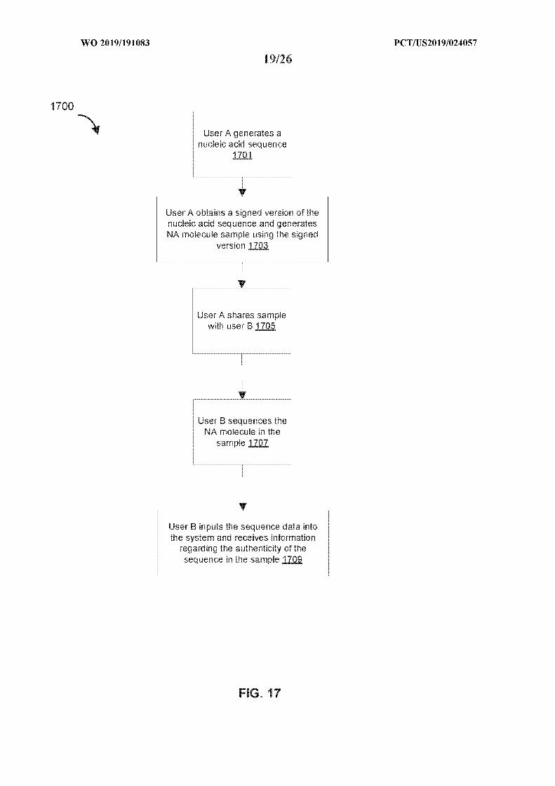


INTERNATIONAL SEARCH REPORTInternational application No
PCT/US2019/024057
A. CLASSIFICATION OF SUBJECT MATTERINV. G16B50/40ADD.
According to International Patent Classification (IPC) or to both national classification and IPC
B. FIELDS SEARCHED
Minimum documentation searched (classification system followed by classification symbols)
G16B
Documentation searched other than minimum documentation to the extent that such documents are included in the fields searched
Electronic data base consulted during the international search (name of data base and, where practicable, search terms used)
EPO-Internal , BIOSIS, Sequence Search , EMBASE, WPI Data
* Special categories of cited documents :"T" later document published after the international filing date or priority
"A" document defining the general state of the art which is not considereddate and not in conflict with the application but cited to understand
to be of particular relevancethe principle or theory underlying the invention
Έ " earlier application or patent but published on or after the internationalfiling date
"X" document of particular relevance; the claimed invention cannot beconsidered novel or cannot be considered to involve an inventive
"L" document which may throw doubts on priority claim(s) orwhich is step when the document is taken alone
rnational search report
or g
Form PCT/ISA/210 (second sheet) (April 2005)

INTERNATIONAL SEARCH REPORTInternational application No
PCT/US2019/024057
C(Continuation). DOCUMENTS CONSIDERED TO BE RELEVANT
im No.
Form PCT/ISA/210 (continuation of second sheet) (April 2005)