MODELS Mercury/Mariner 40·45·50·50 Bigfoot (4-Stroke)
599
MODELS SERVICE MANUAL Mercury/Mariner 40·45·50·50 Bigfoot (4-Stroke) United States 0G231123 . . . . . . With Starting Serial Numbers Printed in U.S.A. 1999, Mercury Marine 90-828631R3 MARCH 1999
-
Upload
khangminh22 -
Category
Documents
-
view
0 -
download
0
Transcript of MODELS Mercury/Mariner 40·45·50·50 Bigfoot (4-Stroke)

MODELS
SERVICEMANUAL
Mercury/Mariner40·45·50·50 Bigfoot (4-Stroke)
United States 0G231123. . . . . .
With Starting Serial Numbers
Printed in U.S.A. 1999, Mercury Marine 90-828631R3 MARCH 1999

90-828631R3 MARCH 1999 Page i
Notice
Throughout this publication, “Dangers”, “Warnings” and “Cautions” (accompanied by the In-ternational HAZARD Symbol ) are used to alert the mechanic to special instructions con-cerning a particular service or operation that may be hazardous if performed incorrectly orcarelessly. OBSERVE THEM CAREFULLY!
These “Safety Alerts” alone cannot eliminate the hazards that they signal. Strict complianceto these special instructions when performing the service, plus “Common Sense” operation,are major accident prevention measures.
DANGERDANGER - Immediate hazards which WILL result in severe personal injury or death.
WARNINGWARNING - Hazards or unsafe practices which COULD result in severe personal in-jury or death.
CAUTIONHazards or unsafe practices which could result in minor personal injury or productor property damage.
Notice to Users of This Manual
This service manual has been written and published by the Service Department of MercuryMarine to aid our dealers’ mechanics and company service personnel when servicing theproducts described herein.
It is assumed that these personnel are familiar with the servicing procedures of these prod-ucts, or like or similar products manufactured and marketed by Mercury Marine, that theyhave been trained in the recommended servicing procedures of these products which in-cludes the use of mechanics’ common hand tools and the special Mercury Marine or recom-mended tools from other suppliers.
We could not possibly know of and advise the service trade of all conceivable proceduresby which a service might be performed and of the possible hazards and/or results of eachmethod. We have not undertaken any such wide evaluation. Therefore, anyone who usesa service procedure and/or tool, which is not recommended by the manufacturer, first mustcompletely satisfy himself that neither his nor the products safety will be endangered by theservice procedure selected.
All information, illustrations and specifications contained in this manual are based on thelatest product information available at the time of publication. As required, revisions to thismanual will be sent to all dealers contracted by us to sell and/or service these products.
It should be kept in mind, while working on the product, that the electrical system and ignitionsystem are capable of violent and damaging short circuits or severe electrical shocks. Whenperforming any work where electrical terminals could possibly be grounded or touched bythe mechanic, the battery cables should be disconnected at the battery.
Any time the intake or exhaust openings are exposed during service they should be coveredto protect against accidental entrance of foreign material which could enter the cylinders andcause extensive internal damage when the engine is started.

Page ii 90-828631R3 MARCH 1999
It is important to note, during any maintenance procedure replacement fasteners must havethe same measurements and strength as those removed. Numbers on the heads of the met-ric bolts and on the surfaces of metric nuts indicate their strength. American bolts use radiallines for this purpose, while most American nuts do not have strength markings. Mis-matched or incorrect fasteners can result in damage or malfunction, or possibly personalinjury. Therefore, fasteners removed should be saved for reuse in the same locations when-ever possible. Where the fasteners are not satisfactory for re-use, care should be taken toselect a replacement that matches the original.
Cleanliness and Care of Outboard Motor
A marine power product is a combination of many machined, honed, polished and lappedsurfaces with tolerances that are measured in the ten thousands of an inch/mm. When anyproduct component is serviced, care and cleanliness are important. Throughout this manu-al, it should be understood that proper cleaning, and protection of machined surfaces andfriction areas is a part of the repair procedure. This is considered standard shop practiceeven if not specifically stated.
Whenever components are removed for service, they should be retained in order. At thetime of installation, they should be installed in the same locations and with the same matingsurfaces as when removed.
Personnel should not work on or under an outboard which is suspended. Outboards shouldbe attached to work stands, or lowered to ground as soon as possible.
We reserve the right to make changes to this manual without prior notification.
Refer to dealer service bulletins for other pertinent information concerning the products de-scribed in this manual.
EXAMPLE:
90-826148 R1 JANUARY 1996 LOWER UNIT - 6A-7
Revision No. 1
Month of Printing
Year of Printing
Section Description
Section Number
Part of Section Letter
Page Number

1
2
3
4
5
6
7
9
Important Information
Electrical
Fuel System
Powerhead
Mid-Section
Gear Housing
Attachments/Control Linkage
90-828631R3 MARCH 1999 Page iii
Service Manual Outline
Section 1 - Important InformationA - SpecificationsB - MaintenanceC - General InformationD - Outboard Motor Installation
Section 2 - ElectricalA - IgnitionB - Charging & Starting SystemC - Timing,Synchronizing & AdjustingD - Wiring Diagrams
Section 3 - Fuel SystemA - Fuel PumpB - CarburetorC - Emissions
Section 4 - PowerheadA - Cylinder HeadB - Cylinder Block/CrankcaseC - Lubrication
Section 5 - Mid-SectionA - Clamp/Swivel Brackets & Drive Shaft HousingB - Power Trim (1998 And Earlier Non-Bigfoot)C - Power Trim (1999 And Later Non-Bigfoot/
All Big-Foot Model Years)D - Manual Tilt Assist
Section 6 - Gear HousingA - Non-Bigfoot Gear HousingB - Bigfoot Gear Housing
Section 7 - Attachments/Control LinkageA - Throttle/Shift LinkageB - Tiller Handle

1A
SPECIFICATIONS
90-828631R3 MARCH 1999 Page 1A-1
IMPORTANT INFORMATIONSection 1A - Specifications
Table of Contents
Specifications 1A-1. . . . . . . . . . . . . . . . . . . . . . . . . . . . . Gear Case Design Identification 1A-7. . . . . . . . . . . . . Propeller Information Charts 1A-8. . . . . . . . . . . . . . . .
Mercury/Mariner 50 (4-Stroke)2.00:1 Non Bigfoot 1A-8. . . . . . . . . . . . . . . . . . . . . .
Mercury/Mariner 50 (4-Stroke)1.83:1 Non Bigfoot 1A-9. . . . . . . . . . . . . . . . . . . . . . Mercury/Mariner 50 (4-Stroke)2.3:1 Bigfoot 1A-10. . . . . . . . . . . . . . . . . . . . . . . . . .
Specifications
Models 40/45/50/50 (4-Stroke)
HORSEPOWER(kW)
Model 50Model 45Model 40
50 hp (37.3 Kw) @ 6000 rpm45 hp (33.5 Kw) @ 6000 rpm40 hp (29.8 Kw) @ 6000 rpm
OUTBOARDWEIGHT
Electric40/45/50 ELPT 224 lb (102 kg)
FUELRECOMMENDED GASOLINE Automotive Unleaded
with a Minimum Pump PostedOctane Rating of 87
OIL
ENGINE OIL CAPACITYENGINE OIL
+20
+40
+60
+80
F° C°
0
+100
–7
+4
+16
+27
–18
+38
SAE 10W-30
SAE 25W-40
Either 3 Quarts or 3 LitersSAE 10W-30 viscosity oil is recom-mended for use in all temperatures.
SAE 25W-40 viscosity oil may be used attemperatures above 40° F (4° C).
Use Quicksilver 4-Cycle Marine Oil withthe proper viscosity for the expectedtemperature in your area (see range
thermometer on left). If not available, usea premium quality 4-cycle engine oil, cer-
tified to meet or exceed anyone of thefollowing American Petroleum Institute(API) service classification SH, SG, SF,
CF-4, CE, CD, CDll.

SPECIFICATIONS
Page 1A-2 90-828631R3 MARCH 1999
IGNITION SYSTEM*
*Readings taken @ 68 °F(20°C).
TypeSpark Plug Type (NGK)Spark Plug GapFiring OrderIgnition Timing:
40/45 HPFully Retarded Fully Advanced (2500-3000 rpm)
50 HPFully Retarded Fully Advanced (2500-3000 rpm)
Charge Coil ResistanceTrigger Coil ResistanceIgnition Coil Resistance:
PrimarySecondary
cdi Engine Speed Limitercdi Overheat Speed ControlEngine Temperature Switch
Above 131 ° F (55° C)Below 104 ° F (40° C)
Capacitor Discharge IgnitionNGK DPR6EA-9
0.035 in. (1.0 mm)1-3-4-2
5° B.T.D.C25° B.T.D.C
5° B.T.D.C35° B.T.D.C
272 - 408 Ω (BRN-BLU)396 - 594 Ω (WHT/BLK-WHT/RED)
0.1 - 0.7 Ω3.5 - 4.7 kΩ
6120 - 6280 rpm1600 - 2400 rpm
No ContinuityContinuity
CHARGINGSYSTEM
Alternator TypeAlternator Output:
Electric StartLighting Coil Resistance (Grn - Grn)Lighting Coil Output Peak Voltage
Three Phase
12 Volts - 10 Amps. (Regulated)1.2 - 3.2 Ohms @ 68°F (20°C)
8.9 Volts @ 1500 rpm
STARTINGSYSTEM
P/N 50-825095 Top MountedElectric Start:
Starter TypeOutputAmpere Draw Under:
(Load)(No Load)
P/N 50-834749 Side MountedStarter TypeOutputAmpere Draw Under:
(Load)(No Load)
Bendix1.1 kW
106.0 Amps21.1 Amps
Bendix1.1 kW
95.0 Amps20.0 Amps
BATTERY
Battery RatingMinimum Requirement
For operation below 32 ° F (0° C)
465 Marine Cranking Amps (MCA)or 350 Cold Cranking Amps (CCA).
1000 Marine Cranking Amps (MCA) or775 Cold Cranking Amps (CCA)
ENRICHMENTCONTROL SYSTEM
Choke SolenoidElectro-thermal ram projection
3.2 - 4.8 Ω @ 68°F (20 °C)0.3 in. (7 mm) after 5 min. of power
FUEL SYSTEM
Fuel Pump TypeFuel Pump:
PressureDiaphragm StrokePlunger Stroke
Fuel Tank Capacity
External (Plunger/Diaphragm)
3-6 psi (21-41 kPa)0.14 - 0.20 in. (3.5 - 5.1 mm)
0.23 - 0.38 in. (5.85 - 9.65 mm)Accessory

SPECIFICATIONS
90-828631R3 MARCH 1999 Page 1A-3
CARBURETOR
Idle rpm (Out Of Gear)45 hp40/50 hp
Idle rpm (In Forward Gear)45 hp40/50 hp
Wide Open Throttle rpm (WOT)RangeMain Jet Size
40/45 hpCarburetors 1 and 2Carburetors 3 and 4
50 hpPilot JetFloat Height
950 ± 25 rpm825 ± 25 rpm
850 ± 25 rpm725 ± 25 rpm
5500–6000 rpm
#104#103#112#42
0.39 ± 0.02 in. (10.0 ± 0.5 mm)
CYLINDER BLOCKTypeDisplacementNumber of Cylinders
4 Stroke Cycle – Over Head Camshaft57 cu. in. (935cc)
4
STROKE Length 2.953 in. (75 mm)
CYLINDER BORE
DiameterStandardOversize-0.020 in. (0.050 mm)
Taper/Out of Round MaximumBore Type
2.4803 in. (63.0 mm)2.5003 in. (63.5 mm)0.003 in. (0.08 mm)
Steel
PISTON
Piston TypeO.D. at Skirt
StandardOversize-0.020 in. (0.50mm)
Aluminum
2.4783-2.4789 in. (62.950-62.965 mm)2.4983-2.4989 in. (63.450-63.465 mm)
PISTONCLEARANCE
Piston to Cylinder Clearance 0.0014 - .0026 in. (0.035 - 0.065 mm)
RINGS
Ring End Gap (Installed)TopMiddleBottom (Oil Ring)
Side Clearance:TopMiddle
0.006 - 0.012 in. (0.15 - 0.30 mm)0.012 - 0.020 in. (0.30 - 0.50 mm)0.008 - 0.028 in. (0.20 - 0.70 mm)
0.002 - 0.003 in. (0.04 - 0.08 mm)0.001 - 0.003 in. (0.03 - 0.08 mm)
COMPRESSIONRATIO
Compression RatioCylinder Compression (cold engine@ W.O.T.)
9.8:1170 -190 lb/in2 (Peak)
PISTON PIN Piston Pin Diameter 0.6285-0.6287 in. (15.965 - 15.970 mm)
CONNECTINGROD
Oil Clearance (Big End)Small End Inside Diameter
0.0008 - 0.0020 in. (0.020 - 0.052 mm)0.6293 - 0.6298 in. (15.985-15.998 mm)

SPECIFICATIONS
Page 1A-4 90-828631R3 MARCH 1999
CRANKSHAFT Main Bearing ClearanceCrankshaft Run-out
0.0005 - 0.0017 in. (0.012 - 0.044 mm)0.0012 in. (0.03 mm)
CAMSHAFT
Camshaft DimensionsIntake “A”Exhaust “A”Intake “B”Exhaust “B”
Run-out Limit
A
B
1.216 - 1.220 in. (30.89 - 30.99 mm)1.213 - 1.217 in. (30.82 - 30.92 mm)1.022 - 1.025 in. (25.95 - 26.05 mm)1.022 - 1.025 in. (25.95 - 26.05 mm)
0.0039 in. (0.1 mm)
VALVE SPRING
Free Length “a”Tilt Limit “b”
Compressed Pressure (Installed)IntakeExhaust
Tilt Limit (Intake & Exhaust)Dir. of Winding (Intake & Exhaust)
a
b
1.491-1.569 in. (37.85-39.85 mm)Less than 0.060 in. (1.7 mm)
19.8 - 22.0 lb (9.0 - 10.0 kg)19.8 - 22.0 lb (9.0 - 10.0 kg)
0.043 in. (1.1 mm)Left Hand
CYLINDER HEAD
Warp Limit
* Lines indicatestraight edgemeasurement
0.004 in. (0.1 mm)

SPECIFICATIONS
90-828631R3 MARCH 1999 Page 1A-5
VALVES
Valve/Valve Seat/Valve Guides:Valve Clearance (cold)
IntakeExhaust
Valve Dimensions:“A” Head Diameter
IntakeExhaust
“B” Face WidthIntakeExhaust
“C” Seat WidthIntakeExhaust
“D” Margin ThicknessIntakeExhaust
Stem Outside DiameterIntakeExhaust
Guide Inside DiameterIntakeExhaust
Stem To Guide ClearanceIntakeExhaust
Stem Run-out Limit (max.)
0.006 - 0.010 in. (0.15 - 0.25 mm)0.010 - 0.014 in. (0.25 - 0.35 mm)
1.177 - 1.185 in. (29.9 - 30.1 mm)1.020 - 1.028 in. (25.9 - 26.1 mm)
0.079 - 0.124 in. (2.00 - 3.14 mm)0.079 - 0.124 in. (2.00 - 3.14 mm)
0.035 - 0.043 in. (0.9 - 1.1 mm)0.035 - 0.043 in. (0.9 - 1.1 mm)
0.020 - 0.035 in. (0.5 - 0.9 mm)0.020 - 0.035 in. (0.5 - 0.9 mm)
0.2156 - 0.2161 in. (5.475 - 5.490 mm)0.2150 - 0.2156 in. (5.460 - 5.475 mm)
0.2165 - 0.2170 in. (5.500 - 5.512 mm)0.2165 - 0.2170 in. (5.500 - 5.512 mm)
0.0004 - 0.0015 in. (0.010 - 0.037 mm)0.0010 - 0.0020 in. (0.025 - 0.052 mm)
0.0006 in. (0.016 mm)
“A”
“B”“C”
“D”
Valve Dimensions
Head Diameter Face Width Seat Width Margin Thickness

SPECIFICATIONS
Page 1A-6 90-828631R3 MARCH 1999
THERMOSTATValve Opening TemperatureFull Open TemperatureValve Lift
136° F - 143° F (58° C - 62° C)158° F (70° C)0.12 in. (3 mm)
LUBRICATIONSYSTEM
Pump TypeEngine Oil PressureEngine Oil Pan CapacityOil Pump:
Outer Rotor to Housing “a”Inner Rotor to Outer Rotor “b”Rotor to Housing “c”
a
b
c
Trochoid30-40 psi at 3000 rpm (Warm Engine)
Either 3 Qts. or 3 Liters
0.001 - 0.006 in. (0.03 - 0.15 mm)0.005 in. (0.12 mm)
0.001 - 0.003 in. (0.03 - 0.08 mm)
MID-SECTION
Transom Height:Long Shaft
Steering Pivot RangeTilt Pin PositionsFull Tilt Up AngleAllowable Transom Thickness
20 in. (51 cm)90°
5 + Shallow Water70°
2-3/8 in. (60.3 mm)
1995/1996GEAR HOUSING
(2.00:1)
45/50 1995/1996 modelsGear Ratio Gearcase Capacity Lubricant TypeForward Gear
Number of TeethPinion Gear
Number of TeethPinion HeightForward Gear BacklashWater Pressure
@ Idle@ WOT
2.00:114.9 fl oz (440 mL)
Quicksilver Gear Lube-Premium Blend
26 Spiral/Bevel
13 Spiral/Bevel0.025 in. (0.64 mm)
No Adjustment
2-4 psi (14-28 kPa) @ 750 rpm12-17 psi (83-117 kPa) @ 6000 rpm

SPECIFICATIONS
90-828631R3 MARCH 1999 Page 1A-7
1997 AND NEWERGEAR HOUSING
(1.83:1)
40/45/50 1997 and Newer modelsGear Ratio Gearcase Capacity Lubricant TypeForward Gear
Number of TeethPinion Gear
Number of TeethPinion HeightForward Gear BacklashWater Pressure
@ Idle@ WOT
1.83:114.9 fl oz (440 mL)
Quicksilver Gear Lube-Premium Blend
22 Spiral/Bevel
12 Spiral/Bevel0.025 in. (0.64 mm)
No Adjustment
2-4 psi (14-28 kPa) @ 750 rpm12-17 psi (83-117 kPa) @ 6000 rpm
1998 AND NEWERBIGFOOT GEAR
HOUSING(2.3:1)
Gear Ratio Gearcase Capacity Lubricant TypeForward Gear
Number of TeethPinion Gear
Number of TeethPinion HeightForward Gear BacklashWater Pressure
@ 750 rpm (Idle)@ 6000 rpm (WOT)
2.3:122.5 fl oz (655 mL)
Quicksilver Gear Lube-Premium Blend
30 Spiral/Bevel
13 Spiral/Bevel0.025 in. (0.64 mm)
0.012-0.019 in. (0.30-0.48 mm)
2-4 psi (14-28 kPa)10-15 psi (69-103 kPa)
Gear Case Design Identification
a b
“3 Jaw Reverse Clutch” “6 Jaw Reverse Clutch”a - Design I - “3 Jaw Reverse Clutch” Gear Case Identifierb - Design II - “6 Jaw Reverse Clutch” Gear Case Identifier
Identify gear case design to ensure correct components are being installed. Design I -“3 Jaw Reverse Clutch” (a) gear case identified with straight machined edge for trim tabscrew mounting surface. Design II - “6 Jaw Reverse Clutch” (b) gear case identified withangled machined edge for trim tab screw mounting surface.

SPECIFICATIONS
Page 1A-8 90-828631R3 MARCH 1999
Propeller Information Charts
Mercury/Mariner 50 (4-Stroke) 2.00:1 Non BigfootWide Open Throttle rpm : 5500-6000Recommended Transom Heights : 15”, 20”, 22.5”Right Hand Rotation StandardGear Reduction : 2.00:1
Diameter PitchNo. ofBlades Material
Approx.Gross Boat
Wgt. (lb)
Approx.Boat
Length
SpeedRange (mph)
PropellerPart Number
10” 19” 3 Alum Up to 800 Up to 14’ 43-51 48-73146A40
10” 17” 3 Alum Up to 900 Up to 15’ 40-46 48-73144A40
10” 16” 3 Steel 800-1000 Up to 15’ 37-43 48-91818A5
10” 16” 3 Alum 800-1000 Up to 15’ 37-43 48-73142A40
10-1/8” 15” 3 Steel 900-1300 13-15’ 34-41 48-76232A5
10-1/8” 15” 3 Alum 900-1300 13-15’ 34-41 48-73140A40
10-3/8” 14” 3 Alum 1000-1500 14-16’ 32-37 48-816706A40
10-1/4” 14” 3 Steel 1000-1500 14-16’ 32-37 48-76230A5
10-1/4” 14” 3 Alum 1000-1500 14-16’ 32-37 48-73138A40
10-1/2” 13” 3 Alum 1100-1700 14-17’ 29-34 48-816704A40
10-3/8” 13” 3 Steel 1100-1700 14-17’ 29-34 48-76228A5
10-3/8” 13” 3 Alum 1100-1700 14-17’ 29-34 48-73136A40
10-3/4” 12” 3 Alum 1200-1900 15-17’ 25-31 48-816702A40
10-5/8” 12” 3 Steel 1200-1900 15-17’ 25-31 48-79792A5
10-5/8” 12” 3 Alum 1200-1900 15-17’ 25-31 48-73134A40
10-7/8” 11” 3 Alum 1400-2100 16-18’ 22-27 48-85632A45
11-5/8” 11” 3 Steel 1400-2100 16’ + 22-27 48-823478A5
11-5/8” 10-1/2” 3 Alum 1500-2300 16’ + 20-25 48-827312A10
11-1/4” 10” 3 Alum 1700-2500 17’ + 18-23 48-73132A40
12-1/4” 9” 3 Steel 1900+ 18’ + 13-20 48-97868A10
12-1/4” 9” 3 Alum 1900+ 18’ + 13-20 48-87818A10
12-1/2” 8” 3 Alum 2100+ 18’ + 1-16 48-42738A10
12-1/2” 8” Cup 3 Alum pontoon 48-42738A12

SPECIFICATIONS
90-828631R3 MARCH 1999 Page 1A-9
Mercury/Mariner 50 (4-Stroke) 1.83:1 Non BigfootWide Open Throttle rpm : 5500-6000Recommended Transom Heights : 15”, 20”, 22.5”Right Hand Rotation StandardGear Reduction : 1.83:1
Diameter PitchNo. ofBlades Material
Approx.Gross Boat
Wgt. (lb)
Approx.Boat
Length
SpeedRange (mph)
PropellerPart Number
10” 19” 3 Alum Up to 800 Up to 14’ 49-58 48-73146A40
10” 17” 3 Alum Up to 900 Up to 15’ 43-50 48-73144A40
10” 16” 3 Steel 900-1300 Up to 15’ 39-46 48-91818A5
10” 16” 3 Alum 900-1300 Up to 15’ 39-46 48-73142A40
10-1/8” 15” 3 Steel 1000-1400 13-15’ 36-43 48-76232A5
10-1/8” 15” 3 Alum 1000-1400 13-15’ 36-43 48-73140A40
10-1/4” 14” 3 Steel 1100-1600 14-16’ 33-39 48-76230A5
10-1/4” 14” 3 Alum 1100-1600 14-16’ 33-39 48-73138A40
10-3/8” 13” 3 Steel 1300-1800 14-17’ 30-35 48-76228A5
10-3/8” 13” 3 Alum 1300-1800 14-17’ 30-35 48-73136A40
10-5/8” 12” 3 Steel 1400-2000 15-17’ 27-32 48-79792A5
10-5/8” 12” 3 Alum 1400-2000 15-17’ 27-32 48-73134A40
11-5/8” 11” 3 Steel 1700-2400 16-18’ 24-29 48-823478A5
10-7/8” 11” 3 Alum 1700-2400 16-18’ 24-29 48-85632A45
11-5/8” 10-1/2” 3 Alum 1900-2700 16’ + 21-25 48-827312A10
11-1/4” 10” 3 Alum 2100-3000 17’ + 19-24 48-73132A40
12-1/4” 9” 3 Steel 2500+ pontoon 17-21 48-97868A10
12-1/4” 9” 3 Alum 2500+ pontoon 17-21 48-87818A10
12-1/2” 8” 3 Alum 3000+ pontoon/houseboat
1-18 48-42738A10
12-1/2” 8” Cup 3 Alum pontoon 48-42738A12

SPECIFICATIONS
Page 1A-10 90-828631R3 MARCH 1999
Mercury/Mariner 50 (4-Stroke) 2.3:1 BigfootWide Open Throttle rpm : 5500-6000Recommended Transom Heights : 20”, 25”Right Hand Rotation StandardGear Reduction : 2.31:1
Diameter PitchNo. ofBlades Material
Approx.Gross Boat
Wgt. (lb)
Approx.Boat
Length
SpeedRange (mph)
PropellerPart Number
13” 18” 3 Steel Up to 1400 Up to 14’ 34-40 48-16988A45
13-1/4” 17” 3 Alum 1300-1600 Up to 14’ 32-38 48-77344A45
13-1/8” 16” 3 Steel 1400-1700 14-16’ 29-35 48-16986A45
13-3/4” 15” 3 Alum 1500-1900 14-16’ 27-32 48-77342A45
13-3/8” 14” 3 Steel 1700-2200 15-17’ 24-30 48-17314A45
14” 13” 3 Alum 1900-2400 16-18’ 22-27 48-77340A45
14” 12” 3 Steel 2500-3200 17’+ 18-24 48-17312A45
14” 11” 3 Alum 2800-4000 pontoon 17-21 48-77338A45
14” 10” 3 Alum 3000+ pontoon/work 14-19 48-854342A45
14” 9” 3 Alum 5000+ houseboat/work
1-15 48-854340A45
Mercury/Mariner 50 (4-Stroke) 2.3:1 Bigfoot
Special soft rubber hub propellers designed to reduce clutch rattleWide Open Throttle rpm : 5500-6000Recommended Transom Heights : 20”, 25”Right Hand Rotation StandardGear Reduction : 2.31:1
IMPORTANT: These specially designed rubber hub propellers are rated for 50 horse-power MAXIMUM.
Diameter PitchNo. ofBlades Material
Approx.Gross BoatWgt. (lbs)
Approx.Boat
Length
SpeedRange(mph)
PropellerPart Number
14” 13” 3 Alum 1900-2400 16-18’ 22-27 48-77340A33
14” 11” 3 Alum 2800-4000 pontoon 17-21 48-77338A33
14” 10” 3 Alum 3000+ pontoon/work 14-19 48-854342A33
14” 9” 3 Alum 5000+ houseboat/work
1-15 48-854340A33

1B
MAINTENANCE
90-828631R3 MARCH 1999 Page 1B-1
IMPORTANT INFORMATIONSection 1B - Maintenance
Table of ContentsSpecial Tools 1B-1. . . . . . . . . . . . . . . . . . . . . . . . . . . . . Quicksilver Lubricant/Sealant 1B-2. . . . . . . . . . . . . . . Inspection And Maintenance Schedule 1B-4. . . . . . .
Before Each Use 1B-4. . . . . . . . . . . . . . . . . . . . . . . After Each Use 1B-4. . . . . . . . . . . . . . . . . . . . . . . . . Every 100 Hours of Use or Once yearly,Whichever occurs first 1B-5. . . . . . . . . . . . . . . . . . Every 300 Hours of Use or Three Years 1B-5. . . Before Periods of Storage 1B-5. . . . . . . . . . . . . . .
Corrosion Control Anode 1B-6. . . . . . . . . . . . . . . . . . . Spark Plug Inspection 1B-7. . . . . . . . . . . . . . . . . . . . . . Battery Inspection 1B-7. . . . . . . . . . . . . . . . . . . . . . . . . Fuse Replacement – Electric Start Models 1B-8. . . . Timing Belt Inspection 1B-8. . . . . . . . . . . . . . . . . . . . . Lubrication Points 1B-9. . . . . . . . . . . . . . . . . . . . . . . . . Checking Power Trim Fluid 1B-10. . . . . . . . . . . . . . . .
Changing Engine Oil 1B-11. . . . . . . . . . . . . . . . . . . . . . Oil Changing Procedure 1B-11. . . . . . . . . . . . . . . . Changing Oil Filter 1B-12. . . . . . . . . . . . . . . . . . . . . Oil Filling 1B-12. . . . . . . . . . . . . . . . . . . . . . . . . . . . .
Gear Case Lubrication 1B-13. . . . . . . . . . . . . . . . . . . . 3-1/4 In. (83mm) Diameter Gear Case 1B-13. . . 4-1/4 In. (108mm) Diameter Gear Case 1B-14. .
Storage Preparation 1B-16. . . . . . . . . . . . . . . . . . . . . . Fuel System 1B-16. . . . . . . . . . . . . . . . . . . . . . . . . . Protecting External OutboardComponents 1B-16. . . . . . . . . . . . . . . . . . . . . . . . . . Protecting Internal Engine Components 1B-16. . Gear Case 1B-16. . . . . . . . . . . . . . . . . . . . . . . . . . . Positioning Outboard for Storage 1B-17. . . . . . . . Battery Storage 1B-17. . . . . . . . . . . . . . . . . . . . . . .
Special Tools1. Flushing Attachment P/N 44357A2
2. Crankcase Oil Pump P/N 90265A2
3. Oil Filter Wrench P/N 91-802653

MAINTENANCE
Page 1B-2 90-828631R3 MARCH 1999
Quicksilver Lubricant/Sealant1. Quicksilver Anti-Corrosion Grease P/N 92-78376A6
2. 2-4-C Marine Lubricant with Teflon P/N 92-825407A12
3. Special Lubricant 101 P/N 92-13872A1
4. Quicksilver Power Trim and Steering Fluid P/N 92-190100A12

MAINTENANCE
90-828631R3 MARCH 1999 Page 1B-3
5. Quicksilver 4-Stroke Outboard Oil P/N 92-828000A12
6. Gear Lube-Premium Blend P/N 92-19007A24
7. Quicksilver 4-Cycle Marine Engine Oil P/N 92-832111A1
4-CYCLEMARINE
ENGINE OIL
Premium BlendSAE 25W-40
NET 32 OZ (1 QT) 946 ml

MAINTENANCE
Page 1B-4 90-828631R3 MARCH 1999
Inspection And Maintenance ScheduleTo keep your outboard in the best operating condition, it is important that your outboard re-ceive the periodic inspections and maintenance listed in the Inspection and MaintenanceSchedule. We urge you to keep it maintained properly to ensure the safety of you and yourpassengers and retain its dependability.
WARNINGNeglected inspection and maintenance service of your outboard or attempting toperform maintenance or repair on your outboard if you are not familiar with the cor-rect service and safety procedures could cause personal injury, death, or productfailure.
Before Each Use1. Check engine oil level.
2. Check that lanyard stop switch stops the engine.
3. Visually inspect the fuel system for deterioration or leaks.
4. Check outboard for tightness on transom.
5. Check steering system for binding or loose components.
6. Visually check steering link rod fasteners for proper tightness.
7. Check propeller blades for damage.
After Each Use1. Flush out the outboard cooling system if operating in salt or polluted water.
2. Wash off all salt deposits and flush out the exhaust outlet of the propeller and gear casewith fresh water if operating in salt water.

MAINTENANCE
90-828631R3 MARCH 1999 Page 1B-5
Every 100 Hours of Use or Once yearly, Whichever occurs first1. Lubricate all lubrication points. Lubricate more frequently when used in salt water.
2. Change engine oil and replace the oil filter. The oil should be changed more often whenthe engine is operated under adverse conditions such as extended trolling.
3. Inspect thermostat visually for corrosion, broken spring, and to determine that the valveis completely closed at room temperature. If questionable, inspect thermostat as out-lined in Section 4B “Thermostat” .
4. Inspect and clean spark plugs.
5. Check engine fuel filter for contaminants.
6. Adjust carburetor(s) (if required).
7. Check engine timing setup.
8. Check corrosion control anodes. Check more frequently when used in salt water.
9. Drain and replace gear case lubricant.
10. Lubricate splines on the drive shaft.
11. Check and adjust valve clearance, if necessary.
12. Check power trim fluid.
13. Inspect battery.
14. Check control cable adjustments.
15. Inspect timing belt.
16. Remove engine deposits with Quicksilver Power Tune Engine Cleaner.
17. Check tightness of bolts, nuts, and other fasteners.
Every 300 Hours of Use or Three Years1. Replace water pump impeller (more often if overheating occurs or reduced water pres-
sure is noted).
Before Periods of Storage1. Refer to Storage procedure (this section).

MAINTENANCE
Page 1B-6 90-828631R3 MARCH 1999
Corrosion Control AnodeYour outboard has control anodes at different locations. An anode helps protect the out-board against galvanic corrosion by sacrificing its metal to be slowly eroded instead of theoutboard metals.
Each anode requires periodic inspection especially in salt water which will accelerate theerosion. To maintain this corrosion protection, always replace the anode before it is com-pletely eroded. Never paint or apply a protective coating on the anode as this will reduceeffectiveness of the anode.
1. An anode is installed on the bottom of the transom bracket assembly. Trim tab is alsoan anode on the 3-1/4 in. (83 mm) diameter gear case. The 4-1/4 in. (108 mm) diametergear case has three anodes. One of the anodes is the trim tab and two anodes are lo-cated on the side.
a
b
c
a - Bottom Anodeb - Trim Tabc - Side Anodes
2. Four anodes are installed in the engine block. Remove anodes at locations shown.Install each anode with rubber seal and cover. Torque bolts to specified torque.
ab
c
a - Anodes-Engine Blockb - Rubber Sealc - Cover
Bolt Torque
70 lb-in. (8 Nm)

MAINTENANCE
90-828631R3 MARCH 1999 Page 1B-7
Spark Plug InspectionInspect spark plugs at the recommended intervals.
1. Remove the spark plug leads by twisting the rubber boots slightly and pull off.
2. Remove the spark plugs to inspect and clean. Replace spark plug if electrode is wornor the insulator is rough, cracked, broken, blistered or fouled.
3. Set the spark plug gap. See Specification Chart.
4. Before reinstalling spark plugs, clean away dirt on the spark plug seats. Install plugs fin-ger tight, and tighten 1/4 turn or torque to specified torque.
Spark Plug Torque
20 lb-in. (27 Nm)
Battery InspectionThe battery should be inspected at periodic intervals to ensure proper engine starting capa-bility.
IMPORTANT: Read the safety and maintenance instructions which accompany yourbattery.
1. Turn off the engine before servicing the battery.
2. Add water as necessary to keep the battery full.
3. Make sure the battery is secure against movement.
4. Battery cable terminals should be clean, tight, and correctly installed. Positive to positiveand negative to negative.
5. Make sure the battery is equipped with a nonconductive shield to prevent accidentalshorting of battery terminals.

MAINTENANCE
Page 1B-8 90-828631R3 MARCH 1999
Fuse Replacement – Electric Start ModelsThe electric starting circuit is protected from overload by an SFE 20 AMP fuse. If the fuseis blown, the electric starter motor will not operate. Try to locate and correct the cause ofthe overload. If the cause is not found, the fuse may blow again. Replace the fuse with afuse of the same rating.
1. Open the fuse holder and look at the silver colored band inside the fuse. If band is brokenreplace the fuse. Replace fuse with a new fuse with the same rating.
a
a - Blown Fuse
Timing Belt Inspection1. Inspect the timing belt and replace if any of the following conditions are found.
a. Cracks in the back of the belt or in the base of the belt teeth.
b. Excessive wear at the roots of the cogs.
c. Rubber portion swollen by oil.
d. Belt surfaces roughened.
e. Signs of wear on edges or outer surfaces of belt.
a
a - Timing Belt

MAINTENANCE
90-828631R3 MARCH 1999 Page 1B-9
Lubrication PointsLubricate Point 1 with Quicksilver Anti-Corrosion Grease or 2-4-C Marine Lubricantwith Teflon
1. Propeller Shaft – Refer to Propeller Replacement for removal and installation of the pro-peller. Coat the entire propeller shaft with lubricant to prevent the propeller hub from cor-roding and seizing to the shaft.
1
Lubricate Points 2 thru 4 with Quicksilver 2-4-C Marine Lubricant with Teflon or Spe-cial Lubricant 101.
2. Swivel Bracket – Lubricate through fitting.
3. Tilt Support Lever – Lubricate through fitting.
2
3

MAINTENANCE
Page 1B-10 90-828631R3 MARCH 1999
Lubricate Point 4 with light weight oil.
4. Steering Cable Grease Fitting – Rotate steering wheel to fully retract the steering cableend into the outboard tilt tube. Lubricate through fitting. Lubricate steering link rod pivotpoints with light weight oil.
ba
4
a - Steering Cable Endb - Fitting
WARNINGThe end of the steering cable must be fully retracted into the outboard tilt tube be-fore adding lubricant. Adding lubricant to steering cable when fully extended couldcause steering cable to become hydraulically locked. An hydraulically locked steer-ing cable will cause loss of steering control, possibly resulting in serious injury ordeath.
Checking Power Trim Fluid1. Tilt outboard to the full up position and engage the tilt support lock.
a
a - Tilt Support Lock
2. Remove fill cap and check fluid level. The fluid level should be even with the bottom ofthe fill hole. Add Quicksilver Power Trim & Steering Fluid. If not available, use automo-tive (ATF) automatic transmission fluid.
a
a - Fill Cap

MAINTENANCE
90-828631R3 MARCH 1999 Page 1B-11
Changing Engine OilEngine Oil Capacity
3 U.S. Quarts (3.0 Liters)
Oil Changing ProcedurePump Method
1. Place the outboard in an vertical upright position.
2. Remove dipstick and thread a Quicksilver Crankcase Oil Pump onto the dipstick tube.Pump out the engine oil into an appropriate container.
a
a - Crankcase Oil Pump
Drain Plug Method
1. Tilt the outboard up to the trailer position.
2. Turn the steering on the outboard so that the drain hole is facing downward. Removedrain plug and drain engine oil into an appropriate container. Lubricate the seal on thedrain plug with oil and reinstall.
a
a - Drain Hole

MAINTENANCE
Page 1B-12 90-828631R3 MARCH 1999
Changing Oil Filter1. Place a rag or towel below the oil filter to absorb any spilled oil.
2. Unscrew old filter by turning the filter counterclockwise.
3. Clean the mounting base. Apply film of clean oil to filter gasket. Do not use grease.Screw new filter on until gasket contacts base, then tighten 3/4 to 1 turn.
91-802653
a
a - Oil Filter
Oil Filling1. Remove the oil fill cap and add oil to the proper operating level.
2. Idle engine for five minutes and check for leaks. Stop engine and check oil level on dip-stick. Add oil if necessary.
a
a - Oil Fill Cap

MAINTENANCE
90-828631R3 MARCH 1999 Page 1B-13
Gear Case LubricationWhen adding or changing gear case lubricant, visually check for the presence of water inthe lubricant. If water is present, it may have settled to the bottom and will drain out priorto the lubricant, or it may be mixed with the lubricant, giving it a milky colored appearance.If water is noticed, have the gear case checked by your dealer.Water in the lubricant mayresult in premature bearing failure or, in freezing temperatures, will turn to ice and damagethe gear case.
Whenever you remove the fill/drain plug, examine the magnetic end for metal particles. Asmall amount of metal filings or fine metal particles indicates normal gear wear. An exces-sive amount of metal filings or larger particles (chips) may indicate abnormal gear wear andshould be checked by an authorized dealer.
3-1/4 In. (83mm) Diameter Gear CaseDRAINING GEAR CASE
1. Place outboard in a vertical operating position.
2. Place a drain pan below outboard.
3. Remove vent plug and fill/drain plug and drain lubricant.
a
a - Vent Plug and Fill/Drain Plug
GEAR CASE LUBRICANT CAPACITY
Gear case lubricant capacity is approximately 14.9 fl oz (440 ml).

MAINTENANCE
Page 1B-14 90-828631R3 MARCH 1999
CHECKING GEAR CASE LUBRICANT LEVEL AND REFILLING GEAR CASE
1. Place outboard in a vertical operating position.
2. Remove vent plug.
3. Place lubricant tube into the fill hole and add lubricant until it appears at the vent hole.
IMPORTANT: Replace sealing washers if damaged.
4. Stop adding lubricant. Install the vent plug and sealing washer before removing the lubri-cant tube.
5. Remove lubricant tube and reinstall cleaned fill/drain plug and sealing washer.
a
b
c
d
a - Vent Plug/Sealing Washerb - Lubricant Tubec - Vent Holed - Fill/Drain Plug and Sealing Washer
4-1/4 In. (108mm) Diameter Gear CaseWhen adding or changing gear case lubricant, visually check for the presence of water inthe lubricant. If water is present, it may have settled to the bottom and will drain out priorto the lubricant, or it may be mixed with the lubricant, giving it a milky colored appearance.If water is noticed, have the gear case checked by your dealer. Water in the lubricant mayresult in premature bearing failure or, in freezing temperatures, will turn to ice and damagethe gear case.
Whenever you remove the fill/drain plug, examine the magnetic end for metal particles. Asmall amount of metal filings or fine metal particles indicates normal gear wear. An exces-sive amount of metal filings or larger particles (chips) may indicate abnormal gear wear andshould be checked by an authorized dealer.

MAINTENANCE
90-828631R3 MARCH 1999 Page 1B-15
DRAINING GEAR CASE
1. Place outboard in a vertical operating position.
2. Place a drain pan below outboard.
3. Remove vent plugs and fill/drain plug and drain lubricant.
a
a - Vent Plugs and Fill/Drain Plug
GEAR CASE LUBRICANT CAPACITY
Gear case lubricant capacity is approximately 22.5 fl oz (655 ml).
CHECKING LUBRICANT LEVEL AND FILLING GEAR CASE
1. Place outboard in a vertical operating position.
2. Remove the front vent plug and rear vent plug.
3. Place lubricant tube into the fill hole and add lubricant until it appears at the front venthole. At this time install the front vent plug and sealing washer.
4. Continue adding lubricant until it appears at the rear vent hole.
5. Stop adding lubricant. Install the rear vent plug and sealing washer before removinglubricant tube.
6. Remove lubricant tube and reinstall cleaned fill/drain plug and sealing washer.
a
c
d
e
b
a - Front Vent Plugb - Rear Vent Plugc - Front Vent Holed - Rear Vent Holee - Fill/Drain Plug and Sealing Washer

MAINTENANCE
Page 1B-16 90-828631R3 MARCH 1999
Storage PreparationThe major consideration in preparing your outboard for storage is to protect it from rust, cor-rosion, and damage caused by freezing of trapped water.
The following storage procedures should be followed to prepare your outboard for out-of-season storage or prolonged storage (two months or longer).
CAUTIONNever start or run your outboard (even momentarily) without water circulatingthrough the cooling water intake in the gear case to prevent damage to the waterpump (running dry) or overheating of the engine.
Fuel SystemIMPORTANT: Gasoline containing alcohol (ethanol or methanol) can cause a forma-tion of acid during storage and can damage the fuel system. If the gasoline being usecontains alcohol, it is advisable to drain as much of the remaining gasoline as pos-sible from the fuel tank, remote fuel line, and engine fuel system.
Fill the fuel system (tank, hoses, fuel pump, and carburetor) with treated (stabilized) fuel tohelp prevent formation of varnish and gum. Proceed with following instructions.
1. Portable Fuel Tank – Pour the required amount of Quicksilver Gasoline Stabilizer (followinstructions on container) into fuel tank. Tip fuel tank back and forth to mix stabilizer withthe fuel.
2. Permanently Installed Fuel Tank – Pour the required amount of Quicksilver GasolineStabilizer (follow instructions on container) into a separate container and mix withapproximately one quart (one liter) of gasoline. Pour this mixture into fuel tank.
3. Place the outboard in water or connect flushing attachment for circulating cooling water.Run the engine for ten minutes to allow treated fuel to reach the carburetor.
Protecting External Outboard Components1. Lubricate all outboard components listed in the Inspection and Maintenance Schedule.
2. Touch up any paint nicks.
3. Spray Quicksilver Corrosion Guard on external metal surfaces (except corrosion controlanodes).
Protecting Internal Engine Components1. Remove the spark plugs and inject a small amount of engine oil inside of each cylinder.
2. Rotate the flywheel manually several times to distribute the oil in the cylinders. Reinstallspark plugs.
3. Change the engine oil.
Gear Case1. Drain and refill the gear case lubricant (refer to maintenance procedure).

MAINTENANCE
90-828631R3 MARCH 1999 Page 1B-17
Positioning Outboard for StorageStore outboard in an upright (vertical) position to allow water to drain out of outboard.
CAUTIONIf outboard is stored tilted up in freezing temperature, trapped cooling water or rainwater that may have entered the propeller exhaust outlet in the gear case couldfreeze and cause damage to the outboard.
Battery Storage1. Follow the battery manufacturer’s instructions for storage and recharging.
2. Remove the battery from the boat and check water level. Recharge if necessary.
3. Store the battery in a cool, dry place.
4. Periodically check the water level and recharge the battery during storage.

1C
GENERAL INFORMATION
90-828631R3 MARCH 1999 Page 1C-1
IMPORTANT INFORMATIONSection 1C - General Information
Table of Contents
Serial Number Location 1C-1. . . . . . . . . . . . . . . . . . . . Conditions Affecting Performance 1C-2. . . . . . . . . . .
Weather 1C-2. . . . . . . . . . . . . . . . . . . . . . . . . . . . . . . Boat 1C-3. . . . . . . . . . . . . . . . . . . . . . . . . . . . . . . . . . Engine 1C-4. . . . . . . . . . . . . . . . . . . . . . . . . . . . . . . .
Following Complete Submersion 1C-5. . . . . . . . . . . . Submerged While Running(Special Instructions) 1C-5. . . . . . . . . . . . . . . . . . . Salt Water Submersion(Special Instructions) 1C-5. . . . . . . . . . . . . . . . . . . Fresh Water Submersion(Special Instructions) 1C-5. . . . . . . . . . . . . . . . . . .
Propeller Selection 1C-6. . . . . . . . . . . . . . . . . . . . . . . . Propeller Removal/Installation 1C-7. . . . . . . . . . . . . .
Standard Models 1C-7. . . . . . . . . . . . . . . . . . . . . . .
Power Trim System 1C-9. . . . . . . . . . . . . . . . . . . . . . . . General Information 1C-9. . . . . . . . . . . . . . . . . . . . Power Trim Operation 1C-9. . . . . . . . . . . . . . . . . . . Trim “In” Angle Adjustment 1C-10. . . . . . . . . . . . .
Trim Tab Adjustment 1C-12. . . . . . . . . . . . . . . . . . . . . . Compression Check 1C-12. . . . . . . . . . . . . . . . . . . . . . Cylinder Leakage Testing 1C-13. . . . . . . . . . . . . . . . . .
Analysis 1C-13. . . . . . . . . . . . . . . . . . . . . . . . . . . . . . Painting Procedures 1C-14. . . . . . . . . . . . . . . . . . . . . .
Cleaning & Painting AluminumPropellers & Gear Housings 1C-14. . . . . . . . . . . .
Decal Application 1C-15. . . . . . . . . . . . . . . . . . . . . . . . . Decal Removal 1C-15. . . . . . . . . . . . . . . . . . . . . . . . Instructions for “Wet” Application 1C-15. . . . . . . .
Serial Number Location
The Outboard serial number is located on the lower starboard side of the engine block. Aserial number is also located on the starboard side of the swivel bracket.
19XX
XX
OGXXXXXX
XXXX
ed
c
ba
a - Serial Numberb - Model Yearc - Model Descriptiond - Year Manufacturede - Certified Europe Insignia

GENERAL INFORMATION
Page 1C-2 90-828631R3 MARCH 1999
Conditions Affecting Performance
Weather
ENGINE RPM
Rated hp
Summer hp
Horsepower LossDue to AtmosphereConditions
Secondary Loss Due toPropeller Becoming ToLarge for SummerHorsepower
RPM Drop Dueto Weather
Rated RPM
It is a known fact that weather conditions exert a profound effect on power output of internalcombustion engines. Therefore, established horsepower ratings refer to the power that theengine will produce at its rated rpm under a specific combination of weather conditions.
Corporations internationally have settled on adoption of I.S.O. (International Standards Or-ganization) engine test standards, as set forth in I.S.O. 3046 standardizing the computationof horsepower from data obtained on the dynamometer, correcting all values to the powerthat the engine will produce at sea level, at 30% relative humidity at 77° F (25° C) tempera-ture and a barometric pressure of 29.61 inches of mercury.
Summer Conditions of high temperature, low barometric pressure and high humidity allcombine to reduce the engine power. This, in turn, is reflected in decreased boat speeds--asmuch as 2 or 3 miles-per-hour (3 or 5 Km per-hour) in some cases. (Refer to previous chart.)Nothing will regain this speed for the boater, but the coming of cool, dry weather.
In pointing out the practical consequences of weather effects, an engine--running on a hot,humid summer day--may encounter a loss of as much as 14% of the horsepower it wouldproduce on a dry, brisk spring or fall day. The horsepower, that any internal combustion en-gine produces, depends upon the density of the air that it consumes and, in turn, this densityis dependent upon the temperature of the air, its barometric pressure and water vapor (orhumidity) content.
Accompanying this weather-inspired loss of power is a second but more subtle loss. At rig-ging time in early spring, the engine was equipped with a propeller that allowed the engineto turn within its recommended rpm range at full throttle. With the coming of the summerweather and the consequent drop in available horsepower, this propeller will, in effect, be-come too large. Consequently, the engine operates at less than its recommended rpm.

GENERAL INFORMATION
90-828631R3 MARCH 1999 Page 1C-3
Due to the horsepower/rpm characteristics of an engine, this will result in further loss ofhorsepower at the propeller with another decrease in boat speed. This secondary loss, how-ever, can be regained by switching to a smaller pitch propeller that allows the engine to againrun at recommended rpm.
For boaters to realize optimum engine performance under changing weather conditions, itis essential that the engine have the proper propeller to allow it to operate at or near the topend of the recommended maximum rpm range at wide-open-throttle with a normal boatload.
Not only does this allow the engine to develop full power, but equally important is the factthat the engine also will be operating in an rpm range that discourages damaging detona-tion. This, of course, enhances overall reliability and durability of the engine.
Boat
WEIGHT DISTRIBUTION
1. Proper positioning of the weight inside the boat (persons and gear) has a significant ef-fect on the boat’s performance, for example:
a. Shifting weight to the rear (stern)
(1.)Generally increases top speed.
(2.) If in excess, can cause the boat to porpoise.
(3.)Can make the bow bounce excessively in choppy water.
(4.)Will increase the danger of the following - wave splashing into the boat whencoming off plane.
b. Shifting weight to the front (bow)
(1.) Improves ease of planing off.
(2.)Generally improves rough water ride.
(3.) If excessive, can make the boat veer left and right (bow steer).
BOTTOM
For maximum speed, a boat bottom should be nearly a flat plane where it contacts the waterand particularly straight and smooth in fore-and-aft direction.
1. Hook: Exists when bottom is concave in fore-and-aft direction when viewed from theside. When boat is planing, “hook” causes more lift on bottom near transom and allowsbow to drop, thus greatly increasing wetted surface and reducing boat speed. “Hook”frequently is caused by supporting boat too far ahead of transom while hauling on a trail-er or during storage.
2. Rocker: The reverse of hook and much less common. “Rocker” exists if bottom is con-vex in fore-and-aft direction when viewed from the side, and boat has strong tendencyto porpoise.
3. Surface Roughness: Moss, barnacles, etc., on boat or corrosion of outboard’s gearhousing increase skin friction and cause speed loss. Clean surfaces when necessary.
WATER ABSORPTION
It is imperative that all through hull fasteners be coated with a quality marine sealer at timeof installation. Water intrusion into the transom core and/or inner hull will result in additionalboat weight (reduced boat performance), hull decay and eventual structural failure.

GENERAL INFORMATION
Page 1C-4 90-828631R3 MARCH 1999
CAVITATION
Cavitation is caused by water vapor bubbles forming either from a sharp edge or angle onthe gear case or from an irregularity in the propeller blade itself. These vapor bubbles flowback and collapse when striking the surface of the propeller blade resulting in the erosionof the propeller blade surface. If allowed to continue, eventual blade failure (breakage) willoccur.
Engine
DETONATION
Detonation in a 4-cycle engine resembles the “pinging” heard in an automobile engine. Itcan be otherwise described as a tin-like “rattling” or “plinking” sound.
Detonation is an explosion of an unburned portion of the fuel/air charge after the spark plughas fired. Detonation creates severe shock waves in the engine, and these shock wavesoften find or create a weakness: The dome of a piston, cylinder head/gasket, piston ringsor piston ring lands, piston pin and roller bearings.
A few of the most common causes of detonation in a marine 4-cycle application are as fol-lows:
• Over-advanced ignition timing.
• Use of low octane gasoline.
• Propeller pitch too high (engine rpm below recommended maximum range).
• Lean fuel mixture at or near wide-open-throttle.
• Spark plugs (heat range too hot - incorrect reach - cross-firing).
• Inadequate engine cooling (deteriorated cooling system).
• Combustion chamber/piston deposits (result in higher compression ratio).
Detonation usually can be prevented if:
1. The engine is correctly set up.
2. Diligent maintenance is applied to combat the detonation causes.
51115
Damaged Piston Resulting from Detonation

GENERAL INFORMATION
90-828631R3 MARCH 1999 Page 1C-5
Following Complete Submersion
Submerged While Running (Special Instructions)When an engine is submerged while running, the possibility of internal engine damage isgreatly increased. If, after engine is recovered and with spark plugs removed, engine failsto turn over freely when turning flywheel, the possibility of internal damage (bent connectingrod and/or bent crankshaft) exists. If this is the case, the powerhead must be disassembled.
Salt Water Submersion (Special Instructions)Due to the corrosive effect of salt water on internal engine components, complete disassem-bly is necessary before any attempt is made to start the engine.
Fresh Water Submersion (Special Instructions)1. Recover engine as quickly as possible.
2. Remove cowling.
3. Flush exterior of outboard with fresh water to remove mud, weeds, etc. DO NOT attemptto start engine if sand has entered powerhead, as powerhead will be severely damaged.Disassemble powerhead if necessary to clean components.
4. Remove spark plugs and get as much water as possible out of powerhead. Most watercan be eliminated by placing engine in a horizontal position (with spark plug holes down)and rotating flywheel.
5. Change engine oil and filter as outlined in Section 1B “Changing Engine Oil” . Runoutboard for short time and check for presence of water in oil. If water present (milkyappearance) drain and refill as previously mentioned.
6. Pour alcohol into carburetor throats (alcohol will absorbed water). Again rotate flywheel.
7. Turn engine over and pour alcohol into spark plug openings and rotate flywheel.
8. Turn engine over (place spark plug openings down) and pour engine oil into throat ofcarburetors while rotating flywheel to distribute oil throughout crankcase.
9. Again turn engine over and pour approximately one teaspoon of engine oil into eachspark plug opening. Again rotate flywheel to distribute oil in cylinders.
10. Remove and clean carburetors and fuel pump assembly.
11. Dry all wiring and electrical components using compressed air.
12. Disassemble the engine starter motor and dry the brush contacts, armature and othercorrodible parts.
13. Reinstall spark plugs, carburetors and fuel pump.
14. Attempt to start engine, using a fresh fuel source. If engine starts, it should be run forat least one hour to eliminate any water in engine.
15. If engine fails to start, determine cause (fuel, electrical or mechanical). Engine shouldbe run within 2 hours after recovery of outboard from water, or serious internal damagemay occur. If unable to start engine in this period, disassemble engine and clean allparts. Apply oil as soon as possible.

GENERAL INFORMATION
Page 1C-6 90-828631R3 MARCH 1999
Propeller Selection
For in-depth information on marine propellers and boat performance - written by marine en-gineers - see your Authorized Dealer for the illustrated “What You Should Know AboutQuicksilver Propellers...and Boat Performance Information ” (Part No. 90-86144).
For best all around performance from your outboard/boat combination, select a propellerthat allows the engine to operate in the upper half of the recommended full throttle rpm rangewith the boat normally loaded (refer to Specifications). This rpm range allows for better ac-celeration while maintaining maximum boat speed.
If changing conditions cause the rpm to drop below the recommended range (such as warm-er, more humid weather, operation at higher elevations, increased boat load or a dirty boatbottom/gear case) a propeller change or cleaning may be required to maintain performanceand ensure the outboard’s durability.
Check full-throttle rpm using an accurate tachometer with the engine trimmed out to a bal-anced-steering condition (steering effort equal in both directions) without causing the pro-peller to “break loose”.
Refer to “Quicksilver Accessory Guide” for a complete list of available propellers.
1. Select a propeller that will allow the engine to operate at or near the top of the recom-mended full throttle rpm range (listed in “Specifications ,” preceding) with a normal load.Maximum engine speed (rpm) for propeller selection exists when boat speed is maxi-mum and trim is minimum for that speed. (High rpm, caused by an excessive trim angle,should not be used in determining correct propeller.) Normally, there is a 150-350 rpmchange between propeller pitches.
2. If full throttle operation is below the recommended range, the propeller MUST BEchanged to one with a lower pitch to prevent loss of performance and possible enginedamage.
3. After initial propeller installation, the following common conditions may require that thepropeller be changed to a lower pitch:
a. Warmer weather and great humidity will cause an rpm loss.
b. Operating in a higher elevation causes an rpm loss.
c. Operating with a damaged propeller or a dirty boat bottom or gear housing will causean rpm loss.
d. Operation with an increased load (additional passengers, equipment, pulling skiers,etc.).

GENERAL INFORMATION
90-828631R3 MARCH 1999 Page 1C-7
Propeller Removal/Installation
Standard Models
WARNINGIf the propeller shaft is rotated while the engine is in gear, there is the possibility thatthe engine will crank over and start. To prevent this type of accidental engine start-ing and possible serious injury caused from being struck by a rotating propeller,always shift outboard to neutral position and remove spark plug leads when youare servicing the propeller.
1. Shift outboard to neutral position.
NN
2. Remove the spark plug leads to prevent engine from starting.
3. Straighten the bent tabs on the tab washer.
a

GENERAL INFORMATION
Page 1C-8 90-828631R3 MARCH 1999
4. Place a block of wood between gear case and propeller to hold propeller and removepropeller nut.
5. Pull propeller straight off shaft. If propeller is seized to the shaft and cannot be removed,have the propeller removed by an authorized dealer.
6. Coat the propeller shaft with Quicksilver Anti-Corrosion Grease or 2-4-C Marine Lubri-cant with Teflon.
IMPORTANT: To prevent the propeller hub from corroding and seizing to the propellershaft, especially in salt water, always apply a coat of the recommended lubricant tothe entire propeller shaft at the recommended maintenance intervals and also eachtime the propeller is removed.
7. Flo-Torque I Drive Hub Propellers
d cb a
a - Forward Thrust Hubb - Propellerc - Tab Washerd - Propeller Nut

GENERAL INFORMATION
90-828631R3 MARCH 1999 Page 1C-9
8. Flo-Torque II Drive Hub Propellers
ed
cb a
f
a - Forward Thrust Hubb - Propellerc - Drive Sleeved - Rear Thrust Hube - Tab Washerf - Propeller Nut
9. Place propeller nut retainer over pins. Place a block of wood between gear case andpropeller and tighten propeller nut to 55 lb-ft (75 Nm), aligning flat sides of the propellernut with tabs on the tab washer.
10. Secure propeller nut by bending tabs up and against the flats on the propeller nut.
a
a b
ba - Tab Washer Pinsb - Tabs
11. Reinstall spark plug leads.
Power Trim SystemGeneral Information
The power trim system is filled at the manufacturer and is ready for use.
Trim outboard through entire trim and tilt range several times to remove any air from the sys-tem.
The trim system is pressurized and is not externally vented.
Power Trim OperationWith most boats, operating around the middle of the “trim” range will give satisfactory re-sults. However, to take full advantage of the trimming capability there may be times whenyou choose to trim your outboard all the way in or out. Along with an improvement in someperformance aspects comes a greater responsibility for the operator, and this is being awareof some potential control hazards. The most significant control hazard is a pull or “torque”that can be felt on the steering wheel or tiller handle. This steering torque results from theoutboard being trimmed so that the propeller shaft is not parallel to the water surface.

GENERAL INFORMATION
Page 1C-10 90-828631R3 MARCH 1999
WARNINGAvoid possible serious injury or death. When the outboard is trimmed in or out be-yond a neutral steering condition, a pull on the steering wheel or tiller handle in ei-ther direction may result. Failure to keep a continuous firm grip on the steeringwheel or tiller handle when this condition exists can result in loss of boat controlas the outboard can turn freely. The boat can now “spin out” or go into a very tightmaximum turn which, if unexpected, can result in occupants being thrown withinthe boat or out of the boat.
Consider the following lists carefully:
TRIMMING IN OR DOWN CAN:
1. Lower the bow.
2. Result in quicker planing off, especially with a heavy load or a stern heavy boat.
3. Generally improve the ride in choppy water.
4. Increase steering torque or pull to the right (with the normal right hand rotationpropeller).
5. In excess, lower the bow of some boats to a point where they begin to plow with theirbow in the water while on plane. This can result in an unexpected turn in either directioncalled “bow steering” or “over steering” if any turn is attempted or if a significant waveis encountered.
WARNINGAvoid possible serious injury or death. Adjust outboard to an intermediate trim po-sition as soon as boat is on plane to avoid possible ejection due to boat spin-out.Do not attempt to turn boat when on plane if outboard is trimmed extremely in ordown and there is a pull on the steering wheel or tiller handle.
TRIMMING OUT OR UP CAN:
1. Lift the bow higher out of the water.
2. Generally increase top speed.
3. Increase clearance over submerged objects or a shallow bottom.
4. Increase steering torque or pull to the left at a normal installation height (with the normalright hand rotation propeller).
5. In excess, cause boat “porpoising” (bouncing) or propeller ventilation.
6. Cause engine overheating if any water intake holes are above the water line.
Trim “In” Angle AdjustmentSome outboard boats, particularly some bass boats, are built with a greater than normaltransom angle which will allow the outboard to be trimmed further “in” or “under”. This great-er trim “under” capability is desirable to improve acceleration, reduce the angle and timespent in a bow high boat, altitude during planing off, and in some cases, may be necessaryto plane off a boat with aft live wells, given the variety of available propellers and heightrange of engine installations.
However, once on plane, the engine should be trimmed to a more intermediate position toa avoid a bow-down planing condition called “plowing”. Plowing can cause “bow steering”or “over steering” and inefficiently consumes horsepower. In this condition, if attempting aturn or encountering a diagonal, moderate wake, a more abrupt turn than intended mayresult.

GENERAL INFORMATION
90-828631R3 MARCH 1999 Page 1C-11
In rare circumstances, the owner may decide to limit the trim in. This can be accomplishedby repositioning the tilt stop pins into whatever adjustment holes in the transom bracketsis desired.
WARNINGAvoid possible serious injury or death. Adjust outboard to an intermediate trim po-sition as soon as boat is on plane to avoid possible ejection due to boat spin-out.Do not attempt to turn boat when on plane if outboard is trimmed extremely in ordown and there is a pull on the steering wheel or tiller handle.
50 HP NON-BIGFOOT MODELS
aa
a - Tilt Stop Pins
50 HP BIGFOOT MODELS
If an adjustment is required, purchase a stainless steel tilt pin (P/N 17-49930A1) and insertit through whatever pin hole is desired. The non-stainless steel shipping bolt should not beused in this application other than on a temporary basis.
28216
a
a - Optional Tilt Pin

GENERAL INFORMATION
Page 1C-12 90-828631R3 MARCH 1999
Trim Tab Adjustment
Propeller steering torque will cause your boat to pull in one direction. This steering torqueis a normal thing that results from your outboard not being trimmed so the propeller shaftis parallel to the water surface. The trim tab can help to compensate for this steering torquein many cases and can be adjusted within limits to reduce any unequal steering effort.
NOTE: Trim tab adjustment will have little effect reducing steering torque if the outboard isinstalled with the anti-ventilation plate approximately 2 inches (50mm) or more above theboat bottom.
Operate your boat at normal cruising speed, trimmed to desired position. Turn your boat leftand right and note the direction the boat turns more easily.
If adjustment is necessary, loosen trim tab bolt and make small adjustments at a time. If theboat turns more easily to the left, move the trailing edge of trim tab to the left. If the boat turnsmore easily to the right move the trailing edge of trim tab to the right. Retighten bolt andretest.
a
a - Trim Tab
Compression Check1. Remove spark plugs.
2. Install compression gauge in spark plug hole.
3. Hold throttle plate at W.O.T.
4. Crank the engine over until the compression reading peaks on the gauge. Record thereading.
5. Check and record compression of each cylinder. The highest and lowest readingrecorded should not differ by more than 15% (see example chart below). A readingbelow 120 psi might indicate a total engine wear problem.
Example of compression test differences
Maximum (psi) Minimum (psi)
180 162
150 127.5
6. Compression check is important because an engine with low or uneven compressioncannot be tuned successfully to give peak performance. It is essential, therefore, thatimproper compression be corrected before proceeding with an engine tuneup.
7. Cylinder scoring: If powerhead shows any indication of overheating, such as discoloredor scorched paint, visually inspect cylinders for scoring or other damage as outlined inSection 4 “Powerhead.”

GENERAL INFORMATION
90-828631R3 MARCH 1999 Page 1C-13
Cylinder Leakage Testing
NOTE: Cylinder leakage testing*, along with compression testing, can help the mechanicpinpoint the source of a mechanical failure by gauging the amount of leakage in an enginecylinder. Refer to the manufactures tester instructions for proper testing procedures.
* Courtesy of Snap-On-Tools
Cylinder Leakage Tester (Snap-On-Tools MT324)
NOTE: Spark plug hole is a 12 mm diameter. Use Snap-On-Tool MT26-18 adapter withvalve core removed.
AnalysisDue to standard engine tolerances and engine wear, no cylinder will maintain a 0% of leak-age. It is important only that cylinders have somewhat consistent reading between them.Differences of 15 to 30% indicate excessive leakage. Larger engines tend to have a largerpercentage of cylinder leakage than smaller engines.
If excessive leakage is present, first check that the piston is at top dead center of its com-pression stroke. Leakage will naturally occur if the exhaust or intake valve is open.
To determine the cause of high percentage leaks, you must locate where the air is escapingfrom. Listen for air escaping thru the carburetor intake, adjacent spark plug holes, exhaustpipe, crankcase fill plug. Use the following table to aid in locating the source of cylinder leak-age:
Air Escaping From: Indicates Possible Defective:
Carburetor Intake Valve
Exhaust System Exhaust Valve
Crankcase Fill Plug Piston or Rings
Adjacent Cylinders Head Gasket

GENERAL INFORMATION
Page 1C-14 90-828631R3 MARCH 1999
Painting Procedures
Cleaning & Painting Aluminum Propellers & Gear Housings
WARNINGAvoid serious injury from flying debris. Avoid serious injury from airborne par-ticles. Use eye and breathing protection with proper ventilation.
PROPELLERS
1. Sand the entire area to be painted with 3M 120 Regalite Polycut or coarse Scotch-Brite,disc or belts.
2. Feather edges of all broken paint edges. Try not to sand through the primer.
3. Clean the surface to be painted using PPG Industries DX330 Wax and Grease Removeror equivalent (Xylene or M.E.K.).
4. If bare metal has been exposed, use Quicksilver’s Light Gray Primer.
5. Allow a minimum of 1 hour dry time and no more than 1 week before applying the finishcoat.
6. Apply the finish coat using Quicksilver’s EDP Propeller Black.
GEAR HOUSINGS
The following procedures should be used in refinishing gear housings. This procedure willprovide the most durable paint system available in the field. The materials recommendedare of high quality and approximate marine requirements. The following procedure will pro-vide a repaint job that compares with a properly applied factory paint finish. It is recom-mended that the listed materials be purchased from a local Ditzler Automotive Finish SupplyOutlet. The minimum package quantity of each material shown following is sufficient to refin-ish several gear housings.
Procedure:
1. Wash gear housing with a muriatic acid base cleaner to remove any type of marinegrowth, and rinse with water, if necessary.
2. Wash gear housing with soap and water, then rinse.
3. Sand blistered area with 3M 180 grit sandpaper or P180 Gold Film Disc to remove paintblisters only. Feather edge all broken paint edges.
4. Clean gear housing thoroughly with (DX-330) wax and grease remover.
5. Spot repair surfaces where bare metal is exposed with (DX-503) alodine treatment.
IMPORTANT: Do not use any type of aerosol spray paints as the paint will not properlyadhere to the surface nor will the coating be sufficiently thick to resist future paintblistering.
6. Mix epoxy chromate primer (DP-40) with equal part catalyst (DP-401) per manufactur-ers instructions, allowing proper induction period for permeation of the epoxy primer andcatalyst.
7. Allow a minimum of one hour drying time and no more than one week before top coatingassemblies.
8. Use Ditzler Urethane DU9000 for Mercury Black, DU34334 for Mariner Grey, andDU35466 for Force Charcoal, and DU33414M for Sea Ray White. Catalyze all four col-ors with Ditzler DU5 catalyst mixed 1:1 ratio. Reduce with solvents per Ditzler label.

GENERAL INFORMATION
90-828631R3 MARCH 1999 Page 1C-15
CAUTIONBe sure to comply with instructions on the label for ventilation and respirators. Us-ing a spray gun, apply one half to one mil even film thickness. Let dry, flash off forfive minutes and apply another even coat of one half to one mil film thickness. Thisurethane paint will dry to the touch in a matter of hours, but will remain sensitiveto scratches and abrasions for a few days.
9. The type of spray gun used will determine the proper reduction ratio of the paint.
IMPORTANT: Do not paint sacrificial zinc trim tab or zinc anode.
10. Cut out a cardboard “plug” for trim tab pocket to keep paint off of mating surface to main-tain good continuity circuitry between trim tab and gear housing.
Decal ApplicationDecal Removal
1. Mark decal location before removal to assure proper alignment of new decal.
2. Carefully soften decal and decal adhesive with a heat gun or heat blower while removingold decal.
3. Clean decal contact area with a 1:1 mixture of isopropyl alcohol and water.
4. Thoroughly dry decal contact area and check for a completely cleaned surface.
Instructions for “Wet” ApplicationNOTE: The following decal installation instructions are provided for a “Wet” installation. Alldecals should be applied wet.
TOOLS REQUIRED
1. Plastic Squeegee*
2. Stick Pin
3. Dish Washing Liquid/Detergent without ammonia** “Joy” and “Drift” are known to becompatible for this process.
** Automotive Body Filler Squeegee
** Do not use a soap that contains petroleum based solvents.
SERVICE TIP: Placement of decals using the “Wet” application will allow time to posi-tion decal. Read entire installation instructions on this technique before proceeding.
TEMPERATURE
IMPORTANT: Installation of vinyl decals should not be attempted while in direct sun-light. Air and surface temperature should be between 60 °F (15°C) and 100°F (38°C)for best application.
SURFACE PREPARATION
IMPORTANT: Do not use a soap or any petroleum based solvents to clean applicationsurface.
Clean entire application surface with mild dish washing liquid and water. Rinse surface thor-oughly with clean water.

GENERAL INFORMATION
Page 1C-16 90-828631R3 MARCH 1999
DECAL APPLICATION
1. Mix 1/2 ounce (16 ml) of dish washing liquid in one gallon (4 l) of cool water to use aswetting solution.
NOTE: Leave protective masking, if present, on the face of decal until final steps of decalinstallation. This will ensure that the vinyl decal keeps its shape during installation.
2. Place the decal face down on a clean work surface and remove the paper backing from“adhesive side” of decal.
3. Using a spray bottle, flood the entire “adhesive side” of the decal with the pre-mixed wet-ting solution.
4. Flood area where the decal will be positioned with wetting solution.
5. Position pre-wetted decal on wetted surface and slide into position.
6. Starting at the center of the decal, “lightly” squeegee out the air bubbles and wettingsolution with overlapping strokes to the outer edge of the decal. Continue going over thedecal surface until all wrinkles are gone and adhesive bonds to the cowl surface.
7. Wipe decal surface with soft paper towel or cloth.
8. Wait 10 - 15 minutes.
9. Starting at one corner, “carefully and slowly” pull the masking off the decal surface ata 180° angle.
NOTE: To remove any remaining bubbles, pierce the decal at one end of the bubble withstick pin and press out the entrapped air or wetting solution with your thumb (moving towardthe puncture).

1D
OUTBOARD MOTOR INSTALLATION
90-828631R3 MARCH 1999 Page 1D-1
IMPORTANT INFORMATIONSection 1D - Outboard Motor Installation
Table of Contents
Electric Fuel Pump 1D-1. . . . . . . . . . . . . . . . . . . . . . . . Boat Horsepower Capacity 1D-1. . . . . . . . . . . . . . . . . Start in Gear Protection 1D-2. . . . . . . . . . . . . . . . . . . . Selecting Accessories For The Outboard 1D-2. . . . . Installation Specifications 1D-2. . . . . . . . . . . . . . . . . . . Lifting Outboard 1D-3. . . . . . . . . . . . . . . . . . . . . . . . . . . Steering Cable 1D-3. . . . . . . . . . . . . . . . . . . . . . . . . . . . Steering Cable Seal 1D-4. . . . . . . . . . . . . . . . . . . . . . . Steering Link Rod 1D-4. . . . . . . . . . . . . . . . . . . . . . . . . Installing Outboard – Thumb Screw Models 1D-5. . . Installing Outboard – Non ThumbScrew Models 1D-6. . . . . . . . . . . . . . . . . . . . . . . . . . . .
Wiring Harness 1D-7. . . . . . . . . . . . . . . . . . . . . . . . . . . Battery Cable Connections 1D-8. . . . . . . . . . . . . . . . .
Single Outboards 1D-8. . . . . . . . . . . . . . . . . . . . . . . Dual outboards 1D-8. . . . . . . . . . . . . . . . . . . . . . . . .
Shift and Throttle Cable 45 and 50 hp Models 1D-9. 45-50 hp - Shift Cable Installation 1D-9. . . . . . . . 45-50 hp - Throttle Cable Installation 1D-11. . . . .
Trim-In Stop Adjustment – PowerTrim Models 1D-13. . . . . . . . . . . . . . . . . . . . . . . . . . . . . Trim Tab Adjustment 1D-13. . . . . . . . . . . . . . . . . . . . . .
Electric Fuel Pump
If an electric fuel pump is used, the fuel pressure must not exceed 4 psi at the engine. If nec-essary, install a pressure regulator to regulate the pressure.
Boat Horsepower Capacity
MAXIMUM HORSEPOWER XXX
MAXIMUM PERSON CAPACITY (POUNDS) XXX
MAXIMUM WEIGHT CAPACITY XXX
U.S. COAST GUARD CAPACITY
Do not overpower or overload the boat. Most boats will carry a required capacity plate indi-cating the maximum acceptable power and load as determined by the manufacturer follow-ing certain federal guidelines. If in doubt, contact your dealer or the boat manufacturer.
WARNINGUsing an outboard that exceeds the maximum horsepower limit of a boat can: 1.cause loss of boat control 2. place too much weight at the transom, altering the de-signed flotation characteristics of the boat or 3. cause the boat to break apart, par-ticularly around the transom area. Overpowering a boat can result in serious injury,death, or boat damage.

OUTBOARD MOTOR INSTALLATION
Page 1D-2 90-828631R3 MARCH 1999
Start in Gear Protection
The remote control connected to the outboard must be equipped with a start-in-gear protec-tion device. This prevents the engine from starting in gear.
WARNINGAvoid serious injury or death from a sudden unexpected acceleration when startingyour engine. The design of this outboard requires that the remote control used withit must have a built in start-in-gear protection device.
Selecting Accessories For The Outboard
Genuine Quicksilver Parts and Accessories have been specifically designed and tested forthis outboard.
Some accessories not manufactured or sold by Quicksilver are not designed to be safelyused with this outboard or outboard operating system. Acquire and read the Installation, Op-eration, and Maintenance manuals for all selected accessories.
Installation Specifications
a b
a
Transom Opening “a” (Minimum)
Single Engine (Remote) 19 in. (483 mm)
Single Engine (Tiller) 30 in. (762 mm)
Dual Engines 40 in. (1016 mm)
Engine Center Line For Dual Engines “b” (Minimum)
22 1/2 in. (572 mm)

OUTBOARD MOTOR INSTALLATION
90-828631R3 MARCH 1999 Page 1D-3
Lifting Outboard
1. Use lifting eye on engine.
Steering Cable
STARBOARD SIDE ROUTED CABLE
1. Lubricate the entire cable end with 2-4-C Lubricant with Teflon.
95 2-4-C w/Teflon (92-850736A1)
95
2. Insert steering cable into tilt tube.
3. Torque nut to specified torque.
Nut Torque
35 lb-ft (47.5 Nm)

OUTBOARD MOTOR INSTALLATION
Page 1D-4 90-828631R3 MARCH 1999
Steering Cable Seal
1. Mark tilt tube 1/4 in. (6.4 mm) from end. Install seal components.
2. Thread cap to the mark.
1/4 in. (6.4 mm)
b da c
a - 1/4 in. (6.4 mm) Markb - Plastic Spacerc - O-Ring Seald - Cap
Steering Link Rod1. Install steering link rod per illustration.
a
b d
ef
c
a - Special Bolt (10-90041) Torque to 20 lb-ft (27.1 Nm)b - Nylon Insert Locknut (11-34863) Torque to 20 lb-ft (27.1 Nm)c - Spacer (12-71970)d - Flat Washer (2)e - Nylon Insert Locknut (11-34863) Tighten Locknut Until it Seats, Then Back Nut
Off 1/4 Turnf - Use Middle Hole
IMPORTANT: The steering link rod that connects the steering cable to the enginemust be fastened using special bolt (“a” - Part Number 10-90041) and self lockingnuts (“b” & “e” - Part Number 11-34863). These locknuts must never be replaced withcommon nuts (non locking) as they will work loose and vibrate off, freeing the linkrod to disengage.
WARNINGDisengagement of a steering link rod can result in the boat taking a full, sudden,sharp turn. This potentially violent action can cause occupants to be thrown over-board exposing them to serious injury or death.

OUTBOARD MOTOR INSTALLATION
90-828631R3 MARCH 1999 Page 1D-5
Installing Outboard – Thumb Screw ModelsWARNING
Outboard must be fastened to boat transom one of two ways: 1. permanently fas-tened to transom with thumb screws, and mounting bolts (provided), or 2. securedto the transom using the optional outboard mounting kit (shown below). Should theoutboard strike an underwater object or be steered into a sharp turn, failure to fas-ten outboard correctly to the boat transom with mounting bolts or optional mount-ing kit could result in outboard ejecting suddenly off boat transom causing seriousinjury, death, boat damage, or loss of outboard.
IMPORTANT: Optional outboard mounting kits shown, must be used if outboard willnot be permanently fastened to the transom with mounting bolts.
a
a - Outboard Mounting Kit Part No. 812432A4
1. Center outboard on the transom. Install the outboard so that the anti-ventilation plateis in line or within 1 in. (25 mm) below the bottom of the boat.
0 - 1 in. (0 - 25 mm)
a
a - Anti-Ventilation Plate
2. Fasten outboard with provided mounting hardware shown.
3. Mark and drill two 17/32 in. (13.5 mm) lower mounting holes.
ab
c d
e
a - 1/2 in. Diameter Bolts (2)b - Flat Washersc - Locknutsd - Marine Sealer - Apply to Shanks of Bolts, Not Threadse - Thumb Screws - Tighten Securely

OUTBOARD MOTOR INSTALLATION
Page 1D-6 90-828631R3 MARCH 1999
Installing Outboard – Non Thumb Screw Models
1. Attach (tape) engine mounting template (located in this manual) to boat transom.
2. Mark and drill four 17/32 in. (13.5 mm) mounting holes.
3. Install the outboard so that the anti-ventilation plate is in-line or within 1 in. (25 mm) be-low the bottom of the boat.
0 - 1 in. (0 - 25 mm)
a
a - Anti-Ventilation Plate
4. Fasten outboard with provided mounting hardware shown.
a
b
c
d
c
b a
d
a - 1/2 in. Diameter Bolts (2)b - Flat Washersc - Locknutsd - Marine Sealer - Apply to Shanks of Bolts, Not Threads

OUTBOARD MOTOR INSTALLATION
90-828631R3 MARCH 1999 Page 1D-7
Wiring Harness
IMPORTANT: Warning Horn Requirement – The remote control or key switch assem-bly must be wired with a warning horn. This warning horn is used with the enginewarning system.
1. Route wiring harness into bottom cowl.
2. Connect wiring. Place harness into the holder.
GRN/WHTBLU/WHT
BRN/WHTTAN
BLU/WHTGRN/WHT a
b
a - Power Trim Connectionsb - Holder – Place Harness Into Holder

OUTBOARD MOTOR INSTALLATION
Page 1D-8 90-828631R3 MARCH 1999
Battery Cable Connections
Single Outboards
(+)
(–)
a
b
c
a - Red Sleeve (Positive)b - Black Sleeve (Negative)c - Starting Battery
Dual outboards1. Connect a common ground cable (wire size same as engine battery cables) between
negative (–) terminals on starting batteries.
(–)
(–)
a
a - Ground Cable (Same Wire Size As Engine Battery Cable) – Connect BetweenNegative (–) Terminals

OUTBOARD MOTOR INSTALLATION
90-828631R3 MARCH 1999 Page 1D-9
Shift and Throttle Cable 45 and 50 hp ModelsInstall cables into the remote control following the instructions provided with the remote con-trol.
NOTE: Install the shift cable to the engine first. The shift cable is the first cable to move whenthe remote control handle is moved out of neutral.
45-50 hp - Shift Cable Installation1. Position remote control into neutral.
N
2. Shift outboard into neutral.
3. Measure the distance between pin and center of lower hole.
cb
a
a - Distance Between Pin And Center of Lower Holeb - Pinc - Lower Hole
4. Fit shift cable through rubber grommet.
a
a - Shift Cable

OUTBOARD MOTOR INSTALLATION
Page 1D-10 90-828631R3 MARCH 1999
5. Push in on the cable end until resistance is felt.
6. While pushing in on the cable end, adjust the cable barrel to attain the measured dis-tance taken in Step 3.
a
b
a - Adjust Cable Barrel To Attain The Measured Distance Taken In Step 3b - Cable Barrel
7. Place cable barrel into the barrel holder. Fasten cable to pin with retainer.
ba
a - Place Barrel Into Barrel Holderb - Retainer
8. Check shift cable adjustments as follows:
a. Shift remote control into forward. The propeller shaft should be locked in gear. If not,adjust the barrel closer to the cable end.
b. Shift remote control into neutral. The propeller shaft should turn freely without drag.If not, adjust the barrel away from the cable end. Repeat steps a and b.
c. Shift remote control into reverse while turning propeller. The propeller shaft shouldbe locked in gear. If not, adjust the barrel away from the cable end. Repeat steps athru c.
d. Shift remote control back to neutral. The propeller shaft should turn freely withoutdrag. If not, adjust the barrel closer to the cable end. Repeat steps a thru d.

OUTBOARD MOTOR INSTALLATION
90-828631R3 MARCH 1999 Page 1D-11
45-50 hp - Throttle Cable Installation1. Position remote control into neutral.
N
2. Fit throttle cable through rubber grommet.
a
a - Throttle Cable
3. Install throttle cable with retainer pin. Lock retainer pin in place.
ab
a - Throttle Cableb - Retainer Pin

OUTBOARD MOTOR INSTALLATION
Page 1D-12 90-828631R3 MARCH 1999
4. Move the throttle linkage arm down.
a
a - Throttle Linkage Arm
5. While holding down the throttle linkage arm (“a” Step 4), adjust the throttle barrel untila 1/8 in. (3.2 mm) gap exists between the oval shaped boss and the cam.
1/8 in. (3.2 mm)
a
b
c
a - Throttle Barrelb - Oval Shaped Bossc - Cam

OUTBOARD MOTOR INSTALLATION
90-828631R3 MARCH 1999 Page 1D-13
6. Fasten control cables with the cable latch.
IMPORTANT: After installation, move the remote control handle a few times from theneutral position to the wide-open-throttle position in forward gear. Move handle backto neutral and repeat Step 6. Visually Check for the specified gap between the ovalshaped boss and the throttle cam. If necessary, readjust the barrel.
Trim-In Stop Adjustment – Power Trim Models
If an adjustment is required, purchase a stainless steel tilt pin (P/N 17-49930A1) and insertit through whatever pin hole is desired. The non-stainless steel shipping bolt should not beused in this application other than on a temporary basis.
a
a - Tilt Pin
Trim Tab Adjustment
The trim tab can be adjusted within limits to help compensate for steering torque.
Adjust trim tab as follows:
• If boat tends to pull to the right, move the rear edge of the trim tab to the right.

OUTBOARD MOTOR INSTALLATION
Page 1D-14 90-828631R3 MARCH 1999
• If boat tends to pull to the left, move the rear edge of the trim tab to the left.
NOTE: Trim tab adjustment will have little effect reducing steering torque if the anti-ventila-tion plate is raised 2 inches (50 mm) or more above the boat bottom.

2A
IGNITION
90-828631R3 MARCH 1999 Page 2A-1
ELECTRICALSection 2A - Ignition
Table of Contents
Specifications 2A-2. . . . . . . . . . . . . . . . . . . . . . . . . . . Special Tools 2A-3. . . . . . . . . . . . . . . . . . . . . . . . . . . Flywheel 2A-4. . . . . . . . . . . . . . . . . . . . . . . . . . . . . . . Flywheel 2A-5. . . . . . . . . . . . . . . . . . . . . . . . . . . . . . . Electrical Components 2A-6. . . . . . . . . . . . . . . . . . . Electrical Components 2A-7. . . . . . . . . . . . . . . . . . . Ignition Description 2A-8. . . . . . . . . . . . . . . . . . . . . . Ignition Component Description 2A-8. . . . . . . . . . .
Capacitor Discharge Unit (CDI) 2A-8. . . . . . . . . Trigger Coil 2A-9. . . . . . . . . . . . . . . . . . . . . . . . . . Stator Assembly 2A-9. . . . . . . . . . . . . . . . . . . . . . Flywheel Assembly 2A-10. . . . . . . . . . . . . . . . . . . Ignition Coil 2A-10. . . . . . . . . . . . . . . . . . . . . . . . . .
Ignition Test Procedures 2A-11. . . . . . . . . . . . . . . . . . Direct Voltage Adapter (DVA) 2A-11. . . . . . . . . .
Ignition Troubleshooting 2A-12. . . . . . . . . . . . . . . . . . Tool: Multimeter/DVA Tester 91-99750A1 2A-12
Ignition Diagnostic Procedures 2A-13. . . . . . . . . . . . Suggested Testing Procedures 2A-13. . . . . . .
*Recommended Test 2A-13. . . . . . . . . . . . . . . . . .
Testing Ignition Components 2A-15. . . . . . . . . . . . . . Resistance Tests 2A-15. . . . . . . . . . . . . . . . . . . . .
Trigger Coil Test 2A-15. . . . . . . . . . . . . . . . . . . Stator Test (Ignition Charge Coil) 2A-16. . . . Lighting Coil 2A-16. . . . . . . . . . . . . . . . . . . . . . Ignition Coil (Primary) 2A-17. . . . . . . . . . . . . . Spark Plug cap Removal 2A-17. . . . . . . . . . . Ignition Coil (Secondary) 2A-17. . . . . . . . . . . Spark Plug Cap Resistor Test 2A-18. . . . . . . Thermo Switch 2A-18. . . . . . . . . . . . . . . . . . . .
Flywheel Removal and Installation 2A-19. . . . . . . . . Flywheel Removal 2A-19. . . . . . . . . . . . . . . . . . . . Flywheel Installation 2A-20. . . . . . . . . . . . . . . . . .
Flywheel without load ring & Spacer 2A-20. Flywheel with load ring & Spacer 2A-21. . . .
(CDI) Unit Removal and Installation 2A-22. . . . . . . . Ignition Coil Removal and Installation 2A-23. . . . . . Rectifier Removal and Installation 2A-24. . . . . . . . . Stator Removal and Installation 2A-25. . . . . . . . . . . Trigger Coil Removal and Installation 2A-26. . . . . .

IGNITION
Page 2A-2 90-828631R3 MARCH 1999
Specifications
IGNITION SYSTEM*
*Readings taken @ 68 °F(20°C).
TypeSpark Plug Type (NGK)Spark Plug GapFiring OrderIgnition Timing:
40/45 hpFully Retarded Fully Advanced (2500-3000 rpm)
50 hpFully Retarded Fully Advanced (2500-3000 rpm)
Charge Coil ResistanceTrigger Coil ResistanceIgnition Coil Resistance:
PrimarySecondary
C.D.I. Engine Speed LimiterC.D.I. Overheat Speed ControlEngine Temperature Switch
Above 131 ° F (55° C)Below 104 ° F (40° C)
Capacitor Discharge IgnitionNGK DPR6EA-9
0.035 in. (1.0 mm)1-3-4-2
5° B.T.D.C25° B.T.D.C
5° B.T.D.C35° B.T.D.C
272 - 408 Ω (BRN-BLU)396 - 594 Ω (WHT/BLK-WHT/RED)
0.1 - 0.7 Ω3.5 - 4.7 kΩ
6120 - 6280 rpm1600 - 2400 rpm
No ContinuityContinuity

IGNITION
90-828631R3 MARCH 1999 Page 2A-3
Special Tools
1. Flywheel Holder P/N 91-83163M.
2. Flywheel Puller P/N 91-83164M.

IGNITION
Page 2A-4 90-828631R3 MARCH 1999
Flywheel
1
2
4
3
5
6
7
9
10
11
12
13 14
15
16
4-stroke Outboard Oil (92-828000A12)110
51
110
8
17
1819
Loctite “222” Small Screw Threadlocker (92-809818)51

IGNITION
90-828631R3 MARCH 1999 Page 2A-5
Flywheel
REF. TORQUEREF.NO. QTY. DESCRIPTION lb-in. lb-ft Nm
1 1 COVER
2 2 GROMMET3 1 TUBING (19 IN.)4 2 DAMPER5 1 NUT 116 1576 1 WASHER7 1 FLYWHEEL
8 1 DECAL-Warning Spinning flywheel9 3 SCREW (M6 x 25) 75 8.510 1 STATOR11 1 BASE–Stator12 2 SCREW 100 11.513 2 PIN14 1 KEY
15 1 COIL–Pulser16 2 SCREW (M5 x 10) 45 5.017 1 DECAL-Warning Neutral18 1 DECAL-Engine Oil/Valve clearance19 1 DECAL-EPA INFO (1999)(SEE NOTE)
NOTE: THE EPA LABEL HAS IMPORTANT INFORMATION ON EPA EMISSION REGULATIONS. REPLACE ANYMISSING OR UNREADABLE EPA LABEL.

IGNITION
Page 2A-6 90-828631R3 MARCH 1999
Electrical Components
NOTE: APPLY LIQUID NEOPRENE TO ALL EYELET WIRING TERMINAL CONNECTIONS.
1 2
23
5
6
7
8
910
11
12
13
14 1517
18
192021
22
24
2526
27
28
29
30
31
24 32
3
4
6
9
6
Dielectric Grease (92-823506--1)6
Loctite PST Pipe Sealant (92-809822)9
16
14 176

IGNITION
90-828631R3 MARCH 1999 Page 2A-7
Electrical Components
REF. TORQUEREF.NO. QTY. DESCRIPTION lb-in. lb-ft Nm
1 2 SCREW (M6 x 25) 100 11.5
21 ELECTRIC CONTROLLER (50)
21 ELECTRIC CONTROLLER (4045)
3 1 BRACKET (NON-BIGFOOT)4 1 BRACKET (BIGFOOT)5 4 SCREW (M8 x 35) 210 17.5 23.76 1 SOLENOID PLATE
7 1 SCREW (M6 x 16) 75 8.58 2 NUT 30 3.59 1 STARTER SOLENOID10 1 BRACKET11 1 VOLTAGE REGULATOR12 2 SCREW (M6 x 25) 100 11.513 1 PRESSURE SWITCH 75 8.5
14 2 PLATE15 1 TEMPERATURE SWITCH16 1 TEMPERATURE SWITCH17 2 SCREW (M6 x 13) 75 8.518 4 GROMMET19 4 HI–TENSION CABLE20 4 SPARK PLUG 150 12.5 17
21 2 IGNITION COIL22 4 SCREW (M6 x 30) 75 8.5
1 DECAL-(Coil Identification #1)
231 DECAL-(Coil Identification #2)
231 DECAL-(Coil Identification #3)1 DECAL-(Coil Identification #4)
24 1 ENGINE WIRING HARNESS
25 1 FUSE
261 SCREW (M5 x 10) (NON-BIGFOOT) 30 3.5
261 SCREW (M6 x 13) (BIGFOOT) 30 3.5
27 1 SCREW (M6 x 13)28 AR STA–STRAP29 1 BATTERY CABLE (NEGATIVE)30 1 INSULATOR BOOT
31 BATTERY CABLE (POSITIVE)32 1 HARNESS–Auxiliary (HANDLE)

IGNITION
Page 2A-8 90-828631R3 MARCH 1999
Ignition DescriptionThe ignition system uses CDI (Capacitor Discharge Ignition). This system provides quickvoltage buildup and strong spark required for high power and high performance engines.The CDI ignition system does not incorporate mechanically operated points, therefor mak-ing this CDI unit virtually maintenance free.
As the flywheel rotates, electrical power (alternating current) is produced by the capacitorcharging coil. This power is rectified by diodes so that direct current voltage is utilized bythe ignition system. When the silicone controlled rectifier (SCR) is off, the D.C. voltage isstored by the capacitor.
As the flywheel rotates 360° from the point at which charging of the system began, the trig-ger coil produces voltage which is rectified and applied to the (SCR) gate.
This gate signal then turns on the (SCR) and the stored voltage is shorted to ground thruthe primary winding of the ignition coil.
The voltage discharged to the primary winding of the ignition coil causes a surge of high volt-age to be induced in the secondary winding of the ignition coil. This induced voltage of suffi-cient amplitude causes the spark plugs to fire.
The voltage stored by the capacitor holds the (SCR) on until the ignition coil current is dis-charged. Then once the capacitor has discharged, the (SCR) turns off and the ignition cycleis repeated.
Actuating the stop switch shorts the power being produced by the charge coil to ground. Thisprevents charging of the capacitor and thus stops spark plug firing.
Ignition Component DescriptionCapacitor Discharge Unit (CDI)
a
a - Ignition CDI Unit (Capacitor Discharge Ignition)
Under normal operating conditions the CDI unit controls the following:
1. Control ignition spark timing by monitoring the trigger pulses.
2. Maintains an idle timing of 5° BTDC.
3. Advances spark timing quickly to 35° BTDC under hard acceleration conditions.
4. Limits rpm of the engine to 2000 rpm in the event of low oil pressure conditions.
5. Limits rpm of the engine to 2000 rpm in the event of overheat condition.
6. Limits rpm of the engine in the event of over-speed (@ 6200 rpm).
NOTE: The CDI unit controls all timing operations. There is no timing adjustment requiredon this outboard engine.

IGNITION
90-828631R3 MARCH 1999 Page 2A-9
Trigger Coil
12
a
a - Trigger Coil
A single wound coil with magnet core mounted to one side of the stator mounting base. Thetrigger is positioned on the outside of the flywheel assembly and is charged when a raisedboss on the flywheel passes the trigger/magnet winding. A pulse voltage is then sent to an(SCR) switch within the CDI unit. The trigger is mounted in a fixed timing position.
Stator Assembly
1 2
3
1 2
a
b
a - Ignition Charge Coilb - Lighting System Coils and Electrothermal Valve Coils
The stator assembly located under the flywheel contains the Ignition Charge Coils, and light-ing system Coils. All of these coils make up the stator assembly.
As the flywheel permanent magnets pass the respective stator coil windings, an AC pulsecurrent is produced at each coil winding when magnet polarity changes. (South to North),(North to South) etc.

IGNITION
Page 2A-10 90-828631R3 MARCH 1999
Flywheel Assembly
The flywheel assembly contains one permanently charged magnet which is bonded andretained to the inner wall of the flywheel. This magnet is segmented with 3 positive and 3negative poles. (12 pole) (6 positive pulses per revolution).
Ignition Coil
a
a - Ignition Coil and High Tension Lead Assembly
The primary (+) side of the ignition coil receives voltage discharged from a capacitor in theignition (CDI) unit. The voltage is multiplied by the coil until it can jump the spark plug gap.The ignition coil will produce a high voltage current each crankshaft revolution, producinga spark at each cylinder at the same time (Waisted Spark Ignition). Ignition coil maximumoutput is approximately 40,000 volts.

IGNITION
90-828631R3 MARCH 1999 Page 2A-11
Ignition Test Procedures
Direct Voltage Adapter (DVA)
WARNINGDANGER – HIGH VOLTAGE/SHOCK HAZARD! Do not touch ignition componentsand/or metal test probes while engine is running and/or being “cranked”. STAYCLEAR OF SPARK PLUG LEADS. To assure personal safety, each individual sparkplug lead should be grounded to engine.
WARNINGWhen testing or servicing the ignition system, high voltage is present. DO NOTTOUCH OR DISCONNECT any ignition parts while engine is running, while keyswitch is on or while battery cables are connected.
CAUTIONFailure to comply with the following items may result in damage to the ignition sys-tem.
1. DO NOT reverse battery cable connections. The battery negative cable is (–) ground.
2. DO NOT “spark” battery terminals with battery cable connections to check polarity.
3. DO NOT disconnect battery cables while engine is running.
4. DO NOT crank engine with CDI or Ignition Coils not grounded.
CAUTIONTo protect against meter and/or component damage, observe the following precau-tions:
• 400 VDC* test position (or higher) MUST BE used for all tests.
• INSURE the Positive (+) lead/terminal of DVA is connected to the Positive (+) receptacleof meter.
• DO NOT CHANGE meter selector switch position while engine is running and/or being“cranked”.
• ALL COMPONENTS MUST BE GROUNDED during tests. Running or “cranking” en-gine with CDI or Ignition Coils ungrounded may damage components.
* If using a meter with a built-in DVA, the DVA/400 or DVA/500 VDC test position should beused.
NOTE: Test leads are not supplied with the Direct Voltage Adapter. Use test leads suppliedwith multi meter.
Test procedures and specifications are provided for checking primary ignition voltagewhile the engine is running and/or being “cranked” with all harnesses connected.

IGNITION
Page 2A-12 90-828631R3 MARCH 1999
Ignition Troubleshooting
WARNINGDANGER - HIGH VOLTAGE/SHOCK HAZARD! Do not touch ignition componentsand/or metal test probes while engine is running and/or being “cranked”. STAYCLEAR OF SPARK PLUG LEADS. To assure personal safety, each individual sparkplug lead should be grounded to engine.
WARNINGWhen testing or servicing the ignition system, high voltage is present. DO NOTTOUCH OR DISCONNECT any ignition parts while engine is running.
Tool: Multimeter/DVA Tester 91-99750A1
ComponentTest
Selector SwitchPosition
DVA LeadRed
DVA LeadBlack
Voltage Reading (1)
@300-3000 RPM
CoilPrimary
400 DVA* Coil (–) Black (B)Lead (2) **
Coil (+) Orange(O) Lead (2) **
160 - 280 (1)
Stator Charge Coil 400 DVA* Brown (Br) Lead (2) Ground 160 - 280 (1)
(CDI) UnitStop Circuit
20 DVA (CDI) UnitWhite (W) Lead (2)
Ground 3 - 7
* If using a meter that requires a DVA adapter, place selector switch to the 400 VDC position.** Reverse Polarity
(1) Readings may vary at cranking speed or at idle speed.
(2) Back probe the electrical lead bullet connector in order to make connection.
Multimeter Ohm ChecksTested Part Multimeter Wires Connected To: Meter Scale Meter Reading
Stator Charge CoilRed
Black
Blue (2)
Brown (1)R x 1 Ω 272 - 408
Trigger CoilRed
Black
White/Red (1)
White/Blk (2)R x 1 Ω 396 - 594
Ignition Coil Primary(with wires
disconnected)
Red
Black
Orange (O)
Black (B)R x 1 Ω 0.1 - 0.7
Ignition Coil Secondary(test with coil leads dis-
connected and thehigh tension lead cap
removed)***
Red
Black
High Tension Lead#1
High Tension Lead#2
k Ω 3.5 - 5.2
NOTE: Copper is an excellent conductor, however, resistance may notably vary betweenlow and high temperature. Therefore, reasonable differences can be accepted betweenresistance readings and specifications. The above readings are for a cold (room tempera-ture) engine. Resistance will increase if the engine is warm.
*** High tension lead cap contain a 5k ohm resister. Remove caps when making secondaryignition coil test.

IGNITION
90-828631R3 MARCH 1999 Page 2A-13
Ignition Diagnostic Procedures
TROUBLESHOOTING TIP: With engine running, use inductive timing light to check sparkadvance of each cylinder as throttle is opened and closed. If timing advances and retardson each cylinder, ignition system is MOST LIKELY functioning properly.
IMPORTANT: If outboard appears to have an ignition system failure, it is recom-mended that before beginning in-depth troubleshooting:
• Ensure that the engine is mechanically sound condition. (Fuel System, Cylinder Com-pression etc.)
• Check all engine ground leads for loose or corroded connections.
• Disconnect and reconnect ignition harness connectors to verify proper continuity.
SUGGESTED TESTING PROCEDURES
NOTE: The following recommended tests and probable causes are not listed in any specificorder. The technician should use this table as a guide to help isolate and test the specificproblem/condition. Always perform the DVA tests first (if applicable), then perform resis-tance test to validate suspected component failure.
*Recommended Test(1) DVA TEST (Direct Voltage Adapter)(2) OHM TEST (Resistance Testing)(3) Replace Component and Retest(4) Mechanical Test/Repair
PROBLEM/CONDITION Probable Cause *PerformTest No.
No Spark Condition (Both Cylinders) TriggerStator(CDI) UnitStop Circuit Short to Ground:
a - stop circuit leadb - lanyard stop switchc - tiller handle stop buttond- remote control harness
Ignition CoilSpark PlugsOpen Ground Condition:
a - ignition coilb - (CDI) unitc - stator ground
21-21-3
222223
232
No Spark Condition (One Cylinder) High Tension LeadSpark Plug Cap (Resistor)Spark Plug
223

IGNITION
Page 2A-14 90-828631R3 MARCH 1999
Weak Spark Condition(Low Primary Voltage)
Ground Connection at:a - ignition coilb - (CDI) unitc - stator
High Resistance To Ground at:a - stop/lanyard switch (water/corrosion)
Weak Charge Coil(CDI) Unit FailureIgnition Coil/High Tension Lead(s)Spark Plug(s)Spark Plug Cap (Resistor)
222
21-21-3232
Timing FluctuatesNote: It is considered normal for the timingto fluctuate approximately 1° - 2° within thedesignated timing window.
Loss Of Oil Pressure:a - timing retards and fluctuates, rpm will drop below 2000 rpm
Flywheel Key Sheared(CDI) Unit
4
43
*Recommended Test (cont.)(1) DVA TEST (Direct Voltage Adapter)(2) OHM TEST (Resistance Testing)(3) Replace Component and Retest(4) Mechanical Test/Repair
PROBLEM/CONDITION Probable Cause *PerformTest No.
Timing Will Not Advance Low Oil Pressure:a - timing retards and fluctuates, rpm
will remain below 2000 rpm(CDI) Unit
4
1-3
Engine Misfires At High RPMLow Oil Pressure:
a - timing retards and fluctuates, rpm will remain below 2000 rpm
Ignition Coil/High Tension Lead(s)Spark Plug Cap(s) 5k Ω ResistorSpark Plug(s)(CDI) UnitGround Connection:
a - (CDI) unitb - ignition coilc - stator
4
223
1-3
222
Engine Hard To Start Cold Debris In Carburetor Enrichener CircuitWeak Spark ConditionThrottle Plate in Open Position
414
Engine Hard To Start Hot Weak Spark ConditionVapor Lock
41
Engine Will Not Run Over 2000 RPM Low Oil Pressurea - timing retards and fluctuates, rpm
will remain below 2000 rpmStatorIgnition Coil/High Tension Lead(s)(CDI) UnitSpark Plug(s)
4
1-22
1-33

IGNITION
90-828631R3 MARCH 1999 Page 2A-15
Engine Occasionally Misfires Charge Coil(CDI) UnitIgnition Coil/High Tension Lead(s)Spark Plug Cap(s) 5k Ω ResistorSpark Plug(s)Ground Connection at:
a - ignition coilb - (CDI) unitc - stator
High Resistance To Ground at:a - stop/lanyard switch (water/corrosion)
1-21-3223
222
2
Engine Surges Over 5700 RPM WhileUnder LoadNote: The engine (CDI) unit will retardtiming and reduce RPM above 5700RPM.
Boat Under ProppedPropeller Hub Spun
44
Testing Ignition Components
Resistance TestsWhen performing resistance tests, all component leads must be disconnected. Readingsmay very slightly due to temperature changes. Reading listed taken at 68° (20° C).
TRIGGER COIL TEST
12
VOLTSDC AMPS
OHMS
0 2 4 6 8 10
DCV ACV
DVA
005
10 2010 30
15 4020
05101520304060100200
12
METER TEST LEADS METER SCALE OHMS READING
RED BLACK
1 2 RX1 396 - 594

IGNITION
Page 2A-16 90-828631R3 MARCH 1999
STATOR TEST (IGNITION CHARGE COIL)
1 2
3
1 2
VOLTSDC AMPS
OHMS
0 2 4 6 8 10
DCV ACV
DVA
0 05
10 2010 30
15 4020
05101520304060100200
12
GR
NG
RN
GR
N
BR
N
BLU
METER TEST LEADS METER SCALE OHMS READING
RED BLACKRX1 272 4081 2 RX1 272 - 408
LIGHTING COIL
1 2
3
1 2
VOLTSDC AMPS
OHMS
0 2 4 6 8 10
DCV ACV
DVA
0 05
10 2010 30
15 4020
05101520304060100200
12
3
GR
NG
RN
GR
N
BR
N
BLU
METER TEST LEADS METER SCALE OHMS READING
RED BLACK
1 2 RX1 1.2-3.2
1 3 RX1 1.2-3.2
2 3 RX1 1.2-3.2

IGNITION
90-828631R3 MARCH 1999 Page 2A-17
IGNITION COIL (PRIMARY)
METER TEST LEADS METER SCALE OHMS READING
RED BLACKRX1 0 1 0 7ORANGE BLACK RX1 0.1 - 0.7
SPARK PLUG CAP REMOVAL
NOTE: High tension cables must have spark plug cap removed before testing. Cap contains5k ohm resistor.
IMPORTANT: To remove spark plug cap from high tension leads, turn cap counter-clockwise while applying slight outward pressure. DO NOT PULL HARD or lead maybe damaged. To install cap, turn cap clockwise threading cap onto high tension lead.
IGNITION COIL (SECONDARY)
55852
#1# 2
METER TEST LEADS METER SCALE OHMS READING
RED BLACKRXKΩ 3 5 4 7#1 CABLE #2 CABLE RXKΩ 3.5 - 4.7

IGNITION
Page 2A-18 90-828631R3 MARCH 1999
SPARK PLUG CAP RESISTOR TEST
55853
METER TEST LEADS METER SCALE OHMS READING
RED BLACK RXKΩ 3.5 - 5.2
THERMO SWITCH
57398
a
a - Thermo Switch
1. Check continuity of switch.
Thermo Switch Continuity Check
Above 131° F (50° C) No Continuity
Below 104° F (40° C) Continuity

IGNITION
90-828631R3 MARCH 1999 Page 2A-19
Flywheel Removal and Installation
Flywheel Removal
WARNINGEngine could possibly start when turning flywheel during removal and installation.To prevent this type of accidental engine starting and possible serious injury, al-ways remove spark plug leads from spark plugs.
1. Disconnect spark plug leads from spark plugs.
2. Hold flywheel using flywheel holder (91-83163M). Remove nut and washer.
30026
a
a - Flywheel Holder (91-83163M)
3. Remove flywheel using puller (91-83164M).
30025
a
a - Flywheel Puller (91-83164M)

IGNITION
Page 2A-20 90-828631R3 MARCH 1999
Flywheel Installation1. Place flywheel key into slot.
2. Install flywheel.
3. Hold flywheel using flywheel holder (91-83163M). Apply oil to threads on crankshaft andtighten nut to the specified torque.
FLYWHEEL WITHOUT LOAD RING & SPACER
53278
a
bc
d
a - Flywheel Keyb - Washerc - Nutd - Apply Oil to Threads
Flywheel Nut Torque
116 lb-ft (157 Nm)

IGNITION
90-828631R3 MARCH 1999 Page 2A-21
FLYWHEEL WITH LOAD RING & SPACER
53278
110a
c
b
d
e
110 4-Stroke Outboard Oil (92-828000A12)a - Flywheel Keyb - Washerc - Nutd - Spacere - Load Ring
NOTE: Load Ring is for one time use and must be replaced if flywheel is removed.
Flywheel Nut Torque
116 lb-ft (157 Nm)

IGNITION
Page 2A-22 90-828631R3 MARCH 1999
(CDI) Unit Removal and Installation
1. Remove and install the (CDI) unit as shown.
2. Refer to Section 2 Part D for wiring diagrams.
28341
a
b
a - (CDI) Unitb - Mounting Bolts (2)
(CDI) Mounting Bolt Torque
100 lb-in. (11.3 Nm)

IGNITION
90-828631R3 MARCH 1999 Page 2A-23
Ignition Coil Removal and Installation
1. Remove and install ignition coils as shown.
2. Refer to Section 2 Part D for wiring diagrams.
28342
1
2
3
4
a
bc
a - Top Ignition Coilb - Bottom Ignition Coilc - Bolt - Fasten (and Ground) Coil Ground Leads
Ignition Coil Mounting Bolt Torque
75 lb-in. (8.5 Nm)
3. Reconnect spark plug leads.
2
3
4
1
12
3
4

IGNITION
Page 2A-24 90-828631R3 MARCH 1999
Rectifier Removal and Installation
1. Remove and install rectifier as shown.
2. Refer to Section 2 Part D for wiring diagrams.
55625b
a
a - Rectifierb - Bolts (2)
Rectifier Mounting Bolt Torque
100 lb-in. (11.3 Nm)

IGNITION
90-828631R3 MARCH 1999 Page 2A-25
Stator Removal and Installation
1. Remove and install flywheel. Refer to Flywheel Removal and Installation.
2. Remove and install the stator as shown.
3. Fasten wiring together with sta-strap.
4. Refer to Section 2 Part D for Wiring Diagrams.
28338
c
a
b
Loctite “222” (92-809818)51
51
a - Statorb - Mounting Bolts (3) Apply Loctite 222 to Threadsc - Sta-Strap
Stator Bolt Torque
75 lb-in. (8.5 Nm)

IGNITION
Page 2A-26 90-828631R3 MARCH 1999
Trigger Coil Removal and Installation
1. Remove and install the trigger coil as shown.
2. Fasten wiring together with sta-strap.
3. Set the air gap at .030 in. (0.77 mm) between the trigger and flywheel.
4. Refer to Section 2 Part D for wiring diagrams.
.030 in.(0.77 mm)
55625
d
b
a
ca - Trigger Coilb - Screw (2)c - Sta-Strapd - Air Gap .030 in. (0.77 mm)
Air Gap Between Trigger and Flywheel
.030 in. (0.77 mm)
Screw Torque
45 lb-in. (5.1 Nm)

2B
CHARGING AND STARTING SYSTEM
90-828631R3 MARCH 1999 Page 2B-1
ELECTRICALSection 2B - Charging And Starting System
Table of Contents
Specifications 2B-2. . . . . . . . . . . . . . . . . . . . . . . . . . . . . Special Tools 2B-3. . . . . . . . . . . . . . . . . . . . . . . . . . . . . Starter Motor (S/N-0G472132 & Below) 2B-4. . . . . . Starter Motor (S/N-0G472133 & UP) 2B-6. . . . . . . . . Battery 2B-8. . . . . . . . . . . . . . . . . . . . . . . . . . . . . . . . . . .
Recommended Battery 2B-8. . . . . . . . . . . . . . . . . . Operating Engine Without Battery 2B-8. . . . . . . . Battery Charging System Troubleshooting 2B-8.
Battery Charging System 2B-9. . . . . . . . . . . . . . . . . . . Description (10 Ampere) 2B-9. . . . . . . . . . . . . . . . Wiring Diagram (10 Ampere) 2B-9. . . . . . . . . . . . . Alternator System Test(10 Ampere Stator) 2B-10. . . . . . . . . . . . . . . . . . . . Stator Ohms Test (AlternatorLighting/Charging Coil) 2B-11. . . . . . . . . . . . . . . . . Rectifier/Regulator Diode Test 2B-12. . . . . . . . . . . Rectifier/Regulator Diode Test ChartDigital Meter (Scale) 2B-12. . . . . . . . . . . . . . . . . . .
Starting System Components 2B-13. . . . . . . . . . . . . . Description 2B-13. . . . . . . . . . . . . . . . . . . . . . . . . . . . . . Troubleshooting the Starting Circuit 2B-13. . . . . . . . .
Starter Solenoid Test 2B-14. . . . . . . . . . . . . . . . . . . Starter Motor P/N 50-825095 (Top Mounted) 2B-17.
Removal 2B-17. . . . . . . . . . . . . . . . . . . . . . . . . . . . . Disassembly 2B-18. . . . . . . . . . . . . . . . . . . . . . . . . . Cleaning and Inspection 2B-18. . . . . . . . . . . . . . . . Reassembly 2B-22. . . . . . . . . . . . . . . . . . . . . . . . . . Installation 2B-25. . . . . . . . . . . . . . . . . . . . . . . . . . . .
Starter Motor P/N 50-834749 (Side Mounted) 2B-26. Removal 2B-26. . . . . . . . . . . . . . . . . . . . . . . . . . . . . Disassembly 2B-27. . . . . . . . . . . . . . . . . . . . . . . . . . Cleaning and Inspection 2B-28. . . . . . . . . . . . . . . . Testing 2B-29. . . . . . . . . . . . . . . . . . . . . . . . . . . . . . . Brush Replacement 2B-31. . . . . . . . . . . . . . . . . . . . Reassembly 2B-32. . . . . . . . . . . . . . . . . . . . . . . . . . Installation 2B-35. . . . . . . . . . . . . . . . . . . . . . . . . . . .

CHARGING AND STARTING SYSTEM
Page 2B-2 90-828631R3 MARCH 1999
Specifications
CHARGINGSYSTEM
Alternator TypeAlternator Output:
Electric StartLighting Coil Resistance (Grn - Grn)Lighting Coil Output Peak Voltage
Three Phase
12 Volts - 10 Amps (Regulated)1.2 - 3.2 Ohms @ 68°F (20°C)
8.9 Volts @ 1500 rpm
STARTINGSYSTEM
P/N 50-825095 Top MountedElectric Start:
Starter TypeOutputAmpere Draw Under:
(Load)(No Load)
P/N 50-834749 Side MountedStarter TypeOutputAmpere Draw Under:
(Load)(No Load)
Bendix1.1 kW
106.0 Amps21.1 Amps
Bendix1.1 kW
95.0 Amps20.0 Amps
BATTERY
Battery RatingMinimum Requirement
For operation below 32 ° F (0° C)
465 Marine Cranking Amps (MCA)or 350 Cold Cranking Amps (CCA)
1000 Marine Cranking Amps (MCA) or775 Cold Cranking Amps (CCA)

CHARGING AND STARTING SYSTEM
90-828631R3 MARCH 1999 Page 2B-3
Special Tools
91-99750A1 Multi Meter/DVA Tester
91-854009A1 Digital Tack Multi Meter

1
2
3
4
5
6
7
8
9
10 11
12
13
14
1516
17
18
19
20
21
6
10
22
25
95
110
95
25 Liquid Neoprene (92-25711--2)
95 2-4-C w/Teflon (92-850736A1)
110 4-Stroke Outboard Oil (92-828000A12)
CHARGING AND STARTING SYSTEM
Page 2B-4 90-828631R3 MARCH 1999
Starter Motor (S/N-0G472132 & Below)

CHARGING AND STARTING SYSTEM
90-828631R3 MARCH 1999 Page 2B-5
Starter Motor (S/N-0G472132 & Below)
REF. TORQUEREF.NO. QTY. DESCRIPTION lb-in. lb-ft Nm
1 1 STARTER MOTOR2 1 RETAINER3 1 GEAR4 1 BRACKET–front5 1 METAL6 2 O RING7 1 WASHER KIT
8 1 ARMATURE9 1 STATOR10 3 SPRING11 1 BRUSH HOLDER ASSEMBLY12 1 BRUSH SET13 1 WASHER14 1 BRACKET–rear
15 2 BOLT16 1 BOLT (M8 x 45) 22.5 31.017 2 BOLT (M8 x 30) 22.5 31.018 1 BOLT (M8 x 20) 155 13.0 17.519 1 LOCKWASHER20 1 NUT 60 7.021 1 J CLAMP
22 1 CABLE

1
23
4
5
67
8
9
10
11
1213
14
15
8
CHARGING AND STARTING SYSTEM
Page 2B-6 90-828631R3 MARCH 1999
Starter Motor (S/N-0G472133 & UP)

CHARGING AND STARTING SYSTEM
90-828631R3 MARCH 1999 Page 2B-7
Starter Motor (S/N-0G472133 & UP)
REF. TORQUEREF.NO. QTY. DESCRIPTION lb-in. lb-ft Nm
1 1 STARTER MOTOR
2 1 THRU BOLT 70 8.03 1 DRIVE KIT4 1 DRIVE ASSEMBLY5 1 DRIVE CAP6 1 ARMATURE7 1 COMMUTATOR CAP
8 1 BRUSH & SPRING KIT9 1 BRUSH HOLDER10 2 SCREW11 3 SCREW (M8 x 50) 16.5 22.512 1 LOCKWASHER13 1 NUT 60 7.014 1 DECAL-Warning-High Voltage
15 1 CABLE

CHARGING AND STARTING SYSTEM
Page 2B-8 90-828631R3 MARCH 1999
Battery
Recommended BatteryA 12 volt battery with a minimum rating of 465 marine cranking amps (MCA) or 350 coldcranking amps (CCA). For operation below 32° F (0° C) a rating of 1000 Marine CrankingAmps (MCA) or 775 Cold Cranking Amps (CCA) is recommended.
Operating Engine Without BatteryIf desired (or in an emergency), engines equipped with an electric start and alternator canbe started and operated without a battery (either disconnected or removed) if “WARNING”,below, is followed.
WARNINGBefore operating engine with battery leads disconnected from battery, disconnectthe three wire (stator harness plug) from rectifier.
Battery Charging System Troubleshooting
CAUTIONThe charging system may be damaged by: 1) reversed battery cables, 2) running theengine with battery cables disconnected and stator leads connected to rectifier,and 3) an open circuit, such as a broken wire or loose connection.
A fault in the battery charging system usually will cause the battery to become under-charged. Check battery electrolyte level, and charge battery. See “Electrolyte Level” , and“Charging a Discharged Battery” .
If battery will NOT accept a satisfactory charge, replace battery.
If battery accepts a satisfactory charge, determine the cause of the charging system prob-lem as follows.
1. Check for correct battery polarity [RED cable to POSITIVE (+) battery terminal]. If polar-ity was incorrect, check for damaged rectifier. See “RECTIFIER TEST/REGULATORDIODE TEST”.
2. Check for loose or corroded battery connections.
3. Visually inspect wiring between stator and battery for cuts, chafing; and disconnected,loose or corroded connection.
4. Excessive electrical load (from too many accessories) will cause battery to run down.
If visual inspection determines that battery connections and wiring are OK, perform the fol-lowing stator and rectifier tests.

CHARGING AND STARTING SYSTEM
90-828631R3 MARCH 1999 Page 2B-9
Battery Charging System
Description (10 Ampere)The battery charging system components are the stator lighting coils, rectifier/regulator andbattery. Alternating current (generated in stator lighting coils) flows to the rectifier/regulator,which changes the alternating current to a regulated direct current for charging the battery.
Wiring Diagram (10 Ampere)
1 2
3
1 2
3
BLK
AB
+ –
12
3
4
56
7
8
GR
N
GR
NG
RN
GRN
GRN/WHT
BLK
REDGRN
GRN/WHT
RED/PPL
RED/PPL
RED
1–GRN2–GRN3–GRN/WHT
1–GRN2–GRN3–GRN
Blk
e
a
b
Blk = BlackBlu = BlueBrn = BrownGry = GrayGrn = GreenOrn = OrangePnk = PinkPur = PurpleRed = RedTan = TanWht = WhiteYel = Yellow
f
c
d
a - Statorb - 20 Ampere Fusec - Rectifier/Regulatord - Batterye - Starter Solenoidf - Auto Starter

CHARGING AND STARTING SYSTEM
Page 2B-10 90-828631R3 MARCH 1999
Alternator System Test (10 Ampere Stator)1. Check battery voltage at battery with engine running.
2. If battery voltage is above 14.5-15.0 volts, replace voltage regulator/rectifier. Check con-dition of battery as overcharging may have damaged battery.
3. If battery voltage is below 14.5 volts, charge battery; refer to “CHARGING A DIS-CHARGED BATTERY”. If battery can NOT be satisfactorily charged, replace battery.
4. If battery accepts a satisfactory charge, check battery voltage while cranking engine;refer to “CHARGING A DISCHARGED BATTERY”. If cranking voltage is not acceptable,replace battery.
5. If cranking voltage is acceptable, disconnect the RED (voltage regulator) wire bullet con-nector from the RED/PUR wire.
6. Connect RED (+) ammeter lead to RED wire and the BLACK (–) ammeter lead to theRed/PUR wire.
7. Secure starter wires away from flywheel.
8. With engine running at the indicated rpm, the ammeter should indicate the following ap-propriate amperes:
RPM AMPERES
Idle 4.2
1000 6.0
10 AmpereStator
2000 8.0
3000 8.4
4000 8.5
5000 8.6
9. A reading of 8.5-8.6 amperes at 5000 rpm indicates the charging system is functioningproperly.
10. If ammeter reads less than required amperes @ 5000 rpm, test the stator; refer to “Sta-tor Ohm Test” . If stator tests OK, replace rectifier/regulator.

CHARGING AND STARTING SYSTEM
90-828631R3 MARCH 1999 Page 2B-11
Stator Ohms Test (Alternator Lighting/Charging Coil)NOTE: Stator can be tested without removing from engine.
1. Disconnect the three wire (stator harness plug).
2. Use an ohm meter and perform the following test.
NOTE: When measuring the resistance of 10 ohms or less using a digital ohm meter, if thecorrect measurement cannot be obtained, place the meter selector to a lower resistancemeasurement.
LIGHTING COIL
1 2
3
GR
N
GR
NG
RN
1 2
3
METER TEST LEADS METERSCALE
OHMSREADING
RED BLACK
1 2 RX1 1.2-3.2
1 3 RX1 1.2-3.2
2 3 RX1 1.2-3.2

CHARGING AND STARTING SYSTEM
Page 2B-12 90-828631R3 MARCH 1999
Rectifier/Regulator Diode Test
1 2
3
GRN
GRN/WHT
BLK
REDGRN
GRN/WHT
a c
b
f
e
d
a - Voltage Regulator/Rectifierb - Test Point - BLKc - Test Point- GRN (1)d - Test Point- GRN (2)e - Test Point- GRN/WHTf - Test Point- RED
IMPORTANT: When performing a diode test on the rectifier/regulator, use only a digi-tal meter with the capability of selecting a diode inspection mode.
NOTE: Due to differences in the manufacturing of ohmmeters, the internal polarity may vary.As a result, the test readings may be a direct reversal of the readings specified. If so, reversethe meter leads and perform the test again. A slight variance from the listed specificationdoes not necessarily indicate a defective component.
Rectifier/Regulator Diode Test Chart-Digital Meter ( Scale)
Red (+) Meter Lead To:
BLk GRN (1) GRN (2) GRN/WHT RED
BLK - OUCH OUCH OUCH OUCH
GRN (1) 0.3 to 0.8 - OUCH OUCH OUCH
GRN (2) 0.3 to 0.8 OUCH - OUCH OUCH
GRN/WHT 0.3 to 0.8 OUCH OUCH - OUCH
RED 0.8 to 1.3 0.3 to 0.8 0.3 to 0.8 0.3 to 0.8 -
NOTE: OUCH=OL=Full Meter Deflection
NOTE: All rectifier/regulator leads MUST BE disconnected to obtain accurate diode testreadings.

CHARGING AND STARTING SYSTEM
90-828631R3 MARCH 1999 Page 2B-13
Starting System Components
The starting system consists of the following components.
1. Battery
2. Starter Solenoid
3. Neutral Safety Switch
4. Starter Motor
5. Ignition Switch
Description
The function of the starting system is to crank the engine. The battery supplies electricalenergy to crank the starter motor. When the ignition switch is turned to “START” position,the starter solenoid is activated and completes the starting circuit between the battery andstarter.
The neutral start switch opens the start circuit when the shift control lever is not in neutral.This prevents accidental starting when engine is in gear.
CAUTIONThe starter motor may be damaged if operated continuously. DO NOT operate con-tinuously for more than 30 seconds. Allow a 2 minute cooling period between start-ing attempts .
Troubleshooting the Starting Circuit
Before beginning the starting circuit troubleshooting flow chart, following, check first for thefollowing conditions:
1. Make sure that battery is fully charged.
2. Check that control lever is in “NEUTRAL” position.
3. Check terminals for corrosion and loose connections.
4. Check cables and wiring for frayed and worn insulation.
5. Check 20 Amp fuse.

CHARGING AND STARTING SYSTEM
Page 2B-14 90-828631R3 MARCH 1999
Starter Solenoid Test1. Inspect starter solenoid for cracks, loose terminals or loose terminal lead connections.
2. Connect ohm meter between terminals of starter solenoid.
3. Connect the BLACK lead from solenoid to battery negative (–) terminal and momentarilyconnect the BROWN lead to the positive (+) terminal of battery.
4. Verify continuity between the starter solenoid terminals when 12 volts are applied.
a
b
c
d
a - BROWN Leadb - Starter Solenoidc - BLACK Leadd - Battery

CHARGING AND STARTING SYSTEM
90-828631R3 MARCH 1999 Page 2B-15
The following “STARTING CIRCUIT TROUBLESHOOTING FLOW CHART” is designed asan aid to troubleshooting the starting circuit. This flow chart will accurately locate any exist-ing malfunction. Location of “TEST POINTS” (called out in the chart) are numbered in dia-gram below.
Starter Motor Does Not Turn
SAFETY WARNING: Disconnect BLACK (starter motor)cable from starter solenoid test point 1 BEFORE makingtests 1-thru-7 to prevent unexpected engine cranking.
TEST 1Use an ohmmeter (R x 1 scale) and connect meter leads be-tween NEGATIVE (-) battery post and common powerheadground.
No continuity indicated; there is an open circuit in the BLACKNEGATIVE (-) battery cable between the NEGATIVE (-) batterypost and the powerhead.• Check cable for loose or corroded connections.• Check cable for open.
Continuity IndicatedProceed to TEST 2, on next page.
Starting Circuit Troubleshooting Flow Chart
+
AB
NEUTRAL START SWITCH
IGNITION SWITCH
STARTER
STARTERSOLENOID
BATTERY
20 AMP FUSE
–
Blk
Blk = BlackBlu = BlueBrn = BrownGry = GrayGrn = GreenOrn = OrangePnk = PinkPur = PurpleRed = RedTan = TanWht = WhiteYel = Yellow
Yel
Red/ Pur
Red
Red
Yel/ RedYel/ Red
Yel/ Red
Blk
Blk 1
2
3
45
6
7

CHARGING AND STARTING SYSTEM
Page 2B-16 90-828631R3 MARCH 1999
a. Disconnect BLACK ground wire(s) from Test Point 2.b. Connect voltmeter between common engine ground and Test Point 2.c. Turn ignition key to “Start” position.
* Battery VoltageTEST 2
TEST 3
TEST 4
TEST 5
TEST 6
TEST 7
TEST 8
12 Volt Reading*
12 Volt Reading
12 Volt Reading*
12 Volt Reading*
12 Volt Reading*
12 Volt Reading*
12 Volt Reading*
No voltage reading;proceed to TEST 3.
No voltage reading;proceed to TEST 4.
No voltage reading;proceed to TEST 5.
No voltage reading;proceed to TEST 6.
a. Reconnect BLACK ground wire(s).b. Connect voltmeter between common engine ground and Test Point 3.c. Turn ignition key to “Start” position.
Check BLACK ground wire for poor connectionor open circuit. Reconnect ground wire to startersolenoid; proceed to TEST 7.
Neutral start switch is open, or YELLOW/REDor BLACK wire is open between Test Points 4and 3.
a. Connect voltmeter between commonengine ground and Test Point 4.
b. Turn ignition key to “Start” position.
Defective starter solenoid.
Connect voltmeter between commonengine ground and Test Point 5. Defective ignition switch.
Connect voltmeter between common engine ground and Test Point 6.
No voltage reading; check BLACK wire be-tween battery (+) positive terminal and TestPoint 6.
Check fuse in RED wire between test points 5 and 6.Check for open RED wire between test points 5 and 6.
a. Connect voltmeter between common engine ground and Test Point 1.b. Turn ignition key to “Start” position.
No voltage reading; De-fective starter solenoid. Should hear solenoid click; proceed to TEST 8.
a. Reconnect Yellow (starter motor) cable to starter solenoid Test Point 1.b. Connect voltmeter between common engine ground and Test Point 7c. Turn ignition key to “Start” position.
No voltage reading; check Yellow cablefor poor connection or open circuit. Check BLACK ground cable at starter for loose
or corroded connection, or open circuit. Ifcable is O.K., check starter motor.
Electric Start Tiller Handle ModelNeutral start switch is open or BLACK leads aredisconnected or damaged.
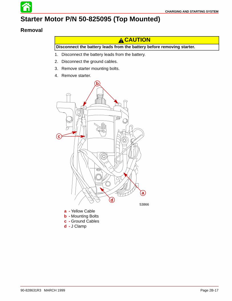
CHARGING AND STARTING SYSTEM
90-828631R3 MARCH 1999 Page 2B-17
Starter Motor P/N 50-825095 (Top Mounted)
Removal
CAUTIONDisconnect the battery leads from the battery before removing starter.
1. Disconnect the battery leads from the battery.
2. Disconnect the ground cables.
3. Remove starter mounting bolts.
4. Remove starter.
53866
c
b
a
d
a - Yellow Cableb - Mounting Boltsc - Ground Cablesd - J Clamp

CHARGING AND STARTING SYSTEM
Page 2B-18 90-828631R3 MARCH 1999
Disassembly1. Press down the pinion stopper and remove the circlip. Remove the pinion.
a
b c
a - Pinionb - Pinion Stopperc - Circlip (discard and use new circlip on assembly)
2. Remove through bolts and disassemble starter motor assembly.
Cleaning and Inspection1. Clean all motor parts.
2. Check pinion teeth for chips, cracks or excessive wear.
3. Replace the drive clutch spring and/or collar, if tension is not adequate, or if wear is ex-cessive.
4. Check that the brush holder is not damaged or is not holding the brushes against thecommutator.
5. Replace brushes that are pitted or worn to less than 0.35 - 0.49 in. (9.0 - 12.5 mm) inlength. Refer to “BRUSH HOLDER”, following.
6. Replace rear or front bracket for excessively worn bushings.
7. Check the armature (commutator) for wear, or being burnt. (A poor connection usuallyresults in a burned commutator bar.)
8. Re-surface and undercut a rough commutator. Refer to “Armature Inspection/Testing”.
PINION
9. Check pinion teeth for chips, cracks or excessive wear.
a
a - Pinion Gear

CHARGING AND STARTING SYSTEM
90-828631R3 MARCH 1999 Page 2B-19
BRUSH HOLDER
10. Inspect brushes for wear. Replace brush holder if not within specifications.
a
a - Wear Limit - 0.47 (12.0 mm)
11. Ohm test the brush holder. The positive (+) brushes should not show continuity to brushholder. Replace brush holder assembly if ohm test shows continuity.
a
ba
a - Positive (+) Brushesb - Brush Holder Assembly
ARMATURE INSPECTION/TESTING
12. Inspect the commutator surface of the armature for burnt marks and dirt in commutatorgrooves.
13. Using a piece of #600 grit wet-or-dry sand paper, clean the surface of the commutator.
a
b
a - Commutatorb - Sand Paper (#600 Grit)

CHARGING AND STARTING SYSTEM
Page 2B-20 90-828631R3 MARCH 1999
14. Measure the armature shaft for deflection. If the armature has greater than 0.002 in.(0.05 mm) deflection, replace armature.
a
c
b
a
a - Armatureb - V-Blockc - Dial Indicator Gauge
15. Measure the commutator diameter. Replace if not within specification.
MIN.
a
bb
a - Commutatorb - Commutator Diameter Wear Limit - 1.22 in. (31.0 mm)
16. Measure the mica undercut of the commutator. Clean out and undercut mica and buildup of brush material to a depth of 0.003 - 0.008 in. (0.2 - 0.8 mm).
a
b
a - Commutator Depthb - File (or use commutator cutter)

CHARGING AND STARTING SYSTEM
90-828631R3 MARCH 1999 Page 2B-21
17. After cleaning, ohm test each segment of the commutator as shown. If ohm test readingis other than listed, replace the armature.
ARMATURE COIL CONTINUITY
METER TEST LEADS METERSCALE
READING
RED BLACKX1 CONTINUITY
SEGMENT SEGMENTX1 CONTINUITY
a bc
a - Commutatorb - Laminationc - Shaft
ARMATURE COIL CONTINUITY
METER TEST LEADS METERSCALE
READING
RED BLACKX1 NO
SEGMENT LAMINATIONX1 CONTINUITY
SEGMENT SHAFT X1 NOCONTINUITY

CHARGING AND STARTING SYSTEM
Page 2B-22 90-828631R3 MARCH 1999
Reassembly1. Place washers on the armature shaft.
2. Place armature shaft into front bracket.
a cbd
a - Washer (Fiber) .08 in. (2.0 mm) Thickb - Washer .04 in. (1.0 mm) Thickc - Washers (Use as Required) (Adjust Washers Until 0.05 - 0.010 in.
(0.05 - 0.25 mm) Axial Play Exist on the Armature Shaftd - Front Bracket
1. Install the pinion, spring, and pinion stopper onto starter shaft.
2. Place circlip into groove on shaft.
3. Press the pinion stopper over the circlip.
IMPORTANT: Install new circlip for reassembly.
NOTE: Make sure the circlip fits tightly into pinion stopper.
a
b
d
c
a
b
c
d
a - Circlipb - Pinion Stopperc - Springd - Pinion

CHARGING AND STARTING SYSTEM
90-828631R3 MARCH 1999 Page 2B-23
4. Install stator onto the front bracket. Align Projection with cut in the cover.
NOTE: Make sure stator is installed so magnets are positioned correctly.
3/4 in.(19.0 mm)
53833
a
b
e
c
d
a - O-Ring Sealb - Space Between Magnets and Stator Endc - Align Projection with Cut in the Bracketd - Statore - Front Bracket
5. Spread the brushes and slide the brush card onto the commutator.
53831a
a
a - Brush Card

CHARGING AND STARTING SYSTEM
Page 2B-24 90-828631R3 MARCH 1999
6. Install rear bracket. Insert wire insulator into slot and align projection with cut in bracket.
53832
d
ca
b
a - O-Ring Sealb - Wire Insulatorc - Align Projection with Cut in the Rear Bracketd - Rear Bracket
7. Fasten brush card to rear bracket with two screws.
8. Fasten the starter motor together with two through bolts.
53834
a
b
a - Screw (2) Fasten Brush Card In-Placeb - Through Bolts (2)

CHARGING AND STARTING SYSTEM
90-828631R3 MARCH 1999 Page 2B-25
Installation1. Tighten mounting bolts to specified torque. Connect yellow cable and J-clamp with bot-
tom bolt.
2. Reconnect the ground cables.
53866
c
d
b
a
a - Yellow Cableb - Mounting Boltsc - Ground Cablesd - J Clamp
Starter Motor Mounting Bolt Torque
22.7 lb-ft (30.8 Nm)

CHARGING AND STARTING SYSTEM
Page 2B-26 90-828631R3 MARCH 1999
Starter Motor P/N 50-834749 (Side Mounted)
Removal
WARNINGAlways disconnect the battery and remove spark plug leads from spark plugs be-fore working on motor.
1. Disconnect battery leads from battery.
2. Disconnect BLACK cable.
3. Remove 3 bolts.
4. Remove starter.
55626
50-
a
c
b
b
a - Black Cableb - Bolts (3)c - Part Number Location

CHARGING AND STARTING SYSTEM
90-828631R3 MARCH 1999 Page 2B-27
Disassembly1. Remove 2 thru bolts and commutator end cap, taking care not to lose brush springs.
a
a
c
c ba - Thru Boltsb - Commutator End Capc - Brush Springs
2. Press down the pinion stopper and remove the circlip. Remove the pinion.
c
ba
a - Pinionb - Pinion Stopperc - Circlip (discard and use new circlip on assembly)
3. Pull armature from starter frame. Remove locknut.
4. Remove components from armature.
c
e
a b
fd
a - Spacerb - Springc - Drive Assemblyd - Drive End Cape - Armature Shaftf - Washer

CHARGING AND STARTING SYSTEM
Page 2B-28 90-828631R3 MARCH 1999
Cleaning and Inspection1. Clean all motor parts.
2. Check pinion teeth for chips, cracks or excessive wear.
3. Replace the drive clutch spring and/or collar, if tension is not adequate, or if wear is ex-cessive.
4. Check that the brush holder is not damaged or is not holding the brushes against thecommutator.
5. Replace brushes that are pitted or worn to less than 1/4 in. (6.4 mm) in length. Refer to“BRUSH REPLACEMENT”, following.
6. Replace a damaged or excessively worn bushing in the end cap.
7. Check the armature conductor (commutator bar junction) for a firm connection. A poorconnection usually results in a burned commutator bar.
8. Re-surface and undercut a rough commutator, as follows:
CAUTIONDo not turn down the commutator excessively .
a. Re-surface the commutator and undercut the insulation between the commutatorbars 1/3 in. (0.8mm) to the full width of the insulation, make sure that the undercutis flat.
b. Clean the commutator slots after undercutting.
c. De-burr the commutator lightly with No. 00 sandpaper, then clean the commutator.
d. Check the armature on a growler for shorts. See “TESTING”, following.
9. Open-circuited armatures often can be saved where an open circuit is obvious and re-pairable. The most likely place for an open circuit is at the commutator bars. Long crank-ing periods overheat the starter motor so that solder in the connections melts. The poorconnections cause arcing and burning of the commutator bars.
10. Repair bars, that are not too badly burned, by re-soldering the leads in bars (using rEsinflux solder) and turning down the commutator in a lathe to remove burned material, thenundercut the mica.
11. Clean out the copper or brush dust from slots between the commutator bars.
12. Check the armature for shorts and ground. See “TESTING”.

CHARGING AND STARTING SYSTEM
90-828631R3 MARCH 1999 Page 2B-29
Testing
ARMATURE TEST FOR SHORTS
Check armature for short circuits by placing on growler and holding hack saw blade overarmature core while armature is rotated. If saw blade vibrates, armature is shorted. Re-check after cleaning between commutator bars. If saw blade still vibrates, replace armature.
ARMATURE TEST FOR GROUND
1. Set ohmmeter to (R x 1 scale). Place one lead of ohmmeter on armature core (or shaft)and other lead on commutator, as shown.
2. If meter indicates continuity, armature is grounded and must be replaced.
11675

CHARGING AND STARTING SYSTEM
Page 2B-30 90-828631R3 MARCH 1999
CHECKING POSITIVE BRUSHES AND TERMINALS
1. Connect ohmmeter (R x 1 scale) leads between positive brushes.
2. Ohmmeter must indicate full continuity (zero resistance). If resistance is indicated,check lead to positive terminal solder connection. If connection cannot be repaired,brushes must be replaced. Refer to “BRUSH REPLACEMENT”.
11673
a
a - Positive Brushes
TESTING NEGATIVE BRUSHES FOR GROUND
Set ohmmeter to (R x 1 scale). Place one lead of ohmmeter on the negative brush and theother lead on the end cap (bare metal). If the meter indicates NO continuity, replace the neg-ative brush. Repeat this procedure on the other negative brush.
ba
a - Negative (-) Brushesb - End Cap

CHARGING AND STARTING SYSTEM
90-828631R3 MARCH 1999 Page 2B-31
Brush ReplacementIMPORTANT: Replace brushes that are pitted or worn to less than 1/4 in. (6.4mm) inlength .
11660
a
c
d
e
f
g
b
a - Positive (+) Terminalb - Long Brush Leadc - Push Lead Into Slotd - Insulating Washere - Flat Washerf - Lock Washerg - Nut
11656
a
c
b
d
a b
d
a - Positive (+) Brushesb - Negative (–) Brushesc - Brush Holderd - Bolts (Fasten Negative Brushes and Holder)

CHARGING AND STARTING SYSTEM
Page 2B-32 90-828631R3 MARCH 1999
Reassembly1. Lubricate helix threads and drive end cap bushing with SAE 10W oil.
2. Install the pinion, spring, and pinion stopper onto starter shaft.
3. Place circlip into groove on shaft.
4. Press the pinion stopper over the circlip.
IMPORTANT: Install new circlip for reassembly.
NOTE: Make sure the circlip fits tightly into pinion stopper.
a
b
d
c
d
c
a
b
a - Circlipb - Pinion Stopperc - Springd - Pinion

CHARGING AND STARTING SYSTEM
90-828631R3 MARCH 1999 Page 2B-33
5. Construct a brush retainer tool as shown.
Brush Retainer Tool Layout (Full Size)
18-Gauge Sheet MetalMETRICSCALE3”2”1-3/4”1-11/16”3/4”1/2”
= 76.2mm= 50.8mm= 44.5mm= 42.9mm= 19.1mm= 12.7mm
Brush Retainer Tool Side View (Full Size)

CHARGING AND STARTING SYSTEM
Page 2B-34 90-828631R3 MARCH 1999
6. Place springs and brushes into brush holder and hold in place with brush retainer tool.
7. Lubricate bushing with one drop of SAE 10W oil. DO NOT over-lubricate.
11661
b
a
a - Brush Retainer Toolb - Bushing
8. Position armature into starter frame so that commutator end of armature is at end ofstarter frame where permanent magnets are recessed 1 in. (25.4mm). Align marks (a)as shown.
9. Install commutator end cap onto starter frame; align marks (b) as shown, and removebrush retainer tool.
10. Install thru bolts (c) and torque to specified torque.
52659
a
b
cc
a - Alignment Marksb - Alignment Marksc - Bolts (2)
End Cap Bolt Torque
70 lb-in. (7.9 Nm)

CHARGING AND STARTING SYSTEM
90-828631R3 MARCH 1999 Page 2B-35
Installation1. Secure starter to block with 3 bolts. Torque bolts to specified torque. Secure NEGATIVE
battery lead to block with bottom bolt.
2. Connect battery lead (BLACK cable) to starter. Torque attaching nut to specified torque.
55626
a
b
b
a - Black Cableb - Bolts (3)
Starter Bolt Torque
16.5 lb-ft (22.3 Nm)
Attaching Nut Torque
60 lb-in. (6.8 Nm)

2C
TIMING, SYNCHRONIZING, & ADJUSTING
90-828631R3 MARCH 1999 Page 2C-1
ELECTRICALSection 2C - Timing, Synchronizing, & Adjusting
Table of Contents
Specifications 2C-1. . . . . . . . . . . . . . . . . . . . . . . . . . . . . Special Tools 2C-2. . . . . . . . . . . . . . . . . . . . . . . . . . . . . Carburetor Adjustments 2C-3. . . . . . . . . . . . . . . . . . . .
Idle Speed Adjustment 2C-3. . . . . . . . . . . . . . . . . .
Carburetor Sync. – Dynamic Adjustment 2C-4. . Idle Mixture Screw Adjustment 2C-7. . . . . . . . . . . Dash-Pot Adjustment 2C-9. . . . . . . . . . . . . . . . . . .
Timing 2C-10. . . . . . . . . . . . . . . . . . . . . . . . . . . . . . . . . .
Specifications
IGNITION SYSTEM*
*Readings taken @ 68 °F(20°C).
TypeSpark Plug Type (NGK)Spark Plug GapFiring OrderIgnition Timing:
40/45 HPFully Retarded Fully Advanced (2500-3000 rpm)
50 HPFully Retarded Fully Advanced (2500-3000 rpm)
Charge Coil ResistanceTrigger Coil ResistanceIgnition Coil Resistance:
PrimarySecondary
C.D.I. Engine Speed LimiterC.D.I. Overheat Speed ControlEngine Temperature Switch
Below 131 ° F (55° C)Above 104 ° F (40° C)
Capacitor Discharge IgnitionNGK DPR6EA-9
0.035 in. (1.0 mm)1-3-4-2
5° B.T.D.C25° B.T.D.C
5° B.T.D.C35° B.T.D.C
272 - 408 Ω (BRN-BLU)396 - 594 Ω (WHT/BLK-WHT/RED)
0.1 - 0.7 Ω3.5 - 4.7 kΩ
6120 - 6280 rpm1600 - 2400 rpm
No ContinuityContinuity
CARBURETOR
Idle rpm (Out Of Gear)45 hp40/50 hp
Idle rpm (In Forward Gear)45 hp40/50 hp
Wide Open Throttle rpm (WOT)RangeMain Jet Size
40/45 hpCarburetors 1 and 2Carburetors 3 and 4
50 hpPilot JetFloat Height
950 ± 25 rpm825 ± 25 rpm
850 ± 25 rpm725 ± 25 rpm
5500–6000 rpm
#104#103#112#42
0.39 ± 0.02 in. (10.0 ± 0.5 mm)

TIMING, SYNCHRONIZING, & ADJUSTING
Page 2C-2 90-828631R3 MARCH 1999
Special Tools
1. Carburetor Tuner P/N 91-809641A1
2. Timing Light P/N 91-99379
3. Exhaust Manifold Adaptor P/N 91-809905A1
4. Idle Mixture Screw Adjuster (45 HP Bodensee Models Only) P/N 91-809906A1
5. DMT 2000 Digital Tachometer Multi-meter P/N 91-854009A1

TIMING, SYNCHRONIZING, & ADJUSTING
90-828631R3 MARCH 1999 Page 2C-3
Carburetor Adjustments
Idle Speed AdjustmentNOTE: The engine should be completely warmed up for the adjustment. Correct adjust-ments can not be obtained in a cold condition.
1. With the outboard in neutral gear and in the water, start engine and allow to warm up.
2. Shift outboard into forward gear.
3. Turn the idle adjustment screw located on the #4 (bottom) carburetor to attain the speci-fied idle rpm.
a
a - Idle rpm Adjustment Screw
Idle rpm in Forward Gear
45 hp 850 ± 25 rpm
40/50 hp 725 ± 25 rpm
4. Rev engine 2 or 3 times and allow to idle for 15 seconds.
• If the engine holds a stable idle condition, then no other adjustments are necessary.
• If the engine has an unstable idle condition, then carburetor synchronization is re-quired. Refer to Carburetor Synchronization following.

TIMING, SYNCHRONIZING, & ADJUSTING
Page 2C-4 90-828631R3 MARCH 1999
Carburetor Synchronization – Dynamic AdjustmentNOTE: The carburetors are synchronized by adjusting the intake manifold vacuum on thetop three carburetors. Use Carburetor Tuner (91-809641A1) to measure the vacuum.
NOTE: The engine should be completely warmed up for the adjustment. Correct adjust-ments can not be obtained in a cold condition.
INSTALLING CARBURETOR TUNER (91-809641A1)
1. Remove four plugs from the intake manifold.
2. Install a intake manifold hose adaptor in each plug hole.
NOTE: Intake manifold hose adaptors are provided with the Carburetor Tuner.
3. Connect the carburetor tuner to the hose adaptors.
a
b
c
d
a - Intake Manifold Plugs (4)b - Intake Manifold Hose Adaptor (4)c - Filters (35-18206)d - Carburetor Tuner (91-809641A1)
CAUTIONTo avoid the possibility of drawing mercury from the vacuum gauge into the engine,do not run engine at high rpm speed and avoid rapid throttle deceleration (high vac-uum situations).
SYNCHRONIZING CARBURETORS1. With the outboard in water, start engine and allow to warm up. Shift the outboard to neu-
tral.
2. Connect a tachometer to the engine.
3. Adjust idle rpm screw (a) on #4 carburetor to obtain an idle setting of approximately1000rpm in neutral. If necessary, keep adjusting the idle screw.

TIMING, SYNCHRONIZING, & ADJUSTING
90-828631R3 MARCH 1999 Page 2C-5
NOTE: Keep engine speed set at approximately 1000 rpm in neutral while synchronizingcarburetors.
a
a - Idle rpm Screw
4. Read the vacuum of cylinder #4. It’s not important to be at any specific vacuum setting.
a
1 2 3 4
1
2
3
a - Vacuum Reading Cylinder #4. – Note, that it’s not Important to be at any Spe-cific Vacuum Setting
5. Adjust cylinder # 3 vacuum (turn screw 3) to read one cm less vacuum than cylinder #4.
6. Adjust cylinder #2 vacuum (turn screw 2) to read two cm less vacuum than cylinder #4.
7. Adjust cylinder #1 vacuum (turn screw 1) to read three cm less vacuum than cylinder#4.

TIMING, SYNCHRONIZING, & ADJUSTING
Page 2C-6 90-828631R3 MARCH 1999
NOTE: Keep viewing the tachometer, as the engine rpm may fluctuate during adjustments.Keep adjusting the idle rpm screw in order to keep the engine speed at approximately 1000rpm.
Example
34 cm
32 cm
30 cm
28 cm
26 cmCyl.# 4
Cyl.# 3
Cyl.#. 2
Cyl.# 1
If the vacuum reading of Cyl. #4 is 32 cm, thenadjust carburetor screws 3, 2, and 1 to obtain thelisted averaged vacuum values at the other cylin-ders.
Cyl. #4: (Base ) = 32 cm. . . . . . . . . . . . . . . . . . . . .
Cyl. #3: 32 cm – 1 cm = 31 cm. . . . . . . . . . . . . . .
Cyl. #2: 32 cm – 2 cm = 30 cm. . . . . . . . . . . . . . .
Cyl. #1: 32 cm – 3 cm = 29 cm. . . . . . . . . . . . . . .
8. Rev engine a few times and let engine idle for 15 seconds. Check that the average vacu-um values remain between cylinders. Readjust if necessary.
9. Stop engine, remove adaptors and reinstall plugs. Refer to Idle Speed Adjustment andadjust the idle rpm back to specification.

TIMING, SYNCHRONIZING, & ADJUSTING
90-828631R3 MARCH 1999 Page 2C-7
Idle Mixture Screw AdjustmentNOTE: Idle mixture screw adjustment is required when stable idling could not be obtainedafter synchronization.
NOTE: The engine should be completely warmed up for the adjustment. Correct adjust-ments can not be obtained in a cold condition.
NOTE: The idle mixture screw is:Adjustable:
-All model years for the 45 hp version-1995-1997 model years for all other versions
Non-adjustable:-1998 model year and later (50 hp).
NOTE: Screw Adjuster (91-809906A1) is required to adjust the idle mixture screws on 45hp models.
DYNAMIC ADJUSTMENT (50 HP MODELS) 1995-1997 MODEL YEAR
1. Connect tachometer.
2. With engine idling, turn the #4 carburetor idle mixture screw an 1/8 turn both directions(clockwise and counterclockwise).
3. If the engine speed drops when turning screw both directions, leave screw at initial posi-tion.
4. If the engine speed increases in one direction, keep turning it in that direction by 1/8 turnincrements to find the point of highest idle speed.
5. Adjust the idle mixture screw on the #1, #2 and #3 cylinders in the same manner.
6. Rev engine two or three times and let idle for 15 seconds, if a stable idle is obtained,perform the Idle Speed Adjustment .
1
2
3
4
a
b
a - Remove Plugb - Idle Mixture Screw

TIMING, SYNCHRONIZING, & ADJUSTING
Page 2C-8 90-828631R3 MARCH 1999
DYNAMIC ADJUSTMENT (45 HP MODELS)NOTE: CO metering equipment has to be used to accurately adjust the idle mixture screwswithin the exhaust emissions limits.
1. Remove four plugs from the exhaust manifold.
2. Install a exhaust manifold hose adaptor (91-809905A1) in each plug hole.
a
bc
a - Exhaust Manifold Plugs (4)b - Exhaust Manifold Hose Adaptor (91-809905A1)c - Plug - Hose Adaptor
3. Install the CO metering equipment to the hose adaptors.
NOTE: Keep all the hose adaptors plugged that are not connected to the CO meteringequipment.
4. With engine in water, start engine and run at the recommended idle speed in neutral.
Idle Speed-Neutral
950 ± 25 rpm
5. Check CO reading on each cylinder to verify if CO is within 4-6% range. While checkingCO readings, allow time for the readings to stabilize.
NOTE: Keep viewing the tachometer, as the engine rpm may fluctuate during adjustments.Keep adjusting the idle rpm screw in order to keep the engine speed at 850 RPM.
6. Adjust CO as follows:
• Adjust CO starting from No. 1 cylinder.
• If CO reading on any cylinder is higher than 6.0%, turn idle mixture screw clockwise(leaner).
• If CO reading on any cylinder is lower than 4.0%, turn idle mixture screw counter-clockwise (richer).
• Changes to any one cylinder can effect other cylinders, so If changes are made toany cylinder, all previous cylinders checked must be rechecked/adjusted.
7. Remove hose adaptors and reinstall plugs.
8. Recheck carburetor synchronization.

TIMING, SYNCHRONIZING, & ADJUSTING
90-828631R3 MARCH 1999 Page 2C-9
Dashpot AdjustmentNOTE: Dash-pot adjustment is required when engine stalls upon quick deceleration.
NOTE: The engine should be completely warmed up for the adjustment. Correct adjust-ments can not be obtained in a cold condition.
1. Pull out the retarder plunger fully.
2. Loosen the locknut.
3. Turn the dashpot until the dashpot ram is just touching the lever at the specified enginespeed.
4. Tighten lock nut.
ab
c
d
a - Retarder Plungerb - Locknutc - Dashpotd - Lever
Dash-pot Adjustment Speed
1700 rpm 50 rpm

TIMING, SYNCHRONIZING, & ADJUSTING
Page 2C-10 90-828631R3 MARCH 1999
TimingWARNING
To prevent personal injury or possible death, from loss of balance or stability whileservicing the motor, DO NOT attempt to check timing while boat is in motion. Failureto follow one of the recommended servicing procedures may result in the personfalling overboard or causing personal injury from fall in boat.
WARNINGTo prevent personal injury from spinning flywheel, Do Not attempt to remove fly-wheel cover or place hands on top of cover when checking ignition timing.
Timing Specifications
40/45HP
Full Retarded - 5° B.T.D.C. Full Advanced (2500-3000 rpm) - 25° B.T.D.C.
50HP
Full Retarded - 5° B.T.D.C.Full Advanced (2500-3000 rpm) - 35° B.T.D.C.
Ignition timing is not adjustable. The C.D.I. unit electronically controls the ignition timing.
When initially running the outboard, use a timing light to verify that the ignition timing fallswithin the timing windows as described within the following tests. If the ignition timing doesnot stay within the timing windows, replace the C.D.I. unit and retest. (Refer to the IgnitionDiagnostic Procedures tests in Section 2A.)
IMPORTANT: When checking the timing with the engine running, one of the followingtest procedures must be followed.
Check maximum timing per specification while running the outboard:
• IN A TEST TANK
• ON A DYNAMOMETER
• ON A BOAT THAT SECURED ON A TRAILER “Backed in Water”

TIMING, SYNCHRONIZING, & ADJUSTING
90-828631R3 MARCH 1999 Page 2C-11
1. Place the outboard in “Forward” gear and check timing at idle “Retarded.” (If not withinspecification window, refer to Diagnostic Test Procedures Section 2A.)
5°a
a - Timing Mark (Full Retarded)
2. Slowly increase the engine rpm while watching the ignition timing marks. The timingshould increase to the maximum timing specification “Full Advance” at approximately2500-3000 RPM. (If not within specification window, refer to Diagnostic Test ProceduresSection 2A.)
35°25°
40/45 hp 50 hp
a
a - Timing Mark (Full Advance)

2D
WIRING DIAGRAMS
90-828631R3 MARCH 1999 Page 2D-1
ELECTRICALSection 2D - Wiring Diagrams
Table of Contents
Electric Start Wiring Diagram 2D-2. . . . . . . . . . . . . . . Tiller Handle Wiring Diagram 2D-3. . . . . . . . . . . . . . . Commander Remote Control (Electric Start) 2D-4. . Commander 2000 Remote Control(Electric Start) 2D-5. . . . . . . . . . . . . . . . . . . . . . . . . . . .
Commander 3000 Panel Mount Control 2D-6. . . . . . Power Trim Switch Wiring Diagram 2D-7. . . . . . . . . . Remote Wiring Harness Connectionto Engine 2D-8. . . . . . . . . . . . . . . . . . . . . . . . . . . . . . . . .
Electric Start Remote Control Model 2D-8. . . . . .

LT.B
LU/W
HT
BLU
E14
BLA
CK
RE
DB
LAC
K
GR
N/W
HT
GR
EE
N14
BLA
CK
RE
DB
LAC
K
DN
UP
RE
D/P
PL
GR
N/W
HT
LT.B
LU/W
HT
GR
N/W
HT
LT.B
LU/W
HT
LT.B
LU/W
HT
GR
N/W
HT
WH
T/B
LKW
HT
/RE
DB
LUB
RN
BLK
/OR
GB
LKB
LK/W
HT
YE
L/R
ED
WH
TY
EL/
BLK
PN
K/W
HT
PN
KP
NK
/BLK
GR
Y/B
LK
12
34
56
78
9
PNK/BLKPNK
PNK/WHTYEL/BLK
WHTYEL/REDBLK/WHT
BLKBLK/ORG
GRY/BLK
BRNBLU
WHT/BLKWHT/RED
BRNBLU
WHT/BLKWHT/RED
79 36
428 5
1
11
112 2
22
WH
T/R
ED
WH
T/B
LK
BLUBRNGRNGRNGRN
1–B
LK/W
HT
2–B
LK3–
BLK
/OR
G4–
YE
L/B
LK5–
WH
T6–
YE
L/R
ED
7–P
NK
/BLK
8–P
NK
9–P
NK
/WH
T
1–B
LK/W
HT
2–B
LK3–
RE
D/W
HT
4–E
MP
TY
5–B
LK/Y
EL
6–E
MP
TY
7–TA
N/B
LK8–
TAN
/BLU
9–TA
N/W
HT
TAN/BLKTAN/BLUTAN/WHT
BLK/YEL
BLK/WHTBLKRED/WHT
GRY
GR
NB
LKG
RN
RE
DG
RN
/WH
TG
RN
/WH
T
12
3
12
3 GRNGRN
GRN/WHT
GRNGRNGRN
BLK
GRN/WHTGRN/WHTREDRED/PPL
1–G
RN
2–G
RN
3–G
RN
/WH
T
1–G
RN
2–G
RN
3–G
RN
12
3 4 56
78
BLA
CK
GR
N/W
HT
YE
L/R
ED
RE
D/P
PL
BLK
/YE
L
PU
RP
LETA
N/B
LU
BLKBLK
BLK
BLK
GN
D
BLKBLKBLKBLK
OR
G
OR
G
ORGORG
PPLTAN/BLKRED/WHTBLK/WHTTAN/WHTTAN/WHT
TAN
/WH
T
BLK
BLKBRNYEL/RED
YEL W/BLK ENDS
REDRED
GR
Y/B
LKP
NK
/BLK
PN
KP
NK
/WH
TY
EL/
BLK
WH
TY
EL/
RE
DB
LK/W
HT
BLK
BLK
/OR
GB
RN
BLU
WH
T/R
ED
WH
T/B
LK
GN
D
AB
RE
D
RE
D/P
PL
RE
DR
ED
BLKBLKBLKBLK
BLU/YEL
BLU
BLU
/YE
LB
LKB
LK
BLKBLKBLK
BLK
BLK
BLK
BLK
GR
N/W
HT
GR
N/W
HT
GR
N/W
HT
GR
Y/B
LKG
RY
BLK
BLK
1 2 3 4
1 42 3
YE
L/B
LK
YE
L/B
LK
ab c
d e
f
g
h
i
j
k
l
m
n
o
p
q
r
o
s
WIRING DIAGRAMS
Page 2D-2 90-828631R3 MARCH 1999
Electric Start Wiring Diagram
a - PTC Heaterb - Solenoid Coilc - CDI Unitd - Trim Down Relaye - Trim Up Relayf - Starterg - Trim Pumph - 20 Amp Fusei - Starter Relayj - Voltage Regulatork - Cowl Mounted Trim Switchl - Stator
m - Triggern - Oil Pressure Switcho - Ignition Coilp - Remote Wiring Plugq - Spark Plugsr - Block Temperature Switchs - Thermo Switch

WIRING DIAGRAMS
90-828631R3 MARCH 1999 Page 2D-3
Tiller Handle Wiring Diagram
YEL/RED
BLK = BlackBLU = BlueGRY = GrayGRN = GreenPUR = PurpleRED = RedTAN = TanYEL = Yellow
REDBLK/YEL
BLK
BLK/YELBLK
TAN/BLU TAN
PUR RED
BLK/YELBLK
RED
BLK
BLKBLK/YEL
BLK
GRY
YEL/RED
PUR
YEL/BLK
g f e d
c
b
a
a - Neutral Start Switchb - Auxiliary Harnessc - Not Usedd - Horne - Lanyardf - Stop Switchg - Start Switch

BLK = BlackBRN = BrownGRY = GrayGRN = GreenRED = RedWHT = WhiteYEL = Yellow
a
d
e
c
b
WIRING DIAGRAMS
Page 2D-4 90-828631R3 MARCH 1999
Commander Remote Control (Electric Start)
a - Ignition Choke Switchb - Emergency Stop Switchc - Neutral Start Switchd - Tachometer/Accessories Harness Connectore - Wiring Harness Connector

WIRING DIAGRAMS
90-828631R3 MARCH 1999 Page 2D-5
Commander 2000 Remote Control (Electric Start)
BLK = BlackBRN = BrownGRY = GrayGRN = GreenRED = RedWHT = WhiteYEL = Yellow
a b
c
d
e
a - Wiring Harness Connectorb - Tachometer/Accessories Harness Connectorc - Ignition/Choke Switchd - Emergency Stop Switche - Neutral Start Switch

WIRING DIAGRAMS
Page 2D-6 90-828631R3 MARCH 1999
Commander 3000 Panel Mount Control
B
ACS
M
M
ÂÂÂÂÂÂ
ÂÂÂ
YEL/RED
RED
YEL/RED
YEL/RED
YEL/RED
PUR
GRN
BLU/WHT
GRN/WHT
RED
BLK/YEL
BLK
a
b
c
BLK = BlackBLU = BlueBRN = BrownGRN = GreenGRY = GrayPUR = PurpleRED = RedTAN = Tan
WHT = WhiteYEL = Yellow
a - Lanyard stop switch leads must be soldered and covered with shrink tube for a water proof connection.If alternate method of connection is made, (use of electrical butt connector) verify connection is secureand sealed for moisture proof connection.
b - Connect wires together with screw and hex nut (2 places); apply Quicksilver Liquid Neoprene to con-nections and slide heat shrink tubing over each connection.
c - Keyswitch

WIRING DIAGRAMS
90-828631R3 MARCH 1999 Page 2D-7
Power Trim Switch Wiring Diagram
DN
UP
DN
UP
BLU/WHT
GRN/WHT
RED
LT. BLU/WHT
LT. GRN/WHT
REDRED
LT. GRN/WHT
RED
LT. BLU/WHT
a
b
GRN = GreenBLU = BlueRED = RedWHT = White
a - Trim Switchb - Starter Relay

WIRING DIAGRAMS
Page 2D-8 90-828631R3 MARCH 1999
Remote Wiring Harness Connection to EngineELECTRIC START REMOTE CONTROL MODEL
1. Route the remote wiring harness to the back of the engine block as shown.
a
a - Remote Wiring Harness
2. Plug the remote wiring harness into the engine wiring harness connector. Push the har-ness connection into the holder.
3. Connect additional wires leads (if equipped).
a
b
a - Remote Wiring Harnessb - Engine Wiring Harness Connector

3A
FUEL PUMP
90-828631R3 MARCH 1999 Page 3A-1
FUEL SYSTEMSection 3A - Fuel Pump
Table of ContentsSpecifications 3A-1. . . . . . . . . . . . . . . . . . . . . . . . . . . . . Fuel Pump 3A-2. . . . . . . . . . . . . . . . . . . . . . . . . . . . . . . Fuel Pump Operation 3A-4. . . . . . . . . . . . . . . . . . . . . . Fuel Pump Removal 3A-5. . . . . . . . . . . . . . . . . . . . . . .
Fuel Pump Disassembly 3A-6. . . . . . . . . . . . . . . . . . . Cleaning/Inspection/Repair 3A-7. . . . . . . . . . . . . . . . . Fuel Pump Reassembly 3A-8. . . . . . . . . . . . . . . . . . . . Fuel Pump Installation 3A-10. . . . . . . . . . . . . . . . . . . .
Specifications
FUEL SYSTEM
Fuel Pump TypeFuel Pump:
PressureDiaphragm StrokePlunger Stroke
Fuel Tank Capacity
External (Plunger/Diaphragm)
3-6 psi0.14 - 0.20 in. (3.5 - 5.1 mm)
0.23 - 0.38 in. (5.85 - 9.65 mm)Accessory

1
2
3
4
5
6
7
910
11
1213
15
7
6
5
8
16
17
19
20
21
20
20
14
22
2018
FUEL PUMP
Page 3A-2 90-828631R3 MARCH 1999
Fuel Pump

FUEL PUMP
90-828631R3 MARCH 1999 Page 3A-3
Fuel PumpREF. TORQUEREF.NO. QTY. DESCRIPTION lb-in. lb-ft Nm
1 1 FUEL PUMP2 4 SCREW Drive Tight3 1 O RING4 1 DIAPHRAGM5 2 SCREW Drive Tight
6 2 NUT7 2 CHECK VALVE8 1 DIAPHRAGM9 1 PIN10 1 SPRING11 4 NUT12 1 SPRING
13 1 PLUNGER14 1 O RING15 2 SCREW 75 8.516 1 J CLAMP17 1 FUEL CONNECTOR– 1 O RING
18 1 TUBING (19 IN.)19 1 TUBING (16 IN.)20 AR STA STRAP21 1 FUEL FILTER22 1 COWL DEFLECTOR

FUEL PUMP
Page 3A-4 90-828631R3 MARCH 1999
Fuel Pump Operation1. The fuel pump is a diaphragm pump which is mechanically driven off of the rocker arm.
2. The black mounting block (insulator) and the two outlets on the fuel pump help preventvapor lock.
3. If the engine runs out of fuel, or has a restriction preventing adequate fuel flow, the pumpwill make a “clicking” noise.
WARNINGFIRE AND EXPLOSION HAZARD. Observe fire prevention rules, particularly NOSMOKING. Before servicing any part of the fuel system, disconnect electrical sys-tem at the battery. Drain the fuel system completely. Use an approved container tocollect and store fuel. Wipe up any spillage immediately. Materials used to containspillage must be disposed of in an approved receptacle. Any fuel system servicemust be performed in a well ventilated area .
FUEL LEAKAGE FROM ANY PART OF THE FUEL SYSTEM CAN BE A FIRE AND EX-PLOSION HAZARD WHICH CAN CAUSE SERIOUS BODILY INJURY OR DEATH.Careful periodic inspection of the entire fuel system is mandatory, particularly afterengine storage. All fuel components, including fuel tanks, whether plastic, metal,or fiberglass, fuel lines, primer bulbs, fittings, swelling, and must be inspected forcorrosion. Any sign of leakage or deterioration necessitates replacement beforefurther engine operation.

FUEL PUMP
90-828631R3 MARCH 1999 Page 3A-5
Fuel Pump Removal1. Remove sta-straps from fuel lines.
IMPORTANT: The hose fittings on the fuel pump can break if you try twisting or pull-ing the hoses off. Remove hoses by slowly prying off the hoses using a small screw-driver.
2. Disconnect fuel lines from pump.
3. Separate fuel pump from cylinder head cover by removing mounting bolts.
53668
outoutin
a
cdb
a - Mounting Bolts-10mm (2)b - Fuel Lines (3)c - J-Clampd - Fuel Filter

FUEL PUMP
Page 3A-6 90-828631R3 MARCH 1999
Fuel Pump Disassembly1. Remove screws to separate pump cover, cover seal, and diaphragm, from pump body.
28378
cd
b
a
e
f
a - Screws (4)b - Pump Coverc - Cover Seald - Diaphragme - Pump Bodyf - Nuts (4)
2. Rotate plunger to line up slots.
53615
a b
a - Slots Offsetb - Slots Aligned
3. Compress pump assembly to free spring load on pin.
4. Tilt assembly to allow pin to slide out.
53617
a
a - Pin

FUEL PUMP
90-828631R3 MARCH 1999 Page 3A-7
Cleaning/Inspection/Repair1. Inspect fuel filter for cracks/clogs, replace if necessary.
2. Inspect the check valves for damage, replace if necessary.
3. Inspect springs for damage, replace if necessary.
4. Inspect cover seal and diaphragm, replace if damaged.
ab
a - Cover Sealb - Diaphragm

FUEL PUMP
Page 3A-8 90-828631R3 MARCH 1999
Fuel Pump Reassembly1. Assemble springs, diaphragm, and plunger onto pump body.
a
b
c
d
e
a - Diaphragmb - Diaphragm Springc - Pump Bodyd - Springe - Plunger
2. Line up slots and compress assembly.
3. Insert pin into hole.
a
b
c
a - Pump Bodyb - Slotsc - Pin
4. Rotate plunger 90° to offset slots.
53615
a b
a - Slots Alignedb - Slots Offset

FUEL PUMP
90-828631R3 MARCH 1999 Page 3A-9
5. Assemble diaphragm, seal, and cover, to pump body, secure with screws and nuts.
NOTE: Seal installs in one direction only.
cd
b
a
e
f
a - Screws (4)b - Coverc - Cover Seald - Diaphragme - Pump Bodyf - Nuts (4)
6. Install a new O-ring onto the pump assembly.
NOTE: Always install a new O-ring.
53620
a
a - O-ring

FUEL PUMP
Page 3A-10 90-828631R3 MARCH 1999
Fuel Pump Installation1. Secure fuel pump and cowl deflector to cylinder head cover with 2 bolts.
2. Connect fuel lines to pump and secure with sta-straps.
de
d
outoutin
c
a
b
c
e
f
a - Outlet Fuel Hoseb - Inlet Fuel Hosec - Mounting Bolts (2)-M6x30d - Cowl Deflectore - J-Clipf - Cable Ties (3)
Fuel Pump Mounting Bolt Torque
75 lb-in. (8.5 Nm)

3B
CARBURETOR
90-828631R3 MARCH 1999 Page 3B-1
FUEL SYSTEMSection 3B - Carburetor
Table of Contents
Specifications 3B-2. . . . . . . . . . . . . . . . . . . . . . . . . . . . . Special Tools 3B-3. . . . . . . . . . . . . . . . . . . . . . . . . . . . . Carburetor Linkage 3B-4. . . . . . . . . . . . . . . . . . . . . . . . Carburetor (40/45) 3B-6. . . . . . . . . . . . . . . . . . . . . . . . . Carburetor (50) 3B-8. . . . . . . . . . . . . . . . . . . . . . . . . . . Intake 3B-10. . . . . . . . . . . . . . . . . . . . . . . . . . . . . . . . . . . Carburetor Adjustments 3B-12. . . . . . . . . . . . . . . . . . .
Carburetor Synchronization-StaticAdjustment 3B-12. . . . . . . . . . . . . . . . . . . . . . . . . . . Idle Mixture Screw Adjustment-StaticAdjustment 3B-13. . . . . . . . . . . . . . . . . . . . . . . . . . . Choke Cam Angle Adjustment 3B-14. . . . . . . . . . Fast Idle Adjustment 3B-15. . . . . . . . . . . . . . . . . . . Unloader Adjustment 3B-16. . . . . . . . . . . . . . . . . . Choke Shutter Closing Adjustment 3B-17. . . . . . .
Carburetor Unit Removal 3B-18. . . . . . . . . . . . . . . . . . Carburetor Link Removal 3B-21. . . . . . . . . . . . . . . . . . Solenoid Coil 3B-22. . . . . . . . . . . . . . . . . . . . . . . . . . . . Electrothermal Plunger Removal 3B-22. . . . . . . . . . .
Acceleration Pump 3B-23. . . . . . . . . . . . . . . . . . . . . . . Removal 3B-23. . . . . . . . . . . . . . . . . . . . . . . . . . . . . Disassembly 3B-23. . . . . . . . . . . . . . . . . . . . . . . . . . Inspection 3B-24. . . . . . . . . . . . . . . . . . . . . . . . . . . .
Fuel Piping Removal 3B-24. . . . . . . . . . . . . . . . . . . . . . Silencer Removal 3B-25. . . . . . . . . . . . . . . . . . . . . . . . Carburetor 3B-25. . . . . . . . . . . . . . . . . . . . . . . . . . . . . .
Disassembly 3B-25. . . . . . . . . . . . . . . . . . . . . . . . . . Inspection 3B-27. . . . . . . . . . . . . . . . . . . . . . . . . . . .
Carburetor Assembly 3B-28. . . . . . . . . . . . . . . . . . . . . Silencer Installation 3B-31. . . . . . . . . . . . . . . . . . . . . . . Acceleration Pump 3B-31. . . . . . . . . . . . . . . . . . . . . . .
Assembly 3B-31. . . . . . . . . . . . . . . . . . . . . . . . . . . . Installation 3B-32. . . . . . . . . . . . . . . . . . . . . . . . . . . .
Fuel Piping Installation 3B-33. . . . . . . . . . . . . . . . . . . . Electrothermal Plunger Installation 3B-34. . . . . . . . . Solenoid Coil Installation 3B-34. . . . . . . . . . . . . . . . . . Carburetor Link Installation 3B-35. . . . . . . . . . . . . . . . Carburetor Unit Installation 3B-36. . . . . . . . . . . . . . . .

CARBURETOR
Page 3B-2 90-828631R3 MARCH 1999
Specifications
CARBURETOR
Idle rpm (Out Of Gear)45 hp40/50 hp
Idle RPM (In Forward Gear)45 hp40/50 hp
Wide Open Throttle rpm (WOT)RangeMain Jet Size
40/45 hp
50 hpPilot JetFloat Height
950 ± 25 rpm825 ± 25 rpm
850 ± 25 rpm725 ± 25 rpm
5500–6000
#104 for Carburetors 1 and 2#103 for Carburetors 3 and 4
#112#42
0.39 ± 0.02 in. (10.0 ± 0.5 mm)

CARBURETOR
90-828631R3 MARCH 1999 Page 3B-3
Special Tools
1. Carburetor Scale (P/N 91-36392)
2. Idle Mixture Screw Adjuster (45 HP Bodensee Models Only) P/N 91-809906A1

2
3
45
6
7
8
91011
12
1314
15
16
1718
1920
2122
23
2425
26
27
3031
32 33 34
28
35
36 37
5
3
1013
14
9
9
9
17
1
29
CARBURETOR
Page 3B-4 90-828631R3 MARCH 1999
Carburetor Linkage

CARBURETOR
90-828631R3 MARCH 1999 Page 3B-5
Carburetor Linkage
REF. TORQUEREF.NO. QTY. DESCRIPTION lb-in. lb-ft Nm
1 1 DIAPHRAGM
2 1 JOINT3 3 SCREW Drive Tight4 1 PIPE
5 1/2 PIPE (Qty. of 2 with carb with adjustable pilot screw/ Qty. of 1 with carb with non-adjustable pilot screw)
6 1 PIPE7 1 PIPE8 1 CHOKE ROD9 4 JOINT10 2 WASHER11 1 CHOKE ROD12 1 CHOKE ROD
13 2 COLLAR14 2 JOINT15 1 CHOKE ROD16 1 CHOKE ROD17 2 SCREW Drive Tight18 1 THROTTLE DAMPER
19 1 SPRING20 1 CHOKE ROD21 1 STARTER LEVER22 1 STARTER LEVER23 1 WASHER24 1 SCREW25 1 WASHER
26 2 SCREW Drive Tight27 1 AUTO STARTER28 1 SOLENOID29 1 COVER30 1 BRACKET (Included W/825105A1 ON INTAKE)31 2 SCREW Drive Tight32 1 NUT
33 1 WASHER34 1 WIRE PULL35 1 SPRING36 1 PLATE37 1 SCREW Drive Tight

1
2
3
4
5
6
78
91011
1213 14
1516 17
1819
20
21222324
25
26
28 29
3031
32
33
34
35
3637
38
39 40 41 4243 44
4546
47
48
49
5
5
5
7
7
7
43
4342 30
32
CARBURETOR
Page 3B-6 90-828631R3 MARCH 1999
Carburetor (40/45)

CARBURETOR
90-828631R3 MARCH 1999 Page 3B-7
Carburetor (40/45)
REF. TORQUEREF.NO. QTY. DESCRIPTION lb-in. lb-ft Nm
1 1 CARBURETOR (1)2 1 CARBURETOR (2)3 1 CARBURETOR (3)4 1 CARBURETOR (4)5 8 SCREW6 1 COVER (1)7 4 VALVE8 4 SEAL9 4 PILOT SCREW SET10 4 O RING11 4 SPRING–air adjusting12 3 WASHER (1/2/3)13 3 SPRING–pilot adjusting (1/2/3)14 3 SCREW– throttle (1/2/3)15 4 WASHER16 4 CIRCLIP17 1 LEVER (1)18 1 LOCKWASHER (1)19 1 NUT (1)20 4 NEEDLE VALVE21 4 SCREW22 4 MAIN NOZZLE23 4 O RING24 4 MAIN NOZZLE25 4 PILOT JET (#42)26 2 MAIN JET (#104)(1/2)27 2 MAIN JET (#103)(3/4)28 4 FLOAT29 4 FLOAT PIN30 4 GASKET31 3 BODY (1/2/3)32 16 SCREW33 4 SCREW–drain34 4 GASKET35 1 COVER (2)36 1 CLIP (2)37 1 ROLLER (2)38 1 COVER (3)39 1 JOINT–throttle lever (4)40 1 ROD–starter (4)41 1 JOINT–choke lever (4)42 2 SCREW (4)43 3 SPRING–pilot adjusting (4)44 1 COVER (4)45 1 SCREW (4)46 1 WASHER (4)47 1 LEVER (4)48 1 SCREW–throttle (4)49 1 BODY (4)

1
2
3
4
5
6
7
89 10
1112 13
1415
16
17181920
21
22
2324
2526
27
28
29
30
3132
33
34 35 36 3738 39
4041
42
43
44
7
5
5
5
7
7
38
3738
25
27
CARBURETOR
Page 3B-8 90-828631R3 MARCH 1999
Carburetor (50)

CARBURETOR
90-828631R3 MARCH 1999 Page 3B-9
Carburetor (50)
REF. TORQUEREF.NO. QTY. DESCRIPTION lb-in. lb-ft Nm
1 1 CARBURETOR (1)2 1 CARBURETOR (2)3 1 CARBURETOR (3)4 1 CARBURETOR (4)5 8 SCREW6 1 COVER (1)7 4 VALVE
8 3 WASHER (1/2/3)9 3 SPRING–pilot adjusting (1/2/3)10 3 SCREW– throttle (1/2/3)11 4 WASHER12 4 CIRCLIP13 1 LEVER (1)14 1 LOCKWASHER (1)15 1 NUT (1)16 4 NEEDLE VALVE17 4 SCREW18 4 MAIN NOZZLE19 4 O RING20 4 MAIN NOZZLE21 4 PILOT JET (#44)
22 4 MAIN JET (#112)23 4 FLOAT24 4 FLOAT PIN25 4 GASKET26 3 BODY (1/2/3)27 16 SCREW28 4 SCREW–drain
29 4 GASKET30 1 COVER (2)31 1 CLIP (2)32 1 ROLLER (2)33 1 COVER (3)34 1 JOINT–throttle lever (4)35 1 ROD–starter (4)36 1 JOINT–choke lever (4)37 2 SCREW (4)38 3 SPRING–pilot adjusting (4)39 1 COVER (4)40 1 SCREW (4)41 1 WASHER (4)42 1 LEVER (4)43 1 SCREW–throttle (4)44 1 BODY (4)

1
23
4
5
6
7
8
9
10
1112
13
1415
16
17
18
19
20
2122
23 24
25
26
27
28
29 30
3132
33
2
21
21
21
21
21
24
23
24
2423
27
34
35
CARBURETOR
Page 3B-10 90-828631R3 MARCH 1999
Intake

CARBURETOR
90-828631R3 MARCH 1999 Page 3B-11
Intake
REF. TORQUEREF.NO. QTY. DESCRIPTION lb-in. lb-ft Nm
1 8 SCREW 70 8
2 8 O RING3 1 INSULATOR4 2 PLUG5 1 JOINT–carburetor6 2 DOWEL PIN7 4 O RING
8 4 O RING9 4 O RING10 4 GROMMET11 AR STA–STRAP12 1 BREATHER PIPE13 1 CLAMP14 8 COLLAR
15 8 SCREW 50 5.716 2 SCREW 75 8.517 2 COLLAR18 1 INTAKE SILENCER ASSEMBLY19 1 CABLE TIE20 1 PLUG21 16 CLAMP
22 1 HOSE23 3 CONNECTOR24 4 HOSE25 1 HOSE26 1 CLAMP27 2 HOSE28 1 FUEL HOSE
29 1 CLAMP30 1 CONNECTOR31 1 HOSE32 1 HOSE33 1 CLIP34 1 DECAL-SERVICING REFERRAL35 1 DECAL-Caution-Start in Gear

CARBURETOR
Page 3B-12 90-828631R3 MARCH 1999
Carburetor Adjustments
Carburetor Synchronization-Static AdjustmentNOTE: This static adjustment is necessary if the throttle stop screws were loosened or tam-pered with. The initial static setting is preparation for the Carburetor Synchronization-dy-namic adjustment (Section 2C).
1. Remove the carburetors as a unit.
2. Disconnect throttle link (a) and auto choke “Z” link (b).
3. Adjust the idle rpm screw #4 until the throttle shutter covers half of bypass hole.
4. Install throttle link.
5. Adjust throttle stop screws #1, #2 and #3 until the throttle shutters cover half of bypasshole.
6. Re-install “Z” link.
7. Re-install the carburetors as a unit.
1
2
4
3
b
a
c
a - Throttle Link (Disconnect)b - Auto Choke “Z” Link (Disconnect)c - Bypass Hole

CARBURETOR
90-828631R3 MARCH 1999 Page 3B-13
Idle Mixture Screw Adjustment-Static AdjustmentNOTE: Idle mixture screw adjustment is required when carburetor has been overhauled.
NOTE: Screw Adjuster (91-809906A1) is required to adjust the idle mixture screws on 45hp models.
NOTE: The idle mixture screw is:Adjustable:
-All model years for the 45 hp version.-1995-1997 model years for all other versions.
Non-adjustable:-1998 model year and later.
1. Screw in the idle mixture screw on each carburetor until it is lightly seated, than back-outspecified number of turns.
1
2
3
4
a
b
a - Remove Plugb - Idle Mixture Screw
Idle Mixture Screw-Turns Out
2.5

CARBURETOR
Page 3B-14 90-828631R3 MARCH 1999
Choke Cam Angle AdjustmentNOTE: Choke cam angle adjustment is required when #4 carburetor has been replaced oroverhauled.
1. Measure gap “a” and refer to the thermal gap graph, if out of specification adjust.
2. Adjustment steps:
a. Loosen cam angle adjustment screw.
b. Find the gap for the temperature on the graph.
c. Adjust and tighten the cam angle adjustment screw with the specified gap “a”.
a
b
a - Gapb - Cam Angle Adjustment Screw
THERMAL GAP GRAPH
Gap
(m
m)
Temp. (°C)

CARBURETOR
90-828631R3 MARCH 1999 Page 3B-15
Fast Idle AdjustmentNOTE: Fast idle adjustment is required when fast idle exceeds 1500 rpm or engine stallsduring a cold start.
1. Remove the link rods (a & b) and loosen fast idle screw (c).
2. Loosen idle stop screw (d) until the screw is free from the lever.
3. Tighten the idle stop screw (d) until the bypass hole is half visible.
4. Tighten the idle stop screw (d) to the specified number of turns from the graph.
5. Connect the link rods (a &b).
6. Hold the fast idle lever (f) to the roller (g) and secure the fast idle screw (c).
e
ad
c
fg
b
a - Link Rodb - Link Rodc - Fast Idle Screwd - Idle Stop Screw
e - Bypass Hole (Reference View Only)f - Fast Idle Leverg - Roller
Turn
s
Temp. (°C)

CARBURETOR
Page 3B-16 90-828631R3 MARCH 1999
Unloader AdjustmentNOTE: Unloader adjustment is required when the unloader adjustment screw has beenloosened.
1. Disconnect the choke actuator rod (a).
2. Loosen the unloader adjustment screw (c).
3. Close the choke valve fully.
NOTE: Check for a fully closed choke valve by depressing the #4 carburetor choke lever,then check the #1 carburetor choke lever to see that it is touching the stopper.
4. Turn the unloader adjustment screw (c) in until the screw tip touches the lever.
a
b
cd
a - Choke Actuator Rodb - #1 Choke Shutter Stopc - Unloader Adjustment Screwd - Lever

CARBURETOR
90-828631R3 MARCH 1999 Page 3B-17
Choke Shutter Closing Adjustment1. Measure gap “a” and refer to the thermal gap graph below, if out of specification adjust.
2. Adjust gap by tightening/loosening the choke valve closing screw (b) to obtain the speci-fied gap found on the graph.
a
b
a - Gapb - Choke Shutter Closing Screw
THERMAL GAP GRAPH
Gap
(m
m)
Temp. (°C)

CARBURETOR
Page 3B-18 90-828631R3 MARCH 1999
Carburetor Unit Removal
1. Remove fuel line sta-straps.
2. Disconnect fuel lines and breather hose.
3. Disconnect solenoid and plunger leads.
28379
ab
c
de
a
a - Sta-Straps (3)b - Breather Hosec - Fuel Lines (2)d - Solenoid Leads (Blue, Black)e - Plunger Leads (Green/White, Black)
4. Remove bolts and collars.
28379
abc
a - Bolt w/Washer-M6x30 mm (2)b - Collar (2)c - Mounting Bolt w/Washer-M6x25 mm (8)

CARBURETOR
90-828631R3 MARCH 1999 Page 3B-19
5. Remove carburetor unit from intake manifold.
53679
6. Remove dowel pins.
7. Remove insulator from carburetor by prying near the plugs.
53679
a
b
c
c
a
a - Dowel Pin (2)b - Insulatorc - Plug (2)

CARBURETOR
Page 3B-20 90-828631R3 MARCH 1999
NOTE: Do not loosen or remove screw a, b, c, or d. Fine adjustments will be required if thesescrews are tampered with.
28379
a
b
c
d
a - Screw “a”b - Screw “b”c - Screw “c”d - Screw “d”

CARBURETOR
90-828631R3 MARCH 1999 Page 3B-21
Carburetor Link Removal
1. Unsnap links from retainer clips.
28379
a
e
db
f
g
c
a - Upper Choke Link-“C” Linkb - Lower Choke Link-“J” Linkc - Auto Choke Link-“Z” Linkd - Unloader Link-Small “J” Linke - Throttle Linkf - Joint Plateg - Retainer Clips

CARBURETOR
Page 3B-22 90-828631R3 MARCH 1999
Solenoid Coil
1. Unhook spring and remove screws.
2. Loosen locknut to free wire pull from coil assembly.
28379
a
b
cd
a - Springb - Screw (2)c - Lock Nutd - Wire Pull
Electrothermal Plunger Removal
1. Remove cover (if so equipped).
2. Remove screws.
28379
a
b
a - Coverb - Screw (2)

CARBURETOR
90-828631R3 MARCH 1999 Page 3B-23
Acceleration Pump
Removal1. Disconnect delivery hoses, remove screws, and un-clip retainer.
53681
ab
c
a - Delivery Hoses (4)b - Screw (3)c - Retainer
Disassembly1. Remove screws.
53752
ab
a - Cover Screw (2)b - Diaphragm Screw (2)

CARBURETOR
Page 3B-24 90-828631R3 MARCH 1999
Inspection1. Inspect check valve and diaphragm, replace if worn or damaged.
53752
Fuel Piping Removal
1. Cut sta-straps and remove fuel hoses.
53725
a
a
a
a
a - Sta-Strap (4)

CARBURETOR
90-828631R3 MARCH 1999 Page 3B-25
Silencer Removal
1. Remove bolts and collars.
2. Remove plate, silencer, and retaining plate.
53679
a b
d
e
c
a - Bolt w/Washer-M6x90mm (8)b - Collar (8)c - Silencer Assemblyd - Retaining Platee - Plate
Carburetor
Disassembly1. Remove float bowl.
53674
a
b
a - Screw (4)b - Float Bowl

CARBURETOR
Page 3B-26 90-828631R3 MARCH 1999
2. Remove float and needle valve.
53676
a b
cd
a - Float Pin Retaining Screwb - Floatc - Float Pind - Needle Valve
3. Remove cover and seal.
ab
c
a - Screws (2)b - Coverc - Seal
4. Remove nozzles and jets.
53676
ac
db
a - Plugb - Nozzlec - Main Jetd - Pilot Jet

CARBURETOR
90-828631R3 MARCH 1999 Page 3B-27
5. Remove idle mixture screw.
NOTE: 45 hp Models – Screw Adjuster (91-809906A1) is required to remove idle mixturescrew.
53674
ab
c
a - Idle Mixture Springb - Idle Mixture Screwc - Plug
Inspection
CAUTIONDo not use steel wire for cleaning the jets as this may enlarge the jet diameters andseriously affect performance. Use a petroleum based solvent for cleaning and blowout all passages with compressed air.
1. Inspect carburetor body, replace if cracked or damaged.
53671
2. Inspect float, replace if cracked or damaged.
53673
3. Inspect pilot screw. Replace if bent or damaged.
53673

CARBURETOR
Page 3B-28 90-828631R3 MARCH 1999
4. Inspect main jet, pilot jet and main nozzle. Clean if they are contaminated.
53672
5. Inspect needle valve, replace if end is worn or grooved.
28375
Carburetor Assembly
NOTE: Note different carburetor design from old style to new style for top carburetor (#1).New style does not have breather port.
a
Old Style New Style
a - Breather Port

CARBURETOR
90-828631R3 MARCH 1999 Page 3B-29
1. Install idle mixture screw. Lightly seat idle mixture screw and then back out 2.5 turns.
NOTE: 45 hp Models – Use Screw Adjuster (91-809906A1) to install idle mixture screw.
53674c
ab
a - Idle Mixture Springb - Idle Mixture Screwc - Plug
2. Install nozzle and jets.
53676
b
c
da
a - Plugb - Nozzlec - Main Jetd - Pilot Jet (#42)
3. Install float pin and needle valve. Needle valve should slide into valve seat on float.
53676
ab
cd
a - Retaining Screwb - Floatc - Float Pind - Needle Valve

CARBURETOR
Page 3B-30 90-828631R3 MARCH 1999
NOTE: Measure float height with carb. scale, replace float if height is not within specification[0.390.02 in. (10.00.5mm)]. Take measurements at the mid-line of the float opposite itspivot side. After installing, check for smooth movement of the float.
28380
4. Install cover and seal.
ab
c
a - Screws (2)b - Coverc - Seal
5. Install float bowl.
53674
a
b
a - Screw (4)b - Float Bowl

CARBURETOR
90-828631R3 MARCH 1999 Page 3B-31
Silencer Installation
1. Install plate, silencer, and retaining plate. Install bolts and collars.
53679
95
95 2-4-C With Teflon (92-825407A12)
ab
c
d
e
NOTE: Dowel pins must match between carb. flange and retaining plate.
a - Bolt w/Washer-M6x90mm (8)b - Collar (8)c - Silencerd - Retaining Platee - Plate
Bolt Torque
50 lb-in. (5.7 Nm)
Acceleration Pump
Assembly1. Install screws.
53752
ba
a - Cover Screw (2)b - Diaphragm Screw (2)

CARBURETOR
Page 3B-32 90-828631R3 MARCH 1999
Installation1. Secure pump link with retainer, install screws, and connect delivery hoses.
53681
ab
d
c
a - Delivery Hoses (4)b - Screw (3)c - Retainerd - Breather Hose
NOTE: On older models with breather port located on the top carburetor (#1), route breatherhose through bracket flange. If replacing top carburetor with new carburetor, breather hoseis not needed.
57265
b
a
b
c
a - Bracket Flangeb - Breather Hosec - Breather Port

CARBURETOR
90-828631R3 MARCH 1999 Page 3B-33
Fuel Piping Installation
1. Install fuel hoses and secure with sta-straps.
53752
a
a
a
a
a - Sta-Strap (4)

CARBURETOR
Page 3B-34 90-828631R3 MARCH 1999
Electrothermal Plunger Installation1. Install screws.
2. Install cover (if so equipped).
28378
a b
a - Screw (2)b - Cover
Solenoid Coil Installation1. Connect wire pull to coil assembly with lock nut.
2. Install screws and hook spring onto carburetor assembly.
28378
c
d
b a
a - Wire Pullb - Lock Nutc - Screw (2)d - Spring

CARBURETOR
90-828631R3 MARCH 1999 Page 3B-35
Carburetor Link Installation
1. Snap links onto retainer clips. Apply a light oil to link balls.
28378
14
14 4 Cycle Outboard Oil (92-828000A1)
14
14
14
g
b
c
f
a
e
d
a - Upper Choke Link-“C” Linkb - Lower Choke Link-“J” Linkc - Auto Choke Link-“Z” Linkd - Unloader Link-Small “J” Linke - Throttle Linkf - Joint Plateg - Retainer Clips

CARBURETOR
Page 3B-36 90-828631R3 MARCH 1999
Carburetor Unit Installation
NOTE: Carburetor synchronization/static adjustment is required after rebuilding carbure-tors. Refer to beginning of section for adjustments.
1. Snap plugs into carburetor to secure insulator.
2. Install dowel pins.
53679
a
b
c
a
c
a - Dowel Pin (2)b - Insulatorc - Plug (2)
3. Install carburetor unit to intake manifold.
53679

CARBURETOR
90-828631R3 MARCH 1999 Page 3B-37
4. Install bolts and collars.
28378
c
b a
a - Bolt w/Washer-M6x30mm (2)b - Collar (2)c - Mounting Bolt w/Washer-M6x25mm (8)
5. Connect solenoid and plunger leads.
6. Connect fuel lines and breather hose.
7. Install sta-straps.
28378
a
b
c
de
a
a - Sta-Straps (3)b - Breather Hosec - Fuel Lines (2)d - Solenoid Leads (Blue, Black)e - Plunger Leads (Green/White, Black)
3C
EMISSIONS
90-828631R3 MARCH 1999 Page 3C-1
FUEL SYSTEMSection 3C – Emissions
Table of ContentsExhaust Emissions Standards 3C-2. . . . . . . . . . . . . .
What Are Emissions? 3C-2. . . . . . . . . . . . . . . . . . . Hydrocarbons – HC 3C-2. . . . . . . . . . . . . . . . . . . . . Carbon Monoxide – CO 3C-2. . . . . . . . . . . . . . . . . Oxides of Nitrogen – NOx 3C-2. . . . . . . . . . . . . . . Controlling Emissions 3C-2. . . . . . . . . . . . . . . . . . . Stoichiometric (14.7:1) Air/Fuel Ratio 3C-3. . . . .
Outboard HydrocarbonEmissions Reductions 3C-3. . . . . . . . . . . . . . . . . . . . .
8 1/3% Per Year Over 9 Model Years 3C-3. . . .
Stratified Vs Homogenized Charge 3C-4. . . . . . . . . . Homogenized Charge 3C-4. . . . . . . . . . . . . . . . . . . Stratified Charge 3C-5. . . . . . . . . . . . . . . . . . . . . . .
Emissions Information 3C-6. . . . . . . . . . . . . . . . . . . . . Manufacturer’s Responsibility: 3C-6. . . . . . . . . . . Dealer Responsibility: 3C-6. . . . . . . . . . . . . . . . . . . Owner Responsibility: 3C-6. . . . . . . . . . . . . . . . . . . EPA Emission Regulations: 3C-7. . . . . . . . . . . . . . Decal Location for 1999 Models: 3C-8. . . . . . . . .

EMISSIONS
Page 3C-2 90-828631R3 MARCH 1999
Exhaust Emissions Standards
Through the Environmental Protection Agency (EPA), the federal government has estab-lished exhaust emissions standards for all new marine engines sold in the U.S.
What Are Emissions?Emissions are what comes out of the exhaust system in the exhaust gas when the engineis running. They are formed as a result of the process of combustion or incomplete combus-tion. To understand exhaust gas emissions, remember that both air and fuel are made ofseveral elements. Air contains oxygen and nitrogen among other elements; gasoline con-tains mainly hydrogen and carbon. These four elements combine chemically during com-bustion. If combustion were complete, the mixture of air and gasoline would result in theseemissions: water, carbon dioxide and nitrogen, which are not harmful to the environment.But combustion is not usually complete. Also, potentially harmful gases can be formed dur-ing and after combustion.
All marine engines must reduce the emission of certain pollutants, or potentially harmfulgases, in the exhaust to conform with levels legislated by the EPA. Emissions standards be-come more stringent each year. Standards are set primarily with regard to three emissions:hydrocarbons (HC), carbon monoxide (CO) and oxides of nitrogen (NOx).
Hydrocarbons – HCGasoline is a hydrocarbon fuel. The two elements of hydrogen and carbon are burned dur-ing combustion in combination with oxygen. But they are not totally consumed. Some passthrough the combustion chamber and exit the exhaust system as unburned gases knownas hydrocarbons.
Carbon Monoxide – COCarbon is one of the elements that make up the fuel burned in the engine along with oxygenduring the combustion process. If the carbon in the gasoline could combine with enoughoxygen (one carbon atom with two oxygen atoms), it would come out of the engine in theform of carbon dioxide (CO2). CO2 is a harmless gas. But carbon often combines with insuffi-cient oxygen (one carbon atom with one oxygen atom). This forms carbon monoxide, CO.Carbon monoxide is the product of incomplete combustion and is a dangerous, potentiallylethal gas.
Oxides of Nitrogen – NOxNOx is a slightly different byproduct of combustion. Nitrogen is one of the elements thatmakes up the air going into the engine. Under extremely high temperatures it combines withoxygen to form oxides of nitrogen (NOx). This happens in the engine’s combustion cham-bers when temperatures are too high. NOx itself is not harmful, but when exposed to sunlightit combines with unburned hydrocarbons to create the visible air pollutant known as smog.Smog is a serious problem in California as well as many other heavily populated areas ofthe United States.
Controlling EmissionsThere are two principle methods of reducing emissions from a two-stroke-cycle marine en-gine. The first method is to control the air/fuel ratio that goes into the combustion chamber.The second is to control the time when this air/fuel mixture enters the combustion chamber.Timing is important, to prevent any unburned mixture from escaping out of the exhaust port.

EMISSIONS
90-828631R3 MARCH 1999 Page 3C-3
Stoichiometric (14.7:1) Air/Fuel RatioIn the search to control pollutants and reduce exhaust emissions, engineers have discov-ered that they can be reduced effectively if a gasoline engine operates at an air/fuel ratioof 14.7:1. The technical term for this ideal ratio is stoichiometric. An air/fuel ratio of 14.7:1provides the best control of all three elements in the exhaust under almost all conditions.The HC and CO content of the exhaust gas is influenced significantly by the air/fuel ratio.At an air/fuel ratio leaner than 14.7:1, HC and CO levels are low, but with a ratio richer than14.7:1 they rise rapidly. It would seem that controlling HC and CO by themselves might notbe such a difficult task; the air/fuel ratio only needs to be kept leaner than 14.7:1. However,there is also NOx to consider.
As the air/fuel ratio becomes leaner, combustion temperatures increase. Higher combus-tion temperatures raise the NOx content of the exhaust. But, enrichening the air/fuel ratioto decrease combustion temperatures and reduce NOx also increases HC and CO, as wellas lowering fuel economy. So the solution to controlling NOx - as well as HC and CO - is tokeep the air/fuel ratio as close to 14.7:1 as possible.
OUTBOARD HYDROCARBONEMISSIONS REDUCTIONS
8 1/3% PER YEAR OVER 9 MODEL YEARS
0
20
40
60
80
100
120
96 97 98 99 2000 01 02 03 04 05 06 07 08

EMISSIONS
Page 3C-4 90-828631R3 MARCH 1999
STRATIFIED VS HOMOGENIZED CHARGE
DFI engines use a stratified charge inside the combustion chamber to aid in reducing emis-sions. All other models use a homogenized charge. The difference between the two is:
Homogenized ChargeA homogenized charge has the air/fuel particles mixed evenly throughout the cylinder. Thismixing occurs inside the carburetor venturi, reed blocks and crankcase. Additional mixingoccurs as the fuel is forced through the transfer system into the cylinder. The homogenizedcharge is easy to ignite as the air/fuel ratio is approximately 14.7:1.

EMISSIONS
90-828631R3 MARCH 1999 Page 3C-5
Stratified ChargeA stratified charge engine only pulls air through the transfer system. The fuel required forcombustion is forced into the cylinder through an injector placed in the top of the cylinder(head). The injector sprays an air/fuel mixture in the form of a bubble into the cylinder. Sur-rounding this bubble is air supplied by the transfer system. As the bubble is ignited andburns, the surrounding air provides almost complete combustion before the exhaust portopens.
A stratified charge is hard to ignite, the fuel/air bubble is not evenly mixed at 14.7:1 and noteasily ignited.

EMISSIONS
Page 3C-6 90-828631R3 MARCH 1999
Emissions Information
Manufacturer’s Responsibility:Beginning with 1998 model year engines, manufacturers of all marine propulsion enginesmust determine the exhaust emission levels for each engine horsepower family and certifythese engines with the United States Environmental Protection Agency (EPA). A certifica-tion decal/emissions control information label, showing emission levels and engine specifi-cations directly related to emissions, must be placed on each engine at the time of manufac-ture.
Dealer Responsibility:When performing service on all 1998 and later outboards that carry a certification, attentionmust be given to any adjustments that are made that affect emission levels.
Adjustments must be kept within published factory specifications.
Replacement or repair of any emission related component must be executed in a mannerthat maintains emission levels within the prescribed certification standards.
Dealers are not to modify the engine in any manner that would alter the horsepower or allowemission levels to exceed their predetermined factory specifications.
Exceptions include manufacturers prescribed changes, such as that for altitude adjust-ments.
Owner Responsibility:The owner/operator is required to have engine maintenance performed to maintain emis-sion levels within prescribed certification standards.
The owner/operator is not to modify the engine in any manner that would alter the horse-power or allow emissions levels to exceed their predetermined factory specifications.
Exceptions:
• Carburetor jets may be changed for high altitude use in accordance with factory recom-mendations.
• Single engine exceptions may be allowed with permission from the EPA for racing andtesting.

EMISSIONS
90-828631R3 MARCH 1999 Page 3C-7
EPA Emission Regulations:All new 1998 and later outboards manufactured by Mercury Marine are certified to theUnited States Environmental Protection Agency as conforming to the requirements of theregulations for the control of air pollution from new outboard motors. This certification is con-tingent on certain adjustments being set to factory standards. For this reason, the factoryprocedure for servicing the product must be strictly followed and, whenever practicable, theproduct returned to the original intent of the design.
The responsibilities listed above are general and in no way a complete listing of the rulesand regulations pertaining to the EPA laws on exhaust emissions for marine products. Formore detailed information on this subject, you may contact the following locations:
VIA U.S. POSTAL SERVICE:Office of Mobile SourcesEngine Programs and Compliance DivisionEngine Compliance Programs Group (6403J)401 M St. NWWashington, DC 20460
VIA EXPRESS or COURIER MAIL:Office of Mobile SourcesEngine Programs and Compliance DivisionEngine Compliance Programs Group (6403J)501 3rd St. NWWashington, DC 20001
EPA INTERNET WEB SITE:http:/www.epa.gov/omswww

EMISSIONS
Page 3C-8 90-828631R3 MARCH 1999
CERTIFICATION LABEL:
The certification label must be placed on each engine at the time of manufacture and mustbe replaced in the same location if damaged or removed. Shown below is a typical certifica-tion label and is not representative of any one model. Label shown below is not to scale;(shown at twice the normal size).
JAN FEB MAR APR MAY JUNE JULY AUG SEP OCT NOV DEC
Emission ControlInformation
1999PART # 37-856985 23
This engine conforms to 1998 Model Year U.S. EPA regulations for marine SI engines.
Idle Speed (in gear): XXX RPM
Timing: XXXX
Standard Spark Plug: NGK DPR6EA-9Gap: .035″
Valve Clearance (Cold) mmIntake: XXXX Exhaust: XXXX
Refer to Owners Manual for required maintenance.
Family: WM9XM.935220
FEL: 32.20 GM/KW-HR
935 cc
40-50 HP4-Stroke
e
ba
k
j
i
d
f
g
h
c
a - Spark Ignition (SI)b - Cubic Centimeterc - Model year of engine and production decal part numberd - Idle Speed (In Gear)e - Timing specifications when adjustablef - Recommended spark plug for best engine performanceg - Valve Clearance (Four Stroke engines only)h - Engine Horsepower ratingi - Month of production (Boxing month will punched)j - FEL: Represents (Mercury Marine) statement of the maximum emissions output
for the engine familyk - Family example
W M9X M. 747 2 2 0
Model YearW=1998X=1999
ManufacturerMercury Marine
RegulationM=Marine
DisplacementLiterCubic Inch
Application1=PWC2=OB
Technology type1=Existing2=New
Unspecified
Decal Location for 1999 Models:
Model Production Part No. Service Part No. Location on Engine
1998 Merc/Mar 935 cc 37-855211-25 37-855577-25 (1998 Carb withnon-adjustable pilot screw)
Inside Top Cowl
1998 Merc/Mar 935 cc 37-855211-39 37-855577-39 (1998 Carb withadjustable pilot screw)
Inside Top Cowl
1999 Merc/Mar 935 cc 37-856984 23 37-856985 22 Flywheel/Rewind Cover

4A
CYLINDER HEAD
90-828631R3 MARCH 1999 Page 4A-1
POWERHEADSection 4A - Cylinder Head
Table of Contents
Specifications 4A-1. . . . . . . . . . . . . . . . . . . . . . . . . . . . . Special Tools 4A-3. . . . . . . . . . . . . . . . . . . . . . . . . . . . . Cylinder Head 4A-4. . . . . . . . . . . . . . . . . . . . . . . . . . . . Camshaft/Oil Pump 4A-6. . . . . . . . . . . . . . . . . . . . . . . . Intake/Exhaust Valves 4A-8. . . . . . . . . . . . . . . . . . . . . Valve Clearance Adjustment 4A-10. . . . . . . . . . . . . . .
Cylinder Head Cover Removal 4A-10. . . . . . . . . . Adjusting Valves 4A-11. . . . . . . . . . . . . . . . . . . . . . Cylinder Head Cover Installation 4A-13. . . . . . . .
Timing Belt Inspection 4A-14. . . . . . . . . . . . . . . . . . . . Timing Belt Removal 4A-14. . . . . . . . . . . . . . . . . . . . . . Timing Belt Installation 4A-17. . . . . . . . . . . . . . . . . . . . Cylinder Head Disassembly 4A-21. . . . . . . . . . . . . . .
Cylinder Head Cover Removal 4A-21. . . . . . . . . . Cylinder Head Removal 4A-22. . . . . . . . . . . . . . . . Rocker Arm Assembly Removal 4A-23. . . . . . . . . Oil Pump Removal 4A-23. . . . . . . . . . . . . . . . . . . . Camshaft Removal 4A-24. . . . . . . . . . . . . . . . . . . . Valve Removal 4A-25. . . . . . . . . . . . . . . . . . . . . . . . Anode Removal 4A-26. . . . . . . . . . . . . . . . . . . . . . . Oil Pump Disassembly 4A-26. . . . . . . . . . . . . . . . .
Cleaning and Inspection 4A-27. . . . . . . . . . . . . . . . . . . Oil Pump 4A-27. . . . . . . . . . . . . . . . . . . . . . . . . . . . . Rocker Shaft and Rocker Arm 4A-27. . . . . . . . . . . Camshaft 4A-28. . . . . . . . . . . . . . . . . . . . . . . . . . . . . Cylinder Head 4A-29. . . . . . . . . . . . . . . . . . . . . . . . Valve Guides 4A-29. . . . . . . . . . . . . . . . . . . . . . . . . Valve Guide Replacement 4A-30. . . . . . . . . . . . . . Valves 4A-31. . . . . . . . . . . . . . . . . . . . . . . . . . . . . . . Valve Springs 4A-32. . . . . . . . . . . . . . . . . . . . . . . . . Valve Seat Reconditioning 4A-33. . . . . . . . . . . . . . Valve Refacing Steps 4A-34. . . . . . . . . . . . . . . . . .
Cylinder Head Reassembly 4A-35. . . . . . . . . . . . . . . . Valve Installation 4A-35. . . . . . . . . . . . . . . . . . . . . . Camshaft Oil Seal Installation 4A-37. . . . . . . . . . . Camshaft Installation 4A-38. . . . . . . . . . . . . . . . . . Oil Pump Assembly 4A-39. . . . . . . . . . . . . . . . . . . . Oil Pump Installation 4A-40. . . . . . . . . . . . . . . . . . . Rocker Arm Shaft Assembly 4A-41. . . . . . . . . . . . Rocker Arm Shaft Installation 4A-41. . . . . . . . . . . Cylinder Head Gasket 4A-42. . . . . . . . . . . . . . . . . . Cylinder Head Installation 4A-42. . . . . . . . . . . . . . Cylinder Head Cover Installation 4A-44. . . . . . . .
Specifications
CAMSHAFT
Camshaft DimensionsIntake “A”Exhaust “A”Intake “B”Exhaust “B”
Run-out Limit
A
B
1.216 - 1.220 in. (30.89 - 30.99 mm)1.213 - 1.217 in. (30.82 - 30.92 mm)1.022 - 1.025 in. (25.95 - 26.05 mm)1.022 - 1.025 in. (25.95 - 26.05 mm)
0.0039 in. (0.1 mm)
VALVE SPRING
Free Length “a”Tilt Limit “b”
Compressed Pressure (Installed)IntakeExhaust
Tilt Limit (Intake & Exhaust)Dir. of Winding (Intake & Exhaust)
a
b
1.491-1.569 in. (37.85-39.85 mm)Less than 0.060 in. (1.7 mm)
19.8 - 22.0 lb (9.0 - 10.0 kg)19.8 - 22.0 lb (9.0 - 10.0 kg)
0.043 in. (1.1 mm)Left Hand

CYLINDER HEAD
Page 4A-2 90-828631R3 MARCH 1999
CYLINDER HEAD
Warp Limit
* Lines indicatestraight edgemeasurement
0.004 in. (0.1 mm)
VALVES
Valve/Valve Seat/Valve Guides:Valve Clearance (cold)
IntakeExhaust
Valve Dimensions:“A” Head Diameter
IntakeExhaust
“B” Face WidthIntakeExhaust
“C” Seat WidthIntakeExhaust
“D” Margin ThicknessIntakeExhaust
Stem Outside DiameterIntakeExhaust
Guide Inside DiameterIntakeExhaust
Stem To Guide ClearanceIntakeExhaust
Stem Run-out Limit (max.)
0.006 - 0.010 in. (0.15 - 0.25 mm)0.010 - 0.014 in. (0.25 - 0.35 mm)
1.177 - 1.185 in. (29.9 - 30.1 mm)1.020 - 1.028 in. (25.9 - 26.1 mm)
0.079 - 0.124 in. (2.00 - 3.14 mm)0.079 - 0.124 in. (2.00 - 3.14 mm)
0.035 - 0.043 in. (0.9 - 1.1 mm)0.035 - 0.043 in. (0.9 - 1.1 mm)
0.020 - 0.035 in. (0.5 - 0.9 mm)0.020 - 0.035 in. (0.5 - 0.9 mm)
0.2156 - 0.2161 in. (5.475 - 5.490 mm)0.2150 - 0.2156 in. (5.460 - 5.475 mm)
0.2165 - 0.2170 in. (5.500 - 5.512 mm)0.2165 - 0.2170 in. (5.500 - 5.512 mm)
0.0004 - 0.0015 in. (0.010 - 0.037 mm)0.0010 - 0.0020 in. (0.025 - 0.052 mm)
0.0006 in. (0.016 mm)

CYLINDER HEAD
90-828631R3 MARCH 1999 Page 4A-3
Special Tools
1. Flywheel Holder P/N 91-83163M
2. Valve Guide Remover P/N 91-809495A1
3. Valve Guide Installer Bushing P/N 91-809496A1
4. Valve Guide Reamer P/N 91-809497A1
5. Valve Spring Compressor P/N 91-809494A1
6. Valve Seat Cutter Kit (Obtain Locally).

1
4 5
19
20
67
21
8 910 11
22
1223
13
14
2425
27
15
1617
18
29
30
31
20
28
23
26
4-Stroke Outboard Oil (92-828000A12)110
110
9
95
95
Loctite PST Pipe Sealant (92-809822)9
95 2-4-C w/Teflon (92-825407A12)
CYLINDER HEAD
Page 4A-4 90-828631R3 MARCH 1999
Cylinder Head

CYLINDER HEAD
90-828631R3 MARCH 1999 Page 4A-5
Cylinder Head
REF. TORQUEREF.NO. QTY. DESCRIPTION lb-in. lb-ft Nm
– 1 CYLINDER HEAD ASSEMBLY
1 1 CYLINDER HEAD2 4 SCREW3 4 WASHER4 8 GUIDE5 8 CIRCLIP6 4 BOLT Drive Tight
7 4 GASKET8 4 ANODE9 4 GROMMET10 4 COVER11 4 SCREW (M6 x 20) Drive Tight12 1 BOLT 57 6.413 4 SCREW (M4 x 10) Drive Tight
14 1 COVER15 1 O RING16 1 COVER17 1 BREATHER PIPE18 7 SCREW (M6 x 20) 70 819 1 GASKET20 2 DOWEL PIN
21 5 SCREW (M6 x 25) 106 1222 10 SCREW (M9 x 1.5 x 95) 34.7 4723 1 GASKET24 1 DIAPHRAGM Drive Tight25 1 BRACKET (NON HANDLE)26 1 BRACKET (HANDLE)27 2 SCREW (M6 x 13) 75 8.5
28 1 ELBOW29 1 CLAMP30 1 PLUG31 1 O RING

1
2
3
4
5
8
9
10
11
12
13
14
15
16
17
18
19
2021
22
23
8
6
7
4-Stroke Outboard Oil (92-828000A12)110
110
110
95
95 2-4-C With Teflon (92-825407A12)
CYLINDER HEAD
Page 4A-6 90-828631R3 MARCH 1999
Camshaft/Oil Pump

CYLINDER HEAD
90-828631R3 MARCH 1999 Page 4A-7
Camshaft/Oil Pump
REF. TORQUEREF.NO. QTY. DESCRIPTION lb-in. lb-ft Nm
1 1 PIN (Included with Cyl. Block)
2 1 SPRING3 1 TENSIONER ASSEMBLY4 1 SCREW (M8 x 20) 220 18.5 255 1 SCREW 70 86 1 SPACER7 1 LOAD RING
8 2 WASHER9 1 GEAR–Drive10 1 KEY11 1 BELT12 1 SCREW (M8 x 40 x 1.25) 28 3813 1 WASHER14 1 GEAR–Driven
15 1 OIL SEAL16 1 DOWEL PIN17 1 CAMSHAFT18 1 PIN19 1 OIL PUMP ASSEMBLY20 1 O RING21 1 O RING
22 1 O RING23 4 SCREW (M6 x 40) 68.0 7.5

1
2
3
4
5
6
7
8
910
11
12
13
14
16
3
45
6
7
7
7
89 10
14
12
15
4-Stroke Outboard Oil (92-828000A12)110
110
110
110
CYLINDER HEAD
Page 4A-8 90-828631R3 MARCH 1999
Intake/Exhaust Valves

CYLINDER HEAD
90-828631R3 MARCH 1999 Page 4A-9
Intake/Exhaust Valves
REF. TORQUEREF.NO. QTY. DESCRIPTION lb-in. lb-ft Nm
1 4 EXHAUST VALVE
2 4 INTAKE VALVE3 8 SEAT–Valve Spring4 8 SEAL–Valve Stem5 8 VALVE SPRING–Outer6 8 RETAINER–Valve Spring7 16 KEY
8 8 ROCKER ARM9 8 SCREW10 8 NUT 120 10 13.511 1 ROCKER SHAFT12 2 PLATE13 1 PLATE14 2 SPRING
15 5 SCREW (M8 x 30)160 160 13.3 1816 2 PLUG

CYLINDER HEAD
Page 4A-10 90-828631R3 MARCH 1999
Valve Clearance Adjustment
NOTE: Valves should be adjusted when engine is cold.
WARNINGEngine could possibly start when turning flywheel during adjustment. To preventthis type of accidental engine starting and possible serious injury, always removespark plug leads from spark plugs.
Cylinder Head Cover Removal1. Disconnect the breather hose and vent hose.
2. Remove fuel pump assembly.
53726
b
a c
a - Fuel Pump Assemblyb - Vent Hosec - Breather Hose
3. Remove cylinder head cover.
53734
b
c
a
a - Cylinder Head Coverb - Bolts (7)c - Harness Retainer

CYLINDER HEAD
90-828631R3 MARCH 1999 Page 4A-11
Adjusting Valves
NO. 1 AND NO. 2 INTAKE VALVES NO. 1 AND NO. 3 EXHAUST VALVES
1. Disconnect spark plug leads.
2. Turn the driven gear and align the “1” mark on the gear with the cylinder head mark “”.
3. Adjust the valve clearance for No. 1 and No. 2 intake valves and No. 1 and No. 3 exhaustvalves.
#1 (b)
#3 (b)
3
1
2
4
#1 (a)
#2 (a)
(b) (a)
Valve Clearance Specifications (Cold)
Intake Valve (a) 0.006 - 0.010 in.(0.15 - 0.25 mm)
Exhaust Valve (b) 0.010 - 0.014 in.(0.25 - 0.35 mm)
Valve Adjusting Nut Torque
120 lb-in. (13.5 Nm)

CYLINDER HEAD
Page 4A-12 90-828631R3 MARCH 1999
Adjusting Valves
NO. 3 AND NO. 4 INTAKE VALVESNO. 2 AND NO. 4 EXHAUST VALVES
1. Turn the driven gear and align the “4” mark on the gear with the cylinder head mark “”.
2. Adjust the valve clearance for No. 3 and No. 4 intake valves and No. 2 and No. 4 exhaustvalves.
#2 (b)
#4 (b)
3
1
2
4
#3 (a)
#4 (a)
(a)(b)
Valve Clearance Specifications (Cold)
Intake Valve (a) 0.006 - 0.010 in.(0.15 - 0.25 mm)
Exhaust Valve (b) 0.010 - 0.014 in.(0.25 - 0.35 mm)
Valve Adjusting Nut Torque
120 lb-in. (13.5 Nm)

CYLINDER HEAD
90-828631R3 MARCH 1999 Page 4A-13
Cylinder Head Cover Installation1. Reinstall the cylinder head cover. Tighten bolts to the specified torque.
53734
a
b
a - Retainerb - Mounting Bolts (7)
Cylinder Head Cover Bolt Torque
70 lb-in. (8 Nm)
2. Reinstall the fuel pump. Tighten bolts to the specified torque.
3. Reconnect the breather hose and vent hose. Use sta-straps to fasten all hose connec-tions.
53726
a
b
ca
b
c
a - Fuel Pumpb - Vent Hosec - Breather Hose
Fuel Pump Mounting Bolt Torque
75 lb-in. (8.5 Nm)

CYLINDER HEAD
Page 4A-14 90-828631R3 MARCH 1999
Timing Belt Inspection
Replace timing belt if any of the following conditions are found:
• Cracks in the back of the belt or in the base of the belt teeth.
• Excessive wear at the roots of the cogs.
• Rubber portion swollen by oil.
• Belt surfaces roughened.
• Signs of wear on edges or outer surfaces of belt.
Timing Belt Removal
WARNINGEngine could possibly start when turning flywheel during removal and installation.To prevent this type of accidental engine starting and possible serious injury, al-ways remove spark plug leads from spark plugs.
1. Disconnect spark plug leads from spark plugs.
2. Hold flywheel using flywheel holder (91-83163M). Remove nut and washer.
30026
a
a - Flywheel Holder (91-83163M)

CYLINDER HEAD
90-828631R3 MARCH 1999 Page 4A-15
3. Remove flywheel using puller (91-83164M).
30025
a
a - Flywheel Puller (91-83164M)
4. Remove the stator.
53745
a b
a - Statorb - Stator Mounting Bolts

CYLINDER HEAD
Page 4A-16 90-828631R3 MARCH 1999
5. Remove the trigger base.
30027
a
a - Trigger Base
6. Turn the driven gear and align the “1” mark with the cylinder head mark “”.
30033
3
1
2
47. Loosen belt tensioner fastening bolt to release the tension.
8. Remove the timing belt.
30033
1
4
23
a
b
a - Belt Tensioner Fastening Boltb - Timing Belt

CYLINDER HEAD
90-828631R3 MARCH 1999 Page 4A-17
Timing Belt Installation
Timing Belt Installation Notes:
• Protect the timing belt from water and oil.
• Use care not to scratch the belt.
• Do not use any metal device to help stretch the belt onto the driven gear.
1. Align drive gear mark with cylinder mark.
30033
a
b
a - Drive Gear Markb - Cylinder Mark
2. Align the “1” mark on the driven gear with the cylinder head mark “”.
30033
3
1
2
4

CYLINDER HEAD
Page 4A-18 90-828631R3 MARCH 1999
3. Install timing belt as follows:
• Align both gears with their alignment marks (Steps 1 and 2).
IMPORTANT: Make sure the Part Number on the belt is upright, not inverted.
• Install the timing belt around the gears as shown.
NOTE: The spring loaded belt tensioner will automatically apply the correct tension againstthe belt.
• Allow the spring loaded belt tensioner to pivot against the belt. Fasten the belt ten-sioner at this position.
30033
1
4
23
a
b
c
a - Belt Tensionerb - Belt Tensioner Fastening Boltc - Belt Tensioner Pivot Bolt
Belt Tensioner Bolt Torque
Fastening Bolt (b) 221 lb–in. (25 Nm) Pivot Bolt (c) 70 lb-in. (8.0 Nm)
4. Reinstall trigger base with four bolts.
30033
a
b
a - Trigger Baseb - Mounting Bolts (4)
Trigger Base Bolt Torque
75 lb-in. (8.5 Nm)

CYLINDER HEAD
90-828631R3 MARCH 1999 Page 4A-19
5. Reinstall stator with three bolts.
53745
a
b
a - Statorb - Mounting Bolts (3) Apply Loctite 222 to Threads
Stator Bolt Torque
75 lb-in. (8.5 Nm)
6. Place flywheel key into slot.
7. Install flywheel.
8. Hold flywheel using flywheel holder (91-83163M). Apply oil to threads on crankshaft.Tighten nut to the specified torque.
FLYWHEEL WITHOUT LOAD RING & SPACER
53278
a
b
c
d
a - Flywheel Keyb - Washerc - Nutd - Apply Oil to Threads
Flywheel Nut Torque
116 lb-ft (157 Nm)

CYLINDER HEAD
Page 4A-20 90-828631R3 MARCH 1999
FLYWHEEL WITH LOAD RING & SPACER
53278
a
b
c
d
e
f
a - Flywheel Keyb - Washerc - Nutd - Apply Oil to Threadse - Spacerf - Load Ring
NOTE: Load Ring is for one time use and must be replaced if flywheel is removed.
Flywheel Nut Torque
116 lb-ft (157 Nm)

CYLINDER HEAD
90-828631R3 MARCH 1999 Page 4A-21
Cylinder Head DisassemblyCylinder Head Cover Removal
1. Disconnect the breather hose and vent hose from the cylinder head cover.
IMPORTANT: The hose fittings on the fuel pump can break if you try twisting or pull-ing off the hoses. Remove hoses by slowly prying off the hoses using a small screw-driver.
2. Disconnect the top fuel hose from the fuel pump.
3. Remove fuel pump.
53726
a
b
c
e
d
a - Fuel Pumpb - Pry Fuel Hoses Off Fuel Pump. DO NOT Twist or Pull Hosesc - Top Fuel Hosed - Breather Hosee - Vent Hose
4. Remove cylinder head cover.
53734
a
b
c
a - Coverb - Bolts (7)c - Harness Retainer

CYLINDER HEAD
Page 4A-22 90-828631R3 MARCH 1999
Cylinder Head Removal1. Remove timing belt from driven gear.
2. Remove spark plugs leads from spark plugs.
3. Remove the throttle and shift levers from side of cylinder head.
4. Remove the cylinder head mounting bolts.
5. Separate the cylinder head from the block.
53727
a
b
c
a - Center Bolts (10)b - Flange Bolts (5)c - Carburetor Bolts (8)

CYLINDER HEAD
90-828631R3 MARCH 1999 Page 4A-23
Rocker Arm Assembly Removal1. Remove five bolts and the rocker arm shaft.
53740
a
b
a - Rocker Arm Shaftb - Bolts (5)
Oil Pump Removal1. Remove four bolts and pull out the oil pump assembly.
53732
b
aa - Oil Pump Assemblyb - Bolts (4)

CYLINDER HEAD
Page 4A-24 90-828631R3 MARCH 1999
Camshaft Removal1. Hold driven gear using tool (91-83163M) and remove bolt and flat washer. Remove driv-
en gear.
2. Remove camshaft retaining bolt. Slide camshaft out of cylinder head.
NOTE: The cam can also be removed from the top without removing the cylinder head fromengine.
53729
a
b
c
a - Driven Gearb - Camshaftc - Camshaft Retaining Bolt

CYLINDER HEAD
90-828631R3 MARCH 1999 Page 4A-25
Valve Removal
VALVE COMPONENTS
ab
c de f
a - Valveb - Spring Seatc - Valve Seald - Valve Springe - Spring Retainerf - Valve Keepers
REMOVING VALVES
1. Anytime a valve is removed, replace the valve seal.
2. Remove valves as shown.
53735
a
b
a - Use Spring Compressor Tool (91-809494A1) to Compress the Springs forRemoval
b - Compress the Spring and Remove the Valve Keepers

CYLINDER HEAD
Page 4A-26 90-828631R3 MARCH 1999
Anode Removal1. Check condition of the anodes. Replace, if anodes show sign of deterioration.
NOTE: If anodes are not deteriorated, wire brush corrosion off before installation.
bacd
95 2-4-C w/Teflon (92-850736A1)
95
a - Anode Coverb - Boltc - Rubber Seald - Anode
Oil Pump Disassembly1. Heat screws to loosen Loctite sealant. Remove screws.
53731
a
a - Screw (2) Heat Screws to Loosen Loctite Sealant.
2. Disassemble Oil Pump.
53741
c
e
d
b
a
a - Cover Sealb - Outer Rotorc - Inner Rotord - Shafte - Cross Pin

CYLINDER HEAD
90-828631R3 MARCH 1999 Page 4A-27
Cleaning and Inspection
Oil Pump1. Check oil pump components for pitting, scratches, and for the following measurements.
Replace oil pump if worn or out of specification.
2. Using a feeler gauge, measure the following oil pump clearances:
• between outer rotor and pump housing (a)
• between the inner rotor and outer rotor (b)
• between the outer rotor and pump housing (c)
55803
a
b
c
Oil Pump Clearances
a 0.001 - 0.006 in. (0.03 - 0.15 mm)
b 0.005 in. (0.12 mm)
c 0.001 - 0.003 in. (0.03 -0.08 mm)
Rocker Shaft and Rocker Arm1. Measure rocker shaft diameter. Replace shaft if out of specification.
Rocker Shaft Diameter
0.6288 - 0.6296 in. (15.971 -15.991 mm)
2. Measure rocker arm inside diameter. Replace rocker arms if out of specification.
55804
Rocker Arm Inside Diameter
0.6299 - 0.6306 in. (16.000 -16.018 mm)

CYLINDER HEAD
Page 4A-28 90-828631R3 MARCH 1999
Camshaft1. Inspect the camshaft for pitting, heat discoloration, scratches and for the following mea-
surements. Replace camshaft if worn or not within specification.
2. Measure the cam lobe length (a) and width (b).
55805a
b
Cam Lobe Specifications
a Intake 1.216 - 1.220 in.(30.89 - 30.99 mm)
Exhaust 1.213 - 1.217 in.(30.82 - 30.92 mm)
b Intake 1.022 - 1.025 in.(25.95 -26.05 mm)
Exhaust 1.022 - 1.025 in.(25.95 -26.05 mm)
3. Measure the camshaft bore diameters (a) and camshaft bearing diameters (b and c).
ccc b
a a a a
Camshaft Bore Inside Diameter “a”
1.4567 - 1.4577 in. (37.000 - 37.025 mm)
Camshaft Bearing Diameter “b”
1.4541 - 1.4549 in. (36.935 - 36.955 mm)
Camshaft Bearing Diameter “c”
1.4537 - 1.4545 in. (36.925 - 36.945 mm)

CYLINDER HEAD
90-828631R3 MARCH 1999 Page 4A-29
Cylinder Head1. Inspect the cylinder head for the following conditions:
• Mineral deposits/corrosion in water passage ways.
• Carbon Deposits In Combustion Chamber (use round scraper to clean awaydeposits). Be careful not to scratch or remove material.
2. Inspect cylinder head for warpage. Replace cylinder head If out of specification.
Cylinder Head Warpage Limit
0.004 in. (0.1 mm)
Valve GuidesNOTE: Inspect the valve guides for wear or damage. If valve guide wear is out of specifica-tion, replace the valve guide.
Measure valve guide bore.
53736
a
Valve Guide Inside Diameter
Intake Valve 0.2165 - 0.2170 in.Exhaust Valve (5.500 - 5.512 mm)

CYLINDER HEAD
Page 4A-30 90-828631R3 MARCH 1999
Valve Guide Replacement1. Heat the cylinder head in an oven to 390° F (200° C). This will help to ease guide removal
and installation and to maintain correct interference fit.
2. Remove the valve guide using a valve guide remover.
55806
a
a - Valve Guide Remover (91-809495A1)
3. Install the new valve guide and circlip using a valve guide installer bushing along withthe valve guide remover.
55807
a
b
a - Valve Guide Remover (91-809495A1)b - Valve Guide Installer Bushing (91-809496A1)
4. After installing the valve guide, ream the valve guide using a valve guide reamer to ob-tain proper stem-to-guide clearance.
55808
a
a - Valve Guide Reamer (91-809497A1)

CYLINDER HEAD
90-828631R3 MARCH 1999 Page 4A-31
Valves1. Clean the carbon deposits from the valve. Discard any cracked, warped, or burned
valves.
2. Measure the valve stem to check for wear. Replace valves if not in specification.
55810
a
Valve Stem Diameter “a”
Intake Valve 0.2156 - 0.2161 in.(5.475 - 5.490 mm)
Exhaust Valve 0.2150 - 0.2156 in.(5.460 - 5.475 mm)
3. Check the valve face for pitting. Valves faces that are pitted must be refaced.
NOTE: Several different types of equipment are available for refacing valves. Follow theequipment manufacturer’s instructions.
IMPORTANT: Do not lap the valves.
4. Check the margin thickness of the valves after the valves have been ground. Any valvewith a margin thickness of less than the specification, should be replaced.
55809
45°
a
Margin Thickness “a”
Intake Valve 0.020 - 0.035 in.(0.5 - 0.9 mm)
Exhaust Valve 0.020 - 0.035 in.(0.5 - 0.9 mm)

CYLINDER HEAD
Page 4A-32 90-828631R3 MARCH 1999
Valve SpringsCheck free length limit of each spring. Replace valve springs if not in specification.
55846
Valve Spring Free Length
1.569 - 1.491 in. (39.85 – 37.85 mm)
Check each spring on a flat surface using a square. Rotate spring and check space betweenthe top coil and square. Replace valve springs if not in specification.
55797
a
Valve Spring Tilt Specification “a”
Less than 0.06 in. (1.7 mm)

CYLINDER HEAD
90-828631R3 MARCH 1999 Page 4A-33
Valve Seat ReconditioningClean the carbon deposits from the combustion chambers and valve seats and check forpitting.
Several different types of equipment are available for reseating valve seats. Follow theequipment manufacturer’s instructions.
Measure valve seat width (a). Resurface the valve seat If not in specification.
55799
a
Valve Seat Width Specification “a”
Intake Valve 0.035 - 0.043 in. (0.9 - 1.1 mm)
Exhaust Valve
If resurfacing the valve seats is required, resurface the valve seats to the specified anglesshown in chart.
55798
ab
c
Valve Seat Angle Specifications
a 15°b 45°c 60°

CYLINDER HEAD
Page 4A-34 90-828631R3 MARCH 1999
Valve Refacing StepsCondition : The valve seat is centered on valve face but it is too wide.
55799
Valve Seat Cutter Set Desired Results
UseLi htl
15° Cutter To reduce valve seat widthLightly 60° Cutter
Condition : The valve seat is in the middle of the valve face but it is too narrow.
55800
Valve Seat Cutter Set Desired Results
Use 45° Cutter To achieve a uniform valvet idthseat width
Condition : Valve seat is too narrow and it is near valve margin.
55801
Valve Seat Cutter Set Desired Results
Use 15° Cutter, First To center the seat and tohi it idth45° Cutter achieve its width

CYLINDER HEAD
90-828631R3 MARCH 1999 Page 4A-35
Condition : Valve seat is too narrow and is located near the bottom edge of the valve face.
55802
Valve Seat Cutter Set Desired Results
Use 60° Cutter, First To center the seat and to in-crease its Width45° Cutter crease its Width
Cylinder Head Reassembly
Valve Installation
INTAKE AND EXHAUST VALVE COMPONENTS
a b c de f
a - Valveb - Spring Seatc - Valve Seald - Valve Springe - Spring Retainerf - Valve Keepers

CYLINDER HEAD
Page 4A-36 90-828631R3 MARCH 1999
INSTALLING VALVES
1. Always use new valve seals.
2. Apply engine oil to the valves and valve seats.
3. Install valves as shown.
53735
ab
c
91-809494A1
a - End of the Valve Spring with the Pre-Compressed Coils gets Installed Towardsthe Cylinder Head
b - Use Spring Compressor Tool to Compress the Springs for Installationc - Compress the Spring and Retainer and Install the Valve Keepers Around the
Valve Stem. You May have to Tap Lightly on End of Valve to Seat the Keepers

CYLINDER HEAD
90-828631R3 MARCH 1999 Page 4A-37
Camshaft Oil Seal Installation1. If removed, install Oil Seal. Position seal so part number side is facing outward. Press
seal in until it makes contact with the inside flat surface.
NOTE: Seal must be properly seated before it is secured in place with a bead of Loctite 499Super Bonder.
2. Apply a continuous bead of Loctite 499 Super Bonder (Quicksilver p/n 92-852882) intothe chamfer around O.D. of the oil seal and I.D. of the seal bore.
3. Allow Loctite to cure overnight before placing unit into service.
a
b
a - Upper Camshaft Oil Sealb - Chamfer Around O.D. of Oil Seal

CYLINDER HEAD
Page 4A-38 90-828631R3 MARCH 1999
Camshaft Installation1. Apply engine oil to the main journals (5 places) on the camshaft.
2. Slide camshaft into cylinder head (threaded end towards driven gear).
3. Install camshaft retaining bolt. Tighten bolt to the specified torque.
4. Place driven gear on camshaft so alignment pin is in hole. Hold gear with tool(91-83163M) and fasten with washer and bolt. Tighten bolt to the specified torque.
5. Remove any oil from the camshaft lobes and apply Moly Grease to the lift portion of thelobes. Obtain Moly Grease from a local source.
NOTE: Rotate camshaft after assembly to ensure it rotates smoothly.
53739
a
b
d
f e
c
a - Camshaftb - Camshaft Retaining Boltc - Alignment Pind - Driven Geare - Washerf - Bolt
Driven Gear Bolt Torque (f)
28 lb-ft (38 Nm)
Camshaft Retaining Bolt Torque (b)
57 lb-in. (6.4 Nm)

CYLINDER HEAD
90-828631R3 MARCH 1999 Page 4A-39
Oil Pump Assembly1. Reassemble the oil pump assembly.
2. Lubricate the outer and inner rotors thoroughly with engine oil.
53741
ac
d
e
b
a - Cover Sealb - Outer Rotorc - Inner Rotord - Shafte - Cross Pin
3. Fasten cover with two screws. Apply Loctite 222 to threads. Tighten screws to the speci-fied torque.
53731
a
a - Screws (2) Apply Loctite 222 to Threads
Oil Pump Cover Screw Torque
68 lb-in. (7.6 Nm)

CYLINDER HEAD
Page 4A-40 90-828631R3 MARCH 1999
Oil Pump Installation1. Place O-ring seals on the oil pump. Lubricate the O-rings with oil.
2. Prime the oil pump by pouring approximately 1 fl oz (30 ml) of engine oil into the oil pumpbody.
53730
b
a
a
a
a - O-Ring Sealsb - Pour Approximately 1 fl oz (30 ml) of Engine Oil into the Oil Pump Body
3. Align oil pump shaft with the camshaft and install the oil pump.
4. Fasten with 4 bolts. Tighten bolts to the specified torque.
53738
b a c
a - Oil Pump Assemblyb - Align Slot with Camshaft Projectionc - Bolt (4)
Oil Pump Mounting Bolt Torque
68 lb-in. (7.6 Nm)

CYLINDER HEAD
90-828631R3 MARCH 1999 Page 4A-41
Rocker Arm Shaft Assembly1. Apply engine oil to the rocker shaft and arms.
2. Locate the end of the rocker shaft that gets installed towards driven gear (oil holes willline-up with the mating oil holes in the cylinder head).
3. Slide the rocker arms onto rocker shaft as shown.
53739
ab
a - Rocker Shaftb - Rocker Arms
Rocker Arm Shaft Installation1. Install the rocker arm shaft assembly as shown. Tighten bolts to the specified torque.
NOTE: Leave all adjustment screws loose at this time.
53740
c
b
a
b
cd
a - Rocker Arm Retainer (1)b - Rocker Arm Retainer (2) Arrow Must Point Towards Driven Gearc - Rocker Arm Retainer (2)d - Mounting Bolts (5)
Rocker Arm Shaft Mounting Bolt Torque
160 lb-in. (18 Nm)

CYLINDER HEAD
Page 4A-42 90-828631R3 MARCH 1999
Cylinder Head Gasket1. Install cylinder head gasket and dowel pins.
a
b
c
a
a - Dowel Pin (2)b - Gasketc - Flange Seals (4)
Cylinder Head Installation1. Apply engine oil to the threads of each bolt and seat surface.
2. Fasten cylinder head with bolts shown.
53727
a
b
c
a - Center Bolts (10)b - Cylinder Head Flange Bolts (5)c - Carburetor Flange Bolts (8)

CYLINDER HEAD
90-828631R3 MARCH 1999 Page 4A-43
3. Torque center bolts in sequence and in two steps, than torque the Cylinder Head andcarburetor flange bolts.
53740
85
34
1
2
5
910
67
1
1
6
4
4
87
3 3
2
2
5
Cylinder Head Bolt Torque
Center Bolts Qty. 10 (Larger Dia. M9) 1st: 17 lb-ft (23 Nm)
2nd: 34.7 lb-ft (47 Nm)Cyl. Head Flange Bolts Qty. 5 (Smaller Dia. M6)
1st: 53 lb-in. (6 Nm) 2nd: 106 lb-in. (12 Nm)
Carburetor Flange Bolts Qty. 8 (Smaller Dia. M6) 75 lb-in. (8.5 Nm)
4. Install timing belt. Refer to Section 4 Part B.
5. Adjust valves. Refer to Section 4 Part A.
30033
1 4
2
3
a
a - Timing Belt

CYLINDER HEAD
Page 4A-44 90-828631R3 MARCH 1999
Cylinder Head Cover Installation1. Install cover seal into groove.
2. If removed, reinstall diaphragm.
a
c
b
de
a - Baffle Plateb - Screw (4)c - Cover Seald - Diaphragme - Bolt (2)
3. Install cylinder head cover. Tighten bolts to the specified torque.
53734
a
b
a - Retainerb - Mounting Bolts (7)
Cylinder Head Cover Bolt Torque
70 lb-in. (8 Nm)

CYLINDER HEAD
90-828631R3 MARCH 1999 Page 4A-45
4. Reinstall the fuel pump. Tighten bolts to the specified torque.
5. Reconnect hoses. Use sta-straps to fasten all hose connections.
6. Reconnect the throttle and shift levers.
53726
e
c d
b
a
a - Breather Hoseb - Top Fuel Hosec - Vent Hosed - Throttle and Shift Leverse - Sta-Straps
Fuel Pump Mounting Bolt Torque
75 lb-in. (8.5 Nm)

4B
CYLINDER BLOCK/CRANKCASE
Page 4B-190-828631R3 MARCH 1999
POWERHEADSection 4B - Cylinder Block/Crankcase
Table of Contents
Specifications 4B-1. . . . . . . . . . . . . . . . . . . . . . . . . . . . . Special Tools 4B-2. . . . . . . . . . . . . . . . . . . . . . . . . . . . . Crankshaft 4B-4. . . . . . . . . . . . . . . . . . . . . . . . . . . . . . . Cylinder Block 4B-6. . . . . . . . . . . . . . . . . . . . . . . . . . . . Torque Sequence 4B-8. . . . . . . . . . . . . . . . . . . . . . . . . Powerhead Removal 4B-9. . . . . . . . . . . . . . . . . . . . . . Removing Powerhead Components 4B-11. . . . . . . . Cylinder Block Disassembly 4B-15. . . . . . . . . . . . . . . Inspection 4B-18. . . . . . . . . . . . . . . . . . . . . . . . . . . . . . .
Cylinder Bore 4B-18. . . . . . . . . . . . . . . . . . . . . . . . . Piston 4B-19. . . . . . . . . . . . . . . . . . . . . . . . . . . . . . . . Piston Pin 4B-20. . . . . . . . . . . . . . . . . . . . . . . . . . . . Piston Rings 4B-21. . . . . . . . . . . . . . . . . . . . . . . . . . Crankshaft 4B-22. . . . . . . . . . . . . . . . . . . . . . . . . . . Checking Main Bearing Clearance 4B-22. . . . . . . Checking Connecting RodBearing Clearance 4B-24. . . . . . . . . . . . . . . . . . . . .
Thermostat 4B-26. . . . . . . . . . . . . . . . . . . . . . . . . . . Oil Pressure Switch 4B-26. . . . . . . . . . . . . . . . . . . .
Cylinder Block Reassembly 4B-27. . . . . . . . . . . . . . . . Selecting New Main Bearings 4B-27. . . . . . . . . . . Main Bearing Installation 4B-28. . . . . . . . . . . . . . . Selecting New Connecting Rod Bearings 4B-29. Installing Connecting Rod Bearings 4B-29. . . . . . Connecting Rod Installation 4B-30. . . . . . . . . . . . . Piston Ring Installation 4B-30. . . . . . . . . . . . . . . . . Piston Installation 4B-31. . . . . . . . . . . . . . . . . . . . . Crankshaft Installation 4B-32. . . . . . . . . . . . . . . . . Crankcase Cover Installation 4B-34. . . . . . . . . . . . Exhaust Cover Installation 4B-35. . . . . . . . . . . . . . Drive Gear Installation 4B-36. . . . . . . . . . . . . . . . . Installing Powerhead Components 4B-37. . . . . . .
Powerhead Installation 4B-43. . . . . . . . . . . . . . . . . . . .
Specifications
CYLINDER BLOCKTypeDisplacement Number of Cylinders
4 Stroke Cycle – Over Head Camshaft57 cu. in. (935cc)
4
STROKE Length 2.953 in. (75 mm)
CYLINDER BORE
DiameterStandardOversize-0.020 in. (0.050 mm)
Taper/Out of Round MaximumBore Type
2.4803 in. (63.0mm)2.5003 in. (63.5 mm)0.003 in. (0.08 mm)
Steel
PISTON
Piston TypeO.D. at Skirt
StandardOversize-0.020 in. (0.50mm)
Aluminum
2.4783-2.4789 in. (62.950-62.965 mm)2.4983-2.4989 in. (63.450-63.465 mm)
PISTONCLEARANCE
Piston to Cylinder Clearance 0.0014 - .0026 in. (0.035 - 0.065 mm)
RINGS
Ring End Gap (Installed)TopMiddleBottom (Oil Ring)
Side Clearance:TopMiddle
0.006 - 0.012 in. (0.15 - 0.03 mm)0.012 - 0.020 in. (0.30 - 0.50 mm)0.008 - 0.028 in. (0.20 - 0.70 mm)
0.002 - 0.003 in. (0.04 - 0.08 mm)0.001 - 0.003 in. (0.03 - 0.08 mm)
COMPRESSIONRATIO
Compression RatioCylinder Compression (coldengine @ W.O.T.)
9.8:1170 -190 lb./in2 (Peak)
PISTON PIN Piston Pin Diameter 0.6285 - 0.6287 in. (15.965 - 15.970 mm)

CYLINDER BLOCK/CRANKCASE
Page 4B-2 90-828631R3 MARCH 1999
CONNECTINGROD
Oil Clearance (Big End)Small End Inside Diameter
0.0008 - 0.0020 in. (0.020 - 0.052 mm)0.6293 - 0.6298 in. (15.985 - 15.998 mm)
CRANKSHAFT Main Bearing ClearanceCrankshaft Run-out
0.0005 - 0.0017 in. (0.012 - 0.044 mm)0.0012 in. (0.03 mm)
Special Tools
1. Oil Filter Wrench (P/N 91-802653)
2. Flywheel Holder (P/N 91-83163M)
3. Flywheel Puller (P/N 91-83164M)
4. Piston Ring Compressor (P/N FT2997)
5. Piston Ring Expander (P/N 91-24697)

CYLINDER BLOCK/CRANKCASE
Page 4B-390-828631R3 MARCH 1999
6. Powerhead Stand (Bigfoot)P/N 91-812549
7. Powerhead Stand (Non-Bigfoot)P/N 91-827001A1
8. 1-5/8 in. socket P/N 91-809646A1

1
2
9
45
6
710
11
8
11
3
12
4-Stroke Outboard Oil (92-828000A12)110
110
110
110
110
110
110
110
110
CYLINDER BLOCK/CRANKCASE
Page 4B-4 90-828631R3 MARCH 1999
Crankshaft

CYLINDER BLOCK/CRANKCASE
Page 4B-590-828631R3 MARCH 1999
Crankshaft
REF. TORQUEREF.NO. QTY. DESCRIPTION lb-in. lb-ft Nm
11 CRANKSHAFT (NON-BIGFOOT)
11 CRANKSHAFT (BIGFOOT)
2 1 OIL SEAL3 1 OIL SEAL4 4 CONNECTING ROD5 8 BOLT 150 12.5 17
8 BEARING (BROWN)6 8 BEARING (BLACK)
8 BEARING (BLUE)
74 PISTON (STANDARD)
74 PISTON (.5MM O/S)
84 PISTON RING (TOP) (STANDARD)
84 PISTON RING (TOP) (.5 MM O/S)
9 4 PISTON RING (SECOND)
10 4 PISTON OIL RING11 4 PISTON PIN12 8 RETAINER

12
3
7
8 910
11
12
13 15 1617
18
1920
21
2
3
18
6
4-Stroke Outboard Oil (92-828000A12)110
110
12
9
9
14
45
22
Loctite PST Pipe Sealant (92-809822)9
12 Loctite “514” Master Gasket (92-12564-2)
CYLINDER BLOCK/CRANKCASE
Page 4B-6 90-828631R3 MARCH 1999
Cylinder Block

CYLINDER BLOCK/CRANKCASE
Page 4B-790-828631R3 MARCH 1999
Cylinder Block
REF. TORQUEREF.NO. QTY. DESCRIPTION lb-in. lb-ft Nm
1 1 CYLINDER BLOCK
2 2 DOWEL PIN3 3 PLUG4 1 PIPE PLUG (1/4-14)5 1 PIPE PLUG (3/4-14)
10 BEARING (BROWN)6 10 BEARING (BLACK)
10 BEARING (BLUE)7 10 SCREW (M8 x 1.25 x 82) 264 22 308 10 SCREW (M6 x 35) 106 129 1 GASKET10 1 OIL FILTER 155 12.9 17.511 1 NIPPLE 29.5 4012 1 GASKET
13 1 EXHAUST COVER14 1 PIPE PLUG15 1 THERMOSTAT16 1 GASKET17 1 COVER18 12 SCREW (M6 x 35) 106 1219 1 TUBING (11 IN.)
20 1 STA STRAP21 1 ELBOW22 1 PLUG-Serial Number

CYLINDER BLOCK/CRANKCASE
Page 4B-8 90-828631R3 MARCH 1999
Torque Sequence
1 2
34
5 6
78
9 10
1112
13 14
1516
1
5
86
2
3
7
910
4
Exhaust Cover Crankcase Cover

CYLINDER BLOCK/CRANKCASE
Page 4B-990-828631R3 MARCH 1999
Powerhead RemovalWARNING
Engine could possibly start when turning flywheel during removal and installation.To prevent this type of accidental engine starting and possible serious injury,always remove spark plug leads from spark plugs.
1. Remove the bottom cowls.
2. Open the latch and disengage the vertical shift shaft.
3. Disconnect the power trim harness wires.
53859
c
a
b
a - Open Latch and Disengage Vertical Shift Shaftb - Power Trim Harness Wiresc - Cut Sta-Strap
4. Disconnect the vent hose.
53726
a
a - Vent Hose

CYLINDER BLOCK/CRANKCASE
Page 4B-10 90-828631R3 MARCH 1999
5. Remove powerhead mounting bolts.
53868
a
a - Powerhead Mounting Bolts (4 Each Side)
6. Lift powerhead from drive shaft housing.
a
a - Hoist

CYLINDER BLOCK/CRANKCASE
Page 4B-1190-828631R3 MARCH 1999
Removing Powerhead Components
1. Place powerhead on Powerhead Stand.
a
91-827001A1
91-812549
a - Powerhead Stand (91-827001A1-Non-Bigfoot) (91-812549-Bigfoot)
2. Remove flywheel, stator, trigger base, and timing belt. Refer to Section 4 Part A.
30033
1
4
23

CYLINDER BLOCK/CRANKCASE
Page 4B-12 90-828631R3 MARCH 1999
3. Remove 8 flange bolts and 2 side mounting bolts and lift carburetor assembly from pow-erhead. Disconnect hoses and wiring as necessary.
IMPORTANT: The hose fittings on the fuel pump can break if you try twisting or pull-ing off the hoses. Remove hoses by slowly prying off the hoses using a small screw-driver.
outoutin
decb
a
a - Carburetor Assemblyb - Pry Fuel Hoses Off Fuel Pump. DO NOT Twist or Pull Hosesc - Flange Bolts (8)d - Side Mounting Bolts (2)e - Collar (2)

CYLINDER BLOCK/CRANKCASE
Page 4B-1390-828631R3 MARCH 1999
4. Remove the control cable anchor bracket.
5. Remove shift and throttle lever.
53869
b a
a - Control Cable Anchor Bracketb - Shift and Throttle Lever
6. Remove cylinder head. Refer to Section 4 Part A.
53740

CYLINDER BLOCK/CRANKCASE
Page 4B-14 90-828631R3 MARCH 1999
7. Remove four bolt securing starter bracket.
8. Cut sta-straps and lift starter bracket, electrical components and wiring harness fromengine. Disconnect wiring as necessary.
53866
b
a
bb
b
a - Starter Bracketb - Mounting Bolts (4)

CYLINDER BLOCK/CRANKCASE
Page 4B-1590-828631R3 MARCH 1999
Cylinder Block Disassembly
1. Hold crankshaft from turning using Powerhead Stand (91-827001A1). Remove nutusing 1-5/8 in. Socket Tool (91-809646A1).
2. Remove the drive gear components.
CRANKSHAFT WITH NUT
53742
a
b
c
d
eb
a - Drive Gear Nutb - Washer (2)c - Drive Geard - Keye - 1-5/8 in. Socket Tool (91-809646A1) Use for Removing Drive Gear Nut
CRANKSHAFT WITHOUT NUT
a
c
d
e
f
b
a - Washer, Lowerb - Woodruff Keyc - Drive Geard - Washer, Uppere - Load Ringf - Spacer

CYLINDER BLOCK/CRANKCASE
Page 4B-16 90-828631R3 MARCH 1999
3. Remove exhaust cover and gasket.
4. Remove oil filter.
a
b c de
f
a - Exhaust Coverb - Gasketc - Thermostatd - Gaskete - Thermostat Coverf - Oil Filter
5. Remove crankcase cover bolts.
53743
a
a - Crankcase Cover Bolts (20)

CYLINDER BLOCK/CRANKCASE
Page 4B-1790-828631R3 MARCH 1999
6. Insert a screwdriver at the pry points between the crankcase cover and block to sepa-rate.
53744
a
7. Use a 5/16 in. 12 point socket and remove connecting rod bolts.
8. Remove carbon ridge from the cylinder bore using a burr knife. Push out the pistons.Keep each piston, connecting rod, and cap together as an assembly.
NOTE: Each connecting rod and cap are a matched set. They must not be interchanged.
53824ab
d c
a - Remove Circlips with a Needle Nose Pliersb - Connecting Rod and Cap are a Matched Set, Don’t Interchangec - Scribe the Cylinder Number (1 thru 4) on Inside of Each Piston and Connecting
Rod so they can be Reinstalled in their Original Locationd - Connecting Rod Bearings – Do Not Interchange. Reinstall in Original Locations

CYLINDER BLOCK/CRANKCASE
Page 4B-18 90-828631R3 MARCH 1999
9. Remove crankshaft from block.
a
a - Main Bearings – Do Not Interchange. Reinstall in Original Locations
InspectionCylinder Bore
MEASURING CYLINDER BORE
1. Measure the cylinder bore diameter “d” at three locations in both X and Y axis.
2. If the cylinder bore is beyond the standard limits listed in the tables below, it will be nec-essary to re-bore the cylinder to accept the oversize piston.
55837
Cylinder Bore Specifications
Diameter (Standard) 2.4803 - 2.4809 in.(63.000 - 63.015 mm)
Taper or Out-of-Round MaximumLimit
0.003 in. (0.08 mm)
Diameter 0.020 in.(0.50 mm) Oversize
2.5003 - 2.5009 in.(63.500 - 63.515 mm)
Taper or Out-of-Round MaximumLimit
0.003 in. (0.08 mm)

CYLINDER BLOCK/CRANKCASE
Page 4B-1990-828631R3 MARCH 1999
Piston
MEASURING PISTON
1. Measure the piston at a point 0.2 in. (5.0 mm) from the bottom.
55838
b
a
a - Piston Diameterb - 0.2 in. (5.0 mm)
Piston Diameter “a”
Diameter (Standard) 2.4783 - 2.4789 in.(62.950 - 62.965 mm)
(Oversize) 0.020 in. (0.50 mm) 2.4983 - 2.4989 in.(63.450 - 63.465 mm)
Piston to Cylinder Clearance
0.0014 - 0.0026 in. (0.035 - 0.065 mm)
Minimum bore measurement– maximum piston measurement
= piston to cylinder clearance

CYLINDER BLOCK/CRANKCASE
Page 4B-20 90-828631R3 MARCH 1999
Piston Pin1. Measure piston pin diameter. Replace piston pin if out of specification.
55839
Piston Pin Diameter
0.6285 - 0.6287 in. (15.965 - 15.970 mm)
1. Place the piston pin into the connecting rod and check for free play. There should be nonoticeable free play.
55840
2. Place the piston pin into the piston and check for free play. There should be no notice-able free play.
55841

CYLINDER BLOCK/CRANKCASE
Page 4B-2190-828631R3 MARCH 1999
Piston Rings
PISTON RING SIDE CLEARANCE
1. Measure piston ring side clearance. Replace piston and/or piston rings if out of specifi-cation.
55842
Piston Ring Side Clearance
Top 0.002 - 0.003 in. (0.04 - 0.08 mm)
2nd 0.001 - 0.003 in. (0.03 - 0.08 mm)
PISTON RING END GAP CLEARANCE
1. Measure piston ring end gap clearance. Replace piston ring if out of specification.
53747
a
a - Push Piston Rings into Cylinder 0.8 in. (20 mm) Deep. Push in the Rings Usingthe Piston.
Piston Ring End Gap
Top 0.006 - 0.012 in. (0.15 - 0.30 mm)
2nd 0.012 - 0.020 in. (0.30 - 0.50 mm)
Oil 0.008 - 0.028 in. (0.20 - 0.70 mm)

CYLINDER BLOCK/CRANKCASE
Page 4B-22 90-828631R3 MARCH 1999
Crankshaft1. Thoroughly clean crankshaft and inspect bearing surfaces. Replace crankshaft if bear-
ing surfaces are pitted, scored, or discolored.
2. Measure Run-out. Replace crankshaft if out of specification.
Crankshaft Run-out
0.0012 in. (0.03 mm)
Checking Main Bearing ClearanceIMPORTANT: Do not interchange the main bearings. Reinstall in their original posi-tion.
1. Clean all the old sealing material from the split line on the crankcase cover and cylinderblock.
2. Clean all the oil from the following areas:
• Main bearing surfaces on the cylinder block and crankcase cover.
• Main bearings.
• Crankshaft bearing surfaces.
NOTE: Refer to instructions in Cylinder Block Reassembly for selecting and installing mainbearings.
3. Install main bearings.
4. Place crankshaft into cylinder block.
53811

CYLINDER BLOCK/CRANKCASE
Page 4B-2390-828631R3 MARCH 1999
5. Place a piece of plastigauge onto each crankshaft bearing surface.
53812
a
a - Plastigauge
6. Install crankcase cover. Apply oil to the cover bolts and torque cover bolts in sequenceand in two steps.
53743
2
1 2
34
5 6
78
9 102019
15 16
1718
14 13
1211
Crankcase Cover Bolt Torque
Center Bolts Qty. 10 (Larger Diameter M8) 1st: 11 lb-ft (15 Nm)
2nd: 22 lb–ft (30 Nm)Outer Bolts Qty. 10 (Smaller Diameter M6)
1st: 53 lb–in. (6 Nm) 2nd: 106 lb-in. (12 Nm)

CYLINDER BLOCK/CRANKCASE
Page 4B-24 90-828631R3 MARCH 1999
7. Remove the crankcase cover. Measure the compressed plastigauge to check the mainbearing clearance. Replace bearings if clearance is not in specification.
53751
Main Bearing Clearance
0.0005 - 0.0017 in. (0.012 - 0.044 mm)
8. If replacement of the main bearings is required, refer to Main Bearing Selection andInstallation in Cylinder Block Reassembly.
Checking Connecting Rod Bearing ClearanceIMPORTANT: Do not interchange used connecting rod bearings. Reinstall bearingsin their original position.
1. Clean all the oil from the connecting rod bearing surfaces and connecting rod journalson the crankshaft.
NOTE: Refer to instructions in Cylinder Block Reassembly for selecting and installing con-necting rod bearings.
2. Place a piece of plastigauge on the connecting rod journals.
53751
a
a - Plastigauge
IMPORTANT: Do not rotate connecting rod when checking clearance.

CYLINDER BLOCK/CRANKCASE
Page 4B-2590-828631R3 MARCH 1999
3. Install the connecting rod to the respective journal. Tighten connecting rod bolts in se-quence and in two steps to the specified torque.
53814
a
a - Connecting Rod Bolts
Connecting Rod Bolt Torque
1st: 53 lb-in. (6 Nm)2nd: 150 lb-in. (17 Nm)
4. Remove the connecting rod cap. Measure the compressed plastigauge to check theconnecting rod oil clearance. Replace bearings if oil clearance is not in specification.
53810
Connecting Rod Oil Clearance
0.0008 – 0.0020 in. (0.020 - 0.052 mm)

CYLINDER BLOCK/CRANKCASE
Page 4B-26 90-828631R3 MARCH 1999
Thermostat1. Measure the lift of the thermostat at the operating water temperature listed.
55843
Water Temperature Valve Lift
136° -143° F (58° - 62° C) 0 in. (0 mm)
Above 158° F (70° C) Minimum 0.12 in. (3 mm)
Oil Pressure Switch1. Check continuity of switch.
55845
Oil Switch Continuity Check
Below 2.9 psi (20.0 kPa) Continuity
Above 2.9 psi (20.0 kPa) No Continuity

CYLINDER BLOCK/CRANKCASE
Page 4B-2790-828631R3 MARCH 1999
Cylinder Block ReassemblySelecting New Main Bearings
1. Locate the main bearing code letters on the cylinder block.
2. Refer to the following reference chart to select the correct main bearings.
3. Use the color coded main bearings that match the main bearing code letter.
Main Bearing Code Letter
Main Bearing Color Code
A Blue
B Black
C Brown
53819
#1
#2
#3
#4
#5
#1
#2
#3
#4
#5
A B C
a
b
a - Main Bearing Code Lettersb - Main Bearing Identification Color Location

CYLINDER BLOCK/CRANKCASE
Page 4B-28 90-828631R3 MARCH 1999
Main Bearing InstallationIMPORTANT: Do not interchange used main bearings. Reinstall in their original posi-tion.
1. Check clearance of each bearing, following procedure in Cleaning and Inspection.
2. Clean all the oil from the main bearing surfaces on the cylinder block and crankcasecover.
3. Install main bearings. Make sure the locking lug on each bearing fits into its notch.
a
b
a - Main Bearingsb - Fit the Locking Lugs into the Notches

CYLINDER BLOCK/CRANKCASE
Page 4B-2990-828631R3 MARCH 1999
Selecting New Connecting Rod Bearings1. Locate the connecting rod bearing code letter that is scribed on the side of the connect-
ing rod.
2. Refer to the following reference chart to select the correct connecting rod bearings.
3. Use the color coded connecting rod bearings that match the connecting rod bearingcode letter.
Connecting RodBearing Code Letter
Connecting RodBearing Color Code
A Blue
B Black
C Brown
53816
ABC
a
b
a - Connecting Rod Bearing Code Lettersb - Connecting Rod Bearing Identification Color Location
Installing Connecting Rod BearingsIMPORTANT: Do not interchange used connecting rod bearings. Reinstall bearingsin their original position.
1. Clean all the oil from the bearing surfaces on the connecting rod.
2. Install connecting rod bearings. Make sure the locking lug on each bearing fits into itsnotch.
53815
a
b
a - Connecting Rod Bearingsb - Fit the Locking Lugs into the Notches

CYLINDER BLOCK/CRANKCASE
Page 4B-30 90-828631R3 MARCH 1999
Connecting Rod Installation1. Lubricate the piston pin with oil and assemble the piston to the connecting rod. Always
use new circlips.
IMPORTANT: Install side of connecting rod marked with a “Y” towards “UP” on pis-ton.
c
b
a
a
Y
a - Circlipb - Piston Pinc - Side Marked “Y” is Installed Towards “UP” on Piston
Piston Ring Installation1. Install the oil ring components as shown. Align upper oil ring rail ends with locating pin.
Spread rings just enough to slip over piston.
53818
d
c
ae
b
f
a - Lower Oil Ring Railb - Lower Rail has Flat Endsc - Upper Oil Ring Raild - Upper Rail has Notched Endse - Oil Ring Spacerf - Locating Pin (Align Upper Oil Ring Rail Ends with Pin)

CYLINDER BLOCK/CRANKCASE
Page 4B-3190-828631R3 MARCH 1999
2. Install the second and top compression rings (“T” side up). Spread rings just enough toslip over piston.
53818
a
b
c
a - Top Compression Ring ( “T” Side Up)b - Second Compression Ring ( “T” Side Up)c - Install Side of Ring Stamped “T” Towards Top of Piston
Piston Installation1. Align piston ring end gaps as shown.
UPb
d
a
c
a - End Gap – Top Compression Ringb - End Gap – Second Compression Ringc - End Gap – Upper Oil Ring Rail (Align with Locating Pin)d - End Gap – Lower Oil Ring Rail
NOTE: Cylinder bores must be clean before installing pistons. Clean with light honing, asnecessary. After honing, clean cylinder bores with water and detergent. After cleaning, swabcylinder bores several times with engine oil and a clean cloth, then wipe with a clean drycloth.

CYLINDER BLOCK/CRANKCASE
Page 4B-32 90-828631R3 MARCH 1999
2. Lubricate pistons, rings, and cylinder walls with engine oil.
3. Install each piston in its respective cylinder.
NOTE: Install used pistons into same cylinder from which they were removed.
4. Use Piston Ring Compressor (FT2997) to compress rings.
5. Position the “UP” mark on the piston toward the flywheel side. Push each piston into thecylinder until all rings enter the bore.
IMPORTANT: Position the “UP” mark on the piston toward the flywheel end.
53818
53748
a
a - Piston Ring Compressor (FT2997)
Crankshaft Installation1. Lubricate the crankshaft bearing surfaces with engine oil.
53822
2. Carefully lower crankshaft into place.
3. Lubricate the connecting rod journals with engine oil.
4. Assemble the connecting rods to the crankshaft. Install the connecting rod caps, align-ing the code letter marked on the connecting rod and cap.

CYLINDER BLOCK/CRANKCASE
Page 4B-3390-828631R3 MARCH 1999
5. Apply oil to the connecting rod bolts. Tighten bolts in sequence and in two steps to thespecified torque.
53823
a a
a - Apply Oil to Bolt Threads
Connecting Rod Bolt Torque
1st: 53 lb-in. (6 Nm)2nd: 150 lb-in. (17 Nm)
6. Lubricate the oil seals lips with oil.
7. Install upper and lower oil seals. Position oil seal lips as shown.
8. If removed, install dowel pins.
53824a
cb
a
a - Dowel Pin (2)b - Upper Oil Sealc - Lower Oil Seal (Flat) or (Raised Rib)

CYLINDER BLOCK/CRANKCASE
Page 4B-34 90-828631R3 MARCH 1999
Crankcase Cover Installation1. Clean off all oil from the contacting surfaces of the crankcase cover and cylinder block.
IMPORTANT: Make sure the contacting surface of the crankcase cover and cylinderblock are clean before applying gasket sealant.
2. Apply a smooth even coat of Loctite Master Gasket Sealant to the contacting surfaceson the crankcase cover. Use a small (paint type) roller to spread out the sealant for asmooth even coverage. Instructions in gasket sealant kit must be followed exactly.
NOTE: Do not apply gasket sealant to the main bearings or the bolt holes.
53821
b
a
a - Apply Loctite Master Gasket Sealantb - Use a Roller to Apply a Smooth Even Coat
3. Apply oil to bolt threads. Tighten bolts in sequence and in two steps to the specifiedtorque.
53743
2
10
11
14
15 16
1718
19 20
1 2
34
5 6
78
9
12
13
a
b 1 2
34
5 6
78
9 10
11 12
1314
15 16
1718
19 20
a - Center Bolts (10)b - Outer Bolts (10)
Crankcase Cover Bolt Torque
Center Bolts Qty. 10 (Larger Diameter M8) 1st: 11 lb-ft (15 Nm) 2nd: 22 lb-ft (30 Nm)
Outer Bolts Qty. 10 (Smaller Diameter M6) 1st: 53 lb-in. (6 Nm)
2nd: 106 lb-in. (12 Nm)

CYLINDER BLOCK/CRANKCASE
Page 4B-3590-828631R3 MARCH 1999
Exhaust Cover Installation1. Install oil filter.
2. Install exhaust cover along with the thermostat and thermostat cover. Use new gaskets.
3. Tighten bolts in sequence and in two steps to the specified torque.
4. Install the oil pressure and temperature switch.
53746
a
h
edc
bgf
8
11
7 4
1
3
2
5
6
10
9
12
a - Exhaust Coverb - Gasketc - Thermostatd - Gaskete - Thermostat Coverf - Oil Pressure Switchg - Temperature Switchh - Oil Filter
Exhaust and Thermostat Cover Bolt Torque
1st: 53 lb-in. (6 Nm)2nd: 106 lb-in. (12 Nm)

CYLINDER BLOCK/CRANKCASE
Page 4B-36 90-828631R3 MARCH 1999
Drive Gear Installation
CRANKSHAFT WITH NUT
1. Install the drive gear components.
2. Hold crankshaft from turning using Powerhead Stand (91-827001A1). Tighten nut to thespecified torque using 1-5/8 in. Socket Tool.
53742
a
b
c
d
f
e
e
b
a - Drive Gear Nutb - Washer (2)c - Drive Geard - Drive Keye - Insert Projections (3) on the Drive Gear into the Holes in the washersf - 1-5/8 in. Socket Tool (91-809646A1) Use for Tightening Drive Gear Nut
Drive Gear Nut Torque
103 lb-ft (140 Nm)

CYLINDER BLOCK/CRANKCASE
Page 4B-3790-828631R3 MARCH 1999
CRANKSHAFT WITHOUT NUT
113
4-Stroke Outboard Oil (92-828000A12)113
a
c
d
e
f
b
g
g
NOTE: Load Ring is for one time use and must be replaced if flywheel is removed.
a - Washer, Lowerb - Woodruff Keyc - Drive Geard - Washer, Uppere - Load Ringf - Spacerg - Insert Projections (3) on the Drive Gear into washer holes
Installing Powerhead Components1. Reinstall cylinder head. Refer to Section 4 Part A.
53740

CYLINDER BLOCK/CRANKCASE
Page 4B-38 90-828631R3 MARCH 1999
2. Install Timing belt. Refer to Section 4 Part A.
30033
1
4
2
3
3. Install starter bracket with 4 bolts. Tighten bolts to the specified torque.
53866
b
b
b
b
a
a - Starter Bracketb - Mounting Bolts (4)
Starter Bracket Mounting Bolt Torque
210 lb–in. (23.7 Nm)

CYLINDER BLOCK/CRANKCASE
Page 4B-3990-828631R3 MARCH 1999
4. Install ignition coils and reattach engine wiring harness.
30028
cb
a
d
a - Top Ignition Coilb - Bottom Ignition Coilc - Fasten (and Ground) Coil Ground Leads with Boltd - Sta-Strap
Ignition Coil Mounting Bolt Torque
62 lb-in. (7 Nm)
5. Reinstall trigger base with four bolts.
30027
a
b
a - Trigger Baseb - Mounting Bolts (4)
Trigger Base Bolt Torque
75 lb-in. (8.5 Nm)

CYLINDER BLOCK/CRANKCASE
Page 4B-40 90-828631R3 MARCH 1999
6. Reinstall stator with three bolts.
53745
c
a
b
a - Statorb - Mounting Bolts (3) Apply Loctite 222 to Threadsc - Sta-Strap
Stator Bolt Torque
75 lb-in. (8.5 Nm)
7. Place flywheel key into slot.
8. Install flywheel.
9. Apply oil to threads on crankshaft and tighten nut to the specified torque.
a
cb
d
a - Flywheel Keyb - Washerc - Nutd - Apply Oil to Threads
Flywheel Nut Torque
116 lb-ft (157 Nm)

CYLINDER BLOCK/CRANKCASE
Page 4B-4190-828631R3 MARCH 1999
10. Install shift and throttle lever.
11. Install control cable anchor bracket.
53869
d c b
e
a
a - Cable Anchor Bracketb - Shift and Throttle Leverc - Bushingd - Bolt (1)e - Bolt and Bushing (2)
Shift and Throttle Lever Mounting Bolt Torque
100 lb-in. (11.3 Nm)
Cable Anchor Bracket Mounting Bolt Torque
75 lb-in. (8.5 Nm)

CYLINDER BLOCK/CRANKCASE
Page 4B-42 90-828631R3 MARCH 1999
12. Reinstall carburetor assembly with 8 flange bolts and 2 side mounting bolts. Tightenbolts to the specified torque.
c
e d
a
b
8
4
2
6
7
5
1
3
a - Carburetor Assemblyb - O-Ring Flange Seals (4)c - Flange Bolts (8)d - Side Mounting Bolts (2)e - Collar (2)
Flange Bolt Torque
50 lb-in. (5.7 Nm)
Side Bolt Torque
75 lb-in. (8.5 Nm)

CYLINDER BLOCK/CRANKCASE
Page 4B-4390-828631R3 MARCH 1999
13. Reconnect hoses. Use sta-straps to fasten all hose connections.
53726
d
c b
b
a
a - Breather Hoseb - Fuel Hose (2)c - Remote Fuel Hosed - Sta-Straps
Powerhead Installation1. Install powerhead and new gasket with 8 bolts. Tighten bolts to the specified torque.
53868
a
b
a - Powerhead Mounting Bolts (4 Each Side)b - Gasket
Powerhead Mounting Bolt Torque
28.0 lb-ft (38.0 Nm)

CYLINDER BLOCK/CRANKCASE
Page 4B-44 90-828631R3 MARCH 1999
2. Reconnect the vent hose. Use sta-strap to fasten hose connections.
53726
a
a - Vent Hose
3. Engage the vertical shift shaft.
4. Reconnect the power trim harness wires.
5. Position the trim wiring harness away from the moving horizontal shift shaft. Fasten har-ness to mounting boss with sta-strap as shown.
53859
c
d
b
a
a - Engage Vertical Shift Shaft and Close the Latchb - Power Trim Harness Wiresc - Use Sta-strap to Fasten Wiring Harness Away from the Moving Horizontal Shift
Shaftd - Horizontal Shift Shaft

4C
LUBRICATION
90-828631R3 MARCH 1999 Page 4C-1
POWERHEADSection 4C - Lubrication
Table of Contents
Specifications 4C-1. . . . . . . . . . . . . . . . . . . . . . . . . . . . . Oil Pump Removal 4C-2. . . . . . . . . . . . . . . . . . . . . . . . Oil Pump Disassembly 4C-2. . . . . . . . . . . . . . . . . . . . .
Cleaning and Inspection 4C-3. . . . . . . . . . . . . . . . . . . . Oil Pump 4C-3. . . . . . . . . . . . . . . . . . . . . . . . . . . . . .
Oil Pump Assembly 4C-4. . . . . . . . . . . . . . . . . . . . . . . . Oil Pump Installation 4C-5. . . . . . . . . . . . . . . . . . . . . . .
Specifications
LUBRICATIONSYSTEM
Pump TypeEngine Oil Pressure (Warm Engine)
@ 3000 rpmEngine Oil Pan CapacityOil Pump:
Outer Rotor to Housing “a”Inner Rotor to Outer Rotor “b”Rotor to Housing “c”
a
b
c
Trochoid
30-40 psi (207-278 kPa)Either 3 Qts. or 3 Liters
0.001 - 0.006 in. (0.03 - 0.15 mm)0.005 in. (0.12 mm)
0.001 - 0.003 in. (0.03 - 0.08 mm)

LUBRICATION
Page 4C-2 90-828631R3 MARCH 1999
Oil Pump Removal
1. Refer to section 4A for Cylinder Head Removal.
2. Remove oil pump bolts, separate oil pump from cylinder head.
a
a - Bolts (4) M6x35
Oil Pump Disassembly
1. Heat screws to loosen Loctite sealant. Remove screws.
a
a - Screw (2) Heat Screws to Loosen Loctite Sealant

LUBRICATION
90-828631R3 MARCH 1999 Page 4C-3
2. Disassemble Oil Pump.
a
b
c
d
e
a - Cover Sealb - Outer Rotorc - Inner Rotord - Shafte - Cross Pin
Cleaning and Inspection
Oil Pump1. Check oil pump components for pitting, scratches, and for the following measurements.
Replace oil pump if worn or out of specification.
2. Using a feeler gauge, measure the following oil pump clearances:
a. Between outer rotor and pump housing (a).
b. Between the inner rotor and outer rotor (b).
c. Between the outer rotor and pump housing (c).
55803
a
bc
Oil Pump Clearances
a 0.001 - 0.006 in. (0.03 - 0.15 mm)
b 0.005 in. (0.12 mm)
c 0.001 - 0.003 in. (0.03 - 0.08 mm)

LUBRICATION
Page 4C-4 90-828631R3 MARCH 1999
Oil Pump Assembly
1. Reassemble the oil pump assembly.
2. Lubricate the outer and inner rotors thoroughly with engine oil.
a
b
c
d
e
a - Cover Sealb - Outer Rotorc - Inner Rotord - Shafte - Cross Pin
3. Fasten cover with two screws. Apply Loctite 222 to threads. Tighten screws to the speci-fied torque.
a
Loctite “222” (92-809818)51
51
a - Screws (2) Apply Loctite 222 to Threads
Oil Pump Cover Screw Torque
68 lb-in. (7.5 Nm)

LUBRICATION
90-828631R3 MARCH 1999 Page 4C-5
Oil Pump Installation
1. Place O-ring seals on the oil pump. Lubricate the O-rings with oil.
2. Prime the oil pump by pouring approximately 1 fl oz (30 ml) of engine oil into the oil pumpbody.
a
a
a
b
a - O-Ring Sealsb - Pour Approximately 1 fl oz (30 ml) of Engine Oil into the Oil Pump Body
3. Align oil pump shaft with the camshaft and install the oil pump.
4. Fasten with 4 bolts. Tighten bolts to the specified torque.
c
a
b
a - Oil Pump Assemblyb - Align Slot with Camshaft Projectionc - Bolts (4)-M6x35
Oil Pump Mounting Bolt Torque
68 lb-in. (7.5 Nm)

5A
CLAMP/SWIVEL BRACKETS & DRIVESHAFT HOUSING
90-828631R3 MARCH 1999 Page 5A-1
MID-SECTIONSection 5A - Clamp/Swivel Brackets & Driveshaft Housing
Table of Contents
Specifications 5A-1. . . . . . . . . . . . . . . . . . . . . . . . . . . . . Transom Bracket 5A-2. . . . . . . . . . . . . . . . . . . . . . . . . . Swivel Bracket 5A-4. . . . . . . . . . . . . . . . . . . . . . . . . . . . Driveshaft Housing 5A-6. . . . . . . . . . . . . . . . . . . . . . . . Adaptor Plate 5A-8. . . . . . . . . . . . . . . . . . . . . . . . . . . . .
Steering Arm 5A-10. . . . . . . . . . . . . . . . . . . . . . . . . . . . Bottom Cowl 5A-12. . . . . . . . . . . . . . . . . . . . . . . . . . . . . Bottom Cowl Removal 5A-14. . . . . . . . . . . . . . . . . . . . Bottom Cowl Installation 5A-15. . . . . . . . . . . . . . . . . . . Co-Pilot Installation 5A-17. . . . . . . . . . . . . . . . . . . . . . .
Specifications
MID-SECTION
Transom Height:Long Shaft
Steering Pivot RangeTilt Pin PositionsFull Tilt Up AngleAllowable Transom Thickness
20 in. (51 cm)90°
5 + Shallow Water70°
2-3/8 in. (60.3 mm)
Part No. Description
92-88504 Loctite Pipe Sealant w/Teflon
92-850735A1 Anti-Corrosion Grease
92-850736A1 2-4-C w/Teflon
92-828000A12 4-Stroke Outboard Oil

1
23
4
5 6
78
910
11
12
13
14
15
1617
18
39
19
20
21
22
23
24
25
2627
28
29
30
31
32
33
3435 36
37
38
95
95
95
41
22
40
95 2-4-C w/Teflon (92-825407A12)
42
CLAMP/SWIVEL BRACKETS & DRIVESHAFT HOUSING
Page 5A-2 90-828631R3 MARCH 1999
Transom Bracket

CLAMP/SWIVEL BRACKETS & DRIVESHAFT HOUSING
90-828631R3 MARCH 1999 Page 5A-3
Transom BracketREF. TORQUEREF.NO. QTY. DESCRIPTION lb-in. lb-ft Nm
11 TRANSOM BRACKET (PORT)(BLACK)
11 TRANSOM BRACKET (PORT)(GRAY)
2 1 GREASE FITTING (NON-BIGFOOT)3 1 GROOVE PIN
41 TRANSOM BRACKET (STBD.)(BLACK)
41 TRANSOM BRACKET (STBD.)(GRAY)
51 TILT LOCK LEVER (BLACK)
51 TILT LOCK LEVER (GRAY)
6 1 SPRING7 1 NYLINER8 1 SPRING
91 KNOB (BLACK)
91 KNOB (GRAY)
10 1 GROOVE PIN11 2 WASHER
121 ANCHOR BRACKET (BLACK)
121 ANCHOR BRACKET (GRAY)
13 1 ANODE ASSEMBLY14 2 SCREW (M6 x 25) 60 6.815 2 WASHER
165 SCREW (30 MM)
161 SCREW (35 MM)
17 4 LOCKWASHER18 2 NUT19 1 TILT PIN ASSEMBLY NON POWER TRIM20 1 SPRING21 1 TILT TUBE22 2 NUT Tighten nut to 32 lb-ft
and then back off 1/4turn
23 1 SEAL KIT24 1 O RING NON-HANDLE25 1 SPACER26 2 CLIP27 1 C-WASHER POWER TRIM28 1 SCREW Drive Tight29 4 SCREW Drive Tight30 4 WASHER Drive Tight31 4 NUT32 1 LINK33 1 TILT LEVER34 1 BUSHING NON POWER TRIM35 1 WASHER36 1 WAVE WASHER37 1 TILT KNOB38 1 SCREW (.375-16 x .62) 220 18.3 24.939 2 SCREW (M10 x 40)40 2 WASHER
41 2 NUT
42 1 DECAL-Tilt Lock

1
2
3
4
5
6
11
13
14
15
16
17
7
95
95
95
95
A
8
10
9
10
12
95 2-4-C w/Teflon (92-825407A12)
CLAMP/SWIVEL BRACKETS & DRIVESHAFT HOUSING
Page 5A-4 90-828631R3 MARCH 1999
Swivel Bracket
A = TORQUE NUT 120 LB-IN. (13.5 NM) AND THEN BACK OFF 1/4 TURN.

CLAMP/SWIVEL BRACKETS & DRIVESHAFT HOUSING
90-828631R3 MARCH 1999 Page 5A-5
Swivel Bracket
REF. TORQUEREF.NO. QTY. DESCRIPTION lb-in. lb-ft Nm
1 1 LINK ROD
2 1 SCREW (1-1/2 IN.) 20 27.03 1 WASHER NON HANDLE4 2 WASHER5 2 NUT (.375-24) 120 13.56 1 PUCK7 1 BUSHING
81 SWIVEL BRACKET (BLACK)
81 SWIVEL BRACKET (GRAY)
9 2 BEARING10 2 GREASE FITTING11 1 DECAL-Co-Pilot12 1 DECAL-Serial Overlaminate13 1 BUSHING (LOWER)
14 1 SEAL
151 SCREW (M8 x 10) (HANDLE)
151 SCREW (M8 x 25) NON HANDLE
16 1 SEAL17 2 BUSHING (NON-BIGFOOT)

1
2
8
9
101112
13
14
15
16
4
17
18
7
5
6
3
19
20
21
22
23
242526
CLAMP/SWIVEL BRACKETS & DRIVESHAFT HOUSING
Page 5A-6 90-828631R3 MARCH 1999
Driveshaft Housing

CLAMP/SWIVEL BRACKETS & DRIVESHAFT HOUSING
90-828631R3 MARCH 1999 Page 5A-7
Driveshaft Housing
REF. TORQUEREF.NO. QTY. DESCRIPTION lb-in. lb-ft Nm
1 1 SEAL–water tube
21 DRIVESHAFT HOUSING (NON-BIGFOOT) (BLACK)
21 DRIVESHAFT HOUSING (NON-BIGFOOT) (GRAY)
31 DRIVESHAFT HOUSING (BIGFOOT) (BLACK)
31 DRIVESHAFT HOUSING (BIGFOOT) (GRAY)
4 1 EXHAUST TUBE RETAINER5 1 PLATE BIGFOOT6 1 SCREW (M10 x 25)7 8 SCREW–Adaptor Plate 336 28 388 5 SCREW (M8 x 1.25 x 45) 336 28 389 1 BUMPER10 1 DRAIN PLUG 210 17.5 23.511 1 GASKET12 2 BUMPER
13 1 GROMMET
141 STUD (NON-BIGFOOT)
141 STUD (BIGFOOT)
15 1 WASHER16 1 NUT 40 54.517 1 WATER TUBE18 1 GUIDE
19 4 SCREW20 4 WASHER21 1 SPEEDOMETER PICK UP ASSEMBLY22 1 CONNECTOR (STRAIGHT)23 1 FITTING24 1 SPACER BIGFOOT25 1 COUPLING
26 1 BUSHING

12
3
59
10 11
12
21
22
13
19
25
27
28
6
78
26
5
5
4
20
110
110
9
23
15
16
17 18
18
23
14
24
4-Stroke Outboard Oil (92-828000A12)110
Loctite PST Pipe Sealant (92-809822)9
CLAMP/SWIVEL BRACKETS & DRIVESHAFT HOUSING
Page 5A-8 90-828631R3 MARCH 1999
Adaptor Plate

CLAMP/SWIVEL BRACKETS & DRIVESHAFT HOUSING
90-828631R3 MARCH 1999 Page 5A-9
Adaptor Plate
REF. TORQUEREF.NO. QTY. DESCRIPTION lb-in. lb-ft Nm
1 1 DIPSTICK
2 1 DIPSTICK TUBE3 1 SEAL4 1 HEAT SHIELD5 5 DOWEL PIN6 1 ELBOW7 2 STA-STRAP
8 1 TUBING (20 IN.)
91 SEAL–driveshaft (NON-BIGFOOT)
91 SEAL–driveshaft (BIGFOOT)
10 1 PLUG–oil passage11 1 GROMMET (NON BIGFOOT)12 1 ADAPTOR PLATE13 1 GASKET
14 1 O RING15 1 PLATE16 1 HOSE17 1 BAFFLE18 2 CLAMP19 1 BUSHING (NON BIGFOOT)20 1 GROMMET (POWER TRIM)21 1 GROMMET (NON-POWER TRIM)22 8 SCREW (M6x 1 x 20) 130 1123 3 SCREW (M6 x 1 x 20) 75 8.524 1 DEFLECTOR-Oil25 1 BODY–oil pressure relief 34 4626 1 COTTER PIN27 1 PLUNGER
28 1 SPRING

12
3
4 6
7
89
10
11
13
14
20
1516
17
19
21
22
23
24
25
26
27
28
2930
94
95
95
95
18
12
18
5
95 2-4-C w/Teflon (92-825407A12)
94 Anti-Corrosion Grease (92-78376A6)
CLAMP/SWIVEL BRACKETS & DRIVESHAFT HOUSING
Page 5A-10 90-828631R3 MARCH 1999
Steering Arm

CLAMP/SWIVEL BRACKETS & DRIVESHAFT HOUSING
90-828631R3 MARCH 1999 Page 5A-11
Steering Arm
REF. TORQUEREF.NO. QTY. DESCRIPTION lb-in. lb-ft Nm
1 2 NUT
2 1 STRAP3 2 MOUNT4 1 BUMPER5 1 BUMPER (BIGFOOT)6 1 RETAINING RING
71 STEERING ARM (BLACK)
71 STEERING ARM (GRAY)
8 1 BRACKET9 1 TAB WASHER NON HANDLE10 2 SCREW (M10 x 1.5 x 30) 32.5 4411 2 SCREW (M12 x 1.75 x 154) 50 6812 2 WASHER (BIGFOOT)13 1 SPACER
141 SWIVEL TUBE (NON-BIGFOOT)
141 SWIVEL TUBE (BIGFOOT)
15 1 GROUND STRAP16 1 GROUND STRAP17 2 SCREW (M10 x 1.5 x 105) 32.5 4418 2 WASHER (BIGFOOT)19 1 BRACKET
20 3 SCREW(SELF–TAPPING) Drive Tight21 2 NUT22 1 NUT (.375-24)23 1 LEVER–Co-Pilot24 1 WASHER25 1 ROD (THREADED) HANDLE26 1 BRACKET PLATE
27 1 DISC28 1 PLATE29 1 DISC30 2 SCREW (Hex Shoulder) 70 8.0

1
2
3
5
6
810
12
1314
15
16
17
15
3
3
7
4
9
95
11 18
19
20
95 2-4-C w/Teflon (92-825407A12)
CLAMP/SWIVEL BRACKETS & DRIVESHAFT HOUSING
Page 5A-12 90-828631R3 MARCH 1999
Bottom Cowl

CLAMP/SWIVEL BRACKETS & DRIVESHAFT HOUSING
90-828631R3 MARCH 1999 Page 5A-13
Bottom Cowl
REF. TORQUEREF.NO. QTY. DESCRIPTION lb-in. lb-ft Nm
11 BOTTOM COWL (PORT) (BLACK)
11 BOTTOM COWL (PORT) (GRAY)
21 BOTTOM COWL (STBD.) (BLACK)
21 BOTTOM COWL (STBD.) (GRAY)
3 6 SCREW 60 7.04 1 WASHER5 1 SEAL
6 1 SCREW (M6 x 1 x 60) 60 7.07 1 GASKET8 1 FITTING-telltale9 1 WASHER10 1 BOOT11 2 STA-STRAP12 1 SCREW (M6 x 1 x 16) 60 7.0
13 1 HOOK-Latch14 1 WAVE WASHER15 2 BUSHING16 1 WAVE WASHER
171 LEVER (BLACK)
171 LEVER (GRAY)
18 1 PLUG (NON-POWER TRIM)19 1 SWITCH (POWER TRIM)20 2 PLUG (HANDLE)

CLAMP/SWIVEL BRACKETS & DRIVESHAFT HOUSING
Page 5A-14 90-828631R3 MARCH 1999
Bottom Cowl Removal
1. Disconnect trim wires.
53860
UPDN
ca b
a - Green/Whiteb - Lt. Blue/Whitec - Red/Purple
2. Remove fuel connector bolt.
a
b
a - Fuel Connector Bolt-M6 x 60b - Fuel Connector

CLAMP/SWIVEL BRACKETS & DRIVESHAFT HOUSING
90-828631R3 MARCH 1999 Page 5A-15
3. Remove screws holding cowl halves together.
a
a - Cowl Screws (6)
Bottom Cowl Installation
1. Check for proper placement of boot between cowl halves. Verify trim wires are clear.
2. Secure cowl halves together with screws.
a
b
a - Bootb - Screws (6)

CLAMP/SWIVEL BRACKETS & DRIVESHAFT HOUSING
Page 5A-16 90-828631R3 MARCH 1999
3. Secure fuel connector with bolt.
a
b
a - Bolt - M6 x 60b - Fuel Connector
4. Connect trim wires.
53860
UPDN
a b
c
a - Green/Whiteb - Lt. Blue/Whitec - Red/Purple

CLAMP/SWIVEL BRACKETS & DRIVESHAFT HOUSING
90-828631R3 MARCH 1999 Page 5A-17
Co-Pilot Installation
1. Apply 2-4-C Marine Lubricant with Teflon to threads on the threaded rod.
2. Thread rod into swivel bracket to a height of 7/8 in. (22.2 mm).
54275
7/8 in. (22.2 mm)
a
95 2-4-C w/Teflon (92-850736A1)
95
a - Threaded Rod
3. Install one of the brake discs on the threaded rod.
4. Install the swivel head plate with two hex shoulder screws.
ac b
a - Brake Discb - Swivel Head Platec - Hex Shoulder Screw (2)
Swivel Head Plate Screw Torque
70 lb-in. (8 Nm)

CLAMP/SWIVEL BRACKETS & DRIVESHAFT HOUSING
Page 5A-18 90-828631R3 MARCH 1999
5. Install remaining co-pilot components.
54275
54276
a
b
c
d
e
f
g
a - Brake Disc (2)b - Swivel Head Platec - Hex Shoulder Screw (2)d - Brake Platee - Nylon Washerf - Co-Pilot Leverg - Lock Nut (Tighten Next Step)

CLAMP/SWIVEL BRACKETS & DRIVESHAFT HOUSING
90-828631R3 MARCH 1999 Page 5A-19
6. Adjust the co-pilot steering friction as follows:
• Loosen the secondary steering friction screw. This screw can be used after theco-pilot lever has been adjusted to add steering friction on the tiller handle.
a
a - Secondary Steering Friction Screw
• Set the co-pilot lever to the full friction (left side) position.
• Tighten locknut to the desired co-pilot friction. Move the co-pilot lever to the less fric-tion (right side) position, the outboard should steer freely.
More Friction
Less Friction

5B
POWER TRIM
90-828631R3 MARCH 1999 Page 5B-1
MID-SECTIONSection 5B – Power Trim
1998 and Earlier Non-BigfootTable of Contents
Special Tools 5B-2. . . . . . . . . . . . . . . . . . . . . . . . . . . . . Power Trim Mounting 5B-3. . . . . . . . . . . . . . . . . . . . . . Power Trim 5B-4. . . . . . . . . . . . . . . . . . . . . . . . . . . . . . . Theory Of Operation 5B-6. . . . . . . . . . . . . . . . . . . . . . . Adjustments 5B-6. . . . . . . . . . . . . . . . . . . . . . . . . . . . . .
Trimming Characteristics 5B-6. . . . . . . . . . . . . . . . Trailering Outboard 5B-7. . . . . . . . . . . . . . . . . . . . . Tilting Outboard Up and Down Manually 5B-7. . . Trim “In” Angle Adjustment 5B-8. . . . . . . . . . . . . .
Power Trim Flow Diagrams 5B-10. . . . . . . . . . . . . . . . Trim Up 5B-11. . . . . . . . . . . . . . . . . . . . . . . . . . . . . . Tilt Up 5B-13. . . . . . . . . . . . . . . . . . . . . . . . . . . . . . . Maximum Tilt 5B-15. . . . . . . . . . . . . . . . . . . . . . . . . Down Mode 5B-17. . . . . . . . . . . . . . . . . . . . . . . . . . Shock Function Up 5B-19. . . . . . . . . . . . . . . . . . . . Shock Function Return 5B-21. . . . . . . . . . . . . . . . . Manual Tilt 5B-23. . . . . . . . . . . . . . . . . . . . . . . . . . .
Troubleshooting 5B-24. . . . . . . . . . . . . . . . . . . . . . . . . . Preliminary Checks 5B-24. . . . . . . . . . . . . . . . . . . . Hydraulic System TroubleshootingFlow Chart 5B-25. . . . . . . . . . . . . . . . . . . . . . . . . . . Troubleshooting the Power TrimElectrical System 5B-29. . . . . . . . . . . . . . . . . . . . . .
Power Trim System Removal 5B-31. . . . . . . . . . . . . .
Disassembly 5B-32. . . . . . . . . . . . . . . . . . . . . . . . . . . . . Shock Rod Removal 5B-32. . . . . . . . . . . . . . . . . . .
Shock Rod Disassembly 5B-33. . . . . . . . . . . . . . . . . . Memory Piston Removal 5B-35. . . . . . . . . . . . . . . Trim Motor Removal 5B-36. . . . . . . . . . . . . . . . . . . Oil Pump Removal 5B-37. . . . . . . . . . . . . . . . . . . . Tilt Relief Valve Removal 5B-37. . . . . . . . . . . . . . . Suction Seat Removal 5B-39. . . . . . . . . . . . . . . . . Pilot Check Valve Assembly Removal 5B-39. . . .
Cleaning/Inspection/Repair 5B-41. . . . . . . . . . . . . . . . Trim Motor Electrical Tests 5B-41. . . . . . . . . . . . . .
Reassembly 5B-42. . . . . . . . . . . . . . . . . . . . . . . . . . . . . O-Ring and Seal Placement 5B-42. . . . . . . . . . . .
Power Trim Reassembly 5B-44. . . . . . . . . . . . . . . . . . Tilt Relief Valve Reassembly 5B-44. . . . . . . . . . . . Suction Seat Reassembly 5B-45. . . . . . . . . . . . . . Pilot Check Valve Reassembly 5B-45. . . . . . . . . . Oil Pump Reassembly 5B-46. . . . . . . . . . . . . . . . . Trim Motor Reassembly 5B-47. . . . . . . . . . . . . . . . Shock Rod Reassembly 5B-48. . . . . . . . . . . . . . . . Shock Rod Installation 5B-49. . . . . . . . . . . . . . . . . Manual Release Valve Installation 5B-50. . . . . . . Bleeding Power Trim Unit 5B-51. . . . . . . . . . . . . .
Power Trim System Installation 5B-51. . . . . . . . . . . .

POWER TRIM
Page 5B-2 90-828631R3 MARCH 1999
Special Tools
1. Spanner Wrench P/N 91-74951
2. Lock-Ring Pliers P/N SRP-2 (Snap-On)
3. Expanding Rod P/N CG 41-11 (Snap-On)
4. Collet P/N CG 41-12 (Snap-On)
AddressSnap-On Tools Company2801 - 80th StreetKenosha, Wisconsin 53143Phone 414.656.5200

1
2
3
4
5
6
78
9
1011
12
13
14
95 2-4-C w/Teflon (92-850736A1)
95
95
POWER TRIM
90-828631R3 MARCH 1999 Page 5B-3
Power Trim Mounting
REF. TORQUEREF.NO. QTY. DESCRIPTION lb-in. lb-ft Nm
1 1 PIN-anchor (14MM)2 2 BUSHING3 2 BUSHING4 2 WASHER5 2 NUT 18.0 24.5
6 2 SCREW (M10 x 40)7 2 WASHER8 2 NUT9 1 SCREW (10-16 x .35) Drive Tight10 1 C-WASHER11 2 CLIP
12 1 PIN13 1 PIN14 1 BUSHING

1
2
3
4
5
17
18
19
20
2122
2324
25
26
3
6
11
7
8
9
10
12
13
14
15
16
27282930
31
32
33
25 Liquid Neoprene (92-25711--2)
25
25
B
A
G
D
F
E
C
D
POWER TRIM
Page 5B-4 90-828631R3 MARCH 1999
Power Trim
NOTE: Lubricate all O-rings using Quicksilver Power Trim and Steering Fluid. If not available, use automotive(ATF) automatic transmission fluid.
NOTE: It is recommended that all O-rings be replaced when servicing tilt system.

POWER TRIM
90-828631R3 MARCH 1999 Page 5B-5
Power TrimREF. TORQUEREF.NO. QTY. DESCRIPTION lb-in. lb-ft Nm
1 1 POWER TRIM ASSEMBLY– 1 O RING KIT2 1 SHOCK ROD ASSEMBLY 45 613 1 PILOT CHECK ASSEMBLY 120 13.54 1 TILT RELIEF VALVE ASSEMBLY 120 13.5
5 1 SUCTION SEAT ASSEMBLY 120 13.56 1 PUMP ASSEMBLY7 1 SPRING/DOWN RELIEF BALL8 2 SCREW (10-32 x 1-1/4 IN.) 70 8.09 1 FILTER10 1 SEAL RING11 1 MOTOR ASSEMBLY
12 4 SCREW (1/4-28 x 5/8 IN.) 80 9.013 1 GROUND STRAP14 1 LOCKWASHER15 1 O RING16 1 COUPLER17 1 MEMORY PISTON
18 1 MANUAL RELEASE VALVE ASSY. Drive Tight19 1 RESERVOIR PLUG Drive Tight– 1 HARNESS ASSEMBLY - Trim20 1 HARNESS ASSEMBLY - Trim21 2 RELAY22 2 BRACKET (S/N-0G472132 & BELOW)23 2 GROMMET
24 2 BUSHING25 2 SCREW (M6 x 1 x 25)26 2 PLUG–Male– 1 HARNESS ASSEMBLY - Trim27 1 HARNESS ASSEMBLY-Trim28 2 RELAY ASSEMBLY29 2 BRACKET (S/N-0G472133 & UP)30 2 GROMMET31 2 BUSHING32 2 SCREW (M6 x 25)33 1 HARNESS
A - Torque Cylinder Cap To 45 lb-ft (61 Nm)
B - Torque Screw To 80 lb-in. (9.0 Nm)
C - Torque Screw To 70 lb-in. (7.9 Nm)
D - Torque Pilot Check Plug To 120 lb-in. (13.6 Nm)
E - Torque Tilt Relief Plug To 120 lb-in. (13.6 Nm)
F - Torque Suction Seat Plug To 120 lb-in. (13.6 Nm)
G - Torque Shock Piston To 45 lb-ft (61 Nm)

POWER TRIM
Page 5B-6 90-828631R3 MARCH 1999
Theory Of OperationThe Power Trim system consists of an electric motor, pressurized fluid reservoir, pump andtrim cylinder.
The remote control (or trim panel) is equipped with a switch that is used for trimming theoutboard “up” and “down”, and for tilting the outboard for shallow water operation (at slowspeed) or for “trailering”. The outboard can be trimmed “up” or “down” while engine is underpower or when engine is not running.
AdjustmentsTrimming Characteristics
NOTE: Because varying hull designs react differently in various degrees of rough water, itis recommended to experiment with trim positions to determine whether trimming “up” or“down” will improve the ride in rough water.
When trimming your outboard from a mid-trim position (trim tab in neutral, straight fore-and-aft, position), you can expect the following results:
TRIMMING OUTBOARD “UP” (“OUT”)
WARNINGExcessive trim “out” may reduce the stability of some high speed hulls. To correctinstability at high speed, reduce the power gradually and trim the motor “In” slightlybefore resuming high speed operation. Rapid reduction in power will cause a sud-den change of steering torque and may cause additional momentary boat instabili-ty.
• Will lift bow of boat, general increasing top speed.
• Transfers steering torque harder to port on installations below 23 in. (58.5 cm) transomheight.
• Increases clearance over submerged objects.
• In excess, can cause porpoising and/or ventilation.
• In excess, can cause insufficient water supply to water pump resulting in serious waterpump and/or powerhead overheating damage.
WARNINGExcessive engine trim angle will result in insufficient water supply to water pumpcausing water pump and/or powerhead overheating damage. Make sure that waterlevel is above gear housing water intake holes whenever engine is running.
Operating “Up” circuit will actuate the “up” relay (located under engine cowl) and close theelectric motor circuit. The electric motor will drive the pump, thus forcing automatic transmis-sion fluid through internal passageways into the “up” side of the trim cylinder.
The trim cylinder/trim rod will position the engine at the desired trim angle within the 20maximum trim range. The power trim system is designed so the engine cannot be trimmedbeyond the 20 maximum trim angle as long as engine rpm is above approximately 2000rpm.

POWER TRIM
90-828631R3 MARCH 1999 Page 5B-7
The engine can be raised beyond the 20 maximum trim angle for shallow water operation,etc., by keeping the engine rpm below 2000 rpm. If engine rpm increases above 2000 rpm,the thrust created by the propeller (if deep enough in the water) will cause the trim systemto automatically lower the engine back to the 20 maximum trim angle.
TRIMMING OUTBOARD “DOWN” (“IN”)
WARNINGExcessive speed at minimum trim “In” may cause undesirable and/or unsafe steer-ing conditions. Each boat should be tested for handling characteristics after anyadjustment is made to the tilt angle (tilt pin relocation).
• Will help planing off, particularly with a heavy load.
• Usually improves ride in choppy water.
• In excess, can cause boat to veer to port or starboard (bow steer).
• Transfers steering torque harder to starboard (or less to port).
• Improves planing speed acceleration (by moving tilt pin one hole closer to transom).
Operating “Down” circuit will actuate the “down” relay (located under engine cowl) and closethe electric motor circuit (motor will run in opposite direction of the “Up” circuit). The electricmotor will drive the pump, thus forcing automatic transmission fluid through internal pas-sageways into the “down” side of the trim cylinder. The trim rod will move the engine down-ward to the desired angle.
Trailering Outboard
WARNINGExcessive engine trim angle will result in insufficient water supply to water pumpcausing water pump and/or powerhead overheating damage. Make sure that waterlevel is above gear housing water intake holes whenever engine is running.
While operating “up” circuit, the cylinder rod will continue to tilt the outboard to a full up posi-tion for trailering.
Tilting Outboard Up and Down Manually
WARNINGBefore loosening the manual release valve, make sure all persons are clear of en-gine as engine will drop to full “down” position when valve is loosened.
With power trim installed, the outboard can be raised or lowered manually by opening themanual release valve 3 to 4 turns (counterclockwise).
aa
a - Manual Release Valve

POWER TRIM
Page 5B-8 90-828631R3 MARCH 1999
Trim “In” Angle Adjustment
WARNINGOperating some boats with engine trimmed to the full “in” trim angle at planingspeed will cause undesirable and/or unsafe steering conditions. Each boat must bewater tested for handling characteristics after engine installation and after any trimadjustments.
IMPORTANT: Some boat/motor combinations that are trimmed to the full “in” trimangle, will not experience any undesirable and/or unsafe steering conditions duringplaning speed. However, some boats with engine trimmed to the full “in” trim angleat planing speed will cause undesirable and/or unsafe steering conditions. If thesesteering conditions are experienced, adjust the left and right tilt stop pins to preventunsafe handling characteristics.
Water test the boat. If undesirable and/or unsafe steering conditions are experienced (boatruns with nose down), adjust the left and right tilt stop pins in proper hole to prevent unsafehandling characteristics.
a ba b
a - Left Tilt Stop Pinb - Right Tilt Stop Pin
IMPORTANT: In order to remove the right tilt stop pin it may be necessary to removethe upper pivot pin and pivot the tilt/trim assembly out of the clamp brackets. See“Power Trim System Removal” to remove the upper pivot pin.

POWER TRIM
90-828631R3 MARCH 1999 Page 5B-9
Notes:

POWER TRIM
Page 5B-10 90-828631R3 MARCH 1999
Power Trim Flow Diagrams
ÁÁÁÁ
ÁÁ
TRIM UPReservoir and Feed Oil
Oil Under Pressure
Return Oil
Up Pressure2530 psi (min)
aa
b
c d
e
f
g
h
i
j
k
l
m
no
pq r
stu
vw
w

POWER TRIM
90-828631R3 MARCH 1999 Page 5B-11
Trim UpWhen the trim switch is activated in the up position, the electric motor (a) begins to rotatethe oil pump gears (n), the oil pump draws a small amount of oil through the filter, up circuitpick-up and past the up circuit feed check ball (o). The oil pump gear (n) rotation forces oilinto the passages for the up circuit. Oil, under pressure, will slide the shuttle valve (p) againstthe down circuit pressure operated valve (h). The shuttle valve will mechanically open thedown circuit pressure operated valve, allowing oil from the down cavity of the trim cylinder,to flow into the oil pump. This returning oil, from the down cavity, will supply most of the oilrequired for the up circuit. Oil in the up circuit is blocked from returning into the reservoir (t)by the ball inside the down circuit feed check ball (m). The pressure of the oil will force theup circuit pressure operated valve (l) to open, allowing the oil to enter the passages insidethe manifold (f) leading to the trim cylinder up cavity. Oil is blocked from all other passagesby the closed manual release valve (j) and closed tilt relief valve (k). Oil under pressure willenter the trim cylinder below the memory piston (e). With an increasing amount of oil enter-ing the cylinder, the memory piston contacts the shock piston (d) and forces the trim rod (b)up and out, raising the outboard motor. Oil on the top of the shock piston exits through apassage running down along the side of the cylinder and enters the manifold passages. In-side the manifold the oil seats the ball (r) inside the suction valve (g), closing the passageinto the reservoir. The oil is drawn back into the pump (n) through the opened down circuitpressure operated valve (h) and enters the pump as supply for the up circuit.
a - Electric Motorb - Trim Rodc - Impact Relief Valved - Shock Pistone - Memory Pistonf - Manifoldg - Suction Valveh - Down Circuit Pressure Operated Valvei - Tilt Relief Actuatorj - Manual Release Valvek - Tilt Relief Valvel - Up Circuit Pressure Operated Valve
m - Down Circuit Feed Check Balln - Oil Pump Gearso - Up Circuit Feed Check Ballp - Shuttle Valveq - Down Circuit Pressure Relief Valver - Check Balls - Reservoir Oilt - Oil Reservoiru - Oil Fill Capv - Shock Return Valvew - Filter

POWER TRIM
Page 5B-12 90-828631R3 MARCH 1999
ÁÁ
ÁÁ
Á
ÁÁÁ
TILT UPReservoir and Feed Oil
Oil Under Pressure
Return Oil
Tilt Relief Pressure 500-600 psi
a
b
c d
e
f
g
h
i
j
k
l
m
n o
p
q r
stu
v
ww

POWER TRIM
90-828631R3 MARCH 1999 Page 5B-13
Tilt UpIn the up mode, as the trim rod (b) extends from the cylinder, the memory piston (e) clearsor uncovers the pressure relief passage. Oil from the up cavity will enter this passage andopen the tilt pressure relief valve (k). This valve lowers the amount of pressure available tolift the outboard motor. With the engine in forward gear, and at high engine rpm, the oil pres-sure available will not be able to overcome the propeller thrust, limiting the trim range to be-low the pressure relief orifice. When the engine rpm decreases or if engine is not in forwardgear, the oil pressure is available to extend the trim rod (b) up into the tilt range.
a - Electric Motorb - Trim Rodc - Impact Relief Valved - Shock Pistone - Memory Pistonf - Manifoldg - Suction Valveh - Down Circuit Pressure Operated Valvei - Tilt Relief Actuatorj - Manual Release Valvek - Tilt Relief Valvel - Up Circuit Pressure Operated Valve
m - Down Circuit Feed Check Balln - Oil Pump Gearso - Up Circuit Feed Check Ballp - Shuttle Valveq - Down Circuit Pressure Relief Valver - Check Balls - Reservoir Oilt - Oil Reservoiru - Oil Fill Capv - Shock Return Valvew - Filter

POWER TRIM
Page 5B-14 90-828631R3 MARCH 1999
ÁÁ
ÁÁÁÁÁ
MAXIMUM TILT
Reservoir and Feed Oil
Oil Under Pressure
Return Oil
Tilt Relief Pressure 500-600 psi
a
b
c d
e
f
g
h
i
j
k
l
m
no
pq r
stu
v
w
w

POWER TRIM
90-828631R3 MARCH 1999 Page 5B-15
Maximum TiltWith the cylinder at maximum travel, and due to no ram movement, the pressure inside ofthe trim cylinder will increase to the pressure required to move the tilt relief actuator (i). Thetilt relief actuator’s “pin” opens the tilt relief valve (k). Up pressure flows into the trim reliefpassage, and return back into the reservoir (t).
a - Electric Motorb - Trim Rodc - Impact Relief Valved - Shock Pistone - Memory Pistonf - Manifoldg - Suction Valveh - Down Circuit Pressure Operated Valvei - Tilt Relief Actuatorj - Manual Release Valvek - Tilt Relief Valvel - Up Circuit Pressure Operated Valve
m - Down Circuit Feed Check Balln - Oil Pump Gearso - Up Circuit Feed Check Ballp - Shuttle Valveq - Down Circuit Pressure Relief Valver - Check Balls - Reservoir Oilt - Oil Reservoiru - Oil Fill Capv - Shock Return Valvew - Filter

POWER TRIM
Page 5B-16 90-828631R3 MARCH 1999
ÁÁÁ
ÁÁÁÁÁÁ
TRIM DOWNReservoir and Feed Oil
Oil Under Pressure
Return Oil
Down Relief500-800 psi
l
k
a
b
c d
e
f
g
h
i
j
k
l
m
n o
pq r
stu
vw
w

POWER TRIM
90-828631R3 MARCH 1999 Page 5B-17
Trim DownWhen the trim switch is activated in the down position, the electric motor (a) will rotate theoil pump gears (n) in the opposite direction. With the oil pump gears rotating backwards, theflow of oil is reversed. Oil is drawn through the filter, past the up circuit feed check ball (m),into the down circuit oil pick-up and finally into the oil pump. The pump feeds pressurizedoil into the down passages, oil will slide the shuttle valve (p) into the up circuit pressure oper-ated valve (l). The shuttle valve will mechanically open the pressure operated valve and al-low oil, from the up cavity of the trim cylinder (f), to return into the oil pump. This returningoil, from the up cavity, will supply the oil required for the down circuit. The oil is blocked fromreturning into the reservoir by the shuttle valve (p) inside the up circuit feed check ball. Oil,under pressure, opens the down circuit pressure operated valve (h) and enters the downpassages inside of the manifold (f). The manifold passage connects into the trim cylinderpassage leading to the top of the cylinder. The cavity, inside the cylinder, above the shockpiston (d) is the down cavity. As the down cavity fills with oil, the trim rod (b) retracts into thecylinder, lowering the outboard motor. Oil from the up cavity exits the cylinder and is drawnback into the pump through the opened up circuit pressure operated valve (l). When the trimrod reaches full travel, the oil pressure inside the down circuit will rise until the down circuitpressure relief valve (q) opens, bypassing oil back into the reservoir(t). When the trim buttonis released, and the oil pump stops supplying pressure, both of the pressure operated valves(h & l) will close and; if open, the down circuit pressure relief valve (q) will close. The closedvalves will lock the fluid on either side of the shock piston (d), holding the outboard motorin position.
a - Electric Motorb - Trim Rodc - Impact Relief Valved - Shock Pistone - Memory Pistonf - Manifoldg - Suction Valveh - Down Circuit Pressure Operated Valvei - Tilt Relief Actuatorj - Manual Release Valvek - Tilt Relief Valvel - Up Circuit Pressure Operated Valve
m - Down Circuit Feed Check Balln - Oil Pump Gearso - Up Circuit Feed Check Ballp - Shuttle Valveq - Down Circuit Pressure Relief Valver - Check Balls - Reservoir Oilt - Oil Reservoiru - Oil Fill Capv - Shock Return Valvew - Filter

POWER TRIM
Page 5B-18 90-828631R3 MARCH 1999
ÁÁÁÁ
ÁÁ
SHOCK FUNCTION UPReservoir and Feed Oil
Oil Under Pressure
Return Oil
1550-1850 psi
a
b
c d
e
f
g
h
i
j
k
l
m
n o
pq r
stu
v
ww

POWER TRIM
90-828631R3 MARCH 1999 Page 5B-19
Shock Function UpOil inside the down cavity is locked in a static position by the closed down circuit pressureoperated valve (h), the manual release valve (j) and the tilt relief valve (k). If the outboardstrikes an underwater object while in forward gear the trim rod (b) will try to rapidly extendfrom the cylinder , the pressure increases inside the trim cylinder down cavity and connect-ing passages. The rise in pressure will seat the check ball (r) inside the suction valve (g),preventing fluid from returning into the reservoir. When the pressure increases to the levelrequired, the impact relief valves (c), located inside the shock piston (d), will open and allowthe fluid to pass through the shock piston. As the fluid passes through the piston, the trimrod (b) will extend from the trim cylinder. The memory piston (e) is held in position by vacu-um, created by the oil in the up cavity being locked in a static position. Therefore; oil passingthrough the trim rod piston is trapped between the memory piston (e) and shock piston (d).
a - Electric Motorb - Trim Rodc - Impact Relief Valved - Shock Pistone - Memory Pistonf - Manifoldg - Suction Valveh - Down Circuit Pressure Operated Valvei - Tilt Relief Actuatorj - Manual Release Valvek - Tilt Relief Valvel - Up Circuit Pressure Operated Valve
m - Down Circuit Feed Check Balln - Oil Pump Gearso - Up Circuit Feed Check Ballp - Shuttle Valveq - Down Circuit Pressure Relief Valver - Check Balls - Reservoir Oilt - Oil Reservoiru - Oil Fill Capv - Shock Return Valvew - Filter

POWER TRIM
Page 5B-20 90-828631R3 MARCH 1999
Á
ÁÁÁÁÁ
SHOCK FUNCTIONRETURN
Reservoir and Feed Oil
Oil Under Pressure
Return Oil
a
b
c d
e
f
g
h
i
j
k
l
m
n o
pq r
stu
v
ww

POWER TRIM
90-828631R3 MARCH 1999 Page 5B-21
Shock Function ReturnAfter the engine clears the under water object, the weight of the engine will increase the oilpressure between the memory piston (e) and shock piston (d) to the level required to openthe shock return valve (v), inside the shock piston, allowing the oil to bleed back through theshock piston into the down cavity. If required, additional oil will enter the down cavity throughthe suction valve (g). This will return the engine back against the memory piston (e) in tothe original running position.
a - Electric Motorb - Trim Rodc - Impact Relief Valved - Shock Pistone - Memory Pistonf - Manifoldg - Suction Valveh - Down Circuit Pressure Operated Valvei - Tilt Relief Actuatorj - Manual Release Valvek - Tilt Relief Valvel - Up Circuit Pressure Operated Valve
m - Down Circuit Feed Check Balln - Oil Pump Gearso - Up Circuit Feed Check Ballp - Shuttle Valveq - Down Circuit Pressure Relief Valver - Check Balls - Reservoir Oilt - Oil Reservoiru - Oil Fill Capv - Shock Return Valvew - Filter

POWER TRIM
Page 5B-22 90-828631R3 MARCH 1999
Á
Á
Á
MANUAL TILT
ÁÁÁ
Reservoir and Feed Oil
Return Oil
a
b
c d
e
f
g
h
i
j
k
l
m
no
p
qr
st
u
vww

POWER TRIM
90-828631R3 MARCH 1999 Page 5B-23
Manual TiltTo manually tilt the outboard engine, the owner will need to back out the manual releasevalve (j). With the valve backed out, the internal passages inside the manifold are connectedtogether. These passages connect both the cylinder down and up cavities together, alongwith the reservoir (t), allowing the engine to be raised or lowered. Trim rod (b) movementwill continue until the manual release valve is closed, locking the fluid inside of the cylinderand manifold.
a - Electric Motorb - Trim Rodc - Impact Relief Valved - Shock Pistone - Memory Pistonf - Manifoldg - Suction Valveh - Down Circuit Pressure Operated Valvei - Tilt Relief Actuatorj - Manual Release Valvek - Tilt Relief Valvel - Up Circuit Pressure Operated Valve
m - Down Circuit Feed Check Balln - Oil Pump Gearso - Up Circuit Feed Check Ballp - Shuttle Valveq - Down Circuit Pressure Relief Valver - Check Balls - Reservoir Oilt - Oil Reservoiru - Oil Fill Capv - Shock Return Valvew - Filter

POWER TRIM
Page 5B-24 90-828631R3 MARCH 1999
Troubleshooting
Support outboard with tilt lock pin when servicing power trim system.
IMPORTANT: After debris or failed components have been found (during trouble-shooting procedure) it is recommended that unit be disassembled completely andALL O-rings be replaced. Check ball valve components and castings must becleaned using engine cleaner and compressed air or replaced prior to re-assembly.
IMPORTANT: Power trim system is pressurized. Outboard must be in the full “UP”position (trim rod fully extended) prior to fill/drain plug, or manual release valve re-moval.
Refer to instructions following if disassembly is required when servicing.
Follow preliminary checks before proceeding to troubleshooting flow diagrams (following).
Preliminary ChecksIMPORTANT: Operate Power Trim system after each check to see if problem has beencorrected. If problem has not been corrected proceed to next check.
1. Check that manual release valve is tightened to full right (clockwise) position.
2. Check trim pump fluid level with outboard in full “UP” position and fill if necessary. Referto “Bleeding Power Trim Unit”.
3. Check for external leaks in Power Trim system. Replace defective part(s) if leak is found.
4. Outboard not holding tilted position (falls down to trim position) indicates debris or defec-tive components in trim assembly. Clean or replace components as required.

POWER TRIM
90-828631R3 MARCH 1999 Page 5B-25
Hydraulic System Troubleshooting Flow Chart
OUTBOARD WILL NOT HOLD TILTED POSITIONDURING REVERSE AND/OR TRAILS OUTDURING HIGH SPEED DECELERATION
Inspect manual release valveManual releasevalve and O-ringdamaged
Manual release valve andO-rings appear to be O.K.Clean and reinstall manu-al release valve
Trim system holdsreverse thrust:Testing complete
Trim will not holdreverse thrustReplace manual release
valve and O-rings
Trim system holdsreverse thrust:Testing complete
Remove and inspect pis-ton rod assembly for de-bris and/or shock ballhang up
Shock piston appearsO.K. - Clean and reinstallpiston rod assembly
Trim system holdsreverse thrust:Testing complete
Debris and/or shockball hang up identified
Replace pistonrod assembly
Trim system holdsreverse thrust:Testing complete
Trim will not holdreverse thrust
Remove PO check valveassembly, inspect O-rings and seals for dam-age
Debris and/or dam-age identified
PO check valve appearsO.K. - Clean and reinstallPO check valve assembly
Replace PO checkvalve assembly Trim system holds
reverse thrust:Testing complete
Trim will not holdreverse thrust
Trim system holdsreverse thrust:Testing complete
continued on next page

POWER TRIM
Page 5B-26 90-828631R3 MARCH 1999
Replace trim system
continued
Replace suction seatassembly
Remove suction seat as-sembly and inspect fordebris and/or damage
Debris and/or damageidentified
Trim system holdsreverse thrust:Testing complete
Trim will not holdreverse thrust
Suction seat assemblyappears O.K. - Clean andreinstall suction seat as-sembly
Trim system holdsreverse thrust:Testing complete

POWER TRIM
90-828631R3 MARCH 1999 Page 5B-27
Hydraulic System Troubleshooting Flow Chart
TRIM SYSTEM LEAKS DOWN WITHMANUAL RELEASE VALVE CLOSED
Inspect manual release valveManual releasevalve and O-ringdamaged
Replace manual re-lease valve and O-rings
Trim system doesnot leak down:Testing complete
Trim system leaksdown
Manual release valve and O-rings appear to be O.K. - Cleanand reinstall manual releasevalve
Trim system doesnot leak down:Testing complete
Remove tilt relief valvingand inspect O-rings andseals for debris and/ordamage
Debris and/or dam-age identified
Replace tilt relief valving
Trim system doesnot leak down:Testing complete
Trim system leaksdown
Tilt relief valving and O-ringsappear to be O.K. - Clean andreinstall tilt relief valving
Trim system doesnot leak down:Testing complete
continued on next page

POWER TRIM
Page 5B-28 90-828631R3 MARCH 1999
Replace trim system
continued
Replace memory pis-ton and shock pistonO-rings
Inspect memory pistonO-ring and cylinderbore
Cylinder bore appearssmooth with no debris
Cylinder bore appearsrough and/or debrisfound in cylinder
Trim leaks down
Trim system doesnot leak down:Testing complete
Remove PO check valveassembly, inspect O-rings and seals for dam-age
Debris and/or damageidentified
Replace PO checkvalve assembly
PO check valve appearsO.K. - Clean and reinstallPO check valve assembly
Trim system leaksdown
Trim system doesnot leak down:Testing complete
Trim system doesnot leak down:Testing complete

POWER TRIM
90-828631R3 MARCH 1999 Page 5B-29
Troubleshooting the Power Trim Electrical System
LT.BLU/WHT
GRN/WHT
BLUE14 BLKREDBLK
DN
UP
AB
REDRED/PUR
DN
UP
LT. GRN/WHT
LT. BLU/WHT
RED
GRN/WHTBLU/WHT
DN
UP
GRN/WHT
BLU/WHT
REDGRN/WHT or GRNBLU/WHT or PUR
GRN14 BLKREDBLK
+–
LT. GRN/WHT
LT. BLU/WHT
RED/PUR
1
2
3
4
a b
c
d
e
f gh
i
j
kl
a - Trim Switch (Remote Control Mounted)b - Trim Switch (Panel Mounted)c - Fuse Holderd - Remote Controle - Fuse Holderf - Batteryg - Starter Bolth - Solenoidi - Down Relayj - Up Relayk - Trim Pump Motorl - Cowl Switch

POWER TRIM
Page 5B-30 90-828631R3 MARCH 1999
Troubleshooting the Power Trim Electrical SystemRefer to wiring diagram on preceding page for location of wire connections.
Problem Possible Cause Remedy
Trim Switch “UP” is inopera-tive, but the Cowl Switch“UP” does operate.
1. Open wire between Wire Connection (1)and Trim Switch.2. Faulty Trim Switch.
1. Check for a open connection or cutwire.2. Replace
Cowl Switch “UP” is inopera-tive, but the Trim Switch “UP”does operate.
1. Open wire between Wire Connection (2)and Solenoid.2. Faulty Cowl Switch.
1. Check for a open connection or cutwire.2. Replace
Trim Switch “UP” and CowlSwitch “UP” are both inop-erative.
1. Open wire between Wire Connection (1)and the Up Relay2. Open BLK wire between ground and UPRelay.3. Open RED wire between Solenoid andUp Relay4. Faulty Up Relay.
1. Check for an open connection.
2. Check for an open connection.
3. Check for an open connection.
4. Replace
Trim Switch “DOWN” is inop-erative, but the Cowl Switch“DOWN” does operate.
1. Open wire between Wire Connection (3)and Trim Switch.2. Faulty Trim Switch.
1. Check for a open connection or cutwire.2. Replace
Cowl Switch “DOWN” is inop-erative, but the Trim Switch“DOWN” does operate.
1. Open wire between Wire Connection (2)and Solenoid.2. Faulty Cowl Switch.
1. Check for a open connection or cutwire.2. Replace
Trim Switch “DOWN” andCowl Switch “DOWN” areboth inoperative.
1. Open wire between Wire Connection (3)and the Up Relay.2. Open BLK wire between ground andDown Relay.3. Open RED wire between Solenoid andDown Relay.4. Faulty Down Relay.
1. Check for an open connection.
2. Check for an open connection.
3. Check for an open connection.
4. Replace
Trim Switch “UP” and“DOWN” are both inopera-tive, but the Cowl Switchdoes operate.
1. 20 AMP Fuse blown.2. Faulty trim switch.3. Wire is open between fuse holder andsolenoid.4. Wire is open between fuse holder andtrim switch.
1. Replace fuse. Locate the cause ofthe blown fuse. Check electrical wiringfor a shorted circuit.2. Replace3. Check for a open connection or cutwire.4. Check for a loose or corroded con-nection.
Trim Switch and Cowl Switchare both inoperative.
1. One of the Trim Pump Motor wires isopen between the motor and the Relays.2. Faulty trim pump motor.
1. Check wire connections (4) for looseor corroded condition.2. If voltage is present at connections(4) when the appropriate trim button ispressed, then the motor is faulty. Re-place motor.
Trim system operates (motorruns) without pressing theswitches.
1. The Trim or Cowl switch is shorted. 1. Replace

POWER TRIM
90-828631R3 MARCH 1999 Page 5B-31
Power Trim System Removal
1. Tilt outboard to the full up position and support with tilt lock pin.
2. Disconnect the power trim wire harness and remove clamps.
b
aa
b
a - Tilt Lock Pinb - Power Trim Wire Harness Clamps
3. Remove the trilobe pin.
4. Drive out the upper pivot pin.
5. Remove the sacrificial anode.
c
a
b
a
b
c
a - Trilobe Pinb - Upper Pivot Pinc - Sacrificial Anode

POWER TRIM
Page 5B-32 90-828631R3 MARCH 1999
6. Remove nuts and washers securing the lower pivot pin. Remove lower pivot pin. Retainthe pivot pin bushings from the clamp brackets and trim unit.
7. Remove the trim unit.
Disassembly
Shock Rod RemovalIMPORTANT: Power trim system is pressurized. Outboard must be in the full “UP”position (trim rod fully extended) prior to fill/drain plug, or manual release valve re-moval.
1. Remove reservoir cap.
2. Remove manual release valve assembly.
3. Drain power trim fluid as shown.
a
b
a
b
a - Reservoir Capb - Manual Release Valve

POWER TRIM
90-828631R3 MARCH 1999 Page 5B-33
4. Secure power trim assembly in a soft jaw vise.
5. Unscrew end cap assembly from cylinder using spanner wrench 91-74951.
6. Remove shock rod assembly from cylinder.
91-74951
Shock Rod Disassembly
NOTE: The only serviceable items on the shock rod assembly are the O-rings and wiperring. If shock rod requires any other repair, replace shock rod assembly.
a
d
c
c
b
c
ca
bc
c c
c
d
a - End Capb - Shock Pistonc - O-ringd - Wiper Ring
1. Place shock rod assembly on clean work surface.
2. Remove bolt from end of shock rod.
aa
a - Bolt

POWER TRIM
Page 5B-34 90-828631R3 MARCH 1999
3. Remove check ball components from shock rod piston.
4. Remove O-ring from shock rod piston.
51147
ab c
d
a
bc
d
a - Spring (5)b - Seat (5)c - Ball (5)d - O-ring
CAUTIONWhen removing shock piston, spanner wrench must have 1/4 in. x 5/16 in. long pegsto avoid damage to shock piston.
5. Place shock rod into soft jawed vise and apply heat to loosen piston using torch lamp(P/N 91-63209).
6. Loosen shock rod piston using spanner wrench [1/4 in. x 5/16 in. (6.4mm x 8mm) longpegs].
7. Allow shock rod piston to cool. Remove from shock rod.
5114651146
a ba
b
a - Spanner Wrenchb - Shock Rod Piston

POWER TRIM
90-828631R3 MARCH 1999 Page 5B-35
8. Inspect check valve for debris; clean debris from check valve if found. If debris cannotbe cleaned from check valve, replace shock piston as an assembly.
9. Clean shock and components with compressed air.
10. Remove inner O-ring from shock rod piston.
11. Remove cylinder end cap assembly from shock rod.
12. Inspect shock. If wiper (located in cap) has failed to keep rod clean, replace wiper.
13. Place end cap on clean work surface.
14. Remove rod wiper, inner O-ring, and outer O-ring.
51145
d
e
c
51199a
ba
b
c
d
e
a - Shock Pistonb - O-ringc - Rod Wiperd - Inner O-ringe - Outer O-ring
Memory Piston Removal1. Remove memory piston from cylinder using one of two methods:
a. Using lock ring pliers P/N SRP-2 (Snap-On) or suitable tool.
SRP-2 (Snap-On)

POWER TRIM
Page 5B-36 90-828631R3 MARCH 1999
b. Blowing compressed air into manual release valve hole using air nozzle.
WARNINGMemory piston cup may be expelled at a high velocity when air pressure is applied.Failure to place cylinder as shown below could result in personal injury.
NOTE: Point cylinder opening down and away. Use a shop rag or towel to avoid damageto the memory piston.
2. Remove O-ring from memory piston.
e
a
b
d
c
a
b
c
d
e
a - Adaptorb - Air Hosec - Memory Piston Exitd - Shop Rage - O-ring
Trim Motor Removal1. Secure power trim assembly in soft jawed vise.
2. Remove screws securing trim motor to manifold.
3. Remove motor assembly.
a
b
a
b
a - Trim Motorb - Screw (4)

POWER TRIM
90-828631R3 MARCH 1999 Page 5B-37
Oil Pump Removal1. Remove oil filter and pump from manifold.
IMPORTANT: DO NOT disassemble the oil pump. The pump is not serviceable.
e
d
a
b
cf
a
b
c
d
e
f
a - Screw (2)b - Oil Pumpc - Springd - Filtere - O-Ringf - Down Relief Ball
Tilt Relief Valve RemovalNOTE: The following procedures requires the use of a Snap-On blind hole removal tool#CG-41-11 with 5/16” attachment #CG-41-12. Or a removal tool can be fabricated with thematerial and specifications listed below.
4 1/2”
3 1/4”
1/4”
aa
a - Removal Tool made from .060 Stainless Steel Rod

POWER TRIM
Page 5B-38 90-828631R3 MARCH 1999
1. Unscrew plug from manifold and remove spring and poppet assembly.
NOTE: Do not lose shim that may be lodged in the plug.
2. Use the removal tool and pull out the pilot valve.
cd
ef g h
bbbb
a
b b bb
cd
ef g
h
a - Tilt Relief Valve Assemblyb - O-Ringsc - Actuator Pind - Pilot Valvee - Poppet Assemblyf - Springg - Shimh - Plug
IMPORTANT: Inspect poppet assembly for debris in the area shown. If debris is foundon poppet replace poppet.
a
b
a
b
a - Debris Under Valve Tipb - Rubber Seat

POWER TRIM
90-828631R3 MARCH 1999 Page 5B-39
Suction Seat Removal1. Unscrew plug from manifold and remove ball.
2. Use a pin punch and knock the filter and suction seat out from the inside of the manifoldcavity.
CAUTIONDO NOT use any tool on the suction seat as any damage to the surface will not allowthe ball to seat.
a
b
c
d
a
b
c
d
a - Filterb - Suction Seatc - Balld - Plug
Pilot Check Valve Assembly Removal1. Unscrew both plugs.
2. Remove both springs and poppets.

POWER TRIM
Page 5B-40 90-828631R3 MARCH 1999
3. Use the (.060 wire) removal tool (see previous page) and push out the spool and oneseat.
4. From opposite side, use a punch and push out the remaining seat.
a bc d
e d cb
a
a - Plug (2)b - Spring (2)c - Poppet Assembly (2)d - Seat (2)e - Spool (1)
IMPORTANT: Inspect poppet assemblies for debris in the area shown. If debris isfound on poppets replace poppets.
a
b
a
b
a - Debris Under Valve Tipb - Rubber Seat

POWER TRIM
90-828631R3 MARCH 1999 Page 5B-41
Cleaning/Inspection/Repair
IMPORTANT: Components must be dirt and lint free. Slightest amount of debris inPower Trim system could cause system to malfunction.
Clean shock rod and components with parts cleaner and dry with compressed air.
It is recommended that all O-rings in trim system be replaced. Use O-Ring Kit 25-827668A1.
Lubricate all O-rings with power trim fluid.
Trim Motor Electrical Tests1. Connect a 12 volt supply to motor leads. If motor fails to run, replace pump motor.
IMPORTANT: Trim Motor is not serviceable. If motor fails to run, replace motor assem-bly.

POWER TRIM
Page 5B-42 90-828631R3 MARCH 1999
Reassembly
O-Ring and Seal PlacementO-Rings and Seals are part of O-Ring Kit 25-827668A1
ab c
d
e
f
gh
i
j
k
l
mn
o
p
q
r
stu
v
w
w
wh
i

POWER TRIM
90-828631R3 MARCH 1999 Page 5B-43
O-Ring and Seal Placement
O-Ring Description O-Ring I.D. O-Ring O.D. O-Ring Width
a Actuator Pin 0.07 in. (1.78 mm) 0.21 in. (5.33 mm) 0.07 in. (1.78 mm)
b Tilt Relief Cartridge 0.239 in. (6.07 mm) 0.379 in. (9.63 mm) 0.07 in. (1.78 mm)
c Tilt Relief Cartridge 0.301 in. (7.65 mm) 0.441 in. (11.20 mm) 0.07 in. (1.78 mm)
d Tilt Relief Plug 0.359 in. (9.12 mm) 0.565 in. (14.35 mm) 0.139 in. (3.53 mm)
e Suction Seat 0.301 in. (7.65 mm) 0.441 in. (11.20 mm) 0.07 in. (1.78 mm)
f Suction Seat Plug 0.487 in. (12.37 mm) 0.693 in. (17.60 mm) 0.103 in. (2.62 mm)
g Spool 0.239 in. (6.07 mm) 0.379 in. (9.63 mm) 0.07 in. (1.78 mm)
h P. O. Check Seat 0.364 in. (9.25 mm) 0.504 in. (12.80 mm) 0.07 in. (1.78 mm)
i P. O. Check Plug 0.489 in. (12.42 mm) 0.629 in. (15.98 mm) 0.07 in. (1.78 mm)
j Pump Ports 0.145 in. (3.68 mm) 0.285 in. (7.24mm) 0.07 in. (1.78 mm)
k Pump Filter O-ring, Pump Filter - Square Cut
l Reservoir/Motor 2.614 in. (66.40 mm) 2.754 in. (70.0 mm) 0.07 in. (1.78 mm)
m Memory Piston 1.037 in. (26.34 mm) 1.457 in. (37.0 mm) 0.21 in. (5.33 mm)
n Piston Bolt 0.364 in. (9.25 mm) 0.504 in. (12.80 mm) 0.07 in. (1.78 mm)
o Shock Piston 1.171 in. (29.74 mm) 1.449 in. (36.80 mm) 0.139 in. (3.53 mm)
p Cylinder Cap 1.364 in. (34.65 mm) 1.50 in. (38.10 mm) 0.07 in. (1.78 mm)
q Wiper Ring
r Cylinder Cap - Inner 0.546 in. (13.87 mm) 0.752 in. (19.10 mm) 0.139 in. (3.53 mm)
s Manual Release Valve 0.239 in. (6.07 mm) 0.379 in. (9.63 mm) 0.07 in. (1.78 mm)
t Manual Release Valve 0.176 in. (4.47 mm) 0.316 in. (8.03 mm) 0.07 in. (1.78 mm)
u Manual Release Valve 0.114 in. (2.90 mm) 0.254 in. (6.45 mm) 0.07 in. (1.78 mm)
v Reservoir Plug 0.426 in. (10.82 mm) 0.566 in. (14.38 mm) 0.07 in. (1.78 mm)
w Check Valve
O.D. I.D.
Cutaway View of O-ring
Width

POWER TRIM
Page 5B-44 90-828631R3 MARCH 1999
Power Trim Reassembly
IMPORTANT: Lubricate all O-rings with Quicksilver Power Trim Fluid (92-90100A12).If not available, use automotive (ATF) automatic transmission fluid.
Tilt Relief Valve Reassembly1. Lubricate O-rings with power trim fluid.
2. Place actuator pin into pilot valve.
3. Install and seat the pilot valve into manifold. Seat the pilot valve using a 9/32″ or 7 mmsocket on OUTSIDE diameter of the pilot valve.
IMPORTANT: The pilot valve must be seated using a suitable mandrel on the OUT-SIDE diameter.
4. Install poppet, spring, shim (if used) and plug. Torque plug to specified torque.
cd
ef g h
bbbbb b b
b
cd
ef g
h
a
a - Tilt Relief Valve Assemblyb - O-Ringsc - Actuator Pind - Pilot Valvee - Poppet Assemblyf - Springg - Shimh - Plug
Plug Torque
120 lb-in. (13.5 Nm)

POWER TRIM
90-828631R3 MARCH 1999 Page 5B-45
Suction Seat Reassembly1. Lubricate O-rings with power trim fluid.
2. Install filter and suction seat using a 9/32” or 7 mm socket on OUTSIDE diameter of suc-tion seat.
3. Install ball and plug. Torque plug to 120 lb-in. (13.5 Nm).
a
b
c
d
a
b
c
d
a - Filterb - Suction Seatc - Balld - Plug - Torque to 120 lb-in. (13.5 Nm)
Pilot Check Valve Reassembly1. Lubricate O-rings with power trim fluid.
2. Install one of the seats into manifold. Push the seat into place using a 9/32” or 7 mmsocket on the OUTSIDE diameter of the seat.
3. Install corresponding poppet, spring and plug.
4. From the opposite side of the manifold, install spool and the other seat. Push the seatinto place using a 9/32” or 7 mm socket on OUTSIDE diameter of seat.
5. Install remaining poppet, spring and plug. Torque plugs to 120 lb-in. (13.5 Nm).
aa
b
b
c
cd
d
e
a - Plug (2) - Torque to 120 lb-in. (13.5 Nm)b - Spring (2)c - Poppet (2)d - Seat (2)e - Spool

POWER TRIM
Page 5B-46 90-828631R3 MARCH 1999
Oil Pump Reassembly1. Install the down relief ball and spring into manifold.
2. Check to see that O-rings are placed on bottom of pump.
3. Place O-ring (square cut) on filter.
4. Place filter over the oil pump.
5. Install oil pump with two (2) screws. Torque screws to specified torque.
e
d
a
b
c
a
b
c
d
e
f
gg
a - Screws (2)b - Oil Pumpc - O-ringd - Filtere - Springf - Down Relief Ballg - Pump O-Ring (2)
Screw Torque
70 lb-in. (7.9 Nm)

POWER TRIM
90-828631R3 MARCH 1999 Page 5B-47
Trim Motor Reassembly1. Align coupler between oil pump and motor.
2. Install trim motor and secure with four (4) screws. Torque screws to specified torque.
cf
e
d
b
aa
b
c
d
e
f
a - Couplerb - O-ringc - Trim Pump Motord - Ground Strape - Lock Washer (1)f - Screws (4)
Screw Torque
80 lb-in. (9.0 Nm)

POWER TRIM
Page 5B-48 90-828631R3 MARCH 1999
Shock Rod Reassembly1. Install lubricated O-rings to end cap.
2. Install rod wiper.
3. Install lubricated O-rings to shock piston.
51199
fe
dd
e f
51145
bc
aa
bc
a - Rod Wiperb - Inner O-ringc - Outer O-ringd - Shock Pistone - O-ringf - O-ring
4. Clamp shock rod in soft jawed vise.
5. Position cylinder end cap onto rod as shown.
CAUTIONWhen installing shock rod piston, spanner wrench must have1/4 in. x 5/16 in.(6.4mm x8mm) long pegs to avoid damage to shock rod piston.
6. Apply Loctite Grade “A” (271) to threads on shock rod.
7. Install shock rod piston.
8. Tighten shock rod piston securely using spanner wrench (1/4 in. x 5/16 in. long pegs).If a torquing type spanner tool is used to tighten shock piston, then torque to specifiedtorque.
51146
b aab
51146
a - Shock Rod Pistonb - Spanner Wrench
Shock Rod Piston Torque
45 lb-ft (61 Nm)

POWER TRIM
90-828631R3 MARCH 1999 Page 5B-49
9. Remove shock rod assembly from vise.
10. Install ball, seat, and spring (five sets) to shock rod piston.
51147
a
b
c
a - Spring (5)b - Seat (5)c - Ball (5)
11. Secure components with shock piston bolt. Torque bolt to specified torque.
aa
a - Bolt
Bolt Torque
45 lb-ft (61 Nm)
Shock Rod Installation1. Place trim cylinder in soft jawed vice.
2. Install lubricated O-ring to memory piston and place into cylinder. Push memory pistonall the way to bottom.
b
aa
b
a - Memory Pistonb - O-ring

POWER TRIM
Page 5B-50 90-828631R3 MARCH 1999
3. Fill cylinder three inches (76.2 mm) from top of cylinder using Dexron III, (ATF) automatictransmission fluid. If not available, use Quicksilver Power Trim and Steering Fluid.
4. Install shock rod into cylinder until power trim fluid flows through oil blow off ball passage.Fill remaining cylinder to just below the cylinder threads.
CAUTIONEnd cap must not make contact with shock rod piston when tightening. Shock rodpiston must be positioned in cylinder deep enough to avoid contact.
5. Tighten end cap securely using spanner wrench [3/16 in. x 5/16 in. (4.8mm x 8mm) longpegs]. If a torquing type spanner tool is used to tighten end cap, then torque to specifiedtorque.
aa
a - Oil Blow Off Ball Passage
End Cap Torque
45 lb-ft (61 Nm)
Manual Release Valve Installation1. Install “E” clip (if removed) and lubricate O-rings with power trim fluid.
2. Insert manual release valve into manifold and tighten securely.

POWER TRIM
90-828631R3 MARCH 1999 Page 5B-51
Bleeding Power Trim Unit1. Secure power trim unit in soft jawed vise.
2. Remove reservoir plug. Add power trim fluid until it is even with the bottom of the fill hole.Reinstall plug.
3. Close the manual release valve. (Turn full clockwise.)
aa
a - Reservoir Plug
4. Cycle system full up and down 3 times or until fluid level remains at proper level.
Connect power trim wire to 12 volt source.
Direction
⇑ Up ⇓ Down
Blue + Positive Blue – Negative
Green – Negative Green + Positive
5. Recheck fluid level with rod fully extended, add fluid if required and repeat cycle untilfluid level stays even with the bottom of the fill hole.
Power Trim System Installation
1. Lubricate lower pivot pin, mounting holes and bushings with 2-4-C Marine Lubricant.
2. Install lower pivot pin bushings into the clamp brackets and trim unit.
aa
b95 2-4-C w/Teflon (92-850736A1)95
a - Bushing (2) Install into each Clamp Bracketb - Bushing (2) Install into each side of Trim Unit

POWER TRIM
Page 5B-52 90-828631R3 MARCH 1999
3. Install lower pivot pin. Secure with flat washers and nuts. Torque nuts to specified torque.
aa
a - Nuts
Nut Torque
18 lb-ft (24.4 Nm)
4. Install sacrificial anode to clamp brackets. Fasten ground strap between anode andclamp bracket. Torque bolts to specified torque.
a
b
a
b
a - Ground Wireb - Sacrificial Anode
Bolt Torque
60 lb-in. (6.8 Nm)
5. Lubricate the upper pivot pin and mounting holes with 2-4-C Marine Lubricant.
6. Fasten shock rod with the upper pivot pin.
NOTE: Pivot pin should be installed with grooved end inserted first.
95 2-4-C w/Teflon (92-850736A1)
95

POWER TRIM
90-828631R3 MARCH 1999 Page 5B-53
7. Secure upper pivot pin with trilobe pin. Press trilobe pin in until its fully seated.
aa
a - Trilobe Pin
8. Re-connect trim wire harness leads (see wiring diagram Section 2D for proper connec-tions).
9. Recheck fluid level (tilt/trim rod fully extended).
10. Route wire harness through clamp bracket and cowling.
11. Secure wire harness with clamps as shown.

5C
POWER TRIM
90-828631R3 MARCH 1999 Page 5C-1
MID-SECTIONSection 5C - Power Trim
1999 and Later Non-Bigfoot/All Big-Foot Model Years
Table of Contents
Special Tools 5C-2. . . . . . . . . . . . . . . . . . . . . . . . . . . . . Quicksilver Lubricants and Service Aids 5C-2. . . . . . Power Trim Components 5C-4. . . . . . . . . . . . . . . . . . . Theory Of Operation 5C-6. . . . . . . . . . . . . . . . . . . . . . . Adjustments 5C-6. . . . . . . . . . . . . . . . . . . . . . . . . . . . . .
Trimming Characteristics 5C-6. . . . . . . . . . . . . . . . Trailering Outboard 5C-7. . . . . . . . . . . . . . . . . . . . . Tilting Outboard Up and Down Manually 5C-7. . .
Power Trim Flow Diagrams 5C-8. . . . . . . . . . . . . . . . . Trim Up Circuit 5C-8. . . . . . . . . . . . . . . . . . . . . . . . . Tilt Circuit 5C-10. . . . . . . . . . . . . . . . . . . . . . . . . . . . Maximum Tilt 5C-12. . . . . . . . . . . . . . . . . . . . . . . . . Down Circuit 5C-14. . . . . . . . . . . . . . . . . . . . . . . . . . Shock Function Up 5C-16. . . . . . . . . . . . . . . . . . . . Shock Function Return 5C-18. . . . . . . . . . . . . . . . . Manual Release 5C-20. . . . . . . . . . . . . . . . . . . . . . .
Troubleshooting 5C-22. . . . . . . . . . . . . . . . . . . . . . . . . . Preliminary Checks 5C-22. . . . . . . . . . . . . . . . . . . . Hydraulic System TroubleshootingFlow Chart 5C-23. . . . . . . . . . . . . . . . . . . . . . . . . . . Troubleshooting the Power TrimElectrical System 5C-27. . . . . . . . . . . . . . . . . . . . . .
Power Trim System Removal 5C-29. . . . . . . . . . . . . . Power Trim Disassembly 5C-30. . . . . . . . . . . . . . . . . .
Trim Motor Removal 5C-31. . . . . . . . . . . . . . . . . . . Pump and Components Removal 5C-31. . . . . . . . Manifold Removal 5C-32. . . . . . . . . . . . . . . . . . . . . Shock Rod Removal 5C-33. . . . . . . . . . . . . . . . . . .
Shock Rod Disassembly 5C-33. . . . . . . . . . . . . . . . . . Memory Piston Removal 5C-36. . . . . . . . . . . . . . .
Cleaning/Inspection/Repair 5C-37. . . . . . . . . . . . . . . . Trim Motor Electrical Tests 5C-37. . . . . . . . . . . . . .
Reassembly 5C-38. . . . . . . . . . . . . . . . . . . . . . . . . . . . . O-ring and Seal Placement 5C-38. . . . . . . . . . . . .
O-ring Sizes 5C-39. . . . . . . . . . . . . . . . . . . . . . . . . . . . . O-ring Description and Sizes 5C-40. . . . . . . . . . . . . . . Power Trim Reassembly 5C-41. . . . . . . . . . . . . . . . . .
Shock Rod Reassembly 5C-41. . . . . . . . . . . . . . . . Shock Rod Installation 5C-43. . . . . . . . . . . . . . . . . Trim Limit Assembly Installation 5C-44. . . . . . . . . Manual Release Valve Installation 5C-44. . . . . . . Manifold Installation 5C-45. . . . . . . . . . . . . . . . . . . Oil Pump Installation 5C-46. . . . . . . . . . . . . . . . . . . Pressure Operated Assembly Installation 5C-46. Reservoir/Motor Installation 5C-47. . . . . . . . . . . . . Bleeding Power Trim Unit 5C-48. . . . . . . . . . . . . .
Installation of Power Trim System 5C-48. . . . . . . . . .

POWER TRIM
Page 5C-2 90-828631R3 MARCH 1999
Special Tools
1. Spanner Wrench P/N 91-74951
2. Lock-Ring Pliers P/N SRP-4 (Snap-On)
3. Expanding Rod P/N CG 41-11 (Snap- On)
4. Collet P/N CG 41-12 (Snap- On)AddressSnap-On Tools Company2801 - 80th StreetKenosha, Wisconsin 53143Phone 414.656.5200
5. Heat Lamp P/N 91-63209
Quicksilver Lubricants and Service Aids
Part No. Description
92-90100A12 Power Trim Fluid
92-850736A1 2-4-C w/Teflon

POWER TRIM
90-828631R3 MARCH 1999 Page 5C-3
Notes:

1
2
3
4
5
67
8 9
10
11
12
13
14
15
16
17
18
19
20
26
212223
24
4
611 6
11
611
17
1511
11
6
11
25 2728
A
E
D
C
D
B
F
POWER TRIM
Page 5C-4 90-828631R3 MARCH 1999
Power Trim
NOTE: Lubricate all O-rings using Quicksilver Power Trim and Steering Fluid. If not available, use auto-motive (ATF) automatic transmission fluid.
NOTE: It is recommended that all O-rings be replaced when servicing tilt system.

POWER TRIM
90-828631R3 MARCH 1999 Page 5C-5
Power TrimREF. TORQUEREF.NO. QTY. DESCRIPTION lb-in. lb-ft Nm
– 1 POWER TRIM PUMP (NON-BIGFOOT) S/N- & UP– 1 POWER TRIM PUMP (BIGFOOT)– 1 POWER TRIM PUMP (NON-BIGFOOT) S/N- & BELOW– 1 POWER TRIM PUMP (BIGFOOT)
1 SHOCK ROD KIT (S/N- & UP)1 1 SHOCK ROD KIT (NON-BIGFOOT) S/N- & BELOW
1 SHOCK ROD KIT (BIGFOOT)2 1 MEMORY PISTON ASSEMBLY3 1 O RING REBUILD KIT4 2 O RING5 1 CYLINDER ASSEMBLY
61 TRIM LIMIT VALVE KIT (NON-BIGFOOT)
61 TRIM LIMIT VALVE KIT (BIGFOOT)
7 1 PUMP ASSEMBLY8 1 MOTOR KIT9 1 RESERVOIR PLUG10 1 MANUAL RELEASE ASSEMBLY11 1 MANIFOLD KIT
12 1 SCREW KIT (MOTOR)13 1 DRIVE SHAFT14 1 FILTER KIT15 1 P.O. CHECK ASSEMBLY KIT16 1 CABLE– 1 O RING KIT (COMPLETE TRIM)17 2 GROOVE PIN
18 1 ANCHOR PIN19 1 PIN– 1 TRIM HARNESS20 1 HARNESS-Trim21 2 RELAY22 2 BRACKET23 2 GROMMET
24 2 BUSHING25 2 DECAL-Trim Relay26 2 SCREW (M6 x 25)27 2 PLUG28 1 ADAPTOR HARNESS
A - Torque cylinder cap to 45 lb-ft (61 Nm)
B - Torque screws to 80 lb-in. (9.0 Nm)
C - Torque screws to 70 lb-in. (7.9 Nm)
D - Torque plugs to 120 lb-in. (13.5 Nm)
E - Torque screws to 100 lb-in. (11 Nm)
F - Torque shock piston to 90 lb-ft (122 Nm)

POWER TRIM
Page 5C-6 90-828631R3 MARCH 1999
Theory Of Operation
The Power Trim system consists of an electric motor, pressurized fluid reservoir, pump andtrim cylinder.
The remote control (or trim panel) is equipped with a switch that is used for trimming theoutboard “up” and “down”, and for tilting the outboard for shallow water operation (at slowspeed) or for “trailering”. The outboard can be trimmed “up” or “down” while engine is underpower or when engine is not running.
Adjustments
Trimming CharacteristicsNOTE: Because varying hull designs react differently in various degrees of rough water, itis recommended to experiment with trim positions to determine whether trimming “up” or“down” will improve the ride in rough water.
When trimming your outboard from a mid-trim position (trim tab in neutral, straight fore-and-aft, position), you can expect the following results:
TRIMMING OUTBOARD “UP” (“OUT”)
WARNINGExcessive trim “out” may reduce the stability of some high speed hulls. To correctinstability at high speed, reduce the power gradually and trim the motor “In” slightlybefore resuming high speed operation. (Rapid reduction in power will cause asudden change of steering torque and may cause additional momentary boat insta-bility.)
• Will lift bow of boat, generally increasing top speed.
• Transfers steering torque harder to left on installations below 23 in. transom height.
• Increases clearance over submerged objects.
• In excess, can cause porpoising and/or ventilation.
• In excess, can cause insufficient water supply to water pump resulting in serious waterpump and/or powerhead overheating damage.
WARNINGExcessive engine trim angle will result in insufficient water supply to water pumpcausing water pump and/or powerhead overheating damage. Make sure that waterlevel is above gear housing water intake holes whenever engine is running.
Operating “Up” circuit will actuate the “up” relay (located under engine cowl) and close theelectric motor circuit. The electric motor will drive the pump, thus forcing automatic transmis-sion fluid through internal passageways into the “up” side of the trim cylinder.
The trim cylinder/trim rod will position the engine at the desired trim angle within the 20maximum trim range. The power trim system is designed so the engine cannot be trimmedbeyond the 20 maximum trim angle as long as engine rpm is above approximately 2000rpm.
The engine can be raised beyond the 20 maximum trim angle for shallow water operation,etc., by keeping the engine rpm below 2000 rpm. If engine rpm increases above 2000 rpm,the thrust created by the propeller (if deep enough in the water) will cause the trim systemto automatically lower the engine back to the 20 maximum trim angle.

POWER TRIM
90-828631R3 MARCH 1999 Page 5C-7
TRIMMING OUTBOARD “DOWN” (“IN”)
WARNINGExcessive speed at minimum trim “In” may cause undesirable and/or unsafe steer-ing conditions. Each boat should be tested for handling characteristics after anyadjustment is made to the tilt angle (tilt pin relocation).
• Will help planing off, particularly with a heavy load.
• Usually improves ride in choppy water.
• In excess, can cause boat to veer to the left or right (bow steer).
• Transfers steering torque harder to right (or less to the left).
• Improves planing speed acceleration (by moving tilt pin one hole closer to transom).
Operating “Down” circuit will actuate the “down” relay (located under engine cowl) and closethe electric motor circuit (motor will run in opposite direction of the “Up” circuit). The electricmotor will drive the pump, thus forcing automatic transmission fluid through internal pas-sageways into the “down” side of the trim cylinder. The trim rod will move the engine down-ward to the desired angle.
Trailering Outboard
WARNINGExcessive engine trim angle will result in insufficient water supply to water pumpcausing water pump and/or powerhead overheating damage. Make sure that waterlevel is above gear housing water intake holes whenever engine is running.
While operating “up” circuit, the cylinder rod will continue to tilt the outboard to a full up posi-tion for trailering.
Tilting Outboard Up and Down Manually
WARNINGBefore loosening the manual release valve, make sure all persons are clear of en-gine, as engine will drop to full “down” position when valve is loosened.
With power trim installed, the outboard can be raised or lowered manually by opening themanual release valve 3 to 4 turns (counterclockwise).
55170
a
a - Manual Release Valve

POWER TRIM
Page 5C-8 90-828631R3 MARCH 1999
Power Trim Flow Diagrams
ÍÍ
ÍÍ
Reservoir Oil
Filtered Feed Oil
Oil Under Pressure
Return Oil
Up Pressure1625 psi (30-60 hp)2800 psi (75-125 hp)
mininmumTilt Relief Pressure
250-400 psi (30-60 hp) 500-700psi (40-60 hp Bigfoot)
540-990 psi (75-125 hp)
Impact Relief Pressure #22880-1110 psi (30-60 hp)
1220-1420 psi (75-125 hp)
a b
c
d
e
fg
h
ij
kl
m
o
g
p
rs
t
uv
w
TRIM UP
n
q

POWER TRIM
90-828631R3 MARCH 1999 Page 5C-9
Trim UpWhen the trim switch is activated in the up position, the electric motor (c) begins to rotatethe oil pump gears (j), the oil pump draws a small amount of oil through the filter (g) andthrough the up circuit suction port (i). The oil pump gear (j) rotation forces oil into the pas-sages for the up circuit. Oil, under pressure, will slide the shuttle valve (m) against the downcircuit pressure operated valve (f). The shuttle valve will mechanically open the down pres-sure operated valve, allowing oil from the down cavity of the trim cylinder, to flow into theoil pump. This returning oil, from the down cavity, will supply most of the oil required for theup circuit. Oil in the up circuit is blocked from returning into the reservoir by the ball insidethe down circuit suction port (k). The pressure of the oil will force the up circuit pressure oper-ated valve (n) to open, allowing the oil to enter the passages inside the manifold (q) leadingto the trim cylinder (w) up cavity. Oil is blocked from all other passages by the closed manualrelease valve (p). Oil under pressure will enter the trim cylinder below the memory piston(t). With an increasing amount of oil entering the cylinder, the memory piston contacts theshock piston (u) and forces the trim rod (a) up and out, raising the outboard motor. Oil onthe top of the shock piston exits through a passage running down along the side of the cylin-der and enters the manifold passages. The oil is drawn back into the pump (j) through theopen down circuit pressure operated valve (f) and enters the pump as supply for the up cir-cuit.
a - Trim Rodb - End Capc - Electric Motord - Reservoir Oile - Down Circuit Pressure Relief Valvef - Down Circuit Pressure Operated Valveg - Filter (2 shown for clarity)h - Shock Return Valvei - Up Circuit Suction Portj - Oil Pump Gearsk - Down Circuit Suction Portl - Oil Fill Cap
m - Shuttle Valven - Up Circuit Pressure Operated Valveo - Manifold Reverse Suction Valvep - Manual Release Valveq - Manifoldr - Tilt Relief Valves - Tilt Relief Pistont - Memory Pistonu - Shock Pistonv - Impact Relief Valvew - Cylinder

POWER TRIM
Page 5C-10 90-828631R3 MARCH 1999
Tilt Up
Tilt Relief Pressure250-400 psi (30-60 hp)
500-700 psi (40-60 hp Bigfoot)540-990 psi (75-125 hp)
Up Pressure1625 psi (30-60 hp)2800 psi (75-125 hp)
minimun
Reservoir Oil
Filtered Feed Oil
Oil Under Pressure
Return OilÍÍ
ÍÍ
Impact Relief Pressure #22880-1110 psi (30-60 hp)
1220-1420 psi (75-125 hp)
a b
c
d
w
vu
t
h
e
fg
s r
po
gnm
kji
l
q

POWER TRIM
90-828631R3 MARCH 1999 Page 5C-11
Tilt UpIn the up mode, as the trim rod (a) extends from the cylinder (w), the memory piston (t) clearsor uncovers the pressure relief passage. Oil from the up cavity will enter this passage and,if required, causes the tilt relief piston (s) to open the tilt relief valve (r). This valve lowersthe amount of pressure available to lift the outboard motor. With the engine in forward gear,and at high engine rpm, the oil pressure available will not be able to overcome the propellerthrust, limiting the trim range to below the pressure relief orifice. When the engine rpmdecreases or if engine is not in forward gear, the oil pressure is available to extend the trimrod (a) up into the tilt range.
a - Trim Rodb - End Capc - Electric Motord - Reservoir Oile - Down Circuit Pressure Relief Valvef - Down Circuit Pressure Operated Valveg - Filter (2 shown for clarity)h - Shock Return Valvei - Up Circuit Suction Portj - Oil Pump Gearsk - Down Circuit Suction Portl - Oil Fill Cap
m - Shuttle Valven - Up Circuit Pressure Operated Valveo - Manifold Reverse Suction Valvep - Manual Release Valveq - Manifoldr - Tilt Relief Valves - Tilt Relief Pistont - Memory Pistonu - Shock Pistonv - Impact Relief Valvew - Cylinder

POWER TRIM
Page 5C-12 90-828631R3 MARCH 1999
Maximum Tilt
Up Pressure1625 psi (30-60 hp)2800 psi (75-125 hp)
minimum
ÍÍ
ÍÍ
Reservoir Oil
Filtered Feed Oil
Oil Under Pressure
Return Oil
Tilt Relief Pressure250-400 psi (30-60 hp)
500-700 psi (40-60 hp Bigfoot)540-990 psi (75-125 hp)
Impact Relief Pressure #22880-1110 psi (30-60 hp)
1220-1420 psi (75-125 hp)
a
v
t
w
b
h
c
d
e
fg
s r
po
gnm
kjil
u
q

POWER TRIM
90-828631R3 MARCH 1999 Page 5C-13
Maximum TiltWith the trim rod at maximum travel, and due to no rod movement, the pressure inside ofthe trim cylinder (w) will increase to the pressure required to move the tilt relief piston (s).The tilt relief piston’s “pin” opens the tilt relief valve (r). Up pressure flows allowing the oilto flow into the trim relief passage, and returns back into the reservoir.
a - Trim Rodb - End Capc - Electric Motord - Reservoir Oile - Down Circuit Pressure Relief Valvef - Down Circuit Pressure Operated Valveg - Filter (2 shown for clarity)h - Shock Return Valvei - Up Circuit Suction Portj - Oil Pump Gearsk - Down Circuit Suction Portl - Oil Fill Cap
m - Shuttle Valven - Up Circuit Pressure Operated Valveo - Manifold Reverse Suction Valvep - Manual Release Valveq - Manifoldr - Tilt Relief Valves - Tilt Relief Pistont - Memory Pistonu - Shock Pistonv - Impact Relief Valvew - Cylinder

POWER TRIM
Page 5C-14 90-828631R3 MARCH 1999
Trim Down
Up Pressure1625 psi (30-60 hp)2800 psi (75-125 hp)
minimum
ÍÍ
ÍÍ
Reservoir Oil
Filtered Feed Oil
Oil Under Pressure
Return Oil
Tilt Relief Pressure250-400 psi (30-60 hp)
500-700 psi (40-60 hp Bigfoot)540-990 psi (75-125 hp)
Impact Relief Pressure #22880-1110 psi (30-60 hp)
1220-1420 psi (75-125 hp)
a
w
b
c
di j k
l
m n
g
op
rs
h gf
e
t
u v
q

POWER TRIM
90-828631R3 MARCH 1999 Page 5C-15
Trim DownWhen the trim switch is activated in the down position, the electric motor (c) will rotate theoil pump gears (j) in the opposite direction. With the oil pump gears rotating backwards, theflow of oil is reversed. Oil is drawn through the filter (g), through the down circuit suction port(k) and into the oil pump gears (j). The pump forces pressurized oil into the down passages,oil will slide the shuttle valve (m) into the up circuit pressure operated valve (n). The shuttlevalve will mechanically open the up circuit pressure operated valve and allow oil, from theup cavity of the trim cylinder (w), to return into the oil pump. This returning oil, from the upcavity, will supply the oil required for the down circuit. The oil is blocked from returning intothe reservoir by the ball (i) inside the up circuit suction port. Oil, under pressure, opens thedown circuit pressure operated valve (f) and enters the down passages inside of the man-ifold (q). The manifold passage connects into the trim cylinder passage leading to the topof the cylinder. The cavity, inside the cylinder, above the shock piston (u) is the down cavity.As the down cavity fills with oil, the trim rod (a) retracts into the cylinder, lowering the out-board motor. Oil from the up cavity exits the cylinder and is drawn back into the pumpthrough the open up circuit pressure operated valve (n). When the trim rod reached full trav-el, the oil pressure inside the down circuit will rise until the down circuit pressure relief valve(e) opens, bypassing oil back into the reservoir. When the trim button is released, and theoil pump stops supplying pressure, both of the pressure operated valves (f & n) will closeand; if open, the down circuit pressure relief valve (e) will close. The closed valves will lockthe fluid on either side of the shock piston (u) & memory piston (t), holding the outboard mo-tor in position.
a - Trim Rodb - End Capc - Electric Motord - Reservoir Oile - Down Circuit Pressure Relief Valvef - Down Circuit Pressure Operated Valveg - Filter (2 shown for clarity)h - Shock Return Valvei - Up Circuit Suction Portj - Oil Pump Gearsk - Down Circuit Suction Portl - Oil Fill Cap
m - Shuttle Valven - Up Circuit Pressure Operated Valveo - Manifold Reverse Suction Valvep - Manual Release Valveq - Manifoldr - Tilt Relief Valves - Tilt Relief Pistont - Memory Pistonu - Shock Pistonv - Impact Relief Valvew - Cylinder

POWER TRIM
Page 5C-16 90-828631R3 MARCH 1999
Shock Function Up
Up Pressure1625 psi (30-60 hp)2800 psi (75-125 hp)
minimum
ÍÍ
ÍÍ
Reservoir Oil
Oil Under Pressure
Return Oil
Tilt Relief Pressure250-400 psi (30-60 hp)
500-700 psi (40-60 hp Bigfoot)540-990 psi (75-125 hp)
Impact Relief Pressure #22880-1110 psi (30-60 hp)
1220-1420 psi (75-125 hp)
a b
c
w
v
u
t
h
d
e
fg
ij
kl
nm
g
op
rs
q

POWER TRIM
90-828631R3 MARCH 1999 Page 5C-17
Shock Function UpOil inside the down cavity is locked in a static position by the closed down circuit pressureoperated valve (f), the manual release valve (p) and the manifold reverse suction valve (o).If the outboard strikes an underwater object while in forward gear, the trim rod (a) will try torapidly extend from the cylinder (w), the pressure increases inside the trim cylinder downcavity and connecting passages. When the pressure increases to the level required, the im-pact relief valves (v), located inside the shock piston (u), will open and allow the fluid to passthrough the shock piston. As the fluid passes through the piston, the trim rod (a) will extendfrom the trim cylinder. The memory piston (t) is held in position by vacuum, created by theoil in the up cavity being locked in a static position. Therefore; oil passing through the shockpiston is trapped between the memory piston (t) and shock piston (u).
a - Trim Rodb - End Capc - Electric Motord - Reservoir Oile - Down Circuit Pressure Relief Valvef - Down Circuit Pressure Operated Valveg - Filter (2 shown for clarity)h - Shock Return Valvei - Up Circuit Suction Portj - Oil Pump Gearsk - Down Circuit Suction Portl - Oil Fill Cap
m - Shuttle Valven - Up Circuit Pressure Operated Valveo - Manifold Reverse Suction Valvep - Manual Release Valveq - Manifoldr - Tilt Relief Valves - Tilt Relief Pistont - Memory Pistonu - Shock Pistonv - Impact Relief Valvew - Cylinder

POWER TRIM
Page 5C-18 90-828631R3 MARCH 1999
Shock Function Return
Up Pressure1625 psi (30-60 hp)2800 psi (75-125 hp)
minimum
ÍÍ
ÍÍ
Reservoir Oil
Oil Under Pressure
Return Oil
Tilt Relief Pressure250-400 psi (30-60 hp)
500-700 psi (40-60 hp Bigfoot)540-990 psi (75-125 hp)
Impact Relief Pressure #22880-1110 psi (30-60 hp)
1220-1420 psi (75-125 hp)
a b
c
w
vu
t
h
di j k l
nm
e
f
gg
op
rs
q

POWER TRIM
90-828631R3 MARCH 1999 Page 5C-19
Shock Function ReturnAfter the engine clears the under water object, the weight of the engine will increase the oilpressure between the memory piston (t) and shock piston (u) to the level required to openthe shock return valve (h), inside the shock piston, allowing the oil to bleed back throughthe shock piston into the down cavity. If required, additional oil will enter the down cavitythrough the manifold reverse suction valve (o). This will return the engine back against thememory piston (t) and into the original running position.
a - Trim Rodb - End Capc - Electric Motord - Reservoir Oile - Down Circuit Pressure Relief Valvef - Down Circuit Pressure Operated Valveg - Filter (2 shown for clarity)h - Shock Return Valvei - Up Circuit Suction Portj - Oil Pump Gearsk - Down Circuit Suction Portl - Oil Fill Cap
m - Shuttle Valven - Up Circuit Pressure Operated Valveo - Manifold Reverse Suction Valvep - Manual Release Valveq - Manifoldr - Tilt Relief Valves - Tilt Relief Pistont - Memory Pistonu - Shock Pistonv - Impact Relief Valvew - Cylinder

POWER TRIM
Page 5C-20 90-828631R3 MARCH 1999
Manual Tilt
ÍÍ
ÍÍ
Reservoir Oil
Return Oil
Filtered Oil
DownPressure
525-880 psi
Up Pressure1625 psi (30-60 hp)2800 psi (75-125 hp)
minimum
Tilt Relief Pressure250-400 psi (30-60 hp)
500-700 psi (40-60 hp Bigfoot)540-990 psi (75-125 hp)
Impact Relief Pressure #22880-1110 psi (30-60 hp)
1220-1420 psi (75-125 hp)
e
fg
a b
c
w
v
ut
h di j k l
m n
g
op
rs
q
e
fg

POWER TRIM
90-828631R3 MARCH 1999 Page 5C-21
Manual TiltTo manually tilt the outboard engine, the owner will need to back out the manual releasevalve (p) 3-4 turns. With the valve backed out, the internal passages inside the manifold areconnected together. These passages connect both the cylinder down and up cavities to-gether, along with the reservoir, allowing the engine to be raised or lowered. Trim rod (a)movement will continue until the manual release valve (p) is closed, locking the fluid insideof the cylinder and manifold.
a - Trim Rodb - End Capc - Electric Motord - Reservoir Oile - Down Circuit Pressure Relief Valvef - Down Circuit Pressure Operated Valveg - Filter (2 shown for clarity)h - Shock Return Valvei - Up Circuit Suction Portj - Oil Pump Gearsk - Down Circuit Suction Portl - Oil Fill Cap
m - Shuttle Valven - Up Circuit Pressure Operated Valveo - Manifold Reverse Suction Valvep - Manual Release Valveq - Manifoldr - Tilt Relief Valves - Tilt Relief Pistont - Memory Pistonu - Shock Pistonv - Impact Relief Valvew - Cylinder

POWER TRIM
Page 5C-22 90-828631R3 MARCH 1999
Troubleshooting
Support outboard with tilt lock pin when servicing power trim system.
IMPORTANT: After debris or failed components have been found (during trouble-shooting procedure), it is recommended that unit be disassembled completely andALL O-rings be replaced. Check ball valve components and castings must becleaned using engine cleaner and compressed air or replaced prior to re-assembly.
IMPORTANT: Power trim system is pressurized. Outboard must be in the full “UP”position (trim rod fully extended) prior to fill/drain plug, or manual release valve re-moval.
Refer to instructions following if disassembly is required when servicing.
Follow preliminary checks before proceeding to troubleshooting flow diagrams (following).
Preliminary ChecksIMPORTANT: Operate Power Trim system after each check to see if problem has beencorrected. If problem has not been corrected proceed to next check.
1. Check that manual release valve is tightened to full right (clockwise) position.
2. Check trim pump fluid level with outboard in full “UP” position and fill if necessary. Referto “Bleeding Power Trim Unit”.
3. Check for external leaks in Power Trim system. Replace defective part(s) if leak is found.
4. Outboard not holding tilted position (falls down to trim position) indicates debris or defec-tive components in trim assembly. Clean or replace components as required.

POWER TRIM
90-828631R3 MARCH 1999 Page 5C-23
Hydraulic System Troubleshooting Flow Chart
OUTBOARD WILL NOT HOLD TILTEDPOSITION DURING REVERSE AND/ORTRAILS OUT DURING HIGH SPEEDDECELERATION.
Inspect manual release valve.Manual releasevalve and O-ringdamaged.
Manual release valve andO-rings appear to be O.K. -Clean and reinstall manualrelease valve.
Trim system holds re-verse thrust. Testingcomplete.
Trim will not holdreverse thrust.Replace manual re-
lease valve and O-rings.
Trim system holds re-verse thrust. Testingcomplete.
Remove and inspect pis-ton rod assembly for de-bris and/or shock ballhang up.
Shock piston appearsO.K. - Clean and reinstallpiston rod assembly.
Trim system holds re-verse thrust. Testingcomplete.
Debris and/or shockball hang up identi-fied.
Replace pistonrod assembly.
Trim system holds re-verse thrust. Testingcomplete.
Trim will not holdreverse thrust.
Remove PO check valveassembly, inspect O-ringsand seals for damage.
Debris and/or dam-age identified.
Replace PO checkvalve assembly.
Trim system holds re-verse thrust. Testingcomplete.
PO check valve appearsO.K. - Clean and reinstallPO check valve assem-bly.
Trim will not holdreverse thrust.
Trim system holdsreverse thrust. Test-ing complete.
continued on next page

POWER TRIM
Page 5C-24 90-828631R3 MARCH 1999
Hydraulic System Troubleshooting Flow Chart
Replace trim system.
continued
Replace suction seatassembly.
Remove suction seat as-sembly and inspect fordebris and/or damage.
Debris and/or damageidentified.
Trim system holdsreverse thrust. Test-ing complete.
Trim will not holdreverse thrust.
Suction seat assemblyappears O.K. - Clean andreinstall suction seatassembly.
Trim system holdsreverse thrust. Test-ing complete.

POWER TRIM
90-828631R3 MARCH 1999 Page 5C-25
Hydraulic System Troubleshooting Flow Chart
TRIM SYSTEM LEAKS DOWNWITH MANUAL RELEASE VALVECLOSED.
Inspect manual release valve.Manual release valveand O-ring damaged.
Replace manual re-lease valve andO-rings.
Trim system doesnot leak down. Test-ing complete.
Trim system leaksdown.
Manual release valve and O-rings appear to be O.K. - Cleanand reinstall manual releasevalve.
Trim system doesnot leak down. Test-ing complete.
Remove tilt relief valvingand inspect O-rings andseals for debris and/ordamage.
Debris and/or dam-age identified.
Replace tilt relief valving.
Trim system doesnot leak down. Test-ing complete.
Trim system leaksdown.
Tilt relief valving and O-ringsappear to be O.K. - Clean andreinstall tilt relief valving.
Trim system doesnot leak down. Test-ing complete.
Remove PO check valveassembly, inspect O-rings and seals for dam-age.
Debris and/or dam-age identified.
Replace PO checkvalve assembly.
PO check valve appearsO.K. - Clean and reinstallPO check valve assem-bly.
continued on next page
Trim system leaks down. Trim system doesnot leak down.Testing complete.
Trim system doesnot leak down. Test-ing complete.

POWER TRIM
Page 5C-26 90-828631R3 MARCH 1999
Hydraulic System Troubleshooting Flow Chart
Replace trim system.
continued
Replace memory pis-ton and shock pistonO-rings.
Inspect memory pis-ton O-ring and cylinderbore.
Cylinder bore appearssmooth with no debris.
Cylinder bore appearsrough and/or debrisfound in cylinder.
Trim leaks down.
Trim system doesnot leak down. Test-ing complete.

POWER TRIM
90-828631R3 MARCH 1999 Page 5C-27
Troubleshooting the Power Trim Electrical System
LT.BLU/WHT
GRN/WHT
BLUE14 BLKREDBLK
DN
UP
ABREDRED/PUR
DN
UP
LT. GRN/WHT
LT. BLU/WHT
RED
GRN/WHTBLU/WHT
DN
UP
GRN/WHT
BLU/WHT
Solenoid
REDGRN/WHT or GRN
BLU/WHT or PUR
1
3
4
GRN14 BLKREDBLK
+–
LT. GRN/WHT
LT. BLU/WHT
RED/PUR2
a
j
kh
g
e f
cd
c
b
1
2
3
4
i
a - Trim Switch (Remote Control Mounted)b - Trim Switch (Panel Mounted)c - Fuse Holderd - Remote Control Wiring Plug Connectore - Batteryf - Starter Bolt
g - Down Relayh - Up Relayi - Solenoidj - Trim Pump Motork - Cowl Switch

POWER TRIM
Page 5C-28 90-828631R3 MARCH 1999
Troubleshooting the Power Trim Electrical SystemRefer to wiring diagram on preceding page for location of wire connections.
Problem Possible Cause Remedy
Trim Switch “UP” is inopera-tive, but the Cowl Switch“UP” does operate.
1. Open wire between Wire Connection (1)and Trim Switch.2. Faulty Trim Switch.
1. Check for an open connection or cutwire.2. Replace.
Cowl Switch “UP” is inopera-tive, but the Trim Switch “UP”does operate.
1. Open wire between Wire Connection (2)and Solenoid.2. Faulty Cowl Switch.
1. Check for an open connection or cutwire.2. Replace.
Trim Switch “UP” and CowlSwitch “UP” are both inop-erative.
1. Open wire between Wire Connection (1)and the “Up” Relay.2. Open BLK wire between ground and“UP” Relay.3. Open RED wire between Solenoid and“UP” Relay.4. Faulty “UP” Relay.
1. Check for an open connection.
2. Check for an open connection.
3. Check for an open connection.
4. Replace.
Trim Switch “DOWN” is inop-erative, but the Cowl Switch“DOWN” does operate.
1. Open wire between Wire Connection (3)and Trim Switch.2. Faulty Trim Switch.
1. Check for an open connection or cutwire.2. Replace.
Cowl Switch “DOWN” is inop-erative, but the Trim Switch“DOWN” does operate.
1. Open wire between Wire Connection (2)and Solenoid.2. Faulty Cowl Switch.
1. Check for a open connection or cutwire.2. Replace
Trim Switch “DOWN” andCowl Switch “DOWN” areboth inoperative.
1. Open wire between Wire Connection (3)and the “UP” Relay.2. Open BLK wire between ground and“DOWN” Relay.3. Open RED wire between Solenoid and“DOWN” Relay.4. Faulty “DOWN” Relay
1. Check for an open connection.
2. Check for an open connection.
3. Check for an open connection.
4. Replace.
Trim Switch “UP” and“DOWN” are both inopera-tive, but the Cowl Switchdoes operate.
1. 20 AMP Fuse blown.
2. Faulty trim switch.3. Wire is open between fuse holder andsolenoid.4. Wire is open between fuse holder andtrim switch.
1. Replace fuse. Locate the cause ofthe blown fuse. Check electrical wiringfor a shorted circuit.2. Replace.3. Check for a open connection or cutwire.4. Check for a loose or corroded con-nection.
Trim Switch and Cowl Switchare both inoperative.
1. One of the Trim Pump Motor wires isopen between the motor and the Relays.2. Faulty trim pump motor.
1. Check wire connections (4) for looseor corroded condition.2. If voltage is present at connections(4) when the appropriate trim button ispressed, then motor is faulty. Replacemotor.
Trim system operates (motorruns) without pressing theswitches.
1. The Trim or Cowl switch is shorted. 1. Replace.

POWER TRIM
90-828631R3 MARCH 1999 Page 5C-29
Power Trim System Removal
1. Tilt outboard to the full up position and support with tilt lock pin.
2. Disconnect the power trim wire harness and remove clamp.
55264
b
c
55464
a
a - Tilt Lock Pinb - Power Trim Wire Harness Clampc - Harness
3. Remove the trilobe pin.
4. Drive out the upper pivot pin.
5. Remove the sacrificial anode.
55331c
ba
a - Trilobe Pinb - Upper Pivot Pinc - Sacrificial Anode

POWER TRIM
Page 5C-30 90-828631R3 MARCH 1999
6. Use suitable punch to remove (Drive Down) lower pin. Retain dowel pin.
7. Use suitable punch to drive out lower pivot pin.
5114451144
ba
a - Dowel Pinb - Lower Pivot Pin
Power Trim Disassembly
IMPORTANT: Power trim system is pressurized. Trim rod must be in the full “UP”position (fully extended) prior to fill/drain plug, or manual release valve removal.
1. Remove reservoir cap.
2. Remove manual release valve assembly to drain oil.
55263
b
a
a - Reservoir Capb - Manual Release Valve

POWER TRIM
90-828631R3 MARCH 1999 Page 5C-31
Trim Motor Removal1. Secure power trim assembly in a soft jaw vise.
2. Remove four (4) screws to remove motor/reservoir. Remove reservoir seal and coupler.
e
d
c
b
a
a - Screw (4)b - Reservoirc - Reservoir Seald - Couplere - Manifold Assembly
Pump and Components Removal1. Remove pressure operated plugs on pump. Remove spring and check valve/poppet
(both sides). Use special tool CG 41-11 and special tool CG 41-14 with 5/16″ end to re-move spool.
d
ba
c
ab
de
c
a - Plug (2)b - Spring (2)c - Check Valve/Poppet (2)d - Seat (2)e - Spool

POWER TRIM
Page 5C-32 90-828631R3 MARCH 1999
IMPORTANT: Inspect poppet assembly for debris in the area shown. If debris is foundon poppet replace poppet.
2. Remove three (3) screws to remove pump. Remove filter and filter seal under pump.Remove suction seat assembly.
d
c
e
f
b
a
a - Debris Under Valve Tipb - Rubber Seatc - Screws (3)d - Filter Seale - Filterf - Suction Seat Assembly
Manifold Removal1. Remove two (2) screws to remove manifold from cylinder.
2. Remove tilt relief components.
51146
a
51008
b
c
d
e
a - Screws (2)b - Springc - Poppetd - Spool Housinge - Trim Limit Spool

POWER TRIM
90-828631R3 MARCH 1999 Page 5C-33
Shock Rod Removal1. Unscrew end cap assembly from cylinder using spanner wrench [1/4 in. x 5/16 in.
(6.4 mm x 8 mm) long pegs].
2. Remove shock rod assembly from cylinder.
Shock Rod Disassembly
NOTE: The only serviceable items on the shock rod assembly are the O-rings and wiperring. If shock rod requires any other repair, replace shock rod assembly.
b
b
c
a
a - End Capb - O-ring (2)c - Wiper Ring
1. Place shock rod assembly on clean work surface.
2. Remove three (3) screws and remove plate from shock rod piston.
51143
a
b
c
a - Screw (3)b - Platec - Shock Rod Piston

POWER TRIM
Page 5C-34 90-828631R3 MARCH 1999
3. Remove check ball components from shock rod piston.
4. Remove O-ring from shock rod piston.
51147
d
a
b
c
a - Spring (5)b - Seat (5)c - Ball (5)d - O-ring
CAUTIONWhen removing shock piston, spanner wrench must have 1/4 in. x 5/16 in. long pegsto avoid damage to shock piston.
5. Place shock rod into soft jawed vise and apply heat to loosen piston using torch lamp(P/N 91-63209).
6. Loosen shock rod piston using spanner wrench [1/4 in. x 5/16 in. (6.4mm x 8mm) longpegs].
7. Allow shock rod piston to cool. Remove from shock rod.
5114651146
a
b
a - Spanner Wrenchb - Shock Rod Piston

POWER TRIM
90-828631R3 MARCH 1999 Page 5C-35
8. Inspect check valve for debris; clean debris from check valve if found. If debris cannotbe cleaned from check valve, replace shock piston as an assembly.
9. Clean shock and components with compressed air.
10. Remove inner O-ring from shock rod piston.
51199a b
a - Shock Pistonb - O-ring
11. Remove cylinder end cap assembly from shock rod.
12. Inspect shock. If wiper (located in cap) has failed to keep rod clean, replace wiper.
13. Place end cap on clean work surface.
14. Remove rod wiper, inner O-ring, and outer O-ring.
51145
a
bc
a - Rod Wiperb - Inner O-ringc - Outer O-ring

POWER TRIM
Page 5C-36 90-828631R3 MARCH 1999
Memory Piston Removal1. Remove memory piston from cylinder using one of two methods:
a. Using lock ring pliers P/N SRP-4 (Snap-On) or suitable tool.
SRP-4 (Snap-On)
b. Blowing compressed air into manual release valve hole using air nozzle.
WARNINGMemory piston cup may be expelled at a high velocity when air pressure is applied.Failure to place cylinder as shown below could result in personal injury.
NOTE: Point cylinder opening down and away. Use a shop rag or towel to avoid damageto the memory piston.
2. Remove O-ring from memory piston.
51144
d
e
55466
a
c
b
a - Adaptor/Air Hoseb - Memory Piston Exitc - Shop Ragd - O-ringe - Memory Piston

POWER TRIM
90-828631R3 MARCH 1999 Page 5C-37
Cleaning/Inspection/Repair
IMPORTANT: Components must be dirt and lint free. Slightest amount of debris inPower Trim system could cause system to malfunction.
Clean shock rod and components with parts cleaner and dry with compressed air.
It is recommended that all O-rings in trim system be replaced. Use O-ring Kit 25-809880A1.
Lubricate all O-rings with Quicksilver Power Trim Fluid (92-90100A12). If not available, useautomotive (ATF) automatic transmission fluid.
Trim Motor Electrical Tests1. Connect a 12 volt supply to motor leads. If motor fails to run, replace pump motor.
IMPORTANT: Trim Motor is not serviceable. If motor fails to run, replace motor assem-bly.

POWER TRIM
Page 5C-38 90-828631R3 MARCH 1999
Reassembly
O-Ring and Seal PlacementO-rings and Seals are part of O-ring Kit 25-809880A1
3
21
223
19
21
22
4
5
1
20
89
1018 9
7
6
1516
17
8
910
14
13
11
12

POWER TRIM
90-828631R3 MARCH 1999 Page 5C-39
O-ring Sizes
O.D. I.D.
Cutaway View of O-Ring
Width
O-RINGS SHOWN ARE ACTUAL SIZE
422
11
10
8
6
5
2121
1919
1616
1520
121718
33
1122
99
77
1313
1414

POWER TRIM
Page 5C-40 90-828631R3 MARCH 1999
O-ring Description and Sizes
O-Ring Description O-Ring I.D. O-Ring O.D. O-Ring Width
1 Wiper Ring (412585)
2 Cyl. Cap, Inner12586) 0.671 in. (17.04 mm) 0.949 in. (24.10 mm) 0.139 in. (3.53 mm)
3 Cyl. Cap8134) 1.864 in. (47.34 mm) 2.004 in. (50.90 mm) 0.07 in. (1.78 mm)
4 Shock Piston2579) 1.6 in. (40.64 mm) 2.02 in. (53.086 mm) 0.21 in. (5.334 mm)
5 Piston Bolt05797) 0.676 in. (17.17 mm) .816 in. (20.726 mm) 0.07 in. (1.78 mm)
6 Reservoir Plug01271) 0.549 in. (13.94 mm) 0.755 in. (19.17 mm) 0.103 in. (2.616 mm)
7 Motor Seal12599)
8 (2) P.O. Check Plug06484) 0.489 in. (12.42 mm) 0.629 in. (15.97 mm) 0.07 in. (1.78 mm)
9 (3) Poppet Assy.4585)
10 (2) P.O. Check Seat07328) 0.364 in. (9.25 mm) 0.504 in. (12.80 mm) 0.07 in. (1.78 mm)
11 (2) Pump Port 0.145 in. (3.683 mm) 0.285 in. (7.239 mm) 0.07 in. (1.78 mm)
12 Suction Seat 0.239 in. (6.07 mm) 0.379 in. (9.626 mm) 0.07 in. (1.78 mm)
13 Filter Seal12607)
14 Filter12590)
15 Manual Release406483) 0.114 in. (2.90 mm) 0.254 in. (6.451 mm) 0.07 in. (1.78 mm)
16 Manual Release06226) 0.176 in. (4.47 mm) 0.316 in. (8.026 mm) 0.07 in. (1.78 mm)
17 Manual Release09051) 0.239 in. (6.07 mm) 0.379 in. (9.626 mm) 0.07 in. (1.78 mm)
18 Spool09051) 0.239 in. (6.07 mm) 0.379 in. (9.626 mm) 0.07 in. (1.78 mm)
19 (3) Spool Housing09005) 0.301 in. (7.645 mm) 0.441 in. (11.20 mm) 0.07 in. (1.78 mm)
20 Trim Limit Spool06483) 0.114 in. (2.895 mm) 0.254 in. (6.451 mm) 0.07 in. (1.78 mm)
21 (2) Manifold405387) 0.208 in. (5.283 mm) 0.348 in. (8.839 mm) 0.07 in. (1.78 mm)
22 Memory Piston412579) 1.6 in. (40.64 mm) 2.02 in. (53.086 mm) 0.21 in. (5.334 mm)

POWER TRIM
90-828631R3 MARCH 1999 Page 5C-41
Power Trim Reassembly
IMPORTANT: Lubricate all O-rings with Quicksilver Power Trim Fluid (92-90100A12).If not available, use automotive (ATF) automatic transmission fluid.
Shock Rod Reassembly1. Install lubricated O-rings to end cap.
2. Install rod wiper.
3. Install lubricated O-rings to shock piston.
51199
f
d
e
a
bc
51145
a - Rod Wiperb - Inner O-ringc - Outer O-ringd - Shock Pistone - O-ringf - O-ring
4. Clamp shock rod in soft jawed vise.
5. Position cylinder end cap onto rod as shown.
51146
CAUTIONWhen installing shock rod piston, spanner wrench must have1/4 in. x 5/16 in.(6.4mm x 8mm) long pegs to avoid damage to shock rod piston.
6. Apply Loctite Grade “A” (271) to threads on shock rod.
7. Install shock rod piston.

POWER TRIM
Page 5C-42 90-828631R3 MARCH 1999
8. Tighten shock rod piston securely using spanner wrench (1/4 in. x 5/16 in. long pegs).If a torquing type spanner tool is used to tighten shock piston, then torque to specifiedtorque.
51146
b a
a - Shock Rod Pistonb - Spanner Wrench
Shock Piston Torque
90 lb-ft (122 Nm)
9. Remove shock rod assembly from vise.
10. Install ball, seat, and spring (five sets) to shock rod piston.
11. Secure components with plate. Torque screws to specified torque.
51147
ed
ca
b
a - Screw (3)b - Platec - Spring (5)d - Seat (5)e - Ball (5)
Screw Torque
35 lb-in. (4 Nm)

POWER TRIM
90-828631R3 MARCH 1999 Page 5C-43
Shock Rod Installation1. Place trim cylinder in soft jawed vice.
2. Install lubricated O-ring to memory piston and place into cylinder. Push memory pistonall the way to bottom.
3. Fill cylinder three inches (76.2 mm) from top of cylinder using Quicksilver Power Trimand Steering Fluid. If not available, use automotive (ATF) automatic transmission fluid.
4. Install shock rod into cylinder until power trim fluid flows through oil blow off ball passage.Fill remaining cylinder to just below the cylinder threads.
c
a
b
a - Memory Pistonb - O-ringc - Oil Blow Off Ball Passage
CAUTIONEnd cap must not make contact with shock rod piston when tightening. Shock rodpiston must be positioned in cylinder deep enough to avoid contact.
5. Tighten end cap securely using spanner wrench [1/4 in. x 5/16 in. (6.4 mm x 8 mm) longpegs]. If a torquing type spanner tool is used to tighten end cap, then torque to specifiedtorque.
End Cap Torque
45 lb-ft (61 Nm)

POWER TRIM
Page 5C-44 90-828631R3 MARCH 1999
Trim Limit Assembly Installation1. Lubricate all O-rings. Install spring, poppet, spool housing and trim limit spool into
manifold.
NOTE: There are three different size springs used in this manifold. The heavy spring is usedon 75-125 hp outboards. The medium spring is used on 40-60 hp Bigfoot outboards. Thelight spring is used on 30-60 hp outboards.
51008
or a
b
c
d
or
a - Springb - Poppetc - Spool Housingd - Trim Limit Spool
Manual Release Valve Installation1. Install “E” clip (if removed) and lubricate O-rings to manual release valve.
2. Install manual release valve assembly into manifold.
a
b
c
a - Manifoldb - Manual Release Valvec - E Clip

POWER TRIM
90-828631R3 MARCH 1999 Page 5C-45
Manifold Installation1. Install dowel pin and two (2) lubricated O-rings into trim cylinder.
b
a
a - O-ring (2)b - Dowel Pin
2. Align the trim cylinder and pump/reservoir assembly together.
3. Install the two (2) long screws and torque to specified torque.
51146
a
bc
a - Trim Cylinder Assemblyb - Reservoir/Manifold Assemblyc - Screw (2)
Screw Torque
100 lb-in. (11 Nm)

POWER TRIM
Page 5C-46 90-828631R3 MARCH 1999
Oil Pump Installation1. Install spring, ball, lubricated O-ring and plastic seat to manifold.
2. Check to see that O-rings are placed on bottom of pump.
3. Install filter and filter seal under pump. Install pump onto manifold. Torque screws to spe-cified torque.
b
a
a - Screw (3)b - Suction Seat Assembly
Screw Torque
70 lb-in. (7.7 Nm)
Pressure Operated Assembly InstallationIMPORTANT: Inspect poppet assembly for debris in the area shown. If debris is foundon poppet, replace poppet.
a
b
a - Debris Under Valve Tipb - Rubber Seat
1. Lubricate O-rings.

POWER TRIM
90-828631R3 MARCH 1999 Page 5C-47
2. Install spool, seat with O-ring, check valve/poppet, spring and plug with O-ring intopump. Repeat for other side. Torque plugs to 120 lb-in. (13.5 Nm).
d
ba
c
ab
de
c
a - Plug (2) Torque to 120 lb-in. (13.5 Nm)b - Spring (2)c - Check Valve/Poppet (2)d - Seat (2)e - Spool
Reservoir/Motor Installation1. Install coupler into top of pump. Make sure reservoir seal is in the reservoir groove and
place reservoir onto pump/manifold assembly. Install ground strap under screw shown.Torque screws to 80 lb-in. (9 Nm).
a
b
c
d
f
e
a - Screw (4) Torque to 80 lb-in. (9 Nm)b - Reservoirc - Reservoir Seald - Couplere - Manifold Assemblyf - Ground Strap
2. Fill reservoir to bottom of fill hole using Quicksilver Power Trim Fluid (92-90100A12). Ifnot available, use automotive (ATF) automatic transmission fluid.

POWER TRIM
Page 5C-48 90-828631R3 MARCH 1999
Bleeding Power Trim Unit1. Secure power trim unit in soft jawed vise.
2. Add power trim fluid until it is even with the bottom of the fill hole. Reinstall plug.
3. Close the manual release valve. (Turn full clockwise).
55263
a
b
a - Reservoir Plug/Fill Holeb - Manual Release Valve
4. Cycle system full up and down 3 times or until fluid level remains at proper level.
Connect power trim wire to 12 volt source.
Direction
⇑ Up ⇓ Down
Blue + Positive Blue – Negative
Green – Negative Green + Positive
5. Recheck fluid level with rod fully extended, add fluid if required and repeat cycle untilfluid level stays even with the bottom of the fill hole.
Installation of Power Trim System
1. Lubricate lower pivot pin, mounting holes with 2-4-C Marine Lubricant.
2. Start lower pivot pin into pivot pin bore and position lower dowel pin (retained) in its re-spective hole.
51148
b
95a
95 2-4-C w/Teflon (92-850736A1)
a - Lower Pivot Pinb - Lower Dowel Pin

POWER TRIM
90-828631R3 MARCH 1999 Page 5C-49
3. Position trim cylinder assembly (bottom first) between clamp brackets.
4. Apply 2-4-C Marine Lubricant to lower pivot pin. Using a suitable punch, drive lowerpivot pin into clamp bracket and trim cylinder assembly until pivot pin is flush with out-side surface.
51147
95b
55467
a
95 2-4-C w/Teflon (92-850736A1)
a - Trim Cylinder Assemblyb - Lower Pivot Pin
5. Using a suitable punch, drive lower dowel pin into its hole until seated.
6. Apply 2-4-C Marine Lubricant to surface of upper pivot pin, pivot pin bore and trim rambore.
51148
95
b
c
d
51148
a
95 2-4-C w/Teflon (92-850736A1)
a - Lower Dowel Pinb - Pivot Pinc - Pivot Pin Bored - Trim Ram Bore

POWER TRIM
Page 5C-50 90-828631R3 MARCH 1999
7. Using a suitable mallet, drive upper pivot pin into swivel bracket and through trim ramuntil pivot pin is flush with swivel bracket.
8. Drive pivot pin into its hole until seated.
55464
d
51148
b
c
a
a - Pivot Pinb - Swivel Bracketc - Trim Ramd - Trilobe Pin
9. Install sacrificial aluminum anode to reservoir bracket placing ground strap betweenbracket and anode, as shown.
10. Route trim harness through clamp bracket and cowling.
55264
d
55465c
ba
a - Sacrificial Anodeb - Ground Strapc - Bracketd - Trim Harness

POWER TRIM
90-828631R3 MARCH 1999 Page 5C-51
11. Secure trim harness with clamp, as shown.
55264
a
a - Clamp

5D
MANUAL TILT ASSIST
90-828631R3 MARCH 1999 Page 5D-1
MID-SECTIONSection 5D - Manual Tilt Assist
Table of Contents
Special Tools 5C-1. . . . . . . . . . . . . . . . . . . . . . . . . . . . . Manual Tilt Components 5C-2. . . . . . . . . . . . . . . . . . . Manual Trim Flow Diagrams 5C-4. . . . . . . . . . . . . . . .
Up Circuit 5C-4. . . . . . . . . . . . . . . . . . . . . . . . . . . . . Down Circuit 5C-6. . . . . . . . . . . . . . . . . . . . . . . . . . . Slow Tilt Down Under High Thrust 5C-8. . . . . . . . Under Water Strike (Valves Open) 5C-10. . . . . . . Shock Function (Valves Closed) 5C-12. . . . . . . . . Shock Function Return 5C-14. . . . . . . . . . . . . . . . .
Hydraulic System Troubleshooting 5C-16. . . . . . . . . . Manual Tilt System Removal 5C-18. . . . . . . . . . . . . . . Manual Tilt System Disassembly 5C-19. . . . . . . . . . .
Accumulator Removal 5C-20. . . . . . . . . . . . . . . . . . Shock Rod Removal 5C-21. . . . . . . . . . . . . . . . . . .
Shock Rod Disassembly 5C-21. . . . . . . . . . . . . . . . . . Valve Block Removal 5C-24. . . . . . . . . . . . . . . . . .
Memory Piston Removal 5C-24. . . . . . . . . . . . . . . Valve Block Disassembly 5C-26. . . . . . . . . . . . . . . . . . Reassembly - O-Ring and Seal Placement 5C-27. . Actual O-Ring Sizes 5C-28. . . . . . . . . . . . . . . . . . . . . . O-Ring Description and Sizes 5C-29. . . . . . . . . . . . . . Manual Tilt System Cleaning and Inspection 5C-29. Manual Tilt System Reassembly 5C-29. . . . . . . . . . .
Valve Block Installation 5C-32. . . . . . . . . . . . . . . . . Shock Rod Reassembly 5C-33. . . . . . . . . . . . . . . . Shock Rod Installation and FluidFilling Procedure 5C-35. . . . . . . . . . . . . . . . . . . . . .
Filling Procedure Option Two Instructionsfor Making Retaining Tool 5C-37. . . . . . . . . . . . . . . . . Bleeding Manual Tilt System 5C-38. . . . . . . . . . . . . . . Manual Tilt System Installation 5C-40. . . . . . . . . . . . .
Manual Release Valve Adjustment 5C-42. . . . . . .
Special Tools
1. Spanner Wrench P/N 91-74951
2. Heat Lamp P/N 91-63209
3. Lock-Ring Pliers P/N SRP-4 (Snap-On)AddressSnap-On Tools Company2801 - 80th StreetKenosha, Wisconsin 53143Phone 414.656.5200

MANUAL TILT ASSIST
Page 5D-2 90-828631R3 MARCH 1999
Manual Tilt Components
7
95
7 Loctite 271 (92-809819)
95 2-4-C With Teflon (92-850736A1)
95
1
13
12
3
4
4
2
7
9
98
11
12
13
58 11
811
10
6811
68
11
A
F
E
D
B
C
NOTE: Lubricate all O-rings using Quicksilver Power Trim and Steering Fluid. If not avail-able, use automotive (ATF) automatic transmission fluid.
NOTE: It is recommended that all O-rings be replaced when servicing tilt system.

MANUAL TILT ASSIST
90-828631R3 MARCH 1999 Page 5D-3
Manual Tilt Components
REF. TORQUEREF.NO. QTY. DESCRIPTION lb-in. lb-ft Nm
11 SHOCK ROD ASSEMBLY 45 61
11 SHOCK ROD ASSEMBLY (BEACHING)
2 1 MEMORY PISTON ASSEMBLY3 1 O RING REBUILD KIT-Cylinder4 2 O RING5 1 CYLINDER ASSEMBLY6 1 SCREW AND SEAL KIT7 1 ACCUMULATOR ASSEMBLY 35 478 1 VALVE BODY ASSEMBLY
9 1 CAM KIT10 1 VELOCITY VALVE KIT 75 6.2 8.511 1 CHECK SYSTEM REPAIR KIT 75 6.2 8.5– 1 O RING KIT12 2 PIN13 2 GROOVE PIN
A – Torque cylinder cap to 45 lb-ft (61 Nm)
B – Torque Accumulator to 35 lb-ft (47 Nm)
C – Torque Velocity Valve to 75 lb-in. (8.5 Nm)
D – Torque Transfer Valve Plug to 75 lb-in. (8.5 Nm)
E – Torque Screw to 100 lb-in. (11 Nm)
F – Torque Shock Piston to 90 lb-ft (122 Nm)

MANUAL TILT ASSIST
Page 5D-4 90-828631R3 MARCH 1999
Manual Trim Flow Diagrams
Up Circuit
ab
c
d
e
f
ghij
k
l
m
n
o
p

MANUAL TILT ASSIST
90-828631R3 MARCH 1999 Page 5D-5
Up CircuitWith the engine in the down position, the accumulator piston (d) will be at the top of the accu-mulator (c) with the gas at maximum pressure. To raise the engine, the camshaft lever (f)is rotated all the way down. The internal shaft connected to the camshaft lever will move thepush rods, opening the accumulator check valve (e), both fast transfer valves (h & j) andthe down circuit slow transfer valve (i). As the operator lifts the engine, oil, under pressureinside the accumulator, will flow around both the slow transfer valve (i) and the down circuitfast transfer valve (h). Oil flows into the bottom of the tilt cylinder forcing the memory piston(m) into the shock piston (n) and then forcing the shock rod up and out. Oil above the shockpiston exits the cylinder (l) through an interconnecting passage along side of the cylinderand returns into the manifold (g). Inside the manifold the oil flows past the groove in thesurge valve (k), through the up circuit fast transfer valve (j) and mixes with the oil flowingfrom the accumulator into the up cavity. With the engine in the correct position, the camshaftlever (f) is rotated up and the push rods allow the check valves (e, h, i, & j) to close. Theclosed check valves prevent the oil from traveling between cavities and locks the engine intoposition.
a - Shock Rodb - End Capc - Accumulatord - Accumulator Pistone - Accumulator Check Valvef - Camshaft Leverg - Manifoldh - Down Circuit Fast Transfer Valvei - Down Circuit Slow Transfer Valvej - Up Circuit Fast Transfer Valvek - Surge Valvel - Cylinder
m - Memory Pistonn - Shock Pistono - Shock Return Valvep - Impact Relief Valve

MANUAL TILT ASSIST
Page 5D-6 90-828631R3 MARCH 1999
Down Circuit
ab
c
d
p
o
n
m
l
j
k
i h g
f
e

MANUAL TILT ASSIST
90-828631R3 MARCH 1999 Page 5D-7
Down CircuitWith the engine tilted up, the piston inside the accumulator piston (d) will be at the bottomof the accumulator (c) and the gas pressure is low. To lower the engine, the camshaft lever(f) is rotated down, the internal cam will cause the push rods to open the accumulator checkvalve (e), both fast transfer valves (h & j) and the down circuit slow transfer valve (i). Theoperator will have to press down on the engine cowl to overcome the pressure inside cylin-der. Fluid will flow out of the bottom of the cylinder, past both the down circuit fast transfervalve (h) and down circuit slow transfer valve (i). Fluid will flow past the up circuit fast transfervalve (j), surge valve (k) and through the interconnecting passage into the top of the cylinder(l). Due to the shock rod (a), the tilt cylinder cavities differ in volume, the extra fluid from theup cavity [forced into the accumulator (c)] will cause the internal accumulator piston (d) tocompress the gas. With the engine in the correct position, the camshaft lever is rotated upand the push rods allow the check valves (e, h, i, & j) to close.
a - Shock Rodb - End Capc - Accumulatord - Accumulator Pistone - Accumulator Check Valvef - Camshaft Leverg - Manifoldh - Down Circuit Fast Transfer Valvei - Down Circuit Slow Transfer Valvej - Up Circuit Fast Transfer Valvek - Surge Valvel - Cylinder
m - Memory Pistonn - Shock Pistono - Shock Return Valvep - Impact Relief Valve

MANUAL TILT ASSIST
Page 5D-8 90-828631R3 MARCH 1999
Slow Tilt Down Under High Thrust
ab
p
c
d
fe
ghij
k
l
m
n
o

MANUAL TILT ASSIST
90-828631R3 MARCH 1999 Page 5D-9
Slow Tilt Down Under High ThrustTo tilt the engine down under high thrust conditions [where the propeller thrust forces theshock rod down, creating higher pressure below the memory piston (m)], the camshaft lever(f) is rotated slightly downward. The internal shaft connected to the lever will open the downcircuit slow transfer valve (i) allowing oil under pressure into the cavity around the shaft. Thehigher oil pressure will open the up circuit fast transfer valve (j) allowing oil from the bottomof the cylinder to flow above the shock piston (n) while lowering the engine. Additional oilwill flow into the accumulator (c) as the internal pressure forces the accumulator check valve(e) to open. Oil flowing into the accumulator moves the accumulator piston (d) and compres-ses the gas.
a - Shock Rodb - End Capc - Accumulatord - Accumulator Pistone - Accumulator Check Valvef - Camshaft Leverg - Manifoldh - Down Circuit Fast Transfer Valvei - Down Circuit Slow Transfer Valvej - Up Circuit Fast Transfer Valvek - Surge Valvel - Cylinder
m - Memory Pistonn - Shock Pistono - Shock Return Valvep - Impact Relief Valve

MANUAL TILT ASSIST
Page 5D-10 90-828631R3 MARCH 1999
Under Water Strike (Valves Open)
ab
p
o
n
m
l
k
j i h g
f
e
d
c

MANUAL TILT ASSIST
90-828631R3 MARCH 1999 Page 5D-11
Under Water Strike (Valves Open)Should the drive unit strike a submerged object while in forward motion, the shock rod (a)will extend from the tilt cylinder (l). Fluid will attempt to exit the cylinder through the intercon-necting passage. The rapid fluid flow will increase the pressure below the surge valve (k),causing the valve to move, closing the oil return passage back into the accumulator (c). Oilinside the up cavity is locked in a static position by the closed surge valve. As the shock rodextends outward, the pressure inside the up cavity will reach sufficient pressure to open theshock valve (p) which opens at 880-1110 psi. Oil will flow into the cavity created as the shockrod & shock piston (a & n) moves away from the memory piston (m).
a - Shock Rodb - End Capc - Accumulatord - Accumulator Pistone - Accumulator Check Valvef - Camshaft Leverg - Manifoldh - Down Circuit Fast Transfer Valvei - Down Circuit Slow Transfer Valvej - Up Circuit Fast Transfer Valvek - Surge Valvel - Cylinder
m - Memory Pistonn - Shock Pistono - Shock Return Valvep - Impact Relief Valve

MANUAL TILT ASSIST
Page 5D-12 90-828631R3 MARCH 1999
Shock Function (Valves Closed)
AccumulatorGas Pressure400 psi
ab
o
n
m
p
l
k
j i h g
f
d
c
e

MANUAL TILT ASSIST
90-828631R3 MARCH 1999 Page 5D-13
Shock Function (Valves Closed)Should the drive unit strike a submerged object while in forward motion, the shock rod (a)will extend from the cylinder (l). Oil inside the up cavity is locked in a static position by theclosed up circuit fast transfer valve (j), the closed down circuit slow transfer valve (i) andclosed down circuit fast transfer valve (h). Fluid will attempt to exit the cylinder through theinterconnecting passage back into the accumulator (c). The closed up circuit fast transfervalve (j) will prevent the fluid return. As the shock rod extends outward, the pressure insidethe up cavity will reach sufficient pressure to open the shock valve (p) which opens at880-1110 psi. Oil will flow into the cavity created as the shock rod & shock piston (n) movesaway from the memory piston (m).
a - Shock Rodb - End Capc - Accumulatord - Accumulator Pistone - Accumulator Check Valvef - Camshaft Leverg - Manifoldh - Down Circuit Fast Transfer Valvei - Down Circuit Slow Transfer Valvej - Up Circuit Fast Transfer Valvek - Surge Valvel - Cylinder
m - Memory Pistonn - Shock Pistono - Shock Return Valvep - Impact Relief Valve

MANUAL TILT ASSIST
Page 5D-14 90-828631R3 MARCH 1999
Shock Function Return
ab
p
o
n
m
lj
k
i h g
f
e
d
c

MANUAL TILT ASSIST
90-828631R3 MARCH 1999 Page 5D-15
Shock Function ReturnAfter the drive clears the object, the shock return valve (o) will allow the oil to flow from be-tween the shock piston (n) and memory piston (m) onto the down cavity as the drive returnsto its original running position.
a - Shock Rodb - End Capc - Accumulatord - Accumulator Pistone - Accumulator Check Valvef - Camshaft Leverg - Manifoldh - Down Circuit Fast Transfer Valvei - Down Circuit Slow Transfer Valvej - Up Circuit Fast Transfer Valvek - Surge Valvel - Cylinder
m - Memory Pistonn - Shock Pistono - Shock Return Valvep - Impact Relief Valve

MANUAL TILT ASSIST
Page 5D-16 90-828631R3 MARCH 1999
Hydraulic System Troubleshooting
Refer to disassembly/reassembly instructions (following) if disassembly is required whenservicing.
IMPORTANT: After debris or failed components have been found (during trouble-shooting procedure), it is recommended that unit be disassembled completely andall O-rings be replaced. Check ball components and castings must be cleaned usingengine cleaner and compressed air or replaced prior to reassembly.
Support outboard with tilt lock lever when servicing manual tilt system.
1. Check manual release cam adjustment. Cam must open and close freely. Adjust camlink rod as necessary.
51143
b
a
c
a - Link Rodb - Manual Release Leverc - Accumulator

MANUAL TILT ASSIST
90-828631R3 MARCH 1999 Page 5D-17
2. Check for external leaks in the manual tilt system. Replace defective part(s) if leak isfound.
IMPORTANT: If cut or damaged O-rings are found, inspect machined surfaces forscoring, burrs or debris.
3. Check for discharged accumulator. 35 to 50 lb-ft (47-68 Nm) of pulling force must be at-tained when tilting outboard from full “down” to full “up” position. If more than 50 lb-ft (68Nm) of force is required, replace accumulator.
50431
a
b
a - Weight Scaleb - Valve Lever (open position)

MANUAL TILT ASSIST
Page 5D-18 90-828631R3 MARCH 1999
Manual Tilt System Removal
CAUTIONRemove cowling and remove all spark plug leads from spark plugs to prevent acci-dental starting while servicing outboard.
WARNINGService or installation of the tilt system may result in loss of pressure in the shockcylinder. If the outboard is not in the full down position, such loss of pressure willcause the engine to fall to the full down position with a potential for damaging en-gine or causing personal injury. To avoid such injury support outboard in the up po-sition using tilt lock lever.
WARNINGManual tilt system is pressurized. Accumulator must be removed when shock rodis in the full up position, prior to servicing, otherwise oil spray-back may occur.
1. Support outboard in the up position using tilt lock lever.
2. Remove link rod.
3. Position piece of wood under transom bracket instead of tilt lock for access of removingpin. Use suitable punch to remove (DRIVE DOWN) upper dowel pin. Retain dowel pin.
51144
51143
b
a
c
d
a - Link Rodb - Accumulatorc - Dowel Pind - Wood

MANUAL TILT ASSIST
90-828631R3 MARCH 1999 Page 5D-19
4. Position tilt lock and remove piece of wood. Use suitable punch to drive out upper pivotpin.
5. Use punch to remove (Drive Down) lower dowel pin. Retain dowel pin.
5114451144b
a
c
a - Pivot Pinb - Tilt Lockc - Dowel Pin
6. Use suitable punch to drive out lower pivot pin.
7. Tilt shock absorber assembly (TOP FIRST) out from clamp bracket and remove assem-bly.
51144
b 1
2
51144a
a - Pivot Pinb - Manual Tilt System
Manual Tilt System Disassembly
NOTE: Accumulator contains a high pressure nitrogen charge and is NOT SERVICEABLE.Replace if necessary.
WARNINGThis tilt system is pressurized. Remove accumulator only when shock rod is in fullup position.

MANUAL TILT ASSIST
Page 5D-20 90-828631R3 MARCH 1999
Accumulator Removal1. Place manual tilt system in soft jawed vise.
2. Position shock rod to full up position.
3. Open cam shaft valve (Down Position).
4. Loosen velocity valve enough to drip, wait until dripping stops.
5. When fluid stops dripping, loosen and remove accumulator.
6. If plunger can be compressed into accumulator by hand, accumulator is defective. Re-place accumulator.
51143
d
51143
c
ab
a - Accumulatorb - Cam Leverc - Velocity Valved - Plunger
7. Once accumulator is removed, remove O-ring, conical spring, steel ball and plunger.
51145
d
c
b
a
a - Conical Springb - Steel Ballc - Plungerd - O-ring

MANUAL TILT ASSIST
90-828631R3 MARCH 1999 Page 5D-21
Shock Rod Removal1. Unscrew cylinder end cap assembly using spanner wrench [1/4 in. x 5/16 in. long pegs].
2. Remove shock rod assembly from cylinder.
51145
91-74951
Shock Rod Disassembly
NOTE: The only serviceable items on the shock rod assembly are the O-rings and wiperring. If shock rod requires any other repair, replace shock rod assembly.
b
c
a
a - End Capb - O-ring (2)c - Wiper Ring
1. Place shock rod assembly on clean work surface.
2. Remove three (3) screws and remove plate from shock rod piston.
51143
a
b
c
a - Screw (3)b - Platec - Shock Rod Piston

MANUAL TILT ASSIST
Page 5D-22 90-828631R3 MARCH 1999
3. Remove check ball components from shock rod piston.
4. Remove O-ring.
51147d
cb
a
a - Spring (5)b - Seat (5)c - Ball (5)d - O-ring
CAUTIONWhen removing shock piston, spanner wrench must have 1/4 in. x 5/16 in. long pegsto avoid damage to shock piston.
5. Place shock rod into soft jawed vise and apply heat to loosen piston using torch lamp(P/N 91-63209).
6. Loosen shock rod piston using spanner wrench [1/4 in. x 5/16 in. (6.4mm x 8mm) longpegs].
7. Allow shock rod piston to cool. Remove from shock rod.
ba
91-74951
91-63209
a - Spanner Wrenchb - Shock Rod Piston

MANUAL TILT ASSIST
90-828631R3 MARCH 1999 Page 5D-23
8. Inspect check valve for debris; clean debris from check valve if found. If debris cannotbe cleaned from check valve, replace shock piston as an assembly.
9. Clean shock and components with compressed air.
10. Remove inner O-ring.
51199
ba
a - Shock Pistonb - O-ring
11. Remove cylinder end cap assembly from shock rod.
12. Inspect shock. If wiper (located in cap) has failed to keep rod clean, replace wiper.
13. Place end cap on clean work surface.
14. Remove rod wiper, inner O-ring, and outer O-ring.
5114551147
cb
a
a - Rod Wiperb - Inner O-ringc - Outer O-ring

MANUAL TILT ASSIST
Page 5D-24 90-828631R3 MARCH 1999
Valve Block Removal1. Remove two screws from the shock rod cylinder to separate the valve block.
2. Remove O-rings and dowel pins.
51148
51146
aab
c
a
d
e
a - Screwb - Valve Blockc - Shock Rod Cylinderd - O-ring (2)e - Dowel Pin (2)
Memory Piston Removal1. Remove memory piston from cylinder using one of two methods:
a. Using lock ring pliers P/N SRP-4 (Snap-On) or suitable tool.
SRP-4 (Snap-On)

MANUAL TILT ASSIST
90-828631R3 MARCH 1999 Page 5D-25
b. Blowing compressed air into center O-ring hole.
WARNINGMemory piston cup may be expelled at a high velocity when air pressure is applied.Failure to place cylinder as shown below could result in personal injury.
NOTE: Point cylinder opening down and away. Use a shop rag or towel to avoid damageto the memory piston. Fluid will blow out also.
2. Remove O-ring from memory piston.
51144
e
d
55466
a
c
b
a - Adaptor/Air Hoseb - Memory Piston Exitc - Shop Ragd - O-ringe - Memory Piston

MANUAL TILT ASSIST
Page 5D-26 90-828631R3 MARCH 1999
Valve Block Disassembly
1. Remove check retainer plug and components.
2. Remove hydraulic oil transfer valve plugs and components.
3. Remove surge valve assembly.
d
c
e
f
51142
a
b
a - Transfer Valve Plug Assembly (2)b - Check Retainer Plug or Screw Assemblyc - Spoold - Springe - O-ringf - Velocity Valve
4. Remove screw and remove cam assembly.
ab c
de
a - Spacer Retainer Clipb - Retainer Clipc - Screwd - Shaft Seale - Cam

MANUAL TILT ASSIST
90-828631R3 MARCH 1999 Page 5D-27
Reassembly - O-Ring and Seal Placement
1
2
3
5
4
14
6
7
9
11 12
10
13
8
NOTE: Lubricate all O-rings using Quicksilver Power Trim and Steering Fluid. If not avail-able, use automotive (ATF) automatic transmission fluid.
NOTE: It is recommended that all O-rings be replaced when servicing tilt system.

(2)
O.D. I.D.
Cutaway View of O-Ring
Width
O-RINGS SHOWN ARE ACTUAL SIZE
1
2 9
3
414
5
6
8 (2)
7 12
1113
10
MANUAL TILT ASSIST
Page 5D-28 90-828631R3 MARCH 1999
Actual O-Ring Sizes

MANUAL TILT ASSIST
90-828631R3 MARCH 1999 Page 5D-29
O-Ring Description and Sizes
O-Ring Description O-Ring I.D. O-Ring O.D. O-Ring Width
1 Wiper Ring
2 Cyl. Cap, Inner 0.671 in. (17.04 mm) 0.949 in. (24.10 mm) 0.139 in. (3.53 mm)
3 Cyl. Cap 1.864 in. (47.34 mm) 2.004 in. (50.90 mm) 0.07 in. (1.78 mm)
4 Shock Piston 1.6 in. (40.64 mm) 2.02 in. (53.086 mm) 0.21 in. (5.334 mm)
5 Piston Bolt 0.676 in. (17.17 mm) .816 in. (20.726 mm) 0.07 in. (1.78 mm)
6 (2) Manifold Split Line 0.208 in. (5.283 mm) 0.348 in. (8.839 mm) 0.07 in. (1.78 mm)
7 Slow Valve 0.114 in. (2.90 mm) 0.254 in. (6.451 mm) 0.07 in. (1.78 mm)
8 (2) Plug 0.489 in. (12.42 mm) 0.629 in. (15.97 mm) 0.07 in. (1.78 mm)
9 Accumulator 2.114 in. (53.69 mm) 2.254 in. (57.25 mm) 0.07 in. (1.78 mm)
10 Lip Seal
11 Cam Shaft 0.301 in. (7.645 mm) 0.441 in. (11.20 mm) 0.07 in. (1.78 mm)
12 Back Up Ring
13 Surge Valve02664) 0.301 in. (7.645 mm) 0.441 in. (11.20 mm) 0.07 in. (1.78 mm)
14 Memory Piston 1.6 in. (40.64 mm) 2.02 in. (53.086 mm) 0.21 in. (5.334 mm)
Manual Tilt System Cleaning and Inspection
1. It is recommended that all O-rings exposed during disassembly be replaced.
2. Clean components, filter, and check valve seats using engine cleaner and compressedair. Do not use cloth rags.
3. Inspect all machined surfaces for burrs or scoring to assure O-ring longevity.
4. Inspect shock rod. If scraper (located in cap) has failed to keep rod clean, replacescraper.
Manual Tilt System Reassembly
IMPORTANT: Components must be dirt and lint free. Slightest amount of debris in tiltsystem could cause system to malfunction.
Apply Quicksilver Power Trim and Steering Fluid to all O-rings during reassembly. If notavailable, use automotive (ATF) automatic transmission fluid.

MANUAL TILT ASSIST
Page 5D-30 90-828631R3 MARCH 1999
CAM SHAFT REASSEMBLY
IMPORTANT: Cam shaft O-ring must be lubricated using 2-4-C with Teflon.
1. Install lubricated O-ring and back up seal to cam.
2. Install shaft seal in valve block with lips facing out.
3. Install cam shaft assembly in valve block.
4. Secure cam shaft in place using insulator, retainer plate, and screw. Tighten screwsecurely.
95 2-4-C w/Teflon (92-850736A1)
95a
b c
de
f g
a - Spacer Retainer Clipb - Retainer Clipc - Screwd - Shaft Seale - O-ringf - Back up Sealg - Cam
VALVE BODY CHECK REASSEMBLY
1. Install lubricated O-ring, plunger, steel ball and conical spring to valve block.
51145
a
b
c
d
a - Conical Springb - Steel Ballc - Plungerd - O-ring

MANUAL TILT ASSIST
90-828631R3 MARCH 1999 Page 5D-31
VELOCITY VALVE REASSEMBLY
1. Install spool, spring, lubricated O-ring and screw plug (surge valve assembly) into valveblock.
2. Torque velocity valve to specified torque.
dc
b
a
a - Spoolb - Springc - O-ringd - Velocity Valve
Velocity Valve Torque
75 lb-in. (8.5 Nm)
CHECK RETAINER REASSEMBLY
1. Install plunger, spring (large), ball, spring (small), and plug into valve block.
51142
a
b
c
d
e
a - Plungerb - Spring (Large)c - Balld - Spring (Small)e - Plug

MANUAL TILT ASSIST
Page 5D-32 90-828631R3 MARCH 1999
VALVE PLUG REASSEMBLY
1. Install plunger, steel ball, spring, lubricated O-ring and screw plug. Torque screw plugsto specified torque.
51142
a
b
c
d
e
a - Plunger (2)b - Steel Ball (2)c - Spring (2)d - O-ring (2)e - Screw Plug (2)
Screw Plug Torque
75 lb-in. (8.5 Nm)
Valve Block Installation1. Install lubricated O-rings and dowel pins.
2. Install valve block to shock rod cylinder. Insert screws to shock rod cylinder and torqueto specified torque.
5114651148
1
a
b c
d
e
a - O-ring (2)b - Dowel Pin (2)c - Valve Blockd - Screw (2)e - Shock Rod Cylinder
Screw Torque
100 lb-in. (11.3 Nm)

MANUAL TILT ASSIST
90-828631R3 MARCH 1999 Page 5D-33
Shock Rod Reassembly1. Install lubricated O-rings to end cap.
2. Install rod wiper.
3. Install lubricated O-rings to shock piston.
51199
fe
d51145
a
bc
a - Rod Wiperb - Inner O-ringc - Outer O-ringd - Shock Pistone - O-ringf - O-ring
4. Clamp shock rod in soft jawed vise.
5. Position cylinder end cap onto rod, as shown.
51146

MANUAL TILT ASSIST
Page 5D-34 90-828631R3 MARCH 1999
CAUTIONWhen installing shock rod piston, spanner wrench must have 1/4 in. x 5/16 in.(6.4mm x 8mm) long pegs to avoid damage to shock rod piston.
6. Apply Loctite Grade “A” (271) to threads on shock rod.
7. Install shock rod piston.
8. Tighten shock rod piston securely using spanner wrench [1/4 in. x 5/16 in. (6.4mm x8mm) long pegs]. If a torquing type spanner tool is used to tighten shock piston, thentorque to specified torque.
51146Loctite “271” (92-809819)
7
a b
91-74951
7
a - Spanner Wrenchb - Shock Rod Piston
Shock Rod Piston Torque
90 lb-ft (122 Nm)
9. Install ball, seat, and spring (five sets) to shock rod piston.
10. Secure components with plate. Torque screws to 35 lb-in. (3.9 Nm).
11. Remove shock rod assembly from vise.
51147
e
d
ca
b
a - Screw (3) Torque to 35 lb-in. (3.9 Nm)b - Platec - Spring (5)d - Seat (5)e - Ball (5)

MANUAL TILT ASSIST
90-828631R3 MARCH 1999 Page 5D-35
Shock Rod Installation and Fluid Filling ProcedureNOTE: There are two ways for the filling procedure. The first is the easiest and less timeconsuming.
Filling Procedure Option One
1. Place trim cylinder in soft jawed vice.
2. With manifold cam lever closed (Up Position), fill cylinder and manifold to top with Quick-silver Power trim and steering fluid, or (ATF) automatic transmission fluid. Let bubblesdisperse.
3. Install lubricated O-ring to memory piston.
4. Using lock ring pliers (P/N 91-822778A3). Set memory piston in top of cylinder then opencam lever (Down Position) and push memory piston down just below cylinder treads.Close cam lever (Up Position).
51144
5. Fill top of cylinder again with fluid to top and install shock rod assembly on top memorypiston. Open cam lever (Down Position) and push shock rod assembly down to 1/8″ be-low cylinder threads. Close cam lever (Up Position).
6. Fill top of shock rod assembly with fluid to top of cylinder. Open cam lever (Down Posi-tion) and screw cylinder cap down.
7. Tighten end cap securely using spanner wrench [1/4 in. x 5/16 in. (6.4mm x 8mm) longpegs]. If a torquing type spanner tool is used to tighten end cap, then torque the end capto specified torque. Close cam lever (Up Position).
51145
End Cap Torque
45 lb-ft (61 Nm)

MANUAL TILT ASSIST
Page 5D-36 90-828631R3 MARCH 1999
8. Open and close cam lever, watching for bubbles coming from accumulator check ballhole. When bubbles stop, fill accumulator opening to top with fluid. Grease threads onaccumulator and opening with 2-4-C with Teflon. Start accumulator in threads and opencam lever (Down Position). Torque accumulator to specified torque.
51143
ba
a - Accumulatorb - Cam Lever (Down Position)
Accumulator Torque
35 lb-ft (47 Nm)
NOTE: If filling procedure is done correctly, it should be hard to turn cylinder rod assemblyby hand.

2 holes, 7/16 in. dia. (11 mm)
3/8 in. x 13 in.(10 mm x 33 cm)Threaded Rod
3/16 in x 3 in.(5 x 7.5 cm)Steel Plate
4in. x 1/4 in. min.(10cm x 6.4 mm) minimumChannel Iron
10 in.(25 cm)
8 in.(20 cm)
1 in.(25mm)
3 in.(76mm)
5 in.(125mm)
1 1/4 in. dia.(30m)
20 in.(508mm)
8 in.(203mm)
6 in.(152mm)
4 in.(100 mm)
2 in.(50mm)
3/8 in. dia. 2 holes
MANUAL TILT ASSIST
90-828631R3 MARCH 1999 Page 5D-37
Filling Procedure Option Two Instructions for MakingRetaining Tool

MANUAL TILT ASSIST
Page 5D-38 90-828631R3 MARCH 1999
Bleeding Manual Tilt System
IMPORTANT: While bleeding tilt system, time must be allowed between each stroketo allow air bubbles to dissipate.
1. With shock rod in the full up position and manifold cam lever open (facing down), securetilt system to retaining tool and container. (A No. 10 can or 3 lb coffee can could be used.)
2. Fill container to near full level using Quicksilver Power Trim and Steering Fluid. If notavailable, use automotive (ATF) automatic transmission fluid.
IMPORTANT: Fluid level must remain above accumulator opening during bleedingprocess.
50447d
e
a
b
c
a
a - Retaining Toolb - Tilt Systemc - Containerd - Cam Levere - Accumulator Opening
3. Bleed unit by pushing rod down slowly (18-20 seconds per stroke) until stopped at base.Wait until all air bubbles exit accumulator base.
50432

MANUAL TILT ASSIST
90-828631R3 MARCH 1999 Page 5D-39
4. During up stroke, pull up on rod slowly 3 in. (76 mm) from base.
5. Wait until all air bubbles to exit accumulator base.
50433
6. Slowly cycle unit 5-8 times (round trip per cycle) using short strokes 3 in. (76 mm) frombase allowing bubbles to disappear during each stroke.
7. Allow unit to stand five minutes, then proceed to cycle unit 2-3 more times using shortstrokes. No air bubbles should appear from accumulator port at this time.
8. With oil level well above accumulator port, slowly pull rod to full up position.
9. Install accumulator making sure air bubbles do not enter system.
10. Tighten accumulator snugly at this time.
5043250432

MANUAL TILT ASSIST
Page 5D-40 90-828631R3 MARCH 1999
11. With cam lever remaining open (facing down), remove tilt assembly from oil and securein soft jawed vise. Torque accumulator to specified torque.
50433
Accumulator Torque
35 lb-ft (47 Nm)
Manual Tilt System Installation
1. Apply 2-4-C Marine Lubricant to lower pivot pin hole and pivot pin surface.
2. Start lower pivot pin into pivot pin hole and position lower dowel pin (retained) in its hole.
3. Reinstall manual tilt system, bottom first. Reconnect release valve link rod.
51144
2
151148
95 2-4-C w/Teflon (92-850736A1)
95
a
b
c
a - Lower Pivot Pinb - Lower Dowel Pinc - Manual Tilt System

MANUAL TILT ASSIST
90-828631R3 MARCH 1999 Page 5D-41
4. Using a suitable punch, drive lower pivot pin into clamp bracket and trim cylinder assem-bly until pivot pin is flush with outside surface.
5. Using a punch, drive lower dowel pin in until seated.
51148
b
51147
a
a - Lower Pivot Pinb - Lower Dowel Pin
6. Apply 2-4-C Marine Lubricant to surface of upper pivot pin, pivot pin hole and shock rodhole.
7. Using a mallet, drive upper pivot pin into swivel bracket and through shock rod until pivotpin is flush with swivel bracket.
51148
f
e
d
51148
95 2-4-C w/Teflon (92-850736A1)
95
b
c
a
a - Pivot Pinb - Pivot Pin Borec - Shock Rod Bored - Pivot Pine - Swivel Bracketf - Shock Rod

MANUAL TILT ASSIST
Page 5D-42 90-828631R3 MARCH 1999
8. Drive upper dowel pin (a) into its hole until seated.
51147
a
a - Dowel Pin
9. Check manual release cam adjustment. Cam must open and close freely. Adjust link rodas necessary.
Manual Release Valve Adjustment1. With outboard in full up position, place tilt lock lever forward.
2. Lift cam lever (with link rod) to full up position.
51143b
a
c
a - Tilt Lock Leverb - Cam Leverc - Link Rod
3. Link rod end must snap onto ball of tilt lock lever without moving tilt lock lever or camlever.

6A
NON-BIGFOOT GEAR HOUSING
Page 6A-190-828631R3 MARCH 1999
LOWER UNITSection 6A - Non-Bigfoot Gear Housing
Table of ContentsSpecifications 6A-1. . . . . . . . . . . . . . . . . . . . . . . . . . . . . Special Tools 6A-2. . . . . . . . . . . . . . . . . . . . . . . . . . . . . Quicksilver Lubricants and Service Aids 6A-5. . . . . . Gear Housing (Driveshaft)(1.83:1 Gear Ratio) 6A-6. . . . . . . . . . . . . . . . . . . . . . . . Gear Housing (Prop Shaft)(1.83:1 Gear Ratio) 6A-8. . . . . . . . . . . . . . . . . . . . . . . . General Service Recommendations 6A-10. . . . . . . .
Bearings 6A-10. . . . . . . . . . . . . . . . . . . . . . . . . . . . . Seals 6A-10. . . . . . . . . . . . . . . . . . . . . . . . . . . . . . . .
Draining and Inspecting Gear Lubricant 6A-11. . . . . Gear Housing Removal 6A-12. . . . . . . . . . . . . . . . . . .
2-Stroke Models 6A-12. . . . . . . . . . . . . . . . . . . . . . . 4-Stroke Models 6A-13. . . . . . . . . . . . . . . . . . . . . . .
Disassembly 6A-15. . . . . . . . . . . . . . . . . . . . . . . . . . . . . Water Pump 6A-15. . . . . . . . . . . . . . . . . . . . . . . . . . Water Pump Seals 6A-22. . . . . . . . . . . . . . . . . . . . .
Inspection 6A-24. . . . . . . . . . . . . . . . . . . . . . . . . . . . . . . Upper Drive Shaft Bearing 6A-24. . . . . . . . . . . . . . Pinion Gear Bearing 6A-25. . . . . . . . . . . . . . . . . . . Pinion Gear 6A-25. . . . . . . . . . . . . . . . . . . . . . . . . . . Forward Gear 6A-25. . . . . . . . . . . . . . . . . . . . . . . . .
Shift Shaft 6A-28. . . . . . . . . . . . . . . . . . . . . . . . . . . . Propeller Shaft Disassembly 6A-29. . . . . . . . . . . .
Propeller Shaft and Carrier Inspection 6A-30. . . . . . Clutch 6A-30. . . . . . . . . . . . . . . . . . . . . . . . . . . . . . . Cam Follower 6A-30. . . . . . . . . . . . . . . . . . . . . . . . . Reverse Gear 6A-30. . . . . . . . . . . . . . . . . . . . . . . . . Reverse Gear Bearing 6A-31. . . . . . . . . . . . . . . . . Bearing Carrier 6A-32. . . . . . . . . . . . . . . . . . . . . . . .
Gear Housing Reassembly 6A-36. . . . . . . . . . . . . . . . Shift Shaft Assembly 6A-36. . . . . . . . . . . . . . . . . . . Pinion Bearing Race 6A-37. . . . . . . . . . . . . . . . . . . Forward Gear 6A-38. . . . . . . . . . . . . . . . . . . . . . . . . Pinion Gear/Drive Shaft Assembly 6A-39. . . . . . . Propeller Shaft 6A-40. . . . . . . . . . . . . . . . . . . . . . . . Bearing Carrier 6A-42. . . . . . . . . . . . . . . . . . . . . . . . Water Pump 6A-43. . . . . . . . . . . . . . . . . . . . . . . . . .
Gear Housing Pressure Test 6A-46. . . . . . . . . . . . . . . Gear Housing Installation 6A-47. . . . . . . . . . . . . . . . . .
2-Stroke Models 6A-48. . . . . . . . . . . . . . . . . . . . . . . 4-Stroke Models 6A-48. . . . . . . . . . . . . . . . . . . . . . .
Trim Tab Adjustment and Replacement 6A-49. . . . . Filling Gear Housing with Lubricant 6A-51. . . . . .
Specifications
1995/1996GEAR HOUSING
(2.00:1)
45/50 1995/1996 modelsGear Ratio Gearcase Capacity Lubricant TypeForward Gear
Number of TeethPinion Gear
Number of TeethForward Gear BacklashWater Pressure
@ 750 rpm (Idle)@ 6000 rpm (WOT)
2.00:114.9 fl oz (440 mL)
Quicksilver Gear Lube-Premium Blend
26 Spiral/Bevel
13 Spiral/BevelNo Adjustment
2-4 psi (14-28 kPa)12-17 psi (69-103 kPa)
1997 AND NEWERGEAR HOUSING
(1.83:1)
45/50 1997 and Newer modelsGear Ratio Gearcase Capacity Lubricant TypeForward Gear
Number of TeethPinion Gear
Number of TeethForward Gear BacklashWater Pressure
@ 750 rpm (Idle)@ 6000 rpm (WOT)
1.83:114.9 fl oz (440 mL)
Quicksilver Gear Lube-Premium Blend
22 Spiral/Bevel
12 Spiral/BevelNo Adjustment
2-4 psi (14-28 kPa)12-17 psi (69-103 kPa)

NON-BIGFOOT GEAR HOUSING
Page 6A-2 90-828631R3 MARCH 1999
Special Tools
1. Bearing 31-85560
54978
2. Driver 91-13779
3. Bearing Puller & Installation Tool 91-31229A7
a. Nut 11-24156
b. Washer (2) 12-34961
c. Plate 91-29310
d. Shaft 91-31229
4. Bearing Puller Tool 91-27780
5. Mandrel 91-36571

NON-BIGFOOT GEAR HOUSING
Page 6A-390-828631R3 MARCH 1999
6. Universal Puller Plate 91-37241
7. Driver Head 91-37312
8. Driver 91-817011
9. Driver Rod 91-37323

NON-BIGFOOT GEAR HOUSING
Page 6A-4 90-828631R3 MARCH 1999
10. Drive Shaft Holding Tool
a. 2-stroke models 91-825196
b. 4-stroke models 91-83180M
11. Mandrel 91-825197
12. Driver 91-817007
13. Mandrel 91-825198
14. Pilot 91-825199
15. Spring Hook 91-825200A1

NON-BIGFOOT GEAR HOUSING
Page 6A-590-828631R3 MARCH 1999
16. Driver 91-826872
17. Leakage Tester FT8950
Quicksilver Lubricants and Service Aids
Part No. Description
92-809819 Loctite “271”
PurchaseLocal
Loctite “405”
92-891601-1 RTV Silicone Sealer
92-850737A1 Super Duty Gear Lubricant
92-809824 Loctite Primer “7649”
92-850735A1 Anti-Corrosion Grease
92-850736A1 2-4-C w/Teflon

87
1
2
3
54
76
8
9
10
11
12
13
14
15
16
17
18
19
20
21
22
2324
25
27
26
28
29
30
31
3233
34
35
36
37
38
74
95
7
95
7
95
95
95
95
87
7
92
95
3.44 IN./87.37 MMTORPEDO DIA.
7 Loctite “271” Adhesive Sealant (92-809819)
74 Loctite “405” (Purchase Locally)
87 Super Duty Gear Lubricant (92-13783A24)
92 Loctite Primer “N” (92-59327-1)
95 2-4-C w/Teflon (92-825407A12)
NON-BIGFOOT GEAR HOUSING
Page 6A-6 90-828631R3 MARCH 1999
Gear Housing (Driveshaft)(1.83:1 Gear Ratio)

NON-BIGFOOT GEAR HOUSING
Page 6A-790-828631R3 MARCH 1999
Gear Housing (Driveshaft)(1.83:1 Gear Ratio)
REF. TORQUEREF.NO. QTY. DESCRIPTION lb-in. lb-ft Nm
– 1 GEAR HOUSING (1.83:1 GEAR RATIO) (BLACK)– 1 GEAR HOUSING (1.83:1 GEAR RATIO) (GRAY)
11 GEAR HOUSING (BASIC) (BLACK)
11 GEAR HOUSING (BASIC) (GRAY)
2 1 SEAL/PLATE KIT3 1 PLATE4 1 SCREW (.375–16 x .25) 60 7.0
5 1 WASHER–Sealing6 1 DRAIN SCREW (MAGNETIC) 60 7.07 1 WASHER–Sealing8 1 NUT 50 68.09 1 PINION GEAR (1.83:1 GEAR RATIO)(12 TEETH)10 1 BEARING ASSEMBLY–Roller11 1 CUP
12 4 SCREW (M6 x 16) 60 7.013 1 WATER PUMP ASSEMBLY14 1 SEAL–Water Tube15 1 WASHER16 1 KEY17 1 WASHER18 1 GASKET
19 1 GASKET (LOWER)20 1 FACE PLATE21 1 IMPELLER22 1 WATER PUMP BASE ASSEMBLY23 1 SEAL–Oil24 1 SEAL–Oil25 1 O RING
26 1 DRIVESHAFT (30-3/4)27 1 BALL BEARING28 1 CABLE TIE29 1 BOOT–Shift Shaft30 1 RETAINER–Shift Shaft31 1 O RING32 1 O RING
33 1 WASHER34 1 SHIFT SHAFT (31.14)35 1 WASHER36 1 ROLL PIN37 1 CAM–Shift38 1 PIN

3940
41
42
43
44
45
46
47
48
49
50
5152
535455
56
57
58
59
6061
62
63
64
68
6970
71
72
1
73
95
95
87
95
87
7
95
87
8766
65
67
39
7 Loctite “271” Adhesive Sealant (92-809819)
87 Super Duty Gear Lubricant (92-13783A24)
95 2-4-C w/Teflon (92-825407A12)
3.44 IN./87.37 MMTORPEDO DIA.
NON-BIGFOOT GEAR HOUSING
Page 6A-8 90-828631R3 MARCH 1999
Gear Housing (Prop Shaft)(1.83:1 Gear Ratio)

NON-BIGFOOT GEAR HOUSING
Page 6A-990-828631R3 MARCH 1999
Gear Housing (Prop Shaft)(1.83:1 Gear Ratio)
REF. TORQUEREF.NO. QTY. DESCRIPTION lb-in. lb-ft Nm
– 1 GEAR HOUSING (1.83:1 GEAR RATIO) (BLACK)– 1 GEAR HOUSING (1.83:1 GEAR RATIO) (GRAY)
11 GEAR HOUSING (BASIC) (BLACK)
11 GEAR HOUSING (BASIC) (BLACK)
39 2 DOWEL PIN40 1 GASKET Water Tube41 1 TUBE
42 1 PLUG–RUBBER43 1 SCREEN–Water Inlet44 1 TRIM TAB45 1 SCREW (M8 x 20) 190 15.8 21.546 1 WASHER47 1 FORWARD GEAR (1.83:1 GEAR RATIO)(22 TEETH)48 1 ROLLER BEARING ASSY.
49 1 CUP50 1 ROLLER BEARING51 1 FOLLOWER–Cam52 1 SPRING53 1 PIN–Cross54 1 CLUTCH55 1 SPRING
56 1 PROPELLER SHAFT57 1 REVERSE GEAR (1.83:1 GEAR RATIO) (22 TEETH)58 1 BALL BEARING59 1 BEARING CARRIER60 1 O RING61 1 NEEDLE BEARING62 1 OIL SEAL
63 1 OIL SEAL64 2 WASHER65 2 SCREW (M8 x 30) 225 18.8 25.466 2 THREADED INSERT67 1 DECAL-Gear Case Gear Ratio68 1 THRUST HUB69 1 PROP NUT THESE REPLACEMENT PARTS 55 74.5
70 1 TAB WASHER ARE NOT INCLUDED WITH71 4 SCREW COMPLETE GEAR HOUSING 40 54.072 4 WASHER REPLACEMENT73 1 PLUG

NON-BIGFOOT GEAR HOUSING
Page 6A-10 90-828631R3 MARCH 1999
General Service Recommendations
There may be more than one way to “disassemble” or “reassemble” a particular part(s),therefore, it is recommended that the entire procedure be read prior to repair.
IMPORTANT: Read the following before attempting any repairs.
In many cases, disassembly of a sub-assembly may not be necessary until cleaning andinspection reveals that disassembly is required for replacement of one or more components.
Service procedure order in this section is a normal disassembly-reassembly sequence.
Threaded parts are right hand (RH), unless otherwise indicated.
When holding, pressing or driving is required, use soft metal vise jaw protectors or woodfor protection of parts. Use a suitable mandrel (one that will contact only the bearing race)when pressing or driving bearings.
Whenever compressed air is used to dry a part, verify that no water is present in air line.
BearingsAll bearings must be cleaned and inspected. Clean bearings with solvent and dry with com-pressed air. Air should be directed at the bearing so that it passes through the bearing. DONOT spin bearing with compressed air, as this may cause bearing to score from lack of lu-brication. After cleaning, lubricate bearings with Quicksilver Gear Lubricant. DO NOT lubri-cate tapered bearing cups until after inspection.
Inspect all bearings for roughness, binding and bearing race side wear. Work inner bearingrace in-and-out, while holding outer race, to check for side wear. When inspecting taperedbearings, determine condition of rollers and inner bearing race by inspecting bearing cupfor pitting, scoring, grooves, uneven wear, imbedded particles and/or discoloration fromover-heating. Always replace tapered bearing and race as a set.
Inspect gear housing for bearing races that have spun in their respective bores. If race(s)have spun, gear housing must be replaced.
Roller bearing condition is determined by inspecting the surface of the shaft that the rollerbearing supports. Check shaft surface for pitting scoring, grooving, imbedded particles, un-even wear and/or discoloration from overheating. The shaft and bearing must be replacedif such a condition exists.
SealsAs a normal procedure, all O-rings and oil seals should be replaced without regard to ap-pearance. To prevent leakage around seals, apply Loctite 271 to outer diameter of all metalcase seals. When using Loctite on seals or threads, surfaces must be clean and dry. Apply2-4-C w/Teflon on all O-rings and on I.D. of oil seals. Apply 2-4-C w/Teflon to external sur-faces of bearing carrier.

NON-BIGFOOT GEAR HOUSING
Page 6A-1190-828631R3 MARCH 1999
Draining and Inspecting Gear Lubricant
WARNINGIf gear housing is installed on outboard, disconnect (and isolate) spark plug leadsfrom spark plugs before working near the propeller.
1. With gear housing in normal running position, place a clean pan under housing andremove vent plug and fill/drain plug (with gaskets).
a
b
a - Vent Plug/Washerb - Fill/Drain Plug/Washer
2. Inspect gear lubricant for metal particles (lubricant will have a “metal flake” appearance).Presence of fine metal particles (resembling powder) on the drain plug magnet indicatesnormal wear. Metal chips on the magnet indicate the need for gear housing disassemblyand component inspection.
3. Note color of gear lubricant. White or cream color indicates presence of water.
4. Presence of water indicates the need for disassembly and inspection of oil seals,O-rings, gaskets, shift shaft boot and components for damage. Pressure check gearcase prior to disassembly.

NON-BIGFOOT GEAR HOUSING
Page 6A-12 90-828631R3 MARCH 1999
Gear Housing Removal
WARNINGTo prevent accidental engine starting, remove (and isolate) spark plug leads fromspark plugs before removing gear housing.
1. Remove (and isolate) spark plug leads from spark plugs.
2. Shift into NEUTRAL.
2-Stroke ModelsMERCURY/MARINER 30/40, AND 40/50
FORCE 40/50
3. Loosen jam nut. Unscrew attaching nut to separate shift shaft.
52832
b
a
a - Jam Nutb - Attaching Nut

NON-BIGFOOT GEAR HOUSING
Page 6A-1390-828631R3 MARCH 1999
4-Stroke ModelsMERCURY/MARINER 25, 30/40, AND 45/50
4. Disconnect shift shaft by un-snapping retainer to lower clip and sliding retainer to theleft.
a
1
2
b
a - Retainerb - Lower Clip
5. Make a scribe line showing alignment of trim tab to gear case and remove trim tab boltand washer.
52835
a
b
a - Bolt and Washerb - Scribe Line

NON-BIGFOOT GEAR HOUSING
Page 6A-14 90-828631R3 MARCH 1999
6. Remove nut and washer in trim tab cavity.
52835
a
a - Nut and Washer
7. Remove 4 bolts securing gear case to drive shaft housing.
52836
a
a - Bolt (4)

NON-BIGFOOT GEAR HOUSING
Page 6A-1590-828631R3 MARCH 1999
Disassembly
Water PumpNOTE: If water tube seal remained in drive shaft housing, remove seal from housing andreinstall on water pump cover. Secure seal to cover with Loctite 405.
1. Remove 4 bolts securing pump cover.
52830
a
b
a - Sealb - Bolt (4)
NOTE: Replace cover if thickness of steel at discharge slots is 0.060 in. (1.524 mm) or less,or if groove(s) (other than impeller sealing groove) in cover roof are more than 0.030 in.(0.762 mm) deep.

NON-BIGFOOT GEAR HOUSING
Page 6A-16 90-828631R3 MARCH 1999
2. Remove cover, washer (above impeller), impeller, key and washer (below impeller).
3. Remove cover gasket, base plate and base gasket.
52692
a
b
c
d
e
f
g
h
a - Coverb - Nylon Washer (above impeller)c - Impellerd - Keye - Nylon Washer (below impeller)f - Cover Gasketg - Face Plateh - Base Gasket
NOTE: Replace impeller if:– Impeller blades are cracked, torn or worn.– Impeller is glazed or melted– Rubber portion of impeller is not bonded to impeller hub.

NON-BIGFOOT GEAR HOUSING
Page 6A-1790-828631R3 MARCH 1999
4. Remove and/or replace exhaust deflector plate if damaged.
52832
a
a - Deflector Plate
5. Inspect auxiliary water inlet tube for excessive corrosion/erosion. Replace as required.
57830
a
a - Water Inlet Tube

NON-BIGFOOT GEAR HOUSING
Page 6A-18 90-828631R3 MARCH 1999
6. Remove bearing carrier attaching bolts and locking tab washers or flat washers. Discardtab washers.
b
a
a - Bolts and Tab Washers or Flat Washersb - Tab Washers Style 2
7. Using Puller (91-27780), remove carrier assembly from gear case.
52829
91-27780
a
a - Puller (91-27780)

NON-BIGFOOT GEAR HOUSING
Page 6A-1990-828631R3 MARCH 1999
NOTE: When removing propeller shaft assembly, cam follower may dislodge. Retrieve fol-lower from gear housing.
8. Remove propeller shaft assembly.
52864a
a - Propeller Shaft
Models Drive Shaft Holding Tool
4-StrokeMercury/Mariner25, 30/40, and 45/50
91-83180M
2-StrokeForce 40/50Mercury/Mariner 30/40, 40/50
91-825196
9. Remove pinion nut.
52864
b
c a
a - Drive Shaft Holding Toolb - Pinion Nutc - Pinion Gear

NON-BIGFOOT GEAR HOUSING
Page 6A-20 90-828631R3 MARCH 1999
10. Remove drive shaft assembly and pinion gear.
11. Remove forward gear.
52870
a
a - Forward Gear
12. Remove shift shaft assembly.
52841
a
a - Shift Shaft Assembly

NON-BIGFOOT GEAR HOUSING
Page 6A-2190-828631R3 MARCH 1999
13. Insert spring hook (91-825200A1) or bearing cup puller (91-859749) through gear caseand position inside of pinion bearing race. Insert driver (91-13779) into spring hook ordriver (91-44385) into bearing cup puller through drive shaft cavity and drive out race.
52844
91-825200A1
b
a
57829
91-13779
or
c
d
91-859749 91-44385
a - Spring Hook (91-825200A1)b - Driver (91-13779)c - Bearing Cup Puller (91-859749)d - Driver (91-44385)
14. Remove forward bearing race with puller (91-27780).
53838
91-27780
ba
a - Bearing Raceb - Puller (91-27780)

NON-BIGFOOT GEAR HOUSING
Page 6A-22 90-828631R3 MARCH 1999
Water Pump SealsNOTE: All gaskets, seals and O-rings should be replaced as a normal repair procedure dur-ing gear case disassembly.
NOTE: DO NOT use a screwdriver to remove seals from carrier, as carrier may be dam-aged.
1. Using a suitable mandrel, press both seals from carrier.
7
7 Loctite “271” (92-809819)
a
b
c
d
a - Neoprene Ribbed Sealb - Metal Cased Sealc - Carrierd - O-ring
2. Apply Loctite 271 to the O.D. of the metal cased seal. With seal lip facing away from thelarge shoulder of mandrel (91-825197), press seal into carrier until mandrel bottoms oncarrier.
91-825197 a
b
7 Loctite “271” (92-809819)
7
a - Seal (Metal Cased) Lip Facing Downb - Mandrel (91-825197)

NON-BIGFOOT GEAR HOUSING
Page 6A-2390-828631R3 MARCH 1999
3. With lip of ribbed neoprene O.D. seal facing towards small shoulder of Mandrel(91-825197), press seal into carrier until mandrel bottoms on carrier.
52853
91-825197
ba
a - Seal (Ribbed Neoprene) Lip Facing Upb - Mandrel (91-825197)
NOTE: Apply a light coat of 2-4-C w/Teflon (92-850736A1) to the lips of both seals afterinstallation in carrier.
4. Apply a light coat of 2-4-C w/Teflon to the new O-ring and install on carrier.
52825
95
95 2-4-C w/Teflon (92-850736A1)
a
a - O-ring

NON-BIGFOOT GEAR HOUSING
Page 6A-24 90-828631R3 MARCH 1999
Inspection
Upper Drive Shaft Bearing1. Inspect bearing for rust, roughness or discoloration from lack of lubricant.
2. DO NOT remove bearing from drive shaft unless bearing must be replaced, as removalprocess will damage bearing.
3. If bearing must be replaced, position drive shaft assembly in vise (jaws of vise support-ing only bearing) and while holding drive shaft, strike top of drive shaft with lead hammerand drive bearing off.
a
a - Bearing
4. To install new bearing, thread old pinion nut 3/4 way onto drive shaft. Position UniversalPuller Plate (91-37241) under bearing and press on pinion nut while holding drive shaftuntil bearing seats against shoulder.
52387
91-37241
a
bc
a - Old Pinion Nut (Nut Should be Above Drive Shaft)b - Bearingc - Universal Puller Plate (91-37241)

NON-BIGFOOT GEAR HOUSING
Page 6A-2590-828631R3 MARCH 1999
Pinion Gear Bearing1. Inspect bearing for rust, roughness or discoloration from lack of lubricant.
2. If bearing is damaged, bearing and race must be replaced as an assembly.
3. If race appears to have spun in drive shaft bore, gear case housing must be replaced.
52823
b
a
a - Bearingb - Race
Pinion Gear1. Inspect pinion gear teeth for rust, pits, chipping, excessive wear (teeth are sharp edged)
or broken.
2. If pinion gear teeth are damaged, also inspect forward and reverse gear teeth for dam-age.
3. Replace gears as required.
52839
Forward Gear1. Inspect forward gear teeth for rust, pits, chipping, excessive wear (teeth are sharped
edged), or broken teeth.
2. Inspect forward gear clutch jaws for wear. Rounded jaws indicate the following:
• Improper shift cable adjustment.
• Engine idle speed too high.
• Shifting too slowly.
52874

NON-BIGFOOT GEAR HOUSING
Page 6A-26 90-828631R3 MARCH 1999
3. Inspect propeller shaft forward gear bearing surface to determine condition of forwardgear needle bearing. If bearing surface is discolored (from lack of lubricant), pitted orworn, propeller shaft and bearing should be replaced.
52846
52874
b
a
a - Bearing Surfaceb - Bearing
4. Use a suitable mandrel to press needle bearing out of forward gear.
52873
a b
a - Mandrel (14 mm Socket)b - Bearing
5. Use Driver 91-826872 to press new needle bearing into forward gear. Press on num-bered side of bearing.
52847
87
87 Super Duty Gear Lubricant (92-850737A1)
91-826872
a
b
a - Driver (91-826872)b - Bearing

NON-BIGFOOT GEAR HOUSING
Page 6A-2790-828631R3 MARCH 1999
6. Inspect forward gear tapered bearing and race for rust, roughness or excessive wear(looseness).
7. If bearing is in serviceable condition, DO NOT remove bearing from gear, as removalprocess will damage bearing.
8. If bearing must be replaced, remove bearing from gear using Universal Puller Plate(91-37241) and suitable mandrel.
9. Replace bearing and race as a set. Use suitable mandrel to press bearing onto gear.PRESS ONLY ON INNER RACE when installing bearing.
REMOVAL
91-37241
b
a
a - Universal Puller Plate (91-37241)b - Mandrel (15/16 in. socket)
INSTALLATION
a
a - Mandrel (1-1/8 in. socket)

NON-BIGFOOT GEAR HOUSING
Page 6A-28 90-828631R3 MARCH 1999
Shift Shaft1. Inspect shift cam for wear or galling. Replace cam if necessary.
2. If cam is worn, inspect cam follower in end of propeller shaft for wear.
52845
b
a
a - Cam Followerb - Shift Cam
3. Inspect shift shaft boot for deterioration.
4. Inspect shift shaft carrier O-ring for cuts or abrasions. It is a good service procedure toreplace all O-rings, seals and gaskets regardless of appearance.
52828
a
b
a - Bootb - O-ring

NON-BIGFOOT GEAR HOUSING
Page 6A-2990-828631R3 MARCH 1999
Propeller Shaft Disassembly1. Remove propeller shaft from carrier and disassemble shaft.
cd
e
ab
f
a - Prop Shaftb - Retaining Springc - Clutch Dogd - Cross Pine - Cam Follower Springf - Cam Follower
2. Remove reverse gear and bearing from carrier with Puller (91-27780).
52840
91-27780
b
a
a - Reverse Gear and Bearingb - Puller (91-27780)

NON-BIGFOOT GEAR HOUSING
Page 6A-30 90-828631R3 MARCH 1999
Propeller Shaft and Carrier InspectionClutch
1. Inspect clutch dogs for chips or rounding off.
2. If wear is present, inspect corresponding forward or reverse gear matching dogs for sim-ilar wear. Replace appropriate components as required.
52824
Cam Follower1. Inspect cam follower for wear or galling.
2. If wear is present, inspect corresponding shift cam for wear. Replace if worn.
52822
Reverse Gear1. Inspect reverse gear teeth for rust, pits, chipping, excessive wear (teeth are sharped
edged) or broken teeth.
2. Inspect reverse gear clutch jaws for wear. Rounded jaws indicate the following:
• Improper shift cable adjustment.
• Engine idle speed too high.
• Shifting too slowly.
52875

NON-BIGFOOT GEAR HOUSING
Page 6A-3190-828631R3 MARCH 1999
Reverse Gear Bearing1. Inspect bearing for rust, roughness or excessive wear (looseness).
2. If bearing is in serviceable condition, DO NOT remove bearing from gear as removal willdamage bearing.
3. If bearing must be replaced, remove bearing from gear using Universal Puller Plate(91-37241) and Driver (91-37312).
4. Install new bearing using a suitable mandrel. PRESS ONLY ON INNER RACE wheninstalling bearing.
REMOVAL
91-37312
91-37241
d
a
bc
a - Bearingb - Reverse Gearc - Universal Puller Plate (91-37241)d - Driver (91-37312)
INSTALLATION 52867
87
a
b
87 Super Duty Gear Lubricant (92-850737A1)
a - Mandrel (1-1/4 in. socket)b - Bearing

NON-BIGFOOT GEAR HOUSING
Page 6A-32 90-828631R3 MARCH 1999
Bearing CarrierNEEDLE BEARING
1. The condition of the carrier needle bearing can be determined by inspecting its runningsurface on the propeller shaft.
2. If the shaft is discolored (from lack of oil) or pitted, replace bearing and shaft.
3. Bearing can be removed by using Driver Rod (91-37323) and Driver (91-37312). Re-moving bearing will also remove both propeller shaft seals.
51264
91-37312
91-37323
a
b
c
d
a - Driver Rod (91-37323)b - Driver (91-37312)c - Needle Bearingd - Seals
4. Apply Super Duty Gear Lubricant to O.D. of bearing.
5. Install bearing using Mandrel 91-817011.

NON-BIGFOOT GEAR HOUSING
Page 6A-3390-828631R3 MARCH 1999
6. Press bearing into carrier until mandrel bottoms on carrier.
NOTE: Press on number side of bearing.
52861
87
91-817011
a
b
87 Super Duty Gear Lubricant (92-850737A1)
a - Bearingb - Mandrel (91-817011)
7. Apply Loctite 271 to O.D. of small diameter seal.
8. With seal lip facing away from large shoulder of Mandrel 91-817007, press seal intocarrier until mandrel bottoms on carrier.
52862
7
7 Loctite “271” (92-809819)
91-817007
b
a
a - Sealb - Mandrel (91-817007)

NON-BIGFOOT GEAR HOUSING
Page 6A-34 90-828631R3 MARCH 1999
9. Apply Loctite 271 to O.D. of large diameter seal.
10. With seal lip FACING TOWARDS SMALL SHOULDER of Mandrel 91-817007, pressseal into carrier until mandrel bottoms on carrier.
52863
7
7 Loctite “271” (92-809819)
91-817007
b
a
a - Sealb - Mandrel (91-817007)
Installation Note: If service tools are not available, the following reference dimensions ap-ply for installing bearing and seals to proper depths.
51275
.82 in. (20 mm)
a
a - Bearing
51275
.04 in. (1mm).44 in. (11mm)
a
b
a - Oil Seal (Install with Lip Down)b - Oil Seal (Install with Lip Up)

NON-BIGFOOT GEAR HOUSING
Page 6A-3590-828631R3 MARCH 1999
11. Bearing carrier O-ring should be inspected for cuts and abrasions.
NOTE: It is a good repair procedure to replace all O-rings and seals regardless of appear-ance.
12. Apply 2-4-C w/Teflon to O.D. of bearing carrier and also to O-ring. Install O-ring ontobearing carrier.
13. Using suitable mandrel, press reverse gear assembly into carrier.
52827
95
95 2-4-C w/Teflon (92-850736A1)
bc
a
a - O-ringb - Mandrel (3/4 in. Socket)c - Reverse Gear Assembly

NON-BIGFOOT GEAR HOUSING
Page 6A-36 90-828631R3 MARCH 1999
Gear Housing Reassembly
IMPORTANT: This gear case assembly does not have have any shims for the gear as-semblies. Backlash cannot be adjusted. The mechanic must verify that all bearingraces are firmly seated in the gear case during reassembly and that all gear case com-ponents are in serviceable condition. Prior to installing the seal carrier and waterpump assembly on the drive shaft, the FORWARD gear should be held stationary(with a screw driver or similar tool). While pulling up on the drive shaft, lightly turnthe shaft back and forth. A light “clicking” sound should be heard indicating the pres-ence of backlash between FORWARD and PINION gears. If this backlash is not pres-ent, the pinion gear race and/or forward gear race are not fully seated. Races shouldbe removed and inspected for debris. Reinstall races and check backlash. If backlashis still not present, replace gear housing.
Shift Shaft Assembly1. Apply 2-4-C w/Teflon to new O-rings and install O-rings on shift shaft and carrier.
2. Install carrier on shift shaft.
IMPORTANT: When installing shift shaft assembly into gear housing, DO NOT BOT-TOM OUT SHAFT IN HOUSING. Pull up on shift shaft until shift boot is not deformed.If shaft is bottomed out, cross pin in clutch dog will be bent by cam follower whentightening carrier bolts.
3. Install shift shaft/carrier assembly into gear housing.
4. Secure boot to carrier with sta-strap.
5. Position shift shaft so ramp faces towards propeller shaft.
52841
95
95 2-4-C w/Teflon (92-850736A1)
e
d
b
c
a
a - O-ringsb - Carrierc - Bootd - Sta-strape - Ramp

NON-BIGFOOT GEAR HOUSING
Page 6A-3790-828631R3 MARCH 1999
Pinion Bearing Race1. Apply Super Duty Gear Lubricant to O.D. of race.
2. Position race in gear housing (NUMBERS UP - TAPERED SIDE FACING DOWN).
3. Draw race up into housing until seated.
52842
87
91-29310
12-34961
91-825198
91-31229
11-24156
31-85560
91-825199
b
e
g
87 Super Duty Gear Lubricant (92-850737A1)
dc
fa
a - Threaded Rod (91-31229)b - Washer(2) (12-34961)c - Bearing (31-85560)d - Plate (91-29310)e - Pilot (91-825199)f - Nut (11-24156)g - Mandrel (91-825198)

NON-BIGFOOT GEAR HOUSING
Page 6A-38 90-828631R3 MARCH 1999
Forward Gear1. Apply Super Duty Gear Lubricant to O.D. of race. Install forward gear bearing race into
housing using Mandrel 91-36571 and propeller shaft. Use a lead hammer on prop shaftto prevent damage to threads. Bearing carrier should be installed to keep prop shaftcentered while seating race.
52843
87
87 Super Duty Gear Lubricant (92-850737A1)
91-36571b
a
a - Raceb - Mandrel (91-36571)
NOTE: Remove drain plug/magnet assembly from gear case (if installed) to prevent pos-sible breakage of magnet if struck by forward gear.
2. Install forward gear and bearing assembly into forward gear race.
52870
a
a - Forward Gear Assembly

NON-BIGFOOT GEAR HOUSING
Page 6A-3990-828631R3 MARCH 1999
Pinion Gear/Drive Shaft Assembly1. Clean pinion nut and pinion nut threads of drive shaft with Loctite Primer T.
2. Position pinion bearing into race while installing drive shaft and pinion gear into housing.
3. Apply Loctite 271 to pinion nut threads.
4. Install new pinion nut, with rounded corners FACING pinion gear, onto drive shaft.
Models Drive Shaft Holding Tool
4-StrokeMercury/Mariner
25, 30/40, and 45/5091-83180M
2-StrokeForce
40/50Mercury/Mariner
30/40, 40/50
91-825196
5. Using Drive Shaft Holding Tool to hold drive shaft, torque pinion nut to specified torque.
52864
7
7 Loctite “271” (92-809819)
a
b
c
d
a - Pinion Nutb - Pinion Gearc - Pinion Bearingd - Drive Shaft Holding Tool
Pinion Nut Torque
50 lb-ft (67.8 Nm)

NON-BIGFOOT GEAR HOUSING
Page 6A-40 90-828631R3 MARCH 1999
Propeller Shaft1. Slide clutch (short shoulder faces forward gear) over propeller shaft aligning cross pin
hole with slot in propeller shaft.
2. Insert cam follower spring into propeller shaft.
ab
d
e f
c
a - Prop Shaftb - Retaining Springc - Clutch Dogd - Cross Pine - Cam Follower Springf - Cam Follower
3. Using a 3/16 in. allen wrench or similar device, compress the follower spring enough toinsert the cross pin partially through clutch.
4. Remove wrench and press cross pin through clutch and propeller shaft until flush.
52851
c a
ba - Short Shoulderb - Allen Wrenchc - Cross Pin
5. Reinstall retaining spring. position spring so as spring coils lay flat in clutch groove.
a
a - Spring

NON-BIGFOOT GEAR HOUSING
Page 6A-4190-828631R3 MARCH 1999
NOTE: Applying 2-4-C w/Teflon to cam follower will aid in retention of follower in propellershaft during installation of propeller shaft assembly into gear case.
6. Install cam follower.
5282695
95 2-4-C w/Teflon (92-850736A1)
a
a - Cam Follower
7. Install propeller shaft assembly into gear case.
52864
a
a - Propeller Shaft Assembly

NON-BIGFOOT GEAR HOUSING
Page 6A-42 90-828631R3 MARCH 1999
Bearing Carrier1. Install carrier into gear case.
2. Discard the original tab washers or the thin 0.063 in. (1.60 mm) flat washers and the 25mm long bolts on models listed. Install thicker flat washers and longer bolts.
25 (2 Cylinder - 4 Stroke)USA 0G621670 and below. . . . . . . .
45/50 (4 Cylinder - 4 Stroke) Non Big FootUSA 0G621709 and below. . . . . . . .
30/40 (2 Cylinder - 2 Stroke)USA 0G650736 and below. . . . . . . . Belgium NA. . . .
40/50 (3 Cylinder - 2 Stroke)USA 0G650699 and below. . . . . . . . Belgium NA. . . .
Force 40/50 (2 Cylinder - 2 Stroke)USA 0E323508 and below. . . . . . . .
a cb
a - Bolt 25 mm Long - Discardb - Tab Washer - Discardc - Thin Flat Washer 0.063 in. (1.60 mm) thick - Discard
3. Install thicker flat washers and longer bolts.
a b
a - Bolt (10-855940-30) 1.18 in. (30 mm) Longb - Washer (12-855941) 0.090 in. (2.29 mm) Thick

NON-BIGFOOT GEAR HOUSING
Page 6A-4390-828631R3 MARCH 1999
4. Torque bolts to specified torque.
7
7
7 Loctite “271” (92-809819)
a
a
a - Bolts
Bearing Carrier Bolt Torque
18.8 lb-ft (25.4 Nm)
Water Pump1. Install water pump seal carrier.
2. Install exhaust deflector plate, if removed.
52832
ba
a - Seal Carrierb - Exhaust Deflector

NON-BIGFOOT GEAR HOUSING
Page 6A-44 90-828631R3 MARCH 1999
3. Install base gasket, face plate, pump cover gasket (NEOPRENE STRIP FACES UP),nylon washer and impeller key.
52868
a
b
c
ef
d
a - Base Gasketb - Base Platec - Cover Gasketd - Neoprene Stripe - Nylon Washerf - Key
IMPORTANT: If impeller being installed has been previously used and vanes have tak-en a “set,” DO NOT INSTALL THE IMPELLER WITH THE VANES REVERSED FROMTHEIR PREVIOUS “SET” AS VANE BREAKAGE WILL OCCUR SHORTLY AFTER UNITIS RETURNED TO SERVICE.

NON-BIGFOOT GEAR HOUSING
Page 6A-4590-828631R3 MARCH 1999
4. Install impeller and nylon washer.
52869
ab
a - Impellerb - Nylon Washer
NOTE: Apply a light coat of 2-4-C w/Teflon to inside of pump cover to ease installation ofcover over impeller.
5. Install pump cover. Rotate drive shaft CLOCKWISE while pressing cover down over im-peller.
6. Apply Loctite 271 to retaining bolts and torque bolts to specified torque.
52830
7
7 Loctite “271” (92-809819)
b
a
a - Coverb - Bolts (4)
Water Pump Bolt Torque
60 lb-in. (6.8 Nm)

NON-BIGFOOT GEAR HOUSING
Page 6A-46 90-828631R3 MARCH 1999
Gear Housing Pressure Test
1. Remove vent plug and install pressure test gauge. Tighten securely.
2. Pressurize housing to 10-12 psi (69-83 kPa) and observe gauge for 5 minutes.
3. Rotate drive shaft, prop shaft and move shift rod while housing is pressurized to checkfor leaks.
4. If pressure drop is noted immerse housing in water.
5. Re-pressurize to 10-12 psi (69-83 kPa) and check for air bubbles.
6. Repair leak as necessary. Retest housing.
NOTE: It should hold 10-12 psi (69-83 kPa) for 5 minutes.
7. Remove tester from housing and install vent plug.

NON-BIGFOOT GEAR HOUSING
Page 6A-4790-828631R3 MARCH 1999
Gear Housing Installation
WARNINGDisconnect (and isolate) spark plug leads before installing gear housing onto driveshaft housing.
1. Position shift lever in NEUTRAL gear position.
2. Tilt engine to full “Up” position. Engage tilt lock lever.
3. Shift gear housing into NEUTRAL. Propeller shaft will rotate freely in either direction.
IMPORTANT: Liberally apply 2-4-C Marine Lubricant w/Teflon to drive shaft splines.
4. Position drive shaft into drive shaft housing. Move gear housing upwards in drive shafthousing while aligning both shift shafts, water tube seal and drive shaft splines.
NOTE: If the drive shaft splines will not align with the crankshaft splines, rotate flywheelslightly while pushing gear housing into drive shaft housing.
5. Install 4 bolts and washers, (two each side). Torque bolts to specified torque.
52836
a
a - Bolt and Washers (2 each side)
Gear Housing Bolt Torque
40 lb-ft (54.2 Nm)

NON-BIGFOOT GEAR HOUSING
Page 6A-48 90-828631R3 MARCH 1999
2-Stroke ModelsMERCURY/MARINER 30/40, AND 40/50
FORCE 40/50
6. Reconnect shift shaft with coupler nut and jam nut. Tighten jam nut against coupler nut.
NOTE: After reconnecting shift shaft, bottom of jam nut should be approximately flush withtop of spray plate.
52834
ac
b
a - Coupler Nutb - Jam Nutc - Spray Plate
4-Stroke ModelsMERCURY/MARINER 25, 30/40, AND 45/50
7. Connect shift shaft by sliding retainer to the right and snapping into upper “locked”position.
53859
a
b
a - Retainerb - Lower Clip

NON-BIGFOOT GEAR HOUSING
Page 6A-4990-828631R3 MARCH 1999
8. Install locknut and washer. Torque nut to specified torque.
52833
a
a - Locknut and Washer
Nut Torque
40 lb-ft (54.2 Nm)
9. Check shift operation.
a. In NEUTRAL, propeller shaft should turn freely in either direction.
b. In FORWARD, propeller shaft SHOULD NOT TURN COUNTERCLOCKWISE.
c. In REVERSE, propeller shaft SHOULD NOT TURN IN EITHER DIRECTION.
IMPORTANT: If shift operation is not as described, remove the gear housing and cor-rect the shift operation.
Trim Tab Adjustment and Replacement
IMPORTANT: The trim tab is made of a special alloy to aid in protecting the drive shafthousing and gear housing from galvanic corrosion (corrosion and pitting of metalsurfaces). Do not paint or place protective coating on the trim tab, or trim tab corro-sion protection function will be lost.
Replace trim tab if 50% (or more) corroded. Mark location of old trim tab on anti-ventilationplate before removal; install new trim tab in same location.
1. Check trim tab position as follows:
a. Operate boat at the speed at which it would normally be operated.
b. If the boat pulls to the right (starboard), the trailing edge of trim tab must be movedto the right. If the boat pulls to the left (port), the trailing edge of trim tab must bemoved to the left.
2. If necessary, adjust trim tab as follows:
a. Shift engine control into NEUTRAL and turn ignition key to “OFF” position.
NOTE: Loosen trim tab bolt sufficiently to allow trim tab to disengage from locking ridgesin gear case before attempting to move tab. DO NOT strike trim tab with a hard object tomake adjustments.

NON-BIGFOOT GEAR HOUSING
Page 6A-50 90-828631R3 MARCH 1999
b. If boat pulls to the left, adjust trailing edge of trim tab to the left. If boat pulls to theright, adjust trailing edge of trim tab to the right.
52835
a
bc
a - Trim Tabb - Anti-Ventilation Platec - Retaining Bolt and Washer
Bolt Torque
15.8 lb-ft (21.4 Nm)

NON-BIGFOOT GEAR HOUSING
Page 6A-5190-828631R3 MARCH 1999
Filling Gear Housing with LubricantNOTE: Gear housing lubricant capacity is approximately 14.9 fl oz (440 ml).
WARNINGIf gear housing is installed on outboard, disconnect (and isolate) spark plug leadsfrom spark plugs before working near the propeller.
CAUTIONDo not use automotive grease in the gear housing. Use only Quicksilver Gear Lube.
1. Remove any gasket material from “Fill” and “Vent” plugs and gear housing. Install newgaskets on “Fill” and “Vent” plugs.
IMPORTANT: Never add lubricant without removing “Vent” plug. Gear housing can-not be filled because of trapped air. Fill gear housing when driveshaft is in a verticalposition.
2. Remove “Fill” plug and gasket.
3. Insert lubricant tube in “Fill” hole, then remove “Vent” plug and gasket.
4. Fill until excess lubricant flows out of “Vent” hole. Let gearcase sit for at least one minuteto allow lube to settle out, then top off.
5. Replace this “Vent” plug and gasket.
6. Install “Fill” plug and gasket.
a
a - “Vent” Plug
7. Torque “Fill” and “Vent” screws to 55 lb-in. (6.2 Nm).

6B
BIGFOOT GEAR HOUSING
90-828631R3 MARCH 1999 Page 6B-1
LOWER UNITSection 6B - Bigfoot Gear Housing
Table of Contents
Specifications 6B-1. . . . . . . . . . . . . . . . . . . . . . . . . . . . . Special Tools 6B-2. . . . . . . . . . . . . . . . . . . . . . . . . . . . . Quicksilver Lubricants and Service Aids 6B-5. . . . . . Gear Housing (Driveshaft)(2.31:1 Gear Ratio) 6B-6. . . . . . . . . . . . . . . . . . . . . . . . Gear Housing (Prop Shaft)(2.31:1 Gear Ratio) 6B-8. . . . . . . . . . . . . . . . . . . . . . . . General Service Recommendations 6B-10. . . . . . . .
Bearings 6B-10. . . . . . . . . . . . . . . . . . . . . . . . . . . . . Seals 6B-10. . . . . . . . . . . . . . . . . . . . . . . . . . . . . . . .
Draining and Inspecting Gear Lubricant 6B-11. . . . . Removal 6B-12. . . . . . . . . . . . . . . . . . . . . . . . . . . . . . . . Disassembly 6B-13. . . . . . . . . . . . . . . . . . . . . . . . . . . . .
Water Pump 6B-13. . . . . . . . . . . . . . . . . . . . . . . . . . Bearing Carrier and Propeller Shaft 6B-16. . . . . . Pinion Gear, Driveshaft, andForward Gear 6B-21. . . . . . . . . . . . . . . . . . . . . . . . . Upper Driveshaft Bearing 6B-24. . . . . . . . . . . . . . . Oil Sleeve 6B-25. . . . . . . . . . . . . . . . . . . . . . . . . . . . Lower Driveshaft Bearing Race 6B-26. . . . . . . . . Shift Shaft 6B-27. . . . . . . . . . . . . . . . . . . . . . . . . . . . Forward Gear Bearing Race 6B-29. . . . . . . . . . . . Trim Tab Adjustment and Replacement 6B-29. . .
Reassembly 6B-30. . . . . . . . . . . . . . . . . . . . . . . . . . . . . Forward Gear Bearing Race 6B-30. . . . . . . . . . . . Shift Shaft 6B-30. . . . . . . . . . . . . . . . . . . . . . . . . . . . Bearing Carrier Reassembly 6B-33. . . . . . . . . . . . Forward Gear Reassembly 6B-37. . . . . . . . . . . . . Propeller Shaft Reassembly 6B-39. . . . . . . . . . . . Driveshaft Wear Sleeve Installation 6B-40. . . . . . Lower Driveshaft BearingRace Installation 6B-42. . . . . . . . . . . . . . . . . . . . . . Oil Sleeve Installation 6B-43. . . . . . . . . . . . . . . . . . Upper Driveshaft Bearing Installation 6B-43. . . . Forward Gear, Lower Driveshaft Bearing,Pinion Gear, and Driveshaft Installation 6B-45. . Pinion Gear Depth and ForwardGear Backlash 6B-46. . . . . . . . . . . . . . . . . . . . . . . . Bearing Carrier and Propeller ShaftInstallation 6B-51. . . . . . . . . . . . . . . . . . . . . . . . . . . . Water Pump Reassembly and Installation 6B-53Gear Housing Pressure Test 6B-56. . . . . . . . . . . .
Filling Gear Housing With Lubricant 6B-57. . . . . . . . Gearcase Installation 6B-58. . . . . . . . . . . . . . . . . . . . .
Trim Tab Adjustment 6B-62. . . . . . . . . . . . . . . . . . .
Specifications
GEAR HOUSINGBIGFOOT
(2.3:1)
Gear RatioGearcase CapacityLubricant TypeForward Gear
Number of TeethPinion Gear
Number of TeethPinion Height
Pinion Gear Locating ToolFlat NumberDisc Number
Forward Gear BacklashBacklash Indicating Tool
Mark NumberWater Pressure
@ 800 rpm (Idle)@ 6000 rpm (WOT)
2.31:122.5 fl oz (655 mL)
Quicksilver Gear Lube-Premium Blend
30 Spiral/Bevel
13 Spiral/Bevel0.025 in. (0.64 mm)
91-12349A2#8#3
0.012-0.019 in. (0.30-0.48 mm)91-78473
#4
2-4 psi (14-28 kPa)10-15 psi (69-103 kPa)

BIGFOOT GEAR HOUSING
Page 6B-2 90-828631R3 MARCH 1999
Special Tools1. Pinion Gear Locating Tool (91-12349A2)
55079
Disc 3 Disc1
Disc 2
2. Bearing Installation Tool (91-13945)
3. Oil Seal Driver (91-13949)
4. Bearing Race Tool (91-14308A1)
5. Bearing Installation (91-14309A1)
6. Wear Sleeve Installation Tool (91-14310A1)

BIGFOOT GEAR HOUSING
90-828631R3 MARCH 1999 Page 6B-3
7. Bearing Preload Tool (91-14311A2)
8. Mandrel (91-15755)*
73815
9. Backlash Indicator Tool (91-19660--1) 2.07:1 Gear Ratio (14/29)
19660-1
10. Mandrel (91-31106)
11. Oil Seal Driver (91-31108)
12. Threaded Rod (91-31229) and Nut (91-24156)*
13. Slide Hammer (91-34569A1)

BIGFOOT GEAR HOUSING
Page 6B-4 90-828631R3 MARCH 1999
14. Mandrel (91-36569)*
15. Universal Puller Plate (91-37241)
73652
16. Driver Rod (91-37323)*
74184
17. Mandrel (91-37350)
18. Puller Jaws (91-46086A1)
19. Driver Shaft Holding Tool (91-56775, 2-Stroke) (91-817070, 4-Stroke)
20. Dial Indicator (91-58222A1)

BIGFOOT GEAR HOUSING
90-828631R3 MARCH 1999 Page 6B-5
21. Backlash Indicator Tool (91-78473) 2.31:1 Gear Ratio (13/30)
22. Puller Bolt (91-85716)
23. Dial Indicator Adaptor Kit (91-83155)
24. Bearing Puller Assembly (91-83165M)
25. Bearing Installation Tool (91-856875A1)
56783
* From Bearing Removal and Installation Kit (91-31229A7)
Quicksilver Lubricants and Service Aids
Part No. Description
92-809819 Loctite “271”
92-891601-1 RTV Silicone Sealer
92-850737A1 Super Duty Gear Lubricant
92-850735A1 Anti-Corrosion Grease
92-850736A1 2-4-C w/Teflon

95
95
95
95
7
7
7
7
7
87
95
7
2
3
45
6
7
89
10
12
13
14
15
1617
18
19
20
21
22
23
24
2526
27
28
29
30
31
32
33
34
35
36
37
38
39
40 41
35
5
13
4.25 IN./107.95 MMTORPEDO DIA.
BIGFOOT
11
7 Loctite “271” Adhesive Sealant (92-809819)
87 Super Duty Gear Lubricant (92-13783A24)
95 2-4-C w/Teflon (92-825407A12)
1
BIGFOOT GEAR HOUSING
Page 6B-6 90-828631R3 MARCH 1999
Gear Housing (Driveshaft)(2.31:1 Gear Ratio)

BIGFOOT GEAR HOUSING
90-828631R3 MARCH 1999 Page 6B-7
Gear Housing (Driveshaft)(2.31:1 Gear Ratio)
REF. TORQUEREF.NO. QTY. DESCRIPTION lb-in. lb-ft Nm
– 1 GEAR HOUSING (BLACK)– 1 GEAR HOUSING (GRAY)
11 GEAR HOUSING (BLACK)
11 GEAR HOUSING (GRAY)
2 1 DOWEL PIN (FRONT)3 2 DRAIN SCREW 60 6.84 1 SCREW (MAGNETIC) 60 6.85 3 WASHER–Sealing6 1 DOWEL PIN (REAR)7 1 TRIM TAB8 1 SCREW (7/16-14 x 1-1/4) 22 29.89 1 WASHER10 1 CARRIER11 1 NEEDLE BEARING12 1 OILER TUBE13 2 ANODE14 1 SCREW15 1 NUT 60 6.816 1 PINION GEAR (13 TEETH)17 1 NUT 70 94.918 1 SHIFT CAM19 1 TAPERED ROLLER BEARING20 AR SHIM ASSEMBLY21 1 DRIVESHAFT ASSEMBLY22 1 WEAR SLEEVE ASSEMBLY23 1 COVER ASSEMBLY24 1 GASKET25 1 OIL SEAL (LOWER)26 1 OIL SEAL (UPPER)27 1 GASKET28 1 GASKET29 1 WATER PUMP ASSEMBLY30 1 FACE PLATE31 4 SCREW (M6 x 30) 60 6.832 1 SEAL33 1 KEY34 1 IMPELLER35 6 SCREW (M6 x 25) 60 6.836 1 SHIFT SHAFT ASSEMBLY37 1 E-RING38 1 BUSHING ASSEMBLY39 1 O-RING40 1 OIL SEAL41 2 SCREW (M6 x 25) 60 6.8

BIGFOOT GEAR HOUSING
Page 6B-8 90-828631R3 MARCH 1999
Gear Housing (Propeller Shaft)(2.31:1 Gear Ratio) Bigfoot
1
95
95
7
95
95
95
95
7
42
43
44
46
47
48
50
5152
53
54
55
56
57
5859
60
6162
63
64
6566
67
68
45
4.25 IN./107.95 MMTORPEDO DIA.
49
67
7 Loctite “271” Adhesive Sealant (92-809819)
95 2-4-C w/Teflon (92-825407A12)
A
69
70
71
A – TORQUE NUT TO 55 LB-FT (74.6 NM)

BIGFOOT GEAR HOUSING
90-828631R3 MARCH 1999 Page 6B-9
Gear Housing (Propeller Shaft)(2.31:1 Gear Ratio)
REF. TORQUEREF.NO. QTY. DESCRIPTION lb-in. lb-ft Nm
– 1 GEAR HOUSING (BLACK)– 1 GEAR HOUSING (GRAY)
11 GEAR HOUSING (BASIC) (BLACK)
11 GEAR HOUSING (BASIC) (GRAY)
42 1 FORWARD GEAR (30 TEETH)43 AR SHIM ASSEMBLY44 1 TAPERED ROLLER BEARING45 1 CUP46 1 ROLLER BEARING
47 1 CAM FOLLOWER ASSEMBLY48 3 BALL49 1 SLIDE50 1 SPRING51 1 CLUTCH52 1 CROSS PIN53 1 SPRING
54 1 PROPELLER SHAFT55 1 REVERSE GEAR (30 TEETH)56 1 BEARING CARRIER ASSEMBLY57 1 O-RING58 1 ROLLER BEARING59 1 OIL SEAL (INNER)60 1 OIL SEAL (OUTER)61 1 ROLLER BEARING62 1 THRUST WASHER63 1 THRUST BEARING64 2 STUD (M8 x 48) 100 13565 2 WASHER66 2 NUT 25 33.967 2 THREADED INSERT
68 1 DECAL-Gear Case Identification69 1 THRUST HUB ASSEMBLY THESE PARTS ARE NOT70 1 PROPELLER NUT ASSEMBLY INCLUDED WITH COMPLETE 55 74.671 1 TAB WASHER GEAR HOUSING REPLACEMENT

BIGFOOT GEAR HOUSING
Page 6B-10 90-828631R3 MARCH 1999
General Service Recommendations
There may be more than one way to “disassemble” or “reassemble” a particular part(s),therefore, it is recommended that the entire procedure be read prior to repair.
IMPORTANT: Read the following before attempting any repairs.
In many cases, disassembly of a sub-assembly may not be necessary until cleaning andinspection reveals that disassembly is required for replacement of one or more components.
Service procedure order in this section is a normal disassembly-reassembly sequence.
Threaded parts are right hand (RH), unless otherwise indicated.
When holding, pressing or driving is required, use soft metal vise jaw protectors or woodfor protection of parts. Use a suitable mandrel (one that will contact only the bearing race)when pressing or driving bearings.
Whenever compressed air is used to dry a part, verify that no water is present in air line.
BearingsAll bearings must be cleaned and inspected. Clean bearings with solvent and dry with com-pressed air. Air should be directed at the bearing so that it passes through the bearing. DONOT spin bearing with compressed air, as this may cause bearing to score from lack of lu-brication. After cleaning, lubricate bearings with Quicksilver Gear Lubricant. DO NOT lubri-cate tapered bearing cups until after inspection.
Inspect all bearings for roughness, catches and bearing race side wear. Work inner bearingrace in-and-out, while holding outer race, to check for side wear. When inspecting taperedbearings, determine condition of rollers and inner bearing race by inspecting bearing cupfor pitting, scoring, grooves, uneven wear, imbedded particles and/or discoloration fromover-heating. Always replace tapered bearing and race as a set.
Inspect gear housing for bearing races that have spun in their respective bores. If race(s)have spun, gear housing must be replaced.
Roller bearing condition is determined by inspecting the surface of the shaft that the rollerbearing supports. Check shaft surface for pitting scoring, grooving, imbedded particles, un-even wear and/or discoloration from overheating. The shaft and bearing must be replacedif such a condition exists.
SealsAs a normal procedure, all O-rings and oil seals should be replaced without regard to ap-pearance. To prevent leakage around seals, apply Loctite 271 to outer diameter of all metalcase seals. When using Loctite on seals or threads, surfaces must be clean and dry. Apply2-4-C w/Teflon on all O-rings and on I.D. of oil seals. Apply 2-4-C w/Teflon to external sur-faces of bearing carrier.

BIGFOOT GEAR HOUSING
90-828631R3 MARCH 1999 Page 6B-11
Draining and Inspecting Gear Lubricant
WARNINGIf gear housing is installed on engine, to avoid accidental starting, disconnect (andisolate) spark plug leads from spark plugs before working near the propeller.
1. With gear housing in normal running position, place a clean pan under housing and re-move the two vent screws and one fill/drain screw (with gaskets).
53922
a
b
c
a - Oil Level Screwb - Fill/Drain Screwc - Vent Screw
2. Inspect gear lubricant for metal particles (lubricant will have a “metal flake” appearance).Presence of fine metal particles (resembling powder) on the drain plug bar magnet indi-cates normal wear. The presence of metal chips on the drain plug bar magnet indicatesthe need for gear housing disassembly and component inspection.
3. Note color of gear lubricant. White or cream color MAY indicate presence of water in lu-bricant. Gear lubricant which has been drained from a gear case recently in operationwill have a yellowish color due to lubricant agitation/aeration. Gear lube which is mixedwith assembly lubricant (Special Lube 101 or 2-4-C w/Teflon) will also be creamy whitein color. This is normal and should not be confused with the presence of water. If wateris suspected to be present in gearcase, a pressure check of gearcase should be made(with no lubricant in gearcase). Gearcase should hold 10 to 12 psi of pressure for 5 min-utes without leaking down. Pouring a portion of the gear lubricant into a glass jar andallowing the lubricant to settle will allow any water in the lube to separate and settle tothe bottom of the jar.
4. Presence of water in gear lubricant indicates the need for disassembly and inspectionof oil seals, seal surfaces, O-rings, water pump gaskets as well as gear housing compo-nents for damage. If gearcase is rebuilt, gearcase should be pressure checked beforefilling with lubricant.

BIGFOOT GEAR HOUSING
Page 6B-12 90-828631R3 MARCH 1999
Removal
WARNINGTo prevent accidental engine starting, remove (and isolate) spark plug leads fromspark plugs before removing gear housing.
1. Remove (and isolate) spark plug leads from spark plugs.
2. Shift engine into forward gear.
3. Tilt engine to full “Up” position.
4. Remove 4 fasteners.
5. Remove locknut and washer.
6. Remove gear housing.
53992
ab
a - Fasteners (2 Each Side)b - Locknut and Washer

BIGFOOT GEAR HOUSING
90-828631R3 MARCH 1999 Page 6B-13
Disassembly
Water PumpNOTE: If water tube seal stayed on water tube (inside of driveshaft housing) when gearhousing was removed, pull water tube seal from water tube.
1. Replace water tube seal, if damaged.
2. Remove 4 bolts, washers, and isolators.
3. Remove cover.
19212
a
b
c
b
a - Water Tube Sealb - Bolts (4 each)c - Cover
IMPORTANT: The circular groove formed by the impeller sealing bead should be dis-regarded when inspecting cover (Step 5) and plate (Step 9), as the depth of the groovewill not affect water pump output.
4. Replace cover if thickness of steel at the discharge slots is 0.060 in. or less, or ifgroove(s) (other than impeller sealing bead groove) in cover roof are more than 0.030in. (0.762 mm) deep.
5. Lift impeller, drive key, and gasket from driveshaft.
19220
a
bc
a - Impellerb - Drive Keyc - Gasket

BIGFOOT GEAR HOUSING
Page 6B-14 90-828631R3 MARCH 1999
6. Inspect impeller. Replace impeller if any of the following conditions exist:
• Impeller blade(s) are cracked, torn, or worn.
• Impeller is glazed or melted (caused by operation without sufficient water supply).
• Rubber portion of impeller is not bonded to impeller hub.
7. Remove plate and gasket.
8. Replace plate if groove(s) (other than impeller sealing bead groove) in plate are morethan 0.030 in. (0.762 mm) deep.
19219
a
b
c
a - Plateb - Gasketc - Impeller Sealing Groove
9. Remove bolts and washers.
19217
a
a - Bolts and Washers (6 each)

BIGFOOT GEAR HOUSING
90-828631R3 MARCH 1999 Page 6B-15
10. Remove water pump base.
19226
a
a - Water Pump Base
11. Remove (and discard) seals.
19195
a
a - Seals
12. Remove gasket.
19218
a
a - Gasket

BIGFOOT GEAR HOUSING
Page 6B-16 90-828631R3 MARCH 1999
Bearing Carrier and Propeller Shaft1. Remove fasteners.
51117
a
a
a - Fasteners
2. With propeller shaft horizontal, pull carrier to break seal with gear housing. Removebearing carrier/propeller shaft components as an assembly, taking care not to lose camfollower or 3 metal balls in end of propeller shaft.
3. Remove propeller shaft from bearing carrier.
51116
a
b
c
d
e
a - Bearing Carrierb - Puller Jaws (91-46086A1)c - Puller Bolt (91-85716)d - Thrust Hube - Propeller Shaft

BIGFOOT GEAR HOUSING
90-828631R3 MARCH 1999 Page 6B-17
4. Lift reverse gear, thrust bearing and thrust washer from bearing carrier.
5. Replace reverse gear if gear teeth or clutch teeth on reverse gear are chipped or worn.If reverse gear must be replaced, pinion gear and sliding clutch should be inspected fordamage.
6. Replace thrust bearing and thrust washer if rusted or damaged.
19202
a
b
c
a - Reverse Gearb - Thrust Bearingc - Thrust Washer
7. If bearing is rusted or does not roll freely, replace bearing. Remove bearing using SlideHammer (91-34569A1).
19205
a
91-34569A1
a - Bearing

BIGFOOT GEAR HOUSING
Page 6B-18 90-828631R3 MARCH 1999
8. If bearing is rusted or does not roll freely, replace bearing. Remove bearing and oil sealsusing Mandrel* (91-36569) and Driver Rod* (91-37323). Discard oil seals.
NOTE: *From Bearing Removal and Installation Kit (91-31229A7)
51264
a
b
c
91-37323
91-36569
a - Bearingb - Mandrel (91-26569)c - Driver Rod (91-37323)
9. Remove (if not removed with bearing in Step 9) propeller shaft seals and bearing carrierO-ring.
51263
a
a - O-ring

BIGFOOT GEAR HOUSING
90-828631R3 MARCH 1999 Page 6B-19
10. Remove spring.
51876
a
a - Spring
11. Apply constant pressure to cam follower to prevent cam follower assembly from ejectingfrom propeller shaft while pushing cross pin out of clutch dog.
51800
a
b
a - Cross Pinb - Cam Follower

BIGFOOT GEAR HOUSING
Page 6B-20 90-828631R3 MARCH 1999
12. Remove components from propeller shaft.
13. Replace cam follower if worn or pitted.
14. Replace sliding clutch if jaws are rounded or chipped. Rounded jaws indicate one ormore of the following:
• Improper shift cable adjustment.
• Engine idle speed too high while shifting.
• Shifting from neutral to reverse (or forward) too slowly.
51265
a b c d e
f f
a - Cam Followerb - 3 Metal Ballsc - Guide Blockd - Springe - Sliding Clutchf - Jaws
15. Check bearing surfaces of propeller shaft for pitting or wear. If shaft is worn or pitted,replace shaft and corresponding bearing.
16. Replace propeller shaft if any of the following exist:
• Splines are twisted or worn.
• Oil seal surface is grooved.
• Shaft has a noticeable “wobble” or is bent more than 0.009 in. (0.228 mm). Propshaft trueness should be measured with a dial indicator with prop shaft on V-blocks.
51877
a
bc b
a - V-Blocksb - Bearing Surfacesc - Measure with Dial Indicator at This Point

BIGFOOT GEAR HOUSING
90-828631R3 MARCH 1999 Page 6B-21
Pinion Gear, Driveshaft, and Forward Gear1. Hold driveshaft using Driveshaft Holding Tool; remove (and discard) pinion nut.
Model Driveshaft Holding Tool
40/50 Bigfoot (4-Stroke) 91-56775
60 Bigfoot 91-817070
75/90/100/115/125 91-56775
2. Remove driveshaft, pinion gear, bearing and forward gear.
3. Replace pinion gear if it is chipped or worn.
4. Replace bearing and race if either are rusted, pitted or damaged; or if bearing does notroll freely. To remove race, refer to “Lower Driveshaft Bearing Race,” following.
5. Replace forward gear if gear teeth or clutch teeth are chipped or worn.
19175
a
b
c
d
e
f
a - Driveshaft Holding Toolb - Pinion Nutc - Driveshaftd - Pinion Geare - Bearingf - Forward Gear

BIGFOOT GEAR HOUSING
Page 6B-22 90-828631R3 MARCH 1999
6. Replace bearing if it is rusted or does not roll freely; use a punch and hammer to removebearing.
19203a
a - Bearing
7. Replace forward gear bearing and race if either are rusted, pitted or damaged; or if bear-ing does not roll freely. Remove bearing from gear using Universal Puller Plate(91-37241) and mandrel. To remove race, refer to “Forward Gear Bearing Race,” follow-ing.
51119
a
b
c
91-37241
a - Forward Gear Bearingb - Universal Puller Plate (91-37241)c - Mandrel

BIGFOOT GEAR HOUSING
90-828631R3 MARCH 1999 Page 6B-23
8. Replace driveshaft if splines are worn or twisted.
9. If bearing surface is damaged, replace driveshaft and corresponding bearing.
IMPORTANT: Do not tighten vise against driveshaft.
10. If wear sleeve is deeply grooved allowing water to enter gear case, remove (and discard)sleeve using Universal Puller Plate (91-37241) and mallet.
19710
a
b
c
e
a
91-37241
d
a - Splinesb - Bearing Surfacec - Wear Sleeved - Universal Puller Plate (91-37241)e - Mallet
11. Remove (and discard) rubber ring.
19152
a
a - Rubber Ring

BIGFOOT GEAR HOUSING
Page 6B-24 90-828631R3 MARCH 1999
Upper Driveshaft Bearing1. Replace upper driveshaft bearing and sleeve if either are rust stained, or if bearing will
not roll freely. Remove bearing and then sleeve using Puller Assembly (91-83165M) withsuitable jaws.
19177
OR
a
b
91-83165M
c
a - Upper Driveshaft Bearingb - Sleevec - Puller Assembly (91-83165M)
IMPORTANT: Upper driveshaft bearing/sleeve must be removed prior to oil sleeve re-moval. Refer to “Upper Driveshaft Bearing,” preceding.

BIGFOOT GEAR HOUSING
90-828631R3 MARCH 1999 Page 6B-25
Oil Sleeve1. Remove oil sleeve (if necessary) using Puller Assembly (91-83165M) with suitable jaws.
19222
b
a
91-83165M
a - Oil Sleeveb - Puller Assembly (91-83165M)
IMPORTANT: Upper driveshaft bearing/sleeve and oil sleeve do not have to be re-moved for lower driveshaft bearing race removal.

BIGFOOT GEAR HOUSING
Page 6B-26 90-828631R3 MARCH 1999
Lower Driveshaft Bearing RaceIMPORTANT: Retain shim(s) for reassembly.
1. Remove race and shim(s) using bearing race tool (91-14308A1).
19171
a
b
c
91-14308A1
a - Raceb - Shim(s)c - Bearing Race Tool (91-14308A1)

BIGFOOT GEAR HOUSING
90-828631R3 MARCH 1999 Page 6B-27
Shift Shaft1. Remove shift shaft coupler and nylon spacer.
53925
a
b
75 Tiller Model Showna - Shift Shaft Couplerb - Spacer
2. Remove bolts.
53926
a
a - Bolts
NOTE: Gearcase should be in FORWARD for easiest removal of shift shaft.
3. Remove shift shaft bushing and shift shaft.
53927
ab
a - Bushingb - Shift Shaft

BIGFOOT GEAR HOUSING
Page 6B-28 90-828631R3 MARCH 1999
4. Remove shift cam from housing.
5. Replace shift cam if worn.
60 Bigfoot Shown
51117
a
a - Shift Cam
NOTE: If shift shaft splines are rough, shift shaft seal lips will be cut during removal/installation.
6. Remove shift shaft bushing and clip from shift shaft.
7. Replace shift shaft if splines are worn or shaft is twisted.
8. Remove (and discard) O-ring.
53928
a
bc ded
a - Bushingb - Clipc - Shift Shaftd - Splinese - O-ring
9. Remove (and discard) seal.
53929a
a - Seal

BIGFOOT GEAR HOUSING
90-828631R3 MARCH 1999 Page 6B-29
Forward Gear Bearing RaceIMPORTANT: Retain shim(s) for reassembly. If shims are damaged, replace with newshims of equal thickness.
1. Remove race and shim(s) using Slide Hammer (91-34569A1).
27653
a
b c
91-34569A1
a - Raceb - Shim(s)c - Slide Hammer (91-34569A1)
Trim Tab Adjustment and ReplacementIMPORTANT: The trim tab is now painted and does NOT aid in protecting the drive-shaft housing and gear housing from galvanic corrosion (corrosion and pitting ofmetal surfaces). Side anodes now provide protection. Do not paint or place protec-tive coating on the side anodes, or corrosion protection function will be lost.
1. Replace trim tab if damaged. Mark location of old trim tab on anti-ventilation plate beforeremoval; install new trim tab in same location.
2. The trim tab provides a means to offset (balance) some of the steering load that iscaused by propeller torque at higher operating speeds. If at higher speeds the boat turnsmore easily to the left, loosen bolt, move the trim tab (trailing edge) to the left (whenviewed from behind); retighten bolt. Turn trim tab (trailing edge) to the right if the boatturns more easily to the right. Torque retaining bolt to specified torque.
53931ab
c
a - Trim Tabb - Anti-Ventilation Platec - Retaining Bolt and Washer
Retaining Bolt Torque
22 lb-ft (29.8 Nm)

BIGFOOT GEAR HOUSING
Page 6B-30 90-828631R3 MARCH 1999
Reassembly
Forward Gear Bearing Race1. Place shim(s) (retained from disassembly) into housing. If shim(s) were lost, or a new
gear housing is being assembled, start with 0.010 in. (0.254 mm) shim(s).
2. Assemble components as shown using mandrel (91-31106); Apply 2-4-C w/Teflon toO.D. of race. Drive race into housing by striking propeller shaft end with lead hammer.
19179
b
de
a
c
91-31106
95 2-4-C w/Teflon (92-850736A1)
95
a - Shim(s)b - Racec - Mandrel (91-31106)d - Disassembled Propeller Shafte - Assembled Bearing Carrier
Shift Shaft1. Apply Loctite 271 on O.D. of new seal.
2. Press seal into shift shaft bushing until seal is seated against shoulder.
3. Install new O-ring.
4. Apply 2-4-C with Teflon on O-ring and I.D. of seal.
53930
b
c
d7 Loctite “271” (92-809819)
7
95 2-4-C w/Teflon (92-850736A1)95
a
a - Sealb - Bushingc - Surfaced - O-ring

BIGFOOT GEAR HOUSING
90-828631R3 MARCH 1999 Page 6B-31
5. Assemble components as shown.
53928
a b
c
a - Shift Shaftb - “E” Clipc - Shift Shaft Bushing
6. Install shift cam; align hole in shift cam with hole in gear housing.
60 Bigfoot 75/90/100/115/125
51117
a
b
a - Shift Cam (marked with “UP” and part number)b - Gear Housing Hole
60 Bigfoot 75/90/100/115/125
51117
a
b
a - Shift Cam (marked with part number only )b - Gear Housing Hole

BIGFOOT GEAR HOUSING
Page 6B-32 90-828631R3 MARCH 1999
40/50 Bigfoot (4-Stroke)
51117
850307
a
b
a - Shift Cam (Numbers Down )b - Hole
7. Install shift shaft assembly; insert splines into shift cam.
53932
a
b
a - Shift Shaft Assemblyb - Splines
8. Apply Loctite 271 on bottom half of threads of bolts; install bolts and torque to specifiedtorque.
53926
a
7 Loctite “271” (92-809819)
7
a - Bolts (2)
Bolt Torque
60 lb-in. (6.8 Nm)

BIGFOOT GEAR HOUSING
90-828631R3 MARCH 1999 Page 6B-33
Bearing Carrier Reassembly1. Lubricate O.D. of bearing and bearing carrier bore with Quicksilver 2-4-C w/Teflon.
2. Protect lip on forward side of bearing carrier, using bearing installation tool (91-13945).
3. Press propeller shaft needle bearing (number side toward mandrel 91-15755) intocarrier, until bearing bottoms out.
21042
a
b
c
95 2-4-C w/Teflon (92-850736A1)
95
91-13945
91-15755
a - Bearing Installation Tool (91-13945)b - Mandrel (91-15755)c - Suitable Driver Rod

BIGFOOT GEAR HOUSING
Page 6B-34 90-828631R3 MARCH 1999
4. Place smaller diameter seal on longer shoulder of Oil Seal Driver (91-31108) with seallip away from shoulder.
5. Protect lip on front side of bearing carrier using Bearing Installation Tool (91-13945).Apply Loctite 271 on O.D. of seal. Press seal into carrier until tool bottoms.
21040
ab
c
7 Loctite “271” (92-809819)
7
91-31108
91-13945
a - Sealb - Oil Seal Driver (91-31108)c - Bearing Installation Tool (91-13945)
6. Place larger diameter seal on shorter shoulder of Oil Seal Driver (91-31108) with seallip toward shoulder.
7. Protect lip on front side of bearing carrier using Bearing Installation Tool (91-13945).Apply Loctite 271 on O.D. of new seal. Press seal into carrier until tool bottoms.
21041
ab
c
a91-31108
91-139457 Loctite “271” (92-809819)
7
a - Sealb - Oil Seal Driver (91-31108)c - Bearing Installation Tool (91-13945)

BIGFOOT GEAR HOUSING
90-828631R3 MARCH 1999 Page 6B-35
8. Install O-ring. Lubricate O-ring with 2-4-C w/Teflon. Lubricate seal lips with 2-4-Cw/Teflon.
9. Lubricate outside diameter of reverse gear bearing and bearing carrier bore with a lightcoating of 2-4-C w/Teflon.
10. Press bearing into carrier until tool bottoms.
19163
a
b
c
95 2-4-C w/Teflon (92-850736A1)
95
91-13945
a - O-ringb - Bearing, Numbered Side Toward Toolc - Bearing Installation Tool (91-13945)
11. Install thrust washer. Coat thrust washer with Super Duty Gear Lubricant.
19167
a
87 Super Duty Gear Lubricant (92-850737A1)
87
a - Thrust Washer

BIGFOOT GEAR HOUSING
Page 6B-36 90-828631R3 MARCH 1999
12. Install thrust bearing. Coat thrust bearing with Super Duty Gear Lubricant.
19168
a
87 Super Duty Gear Lubricant (92-850737A1)
87
a - Thrust Bearing
13. Apply Super Duty Gear Lubricant to bearing surface of reverse gear and install reversegear.
19202
a
b
87 Super Duty Gear Lubricant (92-850737A1)
87
a - Reverse Gearb - Bearing Surface

BIGFOOT GEAR HOUSING
90-828631R3 MARCH 1999 Page 6B-37
Forward Gear Reassembly1. Press bearing onto gear using mandrel 91-37350 (press only on inner race of bearing).
51869
a
b
91-37350
95 2-4-C w/Teflon (92-850736A1)
95
a - Mandrel (91-37350)b - Bearing; Lubricate I.D. with Quicksilver 2-4-C w/Teflon
2. Inspect reverse gear end of clutch to determine the number of jaws. Refer to chart, fol-lowing, for tool end selection.
Model InstallationTool
EndStamped
Bearing Position
3 Jaw ReverseClutch
91-856875 3 0.155 in. (3.94mm)below surface
6 Jaw ReverseClutch
91-856875 6 Flush with surface
3 Jaw Reverse Clutch
56783
c
a
b
a - Stamped “3”b - Numbered end of Needle Bearingc - 3 Jaw Reverse Clutch

BIGFOOT GEAR HOUSING
Page 6B-38 90-828631R3 MARCH 1999
6 Jaw Reverse Clutch
56784
c
a
b
a - Stamped “6”b - Numbered end of Needle Bearingc - 6 Jaw Reverse Clutch
3. Apply Quicksilver gear lubricant to I.D. of forward gear. Press bearing into forward gearuntil tool contacts gear.
56785
87 Quicksilver Gear Lubricant (92-19007A24)
87
a
b
a - Forward Gear Bearing Installer (91-856875)b - Needle Bearing, Numbered Side Toward Installer Tool

BIGFOOT GEAR HOUSING
90-828631R3 MARCH 1999 Page 6B-39
Propeller Shaft Reassembly1. Install components into propeller shaft in sequence shown.
19154
abcd
a - Springb - Guide Blockc - 3 Metal Balls*d - Cam Follower*
*Hold in Place With Quicksilver 2-4-C w/Teflon
2. Install cross pin.
51800
ab
a - Apply Pressure in This Directionb - Cross Pin
3. Install spring. DO NOT overlap springs.
51876
a
a - Spring

BIGFOOT GEAR HOUSING
Page 6B-40 90-828631R3 MARCH 1999
Driveshaft Wear Sleeve Installation1. Install new rubber ring.
2. Apply a light coat of Loctite 271 on outside diameter of rubber ring.
19152
a
7 Loctite “271” (92-809819)
a - Ring
3. Insert sleeve into holder*.
*Component of Wear Sleeve Installation Tool (91-14310A1).
19169
a
b
a
91-14310A1
a - Sleeveb - Holder

BIGFOOT GEAR HOUSING
90-828631R3 MARCH 1999 Page 6B-41
4. Press sleeve onto driveshaft using Wear Sleeve Installation Tool (91-14310A1); contin-ue pressing until surface contacts surface.
19166
a
b
c
d
b
91-14310A1
a - Driveshaftb - Wear Sleeve Installation Tool (91-14310A1)c - Surfaced - Surface
5. Remove excess Loctite from assembled shaft.

BIGFOOT GEAR HOUSING
Page 6B-42 90-828631R3 MARCH 1999
Lower Driveshaft Bearing Race InstallationIMPORTANT: Lower driveshaft bearing cup can be installed with or without upperdriveshaft bearing/sleeve and oil sleeve installed.
1. Lubricate O.D. of bearing race with Quicksilver 2-4-C w/Teflon.
2. Install shim(s) and bearing race into housing.
NOTE: Verify shim(s) are not cocked when drawing up race.
53933
a
b
c
d
f
95 2-4-C w/Teflon (92-850736A1)
95 91-14310A1
fd
c
e
a - Shim(s); Retained From Disassembly. If Shim(s) Were Lost or a New GearHousing is Being Assembled, Start With 0.025 in. (0.635 mm) Shim(s)
b - Bearing Racec - Mandrel* (13780)d - Mandrel* (13781)e - Threaded Rod** (91-31229)f - Nut** (11-24156)
*From Bearing Installation Tool (91-14309A1)
**From Bearing Removal and Installation Kit (91-31229A7)

BIGFOOT GEAR HOUSING
90-828631R3 MARCH 1999 Page 6B-43
Oil Sleeve Installation1. Install oil sleeve with tab positioned as shown.
53934
a
b
a - Oil Sleeveb - Tab
Upper Driveshaft Bearing Installation1. Lubricate I.D. of bearing holder and O.D. of bearing with 2-4-C w/Teflon.
2. Press bearing into sleeve using mandrel from bearing installation tool (91-14309A1).
19164
a
b
c
d
95 2-4-C w/Teflon (92-850736A1)
91-1378195
a - Bearing Sleeveb - Tapered Endc - Bearing; Numbered Side Toward Mandreld - Mandrel (91-13781); From Bearing Installation Tool (91-14309A1)

BIGFOOT GEAR HOUSING
Page 6B-44 90-828631R3 MARCH 1999
IMPORTANT: Oil sleeve must be installed prior to upper drive bearing installation.
IMPORTANT: Upper driveshaft bearing/sleeve can be installed with or without lowerdriveshaft bearing cup installed.
3. Install bearing/sleeve into housing.
53935
ab
c
91-14310A1
e
f
d
a - Bearing/Sleeveb - Tapered Endc - Mandrel* (13781)d - Mandrel* (13780)e - Threaded Rod** (91-31229)f - Nut** (11-24156)
*From Bearing Installation Tool (91-14309A1)
**From Bearing Removal and Installation Kit (91-31229A7)

BIGFOOT GEAR HOUSING
90-828631R3 MARCH 1999 Page 6B-45
Forward Gear, Lower Driveshaft Bearing, Pinion Gear, and DriveshaftInstallation
1. Install components in sequence shown.
19175
a
b
c
d
e
f
d
87 Super Duty Gear Lubricant (92-850737A1)
7 Loctite “271” (92-809819)
7
87
Model Driveshaft Holding Tool
40/50 Bigfoot (4-Stroke) 91-56775
60 Bigfoot 91-817070
75/90/100/115/125 91-56775
a - Forward Gear/Bearing: Work Quicksilver gear lube into bearing rollers.b - Lower Driveshaft Tapered Roller Bearing: Work Super Duty Gear Lube into
bearing rollers.c - Pinion Geard - Driveshafte - Driveshaft Holding Toolf - Pinion Nut (New): Apply Loctite 271 to threads during final assembly (after pin-
ion gear depth and forward gear backlash have been set), torque to specifiedtorque.
Pinion Nut Torque
70 lb-ft (95 Nm)

BIGFOOT GEAR HOUSING
Page 6B-46 90-828631R3 MARCH 1999
Pinion Gear Depth and Forward Gear BacklashDETERMINING PINION GEAR DEPTH
NOTE: Read entire procedure before attempting any change in shim thickness.
IMPORTANT: Forward gear assembly must be installed in gear housing when check-ing pinion gear depth or an inaccurate measurement will be obtained.
1. Clean the gear housing bearing carrier shoulder and diameter.
2. With gear housing positioned up right (driveshaft vertical), install Bearing Preload Tool(91-14311A2) over driveshaft in sequence shown.
a
b
c
d
e
f
g
h h
a - Adaptor: Bearing surfaces clean and free ofnicks
b - Thrust Bearing: Oiled and able to move freelyc - Thrust Washer: Clean and free of nicks and
bendsd - Spring
e - Nut: Threaded all-the-way onto boltf - Bolt: Held snug against springg - Sleeve: Holes in sleeve must align with set
screwsh - Set Screw (2): Tightened against driveshaft,
bolt should not slide on driveshaft.
3. Measure distance between top of nut and bottom of bolt head.
4. Increase distance by 1 in. (25.4 mm).
5. Rotate driveshaft 5 to 10 revolutions. This should properly seat driveshaft tapered rollerbearing.
19884
a
b
c
a - 1 in. (25.4 mm)b - Nutc - Bolt Head

BIGFOOT GEAR HOUSING
90-828631R3 MARCH 1999 Page 6B-47
6. Assemble Pinion Gear Locating Tool (91-12349A2) as shown; do not tighten collar retain-ing bolt at this time.
a
b
c
d e
f
c
a - Arborb - Gauging Block; Install With Numbers Away
From Split Collarc - Bolt; Gauging Block Retaining
d - Split Collare - Bolt; Collar Retainingf - Snap Ring
7. Insert tool into forward gear assembly; position gauging block under pinion gear asshown.
22067
a
a - Gauging Block
8. Remove tool, taking care not to change gauging block position, and tighten collar retain-ing bolt.
9. Insert tool into forward gear assembly; position proper numbered flat (from chart) ofgauging block – under pinion gear.
MODEL GEAR RATIO (PINION GEARTEETH/REVERSE GEAR TEETH)
USE FLAT NO. LOCATING DISC NO.
40/50 Bigfoot (4-stroke) 2.31:1 (13/30) 8 3
60 Bigfoot/60 Seapro/60Marathon
2.31:1 (13/30) 8 3
75-thru-90(3 Cylinder)
2.31:1 (13/30) 8 3
100/115/125(4 Cylinder)
2.07:1 (14/29) 2 3

BIGFOOT GEAR HOUSING
Page 6B-48 90-828631R3 MARCH 1999
10. Install locating disc against bearing carrier shoulder in gear housing.
11. Position access hole as shown.
24643
b
a
Disc 3
a - Locating Discb - Access Hole
12. Determine pinion gear depth by inserting a feeler gauge thru access hole in locatingdisc.
13. The correct clearance between gauging block and pinion gear is 0.025 in. (0.64 mm).
14. If clearance is correct, leave Bearing Preload Tool on driveshaft and proceed to “Deter-mining Forward Gear Backlash,” following.
15. If clearance is incorrect, add (or subtract) shims from above bearing race to lower (orraise) pinion gear. When reinstalling pinion nut, apply Loctite 271 on threads of nut.
24643
a
b
c
d
7 Loctite “271” (92-809819)
7
a - Feeler Gaugeb - Gauging Blockc - Pinion Geard - Bearing Race

BIGFOOT GEAR HOUSING
90-828631R3 MARCH 1999 Page 6B-49
DETERMINING FORWARD GEAR BACKLASHNOTE: Read entire procedure before attempting any change in shim thickness.
1. Obtain correct pinion gear depth; refer to “Determining Pinion Gear Depth,” preceding.
2. Install Bearing Preload Tool (91-14311A2) on driveshaft; refer to “Determining PinionGear Depth,” preceding.
3. Install components as shown.
53936
a bd
c
a - Propeller Shaft*b - Bearing Carrier* (Assembled)c - Puller Jaws (91-46086A1)d - Puller Bolt (91-85716)
Puller Bolt Torque
45 lb-in. (5 Nm)
*Refer to “Bearing Carrier and Propeller Shaft Installation,” following.

BIGFOOT GEAR HOUSING
Page 6B-50 90-828631R3 MARCH 1999
4. Rotate driveshaft 5 to 10 revolutions. This should properly seat forward gear taperedroller bearing.
5. Install components as shown.
51117
a
b
d
e f
c
c
a - Threaded Rod (Obtain Locally)b - Washersc - Nutsd - Dial Indicator Adaptor Kit (91-83155)e - Dial Indicator (91-58222A1)f - Backlash Indicator Tool
6. Position Dial Indicator on appropriate line (from chart) marked on Backlash IndicatorTool.
MODELBACKLASH INDICATOR
TOOLALIGN POINTER OF DIAL INDICATOR
WITH MARK
40/50 Bigfoot(4-Stroke) 91-78473 4
60 Seapro/60 Mara-thon/60 Bigfoot 91-78473 4
75-thru-90(3 Cylinder) 91-78473 4
100/115/125(4 Cylinder) 91-19660--1 1

BIGFOOT GEAR HOUSING
90-828631R3 MARCH 1999 Page 6B-51
7. Lightly turn driveshaft back-and-forth (no movement should be noticed at propellershaft).
8. Dial Indicator registers amount of backlash, which must be between specification shownin chart.
MODEL DIAL INDICATOR MINIMUM READING MAXIMUM
40/50 Bigfoot(4-Stroke)
0.012 in.(0.30 mm)
0.019 in.(.48 mm)
60 Bigfoot 0.012 in.(0.30 mm)
0.019 in.(.48 mm)
75-thru-90(3 Cylinder)
0.012 in.(0.30 mm)
0.019 in.(.48 mm)
100/115/125(4 Cylinder)
0.015 in.(0.38 mm)
0.022 in.(0.55 mm)
9. If backlash is less than the minimum specification, remove shim(s)* from in front of for-ward gear bearing race to obtain correct backlash. When reinstalling pinion nut, applyLoctite 271 on threads of nut.
10. If backlash is more than the maximum specification, add shim(s)* in front of forward gearbearing race to obtain correct backlash. When reinstalling pinion nut, apply Loctite 271on threads of nut.
* By adding or subtracting 0.001 in. (0.025 mm) shim, the backlash will change approximately 0.001 in. (.025 mm).
Bearing Carrier and Propeller Shaft Installation1. Insert propeller shaft assembly into bearing carrier.
2. Before installing bearing carrier assembly into gear housing, obtain locally a 6 in. (152.4mm) long by 1-1/4 in. – 1-1/2 in. (31.7 – 38.1 mm) diameter piece of PVC pipe. Installthe PVC pipe over the prop shaft and secure the pipe against the bearing carrier assem-bly with the propeller nut and tab washer. This will allow the reverse gear to apply pres-sure to the reverse gear thrust bearing to prevent the thrust bearing from being inadver-tently dislodged as the bearing carrier assembly is installed in the gear housing.
21043
da b c
e
a - Bearing Carrier Assemblyb - PVC Pipec - Propeller Nutd - Prop Shafte - Tab Washer

BIGFOOT GEAR HOUSING
Page 6B-52 90-828631R3 MARCH 1999
3. Lubricate O-ring and mating surfaces with 2-4-C w/Teflon.
4. Install bearing carrier and propeller shaft into housing with the word “TOP” located onflange toward top of housing.
21044
ab
95 2-4-C w/Teflon (92-850736A1)
95
a - O-ringb - TOP
NOTE: Use thick 0.090 in. (2.29mm) washers (12-855941) under fasteners if not previouslyinstalled.
Washer Thickness Fastener Torque
0.090 in. (2.29mm) 22 lb-ft (29.8 Nm)
0.060 in. (1.53mm) 25 lb-ft (33.9 Nm)
a
b
a - Washersb - Fasteners (If using Bolts - Apply Loctite 271 on Threads)

BIGFOOT GEAR HOUSING
90-828631R3 MARCH 1999 Page 6B-53
Water Pump Reassembly and Installation1. Place upper seal on longer shoulder side of Oil Seal Driver (91-13949) with seal lip away
from shoulder.
2. Apply Loctite 271 on O.D. of seal; press seal into water pump base until tool bottoms.
51553
c
91-13949
7 Loctite “271” (92-809819)
7ba
a - Seal - Lip Faces Toward Power Headb - Spring - Faces Toward Power Headc - Oil Seal Driver (91-13949)

BIGFOOT GEAR HOUSING
Page 6B-54 90-828631R3 MARCH 1999
3. Place lower seal on shorter shoulder side of Oil Seal Driver (91-13949) with seal lip to-ward shoulder.
4. Apply Loctite 271 on O.D. of seal; press seal into water pump base until tool bottoms.
5. Lubricate lip of each seal with Quicksilver 2-4-C w/Teflon (92-825407A12).
51553
c
91-13949
7
Loctite “271” (92-809819)
95 2-4-C w/Teflon (92-850736A1)
7
95
a b
a - Seal - Lip Faces Toward Gear Caseb - Spring - Faces Toward Gear Casec - Oil Seal Driver (91-13949)
6. Install gasket.
19218
a
a - Gasket

BIGFOOT GEAR HOUSING
90-828631R3 MARCH 1999 Page 6B-55
7. Install components as shown. Apply Loctite 271 on bottom half of threads and torqueto specified torque.
19217
a b
7 Loctite “271” (92-809819)
7
a - Water Pump Baseb - Bolts and Washers
Bolt Torque
60 lb-in. (6.8 Nm)
8. Install gasket and plate.
19219
a
b
a - Gasketb - Plate
IMPORTANT: If the old impeller will be re-used, impeller must be installed in original(clockwise) direction of rotation.
9. Install gasket, drive key and impeller.
19220
a
b
c
a - Gasketb - Drive Keyc - Impeller

BIGFOOT GEAR HOUSING
Page 6B-56 90-828631R3 MARCH 1999
10. Lubricate I.D. of cover with Quicksilver 2-4-C w/Teflon.
11. Rotate driveshaft clockwise and push cover down over impeller.
12. Install cover.
13. If water tube seal stayed on water tube (inside of driveshaft housing) when gear housingwas removed, pull water tube seal from water tube.
14. Lubricate I.D. of water tube seal with Quicksilver 2-4-C w/Teflon and install as shown.
15. Install cover bolts and torque to specified torque.
19212
c
c
a
b
95 2-4-C w/Teflon (92-850736A1)
95
a - Coverb - Sealc - Bolts (4); Apply Loctite 271 on Threads
Bolt Torque
60 lb-in. (6.8 Nm)
NOTE: It is recommended that the gearcase be pressure tested for leaks after reassemblyand BEFORE gear lube is added. Gearcase should hold 10 to 12 psi (69-83 kPa) for 5 min-utes.
Gear Housing Pressure Test1. Remove vent plug and install pressure test gauge.

BIGFOOT GEAR HOUSING
90-828631R3 MARCH 1999 Page 6B-57
2. Pressurized housing to 10 to 12 psi (69-83 kPa) and observe gauge for 5 minutes.
3. Rotate driveshaft, prop shaft and move shift shaft while housing is pressurized to checkfor leaks.
4. If pressure drop is noted, immerse housing in water.
5. Re-pressurize to 10 to 12 psi (69-83 kPa) and check for air bubbles.
6. Replace leaking seals as necessary. Retest housing.
NOTE: Gearcase should hold 10 to 12 psi (69-83 kPa) for 5 minutes.
7. Remove tester from housing and install vent plug.
Filling Gear Housing With Lubricant
NOTE: Gear housing lubricant capacity is 22.5 fl oz (665.2 ml).
WARNINGIf gear housing is installed on engine, to avoid accidental starting, disconnect (andisolate) spark plug leads from spark plugs before working near the propeller.
CAUTIONDo not use automotive grease in the gear housing. Use only Quicksilver Gear Lubeor Quicksilver Super-Duty Lower Unit Lubricant.
1. Remove any gasket material from “Fill” and “Vent” screws and gear housing.
2. Install new gaskets on “Fill” and “Vent” screws.
IMPORTANT: Never apply lubricant to gear housing without first removing “Vent”screws or gear housing cannot be filled because of trapped air. Fill gear housing onlywhen housing is in a vertical position.
3. Remove lubricant “Fill” screw and gasket from gear housing.
4. Insert lubricant tube into “Fill” hole, then remove “Vent” screws and gaskets.
5. Fill gear housing with lubricant until excess starts to flow out of one (first) “Vent” screwhole.

BIGFOOT GEAR HOUSING
Page 6B-58 90-828631R3 MARCH 1999
6. Replace this lubricant “Vent” screw and gasket only and continue filling until excessstarts to flow out of second lubricant “Vent” screw hole.
7. Let gearcase sit for at least on minute to allow lube to settle out, then top off.
53922
a
b
c
a - Vent Screw - Torque to 60 lb-in. (6.8 Nm)b - Fill/Drain Screw - Torque to 60 lb-in. (6.8 Nm)c - Oil Level Vent Screw - Torque to 60 lb-in. (6.8 Nm)
8. Replace second lubricant “Vent” screw and gasket.
IMPORTANT: Do not lose more than one fluid ounce (30cc) of gear lubricant while re-installing “FILL” screw.
9. Remove lubricant tube from “Fill” hole; install “Fill” screw and gasket.
Gearcase Installation
WARNINGDisconnect (and isolate) spark plug leads from spark plugs before installing gearhousing onto driveshaft housing. Failure to follow this warning could result in acci-dental engine starting and possible injury.
1. Position outboard shift linkage into forward gear position.
Models 40/50 Bigfoot (4-Stroke)
a
Remote Control Model Showna - Shift Lever

BIGFOOT GEAR HOUSING
90-828631R3 MARCH 1999 Page 6B-59
Models 60 Bigfoot
a
a - Shift Block
Models 75/90/100/115/125
19879
a b
a - Shift Block; Front of Block MUST Extend 1/8 in. (3.2 mm) Past Front of Rail.b - Rail
2. Tilt engine to full up position and engage tilt lock lever.
3. Shift gear housing into neutral position. Propeller shaft will rotate freely in either direc-tion.
4. Install water tube seal; lube I.D. of seal with Quicksilver 2-4-C w/Teflon.
5. Apply a bead of RTV Sealer as shown.
53938
a
b
95 2-4-C w/Teflon (92-850736A1)
85 RTV Silicone Sealer (92-91601-1)
85
95
a - Water Tube Sealb - RTV Sealer

BIGFOOT GEAR HOUSING
Page 6B-60 90-828631R3 MARCH 1999
CAUTIONDo not use lubricant on top of driveshaft. Excess lubricant, that is trapped in clear-ance space, will not allow driveshaft to fully engage with crankshaft. Subsequently,tightening the gear housing fasteners (while lubricant is on top of driveshaft) willload the driveshaft/crankshaft and damage either or both the power head and gearhousing. Top of driveshaft is to be wiped free of lubricant.
6. Apply a light coat of Quicksilver 2-4-C w/Teflon onto driveshaft splines.
7. Apply a light coat of Quicksilver 2-4-C w/Teflon on gear case shift shaft splines and uppershift shaft splines. Do not use lubricant on ends of shift shafts.
8. Install components as shown in appropriate photo.
ALL EXCEPT 75 W/MECHANICAL REVERSE LOCK
53968
a
b
c
a - Nylon Spacerb - Shift Shaft Couplerc - Bushing 40/45/50 Bigfoot (4-Stroke) Only
75 W/MECHANICAL REVERSE LOCK
53925
a b
c
a - Nylon Spacerb - Shift Shaft Couplerc - Flat; MUST BE Positioned Toward Front of Gear Housing

BIGFOOT GEAR HOUSING
90-828631R3 MARCH 1999 Page 6B-61
9. Shift gear housing into forward gear position. In forward gear the gear housing willratchet when propeller shaft is turned clockwise. Resistance will be felt when propellershaft is rotated counterclockwise.
10. Apply Loctite Grade 271 on threads of gear housing retaining bolts.
NOTE: If, while performing Step 11, the driveshaft splines will not align with the crankshaftsplines, place a propeller onto propeller shaft and turn it counterclockwise as the gearhousing is being pushed toward driveshaft housing.
NOTE: During installation of gear housing, it may be necessary to move the shift block (lo-cated under cowl) slightly to align upper shift shaft splines with shift shaft coupler splines.
11. Position gear housing so that the driveshaft is protruding into driveshaft housing.
12. Move gear housing up toward driveshaft housing, while aligning upper shift shaft splineswith shift shaft coupler splines, water tube with water tube seal, and crank shaft splineswith driveshaft splines.
13. Install 4 fasteners and washers (two each side).
14. Install locknut and washer.
15. Torque bolts and locknut (or nuts only if applicable) to specified torque.
53922
ab
7 Loctite “271” (92-809819)
7
a - Fasteners and Washers (2 Each Side)b - Locknut and Washer
Bolt or Nut Torque
40 lb-ft (54 Nm)
16. Check shift operation as follows:
• Place shift lever in forward gear. Gear housing should ratchet when propeller shaft isturned clockwise. Resistance should be felt when propeller shaft is turned counter-clockwise.
• Place shift lever in neutral. Propeller shaft should rotate freely in either direction.
• While rotating propeller shaft, place shift lever in reverse gear. Resistance should befelt when propeller shaft is rotated in either direction.
IMPORTANT: If shift operation is not as described, preceding, the gear housing mustbe removed and the cause corrected.

BIGFOOT GEAR HOUSING
Page 6B-62 90-828631R3 MARCH 1999
Trim Tab Adjustment1. Check trim tab position as follows:
• Operate boat at the speed at which it normally would be operated.
• If the boat pulls to the right (STARBOARD), the trailing edge of trim tab must bemoved to the right. If the boat pulls to the left (PORT), the trailing edge of trim tabmust be moved to the left.
2. If necessary, adjust trim tab as follows:
• Shift engine control into NEUTRAL and turn ignition key to “OFF” position.
NOTE: Loosen trim tab bolt sufficiently to allow trim tab to disengage from locking ridgesin gear case before attempting to move tab. DO NOT strike trim tab with a hard object tomake adjustments.
• If boat pulls to the left, adjust trailing edge of trim tab to the left. If boat pulls to theright, adjust trailing edge of trim tab to the right.
3. Tighten trim tab retaining bolt and washer to 22 lb-ft (29.8 Nm).

7A
THROTTLE/SHIFT LINKAGE
90-828631R3 MARCH 1999 Page 7A-1
ATTACHMENTS/CONTROL LINKAGESection 7A - Throttle/Shift Linkage
Table of Contents
Linkage (Non Bigfoot) 7A-2. . . . . . . . . . . . . . . . . . . . . . Linkage (Bigfoot) 7A-4. . . . . . . . . . . . . . . . . . . . . . . . . . Shift and Throttle Cable InstallationTo The Outboard 7A-6. . . . . . . . . . . . . . . . . . . . . . . . . .
Shift Cable Installation 7A-6. . . . . . . . . . . . . . . . . . Throttle Cable Installation 7A-7. . . . . . . . . . . . . . .

23 25
26
1
2
3
4
5
6
8
97
10
11
12 13
14
161718
2122
27
28
29
19
20
15
95
95
24
95 2-4-C w/Teflon (92-825407A12)
THROTTLE/SHIFT LINKAGE
Page 7A-2 90-828631R3 MARCH 1999
Linkage (Non Bigfoot)

THROTTLE/SHIFT LINKAGE
90-828631R3 MARCH 1999 Page 7A-3
Linkage (Non Bigfoot)
REF. TORQUEREF.NO. QTY. DESCRIPTION lb-in. lb-ft Nm
1 1 SCREW (M8 x 70) 100 11.3
2 1 SCREW (M6 x 55)3 1 NUT4 1 CAP5 1 RETAINER6 1 THROTTLE LEVER7 1 BUSHING
8 1 RETAINER9 1 SHIFT LEVER10 1 BRACKET NON HANDLE11 1 LATCH12 2 SCREW (M6 x 16) 75 8.513 2 SLEEVE14 1 SHIFT ROD
151 THROTTLE CAM
151 THROTTLE CAM (40 ITALIAN)
16 1 SPACER17 1 WASHER18 1 SCREW (M5 x 16) 75 8.519 1 HORIZONTAL SHIFT SHAFT20 1 RETAINER
21 1 WASHER22 1 COTTER PIN23 1 SPRING24 2 SPRING25 1 PLATE26 2 SCREW (M5 x 16)27 1 SWITCH
28 2 SCREW (M3 x 20) HANDLE MODELS29 1 PLATE–Switch

1
2
3
4
5
6
7
8
9
10
11
12 13
14
15
16
17
18
19
20
21
17
18
22
95
95 2-4-C w/Teflon (92-825407A12)
2324
2526
THROTTLE/SHIFT LINKAGE
Page 7A-4 90-828631R3 MARCH 1999
Linkage (Bigfoot)

THROTTLE/SHIFT LINKAGE
90-828631R3 MARCH 1999 Page 7A-5
Linkage (Bigfoot)
REF. TORQUEREF.NO. QTY. DESCRIPTION lb-in. lb-ft Nm
1 1 SCREW (M8 x 70) 100 11.3
2 1 SCREW (M6 x 55)3 1 NUT4 1 CAP5 1 RETAINER6 1 THROTTLE LEVER7 1 BUSHING
8 1 RETAINER9 1 SHIFT LEVER10 1 BRACKET11 1 LATCH12 2 SCREW (M6 x 16) 75 8.513 2 SLEEVE14 1 SHIFT ROD
15 1 GUIDE-Shift Rod16 1 SHIFT LINK17 2 NYLINER18 2 WASHER19 1 NUT20 1 COTTER PIN21 1 SHIFT SHAFT LEVER
22 1 BUSHING23 1 THROTTLE CAM24 1 SPACER25 1 WASHER26 1 SCREW (M5 x 16) 75 8.5

THROTTLE/SHIFT LINKAGE
Page 7A-6 90-828631R3 MARCH 1999
Shift and Throttle Cable Installation To The Outboard
Install the shift cable and throttle cable into the remote control and mount the remote control followinginstructions which are provided with the remote control.
NOTE: Install the shift cable before the throttle cable. The shift cable is the first cable tomove when the remote control handle is moved into gear.
Shift Cable Installation1. Position the remote control handle into neutral detent.
2. Fit the shift cable thru the front rubber grommet and into the bottom cowl.
3. Place the engine shift lever pin into neutral position. The propeller shaft will rotate in ei-ther direction when in neutral position.
4. Open up the cable latch.
5. Install the shift cable onto the shift lever pin. lock in place with the cable latch.
6. Adjust the barrel on the shift cable so the barrel will fit into the bottom hole of the barrelholder with a slight pre-load toward reverse when installed.
ab
d c
a - Shift Lever Pinb - Cable Latchc - Barreld - Cable End Guide
7. Check shift cable adjustments as follows:
a. With remote control in forward, the propshaft should lock solidly in gear. If it does not,adjust the cable barrel closer to the cable end guide.
b. Shift remote control into neutral. The propshaft should turn freely without drag. If not,adjust the barrel away from the cable end guide. Repeat Steps a and b.
c. Shift remote control into reverse while turning propeller. The propshaft should locksolidly in gear. If not, adjust the barrel away from the cable end guide. Repeat Stepsa thru c.
d. Return remote control handle to neutral. The propeller should turn freely withoutdrag. If not, adjust the barrel closer to the cable end guide. Repeat Steps a thru d.

THROTTLE/SHIFT LINKAGE
90-828631R3 MARCH 1999 Page 7A-7
Throttle Cable InstallationNOTE: Attach Shift cable to engine prior to attaching throttle cable.
1. Position the remote control handle into neutral detent.
2. Fit the throttle cable thru the front rubber grommet and into the bottom cowl.
3. Install the throttle cable to the throttle lever with retainer pin. Lock retainer pin in place.
ba
a - Throttle Cableb - Retainer Pin
4. Move the throttle linkage arm down.
a
a - Throttle Linkage

THROTTLE/SHIFT LINKAGE
Page 7A-8 90-828631R3 MARCH 1999
5. Pull the throttle cable adjustment barrel out of the holder.
6. While holding down the throttle linkage arm (Step 4), position throttle lever so there isa 1/8 inch (3.2mm) gap between the top side of the oval shaped boss and top inside sur-face of the carburetor cam. With the throttle lever at this position, adjust barrel on thethrottle cable to fit into the barrel holder.
1/8 in. (3.2mm)
ab
c
d
a - Cable Adjustment Barrelb - Throttle Leverc - Oval Shaped Bossd - Carburetor Cam
7. Fasten the cable barrels with cable latch.
aa - Cable Latch
IMPORTANT: After installation, move the remote control handle a few times from theneutral position to the wide-open-throttle position in forward gear. Move handle backto neutral and repeat Step 6. Visually Check for the specified gap between the ovalshaped boss and the throttle cam. If necessary, readjust the barrel.

7B
TILLER HANDLE
90-828631R3 MARCH 1999 Page 7B-1
ATTACHMENTS/CONTROL LINKAGESection 7B - Tiller Handle
Table of Contents
Tiller Handle 7B-2. . . . . . . . . . . . . . . . . . . . . . . . . . . . . . Tiller Handle Removal 7B-4. . . . . . . . . . . . . . . . . . . . . Tiller Handle Disassembly 7B-6. . . . . . . . . . . . . . . . . .
Cleaning/Inspection/Repair 7B-8. . . . . . . . . . . . . . . . . Tiller Handle Reassembly 7B-8. . . . . . . . . . . . . . . . . . Tiller Handle Installation 7B-12. . . . . . . . . . . . . . . . . . .

1
23
45
6
7
8
9
10
11
12
1314
1516
17
18
19
20
22 23
24
25
262728
29
30
31
32
33
34
3536
37
38
39
4142
4344
45
95
95
21
40
95 2-4-C w/Teflon (92-825407A12)
TILLER HANDLE
Page 7B-2 90-828631R3 MARCH 1999
Tiller Handle

TILLER HANDLE
90-828631R3 MARCH 1999 Page 7B-3
Tiller HandleREF. TORQUEREF.NO. QTY. DESCRIPTION lb-in. lb-ft Nm
1 1 COVER KIT2 1 PULLEY3 1 CASE4 1 SCREW (10-16 x 1/2 IN. Self Tapping) 20 2.55 1 THROTTLE CABLE (30-1/2 IN.)6 1 THROTTLE CABLE (41-1/2 IN.)7 1 SLEEVE8 2 SCREW (M8 x 25) 16.5 22.5
91 COVER (BLACK)
91 COVER (GRAY)
10 1 BUSHING
111 ARM–Steering Handle (BLACK)
111 ARM–Steering Handle (GRAY)
12 1 RETAINER13 1 SCREW (M5 x 16) 35 4.014 1 SCREW (M6 x 25)15 1 LOCK–Throttle16 1 SPRING17 1 KNOB–Throttle18 1 CLIP19 1 SWITCH (START)20 1 HOUSING21 1 DECAL-Start22 1 TILLER TUBE23 1 DECAL24 1 HANDLE–Throttle25 1 GRIP26 1 SWITCH (STOP)27 1 SCREW (M5 x 12)28 1 WASHER29 1 ALARM30 2 CLIP31 1 STA-STRAP32 1 DECAL-Shift33 1 SWITCH (STOP)34 1 LANYARD SWITCH35 1 RETAINER36 1 SCREW (M8 x 35)37 1 SHIFT HANDLE38 1 BUSHING39 1 SHIFT ROD40 1 WASHER
411 BRACKET–Tiller (BLACK)
411 BRACKET–Tiller (GRAY)
42 1 WAVE WASHER43 1 BUSHING44 1 WASHER45 1 CONDUIT

TILLER HANDLE
Page 7B-4 90-828631R3 MARCH 1999
Tiller Handle Removal
1. Remove lower cowl.
a
b
a - Screws-M6x30 (6)b - Screw-M6x60
2. Remove shift handle.
a
b
c
a - Shift Handleb - Bushingc - Screw-M8x35

TILLER HANDLE
90-828631R3 MARCH 1999 Page 7B-5
3. Loosen the jam nuts and disconnect the throttle cables from the throttle lever.
54283
a
b
a - Throttle Cable (Long)b - Throttle Cable (Short)
4. Disconnect the tiller handle wiring.
5. Remove two screws securing the tiller handle. Remove the tiller handle assembly fromthe outboard.
54272
RED
BLK
TAN/BLUPUR
BLK/YELBLK
BLKBLK/YEL
YEL/RED
BLK
YEL/RED
BLK/YEL
BLK/YELBLKTANRED
BLK
RED
b
c
a
a - Disconnect Tiller Handle Wiresb - Screws-M10x90 (2)c - Tab Washer

TILLER HANDLE
Page 7B-6 90-828631R3 MARCH 1999
Tiller Handle Disassembly
1. Pry the two clips out of the hand grip.
2. Remove the side cover.
a
b
a - Clips (2)b - Side Cover
3. Pull the arm along with the throttle cables and wiring from the bracket.
4. Remove retainer and slide out the tiller tube assembly.
5. Remove the throttle lock assembly.
a
bc
a - Retainerb - Throttle Lock Assemblyc - Tiller Tube Assembly

TILLER HANDLE
90-828631R3 MARCH 1999 Page 7B-7
6. Use a flat tip screwdriver to pry/push the rubber grip off the handle.
7. Pull out the stop switch harness.
8. Push the tiller tube out of the handle.
ab c
a - Stop Switch Harnessb - Tiller Tubec - Handle
9. Remove cover and disconnect throttle cables from pulley.
c
ba
a - Coverb - Throttle Cablesc - Pulley

TILLER HANDLE
Page 7B-8 90-828631R3 MARCH 1999
Cleaning/Inspection/Repair
1. Inspect throttle cables for bending/damage and replace if necessary.
2. Inspect steering handle arm for cracks/damage and replace if necessary.
Tiller Handle Reassembly
1. Wrap cables around pulley as shown.
a
c
b
a - Short Throttle Cable (30-1/2 in.) Place in Top Grooveb - Long Throttle Cable (40-1/2 in.) Place in Bottom Groovec - Pulley
2. Place pulley and cables into case.
3. Install cover with screw.
c
a
b
a - Pulleyb - Coverc - Screw 10-16x1/2 in.
Pulley Cover Screw Torque
20 lb. in. (2.3 N·m)

TILLER HANDLE
90-828631R3 MARCH 1999 Page 7B-9
4. Match tiller tube end with the slots and pull the tube end into the handle until it bottomsout.
5. Install the throttle lock components on tiller tube.
a
b
c
c
de
fg
a - Tiller Tubeb - Handlec - Match the Tube End with Slotsd - Screwe - Lockf - Springg - Knob
6. Check to make sure tiller tube is pushed in 7/8 in. (22.2mm).
7. Insert the engine stop switch harness through the tiller tube. Place the stop switch intoend on handle.
7/8 in. (22.2mm)ca
b
a - 7/8 in. (22.2 mm) between Tiller Tube and end of Handleb - Engine Stop Switch Harnessc - Stop Switch
8. Align the grooves inside the rubber grip with the ridges on the handle. Push the rubbergrip onto the handle.
NOTE: Applying a soapy/water solution to the inside of the rubber grip will ease installation.

TILLER HANDLE
Page 7B-10 90-828631R3 MARCH 1999
9. Place pulley assembly into arm.
10. Slide the tiller tube into the arm. Position the throttle lock knob into its slot.
11. Match the end of the tiller tube with the slots in the pulley assembly. Insert the tiller tubeend into the pulley assembly.
12. Secure tiller tube with retainer.
13. Snap the engine start switch on the tiller tube.
a
cdb
a - Pulley Assemblyb - Throttle Lock Knobc - Retainerd - Screw-M5x16
Tiller Tube Retainer Screw Torque
35 lb-in. (3.9 Nm)
14. Place bushing components on the arm mounts.
a
b
c
d
95 2-4-C w/Teflon (92-850736A1)
95
95
a - Flat Washerb - Bushingc - Wave Washer (2)d - Bushing

TILLER HANDLE
90-828631R3 MARCH 1999 Page 7B-11
15. Pull the throttle cables and wiring into the bracket.
16. Fasten arm with cover.
Arm Cover Screw Torque
135 lb-in. (15.3 Nm)
CAUTIONWiring passing through the hand grip opening must be protected from chaffing orbeing cut, by using the wiring conduit described in the following steps. Failure toprotect wiring as described could result in electrical system failure.
17. Place the throttle cables through the hand grip opening as shown.
18. Place all wiring inside the wiring conduit.
19. Route the wiring through the hand grip opening and position the wiring conduit insidethe opening so that at least 1/2 in. (12.7 mm) extends inside the handle grip.
20. Push the wiring and throttle cables down into the handle grip and hold in place with twoclips.
1/2 in. (12mm)
1/2 in. (12mm)
a
b
b
d
c
a - Wiring Conduit (Place all Wiring Inside – See CAUTION above)b - Place Wiring Conduit inside opening 1/2 in. (12.7 mm)c - Throttle Cables (Position toward outer side)d - Clips (2)

TILLER HANDLE
Page 7B-12 90-828631R3 MARCH 1999
Tiller Handle Installation
1. Install diaphragm to the cable bracket. Refer to Section 2C for adjustment after tiller han-dle is installed.
2. Install cable bracket.
54281
a
b
c
a - Diaphragmb - Cable Bracketc - Screws (2)
Cable Bracket Screw Torque
75 lb-in. (8.5 Nm)
CAUTIONTiller handle outboard must have the reinforced throttle lever. A non-reinforcedthrottle lever could break and inactivate the throttle control.
ReinforcedThrottleLever
Non-reinforcedThrottle Lever
SupportRibs
DO NOT USE

TILLER HANDLE
90-828631R3 MARCH 1999 Page 7B-13
3. If removed, install hardware to the throttle lever as shown.
50 HP Models 45 HP Models
a b
c da
a - Screwb - Nutc - Capd - Bushing
4. Install throttle lever.
a b
95 2-4-C w/Teflon (92-850736A1)
95
a - Bushing (Existing)b - Screw (Existing)
Throttle Lever Screw Torque
100 lb-in. (11.3 Nm)

TILLER HANDLE
Page 7B-14 90-828631R3 MARCH 1999
5. 50 HP Models – adjust screw to allow for some free play in the carburetor linkage at wideopen throttle. Do not allow the carburetor shutters to act as throttle stops.
NOTE: 45 HP Models – the throttle stop is fixed and does not require adjustment.
54281
6. Install switch assembly.
NON-BIGFOOT
a. S/N 0G472132 and below.
54277
a
b
c
a - Switch Assemblyb - Backing Platec - Screw (2)

TILLER HANDLE
90-828631R3 MARCH 1999 Page 7B-15
b. S/N 0G472133 and up.
54277
a
b
c
a - Switch Assemblyb - Backing Platec - Screw (2)
BIGFOOT
56243
ab c
a - Switchb - Backing Platec - Screws (2)-Fully Tighten

TILLER HANDLE
Page 7B-16 90-828631R3 MARCH 1999
7. Install tiller handle assembly.
8. Pry up the left side lower corner of the rubber grommet in order to fit the wiring in thelower opening.
9. Connect the auxiliary harness. Refer to wiring diagram on next page.
10. Bundle all the wiring connections and fasten together with a sta-strap.
54272a
b
f
c
de
a - Screw (2)b - Tab Washer, Lock - Bend Tabs Against the Screw Headsc - Rubber Grommetd - Throttle Cablese - Auxiliary Harnessf - Sta-Strap
Tiller Handle Screw Torque
32 lb-ft (43.4 Nm)

TILLER HANDLE
90-828631R3 MARCH 1999 Page 7B-17
11. Reconnect wires.
RED
BLK
TAN/BLUPUR
BLK/YELBLK
BLKBLK/YEL
YEL/RED
BLK
YEL/RED
BLK/YEL
BLK/YELBLKTANRED
BLK
RED
BLK = BlackBLU = BlueGRY = GrayGRN = GreenPUR = PurpleRED = RedTAN = TanYEL = Yellow
12. Connect wiring harness into the engine wiring harness. Push the harness connectioninto the holder.
a
a - Engine Wiring Harness

TILLER HANDLE
Page 7B-18 90-828631R3 MARCH 1999
13. Rotate throttle grip to idle position.
14. Insert the anchor on the shorter throttle cable into the anchor hole on the throttle lever.Push in the anchor until it bottoms out. Cable has to be aligned with the slot.
54282b
aa - Shorter Throttle Cableb - Cable Must be able to Rotate in Slot
15. Bring the throttle cable to the back side of the throttle lever. Place the throttle cable intothe notch in the cable bracket.
NOTE: Throttle cam was removed to show cable installation.
54283

TILLER HANDLE
90-828631R3 MARCH 1999 Page 7B-19
16. Route the longer throttle cable behind the cable bracket as shown.
17. Insert the anchor into the anchor hole on the throttle cable.
18. Place the throttle cable into the notch in the cable bracket.
54284
a
b
a - Longer Throttle Cable (Position Behind Cable Bracket as Shown)b - Cable Must be able to Rotate in Slot
19. Adjust the throttle cables as follows:
a. Position the throttle grip to idle position.
b. Move the throttle linkage arm down.
a
a - Throttle Linkage Arm

TILLER HANDLE
Page 7B-20 90-828631R3 MARCH 1999
c. While holding down the throttle linkage arm (Step b), adjust the throttle cable jamnuts so there is a 1/8 in. (3.2mm) gap between the top side of the oval shaped bossand top inside surface of the throttle cam. With the throttle lever at this position, tight-en the jam nuts.
1/8 in. (3.2mm)
a
b
a - Oval Shape Bossb - Top Inside Surface of the Throttle Cam
IMPORTANT: After installation, move the throttle grip a few times from the idle posi-tion to the wide-open-throttle position. Return throttle grip to the idle position andvisually check for the specified gap between the oval shaped boss and the throttlecam. If necessary, readjust the jam nuts.
20. Install the shift rod.

TILLER HANDLE
90-828631R3 MARCH 1999 Page 7B-21
NON-BIGFOOT
s/n 0G472132 and below s/n 0G472133 and above
cc
a
b
a - Cotter Pinb - Washerc - Shift Rod
BIGFOOT
56249
dc
ab
a - Shift Rod Assemblyb - Shift Linkc - Washerd - Cotter Pin

TILLER HANDLE
Page 7B-22 90-828631R3 MARCH 1999
21. Attach swivel linkage to shift rod. Attach swivel/rod assembly to shift link. Make surethreads are fully engaged but do not tighten completely.
22. Secure bracket and shift rod assembly to side of powerhead with bolts. Torque bolts tospecified torque.
56250ab
c
de f
a - Bolts, M6x16-(2)b - Bracket Assemblyc - Shift Rod Assemblyd - Swivel Linkagee - Shift Linkf - Shift Rod
Shift Rod Assembly Bolt Torque
75 lb-in. (8.5 Nm)
23. Install lower cowl.
c
a
b
56251
a - Screws (6)-M6x30b - Lower Cowlc - Screw-M6x20
Bottom Cowl Bolt Torque
60 lb-in. (7 Nm)

TILLER HANDLE
90-828631R3 MARCH 1999 Page 7B-23
24. Assemble the shift rod into the shift handle.
54286
ab
a - Shift Rodb - Shift Handle
25. Secure the shift handle as shown.
c
b
a
95 2-4-C w/Teflon (92-850736A1)
95
a - Shift Handleb - Bushingc - Screw
Screw Torque
100 lb-in. (11.3 Nm)