G1000® - Scuola di Volo Sky Services Flight Academy
200
G1000 ® Integrated Flight Deck Pilot’s Guide
-
Upload
khangminh22 -
Category
Documents
-
view
3 -
download
0
Transcript of G1000® - Scuola di Volo Sky Services Flight Academy

G1000® Integrated Flight DeckPilot’s Guide


190-00494-04 Rev. A Garmin G1000 Pilot’s Guide for the Cessna Citation Mustang
Copyright © 2006-2011 Garmin Ltd. or its subsidiaries. All rights reserved.
This manual reflects the operation of System Software version 0435.23 or later for the Cessna Citation Mustang. Some differences in operation may be observed when comparing the information in this manual to earlier or later software versions.
Garmin International, Inc., 1200 East 151st Street, Olathe, Kansas 66062, U.S.A. Tel: 913/397.8200 Fax: 913/397.8282
Garmin AT, Inc., 2345 Turner Road SE, Salem, OR 97302, U.S.A.Tel: 503/391.3411 Fax 503/364.2138
Garmin (Europe) Ltd, Liberty House, Bulls Copse Road, Hounsdown Business Park, Southampton, SO40 9RB, U.K.Tel: 44/0870.8501241 Fax: 44/0870.8501251
Garmin Corporation, No. 68, Jangshu 2nd Road, Shijr, Taipei County, Taiwan Tel: 886/02.2642.9199 Fax: 886/02.2642.9099
For after-hours emergency, aircraft on ground (AOG) technical support for Garmin panel mount and integrated avionics systems, please contact Garmin’s AOG Hotline at 913.397.0836.
Web Site Address: www.garmin.com
Except as expressly provided herein, no part of this manual may be reproduced, copied, transmitted, disseminated, downloaded or stored in any storage medium, for any purpose without the express written permission of Garmin. Garmin hereby grants permission to download a single copy of this manual and of any revision to this manual onto a hard drive or other electronic storage medium to be viewed for per-sonal use, provided that such electronic or printed copy of this manual or revision must contain the complete text of this copyright notice and provided further that any unauthorized commercial distribution of this manual or any revision hereto is strictly prohibited.
Garmin® and G1000® are registered trademarks of Garmin Ltd. or its subsidiaries. WATCH®, FliteCharts®, and SafeTaxi® are trademarks of Garmin Ltd. or its subsidiaries. These trademarks may not be used without the express permission of Garmin.
Bendix/King® and Honeywell® are registered trademarks of Honeywell International, Inc.; Becker® is a registered trademark of Becker Flugfunkwerk GmbH; NavData® is a registered trademark of Jeppesen, Inc.
AOPA Membership Publications, Inc. and its related organizations (hereinafter collectively “AOPA”) expressly disclaim all warranties, with respect to the AOPA information included in this data, express or implied, including, but not limited to, the implied warranties of merchantability and fitness for a particular purpose. The information is provided “as is” and AOPA does not warrant or make any representations regarding its accuracy, reliability, or otherwise. Under no circumstances including negligence, shall AOPA be liable for any incidental, special or consequential damages that result from the use or inability to use the software or related documentation, even if AOPA or an AOPA authorized representative has been advised of the possibility of such damages. User agrees not to sue AOPA and, to the maximum extent allowed by law, to release and hold harmless AOPA from any causes of action, claims or losses related to any actual or alleged inaccuracies in the information. Some jurisdictions do not allow the limitation or exclusion of implied warranties or liability for incidental or consequential damages so the above limitations or exclusions may not apply to you.
December, 2011 190-00494-04 Rev. A Printed in the U.S.A.

Garmin G1000 Pilot’s Guide for the Cessna Citation Mustang 190-00494-04 Rev. AB
LIMITED WARRANTY
LIMITED WARRANTY
Within the warranty period, Garmin will, at its sole discretion, repair or replace any components that fail in normal use. Such repairs or replacement will be made at no charge to the customer for parts and/or labor incidental to the direct repair of said product. Garmin may, at its discretion with prior approval, reimburse an authorized Garmin Service Center for associated labor costs incurred for removal and replacement of the panel mount product installed in an aircraft. The customer shall be responsible for any transportation or other cost. This warranty does not apply to: (i) cosmetic damage, such as scratches, nicks and dents; (ii) consumable parts, such as batteries, unless product damage has occurred due to a defect in materials or workmanship; (iii) damage caused by accident, abuse, misuse, water, flood, fire, or other acts of nature or external causes; (iv) damage caused by service performed by anyone who is not an authorized service provider of Garmin; or (v) damage to a product that has been modified or altered without the written permission of Garmin. In addition, Garmin reserves the right to refuse warranty claims against products or services that are obtained and/or used in contravention of the laws of any country.
THE WARRANTIES AND REMEDIES CONTAINED HEREIN ARE EXCLUSIVE AND IN LIEU OF ALL OTHER WARRANTIES, WHETHER EXPRESS, IMPLIED OR STATUTORY, INCLUDING ANY LIABILITY ARISING UNDER ANY WARRANTY OF MERCHANTABILITY OR FITNESS FOR A PARTICULAR PURPOSE, STATUTORY OR OTHERWISE. THIS WARRANTY GIVES YOU SPECIFIC LEGAL RIGHTS, WHICH MAY VARY FROM STATE TO STATE.
IN NO EVENT SHALL GARMIN BE LIABLE FOR ANY INCIDENTAL, SPECIAL, INDIRECT OR CONSEQUENTIAL DAMAGES, WHETHER RESULTING FROM THE USE, MISUSE, OR INABILITY TO USE THIS PRODUCT OR FROM DEFECTS IN THE PRODUCT. Some states do not allow the exclusion of incidental or consequential damages, so the above limitations may not apply in every case.
Garmin retains the exclusive right to repair or replace (with a new or newly-overhauled replacement product) the product or offer a full refund of the purchase price at its sole discretion. SUCH REMEDY SHALL BE YOUR SOLE AND EXCLUSIVE REMEDY FOR ANY BREACH OF WARRANTY.
To obtain warranty service, contact your local Garmin Authorized Service Center. For assistance in locating the nearest Service Center, call Garmin Customer Service at one of the numbers listed below.
Products sold through online auctions are not eligible for warranty coverage or rebates or other special offers from Garmin. Online auction confirmations are not accepted for warranty verification. To obtain warranty service, an original or copy of the sales receipt from the original retailer is required. Garmin will not replace missing components from any package purchased through an online auction.
Garmin International Inc.1200 East 151st Street, Olathe, Kansas 66062Telephone: (913)397-8200 Telephone Toll Free: (888)606-5482Facsimile: (913)397-8282Facsimile Toll Free: (800)801-4670E-mail: [email protected] [email protected] [email protected]
Garmin (Europe) Ltd.Liberty House, Bulls Copse Road, Southampton, SO40 9RB, UK Telephone: ++44 (0) 870-8501243 Telephone Toll Free: ++44 (0) 0808 238 0000 (option 5)Facsimile: ++44 (0) 238052004E-mail: [email protected]

190-00494-04 Rev. A Garmin G1000 Pilot’s Guide for the Cessna Citation Mustang i
WARNINGS, CAUTIONS, AND NOTES
WARNING: Navigation and terrain separation must NOT be predicated upon the use of the terrain avoidance feature. The terrain avoidance feature is NOT intended to be used as a primary reference for terrain avoidance and does not relieve the pilot from the responsibility of being aware of surroundings during flight. The terrain avoidance feature is only to be used as an aid for terrain avoidance. Terrain data is obtained from third party sources. Garmin is not able to independently verify the accuracy of the terrain data.
WARNING: The displayed minimum safe altitudes (MSAs) are only advisory in nature and should not be relied upon as the sole source of obstacle and terrain avoidance information. Always refer to current aeronautical charts for appropriate minimum clearance altitudes.
WARNING: The altitude calculated by the GPS receivers is geometric height above Mean Sea Level and could vary significantly from the altitude displayed by pressure altimeters, such as the GDC 74B Air Data Computer, or other altimeters in aircraft. GPS altitude should never be used for vertical navigation. Always use pressure altitude displayed by the PFD or other pressure altimeters in aircraft.
WARNING: Do not use outdated database information. Databases used in the system must be updated regularly in order to ensure that the information remains current. Pilots using any outdated database do so entirely at their own risk.
WARNING: Do not use basemap (land and water data) information for primary navigation. Basemap data is intended only to supplement other approved navigation data sources and should be considered as an aid to enhance situational awareness.
WARNING: Do not use data link weather products (e.g., XM WX Satellite Weather, GFDS World Wide Weather, or FIS-B) for hazardous weather penetration. Weather information provided by these products is aged by up to several minutes and may not depict actual weather conditions as they currently appear.
WARNING: NEXRAD weather data is to be used for long-range planning purposes only. Due to inherent delays in data transmission and the relative age of the data, NEXRAD weather data should not be used for short-range weather avoidance.
WARNING: The Garmin G1000, as installed in the Cessna Citation Mustang aircraft, has a very high degree of functional integrity. However, the pilot must recognize that providing monitoring and/or self-test capability for all conceivable system failures is not practical. Although unlikely, it may be possible for erroneous operation to occur without a fault indication shown by the system. It is thus the responsibility of the pilot to detect such an occurrence by means of cross-checking with all redundant or correlated information available in the cockpit.
WARNING: Traffic information shown on system displays is provided as an aid in visually acquiring traffic. Traffic avoidance maneuvers are based upon TCAS II Resolution Advisories (if installed), ATC guidance, or positive visual acquisition of conflicting traffic.
WARNING: For safety reasons, system operational procedures must be learned on the ground.

Garmin G1000 Pilot’s Guide for the Cessna Citation Mustang 190-00494-04 Rev. Aii
WARNINGS, CAUTIONS, AND NOTES
WARNING: The United States government operates the Global Positioning System and is solely responsible for its accuracy and maintenance. The GPS system is subject to changes which could affect the accuracy and performance of all GPS equipment. Portions of the system utilize GPS as a precision electronic NAVigation AID (NAVAID). Therefore, as with all NAVAIDs, information presented by the system can be misused or misinterpreted and, therefore, become unsafe.
WARNING: To reduce the risk of unsafe operation, carefully review and understand all aspects of the G1000 Pilot’s Guide documentation and the Cessna Citation Mustang Airplane Flight Manual. Thoroughly practice basic operation prior to actual use. During flight operations, carefully compare indications from the system to all available navigation sources, including the information from other NAVAIDs, visual sightings, charts, etc. For safety purposes, always resolve any discrepancies before continuing navigation.
WARNING: The illustrations in this guide are only examples. Never use the system to attempt to penetrate a thunderstorm. Both the FAA Advisory Circular, Subject: Thunderstorms, and the Aeronautical Information Manual (AIM) recommend avoiding “by at least 20 miles any thunderstorm identified as severe or giving an intense radar echo.”
WARNING: Lamp(s) inside this product may contain mercury (HG) and must be recycled or disposed of according to local, state, or federal laws. For more information, refer to our website at www.garmin.com/aboutGarmin/environment/disposal.jsp.
WARNING: Because of variation in the earth’s magnetic field, operating the system within the following areas could result in loss of reliable attitude and heading indications. North of 72° North latitude at all longitudes. South of 70° South latitude at all longitudes. North of 65° North latitude between longitude 75° W and 120° W. (Northern Canada). North of 70° North latitude between longitude 70° W and 128° W. (Northern Canada). North of 70° North latitude between longitude 85° E and 114° E. (Northern Russia). South of 55° South latitude between longitude 120° E and 165° E. (Region south of Australia and New Zealand).
WARNING: Do not use GPS to navigate to any active waypoint identified as a ‘NON WGS84 WPT’ by a system message. ‘NON WGS84 WPT’ waypoints are derived from an unknown map reference datum that may be incompatible with the map reference datum used by GPS (known as WGS84) and may be positioned in error as displayed.
CAUTION: The PFD and MFD displays use a lens coated with a special anti-reflective coating that is very sensitive to skin oils, waxes, and abrasive cleaners. CLEANERS CONTAINING AMMONIA WILL HARM THE ANTI-REFLECTIVE COATING. It is very important to clean the lens using a clean, lint-free cloth and an eyeglass lens cleaner that is specified as safe for anti-reflective coatings.
CAUTION: The system does not contain any user-serviceable parts. Repairs should only be made by an authorized Garmin service center. Unauthorized repairs or modifications could void both the warranty and the pilot’s authority to operate this device under FAA/FCC regulations.

190-00494-04 Rev. A Garmin G1000 Pilot’s Guide for the Cessna Citation Mustang iii
WARNINGS, CAUTIONS, AND NOTES
NOTE: All visual depictions contained within this document, including screen images of the panel and displays, are subject to change and may not reflect the most current system and databases. Depictions of equipment may differ slightly from the actual equipment.
NOTE: This device complies with part 15 of the FCC Rules. Operation is subject to the following two conditions: (1) this device may not cause harmful interference, and (2) this device must accept any interference received, including interference that may cause undesired operation.
NOTE: This product, its packaging, and its components contain chemicals known to the State of California to cause cancer, birth defects, or reproductive harm. This notice is being provided in accordance with California’s Proposition 65. If you have any questions or would like additional information, please refer to our web site at www.garmin.com/prop65.
NOTE: Interference from GPS repeaters operating inside nearby hangars can cause an intermittent loss of attitude and heading displays while the aircraft is on the ground. Moving the aircraft more than 100 yards away from the source of the interference should alleviate the condition.
NOTE: Use of polarized eyewear may cause the flight displays to appear dim or blank.

Garmin G1000 Pilot’s Guide for the Cessna Citation Mustang 190-00494-04 Rev. Aiv
WARNINGS, CAUTIONS, AND NOTES
Blank Page

190-00494-04 Rev. A Garmin G1000 Pilot’s Guide for the Cessna Citation Mustang v
REVISION INFORMATION
Record of Revisions
Part Number Revision Date Page Range Description190-00494-00 A
BOctober, 2006November, 2006
i through I-64-7, 4-16,4-345-108 through 5-1267-33 through 7-45
Production releaseAdded ‘SQ’ and ‘RX’ annunciations.Added transponder code entry using the FMS Knob.Added flying an example flight plan to the GPS Navigation section.Udated AFCS examples to be consistent with the example flight plan in GPS Navigation section.
190-00494-01 AB
February, 2007May, 2007
i through I-6i through I-6
Added GDU 8.00 parameters and made various corrections.Added KHF 1050 HF and KTA 870 TASReformatted GPS Navigation SectionCorrected various clerical errors
190-00494-02 A
B
April, 2008
May, 2008
i through I-6
All
Production ReleaseAdded Synthetic Vision SystemAdded other GDU 9.01 parameters
Corrected clerical error.190-00494-03 A June, 2010 i through I-6 Added GDU 10.01 parameters
Added GSD 41Added GMA -20Added new page navigationTCAS IIRadar AltimeterAdded AOPA Airport DirectoryAdded dual navigation database capabilityAdded database synchronizationCorrected various clerical errors
190-00494-04 A December, 2011 All Added Profile ViewAdded Standby Navigation DatabaseAdded new database update proceduresUpdated system messagesAdded other GDU 12.03 parameters

Garmin G1000 Pilot’s Guide for the Cessna Citation Mustang 190-00494-04 Rev. Avi
REVISION INFORMATION
Blank Page

190-00494-04 Rev. A Garmin G1000 Pilot’s Guide for the Cessna Citation Mustang vii
TABLE OF CONTENTS
SECTION 1 SYSTEM OVERVIEW
1.1 System Description ................................................. 11.2 Line Replaceable Units (LRU) ................................. 21.3 G1000 Controls ........................................................ 7
PFD Controls ................................................................ 7Controls Associated With the MFD ................................. 9AFCS Controls ............................................................ 11Audio Panel Controls .................................................. 13
1.4 Secure Digital Cards.............................................. 151.5 System Power-up ................................................... 161.6 System Operation .................................................. 17
Normal Operation ....................................................... 17Reversionary Mode ..................................................... 17AHRS Operation ......................................................... 19G1000 System Annunciations ...................................... 20Softkey Function ......................................................... 21GPS Receiver Operation .............................................. 29
1.7 Accessing G1000 Functionality............................ 34Menus ....................................................................... 34MFD Page Groups ....................................................... 34MFD System Pages...................................................... 38
1.8 Display Backlighting ............................................. 48Automatic Adjustment ................................................ 48Manual Adjustment .................................................... 48
SECTION 2 FLIGHT INSTRUMENTS
2.1 Flight Instruments ................................................. 54Airspeed Indicator ...................................................... 54Attitude Indicator ....................................................... 57Altimeter ................................................................... 59Vertical Speed Indicator (VSI) ....................................... 63Vertical Deviation ....................................................... 63Horizontal Situation Indicator (HSI) .............................. 64Course Deviation Indicator (CDI) .................................. 69
2.2 Supplemental Flight Data .................................... 77Temperature Displays .................................................. 77Wind Data ................................................................. 78Vertical Navigation (VNV) Indications ........................... 79
2.3 PFD Annunciations and Alerting Functions ........ 80System Alerting .......................................................... 80Marker Beacon Annunciations...................................... 81
Traffic Annunciations................................................... 81TAWS Annunciations ................................................... 82Minimum Descent Altitude/Decision Height Alerting ...... 82Altitude Alerting ......................................................... 84Low Altitude Annunciation .......................................... 84Radar Altimeter (Optional) ........................................... 85
2.4 Abnormal Operations ........................................... 87Abnormal GPS Conditions ........................................... 87Unusual Attitudes ....................................................... 88
SECTION 3 ENGINE INDICATION & CREW ALERTING SYSTEM (EICAS)
3.1 Engine Indication System (EIS) ............................ 91Engine Stage Rotation Speeds (N1 and N2) ................... 92Oil Pressure and Temperature ...................................... 93Fuel Display ............................................................... 93Interstage Turbine Temperature .................................... 94Electrical Display ........................................................ 94Pressurization Display ................................................. 95Trim and Flap Indicators .............................................. 96
3.2 Crew Alerting System (CAS) ................................. 97CAS Messages and Prioritization .................................. 98
SECTION 4 AUDIO PANEL AND CNS
4.1 Overview .............................................................. 101Audio Panel Volume Control ...................................... 101PFD Controls and Frequency Display ........................... 102Audio Panel Controls ................................................ 104
4.2 COM Operation .................................................... 106COM Transceiver Selection and Activation ................... 106COM Transceiver Manual Tuning ................................ 107Quick-tuning and Activating 121.500 MHz .................. 108Auto-tuning the COM Frequency ................................ 109Frequency Spacing .................................................... 114Automatic Squelch .................................................... 115Volume .................................................................... 115
4.3 NAV Operation ..................................................... 116NAV Radio Selection and Activation ........................... 116NAV Receiver Manual Tuning ..................................... 117Auto-tuning a NAV Frequency from the MFD ............... 119Marker Beacon Receiver ............................................ 124ADF/DME Tuning ...................................................... 125

Garmin G1000 Pilot’s Guide for the Cessna Citation Mustang 190-00494-04 Rev. Aviii
TABLE OF CONTENTS
4.4 Mode S Transponder ........................................... 129GTX 33/33D Transponder Controls .............................. 130GTX 33/33D Transponder Mode Selection.................... 131TCAS II Transponder Controls (optional) ...................... 133TCAS II Transponder Mode Selection (optional) ............ 134Entering a Transponder Code ..................................... 136IDENT Function ........................................................ 137Flight ID Reporting.................................................... 138
4.5 Additional Audio Panel Functions ..................... 139Power-up ................................................................. 139Mono/Stereo Headsets .............................................. 139Speaker ................................................................... 139Unmuted Inputs ....................................................... 139Intercom .................................................................. 140Passenger Address (PA) System .................................. 141Simultaneous COM Operation .................................... 141Clearance Recorder and Player ................................... 142
4.6 Audio Panels Preflight Procedure ...................... 1434.7 Abnormal Operation ........................................... 145
Stuck Microphone ..................................................... 145COM Tuning Failure ................................................... 145PFD Failure, Dual System ........................................... 145Audio Panel Fail-safe Operation ................................. 146Reversionary Mode ................................................... 146
SECTION 5 FLIGHT MANAGEMENT
5.1 Introduction ......................................................... 147Navigation Status Box ............................................... 148
5.2 Using Map Displays ............................................. 150Map Orientation ....................................................... 150Map Range .............................................................. 152Map Panning ............................................................ 154Measuring Bearing and Distance ................................ 159Topography .............................................................. 160Map Symbols ........................................................... 163Airways ................................................................... 169Track Vector ............................................................. 171Wind Vector ............................................................. 172Nav Range Ring........................................................ 173Fuel Range Ring ....................................................... 174Field of View (SVS) .................................................... 175Selected Altitude Intercept Arc ................................... 176
5.3 Waypoints ............................................................. 177Airports ................................................................... 178Intersections ............................................................ 185NDBs ....................................................................... 187VORs ....................................................................... 189User Waypoints ........................................................ 191
5.4 Airspaces .............................................................. 1975.5 Direct-to-Navigation .......................................... 2015.6 Flight Planning ..................................................... 207
Flight Plan Creation .................................................. 208Adding Waypoints to an Existing Flight Plan ................ 213Adding Airways to a Flight Plan ................................. 215Adding Procedures to a Stored Flight Plan .................. 219Flight Plan Storage ................................................... 226Flight Plan Editing .................................................... 228Along Track Offsets ................................................... 231Parallel Track ............................................................ 233Activating a Flight Plan Leg ....................................... 236Inverting a Flight Plan ............................................... 237Flight Plan Views ...................................................... 238Closest Point of FPL .................................................. 240
5.7 Vertical Navigation ............................................. 241Altitude Constraints .................................................. 243
5.8 Procedures ........................................................... 248Departures ............................................................... 248Arrivals ................................................................... 251Approaches ............................................................. 253
5.9 Trip Planning ........................................................ 259Trip Planning ............................................................ 259Weight Planning ....................................................... 263Weight Caution And Warning Conditions .................... 265
5.10 RAIM Prediction................................................... 2665.11 Navigating a Flight Plan ..................................... 2695.12 Abnormal Operation ........................................... 297
SECTION 6 HAZARD AVOIDANCE
6.1 XM WX Satellite Weather ................................... 300Activating Services .................................................... 300Using XM WX Products ............................................. 301Weather Softkeys on the Weather Data Link (XM) Page 305
6.2 Airborne Color Weather Radar .......................... 335System Description ................................................... 335

190-00494-04 Rev. A Garmin G1000 Pilot’s Guide for the Cessna Citation Mustang ix
TABLE OF CONTENTS
Principles of Pulsed Airborne Weather Radar ............... 335Safe Operating Distance ............................................ 340Basic Antenna Tilt Setup ............................................ 340Weather Mapping and Interpretation ......................... 342Ground Mapping and Interpretation ........................... 355System Status ........................................................... 356
6.3 TAWS-B ................................................................. 357Displaying TAWS-B Data ............................................ 358TAWS-B Page ........................................................... 361TAWS-B Alerts .......................................................... 363System Status ........................................................... 369
6.4 Profile View Terrain ............................................. 371Profile View Display .................................................. 372
6.5 Traffic Information Service (TIS) ........................ 375Displaying TRAFFIC Data ........................................... 376Traffic Map Page ....................................................... 378TIS Alerts ................................................................. 379System Status ........................................................... 381
6.6 Traffic Advisory System (TAS)............................. 384TAS Symbology ......................................................... 384Operation ................................................................ 385Altitude Display ........................................................ 388Traffic Map Page Display Range ................................. 388TAS Alerts ................................................................ 390System Status ........................................................... 391
6.7 TCAS II Traffic ....................................................... 393TCAS II Symbology .................................................... 393TCAS II Alerts ........................................................... 394System Test .............................................................. 397Operation ................................................................ 398System Status ........................................................... 404
SECTION 7 AUTOMATIC FLIGHT CONTROL SYSTEM
7.1 AFCS Controls ...................................................... 4087.2 Flight Director Operation ................................... 410
Activating the Flight Director ..................................... 410AFCS Status Box ....................................................... 411Flight Director Modes ................................................ 412Switching Flight Directors .......................................... 412Command Bars ......................................................... 413
7.3 Vertical Modes ..................................................... 414Pitch Hold Mode (PIT) ............................................... 415Selected Altitude Capture Mode (ALTS) ....................... 416
Altitude Hold Mode (ALT) .......................................... 417Vertical Speed Mode (VS) .......................................... 418Flight Level Change Mode (FLC) ................................. 419Vertical Navigation Modes (VPTH, ALTV) ..................... 422Glidepath Mode (GP) ................................................ 427Glideslope Mode (GS) ............................................... 429Takeoff (TO) and Go Around (GA) Modes .................... 430
7.4 Lateral Modes ...................................................... 431Roll Hold Mode (ROL) ............................................... 432Low Bank Mode ....................................................... 432Navigation Modes (GPS, VOR, LOC) ............................ 434Approach Modes (GPS, VAPP, LOC) ............................. 436Backcourse Mode (BC) .............................................. 437
7.5 Autopilot and Yaw Damper Operation ............. 439Flight Control ........................................................... 439Engagement ............................................................. 440Control Wheel Steering ............................................. 440Disengagement ........................................................ 441
7.6 Example Flight Plan ............................................ 442Departure ................................................................ 443Intercepting a VOR Radial .......................................... 445Flying a Flight Plan/GPS Course ................................. 446Descent ................................................................... 447Approach ................................................................. 451Go Around/Missed Approach ..................................... 454
7.7 AFCS Annunciations and Alerts ......................... 456AFCS Status Alerts .................................................... 456Overspeed Protection ................................................ 457Emergency Descent Mode (EDM) ............................... 457
SECTION 8 ADDITIONAL FEATURES
8.1 Synthetic Vision System (SVS) ........................... 460SVS Operation .......................................................... 461SVS Features ............................................................ 463Field of View ............................................................ 472
8.2 SafeTaxi ................................................................ 474SafeTaxi Cycle Number and Revision .......................... 477
8.3 ChartView ............................................................. 480ChartView Softkeys ................................................... 480ChartView Terminal Procedures Charts ........................ 481Chart Options ........................................................... 489Day/Night View ........................................................ 495ChartView Cycle Number and Expiration Date ............. 497

Garmin G1000 Pilot’s Guide for the Cessna Citation Mustang 190-00494-04 Rev. Ax
TABLE OF CONTENTS
8.4 FliteCharts ............................................................ 500FliteCharts Softkeys .................................................. 500FliteCharts Terminal Procedures Charts ....................... 501Chart Options ........................................................... 508Day/Night View ........................................................ 512FliteCharts Cycle Number and Expiration Date ............. 514
8.5 AOPA Airport Directory ....................................... 517AOPA Database Cycle Number and Revision ............... 518
8.6 SiriusXM Satellite Radio Entertainment ........... 520Activating SiriusXM Satellite Radio Services ................ 520Using SiriusXM Satellite Radio ................................... 522
8.7 Scheduler .............................................................. 5258.8 Flight Data Logging ............................................ 5278.9 Abnormal Operation ........................................... 529
SVS Troubleshooting ................................................. 529Reversionary Mode ................................................... 529Unusual Attitudes ..................................................... 530
APPENDICES
Annunciations and Alerts ............................................. 533CAS Messages .......................................................... 533Comparator Annunciations ........................................ 534Reversionary Sensor Annunciations ............................ 535G1000 System Annunciations .................................... 535G1000 System Message Advisories ............................. 538AFCS Alerts .............................................................. 551TAWS-B ALERTS ........................................................ 552TCAS II Alerts and Annunciations ............................... 553Weather Radar Alerts and Annunciations .................... 554Other G1000 Aural Alerts .......................................... 555Flight Plan Import/Export Messages ........................... 555
Database Management ................................................ 557Jeppesen Databases .................................................. 557Garmin Databases .................................................... 561
Glossary .......................................................................... 567Frequently Asked Questions ........................................ 573General TIS Information ............................................... 577
Introduction ............................................................. 577TIS vs. TAS/TCAS ....................................................... 577TIS Limitations.......................................................... 577
Display Symbols ............................................................ 579
INDEX
Index ................................................................................ I-1

190-00494-04 Rev. A Garmin G1000 Pilot’s Guide for the Cessna Citation Mustang 1
SYSTEM OVERVIEW
SECTION 1 SYSTEM OVERVIEW
1.1 SYSTEM DESCRIPTION
This section provides an overview of the G1000 Integrated Flight Deck as installed in the Cessna Citation Mustang. The G1000 system is an integrated flight control system that presents flight instrumentation, position, navigation, communication, and identification information to the pilot through large-format displays. The system consists of the following Line Replaceable Units (LRUs):
•GDU 1040A Primary Flight Display (PFD)
•GDU 1500 Multi Function Display (MFD)
•GIA 63W Integrated Avionics Unit
•GDC 74B Air Data Computer (ADC)
•GEA 71 Engine/Airframe Unit
•GRS 77 Attitude and Heading Reference System (AHRS)
•GMU 44 Magnetometer
•GMA 1347D or GMA 1347D-20 Dual Audio System with Integrated Marker Beacon Receiver
•GTX 33/33D Mode S Transponder (not used with optional TCAS II)
•GDL 69A Satellite Data Link Receiver
•GWX 68 Weather Radar
•GCU 475 MFD Control Unit
•GMC 710 AFCS Control Unit
•GSD 41 Data Concentrator (optional)
•GTP 59 Outside Air Temperature (OAT) Probe
•GA 36 GPS/SBAS and GA 37 GPS/SBAS/SiriusXM Antennas
•GSA 80 and GSA 81 AFCS Servos
•GSM 85A Servo Gearboxes
A top-level G1000 system block diagram is shown in Figure 1-1 (it does not include the GA 36, GA 37, or GSM 85A).
The following equipment is also connected to the G1000 system and interfaces with the GIA 63Ws:
•Becker RA 3502 – A remotely mounted ADF receiver that operates in the 190.0 kHz to 1799.5 kHz frequency band with 0.5 kHz channel spacing.
•Honeywell KN 63 – A remotely mounted 200-channel, 100-watt, all-solid-state digital DME transceiver that provides distance information to the G1000 system.
•Honeywell KTA 870 – Traffic Advisory System
•Honeywell KHF 1050 – HF Transceiver
•Honeywell KRA405B – Radar Altimeter
•Aviation Communication & Surveillance Systems RCZ 852 – Mode S Transponder
•L-3 FA2100 – Cockpit Voice and Flight Data Recorder
NOTE: Refer to the AFCS section for details on the GFC 700 AFCS.
In the Cessna Citation Mustang, the GFC 700 Automated Flight Control System (AFCS) provides the flight director (FD), autopilot (AP), and yaw damper (YD) functions of the G1000 system.

190-00494-04 Rev. AGarmin G1000 Pilot’s Guide for the Cessna Citation Mustang2
SYSTEM OVERVIEW
1.2 LINE REPLACEABLE UNITS (LRU)
•GDU 1040A (2) – Each unit is configured as a PFD that features a 10.4-inch LCD with 1024 x 768 resolution. The unit installed on the left/pilot side is designated as PFD1, and the one installed on the right/copilot side is designated as PFD2. These units communicate with each other, the MFD, and with the on-side GIA 63W Integrated Avionics Unit through a High-Speed Data Bus (HSDB) connection.
•GDU 1500 (1) – Features a 15-inch LCD with 1024 x 768 resolution and is configured as an MFD. This unit is linked to both PFDs via HSDB connection.
•GIA 63W (2) – Functions as the main communication hub, linking all LRUs with the on-side PFD. Each GIA 63W contains a GPS SBAS receiver, VHF COM/NAV/GS receivers, a flight director (FD) and system integration microprocessors. Each GIA 63W is paired with the on-side PFD via HSDB connection. The GIA 63Ws are not paired together and do not communicate with each other directly.

190-00494-04 Rev. A Garmin G1000 Pilot’s Guide for the Cessna Citation Mustang 3
SYSTEM OVERVIEW
•GDC 74B (2) – Processes data from the pitot/static system as well as the OAT probe. This unit provides pressure altitude, airspeed, vertical speed and OAT information to the G1000 system, and it communicates with the on-side GIA 63W, on-side GDU 1040A and on-side GRS 77, using an ARINC 429 digital interface (it also interfaces directly with the on-side GTP 59). The GDC 74B is designed to operate in Reduced Vertical Separation Minimum (RVSM) airspace.
•GEA 71 (2) – Receives and processes signals from the engine and airframe sensors. This unit communicates with both GIA 63Ws using an RS-485 digital interface.
•GRS 77 (2) – Provides aircraft attitude and heading information via ARINC 429 to both the on-side GDU 1040A and the on-side GIA 63W. The GRS 77 contains advanced sensors (including accelerometers and rate sensors) and interfaces with the on-side GMU 44 to obtain magnetic field information, with the GDC 74B to obtain air data, and with both GIA 63Ws to obtain GPS information. AHRS modes of operation are discussed later in this document.
•GMU 44 (2) – Measures local magnetic field. Data is sent to the GRS 77 for processing to determine aircraft magnetic heading. This unit receives power directly from the GRS 77 and communicates with the GRS 77, using an RS-485 digital interface.

190-00494-04 Rev. AGarmin G1000 Pilot’s Guide for the Cessna Citation Mustang4
SYSTEM OVERVIEW
•GMA 1347D or GMA 1347D-20 (2) – Integrates NAV/COM digital audio, intercom system and marker beacon controls, and is installed in dual configuration on the outboard side of PFD1 and PFD2. This unit also enables the manual control of the display reversionary mode (red DISPLAY BACKUP button) and communicates with the on-side GIA 63W, using an RS-232 digital interface.
•GTX 33 (1) and GTX 33D (1 or 2) – Solid-state transponders that provide Modes A, C and S capability. Transponder #1 (XPDR1) is a GTX 33D, which includes Mode S with diversity. Either the GTX 33 or GTX 33D may be installed as Transponder #2 (XPDR2). Both transponders can be controlled from either PFD, and only one transponder can be active at a time. Each transponder communicates with the on-side GIA 63W through an RS-232 digital interface.
•GDL 69A (1) – A satellite radio receiver that provides weather information to the G1000 MFD (and, indirectly, to the inset map of the PFD) as well as digital audio entertainment. The GDL 69A communicates with the MFD via HSDB connection. A subscription to the SiriusXM Satellite Radio service is required to enable the GDL 69A capability.
•GWX 68 (1) – Provides airborne weather and ground mapped radar data to the MFD, through the GDL 69A, via HSDB connection.

190-00494-04 Rev. A Garmin G1000 Pilot’s Guide for the Cessna Citation Mustang 5
SYSTEM OVERVIEW
•GCU 475 (1) – Provides the Flight Management System (FMS) controls for the MFD through an RS-232 digital interface.
•GMC 710 (1) – Provides the controls for the GFC 700 AFCS through an RS-232 digital interface allowing communication with both PFDs.
•GSD 41 (1) – This optional unit is a data concentrator used to expand the input and output capabilities of the system when a Cockpit Voice Data Recorder is installed. Communication is through the High Speed Data Bus.
•GTP 59 (2) – Provides Outside Air Temperature (OAT) data to the on-side GDC 74B.
•GSA 80 (2), GSA 81 (2), and GSM 85A (4) – The GSA 80 servos are used for the automatic control of roll and yaw, while the GSA 81 servos are used for the automatic control of pitch and pitch trim. These units interface with each GIA 63W.
The GSM 85A servo gearbox is responsible for transferring the output torque of the GSA 80/81 servo actuator to the mechanical flight-control surface linkage.
•GA 36 (1) and GA 37 (1) – The GA 36 is a through-mount GPS/SBAS antenna. The GA 37 is a through-mount GPS/SBAS antenna with SiriusXM/Data Link.
GA 36 GA 37

190-00494-04 Rev. AGarmin G1000 Pilot’s Guide for the Cessna Citation Mustang6
SYSTEM OVERVIEW
GDU 1040A
(PFD #1)
GDU 1040A
(PFD #2)GDU 1500
(MFD)
GIA 63W #2
GSA 80
(Yaw)
GSA 80
(Roll)
GSA 81
(Pitch)
GSA 81
(Pitch Trim)
GRS 77 #1
GIA 63W #1
GMC 710
GMU 44 #1
GEA 71 #2
GEA 71 #1
GDC 74B #1
GTP 59 #1
#2
GMA 1347D orGMA 1347D-20
#1
GTX 33D GTX 33
GCU 475GDL 69A
GRS 77 #2
GMU 44 #2
GDC 74B #2
GTP 59 #2
VHF COM VHF NAV/LOC
GPS/WAAS G/S
AFCS Mode Logic
Flight Director Servo Management
VHF COM VHF NAV/LOC
GPS/WAAS G/S
AFCS Mode Logic
Flight Director Servo Management
GMA 1347D orGMA 1347D-20
GSD 41 GWX 68
Figure 1-1 G1000 System (LRU Configuration)

190-00494-04 Rev. A Garmin G1000 Pilot’s Guide for the Cessna Citation Mustang 7
SYSTEM OVERVIEW
1.3 G1000 CONTROLS
NOTE: The Audio Panel (GMA 1347D) and AFCS controls (GMC 710) are described in the CNS & Audio Panel and AFCS sections respectively.
The G1000 system controls are located on the PFD and MFD bezels, MFD Control Unit, AFCS Control Unit and audio panel. The controls for the PFD and MFD are discussed within the following pages of this section.
PFD CONTROLS
Figure 1-2 PFD Controls
21 54 6 873
11
12
10
9
15
14
13

190-00494-04 Rev. AGarmin G1000 Pilot’s Guide for the Cessna Citation Mustang8
SYSTEM OVERVIEW
The following list provides an overview of the controls located on the PFD bezel (see Figure 1-2).
1 NAV VOL/ID Knob – Controls NAV audio volume level. Press to toggle the Morse code identifier audio ON and OFF. Volume level is shown in the NAV frequency field as a percentage.
2 NAV Frequency Transfer Key – Toggles the standby and active NAV frequencies.
3 Dual NAV Knob – Tunes the standby frequencies for the NAV receiver (large knob for MHz; small knob for kHz). Press to switch the tuning box (cyan box) between NAV1 and NAV2.
4 Joystick – Changes the map range when rotated. Activates the map pointer when pressed.
5 BARO Knob – Sets the altimeter barometric pressure. Press to enter standard pressure (STD BARO).
6 Dual COM Knob – Tunes the standby frequencies for the COM transceiver (large knob for MHz; small knob for kHz). Press to switch the tuning box (cyan box) between COM1 and COM2.
7 COM Frequency Transfer Key – Toggles the standby and active COM frequencies. Press and hold this key for two seconds to tune the emergency frequency (121.5 MHz) automatically into the active frequency field.
8 COM VOL/SQ Knob – Controls COM audio volume level. Volume level is shown in the COM frequency field as a percentage. Press to turn the COM automatic squelch ON and OFF.
9 Direct-to Key ( ) – Allows the user to enter a destination waypoint and establish a direct course to the selected destination (the destination is either specified by the identifier, chosen from the active route, or taken from the map pointer position).
10 FPL Key – Displays the active Flight Plan Page for creating and editing the active flight plan.
11 CLR Key – Erases information, cancels entries, or removes page menus.
12 Dual FMS Knob – Flight Management System Knob. Press the FMS Knob to turn the selection cursor ON and OFF. When the cursor is ON, data may be entered in the applicable window by turning the small and large knobs. The large knob moves the cursor on the page, while the small knob selects individual characters for the highlighted cursor location.
13 MENU Key – Displays a context-sensitive list of options. This list allows the user to access additional features or make setting changes that relate to particular pages.
14 PROC Key – Gives access to IFR departure procedures (DPs), arrival procedures (STARs) and approach procedures (IAPs) for a flight plan. If a flight plan is used, available procedures for the departure and/or arrival airport are automatically suggested. These procedures can then be loaded into the active flight plan. If a flight plan is not used, both the desired airport and the desired procedure may be selected.
15 ENT Key – Validates or confirms a menu selection or data entry.
190-00494-04 Rev. A Garmin G1000 Pilot’s Guide for the Cessna Citation Mustang 9
SYSTEM OVERVIEW
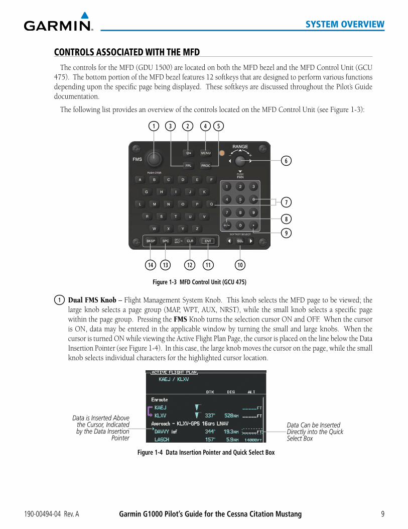
CONTROLS ASSOCIATED WITH THE MFDThe controls for the MFD (GDU 1500) are located on both the MFD bezel and the MFD Control Unit (GCU
475). The bottom portion of the MFD bezel features 12 softkeys that are designed to perform various functions depending upon the specific page being displayed. These softkeys are discussed throughout the Pilot’s Guide documentation.
The following list provides an overview of the controls located on the MFD Control Unit (see Figure 1-3):
3 4 52
6
7
8
9
13 12 11 10
Figure 1-3 MFD Control Unit (GCU 475)
1
14
1 Dual FMS Knob – Flight Management System Knob. This knob selects the MFD page to be viewed; the large knob selects a page group (MAP, WPT, AUX, NRST), while the small knob selects a specific page within the page group. Pressing the FMS Knob turns the selection cursor ON and OFF. When the cursor is ON, data may be entered in the applicable window by turning the small and large knobs. When the cursor is turned ON while viewing the Active Flight Plan Page, the cursor is placed on the line below the Data Insertion Pointer (see Figure 1-4). In this case, the large knob moves the cursor on the page, while the small knob selects individual characters for the highlighted cursor location.
Figure 1-4 Data Insertion Pointer and Quick Select Box
Data is Inserted Above the Cursor, Indicated by the Data Insertion
Pointer
Data Can be Inserted Directly into the Quick Select Box

190-00494-04 Rev. AGarmin G1000 Pilot’s Guide for the Cessna Citation Mustang10
SYSTEM OVERVIEW
2 Direct-to Key ( ) – Allows the user to enter a destination waypoint and establish a direct course to the selected destination (the destination is either specified by the identifier, chosen from the active route, or taken from the map pointer position).
3 FPL Key – Displays the active Flight Plan Page for creating and editing the active flight plan, or for accessing stored flight plans.
4 MENU Key – Displays a context-sensitive list of options. This list allows the user to access additional features or make setting changes that relate to particular pages.
5 PROC Key – Gives access to IFR departure procedures (DPs), arrival procedures (STARs) and approach procedures (IAPs) for a flight plan. If a flight plan is used, available procedures for the departure and/or arrival airport are automatically suggested. Theses procedures can then be loaded into the active flight plan. If a flight plan is not used, both the desired airport and the desired procedure may be selected.
6 Joystick – Changes the map range when rotated. Activates the map pointer when pressed. Also, used to position the Quick Select Box in the desired field as shown in Figure 1-4. Also, see the Flight Planning discussion in the Flight Management section for further explanation of the Quick Select Box.
7 Alphanumeric Keys – Allow the user to enter data quickly, without having to select individual characters with the FMS Knob.
8 Plus (+) Minus (-) Key – Toggles a (+) or (-) character.
9 Decimal Key – Enters a decimal point.
10 SEL Key – The center of this key activates the selected softkey, while the right and left arrows move the softkey selection box to the right and left, respectively.
11 ENT Key – Validates or confirms a menu selection or data entry.
12 CLR Key – Erases information, cancels entries, or removes page menus. Pressing and holding this key displays the Navigation Map Page automatically.
13 SPC Key – Adds a space character.
14 BKSP Key – Moves the cursor back one character space.

190-00494-04 Rev. A Garmin G1000 Pilot’s Guide for the Cessna Citation Mustang 11
SYSTEM OVERVIEW
AFCS CONTROLS
NOTE: With the exception of the FD and SPD Keys, if a key is selected, its respective annunciator is illuminated.
1 2 3 4 5 6 7 8
10 917 16 15 14 13 12 111819
Figure 1-5 AFCS Control Unit (GMC 710)
The GFC 700 AFCS is mainly controlled through the GMC 710 AFCS Control Unit. The AFCS Control Unit consists of the following controls:
1 HDG Key – Selects/deselects Heading Select Mode.
2 APR Key – Selects/deselects Approach Mode.
3 NAV Key – Selects/deselects Navigation Mode.
4 FD Key – Activates/deactivates the flight director in the default pitch and roll modes. If the autopilot is engaged, the FD Key is disabled.
5 XFR Key – Switches the autopilot between the pilot-side and the copilot-side flight directors. This selection also selects which air data computer is communicating with the active transponder. Upon power-up, the pilot-side FD is selected.
6 ALT Key – Selects/deselects Altitude Hold Mode.
7 VS Key – Selects/deselects Vertical Speed Mode.
8 FLC Key – Selects/deselects Flight Level Change Mode.
9 CRS2 Knob – Sets the copilot-selected course on the HSI of PFD2 when the VOR1, VOR2, or OBS/SUSP mode is selected. Pressing this knob centers the CDI on the currently selected VOR. The copilot-selected course provides course reference to the copilot-side flight director when operating in Navigation and Approach modes.
10 SPD Key – Switches the Flight Level Change mode reference speed between IAS and MACH number.
11 NOSE UP/DN Wheel – Controls the active mode reference for the Pitch, Vertical Speed, and Flight Level Change modes.
12 VNV Key – Selects/deselects Vertical Navigation mode.

190-00494-04 Rev. AGarmin G1000 Pilot’s Guide for the Cessna Citation Mustang12
SYSTEM OVERVIEW
13 ALT SEL Knob – Sets the selected altitude in the Selected Altitude Box. In addition to providing the standard G1000 altitude alerter function, selected altitude provides an altitude setting for the Altitude Capture/Hold mode of the AFCS.
14 YD Key – Engages/disengages the yaw damper.
15 AP Key – Engages/disengages the autopilot.
16 BANK Key – Selects/deselects Low Bank Mode.
17 CRS1 Knob – Sets the pilot-selected course on the HSI of PFD1 when the VOR1, VOR2, or OBS/SUSP mode is selected. Pressing this knob centers the CDI on the currently selected VOR. The pilot-selected course provides course reference to the pilot-side flight director when operating in Navigation and Approach modes.
18 BC Key – Selects/deselects Back Course Mode.
19 HDG Knob – Sets the selected heading on the HSI. When operating in Heading Select mode, this knob provides the heading reference to the flight director.
ADDITIONAL AFCS CONTROLS
The AP DISC (Autopilot Disconnect) Switch, CWS (Control Wheel Steering) Button, GO AROUND Switch, and MEPT (Manual Electric Pitch Trim) Switch are additional AFCS controls and are located in the cockpit, separately from the AFCS Control Unit. These are discussed in detail in the AFCS section.

190-00494-04 Rev. A Garmin G1000 Pilot’s Guide for the Cessna Citation Mustang 13
SYSTEM OVERVIEW
AUDIO PANEL CONTROLS
Figure 1-6 Audio Panel Controls
17
18
15
13
11
9
20
7
5
3
1
14
2
16
4
6
8
10
12
22
24
23
21
19 21
25
GMA 1347D GMA 1347D-20
NOTE: When a key is selected, a triangular annunciator above the key is illuminated.
1 COM1 MIC – Selects the #1 transmitter for transmitting. COM1 receive is simultaneously selected when this key is pressed allowing received audio from the #1 COM receiver to be heard. COM2 receiver audio can be added by pressing the COM2 Key.
2 COM1 – When selected, audio from the #1 COM receiver can be heard.
3 COM2 MIC – Selects the #2 transmitter for transmitting. COM2 is simultaneously selected when this key is pressed allowing received audio from the #2 COM receiver to be heard. COM2 can be deselected by pressing the COM2 Key, or COM1 can be added by pressing the COM1 Key.
4 COM2 – When selected, audio from the #2 COM receiver can be heard.

190-00494-04 Rev. AGarmin G1000 Pilot’s Guide for the Cessna Citation Mustang14
SYSTEM OVERVIEW
5 COM3 MIC – Selects the KHF 1050 transmitter for transmitting (if installed). COM3 is simultaneously selected when this key is pressed allowing received audio from the HF receiver to be heard. COM3 can be deselected by pressing the COM3 Key, or COM1/COM2 can be added by pressing the COM1/COM2 Key.
6 COM3 – When selected, audio from the HF receiver (if installed) can be heard.
7 PA – Selects the passenger address system. The selected COM transmitter is deselected when the PA Key is pressed.
8 TEL – Not used on the Cessna Citation Mustang.
9 MUSIC – Press to deliver SiriusXM audio to the cockpit.
10 SPKR – Pressing this key selects and deselects the corresponding cockpit speaker. COM and NAV receiver audio will be heard on the speaker.
11 MKR/MUTE – Mutes the currently received marker beacon receiver audio. Unmutes when new marker beacon audio is received.
12 HI SENS – Press to increase Marker Beacon Receiver sensitivity. Press again to return to normal.
13 DME – Pressing turns the optional DME audio on or off.
14 NAV1 – When selected, audio from the #1 NAV receiver can be heard.
15 ADF – Pressing turns on or off the audio from the ADF receiver.
16 NAV2 – When selected, audio from the #2 NAV receiver can be heard.
17 AUX – Not used on the Cessna Citation Mustang.
18 REC – Press to start the recording up to 2.5 minutes of COM receiver audio. When no audio is being received, nothing is recorded. Press again to stop recording.
19 PLAY – Press once to play the last recorded audio. Press again to stop playing. Press twice quickly while audio is playing and the previous block of recorded audio will be played. Each subsequent two presses will skip back to the previously recorded block.
20 INTR COM – Pressing selects the pilot/copilot intercom on both audio panels. Press again to deselect the intercom.
21 MAN SQ – Press to enable manual squelch for the intercom. When active, press the ICS Knob to illuminate ‘SQ’. Turn the ICS Knob to adjust squelch.
22 ICS Knob – Turn to adjust intercom volume or squelch. Press to switch between volume and squelch control as indicated by the ‘VOL’ or ‘SQ’ being illuminated. The MAN SQ Key must be selected to allow squelch adjustment.
23 MSTR Knob – The Master Volume Control adjusts volume for the blended NAV, COM, and intercom audio.
24 Reversionary Mode Button – Pressing manually selects Reversionary Mode.
25 CABIN – Not used on the Cessna Citation Mustang.

190-00494-04 Rev. A Garmin G1000 Pilot’s Guide for the Cessna Citation Mustang 15
SYSTEM OVERVIEW
1.4 SECURE DIGITAL CARDS
NOTE: Refer to the Appendices for instructions on updating the aviation database.
NOTE: Ensure that the G1000 system is powered off before inserting the SD card.
The GDU 1040A and GDU 1500 data card slots use Secure Digital (SD) cards and are located on the top right portion of the display bezels. Each display bezel is equipped with two SD card slots. SD cards are used for aviation database and system software updates as well as terrain database storage.
Not all SD cards are compatible with the G1000. Use only SD cards supplied by Garmin or the aircraft manufacturer.
Install an SD card
Insert the SD card in the SD card slot, pushing the card in until the spring latch engages. The front of the card should remain flush with the face of the display bezel.
Remove an SD card
Gently press on the SD card to release the spring latch and eject the card.
Figure 1-7 Display Bezel SD Card Slots
PFD MFD
SD Card Slots

190-00494-04 Rev. AGarmin G1000 Pilot’s Guide for the Cessna Citation Mustang16
SYSTEM OVERVIEW
1.5 SYSTEM POWER-UP
NOTE: Refer to the Appendices for AHRS initialization bank angle limitations.
NOTE: See the Appendices for additional information regarding system-specific annunciations and alerts.
NOTE: See the Airplane Flight Manual (AFM) for specific procedures concerning avionics power application and emergency power supply operation.
The G1000 system is integrated with the aircraft electrical system and receives power directly from electrical busses. The G1000 PFDs, MFD and supporting sub-systems include both power-on and continuous built-in test features that exercise the processor, RAM, ROM, external inputs and outputs to provide safe operation.
During system initialization, test annunciations are displayed, as shown in Figure 1-8. All system annunciations should disappear typically within one minute of power-up. Upon power-up, key annunciator lights also become momentarily illuminated on the audio panels, the control units and the display bezels.
On the PFD, the AHRS begins to initialize and displays ‘AHRS ALIGN: Keep Wings Level’. The AHRS should display valid attitude and heading fields typically within one minute of power-up. The AHRS can align itself both while taxiing and during level flight.
When the MFD powers up (Figure 1-9), the MFD Power-up Page displays the following information:
•Systemversion
•Copyright
•Landdatabasenameandversion
•SafeTaxidatabaseinformation
•Terraindatabasenameandversion
•AirportTerraindatabasenameandversion
•Obstacledatabasenameandversion
•Navigationdatabasename,version,andeffectivedates
•AirportDirectoryname,versionandeffectivedates
•FliteChartsorChartViewdatabaseinformation
Current database information includes the valid operating dates, cycle number and database type. When this information has been reviewed for currency (to ensure that no databases have expired), the pilot is prompted to continue. Pressing the ENT Key acknowledges this information and displays the Auxiliary (AUX) Weight Planning Page.
Figure 1-9 MFD Power-up PageFigure 1-8 PFD Initialization
190-00494-04 Rev. A Garmin G1000 Pilot’s Guide for the Cessna Citation Mustang 17
SYSTEM OVERVIEW
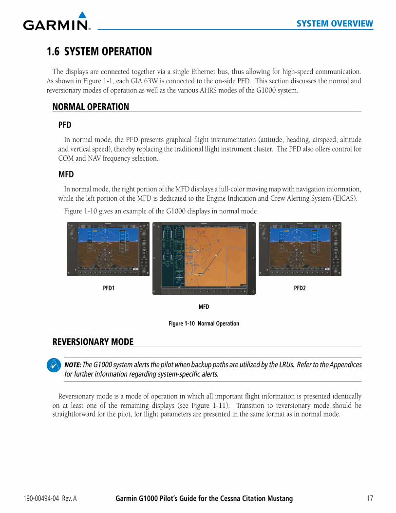
1.6 SYSTEM OPERATION
The displays are connected together via a single Ethernet bus, thus allowing for high-speed communication. As shown in Figure 1-1, each GIA 63W is connected to the on-side PFD. This section discusses the normal and reversionary modes of operation as well as the various AHRS modes of the G1000 system.
NORMAL OPERATION
PFD
In normal mode, the PFD presents graphical flight instrumentation (attitude, heading, airspeed, altitude and vertical speed), thereby replacing the traditional flight instrument cluster. The PFD also offers control for COM and NAV frequency selection.
MFD
In normal mode, the right portion of the MFD displays a full-color moving map with navigation information, while the left portion of the MFD is dedicated to the Engine Indication and Crew Alerting System (EICAS).
Figure 1-10 gives an example of the G1000 displays in normal mode.
Figure 1-10 Normal Operation
MFD
PFD1 PFD2
REVERSIONARY MODE
NOTE: The G1000 system alerts the pilot when backup paths are utilized by the LRUs. Refer to the Appendices for further information regarding system-specific alerts.
Reversionary mode is a mode of operation in which all important flight information is presented identically on at least one of the remaining displays (see Figure 1-11). Transition to reversionary mode should be straightforward for the pilot, for flight parameters are presented in the same format as in normal mode.

190-00494-04 Rev. AGarmin G1000 Pilot’s Guide for the Cessna Citation Mustang18
SYSTEM OVERVIEW
In reversionary mode, critical flight instrumentation is combined with engine instrumentation on the remaining display. Minimal navigation capability is available on the reversionary mode display.
Figure 1-11 Reversionary Mode (Manual)
If the system detects a failure in the MFD, PFD1 will enter reversionary mode automatically. Reversionary mode must be entered manually in the case of PFD1 or PFD2 failure.
Reversionary mode is manually activated by pressing the dedicated DISPLAY BACKUP button at the bottom of the audio panel (see Figure 1-12 and refer to the Audio Panel section for further details). Pressing this button again deactivates reversionary mode.
Figure 1-12 DISPLAY BACKUP Button
Press ing the DISPLAY BACKUP button activates/deactivates reversionary mode for both the on-side PFD and the MFD.
Each display can be configured to operate in reversionary mode, as follows:
•PFD1 – Manual reversion by pressing the DISPLAY BACKUP button on the left audio panel.
•MFD – Auto-reversion by the system or manually by pressing the DISPLAY BACKUP button on the left or the right audio panel.
•PFD2 – By pressing the DISPLAY BACKUP button on the right audio panel.
Should the connection between a PFD and the on-side GIA 63W become inoperative, the on-side GIA 63W can no longer communicate with the remaining PFD (refer to Figure 1-1). As a result, the NAV and COM functions provided to the failed PFD by the on-side GIA 63W are flagged as invalid (red “X”) on the remaining PFD (see Figure 1-13).
Figure 1-13 Inoperative Input (NAV1 Shown)

190-00494-04 Rev. A Garmin G1000 Pilot’s Guide for the Cessna Citation Mustang 19
SYSTEM OVERVIEW
AHRS OPERATION
NOTE: Refer to the Appendices for specific AHRS alert information.
NOTE: Aggressive maneuvering while the AHRS is not operating normally can degrade AHRS accuracy.
In addition to using internal sensors, the GRS 77 AHRS uses GPS information, magnetic field data and air data to assist in attitude/heading calculations. In normal mode, the AHRS relies upon GPS and magnetic field measurements. If either of these external measurements is unavailable or invalid, the AHRS uses air data information for attitude determination. Four AHRS modes of operation are available (see Figure 1-14) and depend upon the combination of available sensor inputs. Loss of air data, GPS, or magnetometer sensor inputs is communicated to the pilot by message advisory alerts.
Attitude/Heading Invalid
AHRSno-GPSMode
AHRS NormalOperation
AHRS no-Mag Mode
AHRS no-Mag/no-Air Mode
Heading Invalid
avai
labl
e
avai
labl
e
unav
aila
ble
unavailableav
aila
ble
unav
aila
ble
unav
aila
ble
avai
labl
eAir Data
Magnetometer Data
unav
aila
ble
avai
labl
e
GPS Data
Magnetometer Data
Air Data
Figure 1-14 AHRS Operation
GPS INPUT FAILURE
NOTE: In-flight initialization of AHRS, when operating without any valid source of GPS data and at true air speed values greater than approximately 200 knots, is not guaranteed. Under these rare conditions, it is possible for in-flight AHRS initialization to take an indefinite amount of time which would result in an extended period of time where valid AHRS outputs are unavailable.
The G1000 system provides two sources of GPS information. If a single GPS receiver fails, or if the information provided from one of the GPS receivers is unreliable, the AHRS seamlessly transitions to using the other GPS receiver. An alert message informs the pilot of the use of the backup GPS path. If both

190-00494-04 Rev. AGarmin G1000 Pilot’s Guide for the Cessna Citation Mustang20
SYSTEM OVERVIEW
GPS inputs fail, the AHRS continues to operate in reversionary No-GPS mode so long as the air data and magnetometer inputs are available and valid.
AIR DATA INPUT FAILURE
A failure of the air data input has no effect on AHRS output while AHRS is operating in normal mode. A failure of the air data input while the AHRS is operating in reversionary No-GPS mode results in invalid attitude and heading information on the PFD (as indicated by red “X” flags).
MAGNETOMETER FAILURE
If the magnetometer input fails, the AHRS transitions to one of the reversionary No-Magnetometer modes and continues to output valid attitude information. However, if the aircraft is airborne, the heading output on the PFD does become invalid (as indicated by a red “X”).
G1000 SYSTEM ANNUNCIATIONS
NOTE: For a detailed description of all annunciations and alerts, refer to Appendix A. Refer to the Airplane Flight Manual (AFM) for additional information regarding pilot responses to these annunciations.
When an LRU or an LRU function fails, a large red “X” is typically displayed on windows associated with the failed data (Figure 1-15 displays all possible flags and responsible LRUs). Upon G1000 power-up, certain windows remain invalid as equipment begins to initialize. All windows should be operational within one minute of power-up. If any window remains flagged, the G1000 system should be serviced by a Garmin-authorized repair facility.
Figure 1-15 G1000 System Failure Annunciations
GDC 74B Air Data Computer
GTX 33/D TransponderOrGIA 63W Integrated Avionics Units
GDC 74B Air Data Computer
GEA 71 Engine Airframe Unit
OrGIA 63W Integrated
Avionics Unit
GIA 63W Integrated Avionics Units
GRS 77 AHRSOrGMU 44 Magnetometer
GIA 63W Integrated Avionics Units
GIA 63W Integrated Avionics Units
FADEC
Fuel Qty. Signal Conditioner
KAPSIIPressure Controller
GEA 71 Engine Airframe Unit
GEA 71 Engine Airframe Unit

190-00494-04 Rev. A Garmin G1000 Pilot’s Guide for the Cessna Citation Mustang 21
SYSTEM OVERVIEW
SOFTKEY FUNCTIONThe softkeys are located along the bottoms of the displays. The softkeys shown depend on the softkey level
or page being displayed. The bezel keys below the softkeys can be used to select the appropriate softkey. When a softkey is selected, its color changes to black text on gray background and remains this way until it is turned off, at which time it reverts to white text on black background.
Softkey Names (displayed)
Figure 1-16 Softkeys (Second-Level PFD Configuration)
Bezel-Mounted Softkeys (press)
Softkey On
Another means of selecting softkeys on the MFD is by using the MFD Control Unit:
Selecting a softkey using the MFD Control Unit
1) Move the softkey selection box to the desired softkey using the arrows of the SEL Key.
2) Press the center of the SEL Key to select the desired softkey.
PFD SOFTKEYS
The CDI, IDENT, TMR/REF, NRST, and MSG Softkeys undergo a momentary change to black text on gray background and automatically switch back to white text on black background when selected. If messages remain after acknowledgement, the MSG Softkey will be black on white.
The PFD softkeys provide control over flight management functions, including GPS, NAV, terrain, traffic, and lightning (optional). Each softkey sublevel has a BACK Softkey which can be pressed to return to the previous level. The MSG Softkey is visible in all softkey levels. For the top level softkeys and the transponder (XPDR) levels, the IDENT Softkey remains visible.
Level 1 Level 2 Level 3 Level 4 Description
INSET or TRFC/MAP
Displays Inset Map in PFD lower left corner. The TRFC/MAP Softkey is displayed when the TCAS II option is installed. Pressing the TRFC/MAP Softkey displays the Inset Map showing Traffic Map Page.
OFF Removes Inset Map
DCLTR (3) Selects desired amount of map detail; cycles through declutter levels: DCLTR (No Declutter): All map features visible DCLTR-1: Declutters land data DCLTR-2: Declutters land and SUA data DCLTR-3: Removes everything except for the active flight plan
WX LGND Displays icon and age on the Inset Map for the selected weather products (optional)
TRAFFIC Cycles through traffic display options: TRAFFIC: Traffic not displayed on inset map TRFC-1: Traffic displayed on inset map TRFC-2: Traffic Map Page is displayed in the inset map window

190-00494-04 Rev. AGarmin G1000 Pilot’s Guide for the Cessna Citation Mustang22
SYSTEM OVERVIEW
Level 1 Level 2 Level 3 Level 4 Description
TOPO Displays topographical data (e.g., coastlines, terrain, rivers, lakes) and elevation scale on Inset Map
TERRAIN Displays terrain information on Inset Map
NEXRAD Displays NEXRAD weather and coverage information on Inset Map (optional feature)
XM LTNG Displays XM WX lightning information on Inset Map (optional feature)
METAR Displays METAR flags on airport symbols shown on the Inset Map (optional)
SENSOR Displays softkeys for selecting the #1 and #2 AHRS and Air Data Computers
ADC1 Selects the #1 Air Data Computer
ADC2 Selects the #2 Air Data Computer
AHRS1 Selects the #1 AHRS
AHRS2 Selects the #2 AHRS
PFD Displays second-level softkeys for additional PFD configurations
SYN VIS Displays the softkeys for enabling or disabling Synthetic Vision features
PATHWAY Displays rectangular boxes representing the horizontal and vertical flight path of the active flight plan
SYN TERR Enables synthetic terrain depiction
HRZN HDG Displays compass heading along the Zero-Pitch line
APTSIGNS Displays position markers for airports within approximately 15 nm of the current aircraft position. Airport identifiers are displayed when the airport is within approximately 9 nm.
DFLTS Resets PFD to default settings, including changing units to standard
WIND Displays softkeys to select wind data parameters
OPTN 1 Wind direction arrows with headwind/tailwind and crosswind components
OPTN 2 Wind direction arrow and speed
OPTN 3 Wind direction arrow with headwind/tailwind and crosswind components
OFF Information not displayed
DME Displays the information window for DME
BRG1 Cycles the Bearing 1 Information Window through NAV1, GPS/ waypoint identifier and GPS-derived distance information.
BRG2 Cycles the Bearing 2 Information Window through NAV2 or GPS waypoint identifier and GPS-derived distance information.

190-00494-04 Rev. A Garmin G1000 Pilot’s Guide for the Cessna Citation Mustang 23
SYSTEM OVERVIEW
Level 1 Level 2 Level 3 Level 4 Description
ALT UNIT Displays softkeys for setting the altimeter and BARO settings to metric units
METERS When enabled, displays altimeter in meters
IN Press to display the BARO setting as inches of mercury
HPA Press to display the BARO setting as hectopacals
STD BARO Sets barometric pressure to 29.92 in Hg (1013 hPa if metric units are selected)
OBS Selects OBS mode on the CDI when navigating by GPS (only available with active leg)
CDI Cycles through GPS, VOR1 (LOC1), and VOR2 (LOC2) navigation source on the CDI
ADF/DME (when ADF is installed) or
DME
Displays the ADF/DME Tuning Window, providing ADF (when installed) tuning tuning, ADF Mode selection, ADF volume control, and selection of the NAV source for tuning each DME
Transponder Softkeys without TCAS II OptionXPDR Displays transponder mode selection softkeys
XPDR1 Selects the #1 transponder as active
XPDR2 Selects the #2 transponder as active
STBY Selects standby mode (transponder does not reply to any interrogations)
ON Selects Mode A (transponder replies to identification interrogations)
ALT Selects Mode C – altitude reporting mode (transponder replies to identification and altitude interrogations)
GND Manually selects Ground Mode, the transponder does not allow Mode A and Mode C replies, but it does permit acquisition squitter and replies to discretely addressed Mode S interrogations (not available with TCAS II)
VFR Automatically enters the VFR code (1200 in the U.S.A. only)(not avialable with TCAS II)
CODE Displays transponder code selection softkeys 0-7
0 — 7 Use numbers to enter code
BKSP Removes numbers entered, one at a time
IDENT Activates the Special Position Identification (SPI) pulse for 18 seconds, identifying the transponder return on the ATC screen
TMR/REF Displays Timer/References Window
NRST Displays Nearest Airports Window
MSG Displays Messages Window

190-00494-04 Rev. AGarmin G1000 Pilot’s Guide for the Cessna Citation Mustang24
SYSTEM OVERVIEW
Level 1 Level 2 Level 3 Level 4 Description
Transponder/Traffic Softkeys with TCAS II OptionXPDR/TFC Displays the transponder and TCAS II system selection softkeys
MODE Displays transponder mode selection softkeys
STBY Selects transponder Standby Mode (transponder does not reply to any interrogations). When the transponder is set to standby, the TCAS II system is also set to standby.
ON Activates transponder (transponder replies to identification interrogations). When the transponder is set to ON, the TCAS II system is set to standby.
ALT Altitude Reporting Mode (transponder replies to identification and altitude interrogations). When the transponder is set to ALT, the TCAS II system is set to standby.
TA ONLY Activates the TCAS II system in TA Only Mode and sets the transponder to ALT
TA/RA Activates the TCAS II system in TA/RA Mode and sets the transponder to ALT
BACK Returns to the previous softkey level
TCAS Displays the TCAS control softkeys
REL Displays intruder altitude as altitude relative to own aircraft altitude
ABS Displays intruder MSL altitude
ALT RNG Displays the altitude display range softkeys
ABOVE Displays non-threat traffic from 9900 feet above the aircraft to 2700 feet below the aircraft. Typically used during climb phase of flight.
NORMAL Displays non-threat traffic from 2700 feet above the aircraft to 2700 feet below the aircraft. Typically used during enroute phase of flight.
BELOW Displays non-threat traffic from 2700 feet above the aircraft to 9900 feet below the aircraft. Typically used during descent phase of flight.
UNREST All traffic is displayedTEST Activates Test Mode and displays test intruder symbols
BACK Returns to the previous softkey level
CODE Displays transponder code selection softkeys 0-7
0 — 7 Use numbers to enter code
IDENT Activates the Special Position Identification (SPI) pulse for 18 seconds, identifying the transponder return on the ATC screen
BKSP Removes numbers entered, one at a time
IDENT Activates the Special Position Identification (SPI) pulse for 18 seconds, identifying the transponder return on the ATC screen
TMR/REF Displays Timer/References Window
NRST Displays Nearest Airports Window
MSG Displays Messages Window

190-00494-04 Rev. A Garmin G1000 Pilot’s Guide for the Cessna Citation Mustang 25
SYSTEM OVERVIEW
Figure 1-17 Top Level PFD Softkeys
Figure 1-18 INSET Softkeys
Select the BACK or OFF Softkey to return to the top-level softkeys.
TRFC-1
TRFC-2
WX LGND METAR
Figure 1-19 SENSOR Softkeys
Press the BACK Softkey toreturn to the top level softkeys.
BACK MSGADC2ADC1 AHRS1 AHRS2

190-00494-04 Rev. AGarmin G1000 Pilot’s Guide for the Cessna Citation Mustang26
SYSTEM OVERVIEW
Figure 1-20 PFD Configuration Softkeys
Select the BACK Softkeyto return to the top-level softkeys
ALT UNIT
METERS IN HPA
SYN VIS
SYN TERR HRZN HDG PATHWAY APTSIGNS
(optional)
Figure 1-21 XPDR Softkeys (without TCAS II)
Press the BACK Softkey to returnto the top-level softkeys.
Press the BACK Softkey to returnto the top-level softkeys.
MSG
MSG

190-00494-04 Rev. A Garmin G1000 Pilot’s Guide for the Cessna Citation Mustang 27
SYSTEM OVERVIEW
MSG
MSG
ADF/DMETRFC/MAP XPDR/TFC
Press the BACK Softkey to returnto the top-level softkeys.
MSGMODE TCAS CODE IDENT
Selecting BACK returns to theprevious softkey level.
Selecting BACK returns to theprevious softkey level.
Selecting BACK returns to theprevious softkey level.
MSGREL ABS ALT RNG TEST
TA ONLY TA/RA
SENSOR PFD OBS CDI IDENT TMR/REF NRST MSG
BACK
STBY ON ALT BACK
BACK
IDENT BKSP BACK0 54321 6 7
MSG
Selecting BACK returns to theprevious softkey level.
UNRESTABOVE BELOWNORMAL BACK
Figure 1-22 XPDR Softkeys (with TCAS II)
MFD SOFTKEYSLevel 1 Level 2 Level 3 DescriptionCAS ↑ Scroll up (enabled only when a sufficient number of items are displayed in the Crew
Alerting System Display to warrant scrolling)CAS ↓ Scroll down (enabled only when a sufficient number of items are displayed in the
Crew Alerting System Display to warrant scrolling)MAP Enables second-level Navigation Map softkeys
TRAFFIC Displays traffic information on Navigation Map
PROFILE Displays/removes Profile View on Navigation Map Page
TOPO Displays topographical data (e.g., coastlines, terrain, rivers, lakes) and elevation scale on Navigation Map
TERRAIN Displays terrain information on Navigation Map (not available with TAWS-A)
AIRWAYS Displays airways on the map; cycles through the following: AIRWAYS: No airways are displayed AIRWY ON: All airways are displayed AIRWY LO: Only low altitude airways are displayed AIRWY HI: Only high altitude airways are displayed(Default label is dependant on map setup option selected)

190-00494-04 Rev. AGarmin G1000 Pilot’s Guide for the Cessna Citation Mustang28
SYSTEM OVERVIEW
Level 1 Level 2 Level 3 DescriptionNEXRAD Displays NEXRAD weather and coverage information on Navigation Map (optional
feature)XM LTNG Displays XM WX lightning information on Navigation Map (optional feature)
METAR Displays METAR flags on airport symbols shown on the Navigation Map
LEGEND Displays the legend for the selected weather products. Available only when NEXRAD, XM LTNG, METAR and/or PROFILE softkeys are selected.
BACK Returns to top-level softkeys
DCLTR (3) Selects desired amount of map detail; cycles through declutter levels:DCLTR (No Declutter): All map features visibleDCLTR-1: Declutters land dataDCLTR-2: Declutters land and SUA dataDCLTR-3: Removes everything except the active flight plan
SHW CHRT When available, displays optional airport and terminal procedure charts
Figure 1-23 MFD Softkeys
MAP DCLTR
DCLTR-2
DCLTR-3
DCLTR-1
SHW CHRT
(optional)
(Default softkeyis dependant onthe selection madein the map setupoptions)
AIRWY ON
AIRWY LO
AIRWAYS
AIRWY HI
Press the BACK softkey toreturn to the top-level softkeys.
BACKMETARXM LTNGNEXRADAIRWAYSTERRAINPROFILE TOPOTRAFFIC LEGEND
CAS ↓CAS ↑

190-00494-04 Rev. A Garmin G1000 Pilot’s Guide for the Cessna Citation Mustang 29
SYSTEM OVERVIEW
GPS RECEIVER OPERATIONEach GIA 63W Integrated Avionics Unit (IAU) contains a GPS receiver. Information collected by the specified
receiver (GPS1 for the #1 IAU or GPS2 for the #2 IAU) may be viewed on the AUX - GPS Status Page.
GPS1 provides information to the pilot-side PFD and GPS2 provides data to the copilot-side PFD. Internal system checking is performed to ensure both GPS receivers are providing accurate data to the PFDs. In some circumstances, both GPS receivers may be providing accurate data, but one receiver may be providing a better GPS solution than the other receiver. In this case the GPS receiver producing the better solution is automatically coupled to both PFDs. “BOTH ON GPS 1” or “BOTH ON GPS 2” are then displayed in the Reversionary Sensor Window (see Appendix A) indicating which GPS receiver is being used. Both GPS receivers are still functioning properly, but one receiver is performing better than the other at that particular time.
These GPS sensor annunciations are most often seen after system power-up when one GPS receiver has acquired satellites before the other, or one of the GPS receivers has not yet acquired an SBAS (Satellite Based Augmentation System) signal. While the aircraft is on the ground, the SBAS signal may be blocked by obstructions causing one GPS receiver to have difficulty acquiring a good signal. Also, while airborne, turning the aircraft may result in one of the GPS receivers temporarily losing the SBAS signal.
If the sensor annunciation persists, check for a system failure message in the Messages Window on the PFD. If no failure message exists, check the GPS Status Page and compare the information for GPS1 and GPS2. Discrepancies may indicate a problem.
Viewing GPS receiver status information
1) Use the large FMS Knob to select the Auxiliary Page Group (see Section 1.7 for information on navigating MFD page groups).
2) Use the small FMS Knob to select GPS Status Page.
Selecting the GPS receiver for which data may be reviewed
1) Use the FMS Knob to select the AUX - GPS Status Page.
2) To change the selected GPS receiver:
a) Select the desired GPS Softkey.
Or:
a) Press the MENU Key.
b) Use the FMS Knob to highlight the receiver which is not selected and press the ENT Key.

190-00494-04 Rev. AGarmin G1000 Pilot’s Guide for the Cessna Citation Mustang30
SYSTEM OVERVIEW
Figure 1-24 GPS Status Page (RAIM or SBAS Selected)
Satellite Signal Strength Bars
Satellite Constellation Diagram
Satellite Signal Information Status RAIM
Availability Prediction
GPS Receiver Status
EnabledSBAS Options
RAIM Softkey Selected
SBAS Softkey Selected
GPS Selection Softkeys
The GPS Status Page provides the following information:
•Satelliteconstellationdiagram
Satellites currently in view are shown at their respective positions on a sky view diagram. The sky view is always in a north-up orientation, with the outer circle representing the horizon, the inner circle representing 45° above the horizon, and the center point showing the position directly overhead.
Each satellite is represented by an oval containing the Pseudo-random noise (PRN) number (i.e., satellite identification number). Satellites whose signals are currently being used are represented by solid ovals.
•Satellitesignalinformationstatus
The accuracy of the aircraft’s GPS fix is calculated using Estimated Position Uncertainty (EPU), Dilution of Precision (DOP), and horizontal and vertical figures of merit (HFOM and VFOM). EPU is the radius of a circle centered on an estimated horizontal position in which actual position has 95% probability of laying. EPU is a statistical error indication and not an actual error measurement.
DOP measures satellite geometry quality (i.e., number of satellites received and where they are relative to each other) on a range from 0.0 to 9.9, with lower numbers denoting better accuracy. HFOM and VFOM, measures of horizontal and vertical position uncertainty, are the current 95% confidence horizontal and vertical accuracy values reported by the GPS receiver.

190-00494-04 Rev. A Garmin G1000 Pilot’s Guide for the Cessna Citation Mustang 31
SYSTEM OVERVIEW
The current calculated GPS position, time, altitude, ground speed, and track for the aircraft are displayed below the satellite signal accuracy measurements.
•GPSreceiverstatus
The GPS solution type (ACQUIRING, 2D NAV, 2D DIFF NAV, 3D NAV, 3D DIFF NAV) for the active GPS receiver (GPS1 or GPS2) is shown in the upper right of the GPS Status Page. When the receiver is in the process of acquiring enough satellite signals for navigation, the receiver uses satellite orbital data (collected continuously from the satellites) and last known position to determine the satellites that should be in view. ACQUIRING is indicated as the solution until a sufficient number of satellites have been acquired for computing a solution.
When the receiver is in the process of acquiring a 3D differential GPS solution, 3D NAV is indicated as the solution until the 3D differential fix has finished acquisition. SBAS (Satellite-Based Augmentation System) indicates INACTIVE. When acquisition is complete, the solution status indicates 3D DIFF NAV and SBAS indicates ACTIVE.
•RAIM(ReceiverAutonomousIntegrityMonitoring)Prediction(RAIM Softkey is selected)
In most cases performing a RAIM prediction is not be necessary. However, in some cases, the selected approach may be outside the SBAS coverage area and it may be necessary to perform a RAIM prediction for the intended approach.
Receiver Autonomous Integrity Monitoring (RAIM) is a GPS receiver function that performs a consistency check on all tracked satellites. RAIM ensures that the available satellite geometry allows the receiver to calculate a position within a specified RAIM protection limit (2.0 nautical miles for oceanic and enroute, 1.0 nm for terminal, and 0.3 nm for non-precision approaches). During oceanic, enroute, and terminal phases of flight, RAIM is available nearly 100% of the time.
The RAIM prediction function also indicates whether RAIM is available at a specified date and time. RAIM computations predict satellite coverage within ±15 min of the specified arrival date and time.
Because of the tighter protection limit on approaches, there may be times when RAIM is not available. The G1000 automatically monitors RAIM and warns with an alert message when it is not available. If RAIM is not predicted to be available for the final approach course, the approach does not become active, as indicated by the messages “Approach is not active” and “RAIM not available from FAF to MAP”. If RAIM is not available when crossing the FAF, the missed approach procedure must be flown.
Predicting RAIM availability
1) Select the GPS Status Page.
2) If necessary, select the RAIM Softkey.
3) Press the FMS Knob. The ‘WAYPOINT’ field is highlighted.
4) Turn the small FMS Knob to display the Waypoint Information Window.
5) Enter the desired waypoint:
a) Use the FMS Knob to enter the desired waypoint by identifier, facility, or city name and press the ENT Key. Refer to Section 1.7 for instructions on entering alphanumeric data into the G1000.
Or:

190-00494-04 Rev. AGarmin G1000 Pilot’s Guide for the Cessna Citation Mustang32
SYSTEM OVERVIEW
a) Use the large FMS Knob to scroll to the Most Recent Waypoints List.
b) Use the small FMS Knob to highlight the desired waypoint in the list and press the ENT Key. The G1000 automatically fills in the identifier, facility, and city fields with the information for the selected waypoint.
c) Press the ENT Key to accept the waypoint entry.
6) Use the FMS Knob to enter an arrival time and press the ENT Key.
7) Use the FMS Knob to enter an arrival date and press the ENT Key.
8) With the cursor highlighting ‘COMPUTE RAIM?’, press the ENT Key. Once RAIM availability is computed, one of the following is displayed:
• ‘COMPUTE RAIM?’—RAIM has not been computed for the current waypoint, time, and date combination
• ‘COMPUTING AVAILABILITY’—RAIM calculation in progress
• ‘RAIM AVAILABLE’—RAIM is predicted to be available for the specified waypoint, time, and date
• ‘RAIM NOT AVAILABLE’—RAIM is predicted to be unavailable for the specified waypoint, time, and date
Predicting RAIM availability at present position
1) Select the GPS Status Page.
2) If necessary, select the RAIM Softkey.
3) Press the FMS Knob. The ‘WAYPOINT’ field is highlighted.
4) Press the MENU Key.
5) With ‘Set WPT to Present Position’ highlighted, press the ENT Key.
6) Press the ENT Key to accept the waypoint entry.
7) Use the FMS Knob to enter an arrival time and press the ENT Key.
8) Use the FMS Knob to enter an arrival date and press the ENT Key.
9) With the cursor highlighting ‘COMPUTE RAIM?’, press the ENT Key. Once RAIM availability is computed, one of the following is displayed:
• ‘COMPUTE RAIM?’—RAIM has not been computed for the current waypoint, time, and date combination
• ‘COMPUTING AVAILABILITY’—RAIM calculation in progress
• ‘RAIM AVAILABLE’—RAIM is predicted to be available for the specified waypoint, time, and date
• ‘RAIM NOT AVAILABLE’—RAIM is predicted to be unavailable for the specified waypoint, time, and date
•SBASSelection(SBAS Softkey is pressed)(WAAS, EGNOS, or MSAS capable systems only)In certain situations, such as when the aircraft is outside or on the fringe of the WAAS, EGNOS, or MSAS
coverage area, it may be desirable to disable the reception of the applicable SBAS signal (although it is not recommended). When disabled, the SBAS field in the GPS Status box indicates DISABLED. There may be a small delay for the GPS Status box to be updated upon WAAS, EGNOS, and MSAS enabling/disabling.

190-00494-04 Rev. A Garmin G1000 Pilot’s Guide for the Cessna Citation Mustang 33
SYSTEM OVERVIEW
Disabling WAAS, EGNOS or MSAS
1) Select the GPS Status Page.
2) If necessary, select the SBAS Softkey.
3) Press the FMS Knob, and turn the large FMS Knob to hightlight the desired SBAS system.
4) Press the ENT Key to uncheck the box.
5) Press the FMS Knob to remove the cursor.
•GPSSatelliteSignalStrengthsThe GPS Status Page can be helpful in troubleshooting weak (or missing) signal levels due to poor satellite
coverage or installation problems. As the GPS receiver locks onto satellites, a signal strength bar is displayed for each satellite in view, with the appropriate satellite PRN number (01-32 or 120-138 for WAAS) below each bar. The progress of satellite acquisition is shown in three stages, as indicated by signal bar appearance:
- No bar—Receiver is looking for the indicated satellite- Hollow bar—Receiver has found the satellite and is collecting data- Light blue bar—Receiver has collected the necessary data and the satellite signal can be used- Green bar—Satellite is being used for the GPS solution- Checkered bar—Receiver has excluded the satellite (Fault Detection and Exclusion)- “D” indication—Denotes the satellite is being used as part of the differential computations
Each satellite has a 30-second data transmission that must be collected (signal strength bar is hollow) before the satellite may be used for navigation (signal strength bar becomes solid).

190-00494-04 Rev. AGarmin G1000 Pilot’s Guide for the Cessna Citation Mustang34
SYSTEM OVERVIEW
1.7 ACCESSING G1000 FUNCTIONALITY
MENUSThe G1000 has a MENU Key that, when pressed, displays a context-sensitive list of options. This options list
allows the user to access additional features or make settings changes which specifically relate to the currently displayed window/page. There is no all-encompassing menu. Some menus provide access to additional submenus that are used to view, edit, select, and review options. Menus display ‘NO OPTIONS’ when there are no options for the window/page selected. The main controls used in association with all window/page group operations are described in section 1.3. Softkey selection does not display menus or submenus.
Navigating the Page Menu Window
1) Press the MENU Key to display the Page Menu Window.
2) Turn the FMS Knob to scroll through a list of available options (a scroll bar appears to the right of the window when the option list is longer than the window).
3) Press the ENT Key to select the desired option.
4) The CLR Key may be pressed to remove the menu and cancel the operation. Pressing the FMS Knob also removes the displayed menu.
Figure 1-25 Page Menu Examples
No Options with NRST Window Displayed on the PFD
Options with FPL Window
Displayed
MFD PAGE GROUPS
NOTE: Refer to other supporting sections in this Pilot’s Guide for details on specific pages.
Information on the MFD is presented on pages which are grouped according to function. The page group and active page title box are displayed in the upper right of the screen. In the bottom right corner of the screen, a page group window is displayed by turning either FMS Knob. The page group tabs are displayed along the bottom of the window. The page titles are displayed in a list above the page group tabs. The current page group and current page within the group are shown in light blue. For some of these pages (Airport/Procedures/Weather Information, SiriusXM, Procedure Loading), the active title of the page changes while the page name in the list remains the same.

190-00494-04 Rev. A Garmin G1000 Pilot’s Guide for the Cessna Citation Mustang 35
SYSTEM OVERVIEW
Figure 1-26 Page Title and Page Groups
Page Group Active Page TitleMFD
Page Groups
Pages inCurrentGroup
The main page groups are navigated using the FMS Knob; specific pages within each group can vary depending on the configuration of optional equipment.
Selecting a page using the FMS Knob:
1) Turn the large FMS Knob to display the list of page groups; continue turning the large FMS Knob until the desired page group is selected
2) Turn the small FMS Knob to display the desired page within a specific page group.
There are also several pages (Airport Information and XM Information pages) which are selected first from within a main page group with the FMS Knobs, then with the appropriate softkey at the bottom of the page. In this case, the page remains set to the selected screen until a different screen softkey is selected.
Figure 1-27 Map Pages
Map Pages (MAP)
Navigation Map
Traffic Map
Weather Radar
Weather Data Link (service optional)
TAWS

190-00494-04 Rev. AGarmin G1000 Pilot’s Guide for the Cessna Citation Mustang36
SYSTEM OVERVIEW
Waypoint Pages (WPT)
Airport Information pages
- Airport Information (INFO-1 Softkey)
- Airport Directory (INFO-2 Softkey)
- Departure Information (DP Softkey)
- Arrival Information (STAR Softkey)
- Approach Information (APR Softkey)
- Weather Information (WX Softkey)
Intersection Information
NDB Information
VOR Information
User Waypoint Information Figure 1-28 Waypoint Pages
Airport Information
Pages
Figure 1-29 Auxiliary Pages
Auxiliary Pages (AUX)
Weight Planning
Trip Planning
Utility
GPS Status
System Setup
SiriusXM Satellite pages
- XM Information (INFO Softkey)
- XM Radio (RADIO Softkey)
System Status
SiriusXM Satellite Pages

190-00494-04 Rev. A Garmin G1000 Pilot’s Guide for the Cessna Citation Mustang 37
SYSTEM OVERVIEW
Figure 1-30 Nearest Pages
Nearest Pages (NRST)
Nearest Airports
Nearest Intersections
Nearest NDB
Nearest VOR
Nearest User Waypoints
Nearest Frequencies
Nearest Airspaces
In addition to the main page groups accessed exclusively using the FMS Knobs, there are pages for flight planning (FPL) and loading procedures (PROC) which are accessed by bezel key. In some instances, softkeys may be used to access the Procedure Pages.
The Flight Plan Pages are accessed using the FPL Key on the MFD. Main pages within this group are selected by turning the small FMS Knob.
Figure 1-31 Flight Plan Pages
Flight Plan Pages (FPL)
Active Flight Plan
- Wide View, Narrow View (VIEW Softkey)
Flight Plan Catalog
or
Stored Flight Plan (NEW Softkey)
Narrow and Wide View

190-00494-04 Rev. AGarmin G1000 Pilot’s Guide for the Cessna Citation Mustang38
SYSTEM OVERVIEW
The Procedure pages may be accessed at any time on the MFD by pressing the PROC Key. A menu is initialized, and when a departure, approach, or arrival is selected, the appropriate Procedure Loading Page is opened. Turning the FMS Knob does not scroll through the Procedure pages (note the single page icon in the lower right corner).
Figure 1-32 Procedure Pages
Procedure Pages (PROC)
Departure Loading
Arrival Loading
Approach Loading
For some of these pages (Airport Information pages, SiriusXM Satellite pages, Procedure pages), the title of the page may change while the page icon remains the same.
MFD SYSTEM PAGESIn the Auxiliary (AUX) Page Group, there are two system pages: System Setup and System Status. The System
Setup Page allows management of various system parameters, while the System Status Page displays the status of all G1000 system LRUs.
SYSTEM SETUP PAGE
The System Setup Page allows management of the following system parameters:
•Date/time
•DisplayUnits (see Flight Instruments Section)
•BaroTransitionAlert (see Flight Instruments Section)
•AirspaceAlerts (see Flight Management Section)
•AudioAlerts
•FlightDirector (see AFCS Section)
•PageNavigation
•MFDDataBarFields(NavigationStatusBox) (see Flight Management Section)
•GPSCDIscalingforGPSnavigationsource (see Flight Instruments Section)
•COMConfiguration (see Audio Panel and CNS Section)
•NearestAirportsdisplaycriteria (see Flight Management Section)
•SynchronizationofBaroandCDIbetweenPFDs(see Flight Instruments Section)

190-00494-04 Rev. A Garmin G1000 Pilot’s Guide for the Cessna Citation Mustang 39
SYSTEM OVERVIEW
MFD Data Bar Fields Box
GPS CDI Box
COM Configuration Box
Nearest Airports Box
Flight Director Command Bar Format
CDI and Altimeter Baro Sync
Figure 1-33 System Setup Page
Airspace Alerts Box
Date/Time Box
Display Units Box
Audio Alert Voice Selection
Select Baro Transition Alert
Page Navigation
Settings
Date/time
The Date/Time Box on the System Setup Page displays the current date and time and allows the pilot to set the time format (local 12-hr, local 24-hr, or UTC) and offset. The time offset is used to define current local time. UTC (also called “GMT” or “Zulu”) date and time are calculated directly from the GPS satellites signals and cannot be changed. When using a local time format, designate the offset by adding or subtracting the desired number of hours.
To set the system time format:
1) While on the System Setup Page, press the FMS Knob momentarily to activate the flashing cursor.
2) Turn the large FMS Knob to highlight the time format field in the Date/Time Box.
3) Turn the small FMS Knob to select the desired system time format (local 12hr, local 24hr, UTC) and press the ENT Key.
To set the current time offset:
1) While on the System Setup Page, press the FMS Knob momentarily to activate the flashing cursor.
2) Turn the large FMS Knob to highlight the time offset field in the Date/Time Box.
3) Turn the FMS Knobs to enter the time offset and press the ENT Key.

190-00494-04 Rev. AGarmin G1000 Pilot’s Guide for the Cessna Citation Mustang40
SYSTEM OVERVIEW
DisPlay Units
The Display Units Box on the System Setup Page allows configuration of the measurement units used for the following displayed data:
•Navangle(magnetic,true)
Affects the BRG field in the PFD Navigation Status Box.
Affects the BRG, DTK, TKE, TRK, and XTK fields in the MFD Navigation Status Box.
•Position(HDDD°MM.MM’orHDDD°MM’SS.S”)
Affects all position displays.
To change a Display Units setting:
1) While on the System Setup Page, press the FMS Knob momentarily to activate the flashing cursor.
2) Turn the large FMS Knob to highlight the desired field in the Display Units Box.
3) Turn the small FMS Knob to select from a list of measurement units and press the ENT Key when the desired unit is highlighted. Press the CLR Key to cancel the action without changing the units.
BaRO tRansitiOn aleRt
See the Flight Instruments section for a discussion on setting the Baro Transition Alert.
aiRsPace aleRts
The Airspace Alerts Box allows the pilot to turn the controlled/special-use airspace message alerts on or off. This does not affect the alerts listed on the Nearest Airspaces Page or the airspace boundaries depicted on the MFD Navigation Map Page. It simply turns on/off the warning provided when the aircraft is approaching or near an airspace.
Alerts for the following airspaces can be turned on/off in the Airspace Alerts Box:
•ClassB/TMA
•ClassC/TCA
•ClassD
•Restricted
•MOA(Military)
•Otherairspaces
An altitude buffer is also provided which “expands” the vertical range above or below an airspace. For example, if the buffer is set at 500 feet, and the aircraft is more than 500 feet above/below an airspace, an alert message is not generated, but if the aircraft is less than 500 feet above/below an airspace and projected to enter it, the pilot is notified with an alert message. The default setting for the altitude buffer is 200 feet.
To change the altitude buffer distance setting:
1) While on the System Setup Page, press the FMS Knob momentarily to activate the flashing cursor.
2) Turn the large FMS Knob to highlight the altitude buffer field in the Airspace Alerts Box.
3) Turn the FMS Knobs to enter an altitude buffer value and press the ENT Key.

190-00494-04 Rev. A Garmin G1000 Pilot’s Guide for the Cessna Citation Mustang 41
SYSTEM OVERVIEW
To turn an airspace alert on or off:
1) While on the System Setup Page, press the FMS Knob momentarily to activate the flashing cursor.
2) Turn the large FMS Knob to highlight the desired field in the Airspace Alerts Box.
3) Turn the small FMS Knob clockwise to turn the airspace alert ON or counterclockwise to turn the alert OFF.
aUDiO aleRts
The Audio Alert Box on the System Setup Page allows the audio alert voice to be set to male or female.
To change the audio alert voice:
1) While on the System Setup Page, press the FMS Knob momentarily to activate the flashing cursor.
2) Turn the large FMS Knob to highlight the voice in the Audio Alert Box.
3) Turn the small FMS Knob to display and highlight the desired voice and press the ENT Key.
Flight DiRectOR
Two formats are available for the display of the flight director. Single Cue or X-Pointer may be selected.
To change the flight director format:
1) While on the System Setup Page, press the FMS Knob momentarily to activate the flashing cursor.
2) Turn the large FMS Knob to highlight the Format Active field in the Flight Director Box.
3) Turn the small FMS Knob to display and highlight the desired flight director format and press the ENT Key.
mFD Data BaR FielDs
The MFD Data Bar Fields Box on the System Setup Page displays the current configuration of the MFD Navigation Status Box. By default, the Navigation Status Bar is set to display ground speed (GS), desired track (DTK), track (TRK), and estimated time enroute (ETE).
To change the information shown in an MFD Navigation Status Bar field:
1) While on the System Setup Page, press the FMS Knob momentarily to activate the flashing cursor.
2) Turn the large FMS Knob to highlight the desired field number in the MFD Data Bar Fields Box.
3) Turn the small FMS Knob to display and scroll through the data options list and press the ENT Key when the desired data selection is highlighted.
The following data may be selected for display in each of the four fields of the Navigation Status Box.
•Bearing(BRG)
•Distance(DIS)
•DesiredTrack(DTK)
•EnRouteSafeAltitude(ESA)
•EstimatedTimeofArrival(ETA)
•EstimatedTimeEnRoute(ETE)
•GroundSpeed(GS)
•MinimumSafeAltitude(MSA)
•TrueAirSpeed(TAS)
•TrackAngleError(TKE)
•Track(TRK)
•VerticalSpeedRequired(VSR)
•CrosstrackError(XTK)
•FuelOverDestination(FOD)
•FuelOnBoard(FOB)
•Endurance(END)

190-00494-04 Rev. AGarmin G1000 Pilot’s Guide for the Cessna Citation Mustang42
SYSTEM OVERVIEW
Page navigatiOn
The large FMS Knob displays the Page Group Tabs and navigates through the tabs. The small FMS Knob navigates through the pages listed within a specific group. The number of clicks it takes to display the Page Group Tabs and change to the next tab can be controlled from the Page Navigation box on the AUX - System Setup Page.
OFF – Displays the Page Group Tabs with one click of either FMS Knob.
ON – Displays the Page Group Tabs and navigates to the next tab with one click of either FMS Knob.
The pilot can select, from the AUX - System Setup Page, the amount of time the Page Group Tabs are displayed (in the lower right corner of the MFD). The timeout can range from two to ten seconds.
Selecting page navigation settings:
1) Use the FMS Knob to select the AUX - System Setup Page.
2) Press the FMS Knob momentarily to activate the flashing cursor.
3) Turn the large FMS Knob to highlight the ‘Change On 1st Click’ field in the Page Navigation Box.
4) Turn the small FMS Knob to select ‘OFF’ or ‘ON’.
5) Turn the large FMS Knob to highlight the ‘Timeout Seconds’ field in the Page navigation Box.
6) Turn the small FMS Knob to select the desired number of seconds
7) Press the FMS Knob momentarily to remove the flashing cursor.
gPs cDi
The GPS CDI Box on the System Setup Page allows the pilot to define the range for the on-screen course deviation indicator (CDI). The range values represent full range deflection for the CDI to either side. The default setting is ‘AUTO’. Refer to the Flight Instruments sections for a discussion on CDI scaling.
If a lower CDI range setting is selected (i.e., 1.0 or 0.3 nm), the higher range settings are not selected during any phase of flight. For example, if 1.0 nm is selected, the G1000 uses this for en route and terminal phases and ramps down to 0.3 nm during an approach. Note that the Receiver Autonomous Integrity Monitoring (RAIM) protection limits follow the selected CDI range and corresponding flight phases.
The GPS CDI Box on the System Setup Page displays the following:
•SelectedCDIrange(auto,2nm,1nm,0.3nm)
•CurrentsystemCDIrange(2nm,1nm,0.3nm)
To change the CDI range:
1) While on the System Setup Page, press the FMS Knob momentarily to activate the flashing cursor.
2) Turn the large FMS Knob to highlight the selected field in the GPS CDI Box.
3) Turn the small FMS Knob to display and scroll through the range list and press the ENT Key when the desired selection is highlighted.

190-00494-04 Rev. A Garmin G1000 Pilot’s Guide for the Cessna Citation Mustang 43
SYSTEM OVERVIEW
To change the ILS CDI capture setting:
1) While on the System Setup Page, press the FMS Knob momentarily to activate the flashing cursor.
2) Turn the large FMS Knob to highlight the ILS CDI capture field in the GPS CDI Box.
3) Turn the small FMS Knob to select the desired mode and press the ENT Key.
cOm cOnFigURatiOn
WARNING: Selecting the DFLTS Softkey will set the COM frequency spacing to 25.0 kHz, possibly resulting in loss of communications if using 8.33 kHz frequency spacing.
NOTE: 8.33 kHz VHF communication frequency channel spacing is not approved for use in the United States. Select the 25.0 kHz channel spacing option for use in the United States.
The COM Configuration Box on the System Setup Page allows the pilot to select 8.33 kHz or 25.0 kHz COM frequency channel spacing.
To change COM channel spacing:
1) While on the System Setup Page, press the FMS Knob momentarily to activate the flashing cursor.
2) Turn the large FMS Knob to highlight the channel spacing field in the COM Configuration Box.
3) Turn the small FMS Knob to select the desired spacing and press the ENT Key.
neaRest aiRPORts
The Nearest Airports Box on the System Setup Page defines the minimum runway length and surface type used when determining the nine nearest airports to display on the MFD Nearest Airports Page. A minimum runway length and/or surface type can be entered to prevent airports with small runways or runways that are not of appropriate surface from being displayed. Default settings are zero feet (or meters) for runway length and “HARD/SOFT” for runway surface type.
To select nearest airport surface matching criteria (any, hard only, hard/soft):
1) While on the System Setup Page, press the FMS Knob momentarily to activate the flashing cursor.
2) Turn the large FMS Knob to highlight the runway surface field in the Nearest Airports Box.
3) Turn the small FMS Knob to display and scroll through the runway options (any, hard only, hard/soft) and press the ENT Key when the desired selection is highlighted.
To select nearest airport minimum runway length matching criteria:
1) While on the System Setup Page, press the FMS Knob momentarily to activate the flashing cursor.
2) Turn the large FMS Knob to highlight the minimum length field in the Nearest Airport Box.
3) Turn the FMS Knobs to enter the minimum runway length (zero to 25,000 feet) and press the ENT Key.
cDi/BaRO synchROnizatiOn
See the Flight Instruments section for a discussion on synchronizing both PFD’s Course Deviation Indicators and the altimeter barometric settings.

190-00494-04 Rev. AGarmin G1000 Pilot’s Guide for the Cessna Citation Mustang44
SYSTEM OVERVIEW
SYSTEM STATUS PAGE
The System Status Page displays the status and software version numbers for all detected system LRUs. Pertinent information on all system databases is also displayed. Active LRUs are indicated by green check marks and failed LRUs are indicated by red “X”s.
Figure 1-34 Example System Status Page
The LRU and ARFRM, Softkeys on the System Status Page select the applicable list (LRU INFO or AIRFRAME window) through which the FMS Knob can be used to scroll information within the selected window.
Selecting the MFD1 DB Softkey (label background changes to grey indicting the softkey is selected) places the cursor in the DATABASE window. Use the FMS Knob to scroll through database information for the MFD. Selecting the softkey again will change the softkey label to PFD1 DB. PFD 1 database information is now displayed in the DATABASE window. Selecting the softkey a third time will change the softkey label to PFD2 DB. PFD 2 database information is now displayed in the DATABASE window.
The ANN TEST Softkey, when selected, causes an annunciation test tone to be played and lights all annunciators on the audio panels, the MFD Control Unit, and the AFCS Control Unit.

190-00494-04 Rev. A Garmin G1000 Pilot’s Guide for the Cessna Citation Mustang 45
SYSTEM OVERVIEW
UTILITY PAGE
For flight planning purposes, timers, trip statistics, and a scheduler feature are provided on the AUX - Utility Page. The timers available include a stopwatch-like generic timer, a total time in flight timer, and a record of the time of departure. Trip statistics—odometer, trip odometer, and average trip and maximum groundspeeds—are displayed from the time of the last reset. Refer to the Additional Features section for a dicussion on the Scheduler feature.
Figure 1-35 Utility Page
timeRs
The generic timer can be set to count up or down from a specified time (HH:MM:SS). When the countdown on the timer reaches zero the digits begin to count up from zero. If the timer is reset before reaching zero on a countdown, the digits are reset to the initial value. If the timer is counting up when reset, the digits are zeroed.
Setting the generic timer
1) Use the FMS Knob to select the AUX - Utility Page.
2) Press the FMS Knob momentarily to activate the flashing cursor.
3) Turn the small FMS Knob to select the timer counting direction (UP/DN) and press the ENT Key.
4) If a desired starting time is desired:
a) Use the large FMS Knob to highlight the HH:MM:SS field.
b) Use the FMS Knob to enter the desired time and press the ENT Key.

190-00494-04 Rev. AGarmin G1000 Pilot’s Guide for the Cessna Citation Mustang46
SYSTEM OVERVIEW
5) Turn the large FMS Knob to highlight ‘START?’ and press the ENT Key to start the timer. The field changes to ‘STOP?’.
6) To stop the timer, press the ENT Key with ‘STOP?’ highlighted. The field changes to ‘RESET?’.
7) To reset the timer, press the ENT Key with ‘RESET?’ highlighted. The field changes back to ‘START?’ and the digits are reset.
The flight timer can be set to count up from zero starting at system power-up or from the time that the aircraft lifts off; the timer can also be reset to zero at any time.
Setting the flight timer starting criterion
1) Use the FMS Knob to select the AUX - Utility Page.
2) Press the FMS Knob momentarily to activate the flashing cursor.
3) Turn the large FMS Knob to highlight the field next to the flight timer.
4) Turn the small FMS Knob to select the starting criterion (PWR-ON or IN-AIR) and press the ENT Key.
Resetting the flight timer
1) Use the FMS Knob to select the AUX - Utility Page.
2) Press the MENU Key.
3) With ‘Reset Flight Timer’ highlighted, press the ENT Key.
The G1000 records the time at which departure occurs, depending on whether the pilot prefers the time to be recorded from system power-up or from aircraft lift off. The displayed departure time can also be reset to display the current time at the point of reset. The format in which the time is displayed is controlled from the System Setup Page.
Setting the departure timer starting criterion
1) Use the FMS Knob to select the AUX - Utility Page.
2) Press the FMS Knob momentarily to activate the flashing cursor.
3) Turn the large FMS Knob to highlight the field next to the departure time.
4) Turn the small FMS Knob to select the starting criterion (PWR-ON or IN-AIR) and press the ENT Key.
Resetting the departure time
1) Use the FMS Knob to select the AUX - Utility Page.
2) Press the MENU Key.
3) Use the FMS Knob to highlight ‘Reset Departure Time’ and press the ENT Key.

190-00494-04 Rev. A Garmin G1000 Pilot’s Guide for the Cessna Citation Mustang 47
SYSTEM OVERVIEW
tRiP statistics
The odometer and trip odometer record the total mileage traveled from the last reset; these odometers can be reset independently. Resetting the trip odometer also resets the average trip groundspeed. Maximum groundspeed for the period of time since the last reset is also displayed.
Resetting trip statistics readouts
1) Use the FMS Knob to select the AUX - Utility Page.
2) Press the MENU Key. The following reset options for trip statistics are displayed:
• Reset Trip ODOM/AVG GS—Resets trip average ground speed readout and odometer
• Reset Odometer—Resets odometer readout only
• Reset Maximum Speed—Resets maximum speed readout only
• Reset All—Resets flight timer, departure timer, odometers, and groundspeed readouts
2) Use the FMS Knob to highlight the desired reset option and press the ENT Key. The selected parameters are reset to zero and begin to display data from the point of reset.

190-00494-04 Rev. AGarmin G1000 Pilot’s Guide for the Cessna Citation Mustang48
SYSTEM OVERVIEW
1.8 DISPLAY BACKLIGHTING
The G1000 display and control backlighting can be adjusted either automatically or manually. Backlighting intensity ranges from 0.22% to 100% on the PFDs and 0.80% to 100.00% on the MFD.
AUTOMATIC ADJUSTMENTWhen the aircraft panel dimmer bus is not used by the G1000 system, photocell technology automatically
controls backlighting adjustments. Photocell calibration curves are pre-configured to optimize display appearance through a broad range of cockpit lighting conditions.
MANUAL ADJUSTMENT
NOTE: The avionics dimming knob may also be used to adjust backlighting. Refer to the AFM for details.
NOTE: In normal mode, backlighting can only be adjusted from PFD1 or PFD2. In reversionary mode, it can also be adjusted from the MFD.
NOTE: No other window can be displayed on the PFD while the PFD Setup Menu Window is displayed.
Backlighting may also be adjusted manually for all of the displays and the associated bezels. The audio panel key backlighting is directly tied to the on-side PFD key backlighting setting.
Adjust display backlighting manually
1) Press the MENU Key on the PFD to display the PFD Setup Menu Window. ‘AUTO’ becomes highlighted to the right of ‘PFD1 DSPL’.
Figure 1-36 Manual Display Backlighting Adjustment
2) Turn the small FMS Knob to display the selection box. Turn the FMS Knob to select ‘MANUAL’, then press the ENT Key. The intensity value becomes highlighted.
3) Turn the small FMS Knob to select the desired backlighting, then press the ENT Key.
4) Turn the large FMS Knob to highlight ‘AUTO’ to the right of ‘MFD DSPL’ or ‘PFD2 DSPL’, respectively, and repeat steps 2 and 3.
5) Press the CLR or MENU Key to remove the PFD Setup Menu Window from the display.

190-00494-04 Rev. A Garmin G1000 Pilot’s Guide for the Cessna Citation Mustang 49
SYSTEM OVERVIEW
Adjust key backlighting manually
1) Press the MENU Key on the PFD to display the PFD Setup Menu Window. ‘AUTO’ becomes highlighted to the right of ‘PFD1 DSPL’.
Figure 1-37 Manual Key Lighting Adjustment
2) Turn the large FMS Knob to highlight ‘PFD1 DSPL’. Turn the small FMS Knob in the direction of the green arrowhead to display ‘PFD1 KEY’.
3) Turn the large FMS Knob to highlight ‘AUTO’ and turn the small FMS Knob to display the selection box.
4) Turn the FMS Knob to select ‘MANUAL’, then press the ENT Key. The intensity value becomes highlighted.
5) Turn the small FMS Knob to select the desired backlighting, then press the ENT Key.
6) Turn the large FMS Knob to highlight ‘MFD DSPL’ or ‘PFD2 DSPL’ and turn the small FMS Knob in the direction of the green arrowhead to display ‘MFD KEY’ or ‘PFD2 KEY’, respectively.
7) Repeat steps 3 to 5.
8) Press the CLR or MENU Key to remove the PFD Setup Menu Window from the display.

190-00494-04 Rev. AGarmin G1000 Pilot’s Guide for the Cessna Citation Mustang50
SYSTEM OVERVIEW
Blank Page

190-00494-04 Rev. A Garmin G1000 Pilot’s Guide for the Cessna Citation Mustang 51
FLIGHT INSTRUMENTS
SECTION 2 FLIGHT INSTRUMENTS
WARNING: If the airspeed, attitude, altitude, or heading indications become unusable, refer to the backup instruments.
NOTE: The Automatic Flight Control System (AFCS) provides additional readouts and bugs on selected flight instruments. Refer to the AFCS Section for details on these bugs and readouts, as they appear on the display during certain AFCS flight director modes.
Increased situational awareness is provided by replacing the traditional instruments on the panel with two easy-to-scan Primary Flight Displays (PFDs) that feature large horizons, airspeed, attitude, altitude, vertical speed, and course deviation information. In addition to the flight instruments, navigation, communication, terrain, traffic, and weather information are also presented on the PFDs and explained in other sections of this Pilot’s Guide.
The following flight instruments and supplemental flight data are displayed on the PFDs:
•AirspeedIndicator,showing
–Airspeedawarenessranges
– Mach number
– Reference flags
•AttitudeIndicatorwithslip/skidindication
•Altimeter,showing
– Barometric setting
–SelectedAltitude
•RadarAltimeter(RA)
•VerticalDeviation,Glideslope,and Glidepath Indicators
•VerticalSpeedIndicator(VSI)
•HorizontalSituationIndicator,showing
– Turn Rate Indicator
– Bearing pointers and information windows
– DME Information Window
•CourseDeviationIndicator(CDI)
•Ramairtemperature(RAT)
•ISAtemperaturedeviation
•Winddata
•VerticalNavigationindications
The PFDs also display various alerts and annunciations.

Garmin G1000 Pilot’s Guide for the Cessna Citation Mustang 190-00494-04 Rev. A52
FLIGHT INSTRUMENTS
10
1
2024 2123
2
3
9
12
14
19
13
16
15
17
18
5
6
4
711
22
8
1 NAV Frequency Box
2 Airspeed Indicator
3 Mach Number
4 Current Heading
5 Current Track Indicator
6 Course Deviation Indicator (CDI)
7 Horizontal Situation Indicator (HSI)
8 Ram Air Temperature (RAT)
9 ISA Temperature Deviation
10 Softkeys
11 System Time
12 Transponder Status Box
13 Selected Heading Bug
14 Turn Rate Indicator
15 Barometric Altimeter Setting
16 Vertical Speed Indicator (VSI)
17 Selected Altitude Bug
18 Altimeter
19 Selected Altitude
20 COM Frequency Box
21 Navigation Status Box
22 AFCS Status Box
23 Slip/Skid Indicator
24 Attitude Indicator
Figure 2-1 Primary Flight Display (Default)

190-00494-04 Rev. A Garmin G1000 Pilot’s Guide for the Cessna Citation Mustang 53
FLIGHT INSTRUMENTS
2
8
4
1
5
6
7
10
15
9
11
13
16
12
14
18
3
17
1 Traffic Annunciation
2 Flap Speed Reference
3 Radar Altimeter
4 Selected Heading
5 Wind Data
6 Inset Map
7 DME Information Window
8 Bearing Information Windows
9 Timer/References Window
10 Minimum Descent Altitude/Decision Height
11 Selected Course
12 Required Vertical Speed
13 Current Vertical Speed
14 Vertical Deviation Indicator (VDI)
15 Comparator Window
16 VNV Target Altitude
17 TAWS Annunciation
18 AFCS Status Annunciation
Figure 2-2 Primary Flight Display (Additional Information)

Garmin G1000 Pilot’s Guide for the Cessna Citation Mustang 190-00494-04 Rev. A54
FLIGHT INSTRUMENTS
2.1 FLIGHT INSTRUMENTS
AIRSPEED INDICATOR
NOTE: Refer to the Airplane Flight Manual (AFM) for speed criteria and Vspeed values.
NOTE: VREF cannot be set above the indicated value for VAPR.
The AirspeedIndicatordisplaysairspeedonarollingnumbergaugeusingamovingtape.Thenumericlabelsandmajortickmarksonthemovingtapeareshownatintervalsof10knots,whileminortickmarksonthemovingtapeareindicatedatintervalsof5knots.Speedindicationstartsat20knots,with60knotsofairspeedviewableatanytime.Theactualairspeedisdisplayedinsidetheblackpointer.Thepointerremainsblackuntilreaching the high airspeed limit, at which point it turns red along with the Mach number readout.
The MachnumberisdisplayedbelowtheAirspeedIndicator(seeFigure2-1)forairspeedsatoraboveMach0.4or at altitudes exceeding27,120 feet. The color of the readout corresponds to the color of the actualairspeed pointer.
Figure 2-4 Red Pointer Showing Overspeed
Figure 2-3 Airspeed Indicator
Actual Airspeed
Airspeed Trend Vector
Reference Approach Speed
Vspeed References
Speeds above themaximum operating speed, VMO or MMO depending on aircraft altitude, appear in the highspeedawarenessrange,representedontheairspeedtapebyred/whitebarberpolecoloration.Anauraloverspeed warning tone is generated if the airspeed exceeds the high airspeed limit.
Aredlowspeedawarenessbandextendsuptothelowspeedawarenessvelocity,VLSA.AnauralstallwarningisgeneratedandtheairspeedpointerturnsrediftheairspeedfallsbelowVLSA.Anopengreencircleontheairspeedtaperepresents1.3VS1.
TheAirspeedTrendVectorisavertical,magentaline,extendingupordownontheairspeedscale,locatedto the right of the color-coded speed range strip. The end of the trend vector displays approximately what airspeedwillbereachedin6secondsifthecurrentrateofaccelerationismaintained.IfthetrendvectorcrossesVLSA, or VMO/MMO, the text of the actual airspeed readout and the Mach readout changes to yellow. The trend vector is absent if the speed remains constant or if any data needed to calculate airspeed is not available due to a system failure.

190-00494-04 Rev. A Garmin G1000 Pilot’s Guide for the Cessna Citation Mustang 55
FLIGHT INSTRUMENTS
Flap extension maximum speed references (for takeoff/approach, TA, and landing, LD, conditions) aredisplayedasflagstotherightoftheAirspeedIndicatorforaltitudesbelow18,000feet.Theseflagscannotbeturned off or modified. The airspeed pointer will turn red upon exceeding these speeds if the flaps are in the corresponding configuration.
Vspeedscanbechangedandtheirflagsalongtherightoftheairspeedscaleturnedon/off.
Figure 2-5 Flap Speed References
Vspeed Flag
Take
off
V1 1
VR R
V2 2
VENR E
Land
ing VAPR AP
VREF RF
Table 2-1 Vspeed Flag Labels
Vspeedsarecategorizedaseithertakeofforlanding.TakeoffVspeedflagsareautomaticallyturnedoffwhenairspeedreaches160knots. Theorder inwhichthecategoriesaredisplayedisdeterminedbywhethertheaircraftisonthegroundorintheair.Iftheaircraftisontheground,thetakeoffVspeedsaredisplayedatthetopoftheVspeedlist.Iftheaircraftisintheair,thelandingVspeedsaredisplayedatthetop.
Changing Vspeeds and turning flags on/off:
1) Press the TMR/REF Softkey.
2) Turn the large FMS Knob to highlight the desired Vspeed.
3) Use the small FMS Knob to change the Vspeed in 1-kt increments (when a speed has been changed from a default value, an asterisk appears next to the speed).
4) Press the ENT Key or turn the large FMS Knob to highlight the ON/OFF field
5) Turn the small FMS Knob clockwise to ON or counterclockwise to OFF.
6) To remove the window, press the CLR Key or press the TMR/REF Softkey.
Figure 2-6 Takeoff and Landing Vspeeds (Timer/References Window)

Garmin G1000 Pilot’s Guide for the Cessna Citation Mustang 190-00494-04 Rev. A56
FLIGHT INSTRUMENTS
Vspeedflagscanbeturnedonoroffandvaluesrestoredallatonceorbycategory(takeoffandlanding).
Modifying Vspeeds (on, off, restore defaults):
1) Press the TMR/REF Softkey.
2) Press the MENU Key.
3) Turn the FMS Knob to highlight the desired selection.
4) Press the ENT Key.
5) To remove the window, press the CLR Key or the TMR/REF Softkey.
Figure 2-7 Page Menu (Timer/References Window)

190-00494-04 Rev. A Garmin G1000 Pilot’s Guide for the Cessna Citation Mustang 57
FLIGHT INSTRUMENTS
ATTITUDE INDICATORAttitudeinformationisdisplayedoveravirtualblueskyandbrowngroundwithawhitehorizonline.The
AttitudeIndicatordisplaysthepitch,roll,andslip/skidinformation.
1 Roll Pointer
2 Roll Scale
3 Horizon Line
4 Aircraft Symbol(Formatted for Single-cue Command Bars)
5 Land Representation
6 Pitch Scale
7 Slip/Skid Indicator
8 Sky Representation
9 Roll Scale Zero
Figure 2-8 Attitude Indicator
5
6
8
72
4
3
9
1
Thehorizonlineispartofthepitchscale.Aboveandbelowthehorizonline,majorpitchmarksandnumericlabelsareshownforevery10˚,upto80˚.Minorpitchmarksareshownforintervening5˚increments,upto25˚belowand45˚abovethehorizonline.Between20˚belowto20˚abovethehorizonline,minorpitchmarksoccurevery2.5˚.WhentheSyntheticVisionSystemisactivated,thepitchscaleisreducedto10˚upand7.5˚down;refertotheAdditionalFeaturessection.
Theinvertedwhitetriangleindicateszeroontherollscale.Majortickmarksat30˚and60˚andminortickmarksat10˚,20˚,and45˚areshowntotheleftandrightofthezero.Angleofbankisindicatedbythepositionof the pointer on the roll scale.
The Slip/SkidIndicator is thebarbeneaththerollpointer.The indicatormoveswiththerollpointerandmoveslaterallyawayfromthepointertoindicatelateralacceleration.Slip/skidisindicatedbythelocationofthe bar relative to the pointer.
Figure 2-9 Slip/Skid Indication

Garmin G1000 Pilot’s Guide for the Cessna Citation Mustang 190-00494-04 Rev. A58
FLIGHT INSTRUMENTS
TheyellowsymbolicaircraftontheAttitudeIndicatorchangesappearancebasedonselectionofAFCSflightdirectorCommandBarformat(seetheAFCSSectionfordetails).BothPFDsshowthesameCommandBarformatandAircraftSymbol.Whenthesingle-cueorthecross-pointerCommandBarformatisselected,theAircraftSymbolappearsasshown.
Changing Command Bar and Aircraft Symbol format:
1) Use the FMS Knob to select the AUX - System Setup Page on the MFD.
2) Press the FMS Knob to activate the cursor.
3) Turn the large FMS Knob to highlight Format Active in the Flight Director box.
4) Turn the small FMS Knob to highlight the desired format.
SNGL CUE to display Command Bars as a single cue.
Or:
X-POINTER to display Command Bars as a cross pointer.
Figure 2-10 Flight Director Format(AUX - System Setup Page)
Figure 2-11 Single-cue Aircraft Symbol Figure 2-12 Cross-pointer Aircraft Symbol

190-00494-04 Rev. A Garmin G1000 Pilot’s Guide for the Cessna Citation Mustang 59
FLIGHT INSTRUMENTS
ALTIMETERThe Altimeterdisplays600feetofbarometricaltitudevaluesatatimeonamovingtaperollingnumbergauge.
Numericlabelsandmajortickmarksareshownatintervalsof100feet.Minortickmarksareatintervalsof20feet.Theindicatedaltitudeisdisplayedinsidetheblackpointer.
The SelectedAltitudeisdisplayedabovetheAltimeterintheboxindicatedbyaselectionbugsymbol.Abugcorrespondingtothisaltitudeisshownonthetape.IftheSelectedAltitudeexceedstherangeshownonthetape, the bug appears at the upper or lower edge of the tape. When the metric value is selected it is displayed inaseparateboxabovetheSelectedAltitude.
Setting the Selected Altitude:
Turn the ALT Knob to set the Selected Altitude. Turn the large knob for 1000-ft increments, small knob for 100-ft increments. If set to Metric mode, the large knob adjusts the Selected Altitude in 500-meter increments; the small knob adjusts the Selected Altitude in 50-meter increments.
If set, the Minimum Descent Altitude/Decision Height (MDA/DH) value is also available for the Selected Altitude.
Barometric Setting
(Hectopascals)
Barometric Minimums Bug
Barometric Setting
Altitude Trend
Vector
Selected Altitude
Bug
Selected Altitude
Indicated Altitude
Altimeter Setting (In Hg)
Indicated Altitude (Meters)
Selected Altitude (Meters)
Altimeter Setting (Metric)
Figure 2-13 Altimeter Settings, In HG and Metric
Selected Altitude
Bug

Garmin G1000 Pilot’s Guide for the Cessna Citation Mustang 190-00494-04 Rev. A60
FLIGHT INSTRUMENTS
Altitudescanalsobedisplayedinmeters(Figure2-14).Notethatthealtitudetapedoesnotchangescale.
Displaying altitude in meters:
1) Press the PFD Softkey to display the second-level softkeys.
2) Press the ALT UNIT Softkey.
3) Press the METERS Softkey to turn on metric altitude readouts.
4) Press the BACK Softkey twice to return to the top-level softkeys.
AmagentaAltitudeTrendVectorextendsupordown the leftof thealtitude tape, theend restingat theapproximatealtitudetobereachedin6secondsatthecurrentverticalspeed.Thetrendvectorisnotshownifaltitude remains constant or if data needed for calculation is not available due to a system failure.
The barometricpressuresettingisdisplayedbelowtheAltimeterininchesofmercury(inHg)orhectopascals(hPa)whenmetricunitsareselected.AdjustingthealtimeterbarometricsettingcreatesdiscontinuitiesinVNVverticaldeviation,movingthedescentpath.Forlargeadjustments,itmaytakeseveralminutesfortheaircrafttore-establishonthedescentpath.IfthechangeismadewhilenearingawaypointwithaVNVTargetAltitude,the aircraft may not re-establish on the descent path in time to meet the vertical constraint.
Selecting the altimeter barometric pressure setting:
Turn the BARO Knob to select the desired setting.
Selecting standard barometric pressure (STD BARO):
Press the BARO Knob to select standard pressure.
Or:
1) Press the PFD Softkey to display the second-level softkeys.
2) Press the STD BARO Softkey.
Changing altimeter barometric pressure setting units:
1) Press the PFD Softkey to display the second-level softkeys.
2) Press the ALT UNIT Softkey.
3) Press the IN Softkey to display the barometric pressure setting in inches of mercury (in Hg).
Or, press the HPA Softkey to display the barometric pressure setting in hectopascals (hPa).
4) Press the BACK Softkey twice to return to the top-level softkeys.

190-00494-04 Rev. A Garmin G1000 Pilot’s Guide for the Cessna Citation Mustang 61
FLIGHT INSTRUMENTS
IfthebarometricaltimetersettingsdifferbetweenPFDsbymorethan0.02inHg,thereadoutsturnyellow(Figure2-13).ThesettingscanbesynchronizedfromtheAUX-SystemSetupPageontheMFD.TheG1000remembersthebarosynchronizationsetting(ONorOFF)acrosspowercycles.
Synchronizing the altimeter barometric pressure settings:
1) Use the FMS Knob to select the AUX - System Setup Page.
2) Press the FMS Knob to activate the cursor.
3) Turn the large FMS Knob to highlight Baro in the Synchronization box.
4) Turn the small FMS Knob clockwise to ON or counterclockwise to OFF.
5) Press the FMS Knob to remove the cursor.
Figure 2-14 Baro Sync Setting (AUX - System Setup Page)

Garmin G1000 Pilot’s Guide for the Cessna Citation Mustang 190-00494-04 Rev. A62
FLIGHT INSTRUMENTS
ABaroTransitionAlertisprovidedtoalertthepilottochangethebarometricpressuresettingwhencrossingthe transition altitude (in either direction). This is displayed by the barometric pressure setting flashing light blue when crossing the transition altitude.
Setting the Baro Transition Alert:
1) Use the FMS Knob to select the AUX - System Setup Page.
2) Press the FMS Knob to activate the cursor.
3) Turn the large FMS Knob to highlight ON or OFF in the Baro Transition Alert box.
4) Turn the small FMS Knob to turn the alert OFF or ON and press the ENT Key.
5) With the altitude field highlighted, turn the small FMS Knob to set desired altitude and press the ENT Key.
6) To cancel the selection, press the FMS Knob.
Figure 2-15 Baro Transition Alert(AUX - System Setup Page)

190-00494-04 Rev. A Garmin G1000 Pilot’s Guide for the Cessna Citation Mustang 63
FLIGHT INSTRUMENTS
VERTICAL SPEED INDICATOR (VSI)The VerticalSpeedIndicator(VSI)displaystheaircraftverticalspeedwithnumericlabelsandtickmarksat
2000and4000fpmineachdirectiononthenon-movingtape.Minortickmarksareatintervalsof1000fpm.The current vertical speed is displayed in the pointer, which also points to that speed on the non-moving tape. Digitsappearinthepointerwhentheclimbordescentrateisgreaterthan100fpm.Iftherateofascent/descentexceeds4000fpm,thepointerappearsatthecorrespondingedgeofthetapeandtherateappearsinsidethepointer.
AmagentachevronisdisplayedastheRequiredVerticalSpeedIndication(RVSI)forreachingaVNVTargetAltitudeoncethe“TOD[TopofDescent]within1minute”alerthasbeengenerated.SeetheFlightManagementandAFCSsectionsfordetailsonVNVfeatures,andrefertoSection2.2,SupplementalFlightData,formoreinformationaboutVNVindicationsonthePFD.
VERTICAL DEVIATIONTheVerticalDeviationIndicator(VDI)usesamagentachevrontoindicatethebaro-VNVverticaldeviation
whenVerticalNavigation(VNV)isbeingused;theVDIappearsinconjunctionwiththe“TODwithin1minute”alert.Full-scaledeflection(twodots)is1000feet.TheVDIisremovedfromthedisplayifverticaldeviationbecomes invalid. See theFlightManagement andAFCS sections fordetails onVNV features, and refer toSection2.2,SupplementalFlightData,formoreinformationaboutVNVindicationsonthePFDs.
The GlideslopeIndicatorappearstotheleftoftheAltimeterwheneveranILSfrequencyistunedintheactiveNAVfieldandtheaircraftheadingandselectedcoursearewithin107˚AgreendiamondactsastheGlideslopeIndicator,likeaglideslopeneedleonaconventionalindicator.Ifalocalizerfrequencyistunedandthereisnoglideslope,“NOGS”isannunciated.
TheglidepathisanalogoustotheglideslopeforGPSapproachessupportingSBASverticalguidance(LNAV+V,LNAV/VNAV, LPV) and is generated by the system to reduce pilot workload during approach. When anapproach of this type is loaded into the flight plan and GPS is the selected navigation source, the Glidepath Indicatorappearsasamagentadiamond.Iftheapproachtypedowngradespastthefinalapproachfix(FAF),“NOGP”isannunciated.
Figure 2-16 Vertical Speed and Deviation Indicators (VSI and VDI)
Vertical Deviation Indicator
VNV Target Altitude
Vertical Speed Indicator
Vertical Speed PointerRequired
Vertical Speed
Indicator
Figure 2-17 Glideslope Indicator
Marker Beacon
Annunciation
Glideslope Indicator
Figure 2-18 Glidepath Indicator
Glidepath Indicator

Garmin G1000 Pilot’s Guide for the Cessna Citation Mustang 190-00494-04 Rev. A64
FLIGHT INSTRUMENTS
HORIZONTAL SITUATION INDICATOR (HSI)The HorizontalSituationIndicator(HSI)displaysarotatingcompasscardinaheading-uporientation.Letters
indicatethecardinalpointsandnumericlabelsoccurevery30˚.Majortickmarksareat10˚intervalsandminortickmarksat5˚intervals.TheHSIpresentsheading,turnrate,coursedeviation,bearing,andnavigationsourceinformationina360˚compass-roseformat.
TheHSIcontainsaCourseDeviationIndicator(CDI)withacoursepointerarrow,aTo/Fromarrow,aslidingdeviationbar,andscale.Thecoursepointerisasinglelinearrow(GPS,VOR1,andLOC1)oradoublelinearrow(VOR2andLOC2)whichpointsinthedirectionofthesetcourse.TheTo/FromarrowrotateswiththecoursepointerandisdisplayedwhentheactiveNAVAIDisreceived.
11
8
7
6
4
3
9
1
13
12
10
2
5
1516 14
Figure 2-19 Horizontal Situation Indicator (HSI)
1 Turn Rate Indicator
2 Selected Heading
3 Current Track Indicator
4 Lateral Deviation Scale
5 Navigation Source
6 Aircraft Symbol
7 Course Deviation Indicator (CDI)
8 Rotating Compass Rose
9 To/From Indicator
10 Course Pointer
11 Selected Heading Bug
12 Flight Phase
13 Selected Course
14 Turn Rate/HeadingTrend Vector
15 Current Heading
16 Lubber Line

190-00494-04 Rev. A Garmin G1000 Pilot’s Guide for the Cessna Citation Mustang 65
FLIGHT INSTRUMENTS
AdigitalreadingofthecurrentheadingappearsontopoftheHSI.ThecurrenttrackisrepresentedontheHSIbyamagentadiamondbug.TotheupperleftoftheHSI,theSelectedHeadingisshowninlightblue;thelightbluebugonthecompassrosecorrespondstotheSelectedHeading.TheSelectedCourseisshowntotheupperrightoftheHSI.ThecoloroftheSelectedCoursecorrespondstotheselectednavigationsource:magentaforGPSorgreenforNAV(VOR,LOC).
SelectedHeadingBug
SelectedCourseSelected
Heading
Current TrackIndicator
Figure 2-20 Heading and Course Indications
Current Heading
Adjusting the Selected Heading:
Turn the HDG Knob to set the Selected Heading on both PFDs.
Press the HDG Knob to synchronize the bug to the current heading.
Adjusting the Selected Course:
Turn the CRS Knob to set the Selected Course (for each PFD).
Press the CRS Knob to re-center the CDI and return the course pointer to the bearing of the active waypoint or navigation station (see OBS Mode for adjusting a GPS course).
The heading displayed on the HSI and all other navigation angles (track, heading, course, bearing) aremagneticwhentheNAVANGLEissettoMagneticontheAUX-SystemSetupPage.WhenTrueisselected,allnavigationanglesandtheHSIdisplayaTnexttotheanglevalue.Whenanapproachreferencedtotruenorthhasbeenloadedintotheflightplan,thesystemgeneratesamessagealertingthepilottoswitchtheNAVANGLEsetting to True at the appropriate time.
Figure 2-21 Heading and Course Indications (True)

Garmin G1000 Pilot’s Guide for the Cessna Citation Mustang 190-00494-04 Rev. A66
FLIGHT INSTRUMENTS
Changing the navigation angle setting:
1) Use the FMS Knob to select the AUX - System Setup Page on the MFD.
2) Press the FMS Knob to activate the cursor.
3) Turn the large FMS Knob to highlight Nav Angle in the Display Units box.
4) Turn the small FMS Knob to highlight the desired setting and press the ENT Key.
Figure 2-22 Navigation Angle Settings(AUX - System Setup Page)

190-00494-04 Rev. A Garmin G1000 Pilot’s Guide for the Cessna Citation Mustang 67
FLIGHT INSTRUMENTS
TURN RATE INDICATOR
The TurnRateIndicatorislocateddirectlyabovetherotatingcompasscard.Tickmarkstotheleftandrightofthelubberlinedenotehalf-standardandstandardturnrates.AmagentaTurnRateTrendVectorshowsthecurrentturnrate.Theendofthetrendvectorgivestheheadingpredictedin6seconds,basedonthepresentturnrate.Astandard-rateturnisshownontheindicatorbythetrendvectorstoppingatthestandardturnratetickmark,correspondingtoapredictedheadingof18˚fromthecurrentheading.Atratesgreaterthan4deg/sec,anarrowheadappearsattheendofthemagentatrendvectorandthepredictionisnolongervalid.
Figure 2-23 Turn Rate Indicator and Trend Vector
Half-std Turn Rate
Std Turn Rate Arrow Shown for Turn Rate > 4 deg/sec
BEARING POINTERS AND INFORMATION WINDOWS
Two bearingpointers andassociated informationcanbedisplayedon theHSI forNAV,GPS, andADFsources.Thepointersarelightblueandaresingle-(BRG1)ordouble-lined(BRG2);aniconisshownintherespectiveinformationwindowtoindicatethepointertype.ThebearingpointersneveroverridetheCDIandarevisuallyseparatedfromtheCDIbyawhitering(shownwhenbearingpointersareselectedbutnotnecessarily visible due to data unavailability).
Figure 2-24 HSI with Bearing and DME Information
Bearing 2 Information Window
No Waypoint Selected
Pointer Icon
Bearing Source
Bearing 1 Information Window
Pointer Icon
Distance to Bearing Source
Bearing Source
Bearing 2 Pointer
Bearing 1 PointerFrequency
Tuning Mode
Distance
Station Identifier
DME Information Window
When a bearing pointer is displayed, its associated information window is also displayed. The Bearing Informationwindows(Figure2-24)aredisplayedtothelowersidesoftheHSIandshow:

Garmin G1000 Pilot’s Guide for the Cessna Citation Mustang 190-00494-04 Rev. A68
FLIGHT INSTRUMENTS
•Bearingsource(NAV,GPS,ADF)
•Pointericon(singlelineforBRG1,doublelineforBRG2)
•Frequency(NAV,ADF)
•Station/waypointidentifier(NAV,GPS)
•GPS-derivedgreatcircledistancetobearingsource
IftheNAVradioisthebearingsourceandistunedtoanILSfrequency,thebearingpointerisremovedfromtheHSIandthefrequencyisreplacedwithILS.WhenNAV1orNAV2istheselectedbearingsource,thefrequencyisreplacedbythestationidentifierwhenthestationiswithinrange.IfGPSisthebearingsource,theactivewaypointidentifierisdisplayedinlieuofafrequency.
Underthefollowingconditions,thebearingpointerisremovedfromtheHSIandNODATAisdisplayedin the information window:
•TheNAVradioisnotreceivingthetunedVORstation
•GPSisthebearingsourceandanactivewaypointisnotselected
Selecting bearing display and changing sources:
1) Press the PFD Softkey.
2) Press a BRG Softkey to display the desired bearing pointer and information window with a NAV source.
3) Press the BRG Softkey again to change the bearing source to GPS.
4) Press the BRG Softkey a third time to change the bearing source to ADF.
5) To remove the bearing pointer and information window, press the BRG Softkey again.
DME INFORMATION WINDOW
The DMEInformationWindowisdisplayedabovetheBRG1InformationWindowontheHSI.ItshowstheDMElabel,tuningmode(NAV1,NAV2,orHOLD),frequency,anddistance.Whenasignalisinvalid,thedistanceisreplacedby–.––NMRefertotheAudioPanelandCNSSectionforinformationontuningthe DMEs.
Displaying the DME Information Window:
1) Press the PFD Softkey.
2) Press the DME Softkey to display the DME Information Window above the BRG1 Information Window.
3) To remove the DME Information Window, press the DME Softkey again.

190-00494-04 Rev. A Garmin G1000 Pilot’s Guide for the Cessna Citation Mustang 69
FLIGHT INSTRUMENTS
COURSE DEVIATION INDICATOR (CDI)The CourseDeviationIndicator(CDI)movesleftorrightfromthecoursepointeralongalateraldeviation
scaletodisplayaircraftpositionrelativetothecourse.Ifthecoursedeviationdataisnotvalid,theCDIisnotdisplayed.
Figure 2-25 Course Deviation Indicator
Scale
Crosstrack Error
Flight Phase
CDI
Navigation Source
TheCDIcandisplaytwosourcesofnavigation:GPSorNAV(VOR,localizer).Colorindicatesthecurrentnavigationsource:magenta(forGPS)orgreen(forVORandLOC);theSelectedCoursereadoutalsofollowsthesecolorindications.WhencoupledtoGPS,thefullscalelimitsfortheCDIaredefinedbyaGPS-deriveddistance.WhencoupledtoaVORorlocalizer(LOC),theCDIhasthesameangularlimitsasamechanicalCDI.IftheCDIexceedsthemaximumdeviationonthescale(twodots)whilecoupledtoGPS,thecrosstrackerror(XTK)isdisplayedbelowthewhiteaircraftsymbol.
Figure 2-26 Navigation Sources
Navigation Source Selected on Both PFDs

Garmin G1000 Pilot’s Guide for the Cessna Citation Mustang 190-00494-04 Rev. A70
FLIGHT INSTRUMENTS
Changing navigation sources:
1) Press the CDI Softkey to change from GPS to VOR1 or LOC1. This places the light blue tuning box over the NAV1 standby frequency in the upper left corner of the PFD.
2) Press the CDI Softkey again to change from VOR1 or LOC1 to VOR2 or LOC2. This places the light blue tuning box over the NAV2 standby frequency.
3) Press the CDI Softkey a third time to return to GPS.
Figure 2-27 Selecting a Navigation Source
LOC2 Selected
VOR1 Selected
Pressing the CDI Softkey Cycles through Navigation
Sources
GPS Selected
NAV1 Selected for Tuning and Navigating a VOR
NAV2 Selected for Tuning and Navigating an ILS
The system automatically switches from GPS to LOC navigation source and changes the CDI scalingaccordingly when all of the following occur:
•AlocalizerorILSapproachhasbeenloadedintotheactiveflightplan
•Thefinalapproachfix(FAF)istheactiveleg,theFAFislessthan15nmaway,andtheaircraftismovingtowardtheFAF
•Avalidlocalizerfrequencyhasbeentuned
•TheGPSCDIdeviationislessthan1.2timesfull-scaledeflection
GPSsteeringguidanceisstillprovidedaftertheCDIautomaticallyswitchestoLOCuntilLOCcapture,uptotheFinalApproachFix(FAF)foranILSapproach,oruntilGPSinformationbecomesinvalid.ActivatingaVector-to-Final(seetheFlightManagementSection)alsocausestheCDItoswitchtoLOCnavigationsource;GPS steering guidance is not provided after this switch.

190-00494-04 Rev. A Garmin G1000 Pilot’s Guide for the Cessna Citation Mustang 71
FLIGHT INSTRUMENTS
IfthesameVOR/LOCnavigationsourceisselectedonbothPFDs,thenavigationsourceannunciationturnsyellowonbothdisplays(unlesssynchronized).OncetheCDIsaresynchronized(CDIturnedon),theyremainsynchronized for the entire flight. Synchronization setting is maintained through power cycles.
Synchronizing the CDIs:
1) Use the FMS Knob to select the AUX - System Setup Page.
2) Press the FMS Knob to activate the cursor.
3) Turn the large FMS Knob to highlight CDI in the Synchronization box.
4) Turn the small FMS Knob clockwise to ON or counterclockwise to OFF.
5) Press the FMS Knob to remove the cursor.
Figure 2-28 CDI Sync Setting (AUX - System Setup Page)

Garmin G1000 Pilot’s Guide for the Cessna Citation Mustang 190-00494-04 Rev. A72
FLIGHT INSTRUMENTS
GPS CDI SCALING
When GPS is the selected navigation source, the flight plan legs are sequenced automatically andannunciationsappearontheHSI fortheflightphase. Flightphaseannunciationsarenormallyshowninmagenta, but when cautionary conditions exist the color changes to yellow. If the current leg in the flight plan isaheadingleg,HDGLEGisannunciatedinmagentabeneaththeaircraftsymbol.
ThecurrentGPSCDIscalesettingisdisplayedasSystemCDIontheAUX-SystemSetupPageandthefull-scaledeflectionsettingmayalsobechanged(2.0nm,1.0nm,0.3nm,orAuto)fromthispage.Iftheselectedscalingissmallerthantheautomaticsettingforenrouteandterminalphases,theCDIisscaledaccordinglyandtheselectedsettingisbedisplayedratherthantheflightphaseannunciation.ReceiverAutonomousIntegrityMonitoring(RAIM)protectionlimitsfollowtheselectedCDIscaleandcorrespondingflightphases.
Changing the selected GPS CDI setting:
1) Use the FMS Knob to select the AUX - System Setup Page on the MFD.
2) Press the FMS Knob to activate the cursor.
3) Turn the large FMS Knob to highlight Selected in the GPS CDI box.
4) Turn the small FMS Knob to highlight the desired setting and press the ENT Key.
5) To cancel the selection, press the FMS Knob or the CLR Key.
Figure 2-29 GPS CDI Settings(AUX - System Setup Page)
WhensettoAuto(default),theGPSCDIscaleautomaticallyadjuststothedesiredlimitsbaseduponthecurrentphaseofflight(Figure2-30,Table2-2).

190-00494-04 Rev. A Garmin G1000 Pilot’s Guide for the Cessna Citation Mustang 73
FLIGHT INSTRUMENTS
Figure 2-30 Automatic CDI Scaling2.
0 nm
Enroute(Oceanic if >200 nmfrom nearest airport)
0.3
nm
MissedApproach
1.0
nm
Approach
1.0
nm
Terminal1.
0 nm
Terminal
0.3
nm
Departure
CD
I Ful
l-sca
le D
efle
ctio
n
Refer to accompanyingapproach CDI scaling figures
•Onceadepartureprocedureisactivated,theCDIisscaledfordeparture(0.3nm).
•ThesystemswitchesfromdeparturetoterminalCDIscaling(1.0nm)underthefollowingconditions:
- The next leg in the departure procedure is not aligned with the departure runway
- ThenextleginthedepartureprocedureisnotaCA,CD,CF,CI,CR,DF,FA,FC,FD,FM,IF,orTFleg
- AfteranyleginthedepartureprocedurethatisnotaCAorFAleg
•At30nmfromthedepartureairporttheenroutephaseofflightisautomaticallyenteredandCDIscalingchangesto2.0nmoveradistanceof1.0nm,exceptunderthefollowingconditions:
- Whennavigatingwithanactivedepartureprocedure,theflightphaseandCDIscaledoesnotchangeuntiltheaircraftarrivesatthelastdeparturewaypoint(ifmorethan30nmfromthedepartureairport)orthe leg after the last departure waypoint has been activated or a direct-to waypoint is activated.
•Ifaftercompletingthedepartureprocedurethenearestairportismorethan200nmawayfromtheaircraftandtheapproachprocedurehasnotyetcommenced,theCDIisscaledforoceanicflight(2.0nm).
•Within31nmofthedestinationairport(terminalarea),theCDIscalegraduallyrampsdownfrom2.0nmto1.0nmoveradistanceof1.0nm,exceptunderthefollowingconditions:
- Uponreachingthefirstwaypointofanarrivalroutethatismorethan31nmfromthedestinationairport,theflightphasechangestoterminalandtheCDIscalebeginstotransitiondownfrom2.0nmto1.0nmoveradistanceof1.0nm.
•Duringapproach,theCDIscalerampsdownevenfurther(seeFigures2-31and2-32).Thistransitionnormallyoccurswithin2.0nmoftheFinalApproachFix(FAF).TheCDIswitchestoapproachscalingautomaticallyoncetheapproachprocedureisactiveorifVectors-To-Final(VTF)areselected.
- IftheactivewaypointistheFAF,thegroundtrackandthebearingtotheFAFmustbewithin45°ofthefinal approach segment course.
- If the active waypoint is part of the missed approach procedure, the active leg and the preceding missed approach legs must be aligned with the final approach segment course and the aircraft must not have passed the turn initiation point.

Garmin G1000 Pilot’s Guide for the Cessna Citation Mustang 190-00494-04 Rev. A74
FLIGHT INSTRUMENTS
Figure 2-31 Typical LNAV and LNAV+V Approach CDI Scaling
1.0
nm2 nm
350
ftangle setby system
0.3
nm
FAF
CD
I Ful
l-sca
le D
efle
ctio
n CDI scale is set to the smaller of 0.3 nmor an angle set by the system
CDI scale varies if VTF is activated
Figure 2-32 Typical LNAV/VNAV and LPV Approach CDI Scaling
1.0
nm
2 nm
FAF
0.3
nm
cour
se w
idth
LandingThreshold
CD
I Ful
l-sca
le D
efle
ctio
n
angle basedon databaseinformation
CDI scale varies if VTF is activated
•Whenamissed approachisactivated,theCDIscalechangesto0.3nm.
•Thesystemautomaticallyswitchesbacktoterminal mode under the following conditions:
- The next leg in the missed approach procedure is not aligned with the final approach path
- ThenextleginthemissedapproachprocedureisnotaCA,CD,CF,CI,CR,DF,FA,FC,FD,FM,IF,orTFleg
- AfteranyleginthemissedapproachprocedurethatisnotaCAorFAleg
Flight Phase Annunciation* Automatic CDI Full-scale DeflectionDeparture DPRT 0.3 nmTerminal TERM 1.0 nmEnroute ENR 2.0 nmOceanic OCN 2.0 nm
Approach (Non-precision)
LNAV1.0 nm decreasing to 350 feet depending on
variables (see Figure 2-31)Approach (Non-precision with Vertical Guidance)
LNAV + V
Approach (LNAV/VNAV)
L/VNAV1.0 nm decreasing to a specified course width, then 0.3 nm, depending on variables (see Figure 2-32)Approach
(LPV)LPV
Missed Approach MAPR 0.3 nm* Flight phase annunciations are normally shown in magenta, but when cautionary conditions exist the color changes to yellow.
Table 2-2 Automatic GPS CDI Scaling

190-00494-04 Rev. A Garmin G1000 Pilot’s Guide for the Cessna Citation Mustang 75
FLIGHT INSTRUMENTS
OBS MODE
NOTE: VNV is inhibited while automatic waypoint sequencing has been suspended.
EnablingOmni-bearingSelector(OBS)ModesuspendstheautomaticsequencingofwaypointsinaGPSflightplan(GPSmustbetheselectednavigationsource),butretainsthecurrentActive-towaypointasthenavigation reference even after passing the waypoint. OBS is annunciated to the lower right of the aircraft symbol when OBS Mode is selected.
WhileOBSModeisenabled,acourselineisdrawnthroughtheActive-towaypointonthemovingmap.Ifdesired,thecourseto/fromthewaypointcannowbeadjusted.WhenOBSModeisdisabled,theGPSflightplanreturnstonormaloperationwithautomaticsequencingofwaypoints,followingthecoursesetinOBSMode. The flight path on the moving map retains the modified course line.
Extended Course Line
OBS Course
Figure 2-33 Omni-bearing Selector (OBS) Mode
Pressing the OBS Softkey Again, Returns to Normal Operation
GPS Selected
OBS Mode Enabled
Pressing the OBS Softkey Suspends
Waypoint Sequencing

Garmin G1000 Pilot’s Guide for the Cessna Citation Mustang 190-00494-04 Rev. A76
FLIGHT INSTRUMENTS
Enabling/disabling OBS Mode while navigating a GPS flight plan:
1) Press the OBS Softkey to select OBS Mode.
2) Turn a CRS Knob to select the desired course to/from the waypoint. Press a CRS Knob to synchronize the Selected Course with the bearing to the next waypoint.
3) Press the OBS Softkey again to return to automatic waypoint sequencing.
As the aircraft crosses themissed approach point (MAP), automatic approachwaypoint sequencing issuspended.SUSPappearsontheHSIatthelowerrightoftheaircraftsymbolinplaceofOBSandtheOBS Softkey label changes toSUSP. Pressing the SUSP Softkey resumes automatic sequencing of approachwaypoints.
Figure 2-34 Suspending Automatic Waypoint Sequencing
SUSPAnnunciation
SUSP Softkey

190-00494-04 Rev. A Garmin G1000 Pilot’s Guide for the Cessna Citation Mustang 77
FLIGHT INSTRUMENTS
2.2 SUPPLEMENTAL FLIGHT DATA
NOTE: Pressing the DFLTS Softkey turns off metric Altimeter display, the Inset Map and wind data display.
In addition to the flight instruments, the PFD also displays various supplemental information, including temperatures,winddata,andVerticalNavigation(VNV)indications.
TEMPERATURE DISPLAYSTheRamAirTemperature(RAT)anddeviationfromInternationalStandardAtmosphere(ISA)temperature
aredisplayedinthelowerleftofthePFDundernormalconditions,orunderneaththeAirspeedIndicatorinreversionarydisplaymode.BotharedisplayedindegreesCelsius(°C).
Figure 2-35 Ram Air Temperature and ISA Temperature Deviation
Reversionary Mode
Normal Display

Garmin G1000 Pilot’s Guide for the Cessna Citation Mustang 190-00494-04 Rev. A78
FLIGHT INSTRUMENTS
WIND DATAWinddirectionandspeed(relativetotheaircraft)canbedisplayedinawindowtotheupperleftoftheHSI.
When the window is selected for display, but wind information is invalid or unavailable, the window shows “NOWINDDATA”.
Figure 2-36 Wind Data
No Data
Option 2Option 1
Option 3
Displaying wind data:
1) Press the PFD Softkey.
2) Press the WIND Softkey to display wind data below the Selected Heading.
3) Press one of the OPTN softkeys to change how wind data is displayed:
•OPTN 1: Headwind/tailwind and crosswind components
•OPTN 2: Wind direction arrow with respect to heading and speed
•OPTN 3: Wind direction arrow with heading in degrees and speed
4) To remove the window, press the OFF Softkey.

190-00494-04 Rev. A Garmin G1000 Pilot’s Guide for the Cessna Citation Mustang 79
FLIGHT INSTRUMENTS
VERTICAL NAVIGATION (VNV) INDICATIONSWhenaVNVflightplanhasbeenactivated,VNVindications(VNVTargetAltitude,RVSI,VDI)appearonthe
PFDinconjunctionwiththe“TODwithin1minute”messageand“Verticaltrack”voicealert.SeetheFlightManagement andAFCS sections fordetails onVNV features. VNV indications are removed from thePFDaccording to the criteria listed in the table.
Figure 2-37 Vertical Navigation Indications (PFD)
Top of Descent Message
VNV Target Altitude
Vertical Deviation Indicator
Required Vertical Speed Indicator
GPS is Selected Navigation Source
Enroute Phase of Flight
CriteriaVNV Indication Removed
Required Vertical Speed (RVSI)
Vertical Deviation (VDI)
VNV Target Altitude*
Aircraft > 1 min before the next TOD and not on a descent leg X X XAircraft > 1 min before the next TOD due to flight plan change X X XVNV cancelled (CNCL VNV Softkey selected on MFD) X X XDistance to active waypoint cannot be computed due to unsupported flight plan leg type (see Flight Management Section)
X X X
Aircraft > 250 feet below active VNV Target Altitude X X XCurrent crosstrack or track angle error has exceeded limit X X XActive altitude-constrained waypoint can not be reached within maximum allowed flight path angle and vertical speed
X X
Last altitude-constrained waypoint in active flight plan reached XX
(30 sec before)X
* If the flight director has been engaged to fly a VNV flight plan, the VNV Target Altitude being held remains displayed while on level flight plan legs.
Table 2-3 VNV Indication Removal Criteria

Garmin G1000 Pilot’s Guide for the Cessna Citation Mustang 190-00494-04 Rev. A80
FLIGHT INSTRUMENTS
2.3 PFD ANNUNCIATIONS AND ALERTING FUNCTIONS
The followingannunciations andalerting functions aredisplayedon thePFD. Refer to theEICASSectionfor information on theCrewAlerting System (CAS) and to AppendixA formore information on alerts andannunciations.
SYSTEM ALERTINGThe SystemMessagesWindow conveysmessages to the flight crew regarding problemswith theG1000
System. When a new message is issued, the MSGSoftkeyflashestoalerttheflightcrew.Itcontinuestoflashuntilselected,whichopenstheSystemMessagesWindowandacknowledgesthemessage(s)whichinitiatedthe flashing. When the window is open, messages for which the trigger conditions no longer exist turn gray. Messages generated while the window is open are not automatically displayed, but cause the MSGSoftkeytobegin flashing again. Pressing the MSGSoftkeywhiletheSystemMessagesWindowisopenclosesthewindow,unless the MSGSoftkeyisflashing.
Criticalvalues generated by redundant sensors are monitored by comparators. If differences in the sensors exceedaspecifiedamount, theComparatorWindowappears in theupperrightcornerof thePFDandthediscrepancyisannunciatedintheComparatorWindowasaMISCOMP(miscompare).Ifoneorbothofthesensedvaluesareunavailable,itisannunciatedasaNOCOMP(nocompare).
Reversionary sensor selection is annunciated in a window on the right side of the PFD. These annunciations reflect reversionary sensors selected on one or both PFDs. Pressing the SENSORSoftkeyaccessestheADC1, ADC2, AHRS1, and AHRS2softkeys.ThesesoftkeysallowswitchingofthesensorsbeingviewedoneachPFD.Withcertaintypesofsensorfailures,theG1000maymakesomesensorselectionsautomatically.TheGPSsensor cannot be switched manually.
Figure 2-38 G1000 Alerting System
System Messages Window
Softkey Flashes for New Message
Comparator Window
Reversionary Sensor Window

190-00494-04 Rev. A Garmin G1000 Pilot’s Guide for the Cessna Citation Mustang 81
FLIGHT INSTRUMENTS
MARKER BEACON ANNUNCIATIONSMarkerBeaconAnnunciationsaredisplayedonthePFDtotheleftoftheSelectedAltitude.Outermarker
receptionisindicatedinblue,middleinamber,andinnerinwhite.RefertotheAudioPanelandCNSSectionformoreinformationonMarkerBeaconAnnunciations.
Figure 2-39 Marker Beacon Annunciations
Inner MarkerMiddle MarkerOuter Marker
Altimeter
TRAFFIC ANNUNCIATIONSTraffic is displayed symbolically on the InsetMap (PFD), theNavigationMap Page (MFD), and various
otherMFDpagemaps. Refer to theHazardAvoidanceSectionandAppendixF formoredetailsabout theTrafficInformationService(TIS)andtheoptionalTrafficAdvisorySystem(TAS)andTrafficCollisionAvoidanceSystemII(TCASII).WhenaTrafficAdvisory(TA)orTCASIIResolutionAdvisory(RA)detected,thefollowingautomatically occur:
•ThePFDInsetMapisenabled,displayingtraffic.
•Aflashingblack-on-yellow(TA)TRAFFICannunciationorwhite-onred(RA)TRAFFICannunciationappearstothetopleftoftheAttitudeIndicatorforfivesecondsandremainsdisplayeduntilnoTAsorRAsaredetectedin the area.
•Oneormoreaural traffic alerts is generated.
•ForTCASIIinstallationswithanactiveRA,verticalguidancepitchcueswillappearontheAttitudeIndicatorandVerticalSpeedIndicator;seetheHazardAvoidanceSectionfordetailsaboutTCASII.
Figure 2-40 Traffic Annunciation and Inset Map with Traffic Displayed
PFD TA Annunciation
PFD Inset Map with TIS Traffic Displayed
Traffic Symbols
PFD RA Annunciation(TCAS II Only)
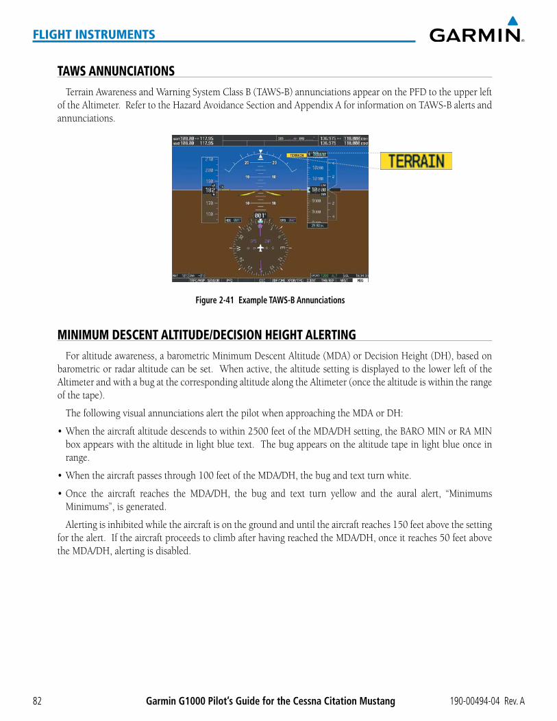
Garmin G1000 Pilot’s Guide for the Cessna Citation Mustang 190-00494-04 Rev. A82
FLIGHT INSTRUMENTS
TAWS ANNUNCIATIONSTerrainAwarenessandWarningSystemClassB(TAWS-B)annunciationsappearonthePFDtotheupperleft
oftheAltimeter.RefertotheHazardAvoidanceSectionandAppendixAforinformationonTAWS-Balertsandannunciations.
Figure 2-41 Example TAWS-B Annunciations
MINIMUM DESCENT ALTITUDE/DECISION HEIGHT ALERTINGForaltitudeawareness,abarometricMinimumDescentAltitude(MDA)orDecisionHeight(DH),basedon
barometric or radar altitude can be set. When active, the altitude setting is displayed to the lower left of the AltimeterandwithabugatthecorrespondingaltitudealongtheAltimeter(oncethealtitudeiswithintherangeof the tape).
ThefollowingvisualannunciationsalertthepilotwhenapproachingtheMDAorDH:
•Whentheaircraftaltitudedescendstowithin2500feetoftheMDA/DHsetting,theBAROMINorRAMINbox appears with the altitude in light blue text. The bug appears on the altitude tape in light blue once in range.
•Whentheaircraftpassesthrough100feetoftheMDA/DH,thebugandtextturnwhite.
•Once the aircraft reaches the MDA/DH, the bug and text turn yellow and the aural alert, “MinimumsMinimums”,isgenerated.
Alertingisinhibitedwhiletheaircraftisonthegroundanduntiltheaircraftreaches150feetabovethesettingforthealert.IftheaircraftproceedstoclimbafterhavingreachedtheMDA/DH,onceitreaches50feetabovetheMDA/DH,alertingisdisabled.

190-00494-04 Rev. A Garmin G1000 Pilot’s Guide for the Cessna Citation Mustang 83
FLIGHT INSTRUMENTS
Figure 2-42 Barometric MDA/DH Alerting Visual Annunciations
Barometric Minimum
Box
Barometric Minimum
Bug
Light Blue Within 2500 ft Yellow When Altitude ReachedWhite Within 100 ft
TheMDA/DHmaybesetfromeitherPFDandissynchronizedonbothPFDs.Thefunctionisresetwhenthepower is cycled.
Setting the barometric or radar minimum descent altitude and bug:
1) Press the TMR/REF Softkey.
2) Turn the large FMS Knob to highlight the Minimums field.
3) Turn the small FMS Knob to highlight ‘BARO’ or ‘RAD ALT’. ‘OFF’ is selected by default. Press the ENT Key or turn the large FMS Knob to highlight the next field.
4) Use the small FMS Knob to enter the desired altitude (from zero to 16,000 feet when ‘BARO’ is selected, or up to 2,500 feet when ‘RAD ALT’ is selected).
5) To remove the window, press the CLR Key or the TMR/REF Softkey.
Figure 2-43 MDA/DH Setting (Timer/References Window)

Garmin G1000 Pilot’s Guide for the Cessna Citation Mustang 190-00494-04 Rev. A84
FLIGHT INSTRUMENTS
ALTITUDE ALERTINGTheAltitudeAlerting function provides visual and audio alertswhen approaching the SelectedAltitude.
WhenevertheSelectedAltitudeischanged,AltitudeAlertingisreset.AltitudeAlertingisbasedonthealtitudeinformationshownonPFD1.AltitudeAlertingisindependentoftheAFCS,however,alertingtonesandvisualalertsonlyoccurinGFC700installations.
ThefollowingoccurwhenapproachingtheSelectedAltitude:
•Uponpassingthrough1000feetoftheSelectedAltitude,theSelectedAltitudeBoxchangestoblacktextonalightbluebackground,flashesfor5seconds,andanauraltoneisgenerated.
•Whentheaircraftpasseswithin200feetoftheSelectedAltitude,theSelectedAltitudechangestolightbluetextonablackbackgroundandflashesfor5seconds.
•AfterreachingtheSelectedAltitude,iftheaircraftfliesoutsidethedeviationband(±200feetoftheSelectedAltitude),theSelectedAltitudeBoxchangestoyellowtextonablackbackground,flashesfor5seconds,andan aural tone is generated.
Figure 2-44 Altitude Alerting Visual Annunciations
Within 1000 feet Within 200 feet Deviation of ±200 feet
LOW ALTITUDE ANNUNCIATION
NOTE: This annunciation is only shown if TAWS is inhibited.
WhentheFinalApproachFix(FAF)istheactivewaypointinaGPSSBASapproachusingverticalguidance,aLowAltitudeAnnunciationmayappearifthecurrentaircraftaltitudeisatleast164feetbelowtheprescribedaltitudeattheFAF.Ablack-on-yellowLOWALTannunciationappearstothetopleftoftheAltimeter,flashingfor several seconds then remaining displayed until the condition is resolved.
Figure 2-45 Low Altitude on GPS SBAS Approach
Altimeter

190-00494-04 Rev. A Garmin G1000 Pilot’s Guide for the Cessna Citation Mustang 85
FLIGHT INSTRUMENTS
RADAR ALTIMETER (OPTIONAL)When the radar height (the aircraft altitude above ground level detected by the radar altimeter) is between
zeroand2500feet,thecurrentvalueisdisplayedingreentotheupperrightoftheHSI(Figure2-46).Displayofradarheightbecomesmoresensitiveastheheightabovegrounddecreases(Table2-4).
Figure 2-46 Current Radar Height
Radar Altimeter
Radar Height Range Shown to Nearest
0 to 200 feet 5 feet
200 to 1500 feet 10 feet
1500 to 2500 feet 50 feet
Table 2-4 Radar Altimeter Sensitivity
Whentheradaraltimeterisselectedasthealtitudesourcefortheminimumsalertingfunction(Figure2-47),the color of the radar height changes to yellow upon reaching (or desending below) the altitude entered. (Figure 2-48).
Figure 2-47 RAD ALT Setting(Timer/References Window)
Figure 2-48 RA as Altitude Source for MDA/DH

Garmin G1000 Pilot’s Guide for the Cessna Citation Mustang 190-00494-04 Rev. A86
FLIGHT INSTRUMENTS
Agroundline(Figure2-49)isshownontheAltimetertodisplaytheaircraft’sheightrelativetotheground.Ifthedatabecomesinvalid,themessage“RAFAIL”isdisplayedinyellowinplaceofthecurrentradarheight(Figure2-50).TheRadarAltimetertestisdoneontheMFDbutisdisplayedonthePFDdirectlyabovethecurrentheading(Figure2-51).
Radar AltimeterMinimums Box
GroundLine
Radar Altimeter
Figure 2-49 Altimeter Displaying the Ground Line (RAD ALT)
Figure 2-50 Radar Altimeter Invalid Data
Testing the Radar Altimeter:
1) Use the FMS Knob to select the AUX - System Status Page on the MFD.
2) Press the RA TEST Softkey to start test.
3) Pess the RA TEST Softkey again to end test.
Or:
1) Use the FMS Knob to select the AUX - System Status Page on the MFD.
2) Press the MENU Key.
3) Turn the small FMS Knob to choose ‘Enable RA Test Mode’ or ‘Disable RA Test Mode’ (choice dependent on current mode).
4) Press the ENT Key to start or end test.
Whenaradaraltimetertestisinprogress,‘RATEST’isannunciatedand50feetwillbedisplayedintheRAbox directly above the current heading on the PFD.
Figure 2-51 Radar Altimeter Test

190-00494-04 Rev. A Garmin G1000 Pilot’s Guide for the Cessna Citation Mustang 87
FLIGHT INSTRUMENTS
2.4 ABNORMAL OPERATIONS
ABNORMAL GPS CONDITIONSTheannunciationslistedinthetablecanappearontheHSIwhenabnormalGPSconditionsoccur.Referto
theFlightManagementSectionformoreinformationonDeadReckoningMode.
Annunciation Location Description
LOILower left of
aircraft symbolLoss of Integrity Monitoring–GPS integrity is insufficient for the current phase of flight
INTEG OKLower left of
aircraft symbolIntegrity OK–GPS integrity has been restored to within normal limits (annunciation displayed for 5 seconds)
DRUpper right of aircraft symbol
Dead Reckoning–System is using projected position rather than GPS position to compute navigation data and sequence active flight plan waypoints
Table 2-5 Abnormal GPS Conditions Annunciated on HSI
Figure 2-52 Example HSI Annunciations
InDRModetheCDIturnsyellowwhenGPSistheselectednavigationsource,andisremovedfromdisplayafter20minutes. In addition, allGPS-deriveddata is computedbasedupon an estimatedposition and isdisplayed as yellow text on the display to denote degraded navigation source information. This data includes the following:
•NavigationStatusBoxfieldsexceptActiveLeg,TAS,andDTK
•GPSBearingPointer
•CDIwhencoupledtoGPS(removedafter20minutes)
•WinddataandpointersintheWindDataBoxonthePFD
•TrackIndicator
•AllBearingPointerDistances
•ActiveFlightPlandistances,bearings,andETEvalues
•Groundspeed
TheseitemsshouldbeverifiedwhenoperatinginDeadReckoningModeandbecomeincreasinglyinaccurateover time.

Garmin G1000 Pilot’s Guide for the Cessna Citation Mustang 190-00494-04 Rev. A88
FLIGHT INSTRUMENTS
UNUSUAL ATTITUDESWhen the aircraft enters an unusual pitch attitude, red extreme pitch warning chevrons pointing toward the
horizonaredisplayedontheAttitudeIndicator,startingat50˚aboveand30˚belowthehorizonline.
Figure 2-53 Pitch Attitude Warnings
Nose LowNose High
Ifpitchexceeds+30˚/-20˚orbankexceeds65˚,someinformationdisplayedonthePFD is removed. The AltimeterandAirspeed,Attitude,VerticalSpeed,andHorizontalSituation indicators remainon thedisplayandtheBearingInformation,Alerts,andAnnunciationwindowscanbedisplayedduringsuchsituations.ThefollowinginformationisremovedfromthePFD(andcorrespondingsoftkeysaredisabled)whentheaircraftexperiences unusual attitudes:
•TrafficAnnunciations
•AFCSAnnunciations
•FlightdirectorCommandBars
•InsetMap
•Temperatures
•DMEInformationWindow
•Winddata
•SelectedHeadingBox
•SelectedCourseBox
•TransponderStatusBox
•SystemTime
•PFDSetupMenu
•Windowsdisplayedinthelowerright corner of the PFD:
–Timer/References
–NearestAirports
– Flight Plan
– Messages
– Procedures
–ADF/DMETuning
•MinimumDescentAltitude/DecisionHeightreadout
•VerticalDeviation,Glideslope,and Glidepath Indicators
•AltimeterBarometricSetting
•SelectedAltitude
•VNVTargetAltitude

190-00494-04 Rev. A Garmin G1000 Pilot’s Guide for the Cessna Citation Mustang 89
ENGINE INDICATION & CREW ALERTING SYSTEM
NOTE: Refer to the Airplane Flight Manual (AFM) for limitations.
The Cessna Citation Mustang’s Engine Indication and Crew Alerting System (EICAS) offers improved flight operations and reduces crew workload by automatically monitoring critical system parameters and providing system alerts during all phases of flight. In combination with the EICAS, aural alerts, additional avionics messages, and master indicators are used to inform the crew of aberrant flight conditions. The EICAS is also designed to provide an improved level of maintenance data for the ground crew.
The EICAS can be divided into two major functions:
•The Engine Indication System (EIS) displays electrical, fuel, engine, pressurization, and flight control information.
•TheCrew Alerting System (CAS) displays advisories, cautions, and warnings to communicate conditions, statuses, and system failures. CAS messages are grouped by level of importance and color-coded based on urgency in the CAS pane in the lower left of the EICAS Display.
EICAS information is normally displayed on the left side of the Multi Function Display (MFD).
Figure 3-1 Multi Function Display (Normal)
EICAS Display
SECTION 3 ENGINE INDICATION & CREW ALERTING SYSTEM (EICAS)

Garmin G1000 Pilot’s Guide for the Cessna Citation Mustang 190-00494-04 Rev. A90
ENGINE INDICATION & CREW ALERTING SYSTEM
In the event of a display failure, depending on the failed display(s), the remaining display(s) may be re-configured to present Primary Flight Display (PFD) symbology together with EICAS information (refer to the System Overview for more information about reversionary mode).
In reversionary mode, the data is pared down to a single column on any display. The N1, N2, and ITT indicators are presented in the same way, but all other parameters are shown as readouts only. The following are not shown:
•Totalfuel
•Cabinaltituderate
•Destinationelevation
•Batterycurrent
•Aileronandruddertrim
The CAS is moved to a window on the right side of the display. CAS messages are treated in the same way as they are during normal display. Messages are prioritized by criticality.
CASWindow
EIS Display
Figure 3-2 Reversionary Mode

190-00494-04 Rev. A Garmin G1000 Pilot’s Guide for the Cessna Citation Mustang 91
ENGINE INDICATION & CREW ALERTING SYSTEM
3.1 ENGINE INDICATION SYSTEM (EIS)
Figure 3-3 EICAS Display (Normal Mode)
1
2
3
4
5
6
7
8
9
10
Figure 3-4 EIS Display (Reversionary Mode)
1
2
3
5
6
7
8
10
1 Engine Fan Rotation Speed
2 Oil Pressure and Temperature
3 Fuel Display
4 CAS Display (refer to Section 3.2)
5 Interstage Turbine Temperature
6 Engine High Pressure Turbine Rotation Speed
7 Electrical Display
8 Pressurization Display
9 Trim Indicator
10 Flap Indicator

Garmin G1000 Pilot’s Guide for the Cessna Citation Mustang 190-00494-04 Rev. A92
ENGINE INDICATION & CREW ALERTING SYSTEM
EIS information is presented using horizontal and vertical bar indicators and digital readouts. Green ranges on the instrument scales indicate normal ranges of operation; yellow and red bands indicate caution and warning, respectively. During normal operating conditions, an instrument’s pointer appears in white or green and readout text is green. Refer to each instrument description for additional details on display behavior.
When an unsafe operating condition occurs, the pointer and readout color change to indicate a caution (yellow) or warning (red). If the time limit for an unsafe condition is exceeded, the color of the sliders, pointers, and digits may change to denote an increase in priority level, even if the parameter is still within in the lower priority condition range. If sensor data for a parameter becomes invalid or unavailable, a red “X” is displayed across the indicator and/or readout.
Figure 3-5 Indicators and Exceedance Levels
Pointer (Exceedance)
Normal Band
Exceedance Levels
Pointer (Normal)
Slider (Exceedance)
Exceedance Levels
Slide (Normal)
ENGINE STAGE ROTATION SPEEDS (N1 AND N2)The N1 display (Figure 3-6) indicates the engine fan rotation speeds while the N2 readouts (Figure 3-7) show
theenginehighpressureturbinerotationspeeds.Bothareshownaspercentages.TheN1andN2displaysareshown in the same format in reversionary mode.
The N1 display ranges from 20 to 110% of maximum rotational speed. Values and limits are obtained from the Full Authority Digital Engine Controller (FADEC). When the N1 values of the engines are synchronized, ‘SYNC’ appears in green between the readouts below the scale. If N1 drops below 20%, the sliders are removed from the scale while the readouts remain displayed below.
An N1 target based on the indicated Thrust Mode is shown for each engine by a bug along the scale. The readout in the box at the top of the scale is the minimum N1 target value for both engines. When the Thrust Lever Angle (TLA) position corresponds to the indicated Thrust Mode (Table 3-1), the indication is shown in green; otherwise, the indication appears in white.
Indication Thrust ModeCRU CruiseCLB Max ClimbT/O Takeoff
Table 3-1 Thrust Modes
N1 Values Synchronized
N1 TargetBug
N1 Target ValueWarning
Line
Figure 3-6 N1 Display
Thrust ModeFigure 3-7 N2 Display
The N2 readouts are located beneath the ITT display. At engine start, the readouts appear in white. Once normal operating conditions are reached, the readouts change to green.

190-00494-04 Rev. A Garmin G1000 Pilot’s Guide for the Cessna Citation Mustang 93
ENGINE INDICATION & CREW ALERTING SYSTEM
OIL PRESSURE AND TEMPERATUREThe oil pressure and temperature for each engine are shown below the N1 display under normal display
operating conditions. Oil pressure is shown in pounds per square inch (psi) and temperature in degrees Celsius (°C). When oil pressure and temperature are in the normal operating range, no readout is provided. When an abnormal operating condition occurs, the readouts appear in the corresponding color. In reversionary mode, only the readouts are shown.
Figure 3-8 Oil Display (Normal Mode)
FUEL DISPLAYThe fuel display is located beneath the oil indicators and shows the fuel quantity in pounds (lb) and fuel flow
in pounds per hour (pph) for each engine, the total fuel quantity, and the fuel tank temperature in °C. Fuel information is provided primarily by the Fuel Quantity Signal Conditioner (FQSC), which has a fuel quantity processor for each tank. Fuel display can also be configured for display in metric units.
Fuel quantity for each tank is normally shown along a slider scale with readouts below for each tank and the total. The fuel flow readout for each engine is shown below the fuel quantity.
Tank FuelQuantities
Total FuelQuantity
FuelTemperature
Figure 3-9 Fuel Display (Normal Mode)
Fuel Flow

Garmin G1000 Pilot’s Guide for the Cessna Citation Mustang 190-00494-04 Rev. A94
ENGINE INDICATION & CREW ALERTING SYSTEM
INTERSTAGE TURBINE TEMPERATUREInterstage Turbine Temperatures (ITT) are displayed along a slider scale in °C. ITT values and limits are
obtained from the FADEC. ITT is shown in the same format in display reversionary mode. During normal operations, the sliders appear in white and no readout is shown. Readouts are provided for each engine below the scale during engine start, for values below 200°C, or for caution and warning values. When the respective engine ignitors are commanded on, ‘IGN’ appears in green text at the top of the ITT scales.
Ignitor OnIndicationWarning
Line
Figure 3-10 Interstage Turbine Temperature Display
ELECTRICAL DISPLAYVoltage and current for the direct current (DC) generators and battery are obtained directly from the electrical
system buses. Generator voltages and currents are normally shown along color-coded scales, with readouts below. Batteryvoltageandcurrentaredisplayedasreadouts. Inreversionarymode,batterycurrent isnotshown.
GeneratorVoltage
GeneratorCurrent
Battery CurrentBattery Voltage
Figure 3-11 Electrical Display (Normal Mode)

190-00494-04 Rev. A Garmin G1000 Pilot’s Guide for the Cessna Citation Mustang 95
ENGINE INDICATION & CREW ALERTING SYSTEM
PRESSURIZATION DISPLAYCabin pressurization information (cabin altitude and rate of change, destination elevation, differential cabin
pressure) is shown beneath the electrical display. Only cabin altitude and the pressure differential readouts are displayed in reversionary mode.
Cabin altitude is shown on a color-coded scale labeled in 5,000-ft increments with a readout (in feet) below (unlessontheground).Thecabinaltitudescaleandcorresponding“CABINALT”CASmessagesshiftuptohigher altitude when in high altitude pressurization mode. High altitude mode is active whenever all the following are true:
•Thetakeoffordestinationelevationisabove8,000feet
•Theaircraftaltitudeislessthan24,500feet
•Thepressurizationsystemhasverifiedtheconditions
Cabin altitude change rate is displayed on a scale in terms of 1,000-fpm increments with a readout (in fpm) below. Cabin pressure differential (DIFF PSI), in pounds per square inch (psi), is indicated on a color-coded scale with a readout.
PressureAltitude
DestinationElevation
PressureDifferential
PressureChange Rate
Figure 3-12 Cabin Pressure Display (Normal Mode)

Garmin G1000 Pilot’s Guide for the Cessna Citation Mustang 190-00494-04 Rev. A96
ENGINE INDICATION & CREW ALERTING SYSTEM
The destination elevation (from -1,000 to 14,000 feet) entered in the PFDTimer/ReferencesWindow isdisplayed below the cabin altitude readings. This value is retained by the G1000 on power-down.
Setting the destination elevation:
1) Press the TMR/REF Softkey.
2) Turn the large FMS Knob to highlight the ‘DEST ELV’ field.
3) Use the small FMS Knob to enter the destination elevation (in 10-ft increments from -1,000 to 14,000 feet).
4) To remove the window, press the CLR Key or the TMR/REF Softkey.
DestinationElevation
Figure 3-13 Timer/References Window
TRIM AND FLAP INDICATORSLateral trim indications are shown along a slide bar scale beneath the pressurization display in normal display
mode. Aileron trim is displayed at the top of the scale and rudder trim is displayed at the bottom. The trim display is not present in reversionary mode.
Flap deflection is normally displayed beneath the trim indications using a rotating pointer. Flap positions for takeoff/approach, landing, and up positions are labeled. In reversionary mode, a digital readout of the flap position (UP, TO/APR, LAND) is provided.
Figure 3-14 Trim and Flap Indications (Normal Mode)

190-00494-04 Rev. A Garmin G1000 Pilot’s Guide for the Cessna Citation Mustang 97
ENGINE INDICATION & CREW ALERTING SYSTEM
3.2 CREW ALERTING SYSTEM (CAS)
NOTE: Aural alerts associated with abnormal conditions and advisories are managed through the Audio Panels. Refer to the Audio Panel and CNS Section for more information.
NOTE: If there is a mismatch between databases or software on the PFDs, CAS is inoperative.
The Crew Alerting System (CAS) Display is located in the lower left corner of the EICAS Display (on the MFD) undernormaldisplayconditions.Upto14messagescanbedisplayed;whenmorethan14messagesaccumulate,the scrolling CAS softkeys become available.
When CAS messages are present while in reversionary mode, the CAS Window appears on the display along withtheflightinstrumentsandEIS.Thewindowsizeincreasestofitupto14CASmessages;ifmorethan14messages are generated, the messages can be scrolled through using the CAS softkeys (two left-most softkeys).
Figure 3-15 CAS Messages
Reversionary Mode
CAS Window
Normal
CAS Display

Garmin G1000 Pilot’s Guide for the Cessna Citation Mustang 190-00494-04 Rev. A98
ENGINE INDICATION & CREW ALERTING SYSTEM
CAS MESSAGES AND PRIORITIZATION
NOTE: Information on CAS messages in this pilot’s guide is always superseded by the AFM.
CAS messages are grouped by criticality (warning, caution, advisory) and sorted by order of appearance (most recent messages on top). The color of the message is based on its urgency and on required action:
•Warning (red) – Immediate crew awareness and action required; Master Warning triggered
•Caution (yellow) – Immediate crew awareness and possible future corrective action required; Master Caution triggered
•Advisory (white) – Crew awareness required and subsequent action may be required
Any CAS messages that come up when the system is first powered on are considered already acknowledged. They do not flash or trigger the Master Warning or Master Caution. CAS messages listed in Table 3-2 are shown in the acknowledged state (text corresponding to criticality on a black background).
Since red and yellow CAS messages indicate the immediate or future need for corrective action, two momentary switches are located above each PFD for CAS message acknowledgment: Master Warning and Master Caution.
When a new red CAS warning message appears, it flashes in conjunction with the Master Warning Indicator. Pressing a Master Warning Indicator acknowledges all flashing red messages, extinguishes the master warning lights, and stops the message flashing. Messages are displayed until the issue is corrected and a Master Warning Indicator has been pressed.
When a new yellow caution message appears on the CAS display, it flashes and triggers the Master Caution Indicator to come on, but not to flash. Pressing a Master Caution Indicator acknowledges all flashing yellow messages, extinguishes the master caution lights, and stops the message flashing. Messages are displayed until the issue is corrected.
Figure 3-16 Panel Layout
PFD2PFD1
MFD
Master Caution and Warning Indicators
A CAS message does not appear more than once at a given time (unless the CAS is being tested). If signals are received that justify multiple priorities for a certain message, the message is displayed for the higher priority condition. When graduating to a higher priority, the message flashes and requires new acknowledgment.

190-00494-04 Rev. A Garmin G1000 Pilot’s Guide for the Cessna Citation Mustang 99
ENGINE INDICATION & CREW ALERTING SYSTEM
When degrading to a lower priority condition, the message moves to the top of the appropriate grouping, but does not require new acknowledgment.
Red warning messages cannot be scrolled through and remain at the top of the CAS display. The scroll bar changes color to yellow if more caution messages exist than can be displayed at once or if caution messages havebeenscrolledoffthedisplay.Thescrollbarremainsintheselectedpositionfor45secondsoruntilanewcaution message is generated, at which point the scroll bar returns to the top of the display.
MessagesDescription
Warning Caution Advisory
AFT DOOR Tailcone baggage door not fully securedAFT JBOX CB L-R* Start control circuit breaker (located in aft j-box) tripped
AFT JBOX LMT L-R* Current limiter failed (located in aft j-box)ANTISKID FAIL Antiskid Control Unit cannot perform anti-skid functions
BATTERY O’TEMP BATTERY O’TEMP Overheated NiCad battery (optional)BATT TEMP FAIL Battery temperature sensor failure
CABIN ALT CABIN ALT CABIN ALT Cabin altitude potentially unsafeCABIN DOOR Cabin door not fully secured
CHECK DOORS A door monitor has not been properly tested or has failedCVR FAIL Cockpit Voice Recorder has failed.
DUCT O’HEAT L-R* Duct temperature too high or sensor disconnectedENG A/I COLD L-R* ENG A/I COLD L-R* Engine anti-ice system ON and inlet temperature is coldENG CTRL SYS L-R* FADEC has a fault that requires maintenance
ENGINE FAIL L-R* An engine has failedF/W SHUTOFF L-R* Fuel firewall shutoff valve fully closed
FDR FAIL Flight Data Recorder is not recording data.FLAPS FAIL A flap system failure has occurred.
FUEL BOOST L-R* FUEL BOOST L-R*Electric fuel boost pump ON. Caution condition is displayed when the boost pump is operating in abnormal conditions.
FUEL FLTR BP L-R* Engine fuel filter impending bypass switch closedFUEL LO INOP L-R* Fuel low level function failure
FUEL LVL LO L-R* Fuel level in tank is too lowFUEL PRES LO L-R* Fuel pressure too low
FUEL TRANSFER Fuel transfer valve openGEN OFF L-R GEN OFF L-R* One or both electrical generators offline
HYD PRESS LO Hydraulic system pressure too lowHYD PUMP ON Hydraulic pump running too long
MFD COLD MFD temperature is below -20° CNOSE DOOR L-R* One or both nose baggage doors not fully secured
NO TIRE SPINDOWN Antiskid control spindown function not workingOIL PRESS LO L-R* Oil pressure less than redline low limit
OXYGEN OFF Oxygen supply offP/S HTR L-R* P/S HTR L-R* No current detected to pitot static heaterPRESS CTRL PRESS CTRL Pressure controller loss of integrity
PRESS OFF Air Source Selector switch in OFF or fresh air positionSPD BRK EXTEND Speed brakes extended
STALL WARN FAIL Failure detected in stall warning systemSTALL WARN HI Stall warning system on ice-contaminated schedule
STALL WARN HTR No power delivered to stall warning vane heater

Garmin G1000 Pilot’s Guide for the Cessna Citation Mustang 190-00494-04 Rev. A100
ENGINE INDICATION & CREW ALERTING SYSTEM
MessagesDescription
Warning Caution Advisory
SURFACE DE-ICE De-ice boots inflating/deflating as designedT2 HTR FAIL L-R* T2 probe heater failure
TAIL CONE BLD LK Tailcone temp high, possible bleed air leak.TAIL DE-ICE FAIL De-ice system not operating normallyW/S A/I FAIL L-R* W/S A/I FAIL L-R* Loss of power to windshield heaterW/S O’HEAT L-R* W/S O’HEAT L-R* Windshield anti-ice power ON; temperature too highWING DE-ICE FAIL De-ice system operating abnormally
WOW MISCOMPARE Gear on-ground inputs do not agree * Only affected side displayed (L, R, or L-R) in a CAS message; applicable CAS messages listed here display L-R for example.** The “HYD PRESS LO” message cannot be acknowledged using the Master Caution Indicator if the aircraft is on the ground. Both Master Caution annunciators remain on and the message continues to flash until the issue is corrected.
Table 3-2 Color-Coded CAS Messages

190-00494-04 Rev. A Garmin G1000 Pilot’s Guide for the Cessna Citation Mustang 101
AUDIO PANEL AND CNS
SECTION 4 AUDIO PANEL AND CNS
4.1 OVERVIEW
The Communication/Navigation/Surveillance (CNS) system includes the Audio Panels, communication radios, navigation radios, and Mode S transponders. The System Overview Section provides a block diagram description of the Audio Panels and CNS system interconnection.
CNS operation in the Cessna Citation Mustang is performed by the following Line Replaceable Units (LRUs):
•PrimaryFlightDisplay(PFD)(2)
•MultiFunctionDisplay(MFD)
•IntegratedAvionicsUnit(2)
•AudioPanel(2)
•ModeSTransponder(2)
•MFDControlUnit
ThePFDcontrolsareusedtotunethecommunicationtransceiversandnavigationradios.
The two Audio Panels provide the traditional audio selector functions of microphone and receiver audio selection. EachAudioPanel includesa twoposition intercomsystem (ICS)between thepilot andcopilot, amarker beacon system, and a COM clearance recorder. Ambient noise from the aircraft radios is reduced by a feature called Master Avionics Squelch (MASQ). When no audio is detected, MASQ processing further reduces the amount of background noise from the radios.
The Mode S Transponders are controlled with softkeys and the FMSKnoblocatedonthePrimaryFlightDisplay(PFD).TheTransponderDataBoxislocatedtotheleftoftheSystemTimeBox.Thedataboxdisplaystheactivefour-digit code, mode,andareplystatus(Figure4-1).
AUDIO PANEL VOLUME CONTROLAdjusting the master volume control affects all radio audio volume and airframe type warnings that will be
heard in the headsets (not the speaker) for the pilot or copilot side Audio Panel. Radio adjustments made on thePFDcontrolstocompensateforthemastervolumechangeontheAudioPanelwillalsoaffecttheradiolevelsfortheotherpilot.IndependentradiovolumeadjustmentsmadeusingtheAudioPanelMasterVolumecontrolswill affect only the audio heard in the corresponding crew position headset.
Radio volume adjustments may be overridden by each crew position independently using the master volume controlontheAudioPanelfortherespectivecrewposition.Inaddition,themastervolumecontrolforeachAudio Panel will affect all other system audio output to its designated crew position headset much like volume adjustments found on many aviation headsets.

190-00494-04 Rev. AGarmin G1000 Pilot’s Guide for the Cessna Citation Mustang102
AUDIO PANEL AND CNS
PFD CONTROLS AND FREQUENCY DISPLAY
Figure 4-1 PFD Controls, COM/NAV Frequency Tuning Boxes, and ADF/DME Tuning Window
12
21 6 873 4 5
9
10
11

190-00494-04 Rev. A Garmin G1000 Pilot’s Guide for the Cessna Citation Mustang 103
AUDIO PANEL AND CNS
1 NAV VOL/ID Knob–ControlsNAVaudiovolumelevel.PresstoturntheMorsecodeidentifieraudioonandoff.VolumelevelisshownintheNAVfrequencyfieldasapercentage.
2 NAV Frequency Transfer Key–TransfersthestandbyandactiveNAVfrequencies.
3 NAV Knob–TunesthestandbyfrequenciesfortheNAVreceiver(large knob for MHz; small knob for kHz). Presstomovethetuningbox(lightbluebox)andFrequencyTransferArrowbetweenNAV1andNAV2.
4 NAV Frequency Box–DisplaysNAVstandbyandactivefrequencyfields,volume,andstationID.ThefrequencyoftheNAVradioselectedfornavigationisdisplayedingreen.
5 COM Frequency Box–DisplaysCOMstandbyandactivefrequencyfieldsandvolume.TheselectedCOMtransceiver frequency is displayed in green.
6 COM Knob – Tunes the standby frequencies for the COM transceiver (large knob for MHz; small knob for kHz).Presstomovethetuningbox(lightbluebox)andFrequencyTransferArrowbetweenCOM1andCOM2.
7 COM Frequency Transfer Key – Transfers the standby and active COM frequencies. Press and hold this key fortwosecondstotunetheemergencyfrequency(121.500MHz)automaticallyintotheactivefrequencyfield.
8 COM VOL/SQ Knob – Controls COM audio volume level. Press to turn the COM automatic squelch on andoff.VolumelevelisshownintheCOMfrequencyfieldasapercentage.
9 ADF/DME Tuning Window–DisplaysADF frequencies,volumesetting,andmodes,andDMEtuningselection.DisplaybypressingADF/DME Softkey.
10 ENT Key–ValidatesorconfirmsanADFfrequencyorADF/DMEmodeandAuto-tuneselection.
11 FMS Knob–FlightManagementSystemKnob,usedtoenterADFfrequenciesandselectADF/DMEmodes,enter transponder codes, andAuto-tuneentrieswhenADF/DMETuningWindoworNRSTWindow ispresent. Press the FMS Knob to turn the selection cursor on and off. The large knob moves the cursor in the window. The small knob selects individual characters for the highlighted cursor location.
12 Transponder Data Box–Indicatestheselectedtranspondercode,operatingmode,reply,andidentstatusfor the applicable transponder.
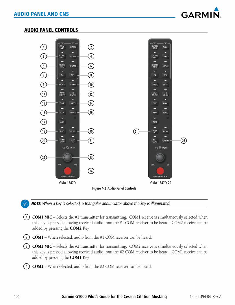
190-00494-04 Rev. AGarmin G1000 Pilot’s Guide for the Cessna Citation Mustang104
AUDIO PANEL AND CNS
AUDIO PANEL CONTROLS
Figure 4-2 Audio Panel Controls
17
18
15
13
11
9
20
7
5
3
1
14
2
16
4
6
8
10
12
22
24
23
21
19 21
25
GMA 1347D GMA 1347D-20
NOTE: When a key is selected, a triangular annunciator above the key is illuminated.
1 COM1 MIC–Selectsthe#1transmitterfortransmitting.COM1receiveissimultaneouslyselectedwhenthiskeyispressedallowingreceivedaudiofromthe#1COMreceivertobeheard.COM2receivecanbeadded by pressing the COM2 Key.
2 COM1–Whenselected,audiofromthe#1COMreceivercanbeheard.
3 COM2 MIC–Selectsthe#2transmitterfortransmitting.COM2receiveissimultaneouslyselectedwhenthiskeyispressedallowingreceivedaudiofromthe#2COMreceivertobeheard.COM1receivecanbeadded by pressing the COM1 Key.
4 COM2–Whenselected,audiofromthe#2COMreceivercanbeheard.
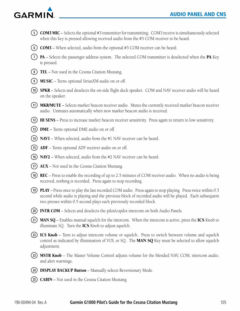
190-00494-04 Rev. A Garmin G1000 Pilot’s Guide for the Cessna Citation Mustang 105
AUDIO PANEL AND CNS
5 COM3 MIC – Selects the optional #3 transmitter for transmitting. COM3 receive is simultaneously selected when this key is pressed allowing received audio from the #3 COM receiver to be heard.
6 COM3 – When selected, audio from the optional #3 COM receiver can be heard.
7 PA – Selects the passenger address system. The selected COM transmitter is deselected when the PA Key is pressed.
8 TEL – Not used in the Cessna Citation Mustang.
9 MUSIC – Turns optional SiriusXM audio on or off.
10 SPKR–Selectsanddeselectstheon-sideflightdeckspeaker.COMandNAVreceiveraudiowillbeheardon the speaker.
11 MKR/MUTE – Selects marker beacon receiver audio. Mutes the currently received marker beacon receiver audio. Unmutes automatically when new marker beacon audio is received.
12 HI SENS – Press to increase marker beacon receiver sensitivity. Press again to return to low sensitivity.
13 DME–TurnsoptionalDMEaudioonoroff.
14 NAV1–Whenselected,audiofromthe#1NAVreceivercanbeheard.
15 ADF–TurnsoptionalADFreceiveraudioonoroff.
16 NAV2–Whenselected,audiofromthe#2NAVreceivercanbeheard.
17 AUX – Not used in the Cessna Citation Mustang.
18 REC–Presstoenabletherecordingofupto2.5minutesofCOMreceiveraudio.Whennoaudioisbeingreceived, nothing is recorded. Press again to stop recording.
19 PLAY–PressoncetoplaythelastrecordedCOMaudio.Pressagaintostopplaying.Presstwicewithin0.5second while audio is playing and the previous block of recorded audio will be played. Each subsequent twopresseswithin0.5secondplayseachpreviouslyrecordedblock.
20 INTR COM – Selects and deselects the pilot/copilot intercom on both Audio Panels.
21 MAN SQ – Enables manual squelch for the intercom. When the intercom is active, press the ICS Knob to illuminate SQ. Turn the ICS Knob to adjust squelch.
22 ICS Knob – Turn to adjust intercom volume or squelch. Press to switch between volume and squelch controlasindicatedbyilluminationofVOLorSQ.TheMAN SQ Key must be selected to allow squelch adjustment.
23 MSTR Knob–TheMasterVolumeControladjustsvolumefortheblendedNAV,COM,intercomaudio,and alert warnings.
24 DISPLAY BACKUP Button – Manually selects Reversionary Mode.
25 CABIN – Not used in the Cessna Citation Mustang.

190-00494-04 Rev. AGarmin G1000 Pilot’s Guide for the Cessna Citation Mustang106
AUDIO PANEL AND CNS
4.2 COM OPERATION
COM TRANSCEIVER SELECTION AND ACTIVATION
NOTE: During PA Mode, the COM MIC Annunciator is extinguished and the COM active frequency color changes to white, indicating that neither COM transmitter is active.
NOTE: When turning on the G1000 for use, the system remembers the last frequencies used and the active COM transceiver state prior to shutdown.
The COMFrequencyBoxiscomposedoffourfields;thetwoactive frequencies are on the left side and the two standby frequencies are on the right. The COM transceiver is selected for transmitting by pressing the COM MIC Keys on the Audio Panel.
An active COM frequency displayed in green indicates that the COM transceiver is selected on the Audio Panel (COM1 MIC or COM2 MICKey).BothactiveCOMfrequenciesappearinginwhiteindicatethatnoCOMradio is selected for transmitting (PAKeyisselectedontheAudioPanel).Frequenciesinthestandbyfieldsarealso displayed in white.
Active Fields
Standby Fields
Tuning Box
COM2 Radio is Selected on the Audio Panel
Figure 4-3 Selecting a COM Radio for Transmit
Top Section of the Audio Panel
COM3 is reserved for the optional radio.

190-00494-04 Rev. A Garmin G1000 Pilot’s Guide for the Cessna Citation Mustang 107
AUDIO PANEL AND CNS
TRANSMIT/RECEIVE INDICATIONS
DuringCOM transmission, awhiteTX appears by the active COM frequency replacing the FrequencyTransfer Arrow. On the Audio Panel, when the active COM is transmitting, the active transceiver COM MIC KeyAnnunciatorflashesapproximatelyoncepersecond.
DuringCOMsignalreception,awhiteRXappearsbytheactiveCOMfrequencyreplacingtheFrequencyTransfer Arrow.
Annunciator Flashes During TransmissionTransmit
Indication
Figure 4-4 COM Radio Transmit and Receive Indications
When the same COM radio is selected on both Audio Panels, the pilot Audio Panel has transmit priority on COM1,thecopilotAudioPanelhastransmitpriorityonCOM2.
COM TRANSCEIVER MANUAL TUNINGTheCOMfrequencycontrolsandfrequencyboxesareontherightsideofeachPFD.
Manually tuning a COM frequency:
1) Turn the COM Knob to tune the desired frequency in the COM Tuning Box (large knob for MHz; small knob for kHz).
2) Press the Frequency Transfer Key to transfer the frequency to the active field.
3) Adjust the volume level with the COM VOL/SQ Knob.
4) Press the COM VOL/SQ Knob to turn automatic squelch on and off.
Press the Frequency Transfer Key to Transfer COM Frequencies Between Active and Standby Frequency Boxes
Turn the VOL/SQ Knob to adjust volume. Press the Knob to Turn
Automatic Squelch On or Off
Figure 4-5 COM Frequency Tuning
Turn the COM Knob to Tune the Frequency in the Tuning Box

190-00494-04 Rev. AGarmin G1000 Pilot’s Guide for the Cessna Citation Mustang108
AUDIO PANEL AND CNS
SELECTING THE RADIO TO BE TUNED
Press the small COMKnobtotransferthefrequencytuningboxandFrequencyTransferArrowbetweentheupperandlowerradiofrequencyfields.
Figure 4-6 Switching COM Tuning Boxes
Press the COM Knob to Switch the Tuning Box From
One COM Radio to the Other
QUICK-TUNING AND ACTIVATING 121.500 MHZPressing and holding the COM Frequency Transfer Key for two seconds automatically loads the emergency
COMfrequency (121.500MHz) in theactivefieldof theCOMradioselected for tuning (theonewith thetransferarrow).Intheexampleshown,pressingtheAudioPanelCOM2 MIC Key activates the transceiver.
Figure 4-7 Quickly Tuning 121.500 MHz
Press for Two Seconds to Load 121.500 MHz

190-00494-04 Rev. A Garmin G1000 Pilot’s Guide for the Cessna Citation Mustang 109
AUDIO PANEL AND CNS
AUTO-TUNING THE COM FREQUENCYCOM frequencies can be automatically tuned from the following:
•NearestAirportsWindow(PFD)
•WPT–AirportInformationPage
•NRST–NearestAirportsPage
•NRST–NearestFrequenciesPage(ARTCC,FSS,WX)
•NRST–NearestAirspacesPage
AUTO-TUNING FROM THE PFD
COM frequencies for the nearest airports can be automatically tuned from the Nearest Airports Window on thePFD.Whenthedesiredfrequencyisentered,itbecomesastandby frequency. Pressing the Frequency Transfer KeyplacesthisfrequencyintotheCOMActiveFrequencyField.
Auto-tuning a COM frequency for a nearby airport from the PFD:
1) Press the NRST Softkey on the PFD to open the Nearest Airports Window. A list of 25 nearest airport identifiers and COM frequencies is displayed.
2) Turn the FMS Knob to scroll through the list and highlight the desired COM frequency.
3) Press the ENT Key to load the COM frequency into the COM Standby Tuning Box.
4) Press the Frequency Transfer Key to transfer the frequency to the COM Active Frequency Field.
Figure 4-8 Nearest Airports Window (PFD)
Select the NRST Softkey to Open the Nearest Airports Window

190-00494-04 Rev. AGarmin G1000 Pilot’s Guide for the Cessna Citation Mustang110
AUDIO PANEL AND CNS
AUTO-TUNING FROM THE MFD
FrequenciescanbeautomaticallyloadedintotheCOMFrequencyBoxfrompagesintheNRSTorWPTpage group by highlighting the frequency and pressing the ENTKey(Figures4-9,4-10,and4-11).
Auto-tuning a COM frequency from the WPT and NRST Pages:
1) From any page that the COM frequency can be auto-tuned, activate the cursor by pressing the FMS Knob on the MFD control unit or selecting the appropriate softkey.
2) Turn the FMS Knob to place the cursor on the desired COM frequency (Figure 4-11).
3) Press the ENT Key to load the COM frequency into the standby field of the selected COM radio.
4) Press the Frequency Transfer Key on either PFD to transfer the frequency to the COM Active Frequency Field.
Figure 4-9 Frequency Auto-Tuning from the MFD
Press the ENT Key to Load a Highlighted Frequency into the COM Standby Frequency Box.
Turn the FMS Knob to Scroll Through a List of Frequencies.

190-00494-04 Rev. A Garmin G1000 Pilot’s Guide for the Cessna Citation Mustang 111
AUDIO PANEL AND CNS
Or:
1) Press the MENU Key on the MFD control unit (Figure 4-9) to display the page menu (Figure 4-10).
2) Turn the large FMS Knob to scroll through the menu options.
3) Press the ENT Key to place the cursor on the desired selection.
4) Scroll through the frequency selections with the FMS Knob or the ENT Key.
5) Press the ENT Key to load the COM frequency into the standby field of the selected COM radio.
6) Press the Frequency Transfer Key to transfer the frequency to the COM Active Frequency Field.
Figure 4-10 Nearest Pages Menus
Nearest Airspaces MenuNearest Airports Menu Nearest Frequencies Menu

190-00494-04 Rev. AGarmin G1000 Pilot’s Guide for the Cessna Citation Mustang112
AUDIO PANEL AND CNS
OntheWPT-AirportInformationPage,thecursorcanbeplacedonthefrequencyfieldbypressingtheFMSKnobandscrollingthroughthelist.ThefrequencyistransferredtotheCOMStandbyFieldwiththeENT Key.
Press ENT Key to load frequency into PFD1 COM Standby Field. Cursor then advances to the next frequency.
Select INFO-n Softkey for AIRPORT, RUNWAYS, and FREQUENCIES Windows
Selected Airport Identifier and Information
Runway Information
Figure 4-11 WPT – Airport Information Page

190-00494-04 Rev. A Garmin G1000 Pilot’s Guide for the Cessna Citation Mustang 113
AUDIO PANEL AND CNS
COMfrequenciescanalsobeauto-tunedfromtheNRST–NearestAirspaces,NRST–NearestFrequencies,andNRST–NearestAirportsPagesontheMFDinasimilarmannerusingtheappropriatesoftkeysorMENU Key, the FMS Knob, and the ENT Key.
Figure 4-12 NRST – Nearest Airspaces, NRST – Nearest Airports, and NRST – Nearest Frequencies Pages

190-00494-04 Rev. AGarmin G1000 Pilot’s Guide for the Cessna Citation Mustang114
AUDIO PANEL AND CNS
FREQUENCY SPACINGTheG1000COMradioscantuneeither25-kHzspacing(118.000to136.975MHz)or8.33-kHzspacing
(118.000to136.990MHz)for760-channelor3040-channelconfiguration.When8.33-kHzchannelspacingisselected,allofthe25-kHzchannelspacingfrequenciesarealsoavailableinthecomplete3040-channellist.
COM channel spacing is set on the System Setup Page of the AUX Page Group.
Figure 4-13 COM Channel Spacing
25-kHz Channel Spacing
8.33-kHz Channel Spacing
Changing COM frequency channel spacing:
1) Select the AUX – System Setup Page.
2) Press the FMS Knob to activate the flashing cursor.
3) Turn the large FMS Knob to highlight the Channel Spacing Field in the COM Configuration Box.
4) Turn the small FMS Knob to select the desired channel spacing.
5) Press the ENT Key to complete the channel spacing selection.
WhiletheCOMCONFIGWindowisselected,theG1000softkeysareblank.
Figure 4-14 AUX – System Setup Page
Select 8.33-kHz or 25.0-kHz COM Frequency Channel Spacing

190-00494-04 Rev. A Garmin G1000 Pilot’s Guide for the Cessna Citation Mustang 115
AUDIO PANEL AND CNS
AUTOMATIC SQUELCHAutomatic Squelch quiets unwanted static noise when no audio signal is received, while still providing good
sensitivity to weak COM signals. To disable Automatic Squelch, press the VOL/SQ Knob. When Automatic Squelch is disabled, COM audio reception is always on. Continuous static noise is heard over the headsets and speaker, if selected. Pressing the VOL/SQ Knob again enables Automatic Squelch.
WhenAutomaticSquelchisdisabled,awhiteSQappearsnexttotheCOMfrequency.
Figure 4-15 Overriding Automatic Squelch
Squelch Indication
Press the COM VOL/SQ Knob to turn off Automatic Squelch.
Press again to restore Automatic Squelch.
VOLUMECOM radio volume level can be adjusted from0 to 100%using theVOL/SQ Knob. Turning the knob
clockwise increases volume, turning the knob counterclockwise decreases volume. When adjusting volume, thelevelisdisplayedinplaceofthestandbyfrequencies.Volumelevelindicationremainsfortwosecondsafterthe change.
Figure 4-16 COM Volume Level
COM Volume Level Remains for Two Seconds

190-00494-04 Rev. AGarmin G1000 Pilot’s Guide for the Cessna Citation Mustang116
AUDIO PANEL AND CNS
4.3 NAV OPERATION
NAV RADIO SELECTION AND ACTIVATIONTheNAVFrequencyBoxiscomposedof fourfields; twostandbyfieldsandtwoactivefields. Theactive
frequencies are on the right side and the standby frequencies are on the left.
ANAVradioisselectedfornavigationbypressingtheCDISoftkeylocatedonthePFD.TheactiveNAVfrequency selected for navigation is displayed in green. Pressing the CDISoftkeyonceselectsNAV1asthenavigation radio. Pressing the CDISoftkeyasecondtimeselectsNAV2asthenavigationradio.PressingtheCDI Softkey a third time activates GPS mode. Pressing the CDISoftkeyagaincyclesbacktoNAV1.
While cycling through the CDISoftkeyselections,theNAVTuningBoxandtheFrequencyTransferArrowareplacedintheactiveNAVFrequencyFieldandtheactiveNAVfrequencycolorchangestogreen.
The three navigation modes that can be cycled through are:
•VOR1(orLOC1)–IfNAV1isselected,agreen single line arrow (not shown) labeled either VOR1orLOC1isdisplayedontheHSIandtheactiveNAV1frequencyisdisplayedingreen.
•VOR2(orLOC2)–IfNAV2isselected,agreen double line arrow (shown) labeled either VOR2orLOC2isdisplayedontheHSIandtheactiveNAV2frequencyisdisplayedingreen.
•GPS–IfGPSModeisselected,amagentasinglelinearrow(notshown)appearsontheHSIandneitherNAVradioisselected.BothactiveNAVfrequenciesarethendisplayedinwhite.
Active Fields
Standby Fields
Tuning BoxThe NAV Radio is
Selected by Pressing the CDI Softkey
Figure 4-17 Selecting a NAV Radio for Navigation
SeetheFlightInstrumentsSectionforselectingtheDMEandBearingInformationwindowsandusingVORorADFasthesourceforthebearingpointer.

190-00494-04 Rev. A Garmin G1000 Pilot’s Guide for the Cessna Citation Mustang 117
AUDIO PANEL AND CNS
NAVradiosareselectedforlisteningbypressingthecorrespondingkeysontheAudioPanel.Pressing the NAV1, NAV2, ADF, or DME Key selects and deselects the navigation radio source. Selected audio can be heard over the headset and the speakers (if selected). All radios can be selected individually or simultaneously.
Figure 4-18 Selecting a NAV Radio Receiver
NAV RECEIVER MANUAL TUNINGTheNAVfrequencycontrolsandfrequencyboxesareontheleftsideofthePFDs.
Manually tuning a NAV frequency:
1) Turn the NAV Knob to tune the desired frequency in the NAV Tuning Box.
2) Press the Frequency Transfer Key to transfer the frequency to the NAV Active Frequency Field.
3) Adjust the volume level with the NAV VOL/ID Knob.
4) Press the NAV VOL/ID Knob to turn the Morse code identifier audio on and off.
Figure 4-19 NAV Frequency Tuning
Press the Frequency Transfer Key to Transfer NAV Frequencies Between
Active and Standby Frequency Fields
Turn VOL/ID Knob to adjust volume. Press Knob to Turn
Morse Code On or Off.
Turn the NAV Knob to Tune
the Frequency in the Tuning Box

190-00494-04 Rev. AGarmin G1000 Pilot’s Guide for the Cessna Citation Mustang118
AUDIO PANEL AND CNS
SELECTING THE RADIO TO BE TUNED
Press the small NAVKnobtotransferthefrequencytuningboxandFrequencyTransferArrowbetweentheupperandlowerradiofrequencyfields.
Figure 4-20 Switching NAV Tuning Boxes
Press the NAV Knob to Switch the Tuning Box from One NAV Radio to the Other
VOR/LOC ID
When the MorsecodeIdentifieraudioisonforaNAVradio,awhiteIDappearstotheleftoftheactiveNAVfrequency.
Intheexampleshown,inordertolistentoeitherstationidentifier,presstheNAV1 or NAV2 Key on the Audio Panel. Pressing the VOL/IDKnobturnsofftheMorsecodeaudioonlyintheradiowiththeNAVTuningBox.ToturnoffbothNAVIDs,transfertheNAVTuningBoxbetweenNAV1andNAV2withthesmallNAV Knob and press the VOL/ID Knob again to turn the Morse code off in the other radio.
Figure 4-21 NAV Radio ID Indication
The Morse Code Identifiers for the GHM and BNA VORs are On
Station Identifier
VOLUME
NAVRadiovolume level canbeadjusted from0 to100%using theVOL/ID Knob. Turning the knob clockwise increases volume, counterclockwise decreases volume.
Whenadjusting,thelevelisdisplayedinplaceofthestandbyfrequencies.Volumelevelindicationremainsfor two seconds after the change.
Figure 4-22 NAV Volume Level
NAV Volume Level Remains for Two
Seconds

190-00494-04 Rev. A Garmin G1000 Pilot’s Guide for the Cessna Citation Mustang 119
AUDIO PANEL AND CNS
AUTO-TUNING A NAV FREQUENCY FROM THE MFDNAVfrequenciescanbeselectedandloadedfromthefollowingMFDpages:
•WPT–AirportInformation
•WPT–VORInformation
•NRST–NearestAirports
•NRST–NearestVOR
•NRST–NearestFrequencies(FSS,WX)
•NRST–NearestAirspaces
The MFD provides auto-tuning of NAV frequencies from waypoint and nearest pages. During enroutenavigation,theNAVfrequencyisenteredautomaticallyintotheNAVstandbyfrequencyfield.DuringapproachactivationtheNAVfrequencyisenteredautomaticallyintotheNAVactivefrequencyfield.
FrequenciescanbeautomaticallyloadedintotheNAVFrequencyBoxfrompagesintheNRSTorWPTpagegroup by highlighting the frequency and pressing the ENTKey(Figures4-23,4-24,and4-25).
Auto-tuning a NAV frequency from the WPT and NRST Pages:
1) From any page that the NAV frequency can be auto-tuned, activate the cursor by pressing the FMS Knob on the MFD control unit or selecting the appropriate softkey.
2) Turn the FMS Knob to place the cursor on the desired NAV identifier or NAV frequency.
3) On the Nearest VOR and Nearest Airports pages, select the FREQ Softkey to place the cursor on the NAV frequency (Figure 4-25).
4) Press the ENT Key to load the NAV frequency into the standby field of the selected NAV radio.
5) Press the Frequency Transfer Key to transfer the frequency to the NAV Active Frequency Field.
Press the ENT Key to Load a Highlighted Frequency into the NAV Standby Frequency Box.
Turn the FMS Knob to Scroll Through a List of Frequencies.
Figure 4-23 NAV Frequency Auto-Tuning from the MFD

190-00494-04 Rev. AGarmin G1000 Pilot’s Guide for the Cessna Citation Mustang120
AUDIO PANEL AND CNS
Or:
1) When on the NRST pages, press the MENU Key on the MFD control unit to display the page menu.
2) Turn the large FMS Knob to scroll through the menu options.
3) Press the ENT Key to place the cursor in the desired window.
4) Scroll through the frequency selections with the FMS Knob or the ENT Key.
5) Press the ENT Key to load the NAV frequency into the standby field of the selected NAV radio.
6) Press the Frequency Transfer Key to transfer the frequency to the NAV Active Frequency Field.
Figure 4-24 Nearest Pages Menus
Nearest Airspaces MenuNearest Airports Menu Nearest Frequencies MenuNearest VOR Menu

190-00494-04 Rev. A Garmin G1000 Pilot’s Guide for the Cessna Citation Mustang 121
AUDIO PANEL AND CNS
Intheexampleshown,theVORlistisselectedwiththeVOR Softkey or from the page menu. The FMS Knob or ENT Key is used to scroll through the list. The cursor is placed on the frequency with the FREQ Softkey and loadedintotheNAVTuningBoxwiththeENT Key.
Select the FREQ Softkey to Place the Cursor on the VOR Frequency
Figure 4-25 Loading the NAV Frequency from the NRST – Nearest VOR Page
Press the ENT Key to Load the Frequency into the NAV Standby Field.Select the VOR Softkey
to Place the Cursor on the VOR Identifier

190-00494-04 Rev. AGarmin G1000 Pilot’s Guide for the Cessna Citation Mustang122
AUDIO PANEL AND CNS
While enroute, NAV frequencies can also be auto-tuned from the NRST–Nearest Airports,WPT–AirportInformation,WPT–VORInformation,andNRST–NearestFrequenciesPagesontheMFDina similar manner using the appropriate softkeys or MENU Key, the FMS Knob, and the ENT Key.
Figure 4-26 NRST – Nearest Frequencies, WPT – VOR Information, WPT – Airport Information, and NRST – Nearest Airports Pages

190-00494-04 Rev. A Garmin G1000 Pilot’s Guide for the Cessna Citation Mustang 123
AUDIO PANEL AND CNS
AUTO-TUNING NAV FREQUENCIES ON APPROACH ACTIVATION
NOTE: The primary NAV frequency is auto-tuned upon loading a VOR or ILS/Localizer approach.
NOTE: When an ILS/LOC approach has been activated in GPS Mode, the system switches to NAV Mode as the final approach course is intercepted (within 15 nm of the FAF). See the Flight Management Section for details.
NAVfrequenciesareautomaticallyloadedintotheNAVFrequencyBoxonapproachactivation,onbothPFD1andPFD2.
WhenloadingoractivatingaVORorILS/LOCapproach,theapproachfrequencyisautomaticallytransferredtoaNAVfrequencyfieldasfollows:
•IfthecurrentCDInavigationsourceisGPS,theapproachfrequencyistransferredtotheNAV1orNAV2activefrequencyfields.ThefrequencythatwaspreviouslyintheNAV1orNAV2activefrequencyfieldsaretransferred to standby.
•IfthecurrentCDInavigationsourceisGPS,andiftheapproachfrequencyisalreadyloadedintotheNAV1orNAV2standbyfrequencyfield,thestandbyfrequencyistransferredtoactive.
•IfthecurrentCDInavigationsourceisNAV1orNAV2,theapproachfrequencyistransferredtothestandbyfrequencyfieldsoftheselectedCDINAVradio.

190-00494-04 Rev. AGarmin G1000 Pilot’s Guide for the Cessna Citation Mustang124
AUDIO PANEL AND CNS
MARKER BEACON RECEIVER
NOTE: The marker beacon indicators operate independently of marker beacon audio and cannot be turned off.
ThemarkerbeaconreceiverisusedaspartoftheILS.Themarkerbeaconreceiverisalwaysonanddetectsany marker beacon signals within the reception range of the aircraft.
The receiver detects the three marker tones – outer, middle, and inner – and provides the marker beacon annunciationslocatedtotheleftoftheAltimeteronthePFD.
Figure 4-27 Marker Beacon Annunciations on the PFD
Outer Marker Indication
Middle Marker Indication
Inner Marker Indication
Figure 4-28 Marker Beacon Keys
TheAudioPanelsprovide threedifferent statesofmarkerbeaconoperation;On,Muted,andDeselected.Pressing the MKR/MUTE Key selects and deselects marker beacon audio. The key annunciator indicates when marker beacon audio is selected.
Duringmarkerbeaconaudioreception,pressingtheMKR/MUTE Key mutes the audio but does not affect the markerannunciations(Figure4-27).Themarkertoneissilenced,thenwaitsforthenextmarkertone.TheMKR/MUTEKeyAnnunciatorisilluminated,indicatingaudiomuting.Theaudioreturnswhenthenextmarkerbeaconsignalisreceived.IftheMKR/MUTEKeyispressedduringsignalreception(O,M,Iindication)whilemarker beacon audio is muted, the audio is deselected and the MKR/MUTEKeyAnnunciatorisextinguished.
Pressing the HI SENS Key switches between high and low marker beacon receiver sensitivity. The HISENSfunction (annunciator illuminated) is used to provide an earlier indication when nearing a marker during an approach. The LOSENSfunction(annunciatorextinguished)resultsinanarrowermarkerdwellwhileoverastation.

190-00494-04 Rev. A Garmin G1000 Pilot’s Guide for the Cessna Citation Mustang 125
AUDIO PANEL AND CNS
ADF/DME TUNING
NOTE: When another auxiliary window is turned on, the ADF/DME Tuning Window is replaced on the PFD.
See theFlight InstrumentsSection fordisplaying theDMEandbearing informationwindows (ADF)andusingtheADFasthesourceforthebearingpointer.
TheG1000systemtunestheADFreceiver(optional)andDMEtransceiver(optional).TheADFistunedbyenteringthefrequencyintheADFstandbyfrequencyfieldoftheADF/DMETuningWindow.(Thesoftkeymaybe labeled ADF/DME or DME, depending on installed equipment.)
TheUHFDMEfrequencyistunedbypairingwithaVHFNAVfrequency.DMEfrequencypairingisautomaticandonlytheVHFNAVfrequencyisshown.
ThefollowingADF/DMEinformationisdisplayedintheADF/DMETuningWindow:
•Active and standbyADFfrequencies
•ADFreceivermode
•ADFreceivervolume
•DMEtuningmode(DMEtransceiverpairing)
When theADF/DMETuningWindow is displayed, the selection cursor is placed over the standbyADFfrequencyfield.
Turning the large FMSKnobmovestheselectioncursorthroughthevariousfields(standbyADFfrequency,ADFreceivermode,ADFradiovolume,andDMEtuningmode).PressingtheFMS Knob activates/deactivates theselectioncursorintheADF/DMETuningWindow.TheADFfrequencyisenteredusingtheFMS Knob and the ENT Key.
Figure 4-29 ADF/DME Tuning Window
Active ADF Frequency Standby ADF Frequency
ADF Mode
DME Tuning Mode
ADF Volume

190-00494-04 Rev. AGarmin G1000 Pilot’s Guide for the Cessna Citation Mustang126
AUDIO PANEL AND CNS
ADF TUNING
ADFfrequenciesinthe190.0-kHzto1799.5-kHzrangeareenteredinthestandbyADFfrequencyfieldoftheADF/DMETuningWindow.TheG1000SystemdoesnottunetheADFemergencyfrequency,2182.0-kHz.
Tuning an ADF frequency:
1) Press the ADF/DME Softkey to display the ADF/DME Tuning Window.
2) Turn the large FMS Knob to place the selection cursor over the standby ADF frequency field.
3) Turn the small FMS Knob to begin data entry and change each digit.
4) Turn the large FMS Knob to move the cursor to the next digit position.
5) Press the ENT Key to complete data entry for the standby frequency.
Figure 4-30 Entering ADF Standby Frequencies
Press the ENT Key to Complete ADF Frequency Entry
Turn the Small FMS Knob to Enter Data in
the Standby ADF Frequency Field
Turn the Large FMS Knob to Move the Cursor to the Next Character
Pressing the CLR Key before completing frequency entry cancels the frequency change and reverts back to the previously entered frequency.
Pressing the CLRKeywhenthecursorisflashing,clearsthefrequencyandreplacesthestandbyfieldwith‘0000.0’.
Transferring the active and standby ADF frequencies:
1) Turn the large FMS Knob to place the selection cursor over the standby ADF frequency field.
2) Press the ENT Key to complete the frequency transfer.
Figure 4-31 Transferring ADF Frequencies
Press the ENT Key to Transfer the ADF Frequencies

190-00494-04 Rev. A Garmin G1000 Pilot’s Guide for the Cessna Citation Mustang 127
AUDIO PANEL AND CNS
SELECTING ADF RECEIVER MODE
Thefollowingmodescanbeselected:(InallmodesNDBaudiocanbeheardbypressingtheADF Key on the Audio Panel.)
•ANT(Antenna)–TheADFbearingpointerparksontheHSIat90degrees.BestmodeforlisteningtoNDBaudio.
•ADF(AutomaticDirectionFinder)–TheADFpointerpointstotherelativebearingoftheNDBstation.
•ADF/BFO(ADF/BeatFrequencyOscillator)–TheADFpointerpointstotherelativebearingoftheNDBstationandanaudibletoneconfirmssignalreception.Thismodeallowsidentificationoftheinterruptedcarrier beacon stations used in various parts of the world.
•ANT/BFO(Antenna/BeatFrequencyOscillator)–TheADFbearingpointerparksontheHSIat90degreeswhileanaudibletoneisprovidedwhenasignalisreceived.Thismodealsoallowsidentificationoftheinterruptedcarrierbeaconstationsandconfirmssignalreception.
Selecting an ADF receiver mode:
1) Turn the large FMS Knob to place the selection cursor over the ADF mode field.
2) Turn the small FMS Knob to select the desired ADF receiver mode.
Figure 4-32 Selecting ADF Receiver Mode
Turn the Small FMS Knob to Select the Mode
ADFreceivervolumelevelcanbeadjustedinthetuningwindowfrom0to100%.Thedefaultvolumelevelissetto50%.TheADFvolumelevelisthesameforbothAudioPanels.
Adjusting ADF receiver volume:
1) Turn the large FMS Knob to place the selection cursor over the ADF volume field.
2) Turn the small FMS Knob to adjust volume as desired.
Turn the Small FMS Knob to Select the Volume
Figure 4-33 Adjusting ADF Receiver Volume
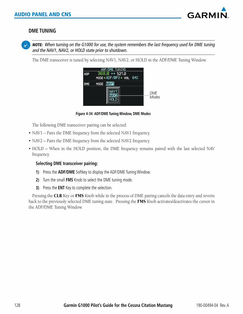
190-00494-04 Rev. AGarmin G1000 Pilot’s Guide for the Cessna Citation Mustang128
AUDIO PANEL AND CNS
DME TUNING
NOTE: When turning on the G1000 for use, the system remembers the last frequency used for DME tuning and the NAV1, NAV2, or HOLD state prior to shutdown.
TheDMEtransceiveristunedbyselectingNAV1,NAV2,orHOLDintheADF/DMETuningWindow.
Figure 4-34 ADF/DME Tuning Window, DME Modes
DME Modes
ThefollowingDMEtransceiverpairingcanbeselected:
•NAV1–PairstheDMEfrequencyfromtheselectedNAV1frequency.
•NAV2–PairstheDMEfrequencyfromtheselectedNAV2frequency.
•HOLD–When in theHOLDposition, theDME frequency remains pairedwith the last selectedNAVfrequency.
Selecting DME transceiver pairing:
1) Press the ADF/DME Softkey to display the ADF/DME Tuning Window.
2) Turn the small FMS Knob to select the DME tuning mode.
3) Press the ENT Key to complete the selection.
Pressing the CLR Key or FMS Knob while in the process of DMEpairingcancelsthedataentryandrevertsbacktothepreviouslyselectedDMEtuningstate.PressingtheFMS Knob activates/deactivates the cursor in theADF/DMETuningWindow.

190-00494-04 Rev. A Garmin G1000 Pilot’s Guide for the Cessna Citation Mustang 129
AUDIO PANEL AND CNS
4.4 MODE S TRANSPONDER
The Mode S Transponders provide Mode A, Mode C, and Mode S interrogation and reply capabilities. Diversityincorporates antennas mounted on the top and bottom of the aircraft for dependable operation while maneuvering. Selective addressing or Mode Select (Mode S) capability includes the following features:
•Level-2replydatalinkcapability(usedtoexchangeinformationbetweenaircraftandATCfacilities)
•Surveillanceidentifiercapability
•FlightID(FlightIdentification)reporting–TheModeSTransponderreportsaircraftidentificationaseithertheaircraftregistrationorauniqueFlightID.
•Altitudereporting
•Airbornestatusdetermination
•Transpondercapabilityreporting
•ModeSEnhancedSurveillance(EHS)requirements
•Acquisitionsquitter–Acquisitionsquitter,orshortsquitter,isthetransponder24-bitidentificationaddress.The transmission is sent periodically, regardless of the presence of interrogations. The purpose of acquisition squitteristoenableModeSgroundstationsandaircraftequippedwithatrafficavoidancesystemtorecognizethe presence of Mode S-equipped aircraft for selective interrogation.
WhenturningontheG1000foruse,thesystemactivatesTransponder1asthedefaultunit,regardlessofwhichtransponderwasactivepriortoshutdown.WhenswitchingbetweenTransponder1andTransponder2,thecodeandmoderemainthesame.Ifanewcodeisenteredintheactivetransponder,switchingtranspondersdoesnotbring back the previous code
TheHazardAvoidanceSectionprovidesmoredetailsontrafficavoidancesystems.

190-00494-04 Rev. AGarmin G1000 Pilot’s Guide for the Cessna Citation Mustang130
AUDIO PANEL AND CNS
GTX 33/33D TRANSPONDER CONTROLSTransponder function isdisplayedonthree levelsofsoftkeysonthePFD:Top-level,ModeSelection,and
Code Selection. When the top-level XPDR Softkey is pressed, the Mode Selection softkeys appear: XPDR1, XPDR2, STBY, ON, ALT, VFR, CODE, IDENT, BACK.
When the CODE Softkey is pressed, the number softkeys appear: 0, 1, 2, 3, 4, 5, 6, 7, IDENT, BKSP, BACK. The digits 8 and 9 are not used for code entry. Pressing the numbered softkeys in sequence enters thetranspondercode.Ifanerrorismade,pressingtheBKSP Softkey moves the code selection cursor to the previous digit. Pressing the BKSP Softkeyagainmovesthecursortothenextpreviousdigit.
Pressing the BACK Softkey during code selection reverts to the Mode Selection Softkeys. Pressing the BACK Softkey during mode selection reverts to the top-level softkeys.
The code can also be entered with the FMSKnoboneitherPFD.Codeentrymustbecompletedwitheitherthe softkeys or the FMS Knob, but not a combination of both.
Pressing the IDENT Softkey while in Mode or Code Selection initiates the ident function and reverts to the top-level softkeys.
After45secondsoftranspondercontrolinactivity,thesystemrevertsbacktothetop-levelsoftkeys.
Figure 4-35 Transponder Softkeys (PFD)
Pressing the BACK Softkeyreturns to the top-level softkeys.
Pressing the BACK Softkey returns to the mode selection softkeys.
MSG
MSGBACKBKSPIDENT76543210
STBY ON ALT VFR CODE IDENT BACK
XPDR
GND
IDENT
XPDR1 XPDR2
Selecting and activating Transponder 1 or Transponder 2:
1) Press the XPDR Softkey to display the Transponder Mode Selection Softkeys.
2) Press the XPDR1 or XPDR2 Softkey to select and activate the other transponder.

190-00494-04 Rev. A Garmin G1000 Pilot’s Guide for the Cessna Citation Mustang 131
AUDIO PANEL AND CNS
GTX 33/33D TRANSPONDER MODE SELECTIONMode selection can be automatic (Ground and Altitude Modes) or manual (Standby, ON, and Altitude Modes).
The STBY, ON, and ALT Softkeys can be accessed by pressing the XPDR Softkey.
Selecting a transponder mode:
1) Press the XPDR Softkey to display the Transponder Mode Selection Softkeys.
2) Press the desired softkey to activate the transponder mode.
GROUND MODE
Ground Mode is normally selected automatically when the aircraft is on the ground. The transponder powers up in the last mode it was in when shut down. Ground Mode can be overridden by pressing any one of the ModeSelectionSoftkeys.AgreenGNDindicationandtranspondercodeappearinthemodefieldoftheTransponderDataBox.InGround Mode, the transponder does not allow Mode A and Mode C replies, but it does permit acquisition squitter and replies to discretely addressed Mode S interrogations.
When Standby Mode has been selected on the ground, the transponder can be returned to Ground Mode by pressing the GND Softkey.
GND Mode
Figure 4-36 Ground Mode
STANDBY MODE (MANUAL)
NOTE: In Standby Mode, the IDENT function is inhibited.
Standby Mode can be selected at any time by pressing the STBYSoftkey.InStandby,thetransponderdoesnot reply to interrogations, but new codes can be entered. When Standby is selected, a white STBY indication and transponder code appear in the modefieldoftheTransponderDataBox.Inallothermodes,thesefieldsappear in green.
STBY Mode (White Code Number and Mode)
Figure 4-37 Standby Mode

190-00494-04 Rev. AGarmin G1000 Pilot’s Guide for the Cessna Citation Mustang132
AUDIO PANEL AND CNS
MANUAL ON MODE
ON Mode can be selected at any time by pressing the ON Softkey. ON Mode generates Mode A and Mode S replies,butModeCaltitudereportingisinhibited.InONMode,agreenONindicationandtranspondercodeappearinthemodefieldoftheTransponderDataBox.
ON Mode (No Altitude Reporting)
Figure 4-38 ON Mode
ALTITUDE MODE (AUTOMATIC OR MANUAL)
Altitude Mode is automatically selected when the aircraft becomes airborne. Altitude Mode may also be selected manually by pressing the ALT Softkey.
IfAltitudeModeisselected,agreenALTindicationandtranspondercodeappearinthemodefieldoftheTransponderDataBox,andalltransponderrepliesrequestingaltitudeinformationareprovidedwithpressurealtitude information.
ALT Mode (Mode C Altitude Reporting)
Figure 4-39 Altitude Mode
REPLY STATUS
When the transponder sends replies to interrogations, a white R indication appears momentarily in the replystatusfieldoftheTransponderDataBox.
Reply to Interrogation
Figure 4-40 Reply Indication

190-00494-04 Rev. A Garmin G1000 Pilot’s Guide for the Cessna Citation Mustang 133
AUDIO PANEL AND CNS
TCAS II TRANSPONDER CONTROLS (OPTIONAL)Transponder function is displayed on three levels of softkeys on the PFD: Top-level, Transponder/Traffic
Selection, and Mode Selection or Code Entry. When the top-level XPDR/TFCSoftkeyisselected,theFunctionSelect softkeys appear: XPDR1, XPDR2, MODE, TCAS, CODE, IDENT, BACK.
When the MODE Softkey is selected, the Mode Selection softkeys appear: STBY, ON, ALT, TA ONLY, TA/RA, BACK.
When the CODE Softkey is selected, the number softkeys appear: 0, 1, 2, 3, 4, 5, 6, 7, IDENT, BKSP, BACK. The digits 8 and 9 are not used for code entry. Selecting the numbered softkeys in sequence enters thetranspondercode.Ifanerrorismade,selectingtheBKSP Softkey moves the code selection cursor to the previous digit. Selecting the BKSP Softkeyagainmovesthecursortothenextpreviousdigit.
Selecting the BACK Softkey returns to the previous level softkeys.
The code can also be entered with the FMSKnoboneitherPFD.Codeentrymustbecompletedwitheitherthe softkeys or the FMS Knob, but not a combination of both.
Selecting the IDENT Softkey while in Code Selection initiates the ident function and reverts to the top-level softkeys.
After45secondsoftranspondercontrolinactivity,thesystemrevertsbacktothetop-levelsoftkeys.
Figure 4-41 Transponder Softkeys (with TCAS II option)
Selecting the BACK Softkeyreturns to the top-level softkeys.
MSG
MSG
BACKBKSPIDENT76543210
MODE TCAS CODE IDENT BACK
XPDR/TFC IDENT
Selecting the BACK Softkeyreturns to the previous level softkeys.
MSGSTBY ON ALT TA/RA BACKTA ONLY
Selecting the BACK Softkeyreturns to the previous level softkeys.
XPDR1 XPDR2
Selecting and activating Transponder 1 or Transponder 2:
1) Press the XPDR Softkey to display the Transponder Mode Selection Softkeys.
2) Press the XPDR1 or XPDR2 Softkey to select and activate the other transponder.

190-00494-04 Rev. AGarmin G1000 Pilot’s Guide for the Cessna Citation Mustang134
AUDIO PANEL AND CNS
TCAS II TRANSPONDER MODE SELECTION (OPTIONAL)Mode selection can be automatic (Altitude Mode) or manual (Standby, On, and Altitude Modes). The STBY,
ON, ALT, TA ONLY, and TA/RA Softkeys can be accessed by selecting the XPDR/TRC Softkey, then the MODE Softkey.
Selecting a transponder mode:
1) Select the XPDR/TRC Softkey.
2) Select the MODE Softkey to display the Transponder Mode Selection Softkeys.
3) Select the desired softkey to activate the transponder mode (STBY, ON, or ALT).
Selecting a TCAS II mode:
1) Select the XPDR/TRC Softkey.
2) Select the MODE Softkey to display the TCAS II Mode Selection Softkeys.
2) Select the desired softkey to activate the TCAS II mode (TA ONLY or TA/RA).
STANDBY MODE (MANUAL)
NOTE: In Standby Mode, the IDENT function is inhibited. TCAS II is switched to Standby Mode, because the transponder is not capable of supporting TCAS II operation in Standby Mode.
Standby Mode can be selected at any time by selecting the STBYSoftkey.InStandby,thetransponderdoesnot reply to interrogations, but new codes can be entered. When Standby is selected, a white STBY indication and transponder code appear in the modefieldoftheTransponderDataBox.Inallothermodes,thesefieldsappear in green.
STBY Mode (White Code Number and Mode)
Figure 4-42 Standby Mode

190-00494-04 Rev. A Garmin G1000 Pilot’s Guide for the Cessna Citation Mustang 135
AUDIO PANEL AND CNS
ON MODE (MANUAL)
NOTE: TCAS II is switched to Standby Mode, because the transponder is not capable of supporting TCAS II operation in On Mode.
ON Mode can be selected at any time by selecting the ON Softkey. ON Mode generates Mode A replies, but Mode C altitude reporting is inhibited. Acquisition squitter and replies to discretely addressed Mode S interrogationsarealsopermitted.InONMode,agreenONindicationandtranspondercodeappearinthemodefieldoftheTransponderDataBox.
ON Mode (No Altitude Reporting)
Figure 4-43 ON Mode
ALTITUDE MODE (AUTOMATIC OR MANUAL)
NOTE: TCAS II is switched to Standby Mode.
Altitude Mode is automatically selected when the aircraft becomes airborne. Altitude Mode may also be selected manually by selecting the ALT Softkey. ALT Mode generates Mode A and Mode C replies. Acquisition squitter and replies to discretely addressed Mode S interrogations are also permitted.
IfAltitudeModeisselected,agreenALTindicationandtranspondercodeappearinthemodefieldoftheTransponderDataBox,andalltransponderrepliesrequestingaltitudeinformationareprovidedwithpressurealtitude information.
ALT Mode (Mode C Altitude Reporting)
Figure 4-44 Altitude Mode
REPLY STATUS
When the transponder sends replies to interrogations, a white R indication appears momentarily in the replystatusfieldoftheTransponderDataBox.
Reply to Interrogation
Figure 4-45 Reply Indication

190-00494-04 Rev. AGarmin G1000 Pilot’s Guide for the Cessna Citation Mustang136
AUDIO PANEL AND CNS
ENTERING A TRANSPONDER CODE
Entering a transponder code with softkeys:
1) Press the XPDR Softkey to display the Transponder Mode Selection Softkeys.
2) Press the CODE Softkey to display the Transponder Code Selection Softkeys, for digit entry.
3) Press the digit softkeys to enter the code in the code field. When entering the code, the next softkey in sequence must be pressed within 10 seconds, or the entry is cancelled and restored to the previous code. Pressing the BKSP Softkey moves the code selection cursor to the previous digit. Five seconds after the fourth digit has been entered, the transponder code becomes active.
Entering a Code
Figure 4-46 Entering a Code with Softkeys
Entering a transponder code with the PFD FMS Knob:
1) Press the XPDR and the CODE Softkeys as in the previous procedure to enable code entry.
2) Turn the small FMS Knob to enter the first two code digits.
3) Turn the large FMS Knob to move the cursor to the next code field.
4) Enter the last two code digits with the small FMS Knob.
5) Press the ENT Key to complete code digit entry.
Pressing the CLR Key or small FMS Knob before code entry is complete cancels code entry and restores the previouscode.Waitingfor10secondsaftercodeentryisfinishedactivatesthecodeautomatically.
Figure 4-47 Entering a Code with the FMS Knob
Press the ENT Key to Complete Code Entry
Turn the Large FMS Knob to Move the Cursor to the Next Code Field
Turn the Small FMS Knob to
Enter Two Code Digits at a Time

190-00494-04 Rev. A Garmin G1000 Pilot’s Guide for the Cessna Citation Mustang 137
AUDIO PANEL AND CNS
VFR CODE
The VFRcodecanbeenteredeithermanuallyorbypressing theXPDR Softkey, then the VFR Softkey. When the VFRSoftkeyispressed,thepre-programmedVFRcodeisautomaticallydisplayedinthecodefieldoftheTransponderDataBox.PressingtheVFRSoftkeyagainrestoresthepreviousidentificationcode.
Thepre-programmedVFRCodeissetatthefactoryto1200.IfaVFRcodechangeisrequired,contactaGarmin-authorizedservicecenterforconfiguration.
Figure 4-48 VFR Code
VFR Code
IDENT FUNCTION
NOTE: In Standby Mode, the IDENT Softkey is inoperative.
Pressing the IDENTSoftkeysendsadistinctidentityindicationtoAirTrafficControl(ATC).Theindicationdistinguishes the identingtransponder fromall theothersontheair trafficcontroller’sscreen. TheIDENT Softkey appears on all levels of transponder softkeys. When the IDENT Softkey is pressed, a green IDNT indicationisdisplayedinthemodefieldoftheTransponderDataBoxforadurationof18seconds.
After the IDENT Softkey is pressed while in Mode or Code Selection, the system reverts to the top-level softkeys.
Press the IDENT Softkey to Initiate the
ID Function
IDNT Indication
Figure 4-49 IDENT Softkey and Indication

190-00494-04 Rev. AGarmin G1000 Pilot’s Guide for the Cessna Citation Mustang138
AUDIO PANEL AND CNS
FLIGHT ID REPORTINGThe flight crewmust enter the Flight ID before flight operation. The number is entered in the Timer/
ReferencesWindowonthePFD.TheFlightIDisnottoexceedsevencharacters.NospaceisneededwhenenteringFlightID.WhenaFlightIDcontainsaspace,thesystemautomaticallyremovesituponcompletionofFlightIDentry.Ifconfigurationissetto“SAMEASTAIL”theaircrafttailnumberwillalwaysbedisplayed.
Entering a Flight ID:
1) Press the TMR/REF Softkey to display the Timer/References Window.
2) Press the FMS Knob to activate the selection cursor, if not already activated.
3) Turn the large FMS Knob to scroll down to the Flight ID.
4) Turn the small FMS Knob to enter the desired Flight ID.
5) Press the ENT Key to complete Flight ID entry.
IfanerrorismadeduringFlightIDentry,pressingtheCLRKeyreturnstotheoriginalFlightIDentry.WhileenteringaFlightID,turningtheFMS Knob counterclockwise moves the cursor back one space for each detent ofrotation.IfanincorrectFlightIDisdiscoveredaftertheunitbeginsoperation,reenterthecorrectFlightIDusing the same procedure.
Figure 4-50 Timer/References Window, Entering Flight ID
Flight ID PFD Entry

190-00494-04 Rev. A Garmin G1000 Pilot’s Guide for the Cessna Citation Mustang 139
AUDIO PANEL AND CNS
4.5 ADDITIONAL AUDIO PANEL FUNCTIONS
POWER-UPTheAudioPanelsperformaself-testduringpower-up.Duringtheself-testallAudioPanelannunciator lights
illuminateforapproximatelytwoseconds.Oncetheself-testiscompleted,mostofthesettings are restored to thoseinusebeforetheunitwaslastturnedoff.Theexceptionsarethespeakerandintercom,whicharealwaysselected during power up.
MONO/STEREO HEADSETSStereo headsets are recommended for use in this aircraft.
Using a monaural headset in a stereo jack shorts the right headset channel output to ground. While this does not damage the Audio Panel, a person listening on a monaural headset hears only the left channel in both ears. Ifamonauralheadsetisusedatoneofthepassengerpositions,anyotherpassengerusingastereoheadsethearsaudio in the left ear only.
SPEAKER
NOTE: When the oxygen mask switch on the instrument panel is selected, each pilot’s microphone audio is heard on the cross-side speaker. The on-side speaker is also enabled and cannot be deselected.
Each Audio Panel controls a separate flight deck speaker. Each SPKR Key controls the on-side speaker unless oxygenmasksareinuse.Duringoxygenmaskusetheon-sidespeakerisalwaysenabled.
Pressing the SPKRKey selects anddeselects the speaker. Except foroxygenmaskuse, speakeraudio ismuted when the PTT Key is pressed.
Figure 4-51 Speaker Key
UNMUTED INPUTSStall, overspeed, and aural gear alerts are heard on the headset and speaker always, even when the speaker
is off.
All other alerts are always present on the headset and are on the speaker when the SPKR Key is selected. These warnings and the aircraft radios are not heard on the passenger headphones.

190-00494-04 Rev. AGarmin G1000 Pilot’s Guide for the Cessna Citation Mustang140
AUDIO PANEL AND CNS
INTERCOMPressing the INTR COM Key on either Audio Panel selects and deselects the intercom on both Audio Panels.
The annunciator is lit when the intercom is active. The intercom connects the pilot and copilot together. Either the pilot or copilot may select or deselect the intercom.
The MAN SQ Key allows either automatic or manual control of the intercom squelch setting. Pressing the MAN SQ Key enables manual squelch control, indicated by the MAN SQ annunciator.
•WhentheMANSQAnnunciatorisextinguished(AutomaticSquelchison),theICS Knob controls only the volume (pressing the ICSKnobhasnoeffectontheVOL/SQselection).
•WhentheMANSQAnnunciatorisilluminated(ManualSquelch),theICS Knob controls either volume or squelch (selected by pressing the ICSKnobandindicatedbytheVOLorSQannunciation).
Manual Squelch Annunciator; Off
for Automatic Squelch, On for Manual Squelch
Press to switch between VOL and SQ. Turn to adjust Squelch
when SQ Annunciation is lit, Volume when
VOL Annunciation is lit.
Volume Annunciation Squelch Annunciation
Master Volume Control for Pilot Side or Copilot Side
ICS Isolation
Figure 4-52 Intercom Controls
GMA 1347D-20
GMA 1347D

190-00494-04 Rev. A Garmin G1000 Pilot’s Guide for the Cessna Citation Mustang 141
AUDIO PANEL AND CNS
PASSENGER ADDRESS (PA) SYSTEMA passenger address system is provided by pressing the PA Key to deliver messages to the passengers. The
message is heard by the other pilot on the headset only if the INTR COM Key is enabled. PA messages are one way from the flight deck to the passengers.
A Push-to-talk (PTT) must be pressed to deliver PA announcements. The announcements are heard over the cockpit speakers and by the passengers over their headphones.
When PA is selected on the Audio Panel, the annunciator flashes about once per second while pressing the PTT,theCOMMICannunciatorisnolongerlit,andtheactiveCOMfrequencyforthatAudioPanelchangestowhite, indicating that there is no COM selected.
Figure 4-53 PA Key Selected for Cabin Announcements
PA Key is Selected on the Audio Panel
SIMULTANEOUS COM OPERATION
NOTE: If the selected COM1 and COM2 frequencies are within approximately 1 MHz of each other, interference may be heard during transmission on the other radio. Simultaneous COM operation is affected by the distance between the COM antennas and the separation of the tuned frequencies.
Both the pilot and the copilot can transmit and receive simultaneously over separateCOM radios. TheselectedCOMMICAnnunciatorflasheswheneitherpilot’smicrophonePTTispressed.
IfbothpilotsselectthesameCOMradio,thepilothaspriorityonCOM1andthecopilothaspriorityonCOM2.

190-00494-04 Rev. AGarmin G1000 Pilot’s Guide for the Cessna Citation Mustang142
AUDIO PANEL AND CNS
CLEARANCE RECORDER AND PLAYERTheAudioPanelscontainadigitalclearancerecorderthatrecordsupto2.5minutesoftheselectedCOM
radiosignal.RecordedCOMaudioisstoredinseparatememoryblocks.Once2.5minutesofrecordingtimehave been reached, the recorder begins recording over the stored memory blocks, starting from the oldest block.
Pressing the REC Key enables recording of audio from the COM radio selected for transmission. Quiet periods between COM reception are not recorded.
The PLAYKeycontrolstheplayfunction.ThePLAYannunciatorindicateswhenplayisinprogress.ThePLAYannunciatorturnsoffafterplaybackisfinished.
Pressing the PLAY Key once plays the latest recorded memory block and then returns to normal operation. Pressing the PLAYKeyagainduringplayofamemoryblockstopsplay. IfaCOMinputsignal isdetectedduring play of a recorded memory block, play is halted.
Pressing the PLAY Key twice within one-half second while audio is playing plays the previous block of recorded audio. Each subsequent two presses of the PLAY Key within one-half second will backtrack through the recorded memory blocks to reach and play any recorded block.
Powering off the unit automatically clears all recorded blocks.
Figure 4-54 Record and Playback Key

190-00494-04 Rev. A Garmin G1000 Pilot’s Guide for the Cessna Citation Mustang 143
AUDIO PANEL AND CNS
4.6 AUDIO PANELS PREFLIGHT PROCEDURE
NOTE: If the flight crew is using headsets that have a high/low switch or volume control knob, verify that the switch is in the high position and the volume control on the headsets are at max volume setting. On single-pilot flights, verify that all other headsets are not connected to avoid excess noise in the audio system.
NOTE: When the MAN SQ Key is pressed, the flight crew is now able to set the ICS squelch manually. If manual squelch is set to full open (SQ annunciated and the small knob turned counterclockwise) background noise will be heard in the ICS system as well as during COM transmissions.
AfterpoweringuptheG1000systemthefollowingstepswillaidtheflightcrewinmaximizingtheuseoftheAudio Panels as well as prevent flight crew induced issues. These preflight procedures should be performed each time a flight crew boards the aircraft to insure awareness of all audio levels in the Audio Panels and radios.
Figure 4-55 Audio Panel Controls
Reversionary Mode for PFD1 and MFD
Pilot Side Copilot Side
Manual Squelch
ICS Volume and Squelch Control
VOL Annunciation SQ Annunciation
Master Volume Control
ICS Isolation
Reversionary Mode for PFD2 and MFD
IndependentradiovolumeadjustmentsmadeusingthePFDcontrolswillaffectonlytheaudiooutputforeachradio selected for adjustment. Radio volume adjustment will affect both crew positions equally for each radio that is adjusted. Turning the master volume control located on either Audio Panel will affect only the audio heard in the corresponding crew position headset. Thus, radio volume adjustments may be overridden by each crew position independently using the master volume control on the Audio Panel for the respective crew position. The master volume control for each Audio Panel will affect all other system audio output for the pilot or copilot headset.

190-00494-04 Rev. AGarmin G1000 Pilot’s Guide for the Cessna Citation Mustang144
AUDIO PANEL AND CNS
Setting the Audio Panel volume levels during preflight:
1) Verify the INTR COM Key is selected.
2) Verify manual squelch is set to minimum.
3) Turn the MSTR Knob (Master Volume Control) on both Audio Panels clockwise two full turns. This sets the headset audio level to max volume (least amount of attenuation).
4) Adjust radio volume levels (COM, NAV, etc.) to a suitable level.
5) Adjust the ICS volume Knob on each Audio Panel to the desired intercom level.
6) Reset squelch to automatic, or adjust to the appropriate level manually.
Once this procedure has been completed, the master volume controls on both Audio Panels may now be adjusted. The flight crew can change settings, keeping in mind the notes above.
Figure 4-56 Radio and Headphone Volume Controls
Radio Volume Knobs Adjust Radio Level
Copilot Master Volume Control
Pilot Master Volume Control
Master Volume Knobs Adjust Headphone
Volume Level
COM Radio Audio
NAV Radio Audio
FMS Knob Adjusts ADF Volume Level
ADF Radio Audio

190-00494-04 Rev. A Garmin G1000 Pilot’s Guide for the Cessna Citation Mustang 145
AUDIO PANEL AND CNS
4.7 ABNORMAL OPERATION
Abnormal operation of the G1000 includes equipment failures of the G1000 components and failure ofassociatedequipment,includingswitchesandexternaldevices.
STUCK MICROPHONEIf thepush-to-talk(PTT)Keybecomesstuck,theCOMtransmitterstopstransmittingafter35secondsof
continuousoperation.AnalertappearsonthePFDtoadvisethecrewofastuck microphone.
The COM1 MIC or COM2 MIC Key Annunciator on the Audio Panel flashes as long as the PTT Key remains stuck.
Figure 4-57 Stuck Microphone Alert
COM TUNING FAILUREIncaseofaCOMsystemtuningfailure,theemergencyfrequency(121.500MHz)isautomaticallytunedin
theradioinwhichthetuningfailureoccurred.Dependingonthefailuremode,aredXmayappearonthefrequency display.
Figure 4-58 COM Tuning Failure
Emergency Channel Loaded Automatically
PFD FAILURE, DUAL SYSTEMIfPFD1fails,COM1andNAV1displayaredXonbothremainingdisplays.NAV1isunavailable.COM1
automaticallytunes121.500MHz,butthefrequencyisnotshown.TheCOM1emergencyfrequencyisavailableto both the copilot and pilot.
Figure 4-59 Frequency Section of PFD2 Display after PFD1 Failure
Emergency Channel Loaded Automatically

190-00494-04 Rev. AGarmin G1000 Pilot’s Guide for the Cessna Citation Mustang146
AUDIO PANEL AND CNS
IfPFD2fails,COM2andNAV2displayaredXontheremainingPFDdisplay.NAV2isunavailable.COM2tunes121.500MHz,butthefrequencyisnotshown.TheCOM2emergencyfrequencyisavailabletoboththecopilot and pilot.
Figure 4-60 PFD1 Display after PFD2 Failure
AUDIO PANEL FAIL-SAFE OPERATIONIfthereisafailureofbothAudioPanels,afail-safecircuitconnectsthepilot’sheadsetandmicrophonedirectly
totheCOM1transceiverandthecopilot’sheadsetdirectlytotheCOM2transceiver.Audiowillnotbeavailableon the speakers.
IfthereisafailureofoneAudioPanel,theremainingonewillnothaveaccesstotheothersside’sCOMandNAV.Forexample,ifthepilotsideAudioPanelfails,thecopilotsideAudioPanelhasaccesstoalltheradiosexceptforCOM1andNAV1.
REVERSIONARY MODEThe red DISPLAY BACKUPButtonselectstheReversionary Mode. See the System Overview Section for
more information on Reversionary Mode.
Figure 4-61 Reversionary Mode Button

190-00494-04 Rev. A Garmin G1000 Pilot’s Guide for the Cessna Citation Mustang 147
FLIGHT MANAGEMENT
SECTION 5 FLIGHT MANAGEMENT
5.1 INTRODUCTION
The G1000 is an integrated flight, engine, communication, navigation and surveillance system. This section of the Pilot’s Guide explains flight management using the G1000.
The most prominent part of the G1000 are the three full color displays: two Primary Flight Displays (PFD) and a Multi Function Display (MFD). The information to successfully navigate the aircraft using the GPS sensors is displayed on the PFD and the MFD. See examples in the Figure 5-1 and Figure 5-2. Detailed descriptions of flight management functions are discussed later in this section.
A brief description of the GPS navigation data on the PFD and MFD follows.
Navigation mode indicates which sensor is providing the course data (e.g., GPS, VOR) and the flight plan phase (e.g., Departure (DPRT), Terminal (TERM), Enroute (ENR), Oceanic (OCN), Approach (LNAV, LNAV+V, L/VNAV, or LPV), or Missed Approach (MAPR)).
The Inset Map is a small version of the MFD Navigation Map and can be displayed in the lower left corner of the PFD. When the system is in reversionary mode, the Inset Map can be displayed in the lower right corner. The Inset Map is displayed by pressing the INSET Softkey. Pressing the INSET Softkey again, then pressing the OFF Softkey removes the Inset Map.
The Navigation Map displays aviation data (e.g., airports, VORs, airways, airspaces), geographic data (e.g., cities, lakes, highways, borders), topographic data (map shading indicating elevation), and hazard data (e.g., traffic, terrain, weather). The amount of displayed data can be reduced by selecting the DCLTR Softkey. The Navigation Map can be oriented four different ways: North Up (NORTH UP), Track Up (TRK UP), Desired Track Up (DTK UP), or Heading Up (HDG UP).
An aircraft icon is placed on the Navigation Map at the location corresponding to the calculated present position. The aircraft position and the flight plan legs are accurately based on GPS calculations. The basemap upon which these are placed are from a source with less resolution, therefore the relative position of the aircraft to map features is not exact. The leg of the active flight plan currently being flown is shown as a magenta line on the navigation map. The other legs are shown in white.
There are 28 different map ranges available, from 500 feet to 2000 nm. The current range is indicated in the lower right corner of the map and represents the top-to-bottom distance covered by the map. To change the map range on any map, turn the Joystick counter-clockwise to zoom in ( -, decreasing), or clockwise to zoom out (+, increasing).
The Direct-to Window, the Flight Plan Window, the Procedures Window, and the Nearest Airports Window can be displayed in the lower right corner of the PFD. Details of these windows are discussed in detail later in the section.

Garmin G1000 Pilot’s Guide for the Cessna Citation Mustang 190-00494-04 Rev. A148
FLIGHT MANAGEMENT
Figure 5-1 GPS Navigation Information on the PFD
Location of:- Direct To Window- Flight Plan Window- Procedures Window- Nearest Airports Window
Inset Map
Navigation Status Box
Navigation Mode
Figure 5-2 GPS Navigation Information on the MFD Navigation Page
Active Flight Plan Leg
Navigation Map- Aviation Data
- Geographic Data- Topographic Data
- Hazard Data
Navigation Status Box
Aircraft Iconat Present Position
Map Range
Map Orientation
Flight Plan Leg
NAVIGATION STATUS BOXThe Navigation Status Box located at the top of the PFD contains two fields displaying the following
information:
PFD Navigation Status Box

190-00494-04 Rev. A Garmin G1000 Pilot’s Guide for the Cessna Citation Mustang 149
FLIGHT MANAGEMENT
•Activeflightplanleg(e.g.,‘D->KICT’or‘KIXD->KCOS’) or flight plan annunciations (e.g., ‘Turnright to 021˚ in 8 seconds’)
•Distance (DIS) and Bearing (BRG) to the nextwaypoint orflightplanannunciations(e.g.,‘TODwithin 1 minute’)
The symbols used in the PFD status bar are:
Symbol Description
Active Leg
Direct-to
Right Procedure Turn
Left Procedure Turn
Right Holding Pattern
Left Holding Pattern
Vector to Final
Right DME Arc
Left DME Arc
The Navigation Status Box located at the top of the MFD contains four data fields, each displaying one of the following items:
•Bearing(BRG)
•Distance(DIS)
•DesiredTrack(DTK)
•Endurance(END)
•EnrouteSafeAltitude(ESA)
•EstimatedTimeofArrival(ETA)
•EstimatedTimeEnroute(ETE)
•FuelonBoard(FOB)
•FueloverDestination(FOD)
•GroundSpeed(GS)
•MinimumSafeAltitude(MSA)
•TrueAirSpeed(TAS)
•TrackAngleError(TKE)
•Track(TRK)
•VerticalSpeedRequired(VSR)
•CrosstrackError(XTK)
MFD Navigation Status Box
The navigation information displayed in the four data fields can be selected on the MFD Data Bar Fields Box ontheAUX-SystemSetupPage.Thedefaultselections(inorderlefttoright)areGS,DTK,TRK,andETE.
Changing a field in the MFD Navigation Status Box:
1) Select the System Setup Page.
2) Press the FMS Knob momentarily to activate the flashing cursor.
3) Turn the large FMS Knob to highlight the desired field number in the MFD Data Bar Fields Box.
4) Turn the small FMS Knob to display and scroll through the data options list.
5) Select the desired data.
6) Press the ENT Key. Selecting the DFLTS Softkey returns all fields to the default setting.

Garmin G1000 Pilot’s Guide for the Cessna Citation Mustang 190-00494-04 Rev. A150
FLIGHT MANAGEMENT
5.2 USING MAP DISPLAYS
Map displays are used extensively in the G1000 to provide situational awareness in flight. Most G1000 maps can display the following information:
•Airports, NAVAIDs, airspaces, airways, land data(highways, cities, lakes, rivers, borders, etc.) with names
•Map Pointer information (distance and bearingto pointer, location of pointer, name, and other pertinent information)
•Maprange
•Wind direction and speed
•Maporientation
•Iconsforenabledmapfeatures
•Aircrafticon(representingpresentposition)
•Navrangering
•Fuelrangering
•Flightplanlegs
•Userwaypoints
•Trackvector
•Topographyscale
•Topographydata
•Obstacledata
MAP ORIENTATIONMaps are shown in one of four different orientation options, allowing flexibility in determining aircraft
position relative to other items on the map (north up) or for determining where map items are relative to where the aircraft is going (track up, desired track up, or heading up). The map orientation is shown in the upper right corner of the map.
Figure 5-3 Map Orientation
•Northup(NORTHUP)alignsthetopofthemapdisplaytonorth(defaultsetting).
•Trackup(TRKUP)alignsthetopofthemapdisplaytothecurrentgroundtrack.
•AllMapGroupPages(MAP)
•AllWaypointGroupPages(WPT)
•AUX-TripPlanning
•AllNearestGroupPages(NRST)
•FlightPlanPages(FPL)
•Direct-toWindow
•PFDInsetMap
•ProcedureLoadingPages
The information in this section applies to the following maps unless otherwise noted:

190-00494-04 Rev. A Garmin G1000 Pilot’s Guide for the Cessna Citation Mustang 151
FLIGHT MANAGEMENT
•Desiredtrackup(DTKUP)alignsthetopofthemapdisplaytothedesiredcourse.
•Headingup(HDGUP)alignsthetopofthemapdisplaytothecurrentaircraftheading.
NOTE: When panning or reviewing active flight plan legs in a non-North Up orientation, the map does not show the map orientation nor the wind direction and speed.
NOTE: Map orientation can only be changed on the Navigation Map Page. Any other displays that show navigation data reflect the orientation selected for the Navigation Map Page:
Changing the Navigation Map orientation:
1) With the Navigation Map Page displayed, press the MENU Key. The cursor flashes on the ‘Map Setup’ option.
Figure 5-4 Navigation Map Page Menu Window
Map Setup Selection
2) Press the ENT Key to display the Map Setup Window.
3) Turn the large FMS Knob, or press the ENT Key once, to select the ‘ORIENTATION’ field.
Figure 5-5 Map Setup Menu Window - Map Group
Orientation Field
Map Group Selection

Garmin G1000 Pilot’s Guide for the Cessna Citation Mustang 190-00494-04 Rev. A152
FLIGHT MANAGEMENT
4) Turn the small FMS Knob to select the desired orientation.
5) Press the ENT Key to select the new orientation.
6) Press the FMS Knob to return to the base page.
MAP RANGEThere are 28 different map ranges available, from 500 feet to 2000 nm. The current range is indicated in
the lower right corner of the map and represents the top-to-bottom distance covered by the map. When the map range is decreased to a point that exceeds the capability of the G1000 to accurately represent the map, a magnifying glass icon is shown to the left of the map range. To change the map range turn the Joystick counter-clockwise to decrease the range, or clockwise to increase the range.
Figure 5-6 Map Range
Range Overzoom
AUTO ZOOM
Auto zoom allows the G1000 to change the map display range to the smallest range clearly showing the active waypoint. Auto zoom can be overridden by adjusting the range with the Joystick, and remains until the active waypoint changes, a terrain or traffic alert occurs, the aircraft takes off, or the manual override times out (timer set on Map Setup Window).
If a terrain caution or warning occurs, any map page displaying TAWS/TERRAIN data automatically adjusts to the smallest map range clearly showing the highest priority alert. If a new traffic advisory alert occurs, any map page capable of displaying traffic advisory alerts automatically adjusts to the smallest map range clearly showing the traffic advisory. When terrain or traffic alerts clear, the map returns to the previous auto zoom range based on the active waypoint.
The auto zoom function can be turned on or off independently for the PFDs and MFD. Control of the rangesatwhichtheautozoomoccursisdonebysettingtheminimumandmaximum‘lookforward’times(set on the Map Setup Window for the Map Group). These settings determine the minimum and maximum distance to display based upon the aircraft’s ground speed.
•Waypointsthatarelongdistancesapartcausethemaprangetoincreasetoapointwheremanydetailsonthe map are decluttered. If this is not acceptable, lower the maximum look ahead time to a value that limits the auto zoom to an acceptable range.

190-00494-04 Rev. A Garmin G1000 Pilot’s Guide for the Cessna Citation Mustang 153
FLIGHT MANAGEMENT
•Waypointsthatareveryshortdistancesapartcausethemaprangetodecreasetoapointwheresituationalawareness may not be what is desired. Increase the minimum look ahead time to a value that limits the auto zoom to a minimum range that provides acceptable situational awareness.
•Flightplansthathaveacombinationof longandshort legscausetherangetoincreaseanddecreaseaswaypointssequence.Toavoidthis,autozoomcanbedisabledorthemaximum/minimumtimescanbeadjusted.
•The‘timeout’time(configurableontheMapSetupPagefortheMapGroup)determineshowlongautozoom is overridden by a manual adjustment of the range knob. At the expiration of this time, the auto zoomrangeisrestored.Settingthe‘timeout’valuetozerocausesthemanualoverridetonevertimeout.
•Whenthemaximum‘lookforward’timeissettozero,theupperlimitbecomesthemaximumrangeavailable(2000 nm).
•Whentheminimum‘lookforward’timeissettozero,thelowerlimitbecomes1.5nm.
Figure 5-7 Map Setup Menu Window - Map Group, Auto Zoom
Auto Zoom:Off, MFD Only, PFD Only, All On
Manual Range Override Expiration Time
Maximum Look Forward TimeMinimum Look Forward Time
Configuring automatic zoom:
1) Press the MENU Key with the Navigation Map Page displayed. The cursor flashes on the ‘Map Setup’ option.
2) Press the ENT Key. The Map Setup Menu is displayed.
3) Select the ‘Map’ group.
4) Press the ENT Key.
5) Highlight the ‘AUTO ZOOM’ field.
6) Select ‘Off’, ‘MFD Only’, ‘PFD Only’, or ‘ALL On’.
7) Press the ENT Key to accept the selected option. The flashing cursor highlights the ‘MAX LOOK FWD’ field. Times are from zero to 999 minutes.

Garmin G1000 Pilot’s Guide for the Cessna Citation Mustang 190-00494-04 Rev. A154
FLIGHT MANAGEMENT
8) Use the FMS Knobs to set the time. Press the ENT Key.
9) Repeat step 8 for ‘MIN LOOK FWD’ (zero to 99 minutes) and ‘TIME OUT’ (zero to 99 minutes).
10) Press the FMS Knob to return to the Navigation Map Page.
MAP PANNINGMap panning allows the pilot to:
•Viewpartsofthemapoutsidethedisplayedrangewithoutadjustingthemaprange
•Highlightandselectlocationsonthemap
•Reviewinformationforaselectedairport,NAVAIDoruserwaypoint
•Designatelocationsforuseinflightplanning
•Viewairspaceandairwayinformation
When the panning function is selected by pressing the Joystick, the Map Pointer flashes on the map display. A window also appears at the top of the map display showing the latitude/longitude position of the pointer, the bearing and distance to the pointer from the aircraft’s present position, and the elevation of the land at the position of the pointer.
Figure 5-8 Navigation Map - Map Pointer Activated
Map Pointer
Map Pointer Information
NOTE: The map is normally centered on the aircraft’s position. If the map has been panned and there has been no pointer movement for about 60 seconds, the map reverts back to centered on the aircraft position and the flashing pointer is removed.

190-00494-04 Rev. A Garmin G1000 Pilot’s Guide for the Cessna Citation Mustang 155
FLIGHT MANAGEMENT
When the Map Pointer is placed on an object, the name of the object is highlighted (even if the name was not originally displayed on the map). When any map feature or object is selected on the map display, pertinent information is displayed.
Figure 5-9 Navigation Map - Map Pointer on Point of Interest
Map Pointer on POI
Information about Point of Interest

Garmin G1000 Pilot’s Guide for the Cessna Citation Mustang 190-00494-04 Rev. A156
FLIGHT MANAGEMENT
When the Map Pointer crosses an airspace boundary, the boundary is highlighted and airspace information is shown at the top of the display. The information includes the name and class of airspace, the ceiling in feet above Mean Sea Level (MSL), and the floor in feet MSL.
Figure 5-10 Navigation Map - Map Pointer on Airspace
Map Pointer on Airspace
Informationabout Airspace
Panning the map:
1) Press the Joystick to display the Map Pointer.
2) Move the Joystick to move the Map Pointer around the map.
3) Press the Joystick to remove the Map Pointer and recenter the map on the aircraft’s current position.

190-00494-04 Rev. A Garmin G1000 Pilot’s Guide for the Cessna Citation Mustang 157
FLIGHT MANAGEMENT
Reviewing information for an airport, NAVAID, or user waypoint:
1) Place the Map Pointer on a waypoint.
2) Press the ENT Key to display the Waypoint Information Page for the selected waypoint.
3) Press the GO BACK Softkey, the CLR Key, or the ENT Key to exit the Waypoint Information Page.
Figure 5-11 Navigation Map - Information Window - NAVAID
NAVAID Information
GO BACK Softkey

Garmin G1000 Pilot’s Guide for the Cessna Citation Mustang 190-00494-04 Rev. A158
FLIGHT MANAGEMENT
Viewing airspace information for a special-use or controlled airspace:
1) Place the Map Pointer on an open area within the boundaries of an airspace.
2) Press the ENT Key to display an options menu.
3) ‘Review Airspaces’ should already be highlighted, if not select it. Press the ENT Key to display the Airspace Information Page for the selected airspace.
4) Press the CLR or ENT Key to exit the Airspace Information Page.
Figure 5-12 Navigation Map - Information Window - Airspace
Airspace Information

190-00494-04 Rev. A Garmin G1000 Pilot’s Guide for the Cessna Citation Mustang 159
FLIGHT MANAGEMENT
MEASURING BEARING AND DISTANCEDistance and bearing from the aircraft’s present position to any point on the viewable navigation map may be
calculatedusingthe‘MeasureBearingandDistance’selectionfromNavigationMappagemenu.Thebearingand distance tool displays a dashed Measurement Line and a Measure Pointer to aid in graphically identifying points with which to measure. Lat/Long, distance and elevation data for the Measure Pointer is provided in a window at the top of the navigation map.
Measuring bearing and distance between any two points:
1) Press the MENU Key (with the Navigation Map Page displayed).
2) Highlight the ‘Measure Bearing/Distance’ field.
3) Press the ENT Key. A Measure Pointer is displayed on the map at the aircraft’s present position.
4) Move the Joystick to place the reference pointer at the desired location. The bearing and distance are displayed at the top of the map. Elevation at the current pointer position is also displayed. Pressing the ENT Key changes the starting point for measuring.
5) To exit the Measure Bearing/Distance option, press the Joystick
Or:
Select ‘Stop Measuring’ from the page menu and press the ENT Key.
Figure 5-13 Navigation Map - Measuring Bearing and Distance
Pointer Lat/Long
Measurement Information
Measurement Line

Garmin G1000 Pilot’s Guide for the Cessna Citation Mustang 190-00494-04 Rev. A160
FLIGHT MANAGEMENT
TOPOGRAPHYAll navigation maps can display various shades of topography colors representing land elevation, similar
to aviation sectional charts. Topographic data can be displayed or removed as described in the following procedures.
Navigation Map Black Background
TOPO Off
Figure 5-14 Navigation Map - Topographic Data
TOPO SoftkeyEnabled
Navigation Map Topographic Data
TOPO On
Topographic Data on Profile Map
TOPO SoftkeyNot Enabled
Displaying/removing topographic data on all pages displaying navigation maps:
1) Press the MAP Softkey (the INSET Softkey for the PFD Inset Map).
2) Select the TOPO Softkey.
3) Select the TOPO Softkey again to remove topographic data from the Navigation Map. When topographic data is removed from the page, all navigation data is presented on a black background.
Displaying/removing topographic data (TOPO DATA) using the Navigation Map Page Menu:
1) Press the MENU Key with the Navigation Map Page displayed. The cursor flashes on the ‘Map Setup’ option.
2) Press the ENT Key. The Map Setup Menu is displayed.
3) Select the ‘Map’ group.
4) Press the ENT Key.
5) Highlight the ‘TOPO DATA’ field.
6) Select ‘On’ or ‘Off’.
7) Press the FMS Knob to return to the Navigation Map Page.

190-00494-04 Rev. A Garmin G1000 Pilot’s Guide for the Cessna Citation Mustang 161
FLIGHT MANAGEMENT
Figure 5-15 Navigation Map Setup Menu - TOPO DATA Setup
TOPO DATA On/Off
TOPO DATA Range
The topographic data range is the maximum map range on which topographic data is displayed.
NOTE: Since the PFD Inset Map is much smaller than the MFD navigation maps, items are removed on the PFD Inset Map two range levels smaller than the range selected in the Map Setup pages (e.g., a setting of 100 nm removes the item at ranges above 100 nm on MFD navigation maps, while the PFD Inset Map removes the same item at 50 nm).
Selecting a topographical data range (TOPO DATA):
1) Press the MENU Key with the Navigation Map Page displayed. The cursor flashes on the ‘Map Setup’ option.
2) Press the ENT Key. The Map Setup Menu is displayed.
3) Select the ‘Map’ group.
4) Press the ENT Key.
5) Highlight the ‘TOPO DATA’ range field. TOPO ranges are from 500 ft to 2000 nm.
6) To change the TOPO range setting, turn the small FMS Knob to display the range list.
7) Select the desired range using the small FMS Knob.
8) Press the ENT Key.
9) Press the FMS Knob to return to the Navigation Map Page.
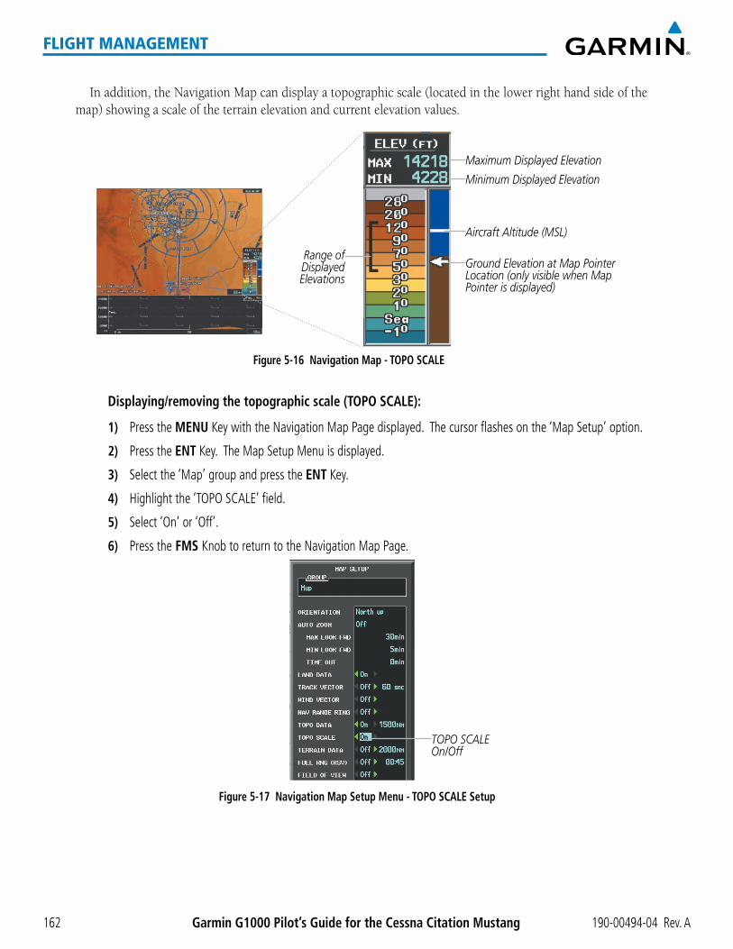
Garmin G1000 Pilot’s Guide for the Cessna Citation Mustang 190-00494-04 Rev. A162
FLIGHT MANAGEMENT
In addition, the Navigation Map can display a topographic scale (located in the lower right hand side of the map) showing a scale of the terrain elevation and current elevation values.
Figure 5-16 Navigation Map - TOPO SCALE
Maximum Displayed Elevation
Minimum Displayed Elevation
Aircraft Altitude (MSL)
Ground Elevation at Map Pointer Location (only visible when Map Pointer is displayed)
Range of Displayed Elevations
Displaying/removing the topographic scale (TOPO SCALE):
1) Press the MENU Key with the Navigation Map Page displayed. The cursor flashes on the ‘Map Setup’ option.
2) Press the ENT Key. The Map Setup Menu is displayed.
3) Select the ‘Map’ group and press the ENT Key.
4) Highlight the ‘TOPO SCALE’ field.
5) Select ‘On’ or ‘Off’.
6) Press the FMS Knob to return to the Navigation Map Page.
Figure 5-17 Navigation Map Setup Menu - TOPO SCALE Setup
TOPO SCALE On/Off

190-00494-04 Rev. A Garmin G1000 Pilot’s Guide for the Cessna Citation Mustang 163
FLIGHT MANAGEMENT
MAP SYMBOLSThis section discusses the types of land and aviation symbols that can be displayed. Each listed type of symbol
can be turned on or off, and the maximum range to display each symbol can be set. The decluttering of the symbols from the map using the DCLTR Softkey is also discussed.
LAND SYMBOLS
The following items are configured on the land menu:
Land Symbols(Text label size can be None, Small, Medium (Med), or Large (Lrg))
Symbol Default Range (nm)
Maximum Range (nm)
Latitude/Longitude (LAT/LON) Off 2000
Highways and Roads
Interstate Highway (FREEWAY) 300 800
International Highway (FREEWAY) 300 800
US Highway (NATIONAL HWY) 30 80
State Highway (LOCAL HWY) 15 30
Local Road (LOCAL ROAD) N/A 8 15
Railroads (RAILROAD) 15 30
LARGE CITY (> 200,000) 800 1500
MEDIUM CITY (> 50,000) 100 200
SMALL CITY (> 5,000) 20 50States and Provinces (STATE/PROV) 800 1500
Rivers and Lakes (RIVER/LAKE) 200 500
USER WAYPOINT 150 300
Table 5-1 Land Symbol Information

Garmin G1000 Pilot’s Guide for the Cessna Citation Mustang 190-00494-04 Rev. A164
FLIGHT MANAGEMENT
AVIATION SYMBOLS
The following items are configured on the aviation menu:
Aviation Symbols(Text label size can be None, Small, Medium (Med), or Large (Lrg))
Symbol Default Range (nm)
Maximum Range (nm)
Active Flight Plan Leg (ACTIVE FPL) 2000 2000
Non-active Flight Plan Leg (ACTIVE FPL) 2000 2000
Active Flight Plan Waypoint (ACTIVE FPL WPT) See Airports, NAVAIDs 2000 2000Large Airports (LARGE APT)
250 500Medium Airports (MEDIUM APT) 150 300Small Airports (SMALL APT) 50 100Taxiways (SAFETAXI) See Additional Features 3 20Runway Extension (RWY EXTENSION) N/A Off 100Intersection (INT WAYPOINT) 15 30
Non-directional Beacon (NDB WAYPOINT) 15 30
VOR (VOR WAYPOINT)
150 300
Class B Airspace/TMA (CLASS B/TMA) 200 500
Class C Airspace/TCA (CLASS C/TCA) 200 500
Class D Airspace (CLASS D) 150 300
Restricted Area (RESTRICTED) 200 500
Military Operations Area [MOA(MILITARY)] 200 500
Other/Air Defense Interdiction Zone (OTHER/ADIZ) 200 500
Temporary Flight Restriction (TFR) 500 2000
Table 5-2 Aviation Symbol Information

190-00494-04 Rev. A Garmin G1000 Pilot’s Guide for the Cessna Citation Mustang 165
FLIGHT MANAGEMENT
SYMBOL SETUP
All pages with maps can display land symbols (roads, lakes, borders, etc). Land symbols can be removed totally (turned off).
Displaying/removing all land symbols:
1) Press the MENU Key with the Navigation Map Page displayed. The Page Menu is displayed and the cursor flashes on the ‘Map Setup’ option.
2) Press the ENT Key. The Map Setup Group Menu is displayed and the cursor flashes on the ‘Map’ option.
3) Highlight the ‘LAND DATA’ field.
4) Select ‘On’ or ‘Off’.
5) Press the FMS Knob to return to the Navigation Map Page.
Figure 5-18 Navigation Map Setup Menu - LAND DATA Setup
LAND DATA On/Off
Thelabelsize(TEXT)setsthesizeatwhichlabelsappearonthedisplay(none,small,medium,andlarge).The range (RNG) sets the maximum range at which items appear on the display.
Selecting a ‘Land’ or ‘Aviation’ group item text size and range:
1) Press the MENU Key with the Navigation Map Page displayed. The cursor flashes on the ‘Map Setup’ option.
2) Press the ENT Key. The Map Setup Menu is displayed.
3) Select the ‘Land’ or ‘Aviation’ group.
4) Press the ENT Key. The cursor flashes on the first field.
5) Select the desired land option.
6) Select the desired text size.
7) Press the ENT Key to accept the selected size.
8) Select the desired range.

Garmin G1000 Pilot’s Guide for the Cessna Citation Mustang 190-00494-04 Rev. A166
FLIGHT MANAGEMENT
9) Press the ENT Key to accept the selected range.
10) Press the FMS Knob to return to the Navigation Map Page.
Figure 5-19 Navigation Map Setup Menu - LAND GROUP Setup
Maximum Display Range Text Label Size(None, Small, Med, or Lrg)
Figure 5-20 Navigation Map Setup Menu - AVIATION GROUP Setup
Maximum Display Range Text Label Size
(None, Small, Med, or Lrg)
NOTE: Since the PFD Inset Map is much smaller than the MFD navigation maps, items are removed on the PFD Inset Map two range levels smaller than the range selected in the Map Setup pages (e.g., a setting of 100 nm removes the item at ranges above 100 nm on MFD navigation maps, while the PFD Inset Map removes the same item at 50 nm).

190-00494-04 Rev. A Garmin G1000 Pilot’s Guide for the Cessna Citation Mustang 167
FLIGHT MANAGEMENT
MAP DECLUTTER
The declutter feature allows the pilot to progressively step through four levels of removing map information. The declutter level is displayed in the DCLTR Softkey and next to the Declutter Menu Option.
Figure 5-21 Navigation Map - Declutter Level Indications
Declutter Level
Navigation Map Page Menu
DCLTR Softkey
Decluttering the map:
Select the DCLTR Softkey with the Navigation Map Page displayed (the current declutter level is shown on the softkey). With each softkey selection, another level of map information is removed.
Or:
1) Press the MENU Key with the Navigation Map Page displayed.
2) Select ‘Declutter’. The current declutter level is shown.
3) Press the ENT Key.
Decluttering the PFD Inset Map:
1) Press the INSET Softkey.
2) Press the DCLTR Softkey. The current declutter level is shown. With each selection, another level of map information is removed.

Garmin G1000 Pilot’s Guide for the Cessna Citation Mustang 190-00494-04 Rev. A168
FLIGHT MANAGEMENT
Table5-3liststheitemsdisplayedateachdeclutterlevel.The‘X’representsmapitemsdisplayedforthevarious levels of declutter.
Item No Declutter Declutter-1 Declutter-2 Declutter-3Flight Plan Route Lines X X X XFlight Plan Route Waypoints X X X XRivers/Lakes X X X XTopography Data X X X XInternational Borders X X X XTrack Vector X X X XNavigation Range Ring X X X XFuel Range Ring X X X XTerrain Data X X X XTraffic X X X XAirways X X X XNEXRAD X X XXM Lightning Data X X XAirports X X XRunway Labels X X XRestricted X X XMOA (Military) X X XUser Waypoints X XLatitude/Longitude Grid X XNAVAIDs X XClass B Airspaces/TMA X XClass C Airspaces/TCA X XClass D Airspaces X XOther Airspaces/ADIZ X XTFRs X XObstacles X XLand/Country Text XCities XRoads XRailroads XState/Province Boundaries XRiver/Lake Names X
Table 5-3 Navigation Map Items Displayed by Declutter Level

190-00494-04 Rev. A Garmin G1000 Pilot’s Guide for the Cessna Citation Mustang 169
FLIGHT MANAGEMENT
AIRWAYSThis airways discussion is based upon the North American airway structure. The airway structure in places
other than North America vary by location, etc. and are not discussed in this book. Low Altitude Airways (or Victor Airways) primarily serve smaller piston-engine, propeller-driven airplanes on shorter routes and at lower altitudes. Airways are eight nautical miles wide and start 1,200 feet above ground level (AGL) and extend up to 18,000 feet mean sea level (MSL). Low Altitude Airways are designated with a “V” before the airway number (hence the name “Victor Airways”) since they run primarily between VORs.
High Altitude Airways (or Jet Routes) primarily serve airliners, jets, turboprops, and turbocharged piston aircraft operating above 18,000 feet MSL. Jet Routes start at 18,000 feet MSL and extend upward to 45,000 feet MSL (altitudes above 18,000 feet are called “flight levels” and are described as FL450 for 45,000 feet MSL). Jet Routes are designated with a “J” before the route number.
Low Altitude Airways are drawn in gray (the same shade used for roads). High Altitude Airways are drawn in green. When both types of airways are displayed, High Altitude Airways are drawn on top of Low Altitude Airways.
When airways are selected for display on the map, the airway waypoints (VORs, NDBs and Intersections) are also displayed.
Figure 5-22 Airways on MFD Navigation Page
Low Altitude Airway(Victor Airway)
High Altitude Airway(Jet Route)

Garmin G1000 Pilot’s Guide for the Cessna Citation Mustang 190-00494-04 Rev. A170
FLIGHT MANAGEMENT
Airways may be displayed on the map at the pilot’s discretion using either a combination of AIRWAYS Softkey selections, or menu selections using the MENU Key from the Navigation Map Page. The Airway range can also be programmed to only display Airways on the MFD when the map range is at or below a specific number.
Displaying/removing airways:
1) Select the MAP Softkey.
2) Select the AIRWAYS Softkey. Both High and Low Altitude Airways are displayed (AIRWY ON).
3) Select the softkey again to display Low Altitude Airways only (AIRWY LO).
4) Select the softkey again to display High Altitude Airways only (AIRWY HI).
5) Select the softkey again to remove High Altitude Airways. No airways are displayed (AIRWAYS).
Or:
1) Press the MENU Key with the Navigation Map Page displayed. The cursor flashes on the ‘Map Setup’ option.
2) Press the ENT Key. The Map Setup Menu is displayed.
3) Turn the small FMS Knob to select the ‘Airways’ group, and press the ENT Key.
4) Turn the large FMS Knob to highlight the ‘AIRWAYS’ field.
5) Turn the FMS Knob to select ‘Off’, ‘All’, ‘LO Only’, or ‘HI Only’, and press the ENT Key.
6) Press the FMS Knob to return to the Navigation Map Page.
Figure 5-23 Navigation Map Setup Menu - AIRWAYS Setup
Low Altitude Airway Range
High Altitude Airway Range
Airway Display SelectionOff, All, LO ALT Only, HI ALT Only
The airway range is the maximum map range on which airways are displayed.
Selecting an airway range (LOW ALT AIRWAY or HI ALT AIRWAY):
1) Press the MENU Key with the Navigation Map Page displayed. The cursor flashes on the ‘Map Setup’ option.
2) Press the ENT Key. The Map Setup Menu is displayed.
3) Turn the small FMS Knob to select the ‘Airways’ group, and press the ENT Key.
4) Highlight the ‘LOW ALT AIRWAY’ or ‘HI ALT AIRWAY’ range field.
5) To change the range setting, turn the small FMS Knob to display the range list.
6) Select the desired range using the small FMS Knob.
7) Press the ENT Key.
8) Press the FMS Knob to return to the Navigation Map Page.

190-00494-04 Rev. A Garmin G1000 Pilot’s Guide for the Cessna Citation Mustang 171
FLIGHT MANAGEMENT
The following range items are configurable on the airways menu:
Airway Type Symbol Default Range (nm)
Maximum Range (nm)
Low Altitude Airway (LOW ALT AIRWAY) 200 500
High Altitude Airway (HI ALT AIRWAY) 300 500
Table 5-4 Airway Range Information
TRACK VECTORThe Navigation Map can display a track vector that is useful in minimizing track angle error. The track vector
is a solid light blue line segment extended to a predicted location. The track vector look-ahead time is selectable (30 sec, 60 sec (default), 2 min, 5 min, 10 min, 20 min) and determines the length of the track vector. The track vector shows up to 90 degrees of a turn for the 30 and 60 second time settings.
Figure 5-24 Navigation Map -Track Vector
Track Vector
Displaying/removing the track vector:
1) Press the MENU Key with the Navigation Map Page displayed. The cursor flashes on the ‘Map Setup’ option.
2) Press the ENT Key. The Map Setup Menu is displayed.
3) Select the ‘Map’ group.
4) Press the ENT Key.
5) Highlight the ‘TRACK VECTOR’ field.
6) Select ‘On’ or ‘Off’. Press the ENT Key to accept the selected option. The flashing cursor highlights the look ahead time field. Use the FMS Knob to select the desired time. Press the ENT Key.
7) Press the FMS Knob to return to the Navigation Map Page.

Garmin G1000 Pilot’s Guide for the Cessna Citation Mustang 190-00494-04 Rev. A172
FLIGHT MANAGEMENT
Figure 5-25 Navigation Map Setup Menu -TRACK VECTOR, WIND VECTOR, NAV RANGE RING, FUEL RANGE RING Setup
Track Vector - On/Off - Look Ahead Time
Fuel Range - On/Off - Fuel Reserve Time
Wind Vector On/Off
Nav Range Ring On/Off
WIND VECTORThe map displays a wind vector arrow in the upper right-hand portion of the screen. Wind vector information
is displayed as a white arrow pointing in the direction in which the wind is moving for wind speeds greater than orequalto1kt.
Figure 5-26 Navigation Map - Wind Vector
Wind Direction Wind Speed
NOTE: The wind vector is not displayed until the aircraft is moving. It is not displayed on the Waypoint Information pages.
Displaying/removing the wind vector:
1) Press the MENU Key with the Navigation Map Page displayed. The cursor flashes on the ‘Map Setup’ option.
2) Press the ENT Key. The Map Setup Menu is displayed.
3) Select the ‘Map’ group.
4) Press the ENT Key.
5) Highlight the ‘WIND VECTOR’ field.
6) Select ‘On’ or ‘Off’.
7) Press the FMS Knob to return to the Navigation Map Page.

190-00494-04 Rev. A Garmin G1000 Pilot’s Guide for the Cessna Citation Mustang 173
FLIGHT MANAGEMENT
NAV RANGE RINGThe Nav Range Ring shows the direction of travel (ground track) on a rotating compass card. The range is
determined by the map range. The range is 1/4 of the map range (e.g., 37.5 nm on a 150 nm map).
Figure 5-27 Navigation Map - Nav Range Ring
Nav Range Ring
Range (radius)
NOTE: The Nav Range Ring is not displayed on the Waypoint Information pages, Nearest pages, or Direct-to Window map.
Displaying/removing the Nav Range Ring:
1) Press the MENU Key with the Navigation Map Page displayed. The cursor flashes on the ‘Map Setup’ option.
2) Press the ENT Key. The Map Setup Menu is displayed.
3) Select the ‘Map’ group.
4) Press the ENT Key.
5) Highlight the ‘NAV RANGE RING’ field.
6) Select ‘On’ or ‘Off’.
7) Press the FMS Knob to return to the Navigation Map Page.
NOTE: The Nav Range Ring is referenced to either magnetic or true north, based on the selection on the AUX - System Setup Page.

Garmin G1000 Pilot’s Guide for the Cessna Citation Mustang 190-00494-04 Rev. A174
FLIGHT MANAGEMENT
FUEL RANGE RINGThe map can display a fuel range ring which shows the remaining flight distance. A dashed green circle
indicates the selected range to reserve fuel. A solid green circle indicates the total endurance range. If only reserve fuel remains, the range is indicated by a solid yellow circle.
Figure 5-28 Navigation Map - Fuel Range Ring
Range to Reserve Fuel
Total Endurance Range
Time to Reserve Fuel
Displaying/removing the fuel range ring and selecting a fuel range time:
1) Press the MENU Key with the Navigation Map Page displayed. The cursor flashes on the ‘Map Setup’ option.
2) Press the ENT Key. The Map Setup Menu is displayed.
3) Select the ‘Map’ group.
4) Press the ENT Key.
5) Highlight the ‘FUEL RNG (RSV)’ field.
6) Select ‘On’ or ‘Off’.
7) Highlight the fuel reserve time field. This time should be set to the amount of flight time equal to the amount of fuel reserve desired.
8) To change the reserve fuel time, enter a time (00:00 to 23:59; hours:minutes). The default setting is 00:45 minutes.
9) Press the ENT Key.
10) Press the FMS Knob to return to the Navigation Map Page.

190-00494-04 Rev. A Garmin G1000 Pilot’s Guide for the Cessna Citation Mustang 175
FLIGHT MANAGEMENT
FIELD OF VIEW (SVS)The map can display the boundaries of the PFD Synthetic Vision System (SVS) lateral field of view. The field
of view is shown as two dashed lines forming a V shape in front of the aircraft symbol on the map. This is only available if SVS is installed on the aircraft.
Figure 5-29 Navigation Map - Field of View
Lateral Field of View
Boundaries
Displaying/removing the field of view:
1) Press the MENU Key with the Navigation Map Page displayed. The cursor flashes on the ‘Map Setup’ option.
2) Press the ENT Key. The Map Setup Menu is displayed.
3) Select the ‘Map’ group.
4) Press the ENT Key.
5) Highlight the ‘FIELD OF VIEW’ field.
6) Select ‘On’ or ‘Off’.
7) Press the FMS Knob to return to the Navigation Map Page.

Garmin G1000 Pilot’s Guide for the Cessna Citation Mustang 190-00494-04 Rev. A176
FLIGHT MANAGEMENT
SELECTED ALTITUDE INTERCEPT ARCThe map can display the location along the current track where the aircraft will intercept the selected altitude.
The location will be shown as a light blue arc when the aircraft is actuallly climbing or descending.
Figure 5-30 Navigation Map - Range to Altitude Arc
Range to Altitude Arc
Displaying/removing the selected altitude intercept arc:
1) Press the MENU Key with the Navigation Map Page displayed. The cursor flashes on the ‘Map Setup’ option.
2) Press the ENT Key. The Map Setup Menu is displayed.
3) Select the ‘Map’ group.
4) Press the ENT Key.
5) Highlight the ‘SEL ALT ARC’ field.
6) Select ‘On’ or ‘Off’.
7) Press the FMS Knob to return to the Navigation Map Page.

190-00494-04 Rev. A Garmin G1000 Pilot’s Guide for the Cessna Citation Mustang 177
FLIGHT MANAGEMENT
5.3 WAYPOINTS
Waypoints are predetermined geographical positions (internal database) or pilot-entered positions, and are used for all phases of flight planning and navigation.
Communicationandnavigationfrequenciescanbetuned“automatically”fromvariousWaypointInformation(WPT) pages, Nearest (NRST) pages, and the Nearest Airports Window (on PFD). This auto-tuning feature simplifiesfrequencyentryovermanualtuning.RefertotheAudioPanelandCNSsectionfordetailsonauto-tuning.
Waypoints can be selected by entering the ICAO identifier, entering the name of the facility, or by entering the city name. See the System Overview section for detailed instructions on entering data in the G1000. As a waypoint identifier, facility name, or location is entered, the G1000’s Spell’N’Find™ feature scrolls through the database, displaying those waypoints matching the characters which have been entered to that point. A direct-to navigation leg to the selected waypoint can be initiated by pressing the Direct-to Key on any of the waypoint pages.
Figure 5-31 Waypoint Information Window
Map Area Showing Entered Waypoint
Identifier Entry Field
Entered Waypoint on Map
Facility Entry Field
City Entry Field
- Waypoint Identifier- Type (symbol)- Facility Name- City
Waypoint Location
If duplicate entries exist for the entered facility name or location, additional entries may be viewed by continuing to turn the small FMS Knob during the selection process. If duplicate entries exist for an identifier, a Duplicate Waypoints Window is displayed when the ENT Key is pressed.

Garmin G1000 Pilot’s Guide for the Cessna Citation Mustang 190-00494-04 Rev. A178
FLIGHT MANAGEMENT
Figure 5-32 Waypoint Information Window - Duplicate Identifier
Duplicate Message
Identifier with Duplicates
Duplicate Waypoints
AIRPORTS
NOTE: ‘North Up’ orientation on the Airport Information Page cannot be changed; the pilot needs to be aware of proper orientation if the Navigation Map orientation is different from the Airport Information Page Map.
The Airport Information Page is the first page in WPT group and allows the pilot to view airport information, loadfrequencies(COM,NAV,andlighting),reviewrunways,andreviewinstrumentproceduresthatmaybeinvolvedintheflightplan.SeetheAudioPanelandCNSSectionformoreinformationonloadingfrequencies(auto-tuning). After engine startup, the Airport Information Page defaults to the airport where the aircraft is located. After a flight plan has been loaded, it defaults to the destination airport. On a flight plan with multiple airports, it defaults to the airport which is the current active waypoint.
In addition to displaying a map of the currently selected airport and surrounding area, the Airport Information Pagedisplaysairportinformationinthreeboxeslabeled‘AIRPORT’,‘RUNWAYS’,and‘FREQUENCIES’.Forairports with multiple runways, information for each runway is available. This information is viewed on the Airport Information Page by pressing the INFO softkey until INFO-1 is displayed.

190-00494-04 Rev. A Garmin G1000 Pilot’s Guide for the Cessna Citation Mustang 179
FLIGHT MANAGEMENT
Figure 5-33 Airport Information Page
Airport/Runway Diagram
Navigation MapShowing Selected
Airport
Runway Information - Designation - Length/Width/Surface - Lighting Available
Airport Information - ID/Facility/City - Usage Type/Region - Lat/Long/Elev - Fuel Available - Time Zone (UTC Offset)
COM/NAV Freq. Info. - Identification - Frequency - Availability - Additional Information
Softkeys
The following descriptions and abbreviations are used on the Airport Information Page:
•Usagetype:Public,Military,Private,orHeliport
•Runwaysurfacetype:Hard,Turf,Sealed,Gravel,Dirt,Soft,Unknown,orWater
•Runway lighting type: No Lights, Part Time, Full Time, Unknown, or PCL Freq (for pilot-controlledlighting)
•COMAvailability:TX(transmitonly),RX(receiveonly),PT(parttime),i(additionalinformationavailable)

Garmin G1000 Pilot’s Guide for the Cessna Citation Mustang 190-00494-04 Rev. A180
FLIGHT MANAGEMENT
Figure 5-34 Airport Directory Page Example
Airport Information - ID/Facility/City
- Usage Type/Region
Airport Directory Information
Softkeys
The AOPA directory information is viewed on the Airport Directory Page by pressing the INFO softkey until INFO-2 is displayed. The following are types of AOPA airport directory information shown (if available) on the Airport Directory Page:
•Airport: Identifier, Site Number, Name, City, State
•Traffic Patteren Altitudes (TPA): Aircraft Class/Altitude
•Runway: Headings, Length, Width, Obstructions, Surface
•Phones: Phone/Fax Numbers •Weather: Service Type, Frequency,PhoneNumber
•Obstructions: General Airport Obstructions
•Hours: Facility Hours, Light Hours, Tower Hours, Beacon Hours
•Flight Service Station (FSS): FSS Name, Phone Numbers
•Special Operations at Airport
•Location: Sectional, Magnetic Variation
•Instrument Approaches: Published Approach, Frequency
•Services Available: Category, Specific Service
•Frequencies:Type/Frequency •NAVAIDS: Type, Identifier, Frequency,Radial,Distance
•Notes: Airport Notes
•Transportation: Ground Transportation Type Available
•Noise: Noise Abatement Procedures
•Pilot Controlled Lighting: High/Med/Low Clicks/Second
•Approach: Approach Facility Name, Frequency, FrequencyParameter
•Charts: Low Altitude Chart Number
•FBO: Type, Frequencies,Services, Fees, Fuel, Credit Cards, Phone/Fax Numbers

190-00494-04 Rev. A Garmin G1000 Pilot’s Guide for the Cessna Citation Mustang 181
FLIGHT MANAGEMENT
Selecting an airport for review by identifier, facility name, or location:
1) From the Airport Information Page, press the FMS Knob.
2) Use the FMS Knobs and enter an identifier, facility name, or location.
3) Press the ENT Key.
4) Press the FMS Knob to remove the cursor.
Selecting a runway:
1) With the Airport Information Page displayed, press the FMS Knob to activate the cursor.
2) Turn the large FMS Knob to place the cursor in the ‘RUNWAYS’ Box, on the runway designator.
3) Turn the small FMS Knob to display the desired runway (if more than one) for the selected airport.
4) To remove the flashing cursor, press the FMS Knob.
View a destination airport:
From the Airport Information Page press the MENU Key. Select ‘View Destination Airport’. The Destination Airport is displayed.
TheAirportFrequenciesBoxusesthedescriptionsandabbreviationslistedinthefollowingtable:
Communication Frequencies Navigation FrequenciesApproach *Arrival *ASOSATISAWOSCenterClass B *Class C *Clearance
ControlCTA *Departure *GateGroundHelicopterMulticomOther
Pre-TaxiRadarRampTerminal *TMA *TowerTRSA *Unicom
ILSLOC
* May include Additional Information
Table 5-5 Airport Frequency Abbreviations
A departure, arrival, or approach can be loaded using the softkeys on the Airport Information Page. See the Procedures section for details. METARs or TAFs applicable to the selected airport can be selected for display (see
the Hazard Avoidance section for details about weather).
The G1000 provides a NRST Softkey on the PFD,which gives the pilot quick access tonearest airport information(veryuseful ifanimmediatelandingisrequired). TheNearestAirportsWindowdisplaysalistof up to 25 nearest airports (three entries can be displayed at one time). If there are more than three they are displayed in a scrollable list. If there are no nearest airports available, “NONE WITHIN 200NM” is displayed.

Garmin G1000 Pilot’s Guide for the Cessna Citation Mustang 190-00494-04 Rev. A182
FLIGHT MANAGEMENT
Figure 5-35 Nearest Airports Window on PFD
COM Freq. Info. - Identification
- Frequency
Airport Identifier/Type
Length of Longest Runway
Approach Available
Additional Airports (within 200 nm)
NRST Softkey
Bearing/Distance to Airport
Pressing the ENT Key displays the PFD Airport Information Window for the highlighted airport. Pressing the ENT Key again returns to the Nearest Airports Window with the cursor on the next airport in the list. Continued presses of the ENTKeysequencesthroughtheinformationpagesforallairportsintheNearestAirportslist.
Figure 5-36 Airport Information Window on PFD
Airport Information - Usage/Time/Elev - Region
Airport Information - Lat/Long
Airport Information - ID/Type/City
- Facility
The Nearest Airports Page on the MFD is first in the group of NRST pages because of its potential use in the event of an in-flight emergency. In addition to displaying a map of the currently selected airport and surrounding area, the page displays nearestairportinformationinfiveboxeslabeled‘NEARESTAIRPORTS’,‘INFORMATION’,‘RUNWAYS’,‘FREQUENCIES’,and‘APPROACHES’.
The selected airport is indicated by a white arrow, and a dashed white line is drawn on the navigation map fromtheaircraftpositiontothenearestairport.Uptofournearestairports,onerunway,uptosixfrequencies,and up to six approaches are visible at one time. If there are more than can be shown, each list can be scrolled. If there are no items for display in a boxed area, text indicating that fact is displayed. The currently selected airport remains in the list until it is unselected.

190-00494-04 Rev. A Garmin G1000 Pilot’s Guide for the Cessna Citation Mustang 183
FLIGHT MANAGEMENT
Figure 5-37 Nearest Airport Page
Nearest Airport
Navigation MapShowing Nearest
Airport
Runway Information - Designation/Surface - Length/Width
Nearest Airports - ID/Type - Bearing/Distance
COM/NAV Freq. Info. - Identification - Frequency
Window Selection Softkeys
Airport Information - Facility/City/Elevation
Approaches Available
LD APR Softkey (only available if an approach is highlighted)
Viewing information for a nearest airport on the PFD:
1) Press the NRST Softkey to display the Nearest Airports Window. Press the FMS Knob to activate the cursor.
2) Highlight the airport identifier with the FMS Knob and press the ENT Key to display the Airport Information Window.
3) To return to the Nearest Airports Window press the ENT Key (with the cursor on ‘BACK’) or press the CLR Key. The cursor is now on the next airport in the nearest airports list. (Repeatedly pressing the ENT Key moves through the airport list, alternating between the Nearest Airports Window and the Airport Information Window.)
4) Press the CLR Key or the NRST Softkey to close the PFD Nearest Airports Window.
Viewing information for a nearest airport on the MFD:
1) Turn the large FMS Knob to select the NRST page group.
2) Turn the small FMS Knob to select the Nearest Airports Page (it is the first page of the group, so it may already be selected). If there are no Nearest Airports available, “NONE WITHIN 200 NM” is displayed.
3) Select the APT Softkey; or press the FMS Knob; or press the MENU Key, highlight ‘Select Airport Window’ and press the ENT Key. The cursor is placed in the ‘NEAREST AIRPORTS’ Box. The first airport in the nearest airports list is highlighted.
4) Turn the FMS Knob to highlight the desired airport. (Pressing the ENT Key also moves to the next airport.)
5) Press the FMS Knob to remove the flashing cursor.

Garmin G1000 Pilot’s Guide for the Cessna Citation Mustang 190-00494-04 Rev. A184
FLIGHT MANAGEMENT
Viewing runway information for a specific airport:
1) With the Nearest Airports Page displayed, press the RNWY Softkey; or press the MENU Key, highlight ‘Select Runway Window’; and press the ENT Key. The cursor is placed in the ‘RUNWAYS’ Box.
2) Turn the small FMS Knob to select the desired runway.
3) Press the FMS Knob to remove the flashing cursor.
SeetheAudioPanelandCNSSectionforfrequencyselectionandtheProceduressectionforapproaches.
The Nearest Airports Box on the System Setup Page defines the minimum runway length and surface type used when determining the 25 nearest airports to display on the MFD Nearest Airports Page. A minimum runway length and/or surface type can be entered to prevent airports with small runways or runways that are not appropriately surfaced from being displayed. Default settings are 0 feet (or meters) for runway length and “HARD/SOFT” for runway surface type.
Selecting nearest airport surface matching criteria:
1) Use the FMS Knob to select the System Setup Page.
2) Press the FMS Knob momentarily to activate the flashing cursor.
3) Turn the large FMS Knob to highlight the runway surface field in the Nearest Airports Box.
4) Turn the small FMS Knob to select the desired runway option (ANY, HARD ONLY, HARD/SOFT).
5) Press the ENT Key.
6) Press the FMS Knob to remove the flashing cursor.
Selecting nearest airport minimum runway length matching criteria:
1) Use the FMS Knob to select the System Setup Page.
2) Press the FMS Knob momentarily to activate the flashing cursor.
3) Turn the large FMS Knob to highlight the minimum length field in the Nearest Airport Box.
4) Use the FMS Knob to enter the minimum runway length (zero to 25,000 feet) and press the ENT Key.
5) Press the FMS Knob to remove the flashing cursor.
Figure 5-38 System Setup Page - Nearest Airport Selection Criteria
Nearest Airport Criteria - Type of Runway Surface - Minimum Runway Length

190-00494-04 Rev. A Garmin G1000 Pilot’s Guide for the Cessna Citation Mustang 185
FLIGHT MANAGEMENT
INTERSECTIONS
NOTE: The VOR displayed on the Intersection Information Page is the nearest VOR, not necessarily the VOR used to define the intersection.
The Intersection Information Page is used to view information about intersections. In addition to displaying a map of the currently selected intersection and surrounding area, the Intersection Information Page displays intersectioninformationinthreeboxeslabeled‘INTERSECTION’,‘INFORMATION’,and‘NEARESTVOR’.
Figure 5-39 Intersection Information Page
Selected Intersection
Navigation MapShowing Selected
Intersection
Intersection Identifier
Nearest VOR Info - Identifier/Type (symbol) - Radial to VOR - Distance to VOR
Intersection Info - Region - Lat/Long
Selecting an intersection:
1) With the Intersection Information Page displayed, enter an identifier in the Intersection Box.
2) Press the ENT Key.
3) Press the FMS Knob to remove the flashing cursor.
Or:
1) With the Nearest Intersections Page displayed, press the FMS Knob.
2) Press the ENT Key or turn either FMS Knob to select an identifier in the Nearest Intersection Box.
3) Press the FMS Knob to remove the flashing cursor.

Garmin G1000 Pilot’s Guide for the Cessna Citation Mustang 190-00494-04 Rev. A186
FLIGHT MANAGEMENT
TheNearestIntersectionsPagecanbeusedtoquicklyfindanintersectionclosetotheflightpath.Inadditionto displaying a map of the surrounding area, the page displays information for up to 25 nearest intersections in threeboxeslabeled‘NEARESTINT’,‘INFORMATION’,and‘REFERENCEVOR’.
The selected intersection is indicated by a white arrow. Up to sixteen Intersections are visible at a time. If there are more than can be shown, the list can be scrolled. If there are no items for display, text indicating that fact is displayed
NOTE: The list only includes waypoints that are within 200 nm.
Figure 5-40 Nearest Intersections Page
Nearest Intersection
Navigation MapShowing Nearest
Intersection
Intersection Information - Identifier/Symbol - Bearing/Distance to intersection from aircraft position
Reference VOR Info - Identifier/Type (symbol) - VOR Frequency - Bearing/Distance to VOR
Intersection Lat/Long