Further developments on the cfd flow analysis inside the volumatic® spacer
9
Area: Product Engineering ―Selected Proceedings from the 13th International Congress on Project Engineering‖. (Badajoz, July 2009) FURTHER DEVELOPMENTS ON THE CFD FLOW ANALYSIS INSIDE THE VOLUMATIC ® SPACER Rebelo, R. Oliveira, R. Silva, L. F. Teixeira, S. Teixeira, J.C. School of Engineering, University of Minho, Campus Azurém Antunes, H. Pediatrics Service, S. Marcos Hospital, Largo Carlos Amarante Abstract In recent years, allergic diseases, particularly asthma, have been acquiring an increasing importance in the developed countries, due to the rising of its prevalence and morbidity and the economic burden associated. In the preventive and urgent treatment of asthma, the oral pharmacological therapeutics assumes a major role. Therefore, this paper will report another step further to the research been undertaken at the University of Minho, to understand the behaviour of drug flow inside a spacer device, combined with pressurized metered-dose inhalers (or pMDIs), based on the use of Computational Fluid Dynamics (CFD) tools to study multiphase flows inside a Volumatic® spacer device. This paper will present the two respiratory cycles used in the simulations. It will also report the analysis of the obtained results with the Volumatic® spacer using two different grid types (T- Grid and Cooper). With the obtained conclusions, it will be identified some new geometry possibilities for spacer devices (in terms of valve and body). Future work will be addressed to the study of these spacer geometry modifications. Keywords: Asthma; Respiratory flow; Volumatic® spacer; Computational Fluid Dynamics (CFD). 1. Introduction Asthma is a chronic disease most common in children and young people and, therefore, is a major public health problem. This disease has a rate of incidence and prevalence in growth, both in Portugal and the world, and is a major cause of hospitalization and reduced quality of life of asthma patients. Furthermore, asthma is responsible for the death of 220000 individuals per year around the world. Oral based pharmacological therapeutic approaches assume a major role both in the prevention and urgent treatment of asthma. This requires among other services, the selection of the most appropriate medication for the patient. Several inhalation devices are available for the administration of drugs, which includes pressurized metered-dose inhalers (or pMDIs) coupled with spacers. The use of pressurized inhalers with spacers minimizes the problems of a poor inhalation technique associated with the use of pMDIs. Nevertheless a careful selection of the most appropriate inhalation device is necessary for each patient. For children, it is essential to consider their small inspiratory volume and their poor inhalation technique. Although there are a wide variety of devices for the administration of drugs in the bronchial tree that have shown encouraging results, most of the drug does not 443
Transcript of Further developments on the cfd flow analysis inside the volumatic® spacer
Area: Product Engineering
―Selected Proceedings from the 13th International Congress on Project Engineering‖. (Badajoz, July 2009)
FURTHER DEVELOPMENTS ON THE CFD FLOW ANALYSIS INSIDE
THE VOLUMATIC® SPACER
Rebelo, R.
Oliveira, R.
Silva, L. F.
Teixeira, S.
Teixeira, J.C.
School of Engineering, University of Minho, Campus Azurém
Antunes, H.
Pediatrics Service, S. Marcos Hospital, Largo Carlos Amarante
Abstract
In recent years, allergic diseases, particularly asthma, have been acquiring an increasing importance in the developed countries, due to the rising of its prevalence and morbidity and the economic burden associated. In the preventive and urgent treatment of asthma, the oral pharmacological therapeutics assumes a major role.
Therefore, this paper will report another step further to the research been undertaken at the University of Minho, to understand the behaviour of drug flow inside a spacer device, combined with pressurized metered-dose inhalers (or pMDIs), based on the use of Computational Fluid Dynamics (CFD) tools to study multiphase flows inside a Volumatic® spacer device.
This paper will present the two respiratory cycles used in the simulations. It will also report the analysis of the obtained results with the Volumatic® spacer using two different grid types (T-Grid and Cooper). With the obtained conclusions, it will be identified some new geometry possibilities for spacer devices (in terms of valve and body). Future work will be addressed to the study of these spacer geometry modifications.
Keywords: Asthma; Respiratory flow; Volumatic® spacer; Computational Fluid Dynamics
(CFD).
1. Introduction
Asthma is a chronic disease most common in children and young people and, therefore, is a major public health problem. This disease has a rate of incidence and prevalence in growth, both in Portugal and the world, and is a major cause of hospitalization and reduced quality of life of asthma patients. Furthermore, asthma is responsible for the death of 220000 individuals per year around the world. Oral based pharmacological therapeutic approaches assume a major role both in the prevention and urgent treatment of asthma. This requires among other services, the selection of the most appropriate medication for the patient. Several inhalation devices are available for the administration of drugs, which includes pressurized metered-dose inhalers (or pMDIs) coupled with spacers. The use of pressurized inhalers with spacers minimizes the problems of a poor inhalation technique associated with the use of pMDIs.
Nevertheless a careful selection of the most appropriate inhalation device is necessary for each patient. For children, it is essential to consider their small inspiratory volume and their poor inhalation technique. Although there are a wide variety of devices for the administration of drugs in the bronchial tree that have shown encouraging results, most of the drug does not
443

Area: Product Engineering
―Selected Proceedings from the 13th International Congress on Project Engineering‖. (Badajoz, July 2009)
reach the lungs; part is kept in the mouth and in the upper airways and only less than 20% of the drug can reach the lungs. This causes not only a loss of drug but also increases costs and produces undesirable side effects. Therefore, it is important to study the spacers in order to optimize the drug‘s distribution through the respiratory tract, with a smaller loss of drug [1].
The present work is targeted to the CFD study and analysis of the Volumatic® spacer, in order to understand the flow of the drug inside the spacer, during the respiratory cycle, which is important for the design of a new spacer.
2. Methodology
The Volumatic® (by Glaxo Wellcome Inc.) is considered a spacer of large volume (750 ml). It is made of polycarbonate and it is susceptible to electrostatic charge. It is one of the most commonly used spacers in all countries as well as by the Portuguese health service. This spacer, as shown in figure 1, is made up by three components: an adapter, a spacer‘s body
and a mouthpiece (this latter element has a valve that ensures a unidirectional flow). At one end of the spacer the pMDI is attached to the adapter and a mask or mouthpiece is fitted at the other end, where the patient inspires [1, 2].
The geometric model of the spacer was created in Gambit. This model is the basis to build the computational mesh, to create the control volumes required to solve the mathematical model used, as will be described later.
According to literature, a mesh consisting of hexahedrons elements (Hexahedral / Wedge Cooper) has a high quality. However, the use of a mesh with tetrahedrons elements (T-grid mesh) enables a significant reduction in the number of mesh elements and discretization errors [3]. Thus, it is important to use these two types of mesh in order to compare the simulation results.
Figure 1. The Volumatic® spacer.
On the other hand, and according to other results [2], a new spacer geometry has also been modeled, based on a pear-shaped body. This new design was also simulated using a Tetrahedrical/Hybrid T-Grid mesh.
3. Mathematical and Numerical model
The CFD is a powerful simulation technique for the analysis of fluid flow and heat transfer problems. CFD softwares are programmed using physical laws, such as the laws of conservation of mass, momentum and energy with appropriate boundary conditions [4].
The resulting equations take into account the viscosity, mass and other characteristics of the fluid, and are written using differential and integral calculations, which requires specialized computational techniques to solve them.
444
Area: Product Engineering
―Selected Proceedings from the 13th International Congress on Project Engineering‖. (Badajoz, July 2009)
One of the most used iterative techniques is the method of finite volumes [4]. For the use of this method it is necessary, first, to divide the spacer area into a number of control volumes, or elementary volumes, being necessary to create a computational mesh. This method is widely used and successful because it maintains the conservation properties at the level of elementary volumes.
As this method is based on the application of the conservation laws in the elementary volumes of the domain, it is necessary that the area is divided into volumes, so that in each one the conservation equations are obtained, which are in the form of algebraic equations rather than partial differential equations. This set of equations forms a system, which is solved in order to obtain the desired value of the parameters in each volume [4].
3.1 Definition of the velocity data input
In order to make the numerical simulations in Fluent as realistic as possible it is necessary to produce of an input of air velocity into the geometries, just likely the real respiratory cycle.
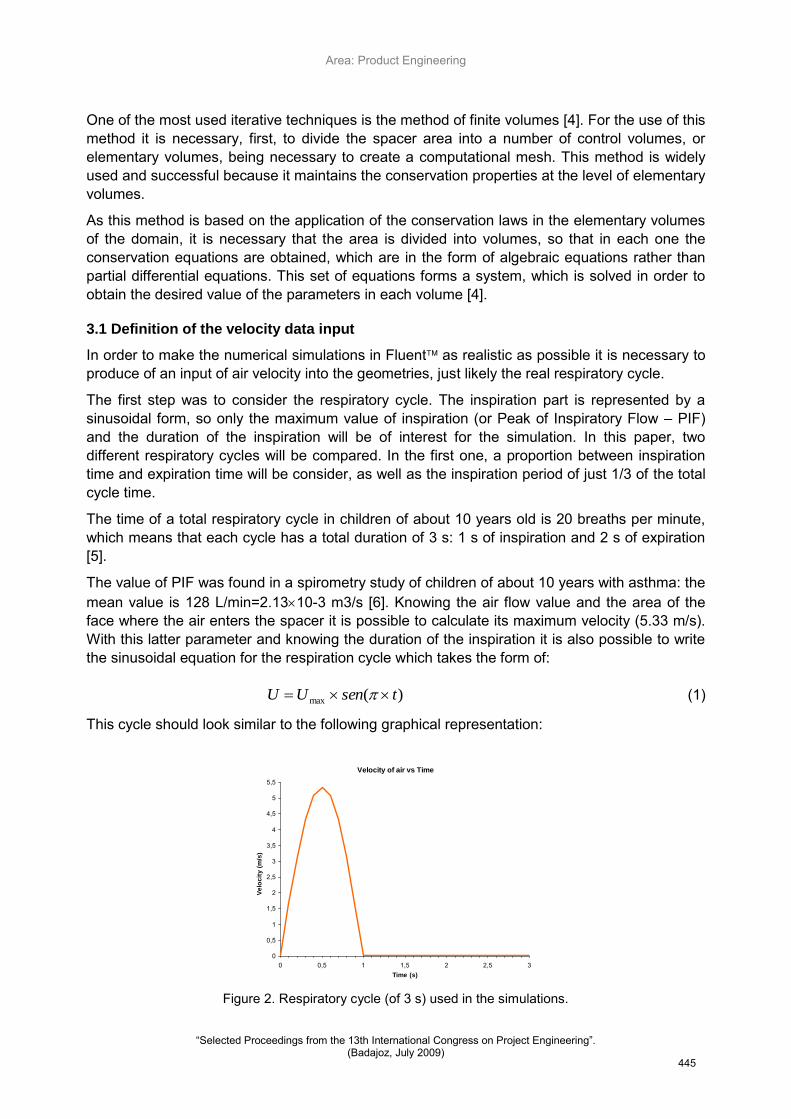
The first step was to consider the respiratory cycle. The inspiration part is represented by a sinusoidal form, so only the maximum value of inspiration (or Peak of Inspiratory Flow – PIF) and the duration of the inspiration will be of interest for the simulation. In this paper, two different respiratory cycles will be compared. In the first one, a proportion between inspiration time and expiration time will be consider, as well as the inspiration period of just 1/3 of the total cycle time.
The time of a total respiratory cycle in children of about 10 years old is 20 breaths per minute, which means that each cycle has a total duration of 3 s: 1 s of inspiration and 2 s of expiration [5].
The value of PIF was found in a spirometry study of children of about 10 years with asthma: the mean value is 128 L/min=2.1310-3 m3/s [6]. Knowing the air flow value and the area of the face where the air enters the spacer it is possible to calculate its maximum velocity (5.33 m/s). With this latter parameter and knowing the duration of the inspiration it is also possible to write the sinusoidal equation for the respiration cycle which takes the form of:
(1)
This cycle should look similar to the following graphical representation:
Figure 2. Respiratory cycle (of 3 s) used in the simulations.
)(max tsenUU
Velocity of air vs Time
0
0,5
1
1,5
2
2,5
3
3,5
4
4,5
5
5,5
0 0,5 1 1,5 2 2,5 3Time (s)
Ve
loc
ity
(m
/s)
.
445

Area: Product Engineering
―Selected Proceedings from the 13th International Congress on Project Engineering‖. (Badajoz, July 2009)
The second respiratory cycle considered has a period of 4 s, which can be divided into different stages: 0.4 s (ascendant phase), 1 s (maximum velocity), 1.6 s (descendent phase), 2 s (beginning of expiration) and 4 s (beginning of inspiration), reaching a maximum velocity of 6.5m/s, as shown in figure 3:
Figure 3. Respiratory cycle (of 4 s) used in the simulations.
Using the user defined function (or UDF) option in Fluent, two functions were written in C programming language to describe these two respiration cycles [7]. The duration of these two cycles are different, as well as the proportion of the inpiration/expiration period. However, the maximum velocity peaks are similar.
3.2 Numerical simulation
As mentioned above, the spacer used in this study was the Volumatic® as an add-on device for pMDIs. Ventolin is a very well-known (pMDI) drug in treatment of asthma, being one of the most used by childrens and adults, making the Volumatic® the most used spacer. It is also the simplest and cheapest one in the market.
The model assumes the fluid to be incompressible, unsteady and turbulent. The turbulence model used was the standard k-ε model, since it is the most common, simple and well-known model of turbulence [1, 3, 4, 8].
It was used the standard discretization method for the pressure and the second order upwind method to the momentum, turbulent kinetic energy and turbulent dissipation rate. The convergence factor used in the simulation had a value of 10-3 for the continuity, x, y and z velocities, k and ε. As far as the boundary conditions are concerned, the air velocity was fixed at the inlet and the exit was assumed as an outflow [9].
4. Results and Discussion
Simulation results will be presented and analysed for two meshes (Cooper and Tetrahedrical/Hybrid T-Grid) created for the Volumatic® spacer geometry. In this section other results will also be discussed for a new pear-shaped body spacer, whose design was based upon previous results.
4.1 Volumatic® mesh and results
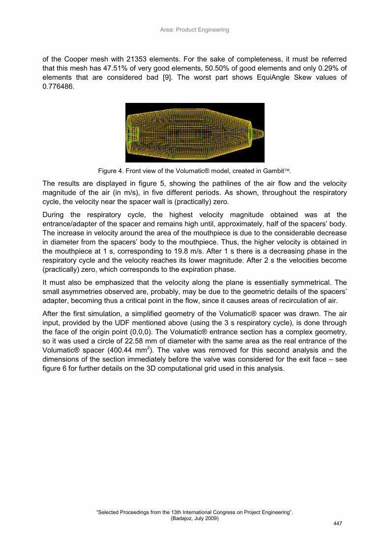
A 3D model of the spacer was created, which included the adapter, the spacers‘ body and the mouthpiece. An air flow test inside the spacer, according to the second respiratory cycle shown in figure 3, was also carried out. This geometry (highlighted in figure 4) corresponds to the use
446
Area: Product Engineering
―Selected Proceedings from the 13th International Congress on Project Engineering‖. (Badajoz, July 2009)
of the Cooper mesh with 21353 elements. For the sake of completeness, it must be referred that this mesh has 47.51% of very good elements, 50.50% of good elements and only 0.29% of elements that are considered bad [9]. The worst part shows EquiAngle Skew values of 0.776486.
Figure 4. Front view of the Volumatic® model, created in Gambit.
The results are displayed in figure 5, showing the pathlines of the air flow and the velocity magnitude of the air (in m/s), in five different periods. As shown, throughout the respiratory cycle, the velocity near the spacer wall is (practically) zero.
During the respiratory cycle, the highest velocity magnitude obtained was at the entrance/adapter of the spacer and remains high until, approximately, half of the spacers‘ body. The increase in velocity around the area of the mouthpiece is due to the considerable decrease in diameter from the spacers‘ body to the mouthpiece. Thus, the higher velocity is obtained in
the mouthpiece at 1 s, corresponding to 19.8 m/s. After 1 s there is a decreasing phase in the respiratory cycle and the velocity reaches its lower magnitude. After 2 s the velocities become (practically) zero, which corresponds to the expiration phase.
It must also be emphasized that the velocity along the plane is essentially symmetrical. The small asymmetries observed are, probably, may be due to the geometric details of the spacers‘ adapter, becoming thus a critical point in the flow, since it causes areas of recirculation of air.
After the first simulation, a simplified geometry of the Volumatic® spacer was drawn. The air input, provided by the UDF mentioned above (using the 3 s respiratory cycle), is done through the face of the origin point (0,0,0). The Volumatic® entrance section has a complex geometry, so it was used a circle of 22.58 mm of diameter with the same area as the real entrance of the Volumatic® spacer (400.44 mm2). The valve was removed for this second analysis and the dimensions of the section immediately before the valve was considered for the exit face – see figure 6 for further details on the 3D computational grid used in this analysis.
447

Area: Product Engineering
―Selected Proceedings from the 13th International Congress on Project Engineering‖. (Badajoz, July 2009)
Figure 5. Air pathlines of the Volumatic® simulation. (The scale values are in m/s, and represent the velocity of air.)
Using the Gambit package it was possible to create a Tetrahedrical/Hybrid T-Grid mesh with interval 4 resulting in a 3D computational grid with 16078 nodes and 84683 elements – see figure 6. The quality report showed an EquiAngle Skew with 14.98% of very good elements, 77.66% of good elements and 7.37% of bad elements [9].
Figure 6. Front view of the 3D computational grid used in the second Volumatic® simulation.
The results obtained are displayed in figure 7, showing the air pathlines and the air velocity in a plane (z=0) that splits the geometry in two equal parts [4]. These results were obtained at 6 different instants of the respiratory cicle (0.2, 0.5, 0.8, 1, 2 and 3 s).
It is possible to observe the behavior and the air flow inside the spacer. In the inspiration period (0.2, 0.5 and 0.8 s) the air flows has expected, with a maximum velocity of approximately 6 m/s at the entrance of the spacer. In the expiration phase the air starts to recirculate, suggesting the occurrence of a large vortex around the spacer, while the air velocity is almost null at this instant.
448

Area: Product Engineering
―Selected Proceedings from the 13th International Congress on Project Engineering‖. (Badajoz, July 2009)
Figure 7. Air pathlines of the Volumatic® simulation (scale in m/s).
During the inspiration phase it is also visible some small vortex regions, near the walls at the entrance. They move forward during the inspiration, untill the start of the expiration phase when they disappear.
These vortexes are mostly likely caused to by the geometry of the spacer as the air path lines do not follow the walls near the entrance of the spacer. With this in mind, the geometry of the spacer was redesigned, in an attempt to smooth the wall lines to reduce the size of the vortexes or to eliminate them.
Sharp corners and high angle walls are more suitable for creating vortexes. These vortexes allow a higher deposition of drug particles and, therefore, a higher waste of drug [9].
A new design was carried out and the volume was kept the same as in the Volumatic® spacer previously analysed.
4.2 Pear-shaped body mesh and results
A new pear-shaped body spacer was prototyped and again with Gambit a new mesh was created using a Tetrahedrical/Hybrid T-Grid scheme with interval 4 resulting in a 3D computational grid with 15689 nodes and 83254 elements. The quality report showed an EquiAngle Skew with 14.87% of very good elements, 78.05% of good elements and 7.09% of bad elements [9]. Figure 8 displays the 3D computational grid developed for this purpose.
It must be referred that the same boundary conditions were used as before, considering the entrance as a velocity inlet and the exit face as an outflow [9].
449

Area: Product Engineering
―Selected Proceedings from the 13th International Congress on Project Engineering‖. (Badajoz, July 2009)
Figure 8. Front view of the 3D computational grid used in the pear-shaped body simulation.
The results of the air velocity and its pathlines for this new shape are shown in Figure 9:
Figure 9. Air pathlines of the pear-shaped body simulation. (The scale values are in m/s.)
According to figure 9 it can be observed that the air flow experiments the same behavior as in the Volumatic® simulation, with a maximum velocity around 5 m/s. The expiration phase of the simulation, when air velocity reaches 0 m/s, a very low velocity recirculation can also be observed inside the pear-shaped spacer.
The main difference, comparing with the Volumatic® simulation results, is at 0.2 s: at this stage it does not show any vortex region for the simulation on this pear-shaped body; these observations were consistent throughout the whole simulations. This can probably improve the efficiency of the pear-shaped geometry, because of the non existence of vortexes, reducing the possibility of drug particles deposition on the walls of the spacer [2].
At 0.5 and 0.8 s, the vortexes appear to be smaller than those observed for the Volumatic® spacer: the air flows more regularly in a wider extension. This can result in a better air flow to provide a better drug delivery to the lungs.
450
Area: Product Engineering
―Selected Proceedings from the 13th International Congress on Project Engineering‖. (Badajoz, July 2009)
5. Conclusions
As a further step towards the design and development of a new spacer device to improve the efficiency of drug delivery, undertaken at the University of Minho, further numerical simulations have been carried out on a commonly world-wide used spacer: the Volumatic®.
Based upon the results reported, it is possible to conclude that the spacer shape influences the air flow, and that the higher deposition of drug particles are located next to the wall of the spacer (where more recirculation zones appear during the inspiration phase).
Based on previous results a different pear-shaped spacer was modeled and prototyped. These simulation results also showed that a little change in the geometry of the spacer can reduce the vortex regions, which will likely improve drug deliver to the patient.
In search for a better spacer device, more adjustments and new/different geometries will be tested in the future, and the Particle Image Velocimetry (or PIV) method will also be used to obtain velocity measurements of the drug particles and other related properties of the flow.
References
[1] Abreu S., "Estudo de diferentes câmaras de expansão para inaladores pressurizados", Biomedical Engineering Master Thesis, Department of Mechanical Engineering, University of Minho, Braga, 2007.
[2] Abreu S., Silva L.F., Antunes H. and Teixeira S.F.C.F., "Multiphase flow inside the Volumatic spacer: a CFD approach", Proceedings of the 10th International Chemical and Biological Engineering Conference - CHEMPOR 2008, Braga, 2008.
[3] FLUENT, "FLUENT 6.3 User's Guide", Fluent Inc., Lebanon, New Hampshire, USA, 2006.
[4] Versteeg H.K. and Malalasekera W., "An introduction to Computational Fluid Dynamics: The finite volume method", Longman Scientific & Technical, 1995.
[5] Marshall S.G. and Debley J.S., "Section XVIII The respiratory System", In: Kliegman R.M., Marcdante K.J., Jenson H.B. and Behrman R.E., Nelson Essential of Pediatrics, Elsevier Saunders, Philadelphia, 2006, pp.628.
[6] Vogelberg C., Kremer H.-J., Ellers-Lenz B., Engel M., Maus J., Conred F. and Hermann R., "Clinical evaluation of the peak inspiratory flow generated by asthmatic children through the Novolizer", Respiratory Medicine, Vol. 98, 2003, pp.924-931.
[7] FLUENT, "FLUENT 6.3 UDF Manual", Fluent Inc., Lebanon, New Hampshire, USA, 2006.
[8] Ferziger J.H. and Peric M., "Computational Methods for Fluid Dynamics", Springer, 2002.
[9] GAMBIT, "GAMBIT 2.2 User's Guide", Fluent Inc., Lebanon, New Hampshire, USA, 2004.
10. Contact (For further inquiries please contact):
Luís F. Silva Department of Mechanical Engineering, School of Engineering, University of Minho Campus de Azurém, 4800-058 Guimarães, PORTUGAL +351 253 510220 [email protected]
451