Intensi"cation and diversi"cation with elite tabu search solutions for the linear ordering problem
Upload
khangminh22Category
view
0download
0
HAL Id: hal-03411394https://hal.archives-ouvertes.fr/hal-03411394
Submitted on 2 Nov 2021
HAL is a multi-disciplinary open accessarchive for the deposit and dissemination of sci-entific research documents, whether they are pub-lished or not. The documents may come fromteaching and research institutions in France orabroad, or from public or private research centers.
L’archive ouverte pluridisciplinaire HAL, estdestinée au dépôt et à la diffusion de documentsscientifiques de niveau recherche, publiés ou non,émanant des établissements d’enseignement et derecherche français ou étrangers, des laboratoirespublics ou privés.
Deciphering the Orientation of the Aromatic SpacerCation in Bilayer Perovskite Solar Cells through
Spectroscopic TechniquesMeenakshi Pegu, Samrana Kazim, Thierry Buffeteau, Dario Bassani,
Shahzada Ahmad
To cite this version:Meenakshi Pegu, Samrana Kazim, Thierry Buffeteau, Dario Bassani, Shahzada Ahmad. Decipheringthe Orientation of the Aromatic Spacer Cation in Bilayer Perovskite Solar Cells through SpectroscopicTechniques. ACS Applied Materials & Interfaces, Washington, D.C. : American Chemical Society,2021, 13 (40), pp.48219-48227. �10.1021/acsami.1c13166�. �hal-03411394�
1
Deciphering the orientation of the aromatic spacer cation in bilayer perovskite solar
cells through spectroscopic techniques
Meenakshi Pegu, a Samrana Kazim,
a,c Thierry Buffeteau,
b Dario M. Bassani,
b and Shahzada
Ahmada,c,
*
aBCMaterials, Basque Center for Materials, Applications, and Nanostructures, UPV/EHU
Science Park, 48940, Leioa, Spain
Email: [email protected]
bUniv. Bordeaux, CNRS, Bordeaux INP, ISM, UMR 5255, F-33405, Talence, France
cIKERBASQUE, Basque Foundation for Science, Bilbao, 48009, Spain
Abstract
Slowing the degradation of perovskite-based solar cells (PSCs) is of substantial interest. We
engineered the surface by introducing a hydrophobic overlayer on a 3-dimensional perovskite
using fluorinated or nonfluorinated aryl ammonium cation spacers. The placement of a
fluoroarene cation allows the formation of a bilayer structure i.e., layered/3-dimensional
perovskites. By doing so, the surface hydrophobic character increases notably by the virtue of
perfluorinated benzene moiety. The fabricated devices thereof gave higher performance and
longevity than control devices, in addition to mitigating reliability. The
fluoro‐ phenethylammonium iodide (FPEAI) based devices showed lower non-radiative
carrier recombination. To decipher the orientation of the spacer cation in this bilayer
structure, we probed the surface by polarization-modulated infrared reflection-absorption
spectroscopy and noted substantial differences in the orientation due to the presence of
fluorine substitution. We hypothesize that the stronger van der Waals interactions due to the
higher electronegativity in FPEAI govern the orientation, performance enhancement, and acts
as a barrier to moisture decomposition.
Keywords: PM-IRRAS, fluorinated molecules, FPEAI, PEAI, orientation of spacer cation,
bilayer perovskite solar cells.
2
1. Introduction
Hybrid perovskite-based solar cells (PSCs) have witnessed tremendous progress and a rise in
performance and reliability.1,2
It is known that the photovoltaic (PV) power conversion
efficiency (PCE) and reliability are influenced by the quality of the microcrystalline grain,
boundary size, and surface properties.3 The use of layered perovskites has shown
improvement, and efforts have focussed on the employment of interfacial materials to
increase reliability.4-6
In the case of bilayer perovskites, the crystalline growth condition and
orientation of these materials are of paramount importance as they impact interfacial losses
and thus PCE. All-inorganic based PSCs display improved stability but also demand higher
annealing temperatures, possess relatively lower PCE, and show phase transformation.7
Annealing at high temperatures (>250 oC) is not aligned with the inert atmosphere fabrication
process such as glove box. Dimensionally reduced perovskites display higher moisture
resistance and lower thermal diffusion compared to 3-dimensional (bulk) perovskites.8-10
However, the high quantum well, lower quantum and dielectric confinement, and anisotropic
charge transport properties11,12
make free carriers difficult to generate in pristine layered
perovskites, and the high density of acceptor type trap states at the surface limits PCE
values.13
One approach is to use bilayer formation to increase the light-harvesting properties
of the active layers.14
Nevertheless, achieving PCE similar to bulk perovskites along with
high operational stability remains challenging.15
Controlled deposition of a hydrophobic,
uniform, and conformal layer on top of a bulk perovskite has been used to mitigate dispersion
forces. Arguably, fluorinated compounds with carbon-fluorine (C-F) bonds having low
polarizability are a contributing factor to the stability of the material and are deterrence
towards moisture.16, 17
Fluorinated compounds contribute to the formation of hydrogen-
bonding interactions between electronegative fluorine atoms and the surface of perovskites.19
3
The use of partially fluorinated aliphatic amines for the passivation of interfacial
defects and fluorous aliphatic spacer groups within layered (fashionably termed 2D)
perovskites gave PCE close to 20%, without hysteresis correction and scan speed–
independent maximum power point (MPP) data reported.20
Similarly, fluorinated tin
perovskites were also reported.21
Additionally, employing fluoro-halogenated layers as
molecular moisture barriers for stability purposes can increase reliability by forming halogen
bonding with the bulk perovskites.18, 22
We reported the use of a perfluoroalkyl-substituted
imidazolium derivative as a doping agent compared to iodopentafluorophenol, and the
hydrophobic nature of the dopant allows the formation of a protective layer.23
With the surge
in the reports dealing with the use of bilayers/passivation/doping agents to improve PCE and
moisture resistance, a rapid and effective approach to deduce the molecular orientation of the
layer is paramount in deciphering its action.24
In addition to imparting moisture stability, the perfluorinated benzene unit possesses
electronic properties conducive towards hole extraction while constraining ion migration.
Both ion migration and moisture-induced degradation negatively affect the reliability of
PSCs,25
and an overlayer can intrinsically mitigate such issues. Ion migration, axial rotation,
and moisture-induced degradation are interwoven as surface-bound water and ions can
diffuse into the absorber layer through grain boundaries to accelerate degradation.26
For layered perovskites, in situ growth using bulky organic cations derived from
organic salts and the corresponding halides is widely adopted. These react with excess PbI2
present on the surface to form a layered structure post-annealing through the interaction of
the Pb-I framework of the bulk perovskite. Placement of a low dimensional perovskite
facilitates the nucleation at the interfaces, resulting in minimal structural disorder and higher
charge carrier lifetimes.27
While fluoroarene bilayer-based PSCs display higher operational
stability under humid conditions.17
In our efforts to probe interfacial layers that passivate
4
surface defects or add functionality, we focus on the role played by surface mitigation and its
impact on the stability. Particularly, the non-random orientation of the interfacial layers is
decisive in controlling the electronic effects. However, elucidation of a single or molecular
layer's organizational order can be extremely challenging, especially when they are placed on
hybrid materials due to the inherent complexity of underlying layers. Recently, techniques
such as grazing incidence wide-angle X-rays diffraction (GIWAXD), combined nuclear
magnetic resonance (NMR), X-ray crystallography, and ab-initio calculations have been used
to glean information concerning nature, thickness, and orientation, e.g. PEA spacers in
directing the formation of bilayer hybrid perovskites.28,29
Considering the plethora of possible
interfacial layer compositions, a straightforward technique to probe the composition and
organization of such materials would be extremely valuable. Herein, we show that
polarization-modulated infrared reflection-absorption spectroscopy (PM-IRRAS) is capable
of rapidly providing the necessary information, without using sophisticated techniques and
time investment.
PM-IRRAS is a surface-specific IR technique that combines the electric field
enhancement induced by IRRAS and the surface selection rules for the study of self-
assembled monolayers.30,31
The shifting in the energy of the IR transitions can be assigned to
the interaction of the various functional groups present with the surface and, similarly to IR
spectroscopy, it provides information on a material's composition and organization. It is a
non-destructive technique in which band intensities can be used to obtain information on the
relative proportion and orientation of different functional groups to the surface. The latter is
of significant interest, as it allows one to specifically assign certain orientations to portions of
a molecule that may be partially organized on a surface whereas another part of the same
molecule is more randomly oriented. To demonstrate the utility of this approach, we have re-
5
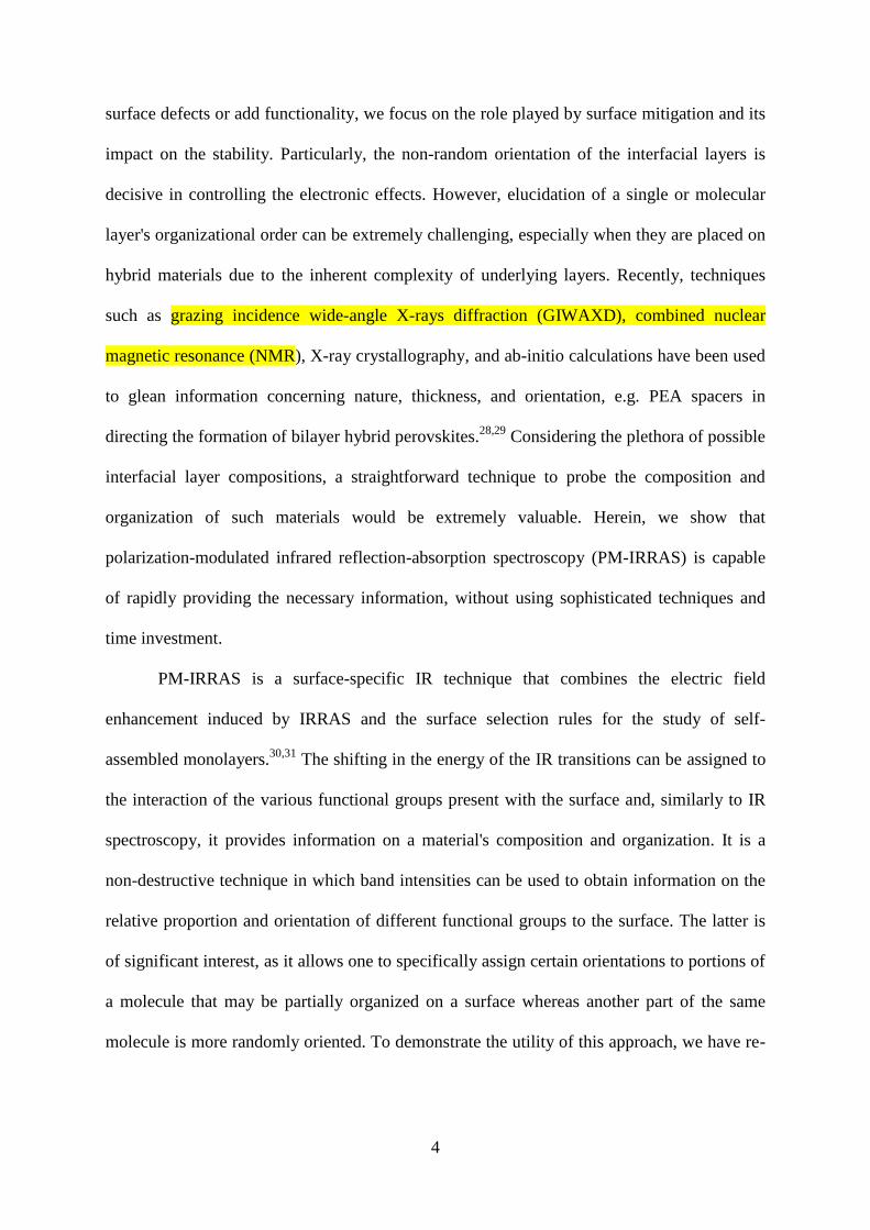
examined interfacial layers formed by PEAI and FPEAI, which form parallel and
perpendicularly oriented monolayers, respectively (Figure 1).
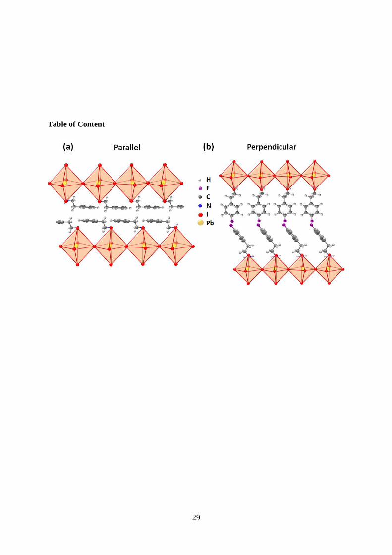
Figure 1. Proposed molecular orientation of (a) PEAI, flat (parallel) orientation, and (b)
FPEAI, vertical (perpendicular) orientation.
Our results confirm that both PEAI and FPEAI (Figure S1) are non-randomly ordered
on the surface and display different orientations. PEAI lies flat (long axis parallel) on the
surface whereas FPEAI is found to be vertically oriented. Moreover, the surface
concentration/density of PEAI is constant and is independent of the concentration used for
deposition (0.3 or 0.7%), whereas in the case of the FPEAI the surface concentration is higher
at 0.7% than at 0.3%. From this, we may rationalize the advantage of the FPEAI over the
non-fluorinated or aliphatic counterpart even though both PEAI and FPEAI improve the
crystallinity and moisture tolerance significantly.32
We measured a PCE of 20.63% along
with a significant increase in stability than of control and PEAI based PSCs, corroborating
that a single F atom in PEA improves the material’s moisture resistance.5
2. Result and Discussions
2.1 PM-IRRAS study on bilayer perovskites
6
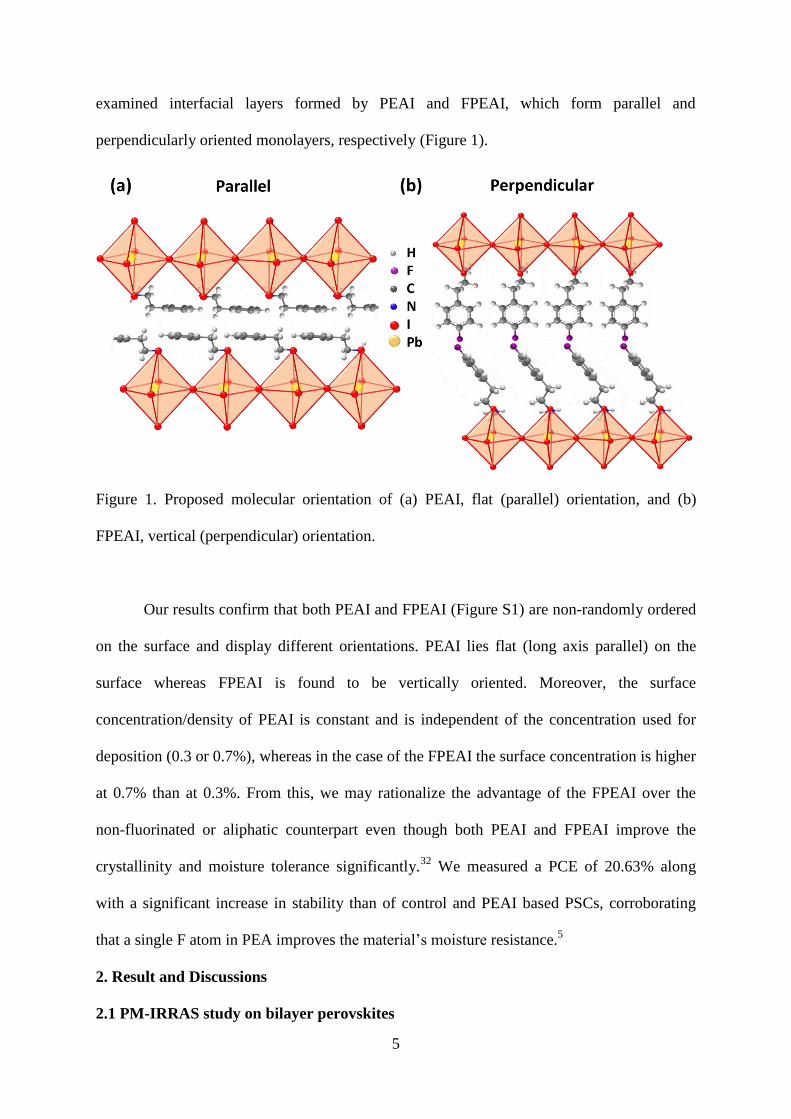
The PM-IRRAS spectra of the pristine perovskites and samples treated with 0.3% and
0.7% FPEAI are shown in Figure 2a, along with the isotropic (non-oriented) spectra of
FPEAI and the assignment of the principal vibrations. From this we can deduce that the
spectral signature of FPEAI is visible in the bilayer perovskites and the intensity of the
FPEAI bands increases by a factor of 2.15 which is close to the ratio of concentrations used
for deposition (0.7% and 0.3%).
Figure 2. PM-IRRAS spectra of pristine PSK (black), PSK + 0.3% (red) and 0.7% (blue) of
(a): FPEAI and (b): PEAI. The assignment of the vibrations is from the ATR spectrum
(green) of an isotropic sample of the ammonium iodide salt. Proposed orientation of FPEAI
(c) and PEAI (d) on the PSK surface in agreement with the enhancement of those transitions
7
that are perpendicular to the surface and suppression of the transitions parallel to the surface.
The NH3 fragment is disordered and shows no orientational preference.
Concerning the orientation of the molecules on the surface, we note that the bands
possessing a1 symmetry (aligned with the C–F bond) are enhanced, whereas the phenyl ring
vibrations possessing b1 or b2 symmetry (perpendicular to the C–F bond) are strongly
reduced. From this, we can conclude that the molecule is preferentially oriented with the C–F
bond perpendicular to the surface (Figure 2c). There is no difference in the intensities of the
aNH3+ vibrations to the sNH3
+, suggesting no preferential orientation of the NH3
+ group.
From this information, we conclude that the FPEAI molecules are oriented vertically. The
structure is shown with the NH3 oriented towards the surface, but this is arbitrary although in
agreement with previous studies. A small shift in the C–F vibration is observed, which would
be in agreement with the possibility that the fluorine atom may be interacting with the
surface.
A similar situation is seen in the PM-IRRAS spectra of PSK treated with 0.3% and
0.7% PEAI solutions (Figure 2b). Despite the absence of the easily identifiable C–F bond, the
spectral signature of PEAI is nonetheless evident in the treated samples, albeit less intense
and somewhat broader than for FPEAI. In the case of PEAI, we note that the band intensities
for samples prepared using 0.7% and 0.3% solutions are similar (ratio = 1.44 vs. expected
2.33). In the absence of the C–F bond, determining the orientation of the molecule is more
challenging. Here, the vibrations of the phenyl ring can be used to provide orientational
information. We can see that the bands possessing a1 symmetry (aligned with the long axis of
the molecule) are decreased in intensity when the molecule is on the surface. This indicates
that the molecule is preferentially lying with the long axis parallel to the surface.
Additionally, if we compare the intensity of the vibrations with b symmetry, we can deduce
8
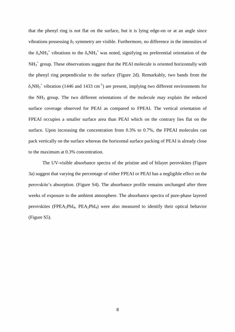
that the phenyl ring is not flat on the surface, but it is lying edge-on or at an angle since
vibrations possessing b2 symmetry are visible. Furthermore, no difference in the intensities of
the aNH3+ vibrations to the sNH3
+ was noted, signifying no preferential orientation of the
NH3+ group. These observations suggest that the PEAI molecule is oriented horizontally with
the phenyl ring perpendicular to the surface (Figure 2d). Remarkably, two bands from the
sNH3+ vibration (1446 and 1433 cm
-1) are present, implying two different environments for
the NH3 group. The two different orientations of the molecule may explain the reduced
surface coverage observed for PEAI as compared to FPEAI. The vertical orientation of
FPEAI occupies a smaller surface area than PEAI which on the contrary lies flat on the
surface. Upon increasing the concentration from 0.3% to 0.7%, the FPEAI molecules can
pack vertically on the surface whereas the horizontal surface packing of PEAI is already close
to the maximum at 0.3% concentration.
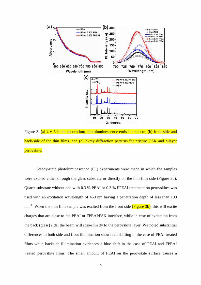
The UV-visible absorbance spectra of the pristine and of bilayer perovskites (Figure
3a) suggest that varying the percentage of either FPEAI or PEAI has a negligible effect on the
perovskite’s absorption. (Figure S4). The absorbance profile remains unchanged after three
weeks of exposure to the ambient atmosphere. The absorbance spectra of pure-phase layered
perovskites (FPEA2PbI4, PEA2PbI4) were also measured to identify their optical behavior
(Figure S5).
9
Figure 3. (a) UV-Visible absorption; photoluminescence emission spectra (b) front-side and
back-side of the thin films, and (c) X-ray diffraction patterns for pristine PSK and bilayer
perovskite.
Steady-state photoluminescence (PL) experiments were made in which the samples
were excited either through the glass substrate or directly on the thin film side (Figure 3b).
Quartz substrate without and with 0.3 % PEAI or 0.3 % FPEAI treatment on perovskites was
used with an excitation wavelength of 450 nm having a penetration depth of less than 100
nm.33
When the thin film sample was excited from the front side (Figure 3b), this will excite
charges that are close to the PEAI or FPEAI/PSK interface, while in case of excitation from
the back (glass) side, the beam will strike firstly to the perovskite layer. We noted substantial
differences in both side and front illumination shows red shifting in the case of PEAI treated
films while backside illumination evidences a blue shift in the case of PEAI and FPEAI
treated perovskite films. The small amount of PEAI on the perovskite surface causes a
10
redshift of the emission of the perovskite.34
The PL emission peak of the bulk PSK is c.a. 768
nm and 770 nm when excited from the quartz (back) and front side respectively, which is
consistent with the absorption results. The small shift in the peak position of bulk PSK might
be due to the variation in crystal size and microstructure on the top and bottom of the
surface.35
Upon formation of low-dimensional perovskite layers due to PEAI/FPEAI
treatment, the PL intensity increases irrespective of the illumination side. We also noted a
stronger PL intensity that is blue-shifted (2-3 nm) for FPEAI treated films (irrespective of
excitation side). The observation of strong PL intensity in the case of FPEAI treated
perovskite regardless of the illumination side can be ascribed to the filling of traps when less
concentrated FPEAI was used which diffuses inside the grain along with the grain boundaries
and the surface during the annealing process.
X-ray diffraction analyses were performed to elucidate changes in the structural
properties (Figure 3c) for pristine and 0.3% treated bilayer perovskites. The PEAI and FPEAI
dissolved in isopropanol (IPA) were coated on the bulk (3D) perovskite layer and annealed at
100°C to allow in situ growth for the formation of a bilayer perovskite. The diffractograms
are unchanged and this suggests that the over layers of the organic spacer group on top of
bulk perovskites do not substantially alter the structure. The peak at 12.8° is ascribed to the
excess PbI2 phase present in the films. The presence of well-defined layered perovskite is
reflected from the characteristic peak patterns at lower angle 2 region (<10°), which are
associated with the formation of a bilayer perovskite. The increase in signal of the perovskite
peak at 14.33° indicates higher crystallinity and large grain size of the films. The X-ray
diffraction pattern with 0.5% and 0.7% treated bilayer perovskite (Figure S6), reflects the
high-intensity peaks of layered perovskite with increment in the concentration of the bulk
layer.
11
To probe the molecular interactions between the bulk perovskite and the bulky organic
cations, we collected FTIR spectra for the corresponding pure phase layered perovskite, bulk,
and the bilayer perovskite layers (Figure S7).20
A similar profile was noted in all the samples
(pristine and 0.3% PEAI, FPEAI treated) in the higher wavenumber region (3000−3500 cm-
1), which corresponds to the N-H stretching frequency of the formamidinium cation (FA)
cations.
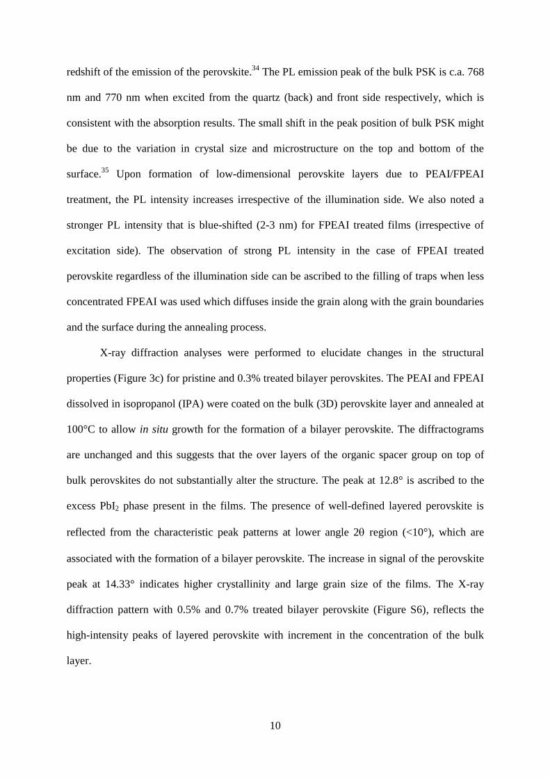
Figure 4. X-ray photoelectron spectroscopy (XPS), (a-c) high-resolution deconvoluted
spectra of C1s, (d-f) N 1s peaks, and (g-i) F 1s peaks of the pristine and bilayer perovskite.

12
To investigate the elemental distribution on the surface, we performed X-ray
photoelectron spectroscopy (XPS) of thin films. The core-level peaks of C, N, and F (Figure
4) suggest the formation of bilayer perovskite, while the strong C1s spectra in the profile are
attributed to the ex-situ measurements condition (Figure 4a-c). In the case of bulk perovskite,
the presence of MA and FA components from the C1s and N1s spectra is supported by the
presence of peaks at 286.21 eV and 288.03 eV. While the N1s peaks of MA and FA with
400.24 eV and 401.9 eV positions are per report. Layered perovskites with PEAI and FPEAI
display a characteristic peak at the binding energy of 292.03 eV due to the presence of the
aromatic (phenyl) group in the PEA+ or FPEA
+ cations. The peaks at 402.44 eV and 401.68
eV of the N1s spectra (Figure 4d-f) are assigned to the C-N of the amino groups in the cations
(PEAI, FPEAI). The fluoro substitution at the phenyl group (FPEA+) was confirmed by the
appearance of a 686.97 eV peak in the F1s spectrum (Figure 4g-i). The Pb 4f and I 3d peaks
of the bulk as well as the layered perovskite (Figure S8) shows the different binding energies
of the organic moieties on the surface of the bulk perovskite.
The microstructure of the bulk and bilayer perovskites was studied with the help of
scanning electron microscopy (Figure 5b-d). The images suggest films composed of a
uniform distribution of crystals without any voids. A significant difference for the bilayer
perovskites was the presence of larger sized crystals, which in turn minimizes the number of
grain boundaries. We note from the images that increasing the thickness (concentration) of
PEAI or FPEAI has a small impact on the shape of the microstructure, while orderly crystal
size with the coarser surface was also noted (Figure S9). The average grain size of pristine
perovskites was 300 nm, while for PEAI or FPEAI we find it to be around 550 nm.
13
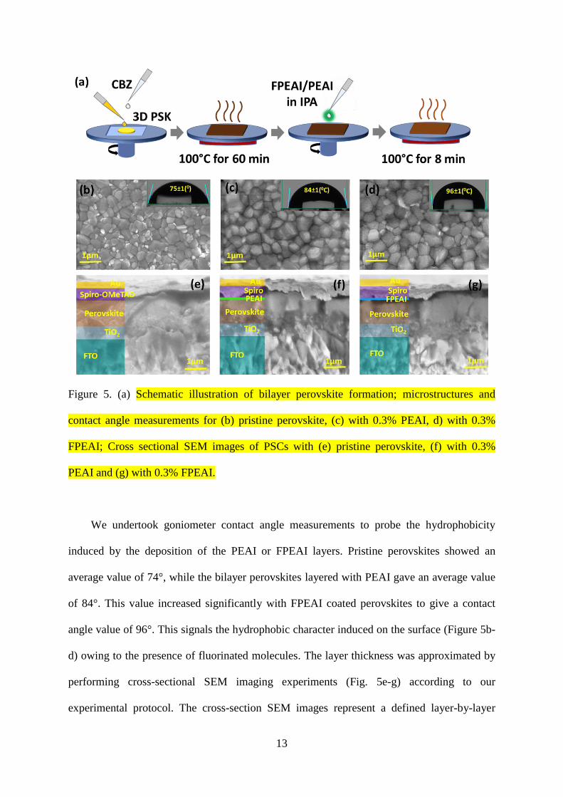
Figure 5. (a) Schematic illustration of bilayer perovskite formation; microstructures and
contact angle measurements for (b) pristine perovskite, (c) with 0.3% PEAI, d) with 0.3%
FPEAI; Cross sectional SEM images of PSCs with (e) pristine perovskite, (f) with 0.3%
PEAI and (g) with 0.3% FPEAI.
We undertook goniometer contact angle measurements to probe the hydrophobicity
induced by the deposition of the PEAI or FPEAI layers. Pristine perovskites showed an
average value of 74°, while the bilayer perovskites layered with PEAI gave an average value
of 84°. This value increased significantly with FPEAI coated perovskites to give a contact
angle value of 96°. This signals the hydrophobic character induced on the surface (Figure 5b-
d) owing to the presence of fluorinated molecules. The layer thickness was approximated by
performing cross-sectional SEM imaging experiments (Fig. 5e-g) according to our
experimental protocol. The cross-section SEM images represent a defined layer-by-layer
14
structure with intimate interfaces, reflecting the architect adopted. The mixed perovskite
(FA0.15MA0.85PbI3-xBrx) layer represents the thickness of (t ꓿ ~ 453 nm), while PEAI and
FPEAI showed a thickness which we speculate to be <20 nm, could be hardly measured as it
lies as a thin sandwich layer between the 3D perovskite and the hole transport layer (Figure
5e-g).
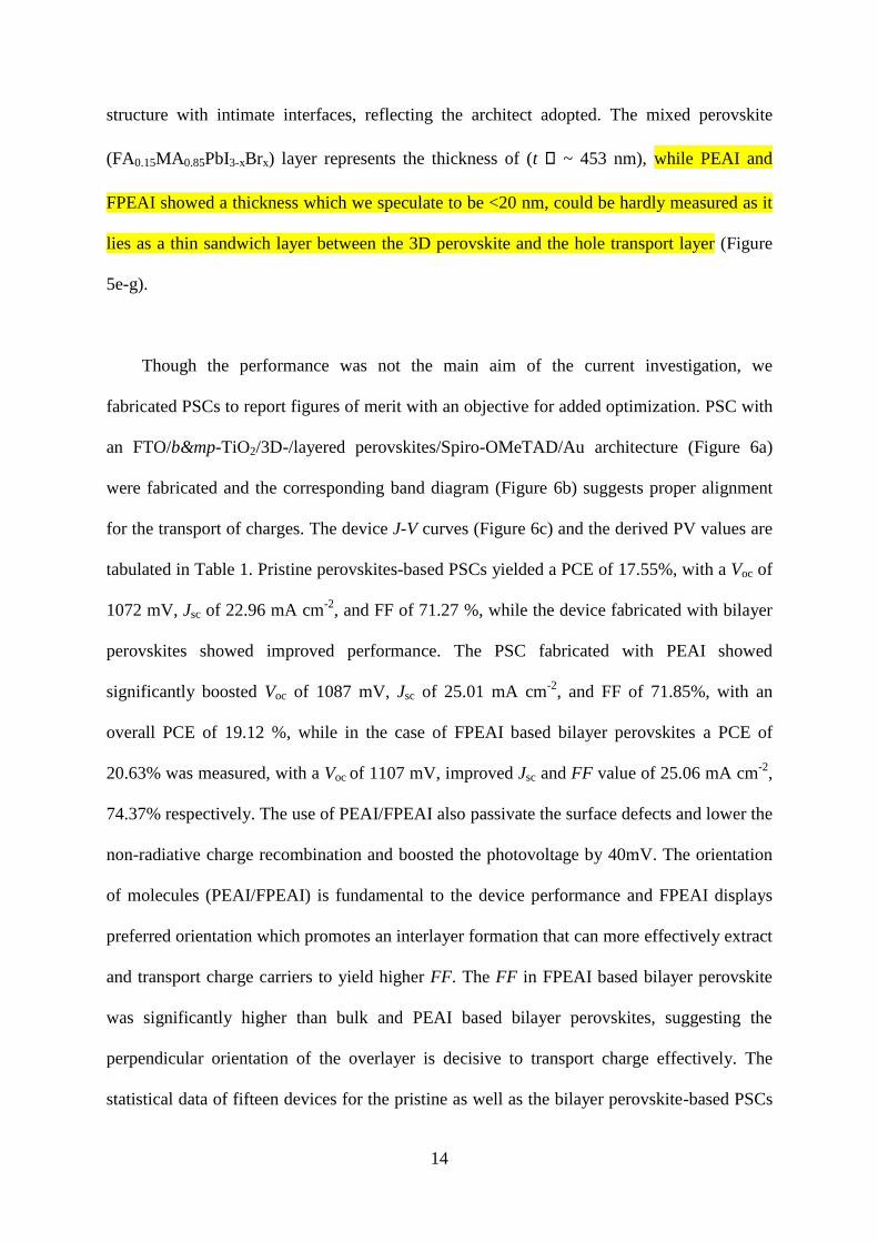
Though the performance was not the main aim of the current investigation, we
fabricated PSCs to report figures of merit with an objective for added optimization. PSC with
an FTO/b&mp-TiO2/3D-/layered perovskites/Spiro-OMeTAD/Au architecture (Figure 6a)
were fabricated and the corresponding band diagram (Figure 6b) suggests proper alignment
for the transport of charges. The device J-V curves (Figure 6c) and the derived PV values are
tabulated in Table 1. Pristine perovskites-based PSCs yielded a PCE of 17.55%, with a Voc of
1072 mV, Jsc of 22.96 mA cm-2
, and FF of 71.27 %, while the device fabricated with bilayer
perovskites showed improved performance. The PSC fabricated with PEAI showed
significantly boosted Voc of 1087 mV, Jsc of 25.01 mA cm-2
, and FF of 71.85%, with an
overall PCE of 19.12 %, while in the case of FPEAI based bilayer perovskites a PCE of
20.63% was measured, with a Voc of 1107 mV, improved Jsc and FF value of 25.06 mA cm-2
,
74.37% respectively. The use of PEAI/FPEAI also passivate the surface defects and lower the
non-radiative charge recombination and boosted the photovoltage by 40mV. The orientation
of molecules (PEAI/FPEAI) is fundamental to the device performance and FPEAI displays
preferred orientation which promotes an interlayer formation that can more effectively extract
and transport charge carriers to yield higher FF. The FF in FPEAI based bilayer perovskite
was significantly higher than bulk and PEAI based bilayer perovskites, suggesting the
perpendicular orientation of the overlayer is decisive to transport charge effectively. The
statistical data of fifteen devices for the pristine as well as the bilayer perovskite-based PSCs

15
are summarized (Figure S10). The integrated current density values derived from the incident
photon-to-current conversion efficiency (IPCE) follow the values obtained from J-V curves
(Figure 6d and S12). In the wavelength region of 400 − 600 nm, over 85% photon-to-
electron conversion was noted and FPEAI-based PSC showed higher response with a
shoulder shift to the red part of the spectrum (extended absorption). The molecular stacking
of the organic cations attached to the perovskite layer may promote interlayer electronic
coupling that in turn allows better charge transfer in the PSCs. The out-of-plane conductivity
in FPEA to the molecular stacking with both the organic and inorganic phases was deduced
to be higher and can influence the current density of the PSCs. High charge carrier
conduction and improved electrical conductivity with the FPEAI treatment were reported and
high current density in the fabricated PSCs stems from this. Further, higher light absorption
by the PEAI/FPEAI treated perovskite, as reflected by the PL spectra, also supports
photocurrent value.
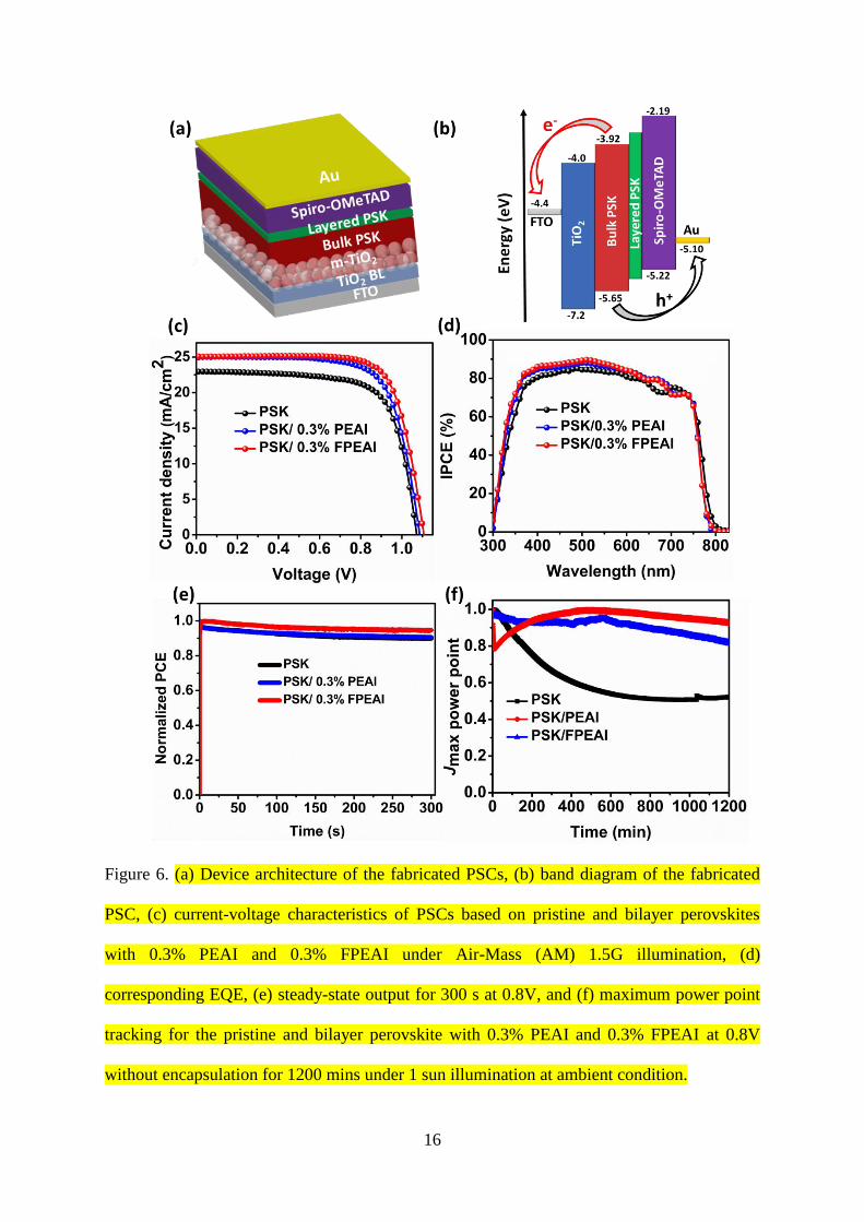
The hysteresis index (HI) was calculated for the PSCs by measuring J-V curves under
the forward and reverse scan directions (Table 1). The bilayer perovskites-based PSCs
showed a lower HI value of 0.058 for PEAI and 0.061 for FPEAI treated PSCs as compared
to pristine perovskites which were 0.144 (Figure S11).
16
Figure 6. (a) Device architecture of the fabricated PSCs, (b) band diagram of the fabricated
PSC, (c) current-voltage characteristics of PSCs based on pristine and bilayer perovskites
with 0.3% PEAI and 0.3% FPEAI under Air-Mass (AM) 1.5G illumination, (d)
corresponding EQE, (e) steady-state output for 300 s at 0.8V, and (f) maximum power point
tracking for the pristine and bilayer perovskite with 0.3% PEAI and 0.3% FPEAI at 0.8V
without encapsulation for 1200 mins under 1 sun illumination at ambient condition.
17
Table 1: Photovoltaic parameters for bulk and bilayer fabricated perovskites solar cells.
B
ilayer
perovskites based on FPEAI therefore gave higher PCE than PEAI based PSCs. To determine
the influence of layered structure on the operational stability of PSCs, we performed
maximum power point tracking (MPPT) of the un-encapsulated devices under ambient
condition and at 1 sun illumination (Figure 6 e,f). The pristine perovskite showed lower
performance as compared to PEAI based layered PSCs, while the PSCs based on FPEAI
showed linear response and negligible loss in performance. Apart from improving the PCE,
steady output performance is fundamental to evaluate the performance of bilayer PSCs. The
bilayer PSCs was also probed for long-term stability to acquire the self-life period, where the
un-encapsulated devices were kept in a dry box and measured on a regular interval.
The electrical parameters such as built-in-potential ( ), and depletion layer width
(W) were deciphered by using Mott-Schottky analysis (Figure 7a) under dark conditions. The
Mott-Schottky plot for the fabricated PSCs yields a straight region from which was
derived from the intercept on the bias axis.36
for the bilayer perovskites-based PSC
increases to 1003 mV (0.3% PEAI treatment) and 1050mV (0.3% FPEAI treatment) as
compared to 950 mV for the pristine PSCs without the interfacial layer. Subsequently, the
depletion width (W=
) increases from 99.98 nm (pristine) to 106.13 nm (0.3%
FPEAI) for the bilayer PSCs. To elucidate the device kinetics that led to the increment in
PCE with bilayer PSCs, we probed the charge accumulation behavior by examining the
Nyquist plots through electrical impedance spectroscopy (EIS). The recombination resistance
Samples Voc
(mV)
Jsc (mA/cm2) FF (%) PCE
(%)
Avg.
PCE
HI
PSK
1072 22.96 71.27 17.55 16.87 0.144
PSK/0.3%
PEAI
1087 25.01 71.85 19.54 18.85 0.058
PSK/0.3%
FPEAI
1107 25.06 74.37 20.63 19.25 0.061
18
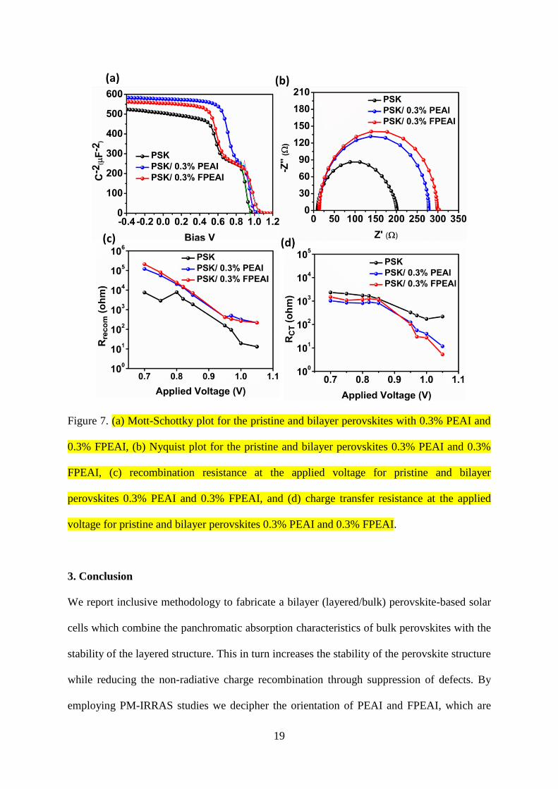
(Figure 7c), and charge transfer resistance (Figure 7d) as function of voltage was were
derived from Nyquist plots (Figure 7b). A single arc was displayed, a characteristic of mixed
perovskites and the equivalent circuit used is shown in Figure S13.37, 38
We can deduce from
the curves that the recombination resistance follows a similar trend and at voltage close to
Voc, they display lower recombination, signaling the main contribution of recombination
processes are in the bulk of the perovskite material not at the interface. Further, the use of
bilayer perovskites irrespective of PEAI or FPEAI shows lower recombination resistance,
suggesting its role in suppressing non-radiative recombination losses. Recombination
resistance, near to the open-circuit voltage, is higher for bilayer perovskite-based PSCs,
signaling a reduction in the non-radiative recombination defects. Bulk perovskites-based
PSCs showed a trap-state recombination, while a change in the slope was noted for bilayer
perovskites. Similarly, the charge transfer resistance was lower for bilayer perovskites based
PSCs, illustrating its advantageous properties stemmed from filling of grain boundaries as
well as defects passivation.
19
Figure 7. (a) Mott-Schottky plot for the pristine and bilayer perovskites with 0.3% PEAI and
0.3% FPEAI, (b) Nyquist plot for the pristine and bilayer perovskites 0.3% PEAI and 0.3%
FPEAI, (c) recombination resistance at the applied voltage for pristine and bilayer
perovskites 0.3% PEAI and 0.3% FPEAI, and (d) charge transfer resistance at the applied
voltage for pristine and bilayer perovskites 0.3% PEAI and 0.3% FPEAI.
3. Conclusion
We report inclusive methodology to fabricate a bilayer (layered/bulk) perovskite-based solar
cells which combine the panchromatic absorption characteristics of bulk perovskites with the
stability of the layered structure. This in turn increases the stability of the perovskite structure
while reducing the non-radiative charge recombination through suppression of defects. By
employing PM-IRRAS studies we decipher the orientation of PEAI and FPEAI, which are
20
located with the phenyl groups parallel and perpendicular to the interface, respecitvely. Due
to its high electro-negativity, strong van der Waals interactions, and surface tension, FPEAI
layers perpendicular to the surface while PEAI lies parallel to the bulk surface. We further
evidence the decisive role of perpendicular orientation for effective charge transport and
extraction. Bilayer formation may also stabilize the surface through hydrogen bonding
contributions. Such synergistic approaches gave improve PV performance and the device's
efficiencies by over 20%.
4. Experimental Section:
Materials
Lead Iodide (99.9%) and formamidinium iodide (FAI) were purchased from Tokyo Chemical
Industry (TCI) and employed as received. Lead bromide was procured from Sigma-Aldrich.
2-(4-Fluorophenyl)ethylammonium iodide (FPEAI), phenethylammonium iodide (PEAI),
methylammonium bromide (MABr) were purchased from Dyesol. Common solvents such as
DMF, DMSO, isopropanol, ethanol, chlorobenzene were purchased from Acros Chemicals
and used as received.
Device Fabrication
The fluorine-doped tin oxide (FTO) coated glass (TEC15) was used as substrate and was
cleaned in sequence before use. Ultrasonication (2% Hellmanex water solution for 30
minutes) followed by rinsing with deionized water, acetone, and then isopropanol (IPA) was
used and finally, the substrates were treated under UV-Ozone for 30 minutes for the removal
of organic residue on the surface. TiO2 compact layer was deposited on this substrate by
spray pyrolysis at 500 °C using a precursor solution of titanium diisopropoxide
bis(acetylacetonate) in anhydrous ethanol (1:19), and the substrates were annealed at 500 °C
for further 30 minutes and left to cool down. The mesoporous TiO2 layer was deposited on
top of this through spin coating process (30 s at 4000 rpm), for this, a TiO2 paste (Dyesol 30
21
NR-D) was diluted to 1:8 in ethanol. The TiO2 coated substrates were annealed first at 125
°C, followed by 500 °C using a programmable ramp in four-step heating, and were finally
maintained at 500°C for 30 min to acquire anatase phase. On attaining room temperature, the
substrates were treated under UV-Ozone for 30 minutes and transferred to an argon-filled
glove-box for perovskite layer deposition. The precursor solution for preparing the mixed
perovskite (MAPbBr3)0.15(FAPbI3)0.85 was prepared by dissolving FAI (1 M), PbI2 (1.2 M),
MABr (0.2 M), and PbBr2 (0.2 M) in anhydrous DMF: DMSO 4:1 (v:v). The perovskite
solution was spin-coated in a two-step sequence at 1000 and 6000 rpm for 10 and 30 s,
respectively. During the second step, 110 μL of chlorobenzene was dripped as an antisolvent
approach on the substrate 5s before the end of the spinning process. The perovskite-coated
substrates were annealed at 100 °C for 1 h in a glovebox. On acquiring room temperature, the
layered perovskites (0.3%, 0.5%, and 0.7% PEAI /FPEAI solution in isopropanol) were
deposited and annealed at 100 °C for 8 minutes. Once it acquires room temperature, Spiro-
OMeTAD (70 mM) as hole selective layer was deposited by dissolving in chlorobenzene.
Spiro-OMeTAD was doped by adding bis-(trifluoromethylsulfonyl)imide lithium salt (Li-
TFSI) and 4-tert-Butylpyridine (t-BP) in the molar ratio 0.5 and 3.3 respectively. 40 μL of
HTM solutions were spin-coated atop of the perovskite layer at 4000 rpm for 30 s, in an
argon-filled glove box. The device fabrication was finished by evaporating an Au layer of 70
nm as a cathode under a low vacuum (10-6
torr). All solutions were prepared inside an argon-
filled glove box with controlled moisture and oxygen conditions (O2 <10 ppm, H2O < 2 ppm).
Device characterization
The device photovoltaics parameters were measured utilizing current density–voltage (J–V)
curves, registered with a Keithley 2400 source-meter under AM 1.5 G, 100 mW cm2
illumination from a 450 W AAA solar simulator (ORIEL, 94023 A). NREL certified
monocrystalline silicon solar cell was used for calibration. A black metal mask (0.1 cm2) was
22
used over the square size active area (0.5 cm2) to reduce the influence of scattered light. The
devices were measured at a scan rate: 100 mV s-1
, pre-sweep delay: 10 s). The external
quantum efficiency (EQE) measurements were carried out using a 150W Xenon lamp
attached to with Bentham PVE300 motorized 1/4m monochromator as the light source.
Thin-film Characterization
For optical characterization, thin films were prepared on quartz substrate by spin coating of
(MAPbBr3)0.15(FAPbI3)0.85 with (0.3%, 0.5%, 0.7%) concentration of PEAI or FPEAI / PSK
was used. X-ray diffractograms were recorded using the D8 Advance diffractometer from
Bruker (Bragg-Bretanto geometry, with an X-ray tube Cu Kα, λ=1.5406 angstrom). A scan of
5-10o
was selected with an acquisition time of 1o/min. The absorption spectra were measured
under a UV-Vis-IR spectrophotometer (Varian Cary 50 UV/Vis Spectrophotometer).
Photoluminescence (PL) steady-state measurements were recorded with a spectrophotometer
(Perkin Elmer Instrument LS55). XPS measurements were carried out on a SPECS system
(Berlin, Germany) equipped with Phoibos 150 ID-DLD analyzer with monochromator Al Kα
radiation (1486.7 eV).
PM-IRRAS spectra of the mixed perovskites spin-coated onto gold substrates (15 × 20 mm),
before and after different PEAI and FPEAI treatment (0.3 and 0.7%), were recorded on a
Thermo Nicolet Nexus 670 FTIR spectrometer at a resolution of 4 cm-1
during 4h acquisition
time. All spectra were collected in a controlled dry environment (RH = 3%) protected from
ambient light. Experiments were performed at an incidence angle of 75° using an external
homemade goniometer reflection attachment and adding a ZnSe photoelastic modulator
(PEM, Hinds Instruments, type III) after the polarizer. The ATR spectrum of the treated
perovskites was recorded on the same FTIR spectrometer using a Silver-Gate (germanium
crystal) ATR accessory (Specac). The ATR spectrum was obtained, at a resolution of 4 cm-1
,

23
by adding 500 scans. See Fig.2 for peak assignment of the vibrational modes of the mixed
perovskite.
Author’s contribution
M.P. performed the experiments and analyzed the data, S.K. performed the electro-optical
measurements, conceived the idea, and made data analysis, T.B. and D.M.B. made PM-
IRRAS measurements and analyzed the data, S.A. supervised, drafted, and directed the
research. All authors contributed to the draft and prepared the final version.
Conflicts of interest
The authors declare no conflict of interest.
Acknowledgments
This work received funding from the European Union H2020 Programme under a European
Research Council Consolidator grant [MOLEMAT, 726360]. PARASOL, the Spanish
Ministry of Science and Innovation.
Supporting information
The scheme, PM-IRRAS stretching bands, device statistics, steady-state device performance,
and admittance spectroscopy.
References
1. Jung, H. S.; Park, N. G. Perovskite Solar Cells: from Materials to Devices. Small,
2015, 11, 10-25.
2. Grätzel, M. The light and Shade of Perovskite Solar Cells. Nat. Mater. , 2014, 13,
838-842.
24
3. Bi, C.; Wang, Q.; Shao, Y.; Yuan, Y.; Xiao, Z.; Huang, J. Non-wetting Surface-
Driven High-Aspect-Ratio Crystalline Grain Growth for Efficient Hybrid Perovskite
Solar Cells. Nat. Commun., 2015, 6, 1-7.
4. Mao, L.; Stoumpos, C. C.; Kanatzidis, M. G. Two-dimensional Hybrid Halide
Perovskites: Principles and Promises. J. Am. Chem. Soc, 2018, 141, 1171-1190.
5. Smith, I. C.; Hoke, E. T.; Solis‐ Ibarra, D.; McGehee, M. D.; Karunadasa, H. I. A
Layered Hybrid Perovskite Solar‐ Cell Absorber with Enhanced Moisture Stability.
Angew. Chem. Int. Ed., 2014, 126, 11414-11417.
6. Alanazi, A. . Kubicki, D. . Prochowicz, D. Alharbi, . A. Bouduban, . .
ahanbakhshi, . ladenovi , M.; ili , J. V.; Giordano, F.; Ren, D. Atomic-Level
Microstructure of Efficient Formamidinium-Based Perovskite Solar Cells Stabilized
by 5-Ammonium Valeric Acid Iodide Revealed by Multinuclear and Two-
dimensional Solid-State NMR. J. Am. Chem. Soc, 2019, 141, 17659-17669.
7. Liang, J.; Zhao, P.; Wang, C.; Wang, Y.; Hu, Y.; Zhu, G.; Ma, L.; Liu, J.; Jin, Z.
CsPb0. 9Sn0. 1IBr2 Based All-Inorganic Perovskite Solar Cells with Exceptional
Efficiency and Stability. J. Am. Chem. Soc, 2017, 139, 14009-14012.
8. Grancini, G.; Roldán-Carmona, C.; Zimmermann, I.; Mosconi, E.; Lee, X.;
Martineau, D.; Narbey, S.; Oswald, F.; De Angelis, F.; Graetzel, M. One-Year Stable
Perovskite Solar Cells by 2D/3D Interface Engineering. Nat. Commun., 2017, 8, 1-8.
9. Tsai, H.; Nie, W.; Blancon, J.-C.; Stoumpos, C. C.; Asadpour, R.; Harutyunyan, B.;
Neukirch, A. J.; Verduzco, R.; Crochet, J. J.; Tretiak, S. High-Efficiency Two-
Dimensional Ruddlesden–Popper Perovskite Solar Cells. Nature, 2016, 536, 312-316.
10. Pegu, M.; Haris, M. P.; Kazim, S.; Ahmad, S. Understanding and Harnessing the
Potential of Layered Perovskite-Based Absorbers for Solar Cells. Emergent
Materials, 2020, 1-28.
25
11. Katan, C.; Mercier, N.; Even, J. Quantum and Dielectric Confinement Effects in
Lower-Dimensional Hybrid Perovskite Semiconductors. Chem. Rev., 2019, 119,
3140-3192.
12. Liu, S.; Sun, S.; Gan, C. K.; Del Águila, A. G.; Fang, Y.; Xing, J.; Do, T. T. H.;
White, T. J.; Li, H.; Huang, W. Manipulating Efficient Light Emission in Two-
Dimensional Perovskite Crystals by Pressure-Induced Anisotropic Deformation. Sci.
Adv., 2019, 5, eaav9445.
13. Li, H.; Wang, X.; Zhang, T.; Gong, X.; Sun, Q.; Pan, H.; Shen, Y.; Ahmad, S.; Wang,
M. Layered Ruddlesden–Popper Efficient Perovskite Solar Cells with Controlled
Quantum and Dielectric Confinement Introduced via Doping. Adv. Funct. Mater.,
2019, 29, 1903293.
14. Wang, Z.; Lin, Q.; Chmiel, F. P.; Sakai, N.; Herz, L. M.; Snaith, H. J. Efficient
Ambient-Air-Stable Solar Cells with 2D–3D Heterostructured Butylammonium-
Caesium-Formamidinium Lead Halide Perovskites. Nat. Energy, 2017, 2, 1-10.
15. Grancini, G.; Nazeeruddin, M. K. Dimensional Tailoring of Hybrid Perovskites for
Photovoltaics. Nat. Rev. Mater., 2019, 4, 4-22.
16. García-Benito, I.; Quarti, C.; Queloz, V. I.; Orlandi, S.; Zimmermann, I.; Cavazzini,
M.; Lesch, A.; Marras, S.; Beljonne, D.; Pozzi, G. Fashioning Fluorous Organic
Spacers for Tunable and Stable Layered Hybrid Perovskites. Chem. Mater., 2018, 30,
8211-8220.
17. Zhou, Q.; Liang, L.; Hu, J.; Cao, B.; Yang, L.; Wu, T.; Li, X.; Zhang, B.; Gao, P.
High‐ Performance Perovskite Solar Cells with Enhanced Environmental Stability
Based on a (p‐ FC6H4C2H4NH3) 2 [PbI4] Capping Layer. Adv. Energy Mater., 2019, 9,
1802595.

26
18. Cho, K. T.; Zhang, Y.; Orlandi, S.; Cavazzini, M.; Zimmermann, I.; Lesch, A.; Tabet,
N.; Pozzi, G.; Grancini, G.; Nazeeruddin, M. K. Water-Repellent Low-Dimensional
Fluorous Perovskite as Interfacial Coating for 20% Efficient Solar Cells. Nano Lett.,
2018, 18, 5467-5474.
19. Sadhu, S.; Aqueche, K.; Buffeteau, T.; Vincent, J.-M.; Hirsch, L.; Bassani, D. M.
Unexpected Surface Interactions between Fluorocarbons and Hybrid Organic
Inorganic Perovskites Evidenced by PM-IRRAS and Their Application Towards
Tuning the Surface Potential. Mater Horiz., 2019, 6, 192-197.
20. Zhou, Q.; Xiong, Q.; Zhang, Z.; Hu, J.; Lin, F.; Liang, L.; Wu, T.; Wang, X.; Wu, J.;
Zhang, B. Fluoroaromatic Cation‐ Assisted Planar Junction Perovskite Solar Cells
with Improved VOC and Stability: The Role of Fluorination Position. Solar RRL, 2020,
4, 2000107.
21. Li, P.; Dong, H.; Xu, J.; Chen, J.; Jiao, B.; Hou, X.; Li, J.; Wu, Z. Ligand Orientation-
Induced Lattice Robustness for Highly Efficient and Stable Tin-based Perovskite
Solar Cells. ACS Energy Lett., 2020, 5, 2327-2334.
22. Abate, A.; Saliba, M.; Hollman, D. J.; Stranks, S. D.; Wojciechowski, K.; Avolio, R.;
Grancini, G.; Petrozza, A.; Snaith, H. J. Supramolecular Halogen Bond Passivation of
Organic–Inorganic Halide Perovskite Solar Cells. Nano Lett., 2014, 14, 3247-3254.
23. Salado, M.; Ramos, F. J.; Manzanares, V. M.; Gao, P.; Nazeeruddin, M. K.; Dyson, P.
J.; Ahmad, S. Extending the Lifetime of Perovskite Solar Cells Using a Perfluorinated
Dopant. ChemSusChem, 2016, 9, 2708-2714.
24. Lee, J. W.; Park, N. G. Chemical Approaches for Stabilizing Perovskite Solar Cells.
Adv. Energy Mater., 2020, 10, 1903249.
27
25. Jiang, Y.; Yang, S.-C.; Jeangros, Q.; Pisoni, S.; Moser, T.; Buecheler, S.; Tiwari, A.
N.; Fu, F. Mitigation of Vacuum and Illumination-Induced Degradation in Perovskite
Solar Cells by Structure Engineering. Joule, 2020, 4, 1087-1103.
26. Ning, J.; Zhu, Y.; Hu, Z.; Shi, Y.; Ali, M. U.; He, J.; He, Y.; Yan, F.; Yang, S.; Miao,
J. Gaining Insight into the Effect of Organic Interface Layer on Suppressing Ion
Migration Induced Interfacial Degradation in Perovskite Solar Cells. Adv Funct
Mater., 2020, 30, 2000837.
27. Song, S.; Yang, S. J.; Choi, W.; Lee, H.; Sung, W.; Park, C.; Cho, K. Molecular
Engineering of Organic Spacer Cations for Efficient and Stable Formamidinium
Perovskite Solar Cell. Adv. Energy Mater., 2020, 10, 2001759.
28. Bouduban, M. E.; Queloz, V. I.; Caselli, V. M.; Cho, K. T.; Kirmani, A. R.; Paek, S.;
Roldan-Carmona, C.; Richter, L. J.; Moser, J. E.; Savenije, T. J. Crystal Orientation
Drives the Interface Physics at Two/Three-Dimensional Hybrid Perovskites. J. Phys.
Chem. Lett., 2019, 10, 5713-5720.
29. ope, . A. akamura, . Ahlawat, P. ishra, A. Cordova, . ahanbakhshi, .
ladenovi , M.; Runjhun, R.; Merten, L.; Hinderhofer, A. Nanoscale Phase
Segregation in Supramolecular π-Templating for Hybrid Perovskite Photovoltaics
from NMR Crystallography. J. Am. Chem. Soc., 2021, 143, 3, 1529–1538
30. Monyoncho, E. A.; Zamlynny, V.; Woo, T. K.; Baranova, E. A. The Utility of
Polarization Modulation Infrared Reflection Absorption Spectroscopy (PM-IRRAS)
in Surface and In Situ Studies: New Data Processing and Presentation Approach.
Analyst, 2018, 143, 2563-2573.
31. Sadhu, S.; Buffeteau, T.; Sandrez, S.; Hirsch, L.; Bassani, D. M. Observing the
Migration of Hydrogen species in Hybrid Perovskite Materials Through D/H isotope
Exchange. J. Am. Chem. Soc, 2020, 142, 10431-10437.
28
32. Madhavan, V. E.; Zimmermann, I.; Baloch, A. A.; Manekkathodi, A.; Belaidi, A.;
Tabet, N.; Nazeeruddin, M. K. CuSCN as Hole Transport Material with 3D/2D
Perovskite Solar Cells. ACS Appl. Energy Mater., 2019, 3, 114-121.
33. van Franeker, J. J.; Hendriks, K. H.; Bruijnaers, B. J.; Verhoeven, M. W.; Wienk, M.
M.; Janssen, R. A. Monitoring thermal annealing of Perovskite Solar Cells with In
Situ Photoluminescence. Adv. Energy Mater., 2017, 7, 1601822.
34. Li, N.; Zhu, Z.; Chueh, C. C.; Liu, H.; Peng, B.; Petrone, A.; Li, X.; Wang, L.; Jen, A.
K. Y. Mixed Cation FAxPEA1–xPbI3 with Enhanced Phase and Ambient Stability
Toward High‐ Performance Perovskite Solar Cells. Adv. Energy Mater., 2017, 7,
1601307.
35. Grancini, G.; Marras, S.; Prato, M.; Giannini, C.; Quarti, C.; De Angelis, F.; De
Bastiani, M.; Eperon, G. E.; Snaith, H. J.; Manna, L. The Impact of the Crystallization
Processes on the Structural and Optical Properties of Hybrid Perovskite Films for
Photovoltaics. J. Phys. Chem. Lett., 2014, 5, 3836-3842.
36. Khan, M. T.; Salado, M.; Almohammedi, A.; Kazim, S.; Ahmad, S. Elucidating the
Impact of Charge Selective Contact in Halide Perovskite Through Impedance
Spectroscopy. Adv. Mater. Interfaces, 2019, 6, 1901193.
37. Abdulrahim, S. M.; Ahmad, Z.; Bahadra, J.; Al-Thani, N. J. Electrochemical
Impedance Spectroscopy Analysis of Hole Transporting Material Free Mesoporous
and Planar Perovskite Solar Cells. Nanomaterials, 2020, 10, 1635.
38. Wang, J.; Shi, H.; Xu, N.; Zhang, J.; Yuan, Y.; Lei, M.; Wang, L.; Wang, P. Aza [5]
helicene Rivals N‐ Annulated Perylene as π‐ Linker of D−π−D yped
Hole‐ Transporters for Perovskite Solar Cells. Adv Funct Mater. , 2020, 30, 2002114.
29
Table of Content
Copyright © 2022 FDOKUMEN