A Differential Sample and Hold Technique that Rejects Offset ...
Upload
independentCategory
view
1download
0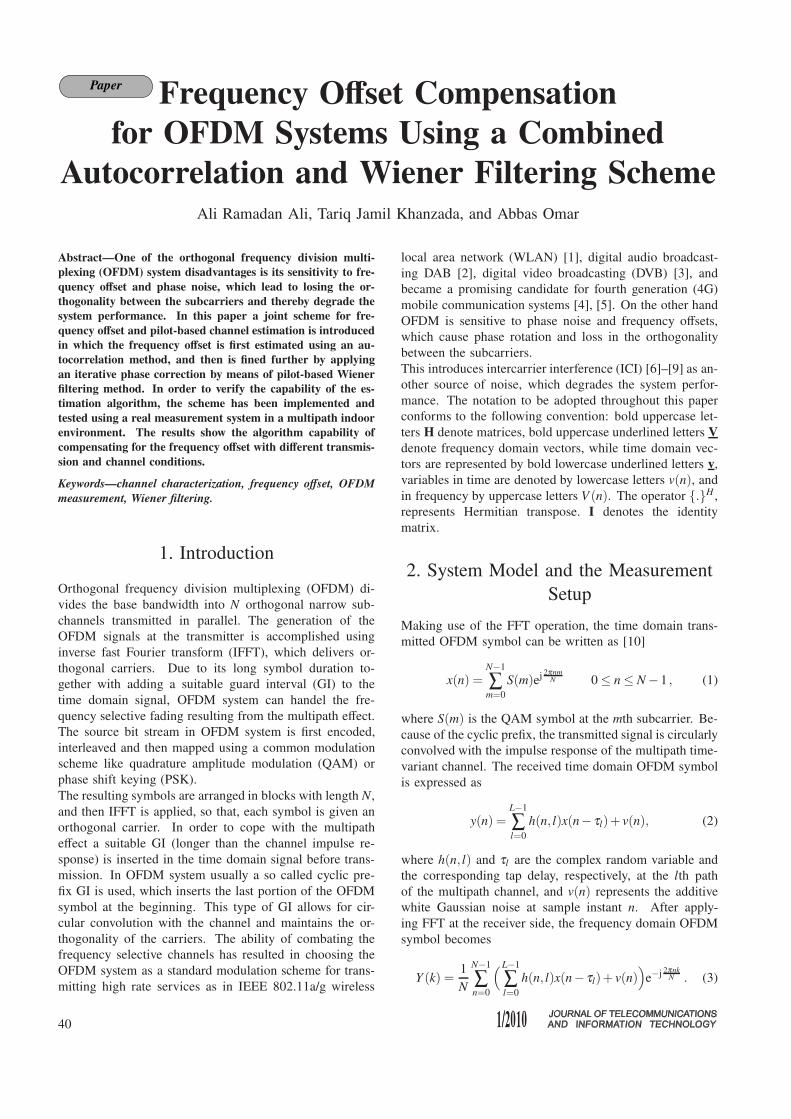
Paper Frequency Offset Compensation
for OFDM Systems Using a Combined
Autocorrelation and Wiener Filtering SchemeAli Ramadan Ali, Tariq Jamil Khanzada, and Abbas Omar
Abstract—One of the orthogonal frequency division multi-
plexing (OFDM) system disadvantages is its sensitivity to fre-
quency offset and phase noise, which lead to losing the or-
thogonality between the subcarriers and thereby degrade the
system performance. In this paper a joint scheme for fre-
quency offset and pilot-based channel estimation is introduced
in which the frequency offset is first estimated using an au-
tocorrelation method, and then is fined further by applying
an iterative phase correction by means of pilot-based Wiener
filtering method. In order to verify the capability of the es-
timation algorithm, the scheme has been implemented and
tested using a real measurement system in a multipath indoor
environment. The results show the algorithm capability of
compensating for the frequency offset with different transmis-
sion and channel conditions.
Keywords—channel characterization, frequency offset, OFDM
measurement, Wiener filtering.
1. Introduction
Orthogonal frequency division multiplexing (OFDM) di-
vides the base bandwidth into N orthogonal narrow sub-
channels transmitted in parallel. The generation of the
OFDM signals at the transmitter is accomplished using
inverse fast Fourier transform (IFFT), which delivers or-
thogonal carriers. Due to its long symbol duration to-
gether with adding a suitable guard interval (GI) to the
time domain signal, OFDM system can handel the fre-
quency selective fading resulting from the multipath effect.
The source bit stream in OFDM system is first encoded,
interleaved and then mapped using a common modulation
scheme like quadrature amplitude modulation (QAM) or
phase shift keying (PSK).
The resulting symbols are arranged in blocks with length N,
and then IFFT is applied, so that, each symbol is given an
orthogonal carrier. In order to cope with the multipath
effect a suitable GI (longer than the channel impulse re-
sponse) is inserted in the time domain signal before trans-
mission. In OFDM system usually a so called cyclic pre-
fix GI is used, which inserts the last portion of the OFDM
symbol at the beginning. This type of GI allows for cir-
cular convolution with the channel and maintains the or-
thogonality of the carriers. The ability of combating the
frequency selective channels has resulted in choosing the
OFDM system as a standard modulation scheme for trans-
mitting high rate services as in IEEE 802.11a/g wireless
local area network (WLAN) [1], digital audio broadcast-
ing DAB [2], digital video broadcasting (DVB) [3], and
became a promising candidate for fourth generation (4G)
mobile communication systems [4], [5]. On the other hand
OFDM is sensitive to phase noise and frequency offsets,
which cause phase rotation and loss in the orthogonality
between the subcarriers.
This introduces intercarrier interference (ICI) [6]–[9] as an-
other source of noise, which degrades the system perfor-
mance. The notation to be adopted throughout this paper
conforms to the following convention: bold uppercase let-
ters H denote matrices, bold uppercase underlined letters V
denote frequency domain vectors, while time domain vec-
tors are represented by bold lowercase underlined letters v,
variables in time are denoted by lowercase letters v(n), and
in frequency by uppercase letters V (n). The operator {.}H ,
represents Hermitian transpose. I denotes the identity
matrix.
2. System Model and the Measurement
Setup
Making use of the FFT operation, the time domain trans-
mitted OFDM symbol can be written as [10]
x(n) =N−1
∑m=0
S(m)ej 2πnmN 0 ≤ n ≤ N −1 , (1)
where S(m) is the QAM symbol at the mth subcarrier. Be-
cause of the cyclic prefix, the transmitted signal is circularly
convolved with the impulse response of the multipath time-
variant channel. The received time domain OFDM symbol
is expressed as
y(n) =L−1
∑l=0
h(n, l)x(n− τl)+ v(n), (2)
where h(n, l) and τl are the complex random variable and
the corresponding tap delay, respectively, at the lth path
of the multipath channel, and v(n) represents the additive
white Gaussian noise at sample instant n. After apply-
ing FFT at the receiver side, the frequency domain OFDM
symbol becomes
Y (k) =1
N
N−1
∑n=0
(L−1
∑l=0
h(n, l)x(n− τl)+ v(n))
e−j 2πnkN . (3)
40

Frequency Offset Compensation for OFDM Systems Using a Combined Autocorrelation and Wiener Filtering Scheme
Equation (3) can be simplified [9] to
Y (k) = S(k)Hk,k + ∑m6=k
S(m)Hk,m
︸ ︷︷ ︸ICI
+V (k), (4)
where:
Hk,m =1
N
N−1
∑n=0
L−1
∑l=0
h(n, l)e−j 2πN (k(τl−n)+nk) . (5)
Writing (4) in vector form representation gives
Y = HS+V , (6)
thus the main diagonal of the matrix H represents the chan-
nel response at the subcarriers, while the off-diagonals rep-
resent the ICI components result from the frequency offsets
and the time variation of the channel.
Fig. 1. The measurement system setup.
The measurement setup of the OFDM system is shown in
Fig. 1. As shown from the figure, the measurement system
is a combination of software and hardware components.
2.1. Software Setup
At an external PC, the baseband IQ (in-phase and quadra-
ture-phase) OFDM signal based on IEEE 802.11g standard
is generated using Matlab code. The OFDM symbols are
arranged in a few frames to be transmitted. At the begin-
ning of each frame, some training symbols (preambles) are
inserted, which are used for packet detection and frequency
and time offset estimation. The time domain baseband sig-
nal is sent via LAN connection to the transmitter, in order
to be up-converted and transmitted through the wireless
channel. The commands for controlling the power and the
carrier frequency are sent to the transmitter before sending
the baseband signal. On the other hand, the IQ data from
the captured signal at the receiver is sent back to the ex-
ternal PC via the LAN for processing. Packet detection,
frequency and time offset estimation and pilot-based chan-
nel estimation are all accomplished using Matlab.
2.2. Hardware Setup
2.2.1. The Transmitter
For transmitting the real time multicarrier signal, an MXG
signal generator N5182A [11] has been used. This signal
generator works on a frequency range between 100 kHz
to 6 GHz and transmission power up to 17 dBm. The
baseband IQ data is generated using Matlab and sent to the
signal generator via LAN connection. The signal generator
saves the IQ data, applies the IF modulation and RF up-
conversion and then transmits the signal with predefined
power and carrier frequency. In order to have a continuous
transmission, the signal generator sends the same signal
repeatedly.
2.2.2. The Antennas
The transmit antenna works between 2.4 GHz and 2.6 GHz
with gain 9 dBi at the resonance frequency [12], while
the receive antenna has an ultra-wideband characteristics in
the frequency range from 800 MHz to 18 GHz [13]. Both
antennas have been fabricated in the Institute of Electronics,
Signal Processing and Communications (IESK) at the Otto
von Guericke University of Magdeburg, Germany.
2.2.3. The Receiver
The EXA spectrum analyzer from Agilent [14] has been
used as a receiver. This device has an absolute sensitivity of
−79.4 dBm, a dynamic range of 93.1 dB, and a maximum
input power of +30 dBm. The reviver down converts the
RF signal and generates the IQ baseband data which is sent
back to the external PC for processing.
3. Wireless Channel Characterization
Estimating the channel parameters such as the number of
multipaths, the delay spread, and the Doppler spread allows
for suitable design and robust behavior of the system. In
this section some measurements have been made in order to
estimate the channel taps and the delay spread of the chan-
nel. An OFDM signal has been sent through the channel,
captured at the receiver and then processed in order to cal-
culate the channel transfer function (CTF) and the channel
impulse response (CIR). The measurements have been con-
ducted in Lab312, which is one of the IESK laboratories at
the University of Magdeburg. The lab was clustered with
furniture, test and measurement equipments. The topology
of the lab and the test scenario is shown in Fig. 2.
During the measurements, the transmit antenna remained
fixed at the same place with different orientations, while the
receive antenna was moved to different places and orienta-
tions. The signal used for measurement was a WLAN sig-
nal with 20 MHz bandwidth and carrier frequency
of 2.412 GHz. The channel transfer function was calcu-
lated as the ratio between the transmitted frequency do-
main OFDM symbols by the received frequency domain
41
Ali Ramadan Ali, Tariq Jamil Khanzada, and Abbas Omar
Fig. 2. The floor plan of the measurement location.
symbols. The channel impulse response h was calculated
by simply applying an IFFT on the CTF.
One of the important parameters required for the charac-
terization of any wireless channel is the root mean square
delay spread τrms, which is calculated from the CIR [15]
as
τrms =
√√√√√√√√
L−1
∑l=0
h2l τ2
l
L−1
∑l=0
h2l
−
L−1
∑l=0
h2l τl
L−1
∑l=0
h2l
2
. (7)
In order to get a clear idea about the multipath channel, the
Ricean K-factor of the channel has also been calculated by
taking the ratio between the signal power in the main path
to the power in the scattered paths as follows:
K =h2
LOS
L−1
∑l=0
h2l −h2
LOS
. (8)
Basically, the Ricean K factor lies between 0, in case of
Rayleigh channel, and ∞ in the case of single path trans-
mission. The measured channel parameters are summarized
in Table 1.
Table 1
The measured channel characteristics
Test Delay spread τrms [ns] K factor [dB] C f [kHz]
T1 306.3 8.8195 653
T2 236 5.7749 847
T3 138 10.5308 1449
T4 97 10.8814 2062
T5 61 11.2222 3279
T6 58 11.3988 3448
T7 143 9.0309 1399
T8 233 10.2531 858
T9 151 10.8991 1325
T10 183 10.5308 1093
In addition, the coherence bandwidth of the channel has
been approximately calculated according to the 50% of the
frequency correlation function [15] as
C f ≈1
5τrms
. (9)
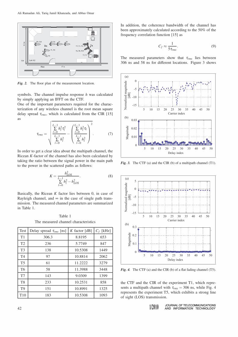
The measured parameters show that τrms lies between
306 ns and 58 ns for different locations. Figure 3 shows
Fig. 3. The CTF (a) and the CIR (b) of a multipath channel (T1).
Fig. 4. The CTF (a) and the CIR (b) of a flat fading channel (T5).
the CTF and the CIR of the experiment T1, which repre-
sents a multipath channel with τrms = 306 ns, while Fig. 4
represents the experiment T5, which exhibits a strong line
of sight (LOS) transmission.
42
Frequency Offset Compensation for OFDM Systems Using a Combined Autocorrelation and Wiener Filtering Scheme
4. A Joint Frequency Offset and Wiener
Filtering Channel Estimation Scheme
The time and frequency synchronization play an important
role in designing and implementing the practical systems.
In WLAN system, the signal is headed with a preamble at
the beginning of each frame. This preamble is basically
used for time synchronization, frequency offset estimation
and for the initial channel estimation. The preamble con-
tains two parts, the first one is called short training symbols
(STS), which contains 10 short symbols occupy 8 µs. The
STS are used for time synchronization and course frequency
offset (CFO) estimation. The second part is called long
training symbols (LTS), which contains two long symbols
each with time duration of 3.2 µs as well as a GI with time
duration of 1.6 µs. The LTS are used for further enhanc-
ing the time synchronization and for fine frequency offset
(FFO) estimation as well as initial channel estimation.
The OFDM symbol of the WLAN system contains 64 car-
riers, 52 of them are active carriers, while the other 12 car-
riers work as frequency guard at both sides of the spectrum.
For channel estimation and equalization proposes, 4 carri-
ers out of the 52 are booked for pilots.
In order to start processing the received OFDM signal, the
signal packets need to be detected first and the first sam-
ple of the OFDM symbols needs to be indicated in order
to apply the FFT operation on the right symbol samples.
A suitable method for detecting the packet is based on the
autocorrelation of the received preamble [16], which con-
tains short and long training symbols. The auto correlation
is written in the following form
Z(n) =NT S−1
∑c=0
y∗(n + c)y(n + c + NTS), (10)
where y(n) represents the nth incoming sample of the base-
band signal, y∗(n) represents the conjugate of y(n) and
NT S = 16 samples in case of short training symbols. In
order to avoid the expected variance of the incoming sig-
nal power, the autocorrelation needs to be normalized by
a moving sum of the received signal power [17]. The mov-
ing sum of the received power can be written as
P(n) =NT S−1
∑c=0
|y(n + c + NTS)|2. (11)
The normalized autocorrelation used for packet detection
reads
M(n) =|Z(n)|2
P(n). (12)
The packet is detected at the first peak of M(n) after a pre-
defined threshold, which should be chosen to minimize the
possibility of false alarm. Using only the short training
symbols in packet detection gives a reasonable performance
in case of good conditions of the channel, however, be-
cause of the expected time offsets at bad channel conditions,
it is better to use both short and long training symbols for
this purpose.
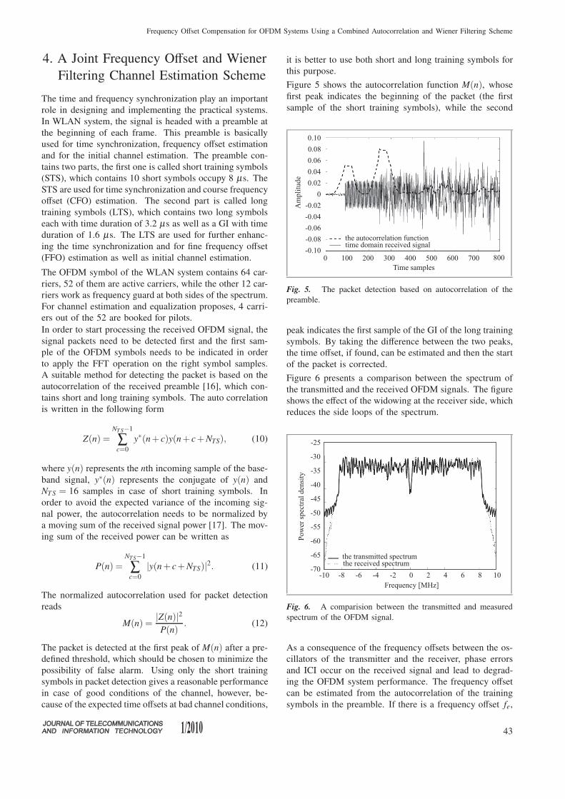
Figure 5 shows the autocorrelation function M(n), whose
first peak indicates the beginning of the packet (the first
sample of the short training symbols), while the second
Fig. 5. The packet detection based on autocorrelation of the
preamble.
peak indicates the first sample of the GI of the long training
symbols. By taking the difference between the two peaks,
the time offset, if found, can be estimated and then the start
of the packet is corrected.
Figure 6 presents a comparison between the spectrum of
the transmitted and the received OFDM signals. The figure
shows the effect of the widowing at the receiver side, which
reduces the side loops of the spectrum.
Fig. 6. A comparision between the transmitted and measured
spectrum of the OFDM signal.
As a consequence of the frequency offsets between the os-
cillators of the transmitter and the receiver, phase errors
and ICI occur on the received signal and lead to degrad-
ing the OFDM system performance. The frequency offset
can be estimated from the autocorrelation of the training
symbols in the preamble. If there is a frequency offset fe,
43

Ali Ramadan Ali, Tariq Jamil Khanzada, and Abbas Omar
the autocorrelation function will be modified by the phase
error as
Z(n) = e−j2π feNT S
NT S−1
∑c=0
|y(n + c)|2. (13)
The phase introduced by the frequency offset is calculated
as
φ = ∠Z(n).
The course frequency offset CFO is calculated in case of
the short symbols as
fe =φ
2π16T, (14)
where T is the sampling time which is (50 ns) for WLAN
system. For better frequency offset estimation, the esti-
mation is accomplished in two stages CFO and then FFO
estimations. After the compensation of the frequency off-
set, a Wiener filtering method described is applied to fur-
ther correcting for the phase rotation, and at the same time
equalizing the OFDM symbols. In order to enhance the
performance of the frequency offset compensation, a mini-
mum mean square error (MMSE) [18]–[20] estimator based
on Wiener filtering has been used. The frequency domain
MMSE estimator minimizes the following formula:
E{|e|2} = E{|Hp − Hp|2} .
The frequency domain channel matrix can be estimated by
linearly filtering the received signal for each channel ele-
ment. The estimated element (m,k) of the channel matrix
is expressed as follows:
Hm,k = WHm,kY, (15)
where Wm,k is the Wiener filter vector that is used to esti-
mate the channel matrix element (m,k).The Wiener filter for each channel element is designed and
optimized according to the MMSE criterion as follows:
W(opt)m,k = arg min
W
E{∣∣∣Hm,k −WH
m,kY
∣∣∣2}
. (16)
The solution of Eq. (16) is given by [21]
W(opt)m,k = R−1Pm,k, (17)
where R = E{YYH} is the autocorrelation of the received
frequency domain signal and Pm,k = E{H∗m,kY} is the cross
correlation between the received signal and the actual fre-
quency response of the channel. The derivation of these
correlation matrices is detailed in Appendix.
In order to correct the phase rotation of the captured OFDM
symbols, an iterative scheme is applied to find the phase
error that minimizes the following cost function:
MSE = E{|Sp − Sp|2} , (18)
where Sp and Sp are vectors contain the transmitted and
equalized pilots.
Fig. 7. The constellation of the equalized 16 QAM modulated
OFDM symbols with different transmission power: (a) 0 dBm,
(b) 5 dBm, (c) 10 dBm, (d) 17 dBm at distance (d = 2 m); gray:
received symbols, black: equalized symbols.
Fig. 8. An example of transmitting a gray scaled image through
the wireless channel: (a) the transmitted image; (b) the received
un-equalized image; (c) the equalized image with a transmission
power −10 dBm; (d) the equalized image with a transmission
power 0 dBm; (e) the constellation of the equalized image with
−10 dBm power; (f) the constellation of the equalized image with
0 dBm power.
44
Frequency Offset Compensation for OFDM Systems Using a Combined Autocorrelation and Wiener Filtering Scheme
Sp is estimated using LS criterion as follows:
Sp = D(Hp)−1Yp , (19)
where Yp is the received pilots, D(·) is vector to diagonal
matrix conversion, and Hp is the estimated CTF, which
is estimated by Wiener filtering of the received signal as
follows:
Hp = (R−1p Pp)
HYp . (20)
According to Eqs. (24) and (25), the autocorrelation Rp and
the cross-correlation Pp contain information about the de-
lay τl of each channel tap. In order to correct the phase rota-
tion, the scheme is searching for τ0 that minimizes Eq. (18),
and then applied the resulting filter for channel equaliza-
tion.
Figure 7 illustrates the constellation of the equalized
16 QAM modulated OFDM symbols with different trans-
mitted power. For simplicity, we used pilot carriers with
the same magnitude.
Figure 8 shows an example of transmitting and receiving
a gray scaled image through the wireless channel. The
size of the image was 5.4 KB, which required 756 OFDM
symbols coded by a convolutional encoder with coding rate
of R = 0.5.
Table 2 and Fig. 9 represent the measured BER and MSE
for different transmission power using 16 QAM modulation
scheme for antenna separation of 2 m.
Table 2
The measured system performance with 16 QAM
modulation scheme
Transmission power
[dBm]MSE [dB] BER
–10 –5.5000 0.213
–5 –10.0000 0.0771
0 –14.5000 0.0093
5 –18.9500 2.5431 ·10−5
10 –23.5000 0
Fig. 9. The measured BER versus the transmission power with
modulation scheme 16 QAM at distance (d = 2 m).
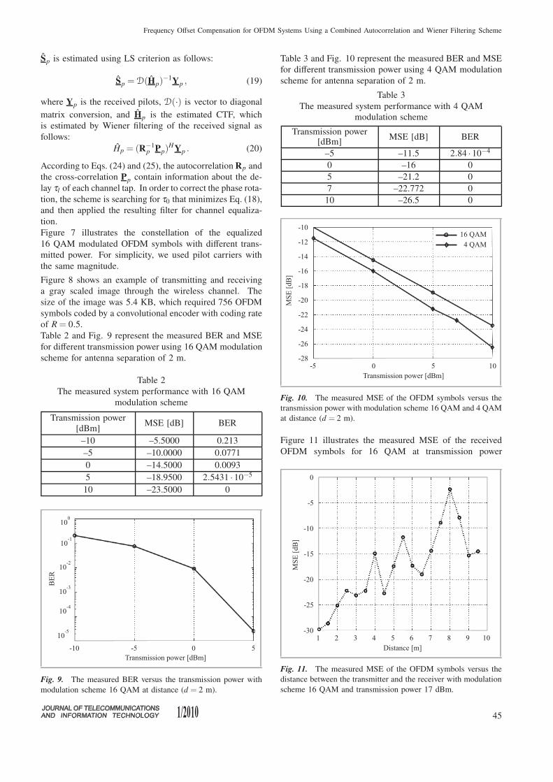
Table 3 and Fig. 10 represent the measured BER and MSE
for different transmission power using 4 QAM modulation
scheme for antenna separation of 2 m.
Table 3
The measured system performance with 4 QAM
modulation scheme
Transmission power[dBm]
MSE [dB] BER
–5 –11.5 2.84 ·10−4
0 –16 0
5 –21.2 0
7 –22.772 0
10 –26.5 0
Fig. 10. The measured MSE of the OFDM symbols versus the
transmission power with modulation scheme 16 QAM and 4 QAM
at distance (d = 2 m).
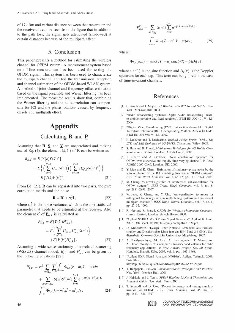
Figure 11 illustrates the measured MSE of the received
OFDM symbols for 16 QAM at transmission power
Fig. 11. The measured MSE of the OFDM symbols versus the
distance between the transmitter and the receiver with modulation
scheme 16 QAM and transmission power 17 dBm.
45
Ali Ramadan Ali, Tariq Jamil Khanzada, and Abbas Omar
of 17 dBm and variant distance between the transmitter and
the receiver. It can be seen from the figure that in addition
to the path loss, the signal gets attenuated (shadowed) at
certain distances because of the multipath effect.
5. Conclusion
This paper presents a method for estimating the wireless
channel for OFDM system. A measurement system based
on off-line measurement has been used for testing the
OFDM signal. This system has been used to characterize
the multipath channel and test the transmission, reception
and channel estimation of the OFDM-based WLAN system.
A method of joint channel and frequency offset estimation
based on the signal preamble and Wiener filtering has been
implemented. The measured results show that, combining
the Wiener filtering and the autocorrelation can compen-
sate for ICI and the phase rotations caused by frequency
offsets and multipath effect.
Appendix
Calculating R and P
Assuming that H, S, and V are uncorrelated and making
use of Eq. (4), the element (k,k′) of R can be written as
Rk,k′ = E{Y (k)Y (k′)∗}
= E{(N−1
∑m=0
Hm,kS(m))( N−1
∑m′=0
H∗m′,k′S(m′)∗
)}
+E{V(k)V (k′)∗} . (21)
From Eq. (21), R can be separated into two parts, the pure
correlation matrix and the noise
R = R′ + σ2v I , (22)
where σ2v is the noise variance, which is the first statistical
parameter that needs to be estimated at the receiver. Also
the element k′ of Pm,k is calculated as
Pk′
m,k = E{Y (k′)H∗m,k}
= E
{ N−1
∑m′=0
Hm′,k′H∗m,kS(m′)
}
+E{V(k′)H∗m,k} . (23)
Assuming a wide sense stationary uncorrelated scattering
(WSSUS) channel model, R′k,k′ and Pk′
m,k can be given by
the following equations [22]:
R′k,k′ = σ2
s ∑m/∈Sp
L−1
∑l=0
∫ ∞
−∞Φl,v(k−m,k′−m)dv
+ ∑m,m′∈Sp
S(m)S∗(m′)L−1
∑l=0
e−j2π(m−m′)∆ f τl
∫ ∞
−∞Φl,v(k−m′,k′−m′)dv ; (24)
Pk′
m,k = ∑m′∈Sp
S(m′)L−1
∑l=0
e−j2π(m−m′)∆ f τl
∫ ∞
−∞Φl,v(k
′−m′,k−m)dv , (25)
where
Φl,v(a,b) = sinc(vTs −a) sinc(vTs −b)Dl(v) ,
where sinc(·) is the sinc function and Dl(v) is the Doppler
spectrum for each tap. This term can be ignored in the case
of time-invariant channels.
References
[1] C. Smith and J. Meyer, 3G Wireless with 802.16 and 802.11. New
York: McGraw-Hill, 2004.
[2] “Radio Broadcasting Systems; Digital Audio Broadcasting (DAB)
to mobile, portable and fixed receivers”, ETSI EN 300 401 V1.4.1,
2006.
[3] “Digital Video Broadcasting (DVB); Interaction channel for Digital
Terrestrial Television (RCT) incorporating Multiple Access OFDM”,
ETSI EN 301 958 V1.1.1, 2002.
[4] P. Lescuyer and T. Lucidarme, Evolved Packet System (EPS): The
LTE and SAE Evolution of 3G UMTS. Chichester: Wiley, 2008.
[5] S. Hara and R. Prasad, Multicarrier Techniques for 4G Mobile Com-
munications. Boston, London: Artech House, 2003.
[6] J. Linartz and A. Grokhov, “New equalization approach for
OFDM over dispersive and rapidly time varying channel”, in Proc.
PIMRC 2000 Conf., London, UK, 2000.
[7] Y. Liao and K. Chen, “Estimation of stationary phase noise by the
autocorrelation of the ICI weighting function in OFDM systems”,
IEEE Trans. Wirel. Commun., vol. 5, no. 12, pp. 3370–3374, 2006.
[8] M. Chang, “A novel algorithm of interference self-cancellation for
OFDM systems”, IEEE Trans. Wirel. Commun., vol. 6, no. 8,
pp. 2881–2893, 2007.
[9] W. Jeon, K. Chang, and Y. Cho, “An equalization technique for
orthogonal frequency-division multiplexing systems in time-variant
multipath channels”, IEEE Trans. Wiurel. Commun., vol. 47, no. 1,
pp. 27–32, 1999.
[10] R. Nee and R. Prasad, OFDM for Wireless Multimedia Communi-
cations. Boston, London: Artech House, 2000.
[11] “Agilent N5182A MXG Vector Signal Generator”, Agilent Technol.,
2007, Data sheet, ftp://ftp.testequity.com/pdf/n5182a.pdf
[12] D. Mittelstrasz, “Design Einer Antenne Bestehend aus Primaer-
strahler und Dielektrischer Linse fuer das ISM-Band 2.4 GHz”, Stu-
dienarbeit: Otto-von-Guericke Universitaet Magdeburg, 2007.
[13] A. Bandyopadhyay, M. Anis, A. Joestingmeier, T. Meyer, and
A. Omar, “Analysis of a compact ultra-wideband antenna for radio
frequency applications”, in Proc. Antenn. Propag. Soc. Int. Symp.,
Honolulu, Hawaii, USA, 2007, vol. 9, pp. 1965–1968.
[14] “Agilent EXA Signal Analyzer N9010A”, Agilent Technol., 2009,
Data Sheet,
http://cp.literature.agilent.com/litweb/pdf/5989-6529EN.pdf
[15] T. Rappaport, Wireless Communications: Principles and Practice.
New York: Prentice Hall, 2001.
[16] J. Heiskala and J. Terry, OFDM Wireless LANs: A Theoretical and
Practical Guide. New York: Sams, 2001.
[17] T. Schmidl and D. Cox, “Robust frequency and timing synchro-
nization for OFDM”, IEEE Trans. Commun., vol. 45, no. 12,
pp. 1613–1621, 1997.
46

Frequency Offset Compensation for OFDM Systems Using a Combined Autocorrelation and Wiener Filtering Scheme
[18] H. Van Trees, Detection, Estimation, and Modulation Theory. Part I:
Detection, Estimation, and Linear Modulation Theory. New York:
Wiley, 1968.
[19] H. Poor, An Introduction to Signal Detection and Estimation. Berlin:
Springer, 1994.
[20] S. Kay, Fundamentals of Statistical Processing. Volume I: Estimation
Theory. Signal Processing Series. Upper Saddle River: Prentice Hall,
1993.
[21] M. Barkat, Signal Detection and Estimation. Norwood: Artech
House, 2005.
[22] C. Sgraja and J. Linder, “Estimation of rapid time-variant channels
for OFDM using wiener filtering”, IEEE Proc. Commun., vol. 4,
pp. 2390–2395, May 2003.
Ali Ramadan Ali received the
B.Sc. degree in electrical en-
gineering from Altahadi Uni-
versiy, Sirt, Libya, in 1997
and the M.Sc. degree in elec-
trical engineering from Darm-
stadt University of Applied Sci-
ence, Germany, in 2004. He
works toward the Ph.D. de-
gree at the Otto-von-Guericke
University of Magdeburg, Ger-
many. His current research field covers the areas of digital
signal processing for OFDM systems and microwave filter
design. He authored or co-authored over 23 technical pa-
pers in the field of wireless communications and microwave
filters.
e-mail: [email protected]
Otto-von-Guericke University of Magdeburg
Institute for Electronic, Signal Processing
and Communications (IESK)
Chair of Microwave and Communication Engineering (HF)
P.O. Box 4120
Universitaetsplatz 2
39016 Magdeburg, Germany
Tariq Jamil Khanzada re-
ceived the M.Eng. degree in
communication systems and
networking, and B.Eng. degree
in computer systems from
Mehran University of Engineer-
ing and Technology (MUET),
Pakistan, in 2004 and 1999, re-
spectively. He currently works
at the Institute of Electronics,
Signal Processing and Com-
munications (IESK), Otto-von-Guericke University of Mag-
deburg, Germany, since June 2005 in order to pursue his
Ph.D. degree. Prior to start his Ph.D. studies he has been
working as an Assistant Professor at the Department of
Computer Systems and Software Engineering at MUET,
since 2004 and as a lecturer since 2001. He is also a co-
author of a practical book on computer workshop pub-
lished in 2004. He is also an author of some international
research publications.
e-mail: [email protected]
Otto-von-Guericke University of Magdeburg
Institute for Electronic, Signal Processing
and Communications (IESK)
Chair of Microwave and Communication Engineering (HF)
P.O. Box 4120
Universitaetsplatz 2
39016 Magdeburg, Germany
Abbas Omar received the
B.Sc. and M.Sc. degrees in
electrical engineering from Ain
Shams University, Cairo, Egypt,
in 1978 and 1982, respectively,
and the Ph.D. degree in electri-
cal engineering from the Tech-
nical University of Hamburg,
Germany, in 1986. Since 1990,
he has been a Professor of elec-
trical engineering, and since
1998, a Director of the chair of microwave and commu-
nication engineering with Otto-von-Guericke University of
Magdeburg, Germany. He authored or co-authored over
250 technical papers extending over a wide spectrum of
research areas. His current research fields cover the areas
of microwave, nuclear magnetic resonance, and ultrasonic
imaging, remote sensing, microwave measurements, indoor
and outdoor positioning systems, wideband wireless (ter-
restrial and mobile) communication, subsurface tomogra-
phy and ground penetrating radar, ultra-wideband anten-
nas, and field theoretical modeling of microwave systems
and components. He is a member of the Editorial Board
of some international technical periodicals.
e-mail: [email protected]
Otto-von-Guericke University of Magdeburg
Institute for Electronic, Signal Processing
and Communications (IESK)
Chair of Microwave and Communication Engineering (HF)
P.O. Box 4120
Universitaetsplatz 2
39016 Magdeburg, Germany
47
Copyright © 2022 FDOKUMEN