Fractional Derivative Based FDTD Modeling of Transient Wave Propagation in Havriliak–Negami Media
10
IEEE Proof IEEE TRANSACTIONS ON MICROWAVE THEORY AND TECHNIQUES 1 Fractional Derivative Based FDTD Modeling of Transient Wave Propagation in Havriliak–Negami Media Luciano Mescia, Pietro Bia, and Diego Caratelli, Member, IEEE Abstract—In this paper, an accurate finite-difference time-do- main (FDTD) scheme for modeling time-domain wave propagation in arbitrary dispersive biological media is proposed. The main drawback occurring in the conventional FDTD implementation for such materials is the approximation of the fractional deriva- tives appearing in the relevent time-domain permittivity model. To overcome this problem, we propose a novel FDTD scheme based on the direct solution of the time-domain Maxwell equations by using the Riemann–Liouville operator for fractional differen- tiation. The feasibility of the proposed method is demonstrated by simulating the transient wave propagation in general bulk and slab dispersive materials with dielectric spectrum described by Cole–Cole, Cole–Davidson, and Havriliak–Negami formulas. In particular, the comparison between the numerical results and those evaluated by using an analytical method based on the Fourier transformation and the matrix formulation for lossy layered media demonstrates the accuracy of the proposed FDTD scheme in a broadband frequency range. Index Terms—Dielectric relaxation, dispersive media, finite dif- ference time domain (FDTD), fractional calculus. I. INTRODUCTION D URING THE last decade, pulsed electric fields (PEFs) have been playing a key role in a number of new re- search activities in bioelectrics, a new interdisciplinary field that combines knowledge of electromagnetic principles and theory, modeling and simulations, physics, material science, cell bi- ology, and medicine. The main goal of this discipline is the study of the interaction between electromagnetic fields and biolog- ical tissues aimed at the investigation of nanopulse bioeffects for human safety, as well as at the use of ultrashort pulses in biomedical and biotechnological applications [1]–[3]. Current applications of PEFs are primarily based on re- versible or irreversible electroporation that is the process by which the permeability to drugs, molecules, and genetic mate- rial of the plasma membrane of a biological cell is affected. This phenomenon can result in either permanent permeabilization of cancer cells or the destabilization of the cell membranes and Manuscript received December 11, 2013; revised March 21, 2014 and May 16, 2014; accepted May 19, 2014. L. Mescia and P. Bia are with the Department of Electrical and In- formation Engineering, Politecnico di Bari, 70125 Bari, Italy (e-mail: [email protected]). D. Caratelli is with The Antenna Company Nederland B.V., 3911 AV Rhenen, The Netherlands (e-mail: [email protected]). Digital Object Identifier 10.1109/TMTT.2014.2327202 intracellular components useful to trigger cellular mechanism leading to cellular death [4]–[6]. As a result, electroporation based therapies and treatments can be used to achieve selec- tive killing of cancer cells, tissue ablation, gene therapy, and DNA based vaccination. In particular, in the cancer therapy, PEFs have been defined for the treatment of easily accessible cutaneous and subcutaneous tumor nodules, prostate cancer, and fibrosarcoma. This approach has demonstrated remarkable potential for the treatment of solid tumors without hyperthermia or delivering drugs or genes [1]–[3], [7]. Other therapeutic applications include coronary and peripheral vascular disease, activating platelets, plasmids transfection, immune responses enhancement, and tissue imaging [1]. Moreover, the application of this new technology could have a great impact on molecular biology by promoting the understanding of molecular mecha- nisms of cells. The efficiency of PEF treatment depends on the electric field distribution within the treated tissue. In fact, the cellular death mechanism is strongly affected by pulse parameters such as am- plitude, duration, number of pulses, and repetition frequency. However, PEF exposure could result in side effects such as tissue damage, conformational changes in macromolecules, al- teration of the biochemical reaction rates, membrane character- istics, and temperature levels [8]. Therefore, in order to predict the effect of exposures and assess possible outcomes, it is very important to know the local electric field distribution inside the exposed tissue. In many applicative cases, the electromagnetic field cannot be easily measured. To this aim, theoretical models are invaluable tools to better understand the involved mecha- nisms as well as to evaluate and optimize treatment modalities and to develop disease-specific or even patient-specific proto- cols. The electric field distribution excited in biological media mainly depends on the electric properties of tissues, but the lack of data and accurate models, over broad frequency ranges, has thus far been an obstacle for both theoretical and exper- imental studies. In fact, the complexity of the structure and composition of biological matter produces anomalies in the dynamic dielectric properties resulting in a strong dispersion of dielectric susceptibility. This dispersion can be explained by considering that the disordered nature and microstructure of the systems yield multiple relaxation times. As a result, the time-domain response is generally nonsymmetric and markedly different from that of dielectric media modeled by the simple Debye equation. Therefore, it is important to define empirical 0018-9480 © 2014 IEEE. Personal use is permitted, but republication/redistribution requires IEEE permission. See http://www.ieee.org/publications_standards/publications/rights/index.html for more information.
Transcript of Fractional Derivative Based FDTD Modeling of Transient Wave Propagation in Havriliak–Negami Media

IEEE
Proo
f
IEEE TRANSACTIONS ON MICROWAVE THEORY AND TECHNIQUES 1
Fractional Derivative Based FDTD Modelingof Transient Wave Propagation in
Havriliak–Negami MediaLuciano Mescia, Pietro Bia, and Diego Caratelli, Member, IEEE
Abstract—In this paper, an accurate finite-difference time-do-main (FDTD) scheme for modeling time-domain wave propagationin arbitrary dispersive biological media is proposed. The maindrawback occurring in the conventional FDTD implementationfor such materials is the approximation of the fractional deriva-tives appearing in the relevent time-domain permittivity model.To overcome this problem, we propose a novel FDTD schemebased on the direct solution of the time-domain Maxwell equationsby using the Riemann–Liouville operator for fractional differen-tiation. The feasibility of the proposed method is demonstratedby simulating the transient wave propagation in general bulkand slab dispersive materials with dielectric spectrum describedby Cole–Cole, Cole–Davidson, and Havriliak–Negami formulas.In particular, the comparison between the numerical resultsand those evaluated by using an analytical method based on theFourier transformation and the matrix formulation for lossylayered media demonstrates the accuracy of the proposed FDTDscheme in a broadband frequency range.
Index Terms—Dielectric relaxation, dispersive media, finite dif-ference time domain (FDTD), fractional calculus.
I. INTRODUCTION
D URING THE last decade, pulsed electric fields (PEFs)have been playing a key role in a number of new re-
search activities in bioelectrics, a new interdisciplinary field thatcombines knowledge of electromagnetic principles and theory,modeling and simulations, physics, material science, cell bi-ology, andmedicine. Themain goal of this discipline is the studyof the interaction between electromagnetic fields and biolog-ical tissues aimed at the investigation of nanopulse bioeffectsfor human safety, as well as at the use of ultrashort pulses inbiomedical and biotechnological applications [1]–[3].Current applications of PEFs are primarily based on re-
versible or irreversible electroporation that is the process bywhich the permeability to drugs, molecules, and genetic mate-rial of the plasma membrane of a biological cell is affected. Thisphenomenon can result in either permanent permeabilizationof cancer cells or the destabilization of the cell membranes and
Manuscript received December 11, 2013; revised March 21, 2014 and May16, 2014; accepted May 19, 2014.L. Mescia and P. Bia are with the Department of Electrical and In-
formation Engineering, Politecnico di Bari, 70125 Bari, Italy (e-mail:[email protected]).D. Caratelli is with The Antenna CompanyNederland B.V., 3911 AVRhenen,
The Netherlands (e-mail: [email protected]).Digital Object Identifier 10.1109/TMTT.2014.2327202
intracellular components useful to trigger cellular mechanismleading to cellular death [4]–[6]. As a result, electroporationbased therapies and treatments can be used to achieve selec-tive killing of cancer cells, tissue ablation, gene therapy, andDNA based vaccination. In particular, in the cancer therapy,PEFs have been defined for the treatment of easily accessiblecutaneous and subcutaneous tumor nodules, prostate cancer,and fibrosarcoma. This approach has demonstrated remarkablepotential for the treatment of solid tumors without hyperthermiaor delivering drugs or genes [1]–[3], [7]. Other therapeuticapplications include coronary and peripheral vascular disease,activating platelets, plasmids transfection, immune responsesenhancement, and tissue imaging [1]. Moreover, the applicationof this new technology could have a great impact on molecularbiology by promoting the understanding of molecular mecha-nisms of cells.The efficiency of PEF treatment depends on the electric field
distribution within the treated tissue. In fact, the cellular deathmechanism is strongly affected by pulse parameters such as am-plitude, duration, number of pulses, and repetition frequency.However, PEF exposure could result in side effects such astissue damage, conformational changes in macromolecules, al-teration of the biochemical reaction rates, membrane character-istics, and temperature levels [8]. Therefore, in order to predictthe effect of exposures and assess possible outcomes, it is veryimportant to know the local electric field distribution inside theexposed tissue. In many applicative cases, the electromagneticfield cannot be easily measured. To this aim, theoretical modelsare invaluable tools to better understand the involved mecha-nisms as well as to evaluate and optimize treatment modalitiesand to develop disease-specific or even patient-specific proto-cols.The electric field distribution excited in biological media
mainly depends on the electric properties of tissues, but thelack of data and accurate models, over broad frequency ranges,has thus far been an obstacle for both theoretical and exper-imental studies. In fact, the complexity of the structure andcomposition of biological matter produces anomalies in thedynamic dielectric properties resulting in a strong dispersionof dielectric susceptibility. This dispersion can be explainedby considering that the disordered nature and microstructureof the systems yield multiple relaxation times. As a result, thetime-domain response is generally nonsymmetric and markedlydifferent from that of dielectric media modeled by the simpleDebye equation. Therefore, it is important to define empirical
0018-9480 © 2014 IEEE. Personal use is permitted, but republication/redistribution requires IEEE permission.See http://www.ieee.org/publications_standards/publications/rights/index.html for more information.

IEEE
Proo
f
2 IEEE TRANSACTIONS ON MICROWAVE THEORY AND TECHNIQUES
models for each organ, in a wide frequency range, for studiesregarding the interaction between electromagnetic wave andbiological bodies, especially for PEF excitation.The dielectric properties of biological tissues result from
the interaction of electromagnetic energy with the tissue con-stituents at the cellular and molecular level. This process isstrongly affected by the bound water content. The frequencyvariation of the dielectric properties of tissues with high watercontent can be easily described by the Debye relation. Thiskind of response is obtained for an assembly of identicaldipoles yielding a loss of energy proportional to the electricfield frequency. However, it is well known that the dielectricproperties of many biological materials displayand dispersion types attributed to a different polarizationmechanism [9]. As a consequence, an accurate representationof the experimental dielectric response in the frequency domainusually cannot be described by a simple exponential expressionwith a single relaxation time (Debye model). To this end, anumber of empirical relationships including Cole–Cole (C–C),Cole–Davidson (C–D), and Havriliak–Negami (H–N) equa-tions have been proposed in order to fit such types of dielectricspectra. The C–C model is generally chosen to describe therelative complex permittivity of many types of biologicaltissues over wide frequency ranges. However, H–N represen-tation includes both C–C and C–D models and provides anextended model flexibility enabling a better parametrization ofthe arbitrary dispersive media properties.The frequency-domain representation of the H–N complex
permittivity exhibits fractional powers of the angular frequency. Due to this, the solution of the Maxwell’s equations in the
time domain by means of conventional modeling methodolo-gies is not trivial. In particular, the evaluation of the transientpropagation of electromagnetic waves in H–N dielectric media,by using the FDTD algorithm, is complex since it contains thetransformation of the H–N expression from the frequency do-main to the time domain. In this contest, the approximation offractional derivatives using finite differences requires specialtreatment.A common approach is to approximate the relative complex
permittivity by means of rational or polynomial functions. Inthis way, auxiliary differential equation (ADE) methods can beformulated for FDTD simulation [8], [10]–[13]. Alternative ap-proaches based on the application of the Riemann–Liouvilletheory to the analysis of C–C media have been proposed in[14]–[16]. However, the authors are unaware of any schemein which the double fractional derivative operator relevant tothe general H–N response is directly incorporated in the FDTDbasic algorithm. The formulation developed to this end [17] ishere detailed together with the relevant numerical implemen-tation. Furthermore, dedicated uniaxial perfectly matched layer(UPML) boundary conditions useful to truncate H–N media inFDTD lattices are derived, thus allowing an accurate electro-magnetic characterization of such media under plane-wave ex-citation by means of a conventional total field/scattered field(TF/SF) approach. The assessment of the proposed scheme iscarried out by using 1-D test cases involving biological mediawith C–C, C–D, and H–N permittivity characteristics.
This paper is organized as follows. The proposed FDTD ap-proach based on fractional calculus is illustrated in detail inSection II. Numerical results showing the accuracy of the pro-posed FDTD scheme are presented in Section III.
II. THEORY
Biological tissues are typically inhomogeneous materials,which are, in some cases, characterized by high anisotropy.Moreover, the supracellular organization in such materials,often taking the form of fractal structures, induces non-Debyebehavior [18]–[22]. In fact, many experimental data from var-ious types of cell suspensions and tissues indicate that markeddeviations from classical Debye behavior is due to near-fieldinteractions or direct ionic coupling between abutting cells. Asa result, biological tissues exhibit several different dispersionsover a wide range of frequencies, and the Debye equation is apoor model of dielectric behavior for most biological materialsover frequency ranges of two or more decades. The H–Nfunction is considered as a general expression for the universalrelaxation law. As a consequence, it can be used to accuratelyfit the frequency dependence of the complex permittivity ofnon-Debye materials such as the biological ones. In particular,in such materials, the frequency dependent H–N relative com-plex permittivity is given by
(1)
where and are the static and infinite relative permit-tivity, respectively, is the principal relaxation time, and andare positive and adjustable parameters between 0 and 1 de-
termining the shape and the width of the complex permittivitycurve. In particular, and describe the symmetric andasymmetric broadening of the relaxation process, respectively.For and , (1) describes the well-known Debyemodel. Moreover, for and , as well as for
and , the C–C and C–D equations are ob-tained, respectively.
A. FDTD Scheme
The Ampere’s law in combination with the material relationin frequency domain (1) can be written as
(2)
where , and is the polarization current
(3)
Transforming (3) in the time domain yields the following frac-tional differential equation:
(4)

IEEE
Proo
f
MESCIA et al.: FRACTIONAL DERIVATIVE BASED FDTD MODELING OF TRANSIENT WAVE PROPAGATION IN H–N MEDIA 3
where is the th-order fractional differential oper-ator and
(5)
By virtue of the Riemann–Liouville theory, it follows that
(6)
In this way, upon using the Taylor-series expansion of the ex-ponential function,
(7)
and considering the integral representation of the Gamma func-tion
(8)
(6) becomes
(9)
Retaining the first terms, (9) can be reformulated as fol-lows:
(10)
In order to determine the optimal value of , which results inan accurate representation of the relative complex permittivityfunction, let us consider the frequency-dependent relation (1),and in particular, the following truncated binomial series:
(11)
In this way, can be defined as the function of theparamters and that satisfies the following inequality:
(12)
where denotes a sufficiently small positive constant. Fig. 1shows the distribution of where the thresholdis selected. In this case, it is worth noting that a good approx-imation can be obtained by using less then six terms. A larger
Fig. 1. Number of terms of the binomial series approximation versusand parameters.
number of terms is needed in order to enhance the accuracy ofthe approximation as becomes smaller.By using the Riemann–Liouville definition of fractional
derivative, the following equation is derived:
(13)
where . Moreover, by setting
(14)
and applying a central finite-difference approximation with timestep , one can readily obtain, at the general time instant
,
(15)
By using the following expansion [23]:
(16)
with the order and the coefficients and beingsuitably chosen in order to minimize the mean square error, andupon setting
(17)

IEEE
Proo
f
4 IEEE TRANSACTIONS ON MICROWAVE THEORY AND TECHNIQUES
(15) can be rewritten as
(18)
where
(19)
In (13), the th-order time derivative of calculated at thetime instant can be approximated by means of the sum
(20)
As a result, (10) becomes
(21)
Thus, setting
(22)
(23)
(24)
(25)
(21) can be recast in the form
(26)
In order to evaluate the electric field components, (4) is dis-cretized at the time instant as
(27)
Moreover, by applying the finite-difference scheme to the Am-pere’s law (2), one readily obtains, at the time instant ,
(28)
where
(29)
Using (26)–(29), it is straightforward to derive the equation forupdating the polarization current as (30), shown at the bottom ofthis page. Finally, by performing a central finite-difference ap-proximation of the Faraday’s law in the time domain, the FDTDupdate equation for the magnetic field is found to be
(31)
B. UPML Boundary Conditions
In order to truncate the FDTD computational region andsolve electromagnetic problems with open boundaries, ded-icated UPML boundary conditions have been derived andimplemented within the proposed FDTD scheme. To this end,the conventional UPML formulation presented in [24]–[28]has been revised and extended here in order to account forthe double fractional behavior of the frequency-dependentpermittivity of general H–N media.Let us consider a -polarized electromagnetic wave prop-
agating in a general dispersive material along the -axis. The
(30)

IEEE
Proo
f
MESCIA et al.: FRACTIONAL DERIVATIVE BASED FDTD MODELING OF TRANSIENT WAVE PROPAGATION IN H–N MEDIA 5
Maxwell equations inside the UPML layer terminating the dis-persive region can be written as [24]
(32)
(33)
where
(34)
with
(35)
(36)
In (35) and (36), and denote the abscissa of theUPML interface and the relevant thickness, respectively. Fur-thermore, is the maximum value assumed by the con-ducibility at the truncation of the UPML region
and is a real coefficient, which is selected heuris-tically in order to enhance the absorption of electromagneticwaves within the UPML region, and in this way, minimize thespurious reflection level in the solution domain.Combining (32) and (34), the following expression is ob-
tained:
(37)
and setting
(38)
(37) can be written
(39)
Transforming (38) in the time domain yields a fractional differ-ential equation
(40)
that can be discretized at the general time instant asfollows:
(41)
TABLE IPARAMETERS OF THE COMPLEX PERMITTIVITY FUNCTION
in order to derive the equation for updating the electric field
(42)
Evaluating (33) at the general time step results in thefollowing expression:
(43)
which can be recast in the update equation for the magnetic field
(44)
III. NUMERICAL RESULTS
The proposed FDTD scheme is assessed by studying threedifferent test cases relevant to biological media described byC–C, C–D, and H–N dielectric characteristics. In Table I, the pa-rameters used in the performed numerical simulations are sum-marized.In order to evaluate the accuracy of the proposed FDTD
scheme, the 1-D problem regarding the electromagnetic prop-agation in a dispersive material half space orthogonal to the-axis of a given Cartesian frame is considered here.The structure is assumed to be excited by a plane wave, whichpropagates along the positive -direction with electric fieldlinearly polarized along the -axis. The time-domain signalsource is an electric current located at a given pointinside the computational domain
(45)
In (45), GHz is the central frequency, and ns isthe duration of the rectangular pulse. The time and spatial stepsare selected to be ps and mm, respectively.The UPML absorbing boundary condition is applied here in
order to truncate the computational domain while minimizing

IEEE
Proo
f
6 IEEE TRANSACTIONS ON MICROWAVE THEORY AND TECHNIQUES
the spurious back-reflection level. To this end, the electricalconductivity profile within the UPML and the relevant thick-ness have been optimized in order to maximize the relevantabsorbing properties. Heuristically, the UPML parameters havebeen selected to be , , , and
[24].Fig. 2 shows the computed space-time distribution of the nor-
malized electric field obtained by (a) removing the UPML andterminating the computational domain with a PEC boundarycondition and (b) implementing the UPML with thickness
. In Fig. 2(a), the spatial extension of thecomputational domain has been chosen in such a way that noreflection of the source pulse from the PEC termination takesplace for the complete duration of the numerical simulationuntil the time instant ns. Fig. 2(c) depicts therelative error calculated by using the expression
(46)
In (46), and denote the reference electricfield distribution and the relevant peak value [see Fig. 2(a)],whereas is the electric field calculated by usingthe UPML boundary condition [see Fig. 2(b)]. It is worth notingthat the absorbing boundary condition efficiently prevents theoutgoing wave from being reflected back into the solution do-main. As result, as it appears from Fig. 2(c), the relative errorwithin the whole computational domain is always smaller than65 dB.The results computed by means of the proposed FDTD
scheme have been compared with those derived using a fullyanalytical approach. As a matter of fact, for the considered 1-Dproblem, the frequency-domain distribution of the electric fieldinside the dispersive half space can be evaluated as product
of the Fourier transform of the electric field at the sourcelocation and the transfer function of the medium [10]
(47)
where
(48)
Numerical simulations have been performed by using boththe proposed FDTD method and the fully analytical procedure.In particular, the PEF propagation is evaluated in C–C, C–D,and H–N media characterized by the parameters reported inTable I. Fig. 3 shows the spatial distribution of the electric fieldcalculated at ns and generated by the source located in
m for the: (a) C–C medium, (b) C–D medium, and(c) H–N medium. In all the considered test cases, a good agree-ment between the developed FDTD technique and the rigorousanalytical approaches can be noticed.As a second validation test we analyzed the transmission
coefficient of the dispersive material using both the proposedFDTD scheme and the Fourier transform based approach. Thenumerical simulations have been performed by considering a1-D H–N medium characterized by the parameters ,
Fig. 2. (a) Space-time electric field distribution without UPML and with a PECboundary condition, (b) with UPML having , and (c) relativeerror.
, ps, , and . A sinusoidallymodulated Gaussian pulse element is used as radio source [10]
(49)
where , , and GHz are se-lected in such a way as to achieve a spectral bandwidth of about10 GHz. In this case, the time and spatial steps in the FDTD-

IEEE
Proo
f
MESCIA et al.: FRACTIONAL DERIVATIVE BASED FDTD MODELING OF TRANSIENT WAVE PROPAGATION IN H–N MEDIA 7
Fig. 3. Electric field spatial distribution in 1-D: (a) C–Cmedia, (b) C–Dmedia,and (c) H–N media. Analytical approach (dashed line) and the proposed FDTDmethod (solid line).
based computations are ps and mm, re-spectively. The transmission coefficient is computed as the ratiobetween the Fourier transforms of the electric field excited attwo different locations and within the dispersive medium
(50)
Fig. 4 illustrates: (a) the real part, (b) the imaginary part, and (c)the magnitude of the transmission coefficient in the H–N 1-Dmedium evaluated by using both the analytical Fourier trans-form based approach and the FDTD method. The consideredobservation and source location points are mm and
mm, respectively. The analysis is carried out over awide frequency range from 0.1 to 10 GHz, which is the band-width of common PEF signals. By visual inspection of Fig. 4,
Fig. 4. Spectrum of the: (a) real part, (b) imaginary part, and (c) modulus ofthe transmission coefficient in the H–N 1-D medium characterized by theparameters , , ps, , and atthe observation point mm. Analytical approach (dashed line) and theproposed FDTD method (solid line).
it can be observed that the proposed FDTD scheme exhibits anexcellent accuracy.A further investigation has been carried out in order to an-
alyze the penetration depth, which is the depth at which theamplitude of the electromagnetic field inside the material fallsto of its value on the surface. This parameter measureshow well an electromagnetic wave can penetrate into a bio-logical medium. Fig. 5 shows the penetration depth versus thefrequency in the H–N medium by using both the analytical ap-proach and the proposed FDTD method. Also in this case, theexcellent accuracy of the proposed FDTD scheme can be no-ticed. The penetration depth varies from a small fraction of amillimeter at the upper cutoff frequency of the excitation sourceto about 1 m at lower working frequencies. This result shows

IEEE
Proo
f
8 IEEE TRANSACTIONS ON MICROWAVE THEORY AND TECHNIQUES
Fig. 5. Penetration deep versus the frequency in the H–N medium. Analyticalapproach (dashed line) and the proposed FDTD method (solid line).
Fig. 6. Space-time electric-field distribution to check the numerical stability ofthe proposed FDTD scheme.
Fig. 7. PEF evolution in a 1-D stratified air/H–N biological/air medium. Theparameters of H–N medium are , , ps, ,and .
that the presented FDTD scheme is a very useful and reliabletool to predict the electromagnetic field propagation character-istic in the H–N medium.In order to check the numerical stability of the proposed al-
gorithm we verified, for the considered test case, that the nu-merical electromagnetic field distribution does not feature anylong time divergence. To this end, a numerical simulation hasbeen performed over a very long time interval, which is 50 timesthe duration of the source pulse. In spite of that, as can be no-ticed in Fig. 6, the electric field propagating inside the H–Nmedium shows well-behaved characteristics and asymptoticallydecreasing energy.
Fig. 8. Spectrum of the: (a) reflectance, (b) transmittance, and (c) absorbanceof a single-layer H–N material slab.
To further assess the accuracy of the proposed FDTD scheme,the PEF propagation in an H–N material slab in air has beenanalyzed under plane-wave excitation. To this end, the TF/SFscheme described in [24] and [28] has been adopted. The sourcepulse, applied in mm, is defined in (49) with the pa-rameters GHz, , and selectedin such a way as to achieve a bandwidth of about 15 GHz. Thedielectric properties of the considered biological medium are
, , ps, , and . Fig. 7shows the space–time distribution of the electric field as com-puted by means of the developed FDTD-based procedure. It canbe observed that the incident electric field is strongly reflected atthe air/H–N interface and only a relatively small radio signal istransmitted inside the biological tissue. In particular, at higherfrequencies, the electromagnetic field can penetrate more effi-ciently inside the material slab thanks to the reduced value of
IEEE
Proo
f
MESCIA et al.: FRACTIONAL DERIVATIVE BASED FDTD MODELING OF TRANSIENT WAVE PROPAGATION IN H–N MEDIA 9
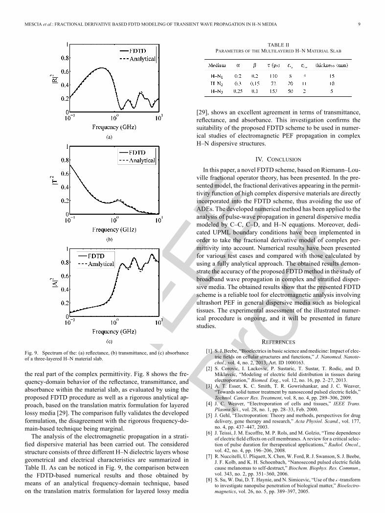
Fig. 9. Spectrum of the: (a) reflectance, (b) transmittance, and (c) absorbanceof a three-layered H–N material slab.
the real part of the complex permittivity. Fig. 8 shows the fre-quency-domain behavior of the reflectance, transmittance, andabsorbance within the material slab, as evaluated by using theproposed FDTD procedure as well as a rigorous analytical ap-proach, based on the translation matrix formulation for layeredlossy media [29]. The comparison fully validates the developedformulation, the disagreement with the rigorous frequency-do-main-based technique being marginal.The analysis of the electromagnetic propagation in a strati-
fied dispersive material has been carried out. The consideredstructure consists of three different H–N dielectric layers whosegeometrical and electrical characteristics are summarized inTable II. As can be noticed in Fig. 9, the comparison betweenthe FDTD-based numerical results and those obtained bymeans of an analytical frequency-domain technique, basedon the translation matrix formulation for layered lossy media
TABLE IIPARAMETERS OF THE MULTILAYERED H–N MATERIAL SLAB
[29], shows an excellent agreement in terms of transmittance,reflectance, and absorbance. This investigation confirms thesuitability of the proposed FDTD scheme to be used in numer-ical studies of electromagnetic PEF propagation in complexH–N dispersive structures.
IV. CONCLUSION
In this paper, a novel FDTD scheme, based on Riemann–Lou-ville fractional operator theory, has been presented. In the pre-sented model, the fractional derivatives appearing in the permit-tivity function of high complex dispersive materials are directlyincorporated into the FDTD scheme, thus avoiding the use ofADEs. The developed numerical method has been applied to theanalysis of pulse-wave propagation in general dispersive mediamodeled by C–C, C–D, and H–N equations. Moreover, dedi-cated UPML boundary conditions have been implemented inorder to take the fractional derivative model of complex per-mittivity into account. Numerical results have been presentedfor various test cases and compared with those calculated byusing a fully analytical approach. The obtained results demon-strate the accuracy of the proposed FDTDmethod in the study ofbroadband wave propagation in complex and stratified disper-sive media. The obtained results show that the presented FDTDscheme is a reliable tool for electromagnetic analysis involvingultrashort PEF in general dispersive media such as biologicaltissues. The experimental assessment of the illustrated numer-ical procedure is ongoing, and it will be presented in futurestudies.
REFERENCES[1] S. J. Beebe, “Bioelectrics in basic science andmedicine: Impact of elec-
tric fields on cellular structures and functions,” J. Nanomed. Nanote-chol., vol. 4, no. 2, 2013, Art. ID 1000163.
[2] S. Corovic, I. Lackovic, P. Sustaric, T. Sustar, T. Rodic, and D.Miklavcic, “Modeling of electric field distribution in tissues duringelectroporation,” Biomed. Eng., vol. 12, no. 16, pp. 2–27, 2013.
[3] A. T. Esser, K. C. Smith, T. R. Gowrishankar, and J. C. Weaver,“Towards solid tumor treatment by nanosecond pulsed electric fields,”Technol. Cancer Res. Treatment, vol. 8, no. 4, pp. 289–306, 2009.
[4] J. C. Weaver, “Electroporation of cells and tissues,” IEEE Trans.Plasma Sci., vol. 28, no. 1, pp. 28–33, Feb. 2000.
[5] J. Gehl, “Electroporation: Theory and methods, perspectives for drugdelivery, gene therapy and research,” Acta Physiol. Scand., vol. 177,no. 4, pp. 437–447, 2003.
[6] J. Teissi, J. M. Escoffre, M. P. Rols, and M. Golzio, “Time dependenceof electric field effects on cell membranes. A review for a critical selec-tion of pulse duration for therapeutical applications,” Radiol. Oncol.,vol. 42, no. 4, pp. 196–206, 2008.
[7] R. Nuccitelli, U. Pliquett, X. Chen,W. Ford, R. J. Swanson, S. J. Beebe,J. F. Kolb, and K. H. Schoenbach, “Nanosecond pulsed electric fieldscause melanomas to self-destruct,” Biochem. Biophys. Res. Commun.,vol. 343, no. 2, pp. 351–360, 2006.
[8] S. Su, W. Dai, D. T. Haynie, and N. Simicevic, “Use of the -transformto investigate nanopulse penetration of biological matter,” Bioelectro-magnetics, vol. 26, no. 5, pp. 389–397, 2005.

IEEE
Proo
f
10 IEEE TRANSACTIONS ON MICROWAVE THEORY AND TECHNIQUES
[9] K. Foster and H. Schwan, “Dielectric properties of tissues,” in Bi-ological Effects of Electromagnetic Fields, C. Polk and E. Postow,Eds. New York, NY, USA: CRC Press, 1996.
[10] I. T. Rekanos, “FDTD schemes for wave propagation inDavidson–Cole dispersive media using auxiliary differentialequations,” IEEE Trans. Antennas Propag., vol. 60, no. 3, pp.1467–1478, Mar. 2012.
[11] Z. Lin, “On the FDTD formulations for biological tissues withCole–Cole dispersion,” IEEE Microw. Wireless Compon. Lett., vol.20, no. 10, pp. 244–246, Oct. 2010.
[12] I. T. Rekanos, “FDTD modeling of Havriliak–Negami media,” IEEEMicrow. Wireless Compon. Lett., vol. 22, no. 2, pp. 49–51, Feb. 2012.
[13] I. T. Rekanos and T. G. Papadopoulos, “FDTDmodeling of wave prop-agation in Cole–Cole media with multiple relaxation times,” IEEE An-tennas Wireless Propag. Lett., vol. 9, pp. 67–69, 2010.
[14] F. Torres, P. Vaudon, and B. Jecko, “Application of fractional deriva-tives to the FDTD modelling of pulse propagation in a Cole–Coledispersive medium,” Microw. Opt. Technol. Lett., vol. 13, no. 5, pp.300–304, 1996.
[15] M.-R. Tofighi, “FDTD modeling of biological tissues Cole–Cole dis-persion for 0.530 GHz using relaxation time distribution samples-noveland improved implementations,” IEEE Trans. Microw. Theory Techn.,vol. 57, no. 10, pp. 2588–2596, Oct. 2009.
[16] H. H. Abdullah, H. A. Elsadek, H. E. ElDeeb, and N. Bagherzadeh,“Fractional derivatives based scheme for FDTD modeling of th-orderCole–Cole dispersive media,” IEEE Antennas Wireless Propag. Lett.,vol. 11, pp. 281–284, 2012.
[17] L. Mescia, D. Caratelli, P. Bia, R. Cicchetti, G. Maione, and F. Pru-denzano, “Fractional-order modeling of transient wave propagation inHavriliak–Negami based dispersive biological tissues,” in Proc. Int.Fract. Syst. Signals Conf., 2013, pp. 1–5.
[18] R. Magin, “Fractional calculus in bioengineering, Part 1,” Crit. Rev.Biomed. Eng., vol. 32, no. 1, pp. 1–104, 2004.
[19] R. Magin, “Fractional calculus in bioengineering, Part 2,” Crit. Rev.Biomed. Eng., vol. 32, no. 2, pp. 105–194, 2004.
[20] R. Magin, “Fractional calculus in bioengineering, Part 3,” Crit. Rev.Biomed. Eng., vol. 32, no. 3, pp. 195–377, 2004.
[21] R. Magin, “Fractional calculus models of complex dynamics in bio-logical tissues,” Comput. Math. Appl., vol. 59, no. 5, pp. 1586–1593,2010.
[22] R. Magin, Fractional Calculus in Bioengineering. Danbury, CT,USA: Begell House Publishers, 2006.
[23] J. W. Schuster and R. J. Luebbers, “An FDTD algorithm for transientpropagation in biological tissue with a Cole–Cole dispersion relation,”in Proc. IEEE Int. Antennas Propag. Symp., 1991, pp. 1988–1991.
[24] A. Taflove and S. Hagness, Computational Electrodynamics: The Fi-nite-Difference Time-Domain Method. Norwood, MA, USA: ArtechHouse, 2005.
[25] L. Bernard, R. R. Torrado, and L. Pichon, “Efficient implementation ofthe UPML in the generalized finite-difference time-domain method,”IEEE Trans. Magn., vol. 46, no. 8, pp. 3492–3495, Aug. 2010.
[26] I. Udagedara, M. Premaratne, I. D. Rukhlenko, H. T. Hattori, and G. P.Agrawal, “Unified perfectly matched layer for finite-difference time-domain modeling of dispersive optical materials,” Opt. Exp., vol. 17,no. 23, pp. 21 179–21 190, 2009.
[27] J. Li, L.-X. Guo, H. Zeng, and X.-B. Han, “Message-passing-inter-face-based parallel FDTD investigation on the EM scattering from a1-D rough sea surface using uniaxial perfectly matched layer absorbingboundary,” J. Opt. Soc. Amer. A, Opt. Image Sci., vol. 26, no. 6, pp.1494–1502, 2009.
[28] W. Sun, H. Pan, and G. Videen, “General finite-difference time-domainsolution of an arbitrary electromagnetic source interaction with an ar-bitrary dielectric surface,” Appl. Opt., vol. 48, no. 31, pp. 6015–6025,2009.
[29] P. Yeh, Optical Waves in Layered Media. New York, NY, USA:Wiley, 1988.
LucianoMescia, photograph and biography not available at time of publication.
Pietro Bia, photograph and biography not available at time of publication.
Diego Caratelli (M’13), photograph and biography not available at time of pub-lication.