Forwards response to Bulletin 87-001, "Thinning of Pipe Walls ...
14
REGULATORYIOFORNATION DISTRIBUTION SYP (RIDS> i ACCESSION NBR: 8709150287 DOC. DATE: 87/09/11 NOTARIZED: YES FACIL: 50-387 Susquehanna Steam Electric Station> Unit ii Pennsglva 50-388 Susquehanna Steam ElectY ic Stationi Unit 2i Pennsg lva AUTH. NAME AUTHOR AFFILIATION KEISERi H. N. Pennsylvania Poujer 5 Light Co. RECIP. NAME RECIPIENT AFFILIATION RUSSELL'. T. Region ii Of f.ice of Director DOCKET 0 05000387 05000388 05000387 05000388 SUBJECT: Forujards response to Bulletin 8701I "Thinning of Pipe Mails in Nuclear Power Plants. " Codes 5 stds used in design fabrication of pi ping associated uj/pipe eall thinning program listed. DISTRIBUTION CODE: IEIID COPIES RECEIVED: LTR i ENCL l " SIZE: 3 TITLE: Bulletin Response (50 DKT) NOTES: 1 cg NMSS/FCAF/PM. LPDR 2c g s Transcr i p ts. icy NMSS/FCAF/PM. LPDR 2cgs Transcripts. r REC IP IENT ID CODE/NAME PD1-2 L* THADANI i M 02 E 01 INTERNAL: AEOD/DOA AEOD/DSP/TPAB NRR/DEST/ADS NRR/DOEA/E*B R/DR /EPB REG FILE G COPIES LTTR ENCL 1 0 1 1 1 1 1 1 1 1 1 1 1 1 1 1, 1 RECIPIENT ID CODE/NAME PD1-2 PD AEOD/DSP NRR/DEST/ADE NRR/DEBT/MEB NRR/DOE*/GCB NRR/PMAS/ ILRB RES/DE/EIB COPIES LTTR ENCL 1 1 1 1 1 1 1 1 1 1 1 1 1 1 EXTERNAL: LPDR NSIC, NOTES: 2 2 1 1 3 3 NRC PDR 1 1 TOTAL NUMBER OF COPIES REQUIRED: LTTR 23 ENCL 22
-
Upload
khangminh22 -
Category
Documents
-
view
6 -
download
0
Transcript of Forwards response to Bulletin 87-001, "Thinning of Pipe Walls ...

REGULATORYIOFORNATION DISTRIBUTION SYP (RIDS>i
ACCESSION NBR: 8709150287 DOC. DATE: 87/09/11 NOTARIZED: YESFACIL: 50-387 Susquehanna Steam Electric Station> Unit ii Pennsglva
50-388 Susquehanna Steam ElectY ic Stationi Unit 2i Pennsg lvaAUTH. NAME AUTHOR AFFILIATION
KEISERi H. N. Pennsylvania Poujer 5 Light Co.RECIP. NAME RECIPIENT AFFILIATION
RUSSELL'. T. Region ii Off.ice of Director
DOCKET 00500038705000388
0500038705000388
SUBJECT: Forujards response to Bulletin 8701I "Thinning of Pipe Mailsin Nuclear Power Plants. " Codes 5 stds used in designfabrication of pi ping associated uj/pipe eall thinningprogram listed.
DISTRIBUTION CODE: IEIID COPIES RECEIVED: LTR i ENCL l " SIZE: 3TITLE: Bulletin Response (50 DKT)
NOTES: 1 cg NMSS/FCAF/PM. LPDR 2c g s Transcr i p ts.icy NMSS/FCAF/PM. LPDR 2cgs Transcripts.
r
REC IP IENTID CODE/NAME
PD1-2 L*THADANIi M
02E 01
INTERNAL: AEOD/DOAAEOD/DSP/TPABNRR/DEST/ADSNRR/DOEA/E*B
R/DR /EPBREG FILE
G
COPIESLTTR ENCL
1 01 1
1 1
1 1
1 1
1 1
1 1
1 1,1
RECIPIENTID CODE/NAME
PD1-2 PD
AEOD/DSPNRR/DEST/ADENRR/DEBT/MEBNRR/DOE*/GCBNRR/PMAS/ ILRBRES/DE/EIB
COPIESLTTR ENCL
1 1
1 1
1 1
1 1
1 1
1 1
1 1
EXTERNAL: LPDRNSIC,
NOTES:
2 21 1
3 3
NRC PDR 1 1
TOTAL NUMBER OF COPIES REQUIRED: LTTR 23 ENCL 22

I

Pennsylvania Power & Light CompanyTwo North Ninth Street ~ Allentown, PA 18101 ~ 215/770-5151
Harold W. KeiserVice President-Nuclear Operations21 5/770-7502
SEP 11 1987
Mr. William T. RussellRegional Administrator, Region IU.S. Nuclear Regulatory Commission631 Park AvenueKing of Prussia, PA 19406
SUSQUEHANNA STEAM ELECTRIC STATIONRESPONSE TO BULLETIN 87-01PLA-2909 FILE R41-2/R41-1A
Docket Nos. 50-387and 50-388
Dear Mr. Russell:
The attached report is PP&L's complete response to Bulletin 87-01, "Thinningof Pipe Walls in Nuclear Power Plants". We trust you will find our responsesatisfactory. If you have any questions, please contact Mr. R. M. Harris at(215) 770-7918.
Very truly yours,
H. W. KeiserVice President-Nuclear Operations
AffidavitAttachments
cc: KLC.-.Document Contxol Desk (original)NRC Region IMr. L. R. Plisco - NRC Resident InspectorMr. M. C. Thadani — NRC Project Manager
09~50>87 87091 gPDR ADOCK 05000387G PDR

AFFIDAVIT
COMMONWEALTH OF PENNSYLVANIA)SS
)
I, HAROLD W. KEISER, being duly sworn according to law, state that I amVice President, Nuclear Operations of Pennsylvania Power & Light Company andthat the facts set forth on the attached response to IE Bulletin 87-01 aretrue and correct to the best of my knowledge, information and belief.
Harold W. KeiserVice President, Nuclear Operations
Sworn to and subycgibedbefore me this t P"'ayof September, 1987.
Notary PublicMAit'fNC. Pkl?70,
si'."TMl''Uittti'tember.
i'ennsytv;.nta A~wociation of itourie!
rmh/msc200368i

ATTACHMENT IPage 1 of 6
RESPONSE TO BULLETIN 87-01
In response to the specific actions requested by Bulletin 87-01, the followinginformation is provided.
Action 1
Identify the codes or standards to which the piping was designed and
fabricated.
Response
The following codes and standards were used in the design and fabrication ofpiping associated with the Susquehanna Steam Electric Station Pipe WallThinning Program:
a. ANSI B31.1.0 (Design)b. Bechtel Specification M-199 (Fabrication)
Refer to Table I for a more detailed breakdown of pipe sizes, materials andapplicable codes.
Action 2
Describe the scope and extent of your programs for ensuring that pipe wallthicknesses are not reduced below the minimum allowable thickness. Include inthe description the criteria that you have established for:
a 0
b.c ~
d.
selecting points at which to make thickness measurementsdetermining how frequently to make thickness measurementsselecting the methods used to make thickness measurementsmaking replacement/repair decisions
Response
The scope and extent of the program to detect pipe wall thinning encompassesboth Susquehanna units. Inspection of Unit 81 piping 'was done during both the1st refueling and inspection outage in March of 1985 and the 2nd refueling andinspection outage in February of 1986. A Unit 82 piping inspection was done
during the first. refueling and inspection outage in September 1986.
Shortly after the startup of Unit 81, PP&L reviewed the two phase moistureerosion problems being reported by the nuclear industry. A technical report,NPE 83-01, was issued in November 3, 1983 that recommended 21 two phase andflashing piping locations be inspected. One conditional piping location wasalso identified. PP&L implemented the recommendations of the report plus 2
additional conditional inspections in time for the Unit f/1 first refuelingoutage. An additional forty-one (41) piping inspection locations have
been'dentifiedas erosion problems as reported by the nuclear industry. Anengineering general specificati'on covering two phase and flashing pipinglocations currently defines the program.

ATTACHMENT IPage 2 of 6
The piping locations presently covered by the inspection program at SSES
encompasses 65 locations which fall into one of the following six categories:
2.1 Extraction Piping (two phase E/C)2.2 Feedwater Heater Drains Piping (Flashing E/C)2.3 Extraction Drains Piping to Condenser2.4 Feedwater Heater Vents to Condenser2.5 Feedpump Turbine Drain Piping2.6 Feedwater Piping (Single Phase E/C)
Items 2.3 through 2.6 above represent additions to the initialprogram. For the Unit <l1 3rd refueling and inspection outage inSeptember 1987, 33.locations of the 65 identified locations in theprogram are scheduled to be inspected. This includes 22 feedwaterlocations that were added as a result of the Surry Unit 2 pipefailure. For the Unit 82 2nd refueling and inspection outage inMarch of 1988, 33 locations including the 22 feedwater locations arescheduled to be inspected.
a ~ Monitoring of industry experience has been the primary criteriaused to select inspection points. Additional considerationsinclude temperature, piping geometry, and fluid bulk velocities(see Table II). Monitoring of industry experience has beencontinuous since the program was initiated. This includes thefollowing sources:
l.2.3.4,5.6.
, 7.8.9.
10.11.12.
INPO SER's and SOER'sNuclear Notepad EntriesEPRI Seminars and ReportsMassachusetts Institute of Technology WorkEEI ReportsEDF (France) ReportsToledo Edison Erosion/Corrosion SeminarCGEB (British) PapersASME PapersNRC IE Bulletins and Information NoticesResults of SSES Piping Inspections (see Table III)Surry Incident Reports and Related Seminars
b. Determination of frequency to take measurements is based uponevaluation of the erosion rate found after both a base line wallthickness inspection and follow-up wall thickness inspectionbetween 12 and 24 months later (ie, one fuel cycle).
C ~ Wall thickness measurements are made with ultrasonicmeasurements. Where automated UT readings are suspected to befalse, the wall thickness is rechecked by hand (see Table III).At six locations, in the cross-around pipe where manways exist,a visual inspection is used to inspect for erosion/corrosion.Results are compared in the field to minimum allowable'allthickness which is the greater of:

0ATTACHMENT IPage 3 of 6
o Two-thirds of nominal wall thickness
o ASME code minimum wall thickness (pressure)
o Piping loads (pressure plus dead weight plus thermal)
In most cases the two-thirds (2/3) of nominal is moreconservative than either the ASME code or piping loads.
When erosion/corrosion has reduced wall thickness by more than50K 'of the difference between nominal and minimum as determinedabove, further engineering evaluation is required.
d. No replacement/repair decision criteria have been establishedbecause no significant wall thinning relative to minimumallowable wall thickness has been detected. When significanterosion is detected, an evaluation on a case-by-case basis willbe made that may include both temporary and permanent repairmethods. Included in this evaluation will be consideration ofmaterial availability, material changes, piping stresses and
geometry changes.
Changes of this nature would be similar to those made during thedesign of the Susquehanna Plant when PP&L requested our A/E,Bechtel, to use more erosion resistant piping materials becauseof known industry problems. Consequently we have copper bearingcarbon steel piping in the cross-around pipe and some turbineextraction piping. Feedwater heater drains and moistureseparator cascading drains have 2-1/4 Cr alloy piping downstreamof the level control valves. Carbon steel piping material isused at most other balance of plant locations.
Action 3
For liquid-phase systems, state specifically whether the following factorshave been considered in establishing your criteria for selecting points atwhich to monitor piping thickness (Item 2a):
a.b.
C ~
d.e.f.
piping material (e.g., chromium content)piping configuration (e.g., fittings less than 10 pipe diametersapart)pH of water in the system (e.g., pH less than 10)system temperature (e.g., between 190 and 500'-F)fluid bulk velocity (e.g., greater than 10 ft/s)oxygen content in the system (e.g., oxygen content less than 50
ppb)
Response
For liquid-phase systems the following factors have been considered (see TableII):

ATTACHMENT'IPage 4 of 6
a ~ Piping material was not a significant consideration. All sevenpiping materials in the program see liquid flow. This includespiping with chromium, copper and molybdenum content. Refer toTable I.for specific percentages of each material. We haveinsufficient data to eliminate these materials at this time.
b. Piping geometry was considered. Several piping configurationswith close coupled fittings are included within the program.Specifically this includes two adjacent elbows (90-90 and 45-90)and elbows adjacent to branching tees in the feedwater system.
C ~ For BWR systems, the pH of the water does not vary significantlyand has been taken as 7. This is representative of thelocations currently in our program.
d 0 Temperature was considered. System temperatures for the 24single-phase, 5 flashing and 36 two-phase inspection locationswithin our program range from 100'F to 540'F. Most locationshave temperatures greater than 190'F. The few locations withtemperatures less than 190'F have been included for reasonsother than temperature considerations.
e. Fluid bulk velocities along with piping geometry (high localvelocities) and temperature are the three major parameters thathave been used to select specific inspection locations. The100% power operating mode as shown in FSAR Figure 10.1-1provides the bulk velocity design basis. However, otheroff-normal, startup or shutdown modes, where the bulk velocityis greater than 100% power operation, have also been used.
Oxygen content was not a controlling parameter for definingprogram scope. Table II indicates systems determined to containless than 50 ppb 0 . All others were assumed to be low 02 forprogram scoping. Phoae systems where oxygen content will be orcould be a controlling variable are under further detailedevaluation.
Action 4
Chronologically list and summarize the results of all inspections that havebeen performed, which weie specifically conducted for the purpose ofidentifying pipe wall thinning, whether or not pipe wall thinning wasdiscovered, and any other inspections where pipe wall thinning was discoveredeven though that was not the purpose of that inspection.
a. Briefly describe the inspection program and indicate whether itwas specifically intended to measure wall thickness or whetherwall thickness measurements were an incidental determination.
b. Describe what piping was examined and how (e.g., describe theinspection instrument(s), test method, reference thickness,
ATTACHMENT IPage 5 of 6
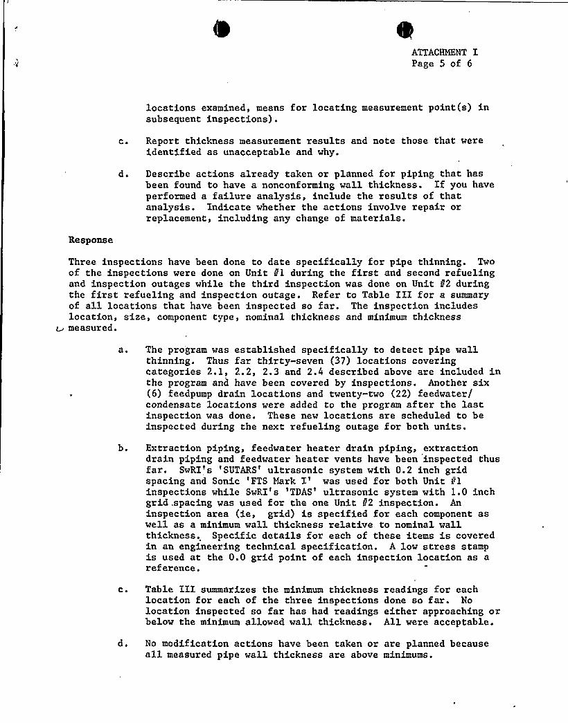
locations examined, means for locating measurement point(s) insubsequent inspections).
c ~ Report thickness measurement results and note those that wereidentified as unacceptable and why.
'd ~ Describe actions already taken or planned for piping that hasbeen found to have a nonconforming wall thickness. If you haveperformed a failure analysis, include the results of thatanalysis. Indicate whether the actions involve repair orreplacement, including any change of materials.
Response
Three inspections have been done to date specifically for pipe thinning. Twoof the inspections were done on Unit //1 during the first and second refuelingand inspection outages while the third inspection was done on Unit 82 duringthe first refueling and inspection outage. Refer to Table III for a summaryof all locations that have been inspected so far. The inspection includeslocation, size, component type, nominal thickness and minimum thickness
w measured.
a ~ The program was established specifically to detect pipe wallthinning. Thus far thirty-seven (37) locations coveringcategories 2.1, 2.2, 2.3 and 2.4 described above are included inthe program and have been covered by inspections. Another six(6) feedpump drain locations and twenty-two (22) feedwater/condensate locations were added to the program after the lastinspection was done. These new locations are scheduled to beinspected during the next refueling outage for both units.
b. Extraction piping, feedwater heater drain piping, extractiondrain piping and feedwater heater vents have been inspected thusfar. SwRI's 'SUTARS'ltrasonic system with 0.2 inch gridspacing and Sonic 'FTS Mark I'as used for both Unit 81inspections while SwRI's 'TDAS'ltrasonic system with 1.0 inchgrid .spacing was used for the one Unit 8'2 inspection. Aninspection area (ie, grid) is specified for each component aswell as a minimum wall thickness relative to nominal wallthickness. Specific details for each of these items is coveredin an engineering technical specification. A low stress stampis used at the 0.0 grid point of each inspection location as areference.
C ~ Table III summarizes the minimum thicknesslocation for each of the three inspectionslocation inspected so far has had readingsbelow the minimum allowed wall thickness.
readings for eachdone so far. Noeither approaching orAll were acceptable.
d. No modification actions have been taken or are planned becauseall measured pipe wall thickness are above minimums.

ATTACHMENT IPage 6 of 6
Action 5
Describe any plans either for revising the present or for developing new oradditional programs for monitoring pipe wall thickness.
Response
At this time, our program incorporates monitoring locations for single- phase,flashing and two-phase flow for all types of BOP piping operating above 190'Fas shown on FSAR Figure 10.1-1 and for several locations with temperaturesbelow 190'F. All locations were selected based upon industry experience. Asa result of the Surry incident the following addit'ional items are underreview:
a. Use of a predictive erosion method. Currently the followingpredictive methods are being reviewed:
o EPRI Report NP-3944 (two phase)
o KWU erosion/corrosion model as presented at EPRI seminar(single and two phase)
o EPRI 'CHEC'omputer program (single phase only)
b. Review of other water systems outside the BOP cycle.
c. Review of water chemistry (PH, oxygen) for the non BOP systems.
d. Upgrading of the inspection program engineering generalspecification to include the 41 additional single phase and twophase inspection locations and other industry recommendations.
e. Review of ASME Section III Class 1 and Section III Class 2feedwater piping inside of primary containment.
In the future, if significant erosion/corrosion is found at other BOP
locations, these will be. added to the program.
RMH: tahrmhmeh162a

Table I
SUSQUEHANNA STEAM ELECTRIC STATION
EROSION/CORROSION PROGRAM PIPING MATERIALS
CATEGORY NOMINAL SIZE
Steel 2, 3,4, 12, 14, 16, 18, 24
30
26
16, 18
Carbon 2,3,4,6,8, 12, 14, 16, 20
CLASS
DBD
GBD
DBD
HBD
MATERIAL SPEC.
A-106 GR
'B'-155
GR KC-70 CL 1
A-155 GR KC-70 CL 2
APPLICABLE CODE (2)
ANSI B31.1.0
ANSI B31.1.0
ANSI B31.1.0
ANSI B31 ~ 1.0
ANSI B31.1.0
1), 2, 4, 6, 14
10
Copper 16, 18
Bearing 16
42, 48
GFD
HFD
GFD
XFX
SA-333 GR 9(Yoloy .75-1.25 CU)
A-155 GR KC-55 CL 1
(.30-.60 CU)
A-155 GR KC-55 CL 2
ANSI B31.1.0
ANSI B31.1.0
ANSI B31.1.0
ANSI B31.1.0
Non Code(Turbine Vendor)
Alloy 6,10,12,16
12, 14, 18 HAD
A-333 GR P-11(MO .44-.65)(CR 1.0-1.5)
ANSI B31.1.0
ANSI B31.1.0
Note: 1. The second letter of the pipe class determines the material.2. The third letter of the pipe class determines the applicables codes.
rmhmeh162a

TABLE II
SUSQUEHANNA
SYSTEMS P&ID
PIPE(1)MATL
(M-199)
NOTWATER/STEAM
REASON FOR ELIMINATIONNOT
CARBON LOW HIGHSTEEL TEMP 0—2-
REQUIRESFURTHER
~>2 d (2)
Sl - SwitchyardS2 - 125V DC
S3 - 13.8 KV SystemS4 - 4160V SystemS5 — 480V Load CentersS6 — 480V Motor Control Center MCCS7 — Lighting & Misc Distribution
120VSB - Domestic WaterS9 - Intake StructureS10 - Screens & Screenwash SystemS11 - Service WaterS12 — Bldgs. & FacilitiesS13 —Fire ProtectionS14 - Reactor Bldg. Cooling WaterS15 —Turbine Bldg. Cooling WaterS16 —Residual Heat Removal
Service Water RHRSWS17 - Instrument ACS18 — Instrument AirS19 - Service AirS20 — Bldg. Drains NonradioactiveS21 - Water PretreatmentS22 - Makeup DemineralizerS23 - Fuel OilS24 — Diesel GeneratorsS25 - Primary Containment Instrument
GasS26 — Motor Operated DoorsS27 - Station Auxiliary BoilerS28 - Misc Areas HVAC (Chillers)S29 - Service & Administration Bldg.
HVAC (Chillers)S30 - Control Structure HVAC
(Chillers)S31 - ComputerS32 - Security SystemsS33 - Turbine Bldg..—HVAC (Chillers)S34 - Reactor Bldg. HVAC (Chillers)S35 - Fuel Pool CoolingS36 - Fuel PoolsS37 - Demineralizer Water TransferS38 - Low Pressure AirS39 - Condensate DemineralizerS40 - Lube Oil Transfer &
PurificationS41 — Cooling TowersS42 — Circulating WaterS43 - Condenser & Air Removal
4 S44 - Condensate0 S45 — Feedwater>s S46 - Extraction Steam>S S47 — Feedwater Heaters FWHN4 S48 - Feedwater Pump Turbine
S49 —Residual Heat Removal RHRS50 - Reactor Core Isolation
Cooling RCICS51 — Core SprayS52 — High Pressure Coolant
Injection HPCIS53 - Standby Liquid Control SLCS54 — Emergency Service Water ESWS55 — Control Rod Drive Hydraulics
CRDHS56 — Control Rod ControlS57 - Uninterruptable ACS58 — Reactor ProtectionS59 — Containment & SuppressionS60 - Primary Containment Atmosphere
CirculationS61 - Reactor Water Cleanup RWCUS62 - Reactor Vessel & AuxiliariesS63 —Bypass Indication
M-117
M-109/10
M-122M-113M-114M-112
M-160M-117M-118
M-12 1
M-189
M-186
M-188M-187M-153/154
M-108
M-116M-119
M-115
M-105M-106/41M-102M-103/104M-127M-151M-149/50
M-152M-155/56
M-148M-111M-146/47
M-141
M-144/45M-141
BID
BIM,NITB
C
B,CB,C>D
BIR
B,RB
BIG
B,C
B,CBE L
A,B>F,AI8B,F
BB
C
RC
B,C
(8)
x x(4)
X '(5)x x(5)
x(5)
(6)(6)
(6)
Yes
x (6)x (6)x x(5)
x(5)x x
xxxx
x(5)x(5)x(9)
( 10)
xx(11)
PLI-49129PLI-49129PLI-48540Yes (3)PLI-48540
x(11)
x(5)x(5)
x x(11)
(12) Yes(12)
x x(5)
x x(5)x (6)x (6)x x(5)
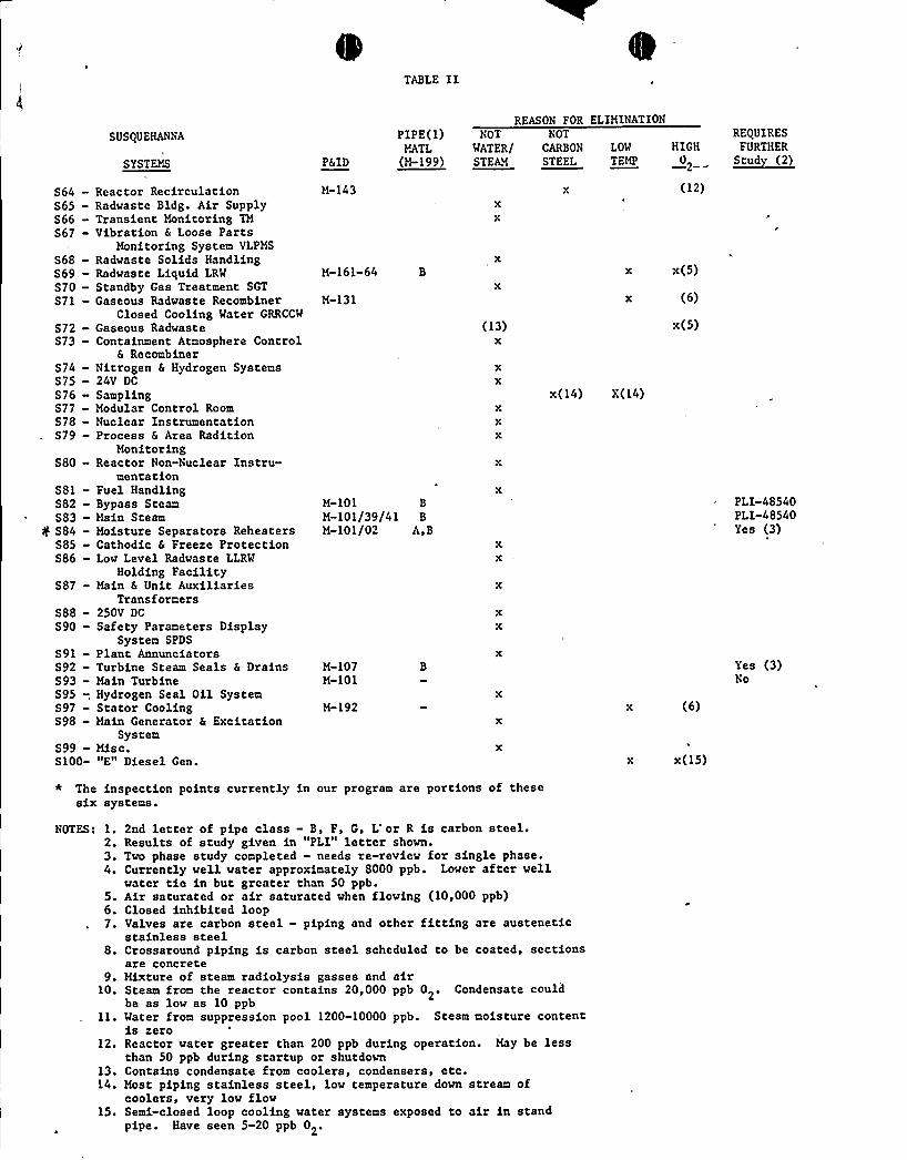
TABLE II
REASON FOR ELIMINATIONSUSQUEHANiNA
SYSTEMS P&ID
PIPE(1)MATL
(M-199)
NOT NOT
WATER/ CARBON
STEAM STEELLOW HIGHTEMP 0—2--
REQUIRESFURTHER
~scud (22
864S65S66S67
868-869—S70—871-
S72S73
S74S75S76S77-S78—S79-
S80
S81S82883f S84S85S86
S87
888S90
S91892S93895 -,897-S98-
S99-S100-
Reactor RecirculationRadvaste Bldg. Air SupplyTransient Monitoring TMVibration & Loose Parts
Monitoring System VLPMSRadwaste Solids HandlingRadvaste Liquid LRW
Standby Gas Treatment SGT
Gaseous Radvaste RecombinerClosed Cooling Water GRRCCW
Gaseous RadvasteContainment Atmosphere Control
& RecombinerNitrogen & Hydrogen Systems24V DC
SamplingModular Control RoomNuclear InstrumentationProcess & Area Radition
MonitoringReactor Non-Nuclear Instru-
mentationFuel HandlingBypass SteamMain SteamMoisture Separators ReheatersCathodic & Freeze ProtectionLow Level Radvaste LLRW
Holding FacilityMain & Unit Auxiliaries
Transformers250V DC
Safety Parameters DisplaySystem SPDS
Plant AnnunciatorsTurbine Steam Seals & DrainsMain TurbineHydrogen Seal Oil SystemStator CoolingMain Generator & Excitation
SystemMisc."E" Diesel Gen.
M-143
M-161-64 B
M-131
M-101 B
M-101/39/41 B
M-101/02 A,B
M-107M-101
M-192
(13)x
(12)
x x(5)
x (6)
x(5)
x(14) X(14)
(6)
x x(15)
PLI-48540PLI-48540Yes (3)
Yes (3)No
* The inspection points currently in our program are portions of thesesix systems.
NOTES: 1.2.3 ~
4 ~
5.6.7 ~
8.
9.10.
12.
13.14.
15.
2nd letter of pipe class — B, F, G, L or R is carbon steel.Results of study given in "PLI" letter shown.Tvo phase study completed - needs re-review for single phase.Currently well water approximately 8000 ppb. Lower after wellwater tie in but greater than 50 ppb.Air saturated or air saturated when floving (10,000 ppb)Closed inhibited loopValves are carbon steel - piping and other fitting are austeneticstainless steelCrossaround piping is carbon steel scheduled to be coated, sectionsare concreteMixture of steam radiolysis gasses and airSteam from the reactor contains 20,000 ppb 02. Condensate couldbe as low as 10 ppbWater from suppression pool 1200-10000 ppb. Steam moisture contentis zeroReactor water greater than 200 ppb during operation. May be lessthan 50 ppb during startup or shutdownContains condensate from coolers, condensers, etc.Most piping stainless steel, low temperature dovn stream ofcoolers, very low flowSerai-closed loop cooling water systems exposed to air in standpipe. Have seen 5-20 ppb 0 .2'

TABLE III
ID (4)No.
X-1X-2X-3X-4X-5X-6X-7X-8X-9X-10X-11X-12X-13X-14X-15X-16X-17X-18X-19X-20X-21X-22X-23X-24X-25X-26X-27X-28X-29X-30X-31X-32X-33X-34X-35X-36X-37
T e
TeeTeeTeeElbowElbowElbovElbowPipeElbowElbovElbowTeeElbowElbovTeeTeeElbowElbowElbowElbovElbowElbovTeeTeeElbowElbowElbowElbowElbowElbovElbowElbovElbowElbovElbowElbovElbow
Size
14-HAD18-GFD18-GFD18-GFD18-GFD18-GFD18-GFD14-GFD14-GFD16-GFD16-GFD10-GAD26-HBD16-HFD24-HBD16-GAD42424242424212-GAD18-HBD4-GBD2-GBD2-HBD2-HBD2-HBD2-HBD3-GBD3-GBD4-HBD3-HBD2-GFD6»GBD16-GBD
Location
Drain 3A to 2AExtr. to FWH 5B, C
Extr. to FWH 5B, C
Extr. to FWH 5B, C
Extr. to FWH 5B, C
Extr. to FWH 5B, C
Extr. to FWH 5B, C
Extr. to FWH 5B, C,Extr. to FWH 5B, C
Extr. to FWH 5BExtr. to FWH 5BMSEP. Drain to 4AExtr. to FWH 3CExtr. to FWH 4CExtr. to FWH 2ADrain 4A to 3ACrossaroundCrossaroundCrossaroundCrossaroundCrossaroundCrossaroundDrain 5A to 4ADrain 2A to 1AExtr. 5C Drain (20C)Extr. 5A Drain {46A)Extr. 4B Drain (05B)Extr. 4C Drain {18C)Extr. 3A Drain (04A)Extr. 3B Drain {09B)FWH 5B VentFWH 4A VentFWH 3C VentFWH 2A VentXaround 'Drain (51A2)F.W. S-U (Fo-10659C)Long Path (FO-10570B
NominalWall
.375
.375
.375
.375
.375
.375
.375
.375
.375
.375
.375
.365
.375
.375
.375
.375
.625
.625
.625
.625
.625
.625
.375
.375
.237
.344
.218
.218
.218
.218
.300
.300
.237
.216,344.280.656
SSES II11-RIO
OKOKOKOKOKOKOK
.360
.360OKOK
OK.348OKOK
(2)OKOKOKOKOKOK
(2)(2)(1)(1)(1)(1)(1)(1)(1)(1)(1)(1)(1)(1)(1)
U.T. RESULTSSSES //1
2-RIO (5)
.385.319/OK.300/OK.300/OK.302/OK ,.312/OK.320/OK .
.267/.360
.194/.360.300/OK.302/OK:.
.403.257/.348-'345/OK
.332/oK(2)
OK(3)oK(3)
(2)(2)
.200/.214.460(2)(2)(2)(2)
. 270(2)(2)(2).42
.249/OK
.471/OK
SSES t21-RIO
. 520
.382
.416
.380
.375
.396
.410
.350..358
432.390.400.342.401(2)(2)
oK(3)
OK(3)
(2)(2)
.203
.500(2)(2)(2){2)
.306{2)(2)(2)
.450
.301
.588
NOTES: (1) Inspection requirements issued after first outage{2) Conditional Inspection — not necessary to inspect unless other inspection
points indicate inspection is warranted.(3) Visual Inspection Only (Per Spec M-1414)(4) Unit f/2 locations use a "20XX" prefix(5) Automated UT/Hand Recheck - Numerous false UT readings were recorded
requiring hand rechecks.
rmhmehl62a