Forwards response re NEDO-24708, "Addl Info Required for ...
166
, - . - ,' |L y' _' '"- [Elg .; j r e t . .~ C , , , , _ TIIE CINCINNATI GAS & ELECTitIC CONII*ANY G ,. - - - - - - m CINCIN N ATI OHIO 4 5 201 E. A. BORG M AN N vict ent s.ot ut Docket No. 50-358 November 14, 1979 Mr. Harold Denton, Director Office of Nuclear Reactor Regulation U.S. Nuclear Regulatory Commission Washington, D.C. 20555 . RE: WM. H. ZIMMER NUCLEAR POWER STATION - UNIT 1 "NEDO-24708, ADDITIONAL INFORMATION REQUIRED FOR NRC STAFF GENERIC REPORT ON BWR REACTORS" Dear Mr. Denton: This information is provided in response to the NRC letter dated July 23 from John F. Stolz to Earl A. Borgmann. This information respor.ds to the long term plant specific information request of the Bulletins and Orders Task Force. Very truly yours, THE CINCINNATI GAS & ELECTRIC COMPANY f' y;' W 'f n* - a . By E . A. BORGMANN Senior Vice President EAB: dew Enclosure cc: Charles Lechhoefer State of Ohio ) Glenn O. Bright County of Hamilton)ss Frank F. Hooper Sworn to and subscribed before me this /VM day of November, 1979. ir s e ker . Steven G. Smith William J. Moran J. Robert Newlin William G. Porter, Jr. Q James D. Flynn Thomas A. Luebbers d Notary Public *' Leah S. Kosik VWO Mei P. f. UHuiOFER . , Jashn D. Woliver retuy em s:m cf onio M Co,mssu bpts My 28.1982 / f371 001 4"<3*7 1 7971200 - k'
-
Upload
khangminh22 -
Category
Documents
-
view
1 -
download
0
Transcript of Forwards response re NEDO-24708, "Addl Info Required for ...
, - . -
,' |Ly' _' '"- [Elg.; j r
e t . .~ C , , , , _
TIIE CINCINNATI GAS & ELECTitIC CONII*ANY G ,. - - - - - - m
CINCIN N ATI OHIO 4 5 201
E. A. BORG M AN Nvict ent s.ot ut
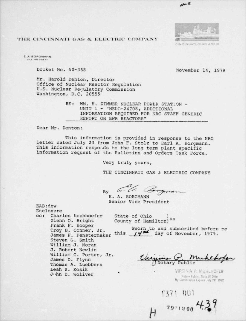
Docket No. 50-358 November 14, 1979
Mr. Harold Denton, DirectorOffice of Nuclear Reactor RegulationU.S. Nuclear Regulatory CommissionWashington, D.C. 20555
.
RE: WM. H. ZIMMER NUCLEAR POWER STATION -UNIT 1 "NEDO-24708, ADDITIONALINFORMATION REQUIRED FOR NRC STAFF GENERICREPORT ON BWR REACTORS"
Dear Mr. Denton:
This information is provided in response to the NRCletter dated July 23 from John F. Stolz to Earl A. Borgmann.This information respor.ds to the long term plant specificinformation request of the Bulletins and Orders Task Force.
Very truly yours,
THE CINCINNATI GAS & ELECTRIC COMPANY
f' y;' W 'f n* -a.
ByE . A. BORGMANNSenior Vice President
EAB: dewEnclosurecc: Charles Lechhoefer State of Ohio )
Glenn O. Bright County of Hamilton)ssFrank F. Hooper
Sworn to and subscribed before methis /VM day of November, 1979.ir s e ker.
Steven G. SmithWilliam J. MoranJ. Robert NewlinWilliam G. Porter, Jr. QJames D. FlynnThomas A. Luebbers d Notary Public *'
Leah S. Kosik VWO Mei P. f. UHuiOFER.,
Jashn D. Woliver retuy em s:m cf onioM Co,mssu bpts My 28.1982/
f371 001
4"<3*71 7971200 -
k'

. .
PLANT ZIMMER UNIT (S) 1.
BYPASS CAPACITY
Plant Steam Bypass Capacity, % Rated 25
.
1371 002'

. .,
.
PLAT 1T ZIMMER.
SYSTEMS APID COMP 0t4ENTS SHARED BETWEEf1 UtilTS
PAGE 1 C0flTINUED PAGE -
Single-unit plant check here X) and do not complete
Shared BetweenSystem or Ccmoonent Uni ts tiumbers
.
' '
T 371.003
.
O
. .
.
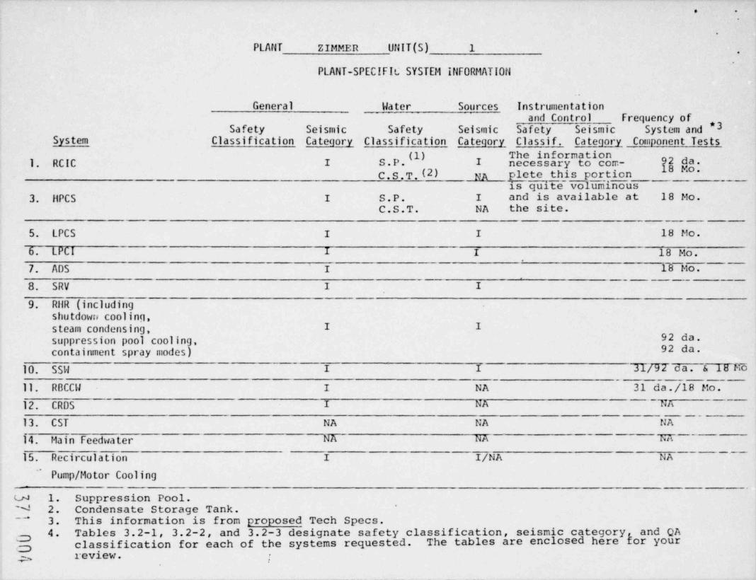
PLAflT ZIMMER UNIT (S) 1 .
PLANT-SPECIFIC SYSTEM INFORMATI0tl
General Water Sources Instrumentationand Control Frequency of
Safety Seismic Safety Seismic $afety Seismic System and *3System Classification Category Classification Category Classif. Category Component Tests
The informationS.P.(1) I necessary to com- 92 da.1. RCIC I18 Mo.C.S.T. (2) NA plete this portion
is quite volum'inous3. IIPCS I S.P. I and is available at 18 Mo.
C.S.T. NA the site.
5. LPCS I I 18 Mo.
6. LPCI I I 18 Mo.,
-
7. ADS I 18 Mo.
8. SRV I I
9. RilR (includingshutdown cooling,steam condensing, I I
92 da.suppression pool cooling,containment spray modes) 92 da.
10. SSW I I 31/TI da. s 18 K611. RBCCW I NA 31 da./18 Mo.12. CRDS I NA - TA
-
13. CST NA NA NA
14. Main Feedwater NA NA LA
'
15. Recirculation I I/NA NA
' Pump / Motor Cooling
u 1. Suppression Pool.N 2. Condensate Storage Tank.
3. This information is from proposed Tech Specs."
4. Tables 3.2-1, 3.2-2, and 3.2-3 designate safety classification, seismic category and QAclassification for each of the systems requested. The tables are enclosed here gor yourg
g2,. rev.tew. ,
.h'e ps
.
I
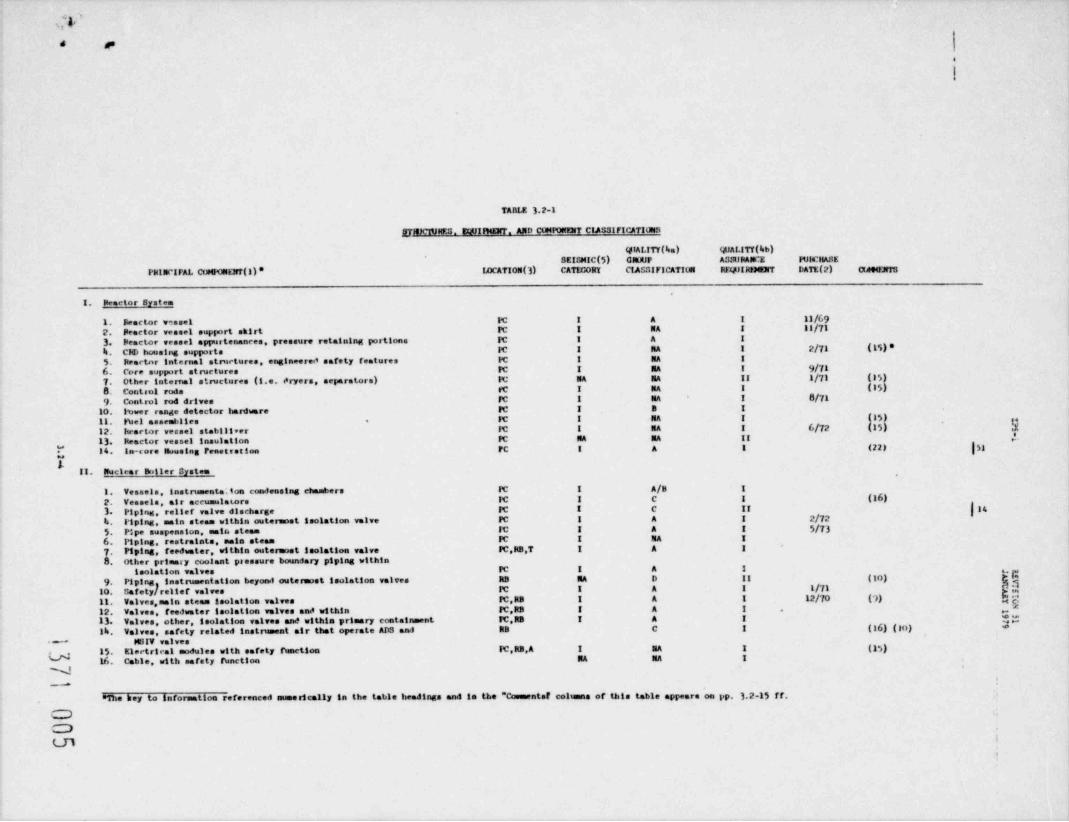
TABLE 3 2-1
gl4MTJfES. EQUIlkEllT. AND CtMP08937 CIAS3tFICATIm3
QlALITY(ba) QUALITY (bb)SEIGNIC(5) cNuuF AUSupANCE I4JIs'HASE
PkIIK'IFAL CtMfGElrT(ll' IDCATION(3) CATlX;ORY CIASSIFICATION REylIRINDIT DATE(2) OANENTS
1. Peactor system
1. Peactor v=ssel IC I A I 11/692. Peactor vessel suplert skirt FC I NA I II/713. Peactor vessel appurtenances, pressure retaining portions IC I A Ib. Cle housing supports IC I MA I 2/71 (15) *5. Reactor internal atrwetures, engineered safety features FC I MA I
6. Core support structures IC I RA I 9/717. Other internal structurea (i.e. dryers, separators) IC NA NA II 1/71 (15)8. Contael rods rc I NA I (15)9. Control rod drives FC I NA I 8/71
10. Inwer range detector harittere PC I B I
FC I MA I (15)11. tuel assemblies12. lu actor vessel stabilleer IC I RA I 6/72 (15) h,
.
13. Iteactor vessel insulation FC MA NA II ,e ,
{ 14. In-core Nousing Fenettetten FC I A I (22) |53i
II. Nuclear Ikiller System
1. Vessels, instrumente. ton condensing chambers FC I A/B I
2. Vessels, air accumulators IC I C I (16)( 143. Pipins, rensef valve discharge FC I C II
b. l'iping, main steam within outermost isolation valve PC I A I 2/725. Pipe suspension, matr. steam IC I A I 5/736. Piping, restratate, main steam FC 1 NA I
7. Piping, feedwater, within outerisost isolation valve IC,kB.T I A I
8 Other primary coolant pressure boundary piping withinteolation valves PC I A 1
9 Piping instrumentation beyond outermost isolation valves RB RA D II (10) E
Safetyfreller valves It I A I 1/71 ;}1011. Valves, main steam isolation valves FC.RB I A I 12/70 (')) gg
z12. Valves, feedwater isolation valves and within IC,RB I A I . g
13. Valves, other, teolation valves and within primary containment It,RS I A I ogIb. Valves, safety related instrument air that operate ADS and RB C I (16) (to) *
~ NSIV valves15. Electrical modules with safety function FC,RB, A I MA I (15)16. Cable, with merety function NA NA I
.N,
__.
a1he key to information referenced numerically in the table headings and la the "th= ants! colens of this table appears on 1p. 3.2-15 ff.
OO
iLD.

. ,
ustm 3.2-1 (cont'd)
OfALITY(ba) QUALITY (bb)SEISMIC (5) CROUP ASSUNueCE ItlacttASE
Pit 1NCIPAL COMror. tart (1) IDCATICH(3) CATEGORY CIASSIFICATION REQilIRFMYF LATE COD 90Yr3
,III. Recirculation System
1. Piping PC I A I 2/712. Pipe suspension, rectreulation line IC I A I 5/733. Pipe restraints, rectreulation line PC I MA I 6/71b. Ibmps IC I A I 5/715. Valves IC I A I 3/716. Motor, pump PC Special NA I 6/71 (19)(15)7 Electrical modules with safety IC I MA I (IS)8. Cable with safety function IC BA NA I
IIV. CHD flydreulle System
Y *
7 1. Yelves, teolation, water return Itne IC.RB I A I
lves, scram discharge volume lines RB I B I* 2. e
3. .alves insert and withdraw !!nes RB I B I (6)b. aves, other RB RA D II
5. Heing, water return line within isolation valves IC,RB I A 1
6. Piping, scram discharge volume lines RB I B I
7. Piping, insert and withdraw 11aes FC.RB I B I
8 Piping, other RB RA D II
9. CRD pumps, filter RB MA D II 11/71 (3510. CitD strained RB RA D II 6/71 (3511. Itydraulle control unit and shtoff valves RB I E I 6/71 (g) (g3)
12. Mritor RB NA MA 11 |
13. Cable, with safety function MA RA I~
lb. Electrical modules with safety function RB,A NA NA I
w
N-
.
.
&
.

.
? y1 ;y*|
3TE ) ) ) ) )0 $ 59 l 1 15
5 51 1
P ( ( ( ( (UC
ES)A2H( 422l
777CEf T ///iA 222RD
0
) ffb l
kEE(CYNDTAR A IIRI IIIIIII1I1M IIII I1 I I I
LUUASQ1QAR
SE g
NOI
) Ta Ab C( I
T F A AABBMAABABMND AA AA A A AT I
IPS BBMN MN M N NLJ GMAaAUl IQC C
)5
) (YI CR
IO'e MG AA A A A An SE IIIIIIIIINN 1IIN IN I N No IT0 EA( SC3
2
3 )A, B3
Z (N B BB B R,IB O R. A. R, R, R, T,A I
- B -T T BBBBBBCBB B CCB - C- R - AA RRRRRRIRR R IIR - F
CDI
tn ye sbm sdn ensi cama g ot er n rsttn o i p so n t d ,d yc o c l ns
a i daiy t e u i g
k r c r b u ,nn qsin a a d r i ara m
t i f mM n o l goi
rsss eR ast .te peeey tP r c sf ig vvvt sA e o a sf na nlll e y nt e eooiir c sr i aaaf n sdo hvvvao b n l n or
m t t si ua e od rone s i ann t r s m mn pt oe a cit wooohce 4
s t n sret0s l liit nh PIy o dttti ut m I1 m r s o eroja
S r naaawfo e T e o ,i n ofei,M t t ti t dt allls .st s s t sal isra) l n ooosy ,t
l o o enssset g y ner y e e el nneir( r c voiiil en s iolA S t liaol a
r. o oaninosi n aon ol
W ut ema ,ts t ii ufi u un n d stdndd ap g t dd n dnt h n
o n oe sn x nea C
i
ll ohom p l ma i s o mv oeomuv q p o yt y h
i
P ot
t il gi t l t a
r ni itd i rxseieltd o I sl c l t
e ai l oeibwbain t TiaI e a
i
id iiit
tM a ana aaaeO u t cwa t cI t c ciml cl rC iq y o , ,,,,i e , ,i o i d
b msssggr ,s gsr , r rs a r1 ,t rtL L d s eeennt ee n net e P t e R t1 ent ns
pvvviicl v i vcl cl cal e cea
nWuaaai1lA aa mlll ppebl n pl eb r eb s et b vevgI' y
aa o ial a o l a s l a lI b tC d SIPVVVPPECV r PVEC t EC e E C EN n t c cR e . ,
a o.
a uI
t ....... . , ,
N 121%.. p 12 P 1 2 3r .. r . .
P S 1234S67890111
a
,
. I
D%, I I
. I I I
s ,WQ s CV V V V
*
$S

.~
, e
TABLE 3.2-1 (Cont'd)
UJALITT(be) QUALITT(bb)SEIEMIC(5) caouP ASSURANCE IUlb31ASE
PRINCIPAL COMIM'NF(l) IOCATION(3) CATIDORT CIASSIFICATION req)llehElrF DATT(2) CED9WWrS
II. M(31 Heat Remval System Igig
1. Heat eschangere, p.imasy side RB I B I 5/712. Heat emela gers, secondary side RB I C I 5/713. Piping, connected to RCPB within outerw>9%
tooletion valves PC RB I A I
b. Piping, beyond outermost teolation valves RB I B I
5. Puses RB I B I 8/106. 1%mp setore RB I MA I 11/70 (13)7. Talves, teolation, t.FCI and shutdown Innes IC.RB I A I
8. Valves, isolation, other IC,RB I B I
9. Valves, beyond feelstion valves RB I B I
10. Electrical modules with safety functior. RB.A I MA I (15). -- NA NA I11. Cable, with amfety funetton ,
|s,o
E. Low Pressure Core Spray System 1.ICS
1. Piping, within outernost isolation valv-s PC RB I A I
2. Piping, beyond outernost isolation valves RB I B I
3. Pumps RB I B I 8,'70h. Ibsp sotors RB I NA I lip 30 (15)
|S. Valves, isolation and within PC.RB I A I
6. Valves, beyond outermost isolation valves RB I B I
7. Electrical sedules with safety function RB A I MA I (ii)
8. Cable, with safety function -- BA NA I
'
a
II. High Pressure Core Srray Systen HICS ]i ,
1. Piping, within outernost isolation valves | IC,RB I A I,
2. Piping, beyond outermost isolation valvea RB I B I'
3 Piptog, return test Itne to condensate storage jtank beyond Reactor tha!! ding '
O.T NA D II
%. 3%mp discharge line | RB I B I'u 5. Pap RB I B I 1/71
6. Talves, within outeruoat isolation valve i IC RB I A I 1/72q7. Talves, return test line to condensate storage RB I B I
8. Valves, other RB I B I----
9 HFCS diesel , A I NA I.
10 Electrical modules with safety function RB.A I NA I (15)C 11. Cable, with safety ibnct'on -- NA NA I
g 12. Motor RB I NA I (IS)
C.
,.m
. .
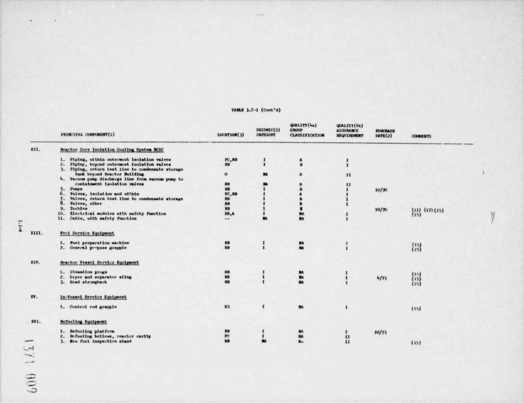
TAB 12 3.2-1 (Cont'd)
@ALITY(ba) QlALITI(4b)SE2SMIC(5) CROUP ASSURANCE ItlpmASg
PRINCIFAL QMFUNE!rf(1) IOCATION(3) CATELORY CIASSIFICATION RE4f!RDGET DATE(2) (XHe3TS-
III. Reactor Core Isolation Cooling System RCIC
1. Piptag, within outermost teolation valves FC.RB I A I
2. Pipinc, beyond outernost toolattoa valves RB I B I
3. Piping, return test line to condensate storageItank beyond Reactor Building O NA D II
b. Vacuun pismp discimrge line from vacuun pump tocontainment isolation valves BB M D II
5. Pumpe RB I B I lo/p6. Valves, teolation and within PC,RB I A I
7. Valves, return test anne to condensate storage RB I B I
8. Valves, other RB I B I
9. Turbine RB I E 10/-|0 (gg){g7)(35)10. Electrical modules with safety function RB,A I NA I (35) i{11. Cable, with safety function -- M NA I
=
J.IIII. Fel Service Equirment
1. Fuel preparation machine RB I MA I (35)2. General pteepose grapple BB I MA I (35)
IIV. Reactor Vessel Serviu Equirment
1. Steamline pluge RB I MA I gg$2. Dryer and separator sling RB I MA I h/73 (153 Head strongback RB I MA I (g5
IV. In-Vessel Service Ewirment
1. Control rod grapple R3 I MA I (gg)
IVI. Rerueling Equireent
1. Refbeling platform RB I MA I 10/732. Refueling bellowe, reactor cavity PC I MA II
3. New fuel inspectico stand RB RA h II (gg)-
J'
-
W
(y

6
(, .
e
TABI2 3.2 1 (Cont'd)._
QIALITY(ba) QMLITY(hb)SE13MIC(5) GROUP ASSURANCE EURCliASE
PRINCIIAL CGUVNENT(1) IDCATION(3) CATEGORY CIASSIFICATION RE@IRIM2rF DATE(2) CO HfhTG
IVII. Storage Equipment
1. Fuel storage racks RB I NA I (I s)2. Defective fuel storage container RB I MA I (1%)3. Spent fuel pool, dner/sep. pool, Its tell RB I NA I
IVIII. Radweste System
1. Tanks, atmspheric RW,7 NA D II2. Elest exchangers RW,T NA D II3. Piping, containment isolation IC,RB I B I
b. Valves, containment isolation FC.RB 1 B I
5. Piping, ottser RB T RW NA D II j '
6. I%mps RB,FW,T,A NA D II*s. .
b 7. Valves, flow control and filter system RW,T MA D IIE 8 , other RB,RW,T,A NA D II
III. Reactor Water Cleanu o System
1. Vessels: filter /demineraliser BB NA C II 6/"I2. Heat exchangers RB NA C II b/?D (14)3. Piping, within outermost isolation valves RB,PC I A I
b. Piping, beyond outerwist isolation valves RB NA C II
S. I' umps /mtors RB NA C II 8 6/3 (3h)6 Valves, isolation valves and within RB I A I
7. Valves, beyond outermost isolation valves 13 NA C 11 6/71
11.- Nel Ibol Cooling and Cleanup System
1. Demineraliser vessel RB NA C II
2. Filters RB NA C II
3. hanps, purification RB NA C II4 Piping esc!cdtng item 7 RB NA C II
'I**
hgU 5. Valves RB RA C, II6. Heat enchanger RB NA C II e
N 7. Puel pool cooling piping RB 1 C II | .js ,
8. Cocling pumps and heat enchanger supports BB I C II 16-
Q_

. .
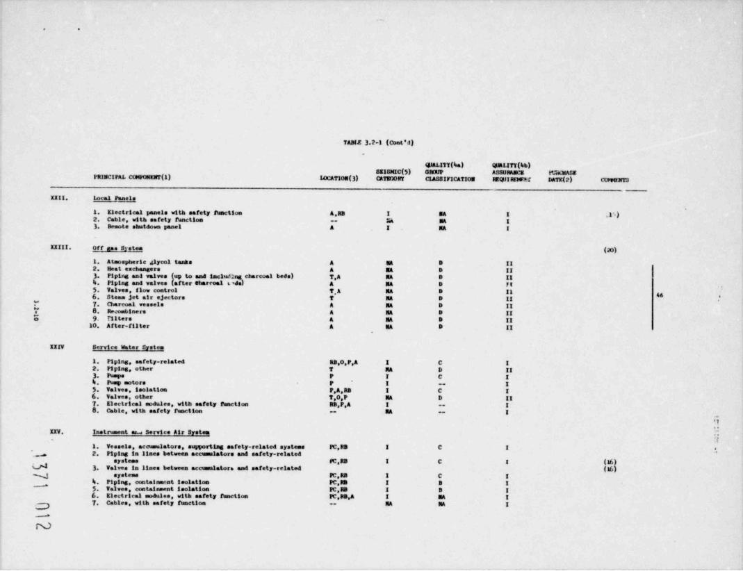
TABLE 3.2-1 (Cont'd)
@ALITT(ba) QUALITY (Isb)sEisurC(5) GROUP ASSURANCE IUBmASEPRINCIPAL C[MIONKirt(1) IOCATION(3) CATEGORY CIASS!FICATION REQt!!RDElf? DATE(2) COH4ENTS
III. C<mtrol ihm Fanels
1. Electrical panels with safety function A I M I (15)*
2. Cable, with safety fianction -- M MA I
Yb
Q'b
._.
NS.
-
6
E4 *
*
Uw
HN$,
. .
TABLE 3.2-1 (Cont'J).
QJALITT(ba) QUALITT(%b)SEISMIC (5) GROUP ASSURANCE t*J"shalASE
PRINCIPAI. COMH)MEart(1) I4 CAT 10N(3) CATEY10RY CIASSIFICATION REQllI RD5's:f DATE(2) C(PsOET3
IIII. Incal Panels
1. Electrical panels with safety function A.RB I BA I il5)2. Cable, with safety thnction -- |i4 NA I3. Demote staatdown panel A I NA I
IIIII. Off gas System (20)
1. Atmospheric glycol tanks A E D II2. Heat eschangers A NA D II3 Piping an4 valves (up to and including charcoal beds) T,A NA D II%. Piping and valves (after charcoal t ds) A NA D FIS. Valves, flow control T,A RA D Il g6 Steam jet mir ejectors T RA D II
,
I'* 7. Charcoal vessels A RA D 11Y 8 Recombiners A MA D IIE 9 titters a uA D II
10 A f ter-filter A EA D II,
IIIV Service Water Systen
1. Piping, safety-related RB,0,P,A I C I2. Piping, other T RA D II3. Pumps P I C I%. Pump motors P I -- I5. Valves, isolation P.A,RB I C I6. Valves, other T,0,P RA D II7. Electrical modules, with aaraty finnetton RB,P,A I -- I8 Chble, with safety function RA -- I--
'l..KIV. Instrument ara Service Air System
1. Vessels, accumulators, supporting safety-related systems FC,RB I C I e
2. Piping in lines between accussalators and safety-related *s
systems IC,RB I C I (16)d 3 Valves in lines between accussalatora and safety-related (16)N systems FC.RB I C I
4. Piping, conteirosent isolation PC,RB I B I"5. Valves, containment isolation Ic,RB I B I6. Electrical modules, with safety function PC,RB,A I MA I
7. Cables, with safety funetton -- RA NA Ig--*

. .
i
TABt2 ).2-1 (Cont'i)
QJALITY(ka) QlALITY(kb)SEISMIC (5) GRUUP ASSURANCE FtF13tASE
rRINCIPAL COMNNENT(1) IDCATIOE(3) CATIIiORY CIASSIFICATION ItEQJIHEN!rf DATE(2) (Int 4ENT3
IIVI. Ut esel Generator Systems
1. Day tanks A I C I
2. Piping, het oli system and diesel service water system A I C I3. Valves, het oil system and diesel service water system A I C I
4. Iumps, het oil system and diesel service water system A I C I
5. I%mp setors, hel oli system and diesel service watersystem A I C I
6. Diesel g nerators A I ItA I7. Electrical amtutes, with safety function A I C I
8. Cable, with safuty function A HA NA I
9 Diesel fuel storage tanks A I C I
10. Diesel air tanks A I C I
1.!#
64 e
L IIVII. Flossmbility Control System
A** 1. Piping RB I B I
2. Valves RB I B I3. Flasanability control unit on skid -- I B I
b. Electriest satules, with safety h netton RB.A I NA I ( ")5. Cables, with safety function -- IRA HA I
IIVIII. Stamtby Gas Treatment Systeme
1. Piping and isolation valves with safet; hnctton RB I MA I
2. Blowers RB I ItA I
3. Electrical / mechanical sedules, with darety function RB.A 1 NA I (15) 9b. Cable, with safety ftsetton -- NA IIA I
IIII. Primary containswnt Ventilatf or. lysten'
% it** ; .
,
1. All components FC,RB M MA II". N.|l .
**
.- .
N-
C-

e *
TABIE 3.2 1 (Cont'd)
@ALITY(ka) QUALITY %)SEISMIC (*)) Cit 00P ASSURANL4 IVIDIASEFBINCIPAL CorGufENT(!) 14 CATION (3) CATECORY CIASSIFICATION Rt.Q'flRtM3rT DATE(2) Cut #ET:1
XXX. Power Corversion System
1. Itain steam piping between outereost isolationvalv*s up to turbine stop valves BB,7 I D II (7,21)2. Main steam branch piping to first valve closedor apable of automatte actuation T RB I D 11 (7,23),
3. Main turbine bypass piping up to t$ypass valve T I D II (7.28)b. First valve that is either normally closed ore4pable of automatic closurs in branch
9piping connected to main steam and turbinebypass piping T.RB I D II (8,21)5. Turbine stop valves, turbine control valves, iamt turbine typass valves ? NA D II (21)
,
6 Main steam leads from turbine control valvey
J. to tu bine casing NA NA NA NA No piping (21)* 7. Feedwater and conder. sate system beyond thirdisolation valve RB,7 NA D II (9)
XXXI. Cycled Condensste Storage and Transfer System
1. Consensate storage tank 0 NA D II (12)2. Piping, suction line to illCS, BCIC 0,RB,T A,BW I B I3, Piping, other 0 NA D II4 Valves and other components 0,RB,T,A RW NA D II
XXXII. Stamtby A-C Fower System
1. All components with safety ibaction A I NA I
XXXIII. Emergency D-C R>wer System
1. All components with aarety fusntion A I RA I[
_a
XXXIV. Miscellaneous Comeponents a,
*
N 1. Reactor Building BB I MA I2. ECCS Water Les Ibaps RB ,I B I
0-

s- ~. ,
-.
TABIE 3.2-1 (Cnnt'd)'
@ALITT(ba) @AfJTI(bb)SEIGNIC(5) GROUP ASSURANCE IVitCliASEPRINCIPAL COMitmENT(1) IOCATION(3) CATE00RT CIASSIFICATION REWIRDEFF DATE C0HO.1rTS
IIIV. Reactor Building Closed Cooling unter System
1. Ihaps and heat enchangers RB I C 1 (18)2. Valves, containment isolation IC,RB I B I3 Piping and valves for spent fuel pool IG3 ECC8 e
pump coolers, and other aarety-related equipment RB,A I/RA C/D I/NA (18)4. Fumps and piping for motor generator 8E3 set coolers A HA D II (18)5. Piping, ot* r IC RB,A NA D II6. Valves, other IT,RB, A RA D II7. Intertte to spent met pool III RB I C I
|16XXXVI. Equipment an.I Floor Drainare System
( !. Sumya RB,T, RW,A. P RA D II !5g., 2. Ibups RB.T.IlW,A,P RA D IIue 3. Piping, containment isolation RB 1 B I
*,.
b. Valves, containment taolation RB I B I5. Cable, with a safety function - RA IIA I6. Piping, otherRB T.IEW.A.P IIA D II7. Valves, other RB,T,RW,A,P RA D II
IIIVII. Miscellaneous Ventilation Systems
1. Battery room H & V A I NA I2. Service water structure P I MA I3. Relay and emergency switchgens II & T A I NA Ib. Control room air conditioning A I RA I5 Emergency diesel generator ventilation system A I IIA I
IIIVIII. Area Radiation ninttoring System
1. All components .Td,T,A RB IIA NA II*
jt
-d--
W il,%,,g. - -
O-

.I.
.
TAM.E 1.2 1 (cont'd)
@ALITy(ka) QJALITY(hb)*
SEISMIC ($) GRXfP ASSURANCE .URO{ASEFRINCIPAL COMIMElft(1) IOCATICE(3) CATE00RT CIASSIFICATION REQtlIREMN7 DATE(2) C040]fTS
IIIII. Isak Detection System
1. Temperature element IT RB,T I BA I flS)2. Temperature switch M.RB,T I MA I (15)3 Differential temperature switch N ,RB.T I BA I i,1$ i
%. Differential flow switch PC,kB I NA I ft$ i
5. Pressure switch FC RB I NA I [15 i
6. Differential pressure switch PC.RB I BA I | 1$l7. Differential flow sumuner RB I NA I flh8. Reactor bulloing floor drain en RB NA NA II
9. Reactor butIdtng floor drata Innes and piping RB NA NA II
hIL. P1re Protection System:.
w 1. Water sprsy deluge systems - NA NA II
b 2. Sprinklers, carbon dioxide systems - NA NA II
M 3. IDrtable and wheeled estinguishers - NA NA II* h. Halon system - NA NA II
ILI. Civil Structures
1. Reactor building RB I NA I
2. Service water pump structure P I NA II
3. Radwaste building BW NA NA II
b. f.uzillary butiding A I BA II
5. Turbine butiding T NA NA II
6. servlee water pipe supports & encasements o I NA II
.--
N-
-
.

_.u a
TABLE 3.2-1 (Cont'd)
KEY TO INFORMATION REFERENCED NUMERICALLY IN TABLE HEADINGSAND " COMMENTS" COLITMNS
(1) A module is an assembly of interconnected components which consti-tute an identifiable device or piece of equipment. For example,electrical modules include sensors, power supplies, and signal pro-cessors, and mechanical modules include filters, strainers, andflow (element) assemblies / orifices.
(2) Purchase order dates are given for cerrain equipment as a basis fordetermining certain applicable codes in Table 3.2-2 and applicabi-lity system safety class requirements in Table 3.2-3.
(3) PC = within , imary containmentRB = within reactor building
0 = outdoors onsiteP = service water pump structureA = auxiliary buildingT = turbine buildingRW = radwaste building
Quality group uassification per Table 3.2-2. For items where(4) a.two classes are .l'.sted (e.g. , B/C), the first letter indicatesclassification for ZPS-1.
(b. Conformance to q'uality assurance requirements:'
I - The equipment meets the quality assurance requirements of10 CFR 50, Appendix B.
II - The equipment meets the quality assurance requirements de-fined in the purchasu specification.
(5) 1 - The equipment is designed in accordance with the seismic require-ments for the SSE.
NA - The seismic requirements for the SSE are not applicable to theequipment.
(6) The control rod drive insert and withdraw lines from the drive flangeup to and including the first valve on the hydraulic control unit areQuality Group B.
(7) The main steamlines between the outermost containment isolation valveup to the turbine stop valve, the main turbine bypass lines up to the
,
turbine bypass valve, and all branch lines connected to these portionsof the main steam and turbine bypass lines up to the first valve cap-able of timely actuation are classified D. These sections of pipes
meet all of the pressure integrity requirements of code practice forsteam power plants plus the following additional requirements:,
..
All longitudinal and circumferential butt weld joints are radio-a.graphed (or ultrasonically tested to equivalent standards) .
.
3.2- 151371 017

- - . . ...
OC10bt.s ad o
TABLE 3.2-1 (Cont'd)- . _ _ _ . _ _
Where size or configuration does not permit effective volumetricexamination, magnetic particle or liquid penetraut examinationis substituted. Examination procedures and a:ceptance stahdardsare at least equivalent to those specified as supplementary typesof examination, in ANSI B31.1 Code.
b. All fillet and socket welds are examined by either magnetic par-ticle or liquid penetrant methods. All' structural attachmentwelds to pressure-retaining materials are examined by excher =ag-netic particle or liquid penetrant methods. Examination proce-dures and acceptance standards are at least equivalent to thoJespecified as supplementary types of examinations in ANSI B31.1Code.
c. All inspection recorda are maintained for the life of the plant.These records include data pertaining to quali.#1 cation of inspec-tion personnel, examination procedures, and examination results.
(8) The first valve capable of timely actuation in branch lines connectedto the main steamlines between the outer ost containment isolationvalve and turbine stop valve and in branch lines connected to turbine
bypass valve, including the turbine stop/ control valve and turbine bypass | 18valv2, meet all the pressure integrity requirements of code practice
- for steam power plants plus the following additional requirements:\
.
a. Pressure-retaining components of all cast parts of valves ofa size and configuration for which volumetric examinationmethods are effective are radiographed. Ultrasonic examinationto equivalent standards may be used as an alternate to radio-graphic methods. If size or configuration does not permit effec-tive . volumetric examination, magnetic particle or liquid pene-trant methods may be substituted. Examination procedures andacceptance standards are at leapt equivalent to those specifiedas supplementary types of examination in Paragraph 136.4.3, ANSIB31.1 Code.
b. All inspection records are retained for the life of the plant.These records incivde data pertaining to the qualification ofinspection personnel, examination procedures, and examinationresults.
It is therefore concluded that the intent of Regulatory Guide 1.26 12is met.
(9) The outermost valve of the three isolacion valves in the feedwaterlines and the control rad drive system water return line is a posi-tive acting motor-operated valve of high leaktight integrity. Thecheck valve outside the containment is sin 11ar to a pump check valve.
The classification of the feedwater lines from the reactor vessel to's and including the third isolation valve is Quality Group A; beyond
the third valve is Quality Group D.
- 3.2-16'1371 018

zp3_1 c2..sivu 14
. JUNE 1976
TABLE 3.2-1 (Cont'd)
Where size or configuration does not permit effective volumetricexamination, magnetic particle or liquid penetrant examinationis substituted. Eramination procedures and acceptance standardsare at least equivalent to those specified as supplementary typesof examination, in ANSI B31.1 Code,
b. All fillet and soc ket welds are examined by either magnetic par-ticle or liquid penetrant methods. All e ductural attachmentvelds to pressure-retaining materials are examined by either mag-netic particle or liquid penetrant methods. Examination proce-dures and acceptance standards are at least equivalent to thosespecified as supplementary types of examinations in ANSI B31.1Code.
c. All inspection records are maintained for the life of the plant.These rccords include data pertaining to qualification of inspec-tion personnel, examination procedures, and examination results.
(8) The first valve capable of timely actuation in branch lines connectedto the main steamlines between the outermost containment isolationvalve and turbine stop valve and in branch lines connected to turbinebypass valve, including the turbine stop valve and turbine bypass 12
, valve, meet all the precsure integrity requirements of code practice\ for steam power plants plus the following additional requirements:
a. Pressure-retaining components of all cast parts of valves ofa size and configuration for which volumetric examination
Th methods are effective are radiographed. Ultrasonic examinationto equivalent standards may he used as an alternate to radio-graphic methods. If size or configuration does not permit effec-tive volumetric examination, magnetic particle or liquid pene-trant methods may be substituted. Examination procedures andacceptance standards are at least equivalent to those specifiedas supplementary types of examination in Paragraph 136.4.3, ANSIB31.1 Code,
b. All inspection records are retained for the life of the plant.These records include data pertaining to the qualification ofinspection personnel, examination procedures, and examinationresults.
It is therefore concluded that the intent of Regulatory Guide 1.26 12is met.
(9) The outermost valve of the three isolation valves in the feedwaterlines and the control rod drive system water return line is a posi-tive acting motor-operated valve of high leaktight integrity. Thecheck valve outside the containment is sbnilar to a pump check valve.
'. The classification of the feedwater lines from the reactor vessel toand including the third isolation valve is Quality Group A; beyondthe third valve is Quality Group D.
'
.
3.2-16 j }[j qjg
_
ZPS-1
- IABLE 3.2-1 (Cont'd)
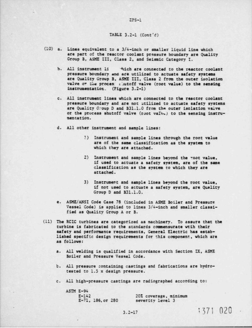
(10) a. Lines equivalent to a 3/4-inch or smaller liquid line whichare part of the reactor coolant pressure boundary are QualityGroup B, ASME III, Class 2, and Seismic Category I.
b. All instrument 11 hich are connected to the reactor coolantpressure boundary and are utilized to actuate safety systemsare Quality Group B, ASME III, Class 2 from the outer isolationvalve or the procesc fautoff valve (root value) to the sensinginstrumentation. (Figure 3.2-1)
c. All instrument lines which are connected to the reactor coolantpressure boundary and are not utilized to actuate safety systemsare Quality G. oup D and B31.1.0 from the outer isolation valveor the process shutoff valve (root varvs) to the sensing instru-mencation.
d. All other instrument and sample lines:
1) Instrument and sample lines through the root valueare of the same classification as the system towhich they are attached.
2) Instrument and sample lines beyond the root value,if used to actuate a safety system, are of the sameclassification as the system to which they areattach ed .
3) Instrument and sample lines beyond the root value,if not used to actuate a safety system, are QualityGroup D and B31.1.0.
e. ASME/ ANSI Code Case 78 (included in ASME Boiler and PressureVessel Code) is applied to lines 3/4-inch and smaller classi-fied as Quality Group A or B.
(11) The RCIC turbines are categorized as machinery. To assure that theturbine is fabricated to the standards commensurate weih theirsafety and performance requirements, General Electric has estab-lished specific design requirements for this component, which areas follows:
a. All welding is qualified in accordance with Section IX, ASMEBoiler and Pressure Vessel Code.
b. All pressure containing castings and fabrications are hydro-tested to 1.5 x design pressure.
c. All high-pressure castings are radiographed according to:
. ASTM E-94E-142 20% coverage, minimumE-71, 186,or 280 severity level 3
371 0203.2-17 -
.

-:a -
TABLE 3.2-1 (Cent 'd) _. . _ _ _ _ _ _
d. As-cast surfaces are magnetic particle or liquid penetranttested according to ASME, Section III, Paragraph NB-2575 orNB-2576.
e. Wheel and shaf t forgings are ultrasonically tested accordingto ASTM A-388.
f. Butt-welds are radiographed according to ASME Section III,NB-2573,and magnetic particle of liquid penetrant tested accord-ing to ASME Section III, NB 2575,or NB-2576.
g. GE is to be notified of major repairs and records are to be main-tained thereof.
h. Record system and traceability according to ASME Section III,Code, Paragraphs NA-4442.1 and NB-2151.
1. Control and identification according to ASME Section III, Code,Paragraphs NA-4442.1 and NB-2151.
j. Procedures conform to ASME Section III, NB-5520.
k. Inspection personnel are qualified according to ASME SectionIII, IX-400.
(12) Condensate storage tanks are Quality Group D+QA. The condensatestorage tanks are designed, fabricated, and tested to meet theintent of ANSI B96.1. In addition, the NDE requirement for thetank requires 1) 100% surface examination of nozzle welds, and2) volume examination of the shell weld joints in accordance withANSI B96.1.
(13) The hydraulic control unit (HCU) is a General Electric factory-assembled engineered module of valves, tubing, piping, and storedwater which controls a single control rod drive by the applicationof precisely timed sequences of pressures and flows to accomplishslow insertion or withdrawal of the control rods for power control,and rapid insertion for reactor scram.
Although the hydraulic contro4 ait, as a unit, is field installedand connected to process piping, many of its internal parts differmarkedly from process piping components because of the more com-plex functions they must provide. Thus, although the codes andstandards invoked by Groups A, B, C, and D pressure integrityquality levels clearly apply at all levels to the interfaces betweenthe HCU and the connecting conventional piping components (e.g. ,pipe nipples, fittings, simple hand valves, etc.), it is consideredthat they do not apply to the apecialty parts (e.g., solenoidvalves, pneumatic components,and instruments). The HCU shutoff(isolation) valves are Quality Group B.
,
1,371 021-
3.2-18~

_.. _
..
TABLE 3.2-1 (Cont'd)
The design and construction specifications for the HCU (.o invokesuch . odes and standards as can be reasonably applied to individualparts in developing required quality levels, but these codes andstandards are supplemented with additional requirements for theseparts and for the remaining parts and details. For example, 1) allwelds are LP inspected, 2) all socket welds are inspected for gapsbetween pipe and socket bottom, 3) all welding is performed byqualified welders, 4) all work is done per written procedures.Quality Group D is generally applicable because the codes and stan-dards invoked by that group contain clauses which permit the use ofmanufacturer's standards and proven design techniques which are notexplicitly defined within the codes of Quality Groups A, B, or C.This is supplemented by the QC techniques described above.
(14) Reactor Water Cleanup
A high leaktight integrity isolation valve will be provided in thereactor water cleanup discharge line connecting to tne feedwaterheader outside of the containment. This valve will be remotemanually operated from the control room using signals which indicateloss of flow of cleanup water.
The reactor water cleanup discharge line from the feedwater headerto and including the high leaktight valve and the suction line fromthe reactor to and including the outermost isolation valve will beclassified Group A. The remainder of the cleanup system will beGroup C.
(15) No principal industrial code is applicable.
(16) Pneumatic systems associated with actuatien of safety-related valvesto accomplish safety functions (e.g., main steam isolation valves,main steam safety / relief valves) are classified GE Quality Group C.This classification is intended to apply to components such as theair piping, fittings, and accumulator tanks (Ref er to Figure 3.2-1) .This classification does not apply to components of the system suchas air control valves, air check valves, and cylinder (or diaphragm)air actuators. These components are classified as "special equip-ment" and are selected based on engineering reviews, operatingexperience and testing as being the most suitable for the applica-tion. Such equipment is required to be qualified to demonstrateoperability during normal and emergency ambient conditions. Com-ponents normally furnished with the process valve (e.g., air con-trol valves, air actuators) are performance tested with the valveas part of its acceptance test procedure. Group C classification hasnot been applied to these components due to the nonavailability ofthe equipment with "N" symbol stamp and due to the inappropriaterestrictions (e.g., materials, minimum allowable wall thickness)in gosed by the code on the equipment in the relatively low pres-sure, low-temperature air service. The special equipment designa-tion for the above described components is based on considerations
1371 022*
3.2-19

-
ZPS-1 FIVISION 9MAY 1976
TABLE 3.2-1 (Cont'd)
consistent with those of Comment 15 above.
(17) RCIC turbine steam exhaust line is Quality Group B except thathydrostatic testing of this portion of the line is not required.
(18) Fuel pool (cooling) supply (RHR intertie) is Quality Group B andSeismic Category I; the. rest of system is Seismic NA.
(19) Special (engineered design-quality) requirements (motors, pumps,tanks, and equipment). -
The engineering QC requirements for the specified equipment havebeen prc:ured/ designed to the horizontal and vertical values inSubsection 3.9.2. This equipment is capable of withstanding in-ertial forces equal to the weight multiplied by the seismic coeffi-cient specified in Subsection 3.9.2 as applied to each member andto the system as a whole.
The QA/QC requirements are as required by either:
1) ASME B&PVC Section III, Appendix II or equivalent; equipmentordered prior to January 1, 1970 apply QC plan "in effect"based on purchase order requirements.
.
2) A QA plan / program at least equivalent to that required byQAR 2 as specified in Chapter 17.0.
(20) The unprocessed radwaste piping will meet Group D requirements andthe following supplementary requirements:
a. Piping
For sizes over 4 inches nominal, random radiography of 20% ofthe joints will be performed on girth and longitudinal butt-welds. Sockets and fillet welds in sizes over 4 inches nominal-will be given random magnetic particle and liquid penetrantav== h ation on 20% of the joints.
b. Pump and Valves
Welds in pumps and valves of pipe size over 4 inches will be givenrandom magnetic particle or liquid penetrant examination. Randomexamination is defined as examination of the linear dimension ofa weld in a pump or valve with piping connecting over 10-inchnominal size or as examination of all of the welding in 20% ofthe pump and valves with piping connecting 10-inch nominal orless.
.
(21) The main steamline from the outermost main steamline containmentisolation valve, up to and including the main stop and control 9
valve assembly, and all branch line 2 " (IPS inches) diameter and
-21371 023

... . --..--.. . ..
JANUARY 19/9
IABLE 3.2-1 (Cont'd) 51
larger, up to and including the first valve (including theirrestraints), have been designed by the use of an appropriatedynamic seismic systems analysis to withstand the OBE and DBEloads, in combination with other appropriate loads within thelimits of the ANSI B31.1 piping code and the PSAR Group Brequirements for OBE and DBE loading combinations.
The main steamline (MSL) for the outermost MSL containment isola-tion valve up to and including the main stop and control valveassembly and all branch lines 2 1/2 IPS inches diameter andlarger up to and including their first valve (including theirrestraints) have been designed by the use of appropriate dynamicseismic system analyses to withstand the OBE and DBE loads, incambination with other appropriate loads, within the limits ofthe ANSI B31.1 piping code and the PSAR Group B requirements forOBE and DBE loading combinations. The MSL analysis confirmedthat the main stop and control valve assembly and branch linesterminal stop valves, including their directly associated sup- 9porting structures connected to the turbine building, do not
,
produce an amplified response input into the MSL (natural fre-quencies above 33 cps). The dynamic input loads for design ofthe MSL are derived from a time history modal analysis (or rmequivalent method) of the auxiliary, reactor, and applicableportions of the tuttine buildings.
The pressuze-retaining portions of the main stop and controlvalve assembly and the branch line terminal valves have beendesigned to withstand the OBE and DBE loads within the PSARGroup B requirements.
The turbine building housing portions of the main steamlines mayundergo some plastic deformation under the DBE. However, the
,
plastic deformation will be limited to a ductility factor of two,and an elastic multi-degree of freedom system analysis will beused c determine the input to the main steamline.
It is therefore concluded that the intent of Regulatory Guide 121.29 is met.
(22) ASME Code Case N-196 used. 51
1371 024
3.2-20a

.'
TABLE 3.2-2
CODE CROUP DESIGNATION - IIIDUSTRY CODES AND STANDARDS FOR MECilANICAL COMPONENTS
QUALITY ASME B&PV COMPONENTS ORDERED COMPONENTS ORDERED ON COMPONENTS ORDERED ONCROUP CODE CLASSES /DIV. PRIOR TO OR AFTER JAN. 1, 1970 OR AFTER JULY 1, 1971 ANDCl.ASSIFICATION 1968 ED./1971 ED. JAN. 1, 1970*** TO JULY 1, 1971 PRIOR To JULY 1,1974 |9
A A 1 ASME III, A ASME III. A ASME III, 1
ANSI B31.1.0 ANSI B31.7 I NA & HB SubsectionsNP & VC I B31.7 I**
TEMA C TEMA C TEMA CSee Note (a) See Note (a) and (f) See Note (c) |18
B B*,C 2,MC* ASME III, B*,C ASME III, B*,C ASME III, 2 & MC*-
ANSI B31.1.0 ANSI B31.7, 11 NA & NC SubsectionsNP & VG, II HA & NE Subsections
TEMA C TEMA C TEMA CSee Notes (a) and (e) TANKS API 620/650 TANKS ****
See Notes (a), (e) and (f) See No es (c) and (e) |18
C I 3 ASME VIII, Div. 1 ASME VIII, Div. 1 ASME III, 3ANSI B31.1.0 ANSI B31.7, III HA & ND Subsections,
HP & VC III-,e TDIA C TEMA C TEMA C
('U See Notes (b) and (e) TANKS API 620/650 TANKS ****See Notes (b),(e)and (f) See Notes (c) and (e) |18 e'
D 1 1 ASME VIII, Div. 1 ASME VIII, Div. 1 ASME VIII, Div. 1ANSI B31.1.0 ANSI B31.1.0 ANSI B31.1.0TEMA C TEMA C TEMA CSee Hotes (b) and (e) TANKS API 620/650 TANKS API 620/6';0
See Notes (b), (e) and (f) See Notes (d) and (e)|18
E SPECIAL ENGINEERED EQUIPMENT WITH CODES AND STANDARisS AS SPECIFIED IN NOTES AND COMMENTS IN TABLE 3.2-1
* Hetal containment vessel only.LtdN ** Section III - 71 Ed. requires design of pipe supporting elements to be in accordance with the requirement
of ANSI 631. 7-6a, Divisions 1-720 and 1-721."
*** No piping procared prior to Jan. 1. 1970.O.N **** See Connent 12 of Table 3.2-1. 9
LT18 i!|W.AhW [:
.!

ers - REVIS10F 19NOVEMIER 1976
TABLE 3.2-2 (Cont'd)
NOTES
(a) Pumps Classified A and BThe requirements of ASME Section III, C, Boiler and PressureVessel Code, are used as a guide in calculating the thickness ofpressure-retaining portions of the pump and in sizing coverbolting.
(b) rumps Classified C or D and Operating Above 150 psig or 212" FThe requirements of ASME Section VIII, Div. 1, Boiler and PressureVessel Code are used as a guide in calculating the thickness ofpressure-retaining portions of the pump and in sizing coverbolting. Pumps classified D and operating below 150 psig and212*F use manufacturer's standard pump for service intended.
(c) Pumps Classified A, B, and CUse applicable ASME Section III Subsections NB, ND or NDrespectively for vessel design as a guide in calculating thethickness of pressure-retaining portions of the pump and in sizingcover bolting.
(d) Pumos Classified D ani Operating Above 150 psig and 212' FThe requirements of ASME VIII, Div. 1 are used as a guide incalculating the thickness of pressure-retaining portions of thepump and in sizing cover bolting. Pumps operating below 150 psisand 212' F use manufacturer's standard pump for service intended.
(e) Tanks are not fully covered by ASME codes. Groups B and C tanksordered on or after July 1, 1972, apply Winter 1971 Addenda ofASME Section III,197L Edition.
Other tanks are designed, constructed, and tested to meet theintent of API Standards 620/650, AWWA itandard D100 or ANSI B96.1Standard for Aluminum Tanks.
(f) All pumps a7d valves for lines over 2 inches, up to and including4 inches, in systems which are classified as Group A, B, and D+ for h973main steam and turbine bypass lines were purchased to the ASMEBoiler and Pressure Vessel Code, Section III.
Also additional testing was performed for these castings inaccordance with Section 3.2.1 of the Wm. H. Zimmer Safety L9Evaluation Report.
t371 026'
-
.
3.2-22

_ . . _
TABLE 3.2-3
SUMMARY OF SAFETY CLASS DESIGN REQUIREMENTS (Minimum)
. SAFETY CLASS
DESIGN REQUIREMENTS 1 2_ 3 OTHER
ASME/ SYSTEM CODE Classification (a) 1 2/E 3/E D
(D) B B B/E N/AQuality Assurance Requirement
Seismic Category (C) I I I/NA NA
(a) The equipment is constructed in accordance with the indicated codegroup listed in Table 3.2-1 and defined in Table 3.2-2. The aboveclasses are as per ASME III 1971 edition.
(b) B - The equipment shall be constructed in accordance with thequality assurance requirements of 10 CFR 50 Appendix 3 asdelineated in Chapter 17.0.N/A - The equipment shall be constructed in accordance with thequality assurance requirements consistant with accepted practicefor steam power plants.
'
E - Special items are manufactured to a QA program generallyconsistent with ASME III, Appendix II,1968 edition requirements.
(c) I - The equipment of these safety classes shall be constructed inaccordance with the seismic requirements for the safe shutdownearthquake as described in Section 3.7.NA - The seismic requirements for the safe shutdown earthquake arenot applicable to the equipment of this classification.
~
.
371 027'
.
=
.
.
3.2-23

.
THE CINCINNATI GAS & ELECTRIC COMPANY
PLANT ZIMMER UNIT 1
PRIMARY CONTAINMENT ISOLATION SYSTEM DATA
The information requested can be found in Table2.2-6 of NEDO-24708, " Additional Information Required for NRCStaff Generic Report on Boiling Water Reactors." This tablewas taken from the Zimmer FSAR.
The drawings that are attached, were taken fromVolume XI of Zimmer FSAR, pages Q0.41.48-1 through 41.
.
$71028'
.
A 4 79- G E .

.a e
ZPS-1 REVISION 16SEPTEMBER 1976
POSITION 041.48 (6.2.4)
" Provide the following information related to the containmentisolation systems.
Table 6.2-8 should be revised where practical to show this addi-tional information.
a. In Table 6.2-8 identify all fluid system lines and all 21uidinstrument lines that penetrate the primary containment.Not all penetrations where identified and labeled as such.An example is the 'LPCS to Reactor' line (higure 6.3-4) wheretwo 3/4 inch lines (1LP24A3/4 and ILP25A3/4) pete' rated theccontainment and were not labeled. For each penetration, identi-fy all branch lines that require isolation. An example wouldbe line ILP12A3/4 (Figure 6.3-4). No indication of isolaticnrequirement exists in Table 6.2-8 for this line.
b. Provide simplified sketches for each containment penetration.Show the isolation valves on each sketch along with the Qualitygroup and Seismic categroy of the pipe. Provide a cross-reference to the appropriate sketch in Table 6.2-8.
Indicate in Table 6.2-8 the position of each isolation valvee.in the event of power failure. Indicate which valves arein systems needed for safe shutdown, or, are in engineeredsafety feature systems.
g. For each remote manual containment isolation valve, indicatethe provisions made to allow the operator in the main con-trol room to know when to isolate by remote manual means.Such provisions may include instruments to measure flow rate,sump water level, temperature, pressure, and radiation level."
RESPONSE
Table 6.2-8 has been revised to identify all fluid system linesa.and all fluid instrument lines that penetrate the primary contain-ment. This table has been redesigned to list the lines by pene-tration number. All lines connecting or being a part of themain (process line) penetration have been listed under the particularpenetration number. Instrument lines, which include up to sevenlines for each penetration, have been grouped into particularcategories. The majority of the instrument lines all qualifyfor being exempted from Type C leak rate testing in accordancewith Regulatory Guide 1.11. Those penetration instrument linesthat do not qualify under the regulatory guide have been listedindividually to indicate whether or not they receive a Type Cleak rate test. The note associated with that particular lineidentifies either the justification for not testing or the typeof test this line will receive. The two 3/4-inch lines (ILP24A3/4 and LP25A 3/4) referred to in part of the questions .do not
Q041.48-1
1371 029
. .
ZPS-1 REVISION 16SEPTEMBER 1976
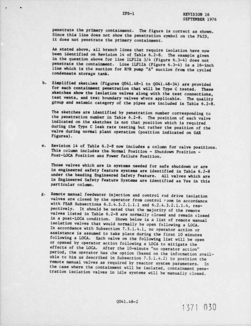
penetrate the primary containment. The figure is correct as shown.Since this line does not show the penetration symbol on the P&ID,it does not penetrate the primary containment.
As stated above, all branch lines that require isolation have nowbeen identified on Revision 14 of Table 6.2-8. The example givenin the question above for line ILP12A 3/4 (Figure 6.3-4) does notpenetrate the containment. Line ILP12A (Figure 6.3-4) is a 16-inchline which is the suction for RNR pump "A" suction from the cycledcondensate storage tank.
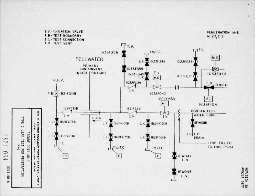
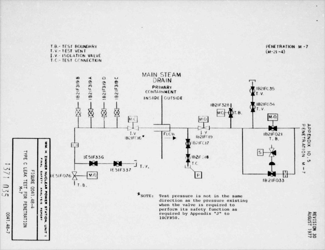
b. Simplified sketches (Figures Q041.48-1 to Q041.48-34) are providedfor each containment penetration that will be Type C tested. Thesesketches show the isolation valves along with the test connections,test vents, and test boundary valves where applicable. The qualitygroup and seismic category of the pipes are included in Table 6.2-8.
The sketches are identified by penetration number corresponding tothe penetration number in Table 6.2-8. The position of each valveindicated on the sketches is not that position which is requiredduring the Type C leak rate testing but rather the position of thevalve during normal plant operation (position indicated on SARFigures).
Revision 14 of Table 6.2-8 now includes a column for valve positions.e.
This column includes the Normal Position - Shutdown Position -Post-LOCA Position and Power Failure Position.
Those valves which are in systems needed for safe shutdown or arein engineered safety feature systems are identified in Table 6.2-8under the heading Engineered Safety Feature. All valves which arein Engineered Safety Feature Systems are identified as Yes in thisparticular column.
g. Remote manual feedwater injection and control rod drive isolationvalves are closed by the operator from control room in accordancewith FSAR Subsections 6.2.4.3.2.1.1.1 and 6.2.4.3.2.1.1.4, res-pectively. It should be noted that the majority of the remotevalves listed in Table 6.2-8 are normally closed and remain closedin a post-LOCA condition. Shown below is a list of remote manualisolation valves that would normally be open following a LOCA.In accordance with Subsection 7.5.1.4.1, no operator action orassistance is assumed to take place during the first 10 minutesfollowing a LOCA. Each valve on the following list will be openor opened by operator action following a LOCA to mitigate theeffects of the LOCA. After the 10-minute "no operator action"period, the operator has che option (based on the information avail-able to him as described in Subsection 7.5.1.4.2) to position theremote manual valves as required by reactor system parameters. Inthe case where the containment will be isolated, containment pene-tration isolation valves in idle systems will be manually closed.
Q041.48-2
1371 030

. .
ZPS-1 REVISION 27MAY 1977
Af ter the 10-minute "no operator action" period, some valves maybe positioned by the operator in accordance with post-LOCA operatingprocedures. These procedures direct such events as containmentatmosphere sampling and subsequent cleanup and ventilation systemoperation, i.e., cooling water to sump coolers in drywell, etc.These operation decisions are based on reactor system parameterssva11able as described in Subsection 7.5.1.4.2.
Additional indications available to the operator during the post-LOCA condition are valve position indicators and pump or blowermotor status lights. These safety-related indicators can be usedin conjunction with other indications outlined in Subsection7.5.1.4.2 to indicate system malfunctions requiring operator action(i.e., the need to close remote manual valves to maintain contaf -ment isolation).
.
Valve Penetration Number Post-LOCA
RBCCW supply M-23 Open-Closed
RBCCW return M-9 Open-Clcsed
Hydrogen gas control supply M-54 Open-Closed
Hydrogen gas control return M-104 Open-Closed
ADS Instrument Air M-95 Open-closed27ADS Instrument Air M-96 Open Closed
1371 031
.
s.
Q041. 48- 3

.
.
T.V. -TEST VENTPENETRATION M-1(A)1.V. -lSOLATION VALVE M-2(B)
T.C.-TEST CONNECTION MAIN STEAM u-stC)M A tD)
PRIMARYCONTAINMENT T.V.
kghhIINSIDE OUTSIDE
L.C IB21F 301C.,i OIDIB21F028A
|0$ $k |B21F300ABL.Ch iB21F300Bl V- |B21F028D
JL IB21F300Cf'' F V i IB21F300Dg g TURBINE
T.VII.C' n F. C.FLOW IE32F004A-- IE21F022 A IE32F004B M l. V. IE32f001A lE32FOO2A~
IE32FOO4C IE32FOOlB IE32F002BC IB21 FO228
IE32FOO4D](IE32F005AlE32F00lC IE32F002C- IE21F022C IE32F00lO lE32F0020IB21F0220 IE32F005B
IE32F005C IM ITEUl
! le21F319A T.V'z IE2|F319B 182iF026A n LEAKAGEd
IB21F319C IB2iF0268 ( IB21F067DA , t!T V- IB21F319D IB21F026Cij ( IB21F067Cn
Eg IB21F026D IB21F0678( IB21F025A
.- r_
u ?9 " IB21F025B IB21F067A;8 )ZN E"
:g y IB21F025C [M O-
y= : IB21F0250 MAIN- - -
T.V'~[g ; o*7 CONDEN5ERox wo - c
*U
~m t .G &AQ o -!o
d S $$L e 'c 21:5m Z m tA
k O- mz
@
a

~
.
.
.
1.V.-ISOL ATIO N VALVE FE N E TR ATION M-5T. B,-TEST BOUNDAF{YT. C.-TEST CONNECTION M-23, E-2T. V.-TEST VE N T
FEEDWATERPRIMARY
CONTAIN MENT pgINSIDE OUTSIDE
(IFWD50K T.V.
5IFWD49IB21F065 A L T . V.
M . O'I B21FOll A IB21FOIOA IB2iF32 ARPVM SA / >G' '
5,
T. 8 i . v. tow l . v. i . v. /g
L.C.f) iB21F078A IB21FO38A IB21F030p LINE FILLEDIdJ k L.C.g 'g L.C. TO THIS. ,
LN n r POIN TN "r- =ga ;c L . C. I B21FO79 A L.C. IB21F039A I B21F031 A- -- zn o ,
E "P L'C'o y(IFW0ll Ay } ! fa T. C. j__I T.V./T.C. M T.V./T. C. . L.C. K T. V.
3 |P P Pm ;g 3 ;3@"b
m m ..
f y L . P. jeg8 g 3d DRAIN 85t n '? nnh e 's EGa a ::a
.
.
I.V.-lSOLATION VALVE PENETRATION M-6T.B.- TEST BOUNDARY M -2 3,C-2T.C.- TEST CONNECTIONT.V. TEST VEN T g- 1
T.V.p T.V.
g .V/ T.C.TIG33F356
FEE.l) WATER }L.C iG33F348 Ic33F038PRIM A RY y
CON T AIN M EN T }iG 33F355 @I V. IG33F042INSIDE OUTSIDE IG33F349
L.Cl) u.0) IWf0dl{g" ' - -
|G33F039T. B. R W C U
_ _M X gi gl.V.
T. B . IB2iFOllB IG33F040
IDPIF(45B kl0
M^ IG 33 FIO 4IB21F 10B IB21F320
R m WFED! ' [ y, f g > WATER FUMFi-i Flow j
h L .C 1 )1Bdif 078B LC IB21F03BB L .C . IB21F0300 t IFWOllB. n 'r
5m 5
] #g *g L .C .(1I E2tF07-38 L.C IB21F039B L.C IB21F031B OR INT.V. l. .P
E T. C . LINE FILLEDN m m
ya g ,s L--
T.v./ T.C. T TO THIS P9|hT
", h ;;! W.v./T.C .*82 8ap P y (FWO47u
==a g g, T . v."I *3
8 B 35 MAe 1 *j $ {IFWO48 g;<:,. e c T . v. ME:? I tJ -9
2 L*
so
.
.
.
T.B.- TEST BOUNDARY PENE TR ATION M -7T.V.- T EST VEN T (M-21 -4)I.V.- ISOL ATION VA LVET.C - TEST CCNNECTION
MAIN STEAM[ $ M DRAIN r,
C C p C PRIMARY f |B2|f035g g g g CONT AIN M EN T ) g y , y,g ai co 9 |NSIDE OUTSIDE
IB21F328 | |B21F034
MO T. B .--
M .O.{g~L, .1 -
es -u y ea mou
I.V FLCV, l.V IB21F021 5MIB21FC l6 ' -> IU2If039 T . B. yZ
N'82'I''' 4 Rg
.! E3H 1 5 O-Y
, tf IE 51F336 d f IB21F 018*
Em! d' T . '/ 'i " W
T. C db I'" M M
IE 5t F3 3 7 d'ud Rm *
a m,ENE C I E 5|F076 M.C. P u Ltj
~E :9 O~~
IB 21F033I .B.0* *5 TO I -t o ,a
bm O l' 4LII Q -' ; y NOTE: Test pressure is not in the samedirection as the pressure existingA * m
7 ** when the valve is required tomM* =$ perform its safety function as
j $ required by Appendix "J" to $$Ho0 h =5 10CFR50. @<-P s .' 41':e | -9==
L a L- ~o

.
.
.
T. B.- TEST BOUNDARY PENETRATION M-9T.C.- TEST CONNECTIONT.V.- TEST V E N TI.Vr ISOL ATION VALVE
R.S.C.C.W. RETURN
F R il.l A RYCCNTAINMENT
INSIDE O U TSIDE
T. V.F1
1 0741, V, IWRl37
SM . O. -
'
I 6s DRYWELL HEAT*
COOLING COILS F. C EXOiANGERS 'd T' B' ' T. B. FLOW IWROSSI
" k b ['*A g,
|k REACTOR |WRO77IWh067Ao
D8d-^ r =z REClkC. FUMFS T. B . LJL.4 93
N *8 ;E' T. C .
h5 Ih I WR0678~^
REACTOR D8tjca ?" 8 **,j eg 3 ,f g RECIRC. FUMPS
T. B .O "b 33
AP 3"
E* = "| >=34 828 *
t 8 =5 50;. s .= s
E G*P ** a 48
_

.
.
.
T.C.-TEST CONNEC TlONT.B. 'EST BTNDARY PENETRATION M-loT.V.-TEST VENT 0a-52-2)l.V.- ISCLATIOh VALVE
PREACTOR CORE T.V./ T.C'rT r,. v.T
ISOLATION COOLINGlEl2F062
PRIMARY lEl2F3508CONTAINMENT
R. P. V. H E A D INSIDE OUTSIDEIEl2F061 lE12F350A
:: M.O lEl2F086INSTAL L lEl2FOjg
I RHR T. B .O V.BLINO FLANGE t,i .B.TIE51F066 lEl2F023 '"
IE51FOl3 IE51FOl2 'SM.O. N 13
RCIC,>g| || ewFLOW TESTABLE V- T. B. PUMP
H CHECK VALVEM, lE5|F065 (E51F034 I4 7,e ] (L.C -
''
me m
E" 2 ,
Rm "E M.O.|'
. Rs ;2 J ESlFO22a I IE5|F035
0m J L 'C 'L
3 F1-e c >
Egg ;; Q IE 51F 338 IESlFO23o
( h- -
y
A 2 4 g IE51F 339 95|E5lFO59s- m
s 34 I b $$o
b $ 0E u 5-s-
b E T.C. ETO CYCLED *4 CCNDENSATE w= wo-

.
.
.
I . V.-ISOL ATIO N V ALV E PE NE TR ATION M - 14T. B.-TE ST BOUNDARYT. C.-TEST CONNECTIONT . V.-TE ST VE N T
c
CONTROL ROD DRIVEPRIMARY
CONTAINMENT ICllF32 3-}INSIDE OUTSIDE n TN/L C
'v .
ICllF085 df ] (ICllF355'
I ICilFOlBIClitO B, g
ICilF084 Ml T. B .,* ICliF087 ICilF086 f.V IC liFO72
5 s C)<C / !><C M -C><C' '
ij T. B. l . V. FLOW ICllF083 1. V. T. B.~*,
3,- a _..
@a ;" ICilF360 ICilF358 j IC il F357u^e 28N
_...
7
3 $ |1ICilF361 ICllF359 ICilF356
ca w -.
if !! u V/T C oT. C . Tue S !! am9 $ IN $$@ E i 25s 2 %

.
-
i
.
T.V. IEST VEN T PENETRATION M-lBl.V. - ISOL ATION val.VET.C.-TEST CONNECTION
STEAM TORHR HX
fIESIF076 PRIMARY
MO CONTAINMENT .INSIDE OUTSIDE
MAIN STEAM ,
DRAIN
IL5tF063+ IESIF004
MO M0
RESIDUAL HEATMAIN STEAMT.V. -C><j >4 T. V.
l.v' D.C. REMOVA L
{ FLO W g ,y,,
*IE51F072
ji TOo
p, PENE IRATION=
Ny ,j{ U-24 IE51F073-s x 4 r-
r C '' *$ NOTE: Test pressure is not in the same T. C .
1. " 8 E* direction as the pressure existing _
"5 E Eo when the valve is required to Pk Ek perform its safety function as" - mm
required by Appendix "J" to 9EM* 3"
{* *f [ 10CFR50. h7jN 88E 2s8 d z "m-
2 9 'e 3"% ? O um -4 uh
-
G
.

.
.
.
I . V,-ISOLArl0N VALVE PENE TR ATION M-20T. B.-TEST BC UNDARY M - 51 SHT. 3, D - 7T. C.- TEST CONNEC TlONT. V._ TEST VENT RHR SD
SUCTIONT . C. p RIM ARYR CONTAINM FN T
llJSIE OUTSIDER] IEI2FOO5
M.O.
IE12F353 IEl2FCC9NIE12 F 3( 6 |M.O.| y .0, | T. B.
I'EClh C . LESIDUALclNE T. B. I . v. g, y, HEAT REMOVAL
}' 'I'CW IEl2FCO8 _
IEl2FOCl IEl2F 305
7 7 IE l2 F36 8-
y 7IE l2 F0 67
AUo n*
i ~j y T. B .fEa IE12FOO2 IEl2FOO7." J I k IE12F370m n
g . V./T. C. IE12F369(f O N3f T T. B.cm m 4 m IE 12F371
Y 8 E $[lFCO345$ $ 5y N
8 *g "o
Ee :: oc
[2 h ! IFC O3 5oFPC8 @
b $
.gc
EG::a-

.
.
.
I.V.-ISOL ATION VALVE PENETRATION M - 21T. B.-TEST BOUNDARY (M -51 - 1)T.C.-TEST CONNE CTIO N
iI T . V.T. V.-TE ST V ENT
R.H.R. D.W. -
SPRAY { IEl2F366PRIMARY p
CONTAIN MENT
INSIDE OUTSIDE
h IE12F367T.C.3 7 IE12FOIOA
lEl2FOO3A'
DM.O. M .O. M.O.cCONT AINM EN T SPRAY 1 jT . V* ,V M V m
F l . V. 1. V. I* LOW IEl2 FOl7A* IEl2FOl6A M.O. U
T. B.]T T. B M.Og A . B. g1
A , tfIE12 F027Ae
[! lE12F053Ac,
"9r- IE 12 F304'
NO i! M T. B.c- ,a
h Ih * NOTE: Test pressure is not in the same M. O. lEl2F3498?* 8 *
'33 3 ;; o direction as the pressure existing g|2 O M ] T. V.when the valve is required to T.B. F ' IEl2 F349A"b 3% perform its safety function as IEl2F042A"
A i' 3* required by Appendix "J" to
g {E =y 10CFR50.___. gg3 5 % -f e$i d <E C? e 'c * U
me"! $w~o,

.
.
1. V.-ISOL ATIO N VA LVE ~
PE NE TR ATION M - 17T . B.-TEST BOUNDARY (M -51 - 2 )T . C.-TEST CONNECTIONT . V.-TE ST V E N T
( IE12F350B
IE12F350AIEl2F039D L
R.H.R. D.W. T.e. $ M N.CTB IEl2FO86SPRAY e
IEl2F023PRIMARY
CONTAIN ME NT-
u INSIDE OUTSIDE n T* V* '
w pr
T. C.FTIEl2FOIO8 dlE12F351B /YlE12F0488- n
CD T. B~> IEl2F335u M.O.N J n- IEl2F351 AM. O. M.O T. B .
T. B.! p(w 2 w'
* FLOW . 7. 1. IEl2 FOS 3B IE12FOO3Bd .
IE 12 FOl7B* IE12FOIE 8 1 Pe
{ f M.O. E M.0-i M.O.
[ Eg! I k NT. B IEl2F049M. O. IEl2F0278 T.B- T. B.ga ;g T.B.m sx o =
g5 ~hr,
IEI2 F042 8 3 7 IEl2F0248P is j"
GB * &,y T. V. T . B'=-, , n n
o m e 3
9L 5, M M
|E 12F375 IE12 F 374$@
m o a
h h !>$e
c ._,NOTE: Test pressure is not in the same USd *z-
direction as the pressure existing -.9b e.
c"L $ when the valve is required to $w
^
perform its safety function as "* -
required by Appendix "J" to10CFRSO.

_ _ _ _ _ _ _ _ . . . . . . _ _ _ _
.
.
.
1.V.- ISOLATION VALVET.B.- TEST BOUNDARYT.C.- TEST CONNECTION PENETRATION M -23T.V.- TEST VENT M - 58 SHT. 4, B-7
R.B.C.C.W.
SUPPLYPRIMARY
IWR064A CONTAIN ME NT
' 'T. B. T. B. lWRO80
T . V.n
IWRO73 IWRO54 rS M.O. glWRl35
: T
s x DRYWELL IWRI34
COOLING COILS Xk ",.
!E T. B. JLOW T. B.," -
va o"9 HEATN r-
IWR066A IWRISO IWREl2O EXCHANGERSk3 {! REACTOR-"
,
Mk 3k'
RECIRC. PUMPSO- em .: o o
by,$ [! , REACTOR IWR066B T. C .
g{ I9 'RECIRC. PUMPS
g m- 5, um:A M O 4 O4
$z t,n A~*H. y--
--* OO C2 Sm-
m * uo,
.
.
.
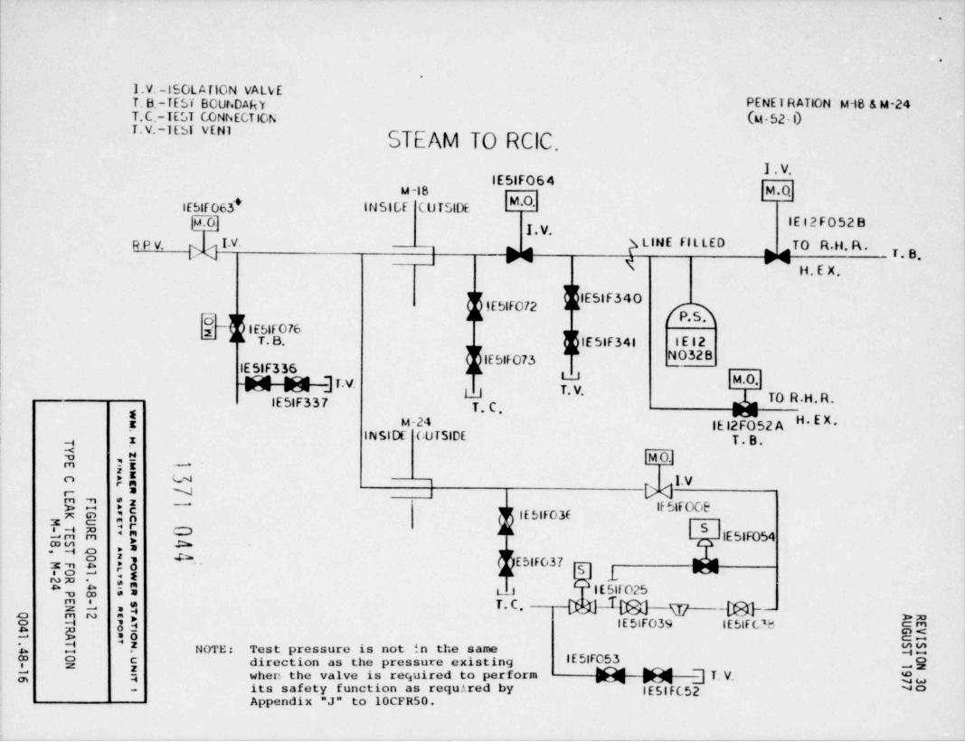
I.V. -ISOLATION VALVET. B.-TEST BOUr.DAftY PENE1 R ATION M-18 & M-24T.C.-TEST CONNECTION (M. 52 - 1)T.V.-1EST VEN1
STtAM TO RCIC.r
1. V.IE51FO64
M -18 M . 0'~ M.O.IE5|F063* INSICF C U TSIDE
{0] IE 12 F052 By , y,
RPV. I.V. g LINE FILLED , TO R.H. F\ ., , ,
T . B~N " ' H. E X.
'
f flE5|F340I f_ j { IESIFO72y IESIF076
T. B. IE 51F341 IEl2
f $1Ebtf073 NO32BIE 51F336 J L U" "
'l T ' V' M.O.y T. V" e J
IE51F337 TO R.H.R.T. C '
! M-24 |E 12Y52 A H.EX.IN SIDE CUTSIDE T.B.y z
j! M O..-
;A U lo
[> <j .V= Nr
IE5|FO3C3
h $ IE51F054
Oyy S, 3 E5|F037 pyg Mg .1.:Emx .
e ,E 5 L_1 IE51F025*o
T. c. ptyjl{g} g _ggc}__3h :gc-i 3 -e IE5tF039 IEttFL's cmgE : 5 85-
d 2 NOTE: Test pressure is not in the same $$*
wC direction as the pressure existing IE5|F053 o? @
m" ! when the valve is required to perform M ] T. V. *
its safety function as required by IE 51FC52 No-
Appendix "J" to 10CFR50.

.
.
.
I.V.-ISOLATION VALVET.B.-T EST BOUNDARYT.C.-TEST CONNECTION PENETRATION M-27
REACTOR WAT,ER M-55 S HT.1, E-7T.v.-TEST VENT
CLEAN-UPPRIMAfiY
CON TAINMENT IG 33F307*17 INSIDE OUTSIDE-
g p,
y T. B.IG33F358 g IG33FOO4
'' '
IG33 FOOL
M.O. HEATIG 33 F357 d 5 / EXCHANGER S IG33FOO5A
3 L :(REACTOR
{ '" RE tyj C. T. B..
FLOW# I . V.y z
4 ,e IG33FOO6[ [E hIG33FOO2:--9a g IG33FIO2*
FIG 33F007*8 3p U T. B IG33103o-2- ]T. B. { {IG33F003yA ;<
__
[$ T.v/T. C .$$ $ || C T.s T.v./r.c~
h !9 IG33F101 IG33F005B.o
( C -
P2" w a
8 A" j $ > T . B. RAB E 5 m 85=
% 2 .* nn? 8 ! -9C
2 58

.
.
I . V.-I S OL A TI ON VALVE PENETRATION N-49T. B.-TES T BOUNDARY DRYWELL SUMP (M-62 - i)T . C.-TEST CONNECTIONT . V.-TE S T VE N T DRM N
PRIMARY -
CONTAINMENTIN S IDE O U TSIDE
F' 1 T. V.IRE 048 $ IREO49
(IRE 079 E E IREOSOA 7\:5 1S_i S-
k IRE 5IM ADRYWELL EQUIPMENT DRAIN SUMP
f ':u).
'u' F1. V. 1. V. T. B. "H "
FLOWT . V.
!g IRE 065z
A jE T.C. IRE 050B;A p DRAINo
r; , .'Rg ;E P% "9a
0 '' *O?" 8 E"-
T*B*o * NOTE: Test pressure is not in th'e samegy 3 ;j. direction as the pressure existing
gy
--~x -
," * ** #,
when the valve is required to performkh =$ its safety function as required by %$o
2 ;;j 3 h Appendix "J" to 10CFRSO. 85*$ h 5 O
** g 3*c *! 08s| -

.
.
I.V. - I SOLATION VALVE PENETRATION M-50T B.- TEST BOUNDARY (M -62-l)T C.- TEST CONNECTION Sf.v._TcST VENT DRYWELL SUMP IRF00 7
DRAIN k, y , y,PRIMARY
CONTAINMENT rINSIDE OUTSIDE
h IRFOM T. B.
LI
IRFOOI % IRFOO2QSS '
'
MI RFSIMC
/c-::,
%3) -1 m/\
DRYWE L L FLOOR DRAIN SUMP I .V. 1.V. \;;hiFLOW T V-
l [$IRF050=
JL DRAIN$ b T.c
5E d.m
?NO'F
r- =92 *i^8 n
- h;;y y -.
Sg ; N ix
NOTE: Test pressure.is not in the same 'g3 3;[o direction as the pressure existincJ
-
@x
,m m ** O when the valve is required tokk ={ Q required by Appendix "J" to
perform its safety function as@ g> 33 wmE E "3 g$10CFR50.' gg{= 5 g -9: 38
..MN
%

.
.
.
I . V.-ISOL ATIO N VALVET . B.-T E ST BOUNDARY
PE N E TR ATION M-51T . C.-TEST CONNECTION M -27-2T . V.-TEST VENT
CYCLED CONDENSATE
PRIMARYCONTAINMEN T
INSIDE OUTSIDE
R T. C/T.V. R T. V.
! ICYO53 ICY 052k_, x
4 ,e ICYO47 ICYO46 I CYO 45 T.V. ICYO 512 || T, C . [ >4 ' '" ^A
CONDENSATE" L C. L.C. T. B.m n .PUMPSN5 38 i . V. ICYO54 1. V.
yA y + FLEX HOSE---
2 _4 o ,= t_j
$g p || E[, T. V.
a ! -
m
~ $;m :a omo -i
;U s >=" Q bE_4 .'b g -
S4 -GOD C,
$::8
-

.
.
.
I .V.-IS OL ATION VALVET. B.-T E ST BOUNDARY COM BUSTABLET. C.-TE ST CONN EC TIONT . V.-T E ST V E NT GAS CONTROL PENETRATION M - 54
P RIMA RY M - 74 , F - 8CONTAINMENTINSIDE OUTSIDE
IT49FOO2 A
IN TAKE IT49 FOOL M.O. D001 -14 AC g T. B.
5FLOW T. 8- I V- - SN -~z
c x > IT49FOO2 BA 3E M.O.
M.O.i roE T. B.
.! DI D4m nRs : --
i . v.E :P t4-m m 4 M Ntr4 o s IT49F3OO, -
a,2y. U T.V.*S P '; o
L_| J T. C .g i: *m
M. O. DOOI-14 BEL 4.A* i.s8 E is IHGCO8 RM
2 d *z
e' E. 85E
42$ f ;9
08

.
.
'
PENE TR ATION M - 56M -57 C-2/3
I . V.-IS O L ATIO N VALVE STAND-BY LIQUID 1. v~T. B .-TE ST BOUNDARY P RIM A RY
f IC4tFO21T. C--TEST CONNECTION CONTAINMENTT. V.-TEST VE N T INSIDE OUTSIDE a IC41FOl7
mm
F T. 8.CAUTION
}lC41FOl6T. V. IC41FOO4A IC41FC 03AIC 41FO27 yq X
l . V. T. B.
IC 41F026
I C41FOO8 IC41FOO7 IC4|FOO6
IC4 Fhs4L.O. 1. V. ' ' ~FLOWg T.B. e r
b IC41F305 IC4 tF303} T. B.- z
g J L IC41F025ujim
ro o eyIC4IF304 CAUTION T. B.E2 IC4|F306--
8 E L I4 M* vayA 2E N 1.V ICAIFOO4B I C4|FOO3 B
U hlC41F020~~
$[ $ !ymg r ; a T. C . ** *a (_n
IC41FOl4--a m wm
g IC41FOl9 5IC4tFOIO
m o IC4tF302 -9c*m
. ! -Cx3 N T B- %| IC41FOO9
-
.

.
.
.
I . V.-IS OL ATION VALVET. B.-TE ST BOUNDARY
PE NETR ATION M -70T. C.- TE ST CONNECTION(M - 40-1)T. V.- TEST VENT
DRYWELLINST. SUPP
i4 PRIMARY/ CONTAINMENTINSIDE 'CUTSIDE
/ T. V.'
R CIC. MIIN 06iFLOW'
M.O. IINO87"IE5|F066 AIR- II N 0 6 3 T. B. RECIVE RDRY WE LL 'A / W # AFTER RLTERI V. IINO74,
.
xII N 0 5 7/ IIN126 M-. 1
j ,e_ T . 3.
!E \lE12F04l A T.C.n"9 / LJr-
m m .,
RE i8 j [IIN156.
g" gr,3A 2E T. V. 'lIN108? " is "
:3,
L_Jaa S ;g R;= . , _.
o m a= u"$ Na Ch"I * -a
2 E 2. a8:545_ - z a -
o
L a. W
~aw

.
.
.
.
I.V.-ISOLATION VALVE PENETR ATION M - 71T.B.-TEST BOUNDARY M -72 SHT 2,F-6T.C.-TEST CONNECTIONT.V.- TES T V E N T
SERVICE AIR
FhlMARYCCNTAINNEN T
INSIDE OUTSIDE
ISA83C@ T. B *
H.C -FLEX HOSET --
I Nb1
fEISAIO3=T. a
d F |$AOfl ISAO79 IS AIOl
|yA C- 1/ O DO(3
Eo I. V. ISA080 1. V. T. B.
h3 '^ ^*5 M blSAIOP^@ ;
T B. ISAIO4gg Ei [r. V.r4 o .A
t_j
by h !! r.B.{5 {$T. c. I V-u ?m L KA? ** " ISAb2A ISA82C
$ kr. .B. :; 5 56-
? @' [ s_.a
.
c c? ISA028 -
% h Q -@N $w_
~o

.
.
I .V.-IS OL AT IO N VALVE PENETR ATION M -74T. B.-TEST SOUN DARY M- 8 8 -lT. C.-TEST CO N NECTIO N DRY WEL LT. V.-TEST VENT CHILLED WATER
IN'
PRIMARYCON TAINM ENT
INSIDE OUTSIDE T. V.HEAT EXCHA NGERS F1
IVPO46B(FUT UR E )
g( OMT. B . T. B . ]M.O _
IVP 08F IVPOO8H -
, u C)<!-IVPOO6B-OPE N IVPOO3 B
! T. B.H Z
Y e T. B. T. B.jr IVPO26 8mrn o
} IVPOO8E IVP008G L_)T.C.;d h 3k IVPOO78 T. B. T.B. HEAT EXCHANGER-B
j | IVPO40* ja ." 5:E FLOOR-
$ 59 u DRAINu
9L .. NQ ; 0 ~
Emc2 E 26 85.- d- ~ .z C3 40u o w* c a? 2 u e" *$ No
.

,
'
,
I.V.- ISOLATION VALVEPENETRATION M-77T. B.- TE ST BOUNDARY
M-88-1T.C- TEST CONNECTIONT. v.- TE ST VENT
DRY WE L LC HIL L ED WATER
INC ON T AINMENTINSIDE OUTSIDE
r7
T.V.IHEAT EXCHANGERS
*
IVPO44T. B. T. B . T. B . - -
fEIDI T. B'! IVPOOBB IVPOObC IVPOC8C
--
. ,.4 g X2g ' '
A jE IVPOO6A IVPOO3AFE FLOW CLOSEDo
IVPO46A =
h3 i3{ blVPO26A
y h T. B.g$ 2 kivpoi7
h|;9[ $ IVP008 A-
"2 " * u. T. C . HEAT-g a N EXCHANGERo
gL .gT.V. IVPO40
--
8 US 35 >ma2 3 "9 u, $$.
.g s a w Ll 45. = -9zg a %-. ~o

.
.
T. V.-IS OL A T IO N VALVE .
PE NETR ATION , M -75T . B.-TES T BOLiND AR Y
T. C.-TEST CONNECTION DRYWE LL M -es-i
T v.-Test VENT CHILL ED WATEROUT
P RIM ARY gCON T AIN MENT T, V,
IN SIDE OUTSIDE
T. B. R SET @ (IVPO41 SET @ 35 PSiG130 POG nT. B . FLOOR
FLOORIVPOO9E IVP009F DRAIN d(IVP028B Nd
A c DRAIN ( IVPOl2B T. B..
1 F IVPOllB IVPOI4 BIVPOIOBj ') - M.O.
N[ DG i><3. B. R ECIR
1.V* PUMPT. B. T. B. FLOW IVPOl6 B
IVP009G IVPOO9H
4IVP O25 Bj IVPO45B
m
IVPOISBn"9 HE AT EXCHANGER (FUT URE),-
9' *z 1 L AUX. B L D.5 i8 T. B'x
yN AE' SET (E FLOOR DRAIN
__. . [R*?" 8 ;"38 b E o, CA['g !h j T. B . PU M P- IA=s
j:g ><.
C"g o IVPOl8 ggE *o L.,9a =
d z c) <"g Sg.
e e g( {lVPO42 [y -
~ ," _-
T. B. OELJ

-
-
.
.
I.V. ISOLATION VALVE DRYWELL PENETRATION M-76T.B. TEST BOUNDARY CHILLED WATER N-88-1 'T.C. TEST CONNECTION OUTT.V. TEST VENT PRIM ARY
CONTAINMENTINSIDE OUTSIDE
HIGH PT. OVENT R SET @ T . V. SET @ 35PSIG
dn i 130PSIG rT. B. g IVPO43
FLOOR'.B7
"7, g 2
IVP009A IVPO47 J L' D R AIN IVPOl2A-CLOSED T
IVPOllA M .9,
@{0]r. j. , T. . RE CIR.g"a' 3 PUMP
IVPO45A FLOW l ' V- IVP016AT. B. TB TB (FUTURE) ~
I VF OO9B IVPOO9C IVPOO90 ppa g ( IVP025An ,x
"
L_J IVPOISAr-
g]*P
T.B3 AUX. BLD ..
g HEAT EXCHANGER
E ':SET @ FLOOR DRAINy
2@ ] ~,3 55 PSIGkg 8 IB "
.-.
b ;!u"*
T.B PbMP-IB, mc -,
j,j,r ,
$ $ O IV pol 8 $@% 8 - '5m
[ f { hlVPO42 25*
'"- %
T.B. "o
L.J

.
. .
2Gsz am8S~ gd75 .
0W"B47 N ..
0MTB I T
IN .
ll'
49
- ?8M) 0
1
.2 N 6N -O I O O. BI
. .
0 V1 N M TI
T 4 - I.
A TF l
_RT yE( 2 .N 6
NNCV.E 0 . .
P L1II
.
f J CL .
T
4 76 2
0A I
1
NNI II
ED W
TILC S ON T LYI
EL TR U F-MEAA O.
NW M MIA'I
EYURT DPNIRE CSDN CN
I
E PNV OL Y I
AV RT i
A C
O/l
D ENN NT NC U N N l '
OOE lI
T B C VAL T T TOSS S L - v2 OWN
6 s
S E E E LT T TI
. - - EV.BC V. W
Y. . . .
I T T T RD
gy7"IgzEEl !: :4sz. i 4 i.
,!r ' ,! 5 ."2*
38A o 2 aA">
d A c, 9*14 $m0AsdE;;
2N
82 ?

4
-
.
1. V.-ISOL ATION VALVEP E NE TR ATION M - 93
T . B.-T E S T BOUNDARY(M 40-1,2)
T . C,-TEST CONNECTION
T . V.-T ES T VENT
DRY WE L LPN U EMATIC
.
PRIMARYCONTAlt8 MENT
INSIDE | OUTSIDEg ,g IINil3
S rn"
SJ TO FI LTERS
IIN 012 G3 73 y
T. B.T' C ' IINOIS
OPE N TO T. B. TO Fl LTERS W W WSr DRYWELL l.V. F. C . IINO36
h h *
FLOW IIN130-,
1= J L=? Ag LJ T . V.93 : z^8 :EM #? N
24 ,s "
6 ,. g ", w>"' S ." ;y N
$ 59 ~m
Eb :: a2- :o
$3ge f 35 u,
n!c$ :! Q-
2.g
[ e g Z8o a

.
n
.
.
1. V.-IS OL Al lON VALVE'
T. B.-TEST BOUNDARY
T. C.-TEST CONNECTlON~
T . V.- T ES T VENT ,
DRYWELLPN E UMATIC
PRIMARYCON TAINMENT
IN SIDE OUTSIDEIINOJ6A SET @ 200 PSIG
IB 21F040F @T. B.IINOO8 A A OOSA
M.O.j AIIN OO4 AIB21FO408 IINOlOA IIN OO9 A SET @ 150y ,
Y '/ 'M '/ M >4 PSIG.,e[E FLOW l . V. T . B.
n="
1,-
z llN157 IINO92 IINilO93O ;5*
IB 21F040K
h b! Uh / y g.C.T
iz " is ;*Naf: ;o ' P
e j| ~- T. V." '
OA u"I * i.0 '!
,,
5 E5 EE~
r M " .z Su,4 O w Amg
I w2
e * 4 L- uo

.
.
.
1. V.-ISOL ATION VALVE PENE TRATION M - 101T. B.-TEST BOUNDARY M - 103, E-7 |T. C.-TEST CONNECTIONT. V.-TEST VE NT
DRYWELL PURGEIN
PRIMARYCON TAINMENT P M.O'
INSIDE OUTSIDE NT. c. _L\ IVQlOY
IVQOIOAT.B.
IVGO7YAIV ' \ M.O.A. O.
. B.l V. 1. V.s DRYWEL L
| T. V. K KFLOW IVQ 0018 -* IVQOOIAj ,g IVGO7YB
5Ao " y M.O.m %
y3 .| $ y y i T. V.T. B.g ;gn g g_ _ _ .
;sin Ma 1. V. 1. V.? c ,
ig $ IVQOO78 * IVQOO7A2sge I:,
N$y
NOTE: Test pressure is not in the > :o
"3y g 2 same direction as the pressure g
a e.
existing when the valve is required ggd *z.-.
to perform its safety function oc~
? j as required by Appendix "J" toto - 10CFR50. uo

.
I . V.-IS OL ATION VALVE~
7. B.-TEST BOUNDARY
T . C.-TEST CONNECT 10NT . V.-TE S T V E N T P ENETRATION M - 10 2
M - 10 3, E- 6
DRYWELL PURGEOUT P
P RIM AR YCONTAINMENT T.C.
IN S IDE OUTSIDE
^ 0- IvoOl2 BJ k
1. V.
#IVQOO2 A IVO OO 2 B! FLOW
-8 L IVoO204 ts~m 3g -
?5 t#*r- :s N Y- W NQ'
*Ez --
/ I~8"
gg : r, O IVQO l7 ivoolMA,5 3 S IVOOO5A S IVQOOSB I I I[M g ( IVQ OlB IVQ Ol93om =
"S F Gs J L L,e !9mL .. 4
U NOTE: Test pressure is not in the same"1 * ;$ direction as the pressure existingS s % nd *z when the valve is required to perform 80_.
g E g its safety function as required by SGa ; Appendix "J" to 10CFR50. p p ]
- _ g-

4
.
n.
SUPPRESSION POOL PURGEOUT PENETR ATION - M 10 3
P RIM ARY M 103, E - 6
C ONTAINMENTI .V.-ISOL ATI ON VALVE INSIDE OUTSIDET . B.-TE S T BOUNDAR Y pT . C.-TEST CONNECTlON T. C.T . V.- T E S T VENT
IVQOl3 A
AO A.0l . V.
IVQ OO 4 ' iVQOO4BFLOW
T. V."
E
( IVQOO2AY ,e A . O. IVQOl2 B A .0,m -r
!AoT 8, IVQOO2B."m m V
$5 is d 3-0m *53:. aa >=5n S *3 , NOTE: Test pressure is not in the same IVQO2O"@" 5 1 direction as the pressure existing j k$ $5 when the valve is required too ,,
9L ,y j perform its safety function as ! u w"1 " ;3 y required by Appendix "J" to mw V,_ TN
| EMo2 E 25 10CFR50. IVQOl7 8:5
g--.
d *z"
4 O- IVQOl9 45
.
c m
$. 5 O*., IVQQ5A IVQOl8 T . V. -2
m_ ~o

.
.
I . V.-IS O L ATION VALVE'
PE NE TRATION M -10 4
T . B.-1EST BOUNDARY M - 103, D - 7B
h3T. C.-TEST CONNECTION M.O. 80Q{ESlFO85T . V.- TES T VEN T
~
IE5|F084g T. B.T.C. 7
IE51F083lE 51F 81 IE5|F082
S UPPRESSION POOL IE12|102 _9
PURGE IN BP RIMARY M.0, IE5|F086 /
CONTAINMENT _ gINSIDE OUTSIDE IVQOG3A
'
VQOO3B_ 0 0118
IE51F332 A. O. A.O.T. B. IE 51F 333
l IVQOllAFLOW M-52/fSUPPRESSION
(T.V.' POOLM -74 1. V. g*y-
i FLOWx - U
Wd I IT49FOO3
Ti.v.A ,e g /,j[ M .O. gn1. V. IVO OO 8 B*
I V-q, ,=NE CE kk
E "P | T49FOO4 A 1 Fa 'VQUO8^ J L
F3 $ |IL ATERM.O.-
"58 E I8 *
%, 1. V.<s:o .
$ $Q -" L M .
o77 $9L =. 1749004B NOTE: Test pressure is not
(T49F3OI4 cpm co
L ATER in the same direc- > :o8 h 3$ >. (I tion as the pressure EQ3 -q *O trJ
5 -* existing when the 5G*
valve is required -ig3j to perform its safetym 2 ~2
''' I T. C ' L_J function as required by 0uw a"-
Appendix "J" to 10CFR50.

.
.
.
TYPICAL INSTRUMENTPENETRATION
El TO I- 80 EXCEPT AS NOTED
F RIM ARY
CONTAINMENTINSIDE OUTS 1DF
I D8C >4 P
PROC. LINE
[ M NNd 1A *
*n ;
!i DPm
*S ~T~M .' 2 g i_[_u4 8 ',E rN
9, A : f,
QS ,5 N-
B -< g K3 ^s'>d 4 .- ;sSE $ 59
NO TYPE *C TEST REQUIRED~' ~
Eh .; a F90C.LINEo E2 34 > gg2 4 *5 * 2i5" 'a 90-
e M 1 MSL * 4 "sm -.
$*g
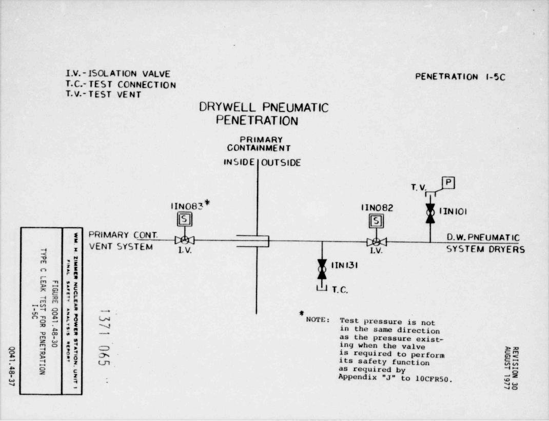
.
}
.
I.V.-ISOL ATION VALVE PENETRATION l-5CT.C.- TEST CONNECTIONT.V.- TEST VENT
DRYWELL PNEUMATICPENETRATION
PRIM ARYCONTAINMEN T
INSIDE OUTSIDE
PT. V.
IINO83* IINO82 IINIOlS S
s PRIMARY CONT. D.W. PNEUM ATICIXM MzVENT SYSTEM 1 V. LV. SYSTEM DRYERSy ,
jEM( IIN f31aAo]
$ $E l1 T. C.E OO-a
. 0; m *:ac >= -
E gy f3 u - gNOTE: Test pressure is not
, yjm N in the same directionyp *= -
as the pressure exist-M8 y, 5 ing when the valveO >m8 g 34 is required to perform EE8 h 5y . Its safety function hy,
. g as required by5 o? *
$ }, Appendix "J" to 10CFR50. U*-
Do

,
1
.
I . V.- ISOL ATION VALVE PE N ETR ATI O N I-29T . C.-TEST CONNECTION 1-6SA
T . V.- T E S T VENT
AIR SAMPLEPRIMARY
C ONTAINMENT
INSIDE OUTSIDE P
NT.C.
1. v. % g . v..
S SS AM PLE 1 y
, O T . V."T*B*". C .E |N TAK E F. C. F
H I
$ 3y F.C. $ F. C .ji T. V.
o
b3 *! j
r: = ie E* y B0 01 "' ' u-> 1. V. l . V.**8 " N T. C .T3 * {.y %~
v, -2o m == c3 P
O $A
d 2' g c-"os
~
NOTE: Test pressure is not in the same "j $-
$ @ j direction as the pressure existing 3'
$2 a when the valve is required to perform $w*- its safety function as required by "
Appendix "J" to 10CFR50.

.
,
.
P ENETRATION 1 -18I-22.
ADS.& M.S. IS0. VALVEACCUMULATIONPENET RATION
P P RIM ARY/ C ONT Al NM E NT
n VENT INSIDE OUTSIDE
!
[ACCUMUL ATOR ].O\**
a ;y D8tiNin"
E' : ~
^8 :E -
7;;; A :E -
?o! CEU 8 :8b N
L" % i? U"
**NA* DRAINMM :0 O wm
e y jj $ NO TYPE * C " TEST REQUIRED g3e a z me'e E E G E
$ $ 08\1 .
.

,
.
L . V.-lSOL ATION VALVEP ENETRATION I- 19FT. B.-TEST BOUNDARY
T . C-TEST CONNECTIONREACTOR RECIRCULATION
T . V.-TES T VENTS AM PLE
PRIMARYCONTAINMENT
INSIDE OUTSIDE
IB 33 F Ol9 IB33F020
S
REACTOR IB 33F059 | PROCESSA SAMPLE
! M v vR ECIR C . T. B. 3 . y, l . V. T. V.y ,
4 Lii IB 33F353 FLOW IB 33F021"
#5 Q"
5 CEa :@ ip b"
) (lB 33F3 54.
- ,m m <mTM o ,? u IB 33 F022
T. C .g, g ii N ymg r ;y T. V/ T. C .-
A@ I W_
$ $6- 4 c-,.
h C03
j; 5 G*:18-

,
.
T . C .- TES T CONNECTIONT . V. - TEST VENT
TYPICAL P E NET R ATI ON I || 165
DRYWELL AIR I 27 Is615 I67SAMPLE I 19 A*8,Cp
PRIMARY y7CONTAINMENT
INSIDF 00 TSIDE
S AM PLE -X'" "C " eT . V. T. V.IN TA K E
f b L. C.s FLOW_E = J [
s I T. t.
;AL.o* # PTG n . "2UN E 5CLy E "E -
4, 0 '" 5 (A*
PH 8 ;" N78 b ?o -
$" b il** CL, A 9" :4. &2 m
S $U # 4 @M3 Ls S6 % NOTE: Test Pressure is not in the sameb Ed "2 85
direction as the pressure existing when $$[ "O j the valve is required to perform its m@- ; safety function as required by Appendix *
w- "J" to 10CFR50. "o
.
'.
PLANT ZIMMER UNIT (S) 1
DESIGN REQUIREMENTS FOR CONTAINMENT ISOLATION BARRIERS
Ouestion: Discuss the extent to which the quality standards and seismicdesign classification of the containment isolation provisionsfollow the recommendations of Regulatory Guides 1.26, " QualityGroup Classifications and Standards for Water , steam , andRadioactive-Water-Containing Components of Nuclear Power Plants",and 1.29, " Seismic Design Classification".
.
Resconse:
The Zimmer FSAR does not contain a response toRegulatory Guide 1.26.
Page 6,2-43 of the Zimmer FSAR indicates that we havedesigned to ASME Section III, Class B or better. All penetrationshave been designed to Seismic Categroy 1 in accordance withRegulatory Guide 1.29.
1371 070
.

*.
.
.
.
. . PLANT ZIMMER UNIT (S) 1
PROVISIONS FOR TESTING
Ouestion: Discuss the design provisions for testing theoperability of the isolation valves.
Resconse:
The design provisions for testing the operability ofIsolations Valves are discussed in FSAR Sections 6.2.4, 6.2.1.4.1.2,5.2.1.7 and associated tables.. Additional information containedin the FSAR Sections dealing with General Criteria 55, 56, and 57have also been included for clarity purposes.
In general, the Isolation Valves undergo testing duringconstruction, preoperational test program, in-service test program,and plant outages. The valves are designed and located such that thistesting is possible with a high level of reliability. The designuses redundancy in equipment and control, administrative controls,and proven industry test programs to maintain this reliability level.
.
1371 071 -

* *s,
REVISION 2ZPS-1 NOVEMBER 1975
6.2.4 Primary Containment Isolation System |2
6.2.4.1 Design Bases
6.2.4.1.1 Safety Design Bases
a. Primary containment isolation valves shall provide the |2necessary isolation of the primary containment in the eventof accidents or other conditions when the free release ofprimary containment contents cannot be permitted. |2
b. The design of isolation valving for lines penetrating theprimary containment shall follow the requirements of General |2Design Criteria 54 through 57 or be designed on some otherbasis consistent with safety and reliability,
c. Isolation valving for instrument lines which penetrate theprimary containment shall conform to the requirements of |2Regulatory Guide 1.11.
d. Isolation valves, actuators, and controls shall be protectedagainst loss of safety function by missiles,
e. Design of the primary containment isolation valves and f2associated piping and penetrations shall be Seismic Cate-gory I.
f. Primary containment isolation valves and associated piping |2and penetrations shall meet the requirements of the ASMEBoiler and Pressure Vessel Code, Section II, Classes 1 or2, as applicable.
g. Nuclear steam supply isolation valve closure speeds limitradiological effects from exceeding guidelines values estab-lished by 10 CFR 100.
The primary objective of the primary containment isolation systems is |2to provide protection against releases of radioactive materials to theenvironment as a result of accidents occurring to the nuclear boilersystem, auxiliary systems and support systems. This objective isaccomplished by automatic isolation of appropriate lines that penetratethe primary containment vessel. Actuation of the primary containment |2isolation systems is automatically initiated at specific limits definedfor reactor plant operation and af ter the isolation function is initia-ted, it goes to completion.
The primary containment isolation systems, in general, close tho sefluid lines penetrating primary containment that support systems not |2required for emergency operation. Those fluid lines penetrating primarycontainment and which support engineered safety feature systems haveremote manual isolation valves which may be closed from the controlroom, if required..
1371 0726.2-43

N REVISION 2'
ZPS-1 NOVEMBER 1975
The isolation criteria for the determination of the quantity and res-pective locations of isolation valves for a particular syst.em conformto the General Design Criteria 54, 55, 56, 57, and Regulatory Guide1.11. Redundancy and physical separation are required in the elec-trical and mechanical design to ensure that no single failure in theprimary containment isolation system prevents the system from perform- |2ing its intended functions.
Protection of the primary containment isolation system components from |2missiles is considered in the design, as well as the integrity of thesecomponents to withstand seismic occurrences without loss of cpataoility.
The isolation system is designed to Seismic Category I. Classificationof equipment and systems is found in Table 3.2-1.
Actuation of the primery containment isolation systems is initiated by |2the signals listed in Table 6.2-7.
The criteria for the design of the primary containment and reactor |2vessel isolation control system are listed in Subsection 7.1.2.1.2.1.1.The bases for assigning certain signals for primary containment isola- |2tion are listed and explained in Subsections 7.3.1.1.2.3, 7.6.1.3.6,7.6.1.6.5, and 7.6.1.6.7.
On signals of high drywell pressure or low water level in the reactorvessel, all isolation valves that are part of systems not required for
,
emergency shutdown of the plant are closed. The same signals willinitiate the operation of systems associated with the emergency corecooling system. The isolation valves which are part of the ECCS maybe closed remote manually from the control room or close automstically,as appropriate.
Instrument lines that penetrate the primary containment will conform to |2Regulatory Guide 1.11, and General Design Criteria 55 and 56.
6.2.4.2 Svstem Design
The general criteria governing the design of the primary containment |2isolation systems is provided in Subsections 3.1.2 and 6.2.4.1. Tables6.2-7 and 6.2-8 summarize the primary containment penetrations and con- |2tain information as to:
a. Open or closed status under normal operating conditionsand accident situations.
b. The primary and secondary modes of actuation providedfor isolation valves.
c. The parameters sensed to initiate isolation valveclosure.
d. The closure time and sequence of timing for principal iso-lation valves to secure primary containment isolation. |2
i ')| \6.2-44

.
9 *
REVISION 2ZPS-1 NOVENBER 1975
e. Applicable General Design Criteria.
Protection is provided for isolation valves, actuators, and controlsagainst damage from missiles. All potential sources of missiles areevaluated. Where possible hazards exist, protection is afforded byseparation, missile shields, or by location.
Isolation valves are designed to be operable under the most adverseenvironmental conditions such as operation under maximum differentialpressures, extreme seismic occurrences, steam laden atmosphere, hightemperature, and high hunidity. Electrical redundancy is provided forpower operated valves. Power for the actuation of two isolation valvesin a line (inside and outside cf primary containment) is supplied by |2two redundant, independent power sources without cross ties. In
general, outboard isolation valves receive power from the Division 1power supply while isolation valves within primary containment receive |2power from the Division 2 power supply. In general, the supply isa-c for Division 2 valves and d-c for Division 1 valves depending uponthe system under consideration.
The main steamline isolation valves are spring loaded, pneumatic, pistonoperated globe valves designed to fail closed on less of pneumatic pres-sure or loss of power to the solenoid-operated pilot valves. Eachvalve has two independent pilot valves supplied from independent powersources. Each main steamline isolation valve has an air accumulatorto assist in its closure upon loss of air supply, loss of electricalpower to the pilot valves, and/or failure of the loaded spring. Theseparate and independent action of either air pressure or spring forceis capable of closing an isolation valve.
It should be noted that all motor operated isolation valves remain intheir last position upon failure of valve power. On the other hand,all air operated valves, (not applicable to air-testable check valves),close on loss of air.
The design of the isolation valve system includes consideration to thepossible adverse effects of sudden isolation valve closure when theplant systems are functioning under normal operation.
6.2.4.3 Design Evaluation
6.2.4.3.1 Introduction
The main objective of the primary containment isolation system is to |2provide protection by preventing releases to the environment of radio-active materials. This is accomplished by complete isolation of systemlines penetrating the primary containment. Redundancy is provided inall design aspects to satisfy the requirement that any active failureof a single valve or component does not prevent primary containment |2isolation.
'- .
371 0746.2-45,

. .
ZPS-1 REVISION 26MAY 1977
Mechanical components are redundant, such as isolation valve arrange-ments to provide back-up in the event of accident conditions. Isola-tion valve arrangements satisfy all requirements specified in GeneralDesign Criteria 54, 55, 56, and 57, and Regulatory Guide 1.11.
The arrangements with appropriate instrumentation are described in Tables6.2-8 and 6.2-9. The isolation valves have redundancy in the mode of 4actuation with the primary mode being automatic and the secondary modebeing remote manual. A program of testing, described in Subsection6.2.4.4, is maintained to ensure valve operability and leaktightness.The bases for conformance to the NRC criteria and the General DesignCriteria are summarized in Subsection 6.2.4.3.2 and Table 6.2-10. 26
The design specifications require each isolation valve to be operableunder the most severe operating conditions that it might experience.Each isolation valve is afforded protection by separation and/oradequate barriers from the consequences of potential missiles.
Electrical redundancy is provided in isolation valve arrangements whicheliminates dependency on one power source to attain isolation. Elec-trical cables for isolation valves in the same line have been routedseparately. Cables have been selected and based on the specificenvironment to which they may be subjected, such as magnetic fields,high radiation, high temperature, and high humidity.
Provisions for administrative control and/or locks ensure that theposition of all nonpowered isolation valves is maintained and known.For a.1 power operated valves the position is indicated in the maincontral room. Discussion of instrumentation and controls for theisolation valves is included in Chapter 7.0.
6.2.4.3.2 Evaluation against NRC Criteria
6.2.4.3.2.1 Evaluation against Criterion 55
The reactor coolant pressure boundary (RCPB) as defined in 10 CFR 50,Section 50.2(v) consists of the reactor pressure vessel, pressureretaining appurtenances attached to the vessel, valves and pipes whichextend from the reactor pressure vessel up to and including the outer-most isolation valve. The lines of the reactor coolant pressure bound-ary which penetrate the primary containment are capable of isolatingthe primary containment, thereby precluding any significant release of 2radioactivity. Similarly, for lines which do not penetrate the primarycontainment but which form a portion of the reactor coolant pressureboundary, the design ensures that isolation from the reactor coolantpressure boundary can be achieved.
6.2.4.3.2.1.1 Influent Lines
Influent lines which penetrate the primary containment and connectdirectly to the RCPB are equipped with at least two isolation valves,one inside the drywell, and the other as close to the external side of
the primary containment as practical. Protection of the environment is |2provided by these isolation valves.
i371 0756.2-46

. .
ZPS-1 REVISION 39JANUARY 1978
Tables 6.2-8 and 6.2-9 contain those influent pipes that comprise the |4reactor coolant pressure boundary and penetrate the primary containment.
'
6.2.4.3.2.1.1.1 Feedwater Line
The feedwater line is part of the reactor coolant pressure boundary asit penetrates the drywell to connect with the reactor pressure vessel.It has three isolation valves. The isolation valve inside the drywellis a y-pattern check valve, located as close as practicable to t heprimary containment wall. Outside the primary containment is a tothery-pattern check valve located as close as practicable to the primarycontainment wall and farther away from the primary containment is a |2i
motor operated gate valve. Should a break occur in the feedwater line,the check valves prevent significant loss of reactor coolant inventoryand offer immediate primary containment isolation. During the postu- |2laced loss-of-coolant accident, it is desirable to maintain reactorcoolant makeup from all sources of supply. For this reason, the outer-most valve does not automatically isolate upon signal from the protec-tion system, However, this valve will be procedurally controlled andwill be remotely closed from the control room to provide long-termleakage protection after 20 minutes of a postulated loss-of-coolantaccident. All valves meet the primary containment leak rate criteriausing air as the testing medium. (See Table 6.2-10, Penetrations M-5and -6, for more information.)
The ZPS-1 feedwater cbutainment isolation valves are plug type, y-patterncheck valves similar to Figure 6.'2-51. In addition to meeting the ser- 39vice requirements for normal plant operation, the valves are designed towithstand the reverse flow due to a feedwater line rupture outside con-tainment and also to maintain low leakage characteristics with low con-tainment backpressure.
The plug type, y-pattern, check design has been specially designed for 26this application to meet the large variation in conditions as well asto address operating problems associated with containment leak testing.The ZPS-1 valve design with the plug inclined to the vertical signifi-cantly improves the closing and the shutoff requirements as compared toa simple swing check valve. Whereas a swing check requires reverse flowor significant backpressure to position and properly seat the dise dueto its horizontal seating characteristics, the plug type check utilizesthe weight of the plug to seat properly. Any backpressure providesgreater seating force and leaktightness.
6.2.4.3.2.1.1.2 HPCS Line
The HPCS line penetrates the drywell to inject directly into the reactorpressure vessel. Isolation is provided by an air testable check valveand closed remote manual globe valve located inside the drywell with | 26position indicated in the main control room, and a remote-manually actuatedgate valve located as close as practicable to the exterior wall of theprimary containment. The system is also a closed system outside the 39containment. Long term leakage control is maintained by the outboardgate valve. If a loss-of-coolant accident occurred, this gate valve 26
6.2-47
.

.
ZPS-1 REVISION 57 _
APRIL 1979
t,ald rec:ive an automatic signal to open and provide core cooling.The bypass valve is interlocked with the check valve and is used toequalize the pressure across the check valve to permit testing of the 26check valve during normal plant operation. (Also see Table 6.2-10,Penetration M-16, for more information.) -
6.2.4.3.2.1.1.3 LPCI and LPCS Lines
Satisfaction of isolation criteria for the LPCI and the LPCS system isaccomplished by use of remote-manually operated gate valves, air testable
39check valves, and a closed system outside of the containment. Both typesof valves are normally closed with the gate valves receiving an sutomaticsignal to open at the appropraite time to assure that acceptable fueldesign limits are not exceeded in the event of a loss-of-coolant accident.The air testable check valves with remote manual bypass globe valves arelocated as close as practicable to the RPV. The normally closed check 26valves protect against primary containment pressurization in the event ofpipe rupture between the check valve and primary containment. Once the 126system is in oper. scion, the low energy of the influent fluid (185* F 2maximum) excludes any possibility of primary containment overpressurizationshould a break occur. The bypass valves are interlocked with the checkvalve to permit testing the check valves during plant operation. The globe 26valves automatically close upon completion of the test. (Also see Table6.2-10, Penetrations M-ll, -12, -13, and -15, for more information.)6.2.4.3.2.1.1.4 Control Rod Drive Lines
The control rod drive system, located between the reactor vessel andprimary containment, has three influent lines; the supply line thatpenetrates the primary containment and injects into the reactor pressurevessel and the insert and withdraw lines that penetrate the drywell.
The line which injects into the reactor vessel from the control roddrive system has three isolation valves. In addition to a simple checkvalve inside the drywell and a check valve outside the drywell, anormally closed motor-operated gate valve functions as a third isolation
37valve. All valves will meet the primary containment leak rate criteriausing air as the testing medium.
The CRD insert and withdraw lines are not part of the reactor coolantpressure boundary since they do not directly communicate with thereactor coolant. The classification of these lines is quality groupB, and they are therefore designed in accordance with ASME Section III,Class 2. The basis to which the CRD insert and withdraw lines are designedis commensurate with the safety importance of maintaining pressureintegrity of these lines.
1371 077
6.2-48

. .
:PS-1 REVISION 26MAY 1977
--
- lhe control rod drive insert and withdraw lines can be isolated by thesolenoid valves outside the primary containment. These lines thatextend outside the primary containment are small, and terminate in asystem that is designed to prevent out-leakage. Solenoid valves nor-mally are closed, but open on rod movement and during reactor scram.In addition, a ball check valve located in the control rod drive flangehousing automatically seals the insert line in the event of a break.Primary containment overpressurization will not result from a linebreak in the primary containment since these lines contain small volumes | 2at low energy levels. (Also see Table 6.2-10, Penetration M-14, for b6
~
more information.) I
6.2.4.3.2.1.1.5 RHR and RCIC Lines
The RHR head spray and RCIC lines meet outside the primary containment |2to form a common line which penetrates the drywell and discharge di-rectly into the reactor pressure vessel. The testable check valve andbypass globe valve inside the drywell are normally closed and have posi-tion indication lights in the main control room to verify their position. 26The testable check valve is located as close as practicable to the reac-cor pressure vessel. Two types of valves, a check valve and a remoteanual tJock valve, are located outside the primary containment. Thecheck valve assures immediate isolation of the primary containment in |2the event of a line break. The block valve on the RER line receives anautomatic isolation signal while the block valve on the RCIC line isremote manually actuated to provide long-term leakage control. The in-board bypass globe valve is interlocked with the check valve and isused to equalize the pressure across the check valve to permit testing 26of the check valve during normal plant operation. (Also see Table6.2-10, Penetration M-10, for more information.)
6.2.4.3.2.1.1.6 Standbv Liquid Control System Lines
The standby liquid control system line penetrates the drywell and con-nects to the reactor pressure vessel. In addition to a simple checkvalve inside the dryvell, a check valve together with an explosiveactuated valve are located outside the drywell. Since the standbyliquid control line is a normally closed, nonflowing line, rupture ofthis line is extremely remote. The explosive actuated valve, though,functions as a third isolation valve. This valve provides an absoluteseal for long term leakage control as well as preventing leakage ofsodium pentaborate into the reactor pressure vessel during normalreactor operation.
6.2.4.3.2.1.1.7 Reactor Water Cleanup System |2
The reactor water cleanup (RWCU) pumps, heat exchangers, and filterdemineralizers are located outside the primary containment. The returnline frem the filter demineralizers connects to the feedwater line out-side the primary containment between the primary containment wall and theoutside primary containment feedwater check valve. Isolation of this |2line is provided by the feedwater system check valve inside the primary
'
containment and a check valve and motor-operated gate valve outside theprimary containment. The motor-operated gate valve functions as a |2 '
third isolation valve.
6.2-49137 078

. .
ZPS-1 REVISION 26MAY 1977
Should a break occur in the reactor water cleanup return line, the checkvalves would prevent significant loss of inventory and offer immediateisolz. tion, while the outermost isolation valve would provide long term 4leakage control. The motor-operated gate valve closes automaticallyupon receipt of an isolation signal.
[12
6.2.4.3.2.1.1.8 Recirculation Pumo Seal Water Supoly Line
The recirculation pump seal water line extends from the recirculationpump through the drywell and connects to the CRD supp1 f line outsidethe primary containment. The seal water line forms a part of the reactorcoolant pressure boundary, therefore the consequences of failing thisline has been evaluated. This evaluation shows that the consequencesof breaking this line is less severe than that of failing an instrumentline. The recirculation pump sea. water line is 3/4 in. Class B fromthe recirculation pump through the second check valve (located outsidethe primary containment). From this valve to the CRD connection, the |2line is Class D. Should this line be postulated to fail and either oneof the check valves is assumed not to close (single active failure),the flow rate through the broken line has been calculated to be sub-stantially less than that permitted for a broken instrument line.Therefore, the two check valves in series provide sufficient isolationcapability for postulated failure of this line.
6.2.4.3.2.1.2 Effluent Lines
Effluent lines which form part of the reactor coolant pressure boundaryand penetrate primary containment are equipped with at least two isola- |2tion valves; one inside the drywell and the other outside and locatedas close to the primary containment as practicable or justified onan alternative basis. 26
Tables 6.2-8 and 6.2-9 also contain those effluent lines that comprise |4the reactor coolant pressure boundary and which penetrate the primary |2containment.
6.2.4.3.2.1.2.1 Main Steam and RHR Shutdown Cooling Lines
The main steamlines extend from the reactor pressure vessel to the mainturbine and condenser system, penetrating the primary containment. TheRHR steam supply line and RCIC turbine steamline connect to the mainsteamline inside the drywell and penetrate the primary containment. Forthese lines, isolation is provided by .utomatically actuated gate valves,one inside the primary containment and one just outside the primary con-tainment. The RCIC steamline is also provided with a normally closedremote manual globe valve which bypasses the inboard isolation valvefor heatup purposes. The RHR shutdown cooling effluent line is pro- 26vided with automatically actuated gate valves. (Also see Table 6.2-10,Penetration M-18, for more information.) 2
6.2.4.3.2.1.2.2 Recirculation System Samole Lines
A sample line from the recirculation system penetrates the drywell. Thesample line is 3/A-in. diameter and designed to ASME Section III, Class 2.
6.2-50
1371 079

. .
ZPS-1^
REVISION 26MAY 1977
A sample probe with a 1/8-in.-diameter hole is located inside therecirculation line inside the drywell. In the event of a line break,the probe acts as a restricting orifice and limits the escaping fluid.Two air-operated valves which fail closed are provided, one inside andone outside the primary containment. |2
6.2.4.3.2.1.3 Summary
In order to assure protection against the consequences of accidents in-volving the release of radioactive material, pipes which form the reactorcoolant pressure boundary have 'veen shown aoove and in Table 6.2-10to provide adequate isolation capabilities and conformance to General
- Design Criterion 55 and Section 6.2.4 of the Standard Review Plan. In 26all cases, a minimum of two barriers were shown to protect against therelease of radioactive materials.
In addition to meeting the isolation requirements stated in Criterion55, the pressure-retaining components which comprise the reactor coolantpressure boundary are designed to meet other appropriate requirementswhich miMmf ze the probability or consequences of an accident rupture.The quality requirements for these components ensure that they are de-signed, fabricated, and tested to the highest quality standards of allreactor plant components. The classification of components which com-prise the reactor coolant pressure boundary are designed in accordancewith the ASME Boiler and Pressure Vessel Code, Section III, Class 1.
It is, therefore, concluded that the design of piping systems whichcomprise the reactor coolant pressure boundary and penetrate primary |2
- containment satisfies Criterion 55. For further discussion, see thefollowing subsections of the FSAR:
a. Quality Group Classification Diagram, Table 3.2-1.
b. Primary Containment and Reactor Vessel IsolationControl System - Section 7.3.
6.2.4.3.2.2 Evaluation Against Criterion 56
Criterion 56 requires that lines which penetrate the primary containmentand communicate with the primary containment interior must have twoisolation valves; one inside the primary containment, and one outside 2unless it can be demonstrated that the primary containment isolationprovisions for a specific class of lines are acceptable on some otherbasis.
Tables 6.2-8 and 6.2-9 include those lines that penetrate the primary 14containment and connect to the drywell and suppression chamber.
Table 6.2-10 provides additional information for demonstrating conformanceto General Design Criterion 56 and Standard Review Plan 6.2.4 or provides 26justification for demonstrating adequate isolation provisions.on someother defined basis.
.
.
1371 0806.2-51

. .
- ZPS-1 REVISION 28JULY 1977
-. . - - - - -,
-
6.2.4.3.2.2.1 Influent Lines to Suppression Pool
6.2.4.3.2.2.1.1 LPCS, HPCS, and RHR Test Lines
The LPCS, HPCS, and RER test lines have test isolation capabilitiescommensurate with the importance to safety of isolating these lines.Each line has a normally closed motor-operated valve located outside the hprimary containment. Primary containment isolation requirements are met | 2on the basis that the test lines are low-pressure lines constructed tothe same quality standards as the primary containment. Furthermore, the | 2systems are Quality Group B. Seismic Category I, and meet the require-ments of Section 6.2.4 of the Standard Review Plan for closed systems. 26The isolation valves are also located in a leakage controlled areaserved by the SGTS. Remote manual isolation can be accomplished fromthe main control room.
The test return lines are also used for suppression chamber return flowduring other modes of operation which are ESF-related. In this manner |26the number of penetrations are reduced, minimizing the potential path-ways for radioactive material release. Typically, pump =4n4="= flowbypass lines join the respective test return lines downstream of the testreturn isolation valv9. The bypass lines are isolated by automaticmotor-operated valvea with a restricting orifice downstream of the motor- 26operated valve. (Also see Table 6.2-10, Penetrations M-44, -46, -47,and -98 for more information.)
6.2.4.3.2.2.1.2 RCIC Turbine Exhaust and Vacuum Pump Dischargeand Pump Minimum Flow Bypass
These lines which penetrate the primary containment and connect to thesuppression chamber below water are equipped with a normally open ornormally closed motor-operated, remote manually actuated gate valve 2located as close to the primary containment as possible. In addition,there is a simple check valve upstream of the gate valve which providespositive actuation for immediate isolation in the event of a break up-stream of this valve. The gate valve in the RCIC turbine exhaust isdesigned to be open and interlocked to preclude opening of the inletsteam valve to the turbine while the turbine exhaust valve is not in afull open position. The RCIC vacuum pump discharge line is alsonormally open. All piping and valves are located in a leakage controlledarea, and the RCIC equipment areas are monitored for leak detection on 26high temperature. The RCIC pump minimum flow bypass line is isolatedby a normally closed valve with a check valve installed upstream. Thevalve is capable of being closed remote manually from the control roomin addition to its automatic operation for minimum flow bypass. (Also |2see Table 6.2-10, Penetrations M-39, -40, and -42 for more information.)
6.2.4.3.2.2.1.3 RHR Reat Exchanger Vent Lines
The RHR heat exchanger vent lines discharge to the suppression chambervia relief valve discharge lines and are provided with two normallyclosed remotely controlled motor-operated globe valves. The relief 26s
discharge lines are isolated by the relief valves themselves. The
1371 081.
6.2-52

. .
ZPS-1 REVISION 26- - - MAY 1977
' addition of block valves to the relief valve discharge line would defeatthe purpose for which the relief valves are installed and is not per-mitted by ASME Section III. (See Table 6.2-10, Penetrations M-79 and 26-97, for more information.)
6.2.4.3.2.2.2 Effluent Lines from Suppression Chamber
6.2.4.3.2.2.2.1 RHR, RCIC, LPCS, and HPCS Suction Lines
These valves are motor-operated, remote manually operated gate valveswhich provide assurance of isolating these lines in the event of abreak and also provide long-term leakage control. In addition, thesuction piping from the suppression chamber is considered an extensionof primary containment since it must be available for long-term usage |2following a design basis loss-of-coolant accident, and as such, is de-signed to the same quality standards as the primary containment. Thus, | 2the need for additional isolation is obviated by providing a high quality |26system. The ECCS discharge line fill system (ECCS waterleg pumps)takes suction from the respective ECCS pump effluent line from thesuppression pool downstream of the isolation valve. The ECCS dischargeline fill system suction line has a manual valve for operational pur-poses. This system as isolated from the primary containment by the |2respective ECCS pump suction valve from suppression pool as listed inTables 6.2-8 and 6.2-9. (For additional information, see Table 6.2-10, | 4 26Penetrations M-34, -35, -36, -37, -38 and -41.)
6.2.4.3.2.2.3 Influent and Effluent Lines from Drywell andSuppression Pool Air Volume
6.2.4.3.2.2.3.1 Combustible Gas Control and Post-LOCA AtmosphereSamoling Lines
Thepost-LOCAsamplingsystemlineswhichpenetratetheprimarycontaind2ment and connect to the drywell and suppression chamber air volume areequipped with two normally closed, solenoid operated isolation valvesin series located as close to the primary containment as possible. |2The combustible gas control system lines which penetrate the primarycontainment are equipped with two motor-operated valves in parallel,normally closed, remote manually actuated from the control room. Addi-tional isolation valves would reduce the capability of this ESF systemto perform its safety function.
26In addition, the piping outside containment forms a closed system andis considered an extension of primary containment, since it must be |2available for long-term usage following a design-basis loss-of-coolantaccident, and, as such, is designed to the same quality standards asthe primary containment, including Standard Review Plan 6.2.4. Thus,the need for additional isolation provision is obviated. (Also seeTable 6.2-10, Penetrations M-54 and -104, for more information.)
6.2.4.3.2.2.3.2 Primary Containment Purge and Primarv ContainmentDrain Lines 2
The drywell and suppression chamber purge and primary containment drainlines have isolation capabilities commensurate with the importance to | 26
6.2-53 !3[} Q@2

. .
ZPS-1 REVISION 26MAY 1977-
safety of isolating these lines. Each line has two normally closed airto open, spring to close, valves located outside the primary contain-ment. Primary containment isolation requirements are met on the basis |2that the purge and drain lines are normally closed, low-pressure linesconstructed to the same quality standards as the primary containment. 12The isolation valves for the purge lines are designed to be closed fromthe main control room. These isolation valves are interlocked to pre-clude opening of the valves while a primary containment 1 solation signal |2exists as noted in Tables 6.2-8 and 6.2-9. Furthermore, the drain valves 4are located'in a leakage controlled area outside containment to precludeexposing the valves to suppression pool atmo.aphere and associated hydro- 26dynamic loads. (See Table 6.2-10, Penetrations M-49, -50, -101, -102,-103 and -104 for more information.) '
6.2.4.3.2.2.3.3 Drvwell and Suppression Chamber Air Sampling Lines
These air sampling lines branch from the post-LOCA atmosphere samplinglines which penetrate the primary containment. The air sampling linesare used for continuously drawing primary containment air during normal |2operation as part of the leak detection system. These lines are equippedwith two normally open, air to open, spring to close valves in serieslocated as close as possible outside the primary containment. Thismanner of routing the system piping reduces the number of primary con- |2tainment penetrations and =4n4=4'es the potential pathways for radio-active material release. In addition, the piping upstream of the airsampling isolation valves is considered an extension of primary con- |2tainment since it must be available for long-term usage following adesign-basis loss-of-coolant accident as part of the post-LOCA atmos-phere sampling system, and as such, is designed and fabricated to thesane quality standards as the primary containment. Primary containment |2isolation requirements are met on the basis that these lines are low-pressure lines constructed to the same quality standards as the primarycontainment. Furthermore, the consequences of a break in these linesresult in no significant safety consideration. |36.2.4.3.2.2.4 Summary
In order to assure protection against the consequences of accidentsinvolving release of significant amounts of radioactive materials, pipesthat penetrate the primary containment have been demonstrated above and 26in Table 6.2-10 to provide irolation capabilities in accordance withCriterion 56 or on an alternative basis. In addition, the isolationprovisions have been demonstrated to conform to Section 6.2.4 of theStandard Review Plan.
In addition to meeting isolation requirements, the pressure-retainingcomponents of these systems are designed to the same quality standardsas the primary containment. |26.2.4.3.2.3 Evaluation Against Criterion 57
Lines penetrating the primary containment and for which neither Cri-terion 55 nor Criterion 56 govern, comprise the closed system isolationvalve group.
6.2-54 37 083

. .
ZPS-1 REVISION 26MAY 1977
'Both influent and effluent lines are isolated by automatic or remotemanual isolation valves located as close as possible to the primary |2containment boundary. (Also see Table 6.2-10, Penetrations M-9, -23,-95, -96, -68, '69, -74, -75, -76 and -77 for more information.) 26
6.2.4.3.2.3.1 Evaluation Against Regulatory Guide 1.11
Instrument lines which penetrate the primary containment from the reac- |2tor coolant pressure boundary conform to Regulatory Guide 1.11 in thatthey are equipped with a restricting orifice located inside the drywelland an excess flow check valve located outside and as close as prac-ticable to the primary containment. Those instrument lines which do |2not connect to the reactor coolant pressure boundary also conform to |26Regulatory Guide 1.11 in that they are equipped with isolation valveswhose status will be indicated in the control room.
6.2.4.3.3 Evaluation of Single Failure
A single failure can be defined as a failure of some component in anysafety system which results in a loss or degradation of the system'scapability to perform its safety function. Active components are de-fined in Regulatory Guide 1.48 as components that must perform amechanical motion during the course of accomplishing a system safetyfunction. Appendix A to 10 CFR 30 requires that electrical systemsalso be designed against passive single failures as well as activesingle failures. Chapter 3.0 describes the implementation of thesestandards as well as General Design Criteria 17, 21, 35, 38, 41, 44,54, 55, and 56.
In single failure analysis of electrical systems, no distinction ismade between mechanically active or passive components; all fluidsystem components such as valves are considered " electrically active"whether or not " mechanical" action is required.
Electrical systems as well as mechanical systems are designed to meetthe single failure criterion for both mechanically active and passivefluid system components regardless of whether that component is re-quired to perform a safety action in the nuclear safety operationalanalysis outlined in Appendix B. Even though a component such as anelectrically operated valve is not designed to receive a signal tochange state (open or closed) in a safety scheme, it is assumed as asingle failure that the system component changes state or fails.Electrically operated valves include valves that are electricallypiloted but air operated as we]1 as valves that are directly operatedby an electrical device. In addition, all electrically operated valvesthat are automatically actuated also can be manually actuated from themain control room. Therefore, a single failure in any electrical sys-tem is analyzed regardless of whether the loss of a safety functionis caused by a component failing to perform a requisite mechanicalmotion or a component performing an unnecessary mechanical motion.
6.2.4.4 Tests and Inspections
The primary containment isolation system is scheduled to undergo per- |2iodic testing during reactor operation. The functional capabilities
6.2-55
1371 084
. .
ZPS-1 REVISION 26MAY 1977
~ f power-operated isolation valves are tested remote manually from theo
main control room. By observing position indicators and changes inthe affected system operation, the closing ability of a particularisolation valve is demonstrated.
Air testable check valves are provided on influent emergency core cool-ing lines of the LPCS, HPCS, and RHR systems whose operability .s reliedupon to perform a safety function.
A discussion of testing and inspection pertaining to isolation valvesis provided in Subsection 6.2.1.4 and in Chapter 16.0. Tables 6.2-8 4and 6.2-9 list all isolation valves and systems to be tested. |. 62
Instruments will be periodically tested and inspected. Test and/orcalibration points will be supplied with each instrument.
Excess flow check valves (EFCV) will be periodically tested by openinga te'st drain valve downstream of the EFCV and verifying pcoper opera-tion. As these valves are outside the primary containment and access- |2ible, periodic visual inspection is performed in addition te the opera-tional check.
.
1371 085'
6.2-55a

. .
ZPS-1 REVISION 39JANUARY 1978
6.2.1.4.1.2 Preoperational Leak Rate Testing
After the structural integrity test of the containment has been per-formed, integrated leak rate tests will be performed at the maximumcalculated pressure of 40.4 psig. The purpose of this test is to con-firm that the actual containment leak rate is within the design require-ments of 0.5% of the containment volume in 24 hours at 40.4 psig.
The leakage rate test method to be used will be the absolute method.The absolute merh:J of leakage rate testing shall constitute thedetermination and calculation of air losses by containment leakage overa stated period of ttne by the means of direct pressure, temperature,and humidity observations during the period of test, with temperaturedetectors properly located to provide an average air temperature. | 27
The initial leak rate test will be performed in accordance with 10 CFR50, Appendix J. Type A tests will be considered acceptable if thetotal leakage rate does not exceed 75% of the design leakage rate overa 24-hour period.
Prior to the performance of the initial containment leak rate test, thefollowing Type B and . Type C tests of 10 CFR 50, Appandix J, will beperformed on the indicated components:
a. Type B tests:
1. equipment access hatch,
2. personnel air lock,
3. drywell head,
4. suppression chamber access hatches,
5. CRD removal hatch, and
6. electrical penetrations. 30
b. Type C tests:
Containment isolation valves identified in Table 6.2-8 willbe Type "C" leak rate tested. Valves which are tested withair or nitrogen as the test fluid shall be tested in accor-dance with 10 CFR 50, Appendix J, Section III C.2(a). Valves 39which are tested using water as the test fluid shall be testedin accordance with 10 CFR 50, Appendix J, Section III C.2(b).The acceptance criteria of 10 CFR 50, Appendix J, Section IIIC.3 shall apply. See Question Q041.40 for additional infor-mation and the acceptance criteria.
The type B and C tests will be considered acceptable if the combinedleakage does not exceed 60% of the design leakage rate over a 24-hourperiod.
-
6.2-26

. .
ZPS-1 REVISION 39JANUARY 1978
6 . 2.1. 4 .1. 3 Drywell Floor Bypass Leakage Test
The preoperational high- and low pressure bypass leakage integrity of 31the suppression chamber /drywell barrier will be determined by two 27separate bypass tests. Each test will be conducted at designated timesduring the construction /preoperational test periods respectively.The high-pressure bypasr test is performed at a test pressure differ-ential of 16 psid. Acceptance criteria will be the measured leakagecorresponding to a flow path of A/VK b .025 ft2 at 16 psid. The low-pressure bypass test is performed at a test pressure differential of3 psid. Acceptance criteria will be measured leakage corresponding toa flow path'of A/VE k .004 ft2 at 3 psid. The calculated allowablebypass flow rates at 70* F are 2093 cfm for the high-pressure test and145 cfm for the low-pressure test.
'
Prior to the suppression V. amber /drywell barrier structural integrityand bypass tests, the downcomers will be sealed by the jet deflectionplates. In addition, a visual inspection of the drywell floor will beperformed to uncover any evidence of structural deficiencies which mayaffect leaktightness.
The high-pressure bypass test will be performed af ter completion of theContainment Structural Integrity Test and Drywall Floor StructuralIntegrity Test. This high-pressure leak test is a "once in the lifetimeof the containment" test and will therefore not be periodically repeatedas will the low-pressure bypass test. The low-pressure bypass test willbe performed after completion of the Type "A" contaimment leakage ratetest. The frequency of the periodic low-pressure bypass test will be
27in accordance with 10 CFR 50, Appendix J, Section III.D.l.
The high-pressure floor bypass test will be conducted during the de-pressurization of the contaimment drywell following the successful com-pletion of the drywell floor loading test (described in Subsection
3.8.3.7). Drywell pressure will be reduced to 16 psid. The low-pressurebypass test will be conducted upon successful completion of the con-tainment integrated leakage rate (Type "A") test. A 3-psid differentialwill be created between the drywell and suppression chamber.
The te.st shall consider the following methods either in combination orindividually:
a. Outleakage Flow Test
Once test pressure differential is reached, the suppressionpool vent will be closed and ficar leakage will be measuredby measuring out leakage via a flow rate instrument from thesuppression chamber to atmospheric pressure,
b. Inflow Pump Test
The downcomers will be sealed at the drywell floor for thehigh-pressure floor bypass test. A water seal in the down-comer will be used for the low-pressure bypass test. The [
6.2-26a
.

1 .
ZPS-1 REVISION 31AUGUST 1977
A Type B test will be performed on the equipment access hatch, personnelair lock, drywell head, suppression chamber access hatches, and CRDremoval hatch as outlined in Section III.D.2 of 10 CFR 50, Appendix J.
The electrical penetrations for ZPS-1 are pressurized containers. Thesecontainers are pressurized to P at an ambient temperature of 700 F.aDuring all normal and abnormal conditions the pressure in the containerwill be greater than primary containment pressure. See Subsection 318.3.1.11.4 for further information on the electrical penetrations.
The Type B test of the electrical penetrations will be considered satis-factory by performing a review of the quality control log to insure theleaktightness of all the penetrations. The installation requirements forthe electrical penetrations require a permanent periodic log of pressuregauge indication beginning with a set of readings at the time of instal-lation and is kept as a lifetime record. Additional inservice testing 31is performed in accordance with the technical specifications (Subsection
16.3/4.6.1).
In the event that a leak is noted, the installation manual provides re-pair procedures. All penetration leaks will be tested for leak ratebefore and after repair.
Testing in addition to this program would not aid in determining theleaktightness of the penetrations. Additional active testing couldalso degrade the physical condition of penetration pressurization 31provisions, reducing their reliability.
Type C tests will be performed on containment isolation valves as out-lined in Section III.D.3 of 10 CFR 50, Appendix J.
Provisions for periodic leak rate testing of the containment will beprovided for Type A, B, and C tests in the following manner:
a. Type A test
1. one containment penetration for pressurizing and depres-surizing the containment;
2. two containment penetrations for instrumentation connec-tions required for the leak rate test; and
3. provisions inside the containment for installing therequired instrumentation.
b. Type B test
1. permanent connections outside the containment for leakrate testing all access hatches by pressurizing doublegasketed plenums on the closure flange (Figure 3.8-35).
2. Leak rate testing of the personnel air lock 'will beperformed by pressurizing the interior and by pressur- 30izing double-gasketed plenums of both the interior and
6.2-27
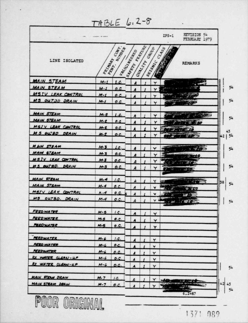
. .
T/t i3L E /,, 2.~8' .
zps.1 m .SION Sk.- _ . _
. FE37J.Rr 1979,
6"/e!||I*LINE ISOLATED + A
$$ [9[.c,[4 'y' REMARKS&
_
MA IN STEAM M-1 1.c. ! 3Lx_
MAIN B TFA M M-f 0. c,
ggf |_
MS TV LFAW COMTROL M-f 0. C. ' A 1 Y~~ ?
. _- i pMS ou T3D DRA/N |Mf _ - _ _ -
0. c. A j y * = ^ ~ Qi>W || I
^
MAix strAM 1 M-2 i .c. a'tx 9MAIN STEAM Mr o. e i A j y ^ ~.MgMsiv LEAK CaWTROL | M-t 0.c ' A g y <&A g$M S eurso D2AIN | M-2 A j y %.2 ,8
41 | 5hc. e. *
1, .
M AtM STEAM M.3 1.e._] gg3 . %MAsd STEAM | M-E 0.C.
_
Sg3M $1V LF_Ar ctw7eol |M1 0.C. p j Y
_,_ y
MS euf$10 DRAIN | M-3 0. C. A f y L ; Y1
| J ^ ' "
M Aist CTrau |M4 f C.~
L % 38 pMAIM STK4M | M-4 6. e. |9 | |yMs7V LEA K CONTRot | h:-4 | c. C. -|A |t '4 b- ~x ';;'-
MS ouT80 ORArH | M-4 |C.C. |A |t Y~ M- 5h| | | |
^~
Tvro m tre | M*s | 1. C. A f 'Ypccownrre |M-5 c . c. A f YMmcomin M-5 o .C. A f y
''Mtown tra | M-G 1.C. p 'f yMno wrew | M-C 0.c . A j y |MEpwarve | M-C |o.c. p |t Y|tr m ct.rA v - :.Lp | M-C o.c. A f yRx WArra cCEAM-uP | M-G c. c . A g y
Skl
MAIM STng pgssu | M-7 1. c. g y y - | - g_-- - ^
iMaig s7EAm Desist g M-7 -.
,._, 42 45e e.c. 2 i y |3. _ _ _ 1-
_-
, p6.2-8?
0**]D #)DT
'
@wwN s iu , 6~
.u ,
1371 089

. .
~
~ REVISION 57APRIL 1979.,
9 1///PgM J d N REE RKS.
LINE ISOLATEDff b ?f Ufre 5/q
rm > rnr- - -.
, , , , , ,.,
| M-9 0.C. x B f YR a ce w RWwn!
* C I Y 5h| M-9 f. e .RBee w R1rar.2
!
* A I Y| M .fo | 1.C.R6/6 HE4D SPRAY1 8 9 Y|M-f0|/<.R6/6 // DD $PtAY
| p-10|o.c.|2 A 1 YR CIC HEAD sPRA Y
A f Y|| M-to c.c. | cRete /wAo spMAY
RNR MFAO srAA'1' | H-f 0 c.c. | t A f Y |h|5h5
RNR MEAD S* RAY | H-! O n c. 1 A i Y
| | |
| M it | oc. 6 ARMR tPct
| _
l
|Hft e.C. LAPJ K LPCI
| M -15 e.c. 52,.,,, A | 3gR92 LPc/
IA Ii YII H-14 | 1. c. -rC R D RE7u.2,0 70 x pv|A |t Y' 57| M-It/ | C.C . o
CAD KETUALP To R.PV* Ali Y
CRO R87ttR s) To KPV | H-/4 c.c.
l res re KPv u-ts oc _iL. d L-gI I
| N -l & O.c.H PCs 70 R PV1 I I I I i
| | |^
I M t1 | 0.e. 2RJ/2 MYwru. smeAY
| H.l1 0.c. | |5 IRM peywnt spRAv
| | l l I
I\ w t8 ' i.e. | >srsw ro xxx pyI * ~?~~_LL$TDM 7b RH2 Hx D ts. |M-!9 f.c . '
|51SIM-t2|o.c- 5 A_,, iMC4u rc KMR HX
6.2-84
1371 090J
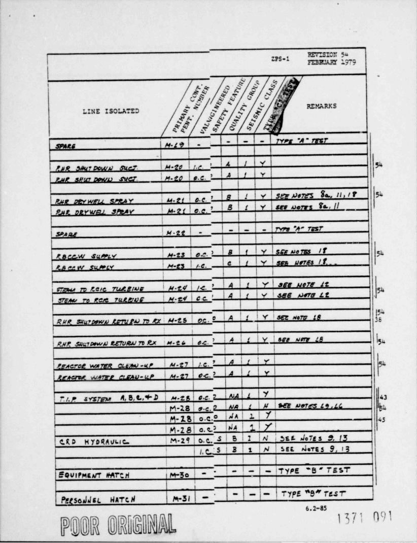
.
. .
* 0"ZPS-1
FE3FJARY 1979
S M's ' q. ,.a -
.$.$C.s
IY d M 9 REMARKS
M N///LINE ISOLATED
,
TY r s *A * 17 5 7| u.g e | . - - -
snes~|
* A I Y ggMNR onurDown 6%c7 \ M.'20 | 1.e.IA I Y
par sPtn Down ner. In.eo e. e. *
l
p2R ptywru gryay | u.g( | o. g. > 9 1 Y Set $8785 Sa., II, I T 5h
Pat 02y'wp1 Step y. I p.g g | e.e s B i Y ser norrs Ta., fl __L
| |
1 u.ee f . l- rm % rar- -
sesarI I
|
l B f Y | SCE neTss /f| H.es e.e. ) ggKBec.w su m vI u.e3 I ,.e. e I I y I sam uorss / t . .'
ro e- w sumyI I i l
| u.ed l 7.c. ' IA I1 Y |3EE No75 12CTDw in Kere rusting 5kI SEE P470 LtSTEAo re Men rute.tvr | u . c 4 | c c. * IA |f V
l |i
Y I ser Here 28 h5fRIIR suurtown trrttro to xx ; H.t5 | oc. O IA |t (
! ; I I I'
esix saanewa zervaa rv e.x w . e s l o.e. ' |A 't \ Y l ser uore is |yI | I I I I
teseree warra cupo-ur | u.z7 ' t. c . ' IA Ii I Y | gg
weru warn arsv-up I u.z, o.c. ) A ! Y||
r t. 2 systen A, s.L,+ D | u.x s o.e. v m i Y u|M-1sla>.e.o In i | M | see aeres is,ic gg
I d ^ l .t. YII g. 2.B o.c. "I M.2 81 c.c.) Id4 1 YI
C.K D H YD RMLu c | M.2 9 | o. c.. S | S 1 IH I bst JeTe s e,15*
! | /, c J S I 3 | 1 | N | SEE dote S 9, I:3l | I |
_
-!- - } TYPE ' S " T E 57"EQulPMEuT #MrtH M-5 o | - -
l'
TYfS "O" T6ST' ~ ~ ~
idtS000EL HATCA M-3l -
6.2-85
D * * lD*
lD NY j37) ()9 }a n mM X X L@'

.
. .
-
._
Z.PS-1 FS7ISION Sk I
FEBICARI 19(9 |--
.4 Q $'
Uh[ ,[,5 O
I E* 8 '[ REMARKS
M //. g/LINE ISOLATED
/ -
TY!r"B" 7967~~ | ~ ~ ~
A ccess MarcM M St
| p.s5 I rYrc "8 " Twi( - -.- -scogss parept'
j
|M-34 I QCrs S i \Y ser Morn 48RWR roup *s' SvertoAs
| i
R H R Po u r * c ~ S u sric a |M-55 0.C rs | 8 I Y . sic Merr 48
|
| M-SC|e. css a t Y' as Mars 48Kyr rout "A sverrou| l
lM-57 c.c as a f Y srg Mars t8'
L. A c.s . suersea|I I
| M-3 6 c.ces g i Y|H. p. e.s susriew
|
Y \seenem u JS 38\ H-59 c.cio 8 1 1x cic run..,ius s> Ha ust! ^5* ($$"N e?$N I M-59 ocoo |8 i Y | see Aora u . it
| M-39 ( o.clo |8 1 Y der Morf u ShRc/C. TURSIMG CyMA UST
I H-4o | o.cso \g|g | y- | .sa Do7sses,JgReic vAcuuu ?vut oise.I M-40 | 0.00 |8 |t | Y | sarnors 26gesc VAcu uu pour otsc.I l l I
t.cie tour soertoa H-41 c.cto a' t |Y sa nors 18_
Reoc uja. float inis |u-Me c.cio a 1 Y ses nors 18 bh
i |
| M-43 | D.cro S f Y | 3G Dom 9 b 1% hSAPP. Poes. SPEA Y *' A '
I | 1 | |
| M 44 0.c.io IB |1 | v | set uorg 48 ShLpcs iss7 uurI M #4 i o.c-0 |8 |f |Y |Seg norr 48RMR *'A * HX CNIMUMTG"| M M $ O.C9 |8 |1 Y SgG 20rt if
f PCS M/M. Cf 0Vi BYOASsKH2'A' Mov. M,est BYPASS | M-44 o.c.e5 |8|2 |Y |Ser Port 19
| | |I i
I I l |
6.2-86_ _ _
M g

.
.
'
m.' 3IC Sk;;PS-1 -7 EI32CAFI 1979
d Md'S .cER M ., f f )s-: .w . c
8 O; + " . ' g C 8 REMARKS;
LINE ISOLA'"ED
fb'ff & & $Y.S $ f 'N<F. I I
__
l l
suPP Rxt SPUY "B " I M-45 | v.c. 8 I Y $63' M07Es- S b,18 - Sk\ |
ARR *C" HIM Fww BYPASS | M-4t, |o.c. 8 I Y | . set DorE 162H2"2"um risw 8vnets I M-4: |c.c 8 i Y I.sre urta laRMP ur"B~ cavorosArv | M-ci |c2 | 8 i Y | Scr Mort 18PJe "B" cou. ft.aw f CLou I H-4C |o.c. 8 'i V | Sir noir 18xxx e"nu. now1 nosa i n es i on. Ia t |Y s n xore se
i I | | | 1
}/PCS rest UMS $ M-W1 | o C. '8 f Y 6G MSTF 18_ HPc3 Mty CL.evV | M d7 | C.C . |8 f |Y |dEt MITF 16
I | | |
cament zoo m m as m i u-48 | - I .n.ra ~s~ resr 38- - -
| | |
ornau. seoir sour or. I u - e I o.c. |e t I Y | ser cores n. ie.hOeywsti seuro. soun og. I u se | c.c. 8 t I Y I .res nort it >
'| | |
ocrwat naox soup ca. lu-so Ioe. 8 L I Y l ses cores it. isceyww puee saue oe. i m-so I o.c. e|t | Y | ser vore n >
l I 1 1 I
cvcwo cocoevsam: I n-51 | 1.c. | |8|1 IY|cyctso cocDcasArg | M -C1l 0.c. |8 t |Y I
I l
ms 72 me -cour s~ | u- se t o.c. s i v-1 I
smes | n ss | '
rYrr -A ~ rEsr- - - -
i I IIyremero ans conmot fu-se|o.c. Ie r 1 v | r vatvas in me.aureavpeo seu su coureot Iu.sa|c.c. Is|t \y |rvavn w a uc.m
I I II I
sraza lu-ss | - | |- rrre v . rest- ~
* 6.2-87
._. -
D"*D 'P PW n'
.
M '
.
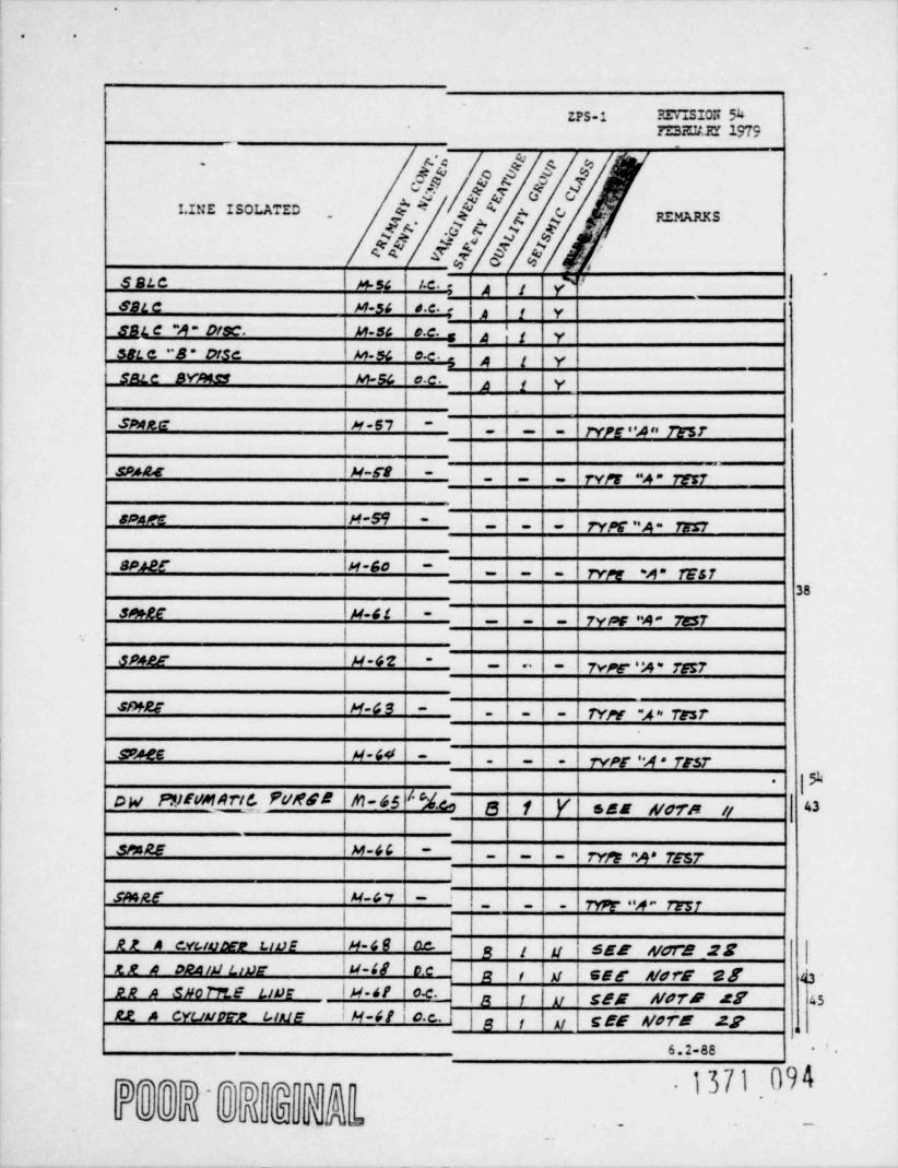
.
. .
.
ZPS-1 REVISIOR 54FEsa.u r 1979
_
* *
, .
[ . REMARKSI.INE ISOLATED
,
b5!f|||SBLC M-54 | 1.C. *
.
'
A 1 YSBLC M-54 d.c. - 3 y ySBL C "A " O!SC. M-56 c C. . 3 'g y38L e "B- O/Sc | M-5& |C.C. p g ySBLC BYMS5 i M-5& 0 C. p j y
| |
snec |x-s7I - ryyg. w. rest- -
I
saae |H-ra ~
-rypr 2 res7- - -
|
so m |H-s9 | - ry,,g g. ryg7.
| |
aner lu-so | - - | rvn s- rest- -
i l | 38
smee fx-si | - ryor .e- resr- -
I
sp4pp | x-4'E - | 7vpLc 'M" rE5r~
~ ~
I| |
smRg | M-G S |- - | - | TYN *A rEsr-
|| |
'
gueg |u-44 .|- rver .g resr--
.
I| |9-
o w p y r m a rv e. P u M G B M- 6s '' % e t Y ses Mora it ''~
l
smag M-4C -
ryyp m* 7es7-- - -
1|
i
smer \ H-& r t- r m-.w- regr-
- .
| | 6| |
RR A cvuvMr uuE IH-4 8 aC- I g j 'y SEE AfGr2 28 |'
tR A O24/d Ling |M-48 0.c I g g y agg- gerf gf 43 -RR A 5 H 0 71'I e L/D E IH-4f 0C- g y y | CBE N07'E Af 45Rt A CYUMPTR L lME I M-41 ' 0 c. |g y a cEE Word 27 u
6.2-88 *-
D " " lD " l0 9[lY hi' '
-
o o M o M J)U AL - -
..
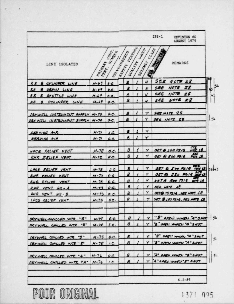
. .
-_
ZPS-1 REVISION 60AUGUST 1979
"
. 4C REMARKSLINE ISOLATED E *~ $+.$~. % , .*
A A w 9
/ 44 f% '% ;
22 8 cYuA30CR uv6 p.C,1 e.c. 8 1 U' BEE Af oT3' 22
3f1 B t a SEB A/GTE 28K? '8 D24/A.) LIU G p.s9 c.c. 4
MA' 8 $N 077L E uos | M 41 | o.e. A f W SE'E A/072 25 __ 45
22 L cYL INDeR us)F | M-49 \o.c. 8|t y sEE A/072 22- | |
PtYws2L tocrzuus-07 sontvl M-7o c.c. _BIL Y ser noit 25
OtYWCu IUsteuupor sumv| H-7o | o.c S |t Y | ses corr es | SkI |
_ set vres A1K | M-71 1 c. B i Y
stitvics nix | M 71 c.c. S I Y
| |
Ppce 282.155' VfDf' | M-72 | 0.c. 8' $ Y 3&7 9 fo9 PS/G b$ 16RJJM ?FLICC VENT | H. 7'2 |94 |6 i Y | SET & Soo 9516 95 19
I | I I |
L Pt* 9 l'ELi&~F VEW7 |As.73 |g 9|1 I Y | 327 e see >=s/c "serets 3s|r521/2 reus)~ V9VT | M .75 | c.c. 8|f Y | 367@ 220 Ps/G!a$tB2pz acues veur I p. 7s l o.c. IeIt |rIsere soo nie a%ape vrur ax > | M-rs l o.c. |8|1 | r f ees nore ieaxe veur nx. s | u-rsIo.e. | 2 - I i | Y | es7s ,sesia ,sar cure Le
LPcS Esucr war I p-71 | oc. |8 If | Y | $G7' & ico rsse , ses pan 1B LA
i l I
i l
|8 ) |v "B'*opga wygy "s~s m | SuoeYesu.cmuso wrx . s~ \ u r<i o.c.|sf! Y \"s~onn weav~sn~suerrcerwm. epium wre. -s* | u.7er 1 r.c. ,
| | | | | I
e|r | Y l 'e* opev wqm "A "syvfoerwm ewu.sv wrp -s ~ | p .,s o.c. r
51eIf | Y I"B" o Aru wpow ~s~ ssorperwen can.:.sp wis ' 8~ |M-75 1. c.
i ! ! I | I
oev wm ewittro wrz. -> ~ lu-7c. lo.c. |B |t | v | ~r oms werv ~s'snor 'p>
oerwwa exiu.e> wrz vA * I M-7G | 1. C . |R |f I Y l'A ~eren werp *p~ spur1 l i l<
Ii i ,
6.2-89
D**D *D YQ I37! 095Su d fru,,wo o,
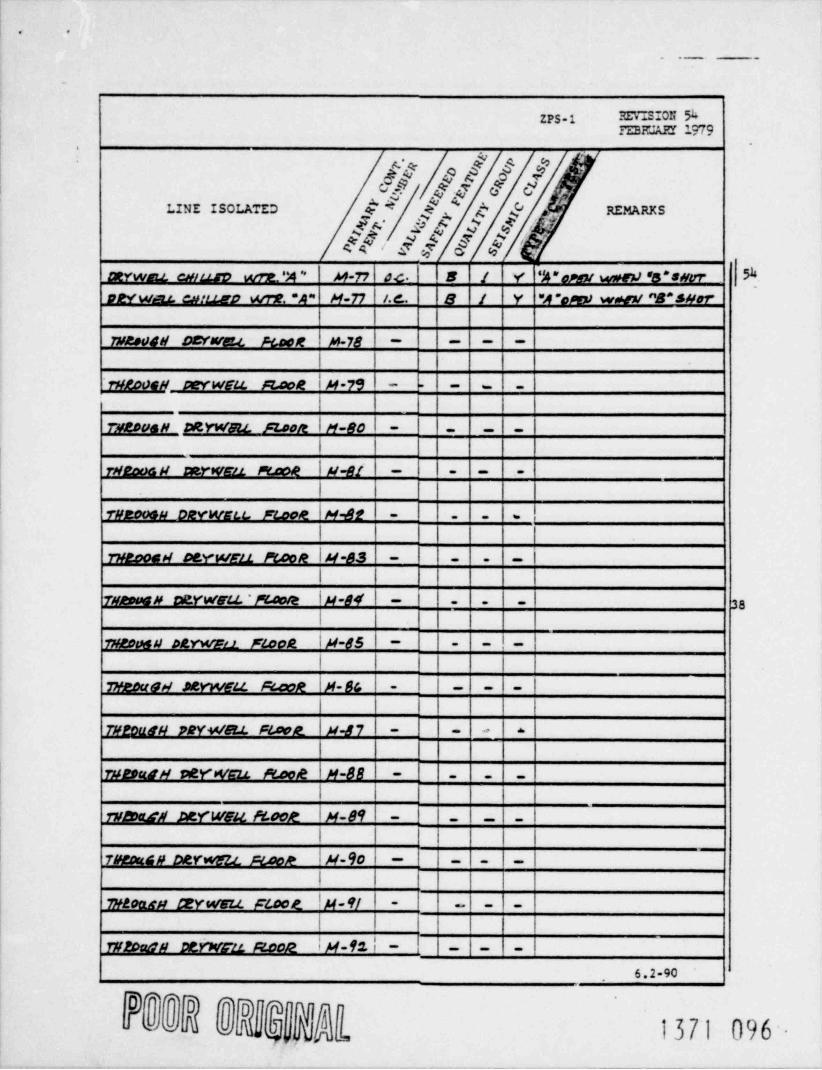
. .
. ._ .
ZPS-1 FFTISION ShFEsm:An 2.979
.~
#[1///;[* .' h 84 REMARKSLINE ISOLATED
a f .y f ' - ,,s$ee'Eq $@ [.
DtYwau. chit.Lsv wit.':4* M-77 0.c. B / Y '|4 * cytoy wME)) 'S * syyr 5'
92YWa.t cn:U.ED wrR *A'' M-77 f. d.. 8 / Y "4'opiry wnxt "B*sNor
TW2004W DEYWE.L FlacM M-78 ~ ~ - -
1 I
THLOOGM DeYWELL R.aot I H-79 | - - - - -
7W2DueH DEYWall. FZ00R | M-80 | - - - -
1 I
rHema H aerwen n.oon i H-et | - - - -
| |
THE006H DRYWELt., FE.coR H-82 - - - s
| |'
runooas cerwm n. con lu-as |- - - -
| 1
TM200GM DVYWELL. ' M00/e | H-84' '-38- - -
I
mzona peYwra floon \ M-85 | - -!--
I | |
7m eo u s a .ne y w eit fecon \ x-sc. | |- - - -
| |
TW20adH PRYWB.L Flock | H-87 "- - y
w ouen ver wsu re.coe x-88 - - - -
|
runa.n perwou rsoor |M-89 - |- -|-
| | | |
7aeous verwezl. scoor Iu-90 1 - -|- -
1 |
maoup xyweZt ficoe lu-91 | -I-- --
| |
WP.Da0N DtYWCZ!. RC02 I M-9% '
6.2-90
0 " 3D S l0 W n
4 d 21 hl' d t, 137~1 096-l

- .
~1
ZPS-l'~ tc.vaSION 5k*FEs mia ac79
d g ,f ,| t 'N 16p% g
.
*. R 8 REMARKSd 9f : $ f 'LINE ISOLATED
fr f f .h N ? - o$$/M-9s | Fc. - 8' l Y
_ %.
I
I.A.secr>e) r.1 muumr i M-9s | oc. 8 J 'Y
p.mer w nr. enmiaxar| | rv; ~.o ~ trst~~ ~
|M-94 ~
| l j j\epene
| H-9s | o.e. \ l 8 1 'YlI
I fi j Itosin . MM -caur. A =
",
\ M-94 > -| (~ ~~
1
I il l i 1st+ef
| Y \ ser 9 500 tstG |$16I u 97 | e.e. ' IB IJ sernib iso Ps/C n#ere 12-gna x.gurf ven7s '
I u-91 Ic.c.' |e 1 Y
Y I ser A Cao Pste Nas_.tist Rcuer vrais I H-D | a c. ' I&Ii \ ser G reo Arte $518RHe neuer venirs i M-97 |o.c. B iIY| H-M \ ac. BlI (Y I s a c orn La yrun Rourf vewr5
Let Hr' 8' VFAtrI i 'l I )
! I i 1 i
\ M-9V \ bc. |8IL I Y | see nsrr lafKMK ris7 uct " A ~
i l l I |_ , _
-|~ rvpr *% * m.irIu-99 | - -
9Pse.G I i l 1 I i
| ~ | ~ I ~ |7yM "4 * rgs7| M- jeO | -
| | | f / I2PARC$GT Dein U.12 _
p| M-f4i I c.c. I B L Y
tMt.C7 Sa-a- Dore if!)2v14tG1r PURdG |H=l0i i e.c. 2 1 Y'
JEYunh t PUR4f IAJLET _ I l j j,
\s\t v 1 sei nores .u. u '
Ix-coe ocaerum. purac anusr IH-Ue|DC |5 |1 iY IsEE Do7E .t.L '
45Puede ErJ/40sr seworres LL LP _
peywett IM-lot I a.e- IB| l' Y,|ptvwnL. Lved! BEHArist \ e I i_ vleervar u
peywnu. puace ernosr lu toro.e.
1 i !
I j -
j { T|
{ .
' ,
i i | |s
6.2-91 )
b,,om' '9 0 g ynvji371 097
-
J"(V g ".
___.
! he 4

. .
. . . _ .
ZPS-1 RETISION 5hFEPRUARY 1779
oW// *
LINE ISOLATED e$' Y [. d' |I~
REMARKS
< <g* e p 4ff 3-E
30*P. CMMemt Ptstat GwNktisT Al-Id6 o.c. 8 1 Y SC dates Jf,17
YJR39' CMMCL92 Bit!RfC 8xotAcc7 H-tos 0.c. 0 $ Y dEU DeTr* ff
C4W8tt97)$LE gng OnstT20f- 1 M-/03 0 C. 5 I Y t VALV25 /At PAMLLCL*
QwAt/tr7RLM 2M &J720L | H-/C2 C.C. b 8 $ Y t VAtM5 IN PA24LLCL
|
Sttyp. cmqqqm Puegg suggy |H-led 0.c. B 1 Y GEC Derts Lt. Lt
SetPP C&MMBC2 DVRdE / Alt.C7 | H-LO4 0.c. '8 I Y SCE d6TE*1f
av PP. cW4,starn Pr/AtGC 129L97 | N- Led 0.c . B 1 Y 468 nsTE5 2 ,ff
AdPP C64M692 Pr/Aldt /AILE7| M-ter/ c.c. 8 1 Y SCf DOTE J.1 45
|5kRot C STrau VAcoux sne. |M-tod o C. _
8 i Y '
|
AJ/K RBJW VALVES dis * lM-LO$i0.C. O i! Y SGT" h 500 PS/C 90rE Z8 38
RM2 RGlJWP VALVf5 pr$. | M-L O$' O.C. 8 || | '1' SC7" 6 4f!O PS/C N Lg
|
tAMC RELLW V4t.vr DISC /t. | M-tc6 0.c. 8 | 1 Y |SE'i @ COO PG/G $gg (45
|0 $ Y SET G 410 PSid sere la24/ c R F LI V W V k t.V C DiscM. | H-Idra 0.C.\| | '
- I ruaoasu neywa m'
vAevou satseas eran | n.co, | ---
| | I'
VAcous; B25ng.E2,s t pg)g | M-toy | ~I'~ ~
rifacca ps .pprzsigzz, pgoop-
I I i
|~ TittDOG R D & fk)FLL PloatVS> COUM 82EA tE8s L /DC |H-iO4~ ~~
| |
l~ TWRouGW O2v4) Ext stootVA covy BBEACEEs tad &T | M.fl0 ~ ~-
| l I_
| |
| |
1 I | 1
l I l-
I l~
i I,
| .
6.2-92.
, j

. .
.. . ..
ZPS-1 ~ . MIDI! SbFEER %RY 1979
?? hhh ^ ' ~~
.c
QS Jg # d nE"' 8 p REMARKSLINE ISOLATED
ff ~5# ',f N& #E. -
~~ S 1 p[o S* pea u SY | 40|T-l|$0$'
sustrupEur unas.
-
|
. __ | - 43
RGejk*. PuuP sDel Mt4G If 50 Yvo g i 125 $67 MOTE 21 | 45
Hz kt switC BETUED | Z 7A No du 8 i YL'5 | S8E A072'5 $br $$ $p.w. Aruos . &#NME !.T-llA|No.;y |g ,f YC5 Sfr norts 11.$1h/2 34AWLE |124A-O| *hio |8 j Yes SCE Norts lloif 40
| f l 52Bacrop Esc 12c. skMPLG to 8 j Ygs
tresee. Avpsort 9026c II 21 c IW'uo |s t Do set <rorr 27 | 45
saw cpAMare AIR 3Auptr IT-27A | VDse |g i ves| gEr aares LL, it 38
sun".c>tAMBFtt ME $6N!L6 lI d 4 O l |* N O |8 1 1 YE5|$22 Asa7Es 11,11 Sh
I -SDA 8 I |0E 10 |S f Yes | SEE nons .U , Upt $4MPt.2-EEAcrOft MCAO .gaw. Aruos. SouPLE |Z 4CA S* *io |8 L Y5 | W D*TE5 11. 41uena SMurY/2Euer e4&vEs | C O* E *|* yo B 1 |Ye5| sta P07Cs 1f. A! 'Mt $4M PL2 N.9 I T-44A N*Jo 8 |1 yes SEE ports JJ,$P 43|
AIR $4Hpt g EZCreti.. PvMP ISC,0F"|S|**io |g| [ ,yes 12Cf DorE5 ll,1-| U*
Are .Caun.E RFeste. MMP |T-G7A|#|0y0 s i res|sEr s.ro72's JL,LJmz 2424pLr EECJRe. A!MP Is OLE Voyo B|1 |Yes, sEE D c72s. 1/ , U
! I | |I-EE TD
|711sove u m Y WEtt P< sosl-1 -s 1 ~~ ~ ~
IMfe? | - |r m ea u aev o e u e,en o aI-- -
l | I I I
I I
|
|
| t
I |
| | | |
| |\
I I I
| | 1'.
I I i
6.2-93
o|g 3 'm m.
U b. .
. . .)b}\.=3gr w
,
O

. ..
Z?S-1 RI7ISION 38DECEGER 1977
".L3LI 6.2-3 (Cent'd).
ISOLATION VAC/E SUMMARY FOR LDTES PETE'" RATING CONTADTMDIT
KIT: I.C. Inside Primat7 Conta1==ent-
0.C. Outside Primary Contain=ent-
0 Open-
L.C. Locked Closed-
C. Closed-
M.0. Motor Opsrated-
A.O. Air Operated-
S.O. Solenoid Operated-
NOTES:;--- - - . ,
:u:r #2iiima t'f EaEu'd yalves.: cam.b.e oT.swit'ch.durinsf any modp_cDaaE nr, penedemclosod>by remoca-man $alcpar=Hmescanc.when automaticsignaliscpraeg
2. For signal legend see T&ble 6.2-7.~
N Wst**?.%Q1.'?*'",T"'3*^%?'9utE*&h.AT.hoth to.'. *'''M piroco-bw..- . ... ...
- -.
' -deenergizek. tat cIs.a. .s v.al. .ia..s_,J V. .. ~ =."1 = tar.s... a.i,::.y-
11ots are deenerf,e,ss.ure 21gg,meringw . . pr ..
s . .i
ace,co,347,g7=y es.Wgen bjt.h 2,g .w .7oltagstfail--=
ura at.anir one pilot.h,tro?GUsWea h h ;.3 n a v=bror aref== g-- * e Witt$ed. W '~ 7.' ' " 7o62*.'se#mEds?.~ Enc. 23'u~o~c' Iase than.
--
3 , ,em s . 2. ~., ~. n ,-+-~ - , - - - - -- % :.r* % .. m.
. - - -- ..._..,..
See- L.Lwi.1co'5 5~$.1 for an pf'tl e.,ETT~C2WGur6i:r thsefiEM*l i:ritaria. ~The principal ,
cri aric W Td--d_gi:me is[q-
*.
thip. Ihi.RfadfAdM'ahitEiiA~61tYitrduidEG*N> 10L"h!CG'.~. ' Supsectin' 5+4hwS:3 seconds:.MSITelosura-T 313e insatr= o&
- - - ---
fchac~ therSt'iw.rti.mera.: sth.==+.=.egab== - .*.... '. * ' -.' Q srevi.de. a ssursuce- .-
iel'as2nytt"meri:mmte._qba .consegnancaeLolcr.2.st romexceeding,the W d " --- af.1G_C7K.100.
4. Deleted.3a
W ALL aemn-age. -~ -.~ . .. ~ ..lv. .aaJ a== h.. in,J.sse positiotr upon fail-.. _. .
rscadLiaolatie gva
M b d.. U N /. M M. TAP 3.=> E._*. t N CIC 1803.y Me~41rfa11ure
. N
- .
.-
_- w - ~ , . _. . .
6. ha. See d eb;staizus. 1catsg -s~f%~a'ut *eHLisolacion -valves is'12 inchee. g:er.mine.:a.fjgenverstetr.. co closing- time ca:: her.=ada. en .his,
.
basis ,using, che actual size of' che '11ca in which the valve .s i:staned..
7~'heon, oparated-valves' reqef'ead~ f at"-iselscierr- funetions are poweredf:cm. the.w,_ standby pewar buses. D-e-ocerated isolati:n velves are
- -
;cvsred. from the stati:n 5atteries.~
..
1371 100s . :-nDM 0 *0%yv.E ; 1 Jt i _ko ci'

. .
ZPS-1 REVISION 54FEBRUARY 1979
TABLE 6.2-8 (Cont'd)
8. a. Containment spray valves are interlocked to prevent both ftombeing open at the same time unless the isolation signcis shownare present. This allows containment spray for high drywellpressure conditions. When the automatic signals are not present,these valves may be opened for test or operating convenience.
54
b. Suppression cooling valves have interlocks to allow them to beopened after automatic closure. This allows for cuppressionpool cooling. When the automatic signals are not present thesevalves may be opened for test or operating convenience.
9. Criterion 55 concerns those lines of the reactor coolant pres-sure boundary penetrating t'ne primary reactor containment. Thecontrol rod drive (CRD) insert and withdraw lines are not partof the reactor coolant pressure boundary. The basis to which theCRD lines are designed is commensurata with the safety importanceof isolating these lines. Since these lines are vital to thescram function, their operability is of utmost concern.
In the design of this system, it has been accepted practice toomit automatic valves for isolation purposes, as this intro-duces a possible failure mechanism. As a means of providingpositive actuation, manual sautof f valves (1C11D001-101 and -102)are used. The charging water, drive water and cooling water headersare provided with a check valve (IC11D001-115, -138 and -137)within the hydraulic control unit (HCU), a Seismic Category I 44module, and the normally closed solenoid valves (IC11D001-120,-121, -122 and -123). These valves will prevent any directflow away from containment. These valves are shown inFigure 4.2-19 (Sheet 2).
If an insert ine fails, a ball check valve provided in each 43drive is designed to seal off the broken line by using reactorpressure to shift the ball check valve to the upper seat. This
feature also prevents any direct flow away from the primarycontainment.
A piping integrity test is accomplished for leaks of the HCU'sduring daily inspection (HCU operating pressure above 1000 psi).In addition, several indicators in the contrcl room, such astemperature and pressure of CRD cooling water or drywell sumppump operation, would indicate if leakage is excessive. The maxi-mum leakage expected at this penetration is 3 gpm when the RPVis still pressurized (about 1000 psi). This leakage also assumesa single active failure of a check valve inside the HCU. Afterthe reactor vesselsis depressurized, the CRD leakage will de-crease to about 0.5 gpm. It may also be said that leakage moni-toring of the CRD insert and withdraw lines is provided by theoverall type A leakage rate test. Since the RPV and non- 44seismic portions of the CRD system are vented during the per-formance of the type A test, any leakage from these lineswould be included in the total type A test leakage.
016.2-95 -
.

. .
ZPS-1 REVISION 54FEBRUARY 1979
TABLE 6.2-8 (Cont'd)
The flowout of the CRD is restricted through the HCU by perfor-mance test requirements to ensure that HCU leakage does notexceed 0.2 gpm. The maximum leakage expected for these pene-trations is 0.2 gpm per HCU. If a single failure is assumed,the maximum leakage would be 3 gpm. Seismic tests have demon-strated the seal integrity of the CRD system. Maximum laakagefollowing these tests did not exceed 3 gpm.
The system design criteria are as follows:
, QualitySeismic Quality Group Assurance
Component Category Classification Classification
Valves; return linewithin containmentboundary I A I
43
Valves; insert andwithdraw I B I
Return line pipingwithin isolation valves I A I
Insert and withdraw linepiping I B I
The CRD insert and withdraw lines are compatible with the criteriaintended by 10 CFR 50, Appendix J, for Type C testing, since the accept-ance criterion for Type C testing allows demonstration of fluid leakagerates by associated bases. The maximum leakage expected has beenfactored in with the total allowable containment penetration leakegeand determined to be acceptable.
10. Main steamline isolation valves to be type "C" tested in accordancewith Subsection 5.5.4. Leakage is exempt from Appendix J total 31measured leakage criteria.
11. Test pressure will be applied between the valves. The total leakagerecorded will be assigned to each penetration.
12. Penetration paths for M-18 and M-24 will be tested sicultaneously. 14
The total leakage recorded will be assigned to each penetration.
13. Deleted 43,
14. Deleted.38
15. Deleted.
* h} \ *
\
6.2-95a

.
ZPS-1 REVISION 54FEBRUARY 1979
,
TABLE 6.2-8 (Cont'd)
16. The Zimmer 1 TIP system design specifications require that the maxi-26mum leakage rate of the ball and shear valves shall be in accordance
with the Manufactureres Standardization Society (Hydrostatic Testingof Valves). The ball valves are 100% leak tested to the followingcriteria by the manufacturer:
Pressure 0 - 62 psigTempersture 340 F
3Leak Rate 10 cm /s 17
A statistically chosen sample of the shear valves is tested by themanufacturer to the following criteria:
Pressure 0 - 125 psig'Temperature 340' F
3Leak Race 10 cm /sec STP
The shear valves have explosive squibs and require testing to destruc-tion. They cannot therefore be 100% tested.
17. Deleted. |3718. Test pressure is not in the same direction as the pressure existing
when the valve is required to perform the safety function as required 16by Appendix "J" to 10 CFR 50.
19. Since the traversing incore probe (TIP) system lines do not com-municate freely with the containment atmosphere or the reactor coolantGeneral Design Criteria 55 and 56 are not directly applicable tothis specific class of lines. The basis to which these lines aredesigned is more closely described by General Design Criterion 54,which states in effect that isolation capability of a system shouldbe commensurate with the safety importance of that isolation. Further-more, even though the failure of the TIP system lines presents nosafety consideration, the TIP system has redundant isolation capa-bilities. The safety features have been reviewed by the NRC forBWR/4 (Duane Arnold), BWR/5 (Nine Mile Point) and BWR/6 (GESSAR),and it was concluded that the design of the containment isolationsystem meets the objectives and intent of the General Design Crtieria. 43
Isolation is accomplished by a seismically qualified solenoid-operatedball valve, which is normally closed. To ensure isolation capability,an explosive shear valve is installed in each line. Upon receiptof a signal (manually initiated by the operator), this explosive valvewill shear the TIP cable and seal the guide tube.
When the TIP system cable is inserted, the ball valve of the selectedtube opens automatically so that the probe and cable may advance.A maximum of four valves may be opened at any one time to conductcalibration, and any one guide tube is used, at most, a few hoursper year.
6.2-95b

. .
ZPS-1 REVISION 54FEBRUARY 1979
(ABLE 6.2-8 (Cont'd)
If closure of the line is required during calibration, a signalcauses the cable to be retracted and the ball valve to close auto-natically after completion of cable withdrawal. If a TIP cablefails to withdraw or a ball valve fails to close, the explosiveshear valve is actuated. The ball valve position is indicated inthe control room.
As stated above, the penetration is normally closed (oEgn ag/sec.average
of 15 hours per month), and the design leak rate is 10 cmIf a failure occurred, such as not being able to withdraw the TIPcable,
theshearvalvewouldisolatetgepg/secnetration, and the
resulting maximum leakage would be 10 cm The shear valves are.
shop tested by statistical sampling methods to ensure that the-3
legkage limits conform to the design specification limits of 10 43cm /sec.
Testing of the ball valve is not recommended, since a very smallamount of leakage is expected, and any testing would need to beperformed from inside the drywell, exposing the operator to radiationdose estimated to be about 50 mR. These lines should thereforebe exempted from the 10 CFR 50 Appendix J Type C tests.
20. Closed system outside the containment. The inlet isolation valves | 38will always be pressurized to a higher pressure than the containmentpressure. The system is seismic Category I and single-failure-proof. 31A Seismic Category I water supply for makeup is available for 30days. 54
The makeup rate into the RBCCW surge tank is established at 300gpm and therefore provides sufficient fluid inventory to assure
38the sealing function for at least 30 days at a pressure greaterthan 1.10 P,.
The RBCCW Class C piping will be subject to the ASME Section XI. 45Inservice. Inspection Program.
21. These lines satisfy the requirements of General Design Criterion54. They are Seismic Category 1 and terminate in instruments thatare Seismic Category 1. They are provided with manual isolationvalves.
38
These lines are connected to the essential ADS accumulators. Onloss of the drywell pneumatic system, they are pressurized by the ni-trogen suosystem. These lines will always be pressurized to 165psig. They terminate in a pressure switch that alarms ar 145 psig.
1371 104
6.2-95c

. .
ZPS-1 REVISTON 43MAY 1978
TABLE 6.2-8 (Cont'd)
These lines are always under test as they are always pressurized.Leakage would be detected by either the low-pressure alarm or normalweekly surveillance inspections.
The accumulators are sized such that the ADS valves may be cycled twotimes without reducing the pressure in these lines to below 50 psig(5 psi above design containment pressure).
22. To satisfy the requirements of General Design Criterion 55 and systemfunctionality, these instrument lines have been designed to meet therequirements of Regulatory Guide 1.11 (Safety Guide 11), Section C.Regulatory Position, Provisions la, b, c, d, and e; and Provision 2a.
These lines are Seismic Category I and terminate in instruments thatare Seismic Category I. They are provided with restricting orifices,manual isolation valves, and excess flow check valves.
Isolation is provided by the excess flow check valve. In the eventof a line rupture, downstream of the check valve, this valve wouldclose to limit the amount of leakage. The flow-restricting orificeis sized to assure that in the event of a postulated failure of thepiping or component, the potential offsite exposure will be substan-tially below the guidelines of 10 CFR 100.
The function of these lines will be tested during reactor plant opera- 38tion. These lines and their associated instruments will be pressurizedto reactor operating pressure. Surveillance inspections will be per-formed weekly to ensure the leaktight integrity of these lines andtheir associated instruments. Additional inservice inspection isincluded in the Technical Specifications, Section 16.3/4.6.3. Thisinservice inspection will verify the function of the excess flow checkvalves and their leakage rates.
23. To satisfy the requirements of General Design Criterion 56 and performtheir function, these instrument lines have been designed to meet therequirements of Regulatory Guide 1.11 (Safety Guide 11), Section C,Regulatory Position, Provisions la, b, c, d, and e; or Provision 2a.
These lines are Seismic Category I and terminate in instruments thatare Seismic Category I. They are provided with manual isolation valvesand excess flow check valves.
These lines are located below the suppression pool water level. Theywould always be flooded during all accident and postaccident phases.Any leakage from these lines would be water leakage.
The integrity of these lines will be tested during the Type "A" Test.These lines and their associated instruments will be pressurized to Pa-Surveillance inspections will be performed weekly to ensure the leak-tight integrity of these lines and their associated instruments. Addi-tional inservice inspection is included in the Technical Specifications,
'
1371 105 1436.2-95d

.
.
ZPS-1 REVISION 43MAY 1978
TABLE 6.2-8 (Cont'd)
Section 16.3/4.6.3. This inservice inspection will verify -he .
function of the excess flow check valves and their leakage rates.
Isolation is provided by the excess flow check valve. In the eventof a line ruprure downstream of the check valve, this valve wouldclose to limit the amount of leakage.
24. To satisfy the requirements of General Design Criterion 56, and toperform their function, these instrument lines have been designed tomeet the requirements of Regulatory Guide 1.11 (Safety Guide 11),Section C, Regulatory Position, Provisions la, b, c, d, and e; andProvision 2a.
These lines are Seismic Category I and terminate in instruments thatare Seismic Category I. They are provided with flow-restrictingorifices, manual isolation valves, and excess flow check valves.
The flow-restricting orifice is s'ized to assure that in the event ofa postulated failure of the piping or component, the potential offsiteexposure will be substantially below the guidelines of 10 CFR 100.
Isolation is provided by the excess flow check valve. In the eventof a line rupture downstream of the check valve, this valve wouldclose to limit the amount of leakage.
The integrity of these lines will be tested during the Type "A" Test. 38Surveillance inspections will be performed weekly to ensure the leak-tight integrity of these lines and their associated instruments.Additional inservice inspection is included in the Technical Specifi-cations, Section 16.3/4.6.3. This inservice inspection will verify thefunction of the excess flow check valves and their leakage rates.
25. This line is provided with two isolation valves outside the containment.The inboard valve is a hard-faced check valve, and the outboard valveis an automatic isolation valve. This arrangement meets the intentof General Design Criterion 56. The piping inside the containment isnonessential. The inboard check valve was located outside the con-tainment to facilitate repair operations and reduce radiation exposureto personnel.
Both the check valve and the automatic isolation valve will be testedwith air.
26. Penetrations 39 nd 40 - RCIC Turbine Exhaust and. Vacuum Pump DischargeValves
Flow paths associated with these valves terminate significantly belowthe normal water level in the suppression pool. A water seal isassured during normal operation and for more than 30 days followinga loss-of-coolant accident. The end of the piping is 4 feet below thelowest water level allowed in the suppression pool. It is not crediblethat these isolation valves will be exposed to the containment atmo-sphere at any time following a loss-of-coolant accident.
6. 2-95 e (43
1371 106

.
. .
ZPS-1 REVISION 43MAY 1978
TABLE 6.2-8 (Cont'd).
The penetration M-39 isolation valves 1E51F068 and IE51F040 willbe water leak tested. The test pressure will be applied betweenthe valves, and the total measured leakage will be assigned tothat penetration path. Valve IE51F068 (inboard automatic valve)will be reverse tested and valve IE51F040 (outboard check valve)will be tested in the proper direction. Valve 1E51080 (RCIC turbineexhaust vacuum breaker isolation valve) is also part of the M-39penetration path. This valve will be water tested in the reversedirection. This leakage will be assigned to M-39 penetration pathleakage rate. (Notes this valve is a globe valve, and reversetesting will tend to unseat the valve.)
Penetration M-40 isolation valves lE51F069 (automatic isolation)and IE51F028 (outboard check) will be water leak tested. The testpressure will be cpplied between the valves and the total measuredleakage will be assigned to that penetration path. Valve IE51F069(inboard isolation) will be reverse tested, and valve 1E51F028will be tested in the proper direction. 38
27. Penetration I-5D and I-21C - Reactor Recirculation Pump Seal WaterLines
These lines are high pressure lines coming from the discharge ofthe CRD pumps to the recirculation pumpa. They are provided witha check valve inside the containmene and a check valve outside.
The inside check valves will be water leak tested during the re-fueling. At this time, the reactor vessel water level will beat the top of the pool (elevation 626 feet 9 inches). The waterhead will provide a pressure of -41-1/4 psi on the line to the"A" pump and ~46.5 psi to the "B" pump. The check valves outsidethe containment will be locally tested with water at 1.10 P,.
28. Penetrations M-68 and M-69 contain lines for the hydraulic controlof the reactor recirculation flow control valve. These lines con-tain corrosive hydraulic fluid used to position the reactor recircu-lation flow control valve.
43These lines inside of the containment are Seismic Category 1 andhave been upgraded to Quality Group B. They are provided withautomatic isolation valves outside the containment which receivean automatic isolation signal on high drywell pressure.
1371 107
6.2-95f

.
_. - - .-
. .
ZPS-1 REVISION 43MAY 1978
- - - - - -
These lines meet the requirement of General Design Criterion 57and therefore require only single automatic isolation valves outsideof the containment. In addition, these lines also meet the require-ment of Standard Review Plan 6.2.4. They are desigend to SeismicCategory 1, Class B. They:
do not communicate with either the reactor coolant system -a.or the containment atmosphere,
b. are protected against missiles and pipe whip, -
are designe.d to withstand temperatures at least equal toc.
the containment design temperature,
d. are designed to withstand the external pressure frem thecontainment structural acceptance test, and
are designed to withstand the loss-of-coolant accidente.
transient and environment.
This system is under constant hydrostatic test because the normaloperating pressure'is 1800 psig. Any leakage through this systemwould be noticed because operation would be erratic and indicationsprovided on the hydraulic control unit.
43In addition, the reactor recirculation flow control valve is locatedsuch that the control unit is approximately 20 feet above the valveactuator. The penet ation and isolation valve are therefore atsuch an eleva: ion that should the valve fail to close there wouldbe a fluid seal between that valve and the valve actuator.
NRC Document for Qualification Raview, Palo Verde Generating Station,Units 1, 2 and 3, Docket Nos. 5-528/529/530 issued December 12, 1977,Section E item 30 n. states as follows:
Locked closed containment isolation valves have not beenn.
identified as being subject to type C tests. In addition,the majority of the containment isolation valves that fallunder General Design Criterion 57 (closed systems insidecontainment) have not been identified as being subjectto Type C leak testing. Unless it can be demonstratedthat the system can withstand a single failure of any activecomponent (e.g., valve failure, pump seal failure) andmaintain a fluid seal; i.e., prevent containment atmosphereleakage through the valve (s), it is our position that thevalves should be Type C tested. Discuss your plans toType C test these valves or provide justification forexempting these valves from Type C testing.
For the above penetrations, the only single active failure possibleis for an isolation valve not to close. In this case the closed systemwould remain filled with fluid for the duration of the accident.
6.2-95 ,
)371 108

.
.
ZPS-1 REVISION 43MAY 1978
Leak detection is provided by the instruments, although non-seismic,on the hydraulic control unit.
In order to perform Type C tests of these lines, the system wouldhave to be disabled and drained of the hydraulic fluid. This is
43. considered to be detrimental to the proper operation of the systemin that possible damage could occur in establishing the test con-dicion or restoring the system to normal.
These lines and associated isolation valves should therefore beconsidered to be exempt from Type C testing.
,
*
6.2-95h

,
TABLE 6.2-9
CONTAINMENT PENETRATIONS
PRIMARY CONTAINMENT~
PENETRATION SYSTEM P&lD FSAR FIGURE *
H-1 H-21-1 5.1-4, Sheet 1 5.2-1, Sheet 2 7.3-30, Sheet 1 10.3-1, Sheet 1
H-21-4 5.1-4, Sheet 1 in.1-1, Sheet 4H-73-2 9.3-8, Sheet 2
H-2 H-21-1 5.1-4, Sheet 1 5.2-1, Sheet 2 7.3-30, Sheet 1 10.3-1. Sheet 1H-21-4 5.1-4, Sheet i 10.3-1. Sheet 4H-73-2 9.3-8, Sheet 2
H-3 H-21-1 5.1-4. Sheet 1 5.2-1, Sheet 2 7.3-30, Sheet 1 10.3-1. Sheet 1M-21-4 5.1-4 Sheet 4 10.3-1, Sheet 4,,
;, M-73-2 9. 3-8, Shee t 2 y'
H-4 H-21-1 5.1-4, Sheet 1 5.2-1, Sheet 2 7.3-30, Sheet 1 10.3-1. Sheet 1H-21-4 5.1-4, Sheet 4 10.3-1 Sheet 4 34H-73-2 9.3-8, Sheet 2
H-5 H-23 5.1-5 10.4-4
H-6 H-23 5.1- 5 10.4-4H-55-1 5.5-14, Sheet 1 7.6-3, Sheet 1
H-7 H-21-4 5.1-4, Sheet 4 10.3-1, Sheet 4,,,
H-8 (spare)
-* r* <H-9 H-58-4 9.2-4, Sheet 4 7.3-34, Sheet 4 -:g
7o-~
~z__.'
CZ) *FSAR figures listed in the same horizontal row are identicail. ;1

.
.
.
TABl.E 6.2-9 (Cont'd)
,
PRIMARY CONTAINHENTPENETRATION SYSTEM P&lD FSAR FICURE*
H-10 H-51-2 5.5-13, Sheet 2 7.3-10, Sheet 2
H-52-2 5.5-9, Sheet 2 7.4-1 Sheet 2
H-11 H-51-2 5.5-13. Sheet 2 7.3-10, Sheet 2
H-12 H-51-3 5.5-13. Sheet 3 7.3-10, Sheet 3
H-13 H-51-1 5.5-13, Sheet 1 7.3-10, Sheet '
H-14 H-56-2 4.2-19, Sheet 1 7.7-1 Sheet 2
( H-15 H-50 6.3-4 7.3-8 yM
1
bd M-16 H-49 6.3-1 7.3-214
H-17 H-51-2 5.5-13 Sheet 2 7.3-10, Sh>et 2
H-18 H-52-1 5.5-9, Sheet 1 7.4-1, S~.eet 1
H-19 (spare)
H-20 H-51-3 5.5-13. Sheet 3 7.3-10, sheet 3
H-21 H-51-1 5.5-13 Sheet 1 7.3-10, Seeet 1
h.< $H-22 (spare)--
NUH-23 H-58-4 9.2-4, Sheet 4 7.3-34, Sheet 4 U
]f $0'
*FSAR figures listed in the same horizontal row are identical. . -_
-- -
. - - .
6

.
.
TABLE 6.2-9 (Cont'd)
PRIMARY CONTAlfetENTPENETRATION SYSTEM P&ID FSAR FICURE*
H-24 H-52-1 5.5-9 Sheet 1 7.4-1 Sheet 1
H-25 H-51-2 5.5-13 Sheet 2 7.3-10, Sheet 2
H-26 H-51-1 5.5-13 Sheet 1 7.3-10, Sheet 1
H-27 H-55-1 5.5-14, Sheit 1 7.6-3, Sheet 1
H-28 None 5.6-1 |15H-29 H-56-3 4.2-19 Sheet 2 7.7-1, Sheet 3*.
L U*
& H-30 T34C* (equipment hatch) "
H-31(personnel hatch) -
H-32(access hatch)
.
H-33(access hatch)
H-34 H-51-2 5.5-13, Sheet 2 7.3-10, Sheet 2
>_
H-35 H-51-3 5.5-13 Sheet 3 7.3-10, Sheet 3 8uN O!U
H-36 H-51-1 5.5-13 Sheet 1 7.3-10, Sheet 1 H$-
~ ~~*FSAR figures listed in the same horizontal rcw are identical, g
N

.
<
.
TABLE 6.2-9 (Cont 'd)
PRIMARY CONTAINHENTPENETRATION SYSTDI P&ID FSAR FICURE*
H-37 H-50 6.3-4 7.3-8
H-38 H-49 6.3-1 7.3-2
H-39 H-52-1 5.5-9, Sheet 1 7.4-1, Sheet 1
H-40 H252-1 5.5-9,. Sheet 1 7.4-1, Sheet 1
H-41 H-52-2 5 . 5-9,. Sheet 2 7.4-1, Sheet 2
H-42 H-52-2 5.5-9, Sheet 2 7.4-1 Sheet 2m '
L S1 H-43 H-51-1 5.5-13, Sheet 1 7.3-10, Sheet 1 Yw w
'
H-44 H-50 6.3-4 7.3-8 14H-51-1 5.5-13, Sheet 1 7.3-10, Sheet 1
H-45 H-51, 5.5-13, Sheet 2 7.3-10, Sheet 2Sheet 2
H-46 H-51-2 5.5-13, Sheet 2 7.3-10, Sheet 2 i
H-51-3 5.5-13 Sheet 3 7.3-10, Sheet 3
H-47 H-49 6.3-1 7.3-2
NH-48 (hatch) "N-
dH-49 H-62-1 11.2-1. Sheet I r$-
*0-* ,
*tr4 H-50 H-62-1 11.7-1 Sheet 1 ~
*FSAR figures listed in the same horizontal row are suentical.

.
.
TABLE 6.2-9 (Cont'd)
PRIMARY CONTAINHENTPENETRATION SYSTEM P&ID FSAR FICURE*
H-51 H-27-1 9.2-10, Sheet 1 45
H-52 H-40-1 9.3-1, Sheet 1H-40-2 9.3-1, Sheet 2
H-53 (spare)
H-54 H-74 6.2-36 (deleted)
.{ H-55 (spare) yi En
$| H-56 H-57 4.2-24 7.4-3 14 4o
H-57 (spare),
H-58 (spare)
H-59 (spare),
H-60 (spare)
H-61 (spare)-
UN H-62 (spare) DG
GG~
H-63 (spare) s$-
'S 9.
] H-64 (spare) "g.
H-65 H-40-1 9.3-1, Sheet 1 45
*FSAR figures listed in the samc horizontal row are identical.

.
.
.
TABLE 6.2-9 (Cont'd)
.
PRIMARY CONTAINHENTPENETRATION SYSTDi P&ID FSAR FIGURE *
H-66 (spare)
H-67 (spare)
H-68 H-47-1 5.5-2, Sheet 1.
H-69 H-47-2 5.5-2 Sheet 2
H-70 H-40-1 9.3-1, Sheet 1
H-71 H-72-2 9.3-2, Sheet 2 '
N.
Y H-72 H-49 6.3-1 7.3-2 5M-51-1 5.5-13 Sheet 1 7.3-10, Sheet 1 b[o 14
H-73 H-50 6.3-4 7.3-8H-51-3 5.5-13, Sheet 3 7.3-10, Sheet 3H-51-4 5.5-13, Sheet 4 7.3-10, Sheet 4
H-74 H-88-1 9.2-12
H-75 H-88-1 9.2-12
H-76 H-88-1 9.2-12-.
LtdN H-77 H-88-1 9.2-12 'g" ?
H-78 through H-48 5.2-1, Sheet 3 7.3-30, Sheet 2 mg
"_ H-92 *OyZ
' *FSAR figures listed in the same horizontal row are identical..

.
.
TABLE 6.2-9 (Cont'd)
PRIMARY CONTAINHENTPENETRATION SYSTEM P&ID FSAR FIGURE *
H-93 H-40-1 9.3-1, Sheet 1H-40-2 9.3-1, Sheet 2
H-94 (spare) 45
H-95 H-40-2 9.3-1, Sheet 2
H-96 H-40-2 9.3-1, Sheet 2
H-97 H-51-2 5.5-13, Sheet 2 7.3-10, Sheet 2
H-51-3 5.5-13, Sheet 3 7.3-10, Sheet 3
H-51-4 5.5-13, Sheet 4 7.3-10, Sheet 4* n.
Y H-98 H-51-1 5.5-13, Sheet 1 7.3-10, Sheet 1 314H-99 (spare)'*
H-100 (spare)
H-101 H-103 9.4-7
H-102 H-88-2 9.4-6 -H-103 9.4-7
H-103 H-103 9.4-7H-74 6.2-36 (deleted) < w
[. H-104 H-52-1 5.5-9, Sheet 1 7.4-1, Sheet 1 i5H-103 9.4-7 ! . Eiy *'..
th*FSAR figures listed in the same horizontal row are identical.-
-
.
e

.
.m
.
TABLE 6.2-9 (Cont'd)s
I
PRIMARY ColffAINMENT FSAR FIGURE *PENETRATION SYSTD1 P6ID
H-105 M-51-4 5.5-13. Sheet 4 7.3-10, Sheet 4 .
H-lO6 M-51-4 5.5-13, Sheet 4 7.3-10, Sheet 4
oLi
? 14 |.w
kw
.
aw
ungg
AFSAR figures listed in the same horizontal row are identical. yaw~
W_
6

.
%
.
TABI.E 6.2-9 (Cont'd)
PRIMARY CONTAINHENTPENETRATION * SYSTEH P&ID FSAR FIGURE **
O
I-1 (6) H-47-1 5.5-2, Sheet 1H-83-1 5.1-3, Sheet 1 7.3-6, Sheet 1H-83-2 5.1-3, Sheet 2 7.3-6, Sheet 2 ,
1-2 (5) H-83-2 5.1-3, Sheet 2 7.3-6, Sheet 2-
,
I-3 (5) H-83-2 5.1-3, Sheet 2 7.3-6, Sheet 2
I-4 (6) H-21-1 5.1-4, Sheet 1 5.2-1, Sheet 2 7.3-30, Sheet 1 10.3-1, Sheet 1
H-83-2 5.1-3, Sheet 2 7.3-6, Sheet 2 ;
I-5 (5) H-47-1 5.5-2, Sheet 1
|' H-83-2 5.1-3, Sheet 2 7.3-6, Sheet 2 nv a-
O I-6 (6) H-51-1 5.5-13 Sheet 1 7.3-10 Sheet I ! ,L'' H-f:.3-2 5.1-3, Sheet 1 7.3-6, Sheet 2
1-7 (3) H-51-3 5.5-13 Sheet 3 7.3-10 Sheet 3 14H-81-1 7.6-35 Sheet 1 '
I-8 (4) H-47-1 5.5-2, Sheet 1
I-9 (6) H-21-1 5.1-4, Sheet 1 5.2-1, Sheet 2 7.3-30 Sheet 1 10.3-1, Sheet 1H-47-2 5.5-2, Sheet 2
. I-10 (5) H-47-1 5.5-2, Sheet 1
H-47-2 5.5-2, Sheet 2 [y~~
Cr4 qGo
4* Figures in parentheses in this column indicate number of lines. y'~
** FSAR figures listed in the same horizontal row are identical. 7_
__
!

.
..
.
. TABLE 6.2-9 (Cont'd)
PRIMARY CONTAINHENTPENETRATION * SYSTEM P&ID FSAR FICURE**
I-11 (4) H-50 6.3-4 7.3-8H-81-1 7.6-35, Sheet 1H-83-1 5.1-3, Sheet 1 7.3-6, Sheet 1
I-12 (1) H-81-2 7.6-35, Sheet 2-
I-13 (2) H-49 6.3-1 7.3-2H-83-2 5.1-3, Sheet 2 7.3-6, Sheet 2
I-14 (1) H-83-1 5.1-3, Sheet 1 7.3-6, Sheec 1 '
I-15 (6) H-21-1 5.1-4, Sheet 1 5.2-1, Sheet 2 7.3-20 Sheet 1 10.J-1, Sheet 1,
H-47-1 5.5-2, Sheet 1 (j-
g
4 H-47-2 5.5-2, Sheet 2 y0
1-16 (6) H-47-1 5.5-2, Sheet 1H-47-2 5.5-2, Sheet 2 14H-52-1 5.5-9, Sheet 1 7.4-1, Sheet 1
1-17 (7) H-47-1 5.5-2, Sheet 1H-47-2 5.5-2, Sheet 2H-51-2 5.5-13, Sheet 2 7.3-10 Sheet 2H-51-3 5.5-13, Sheet 3 7.3-10 Sheet 3
I-18 (6) H-40-2 9.3-1, Sheet 2-
h(j hI-19 (5) H-47-1 5.5-2, Sheet IH-SI-1 7.6-35, Sheet 1 C|__.
Co* Figures in parentheses in this column indicate number of lines. gZ___
** FSAR figures listed in the same horizontal row are identical. g__.
4

.
'.
,
TABLE 6.2-9 (Cont'd)
PRIMARY CONTAINHENTPENETRATION * SYSTEM P&ID FSAR FIGURE **
I-20 (1) H-81-2 7.6-35 Sheet 2
I-21 (5) H-47-2 5.5-2, Sheet 2H-52-1 5.5-9, Sheet 1 7.4-1. Sheet 1
I-22 (5) H-40-2 9.3-1, Sheet 2
H-83-1 5.1-3, Sheet 1 7.3-6, Sheet 1
1-23 (2) H-40-1 9.3-1, Sheet i
H-83-1 5.1-3, Sheet 1 7.3-6, Sheet 1
I-24 (6) H-21-1 5.1-4, Sheet 1 5.2-1, Sheet 2 7.3-20 Sheet 1 10.3-1, Sheet 1
Y 1-25 (6) H-21-1 5.1-4, Sheet 1 5.2-1, Sheet 2 7.3-20 Sheet 1 10.3-1, Sheet 1 y5 H-52-1 5.5-9, Sheet 1 7.4-1, Sheet 1 y
"* H-51-3 5.5-13 Sheet 3 7.3-10 Sheet 310
I-26 (1) (spare)
I-27 (1) H-81-1 7.6-35 Sheet 1
I-28 (1) (spare)
I-29 (2) H-81-1 7.6-35 Sheet 1'
-
U I-30 (1) H-81-2 7.6-35 Sheet 2hisA0~
en
h.h{ * Figures in parentheses in this column indicate number of lines.' *** FSAR figures listed in the same horizontal row are identical. g
g *I
.
9
9

.
t
.
TABLE 6.2-9 (Cont'd)
PRIMARY CONTAINHENTPENETRATION * SYSTEM P&ID FSAR FIGURE **
I-31 (1) (spare)
I-32 (1) H-81-2 7.6-35, Sheet 2
I-33 (1) (spare)
I-36 (6) H-21-1 5.1-4, Sheet 1 5.2-1, Sheet 2 7.3-20, Sheet 1 10.3-1, Sheet 1
I-37 (1) H-81-2 7.6-35, Sheet 2.
I-38 (1) H-81-2 7.6-35, Sheet 2
( I-39 (1) H-81-2 7.6-35, Sheet 2*
is$ I-40 (6) H-21-1 5.1-4, Sheet 1 5.2-1, Sheet 2 7.3-20, Sheet 1 10.3-1, Sheet 1 [
I-41 (1) H-81-2 7.6-35, Sheet 2g
1-42 (1) H-81-2 7.6-35, Sheet 2
I-43 (1) H-81-2 7.6-35, Sheet 2
I-44 (1) H-81-2 7.6-35, Sheet 2
:I-45 (1) H-81-2 7.6-35, Sheet 2
I-46 (1) H-81-2 7.6-35, Sheet 2
m-
-s* Figures in parentheses in this column indicate number of lines. 80_
.N ** FSAR figures listed in the same horizontal row are identical. *>-4
-

.
_
.
TABLE 6.2-9 (Cont'd) |
PRutARY CONTAINHENTPENETRATION * SYSTEM P&ID FSAR FIGURE **
I-47 (4) (spare)
I-48 (2) H-55-1 5.5-14, Sheet 1 7.6-3, Sheet 1
I-49 (6) (spare)
I-50 (2) H-81-1 7.6-35, Sheet 1
1-51 (1) H-81-2 7.6-35, Sheet 2.
I-52 (1) H-81-2 7.6-35, Sheet 2
I-53 (1) H-81-2 7.6-35, Sheet 2o'~
$N
h 1-54 (6) H-21-1 5.1-4, Sheet 1 5.2-1, Sheet 2 7.3-20, Sheet 1 10.3-1, Sheet 1 [cn
I-65 (4) H-81-1 7.6-35, Sheet 1 14
I-66 (5) H-81-1 7.6-35, Sheet 1
.
I-67 (4) H-81-1 7.6-35, Sheet 1
1-68 (1) H-83-1 5.1-3, Sheet 1 7.3-6, Sheet 1
I-69 (1) H-83-1 5.1-3, Sheet 1 7.3-6, Sheet 1
h$1-70 (1) H-83-1 5.1-3, Sheet 1 7.3-6, Sheet I.< d-
u JN * Figures in parentheses in this column indicate number of lines. 8O
*~
** FSAR figures listed in the same horizontal row are identical. g g-
hJ
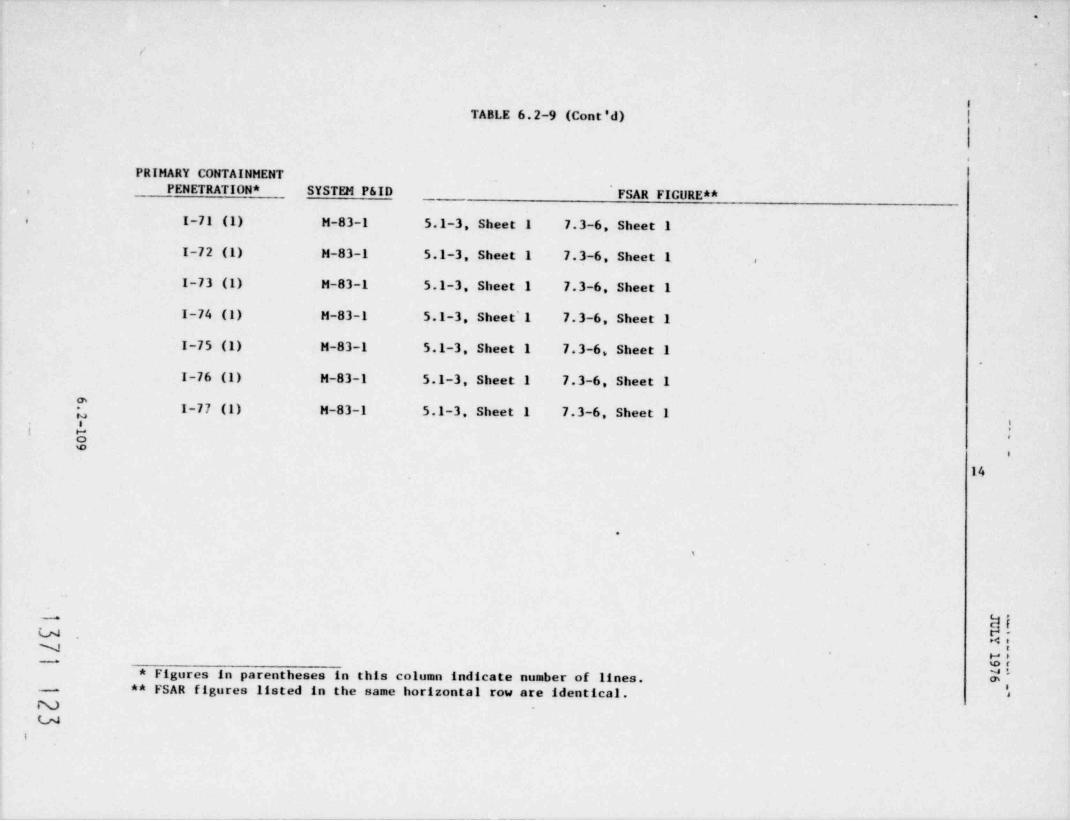
.
.
<
e
iTABLE 6.2-9 (Cont'd)
,
PRIMARY CONTAINHENTPENETRATION * SYSTEM P&ID FSAR FIGURE **,
I-71 (1) H-83-1 5.1-3, Sheet 1 7.3-6, Sheet 1.
I-72 (1) H-83-1 5.1-3, Sheet 1 7.3-6. Sheet 1 .
I-73 (1) H-83-1 5.1-3, Sheet 1 7.3-6, Sheet 1
I-74 (1) H-83-1 5.1-3, Sheet'l 7.3-6, Sheet 1
I-75 (1) H-83-1 5.1-3, Sheet 1 7.3-6, Sheet 1.
I-76 (1) H-83-1 5.1-3, Sheet 1 7.3-6, Sheet 1
*I-77 (1) H-83-1 5.1-3, Sheet 1 7.3-6, Sheet 1
hI ,
we
14
.
%
E8siw. -><
NG;-
u* Figures in parentheses in this column indicate number of lines. m,** FSAR figures listed in the same horizontal row are identical.-'
Nu
i

. .
ZPS-1 REVISION 26MAY 1977
TABLE 6.2-10
CONTAINMENT ISOLATION VALVES -
GENERAL DESIGN CRITERIA CONFORMANCE
PENETRATION LINENUMBER ISOLATED BASIS
M-5, 6 Feedwater 1. Line is provided with a check valveinside containment and a non-simplecheck valve outside containment.The check valves are special checktype valves which do not requirereverse flow to isolate. See Sub-section 6.2.4.3.2.1.1.1 for adescription of the valves. Sincethe outboard check valves are notsimply check valves, the designmeets the requirements of thestandard review plan and GDC 55.
2. The valves hav been designed with 26low leakage characteristics and willbe leak tested using air as thetest fluid in accordance with therequirements of 10 CFR 50, Appendix3.
3. The valves outside containment arelocated in the main steam tunnel.The main steam tunnel is providedwith automatic safety-relatedtemperature and differential tem-perature leak-detection provisions.The leak-detection annunciatoralarms in the main control room aredivisional, redundant, and non-safety-related.
4. In addition, to provide furtherassurance and reliability formaintaining long-term leaktightness,a remote manual third isolationvalve is provided downstream of thecheck valves frem the containment.The third isolation valve will beprocedurally closed after 20minutes of an accident.
13 7 i i 2.t6.2-110

, .
ZPS-1 REVISION 26MAY 1977
TABLE 6.2-10 (Cont'd)
PENETRATION LINENUMBER ISOLATED BASIS
M-10 RPV head spray 1. The outside containment isolationvalve is interlocked with thesteam supply valve to the RCICturbine drive. The head spraylineis part of the RCIC system.Automatic, safety-related leakdetection is provided on theRCIC steam supply line. RPVhead spray will isolate auto-matically upon autoclosure ofthe RCIC steam supply line.
2. Automatic isolation of steamsupply will be initiated onany of the following signals:
a. RCIC turbine trip fromhigh RPV water level,
b. high turbine exhaustpressure,
c. RCIC turbine overspeed 26trip, and
d. high temperature inRCIC piping and equip-ment areas.
3. RCIC pump discharge (RPV headspray) is maintained at positivepressure with the RCIC saf ety-related water leg pump. Sincethe RPV head spray valve isnormally closed, excessiveleakage due to valve not fullyclosed will be alarmed upon lowsystem pressure.
4. The bypass line around the it-board check valve is normallyclosed and is interlocked withthe inboard isolation checkvalve.
I371 125
6.2-111

g e
ZPS-1 REVISION 57APRIL 1979
.
TABLE 6.2-10 (Cont'd)
PENETRATION LINENUMBER ISOLATED BASIS
M-14 CRD return 1. The outboard check isolation valveNis a low leakage type check valve
to assure acequate leaktightnessand will be leaktested to therequirements of 10 CFR 50,Appendix J.
2. A remote manual third isolationvalve is provided downstream ofthe outboard check valve to ensurelong-term leaktightness. Theremote. manual valve is normallyclosed during all modes of plant
57operation.
M-18 Steam to 1. All small branch lines are eitherRER Ex locked closed or procedurally main-
tained closed except during shut-down for testing and/or maintenance.
| 34M-11, 12, 13 RHR LPCI 1. All small branch lines are either 26M-15 LPCS locked closed or procedurallyM-16 HPCS maintained closed except during
shutdown for testing and/ormaintenance.
2. The bypass valves around the in-board check valves are electricallyinterlocked with the check valves toensure that the bypass valves willbe normally closed except whenexercising the check valves.
3. The piping is always maintained atpositive pressure with its respec-tive safety-related water leg pump.This feature will ensure systemintegrity during normal plantoperation. Low pressure isannunciated in the main controlroom.
1371 126.
6.2-112

. -
ZPS-1 REVISION 26MAY 1977
6
TABLE 6.2-10 (Cont'd)
PENETRATION LINENUMBER ISOLATED BASIS
4. The entire system outsidecontainment is Quality Group B,Seismic Category I, segregated,meets the design pressure andtemperature of the containment,and meets the requirements of aclosed system as defined inSRP 6.2.4.
M-17, 21 Drywell 1. Valves are always maintained inspray the closed position.
2. The piping and isolation valvesare located in a controlledleakage area served by thestandby gas treatment system.
3. The containment isolation valvesare gate type valves with adouble wedge disc to precludeexposing the stem packing to thecontainment atmosphere and toprevent packing leakage. 26
M-49, 50 Drywell 1. The inboard containment isolationdrains valves are located outsidecontainment to preclude locatingthe inboard isolation valv's inthe suppression pool andexposing them to hydrodynamicloads.
2. The isolation valves are alllocated in a controlled leakagearea which is served by thestandby gas treatment system.
3. The isolation valves are globetype valves positioned such that
flow from the containment isunder the seat to precludeexposing the stem packing and toprevent packing leakage.
M-34, 35, 36 RHR suction 1. The entire system outside thefrom containment is Quality Groupsuppression B, Seismic Category I. Thepool systems are closed outside the
containment and meet the require-ments of SRP 6.2.4 for closedsystems.
6.2-1371 127
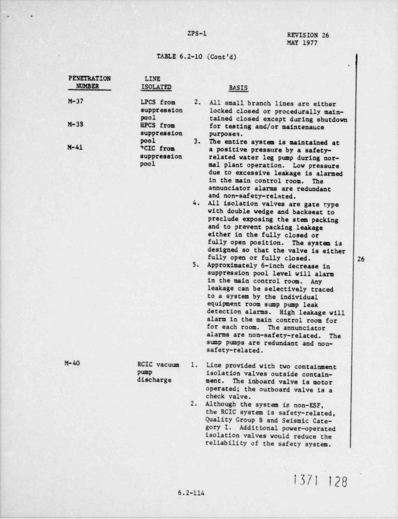
, -
ZPS-1 REVISION 26MAY 1977
IABLE 6.2-10 (Cont'd).
PENETRATION LINENUMBER ISOLATED BASIS
M-37 LPCS from 2 All small branch lines arc eithersuppression locked closed or procedurally main-pool tained closed except during shutdown
M-33 EPCS from for testing and/or maintenancesuppression purposes.pool 3. The entire system is maintained at
M-41 *CIC from a positive pressure by a safety-suppression related water leg pump during nor-pool mal plant operation. Low pressure
due to excessive leakage is alarmedin the main control room. Theannunciator alarms are redundantand non-safety-related.
4. All isolation valves are gate typewith double wedge and backseat topreclude exposing the stem packingand to prevent packing leakageeither in the fully closed orfully open position. The system isdesigned so that the valve is eitherfully open or fully closed. 26
5. Approximately 6-inch decrease insuppression pool level will alarmin the main control room. Anyleakage can be selectively tracedto a system by the individualequipment room sump pump leakdetection alarms. High leakage willalarm in the main control room forfor each room. The annunciatoralarms are non-safety-related. Thesump pumps are redundant and non-safety-related.
M-40 RCIC vacuum 1. Line provided with two containmentpump isolation valves outside contain-discharge ment. The inboard valve is motor
operated; the outboard valve is acheck valve.
2. Although- the system is non-ESF,the RCIC system is safety-related,Quality Group B and Seismic Cate-gory I. Additional power-operatedisolation valves would reduce thereliability of the safety system.
1371 1286.2-114

. .
ZPS-1 REVISION 26MAY 1977
TABLE 6.2-10 (Cont'd) .
PENETRATION LINENUMBER ISOLATED
3. The system, piping, and valves arelocated in a leakage controlledarea which is treated by the stand-by gas treatment system.
4. The RCIC area and steam supplypipe routing is monitored forhigh area temperature and dif-ferential temperature as part ofthe leak-detection system. Theautomatic functions of the leak-detection system are ESF grade.The annunciator alarms are redun-dant and non-safety-related.
5. The motor-operated isolationvalve is a " diaphragm" sealedvalve. A metal diaphragm sepa-rates the valve fluid boundaryfrom the stem, thereby precludingthe stem packing from contactingthe fluid. Stem packing leakageis effectively reduced to zero.Figure Q212.38-1 shows the metal 26diaphragm valve and the metaldiaphragm itself which separatesthe environment from the processfluid.
M-42 RCIC pump 1. Containment isolation valve lo-discharge cated in a leakage controlled
area which is served by thestandby gas treatment system.
2. The second barrier is the RCICsystem, which is Quality Group B,Seismic Category I, and meets therequirements of SRP 6.2.4 forclosed systems. The piping sys-ten is normally pressurized bythe safety-related water leg pump.Excessive leakage will alarm inthe main control room on low pres-sure.
3. All pump discharge lines includingbranch lines are maintained at apositive pressure. All branchlines are administrative 1y closedexcept during system testing andduring shutdown for testing and/ormaintenance.
6.2-115 j}Jj j}g
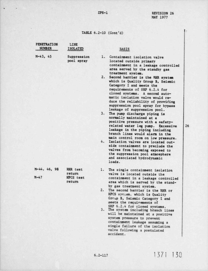
, .
ZPS-1 REVISION 26MAY 1977
>.
TABLE 6.2-10 (Cont'd)
PENETRATION LINENUMBER ISOLATED BASIS
M-43, 45 Suppression 1. Containment isolation valvepool spray located outside primary
containment in a leakage controlledarea served by the standby gastreatment system.
2. Second barrier is the RHR systemwhich is Quality Group B, SeismicCategory I and meets therequirements of SRP 6.2.4 forclosed systems. A second auto-matic isolation valve would re-duce the reliability of providingsuppression pool spray for bypassleakage of suppression pool.
3. The pump discharge piping isnormally maintained at apositive pressure with a safety-related water leg pump. Excessive 26leakage in the piping includingbranch lines would alarm in themain control room on low pressure.
4. Isolation valves are located out-side containment to preclude thevalves from becoming exposed tothe suppression pool atmosphereand associated hydrodynamicloads.
M-44, 46, 98 RER test 1. The single containment isolationreturn valve is located outside the
M-47 HPCS test containment in a leakage controlledreturn area which is served by the stand-
by gas treatment system.2. The second barrier is the RHR or
HPCS syetem, which is QualityGrcup B, Seismic Category I andmeets the requirements ofSRP 6.2.4 for closed systems.
3. The system including branch lineswill be maintained at a positivesystem pressure to preventcontainment leakage assuming asingle failure of the isolationvalve following a postulatedaccident.
6.2-117 1371 130

. -
ZPS-1 REVISION 26MAY 1977
:
TABLE 6.2-10 (Cont'd)
PENETRATION LINENUMBER ISOLATED BASIS
4. The isolation valve design meetsthe intent of GDC 56 on analternative basis, with thesecond barrier being the closedHPCS or RHR system.
M-101, 102, Drywell and 1. Valves are located outside103 suppression containment in a leakage
pool purge controlled area which is servedby the standby gas treatmentsystem.
2. Suppression pool purge valves arelocated outside containment topreclude exposing valves tosuppression pool atmosphere andassociated hydrodynamic loadsand to provide access to valvesfor backup hydrogen control uponfailure of the combustible gas 26control system.
3. Drywell purge valves are locatedoutside containment due to spacelimitations inside the drywellfor these valves and to provideaccess to the valves for backuphydrogen control upon failureof the combustible gas controlsystem.
M-104 Suppression 1. Two valves in parallel arepool purge provided on the combustible gasH control control system discharge since2
it is an ESF system for post-LOCA hydrogen control. A second
isolation valve in series wouldreduce the reliability of theESF systen.
2. The combustible gas controlisolation valves are procedurallymaintained closed except for post-LOCA operation.
1371 13I6.2-118
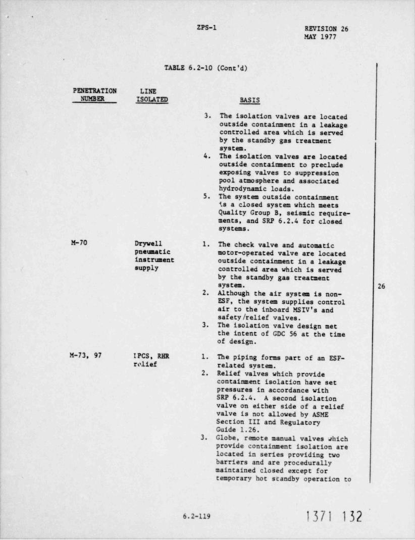
, .
ZPS-1 REVISION 26MAY 1977
.
TABLE 6.2-10 (Cont'd)
PENETRATION LINENUMBER ISOLATED BASIS
3. The isolation valves are locatedoutside containment in a leakagecontrolled area which is servedby the standby gas treatmentsystem.
4. The isolation valves are locatedoutside containment to precludeexposing valves to suppressionpool atmosphere and associatedhydrodynamic loads.
5. The system outside containmentis a closed system which meetsQuality Group B, seismic require-ments, and SRP 6.2.4 for closedsystens.
M-70 Drywell 1. The check valve and automaticpneumatic motor-operated valve are locatedinstrument outside containment in a leakagesupply controlled area which is served
by the standby gas treatmentsystem. 26
2. Although the air system is non-ESF, the system supplies controlair to the inboard MSIV's andsafety / relief valves.
3. The isolation valve design metthe intent of GDC 56 at the timeof design.
M-73, 97 IPCS, RER 1. The piping forms part of an ESF-relief related system.
2. Relief valves which providecontainment isolation have setpressures in accordance withSRP 6.2.4. A second isolationvalve on either side of a reliefvalve is not allowed by ASMESection III and RegulatoryGuide 1.26.
3. Globe, remote manual valves whichprovide containment isolation are
located in series providing twobarriers and are procedurallymaintained closed except fortemporary hot scandby operation to
})f} )b26.2-119

. .
ZPS-1 REVISION 26,
MAY 1977
TABLE 6.2-10 (Cont'd)
PENETRATION LINENUMBER ISOLATED _ BASIS
vent the RHR heat exchanger ofnoncondensible gases and forplant shutdown cooling. Thevalves are an operationalrequirement for plant shutdown.
4. All containment isolation valvesare located in a leakage controlledarea which is served by the stand-by gas treatment system.
5. For those lines with one ise Lationvalve, the second barrier is theRHR-LPCS system which is QualityGroup B, Seismic Category I, andmeets the requirements ofSRP 6.2.4 for closed systems.
6. RHR equipment rooms includingRHR heat exchanger areas areprovided with safety-relatedtemperature and differentialtemperature switches for leak-detection purposes. Excessive 26leakage would alarm in the maincontrol room on high temperature.The annunciator alarms areredundant and non-safety-related.
M-71 Service air 1. Meets all requirements of GDC 56and SRP 6.2.4.
2. Two locked-closed valves providedfor containment isolation, oneinside containment and one outsidecontainment .
M-9, 23 RBCCh 1. Closed system inside and outsidecontainment is Quality Group Cand Seismic Category I exceptthat the outboard isolation valveis Quality Group B.
2. Closed system meets all require-ments of SRP 6.2.4 except qualitygroup class.
1371 133
6.2-120

. .
ZPS-1 REVISION 26MAY 1977
TABLE 6.2-10 (Cont'd)
PENETRATION LINELINE ISOLATED BASIS
3. The non-closed portion of thesystem inside containment isautomatically isolated on lossof offsite power or loss of air.Piping and valves meet SRP 6.2.4except that they are QualityGroup C. Quality Group C isidentical to Quality Group Bexcept that no x-ray is performedon valve body, bonnet and disc.
4. Leak-detection capability isprovided by the use of the RBCCWexpansion tank level indicator /control system. The leak-detectionprovisions are ESF grade,redundant, divisional, and SeismicCategory I.
5. The system is part of an ESF-related system.
M-54 Hydrogen 1. The line forms a part of an ESF-control related system for post-LOCA 26
hydrogen control.2. Two valves in parallel are
provided for containment isolation.The valves are located outsidethe containment in a leakagecontrolled area which is servedby the standby gas treatmentsystem.
3. One of the two valves in parallelis maintained closed during systemoperation. Both valves aremaintained closed during normalplant operation.
4. Since the system is ESF-related,additional containment isolationvalves in series would reduce thereliability of the system toperform its safety function.
.
i37i i346.2-121

. .
- ZPS-1REVISION 26MAY 1977
TABLE 6.2-10 (Cont'd) >
PENETRATION LINENUMBER ISOLATED BASIS
5. The second barrier provided isthe combustible gas controlsystem, which is a closed system.The system is Quality Group B,Seismic Category I and meets therequirements of SRP 6.2.4 for -closed systems.
6. The isolation valves are locatedoutside the containment due toaccess limitation near the topof the drywell as well as toprovide post-LOCA access to thevalves.
M-95, % N, bottle 1. The system forms part of an ESF-sCpply related system to provide controlair to the ADS valves.'
2. The piping system form a closedsystem inside the contuamentand outside the containment.Outboard isolation valves arelocated in a leakage controlledarea.
3. The containment isolation valves 26are Quality Group B and SeismicCategory I. All other piping andvalves meet the requirements ofSRP 6.2.4 for closed systemsexcept that the piping system isQuality Group C.
M-68, 69 Recirculation 1. Piping inside t he containmentFCV hydraulic forms a closed system which iscontrol
Quality Group B, Seismic CategoryI, and meets the requirements ofSRP 6.2.4 for closed systems.
2. Outboard containment isolationvalves will be provided which willautomatically isolate on highdryvell pressure. Table 6.2-8is revised to incorporate thisdesign.
1371 135
6.2-122

.
ZPS-1 REVISION 26 - --
MAY 1977
'
TABLE 6.2-10 (Cont'd)
PENETRATION LINENUMBER 70 LATED BASIS
M-74, 75, Drywell 1. The outboard containment isolation76, 77 chilled valves automatically close on
water high drywell pressure or lowreactor water level.
2. Inboard contaiment isolationvalves have been added. Thechilled water supply is providedwith check valves, and the chilledwater return is provided withautomatic motor-operated gatetype valves. The valves willautomatically isolate on lowreactor water level or high dry- 26well pressure.
3. The outboard valves are locatedin a leakage controlled areawhich is served by the standbygas treatment system.
4. The inboard valves will beinstalled as soon as possible,but not later than the firstrefueling outage.
.
1371 136 '
6.2-123

. .
ZPS-1 REVISION 29JULY 1977
ensure site boundary limits are not exceeded.
b. Valves required for emergency cooling systems shall remainoperable, for both opening or closing as required for sys-tem functions, af ter an accident.
c. Valve operation shall be controlled by the signals describedin Subsection 7. 3.1.2 and in Table 6.2-8.
5.2.1.6.2.6 Pipe Rupture
Protection against dynamic effects of pipe rupture are described inSection 3.6. Protection has been provided on the assumption that eitherlongitudinal or circumferential breaks may occur at the locations speci-fled in Subsection 3.6.1.'2.
5.2.1. 7 Design of Active Pumps and Valves
In order to assure the functional performance of active valves of theRCPB, stringent design requirements were applied. There are no activepumps in the RCPB. Valve operability was demonstrated by the followingparagraphs.
All active valves are being qualified for operability assurance by firstbeing subjected to the following tests:
a. Shop tests which include hydrostatic tests and seal leakagetests as specified in the applicable code,
b. The valves were required to open and close within specifiedtime limits when subjected to design or environmental con-dicions as required by applicable codes and regulatoryguides. Vibrational levels will also be monitored when
1371 137
5.2-9
. .
ZPS-1 REVISION 3FEBRUARY 1976
,required. There are also other tests, such as the cold hydrotests and the hot functional tests to be performed. Pre-operational tests on each system will be performed on site.
Valves are considered rigid under seismic disturbances.Thus, conservative seismic accelerations of .20g horizontal |3
*
and .14g vertical were used simultaneously in the structuralanalyses.
With the loads known from above, the structural analyseswere performed with other conservative loads to mee*. thestress criteria. This will assure that the critical partsof the concerned component will not be damaged during andafter the faulted condition.
Fin' ally, active valves are also required to be operated periodically asspecified in the Technical Specification. This repeated operability re-quirement throughout the life of the specified valve further provides acomplete operability assurance program.
The list of RCPB Class 1 active valves is given in Table 5.2-5. Thelist of ASME III, Classes 2 and 3 pumps and valves is given in Table3.9-23. |2.
The representative combination of loads and analysis to assure oper-ability is summarized in Table 5.2-3B. |25.2.1.8 Inadvertent operation of Valves
A discussion of the design-basis events and their appropriate limits forthis plant is given in Chapter 15.0. The events in Chapter 15.0 havebeen selected to envelope the most severe change in critical parametersfrom events which have been postulated to occur during planned opera-tion.
5.2.1.9 Stress and Pressure Limits
Paragraphs NB-3655 and NB-3656 (Piping Sections) of ASME Section III arenot directly applicable to pumps and valves. On the basis of theutilized method of establishing system design pressures, however, it canbe stated that the permissible pressure requirements of NB-3655.1 sadNB-3556.1 are met.
The allowable stress limits and design loads based on applicable codesfor RCPB components are summarized in Table 5.2-3B. Active or inactive |2components of the RCPB are delineated in Table 5.2-5.
5.2.1.10 Stress Analysis for Structural Adequacy
Stress analysis was used to determine structural adequacy of pressurecomponents of the reactor coolant pressure boundary under various operat-ing conditions and earthquakes.
1371 138
5.2-10

~ .
REVISION 3TEBRUARY 19762FS-1
TABLE 5.2 5
RCPT PtHP AND VA1.VF OESCRIPTION_
MAXIMUMISOLATION CLOSURE TIMEvelvesiSicNAL JactiveVALVE
ACTIVE / teettve velvemNgINACTIVE
LOCATION
InstantaneousvALvt otSchrPTiog Check A0
E12F041Active N/ARMR Veneet in Remote manual
E12F042Active InstantaneousCheck A0
E12F050Active 2 minRNR/ Recirculation IVCS
E12F053Line In Active Instantaneousstaple check
E12F019Active 12 inlainHead Spray IvCS
E12F023Active 29 secTVCS 29 escE12F009IVCSActive E12F008Recirculation Active N/A
Line Suction Remote manualE51F0%Active
RCIC Vessel outE51F072inactiveE31F073Inactive Instantaneous
Remote AOE3170%Active InstantaneousRCIC Vessel Head in Remote Ao
E31F065Active821F001Insctive
(suclear Boiler) 521F002Rescror Veeeel Head Inactive521F005Insceive
Simple check521F010Accive
Feedvater in 521F011Inac tive Remote manualCheck821F032ActiveRemote manual
B21F065Active Remote manualAO
5217061ActiveSafety Relief (through
FOLS}
Remote821F016Active
Manual I521F019Active 5 5 sec* |3Drain to Condeneer IVCS 5.5 esca
821F022ActiveItSIV IVCS
521F028ActiveIVCSMSIV 521F067 Remote manualActive 521F016Drain to Condeneer Active
C33F103InsettveReactor WaterCleanup System |3
initiate valve closure af ter the break.* Includes 0.5 esconda f or instrumentation to
B71 139'
5.2-47
.. . . -*** O *
m >m,-mww MOR6 & O WW 9&&

. . . . _ . ,
Lm
:S C E! **! PJ.Y. 'J.~.5. . , . . . . . . . _ .
r- . . .
LOCAT!ONIN/,CT!t*E NINSEg y ttve ar a'.~es t .actwe vz:<sia.....
Reactor Water Inactive G33F102 s/AInactive G33F103 s/A 12cleanup Discharge C33F100 N/AInactiveInactive G33F101 N/A
Inac tive G33F106 N/A.
Active G33F001 High a Temperature N/AHigh a FlowHigh AmbientTemperature
|12IVCS*
Active G33F004 High a Temperature N/AHigh a FlowHigh AmbientTemperatureHigh NR ExOutlet Tamperature
SLC Actuation 12IVCS*Remote Mtnual
Reactor Water In Active C33F039 Simple check Instantaneous
N/AActive G33F040 High A Temperature
High a FlowHigh AmbientTemperatureIVCS*
29(Recirculation)Inactive B33F023 Remote manual
Recirculation Pump
Suction
Reactor Vessel Drain Inactive B33F029/F030 N/A
Pump Discharge Inactive B33F060 N/A
Pump Discharge Inactive B33F067 Remote manual |26
15
(Control Rod Drive Hyd.)CRD Water Return Inactive C11F087 N/A
CRD Water Return Active C11F086 Simple check Instmataneous
Active C11F082 Remote manual N/A
Active CllF083 Simple check Instantaneous
Active E227005 Simple check Instantaneous12HPCE In
Inactive E22F021 N/A
Acti"e E22F004 Remote manual N/A
Inac tive E22F022 N/A
LPCS In Active E217006 Simple check Ins tantaneous
Active E21F005 Remote manual N/A
Inactive E21F013 N/A
Inactive E21F014 N/A
*IVCS = Reactor low water level signal
5.2-48
|5.2-49 .
1371 140_ _ . _ . . . .
.
- e

. .,
'. .
PLAtlT ZIMMER Uti!T(S) 1,
CODES, STAtlDAR05 Ai40 GUIDES
Oues tion : Identify the codes, standards, and guides applied in thedesign of the containment isolation system and systemcomponents.
Resconse:
The codes, standards, and guides applied in the designof the containment isolation system and system components can befound on page 6.2-43 of the Zimmer FSAR. This page is included inthe response to the question pertaining to the provisions fortesting the operability of the isolation valves.
.
G
l
1371 141
. . - . . . . . . . . ..
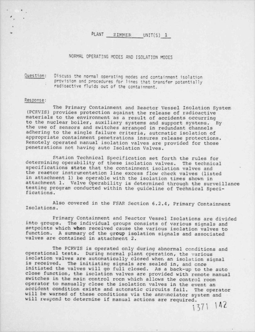
. .,
*.,
.
PLANT zIMMI;R UNIT (S) 1*
NORMAL OPERATING MODES AND ISOLATION MODES
Ouestion: Discuss the normal operating modes and containment isolationprovision and procedures for lines that transfer potentiallyradioactive fluids out of the containment.
*
Resconse:
The Primary Containment and Reactor Vessel Isolation System(PCEVIS) provides protection against the release of radioactivematerials to the environment'as a result of accidents occurringto the nuclear boiler, auxiliary systems and support systems. Bythe use of sensors and switches arranged in redundant channelsadhering to the single failure criteria, autcmatic isolation ofappropriate containment penetrations insures release protections.Remotely operated manual isolation valves are provided for thosepenetrations not having auto Isolation valves.
Station Technical Specification set forth the rules fordetermining operability of these isolation valves. The technicalspecifications state that the containment isolation valves and '
the reactor instrumentation line excess flow check valves (listedin attachment 1) be operable with the isolation times shown inattachment 1. Valve Operability is determined through the surveillancetesting program conducted within the guideline of Technical Speci-fications.
Also covered in the FSAR Section 6.2.4, Primary ContainmentIsolations.
Primary Containment and Feactor Vessel Isolations are dividedinto groups. The individual groups consists of various signals andsetpoints which when received cause the various isolation valves tofunction. A summary of the group isolation signals and associatedvalves are contained in attachment 2.
The PCRVIS is operated only during abnormal conditions andoperational tests. During normal plant operation, the variousisolation valves are automatically closed when an isolation signalis received. The initiating signals are sealed in, and onceinitiated the valves will go full closed. As a back-up to the autoclose function, the isolation valves are provided with remote manualswitches in the main control rocm which allows the control roomoperator to manually close the isolation valves in the event anaccident condition exists and automatic circuits fail. The operatorwill be warned of these conditions via the annunciator system andwill respond to determine if manual actions are required.
\37\ \42
-.

.
===-. - . - - . ===. -- --==
N*-
= .\?"=%. >-ewe ''
!!.iT.-
., e..>= u st3 f*7
i
i CC '
-awtg- t. ,
! C. s==,.os.e 6, 38 4
= ..
;n*-,
= = = . @*
>f p* .C5 .J.m vt. u* *
@**j 6 O= *
==== est est - try - evy M f'>( W) 4.b >= >*
< e. = = = Oan=g s . = .
L M. M 4% t% % % M **.6Qw
gg . . . . = = 6..
Qu - .m. - a== s== m C **
C. :>w
*a .-
Ced. . CN s==== C C
# **E=. C *
m. ** *s== .*
wt eg^C e4m w eG>, c.' %s 4db 4 m 6
,
||>> a 4@ Q1 c :n. w**. g ,
* a== a== C4 N' M f"? Che* CQ .
tag ed. -gr$, |||> ' w tti==i
. 6 L>- a' C ee G..
|C .aC. 4
||> Ce h+aw c b = esmo es=.
T t.. G e e *A C "3. == e as :> 4 === G6 * g -
s== J.**
b . * > = =- 3 89 C W9
c t, 2 wir :> we - '
M @ - .mLuan e* :n. "3 Le - - 6 6 ca
s== |um a=== ft * 6 3 .
ad|" s== === ||> CE C h G3 >-.
| >- . 4e .= |as* L= 2 :p q& C - .a = m,Q * Q
'Wun G @ 3 a=. WP 4
y Gk C C *e== > c I *== >M. orc' ea||um a .
4 wp C" " " . - -;
= = e C C-
. ~ . " * . O ee 4.a. a= c c fe?. 3 e4 o*
t :p e rg c- === === wp =m - um e4 ed. M *e G mi.
,
C" Q === ==== @ U C ee CO e *A a- 3 3G -
.=== === c c O wt s== *s. 42 C
wb a ma C weed. e6" *8- O. 4 *** 4 **=W' @QC C C *pr
8 GI - - 6 3 P- G .ad. .:pa C *= O m. e4 M C C 6 @ me
=== ter e@ 3Cs== WD C.& 4.1 6 f.& CW e 8=* O8F * W *e ft G i . *C g== = . e S -
as -||>
cz e e a c azm e = -|r u - u ._-
t -r.- a w C C - ||sm E - CS@=
4 m *S *3" *"J" C" S. 6O ==== = = === =
s== ad|" 4|" - auC e4@CCC - C e 4 =.ee.- ==
** - I ee' NO @ CT P* C :p * * tt 3 C *e C ||m, C.
- 4 sNN a--c C c= - e oe>c}.- 4CC 4OQC 44 C asC C *C O h 3 a4" === 3 uC '
.O.a.w haewww o c N u's c3 c1 -N c ea C
w s a ** a e a W C - air * w e g= s== c c bc et "'|T ee >,* *
- au.. ==. e-- WF - s== s== b e4 Q Q Q -QC -QQ oe Q Q 6N f4 C4 N N @ 4 Q. 2. C= 3ww C w I.n= ee e - = e4 *5
CS 3 QC E E QC. G f*T S U S=== .- M CC E g 3p ||Br ||D*C2 U
.s== .S. .M. -- , = = = > e-. - g fat O. g ==-c == ====8=* ed' "S* 6 UF b QQ Q Q **"'r f=>= 4 E Q. =u* Q . C 3- GJ 4 C.C.J C. O
W14 wt 4i *d
O h ad *J*
) 6. 3 . . . . . .,.
4C - 4'4 t*? aq* @ M3 Q TC C*g = = -
==" w W1|E 2 2.** . a |||>)==* = | a eeee==
4 4 tJ ''.3aC .
> M .,* %r %e em ,*
'*
n
- - --- - =A . . . .,_ .
.- - '*-= n: r== 2 - . , p- ,.s- . _ _ . _ , _ _ . . . . _.
- - - . _ _. . __ _ .
e

I.- n,..- ,
',
0F-
- . '
{|s' " " 'Q' ''I c' '
,
," i i _'.,
,:_;.S,-43 ,-
''._, . ,
i
% --- - ~ ~~~ ~
'N ,||/ CONTAllMENT ISOLATION VALVES,,
. v,APPLICABLE |.OPERATIONAL ISOLATION TIME g !
VALVE FUNCTION AND HUMBER VALVE GROUP (a) CONDITIONS (Seconds)'
'] ,
!a. Automatic isolation Valves (Continued) ,,
!i n,
il7. Reactor water cleanup discharge valve,,
1, 2, 3 ljIG33-F040 3 .g8. Reactor water cleanup suction inboard valve.
6 ') 1G33-F001 4 1, 2, 3 30 |:,
r3 ~ 1, 2, 3, 5 and * || ,*
g 9. Drywell pneumatic inboard suction valve, llH012 5
10. Drywell pneumatic outboard suction valve, llN013 5 1, 2, 3, 5 and * I' 'p ,)
i '
\s EE'S) II. Drywell pneumatic discharge valve, IIN061 '5 1,.2, 3. 5 and * .l.
ha c9 12. Drywell pneumatic purge valves, llN170 & llH171 5 1, 2. 3, 5 and *-
W 13. brywell air sampilng isolation valves 5 1, 2, 3. 5 and **'
'
D ICH003'
't ICH004 ..
b ''s ICH005
ICH006
14. Suppression chamber air sampilna valves 5- 1, 2, 3, 5 and * .
ICH012 . !' ' ,ICHol4 .P i
-
15 Drywell purge inlet isolation valves 5~ 1, 2, 3, 5 and * 5
IVQ001A and B i,,-
! |'tdrw# 16. Drywell purge outlet isolation valves 5 1, 2, 3, 5 ai.d * 5
IVQ002A and B ',- ,
,
17. Suppression pool purge inlet isolation valves $ 1, 2, 3, 5 1.nd * 5 ;|-
> . . IVQ003A and 3>
> ,
3When handTing Irradiated fuel or a spent fuel shipping cask in the secondary containment. |
o ,.--
1

.
% - . = = = = =---.
.
.N
$ /'.
*->====r.
=E ii a es mau>- n' g tw ,
t es 3- us' qg. . m4i gw-
- -
'.JD" ..s**M,
40s~
a War up umi g e . . ..
i N M W u3 9' 'W* W,g.
n cm. n n n n n mg ,,-_ ." _
,..
-.. - -
: -
. I e= M f4 M M M N. M M M N- -
2::. .
. .-
. .. . -.. . - -
1 Sr - - - -.
- - - -%.e ,
-
O1A\ @
*s** w w'T > 4. *
it g Q -
@ ~ uar se um W O c O O> M -; ' f.3 n==
e-
w-* .
-f > -==*- a =
. . aC & s: .4 ( Dr * w w > .S. O e - a
-
| i3 > > >- @ > W-
3+- - Gr O
> > ('4. @ d me* s===
G @ frP **= .pm *D@ .
b== O - 3 w w -C > 46 * C3 C C 9 th C >
p O *a=
==*- asa C4 O G. g.Q 3= Mm C C*=""""""" m '
4 an om - as== === s==. @ ***E eJ- o6 6 f.ed. eJ8 a cas - ===- e h
''|5" - > @ eeC .A- - 3 w -v==6.,.;'_. 't3" c e @ C ==== 0 4m o & Jn C>-
- @ -wO .m 5 o 0== === ==. '**. . gt auss. tJD es==>= ====. ui C (% W$.=. . 4.b C - .Jn i_ -s==
C . = = = =*s== 6 O 6
- 2 - - u .CF efM ==
C C .W - O3 OC =4, e. w 4 4 CO 2 f.A C m. OCC e
% 41. G 3 O O MC .C. C====
h.e*=== a -
as== b h uw e. e aw.,, e. er . er- o. . x. . ,
.. -. -.oc - c -m .. #..., . - .- .-> = -
- c. a - >. -a - --.o v
. a. o w- e
M*" OS q.A. *>m uC eO CU C 4 9 ..-.:__
> - *p=CC *C.@ a== > m
8.-s- e_ e< .. .. . - = . .-* w C -
ca - ev e-..o,, m: . . =a = .-~- - - = - er er = ,= .3 C C 3CQ,e. e,. -
e -s eC *3* .d C uC CC 4Cv
, s..um . a
.o. u. .
=== C-. e . - = ,= m, s- -. a- =m .
.o. n m.j . .= . o. --a. N. .a.
. = .- --- . . . ., oo. .
.. . .~~ am m m.- m .. u- = vm .- umm v==
-- --i. . ---, e a.--o a . u ..
a. .au c.2.. a-- a --m = = = =- mu = m- = =,, = = =--
-. . .
M. .g-
..
. o e ~.. . .
N N N N M N N N. e,. e - ~ m.
< .e- -W -= a''*
*
I_,I- a||>
-. aC -
> .*'
e.
..
- - -2;:7.cy . .--- -- - ; _ g p_ 3- ..;. -. - --zg g g. _-
- -
. . . . .-
= _
-.
-
.
<,[j$,N inLaT*D**D D
wo. o

;-- .
'( O ,
Ib '''
;l C ab,it.'. |q,'
.g, ,g.I- . .
r _ . - . ~ w. red)-
- --- -y :.
,
S i;'
(- CONTAINNENT ISOLATION VALVES 1(-
,
APPLICABLEN OPERATIONAL ISOLATION 11HE '
gVALVE IUNCIION AND NUMBER VALVE GROUP (a) CON 0lil0NS (Seconds)
,
a. Automatic Isolation Valves (Continued) i,i)l .'
28. IIP Guide tube ball valve 12 1, 2, 3|, ,,
29. Drywell pneumatic IIP Indexer purge valve 12 1, 2, 3't
30. RilRS sample valves dI 12 '1' 2' 3 ; 'iI *
IE12-F060A and B ' '
IE12-i.075A and 8 '.,
31. RilRS shutdown cooling retu.n testable check 13 1, 2. 3valve bypass valves
lE12-F099A and B;
32. RilRS discharge to Iadwaste valves (d) 13 1, 2, 3 |3, IEl2-f040 ''.
lE12-F049*
% :i' i
I ..i-,
- L-N r..
| '!-i
% ^|' ,
W *
Nt__.
,
a- ?.m . ' , . ...
i,_
l.
:!.

.
=. .~
*__ ,
.
|4M W
u c.e m.~
Id.Eg'
.bM
O h6
4 -*t
.. W*WT ^ .
., .Jn ., %**E @,-e ~ t*
. , . , I5
E,
*! = <.c n @ M (C. ,
FCe * *5" V
'
.6C C ', )Jh *c
*e er, e
a=
aC 7 C 9.'M *
'"!!: e -= C w-a- w4 wa> e f-. % O = w
., 3.
:>. . C w g- :> ee -C' b S w-
a - ,C =|pp w h M *2 CTW ~ .
- 'Dmy e - C w*... m Q> 6 N> O - |3m CT flB >==
a= w 15" a==J ||F. Gk h C.aC @ e & e >= C <Ce.a.> e h ca 3 g> - rit ut *
h, e = wer *=a
O6- 2 - %6L C e o ,
Q. w S oC a tem n=> - ek=== O &.:||: - u Ce-o O>= f4 - V me :D- 'T -
n- aC w C *t? @ - C C .
e = 0= 6e s e.C't C -> e ==Q ===
e. y3 aus c- -aC e *al m e .e. O wp=c. :n
as= C f4 |ar W.aM - gaw,ede'i 4C.s, X - @ C h
O.f'% O f% -. J' or a 5Q e*11 >= Ok :pa - e4 *e ===
, p' ,t.> W Q C *e h > 1II . 2 == C u
- g- to :Dr e b @ u w ets .a pS - @a=* M +&
en == w *C* @ to - e
emar S WEB @ <=d> Q O& O = C ws
* = a- === w u e|~ e ==
. Q'l 3* ;>> C 3 e o M @ **= - D. C6 e :p= a - e w*W i *C .*>= - o - .* = 62)-
. *. C w w wC U* W 6 8 CR 44 7 :>> C C
C Q W G C@ C @ O Nr C M a- =
== c wy u === c 6, * i 4.J i
p> 0 eh > 3w & ed. - ===* =eaC - . :>> U tha - = 33> C 4 m. .
@ O e C e O - ** 3 ver 4 e@ @ J2. f4F *== @
C 4 3 6 * W, :>m CD #13 wie :p u b
b u e a== b :> :>>
e *'I" S O @ "!|5" @ tir - - e4 C -
- O 4. ed- :pa a :>> c ), C O C C CsL *ts 1 6 e === 6
S O C sur Q e4 e b 3 46 :> wt =hf*gr e u, - ws
1 wt C wt C. ' e m u's @ b 'Dr A we ====
* u u? - 2 u Ab 7- "3 wik C b e Q
C .2 ** :De w @ u t.a O b um &
-* :>- e as rir a es cp e = - ==. G * e W
I E - O C ma, b 6 C e at O ee 99 c
.e s w ell :>> === W & === |um S c e ett etr E 6
> - e- a u e i|z - c. c. g er = w cru
; S - => === - 6 S C e & X T C*
R- - > C, ..a = - e e -
| C > -7.. -
, == 6 m3 4- ets #E O .Q % .3 ||L === 1 .C ris 2o Ce :2 =s -,
. ==.-- ma4 6 u we
o vt ,= .4 4 --= .d2,8
*** k 6 3.O L eq= 1 't:r4 > ee :p e .= ws u == 9e*
== c c f%. vt X 6 C aa6 e 3 = c 2#s
J3C *e c J. 1|r ed we 3,"3 U Q fL & 2 .3
||> WC == e @E @ C E *J & == === A h 3 X5
3 W W e
== e e3 O E = 0 ===s W W 3 6 Q := b C
>= * w E- := W E E >= Cf. E W Q W CEL Q W
el3||3
. . . _. . -
- . . . .
C*
, Z, - N f*t eq* 4 tJD 5 c3 O C a= N t''t er 4w 1 . .
== .-. - - == -~
.- ].
2" --- wg
->.a
* - auf, ..
' ~ ~ . - - .> ,_ A_ . ,
~ ~ ~~~" --r....-----.% .. - , , , - . . . . _ _ . ___
, _ .~ .
*' * iee.-[" , * *wa
~- '
. .- " = a- ,
,
OO O ' ' -f *f' . .
dg.a@ @ ,gi,

'i'.
( ,
t..-
_
.. . . . ; .
.). ._ ;'
__.
-- - 4 u 0, . .-
;; ,
j[.
,. ,, i
CJHIAINHENT ISOLATION VALVES',
, _ , ,.---
NAPPLICABLE ,
h OPERATIONAL..
g CONDITIONS i
O' VALVE FUNCT10H AND HUMBER
@ b( j,Other Isolation Valves |c.g1. Cycled condensate service connection isolation valves, 4)and1[Y,045l
-w
Compressedairservpeconnectionisolationvalves,I%J9and1(h)'-g j i
~
23'5 0 2.
aQ1e102 II3 104,10h,'106,109,
|.113,114,115,(Valves,(b) CN101}3,1}4, il5,126,127,128,
'
b cd 3. Contajnment/lo,hltoring 116,121,122,1 '
110, Ill, itz,'
YM 129, 130, 135, 136, 137, 138, 139, 140, 141, 142, 143, 144'
Reactor Instrumentation Fxcess Flow Check Valves (c)[,'
0d.h
Shutdownrangelevelreferenceleg.1$1FkoN 1.
~)Sl,1 3,IqIF)57,il I39 i
F2. Wide Mrowrangelevelreferenceleg, ,
j
Widerangelevelvariableleg,182(F352,182(F354,II21,'F358,I821f360- t
3.-
?i ,;.
4 Harrow /shutdownrangelevelvarlableleg.182(F355,
4.q i| |
5. Fuel zone' level reference leg, IB21,F356
Harrowrangelevelvariableleg1821f361,IB2(F453,IB2(F454,!
6.| , i.
7. FuelznneAlevelreferenceleg,182(F362 .h'|l .: - ~ ,
Jet [ ump)%.11flowtap,182(F363 _ I8.
Jet Pump N'o. 12 flow tap, 1821,F364,
[ h 9. '
2 10. JetPumpNo.13flowtap,1831[F365Dd
!ut
-- .
. : -
1(, '|CD
0
1
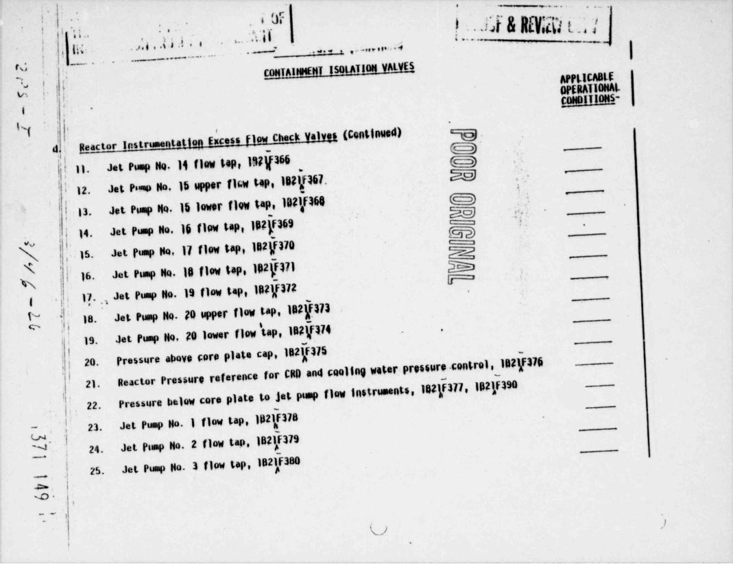
.' .. . , . _
, i Uf-
i b kh) [ _, |- .I-*
! 1 ..' IA bY ,
ib.e'
t
\\ . ,4 , , a , . . .. . . 4,
. .. .
rd i ,- -
CONTAIHMENT ISOLATION VALVESAPPL.lCA8tE
|[;J7., i
OPERATIONAL.v. i-
CONDITIONS-'.
I'
N( |.
Reactor Instrumentation Excess flow Check Valves (Continued), ,
;
D -d -
.,
JetPumpNo.liflowtop,l!!if366 G23.
11. - ;ag; ,.
iL Jet PN No.15 upper (16w tap,1821/167.,
i 12. 5 -
'
g .
Jet Pump No. 16 lower fl9W tap, 1021f46013. h f|jJetPumpHo,]$flowtap,IS$ff369 '
M _14.
JetPumpHQ,17flowtap,lR2(F370\ 15. NJet Pump Ho,16 flow tap, Ip2(F171
-
N '
16.gg | is-
__
( .h| 17.,,JetPumpHo.19flowtap,Ip2(F372_
-
JetPumpNo.20upperflowtap,182f373_18. -
JetPumpHo,20lowerflow' tap,IDE(Fa74,
i1 > 19.
Pressure above fore plate cap, 1821F375I,
1F376 __|| 20.Reactor Pressure reference for CR0 and cooling water;pressur control,102
__
'l21
Pressurebelowcoreplatetojetpumpflowinstruments,182(F377,lp21F390-
i,
', 22.,
Jet Pump Ho. I flow tap, lp21F378! 23.-,
2];' Jet Pump Ho. 2 flow tap, IB21,F379U.~
24.
Jet Pump No. 3 flow tap, lp21F38025. A,
4~~O
,
* * " '
l,
U '
t-

.
( 8Jig;_
j.
IIh 1 ,:. _..s.
- - - - 1, _ _ e. , p 2,1h,c y, ( iEbL. . _ . . _ . . . . -. _ _ . .
_ . . . . . . . .
I CONTAl WENT ISOLATIDH VALVES''
% APPLICABLE !-Y OPERATIONAL''
| O CONDITIONS l'
h G3 h
$ d. Reactor Instrumentation Excess Flow Check Valves (Continued) g |
94flowtap,182f381'
26. Jet i
''
Jetfump .5upperflowtap,182),F382 . EE's)27.I%
Jetgumpgo.5lowerflowtap,182f383 %28. ',
[Jetgumph.6flowtap,IB21,F384 M i29.-2Eso -
'30. J61,funn80. 7flowtap,182f385 p'
31. Jet lap flo. 8 flow tap, 182}386 j'
32. Jet'P' ump (Nb.9flowtap,182(F387
33. Jetkhep(do.10upperflowtap,182 388|g
{ 34. Jet hamptyo.10 lower flow tap,1921,F389 j |,_
N 35. PressureabovecoreplatetollPCSlinebreakdetectioninsitument,1821f391 , | f::
Downconerpressuretoletpumpdevelopedhea'dinstrument,102f392 , ;'~ !36.~-
37. Steap line A f'ow taps 1117 F468A, lh21F369A,1821F470A,182(F470A,1821f472A, Lj1821f473A,182J474A,IB2(FESA
, q* *i j .
ScanlineB(.lowtapdyl4 4688, IB21F4698,1821F4708,1821F4718, lhk}N'728P182u c._ 38.^ " ^ ''t1 4F4738, 1821,F474h, Iy E 8 $
,
I1---* ' -. .. ..
''. j
39. Slean lire C flow taps 1821F468C192(F469C,1821[470C,1821F4710,IB21[472C,182Q473C,1821,J4740. IB21JD5C
...''
y,, ,w ~,
0. ,
'
' ll'
,
. ij
l.h i

-mm mU h.&2 . Nooc o
m=.
'
.
au s u,.
Ea5' . = |-._ ,
.v = de.=6 Cat
t 66i wh
CC u,.
:i. C-,
e :.':3mu.a g 3
-
&8= - Nct=: e =cm n M B*C5 St. 'k< Jkc K ,K <
- Me M n 6 a.,
6 Cnb Cgg M M M 6L.
- - M e M 'mb4.:1 CS CEE 44 4 h* WN
* * - - - N' ua. * G3. M = =
i- - r%* J h** Ma== 44 = =, *
* = n et aC ."1 - **
CC jh 3%- Crt c N 4I
- * - 4 CIS mt M M M u W G=
r== <e e- M M M M - C -
*W" C C CEE CEL A th e MM M - - M W CC 'Q* 96
m M C CEE eCyhC A cIE Cn T 4 nt3Im IM = =c4Cza M M G3 so - - C e a
n/3 p=" GE CEL C N e G *C C -
W - - M M = = N eth )W w w *C C N *
mT MT |||: & M C M 4 C="F 3D- =J ^ c1 -- =
at: W C aC CEE M M 4 e au= * )6* O r*
- >> e f% M M CEE CE d e M N N -
th" CE3 - M MC <r* C C - -
= 2 CL gh M M GP S' m N M )% )6= = 6 6 M es - N c
c .= t g gm ,Ae t% ser 2 s CE m - its-
.: == d N * h b ,'
3 6@.>= C CR. M M C N w w ==
'.t C * WD - -O - CC GL M M W W
4.e G - - 3h J6 " O G = *== d Ce= Cr> = ,# ret 4 b* 6 C3. A C
C w == = n M s & e - o e M w2
@ C=*. w* @ s e GB CEE e E e 3w e
3 :> NT Ce @ b k - s== - a== =
. > > ' e- C C 6 6 e WB &= - N* * * C d # * *
A ""ar w"' 'a'*hE "4 ' t v a w e e C we :> -> f4 *e e CL C CLy|r C C e C 6
= d=== 0G3 6 b eN O r*? O Ga. g C a w==> .ht - C3. g3. MM MM k w % a
b # # * &= E C EI "a="="74 4* t 4 U
3 es9"* 3 mf w w wo e o ===>= e = - -
12: .= C e e GM CM w w C w -
=== a== s= c d d 3C W GE O O - GE - CELu to C2 w w w- h- "J "|3" === u C b o.
*., I 3 au= ut 43 e o e -
aC CC f= C ** E us %} h as aC cEE aE||| CEE ==W I C - - - CP - Wr - ==== 3 O C 3 C4 3-'-* 4 *J 6 ===
* b f% h - M We ===
* M M ut d ee M1
CEE &.
e u .ar. vr C uw -N E* u4 6 e @ C C &w' CEE , MS ==== Q. A C.M M & G C|* & G === === WP
u uu> GE GE O 6 d
M &= C C C- C- C C .2 7 4 .B: u QC C. Q C e ===
ftE C C O.C .CW ,
d ag- === - .ht, e a== d y- = .= = s-
C f% d d b GE de d e .c * C w e CE*C N
- C T e* * e e- SM 4 4 e ==- CY t|||3- @ ,6, C =Cd - -- .a., C C , ,M-
- - ===- C - C- -
u u u === W7 === 4 ===w 4 mM u u u mf
M GE k k %M MM W W - O G ** e M1=
C C- === === *s= G3; ==== G3. === === Q C & C L. C9 ,
g u u u- u- u u C - a C 4|1 0
~ . , g S = @ & G O % 3 4 - u *J-
C C2 ' b= 6 6 - 6 = b $= *5 C C aC* , . be - tW l'a= M C U C C C CCe
uN- w - rs 6 6 6 a== E. M L 6 3 ed e 3 *==
WI 44= . O O CM CM C 3 C Cn o === M
ed fa.4 *eM.C ** ** "J aC "|7 S6. .C itP =='8- u u
gEh =* ** 44"um uM u u =* == ==* .4 t/t2 mo
I C ON g 4 ftr t'9 9 f'9 4 ftr 3 Q W 3 U G@*& 4 & L 4 A ed W
== t- ** GR S O G3 G3 O G1 S.
>= C br3 - CE CM. CE - -- CE .EL V1 =.6 a %rt ||||| V1 -
edu
* 4 . . .
6 43 . . . . . . . . . .
O a== NM C - N M *EP d to P% CD C1
W aq" at= aq= gg= esa e aq- g eq= aq- c @ c5 ;p.*.. a
= :.= \ g .ga
# ** ' M *h - -+m - --.6 , , _
-- -- -- - - - - - - - ~__ . . _-.
___e e
y- -- -. ; - . . .-
gg
,
. r ,,,
) O /7 b'''**~
.-

I-
t, . . - , . .( ..
, 'j
'i 0F 'f'-
,......t. y .
, ,,
-- ., :.,j g(. .,,g,,,
.
.4... . . -. . . ,,
1 1, .. . _ _ , _ . . . _ .
CONTAINHENT IsotATION VALVES N'
,
L ', 8,
h APPLICABLE |t OPERATIONAL ,
N, VALVE FLINCTION AND NUMBER CONDITIONS ! M,
,
d. F.eactor Instrumentation Excess Flow Check Valves (Continued) | | C' [. W"
- -
53. RCICsteamflowinstruments,1E5}F3178,IE51F3188,IE51F3198,IE51F3208 i,A A A yReactorwatercleanupsuctionflowinstruments,IG3f314,IG33f315,1G3}F31654. . -
"pg.
,
EEEE'.
b'
..
. i.: I>;,-.
t, .'.
. I.' >i- '.
N. >>|j'#
.
t j
h ,
t i | .
N ~
:|.
'w i, i.
,! I, '
I. '*
-
-
i; -.
h.f!-U
1'Ni .-
e
43,,!s -
iw ,,
N. ,
:
I'L' -i 'I:t.
.; .
!i |: , '...
*
. . . ' ..

'
RTTh&H m241 1-. . - -- - --- .. . - - . . .= . . - - . - - - -
Primary Containment and Reactor Vessel Isolation Signals
Group I Isolation Signals and Setpoints
(B) 1. Reactor Vessel Low (Level 2) Water Level -38 in.
(C) 2. Main Steamline High Radiation 3 x Normal
(D) 3. Main Steamline High Flow 140 % of Rated Flow *
(E) 4. Main Steamline Low Pressure 840,psig *
(Bypassed with Reactor _ Mode Switch __in Shutdown) _ _ _
(F) 5. Main-Steamline Tunnel High Temperature 140 F *
Main Steamline Tunnel High DifferentiaJ Temperature *50 F
(J) 8. Condensar Vacuum Low 23 in EgA *
(Bypassed with Turbine Stop and Bypass Valves Closed,
Reactor Pressure less than-lO50 psia, and Bypass
Switch in Bypass Position) and mode switch not in "RUN"
(RM) 9. Remote Manual from Control Room Pushbutton
* - Settings will be established upon accumulation of operating
data.
Group I Functions
(a) Main steamline isolation valves
(b) Main steamline drain valves
(c) Turbine trip
(d) Open vacuum break valve
1371 153.
-30-

-
.
.- ..- . _ .
..
.. --. . . . .
_
Valves that close on group I Isolation
POWER SUPPLYISOLATIONISOLATION VALVE DESCRIPTIONVALVE NUMBER
Air / Spring1B21F002A Inboard Main Steamline
Air / Spring1321F022B Inboard Main Steamline
Air / Spring1B21F022C Inboard Main Steamline
Air / Spring1321F022D Inboard Main Steamline
Air / Spring1B21F028A outboard Main Steamline
Air / Spring1B21F028B Outboard Main Steamline
1B21F028C Outboard Main SteamlineAir / Spring
1B21F028D Outboard Main Steamline. Air / Spring
480 VAC ABMCC 1EInboard Main Steamline Drain1B21F016
Outboard Main Steamline Drain 250 VDC RXMCC 131B21F019
1B21F067A- Outboa Main Steamline Drain 250 VDC RXMCC 1B
1B21F067B Outboard Main Steamline Drain 250 VDC RXMCC 1B
1321F067C Outboard Main Steamline Drain 250 VDC RXMCC1B
Outboard Main Steamline Drain 250 VDC RXMCCl31321F067D
Valves that open on group I isolation
ISOLATION POWER SL"dPLYISOLATION VALVE DESCRIPTIONVALVE NUMBEF
480 VAC TRMCC 1G1TD021 Vacuum break valve
'
.
1371 154
'
-31-

G ust C 5- ::- : >- : 5 nec St~rt:n?S_ . .
_ . . . . . -. _ . . . . - - - . .- --.=_=: . . . _ - - , . . . - _ . . _ - .- -- .. -
(B) Reactor vessel low water level (Level 2) -38 in.
(c) Main steam line high radiation 3 x normal
RM Remote manual
Lines that isolate are:
1. Reactor water sanple valves
1B33-F019 Reactor water sample inboard RPS Bus B
1333-F020 Reactor water sample outboard RPS Bus A
.
1371 155-
.
-32-

-. - . . .. . - . .
-m - . - -.._. _ _ _ . _ . _ _ . __.. _ _ _ _ _ _ _
Group III Signals and Setpoints--
-
--- ..-.
. (A) Reactor Vessel Low Water Level (Level 3) +12.5 in.
(L) Drywell Pressure High ' +2 psig
(RM) Remote Manual from Control Room Pushbutton
'
Lines that isolate are:
.
1. RER Sample Line
2. TIP System
.
1371 156 -
.
e
-33-
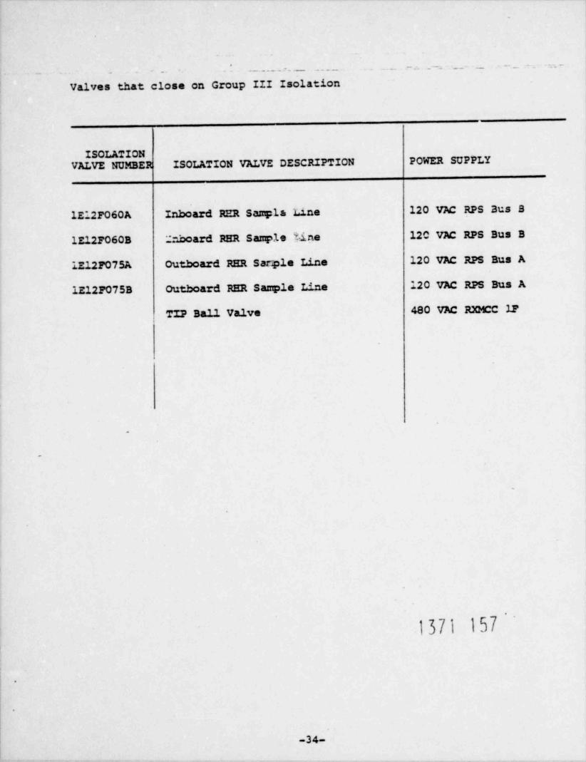
.
*
- - .. - . . . . _ . . . . - . . . _ . _ _ . _ - . _ _ . -
Valves that close on Group III Isolation
ISOLATIONVALVE NUMBER ISOLATION VALVE DESCRIPTION POWER SUPPLY
lE12F060A Inboard RER Sampla L.1.ne 120 VAC RPS Bus B
lE127060B 2nboard RER Sample line 120 VAC RPS Bus B
lE12F075A Outboard RER Sarple Line 120 VAC RPS Bus A
1E12F075B Outboard RER Sample Line 120 VAC RPS Bus A
TIP Ball Valve 480 VAC RXMCC 22
.
O
e
9
1371 157
.
-34-
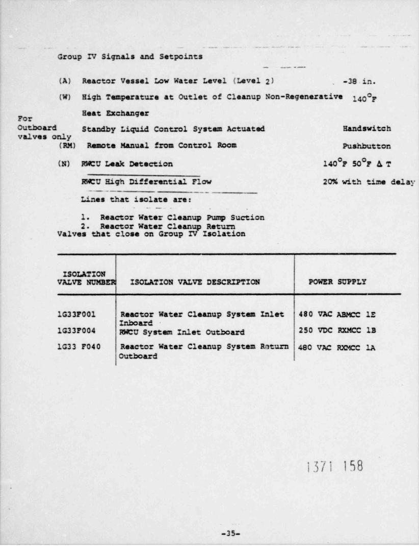
. . . .
-- . . _. - - . . _ . . . - - - _ . - - - -- . _ . . . .-
Group IV Signals and Setpoints~
.- _ _ . -
(A) Reactor Vessel Low Water Level (Level 2) . -38 in.
(W) High Temperature at Outlet of Cleanup Non-Regenerative 140 F
Heat Exchanger
Outboard Standby Liquid Control System Actuated Handswitchvalves only
(RM) Remote Manual from Control Room Pushbutton
(N) RWCU Leak Detection 140 F 50 F A T
RWCU High Differential Flow 20% with time delay_.
Lines that isolate are:. - - . .
1. Reactor Water Cleanup Pump Suction2. Reactor Water Cleanup Return
.
Valves that close on Group IV Isolation
ISOLATIONVALVE NUMBER ISOLATION VALVE DESCRIPTION POWER SUPPLY
1G33F001 Reactor Water Cleanup System Inlet 48 0 VAC ABMCC lEInboard
1G33F004 RWCU System Inlet outboard 250 VDC RXMCC 1B
1G33 F040 Reactor Water Cleanup System Roturn 480 VAC RXMCC 1AOutboard
1371 158
.
9
-35-

..- . -. .. ..
-
Group V Signals and Setpoints.
(R) RER Shutdown Return Line High Differential Pressure
(S) RER Equipment Area High Differential Temperature
(T) RHR Equipment Area High Temperature.
(V) RCIC System Steam 1dne to Turbine:
1. High Steamline Space Temperature
2. Low Steamline Pressure
3. High Steamline flow
4. High Turbine Exhaunt Pressure
5. RCIC Area High Temperature
6. RCIC Area High Differential Temperature
(RM) Remote Manual from Control Room
Lines that isolate are:-
1. Steam Supply to RCIC
2. Steam Supply to RHR.
w
ISOLATION POWER SUPPLYVALVE NUMBER ISOLATION VALVE DESCRIPTION
480 VAC RXMCC 1B1E51F063 Steam Supply to RCIC
250 VDC RXMCC 1AlE51F008
250 VDC RXMCC 1A1E51F064 Steam Supply to RER
.
k
-36-

.
.
_-. _ _ _ _ . . . - --. . . -. - -
Group VI Signals and Setpoints -
(A) Reactor Vessel Low Water Level (Level 3) +12.5 in.
(T) RER Shutdown Return Line High Flow 300%
(S) RER Equipment Area High Differential Temperature 100 F
RER Equipment Area High Temperature 200 F
(RM) Remote Manual from Control Room-- Pushbutton.. . . . . . . _ - - . .
(G) Eigh__ Reactor Pressure 135 psig
. , . _ . .._ . _ . _ _ _
Lines that' isolate are:
1. RER Head Spray
valves That Close on Group VI Isolation -
ISOLATIONVALVE NUMBER ISOLATION VALVE DESCRIPTION POWER SUPPLY
lE12F023 RHR Head Sprey 250 VDC RXMCC 1B
lE12F009 RER Shutdown Cooling SuctionInboard 480 VAC ABMCC 1B
1E12F008 RER Shutdown Cooling SuctionOutboard 250 VDC RXMCC 1B
lE12F053A RER Shutdown Cooling Return 480 VAC RXMCC 1A
lE12F053B RER Shutdown Cooling Return 480 VAC RXMCC 1A.
9
1371 160'-
.
-37-
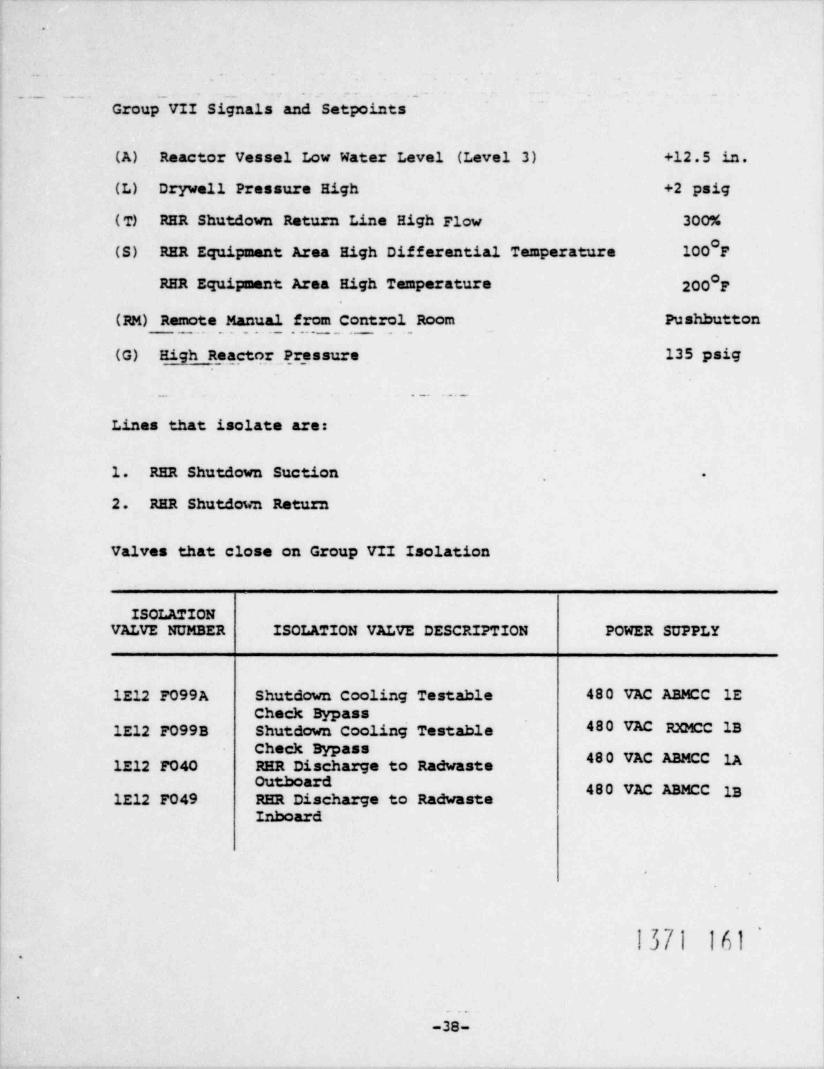
.
..
. ._ . . . . __ __- --
_ _
Group VII Signals and Setpoints
(A) Reactor Vessel Low Water Level (Level 3) +12.5 in.
(L) Drywell Pressure High +2 psig
( T) RHR Shutdown Return Line High Flow 3007.
(S) RER Equipment Area High Differential Temperature 100 F
RHR Equipment Area High Temperature 200 F
(RM) Remote Manual from Control Room Pushbutton.. . . _ . _ _ . . . _ _ _ _ . . _ . _ _
(G) High Reactor Pr_ essure 135 psig
. _ . . . . _
Lines that isolate are:
1. RER Shutdown Suction .
2. RER Shutdown Return
Valves that close on Group VII Isolation
ISOLATIONVALVE NUMBER ISOLATION VALVE DESCRIPTION POWER SUPPLY
1E12 F099A Shutdown Cooling Testable 480 VAC ABMCC lECheck Bypass
lE12 F099B Shutdown Cooling Testable 480 VAC RXMCC IBCheck Bypass
480 VAC ABMCC 1AlE12 F040 RER Discharge to Radwaste
480 VAC ABMCC 1BlE12 F049 RER Di charge to RadwasteInboard
1371 161'.
e
o e
-38-

. .
__ _ _ .__ ___. - . - . - . . = . . - . .. -
_ __._ __ .-.___._- -
Group VIII Isolation Signalt and Setpoints
(B) Reactor Vessel Low Water Level (Level 3) -38 in.
(L) Drywell Pressure High +2 psig
(Z) Refueling Floor Exhaust Radiation High 35 mr/hr
(M) Plant Exhaust Planum High Radiatirm ' 4.5 mr/hr
(RM) Remote Manual Pushbutton
.
ACTIONS
1. Drywell Purge Isolation
a. Inlet
b. Exhaust
2. Suppression Chamber Purge Isolation
a. Inlet
b. Exhaust
3. Drywell Air Sample 1 solation
4. Suppression Chamber Air Sample Isolation
5. Drywell Pneumatic Isolation
a. Supply.
b. Return
c. Purge
6. Start Standby Gas Treatment System }}[] } [)2
7. Open Post LOCA Containment Monitoring System Valves.
-39-

-
-
-. . ... _. . . . . - - . - - - . . . -. -. . --.
Valves that close on Group VIII Isolation
ISOLATIONVALVE NUMBER ISOLATION VALVE DESCRIPTION PCWER SUPPLY
lvQOOlA Drywell Purge Inlet IA/ Spring
lvQ001B IA/ Spring
lvQ002A Drywell Purge Exhaust IA/ Spring
lvQ0023 IA/ Spring
- IVQOO3A Suppression Chamber Purge Inlet IA/ Spring
lvQOO3B.
IVQOO4A Suppression Chamber Purge Exhaust IA/ Spring
lvQ004B IA/ Spring,
1CM003 Drywell Air Sample
ICM004 IA/ Spring
1CM005 Drywell Air Samp1'e IA/ Spring
ICM006 IA/ Spring
1CM012 Suppression Chamber Air Sample IA/ Spring
1CM014 IA/ Spring
IN061 Drywell Pneumatic Supply 250 VDC RXMCC 1B
IN011 Drywell Pneumatic Return 480 VAC ABMCC 1D
INO12 Drywell Pneumatic Return 480 VAC ABMCC lE
IN170 Drywell Pneumatic ??".t LOCA Purge 480 VAC ABMCC 1D
IN171 Drywell Pneumatic Post LOCA Purge 480 VAC ABMCC lE
1371 163
.
-40-

..
,
_- = . .- - -...-.. ._.--. .. - -
_ Valves that open on Group VIII Isolation
ISOLATIONVALVE NUMBER ISOLATION VALVE DESCRIPTION POWER SUPPLY
1CM007 Post LOCA Containment Monitoring IA/ Spring
1CM008 Post LOCA Containment Monitoring IA/ Spring
1CM009 Post LOCA Containment Monitoring IA/ Spring
ICM010 Post LOCA Containment Monitoring IA/ Spring
1CM011 Post LOCA Containment Monitoring IA/ Spring
1CM013 Post LOCA Containment Monitoring IA/ Spring
1CM019 Post LOCA Containment Monitoring IA/ Spring
1CM020 Post LOCA Containment Monitoring IA/ Spring
1CM021 Post LOCA Containment Monitoring IA/ Spring
1CM022 Post LOCA Containment Monitoring IA/ Spring
1CM023 Post LOCA Containment Monitoring. IA/ Spring
1CM024 Post LOCA Containment Monitoring IA/ Spring
1371 16'4.
4
-41-

.
. . .
_~
Isolation Signals~~ -' ~ ~ ~~ ~ ' ~ - '~~~~
(B) Reactor vessel Low (Level 2) -38 in.
(L) Drywell Pressure High 2 psig
RM Remote Manual Pushbutton
Lines that isolate are:
1. Radwaste
a. Drywell Equipment Drain Sump
b. Drywell' Floor Drain Sump
2. Primary Containment Ventilation Chilled Water System
3. Reactor Building Ventilation Supply and Exhaust Dampers
ISOLATIONVALVE NUMBER ISOLATION VALVE DESCRIPTION PCWER SUPPLY
1RE048 D N Equipment Drain Isolation IA/ Spring
1RE049 D N Equipment Drain Isolation IA/ Spring
1RF001 DN Floor Drain Isolation IA/ Spring
1RF002 DN Floor Drain Isolation .IA/ Spring
IVP006A Primary Containment VentilationChilled Water Supply 250 VDC RXMCC 1A
IVPOO6B Primary Containment VentilationChilled Water Supply 250 VDC RXMCC 1B
IvP012A Primary Containment VentilationChilled Water Return 250 VDC RXMCC 1A
lVPO12B Primary Containment VentilationChilled Water Return 250 VDC RXMCC la
IVPO45A Primary Containment VentilationChilled Water Return 480 VAC ABMCC lE
IVPO45B Primary Containment Ventilation=
Chilled Water Retu.n 480 VAC ABPcC lE.
!3[| lbb-42-

-
-
. - - . . . - . = - . - .- . . - . ..
_
VALVE NUMBER ISOLATION VALVE DESCRIPTION POWER SUPPLY
IVG03YA Reactor Building VentilationSupply Damper IA/ Spring
IVG03YB Reactor Building VentilationSupply Damper IA/ Spring
.
IVGO4YA Reactor Building VentilationExhaust Damper IA/ Spring
IVG04YB_ Reactor Building Ventilation
Exhaust Damper IA/ Spring
.
1371 166
.-
.
t
-43-