Forwards update to containment fracture toughness info submitted in ...
13
. . . U-0398 /L1/NO/S PAWER caMPANY {f7 F8{-82(gl- ST ET DECATUR, ILUNOIS 62525 January 13, 1982 sC-M O' / c3 e ,/ Mr. Joseph Halapatz (Mail Stop P-1000) s Materials Engineering Branch Q .- Q . 4,'3 s".',w.s/ Division of Engineering j .p " Office of Nuclear Reactor Regulation . U U. S. Nuclear Regulatory Commission p ~~ ' fl8?g0 ' . ' Washington, D.C. 20555 \, .- , ... ...: . , ,, . ' Dear Mr. Halapatz: N g(\ M t.t \ ' ', Clinton Power Station Units 1 & 2 Docket Nos. 50-461 & 50-462 Reference: Letter G. E. Wuller (IPC) to J. Halapatz (NRC; August 7, 1981; U-0269 The reference letter forwarded information on containment fracture toughness which you requested. The enclosure to this letter is an update to the containment fracture toughness information. Please insert the changes as indicated. This information is in accordance with telephone conversations and meetings among J. Halapatz, P. E. Walberg and C. C. Wheeler during the weeks of November 23 and 30, 1981. If we can be of further assistance, please contact Mr. C. C. Wheeler at (217) 424-6986. Sincerely, / ' / G. E. Wuller Supervisor-Licensing Nuclear Station Engineering FEW/lt Enclosure Mr. J. H. Williams , NRC Clinton Proj ect Manager (w/o enc. ) cc: Mr. H. H. Livermors, NRC Resident Inspector (w/o enc.) gecl , PDR ADOCK 05000 g (E'' ff 8201260346 820113
-
Upload
khangminh22 -
Category
Documents
-
view
0 -
download
0
Transcript of Forwards update to containment fracture toughness info submitted in ...

.
.
.
U-0398/L1/NO/S PAWER caMPANY {f7 F8{-82(gl-ST ET DECATUR, ILUNOIS 62525January 13, 1982
sC-M O' / c3e ,/Mr. Joseph Halapatz (Mail Stop P-1000) s
Materials Engineering Branch Q .- Q
.4,'3 s".',w.s/Division of Engineering j .p
"Office of Nuclear Reactor Regulation .
UU. S. Nuclear Regulatory Commission p ~~ ' fl8?g0 '.
'
Washington, D.C. 20555 \, .-,
... ...: . ,,,.
'
Dear Mr. Halapatz: N g(\M t.t \ ' ',
Clinton Power Station Units 1 & 2Docket Nos. 50-461 & 50-462
Reference: Letter G. E. Wuller (IPC) to J. Halapatz (NRC;August 7, 1981; U-0269
The reference letter forwarded information on containmentfracture toughness which you requested. The enclosure to thisletter is an update to the containment fracture toughnessinformation. Please insert the changes as indicated. Thisinformation is in accordance with telephone conversationsand meetings among J. Halapatz, P. E. Walberg and C. C. Wheelerduring the weeks of November 23 and 30, 1981.
If we can be of further assistance, please contact Mr. C. C.Wheeler at (217) 424-6986.
Sincerely,
/ '
/G. E. WullerSupervisor-LicensingNuclear Station Engineering
FEW/lt
Enclosure
Mr. J. H. Williams , NRC Clinton Proj ect Manager (w/o enc. )cc:Mr. H. H. Livermors, NRC Resident Inspector (w/o enc.)
gecl,
PDR ADOCK 05000 g (E'' ff8201260346 820113

.
.
Revised Pages toClinton Power Station - Unit 1
" Fracture Prevention of ContainmentPressure Boundary"
INSTRUCTIONS
1. Replace introduction with revised introduction (attached).
2. Replace tables labeled " Penetrations", " Head Fittings"," Equipment and Personnel Hatches", "Feedwater System Contain-ment Boundary", and " Main Steam System Containment Boundary" '
with Revised Tables (attached).
3. Add Ivo Garza (Sargent & Lundy) Letter to W. D. Collins(Anchor / Darling Valve Company) October 2, 1981, and W. D.Collins (Anchor / Darling) letter to Ivo Garza, October 13,1981, to Section IV between the feedwater and main steamtables.
4. Insert General Electric drawing 794E708 with the FeedwaterSystem Reference Drawings.
.__ __

~~w .s e
,. INTRODUCTION: .
* *, .
The enclosed documentation tabulates th'e fracture tcughnessdata in, response to a Nuclear Regulatory Commission requestat a meeting held May 12, 1981 in Sargent & Lundy's offices.
|During this meeting the NRC specified the folloding compo-nents, which form part of the containment boundary, willrequire material certification to justify the lowest servicemetal temperature: .
;,
- .
, Penetrations - only the thickest wall penetration for.
each type material.
Head fittings - only the thickest head fitting for eachtype head fitting design and each type =aterial.
Personnel and equipment hatches - only the thickestsection of the hatch assembly.
. Piping - only MS and FW typical. spool sections frod.inside the containment penetration through the first
.
isolation valve.
The lowest service metal temperature specified for each ccm-ponent above was based on the following logic:.
.
1. Results of an acceptable frac'ture toughness inaccordance with NC-2300;'
.
or --
,
2. Derived from Table NC-2311 (a)-l', ASME Code, Section II:| 'for the particular material and heat treatment plus| the temperature adjustment for. thickness
.
or
3. Derived from NUREG-0577. An NDT temperature wasobtained for the particular material and heat treat-
.
ment in the "RU7 +1.3 c" column of Table 4.4, and to
( this value was added the temperature adjustment forthickness from Figure NC-2311(a)-1 of ASME Secticn III.
'
!| or|
|
| 4. Derived from NUREG-0577. An NDT temperature was'
obtained for the particular material and hect treat-ment in the " RUT" column of Table 4.4, and to thisvalue was added the temperature adjustment for thick-
(; ness from Figure NC-2311(a)-1 of ASME Section III.1 The "RDT" column of Table 4.4 was considered appro--
-
, priate because the metallurgical history indicated
.
G
> --- . - - . . .- .. .,_
.. __r
*
. .
t
!
the material properties w'ould be superior to theavailable published data and, therefore, the 1.3 :rwould not be required for the 90% confidence level.The material properties were considered superior to-
the data available in Table 4.4 based on the addi-tional heat treatments performed. ,
or
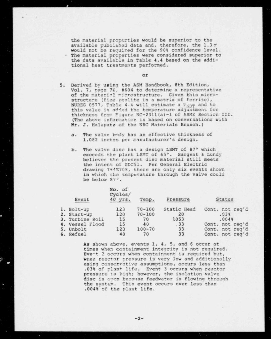
5. Derived by using the ASM Handbook, 8th Edition,Vol. 7, page 76, #604 to determine a representativeof the material microstructure. Given this micro-structure (fice pealite in a matrix of ferrite),NUREG 0577, Table 4.4 will estimate a 7:DT and totthis value is added the temperature adjustment forthickness from Figure NC-2311(a)-1 of ASME Section III.(The above informatien is based on conversations withMr. J. Halapatz of the NRC Materials Branch.)
a. The valve body has an effective thickness of1.082 inches per manufacturer's design.
b. The valve disc has a design LSMT of 87* whichexceeds the plant LSMT of 65'. Sargent & Lundybelieves the present disc material still meetsthe intent of GDC51. Per General Electricdrawing 794E708, there are only six events shownin which the temperature through the valve couldbe below 87*.
No. OfCycles /
' Event 40 yrs. Temo. Pressure Status
1. Bolt-up 123 70-100 Static Head Cont. not reg'd2. Start-up 120 70-100 20 .03%3. Turbine Roll 15 70 1053 .004%4. Vessel Flood 15 40 33 Cont. not reg'd5. Unbolt 123 100-70 33 cont. not reg'd6. Refuel 40 70 33 Cont. not reg'd
As shown above, events 1, 4, 5, and 6 occur attimes when containment integrity is not required.Evert 2 occurs when containment is required but,wnen reactor pressure is very low and additionallyusing conscreative assumptions, occurs less than.03% of plant life. Event 3 occurs when reactorpressure 2.s high; however, the isolation valvedisc is open because feedwater is flowing throughthe system. This event occurs over less than.004% of the plant life.
,
-2- -
|_ - - - - - - - - - - - - - - - - - - - - - - - - - - - - - - - - - - - - - 1

or
6. Derived by using the ASM Handbook, 8th Edition,Vol. 7, page 76, ?604 to deter =ine a representa-tive of the material microstructure. Given thismicrostructurc (fine pealite in a matrix offerrite), NUREG-0577, Table 4.4 will esticate a TNDTTNDT and to this value is added the temperaturead jt:.s tmeht for thickness from Figure NC-2311(a)-1of AC:E Section III. (The above information isbaceu on conversations with Mr. J. Halapace of theNRC Materials Branch.)
.
Several components in the containment boundary are exempt frommaterial certification requirements because of size or thefact they are fabricated from austenitic stainless steel. SeeSection II for the exemptions allowed by the ASME Code, SectionIII.
.
O

___ _ ___ ___________ __________ _________ _ __ _ . _ _ _ _ _ _ _ _ _ _ _ _ _ _ _ _ _ _ _ _ _ _ __
,
: n~ > \-
-.
,
-,
,
,
.
.
.
*. .
,
-.
,
.
.
* '
PENETRATIONS*
,
.
# *Description Material Thickness Ts Charpy Ils Exempt Notes.
N r nt g3Temp. V-notch Lateral
}!C11 S27-1911 34"$ SA240 Gr304 .500"'
NC2311(a) (6)-- -- -- --
MC28 S27-1911 '14"6 SA312 TP304 1.406"'
NC2311(a)(6)-- -- -- --
HC86 S27-1911 10"$ SA333 Cr1 .593" NC2311(a)(4)- -- -- --
'
HC05 S27-1911 42"$ SA516 Cr70 1.500" -30*F 17-26-48 .025 .036 050 -, per,#1-
ft/lba in'
HC42 S27-1911 18"6 SA333 Gr6 .937" -50*F 104-7,9-95 .086 .067 .082~ ~~ - --.
per #1*--- --
-
ft/lbs in*.
-
,
"Note - See introduction for explanatieo of #1. *
.
ee
e
e
0 e ,
.
$ g.
7-_ _ _ _ _ _ _ _ _ _ _ _ _ _ _ - - _ _ _ _ _ _ _ _ _ _ _ __ _ _ _ _ _ _ _ _ _ _ _ _ _ _ _ _ _ _ _ _
s ~. --
l.. / ' i l _r,
O
I1 '
t .
.I ..
*I .
.. . .
*t
'4 .
i -. .
.I
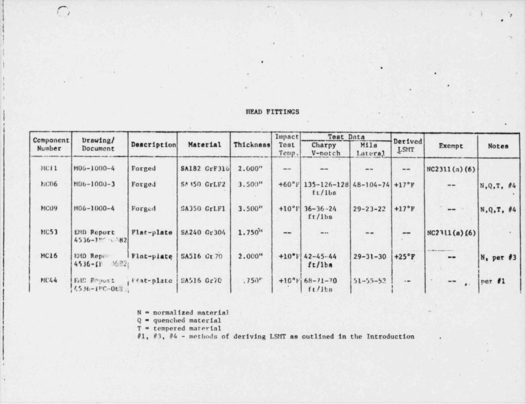
| lIEAD FITTINGS -.
'l ,
.
, .,
Comp 8! Der vedDescription Material Thickness a Charpy Hils Exempt Notespn r Do t_ _ _ Temp,. V-notch Latera,1 -
HC11 H06-1000-4 Forced SA182 CrF316 2.000" -- -- -- -- NC2311(a) (6)
MC06 H06-1000-3 Forged SeISO GrLF2 3.500" +60*F 135-126-128 48-104-74 +17'F N,Q,T, #4--
-
ft/lbs,.
HC09 H06-1000-4 Forged SA350 GrLF1 3.500" +10*F 36-36-24 29-23-22 +17'F ' N,Q,T,#4--
ft/lbs
HC53 EMD Report Plat-plate SA240 Cr304 1.750'' NC2111(a)(6) *-- -- -- --
4536-JP''65H2 -
~~
HC16 IMD Reper iFlat-platq SA516 Cr.7'O 2.000" +10*F 42-45-44 29-31-30 +25'F N, per #3--
4536-[r 3602;, ft/lbs
HC44 Falc Foput t i t e st-piste SA516 Oc'/0 .750" +10*F '68-71-70 51-55-52 - -- per #1-,,
, I.5 Jt,-I t'C-Ot3 a ft/Jbn |*
.
N = normalized materialQ = quenched materialT = tempered material#1, #3, #4 - methods of deriving LSrtT as outlined in the Introduction .
.
G
*.;

____ - _ _- . _ _ _ _ _ _ _ _ _ _ _ - _ _ _ _ _ _ _ _ _
(~)'~
',..
.i.
...
(
* *4e
e
.
.
. . .
*
.r
EQUIRIENT AND PERSONNEL llATCllES.
.
[" "[ Description Material Thickness Test Charpy tills
"
"*[f"r Exempt NotespTemp. V-notch Lateral
51-3 74-2653 Equipment llatch SA516 Cr70 1.00" -30*F 38-38-45 ~ 38-37-45 -- --
'
per #1' #50 Diah 11 cad ft/lbs.
52-1 74-2653 Equipment Hatch SA516 Cr70 3.00" -30*F 82-100-70 56-75-64 +40*F'
N, per f 2,
---f50 cantilever Flange *
f. ft/lbs *
52-4 74-2653 Equipn. cat llatch SA516 Gr70 .750" -30*F 30-30-31 26-29-33 '
per #1-- --f50 Untrel ft/lbs-
150-1 74-2653 Personnoi Lock SA516 Cr70 5/8"'
i NC2311(a)-(1)*-- -- -- --
#150 Darrele
' 154-1 /4-2653 Personnel Lock'
SA516 Gr70 1.00" -30*F 16-29-20 12-22-20 +30*F N, per #2--
#151 11 cad Plate ft/lbs1
-
156-1 74-2653 Personnel Lock SA516 Cr70 1.50" -30*F 31-45-51 28-39-43! #156 Door ft/lbs |
*
per #1-- -- ..,
.
.e
e
,
e
O
f

- * ~
\ 't ' ).
..,
..
.
.
.
, *
.
i -.
*f ..
. *
9
I - ,,
.'
FEFDWATER SYSTEM CONTAINMENT BOUNDARY. *
I.
.
I-
Component - "E"# 8 # #DerivqdNumber Description Material Thickness Test Charpy Mils
,
Exempt NotesLSMTi Temp. V-notch L'ateral,
f 11121F032A Valve Body SA216 WCB 1.060" 50*F 85-87-66 68-71-56 +65* N.T. per #5--.'
. 1B21F032A Valve Bonnet SA105 6.000" 40*F 72-78-84 61-63-65 +34* Q,T, per #4--
|1B21F032A Valve Disc SA216 WCB 4.500" 50*F 55-69-63 50-61-59 +87*
.
N,T, per #5--
.
IFWO2KA20 1-FW-1-1 Pipe Spool SA106 GrB 1.969" 40*F 85-80-86 58-56-60; .
per #1-- - --
MC-9 Forge Head Fitting SA,350 GrLF1 3.500", -- -- -- -- -- See llead FittingSection
1FW02KA20 18 X 20 Reducer SA234 WPB 1.969" 40*F 97-73-64 85-70-64.
, -- -
per #1--
.
.
$
1

- _ _ - _ _ _ _ _ _ _ _ _ - . _ _ _ _ - _ . _ _ _ _ _ _ _ ___ _ -
s.
.) : 1* -.
-
.
-. . . _ _-
. .
.
? -
***., .,
.
** ..i.-
e .
,
.$ 0
MAIN STEAM SYSTEN CONTAINMENT BOUNDARY' .
', - -
1 Implet Trst Data l I*E "*" Derm.dDescription Material Thickness Test charpy Mile Exempt I tioens' **'
__Temp. .V-notch _ Lateral
.
1B21F028A Valve Hody SA216 WCB. 2.500" +60*F 26-23-26 29-28-29 +65'F N T. per #6--
t 1821F028A Valve Poppets SA350 GrLF2 6.031"- +60*F 32-40-48 28-35-36 +35'F Q,T, per #4--
1B21F028A Valve Cover SA105 5.813" +60*F 68-73-71 54-43-50 +34*F*
Q,T, per #4,-, .
,, ,
1HS01EA24 GE llead Fitting "A" SA350 GrLF2 5.000" +60*F 135-126-128 48-104-74 +27'F N,Q,T, per #4--
IHS01EA24 CE Spool "P1" SA333.Gr6 1.218" -50*F 50-64-66 40-52-52 per #1- -
*.
.
.
.
| l' _ . _ ._,
, ..,
8 9
|
|* * . ,
*e
| **
| ,
'
.
.

_ w
'
*g..
- 'SARO3CNT & LUNDY
'
x x o n rE x u tsFOUmotD ST FREctshCn samognf.eest
55 EAST MONROC STREET
CMICAGO.lLLINOIS 60603-
,
, ,TcLepwomc - 312 269 2000
caste mooness - santum-cwicaoo*
October 2, 1981 ,.
Project No. 4536-00
Illinois Power Company ' '
Clinton Power Station - Unit 1 "
.
Specification K-286CA *.
,
Safety Related Valves .
2-1/2" and Larger > --
'.
.
.=
Mr. W. D. CollinsAnchor / Darling Valve Company
.
701 First Street ,
Williamsport, PA 17701 -
'
Dear Mr. Collins: '
. - *
,
The NRC reviewed the Clinton Station design for fracturetoughness adequacy of containment boundary materials andfound that the lowest service metal temperature (LSMT) ofvalves IB21-F032A&B is 87*F based on the valve disc and70*F. based on the valve body casting. Both of these areabove the minimum service temperature of these valvas.The URC further stated.that.in cal.culating the LSMT, the- -' '
minimum required ' thickness may be used in lieu of thema:<imum casting thickness which was used to arrive at the70*F reference above.
In reviewing BTAD-23, we have noted that the report qualifiesthese valves to the full 15005 rating (3750 psig @ 500*F)rather than the actual valve design conditions (2200 psig9 425'F and 1250 psig @ 575'F). It appears that if we usethe minimum valve thickness required by the actual designto calculate'the LSMT, we will arrive at an acceptableLSMT for the valve bodies.
.
.
.
O
p n.e u .
f
= a .,. s !a-
-
5 r.g;,s% 8911
1981.
e
GARGENT Q LUNDY ,
, 'ENGINEEQScasecAco
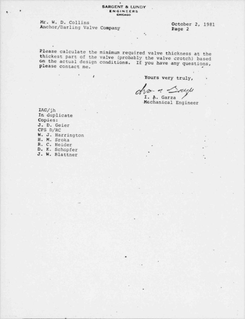
Mr. W. D. Collins ' October 2, 1981Anchor / Darling Valve Company
,Page 2
.'
.
- .
. ,
Please calculate the minimum required valve thickness at thethickest part of the valve (probably the valve crotch) basedon the actual design conditions. If you have any questions,please contact me. '
* *t Yours very truly, '.
.
/jfy #1 J| I. b. Garza
-Mechanical Engineer -
IAG/jh *
,
In duplicateCopies: '
J. D. GeierCPS D/RC ~'
W. J. Harrington -
H. M. Sroka * *
R. C. Heider -,-
D. K. Schopfer.
J. W. Blattner ",-
.
*%
$
e
9
=e
o e *
W
G
O
| '
||
.-
D
O
* e
i
|
||-
.
O
.
=e *e

-
.. ..
-
.
' '
"'
Anchor / Darling -:
..
volve canpany~
' '701 FIRsT STREETP.O. Box 3428
~.
WILLIAMSPORT, PA 17701 !
(717)32M121 * October 13, 1981~
TaEx. as-14as__.
;- :!
.-
* r
SARGENT 5 UJNDY ENGINEERS.
i 55 E. Monroe Street-
Chicago, Illinois 60603*
- Attention: I. A. Garza, Hechanical Engineer -
Subject: CLINTON POWER STATION*
P.O. C-2513 SPEC. K-2F.56A .
A/DV S.O. E-6214.
.... . .
.. ..
*
Gentlemer.:
In response to your October 2,1981 letter, the valve body minimum wall thicknessd
,
at the crotch region for valves IB21-F032A & B is 1.06 inches based on actualdes.ign conditions.
* Sincerely,.
'
ANCHOR / DARLING VALVE COMPANY~
. N $ N&v1 *
..
M. D. COLLINS R L, s- , ,., -aContract Administrator
,
p,J I 0 '31.ucc/ams
; cc: T. Gartes ) 'SARGENT & LUNC 3*
J.-Punch ) ' '
!N# ME 'CC' 'R. Einehart ) A/DV
| R.Stannert) I. M4f 2 + -i
1'
S.O. File E-6214 cj'|[ , -|> ;
'
----
:. .
:., . - - - -
, _y.
'. .
-.M
e
'
|- - - - - - . _ -.
O :fs.'
.,
- - - - -
; ..
- - _ . - .
k e
G . g gM