Naturalised epistemology, reciprocal containment and metaphysical realism
Upload
khangminh22Category
view
1download
0
CRC for Contamination Assessment and Remediation of the Environment
National Remediation Framework
Technology guide: Containment
Version 0.1: August 2018

CRC CARE National Remediation Framework Technology guide: Containment
Information correct at the time of publication i Version 0.1: August 2018
National Remediation Framework
The following guideline is one component of the National Remediation Framework (NRF). The NRF was developed by the Cooperative Research Centre for Contamination Assessment and Remediation of the Environment (CRC CARE) to enable a nationally consistent approach to the remediation and management of contaminated sites. The NRF is compatible with the National Environment Protection (Assessment of Site Contamination) Measure (ASC NEPM).
The NRF has been designed to assist the contaminated land practitioner undertaking a remediation project, and assumes the reader has a basic understanding of site contamination assessment and remediation principles. The NRF provides the underlying context, philosophy and principles for the remediation and management of contaminated sites in Australia. Importantly it provides general guidance based on best practice, as well as links to further information to assist with remediation planning, implementation, review, and long-term management.
This guidance is intended to be utilised by stakeholders within the contaminated sites industry, including site owners, proponents of works, contaminated land professionals, local councils, regulators, and the community.
The NRF is intended to be consistent with local jurisdictional requirements, including State, Territory and Commonwealth legislation and existing guidance. To this end, the NRF is not prescriptive. It is important that practitioners are familiar with local legislation and regulations and note that the NRF does not supersede regulatory requirements.
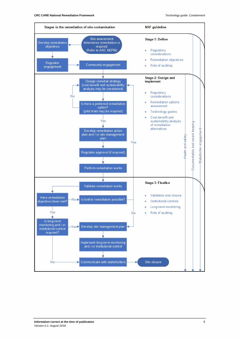
The NRF has three main components that represent the general stages of a remediation project, noting that the remediation steps may often require an iterative approach. The stages are:
• Define; • Design and implement; and • Finalise.
The flowchart overleaf provides an indication of how the various NRF guidelines fit within the stages outlined above, and also indicates that some guidelines are relevant throughout the remediation and management process.
It is assumed that the reader is familiar with the ASC NEPM and will consult other CRC CARE guidelines included within the NRF. This guideline is not intended to provide the sole or primary source of information.
CRC CARE National Remediation Framework Technology guide: Containment
Information correct at the time of publication ii Version 0.1: August 2018
CRC CARE National Remediation Framework Technology guide: Containment
Information correct at the time of publication iii Version 0.1: August 2018
Executive summary
Containment methods can range from simply allowing contamination to remain at depth, covering by a capping layer or structure (such as a building), or containment in an engineered on-site repository.
Key site-specific considerations that will often determine the feasibility of containment as a potential remediation and management option include:
• Whether containment is an option allowed by the relevant regulatory agencies;
• Whether the risk of failure of the containment and management system is acceptable to stakeholders; and
• Whether the requirements for long-term management, ongoing cost, and the possibility that remediation may be required at some time in the future are acceptable.
Data collected in the site contamination assessment phase should inform the initial and detailed remediation screening stages to assess the feasibility of containment application to manage the contaminated soil. It is essential to have a detailed understanding of the soil properties, such as permeability and plasticity, as well as the contaminant mass and distribution to inform the decision as to whether containment will be appropriate and how the system should be designed.
Containment systems contain several components to achieve the level of isolation needed, these include:
• Physical separation using barriers at the surface and sides if necessary to prevent uncontrolled exposure to the contaminated soil;
• Physical separation using a barrier if necessary at the base of the containment cell to prevent infiltration or the loss of leachate and impacts to underlying soils and/or groundwater;
• Capping layer to prevent the entry of water;
• Leachate identification and control if water can enter the containment area; and
• Vapour collection and extraction if necessary.
Containment can be an effective management measure for most soil contaminants and can be applied in most geological conditions, though the components of the containment system will depend on the contaminants present, together with the soil, geology and groundwater properties.
The design life of a containment system is an important consideration. Monitoring and management requirements should be documented in a remediation action plan (RAP) to ensure the integrity of the capping layer or containment system is maintained.

CRC CARE National Remediation Framework Technology guide: Containment
Information correct at the time of publication iv Version 0.1: August 2018
Abbreviations
CRC CARE Cooperative Research Centre for Contamination Assessment and Remediation of the Environment
CSM Conceptual Site Model
NRF National Remediation Framework
PPE Personal Protective Equipment
RAP Remediation Action Plan
CRC CARE National Remediation Framework Technology guide: Containment
Information correct at the time of publication v Version 0.1: August 2018
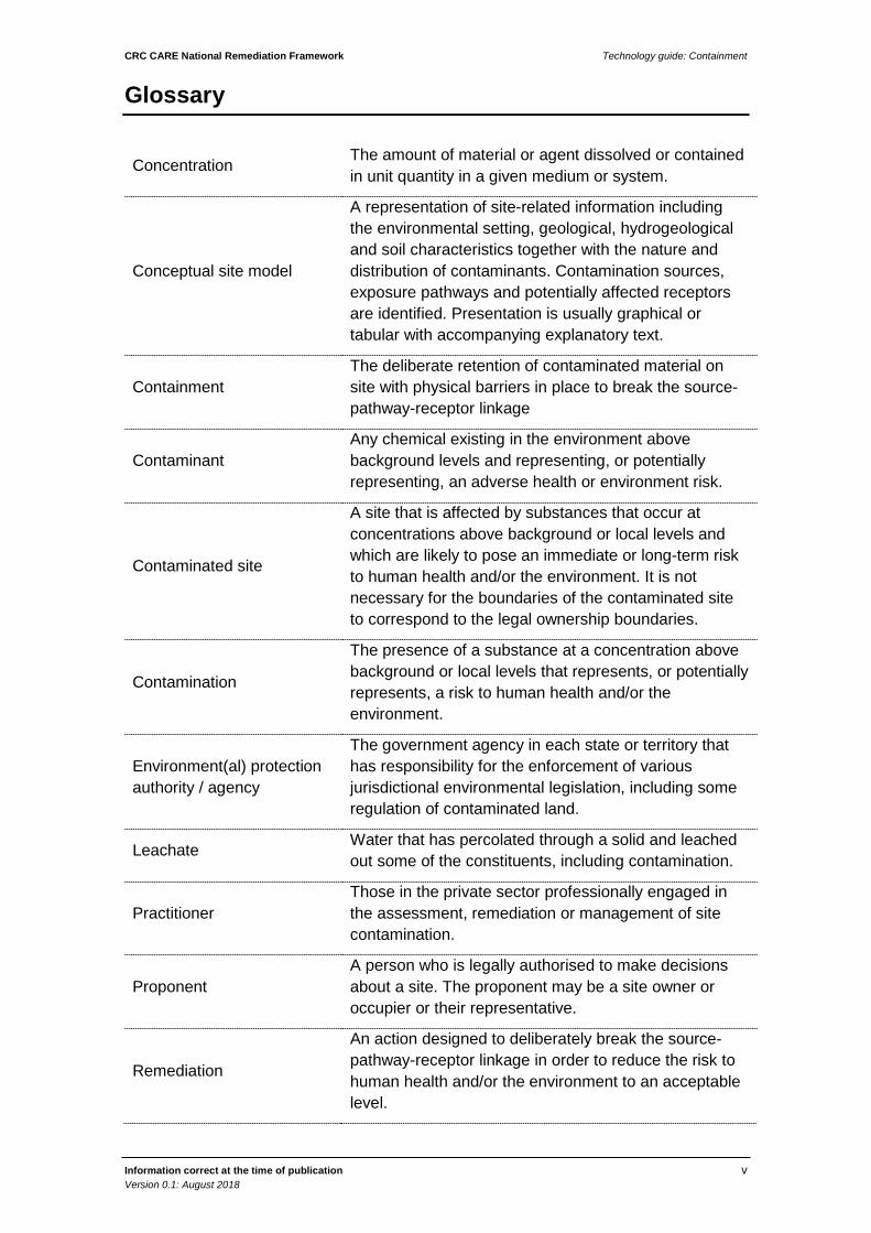
Glossary
Concentration The amount of material or agent dissolved or contained in unit quantity in a given medium or system.
Conceptual site model
A representation of site-related information including the environmental setting, geological, hydrogeological and soil characteristics together with the nature and distribution of contaminants. Contamination sources, exposure pathways and potentially affected receptors are identified. Presentation is usually graphical or tabular with accompanying explanatory text.
Containment The deliberate retention of contaminated material on site with physical barriers in place to break the source-pathway-receptor linkage
Contaminant Any chemical existing in the environment above background levels and representing, or potentially representing, an adverse health or environment risk.
Contaminated site
A site that is affected by substances that occur at concentrations above background or local levels and which are likely to pose an immediate or long-term risk to human health and/or the environment. It is not necessary for the boundaries of the contaminated site to correspond to the legal ownership boundaries.
Contamination
The presence of a substance at a concentration above background or local levels that represents, or potentially represents, a risk to human health and/or the environment.
Environment(al) protection authority / agency
The government agency in each state or territory that has responsibility for the enforcement of various jurisdictional environmental legislation, including some regulation of contaminated land.
Leachate Water that has percolated through a solid and leached out some of the constituents, including contamination.
Practitioner Those in the private sector professionally engaged in the assessment, remediation or management of site contamination.
Proponent A person who is legally authorised to make decisions about a site. The proponent may be a site owner or occupier or their representative.
Remediation
An action designed to deliberately break the source-pathway-receptor linkage in order to reduce the risk to human health and/or the environment to an acceptable level.
CRC CARE National Remediation Framework Technology guide: Containment
Information correct at the time of publication vi Version 0.1: August 2018
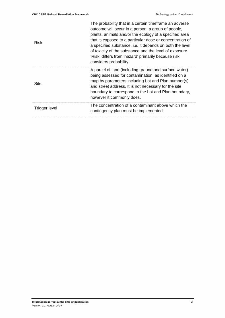
Risk
The probability that in a certain timeframe an adverse outcome will occur in a person, a group of people, plants, animals and/or the ecology of a specified area that is exposed to a particular dose or concentration of a specified substance, i.e. it depends on both the level of toxicity of the substance and the level of exposure. ‘Risk’ differs from ‘hazard’ primarily because risk considers probability.
Site
A parcel of land (including ground and surface water) being assessed for contamination, as identified on a map by parameters including Lot and Plan number(s) and street address. It is not necessary for the site boundary to correspond to the Lot and Plan boundary, however it commonly does.
Trigger level The concentration of a contaminant above which the contingency plan must be implemented.

CRC CARE National Remediation Framework Technology guide: Containment
Information correct at the time of publication vii Version 0.1: August 2018
Table of contents
National remediation framework Error! Bookmark not defined.
Executive summary iii
Abbreviations iv
Glossary v
1. Introduction 1
2. Technology description and application 2
3. Feasibility assessment 3
3.1 Data requirements 3
Physical properties 4
Chemical composition and nature of contamination 4
Depth, distribution and volume of material 4
3.2 Treatable Contaminants and Matrices 5
4. Design parameters 6
4.1 Capping layer 6
4.2 Drainage options to avoid water ingress 6
4.3 Full cell containment 6
4.4 Leachate generation and collection 7
4.5 Vapour collection and extraction/venting 7
4.6 Vertical barriers 7
4.7 Regulatory requirements 8
4.8 Design life 8
5. Validation 9
6. Health and safety 11
Appendix A – Case studies 14
Appendix B – References 15

CRC CARE National Remediation Framework Technology guide: Containment
Information correct at time of publication 1 Version 0.1: August 2018
1. Introduction
The purpose of this guideline is to provide information on containment as a treatment technology for the remediation of contaminated sites to assist with selection of remediation options. The document contains information to inform remediation planning and aid compilation of a remediation action plan (RAP).
This guidance is primarily intended to be utilised by remediation practitioners and those reviewing practitioner’s work, however it can be utilised by other stakeholders within the contaminated sites industry, including site owners, proponents of works, and the community.
This guideline considers contaminated soils that are to be contained at the site of origin and does not extend to the removal of contamination from the site for containment, reuse or disposal elsewhere (such as at a landfill).
Containment is one of many technologies available for contamination remediation, and other technologies may be more appropriate. It is assumed that the information presented within will be used in a remediation options assessment to identify and select the preferred technologies for more detailed evaluation. This guideline provides information for both initial options screening and more detailed technology evaluation. Readers are directed to the NRF Guideline on performing remediation options assessment for detailed advice on assessing remediation options. In addition, the remediation objectives, particularly the required quality of the soil after treatment, are a critical matter and it is assumed that these have been determined and considered in the remediation options assessment and selection process. Readers are directed to the NRF Guideline on establishing remediation objectives for more detailed advice.
References to case studies are provided in Appendix A.
A number of sources of information were reviewed during the formulation of this document to compile information on potential technologies. These are listed in references, and provide an important resource to readers.

CRC CARE National Remediation Framework Technology guide: Containment
Information correct at time of publication 2 Version 0.1: August 2018
2. Technology description and application
Containment of contaminated soil includes capping the contaminated soil or placing contaminated soil into an engineered on-site repository, which is designed to minimise/prevent potential exposure pathways to receptors identified in the conceptual site model (CSM).
Containment methods include:
• Allowing contamination to remain at depth;
• Covering contamination with a capping layer or structure (such as a building); and
• Containment in an engineered on-site repository.
Containment systems may comprise several components to achieve the level of isolation needed, these include:
• Physical separation using barriers at the surface and sides if necessary to prevent uncontrolled exposure to the contaminated soil;
• Physical separation using a barrier if necessary at the base of the containment cell to prevent infiltration or the loss of leachate and impacts to underlying soils and/or groundwater;
• Capping layer to prevent the entry of water;
• Leachate identification and control if water can enter the containment area; and
• Vapour collection and extraction if necessary.
Several of the above components may be needed for a containment system, depending on the contamination present, physical and chemical conditions along with the potential receptors at the specific site, the design life of the containment system and ongoing monitoring, maintenance and management requirements.

CRC CARE National Remediation Framework Technology guide: Containment
Information correct at time of publication 3 Version 0.1: August 2018
3. Feasibility assessment
Key site-specific considerations that will often determine the feasibility of containment as a potential remediation and management option include:
• Whether containment is an option allowed by the relevant regulatory agencies;
• Whether the risk of failure of the containment and management system is acceptable to stakeholders; and
• Whether the requirements for long-term management, ongoing cost, and the possibility that remediation may be required at some time in the future are acceptable.
General parameters that need to be considered at the preliminary stage of assessment are:
• Is the risk associated with the containment system likely to be acceptable to all stakeholders? Is the risk that the containment might fail at some time in the future acceptable?
• Is it likely that other stakeholders (such as local government or members of the public) will accept the use of containment as a remedial solution?
• Will the relevant regulatory agencies accept containment as a viable means of remediation, noting that it does not involve treatment of the contamination and relies on the long-term application of institutional controls?
• What is the length of time the soil needs to be contained for? Is it in perpetuity, or only for the life of the development after which the need for remediation will be re-evaluated?
• Can it be reasonably assumed that the requirements for ongoing management of the contamination are workable and will be implemented?
• Are there sensitive sites/topographical issues that might not be compatible with the containment solution?
• Is sufficient space available at the site for the containment cell to remain accessible (for access to maintain leachate collection and removal system etc.)?
• Has the order of cost to design, monitor, maintain and manage the containment been determined and is it preferred over alternative approaches that involve treatment and avoid the need for ongoing management?
3.1 Data requirements Successful implementation and design of a contaminant containment solution, whichever approach is used, is dependent upon the following key considerations:
• The risk perceived by stakeholders and whether the level of risk is acceptable;
• The physical and chemical properties of the soil to be contained, the soil beneath the proposed containment and the soil surrounding the containment (where relevant);
• The chemistry, concentrations and toxicity of contaminants;

CRC CARE National Remediation Framework Technology guide: Containment
Information correct at time of publication 4 Version 0.1: August 2018
• The levels and usage of groundwater near the containment;
• The exposure that might occur and the level of risk should the containment fail; and
• The physical and chemical characteristics of the containment system.
Physical properties
The physical composition of the contaminated material to be contained needs to be well characterised. Important factors include:
• Permeability and plasticity: this is a critical factor to understand what level of containment is needed, e.g. if contaminated soils are overlying an impermeable stratum such as clay, a surface capping layer may be sufficient to close pathways between the source and relevant receptors identified in the CSM; and
• Soil heterogeneity: this can be an important factor as particle size can affect the mobility of contaminants inside and outside of the containment area. Fine grained materials will retard contaminant migration and may serve to break the pathway for contaminants to migrate to the groundwater table.
Chemical composition and nature of contamination
The composition of the material to be contained needs to be sufficiently well characterised. Important factors include:
• The distribution, concentrations and mass of contaminants in the soil to be contained, and the requirement to locate and treat contamination that exceeds certain concentrations, noting that contamination may be irregular in extent and location. This can be particularly important for in-situ methods, where physical inspection and testing is restricted; and
• The range and nature of contaminants, their concentrations and their ability to migrate through leaching or volatilisation (will a vapour collection system be required?).
Depth, distribution and volume of material
The depth of the soils requiring containment will influence the approach that might be taken. Contamination at shallow depths may be contained by surface structures; if contamination is at depth it is possible that the overlying natural soil will provide a sufficient separation layer.
The volume and location of material to be contained in relation to depth and future overlying structures are also a key consideration, as these will determine the cost and could determine the feasibility of the method and how it might relate to other methods. Quantifying the volume will require careful delineation of the material that needs to be contained, relocated, or otherwise managed or treated. Delineation of the volume and location of material can be expected to require additional sampling and analysis over that required to establish where there is material that is to be contained.
Typically, the location and extent of material should be indicated on a map. The uncertainty in the volume and location of material to be treated should be understood and related to the requirements for decision making.
CRC CARE National Remediation Framework Technology guide: Containment
Information correct at time of publication 5 Version 0.1: August 2018
3.2 Treatable Contaminants and Matrices Containment can be applied as a management measure for most contaminant types and can be applied in most geological conditions, though the design of the containment system and the individual components will vary depending on the contaminants present (e.g. their persistence and toxicity) and the specific site chemical and physical attributes (such as soil permeability and depth to groundwater). Most containment systems have a design life dictated by the nature of the contaminants, the liner system characteristics and physical environmental processes. Some contaminants such as polycyclic aromatic hydrocarbons, chlorinated solvents and volatile organic compounds may require special chemical-resistant lining systems. Monitoring, maintenance and management is also an important consideration.
It is possible that contaminated soil will be immobilised or fixed to lower the toxicity and leaching potential of the contaminants, and thus reduce the risk associated with the containment system. Readers are directed to the NRF Guideline on chemical immobilisation and solidification for more information on this topic.

CRC CARE National Remediation Framework Technology guide: Containment
Information correct at time of publication 6 Version 0.1: August 2018
4. Design parameters
The following sections outline the considerations for design of a containment system. Syste
4.1 Capping layer At sites where the risks associated with contaminated soils relate are limited to direct contact exposure, a capping layer may be sufficient. If the contaminants have minimal solubility, the capping layer may be able to be limited to a clean fill/topsoil layer with a thickness that makes it unlikely that the contaminated soil will be exposed by users of the site.
To reduce the risk that site activities will result in exposure of the underlying contaminated soil, a visual marker layer, such as a permeable geomembrane, can be provided to mark the division between the clean capping layer and the underlying materials.
For the simplest containment systems, a physical capping layer may be all that is required to prevent exposure to contamination that is present in the soil. The capping layer (or barrier) may take the form of an impermeable covering such as an asphalt or concrete ground surface, a structure (such as a building), or a simple separation layer of clean soil.
4.2 Drainage options to avoid water ingress It is generally important to prevent water (stormwater and groundwater) entering a containment system to minimise the potential for leachate generation, unless the nature of the contamination is such that leaching is not of concern. Preventing water ingress may be able to be achieved simply via the use of an impermeable cover layer (e.g. clay) and / or surface water drainage works.
Depending on the nature and concentration of the contaminants (and particularly their solubility), the ingress of water can result in the leaching and migration of contaminants, and the exclusion of water can be an important requirement in the design of a containment system. Where necessary, water may be excluded by an impervious capping (such as a building or paving), or by managing surface drainage so that stormwater is directed away from the containment.
Sub-surface drainage may also need to be provided, particularly where the soil is highly permeable, and/or the contaminants are highly soluble. Geomembrane or clay liners with associated drainage layers are often incorporated into containment systems to aid drainage.
Liners must be tested and protected during placement of contaminated material; this is often accomplished by installing a sacrificial base layer on the liner.
Where infrastructure development takes place over contained material, the risk that services (such as sewers or water reticulation) associated with the development may fail needs to be considered.
4.3 Full cell containment To minimise the potential for contaminants to migrate from the containment cell and impact on underlying clean soil or groundwater, an impermeable layer can be provided

CRC CARE National Remediation Framework Technology guide: Containment
Information correct at time of publication 7 Version 0.1: August 2018
at the base of the cell. This might comprise, for example, a clay layer or an impermeable manufactured liner. Sometimes, systems will contain a double liner to provide extra protection in case the first layer leaks.
If the contaminants in the soil are soluble, liners or impermeable barriers on the walls and base of the containment may be required. Typically, these liners will be installed at the base of the containment cell and possibly on the walls of the cell. Engineered liners minimise the potential for contaminants to leach out of the cell and for water to migrate into the cell, particularly if the water table is near the base of the containment cell.
If the liner or material used is impermeable then a leachate collection system may be needed to prevent build-up of leachate. The compatibility of the liner system with the contaminants will then be an important consideration and may determine the design life of the contaminant system.
If the containment is to be designed to accept contaminated soil that is excavated from elsewhere on the site, then it will be important to have an accurate estimate of the volume of material as it may not be possible to expand the cell if the volume of contaminated material is greater than the design allowed for.
4.4 Leachate generation and collection If the nature of the contamination is such that it can give rise to leachate, a system for collecting, identifying and managing leachate may be required. The provision of a leachate collection may be necessary, depending on the potential for rainwater to infiltrate the capping layer and the solubility of the contaminants.
Leachate systems are complex and should be designed by an experienced remediation contractor/landfill design engineer. The need to limit leachate accumulation to reduce the risk that leakage will occur should be considered.
4.5 Vapour collection and extraction/venting Where the contaminated soil contains volatile contaminants (e.g. volatile chlorinated hydrocarbons or low molecular weight petroleum hydrocarbons) a system to prevent lateral or vertical migration of vapours may be required.
Where the volatiles move through diffusion, a simple impervious barrier may be all that is required and synthetic barrier systems, such as spray applied impermeable membranes, can be considered.
If there is active gas generation (such as can occur if there is significant degrading organic material present), then a depressurisation system can be required that allows generated gas to be vented to atmosphere, rather than being forced into an overlying building. A depressurisation system can be passive (with gas migrating under its own pressure through pipework or other voids), or active (with a mechanical vapour extraction system).
Vapour collection and extraction / venting systems are complex and should be designed by an experienced remediation contractor/landfill design engineer
4.6 Vertical barriers Vertical barriers may be required where there is potential for the contamination to migrate laterally, such as can occur if non-aqueous phase liquid is present, or there are volatiles that might migrate and affect nearby receptors. Vertical barriers may also be

CRC CARE National Remediation Framework Technology guide: Containment
Information correct at time of publication 8 Version 0.1: August 2018
required where there is deep excavation and it is necessary to provide structural stability to the excavation. .
Where there is need to prevent both horizontal and vertical migration of contaminants, vertical barriers may extend and connect with an impermeable base layer. Where the requirement is to prevent lateral migration of volatile contaminants, the vertical barrier may be placed between the containment area and a sensitive receptor (such as a building) and should extend below the depth of contamination but may not be required to extend to an impermeable base layer.
Vertical barriers may also be used to prevent water infiltration when combined with an impermeable capping system.
The design of a vertical barrier system will depend on constructability considerations, including the soil type at the site and the subsurface conditions. The material of the barrier will need to be able to withstand attack by the contaminants or natural groundwater composition. The presence of high concentrations of aromatic organics or salts can require careful consideration
4.7 Regulatory requirements There may be specific regulatory requirements for implementing containment as a remediation option. Jurisdictional regulatory agencies (particularly the agencies responsible for protection of the environment, town planning, and licensing treatment facilities) should be consulted to determine the specific requirements relating to obtaining the necessary approvals and licences, and the acceptability of institutional controls that can be expected.
Readers are directed to the NRF Guideline on implementing institutional controls for both the contact information of regulatory agencies for each jurisdiction, and for information on institutional controls.
4.8 Design life The length of time that the contamination needs to be contained is an important consideration, and the risk that containment fails needs to be assessed. It may be that containment needs to effectively be in perpetuity, or for the life of the development. If natural degradation occurs, then the containment might be required to be provided until the concentrations of contamination have reduced to levels that no longer pose a risk and containment is no longer necessary.
If containment is to be assured for a long time, such as many decades, the design of the containment system to provide this becomes an important consideration. It is not unusual for synthetic liners to have a life of 50 or 60 years, or less if aromatic solvents are present. Clay-based liners or separation systems may have a longer life, although if high levels of salts are present the life may be reduced.
Ongoing monitoring and management measures should be documented and implemented to prevent the release of contaminants from the containment cell over time, and a monitoring plan should include trigger levels and contingency measures that can be implemented if the trigger levels are exceeded.
There are instances where the design life of an encapsulation liner has been exceeded and soluble contaminants leached to groundwater, requiring the encapsulation to be exhumed and the material treated. Capping layers can be subject to erosion which can compromise the containment, allowing liquid to penetrate the capping layer.

CRC CARE National Remediation Framework Technology guide: Containment
Information correct at time of publication 9 Version 0.1: August 2018
5. Validation
The following information describes the specific validation appropriate for containment, to assist validation planning within the RAP. Readers are directed to the NRF Guideline on validation and closure, which among other things, provides information on lines of evidence.
Validation should comprise an assessment of the structure and permeability of the barrier over time. This should include an assessment of the long-term stability of the capping and/or containment system and any proposed structures above it, from an engineering perspective. The validation of a containment call should comprise integrity testing through inspection during construction, integrity testing of the leak detection network (placed within the perimeter of the cell as part of its design) and a backup leachate collection and treatment system. Where appropriate, the potential for leachate formation and/or volatilisation of contaminants may need to be assessed as part of the validation works.
In addition to assessing the integrity of the containment structure, recommended lines of evidence for the validation of containment systems include a documented reduction in down-gradient concentrations and the analysis of geochemical and biochemical parameters, as discussed in Sections 6.1 and 6.3, respectively. Groundwater sampling (and vapour sampling, if appropriate) down-gradient of the structure serves to determine whether the system is effectively containing contaminants and allows comparison against validation criteria.
Validation approaches will vary depending on the containment method used and site characteristics, however the following elements may be included:
• groundwater/vapour monitoring around an engineered containment system;
• measuring the thickness of a capping layer after placement by topographical surveys before and after placement;
• measuring the permeability, strength and/or strain at a defined stress of a bentonite and/or cement slurry wall;
• visual inspection and integrity testing of gas-resistant membranes laid in composite floor slabs for evidence of tears, gaps around service entries, etc. (Environment Agency 2004);
• modelling to assess the possibility of diffusion of contaminants through the barrier (CCME 1994); and/or
• vapour monitoring in connection with a building that has a vapour control system DEC WA 2014).
Some barriers may react chemically with contaminants such as NAPL. Hydraulic performance tests, i.e. pumping from a well inside the barrier and measuring the hydraulic response outside the barrier, may be useful for assessing the permeability of the material and the potential degradation of the material. Whilst most barriers are installed to prevent the lateral movement of groundwater and/or NAPL, the reliability of any natural low-permeability materials in preventing downwards movement of contaminants should also be assessed through the collection of core samples for laboratory permeability testing or conducting pumping tests .

CRC CARE National Remediation Framework Technology guide: Containment
Information correct at time of publication 10 Version 0.1: August 2018
It is important to consider issues related to the ongoing management and maintenance of the containment system, and monitoring in order to assess its integrity over time. The consequences of failure of any of the components that comprise the system must be assessed and appropriate contingency measures put in place.

CRC CARE National Remediation Framework Technology guide: Containment
Information correct at time of publication 11 Version 0.1: August 2018
6. Health and safety
Containment poses a risk of exposure to site workers during the remediation work, via dust or vapour inhalation, or dermal contact.
Common health and safety hazards associated with containment are highlighted in Table 1, together with possible control measures. The list is intended to provide an indication of the hazards potentially associated with implementing a containment solution for contaminated soil. They will vary from site to site and the list is not intended as a substitute for a detailed hazard assessment which should be undertaken as part of the RAP.
Readers are directed to the NRF Guideline on health and safety for further information on health and safety on remediation sites, including risk assessment, the hierarchy of controls and suggested documentation

CRC CARE National Remediation Framework Technology guide: Containment
Information correct at time of publication 12 Version 0.1: August 2018
Table 1 Common containment safety hazards and controls
Hazard Sources of hazard Suggested controls
Site contaminants Releasing or encountering contaminants during excavation and movement to the containment cell, via dust or vapour inhalation, or dermal contact.
Site workers:
• Work ‘up-wind’ of disturbed soil, when possible.
• Use enclosed excavators to minimise potential exposure to dust or vapour (where relevant).
• Consider use of enclosures and emissions control if contaminant risks warrant this level of protection.
• Ensure medical monitoring requirements as stipulated in the WHS Regulations are completed.
• Use personal protective equipment that is suitable to for the task.
• Perform personal exposure monitoring for hazardous substances as identified in an occupational exposure risk assessment as per the WHS Regulations and associated Guidance Note
Off-site receptors:
• Implement good practice environmental management processes for construction sites including preventing run off from contaminated soils, preventing stormwater run off, dust suppression, odour suppression, protection of stockpiles, consider use of enclosures and emissions control if contaminant risks warrant this level of protection.
• Ambient air monitoring where required.

CRC CARE National Remediation Framework Technology guide: Containment
Information correct at time of publication 13 Version 0.1: August 2018
Hazard Sources of hazard Suggested controls
Deep excavations Falling into or being within an excavation when collapse of the excavation occurs.
• Security and control on access to excavations in accordance with regulations.
• Minimising open deep excavations.
• Proper shoring of excavations.
• Use of high visibility barricades around the excavation.
• Control on use of machinery within excavations and the excavation procedures.
Ergonomic risks Lifting or performing any other movement with too much force and/or in an awkward position or repeating the lift/movement too often.
Procedures and controls relating to the construction of stockpiles and security associated with access to them.
Slips, trips and falls • Storing construction materials or other unnecessary items on walkways and in work areas.
• Creating and/or using wet, muddy, sloping, or otherwise irregular walkways and work surfaces.
• Creating and/or using uneven terrain in and around work areas.
• Dial before you dig,
• clearance programs,
• procedures.
Moving vehicles Moving contaminated soil from origin location to the containment cell.
• Provide conveniently located equipment for the job, like carts, adjustable work stations (operators), and correctly sized tools.
• Train workers on ergonomic risks and prevention.
CRC CARE National Remediation Framework Technology guide: Containment
Information correct at time of publication 14 Version 0.1: August 2018
Appendix A – Case studies
The following case studies demonstrate successful implementation of containment as a remediation strategy.
• Slurry wall containment and National Grid’s Harbour Point, New York, USA - http://dl.dropboxusercontent.com/u/67964190/14-02-44.pdf (accessed 16/6/14).
- This project comprised part of a wider remediation program at the former manufactured gas plant to contain contamination associated with the former water gas plant.
- Waste material to be contained included tar, non aqueous phase liquids and purifier waste.
- This paper sets out the containment approach, the design elements and results the compatibility testing (determining that an effective soil bentonite backfill could be prepared for the barrier wall)
• Immobilisation, stabilisation, solidification: a New Approach for the Treatment of Contaminated Soils. Case studies: London Olympics and Total Ertvelde - http://www.wtcb.be/homepage/download.cfm?dtype=services&doc=pdf_8_Tekst_DEC_Immobilisation_paper.pdf&lang=nl (accessed 16/6/14).
- This case study documents the construction of a containment cell built to hold 170,000 m3 of solidified material from former acid tar lagoons.
CRC CARE National Remediation Framework Technology guide: Containment
Information correct at time of publication 15 Version 0.1: August 2018
Appendix B – References
ANZECC, 1999, Guidelines for the assessment of on-site containment of contaminated soil, Australian and New Zealand Environment and Conservation Council, Canberra.
ASC NEPM, 1999, National Environment Protection (Assessment of Site Contamination) Measure 1999, as varied, National Environment Protection Council, Australia.
CCME, 1994, Subsurface assessment handbook for contaminated sites, Report no. CCME EPC-NCSRP-48E, Canadian Council of Ministers of the Environment, Canada.
CRC CARE, 2013, Safe on-site retention of contaminants. Part 2: A risk-based approach, CRC CARE Technical Report no 16, CRC for Contamination Assessment and Remediation of the Environment, Adelaide.
NSW EPA, 2012, Guidelines for the assessment and management of sites impacted by hazardous ground gases, New South Wales Environment Protection Authority, Sydney.
US EPA, 1992, Guide for conducting treatability studies under CERCLA, EPA/540/R-92/071a, United States Environmental Protection Agency, Cincinnati, OH.
Copyright © 2022 FDOKUMEN