Forwards "WPPSS 2 Purge & Vent Valves Seismic ...
559
7) REGULATORY 1M)ARMATION DISTRIBUTION SY Q i (RIDS) W) ACCESSION NBR: 8307120309 DOC. DATE: 83/06/22 NOTARIZED: NO DOCKET FACIL:50-397 WPPSS Nuclear Proiect. Unit 2P Washington Public Powe 05000397 AUTH. NAME AUTHOR AFFILIATION, BOUCHEY.G.D. Washinaton Public Power Supply Svstem RECIP.NAME„RECIPIENT AFFILIATION SCHWENCERPA Licensino Branch 2 ( SUBJECT: Forward ds "WPPSS 2 Purae L Vent Valves Seismic 8 Hydr odvnamic Ana'Ivsiss" per SER Outstanding Issue 26 DISTRIBUTION CODE: BOOIS COPIES RECEIVED:LTR i ENCL 5 SIZE: TITLE: Licensina Submittal: PSAR/FSAR Amdts L Related Correspondence NOTES: ~( 0'@ 5/G4I" ISac %Q~ RECIPIENT ID CODE/NAME NRR/DL/ADL NRR LB2 LA INTERNAL: ELD/HDS2 IE/DEPER/EPB 36 IE/DEQA/QAB 21 NRR/DF/CEB 11 NRR/DE/EQB 13 NRR/DE/MEB 18 NRR/DE/SAB 20 NRR/DHFS/HFEBOO NRR/DHFS/PSRB NRR/DSI/AE8 26 NRR/DSI/CPB 10 NRR/DS I/I CSB 16 NRR/DS I/PSB 19 NRR/DSI/RSB 23 RGN5 EXTERNAL: ACRS 01 DMB/DSS (AMDTS) LPDR 03 NSIC 05 COPIES LTTR ENCL 1 0 1 0 .1 3 1 1 2 1 1 1 1 1 1 1 ~ 1 1 3 0 g 1 1 1 1 RECIPIENT ID CODE/NAME NRR LB2 BC AULUCK R. 01 IE FILE IE/DEPER/IRB 35 NRR/DE/AEAB NRR/DE/EHEB NRR/DE/GB 28 NRR/DE/MTEB 17 NRR/DE/SGEB 25 'RR/DHFS/LQB 32 NRR/DL/SSPB NRR/DSI/ASB NRR/DS I/CSB 09 NRR/DS I/METB 12 NRR 9 0 22 G FIL 00 R /MI8 BNL(AMDTS ONLY) FEMA REP DI V 39 NRC PDR . 02 NTIS COPIES LTTR ENCL 1 0 1 1 1 1 1 1 2 1 1 1 1 1 1 1 1 1 0 1 g 1 1 1 1 TOTAL NUMBER OF COPIES REQUIRED: LTTR 53 ENCL 06
-
Upload
khangminh22 -
Category
Documents
-
view
2 -
download
0
Transcript of Forwards "WPPSS 2 Purge & Vent Valves Seismic ...

7)REGULATORY 1M)ARMATION DISTRIBUTION SY Q i (RIDS)
W)
ACCESSION NBR: 8307120309 DOC. DATE: 83/06/22 NOTARIZED: NO DOCKET
FACIL:50-397 WPPSS Nuclear Proiect. Unit 2P Washington Public Powe 05000397AUTH.NAME AUTHOR AFFILIATION,
BOUCHEY.G.D. Washinaton Public Power Supply SvstemRECIP.NAME„RECIPIENT AFFILIATION
SCHWENCERPA Licensino Branch 2 (
SUBJECT: Forward ds "WPPSS 2 Purae L Vent Valves Seismic 8 Hydr odvnamicAna'Ivsiss" per SER Outstanding Issue 26
DISTRIBUTION CODE: BOOIS COPIES RECEIVED:LTR i ENCL 5 SIZE:TITLE: Licensina Submittal: PSAR/FSAR Amdts L Related Correspondence
NOTES: ~( 0'@ 5/G4I" ISac %Q~RECIPIENT
ID CODE/NAMENRR/DL/ADLNRR LB2 LA
INTERNAL: ELD/HDS2IE/DEPER/EPB 36IE/DEQA/QAB 21NRR/DF/CEB 11NRR/DE/EQB 13NRR/DE/MEB 18NRR/DE/SAB 20NRR/DHFS/HFEBOONRR/DHFS/PSRBNRR/DSI/AE8 26NRR/DSI/CPB 10NRR/DS I/ICSB 16NRR/DS I/PSB 19NRR/DSI/RSB 23RGN5
EXTERNAL: ACRS 01DMB/DSS (AMDTS)LPDR 03NSIC 05
COPIESLTTR ENCL
1 01 0
.131
1
21
1
1
1
1
1
1~
1
1
3
0g
1 1
1 1
RECIPIENTID CODE/NAME
NRR LB2 BCAULUCK R. 01
IE FILEIE/DEPER/IRB 35NRR/DE/AEABNRR/DE/EHEBNRR/DE/GB 28NRR/DE/MTEB 17NRR/DE/SGEB 25
'RR/DHFS/LQB 32NRR/DL/SSPBNRR/DSI/ASBNRR/DS I/CSB 09NRR/DS I/METB 12NRR 9 0 22
G FIL 00R /MI8
BNL(AMDTS ONLY)FEMA REP DIV 39NRC PDR . 02NTIS
COPIESLTTR ENCL
1 01 1
1
1
1
1
21
1
1
1
1
1
1 1
1 0
1 g1 1
1 1
TOTAL NUMBER OF COPIES REQUIRED: LTTR 53 ENCL 06

~r w
Ih
U
,1

Washington Public Power Supply SystemP.O. Box968 3000 George Washington Way Richland, Washington 99352 (509) 372-5000
June 22, 1983G02-83-550
Director of Nuclear Reactor RegulationAttention: Mr. A. Schwencer, ChiefLicensing Branch No. 2Division of LicensingU. S. Nuclear Regulatory CommissionWashington, D.C. 20555
Dear Mr. Schwencer:
Subject: NUCLEAR PROJECT 2QUALIFICATION OF WNP-2 CONTAINMENTVENT AND PURGE VALVES
References: 1) Letter, A. Schwencer (NRC) to R. L. Ferguson, (SupplySystem), "Request for Additional Information""; datedSeptember 16, 1982, Docket No. 50-397
2) NUREG-0892, WNP-2 SER, Outstanding Issue No. 26,"Operability of Purge Valves"
3) Letter, G. D. Bouchey (Supply System). to A. Schwencer(NRC), G02-83-170, "Nuclear Project No. 2, gualifica-tion of WNP-2 Containment Vent and Purge Valves",dated February 24, 1983
Reference 3) provided partial response to the Purge and Vent valveoperability concerns cited in Reference 1) and 2). This letter transmitsstress analysis work to address the remaining open issues.
The enclosed reports provide the qualification stress analyses for thesubject valves and their operators. Each has a positive margin of safetywhen the stress caused by a safe shutdown earthquake is combined withsafety relief valve operation along with chugging or annulus pressuriza-tion. Acceptance criteria are from Section III of the ASME Boiler andPressure Vessel Code or the AISC Steel Construction Manual, whichever isapplicable.
These margins of safety were found only with the modifications describedin the attached reports. These modifications will be performed prior tooperation of WNP-2.
8307i20309 830622PDR ADOCX OSOOOS97E,;,, ', PDR
QO
IL@STAN>~ ~

I
P
'"lh V
it
lr

Mr. A. SchwencerPage 2
June 22, 1983
With the modifications in place, these valves will remain functionalthrough forty years of postulated hydrodynamic events, five operatingbasis earthquakes, and one,.safe shutdown earthquake.
phdG. D. Bouchey, nagerNuclear Safety and Regulatory Programs
RWH/sms
Attachments
cc: Mr. R. Auluck - NRCMr. W. S. Chin - BPAMr. A. Toth - NRC Site

I.I
~ ~

Washington Public Power Supply Sys'.emP.O. Box 968 3000 George Washington Way Richland, Washington 99352 (609) 373-6000
The attached reports are the structural analysis of the purge and ventvalves and operators installed at NNP-2. The loads used in th. anal'"-'iare the valve operating loads combined with the dynamic '~oads whichwould result from seismic and hydrodynamic events as determined by thepiping analyses for the plant.
There are three reports attached. They separately address:
1) The 24-inch butterfly valves manufactured by BIF (identified asQID 361106),
2) The 30-inch butterfly valves manufactured by B:F (identified asQID 361104), and
3) The air operators manufactured by Miller Fluid Pcwer and suppl'.edby BIF as a part of the'alve assembly (identified as QID 018C01').
These reports have been prepared by Cygna Energy Services for ti e St ppliSystem's Equipment Qualification Group and are in heir compl-te formin the Equipment Qualification files. However, in the '.ntei"est ofconserving space in the transmittal to the U.S. NRC, pages wh'.ch areduplicated in the reports have been removed from all but one of thereports. Also, documents which have previously beett submitted to ".h=
. U.S. NRC are not attached as stated in the report.'

I

WASHINGTON PUBLIC POPOVER SUPPLY SYSTEM
SUPPI.IElh TII,A)IShllTTALFORhl(AREA WITHIN HEAVYBORDER To BE COMPLETED BY SUPPLIER)
B
To THK ATTENTloNoF: Dennis Arms tron3 p p 0 G gOGNIZAQTg A HA PCEg /gU Y
SUBJKCTz
FROM: n
C RAC AOMIN.)
r
PAGE OF ~1
NEW P RKNUBhjlTTAL
1200 Jadwin Suite R h nd W
THK FOI LOWING PUBLICATIONS/DRAWINGSARE SUBMITTED FORt
@APPROVAL Q REVIEW Q INFORMATION DISTRIBUTION
NO. OF PRINTS DF EACH HD.DFREFRDDUBIBEES DF ~EH5UBMITTED BY: Fawaz Khanachet
Assistant Pro ec~ana
i'EQUESTED DATEOF RKTURNI
P.O. NOc
WORK ORDER NOI
SPEC. NOz
SUBVKNOOR: 0NT./P.O. NO.: SPEC. SECT. NOi
ITEMNO.
PUBLICATIONORDRAWING NO.
REV.NO. PUBLICATIONOR DRAWING TITLEri dna e ua , R t. or
ID 3 0
MANUFACTURERWPPSS
ACTION
T- RB C na T-644RB
COMMENTS: IUSE ADDITIONALSHEETB IF REQUIRED) TO BE REVIEWED BY
ECEIVCD BY: IPURCHASING ONLY) TRANSMITTED BY: (PURCHASING ONI Y)
NAMP ROVED BY:
OAITLK AT
ACTION LKGENOaA ~ APPROVED FOR PUBLICATION
AN ~ APPROVED AS NOTED FOR FABRICATIONWP 770 R I
~ INFORMATIONONLYNA ~ NOT APPROVED

IIIIIIIIIIIIIIIIIIIIIIIIIIIIII
FinalQualityicationReport
I
PROJeCT'.. . Equipment Seismic/Hydrodynamic RequalificationJOB gNO„:",„82P 4 4
———CAXm-NO' OT.p1.F
t I f II 0 jl
CLIENT- Washington Public Power Supply System
!>+ QTD"NO=;, ''361'10fI~g
'I llr TITLE,'. '. Equipment Seismic and Hydrodynamic Requalification of...24" Cylinder Operated Butterfly Valves for:
CSP-V-3,4,5,6, and 9
CEP-V-3A, and 4A
II ~
I (.-II
PREPARED BY:
fn qREVIE!KD BY: E(..~!D ~ . n . lr,
APPROVED BY:
DATE
Lo des nandez 6 9 83DATE
DATE
yd~w/ s+~ gee'«~
g ld. JiQ+i84AI
REVISION: 3
~/i%~

REVISION STATUS REPORT
~ ~ '
DATE
PRE'D BY
REV'D BY
APPROVEDBY DESCRY'PTiOH
c R l C- I w p a.
to/~7/g
iz j~/rz
t Q cL-v Klci&4 Dg'.;; QAM~Ag,fg gzvlsi ca/c.,788LE op
caeT~~DRcurot d 0 v<>4c C.s lc. > ~< f«<<
Bcw ~ cgl~ ~<~ c(ji M>n c7
g peso gprrlocds ac J tg t~c<i><
cl p*m~c ~rfAc p, FgtT l ~
i%4auL' q~w giW /w~ r
)('l~ ( ~~QQA~~a'/9/B3
l- C.W~~c.
~pwQo~cwd ~~i a~ld cocwezW TW C+'"~">
W p~ ~ ~
h \

REVISION 3
WASHINGTON PUBLIC POWER SUPPLY SYSTEM
REQ UALIFICATIONCERTIFICATE
WNP- 2 gzDI 361106
coMPDNKNTNot CSP V 3g CSP V 4 g CSP V 5g CSP V 6g CSP V 9g CEP V 3A 6 CEP V 4
24" Cylinder Operated Butterfly Valves
MANUPACTURKRtBIF A-206765
MODKI NOI
EQUIPMENT CLASSIPICATIONs Qg ACTIVE Q PASSIVE
SK15MIC QUALIPICATIONREPORT REPKRKNCKI
C ana Re ort Ot.01/F OID 361106"24" C linder-Ooerated Butterfl Valve"
Reauired action: 1) Remove A-307 Ear Bolts and replace with A-325.
2} Reinforce va'lve ear grou with 4" shear platesto aualifv air operators for reauired fatiauecvcles.
THK ABOVESKISMIC ANO
THK CURRENT NRC SKI5MICAND
QUALIPICATIONREPORTS HAVE BEEN RKKVALUATKDIN ACCORDANCKWITH
CRITERIA'
~ IKEK5TANOAROS 244 (1575)
2 USNRC RKOULATORYCUIOKS 1.$ 2, 'I,144
2» 5TANOARO REVIEW PLANS 2&Pe 2»14eEN
~WSKkggW
THKABOVE COMPONENT HAS BEEN P'OUNO ACCEPTABLE POR PKRPORMINQ IT5 INTKNOKOSAI ETY RKLATKDPUNCTION
WHEN SULIECTKD TO THE PLANT SPKCIPIC VIBRATORY
r'1 ~
LOAO5.
rRKPARED BV Plp>v 0 r»,',/c /3'' Fr»', =< >/i.a~
RKVIEWKDBY+.'~rd~ i"'< rr~z «» I
APPROVED BY
9$ $»12574
OATK~

IL
C
2.0 SQRT FORM(S) AND REFERENCES .
e ~ ~

IIWIIOV
(
l h « ~
el' ~
.oL< .)c"'.i <
I
w ~ we ~
I
* \ i
)T". ~ 'w
J' ~
I
I
lrs
t
I
4 t
I
F
W''~ g™f<
IIII~V~~\ >~~OAK~< A lt A

REVISIONQ
T ~'j-E ST
llllllllllllllllllllllllllllll
WASHINGTOt4 PUBI IC POWER SUPPLY SYSTEM
Qualification Summary of EquipmentQIDN 361106
Ref. No.LANT NAME'P-2 TYPE
I ~ NSSS, GE BEE rn GE
coMPGNENT NAME, 24" C 1.0 er. Butterfly ValvecoMPoNENT NO.CSP-V- 4 9CEP-V-3A ET 4A
I ~ SCOPE: NSSS Q BOP
MOOEL NU4BER. A-206765
~. VENOOR: B~F
OUANTI TY:
4 ~ IF THE COMPONENT IS A CABINET OR PANEL, NAME ANO MOOEL NO. OF THE OEVICES INCLUOEO:
N/A
PHYs IOAL oEscRIPTIoNI > APPEARANcE Butter f1 Valve with 8" C 1 0 erato
o. oIMENSIoNS: 24" nominal diameters
c WE I GHT: 847N - Valve Ass; 6764 — 0 erator & bracket
6 LOCATION: BU I LO I NG:
ELFVATION Maximum elevation: 495 'CSP-V-3A & 4A)
T, Fl ELO MOUNTING OONOITIOHS: Q BOLT (NO SIZE )
Q MELO (LENGTH
sYsTEM IN wHIcH LccATEo. Containment Suppl Pur e S stems
FUNcTI oNAL oEscR I PT I oN Primary Containment iso 1ation, orevent ionof the release of radioactive material to the environment.
c. I S THE EOUIFMENT REOUIREO FOR: HOT STANOBY COLO SHUTOCMN
P] BOTH
9 PERTINENT REFERENCE OESIGN SPECIFICATION: WPP
NEITHER
ec. 2808-
I I I. IS EOUIRIENT AVAILABLEFOR INSPECTION IN THE PLANT: YES NO
PAGE I OF 5

REVISION,Q 2.2
Qualification Summary of Equipment (Continued)QID-":. 361106
C(NBI NATION OF TEST & ANALYSIS
l
IV l EQUIPMENT QUALIFICATION METHOD:I
TEST QX ANALYSIS
QUALIF(cATIQN REpcRT ~ 24" c 1inder-ooerated Butter f1 va lve*
(NQ ~ TITLE 6 DATE) OT 0 1 . F Revision 3, June, 1 98 3
CCMPANY TIIAT PREPARED REPCRT: e
cQMPANY THAT REYIEwFQ REPORT: washin ton Public Power su olv svstems*Plus original valve analysis
V, III BRAT ION I NPUT:~ I a
~l. LOADS CONSIOEREO: a. SEISMIC ONLYI'a
Q HYCRQOYNAMIC ONLY
c. Q CCMBINATON OF (a) ANO (b)CM ) Cf'~l'2
MET)K)O OF C(MBINING RRS: Q ABSOLUTE S(H Q SRSS OTHER (SPECIFY)
I
REQUIRED RESPONSE SPECTRA (ATTACH THE GRAPHS):I
<4 ~ DAMPING CORRESPONDING. TO RSS: CBE Q SSE
Ref. No.
I ~I
I 15
3,4
I 5 REQUIRED ACCELERAT ION IN EACH DIRECTION: Q ZPA Q OTHER (SPECIFY) )i/~h 15
QBE sos - Attached F/B . V ~
Attachedl J, ~ t6. WERE FATIGUE EFFECTS CR OTHER VIBRATION LOADS CONS IDEREOT
Q YES NO '
TF YES; DESCRIBE'OADS CQNSIOEREO ANO HOW THEY. WERE TREATED IN OVERALL QUALIFICATION FRO(BAM:I
d
w tures a vzed we e not
art of the ressure boundar
'- NOTE:, IF MORE THAN ONE REPORT, COMPLETE I TEMS IV TI4(OUGH Yl I FOR EACH REPORT
PAGE 2 CF S

2.3
Qualification Summary of Equipment (Continued)QlDg 361106
ROI. No.Vl~ IF QUALIFICATION BY TEST THEN COMPLETE»:
1. SINGLE FREQUENCY Q MULTI-FREQUENCY Q RANOO4iaaf ~ ~ 5
2+ Q SINGLE AXIS MULTI-AXI S SINE BEAT
~ ' ill"
3 NO, OF QUALIF ICATION TESTS: OBE SSE OTHER (SPECIFY)i ~ ~
4. FREQUENCY RANGc:
5, NATlRAL FREQUENCIES IN EACH DIRECTION (SIDE/SIDE, FRONT/BACK, VERTICAL):
S/S ~ F/B
6 METHOD OF DETERMI NING NAT(RAL FREQUENC I ES:
LAB TEST IN SITU TEST ANALYSIS
7. TRS .ENVELOPING RRS USING MULTI-FREQUENCY TEST: Q YES (ATTACH TRS 4 RRS GRAPHS) Q NO
v~ ~ =~
8, INPUT g-LEVEL TEST: CBE S/S ~
SSE S/S i9, LABORATORY MOUNTI NG:
F/8 a
F/8 s"»+i I i1F (
BOLT (NO. a ----0 FUNCT I 0 OPE L TY ER EO: ES NO Q
) C3
NOT APPLICABLE
I I ~ TEST REULTS INCLUDING MODIFICATIONS MADE:
12. OTHER TEST PERFORMED (SUCH AS AGING OR FRAGILITY TEST, INCLUDING RESULTS):
NOTE IF QUAL IF ICATION BY A CCMB I NTATI ON OF TEST ANO ANALYSI 5 i ALSO COI4 LETE I TEM VI"I ~
PAGE 3 OF 5

rQNAWAVWWI»»»»»»»»P A AA REVlS10N '3i 2.4
E, ~
~F»»»»»~ ~ ~S w» 'w
'Qualification Summary of Equipment (Continued)QID~ 361106
Vl I. IF QUAL IF ICATION BY ANALYSI S, THEN CO4PLETE:
Ref. No
I ~ METHOO OF ANALYSIS:
STATIC ANALYSIS
Q 0YNAMIC ANALYSIS
2 NATLRAL FREQUENCIES
s/s - 10.81 Hz
MOOEL TYPE:
Q5O . Qa)4.Q COMPUTER COOES:
iC EQUI VALENT STATIC ANALYSI S
T INES I STCRY Q RESPONSE SPECTRIH
IN EACH OIRECTION (SIOE/SIOE, FRONT/BACK, VERTICAL):
26.1 Hz v ) 100
Q IO Q FINITE ELEMENT Q BEAM Q CLOSEO FCRM SOLUTION
PREQUEL Y RANGE ANO NO OF MODES CONSIOEREO
OTHERABSOOLTE SIR [)(j SRSS Q (SFECIFY)
GOVERN I NG LOAO
OR RESPONSE
CCIBI RATICRPLPB-BR&&1
STRESS
ALLO6ABLE
26880 (PS )
6600a (PS )
TOTAL
STRESS
19538
SE I SMI C
STIIESS
15743LCCATI OR
CPP-T)-3&4A, IOENTIFICATION
,o,Valvel EarsEar 'Bolts CSP-V-3&4 pipe-normal 15777 18382
3301958884
86400 (PPI) I
+/66000 (PPZ)i
Drive Rod CSP-V-4 rod-normal 8543
pipe-normal.57543'hr- Bolts CSP-V-6
HANO CAI.CULATIONS
5, METHOO OF CCHBINING DYNAMIC RESPONSES:R' ~
6, OAI»IIIO: CBE SSE~ F
7» SUPPORT CONS IOERATIONS IN THE MOOEL:
8 CR I T ICAL STRlJCTtRAL ELEMENTS 6
BE MAX» CRITICAL
I, OEFLECTION
<0. 01"LCCATI ON
Valve disk radialdeflection
MAxIMMY ALLQIABLE
OEFLECTION TO ASSURE
FUNCTIONAL OPERABI L I TY
approx 1/8" radialclearance
VT»IFA»»»»»AA»~'»» R AA WW
*Final.response accelerations rom pining analysisBre=uBed.
I
~A»»AA»l'&w»A»AYYFFA»»A»L»»YAAF„AHA»»»A»AA
~ F PT (S 4
PAGE 4 OF 5
Revision 2 2.5
Qualification Summary of Equipment (Continued)gQID 361106
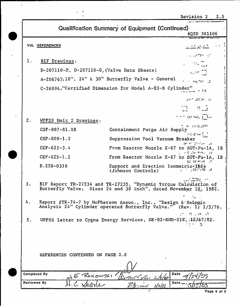
Vill. REFERENCES
' * \
D-207110-P., D-207110-G,(Valve Data Sheets)
A-206767,18", 24" & 30" Butterfly Valve - General
C-26096,"Certified Dimension for Model A-83-B Cylinder"
> ~
'l~ ~
2. 4'PPSS Unit 2 Drawin s:
CSP-807-81 '8CSP-809-1.2
CEP-625-3.4
CEP-625-1.2
D.220-0310
Containment Purge Air Supply» ~ >" pr
Suppression Pool Vacuum Breaker
From Reactor Nozzle X-67 to SGT-Fu-lA,~ (>>
From Reactor Nozzle X-67 to SGT-Fu-lA,>>> >g
Support and Erection Isometric-IR64(Johnson Controls)
~ >
1B'B,
l
3. BIF Report TR-27234 and TR-27235, "Dynamic Torque Calculation ofButterfly Valve; Sizes 24 and 30 inch", dated November 1P, 1982.
4. Report //TR-74-7 by McPherson Assoc., Inc., "Design 6 SeismicAnalysis 24" Cylinder operated Butterfly Valve." (Rev. 1) 1/5/76.
5. WPPSS letter to Cygna Energy Services, GE-02-RVH-018',-12/47/82.
REFERENCES CONTINUED ON PAGE 2.6
Completed By
Rovlowod By
gP l>
~t<a'A~>t ~p~.,~>.../~ ~. +b'g'/>>$
g$~ j($p '. ~~ g glcj'/fgPago 5 of 5

hl ~ J At
C ~
1~ c'
P
'I
I
I

c
IIIIIIIIIIIIIIIIIIIIIIIIIIIIII
CalculationSheet
. /PcoIect Prepared By: "II .I Date
Washin ton Public Power Su l S stem L.C.~ Fernandez 5/27/83I
Subtect Checked By.Equipment Seismic/Hydrodynamic Requal.
Date+ .-~/=~
CSP & CEP 82044 OT.01.F
QID 361106Rev. No.
2Sheet No.
2.6
SECTION 4.4. REFERENCES (CONTINUED):
~ ~~i 4 - .. ~j-/z: rQ.pr.c~~~~J c/g// c
6. Cygna Energy Services Communications Report, R. Ricappito,BIF Valve, and J. Rakowski, CES, "BIF'alve Dimensions",2/11/83.
7. Cygna Energy Services, Project Manual Design Criteria,DC-1, Rev. 1, November, 1982.
8. Cygna Energy Services, Equipment Qualification WalkdownVerification Forms, Revision 1, dated 1/5/83.
9. WPPSS, %3P-2, Safety Related Mechanical Equipment ListSummary Sheets, dated 2/10/83.
10. "AISC Manual of Steel Construction", American Instituteof Steel Construction, 8th Edition, 1980.
ll. Preliminary Transfer of Final Burns & Roe Piping Loadsfor CSP-V-1,2,3,4,5,6 and CEP-V-3A&4A, received 4/13/83.
12. Cygna Energy Services, "Equipment Seismic and HydrodynamicRequalification of 30" Cylinder Operated Butterfly Valvesfor CSP-V-1, & 2, and CEP-V-lA, & 2A," File No. OS.01.F,QID No. 361104, Revision l, June, 1983.
13. Cygna Energy Services, "Equipment Seismic and HydrodynamicRequalification for 8", 10" and 12" Bore Air CylinderOperators," File No. 1P.01.F, QID No. 018001, Revision 0,May, 1983.
14. USNRC, "Standard Review Plan, NUREG-0800"
15. Cygna Energy Services, "Equipment Seismic and HydrodynamicRequalification of 24" Cylinder Operated Butterfly Valvesfor CSP-V-3,4,5,6, & 9 and CEP-V-3A & 4A," File No. OT.01.F,QID No. 361106, Revision 3, June, 1983.
ccoe co
IIIIIIIIIIIIIIIIIIIIIIIIIIIIII
CalculationSheet
Pcotect I~ . ~ < / . w P)cpa)ed By., (/ Date( t.'.J/I- (..) > ( DIJ" Iv:nd T..<(! Jg, )
Subject . C C.. v, . ( I . '. I I: L:; .
System,."'t -c''gi-
Checked By
Job No
Date
File No;r 9 I
Analysis No, r I I Rev, No. Sheet No.2 7
,,)
C'g 'I,
I
(
'l
lI j( ~)a /
;r ~ .,$
;V I E.( k; I.
/ ~Pl/~'!Z": t.i-
Acc
X
~( Ql.'r T(ci J
Y
(Q'( tZ,CO Vt~mE. )J~
i ( ~=-std(cga(od
, c/s/--.Pcj'~„w. g I "~((. '(,,I;,I Ig,c I )
'.',/I'+ g- C!
~NP a/
:" "I'-./- ~i
I'P:,/: f..
I'('-< -,%
)'
yY
/'-,'l IAi;C;'n
I
Cr, I
r ~ ( i ( ~
~ 1li rI
C,('I'7
<i.. 7l
C
I (7
/'i Cr, s ~
( ~
/-;
r: fg(,~ I'r ')
- ./-'. j-„~ os JC
I
ng~ P ~r.'I~e. J-q/,."
2 <Ys
~ Pi(5,. l
/I.~ /
( I
(„C) ~~Z
,. I/I /i/./4'.6'C-.
; wQ
n,: I(
I c /PZI!( (
Q'C I(J
Ii ( /
1005 OC

TABLE Or CONTENTS QXDN 361106
SECTION
1.0
2.0
3.0
4.0
4.1
4.2
4.3
4.3.1
4.3.2
4.4
5.0
5.1
5.2
5.3
5.4
5.5
6.0
TITLE
Requalification CertificateSQRT Forms
Table of Contents
Requalification Analysis
Conclusions
Summary of Results
Analysis
Introduction
Calculations
References
Appendices
Response Spectra
Nalkdown Sheets
Valve Local Coordinate Systems
SRM Sheets
Final Pipe-Mounted EquipmentResponse G-levelsDrawings
NO OF PAGES
66 +Appendices
21
Revision 3

TABLE OF CONTENTS
CON'TQIDI 361106
SECTION TTTLE NO OF PAGES
7.0
7.1
7.2
7.3
7.4
Transmittals, Prior Calculationsand Reports
Communication Reports & Correspondence
Old Regualification 6 SQRT Forms
BXF Report
McPherson Associates Analysis
37
98
75

SECTION 4.0
REQUALIFICATION ANALYSIS

4I 4 O4 OW
Pt
I

IIIIIIIIIIIIIIIIIIIIIIIIIIIIII
CalculationCoverSheet
Project Job No. 82044
E ui ment Seismic & H drod namic RequalificatioA'" 'T.01/FClient
Washin ton Public Power Su ply SystemSubject
Gale. Set No. ]No. of Sheets
Seismic Qualification of 24" Cylinder Operated Butterfly ValvesQID 361106, EPN ifICSP-V-3,4,5,6 & 9, and CEP-V-3A & 4A
Statement of Problem
The equipment qualification was performed based on calculations usingvalve and operator response g-levels transmitted by the A/E,(Finalpiping loads dated 3/31/83) .
Sources of Data
See sheets 4.3.65 and 4.3.66
Sources of Formulae & References
See sheets 4.3.65 and 4.3.66
Remarks
None
Originators
J. Rakowski
Checkers
D. Searle
L. Kaner
Distribution
WPPSS-2
Project File-1
Revision No.
Supersedes Calculation Set No.
Revision 2
M. Scott
f005 00
LC FernandeApproved By:
~P+Date:
Ii
t /yg'Xg

IIIIIIIIIIIIIIIIIIIIIIIIIIIIII
CalculationSheet
Project
Subject
Prepared
By.'hecked
By;
Date
Date
System Job No. Fite No.
Analysis No. Rev, No. Sheet No.
CONTENTS
4.1
4.2
4.3
4.3.1
4.3.2
4.4
Calculation Cover Sheet
Conclusions
Summary of Results
Analysis
Introduction
Calculations
References
rccs cc

IIIIIIIIIIIIIIIIIIIIIIIIIIIIII
CalculationSheet
project
Subject
System
Analysis No. Rev. No.
Prepared By:
CheckedBy.'ob
No.
Sheet No,
File No.
Date
Date
SECTION 4.1
CONCLUSIONS

IIIIIIIIIIIIIIIIIIIIIIIIIIIIII
CalculationSheet
Project .WPPSS Equipment SeismicH drod namz.c Re ualification
Subject BIF Valves/Miller Operators
Prepared By, Oate 6'9 83
Ã. ~ay, ~ 4, 6/9/83System
CEP 6 CSPAnalysis No,
361106Rev. No.
Job No.82044
Sheet No,4.1.1
File Jlo.1T.01.F
CONCLUSIONS
Seven 24-inch BZF,Butterfly valves with Miller Air Productscylinder operators have been analyzed for structuralintegrity and operability for the plant, specific seismicand hydrodynamic piping loads transmitted from Burns andRoe. ,These piping loads are in the form of air operatorresponse G-levels (Section 5.5, dated March 31, 1983) .
The valves will be qualified after incorporating thefollowing modifications:
1). Remove the existing operator bracket attach-ment bolts (A-307) and replace with an A-325or A-490 bolt.
2) Reinforce the operator support ears with theaddition of shear plates as shown on page4.3-48 or 4.3-54 of 361106, Rev. 3 (this report) .

IIIIIIIIIIIIIIIIIIIIIIIIIIIIII
CalculationSheet
Project Prepared By; Date
Subject Checked By: Date
System
Analysis No, Rev. No.
Job No.
Sheet No.
Fite No.
SECTION 4.2
SUMMARY OF RESULTS
rooe oo
IIIIIIIIIIIIIIIIIIIIIIIIIIIIII
CalculationSheet
WPPSS MECHANICAL EQ
Subject 24" Butterfly ValvesSystem
CSP it'r CEP
Prepared By
Checked By;
Job No.82044
Date'3z, 33 aolas
File No.OT.01.F
Analysis No.36110
Rev. No. Sheet No. 36 1 1 06 -~Z-
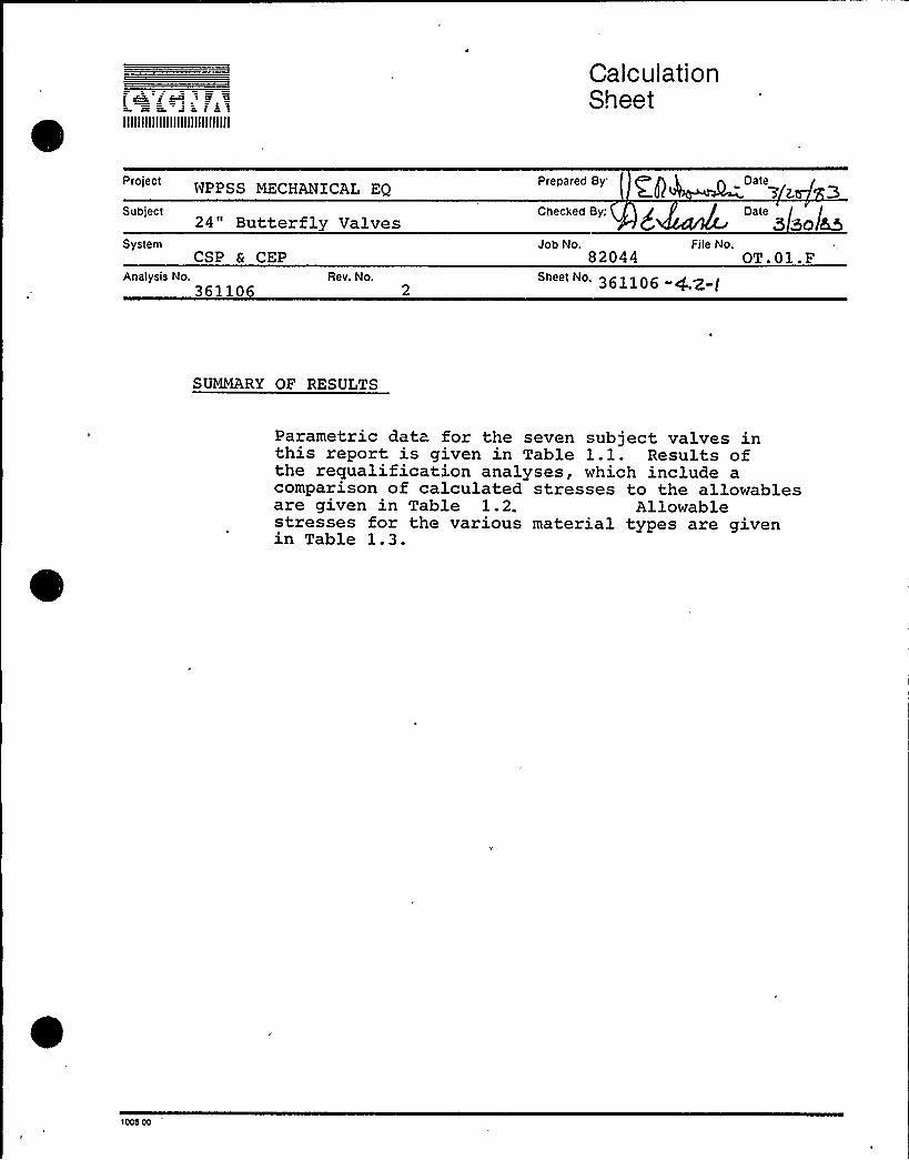
SUMMARY OF RESULTS
Parametric data for the seven subject valves inthis report, is given in Table 1.1. Results ofthe requalification analyses, which include acomparison of calculated stresses to the allowablesare given in Table 1.2. Allowablestresses for the various material types are givenin Table 1.3.
'Iccb co

s. ~ B. JIIIIIIIIIIIIIIIIIIIIIIIIIIIIII
CalculationSheet
Subject "< 8v ,,e'—f.=.'.- Id(.lr-." Checked By:
Date,~g,r.)
Date
System Job No.... r ~ File No./". 3 I..=
Analysis No. R Sheet No.
5/9/ ~>Pc~ m. c /~/6
/ ("'/~i~I e fl, v'pga«.« I ~ t
/ 'nE. I
EL. / C>)". X,Y'/-.le@"'-KOu
//'-s~
'-,; i/.;" f,dr jtt'„
Accc cAr.r/
/ t, I,V
~45> ol~ &e, sj ~1' St ~iCA rlo~
"- i- i'-3
gc/',I =g'- t/-
/> v-.J.:/-':r"6'/ - /<i(-;'
yY
t:(C
lc'. /~
h'r)
St
C', iaZ%z
I~ ~
w7~ /»
/'
3W
/ Q9
c'. $g~r 7
g /»/n
9 5-?
gt
i
g>//
W/«/
//. 57 ~ /5/1 / / h '7/'
r ~ /~ pig
'1008 00

~ >~ ~>» aur-(ra+~-l. 1 f .aLE. I.Z
CW ttt. — lt.t ~'3 )F A t.) I -TEt t. <br"lU le Ot .)
hh L><STec.
Rvi li rto> I QtP.I5'A.Z (/c. cc
FA>r'V.L'r l-tt.L SA. 27tc SLt'rVt. V-
LLVr-R. r-LYLI-l'-Y
MC)C
rnAtt4 = lr-I-T 5A-47/
ADIOS IIW8 (IO i.ra<
C/O4ZO r.rAg
7+BI I IA c
9 IZ7 rrAWE.CaTr
-4 4»i>t" g . t,,t+LCr
vh,l vc t,btr vJL1c
g r4ag
I>i-S23 I Cc>Z'3
//F45I4< -/O
33OI 7 IO&Q/a ~vz zoril&I<>4 75 /e4&z
to43/DP 0
~S~~C 4
7Q CoZ
-"~Z6 /D~/Gl rr9 <c> /3@
YALvE EPI 1 5C„-y-V-~r C. V~-V -~ g~~t/-q C- l- I-(~ 4CP->I--„0 Cr 8-'4-'(A
(V(RTQrc'Ar
gl.l gurP ~l.F.
((e-4aI I &4o
4+200g~ Z CIO
i=I~ooac=/ ooQ &OA32 &Z~O
DP>Qh~
DICC>>
CC>
Z0
Z0
iCID
!I,
P)
'00IDCt
(l
ir
~>
~p~a ><el~SRZ.7t'PlVl.
DrO"t
~g:ctt lir:>~ l t
St {C~I lL
+LLEW
~~- T/4-
E<~
d 52<~~~~II.
QI.LI,IL i/Dr >. tLt„'> Q<,Q
tribrrfL'( l
FATI@vs Ke==vr- t~~- ~ r.lc~t-. t W
<r <cDCt5g 8 I Z(r Q C-(rC>tc. &/b<jrrd VpIC
> C»~ cc'>I
/O /hh
Ar~ulAMLctc>+r+g 'l».'AlJI g.
4)O GOO
goooo9oodo9 Z+pOO
Z0
4lG'
l(.rr
Z
(x
(:i
0
aI
O
Xs
CD
D>I
O
I
IIIIIIIIIIIIIIIIIIIIIIIIIIIIII
CalculationSheet
WPPSS EQPrepared By: mV3
SubjectII
Checked By, Date8 55
System
Analysis No.361106
Rev. No.
82044File No.
OT.01/F
3@/lb/ -4.z-
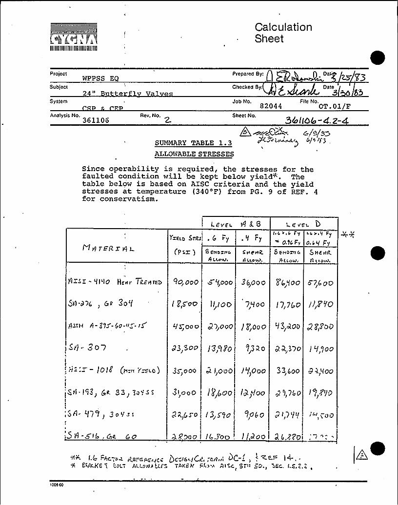
SUMMARY TABLE 1.3ALLONABLESTRESSES
Qo ~~cCZ» c io/s>P(>d- Q)m~r) ~/ I I/')
Since operability is required, the stresses for thefaulted condition will be kept below yield. Thetable below is based on AISC criteria and the yieldstresses at temperature (340'F) from PG. 9 of REF. 4for conservatism.
Levee A 8. 8 aV C
NH TEI2zg L (ps' 8 E'II bg)I0L
)I ccawi
y'=kCb StaS~, 5 t=y ,tI Fy
5 IIe'wiZ.
il
ecole.
reC,II ~ & I y" O.NFy
S coro~~ o
5 CCoo)
I s >.Il Fy
O.l,q S'y
$ H4'HR.
H SZ - 'll'IO Hertr I PEIlaa RO, OoO > '/oooo 3'6,ooo F(o,goo 5 7,Q oc
SyI-a><, C t ZD'/
8- gas-io-«„-- )S
/ P,s-oO
qS;ooo
J/,I oo 7,"/oo /7, /(,g I/,7 /C)
33~ooo / p Ooo c/3 QOO g /Sory
~ii- ZO7
.:. — /O/Z (>-n 'i'=co )
IoI3 5OO
$S) ooo
/3'lh'O
oc liooO
33 2 o 0 237o / '/ )oo
/ "/>Ooo 33, boo 9 k,Moo
l
pH- I"l3> Qtt. 93> jo~S 5
I
// / / 3 o'/S'.
'~ 8-5 ll C~a, t'
3l,ooO / gggOO /3)!oo g '/) /~o
g4i~so /3,5 /o lobo — 7'/'/ <-'"oo
oooo /r, )oo . I/>oo I.aI.)Poi ~I
I.4 ">< i4 r=F".Pciyr„< Qc,-ih~ICZ,,CR i l~C ' Ze- I ~ ~-EVOKE 5 I'.O'=I ACt.cu)~ LES TAr<E k Fio ) ~lt C, ST'It =D.I HAEC,. l.5,).=
g ~I 000 00

SECTION 4.3
ANALYSIS

z cz = s =- f = iIIIIIIIIIIIIIIIIIIIIIIIIIIIIII
CalculationSheet
Pro ect Prepared By:GPSS Mechanical E ui ment Qualification ""1 10
Artalvsis No.361106
Rev. No.
Subject24" Butterflv Valves
System
Checked B i 2 ) Date. XJ..~'.~(
82044 'T.01/FSheet No.
361106 "4.>-I
EQUIPMENT REQUALIFICATION FOR QID 36110
BIF 24" CYLINDER OPERATOR BUTTERFLY VALVES
4.3.1 Introduction
The seven valves in this file are classified accordingto the parametric data given in Summary Table 1 ~ 1.
Since hydrodynamic loads apply in certain cases, fatigueanalyses were provided for components with the higheststress ranges.
The calculated stresses are based on valve and operatorG-levels calculated from the piping analysis and re-
'eivedfrom Burns 6 Roe. Since theseloads were initial-ly too high to qualify all EPN's the response G-levelswere subsequently recalculated with some of the con-servatisms removed from the piping analysis. In ad-dition, an SRSS analysis was set up in a computer pro-gram for each valve EPN in its specific orientation inthe piping system (see Section 5.4). Each computerprogram (Appendix A) is compiled and hence not subjectto subsequent change unless recompiled (and documented).
The method calculates stress from the north, vertical,and east component of operator response g-levels. TheSRSS is taken at the stress level and operating loadsdue to seating torque force and dead weight are latercombined by an absolute sum. Valve ear bending stresscomponents due to any one response g-level componentare combined by an absolute sum.
1000 00
IIIIIIIIIIIIIIIIIIIIIIIIIIIIII
CalculationSheet
'CVSS Mechanical Equipment Qualification ' "'2~ 1/10/83Sub e~t2k'utterfl Valves
Checked By ~ 1 i J Dateje m,I./~~SystemCSP & CEP
Job No.82044
File No.OT.01 F
Rev, No.361106 - g,g g
The computer analysis addresses only the more highlystressed components in the valve operator assembly.Separate analysis is given for the remaining compo-nents using a simpler approach with upper bound loads.This applies to all valve operator EPN's in QID 361106(24" Valve/8" cylinders) and QXD 361104'(30" valves/10"operators). Hand calculations which check selected por-tions of oomputer output gt-e, shown in Appendix C.
Appendix B of this section describes the air operatormass/stiffness model which was incorporated in thefinal piping analysis for calculation of operator re-sponse g-levels. The computer program includes an op-tion for using the valve ear forces and moments whichare directly output from the piping analysis with thevalve/operator model included. This was not finallyutilized, however, to qualify the subject equipment.
The equipment locations and elevations were taken fromthe PAID's in section 6.0. Natural frequency calcu-lations are given for the air operator assembliesin Section 4.3.2.1.
Preliminary analyses were performed which showedthat, for operator response g-levels greater than ap-proximately 3 g's, the air cylinder spring preloadforce would be exceeded and hence some disk flutterwould occur when the valve is in the open position.The calculation in section 4.3.2.2 shows that the mag-nitude of the valve disk flutter vibration angle dueto upper bound g-levels which occur in the hydro-dynamic frequency range is approximately 6 degrees.This flutter was evaluated to have no detrimentaleffect'n system safety function as noted in Reference5.
Valve operability was addressed in the following manner.For the valves with Use Code 2, operability after theevent can be assured by demonstrating that faulted con-dition stresses remain below elastic limits (seeSummary of Results.
~cce cc

IIIIIIIIIIIIIIIIIIIIIIIIIIIIII
CalculationSheet
Proiect Prepared By:WPPSS Mechanical- E ui ment ualification 1 10 8Subject I Checked B g r Date24" Butterfl F v ..:-X.iA r, .: -Q,."rgSySterh Job No. File No.
Rev. No. Sheet No.361106
For valves CSP-V-3 and 4, which must operate from opento fail closed during an event, the following additionalevaluations were made:
1) Dynamic flow torques were assessed per Ref. 3and found to be less than the seating torquewhich controlled the equipment ~tresses.Furthermore these flow torques tend to movethe valve disk toward the fail-closed position,as noted in the above report.
2) The details of BIF drawing 206 767> parts ofwhich are shown in figures 1.1 and 1.2, allowthe following conclusions to be made for valveoperability:A) Figure 1.1 shows that thrust bearings are
part of the shaft bearing design. Thisdesign prevents lateral movement of thedisk in the direction of the shaft to eli-minate interference with the valve bodywhen closing. Further, it is noted onPage 26 of Ref. 3 that frictional torquesin the shaft bearing system are negligible.
B) Figures 1.1 and 1.2 show a circular valvecross section having an internal rim withinwhich the valve seats, in the closed posi-tion. The only mechanism remaining to af-fect valve closing which can be postulatedis out-of-round distortion of the sectiondue to DBE piping loads and dynamic loadson the valve.
These loads were accounted for in Ref. 4 in the overallvalve sizing calculations, where analysis showed thatthe stress intensity in the 0.5 inch thick valve bodyremained below 1.2 Sri, or approximately 0.8 of yield.Stress contribution from dynamic loads on the valveand operator were relatively small. Further, as shownin the figures:
1005 co

n~ >~ ICJ
7HP ~. ~ I; 3J'f
~',~9 <~k fP'>'i
q~ .' fk
) fP; ~
1I'." ~ ~ It ~ ~f f~
g Lf 4 rig \~ i
~ r ~
I ~ l ~
FIGURE /. 1 BIF o~u I~ ZOIC 7
1 C
.6
(AC0n
Z0
I
e)
giQ (g~CO
Z0
0CJ
Z0
O
n
0(9
+ ~
r
j r
~ .
~ ~~~
~
5 4 l0 iO
t
4-
eE, Df,r~~i 4
(- ti(o
Z0
rp0ID
A.
fh
'2I(gt

IIIIIIIIIIIIIIIIIIIIIIIIIIIIII
CalculationSheet
protect ~ ~ r Rrepareo By,jw IZA'MA'c.t ~pj's. ~ QSuotect Criecriec By z, / Date
, Jl';;zJC '~pl /S vs't e frt
Ararys.s No~g, r Qr'n
Rev No
Joo No,w7hdc
Srreet No 3'.-
File No<'r ')1= .
~ ~ ~
'
~ ~ r(
NI
~ ica'ItI ~ r y
r i ' '' / jQL~7iL
I~ ~
F't&Ulif (, p BIF'<I'lu i~& ao&7C- 7 t DE7 A(c
'ccc c

h t lIIIIIIIIIIIIIIIIIIIIIIIIIIIIII
CalculationSheet
Proiec! Prepared ByI DateWPPSS Mechanical E ui ment ualification 1/10 83
SubjectII
SystemV lv
Checked
Job No. File No.
An~lys~ N~. Rev. No.361106 - +, g
The valve seat forms a heavily reinforced section madeup of the valve body, internal hub and external flanges(including the mating flange of the piping). Hence thestress levels in this section are much lower than inthe valve'ody and hence no distortion of the sectioncould occur to affect seating'f the valve. Valveflange dimensions are given below. Note the relativelylarge internal radial clearance of 1/8 inch.
2 Stress analysis of the valve extended structures aregiven in this report. Air operator operability isaddressed in QID 018001.
The design data used in the analyses are given inSummary Table 1.1 (pipe-orientations and elevationsare taken from the appropriate PAID's in Section 6.0).Other pertinant data is given below.
1) Spring preload per communication reportin Section 7.0 of QID 018001 are:
Fail Open Preload =350'inal
= 1850ijj
Fail Closed Preload = 15009Final = 30008
2) Cylinder C.G.'s shown on the following sketchesrepresent data received from BIF in the communi-cation report of Section 7.0 of QID 018001.
3) Closing torque values are taken from Ref. 3.
4) Valve component dimensions: (Ref. Feb. 10, 11/83communication report - Section 7)/Flange: width = 3.5", thickness = 1.78"Radial Clearance Disk/Seat 1/8"
rccs co
00
/
I
r J
rI
~ 0
~ I ~I
lS
) r
~ ~ $ e
0Q ~
~ ~

e
~I
tIrr
tr
p J'
iJ
4
y ~
I
yO
< rr
g 0
~ ~ '
l0 +
~ S4

IIIIIIIIIIIIIIIIIIIIIIIIIIIIII
CalculationSheet
project Prepared By: ~p> ~ () . OateGPSS M'anical E i men ualific ion
SubjectII
Checked By . -.:, ~,„,,/ Date
SystemC
Analysis No. Re|r. No.r~
Job No.
Sheet No.
82044File No.
OT.01 F
4.3.2 CALCULATIONS
4.3.2.1 NATURAL FREQUENCY CALCULATTONS
Perform. natural frequency calculations for the fol-lowing four operator configurations:
Grou I - Fail 0 en
EPN's CSP-V-5 6> and 9
Case |: Valve Open
Case I|: Valve Closed
Grou II - Fail Closed
EPN's CSP-V- 3 and 4 and CEP-V-3A and 4A
Case I Valve Open
Case II Valve Closed
>00b CO

't t L~ a i=«IIIIIIIIIIIIIIIIIIIIIIIIIIIIII
v~~ %1«ey in~<Projectll
Subject Sow~=-==.t v
Calculation SheetPrepared By:
'"'fl . < jim a.
Checked Bg:6 i- t'e \,
Job No File No
Date
I.iDate
li/g...
OT'.C I l»System «
Analysis No.E ~ ~ ~
Rev. No.
Sheet No.
~& «I'O~ - ~ -.0
« ~t:— . «A. QR.kL r ~.= 3 9=>~«~~'«-CYl «NQ Mt=a ~%=Ac;,Q~ iOQ~ TO
I
5 T 1 P 1=NB~~c ~~@,«o-.- . TH ES'E r-PLmt A TsorVS itlsSLjwZ
TH RT OPS<A T OP Pf STdAI RE+AWQ SEA Tl*0 tI&BfI) ST 7H»
C PE)J Ofe. Ct OSLO POSITION STOP BY ~T(ON Ql= t HE /felt)t".Vp.«VZ
4-o. ooCt—v«e R~ ~ Z« l.79 @Roc
5 >
I~op. I I-
the«H SPA,«- t
5 dc~«
l t. M r t M1 CO'N
FA
O.4 aI ~ 1 i f D o
' ~t
CALC UI >TION OF FQ:
3Q s'~ io.lg) =, ~ I+5SEZ'(~~ XIO ) (~~.2- !
» iiI8 BFI~ED
'A.V
3 /
«ooe oo

Calculation SheetPrepared By.'
Ghee ed By:
Date
Datet
IIIIIIIIIIIIIIIIIIIIIIIIIIIIII
Project
Subject
System
mD> Q
Analysis No. ~ l l ~+Rev. No.
Job No. File No, li <Sheet No.
~ ~ I'" '3 '~ " 4.6-! I
R~-W t l al AT W D V:— TO M>/M~4.<l
8(o30 KI 1 = ~Os(lO..t',t
= ~+WQ ~
dO OOt3.S
t0.% r
S4 wVazz lQR.'BC 30. S
oZ,> 49 ~ a~ BC KC> ~ %o.s~ = '7sRz.g
( zc,silS~Z. 4 g z j l04&74 Z,
f sa4.~~ r( ][t-' llew 7
4EA 1
qAa."A Q>o4. I
AacACc ««. = ~ (z( .~) = s.e ~,~
Az=~ '2
pent'AHQ
Lt=
C@= -'- (ia.m)= +.V~Pi
h / w ~
1 F,lA ~+L~~
I/-. = z. ( tZ .~) r': =,=> =:=..< . ~I
5 ~(Z ( %ac'r,( 'rr (C t
(A~a,=-,'l-t'Kr=t l- ((..-i ~).'=.=~ ~l-(~Jr'==<~.=.
R~= )Qgc t4.
4 llW (. ~4alS-;.SZ~ ~ le
7 Rl tm7. 'Z
1
wo )+ iiaa.w(~~ ) =ac <~w ~- ~:.-1
- CO~5 M~
1C06 00

Calculation SheetPrepared By;
~{3 i ~r „I I
Date
Oate
IIIIIIIIIIIIIIIIIIIIIIIIIIIIII
Project
Subject
System
6<F'~t rII 3 IZ4 ~Q — ~I + I AL~l
Job No.
Sheet No.
File No
Q t
/ tl~/'nalysisNo. ~ '' ~~ Rev. No.
'lQ > QF Pa<BT',
(A, dUM ~ Qm. OO I I'D m ( I O. tf )
~ mt 7 {
l<TAt EA = EOQO'PS~ J Ol l t = EO'~$ {
KV 7~0 ~ W /t r
.OiS)\
ZUt Z»o~.~«'-.4 ZC O> H=g'l l
( DEAD, 4T OF +VI Ql —WTQ S I )
tlZM ~ 0 t'l. J&
It
ll.75Fc
~I3.E 3)
A

Calculation SheetPrepared By:
Checked By:
Date ~
lt ~
~ t l
Date
IIIIIIIIIIIIIIIIIIIIIIIIIIIIII
Project
Subject
System
-w ~r.. lJ'trot V =
CSP ~ i~ -PJob No
Sheel No,
File No
Q
t-0'nalysis
No. ~ ~ "~ ~ Rev. No.500QHlT
'OA..~GOD '1
~ 7- g -0001 7'&g pz- to'(az.z)
k
tl.1>
ROT'4T l 0 h4 AT 8 DOc= TO Mo C~ 't'-. ~Ot"'t +
2S IW
>t
11.78
'I%6 00
—5

Calculation SheetPrepared By:
\1 )
ChewedBy;
Gate
Date
IIIIIIIIIIIIIIIIIIIIIIIIIIIIII
Projecttt
Subject U»~ Job No. File No
0System pat ~r ~~ r—
Sheet No.\
Analysis No Rev. No.
/ V.G 7+)<Ij .I l.~~
/1 t.'l~tlO'7. g —.~ ) = IQ>H .+7
'E
e- > m C:7 g O Mi
ttAV 7'c) t ~w P,
\l <rt
)04(c O E(~~.4)t

Calculation SheetPrepared By;
I
~- I I!. 1
Checked By.'
Date
'll Li> )a=Date
J'IIIIIIIIIIIIIIIIIIIIIIIIIIIII
Project + <0 0 t Y
ZH Mu = =" r-'/-C~P s PEP
Analysis No. -+ I 0 Rev. No.
C ft 1%~i
Job No. File No,
\ D)r t
Sheet No,
> I I cD tw ——.a —I ~
TQ~K~ t- ~.=~U=W~C., &=. t i-'t=
~Yl 'l'I l ~~ CO~-, < t COB DUE. 05'TLI=FN=—GK a~ r +=- D%'J= RoCC YllH~~ tZ. ~~t —~.T ~ t=z
gas= 6 X ALv~ &=—w
Civet~ Pi~
S. l F
AQ. 00I.7B (5 Rn~
lO. Q-1 I
I =~d
P
t0 ~ PlAtN QtJAl=| I R.~ &1 cp% ~i M
d~ I '4~
CAI-CULAt Od dF
PP„5' l,o,~<>z(z~')(~(o) sz z)
/VfIl bl g AD e cI =..~a"
rg V t
LJclil
/ 1E

Calculation SheetPrepared By:
I A. >t e "l,(Checked
By.'at tt ~=Date
I L s
IIIIIIIIIIIIIIIIIIIIIIIIIIIIII
project
Subject
System .~* 4 7Aev. No.
c- ot v WT' 4DI .~~ tM )j t~/~
wP ~ >~~Job No. Fife No.-.. z-.— 0Sheet No.
M t= I I Q(m ——.' 10
~-,r. T t Ow~l
O'Qc= ~O NL~ W= l: W'A.~'~~~ l
3$ IE vl = ~oo(ta.-.w)~ ='l'ZQ w
4O.O
'I 3.
>o. ~4
pig.o,Rg. I
52 2Z>eZ t <. ISS2.K
3a't 2.
~ 4&
~,= (-;7-..-)(' ) =~~~o4.a~ ts.l ~ w4,~i'5'~= ( — ) ('~ w3 = 1IOQ.'0
Cg ~~ A ~rI gc
R-=t 3 ~ o —"7.
''7.(o7 4Ra r o4, ~~ t. ~~ )+ h)oo,&44c w~.wZ+ I QSS ~ -Z . >~ lw~ c aa
7o Ql l~
a3. 7X
1006 00

Calculation SheetPrepared By;
-'('< t. t~ir.r ~Checked By;
Date
Date
Project
SubjectJob No.
s:644Fite No.
.a„ /;—System
Analysis No. —- Rev. No.
Sheet No,
>llGH-~ 5-l r
-O t ~
(( ~B~a~)
ot=
~ I'I t.75 'l3.3

'a ratIIIIIIIIIIIIIIIIIIIIIIIIIIIIII
Calculation Sheet
Projectn
Subject
Prepared By:
Checked By;
4 ."':.-rr jJob No.
: O-'\ ~
Date
Date
File No,
O-i. Oi I=System I
Analysis No. ~~ t t ~~ Rev. No.
~<t c &~r ~ 'wt~=~~= (,tA .~~) .GOO=-(z-
Sheet No.
991 1 Q~
OSZ
~co:FvatT'ADA
'l~ lr A if/Ro-.a<i os Ai D 'bu a <ia
w 32+.&72&
tttHo
13.a
M = ~a~(L4,4 &)7
72&60
5 Z ~ Z.
D ZZKW &K. ~ I
O. gm
tt ~ G Q'8,= ~ZB+ 4 z )=4IS72,%/i~a Hh~4 > rt '~t ~
=i, ~ g>s.+)=is<~A. i i
4~ l '14 RKA, rL
I
/
tbQ.~thJ.
't B.K CQ z = (ig.S) ~ Q.7~A~ = .'i ~,~ ~~=. ' &SO V"iI gtF-. N6,t—
'2CG„= s(ia ~)= w o$g = =
(i" 4i(isa,--'i-( = (i'~$~~
( G,~ = (Ct ggA.~) -'I'.~=: — .,A-,
A~-A~= (~.~~+ac.c.i -:(-w"Y-.~.O
WAD.D',
+Q t~

IIIIIIIIIIIIIIIIIIIIIIIIIIIIII
CalculationSheet
ProjectWPP M
Subjectll t
Prepared 8:
Checked Q ""a/s0!'asSystem
Anatysis No. Rev. No.
Job No,
Sheet No,
82044File No.
OT.01 F
RB 41572.5 25+ 1364.99 25
= 12754.44 + 1042.85 = 13797.297.67 19 '
0> = . 6—= .000476 rad13797.29
B 29~106Deflection at Point "A"
SA'ue to eB.000476(14.46)
.0069
Total SA = .0069 + .000032 = .0069
V = —= 72306.998/TN5004..00691fn =—
(72307) (386.4) = 42.12 Hz3
C7tLCUL rk'rtcddd OF /he P7k0dkQkL iD i4II 0f kr-(= fd."k
A yg Ta,"ud [O U p<<C
C»iW4hrkg
1008 00

L ~ = jIIIIIIIIIIIIIIIIIIIIIIIIIIIIII
CalculationSheet
Subject24" Butterfl Valves
SystemCSP and CEP
Checked B
Job No,82044
Protect Prepared By(WPPSS Mechanical E ui ment ualificati , Date
""slsolisFile No,
OT.01/FAnalysis No„
361106Rev No. Sheet No.
361106 -+. Q-
TALC uLJI trog oF
gpss
IA "cALLgL To TH 5, PRAISE Rdl7 4P>P LIyutOP
App. sPL",
3 > 2,.'f((o) w Z.IC
(Ze.~)-7
gl~
4. Ir
(Z.IQ Ig Fck Ecy~p
(P.WQ tp Fojt'o C.W )
SRLLCRE7 'K7LFFiYEES Ls: (Cg LvLLLEEYC. ttE*M OF EFFii"-TLYE 2~)
- (LUh~ +LUgg ) ( LQMZ77)E'K't.C
I.7( |M- ~'I
M
tti Lofti j,, >I.'Z~
RIV E, Job
htf.E,, ~+ ~$Q
C PAL E &4 c'5 <Ttf F N C- < = Ehr= ~':E'Nbtdrco
EPf$ l(+FQhs5kyy4$ 1(05/~(lo)~ 7 t Fr. HL -S7.Sero) g„(2 )
I
zz l l~
LOC6 et

I Jh: =':.
IIIIIIIIIIIIIIIIIIIIIIIIIIIIII
CalculationSheet
Pro'ect ~ ...Prepared By: I , DateGPSS biechanical E ui ment Qualification > as.Subject,24" Butterfl ValvesSystem
Checked 8
82044 OT.01/FAnalysis No.
361106Rev. No. Sheet No.
361106 - Q-g - 7
4,3.z. 2
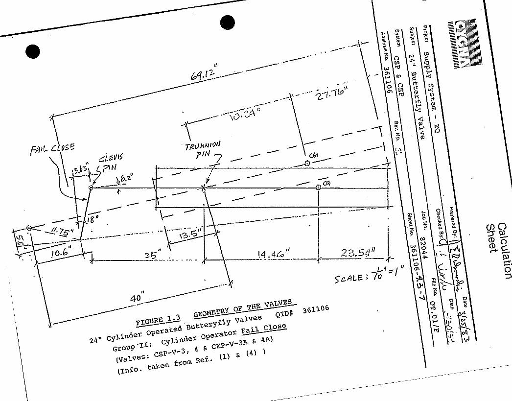
Jig>g t PINi.gue(o 0+ FPo~ FIGUf 6 l.5
5.3 td
~ lO.s —q
r"('PQ 'SEE'JP7 I tg PI y jst S Sg hnE THAT THE. jt(I((IA j)C„(. LEEP ( iW CdMW/FAITC(U~(r'O'T FCcr Ni <HE. F'IP(9 r" Q urtLy SIg Fdk CSP'-V - 5( CIP&V j Petr= OF-0) Flc.~e uCL< Ot>PI (a cX. Wr-W, ~ OI=
THE A IL Qg( ~To~ RELA t tv t'o FH( PII < lM TH="
Fo R.M 0 f-
'lees Cs

IIIIIIIIIIIIIIIIIIIIIIIIIIIIII
CalculationSheet
QN88 Mechanical Equipment Qualification "( 1/10/83Subiect24" Butterfl ValvesSystemCSP and CEP
Rev. No.c~
Checked 8: Date5 5d/89
Job No. File No.82044 OT.01 F
Sheet No.361106 -A.5 ZZ
4.3.2.3 STRESS ANALYSIS
The procedures for the analysis of the subject valvesare outlined below:
Recalculate the valve appurtenance stressesaddressed in Ref. 4 using response g-levelsfrom the final piping analysis. Incorporatethe current seating torque given in Ref. 3.Compare stresses to the appropriate percentage(s)of yield strength as, indicated in Summary Table 1.3.
2. Perform a fatigue analysis on significantlystressed components. Determine allowablealternating stress ranges from AISC 8th Edition,Appendix B, noting commentary.
The fatigue analysis is to be performed only for thoseEPN's subject to;hydrodynamic loads. The number ofrespective .load cycles is given below,
-LOAD COMBINATIONS G,STRESS CYCLES
The following table lists the load combinations andthe number of expected stress cycles for each com-bination. 'From the design criteria)
Combination ~Ccles1. SRV Alone 13500-200=13300 cycles2. OBE+SRV 50
3. SRV+AP+CHUG 140
4. SSE+SRV+AP+CHUG 10
Note: Load combination g4 with 150 cycles can beused to conservatively bound combinations3 and 4.
10CS CC

IIIIIIIIIIIIIIIIIIIIIIIIIIIIII
CalculationSheet
Project
Sut(ject24'utterfl Valves
Prepared By:
Checked
~ Date1 10 83""
~(ao/a~System
CSP and CEPAnatvsis No.
361106Rev. No.
Job No. File No,
Sheet No, -4 -z
f;I) ALg)I5 QF /QLVE AV~ AIR Oi==r~~<~."- C'J')~~ IEtfTQ
))DT COd EkB-9 II) QIO -O(7~(
D ~P5gggghJ fg I( PfP) uf ERE a>At )f-Br. Av r) I (l 5(lE)of<TRf= gy IA(P -
F ~~() r> ~O Pg f:g I PO+Bff Y fWZ,tlCEAJ 7ON OV'I=P TUR() fN C IIV Tf(f= =-A«5 f-(EEc «o P. UIH&b
A~I~ LM~~O ~IT(( . 'i/,>lies—pisc "wio4 c1z l3 'I
J.'n ( «e ales>r-
LIJ Q5 g 0 L f +~3 (~>LCQUf Oil- I <Q ALLOW/IPyfP.F(A S &~S'd rr- fC (ZA7 Fa" ALL EPW
(Ig f CIJ f p tlOA'-c)LLC)'utl5
(,PEP -v- 34)Lp r)
= M(~SEI)) t CC = )444L«
q, =u3A a~/ - (~qqX(a.gglLI;I-") =V@,f~F-." ~ Pit $0I'57 Qzg~ +
I>.75'11
= (Lp po Lc.r ) Wpo <1
= -'1 ",4 lB'1.(l.<c-)LFoo L zs~~
2 ~IN9 (V.
~ p
P.) o
(~ -pc ~lib
Fz~ = wAo a- — 3ez(Z.
4F
Fgyp = (2+1 — 0> IZ
MZZ.g S0
F> >— -SAT-TKi<E+cog g og
I f.qS"
ItFoIZ 8
% 6= ItSb„13'8'ft
w&t"f(T(z) =
Cd'I~E" >)C f'It(f r. D.'~ "fAIPTro g I
Zr„I +
Fo~ (O
,g r 84Iz~I'l4'Er
SIF I': t< '~c.'-.".'~t. ')'LfW
r.„,-> - = OiD~ I'=~ ~ Iip4 t'->
1OCb CO
J i fs 3
IIIIIIIIIIIIIIIIIIIIIIIIIIIIII
CalculationSheet
projectWPP M ha
Subject24" Butterfl ValvesSvstem
CSP and CEPAnalvsis No
361106Rev. No,
Job No82044
File No.OT.01 F
341 e4 -4.S-Z4
preearee atr:( jj~aate
Checked By. DateBd b3
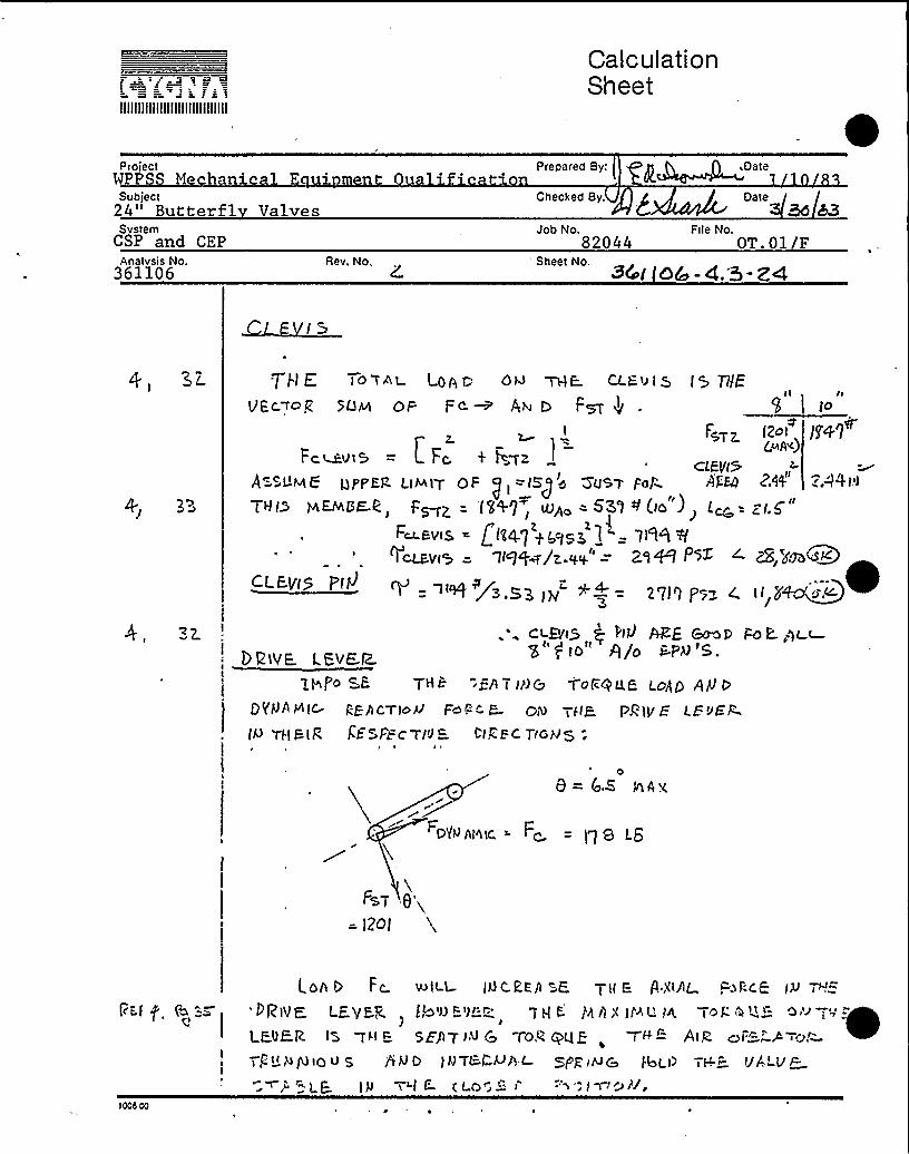
J-I E to Tnt LOA f: 0< THE.
VEC,~op SfJ~ OF FC ~ A1 ~ Fm Vl
Z.I
Fr ae:.vts = t Fc. < Fawz
A=cj g6 gppEg. LiAAq OF 1=15 e O'V~T Fol~
rrI>
/H7F i2retrih~ „)
CfFViSArea ZA4 ":A%1'1
¹(lo )~ L~r- g/.5
zq~ Psx ~ zS,pm+~<
tgig iree C ti tr~ete.
T~e pa oF e., F»z = is+7, mA -531Fet.Etrte = fitgg q.teigg j
~CLS=Vto = if If+IZ.-~+e =CLEyf5 Pfb'"'+ i~ S3 IV
ct-Ph5 Q I'10 APF ~p 1=ok.,gt t
DeiVE. I.eyer~1&P< SF- THE. "SAT I]>$ T'ol QU,B Ldgg Ag 0
!
DI|'Nft HICgf/ICTjo4 Fest-'"- R- OA iffy- PklV F. <Eif<(Q iIIEl@ KESFECT(J -1.".EC TiGH5 ".
09= GZ eAv,
GYOht~tC = Ft. = f") 8 LG
FgT e
= I2OI
rr'i f
>Odd cc
FC. uolLL. Id C.EE) E. TM E. ft X~Af 1=>j-CG I~ ~'".-Pgg~ i ayPg )bio@-i1r-r- q P P )Z 1) < jf'ht'< df' it i=
Il E.gE,R. IZ iW E gZPTfu C -f.ORqqE-, <FF-"- Atf at"- A-.~,"-TCtt plp3tou 5 fiiVD IhJTL4>piL- gjcprHS fjoLt) TH." VALur
F'~p,~gPIg %if C- tLO12- i ='~'1mrr»tl,

IIIIIIIIIIIIIIIIIIIIIIIIIIIIII
CalculationSheet
ProjectWPP H ha i Prepared By( ~ Date
m nt alific tion ~ Ut' 10Subject
II
C8P anti CEP
Checked 8
Job No,82044 OT.01/F
Analysis No361106
Rev. No.34 lib(c-
gO fohn AL }~r~e E ON Pt tVE LGIJEC:
F>T Co5 8 y F< SIV 8 = iS2$ LEI
+ 005'~ w togk 4 QQIA L FORE.h OM P'- IV Q
( Ehl UzLof5)
r,„~joe + F, Co-.e.I o 4'tSZ
(Five or~/
F;r-t I-.Rt c'IPIHU M DP.Wa I FVB I~ ItR.-A = l ~'I:- I.v
>
Cog~ jG kt= III G FRtt-ogF Wogp 5.
AXIAL, S T~~t Ss:
ILIA 'It 5E j'~ $>tt'~ & M0M 4-. $3T Isr 3)9 IN-t-C; (c 0IAt<; "-r''Ttv8 Fo I"
9 Sb OV Ptg P.'(EA 0~ T 'teLPP. mEUt ~ FIICK
I
I
r(Bc+ (~ "==I
b Aatqt. H r ~ FA~
it0 Agg, g IK( IA+ I. e4 'C&r — i 0I QZO PS T
Z.'t'I I .'5'I ~
lOI Az.«4~, z.o. P=. r otic
7 H 2' 'L -Tr C" ~>
q: ~sz~ typic. I'". t
~KtvE. I cr/K./err t=Pg.~ cbT
QpJ SagO'o
A/6 ~~ Z$ 'to-> P~L oc)
l
1008 00

IIIIIIIIIIIIIIIIIIIIIIIIIIIIII
CalculationSheet
ProjecttSubject2 " Butte Valves
,Prepared By:
Checked By
i Date
Date
SystemCSP and CEPAnalysis No,361106
Rev, No.
82044 OT.01/F„Sheet No.
361106-
E.V M)A'P~ i~ & STPggg - gK
Qs,r f R, ~t'.
D) tti-
t-I ~ 4+ 5IU- Lg
I
I.IZ5 IP
Fppr "- fA y - = l2~ 26'7 LG
t.HtN
5 ppg = Eflux Z71 351
'k="$ It
I
sHap- E hy z y oF KEY = (.3y
1CCS.00

IIIIIIIIIIIIIIIIIIIIIIIIIIIIII
CalculationSheet
project prepared By;/ ." 4 A,Date
WPPSS Mechanical E ui ment ualification I ~~~. 1 10 83Subject
II
SystemCSP and CEPAnalysis No.361106
U =zr=
Rev. No.
I. I Zq'Z
Z.Sty Ig+h
III o,EIj.zS I
IP$ o'5 i~7|
Checked B
Job No,
Sheet No.
82044
ID
t.z,s"
4.3z
ze~ 7 cI ir~2< I'7f (, I.~s) 7Z" 7 f'sl:
OT.01/F
CG Vt,„E — Fco ~5.A
FRom Flt" . c.P PPQI. ~, ~> f<>. II
I.I«+'lr5s i = osage Ls
+advs. = 7m~ - /geo rs-,
~. 't'7
Q~ M = lv+q fa.sz..)(II Is~
l4„,"I5 =(4(,)
0- = Pa "I/9 I < (i IZ4E) '7I58 PS l
I.rS .l
C« ~~9.0/I 7$ 0E<'( A'"..) jQQ
7231 + Isqo =
C ~t P~~ I~@\5I'/
'IZl
IS I
'!
t~ 8 I'-" ZIIQ< g«
I''it,~SU(g W~w I-at'c f~-'t I 9 Z+ 9 3o IJA'iJ)
Iecs GO

IIIIIIIIIIIIIIIIIIIIIIIIIIIIII
CalculationSheet
Project Prepared Byf h DateMPPSS Mechanical E ui~ment ualification 1 10 83
Subject24" Butterfl V lv s
System
Checked B:
Job No. File No,a 50/es
Rev, No.361106 -g +-pg
Disc
The stressesRef. 4 to beload. SincePSI will notcelerations,
!in the disc were shown on page 51 ofdue almost entirely', to the pressurethe stress found in Ref. 4 of 3871change significantly for the new ac-the disc is acceptable.
Ta er Pins
The stress in these pins is due only to the seatingtor ue. The stress in Ref. 4 a e 53 is 10753q p g Ipst and is therefore acceptable.I For rhe new, lowerseating torque, the stress becomes 8710 PSI.
Analysis for: Drive Rod, cylinder bushing pressure,valve ears and valve ear bolts.
Method I: Use element forces and moments outputfrom the piping analysis (Summary Table1.1) and the absolute sum of stresses.The conservatism of SRSS summing of thecomponent stresses cannot be assuredbecause the independence of the sixelement forces (/moments) cannot be de-termined without. analysis of modal par-ticipation.
>Ocs co
IIIIIIIIIIIIIIIIIIIIIIIIIIIIII
CalculationSheet
Project Prepared Byp Mechanical -Equipment Qualification 1/10/83
Subject24" Butterfl Valves
Checked Qy:
SystemP dCP
Job No,82044
File No.OT.01 F
Rev. No, Sheet No'361106 - g Q- gg
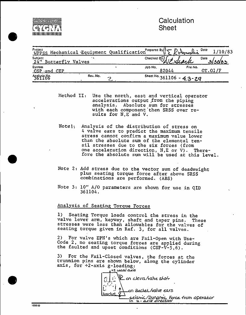
Method Il: Use the north, east and vertical operatoraccelerations output .from the pipinganalysis. Absolute sum for stresseswith each component then SRSS over re-sults for N,E and V.
Note t; Analysis of the distribution of stress on4 valve ears to predict the maximum tensilestress cannot confirm a maximum value lowerthan the absolute sum of the elemental ten-sil stresses due to the six forces (fromone acceleration direction, N,E or V). There-fore the absolute sum will be used at this level.
Note 21 Add stress due to the vector sum of deadweightplus seating torque force after above SRSScombinations are performed. (ABS)
Note 3: 10" A/0 parameters are shown for use in QXD361104.
Anal sis of Seatin Tor ue Forces
1) Seating Torque loads control the stress in thevalve lever arm, keyway, shaft and taper pins. Thesestresses were less than allowables for the valves ofseating torque given in Ref. 3, for all valves.2) For valve EPN's which are Fail-Open with Use-Code 2, no seating torque forces are applied duringthe faulted and upset conditions (CSP-V-5,6).
3) For the Fail-Closed valves, the forces at thetrunnion pins are shown below, along the cylinderaxis, for +2-axis g-loading:
~2, ~ ~iscn c!evis/valve skid
I I I ~
cn sac.~AalVe CarS
~eisrr ic./i7Mre&ic F~ f'rem oPer~rirr a. - cu'/8 dlrCcdDhf

IIIIIIIIIIIIIIIIIIIIIIIIIIIIII
CalculationSheet
Pro"ect Prepared By h DateGPSS Mechanical E ui ment ualification 6( '/10/83
Subject24" Butterfl Valves
Checked B: Oate / /B/50 /8Q
System Job No. File No.
Rev. No, 361106- cf.p-gy
As the bracket deflects in +2, under dynamic loads,the seating torque force is releived. The extentof relief depends on the relative stiffness of thebracket and valve ears relative to the valve seat.Since the steel backets and ears are very stiff inthis direction, little relief can be expected.Hence seating torque forces will be added as anABS sum to the valve ears. However, seating torqueforce will oppose operator weight when the bracketshangs downward from horizontal pipes.
0 erator Drive Rod
Drive rod dynamic stress is due only to g becauseg and g forces are taken out by trunnion pins.Ald seating torque stresses. 7. IZS
F~ = Lcc WgLj,o~
T'No F'at~ t .ARE r=EtT<cqLI FT 4 A I
THt: E'iiSNt~tt" /Iyb PV'E RW Tij c
@~>Uc.G~~'
"tEEC9 PI+ME.PE,F
MA = r (.Lr.o —~>.s') «CM
~Ow
g. (z5 Fc.
Cp)
VF~ = t t" t"-r."
2.qI I,tj. ~
iooeoo

I i j
IIIIIIIIIIIIIIIIIIIIIIIIIIIIII
CalculationSheet
ProjectM
Subject24" Butterfl Valves
Prepared By:
Checked By:
.Date
Date
SystemC c1
Ahalysis No.36>106WigAt L/:
Rev. No.
Job No.
Sheet No.
File No.
361106 -4 -5t
Mp,i
Ap, >A Pw3~ T~
~g
)op 45 ABS sJ'v APi-" ~~
p y g$ etr- r-"i> pglUE ~T
SE'.S>It- Pye A >tC. FORCES 6N 9PLQI= Lag c~~
~A ~-TY t'E j4AS3 j GATI FFPE"-~ QOPjc.L tDAS F~5PA~E.D
FO< TII& PIPING MbPEL 'TC Cher"QLATE% RBFatj~E- C".EI: LS ( ~=-AiTAC @HI EQ i) THE ')ALUE;- EA- SyS~~P ~»f;Iue h~uT04"=ioNAL « ~ 1BII IT 9 V~ b5 jjW C.LURES 'i '~ V0""LAhj D SR&5 FoR eES 0~>P )~O<~ t rim~ Mtt L ALSOCQ r Pt tg FO f t:CM tj&c.~IDU III'TO tj P,Lgg EPI -v„',"",-".=Tf~ E. CquA~rogg
TRvl >toe dan to Pl,(BEE Lccar. Cccao DEE N.—psx Ps )
zpd, =M,
A
Oi (~,= z(te s(ouse~ +A
Tz)+ WHSE T'3 =+
O~
d I
dz =
Z.S
I ~
7S)O.Q
"7.s
le
TOtr'tlj fiivStQV (+) "AIIt-0 KI 1$ +
she- »)oI c.l.:t<~~ ~~-tc~>y )
(ArPE»i'x R)
VI—-t~g '/
1000 00

L= = ~ I
IIIIIIIIIIIIIIIIIIIIIIIIIIIIII
CalculationSheet
Project PrePared By - Date 11083Subject24 'utterfl ValvesSystemCSP and CEPAnalysis No.361106
Rev. No.4
Checked B
'ob
No.
Sheet No.611
Fite No.
Date3 &de
cooRDINATE SYsTEM ( LOCAL)
t 1
I I J
tI,IgL
t 0
lccs CO
IIIIIIIIIIIIIIIIIIIIIIIIIIIIII
CalculationSheet
Prepared Byl Date8SS Mechanical E ui ment ualificationSubject24 'utterfl ValvesSystemCSP and CEP
361106Analysis No. Rev. No'
82044Sheet No.
361106-
File No.OT.01 F
Checked: tI 1 f / Date~i c.. v ~rJ ~ I~&!6"-
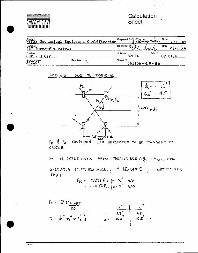
Pop CE g OgE. 7O TOW<t-'lE.
= 4g
(to.S')lb.
I
=dtF Cau 5TR/ttA'I EAR ItE
LECTION..II
wa gK WJlPCMAT WO
C IRCLE.
I ~
ct 7S
J z. IO.d IO.S
) Ocs.oo

IIIIIIIIIIIIIIIIIIIIIIIIIIIIII
CalculationSheet
Pro'ectMPt'SS Mech nSubject24 'utterfl ValvesSystem
Analysis No.361106
Rev, No.
5 ~'
Job No82044
File No.v
Sheet No.611
Prepared By: g k . h A . Date1 10 83
Checked B; Date
T))gtr F SqF ES5 CeE t o brtZ -.
ZP dI >~ z.
,'j A
II hing ~~~

IIIIIIIIIIIIIIIIIIIIIIIIIIIIII
CalculationSheet
projectWP hSubject24" Butterfl Valves
Prepared By:i g p~ Date
Checked By: A DateAdd
SystemCSP and CEPAnalysis No. Rev. No
Job No.82044
Sheet No. 3(/re!-
File No.
5//Eh ~ FglCr. +i@7- gita P/COACT/Gr4
~/rl ~ c7$~ tezydee'bPracLG c)l+/+»
QN EPiH EB= /// .r, ~
F„(F, ~.i' Fg,~g.. ~ (Pc cd $ + XF<
Fzy. = F. ( cw4+ x~~@J = Ar>+Fd.'z-„
AF>I " = i.o> ( dbtaP 4,- p~ p g;aroAFx)yD" = I.bh
f(OJ4t~fC Pm' 1 g(ar =o)
4 f-„Z. Qr~E, ~//L/ L Fa/GEST PQG,TO Q> /g T/t."-, f PP'/b
Z -A~i~ 0/RrCViOP35 /'-ZS/-= C.T IVCt y, Si-6 S- 'J.F0'1&ii 0 g St/Eha WLC F~~ OQ7PQT P~OM TQE. I=iHAt I t/re& AUBLY5i"- US/tiG
ZH C rAOPCt IN Af'PEiJ >)a 5FOP ~cI - Fm~tea J>gi:/46 Cr., SE~
f?Zt/G I// & ADAGE-rt/b PT E,/THER. ~/J.w(CBte PM@ . FrD R QPD PLD yl2. by)
-V/ 2
~B/r- p- jlf'j
r aadd,~~r /b~, ~d. 3
p W f /// C 7gc g~ ~y ppg ~~pplg.- L:
0 1:.)i + F+S ad Td 'ttz
tIt-'.~ ) jto ~ <z4Ju~
CtCg
,'7S
i So
1GGS GO

r a «
OIIIIIIIIIIIIIIIIIIIIIIIIIIII
CalculationSheet
Project Prepared By.MPPSS Mechanical Equi ment Oualification I«~oareSubject Checked By: Date24" Butterf V lv s 3System
Analysis No.361106
Rev. N'o.
Job No. File No.OT. 01 F
Sheet No.btal(d Cu 4. - 5k
cI~ W I~ z
cJ
S( Q(
~-P~)Q~ if@ -- S e.
z =pe)
3
X2. - -'>4I>
3
l2
3Qs zGl2.
Za jrS12
= I.95 fir
= Q,)0 Ifj
31.7s 3
(.75
~- (4 IN
(. >+ IPJ
'TE'ENSILE. STEAL-~g IS THE A5SPf.LlTQ SQfg 5 F q ««E '".'t/~frPtc:;~oplS Ql —) (Q. (L«ss «o'4/o FELS«ETo~ roR «txo=6twJ
5IJFAIc S-tc.&=-5 ~~ E t
P" f l4/VS
l> lf t- TQ
s, +a„4'Pf.Q~
5'z
AQUA g q
,« ~,„, «OOS OO
l
rF4E SHEr "< n~«E= 5-EE;uL-'rAvv = t. 1a + 'V:= 3 (\/ECTo,".
IIIIIIIIIIIIIIIIIIIIIIIIIIIIII
CalculationSheet
Project Prepared By:( P ~ ~ n, DateMPPSS Mechanical E ui ment ualification 4Q~~~ 1 10 83Subject Checked B Date24" Butterfl ValvesSystem
Rev. No,
Job No,
Sheet No,
File No.
-4 5-s7
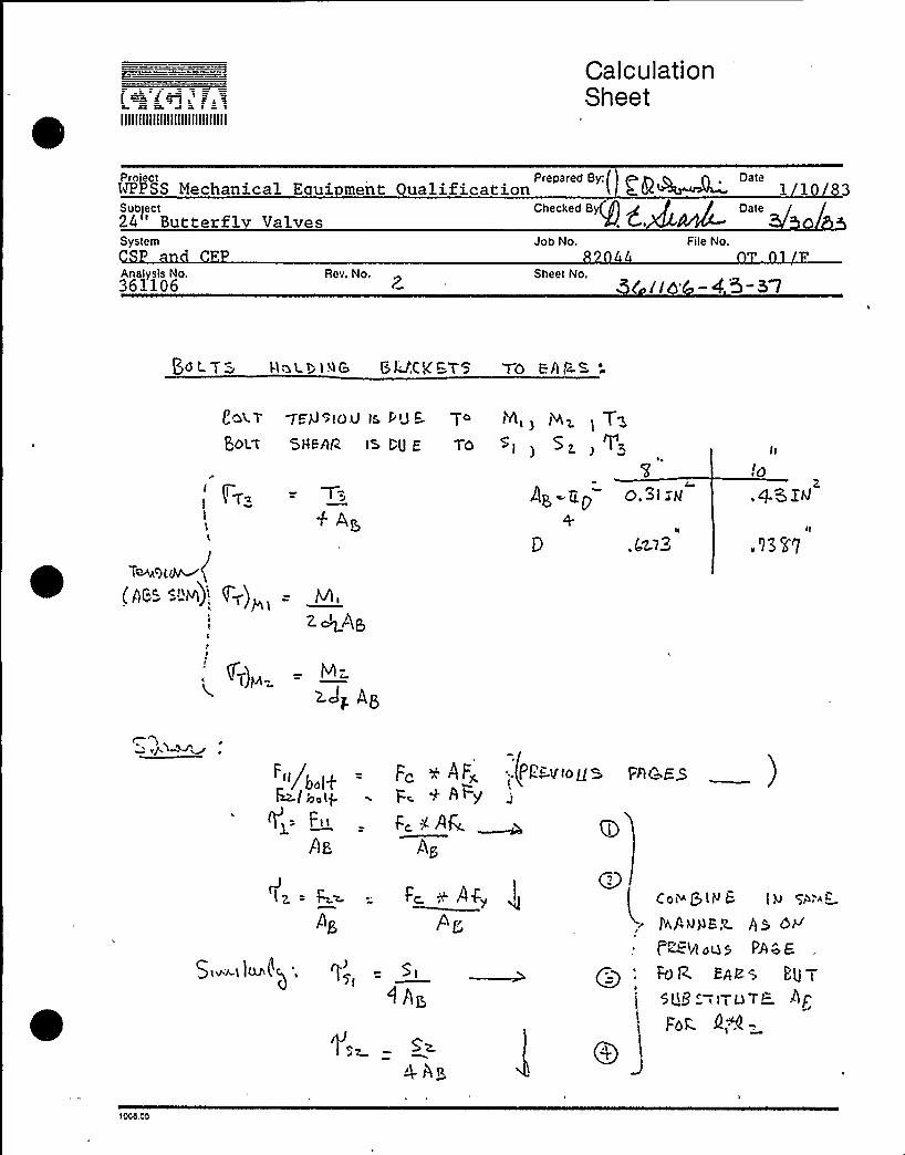
PdL. T= W>t t I ~'IS SL'gC'KB7S TO Efl t~S
'Gt
T -Pcg<lOU lS, Ptj C
POL't 5H&hlZ lS I;U E
t'ht )~i ) S~ )V~
0.3IXMI;o+
II
A@7 2
lltg
,QGIitt
.'l3 l7
hei
<-)~:
~/boHMle.tpgq-. F«
Az
Fc + ~Fz «.PE tftousp + APg
Fc ~ lit'»Ag
t nc as )
S tv'~t )tU'() ',
<hI,
5z.
5P
4m= t' Fc NA4„ Cot~ {jl N & I W
fv,AQHE <r~ t ~<WdOS PW'
Epee5Qi3 '-ilTuTL AP
For.
iCCtt CO
llllllllllllllllllllllllllllll
CalculationSheet
ProjectWPPSS Mechanical E ui m nt Prepared By: g g n . Dateualific tionSubject Checked 8 Date24 'utterfl Valves san kaSystemCSP and CEPAnalysis No.361106
Rev. No.
Job No.82044
File No.OT.01 F
Ski I d5 —4. 5-
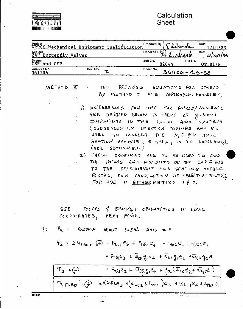
Nt ETtlCd 9 g — TH G. Pk:SVI dU 5 E<QU 4T(GP r j=) I r tr C-~ z
QJ'E -THrs 0 f 5> = Pl'PjtCPl=LE. Ha~RLr&:-",
l) P.XPEESS jc 4 5 Fo i2 AVE. Si< j=oi~-jQo<>-.PYSnttzs rts Qlvbb ERLotnt ttt Tvpvts ot= vj- le~ iceMPoNt=pm'y ~t l- Loc gl Ay» >ye r=M
tt gggqUCPTL Y I fE~CWIGKl C'4 ~iitJL
u ~E-8 ~cd CoMVF"-7 TH p y, E g V p<caL.—~np.~i~V VCc~or<S ) W ~R.M j Ijv 7~ LocAi.gyps).(qpr S,j=c~to u g.q )
2) I ttssl=. L.ntvtn Ito,v" .nRE. Tb d "„IIebTo Et,vb ~TjlE FDEcg 5 AU 0 I~ otg r=.v7 5 c)U T()K. FP,c ~ DLjF
T4 19E I E+rp MJEl8(l r . A,u r 5'Fi-'tIU g ~Ger'7FOLCt- 5 Po P, Citt t.CJt t +W(c Aj 4c gPHS f'r,V+IFOR InsE IN EITHI:R,IncTItcb 1
QE i- FOgi-ES $ L'+r le T >~it> >A t r4 U JH LC(A t-
ea orb jH A TK 5> PE.Xa PAt" <.
ToR bio pC 'tF.':oLrV I o„"AL 0 ii5 3
ZNstnnr. vP+ = Fipt ez + FdR,en + Fnn=<-. +t re-.e,
g+ '2 ((htnb e2n vnnae )
IIIIIIIIIIIIIIIIIIIIIIIIIIIIII
CalculationSheet
ProjectWPPStjtject
2rt Butterfl ValvesSystem
CSP and CEPAnalysis No.
361106Rev. No.
Prepared
By,'hecked
B~ ~ /
Job No, File No.
Date1 10 83
""afro ss
Sheet No.3 &lid&-4.3-
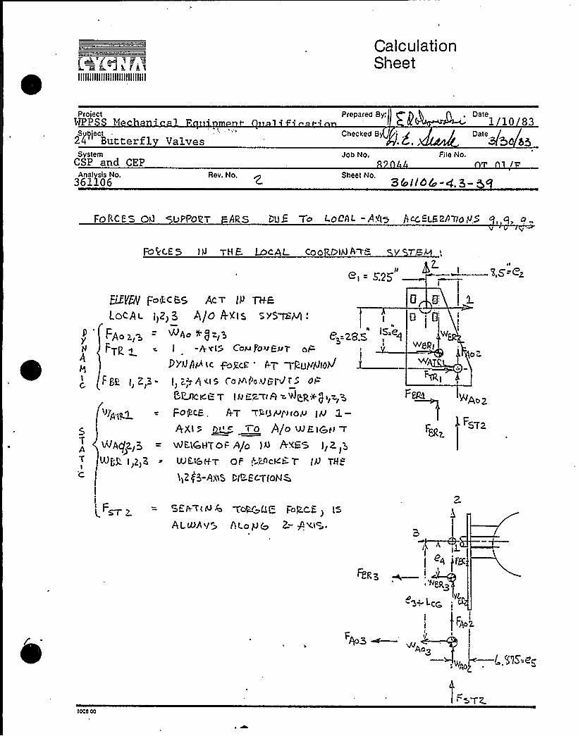
FORCES 00 L)PPOZT ARS t UE To LOCAL -A<l5 itjcc "LERAT(Op) g a „
Fc)kc.E 5 I 9 HE MeAL coo c.foiH A r8
+t = F25',s-ezELEYN f=c)4r- ES RC, T II') TH-E
LOCA l II2) Q P/0 O'XI5 5 YS I~I
FA,~~— e,-.S.~'<= <N FTp ~ = I -A v(5 CovPovt=„p?A <od'i~ FoRcr.. A'r rpoyNlo>1 -)
Fg. I,Z,3- I) Z+hv.tS CDV foVL=.I-dr')=
0 ~
Q
Wwgp)
~TvOc'
TAT
1
I
")'P IO.3
NA(fZ.,S
Npk 1)2)K
~~ tr-'= T I Q B. Tr R = ~ (R )t. j t> z> gFo<RCB, +T rPU H/) to~ I PJ
AXI ~ -0 AgD ~E.IZ»~WEYcHTOt= A/o IQ P YFS Ii? 3
LUht&H-T OF ~,c.r)ct(h.? (it) THE
1)2(3-AXES t"tr-'ECTloNQ
HEI. t t t~) 6 ~or~rQg Fop.c.p>
ALNh~/~ ALoy@ 2-, P«<.
>AoZ
FSTa
'rzp YL
I
F~g
'lOCO OO

s - iIIIIIIIIIIIIIIIIIIIIIIIIIIIIII
CalculationSheet
Project Prepared By:VPPSS Mechanical E ui ment ualifi a ion
, Date
SubjectII
Checked By~ ~ 5 56/3
SystemCSP and CEP
Job No82044
File NoOT.01 F
Analysis No.361106
Rev. No. Sheet No.GC ]lbt'—
FDRCQ O~Ctg.g t/t-Iropg ON L=~ < ". pp-
Fg.
F„
~IFIXm-
»sr<, Trc I + 6~0
Ngp 4 Wq~I'l
FPDM P FOI-'CE B)L/I,VC F 0+ 7 tl g OI~ElcP, Tr'!c. '.
F>RI =.(LIaccLcr lwMIAcIe (0Fc>c-'ekev)0 QtLrc
~ "c,. v«
+/pIaI= I 4cec Lca) IMFIel
Lace
oPEq ao Ão
Ic
1'Lrgy*L.~ —~w +oAo";,. I
LC(i
4o'I
)g or~
7c ZI
I006 00
IIIIIIIIIIIIIIIIIIIIIIIIIIIIII
CalculationSheet
Project
Subject24'utterfl ValvesSystemCSP and CEP
Prepared By:
Checked B(; pJob No
82044
Date
Date
File No.OT. 1
Rev. No. Sheet No. M ilb(o-
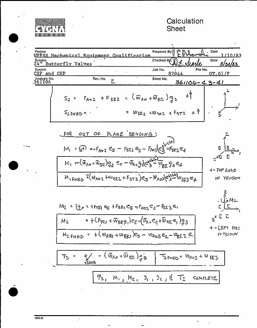
5~ = FA Z + I-PPP = iWit~ qN;. JQ
~2. Ftffb = I,rz ~e~oz < "~V=. +
OR OUT Ot- +>%yQ I r=h»l.~/Q:
F~oz e~ Fr@ eq rg~e~ q~" e4(g.
(>»>>o~ >>>sz >gz "+ >>>z~)483 >>>
(~Ace Z, "R ~c><Z )~D ~~>~% ~ 8gS +
--u tt
4= ToP =.q'5
TErr<ao<
N>z =+4 - 4Fr>>> >'-d < Fz>'-><a -,'»o„cz r>'zs~i
= j (FT»; O wd>tp>»'<g)>» <z" >»pq~>)gg
>z Fez» t i >'»»>>>+~6P~d
2
fair.
i t"
4 "LE I
i' C b~+Pt/
T- = +g = (~i>~+'>it>z)<~esA~tS
û- 'D~Z, ~ "~Z g
~> + Cher"L57~
>ccd 00

IIIIIIIIIIIIIIIIIIIIIIIIIIIIII
CalculationSheet
Proiect Prepared By:/WPPSS Mechanical E ui ment uglification 1 10 83
SubjectII
System
Checked B
Job No.
rye,~ hP <&/ / Oate
File No.0
Analvsis No.361106
Rev. No. Sheet No.361106- .'5" 2
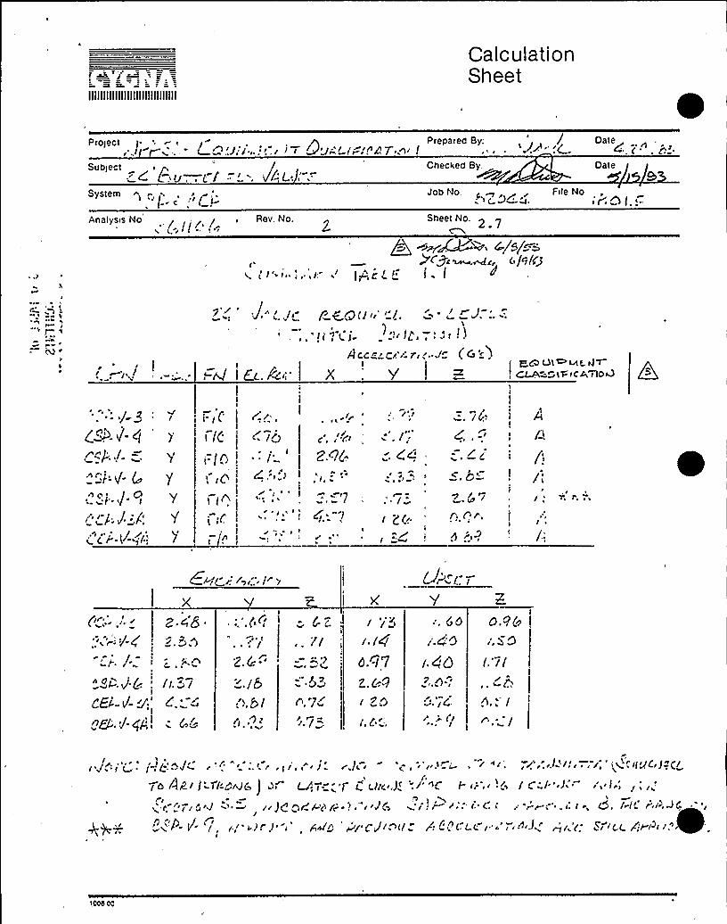
4~/ U set Condition Stresses
Th'e cylinder drive rod and valve ears were separatelyanalyzed for upset condition loads for the EPN's andassociated response g-levels noted below. All othercomponent faulted stresses are less than the upset al-lowables except for taper pins and keyway bearing stress.No additional analysis was performed for these compo-nents because the stress is controlled by the seatingtorque only. The allowable stress for the bracket boltsalso holds for upset conditions per the AISC manual,8th Edition. Bolt fatigue is considered as presentedin Section>.3.5.
Upset g-levels (per revised B&R piping analysis, Sec. 5.5)
EPN N
CSP-V-3CSP-V-4CSP-V-5CSP-V-6
1.731.140.97
1.64
1.601.401.401.44
0.961.501.710 '9
Component stresses are given in Table 1.2.
scca 00

IIIIIIIIIIIIIIIIIIIIIIIIIIIIII
CalculationSheet
projectWPPSS Mechani 1 o i n
SubjectII
Prepar.d By:j gP~~ Date
Checked B:g g ~ Date/
System Job No,82044
File No.
0Analysis No.361106
Rev. No. Sheet No. - 4.3-45
Section4,>.5 — Fati ue Anal sis
Discussion
The operator and bracket assembly are not part of the pressureboundary, therefore, the fatigue analysis will be performed inaccordance with Appendix B of the AISC Manual for Steel Con-struction. The following assumptions apply to the. fatigueanalysis.
1) Faulted stresses (based on piping-analysis accelerations)will be used. This is necessary to insure operabilityafter a design basis event.
2) The actual stresses used will be the ones calculatedin Section g.3.
3) If the alternating portion of the stress has been cal-culated separately only this part will be used. If theoperating loads (i.e. seating torque effects) are al-ready included in the stress analysis it will be con-servative to use the calculated stress value. As longas no failures occur, the operating stress does notneed to be extracted.
4) The allowable s'tress will be based on Table B3 of Appen-dix B in the AISC Manual of Steel Construction.
S) A factor of 1.S will be applied to the allowable be-cause of the low number of cycles. (Per Section 1.7of the Commentary'on the AISC Manual).
6) The actual stress range is taken as 2 times the maxi-mum stress for components subject to alternatingtension and compression.
Iced Cd

IIIIIIIIIIIIIIIIIIIIIIIIIIIIII
CalculationSheet
project
Subject24" Butterf1 Valves.
Prepared By: -(P Date
System
5'BbF. Rev, No.
Job No.82044
Fite No.OT.01 F
'61106- g,+- Qcf.
7) Bracket bolting is assumed to be properly tightened and willnot be considered for fatigue per Section B3.1 of the AISCManual.
The table on the following page gives the calculated stress range,stress category, and allowable for the critical components. The fol-lowing page gives excerpts from Appendix B of the AISC Manual showingthe descriptions of the relevent stress categories.

IIIIIIIIIIIIIIIIIIIIIIIIIIIIII
CalculationSheet
Pr t Prepared By:I P W Date$8VSS Mechanical E ui ment Qualification, ') 4P( 1/10/83
Subject24" Butterfly Valves
System
Rev. No.z
Job No. File No.
'361106-Q >-g~
Checked By Date8 b
Fati ue Anal sis (cont.)
ITEM
TRUNNION PIN
DRIVE ROD MAX
SUPPORT EARS
STRESSTYPE
STRESS(PSI)
4108
SEE TA
SEE TAB
STRFSS STRESSRANGE (PST) CATEGORY
21
LE 1.2
E 1.2
1.5 x ALLOW(FROM AISC)
HAIN SHAFT$ 1278064
19,~M+1 12
90000
NOTES:
(I} Assume shear stress on nominal area of a studtype shear connection.
Note that this comparison includes all of the load combinations in oneconservative comparison using the maximum stress and the total numberof cycles ([3 x 4478] + 60 = 13494 cycles).
>Ocs.00

Calculation SheetPrepared By: Date
!!/l&F~~
'J=~s. s = r ~a f i 3
IIIIIIIIIIIIIIIIIIIIIIIIIIIIII
Project
Subject , cl
System
Analysis No,
'I rr-> 'I
Rev. No,
Checked By'.
Job No,
Sheet No,
Date
/I /File No.o-;-: >:i ;-- ~
3< jlo(-<.
S ZS 0~1;
I Hc ~RIt LF 8 Ei.o~ H+S BEEN ~H DEnac'D FiZnMR PPErvbX'x 9 oF THE HZSc QAHu H v dI'- '4TEEt-COIYS'fRlA.C 7-~Or f. TH c C.RISES uSEb H iZc HRRIr'E21
4J Z' H en lfjRROM.
GeneralCondi ~
tion
Plainmaterial
Built-upmembers
hlechani-callyfastenedconnec-tions
httach.ments
Situation
Base metal with rolled or cleaned sur-faces.
Base metal and weld metal in mem-be'rs, without attachments, built-up ofplates or shapes connected by contin.uous full.or partial. penetration groovewelds or continuous filletwelds parallelto the direction of applied stress.
Calculated flexural stress, Is, in basemetal at toe ofwelds on girder webs orflanges adjacent to welded transversestiffeners.
Base metal at end of partial lengthwelded cover plates having square ortapered ends, with or without weldsacross the ends.
Base metal at gross section of high-strength. bolted friction.type connec.tions, except connections subject, tostress reversal and axially loaded jointswhich induce out.of-plane bending inconnected material.
Base metal at net section ofother me-chanically fastened joints.
Base metal at net section of high.strength bolted bearing connections.
Shear stress on nominal area of stud-type shear connectors.
Kind of
Stress'or
Rev.
Tor Rev.
T or Rev.
Tor Rev.
Tor Rev.
Tor Rev.
Tor Rev.
S
StressCate-gory.(See
TableB3)
D
~ (i.= )~)

IIIIIIIIIIIIIIIIIIIIIIIIIIIIII
CalculationSheet
Project rl/V Prepared By: /~ -,. - -, r3' - . -„, Date (
Subject ") j:--System n ~ i( '~)«c;" -"
i'; =./r I re/'7g dQ jF; d /. r=
Analysis No. Rev. No. Sheet No.
0/~L.));r~~=-
/j
t ZQ/>C -Prier,l
P.'shale!~",< —r ><~/Dr; i-III rr I-;.h-.l 4
r" Il 6 Q/,YIhLlr IE 6 ~ hl ) 4<-, 3 4C r|t) j/'ri'i p'I~ja/fj+r,
\r'/
) r r H « ~ / ) \y r</ irM \ ? ')r " ' ) frjj I (/ r, Qirr Q J/i jl <>~~-.rr J . '. g rh> f//C /)/)5 ~@@>!Ii / 8 8/= ~ r)6 7''i 4)/!r-
,=, did!i ) re~'I„= ';.Iy',~~rZr-' 0 ".y -.:.-Vr'"-;, .y .S'-,r„- ~ <.", -..
~U': r );„„: 'r'/. ~ )0 ($g'-'( p r rrtg/ 'iQg/'Z I 2 /'- i'„ /r j /q/' Zi /r' ')I«/!/i<6 i'i
~ /gC4 Q /«gj/r i ~-r r r«Qi? «< ~:,~rfrf5,
7c r~~/=<-C/ g ><~ gWDc/)> ~r'- ~pi~ ')~r ~: zE>7)gA,
z) /-rod?~~/,///./.g~ /r~e,//~ p/c DsALc'i'-~ -r'' $d; I
'l'dC(A4 WZCa ~>e">
f--CA l"/:A'<~ ) +4C „"8 3'/
g~= a-/'
II«W '7& l'
J
= -»-' J Z= ('"- )( -) ''=l
/.) .-r ~ ~ M
'\ ~
/gati/
''
I)/l'' r~ g ' 'g )r1 7 t
ICOd 00

llllllllllllllll~slillllliltll
C "e; ~ ~.-
E'o:
t':82od4
PkokosEb
C5<ACKZT EAl& xwb tueM 4m c
Yz"~~~~ is~

IIIIIIIIIIIIIIIIIIIIIIIIIIIIII
CalculationSheet
Project Prepared By: Date /..w 3t-Vw~ W3Z r ='ized)U w /i'~/m~"
Subject j . Checked By: i /> / Date /~l/z 'Jo /U3 r~c.r.=.~~r! f' U~ >/jb/80
System
Analysis No.~Q /tQ C~Rev. No.
IJob No. r~ File No.&Zoo~
~C //gd — ~,3 - ~)
~/~/~'C ~p c ~L ci 4/0
e

IIIIIIIIIIIIIIIIIIIIIIIIIIIIII
CalculationSheet
Project Preoared By: .--~ 'ate~/4P ~ ~Q PO~pj I &.J~r f Ic'-7'-—/< 1
Subject , / <Checked By: f> p 1,?I I ~lj7T~Q+ r'i 5'Zfbi)9 +//// haft N', P. 8 4X'--..~~ Date
<g'; Sj~~System ~c=-wAnalysis No. Rev. No.
"""'a~4~ "'"",r-.. oZ =
/ItI'a tOQm~~/~u o%~/=~
A~A. t g%g.gr ~ *
C
(/cg)(7~ . 2<57~ z. /zs
/07(n > $ (c>$ 7 = w7~Z'
/
If~ o4 74 Stc&
+ 77Z /> 3 ~Df<~~" 7 /gg/g W (/gC
(~/)

r tIIIIIIIIIIIIIIIIIIIIIIIIIIIIII
CalculationSheet
Project Prepared By'.LUFF~ ~ WAVWMe'~ QUMi~~eC moJ Wwrz
Subject it / u Checked By: Q / () /~iJ~~r /, i j/g./%= ag I>/r r n, ~ ~JZVMbgAJob No.
""-/r V/Zg
Fite No. y/.ri/~Analysis No. Rev. No. '/ (/~< ~.'R - 5I
4/'
QC~ai~~~~ ~ //'q j(~uJ- L>M;-r~
/O ~t ~C4~= +7 Z~

2 & B 3 L r
IIIIIIIIIIIIIIIIIIIIIIIIIIIIII
CalculationSheet
Project Prepared By: - r ( W< Date j /~ dl~r-/r-rJ '(~c M/- ( —Cp '<WJ
Subject /,t Checked By: p ) / Date /SF ~J/7/ZFZ.r'/W~/r a9 >/ Lee.,c +/j/'.V';r.WSystem+~ /'
W>/ /~ Rev. No.
Job No. File No.u>oC ~/ 'r . O /, —.—
Sheet No.~ &//d 6 ~. 3 - 52
> ~4W 4/z/s* gV~~-n,w //<//iSr ~c
4< = sr+I // ~//
-4 = 8VS)/~W
/Z /Iu~
7z ) /- z./QQ g GQ

IIIIIIIIIIIIIIIIIIIIIIIIIIIIII
CalculationSheet
ProjectWPPSS Equipment Qualification Prepared By; ~Q + Date ~
Subject Checked By: ~ ~ Date24" BIF Butterfl Valves/w 8" Miller OP 6/9/83
SystemCEP & C P
na'ysis No'6 1 1 0 6
Rev. No.
Job No.82044
Fi(e No.1T.01.F
'361106-4.3-53
ow RMi -~oV Z or- ~*isMl&G~QWC~~r-A;-: r )~ ~Q A~GOMid~
&'P~A~~ ~~~8 r-tr"-~c= WQP'F"O ~W ~r, '~A W ( Qm~ r-A.~lLi Jt=C WK KRb ~ 4 ~ WAN<
43 - WH . ~t It— ~WHEC < O~ ~t I— t~gc ~~c- Q~
'ree cho R~ in A-s M~<oMs.1) ~Q= pr ~ul od=-LY cA~c> L~= sTRe~p.=
<a~~ WHY SO PPO~< c- +M~ 6 H'h L= r. <F04~ ~~ ~ ~l Mt--
W~tj'IOQSt W CAwcJW~ ~, WQt g yacc 8=-5~"M~tWtCA r >C& OP't= ~Q~~8~i
~
~) ~s'.. cA~Ua>'YK I-,PW~ .- 9& Zo pJ~ jr~i ~ ~~<4I d- 5IMiDErL~< ICQ Wc -
~ =, Ydt u3&~t~t+~M+ pJ QPJ r t=&~~~l-

Illlllllllllllllllllllllllllll
CalculationSheet
ProjectWPPSS Equi ment Qualification24'utterfly Va3.veswith 8" Miller Operator
Checked By. T ~ ', Datep C ~~i'.s~~~~( 6'/9 83System
EPJob No,
820Fite No.
361106Rev. No. 361106-4.3-54
/i&

IIIIIIIIIIIIIIIIIIIIIIIIIIIIII
CalculationSheet
WPPSS Equipment QualificationSubIect24" BIF Butter fly Valves
with 8"= Miller Operator
Prepared By,' Date. r''==Checked By: Dater~~~ 6 / 9 / 8 3
System ~
CEP & CSPAnalysis No.
361106Rev. No,
82044Sheet No.
361106-4.3-55
1T.01.F
ZKI 4 t-a C ~ Mct47
V.
rs
W.t
C,5Pv'-g~77Z~z. I
6 cm r'-
~Qt A%
tL.C
Q o r.(pro ~
p,tg Ljg&—,aeadK

IIIIIIIIIIIIIIIIIIIIIIIIIIIIII
CalculationSheet
WPPSS Equipment QualificationSUt>Iect24" BIF Butterfly Valves
with 8" Miller 0 erator
Prepared By; ~g Date /'!/~=-Checked By: -y~ .. / Date
SystemCEP 6 CSP
Analysis No,361106
Rev. No.
Job No.82044
FileJlo,1T.01.F
Sheet No.361106-4.3-56
cd ~~ v)~~QQptJ i I 4'P9 7(n ia-ws
'~
~OwPI Qg Matc~

IIIIIIIIIIIIIIIIIIIIIIIIIIIIII
CalculationSheet
ProjectWPPSS Equipment Qua'lification
Subject2)n BXF, Butterfly Valveswith 8" Mailer 0 e ato
Prepared By: Date9 9
Checked By: w, ~ ~ Date>e x,~+System
CEP 6 CSPAnalysis No,
361106Rev. No.
Job No.82044
File Ao.1T.01.F
Sheet No.361106-4.3-57
8 Wo vJT- 4 A Ve-W~C.~ Co~'j=O&<M7 dT=
~+I -T ~ ~~ ~ ~~ ~A2O IM ~HW ~I~IW~~~, gSSu W I Mc, ~he ~W~ Pa'~ ~Pf=~C~ A~Id IK ~tSnd~ PncIe C.OW> IS yZ i%F -Dt„~~c G &I=W<~IVW LaMC ~I Mode& ~~ VIA = YZ.
A; )Z~ z/A.=/~ ~+p= pz "5
= 3.75= g.00
8. z6
o/.4sW
—Id-
~UIJSt t-~ ~A~ A~Lj~tI, ~ ~z (7.is~))/7.~(=')'I/~ —P ~d~ r (7./z+) I/d( )
'aw/4ut, ) vu»=/z rjo )r-I= =) d—tc.,d~/~ (7.+)
Id»85-"-d+7)~r~~ 4 g.+0
+$ t-ct'.o&<
7 yQ= 1~7C
~~a/= 58a7
= Zgo7
I'3C) i&

~ I i~s.ti3IIIIIIIIIIIIIIIIIIIIIIIIIIIIII
CalculationSheet
projectWPPSS E ui ment Qualification
subject24" BZF Butter fly ValvesII
'"'c/s/a=-Checked By; ~ . "
. Date~~c41tr 6 9 8 3
/
CEP 6 CSP 82044File h6. 1T.01.F
Analysis No.361106
Rev. No.3
Sheet No.361106-4.3-58

IIIIIIIIIIIIIIIIIIIIIIIIIIIIII
CalculationSheet
ProjectWPPSS Equipment, Qualification
Sobject24" BIF But ter fly Valveswit
Prepared By; ) Date /o /.0/55
Checked By: Date~~y44iq
SystemCEP tz CSP
Analysis No,361106
Rev. No.
Job No.82044
Fite'No.1T.01.F
Sheet No.361106-4.3-59
gals Vt&W u)a~&M3 t I
IRHC g g/,Z+o ~s(c )(vo~)
Cd, '707
(g /gag)C
,zov)(.aim 8 I
(Q
IJ~ >~~ t J Qtd
l )C~
li I Vg~ )

IIIIIIIIIIIIIIIIIIIIIIIIIIIIII
CalculationSheet
ProjectWPPSS Equipment Qualification
subject 24" BXF Butter fly ValvesIf
Prepared By.'ate~/ g~frg 9
Checked By: ~,> .I ', Dateg.t ~~.)L).»~, 6/9/83
SystemCEP 6 CSP
Job No.82044
File toto.
1T.01.FAnalysis No.
361106'ev. No. Sheet No.
-60
~c L~ > CIB.~~ ~~ + / i rJGA
A~ ~~~I»Jo
~ sl
C
QJ+ d3

IIIIIIIIIIIIIIIIIIIIIIIIIIIIII
CalculationSheet
WPP$ 5 Equipment Qualification Prepared By.'-=-re,~-',.'~ Date'
~ '.6'3=:subiect 24" BIF Butterfly Valves
with DChecked By: ~i ' Datei" tt-i(.tt~~rz
SystemCEP & CSP
Analysis No.361106
Rev. No.3
Job No.82044
Sheet No.361106-
File No.1T.01.F
Qcc~ err I cu) c~ 4 4~d'P ~< WO
0 %~i. F'o~.t Ctr
tfa I HCy p /ISx>

IIIIIIIIIIIIIIIIIIIIIIIIIIIIII
CalculationSheet
WPPSS Equipment QualificationSubject 24" BIF Butter fly Valveswith 8" Miller 0
Date, /'/ gyChecked By: a.~ . > Date
CEP 6 CSP
Analysis No.361106
Rev. No.
82044P
1T.01.FSheet No,
361106-4.3-62
ws a. ~r..=UC.=--iV.DM~< ~ »gii<c.
C~ - it-QLo~==
«»772 7I /Z'>g zg+7>.s (=')
4<>z = Ilqz 4,)
~~=I/o (~)
go=/ rM C~ )
gal
Q+'&ld5 -!3@7
z (io.o)
~(7,e)
=~1~z~')
«+g» gyqgA C
I ag»«. /J- »@ger «/'g~
g 3-4o
/ - (CO ~e-.r 3 ~ 'il o
~Q, A t ~~t/~/

IIIIIIIIIIIIIIIIIIIIIIIIIIIIII
CalculationSheet
WPPSS Equipment QualificationsubIect 24" BXF Butterfly'Valveswith 8" Mailer 0 erator
Prepared By: ri M Date,/'hecked
By: ~r a ~ ~ Date)l~r i~I
SystemCEP 6 CSP
Job No.82044
File No.-
361106Rev. No. Sheet No.
361106-4.3-63
/ pp ~~~I~~AJ. ~A/~r 4 Q p'ST '5'C3 r~/»
L~ = /w >2.5 z
~xi'/~ ~to g~ ~ '~" ~ /
jC&= ~ ~/d /WrD„=-r., l~, ~~ l~—,Q ~,- u)~~C~ / J~~ -ir H~ C-D> / a~< MM/-r *~~C WP
/pork ~5'cog Y8/w'
/ ~/~ ~~~ Qn~//J u3~~~ ~/ZAN = ~~ tt ~/1&
WiAcr-~
(vo7(ai~s)sos@ >fgs= ~ //~s<
F5/r ~t(77C~t 0 C 0+
/ AJ P~&r rZ/>~+4( -C,, ~~ Ar ~A~//JW
«ILL.~i M~~>- %~~am /~A m4s Pt amac- =.-
Oa=-4+t-/= ~ -nl-= a(It-/ r-. —..<-72- %~c
Cct~/A~~/t/r p r OQ C~d cw/+++ w/ WOPJ / 4)'70 L/~/tdr« ~G H~ /o / rJC lac= 4-~c'
0+ 7~4 c-. ~ /

IIIIIIIIIIIIIIIIIIIIIIIIIIIIII
CalculationSheet
WPPSS Equipment qualificationsubject 24" BIF Butter fly Valves
with 8" Miller 0 rat
Prepared By: ) 'y Date;< /Checked By: ~ > t ~ Date+ ~ ( ~~ r.it->c<Lc.r
SystemCEP 6 CSP
Analysis No.361106
Rev. No.3
Job No,82044
Sheet No.3 1 — 4
File Np.1T.01.F
/ H'g L o>~5 os CS7- t( 6 P~z(r!o W P~ ~'S~ (+~ !~3~~ h~
~
~gg~ ~~ Pot= ~ ~"'"- m ~)~S~a!,.e.~ —, ~ca.- ~~maW & !/.> yAc'c'~c-.—.<-'. ptoQ~rr M 7oW 4Z 'Z.5~ < . l: S M~g ~r
aF'CgC„t„~~~ 2Z7 ~~~e ~~ ~eCYI ~~~M M~ 3'9!r ~s.
AN&c3Mc-Y'J!rs.= /~~C!~ r EM'-~ (= ~ C. 4 r gz~~ y&IF-J~c c- a~~a&~'=.Vc ~~U C'~C'c~r" WA. r c- W
// %I
G.. o M~w'(
~~a L-(~ L —i o M: =8~," 3/Z
-s/-- . I j~{.L r c. ~~,~aA~( l-;" CQ(( (
Q ( g l, !o < C ~ ~c~™N
~ ~

IIIIIIIIIIIIIIIIIIIIIIIIIIIIII
CalculationSheet
Project Pre ared By: iDateWashington Public Power Supply SystetwI 3Subject Checked B . r,' f' Date, .
Equi ment Seismic/H drod namic Re ual. <~,.~.'».r. J~ -"i"='~»9System
CSP 6 CEPJob No.
82044File No.
0Analysis No,
361106
SEcTtoN >.4
Rev. No. Sheet No.361106 - k.s.Cs
REFERENCES:
D-207110-H, D-207110-G,(Valve Data Sheets)
A-206767,18", 24" & 30" Butterfly Valve - General
C-26096,"Certified Dimension for Model A-83-B Cylinder"
2. WPPSS Unit 2 Drawin s:
CSP-807-81.08
CSP-809-1.2
CEP-625-3.4
CEP-625-1.2
D.220-0310
Containment Purge Air Supply
Suppression Pool Vacuum Breaker .
From Reactor Nozzle X-67 to SGT-Fu-lA, 1B
From Reactor Nozzle X-67 to SGT-Fu-lA, 1B
Support and Erection isometric-TR64(Johnson Controls)
3. BIF Report TR-27234 and TR-27235, "Dynamic Torque Calculation ofButterfly Valve; Sizes 24 and 30 inch", dated November 10, 1982.
4. Report JTR-74-7 by McPherson Assoc., Tnc., "Design 6 SeismicAnalysis 24" Cylinder operated Butterfly Valve." (Rev. 1) 1/5/76.
5. WPPSS letter to Cygna Energy Services, GE-02-RWH-018, 12/17/82.
1ccs co

IIIIIIIIIIIIIIIIIIIIIIIIIIIIII
CalculationSheet
projectWashin ton Public Power Su 1
Prepared By: DateS stem L.C. Fernandez 5/27/83
Subject CheckedBy.'quipmentSeismic/Hydrodynamic Requal. ~. ~~a g~,, Date
y/q~/o~g
CSP 6 CEP 82044 OT.01.F~tHy5%'Ne'. Rev. No. Sheet No.
QID 361106 2 4. 3. t'(o
SECTION 4.4REFERENCES (CONTINUED):
r~i L-.,;~ ~j./'Z,/c~~~J r/q/~< y
6. Cygna Energy Services: Communications Report, R. Ricappito,BIF Valve, and J. Rakowski, CES, "BXF Valve Dimensions",2/11/83.
7. Cygna Energy Services, Project Manual Design Criteria,DC-1, Rev'. 1, November, 1982.
8. Cygna Energy Services, Equipment Qualification WalkdownVerification Forms, Revision 1, dated 1/5/83.
9. WPPSS, WNP-2, Safety Related Mechanical Equipment ListSummary Sheets, dated 2/10/83.
10. "AISC Manual of Steel Construction", American Instituteof Steel Construction, 8th Edition, 1980.
11. Preliminary Transfer of Final Burns & Roe Piping Loadsfor CSP-V-1,2,3,4,5,6 and CEP-V-3AG4A, received 4/13/83.
12. Cygna Energy Services, "Equipment Seismic and HydrodynamicRequalification of 30" Cylinder Operated Butterfly Valvesfor CSP-V-', 6 2, and CEP-V-1A, .G 2A," File No. OS.01.F,QID No. 361104, Revision 1, June,.
1983.'3.
Cygna Energy Services, "Equipment Seismic and HydrodynamicRequalification for 8", 10" and 12" Bore Air CylinderOperators," File No. 1P.01.F, QID No. 018001, Revision 0,May, 1983.
14. USNRC, "Standard Review Plan, NUREG-0800"
1000 00

APPENDIX A
COMPILED PROGRAMS AND RESULTS FOR
CSP-V-3
CSP-V-4
CSP-V-5
CSP-V-6
CEP-V-3A
CEP-V-4A

4 4' -( ~ c 4 ~
i i '1 "J<~ kl "I II
'I
J~

sbasic csp34tm
-BASIC Compi 1er Version 5.4b
0001:000002:000003!000004:000005!000006:000007'000008:000009:000010:000011:000012:000013:000014:000015:000016:000017!000018:000019:000020:000021!000022:000023:000024:00.'l25:00026:00
0027:000028:000029:000030:000031 $ 000032: 000033:000034!000035:000036:000037:000038!00„0039!000040'000041!000042:000043:000044!000045:000046:000047:000048:000049:000050!00
'51: 00v052:000053:000054:000055:000056.'00
resto! e 2read l rod, 1 cg, x, ph i, 1 ave, ab 1't, 11, 1 2restor e 3read fst2,ca,ia,cb,ib,aa,abrestore 4read wao,wbr,el,e2,e3,e4,e5restore 5read lrodo,lcgo,ldr,d,abushrestore 6read a(1,1),a<2,1),a<3,1),a(1,2),a<2,2),a(3,2)r estor e 7read a<1 s3> ra<2,3),a(3s3) sav<1),av(2),av<3>text 0,8c INPUT GLOBAL ACCELERATIONS 5i npu t b(1), b(2), b(3)pr inttext O,h INPUT DATA hpr intprint "GLOBAL G-LEVELS
ATT~ ~f L~, 0 7Bi.o SZb4
FlLEI;Q. OWbf
GHLRT"'0 BJ—
"ib(i) sb(2) tb(3)LES = ",;a(1,1),a<2,1),a(3,1)
REM~++++ BIF VALVE AND AIR OPERATOR SEISMIC STRESSREM+%%% 4 ++++%+: +++% CSP-Vj'AO-3/4REM++SAME ORIENTATION FOR EPN 3h4, SAME PARAMTERS, VARY G'SREMvar i,j,k = integervar lrod,lcg,x,phi,lave,abl t,li,l2,ei,e2,e3,e4,e5 = realvar fst2, ca, ia,cb, ib,aa,ab,dl,d2,ci, ii,c2, i2=realvar lrodo, 1 ego, 1 dr,d, abush, pbush=realvar fcof, fco, ma,mb, siga, sigb, fcdr, fcdrf,maf, mbf=realvar dear, fcear, fr, f11, f22, la, c i 12, c i 21, st t3, semi=realvar sem2, se t3,sesi, ses2,sr, taui 1, tau22, tauear,aear=realvar b'tens, taubl t, se t3f, semi f,.sem2f, fcear f, frf, f 11 f=! ealvar f22f,stt3f,sesif,ses2f,srf,tauif,tau2f,taurf=realvar taubf,btf, dsr,dtaur,dtaub,dbten,dsa,dsb,dpb=r ealvar sdraf,sdr bf,pbushf, tau11f, tau22f=realvar wao,wbr, f tr i,watr 1, si, si f, s2, s2f,mi,mi f,m2=r ealvar m2f,t3,t3f,tt3,tt3f,lbr,wtot=realvar bs1,bs2,bt3,bmi,bm2,btt3=real ~
dim r eal av(3)dim real wa(3)dim r eal wb<3)REMREM +++ BURNS 7 ROE EAR FORCES ARE bsi etc TURN ON WITH K=1+~+REMREMdim real a(3,3)dim real b<3)dim real glc<3,3>1 —data 7;5, 10, .75, 1.$ 5, 1.25, .72 data 25,14.46,.531,53.,7.125, ~ 31,1.5,2.53 data 1150 , 875,.46,.648,.138,2.41,1.44 data 399,277,5.25,8.5,28.5,15.,6.8755 data 40.,10.96,26.5,30.5,2.0756 data 90.,90.,180.,0.,90.,90.7 data 90 ~ s180 ~ r90 ~ s1'80 '90 ~ s90 ~
REM DATA 657 FOR VALVMGLOBAL-GORIENTATIONS AND WEIGHT VECTORrestoreread di,d2,ci,i'i,c2,i2

cs +34I 'UT GLOBAL ACCELERATI OhlS
? .66,2.99,3.76
INPUT DATA
GLOBAl G-LEVELS " = 2,66NORTH UECTOR ANGLES = 5'0VERTICAL VECTOR ANGLES= 0 5'0EAST VECTOR ANGLES = 90WEIGHT VECTOR ANGLES = 180
2.5'5'0
901805'0
3.76180
9090
LOCAL G-LEVELS
-1.43433E-53 '6
-1.43433E-5
-'1''.01471E-5 '"" 2;95'.,1 '1471E;5, -1.14059E-5-„.2.66 -1.14059E-5
II
OPERATING DP IUE 'OD STRESS AT AOPEPATIhlG DP, I VE ROD STRESS AT BOPERATING CYLINDER BRG PRESSUREOPcRATIhlG VALVE EAR TEl lSI LE STROPERATING VALVE EAR SHEAR STRESOPERATING EAR BOLT SHEAR STRESSOPERATING EAP, BOLT TENSILE STR
5525.528542.57
-98.46463795.21244.5'o225'63.252ol5.8o
D .,AMI C COMPONEhlTS
DRIVE ROD TENSILE STRESS AT A 15094.5DRIUE ROD TENSILE STRESS AT 8 23086.2BUSHING PRESSURE 294.409VALVE EAR TENSILE STRESS 14765.9VALVE EAR SHEAR STRESS 967.76EAR BOLT SHEAR STRESS 11706.8EAR BOLT TENSILE STRESS 14225'.2
, FIXED PLUS DYNAMIC COMPOhlENTS
DRIVE ROD TENSILE STRESS AT A 20620.1DRIUE .ROD TENSILE STRESS AT B 31628.7PUSHING PRESSURE 35'2.874VALVE EAR TENSILE STRESS 18561.1VALUE EAR SHEAP. STRESS 1212.72EAR BOLT SHEAR STRESS 14670EAR BOLT TENSILc STRESS 16845.1
CVGW~A~At-HiHFMTJoe xo. bz'osFLENo.< .dl i=
SHEEV NO.4.e.

O.qI ti'~'JT GLOBAL ACCELERATIONS
? '. ~6)2.99,3.76
INPUT DATA
GLOBAL G-LEVELS 2.66NORTH VECTOR ANGLES = 90VERTICAL VECTOR ANGLES= 0 90EAST VECTOR ANGLES = 90WEIGHT VECTOR ANGLES = 180
2.99909018090
3 ~ 76180
9090
LOCAL G-LEVELS
DRIVE ROD TENSILE STRESS *T ADRIVE ROD TENSILE STRESS AT BBUSHING PRESSUREFAR WELD TENSILE STRESSEAR WELD SHEAR STRESSE*R BOLT SHEAR STRESSEAR BOLT TENSILE STRESS
15094.523086.2294.40916435.22053.2411706.814229 '
FIXED PLUS DYNAMIC COMPONENTS
DRIVE ROD TENSILE STRESS AT A 20620.1DRIVE ROD TENSILE STRESS AT B 31628.7PUSHING PRESSURE 392.874E*R WELD TENSILE STRESS 20773.8EAR WELD SHEAR STRESS 2572.96EAR BOLT SHEAR STRESS " 14670EAR BOLT TENSILE STRESS 16845.1
-1 '1471E-5 2.99 , -1.43433E-5-1.01471E-5 -1.14059E-5 -3.76-2.66 -1 '4059E-5 -1.43433E-5
OPERATING DRIVE ROD STRESS AT A, 5525.52OPERATING DRIVE ROD STRESS AT B 8542.57OPERATING CYLINDER BRG PRESSURE -98 '646OPERATING E*R WELD TENSILE STR 4338.59OPERATING EAR WELD SHEAR STRES 519.72OPERATING E*R BOLT SHEAR STRESS 2963.24OPERATING EAR BOLT TENSILE STR 2615.86
Db...+MI C COMPONENTS
CVGMA
JQB NO.~PILE MQ
SHE+i NO~

I t<+UT GLOBAL *CCELERATI ONS56E2.99,3.76
INPUT DATA
GLOBAL G-LEVELS 2.66NORTH VECTOR ANGLES = 90VERTICAL VECTOR ANGLES= 0 5'0EAST VECTOP. ANGLES = 5'04IEIGHT UECTOR ANGLES = 180
2.95'0
901805'0
3 ~ 76180
5'090
LOCAL G-LEVELS
-1.43433E-S-3.76-1.43433E-5
"-1".01471E-'5 2.5'9-1,. 0,14?1E-.5,'-1 . 140S9E-5-2. 66 -1 . 14059E-5
W
OPERATING DRIVE ROD STRESS AT AOPERATING DRIVE ROD STRESS AT BOPERATING CYLINDER BRG PRESSUREOPERATING VALVE EAR TENSILE STROPEPATING VALVE EAR SHEAR STRESOPERATING EAR BOLT SHEAR STRESSOPERATING EAR BOLT TENSILE STR
5525.528542.57
-98.4646375'5.21244.96225'63.252615 '6
si -906.782s2f= 1150t3f=-2.57873E-3ml f~-7906. 1 5m2f=-6234. 1
t t3f=-12328. 8
DYNAMIC COMPONENTS
DRIVE ROD TENSILE STRESSDRIVE ROD TENSILE STRESS
'BUSHING'RESSUREVALVE EAR TENSILE STRESSVALVE EAR SHEAP, STRESSEAR BOLT SHEAR STRESSEAR BOLT TENSILE STRESS
sld= 2711.27s2d= 2541.76t3d= 175'8.16mid= 59281.6m2d= 22662 'tt3d= 68555 '
AT A 15094. 5AT B 23086.2
294 '0914765.9967.7611706.814229.2
FE.ENQ.E+~< <EHEE7 NO. ~~
F IZED PLUS DYNAMIC COMPONENTS
DPIVE ROD TENSILE STRESS AT A 20620.1DPIUE ROD TENSIl E STRESS AT B 31628.7PUSHING PPESSURE 392.874VALVE EAR TENSILE STRESS 18561.1VALUE EAR
MISHEAR
STPESS 1212 '2

EAP, BOLT SHEAR STRESSEAP. BOLT TENSILE STRESS
s1 t= 3618. 06ts2t= 3691.76t3t= 1798.16ml 0= 67187 . 8m2 28896.7tt3t= 80884 '
1467016845.1

cspSQI'' UT GLOBAL ACCELERATIONS? .96,3.17.4.19
INPUT DATA
GLOBAL G-LEVELS 2.96NORTH VECTOR ANGLES = 90VERTICAL VECTOR ANGLES= 0
*
90EAST VECTOR ANGLES = 904IEIGHT VECTOR ANGLES = 180
3.17909018090
4 ~ 19180
9090
LOCAL G-LEVELS
-1 . 1291'5E-5 '3. 17 '1.59836E-5;,,1 ~ 1 291 5E-„5;. -l.;20926E-5 -4 ~ 19
2 . 96 -1 . 20926E-5 -1 . 59836E-5
OPERATING DRIVE ROD STRESS AT A 5525.52OPERATING DRIVE POD STRESS AT B 8542.57OPERATING CYLINDER BRG PRESSURE -98.4646OPEPATING VALVE EAR TENSILE STR 3795.21OPERATING VALVE EAR SHEAR STRES 244 '62OPERATING EAR BOLT SHEAR STRESS 2963.25OPERATING EAR BOLT TENSILE STR 2615.86
D. AMIC COMPONENTS
DRIVE ROD TENSILE STRESS AT ADR IVE ROD TENS I LE STRESS AT BBUSHING PRESSUREVALVE EAR TENSILE STRESSVALVE EAR SHEAR STRESSEAR ~ BOLT SHEAR STRESSEAR BOLT TENSILE STRESS
16003. 224476312 ~ 133157431034.2912511.615776.8
FIXED PLUS DYNAMIC COMPONBWS
DRIVE ROD TENSILE STRESS AT A 21528 ~ 7DPIVE ROD TENSILE STRESS AT B 33018 ~ 6PUSHING PPESSURE 410. 597VALVE EAP. TENSI LE STRESS 19538. 2VALVE EAR SHEAR STRESS 1279.26EAR BOLT SHEAR STPESS 15474.9EAP. BOLT TENSILE STRESS 18392.7

p33INPUT GLOBAL *CCELERATI ONS?; '6,3.17) 4.19
I NP UT DATA
GLOBAL G-LEVELS 2.96NORTH VECTOR ANGLES = 90VERTICAL VECTOR ANGLES= 0 90EAST VECTOR ANGLES = 90WEIGHT VECTOR ANGLES = 180
,3.17909018090
4.19180
9090
LOCAL G-LEVELS
—l.12915E-5 3.17 -1.59836E-5-1.12915E-5 -1.20926E-5 -4 '9-2.9o - -1.20926E-5 -1.59836E-S
OPERATING DRIVE ROD STRESS AT AOPERATING DRIVE ROD STRESS AT BOPERATING CYLINDER BRG'RESSUREOPERATING EAR WELD TENSILE STROPERATING EAP. WELD SHEAR STRESOPERATING EAR BOLT SHEAR STRESSOPERATING EAR BOLT TENSILE STR
D'. <MIC COMPONENTS
5525.528542.57
-98.464o4338.59519 '22963.242615.86
DRIVE ROD TENSILE STRESS AT ADRIVE ROD TENSILE STRESS AT BBUSHING PRESSUREEAR WELD TENSILE STRESSEAR WELD SHEAR STRESSEAR BOLT SHEAR STRESSEAR BOLT TENSILE STRESS
16003. 224476312.13317548.32194.412511.615776.8
FIXED PLUS DYNAMIC COMPONENTS
DRIVE ROD TENSILE STRESS 'AT ADRIVE ROD TENSILE STRESS AT BPUSHING PRESSUREEAR WELD TENSILE STRESSEAR WELD'HEAR STRESSEAR BOLT SHEAR STRESSEAR BOLT TENSILE STRESS
21 528. 733018 ~ 6410.59721886.92714.1215474.918392.7
~pg gp 82cl44
|:ILKMO DP.e(.Psv"-=-i Np.=A-'7

esp/4I NPOT GLOBAL ACCELERATIONS
? 96,3.17,4.19
INPUT DATA
GLOBAL G-LEVELS 2.96NORTH VECTOR ANGLES = 90VERTICAL VECTOR ANGLES= 0 90EAST VECTOR ANGLES = 904IEIGHT VECTOR ANGLES = 180
3 ~ 17909018090
4 ~ 19180
9090
LOCAL G-LEVELS
-1 ~ 12915E-5 3.17— -1.59836E-51, 1291 5E .'5 ~ '1 '2092oc 5 4 19
-2.. 96 ',; .::" -1 . 20926E-5 -1 . 59836E-5
OPERAT I t }G DRIVE ROD STPESS AT AQPERAT I } }G DR I VE 'OD STRESS AT BOPEPATING CYLINDEP. BRG PPESSUREOPERATlt'}G VALVE EAP. TENSILE STP.OPERATING VALVE EAR SHEAR STRESOPERATING EAR BOLT SHEAR" STRESSOPERATING EAR BOLT TENSILE STR
5525.528542.57
-98.46463795.21244 '622963.252615 '6
sl -906.782s2i- 1150t3$ =-2.57873E-3ml$=-7906.15rn2$ =-6234.1tt3$ =-12328.8
DYNAMIC COMPONENTS
'PIVE ROD TENSILE STRESS AT A, DRIVE ROD TENSILE STRESS AT BBUSHING PRESSUREVALVE EAR TENSILE STRESSVALVE EAR SHEAR STRESSEAR BOLT SHEAR STRESSEAR BOLT TENSILE STPESS
sid= 2874.49s2d= 2832.44t3d= 2000.96mid= 65975.4rn2d= 24418.8tt3d= 72951.2
16003.224476312.133157431034.2912511,615776.8
CVQMAATTACHMEN'7
JOB NO 8ZdMFtt.a No. ~<>~'<SHEET MO.
F .ED PLUS DYt }AMI C COMPONENTS
DRIVE POD TENSILE STRESS AT A 21528.7DRIVE POD TENSILE STRESS AT B 33018. oPUSHING PPESSURc 410.597VALVE EAR TEt'}SILE STRESS 19538 'VALVE EAR SHEAR STRESS 1279.2oc*R RAI T RHFAR RTRFRR 1%4r4.o

EAR 80LT TENSILE STRESS
s1 t= 3781 . 28s2t= 3982.443t= 2000 '61t= 73881.5
m2" - 30652.9tt .= 85280
18392 '
CYQMAAYYACHSEM7sos xo.2~~~FlLKRg ~~01.FSHEET MQ.

esp GQ4
INc'UT GLOBAL ACCELEPATI QNS QQER GE-PC'/? '. r'0
s 1 . 97, 1 ~ 71
INPUT DATA
(c,zg~~~r c „lS~- 7-~~
GLOBAL G-LEVELS 2.8NOPTH VECTOP, ANGLES = 90VERTICAL VECTOR ANGLES= 0 90cAST VECTOR ANGLES — 90idEIGHT VECTOR ANGLES = 180
1.97909018090
'.71180
9090
LOCAL G-LEVELS
-6.52313E-6-1 .71-6.52313E-6
.-'1 . 0 68 1, 1,E-,5.," . ~, 1,. 97'"',1. 0681 1E-5 -7. 51495E-6
'-':". 8 ' -7. 51 495E-6" 'I 0 ll,
OPERATING DRIVE ROD STRESS AT AQPEPATING DRIVE RQD STPESS AT BOPEPATING CYLINDER BRG PRESSUREOPERATING EAR MELD TENSILE STROPERATING EAR MELD SHEAR STRESOPERATING EAR BOLT SHEAR STRESSOPERATING EAR BOLT TENSILE STR
5525.528542.57
-98.46464338.59519.722963.242615.86
D'. iMIC COMPONENTS
DRIVE ROD TENSILE STRESS AT A 9945.23DRIVE ROD TENSILE STRESS AT B 15210.7BUSHING PRESSURE 193.975EAR MELD TENSILE STRESS 10668.6EAP. MELD SHEAR STRESS 1296.94EAR BOLT SHEAR STRESS 7394.64EAR BOLT TENSILE STRESS 14365 F 1
FIXED PLUS DYNANIC COMPONENTS
DRIVE RQD . TENSILE STRESSDP. IVE ROD TENS I LE STRESSPUSHING PRESSURE
R MELD TENSILE STRESSEAR WELD SHEAR STRESSEAR BOLT SHEAR STRESSEAR BOLT TENSILE STRESS
AT A 15470.8AT B 23753.2
292.4415007 '1816 '610357.916980.9
s p~1,~ ggJpa xo A~~ss.s No.SHEET <<1 A-Ib

~ ~
sp Q4INPUT GLOBAL ACCELERATIONS
?"1 l4,1.40,1.5ItlPUT DATA
Q pS'E'7 EQ Jc-'bP~
GLOBAL G-LEVELS 1.14NORTH VECTOR ANGLES = 90VERTICAL VECTOR ANGLES= 0 90EAST VECTOR ANGLES = 90WEIGHT VECTOR ANGLES = 180
1 ~ 4909018090
1.5180
9090
LOCAL G-LEVELS
-4.34875E«6 1.4 -5.72204E-6-4.34875E-6 -5.34057E-6 -1.5-1 ~ 14 -5.34057E-6 -5.72204E-6
OPERATING DRIVE ROD STRESS *T AOPERATING DRIVE ROD STRESS AT BOPERATING CYLINDER BRG PRESSUREOPERATING EAR WELD TENSILE STROPERATING EAR WELD SHEAP, STRESOPERATING EAR BOLT SHEAR STRESSOPERATING EAR BOLT TENSILE STR
5525.528542.57
-98.46464338.59519.722963 '42615 '6
Y'AMIC COMPONENTS
DR IVE ROD TENS I LE STRESS AT A 7067. 68DRIVE ROD TEtlSILE STRESS AT B 10809.6BUSHING PRESSURE 137 '5EAR WELD TENSILE STRESS 7558.92EAR WELD SHEAR STRESS 940. 809EAR BOLT SHEAR STRESS 5364. 13EAR BOLT TENSILE STRESS 6129 '4
FIXED PLUS DYNAMIC COMPONEt'lTS
DRIVE ROD TENSILE STRESS AT A 12593 'DRIVE ROD TENSILE STRESS AT B 19352 'PUSHING PRESSURE 236. 315EAR WELD TENSILE STRESS 11897.5EAR WELD SHEAR STRESS 1460.53EAR BOLT SHEAR STRESS 8327.37EAR BOLT TENSILE STRESS 8744.9
CVC~ll'fld%A~ ~ACRE'.".R7
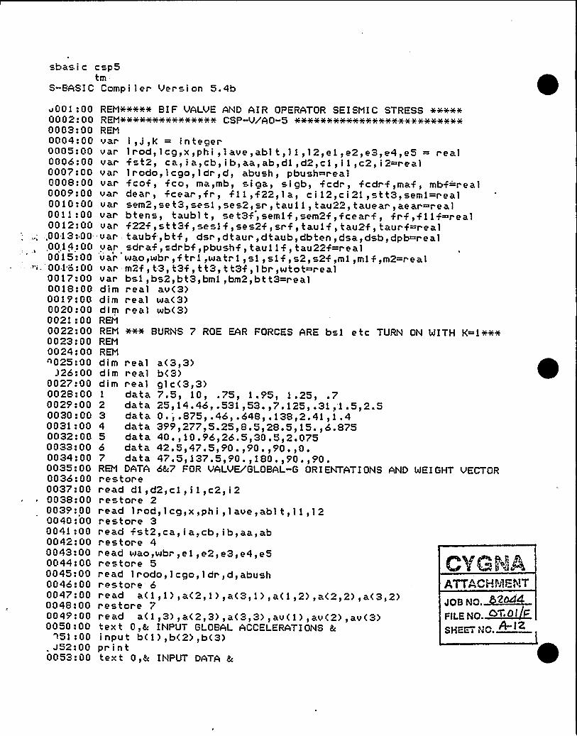
sbasic csp5tm
S-BASI C Comp i l er Ver s i on 5. 4b
v001:000002:000003:000004:000005:000006:000007$ 000008:000009:000010 000011:000012:00
,.; .,0013$ 00.,00,14: 000015 $ 00
-0016:000017:000018: 000019:000020 $ 000021: 000022: 000023:000024:00n025:00
326:000027$ 000028:000029$ 000030:000031:000032:000033:000034:000035:000036:000037:000038!000039:000040:000041$ 000042:000043:000044:000045:000046:000047:000048:000049".000050:00
~51:00. a52 F 000053:00
read wao,wbr,ei,e2,e3,e4,e5restor e 5r ead lrodo, i ego, 1 dr,d,abushr estore'read a(1,1), a(2, 1), a(3, 1), a<1,2), a<2,2), a<3,2)restor e 7read a(1,3),a(2,3),a(3,3),av(1) )av(2),av(3)tex t O,h INPUT GLOBAL ACCELERATIONS 5input b( 1),b(2),b(3)printtext 0,8c INPUT DATA h
ATE"CHMENT
JOB NO ~264~FILE Np ~QT.O
SHEEi i'JC. A-IZ
REM+++++ BI F VALVE AND AI R OPERATOR SE I SMI C STRESSREM%%%%+%% i+:w%%w%% CSP-V/AO-5REMvar i,J,k = integervar l rod, 1 cg,x,phi, 1 ave,abl t, 1 1,12,ei,e2,e3,e4,e5 = realvar fst2, ca, i a,cb, ib,aa, ab,di,d2,c 1, i i,c2, i 2=realvar lrodo, 1 ego, ldr,d, abush, pbush=realvar fcof, fco, ma,mb, siga, sigb, fcdr, fcdrf,maf, mbf='realvar dear, fcear,fr, f1 i,f22, la, ci12,ci 21,stt3,semi=realvar sem2, se t3, sesl, ses2, sr, taui 1, tau22, tauear, aear=realvar btens, taubl t, set3f,semi f,sem2f,fcear f, frf,filf~realvar f22f,stt3f,sesif,ses2f,srf, tauif, tau2f, taurf=r ealvar, taubf-, bt f, dsr, dtaur, dtaub, dbten, dsa, dsb, dpb=realvar sdr af, sdrbf, pbushf, taui 1 f, tau22f~r ealvar wao,wbr, ftrl,watr i,si,s1f,s2,s2f,mi,mi f,m2=realvar m2f,t3,t3f,tt3,tt3f,lbr,wtot=realvar bsi,bs2,bt3,bml,bm2,btt3=$ ealdim real av(3)dim real wa(3)dim real wb(3)REMREM +w+ BURNS 7 ROE EAR FORCES ARE bsi etc TUPIK ON WITH K=1+++REMREMdim real a(3,3)dim r eal b(3>dim real glc<3,3>1 data 7.5, 10, .75, 1.95, 1.25, .72 data 25,14.46,.531,53.,7.125,.31,'1.5,2.53 data 0 ~ i ~ 875s ~ 46s ~ 648s 138~2 '1$ 1 ~ 44 data 399,277,5 '5,8.5,28.5,15.,6.8755 data 40.,10.96,26.5,30.5,2.0756 data 42.5,47.5,90.,90.,90.,0.7 data 47.5,137 ',90.,180.,90.,90.REM DATA 6%7 FOR VALVE/GLOBAL-G ORIENTATIONS AND WEIGHT VECTORrestor eread di,d2, cl, i 1, c2, i 2$'estore 2read lrod,lcg,x,phi,lave,ablt,l1,12restore 3read fst2,ca,ia,cb,ib,aa,abr estore 4

UT GLOBAL ACCELERATIONS? .96,3.44)5 '2
INPUT DATA
GLOBAL G-LEVELS 2 '6NORTH VECTOR ANGLES = 42.5VERTIC*L VECTOR ANGLES= 90EAST VECTOR ANGLES = 47.5WEIGHT VECTOR ANGLES = 180
3.4447.590137. 590
5.4290
09090
h
LOCAL G-LEVELS
2.18234 -1.31225E-5 3.661691.99974 -1.31225E-S -3,.99606
-1.12915E-5 3.44 -2.06756E-5
OPERATING DP IVE ROD STRESS AT AOPERATING DRIVE ROD STRESS AT BOPERATING CYLINDER BRG PRESSUREOPERATING VALVE EAR TENSILE STROPERATING VALVE EAR SHEAR STRESOPERATING EAR BOLT SHE*R STRESSOPERATING EAR BOLT TENSILE STR
D..AMIC COMPONENTS
5048 ~ 357721.14
-98.46464664.25297.6143600 '71340 '9
DRIVE ROD TENSILE STRESS AT ADRIVE ROD TENSILE STRESS AT BBUSHING PRESSUREVALVE EAR TENSIL'E STRESSVALVE E*R SHEAR STRESSEAR BOLT SHEAR STRESSEAR BOLT TENSILE STRESS
FIXED PLUS DYNAMIC COMPONENTS
21519. 632912 '419.72420190.51,312.911588219507
DRIVE ROD TENSILE STRESS AT A 26567.9DRIVE ROD TENSILE STRESS AT B 40633.9
'USHING PPESSURE 518.189VALVE E*R TENSILE STRESS 24854.8VALVE EAR SHEAR STRESS 1610.53EAR BOLT SHEAR STRESS 19482.2EAP. BOLT TENSILE STRESS 20847.7
ATTACHMENTaoswo. ~~44va.exa ~<W FSHEET tlO.
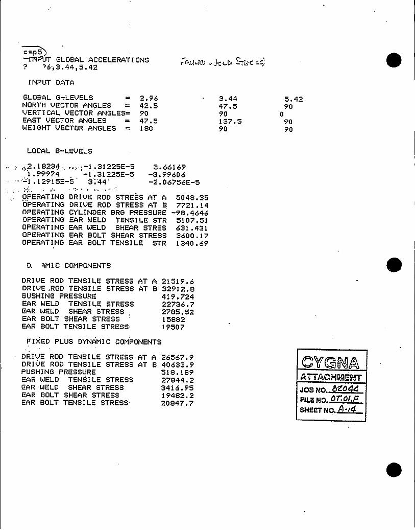
csp5UT Gl OBAL ACCELERATIONS
? >6;3.44,5.42
I NPUT DATA
r >Q ~Rb ~ J q t b; iC -';:
GLOBAL G-LEVELSNORTH VECTOR ANGLESVERTICAL VECTOR ANGLES=EAST VECTOR ANGLESWEIGHT VECTOR ANGLES
2 '642.59047.5180
3.4447.590137.590
5. 4290
09090
LOCAL G-LEVELS
3.66169-3.99606-2.06756E-5
,,2 . 1 8234 ..; -1 . 31 225E-51 ~ 99974 . -1.31225E-5
'-'1 .12915E-5 3 44'H ~ ~
OPERATING DRIVE ROD STRESS AT AOPERATING DRIVE ROD STRESS AT BOPERATING CYLINDER BRG PRESSUREOPERATING EAR MELD TENSILE STROPERATING EAR MELD SHEAR STRESOPERATING EAR BOLT SHEAR STRESSOPERATING EAR BOLT TENSILE STR
5048 '57721.14
-98.46465107.51631.4313600.171340.69
D, WMI C COMPONENTS
DRiVE ROD TENSILE STRESSDRIVE .ROD TENSILE STRESSBUSHING PRESSUREEAR MELD TENSILE STRESSEAR MELD SHEAR STRESSEAR BOLT SHEAR STRESSEAR BOLT TENSILE STRESS
AT A 21519.6AT B 32912.8
419.72422736.72785.5215882I 9507
FIXED PLUS DYNAMIC COMPONENTS
DRIVE POD TENSILE STRESS AT ADRIVE ROD TENSILE STRESS AT BPUSHING PRESSUREEAR WELD TENSILE STRESSEAR MELD SHEAP. STRESSEAR BOLT SHEAP, STRESSEAR BOLT TENSILE STRESS
26567.940633 '518 '8927844'.23416 '519482 '20847.7
boa wo.MC~Od
PILSNER.
~+I <SHEET Ho.dl «L.
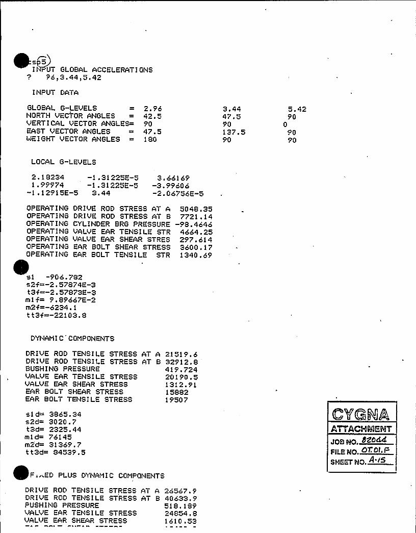
I } r'UT GLOBAL ACCELERATIONS'7 96)3 ~ 44s5 ~ 42
INPUT DATA
GLOBAL G-LEVELSNORTH VECTOP. ANGLESVERTICAL VECTOR ANGLES=EAST VECTOR ANGLESWEIGHT VECTOR ANGLES
2 '642.59047.5180
3.4447.590137. 590
5.4290
0op90
LOCAL G-LEVELS
2 ~ 18234 -1 ~ 31225E-5 3. 661691 . 99974 -1 . 31225E-5 -3. 99606
-1 ~ 12915E-5 3. 44 -2.06756E-5
OPERATING DRIVE ROD STRESS AT AOPERATING DRIVE ROD STRESS AT BOPERATING CYLINDEP. BRG PRESSUREOPERATING VALVE EAR TENSILE STROPERATING VALVE EAR SHEAR STRESOPERATING EAR BOLT SHEAR STRESSOPERATING EAR BOLT TENSILE STR
si -906.782s2$ =-2.57874E-3t3%=-2.57873E-3ml f= 9.89667E-2m2$ =-6234. 1
tt3j=-22103.8
5048 ~ 357721 . 14
-98.464o4664.25297 '143600 '71340.69
DYNAMIC COMPONENTS
DRIVE ROD TENSILE STRESS AT A 21519.6DRIVE ROD TENSILE STRESS AT B 32912.8BUSHING PRESSURE 419.724VALVE EAR TENSILE STRESS 20190.5VALVE EAR SHEAR STRESS 1312.91EAR BOLT SHEAR STPESS 15882EAR BOLT TENSILE STRESS 19507
sld= 3865.34s2d= 3020.7t3d= 2325.44mid= 76145m2d= 31 3o9. 7tt3d= 84539.5
F „,ED PLUS DYNAMIC COMPQl }ENTS
OBHQ 8ZOMFILE IIO.SIIEn'II. A'«
DRIVE ROD TENSILE STRESS ATDRIVE ROD TENSILE STPESS ATPUSHING PRESSUREVAI VE EAR TENSILE STPESSVALVE EAP. SHEAR STRESS
A 2o567.9B 40633 '
518.18924854 'lol0 ~ 53

~rI t'lPUT GLOBAL ACCELERATI Ot'lS
'? ~ o7,1 ~ 4,1.71
I NPUT DATA
j3 PSEUD
GLOBAL G-LEVELS?lORTH VECTOR ANGLESVERTICAL VECTOR AtlGLES=EAST VECTOP, ANGLESWEIGHT VECTOR *tlGLES
.9742.59047.5180
io447.590137.590
1.7190
09090
LOCAL G-LEVELS
~ 715158 -5 '4057E-6 1 ~ 15526'''. 655321': '-5. 34057E-o -1 . 26075-, -.3.70025E-, 6 1.4 -6.52313E-6
'OPERATING DRIVE ROD STRESS AT AOPERATING DRIVE ROD STRESS AT BOPERATING CYLINDER BRG PRESSUREOPERATING EAR WELD TEtlSILE STROPERATING EAR WELD SHEAR STRESOPERATING EAR BOLT SHEAR STRESSOPERATING EAR BOLT TENSILE STR
5048. 357721 . 14
-98.4o465107.51631.4313600.171340.69'~
'AMI C COMPONENTS
DP.IVE ROD TENSILE STRESS AT A 6859.18DRIVE POD TENSILE STRESS AT B 10490 ~ 7BUSHING PRESSURE 133.784
R WELD TEtlSILE STRESS 7323.31EAR WELD SHEAR STRESS 892.936EAR BOLT SHEAR STRESS 5091 . 16EAR BOLT TENSILE STRESS 7599.75
FIXED PLUS DYNAMIC COMPONENTS
DRIVE ROD TENSILE STRESS ATDRIVE ROD TENSILE STRESS ATPUSHING PRESSUREEAR WELD TEt'ISILE STRESS=AR WELD SHEAR STRESS
R BOLT SHEAR STRESSEAR BOLT TENSILE STRESS
A 11907.5B 18211.9
232.24912430.81524.378691 . 338940. 43

sbasi c csp6tm
S-BASIC Compiler Version 5 'bJOI '00
0002:000003:000004:000005:00000620000072000008:000009:000010:000011:000012:0000132000014:0000152000016:000017:000018:00001920000202000021:000022:000023:000024:000025:00
126200v 027: 000028:000029:000030: 000031: 000032: 000033 2 00003420000352000036:0000372000038:0000392000040:000041:00004220000432000044:0000452000046:000047:000048:000049:000050:00nn51:00
522000053:0000542000055:000056:00
read fst2,ca, ia,cb, ib,aa,abrestore 4read wao,wbr,ei,e2,e3,e4,e5res tor e 5read lrodo, 1 ego, 1 dr,d,abushr es tore 62 ead a(1 s 1) sa(2s 1) sa(3»1) sa(1,2)»a<2»2) sa(3»2)*restore 7r ead a< 1, 3), a(2, 3), a(3, 3), av (1), av (2), av (3)text 0»h INPUT GLOBAL ACCELERATIONS 8c
input b<1) sb<2) sb<3)printtext 0,6 INP,UT DATA hpr intpr i n t "GLOBAL G-LEUELSpr int "NORTH VECTOR ANGLES
CVGNAATTACH1icNTJOB NO. 0
RLENO. ~T Oi
sHf s No.
"»b(1)sb(2>sb(3>";a(1,1),a<2,1),a(3,1)
REM+»s+++ BIF VALVE AND AIR OPERATOR SEISMIC STRESSREM»s»s~»s». ~~». ~~~».».s. ~ CSP-VyAO-6»s~»s»s~» ~»s~~~»s~»s»'+» + ss~ss~~~~»sREMvar 1 s J sk = integervar lrod, leg,x,phi, 1 ave,abl t,11,12,el,e2,e3,e4,e5 = realvar fst2, ca, i a,cb, ib,aa,ab,di,d2,cl, i i,c2, i2=r ealvar 1 rodo, 'i cgo, 1 dr, d, abush, pbush=realvar fcof, fco, ma,mb, si ga, s i gb, fcdr, fcdrf,maf, mbf=r ealvar dear, fcear, fr, f 1 1, f22,1 a, c i 12, c i 21, st t3, semi=realvar sem2,set3,sesi,ses2,sr, taul 1, tau22, tauear,aear=r ealvar b tens, taubl t, se t3f, semi f, sem2f, fcear f, frf,f11 4 =realvar f22f,stt3f,sesl f,ses2f,srf, taul f, tau2f s taurf=realvar taubf,btf, dsr, dtaur, dtaub, dbten, dsa, dsb, dpb=realvar 'dr af,sdrbf,pbushf, taui 1 f, tau22f~r ealvar wao,wbr, ftri,watri,sl, sl f, s2, s2f,mi,ml f,m2=r ealvar m2f, t3, t3f, t t3, t t3f, 1 br,wtot=r ealvar bsl, bs2, bt3, bml, bm2, bt t3=realdim real av<3)dim real wa(3)dim real wb<3)REMREM +»s»s BURNS 7. ROE EAR FORCES ARE bsl etc TURN ON WITH K=1»s+»sP.EMREMdim r eal a(3,3)dim real b<3)dim real glc(3,3)1 data 7.5, 10, .75, 1.95, 1.25, .72 data 25,14.46,.531,53.,7.125,.31,1.5,2.53 data 0 ' ~ 875s ~ 46» ~ 648s ~ 138»2 '1sl ~ 44 data 35'5',277»5 '5»8 '»28 '»15 '6 '755 data 40.,10.96,26.5,30.5,2.0756 data 5'O.s90 ~ st »0 '90 '90 ~
7 data 5'0 '0 '5'0 ~ s180 ~ s90 ~ s90 ~
REM DATA 6h7 FOR VALVE/'GLOBAL-G ORIENTATIONS AND WEIGHT VECTORrestoreread dl,d2,cl,i i,c2,i2restore 2read 1rod,'icg,x,phi,lave,ablt,11,12restor e 3

Pl I II I,
0060: 000061: 010062: 02'0063: 020064:020065:01'')66:00367:Oi
0068:010065':000070:000071: 000072: 000073:000074:000075:000076:000077:010078:010079:010080:000081". 000082: 000083: 000084: 000085:000086:000087:000088:000089".000090:000091:00
5'2: 00v093:000094:000095:00005'6:00005'7:00005'8:000095':000100:000101:000102:000103!000104:000105:000106:000107'000108:000105'.000110:000111:000112:000113:000114:000115:000116:00'7:00
18:000115':000120:0001 21: 000122: 000123:000124:00ni oR.nn
ATTACHVi=MTsos NO.~MAFiLE NQ.QX 4~i
SHEETRO. 4 ~
for i=i to 3for j=l to 3;
a<j,i)=a<j',i)+2.+3.1416/360.glc(j,i)=b<i)icos(a(j,i))
nextnext ifor j=l to 3av ( j ) =av ( j ) +2. +3. 1416/360 .next Jprinttext 0,& LOCAL G-LEVELS 4pr intprint gl c(1,1),gl c(1,2),gl c(1,3)print glc(2,1),glc(2,2),glc(2,3)pr in t gl c(3,1), gl c(3,2), gl c(3,3)REM WE I GHT COMPONENTSfor j=i to 3wa(j)=wao+cos(av(j))wb(j)~broncos(av(j))next
'ph'i=phi+2.+3.1416/360.la='lave/2'„c112=c1/i
2c i 2l=c2/i 1
aear=l 1 +12REM CALCULATE EAR FORCES USE BhR LOADS AS OPTION LATERREM FIXED COMPONENTS ARE ALWAYS THERE1 br= 1 r od+1 cgwatr 1=1 br+wa(1)/1 rodslf=wb<1)+watr 1
w t o t~wao+wbrs2f=wb(2)+wa(2)+f st2t3f=wa(3)+wb<3)mi f=-<wa(2)+wb(2)+fst2) +e5-wa(3) +(e3+ 1 cg)-wb(3) +e4m2f=(watr 1+wb(1) ) +e5-wa(3) +e2-wb(3> +elt t3f=watr 1+e3+ <wa(2)+ fst2) +e2+wb< 1 > we4+wb(2> we 1fcdrf~l cg+wa(1)/1 r odmaf~fcdr f+(lrod-13.5)mbf~fcdr f+7.125sdraf=f st2/aa+abs(maf +ca/1 a)sdrbf=f st2/ab+abs(mbf +cb/lb)fcof=lcgoxwa(1)/1 r odopbush f=fcof+< 1 dr+d)/(d+abu sh)REM STRESSES FROM FIXED COMPONENTSdeat =(dl+dl+d2+d2) ++.5se t3f=abs( t3f/(4+aear ) )semi f=abs(ml f/(2+d2+ae ar > )sem2f =abs<m2f/(2wdl +ae ar ) ) CYfcearf=t t3f/(2+dear)frf=x+fcearff i if=-<fcearf+sin(phi )-frf+cos(phi) )f22f=fcearf icos(phi )+fr f+sin< ph 1 )st t3f=abs< f 11 f+1 a+c i 12)+abs( f22f +1 a+c i 21 )se s1 f=abs( sl f+c i 12+1 a/4. )ses2f=abs(s2f+ci 21+la/4 'srf=se t3f+seml f+sem2f+sesl f+ses2f+st t3fREM EAR SHEARtaul 1 f=abs(si f/<4+aear) )+abs< f 1 1 f/aear )tau22f=abs(s2f/(4~aear) )+abs( f22f/aear)taurf=( tau1 1 f+taul 1 f+ tau22f +tau22f ) ++ ~ 5taubf=taur f+aear/abl tREM E*RBOLT TENSIONbtf=(se t3f+seml f+sem2f ) +aear/abl tprintpr int"OPERATING DRIVE ROD STRESS AT A ";sdrafnr i n & ~~ AocpbTTMf'ptlJc Inn QTpccc 6T R "
crier
h4

V 4 V ~ V V
01 26: 000127: 000128!00'0129!000130:000131! 00"132: 00
i33:000134 0001 35: 000136! 0001 37: 000138! 000139! 000140! 000141:000142: 000143: Oi0144! 010145: 0101.46! 010147: 010148! 0 1
01 49: Oi0150: 0 1
0151: 010152! 0 1
0 1 53: 010154! 010155! Oi0156: 010157!01
58: 01!59:Oi
0160:010161! 010162! 010163: 010164! 0 1
0165:010166!010167!010168!010169:010170! 010171! 010172'010173:010174:010175:010176:010177:Oi0178:010179:Oi0180! 010181:010182: 01~'3: 01
84:0001 85: 000186: 000187: 000188: 000189! 000190: 00'n! 01 ~ nn
P ~ ~ ~ ~ s vo 0 ~ 4 ~ ~ 4 ~ 1V 8 ~ l4 V I ~ 'I'VV V I ~ % ~ VV ~ I ~
print"OPERATING CYLINDER BRG PRESSUREprint"OPERATING VALVE EAR TENSILE STRprint"OPERATING VALVE EAR SHEAR STRESprint"OPERATING EAR BOLT SHEAR STRESSprint"OPERATING EAR BOLT TENSILE STRpr intREMREM CALCULATE VARIABLE COMPONENTSREMdsr~O. f
dtaur =0.dtaub=0.dbten=O.dsa=0.dsb=0.dpb=O.for j=i to 3fc o= 1 c go+wao+g 1 c ( 1, j ) 11 rodopbush=f co+< l dr +d)/(d+abush)f tr1=1br+waowgl c<1, j)/1 rodsi=f tr 1+wbr +gl c(1, j)s2=wtot+glc(2,j)t3=wtot+glc(3,J)mi=-wtot+glc(2,j)+e5-wao+glc(3,J>+(e3+m2=(f tr.i+wbr+gl c(1, j ) >+e5-(wao+e2+wbr+tt3=ftriwe3+wbr+glc(i,j)+e4+glc(2,J)+(fcdr=lcg+wao+glc( l,j)r'irodma= fc dr+( l r od-1 3. 5)mb=f cdr+7. 125si ga=ma%cM i as i gb=mb+cbl i bREM CALCULATE EAR TENSIONse t3=abs( t3r'(4+ac ar > )semi=abs(mit'(2wd2+aear) )sem2=abs(m2/(2+di +aear > )fcear =t t3/(2%dear)5 r=x+fcearf 1 1=-(fcear+sin(phi )-fr icos(phi ) )f22~% cear+cos<phi )+fr+sin(phi )st t3=abs( f11+1 a+c i 12)+abs( f22+1 a+c i 21)sesi=abs( si +c i 12+1 M4. )ses2=abs(s2+c i 21+1 al4. )sr ~se t3+semi+sem2+sesi+ses2+s t t3REM EAR SHEARtaui i~abs( si/(4. +aear > >+abs( f11''aear )tau22=abs< s2/< 4. +aear ) )+abs( f22/aear )tauear=( tau11+tau11+ tau22+tau22) w+. 5taublt=tauear+aear/'abltREM EARBOLT TENSIONbtens=(se t3+semi+sem2) +aear/abl tdsa=dsa+ s i ga+s i gadsb=dsb+si gb+s i gbdp b=dp b+ p bu sh +p bushdsr=dsr+s! +srdtaur=dtaur+ tauear+taueardtavb=dtaub+ taubl t+ taubl tdbten=dbten+btens+btensnext jREM CQMBINE STRESSESdsa=dsa++.5dsb=dsb++.5dpb=dpb++ ~ 5dsr=dsr++.5dtaur=dtaur++:.5dtaub=dtaub++.5rlh 0 on .rib 4 or WS
%J ~ ht I
";pbushf"Isrf"; taurf"; taubf";btf
lcg)-wbr+glc(3,J)+e4ei)+glc(3,j)waowe2+wbr+el)
gyGRAATTACHE!BI".!

0192: 000173!000194: 00'01 5'5: 000196! 00015'7:00
198:00E 5'5': 00
0200:000201:000202! 000203:000204:000205:000206!000207:000208!000209:000210:000211 200" ' '0212!'000213:000214'00"' 0215!00
-0216:000217'000218:00021 5'! 000220: 000221 $ 000222!000223:00
'.24! 00225$ 00
AT A";dsaAT B";dsb
";dpb'dsr
";dtaur";dtaub";dbten
ONENTS &
AT A";dsaAT B";dsb
" ldpb"Edsr";dtaur";dtaub";dbten
++ww+w End of program +++++w
printtext 0,& DYNANIC CONPONENTS &printprint "DRIVE ROD TENSILE STRESSprint "DRIVE ROD TENSILE STRESSprint "BUSHING PRESSUREprint "VALVE EAR TENSILE STRESSprint "VALVE EAR SHEAR STRESSprint "EAR BOLT SHEAR STRESSprint "EAR BOLT TENSILE STRESSds
aci�ds
a+ abs ( sdr af )dsb=dsb+abs(sdt bf )dpb=dpb+abs( pbush f )dsr~dsr+abs(srf )dtaur=dtaur+abs( taur f )dtaub=dtaub+'abs( taubf )dbten=dbten+abs(btf )printtext 0,& FIXED PLUS DYNANIC CONPprintpr i'nt "DRIUE ROD TENSILE STRESS.pr.int "DRIVE ROD TENSILE STRESSprint "PUSHING PRESSUREpt.i'nt "UALVE EAR TENSILE STRESSpr int "VALUE EAR SHEAR STRESSprint "EAR BOLT SHEAR STRESSprint "EAR BOLT TENSILE STRESSend
ATTACHE'ENT
gpss No 5'Zbd
FllENO. 0 .blEHEEi NO.~
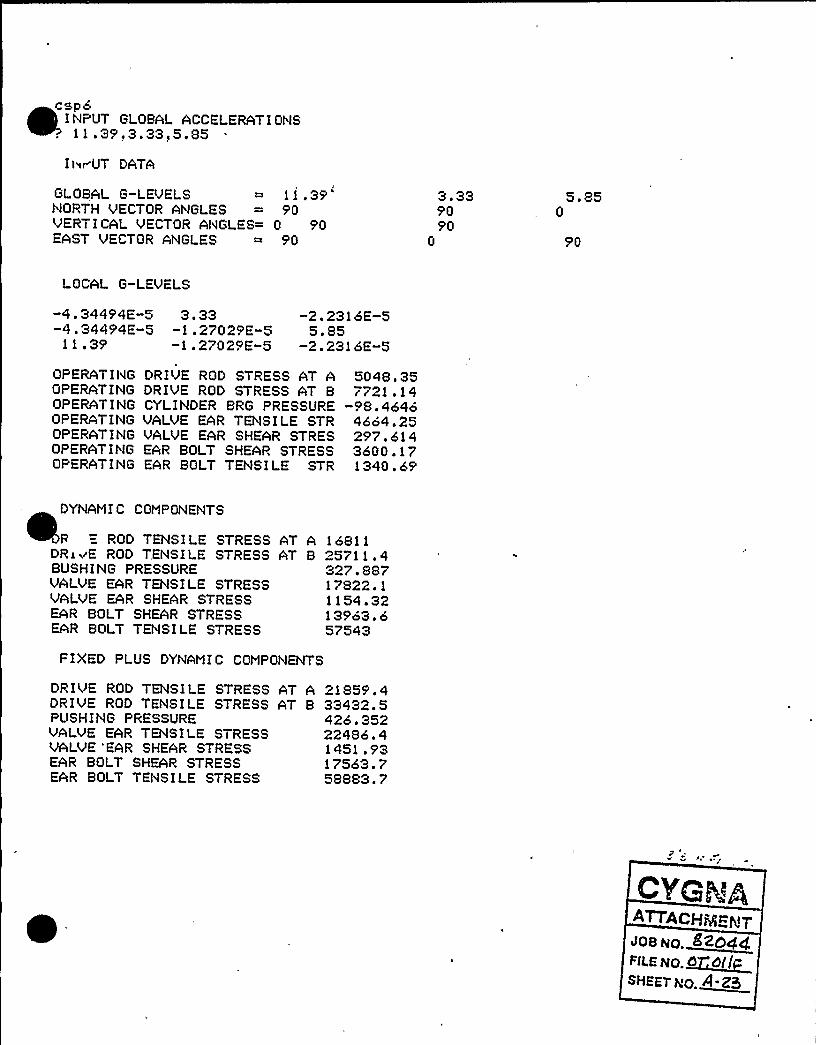
~ ~ ~
csp6INPUT GLOBAL ACCELERATIONS11.39.3.33,5.85
Il~rUT DATA
GLOBAL G-LEVELS11.39'ORTH
VECTOR ANGLES = 90VERTICAL VECTOR ANGLES= 0 90EAST VECTOR ANGLES = 90
3.339090
0
5.850
90
LOCAL G-LEVELS
-4.34494E-5 3.33-4.34494E-5 -1.27029E-5
11.39 -1.27029E-S
-2.23loE-55.85
-2.2316E-5
OPERATING DRIVE ROD STRESS AT AOPERATING DRIVE ROD STRESS AT BOPERATING CYLINDER BRG PRESSUREOPERATING VALVE EAR TENSILE STROPERATIIIG VALVE E*R SHEAR STRESOPERATING EAR BOLT SHEAP, STRESSOPERATING E*R BOLT TENSILE STR
5048.357721.14
-98.46464664.25297.6143600.171340.69
E
DYNAMIC COMPONENTS
R " ROD TENSILE STRESSDRxv'E ROD TENSILE STRESSBUSHING PRESSUREVALVE EAR TENSILE STRESSVALVE EAR SHEAR STRESSEAR BOLT SHEAR STRESSEAR BOLT TENSILE STRESS
AT A 16811AT 8 25711.4
327.88717822.11154 '213963.o57543
FIXED PLUS DYNAMIC COMPONENTS
DRIVE ROD TENSILE STRESS AT *DRIVE ROD TENSILE STRESS AT BPUSHING PRESSUREVALVE EAR TENSILE STRESSVALVE 'EAR SHEAR STRESSEAR BOLT SHEAR STRESSE*R BOLT TENS I LE STRESS
21859. 433432.5426.35222486.41451.9317563.758883.7
~TTACHQgg<yJQBNo. Bzo4cf,<ALE NO. ~dd~llSHEET MO. A Z5

~ ~
csp6T GLOBAL ACCELERATIONS
,39.3.33,5.85
INPUT DATA
GLOBAL G-LEVELS 11.39NORTH VECTOR ANGLES = 90VERTI CAL VECTOR ANGLES= 0 90EAST VECTOR ANGLES = 90
3. 339090
0
5.850
90
LOCAL G-LEVELS
-4.34494E-5 3.33 -2.2316E-5-„4 . 34494E-,5,—,1 . 27029E-5 5. 85
1'1~ 39 -1 . 27029E-5 -2. 231 6E-5
~ * IIp ~ ~ - ~
*
OPERATING DRIVE ~ ROD STPESS AT A 5048. 35OPERATING DRIVE ROD STRESS AT B 7721.14OPERATING CYLINDER BRG PRESSURE -98.4646OPERATING EAR WELD TENSILE STR 5107.51OPERATING EAR WELD SHEAR STRES 631.431OPERATING EAR BOLT SHEAR STRESS 3600.17OPERATItlG EAR BOLT TEhlSILE STR 1340.69
D><AMIC COMPONENTS
DRIVE ROD TENSILE STRESSDRIVE ROD TENSILE STRESSBUSHING PRESSUREEAR WELD TENSILE STRESSEAR WELD SHEAR STRESSEAR BOLT SHEAR STRESSEAR BOLT TENSILE STRESS
AT A 16811AT B 2571'1 ~ 4
327.88721586.22449 '513963 '57543
FIXED PLUS DYNAMIC COMPONENTS
DRIVE ROD TENSILE STRESSDRIVE ROD, TENSILE STRESSPUSHING PRESSUREEAR WELD TEhlSILE STRESSEAR WELD SHEAR STRESSEAR BOLT SHEAR STRESSEAR BOLT TENSILE STRESS
AT A 21859.4AT B 33432.5
426.35226693.73080 '817563.758883.7 JOB RO.~~4
Fn.e WC.~SHEETXO.~<- <

spaI t"~UT GLOBAL ACCELERATI ONS
.35',3.33,5.85
INPUT DATA
GLOBAL G-LEVELS 11.39NORTH VECTOR ANGLES = 90VERTICAL VECTOR ANGLES= 0 90EAST VECTOR ANGLES = 90
3 '3905'0
0
5. 850
5'0
LOCAL G-LEVELS
-4.34494E-5 3.33-4.3445'4E-5 -1.27025'E-511.35'1.27029E-5
-2.2316E-55.85
-2.2316E-5
OPERATING DRIVE ROD STRESS AT AOPEPATING DRIVE ROD STRESS AT 8OPERATING CYLINDER BRG PRESSUREOPERATING VALVE EAR TENSILE STROPERATING VALVE EAR SHEAR STRESOPERATING EAR BOLT SHEAR STRESSOPERATING EAR BOLT TENS! LE STR
5048.357721 . 14
-98.46464664.2525'7 '143600 . 171340. 65'
i"'--906. 7822. -2.57874E-3
t3f=-2. 57873E-3ml f= 9.89667E-2m2f=-6234. 1
t t 3f=-221 03. 8
DYNAMIC COMPONENTS
DRIVE ROD TENSILE STRESSDRIVE ROD TENSILE STRESSBUSHING PRESSUREVALVE EAR TENSILE STRESSVALVE EAR SHEAR STRESSEAR BOLT SHEAP. STRESSEAR BOLT TENSILE STRESS
sld= 3019.58a2d= 3954.6t3d= 7699.63mid= 2.44083E+5m2d= 58968.3tt3d= 78875.3
AT A 16811AT B 25711.4
327.88717822 F 1
1154 '213963.657543
=D PLUS DYNAMIC COMPONENTS
DRIVE ROD TENSILE STRESS AT A 21859.4DRIUE ROD TEt'lSILE STRESS AT B 33432.5PUSHING PRESSURE 426.352VALUE EAR TENSILE STRESS 22486.4VALVE EAR SHEAR STRESS 1451.93EAR BOLT SHEAP. STRESS 17563.7
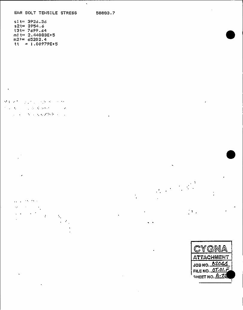
EAR BOLT TENSiLE STRESS
sit= 3926 '6=-Zt= 3954.6t3t= 7699.64mlt= 2.44083E+5m2>= 65202 'tt = l.00979E+5
58883.7

II JT GLOBAL ACCELERATIONS EQgQ g f-gQy? 11.37,3.18,5.83
INPUT DATA
GLOBAL G-LEVELS 11.37NOPTH VECTOP. ANGLES = 90VERTICAL VECTOR AIIGLES= 0 90EAST VECTOR ANGLES = 90
3. 189090
0
5.830
90
LOCAL G-LEVELS
-4 '3731E-5 3.18-4 '3731E-5 -1 ~ 21307E-5
11.37 -1 ~ 21307E-5
-2.22397E-55.83
-2.22397E-5
OPERATING DRIVE ROD STRESS AT AOPERATING DRIVE ROD STRESS AT BOPERATING CYLINDER BRG PRESSUREOPERATING EAR MELD TENSILE STROPERATING EAR MELD SHEAR STRESOPERATING EAR BOLT SHEAR STRESSOPERATING EAR BOLT TENSILE STR
D'AMI
C COMPONEIWS
5048.357721 . 14
-98.46465107.51631 .4313600 ~ 171340.69
DRIVE ROD TENSILE STRESSDRIVE ROD TENSILE STRESSBUSHING PRESSUREE*R MELD TENSILE STRESSEAR WELD SHE*R STRESSEAR BOLT SHEAR STRESSEAR BOLT TENSILE STRESS
*T A 16053.7AT B 24553.2
313. 117209672365.9613489.857426.5
FIXED PLUS DYNAMIC COMPONENTS
DRIVE ROD TENSILE STRESSDRIVE ROD TENSILE STRESSPUSHING PRESSUREEAR MELD TENSILE STRESSEAR MELD SHEAR STRESSEAR BOLT SHEAR STRESSc R BOLT TENSILE STRESS
AT A 21102.1*T B 32274.4
411.58226074.52997.391709058767.2

c&p6I hlPUT GLOBAL ACCELERATI ONS Q Pg Q ('P 2.69,3.09,1.48
Its> JT DATA
GLOBAL G-LEVELS 2.69NORTH VECTOR ANGLES = 90VERTIC*L VECTOR ANGLES= 0 90EAST VECTOR ANGLES = 90
3 ~ 099090
0
1.480
90
LOCAL G-LEVELS
-1.02615E-5 3.09-1.02615E-5 -1 ~ 17874E-52.69, ,. -1 '7874E-5
-5.64575E-61.48
-5.64575E-6
OPERATING DRIVE'OD" STRESS AT A 5048.35OPER*TING DRIVE, ROD,;,STRESS AT B 7721.14OPERATING CYLINDER BRG PRESSURE -98.4646OPERATING EAR WELD TEl'lS I LE STR 5107. 51 ~
OPERATING EAR WELD SHEAR STRES 631 . 431'PERATINGEAR BOLT SHEAR STRESS 3600 . 1 7
OPEPAT ING EAR BOLT TENS I LE STR 1 340 .
69'YNAM
I C COMPONENTS
DP.;: ROD TENSI LE STRESSDR IVE ROD TENS I LE STRESSBUSHING PRESSUREEAR WELD TENSILE STRESSEAR WELD SHE*R STRESSEAR BOLT SHEAR STRESSEAR BOLT TENSILE STRESS
AT A 15599 'AT B 23858.3
304.25616110.81976.811127114173.8
FIXED PLUS DYNAMIC COMPONENTS
DRIVE ROD TENSILE STRESS AT A 20647 'DRIVE ROD TENSILE STRESS AT B 31579.4PUSHING PRESSURE 402. 72EAR WELD TENSILE STRESS 21218.3EAR WELD SHE*R STRESS 2608.24=AR BOLT SHEAR STRESS 14871.2EAR BOLT TENSILE STPESS .15514. 5
J08 NG.ZtFc4C~
FlLE NQ ~~d. t=
SHE TRQ.MWW

Pl I II i Wl 1 VIII V4VIVli PIIWVI I 4 yOVi I t )4ViC I gOVi4)
sba ic cep3atm
S-BASIC Compi 1 er Versi on 5.4b
701:00v002:000003:000004:000005:000006:000007!000008:000009:000010:000011!000012:000013:000014!000015!000016:000017!000018:000019!000020:000021:000022:000023:000024:000025:00"026:00
J27! 000028: 000029:000030:000031:000032:000033:000034:000035!000036:000037!000038!000039:000040:000041!000042:000043:000044:000045:000046!000047:000048:000049!000050:000051!00
i52t00..a53!000054 000055:000056:000057:000058!00
read lrod,lcg,x,phi,lave,ablt,lrestor e 3read
fst2,ca,ia,cb,ib,aa,ab'estore
4read wao,wbr,ei,e2,e3,e4,e5r estore 5read lrodo, 1 ego, l dr,d,abushrestore 6read a(1,1), a(2, 1 >, a<3,1), a(1,r estore 7read a(1,3), a<2,3), a<3,3>, av (1text 0,& INPUT GLOBAL ACCELERATi npu t b(1), b< 2), b< 3)pr in
t'ext 0,& IliPUT DATA &printprint "GLOBAL G-LEVELSprint "NORTH VECTOP. AliGLESprint "VERTICAL VECTOR ANGLES=print "EAST VECTOR ANGLES
i,l2
2), a(2, 2), a< 3, 2)
), av(2), av(3)IONS &
"; b< 1), b(2), b(3)ia(1)1>,a(2,1),a<3,1)
"la(1 t2) sa(2~2) sa(3<2>")a(1,3),a<2,3),a(3,3)
CYGRAATTACHMENT~os wo.FiiE XO. < ~
SHEET NO. WM~
REM+++++ BIF VALVE AND AIR OPERATOR SEISMIC STRESSREM~+~w++w++w+++++ CEp-V/AO-3A +wwww++++++++w+ww+w++++++REMvar i, j,k = integervar lrod,lcg,x,phi,lave,abl t,l1,12,el,e2,e3,e4,e5 = realvar fs t2, ca, i a y cb
>i b, aa, ab, di, d2, c 1, i 1, c2, i 2=real
var ir odo, l cgo, l dr,d, abush, pbush=r ealvar fcof, fco, ma,mb, si ga, si gb, fcdr, fcdrf,maf, mbf=realvar dear, fcear, fr, f11, f22, l a, c i 12,c i 21,st t3,seml=r ealvar sem2, se t3, sesi, ses2, sr, taui 1, tau22, tauear, aear=r ealvar btens, taub) t, se t3f,semi f,sem2f, fcearf, frf,flif=realvar f22f, st t3f, sesi f, ses2f, sr f, taui f, tau2f, taur f=realvar taubf,btf, dsr,dtaur,dtaub,dbten,dsa,dsb,dpb=t ealvar sdraf,sdr bf,pbushf, taui if, tau22f=realvar wao,wbr, f tr i,watri,si,sif,s2, s2f,mi,mi f,m2=r ealvar m2f s t3s t3f s tt3s tt3f s ib!'swtot=realvar bsi,bs2,bt3,bmi,bm2,btt3=realdim real av(3)dim real wa(3)dim real wb(3)REMREM +++ BURNS 7 ROE EAR FORCES ARE bs1 etc TURN ON WITH K=1+++REMREMdim real a(3,3)dim r eal b(3)dim real glc(3,3>1 data 7.5s 10s ~ 75s 1 '5< 1 ~ 25< ~ 72 data 25,14.46,.531,53.,7.125,.31,1.5,2.53 data 1150.~.875s.46s ~ 648s ~ 138s2 ~ 41si ~ 4
data 399,277,5.25,8.5,28.5,15.,6.8755 data 40.,10.96,26.5,30.5,2.0756 data 90 '90 A >0 '90 '0 A >90 '
data 180.,90.,90.,90.,180.,90.REM DATA 6&7 FOR VALVE/'GLOBAL-G ORIENTATIONS AND WEIGHT VECTORrestorer ead di, d2, c 1, i 1, c2, i 2restore 2

Compilation comp) ete
ce aINPUT BLOB*L *CCELERATIONB PER-4-B4 ( . RI ~)? 4 '7,1.2o,.S6INPUT DATA
GLOBAL G-LEVELSNORTH VECTOR ANGLESVERTICAL UECTOR ANGLES=EAST UECTOP. ANGLESWEIGHT VECTOR ANGLES
4.57909018090
1 ~ 2690
090180
.860
905'090
,, LOCAL.,G-,LEVELS,"~
~-1.74332E-5 " -4.80652E-6 -.S6., 1;,,1 . 74332E-,5, 1 . 26 '3. 28064E-6
„ 4.57 -4 '0652E-6 ~ -3.28064E-6
OPEPATING DRIVE POD STRESS AT A 477.15'8OPEPATING DRIUE ROD STRESS AT B 821.458OPERATING CYLINDER BRG PRESSURE -3 '5613E-4OPERATING VALVE EAR TENSILE STR
1136.52'PERATINGVALVE EAR SHEAR STRES 89.1706OPERATING EAR BOLT SHEAR STRESS 1078.68OP~~ATING EAR BOLT TENSILE STR 525.595
sl f=-3. 4591E-3s2f= 474t3f=-2.57873E-3ml f=-3258. 67m2f=-5.29623E-3tt3f= 4929.17
DYNAM!C COMPONENTS
DRIVE ROD TENSILE STRESSDRIVE ROD TENSILE STRESSBUSHING PRESSUREVALUE EAR TENSILE STRESSVALVE EAR SHEAR STRESSEAR BOLT SHEAR STRESSEAP. BOLT TENSILE STRESS
sl d= 779. 831s2d= 851 . 76t3d= 3089.31mid= 5'7498.om2d= 22785tt = 19965.7
AT A 4341 '7AT B 6640.18
84.67954711.31285.5'353458.8922999.3
JQB No.~~FILE NO.~CT' ~
SHEET VO.M~~
FIXED PLUS DYI'iAMIC COMPONENTS
DP.IVE ROD TENSILE STRESS AT A 4818.7oDRIVE ROD TENSILE STRESS AT B 74o1.64PUSHING PRESSURE 84.6799

VALVE EAR TEtISILE STRESSVALUE EAR SHEAR STRESSEAR BOLT SHEAR STRESSEAR BOLT TENSILE STRESS
~
~
31 t= 7?9.835s2t= 1325.76
3089.32mls= 1.0075?E+5m2t= 22785tt3t= 24894 '
5847.84375.1064537.5723524.9
JoaMo ~8Z 4pgpgp STOICsvsevwo.8->~

Ccnpilatian cceplete
cep3SLOBAL ACCELERATICNS
? 4.5711.26)0.86
INPUT DATA
GLOBAL G"LEVELS = 4.57NORTH VECTOR ANGLES = 90
VERTICAL VECTOR ANGLES= 90
EAST VECTOR NGLES = 180
MiiGHT ViCTOR ANGLES = 90
1.2690
0
90
180
,860
90
90
90
LOCAL G-LEVELSqlI~I ', ': -v
-.1,'74332E"5 -4.80652E-6 ,-.86-1.74332E-5 1.26 -3.28064E-6
4.57 '4.80652i-6'" -3;28064E-6
OPERATING DRIVE ROD STRESS AT A 477.198OPERATING DRIVE ROD STRESS AT 8 821.458OPERATING CYLINDER BRG PRESSURE
-3,75613'PERATING
EAR MELD TENSILE STR 1326.01OPERATING EAR MELD SHEAR STRES 189.188OPERATING EAR BOLT SHEAR STRESS 1078.68OPERATING EAR BOLT TENSILE STR 525.595
DYNANIC CONPNENTS
DRIVE ROD TENSILE STRESS AT A4341.57,'RIVE
ROD TENSILE STRESS AT B 6640.18 ',
BUSHING PRESSURE 84.6795EAR MiLD TENSILE STRESS 6247.02EAR MELD SHEAR STRESS 606.65EAR BOLT SHEAR STRESS 3458.89EAR BOLT TENSILE STRESS 22999.3
FIXED PLUS DYNANIC CNPlNBffS
DRIVE ROD TENSILE STRESS AT A 4818.76DRIVE ROD TENSILE STRESS AT B 7461.64PUSHING PRESSURE 84.6799EAR MELD TENSILE STRESS 7573.03EAR MELD SHEAR STRESS 795.838EAR BOLT SHEAR STRESS 4537.57 ,EAR BOLT TENSILE STRESS 23524.9

sbasic cep4atm
-BASIC Compi 1er Version 5.4b
0001:00OOO2:0O0003:000004:000005:000006:000007'000008:000009:000010:0000112000012:000013:000014:000015:000016:000017'000018:000019:000020:000021: 000022: 000023: 000024: 00
l25'00u026'000027:000028:000029:000030:000031:000032:000033:000034:000035:000036:0000375000038:000039:000040:000041:000042:000043:000044'000045'000046:000047:000048:000049:00nO5O:OO
f51:00u052:000053,:000054:000055:000056:000057:000058:00
read l rod, leg, x, ph i, 1 ave, ab1 t, 1 1, l 2restore 3read fst2,ca,ia,cb,ib,aa,abrestore 4read wao,wbr,ei,e2,e3,e4,e5re tore 5read lrodo,lcgo,ldr,d,abushnestor e 6read a< 1, 1), a(2, 1), a(3, 1), a(1,2), a(2,2), a<3,2)restore 7read a(1,3),a<2,3),a<3,3),av<1),av(2),av(3)text o,h INPUT GLOBAL ACCELERATIONS hinput b<i >,b(2>,b< -)printtext o,h INPUT DATA 6pr intprint "GLOBAL G-LEVELS lb< 1 ) )b(2) fb(3)pr int "NORTH VECTOR ANGLES = ";a(1,1>,a(2,1>,a(3,1)pr i nt "VERTICAL VECTOR ANGLES= " la(1 >2) ~ a(2 s2> ~ a(3s2>print "EAST VECTOR ANGLES = ":a(1.3) .a(2.3) .a(3.3)
ATTACHMENT
408 NO.
FILE NO. OT 0SHEET',:.O.~~
REM++++~ BIF VALVE AND AIR OPERATOR SEISMIC STRESSREM%%%%%%%%%%%%%%% CEP-V/AO-4A %%%%%%%%%+%%%%%%%%%%+i:%%OF+
REMvar i,J,k = integervar lrod,lcg,x,phi,lave,abl t,l1,12,ei,e2,e3,e4,e5 = realvar fst2, ca, ia,cb, ib,aa,ab,di,d2,ci, i1,c2, i2=realvar 1 rodo, 1 ego, l dr, d, abush, pbush=realvar fcof, fco, ma,mb, si ga, si gb, fcdr, fcdrf,maf, mbf=r ealvar dear, fcear, fr, f11, f22, 1 a, c i 12,c i 21, st t3,semi=realvar sem2, se t3, ses1, ses2, sr, tau11, tau22, tauear, aear=r ealvar btens, taubl t, set3f,semlf,sem2f,fcearf, fr f,f11f=realvar f22f,stt3f,sesi f,ses2f,srf, tauif, tau2f, taurf=realvar taubf, btf,, dsr,dtaur, dtaub, dbten, dsa, dsb, dpb=r ealvar sdraf,sdrbf,pbushf, taui 1 f, tau22f=realvar wao,wbr, f tri,watr1,si,si f,s2,s2f,mi,mlf,m2=realvar m2f, t3, t3f, t t3, t t3f, 1 br,wtot=realvar bs 1, bs2, b t3, bm 1, bm2, b t.t3=r e a ldim real av(3)dim real wa(3)dim real wb(3)REMREM ++< BURNS 7 ROE EAP. FORCES ARE bsi etc TURN ON WITH K=1+++REMREMdim real a(3,3)dim real b(3)dim real glc(3,3)1 data 7.5, 10, .75, 1.95, 1.25, .72 data 25,14.46,.531,53.,7.125,.31,1.5,2.53 data 1150.s.875'.46< ~ 648s ~ 138>2 '1si 44 data 399,277,5.25,8.5,28 ',15.,6.8755 data 40.,10.96,26.5,30.5,2.0756 data 90.,-38.,52.,90.,52.,142.7 data 180 ~ s90 ~ s90 ~ s90 ~ s 128 ' 38
'EMDATA 657 FOR VALVMGLOBAL-GORIENTATIONS AND WEIGHT VECTORrestoreread di,d2,ci,ii,c2,i2restore 2

0059:00OC'60:000061'000062:Oi0063:020064:020065:02066:Oi
U067r000068:010069:Oi0070: 000071: 000072: 000073:000074:000075:000076:000077'000078:010079:010080:010081:00
: ~ 0082:000083!000084:000085:000086:000087:000088:000089:000090:00"091:00
392r000093:000094:000095:000096:000097:000098:000099:000100r000101!000102:000103:000104:000105:000106:000107:000108:000109:000110:000111:000112:000113:000114:000115:000116:00
17:00vl 18r000119:000120: 000121:000122:000123:0001 24:00
se t3f=abs< t3f/(4+aear ) )semi f=abs (mlf/(2+d2+ae ar ) >
sem2f=abs(m2f/(2+di+aear))fcearf=t t3f/(2%dear)frf~x+fcearff 1 1 f=-< fcearf +sin(ph i >-frficos(phi ) )f22f~fcear ficos(ph 1 )+frf+s 1 n < ph i )st t3f=abs(f 1 1 f+1 a+c i 12)+abs(f22f+1 a~re i 21)sesl f=abs< si f+c i 12' a/4. )ses2f =abs( s2f +c i 21 +1 a/4. )sr f=se t3f+semi f+sem2f+sesl f+ses2f+ st t3fREM EAR SHEARt au 1 1 f=abs( si f/<4+ac ar ) ) + abs( f 1 1 f/ae ar )tau22f=abs(s2f/(4+aear) )+abs(f 22f/aear >
taur f=( taul 1 f~taui if+ tau22f +tau22f ) ++.5taubf=taur f+aear/abl tPEM E*PBOLT TENSI Oilbtf=(se t3f+seml f+sem2f ) +aear/abl tpr int
A~P{ HiNEMT
pr int "WEIGHT VECTOR ANGLES = ";av(l),av(2),av(3)printfor i=i to 3for j=i to 3
a< j, i )=a(j,, i >+2.+3.1416/360.gl c(j, 1 )~b( 1 ) +cos<a(j, i ) )
next Jnext i
for j=l to 3av ( j ) =av ( j ) +2. w3. 1416/360 ~
nextpr inttex t O,h LOCAL G-LEVELS hprintpr int glc(l, l),glc(1,2),glc(1,3>pr int gl c(2,1),gl c(2,2>,gl c(2,3)print gl c(3,1),gl c<3,2),gl c(3,3)REM WE I GHT COMPONENTSfor j=i to 3wa(j)=wao+cos(av(j>),wb( j ) =wbr +co's< av ( J > )next Jphi=phi+2.+3 ~ 1416/360.la=lave/2cii2=ci/i2c i 21=c2/i 1
aear=ll+12REM CALCULATE EAR FORCES USE BhR LOADS AS OPTION LATERREM FIXED COMPONENTS ARE ALWAYS THERE1 br =1 rod+ 1 cgwa tr 1 = 1 br ~a(1 )/1 rodsi fm=wb< 1 ) +watr 1
wtot=wao+wbrs2f=wb(2>+wa(2>+ fst2t3f~a(3)+wb(3)ml f~»<wa<2)+wb<2)+f st2) +e5-wa(3) +< e3+ 1 cg) -wb(3) +e4m2f=(watrl+wb(1) ) +e5-wa(3) +e2~b(3) +elt t3f~atr I +e3+(wa(2>+f st2>+e2+wb( 1 ) +e4+wb(2) +elfcdr f=lcg+wa(1)/1 rodmaf=fcdrf+(lr od-13.5)mbf=fcdr f+7.125sdr af=fst2/aa+abs<maf ~ca/1 a)sdrbf~f st2/ab+abs(mbf +cb/lb)fcof=l cgo+wa(1)/1 rodop bush f=fcof+< 1 dr+ d)/( d+abush)REM STRESSES FROM FIXED COMPONENTSdear=(dl+dl+d2+d2>++.5

01 25: 000126: 000127: 000128:000129:000130:00nl31:00
132:000133:00Oi 34: 000135! 000136:000137:000138:000139:000140:000141:000142:000143:000144:Oi0145'01Oi 46: 010147:010148:010149:010150: 010151: 010152:Oi0153: 010154:010155:0101 56:01
157:01~158: 010159: 010160:Oi0161:010162:Oi0163:010164:010165:010166:010167:010168:010169:010170:010171:010172:010173:01
";sdraf";sdrbf";pbushf";srf"; taurf"; taubf";btf
pr int"OPERATING DRIVE'OD STRESS AT Apr int"OPERATING DRIVE ROD STRESS AT Bprint"OPERATING CYLINDER BRG PRESSUREprint"OPEPATING VALVE EAR TENSILE STRprint"OPERATING VALVE EAR SHEAR STRESpr i n t"OPERATING EAR BOLT SHEAR STRESSprint"OPERATING EAR BOLT TENSILE STRprintREMREM CALCULATE VARIABLE COMPONENTSREMdsr=0.dtaur=0.dtaub=0.dbten=0.dsa=0.dsb=0.dpb=o ~
for j=l to 3fco=lcgoxwao+glc<i,j)/irodopbush=fco+<ldr+d>/<d+abush)ftri=lbr+wao+glc(l,j)/lrods1=f tr 1+wbr +g l c (1, j )s2=wtot+glc(2,j)t3=wtot+glc(3,j>ml=-wtot+glc(2,J>we5-wao+glc(3,j>+<e3+m2=( f tr 1+wbr+gl c(1, j > ) +e5-<wao+e2+wbr+t t3=f tr 1 +e3+wbrwql c < 1, j ) +e4+gl c(2, j >+(fc dr= i cg~ao+gl c (1, J )/l rodma=fcdr+(lrod-13.5)mb=fcdr+7.125siga=mawca/iasigb=mb+cb/ibREM CALCULATE EAR TENSIOi'iset3=abs(t3/(4+aear))semi~abs(mi/(2+d2+aear))sem2=abs(m2/(2+dl+aear))fcear=tt3/<2+dear)fr=x+fcearf11=-< fcear+s in(ph i )-fr+cos(ph i ) >
f22=fcear icos(phi )+fr+sin(phi )st t3=abs(f 1 1 +1 a+c i 12)+abs(f 22+1 a+c i 21)ses 1 =abs < sl +c i 12+1 a/4. )ses2~abs( s2+c i 21+1 a/4. )sr ~se t3+seml+sem2+sesi+ses2+st t3REM EAR SHEARtau1 i=abs( si/(4. +aear) )+abs< f11/aear )tau22=abs(s2/<4. waear) )+abs(f 22/aear )tauear=( taui 1 +taul 1+ tau22+tau22) ++. 5
1 cg) -wbr+ql c ( 3, j ) +e4e 1 ) +ql c(3, j )wa owe 2+ wbr we 1 )
0174: 010175: 0 1
0176:010177'010178:010179:Oi0180:010181: 01nl 82:01
!83:0101 84:010185!000186:000187:0001 88:000189:000190:00
taubl t=tauear+aear/abl tREM EARBOLT TENSIONbtens~< se t3+seml+sem2) +aear/abl tdsa=dsa+si ga+si gadsb=dsb+sigb+sigbdpb=dpb+pbush+pbushdsr=dsr+srwsrdtaur=dtaur+tauear +taueard t aub=d t aub+ t aub 1 t + t aub 1 tdbten=dbten+btens+btensnext JREM COMBINE STRESSESdsa=dsa++.5dsb=dsb++.5dpb=dpbw+.5dsr=dsr++.5dtaur=dtaur ++ .5
ATTACHMENTJOB NO.
FILENO. Q .6EHEET HQ 8.

0191: 0001<2! 000193: 000194 '00195:000196:00n197:00
i98!000199:000200:000201r000202:000203:000204:000205:000206:000207:000208:000209:000210:00'' -0211-: 000212: 000213:00
'214:000215: 000216:000217:000218:000219:000220:000221:000222:00
223:00224:00
0225:000226:00
AT A";dsaAT 8";dsb
";dpbdsrS
";dtaur";dtaub";dbten
ONENTS h
AT A";dsaAT B";dsb
";dpbI dsl
";dtaur";dtaub";dbten
End of progr am w+++++
d t aub=d t aub++. 5dbten=dbten~+.5printtext Q,h DYNAMIC COMPONENTS hpr intprint "DRIVE ROD TENSILE STRESSprint "DRIVE ROD TENSILE STRESSprint "BUSHING PRESSUREprint "VALVE EAR TENSILE STRESSprint "VALVE EAR SHEAR STRESSprint "EAR BOLT SHEAR STRESSprint "EAR BOLT TENSILE STRESSdsa=dsa+ abs( sdr af )dsb=dsb+ abs( sdr bf )dpb=dpb+abs(pbushf )dsr=dsr+abs(sr f )dtaur =dtaur+abs( taur f )d t aub=d t aub+ abs ( t aub f )dbten=dbten+abs(btf )pr inttex,t -Q,h'IXED PLUS DYNAMIC COMPprintprint "DRIVE ROD TENSILE STRESSprint "DRIVE ROD TENSILE STRESSprint "PUSHING PRESSUREprint "VALVE EAR TENSILE STRESSprint "VALVE EAR SHEAR STRESSprint "EAR BOLT SHEAR STRESSprint "EAR BOLT TENSILE STRESSend
CYGNAATTACHMENTJOB NO. ZO 4RLEXO OT.blSHaEv No.k

~ ~
ep4aINPUT GLOBAL ACCELERATIONS
'? '5,1.34,.86INPUT DATA
GLOBAL G-LEVELS 3 '5NORTH VECTOR ANGLES ' 90VERTICAL VECTOP ANGt ES= 90EAST VECTOR ANGLES = 1804IEIGHT VECTOR ANGLES ~ 90
1.34-38
5290
-128
.865214 2
90-38
LOCAL G-LEVELS
-1.27792E-5 -5.11169E-6 —.862.63983 .824984 -3.28064E-62.06246 -1.05594 -3.28064E-6
OPERATING DRIVE ROD STRESS AT A 477.198OPERATING DRIVE ROD STRESS AT B 821.458OPERATING CYLINDER BRG PRESSURE -3.75613E-4OPERATING VALVE EAR TENSILE STR 1946.57OPERATING VALVE EAR SHEAR STRES 128.033OPERATING EAR BOLT SHEAR STRESS
1548.79'PERATING
EAR BOLT TENSILE STR 4771.17
D.'MIC COMPONENTS
DRIVE ROD TENSILE STRESS ATDRIVE ROD TENSILE STRESS ATBUSHING PRESSUREVALVE EAR TENSILE STRESSVALVE EAR SHEAR STRESSEAR BOLT SHEAR STRESSEAR BOLT TENSILE STRESS
A 4341.57B 6640. 18
84.67955948.81379 '114587.2413246.5
F IXED PLUS DYNAMIC COMPONENTS
DRIVE ROD TENSILE STRESS AT A 4818.76DRIVE ROD TENSILE STRESS AT 8 7461.64PUSHING PRESSURE 84.6799VALVE EAP. TENSILE STRESS 7895.38VALVE EAR SHEAR STRESS 507 '44EAR BOLT SHEAR STRESS 6136 ~ 03EAR BOLT TENSILE STRESS 18017. 7
ATTACRh3ENYJpBNp. ~i~+4FILENP ~dt0/ F.SHEET Np

~
~ ~
~A>B>cep4a
INP GLOBAL ACCELERATIONS35sl ~ 34s ~ 86
INPUT DATA
.GLOBAL G-LEVELSNORTH VECTOR ANGLESVERTICAL VECTOR ANGLES=EAST VECTOR ANGLESWEIGHT VECTOR ANGLES
3 ~ ~5909018090
1 ~ 34-38
5290
-128
.865214290
-38
LOCAL G-LEVELS
-1.27792E-5 -5.11169E-6 —.86, 2.63983 „, .824984 -3 '8064E-6
2.06246 „-1.05594 -3.28064E-6
~ OPERATING.'DRIVE ROD STRESS AT A 477.198OPERATING DRIVE ROD STRESS AT B 821.458OPERATING CYLINDER BRG PRESSURE -3.75613E-4OPERATING EAR MELD TENSILE STR 2592.98OPERATING EAR MELD SHEAR STRES 271.64OPERATING EAR BOLT SHEAR STRESS
1548.79'PERATING
EAR BOLT TENSILE STR 4771.17
D~ 'ANIC CONPONENTS
DRIVE ROD TENSILE STRESS AT ADRIVE ROD TENSILE STRESS AT BBUSHING PRESSUREEAR WELD TENSILE STRESSEAR WELD SHEAR STRESSEAR BOLT SHEAR STPESSEAR BOLT TENSILE STRESS
4341 . 576640. 1884 . 67957493 '2804.5474587 '213246.5
FIXED PLUS DYNAMIC COMPONENTS
DRIVE ROD TENSILE STRESSDRIVE ROD TENSI LE STRESSPUSHING PRESSUREEAR WELD TENSILE STPESSEAR MELD SHEAR STRESS
'ARBOLT SHEAR STRESSEAR BOLT TENSILE STRESS
AT A 4818.76AT B 7461 '4
84.679910086.11076 '96136.0118017.7

EFFT
B) cep4aINPUT GLOBAL ACCELEPATIONS
>s 3 '5si ~ 34s ~ 86
INPUT DATA
GLOBAL G-LEVELS 3.35NORTH VECTOR ANGLES = 90VERTICAL VECTOR ANGLES= 90EAST VECTOR ANGLES = 180MEIGHT VECTOR ANGLES = 90
1.34-38
5290
-128
.865214290
-38
LOCAL G-LEVELS
-1.27792E-5 -5.11169E-6 —.862.63983 .824984 -3.28064E-62.06246 -1 ~ 05594 -3 '8064E-6
OPERATING DRIVE ROD STRESS AT AOPERATING DRIVE ROD STRESS AT BOPERATING CYLINDER BRG PRESSUREOPERATING VALVE EAR TENSILE STROPERATING VALVE EAR SHEAR STRES
PER*TING EAR BOLT SHEAR STRESSP,'TING EAR BOLT TENSILE STR
477.198821 .458
-3 '5613E-41946.57128.0331548 '94771 .17
slf=-3.4591E-3s2f = 733. 811t3f= 532. 695mi f=-21 826. 4m2f=-3818.52t t3f= 6791 . 56
DYNAMI C COMPONENTS
DRIVE ROD TENSILE STRESS AT A 4341.57DRIVE ROD TENSILE STRESS AT B 6640.18BUSHING PRESSURE 84.6795VALVE EAR TENSILE STRESS 5948.81VALVE EAR SHEAR STRESS 379E211EAR BOLT SHEAR STRESS 4587.24EAR BOLT TENSILE STRESS 13246.5
s 1 d= 779. 831s2d= 1869.64t3d= 1566.33mid= 59205.9m2+- 12442.3
23258.6
ATTACHMENTqOE NO.LZOet
JFE.ENO. STS~ F
SHEET NO.~2
FIXED PLUS DYNAMIC COMPOIIENTS
DPIVE ROD TENSILE STPESS AT A 4818.76DRIVE ROD TENSILE STRESS AT B 7461.64Rl IRHT Nfi PRFRRI IRF Ad.4799

VALVE EAR TENSI LE STRESSVALVE EAR SHEAR STRESSEAR BOLT SHEAR STRESSEAR BOLT TENS I LE STRESS
Gi t= 779. 835s2" 2603.45t3 2099.02mit= 81032.3m2t= 16260.8tt3t= 30050.1
~ ~
7895.38507.2446136 '318017.7

APPENDIX B
VALVE/AIR OPERATOR MODEL FOR
FINAL PIPING RESPONSE G-LEVEL CALCULATION.

)I)
r'
t

i
IIIIIIIIIIIIIIIIIIIIIIIIIIIIII
CalculationSheet
project Prepared By: Y f I > DateU> P ~". E4 I< "~arw4. I 38
Subject Checked By:,t, .r r / DateBX I- VAt tl0 PC.T('. lJ'0 t'c. A60E ~~t <vae,y A'. C.~~i>r'r~ 'O'Zd /h5
System Job No. File No.c~P '. p- u.cJ. O'T,OI 1-"
Analysis No. Rev, No.. 34IiO+ ~ 1Ot' '0 3Io~I5to- ~I.E-BI
SQMMAt<t')
o 9 L Co~ I-tC~u
~ PtM CeNiJfr'.Trod yo
8,;S2I .
rr
(yj
(El4D RBL Jl E)
O
g, ACrLIAL e~r<uC~I tlZF-,
4
5 Tutti Zt~ R.~L ~EMicEf-
5 +x
Qs
Vi —F'<APE
Q yxp~ v
+vQ~ -v
100d CO

Illlllllllllllllllllllllllllll
CalculationSheet
Project Prepared By: )': "r l q ~ Date
g) p '>+'." tt-7 oi II ~ r
Subject Checked By:( I ~ f j Date8 r ~/AI.VE. C. A r P.,btDI7FL ZLtt ~g ~ ~W.C Mdr.4C
System Job No,, File No.C.gP 0 t. dl lr=
Analysis No. Rev. No."„-r lion~ =.(pro' $ 4!IQQ -<,Q- tg ~
Q) VAcvF EA R~
, 8 ev.i(2.4 Y4 Lie)ii
IO.Air oF«<4To
A~ -AZ7>~ =
t-))'-
C.g
E= 2Q
y= A" = lS IN
Iot 4
II.Z "
3/ Prr
Es'l ~< i~ @I~ I~5
Cz.i )j'.S7 )z.i.V)t,s)
s g)4:.7 i)
(+. iis ")
Qz
(p~ g =co g octet Zcl'1 0 ~5 c4wool o2.lp-. = g >--,g. =4.90 jg (s.s)
lo Q I."4 ~ss.)+ A(~ - I~ IH, (000 iiv
IV
C .za )6.'ij4 I fJ s.s. )
r CS = Il.~el~ F= zg.s ( lg 'o~ Q5 c.G)
Q„~ E,RPc<<ra OFF E'TSCr' 9'")
Qg gq ~j r >, lo<coio Lv) ''(i S.o+/
t ~ n (l grI~ rr (gg )E,jtt> I'~j 7=8 rp F'rSt~
o„, "Q~)1005 00

IIIIIIIIIIIIIIIIIIIIIIIIIIIIII
CalculationSheet
Project Prepared By:, ~,'l l ig DateQ rfS5 EG
SubjectQ ~
Checked By:'
4 Datelj I'-'IL-VF i rk'Tg~il.'af'(>PER pl.~~>WZv'.f 't nr~~,i>/<='ystem
C.S PAnalysis No, Rev. No.
Qbl(c 49 "6((0+ Q
Job No, File No.Z.aQ-f OT.OI-
ski«n oFi=s~ i
IIt,'ir io Li,u y iV,ii.g ugc (iq. So )
AT SZ.4 $ ~< S(+ ~pl
Qg sil~F-i
~~~ = Z.,5'Z(~"
). Z~~
Cy = I . Iz.5
&C~~ =
) ~ I ~~Z.I AfOl:l Eg= I(4g)6 PXI+ Iyt. 12.'it S
tS f(~ r~<.,0,
PVivE. goo2.4I A y=
C.g = Cp=E. = porto Ps~
2.Q( Aw = Z,~t (tJz.
, 4a(e~u-, /4
~ ib(Z~(o
24((g
.'7Z, (x.g7~
(,v'iccs
00

IIIIIIIIIIIIIIIIIIIIIIIIIIIIII
CalculationSheet
Project Prepared By:, ~ t- q ', DateMPI S5 E lr ~ Ikv~w~.>M'~ l >/c+
SubjectC. jtt V
Checked By: 4, 8 / J OateHOGFL. — I: IF tjAI VE 0 A; ="~J.~~r,C
System gcPAnalysis No. Rev. No.
Otto 4 8".I'II04 0
Job No.
Sheet No.
cow.OF"/ol
,y
+ce@ d
CGA„
Pt„-=-t-,r.t PTISAN Gt= hO P 00" I IQCt„Q t t~)Co 4 UALVE FARQ:
OI DS ~ EO~ H~J4k',)Qg
Qw-. Ij.rsJ.rk, (rt 'fa) @ 1b.'. tl I ~ J
~Itjt.v)
I
v,iI~ ~
l
-„-,ii"I
~~
ross cg

IIIIIIIIIIIIIIIIIIIIIIIIIIIIII
CalculationSheet
Subject \ Checked By: 4' l )'ate.tstnt~AO~ ~) ~ YJ.Chyle
Systemp ~ 'zopf<
Sheet No. S~ ': .". -"i 3- I~aAnalysis No. Rev. No.~~intIQ'-I ) 'wt~ Q
Project Prepared By: -g,X q, DateI" I". ('l.l. >~r.'~ I al 3
g gal<» cj./~
3Qw (z-~)'(o.,
Q~ "0
„-g )3
Pig ~ P~ ~$4,eo g e3 Q J +t K»I ts~o+4
F~ J2, F'Z
t~)-. ) (e'@
I~+2'let'ld tI 0 -, G9g PIO
4 ~ -,'-~I ) ->St((+,'Ksl l~ t.o8) ro"
(p~~ ~ 4 I „F (Qjc)
E~~ - " + IO P~-'
g.l~S (azs )
(r„J- -.~>~
- a."/gu>- ~ '3.l:l5 c t 3+IZ.
$ ggaq I/'~ u -<~)= 1.$ 5'~~ I7S ~ 3 „- 3, ~
~'tZ.
V i= 4+ F~((, 3e)
2.414 I l0
/
/8/i
~ i"
C G(0~tf)'go~iF~ V &.I= Y
%-p:) f~
)" ' "- '(5 t " w 5~>'--" » "--LA.r-C E . [r <C--
IU@ ~«L Coi)-. a
~ooe oo

Jk>t tIIIIIIIIIIIIIIIIIIIIIIIIIIIIII
CalculationSheet
project nnC.~ t0-~t ~t>~~> frit
Subject Checked By: G r i' Otil LV4 I/-.r'. t u F-T'AR Ir>aC I "t tv.ma t ~! '.. ~!.',;,~~.- .Z >>'.
System
Analysis No.34IIOW 4 Inj
Rev. No.
Job No.o2QCd.
~~59 io (ia.s)
z 4 6 ..~ ~.iAI
4>->0 ~%>. 94xrv P~ Q ~vJl ~»-i t- ~ %La
4p8.7s ~s.~s = a.~8)
4 Fa. )
QF
") <~4 Q.-m„
+op~->
g)'.>Z.» >'w .
t /J;, r~ u,t Ar t'4.
)Gcs CG

IIIIIIIIIIIIIIIIIIIIIIIIIIIIII
CalculationSheet
Projectl- /
~ I
System ('q,Analysis No.
<4lIClV 4 IW4Rev. No. ~
Prepared By: ~gQ, Date
IDate ~/~ '5 ~
Jot7 No, File No.Chd d. Q (.4//.c='"""'kllO4,—l.h- 87
T'IAMI ( I g ' rr -F ~3». ) —i."-!(F ~9 9 Fr.r 4) (I I'<)
. 76I.Z.)
, <9I)
Itt.~.,3)~ ~ ~ d: F fc.
~@pe '> ~~~~3k» L4
I~ 6S +~I~ ~
C'O
*~~/6 ra' .
//xQ ~N P
C6.9~)i 'lAiir/' ~- 6.'l /!
) ~ $ = .999'Io („' Cir . ij: = .go7,
«I~
~
~~
I
~
~v11~
~I
I
~
I ~
II
hh ~
~ II ~»
iI
I » ~
l.69i.its) (7+7) (69I)','-'-'i = F
z 7g/, .»'>-" -i.'..199 Flz.(z.9il)( ) (67I) ( 74'<)
( )7)~iFc '60 LFIZ'=,z79i F~ + zs,) I.r
(~to).=I e, = .97'. Flz (.9so) .
e. i661"
lhi> ci'NQE> F»r- I » 6ii linrt/)iiir Elizs,
5& =
p,
I2 E ~ If+ c6/iieet,
Ew
ICCO Oo

i pH:— Bh.rkIIIIIIIIIIIIIIIIIIIIIIIIIIIIII
CalculationSheet
Project Prepared By.' . Oate! t-pP. - z. $9
/ //-I / r/'j/~ i ~ .,') r~. r'(8 r . ~ ~)/rrlrrKr. ,-j ',grr~rg,'.SYstem
~ gpAnalysis No. Rev, No.'8( /lad-'-;l,//a/ '
O
Joo No. File No.Dcd44
5411 04- 9. 5- P ~s
H:ee =
Z.„o>(C..z;.) C.~a)(t ) (I.V~)
(7,ov) /~.a4
l ~ 7< (la) ~ %/r-o i(l.st,s(io) )
= I tz. Li') ~ 29~/a ~J
/rsr )
50 PPO QT G(&cKLT PLATE EEtJD{,vQ
t.c< our') eRxGlt> Cyg.—-'-- ---«——
I~I cc c'{L.
(~lq),,54grgf 0 Tr pr + /tJ IQ c,
n n= 42 —S
~
~
~(~~z<( <II',ct KitKX
~g~l C t/Q,~>r)jest
FO f. Cr't'- r t'b~re M b!= EIAc{4{=T I"-c Z..'<l'"/r {T'/O~ I/JQ <t, /I"- /'f'B~ g.VV" tc e~" 8 TA y,r- uC~t - Po- 5 4 < . P/Ltg I~
I>Et-L~C «'J'> Prti I=HO aF Cyi 410 ):Fc f. C E, AT i'-- l t". ~i=
. i~4go
)Z.s,!~ >
la~
t00d 00

r
IIIIIIIIIIIIIIIIIIIIIIIIIIIIII
CalculationSheet
Protect
Suotect
Prepared By:
Checked By,
Date
Date
System Job No. Frte No.
Analysis No Rev, No. Sheet No.
SECTION 4.2
SUMMARY OF RESULTS

IIIIIIIIIIIIIIIIIIIIIIIIIIIIII
CalculationSheet
WPPSS Mechanical Equipment Requalif ication "'.C. Fernandez, 6/13/83Subject Checked By: ~~/Date
30" linder ated Butterfl Valves M.A. Scott 6/13/83System
CAC 6 CEP'tttttat~ Rev. No.
Job No. File No.82044 OS.01.F
Sheet No.
4.1 Conclusions
Four 30" BXF butterfly valves with Miller Fluid Power cylinderoperators have been analyzed for structural integrity
and'perabilityto the seismic and hydrodynamic piping analysisloads. These Burns and Roe piping analysis loads are in theform of operator response g-levels. (see Ref. 9) .
All four EPN's, i.e., CSP-v-l, CSP-V-2, CEP-V-1A and CEP-V-2Aqualify with the following modifications:
1.. Manufacturer supplied A-307 bolts must bereplaced with A-325 bolts.
2. Shear plates must be added to reduce the ear weldstress (see sheets..4.3.30 through 4-3.48 ).
Valve operability was also demonstrated (see p. 4.3.20) whilecylinder operability is addressed in QXD No. 018001.
100e 00

IIIIIIIIIIIIIIIIIIIIIIIIIIIIII
CalculationSheet
WPPSS Mechanical EquipmentSubject 30" Butterfly Valves
CSP 6 CEP 82044File No.
OS.01.F
J.E. Rakowski 3/25/83Checked By: Date
~~Pc-c~ C /~/ ~m
Analysis No.361104
Rev. No. Sheet No.4.2.1
SUMMARY OF RESULTS
Parametric data for the four subject'alves inthis report is given in Table 1.1. Results ofthe regualification analyses, which include acomparison of calculated stresses to the allowablesare given in Table 1.2. Allowable stresses for thevarious material types are given in Table 1.3.

H~OPD
Loh P~ FU &C'T I ON ELEV- P,
PiPeOktaMT
ca IJ'T A,t A~iEtJ T'~oLAllotcI $ () 8
sookhpy TpGLK).t'o
YALva phd wNTf ic PATcl
blot'.~l VGRT E457C
5 t.7. l.7I
LOAOE.
WAUL;tF Cot QITIoti»
04C:
CD
z0
(z0
MCCTCD0
4)
00
d0
MM
Rn
n
IC
IUI '—PCC4„
4ttc= I J4C= Cc" ~C
"CClgCCI= ~wall
C'.OH> A IH~CAT ISOLA'YI~~ +08 3.57 l,'to
5 C9 e I L Et I I Guar S5S Z.Z3 'I-4S
QP Ym5W. Bkflht.tff Z. Il 4 I6
TP/Ij5&t77 p D Fpo& Ti-IC f= IPI AL PIP lp 6 il«t At- vSlG R~~ei'- 7oI
+,Q 5 A'7 VA L'v 6 0( QKR7oh . ( <C FR L T~ SC CT Ibkl 5.-)I
CO
CDCD
z0
z0
CO
z0M
CO
Psj
n
aC7
C'
CD
DCC
CCC
C
r.
n
I
p CD
Q CD
0.CC
CP
td
pM
O
4J
ljl
4J
I+CDg) O~ C
Q
0

SUMMA'P T'ctl5LF I .2 FnUC'7 g O c ot'I LII'C I Ctth5
(~TI ~SS I~ ISI g
CO00'D
n
'00CDn
MBHe ER. HATER.IA,L
TII'PE,
TyreSTRE'-"- CSP-V- I c ~ I' V - 2. cep-u- th I
UALVF EPHScap-Ii-2n I
MAT'ERInLACCbWAP,CF„
I Rug IIIbtJ f'I0 C
TAPCR.Ei> PITS
PRI'Ot I.FEEI<
LP QER ]CFctcVJAII
NAIA sIIAFrSg>IVF R.OD
EAR 6c: TS
SA 2g65'n,~>C,
A3~f5
+~a~S'A+'t94 IAO
4;32.~~
. TTS
TT
5
4 l cQ HAr
N8< HtxI L(69 tqp,q
>7~el I1nr
9 Iz-a
A7~~ HPg
IZISo
8 COO HA]C,
~o c]82.
819o7C Q4f
(I 8'to
IIggo
4.32OO
4?>gee
8GRm
QGooo
262<o
DCD
z0
5HEnp R deco E&o
VALVE ehe HBm Gt'oo
IZ+7715277
g86oaZGBoc
TAPER PI t4S
DPIOC Rob
( PmntohIDt<C'HGPIra
P. AecO
5n~TC-
Q (/CD
Sh-z.74
VALOI;- ~AC mE,Cb GC O
S
TS
SS
I=n TI&cIe.
3 5<t~ qax,
8452.]'Arlt'oq 5~ e~x
ZS IS4
Z(.55'7Pc'STuSs
p.zt,)Ga t4 PSt)aWABU6
SOS e,DIC:e
C( C 0OO
<j OOOO
QP ~coo
ZQoodZQooo
0)CDCD
z0
00z0
'll
z0
AnDC'
'QCD
CD
CDaIC
Hc
MOM Q)(Dg) O~ C
Q
0
IBPHS CEP -u- Ip Pchlo CG P-'4-ZA Ct~VBCOPB 0 P~Ilc CcP-cct -2. &7 0 A IOC RArC6cN
2 I>STALL+0 'BOLTS nRG C'CtPRE<TCY 4 "3O7 ]I EQUIP E. CIInt~GWG TO 4 - /CIA
A<l 6UE CvALafg'TI0 0 OF A S IIE PlR LO+p P C -OLVE5 ILITb g +t45ICE. ~Ss PAAR toE, 4$FOCLOICCY ', Qh,~ = 2 Ct.tgg O'R = 2 ~~nx . 'f ~~a,y.
Ch
IUlCO4J
OCD
CD
VlCO40

i 6= ~ifaiIIIIIIIIIIIIIIIIIIIIIIIIIIIIII
CalculationSheet
Project Prepared By: .DateWPPSS Mechanical E ui ment Qualification J.E. Rakowski
" "'50" Butterfly Valves Checked By: Datet .C'. I-~" ~Wc, ~/~ /c"-
SystemCSP and CEP
AnalYsis No. 36] lp4 Rev. No.I
82044Sheet No.
~ ~
OS.01/F
~w~~ c/r+/~Pc~~~~~ &/ ~ I-< "
THIS SHEET NOT USED

a'e
IIIIIIIIIIIIIIIIIIIIIIIIIIIIII
CalculationSheet
Subject
NPPSS EQ '.E.Rakowski 3/25/83checked By:
C g F'ace
System
Analysis No,36110 4
Rev. No,
82044Sheet No.
~ ~
OS. 01/F
SUMMARY TABLE 1.3ALLOWABLESTRESSES
Since operability is required, the stresses for thefaulted condition will be kept below yield+. Thetable below is based on AESC criteria and the yieldstresses at temperature (340'F) from PG. 9 of REF. 4for conservatism.
LeVeC 8 I 8 Le VEC
N H TElZr g L (P«) 8 crt bTttrA C Ccats.
Yxeco Sos . 6 F'y .'I Fy
StBe VIZ.
8 CCoM.
feS ii ~ Sk fyO.ft'.y
ss x.tl"fyO.NCI F y
5Hi'Bta.fj ito~.
A~sr - 1I IO He~r IZE~~z
SA-B>0, C tt Zoq
HATH Fl - Z9$ - t' ~ 9.ti - ls
Sg- Zo 7
H=S= - IOI/j'r~ Ywco)
QR-(93) ga 83) 3ogss
SH- 'I79) Dotes
5 H -6 lt. 6t. t'
Io,ooo 5 oooo
ov /3;170
35) ooo 2 /~000
gl o00 Ig)goo
g4 t's o /3~S $ 0
c oo /I'o
I Ps ~c II Ioc
qz'oow g )oooo
~6ooo Ft',Woo
7,"Ioo I 7,70G
I P'OD I SicBIOO
3,3 2o 0 2,37o
/$)000 3~jkoo
/3,)/oo J 0> 7&p
9,06O 3 I,7Yt/
II~oo Qj'Fo
5 7~4 ace
//,7'/ct
g gZoO
I '/,goo
8 k,Moo
/ tj,p/0
/Q,no
SPA.KE j Got T ACCoulA SQ'5 TAKE4 F4o~ AtSC., STD ED.> MC.. I.S.Z.2

'SECTION '4.3
ANALYSIS,

IIIIIIIIIIIIIIIIIIIIIIIIIIIIII
CalculationSheet
NPPSS Mechanical Equipment Requalification " L.C. Fernandez 6/13/83Subject
301I
SystemC Sr CEP
Checked By: Dateated Butter f1 Valves M.A. Scott 6/13/83
Job No, File No.82044 'S.01.F
QID 361104Rev. No.
1Sheet'No.
4.3.1
EQUIPMENT REQUALIFICATION FOR QID NO. 361104
BIF 30"CYLINDER OPERATED BUTTERFLY VALVES
4.3.1 IntroductionThe four valves in this file are classified according tothe parametric data given in Summary Table 1.1.
Since hydrodynamic loads apply (Ref. 7) fatigue analyseswere provided for components with the highest stress range.
The analysis method calculates 'stress from north, verticaland east components of operator response g-levels. Theseg-levels ar'e the result of the Burns ij'- Roe piping analyses.(Ref. 9)
An SRSS analysis was set up in a computer program for eachvalue assembly in its specific orientation. The SRSS istaken', at the maximum stress level due to seismic g-loading.Operating loads due to seating torque force and deadweight are combined with the seismic stress by absolutesum. 'alve ear bending stress components due to any oneresponse g-level component are combined by absolute sum.
100s tO

IIIIIIIIIIIIIIIIIIIIIIIIIIIIII
Calculat|onSheet
'QNSS Prepared By. DateMechanical Equipment Qualification J.E.Rakowski 1/10/83Subject30" Butterfl Valves
Checked By„ t „ i ~ DateL. ( . t ~i~ tie'A.ti'/-7Ir3
SystemCSP & CEP
Job No.82044
File ttro.
OS~01 F
"N'VP84 Rev. No.1
Sheet No.4 3
The computer analysis addresses only the more highlystressed components in the valve operator assembly.Separate analysis is given for the remaining compo-nents using a simpler approach with upper bound loads.This applies to all valve operator EPN's in QID 361106(24" Valve/8" cylinders) and QXD 361104 (30" valves/10"operators). Hand calculations which check selected por-tions of computer output is shown in Appendix C.
Appendix B of this section describes the air operatormass/stiffness model which was incorporated in thefinal piping analysis for calculation of operator re-sponse g-levels. The computer program includes an op-tion for using the valve ear forces and moments whichare directly output from the piping analysis with thevalve/operator model included. This was not finally
'tilized,however, to qualify the subject equipment.
The equipment locations and elevations were taken fromthe P&ID's in section 6.0. Natural frequency calcu-lations are given for the air operator assembliesin Section 4.3.2.1.Preliminary analyses were performed which showedthat, for operator response g-levels greater than ap-proximately 3 g's, the air cylinder spring preloadforce would be exceeded and hence some disk flutterwould occur when the valve is in the open position.The calculation in section 4.3.2.2 shows that the mag-nitude of the valve disk flutter vibration angle dueto upper bound g-levels which occur in the hydro-dynamic frequency range is approximately 6 degrees.This flutter was evaluated to have no detrimentaleffect'n system safety function as noted in Reference5.
Valve operability was addressed in the following manner.All valves have a Use Code of 1-3. 't is noted thatthe g-levels pertaining to CSP-V-2 envelope CEP-V-1A andCEP-V-2A.

O.IIIIIIIIIIIIIIIIIIIIIIIIIIIIII
CalculationSheet
Prospect
Prepared By; DateVPPSS Mechanical E ui ment ualification J.E.Rakowski 1 10Subject
ButterfChecked By: Date
L 0a 4 JAl&ILGe ~ l '76 ~
System
Sf@4'ev. No
Job No.
Sheet No,4 3 3
Fite Qd.
RJ3~'or
valves CSP-V-3. and 2, which must operate from opento fail closed during an event, the following additionalevaluations were made:
1) Dynamic flow torques were assessed per Ref. 3and found to be less than the seating torquewhich controlled the equipment ~tresses.Furthermore these flow torques tend to movethe valve disk toward the fail-closed position,as noted in the above report.
2) The details of BTF drawing 206 767> parts ofwhich are shown in figures 1.1 and 1.2, allowthe following conclusions to be made for valveoperability:A) Figure 1.1 shows that thrust bearings are
part of the shaft bearing design. Thisdesign prevents lateral movement of thedisk in the direction of the shaft to eli-minate interference with the valve bodywhen closing. Further, it is noted onPage 26 of Ref. 3 that frictional'torquesin the shaft bearing system are negligible.
B) Figures 1.1 and 1.2 show a circul'ar valve'cross section having an internal rim withinwhich the valve seats in the closed posi-tion. The only mechanism remaining to af-fect valve closing which can be postulatedis out-of-round distortion of the sectiondue to DBE piping loads and dynamic loadson the valve.
These loads were accounted for in Ref. 4 in the overallvalve sizing calculations, where analysis showed thatthe stress intensity in the 0.5 inch thick valve bodyremained below 1.2 Sm, or approximately 0.8 of yield.Stress contribution from dynamic loads on the valveand operator were relatively small. Further, as shownin the figures:

j~ 'tPJkjsIlllllllllllllllllllllllllllll
CalculationSheet
8'LES Mechanical Equipment Qualification " '" "'J.E.Rakowski 1/10/S3Subjec!30 'utterfly Valves
Checked By.'atel.e. FSystemCEP and CSPAnalysis No, Rev. No.
)
Job No,82044
Sheet No. 4 3
File 5o.OS.01.F
l
.0'nJ
C
,'I,
a.~ i~~t
el'I
jl . ~,
s%+,JrJ
4 (
~,,
we tile
QI
~ '\
{'g~) e
g.ie
l 'y
Lq.— I
'4. +
I
j
4
4
O
I
I
I
~ ~
0c)
J
n4
1ccs ce

j --1j=-
IIIIIIIIIIIIIIIIIIIIIIIIIIIIII
CalculationSheet
Prepared By: DateWPPSS Mechanical E ui ment uglification J.E.Rakowski 1/10/83@4'hecked By: ~ DateS5 Butterfly Valves ~/ "/IF~
S stemCEP and CSP
Anatvsls No.361104
Rev, No.
Job No. File N6.82044 Os.ol.F
Sheet No. 4, 3
e /
~ lg~ ~ ~
~ 0
l~'
Lj~ (tt
)I q
~ETIL A.
li
I . e'} ~ I
F(SUPE I."tt BIF ORPur 14& a0$ 7+ 7 j DEl All
)Ocs co

IIIIIIIIIIIIIIIIIIIIIIIIIIIIII
CalculationSheet
Projectwpp
Prepared By'atgMeehan'ca E i ment uglification ~.E.Rakowski 5/25/83
Subjectu
SystemCSP and CEP
Job No,82044
File No'.
OS.01 FAnalysis No.
361104Rev. No Sheet No. 4 3
The valve seat forms a heavily reinforced section madeup of the valve body, internal hub and external flanges(including the mating flange of the piping) . Hence thestress levels in this section are much lower than inthe valve body and hence no distortion of the sectioncould occur to affect seating of the valve. Valveflange dimensions are given below. Note the relativelylarge internal radial clearance of 1/8 inch.
2. Stress analysis of the valve extended structures aregiven in this report. Air operator operability isaddressed in QZD 018001.
The design data used in the analyses are given inSummary Table 1.1 (pipe-orientations and elevationsare taken from the appropriate P&ZD's in Section 6.0) .Other pertinant data is given below.
1), Spring preload per communication reportin Section 7.0 of QZD 018001 are:
Fail Closed Preload = 2800
Final = 4800
2) Cylinder C.G.'s shown on the following sketchesrepresent data received from BZF in the communi-cation report of Section 7.0 of QZD 018001'.
3) Closing torque values are taken from Ref. 3.
4) Valve component dimensions: (Ref. Feb. 10, 11/83communication report — Section 7)
Flange: width = 3.88nr thickness - 2.625"Radial Clearance Disk/Seat 1/8"
tccs tO
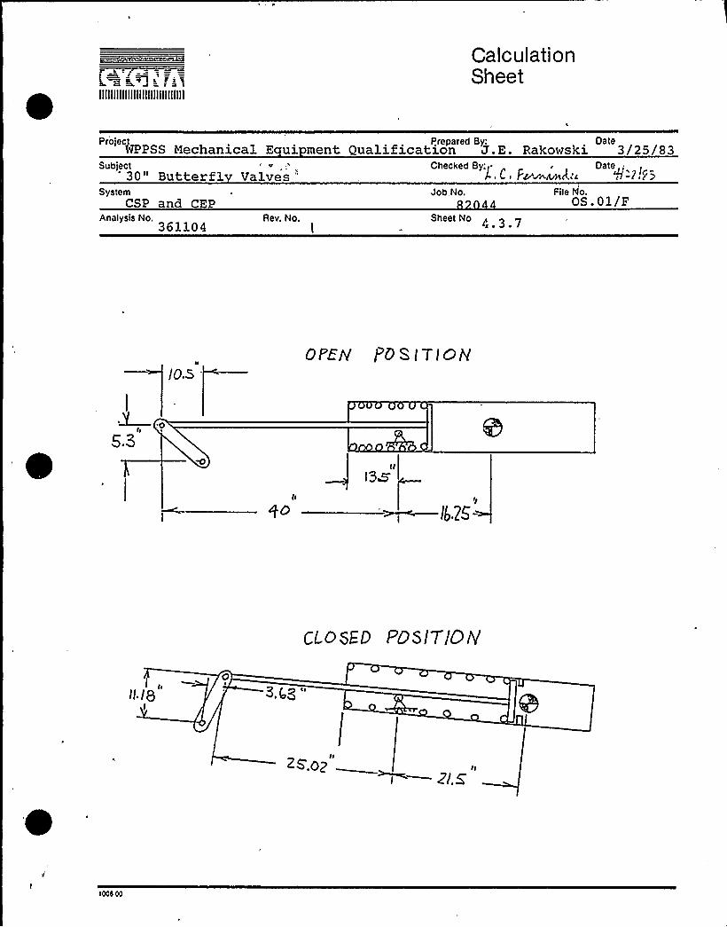
I
IIIIIIIIIIIIIIIIIIIIIIIIIIIIII
CalculationSheet
Pr'oject Prepared By.'ateWPPSS Mechanical E ui ment Qualification J.E. Rakowski 3/25/83
Subject „lE
30" Butterfl Valves "Checked By„~l. C, F ~~rI.;c
Dated/0 P ICE~
SystemCSP and CEP
Analysis No.361104
Rev. No.
Job,No.
Sheet No
File hjo.OS.01/F
/0.5OPEN I'OS tTIGN
5.3
ls&
p*
~> —lb.Z5-
ct 0 sED F'0 sITIO/Y
ZS.02 ~—z~.z
1Xs 00

IIIIIIIIIIIIIIIIIIIIIIIIIIIIII
CalculationSheet
Project Prepared By: H - AbOlhOda DateWPPSS Mechanicla E ui ment uglification J.E. Rakowski 3/25/83
Subject30" Butterfly Valves Checked By: DateL C F~ c "tzvbS
SystemCSP and CEP
Job No,82044
File o,OS.01/F
Rev. No,Analysis No. Sheet No. 4 3 /\361104
4.K. h CAL CULATIOhlL
R t PQLQ 131=/OC C RL CULATtot4+
II I!SZNC f TFIG IO 'CYLIHQG.Ic'.S /RE SIMILAR To THE $
C Y( IN OE-< w „IN 4|;0 o&IIO&I T HE L'QWg5 T PATQR/I L FP-C.@jtP.(JCy OC,Cuj'-t~ WI4&tJ TB E C,yuA D~~l5 IN TH & OI &IU p~ - (T(ON OUI= to Ch'<
Q.gf 4 TE.I~ Fc E X I 8 tI.ITy OI.- TH& g.X.V&IPE.b gl:i{<'5 WOO.
OAF' RVAt-'/Sr5'ejIS PE Fo<u C=.b Ta C/IM-uLIIaa. HeTuaPL FWC@~e~ CV, ZHF'o>eLP E SC g I gg P g E LDMJ.
YA
A',=-Gt=->=-@-~Q-! rP/~i/
>a'7. gy> !.ag
s,+ 8 ~ 'les
I.gcc<' i'~
~ I 4 ~ d!
ii
~ (<'II~ ~ 'ro'.'lsI
I '-l~ Lll
gyral ~
t Gcs,cc

IIIIIIIIIIIIIIIIIIIIIIIIIIIIII
CalculationSheet
Project Prepared BQ. AbOj.hOda DateWPPSS Mechanical E ui ment uglification J.E. Rakowski 3/25/83
'0n Butterfly Valves
ESP and CEP
Checked By„ /} 1 /
'82044
4, >D.,iQ
OS.01/PAnalysis No.
361104Rev, No. Sheet No. 4 3 9
I'Q ZHF NtogE,L t QO NtOQEjV T PP SrS,~Q vC.G ggkg5P~aCP /IT NOOE ~ ~IIWF7. PinNSe A-W
Aps 4), AN r AT TH& PISToN piS(<> fJnDE B.I
I Icl SBM-T p 9 fiE.Lae jIgt= C]tt CUt pyre tu > FokTttF Gt< S6 Tl <c AL jI» e ~xgueqLIyt Pl~~t'r V-Ie"OI= qH F PubEL FLE>EV TS. WH ~ Con PIJ gC".
l Al I'tJ> PZP euTPUT ARF- Snout CM PIISE ""."-~'.
Ron jtIgE:p = wy>(p) =wg<(I.7s) = Z..so~ iN
c.>L.. Ar cl = ry„(p.-v,')
+Dt.ij )Kill "jq D Rl(/6'ngj = 5.'0 t(SJ 1- +
~ 6 5)
= 3'3 /4':~ / ni /.jr„p
7
rTo.a j~hor 'Foci gz. Jq -)(.00/7 . g ~~)~l7I";L'4 ~'li/ilrI p.~~ lz'. rl- S 7g l i
piQg~'I w oj ui i >i>( g i' ggPy gE)
/Ip/ ()7 —.c'0 l7
3~(. A
] 75'1
~3.~a )p"v
o p
r>peg ~ ~ y~t )g ilo+ Jc<
+Q ~/ P+ '/&
SF'.-'~
r 000 00

J a 7k'tIIIIIIIIIIIIIIIIIIIIIIIIIIIIII
CalculationSheet
Project Prepared By; H Abolhoda DateNPPSS Mechanical E ui ment Qualification 3/25/83
SystemCSP and CEP
Analysis No.361104
Rev. No.
Subject30" Butterfly ValvesJob No.
82044Sheet No. 4 3 10
File N8.OS.01/F
~Jr y( C)rtp 4.
-/ Pre ) )P'..vA —,-P"-'t-' "- -'e 'ju. ~ore
r-t:„„"jp.( C,C ( ~-- ~ t~IO-') J s0 0a/v'„t. (I
It t'< L-~~ ~ rr o C'0 o! ~
~'. r 'i<
!
- j:<v(;.t'.. I ~ I
-/5 'vw
QI
kg, J ~
34,Z5'((,5'SrI'1) —.I l'rt (32) -74.tot. O~4>
I. MOOG
( RL COL O'Tlohf OF QTI FI=PE SS
+o- + - ~ 44o4 QL,O = o.9zaa
Zr-yL, = lO( PZ IN4 4
(lo Ls -lo.a) =s0.9t w.(,
'YL I I!J 06 R
r ~
YHI~KMBSS /Jt a 0PLEO Pg g IZ 5
10cs to

CALCULATIONSHEETPREPARED BY
*
P) t gfv I+/DATE
T IW I+
ES CZ C 4 5 t «SIIIIIIIIIIIIIIIIIIIIIIIIIIIIII
PROJECTr
SUBJECT ~ "- "
SVSTEM
p r,''
<)re
CHECKED BY
~r-~ Eg
, DATE
,r rW
JOB NO. I. P ILE NO.j'.
ANALVSISNO. n l. -,4.3.11" REV. NO. SHEET Nd
, ~
/rgft»j.oL IE 7 00/ P Ns Q Jr
99300
0
0 0CS ...0 0
G 0 07.....0 .,09
0 00 0
'I, 54 ,)
."--".7000.000 fv J
gnw'
~G "i!8:-.'iB BUTTERFi Y iJAf 'r'i <OPEih)
00ENS) 1v 7w
10' 72s s)G04 s E$ $ 04
50 v '76
0 5 ~ 0v\ t)t) v0 Gv)~4 ~SG
0 Gs)v '45 5.00 2&f77 0.0
-0. '~0 0-0 40S02 GSG 0l 0 48S48
V-v 0i 0 ~ 0 20,0
~ ~V
S
5I,.
O
"-GGG S300h
2
00'.r i
G8 6TI H)1st W
ZSG v ') GSGCQi~!BTAhT AOOLi'R:1)T:Oi'!
7V
'" 60, (Sv 'r

IIIIIIIIIIIIIIIIIIIIIIIIIIIIII
CalculationSheet
Project P.repared Bv: DateWPPSS Mechanical E ui ment Qualification P.E. Rakowski 3/25/83
Subject30" Butterfl Valves
Checked By. DateL . C ~ F'grus.~nd,c y'/Q0/Pg
SystemP
Job No. File Nh.cI P 82044 OS.01 F
Analysis No.361104
Rev. No. Sheet No. 4 3, 12
chLC fZI Aatog oF 4PJ I'AtQ~ To Ttt G. PPOIE goP gilesRLt VN IO 9
AI P. 6
Pg af s 83gRrlCi ET 5'TIFFPESE l5: ( CAPTIIE PER aEAM OF EFF~TTvE 2~)
» Z.qi(o) ~ 4ZZ
(~I,s)(Z.ll Ia FOR 'Fcya)
(E.S4 iP PoR. (oeL)
ISQ>o P-f~
l
z.a
(.lVEa +MlgR 3 (5 8 l 3+I )a 3 K't.C
I IsgZo
z33IZ.qg 9>
it) t' Ll KL RIUE POb
hj:I.S, ~t't >.5
QphhE Mp oS
Epi-< 5wiFI- 9 t=-~S57tFF N CS5 = Ghl- ';=iV'8t'
jr.~„= 4> +10 X./~ 4o")ST l t-'PlL -"5
= 7~«o)W (.3")
l000 00

IIIIIIIIIIIIIIIIIIIIIIIIIIIIII
CalculationSheet
Project Prepared By: DateWPPSS Mechanical Equi ment Qualification J.E. Rakowski 3/25/83
Subiect30" Butterfl Valves
Checked By DateI- .0. 4~t ~kr "I&tr'rS
SystemCSP and CEP
Analysis No,
361104Rev..No,
|
Job No,
Sheet No. 4
Fite No.
4,'3.z. 2 P koX wAw WZF I= WA
Q5 Ig 0, P IWEg~lo Qp Fgo~ FtGULE I.3
'8
5.3 '
io,s ~u"—I
C't'0 SEE Ui't I t tIE LV'S5 0 ME TP4AT TH E &0K QCr'FLEEA7IW CaM+AEJ/7
OQ~PU T FEcrNt %HE P(PIP C QPItLV SIS FCt~( CUP'~
( CtPE~ / CR(c- OI~~J FfcelgCL< QI5 f't get. VfA'T 5 OF-
%HE I~Ii IP OFE gP.Tok &LA t iv < to WV F pIPE tV THE
F o R. V O F.
d= ACU~
~ii+LE. A = 435p
4 + tt(.~ /gbra~ i'
fTccM ~~ g p~wk. f}
LeR O~;
Iu SEc~ oa 5 i For QvPm Spes~ic.I
cU~ = z<l (is+3 ( ~/g)t~t ie
&, = j~ 4 $o-
i Pts~sK.vp p li Ltri. z)
&i = z.taO
g, (SHrlLL )

llllllllllllllllllllllllllllll
CalculationSheet
e'S
Mechanical EquiPment Qualification ' J.E. Rakowsgi 1/10/83Subiect30" Butterfl Valves
Checkec Sy:L ~ F
~, Oate
SystemCSP and CEP
Analysis No36110 4
Re .No,
Job No, File No82044 O.S.01 F
Sheet No.4 3 14
~ad-'l -!'-!~=C'!3$ /6 3
4.3.2.3 STRESS ANALYSIS
The procedures for the analysis of the subject valvesare outlined below:
2.
3.
Recalculate the valve appurtenance stressesaddressed in Ref. 4 using response g-levelsfrom the Burns a Roe piping analysis. Incorporatethe current seating torque given in Ref. 3.Compare stresses to the lower yield strengthsin Summary Table 1.3.
If faulted condition stresses exceed the upsetcondition allowable stresses, repeat the analy-sis for the affected components using upsetaccelerations from the piping analysis.
Perform a fatigue analysis on significantlystressed components. Determine allowablealternating stress ranges from AISC 8th Edition,Appendix B, noting commentary.
~ tj
The fatigue analysis is to be performed only for thoseEPN's subject to hydrodynamic loads ~ The number ofrespective load cycles is given below.
LOAD COMBINATIONS & STRESS CYCLES
The following table lists the load combinations and.the nubmer of expected stress cycles for each com-bination. (From tHe design criteria)
Combination ~Cc leel. SRV Alone 3 (4500) =135002. OBE+SRV 50
3. OBE+SRV+Chugging 20004. SSE+SRV+Chugging/
SSE+AP 10
Note: Load combination N4 with 15560 cycles can beused to conservatively bound all combinations.
3COS OC

I tc rciIIIIIIIIIIIIIIIIIIIIIIIIIIIIII
CalculationSheet
ProjectWPPSS -Mechanical Equi ment
l'repared By: Date3 25 83
Sublect30" Butte fl V v
'hecked By. r Datel- C. /~mar 4I2..
SystemCSP and CEP
Analysis No.361104
Re,No)
Job No. File N6. I
2Sheet No.
4 3 15
5'TRHS A~ RI VSIS DF VALVE AN ~ A}R. OPERATOR. Co>PORFPT 5gov coo EkF-D I}} 9}D OIVoc I
HM oH PIPS
gggigd tg P f'tAS NEK E 6 hl ALP&~ AN P Th'E54'E8~-'7
RESy ~lc}S F og> p TO gG FL I>ARlc. Y GEE,P PEP TQtN QV EC TUF„P<AI 6 Ih) TRC 8 f}~t5'~C:Tro pl. UJHE'-b
AtJA LOPE 9 }TII . PP ha Egz&Tlauritzy> otAt tit= /3 $ J <, it<jsAAE+r'-~]J L g <3 l~>LCEPl7 OP l "IE /LLOYDASLF. Ttf~
~Hr PgP PE.Z gLI PANIC I~V FOL. AU. E'Ptu S.
a rr
L r u L p t rOQ faLLotrV5;L(tt 'A/tj EtljtrioPMI'ELDjttg
tI
L,~ >= M(~sEf)) LcC = I@44
lMRl?.7~
~~l t= t.s~'t
F <~ Pi, $Ol39
I2.75'tt
= (Lztjrji LCG ) vlAIjL~tt z.
rt-ITF 24}w 241(h
g Iq.9)()q;~6) ='tYO i39 IAJ45.
/2M g (t.oA Z ~~= -vt r=-"~ WtrbcoP~I
lo g/o r- '~ Pr u t t=,>~8.".-.r v)
s. et-~t>nX t .o+) —.$2 jj 4ZQ+ Z.
tttss cc
Fzz —- BA~ gz. s'tIttt.Ar) - spaz+7- Z 4r
4'cy2I20/ Qo IZ
<uOEtr PIT(Z,) = 2.era@?
Co}}SEVUAa IVg ~o} SIN ht toeI zg2
4-~F.>j~~tt ( + ~r-Iy.cu, 'g5(z. gl)
0p' SAAT.TRfjjtz tijou ttrtrII:lS
rtFcR8
~ rt-tt~atttttt
R} IO"
zz l14 ".ds. rrA7"
SEE 5IF R.Pv < Ph c RIES M'trWQiD& WC. l~,geCF~
GK

I ~s'i ==,a e a
CalculationSheet
IIIIIIIIIIIIIIIIIIIIIIIIIIIIII
Project Prepared By.'ateWPPSS Mechanical Equi ment Qualification J.E. Rakowski 3/25/83
Subject30" Butterfl Valves
SystemCSP and CEP
Job No.82
File No.u
checked By. t ~ FDate «/Lr~sS
Analysis No. Rev. No, Sheet No.4 3 j
ioRAt Log r; OiJ ~F Ct Evig Ig 7VE
VEt~og 5U~ CF Fcm AN C F~Q .
1
Fdk -vts = L Fc < gTz ]Asstrhke tteestL LtkktT OF
$ ttsj'tSUs7 Fdf ytrsrt
THI> ~EM55.k, f>>< - 'f'it+)+ e/ic, - 539 I (iO 3> L~-FchStttS LltdL) +gctSg ] Tete'rZ
Ccats trtg = lip+~/Z,.~ -- 29+9 PSX
+ = ~"8 /Z.BP IP ++ = 27I') PSZ C,<LE,VI5 7th
l2oi~A~)
zAzr.6'o
/f47
ZA4iit)
.. ct.a«s, $ h~ mE ~p wLp~~D PlvE. LE,YE.R.
5'g io" A/o Mu 'S.
1&f'o SE THE "'SAT Ii0& T'[email protected] LgAg Ag 0
D'Ni'HI~ REACTId Fcs~< E- OIO THE PRIVY LFuF<IV 'rHF IR gE5+cTIV E DIRFC TrCPlg:
'8= GZ IrtAx
PYMAgit" = Fc. = P 8 Lg
F,T e,~ I20(
Irsr f, item
Low b Fc. ~it-I- IOC,EeP 5E, TII F 9-AtAt Fcsk<E iu THE
-PRiVE LEVER kbEuER
ldll-
QRX IRu M..ToRIQ& oM Trr) I
LFIIFk ia wit E SEPT>t'ai G mR ~Z, .WH& ktR cs~ tonTpghl/VIOL 5 ftM D IItrT~AI- giant(N& Hog& TH-E, VA-LV~
> tt P +LE ill YH c- tt: Log h. Ii Po P I 770/t/F

IIIIIIIIIIIIIIIIIIIIIIIIIIIIII
CalculationSheet
Protect Prepared ByWPPSS Mechanical E ui ment Qualification J.E. Ra 3/25/83
Analysis No361104
Rev. No,
Subtect30" Butterfl Valves
SystemCSP and CEP
Fite NPOS.01/F
Job No.
Sheet No
checked By ~ i DateI- (, 1 g~anzr( q /Zc fats
lwR 8 Nof eAL F Rc E oN Pf tvE LEVER:
252 j LB.F» (Dec + F~ SIVeA/7 0 .9Q + F95'~ + (0
folk 4 $ 'LIAL FIERCE. OIJ P'k IV g- Lg.ItF P'
EfUYELoP5)
f~q SIR)& + Fq Coo eI
P5R> . I o 495K; 99ebs LE (su v~ra.)
MINIVER ~ Syrus LE.Va r< Pr~ W = I ~'IS Iu,I a'ogs Ibk t= IA C Fhtt- ogE 5o pg 5.
A XI A L 5 T k. E 55 '-
%A ~ 5EH 5>ltd & DOMLQQ ~ 22r I7 0 IH-t.g (COPet=r-Yb>IVE FOP.
IJ Se du Ptg, Pt.RQA Oq'r Qt/trc. @LE Yt~
REF'W Q s5
6 A„,AI H+ W FA~
itAg~iiq Lx,i I'i + 'Ik'tg y,rjri&8 = lx,((gPs'I.2'II.FI 5
ll, I GR ( 4p, Z,eo Far c)(
SI Ehk ~~CCsS
'wE. LEIIGg
stj FFta &V~
oN Bmoc4" ~ (o"
A/6 ~5: 'LSZ.4 I30(. I'S T. C 2$P Ps'l OW
18 (~
leos ce

IIIIIIIIIIIIIIIIIIIIIIIIIIIIII
CalculationSheet
Project Ptepared By: DateWPPSS Mechanical Equipment Qualificatz.on J.E. Rakowski 3/25/83
0'Obtect
30" Butterfly ValvesChecked By: Oale
L C ~ F~g t~c4r, ' Pt» ~
System 4 Job No. File No. ~CSP and CEP
Analysis No361104
Rev, No,I
Sheet No,
gB.r-g PS 34
RE|3,t+ ~
P.f,F rit rC 3<
gAy EWLtd & ~ vQESS
0 ~ M'S 2.
l~~ V~~I
I.IZG IP
~o S&A+t~e ~ LLMba" g I VE PAfAA»~~~
-075 rIG
Z.z,17cf. t< "~I ~ 2Q tN
Fgp@ = ~ 2 = l2j ZE'7 LB
DH tN
( iq,77')
Ega-c. Z7, 3$ I
Ap,
(pt'.QD ) ~
I/pLVg Ca trl-<~ 621,FBI q-E, 2~ F'5 | OV- yARC tH =5'8 P
ka,F $ f'c?
h~p, oF KEY =
H-pic F o i~i= Qp R-tQ 6 9—t 4E 9, CoN ~F- t.5.
MAiM soAFa:
I+St.tran tPAR V ALJAt g QI5 S~5'h t t> 6 >T 4 AIGH<Y
STRE55Ep Co > f'0 N~ Z, .'. QprstLy+E. Fo fc. EM PELo /»E. >At)S.
5'iPE~ = ~'TkF= > ~p wc. Sorts t" to+uF +S<1~fm OUE. To &~MR. OF: F+7>>T+cs ~E, to SEPOY'46 dF f57Z .
EGGS GG

r s='z)z F z
f S
Calculation *
SheetIIIIIIIIIIIIIIIIIIIIIIIIIIIIII
Project Prepared By: DateWPPSS Mechanical Equipment Qualification J.E. Rakowski 3/25/33
Subject 30" Butterfly Valves c. .i~w~lwc( r/2rir5System
CSP and CEPAnalysis No.
361104Re . No.
Job No. File No.82044
St)ee(No. 4 3 ]9
C~y, Wm
G -zI-
Qg
Qg
Z5'S
o( 'Y~ =
I. jz,g'(j
c.,S(q I(j'(
L.eaS4Io,bl
't.zs "I
I3 goer(~
7~<-
IO
l.z 5"Z.Vp >u4
('..3z
II. ($
l ~ 9((r)
2 "-g(7+
)5 Lre ().)Eq'R)
2.5) zl.
zz)zz().m> 7E>7)z,) l'1' Sg =
zqp
CD VEEE Fco N 5.
A
FEou, F)c . o.z) ('l))" 5 q.E.)L j (t )(.5.)7:IXQ~z'E = LES> +')055 L = 7SOS LS
75.oS /$7o f'5t;<. a'7
CaN erg'jj((jq >OZC~ A('C th)(" 5H FP( ~xtZ=S ~S
P„q + )Q'(o = <I„7 I I ( IQ,5>ra ~/<
ZllQq
rz Iz
PESOS~ ~O F k fa>H Z+ 9 3o gALVEQ
lees oc

IIIIIIIIIIIIIIIIIIIIIIIIIIIIII
CalculationSheet
Prorect Prepared By.'ateWPPSS Mechanical Eoui~ment ualification J.E. Rakowski 1 10 83
Suhiect30." Butt rf1 Valves
System Jot'o. File Nor.
Checked By: Datej .( . I'~neer g(rr l//2q/ca
Rev. No.~
Sheet No.4 3 20
Disc
The stressesRef. 4 to beload. SincePSI will notcelerations,
in the disc were shown on page 51 ofdue almost entirely to the pressurethe stress 'found in Ref. 4 of 4540change significantly for the new ac-the disc is acceptable.
The stress in these pins is due only to the seatingtorque. The stress in Ref. 4, page 53, is 11265PSI and is therefore acceptable. For the new, lowerseating torque, the stress becomes 8985 PSI.
Analysis for:'rive Rod, cylinder bushing pressure,valve ears and valve ear bolts.
Method It Use element forces and moments outputfrom the piping analysis (Summary Table1.1) and the absolute sum of stresses.The conservatism of SRSS summing of thecomponent stresses cannot be assuredbecause the independence of the sixelement forces (/moments) cannot be de-termined without analysis of modal par-ticipation.
rccs cc

IIIIIIIIIIIIIIIIIIIIIIIIIIIIII
CalculationSheet
Project ~'repared By: QateMechanical .Equipment Qualification J.E. Rakowskz 1/10/83Subject30'utterfl Valves L.C. F~~~ q/tqj+System
d PRev, No
Job No.
Sheet No.
82044File No)
OS.01 F
Method IIt Use the north, east and vertical operatoraccelerations output from the pipinganalysis. Absolute sum for stresseswith each component then SRSS over re-sults for N,E and V.
Note!: Analysis of the distribution of stress on4 valve ears to predict the maximum tensilestress cannot confirm a maximum value lowerthan the absolute. sum of the elemental ten-sil stresses due to the six forces (fromone acceleration direction, N,E or V). There-fore the absolute sum will be used at this level.
Note 2: Add stress due to the vector sum of deadweightplus seating torque force after above SRSScombinations are perfoimed. (ABS)
Note 3: 10" A/0 parameters are shown for use in QID361104.
Anal sis of Seatin Tor ue Forces
100d Oc
1) Seating Torque loads control the stress in thevalve lever arm, keyway, shaft and taper pins. Thesestresses were less than allowables for the valves ofseating torque given in Ref. 3, for all valves.
2) For valve EPN's which are Fail-Open with Use-Code 2, no seating torque forces are applied duringthe faulted and upset conditions (CSP-V-5,6).
3) For the Fail-Closed valves, the forces at thetrunnion pins are shown below, along the cylinderaxis, for +2-axis g-loading:
t2 LaQld Mta
an clevis/va.lvc s4&I
aaC~kolve ~~ets~tc.lgllnprnlc. F~ <ram oper~rIh a. - CLk'/2 dlfCLODh/
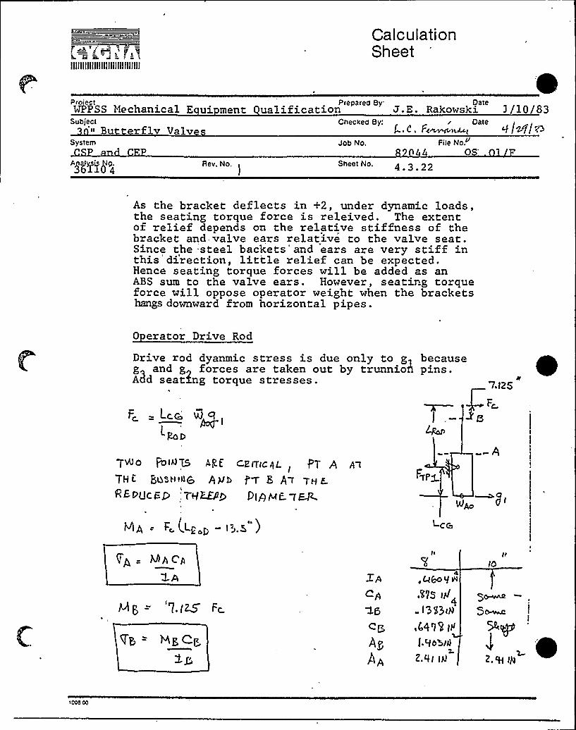
c sallllllllllllllllllllllllllllll
CalculationSheet
Proiect Preparea By. DareWPPSS Hechanical E ui ment ualification J.E. Rakowski ] /10/83
Subject" Bu terf v Valve
System Job No.
l . C. F~)t,ut 'I jrz+j/~>File No.
OS'NY78'4Rev. No, Sheet No. 4 3
As the bracket deflects in +2, under dynamic loads,the seating torque force is releived. The extentof relief depends on the relative stiffness of thebracket and valve ears relative to the valve seat.Since the -steel backets'and ears are very stiff inthis'direction, little relief can be expected.Hence seating torque forces will be added as anABS sum to the valve ears. However, seating torqueforce will oppose operator weight when the bracketshangs downward from horizontal pipes.
0 erator Drive Rod
Drive rod dyanmic stress is due only to g becauseg and g forces are taken out by trunnion pins.A3d seating torque stresses. 7.I25
F~ - Lc.c
L~ ~
T~o FD«75 <Rt r=EITIr AL. PT A A tITH E QQSHt4& hylb f'q E A I TH F
'REPUCGg 'HEE/Ig Pl>HE g~+ A = Fc. (.Lt,p —6.K
'
QA C'A
"l.(ZS Fc.
Hp, Cg
.W2s (4l3$3tH
f.cIObid
2.QI IH
I
2.'H IH

IIIIIIIIIIIIIIIIIIIIIIIIIIIIII
CalculationSheet
Subject30" Butterfl Valves
ProtectWPPSS Mechanical E ui m
Prepared By; Datetion J.E. Rakowski 3/25/d3Checked By;, Date
v '~ Il'6System
CSPAnalysis No
361104ftuAt LV:
Rev. No.)
Job No,
Shee!No.4 3 23
File No.
tm Z.g')ggytgr
Ap, 1A p4
>t's o~4op R5 @BE sJ(( ARK R CP-~5
D y h)j,'-fath 'a& PoggPT'g
SEF~WIC DV)3 A Wtc. Fete'C.FS 6N VALVE LbR5,
~A t'- 7V f'E PuRSS /5 rIFfHE"-S JOCOSE.L (OAT PEF34EDFOR THE. PIPING M(sPEL TCr CAKQLATE % RESPalVSE C<GVELS t.
SEE'ui~r!cH~auT ). THE YALVE- Ebk sysTaPn ~orle h(toTCtk~i(oHAL fLKV ]Bll IT V tu 55 \I!(ELUDES I N TH t f4006 L-AN 0 SEES
Fee�(
ES A~D P>e t NZS W~t L ALSa BEOU I'V7 FOP <>Md@ Idly INTO tIALV& EAr( S~~e=~S,7th E. EqUAg(ogg
rpgslo» d»» 't» Q< fjp(~c (cole Ccdzb. CEF N —Nxr (t» )
2
Mz
2 Pd( hR
~NA ~A
P
+A
+ tc(HB(( T'3 =+TS)
Qz=(2. (=
d I
dz. =
Z.S
re
7, P»
Io.Q
A- P,krl
tcr
3n
'7.5
lOS
'rp
r'+g.,
Q sAP- goOQL,:(Sj S. A~WCH(J(N)
Tpr )II rfp5~pp t+) pirl~ ~~ /5 + (p rE>>p lr 6')
5I R(rTttEI!t» PAALYS(C Plier. r'~'5 "FQ P ( t'Ct ) 0(X it FOK r$ 00 t t' 0 d A L 0 YF rt=',
rCC6 CC

llllllllllllllllllllllllljllll
CalculationSheet
Project Prepared By'ateWPPSS Mechanical Equi ment Qualification J.E. Rakowski 3/25/83
Sublect 30" Butterfly ValvesSystem
CSP and CEP
Checked By: / ~ F' Da'e
g/~ltd< g
Job No File N82044
Analysis No.361104
Rev. No.~
sheet No, 4 3 24
cooRDINATE SYSTEM ( LOCAL)
li !3r
(1l~
100S 00

IIIIIIIIIIIIIIIIIIIIIIIIIIIIII
CalculationSheet
ProjectWPPSS Mechanical E ui ment
Svtstect30" Butterfl Valves
Prepared By: DateJ.E. Rakowski 3/25/83
checzed By:~
- Daie
System CPadAnalysis No,
361104Rev. No,
l
Job No,
Sheet No. 4 3 25
File No.F
JOLTS HoLblAS SLII|VET5 |0 BARS ~
I ~~~m~f--.'-'.>.- g jr >/~WCP~~ ~ r'fris3d
/de l TEQS(OU IS VU6- T4EtOn SHSAIZ lS I:U E TO h,MA
+t) +, lTZ) ~~ )~3
O.SI zw
TtaN.pl~toss 'soM)
g,) Mz
zJ~ Ag
S9s ~:"/l>oH.
4-l ho l$
F~Ap
'loG0 oc

IIIIIIIIIIIIIIIIIIIIIIIIIIIIII
CalculationSheet
Project Prepared By." DateWPPSS Mechanical E ui ment uglification J.E. Rakowski 3/25/83
Subject30" Butterfl
SystemCSP and CEP
ValvesJob No. File No.
OS.01
Checked By'ate'.c. F
Rev, No.I
Analysis No. Sheet No361104 ~ ~
p QTHO p + — TH c PRBV(dU 0 E@U ATroI" 5 Fo I 9 pM~SI3g ME 'THo c 3. AR & ~t.tcAgLE. Homt uE.R,
i') $ ,')C'PRES> jOAt S Fo TZ W9E. GtM FoF~ j+a&auTSqR'S P&iINRP BSLow i4 ~ZEUS . OF
Co M pci>t- P T9 IN tH 6 Lc C 41 AWI5 '5p> >E M( 565SE RUE~'T L. Y Qt'EC~RC hl C'O Sl ASE5, Wt~ t36.
tJ oE -Tct coMlJFQ-'T -'THE PP, E f V PccE.L.—
Erlb 7IoV 'IIEET'ok& I N turEM I 14 'to LoeiLARES)(qgr gpc~to U.g.g )
2) I IlESF EIIQA I%49 NE TO BE liS&O TO FIIIIO ~'THE FOES.Q A.u b Qef184''T 5 Ohl Tt)K FAR S DUE
gd I HE DEh.P lON6H y, AjL25'FA TtlU g mQQLLFFelr'-W 5 Cci R C+t-CUt-+~<+ M OC dp~ T2>6 ~~I /Foe usE llIEIT4&RNIE r4oo l t- 2.
g E E FotIE'cfog g gRhc(~ET d QEu'Tl trod l N Lech t-
Ce D Ic t> l H IItE. 5> g zY-, pp g p.
2: I p-- 'To@5(op h~wog 7 LoZAL Avtg 0 3
73 ~ Z >,.», ++ = FTR, es F FBR, e, + Fq., e, iFspie,
FTRle3 l MiBR$ <q < +Ro )Rez, +WBR$ 8,
'tt3 --P = F~(e3~ BrRIp, el. 3~(w,oe~+ RRtRZ,)\
IP F,~~D = + = ""<i83 VJAD~+ FgTg t- ~ 4 lUPg|Cg 4 ALP 6(
iNB Oc
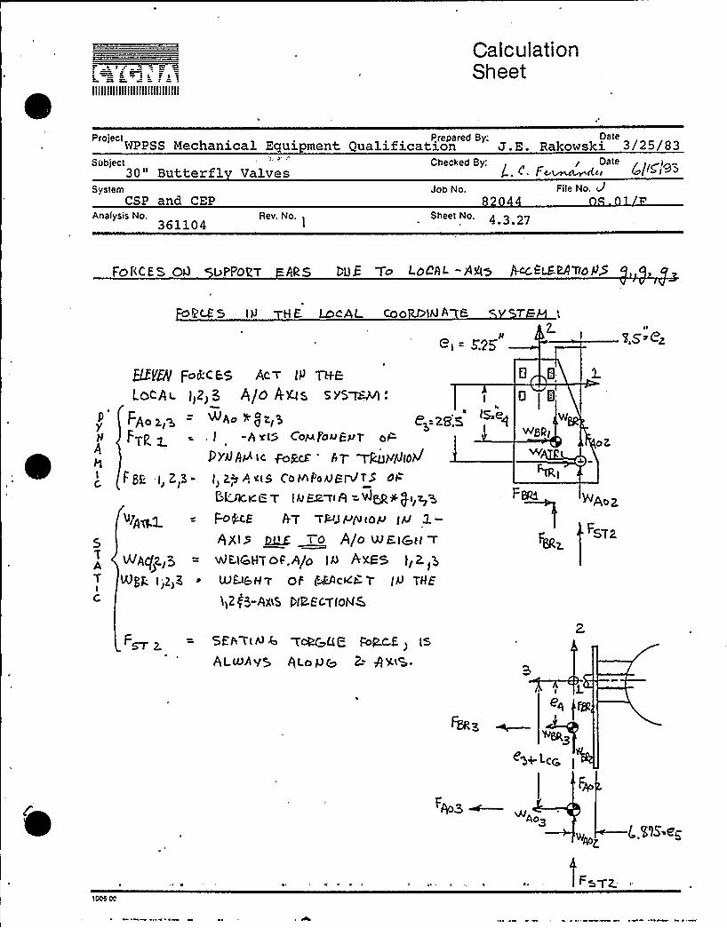
e & K tIIIIIIIIIIIIIIIIIIIIIIIIIIIIII
CalculationSheet
Project Ptepared By: DateWPPSS Mechanical Equipment, Qualification J.E. Rakowski 3/25/83
Subject,30" Butterfl
'J,
Valves L. t.'=e.~«System
CSP and CEPAnalysis No.
361104Re.No.
~
Job No.2
Sheet No, 4 3 27
File No. d
FOI'<CES Od uFPOVT ARS DUE To LOCAL -AA> Act'LEBATtOP5
R'& 5 I N H 6 LocAL coo IAI A tt=
I-t = F25'tI.S'zQE/Q( Fcskt- E5 AC T le TH.E
LOCA t- I>2> 5 A/0 A'XIS S vS~e
y FAo>iz - ~. gal~ 8~=28',S
FTp g=, I -h xt5 Co~ pouEPT oP
PY~AP tc f-ogcf AT ~)vQDPJFSI: -I,Z,3- I,Z,'sl,xtS, CaefooeQt5 et=
5LACtt'.F T IQER~tR =VJ~+ f1 z P
~1p~ = MME AT TWJ P/U to~
5 RXI> ~t t o 4/o WE)Qp( T
t/qjA(f2.]3 = vtlEttc1HT OF,A/o IQ RrXFS )I 2 3
NQ. I~2>Z LUu&H'T OF WACKE-l IP THE
1,2(3-AXES PIE.EcTlohlk
0 i8IS=eg W
Fee ~A,
FSTa
F~ 2= SEF TtP 6 T~QQ pop.t- f
>ts
At uAVS Qt olJe
eq Ise3
3<g+ Lt:~
Ao>
w < ~)S4)Z
1000 00

IIIIIIIIIIIIIIIIIIIIIIIIIIIIII
CalculationSheet
project Prepared By'. DateWPPSS Mechanical E ui ment Qualification J.E. Rakowski 3/25/83
Subject30" Butterfl Valves
Checked By:, ~ . Date. (., I . - ' rt x t r l ~I r.i ~ (( 6ISeZ
SystemCSP and CEP
Analysis'o3 11
Rev. No.
Job No,
Sheet No,4 3 28
File No,
FDLCQ OE".IEQ T/t t tages QiiJ f.+k9 I P + TP
F„
>et
SI=
~ I FIXATE
Frirr i. Fsr<, — Fzr, + equi:+
Wgp) 4 WpqP)
FRDM Q FO~CE BgLAhlCF be- THE. oPs,fn To R.:
FTrl = (Lr o +Lcd)NMigi~s,0 ($ roice dH eri: i)Lr „
~nev Z
'+~i- 4 tLiioo"Lcm) Wgg l
Lmr
oI'Ev
LS~tCTth
n
IO
$o 'l[Og I"..tt &
zCV
4a
g ZS' I.5
~ooe oo
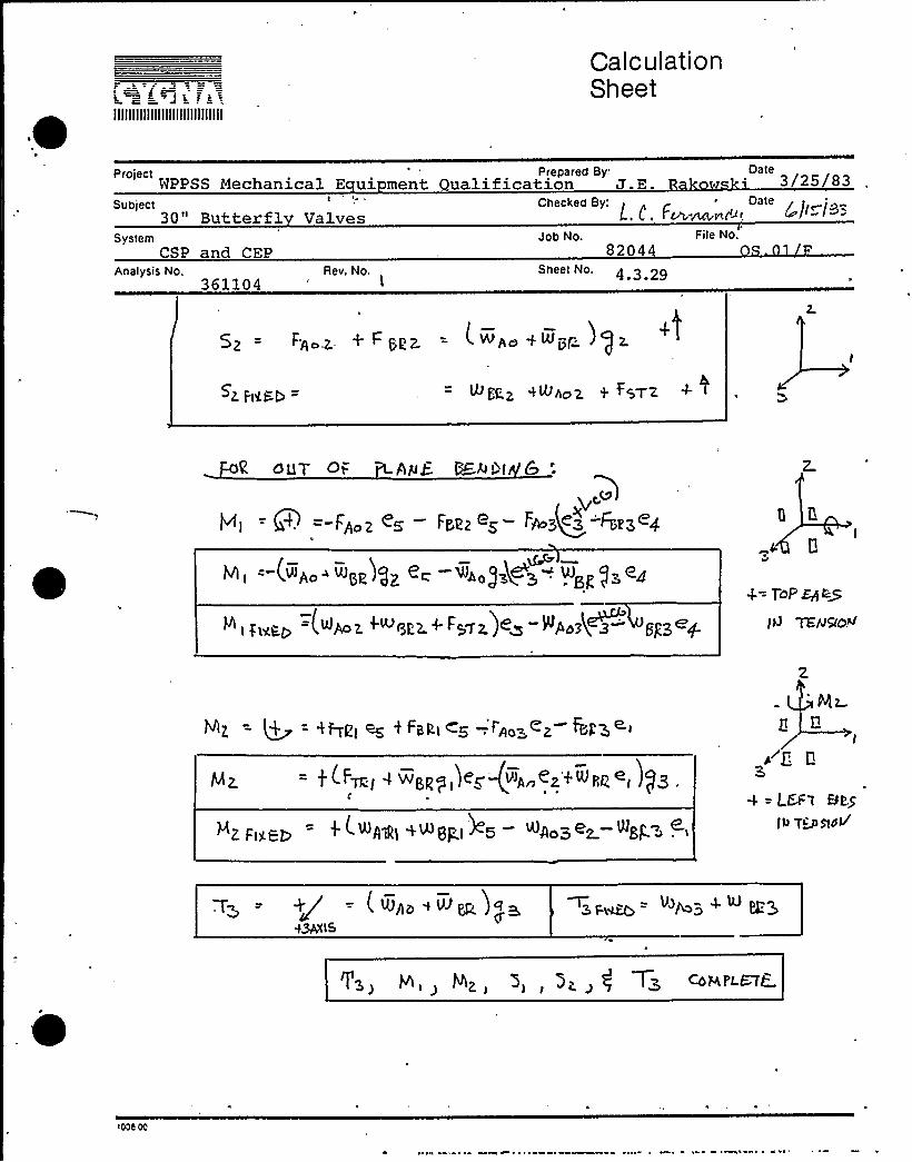
t jIIIIIIIIIIIIIIIIIIIIIIIIIIIIII
CalculationSheet
Project Prepared By-WPPSS Mechanical E ui ment Qualification J.E 3/25/83
Subject30" Butterfl
SystemCSP and CEP
Analysis No.361104
Valves
Rev. No.I
Checked By:L ~ F
'a«@~I ~t~
Job No. File No.
82044StteetNo. 4 3 29
5z -- Fg~z + F pzz = L. wpa + rUgrz J) z.
+SrZ ~+~csX t ~SV'Z
OllT Ot= PL/) yE ~h >~I
= 8 = F~o-z <s —Frizz es- Fws~eq Fary-'<4(x.
v, =-(w„..w„)gz e~-m„),ge's-. w q),e~
=(<Aoz t wszg+ Fgyz)e~ -Wpszk~z gps~+
t|I
4= ToP ~byIW YEAIQO<
Mz
ress cc

IIIIIIIIIIIIIIIIIIIIIIIIIIIIII
CalculationSheet
WPPSS ~hanical Ecpxiprent ~lification ~ M.A. Scott ~ 6/15/83Subject Checked By.'~gW Oate
30" linder rated Butterfl Valves 6 .d. Fernandez 6/15/83System
P dgagl-'ysii eat
QID 361104Rev. No.
Job No.82044
Sheet No.4.3.30
File No.OS.Ol.F
Section 4.3.4 — Ear Support Weld Stress
Comparison of a similar file (QZD No. 361106) to this file noted theunconservative assumption of considering the bracket support ears tobe a guided cantilever (fixed-fixed) . The resulting ear weld stressesexceeded the allowable stresses. The ear weld stresses can be loweredby the addition of- shear plates to stiffen the whole assembly. Theresulting weld stresses (both existing and modified) are to be keptwithin the fatigue allowable stress, i.e., Q stress range. Theallowable fatigue stress range from AISC for fillet welds in shearwith less than 20000 cycles of loading is:
SR = (1.5)(15000)=22500 PSIThis includes the 50% increase due to fewer than 20000 cycles. Theweld stresses are calculated using faulted loads. These loads produceless than one percent of the total 15560 cycles of faulted/hydrodynami~loading. Since the upset and emergency conditions are considerablylower in magnitude, small margins of overstress in fatigue will betolerated for faulted stress levels. The following allowables willbe adhered to in the ear weld stress calculations.Allowable stress for welds for faulted conditions:
liow 1.6 (0.3) Fu = 28800 PSI
Allowable stress for welds subject to fatigue.allowable stress range of AISC Appendix B:
=1. 25 (1. 5) (15) = 14 KSIfat 2
This is 4 the
1.25 = 25% increase due to previous comments
1.5 = 50% increase due to AXSC commentary
'lees.00

r s tIIIIIIIIIIIIIIIIIIIIIIIIIIIIII
CalculationSheet
ProjectNPPSS Mechanical
Prepared By: ~Ac Dateification M.A. Scott 6/15/83Subject Checked By: Q(p Date
30" linder ated Butterf1 Valves L.C. Fernandez 6 15 83System
CSP. and CEP
QID 361104Rev. No.
Job No.82044
Sheet No.4;3.31
File NoOS.01.F
W/~x4 x Io/p~lCALWA, Kt4EO
~/'; (A-s(o afz.EAIJIV)
GUT'TO t- O'TO I '6%t/>
g OTCH Bc)~M COgtJc..pgm C,mAa Ky le-tg4 u~~ /
&tS~tdg
flin Lire THROATcoAT. Chl~ -ror
&AtQ '%Hler QAV~CA( ~ ~gt - ~
A t-t Q3ELio Q~t P 7'QPacH~ ZOO I=
e
Y4Max'~
~~~~hlC-4&Z2.7
~a Qt= ~Ar ~ t=-~
~~~itOV I/ 4 d(Q~~

IIIIIIIIIIIIIIIIIIIIIIIIIIIIII
CalculationSheet .
NPPSS jvjechanicalPrepared By: ~~+6atet Reaualification - M.A. Scott . 6 15 83
Subject30" Butterfl Val es
System
Checked By:
Job No.
/P Oate
File No.
361104Rev. No. Sheet No.
4.3.32
C~ V'-1
T, iS
Mt Ps
/g/0.4"
~i lnO Lama R ~V OI= Z'~OWW
S 5I
o Zz4 zC
WV'A~It rZ.70 I<Wzw t>zsz i
C<->Ac5 IQgzo ~94 6070 3270 / 70 5ZZ. I @Zygo
AI s~

f
IIIIIIIIIIIIIIIIIIIIIIIIIIIIII
CalculationSheet
„ProjectWPPSS Mechanical ' '
Subject30" linder rated tte f
Prepared By: ~a+~r batelification M.A. Scott 6 15 83Checked By: Date
VSystem
CSP and CEP
Rev. No.
Job No.82044
Sheet No.
File No.OS. 01.F
2

IIIIIIIIIIIIIIIIIIIIIIIIIIIIII
CalculationSheet
Project Prepared By.'GVOateWPPSS Mechanical Equi@rent Bequalification M.A. Scott '/15/83
Subject Checked By: prQ Date30" linder ated Butterfl Valves L.C. Fernandez
SystemCSP and CEP
QID 361104Rev, No.
Job No.
Sheet No.~ ~ 3
File No.
7& ~c3t rldc SacW o4 ><orat-d5
I///. FM M rg+4yQ~e:zS~/ S).
~re- NGTloQ WMPEY2.-7t P.- g F ~6- 4Jc,Lio&c w7aP mK a~a ~c d~ ~E /- / ~ r- udice.C
t iAn~ ~F6~ Ca~~( M&~c3Wit ~t~~~(~~~ ~i WC% ~ ~IEc- ~ @ ~&~ dr-A77b
o~t=t MS~ ~H~ gMWr A p M~y&PcM77 E'Q Mc Ur 73 8 c.~c.dt h WQ ~dY.
Ag~~~~ +3~/.75)Z. = 9.5 <w
/Si = ~(i:r~) —' t'.. z7/
I cA.C.

IIIIIIIIIIIIIIIIIIIIIIIIIIIIII
CalculationSheet
NPPSS Mechanical Bpiipnent Requalification M.A. Scott ~ 6/15/83Subject 30" Cylinder Operated Butterfly Valves
Checked By: ~ateL.C. Fernandez 6 15 83
SystemCSP and CEP
Acne~~.QID 361104
Rev. No.
Job No.82044
Sheet No.4 3 35
File No.
HO&~7 Q ccJ~~M~7

IIIIIIIIIIIIIIIIIIIIIIIIIIIIII
CalculationSheet
ProjectWPPSS Mechanical
Prepared By. ~t~w+ tDatet alification M.A. Scott ~' 15 83Subject '0" linderSystem
CSP and CEP
QQD 361104Rev. No.
Job No.82044,
Sheet No.~ ~
File No.GS.01.F
Checked By: ~~. Daterated Butt f V v
/ pJ ~I~iD4 ~~ ~rZy~W~dW5 d'rc=
~~Jzol~g ~~ ~t=vTd~nE'w ir~et-e gU commas r ra&
~~ Qs'TMCi ~ = ~A~ OW '25~~ g ~4COP'~ ~M /M COMP~~a~AkMrM~~~~ ~ r-k ~rC ~~ Ce"~~rdD
I 7-B8

IIIIIIIIIIIIIIIIIIIIIIIIIIIIII
CalculationSheet
'" NPPSS Mechanical Equignent Requa1ification "'.A. Scott ~'/15/83
AR~CP,ID 361104
Rev, No.
Subject30" Cylinder Operated Butterfly Valves
SystemCSP and CEP
Job No.82044
S eetNo.4 3 37
Fite No.OS. 01.F
Checked By.'ate. L.C. Fernandez 6/15/83
4 I%8
C l38(K) C +g/

IIIIIIIIIIIIIIIIIIIIIIIIIIIIII
CalculationSheet
WPPSS Mechanical Bpipnent Requalification "'.A. Scott+~+ 6/15/83Subject e Checked By: ~~ Oate30" Cylinder Operated Butterfly Valves L.C. Fernandei 6/15/83System
CSP and CEP
Rev. No.
Job No.82044
Sheet No.~ ~
File No.OS.01.F
II gl
%go~ pcadLocez g V(t'w wm~z- ~<~»t A,G
I 2.
1

IIIIIIIIIIIIIIIIIIIIIIIIIIIIII
CalculationSheet
projectWPPSS Mechanical 'ment Prepared By: wicd4Aatelification M.A. Scott ~' 15
Subjectgu
SystemCSP and CEP
VRRQp@VSCK
ID 361104Rev. No.
1
Checked By:
Job No.
Sheet No,4.3.39
File No,
ate
Q~= SPh i: '3( &isa) &.<) z.58 Igfl5 i~ ( ~z t7',q~p)
Pp ~ Pa = QFS tgt35g(8 0) /5+/D
=WNcQ& ~IDVIS = —I 727+
uc.gvr ,~~ . yM ~- uJazm zxJ ''~M4g/~ ~ I ~~'?7 d~ ZO~a tc5
IS
/ 7Z7b Q ~Z?/

IIIIIIIIIIIIIIIIIIIIIIIIIIIIII
CalculationSheet
DWPPSS Mechanical Equipment ~lification '.A. Scott '/15/83
Subject30" Cylinder Operated Butterfl Valves
Checked By'. OateL.C. Fernan8ez 6/15/83
SystemCSP and CEP
ID 361104Rev. No.
Job No.82044
Sheet No.4 3 40
File No.OS.01.F
~o~r Co mm.i tJ no ( o~m
~%5> cs/i J
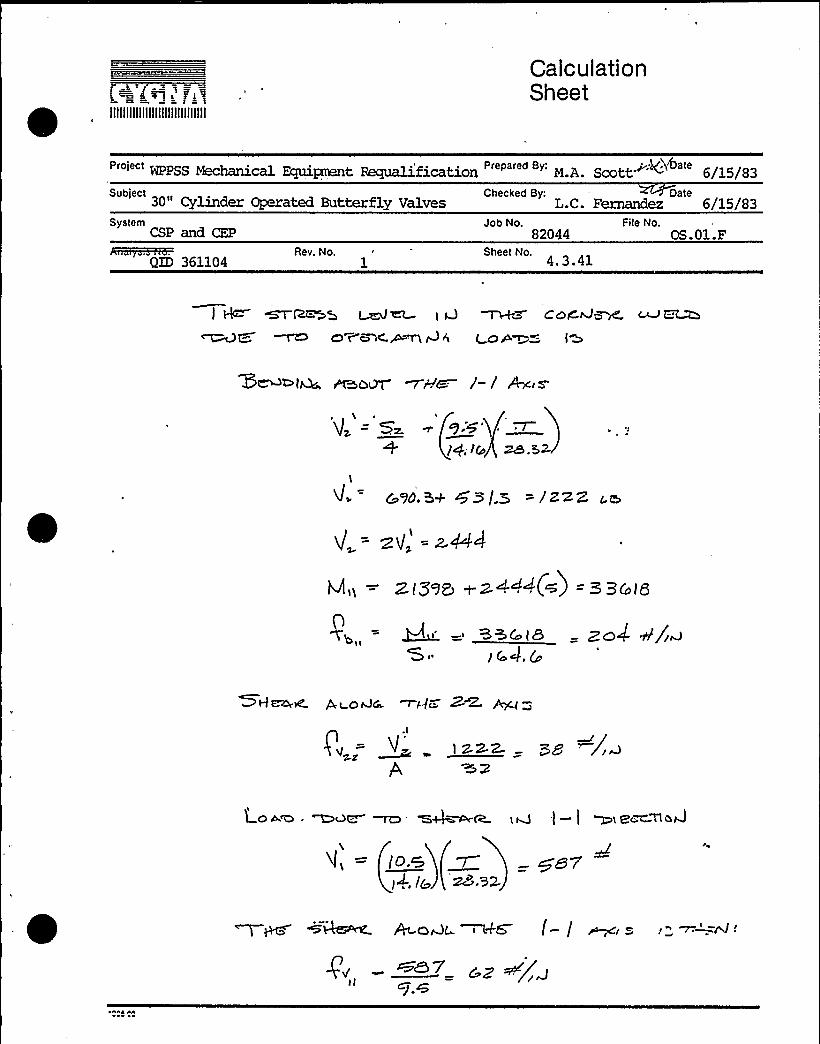
IIIIIIIIIIIIIIIIIIIIIIIIIIIIII
CalculationSheet
'"'PPSS Mechanical Fquipnent Reqmli.fication "'.A. Scott '~ 6/15/83Subject 30" Cylinder Operated Butterfly Valves
Checked By: DateL.C. Fernandez 6/15/83
SystemCSP and CEP
QID 361104Rev. No.
1
Job No.82044
Sheet No.4 ~ 3.41
File No.OS. 01.F
I ~ ~~a ~~ t v ~+a cora~cled-~~~~
P6 ~~~~=- IM
'V, = s.+ ]+, Ic za.sx
ZI595 aZ4+'4I.~) = 5 BColQ
'8+4 t8 — zn4 4/jwSi )t'.ca
SHwte',t orJG ui-(7 Z< hg ~

IIIIIIIIIIIIIIIIIIIIIIIIIIIIII
CalculationSheet
WPPSS Mechanical Equiprent Requalification '.A. Scott"" '~, 6/15/83Subject Checked By: +C~Date
30" linder ated Butterf1 Valves, L.C. Fernandez 6 15 83System
CSP and CEP
QID 361104Rev. No.
1
Job No.82044
Sheet o.4 3 42
File No,
HS 4 ~IAt» L GA=Co corJ ~M ~t "~ I S
~~7 (~) .
(W.~S') q.+
sea.s A/~

i~<p.~:—h, 2" ri\IIIIIIIIIIIIIIIIIIIIIIIIIIIIII
CalculationSheet
Project Prepared By: ~„'i,DateWPPSS Mechanical Equipnent Hequalification M.A. Scott ""4 6/15/83
Subject30 II linder
Checked By; Dateated Butterfl Valves L.C. Fernanddz 6 15 8
SystemCSP and CEP
~n5~M%HQID 361104
Rev. No.
Job No.
Sheet No.~ ~
File No.
Tdr o)s'L2O WWS c 4 WD o ( PR ~/4CQP —„Q- 10. + -DlPc~77Cr J /~ C~dcA-755.rf
A-S Mat om. MSm~~~i tA~-r COW.~l r-ioCMa ~~~ I LE MZo
~M
~Pa
—QZ7,Z
<84-ez -z

Jar=iIIIIIIIIIIIIIIIIIIIIIIIIIIIIII
CalculationSheet
project Prepared By; .. ~ DateWPPSS Mechanical Equi t lification M.A. Scott "'tt, 6/15/83
Subject30" linder
SystemCSP and CEP
Checked By: ~Daterated Butterf1 Valves L.C. Fernandez
Job No. File No.
QID 361104Rev. No. Sheet No.
4.3.44
~H~, M~z~&~oM
~cd~~Zo e~ u~r~

IIIIIIIIIIIIIIIIIIIIIIIIIIIIII
CalculationSheet
'"WPPSS Mechanical Byu.pnent Requalification ' M.A. Scott~~4'/15/83Subject 30" Cylinder Operated Butterfly ValvesSystem
CSP and CEPJob No.
82044File No.
OS.01.F
Checked By: ~ateL.C. Fernandez 6/15/83
hasted~QID 361104
Rev. No. Sheet No.4 3 45
/ Ra ~s/~w Lc>w7o ~~ ~nJw ~ r s
, BP I ~/iw
4-D~~Zo
bee"-M o Q
h
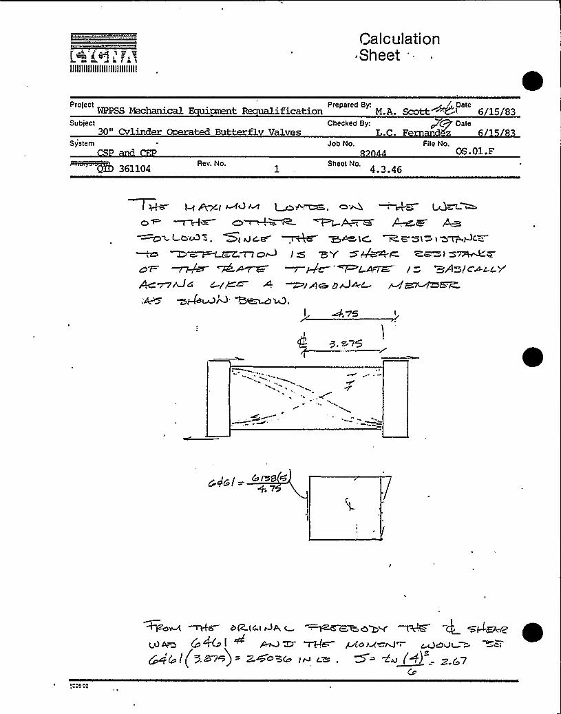
~ ' =-JkistIIIIIIIIIIIIIIIIIIIIIIIIIIIIII
CalculationSheet
NPPSS MechanicalPrepared'y: ~ /,Qatei t ification M.A. Scott i~6» 6/15/83
Subject30u
Checked By: Oatelinder ated Butterfl Valves L..Fdz
Sy'tem
55) 361104Rev. No.
Job No.
Sheet No.~ ~
File No.OS.01.F
e ~ ~h— m~~~ ~P -~> A-e a~~LC ~B'~t m t W~AC-
D~a. LEE:T7 o4 I Q '5 Y S A~te Z,Mow ~M W -- ~Qc-'~ca~ (=- =A~/c~c.c r
~zAw zrJuc
I Ass
Cc lm8 zz
+7

Illllllllllllllllllljlllllllll
Calculation~ Sheet
'"WPPSS Mechanical Ecpiipttent Requalification " " "'.A. Scott ~5 6/15/83
Subject30" Cylinder Operated Butterfly Valves
SystemCSP and CEP
Job No.82044
Fiie No,OS.01.F
Checked By: ~ DateL.C. Fernandez 6/15/83
QID 361104Rev. No. Sheet No
4.3.47
~V"roc)Pr- Pa+oat. p s 7 7 4/gz.( 7
CM/ /dr@
C~W rM~ ~~ &Bd~

i ~ fJ
IIIIIIIIIIIIIIIIIIIIIIIIIIIIII
CalculationSheet
NPPSS MechanicalPrepared By: ~ ItOate
t, lification M.A. Scott Wt 6 15 83Subject
30" linder Operated Butterfl ValvesSystem
P
Checked By:L.
Job No. Fite No.
ate
%6iaijsm+a=.ID 361104
Rev. No. Sheet No/4 3 48
.@ps i (s. sent+( l.s</~J) =Q+UgcA (o) =z /os$f
I t-I ~ +4~rW~~( ~f4 /a R ~~".., PEh%
QCg s D'7+ Z, ) ~Q/3 /g
MOVE "Cb ~C=
Mea+,I
~~++ 4 /6 = /~C g
~0~ MW ~~ uJ ~
— /z5'57 w~no7(W~S)
+ ~if(s ~A~ Is <~~w~c'.~ 4(h,.'~M~PS ~kc- C) ~A=rp&(
~i+77C~ UF '/rZF jNi)cr ( ~r r C~r.'.n

i xitIIIIIIIIIIIIIIIIIIIIIIIIIIIIII
CalculationSheet
Pro'tectWPPSS Mechanica c i Prepared By. Date
Z.E. RakowskiSubject
rr
System Job No: File No82044 0
Z]'-le"
Analysis No361104
Rev, No.1
Sheet No~ ~
Section 4.3.5 —Fati ue Anal sis
Discussion
The operator and bracket assembly are not part of the pressureboundary, therefore, the fatigue analysis will be performed inaccordance with Appendix B of the AISC Manual for Steel Con-struction. The following assumptions apply to the fatigueanalysis.
1) Faulted stresses (based on piping-analysis accelerations)will be used. This is necessary to insure operabilityafter a design basis event.
2) The actual stresses used will be the ones calculatedin Section 4.3.
3) If the alternating portion of the stress has been cal-culated separately only this part will be used. If theoperating loads (i.e. seating torque effects) are al-ready included in the stress analysis it will.be con-servative to use the calculated stress value. As longas no failures occur, the operating stress does notneed to be extracted.
4) The al3owable stress will be based on Table B3 of Appen-dix B in the AISC Manual of Steel Construction.
5) A factor of 1.5 will be applied to the allowable be-cause of the low number of cycles. (Per Section 1.7of the Commentary on the AISC Manual).
6) The actual stress range is taken as 2 times the maxi-mum stress for components subject to alternatingtension and-compression.
icos 00

IIIIIIIIIIIIIIIIIIIIIIIIIIIIII
CalculationSheet
Protect Prepared By.'ateJ.E.Rakowski
Subtect Butterfl ValvesSystem Job f4o.
82044File No.
0 .01 F
g. c ~ F~~~ ~ j~Q jg~Q
SBb Rev. No Sheet No.4 3 50
7) Bracket bolting is assumed to be properly tightened and willnot be considered for fatigue per Section B3.1 of the AISCManual.
The table on the following page gives the calculated stress range,stress category, and allowable for the critical components. The fol-lowing page gives excerpts from Appendix B of the AISC Manual showingthe descriptions of the relevent stress 'categories.
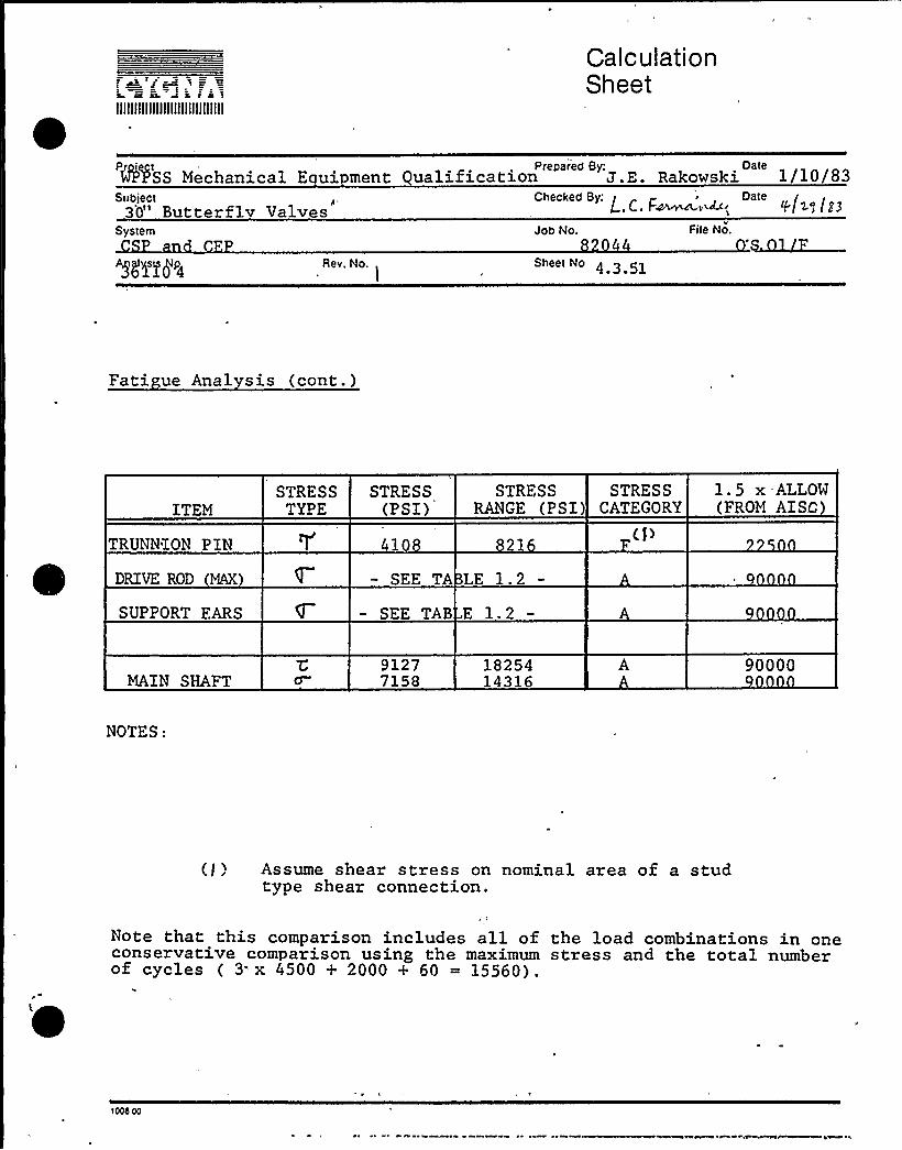
IIIIIIIIIIIIIIIIIIIIIIIIIIIIII
CalculationSheet
Prepar'ed By: OateWPPSS Mechanical E ui ment ualification J.E. Rakowski 1/10/83
Sobject3'0" Butterflv Valves
System Job No.
L., C. F~m~i~', p jL~ (E3
File No.
'5L'|'Mp4 Rev, No. Sheet No 4 3 51
Fati ue Anal sis (cont.)
ITEMSTRESS
TYPESTRESS
(PSI)STRESS
RANGE (PSI)STRESS
CATEGORY1.5 x.ALLOW(FROM AISt")
TRUNNION PIN
DRIVE ROD MAX
SUPPORT FARS
410
SEE TA LE 1.2
SEE TAB E 1.2
MAIN SHAFT91277158
1825414316
90000
NOTES:
(/) Assume shear stress on nominal area of a studtype shear connection.
/
Note that this comparison includes all of the load combinations in oneconservative comparison using the maximum stress and the total numberof cycles ( 3. x 4500 + 2000 + 60 = 15560).
1006 00

Calculation SheetPrepared By Date
zs a. J k. ik~IIIIIIIIIIIIIIIIIIIIIIIIIIIIII
Project 'r
50 o'rT -'p r I + VC
Sysrem
Analysis No. +4'll+ + . Rev, No
Job No File No
Date
ly / SZ.
azQR4- Qs elSneet No.
4.3.52
DENT;
I HE j t9$ LE 8 Ei o ~ 9 +5 BEEN ~H DEADER 'F 2 n&IPPG'Pfb~x 5 oF 7 H e Hx'sc Qt4Hex t. aP ZTEFcC onsrauc rx on. TH E c.pjsEZ uS Eg g as H pj's aC>
Ld z'v H <e RRRouJ.
GeneralCondi-
tion
Plainmaterial
Built-upmembers
hiechani ~
callyfastenedconnec-tions
httach.ments
Situation
Base metal with rolled or cleaned sur-faces.
Base metal and weld metal in mem.hers, without attachments, built-up ofplates or shapes connected by contin-uous full.or partial. penetration groovewelds or continuous filletwelds parallelto the direction of applied stress.
Calculated flexural stress, fs, in basemetal at toe ofwelds on girder webs orilanges adjacent to welded transversestiffeners.
Base metal at end of partial.lengthwelded cover plates having square ortapered ends, with or without «aidsacross the ends.
Base metal at gross section of high-strength. bolted friction.type connec-tions, except connections subject tostress reversal and axially loaded joints
. which induce outwf-plane bending inconnected material.
Base metal at net section ofother me.chanically fastened joints.
Base metal at net section of high-strength bolted bearing connections.
Shear stress on nominal area of stud.type shear connectors.
Kind ofStress'
or Rev.
T or Rev.
T or Rev.
Tor Rev.
Tor Rev.
Tor Rev.
Tor Rev.
StressCate-gory(See
TableB3l
B
D
B
~~ (g0 QQb)
~ (~~,s 5

IIIIIIIIIIIIIIIIIIIIIIIIIIIIII
CalculationSheet
ProjectWPPSS Mechanical E ui ment
Prepared By:ualification 3/25/83Subject Checked By: Date
30" Butterfl Valve '. C. Fe ~~ q/„qI'it~System
CSP and CEPAnalysis No 361104 Rev. No.
Job No.82
Sheet No.4 3 53
File No.
4 ' REFERENCES
1) BXF Drawings
Drawing IA-206763
Revo DescriptionGeneral Arrangement
CEP-625-10
CEP-625-11.12 H
From Reactor NozzleX-3 to SGT-FU-1A, 1B
From Reactor NozzleX-3 to SGT-FU-1A, 1B
C-26095 Model A-83B Cylinder
A-206767 Valve Assembly
DOC-D-220-0310-IR-66 Tube errection iso-metric
D-207110 Valve Data Sheet
M-144
CSP-807-3.4
General Arrangmentlan mis level
Containment purgeair su 1 s stem
tcos.00

IIIIIIIIIIIIIIIIIIIIIIIIIIIIII
CalculationSheet
WPPSS Mechanical Equipment Qualifica~tVon J.E. Rakowski 3/25/83Subject 30" Butterfl ValvesSystem
CSP and CEPJob No, File No.
OS.01/F
Checked By: DateI-.c'. Fe.~~~~, +/:~„'~ ".
Anatysis No.3 6 ] 1 0 4
Rev, No.1
Sheet No.4 3 54
Reference cont'n
Formulas for Natural Frequency and Mode Shapes,Robert D. BlevinsVan Nostrand Reinhold Company1979 Edition
3) BIF Report TR-27234 and TR-27235, "Dynamic TorqueCalculation of Butterfly Valve; Sizes 24 and 30 inch",dated November 10, 1982.
4) Report TR-74-8 by McPherson Assoc., Inc., "Design &Seismic Analysis 30" Cylinder operated Butterfly Valve".(Rev. 1) 12/31/75.
5) WPPSS letter to Cygna Energy Services, GE-02-RWH-018,12/17/82.
6)
7)
8)
WPPSS, WNP-2 SRM Equipment List Summary Sheets dated2/10/83.
Cygna Energy Services, Equipment Qualification WalkdownVerification Form dated 7/14/82 and 7/19/82.
Cygna Energy Services, "Project Manual Design Criteria,"DC-1, Rev. 1, 10/82.
9) Burns and Roe Revised Piping Analysis Loads forCSP-V-1 and 2 (dated 4/12/83) and CEP-V-lA and 1B(dated ll/15/82) .
10) Communications Report, R. Ricappito of BIF and J. Rakowskiof CES, nB1F Valve Dimensions", 2/ll/83
'l000 Oo

APPENDIX A
COMPILED PROGRAMS AND RESULTS FOR
CSP-V-1
CSP-V-2
CVGNAATTAC>!iAC,ViT
V OS IIO.~«<FILE No ~0~. oI. F
SHEE7IIO.~4'

sbasi c csp12tm
S-BASIC Comp i 1 er Version 5.4b
uooi:000002:000003:00OOO4:OO0005:000006:000007:000008:000009:000010ioo0011:000012:000013:000014:000015:000016:000017:000018:000019:000020:000021: 000022:000023:000024:00
= "025:00326'00
0027:000028:000029:000030:000031:000032:000033:000034:000035:000036:000037:000038:000039ioo0040ioo0041:000042:000043:000044'000045'000046:000047:000048:000049:000050:00
'151'00vu52:000053:000054:000055:000056:000057'000058:00
r estore 3r ead fst2,ca, i a,cb, ib,aa,abres tor e 4read wao,wbr,ei,e2,e3,e4,e5restore 5read lr odo,lcgo,ldr sd,abushr estore 6read a< 1, 1), a(2, 1 >, a(3, 1), a(1, 2), a(2,2), a< 3, 2)restore 7r ead a< 1,3), a(2,3), a(3,3), av(1 >, av(2), av < 3)text 0 rh INPUT GLOBAL ACCELERATIOt iS 8c
i npu t 6< 1), b(2), b(3)printtex t 0 s8c INPUT DATA 8c
printprint "GLOBAL G-LEVELS ";b(1> sb(2) sb<3)print "tiORTH VECTOR AhiGLES = ";a(i, l),a(2,1),a(3,1)pr i n t "VEPTICAL VECTOR ANGLES= "; a< 1 s 2) s a< 2 s 2) s a< 3 s 2)
Aii.~~.CH~'."r'QB
NQ.9~~t'-ILE hs0 os. 0 t. F
SH=.KV JQ. < '«
REtlJJ++++ BIF VALVE AtiD AIR OPERATOR SEISI"iIC STRESSCSP-V/'AO-1/2
REt"t+++++++++++++++ 10 IhiCH AO PARAMETERSREt'1
var i,j,k = inteoervar 1 rod, 1 cg,x,phi, 1 ave,abl t,11,12,el,e2,e3,e4,e5 = r ealvar fst2, ca, ia,cbs ib,aa,ab,dl,d2,cl, ii,c2, i 2=realvar lrodo, 1 ego, 1 dr,d, abush, pbush=r ealvar fcof, fco, ma,mb, siga, sigb, fcdr, fcdrf,maf, mbf=realvar dear, fcear, fr, f 1 1, f22,1a, c i 12,c i 21,st t3, seml=r ealvar sem2,set3,sesl,ses2,sr, taul 1, tau22, tauear,aear=realvar btens, taubl t, se t3f, semi f, sem2f, fcear f, f r f, f 11 f=r ealvar f22f,stt3f,sesl f,ses2f,srf, tauif, tau2f, taur f=r ealvar taubf, btf, dsr, dtaur, dtaub, dbten,dsa, dsb, dpb=realvar sdraf,sdrbf,pbushf, taui if, tau22f=r ealvar wao,wbr, f tr1,watr1,si, si f, s2, s2f,mi,mi f,m2=realvar m2f, t3, t3f, t t3, t t3f, 1 br,wtot=realvar bsisbs2sbt3sbmlsbm2sbtt3=r ealdim real av(3)dim real wa<3)dim real wb(3)RENREM ss+ss BURNS 7 ROE EAR FORCES ARE bsi etc TURN Ohi WITH K=is'++REMREI"1
dim real a(3,3)dim r eal b(3)dim real glc(3,3)1 data 9.5,,10.5, .88, 3.94r 1.50,1.342 . data 25,21.50,.488,48.,4.8S,.627,1.75,3.03 data 1847 't 875s i6s ~ 648s ~ 138s2 ~ 41si 44 data 593.,321.,S.25,8.5,28.5,15.,7.755 data 40 ~ s16 ~ 2Ss26 ~ 5s43 ~ s2 ~ 0756 data 135 ~ s90 ~ r135 ~ s90 ~ r180 ~ r90 ~
7 data 45 ~ s90 ~ r135 ~ r90 ~ s0 ~ s90 ~
REM DAT* 657 FOR VALVMGLOBAL-GORIENTATIONS AND WEIGHT VECTORrestor er ead dl,d2,cl, i l,c2s i 2restore 2read lrod,lcg,x,phi,lave,ablt,11,12

oo592ao0060:000061:000062:000063:010064:02
~065:O2~')66:02
~0672010068:000069:Oi0070:010071: 000072: 000073: 000074: 000075:000076:0000772000078:00OQ79:010080:010081:Oi0082:000083:0000842000085:000086:000087:0000882000089:000090200
091:00392:00
0093:000094 000095:0000962000097:000098:000099:000100:000101:0001022000103:000104:000105:000106:000107:000108:000109:000110:00Oili:0001122000113:000114:000115:000116:00
2~ 17:00218200119:00
0120:00- 0121:000122:000123:00o124:ao
";a<1,3),a(2,3),a<3,3)";av(i),av(2>,av(3)
CVGiNAATTACH»'ATJ08 ~'10. ~So~Fli.E NO. O~
SHEET N0,M4~
p r i n t " EAST VECTOR ANGLESpr int "WEIGHT VECTOR AiiGLESprintfor i=1 to 3for j=l to 3
a( j, i ) =a( j, i ) +2. ~3. 141 &'360 .glc(j,i)=b(i)icos(a<j,i)>
next jnext i
for j=i to 3av < j ) =av ( j ) +2. +3. 1416/360 .nextprintt e x t 0, h LOCAL G-LEVELS 8c
printpr int ql c<1,1),gl c(1,2),gl c<1,3)print gl c(2,1),gl c(2,2),ql c(2,3)pr i n t gl c (3, 1 >, gl c (3,2), gl c(3,3)REM WE I GHT COMPONENTSfor j=i to 3wa( j )~ao+cos(av( j) )wb( j )=wbr icos(av( j ) )n.ex t jph i =ph i +2. +3. 141 &'360 .1 a= 1 av e/2c i 12=c lli 2c i 21=cd'i 1
aear=l 1 +12REM CALCULATE EAR FORCES USE BhR LOADS AS OPTION LATERREM FIXED COMPONENTS ARE ALWAYS THERElbr=lrod+lcgwa tr 1 = l br ea�( 1) 11 rodsi f=wb( 1 )+watr 1
wtot=wao+wbrs2f=wb(2)+wa(2)+ fst2t3f=wa(3)+wb(3>mi f=-(wa<2)+wb<2)+fst2) +e5-wa(3) +< e3+ l cg>-wb(3) +e4m2f=(wa tr 1+wb< 1) ) +e5~a(3) +e2-wb(3) +e 1
t t3f=watr 1 +e3+ (wa< 2)+ fst2) +e2+wb< 1) +e4+wb(2) +e 1
fcdr f=lcg+wa( l )t'1 rodmaf=fcdrf +< l rod-13.5)mbf=fcdr f+7. 125sdraf=f st2/aa+abs(maf +cali a)sdrbf=f st2r'ab+abs<mbf+cbJ'ib)fcof=l cgo+wa<1)/ir odopbushf=f cof +( 1 dr+d)f'(d+abush)REM STRESSES FROM FIXED COMPONENTSdear=< di wdi+d2+d2) ++. 5se t3f=abs( t3f/(4+aear) )semif=abs(mif/(2+d2+aear>)sem2f =abs(m2f 1( 2+di +ae ar ) )fcear f=t t3f/'(2+dear)frf=x+fc ear ff1 if=-(fcearf+sin(phi )-frfwcos(phi ) )f22f=fcear f+cos(phi )+frf+sin(phi )s t t3f=abs( f11 f+I a+c i 12>+abs( f22f +1 a+c i 21)sesi f=abs(sl f+c i 12+1 a/4. )ses2f=abs(s2f +c i 21+lax'4. >
sr f=se t3f+semi f+sem2f+sesi f+ses2f+st t3fREM EAR SHEARtau 1 1 f=abs(sl f/(4+aear > )+abs( f 1 1 fi'aear)tau22f=abs(s2f/(4~aear ) )+abs< f22f/aear)taur f=( taui 1 f+taui 1 f+ tau22f +tau22f ) ++ ~ 5taubf=taurf+aear/abl tREM EARBOLT TENSIONb t f= ( se t3f+ semi f+ sem2f ) +ae ar J'ab 1 t

0125:VU0127:000128:00
'0129! 00Oi 30: 000131: 00"132:00
'33: 00I .84!000135:000136! 0001 37: 000138! 0001 39: 000140!000141: 000142: 00Oi 43: 010144:010145!010146!010147:010148:010149! 010150! 01Oi 51: 010152: 010153! 010154: 010155: 010156! 010157!01
~8!019:01
0160!010161:Oi0162! 010163: 010164: 010165:Oi0166!01.0,1 67! 0 1
0168! 010165'! 0 1
0170 2010171! 010172: 010173! 010174: 010175: 010176! 010177: 010178!010179:010180:010181! 010182! 01A1 Q3 ~ Of
4!000185:000186:0001 87: 000188! 000189! 000190! 00
pr i n t "Ul hKA I lNU UYLINDE,K BKG f Kh.SbUKhprint"OPERATING VALVE EAR TENSILE STRprint"OPERATING VALVE EAR SHEAR STRESprint"OPERATING EAR BOLT SHEAR STRESSprint"OPERATING EAR BOLT TENSILE STRprintREMREM CALCULATE VARIABLE COMPONENTSREMdsr~O.dtaur=O.dtaub=0.dbten=0.dsa=O .dsb=O .cip b=o ~
for J=l to 3fco=lcgo+wao+glc(l,j)/lrodopbush=fco+(ldr+d>/<d+abush)ftrl=lbr+wao+glc<l,j)/irodsl=f trl+wbr +gl c(l,j)s2=wtot+alc(2,J)t3=wtot+glc(3,J)mi=-wtot+glc(2,J)+e5-wao+glc(3,J)+<e3+m2=( f tr 1+wbr +g1 c < 1, J ) ) we 5-(waowe 2+wbr +t t3=f triwe3+wbr+gl c( l,j) +e4+gl c(2,J >+(fc dr= 1 cg+wao+gl c (1, J )/1 rodma=fcdr+<lr od-13.5)mb=fcdr +7. 125s i ga=ma+ca/i as i gb=mb+cb/ 1 bREM CALCULATE EAR TENSIONse t3=abs( t3/(4+aear > )seml=abs(ml/(2+d2+aear) )s em2=abs(m2/( 2+0 1 + ae ar ) )fcear =t t3/(2+dear )4 r=x+fcearf 1 1=-( fcear+s in(ph i ) -fr+cos(ph 1 ) )f22=fcear icos(phi )+fr+sin(phi )st t3=abs( f 1 1 +1 a+c i 12)+abs( f22%1 a+c 1 21 )ses1 =abs( si +c i 12+1 a/4. >
ses2=abs( s2+c i 21+1 a/4. )sr=se t3+semi+sem2+sesl+ses2+st t3REM EAR SHEARtau 1 1=abs( sl/(4. +aear ) )+abs( f 1 1/aear )tau22=abs(s2/(4.+aear > )+abs< f22/aea! )tauear ~( taul 1 +tau11+ tau22+tau22) ++.5taubl t=tauear+aear/abl tREM E*RBOLT TENSIONbtens=(se t3+semi+sem2) waear/abl tdsa=dsa+s i ga+s i gadsb=dsb+sigb+sigbdpb=dpb+pbush+pbushdsr~dsr+sr +srdtaur=dtaur+ tauearwtaueardtaub=dtaub+taublt+taubltdbten=dbten+btenswbtensnext JREM COMBINE STRESSESdsa=dsa++.5dsb=dsb++.5dpb=dpb++ ~ 5dsr=dsr++.5dtaur=dtaur++.gdtaub=dtaub++.5
lpousnf" 'srf"; taurf"; taubf";btf
lcg)-wbr +glc(3,J)+e4el ) +gl c<3,J
)'ao+e2+wbr+el>
8 gO.~~~JO
fllKgO.TNO

0192: 0001'F3: 000194: 00
"01 95: 000196:00
197:0098:0099:00
v~00:000201:000202:000203:000204:000205:000206:000207:000208:000209:000210:00021 1: 000212:000213:000214:000215:000216:000217:000218:000219:000220:000221: 000222:00223:00
~4:005:00
AT A"AT B"
I dsaIdsbI dpbI dsl;dtaur;dtaub;dbten
ONENTS h
AT A"tdsaAT BNidsb
"ldpbr dsl
";dtaur";dtaub";dbten
End of program
printtext 0, h DYNAMIC COMPONENTS 5pr intpr i n t "DR I VE ROD TENSILE STRESSpr i n t "DR IVE ROD TENS I LE STRESSprint "BUSHING PRESSUREprint "VALVE EAR TENSILE STRESSprint "VALVE EAR SHEAR STRESSprint "EAR BOLT SHEAR STRESSprint "EAR BOLT TENSILE STRESSdsa=dsa+ abs ( sdr a f )dsb=dsb+abs(sdt bf)dpb=dpb+abs(pbushf)dsr =dsr+abs(sr f )dtaur=dtaur+abs( taur f )d t aub=d t aub+ abs( t aub f )dbten=dbten+abs(btf )printtext O,h FIXED PLUS DYNAMIC COMPprintprint "DRIVE ROD TENSILE STRESSprint "DRIVE ROD TENSILE STRESSprint "PUSHING PRESSUREprint "VALVE EAR TENSILE STRESSprint "VALVE EAR SHEAR STRESSprint "EAR BOLT SHEAR STRESSprint "EAR BOLT TENSII E STRESSend
CYGNAA i rwcvr@EnvJOB NO.~<'~<FlLE NO.
SHEET NO.~>.AE

cspiINPUT GLOBAL ACCEI ERATIONS
'P 2.26,3 '2,2.8INPUT DATA
GLOBAL G-LEVELSNOPTH VECTOR ANGLESVERTICAL VECTOR ANGLES=EAST VECTOR ANGLESWEIGHT VECTOR Al'lGLES
2 '6135904590
— 3. 629018090
0
2.81359013590
LOCAL G-LEVELS
-1.59807 -1.38092E-5 . 1.97989-8.62121E-6 -3.62 -1.06811E-5-1 '9807 —1.38092E-5 —1.97991
OPERATING DRIVE ROD STRESS AT A '66.432OPERATING DRIVE ROD STRESS *T B 1319.35OPERATING CYLINDER BRG PRESSURE -7.15824E-4OPERATING VALVE EAR TENSILE STR 2111.01OPERATING VALVE'EAR SHEAR STRES 293.896OPERATING EAR BOLT SHEAR STRESS 2460.85OPERATING EAR BOLT TENSILE STR 1625.1
DYNAMIC COMPONEllTS
SCC SfRCTQ 1,3 3o - 4:E.<'aEAR BOLT SHEAR STRESSEAR BOLT TENSILE STRESS
FIXED PLUS DYNAMIC COMPONENTS
703910524.9
DRIVE ROD TENSILE STRESS AT A 28384.4DRIVE ROD TEI'lSILE STRESS AT B 43412 ~ 2 ~'~'>'4(g'-'"c'~ C6g ."i lr<wA .'.~BUSHING PRESSURE 477.447
EAR BOLT SHEAR STRESSEAR BOLT TENSILE STRESS
>me-.sa—9499.86121 50
DRIVE ROD TENSILE STRESS AT A 29150.9DRIVE ROD TENSILE STRESS AT B 44731.6PUSHING PRESSURE 477 '48
CVG~~~A
Jos zo.~~FiLs Nosvaa'o. ~s4'
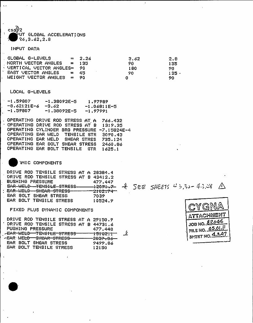
cs@2
~ ~
EUT GLOBAL ACCELERATIQtlS'26,3.62,2.8
INPUT DATA
GLOBAL G-LEVELSNORTH VECTOR ANGLES
'ERTICAL VECTOR ANGLES=EAST VECTOR ANGLESWEIGHT VECTOR ANGLES
2.2o135904590
3 '29018090
0
2 ~ 81359013590
LOCAL G-LEVELS
-1 .59807 -1.38092E-5-8 '2121E-6 -3.62-1 .59807 -1.38092E-5
1.97989-1.06811E-5-1.97991
OPERATIflG DRIVE ROD STRESS AT AOPERATIf'lG DRI'VE ROD STRESS AT BQPERATIflG CYLINDER BRG PRESSUREOPERATING EAR WELD TENSILE STROPERATIt'IG EAR WELD SHEAR STRESOPERATING EAR BOLT SHEAR STRESSOPERATING EAR BOLT TENSILE STR
766.4321319 '5
-7.15824E-43090.43735.1242460.861625.1
W I C CQMPOt lENTS
DRIVE ROD TEt ISILE STRESS AT A 28384 ~ 4DRIVE ROD TENSILE STRESS AT B 43412.2BUSHING PRESSURE 477.447maua -e a=Ed—zan smcss —vis~~ + <Cc~ g,'i '875
; ~R-WEf=&—SHEAR .rrREAR BOLT SHEAR STRESS 7039EAR BOLT TEf'lSILE STRESS 10524.9
FIXED PLUS DYNAMIC COMPONENTS CVQ<4ADRIVE ROD TENSILE STRESS AT ADRIVE ROD TENSILE STRESS AT BPUSHItlG PRESSURE~R-MEt.-D—7 EhEAR'WEL~~EAR BOLT SHEAR STRESSEAR BOLT TENSILE STRESS
29150. 944731.6477.448
28~&6-9499 ~ 8612150
JOB &!0.~„(~~ ~~ ~05.6(.
g.s,A7gfaacT QQ.

c=p QINPUT GLOBAL ACCELERATI Ot'lS
'? 1 '4s3 ~ 54fl 9
I t lPUT DATA
GLOBAL G-LEVELS 1.44NORTH VECTOR At'lGLES = 135VERTICAL VECTOR ANGLES= 90EAST VECTOR ANGLES = 45WEIGHT VECTOR ANGLES = 90
3.54'9018090
0
1.91359013590
LOCAL G-LEVELS
-1.01824 -1.3504E-5-5.49316E-6 -3.54-1.01824 -1.3504E-5
1.3435-7.24792E-6-1.34351
OPERATING DRIVE ROD STRESS AT AOPERATIt'lG DRIVE ROD STPESS AT BOPERATING CYLINDER BRG PRESSUREOPERAT I t lG VAL'VE EAP. TEtitSI LE STROPERATING VALVE EAR SHEAR STRESOPERATING EAR BOLT SHEAR STRESSOPERATING EAR BOLT TENSILE STR
766.4321319.35
-7.15824E-42111.01293.8962460.851625.1
DYNAMIC CONPONENTS
DRIVE ROD TENSILE STRESSDRIVE ROD TEt'lSILE STRESSBUSHIt'lG PRESSURE
EAR BOLT SHEAR STRESSEAR BOLT TENS I LE STPESS
AT A 18806*T B 28762.8
316.332P Cm SWe,VS %.3.~~ -II"%.~
5077.947164.63
FIXED PLUS DYNANIC CONPONENTS
DRIVE ROD TEt'lSILE STRESS AT A 19572.5DRIVE ROD TENSILE STRESS AT B 30082.1PUSHING PRESSURE 316 '33MA~EAR-TSttS.FQ~7RESS "'868. 59
~tNE-EA~HEA~7RES8— - 900~48-'ARBOLT SHEAR STRESS 7538.79
EAR BOLT TENSILE STRESS 8789.72
CVQblAATTACH)BEiil,
JOB NO. f~'pp+
FILfNO. OS.PI ~ P
SHffTNO. "~.~f

c IQ2UT GLOBAL ACCELERATIONS
'4s354)1 9
INPUT DATA
GLOBAL G-LEVELS 1.44NORTH VECTOR ANGLES = 135VERTICAL VECTOR ANGLES= 90EAST VECTOR AllGLES = 45WEIGHT VECTOR Al'lGLES = 90
3.549018090
0
1.91359013590
LOCAL G-LEVELS
-1.01824 -1.3504E-5 1.3435-5.49316E-6 -3.54 -7.24792E-6-1.01824 -1.3504E-5 -1.34351
OPERATIl'lG DRIVE. ROD STRESS AT AOPERATING DRIVE ROD STRESS AT BOPERATING CYLINDER BRG PRESSUREOPERATIl'lG EAR WELD TENSILE STROPERATING EAR WELD SHEAR STRESOPERATING EAR BOLT SHEAR STRESSOPERATING EAR BOLT TENSILE STR
766.4321319.35
-7.15824E-43090.43735.1242460.861625.1
'INIC CONPONENTS
DRIVE ROD TENSILE STRESS AT A 18806DRIVE ROD TENSILE STRESS AT B 28762.8BUSHING PRESSURE 316 '32
~R-IdELD—SHEAR-SFRESS ——+SM.;R2.EAR BOLT SHEAR STRESS 5077 ~ 96EAR BOLT TENSILE STRESS 7164.63
F IXED PLUS DYt lANI C COMPONENTS
DRIVE ROD TENSILE STRESS AT A 19572.5DPIVE ROD TENSILE STRESS AT B 30082.1PUSHING PRESSURE 316. 333
~-WELD.—TENSI-l-E-STRESS—=—1-1 506-..3-
EAR BOLT SHEAR STRESS 7538.81EAR BOLT TENSILE STRESS 8789.72
JOB RO
PILE HO. ~ S'"SHSZVHO.~4

APPENDIX B
VALVE/AIR OPERATOR MODEL FOR
FINAL PIPING RESPONSE G-LEVEL CALCULATION.
JGE NG. ~
SaENG. OSSA F
SHEET NG

f 0 ~ ~ ~ /p
J J /w P'

SECTION 5.0
APPENDTCES
CONTENTS
5.2 Walkdown Sheets
g~ Q+&E' 9~c ~~~)
5;3
5.5
5.6
Valve Local Coordinate Systems
g~ (QPwz&i SE++Tf >c)
Revised 'burns and RoePiscina Analysis Accelerations
Load Comparative Sheets

IIIIIIIIIIIIIIIIIIIIIIIIIIIIII
EQUIPIiEhT QUAL'1CATIONWALKDOWli VERIF 1 CATIOI'I FOR! 1 PAGE 1 OF
EPN 0 SP-'/-
BLDG IR
MiFR c9//-MODEL( 6&5
4~ PSI 8 84D
"~D/COPPPONENT EL 5O&SERIALS / I "7Z+g- (
QIDP Bt'COORDS 4S/7 Co~r ~;MAT'L5l < Q -'75
LBS SIZE~@
YOKE ORIENTATION
I TO AXIS OF PIPE ( )
// TO AXIS OF PIPE ( ), I/'i/V[n
YOKE LENGTH(FLANGE TO FLANGE)
MOUNTING CONDITION
NO OF BOLTS
BOLT TYPE~g ~//s
BOLT 0 //4-(uY 'JC
WELD TYPE 8 SIZE ~cA~)c ~ Ci:~ z'3Z7
PIPE MOUNTED YES (vi) N (
PERYiANENT OBSTRUCTION (WITHIN 2 ")................ YES ( ) NO ( QIS COMP BETWEEN CONT S; 1ST ANC (FULL 6 WAY ANC) YES (g) NO ( )
DO MULTIPLE SUPPORTS EXIST BETWEEN CONT 6 COMP YES ( ) I'10 ()()
Z
TYPE SIZE
GLOBAL CO-ORDINATESYSTEM
OPERATOR EPN 4- '/MODEL NO
VALVE STEM ORIENTATION
MANUFACTURER r'zz<~SERIAL NO
ORDER NO
MOTOR EPN
MODEL NO
ID NO INS CLASS
MANUFACTURER
SERIAL NO
1-PHASE ( ) 3-PHASE ( ) AC DC
TYPE OF CONDUIT CONNECTION: RIGID ( ) „FLEX (Q)
NOTES: 1. Definition (N/F = Not. Found)
~4'4'iA CC ~~«7 <Vi7CWC Z~,~," D) 7CQQQIDdD~~«d> ~rc w'~/D~'. /zDC~JririeArio~
7~t'~ ~cu ''
PREPARED BYI ~(SIGNATURE)
onJZc.d
DATE~Ps a REVIEWED BY ZC&anmnn&r DATE~>l jg(SIGNATURE)
FeRAn~OC2-

IIIIIIIIIIIIIIIIIIIIIIIIIIIIII
C:a ic ulaiionSheet
F'rotf ot Prepareo By Date
Eg ulk. r/Oc /Checked By Date
d.SP- U'-/*h lyk';;
c
Rev No
Job No,
Sheet No2 0
File No
c r
f ~. ~
~ e
t I
/ey
QVC J -'41cceJXp
Ccoty-il- (, z ( <sty Ji gyJ)l~J>
p
l,rIl.X>K/
/Ii I
r
il
PL nl IliCcJ($ -g)
7~
I
e/
6= 7 —~5@- v'- /e,SP - tr'-Z
wC( ccr>c J i/JCvJ 'A-A
J gc 5cSKD c cA(Foi ccrc cvviioskv DF JccoccrccJye ccv=c4>'DE DEcccdtp, co J o~ccvJ

IIIIIIIIIIIIIIIIIIIIIIIIIIIIII
BLDG
MiFR
MODELS
Cf-5'S I
>,QUIPI'„!i"T QUAL ! '(CA'r"1OIiWALKDO)'Pii VERI1" ICAT1 OV. FOR!~i
FLOOR EL 5D /COMPONENT EL~50SERIAL% /- 2 Z - Z
8 Sdt) 'F ASME CLASS I
PAGE 1 OF
EPN Cg -(/-~OIDN aC. )iOCOORDS
DSCRP i - ~m L(/
HAT'L 5
LBS~/SI SE 3Q
YOKE ORIENTATION
TO AXIS OF PIPE ( )
// TO AXIS OF PIPE ( ) J/pYOKE LENGTH(FLANGE TO FLANGE)
MOUNTING CONDITION
NO OF BOLTS
BOLT TYPE
WELD TYPE & SIZE//c V(' c
Le~c >z
PIPE MOUNTED YES (4) NO ( )
PERYIANENT OBSTRUCTION (WITHIN 2")................YES ( ) NO (Y)IS COMIP BETWEEN CONT & 1ST ANC (FULL 6 WAY ANC) YES Q() NO ( )
DO MULTIPLE SUPPORTS EXIST BETWEEN CONT & COMP ,YES ( ) NO
Z
X
GLOBAL CO-ORDINATESYSTEMi
OPERATOR EPN
MODEL NO
TYPE SIZE
VALVE STEM ORIENTATION
HANUFACTURER //< C. -g +/SERIAL NO
ORDER NO
MOTOR EPN
MODEL NO
ID NO
MANUFACTURER
SERIAL NO
INS CLASS I-PHASE ( ) 3-PHASE ( ) AC DC
TYPE OF CONDUIT CONNECTION:'IGID ( ) ...FLEX (P)
NOTES: 1. Definition (N/F = Not Found)
Alkf~jCd C.~+//7 "iJ/-,E~ (- gg~,r g Q/g 74gpg /(gg
' ~'~ / F '-/1 iaaf'. WIFE />iO~CC./ZDCiJ77r/Cq7-/d.JT%65 rdV)JL
PREPARED BY . I ii(SIGNATURE)
8'oUSc i/Le
DATE~&lg (REVIEWED BY gCsgzwwm4< DATE (/>a/f P(SIGNATURE+
L.C . FERNME(".lJ>( g
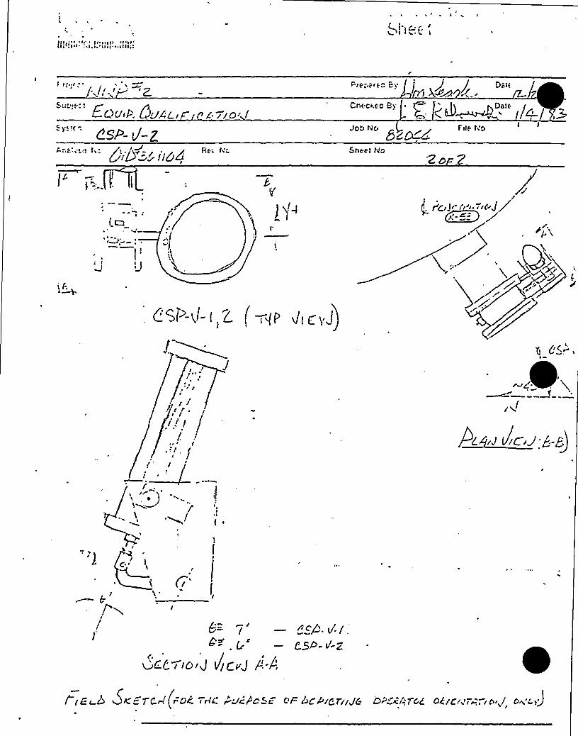
Csee- v'-Z6 //'0/ /
Rt; ti"
Chf'C>~ EC Bi
JOb NO Fitt- ti>8~~~ShEH No
'ZD
! ~)~
~
/fg/J/ I // I/(dJ/
pr
//0
J/";
~ &/x! ncaa. / y
654- ~-2
wCL I ICIIJ VjlryJ Ic-A
/ IC'r-6 SKETCH(rOk TrIC rVCVOS/ >+ /ICVICTII/6 CIr cf TGE OCICI T,,'*-'/ I' >j

lllllllllll!lllllllllllllllll;
QI DT", Ud I/OBLDG
MFR
MODELTL C>|: i
FLOOR EL ~ I/COMPONENT EL~~
SERIALT,'SYiE
CLASS Z
COORDS '7, $ /gv j.
~ii;-', /;MAT L Vj - -6,<@~a
LBS /5O SIZE ZgYOF'E ORI KTATIOh
TO A).'IS OF PIPE ( )
/j TO A>:IS OP PIPE ( ) /jj„'.YOFFE LENGTH(FLANGE TO FLE NGE)
MOUNTING CONDITION
NO OF BOLTS 2QBOLT TYPE
WELD TYPE & SI ZE
BOLT ql
(2 'U~, ~r/i
PIPE MOUNTED YES (P ) NO ( )
PERt~iAhIENT OBSTRUCTIO1 {i'ITHIK 2 ") YES ( ) NP (2 )
I S COMP BETv',EEL CONT & 1ST ANC (FULL 6 NAY ANC) YES (Y~) NO ( )
DO MULTIPLE SUPPORTS E>:IST BETNEEK CONT 6 COMiP YES (p,=) NO ( )
TYPE S1 c.E
GLOBA CO-ORDINATESYSTEM
'OP:JU;TOR EPI2~C~P- 'Pi-1:ODEL NO
VALVE STEM ORIELTATION
SERIAL NO
ORDER NO
MOTOR EPh
MODEL NO
ID tIn IHS CLASS
MANUFACTURER
SERIAL HO
3 -PHASE ( ) 3-PHASE { ) AC DC
TYPE OF CONDUIT COIlNECTIObl: RIGID ( ) FLE>: ( )
NOTES: 3. Dc.in'ion (ti/F = Not Found)2'V'h/'"~ C2 <2/'/'7 2 rJ/ q QrlC S~C/i /& C. Q/~j j @Qadi 0 IQD
I .AC.C VJC' rg<,ll~ ./'-lC " '. ~ - < i, 6 P(>bCL, DC J:,"i<47 f~'J
TAt=" i=a pJq.
PREPARED BY(SIGNATURE)
D Jell/.e.
DAT~~REVIEilED B'l,C,+~iiiii/i DATE ~//2o /"( S IGNATURE )~>
L P . FF tJi'NOF.~~

'/<:v "
~'/.;-'. Qcw:'!Cr ~ Cc 0 ~ ICnec<ec Ep'('< g D&tt
c IJo> ti" '~ File teo
5ZDcc 2
l,(
Sneet tio Zor8
i ~
(tf-,4
)gI
~Wc!J
—Gc
Cci 7/&J A
Qc'p g g —gESP- v'- 4
i cec 6 DKEi CcC (iDE ltlL PVi f'DSC ci DE+c Tc JC O'QcCIIp <A'>cE Jv/iree J op<>.
IIIIIIIIIIIIIIIIIIIIIIIIIIIIII
Ca IC UlationSheet
Pioiecl4tPPSS Hechanical Eaui ment ualifi oSrrbiect24" Butterfl ValvesSvslern
P (j
Prepared By
Joo No
Date
I
grt M/ "2 Z'(bsFile No
Analvsrs No361106
Rev, No. Stteet Nog Or-3
gl"Ill'l.il:J, r'l- 4 vaAAilo'< ~ (Alk DP&rlr I ok Ac uc:g')
gSPAO

E),)UI,P:" t.'i ()U):iL1.' v'.s.'i ) UliWALKDOWIi VERI'CAT10!'. FOP)'. PAGE 1 OF
IIIIIIIIIIIIIIIIIIIIIIIIIIIIII
BLDG
MFR c-MODELS,' . 7
FLOOR EL ~7/COMPONENT EL~s~SERIALS",' 3( - Z
ASME CLASS Z
EPN CSP-Y-dQID". 8C I dCOORDS 7, 5/g8.C~
DSCRP AVE, ~i~w
LBS i S) SIZE C4
YOKE ORIENTATION MOUNTING CONDITION
I TO AXIS OF PIPE ( )
// TO AXIS OF PIPE ( ) yj/AYOKE LENGTH(FLANGE TO FLANGE)
NO OF BOLTS ZQBOLT TYPE
WELD TYPE & SIZEPIPE MOUNTED YES
BOLT g('C4-, ().~~
(X) NO ()PERMANENT OBSTRUCTION (WITHIN 2").... ~ - ~ - . ~ - - .. ~ ~ YES ( ) NO (A )
IS COMP BETWEEN CONT & 1ST ANC (FULL 6 WAY ANC) YES W) NO ( )
DO MULTIPLE SUPPORTS EXIST BETWEEN CONT & COMP YES (y) NO ( )
GLOBAL CO-ORDINATESYSTEM
OPERATOR EPN
MODEL NO 'Q~
TYPE SIZE
pg
VALVE STEM ORI ENTATION
MANUFACTURER
SERIAL NO
ORDER NO
. Is
MOTOR EPN
MODEL NO
ID NO
MANUFACTURER
SERIAL NO
IWS CLASS I-PHASE ( ) 3-PHASE ( ) AC DC
TYPE OF CONDUIT CONNECTION: RIGID ( ) FLEX ( )
NOTES: 1. Definition (N/F = Not Found)(~) s'4///1 ~0 <~WI7 gpJI Qt/C Z(W P('g 7+QQ Q /QL)
7>/~AC sJcae. sos) s)ssz sss~~slrssa ssitc, zsDsscL/~ccJ-,ss-sccirsssv7A65 pgggg
IPREPARED BY (~'.lr/ ~tJ",
(SIGNATURE)
DMw~c4QL.E,
DATECcllbll:~REVIEWED BY + i ci,i„, r, DATE(SIGNATURE) LI
C..C. Fppdrr.lopez

/~//vlf "ZSot.ect
QitAC.I rt L''An")c 5t'r
~gRe No
Fiesta(e Bi I / i / Dote-!!2/ i.'Z PA / c'7'/ >..
Checi ea By '. Date
Jot Mo ~ . File No
Shee! I4o
/I I
I
I~ gM ~ ~
) g)l
1J
"VCEl/C '/ l,'/Jg<E
/ IEc r5 VKZ dd jbE 7skC Pddfosc cF bE>1~7/ J6 oP~dr~ o</&JrA o.g og/ ~
ieae oc

IIIIIIIIIIIIIIIIIIIIIIIIIIIIII
EQUIP! iE?i T Qi.!Al 1I 1 CATI0?iWALKDOWN VERIFY'ATIOI! FORM PAGE I, DP~
EPN t" -V'- S~ I~/I
BLDG Q.
MFR
MODEL(
tS~
FLOOR EL 4-7ICOMPONENT EL 475SERIALS <7'Z 5C -I
PSI 8 'Z'?4 F ASME CLASS Z
COORDS 4,7 8.5DSCRP Qgr7.MAT'LGALS/4 6&idLBS /5(3 SIZE Zg
YOKE ORIENTATION
l TO AXIS OF PIPE ( )
MOUNTING CONDITION
NO OF BOLTS ZD
// TO AXIS OF PIPE ( )
YOKE LENGTH(FLANGE TO FLANGE)
BOLT TYPE
WELD TYPE & SI ZE
PIPE MOUNTED YES
BOLT 0 l~
(SO dsz(X3 NO ()
PERY&NENT OBSTRUCTION (WITHIN 2" ) .'............... YES ( ) NO (+IS COMP BETWEEN CONT & 1ST ANC (FULL 6 WAY ANC) YES (K) NO ( )
DO MULTIPLE SUPPORTS EXIST BETWEEN CONT & COMP YES (K) NO ( )
C~gyle
Z
X
GLOBAL CO-ORDINATESYSTEM
OPERATOR EPN+$~MODEL NO 3
TYPE SIZE
VALVE STEM ORIENTATION
MANUFACTURER
SERIAL NO
ORDER NO
~O~OR EPN~gMODEL NO
ID NO
MANUFACTURER
SERIAL NO
INS CLASS I-PHASE ( ) 3-PHASE ( ) AC DC
TYPE OF CONDUIT CONNECTION: RIGID ( ) FLEX Oc,)
NOTES: 1. Definition (N/F = Not Found)
2. (8) ~JAaC.o <i~>(i <>Jii C~<~ 4CQrp~ 'C4 74QQC)/g~7cja< Zc C Wo ~i< o~c~; —,~e u,p'g /j'g&Cc/L><g) Ir tc47-/d3
gp6 r P60iJ g
/PREPARED BY t ') ' DATES ( /SREVIEWED BY RC,~,, g DATE Gl o/ii
(SIGNATURE) II (SIGNATURES
Z).vS'c~~ ~ L,,('. Fg/'.iJf:<if gg-

llllllllllllllllllllllllllllll
j',r Ca I c U l c.i I 0 t1
Sheet
Fjj.c:/ /'A~~e
Svo/e o! !'U,i-'. (~ zdktl- IDENT nr,Cnect eo Ey Date
''m VW>L "i Z~f
Job No8 dM
Fite No
Ana!3'ja'je t'g) /p ( r ~
Rev No,(i3j
j~~j~ ~ ~
~ ~ jptt j j~ jjj
Shee! NoZ6P'
I
(vaa.)
/lCP t/.C
z4"csgi)-i (
'J
g $w Dic&310/'C
"dS+.
SVwea

IIIIIIIIIIIIIIIIIIIIIIIIIIIIII
EAUXPMENT QUALIF1 CE<. 1 0!iWALKDOWlx VFRXF1CATION FOR!'I PAGL' OF 2
EPN C.SP-V'- b
BLDG~M(FR $ P
MODEL,", 04 S7(SC< PSI S~ZS 'F
FLOOR EL 47 l
COMPONENT EL ~QSERIALS
ASME CLASS
QI DC &En I { 0&COORDS Pl.+ /5.DSCRP
MAT'LBA { a bLBS~QO SIZE ZC~
YOKE ORIENTATION
TO AXIS'F PIPE ( )
// TO AXIS OF PIPE ( ) Q pYOKE LENGTH(FLANGE TO FLANGE)
MOUNTING CONDITION
NO OF BOLTS ZbBOLT TYPE
WELD 'TYPE 6 SIZEBOLT 0 { 1
EarnsPIPE MOUNTED YES (g) NO ( )
PERMANENT OBSTRUCTION (WITHIN 2")..... YES ( ) NO (+XS COMP BETWEEN CONT 6 1ST ANC (FULL 6 WAY ANC) YES (X,) NO ( )
DO MULTIPLE SUPPORTS EXIST BETWEEN CONT 6 COMP YES ()C) NO ( )
-. ~X
GLOBAL CO-ORDINATESY STEPi
OP ERATOR EPN 55/-MODEL NO
TYPE SIZE
VALVE STEM ORIENTATION
MANUFACTURER g( ~ c.
SERXAL NO
ORDER NO
MOTOR EPN~j'ODEL
NO
ID NO
MANUFACTURER
SERIAL NO
XNS CLASS 1-PHASE ( ) 3-PHASE ( ) AC DC
TYPE OF CONDUIT CONNECTION: RIGID ( ) FLEX (+NOTES: 1. Definition (N/F = Not Found)
z., (zJ/J4wu ~«r 5'«i<ro<Ee~ ze<iiwc.~ i@4 So /oo+~ IVSEC Qo AtA! aPH4aa. An<- 5 Z(O DSc./ZD<BJfzpi CAVIESJ%6$ ((-duub.
PREPARED BY(SIGNATURE)
QosJ ~EA~
DATEP Z$ REVIEWED BY .~-~(.F s~-<~<~. DATE(SIGNATURE)y( .6< F Q<C(~h(l jfj ~
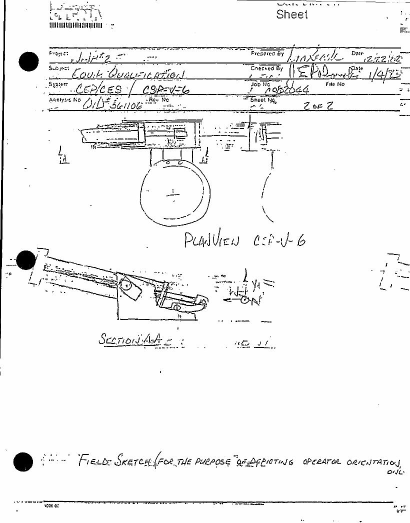
llllllllllllllllllllllllllllll
',.'~aies e "ei i ~ ~
Sheet
t'iepafec By,,< r J~, f(1)J.: i- —.
CheCe.ed By
DateI c.'-,'(. 7 't~Z-
Ae:salyeie tic /t /)g ~' ~ Re+ No~>(d<. '4kflo&" '...:-.- " Sheet tge
J Ott- Z
~mr=
('
i th
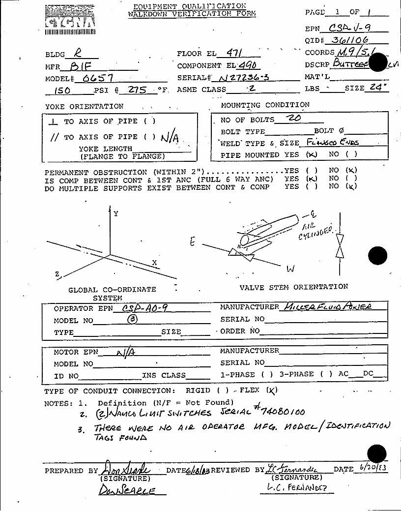
EQUIP?~iENT QUAL11 1 CATIOliWALKDOWN VERIFlCATION FORl I P) GE I OP~
llllllllllllllllllllllllllllll
BLDG
MiFR
MODELN 66 0(50 ISI 8 275'
YOKE ORIENTATION
TO AXIS OF PIPE ( )
TO AXIS OF PIPE ) )J/YOKE LENGTH(FLANGE TO FLANGE)
EPN Q9~ V'- 9OID:; Z //QbCOORDS
DSCRP &CtTTE&-FLOOR EL 47COMPONENT EL~SERIALS' MAT 'L
LBS - SIZE ZC1ASME CLASS Z
MOUNTING CONDITION
NO OF BOLTS
BOLT TYPE BOLT q)
WELD .TYPE 6 SI ZE Fc.~cb COLS
PIPE MOUNTED YES (~ NO ( )
PERl)(IANENT OBSTRUCTION (WITHIN 2")................YES ( ) NO (<)IS COMiP BETWEEN CONT S 1ST ANC (FULL 6 WAY ANC) YES (K) NO ( )
DO MULTIPLE SUPPORTS EXIST BETWEEN CONT & COMiP YES ( ) NO (g)
X
GLOBAL CO-ORDINATESY STEIN
VALVE STEMi ORIENTATION
OPERATOR EPN Qg~MiODEL NO 3
TYPE SIZE
MANUFACTURER
SERIAL NO
. ORDER NO
k.c ur
MOTOR EPM~MODEL NO
ID NO
MANUFACTURER
SERIAL NO
INS CLASS I-PHASE ( ) 3-PHASE ( ) AC DC
TYPE OF CONDUIT CONNECTION: RIGID ( ) ~ FLEX (g)NOTES: 1. Defipition (N/F = h'ot Found)
z. (z)v~<u, 4i(d(r sivir~es ««wc 14olosao
peed Mjenc A(o d ~u. ooed4rdk ArQ. pld&c.c /zodcriwcA-r.id'AG,S
Fdclv&
PREPARED BY(SIG ATURE)
JO.I)
DATE4~iREVIEWED BY C~~amdrcDATE .Sh> II(SIGNATURE)
t-.C, FeV~Wocp
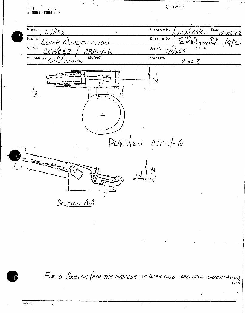
Ilail!ttiliilllll!illfllilili
~ ~ ~Ihi t
IyCfg~ Fil(- ted<

'. ra ~, A ~ s ~,
IIIIIIIIIIIIIIIIIIIIIIIIIIIIII
CalculationSheet
'rotect
/ ~zEgulk. OA<,
System
Prepared By.' Date
JobNo, „~ ~ FiteNo.l
Checked By: > g > Date
Analysis Ns.g~Q a~ .r~g Rsv. Na. Sheet No.
'20
l4~ t
AI ~I ~
~ < ~
Is'
d 0s
b,',
l
It./OI '"'A saJ
ss
QSP-C-i,Z. (-rqP )II-,qj)
l/~c a
A r
///p/y.i 'i/i'
'/'s:,j
j t."Sbt/'-l
PL A/ JSCK/(9'
t
r')L s
/
/
7 —CSEE. v'-/MP- v'-2
BEL l /Olj I//CNJ A-4
CVGMAATTACHASFNT
JOS NO.~t/~a
FILN NO ~a. O
sHssrNO. s ''s
/ /2s 6 SKoiol(FOR Ty/s'. y vodoss oF/AEF/sryyd& oo=o/IroR oR/Eydys/,lolJ oa/slyjs
I005 00

L C R ~ 6
llllllllllllllllllllllllllllll
BLDG R-MiFR
rloDf, 0 "20(& ~3
EQUIPMENT QUALIFICATIONVALKDOWN VERIF ICATION FORK&
FLOOR EL 5 I
COMPONENT EL ~SFSERIAL( 2 7 2. 3g - 3
PAGE 1 OF
ZPN< Ce, —V- l 8
OID~ '3 (.ll O
cooRDs ~.( S 'Ioscar 3o ' 8AT'LSh- S I(-- t'<
( 5 PSI 6 3'IO 'F
YOKE ORI ENTATION MOUNTING CONDZTZON
LBS Nl( SI EE QrD
ASl"E CLASS
To AXIS OF PIPE ( )
TO A>'ZS OF PIPE ( )
YOKE LENGTH , +~P(FLANGE To FLANGE)
No OF BOLTS ~%i
BQLT TYPE r /9 BQLT q) t fhWELD TYPE 6 SIZE
+IA'IPE
MOUNTED YES (~ No ( ) LQ(4 Q~
PERr'&ANENT OBSTRUCTION (WITHIN 2") YES ( ) NO ( ~IS COMP BETWEEN CONT & IST ANC. (FULL 6 WAY ANC) YES (g &(0 ( )DO MULTIPLE SUPPORTS EXIST BETWEEN CONT & COMP YES ( ) NO (+
AT7ACr<""AEN7
JOB NO. ~
Fll.E NO. 0S.ol. F
SHEc~ NO.~ ~X
$ Orr
'rr'LOBAL
CO-ORDINATESYSTEM
PERATOR EPri
oDEL r"oYPE SIZE
VALVE .STEM ORI
Eb'TATZor)'IANUFACTURER
S ERIAL No
ORDER No
ioTOR EPN
iODEL No
D No
Y~UFACTURER
SERIAL No
INS CLASS I PHASE ( ) I PHASE ( ) AC DC
CPfd's'- af g
ma~ la~4rai .. Ha ~ Co 3.mls
DATE~/ ~
/P PREPARED BY
COMMENTS: g L>~it 5 mskgQg Q„~g(4 8J: 4>salon
~ ER~ ) ok')ooD TER/lg//LREYI,WED BY
(S GNATURE) ( SI G &%A'ZU E )
T~ eWA!i6 L/A~

!
Illllllllllfllflllillilllillll
ELD,G
xFMODE QG5 +
PSI 6 3SO
YOYE ORIENTATION
E UZPMJ. l'".'UALZFiCA71ONNJ)J kiDO43'ER1 k ICATION FOr"
, .„,,FLOOR EL ~ j P
COMPONENT EL SSFSERIALS ZWQ i —
I
MOUNTING CONDITION
PAGE 3 OF
EPNt CE'-0- > Al
QZD> 34, t f'0
COORDS S 'iDSCRP 3O' 8~('lMAT'L SA -Sl~- MMLBS ~ f= SI ZE
AShiE CLASS
TO AXIS OF PIPE ( )
v/pTO AXZS OF PZPE ( )
YOk:E LENGTH P'/ 6(FLANGE TO FLANGE)
NO OF BOLTS
BOZ,T TYPE V A BOLT eVi'ELD TYPE & SIZEPZPE MOUNTED YES ( +) NO ( ) LL)X (I Tg S
PERlJiANENT OBSTRUCTION (WITHIN 2" ) YES ( ) NO ( )IS COl'.P B:"TWEEN CONT 6 1ST ANC. (FULL 6 WAY ANC) YES ( (6 NO ( )DO MULTIPLE SUPPORTS EXIST BETWEEN CONT & COMP YES ( g NO
CYQ)",4AA77ACHMENTJOS NO.
FILE NO. r6'SltrrT NO.
GLOBAL CO-ORDI NATESYSTEM
PERATOR EPN
ODEL NO
YPE SIZE
VALVE . S TEM ORIEUTATION
Y~UFACTURER
SERIAL NO
ORDER NO
JOTOP, EPN
.ODEL NO
D NO
hJANUFACTURER
SERIAL NO
INS CIASS 1-PHASE ( ) 3-PHASE ( ) AC DC
g o.~~ C 4-ls
Gfw: C( f-L~s-2*
( GNAT ~r.)
OMMENTS: Z L(~5 5( (Xc.L5
5~i.l 4: l rc Stoa'EA >SOrO>~O
& 9~frPREPARED BY 14 [ DATER/tM/grHEVIEWED BY
( S IGNATUREDATE

5.3 Valve Local Coordinate Systems
CSP-V-1
CSP-V-2

4RQpE&iQR
AT'™iACH~,ENJT
SCRAP-T
0 05 4~~ =.—~ 707...,
50S j~~ - Q
,,8O5 4~~ = -,d.7Q7
s
dos 4~g = 6.7d7
, 0458<z .=
cos 4~ —-d.7oq
8~E
~x4s
V

5. 5 REVISED BURNS 6 ROE
PIPING ANALYSIS ACCELERATIONS

QJ!,'>
i~ ~!!fear«> r,'„
Sub5ectx W. 0. 3900/4 000%lashing ton Public PowerN4P-2Qualification of Ncchant.'ounted Equipnent; ForvZnfoxma tion
Su ppl y S ye ter"..
ical Pipearding of
MAY 11 f983,.P
R f CEIQrFDI!|/Al '! J )f83
I' ~
CYGNA-RICHLggo '--:"-
~ I
April 29, 1983DNPP-83-07 6
!fr. L. T. HarroldAssistant DirectorWashington Public Powe3000 George VaohingtonRichland, Vashington 9
r Supply SystemMay
9352
~ g,
Attention: hlr. B. A. lfolmbc:rgr
References:
'„MQ+.o,i. '. ~ ~
%laic>
Gentlemen:
(a) >7PBR-03-17, Bated 3/16/93.{b) WPBP;S3-20, Gated 4/12/83.(c) MPHR-83-29, datod 4/12/83.
'(d) Te3.ecopy, B. A. Holmherg toJ. J. Vere>crber, dated 4/4/83
sos wo.~8p.c +0os.o{. FF!!.a!40.~
SHeET No. g.5, I
I /i
r
~ I
.,''C. W.rn, ~
i"..tg.!
'h
~ I
;, \
Xn response to the request of references (a) > (b), {c)and (d), this letter ia fcr:rarding rePined valve accelerations.The valve acceleration sheets for the five {5) CSP valvesrepresent the second iterati.on of the refincraent task.. Valve .',sheets for the other four {4) valves represent the firstiteration of the refinement task. - Please inform the Noodbury:.",.-Office if efforts should bc r.-ade to rer1uce accelerationsfurther.
~ I
+ei<~A;~:':>'-" O'JV/BPM/es:" i~i;;;j~:g,<-',! Att
Ve ry truly your s,
QR )caps twL ctCi.'I ED BY J. J. Vr2',DERSEP
John J. VerderberPro5ect Engineering Manager
~ ~
I
~ I
'~". A,~""r"
0:"'C:
Hr. >1. S. Chin - DPA — 3 ~r/1QHr. J. Z. Rhodes - VPPSS - 1 xr/l
P. Buck - E,"Pp"S - l ~./1 .'lail Drop ."'75

ATTACHE1ENT
Ak
Data forwarded with BRNP-83-078, dated April 29, 1983
Valve Kale. No.
SP-V-(~SP V-2 .~
CSP-V-3CSP-V-4CSP-V-5RCIC-V-31RHR-V-17BRHR-V-53AREER-,V-53B
125125125125125107312931
8. 148.148.148.148.148.148.148.148. 14
.129
.129
.129
.129
.129
.112A
..121~ 62C. 121B
CVGMAATTAChV~Eii-'7
JGB NG.
FILE NO.
SHEET IIG.

0
0Z
CI
0 tll
I I, I''"Q.
Bing
l@CV Jso JI/o, . /7Z::: ! ':AN.Nor.Gr,oufLII LIl.!
I 'I
I ~ ' I '. I 0I
0~z V
~ n,]00
1)) 4%
~J I
I-~'I ~
~ ~
Loc a ~/de~ I
~ II ~
I ~
r- ~
I
CoiJ JI7/orJ~I I
Gpss 7
e ~/el-a.+I OrdS / o. 3Cours c>P~~
0\
.I.o
~ I
~ ~ ~
i
~,I
. E/verjeacy
C Io<I I
~ ~ I
nI a-,I
O cnZ .<
'; ~ )
C, o,
II I
I~ ~ -,I

C ~I ~
II ! ~ ~~ ~
4 j ~
~ ~ ~ ~ ~ 4
~ ~
)~ t
0

0Zp p
V)
I 'E,
I'O
I C'0
'i
0 .0''+"LU'LU'~-~ x':
LI~
I
:.'„8 I R. +i/c A ....
8fg /@et? gio. AJo.
Ii
~ ~ E ! ~
~ ~
Ya/~e Q~~l Fc<fo>I j
t—l I r r
I"'IZ
: .'..'Abactor group ~25I EI
i '~ 'j !.
I .I
l
~ E
I VA,L~ ~
0z
0 nI
n)
I. '
I ~
'
I
l'oc a.~i'c zpaJa.lPP 4.
E I
..: i.... I
Opse 6
Ma.,ss. V)7,
((g CoiJ d)h 04:~ I
g..g/. ~ -/27
I ~
]1 ~
c c e.I ro+i oralCo/a+ c>6
p
0z
in
0
O "I
I . ~
Valve.-
Operatorgp g.CLAT
~ III
QC~~I'pi)'.II
RZ/.i
~ ~ I
E
I
I I ~
E
-Emerjeacy
—'Pct:u//c a'-
g/Esc. v;-~;.I: ' ~
E~~r'grec/—
I .i i
I
i..k& .
I I'I
-z'6-
Z-,gz-
-/-8C-
-/-, gd
C
0 p rrgpgjj~
~ ~ ~
E
~ ~ ~ I~ n~ ~
I IIEI
! i .i II
I
. ~ I ~
Ii
I ~ ii

.c ~4.'. -..., ~),,;- ~
\
p. Orn ~g z0
gtR pieB&R )1200
vo @I-Od~ gddI '<"- - "-.' Operation Z,D,"?ro.YgE'P 'I/'-2A'-"..,-~;.—"-'."-<o',jgl ~ 0 ~ ~ ~ ~ «0 ~
~: ~
X'gp ffo /~~ ~~ ~-< '--.'- '
. Anchor Group 'Z 3
Calo'o, .Z 8'~bn
~ ~
(
Valve hcceleration:!';,',:;I ...'-"-- -": '~ 6,': ( (:.:~~,,'( "-","'-' ' I,"-;f,''': ~ «(t ~ (» I~I
r»
c.tion»'
».~>.'; Ualve '-=
( . «», I».
HcdalP t. (low
f ~
~0
Bass 1)t.H (lb.)
+»»» ~ « ~ ~ .»»I»(
~ » \ ~ )» ~
,. ~ FX; FY.;»»
-.— FZ
-".-.'-— Upset
~« I
/sag
maggenqy~ e,
«P cf i»
(p»» \»
li)1~.'7
r~ «»
~"»
3or"P/,,/(I3 p«P 4»(;», ph$
»
»
Conditions .. Loads (lb.)1!ore.zon ta 1
F'H+" zH
Vert calEs'Yg i:)";
i.:/ .: Q g»i(
((»I »
Acceleration 1
4»';.; (»
« ~ »
44-'~f4. 2
(, '»r» ) ~ 4'/»»+ '(
:(=.8Q[g. f
Co~(en ts "'t»
~ » „,I
~ 0
Nl»Pl
»jIA)~ '(»(C
V, 1i
Jv~
'»»
»
,Faulted »,».'»»»
33/5 )/'//6.''l o"
I» i''.(»(»»/»g i»(
»»
.lva'rator~
~
,659-'~
~ ~ ~
~ ~
~ ~
~ ~
~ ~ ~
~ ~
Upset
I~ urgency
~ 0
Faulted
II /tu.,
n. nf
»'
~o5 /y~l
WP /sb2 II
. /.33
;.gg ogP;f «4-
:,:-'-:/;93-''(~+~1~» 'j~('( ~ L~
»
o, (
O
» fg~ ) ~
5g(.»'"
u~fjo4».
j~jf'»
» 4« f».
«(»I „» )(I
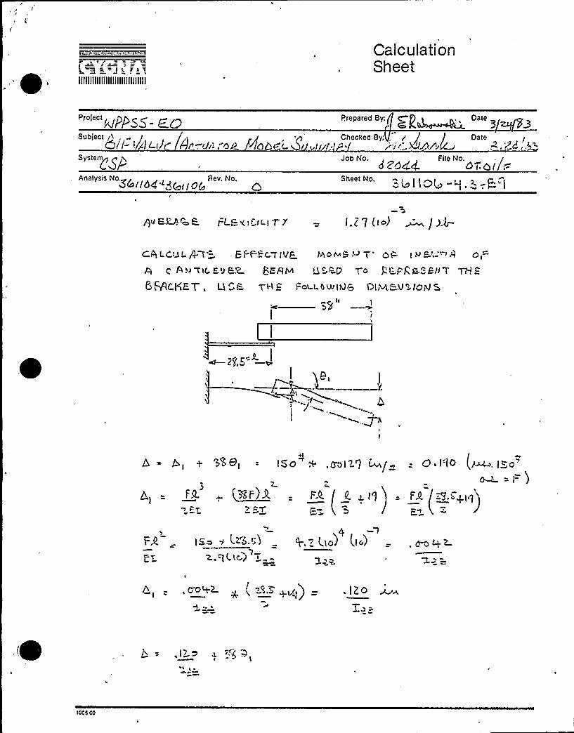
IIIIIIIIIIIIIIIIIIIIIIIIIIIIII
CalculationSheet
Prepared By: «P~~ DateBIO'- E.GSubject y«, - I Checked By g j J Date4/l- «i 1Lt t r«-,.bi,"Qg C)hd«5 „fuI..« '.System~gp
Analysis No. Rev, No.
'zd<4 " 'o-.oil~Sheet No.
I lO( 0%@ i
PV ERA ~t= l=L&<t-''-lT'7 — l.77 (tc«) ~ / 3.b-
ChLCVI.P f'- EI-F"-C.WIVQ Mc«t «-= '~ 7" Ot=
t: Au gt(. E«) E2 JERE Qc pD 7'o p6 I."gF "-E)l T TYING
/+Cga T, Q<l= 7H5 Fat t.bwtd& DIM,«=U- lO«V 5««
ID
,(~-~ I
+ 'N8, = ISa + .Coll'1 m
~F9. (%~tF 3t«
~ hb.t;3
(F.K I|. g I'f = FA,
F,~
19,Z I.la~ (,I.)
yyt -, yyDtP2. ~ y, t.B d.t ri) . IZo
.I) >
1000 00

CalculationSheet
Prepared By: Date3
Dateh'h (* r'"/4
aaedd 0 dl/.(='"""'I.»ab-~.-I=)Q
)Otta 00

IIIIIIIIIIIIIIIIIIIIIIIIIIIIII
CalculationSheet
P oiect PP,~~ Prepared By: Date
Subject /) ~ /, i i p Checked By JKdr' + l' /'70' D t=t'rll./l,'-'.c' ~d,e.>Jr.Da e
System~~@
3ai(~4 ".-3C link
Job No. +Fite No.
+ '~(I<Q4»9.+ -815
rot: Tp! c j (Jcgg.~ gL,<,u Ev T
tt
(MAICF- Q = o f F'iJT 277~ l5 reulV )
QgAc=~~ = ~5.G'(IS ~I..S )WE.tt'g = 'Q7 )f3
A,l - 4g = 0.'S9- IllC- = 4K+
.2 < Itl
( gsve )1~ I~~ htaS- W7I~')
'2.N IAI i.PPC F ~7'
)( io r. .r( t.~ ,~ )( .n(a .)( zss >~')( I~N)( 'tt2. IN )
Z u kA<I=
J-xx =
t 2.
|:FQ & ted& IM t."~i 0
3(o.~)((. =- )
I - .L~S-
o F jf9" t.<I= ~ pggt
.'005
00

IIIIIIIIIIIIIIIIIIIIIIIIIIIIII
CalculationSheet
~ jPP~% ~A Prepared By: tk g fzf ) 5 Date
Subject Checked By:Q Ji g r" j Date8,'ZF VA.ku=/P.ct-u6 tnP. Mn F'. 3l r~e~'!< ~ el C M~A"A'.=,<~f5".
System(\ q
Analysis No. Rev. No.'! Iln~ a)OIo
88644 Ot.at I=
34l l04- 9.5- 8',!
PEIVC. Po p ~~ L~i> p sL '.
PlgyaaCc ARE ~
Qo+I-L '.
5I
rg
c <
LSVr'+
.nfQtb gq ~)w1 >+A/
x
"l4cA)Qgg ~
(n
(to)Qz '5 c yL'.0>
+z. = l~~~. 14.o ((0)
Q'. Pr.we Wt:L = zJ~.5
Z.+A - TI/~ 9 = Z,klIP
~ Y'lS
I~y = X p--(5 'Iz P.ta )
(r~~")PGV s19 /t7 CS ~
Zyy = '1 0 ut ~ (!!9>)i.~~ = s- z iN i )~~+jr~)
A = p<g = so,3 iN (1g) =':,[z. i~c = u."(s)
10"s 00

CalculationSheet
Prepared 8y.' ~t t '.,') Date .Ii ~ )( 4kvAi"' /
Jabwo. oa+~4 FleNo. i/Sheet No.
Df<IYZ I!ol0
=TIP) hi~ CaaC& 5 VL~»iD
'I
i z''!w
1e06 CO

IIIIIIIIIIIIIIIIIIIIIIIIIIIIII
CalculationSheet
PPRPrepared By: )
Stjb't'e T
System~
I Checked By.iA v / ~ra.—,sj /n O~L upr;P'.Ls'!Job No.
2.Od.cf.
Date8,!Zd'h5
File No.Gt ~ col ~
Analysis No., Rev. No.44I/O", 8 ting@ >.Io I IC>4-',.3- l~ I 3,
~ARs: ~j = VA~~~ ~tz.IV o~~M~
j'a'r* ea r,
2.S
I. S"
(i.v<)e
Z,lps
- I,5 %2.5 g 4 = I- (J.JX
.X(J~;-~IA S:
It~ y('-~~ (' Tst'Ty.
X gg=
rsyce c
)10(i.SrSt»)8
l.1Z.(.(oI ~ ~ - Ti~a 4 P
,q z((0)~) gers'QO)
gI S.~St.to>
ej
Ixv I o4 %lO I 04 i(J
4.'RSlc( +
i.VZ q. IZS
C5g IV
tees 00

t~ ~j~JIIIIIIIIIIIIIIIIIIIIIIIIIIIIII
CalculationSheet
Project Prepared By:,' 'q Date
'tJ~l) ~Sub ect I hacked By: '/'
6 VAD/2 1 6 t 'gf~i I 'gp tv(rgb~ t ~U>pt'rf pledDate '.~
~ Z4 a3System n 52odh 0T,d I /~
3LllaR 8 )04 0 ~ " '4/134-~.>- $ 13
g Cggrg~g4e r
(i7QE, = Z I 0 IQ F~L
C y -- S.de 1/iQs.~
~EC.AUSE ot= Bfv~IPII" oF- >~<6 IH P o>e.
jy '6 lg 7 0 /IctoilAT. ( Illl5 vJIl9 Do
I=~ l~ I(+g„) " +err@'m
CELOcu/th) /Nest QS/K
~is,c= Q.z-~5
Y~~ =
IZ~Z'z. ~')Q.1
f'o L
~(h,c~ 7w ~~ J
T. = 7.9( )r'ac)'
r.s~)
10cs cc
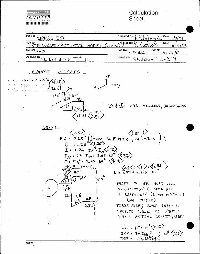
IIIIIIIIIIIIIIIIIIIIIIIIIIIIII
CalculationSheet
Projecttel t.NS
Prepared By: jt p it ~ . Date /„r,„Subject Checked By. ' / Date
'I 0} VE l C| 4A <C'I 0 r L ~«trttrAQ.'l . Jr'4';-ct- ."Irg ''.''s!""
System „
Analysis hto. Rev. No..5( I la I d I 4 6
bZD44 d t. 01 /t-'.;t >lgj - -! ='-(Big
I=tgt td!=„7
7,1~5~ 7
g8 I rg!I (g g f..'-.5 Vcr=- LF"==,,%~I~ ~lWs
(<I.l>3+g.o))
~sHAF
ri
gpss) (s )=(z.sr )- 7,(z5 ! Q,)i'<) -- Iq
+ SllJI.FtQe
i,q" 'II.S',
'-Ite
PIll = '2.2-5 Ir:~ !eIeFtlel.son l -'4 In~! „!zs .(I 2<)I .zr. rn = |>r(!'Iz)
gZ, - Il< Z„„= —..s~ I.o 88+)Vj
A=mt, ="=.qS N (
I00S 00
7.1 H~
g C.
q,OCjt ~f.,)H'l
5g!!IFq ~o ~C. =.at=7
P- f;=Fu=e~ 0tj q STIFF pJ g
= —r =.Pr c- D V (C .u.~ (":0 "
( p g =-,cr: -')
Jjl!IC /J
Italo(I:gCQ P P ~ I: 6,tgp Q p.~gQr'lr Lc,lJ ~~it
!!+=',78
ill (2'I )5'rY = 3+'E-'3 = g lI ~.g<)
.2( g.t1+.et>

APPENDIX C
SAMPLE HAND CALCULATIONS
TO CHECK PROGRAM
CEP-V-3A

~ y I 4 V \ ~
~ v 'I ~ N t ~: ~

nbi f Cc P V'-INPUT GLOBAL ACCELEPATI Ct l$
? 13.89,1.66,1.04It'lPUT ANGLES OF NORTH VECTOR
? 90,90,0INPUT ANGLES OF VERTICAL VECTOR
90 0 r90INPUT ANGl ES OF EAST VECTOR
? 0,90,90
I t lPUT DATA
CalculationSheet
Prepared By
Checked B
"" 'e.os@
Oate
5 RlOT:0 i(~=
GLOBAL G-LEVELS 13.89NORTH VECTOR ANGLES = 90VERTICAL VECTOR Al'lGLES= 90EAST VECTOR ANGLES = 0 90
1 '690
090
1.040
90
5C I Io(.-C -i
-5.29861E-5 -6.33239E-6-5.29861E-5 1.66
13 '9 -6.33239E-6
1.04-3.96728E-6-3.96728E-6
INPUT AtlGLES OF MEIGHT VECTOR? 90,180,90
LOCAL G-LEVELS
%Pl MPCE. CHECl< CALC 5
<A R TL.VSl<E H~ZE>5
TPF - (F T-e~)~V.~ -m> ~~.~—(tlS'o -age)+ bS: 27)~S Z>
'TgF 9031. ) tc --~~~~ I<~%
OPERATING DRIVE ROD STRESS AT AOPERATING DRIVE ROD STRESS AT BOPERATING CYLINDER BRG PRESSUREOPERATING VALVE EAR TENSILE STROPERATIl'lG VALVE EAR SHEAR STRESOPERATItlG EAR BOLT SHEAR STRESSOPERATING EAR BOLT TEllSILE STR
glc(i,j)= J=-S.29861E-5 ~1
fcdr = -1.22282E-2siga= -.267492si gb= —.409114Fc due to T3=-5.71181E-2-fii= 2.73638E-2f22=-5. 85968E-2ds a= . 071 5S2dsr= 3.3257E+7dbten= 4.86604E+9glc(i,j)= j=-6.33239E-6 2fcdr= -1.4614E-3siga= -3.19681E-2sigb= -4.88934E-2Fc due to T3= 321.752f 1 1 0' 43 (p)gg~ pAr E)f22= 33 . 082dsa= .072574dsr= 3.7607E+7dbten= 4.86759E+9glc(i,j)= j= 1.04 3fcdl = 240. 013s i ga= 5250 . 28s i qb=, 8029. 99Fc due to T3= 919 ~ 516f11=-440.516f22= 943.322Ac.a= 2 PSr'REF+7
10CO 00
F„= -.~>~T)F = -~+Fez. = l-i 4'3+T-F = Zdg
SNlr=f-"5'A t I~Sy .7> I+J~o>~7 (~5y t -'5
477.198821.458
-3.75613E-41136.5289.1706
'078.68
525.595
TC TqL t)NP EAR E.~5tt.r- ~ASS=f2I. t++fZ'll=.II%I vS~II37 '.Qg
Ctl Pc<@ p~'zri(u+ wvs) r, n» la-~=as
t5Ir
'(( 55: zs.z+ zn» I oqw<r)/~='7I9
= $ ZC PiT
Ml, due dc'uad tl»»dl~g= l~llakwr+-FST )pep
Q(/~d ~ r ~g259 - d.». I rZw (0 g lD':lZ.S
rd'l» $ du 8 ~ (tJ>flit = (~A<>+Jl r 7')y+'1.!,(4l4
+gee ~ ~~~ — 4>~ ~i.tg ~7.iz.~ c7i P5

IIIIIIIIIIIIIIIIIIIIIIIIIIIIII
CalculationSheet
'"'"'PP ss- E< Prepared By; / . Datec.- v 3wSubject Checked By: Date-c
(
System gyp'~pAnalysis No. Rev. No.
5 ZC44 'V.gI-Sheet No.
M I lob - -Z
CR KCK -X Q TEASDALE. O'T12$ )5 CALC 5:~ ~
— 154
4c 3ZX
t" = ZO Fc
-,4-It, ~ y~>o322
~~it VS~at12 8 + ~>2
4103
= /OHIO lr ~
gN Ec(<:Ftr., A2S.- lwgp ~o WIG ~ Nb~ ~cj2 ~q~~ +~ay ~~a+~ -.
~ I3 (I«c tII 2.@03 I 99+ I 4 + 3.5 + "12 « I '6 -5g4
ttQo 4-0 vs O'Dz-o a t
ChQCLg rove 5f t Sj:-Cg C.RSE
P(gh.0 ~gTD 5$ h$ Qtt E:Is L$ Cij '- c(Q
9 & g VANE F~l t [ifdptji16 Sr@.=.&5 (cHtpa A)i"-!iTS
BF, W 4i N t PI'4~7 Q j2$ +HhC.QQ LJVO~ ~gt~~I~tI )fik,top I~I) sic--ss Q.f c.(9 (.Ho t ": topi l )
Sot- T w&Huiog C.H-C'<~ (Vd T >! A) )
~l't iCM.
ICC0.00

SECTlON 5.0 QZDI 361106
APPENDICES
CONTENTS
5.1
5.2
5.3
—5-.4
5.5
Response Spectra
Walkdown Sheets
Valve Local Coordinate Systems
aces IP~ (go~ruisrRAriJw)
Final Pipe Mounted EquipmentResponse G-Levels
Revision 3

Response Spectra


C)C)
D..~ ~
C)C3
~ CD
C~tM ~n rD
LUj
la)(3~( ) ~
CL
>'3
C
I~ ~
l
I
l'I
l
~ ~
l
l
Il I I
I II l ~
II
II
I I
~ ~
'I
IlI
I
~ ~ I
I
II
l
~ ~
I~ . I ~
~ ~ ~ ~
I I
I
Qj llp 0
m rn Nftl
~OPI
a
r~ 11 rI ~
I ~
o.oo. 2o.oo uo.oo eo.no 8o.oo ioo.oo . i2o.oo ><to.oo ,
FREQUENCY (}IZ)IJf'f'SS BERCTCfR BLOG. SRSS CfF SRV SSE
Rf'/CHUG..'f]SS.
i'IO. 182 EL. 500 FT. HI3RIZ. TRANSt FITIQN. C5flfTflINf)EAT VESSEL OAHP ING= . 005, . 01, . 02.. 04
160.00

v ~

5.2 Walkdown Sheets

k ~

r; )UIPMENT QUA3 3FI CA TIO"hAL1:DO')iN VERI' CATIOl: 1'OR".
~ ravw a VI
'<Illllllilltllllllllllllllllll
>:ODf 9„„-&-A/'> PSI S 2r~
YOKE ORIENTATION
FLOOR EL )/;ICONPOh'= N"T EL~itSERIALS + i 3.~.
NOUNTINC CONDITION
C)IDII.,'.. l l '(-
~>l.. /Q,f-L )
DSCRP . + ~ c U'/.Lv /.
PgrTsL > ~g ( fLBS (/r" SIZE
>='S)'.E
CLASS A/rr
TO AXIS OF PIPE ( ~// TO AXIS OF PIPE ( Q
I g I(YOKE LENGTHEN - 2(FLANGE TO FLANGE)
NO OF BOLTS ~V~BOLT TYPE X,/J. BOLT r/ /fAVELD TYPE 6 SI ZE
PIPE 1:Ou.:TED YES(g-NO ( )
I' RY&NENT OBSTRUCTION (VITHIN 2 ") YES ( ) NO ( 4
, S CONP BETNEEN CONT 6 IST ANC (FULL 6 'IV~Y ANC} YES ( ) NO ( ) h'/F'rQ MULTIPLE SUPPORTS EXIST BETWEEN CO1'T 6 COMP YES ( ) NO ( ) t 'fF
g~r )/
GLOBAI, CO-ORDINATESYSTEM
SECS c-" pp~ <'-- Ii,'Sp t. f.Co<< r'>Z),~ t
VALVE STEM ORIENTATIOI):
ERATOR ZP1 &~am~»~~Dr.L NO
SIZE
OP. EPN + $ /6 /7d//0
1"D3'UFACTURER
SEPIA NO
ORDER NO
RA ~& Y~UFACTURER
ATTICH"";iS= ~)!:
JOB NO.BcLQ-FILE NO.CKC~~SHEEVWO.iM I
DEZ NO
NO INS CLASS
SERI',1 NO
I-PHASE ( ) 3-PHASE ( } AC DC
'"~NTS: Def inition (N/F = Not Founa)c'sP- ~ 4~-3
op pip~ jr~ +y+ &~~~'y~g~~ ~owy4 L&K 7u ~h~pp/AJPf~A'T,
.:P~ D BY/z 'ATE%/r'-, : RIEYVED .BY W K— DATE~~b'I(SIGNATURE) (SI N .TUFE)
'' /4.'f(,
) (b
&au Yl'I)C
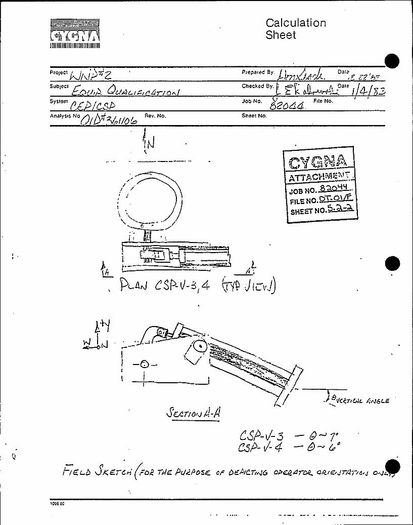
a.=='io, taIIIIIIIIIIIIIIIIIIIIIIIIIIIIII
CalculationSheet
"'""'k/t'ai+ ZSubtect ~ yy i, +UALyCy 4 ooSysteth p pAoelyseNog Q, ~i i y
Re.No.
I,)
Prepared By. ' Date-Jg<. 'i~J-., < Z7'i>".
'Ft. ~ter," . 4. $ .
'ZdddSheet No.
Q <g Pe,~ ~f!iPh~teeo P gist'rgb~ te
JQB HO.~~"„gLE NO.>~V.Ol
sHEEv No M~
cJ e
~I e I
Or
ZEKrlo'J/.-AVC(trPAL En/6(.8
/ tELb DKEy o~ (ioR ryrE Pv&osE of bEAc-«.Jc, ooQsroyL ooyE'Jri'ryo y o g$
1005 cc

IIIIIIIIIIIIIIIIIIIIIIIIIIIIII
CalculationSheet
ProspectWPPSS Mechanica1 E uiomenSubiect24" Butter+1v Valves
System
a P~ oPrepared Bv'ate
1
Job No File No,
Checked By. l I g DatezjrfiV~'-'-.
Anatvsrs No,361106
Rev. No. Sheet No.
I ~,, v
'A /


IIIIIIIIIIIIIIIIIIIIIIIIIIIIII
CalculationSheet
Rroreer Pg~g)~rr ZSubtect
F-Aij:b. Mc/A<("""P
Aoelye e No, Qyl+~ i @Rer. No.
J-llI;. ')y4'J- r:4ZrI <
Checked By:)
Date'I
Job ND. ~~Flic No.
Sheet No,
/ r'(
Iey
~ ~i /I
C+gjP P„tp4774CV. ftt'->'T
gas r]O.ERMAFILSNO.~T'«~sHEav xo.~>M
',:>'0 di~IJ)
04
r
I .I
i6<7/KlA-/-.
VCCriuC. Ci<6C.E.
t leo& ZKr r EAI (iform r lIE iylrlfroE " I4R 4yErr Jro OIAEErfyyAyr oyfrE jyAA4 4 oo JAyy)
1C06 Oc

I"') o!',III)I!(",(I!Illlli
"(.3U: Pl':ti . C)US.3.I F ICATIONX E.;i i I CATI 01'OFJ l
ERNE
I ~va J V!'
(c j-'(
BLDG /(,
KOD$ gab f}>D3C 5
FLOOR EL I (lCpl".PONENT EL ( 75SERIAL: 2R L36- l
QI D 3 ( l l 04.
COORDS R 3 l ~.3DSCRP 2'(" 6fLVMAT 'L
PSI g oF LBS
ASME CLASS
SiZE
}'OVE ORI ENTATIOl'P
AXIS OF PIPE ( )
// TO AXIS OF PIPE ( )
5'Ol:E L NGTH(FLANGE Tp FLANGE)
MOUNTING CONDI Tp pN
NP PF BOLTS
BOLT TY'PE
HELD TYPE & SIZEBOLT ql
PIPZ MOUNTED YES ( ) Np ( )
PERi~iANENT OBSTRUCTION (WITHIN 2 ") YES ( ) NO ( )IS COMP BETtsEEN CONT & 1ST ANC (FULL 6 NAY ANC) YES ( ) Np ( )DO MULTIPLE SUPPORTS EXIST BETNEEN CONT & COMP YES ( ) NO ( )
GLOBAL Cp-ORDINATESYSTEM
PZRATOR ZPN
iODEL NpYPZ
iOTOR EPN
~ODZL NP
SIZE
VALVE STEM ORIENTATIpl)',
MANUFACTURER
SERIAL Np
ORDER Np
MANUFACTURER
SERIAL Np
QW~~ ~ 3q p~
A77AC;- «1" t>„"g+) 1
JOB,'(O. ~O( 9F)L="NO.QTop /~SHE=-Y HO. ~>-(
ID NO IWS CIASc I-PHASE ( ) 3-PHASE ( ) AC DC
6~ IiS~a~l~SWCT(O~ gSDS,HIE.ZIS7)«. T.)«cCOMMENTS: Dcrinx~ioh'i/F = Bio~ FouTiP) ~ ~~ 'J4<'(J< ~4Th~ 5& gp<~~<Z
4 «(vc. lrt4 I 5'4 0 i «5 «5 VI+(/,~i /
PREPARED BY .~///zp . " 4 DATE -.~Ã REVIEWED BY 25 c)«( S IGNATURE ) (SI NYATURE)
i/s/6
DATE 9/I<
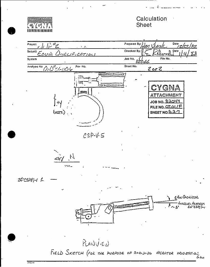
IIIIIIIIIIIIIIIIIIIIIIIIIIIIII
CalculationSheet
Pre~eee/
Suolec: J
6:Cubi'~ C~~iX'F~e8r o..Systelll
Checked By;
Job No. File No.
Analysis No A zygo: +, Rev No.(.jl/'~ //+BIe 'hl~
e
e eeeemereee ge
(.v~-) .,
Sheet No.Z bg'2
CVGÃAATTACHi'~RF i'i!7JOB NO.MQ~RLE NO.QT.picSHEET NO.S~+
Qcp ti'
'e
0 circ. Oi:c@370/2
4,~Q(~L &cd~~zc "esp),
i
,'.AIJ "~/ -„,(,I
I fE'L5 5KEe CEJ (rdE 'eiE&elSPd E de= e'd Je .JG ~~<V~™<OR d 6(e 4T4 i i Cd t
OJr y

ll.".:l)l.".'i):".l;.:!!l.'l:!!ill(
EQ'lzi .''.:.!'I QUALZFZ CAYZ Oti1; p~>>:Pi)'<;g'i V ~ !,Z. j CA. I 9.'OP„>'.
/<' F
B D("-
KFR
FLOOR EL
COMPO''ENT EL 9 (IO
COOM)S
oscar 2'(- Qk~~h11OD Ti > -gab>GS
rszSERI AL4 hU''L
LBS
AS1:E CLASS
SIKE
YOk:E'RZ Et A TATZOti
J TO FD:ZS OF PZPF ( )
// TD A>:IS O. PIPE ( )
YOE;: LEti'GTH(FLAt"GL TO FLANGE)
hiOUb'TING CONDZ TION
NO OF BOLTS
BOLT TYPE BOLTq'ELD
TYPE 6 SZ ZE
PIPE hiOUNTED YES ( } 1:O ( }
PER! LRNEtilT OBSTRUCTION (hITHIN 2 ") YES ( ) NO ( )
IS COtiP BET4'EEN CONT & 1ST ANC (FULL 6 WAY ANC) YES ( ) NO ( )
DO 1/!ULTIPLE SUPPORTS EXIST BETWEEN CONT & COYiP YES ( ) NO ( )
GLOBAL CO-ORDZ t~!ATESY STEYi
PERATOF. EPN
':ODEL t'0YPF
COTOR EP tiiODEL NO
D NO
SIZE
INS CLASS
VALVE STEY1 ORI ENTATZOt);
h~UFACTUREP
SERI AL NO
ORDER NO
Y~UFACTURER
CVG:; l~X!ATTACHMENT
'g
510.<~OFILE NO.~C)I. I/FSHEET hlO. &Uk
DC
SERIAL NO
I-PHASE ( ) 3-PHASE ( ) AC
DATE 9('t fz-COKA&tiTS: Defini tion '(tA'/F = Not Found)
('. 5 p - L r ~ - (. l, ~.4
fgg~7 DP (/)g~"~z/zz(gA< IT sl4I 4irDD d4~ ZQ~T4 Gh~<(- Wci'Zaa
PREPARED BY,'/~'w /i~ ~ .. DATk P - REVIEifED BY a
( S I Gi'AT D RE ) ( S iGt'ATUP, )
g/s/b3 9o~ l<uz..

IIIIIIIIIIIIIIIIIIIIIIIIIIIIII
CalculationSheet
Prolec:, l;'iJ'
x
Sub!eel -(ill-: &'uf> i ir eiof
Prepared By
Checked By
. /i DareJ'/lA ~ ". ~ r'2- ZR r"Z-
EE'0/c LSAnalysis No A 1"r,~+ Rev. No.
wVc Il0(o
Job No, File No.r
Shee! No.
~ g
A7TACH "~"',:Yr7
JOB NO. ~chO~IFILE NO.~OWO F
sHE~w No..h >M
"--~/ -«~~*~~~
«~O~l'j
~—.p f
lKLd /ger Q,g r % if'' PClg+C)5C Dr DCPidrigg dP'ZdATbQ. OgrggrA rra,gOrJr')
'IOQ6 0c

S.=-, 'j,.;c a,:i c',<lllllllllllllllllllllllllllll
BLDG
liFR Q ff-
NOD$ Q ~ +45PSI 6
YOKE ORIENTATION
EQU1 PMENT OUhl IF1 CAT1Ol'ALKDO'v'KVERI F1 CAT1 Ol'OR.'l
FLOOR EL f +I
CONPONENP EL~oSERIAL,
YiOUNTING COND IT1 ON
EPNf
PI Di 3Q 'l I 0(,.
COORDS Me l5'.I
DSCRP L "I " FL-'(
YiAT'LSIZE
ASl"iE CLASS
J TO AXIS OF PIPE ( )
// TO AXIS OF PIPE ( )
YOKE LENGTH(FLANGE TO FLANGE)
NO OF BOLTS
BOLT TYPE BOLT P
VELD TYPE a SIZEPI PZ >lOUNTED YES ( ) NO ( )
r
PERMANENT OBSTRUCTION (WITHIN 2 ") YES ( ) NO ( )
IS COMP BETWEEN CONT & 1ST ANC (FULL 6 NAY ANC) YES ( ) NO ( )DO MULTIPLE SUPPORTS EXIST BETWEEN CONT 6 COMP YES ( ) l'0 ( )
GLOBAL CO-ORDINATESYSTEM
PE PATOR EPN
~ODYL hoYPE
iOTOR EPN
SIZE
VALVE STEYi ORI ENTATIOK
YiANUFACTURER
SERIAL NO
ORDER NO
MANUFACTURER
ATTAC~I:83KNT
aOa WO.MQ~9PiL-NO.~iDl. i t
SsaSY Wo.~
lODEL NO
D NO INS CLASS
SERIAL NO
I-PHASE ( ) 3-PHASE ( ) AC DC
C0~1YiENTS: Definition '(N jF = Not Founc)
.< -/~ /s--„I
PPEPARED By ir.jul, . 8 r p, DAIEPI~P RE'KrIFN-ED(SI GNATURE)
BY(SIGKATURE)
Q,.q W.~
DATE ~lU~2.

illlf)llli!llllltll)llllllll)l
i u uii i;i t5 a t.luaal t i t '/5'2'J t.thV5ALk;DO';) VERIF 3 CATI0)'OR"'.
)w' g t', " /
-;.lit 5,
l
1
or clPOD'
PSI g 77> 'F
YOk'E ORI ENTATIOK
FLOOi; EL
COKPOilEl(T Ei,~~SERIAL;
MOUNTING CONDI TION
COORDS 4 ~ /: ft~~ i. l- Q'i~
A'SCRPi ., g,-5 '.',,:.,-'7)J T'1 -/t -~ ' =/' >i
LBS 4 /F-" SI ZEI
ASME CLASS 'r'./-.
J TO JD IS OF PIPE ( Q
TO AXIS OF PIPE ( 9/ ~g/ c
YOk;E LENGTH c.- - ',.™(FLANGE TO FLANGE)
NO OF BOLTS
BOLT TYPE / '~'OLT g.
KELD TYPE g cZZE
PIPE MOUNTED YES (~ 'n ( )
PERMi(iNENT OBSTRUCTION (WITHIN 2 ") YES ( ) NO ( QIS COMiP BETi>EEN CONT 6 1ST ANC (FULL 6 NAY ANC) YES ( Q NO ( )
DO MULTIPLE SUPPORTS EXIST BETWEEN CONT 6 COMP YES ( ) NO ( ~
GLOBAL CO-ORDINATESYSTEM
PERRTOR EPll +/AODEL NO
YPE
.')OTOR EPN h//
SI ZE
VALVE .STEMi ORIENTATION(
~~'F ~ C T URER
SERIF'. NO
ORDER NO
kiANUFACTURER
ATTACic L9.- tdT
JOB NO. GRQ~~
PiLERO.O~>» ~SHEET NO. ~+
'iODEL NO
D 4'O INS CLASS
SERIAL NO
3-PHASk ( ) 3-PHASE ( ) AC DC
CO! "<iENTS: Def inition '()i/F = Not Founa )
C EP- iuS-3Ag Q~ zdeez zo< z FoE o~g~g~g7/~/'
PREPARED BY g . r~ ATE'r, ZRZVIEl; ED BY(SIGNATURE)
ag,t<JTQT'Igg
(ci+G,.< TDR-.)
'L),„'7rv-
D%TE ~l 'I4

II!>tIII!IIIII!l!IIIIIII!llll!
CalculationSheet
p5, pr g. Ptlta' gp DateZ
C(gpskp
v AoCt>ec>'ec Bt, '
I / Datec. ~P'A< i '<'/8c
Svs'e".t sP
t>a,;s s t!o Rev No
Joo NoE)Z
St>eet No
F>le No,
tJJALI'; OWP
97,!. tJ ". g 0<'f.t.'A~.) f; O'- I> PZ/ "ted'.CEP —V" 3A ~~ 4R
c~f -u- ~A-
~~'V '~ M:5
Voa I >O.3QWMeILE No. ~O ~
~t'HEETNO.~
rn 0
P

4 M I illlllllillilllilillliiiii!3!l:
MFR $ T t-
NOD jssz g
1 LOUR
COh.'PONE!i"" EL i'l5u R5>SERik'- tJ PP
~ ~~ ~
C'2 a':
COORDS 'I'..5 IS.5DSCRP 2 'zgh~hT'L SA - 5 l( SIC -"liLss~d F szzs 2 'I "
ASME CLASS
5 ORE ORI EN ~' Ol
TO FDli S O. PIPE (
j/ro x>:z o.- ':rs (~)
YORE I EN.C- ".:: 0(FLANGE Ti l L2 NGE)
2'.OUNTihG COND'i Oh
hO OF BOLTS
BO' TYPE
Pr
BOLT g VAV;ELD TYPE 6 SIZE - 9 A
PIPE MOUNTED YES(~)'NO ( )
PEE~~iANENT OBS: i"'~TION (WITHIN 2" ) YES ( ) NO (
IS COMiP BETNE'ONT 6 1ST ANC (FULL 6 NAY ANC) YES ( ) HO ( )DO MULTIPLE Si." ORTS EXIST BE&a'iEEN CONT & C MP YES ( ) NO (
GLOBAL CO-OJ.:?:ATESYSTEh!
PERATOR EPN
'iODEL NO
'9s v
VALVE STEMi
ORIENTATIOY'ANUFACTURER
SERiAL NOpTTa m 'll, gl~
YPE
OTOR EPN
iODEL NO
D NO
Si ZE ORDER NOJps sp.BR099PlLE gO ~ I
SHRIFT RO.QW&l
DC
Y~UFACTURER
SERIAL NO
s ( ~ z-~ssss ~ ~ t
( S I GNATUR: )~lge i C'VC
COl&KNTS: Deg i ~i tiori (N/F = Not Founa)4 ~<8
jb ~ 5gp<7.Zo+ Z. CC 8 GDG24TDR, 0<(MVAlibd/
PREPARED BY r'... - '- »T-, '<'"( S GNATUFZ )
DATE ' >iltz

I ~
lllllllllllllllllilllll!Illlll
CalculationSheet
ProtectN 4t'5 Ec i<.
SobleCt
Preoa ec By ~ h 5ate2
Ctrectiec By ' /'i 5ate~l"'A< r 8 ZC'/SicSystem
csPAitatysrs No Rev No
Joe No52
Stree! No.
File No
cE( -J - ='.A .
C 'f o 't r i ill%»
ATTACH'"'s't=N7
JOB HO. WRGdMFILE NC.~~SHE TNO ~l I

5.3 Valve Local Coordinate Systems
CSP-V-3
CSP-V-4
CSP-V-5
CSP-V-6

~SR-i-s 4:-:~~., liN
'I
r AI4 Cy'6/~IGNI?
I&"l9PC)5= i g C.dez,'c
'I
prig-e~~ c~
p~ p>~> p ~r> y ~p~~+v'~lit /Y~
~~ Od rc c-r~lr~ / -'- CyS i ~/4
I . 4K=v
Ms@,«=.,O ~ @gz(
ecs @gal-,-. -l
gg 0
4,-,: ISo'5tg~g -/ .
8sE5gz= DI
8
fE
Bi~=a'g~
=9d.'rse.„.= /
~< >vs= <
0~5vs= Q
g„:-. ><a.8~t [gQ piQ
0~7''gL'$7;0.$M

l.
Csf-- /- >
~d, /li(4Dp~w i dg
f-Qib ~zP
RF')(E~> «PC,r'~/ '
~:
~ +la 0 Fg™ht~ <(///$>
8„~ =4Z~/z.',„=
4>i."
e,„= 5c'"3
SAA~7
Q~s 8<, - d.731
Gas <z= Q.( 7g
ebs 8<q=
f+kdSPOSC Td C.dCA4YS( <,v/
o„P
., =4'l/z.'=
(Bl<dos 4~i-
~~z= c)~~7
Cosd~= 5
QOSqg = Q
<~S&vz= Q
eas4g, = I
l
r'$
oslo ~S
.-I~=.~o.CKc~~~S~~"
~ hO.M

~) C'
~ I I I)P.
kvI
l.c <4- ~/-5 . -rFgcb Ig/, ~,.'.'. > !
Rs'~s~u g".;
8u-,—,<g„-<y
8,g~=9d'0$ 4~g-
8~$ 4~z=
&S4~g = I
"'(~~i
4~a=O'e~=
~D'ds4~~=
CdZ4gp = /Cc)S~cz
~a4~(
gb
~~z=~~'DS 4pg = /
eS 4~)=0~as 4,-,- C)
&vz 1~V
)epehpgy)%$ 4)$]»
JoQ '36. Gko+9...FILE i;0 OT~j/f=SHE% biQ.MM

IIIIIIIIIIIIIIIIIIIIIIIIIIIIII
CalculationSheet
Project
Subject&IF ul"'ter-:. j~«t. Et- 8 IC
Systemc.~ F
Prepared By: 5 ~ r ': Date
Checked By: Date
Job No. File No,Q Z™t+f QT 0/ /g
Analysis No.".4I IO4
Rev. No.0
Sheet No.
C EI'-v- 4P
W sir~N~r
2.
ANGLE S
PGIc rH
VE RV IC Ai
EA-T%E,I GH7
( I-h~ t>)cl ()
goiso'lo
(z-A.>Lt5)
3$
lo
(--~,g2
l HZ.9o
C'i'G:i"jAw I I Aci"Tr"w"tP.&IT
JOB i'io.~t ~~
«ILC SO. Soli%rl 0
10cs 00

5.5 Final Pipe-Mounted EquipmentResponse G-Levels

MAY | I i983:-
y Syster..
'ipeof
Nechanical X
ForwardingIAHf > g j'jr33
CYC"NA-RICI-;Logo;::,.I
~ I
1 ''I~ N
April 29, 1983DRifP-83-07 0
I
~ ., '@~i"
> iI~'«
, ~ Ily System A~@,OH<Dr.i'd%
JO B HO. ~~
FILEI40.~gp. oi, r-
EHEET IIO.IIr. B. A. kfolmberg
~5'4 ~i
Subject~ R. 0. 3900/4000Washington Public Power SunplWt)P-2Qualification of?|ounted Equipnent
'nformation:<c '.,
!ir. L. T. HarroldAssistant Director
""'r'-.p'~'~'.~i.."Washington Public Po~<er Supp.."-s=.",.;.:",9'r -" 3000 George Washington May
Pichland, Washington 99352
:"i'-", . ". References:vP cq~ ~
''F,,'E r$N'r
Gentlemens
(a) WPBR-03-17, dated 3/16/8 3 .(b) WPBR-83-20, dated 4/12/83.(c) f&HR-83-29, dated 4/12/83.(d) Telecopy, B. A. Holmberg to
J. J. Verderber, dated 4/4/03;Ih
0 ~
Xn response to the request of references (a), (b), (c)and (d), this letter io fcr:rarding refined valve accelerations.The valve acceleration sheets for the five (~) CSP valves
".j'';:a".~,,". ~ represent the second iteration of the refinement task.. Valve .',~<'!>;'~",'~,, sheets for the other four (4) valves represent the first'-:".„'jji",~c.';g.",;.;. iteration of the ref inc@rent task. Please inform the Woodhury
.'.",.'fficeif efforts should be r."+de to rec1uce accelerationsfurth r
Very truly yours,
ORIG,~„L SIC~rICO GY 3 3 ~r~DEASEP
i Ebi
~ I ~ I
John J. VerderberProject Fngineering Manager
CC: Hr. W. S. Chin — BPA — 1 r/1QHr. J. 7.'. Rhodes - WPPSS — 1 ~;/1
p. Buck - 5"Ep<S - 1 ~./1 ~tai3. f>rop ~r75

ATTACHMENT
Data forwarded with BRWP-83-078, dated April 29, 1983
Valve I Kale. No.
CSP-V-1CSP-V-2CSP-V-3CSP-V-4CSP-V-5RCXC-V-31RHR-V-17BRHR-V-53ARHR-V-53B
125'25
125125125107312931
8. 148. 148.148. 148.148.148.148.148.14
. 129
.129
.129
.129
.129
.112A
..121
.62C
.121B

0
020c
0 III
t
lQ
xV
( '(~ Ve
~ ~
; Bgg NZCV Iso rile,
~ I ~
l .' I
I'~(~e. ac.l ~i'c<fo4
~ I
/ZX
!g 0Z,
00%
Q)0 e
Ce/I,
Loc a >i'~g
~I I
~ ~ j ~ I ~
e ..I ~
I . ~ I
'' de~I
'
~ ~ '
/Coiii~c>7>
C~
Z
a0z
I 5.I 'I~ X'
~ ~
I.~r // I ~ .
cVpzg 7
—~3z-
~ I
'He
I I ~
II \ ~
Pa./pe .
O/ rcPor~ '. I
(~
+gq
~ ~
O mC
. ~ g o
I"I I ~ ~ I
~ .I.
I~
~ I II: !
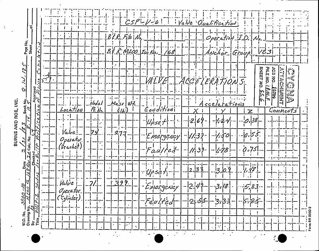
a I
~ w - ~ ~ !a i; '
I I i~ I
Ii i j Qgf a
r
I } } i I I, ': I
'd.l/8 }QO~/r1iC~7 2CrA
I I II~ ~
II
0
0zo oo
0 CO
j I'
. —I.- I:- 'I-~ !
Isq8 f at'aPJ2CU
a
a a op~ia I
. ~ I
~ !I Jr I
0
ill0
zl0
IO
Qo ~)0
~ ~ ~ ~I
I
j M~sI (i/g i
I a
i
Co~ J Aa~j
!'~
c c Kfa.j d.+I'o45
CO W C
X P ('1Injn u„, In
LZ000
0
(p briIP ~
~/p a.»)p
Cornel eel a
O
ZD
0z
oqwo
~ r
Opeiak.r(i"ra.cher)
Ia
Cj Igr,'P I')
!Vv'pf<ld/:
(
-7y
a
X7
.99
! ~ ~ aI; j I
Er)78(g8a y
~ ~ I
a
i iI
c9
ij."Isis,NCg-
~a I- I I
t ~
~ a
~ .a
II a
M ~
a
II ~ a
4» f fI,, Ia
a
a
a
a
O caa
Z .<o
>Odll
!a
I
a~ ~
a
cv
oa K~ gaa
'
~ '

QZDg 361106
7.0 TRANSMITTAL, PREOR CALCULATlONS
AND REPORTS
CONTENTS
7.1
7.2
7.3
7.4
Communication Reports
Old Requalification and SQRT Forms
BIF Report: Dynamic Torque Calculationsof Butterfly Valve (Excerpt) *
McPherson Associates Report:Design and Sei'smic Analysisof 24" Cylinder-OperatedButterfly Valve. (Excerpt) *
*NOTE 1See Cygna Energy Services Project File; "EquipmentSeismic and Hydrodynamic for 24" Cylinder OperatedButterfly Valves", File No. OT.Ol.F,'XDS 361106,Revision 3, June, 1983 for complete report.
Revision 3


6.0 Drawings

QID=: 361106
DRAWINGS SUBi~fITTED TO SUPPLY SYSTEM
IN ORIGINAL PACKAGE
Johnson Controls
D-220-0310-IR-64 Rev 0
Flick-Reedy Corp
C-"26096 Rev 0
BIFD-207110-H Rev B
D-207110-G
A-206767
Rev A
Rev C
Bovee 6 CrailCSP-807-8.10
CSP-809-1.2
CEP-625-3.4
Rev 4
Rev 4
Rev 6
CEP-625-1.2 Rev 3
~ ~

oZ
~ ~ Cl
~ cV cC/l
J''
~
I. ("I=I(
-~ QlO'
I7
7 Z lLI
x'
~
I ~
. Y~l~e Q~~l z.c.<Poa
Fi/q du. E~) . 68-00:-'DoP1. ' 'j eJ.a-lip/(j .d.D,. A. '.l~j-
NZCV ISO AlO . /7Z:.:, ~ "Fl&.CA(Ir:G(Ouf /Z..FI.
I ~' I; ~ '. ' ' '
i ~ -'~ ~
VALVE .Ae/.F/~PAXio~s~ I 'I
4 II
OXZ wI
Coc a ~/OAJ
yoga.lPP 4.
i'~ass Vfv', (ca.l ref ire 'I o. JC o/~Pi cD7"D
(()
z
Q
0
( ~ ~ III
g 7 (
'--Ergdrg8acp'
Q~ w
'(I
~ h
~ (II
II
pa./pe ...djeir /dr
CCg!J':~~r),I
I~ . I I
/ll-
(I I
~ I~ ~ I
I
II.~;
I(> 4g
j(g 7tI S 'I
I
I
Ewargr ~cy-
,z .(=~ g . CI0 eo
Rom
~
)
'II
i~
'I

I ~ ~
~ I
0
0
gCI
a. co
I
I ':- tP Iri
-Q.
lI
.'pss Sj/e 4y. DIJ, 6$ -I
~~ I
Bgg JtrJ2CV .Joo..A/o.
I I ~ I
cs j' Y-2~ ~ ~ ~ - ~ ~
Va.lee 'Qc, /'8'C.<Po'>
00-.600g t 'pzp 2 4 S,D../4.,I f.. jJ
/7Z .: ', ' Au&!or &/-os ~ZWII ~ ~
II CO ~I
I ~ ~
0z r00
CP
o~4I
I ~
L oc a.~sd4Pea/.PP d..
I
4 os Ji7 l orJ
.I
Gybe f-
I
1
C c <I.et-W+J c rdS
I--'5 72-'—
ICor~ra car>
p ~
0'v
O
ZPP ~
. Er~8/g8acp'I
~ ~
~ I I ~
~ ~
~ ~
! 'I
'I. PJ I
~ ~ I
~algidr~dpi .70.
QC@liihr).I
—P,"0Earner'ye Nay-'I~8Dl. -"-
O'
g CI0 !C~ I
! ~Ia ~
~~
I~
)f ~ 't
- ~--—I I
~ ~~ „~ ~
! >~ ~
~.: .I
. jI'

t
Qp P - p'- QA Pd.lu'e Ooa.l.'Fi'c<fio4~ s s
0Z3 O
Ms
I
ratI st
st
ts s
. I
'wcActr.,:GrojuI
~ ~
0C))0
O )s ~
-- .I-I
II
s
~ I I s
ss ~
~ ~ ~
t
o zZOg
IOIoc a-+/Wl
Pong.lPv,
1 ~t
cc c ltL c+I Dtss J r 3Cot~+ caPS
CC
A
Z 0zO
OO~ w
Io~
V~lua'tcro./or
.3g
I'
~ ~ ~
~ ~
Is s
~ ~
s
s
~ '
I
l
I
I ~
gPSs..8I
Eooarg~n)cpt
i . I
O. 73
dr fd
~s
t
I
0zO OsZ .5
~ Q O0 O40mi-
f))
PI I.IIlsI ~ ~
G~,$ < p0
UI
'
I-'s!
s II
l
s
s
I
s
Is
CC
0IS

CE -V- 3A y~ Jie Qua/ f'c<p,o> .
~ I
A Fi/a d.,I r
) 'IF g Az45':Jso A(q.. /4 F
~ I 'I
I~ ~
-"I r
.'per H's Z.D. 4.I iI = ~ ~ ~ ~
,'ADor crau/ rzSI
II
I~ ~
~ r ~
II
I
I !I a
~ I
II
I ~
I I
. VC/LVE 'C'r-EEEIA7JOS5
~ I~
I
0Z
oXS
ca
0
Loca 4idAJ
poJa,/PP g),.
M~s')i'a.
Cod
Jailanal
II
c c C.lata.+a .oddCorntni II6
0
'0
C IIl
Vg/ye8o Jy....
V /~a:d acra.Tor
~~
I
~ I
g,gpI
I I I.I..
I .I, r ~ .I l i
'
I a
I i
I i iI
Llpsr. 6
E~g/geacp
Faaf g'e
J'/oSa
8
I
8,08: .
- 0,:70
:d,78'.z<
o, rd;.:
oft'
P
~ I
0
O OIZ .<
0 aW o ca
rr Q~figal Ia y
a
T$
I
i! ~ III
/-Z6I ~I
o.g

QIDN 361106
7.1 Communication Reports a Correspondence

it 1

llllllllllllllllllllllllllllll
CommunicationsReport
Company:
Project:
Subject:
CBS'elecon 0 Conference Report
Job No.
Date: f3
Time:
Participants:
jl- tUK I AC. StOQ5
4-gb-
Place: g g~
of C
CP p-
Item
z./ tot
Comments
F+ j
Req'd Action 8y
5iF .VA4VE FL AQ &6 Pie&,N sion s
4 'gtc,~~l. d.e). cL.
25
Z.iz.S
'5l
~815
l ~/g ( ~) ( r(g (z.V)
ATTACHMENTJO8 HO.SIilLENO. ~+.SH"=Bi NO.~7' I
Signed:
Distribution:
Page of

Washington Public Power Supply SystemP.Q. Boy.968 3030Georae Washington Way Richland, SVashtnoton 99352 (509) 372-5000
December 17, 1982GE-02-RWH-82-018
Cygna Energy Services141 Battery StreetSuite 400San Francisco, CA 94111
Attention: Hr. T. Wittig, Project thanager
Subject: NUCLEAR PROJECT 2CONTRACT C-0892
'l
Investigation of the CSB and CEB systems shows that during a dynamicevent the systems are not degraded in any way by the butterfly valvesfluttering. Therefore, all work on Work Release Nos. 14 and 17 whichaddress valve stability should be terminated.
R. W. Hickman - 575Senior Engineer,Equipment qualification
RWH/sms
cc: F. Khanachet, Cygna Richland
R ECElVEDL'=Can j982
CYG«'A-RICHLAND
Joe ~O.~™FILENO.~slRET No'

IIIIIIIIIIIIIIIIIIIIIIIIIIIIII
CommunicationsReport
CR-030
company: CES
Project:WPPSS
X3 Teiecon O Conierence Report
82044
7 29 82Subject: Time: 9:40 A.M.
Participants:
/ID 361110 - 18" BUTTERFLY VALVE
Dick Hickman
Hal Reeser
R 'DAOI Supply System
oi CES, SDAO
ot
Comments Req'd Action By
I called Dick re. dynamic instability of BIF valve while inopen position. I also requested permission to contact GE re.use of aulted or upset allowables for RHR valves'
Dick said we should complete the requalification analysisof the valves and flag the dynamic instability issue as aseparate subject that will require Supply System actionfor resolution.
o Supply System has granted a contract to BIF for operabilitystudies on their valves. The contract admistrator at BIFis John McDonald (401/885-1000). Our action should be todetermine the scope of the BIF study and to make certainthat we do not overlap our efforts with theirs. Also weshouId attempt to assure~hat our work does not conflictwith the BIF effort.
o Dick said we may contact GE direct. Our contact at GE forthe decision on faulted or upset allowables is: ArianDeVault (408/925-2208).
*ACTION: Rajan, this resolution should be documented viarevised criteria in our Project Manual.
H. Abolhoda
MD Rajan*
pTT qCI;MEINT
IO™0FILE HO. DT.rst F
SHEET NC. f.I.T
H. Reeser Page 1-oi 1
"'" ""'"'. Wittia, H. Abolhoda, F. Khanachet, P. Guglielmo, B. Schla fer, M. Rajan,
J. Minichiello, P. Patel, Project Files (SD), (SF), (RB)

IIIIIIIIIIIIIIIIIIIIIIIIIIIIII
CommunicationsReportCR-027
Company:
Project:
sttbject:
WPPSS
XI Telecon
Time: P.M ~
0 Conference Report
sob wo 92OQ6
Date: 7/20/82
Participants:
APPLICABILITY OF HYDRODYNAMIC LOADS
W. SchlaferH. Reeser
Piece: SDAO
of CES, SDAO
CES, RBOof
of
Item Comments Req'd Action By
2.
3.
The Hydrodynamic Load Column in the WPPSS SRM list is knownto have errors. A "non listing is not to be trusted.
For packages in analysis Cygna will trace down the P 8 ID todetermine the applicability of hydrodynamic loads to linemounted equipment.
To accomplish this, Cygna will:Al
a. Check the line routing to.see if it penetrates theprimary containment. If not, hydrodynamic loads donot apply. Rt.E
SHEb. If the line penetrates the primary. containment, hydro-
dynamic loads will apply unless:
1. An anchor point appears first in that line, or
2. The line first connects with floor mounted equipmentoutside the, primary containment and it is sufficientlysturdy to eliminate the propagation of pipe linehydrodynamic loads beyond it.
GNAACHM:-H
"I'.
fuff rI.
O. op.o i. I-
NO.Z.I~
If a line mounted equipment fails to qualify due to hydro-dynamic loads, estimate it's fragility level. This informa-tion will be used by WPPSS when they receive the 8 8 R finalpiping analysis and examine actual pipe accelerations.
WS/sak
W. Schlafer Page of
1020.00
L. Kammerzell, J. Read, P. Guglielmino, J. Minichiello, P. Patel, M. Rajan,
H. Abolhoda,~RE~ P. Curry, H. Reeser, T. Wittig, F. Khanachet

l j s j
IIIIIIIIIIIIIIIIIIIIIIIIIIIIII
CommunicationsReportCR-027
Company: CES Telecon 0 Conference Report
project:
Subject:
Participants:
WPPSS
APPLICABILITY OF HYDRODYNAMIC LOADS
Job No.
Date:
Time:
Place:
of
of
of
Item Comments Req'd Action By
5. For packages whose analysis is complete and where hydrodynamicloads were not considered because the SRM said nNou:
a. Review the line as in 3 (first page of this tel'econ).
b. If we feel hydrodynamic loads really do apply; send amemo to the S. S. indicating the package may need'revfork.
c. Send memo to F. Khanachet requesting supply system con-currence that hydro loads do apply and added analysis isrequired.
p "t'gP CH
„iOB«.~V'r.~I ~ fFas« ~
~gFP~ ho.~
signed: W. Schl a ferDistribution:
1020 00
Page of

IIIIIIIIIIIIIIIIIIIIIIIIIIIIII
CommunicationsReport
CR-023
Company:
project:
Subject:
Participants:
WPPSS
Hydrodynamic Loads
g) Telecon
J. Minnachiello
0 Conference Report
82046
Jul 20 1982Time:
g A~San Dieao
of F
of
of
Item . Comments Req'd Action By
2.
3.
During the conversation we discussed the following:
If attenuation data on hydrodynamic loads are not available,one does not have any choice but to take into account hydro-dynamic loads on all line mounted equipments.
One should use 1.5X peak acceleration unless the systemfrequency (line plus equipment) indicates otherwise.
If the equipment satisfies the allowable stress limits, thenone should perform fatigue analysis using the fatigue designcurves given for Class 1 components. To calculate thefatigue damage for normal operation (excluding all dynamicevents) one might take a conservative approach by assumingthe calculated stresses are equal to the allowable stresslimits.
fr f(» B 's >~
>T I,~CH;»~H.r
JO2 BO.~r~rn.a No.
~~~~'~-=-
vo ~~I~
signed: P. K. Patel Page 1 of
Distribution: H. Reeser, L~~AueR> Rajan, H. Abolhoda, P. Curry1020 00

-'IFJuly 7, 1982 CYGAA
Sygna Energy Service225 Stevens StreetSolana Beach, CA 92075
Attention: Mr. "Bill" Schlafer
.IOB XO. ~~<<PILE VQ 0 o( C
SHEET HO.~~ ~ I
I V
Subject: Butterfly Valves for NuclearApplications with IEEE QualificationRequirements
Dear Sir:This information is provided in response to your recent phonecall.l. Enclosed please find some catalog information describingBIF's line of butterfly valves, including our current
models as well as our new Model 0668 design (which willshortly replace our 0652 and 0658 models).2. The following are our best estimates for bud et, our oses
~onl of what it would cost to replace the valves and oper-ators originally furnished to WPPSS in the 1970's (whichdid not require IEEE qualifications) with valves and oper-ators that are fully qualified to IEEE-382-1972, IEEE-323-1971 and IEEE-344-1975
't
is almost impossible to obtain prices from IEEE quali iedactuator vendors without a detailed specification showingexactly what is required; therefore, these are our bestguestimates of what the replacements would cost. Theycould be high or low by 10 to 20$ , depending upon thewording used in the engineer's resultant specification.Replacements for Valves Furnished Ori inall on N-27232
14 — 18" BV's with electric oper-ators (See NODS — ll/1/79) $ 40,000 ea. if qty.
or $ 25,000 ea. if qty.Re lacements for Valves Furnished'Ori inall on N-27233
2 — 18" BV's with spring to ~o encylinder operators
$ 60,000 ea. if qty.or q45,000 ea. if qty.
", 600 OIVISION ROAD ~ WEST WARWICK,RI 02893 ~ BOX 21 7 ~ ~01.885.1000CABLE:BIFWRWKRI ~ TWX 710.382 0402 ~ ELFX 827 631

Sygna Energy ServiceJuly 7, 1982Page 2
Replacements for Valves Furnished Ori inall on N-27234
4 — 30" BV's with spring to close $ 75,000 ea. if sty.cylinder operators or 660,000 ea. if qty.
Replacements for Valves Furnished Ori inall on N-27235
4 — 24" BV' with spring to close $ 60,000 ea. if sty.cylinder operators or 550,000 ea. if qty.Re lacements for Valves Furnished Ori inall on N-27236
3 — 24" BV's with spring to ~o encylinder operators
$ 60,000 ea. if sty.or $ 50,000 ea. if sty.
Ne trust that this information will be of some help to you, andare sorry that our prices cannot be more precise.Sincerely,
eorge E. SayerBV Sales Applications Engineer
Enclosures: 650.20-4BPD-668-45-1BPD-668-1NODS-1 1 /1 /7 9
ATTACH[.hler„"MY
JOB BO.f2oqg'ILE
FIG. or sI pBHB:T FIG. I 5
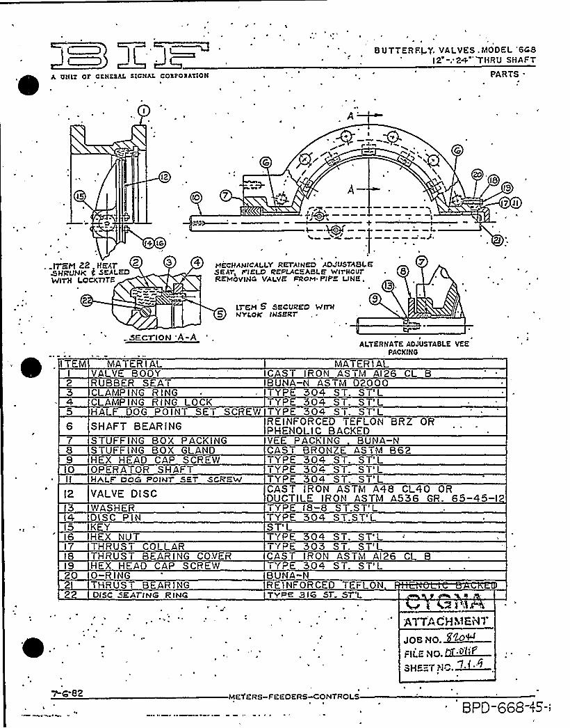
A ottt: or cattaaat. stcam coaaoaaztott
BUTTERFI Q, VALVES.MODEL '6C8l2 .'2+ THRU SHAFT
PARTS .
a
I2
'
7 II
+ IS
ITEM 22 IIEET 2 3SHRUNK f. SEALEDWITII LOCKTITE
WECHANCZLLV RrraIHED ADJuSTABLESEAl
~IIELD IRREPLACEABLE WITHCUT . 8
REHovWG VALVE mom PIPE LWE.3 ~
tT EM 5 SECURED WITH5 wvLott IHsetar
IO
I2
l4l5l6l7I8
20
22
..SECT ION A-A
'ATERIALVALVE BODYRUBBER SEATCLAMP I NG R I NGCLAMP ING R ING LOCKHALF DOG POINT SET SCREW
SHAFT BEARINGSTUFFING BOX PACKINGSTUFFING BOX GLANDHFX HEAD CAP SCREWOPERATOR SHAFTHAt F DOG POIhll SET SCREW
YALYE DISCWASHERDISC P INKEYHEX NUTTHRUST COLLARTHRUST BEAR ING COVERHEX HEAD CAP SCREW0-R INGTHRUST BEAR INGDISC SEATING RING
ALTERNATE AOJUSTABLE VEEPACKING
MATER I ALCAST IRON ASTM AI26 CL BBUNA-N ASTM 02000TYPE 304 ST. ST'LTYPE 304 ST. ST'LTYPE 304 ST. ST'LREINFORCED TEFLON BRZ ORPHENOLIC BACKEDVEE P ACKING BUNA-NCAST BRONZE ASTM B62TYPE 304 ST. ST'TYPE 304 ST. ST'LTYPE 304 ST.- ST'LCAST IRON ASTM A48 CL40 ORDUCTILE I RON ASTM A536 GR. 65-45-12TYPE I8-8 ST.ST'LTYPE 304 ST.ST'LST'LTYPE 304 ST. ST'LTYPE 303 ST. ST'LCAST IRON AS Tidal AI26 CL BTYPE 304 ST. ST'LBUNA-NRE I NFOR CED TEFLONTYPE 3IG ST ST'L
AlTACHMEI~T
7-r-82 METERS-FEEOERS~ONTROI S
BPD 668 rS-l

A UNIT OF GENERAL SIGNALITEM 5 SECURED
5 WITH NYLOKINSERT
2
AWWA BUTTERFLY VALVESMODEL 0668 30" THRU l20
~
'~ PARTS
7
19
l2
15
05 aI
XKZXlLTHRUST ADJUST-
MENT PARTS"
l3 6II
MECHANICALLY RETAINED ADJUSTABLE SEATF I ELD R EP LACEABLE WlTH OUTR EMO V I N G VALVE FR OM P I P ELINE
ITEM 27 HEAT SHRUNKAND SEALED WITH LOCKTITE
czuuLJLa'(FOR 30'HRU 48'.V) 'FOR 54'HRU l20'.V;)'
TEM MATER I ALI VALVE BODY2 RUBBER SEAT3 CLAMP ING R ING.4 CLAMP I NG R ING LOCK5 HALF DOG POINT SET SCREW6 SHAFT BEARING7 STUFF IN G BOX P ACKING8 STUFFING BOX GLAND9 HEX HEAD CAP SCREWIO OPERATOR SH P,.=TII STU HA T
l2 VALVE DISC'3 WASHERI4 DISC P INI5 KEYl6 HEX. NUTl7 THRUST COLLARI8 THRUST BEARING'OVERI9 HEX HEAD CAP SC EW20 0-R I NG2I THRUST BEAR ING22 THRUST ADJUSTING SCREW23 JAM NUT
MATERIALCAS T I RON AS Tidal Al26 CL BBUNA-iV AS TiVI 02000 ~
TYPE 304 ST. ST'LTYPE 304 ST. ST'LTYPE 304 .ST. ST'LREIN ORCED TEFLON BRZ ORPHENOLIC BACKEDVEE P ACK I NG BUiVA-NCAST BRONZE ASTi'A B62TYPE 304 ST: ST'LTYPE 304 ST. ST'LTYPE 304 ST. ST'LGAST IRON ASTM A48 CL40 ORDUCTILE IROI'I ASTiil A536 GR. 65-45-12TYPE l8-8 ST.ST'LTYPE 304 ST.ST'LST'LTYPE 304 ST. ST'LTYPE 303 ST. ST'LCAST IRON ASTM AI26 CL BTYPE 304 ST. ST'LBUNA-NP. E I NFOR CED TEFLON P HENOL I C B ACKEDTYPE 304 ST. ST'LTYPE 304 ST. ST'L
24 THRUST BEAR ING PLATE25 SEAL26 HEX HEAD CAP SCREW27 SEATING EDGF
STEEL ASTM A36S ILICOI'IE RUBBERT'(PE 304 ST. ST'L
'(PE 3I6 ST.ST'LJO
Ml %1»
I-I5-82 MEYERS-FEEDERS~ONTROLS
Fll.gag ~o7. ~SiiE~,'i0.7'I:lo.
SPD-668-I

LIMtrpttpuz
(~i,i j,,:~>' 1. /
'
k~<. ~~,:., ',":;,sMaPL %ha~
LIMITORQUE CORPORATION ~ P. O. BOX 11318 ~ LYNCHBURG, VIRGINIA 24506
/ .>y
'
IEEE 323 (1974) and IEEE 382 (1972)NUCLEAR QUAUFICATIONDATAFOR SAFETY RELATED SERVICE
THREE PHASE ONLY D.C.
Design Life
Ambient Temperature(Continuous)
Ambient Humidity
Aging
Total Radiation(40 yrs, Integrated)
SeismicRof: IEEE344
Nuclear Containment(See Option 8 Price Adders)
40 years (2000 cycles)
140'F
60.100%
Motor Stator only180'C tor 100 hours
2.04x10'ads
"6.0 g's (SMB/SB)" 3.0 g's (SMB/HBC)""6.0 g's (SMB/HBC)
~ ~ ~
~ ~ ~ ~
Outside Containment(Standard Prices) t t40 years (2000
cycles)'20'F
30 100%
Entire Unit165'F for 200 hours at100% relative humidity
2x10'ads
6.0 g's (SMB/SB)3.0 g's (SMB/HBC)6.0 g's (SMB/HBC)
Containment-Inside or Outside(See Option 8 Price Adders)
40 years (2000cycles)'20'F
30.100%
Motor Armature, Field'oils, 8, Brush Box only180'C for 100 hours
1.0x10'ads
t6.0 g's (SMB/SB)" '3.0 g's (SMB/HBC)" 6.0 g's (SMB/HBC)
'mber of transients
I'ransient Temperature
Test Humidity
Profile
Length ot Test
Completed Test Date
340'F (BWR)300'F (PWR)
100% (saturated)
PWR/IEEE382 73,Page 12, Table 1
BWR/IEEE382.73,Page 12, Table 2
30 Days
PWR-September 1974(600456)BWR-September 1972(6000376)
250'F
100% (saturated)
ANSI (yot to be published)
15 Days
February 1975(600461)
340'F
100% (saturat
Special
25 Hours
October 31, 19(80009)
)~77ACHK~E~t 7
'During BWR test, 500 cycles Wore used as a design life per IEEE382,
During PWR test, 2000 cycles were used as a design lite of which 500 wore Incorporated prior to test and 1500 atter test.
During test for outside containment, 200 cycles were Incorporated while the actuators were being aged, and 1800 wereadded prior to Irradiating.
During D.C. test, all 2000 cycles were Incorporated prior to frradlatlng.
"As of 7/26/75, seismic tests were completed to IEEE344-1975 for both SMB and SB units to 6.0 g's vertical and 3.2 g'shOrizontal. Since no cross coupling was noted between axes, the test qualities the SMB/SB to 6.0 g's In both vertical andhorizontal axis. Maximum g level dwells ln each of the three axes qualify the units tor any mounting position. (SeismicQualification Report No. 80021). Qualification extends through 35 Hz.
t tStandard Class-8" insulated motors only.
"Standard units without spur attachments.
""Standard units with seismic support bracket and without spur attachments.
NOTE: SMC.04 and SMC 05 actuators are qualified for -Outside Containment" service per above levels based on theirsimilarity to the SMB actuator.
NODS ~ 11/'I/79
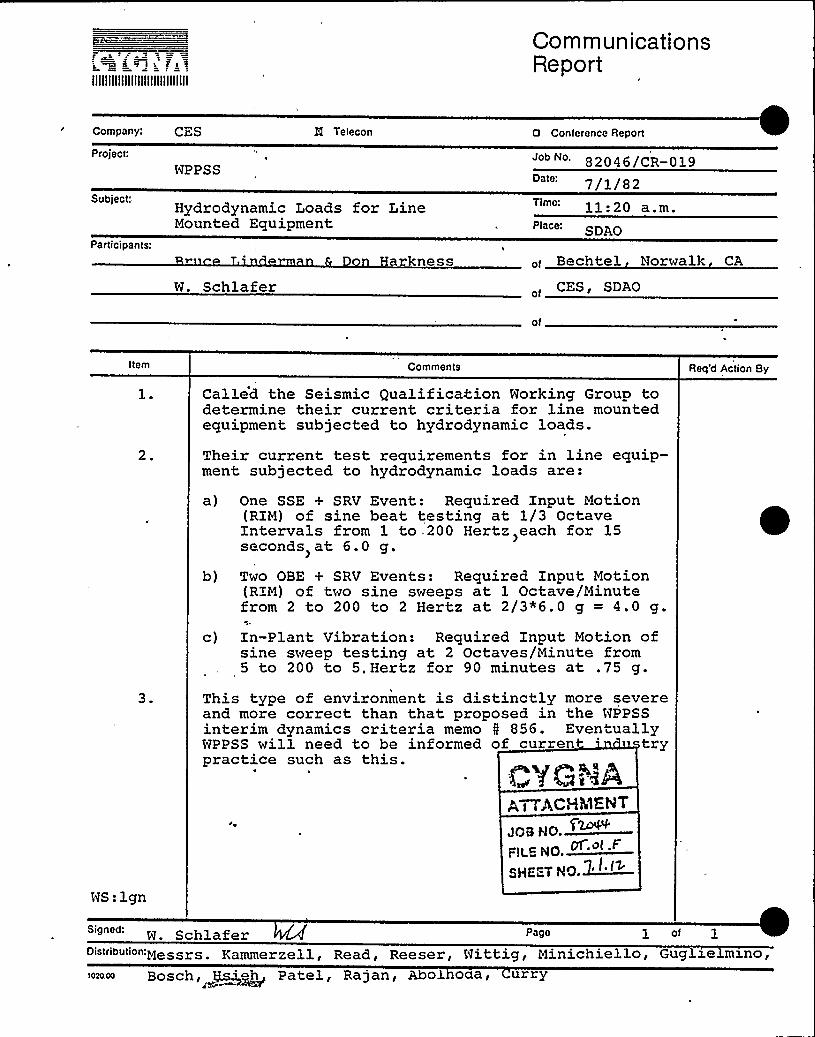
IIIIIIIIIIIIIIIIIIIIIIIIIIIIII
CommunicationsReport
Company: CES
Project:
WPPSS
M Telecon 0 Conference Report
82046/CR-019Date: 7/] /8
Subject.'articipants:
W. SchlaferHarkness
Hydrodynamic Loads for LineMounted Equipment
Time:
SDAO
of Bechtel Norwalk CA
CESi SDAO
of
Item Comments
Callid the Seismic Qualification Working Group todetermine their current criteria for line mountedequipment subjected to hydrodynamic loads.
Req'd Action By
2. Their current test requirements for in line equip-ment subjected to hydrodynamic loads are:
a) One SSE + SRV Event: Required Input Motion(RIM) of sine beat testing at 1/3 OctaveIntervals from 1 to .200 Hertz >each for 15seconds at 6.0 g.
b) Two OBE + SRV Events: Required Input Motion(RIM) of two sine sweeps at 1 Octave/Minutefrom 2 to 200 to 2 Hertz at 2/3*6.0 g = 4.0 g.
c) In-Plant Vibration: Required Input Motion ofsine sweep testing at 2 Octaves/Minute from5 to 200 to 5„Hertz for 90 minutes at .75 g.
3. This type of environment is distinctly more severeand more correct than that proposed in the NPPSSinterim dynamics criteria memo 5 856. EventuallyWPPSS will need to be informed of curren 'rypractice such as this.
WS:lgn
ACHMENT
JOB NO.
FiLS NO. Df.o(.F
SHE"-T NO.~I'~
W. Schlafer Page 1 of 1'"" "" "Messrs. Eammerzell, Read, Reeser, Nittig, Minichiello, Guglz.elms.no,
Bosch, ~~eh Patel, Ra jan, Abol oaa r urry

IIIIIIIIIIIIIIIIIIIIIIIIIIIIII
CommunicationsReport
Company: CES
Project:
WPPSS
i5 Telecon 0 Conference Report
Job No 82046/CR-018Date: 6/29/82
Subject:
Participants:
EQ of BIF Butterfly ValvesQID 361104, 361106
John Henry
12205Place: SDAO
of
John Henry Associatesof
of
Item Comments Req'd Action By
Called John Henry because he was the engineer whoapproved the original seismic calculations for BIFButterfly Valves.
2.
3.
His recollection of these analyses was vague butdid mention they, as consulting engineers, nevertried to assure operability. Operability wasthe manufacturer's responsibility.
\
He recommended testing a similar valve.
g, I, ACHI~.EElA~ !
JQS NO.
SS.=- HO.~>."SHEET NO.
BS:lgnSigned Bill Schlafer Page 1 of
1020.00
L. Eammerzell, J. Read, H. Abolhoda, 222~gsj~~ P. Patel, P. Curry
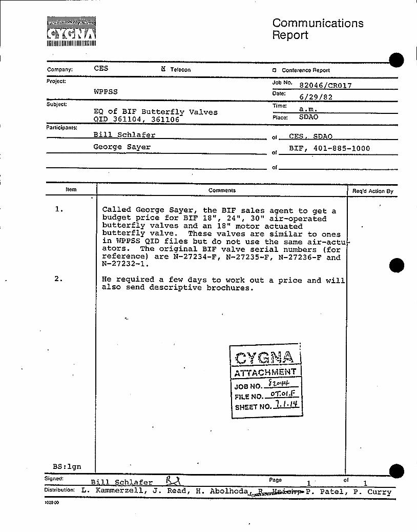
2 r
IIIIIIIIIIIIIIIIIIIIIIIIIIIIII
CommunicationsReport
Company:
Project:
CES
NPPSS
tK Telecon 0 Conference Report
82046 CR017
6/29/82Subject:
Participants:
EQ of BIF Butterfly ValvesQID 361104, 361106
Bill SchlaferGeorge Sayer
Time: a.m.Place: SDAO
of CES S
BIF, 401-885-1000of
of
Item Comments Req'd Action By
Called George Sayer, the BIF sales agent to get abudget price for BIF 18", 24nr 30" air-operatedbutterfly valves and an 18" motor actuatedbutterfly valve. These valves are similar to onesin WPPSS QID files but do not use the same air-actuators. The original BIF valve serial numbers (forreference) are N-27234-F, N-27235-F, N-27236-F andN-27232-1.
2. He required a few days to work out a price and willalso send descriptive brochures.
C vG ~g 'Q
.q"pAr HMb MT
JOB HO )go~FlLs NO. Oyo(.F
SH=aV NO.~I
BS:lgn
Bill Schlafer Page1
of
P. Patel, P. Curry1020 00

IIIIIIIIIIIIIIIIIIIIIIIIIIIIII
CommunicationsReport
Company:
Project:
CES
WPPSS
H Teiecon o Conference Report
82046/CR016Date: 6/29/82
EQ of BXF Butterfly Valves QID 761104,361106 Piace: SDAO
'Bill SchlaferAllan Berger
CES, SDAOof
BIF 401-885-1000of
of'tem
Comments Req'd Action By
Called Allan Berger, a BIF engineer, to gettechnical drawings for the 18", 24" and 30" air-operated butterfly valve actuators.
2. Requested drawings of Miller air cylinders showingdetails ofa) Cylinder dimensionsb) Piston dimensionsc) Rod/piston connections
3. Conversation indicated
BS:lgn
a) There is a bearing and seal around the pistonrod where it exits the cylinder
b) The piston rod fits through a clearance hole inthe, piston and is bolted on.
c) No seismic functional tests have been done onthe Miller air cylinder
d) For dimensional data to verify functionaloperability of the motor actuated valve, con-tact Limitorque in Lynchburg, Vir
Q~/GNA,.~T-,„;gHMENT
JOB NO.~r
fargo~
pf'.ol.FrlLP. FIO.
GHEKT NO. ZL
Bill Schlafer Page 1 of 1
Distribution;
10t0 00
L. Kammerzell, J. Read, H. Abolhoda~"H+Xe , P. Patel, P. Curr
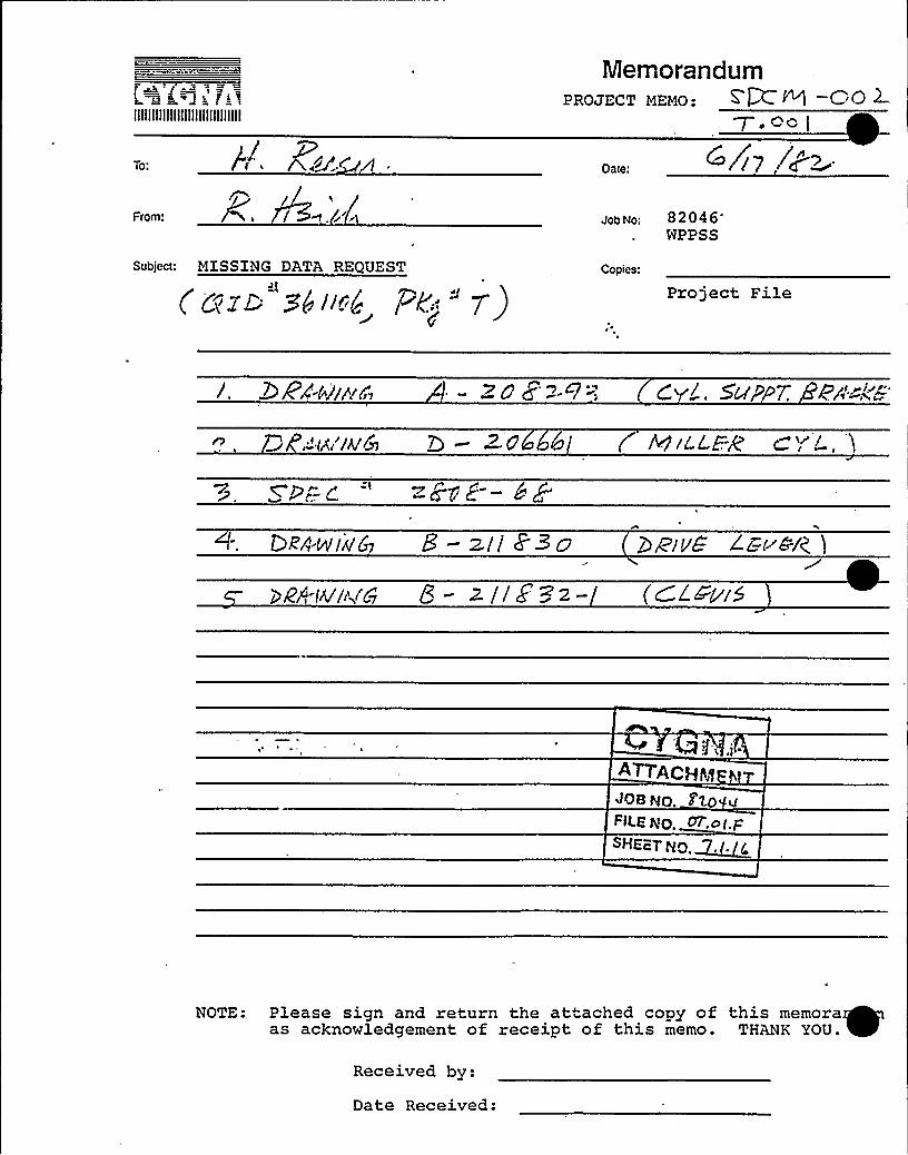
IIIIIIIIIIIIIIIIIIIIIIIIIIIIII
To: gg/ C
MemorandumPROJECT MEMO: ~P
~.Oc (
Oate:
From:
Subject: MISSING DATA REQUEST
Job No: 82046NPPSS
Copies:
Project File
0 gA'-~~///zr,' /.Sup7;
,-'/f/A/6 > g 6I ( Q/ZL.Eg
lORA-w/A& 8- z.l/ Z3o vg 2 E(~PI(
yN-w'/,rC~ 8 - > t'/ ~ - ~- (ClPp/5
tI,,I .
JOB tqpFIl.E tqO. 0T',o(.F:
SHEc=.T gO ~~~(
NOTE: Please sign and return the attached copy of this memora~as acknowledgement of receipt of this memo. THANK YOU. ~
Received by:
Date Received:

Memorandum
IIIIIIIIIIIIIIIIIIIIIIIIIIIIII
To:P . Gugl ielminoJ . Nin ich iello>,
June 17 , 19 8 2
W. Schlafer, PZ.'atel 82046/SDM-003
Subject:Analysis for Operabil tyT+>t HgEpT
JOB NO.~~or~I I:
FiLKRO.~gHEEY NQ.
opies: L. KammerzellJ. ReadH. ReeserG. Shipway (Wyle)T. WittigProject File
ln order to assess operability by analysis of mechanicalequipment which can be modelled to correctly predict itsstress and deformation responses 'relevant to operation,the following criteria are to be considered in conjunc-tion with Section 3.E.1 of the Design Criteria.If an equipment in Group II is expected to perform duringthe seismic and/or hydrodynamic event then the followingrequirements shall be met:
I
(1) Elastic displacement calculations shall be performedto assure non-interference between mating parts, and
(2) The calculated stresses shall be within theallowable stress limits.
If the calculated stresses for any service loading aresuch that permanent deformations might have occurred dueto high allowable stress limits, a displacement analysisas in (3) shall be performed.
(3) A comprehensive elastic-plastic analysis should beconducted in these cases to assure non-interferencebetween between mating parts.
For an equipment in Group I which is expected to operateafter the seismic and/or hydrodynamic event then thefollowing requirements shall be met:
(4) Total stresses in the part must be limited to ayield strength of the material, OR
'(5) Satisfy the requirements of Group II equipment.
WS:lgn

s =sir
IIIIIIIIIIIIIIIIIIIIIIIIIIIIII
CommunicationsReport
Company:
Project:
Subject:
WPPSS
Wyle Data Bank
8 Telecon 0 Conference Report
82046/CR-014Date 6/16/82Time: a.m.Place:
ParticiPants: W. Schla fer
G. Shipway
CES, SDAOof
Wyle, Norcoof'f
Item Comments Req'd Action By
Asked George to initiate a search in their testingdata bank for seismic or seismic/hydrodynamictests on BIF 18", 24" it; 30" Butterfly Valves. G ~ Shipway
2. These valves are in QID files 361106 and 361104.
3. George is skeptical test data exists for thosebutterfly valves experiencing the extended fre-quency range of the hydrodynamic event.
P.TT AC'r'hi=I"
'S:lgn
Signed:
Distribution:W.Schlafer Page of
L. Eammerzell, J. Read, H. A o o a, . see, roy ect: 3.J.e

4 4 C J I cllllllllj!I!ill!!!!Illllllll
;:-"; EC '.-I V",= D
gfJI'1 fy d
tr is~P I"tI'~l f ',t -( -"
CommunicationsReport (~~~ e~™~
CompanyI r nw Itiv1 > Telecon 0 Conference Report
Profe !~ ~ ~ Job No.kauipfttent Seismic/Hydrodynamic Requalifi- '2044
r gati 6./1 5/8 2Subject Interim Dynamic Loads C
Pwticit o riParticipants'
r ro man
Jim Foreman
4
JoBNo~FiLE
No.~~'ime
1 1 00
Richland Office
of n
Nyle Laboratoriesof
of
Item Comments
Joe Braverman of Burns and Roe was contacted bytelephone on June '15, 1982 to get a clarificationon the subject criteria for use in the Requalifi-cation of Equipment for Seismic and Hydrodynamiceffects.
Rep'd Action By
Joe concurred that the accel eration va1 ues shown inthe table of the attachment to the conference notewere intended to be used for rigid line mountedcomponents only and not for flexible components.i.e., those having natural frequencies below thecutoff frequency. To be consistent with B6R re-commendation for qualification of line mountedcomponents by test would indicate that for the anaysis of flexible line mounted components a staticload would be applied at the C.G. of the extendedstructure equal to theamplification factor for sinsusoida1 motion at a justifiabl e damping value.For example, for an SSE condition the amplifica-tion at 3tt damping would be 50 divided by 3 = 16-7This loading may be in some cases present a veryconservative loading on the line mounted componentA somewhat more realistic input motion would be
Signed: Page1
"3
Distribtition'tandard Di ~tri hut i on rfg ol @~et ~ . «tc~ . <Et r~f

llfillllllllllllllllllllllllll
CommunicationsReport
Company: Cy<na/Qlyl e Telecon
ProjectEquipment Seismic/HydrodynamicReaualification
Subject'nterim Dynamic Loads Criteria andFatiaue Criteria
D Conference Report
Job No. 820446/15/8211:00
Place: Richland Of jceParticipants."
Joe Braverman O'Yof Burns and Roe
Item
Jim F A~ACHig~<~tj7 of ta V T
dOB No, r'logeof
C .~OI.8H FT Xr .f.
Req'd Action By
continuous sine beats of 12-15 ocsillations perbeat as recommended by the IEEE-382 draft "Ameri-can Standard of Safety Related Valve Actuators".The amplif'ication for a 15 oscillation sine beatat resonance for 3K damping is approximately 11.5.
If the static loadings given above show an over-stressed condition or deflections which wouldcause operational malfunction, the alternative todevelop a more realistic approach would be to per-form in. situ testing from which the data could beused to develop response spectra at valve locationThe in-situ tests would allow the determination
of the natural frequencies and mode shapes ofa sufficient part of the piping system along withthe valve and extended structure to validate themathematical models used to generate responsespectra'at the valve location and/or componentlocations on the extended structure. The responsespectra at component locations allow direct com-parisons with component test data. It is feltthat a combined test and analysis would be a feas-ible and cost effective approach.
Signed.' xi''tandard Distribution
1020 00
Page of

c~ c. s t. i cc s t F
llllllllllllllllllllllllllllll
&Ull I I I I Uj j jf 'ct L(uj jS
Report
D Conference ReportTeleconComPanyCyqna/Ny1 eProfect Job No. 82Q44
Eouipment Seismic/Hydrodynamic Reauali- Date; 6/15/82cSubject Ff,
Interim Dynamic Loads Criteria andFatigue Criteria
Time.. 11 - PP
Pfttce'i ch1 and OfficePanicipants:
Joe Braverman , Burns and Roe
Jim Foreman « 4 le Laboratories
of
Item Comments Rett'd Action By
Burns and Roe is checking to see if fatigue cri-teria have been developed for b7Ãp-2 and will noti-fy Cygna/Nyle not later than June 17, 1982 if such
criteria exists. CYGNE»A
ATTACHiM~~AIT
coo NO.QQ~«FILE NQ.
SHEET NO.
Signed: +~~
Distribution:
'c:tanya-.d Distribution1020 00
Pege ol
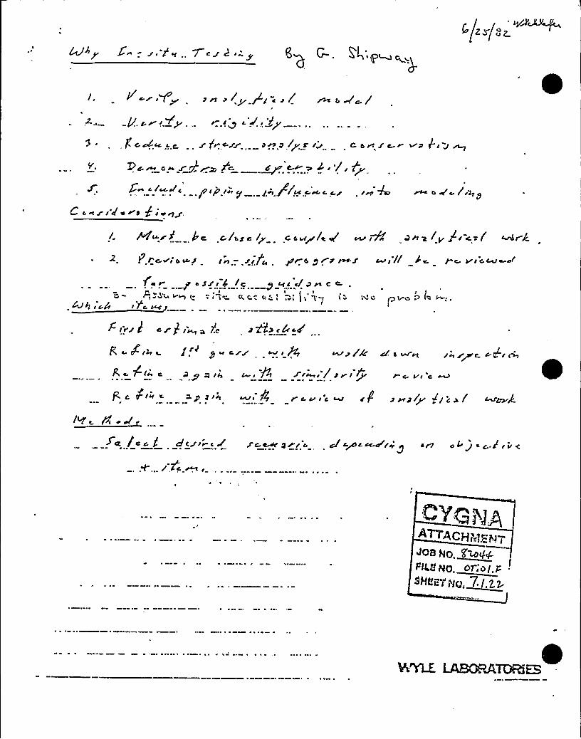
I//-.,/ ~ g,g
/J >r.Yp r I< c'J', 'r'y
fc./cc cc zPr~ir ~~~)y r Iz c e~ ic r vu Pr z ~5yI Pan OSZJZ> JC ~4 ~W ~r /r lyS. 5 c/~4c PIP I > I~/ f~ ~~~ ~ I~ A r c V /'r
C 4~iI'der~ f'ga/ PKQrVP kc 5/bye /p C cad(et'/t iN/ &IW,~+i /y 8I +,~/
P. rc.~r o u-S In ".,ir./I pre pe S mg wr// C< p c Vrca
~ osJ'I4 /I p kc c/C.c e'- i
%f4 r cd
C~
C
Q ~+~ ) jQl
~ IV/ 3 C W) l~ ~ AC g Qi,4 c/
Zr~,//prI ~~
cf 4 w rt err g~c. > PC I+ II"c.vr c
C (Irr a ap pre r v 'c ~ zf zap(y ~/cw/
fC /cia dCr.ref g rr 'o cI c~ c cc-c r ~ y ~ n o>g cP v~
/ 2c ~ r
>~ACHUPP)7
VcYiE LABQRAIZ65EB

~p cr Fur f( c fc,o g pr cAxur c
l ( flic ) P/c pl cc ., + j z~p o I Pe Pb 9c<Pt) f zysi<piZj r<
P)rp wc Pcvg c paao $ ~4 @ccrc)ggf~g
e P(c j o / g4 g Pp~~ ~cft~v ~ r t >. ) c c-u E.Z g4-
4p/l>p'o fNarc.g rd> k>~. /0 )4f gV~+~on/ ger cygne g jq'» yr r gui"vo-4 ] b ~c.ri7p
z cc ah 4lc. spew'z h c ~w.
Pc Qc/ ptr ww e 0 Nr- cf' r u c c c ri 7 cubi e Ps@ cp o.r)

S c C&crroZ5~ cC
PILr. NO. ~< OI P>HEEi NQ. ~2.4
7o 4't ceggs.I fi vc r„i 1 y .„, „vi g iver Pp r.e . 0 c
skJc a of wcsawomcM p0 / / cy 'c/j)c fa.v ~..~e.„ /a t z gr'o h,, ~ f )~g a, cc cr'p h4 P t.
s. E.
3 C 4 ++A r6 c- m au~ ev s
>~r a Aev s+ jC porc Q rr -Z /i~~ ~4 c ~
.~Pc.d ry 8 ~ Q~ v/p Pic,o(mc>crr
<o~ s
Pt 0 /w w /'rc~ ~
Prod ~br'/, gy g j//J b ~ 0 bi lr'ly d f 4Y<e.
p r+ i/IjP r 44 Ape
~-r c.y .. l" c.S ave 0~t c.z
c
( fg g'A~
C C'Cl Pl Ig
A>y <d 4 +t- Pc. C'cr 4 ckoi ce
u~....,~Pyr ager'>g J / 0 e. 6 f ls yw~gp p~4 8 C l» cr'P'g P ~ r/a~
/0 c, Jl Pl bQ (zP r&c bz $ /r/i r'p Qo graded c
c.r c ~ a ~ c e. e c gp o ~ g ~ .
Ho~ r fM 4C2 ct c./crb ~c.~~r p~ ~t ~rcr a &F 7
a r « / y» c.v- J4~ c~
r c,c'r u c PL c w . 47
pgg q Pl d
P ~p'r TJ r c ~ ~jg g ~ lC.
a. ~S t.4
Pvcptcr QJ'c or' r ~ ~,'. 1 H2
P' /'g ow/e KJ g g a.n y +p
JaerC /~ L

Gi
Q+cj7> 7ilo~ PgcV~lr'c, ~/a z ~ 0 +a
/.C
p-cry a gc. p $ 'a/c,c fM /a c4 JiT~
Dc.+r mrh c /p rr c ~ace cy P'pwpc br r++raadt/f fv ~if4+p A~ pvp py Pcz&lh ! 0
~Srsegr. gc. P...,WY > ~ r ~ a «s+~ 'j4c.
Raring gg~ Da,>fp gwcof P l 6,, „.Sfpe>,kc „„»r/yPs,.~ p( >~.', CwP~i~ ca 7"> (
2 c+(< 0'c C4 H V'W~ etc. c g.
I c.r

KYLE LkBQPAM+~ ~ cliiornio Te:.tine Di. i:.ioa
Frc,pored t,> DotE ++ dt~(c, Silt [f'J*-* 5
F'oc. I o! ~.
re.-m F
+P~c~ Ccu C 2w c z~ ~~«'Z 28cp;g JCB MO,~AoRLKNO Or W.p.SHEEN'O 7 I
Ok ~ CIA>'err.'r2 Cg c7 r'R~~Qrig/~
Zccg
rI8 oO2 IJL IC/pp o ~w/, e<yz'o>4<9, P. r/C'.
rgb DOZ /=c Ct'w(C6iz'rg
gG -Ceg. r g> 6
L cc bc C'if Fi (r c~Ivs t'c'
<~6 e ccv~a cc
F c',d5cr
LOLa - F- /Ar>+0-F /8 2
DLO F- IQ IDL,P -F- l08C~O-F- PWI
F-24mS- ZVIS" cd�>
s- ZArf'- s/ 2F'- Zld)F-3C 2
r-: ~p.oa4di, Ie.>-/C.OI. Wi, P. =-/'Z.Og ~/ I - cy'g. P&44/, F;:/d.g
/2.>/4 2r-. z/Z.ol'. ~/~ oP 3/'d. 6.
P, Pd;Op, >/8'. oN. s/g. D
/J3 Pg/
I33 002
FC V~C~~ /W;ac<~PC+cc Cow freC X- p'p
Z.> "SC'o
+c vuc~e /F,~pmZ.4'" Na Gc~sc
/2A'P A;c /4i V
«~-rcv- ra- IQ'
PQ
/ze'R- ecv-645'@gal
R rv'~- PTz/~g+~V J. C/d',7R+P ~ < ~'/4.>R4Fp J.~/r.we<Fs %4/c:oR 9 F-' 4/4'. o
e clz wy/gg~~go V,o/W.F
F, 5C'a
tt ~iI S
Fg =sF~S

5"L ~ LABMATD.
r re r6o Ly Dote
"Q&Hg ~~ps/
~ ~
c...
c'Es
cF=zgr zero Eauierr Zr~r LOCW Vrur~
/Z3 O<g rC V~C csyessr, CAC rC-V ZZ-I=Co~ Gwdro( C~.' -2Q
/Pss'o f//g7. 7R~SZ rr.~/C'
F,' Z p-„
IF'roi v< ~«/c-.,g R/'e< —<cv'-g„-~'d~
C~
R gg/ sS p/p;r. <7/ ~ r7///, /
23K u p4
~~/ /uZ
~d Ilo4
PC ssr. c' /C,. s s'
~ ~~V P~c So<it Fcr
Vcs Cs p // /"2"~lg C c,',7/ Zf
/7eeCs e//ZZr.2 o " Q'~z v
Rhe-Pcv- s (8
SGP- v —r~SGr "V-z/Zspan-p' ides
<A 2.
i //p/
+Ajpg z.
4-4c
682bC/$ 2
Cc=C -V'- /~C wH -4r —2AC5F-v- /Cs+-y- ~
R5 78
RS"7S ff.Z/P P
8 szZ /Pf('~ ~
A ''7D 0 /C,Qs>57K k'/s/7. 7R>W d.cy
/25'7v s/ P/7 +Ce 5 8'7 h'gg~ 7RsZ7 J.o(s.oRQg>IZSZS JCs'/R
s'2577k'./:/7'o/25gg J7 '7. /z ~mr Jr/7its 8 3d/piZ >~8 g.4/g-gZssY/P Sd'f /g g/ggR SO/ ss. 5/s7
F~sg
F;5F,s

'VL~LE LABQRATDKM C alifornia 7e.tinq Division
Dale 5vL~(cct
azo />ESCÃ15, pgr.r Egorpp ~gp ZdcA rap~
WdrrX4 Vu Cue /Dam2f a~< Y

IIIIIIIIIIIIIIIIIIIIIIIIIIIIII
CommunicationsReport
Company:
Project:
Subject:
CES
WPPSS
Teiecon D Conference Report
82046/CR-008Date: „6/11/82Time:
Qualification of Line Mounted Equip. Piece: SDAOParticipants':
H. Reeser CES, RichlandofW. Schlafer
ofCES, SDAO
of
Item Comments Req'd Action By
The new work authorization had not yet been re-leased. Use the Initial Analysis EQ-12-3000number for the week-ending Friday 6/11/82.
2.
3.
Hal recommends that as a result of using our bestengineering judgment in the qualification of linemounted equipment, it is more prudent to fail a fewitems first before presenting WPPSS with our concern for a more well defined position on linemounted equipment qualification. At that time, wcan present a'lanned approach for additionalanalytical and/or in-situ testing to be conductedwhich. will yield data needed for a more accuratedefinition of the dynamic input to line mountedequipment.
An examination of the preliminary horizontal OBEand SSE response spectra outside the containmentbuilding for a frequency of 8Hz, indicate that the'
levels from Attachment 1 (of the Interim DynamicLoads Criteria) to be used in the static analysisof line mounted equipment not affected by hydro-dynamic loads, may already have a multiplicativefactor incorporated in them. This factor may notyet still address the issue of a possible resonancecondition of the line mounted equipment whichwould result in even higher g levels for use inanalysis.
YOND< TACHMEHT8 iXO.~+~
LE NO.
z TN0.~7'."
Signed: W. Schlafer Page 1
Distribution: L. Kammerzell, J. Read, H. Reeser, J. Minichiello, P . Guglielmino1020.00 P.K. Pate3

IllllljlllllllljllllIIIIIIIIII
CommunicationsReport
company: CES R "Telecon Ci Conference Report
Project:
Subject:
Participants:
WPPSS Equipment gualification
Response Spectra I| WPPSS E.g. Documents
H. Reeser
J. Forman
W. Schlafer
"o '82046/CR-005
June 8 . 1982Time:
Place:SDAO
CES, Richlandof
Hyle (CES, Richland)
CES, SDAO
Item Comments Req'd Action 8y
2.
3.
Hal has asked Jim Forman to help Cygna obtain. the followinginformation form WPPSS or from similar data availablewithin Hyle:a) Separate SRV Response Spectra for use in fatugue stress
analysis.b) Time histories used in deriving the SRV response spectra
for use in determining the number of significant stresscycles and duration. of an SRV loading.
c) The number of SRV events.d) The number of significant stress cycles and duration
of the hydrodynamic loads (AP/Chugging) associatedwith the LOCA event.
The large compilation of Response Spectra for OBE, SSE andcombined hydrodynamic events recently received. by the BAO,SDAO and the SFAO are to be considered preliminary.
spectra to'be used for analysis/testing.
Hal is also sending the WPPSSa) FSAR Section 3.10 and Appendicesb) The 2/12/82 submittal to the HRC concerning Equipment
qualification.
wqg G Qg's, fiiC~& e
gy-f .„CHi.fjt-it F
'l,ott'iLi:NO.~
7. (,$ oSiiEF., i'iO.~
Signed: Page of
Kammerzell, Read, Patel, Rsleh Rajan, Abolhoda, Curry, tlinichiello, Guglielminoimo.oo Reeser, PROJECT FILE

IIIIIIIIIIIIIIIIIIIIIIIIIIIIII
CommunicationsReport
Company:
Project:
Telecon
WPPSS Equipment qualification
0 Conference Report
'2046/CR-004June 8, ]g82
Subject:(}ID File Review
Participants:P. Gu lielmino
W. Schlafer
Time: am
Pface: SDAO
of BAO
of SDAO
of
Item Comments Req'd Action 8y
2.
3.
In the revietf of a AID file, if errors in other thanseismic analysis are discovered which adversly affect theequipment's qualification, these too must be noted andcorrected or justified.If the error is such that the equipment can still bequal ified, note the error and the fact it does not advers lyaffect qualification, but avoid the expense of alteringthat portion of the analysis.
Both Peter and myself feel that a better defensibleposition needs to be investigated for the loads usedin the analysis of line mounted equipment.
p, vT>QC+ti.,z" fil t
JOB HO.~~Fll.E NO.
7. I.3ISHEET NO.
Signed: W. Schlafer Pageof'""
"''ammerzell. Read. patel. Hsie@ Raian. Abolhoda. Curr . Minichiello. ReeserPROJECT FILE

IIIIIIIIIIIIIIIIIIIIIIIIIIIIII
CommunicationsReport
company: CES
Project:
Telecon
Subject:
Participants:H R
W. Schlafer
WPPSS Equipment qualification
0 Conference Report
'8204 R-00June 3, 1982
Time:
Place:
of
CES, San Diego
of
Item Comments Rett'd Action By
2.
3.
Hal questioned his immediate contact at WPPSS, DennisArmstrong, about the number of SRV events and number ofcycles. Their reply was "we don't know".
Hal has suggested that Cygna investigate these issues,formulate a position, and then get WPPSS concurrence.
'inceWPPSS has generated combined response spectra forseismic and SRV events, I suggested to Hal he obtainseparate SRV response spectra and time histories fromwhich they were derived. This will help in determiningthe length an SRV event and the number of significantcycles. The number of SRV events is more difficult todetermine and possibly needs a more thorough'nderstandingof the BWR's systems.
Hal will be our contact in Richland to submit our ActionPlan and cost estimates for approval.
HGR
Q'tf'QUA~ r. AcHME~~T
.>0- >>0.
p>LE NO
EHEET >>0. 1 I 12
1
Signed:W. Schlafer ."f.w Page ol
Distribution:
1020 00
I'ammerzell, Read, Patel,~Brreh, Rajan, Abolhoda, Curry, Guglielmino,
Ilinichiello, Reeser, PROJECT FILEWS:ib

llllllllllillllllllllllllllll.
COf f ft I IUiRICatlOf1~
¹pot'otnpan~
Ftofec!
CESX Tetecon o Con'.etence Re por.
Joo No, 82044
4NP-2 Eouioment "Ouali ication 4 / '7 P. / A 0
Subfec!,
F arnot pants
Tinte''eldsize at %'alve Flange/Ear interface
Richland
Don Searle
R1 Ck Ri C29'D1 tool
of
CES/RBO
ElF /t0l-885-1000
of
Iten. Contfnents
Reouested ano received information concerning tneattachment of the rectangular shaoed "ears" to thevalve body flanges.
Pick info med mc tha- all of these items- vere af-: xed to the valve fl-tge by means o we" ding.
Rea'o Action By
a) 0.3l')
0.3T":la..ge
llet weld three si3 '/Groove welc onface.
oes~ 1"sn %v~sn
R-"e" ence: B ~ G" a~ iso: P.'~27"'34, Pi'7"J.ssemb ' D av lng: A-2GC/Q7
ATTACH~AF-'4T
JC3 NO.oi. ~(,F"ILKNO.
3HMT NO.'t <.35
S cnec > ~~.~,Jg Race 0
v,,an a c -,e - ~ . fr,.:s t ong ..'.. ScG t; R ~ f'.1cK:ian,"-rc-'ect .. ='' e,t-'-:D. SearLe G== ice

Sub)ect
Date:
Place:
Purpose:
Pres nt:
Notes:
July 16, 1974nce Notes No. 258
,Jgg g 7~yndrickson
~~ ~~>A-RlP%„'g'jgPPerryMHroncichDMurphyHRehCVesy (PT&O)RLukenRECampJHaganHDoonRWoodwardJBlas (2)HSybi1JO'DonnellAWChamos
Confere
'-0- 2808Washington Public Power Supply SystemWPPSS Nuclear Project No. 2Contract No. 68
!a"a-Jii:lych.",-';<1.,974~ -"-'-<,
B ~ X.F ~
Providence, Rhode Xs land
Rem, '...::, nmmenee~n Bm'aa1hanMa1 nn'. annnnan 'meeBCO"iT"tde V'in~ t fee a an B
B.I.F
MGooamanSFoxJVZalavadiaDSheikhBBedros'anRBa ldwin.EFerrari (6)MKahnpfdb
Burns and Roe
D, SheikhJ. V. Zalavadia
OCCOcca* Part Time
lCi ..CO CP
1. Documents to BIF
BVGFa)AATTACHMENT
Burns and Poe Comments on Q.A. Manual-Burns and Roe letter BRBIF-68-74-011, da tedMarch 19, 1974.
J.P. Cunningham - Product Engr-Butterfly Valves*T. Masse — Engr. Product Mgr. — Butterfly Valves*G-F- MacDonald -- Director Nuclear Q .A.'*T. Wolfe — Marketing anager - Butterfly Valves
2. Seismic Calculations — B&R Comments
Burns and .Ro~~e'ES'"
JOB NO.~~+na.B No.BBePT NO.
a. C~ha ~e~mar, xa ~." TM~~„,"=:!'>6;-'" ~~~w~hicb='acrm~g~g~;-
.„Xro'n " '~~eB pter ontract Specif ication.b. ubmit the ~g4 „Ohab+~~pgre,mriW~TZ.:P~~r~"™~>
c. Submi" the calculations for the detail of seating torquevalue, used in design calculations

Page 2
~ I
f . Submit;.'p cjo~~ti'-there.~wohu:1d:;:be> no'W'oss „of"fuacWon-.,du~ing.'xa'n'd .ref t'ei:thee jr'esecsr'ibemd-'seismicd't~banc~a'll:eritrhone>d in™pacrag'rar'h''"~3'"of'hepecific.-xtion. The seismic calculations include
stress an lysis only. The analysis for strain/deformationis also'required as a proof that there will be noloss of function.
g. Submit analy is or proof that radiation will not~adve slv a feet the yield point of the material.Submit analysis and design for. 72" and 84" valvesconsidering normal. load with the combination of >>
SSE stresses shall be maintained within the normalallowable working stress limit as mentioned inparagraph 3.3.1.1 of specification. 'h
3. Mandatory Testincr for Seismic Qualifications
~W~~for.,m'56ik~;.™sMi%eRQs+%te, ~R~eatwo ned;ih-:".~4"„,,~~pea&'EH5'M+in. 5l~eQXxe'5 'tea>"'t'>th'eyx.~b'av~-a.lready.-'~~'.~:tested the same type of equipment for greater accelerationothan Burns and Roe specified and that they will subthe test: data for Burns and Roe review and approval
4 ~ Stardvne tlodel used in Seismic CalculationsP TTACHMEh
I>Rlmmx, „., Lh,ln' mcco1XX!rnernnsmn~oe:".command's
the<"SZMM~~535"d~Yi's5~oP,."84''aRB+3Y'. <VETves.~~~~!1&0>4'
sosh . '3 n 1 T"Xm~>~~ r
',QQB NO.~~FILE NO
SHEET NO.'7. (.3<
6.
7.
':",oe~dgas 'o .,r-, „..,.. ha.t~-halva hv,.s~w-i@=...QP. A. C'V'LLIggjg~peo &Le~a-i:"'- <>>cia>eeI'xmenL CX>>Ied~>i>i~i>In>Ceje'C Xr~m>>~pr .B~„:; re'o TVedgbag;: 6Ke~g„.,ea'nRot~nÃl'@Mrna'l%Qj ro%'~.'tiff>s, SpV t<~™
Chey~wW~L'C..-l: te~~v~a~;;the-dt im'e -d j=-.Ieakage"..;.t'es.t;.- x,n~I.'.the-~pi.<EMaC~8&Beeui'.a~'aa~~Ra~ii'~eetOr"..~i@'i t '>hem ".COn gaia>C t>-Scpecifi'ca t ion'--'requ'irem'enl ts'.
W5U e.--'Ec'.centi&'&'bC-&Can'd<.r~..~~~~@~ pMme>1AM
" AIFeKdFd~oxcce orL — — h'ehh:ebould'„-cones. 'e -doubleeccen~~~o~tQ~Mnder." v~1~;id'esi:.gnfzi~trunnn ion pi:rp,ins t cad"-.- o f.—,„"thes~naing1e~ccerj~hc x t>y~cons i dered;"„i~. -30 ";:24 "va ives. 'w-.-,'EXp~~ieecL~Lo~ggo: t+e -„"ro5'lcm ...'~~","~i"
M~maa1 Breauermxe'~6f<WS™~4-.7;:and:;.30 "~ Valves ",'
Bu ns and Roe asked B1F to submit the natural fundamentalfrecuency of 18", 24", and 30" valves. B re;
'<T:.~at~>Lt'„..~~
. C~g scop .,of,, her"6t, ".Ph + 'll'ih&M'M+-:i6-~Yid@k&e~ega'rQi.'ri j&dcK'0"=YiVT<1 "ccats t .nr this
1 1an:.i Roe state; > th;:t a;L'. 'L.vl:.:wl:;~ the).rql!ctat cn nd after !'PPSS's approv.-l Br>ms ..nd:.',re '~> 51h;Ot-'. fy B>F i ~ a(MltAhDna I WOX><..l S Ou Cn>>r)ZC(is (B '' slrOr!I'>'!.; F c-I ~, ll-h o l 'rh! le <'> '>> <37.: l>v t- '>
< lr()o!l<n that tho co:>t <'L
see r, ~ ~ ~ se h/ 'ppaeehh ae

Page 3
additiona'ork w'l be $ 300.00) .
General-BIF Comments
BIF indica,ted as follows:
a. If operat'on or acc'dental temperature is high, thcrubber seal should be on valve disc, correctly specifiedby Burns and Roe, instead of valve body. Rubber sealif on valve body, is fixed by glue, which cannot resisthigh temperature. Rubber seal on valve disc is fixedin-between metal pieces.
b. If water or any other fluid is supposed to flow in thepipe, the shaft in the valve should be vertical. Thevertical shaft would mean C.G. of pressure due to fluidwill'be on the axis and hence much less driving forceis -remi ed to operate the valve . But in case of airor steam it makes no difference.
9. ualitv Assurance Hanual-
Burns and Roe stated that Burns and Roe comments on BIFQuality Assurance Hanual was mailed to BIF on Harch 19, 1974(BRBIF-68-74-011) and was classified "Not Approved". Theresponse to these comments has not been rece'ved as of this"date. BIF stated that the BIF Plant is on vacation for.2 weeks (Ju ly 1 thru Ju ly 12) . I lr. HacDona, ld will s tar tupdating QA Hanual on July 15 and he e..pects to complete byJuly 19, 1974. BIF will revise their Q.A. Hanual and/orprovide necessary supplements to the manual as per Burnsand Roe comments. Bu ns and Roe comments were discussed.Hr. HacDonald will call Hr. Sheldon Paige of Burns and Roeon July 15, for the clarification of the following Burns andRoe comments:
a. Corrective actionb. Audit of Purchase Regs./P.O.'s/change ordersc. Complian'ce to supplier Quality Control Progrd. Compliance to Lower Tier Procuremente. Welding Process Sheet Form N-152 (BIF) and t
of Contract Specification 17A-30 and 17A-31
10. Inservice Insaection Recuirements
fQPPS~2oC4
PILH NO.~ggKET NO:
Burns and Roe auestioned regarding the requirements of"calibration blocks" in accordance w'th the draft of the1974 Edition of ASHE Section XI, Article I-3000 "Prep rationfor Calibrat'on" for Inservice Inspection. BZF stated thatthe special calibration blocks are not required. They willsubmit detailed method of Inservice Inspection with StandardCal.ibration blocks.Zt~- 0:"i~~3 t~ '~:- L-.;- '3'.R
Decisic;n on B, guoLatiol')n ca ':: Lat .ons on nc tu
page 4
12 e'
tern
Owed to B&R bv-.',-8 P.
a.; Suzvxssz.on o~ev'C"M'sexsr;.~E'XeaMMons as'-per:-"3 tern Mo'."e-"'2'".!3~aadeP''above".' ",."
b. Suhmissi.on of revised Q;A. Manual (Item Ho. 9)
Inservice Inspection Recuirements (Item hTo." 10)
JJV/JV2/dc~i
~~dÃe<"
prepared by).~
Submitted by Q6~0e~
cc: Mr. J. E. Noolsey — WPPSS -3Mr. P. C. Otness — BPA -1
CPG($ :~$
PTTP,{'H'MEN~
„)OG <tLO.~.yl. F
Fl- g,NOHP"-7 NO.
e
~ e e ue ~~ I 9 ~

QIDg 361106
7.3 BIF Report
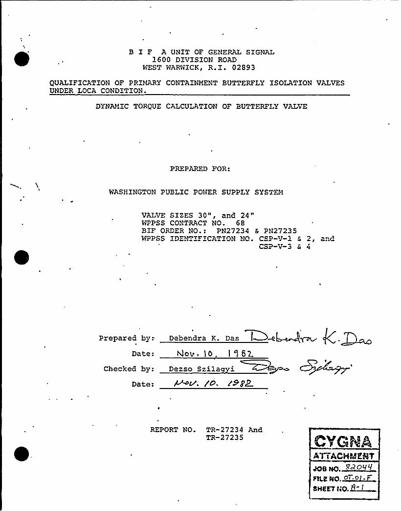
B I F A UNIT OF GENERAL SIGNAL1600 DIVISION ROAD
WEST WARWICK, R.I. 02893
QUALIFICATION OF PRIMARY CONTAINMENT BUTTERFLY ISOLATION VALVESUNDER LOCA CONDITION.
DYNAMIC TORQUE CALCULATION OF BUTTERFLY VALVE
PREPARED FOR:
WASHINGTON PUBLIC POWER SUPPLY SYSTEM
VALVE SIZES 30", and 24"WPPSS CONTRACT NO. 68BIF ORDER NO.: PN27234 & PN27235WPPSS IDENTIFZCATZON NO. CSP-V-1 & 2, and
CSP V 3 & 4
Prepared by.-
Date:
Checked by:
Date:
Debeadra K. Dae
Qov. 10 19 62
Dezso Szila i
REPORT NO. TR-27234 AndTR-27235
Al i ACHMEQY
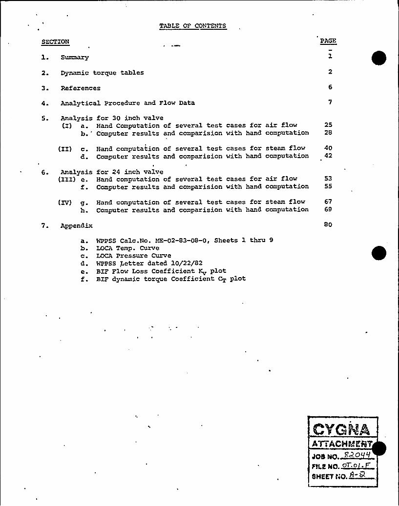
TABLE OF CON~c TS
SECTION
1 ~ Summary
2. Dynamic torque tables
3. Ref erences
4. Analytical Procedure and Flow Data
5. Analysis for 30 inch valve(I) a. Hand Computation of several test cases for air flow 25
b.'omputer results and comparision with hand computation 28
(II) c. Hand computation of several test cases for steam flow 40d. Computer results and comparision with hand computation 42
6. Analysis for 24 inch valve(III) e. Hand computation of several test cases for air flow 53
f. Computer results and comparision with hand computation 55
(XV) g. Hand computation of several test cases for steam flow 67h. Computer results and comparision with hand computation 69
7. Appendix 80
a. WPPSS Calc.No. M-02-83-08-0, Sheets 1 thru 9b. LOCA Temp. Curvec. LOCA Pressure Curved. WPPSS Letter dated 10/22/82e. BIF Flow Loss Coefficient K plotf. BIF dynamic torque Coefficient CT plot

'SUMfMRY
This report contains the„ dynamic toraue analysis of two butterflyvalves of sizes 30, and 24 inch. The analysis is performed forLOCA (loss of Coolant Accident) per'WPPSS Specification, reference
1 on page six of this report. The analytical procedure and the
assumptions are outlined in the section beginning on page seven.
Dynamic torcue calculations have been performed for two media,
namely, air and saturated steam for various angles of opening ofthese valves.
The results of the analysis tabulated on page two through fiveof the report indicate that the dynamic torcrues developed under the
specified flow conditions are less than the design toraues used inthe. original Seismic and Stress analysis o these valves. Therefore
the valves are safe against the action of dynamic torcrue in the
event of a LOCA.
O'II'GNAAT i ACHMKST~~ ~PoRLE NO ~oT o F...SHEET 40. 2

SUK LORY OF RESULTS
T3.mes
1.0
1.5
2.0
2.5
3.0
3.5
4.0
4.5
Table — 1
Angle Wdegas
90(Full open)
78.75
67.50
56.25
45. 00
33.75
22.50
11.25
30 Inch Valve, airflowDynamicTorquein-lb11020
23098
18138
14747
12428
10780
8014
3972
5.0 9. 0 (Full'losed) 0 0 * TNet= 22174 in-lb
* At full closed position the dynamic torque is zero and the net
torque is due to seating and bearing friction.NOTE: The design torque used in the Seismic analysis report
I
No. TR-74-8 by McPherson Associates for this valve is27800 in-lb. Therefore the design is safe.

SUMMARY OF RESULTS
TimeS
1.0
1.5
2.0
2.5
3.0
3.5
4.0
4.5
Table - 2,
Angle Wdegas
90(Pull open)
78.75
67.50
56.25
45. 00
33.75
22.50
11.25
30 1rch Valve Steam- flowDynamicTorquein-lb
11032
23175
18142
14668
12424
10580
7809
3867
5.0 9. 0 (Pullclosed) 00* TNet= 22174 in-lb
* At full closed position the dynamic torque is zero and the net
torque is due to seating and bearinc friction.

SU?&fARY OF RESULTS
Times
Table — 3E
Angle Wdeg.
inch Valve; Air flow
DynamicTorquein-lb
1.0
1.5
2.0
2.5
3.0
3.5
4.0
4.5
90(Full open)
78.75
67.50-
56.25
45. 00
33.75
22.50
11.25
9. 0 (Fullclosed)
5525
11692
9095
7428
6239
5430
4043
2020
0.0 * TNet= 13808 in-lb
* At full closed position the dynamic torque is zero and the net
torque is due to seating and bearing friction.
Note: The design torcue used in the Seismic analysis report
No. TR-74-7 by McPherson Associate for this valve is~
': '70/>in-lb. Therefore the deisgn is safe.
A t iACHMESY~ m,~PO<~qFtLE HO ~ot o F..SHEET HO. S

SUMMARY OF RESULTS
e TimeS
Table — 4
Angle Wdeg
24 Inch Ualve, Steam flow
DynamicTorquein-lb
1.0
2.0
2.5
3.0
3 5
4.0
4.5
5.0
90 (Full open)
78.75
67.50
56. 25
45.00
33.75
22.50
11.25
9. 0 (Fullclosed)
5425
11394
8921
7213
6109
5202
3842
1902
p 0 * TNet= 13808 in-lb
.* At full closed position the dynamic torque is zero and the net
torque is due to seating and bearing friction.

REFERENCES
WPPSS Specification 2808-68, Calc. No. liE-02-83-08-0, Sheets1 thru 9, dated 10/8/82.
LOCA Temperature Curve Fig. 6.2-2.LOCA Pressure Curve Fig. 6.2-3.
ANSI/AWWA C504-80, AWWA Standard for Rubber-Seated ButterflyValves. American Water Works ASsociation, Colo.
Beard,C., Final Control Elements, Valves and Actuators, FirstEdition, Rxmbach Publications, 1969.
Hutchison J. W. ISA Handbook of Control Valves 2nd EditionTorque and Sizing Calculation for BIF Butterfly Valves, No. D-214590,dated 1/9/ 5 for WPPSS Contract 468.
B I F Test Report for Dynamic Torque and Head Loss Tests of CastIron Streamline Disc versus Fabricated Flat Plate Disc datedMay 13, 1974.
B I F Test Report iTR-0650-43, Hydrocynamic and Headloss Test of12" - 150 Lb. Butterfly Valve with directly connected short radiuselbow upstream, dated 2/24/82.
B I F Drawings: 30 inch Valve General Arrangement Drawing A-20676324 inch Valve General Arrangement Drawing A-206764

QID4~361106
7.4 McPherson Associates Analysis

0

'
~ ~
I
0
~ ~
BXF A UNIT OF GcCKRAL SIGNAL1600 DIVISION ROAD
NEST NARNXCK, R.X. 02893
DESIGN A'K) SEZSiMC ANALYSZSOF
24 CYLINDER OPERATED BUTTERFLY VALVEFOR
WASHINGTON PUBLIC PO~ SUPPLY SY~AND 0
BURNS AND ROE
CUSTOMER P.O NT 68
'BZP 5EO . "R~hO'MS-U-0708,'236-U-0808.
I ~ 0
B r S PN27235-1 th~ '4PN27236-1 theo '3
REPORT NO. TR-74-7PREPARED BY McPHERSQN ASSOCIATES, ZNC.
APPRO~~ BY 3 7 7(f'
I/5I7+ ~I@~ 1~
DESIGN ANDSEISMIC ANALYSIS
OF24" CYLINDER OPERATED
BUTTERFLY VALVEA-206765
22 February 1974
Prepared For:
BIF 1
A Unit of General Signal Corporation
Prepared By:
Thomas M. RileyJohn R. Henry
A Unit of Generai Gisnp Co'rpfrationPurchase,Orf er Nq 8+468-68
M he son''Associates, Inc.aport No. TR 74 7-- -<eLta»J» les
~ . ~
408 No.'PILE NO.
OHEKT N
RP~) 9..ol. F
McPherson Associates, Inc.400 Totten Pond Road
Naltham, Massachusetts 02154
4C MS «~5 ~~tel
400 TOTTER PONO ROAO ~ WALTHAM.MASSACHUSETTS 02154

DESIGN ANDSEISbll C ANALYSIS
OF24" CYLINDER OPERATED
BUTTERFLY VALVEA-206765
BIFA Unit of General Signal'orporation:
Purchase Order No. 84908-63 40E HO. E~~>"'I
PLE Ho. ~O. o i.P'HEET
ND. ~~
(~X()
V'cPhersonAssociates, Inc.Report Ho. T R74- ~7- RSV- | i'd/~)/vs
FOR 24" VALVES
BIF Contract No.
68
BIF S.O. No.
N 27235-FN 27236-F
Valve Tax No's
CSP-V-3CSP-V-4CEP-V-3ACEP-V-4ACSP-V-5CSP-V-6
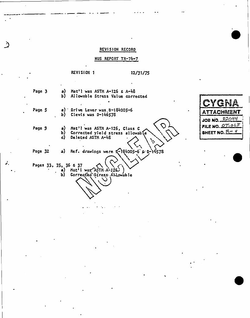
REVl S lOH RECORD
NUS REPORT TR-74-7
REVfSlON 1 12/31/75
Page 3
Page 5
a) Hat'1 was ASTM A-126 s A-48b) Allowable Stress Yalue corrected
a) 'rive Lever was.8-184005"6b) Clevis was D"146578
Page 9 a) Hat'1 was ASTM A-126, Class C 0b) Corrected yield stress allowab ec) Deleted ASTM A-48
Page 32 a) Ref. drawings were " 840054 pD-t 578
>agas 33, 33, 36 < 37 ~ 4 X ('x~a) Hat'1 wa~M A-32& '
b) Corre Cad'Stress AQcwab le
JOB NO.~B~'~
PLE NO O&.ol V
ONE ET NO. +

Section 1.0
QlTRODUCTlON
The purpose of th's report is to determine the structuraladequacy of a 24" . Butterfly Valve Ass emb 3y when s ub jected
to seismic accelerations as described. in Reference '1 and
to insure the valve design is in accordance with Reference
o this report. CVGNAATTACHMENT
The se"'smic plus operating analysis is performed in accord-
ance with Nzshington Public Power Supply System Specifica-V ~tron No. 2808-68, Reference 1, and all applicable information
as described in Sec ion 4,0 of this report..

Section 2.0
'SENARY OF RESULTS
Q)
) K~ ~
~ ~
'hy Q)r'
~tt ~
~ ~ ~
~ ~
~ ~
~ I t ~

ST~(WW~ETET t'l 74 SuaJEETCHKD, SY.A .. QATAR..Z d~
<cg~ V.V'v.c' rt~ h R'$
t
SHEET NS. S S -Sldd8 Nd.
3~A
C4fWP&CLl7
0 ~
.R<QQi4Q P<QL
'
~"< ' et TX 0 0"J~ gQ
Cgt.S 5Q~Cu. IJ) sf
+VCC C'menSeu (r i') a hhT<CS SL
7SI'ffg C.C ay =flfoo (5g L-7T'St,I I
zz flz( Sy flfodo C Ilsl-010 0
S AhtI C 5~= 3bSSO fPPIA-3G )w . c~ = zg ~ C4sssf
a ef iS Pie
bccvC l-v~
YHAz po+ "EhPd
Bhfiolup p.~
P= ff3G C .S 5y-- ff'00 (B-Z
II = 4S< <a C ~~ = 4S~ (Z .
16~$ 1K 'Ey ~ z8~, (5)
~t z,7 ~ sy, c~~z.~~ (><-
ONAA EST401 fIO.~<><~
. O~SI.V,'Hs
No.Q->
SlkhS- S,
78M Px)5,
Vhhue'my
GLAIR t=M~~
M~V KEaa~~c Cevcg
S3r,'
~~ ~
a.7=.1axa7 <,I.a- z7,«> («,, ~ ~s.z. - K a'nfl' s Issso I tt sE -. j
1+~tt IO Ss +~HIf S lES 0 (SS E7'
'-f."~» 1> <>c.~ a ~ * IoE=T ( s ~Hits)mWK&HC%N C Q~)Z ~py
~ ~
+ICRLl+5$ C +~M~ QL3f /
tee pars To ST'P- -s5 )g~wq<l~
C
~ SH
3~ ~

~ I
Section 3.0
CONCLUSIONS
I ~ ~
HcPhers on Ass ocia es, Inc. concludes that all components forthi 24" Butterfly Valve, as analyzed in this report, meet therequirements'of all governing specifications for seismic and
operating considerations as de ined in References 1, and 3 ofthis report.
mSHa~E>'ILEHD.~O. o I. F
SHEET HO. ~
'

TABLE OF CONTENTS
Section No. ~Pa e
:Table of Contents
Certification
1.0
2.0
3.0
4.0
Introduction
Summary of Results
Conclusions
References 0 S
CYGMAA'rTACHMENies wo. '~>'>~<
Pgg gQ,~O'0 I'F'aavND.Q-~
Dc'eeeer gee cree See
6.0 Analysis 10
6.l.
6.2
6.3
Cylinder Operator;Ns emb
c(XCylinder Support Eracke~
Clevis Assembly an Drive Lever
14
23
6.4
6.5
6.6
Valve Body Support "Ears" and AssociatedHardware
~ ~
Shaft and Disc Assembly and 'AssociatedHardware
Valve Si "ing and Stress Analysis ConsideringCombined Operat'ng and Seismic Conditions
38.
. 46

Certification
McPherson Associa es, Inc. certifies tha the 24" ButterflyValve, A-206765, as shown on the customer drawings was
analyzed in accordance with Nashington Public Power SupplySystem Specification No. 2808-68 and to the best of our
Knowledge and belief, meets the requirements of Paragraphs
3.2, 3.3, and 3.5.2.4 of this document and Reference 3 ofSection 4.0 of this report. meso. '»"«
p~~ gg ~O ol ~F.oHEav no. C+
Xr/h. v
John: R.(Fenzy~~) FRegis t'er ed'Qr ofess ional Engineer
qMass.'. Regis"-ation No. 25929

Section 4.0
RFFERFNCES
l. Nashington Public Power Supp y System Specification No.Z808" 68.
2. BIF Drawings
Drawin No. Revision Descript on
A-900523A-900524A-900339A-900340A-208293
~ B-&00521,B-900522S. Z'I>8~b
CD pe Ql'LQ)'2+ I
D-206661
3 ~
5.
6.
. M-206765 B 24" Butterfly Valve-GeneralArrangementsBody, FabricatedBody,.hfachiningDis c, Fabricated ~~Disc, Machined,
. Cylinder Support BracketOperator Shafts.Drive LeverClevis ..',>' ~)Miller C Tinder<>
Section XXI, Nuclear Power Plant Components, AShfE Boilerand Pressure Vessel Code, 1971 w'th,Addenda.
+)'v'Virgil
Moring Faires, Design of hfachine Elements, 4thEd" tion, The MacNillan Co., N.Y.', 1965.
Raymond J'. Roark,. Formulas;.So Stress'nd Strain, 4thEdition, McGraw Hill Book Co., 1955.
Laddish Catalog No. 5S.
~E gC EPOS
SLEWED. <~oi S''
OHEET NO.G
7 ~ Grinnel, Piping and Engineering, 3rd Edition, 1971.
8. 1963 Supplement to Sc=ew Thread Standards for FederalServices s
9 ~ Baumeister ff Marks, Standard Handbook for MechanicalEngineers, 7th Edition, hfcGraw Hill Book 'Company.

h ~ical Engineers Handbook.
S T M. Standards - Part 2.
Handbooks
~ ~o and Goodier, Theory oZ Elasticity, 3rd -dition,'cGzaI( Hill Book Co., 1910.
1 ~d Smith, Advanced Mechanics OZ Materials,ad Sd tion, John Wiley 4 Son, Enc., 1966.
cry>s Handbook, 17th Edition, The Industrial Press,zcHznery364.
„-tion yrZT, Pressure Vessels, Division 2 alternativeles, p.S.~l.E. Boiler and Pressure Vessel Code,<1971.
nubble P»hler.shing Co., otanaara tiara- at'cs>Les, Tve3.=th edition.
ler=can "fational Standards Xnstxtu e .- Document B16.5tied "Steel Pipe Planges and P3.anged Pittings."
.. 'y'q( V:~ ~
~ ~ ~
J ~ ~~ ~ ~ ~ ot
yIgg R209V
SCX WO. <~ of ~
Q4EET NO. ~~
~ ~ ~ ~
p ~
g ~ ~'
& ~

~ ~ ~ ~
~ ~ ~ ~
~ ~ 4 ~
~ 0 ~ ~
~ ~
~ HIKQMRu.
~ ~ ~ ~
~ ~ ~
~ ~
~ 0
~ ~ ~
gg ~ ~ '~ '
~ I~ ~ I
~ ~~ ~ ~ ~ ~
~ ~ ~
MMM
M
~ ~

'".~ IIIIIIIIIIIIIIIIIIIIIIIIIIIIII
FinalQualificationReport
PROZZCT: Equipment Seismic and Hydrodynamic RequalificationO'OB NO: 82044
CALC NO- OS.01.F
CLIEVl: Washington Public Power Supply System
QID NO- 361104
TITLE: Equipment Seismic and Hydrodynamic Requalification of30" Cylinder Operated Butterfly Valves:
CSP-V-1 and 2CEP-V-lA and 2A
PREPARED BY:
REVIEWED BY:
APPROVED BY:
M.A. Scott
/L.C. Fernandez PC+~w >a&.
JF. Khanachet
6/15/83DATE
6/15/83DATE
6/15/83DATE
REVISION:

QID=:. 361104
REVISION STATUS LOG
~'ev.
No. Date
Preparedby
Reviewed.by
Approvedby CygnaEnergy
Services
Approvedby
M'PSS Descrzptxon
0 2/16/83 R. HsiehH. AbolhodaJ. Rakowski
Original. Issue
L. Fernandez
1 6/15/8Scott
Pi 8L. Fernanctez, tl
evised tocorporate
ddition of shearlates

Revision+1 1.1
WASHINGTON PUBLIC POWER SUPPLY SYSTEM
REQUALIFICATIONCERTIFICATE
WNP-QZD 361104
COMPONKNT NO1 -V- gp -V-2 P-V-2A
CDMPDNKNTDKscRIPTIDNs" vlinder Ooerated But ter f1 Valves
MANUPACTURKR1
KQUIPMCNT CLASSIPICATIONi gJ ACTIVE Q PASSIVE
A-206763
SEISMIC QUALIPICATIONRCPORT REPKRENCEs
C gna Energy Services, "Equipment Seismic and Hydrodynamic Requalifica-tion of 30" Cylinder Operated Butterfly Valves," File No. OS.01.F,QID No. 361104, Revision 1, June, 1983.
ikRE UIRED ACTION: 1) Re lace A-307 Ear Bolts with A-325 bolts.
2) Addition of shear plates, see sheets 4.3.30to4.3.48 for additional details.
THK ABOVESEISMIC QUALIPICATIONRCPORT5 HAVC BKKN RKKVALUATEOIN ACCORDANCE WITH
THC CURRENT NRC SC15MIC CRITERIA!
I ICEE STANOARO5 244 {197$)
2 U5NRC RKQULATORYCUIOKS 1.92, I 144
2a 5TANDARD RKVICW PLANS ~Ma 5 14a ISED
4, NURCC&$$ 4
This equipment is qualified asa assembly when the air cylindersare completely qualified addressedin QID f018001.
THC ABOVC COMPONENT HAS BCKN POUND ACCEPTABLE POR PCRPORMINQ ITS INTENOCD SAPETY RKLATED PUNCTION
WHEN SUSPECTED TO THC PLANTSPCCIPIC VIBRATORY LOAO5
PREPARED BV
R EV IKWCD 6 Y
APPROVED BV
J.E. Rakowski 8 ~~4~ Da iA./D5~ p/r ~ i ~~HM.
DATE3 25 83
OATK !OATK
941 12574

Revision 1 2.1
WASHlNGTON PUBL1C POWER SUPPLY SYSTEMB S
J c fllllllllllllllllllllllllllllll
I PLANT NAME: WNP-2
Qualification Summary of Equipment
TYPE
QIDN 361104Ref. Mo.
NSSS: GE Burns & Roe BwR 5, Mark III I ~ COMPONENT NAME:
I ~ SCOPE: Q NSSS
y V.COMPONENT Np CSP-V-1 & 2
CEP-V-1A & 2A
2 MOPEL NLf4BER. A-206763 PUANTITY:
5G VENDCR: BIF .
4 IF THE CCMPONENT I S A CABINET OR PANELS NAME AND MODEL NOG OF THE OEV ICES I NCLUOEO
N/A
PHYs IOAL pfscR IPT I pN + APPfARANcf Butter f1 Valve with 1 0 " C 1 0 erat
b. DIMENSIONS: 30" Nominal D' t r1208 — Valve Assy; 914 — Operator & Bracket
6. LCCATION: BUILDI NGs
ELEYATIDN. 508 'CSP) and 588 'CEP)
T, FIELD NIONTING CONDITIONS: Q BOLT (NO SIZE )
WELD (LENGTN )
B y SYS'EM IN wHICH LOCATEp Containment Supp ly Purge Systems (CSP )
Containment Exhaust Purge Systems (CEPFUNcTIpNAL pfscRIPTION; Primar Containment isolation revention ofof the release of radioactive material to the environment.
c. IS THE EPUIFMENT REQUIRED FOR: Q HOT STANMY Q COLD SHUTPONN
Q BOTH Q NEITHER
9 PFRTINENr RfFERENcf pfSIGN spfcIFIcATIpN~ WPPSS Spec . 2808-68
I I I ~ IS EOUIFMENT AVAILABLE FOR INSPECTION IN THE PlANT: g YES NO
PAGE I OF 5

Revision 1 2.2
Qualification Summary of Equipment (Continued)QIDI 361104
Ref. NoI V EQUIPMENT QUALIF ICATION METHOD:
TEST
QUALIFICATIONREPORT:
X ANALYSIS Q C(NBINATION OF TEST Ij ANALYSIS
Equipment Seismic and Hydrodynamic Requalification of 30" C linder 0 crated Butterfl Valve*
(No., TITLE 6 DATE) File No. OS.01.F, June, 1983
coMPANY THAT PREPARED REPQRT: C na Ener Services
coMPANY THAT REYI EwED REPQRT: Washin ton Public Power Su ol S stems*Plus original valve analysis
V, VIBRATION INPUT:
I LOADS CONSIOEREO: e SEISMIC ONLY
bo HYDRODYNAMIC ONLY
c X CQMBINATON OF (e) AND (b)
2 METHOD OF CO4BINING RRS: ABSOLUTE S(H X SRSS OTHER (SPECIFY)
REQUIRED RESPONSE SPECTRA (ATTACH THE GRAPHS) .. Section 5. 1 of ID 361104
4 ~ DAMPING CORRESPONDING TO RSS: OBE SSE
5 ~ REQUIRED ACCELERATION IN EACH DIRECTION: ZPA [jj] OTHER (SPECIFY) SeotiOn
OBE S/S ~ F/8 a
F/B ~
6 WERE FATIGUE EFFECTS OR OTHER VIBRATION LOADS CONSIOEREOT
[j] YES NO
IF YES, DESCRIBE LOADS CONSIDERED AND HOW THEY. WERE TREATED IN OVERALL QUALIFICATION FRO(RAM:
The calculated stress ran es were com ared to theAISC allowables, as the structures analyzed were not
part of the pressure boundary.
~ NOTE: IF MORE THAN ONE REPORT, C(HPLETE I TEMS IV THROUGH Vl I FOR EACH REPORT
PAGE 2 OF 5
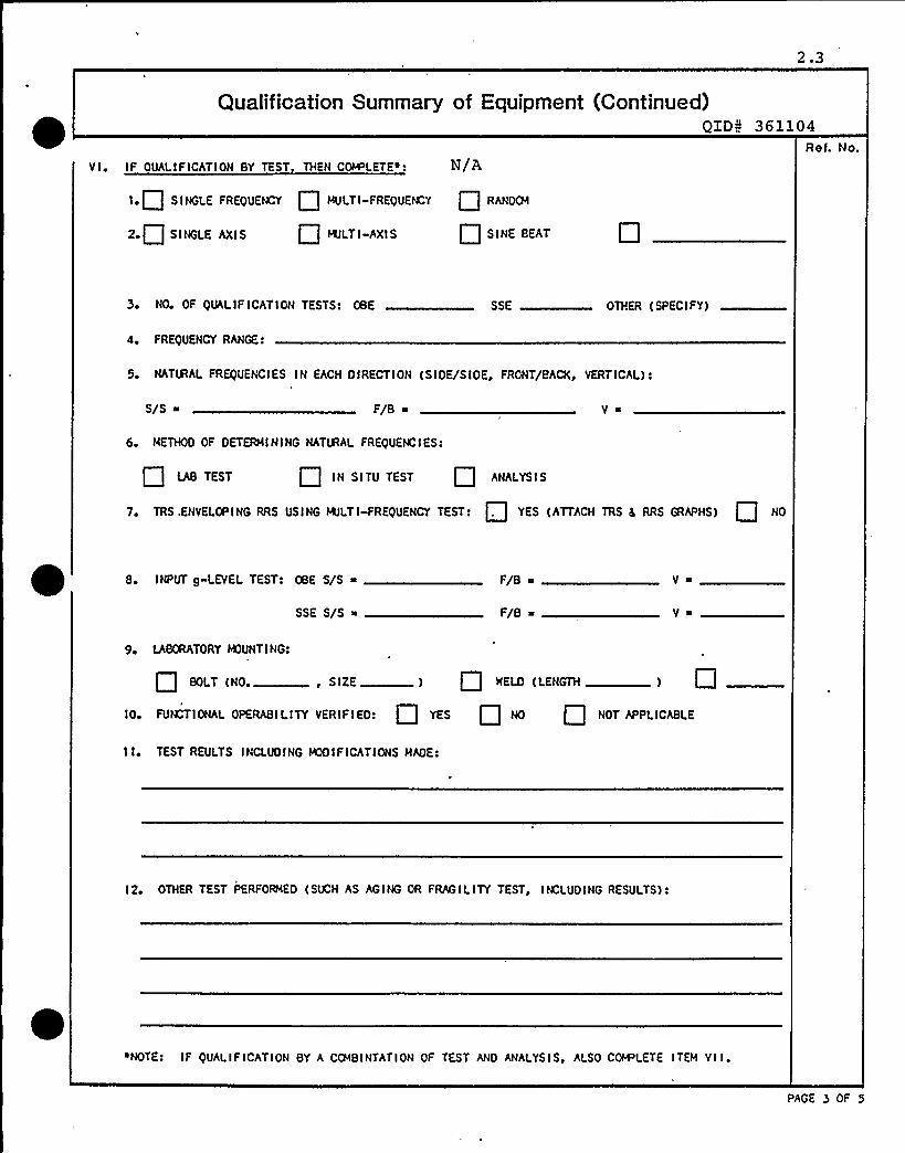
2.3
Qualification Summary of Equipment (Continued)QIDN 361104
Ret. No.
V I IF QUALIFICATION BY TEST THEN COMPLETE~: N/A
I.Q SINGLE FREQUENCY MULTI-FREQUE CY RANOCM
2» SINGLE AXIS MULTI-AXIS Q SINE BEAT
3 NO OF QUALIF ICATION TESTS: OBE SSE OTHER (SPECIFY)
4. FREQUENCY RANGE ~
5» NATIRAL FREQUENCIES IN EACH 0IRECTI ON (S IOE/S IOE, FRONT/BACKS VERT ICAL):
S/S R F/B R R
6 METHOO OF OETERMI NING NATURAL FREQUENCIES:
Q LAB TEST IN SITU TEST Q ANALYSIS
7 TRS .ENVELOPING RRS USING MJLTI-FREQUENCY TEST: Q YES (ATTACH TRS I RRS GRAPHS) Q NO
8» INPUT g-LEVEL TEST! OBE S/S R
SSE S/S
F/B R
F/B R
R
9» LABORATORY MOUNTING:
BOLT (NO., SIZE I IIELO (LENGTH ) Q10» FUNCTIONAL OPERABILITY VERIF I EO: Q YES NO NOT APPLICABLE
I I ~ TEST REULTS INC(.UOING MOOIFICATIONS MAOE:
OTHER TEST PERFORMEO ( SUCH AS AG I NG OR FRAG I L I TY TESTE I NCLUO ING RESUI TS)
NOTE: IF QUALIFICATION BY A CCMBINTATION OF TEST ANO ANALYSIS, ALSO COI4oLETE ITEM Vl I.
PAGE 3 OF 5
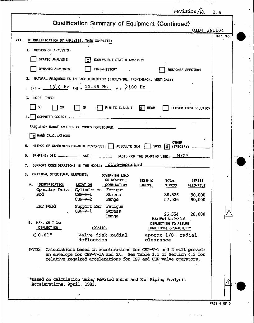
Revision 1 2.4
Qualification Summary of Equipment (Continued)
Vl I ~ IF QUALIFICATION BY ANAI.YSIS, THEN COMPLETE:
QiD~< 361104Ref. No
I ~ METHOD OF ANALYSIS:
STATIC ANALYSIS
Q DYNAMIC ANALYSIS
EQUIVALENT STATIC ANALYSIS
TIN' STORY RESPONSE SPECTRLH
2G NATIRAL FREQUENCIES IN EACH DIRECTION (SIDE/SIDEP FRONT/BACK, VERTICAL):
13' Hz F/B 11 45 Hzv ) 100 Hz
3 MODEL TYPE:
3O Q 2D ID . Fl TE ELEME T g BE Q CLOSED FORM SOLUTIO
4e Q COI4DUTER CODES:
FREQUEM Y RANGE AND NO OF MODES CONSIDERED:
Q HAND CALCULATIONS
OTHER5. ETHOD OF COIB I G 0 IC ESPOHSES: Q SO LTE SLH Q SESS [g (SPECIFY)
6 DAN ING: OBE SSE BASIS FOR THE OAHPIHG USED:
7 SUPPORT CONSIDERATIONS IN THE MODEL
B MAX, CRITICALDEFLECTION
Q 0.01"LOCATIOH
Valve disk radialdeflection
8. CRITICAL STRU TIRAL ELEMENTS: GOVERN I NG LOAD
OR RESPONSE
A, IOEHTIFIGATIOH LOCATIDH COIBI IIATIOH
Operator Drive Cylinder on FatigueRod CSP-V-1 Stress
CSP-V-2 Range
Ear Weld Support Ear FatigueCSP-V-1 Stress
Range
SEISMICSTRESS
TOTAL
STRESS
STRESS
ALLOIABLE
86,82657,526
90,00090,000
26 F 554 28 F 000MAXIM'LLOWABLE
DEFLECTION TO ASSlHEFUNCTIONAL OPERABILITY
approx 1/8" radialclearance
NOTE: Calculations based on accelerations for CSP-V-1 and 2 willprovidean envelope for CEP-V-1A and 2A. See Table 1.1 of Section 4.3 forrelative required accelerations for CSP and CEP valve operators.
~sed on calculation using Revised Burns and Roe Piping AnalysisAccelerations, April, 1983;
PAGE 4 OF 5

Revision 1 2.5
Qualification Summary oi Equipment (Continued)QIDN 361104
VIII. REFERENCES
1) BIF Drawings
Drawing IA-206763
Revl DescriptionF General Arrangement
CEP-625-10
c CEP-625-11.12
From Reactor NozzleX-3 to SGT-FU-lA, 1B
From Reactor NozzleX-3 to SGT-FU-1A, 1B
C-26095 Model A-83B Cylinder
A-206767 Valve Assembly
DOC-D-220-0310-IR-66 0 Tube errection iso-metric
D-207110 F Valve Data Sheet
M-144
CSP-807-3.4
General Arrangmentlan mis level
Containment purgeair su 1 s stem
References continued on page 2.6
" ~ c w~~~ i D~N .~ ~/~/~~Date
~/~~
Pago 5 of 5

THXS PAGE NOT USED.

IIIIIIIIIIIIIIIIIIIIIIIIIIIIII
CalculationSheet
project Prepared By. DateWPPSS Mechanical Equipment Qualification J.E. Rakowski 3/25/83
Subtect 30" Butterfl ValvesChecked By;
')-.C. I=~ +/~ lzzSystem
CSP and CEPAnatysis No'61104 Rev, No.
Job No.
Sheet No.2.6,
File No.Os.ol/F
Reference cont'n
2) Formulas for Natural Frequency and Ytode Shapes,Robert D. BlevinsVan Nostrand Reinhold Company1979 Edition
3) BIF Report TR-27234 and TR-27235, "Dynamic TorqueCalculation of Butterfly Valve; Sizes 24 and 30 inch",dated November 10, 1982.
4) Report TR-74-8 by McPherson Assoc., Inc., "Design &
Seismic Analysis 30" Cylinder operated Butterfly Valve".(Rev. 1) 12/31/75.
5) WPPSS letter to Cygna Energy Services, GE-02-RWH-018,12/17/82.
7)
6) WPPSS, WNP-2 SRM Equipment List Summary Sheets dated2/10/83.
Cygna Energy Services, Equipment Qualification WalkdownVerification Form dated 7/14/82 and 7/19/82.
8)
9)
Cygna Energy Services, "Project Manual Design Criteria,"DC-l, Rev. 1, 10/82.
Burns & Roe Revised Piping Analysis Loadsfor CSP-V-1 and 2 (received 4/13/83) and CEP-V-lA and1B (dated 11/15/82) .
10) Communications Report, R. Ricappito o f BIF and J. Rakowskiof CES, "BIF Valve Dimensions", 2/ll/83
ll) Cygna Energy Services, "Equipment Seismic and HydrodynamicRequalification Calculation No. OS.01.F", QID No. 361104,Revision 1, May, 1983.
rccs Oc

r

7IIIIIIIIIIIIIIIIIIIIIIIIIIIIII
F,o,ec, WPPSS, tvNP-2 Seismic/Hydrodynamic
CalculationSheet
Freoa e" By DaieL.C.Fernandez 4/29/83Svo~ec: Ghee«ea By
IIDaie'l,—.
Systpcc
Analya a No361104
Fle ~ Nc
Joo No82044
Shee: Nc
Foie NoOS. 01
UPSET COND1T10N G-LEVELS
EPICS
CSP- V -1
Cep- V-20.76 1.36 0.88
0.66 1.33 0.79
-e FAULTED CONDI T1ON G-LEVELS ( RWuIREb)6 AND 10 1NCH AIR CYLINDER OPERATORS
EPN
CSP-V -1
CSP- V -2
HYDRLDS ELEV 'R'
50B. 00
Y 508.00
2.26 3.62 2.80
1.44 3.54 1.90
CEP- V -lb Y
CEP- / -2A Y
586.00 1.93 2.23 1.85
588.00 0.96 2.11 1.16
From Revised Burns and Roe Piping Accelerations, see Section 5.5.
le~A cc

Og
0

TABLE OF CONTENTS QlDg 361104
SECTION TITLE NO OF PAGES
1.0
2.0
3.0
4.0
4.1
4.2
4..Pg. 4.3.1
Pg. 4.3.8
Pg. 4.3.53
5.0
5.1
5.2
5.3
5.4
5.5
Requalification CertificateSQRT Forms
Table of Contents
Requalification Analysis
Conclusions
Summary of Results
Analysis
Introduction
Calculations
References
Appendices
Response Spectra
Walkdown Sheets
Valve Local Coordinate Systems
SRM Sheets
Revised Burns & Roe Piping AnalysisAccelerations
6.0 Drawings
Revision 1

TABLE OF CONTENTS
CON'TQIDN 361104
SECTiON TITLE NO OF PAGES
7.0
'7. 1
7.2
7.3
7.4
Transmittals, Prior Calculationsand Reports
Communication Reports
Original Requalification and SQRT Forms
BIF Report *
McPherson Associates Analysis*
*Note: Excerpts from report included in specifiedsection. For complete report see CygnaEnergy Services File No. OS.01.F, QID 361104,"Equipment Seismic and HydrodynamicRequalification of 30" Cylinder OperatedButterfly Valves," Revision 1, June, 1983.
Revision 1

CalculationCoverSheet
Equipment Seismic and HydrodynamicRequalification
ClientWashington Public Power Supply System
Subject
Job No. 82044File No. 0S 0 1 FGale. Set No.
1
No. of Sheets 8 3
BIF 3 0 " Cylinder Operated Butterfly Valves ,QZDN 3 6 1 1 0 4EPNS : CSP-V- 1 , 2
CEP-V-1A , 2A
Statement of Problem
Seismic and Hydrodynamic Requalification of CSP-V-1, CSP-V-2,CEP-V-1A, CEP-V-2A to Burns and Roe Piping Analysis Loads.
Sources of Data
See References pages 4.3.53 and 54.
Sources of Formulae ft References
See References pages 4.3.53 and 54
'he
equipment requalification was performed based on calculationsusing Revised Burns and Roe Piping Analysis Accelerations,April, 1983. (See Section 5.5)
Originators Checkers Distribution Revision No.1
JE Rakowski
H. Abolhoda
R. Hsieh
LC Fernandez
MA Scott
DE Searle
Project File-1 Revision 0, 7/23/82Approved By: ~ P, Date:
~ p,
i~
Supply System 2 SuPersedes Calculation Set No.
100$ .00

ttT
C5 BIIIIIIIIIIIIIIIIIIIIIIIIIIIIII
CalculationSheet
Protect
Subtect
System
Prepared By
Checked By
Job No, File No,
Date
Date
Anatysis No. Rev No. Sheet No
CONTENTS
4.1
Calculation Cover. Sheet
Conclusions
4.2 Summary of Results
4.3
4.3.1
4.3.2
4.4
Analysis
Introauction
Calculations
References
1006 00

IIIIIIIIIIIIIIIIIIIIIIIIIIIIII
CalculationSheet
Project
Subject
System
Analysis No Rev, No,
Prepared By;
Checked By,
Job No,
Sheet No
File No.
Date
Date
SECTION 4.1
CONCLUSIONS
rctjs cc
V

WASHINGTON PUBLIC POWER SUPPLY SYSTEM
SUPP l.1LJR Tl<ANSIlllTTALFORI'Il
AREA WITHINHEAVY BORDER TO BE COMPLETED BY SUPPLIER)
To THK ATTENTIDNoF Denn is Arms tron3 p p p G PP NIZJgiT PfJRCH PFOPGQNQ UYfg CON RAC$ AD I ~ )
sU JKcT Eouio . Seismic H drodvnamic Re u 1' '
C na Ener ServicesADDREss. 1200 Jadwin Suite 565 Richland HA
THE FOLLOWING PUBI ICATIONS/DRAWINGSARE SUBMITTED FOR:
@APPROVAL Q REVIEW " Q INFORMATION Q DISTRIBUTION
NO.OF PRINTS OF EACH NO OP REPROOOCIEL OF E CH
SUBMITTKDBY: t
TITLE:
PAGE ~ OF ~l
2 NEW 0 RK SUBMITTAL
RKQUKSTKD DATEOF RETURN:
CONTRACT NO:
PO NO)
WORK ORDER NO:
SPEC. NOg
SUBVENDOR: CONT.JP.O, NO,: SPEC, SECT NO>
ITEMNO,
PUBLICATION0 RDRAWING NO.
RKV.NO, PUBLICATIONOR DRAWING TITLE MANUFACTURER
WPPSSACTION
T-6 1 4 3
COMMENTS< (USE ADDITIONALSHEET, IF REQUIRED) TO BE REVIEWED BY
R EIVKO BY: IPURCHASING ONLY)II HAMROVED E4Y:
TRANSMITTED BY: IPURCHASING ONLY)
TITLE
ACTION LEGENOcA ~ APPROVED FOR PUBI.ICATION
AN m APPROVKO AS NOTEO FOR FABRICATIONP ~ I P PT SSS
I ~ INFORMATIONONLYNA ~ NOT APPROVED

'- ~k>llllllllllllllllllllllllllllll
FINALQUALIFICATIONREPORT
PROJECT: Equipment Seismic 5 Hydrodynamic Requalification
JOB NO.: 82044
CALC. NO.: 1P.01/F
CLIENT: washington Public Power Supply System
QID NO.: 018001
TITLE: Equipment Seismic 5 Hydrodynamic Requalification8", 10" and 12" Bore Air Cylinder OperatorEPN 8CEP-AO-lA, 2A REA-AO-1', 2
CEP-A0-3A, 4A ROA-A0-,1, 2CSP-A0-1, 2CSP-AO-37 „4, 5, 6, 9
PREPARED BY:
REVIEWED BY:
APPROVED BY:
REVISION:
1001.00

REVISION STATUS LOG
ReviNo. Date
Preparedby
Reviewedby
Approvedby Cygna
EnergyServices
Approvedby
NPPSS Description

1 0 REQUALIFICATION CERTIFICATION

1.1
WASHINGTON PUBLIC POWER SUPPLY SYSTEM
REQUALIFICATIONCERTIFICATE
WNP- QID 018001
cOMPDNENTNO, CSP-,A0-3 4
8" Bore Air Cylinder Operators
MANUPAcTURKR Miller Fluid Power Cor
KQUIPMKNTCLASSIFICATIONt gg ACTIVE Q PASSIVE
MOOKI NOt A83
SEISMIC QUALIFICATIONREPORT REFERENCKt
C a Re ort 1P.Ol/F, QID 018001
WPPSS Seismic Qualification of 8" and 10" Bore Miller Air0 erator.
ENVIRONMENTALQUALIFICATIONREPORT RKPKRKNCKt
Remarks': Parts of the air operators such as the drive rod, trunnion'ns brackets and clevis were evaluated as art of the
res ective valve ID acka es.These o erators do not ualif until the operability dem-
onstration described in Section 4.3.2 has been performed.
THKABOVESKI5MICAND
THK CURRENT NRC SKI5MICANO
QUAIJPICATION REPORT5 HAVE BREN RKKVAL,UATKDIN ACCOROANCK WITH
CRITKRIAt
I~ IKKKSTANOARO5 244 (l57$ I,
2 U5NRC REGULATORYOUIOK5 I%2, I~ ISO
Se 5TANDARO REVIEW PLANS-2&~i2 IOo~4~~%I
This certificate applies only to theoperator which was evaluated as partof the valve assembly. Followingcompletion of the valve requalifica-tion (QID 361106), the certification
willbe revised to address the entireassembly.
THKABOVE COMPONENT HAS BEEN FOUND ACCEPTABLE FOR FERFORMINQ IT5 INTENDED 5APKTY RELATED FUNCTION
WHEN 5UBIECTKD TO THK PLANTSPECIFIC VIBRATORY .LDAos subj ect to the aboveremarks.
PRKPARKO BY3. E . RA&o~S&I
APPROVED BY
t$2 l2$7$
ki4d~ la +S~~ln, ~ I ~4~ A ~vdSOATS+ peggyDATE / ')

1.2
WASKNGTQNPUBLIC POWER SUPPLY SYSTEMIC
REQUALIFICATIONCERTIFICATE
WNe- QID 018001
coMPDNKNT Noi CSP-AO-1 2
cDMPDNKNTDKscRIFTIDN3 10 Bore Air C linder 0 erators
MANUFAOTURER, Miller Fluid Power Cor
KQUIPMKNTCLASSIFICATIONs QX ACTIVE Q PASSIVE
MODELNO(
SKI5MIC QUALIFICATIONREPORT REFERENCE:
or 1P.01 F ID 018001WPPSS Seismic ualification of 8" and 10" Bore MillerAir 0 erator.
KNVIRONMENTALQUALIFICATIONRKPOR'T RKFKRKNCKl
Remarks 1: Parts of the air operators such as the drive rod, trunnionins, brackets and clevis were evaluated as part of the
respective valve QID packages.Remarks 2: CSP-A0-1,2 are not qualified until the operability demon-
stration described in Section 4:3.2 has been performed.
THK ABOVESKI5MICAND'HK
CURRENT NRC SEISMIC ANO
QUALIFICATIONRKPORT5 HAVE BEEN RKKVALUATEDIN ACCORDANCE WITH
CRITERIAc
'I IEEK STANOARD5 244 (I$75)
2e U5NRC REGULATORYQUIOK5 Io$2, I~ IOO
Se 5TANOARD REVIEW PLAN5 SAW 2 I0+410t
4 fCctlRKISNNEE
This certificate applies only to theoperator which was evaluated as partof the valve assembly. Following com-pletion of the valve requalification(QID 361104)., the certification willbe revised to address the entire as-sembly.
THKABOVE COMPONENT HAS BEEN FOUND ACCEPTABLE POR PKRFORMINQ IT5-INTENDED5AFETY RELATED FUNCTION
WHEN SUBJECTED TO THK PLANTSPKCII IC VIBRATORY,remarks.
PREPARED BYJ. 2 RAtc~OSIc I N (4.~ IAA>5c~A
REVIEWED BY
LDAD5) sub ject to the above
DATE
a4'PPROVED
BY( ~v PCi/>,i~r~,,v w
$ 44 I2574
OATKV )
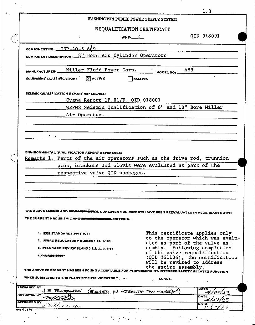
1.3WASHINGTONPUBLIC POWER SUPPLY SYSTEM
REQUALIFICATIONCERTIFICATE
WNP QID 018001
COMPONENT NOs
coMPDNKNT DKscRIPTIDN( 8" Bore Air C linder 0 erators
Miller Fluid Power Corp. A83MODKLNOs
EdIUIPMKNTCLASSIPICATIONs"
g] ACTIVE Q PASSIVE
SEISMIC CIUALIPICATIONREPORT RKPERENCKj
C na Re ort 1P.01/F, QID 018001
WBP6S Seismic ualification of 8" and 10" Bore MillerAir 0 erator.
ENVIRONMENTAL.QUAUPICATIONREPORT REPERKNCEt
Remarks 1: Parts of the air operators such as the drive rod, trunnionins, brackets and clevis were evaluated as part of the
respective valve QID packages.
THKABOVE5KISMICAND
THK CURRENT NRC 5KI5MICAND.
dIUALIPICATIONRKPORT5 HAVE BEEN REEVALUATEDIN ACCORDANCE WITH
CRITERIA>
2e U5NRC REGULATORYOUIDE5 le$ 5, 1 ~ IDO
I ~ IKKKSTANDARD5 544 (1 $75), This certificate applies onlyto the operator which was evalu-ated as part of the valve as-
st STANDARD REVIEW PLANS SA>e 5 10' sembly. Following completionof the valve requalification
4 NCOR$1~~ (QID 361106), the certificationwill be revised to addressthe entire assembly.
THKABOVE COMPONENT HA5 BEEN POUND ACCKPl'ABLEPOR PERPORMINO IT5 INTENDED 5APETY RELATED PUNCTION
WHKN 5UBJECTKD TO THK PLANT SPECI PIC VIBRATORY, ~ ~ LOADS
PREPARED BYQ E ~p, wan (~~g~
REVIEWED BY
DATK
+pwca
DATE
APPROVED BY I<+ IVr 1' -'ides') i$ $ $~1$ $ 15
DATE

1.4WASHINGTONPUBLIC POWER SUPPLY SYSTEM
REQUALIFICATIONCERTIFICATE
WNP- QID 018001
coMPDNENT Not CEP -AO-lA 2A
coMPDNKNTDKscRIFTIDNt 1 0" Bore Air C 1 inder 0 erators
Miller Fluid Power Corp.
KCIUIPMKNTCLA5SII ICATIONt gg ACTIVE Q I ASSIVK
A83 (2A), A83B (1A)MODELNO(
SKI5MICdUAIJFICATIONREPORT REFKRKNCKt
C na Re ort 1P.01/F, QID 018001
WPPSS Seismic Qaulification of 8" and 10" Bore MillerAir 0 erator.
ENVIRONMENTALQUALIFICATIONREPORT REFERKNCEt
Remarks: Parts of the air operators such as the drive rod, trunnionins, brackets and clevis were evaluated as part of the re-
spective valve QID packages.
THK ASOVKSEISMIC AND
THK CURRENT NRC SEISMIC ANO
0IUAIJFICATIONRKPORT5 HAVE SEEN REEVALUATEDIN ACCORDANCE WITH
ITKRIAt
I ~ IKKKSTANOARD5 544 II%75),
USNRC REGULATORYOUIOKS I%Sr I~ IOO
Sr 5TANDARO REVIEW PLANS 5AAr5 IOr~4 OWN~
This certificate applies only to theoperator which was evaluated as partof the valve assembly. Following cornpletion of the valve requalification(QID 361104), the certification willbe revised to address the entire as-sembly.
THE ASOVK COMPONENT HA5 SEEN FOUND ACCKFTASLE fOR PKRFORMINO IT5 INTENDED 5AFETY RELATED FUNCTION
WHEN 5USIKCTKDTO THK PLANT5PKCIFIC VIBRATORY '- LOAO5
PREPARED SYRtl <C k.l
REVIEWED SY
APPROVED SY+ti'tif ilt.rt r
$ 4$ r I 251$
(4 c3~ /A/
OATS

1.5
WASHINGTONPUBLIC POWER SUPPLY SYSTEM
REQUALIFICATIONCERTIFICATE
WOP ~ QXD 018001
coMPDNENT Not CEP -AO-3A 4A8" Bore Air C linder 0 erators
Miller Fluid Power Corp.
KCLUIPMENTCLA55IF ICATI ON s KjACTIVE Q PASSIVE
MDDKL,ND A83 ( IA), A83B (3A)
SEISMIC GUAuPICATION REPORT RKFERENCKt
1P.01 F ID 018001
Seismic uglification of 8" and 10" Bore Hilleror.
ENVIRONMENTALGUAIJFICATIONREPORT REFKRENCKt
Remarks: Parts of the air o erators such as the drive, rod, trunnionins brackets and clevis were evaluated as part of the
res ective valve QID ackages.
THE ABOVESEISMIC AND
THK CURRKNT NRC SEISMIC AND
GUAIJPICATION REPORT5 HAVE BEEN REEVALUATEDIN ACCORDANCE WITH
CRITERIA s
I~ IKKKSTANOARD5 344 1197$ )
USNRC REGULATORYGUIDES 1A2e 1+100
S~ STANDARD REVIEW PLANS SA&e 5 IOe~4lfUlCKIDBRS'his
certificate applies only to theoperator which was evaluated as partof the valve assembly. Followingcompletion of the valve requalifi-cation (QXD 361106), the certificatiowill be revised to address the entireassembly.
THE ABOVE COMPONKNT HAS BEEN I OUND ACCEPTABLE FOR PERFORMING IT5 INTENDED SAF'KTY RELATED FUNCTION
WHEN SUBIKCTKDTO THE PLANTSPECIFIC VIBRATORY~ ~ LOAO5,
PREPARED BY%.&l ~id U~ i'WS~7VW
REVIEWED BY
APPROVED BY...1 4 ~r I'-/d�zc .--.
c91&�I�257
QzY 83DATE >7 &ZOATK /~7/.- i

1. 6
WASHINGTON PUBLIC POWER SUPPLY SYSTEM
REQUALIFICATIONCERTIFICATE
WNP- QXD 018001
coMPDNENTND, REA-AO-1 2 ROA-AO-1 2
coMPDNKNT DKScRIPTIDN< 12" Bore Air C 1 inder Operators
MANUFAcTURER Miller Fluid Power Corp .
EQUIPMENT CLA$5IFICATIONt Q ACTIVE Q PA55IVK
MOOKt.NOtA83
SEISMIC QUALIPICATIONREPORT RKFKRKNCKt
C na Re ort 1P.01/F, QID 018001
WPPSS Seismic Qualification of 8" and 10" Bore MillerAir 0 erator.
ENVIRONMENTALQUALIFICATIONRKPORT REFERENCE
QUALIFICATIONRKPORT5 HAVE BKKN RKKVALUATEDIN ACCORDANCE WITH
THK CURRENT NRC SKI5MICANO CRITERIA'
~ IKKESTANOARO5 244 (I97$ )
2 U5NRC REQULATORYQUIDK5 IA2o I~ I00
2~ 5TANDARO RKVIKWPLANS'$5&v 2 IOe~4
THKABOVE COMPONKNT HA5 BEEN POUND ACCEPTABLE FOR PERFORMINQ IT5 INTENDED 5AFETY RELATED FUNCTION
WHKN SUBJKCTKD TO THK PLANTSPECIFIC VIBRATORY LOAO5
PREPARED BYWiden>
RKVIKWKDBY
APPROVED BY0-, 'iJ '<, 'i v
944 12970
DATEW zan
DATKz7
DATE

2.0 SQRT FORM(S) AND REFERENCES
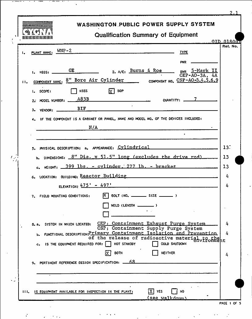
GOBKJE,IIIIIIIIIIIIIIIIIIIIIIIIIIIIIII
WASHlNGTON,PUBLlC POWER SUPPLY SYSTEM
Qualification Summary of Equipment
I PLANT NAME. ~P- 2 TYPE
Ref. No.
GE z AiE. Burns & Roe 5-Mark IICEP-A0-3A, 4A
C~NENT NO. CSP-AO-3 4 5 6 9
I NSSS:
coINoowENT NAME 8 Bore Air C 1 inder
I ~ SCOPE: NSSS
2'DDEL NU4BER. A83B QUANTI TY:
VENDOR'T.F4 IF THE CQ4%WENT IS A CABINET OR PANEL, NAME ANO MODEL NO OF THE DEVICES INCLUDED:
N/A
5 PHYS ICAL OESCR I PT ION: a, APPEARQCE:
b DIMENSIONS: 8" Dia. x 1.
WE I GHT: 3 lb s ~
LocATIow BUILDING Reactor Bu '
ELEVATION. 475 ' 4
13.
13
13
7 FIELD MOUNTING CONDITIONS: BOLT (NO S(ZE
P NELS (LENGTH )
8. a.
b
CO
sYsTEM IN wHIcH LocATED: CEP ~ Containmen hCSP; Containment Supply Purge System
FUNOTIDNAL DEscRIPTIDN.Primar Con tainmen I o '
of the release of radioactive materi@ po @IIS THE EQUIFMENT REQUIRED FOR: HOT STANCBY COLO SHUTDOWN
BOTH Q NEITHER
9. PERTINENT REFERENCE DESIGN SPECIFICATION:
I I I. IS EOUIFMENT AVAILABLEFOR INSPECTION IN THE PLANT: X YES Q NO
see wPAGE I OF 5

2.3
Qualification Summary of Equipment (Continued)QID 018001
Ref. No.
, I ~ S INGLE FREQUENCY Q MULTI-FREQUENCY RAND(H
2o SINGLE AXIS MULTI-AXIS Q SINE SEAT
NO OF QUALIFICATION TESTS: OBE SSE OTHER (SPECIFY)
4 FREQUENCY RANGE
5 NATIRAL FREQUENC I ES I N EACH 0 I RECT I ON ( S I OE/S I OE E FRONT/BACKE VERT ICAL)
S/S ~ F/8 EE
6 METHOD OF OETERMI NING NATIRAL FREQUENCIES:
Q LAB TEST IN SITU TEST ANALYSIS
7 TRS .ENVELOPING RRS USING HJLTI-FREQUENCY TEST: Q YES (ATTACH TRS 4 RRS GRAPHS) Q NO
B. INPUT g-LEVEL TEST: CBE S/S ~
SSE S/S EE
F/8 ~
F/8 EE
go LABORATORY MOUNTI NG:
EOLT (NO., E IZE I Q IIELO (LEIIOO(
10o FUNCTIONAL OPERABILITY VER IF I EO: Q YES NO Q NOT APPLICABLE
11 ~ TEST REULTS INCLUDING MODIFICATIONS MADE:
12 OTHER TEST PERFORMED (SUCH AS AGING OR FRAGILITY TEST, INCLUDING RESULTS):
"NOTE: IF QUALIFICATION BY A CCMBINTATION OF TEST ANO ANALYSIS, ALSO CG4 LETE ITEM Vl I.
PAGE 5 OF 5

'kFAULTED COND I T I ON G-LEVELS8 AND 10 INCH AIR CYLINDER OPERATORS
EPN
CSP-AO-1
CSP-AO-2
CSP-AO-3
CSP-AO-4
CSP-AO-5
CSP~O-6
HYDRLDS ELEV '' G'S
V
V 5OB.OO 4.4O 6.51
Y 508.00 4.95 6.45
Y 481.00 5.72 3.82
Y 478.00 4.65 4.06
Y 475.00 9.35 5.75
E
4 '9+ +
3.72
7 '56.57
Y 480.00 9.35 5.57 1.46
3.s4 goy
3 33 i
«Qg'z,0t
'A': B.7&
p.j7 > . 4. (g
CSP-AO-9
'EP~O-1
EP-AO-2
CEPQO-3A
CEP-Ail-4A
Y
Y
490.00 2.57 1.73 2.67
588.00 1.27 1.77 1.23
588.00 0.78 1.77 1.02
495.00 13.89 1.66 1.04
495.00 10.95 1.50 1.10
4.g7
3.35
rVQ I
I
/JQi Z( co~
+Transmi t ted from the f inal p i ping anal vs is,see Sect i on 5.5.
++These va) ves are required to fai l-closeddur ing a DBE, change Use Code to "1,3" .
~ETC AQQ<r.fkg-,r&J'r-duCrr.jy A? 6 JrVCD gddd'diJ6 qQgr yd.-r~~~~< l4Q MOOA8Udky ~~CC)u(~ T~+l<J d'~l yd'dd L f. "gP~g~
~d'~>~(~>>SSJ. ZEE ZC'Q. K.S/QiD 6/d 00/
4kdld

2.5
AlL aiIIIIIIIIIIIIIIIIIIIIIIIIIIIIII
WASHINGTON PUBLIC POWER SUPPLY SYSTEM
Qualification Summary of Equipment/ID 018001
I~ PLANT HAKEEWNP-2 RoI. No.
lo. HSSSI 2o A/E!
I I~ cosFPoNENT NAKE. 0" Bore Air linder
Burns g Roe 5 - Mark IIBNRCEP-A0-1A, 2A
CyerwENT NO. CSP-AO-1 2
'I ~ SCOPE:
2o ICDEL HLNBER:
YEN'!
NSSS BOP
A83B
BIF
OUANTITY:
4o IF '%E CO4%NKHT IS h CABINET OR PANELS HAKE AHD KOKL HOo OF THE DEVICES IHCLVDEDL
N/A
PHYs IcAL DfScR IPTIDHL I APPfARjgcf li drical 13
b D IKENS I OHS:
c lC I GHT!
10EE dia. x, 64" ion (excludes the drive rod
593 lbs. - c linder, 321 lb. - bracket
13
13
LocATI oH QJ I LDIHG Reactor Bui1ding
ELfyh'TIDH. 508 'o 5607
7 FIEIO OIUIITINO COfOITIOMSF QX BOLT (IIO SIZE )
HELD (LEHGTII )
Bo Oo SYSTEK IN WICK LOCATED: CEP Containment Exhaust Pur e S stemCSP; Containment Supply Purge System
bo FVICTIONAL OESCRLPTIOH:
Co
the release of radioactive material to the environmIS THE EOUIPKEHT REOUIRED FOR: Q HOT STAHCBY Q COLD SHUTDCNH
Q BOTII Q NEITHER
nt.
9o PERTLHENT REFEREM K DESIGN SPECIF ICATIOH: 68
I I I~ LS E UIFKENT AVAllhBLE FOR INSPECTION IN THE PLANT: Q YES Q HO
(See Walkdown)PAGE I OF S

2.6
Qualification Summary of Equipment (Continued)
EOUI PMENT DUALIF ICATION METHOD:
QID 018001Ref. No.
TEST ANALYSIS CO4BINATION OF TEST 4 ANALYSIS
pty L IF IGATI0N REPDRT ~ Re ualification Anal s is of ID 0 1 800 1
(Nos E TITLE a DATE): OP. Ol/F, Februar 1983
coMpANY THAT pREpARFD REPDRT: C a Ener Services
coMpANY THAT REYI EwED REPCRT Washin ton Pub lie Power Su 1 S s
tern
V VIBRATION INPUT:
I LOADS CONSIDERED: es Q SEISMIC ONLY
be Q HYCROOYNAMIC ONLY
c Q CCMBINATON OF (e) AND (b)
2 METHOD OF CCMBI NING RRS: Q ABSOLUTE SLH
3. REOUIRED RESPONSE SPECTRA (ATTACH THE GRAPHS):
Rj SRSS OTHER ( SPECIFY)
Section 5.1
4 DAMPING CORRESPONDING TO RSS: OBE
5 REQUIRED ACCELERATION IN EACH DIRECTION: Q ZPA
Attached F/B .
SSE S/s Attached F/B
sss ~2
Q 0THER (sPEGIFY) Sec. 5 ~ 4
ss
6 WERE FATIGUE EFFECTS OR OTHER VIBRATION LOADS CONSIDEREDT
Q YES NO
IF YES, DESCRIBE LOADS CONSIDERED ANO HOW THEY. WERE TREATED IN OVERALL DUALIF ICATION FROOIAM:
For those EPN's which are sub'ected to h drod amic loadin s
13
the fati ue anal sis on critical locations will be erformed
to comply with the requirements of AISC, Section 5, A endix
B. Total number of h drod namic stress c cles is e ual to
15560.0 cycles (10 x 6 (OBE/SSE) + 3 x 4500 (SRV) + 2000.0 c cl s
(chugging).
~NOTE: IF MORE THAN ONE REPORT, CCMPLETE ITEMS IV Tl+OUGH Vl I FOR EACH REPORT
PAGE 2 OF 5

2.7
Quaiification Summary of Equipment (Continued) qID py8ppy
Yl~ IF UALIFICATION BY TEST THEN C~LKTE»: N/A
I Q SINGLE FREQUE~ Q MULTI-FREQUEJCY Q RANDCH
2oQ SINGLE AXIS Q l4JLTI-AXIS Q SINE BEAT
Ref. No.
3 NO OF QUALIF I CAT(OI TESTS: CBE SSE OTHER (SPECIFY)
FREPUENCY RANGE
5H NATlRAL FREQUENCIES IN EACH DIRECTION (SIDE/S IOE, FRONT/BACXE VERTICAL):
S/S ~ F/B %
6, METHOD OF DETERMINING NATLNAL FREQUENCIES:
LAB TEST Q IN Sl TIJ TEST Q ANALYSIS
7 TRS .ENVELOPING RRS USING MULT INFREQUENCY TEST: Q YES (ATTACH TRS 4 RRS GRAPHS) Q NO
8 INPUT g-LEVEI. TEST( CBE S/S %
SSE S/S %
F/B %
F/B %
Y %
9» LABCRATORY )CUNT I NG:
IIOLT (HO, SIZE ) Q IIELO (LEHOTH )
IOH FUNCTIONAL OPERABILITY YERIF I ED: Q YES Q NO Q NOT APPLICABLE
I I~ TEST REULTS INCLUDING MOOIF ICATIONS MADE:
I2H OTHER TEST PERFORMED (S(CH AS AGING OR FRAGILITY TKST, INCLUDING RESULTS):
NOTE: IF PUALIFICATION BY A ClHBINTATION OF TKST AND ANALYSISE ALSO COMPLETE ITEM Vl I ~
PAGE 3 OF !

2.9
Qualification Summary of Equipment (Continued)
IF QUAL IF ICATION BY ANALYSIS, THEN C(HPLETE:
QID 018001Ref. No.
I METHOD OF ANALYSIS:
STATIC ANALYSIS
DYNAMIC ANALYSI S
2 NATURAL FREQUENCIES
13.0 Hz F/B Bs11.45 Hz v 100 Hz
QX EQUI VALENT STATIC ANALYSI5
Q TIME-HISTORY RESPONSE SPECTRLH
I
IN EACH DIRECTION (SIDE/5 IDEE FRONT/BACK, VERTICAL):
13
10
3P MODEL TYPE:
4 / C~UTER CODES:
Q FINITE ELEMENT Q BEAM Q CLOSED FORM SOLUTION
FREQUEICY RANGE AND NO OF MODES CONSIDERED:N/A
MAND CALCULATI ONS
OTHER
5 NETNOO OF COIBININO OYNANIC RESPOIISES: Q ABSOULTE SIN Q SASS Q ISPECIFY)
SSE BASIS FOR THE ROPING USED:Id*
6o OAH ING: OBE
7 SUPPORT CONSIDERATIONS IN THE MODEL
13
„~SB CR I T ICAL STRLCTlRAL ELEMENTS:
A IDENTIFICATION
Drive Rod
GOVERN I NG LOAD
OR RESPONSE SEI SHIC
I SCAT ION COIBI NATION STRESS
(Range)Operator Fatigue/Fault+ 86824
CSP-V-1
TOTAL
STRESS
STRESS
ALL(%ABLE
90,000 PSX
B HAX CRITICALDEFLECTION I.CCAT I ON
HAXIHLH ALLQfABLE
DEFLECTION TO ASSURE
FUST IONAL OPERA B I L I TY
Operability to be demonstrated by test for CSP-AO-1 & 2.**AirOperator bushing stress ) 200psi
* Final Response accelerations from piping analysis were used.A
PAGE 4 OF 5
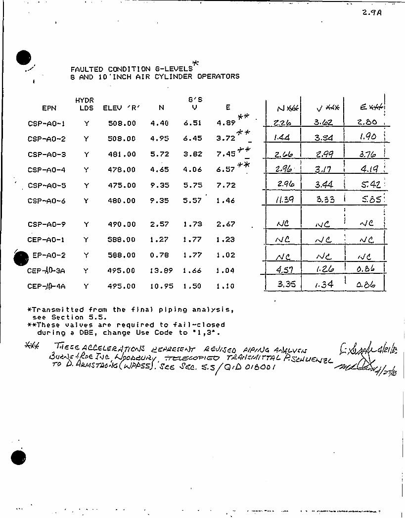
FAULTED CONDITION G-LEUELS8 AND 10'INCH AIR CYLINDER OPERATORS
G'SV
HYDREPN LDS ELEU '' E
4.89
3 '27 '56 '7
CSP-AO-1 Y
CSPMO-2 Y
CSP-AO-3 Y
CSP-AO-4 Y
CSP-AO-5 Y
CSP-AO-6 Y
508. 00 4. 40 6. 51
508.00 4.95 6.45
481 .00 5.72 3.82
478,00 4.65 4.06
475.00 9 '5 5.75 7.72
480 .00 9.35 5.57 1 .46
Z,4&
3 Cc)Z
3.s4
Z,6'.l73.7&
4.fQ
5.Q3 5
344, s4Z
'SP-AO-9
CEP-AO-1
EP-AO-2
CEPS-3A
CEP-A0-4A
Y 490.00 2.57 1.73 2.67
Y 588.00 1.27 1.77 1.23
Y 588.00 0.78 1.77 1.02
Y 495.00 13.89 1.66 1.04
Y 495 F 00 10 '5 1.50 1 ~ 10
4.57
3. 35
I>@<
(.34
+Transmi t ted from the f inal p i p in9 anal ysi s,see Sec t i on 5. 5.
++These val ves are r equir ed to fai l-closeddur ing a DBE, chanpe Use Code to '1,3" .
~ +~ + A~~<""~4 7(c'4~~ QNAPczc "37 4 8J/g~g rvpiNg g~lgc.veil~~~<=~~~< l4"-, 4yorbduiky ~Maoris 724'-rrt/T rgL. pqgpgg~~~ oo«(~>>«J. roe tea. s s/are oieoo i
y/gg/p

2. 10
AkIIIIIIIIIIIIIIIIIIIIIIIIIIIN
VfASHlNGTON PUBLlt POV/ER SUPPLY SYSTEM
Qualification Summary of, EquipmentQID 018001
~LANT NANERts5P-.2 RI5. llo.
lo. NSSS5Buxns g Roe
2 VE
SCOPE: NSSS g OOF
CCHQHENT NO,I I. c~ENT NANE: 12EE Bore Air linder
PNR
5 - Mark IIIIIRREA-AO-l, 2ROA-AO-1 2
2, FIDEL NLHBER: A83B
BIF
OLIANTITY.
io IF TIIE COPONENT IS A CABINET OR PANEL, NAXE ANO ICOEL NOH Of THE DEVICES INCLVDEDI
N/A
S PHYS ICAL DESCRIPT IONI I APPEARAICEI lindrical 13
DINENSICNsI 12 dia. v 46. 83(E ion excludes the drive rod 13
C lC I IOHT5 583 lbs. - cylinder, 586 lb. - bracket
QJ I LDINQReactor Bui1ding
13
ELEYATIDNH 578 'o 597f
T FIELD IOIIIITIHO COIOITI(RHI QX COLT (IHL SITE )
Q IIELO (LEHCIH I
C3
I SYSTEM IN NH IcH LocATED REA Reactor Bui1ding
Exhaust
Air (HVAC) SystemROA; Reactor Building Outside Air (HVAC) System
FIIIcTIDNALDEscRIPTIDN Reactor Buildin Containment Atmosphere Control andprevention of the release of radioactive material to the environment.
C IS THE EOHIH(EHT REOHIREO FCII: Q IOT STIR(ST P COLO SHI/(SOIR
KI ROTI( ( IEA) QX EERIER (ROA)
9, PERTINENT REFEREN-E DESIGN SPECIFICATION: 68
III~ IS E VIRULENT AVAILABLE FOR INSPECTION IN THE PLANT: Q YES Q NO
(See Walkdown)PAGE I OF 5

'.11
Qualification Summary of Equipment (Continued)QID 018001
Ref. No.
EOU I FMENT QUALIF I CAT I ON METHOD:
TEST
QUAL IF ICATION REPORT:
Q ANALYSIS C(HBINATION OF TEST 4, ANALYSIS
ualification Anal sis of ID 018001
(No., TITLE a onE>: OP.Ol/F, February 1983
COMPANY THAT PREPARED REPORT: Ener Services
coMPANY THAT REYI E)(ED REPDRT WashLn on Public Power S 1 tern
V VIBRATION INPUT:
I LOADS CONSIOEREO: a. Q SEISMIC ONLY
b Q HYCROOYNAMIC ONLY
c. X CCMBINATON OF (e> ANO (b)
2, METHOD OF C(NBINING RRS: ABSOLUTE SW Q SRSS OTHER (SPECIFY)
REQUIRED RESPONSE SPECTRA (ATTACH THE GRAPHS):
4 ~ OAR ING CORRESPONDING TO RSS: Q OBE
5 REQUIRED ACCELERATION IN EACH DIRECTION: Q ZPA
CBE S/S ~ 1.0
SSE
Q] DTHER (sPEGIFY) Sect. 5.
6, HERE FATIGUE EFFECTS OR OTHER VIBRATION LOADS CONSIOEREDT
YES NO
IF YES, DESCRIBE LOADS CONSIDEREO ANO HON THEY. MERE TREATED IN OVERALL QUALIFICATION FROGRAM:
13
r PN' d h d m a din
the fati ue anal sis on critical loacations will be erformed
to corn 1 with the re uirements of AISC, Section 5, A endix
B. Total number of h drod namic stress c cles is e ual to
15560.0 c cles 10x6 OBE SSE + 3x4500 SRV + 2000.0 c cles
(chu in ).
~ NOTE: IF MORE THAN ONE REPORT, C04PLEVE ITEMS IV 7k%OUGH Vl I FOR EACH REPORT
PAGE 2 OF 5
2.12
Qualification Summary of Equipment (Continued) QID 018001
V I ~ IF UALIF ICATION BY TEST THEN CO@'LETE+: N/A
I Q 5 NGLE EQUEICY Q MULTI-F EQ ECY Q ANKH
2 Q SINGLE AXIS Q MULTI AXIS Q SINE BEAT
Ref.
NQ, OF QUALIFICATION TESTS: OBE SSE OTHER (SPECIFYI
4 ~ FREQUENCYRANGE',
NATIRAL FREQUENCIES IN EACH DIRECTION (SIDE/SIDE, FRONT/BACKS VERTICAL)!
S/5 ys F/B ~ V RS
6 METHOD OF DETERMINING NATINALFREQUENCIES'AB
TEST Q IN SITU TEST Q ANAI.YSIS
7 TRS .ENVELOPING RRS USING MULT INFREQUENCY TEST) Q YES {ATTACH TRS 4 RRS GRAPHS) Q NO
8P INPUT 9-LEVEL TEST: CSE S/5 ~
SSE 5/5 ~
F/B ys
F/B ~
V RS
9y LABORATORY )OUNT I NG: a----IOO FUICT IONAL OPERABI L ITY VER IF I ED: Q YES Q NO Q NOT APPL ICABLE
11 ~ TEST REULTS INCLUDING MODIFICATIONS MADE:
)2y OTHER TEST PERFORMED ISLCH AS AGING OR FRAGILITY TESTy INCLUDING RESULTS):
NOTES IF QUALIFICATION BY A CCMBINTATION OF TEST AND ANALYSIS, ALSO COMPLETE ITEM Vl I ~
PAGE 3 OF !

'2.13
Qualification Summary of Equipment (Continued)QID 018001
Ref. No.
(', IF DUALIF ICATION BY ANALYSIS, THEN CCHPLETE:
I ~ MFTHOD OF ANALYSIS:
Q STATIC ANALYSIS
Q DYNAMIC ANALYSIS
Qg EOUI VALENT STATIC ANALYSIS
T IME-HI STORY Q RESPONSE SPECTRIN
13
2 NATlRAL FREPUENCI ES
s/s 10. 81
IN EACH DIRECTION (SIDE/SIDEB FRONT/BACK, VERTICAL):
F/B 52. 0 v 100
3 MODEL TYPE:
Q 3D Q D Q E E EM g E CLO ED O UTIO
4 Q COMPUTER CODES:
FREOUEM Y RANGE AND NO OF MODES CONSIDEREO:
HAND CALCUlATIONS
5H METHOD OF CCHBI NING DYNAMIC RESPONSES: Q6H DAIL ING: OBE SSE
7H SUPPORT CONSIDERATIONS IN THE MODEL
N/A
OTHER
ABSOULTE SIP4 Q SRSS Q lSPECIFY)
BASIS FOR THE OhH ING USED:
e-Mounted
13
BH CRI 7 ICAL STRlCTlBAL ELEMENTS- GOVERN I NG LOAD
OR RESPONSE
LCCATIOH COIBI HATICHA IDENTIF ICATION
SE I SMI C
BTHBBB
TOTAL STRESS
STRESS ALLIABLE
Tie Rods
Drive Rods
Operatingthreaded end faulted
13683psi 20000 psi31',172 psi 86,400 ps'3
8 MAX CR I T I GAL
DEFLECTION LCCATIOH
MAXI MLM ALLIABLEDEFLECTION TO ASSLRE
FUNCTIONAL OPERABILITY
* Final response accelerations from piping analysis were used.PAGE 4 OF 5

2.14
Qualification Summary of Equipment (Continued) QID 0180»
Vill. REFERENCES
1. 'V&IE Boiler and Pressure Vessel Code", American Society of Mechanical Engineers1974 Edition with Winter 1974,Addenda. Section III, Division 1, SubsectionsNC and Appendicies.
2. U.S. Atomic Energy Comnission Regulatory Guide No. 1.61, October 1973.
3. Response Spectra Plots. From Design Input Document No. 82045 DID 001.
4. NNP-2 Safety Related Mechanical Equipment List, SRM02. Dated 9/9/82, Section 5.4.
5. "Project Manual for WPPSS Equipment Seismic and Hydrodynamic Requalification",cygna Energy servi'ces,'ev. 0, Dated b/8/Bz. Including Desi'gn'l.rxteria 1K-1.,
6. Cygna Energy Services Project Memorandum, 82044/027SF, dated 9/9/82.
7. WPPSS WNP-2, FSAR Table 3-7.1.
8. Cygna Energy Services Equipment Qualification Walkdown Verification Formsfor EPN's CEP-A0-1A, CEP-AO-ZA, CEP-V-3A, CEP-V-4A, CSP-V-l, CSP-V-2,CSP-V-3) CSP-V-4, CSP-V-S, CSP-V-6) CSP-V-9.
9. American Institute of Steel Construction, 'Manual of Steel Construction", 8thEdition, AISC, New York, NY.
10. Equipment Seismic 5 Hydrodynamic Requalif ication, QID 8361104. File OS.01/F.
11. Equipment Seismic g Hydrodynamic Requalif ication, QID 8361106, File OT.01/F.
12. Equipment Seismic 5 Hydrodynamic Requalification, QID 8361102,
13. Cygna Calculation, Equipment Requalification, QID 018001, File 1P.Ol.F.
Completed By g
Rovlowotl ByJ.E. Rakowski
Date
Pape 5 ol 5

3.0 TABLE OF CONTENTS

TABLE OF CONTENTS QID 018001
SECTION TITLE
1.0
2.0
3.0
4.0
4.14.24.34.4
5.0
Requalification CertificateSQRT Form(s) and References
Table of Contents
Calculations - Cygna RequalificationAnalysis
ConclusionsSummary of ResultsAnalysisReferences
Appendixes to Requalification Analyses
16
6
43
5.15.25.35.4
5.56.0
Response SpectraWalkdown SheetsSummary SheetsLoad Comparative sheets for REA and ROAAir CylindersBurns 6 Roe telex final piping G-levelsDrawings used for Requalification
6
23
16
7.0 Prior Calculations and Transmittals usedfor Requalification

SECTION 4.0
REQUALIFICATION ANALYSIS

R ~ J a 1
IIIIIIIIIIIIIIIIIIIIIIIIIIIIII
Project
E ui ment Seismic H dClient
Washin ton Publi S stem
CalculationCoverSheet
ID 018001'20'P.01 F
Gale. Set No.
No. of Sheets
Sub jec!Dynamic Qualification of 8, 10 and 12 inch Bore Air Cylinder Operators.
Statement ot Problem
The equipment qualification was performed based on calculations usingthe air operator response g-levels transmitted by the A/E, currentto 12/31/82.
Sources of Data
References, Section 4.4
Sources of Formulae 5 References
Cygna Design Criteria DC-l, Rev. 0
Remarks
None
Originators
J. Foie
Rakow
Checkers
R. Casassa
Distribution Revision No.
Supersedes Calculation Set No.
Approved By: ate:

IIIIIIIIIIIIIIIIIIIIIIIIIIIIII
CalculationSheet
Project
Subject
Prepared By:
Checked By:
QID 018001Date
Date
System Job No. File No.
Analysis No. Rev. No. Sheet No.
CONTENTS
Calculation Cover Sheet
4.1 Conclusions
4.2 Summary of Results
4.3 Requalification Analysis
4.3.1 Introduction4.3.2 Cylinder Operability4.3.3 Analysis
4.4 References
APPA>tx A,IC
'lees 00

IIIIIjjjjjjjjIIIjjjjjjjjjjjjjj
CalculationSheet
project
Subject
Prepared By:
Checked By
Date
Date
System Job No. Fite No.
Analysis No, Rev. No. Sheet No.
SECTION 4.1
CONCLUSIONS

IIIIIIIIIIIIIIIIIIIIIIIIIIIIII
CalculationSheet
projectWPSubjectRe ualificationSystemBIF Air 0 eratorsAnalysis No. Rev. No.
Prepared By:
CheckedBy.'ob
No.
Sheet No.
File No.
Date
Date2 83
CONCLUSIONS
This QID demonstrates seismic and hydrodynamic qualification of the8, 10 and 12 inch bore diameter cylinder operators identified inSection 4.2.
Summary Table 4.2.2 presents these comparisons and shows requirementsfor the bolting material in the 8 and 10 inch cylinders.
1. Cylinders CSP-A0-1,2,3 R 4 must be qualified for anactive function and require a representitive opera-bility demonstration as described in Section 4.3.2of this report.
This should be performed using the, values of air operator loads inQTD 361104 and 361106.
QID packages 361101 and 361102 document qualification of the valvesassociated with the 12 inch air cylinder in this report for the seis-mic loads which they experience. No fatigue analysis is requiredfor these cylinders because no hydrodynamic vibration is experienced.These cylinders were shown to quali'fy with A307 bracket bolting forthe actual response g-levels calculated in the piping analysis.This qualification package will be complete when a satisfactoryoperability test is performed and documented herein. Tt has beenconcluded in this report that the standard A307 "earbolts" shouldbe replaced with A325 material type bolts on the'" and 10" aircylinders only.
1005 00

HHHIHHHHHHHHHHHI
CalculationSheet
ProjectWPPS E iSubiectRe ualificationSystemBIF Air 0 erAnatvsts No,018001
Rev. No,0
Prepared By:
Checked By.
Job No.
Sheet No,
Fi(e No.
Date
Date
SECTION 4.2
SUMMARY OF RESULTS

IIIIIIIIIIIIIIIIIIIIIIIIIIIIII
CalculationSheet
project
SubjectR
Prepared By:
Checked By:,
Date
4 rs85System Job No
82044File No.
1P. 01 FAnalysis No.018001
Rev. No.018001 - 4..Z../.
4.2 SUMMARY OF RESULTS
Summary tables in'this section present calculated stressesin comparison to allowables for the 8, 10 and 12 inch air cyl-inder operators. Trunnion pin, drive rod and bracket bolt cal-culated stresses for the 8 and 10 inch air cylinders were takenfrom QID 361106 and 361104, respectively. These calculationswere performed on the valve/operator assembly using the SRSSmethod and the actual piping response g-levels to eliminateunnecessary conservatism in the higher-stressed components. Theair operator components addressed in this'eport are not highlystressed and were analyzed using simpler techniques with generallyhigher envelope loads having greater margin. See Section 4.3.1for more information.
The following summarv tables note corresponding g-levelsand 'ooerator components.
r 008 to

i-~ 'tPIa Pig
IIIIIIIIIIIIIIIIIIIIIIIIIIIIII
CalculationSheet
SubjectRe ualification cheeaeahe:gg
'Date p Z~ QSn~
SystemBIF Air 0 eratorsAnalysis No. Rev. No.
Job No.82044
Sheet No.
File No.
—4.2. 2
1P. 1
TABLE 4.2.1
AIR CYLINDER REQUIRED G-LEVELS
I
ST.ZE EPN ELEVATION REQ'D G'S — GLOBAL*X(N) Y(VERT) Z(E)
8
8
8
8
8
8
8
10
10
10
10
12
12
12
12
CSP-AO-3CSP-AO'-4
CSP-AO-5
CSP-AO-6
CSP-AO-9
CEP-AO-3A
CEP-AO-4A
CSP-AO-1
CSP-AO-2CEP-AO-1A
CEP-AO-2A
REA-AO-1
REA-AO-2
ROA-AO-1
.ROA-AO-2
481
478
475
480
490
497
497
500
500
500
500
597
597578
578
2.662.962.96
11.392.574.573. 35
2. 26
1.441.930.961.001.001.001.00
2. 99
3e173. '44
3.331.731.261.343.623.542 '32.110.600.600.600.60
3.764.195. 712
5. 85
2.670.860.862.801.901.851.161.001.001.001.00
Refer to final piping G-levels in Section 5.5 and QTD361104 and 36110b.
1000 00

4C''j~<SSCS C /ST~
CA 4 lb
s 8deP Jar Q
zA zyy
A-44'QN484r
Siza:Iy ~so> ~4 QsPi mfa
»(+u 4 /os8rQz9'3dr 9
Cnlonyqr
(AcLorJ l /84
Wm4 33463 74t' 4473Z. 3dbBZ
8u~t ~~gI r'A8<C 4 Z, Z,
QC /ling QCCPgfI ICQ, 0 ~gCC ICIQPQ PCP/ J6rPCCAC,gr4D CDS
VA C cJK K~A/S M-Do
9
0'J
CoCCF
CD0
Tl
CC
D0CDCl
/L-sZg 7e VSiCe /C'<SzgAg. r4ro7o
r 8S98r S 4'/5
zosgg s 8 b$5 z5sz5't4M. (7sr'4 4mb
z0
Z95ZS izi50 8,796 ++Scab 95dC) /54d
Cl
<~outs tAg/J'0'Ã44~AkclM$1c1 rAu.ocr'kz&S 'l
add
FPVCC,u su>.rc
ZA-~7(. zc/Mz bZ, IiA-4/g9 A'ok'>4c. 4rgz. 4&SZ &6M r4'2 bb lgZS b MbZ4 s782b ~
Co
z0
00'
0
nClDC'
Gl
'0
'0DI
CDaCllC
~8rllhdg 4LLdccCAdC $0ddd 'llCD
z0
+ ~Ac)-g 6<d<c.obch dy'gp 4Q-4 ay wJ Dc ~AgGim4 8~P-Ad-I3 C~Z4 oui) C,XZgC L dy 0Eg Ag CQ,
Pg J'C-.C li)dC,G g.Z,/

IIIIIIIIIIIIIIIIIIIIIIIIIIIIII
CalculationSheet
Project Prepared By: DateWPPSS E i eismic H drod namic Re ual. J.E. RakowSubjectRe ualification
Checked By: Date f2'gSystem
Aoalvsis No.018001
Rev. No.
Job No.
Sheet No
File No.
018001 - d..Z
TABLE 4.2.2(continued)
Remainin 8" Bore Air 0 erator Com onente 'h~14 =6:
Cylinder:SI = 12,056 psi c 18,000 psimax
Tie Rods:
ft = 6099 psi < 20,000 psi
Support Bracket (Bearing):F = 2299 psi ( 32400 psi
P
Total Stress:= 7492 psi e 21,600 psi
Shear Stress:691 psi ~ 14,400 psi
Weld:f = 789 psi < 21,000 psi
Fatigue:f = 1579 psi ( 45,000 psi
O.K.
O.K.
O.K.
O.K.
O.K.
O.K.
O.K.
Remainin 10" Bore Air 0 erator Com onents ~6 =5:h v—Cylinder:
max
Tie Rods:
18,000 O.K.
10,000 psi
1008 00
f = 6614 psitSupport Bracket (Bearing):
f =2287 psi 32,400 psi
O.K.
O.K.

6 J r a tIIIIIIIIIIIIIIIIIIIIIIIIIIIIII
CalculationSheet
Project
SubjectRe ualification
Prepared By: Dater 83
SystemBIF Air 0 erators
Job No.8204
File No.1P.
Analvsis No.018001
Rev. No. Sheet No.018001 - cf..2. S
Total Stress:= 4830 psi 21,600 psi
TABLE 4.2.2(continued)
O.K.
SUMMARY OF RESULTS
Shear Stress:Weld:Fatigue:
"T = 346 psi w 14,400 psi , O.K.f 832 psi ~ 21,000 psi O.K.N/A (Allowable stress range= 45 ksi for welds).
12" Bore Air 0 erators Com onentsCylinder:
Tie Rods:
Support Bracket;(Bearing):Total Stress:Shear Stress:Weld:Drive Rod (Tensile):Trunnion Pins (Shear):
SImax
ff
p
f
4267 psi ~ 21,600 psi283 psi ( 14,400 psi3445 psi < 21,000 psi31,172 psi ~ 86,400 psi2,515 psi ~ 11,840 psi
O.K.0.K.O.K.O.K.O.K.
3439 psi ( 18,000 psi O.K.
13681 psi ( 20,000 psi O.K.
1775 psi ( 32,400 psi O.K.
Support Bracket Bolts (A307): gh=g = 1.54:h v (I.rS~Tensile: 12,598 psi w 30,000 psi O.K.Shear: 6,339 psi ( 1$ ',000 psi O.K.
1000 00

Li~
aB Fa 4 B 1 aa 1
IIIIIIIIIIIIIIIIIIIIIIIIIIIIII
CalculationSheet
WPPSS EQSubject
II
System
Analysis No,'0'1 v001=Rev. No.
82044File No.
OT.01/F
'18001 - c$ .2. &
Prepared By: DateJ.E..Rakowski 4 22 8
Checked By. J g g J Dale +(
SUMMARY TABLE 1. 3
ALLOWABLESTRESSES
Since operability is required, the stresses for thefaulted condition will be kept in the elastic range. Thetable below is based on AISC criteria and the yieldstresses at temperature (340'F) from PG. 9 of REF. 4for conservatism.
Nw [email protected] W i (P~x 0 Sartthxrrc.A t.~.
SHe'HR.
Levei 8 E 8
yx~t.b Sms, 4 I'y . V Fy
g frtOPf Ck
)t Lao&.5 H t.'HR.
A t.aoM.
L E VEt.tes <ek Fy t S keBt'Fy
0.toFy o.eq F
H>SZ -'II'IO Hattr IPEytmr> Ro~ ooo 8 oooo 36ooo Fkloo 57,t'oc
SA-rills )t'at~ ZD it
BsTH 1- Sf'- 4a-v$ - 1$
SH- ZO7
/ Ij',5 <ct Jlql oo 7,"too I 7 7QQ // FVC)
qs;oo~ g7>ooo / p'00m /S>koD g g,'ZoO
43~S ++ / Q)Q $ 0 )~3'20 Q 2~370 / Q)) oo
HrS-- /OIZ (~ V~.o)
6~-193~ ts,lt. 83> ZOYSS
S~ l79) 3oVJJ
~H-S'lL 't a. t',o
3S OOO
8tooO
2 I~ooO
/P,coo
) P>ooo 33, Coo 8 4,Moo
/a,woo g ) >~c /0 J'yV
0 4)(.zo /3,5 fo 9,okg 2 I,7 Yt)t /Q,~o
900 4 oo //~oo 00 ZFp
8IUKRE 1 BotT At.t.oWa 5&S t'4Kt:)) Fko~ Attic., 8lt) ED., >Er . I.S.Z.2

r ~s'f==
IIIIIIIIIIIIIIIIIIIIIIIIIIIIII
CalculationSheet-
project
SubjectReaualificationSystemBIF ir 0Analysis No, Rev. No.
Prepared By:
Checked By:
Job No.8204
Sheet No.
File No.
Date
Date
1P. 1
Section 4.3
REQUALIFICATION ANALYSIS
>cce 00

J~ 't p,'9J = r.'>
IIIIIIIIIIIIIIIIIIIIIIIIIIIIII
CalculationSheet
project
Subject
Prepared By: Date
checked 8y: / g~ + Date +/System Job No. File No.
Analysis No.018001
Rev. No.018001 4.~. l tI
4.3.1 INTRODUCTION
The analyses herein address specific parts of the 8, 10 and12 inch diameter Miller Air Products air cylinder operatorsidentified in Section 1.0 of this QID. The remaining struc-tural components of the operators were addressed in the asso-ciated* valve dynamic qualification pakcages. Refer toTable 4.3.1.
d 8 and 10is calculation.
The analyses in this QID were performed with envelopingg-levels. Table 4.2.1 summarizes the required g-levelsfrom the piping analysis. The air operator mass-stiffnessmodel incorporated in the piping analysis to calculateresponse g-levels on the more Beverly loadeinch operators is riven in Appendix A of th
4.3.2 CYLINDER OPERABILITY
The cylinders designated as EPN CSP-A0-1.2,3,4 must operateduring an DBE from open to fail-closed.. While seatingthe valve disk during a DBE, the air cylinders must havesufficient capacity to overcome the seating torque of thevalve plus the frictional forces in the bushing and cylin-der. The following table compares the required seatingtorque forces and minimum cylinder spring preloads givenin QID 361106 and 361104 for the 8 and 10 inch cylinders.
sizequzre
Seatin Fore* SprangPreload
Residual CapacityTo Overcome Frictio
8ff
10"1150 lb.1847.lb.'500
lb2900 lb
350 lb.1053 lb.
+ QID's 361106, 361104 and (361101 R 361102) for the 8, 10and 12 which operators respectively.
100s Co

Calculation SheetPrepared By Date
aa o. 3g fes"s
IIIIIIIIIIIIIIIIIIIIIIIIIIIIII
P ssProject
Subject r < ~ or Le.
system ~~F A>~ 0 eratozSAAalysls No. 0 1 0
TA SLE-
Job No
Sheet No.
File No
1P.01/FQ./Sop/-4.8.Z.. I
peR'trrtT R M t.Z c,H o
Ii I
II
Is
XTE'tl bFst;R P T 05 REPoRT IrlQ p'tris H HirihYKEb
ga.in 54af~ Va tve.Benching >
cist af>
A.pway6 eel,ring,
10rtvc Lever V tve TCtrlSron>
Begoting ) l3gar't~sI>
Pwnc4 Slteo r) Kwytsley 8 cesr»rI
C! e. v'ts V>lve. Te ~~ton E ea'g 1~net.5 4car
Cte.;~ P.+L).,;. R.d
Trusnvisovt RnS
V tve
Velse
9 lve
Shear.
T hsero., /le.sr. i.g
Shc ~
gtr Cflissole r Operest or pCgJ'toe (r~l,l eA)~ Prc JJtAr C.
(tsJ t+ Q t'ie ro JS)
Esus4 Oper <ow
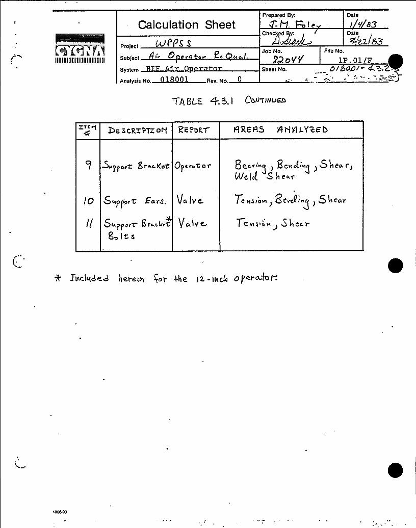
A'~8~ r~~IIIIIIIIIIIIIIIIIIIIIIIIIIIIII
Calcu!ation Sheet
uPPz s
Subject
System
Analysis No. 0
Prepared By:
IeGhee ed y:
Job No.
PQ o1/Sheet No.
File No
Date
I 0'83Oate
<zz SZ
1P 01 F0 IBd.dl- 4.>.Z.
Tp /LE + 3. ) C'd97INuFO
X'TE Q LOa hckx'9TZ o5 QREA5 HH H I-YWG'b
~p)orC Sr~c.K~% Qpecot. 0 t'e."-g ) He~A.g,She r,St e.~
Ear~.
SLapporW 8 t'c,c.keC
8 its
Va iv~
%r've.
7;„g,'., Qe.g',5I t. r
7e~)' She~r
TIAclqded heI-t tg goy 4ht I2. - ieC4 0P~i~kt-.

e deL d 'I
CalculationSheet
Illlljllllllllljllllllllllllll
ProjectWPP S
Prepared By: Datei . eismic H drod amic Re ual. J..E'. Rakowski 4 22 83Subject Checked By: g ~ i / Date J /System
Analysis No.018001
Rev'. No.
Job No.82044
File No.1P. 01 F
018001 —4. 3,2. 5
4. 3. 2 CYLINDER OPERABILITY (CON ')Ability of the spring to fully close the valve depends on thecoefficient of friction.between the sliding surfaces of thecylinder, namely the drive rod and bushing, and the pistonand cylinder.Although upper limit bushing pressures due to load reactionwere given by Miller Air Products for consideration of shaftwear, (Section 7.0, Ref. 5a and 5b) this alone is not asufficient criterion because piston friction in the cylinderis not accounted for.Therefoxe, it is recommended that one 8" air operator(CSP-AO-3 or 4) be fieldtested'to verify operability sincethis size has approximately only 25 percent the residualcapacity of a 10 inch. operator. Dynamic plus static bush-ing pressures for these operators are calculated in QID's361106 and 361104 and these may be used as a guide to speci-fy the simulated test g-level on the end of the air cylinderby consideration of the bushing. reaction equation in Ap-pendix B of this calculation. The test load should beapplied in the direction which tends to rotate the cylinderabout the trunnion pin axis. Bushing pressures for boththe 8 and 10 .inch operators must be considered in compari-son to the'elative residual capacity, of the 8 and 10 inchcylinders so that both sizes axe covered by. this test.
4. 3. 3 ANALYSIS
4.3.3.1 12 inch operator assembly frequency*.
100s 00,
Similar calculation for the 8 and 10 inch assemblies aregiven in QID 361106 and 361104.

Calculation SheetChecked 8y:
Date
ill:~f~
Date
t= 4QaIIIIIIIIIIIIIIIIIIIIIIIIIIIIII
Fmject
Subject +WCirgr) r 0/<.9 err rt
Analysis No. ~+- <> Aev, No.
Job No File No
BED~~ YF 4l ~ ~Sheet No.
d'l8 c z i- .9.3, /
Z ~pEQTDg 855EHQLg'PEgL)&AQP'ALCV
LgYK Tt t& > AYQRAL ~R= S <K~cY Qr ~< Ig4
C Yl t HQ 5~ ac%.A'7Q~ DQQ 'TG THE, EKNDt+ST'l 7 l H+&& OV T'l-'.~ P+'.~l—
M~WAt OWt
24-4'5'I
LQiot R~F
llil,75
3.%
~F'p4 = BOo+
gHn t QAtOTta.oa et O~
al
/ IO.Ot 4Goo ( ~,i"') = .~os.z
/HW2.05- 2. 'L I I.22. )
TO MKg.COM~ p t-tE. &E,ATl N Q ~O~Q =Qppy,~ g 17000 '
)<gg 'e (PER Ft F ~ 4 f 18
t
�wasawe,cy

Calculation SheetPrepared By Date
At 82.Checked By:
Ja./~/s z.Protect t Jt J Crit C~ r'C
J~
Subject /C - JJ' ~W XdA
Systemt' 8 dot"A7er r
Analysis No. ~~~ t Rev. No. ~
File NoJob No.4Zo~Sheet No.
5 05 B 4 s f S
IIIIIIIIIIIIIIIIIIIIIIIIIIIIII ,ot'D
t' . 5, 5 .Z.
C.A.~MLATl 0 M COPP3+ I0oo+ ( lI? I?l 3 .ool7'ox5"
z("-to )(~».~)
soo+QN I TLOAMA
ROTAT l 0 H AT 6 DOE, TO 1~tO OP Jt~ ~~IA~~RAIl
27? o5OO5
>n.= moo( lo.ol)5005 tw 4
rl24.to>
ttto.de
5005~2,c?. i . 2.l ~ S+
7.77 07.Z7,7 .
=. I2 <'9
2770O73 35or .3
I 1>.b yp5os> (, z. )= ZSgyy
AaaA I
3+t. 8
'l2.09
4,ggII
A~n, 2ARFACC A00A, = 5 (I<.55) .4 5<-,»
A~%A 2.
RKc.TAs g t t= ~
Cc - Y.( ii )=;s.z4~=(iI 3(I2.n) = ISS
Vm,t 4 Na, L-E.
CC= a( II g- >,»l '7.I.S5-I7,0$) = 55.f 3;.
TCc„= (c-~ )(w~) -Ccg )(A
= ~i~ * >+'»'-: 9
l33 + 55,r 3
.( 6> '.
ti r:O3 =-<.y7:

Calculation SheetPrepared 8y: Date
63o 8~
f ~ rl=~g=- = ~ i t„ f x x
IIIIIIIIIIIIIIIIIIIIIIIIIIIIII
P oiect
Subject 6 Dr&4//7iSystem fP 4/ 8 cO(6+8/ S
Analysis No. +I ~+++ Rev. No.
Checked 8y:
Job No
Zo~~Sheet No
Dfteia.lV/S 8.
File No
,dr'
N//Cc r- 4. 5.S.3
Jw(
9~0 + [e8 fg11. tb8
2A rb5
~S = ~"4>.~ + Z~( I= eq>g
G8 - ~ =~ DO 0 808
>) X iO
'rr rr
PcFLFcm~m Q Pot~a A
IDv8. ~ &g
I=
~ 000908 (lO.Or) ., OOSoslIr
g„= . 0000'LS + . Oo'508$ = ~ 00 5 loe
P SonI tr 0BTI
oocQI O$
'C.os
7j! ~= s'-.<)
<O you HN ION PiQ& AitIe PRIV PoP '-
I
PFFKL,Eat C 'TO @t,g pgIIO p 0 36ud6 ~H t'- r yc.IHL>EJr'-
Q SS Y l5 MFF rALllLLELT0 THB@vE ROD . LL SE THEREArB.~9 c-y'Lt N Pt'w FJ'Egd E.p~ 1 Ftt P- THh. I Ocr PARP~cE~
WO WH-E. TP-9 pe@ H tl.aIt

project ~ F I S&-Subject
System
Rm~u A t= C A. tL(3
Op~
Calculation SheetChecked 8y:
WcJob No
Sheet No,
Date
Ir Ps
Date
FileNo.'P.
OL
Analysis No. < daoi-,4.3,3.4~C
AXA </~/~
5 I S D Ltt6 8 'P~M
LII)baR
W- ~~a~
Oo = 8.<s" J.D = 7i97
~ (S.~S'- 7 ~7")
(PICA ~, A W) { lAP+1 1 ) ( f)(t<.4()(>99)(lf) =
. So>7$ .4

Calculation SheetPrepared 8y Date
IIIIIIIIIIIIIIIIIIIIIIIIIIIIII
Project
ubj eel R
System
Analysis No.
'1 'I
Rev. No.
YO
Job No
Nza44Sheet No
Date
la a/gQFile No.
1I .O I
F'z/a
Ir8 AkJAt Y&is MMT
Sa.wo<ve sm.a. ~as (x,')
AXiAL. smsssss (.y)
ClW'(Q) 3~ r ('7')
= 452 I ~IQ, l3
E.ssr-s FP e rn PREssoR.E
+r+%1Am
1 So (> ~>)z (.z+)
\woe vfSc3 7 ')7)
RM tFtt 75 pgrirt0rhL
6TR
vV 3 rR(l4) lOZ, p» <
A, t'o- I ~~
1006 00

Calculation SheetPrepared By:z/c Date
Ir /7~ d~
~
tIIIIIIIIIIIIIIIIIIIIIIIIIIIIII
System
Analysis No.
4tRev. No.
Protect Q PP56—Lt&tCAvrO
Checked By:~r = DaIe
Job No File No
eZO44 t O I
Sheet No,
or9oar - 4.9.3.&
g,~/p~/~ 4/zz/a8
ANALYStg (<>~ i)
DRT~Rpn r u a OQ CYF PRr Q nr GTR
OP&a.
I Iti) .ROZ, lo2
g-(„,) 45$ 8 483.B 02S7
.l27S.
J/g '7+8
Iz75,
-6 VGG
—l275
PRI At- I PAt @maes i s:
DPE.P ~~So = II,'ill pst ~ = <>+> p~i
+PE. —GtaeS '. = +225 pSI G = l775 pzt
~TR,RSS tW~S tmGS
DP ~ ~ra.s.'lz33
™~~~ 7 +f's'.t's
/2, 020
- '7'720

Calculation SheetPrepared By:
CheckedBy.'ate~rf~~ s~
Date
Project
Subject CA'T t
g. Qp EIZ. T RSystem
Analysis No. O ~~DQ I,„, Q
Job No File No
~Za44 It .c l t=Sheet No
a/8 c ~r-4.s. B,7
.~ gri'M 4/zzrss
JAt Cm7.
„= IZ,os( F.I
Q+L.t ~gg+ ~R'Thgl Ftt I 5 6 5 I P >T=-4 ~
~ VSG +v 30 cQ psr (matc w rs ar r u 'lrr=Lo)
~wWt- = .& Sv= IS so~ P3
~ ~ SZ „.- /206t ISOCoi s
CYt lut-WZ. i 5 ro CC.C-.e~t K
Tl E. R.o g g t
I GAD = (1Wsit a AREA) X (pR ssuae)
= +t ') (I~a) = 7<43
Tl E
IS II~ 3l
bO') 9 pst C

Calculation SheetPrepared By:
Checked By:
Date
/rg." ~ gtD te
IIIIIIIIIIIIIIIIIIIIIIIIIIIIII
project
Subject
System
Job No File No
SZo44 >P Gi PSheet No~OO IAnalysis No. c rBc~i-,s.9.
AWJ~ 4hz(ha
A 5t ( C rc~-.
5 vPPoR.T 8@Ac,KE~
(Jar z)
QVe< 0 14
P I rdSI,5
W=>ee
2.3. 54 "
RC. TRo& oM t I hJ
dv ~are t~Cs
N- QWL = 5.0 (59'))(5i $ -(<5.5 ~>>~+))
M: . Qo775. 4
(,a=r- o~c A-~>H)
F. 77K ~ 0js.a 5
F Yt L
g i W~~) TD~ W C'l r.i ~0 (~
~~t Se~) ipse(,i&40 aF Prrr
r 006 00

Calculation SheetPrepared By:
j&~~~Date
i.v'. =/~=Date
JafktIIIIIIIIIIIIIIIIIIIIIIIIIIIIII
Project
Subject
sy„, )1=
Analysis No.
i ATO~QJob No. File No.
&ZO4d- IR OtSheet No
O/gC)Dr '-g 3.3,
4/z z./83
lp8 ~ACYLt Q C.n~T
L = s.ci" L„.t 4-+tCGc~i
RE.F 4 t9 3t' t&4P.
M3 5
PORC.E D VD CLaViS RE+TAAiNT (Q —prCECW-><w s
F =F +P
MV ~F C,ut t+~~ = 3cyg
W F~- Fc~c
( / IO I rgb Q q c O~)
F, F~I t.'LZ
ZS t
11,2w

Calculation SheetPrepared By: Date
~:7=. /~-
IIIIIIIIIIIIIIIIIIIIIIIIIIIIII
Project
Subject
System
Analysis No.
P&&—&- t m>C.
a.&At tt=>cAVtC)
Rev. No.
V''ob
No File No
'BZ.044 l~. COL
Sheet No.
c3 ISDo/-.4'. 5.5, ib'P~omjC.Iw(
X~~n./~ ~hz/as
nAQAt YS l 5 C-~v
F = s~~s ~R.aug -. 401 (QZO 36llog> c)caw canc's.)
t c~= F~.~ F',~, F +Fz +Fo
B+~)WG ~QA 'Sv PPDR.i + ~A<M>6) ~ I
BC~~~ I <Q At~Cd = A, P

Calculation SheetPrepared By:
Ghee d
Date
0'ate
IIIIIIIIIIIIIIIIIIIIIIIIIIIIII
Project
Subject
tS'H t CJob No File No.
iw, n< F=
System
0Sheet NoOr/o~ <- 4,a.B.> i
~n .~~,n~/~ 4lzzl86
8 A~At YS,t 5 c~~
Ctd KCtr. BlZAClCC'i Fcr P- BC~0 r nJ g
lr.Bor 7 IC tRGLE
'SHAi=T~28. 5
!
'A/r2'Q
svr~a.rO~~vw = 5')0
CS c'rL <~0~ '. K~0
N i sJ \ MVIH8 Ec.vlo~
F~ P. 2-9
L= lS.Z W= i>.>S
fHIC,'c,~a+5 =, 5
(MgQ Doe% 4 oT'x 1 sT 9 e>ui ~ ~ 56 c.me»)
5 (,5)(. 2.5) + (,t>.S - I.t,z,)(- S)(t+)
'lE. S(.s) ~ (.tS.S- i rw)(.<)
4 ( cr t ~ so~
597. Co ter"

Calculation SheetPrepared By: Date
s tIIIIIIIIIIIIIIIIIIIIIIIIIIIIII
Project
Subject
System
Analysis No.
At 1P'1''T10
Checked By:
Job No File No
0 te
ra/~ Sz-
SZ.044 >P . o>Sheet No.///oor- 4,3 3.iZ
~Y
~A. AAP8A 4/Z ~JBs
8 An't-Yeti C<c'~>)
e~01M G TRES 9:
N =[2.27 (2,8-5- s) +? 9") (os-s)] /4 0=.,2'gr %so
i Zlt'is~(l~- s.sgq =
— 3'.> r»597. g
XIAL s Ta.~os
(I B. s - i.t,~)(, g) =
FA~mt i o~~aw ~c. I ver.n~ ~ sr
ot =2
1006 00
'
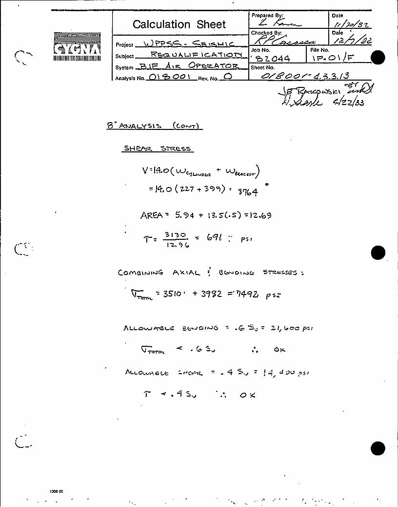
Calculation SheetPrepared 8:
Checked By:
Oate
r 7~ Sz.Dae
Project
Subject
System
Aoalysis No.
R VA,LtF 1C.A TtOW1 t- Qp~tt'i'(3
Job No.'~o44Sheet No
File No.
~ ~. C) 4 jP ~0/c5 OO/ g. 3.3. l'Q
(
~ ~/zz/ss
9 PCM L. 51 8 C.o~y

Calculation Sheet
Project P S5 F- tSHlSubject
Prepared By:
Job No
Date
5'2Date
r~/a s~File No.
ip. oi /t=System
QSheet No~ +goo r' g g 3 jg
UK Wco~K<A.~g~ ~lazes
fit>At'l~ t o~
L~ oQ ~E.~ - (o 0 f4
AREA OF WKLY = +( 7>7) ( 'h[) =~ W4
rlL~C ~ Ot= (Vt=Lg — l 7. 5 (AJEGLec~~g t'c>+ ~o sr4rec pr~)
:. ma~ az> = Cg,s-(.<w) = 7.((( o44
7 ~ lob 7%m) / $ r + + j ++0/~fr ~,' /C
(9'rH BD.)~Pc~oi m Q)
? O Goo too ~Q (8t
(.PM AtSgA Sacmo~FromSVC a~ ~c-. c S,
ASSvrne t o~t~g ac~a tm ~ 1 — C.get.~ =
)pr7q p)t C Q 5 G>OQ ps rIZ, cd7.( 4.

Calculation SheetPrepared By
A.K II IK)chal
Project
Subject ~ GALt LCA T iO W
8 I ~ A t z COt a,~go aAnalysis No. +\ +G& I Rev. No.
/IJob No File No
Date
~Z/~ g~'&ZO+4 l P. a l
Sheet No.
~rigour- 4 3.3./Sttrj'(J ( ~~Sac,l
.~~)~ 4/ZZ/at
~C
O~I~C M~ic Hr ANn C-W. t-aW CVLlmma~Ama ~&Co ~~c H C2.iM Wc «Och,
C C ct= C YLt>C t=z. T=ZQP %HA.c7 = 5~t Q,HrW B9~
C>:D = 'lO 4ZBR. 7&0
Q. a~~
17I <0.42 or-Q. I4 ) 7 A4
iO.4Z.S — I.e(. r 9C .73 tn
MoME.wT'RM='DNT. FPObl T RUHNIOA TO r--Cj ~
EAG~MY CPM = cern —(1+. &2+ 2 Iz&)= 'zl.&Mgy~ n = (Mom~ruy AZ~n,(MmirHi l(g)
(Z I,~)( tooI~)(4') = 'T&4rt7.4 in-(b
B~~~i~c Gyrz~~~=~ (>c ANc a).7&4'R"1 (= )6'„~= ~ = 4(22.. Zd g~'~

IIIIIIIIIIIIIIIIIIIIIIIIIIIIII
Oat
ii ia'Lax~a9/gz.
Prepared By
Calculation Sheet
project
Subject
System
Job No. File No
~WQ44 iP. H >
Sheet No.
erg~.~r- <.s.s.iC
wRa w P aa,~mum= ~Q g <jzzj>>
<ao~AD>AI—'P ADtAl
-P IBO (9.q@$AXi RL ~A~>s i Z~ 'Z<z>z) — BZQCo PS~
l44kmF: 6 goop = q =~+~~
—co412. ~st.
5 ~lWA. R. STRUM~esa 6)= 47&.Z5 ~~L
STza++ X O>t R+SRS
s54R 6czs
wp Q+—SR
E(vs i) 475 475
P<t NC tPAL ST'R'EKSmM

Calculation SheetPrepared By:
fA I Il 17 QZ
eh J~"Jara>IllllIIIIIIIIIIIIIIIIIIIIIIIII
Protect QP P 6 KtG K C
Subject YtONSyaterrt 6 \ P At 6 fZ.l4
,~ooal ... 0
Checked By:
cDate
lZm S2-Job No. File No.
23,Z.C)44 >v .ot wSheet No.
O/8 ODi- d-.S.3./7
SZmc v — '2'33I
at'Sutta
Cat tW CSP Ha~stat 3S 4 -3('m>I~ At t o&AB~ = ~ 4 +tJ- = Z\ GOO pat.
RZ 75. < 2> (o OQ ps<~ C~at~m~m lm Ace ~r w~a.~
TIE Pcp>-
'Eoar = (~~~i~~ Av ap)» (w~cawoaa)= TT (e.'llo (~< ) )'l&8b'1
Low~ >~~ Bo z = "~>~ aeZZ.
Roc DtAAK Yt t=t,II
~ (~i~)A,w~a = ~ =
q.= 182.
K
IZED
G/roc = l44L C & I4 psi < 20 k'sI.
(Assume. ALO7 i<waoz s >os)
1

ra B JIIIIIIIIIIIIIIIIIIIIIIIIIIIIII
Calculation Sheet
Project
Subject
System
Analysis No. + ~~+ I Rev. No.
Prepared By
zlJob No File No
Date
I 1'I t-71~ 2.
Oate
rz/~ ZZ
SzD44t iw. oiSheet No
? 7.12& LcL 7 IZ5
(|I,~~ C>AA~ NO
c —2< ocr'
j.375
DOD TO CI XVI'8 E.'SI RAIN (E DIR)
+la = MKtGH'T Of- CMI 1~~~% —S 1 54
a~L~
F~= t 93 2.I.2-~3
(xs. >me)
F~=( ss,c ~ 598) $ 28. 8 .. ~~DI ov t I~
Hogc 'oQ To o.l «vI RKKTIAAINT (+ DIR1
~F Fc1.3"IQ )\ b I

Ia fa%IIIIIIIIIIIIIIIIIIIIIIIIIIIIII
Calculation Sheet
p„;„, RP'PS&- S'- t
Subject
System
Analysis No. ~ ~ Rev. No.
Prepared By
Checked By:
Job No File No
Date
Date
~~/~Ps~
Sheet No
lP.O1F
C7Zdc~~- 43.a.i9'oc~>~ '4JJ
Qt zaAvoP S4>wot=t~ ~L-RA< K.~7
~o~~~o~ Pin
g I.'lS
FO C K A,T 7R.M )O~ Wt r4
R VAR.Ht&
M =g MAL= (g.c)(w93')(c 4 —(ia..a.o. z.s. w~))75407.5 tg.-l6
O( ~a)d = >s.e a ~ ~ = A.&l i~ (ms~. D~< + A 2corrIq-g
Lr~+. C)F, =~75k .C GZff
VaFt.» W t

Calculation Sheet
Project
Prepared By
Checked By:
Job No File No
Oat
r»~le,z
aZ.a44 i~,OI I=Subject
System
, ~**IIIIIIIIIIIIIIIIIIIIIIIIIIIIII
Sheet No
~~/wc r- 4.8.9. ZD
To~At l os>= F~> F~>l=~ ~Kg +~cZ. Z 2
964+ 5~ii ++7''~ s2.>+»'(4+5S5I:
~49. e
gz /~=
F~ = SKAV<14+ Worc&VK, '9 64 ~ (BI% RKPORT p is)(re+ ~3
PKAgtN os SQPV oRY TR.a N >la sw ~i ~
BMAmN+ A,AHA,= Aa —~D
L= TH tc.K.m&MMD = Dt&MM~t- ~W TW
l = < ~Q<
D= < 7B '(Rr~. W>m@. 42 SKI IBAp =( 'I ~5$ i.1S ) =2.'h4iN~ Du@ C-ZGOlb)
Gain mtwc = F g4g Q gp$ 7 .. p~tp, ~ 2..$ %
wATt=~t 0.L'~owAe,~a.= . ISu.= B2 4 'icosi
6 RaAa)HQ =
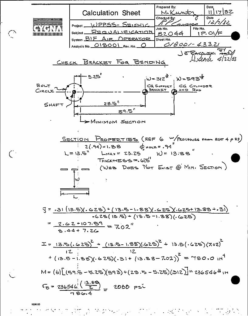
Calculation SheetPrepared By
MI-'4~M \
Date
l I 'I'7 I >Z-
2/5//6Project
t ~Fsc )=ra File NoJob No
~ z.+ 4P ~ +. 04 HSheet No.
c9/gooi- 4.3.3.Z/
Subject
System
Analysis No. ~ O (-l I Rev. No.
IIIIIIIIIIIIIIIIIIIIIIIIIIIIII
~~f
3..v~~~ ch!a"-( ua.c.~ Bvc.<a~ 7oz B=wctw~
9.2% + ~ ~I4= 312 Q=S f'3~Sot QCtact a
Ctni Suorot ySRAVCS Y
(6, CYI-laDg QAHD
zs,a"
SECT'1 0 H
sacwIoIs PgoraIzvIaa (zar (o /p~cao~ac ~~ ac~+ p >v)II
2 (. t4) = l. &8 Q ~ ot a, = . Q4It n rr tL+<> —— 25.h5 4= I5:a,e
II(os('Ncaa, Doaw ttuv E sm'r (Q MIN SKc'Y>o>)
~ 3I (I3.3 CoZ3) + I3 g —I-SS .4 ZK,G,Za+ 'I'3 8'3 < ~ '5)I
~ C Z &( I3 3) ~ ('I3 & I .'K'5 l ( Cc Z &)Q . ~ Z. + LCD 7 W8 rl
a .4-4+ 7 ~ Z.C7.02.
Z.Z,= >3,W .4 ZQ t8,+- L,8S (,( 2.+) 4 hS,Q( ~ ('K)(7,0Z)I Z. tz
( I3.% —I.&3)(.I,ZK)(.3I+ (I3.33 —7O2)) = 7BO.O IN
< = (l l| (3s.a -+.za)(3s3) ~(z3.a —3.za)(~Iz)J= zaescr,al I~
"„ / tS.M,~g= 23454(- i z ) 205 p~~
a &Co ~ 4

IIIIIIIIIIIIIIIIIIIIIIIIIIIIII
Calculation Sheet
Project
Subject
System ~Analysis No.
&T'tZ&~M
Prepared By
Checked By:
Job No.
Sheet No
Oat
I18 SZDate
File No.
.oL F
A„„= (i3.w-i. tea) (.c z~)= 7 z.r. i~~
~~t-T<t'Atda'UN.'TtCA, t
<RAT'15'1IR
II ~ = I'lacL cb.'6'6
I@165 7g5ps't
P,~ Cg= 27. ZQ. + 2055 = '46( 5, . P~l.
GHEAFt &TR,EWM
6 o C clcwc. ~M ace,cmmw)Cc.a ( >+3+ ~ iZ.) = 543 O
gp~p, = a, t.co w ia a ( ~ c z.B) = ia 7
5430i5 7
54.('o p>~
AL.t ovDA.BL 6&
P~mWtM+ ' C S~ —QL l( O~ PW.t
5HaA,R. ~ ~ 4 S~ —14 l4OO Pa<
l000 00pmv tovs t-q Ca,t cu Wzm

Calculation SheetPrepared 8y Date
I l i~ i+Z.
IIIIIIIIIIIIIIIIIIIIIIIIIIIIII
Project
Subject
System
Artatysis No 0 TWO 0 i Rey. No,
Checked
Job No
Sheet No
Date
rzi~File No.
IP Q1 F
or9eor- 4.B.3. E 3
~~, w~v' A,~~~o/zz/zzOi
o" o StNCS 6 ~o~~L=. 4$ IS <. ~ 4 Su. Z),(oOQ p>i94co~.4-S = l4,4ao,
THE, 8 Z.AC-MT iS ACE- PTA,EbL—
C ~wc.w Am~rom ~ ~ G a~~~w
LOAZO CV 'd~L> = (
@gal
+~~~ = z(.var)(.ai p= .44t
LE-AQUA H ot- QELH= F7 i 7 Q (HMG,LE-c'TIN+ Pt~)'' Tora< gas< (<a,76)(g<) = q.el,~
6 = 0494 ~si < 2i 4 OO ~>i
k)HL~ i~ A~~wT ~Eh I c=
r b PATtr'6 4<C>C.ySI5
SI&jt AQ To VA6 S'rg C)Peag —,ag,7 WE'r=-4b STRCS'5 r5 r d W SUCH WiA~ nfGSTRESS +r446'< rS r Ak 9CC,O~ y4eZAr45e 41VGA 8y'ISC,, D~~ C&r7-roN,SGQv rortJ 8 r4PP<rJ+rg
tooe oo

'alculation SheetPrepared By: Date
///Z~/92
IIIIIIIIIIIIIIIIIIIIIIIIIIIIII
project
Subject
Sy t.
Analysis No.
Ghee ed By:
Job No.
ezo44Sheet No
File No.
>V.CI ~t=
~4 ~ Rev. No.
+~pelt y~+(ct ,.~r~ 4/sz/3
'renow-
4. 5 3.z.4
4.~.3.4 QALYSIS aF ~a IW 'PS~I
C.YLI
&DE'SSUME:
cOD = l2. O'25(,Croe m vcc,z or- rNpo<nwne
(.I2 t 25 j2.o )+
.gD = l2.o
)2 op
p . 'Tl (r'L.V?.S -12< O ) pZ p Z r~ 4
4
o c.Y~i ~a (Ler. 5)
C.YLI%DE.R ~
I~.cg (.~S>)HT Se) = i( 3.S
Bt Or XS:
Q,5 (I'2.75) ( ~ 28)( ) = 22-7
BAaS:Z(a)(I.2.S)(4~.SS)(.ZS) = IOO.SS
"
Pl STOM:
(Qg.gay $ ,5+ 4.375)( M'5) &9 ~ 6
itE, RODS
(q)(+s.ss)(.ass)= +i.7
iCTAL, ~Et'

k KitIIIIIIIIIIIIIIIIIIIIIIIIIIIIII
Calculation Sheet
Project
RQ&UA.Lt%'A'TtO'N
System +Analysis No. +I C ~ I Rev. No.
Checke 8:
Date
Fzjr~ -o~
Dateill~ a>Job No. File No.
Q,z.o44 >p. Q1 FSheet No
Oygoo i- cf.3.E.ZS
Q~Q~~LC. < A.&~/~~f~h;
l2. AJALY+iS, (Cc ~)
CYLIAVOCA. (C
re~&-rT—~m = DtS~t-= Wi8c~r mO~ta~ ~ C..C.
rnom~~~~~r <4 SS- (Zi.~s ~(i~ 5-4.~) = lW s".
= ( ~4 5) (>+3)(5) = 422,C a
ot S~E.~~F& ( X ~ E)
— MY - Xa~~e . (T 229
I '@<- ]. psi
~W( ) ss~(<)I Z.~~
ESSES FRo& PREssURE.
AXIS,L t
i-IoOP:
j~~(~)I o c'
A<ini Zg g(.~~ I)
Z)ob F'=i< so |.'a)

Calculation Sheet ZgChecked 8:
Date
!rf~ le=
rr t
IIIIIIIIIIIIIIIIIIIIIIIIIIIIII
Project
Subject
system IFAnalysis No.
Op~i M Op
~OD . Q
File NoJob No
~z~44 1 ~- 0) /FSheet No.
6 ydgc or- 4 3.7.2Co
l2.'WWLVSt~ (C
l)g~gfntwA ftOA Of- R2I QC, I frM STOIC.5~ F5
OPGtp +Re r)Ot«SR,»
(le 8 I l.bs '/ v)p I+os '3 ///
+p5I 2+1 2+t'~ / 3e j 54l
~~.p - >> - g =-7S3,
PR,tWC t PAL SlMSS~Q:
2
G~ = zdsD p
OPCa. — a7i'+
mP==." —5 r-') .

Calculation SheetPrepared By: Date
I//go/43%
IIIIIIIIIIIIIIIIIIIIIIIIIIIIII
„„„, ~ PP&~-<~i~uicSubject ~ . OWL.EF' I Q
ystemt-~~ .T R
,... Q
Checked 8:
Job No.
e ~~44Sheet No
Oate
File No,
lt~.OI e
Wi~aor- cf.S.Z.Z.7
+e. tZ~~~~ ~~D.~~A- 4/z2/b3
12 @+At YS I 5 C o
SZ'~ = 9439 pst
o~ Q~O~A<~t E. - I 8 OO~ pSt

Calculation Sheet Z g~Checked By:
Oate
yg/- gsz.Oate
IIIIIIIIIIIIIIIIIIIIIIIIIIIIII
project
SubjecttW
System
Analysis No.
S —SKEW \C»4 rAtm Ot Zt. A t Qp
Job No
e 2op4Sheet No
File No.
1F .~>F'//acr. 4.3,3.zS
I2. Ruhr sly c~w
t5. 5rRuuto Q
Ptm
'2 I s XF5
)l(yea~)
GScs wmoac,
M.„„: &IS
Hb. S
BRACKEi WT'

Calculation Sheet
p i t i >>RS - +NtcWieSubject
System
Rev. No.
Checked y'.
Date
(( ~./e~
Job No. File No.
&ZB+ t It .ol F ~Sheet No.
~rumor- 4. 3, Z.Z9
J e ~~~M+lc.lA~~4 zz/sz
ltA~ALYS t 5 Co
ORcES 8 %AH«a PlQ
H= @ger 5
depth, = lb"
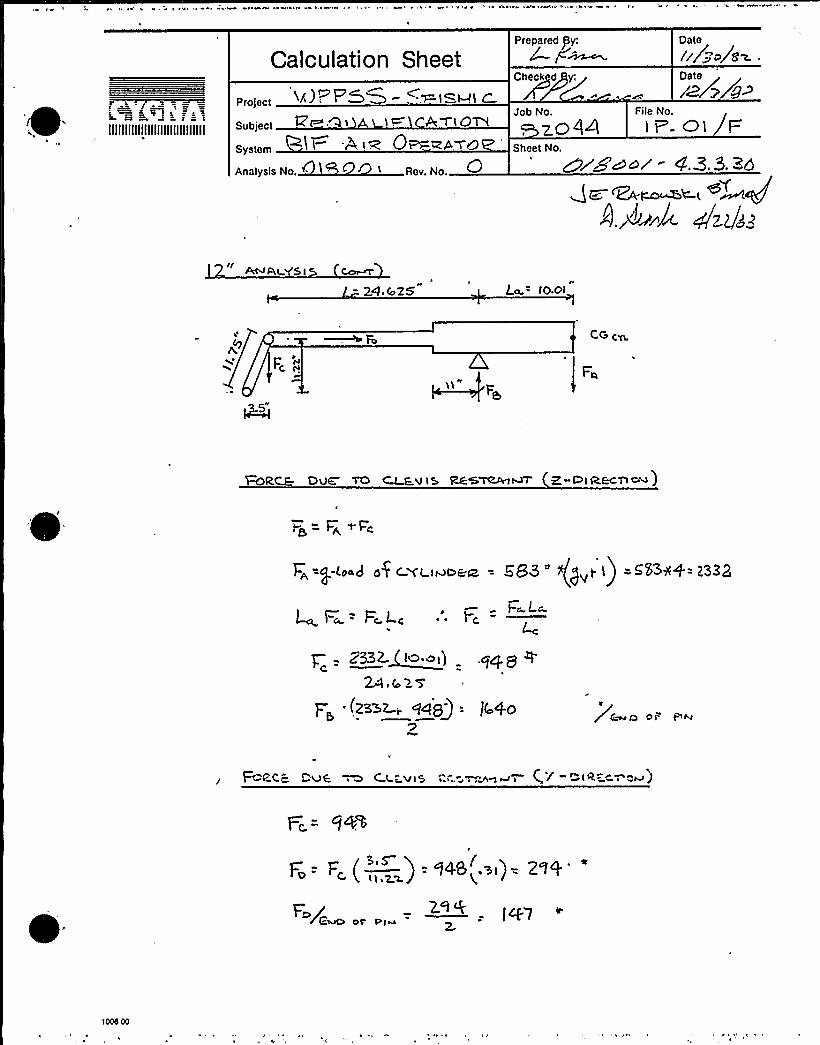
Calculation Sheet
project 8 ): F & ~ 1 'Kl-IIC
Prepared Py:
Chec~kd y;
Job No File No
Date
rr/- /eDate
IIIIIIIIIIIIIIIIIIIIIIIIIIIIII Subject
System
Analysis No.
AwtOM4 tW 0~%4&Q
ZCig4 I P C)1 FSheet No
Dr<~~r - 4'.3.9. >c
~ A,<95 i
- 24,r025 iO.OI
ce.
~RCE.- DvE TO ~v t5 Rk&VRA.t~ Z-C iREcA)
2@= F~ 9-~c
c~=P (oad af cvu~caa = G8s 'J„t1) =<5'311+= 1332
4 F~= F~t cI
l=~ LcF, -—
ZSzz.~e,) .94 8 eWir >S
p;.(zs~z „94'= )(.40 rO Ot"- Pi~
Fc-P-t c. C,'Vk ~ C t "W1S ..=-V,~~i (,.'/ "~tk"- i "~)
F~ = F„(—„' = 948~ si)= 2.99
Fc/ - fzf7
1000 00
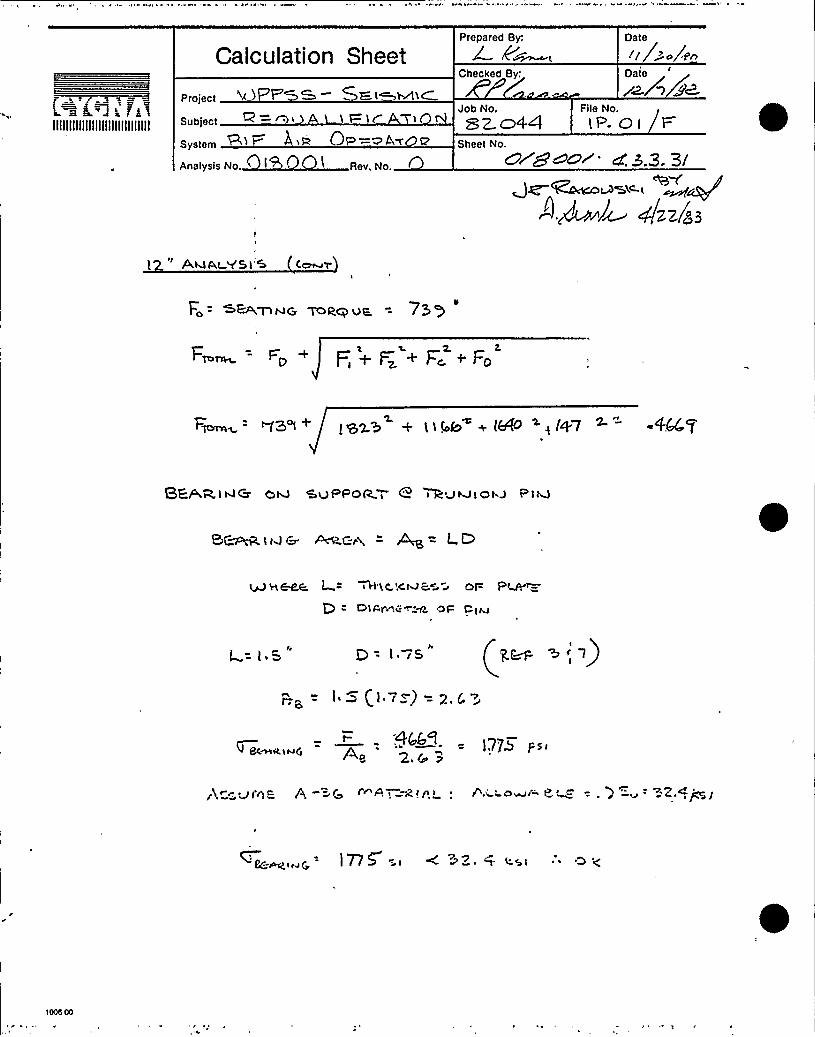
Calculation SheetPrepared By
Checked By:
Date
I/ ~~ a/ pnDate
~"3 k FkIIIIIIIIIIIIIIIIIIIIIIIIIIIIII
System spt OP —~AT 4
Proiect ~l ) P M K. t~~l~Subject 1
Job No File No
SZ.co44 tP. a I
Sheet No
Analysis No. Rev. No. 0/gcor- 4S.3,3I
~~ p&J~ 4/z 2/s 3
AM,Pt +5t'5 ce
Fo = s&>gG 'ToRQ vE, = 75 Ql
Fy~= FP ~ F,~I= +F~+FD
F~= <ZAN+ ~gay + ~<gg '+ (gO >, lyI
SEAR t 4G ov SvPPoR.—, 8 ikQhJ IOhJ P le
BC~ t w c ~c,~i = ~ = LD
ltd H &66 L = +t'Kc.Xr4 c~~ r QF P~Dt~Vv,<~X, Ot=
Irf = j ~ ~ l. rS
F;B, = l. - (j 7Z) = 2. C ~~
1776 /sr4f c.g
Br~Atting
Ikey~ Vr'6R A ~G r A! 24'> '+.Q~Ow(» p t - . t "ay ~Z.,+ I
C(~g<r<Q l77~ - r + > ~ t '45L ~ ~
1008 00

Calculation SheetPrepared 8y: Oate
//fr~ SZ.
Z j lIIIIIIIIIIIIIIIIIIIIIIIIIIIIII
Project 4 t P' 0 —4= E lt C
I I t GAMIC)N
Sya«~' I- t W Q~(2 A r QQ
Artatyala No 0 (QcQQ ) Re> No r
'ii~"File NoJob No
7 &44 I I - 0 I /I=Sheet No Zr8ool- 4. 8.Z BZ
tX" AWOL. SIS
I
Cga CYc<~vCrt,
N/i 58lo'
CI-I&.C V. SkaC.ICa i FC~ B~C tMGA
SHAFT~~iC-1 QJCl ~
I
CC cvrroat II
% vpr oft
W= 58(n
C(b c, (L,lu0&L
%=683
Zo.vS i 7.73, i7.73
IH>wow~~11AM
zo.78
'Ecwou
PRoraamas". (p~ q)
L= 22. W=LC/g
TH I C.K.hlGS'5 mt= 4 - 5
(~M ~S mot 6w>st'Mtmsmv~ 'SCCA~)
'z<(.s)(,zs) (,>z- z. s)(.s)(jr-.7s)7g
Q5'2.(s) + (z,~- z.~ s. ) (, r)(.S') '2g 2., 75 } (,$ ')
( )( )gt2 IK
+ (22. -1. 7 5') (, 5) (,~, 7 q P)-
p = l441 t~4
t => t- Pr GE

Prepared gy:
f~ zw 'FL ~== DalkonIIIIIIIIIIIIIIIIIIIIIIIIIIIIII
Date
i /:~/s~Date
rd e 8z-Calculation Sheet
Check d
Project 9 SS SWL ) MLCFile NoJob No—Q138 t x~ tC >tQN SZQW i~-ot F
Sheet No.
~ggcol- + g p gg~Y
'3~ giz(g
Subject
System
Analysis No..
A-tuAt YS I 5 (.~~
4
OI= BRACKF t
St(~~)(s.) (~) ~ +I4(.«)( <>(»-t~) +
91 ( E<) (, 5') (. K) y 1 4 ( t 4) ( S) + 2 ( s) (.7 $) (»)
+ 7)(i)(>$)~ »~~
I'?. 75"7 (a')(,7 p)
S~Dtma Srkca
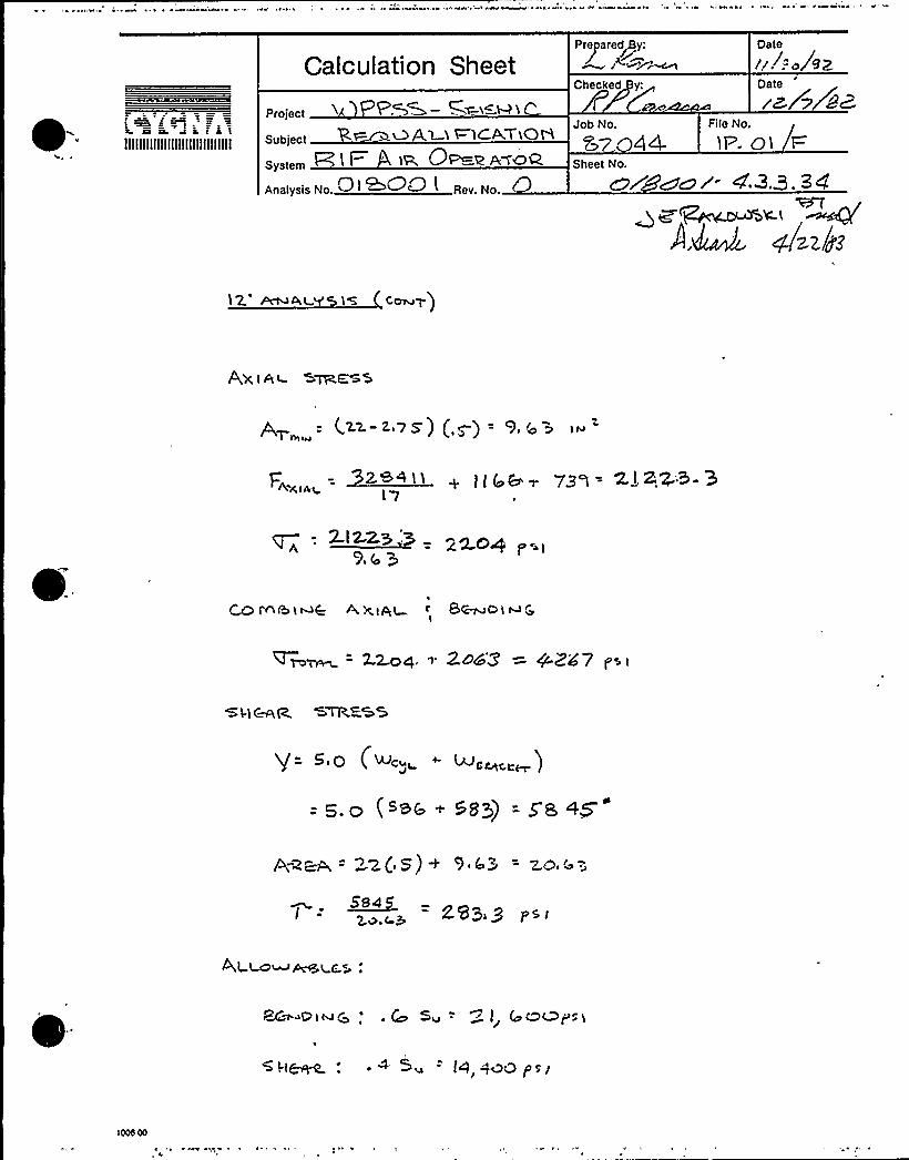
Calculation SheetPreparedgy:g P ~MS~
Date
~.l:-Jew
IIIIIIIIIIIIIIIIIIIIIIIIIIIIII
project ~ PAW- W~x~W t
Subject t= M l 1 ~iC~rtO>System I t '& OP Z AWn<
Analysis No. I ~~& l Rey
Checked y:
Job No File No
Oate
rz,/> aa
S7 44- 1P. Q I F=
Sheet No
DP woe- 4,3.3.34
12. ~D t„g tS Ccrr >)
Ax tat
A~,„= 4~+ ~'> 5') (,~) =
~2.84 i + l ( gb, ~ 7gq = Zl 2+3. $+XIAI
g . 2~l2 Z> ~ ggA P
B~oi ~t
2.~4. t 205'Q' PPg 7
0 (~cg~ ~ lAJP~<
= s. o (>a~ » ss>) = s.e,
es'(5)+
~ ~. =
~5S 4

IIIIIIIIIIIIIIIIIIIIIIIIIIIIII
Calculation Sheet
P K- Swiss tcSubject
AtAnalysis No.+ I ++ ~ Rev. No.
Checked By:
Job No File No
Date
rz .=.~/e-Date
8Z
6zo44 1P.'(Sheet No
c>Y/oor- <.3z z<
l2 ~At YSts
~ ~ Stet E,

IIIIIIIIIIIIIIIIIIIIIIIIIIIIII
CalculationSheet
ProjectWPPSS E ui ment Seismic H drod
Prepared By: Dateamic Re ual. J.E. Rakowski 4 22 83
Subject Checked By: Date~ ~ g+
System'nalysis
No Rev. No.
Job No.82044
File No.1P.01 F
ol~ t—B.B.s,36
lz AMALvsls (coNT ro)
DIt!IIIE. ot)IO.OI
LcCZl.57
0 11
L7.11E
2- A.>os
tf13SE, g g lO C1OIPOEf-C pglug racO CECSS SECWOlOAL
PP E.A Fog. CO 9 9P'R.IIII;l t SPh
Fc = LcOo O. NA +oi, = /O~l r. E9r3(3+1)= 'BslLgQP ZS
Mg= '7.I~+ F = tHS ~-q NATL:4r% -4I Q
g@= Hg Q~ — (-(ss ~ .4%~F 3l,ivz. Az>g . I 3$ '3 C)K
8 c.yL
S11EPP lOo V GcuEESl <VG PER 'KC lO A/o ANAL ySES)ev)a R.oo ATIG,
EIJ I)4 ~ Qpg 3Qf PSX C $ 0 ~ p5 p $>RESS kRQSE <>~QQ p p
%3tPH tc 0
M, = 1NAc + oj> 9 lcc = 553 o'5'l lo.or= Z.9,1"l9 lilf
1OOe.OO

3< fitIlllllllllllllllllllllllllllll
CalculationSheet
Proiect Prepared By:WPPSS E ui . Seismic H drod amic Re ual. J.E.
Dateowski 4 22 83
SubjectRe ual
Z'ystem
Analysis No.018001
0
Rev. No
Checked By:
82044Sheet No.
Datetc
1P. 01 F
d.3.z.z7
Fz~.= r ~Z-9 Br — ZZ S9x iz..cs (p s" m)
F« - (Lr o~Loo,) ~~~, (zsqio.oi')yA>%(+g= VS'i gLg p z
?5'~
~~ ~„zest ~S. Ws8 g2. 2.
FsT> = 737 IIja. (~ o
F~g(g g~ ~3 z fz Q (.QN.OWL ~~~ pJw.)
j.
Fzg+ F~.z ) «( + Fscac.!
,'1s+ Z.QI4
IL(zzS9+iqsg) + lGS7 )+ lv3a
- /OSdg-
cjly~FE
(a~i
9 UPI'o rR, /san. Qo =C o I ~ Sf/ fop. Sa rkdMl Y
SoLV WGHStCH = PT = l4FB t hhhX +ass+LlAg 41 2ht. 'FA g
Ir
Alo PlMSHSt0NS
g g I, Iq to I+)= . 334
FOR- Cozen SEgV h O(DM
|ted.'l>~ earS - <.l+Co(A&t+0 f(O~
0
1005.00

llllllllllllllllllllllllllllll
CalculationSheet
Project Prepared By: DateMPPSS E ui ment Seismic H drod amic Re ual. J.E. kowski 4/22 83Subject
System
Checked By:
Job No.82044
DateO
File No.1P.01 F
Analysis No1 1
Rev. No. Ol't Ml- 4.9.3.36
5"Sz (r%$ +lo ol).//so) ~
+. Ztt'-',lS.7>)0.Z)
(IHgZ= s'R4+ ssB.Pg, Zd )
Pl pg = E>i5'7~
/AA„= l,rs3~55/)(7) j.) P).
yl = j+'f-eZ. mf/-ss-- bs~tss/.I. „)=
IKS Wl.S4 = I~ 4F
zg g
D
i
l6,0 t
r~)Holt~
+)oixseoL'g SHE
Ko 575 + /4A.vz + lcm - /z. s''/sps't
3s(sws,7 its.>sX.so+) w(..ssq3 ( ao/ am> ov(rop A 3o7)
I (s+ /e)t = 1-s~~ + s~„$
lOCd.00

B A D t
IIIIIIIIIIIIIIIIIIIIIIIIIIIIII
CalculationSheet
Proiect Prepared By: DateWPPSS E ui ; Seismic H drod amic Re ua1. J.E. Rakowski 4 22 83Subject
1Checked By: Date
System
Analysis No. Rev. No.
Job No,82044
File No.1P. 01 F
Dl b~ I —c2.P,3 gg
p~t-w gN E+ A. ~ F mo ~R.l~w vzc INmztq:
S<l-l = (~pc +'DSD,) + gv%Ay
StH - II69 W I.S f IS<7PSX'339)
Il E.RttCCIL + DE.RO uJEtr" H V QcL,T' ST'26.95
llr 'r ( l+I Qcl-) ZZa.Z PS X
4Al,
( S(g ~ S)q ) = 2S'9tt PS l
ADD SIIEAR Sa(JESS Dug. >0 TOgQQ E (= pM>>+l9+<
4339 psz c ls;cDD psz l'Ew l3isc sec lr x z..Azoic H~v't . (I S+S)
$ 0 rE: QC t-R--tl C.u L Pre ht l Sit t=ag tX A/OBFc AUSE. po HwQRogyNhM tc Iagg
C y C, t I al 6 g ~ pE g. IEPCF 5.

f ~'IIIIIIIIIIIIIIIIIIIIIIIIIIIII
Calculation SheetWPPSS-Seismic
ProjectRequal ification
Subject
A rr 0 . rw7~"r
Prepared By:
Checked By
Job No. 82044 File No.
Sheet No
dr8oor-
Date
Datel2- S-82
Q+ REFERENCES
1. 8" Cylinder, Dwg. No. C-26096, Flick-Reedy Corp.
2. 10" Cylinder, Dwg. No. C-26045, Flick-Reedy Corp.
3. 12" Cylinder, Dwg. No. C-26093, Flick-Reedy Corp.
4. BIF Report TR-74-7, Rev. 1, Dated 1/5/76.
5. Cylinder Support Bracket, 8" x 15" Cylinder Operator., Dwg. No. A-208293.
6. Cylinder Support Bracket, 10". x 15" Cylinder Operator, Dwg. No. A-208195.
7. Cylinder Support Bracket, 12" x 15" Center Trunion Mtd. Miller Cylinders.Dwg. jj A-208274.
8. Manual of Steel Construction,
9. Cygna Calculation, 82044, QID:(
10. Cygna Calculation, 82044, QID
AISC, 8th Ed.
361106, Dated 12/7/82, Rev. 2.
361104, Dated 7/23/82, Rev. 0.

QID 018001
APPENDIX A
SUMMARY OF A/0 MODEL
USED IN PIPING ANALYSIS

llllllllllllllllljlllllljlljll
CalculationSheet
Projects
8~>- VpN ~c A~a f~Checked By: N
z4/z 5
Prepared By: Datei 3
SystemCS'ob No.
Sheet No.
File No.OT,oj
M@
p) op L Cot Ft U
( tM CeNV~oV y
(EHD RELAAS<)
g) gC1UAb gTRLIC'TIJIZE
5 TABAC.[ERAL lhEPA QEk DtREc.r~5
(9 +x-v
Qz
qxyz - e~AVz
gxPn ~y
+vQe -v
1005 00
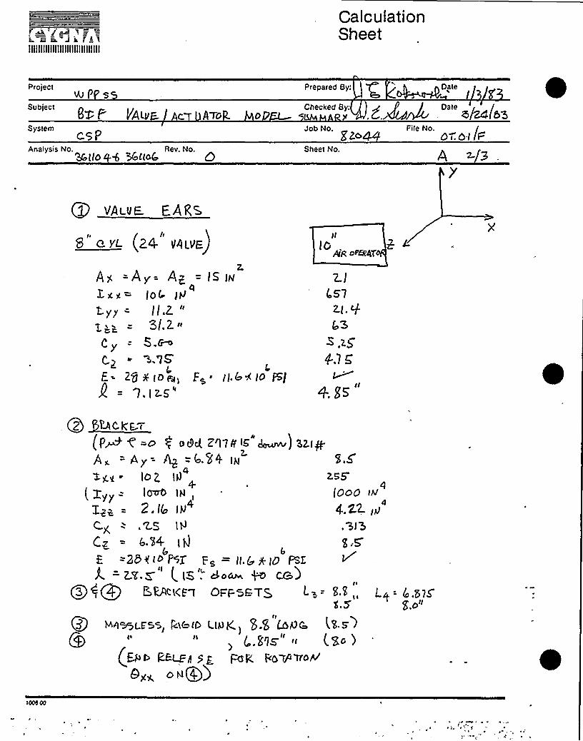
1 ~ e''IIIIIIIIIIIIIIIIIIIIIIIIIIIIII
CalculationSheet
ProjectUv I'58X O'Ae c ATo
SystemcqP
Analysis No. Rev. No.WIIO + %tloQ Q
Prepared By,'ateJob No,
ggaSheet No.
File No.0 r. 6 I /F
Checked 8y:g~ Deke
VAivE. EARS
8 ~ y~ (24 v4tva)
Ag =Ay= Ap = fs w4Jx~= Iot
~v~ = I/.Z "
3/Z'y
= S.~s.'lS'
E= Zg y IO@, F~ ~ II,@< lo %]2 = a.iz.s"
Jl
IO,pig Oui,'4T
2IOs'l
43
4.1 C
+. Ss
QZ 'LAc k'E. (
(PM < =dy 0 o8ct Z'l7N 4 ~jSZiy.A, = A y = AS = <' et i@
lo p4
+255
I y<>- lmrO IH, tgog
2.I(a 19 4,22. (4
C< -..ES IH .'3l 5C~ = sit
6Eve
=25<<> PK F = II.Q +IO PSZ
A = Z!r.S (. IK . dOdch, ~ C&)Q3$ EtVILKE 7 OFFSETQ E = S „Lg- tk.stS
$'.o"
Qy yh~mLrss, roke e L<kyK,~ S Stoic .t'E.E l, r.s~s".ltt.)
(B r ~8 $ g Fard. ls yo yyo<
Qy, NQ4)

IIIIIIIIIIIIIIIIIIIIIIIIIIIIII
CalculationSheet
e Pfs5 Es Prepared By: t Date
6l P >/ A6. AcylA.or-'.s
PJob No. File No.
bT'OI
Checked By: Date
Apy'k3btt Gb~ 34tto
Sheet No. A 33
+5 SHAF' OFFSET
II
R i@ID LIN g l4 +8 Log& (I+.5o lAW SZS 7 bS SI+ ~P
Pg SHEAF~
„= A„=iw = 'j.,5Z (hi
g)v =
i.za»Cy = l, Iz.5
Cq — i. I Z-5
R - 2.'I X-(O~FZ= llew/ I6 WL&
i+ I~.
+el5.o+5 )5
I PZ.
g.zri. z.C
12.'g S
Ql Dt:ivE RoDZ.AI A >= Z.Lft P~= Zgt lg
a 4G (AJ
.'7Z- I~
Ht&g C.g = t-"p = ~78 IPt'llZEP.g E. = poXIO ~W Q= (Zg(d
< c.yuNDE:gPUT Q=o + h&pIS.S
~ =I+>Eyy = '7Q lb'
tt.x,= 4 gq = 5, 2.
Ax= Qy= Ap=(r~~=%= +
24( IP
.92 IN
-52~
Ir'005
00
3'. riiIIIIIIIIIIIIIIIIIIIIIIIIIIIIII
CalculationSheet
project
Subject
System
Analysis No. Rev. No.
Prepared By:
Checked By:
Job No.
Sheet No.
File No.
Date
Date
APPENDIX B <t"
AIR CYLINDER BUSHING PRESSURE EQUATTONS
100 s 00

a T
JIIIIIIIIIIIIIIIIIIIIIIIIIIIIII
CalculationSheet
P Ps> Ea Prepared By: P4~ ""
A IR CML(40Ea 'MtAQ&j'sF'hecked By.g ~ Deke
~ (~~
Job No. +~ File No.
Analysis No.0 +co 1
Rev. No.APP~VlL~ 8 - C .l/~
AMALySIS Fog . u BuSnldS S - Lo O
guSHI y & PRES,SQ g.5, 5LlSH iHG PORC f.
A RsA
Skl H ek'yGcfog d k cd c cULA Y oe\- lrdkhyk F~ ( +m c:Qe=v(c
B~e,~ Ce<
L,r-
e = ~(idA
Ig IlFdP Scd'Chy 'lt 6 lO Ajg p
'Z2'.0't5 ~
LA >k '5T cAGE
tAykiMykged( di
c Q>p,
P @ ))ATE VE.-O~KV~ &HFDF L~~ IS,
IS VtM I Mu M ~ IQ g~ga vE IN ~CH
L>~)crap
d- CyI.t SO.= SI.S
= Zk.S = =.~o~ cyps.ky)Sq(o'4,
~ ~
45'5'u MF f'I oTo 0 CE,PTERStoP S(.S-g= 4Z S"
)
eI =+S.5- lc So,5
F'-~M E.HO lNH-E.)o gal CU fM~
ce-a = svlO
SS-IS

i gT I s t aHIIIIIIIIIIIIIIIIIIIIIIIIIIIIII
CalculationSheet
Project Prepared By: v 0 , Dategl I'F S5 > P. <I'K 3
SubjectAiR. t-M lN PEf'OS'N >AC
System Job No. ~ „File No.CF-P c.st'Z044 GP.OI F
Analysis No. bi'K<> 1
Rev. No.AIPEAPM 6
FOQ C~ lU &OP " 1'.jV P RP I JU OjwlV F'oo( POP:
lo
4o'3
z.0 18'
~larsal A@ f I
~8uaell& =
E%u It=ttV > A» Pa4A ~~ma.WZ ~Z j I= I jtjcoae@7-
EO IH~i i HE cowpU Tap Ibko Q, W Hs FatI CJIt t"U.cA.Tro&
oP VALvg R~ e [email protected]~ ~~K~ C~h I'09<a P
(hl QZ b 34 t jO4 9 3r lto 4,
pllg4 IP 4 P~SQ pE A~ CA~cgl A.w~ 0 Dv T 9 I= SI2-SS
WVTttc 0 lQ tttl ~ pP<SWM& Cp.a BE. U SE 6
/Ace - C At-c.ut h'Tt=: AP Ih) —
SITCOM
LDA D . I-t 'aWG~T Fct R C'jL Ihl Pt= 4 Qp&MglL I7 g. Gal=. jvF 4 1'AGE.
100 d,00

iIIIIIIIIIIIIIIIIIIIIIIIIIIIIII
CalculationSheet
N Pf'SSubject
h tE aYLINO&R BOSH thlC fWESSURE
prepared By: p irr \ fl . DateI
Checked By:$ (~ Date
v'A
CsP eWAnalysis No. 0l Bool Rev. No.
Job No.~
File No.
PPPt=V DIX 8 f'G. 3/3
END OF t'-VL,>HOP/
~6tIS.S
40 (~g)L.
t = SIS'l Pcs REF: &IF XWtnwtlo" Ao ll/q/Sz, Sac, V.O
Fo. = ca lay, M Ph cj, = Pgoyttaa@ yk Ag tdc4'Ua.
'l Dl.
(t l'tt
Q )Qy lItA 8<l- Qpetil -IJ oSt3 to W )throu e4~ti5 at e ((Sto,d bo.co.> S <
)Vl Qt4 Q 4+ JH 5 Dal 2 40. 4W Pp QQLhh~d g tg tert NC C95CLk
an CSt'- V- a f cll
dyydea Hte open ttPB thence'l- Cether(g (,BBR )t.Httotattacj ptrcBBteee ~ ccJcul& d Ptth atzct art too/3<I<0 4. md'g<tA - [csSI I <o~ p~ ~+'1 e~S bOc~S~&to t- weave pyosetaptco o,y-c ~tptpcpttehd tu 9>lalet-
3C IIob ~
u3~ = 3gq+
S„SW= Z..o)S w
T E.M'oP CE. .'
F)~za~yt(<t s-8 sj='ioF~
F)c =<~ ~.iygBAgB8,l,(su-e.s) k=s>
l.oS ep 9S ka2.o72e —'lI-c>R vg><tH6;
oFiMB<Ib~. I-t = I-I'7 PE (.+~

IIIIIIIIIIIIIIIIIIIIIIIIIIIIII
CalculationSheet
ProjectGS — Clef>&84r AcJi= rra
SubjectA R2 MQe
Prepared By:
Checked By:
Date
Date
"'" dele WAnalysis No.
Cr8 0 /8ddrRev. No.
Job No. File No.Zdd dQ I t"-
Sheet No.A+CJ /4 2 P6 fQ
EK7RAAdW~J44 A>P+rJ 6 r x, 8 WPP4dd C4 AVQ rr/PF'C.Yrn/ 4
/2 'rR Qvrr~zEA FHIAt~crcr .
pc<L«0-25d03/2 ZvrCr&
~cab Iaenua
~06 l MCiRAa7Cb
d1<~80sgr
Crud
75I
I g
//" Jb.o
J'.2b&7sf
CAIPMd..a i 7 lEjj~~+++ pr~~>~ ~~7g~ r~ g'gekf ~45 +pgJ gi/ Q~gp J'ToP
dig 47-4 4I"/r 57 Coper"
Fd (<7-Il) = Fq(<s)g Tj
~ Buss( = ~<nazi(Lot+ df~)
r des 00
CSr< /at:.Cd <
55/, r r dn3 7. 0
/C~. EW a<I, a ZOOP~
(bj,c.c.~ 'z d~r&IDCdQr» A~ S~~g
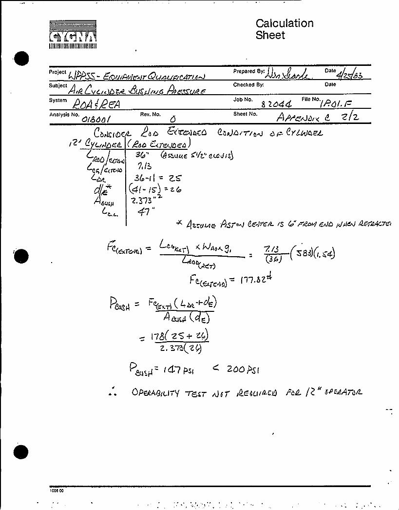
i~'j~a B =IIIIIIIIIIIIIIIIIIIIIIIIIIIIII
CalculationSheet
System
QPP~~- E ///Ai - r8 n
AiA>L Cz~ R 8 ru 8 - /2
Date
Date
Analysis No.0/8dd/
Rev. No. Sheet No. A/P~rJcliv f <h.6'Z'8nlkCQ Chef/5/7 /qg 9 P CY/4tj4&
Ed'KT ~JDCfl )Qwuze <'/r" eudis)
'7,/5
3t'-I( = ZCzj(- g5) =z@
~37~"47"
Cbrit(8 ~
C.4~i04
zg /1(fedC.~
d~ (~~iu
4s.u~c Pi$ 7'g 8t. J.-ek /5 Co rdW&JL) /JAR 4C~>44 ~t=.i
~e(,„,~,) = '".~-,I, «~a~ g, V/~ / i/-()(J( ~ )<Z<r)
J-g(~, )= )1 tt.hZ
I ~cP i'SI 4 ZQQPg(
QP~Agigi7$ ~gg( ggP QC'gg//t.CQ /'QL /P" fACgQPg/L
>000 00
QID 018001
5.0 — CONTENTS
5.1 Response Spectra
5.2 Walkdown Sheets
5.3 SRM Sheets
5.4 Load Comparative Sheets
5.5 Revised BGR Inc. Piping Analysis Accelerations

QID 018001
5.1 - RESPONSE SPECTRA

I ~
i. ~
!i-
I
|.i .l.
I~ ~
i
8D
~ - LQ
...J..i 4
C3
I—~gCC wCC
I ~i
rJda
~ ~ ioI
~ I.
~ ~
I~
'
lo. ~
I..e
'I ~ . ~ ~ ,
~ . I(
~ .'o I> I.' ~ s.
I ~~
~ ~
I
~ I'
~ ~
~ ~i .I~,.
'I.I...
. ~ ~)'~ ~
Il'".I'
. i
. "I.~ I
I ~
I:I.. I ...
i 'I'
~
I
I~ i
~ ~
i ~
II ~
.i I.
i ~
~ ~
i ~ .' .i. i I.,s P~I- ~...,
I ~ 'I,
i ~
~ ~
I
~ ~
I..) . I
~ ~
).. I~ ~
I O
I.:; I I i.
~ ~
~ ~
I ~ .~ I ~
I ~
~ ~ i~ ~
~ ~
OI 'll">~a'.~ I
x
g.
~ W ~ ~
~ ~ ~ ioo ~ ~
I o~ I ..' o
j ~I'.-i
~ ~
~ ~~ ~
I
~ ~
& ~
0.200 Q.iIM Q,6M Q,600 laOM l,200 loiIM lo6MNATUAfiL PEAIQO-SECQHOS
Ilf'PSS, IIANFOI)D H0.2~ BEACTQA OIjtLOJNG+tNDEL NO. 2 BEV. I55E: IDBE) VLGI1fl SFEU'BIjH - IIAAl2QNh.klfISS NO.2. EL. 605'-lO.S", OflHPtNG=0.02
I
l,OM R,OM 2',2M R,IIM
I1
"I a,~ ~
~ ~~ 1

I ~
~ ~
5ia)
gg 9
~ ~
II
~ j ~
~ Ii
I
I
t
I '
~ ~~ ~
g ~
I ~I: o I
o
~ ~~ ~
~ ~
! '.;::l.*„~ ~ I
~ ~ o .
~ I
P ~
~ ~ ~ »
~~
I~ ~
~ II
~ ~ ~ ~
~ » I
' ~ ~
,, ~ .,Ij'-i.o- .~ ~ ~
~ ~ ~
I ~ ~
~ ~
~ ~ ~ o ~ ~
I~ .. I
I'I
i'
~ ~ ~
~ ~ I
tt~ ~ ~ ~ »
~ ~~ ~
I.~ ~ I
)'
~ I
~ ~~ I ~ ~
~ II ~ o
.I'.I;~
)"'I
~ ~o
~ ~
~ II
~ ~
~, Io w) o»
l,,l~ I ~i»ot ~
~ ~, ~ ~
~ ~ ~ , ~ ~'
'I I
I~ ~
~ ~I~ ~
i» ':-, ~
~ I
1 ~ ~
II-Ilt: I~ ~
o
~ P ~ ~
~ ~
~ ~ ~
~ I ~ ~
I ~ .oI.. I ~ )oil'
~ ~
)~ J: 'A,s
I
j~ e I
~ »»~ ~ ~
.I.~ ....
I.I" '» ~
It . ~
I ~ ~ e
C/l Tl CK'I Oill py Ne~"K R0O
~ ~
.-~ I
I
I" I
l
I ~
I
II~ j' I" 'I -o ~
~ ~ ~ ~
I I I I [ I: ):~ I ~ ~
~
CD
OP-
CJl
w.
0'b.Ln o.zaa o.boa o.soa o.aoa l.ooa l.zm I.IIoa l.an
tQTUAAL I'NlQO-SECQYOS i
I)PPSS )lAHFOAO HQ.2 BEflCTQA Ol)lLOlNG HQOFL NQ. 2 BEY.55E fhOB FLOO)) Sf'E(TflUH — CQHDlNEO VtA7lCflLi)f155 NQ.B, CL. 605'-10.6", OA!FlHG-0.02
~ ~
l.naa . R.oal . R.zoa R.IIaa
o ~ ~ I' en'o 't ~ ~ ~ ~
'e ~ I I

Cl
P)
IIII
C)
~ P4
C3~o
leI
1 ljCd PqC)
~ ~ ~ ~ ~
II ~
I
I
I ~II
~ ~
I i
C7tO
D
m g e-:qzz> o ol0g '.b
m
oC!
4
lio. 00
I
Il
'~, '
0.00 20.00 60.00 00.00 100.00 120.00 I 0.00FREQUENCY (HZ)
MPPSS REACTOR BL.DG. SRSS GF SRV SSE FIP/CHUG !.
HASS NO. 186 FL. 561 FT. VERT. TRFlNSLBT I CIN
C tirRIiiHEr~T VESSEi D Rl"1P I I'IG= . 005, . 01, . 02.. 04

~o0-N I
rrIiJ
IILJ(..) p()Q
nlco I I
I
I
COxN=OPl rn. CO
0 00
~ N
~ L
I l
0.00 20.00 QO.OO 60.00 80.00 100.00 120.00 110.00160.00'REQUENCY(HZ)
uPPSS REACTOR OLOC. SaSS Cjr SRV SSE RrZCHuC.HFlSS NQ. 187 EL. 558 FT. ldCIR IZ. TRANSLATIONL'(INTR I [GHENT VESSEL DRHP IIAG= . 005.. 0 lr . 02.. 04~
'
~

~ ~
0

CDCD
CD..
CDo~ 03
~oMoG- CO
CLUJ
[LJ( qoCJA"~
lIII
I
I
r ~ .I
II
I
I
I ~
I I
l:~ ~
I I I
l
o
II
I
I
~ COIX PIO'm ga 'mg I+yO
I ~
I
i
A
fllg'
~ ~ ~
0.00, 20.00 40.00 60.00 80.00 100.00 120.00FREQUENCY (HZ)
IJf'PSS REACTOR BLOG. SRSS QF SRV SSE RP/CHUGMASS. NI3. 182 FL. 500 FT. HI3RIZ. TRRNSLRTICINCL'HTRINciFNT VESSEL OAHPING= .005,.01,.02,
190.00 . 160.00I
. OV.

5.2 Walkdown Sheets

IIIIIIIIIIIIIIIIIIIIIIIIIIIIII
BLDG
MFR QX F
moog zoG+43
E UIPMENT UALIFICATIONWALKDOWN VERIFICATION FORM
FLOOR EL QO )
COMPONENT EL 5 O~
SERIALg
EPNg CSP-V.- l
OZDg t'. l I 0 (
COORDS
DSCRP o" FLYMAT'L
PSI 3 oF LBS
ASME CLASS
SIZE
YOKE ORIENTATION
J To AXIS OF PIPE ( )
/j TO AXIS OF PIPE ( )
YOKE LENGTH(FLANGE To FLANGE)
MOUNTING CONDITIONNO OF BOLTS
BOLT TYPE BOLT qI
WELD TYPE & SIZEPIPE MOUNTED YES( ) No ( )
PERMANENT OBSTRUCTION (WITHIN 2" ) YES ( ) No ( )
FULL (6WAY) ANCHOR BETWEEN COMPONENT &- PRI CONT YES ( ) No ( )
CVGRAATTACHMENTJOS NO.~~~'4RLE NO ~0/SHEET NO.
O'r
G)
Q, r
GLOBAL Co-ORDINATESYSTEM
PERATOR EPN
ODEL No
YPE SIZEr
VALVE .STEM. ORIENTATION
MANUFACTURER
SERIAL No
ORDER No
OTOR EPN
ODEL No
D No
MANUFACTURER
SERIAL No
INS CLASS I-PHASE ( ) 3-PHASE ( ) AC DC
6J 7r
COMMENTS: Definition '(N/F = Not Found)'ol
fJ rrr ('+ (w 5( ((ic() a,5 g 0 /(% ( F Zm Meer Zr<ZHIS(J ((- IA)~('I(Or) PFJr'EOM E(3 XzkZlhZ;JT(()AI rJ J>EjQ Jr) <Ug ggS~yg~P REPARED BY DATE~tillf1REVIEWED BY J~ ~DATE~gy~(SI NATURE) (SIGNATURE)
@J,

IIIIIIIIIIIIIIIIIIIIIIIIIIIIII
CalculationSheet
Project ZEQUiP. c/AL.>
System
Analysis No. giiy +Z Ody Res. No.
Prepared By:
Checked By:
Job No.~
'heet
No.
File No.
Date
Date
QSt -(J- (, Z. ! ~g p $ ( g yJ)
'/;-"',,~p~i
l. ~
, rei
p» tg
yt 0S'( v'-t.
P »J (/iC'V(9-8)
g/r
I
ATTACHMENT
~08NO. «44'-
FILE No.SHEET NO ~Z. L
8= 7' Csee.v-'i— ~~-v'-z
BEr i yryyJ (l(g»J A-A
+(Ey-~ ~<Br<>(FyyR «< eosj»ysyosE 0F ysEDyeryyJrs o»E»4roz esRyEyyry(reosJ online)
1006 00

'IIIIIILIIIIIIIIIIIIIIIIIIIIIII
BLDG
MFR gfFMODE /t - ZQ( P4 3
E UIPMENT UALIFICATIONWALKDOWN VERIFICATION FORM
FLOOR EL YO(COMPONENT EL 5OESERIALN
PAGE 1 OF~
EPN4 CSf- V@ID'('oil O t
COORDS ~ < l 7 'lDSCRP 0 'FLYMAT'L
PSZ C PF LBS
ASME CLASS
SIZE
YOKE ORIENTATION
TO AXIS OF PIPE ( )
IlTO AXIS OF PIPE
YOKE LENGTH(FLANGE TO FLANGE)
MOUNTING CONDITIONNO OF BOLTS
BOLT TYPE BOLT {5
WELD TYPE 6 SIZEPIPE MOUNTED YES( ) NO ( )
PERMANENT OBSTRUCTION (WITHIN 2") YES( ) NO( )
FULL(6WAY) ANCHOR BETWEEN COMPONENT 6 PRI CONT YES( ) NO( )
ATTACHM6blTJO8 hlO.~~~/~ca ~O.CP d~l.
SHSSTNO.S ZE
GLOBAL CO-ORDINATESYSTEM
PERATOR EPN
ODEL NO
SIZE
VALVE STEM ORIENTATION
MANUFACTURER
SERIAL NO
ORDER NO
OTOR EPN
ODEL NO
D NO
MANUFACTURER
SERIAL NO
INS CLASS I-PHASE ( ) 3-PHASE ( ) AC DC
g COMMENTS: Definition '(N/F = Not Found)4&('-TIO J PK4 0M'<rZZ(QZ,QLT Wl}QPJ~ g4(.J(,-4 4.'W i e(. )(J sq .f P((ft/z f +eh Ce ~(fez< z,~Z
PREPARED BY aK 0 DATER/i4tl.REVIEWED BY / 'ATE /g(SI NATURE) (SIGNAT RE)
Tru cch l,

IIIIIIIIIIIIIIIIIIIIIIIIIIIIII
CalculationSheet
Project zEQUIP. GAL.r
System
Analysis No.g~Qg~7 .I~g Rev. No.
I
Prepared By
Checked By
Job No.~
Sheet No.
Fr'le No.
Date
Date
JA
I'~ l;I l t:p"''Ping 7 rlOJ
AQ
QSI~-0-( ~Z. ('NI''(E'YJ)ydS>V'-Z.
-" f.>/
/ yyr'
'/"m,y
ye ~
s
ref
I
PZ AJ i/icyJ(8-EJ!
CVGMAATTACHMENTJOB NO.~~~~flLENO.~r'~SHddVNO.D ~.+
e]q'e»
8=- 7' esP. v'-i— esP-v'-Z
dent i y D yJ I/iCvj A-A
/ (gQ $g ref (y De rgb AyVeySDM dp eyEDyeryy'Jye DR>7nrOe OeyeurD, en J, Oaod
100d Oc

E a. w a
'4IIIIIIIIIIIIIIIIIIIIIIIIIIIII
EQUIPMENT QUALIFICATIONViALKDOWN VERIFICATION FORI.
r~~r a wr
EPNC C'S(-'- V-
QIDf 0 ~. I 1 4
MODE
/SD
BLDG FLOOR EL ~~ I. ~ !.MFR
o@57 COMPONENT EL~% {
SERIAL 7 g. I
PSI S~Z7 'F
COORDS M. tZLIa< 6 fQP
DSCRP +' 9'c.lv
MAT'L -< -C(- - ~LBS A N SIZE ><.
ASME CLASS A/PI
YOKE ORIENTATION
J TO AXIS OF PIPE ( ~// TO AXIS OF PIPE ( Q
/ ( I(YOKE LENGTHEN - 2(FLANGE TO FLANGE)
MOUNTING CONDITION
NO OF BOLTS AVF'I
BOLT TYPE X/4 BOLT ({{ >/AWELD TYPE a SIZEPIPE MOUNTED YES ( ~O ( )
NO ( ) WfpDO MULTIPLE SUPPORTS EXIST BETWEEN CONT &
CYGMAATTACHMENTJOB MO. Md44FILE NO. M~M~+SHEET%0'
PERMANENT OBSTRUCTION (WITHIN 2") YES ( ) NO ( QIS COMP BETWEEN CONT & 1ST ANC (FULL 6 WAY ANC) YES ( ) NO ( ) H/I-
GLOBAL CO-ORDINATESYSTEM
P'q':=,. IgST<I c<-~="=C C(3~ ~g~,'r 4=
VALVE STEM ORIENTATION
YPE SIZE
PERATOR EPN&VMM&~ ~7~ODEL NO
Y~UFACTURER
SERIAL NO
ORDER NO
OTOR EPN +i(t (6 gd o
ODEL NO
MANUFACTURER
SERIAL NO
D NO INS CIASS I-PHASE ( ) 3-PHASE { ) AC DC
Dam T(rV~
COMMENTS: Definition '(N/F = Not Found)
g ("sP-) ws-3/ ~+~7 p c((= pl/7K /fjb5 Aid+ &KM'/)/M~~~yALv( 7~ ~wTAIN~MMT.
PHEPAHED BY 'DATE~4</~~'EYIEWED BY W 0~
( S IGNATURE ) (SI N .TURE)
/ l',+gg ~ P
$ k { (bS
DATE 1b-> fl.

IIIIIIIIIIIIIIIIIIIIIIIIIIIIII
CalculationSheet
Osoiees g ZSubject
/esd/A/ /C/System
Aoslyds No. Qg lees. No.to(
Prepared By: GateV7 i /Z
Checked By: Oate
Job No. + File No.
Sheet No.
0 0
P~ad ESP'-4-B,4 ()Ii g(zg
CYGN:~ATTACH5RGhl7,
JOB NO.~Z684FILE No.i'.It'SHEET NO.M<M
Saber/ov A-A'/Skier CAL 4A/c,LE
/r/e/ b Zxzr~e/(/ot r/r~ Pd/z/sos~ dA bN///'r/gs oo~~ro//.o/d/e.,riisAd g ovty)
10c0.o)
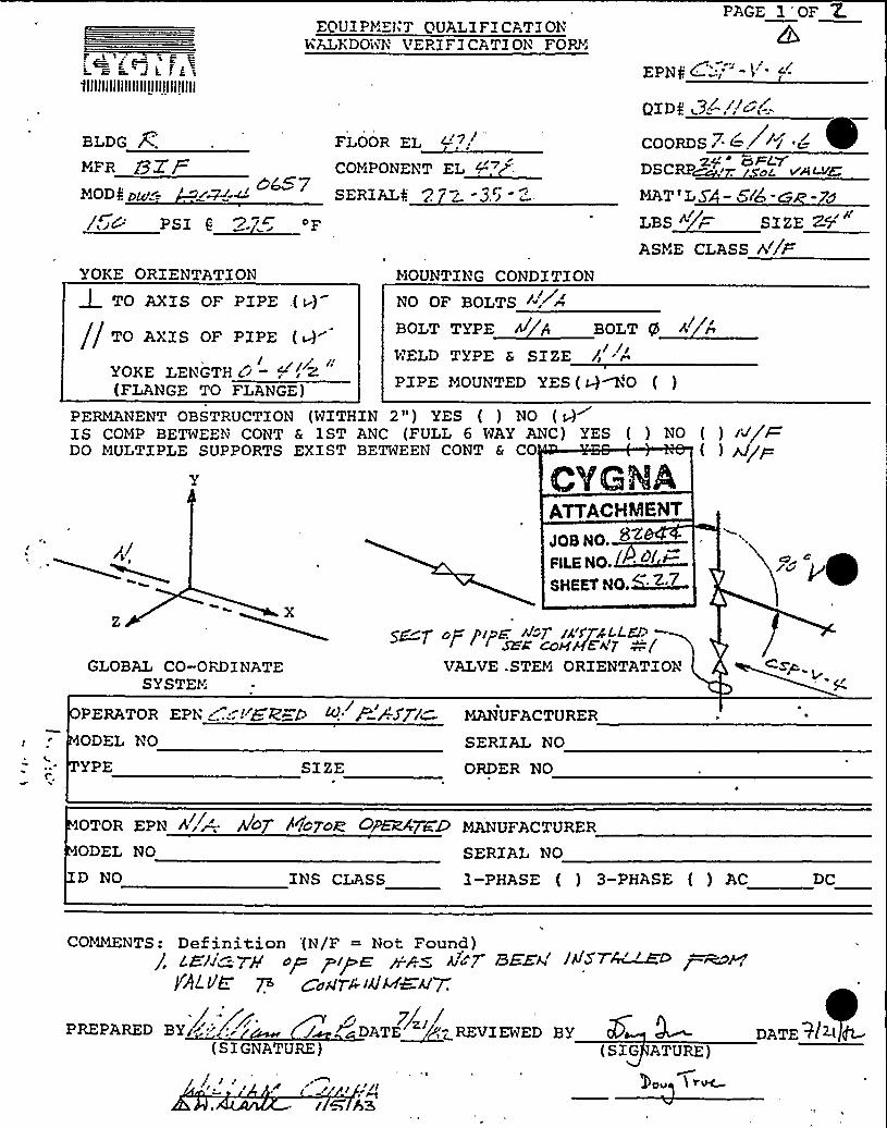
t.Eh.Jc.fk~'llllllllllllllllllllllllllllll
EQUI PMEl'7 QUALIFICATIONViALKDOWN VERIF ICATION FORM
EPNA d
PAGE 1'OF Z.
BLDG
MiFR j3Z /MOD4 yz(~= , a~7
PS I 6'P."'~ 'F
YOKE ORIENTATION
FLOOR EL L'-7/
COHPONENT EL~("
SERZALa ~c. < -3.5
MOUNTING CONDITION
OIDf. ( 3
COORDS 7 ~ .~~~/ 42y'd F/-VDSCRP ~, a< ve~W
MAT'L5»~~4 -D -74
LBS < /- SIZEZ5'SME
CLASS >//a
J TO AXIS OF PIPE .( w)
// TO AXIS OF PIPE ( Q/
YOKE LENGTH C/ - ~(FLANGE TO FLANGE)
NO OF BOLTS /'"'irBOLT TYPE
WELD TYPE 6 SIZEll~/
~/ /g
PIPE MOUNTED YES ( Q NO ( )
( ) /J/~DO MULTIPLE SUPPORTS EXIST BETWEEN CONT & CO
PERMANENT OBSTRUCTION (WITHIN 2" ) YES ( ) NO ( Q~IS COMP BETWEEN CONT 6 1ST ANC (FULL 6 WAY ANC) YES ( ) NO ( ) /'J/W
X
GLOBAL CO-ORDINATESYSTEM
ATTACHMENT
JOSNO. ~
P(LS NO.~~+~SHEET NO.G~E7
P/PF. d~j /l'STILLE'P~g cd~Eh'7 ~~jVALVE .STEMi ORIENTATION
.= v
Cg
PERATOR EPN ..--- -"~Z 0 O'-'F $7/ MANUFACTURER
ODEL NO
YPE SIZESERIAL NO
ORDER NO
OTOR EPN 4/"; PD7 /&7'oZ <~7'ANUFACTURERODEL NO SERIAI NO
D NO INS CLASS I-PHASE ( ) 3-PHASE ( ) AC DC
COMMENTS: Definition '(N/F = Not Found)ZZf„/ -7p'p prpE +~< Ai /F QEZA'/JSr~ED ~—~W
VALt/Q 7 cour>-'/@~we~
./,'Pz ~ n 7/,/PREPARED BY/~.';~,/: ' ~ DATE~+" REVIEWED BY( S IGNATURE ) (SIG ATURE)
JP pap.J/ /h3
DATE~l+ Ill

R i%I 's
IIIIIIIIIIIIIIIIIIIIIIIIIIIIII
CalculationSheet
pgz Prepared By:g7
Oate/ Z
SubjectGAIA/ yC
System
Analysis No. Qy'r .. Rav, No./ //di
Checked By: Oate
Job No.~~ + File No.
Sheet No.
sl
t ~ad ('SP'-U-3,4 (yj( iJ(cw''jj'GFwvATTACH@6»;JOS NO. dFILENO. / dl
F'HarrNO.XR yy
ZECr/~J /I-/1VC&r&c, 4~6C.~
I yey b ZKary'A((iyst re /Ay/a/yyse. Ry: bN/syerygr* oy wayrae. ayAye<rzlrya.z so<A<)
yeas 00

i. s = iIIIIIIIIIIIIIIIIIIIIIIIIIIIIII
BLDG
MFR Q
MOD4 Dub R >DR( <
EQUIPMENT QUALIFICATIONWALKDOhN VERIFICATION FORM
FLOOR EL ( 7 I
COMiPONENT EL I75SERIAL, 2% 2-E4- l
PAGE 1 OF
C5P- v'-5
QIDA 3(o tl04
CDORDS R.W I F.3
OSCar 2.'l" 6fI Y
MAT'L
PSI 6
YOKE ORIENTATION
oF
MOUNTING CONDITION
LBS
ASME CLASS
SIZE
J TO AXIS OF PIPE ( )
llTO AXIS OF PIPE
YOKE LENGTH(FLANGE TO FLANGE)
NO OF BOLTS
BOLT TYPE BOLT gWELD TYPE 6 SI ZE
PIPE MOUNTED YES ( ) NO ( )
PERMANENT OBSTRUCTION (WITHIN 2") YES ( ) NO ( )
IS COMP BETWEEN CONT 6r 1ST ANC (FULL 6 WAY ANC) YES ( ) NO ( )DO MULTIPLE SUPPORTS EXIST BETWEEN CONT 6 COMP YES ( ) NO ( )
GLOBAL CO-ORDINATESYSTEM
PERATOR EPN
ODEL NO
YPE SIZE
VALVE STEMi ORIENTATION
MANUFACTURER
SERIAL NO
ORDER NO
ATTACHESOSNO. ~~FILE t40.SVRSYWO D'".2 t
OTOR EPN
ODEL NO
ID NO INS CLASS
MANUFACTURER
SERIAL NO
1-PHASE ( ) 3-PHASE ( ) AC DC
Lk lISAALIiJ GTIDIJ iidt55 E/EZ.I&+ k IT lal<cCOMMENTS: DeZznxwioh'flF = hot Fourth ~ +~ 'J~<'J< <~TA~ SM gpa~~pZ,
'0 hvc. 4 i sb-O.J i,$ +t~~/<I-
PREPARED BY 'r + g~W DATEj-VA'EVIEWED BY W M DATE+/IP( S IGNATURE ) I ( SI NATURE)
/~y ~ i/,/ ~ ri.~

IIIIIIIIIIIIIIIIIIIIIIIIIIIIII
CalculationSheet
Project z8 uIP 4z r AcIcdr o
System
Prepared By
Checked By:
8 Md,
/ DaterPAD / z,
Date
File No.
AoetysisNo.~g ~~ ~+L
Res. Iso. Sheet No.Z og'Z
tVdtn)
47k
z4'ecyij
ATTACH@<< ~ ..
dOS NO.~RI.d NO.~+
~dpi so 4P Cdsk s Od.
4&/(ELAp.MCQQZ4"CS+i)-t
100d 00
;~( ItRj'J =Q
FIKLt0 Shoal CH (ARR Sgd. rsIIBPM6 OR >N<sJs JIs d0 s227dsR dZI sIW iOJ,col y,

BLDG gMFR Q T.f-
MOD( -lob WoS
'.
E r '~ fi'IIIIIIIIIIIIIIIIIIIIIIIIIIIIII
EQUIPMENT QUALIFICATIONWALKDOWN VERIFICATION FORM
FLOOR EL
COMiPONENT EL IZ0
SERIAL4
EPNg CS -V-6QID4 3(o l h 0 (
COORDS
DSCRP 2 i" 9(-I 9MAT'L
PSI
YOKE ORIENTATION
oF
MiOUNTING CONDITION
LBS
ASME CLASS
SIZE
TO AXIS OF PIPE ( )
// TO AXIS OF PIPE ( )
YOKE LENGTH(FLANGE TO FLANGE)
NO OF BOLTS
BOLT TYPE BOLT {5
WELD TYPE & SIZEPIPE MOUNTED YES ( ) NO ( )
PERYiANENT OBSTRUCTION (WITHIN 2") YES ( ) NO ( )IS COMiP BETWEEN CONT & 1ST ANC (FULL 6 WAY ANC) YES ( ) NO ( )DO MULTIPLE SUPPORTS EXIST BETWEEN CONT & COMP YES ( ) NO ( )
GLOBAL CO-ORDINATESYSTEM
PERATOR EPN
ODEL NO
YPE SIZE
VALVE STEMi ORIENTATION
MANUFACTURER
SERIAL NO
ORDER NO
ATTACH@ 7JOB NO.~Fl(.S NO/~+
HEET NO ZZ~/
OTOR EPN
ODEL NO
D NO
MANUFACTURER
SERIAL NO
INS CLASS I-PHASE ( ) 3-PHASE ( ) AC DC
COMMENTS: Definition (N/F = Not Found)R 659- L~5 - (.
E/<E/()>$ QIid45 g) ED JACJ6 EVSTrlu.S(I
PREPARED BY.„rg/'g~. ~ DATE~~~ REVIEWED BY( S IGNATURE ) (SIG ATURE)
lj'! i ',VJ 'gg p/g(gp .j)o Tsv c.
DATE 9()l

IIIIIIIIIIIIIIIIIIIIIIIIIIIIII
CalculationSheet
Project
Subjecto'i 7xd
Prepared By:
Checked By:
igate
6t=h/0 CSAnalysis No. A A Rev. No.
~l&l 8C ilOC
Job No.
Sheet No.
File No.
P~(J(~U &SP U -c~-
S'w-ic w A-A
ATTAgHMFHYz
FILE NO ~~sHser Nc ~~
pl a=C&~~k'8768 (8& TA'E P!l&>OS'F aaeP<dreeJ g dPEBAi 52dgiq ej a el a a ~.ovc.d
tcctt 00

g s=j f 'E
)IIIIIIIIIIIIIIIIIIIIIIIIIIIII
BLDG
MFR QX.F
MOD4 9 MW<5
EQUIPMENT QUALZFZCATIONWALKDOWN VERIFICATION FORM
FLOOR EL t + I
COMPDNENT EL~oSERIALS
EPN4 608-V- 9
OIDg '3Q'l I 6(o
COORDS PA% /S. I
DSCRP L'I 'i'(MAT'L
PSI 6 oF LBS
ASIDE CLASS
SIZE
YOKE ORIENTATION
J TO AXIS OF PIPE ( )
//TO AXIS OF PIPE:( )
YOKE LENGTH(FLANGE TO FLANGE)
MOUNTING CONDITION
NO OF BOLTS
BOLT TYPE BOLT {5
WELD TYPE & SIZEPIPE MOUNTED YES ( ) NO( )
PERMANENT OBSTRUCTION (WITHIN 2") YES ( ) NO ( )
ZS COMP BETWEEN CONT & 1ST ANC (FULL 6 WAY ANC) YES ( ) NO ( )DO MULTIPLE SUPPORTS EXIST BETWEEN CONT & COMP YES ( ) NO ( )
X
GLOBAL CO-ORDINATESYSTEM
PERATOR EPN
ODEL NO
YPE SIZE
VALVE STEM ORIENTATION
MANUFACTURER
SERIAL NO
ORDER NO
7iiACHMJ Qf3.JQB.NP.
SNBEY'NO.S ~.~~C
OTOR EPN
ODEL NO
D NO 'INS CLASS
MANUFACTURER
SERIAL NO
1-PHASE ( ) 3-PHASE ( ) AC DC
COMMENTS: Definition '(N/F = Not Found)
Hob.: n 8'~s+ 142 «s o~ +(» /~PREPARED BY .g~r . g DATE~kREVIEWED BY V
(SIGNATURE) I (SIG ATURE)DATE 0JQlL.
g/ z QOv PIJ~

a a a s a ~ g
IIIIIIIIIIIIIIIIIIIIIIIIIIIIII
MFR
MODE A. - 7O((B~3
E UIPMENT QUALIFICATIONWALKDOWN VERIFICATION FORM
FLOOR EL
COMPONENT EL ~58SERIALS - + 7 2. 39 —5
PAGE 1 OF I
EPNg CQ -V- l 8
QIDjf 3 4)l 0
COORDS ~'( K'tDSCRP 30 6 6MAT'LSh-5'l4. -6<
( 5 PS1 6 Et(O oF
YOKE ORIENTATION MOUNTING CONDITION
I.BS Nl(- SIZE5o'SME
CLASS
TO AXIS OF PIPE ( )
//TO AXIS OF PIPE ( )
YOKE LENGTH +~A(FLANGE TO FLANGE)
NO OF BOLTS l ABOLT TYPE l"/W BOLT qI ~lbWELD TYPE 6 SI ZE +I
A'IPE
MOUNTED YES (~NO ( ) LOcE 0»
PERl'~ENT OBSTRUCTION (WITHIN 2") YES ( ) NO ( ~IS COMP BETWEEN CONT & 1ST ANC. (FULL 6 WAY ANC) YES ( 4 NO ( )DO MULTIPLE SUPPORTS EXIST BETWEEN CONT & COYjP YES ( ) NO (Q
9O.V
GLOBAL CO-ORDINATESYSTEM
PERATOR EPN
ODEL NO
YPE SIZE
VALVE .STEM ORIEI)'TATION
MANUFACTURER
SERIAL NO
ORDER NO
0.~~~FILE NO.
$ HEET No +
OTOR EPN
ODEL NO
D NO
MANUFACTURER
SERIAL NO
INS CLASS 1-PHASE ( ) 3-PHASE ( ) AC DC
gg s e0 gwug
r;"4.W.i: Ha-~ C.-a~ts
DATE~/
COMMENTS: Q L)~it Sm&44.g QunQR~8d.- 4+dal oo
R ~ I bVOLOc)
PREPARED BY ~ DATER/(Y/lLREVIEWED BY( S GNATURE ) (S NATU E)
T)rw ~ 7Asf'/iC L]AM Q~~gA

i Kr. ik <k!IIIIIIIIIIIIIIIIIIIIIIIIIIIIII
E UIPMENT UALIFICATIONWALKDOWN VERIFICATION FORM
PAGE l OF
EPNN CE P-V- 2 6
BLDG g-MFR P)5 FMODN QC 5+"
PSI C EHO 'F
YOKE ORIENTATION
FLOOR EL ~ 1P
COMPONENT EL ESPSERIALN ZW'QQ —Q-
MOUNTING CONDITION
OIDN
COORDS S'. 9 5"tDSCRP 30 ' SufiMAT'L S,A-S'I(-. MM
~PFASl"E CLASS
J TO AXIS OF PIPE ( )
v/~/j TO AXIS OF PIPE ( )
YOKE LENGTH 9 I 6(FLANGE TO FLANGE)
NO OF BOLTS
BOLT TYPE 8 A BOLT 0 ~/hWELD TYPE 6 SIZE 0 A
PIPE MOUNTED YES ( +) NO ( ) 4 AX I( li~~-s
PERMANENT OBSTRUCTION (WITHIN 2") YES ( ) NO ( )IS COMP BETWEEN CONT 6 IST ANC. (FULL 6 WAY ANC) YES ( L) NO ( )DO MULTIPLE SUPPORTS EXIST BETWEEN CONT 6 COMP YES ( j NO (
GLOBAL CO-ORDINATESYSTEM
PERATOR EPN
ODEL NO H/4YPE SIZE
%ov
VALVE .STEM.ORIENTATION
MANUFACTURER
SERIAL NO
ORDER NO
ATTACHE .:~'g~o44
FlLENO~FSHEaV No.&~
OTOR EPN
ODEL NO
D NO
H/R
INS CLASS
MANUFACTURER
SERIAL NO
1-PHASE ( ) 3-PHASE ( ) AC DC
8<~-4 w . 0 ~~e.~ C ~+-1s
PREPARED BY( GNAT )
h/if f radii
COI iMENTS: Z L)~ ( 'c Ac.4s
p~jh 4: l+c '3>oD Q('g. ('gt -(.~q5R >"Ioroloo
& 9~4r~~~ t4) c 't DATE>l'"/~VIEWED BY
(SIGNATUREOhss Tl Iw
DATE ~

ct (; fPIIIIIIIIIIIIIIIIIIIIIIIIIIIII
EQUIPMENT QUALIFICATIONViALKDOWN VERIFICATION FORM
EPNI CEPi'-'ID4
.
' lA4t BLDG FLOOR EL ' 7lMFR COMiPONENT EL~~MODE,„= ~ g SERIALS
/~~r PSI 6 Z75 F
COORDS 0, /5 l
MAT'L - - - Cr —-I,HS h'/~ SIZE Z»ASNE CLASS
YOKE ORIENTATION
TO AXIS OF PIPE ( ~// TO AXIS OF PIPE ( d~
/ ~g/ cYOKE LENGTH 4(FLANGE TO FLANGE)
MOUNTING CONDITIONNO OF BOLTS + ABOLT TYPE 4 4 BOLT q' A
WELD TYPE & SIZEPIPE MOUNTED YES(~ NO ( )
PERMANENT OBSTRUCTION (WITHIN 2") YES ( ) NO ( ~IS COMP BETWEEN CONT & 1ST ANC (FULL 6 WAY ANC) YES (Q NO ( )DO MULTIPLE SUPPORTS EXIST BETWEEN CONT & COMP YES ( ) NO ( W
GLOBAL CO-ORDINATESYSTEM
PERATOR EPN +/AODEL NO
YPE
goR
SIZE
VALVE .STEM ORIENTATION
MANUFACTURER
SERIAL NO
ORDER NO
CVGNAATTACHMENT
OB NO.AZ~~MFIL,a No.lMSHSrrHO.&Z S>
OTOR EPN ~/ODEL NO
D NO
MANUFACTURER
SERIAL NO
INS CLASS I-PHASE ( ) 3-PHASE ( ) AC DC
COMMENTS: Definition '(N/F = Not Found)C E. (- L AS-BA
Z&jg+YZ4+ Z goP 0 ~gqgyg
PREPARED BY /Mg~ ~ ATB' ZREVIEWED BY(Sl GNATURE)
/r ~
/'s/a~
og<<4rClT log
(S G 'URE)
Dbd Tfv~
DATE ~(~'I))-

IIIIIIIIIIIIIIIIIIIIIIIIIIIIII
CalculationSheet
Subject .g Ao
Projecte 5 Gc.
p eearea Bre g pDare
Checked By: i /~ Date /rz zo/8Z
Systemc.sP
Analysis No. Rev. No.
Job No.52
Sheet No.
File No.
tMJ ALI< DOutJP
V ALVE, ( OPrgA~ag orici ~ir~roiJsca.p —v — s~ $ 4et
cog -v-SA-
tE
ATrAcHMEH~
sos No.d~~~
FiLs NO.~l'Hsst»
cE.P—
0 0
0 O.O ~
1005 00

EOVIPMENT OVM.IFI CATIOh'KALKDO')'cN VE RIFICJI T2 ON FORI'I
EPN) CEP- V-'IAIIIIIIIIIIIIIIIIIIIIIIIIIIIIII
QIDf EWlel
BLDG
MFR 5X F
MOD4
l 55 PSI 6
YOKE ORIENTATION
FLOOR EL
COMPONENT EL
GGA SERIAL4
MOUNTING CONDITION
COORDS 't( S S.H
DSCRP 2 - Ft-
MAT'L S*-$ I( &4 -"/<
LBS~)I F SIZE 2 (
ASME CLASS
TO AXIS OF PIPE (
// TO AXIS OF PIPE (+)
YOKE LENGTH 0(FLANGE TO FLANGE)
NO OF BOLTS
BOLT TYPE
Pr
BOLT g f
WELD TYPE 6 SIZEPIPE MOUNTED YES( ) NO ( )
PERI~NENT OBSTRUCTION (WITHIN 2" ) YES ( ) NO (
IS COMP BETWEEN CONT & 1ST ANC (FULL 6 WAY ANC) YES ( ) NO ( )DO MULTIPLE SUPPORTS EXIST BETWEEN CONT 6 C MP YES ( ) NO (
go'
GLOBAL CO-ORDINATESYSTEM
PERATOR EPN
ODEL NO
YPE SIZE
'sovVALVE STEYi ORIENTATION
MANUFACTURER
SERIAL NO
ORDER NO
'AYTACHM8NT
boa No.~~~~n.a ao.)'i'()~ ("
SHEET HQ ~CZ./
OTOR EPN
ODEL NO
D NO INS CLASS
MANUFACTURER
SERIAL NO
1-PHASE ( ) 3-PHASE ( ) AC DC
(S+I ATDRE)
COMI)ANTS: Definition '(N/F = Not Found)t'EP-L0)-LIh ~I(- 4~~h.
4 ~ SAEC7 Zc+ 2. 4'~R aP'GQArda. aa,<~v.quito J
PREPARED BY Pa'gi.'>~i ( ~, ~..DATE ~'/~~VIEWED BY( S IGNATURE )
DATE~~I Il/h.
aX,~ kleE YfVI('
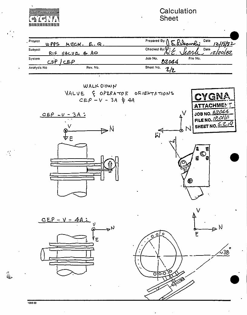
IIIIIIIIIIIIIIIIIIIIIIIIIIIIII
CalculationSheet
Pro>ectN S
Prepared By; g PDate
Subiectg Ao
Checked By: ' /> Date /rz zo/82
SystemCSP
Analysis No Rev. No.
Job No.52
Sheet No.
File No.
uf ALH. Do~gUALvE. ( oy spA~of: otB<sy t n~eoNs
cEP .—v — 3A $ Aye
egg -v-SA-ATTACH@6."'".
goB NO.
F)L.a No. «~'SHEET No.
E
c E.P—
O 0
O O.O.

IIIIIIIIIIIIIIIIIIIIIIIIIIIIIItl BLDG
MFR 6 X.F
MODE 'DWb Awol W(,O
E UIPMENT UALIFICATIONKALKDOWN VERIFICATION FORYi
FLOOR EL
COMPONENT EL~SSERIAL4 2.0 2 'Eb - l
PAGE 1 0."
EPN4 F EA-V-l
QID4 I ( 82.
COORDS 4 >/ G.Xoscar 3Y CF<Y
MATSL 5g - 5 l4-6R. (oo
~PSI 6 (( I> «F
YOKE ORIENTATION MOUNTING CONDITION
LBS I /(- SIZE ~(I'
ASME CLASS ~/-
J TO AXIS OF PIPE
// TO AXIS OF PIPE ((r)
YOKE LENGTH(FLANGE TO FLANGE)
NO OF BOLTS Q Pr
BOLT TYPE 9 A BOLT q)
WELD TYPE & SIZE t))
PIPE MOUNTED YES ( 4 NO ( )
PERYiANENT OBSTRUCTION (WITHIN 2") YES ( ) NO ( )
IS COMP BETWEEN CONT & IST ANC (FULL 6 WAY ANC) YES ( ~O (
~ DO MULTIPLE SUPPORTS EXIST BETWEEN CONT & COMP YES (<) NO ( )
ATTACHMENT
JOB NO.
FILE NO. 'ISHEET NO.
GLOBAL CO-ORDINATESYSTEM
PERATOR EPN
ODEL NO
YPE SIZE
VALVE STEM ORIENTATION
MANUFACTURER
SERIAL NO
ORDER NO
OTOR EPN
ODEL NO
D NO INS CLASS
Y~UFACTURER
SERIAL NO
1-PHASE ( ) 3-PHASE ( ) AC DC
COL'DENTS: Definition (N/F = Not Found)X 0 SR'R& ( ««4 «( ill&4 I l«&t
«g J '*
~br S qaV<4CX
PREPARED BY I W DATE PILI)h-REVIEWED(S G ATURE)
Don Go('
7/ /BY J. w«DATE~II/'«
( SI GNATURE )
I! rlr rg rr ~~! '

i~ IF)a fg":)IIIIIIIIIIIIIIIIIIIIIIIIIIIII
BLDG
MFR
MODE
~PSI 6
EQUIPMENTQUALIFICATION'ALKDOWN
VERIFICATION FORM
FLOOR EL
COMPONENT EL~XOl g+
SERIAL4 9 2-W2-3o -~llC oF
ur~EPN f 8-E8 -')J- 'L
QID4 3(() l l D2-
COORDS k. f (o. 2-
DSCRP 32 QO'L'(
MAT'L SR-5 I4 ( g ( O
LBS 9/I= SIZE +~
ASME CLASS ~/IYOKE ORIENTATION
TO AXIS OF PIPE ( 4TO AXIS OF PIPE (
YOKE LENGTH(FLANGE TO FLANGE)
MOUNTING CONDITION
NO OF BOLTS I
BOLT TYPE ~ h BOLT qI
WELD TYPE 6 SIZEPIPE MOUNTED YES ( 4 NO ( )
PERMANENT OBSTRUCTION (WITHIN 2 N) YES ( ) NO (
IS COMP BETWEEN CONT & IST ANC (FULL 6 WAY ANC) YES ( )~NO ( )
DO MULTIPLE SUPPORTS EXIST BETWEEN CONT & COMP YES ( + NO ( )
fg'VATTACHMENTJOB No. ~+FIL.a Xo.SMEEI NO~<~
GLOBAL CO-ORDINATESYSTEM
PERATOR EPN
ODEL NO
SIZE
VALVE .STEM ORIENTATION
MANUFACTURER
SERIAL NO
ORDER NO
OTOR EPN
ODEL NO
D NO INS CLASS
MANUFACTURER
SERIAL NO
I-PHASE ( ) 3-PHASE ( ) AC DC
COMMENTS: Definition '(N/F
6AC,~Ci C A 4..~+ ~ ~ % r o4 w qu.i>cA.
P RE PARED BY (5( I NATURE)
bg Tt0
= Not Found)
r o ski),)
DATEPl~I tt?. REVIEWED(SIGNATURE)
p/i j W 'p'-

EQUIPMENT UALIFICATIONWALKDOWN VERIFICATION FORM
/ N Y E8 c. i k cc
PIIIIIIIIIIIIIIIIIIIIIIIIIIIII
BLDG
MFR QFMODE
/ PSI 6~ F
YOKE ORIENTATION
FLOOR EL
COMPONENT EL~jSERIAL4 3,
MOUNTING CONDITION
EPNS RO -U-
DID' O (
COORDS
DSCRP g'l2 T ) V i
MAT'Z<r''~ -C~ 6 - ~ 9LBS/)/ g— BIZ~ASME CLASS r
TO AXIS OF PIPE (
TO AXIS OF PIPE (I ( //
YOKE LENSTH 7(FLANGE TO FLANGE
NO OF BOLTS
BOLT TYPE ' BOLT (5 i//".~ /
WELD TYPE 6 SIZE V
PIPE MOUNTED YES (~NO ( )
PERMANENT OBSTRUCTION (WITHIN 2" ) YES ( ) NO (
IS COMP BETWEEN CONT 6 1ST ANC (FULL 6 WAY ANC) YES ( ) NO (~DO MULTIPLE SUPPORTS EXIST BETWEEN CONT S COMP YES ( ) NO (~
Cf/g c
'VGHAATTACHMENTJQg go 82D$4PLS NO.~I~<l ~SHEET MO.
GLOBAL CO-ORDINATESYSTEM
PERATOR EPN
ODEL NO
YPE SI ZE
VALVE . STEMi ORIENTATION
MANUFACTURER
SERIAL NO
ORDER NO
OTOR EPN
ODEL NO ID NO
MANUFACTURER
SERIAL NO
INS CIASS - I-PHASE ( ) 3-PHASE ( ) AC DC
COhKENTS: Definition '(N/F = Not Found)
Q W(C: gO bt4)Pc.~+5
PREPARED BY(SIGN TURE)
Vc.f c " y~ ~pp~f
DATE ~~REVIEWED BY cD(SIG ATURE)
DATE WI(l(L

4lllllllllllllllllllllllllllll
EQUIPMENT QUALIFI CATIONWALKDOWN VERIFICATION FORM
EPN4DID'V-0BLDG FLOOR EL
MFR COMPONENT EL~t~MOD4 0 5 7 SERIAL)
J PSI 6/OQ oF
COORDS
DSCRP c lU
MAT'ZQ "CgR'4OLBS SIZES'Y,ASME CLASS A
YOKE ORIENTATION
J TO AXIS OF PIPE (~TO AXIS OF PIPE (
()
YOKE LENGTH(FLANGE TO FLANGE
MOUNTING CONDITION
NO OF BOLTS
BOLTBOLT TYPEI
WELD TYPE 6 SI ZE
PIPE MOUNTED YES ~NO (-)
PERMANENT OBSTRUCTION (WITHIN 2" ) YES ( ) NO ( 9IS COMP BETWEEN CONT & 1ST ANC (FULL 6 WAY ANC) YES ( ) NO (VFDO MULTIPLE SUPPORTS EXIST BETWEEN CONT & COMP YES ( ) NO ( ~
JOB NP.FILE NP. ~
SHEETNO.$ Z Zg
GLOBAL CO-ORDINATESYSTEM
PERATOR EPN
ODEL NO
YPE SI ZE
VALVE STEM ORIENTATION
MANUFACTURER
SERIAL NO
ORDER NO
OTOR EPN
ODEL NO
D NO
MANUFACTURER
SERIAL NO
INS CLASS I-PHASE ( ) 3-PHASE ( ) AC DC
COMMENTS: Definition '(N/F = Not Found)
hoke: >orki~~+ ~~ lwwA'ac+
PREPARED BY + DATE~~/8 REVIEWED BY 5SIGNATURE) ( SI ATURE)
DC)~ YfUC
DATE +1+

QID 018001
5.3 SRM Sheets

user number 43 date/time 02/10/83 09: 11function ~N -SRM MASTER EGUIPMENT LIST-
SP-AO-1
..'JNTRACT MFG68 8~132 A83B
COMPOSITE EPN2~SP-V-1+
SERIAL NUMBER
DESCRIPTIONAIR OPERATOR FOR SP-V-1
LEVEL2
ECA
USE1 3
HOURS4320
SAFETY FUNCTIONB1i F
ACCURACY
A/E DRAMING8543
AE ZONED5
BLDGR
ELEV DETAIL508 N. 0/T. T
ZONE ROOMR43
SEI S. QUALHL TEST ANL F/0
01
MESSAGE
ENV. QUALC AGING DBE C
QUALSE S
G
R
STATUS TM FREG GIDENV
P 07 $ 18001
pRO JECT 17,.>~(5- ~+~
~~ ggP16srpR A 6D Y:
4ZCHEClKFD
DATeJOB HOA
>)ia No. < -D~
BBBBT 80.

user number 43 date/time 02/10/83 09: 11function FIN -SRM MASTER EQUIPMENT LIST-
2MSP-AO-2
TRACT MFQ8 8322
EPN
A83B
COMPOSITE EPN2~SP-V-2+
SERIAL NUMBER
DESCRIPTIONAIR OPERATOR FOR CSP-V-2
LEVEL2
ECA
HOURS4320
SAFETY FUNCTIONBi. F
ACCURACY
A/E DRAWINGM543
AE ZONE . BLDGp
ELEV DETAIL508 7. 7/N. 0
ZONE ROOM
SE IS. QUALHL TEST ANL F/0
01
MESSAGE
ENV. QUALC AGING DBE C
FREQ
fc) P 07
QUAL STATUS TMSEIS ENV
018001
PROJECT
TITLE 4 f ClS7PRE R BY
BATEOB RO. ~'Z~
Piga NO / ~ 5/ /; >EET,NO

uses numbers 43 date/time 02/10/83 09: 11function FIN -SRM MASTER EQUIPMENT LIST-
CONTRACT MFQ68 N$22 A83B
MODEL
COMPOSITE EPNMSP-V-3+
SERIAL NUMBER73354165
DESCRIPTIONAIR OPERATOR FOR CSP-V-3
LEVELR
ECA
A/E DRAMINGa—SEIS. QUAL
HL TEST ANL F/0
MESSAGE
USER
HOURS4320
AE ZONE BLDGp
ENV. QUALC AGING DBE C
SAFETY FUNCTIONBi ~ F
ELEV DETAIL481 M. 6/7. 6
QUAL STATUS TMSEIS ENV
C P
ACCURACY
ZONE ROOMR33
FREQ GID
10 018001
PROJECT +~~~TITLEPREP E BY
OATE 2%CHEOKEO SY:
GATEJOB NO+ ZO
iLE NO
SHEET 80

user number 43. date/time 02/10/83 09: 12function FIN -SRM MASTER EQUIPMENT'IST-
2-CSP-AO-4EPN COMPOSITE EPN
2-CSP-V-4~
CONTRACT MFG68 M322 A83B
MODEL SERIAL NUMBER73354165
DESCRIPTIONAIR OPERATOR FOR CSP-V-4
LEVEL2
ECA
A/E DRAWINGM543
SE IS. QUALHL TEST ANL F/0
O~y
M SAGE
USE HOURS
R
AE ZONEC5
BLDGR
ENV. QUALC AGING DBE C
SAFETY FUNCTIONBi ~ F
ELEU DETAIL478 M. 6/7. 6
QUAL STATUS TMSEIS ENV
C P
ACCURACY
ZONE ROOMR33 'ID10 018001
PRE 8 0 B
3ZzOATSCHECKED BY~~
DATEJOB NO
/PoPn.E OO. /~8!!BET !IO
-VnJPROJECT
TnaE ~~

user number '43 date/time 02/10/83 09: 12function FIN -SRM MASTER EGUIPMENT LIST-
2-CSP-A0-5EPN COMPOSITE EPN
-CSP-V-5+
CONTRACT MFG68 AB3B
MODEL SERIAL NUMBERRT5508823
DESCRIPTIONAIR OPERATOR FOR CSP-V-5
LEVEL2
ECA
USE2 3
HOURS4320
SAFETY FUNCTIONBfiF
ACCURACY
A/E DRAWINGM543
SEIS. QUALHL TEST ANL F/0
01y
M SSAGE
AE ZONEC5
ENV.AGING
BLDG ELEV DETAILR 4T5 M. T/8. 3
QUAL QUAL STATUS TMDBE C SE ENV
'
P
ZONE ROOMR33
FREQ GID
10 018001
PBa JECT +~~'ldNP
PRE R D
DATE ZS 83
CHECKED
DATE
FtL.E NO. />SHEET ZO. > ~ <

user number, 43 date/time 02/10/83 OV: 1
function FIN -SRM MASTER EQUIPMENT LIST-
2-C SP-AO-6EPN COMPOSITE EPN
2~SP-V-6+
CONTRACT MFG68 M322 A83B
MODEL SERIAL NUMBER
DESCRIPTIONAIR OPERATOR FOR CSP-V-6
LEVEL2
A/E DRAWINGM543
USE2 3
AE ZONE814
HOURS4320
BLDGR
SAFETY FUNCTIONBi ~ F
ELEV DETAIL480 N. 5/7. 7
ACCURACY
ZONE ROOMR31
SEIS. QUALL TEST ANL F/0
01
ENV. QUALC AGING DBE C
QUALSE S
C
STATUSENV
TM FREG 6 ID
P 10 018001
MESSAGE
PRPgEC T P+S /JAPT!TLE ~PRE R 9 B
DATE Z 83
CHECKEO S~jOATE W/re/5>
~5MVIVE No. /+~/ ~$ ))EET NO» ~~~

uses numb ev 43 date/time 02/10/83 09: 1:function FIN -SRM MASTER EQUIPMENT LIST-
-CSP-AO-9EPN COMPOSITE EPN
2-CSP-V-9+
CONTRACT MFQ68 M322 A83B
MODEL SERIAL NUMBER
DESCRIPTIONAIR OPERATOR FOR CSP-V-9
LEVEL2
ECA ~
USE2 3
HOURS4320
SAFETY FUNCTIONB1 ~ F
ACCURACY
A/E DRAMINGM543
AE ZONEC6
BLDGR
ELEV DETAIL ZONE ROOMaWO M. e/S. 1
SEIS. QUALHL TEST ANL F/0
01
ENV. QUALC AGING DBE C
QUAL STATUS TM FREG GIDSEIS ENV
C P ~f 018001
gpss Q S5~~vnL.F.~r RBPQAE
ZZ 8'8
cvacK~D».
oava ~~<=~~gpa NO ~~4
Flea NO..dP'PBET
NO. ~~'
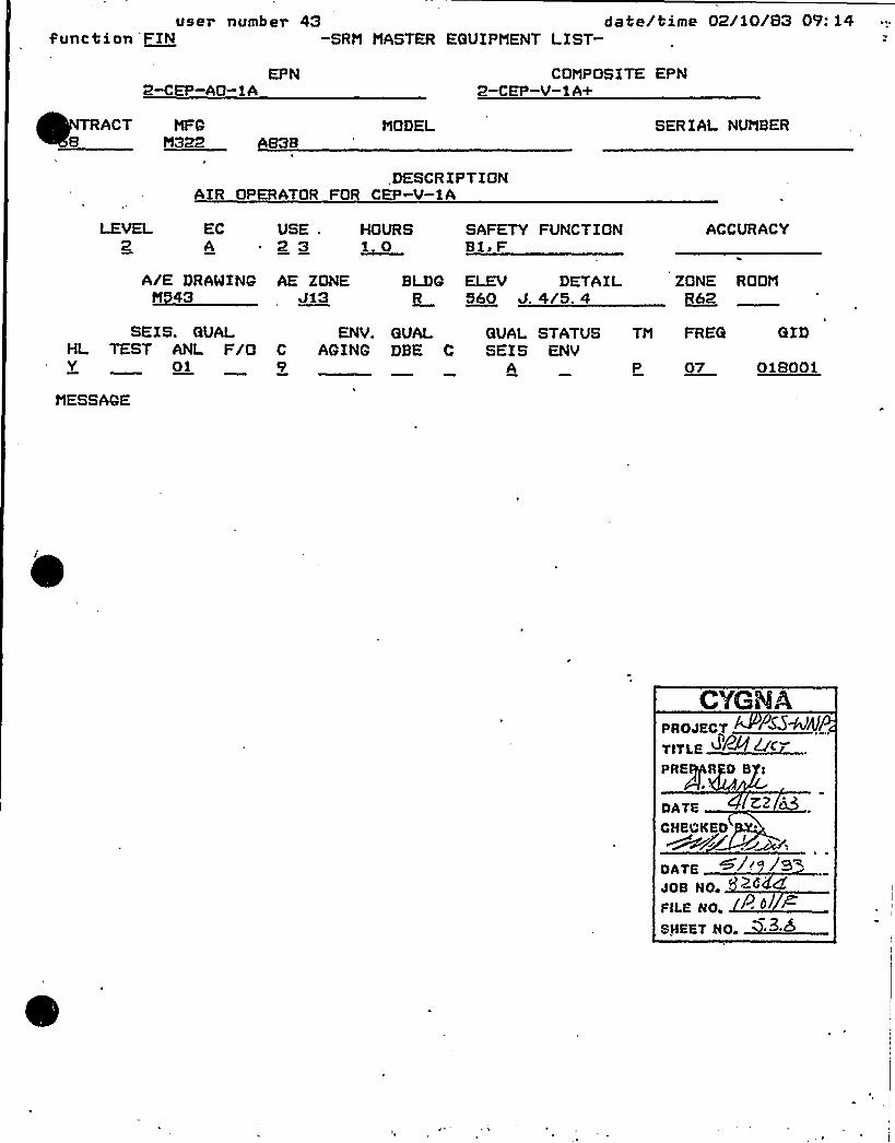
users numbev 43 date/time 02/10/83 09:14function FIN -SRN MASTER EQUIPMENT LIST-
2-CEP-AO-1AEPN COMPOSITE EPN
2-CEP-V-1*+
RACT NFG8 BBBB ABBB
NODEL SERIAL NUt%ER
,DESCRIPTIONAIR OPERATOR FOR CEP-V-1A
ECA
A/E DRAWING
USE2 3
AE ZONEJi3
HOURS1. 0
BLDGR
SAFETY FUNCTIONB1s F
ELEV DETAIL560 J. 4/5. 4
ACCURACY
ZONE ROON
SEIS. QUALHL TEST ANL F/OY 01
MESSAGE
ENV. QUALC AGING DBE C
QUAL STATUS TNSEIS ENV
A P
GID
07 018001
PROJECT
TITI.E d&fs-/C
PRE R 9 B
ATE ZZ
CHECKED
OaTEJOB NO
PII.E VO.ssssv Bo. ~>+
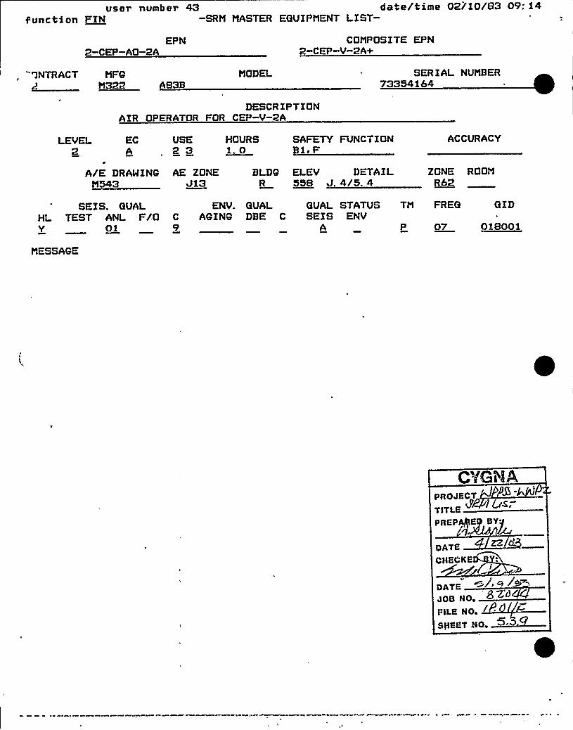
user number 43 date/time 02/10/83 09: 14function ~IN -SRM MASTER EQUIPMENT LIST-
2-CEP-AO-2AEPN COMPOSITE EPN
2-CEP-V-2A+
'3NTRACT MFQ8322 AB3B
MODEL SERIAL NUMBER73354164
DESCRIPTIONAIR OPERATOR FOR CEP-V-2A
LEVEL2
ECA
~
'/E DRAWINQM543
USE2 3
AE ZONEJi3
HOURS1. 0
SAFETY FUNCTION1. F
BLDQ ELEV DETAIL558 J. 4/S. 4
ACCURACY
ZONE ROOMRb2
SEIS. QUALHL TEST ANL F/0Y 01
MESSAGE
ENV. QUAL QUAL STATUS TMC AQINQ DBE C SEIS ENV
A P
GID
07 018001
PROJECT
TlTLEPREPQE
BY'7-
DATECHECKE
I
DATEJoe No. '~~~PiL,E VO. / .
STREET 50

users numb ev 43 date/time 02/10/B3 09: 14function ~N -SRM'ASTER EQUIPMENT LIST-
-CEP-AO-3ACOMPOSITE EPN
-CEP-V-3A+
VlRACT MFGM322 AB3B
MODEL SERIAL NUMBER73354165
DESCRIPTIONAIR OPERATOR FOR CEP-V-3A
LEVEL2
ECA
USE2 3
HOURS1. 0
SAFETY FUNCTIONBiiF
ACCURACY
A/E DRAMINGa—*
AE ZONEC14
BLDG ELEV DETAILR 497 H. 5/5. 4
ZONE ROOMR32
SE IS. QUALHL TEST ANL F/0Y 01
MESSAGE
ENV.C AGING9
QUALDBE C
FREGQUAL STATUS TMSEI S ENV
P 10
GID
018001
PROJECT
TP gE 82Cf<IgsPREP E 8Y
DATE 8
CHECKED S~f~7g~ '
~DATEJOB NO,
P>l.E NO. ++8/IBBT NO. ~~~

user numb er 43, date!time 02/10/83 09: 14function PIN -SRM MASTER EQUIPMENT LIST-
2-CEP-AO-4AEPN COMPOSITE EP N
2-CEP-V-4*+
MTRACT68
MFQNBBB ABBB
MODEL SERIAL NUMBER'73354165
DESCRIPTIONAIR OPERATOR FOR CEP-V-4A
LEVEL2
ECA
USE2 3
HOURS1. 0
SAFETY FUNCTIONBle F
ACCURACY
A/E DRAWINQM543
SEIS. QUALHL TEST ANL F/0Y 01
MESSAQE
AE ZONE BLDQ8
ENV. QUALC AQINQ DBE C
ELEV DETAIL49T H. 5/5. 4
QUAL STATUS TMSEI S ENV
A P
ZONE ROOMR32
FREG QID
10 018001
PROJECT
TITL.EPREP E BY
DATE
CBBC~KB~
DATE W i~'9~JOB HOc
FILE NO
SBKBT BC

user nuiiioer '~v 'B'Ge/ '0 ll4i.'H/BE/ cfog lW.'telfunction FEN -SR M MASTER EQUIP MEiNT LE ST- t +i
2-ROA-V-1
"ONTRACT MFQ8 B250
EPN
0657MODEL
COMPOSETE EPN2-ROA-V-1+
SERIAL NUMBER7229-1
DESCRIPTION84. 0" R BLDG ESO VALVE
LEVEL USE1 -0
HOURS4320
SAFETY FUNCTIONB2i D
ACCURACY
A/E DRAWINGM545
AE ZONEF3
BLDGR
ELEV DETAIL578 N. 7/5. 7
ZONE ROOMR73
SEIS. QUALHL TEST ANL F/0N 02
ENV. QUALC AQENQ DBE C0
QUAL STATUS TMSEIS ENV
A P
FREG GID
14 361101
MESSAGE
y
t
PROJECT
TITLE S7PR ARE BY;
DATE
CHECKED
DATEJOB NO,FILE NO ~ ~ ~
INERT Bo. ~+5'

user numoer 08'ce/'clme volHc/c4 I t: 0/funct'ion FIiV -SRM MASTER EQUIPMENT LIST-
2-ROA-V-2,
COMPOSITE EPN2-ROA-V-2+
CONTRACT MFG68 B250 0657
MODEL SERIAL NUMBER7229-2
DESCRIPTION84. 0" R BLDG ISO VALVE
LEVEL2
ECA
USE.1 0
HOURS4320
SAFETY FUNCTIONB2. D
ACCURACY
A/E DRANINGM545
AE ZQNEF3
BLDGR
ELEV DETAIL578 N. 7/5. 0
ZONE ROOMRZ3
SE IS. QUALHL TEST ANL F/ON 02
MESSAGE
ENV. QUALC AG ING DBE C0
QUAL STATUS TMSEIS ENV
* P
GID
14 361101
PROJECT SS~TITLE ~P PAfl DB!
DATE. 3
CHECKEDY'ATE
JOB HO, ~K~OVILE NO. Dl.0!fHET NO

user number aavezzxme Ueiaaiua 'xe: s/=&unction FIN -SRM MASTER EGUIPMENT LIST-
2-RE*-V-2
CONTRACT MFG8250
EPN
MODELDWG A-206760
COMPOSITE EPN2-RE*-V-2+
SERIAL NUMBER-27230-2
DESCRIPTION72. 0" BFLY R BLD ISO
HOURS4320
SAFETY FUNCTION82. F
ACCURACY
A/E DRAWINGM545
Bl DG ELEV DETAILR '97 H. 4/6. 2
ZONE ROOMR71
SEIS. QUALHL TEST ANL F/0
ENV. QUAL QUAL STATUS TM FREG GIDC AGING DBE C SEIS ENV
A P 361102
MESSAGE
PROJECT K kJAJP
TITlBPRE RED BY:
OATH
CHECKED B
DATEJOB HO ZdFILE NO
P'
SliEET No. ~+~'4

04/06/83 BURNS L AOE ItiCMASIIINGTOti PUBL'IC POMKH SUPPLY SYSTEH
MNP 2 SAFETY RELATED HECHANICAL EOUIPHENT LISTDMG E553-2 AEV 5
SORTED. BY EOUIP ~ tiO ~
PAGE 532
DATA DATE 04/06/83
EGUIPHKtiT tiO ~ COHPOS ITE NO~, DAAMING. NO ~ HRG „CODE, HFG, HODEL NO, . LV SAFETY" /UNCT ION USFE.UUIPHKNI DKSCRIPT ION PLANT LOCATION COIITRACT EOUIP ~ CLASS HOURS
WW
REA AO-8+SPENT FUEL POOLt PUMP ROON
F10 1 JA
10
~ ~ ~ ~ ~ ~ ~ ~ ~ ~ ~ ~ ~ t ~ ~ ~ ~ ~ ~ ~ ~ ~ ~ ~ ~ ~ ~ ~ ~ ~ ~ ~ ~ ~ ~ ~ ~ ~ ~ ~ ~ ~ ~ ~ ~ ~ ~ ~ ~ ~ ~ ~ ~ ~ ~ ~ I ~ ~ ~ ~ ~ ~ ~ ~ ~ ~ ~ ~ ~ ~ ~ ~ ~ ~ ~ ~ ~ ~ ~ ~ ~ ~ ~ ~ ~ ~ ~ ~ ~ ~ ~ ~ ~ ~ ~ ~ ~ ~ ~ ~ ~ ~ ~ ~ ~ ~ ~ ~ ~ ~ ~ ~ ~ ~ ~ ~ ~ ~ ~ ~ E ~ ~ ~ ~ ~ ~ ~ ~ ~REA-AO-Vl REA-V I+AIR OPER FOA VAI.VE HKA V"I
82 ~ F4320
13H322 A838H545 J3R 597 M+2/6 ' .,
2
t ~ ~ t ~ ~ t ~ ~ ~ ~ ~ ~ tt ~ ~ ~ ~ ~ ~ ~ ~ ~ ~ ~ ~ ~ ~ ~ ~ ~ ~ ' t ~ ~ ~ ~ ~ ~ ~ ~ ~ t' ~ ~ ~ ~ ~ ~ ~ ~ ~ ~ ~ ~ ~ ~ ~ ~ ~ ~ ~ ~ ~ ~ ~ ~ ~ ~ ~ ~ ~ ~ ~ ~ ~ ~ ~ ~ ~ ~ ~ ~ ~ ~ ~ ~ ~ ' ~ ~ ~ ~ ~ ~ ~ ~ ~ ~ ~ ~ ~ ~ ~ ~ ~ ~ ~ ~ ~ ~ ~ ~ ~ ~ ~ ~ ~ ~ ~ ~ ~ ~ ~ ~ ~ ~ ~ 0RKA-AO VP. HEA V 2tAIR OPER FOH VALVE AEA-V 2
H545 J3R 597 HE 4/6 '
H322 A83B 2A
B2eF4320
13
REA-Ftt-IAAEACTOA BUILDING
~ ~ ~ ~ ~ ~ ~ ~ ~ ~ ~ ~ ~ ~ ~ ~ ~
BKA-FN-IA+REACTOR UUILDING
~ ~ ~ ~ ~ ~ ~ ~ ~ ~ ~ ~ ~ ~ ~ ~ ~
fIEA=Ftf-1UREACTOR BUILDING
~ ~ ~ ~
~ ~ ~ ~
~ ~ ~ ~ ~ ~ ~ ~ ~ ~ ~ ~ ~ ~ ~ ~ ~ ~ ~ ~ ~ ~ ~ ~ ~ ~ ~ ~ ~ ~ ~ 'I ~ ~ ~ ~ ~ ~ ' ~AKh"FN-IA+
FXHAUST FAN
~ ~ ~ ~ J ~ ~ ~ t ~ t ~ ~
H545R 572
~ ~ ~ ~ ~ ~ ~ ~ ~ ~ ~ ~ ~ ~ ~ ~ ~ ~ ~ ~ ~ ~ ~ ~ ~ ~ ~ ~ ~ ~ ~ ~ ~ ~ ~ ~ ~ ~ ~ ~ ~ ~ ~ ~ ~ ~ ~ ~ ~J5HE 2/4 '
J127 54-26 I/2"17702"22A
2P
~ ~ ~ ~ ~ ~ ~ ~ ~ ~ ~ ~ ~ ~ ~ ~ ~ ~ ~a
~ ~ ~ ~ ~ ~ ~ ~ ~ ~ ~
33
~ ~ ~ ~ ~ ~ ~ ~ ~ ~ ~ ~ ~ ~ ~ ~ ~ ~ 0ttI
P
JSHE 2/4+2
H54 5R 592EXHAUST FAN
~ ~ ~ ~ ~ ~ ~ ~ ~ ~ ~ ~ ~ ~ ~ ~ ~ ~ ~ ~ ~ ~
AEA-FN-IO+EXHAUST FAN
~ ~ ~ ~ ~ ~ ~ ~ ~ ~ ~ ~ ~ ~ ~ ~ ~ ~ ~ ~ ~ ~ ~ ~ ~ ~ t ~ ~ ~ ~ ~ ~ ~ ~ ~ ~ ~ ~ ~ ~ ~ ~ ~ f ~ ~ ~ ~ ~ ~ ~ ~ ~ ~ ~ ~ ~ ~ ~ ~ ~ ~ ~ ~ ~ t ~ ~ ~ ~ ~ ~ ~ ~ ~ ~ ~
J5 J127 54-26 I/2"1770 2HE 2/4 ' 2022A P
H545R 572
~ ~ ~ ~ ~ ~ ~ ~ ~ ~ ~
33
~ ~ ~ ~ ~ ~ ~ ~ ~ ~ ~
33
~ ~ ~ ~ ~ ~ ~ ~ ~ ~ ~ ~ ~ ~ ~ ~ ~ ~ ~ ~ ~ ~ ~ ~ ~ ~ ~ ~ ~ ~ t ~ ~ ~ ~ ~ ~ ~ 1 ~ ~ ~ ~ t ~ ~ ~ ~ ~ ~ ~ ~ ~ ~ ~ ~ ~ ~ ~ ~ ~ ~ ~ I ~ ~ ~ ~ ~ ~ ~ ~ ~ ~ ~ ~ ~ ~ ~ ~ ~
~ ~ ~ ~ ~ ~ ~ ~ ~ ~ ~ ~ ~ ~ ~ ~ ~ ~ ~ ~ 0 ~ ~ ~ ~ ~ ~ ~ ~ ~ ~ ~ ~ ~ ~ ~ ~ ~ ~ ~HEA-FN IB+REACTOR UUILDIHG EXHAUST FAN
~ ~ ~ ~ ~ ~ ~,t ~ ~ 4 ~ ~ ~ ~ ~ ~ ~ ~ ~ ~ ~ ~ ~ ~ ~ ~ t ~ ~ ~ ~ ~ 0 ~ ~ ~ ~ ~ ~ ~ ~ ~ ~ ~ ~ ~ ~ ~ ~ ~ ~ ~ ~ ~ ~ ~ ' ~ ~ ~ ~H545
R 585JSHo2/4 ' I
P
~ ~ ~ ~ ~ ~ ~ ~ ~ ~ ~ ~ ~ ~ ~ ~ ~ ~ ~ ~ ~ ~ ~ ~ ~ ~ ~ ~ ~ ~
~ ~ ~ ~ ~ ~ ~ ~ ~ ~ ~ ~ t ~ ~ ~ ~ ~ ~ ~ ~ ~ ~ ~ ~ ~ ~ ~ ~ ~ ~ ~ ~ ~ ~ ~ ~ ~ ~ ~AEA-SA"27SAHPLE RACK FOR REA"RE"IS
~ ~ ~
F2 2 82eF~ ~ ' ~ ~ ~ ~ ~ ~ ~ ~ ~ ~ ~ ~ ~ ~ ~ ~ ~ ~ ~ ~ ~ ~ ~ ~ ~ ~ ~ ~ ~ ~ ~ ~ ~ ~ ~ ~ ~ ~ ~ ~ ~ ~ ~ ~ 0 ~ ~ ~ ~ ~ ~ ~ ~ ~ ~ ~ ~ ~ ~ ~ ~ ~ ~ ~ ~ ~ ~ ~ ~ ~ ~ ~ ~ ~ ~ ~ ~ ~ ~ ~ ~ ~ ~ ~ ~ ~
20
BEA SH 37FLOM CONT ~ AACK FUA ELEVE DISCUS PT
H544 F3
~ ~ ~ ~ ~ ~ ~ t ~ ~ ~ ~ ~ ~ \ ~ ~ ~ ~ ~ 0 ~ 0 ~ ~ ~ ~ ~ ~ ~ ~ f ~ ~ ~ ~ ~ ~ ~ ~ ~ ~ '
HFA "V-I AKA-V-I+72 ~ 0 BFLY H Bl U ISO
~ ~ ~ ~ ~ ~ ~ ~ ~ ~ ~ ~ ~ ~ ~ ~ ~ ~ ~ ~ ~ ~ ~ ~ ~ ~ ~ ~ ~ ~ ~ ~
H545R 572
J3HE 2/6 '
8250
~ ~ ~ ~ ~ ~ ~ ~ ~ ~ ~ ~ ~ I ~ ~ ~ ~ ~ ~ ~ ~ ~ ~ ~ ~ ~ ~ ~ ~ ~ ~ ~ ~ ~ ~ ~ ~ ~ ~ ~ ~ ~ ~ ~ ~ ~ ~ t ~ ~ ~ ~ t ~ ~ ~ ~ ~ ~ ~ ~ ~ ~ ~ ~ ~ ~ ~ ~ ~ ~ ~ ~ ~
H545A 597
J3HE 2/6 '
IIEA-V-IiHX BLDG EXH VLV DISCH COtiPl)SITE
~ ~ ~ ~ ~ ~ ~ ~ ~ ~ ~ ~ ~ ~ ~ ~ ~ ~ ~ ~ ~ ~ ~ ~ ~
IIEA-V-272 '" BFLY H BLO ISO
~ ~ ~ 0 ~ ~ ~ ~ ~ ~ ~ ~ ~ ~ ~ ~ ~ ~ ~ ~ ~ ~ ~ ~ ~ ~ ~ ~ ~ ~ ' ~ ~ ~ ~ ~ ~ ~ 0 ~ ~ ~ 0 ~ ~H545
H 572IIEA-V"2> J3
t<e4/6 '~ ~ ~ ~ ~
8250
~ ~ 1 ~ ~ ~ ~ ~ t ~ ~ ~ ~ ~ ~ ~ ~ ~ ~ ~ ~ ~ ~ ~ ~ 0 ~ ~ ~ ~ ~ ~ ~ ~ ~ ~ ~ ~ ~ ~ ~ ~ ~ ~ ~ ~ 4 ~ ~ ~ ~ ~ ~ ~ ~ ~ ~ ~ ~ ~ ~ ~ ~ ~ ~ ~ ~ ~ ~ ~ t t ~ ~ ~
H545A 597
J3II~ 4/6 '
AEA-V-24RX BLDG KXtl VLV UISCII COtlPUSITK
~ ~ I ~ 0 ~ ~ ~ ~ ~ ~ t ~ ~ ~ ~ ~ ~ ~ ~ ~ ' ~ ~ ~ ~ ~ ~ ~ ~ ~ ~ ~ ~ ~ ~ ~ ~ ~ ~ ~ ~ ~ ~ ~ ~ ~ ~ ~ ~ ~ ~ ~ ~ ~ ~ ~ ~ ~ ~ ~ ~ ~ ~ ~ ~ ~ ~ ~ + ~ ~ I ~ ~
H529 012C 512 15 O AZ A36-
AFM-V-10A24tt CIIECK flFM TO flPV llNSIUK PC)
A391
~ ~ ~ ~ ~ ~ ~ ~ ~ ~ ~ ~ t ~ ~ ~ ~ ~ ~ 0 ~ ~ ~ ~ ~ ~ ~ ~ ~ ~ i ~ ~ ~ ~ ~ ~ ~ ~ ~ ~ ~ ~ ' ~ ~ ~ ~ ~ ~ ~ ~ ~ ~ ~ ~ ~ ~ ~ ~ ~ ~ ~ ~ ~ ~ ~ ~ ~ ~ ~ ~ ~ 0 ~
lc >
4l
C C)'X I 03mill gl-I a X
0 ~0
a -4 'O
Ora ~~
~ ~ ~ ~I
~ ~ ~I
~ ~ ~
I
~ ~ ~ ~
I
~ ~ ~ ~
~ ~ ~ ~
I
H529512
RFM-V-IGU24" CHECK AFIt TO flPV llNSIDE PC)
~ ~ ~ ~ ~ ~ ~ ~ ~ ~ ~ ~ ~ ~ ~ ~ ~ ~ ~ ~ ~ ~ ~ ~ ~ ~ ~ ~ ~ ~ ~ ~ ~ ~ ~ ~ ~ ~ ~ ~ ~ ~ ~ 0 ~ ~ ~ ~ ~ ~ ~ ~ ~ ~ ~ ~ ~ ~ ~ ~ ~ ~ ~ ~ ~ ~ 4 ~ ~ ~ ~ ~ ~ ~ ~
A391Gb345 D AZ R36
I ~ 0 ~
~ ~ ~ ~ ~ ~ ~ ~ ~ ~ ~ ~ ~ ~ ~ ~ ~ ~ ~ ~ ~ ~ ~ ~ ~ ~ ~ ~ ~ ~ ~ ~ ~ ~ ~ ~ ~ ~ ~ ~ ~ 1 ~ ~ ~ ~ ~ ~ 0 ~ ~ ~ ~ ~ ~ ~ ~ ~ ~ ~ ~ ~ ~ ~ ~ ~ ~ ~ ~ ~ ~ ~ 4 ~ ~
0

0I
: ~ Ioe'4/06/83l.I
li.
e:,I
BURNS 6 ROE ItiCWASHINGTON pUOLIc powER sUppLY sYsTFH
WNP-2 SAFETY RELATED HECHANICAL EQUIPHENT LISTDWG E553-2 REV 5
SORTED UY EaUIP. No.
PAGE 570
DATA DATE 04/06/83
I ~ ~
eij e
EaUIPHEteT rio. C(eHPOSI TE NOt DRAWING No ~ IIFG CODE t4FG MODEL No LV SAFETY FUNCTION,EeieJIPHENT DEScRIPT Ioe4 PLANT LDGATIDN cuNTRncT EOUIP ~ cLnss H0URs
~ '0 ~ '0» A Wa ~ 0 %&a 0 ~
USEet
Boa AD iBtANA RH ln AUIO DAMPEe<
H545R b63
G13HE 8/4 '
JA
10~ ~ ~'
f ~
~ ~ ~ ~ ~ ~ ~ ~ ~ ~ ~ ~ ~ ~ ~ ~ ~ ~ ~ ~ ~ ~ ~ ~ ~ ~ ~ ~ ~ ~ ~ ~ ~ ~ ~ ~ 0 ~ ~ ~ ~ ~ ~ ~ ~ ~ ~ ~ ~ ~ ~ ~ ~Bun-AD-17 ROA-AO-17+ MS45ANA BH lD AUTO DAHPER 548
~ t ~ ~ ~ ~ ~ ~ ~ ~ ~ ~ ~ ~ ~ ~ 0 ~ ~ ~ ~ ~ ~ t ~ ~ ~ t ~ ~ ~ ~ ~ ~ ~ ~ ~ ~ ~ 0 ~ ~ t ~ ~ ~ ~ ~ ~ ~ ~ ~ 0 ~ ~ ~ ~ ~ ~ ~ t ~ ~ ~ ~ ~ ~ ~ ~ ~ ~ ~ ~ ~ ~ ~ ~ ~ ~,H139 331 2782
2-216814HE 8/402
102 JA 4320
~ ~ ~ ~ ~ ~ ~ ~ ~ ~ ~ ~ ~ ~ ~ ~ ~ ~ ~ ~ ~ ~ ~ ~ ~ ~ ~ ~ ~ ~ ~ ~ ~ ~ ~ ~ ~ ~ ~ ~ ~ ~ ~ ~ ~BOA-AQ-17tANA RH IU AUT0 DAHPEB
~ ~ ~ 0 t ~ ~ ~ ~ ~ ~ ~ ~ ~ ~ ~ ~ ~ ~ ~ ~ ~ ~ ~ ~ ~ ~ ~ ~ ~ ~ ~ ~ t ~ ~ ~ ~ ~ ~ ~ ~ ~ ~ ~ ~ ~ ~ ~ ~ ~ ~ ~ ~ ~ ~ ~ ~ ~ ~ ~ ~ ~ ~ ~ ~ ~ ~ ~ ~ ~ ~ ~ ~ ~ ~ ~ ~ ~ ~ ~ ~ ~ ~ ~ ~ ~
10I JA
H54SR. 563
G14k08/4 '
~ ~ ~ ~ ~ ~ ~ ~ ~ ~ ~ ~ ~ ~ ~ ~ ~~ ~ ~ ~ ~ ~ ~ ~ ~ ~ ~ ~ ~ ~ ~ ~ ~ ~ 0 ~ ~ ~ ~ ~ ~ ~ ~ ~ ~ t ~ ~ ~ ~ ~ ~ ~ ~ ~ ~ ~ ~ ~Roa-Ao-19 Ron AD i9tSPENT FUEL POOL PUHP BOOH
~ ~ ~ ~ ~ ~ ~ ~ ~ ~ ~ ~ ~ ~ ~ ~ ~ ~ ~ ~ t ~ ~ ~ ~ ~ ~ ~ ~ ~ ~ ~ ~ ~ ~ ~ ~ ~ ~ ~ ~ ~ ~ ~ ~ t. ~ ~ ~ ~ ~ ~ ~ ~ ~ ~ ~ ~ ~ ~ ~ ~ ~ ~ ~ ~ ~ ~ ~ ~ ~ ~M545
548P014FG
LE 0/400630-N-31408
216102 J
n 4320Ie
II
eIii
~ I
e ieel
~ 'Ii i
iI
i
~ ~~ ~ ~ ~ ~ ~ ~ ~ ~ ~ ~ ~ ~ ~ ~ ~ ~ ~ ~ ~ ~ ~ ~ ~ ~ ~ ~ ~ ~ ~ ~ ~ ~ ~ 0 ~
Boa n0-190SPFtiT FUFL POOL'UHP ROOH
H545B 548
F8L,O/4,0
1 JA
10
~ ~ ~ ~ ~ ~ ~ ~ ~ ~ ~ ~ ~ ~ ~ ~ ~ ~ ~ ~ ~ ~ ~ ~ ~ ~ ~ ~ ~ ~ ~ ~ ~ 0 ~ t f ~ ~ ~ t ~ ~ ~ ~MOA Ao AU10 ROA AD-10+AIR OPEfiATOM FOR Bua AO 10
~ ~ ~ ' ~ ~ ~ ~ ~ ~ ~ ~ ~ ~ ~ ~ ~ ~ ~ ~ t ~ ~ ~ ~ ~ ~ ~ ~ ~ 0 ~ ~ ~ ~ ~ 0 ~ ~ ~ ~ ~ ~ ~ ~ ~ ~ ~ ~ ~ t ~ ~ ~ ~ ~ ~ ~ 0 ~ ~ ~ ~ ~ ~ ~ ~ ~ ~ ~ ~ ~ ~ ~ ~ ~ ~ ~ ~ ~ ~ ~ ~ ~ ~ ~ ~
102 J'a 4320
H545 E14R 542 Ht5/3 '
~ ~ ~ ~ ~ ~ ~ ~ ~ ~ ~ ~ ~ ~ 0 ~ ~ ~ ~ ~ ~ ~ ~ ~ ~ ~ ~ ~ ~ ~ ~ ~ ~ ~ ~ ~ ~ ~ ~ ~ ~ ~ 0 ~ ~Bon-Ao"null ROA-AD-litHCC BOOH II AUTO DneePEB
~ ~ t ~ ~ ~ ~ ~ ~ t ~ t ~ ~ ~ ~ ~ ~ ~ ~ ~ ~ ~ ~ ~ ~ ~ ~ ~ ~ ~ ~ ~ ~ ~ ~ ~ ~ ~ 0 ~ ~ ~ ~ ~ ~ ~ 0% ~ ~ ~ ~ ~ ~ ~ ~ ~ ~ ~ ~ ~ ~ ~ ~ ~ ~ ~ ~ ~ ~ ~ ~ ~ ~ ~ ~ ~ ~ ~ ~ ~ ~ ~ ~ ~ ~H545
B 542Eo
H ~ 7/8 ~ 1
2 JA 4320
10
~ ~ ~ ~~ ~ ~ ~ ~ ~ ~ ~ ~ ~ ~ ~ ~ ~ ~ ~ ~ ~ ~ ~ ~ ~ ~ ~ ~ ~ ~ ~ ~ ~ ~ ~ ~ ~ ~ ~ t ~ ~ ~ ~ ~ ~ ~ ~ ~ ~ ~ ~ ~ ~ ~ ~ ~ ~ ~ ~ ~ ~ ~ ~ ~ 0 ~ ~ ~ ~ ~ ~ ~ ~ ~ ~ ~ ~ ~
BOA Ao AD12 Ron-AO-12+DC HCC BOOM AUTO OAHPEli
C7Jto/8 ~ 3
~ ~ ~ ~ ~ ~ ~ ~ ~ ~ ~ ~ ~ ~ ~ ~ ~ ~ ~ ~ ~ ~
G14MD 5/600
~ ~ ~ t ~ ~ ~ ~ ~ ~ ~ ~ ~ ~ ~ ~ ~ ~ ~ ~ ~ ~U13HE 9/7 '
H545R 480
~ ~' ~ ~ ~ t ~
M545R 591
~ ~ ' ~ ~ ~ ~ ~
~ ~ ~~ ~ ~ ~ ~ ~ ~ ~ ~ ~ ~ ~ ~ ~ ~ ~ ~ ~ ~ ~ ~ ~ t ~ ~ ~
ROA-AD-13+AU'Io DAMpER
~ ~ 0 ~ ~ ~ ~ ~ ~ 0 ~ ~ ~ ~ ~ ~ ~ ~ ~Bon-AU-AUI3BECGHG HCC HHI A D'.0 ee c
m Im m
X XO
I
'II ~ QP o
3 m m
~ ~ ~ ~ ~ ~ ~ 0 ~ ~ ~ 0 ~ ~ ~ ~ ~ ~ f ~ ~ ~ ~ ~ ~ ~
Boa-aD-14 tII AUTO DAMPER
~ ~ ~ ~ ~ ~ ~ ~ ~ ~ ~ ~ ~ ~ ~ ~ ~ ~ ~ROA-AO-AD14QECOMQ HCC RH
~ ~ ~ ~ ~ ~ ~ ~ ~ ~ ~ ~ ~ ~ ~ ~ ~ ~ ~
Ron-AO-AolsANA BH lA AUTO
~ ~ ~M545
R 591~ ~ ' t ~ ~ ~ ~ ~ ~ ~ ~ ~ ~ ~ ~ ~ ~ f ~ ~ ~ ~ ~ ~ ~
BOa-aD-ls+DAMPER
~ ~ ~~ ~ ~ ~ ~ ~ ~ ~ ~ ~ ~ ~ ~ ~ ~ ~ ~ ~ ~ ~ ~ ~ ~ ~ ~ ~ ~ ~ ~ 0H545 G12
B 563 H0 8/4 ~ 8 bQ
b)~-')c C
I
~ ~ ~ ~ ~ ~ ~ ~ ~ ~ ~ ~ ~ ~ ~ ~ ~ ~ ~ ~ ~ ~ ~ ~ ~ ~ ~ ~ ~ ~ ~ ~ ~ ~ ~ ~ ~ ~ ~ ~ ~ ~ ~ ~ ~ 0 ~ ' ~ ~ ~ ~ ~ ~ ~ ~ ~ ~ ~ ~ ~ ~ ~ ~ ~ ~ ~ ~ ~ ~ ~ ~ ~ ~ ~ ~ ~ ~H545
563G14HE 8/4 '
BUA-AD-17+DAMPER
Roa-Ao-AD17ANA liH 18 AUTU
~ 0 ~ ~ ~ 0 ~ ~ ~ ~ ~ ~ ~ ~ ~ ~ ~ ~ ~
Hon-Au-vlieLleG ISO VAL
~ I~ ~ ~ ~ ~ ~ ~ ~ ~ ~ ~ ~ ~ ~ ~ ~ ~ ~ 0
Bon-Ao-VZR IILDG ISO VAL
~ 0 ~ ~ ~ ~ ~ ~ ~ ~ ~ ~ ~ ~ ~ ~ ~ 0 ~IRon-FN IAsUPPLY FAN
~ ~ ~ ~ 0 ~ ~ ~ ~ ~ ~ ~ ~ ~ ~ ~ ~ ~ ~ ~ ~ ~ ~ ~ 0 ~ ~ ~ ~ ~ ~ ~ ~ ~ ~ ~ ~ ~ ~ ~ ~ ~ ~ ~ ~ ~ ~ ~ ~ ~ ~ ~ ~ ~ ~ ~ ~ ~ ~H545
B 572Ron-v-1+ H322F3
O.O/4.0~ ~ ~
~ ~ ~ ~ ~ ~ ~ ~ ~ ~ ~ ~ ~ ~ ~ ~ ~ ~ ~ ~ ~ ~ ~ ~ ~ ~ ~ ~ ~ ~ ~ ~ ~ ~ ~ ~ ~ ~ ~ ~ ~ ~ ~ ~ ~ ~ ~ ~ ~ ~ ~ ~ ~ ~ ~ ~
H545R 572
H322F3DE 0/4 '
ROA"V"2+VE
~ ~ ~~ ~ ~ ~ ~ ~ ~ ~ ~ ~ ~ ~ ~ ~ ~ ~ ~ ~ ~ ~ ~ ~ ~ ~ ~ ~ ~ ~ ~ ~ ~ ~ ~ ~ ~ ~ ~ ~ ~ ~ ~ ~ ~ ~ ~ ~ ~ ~ ~ ~ ~ ~ ~ ~ ~ ~
G7N2/4 '
8515H545R 572
ROA-FN-IA+
~ ~ ~ ~ ~ ~ ~ ~ ~ ~ ~ 0 ~ ~ ~ ~ ~ ~ ~ ~ ~ ~ ~ ~ ~ ~ ~ ~ ~ ~ ~ ~ ~ ~ ~ ~ ~ ~ ~ ~ ~ ~ ~ 0 ~ ~ ~ ~ ~ ~ ~ ~ ~ ~ 0 ~ ~ ~ 0 ~ ~ ~ ~ ~ ~ ~ ~ ~ 0 ~ ~ ~ ~ ~ ~ 0 ~ 0 ~ ~ ~ ~ ~ ~ ~ ~ ~ ~ ~ ~ ~ ~ ~ t
lj1
g[ ~
II'
I
~'
~ ~ ~ ~ 0 ~ ~ ~ ~ ~ ~ ~ ~ ~ ~ ~ ~ ~ ~ ~ ~ ~ ~ ~ ~ ~ ~ ~ ~ ~ ~ ~ ~ ~ ~ ~ ~ ~ ~ ~ ~ ~ ~ ~ ~ ~ ~ ~ ~ ~ ~ ~ ~ ~ ~ ~ ~ ~ ~ ~ ~ ~ ~ ~ ~ ~ ~ ~ ~ ~ ~ ~ ~ ~ ~ ~ ~ ~ ~ ~ ~ ~ I.
~ ~

QID,018001
5.4 Load Comparative Sheetsfor
REA and ROA Air Cylinders

J a J jSl
/tJI
. ~= ~~ S
r
r
yr ~
C'.
ur ~ l u
1
~ r
jf,l4
r r r
rr
/ t
~EHRRH~ERR'M~r
r4
l
55Ogi~4 Wi
got
sil
- rar p w p r ~ j i
pr

4 //II//I
i
r
p
/~p
r
f. er r J
~'I
I
e~ J r
V V
/ r
: f(
r ~
/
gg~mt NttEst
/er
4 ~
ar
J P p
r
p
p i r j i
'I
I
: Ek5<%~
r

~ ~

J ~ J Ifl
r ///I
)
. ~r
~ ~
r 4 f
ur
4
~ p
1
~ /r
~ 4 y
r r r
/fr
r» ar
r
-"- ~i't
p
t 1lf~i~!~
~
Car
Nrt
r
N.N
p r ~ / J r
pi

% ~
E.g:.';.-.=..~'.„::-.'~„"~~.-„-„'-"~~...~~R~? ~~I,"@'+~?ZONAL'

5.5 REVISED BGR INC. PIPINGANALYSIS ACCELERATIONS

ies,"
(r8,- . itI t
I
fWyc
Ig
". )'.*'t'
J
~
J
P
Ii > ~
4 J
J r
j
/
rf
C
l ~
I
~~~~a
I$
P J
jsij
T.
4
5R
FA
l'
J
e{'-
Ipt

j- s
Zt . t'. 'P«r+ QPyrs po t ~ y C
~ ~'
0&r % o ~ ~ «e ~
I ~ ' II ~ I .. i ~ .
gp+i p4 2 D ~i,'
I t g ~ ~ 4 ~ 'I
'18M
e ] -] ~~ I
~ t" « ~ ~ ~ ~ - ~ ~ ~ it ~ — « t, 'd ~I ~ ~
! .. ',, I: Q g Q ~, Pd. It»/'C 8 a./i Pi'C C. rW 00
Q Z:ix g
~
~
"~ )..;~ ~s I~
.l '
.I
I~
'e
'oca.+/oa
Pa./IiC....4~~o.For
cE f
poofPz,.
..nAs~..'v!Ca.
Cg +IOAQ
I
Opal y
l'- ~
~/au/r'~cF + ' —- '8-. 4+
'
;East:~C''ugly ~ ES~'.—./—~<- -./ <~ .
~ ' ~
I, jp
~ I
e'I'k
l"oII .Iv"-
'o» 'Jl
~ ~
g«te
~ e ~
I,5(+/~~4 ~
«gP~C
F+lfL rrV
I ~
t9 M P~
4«~t~ ~ ~r
9 e>o~ +le
~95"i~~>
~ ~ l
r ero
»"i~>tr'r.IC,«re «M
golgi'~re r l8l~~s
f ttet
FI( D
hr~
'
e
4
ee
*
lI~tt

I»
h
j* I-
irP»» I
APE I-
t V,
E
*I
V VE Itr
P
~ I.I ~ I)I
~
4I ~
I ~
V ~~ I V I ~
I
I Sl
~ ~ I
rp
h» ~ » I » i»t I+I f»»»o I I II IE4 ~ ~ - ~ 4
'... Ywlia '0''./i'8'cc.,mi I I
~ ~
0X
0Z0 ~Z Q}
Ql m
I7. Ol
~
~
~
~ I ~ '" ~ I ~ ~.:.:: ': V/LV" ..d QZR47iP85 ':::.=.~ 5, ~,, P m ~
6
I ~II
~ I ~ vr I~ Mt I
I
~ I »t'Pl
I
Loca +«d4
Ilr
P'(PP
..Ha.ss 'Jy. I'
~~ ~ I I
I..LgI
CC +t OPSComic>7>
IP ~ I
f~(ve.'g .a:~Nor
re»4}), »
; I-. ~ .:.::.i .0
En"ge~eecy. ~8+ -: i'7'
P ~
--:/I7/--I
~ ~ ~ 4
~ » I
I? ~
C II.
P
'P
~ ~
4.E'P
MJ« '"K:%E.
I s"I''"4
g$ 1 )YI pp()~»C»
~4k.:~ QfSFN~'kX@g)j
lgtv
.~ PP .fats
K'Pl
tg?
tP)'~ II,
P ~~I f'Ig . r I
.hW+ICh
'III
t'I I
5 I
'L'rpr.PiI r
» I
wing
krPWMt
Wim!I>~gf
Egr+yl t
V.'l~TMH h'P4<i i 5>+~'~>j"=L' $
C
I
~~ i

' 't
~ ~~
J
+I
I~ ~
~ I ~, '~
~SP -'V-~: ''l/e, 8'iS'ct ~
;.I: 'I
~ «4~4 Lt
I:I ~
I I
:;; Ey'R;.SA.S..n.~ a-os=~of
,.....,. W.c'.d. „M~AA..~ t Ltt / ~ ~ ~ « ~ I t ' ~ ' ~ " ~
I~ ~ I. gCKlER/JiopJ 5....
, ...+H+-,: ':':... 'Z:BLEd@40..'.i'..A. ~l~ ' I~+.t'r..'dr«c(P.:..~zW '::.:..
j e ~ ~ « ~I'I '. 7i
tg
'0
t
Loc a.+i'o4poJagPP
M~S 'JH .I
/I
Cc)N Js7~/D4 i
I
Cc Q +I OA78
I 'I CcImklca l>;~
~
~ II't ~
~ ~I
Po.lee . „
P jjak,r~.~)
QI A4It) Ctk
-g 7-7-'.—I
II'
--d-I
I—Eirrergeacp
—.P'I-.C(ir'C:2-.~ t
'It ~
~ ~
I ~
~ LL ~
'%7t ~ ~ I)w ')4 trav w Ott Iv'.-
- /3Z 0, 7o-,I
t
--I;2'7b'-. /. gpss.
F
..„"'ck,;ff.-';"'-„;
--l 73'- -] ]4- '
\I
~ I ~ ~ —.---')t
~tt
«)t) tt Lv t
~, '
'"+. I(CV»
)I'rt(C'iWrV'
I'vt)~f4~)~) CI,
~~At~. I
.tY +.Cvt 't
~tt
K'g '~V«««tl.t
Llh
4EI@i~%",;."')M)- ' >"gf p~ 'p
) ~
««vt I ~
)I+At CI.I
(t!t),"4>fi4~~V'II'C.
gh s++
jl~ Ij.t
7) ~ 'Attt (t tv'
L
AMt
V)7AIO
*«

II 0"~ ~ i
~ ~ ~ ... *
i. ~ - I 7 ~ ~~~ - ~ ~
i
.E-5A 1 ~ i~
'/ ~ ~ I ~g Q~ Li ~ ~ ~ t ~ ~ ~
|"Sl -:V™W'. '' ~ V~lvc ';0'.)').'~~ =
J e ~ . ~ ~
~ " ~'I< )t'ai)
J
A ~ I ~ i:j'.r~r.) ..., ~
~ ~'-: ~ I ~
~ 4~ '; j t
' '. ~ : ! t ( , 1 :. ~
8>X Fk';8)~ h- t-~o'-. bl -'.
~ W I~
ZD~ Pi
~~4g)"',: Gri up:;, ~.
VX~AdQEMEP PiedI, ~ . ~ ~ A ~~, ~
:. 8..X.Sze> A.d;...~7~ '~' ': ~ ~
t I\ ~
—~
I : I' I ~ I~ ~ 'g 1~ i ~
\ ) . ~ I I ~ ~ ~~
~ " ~
'I'*
! ~ ~~ ~ I
.' ~
I ~
I'4oc a.+('c
, j/oota~a' PJe,s~'uJH»'./
~ I ~
7I
cc c.. +7 oHs~ ~
Co'Wkt cu7>..~ ~
~ ~
W~
! i ~
Y~lvc...Cl~~o)'fr
ai..) d'.)
g i ~'lw. ~
)~th 1 t"AI
't7 ~
~ ~
I
' '-.
Zp~
IE ~ ~k
~pp~z-+- —;-.=~ ~
~ ' ~,I
Eiije'@gene'y ~~jb—. —.'g,.g2
'Ht
I-,~p.~ i,i&wXil)rN
I--/3z-'-~
~
I
I~ Pf
I
. ~, Ir...)
L,NZk1! g I~ I
"I
Ig,
7
~ r

~ I
)
.), ~
~ e
~'%$)
~ ~
~i ~ ~ '
~ V
CS] V 2 Va, Jv'5 Octo./i'Ii'c~
'e~ ~ e ~
I' '.. -)t ~ A e w v i ~ ~v~ ~ ~
~ '~ ' ~
~ I i ~
I~ » ~ i I
1 iw ~ q ~ ~. Vt . ~ JJJI~J I ~ i ~ ~ ' ~ I ~ '1 ~
-V
lg
NQ
6 0)tet gg
gg telp
IY
.1 r ~ E t
~ ~
Y'
I" '
~ it'I
'-IIOC 5).1 /ggf Pz .
~ v
~ 5)g C Ct& 8S flD4 I ~
~, 4'q ~
i . CCC O +IaBS
~ I ~ ~e
q
COW&C&7>
l.I
yt
~ I
f etc
e
'
Value...+p~41olgd ~su).
)EA I
ti e
.") (t~~~jie;e
j'C Pjt)
. ~ !45
J ~ ~
gZ/ !
Vi.ttt ~,, I
—Erve~eecy +f+I I
~ „~e
Eie - i:r,Jtet .;I'tI
Ig> ~A
~ 5J+j'-. -—/,5$ '$t~ I I
t ~ t I
)VI ~ t
Lt't Wt iie~'I~-g)~-y'-~ ~<
tI
I ~
f~ t) ' E
ft A dt's 55 ~~+ Egg~
g
ee
er I~ )ee
) "J'F Lt
pterA
t ee
t+ -h.
~NLeet)
Tet
gtI
tF t

~ @+V J ~ t» 1 1 ~
4- »/JlW&n, nt Jrttnnte'~ '
I I ~ ~'»Jr ~ % JJJJJ, I 'IV'tr» tntJtntVI ~
Irt ~
*
n5I
'~
gyeshaec.
cj
tn
n
t
".,D
t
I
J
n
t n
r ~ =
1
t
A~ACHyF5T.
gOBNO. ~
PLF.>)O.
sd EvNo..M~
1 ~
t ~ 1
~ ~ 1
2'
n
1

t
F,
)
(
E

6. 0 DRAYINGS USED FOR PXQUALIFICATION

Contents
BIF Drawing A-208293, Cylinder Support Bracketfor 8 x 15 Cylinder Operator, 24" Valve.
BIF Drawing A208195, Cylinder Support Bracketfor 10 x 15 Cylinder Operator, 30" Valve.
BIF Drawing A-208274, Cylinder Support Bracketfor 12 x 15 Cylinder Operator, 30" Valve.
'
Fli~V, - Reedy Corp. Drawing C-26095, CertifiedDimension for Model A83B Cylinder, 10" Bore,57 5/8" Stroke.
Flick - Reedy Corp. Drawing C-26096, CertifiedDimension for Model A83B Cylinder, 8" Bore,46 3/8" Stroke.
FliCK - Reedy Corp. Drawing C-26093, CertifiedDimension for Model A83B Cylinder, 12" Bore,40" Stroke.
BIF Drawing A206759, General Arrangement of(2), 12"xl5" Cylinders - Spring loaded, 84"(valve).BIF Drawing'A206760, General Arrangement of(2), 12"x15" Cylinders - Spring loaded 72"(valve).Miller Fluid Power Drawings 7505, 7505 A-D,Series 8, SRE Air Cylinder Cross Section—(General Arrangements Showing Seals).

QID 018001
7.0 PRIOR CALCULATIONS AND TRANSMITTALSUSED FOR REQUALIFICATION

AlgllessweeettlwstslgltesaepaasR»t w1 jw
Mi n 'ts~ »n aa 4%'ta
%Ct~pea~a p»»»ep»» ape»
~0ÃTfNTS
4 ~
QXD 018pp1
«y
g., ~ s iwt-s'I Il fd LC
'v,2"«I".>e~LYIC, RA» «P
coP3 from R Rica1.5" gee™no,+CES/BAQ» ~(Mijlee~~ A/~Di
Telecon, 0 Konst:antinow yf M ltt'IMSCd)<z -.. »)c'' ~ CS'. (4/C,.J)fRIenb'ionw1 at y ~ p
lacon R Ric~o- --GE5fSMO,'018001 and 03.8009, (A/0Design Criteria an 2P~ameeer fata'),"~;~4"...~. ~e'leeon~ ~„D"...-.Pflam,'"Coal -Specialty Co. andK. Hsieh, CES/SDAO, ZD 018004 a d 018009,{A/0 Design Crit:eria) < . Pagoda~'..t +-...,,5.-, Tt gecons John kfa'r't'in%of Miller Air'roducts'and"J.R. Rakowski of Cy~na~nrdpMarwices.
) 12/23/82, Ari Cylinder Side Lead.CrireriandBushQ.ng~eads'»tWPI+ M
Cyl~ngegt« I»'
c) 2/10/83, Bushing Naterxa3 .aM Clearances
*
PA
~ at «i + 'ca P~t '
$
g, vlP~s ««» ffw
sI/
t„g, q d j~eL s % ~
f.-P W»«t
s
~
~~
e2a»a» L, «w
n'r
'd8 C~ 4 ~ P ~ s ~ ~ e ~"
~ -'~
>L
~ p»rap»stet»)sk+(tcIsRf Rs «tdct

FAgac A~MBbr
:. gpss 2~~~8 sra+ AF//Se,&PL'-,:,;,G.o.~MirZBS'~AVn&F4,8'...;./88k'+-Y«'P4y'B0 . ra
'l!w~:~~/."- 'iLE "-~';/3M Awb ~ <e~2'g 60'""' '- 'cRSI>5P'"
I
N3 /> ~x'is sf>~> AA/IBFcfZ Ke~wcM94 ~~@~g% St Y ESP-1/t" 8> I.// y(-@.;- ~gr .
0
' ~ ~'R <H>~) ':~~g'" Ahl "~'BAs'/Aek..... Ãrrc000 g~—.-».
l
~ ~ ' ~ r l0 ~ ~ 0 ~ ~ 00 ~ r «\ ~ ~ %00 ~ ~ ~ ~ r0 ~ rr 00 r ~ ~ 00 ~ ~0..0 ~ g ~ ~ 0 ~ r 00 r ~ ~ ~ ~ ~ ~ ~ ~ 0 ~ r ~0 ,0r
2Ri~@~8': 5jr~E Jtll &A/lP»"+Nb-~ Si<IPA~WAF g~C ~NP~sBzcfcpLo, Yacc,,~, d~:, Q~Fp
,: -Wee--~wag" 8'eA ~
8' xW s~W'lilfdN CV4; 'a.~AZ7Z8+ ~4847~8i'v ~sP-'v-b, -4, j-y: ~an
r reer r ~ ~ 0 ~ ~ ~ ~ ~e ~ ~ ~
~ ~ ~ ~ ~ ~ ~
a<. mJ a mv2~v ~ sar j~ f~u.) ~ .
c~ g J 00r0000000 rar//axr3 D't~Qa Bmcin4t &«a 4EoVFQC'~.g%J aCmm~ . ~ ~-gpss f&K)=49 r
gg&cP
w~: SF'~IC7Z'-f4-'J ~I'
cQdalu~d CS ".- AP4"~elf gOac'Q ~W~44$ ' r oar ~ ~
r ~
~ 00 r ~ ~ ~ rr

I «I0 ~
P
/Pih'6C 4,'WS4e:
bN~ ~
r @f-fQ-tN'j .
C.t AB/Epee"Y .—,aM CIAjCPLo4'PII//M'4P
~ ~~ '
J~ 4~ ~
~I
m u//Pk:O.,4'LI[/It/II//I/PM.;
6/Siiee
&j'/hizAf -'.."fi94-78K Af4s%
1 ~ ~ 'LO I~ I
I[LP W~ L LI
IL
I ~
IO
p04o~ .
d
1
I~ I ~
P l
I ~L4 L.
:.;Qg/4~@ -/Jo 'LI
!l
.'j';>P ~ CLIP
IJ ~ Q>
/$/Z. A'6&
"0
0OI
0
4o7$
;4~~Dt 0/) ~ 4
:, Qig,7',„. ~ f I
I~,, ~I[I
~4[
'I
~ ~
-J 'I'f ~ ~ ~ P ~
~ J01 ['0 I
0- IA '.[
jJO ~
,1« i
I 'LI
0
I ~
:P~
'
~0
I«r 0
1~ O
~
[ [«
I I« ~
Sk/[44/Q
,vms u&j4o 'Qo<
:.'4:8t4 iXI
i. PS%:cCK;-AVfcQ".Cori'nl
I
I
0,.
4
IP
0[y
-'I b
~ 'j«
b4
a;,'p
P ~ I
lr\ ~
I ~ ~
P.' '4
I 'L ~'7
I,.'0
[ '
~ .:'e0000
,8
I
. ~ to
0O'a
a80
b
04
« 'I ~ „
-I IA1):.l
-,t" /S
t
,A~ ~
f$ )~
0
«r
0
P:'I
~ I
~I.~ ~
~ '
~
~ I
I/P 4 ~ AC,[
P«O ~ ~ ~ OO OOO ~
&o ~evosP
~ ~
'ORStlJ~ ~
~ PP O ~ 0~ ~ ~ O ~
~ ~ ~ ~ ~ ~ ~
~ «PI
~ ~ ~
I ~
-l ~ ~
'I~ ~ l
~ ~ ~ ~~ ~
~ ~
O ~
~ p I'O p ~ O
OPO 0 ~ O
~i4pe Nee8P
~ f:I,~ I ~
0
0
Fiick ~.84 Awe~ .
. ~ IP
; jail C4oS@O .'."..Aha
A%9rgc'...Pb
Ag-~ OO v5
. 4P+AJrr ~ ~ ~
~ ~ ~ O O
~~y/I/t I pgil« & hAt[P4«P A([04//
'IAII

IIIIIIIIIIIIIIIIIIIIIIIIIIIIII
4
JJ 'e Q p+f 'CommUnicaXions-—Report
[ I am'.
frr
Company: (;ES ijI Telecon" o' Conferepce eport
Project: t4os,r ~2}II4g~b-f4oe,
Washington Publ i c Powem4upp~~st'.em. ~:J
' «)0 6 82
Subject:
/ID inf018001 and 0180 'Acr-4pera@r)"-' "wpi'ec: ~--gD~O
Participants:Ole Konstantinow~WE «J««JJ ~
a
Ra ond Hsihh
of Miller. F
of CES SDAO
,'of
'J ts
~V~
V
mw
r
s
Item~ e J uComments t Req'tf Action
eJ'
c
«8
V;f
I called 0)eg 'ibo&uMR detailed informa'trop„."of 'thehir'ylinderoper~aor" (P', 8" hand.lg-'~.Eo~e)„'for.,'.the 18",24";
1. The air and spring cyli;nder»6p'er'htor,,is'not.in„theMiller's catalog and,it,.~i s.a. special —
design~'P.
2. The sizes of the air cylinder's...are,:: ~fw
OD ~~ 'ID
10n bore,.... '10'A25".;.,'~; . -= 9.;9K .": .'
6n . bore--- ~28,5,".' '5'.SPj'«JVJJ««
ru 4.
The matef'i'al is equivalent4to'"ASTM A519': '~w«a«~JJ« ~««w a w a a«VJ Jv ~ J«JJa
- ~ .3. Miller Fluid Power does.not calculate the GG lo'cation'f'he
ai» cylinder. In oftrJ case, BIF calculated„ tlieJ Ctl '",
1 ocatio „of„+e+." 8"",'rjd 3a', M~yl'inders>.J '~k '4,,'J
p»'.
The'pring inside the cylinder..yas designed"bywti3ers,and there is no record in the file 'indicating'who desj.gn'edthe spring, MFP ordered, the spring'ith this infoRnation;preload, final„"VdSf> Itforf< 'ftVoRep
5. Oleg gave. e ncaa.l-sye~tyf.'' -company which~dt.sigrted ,most ofj'their hir-sp~;cylindeC's'iiot necessagi3> <heone h wdofgesd-ntbee;spri gs onf,
IIELD
6018001 and'rgg)8009).J
6.'leg prhmised to seiul'fse':scmes'ketches of theicraf ra'rjd '9c
spring ~yonder ctes<ign.'
~J}C,sj~
aV
6
v W
ar
(i~
J IIJf
se r
'I 7."
ie
Iggs=
m
pr
fw"
Signed:
Distribution:
102030
~f1a'
e
Page
r,}

~~~—t
=tiiB B h r & l
IIIIIIIIIIIIIIIIIIIIIIIIIIIIII
CommunicationsReport
Company:
PtoIect.
Pelecon ~onference Report«)P, vb"
lob4o.—
lc,r, ~ p., g Xlgte: q
Sebf» l.~ID 8018001: and 0180'09 (Air Cylinder Operator)'
of
of
of
I re, ~ 1
r fa
I
v ~
.7. Basically, ihg. assembly. of,.the„ingegpa] components of anajr-s'pqing.,cy]ipder.Be";,j pre]opded,.corn'pressed spring
-.w'it)-a'concentrate.,jp'ring stpp'ybe'(welded'to the endcap.plhtqf'os'nerend-„ofittje„piston".':. An'd.with a series
,„. „"of concenti;a<p.,rings *on the'other. e'rid,.of,Khe piston,'.,-(Setweeg:phe';pistonrland..the end,,pl'a*'te)" to keep the spring
„... in,coIIIpressjop.'j;he„piston,".i,s,tgadj„; fr.om,iron'. and is'.;:threaded „'into (he drive ro«d"our.;pistoh.',jod, The piston
is"able to 'take 'the'hrust« 0rom the 'air,.;.pressure.
P~ ),,( I, lf) 5pgw@
, „,STIIP7'N'h
cd,
)n~ Al
I
~ s ~ J
'I
4 c<I'~~ V
~ g~ u 'c
~ I .ID« l» r
esPV t
':Ibn i-
«
~ ." ~.'SpR! &cq 5
» 4 M I {
,.~gfu CPrvF+7P ~I~&5» f«rF /BID 'Ur ~» ~ h~~
rh
~ g Pl
Ln apse the,drive rod:js removed-in~the„direction whichcauses ther,'pistoii to'bear'."on. th'„.end. p'(ate,*(through the
,cqncentrtate rings) and assej;i;s'a.'hrust.on..'this end plate,.'he'hretads.on-'tIIe~p'i,jason.,wi11 elope ..iIeqce the same magni-
. .' tude„of. this.'hruusk.~ ~ A,ske)ch of g e.',air=spring cylinder...: operator.'is as'6'ei.ow': , '",
~ „,, „'~-4'c r,.r c,
'.. pielo<(T~<++~>P ru Pfsro- -j.'f'9~ -: Kj0gg STcoÃB
fly++,gpss.,
f pr. " '.w . ~, nn
Req'd Action By
/Of' Q ) pj r'
Blstrtbutlon
«»«)ww«»I»»»»»» «a«»»»«»» maw»»»»»»1«was««»»»»»»»«»er»»»»» Page»» 2~ . ~ 5
rm ~ 't««»m«»»»»»«»»»»»««»a< ~» oaeaseaaaeewae«»» ~ ress «
of
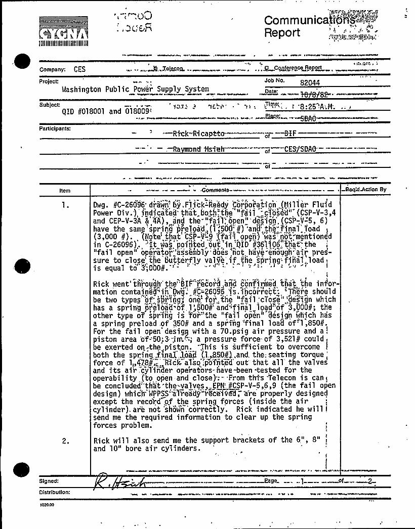
h. ~ == J m ar
='IIIIIIIIIIIIIIIIIIIIIIIIIIIII
t i'<)(r )r'n
~ ~ Mar'Va
~ ~~ ~ re ~r~,rarer~~
Co mmunicati@tta'-''-',-'=-':="
R.a.ni
~," aaeport r r II1 Ij r 1 $ ~ i 1 /
IIiIar r ~
I
Company: CES0 r r ~ a mors, r.....„A,.Jemooa...„....... "".' „„9't C~~nrerencm~Report
project: Job No. 82044Washington Public Power Supply System
wow wire 44 ~e~ ~err PAN Awe ee'oteew 8 Par
Subject r
/ID ¹018001 and 018009-'sAO ——Participants: —Rick-R~ cap&o.
nd iisteh-
of H%F
CESSDAO'f
Item
2.
Gomments-
Dwg. ¹C-26096'rawn'ry,F1ickrReldy'orpnoration',(I'1iller FluidPower Div.), indicated'that„both.the "fait. "c'toshdu (CSP-V-3,4and CEP-V-3A a 4A), and the-"fail: open'-''design',{CSP-,V-5, 6)have the samytspriftg preloa'd (1 '500-'¹) 'and'he„-final Toad(3,000 9). (Npte that CS'P-9'-,9 'Ifa>1 opens'was n'o't mentionedin C-26096),. "It tJ(as'poiih'ted out'in '/ID ¹361106 that th'"fail open" operator"'asshmbly"droes "ttot have-enough'air pres-sure to close'he butterfly valve. if the 'sttring'final,,load 1
is equal to 9'000¹.'-
Rick went'hirough''the"BIF"record award cnonfiriiii d 'that the in/or-mation containelqin'w'g." ¹C'-'26096 'fs.ihcorrrec't". 'Therae shouldbe two types'f ski'inrg'ene.foi',the "fail'cl'ose" ;'design whichhas a sprin'g jYrelOrad of 1'500¹'ndifiiia1 load-of 3,000¹; theother type o7 s)nhg is 'fora"the "fail open" desig'n which hasa spring preload of 350¹ and a sprfng,.'final load of'1,850¹.For the fail open desig~ with a 70.psig air pressure and a;"
piston area 'o'-50:3 .jn'.,-'; a pressure force of 3,521¹ couldbe exerted on -the„piston. -This is sufficient to overcomeboth the spring...final..load (],/50'.,and. the;seating torque
'orceof 1„478¹,-,'l6ck aTso .'pointed'ut that all'he valvesand its ai'r",cyTiiiher ope'razors-jtave+een -tested for theoperability (to open-and close).- From thts Telecon is cantbe concluded"than"t-the valves, EPN'.¹CSP-V-5,6,9 (the fail opendesign) which'PPSS ajTe'ad(I rFc'eivEd; are properly designedexcept the reco'rd of the spring forces (inside the aircylinder). are not show'n 'correct'ly. Rick indicated he willisend me the required information to clear up the springforces problem.
Rick will also send me the support brackets of the 6", 8" i
and 10" bore air cylinders.r
ReqMAction By
Signed:
Oistributlon:
1030.00
coy rerrrr 6 %4'wwH r eaerrerr areal m Ae'&w444 AA1%%a %r r% err ~ I ~ Ir+r A r ne Kerr e
Rage ...1 ~f- .-
~e ~~rr~

. -RtP
f ~E j - % P, EE~~ k=3. r~1IIIIIIIIIIIIIIIIIIIIIIIIIIIIII
CommunicationsReport
Company:
Project:
*~ Itj Teiecon x ct Conterence Report
Job No.
Subject: < E )E
QID f01mjOT-.:antn ISm'ime:<EMl 1 dt E % < piece'.
Participants:".~r 1C,
Comments Req'd Action By
3 ~ I
EA'„'
i4.
Ritk"and I'-discusied'th'e: locations-"of tTie CG'of the 6", 8"and 10" bore air cyl'inders'-'(Vor'both'-'the""fai'I closed" andnfail open" designs). We concluded that the CG locationsof the 6" bore air cylinder'fai'1 op'e'n«des'ign, Dwg. 8A-206762) and the 10n bove air cylinder'fail closed design,Dw'g;«8A'-206763)'l".e probably torrent. (cag';t'.find the" calcs).However, for the 8" bore;. air~ cylinder, Dwg. PA-206764 (failclosed design) and'wg.- imIA-206765 (fail open design), bothhave the identical CG location"yn.,the,gylingens.;
There are possibly two mistakes „about <he; CG.;location on the8" bore air cylinder. First, the "fail closed" and "failopen," designs could not hav'e the same CG .location becausethe "spr'ing and'the. spring storpi tu%e're'.lo'cated o'n 'theopposite-and of the"cyAnder'o'f""the 'tW<o 'QeEsigns.'ote thatthe spring and the spring stop tube are located at theop'p'oui te'end." of. the air'rr1j t~" ~tI;<he'"two.'"designs have adiffer'ent'ocation 'o'f th' air'~hl'et "(at"<he."opposite end).
Second, the CG of the 6" and 10." bove c'ylinders pre bothloBte'd'near'he center of 'the air cyl'in~Ier".E ""Hot'lever,, the8" bore air cylinder has its'B'located'bbut 9~'ff the'copter of„, the,Fylinder toward the,far end (away .from the sup-j'ovt. b "acket)'.„ Pick'w'IT@ se'arch ..for.'the caTc'uTations of the'CG loca/ion's"of tlte'ai'r 'cylind6 s. "" K,he'failed "to findthyrse"'ca'1„'culatioris;- he.pr'okised Cb. i4'nd, me a'=letter statingthat the"CG '-loca't'idn oY'the 'f"'"b'ore'fr'rcyfindev" h'ave boththe "fail open and fail closed designs and can be assumed tohave the same proportion as that of the corresponding 6" borecylinder (fail open design) and the 10" bore cylinder (failclosed design), respectively.The time needed to close or open the butterfly valve is approimately two seconds (estimated).
Sighed:
Oistribution:
'<E<.'gg&

'4! k3llllllllllllllllllllllllllllll
Communicaboas;=,.-,=-.-:.—;—.-.
epojf »»gq»fj!I ~ r» jjc»l,„»»»
»
Company:
Project:
Telecon
Washington Public-Power Supply System
"0 Conference Report
o No. 82044Date: 10/6/82
Subject Time: 10:50 A.M.(ID 8018001, 018009.;(Air Cylinder Operator) Pia'e'- " '"'DAO '-
='articipants:
Dave Pf1am
Ra ond Hsieh
f Co i1 S eci al t Co .
CES/SDAO
of
Item
2.
3.
4,
~ -Comments
Dave exp)ained,toI me ghat,the,,spjing,manufacturer Hses the.following rulies'.'i',."'designsngi'the»spgng's': ', „'..',a. For low cycle„..spring'esign:.. „;:, .
grist
»»»yf,f »,,»,>p,fn~»>t <jr ~ 'aqua
x=f0.45 Fu'Fb-"'='ultimate:"tensile: Stren'gtlT'f>t'";-
" '~~ "~«b!'ateria'])'
b. FOr high'r CJJCle Spy!ing deSign: ir ".r."«. ""I, " ',.'t.!'-'0.3
to" 0;35'Fu -: '«; 3a,'I ot«', .'!„:?c t;b ~ f~ -!max-.
3PDave indicated::i'fr hef lffere,ifesi gnsyg. the'se, spry ngs'f„ th'e as rcylinder for W)PSS,ten y'ea'rs,'ago;.he wil;1, use these safIIe,rules
I
The most comiIIon,used,,'material for the. sprsng,wpj,ch 'Cojl;;Specialty „provides.,to Hjl,.per,rFluid. Power', is AISI 51608'.Whichhas an Fu of 196 'ksi.
The bar diametep, fprf.fpe*:10",3"="ang5.,",bore.'air.'cy'lirfgr.'are:
Dave mention'ed pe,,foesp,.t know, th'e:fatsgue'l i.fe .in'foriiiat)'onof the .sprig .. 'HI„said that,i;t;.,j s .very'pnusua1„.'to, hear .thatsprings fai,lied in, lej,stress, cycles .(j ersz.than JoDI;000'.cy'cl es)when designed..'to th'e gu',lisf menQioned iri„:,(1),;above.;;.„',„"„
Req'd Action By
» ~ - " » y» M t OL»» o u '1 ~
» g » ~'
!iai6",.;3 -.; . Off >'e2 »!p r ~w ~ I
Signed:
Distribution:
Page of

~BD'i"
IIIIIIIIIIIIIIIIIIIIIIIIIIIIII
CommunicationsReport
Company: t y ~~ p ., „QTelecon ' Conference Report
~jlVM .. =~iS(
5ÃtMF(
Date:
~iieet —'=-'- ' "-~teC—- ——BIIBP.—.~cto+, '> 2. gZ.N(l t gg... [P 665@wa,r,. (gggz)fy
~~ie!peateli'
Z~ZV„'f
> ~comments Req'd Action By
OftTF:
t ii
i
'~~ 0 a = I.+Sf ((.m
i
.'g:g~ P a
~p jt
tg» ~
Ig" "'4' Vi'o.''~i
; t'675 . z.9)
Z,>73 3
.:;.' T, -.. Ps .
~'>~yjg~' p~xwu;~ IP
p~ ( cyclo ~ ~ch Ik~pi
:W-'.+-an IP~~ ~Q~m, i/
r > ~
'a~~-x~ —,"—'"'---'-A~-""'{PlA = I /p '%m t„yt,
~ ~ ~
~ . i~.v
gg,,
2w QZ + Z'573 iP —Q p(
P>Q -):.3/j4 (nog5) ~ $ '$o A:? t
PoVg jjMR
i~iynedt
Abutfon —-——- ~
~ "' of
~ceo
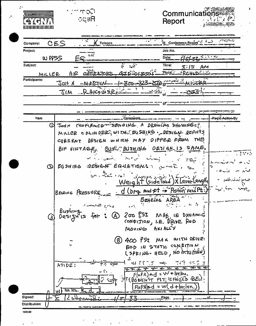
Lf »e».'i~L:= == J h. 1 =* tIIIIIIIIIIIIIIIIIIIIIIIIIIIIII
Communicat)ona-'-'""'-=',-"-'=-:
Reportf "i!IijijiijilIII'.i,IIIIII!j.
Company: Q g.QProject:
NwpwN >»»>>»e» w tbM»
>e W Teiecon 0 Conference Report ==-'r i>t>e>bee» >t ~ ante»at»>eeet»e»ee>eeee» ~ >ee»»»v»»A~>eee»>»»»»e A»A»»e» eP r e»»» e»>e»r»»» r»»eeara
Job No
Ee f>t,
Date:
Subject: Time:'C e
e ye,rt e
>IL It e at>eel>- II>»»—"".:—.Rett
eeeeeee»~e e»»ere>
Participants:Zo(< Pf -PkgEHM---J 5
--p-A'tee a i(cI.
~*~!~vs»!R.——. 5 I—--Q4-~ ————
of
Item
~ »» A»»» ~e»» r»r »ee»ee»reeee
Ca!orna ata Neq'4~Byq~~y~p,an't g!, p~b iNG„A 9 pgtAAf'~ g~ULftjbwt,.
t., jf,f. f~ p~":t et Zai", gb 58(~~ ~ .M>Z.4 4- 4f-'P«T>
cggg,@up ATE@,(sN tp H f<w >+Y'g~..-+Sea!,IS QiSJ >6>t> '.i S. <&IvÃe
e'
1> i
'g
SH rg C NPsfSA"" EQ<A~fOA'-'- '.
)
jif(side food X Leveret.
rj (i! iittdpt ~ pS!>re>rri<eptt."
Deke'us Ag&Ae'
e
Bus4t~pQA P~ [ST AA ii). ia
4'oNO't'7(oy> I.R. gQVC pe@
QOutQ~ AIt.( A~~
Qs etCO f>gg pi,g * Ie>tv'giilÃt!
P ~ g S~P~IC c:O.N,Q n'fo M
t sp~<gs, ski.p He ADYTUM~)
a > v e.» ~
<'9iCE'.
~ ie ~,Q»e
f !U
~ W'
~ > ~
'de,MJ ",~ M+
e~
Signed:
Distribution:
» Ia>'. »eee»e»r» ~ »
»4 %»ere» 4%ee
F(-F'jjl d = W(d+Ivt;le~.
Pa e3 rv ~ e»e A»l »ere v»ee>»»>A»eee re»»t»et»»eev»J

))»J't1 ~ Qt i 1
FI »I
t»
L =ada jib»—jjNNIINQINNINII-
, ~ »F»
CommunicationsReport
Pr'o'ect:
'Subject:
I ~
»
»»M» 4!
'= Participants:
~ ~»»I
'I»»
e Piace: g<
of
QPy
( "I»
.,Item„-: „,,
II '
t
It
, Comments -, .-,
4'-:=-''tf/wI'»9 ' ':(~~>",J ~|»fjtt'~t~~o" V VX'
'K
-~ ~
~-
~~rj
ig
»QI I
Req'd Action 8y
"lI
1
I'
'1II »I
»
» %
- .OistributiOrr.. -."r".", 1r
~ '» W» I »» ICOSI I » - ~ ' *1020.00
of

llllllllllllllllllllllllllllll
CommunicationsReport
a~ '0 l ~ 1 I ~ al I
Company CESG Tetecon/ Conference Report
>roiect
Subject
Fartlclpants
Job No.VPPSS Eauipment .Seismic/Hydrodynatrtj.cRequal xfication .— - -— —~e ~+9i~—'—
018004, 018009,II ~ ~, II!
N. Hardy
L. Fernandez.$. ~
~ ltqa la'+tat
<,-
Item Comments a
RBO ha oriana? veri faICari0ri ~aragaa iaIr..ahaabove referenced files which specify imcojnglete i,,status. These:sh'H 1 'be &organ%'zed 'into completepackace format 3q@ fa,l.ed ip, tpq,. RBQI QID',.binders. ',
The completed packages are <forthcoming from theArea Offices"-i n~5he -foem"'o& Reezsiorf:-R ~''theseRevision 1 requatjification packages will supersedeRevision 0 in RBO QID files.
Ig ' > aZt is noted that nond of'hese incomplete packages(Revision 0) hpve,„'bqen qubmittep- to the~ctS.
- 4NIr.
r.l I
I
Rett'd'ction By
NH
~ a 'l p
rile'y ~i )~~ipr
10' 00
I 'I — ''oc'I'IvT. Yittfc, t . KhanacHet Yi. Scott Pro ject File
rAlva l e~l4~tY,. Hardy. N. Be~m~

C.- 3 i I