Formation of iron-rich shelled structures by microbial communities
22
Formation of iron-rich shelled structures by microbial communities David C. Fernández-Remolar 1 , Joan Santamaría 2 , Ricardo Amils 1,3 , Victor Parro 1 , D. Gómez-Ortíz 4 , Matthew R. M. Izawa 5,6 , Neil R. Banerjee 5 , Raúl Pérez Rodríguez 7 , Nuria Rodríguez 1 , and Nieves López-Martínez 8 1 Centro de Astrobiología (INTA-CSIC), Torrejón de Ardoz, Spain, 2 Consultant Geologist, Sabadell, Spain, 3 Centro de Biología Molecular Severo Ochoa, Universidad Autónoma de Madrid, Madrid, Spain, 4 ESCET, Área de Geología, Universidad Rey Juan Carlos, Móstoles, Spain, 5 Department of Earth Sciences, The University of Western Ontario, London, Ontario, Canada, 6 Now at Hyperspectral Optical Sensing for Extraterrestrial Reconnaissance Laboratory, Department of Geography, University of Winnipeg, Winnipeg, Manitoba, Canada, 7 Nanotechnology Platform, Institute for Bioengineering of Catalonia, Barcelona, Spain, 8 Departamento de Paleontología, Facultad de Ciencias Geológicas, Universidad Complutense de Madrid, Madrid, Spain Abstract In this paper, we describe the discovery and characterization of shelled structures that occur inside galleries of Pyrenees mines. The structures are formed by the mineralization of iron and zinc oxides, dominantly franklinite (ZnFe 2 O 4 ) and poorly ordered goethite (α-FeO(OH)). Subsurface oxidation and hydration of polymetallic sulfide orebodies produce solutions rich in dissolved metal cations including Fe 2+/3+ and Zn 2+ . The microbially precipitated shell-like structure grows by lateral or vertical stacking of thin laminae of iron oxide particles which are accreted mostly by fungal filaments. The resulting structures are composed of randomly oriented aggregates of needle-like, uniform-sized crystals, suggesting some biological control in the structure formation. Such structures are formed by the integration of two separated shells, following a complex process driven likely by different strategies of fungal microorganisms that produced the complex macrostructure. 1. Introduction Since the emergence of the first microbial communities on the early Earth, microbial activity has induced mineral precipitation, by both indirect and direct mechanisms [Allwood et al., 2006; Perry et al., 2007]. This is the result of microbially mediated processes inducing physicochemical changes (commonly at very small spatial scales) that promote the local oversaturation of different minerals. One paradigmatic case is the precipitation of iron oxides by different iron bacteria and fungi [Banfield et al., 2000; Gilbert et al., 2005] that aggregate iron oxides through excess of positive charge, around the negatively charged cellular membrane. By this mechanism, thin precipitates of iron oxides can passively grow, forming mineral coatings [Fernández-Remolar and Knoll, 2008], the composition of which depends on solution chemistry. However, the final product is a simple thin lamina with a morphology and structure that is strongly affected by external physical and chemical processes. Iron oxide growth of this type is representative of indirect microbially influenced mineralization, in which mineral formation is not directly controlled by the microbial communities, yet mineralization would not occur in the absence of microbes. In this work we show the occurrence of a biological system formed by different bacteria and fungi that cause the formation of iron-rich shelled microbial structures (IRSS). Such structures are generated in abandoned mines of the Pyrenees from the biogeochemical integration between iron mobilization by bacteria and precipitation of iron oxides through different mechanisms directed by fungi. 2. Background 2.1. Geographical and Geological Settings The structures were found inside the sphalerite (ZnS) mines occurring in the Arán Valey (Pyrenees) at different altitudes starting at 2000 m (Figures 1, S1, and S2 in the supporting information). Such S-bearing mineralization formed along fractures that affected siliceous deposits of Cambro-Ordovician to Silurian age is FERNÁNDEZ-REMOLAR ET AL. ©2015. American Geophysical Union. All Rights Reserved. 1 PUBLICATION S Journal of Geophysical Research: Biogeosciences RESEARCH ARTICLE 10.1002/2014JG002745 Key Points: • Shelled structures are produced by microbial communities • They produce biomineralized structures in abandoned mines by iron oxidation • Fungi are the main biomineralizing agent, whereas bacteria are secondary Supporting Information: • Figures S1–S14 Correspondence to: D. C. Fernández-Remolar, [email protected] Citation: Fernández-Remolar, D. C., J. Santamaría, R. Amils, V. Parro, D. Gómez-Ortíz, M. R. M. Izawa, N. R. Banerjee, R. Pérez Rodríguez, N. Rodríguez, and N. López- Martínez (2015), Formation of iron-rich shelled structures by microbial communities, J. Geophys. Res. Biogeosci., 120, doi:10.1002/2014JG002745. Received 9 JUL 2014 Accepted 28 DEC 2014 Accepted article online 7 JAN 2015
Transcript of Formation of iron-rich shelled structures by microbial communities
Formation of iron-rich shelled structuresby microbial communitiesDavid C. Fernández-Remolar1, Joan Santamaría2, Ricardo Amils1,3, Victor Parro1, D. Gómez-Ortíz4,Matthew R. M. Izawa5,6, Neil R. Banerjee5, Raúl Pérez Rodríguez7, Nuria Rodríguez1, andNieves López-Martínez8
1Centro de Astrobiología (INTA-CSIC), Torrejón de Ardoz, Spain, 2Consultant Geologist, Sabadell, Spain, 3Centro de BiologíaMolecular Severo Ochoa, Universidad Autónoma de Madrid, Madrid, Spain, 4ESCET, Área de Geología, Universidad Rey JuanCarlos, Móstoles, Spain, 5Department of Earth Sciences, The University of Western Ontario, London, Ontario, Canada, 6Nowat Hyperspectral Optical Sensing for Extraterrestrial Reconnaissance Laboratory, Department of Geography, University ofWinnipeg, Winnipeg, Manitoba, Canada, 7Nanotechnology Platform, Institute for Bioengineering of Catalonia, Barcelona,Spain, 8Departamento de Paleontología, Facultad de Ciencias Geológicas, Universidad Complutense de Madrid, Madrid,Spain
Abstract In this paper, we describe the discovery and characterization of shelled structures that occurinside galleries of Pyrenees mines. The structures are formed by the mineralization of iron and zincoxides, dominantly franklinite (ZnFe2O4) and poorly ordered goethite (α-FeO(OH)). Subsurface oxidationand hydration of polymetallic sulfide orebodies produce solutions rich in dissolved metal cations includingFe2+/3+ and Zn2+. The microbially precipitated shell-like structure grows by lateral or vertical stacking ofthin laminae of iron oxide particles which are accreted mostly by fungal filaments. The resulting structuresare composed of randomly oriented aggregates of needle-like, uniform-sized crystals, suggesting somebiological control in the structure formation. Such structures are formed by the integration of twoseparated shells, following a complex process driven likely by different strategies of fungal microorganismsthat produced the complex macrostructure.
1. Introduction
Since the emergence of the first microbial communities on the early Earth, microbial activity has inducedmineral precipitation, by both indirect and direct mechanisms [Allwood et al., 2006; Perry et al., 2007]. This isthe result of microbially mediated processes inducing physicochemical changes (commonly at very smallspatial scales) that promote the local oversaturation of different minerals. One paradigmatic case is theprecipitation of iron oxides by different iron bacteria and fungi [Banfield et al., 2000; Gilbert et al., 2005]that aggregate iron oxides through excess of positive charge, around the negatively charged cellularmembrane. By this mechanism, thin precipitates of iron oxides can passively grow, forming mineralcoatings [Fernández-Remolar and Knoll, 2008], the composition of which depends on solution chemistry.However, the final product is a simple thin lamina with a morphology and structure that is strongly affectedby external physical and chemical processes. Iron oxide growth of this type is representative of indirectmicrobially influenced mineralization, in which mineral formation is not directly controlled by the microbialcommunities, yet mineralization would not occur in the absence of microbes.
In this work we show the occurrence of a biological system formed by different bacteria and fungi that causethe formation of iron-rich shelled microbial structures (IRSS). Such structures are generated in abandonedmines of the Pyrenees from the biogeochemical integration between iron mobilization by bacteria andprecipitation of iron oxides through different mechanisms directed by fungi.
2. Background2.1. Geographical and Geological Settings
The structures were found inside the sphalerite (ZnS) mines occurring in the Arán Valey (Pyrenees) atdifferent altitudes starting at 2000m (Figures 1, S1, and S2 in the supporting information). Such S-bearingmineralization formed along fractures that affected siliceous deposits of Cambro-Ordovician to Silurian age is
FERNÁNDEZ-REMOLAR ET AL. ©2015. American Geophysical Union. All Rights Reserved. 1
PUBLICATIONSJournal of Geophysical Research: Biogeosciences
RESEARCH ARTICLE10.1002/2014JG002745
Key Points:• Shelled structures are produced bymicrobial communities
• They produce biomineralized structuresin abandoned mines by iron oxidation
• Fungi are the main biomineralizingagent, whereas bacteria are secondary
Supporting Information:• Figures S1–S14
Correspondence to:D. C. Fernández-Remolar,[email protected]
Citation:Fernández-Remolar, D. C., J. Santamaría,R. Amils, V. Parro, D. Gómez-Ortíz,M. R. M. Izawa, N. R. Banerjee, R. PérezRodríguez, N. Rodríguez, and N. López-Martínez (2015), Formation of iron-richshelled structures by microbialcommunities, J. Geophys. Res. Biogeosci.,120, doi:10.1002/2014JG002745.
Received 9 JUL 2014Accepted 28 DEC 2014Accepted article online 7 JAN 2015

strongly affected by the Variscan Orogeny [García Sansegundo, 1991]. The mines are emplaced in the AxialZone of the Pyrenees [Barnolas and Pujalte, 2004] along the boundary between the Les-Dom de la GaronaAnticline and Vielha Syncline [Santamaria et al., 2008], where a complete succession of around 700m ofCambrian to Devonian deposits crops out (supporting information Figures S1 and S2) with the followingunits: 1, the Uret beds composed of schists and slates (Cambrian); 2, the Bentaillou limestones (UpperCambrian to Lower Ordovician); 3, Orla bets (Upper Ordovician); 4, the Mall de Boular conglomerates(Caradoc); 5, the Sandwich limestones (Asghill); 6, Liat beds composed of slates (Late Ordovician); 7, Blackslates (Silurian); and 8, Devonian shales. During the Upper Ordovician, sedimentation of detrital and
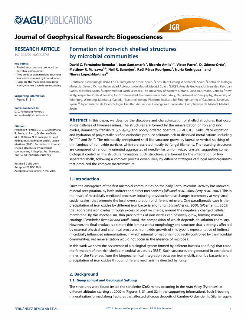
Figure 1. Map showing the locations of the mine sites hosting the shelled structures. (map @ Instituto Geográfico Nacional de España, image @ 2015 InstitutCartografic de Catalunya, @ 2015 google)
Journal of Geophysical Research: Biogeosciences 10.1002/2014JG002745
FERNÁNDEZ-REMOLAR ET AL. ©2015. American Geophysical Union. All Rights Reserved. 2
carbonatic materials was accompanied by volcanic activity, driving exhalative mineralization that promotedthe formation of polymetallic sulfide orebodies with close relation to the structural framework of thesedimentary-forming units [Cardellach et al., 1996]. Furthermore, the sedimentary material has been affectedby Variscian magmatism that induced, during the late Carboniferous, the formation of different felsic plutonicrocks including granites and granodiorites [Barnolas and Pujalte, 2004].
The exoskeleton-like structures studied in this work were discovered in 1999 and have been collected inLiat and Urets mines, during different field campaigns in 2001. The structures are associated with theoxidation of steel and iron products like train tracks, cables, wires, and several tinplate scraps. However, theyhave also been observed in other mines in the area. Liat and Urets mines occur at around 2300 and 2500maltitude in the northeastern region of the Arán Valley (municipality of Vielha e Arán) near the borderbetween Spain and France (Figure 1). Both mines were built to extract sulfide mineralization in similar,but not exactly identical, geological contexts. For example, the Liat Mine was excavated through the Liatbeds (Late Ordovician) for exploiting sulfide mineralization, which formerly occupied sites inside thestratification planes. In a later stage, during the Variscian, the orebodies were remobilized and deformed bylater folding and fracturing that displaced the sulfide deposits toward the fold hinges and fractures, as aresult of its incompetent response to tectonic stress. The Urets Mine was emplaced on the Upper Ordovicianto Silurian deposits of Mall de Boulard and Liat beds, and Sandwich limestones (supporting informationFigure S2), (Caradoc to terminal Ordovician), where the mineralizing materials were placed along the planeof thrusting fault that is subparallel to the stratification. However, the geological context that interplayswith the subsurface solutions is sufficiently similar to maintain a constant hydrochemistry that favors theexoskeleton-like structures.
2.2. Mine Environment and Hydrogeochemistry
The studied Pb-Zn mines are located in the axial zone of the Pyrenean Range that exhibits significant relief,with heights ranging from 650 to 2500m above sea level and slopes up to 30° [Astui et al., 2004]. The climateis typical of high-mountain conditions, characterized by long, cold winters and short, cool summers.Precipitation is very abundant in the form of rain in the late spring, summer, and fall, and snow in winter andearly spring. Rainfall and temperature data [Astui et al., 2004] indicate that the mean temperature during thewinter is ~3°C, whereas during the summer it increases to ~17°C. Annual mean temperature ranges from9.8° to 11.8°C. Annual mean rainfall increases approximately linearly with elevation, ranging from 930 to1536mm. The Pb-Zn mines are located at an elevation of about 2000m corresponding at a mean annualrainfall of more than 1150mm.
The estimation of the potential evapotranspiration (PE), assuming no control on water supply [Pidwirny, 2006]was performed using the Thornthwaite equation [Thornthwaite, 1948; Thornthwaite and Mather, 1955]. As aresult, the PE annual mean values [Astui et al., 2004] range from 655mm to 800mm for a 20 year time lapse(1951–1971). Furthermore, the actual evapotranspiration (AET) can be computed using empirical formulassuch as that of Coutagne [Coutagne, 1954]. Using this expression, the annual mean AET values for the sametime period ranges from 525mm to 568mm [Astui et al., 2004]. PE and AET values are lower than the meanrainfall for the area, resulting in an excess of water that produces both a surface runoff and an aquiferrecharge, which has a higher magnitude at higher elevations where rainfall is maximal andevapotranspiration is minimal.
The mines are excavated in a fractured aquifer developed in Cambrian-Ordovician quartzites, Silurian shales,and Devonian carbonates and shales [Astui et al., 2004], which host the sulfide mineralizations. The aquiferoverlaps some incipient karstic features that can be found in the carbonatic materials. As a consequence, thewater composition of the aquifer varies from calcium-bicarbonatic, in carbonate levels, to calcium-sulfaticfor underground solutions contacted to sulfide orebodies circulating along the mine galleries (supportinginformation Figure S3). Although the oxidation of sulfides produces acidic solutions, they are neutralized byreaction with the Paleozoic carbonate deposits to produce solutions with circumneutral to slightly alkalinepH (6.72 to 7.71), conductivities between 743 and 2160μS/cm in the mine waters, and redox potentialsvarying between 203 and 315mV. The Piper diagram (supporting information Figure S3) shows theprojection of nine water samples [Astui et al., 2004] corresponding to the hydrogeological unit 2, the onewhere the ore body is located. As can be seen (supporting information Figure S3), samples are notconcentrated on a single spot but linearly distributed along the upper part of the diamond-shaped
Journal of Geophysical Research: Biogeosciences 10.1002/2014JG002745
FERNÁNDEZ-REMOLAR ET AL. ©2015. American Geophysical Union. All Rights Reserved. 3
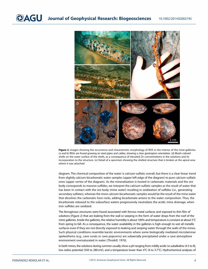
diagram. The chemical composition of the water is calcium-sulfatic overall, but there is a clear linear trendfrom slightly calcium-bicarbonatic water samples (upper left edge of the diagram) to pure calcium-sulfaticones (upper vertex of the diagram). As the mineralization is hosted in carbonatic materials and the orebody corresponds to massive sulfides, we interpret the calcium-sulfatic samples as the result of water thathas been in contact with the ore body (mine water) resulting in oxidization of sulfides (i.e., generatingsecondary sulfates), whereas the more calcium-bicarbonatic samples would be the result of the mine waterthat dissolves the carbonatic host rocks, adding bicarbonate anions to the water composition. Thus, thebicarbonate released to the subsurface waters progressively neutralizes the acidic mine drainage, wheniron sulfides are oxidized.
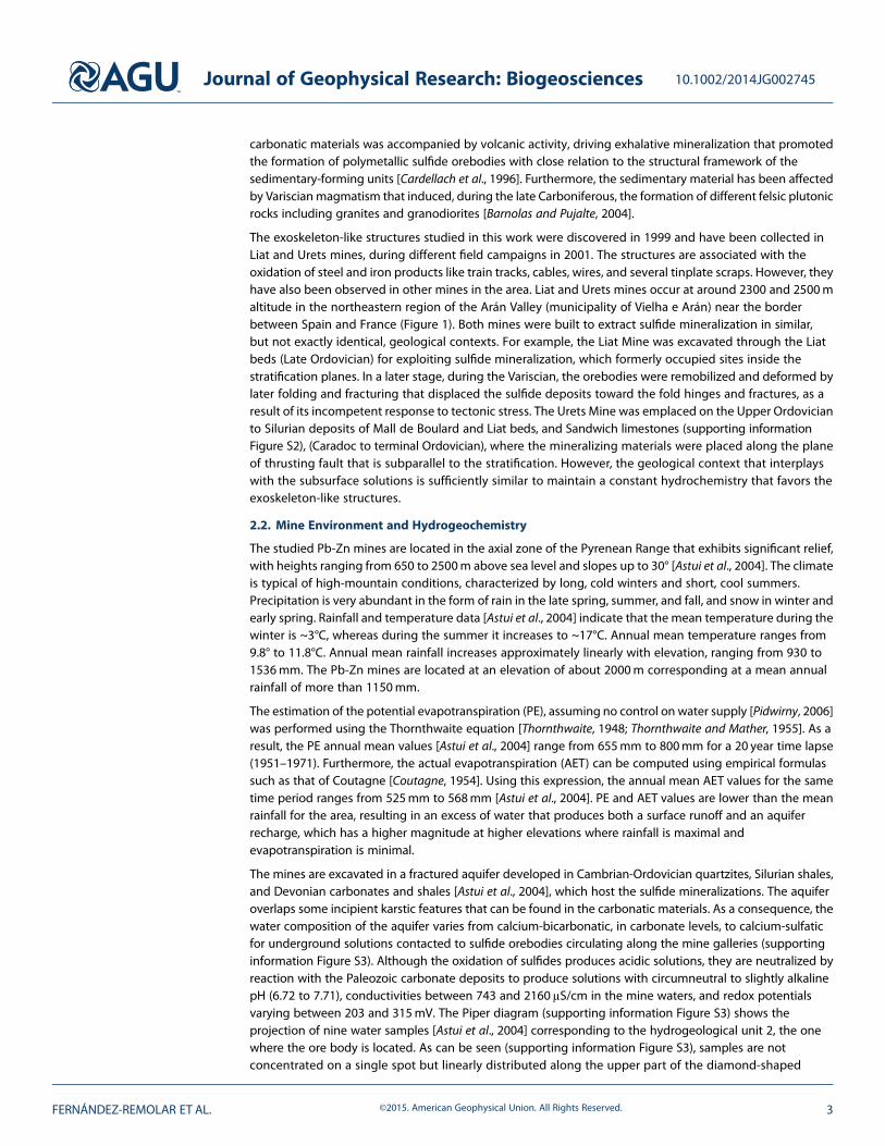
The ferruginous structures were found associated with ferrous metal surfaces and exposed to thin film ofsolutions (Figure 2) that are leaking from the wall or seeping in the form of water drops from the roof of themine galleries. Inside the galleries, the relative humidity is about 100% and temperature is constant at about 5°Cfrom spring to fall. As a consequence, the water availability in the galleries is high enough to wet all metallicsurfaces even if they are not directly exposed to leaking and seeping water through the walls of the mines.Such physical conditions resemble karstic environments where some biologically mediated microlaminarspeleothems (e.g., cave corals or cave popcorns) are subaerially precipitated under a cave atmosphereenvironment oversaturated in water [Thraikill, 1976].
In bothmines, the solutions during summer usually show a pH ranging frommildly acidic to subalkaline (4.5 to 8),low redox potential (350 to 280mV), and a temperature lower than 4°C (4 to 3.7°C). Hydrochemical analyses of
Figure 2. Images showing the occurrence and characteristic morphology of IRSS in the interior of the mine galleries:(a and b) IRSSs are found growing on steel pipes and cables, showing a clear geotropism orientation. (d) Bluish coloredshells on the outer surface of the shells, as a consequence of elevated Zn concentrations in the solutions and itsincorporation to the structure. (e) Detail of a specimen showing the shelled structure that is broken at the apical areawhere it was attached.
Journal of Geophysical Research: Biogeosciences 10.1002/2014JG002745
FERNÁNDEZ-REMOLAR ET AL. ©2015. American Geophysical Union. All Rights Reserved. 4
water samples collected in summer through an Elan 6000 Sciex Perkin Elmer Quadrupole inductively coupledplasma–mass spectrometry (Table 1) show solutions enriched in Zn and Fe that at a pH ~7 are oversaturatedwith respect to hematite, goethite, franklinite, nanophase iron hydroxides, and maghemite. In addition,thermochemical calculations to obtain pH-Eh stability diagrams for those solutions at a temperature of 5°C(Table 1 and supporting information Figure S4) show that the stable phases for the mine galleries arefranklinite (Zn2+Fe3+2 O4) and goethite. Ion concentrations in fluids infiltrating the galleries in the Liat mine,and mineral saturation states have been calculated using the thermodynamic database thermo.com.v8.r6+included in the Geochemist’s Workbench 8.0 package [Bethke, 2008].
3. Materials and Methods
Samples of shelled structures were collected in Liat and Urets galleries to determine the formation mechanismof these peculiar structures and to ascertain the role(s) of biological activity involved in their formation. Toaccomplish the aforementioned goals, a multitechnique approach was applied to the structures, includingthe characterization of macrostructure/microstructure, mineral and elemental compositions, organiccharacterization, and microarray assessment of the biomolecular contents and microbial populationspresent. For the electron and ion-beam techniques and optical microscopy, sample preparation requiredthin sectioning and embedding in epoxy resin. Bulk mineralogical characterization required thepreparation of a fine-grained powder by grinding.
The surface and inner structure of complete or thin sections of specimens were observed under a Leicastereomicroscope and an upright triocular microscope Motic BA400 coupled to a MoticamPro 282a cameraand a Leica stereomicroscope. Optical observations were complemented with observations throughbackscattered electron imagery of the inner and outer faces of shells of iron-shelled structures underscanning electron microscopy (SEM). Semiquantitative chemical microanalysis was performed with a JeolJSM-5600 LV SEM coupled to a Cambridge INCAx SIGHT EDAX (Energy Dispersive X-ray Spectrometer) in orderto determine the microstructure associated to elemental composition. Mineralogical analysis of powderedsamples was performed using a Seifert 3003 T-T X-ray diffractometer (copper source, Cu Kα1,2, λ=1.5401 Å)scanning 2θ diffraction angles from 0 to 70°. X-ray diffractograms were analyzed using Bruker AXS EVAversion 2.0 software and the Crystallography Open Database rev. 1155 2010.05.06 [Grazulis et al., 2009].
Polished thin sections were also prepared for detection and mapping of organics by Time-of-Flight SecondaryIonization Mass Spectrometry (TOF-SIMS) analysis. This technique establishes a direct association between theinorganic and organic composition to the sample microstructure, which provides a strong support to thepresence of microbial activity in the structure of the shells. Thin sections were prepared by using a 0.3μmalumina paste in order to reduce surface imperfections, which can produce strong interferences during thesurface analysis. Before analysis, the thin sections were cleaned by surface sputtering with a 100 nA 500 3 Voxygen ion beam during 3 s on a square of 500 × 500 μm. The TOF-SIMS analyses were performed using aTOF-SIMS IV (ION-TOF, Münster, Germany) operated at a pressure of 5×10�9mbar. Samples were bombardedwith a pulsed Bismuth liquid metal ion source (Bi3
++), at an energy of 25 keV. The gun was operated with a 20ns
Table 1. Ion Concentrations in Fluids Infiltrating the Galleries in the Liat Mine and Mineral Saturation States That HaveBeen Calculated Using the Thermodynamic Database thermo.com.v8.r6+ Included in the Geochemist’s Workbench8.0 Package
Element Concentration Mineral Saturation States
Cation g L�1 Mineral Formula Saturation Index
Zn2+ 1.19E�1 Hematite Fe2O3 12.1Ca2+ 5.65E�2 Magnetite Fe3O4 10.2Mg2+ 3.86E�2 Franklinite ZnFe2O4 10.1Na+ 1.85E�2 Goethite FeOOH 5.6Si4+ 9.21E�3 Maghemite-Mg ϒ-Fe2O3-Mg 0.06K+ 5.92E�3 Maghemite-Ca ϒ-Fe2O3-Ca �0.24Fe2+ 4.15E�3 Gypsum CaSO4 · 2H2O �1.21Mn2+ 2.61E�3 Zincite ZnO �1.43Sr2+ 1.18E�4 Anhydrite CaSO4 �1.59
Journal of Geophysical Research: Biogeosciences 10.1002/2014JG002745
FERNÁNDEZ-REMOLAR ET AL. ©2015. American Geophysical Union. All Rights Reserved. 5
pulse width, 0.3 pA pulsed ion current for a dosage lower than 5×10¹¹ ions/cm2, well below the threshold levelof 1× 10¹³ ions/cm2 generally accepted for static SIMS conditions. Secondary ions were detected with areflector time-of-flight analyzer, amultichannel plate, and a time-to-digital converter. Charge neutralization wasachieved with a low-energy (20 eV) electron flood gun. Secondary ion spectra were acquired from a randomlyrastered surface areas of 500μm×500μm within the sample’s surface. Secondary ions are extracted with 2 kVaccelerating voltage and are postaccelerated to 10 keV kinetic energy just before hitting the detector. Massspectral acquisition and image analysis were performed within the ION-TOF Ion Spec and Ion image software(versions 4.1 and 3.1). Each ion image shown is normalized to the intensity in the brightest pixel. This intensityvalue is assigned to the color value of 256. Zero intensity is assigned to the color value 0. All otherintensities are assigned accordingly using a linear relationship.
LDChip300 (Life Detector Chip) was designed and built for planetary exploration and environmental monitoring[Parro et al., 2011a; Rivas et al., 2008]. It contains about 300 antibodies produced against microbial cells (archaeaand bacteria), extracellular polymers, environmental extracts (soil, sediments, rocks, water, etc), proteins, andpeptides from well-constrained metabolic pathways, exopolysaccharides, or universal biomarkers like DNA,amino acids, and other biomolecules. The IgG fraction of each antibody was printed on epoxy-activated glassslides (Arrayit Corp.) using a MicroGrid II Total Array System arrayer (Biorobotics, Genomic Solutions, UK).
Solid crusts were analyzed with LDChip300 as described [Parro et al., 2011a]. Samples (0.5 g) to be analyzed byLDChip were rinsedwith sterile water and 3%H2O2 to remove any potential contaminant during transportation.Then, they were ground with a sterile mortar and pestle inside a laminar flow cabin. The powder wasresuspended in 1mL of extraction/incubation buffer TBSTRR (0.4M Tris-HCl pH 8, 0.3M NaCl, 0.1% Tween 20)and subjected to 3×1min cycles of sonication (DR. HIELSCHER 50W DRH-UP50H hand sonicator, HielscherUltrasonics, Berlin, Germany). The sample was filtered through a 20μm filter, and 50μL of filtrate was put it incontact with LDChip300 and incubated at ambient temperature (23–25°C) for 1 h. After washing with TBSTRRbuffer, positive antibody-antigen reactions were revealed by incubation with 50μL of a mixture containing400 fluorescent antibodies at a final concentration of 100μg/mL for the whole mixture and around 1μg/mL foreach one of the antibodies. After 1 h incubation at ambient temperature, the microarrays were washed outagain, dried by a short centrifugation in a small and portable microcentrifuge for slides (Arrayit Corp.), andscanned for fluorescence at 635 nm in a GenePix 4100A scanner. The images were analyzed and quantified byGenepixTM Pro Software (Genomic Solutions). A blank control consisting of only extraction buffer, not sample onit, was run to detect and substract any artifact that may come from unspecific binding of the fluorescentantibodies used to reveal the immunoassay. The final fluorescent intensity (FI) for each antibody spot wascalculated by applying the next equation: FI = [(F635-B)sample� (F635-B)blank]� 3× (Average F635-Bcontrol spots),where F635-B is the fluorescent intensity at 635 nm minus the local background as quantified by the software(GenePix Pro.), and the control spots those containing only Bovine Serum Albumin buffer, and otherscorresponding to the preimmune antisera. Spots having obvious defects or those spots whose standarddeviation from their mean were 0.2 times higher than the mean were not considered for quantification.
4. Results4.1. Morphology and Inner Structure of IRSS
Simple observation of the IRSS morphology shows that they are formed of two different shell-like structures,each one with an imprecise bilateral symmetry (Figures 2 and 3). Although the structures do not have a veryprecise symmetry, the growing morphology with regard to the attached substrate has been used to describethe arrangement of the whole structure (Figures 2e and 3). Following this arrangement, the term “uppershell” has been assigned to themore curved structure, whereas the term “lower shell” is assigned to the lowerand flattened shell-like part (Figure 3b) that usually attaches to the metallic substrate which provides theferrous compounds for developing the IRSS.
Very commonly the lower shell is completely integrated in themetallic substrate and does not show any specificattachment. However, in some few specimens the lower shell has a conspicuous apical area that can have ahollow cylindrical protrusion delimiting an operculum. Such protrusions attach the shelled structures to themetallic surface. Therefore, the initial growing phases have a subcircular outline that distally changes to an openand wavy pattern to form, at the marginal area, sharp folds separated by deep furrows (Figure 3a). Both foldsand furrows display a radial pattern of undulating growth lines along the transverse plane of the shells.
Journal of Geophysical Research: Biogeosciences 10.1002/2014JG002745
FERNÁNDEZ-REMOLAR ET AL. ©2015. American Geophysical Union. All Rights Reserved. 6

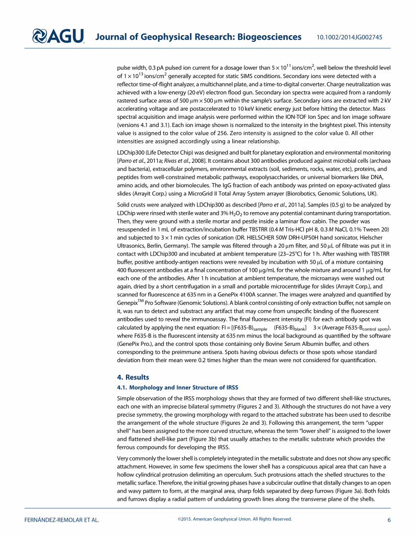
The inner structure of IRSS (Figure 4) is formedby marginal accretion of laminae that arepiled up by successive episodes of sheetgrowth. Growth lines show a sharp andpositive concentric pattern (Figure 3a) thatonly occurs in the inner face of the shells(supporting information Figure S5a). Theouter surface of the shells is smooth andoverlaps all preceding laminae. Suchframework suggests that IRSSs grow on theouter face of the shells. Under visible light, theouter surface of most specimens show abright patina with traces of organic matter,which is observed in the form of fluorescentemission when exposed to UV light. In somefew specimens, such a bright and fluorescentpatina is also observed conforming thegrowth lines in the interior face of the shells.Although both outer and inner fluorescentthin laminae are organic, they are not likely incontact because the upper and lower shellsare strongly occluded.
Microscope observation of thin-sectioned shells shows that they are built up by four different layers(Figures 4 and 5) with a very complex texture and microstructure, each showing distinctive morphologicaland structural traits. From the inner to the outer surface of a shell, the four layers show the following features:
1. Inner layer. Continuous light orange massive crystalline-like layer (Figures 4, 5a, and 5b) embeddingdark filaments that are oriented slightly oblique or subparallel to the layer orientation. Although themicrostructure is not clearly visible in the interior layer, it is revealed in the inner rim of the shell as a20 to 50μm reddish thin lamina composed of needles arranged following a radial to laminar microfabric.The samemicrostructure is also observed inside the layer porosity, which is covered by a palisade of needleswith a radial disposition. Boundaries between the two successive layers are sharp.
2. Coated filaments layer. Very discontinuous and porous layer (Figure 4) replacing the inner layer andappearing as bags of around 20μm wide filament coatings (Figure 5c) without a preferred orientation(Figure 6a), showing preferential and planar orientation only in contact with the next outer layer. Mostcoatings are empty and show little evidence of the primary coated filaments (Figure 6a). The color andmicrostructural features suggest similar composition as the inner layer.
3. Intermediate layer. A 0.8 to 2mm thick noncrystalline opaque layer (Figures 4, 5a, 5d–5f, S6a, and S6bin the supporting information) embedding 10 to 50μm sized orange laminae with sinuous outlines, whichhave a discontinuous and crystalline appearance (Figures 5d and S6a in the supporting information).The intermediate layer grades into the outer layer with increasing number and thickness of orangecrystalline laminae at the transition between layers. Different biological and nonbiological debris areembedded and integrated into the mineral matrix of the layer. Furthermore, at the apical region of theventral shell (supporting information Figure S6b), the layer is onlapping a massive matrix composed ofdense clusters of permineralized filaments (Figures 6b and 6c) and detrital particles of biological andnonbiological origin that form amicrobreccia texture (Figures 4, S6a, and S6b in the supporting information).Such aggregates are included in the opaque matrix in close relation and limiting with the bags of filamentcoatings. Although they are preserved as coatings or permineralized structures, the inner part of the coatedwall is formed by an opaque and noncrystalline matrix of the layer. The brecciated unit borders witha more porous matrix that is partially infilled by sets of densely wrapped filaments (Figures 6b and 6c),which show a strong preferred orientation. Such filament wraps emerge from the microbrecciated unitto form fungal mineralized structures with permineralized and coated walls with squared sections asshown in Figures 6b and 6d.
Figure 3. (a) Sketch of the inner face of a lower shell showing anirregular succession of sinuous and subcircular growth lines; and(b) reconstruction of a specimen showing occluding shells withthe ventral shell attached to a cable.
Journal of Geophysical Research: Biogeosciences 10.1002/2014JG002745
FERNÁNDEZ-REMOLAR ET AL. ©2015. American Geophysical Union. All Rights Reserved. 7
4. Outer layer. The 0.2–0.5μm thick layer built up of orange crystalline alternating with thinner opaque laminae(Figures 4, 5e, 5f, and S6a in the supporting information). Such alternation is laterally discontinuous andonly occurs as a simple piling of very thin orange laminae (<50 μm) or, less frequently, 0.3 to 1mmmassive ochre patches with laminar or discontinuous morphology. Frequently, the fine lamination ofthe layer is crossed by ~ 40 μm sized thick opaque streaks (Figure 5f) with wrinkled surface. Somethicker (80–100 μm) and massive orange laminae contain circular to subcircular-shaped pores (Figure 4)averaging ~40 μm, which in some cases show internal division in the form of septa.
Figure 4. Mosaic of thin section photomicrographs showing the interior structure of an IRSS lower shell composed ofseveral different accretionary layers in the form of laminar or lenticular bodies. Blue squares denote specific sites wherethemicrostructure is detailed in Figure 5. The dashed purple square denotes the apical area for which a transverse section isimaged in detail in supporting information Figure S6.
Journal of Geophysical Research: Biogeosciences 10.1002/2014JG002745
FERNÁNDEZ-REMOLAR ET AL. ©2015. American Geophysical Union. All Rights Reserved. 8
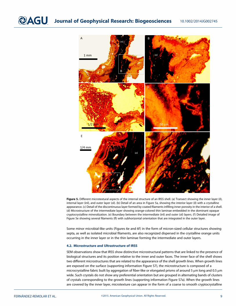
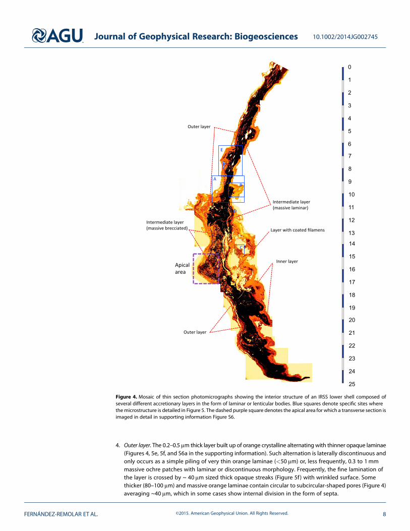
Some minor microbial-like units (Figures 6e and 6f) in the form of micron-sized cellular structures showingsepta, as well as isolated microbial filaments, are also recognized dispersed in the crystalline orange unitsoccurring in the inner layer or in the thin laminae forming the intermediate and outer layers.
4.2. Microstructure and Ultrastructure of IRSS
SEM observations show that IRSS show distinctive microstructural patterns that are linked to the presence ofbiological structures and its position relative to the inner and outer faces. The inner face of the shell showstwo different microstructures that are related to the appearance of the shell growth lines. When growth linesare exposed on the surface (supporting information Figure S7), the microstructure is composed of amicrocrystalline fabric built by aggregation of fiber-like or elongated prisms of around 5μm long and 0.5μmwide. Such crystals do not show any preferential orientation but are grouped in alternating bands of clustersof crystals corresponding to the growth lines (supporting information Figure S7a). When the growth linesare covered by the inner layer, microtexture can appear in the form of a coarse to smooth cryptocrystalline
Figure 5. Different microtextural aspects of the internal structure of an IRSS shell. (a) Transect showing the inner layer (il),internal layer (inl), and outer layer (ol). (b) Detail of an area in Figure 5a, showing the interior layer (il) with a crystallineappearance. (c) Detail of the discontinuous layer formed by coated filaments infilling inner porosity in the interior of a shell.(d) Microstructure of the intermediate layer showing orange-colored thin laminae embedded in the dominant opaquecryptocrystalline mineralization. (e) Boundary between the intermediate (inl) and outer (ol) layers. (f ) Detailed image ofFigure 5e showing several filaments (fl) with subhorizontal orientation that are integrated in the outer layer.
Journal of Geophysical Research: Biogeosciences 10.1002/2014JG002745
FERNÁNDEZ-REMOLAR ET AL. ©2015. American Geophysical Union. All Rights Reserved. 9
Fe-rich mineralization (supporting information Figure S8a), or a mesh of massive material embeddingfilaments, and rod-shaped particles (supporting information Figure S8b).
Under the SEM, the outer faces show a massive, cryptocrystalline and smooth microstructure (Figure S7a).Occasionally, when the organic cover is detached and the interior sheet is exposed, it shows a planar to irregulartexture (Figure S7b) with a spongymatrix. It shows a high abundance of large branched filaments parallel to theboundary between layers. The fabric can laterally change to spheroidal aggregates of zinc and iron oxideswith acomplex internal arrangement in the form of a spongy or mineralized network embedding or trapping longfilaments that are formed by interconnection of ~2μm widely branched threads (Figures 7c and 8).
4.3. Mineral and Elemental Composition
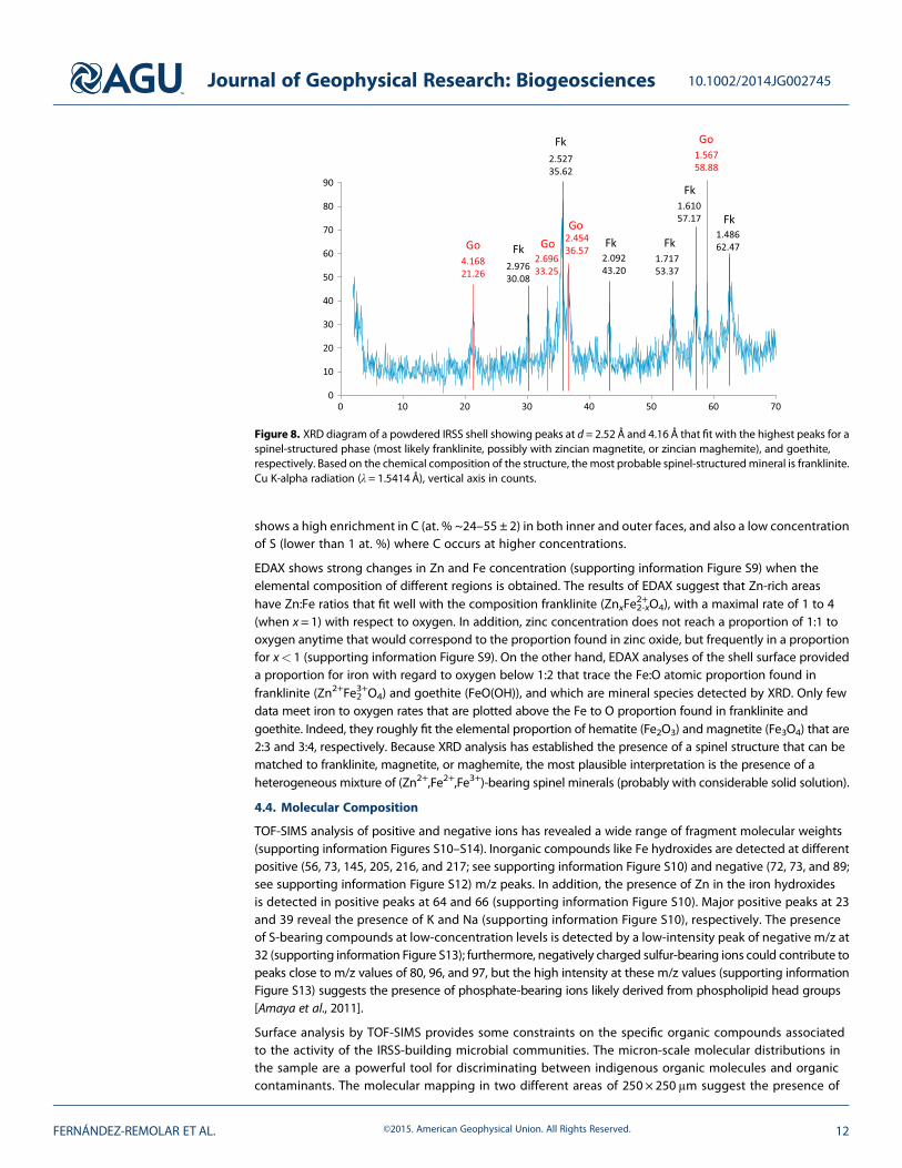
X-ray diffraction patterns show the presence of goethite (reflections at 4.168 Å, 2.454Å, and 1.567 Å) anda cubic spinel phase with strong reflections near 2.976Å, 2.527 Å, 2.092 Å, 1.717 Å, and 1.486 Å. The“spinel-phase” peak locations match several spinel-structured minerals including franklinite (Zn2+Fe3+2 O4),magnetite (Fe2+Fe3+2 O4), maghemite, and possibly trevorite (NiFe3+2 O4). Considering the signal-to-noise leveland angular resolution of the diffraction data, a mixture of spinel-structured minerals may be present. In
Figure 6. Biological structures mineralized in the shells. (a) Mineralized fungal filaments infilling the layer with coatedfilaments. (b) Microbrecciated unit (mu) with massive matrix trapping a dense bundle of filaments occupy an inner void.(c) Detail of densely packed nonmineralized filaments within an inner void associated with the microbrecciated unit.(d) Transverse section of mineralized filaments shown in Figure 6b. Cellular- and filament-like micron-sized structurestrapped in the crystalline laminae and inner layer of the shell shown in Figure 4. (e and f) Preserved cocci-like (Figures 6eand 6f) and bacilli-like (Figure 6f) structures showing an organic-rich mineralized wall.
Journal of Geophysical Research: Biogeosciences 10.1002/2014JG002745
FERNÁNDEZ-REMOLAR ET AL. ©2015. American Geophysical Union. All Rights Reserved. 10
order to better constrain the mineralogy, the X-ray diffraction (XRD) data are considered in light of EnergyDispersive X-ray Spectroscopy (EDAX) of the outer and inner shell faces (supporting information Figure S9),which reveals significant Zn concentrations (supporting information Figure S4 and Table 1). Semiquantitativeanalysis of EDAX spectra show that both inner and outer shells are composed (in at. %) of Zn (~1–20 ± 0.2), Fe(~2–24±1.15), and O (~25–54±1.5) which is compatible with the molecular formula ZnxFe3-xO4 (0< x< 1),corresponding to mixtures or solid solutions in the system franklinite-magnetite-maghemite. EDAX also
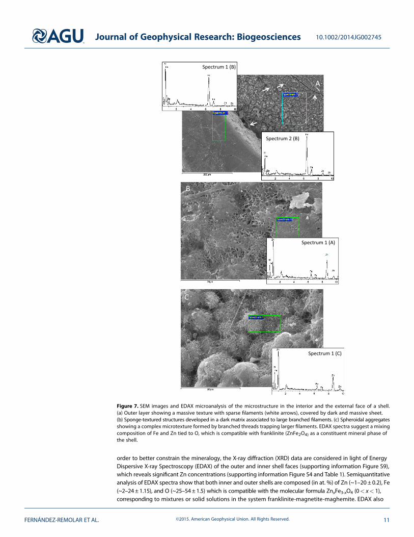
Figure 7. SEM images and EDAX microanalysis of the microstructure in the interior and the external face of a shell.(a) Outer layer showing a massive texture with sparse filaments (white arrows), covered by dark and massive sheet.(b) Sponge-textured structures developed in a dark matrix associated to large branched filaments. (c) Spheroidal aggregatesshowing a complex microtexture formed by branched threads trapping larger filaments. EDAX spectra suggest a mixingcomposition of Fe and Zn tied to O, which is compatible with franklinite (ZnFe2O4) as a constituent mineral phase ofthe shell.
Journal of Geophysical Research: Biogeosciences 10.1002/2014JG002745
FERNÁNDEZ-REMOLAR ET AL. ©2015. American Geophysical Union. All Rights Reserved. 11
shows a high enrichment in C (at. % ~24–55 ± 2) in both inner and outer faces, and also a low concentrationof S (lower than 1 at. %) where C occurs at higher concentrations.
EDAX shows strong changes in Zn and Fe concentration (supporting information Figure S9) when theelemental composition of different regions is obtained. The results of EDAX suggest that Zn-rich areashave Zn:Fe ratios that fit well with the composition franklinite (ZnxFe
2+2-xO4), with a maximal rate of 1 to 4
(when x= 1) with respect to oxygen. In addition, zinc concentration does not reach a proportion of 1:1 tooxygen anytime that would correspond to the proportion found in zinc oxide, but frequently in a proportionfor x< 1 (supporting information Figure S9). On the other hand, EDAX analyses of the shell surface provideda proportion for iron with regard to oxygen below 1:2 that trace the Fe:O atomic proportion found infranklinite (Zn2+Fe3+2 O4) and goethite (FeO(OH)), and which are mineral species detected by XRD. Only fewdata meet iron to oxygen rates that are plotted above the Fe to O proportion found in franklinite andgoethite. Indeed, they roughly fit the elemental proportion of hematite (Fe2O3) and magnetite (Fe3O4) that are2:3 and 3:4, respectively. Because XRD analysis has established the presence of a spinel structure that can bematched to franklinite, magnetite, or maghemite, the most plausible interpretation is the presence of aheterogeneous mixture of (Zn2+,Fe2+,Fe3+)-bearing spinel minerals (probably with considerable solid solution).
4.4. Molecular Composition
TOF-SIMS analysis of positive and negative ions has revealed a wide range of fragment molecular weights(supporting information Figures S10–S14). Inorganic compounds like Fe hydroxides are detected at differentpositive (56, 73, 145, 205, 216, and 217; see supporting information Figure S10) and negative (72, 73, and 89;see supporting information Figure S12) m/z peaks. In addition, the presence of Zn in the iron hydroxidesis detected in positive peaks at 64 and 66 (supporting information Figure S10). Major positive peaks at 23and 39 reveal the presence of K and Na (supporting information Figure S10), respectively. The presenceof S-bearing compounds at low-concentration levels is detected by a low-intensity peak of negative m/z at32 (supporting information Figure S13); furthermore, negatively charged sulfur-bearing ions could contribute topeaks close to m/z values of 80, 96, and 97, but the high intensity at these m/z values (supporting informationFigure S13) suggests the presence of phosphate-bearing ions likely derived from phospholipid head groups[Amaya et al., 2011].
Surface analysis by TOF-SIMS provides some constraints on the specific organic compounds associatedto the activity of the IRSS-building microbial communities. The micron-scale molecular distributions inthe sample are a powerful tool for discriminating between indigenous organic molecules and organiccontaminants. The molecular mapping in two different areas of 250 × 250 μm suggest the presence of
Figure 8. XRD diagram of a powdered IRSS shell showing peaks at d = 2.52 Å and 4.16 Å that fit with the highest peaks for aspinel-structured phase (most likely franklinite, possibly with zincian magnetite, or zincian maghemite), and goethite,respectively. Based on the chemical composition of the structure, themost probable spinel-structuredmineral is franklinite.Cu K-alpha radiation (λ = 1.5414 Å), vertical axis in counts.
Journal of Geophysical Research: Biogeosciences 10.1002/2014JG002745
FERNÁNDEZ-REMOLAR ET AL. ©2015. American Geophysical Union. All Rights Reserved. 12

different groups of molecules associated with specific morphologies (see Figures 9, 11, and S10–S14 inthe supporting information) as the following:
1. Group A. Displaying short-branched treelike morphologies (Figures 9a and S10 in the supporting information)that produce only m/z positive peaks as 98.10, 135.10, and 137.15 that are tentatively assigned to C6H10O
+,C9H11O
+, and C9H13O+, which likely correspond to fragments of small fatty acids or longer chains of
similar compounds exposed to microbial attack.2. Group B. Show distribution of some positive m/z ions as 111.11, 123.11, and 125.13 assigned to C7H11O
+,C8H11O
+, and C8H13O+, respectively. They define a localized globular to amorphous spatial pattern
(Figures 9b and S10 in the supporting information) and are likely sourced in long-chain fatty acids.
Figure 9. TOF-SIMS surface mapping classification in different groups based on themorphological patterns of the differentunits comprising the IRSS. Distribution of positive ion molecular fragments forming the following: (a) short-branchedtreelike morphologies, (b) very localized globular to amorphous structures, (c) massive and amorphous morphologies, and(d) linear structures of contaminants identified as polystyrene [Briggs and Fletcher, 2013].
Journal of Geophysical Research: Biogeosciences 10.1002/2014JG002745
FERNÁNDEZ-REMOLAR ET AL. ©2015. American Geophysical Union. All Rights Reserved. 13
3. Group C. Corresponding to massive morphologies producing positive ions (Figures 9c, S10, and S13 in thesupporting information) with m/z values of 88.09, 494.63, 522.66, and 550.58, which are assigned to smallions like C5H12O
+ (88.09), as well as larger fragments (494.63, 522.66, and 550.58) that have been assignedto phosphoglycerol bound to fatty acids and diacylglycerides (DAG). Group C potentially representsfragments of phospholipids [Sjövall et al., 2006; Nygren and Malmberg, 2007; Richter et al., 2007].
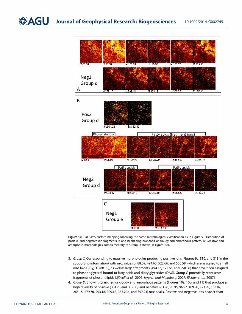
4. Group D. Showing branched or cloudy and amorphous patterns (Figures 10a, 10b, and 11) that produce ahigh diversity of positive (304.28 and 332.30) and negative (63.96, 95.96, 96.97, 109.98, 123.99, 183.02,265.15, 279.70, 293.18, 309.18, 353.20d, and 397.23) m/z peaks. Positive and negative ions heavier than
Figure 10. TOF-SIMS surface mapping following the same morphological classification as in Figure 9. Distribution ofpositive and negative ion fragments (a and b) shaping branched or cloudy and amorphous pattern. (c) Massive andamorphous morphologies complementary to Group D shown in Figure 10a.
Journal of Geophysical Research: Biogeosciences 10.1002/2014JG002745
FERNÁNDEZ-REMOLAR ET AL. ©2015. American Geophysical Union. All Rights Reserved. 14
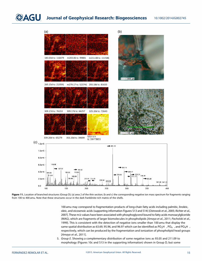
100 amu may correspond to fragmentation products of long-chain fatty acids including palmitic, linoleic,oleic, and eicosenoic acids (supporting information Figures S13 and S14) [Ostrowski et al., 2005; Richter et al.,2007]. Thesem/z values have been associated with phosphoglycerol bound to fatty acids monoacylgliceride(MAG), which are fragments of larger biomolecules in phospholipids [Amaya et al., 2011; Pacholski et al.,1999]. This is consistent with the detection of negative ions smaller than 100 amu that display thesame spatial distribution as 63.69, 95.96, and 96.97 which can be identified as PO2H
�, PO4�, and PO4H
�,respectively, which can be produced by the fragmentation and ionization of phospholipid head groups[Amaya et al., 2011].
5. Group E. Showing a complementary distribution of some negative ions as 93.05 and 211.09 tomorphology (Figures 10c and S13 in the supporting information) shown in Group D, but some
(a)
(c)
(b)
Figure 11. Location of branched structures (Group D); (a) area 2 of the thin section; (b and c) the corresponding negative ion mass spectrum for fragments rangingfrom 100 to 400 amu. Note that these structures occur in the dark franklinite-rich matrix of the shells.
Journal of Geophysical Research: Biogeosciences 10.1002/2014JG002745
FERNÁNDEZ-REMOLAR ET AL. ©2015. American Geophysical Union. All Rights Reserved. 15
correlation to Group B. Interestingly, first negative m/z ion fit well masses of C6H5O�, whereas the peak
at 211.09 can be identified as several isobaric ions remaining as unknown, but likely related with an ionor a long fragment coming from a fatty acid.
6. Group F. A grouping of positive (e.g., m/z of 91.05, 105.08, 115.06, and 117.08) ions sourced from potentialcontaminants like polystyrene [Briggs and Fletcher, 2013] with sharp linear spatial distributions (Figures 9d andS10 in the supporting information) which likely derive from the resins used in thin section preparation.Some other strong and moderate positive m/z peaks were observed at 27, 28, 41, 43, 51, 57, 63, 73, 77,103, 104, 128, 129, 131, 141, 152, 165, 166, 178, 179, 191, and 193 and are assigned to ions producedby fragmentations of polystyrene resin, and they were not further considered.
Some positive and negative ions have not been associated with any specific pattern described in the sixgroups above, but they suggest the presence of well preserved and large biomolecules derived from themicrobial communities in the IRSS (supporting information Figures S10–S13). Positive ion mass spectra showfamilies of strong peaks differing each by 14 amu (CH2
+) which are congruent with the alkyl and alkenyl series[Williamson and Masters, 2012] starting at 43 (C3H7
+) and 41 (C3H5+), respectively, but decreasing in intensity
along the positive m/z region from ~100–300 amu (e.g., positive m/z peaks at 183 and 181 correspondingto C13H27
+ and C13H22+, respectively) (supporting information Figure S10). Positive m/z peaks at 58, 59, 72, 74,
and 86 fit well with N-bearing ions as C3H8N+, C3H9N
+,C4H9N+,C4H12N
+ and C5H12N+ [Williamson and Masters,
2012]. Other m/z peaks in the 250–300 amu rangemay also record different groups of ions bearing carboxylicgroups like 255.23, 283.26, and 299.25 matching C16H31O2
+, C18H35O2+, and C18H35O3
+ (supportinginformation Figure S11), which may represent positive fragments of some middle-chained fatty acids(e.g., linoleic, oleic, and ricinoleic acids) that have also been identified by their negatively charged fragments(see supporting information Figure S14) [Ostrowski et al., 2005; Richter et al., 2007]; as well as some N- andP-bearing ions such as C5H13NPO2
+ and Na5P2O7+ [Vaezian et al., 2010] detected at 150.02 and 186.90 amu,
respectively (supporting information Figure S11). Positive ions with masses greater than 300 amu include ionsdetected at 311.28, 313.27, 339.25, and 341.28 amu, consistent with the C19H35O3
+, C19H37O3+, C21H39O3
+, andC21H41O3
+ which can be assigned to fragments of monoacylglycerols (MAGs) bearing long-chained fatty acids[Leefmann et al., 2013a]. Other positive m/z peaks of larger ions observed at 367.43, 368.44, 369.45, 378.71,386.65, 390.66, 394.45, 396.47, and 402.38 (supporting information Figure S11) may represent still largerhydrocarbon ions such as C27H43
+, C27H44+, C27H45+, C26H50O+, C28H50+, C27H46O
+, C27H50O+, C27H54O+,
C28H44O+, and C28H50O
+ which could be ions and fragments of sterol adducts and radicals of fungi like [M-H]+
and [M]+* [Ghumman et al., 2012; Leefmann et al., 2013b; Nygren et al., 2006; Passarelly and Winograd, 2011].Different positive m/z peaks of ions with m/z larger than 400 were also detected in the IRSS thin-sectionedsample (supporting information Figure S12). In this range, some low-intensity peaks that did not show a clearspatial pattern were observed at m/z values of 612.52, 640.54, 668.54, and 696.59. Although it is unclear whatpositive ions produce these peaks, they are in the range of the diacylglycerols (MAGs) coming fromphospholipids [Leefmann et al., 2013a].
The negative m/z mass spectra lacking any morphological patterns also show a high diversity of peaks thatrange from 100 to large ions heavier than 400 amu (supporting information Figures S13–S14). However, theintensity shown by ions above 400 amu is lower than the corresponding high-mass positive ion spectra, whichbiases the real molecular diversity of the sample. The lowerm/z negative ions display peaks at 41.00, 62.95, 71.09,78.96, and 97.10 (supporting information Figure S13), which likely represent such small ions as CNO�, PO2
�,C3H3O2
�, PO3�, and PO4H2
� [Amaya et al., 2011; Womiloju et al., 2006]. Negative ion spectra show numerouspeaks at masses above 100 amu, supporting a high concentration of phosphate-bearing organic molecules,potentially fatty acids, and other organophosphate compounds. Two groups of negative ions have beendetected, one with peaks at m/z values of 148.91, 156.96, 161.94, 168.91, 176.85, 178.92, 198.91, 203.04, 209.88,211.10, and 238.92 amu (supporting information Figure S13) that have not been assigned to any specificnegative ions and at m/z values of 104.93, 136.95, 138.97, 151.00, 152.95, 199.15, and 239.10 that have beenassigned to FeO3H
�, C2H4NPO4�, C2H6NPO4
�, C4H8PO4�, C3H8NPO4
�, C12H23O2�, and C15H27O2
�, respectively[Heien et al., 2010]. Furthermore, negative ion peaks corresponding to fragment masses above 250 amu(supporting information Figure S14), with no obvious morphological pattern, were observed at m/z values of255.24, 263.18, 281.17, and 283.27 and are consistent with C16H31O2
� (palmitic acid), C17H27O2� (stearidonic
acid), C18H33O2� (oleic acid), and C18H35O2
� (stearic acid) [Amaya et al., 2011;Womiloju et al., 2006], respectively.
Journal of Geophysical Research: Biogeosciences 10.1002/2014JG002745
FERNÁNDEZ-REMOLAR ET AL. ©2015. American Geophysical Union. All Rights Reserved. 16
Mass spectral maps showing positive and negative ion spatial distributions that have not been associated withany specific morphological group nevertheless also support the presence in the IRSS of large biomoleculesincludingmicrobial phospholipids. The occurrence of these molecules is strong evidence for a biological role inthe formation of the IRSS.
4.5. Antibody Microarray Detection of Biomolecules
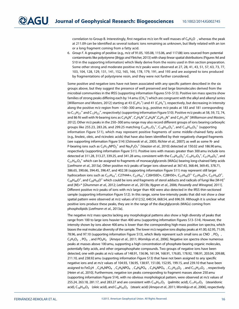
Samples from the IRSS were analyzed for the presence of microbial biomarkers and to search for correlationsbetween IRSS formation and specific microbial metabolic activities. Up to 0.5 g of solid samples, one from theouter face (with black color and dry) and another one from the interior face (yellow and still with somehumidity) were processed and analyzed using LDChip300 as indicated in section 3. Images with fluorescentspots were obtained with yellow colored sample while no fluorescent spots were obtained with the driestand black ones (Figure 12a). The fluorescence was quantified, corrected for background and blank controlimages, and plotted (Figure 12b). Fluorescent signals indicate positive antigen (biomarker-antibody)reactions, detecting the presence of microbes or biomolecules that match (or are very similar to) the structureof the antibodies specific to the microbe or biomolecule in question. We observed positive reactions withantibodies specific to cellular and extracellular material from extracts of microbiota from the iron and sulfurrich acidic environment of Río Tinto (Southwestern Spain). Rio Tinto samples are known to contain iron andsulfur oxidizers such as Acidithiobacillus spp., Leptospirillum spp., and Halothiobacillus spp. In fact, severalantibodies against these chemolithoautotrophic iron and sulfur oxidizing bacteria showed positive signals(see in Figure 12a positive reactions 1/3, 2, and 6 for Acidithiobacillus, Halothiobacillus, and Leptospirillum,respectively). Also, positive signals were detected for the Betaproteobacteria Burkholderia sp. and fromanaerobic bacteria such as the metal reducer Geobacter sulfurreducens.
The LDChip assay revealed microbial signals associated with the yellow crusts indicative of several microbialmetabolic processes. The chemolithoautotrophs Leptospirillum spp., Halothiobacillus spp., and Acidithiobacillusspp. supply some biomass to the system as primary producers. Fermentation processes may produce organicacids that are used as electron donors by the metal reducer Geobacter spp., which can metabolize insolublematerials like iron, magnesium, and uranium oxides that have been integrated in the shell matrix. In fact, thesebacteria are capable of an anaerobic respiration using these solid minerals as the terminal electron acceptor.
5. Discussion5.1. Interpretation
The different methodologies and analytical techniques used in this work provide complementary informationsupporting a close relationship betweenmicrobial activity and the formation of IRSS. Optical and SEM imagery ofthe structure andmorphology of the IRSS added to themolecular results obtained by antibody and spectral data
Figure 12. Antibody multiarray analyses using the LDCHIP300 developed for targeting specific bacteria and archaea; greensquares mark positive detection of biomolecules, yellow squares are fluorescent controls, and red dots are backgroundactivation that can be recognized in both target and control samples. (a) Multiarray analysis of the inner face, where thefollowing microbes were detected: (1) Acidithiobacillus albertensis, (2) Halothiobacillus spp., (3) Acidithiobacillus thiooxidansextract S100, (4) Geobacter sulfurreducens, (5) Burkholderia spp., and (6) Cellular extract of filaments in the site 3.2 of RioTinto. (b) LDChip300 analysis of the outer face of a shell used as negative control, lacking of any detectable signal formicrobes.
Journal of Geophysical Research: Biogeosciences 10.1002/2014JG002745
FERNÁNDEZ-REMOLAR ET AL. ©2015. American Geophysical Union. All Rights Reserved. 17
(e.g., presence of fungal sterols) suggest that they are the result of microbial activity coupled with chemicalsedimentation, which precipitates ~10 to 20μm thick mineral laminae below a layer of microbial biofilm,producing a layered stack of successive laminae. The inner laminae, which do not remain active, graduallybecome nearly devoid of organic matter in the inner part of the shell, as demonstrated by chemicalmicroanalysis using EDAX and TOF-SIMS. Successive stacking of laminae results in the formation of both outerand intermediate layers. The co-occurrence of different morphological and molecular biomarkers of bacterialand fungal origin in both layers demonstrates that the IRSS growth process results from the complex interplayof themicrobial community withmineral precipitation. This is supported by the SEM images of the outer face ofthe shells where a strong interrelation between large (likely fungal) filaments, parallel to the outer surface ofshells, that are integrated inside an iron-zinc oxide mineralized matrix (Figures 7b, 7c, and S9 in the supportinginformation). Minor fiber-like and spheroidal structures in the matrix correspond to bacterial structures thatdevelop inside the mineralized matrix and are interpreted as biofilm EPS (exopolysaccharides). Such interplaycan produce the fine lamination through fungal sequestering of cations [Oggerin et al., 2013] on the cell wall andinside the EPS matrix. Transition metal cations are released by bacterial metabolism during the microbiallyinfluenced oxidation and hydrolysis of polymetallic sulfide orebodies [Sand et al., 2001]. Furthermore, themassive layering formed of successions of coated fungal filaments suggests formation in a second stage, afterthe outer and intermediate laminated layers have been formed. Indeed, such a massive layer, with an irregularand discontinuous outline, shows a sharp boundary with the intermediate layer. This suggests a second stage offungal growth on themineralized structure and subsequent coating on the filament network. The second-stageovergrowth may be promoted by an oversaturation in Fe3+ on the surface of the filament occurring at amicron-sized scale inside the IRSS. Under transmitted light, both layers, the coated filament layer and theintermediate layer, are covered by an inner layer (Figures 4 and 5) that shows a continuous outline frommarginal to central sides of the shell. The inner layer is formed by a dense and mineralized cryptocrystallinematrix embedding different micron-sized filament-like and cellular structures. The texture and color of the innerlayer are consistent with the XRD detection of goethite. Such features strongly suggest that the inner layer wasformed by an oversaturation in Fe3+ and other cations with the IRSS, mediated by microbial activity or underabiotic processes which favor iron oxyhydroxide precipitation at slightly acidic pH, where dissolution offranklinite is favored.
Although most IRSS structures show secondary layers (layer of coated filaments and inner layer) as describedabove, themost common and characteristic structure within the shells is the stacking of thin laminae formingthe intermediate and outer layers. Indeed, observations under stereomicroscope of different shells(supporting information Figure S5a) show that the inner face displays a laminar structure lacking a secondaryinternal layer, but this internal cover may be present in some cases (Figures 4 and 5). The alternation oflight and dark laminae under reflected light suggests that there is an alternation between differentmineral phases, grain morphologies, organic concentration, degree of crystallinity, or some other opticallydetectable parameter(s). Intriguingly, TOF-SIMS analyses of the shells do not show evidence of changesin organic composition corresponding to the alternation of thin laminae observed under transmittedlight. However, XRD and EDAX analyses in the interior and outer areas of shells reveal an assemblage offranklinite with goethite as a secondary phase. The process of inner growth in the shells can result fromalternation between the accretion of franklinite- and- goethite-dominated laminae (Figures 8 and S9 inthe supporting information). Such alternation suggests microscale changes in the pH and temperature(supporting information Figure S4), which can be influenced by microbial activity [Fernández-Remolar et al.,2012; Sánchez-Román et al., 2014]. Because franklinite is the dominant mineral in the interior of the shells,the occurrence of goethite as the alternating phase suggests a decrease in the pH (supporting informationFigure S4) at a scale of microns when microbial growth is locally reduced. In addition, the ultrastructureof the IRSS (supporting information Figure S7) suggests that they could have been formed by microbialactivity. The habit in uniform crystalline mineral and the narrow range of their size distribution observedwhen the intermediate layer is uncovered are clear evidence of biological influence on mineral precipitation[Mann, 1983]; in contrast, abiotic inorganic minerals commonly display different crystal habits and a widerange of sizes. Although the composition of these crystals cannot be quantitatively measured with SEM-EDAX,the composition (supporting information Figure S8) and structure of the crystals associated with theintermediate layer have not been determined at the nanoscale, the occurrence within the laminar structure,which is mainly composed by franklinite, supports that it is a microcrystalline phase of this mineral. Both
Journal of Geophysical Research: Biogeosciences 10.1002/2014JG002745
FERNÁNDEZ-REMOLAR ET AL. ©2015. American Geophysical Union. All Rights Reserved. 18
random crystal orientation and variable crystal size would reduce the transmission of light through thestructure of the shells. Those crystals are randomly oriented contrasting to the preferential orientation of thecrystalline units shown inmetazoan exoskeletons [Mann, 1983;Wood, 2011]. This is likely because preferentialorientation is a more sophisticated biologically mediated crystallization phenomenon that is found in a moredirect biologically controlled crystallization setting.
Multiple complementary lines of evidence including imaging, elemental and organic-chemical microanalysis,biomolecular immunoassay with LDChip, and hydrogeochemical simulations support a role for microbialactivity in the formation of the IRSS. Optical and SEM imaging show an abundance of mineralized fungalfilaments and rod-like or granular structures of probable bacterial origin. Transmitted light observationsreveal several examples of fresh filaments emerging from a microbrecciated and cryptocrystalline area(Figure 6c) where filaments and clastic debris are trapped in the Fe,Zn-oxyhydroxide mineralized matrix. Thisarea was observed around the apical region of an IRSS lower shell that is delimited by voids enclosing somefresh fungal filaments and bacteria with incipient mineralization (Figures 6b and 6c). This brecciated area isonlapped by the laminar intermediate layer, which suggests that this area is representative of the initial stage ofstructure formation. Imaging of the IRSS interior (Figures 5, 6, and S6 in the supporting information) shows thatthe laminar structure of the shell interior is an overgrowth on a core of mineralized fungal filaments.
Molecular mapping of thin sections of shells by TOF-SIMS displays microstructures that are characteristic ofthe size and morphology of fungal filaments and hyphae (Figures 10 and 11). These morphologies aredelineated by elevated concentrations of molecular fragments corresponding to phosphate head groups,large fatty acids, and likely MAGs and DAGs [Amaya et al., 2011; Nygren and Malmberg, 2007; Pacholski et al.,1999; Richter et al., 2007; Sjövall et al., 2006]. The presence of phospholipids demonstrates the high degree ofpreservation of fungal biomolecules in the IRSS and suggests that fungi were still active when the IRSS wascollected. Microbial growth likely induces the precipitation of iron and zinc oxides through simple templatingof minerals on microbial biomass, adopting such a distinctive structure by a peculiar fungal development.The mineralizing process would consists on the formation of iron oxyhydroxides by sequestering ferricions that are present in the solutions, which in a more abundant form should be Fe(OH)2+. Therefore, theco-occurrence of iron oxidizing bacteria together with fungi, which are strong biomineralizing agents, wouldlead to the accretion of a mineral structure at microscale through mineral nucleation on cell walls and in theEPS matrix. Although some molecules are surely sourced in bacteria, the direct association between fungalmorphologies (see group d) and phospholipids by TOF-SIMS is strong evidence that the main mineralizingagents are the fungal communities (Figures 9, 12, and S10–S14 in the supporting information). Furthermore,SEM imaging in the interior of the shells shows that fungal biofilms template most of the mineralizing matrix ofthe IRSS (Figures 7 and S8 in the supporting information).
The detection of other organic compounds shaping morphologies (Groups A, B, and C) different than Group Ddemonstrates that other microbiota are involved in the IRSS. Antibody microarray detection of biomoleculeshas revealed different taxa of chemolithotrophic and chemoheterotrophic bacteria, which may be the primaryproducers in this system. A very low to negligible concentration of sulfur found in the IRSS structures stronglysuggests that the main process of bacterial mineralization concerns to redox cycling of iron cations coupledto the oxidation of organicmatter. Therefore, iron oxidizers as Leptospirillum spp. and Acidithiobacillus spp. couldhave provided the main source of ferric iron to the IRSS structure for fungal mineralization, whereas Geobactersulfurreducens could have recycled Fe3+ to Fe2+ through the oxidation of organics under anaerobic conditions.Furthermore, the redox potential in the solutions is far above 0mV, indicating that iron and sulfur reductionare microbially mediated processes occurring in anoxic microenvironments. The presence of microscars in theshells may be due to a late reduction and dilution of the ferric compounds by bacterial dissolution of iron oxides[Doong and Schink, 2002].
5.2. Origin and Formation of IRSS
To some extent, the IRSS morphologically and structurally resemble some tubercles formed by the bacterialcorrosion of steel [Little et al., 2011]. Tubercles on steel have similar composition (oxyhydroxides andmagnetite) plus an inner structure formed by an oxyhydroxide core surrounded by voids, and a shell ofmagnetite that is covered by a crust of ferric oxyhydroxides. However, there are five essential differencesbetween IRSS and tubercles, demonstrating different formation mechanisms: (1) IRSS are shelled structuresattached to the substrate by an apex, but tubercles are simple crust covering a corroded surface on the steel
Journal of Geophysical Research: Biogeosciences 10.1002/2014JG002745
FERNÁNDEZ-REMOLAR ET AL. ©2015. American Geophysical Union. All Rights Reserved. 19
alloy; (2) fungi are the main microbes involved in the IRSS formation, whereas tubercles are formed bybacterial corrosion; (3) IRSS are not associated with the hydrolysis and corrosion of steel alloys, but withbiomineralization that is supported by an external input of cations, dominantly Zn2+ and Fe2+; (4) IRSS areformed outside water bodies, whereas the tubercles generally form underwater; and (5) IRSSs clearly display ageotropic arrangement, whereas tubercles grow subparallel to the surface of the steel substrate regardless ofthe orientation of the substrate relative to the gravitational field.
Although the IRSSs are not formed underwater (Figure 2), they are directly associated with falling water dropscoming from the top of the galleries. This water likely transports Zn2+ and Fe2+ cations derived from themetallic orebodies, which are the raw material for producing the IRSSs through cation fixation by fungal andbacterial biomineralization. The absence of Zn in the steel substrate and the fluid dynamics in the gallery arestrong evidence supporting an exogenous source for Zn2+. In addition, there are rough morphologicalsimilarities between IRSSs and some speleothems associated with water leaks, including spatial distributionand geotropism, morphology, and internal structure [Fairchild and Baker, 2012]. Speleothems are stronglydependent on the water-dropping flow that is transporting the carbonate or other ions required toprecipitate the phases comprising the structures [Fairchild and Baker, 2012; Thraikill, 1976]. This is the case forsilica-rich mushroom-like structures that adopt similar morphologies to IRSSs in caves with fluids supplyingabundant dissolved silica [Aubrecht et al., 2008]. Such speleothems show geotropism and are attached to thesubstrate by a robust apical area, but the inner structure does not show a similar level of ordered internalarrangement to IRSS. Therefore, although IRSS formation probably requires a continuous water flow for itsoccurrence similar to biomineralization-induced speleothems, the detailed formationmechanisms of IRSS arefar different. While simple trapping of ions and solid particles into microbial EPS [Jones, 2010] can producea simple laminated microstructure in speleothems, IRSS formation requires the integration of severalmineralization processes at different scales (integration of laminar accretion to build up a macrostructure), toproduce an analogous structure to exoskeleton in metazoans.
Antibody microarray analyses show that the microbial diversity in the IRSS is very low when compared to manysurface environments analyzed by this technique [Parro et al., 2011a; Parro et al., 2011b]. As described above,only five different bacterial taxa have been found (Figure 12) of which three of them, Acidithiobacilus spp.,Leptospirillum spp., and Halothiobacillus spp., are feeding on the oxidation of sulfide orebodies [Schrenk et al.,1998]. Only Geobacter sulfurreducens and Burholderia spp., which are chemoheterotrophic and heterotrophictaxa, respectively, can grow by oxidation of organic compounds. Therefore, the three taxa of chemoautotrophicbacteria could have been transported from the metallic orebody to the IRSS site formation by subsurface waterflow and probably have a small or indirect role, if any, in the construction of the structures.
The microscale spatial distribution of microbial taxa and immunoassay-derived molecular data in the IRSSstructure cannot be determined from the LDChip results. As a result, the LDChip data cannot directlyelucidate the relationship between the microbial diversity and the formation of the shells at microscale orconstrain the interplay of the various microbiota during the generation of the IRSSs. However, integrating theLDChip results with optical and SEM imaging and TOF-SIMS chemical microanalysis suggests that fungi arethe most important biological agents during the formation of the IRSS (Figures 7 and S8 in the supportinginformation). Fungal hyphae occur integrated into the mineral matrix throughout the IRSS and displaydifferent morphological characteristics at different spatial locations within the IRSS. In microbrecciated areasproximal to the ventral shell, the fungal mycelia are composed of dense packages of septate hyphae withpronounced preferred orientation (Figures 6b–6d). In the discontinuos layer, mycelia are composed of a lessdense distribution of hyphae with perpendicular or oblique orientations to laminae between filaments(Figures 5c and 6a). In the intermediate and outer layers, fungal hyphae are generally parallel to the surface ofthe laminae. In contrast, within the layers of mineralized filaments, hyphae form a three-dimensionalintergrowth with a general trend of growth perpendicular to the laminae (Figures 5e, 5f, 7a, and 7b). Althoughit is not known whether the three different growth strategies correspond to one or more species of fungi,they seem to be associated with distinct, successive stages of IRSS growth.
The peculiar macroscopic- and microscopic-scale structures of the IRSSs pose many questions, especially inregard to the mechanisms by which microbial activity interacts with chemical and physical sedimentation toform these complex ordered structures. Evidence presented in this study suggest that IRSS are formed primarilyby fungal sequestering of ions interacting with the formation of Fe,Zn-spinels (franklinite, possibly zincian
Journal of Geophysical Research: Biogeosciences 10.1002/2014JG002745
FERNÁNDEZ-REMOLAR ET AL. ©2015. American Geophysical Union. All Rights Reserved. 20

magnetite, or zincian maghemite) and Fe-oxyhydroxides (goethite). Bacteria play secondary or indirectroles in IRSS formation, e.g., Fe3+ reduction in anoxic microenvironments or the oxidization and hydrolysisof polymetallic sulfide orebodies leading to high concentrations of Fe2+ and Zn2+ in solution. Imaging andchemical microanalysis suggests that fungal activity occurs throughout the IRSS structure (albeit to alimited extent in some areas); in contrast, bacterial occurrence is localized in the IRSS interior.
The occurrence of fungal filaments in pores within shells suggests that they can be active in the IRSSinterior. Whether or not fungi are still active inside the structure is not very clear, but if they are present andlead to mineralization inside the shells, then accretion of mineral-organic lamina could occur in boththe outer and inner face of the shells. The growth lines in the internal face of the shells (Figures 3a and S5ain the supporting information) suggests that the IRSS growth mechanism is radial accretion combinedwith internal growth, where the observed geotropism would be favored by rapid fungal growth combinedwith rapid fast mineralization.
6. Conclusions
We have described an unusual microbe-mediated structure, iron-rich shelled structures (IRSS), inhabitingan aphotic and oligotrophic extreme environment that supports a community of chemosynthetic andchemoheterotrophic microbes and associated fungi. The IRSS, which are likely formed primarily by fungiinteracting with metal-rich mine waters, have a unique constitution, and an enigmatic origin and history.The appearance of these structures in mines that were abandoned ~40 years ago indicates a recent origin;and microanalytical observations suggest that several generations of IRSS have been formed since then.Our observations suggest that the growth of IRSS is driven by rapid mineralization at the distal margins of theshell-like structures. Rapid mineralization coupled with the growth of fungal colonies promotes the formationof a structure via a complex interaction with abiotic factors such as gravity, fluid flow, and concentrations ofions in solution.
The development of such complex structures by microbial activity poses some interesting questions regardingto the adaptative advantage of such structures for the microbial communities that produce them. Theformation mechanism of IRSSs elucidated here suggests a novel pathway for the evolution of biomineralizedstructures. Such microbe-mineral systems may have provided the microbiota with evolutionary advantages,e.g., stability for physicochemical conditions or protection from predation. In other words, structure may havepreceded function. In parallel, if the formation of mineralized structures required the metabolic and growthprocesses of multiple microorganisms (e.g., with chemoautolithotrophs providing primary production andadding soluble ions to solutions, and filamentous eukarya producing the macroscopic structure), then thesemicrobial communitiesmay have become ever more closely linked. Moreover, the relatively rapid emergence ofthe IRSS in an environment that has been highly altered by human activity demonstrates the immense capacityof the biosphere for adaptation and innovation.
ReferencesAllwood, A. C., M. R. Walter, B. S. Kamber, C. P. Marshall, and I. W. Burch (2006), Stromatolite reef from the Early Archaean era of Australia,
Nature, 441(7094), 714–718.Amaya, K. R., J. V. Sweedler, and D. F. Clayton (2011), Small molecule analysis and imaging of fatty acids in the zebra finch song system using
time-of-flight-secondary ion mass spectrometry, J. Neurochem., 118(4), 499–511, doi:10.1111/j.1471-4159.2011.07274.x.Astui, O., R. Rodriguez, L. Candela, and I. Queralt (2004), Nuevas aportaciones a la hidrogeología de la zona del Valle de Arán. (Pirineos, Lleida),
paper presented at VIII Simposio de Hidrogeología, IGME.Aubrecht, R., C. Brewer-Carías, B. Šmída, M. Audy, and Ľ. Kováčik (2008), Anatomy of biologically mediated opal speleothems in the World’s
largest sandstone cave: Cueva Charles Brewer, Chimantá Plateau, Venezuela, Sediment. Geol., 203, 181–195.Banfield, J. L., S. A. Welch, H. Zhang, T. T. Ebert, and R. L. Penn (2000), Aggregation-based crystal growth and microstructure development in
natural iron oxyhydroxide biomineralization products, Science, 289, 751–754.Barnolas, A., and V. Pujalte (2004), La Cordillera Pirenaica, in La Geología de España, edited by J. A. Vera, pp. 231–344, IGME, Madrid.Bethke, C. (2008), Geochemical and Biogeochemical Reaction Modeling, Cambridge Univ. Press, Cambridge, U. K.Briggs, D., and I. W. Fletcher (2013), Qualitative interpretation of spectra, in ToF-SIMS: Materials Analysis by Mass Spectrometry, edited by
J. C. Vickerman and D. Briggs, pp. 417–448, IM Publications and SurfaceSpectra Limited, Sussex, U. K.Cardellach, E., A. Canals, and I. Pujals (1996), La composición isotópica del azufre y del plomo en las mineralizaciones de Zn-Pb del Valle de
Arán (Pirineo Central) y su significado metalogenético, Estud. Geol., 52, 189–195.Coutagne, A. (1954), Quelques considérations sur le pouvoir évaporant de l’atmosphère, le déficit d’ecoulement effectif et le déficit
d’ecoulement maximum, La Houille Blanche, 3, 360–374.Doong, R.-A., and B. Schink (2002), Cysteine-nediated reductive dissolution of poorly crystalline iron(III) oxides by Geobacter sulfurreducens,
Environ. Sci. Technol., 36, 2939–2945.
Journal of Geophysical Research: Biogeosciences 10.1002/2014JG002745
FERNÁNDEZ-REMOLAR ET AL. ©2015. American Geophysical Union. All Rights Reserved. 21
AcknowledgmentsThis paper is dedicated to the memoryof Nieves López-Martínez, who workedfor a long time to understand theemergence of such bizarre, but amazingstructures, and who positively believedthat they were created by a new livingform. It was supported by the projectfunded by the European ResearchCouncil ERC-2009-AdG-250350 “Scienceand technology development for in situdetection and characterization ofsubsurface life on the Iberian Pyritic Belt”and project AYA2011-24803 granted bythe Department of Economy in Spain.M.R.M.I. thanks the Natural Sciences andEngineering Council of Canada (NSERC),the Canadian Astrobiology TrainingProgramme (CATp), and theMineralogicalAssociation of Canada. Authorswould liketo thank two anonymous reviewers,associated editor and chief editor whohave greatly improved the paper withtheir suggestions and inputs. Data tosupport this article are available [email protected] upon request.

Fairchild, I. J., and A. Baker (2012), Speleothem Science: From Process to Past Environments, John Wiley, Sussex, U. K.Fernández-Remolar, D. C., and A. H. Knoll (2008), Fossilization potential of iron-bearing minerals in acidic environments of Rio Tinto, Spain:
Implications for Mars exploration, Icarus, 194, 72–85.Fernández-Remolar, D. C., et al. (2012), Carbonate precipitation under bulk acidic conditions as a potential biosignature for searching life on
Mars, Earth Planet. Sci. Lett., 351, 13–26.García Sansegundo, J. (1991), Estratigrafía y estructura de la zona axial pirenaica en la transversal del Valle de Arán y de la Alta Ribagorça
(Parte I), Bol. Inst. Geol. Min. Esp., 102, 3–51.Ghumman, C. A., A. M. C. Moutinho, A. Santos, A. Tolstogouzov, and O. M. N. D. Teodoro (2012), TOF-SIMS study of cystine and cholesterol
stones, J. Mass Spectrom., 47, 547–551.Gilbert, P. U. P. A., M. Abrecht, and B. H. Frazer (2005), The organic-mineral interface in biominerals, Rev. Mineral. Geochem., 59, 157–185.Grazulis, S., D. Chateigner, R. T. Downs, A. F. T. Yokochi, M. Quirós, L. Lutterotti, E. Manakova, J. Butkus, P. Moeck, and A. Le Bail (2009),
Crystallography Open Database—An open-access collection of crystal structures, J. Appl. Crystallogr., 42(4), 726–729.Heien, M. L., P. D. Piehowski, N. Winograd, and A. G. Ewing (2010), Lipid detection, identification, and imaging single cells with SIMS,Methods
Mol Biol, 656, 85–97.Jones, B. (2010), Microbes in caves: Agents of calcite corrosion and precipitation, Geol. Soc. London Spec. Publ., 336(1), 7–30.Leefmann, T., C. Heim, A. Kryvenda, S. Siljeström, P. Sjövall, and V. Thiel (2013a), Biomarker imaging of single diatom cells in a microbial mat
using time-of-flight secondary ion mass spectrometry (ToF-SIMS), Org. Geochem., 57(0), 23–33, doi:10.1016/j.orggeochem.2013.01.005.Leefmann, T., C. Heim, S. Siljeström, M. Blumenberg, P. Sjövall, and V. Thiel (2013b), Spectral characterization of ten cyclic lipids using
time-of-flight secondary ion mass spectrometry, Rapid Commun. Mass Spectrom., 27(5), 565–581, doi:10.1002/rcm.6483.Little, B. J., R. I. Ray, and J. S. Lee (2011), Tubercles and localized corrosion on carbon steel, Corros. Manage. Mag., 98, 12–15.Mann, S. (1983), Biomineralization in lower plants and animals—Chemical perspectives, in Biomineralization in Lower Plants and Animals,
edited by B. S. C. Leadbeater and R. Riding, pp. 39–54, The Systematic Association, Dordrecht, Netherlands.Nygren, H., and P. Malmberg (2007), High resolution imaging by organic secondary ion mass spectrometry, Trends Biotechnol., 25,
499–504.Nygren, H., K. Börner, P. Malmberg, and B. Hagenhoff (2006), Localization of cholesterol in rat cerebellum with imaging TOF-SIMS: Effect of
tissue preparation, Appl. Surf. Sci., 252, 6975–6981.Oggerin, M., F. Tornos, N. Rodríguez, C. De Moral, and M. Sánchez-Román (2013), Specific jarosite biomineralization by Purpureocillium
lilacinum, an acidophilic fungi isolated from Río Tinto, Environ. Microbiol., 15, 2228–2237.Ostrowski, S., C. Szakal, J. Kozole, T. P. Roddy, J. Xu, A. G. Ewing, and N. Winograd (2005), Secondary Ion MS Imaging of lipids in picoliter vials
with a buckminsterfullerene ion source, Anal. Chem., 77, 6190–6196.Pacholski, M. L., D. M. Cannon, A. G. Ewing, and N. Winograd (1999), Imaging of exposed headgroups and tailgroups of phospholipids
membranes by mass spectrometry, J. Am. Chem. Soc., 121, 4716–4717.Parro, V., et al. (2011a), A microbial oasis in the hypersaline Atacama subsurface discovered by a life detector chip: Implications for the search
for life on Mars, Astrobiology, 11(10), 969–996, doi:10.1089/ast.2011.0654.Parro, V., et al. (2011b), Classification of modern and old Río Tinto sedimentary deposits through the biomolecular record using a life marker
biochip: Implications for detecting life on Mars, Astrobiology, 11(1), 29–44, doi:10.1089/ast.2010.0510.Passarelly, M. K., and N. Winograd (2011), Lipid imaging with Time-of-Flight Secondary Ion Mass Spectrometry (ToF-SIMS), Biochim. Biophys.
Acta, 1811, 976–990.Perry, R. S., et al. (2007), Defining biominerals and organominerals: Direct and indirect indicators of life, Sediment. Geol., 201(1–2), 157–179.Pidwirny, M. (2006), Fundamentals of Physical Geography, PhysicalGeography.net, Okanagan, B. C.Richter, K., H. Nygren, P. Malmberg, and B. Hagenhoff (2007), Localization of fatty acids with selective chain length by imaging Time-of-Flight
Secondary Ion Mass Spectrometry, Microsc. Res. Tech., 70, 640–647.Rivas, L. A., M. García-Villadangos, M. Moreno-Paz, P. Cruz-Gil, J. Gómez-Elvira, and V. Parro (2008), A 200-antibody microarray biochip
for environmental monitoring: Searching for Universal Microbial Biomarkers through Immunoprofiling, Anal. Chem., 80(21),7970–7979.
Sánchez-Román, M., D. Fernández-Remolar, R. Amils, A. Sánchez-Navas, T. Schmid, P. S. Martin-Uriz, N. Rodríguez, J. A. McKenzie, andC. Vasconcelos (2014), Microbial mediated formation of Fe-carbonate minerals under extreme acidic conditions, Sci. Rep., 4,doi:10.1038/srep04767.
Sand, W., T. Gehrke, P.-G. Jozsa, and A. Schippers (2001), (Bio)chemistry of bacterial leaching—Direct vs. indirect bioleaching,Hydrometallurgy, 59(2–3), 159–175.
Santamaria, J., E. Ros, and J. Gavaldà (2008), La Minería de la Val d’Aran, 109 pp., Conselh Generau d’Aran, Vielha.Schrenk, M. O., K. J. Edwards, R. M. Goodman, R. J. Hamers, and J. F. Banfield (1998), Distribution of Thiobacillus ferrooxidans and
Leptospirillum ferrooxidans: Implications for Generation of Acid Mine Drainage, Science, 279, 1519–1522.Sjövall, P., B. Johansson, and J. Lausmaa (2006), Localization of lipids in freeze-dried mouse brain sections by imaging TOF-SIMS, Appl. Surf.
Sci., 252, 6966–6974.Thornthwaite, C. W. (1948), An approach toward a rational classification of climate, Geogr. Rev., 38, 55–94.Thornthwaite, C. W., and J. R. Mather (1955), The water balance, Climatology, 8, 1–104.Thraikill, J. (1976), Speleothems, in Stromatolites, edited by M. R. Walter, pp. 73–86, Elsevier, Amsterdam.Vaezian, B., C. R. Anderton, and M. L. Kraft (2010), Discriminating and imaging different phosphatidylcholine species within
phase-separated model membranes by principal component analysis of TOF-secondary ion mass spectrometry images, Anal.Geochem., 11, 10,006–10,014.
Williamson, K. L., and K. M. Masters (2012), Techniques Labs for Macroscale and Microscale Organic Experiments, Mary Finch, Belmont, Calif.Womiloju, T. O., J. D. Miller, and P. Mayer (2006), Phospholipids from some common fungi associated with damp building materials, Anal.
Bioanal. Chem., 384, 972–979.Wood, R. A. (2011), Paleoecology of the earliest skeletal metazoan communities: Implications for early biomineralization, Earth Sci. Rev., 106,
184–190.
Journal of Geophysical Research: Biogeosciences 10.1002/2014JG002745
FERNÁNDEZ-REMOLAR ET AL. ©2015. American Geophysical Union. All Rights Reserved. 22