form r-1 report of repair
269
-
Upload
khangminh22 -
Category
Documents
-
view
1 -
download
0
Transcript of form r-1 report of repair


FORM R-1 REPORT OF REPAIRin accordance with the provisions of the
WORK PERFORMED BY:
OWNER:
LOCATION OF INSTALLATION:
(name of repair organization)
(name)
Aeon PEC
DFW MIDSTREAM SERVICES LLC
DFW MIDSTREAM SERVICES LLC(address)500 Montgomery Street, Shreveport, Louisiana, 71107
(Form "R" Registration no.)309
(address)ATANTA, Georgia, 76084
(name)
(address)ATLANTA, Georgia, 76084
(P.O. no.,job no.,etc.)
1.
4.
2.
3.
5.
6.
7.8.
9.
10.
IDENTIFYING NOS.:
NBIC EDITION / ADDENDA:
REPAIR TYPE:DESCRIPTION OF WORK:
ITEM IDENTIFICATION:
REPLACEMENT PARTS:
REMARKS:
PRESSURE VESSEL NAME OF ORIGINAL MANUFACTURER: TEXAS VESSELS AND FABRICATION, LLC.
13-013(mfg. serial no.)
171(National Board No.)
N/A(Jurisdiction No.)
N/A(other)
2014(year built)
2017(edition)
N/A(addenda)
Welded Graphite Pressure Equipment FRP Pressure Equipment
Build up weld metal over pitted areas(internal shell); replace tray ring #7; replace downcomer bars as neededPT areas prior to welding; grind areas smooth with internal shell surface; UT examine areas to insure thickness meets .245" required t-min thickness; PT all final welds; apply repair nameplate
(Attached are Manufacturer's Partial Data Reports or Form R-3s properly completed for the following items of this report):
N/A
N/A(name of part, item number, data report type or certificate of Compliance, mfg's. name and identifying stamp)
National Board Inspection Code
ASME SECTION VIII DIV 1(name/ section/ division)
2010/2011(edition/ addenda)
ASME SECTION VIII DIV. 1(name/ section/ division)
Construction Code Used for Repair Performed: 2017/(edition/ addenda)
(boiler, pressure vessel or piping)
Pressure Test, if appliedN/A psi 50 psiMAWP
JC184333PO#
JC184333
Form R4, Report Supplementary Sheet is attached FFSA Form (NB-403) is attached
Original Code of Construction for Item:
Theof Boiler and Pressure Vessel InspectorsNational Board
DOT
(Liquid, Pneumatic, Vacuum, Leak)
A blank version of this form may be obtained from the National Board of Boiler and Pressure Vessel Inspectors • 1055 Crupper Avenue, Columbus, Ohio 43229-1183

I, _______________________________________, holding a valid Commission issued by The National Board of Boiler and Pressure VesselInspectors and certificate of competency, where required, issued by the Jurisdiction of ___________________________ and employedby ________________________________________________________ of ___________________________________ have inspected thework described in this report on _____________________ and state that to the best of my knowledge and belief this work complies withthe applicable requirements of the National Board Inspection Code. By signing this certificate, neither the undersigned nor my employermakes any warranty, expressed or implied, concerning the work described in this report. Furthermore, neither the undersigned nor myemployer shall be liable in any manner for any personal injury, property damage or loss of any kind arising from or connected with thisinspection.
David Pinell
I, _______________________________________________ , certify that to the best of my knowledge and belief the statements in thisreport are correct and that all material, construction, and workmanship on this Repair conforms to the National Board Inspection Code.National Board 7565 expires on September 22, 2020Date 12/08/2018 Signed
(name of repair organization)Aeon PEC
(authorized representative)
CERTIFICATE OF COMPLIANCE
CERTIFICATE OF INSPECTION
SignedDecember 21, 2018 Commissions(National Board and Jurisdiction no., including endorsements)
9731R, AR1180, AZ446, LA1394, MS3563, TX1453(inspector)
AR, AZ, LA, MS, TXOneCIS Insurance Company Lynn, MA
December 21, 2018
Date
Shelby Parker
R1-143239927 exe: v6.3.36 NB-66
,
Theof Boiler and Pressure Vessel InspectorsNational Board
Certificate of Authorization No."R"
(Form "R" Registration no.)309
(P.O. no.,job no.,etc.)JC184333
A blank version of this form may be obtained from the National Board of Boiler and Pressure Vessel Inspectors • 1055 Crupper Avenue, Columbus, Ohio 43229-1183


Scanned with CamScanner


INSPECTION SERVICES
INSPECTION SERVICES
Last updated: 2/08/2016
NONDESTRUCTIVE EXAMINATION PERSONNEL INITIAL CERTIFICATION Anthony Otten 501328
NAME EMPLOYEE NO. Liquid Penetrant Testing Level II TEST METHOD AND LEVEL SUMMARY OF QUALIFICATIONS 1. Date of assignment of NDE activity: 09/05/2013
2. NDE Training Summary: PT Level II Training Shawcor Insp. Serv. 12 04/22/2016
Course Title Sponsor Hours Completion Date
Course Title Sponsor Hours Completion Date
Course Title Sponsor Hours Completion Date
3. Visual Acuity: 12/20/2015 Corrective Lenses
Date of Exam Limitations or waivers Note: The visual acuity examination is an annual requirement. Current qualification may be shown by separate documentation.
Certified in accordance with ASNT SNT-TC-1A and Shawcor Inspection Services Written Practice WP-1.
4. Proficiency Examination Summary: Test Version # Score
General 006 90 Specific 003 75 Practical PT II Pract 93 COMPOSITE SCORE 86.0
5. Work History Summary 2 Years 8 Months OJT Form Total experience Reference (Resume or support documentation)
Remarks: Total hours in NDE 5280 minimum with 40 hours minimum in PT. Certification dated as of date confirmed OJT hours.
The above named individual meets the certification requirements of ASNT Recommended Practice SNT-TC-1A, and is hereby certified as PT Testing Level II for a period of three years to expire on 05/09/2019
05/09/2016
Andrew Morrow DATE CERTIFYING AUTHORITY


: 318.221.0122 : 800.344.2546
: 318.425.2943
505 Aero Drive www.aeonpec.com Shreveport, LA 71107
Dallas, TX Glen Rose, TX Little Rock, AR Longview, TX Ruston, LA Shreveport, LA
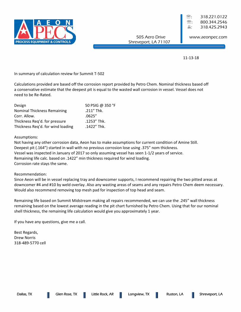
11-13-18 In summary of calculation review for Summit T-502 Calculations provided are based off the corrosion report provided by Petro Chem. Nominal thickness based off a conservative estimate that the deepest pit is equal to the wasted wall corrosion in vessel. Vessel does not need to be Re-Rated. Design 50 PSIG @ 350 °F Nominal Thickness Remaining .211” Thk. Corr. Allow. .0625” Thickness Req’d. for pressure .1253” Thk. Thickness Req’d. for wind loading .1422” Thk. Assumptions: Not having any other corrosion data, Aeon has to make assumptions for current condition of Amine Still. Deepest pit (.164”) started in wall with no previous corrosion lose using .375” nom thickness. Vessel was inspected in January of 2017 so only assuming vessel has seen 1-1/2 years of service. Remaining life calc. based on .1422” min thickness required for wind loading. Corrosion rate stays the same. Recommendation: Since Aeon will be in vessel replacing tray and downcomer supports, I recommend repairing the two pitted areas at downcomer #4 and #10 by weld overlay. Also any wasting areas of seams and any repairs Petro Chem deem necessary. Would also recommend removing top mesh pad for inspection of top head and seam. Remaining life based on Summit Midstream making all repairs recommended, we can use the .245” wall thickness remaining based on the lowest average reading in the pit chart furnished by Petro Chem. Using that for our nominal shell thickness, the remaining life calculation would give you approximately 1 year. If you have any questions, give me a call. Best Regards, Drew Norris 318-489-5770 cell
Scanned with CamScanner

TÜV SÜD America Phone: (281) 884-5100 1475 E. Sam Houston Pkwy. Fax: (734) 847-4846 Pasadena, TX 77503 E-mail: @tuvam.com http://www.tuv-sud-america.com/
Pasadena, TX • Corpus Christi, TX • New Orleans, LA • Baton Rouge, LA
Joliet/Chicago, IL • Beaumont/Groves, TX • Erie, MI • Odessa/Midland, TX
JOCO Summit MidstreamJOCO Summit MidstreamJOCO Summit MidstreamJOCO Summit Midstream
Venus, TXVenus, TXVenus, TXVenus, TX
November 7, 2018
ACFM/ PAUT/UTT Inspection of T-502 Amine Still Welds
Submitted to:Submitted to:Submitted to:Submitted to:
Erica FrisbieErica FrisbieErica FrisbieErica Frisbie---- Megan JohnsonMegan JohnsonMegan JohnsonMegan Johnson
Prepared by : Michael Eads ECT Level IIIA

TÜV SÜD America Phone: (281) 884-5100 1474 E. Sam Houston Pkwy. Pasadena, TX 77503 E-mail: @tuvam.com http://www.tuv-sud-america.com/
Pasadena, TX • Corpus Christi, TX • New Orleans, LA • Baton Rouge, LA
Joliet/Chicago, IL • Beaumont/Groves, TX • Erie, MI • Odessa/Midland, TX
11/07/201811/07/201811/07/201811/07/2018 JOCO Summit Midstream
ACFM/ PAUT/ Visual Inspection T-502 Amine Still
Material Information
Material: Carbon Steel
Thickness: 0.375" (Some areas had weld build-up from previous repair).
Work Scope
The initial inspection scope consisted of performing ACFM on all circumferential and seam
welds. Any indications detected would be inspected with PAUT. A visual inspection with pit
gauge measurements was also requested by the engineer.
Equipment:
ACFM Unit: TSC PACE S/N# 611-7198
Probe: SENSU Probe 619 S/N# 619-7322
Heat Shielding: NA
Computer: Panasonic Tough Book
Calibration Standard: .375” X 6” X 10” Carbon steel with 0.050", 0.10" and 0.125”
EDM notches.004” wide.
Test Frequency: 50 kHz
Personnel:
Michael Eads ECT Level IIIA
Andrew Martinez PAUT Level II
Procedure: C-ACFM-01

TÜV SÜD America Phone: (281) 884-5100 1474 E. Sam Houston Pkwy. Pasadena, TX 77503 E-mail: @tuvam.com http://www.tuv-sud-america.com/
Pasadena, TX • Corpus Christi, TX • New Orleans, LA • Baton Rouge, LA
Joliet/Chicago, IL • Beaumont/Groves, TX • Erie, MI • Odessa/Midland, TX
Disclaimer:
PetroChem thanks you for the opportunity to provide this service to you. Our scope of the
service will be limited to the relevant contract, purchase order, and/or similar agreements. While
every effort has been made to provide comprehensive, accurate, and useful results, it is
understood that all comments, descriptions, etc. contained in this report represent the opinions
of the examiner based on the current conditions of the component and the information
provided. PetroChem does not warrant or guarantee the information, content or accuracy of the
information in this report with respect to the actual condition of the parts inspected.
Furthermore, PetroChem will not be held liable for the manner in which the information
contained within this report is used.

TÜV SÜD America Phone: (281) 884-5100 1474 E. Sam Houston Pkwy. Pasadena, TX 77503 E-mail: @tuvam.com http://www.tuv-sud-america.com/
Pasadena, TX • Corpus Christi, TX • New Orleans, LA • Baton Rouge, LA
Joliet/Chicago, IL • Beaumont/Groves, TX • Erie, MI • Odessa/Midland, TX
ASSESSMENT:
The scans of each welded attachment were initially analyzed during data acquisition. No
usable ACFM or PAUT was obtained on a majority of the seam and circumferential welds
due to moderate to severe weld erosion/ corrosion. The bottom circumferential weld was
the only weld in good shape and no defects were detected with ACFM. UT Thickness was
performed above and below the bottom circumferential weld with nominal readings
obtained (0.379" to 0.383"). A visual inspection with a pit gauge was performed. The Tray
7 connecting ring showed severe corrosion and a through wall hole. Severe pitting was
noted in several areas of the tower shell. The most severe pit measured 0.164" deep and
was located in areas of severe pitting/corrosion. Please see attached pictures, screen
shots and UTT report.
(Per code, this should have been inspected to API 510 with an API 510 onsite. All
information contained in this report shall be calculated per code and by engineering. No
repair recommendations will be included in this report.)

TÜV SÜD America Phone: (281) 884-5100 1474 E. Sam Houston Pkwy. Pasadena, TX 77503 E-mail: @tuvam.com http://www.tuv-sud-america.com/
Pasadena, TX • Corpus Christi, TX • New Orleans, LA • Baton Rouge, LA
Joliet/Chicago, IL • Beaumont/Groves, TX • Erie, MI • Odessa/Midland, TX
Tray 7 Attachment Weld- Northwest
Tray 7 Attachment Ring- Through Wall Hole 2.25" in Length

TÜV SÜD America Phone: (281) 884-5100 1474 E. Sam Houston Pkwy. Pasadena, TX 77503 E-mail: @tuvam.com http://www.tuv-sud-america.com/
Pasadena, TX • Corpus Christi, TX • New Orleans, LA • Baton Rouge, LA
Joliet/Chicago, IL • Beaumont/Groves, TX • Erie, MI • Odessa/Midland, TX
23" x 18" Area of Pitting/ Corrosion on West Side- Thickness reading in good area
0.383", deepest pits found measure 0.131" and 0.140" in depth
Close up of above image showing severe pitting

TÜV SÜD America Phone: (281) 884-5100 1474 E. Sam Houston Pkwy. Pasadena, TX 77503 E-mail: @tuvam.com http://www.tuv-sud-america.com/
Pasadena, TX • Corpus Christi, TX • New Orleans, LA • Baton Rouge, LA
Joliet/Chicago, IL • Beaumont/Groves, TX • Erie, MI • Odessa/Midland, TX
Circumferential/ Seam Weld Junction- 0.140" Weld Erosion
34" x 5.5" Area of Corrosion between Tray 15 and 16 showing a 0.160" Pit

TÜV SÜD America Phone: (281) 884-5100 1474 E. Sam Houston Pkwy. Pasadena, TX 77503 E-mail: @tuvam.com http://www.tuv-sud-america.com/
Pasadena, TX • Corpus Christi, TX • New Orleans, LA • Baton Rouge, LA
Joliet/Chicago, IL • Beaumont/Groves, TX • Erie, MI • Odessa/Midland, TX
ACFM Calibration Standard Showing 0.250" Deep EDM Notch

TÜV SÜD America Phone: (281) 884-5100 1474 E. Sam Houston Pkwy. Pasadena, TX 77503 E-mail: @tuvam.com http://www.tuv-sud-america.com/
Pasadena, TX • Corpus Christi, TX • New Orleans, LA • Baton Rouge, LA
Joliet/Chicago, IL • Beaumont/Groves, TX • Erie, MI • Odessa/Midland, TX
ACFM Data showing noise from corrosion on the weld- No Useable Data

Pasadena, TX • Corpus Christi, TX • New Orleans, LA • Baton Rouge, LA Joliet/Chicago, IL • Beaumont/Groves,TX • Erie, MI • Odessa/Midland, TX
TÜV SÜD America Phone: (281) 884-5100
1475 E. Sam Houston Pkwy. Fax: (734) 847-4846Pasadena, TX 77503 E-mail: @tuvam.com
http://www.tuv-sud-america.com/
JOCO Summit Midstream
Venus, TX
November 7, 2018
ACFM/ PAUT/UTT Inspection of T-502 Amine Still Welds
Submitted to:
Erica Frisbie- Megan Johnson
Prepared by: Michael Eads ECT Level IIIA

Pasadena, TX • Corpus Christi, TX • New Orleans, LA • Baton Rouge, LA Joliet/Chicago, IL • Beaumont/Groves,TX • Erie, MI • Odessa/Midland, TX
TÜV SÜD America 1474 E. Sam Houston Pkwy.Pasadena, TX 77503 E-mail: @tuvam.com
http://www.tuv-sud-america.com/
TABLE OF CONTENTSSections
1 IntroductionScope of Work
2. Vessel Description
3. Assessment
4. Recommendations
5. Calculations
6. Visual InspectionPictures
7. Testing DataShell DrawingShell UT readingsShell Pit Gauge Readings

Pasadena, TX • Corpus Christi, TX • New Orleans, LA • Baton Rouge, LA Joliet/Chicago, IL • Beaumont/Groves,TX • Erie, MI • Odessa/Midland, TX
Section 1
ACFM/ PAUT/ Visual Inspection T-502 Amine Still
Work Scope
The initial inspection scope consisted of performing ACFM on all circumferential and seam welds.Any indications detected would be inspected with PAUT. A visual inspection with pit gaugemeasurements was also requested by the engineer.
Inspection Equipment:
ACFM Unit: TSC PACE S/N# 611-7198
Probe: SENSU Probe 619 S/N# 619-7322
Heat Shielding: NA
Computer: Panasonic Tough Book
Calibration Standard: .375” X 6” X 10” Carbon steel with 0.050", 0.10" and 0.125”
EDM notches.004” wide.
Test Frequency: 50 kHz
Personnel:
Michael Eads ECT Level IIIA
Andrew Martinez PAUT Level II
Procedure: C-ACFM-01

Pasadena, TX • Corpus Christi, TX • New Orleans, LA • Baton Rouge, LA Joliet/Chicago, IL • Beaumont/Groves,TX • Erie, MI • Odessa/Midland, TX
TÜV SÜD America1474 E. Sam Houston Pkwy.Pasadena, TX 77503 E-mail: @tuvam.com
http://www.tuv-sud-america.com/
2 VESSEL INFORMATION
General
Facility JOCO / SummitMidstream
System Amine Still
Equipment ID T-502 Date Performed 1-23-17
Description Last Insp. Date 2017
Orientation Vertical
PSV
#
Diameter 42” ID Set Press.
Length 55’ Test Date
Data Tag
Manufacturer Texas Vessel andFabrication
Date Built 2014
MAWP 50# Radiography RT-3
Temp.Min -20 F PWHT NONE
Max 350 F Serial # / NB # 13-013-9/ 171
Design
Corr. Allowance .0625” Flange Series 150
ShellMaterial SA-516-70 Trays/Packing Stainless Steel
Thickness .375” Lining/Cladding
Head#1
Location Top
Head#2
Location Bottom
Type Ellip Type Ellip
Material SA-516-70 Material SA-516-70
Thickness .3125” Thickness .3125”
Radius Radius
Other (sump,bundle, etc.)

Pasadena, TX • Corpus Christi, TX • New Orleans, LA • Baton Rouge, LA Joliet/Chicago, IL • Beaumont/Groves,TX • Erie, MI • Odessa/Midland, TX
TÜV SÜD America1474 E. Sam Houston Pkwy.Pasadena, TX 77503 E-mail: @tuvam.com
http://www.tuv-sud-america.com/
Section 3
ASSESSMENT:
A visual inspection with a pit gauge was performed. The inspection was performed from thetop circumferential seam and below. The demister was in place at the time of inspection. TheTray 7 connecting ring showed severe corrosion and what appears to be a through wall hole.Severe pitting was noted in several areas of the tower shell. The most severe pit measured0.164" deep and was located in areas of severe pitting/corrosion. Please see attachedpictures, screen shots and UTT report.
The bottom circumferential weld is in good shape and no defects were detected with ACFM.The scans of each welded attachment were initially analyzed during data acquisition. Anestimated 85% of the tray ring attachment welds, shell vertical and circumferential weldsexhibit moderate to severe weld erosion/ corrosion. The corrosion limited the ACFMinspection looking for cracks in the welds. No usable ACFM data was obtained on a majorityof the seams.
Note in 2017 internal visual inspection revealed internal shell corrosion/erosion throughoutthe shell and on the welds seams. Weld repairs were preformed however the locations werenot noted.
UT Thickness was performed above and below the bottom circumferential weld with nominalreadings obtained (0.379" to 0.383"). Additionally UT thickness readings were collectedbefore and after the weld on the horizontal circumferential seams of shell course 3 through 6.Note the data was collected on good base metal not on or in pitting. See UT tables in thisreport.
The data collected indicated the vessel condition needs to be reviewed and assessed.The remaining wall thickness was found to be below the corrosion allowance. Additionalreview and calculations of the data revealed the vessel shell wall is below the structuralminimal thickness requirement in Summit Midstream Mechanical Integrity Program. Seepreliminary calculation spreadsheet in this report. Based on this information the vessel isnot safe to operate, (0 remaining life). Thus see the recommendation for engineeringreview and calculations based on structural loads.

Pasadena, TX • Corpus Christi, TX • New Orleans, LA • Baton Rouge, LA Joliet/Chicago, IL • Beaumont/Groves,TX • Erie, MI • Odessa/Midland, TX
Section 4
Recommendations1. Perform an engineering evaluation of the vessel shell wall remaining wall thickness.2. Calculate the structural Tmin required for the vessel to be suitable for service.3. Calculate the remaining life based on structural Tmin.4. Remove the internal top mesh or demister pad for inspection.5. Perform visual UT thickness inspection on vessel internal top section (demister area).
Repair recommendations1. Weld repair the vessel internal shell circumferential weld seam(s) locations which are
marked on the weld(s) by PetroChem inspection.2. Weld Repair the vessel tray attachment clip weld to shell, which are marked by
PetroChem Inspection.3. Weld overlay repair the shell internal vessel wall pitting found that is greater than
.130" in depth.4. Document the X and y location of the deepest pit remaining of each shell course.
ConclusionAeon performed an engineering evaluation/calculations the vessel shell wall and determinedthe structural Tmin is .142" and .125" for the internal pressure load are the minimalremaining wall needed to operate the vessel safely. However based on the estimatedcorrosion rate the lowest allowable remaining wall thickness of .245" is needed to operatethe vessel safely. The remaining life of the vessel is 1 year based on the Structural Tmin,corrosion rate and .245" remaining wall. See the attached calculations.
TÜV SÜD America1474 E. Sam Houston Pkwy.Pasadena, TX 77503 E-mail: @tuvam.com
http://www.tuv-sud-america.com/
: 318.221.0122 : 800.344.2546
: 318.425.2943
505 Aero Drive www.aeonpec.com Shreveport, LA 71107
Dallas, TX Glen Rose, TX Little Rock, AR Longview, TX Ruston, LA Shreveport, LA
11-13-18 In summary of calculation review for Summit T-502 Calculations provided are based off the corrosion report provided by Petro Chem. Nominal thickness based off a conservative estimate that the deepest pit is equal to the wasted wall corrosion in vessel. Vessel does not need to be Re-Rated. Design 50 PSIG @ 350 °F Nominal Thickness Remaining .211” Thk. Corr. Allow. .0625” Thickness Req’d. for pressure .1253” Thk. Thickness Req’d. for wind loading .1422” Thk. Assumptions: Not having any other corrosion data, Aeon has to make assumptions for current condition of Amine Still. Deepest pit (.164”) started in wall with no previous corrosion lose using .375” nom thickness. Vessel was inspected in January of 2017 so only assuming vessel has seen 1-1/2 years of service. Remaining life calc. based on .1422” min thickness required for wind loading. Corrosion rate stays the same. Recommendation: Since Aeon will be in vessel replacing tray and downcomer supports, I recommend repairing the two pitted areas at downcomer #4 and #10 by weld overlay. Also any wasting areas of seams and any repairs Petro Chem deem necessary. Would also recommend removing top mesh pad for inspection of top head and seam. Remaining life based on Summit Midstream making all repairs recommended, we can use the .245” wall thickness remaining based on the lowest average reading in the pit chart furnished by Petro Chem. Using that for our nominal shell thickness, the remaining life calculation would give you approximately 1 year. If you have any questions, give me a call. Best Regards, Drew Norris 318-489-5770 cell

Pasadena, TX • Corpus Christi, TX • New Orleans, LA • Baton Rouge, LA Joliet/Chicago, IL • Beaumont/Groves,TX • Erie, MI • Odessa/Midland, TX
Section 5
Calculations
TÜV SÜD America Phone: (281) 884-51001474 E. Sam Houston Pkwy.Pasadena, TX 77503 E-mail: @tuvam.com
http://www.tuv-sud-america.com/

Design CA Tmin North East South West
Head Cs-1 Above 0.375 0.0625 0.3125 N/A N/A N/A N/A
Cs-1 Below 0.375 0.0625 0.3125 N/A N/A N/A N/A
Cs-2 Above 0.375 0.0625 0.3125 0.359 0.336 0.336 0.400
Cs-2 Below 0.375 0.0625 0.3125 0.331 0.327 0.318 0.354
Cs-3 Above 0.375 0.0625 0.3125 0.333 0.323 0.325 0.342
Cs-3 Below 0.375 0.0625 0.3125 0.334 0.320 0.307 0.318
Cs-4 Above 0.375 0.0625 0.3125 0.384 0.382 0.374 0.379
Cs-4 Below 0.375 0.0625 0.3125 0.290 0.342 0.370 0.293
Cs-5 Above 0.375 0.0625 0.3125 0.379 0.389 0.376 0.379
Cs-5 Below 0.375 0.0625 0.3125 0.383 0.387 0.381 0.387
0.375 0.0625 0.3125
0.375 0.0625 0.3125
0.375 0.0625
Shell Tray #s Design CA Tmin Wall Loss Max Remaining Average Remaining
1 0.375 0.0625 0.3125 16% 0.060 0.315
2 0.375 0.0625 0.3125 13% 0.050 0.325
3 0.375 0.0625 0.3125 40% 0.150 0.225 0.050 0.3254 0.375 0.0625 0.3125 35% 0.130 0.245
5 0.375 0.0625 0.3125 16% 0.060 0.315
6 0.375 0.0625 0.3125 37% 0.140 0.235 0.070 0.305
7 0.375 0.0625 0.3125 93% 0.350 0.025 0.060 0.3158 0.375 0.0625 0.3125 21% 0.131 0.244 0.080 0.295
9 0.375 0.0625 0.3125 32% 0.120 0.255 0.130 0.245
10 0.375 0.0625 0.3125 35% 0.130 0.245
11 0.375 0.0625 0.3125 37% 0.140 0.235 0.080 0.29512 0.375 0.0625 0.3125 27% 0.100 0.275
13 0.375 0.0625 0.3125 27% 0.100 0.275
14 0.375 0.0625 0.3125 32% 0.120 0.255
15 0.375 0.0625 0.3125 44% 0.164 0.211 0.100 0.27516 0.375 0.0625 0.3125 32% 0.120 0.255
17 0.375 0.0625 0.3125 27% 0.100 0.275
18 0.375 0.0625 0.3125 37% 0.140 0.235 0.130 0.245
19 0.375 0.0625 0.3125 32% 0.120 0.255
20 0.375 0.0625 0.3125
0.375 0.0625 0.3125
0.375 0.0625 0.3125
0.375 0.0625 0.3125
0.375 0.0625 0.3125
#
1
Ultrasonic thickness readings
Preliminary Calculations
Course 6
T-502
Course 1
Course 2
Course 3
Course 4
Course 5
#6
#5
#4
#3
#
2


Aeon PEC
500 Montgomery St
Shreveport, LA 71107
COMPRESS Pressure Vessel Design Calculations
Item: 42" ID X 55'-0" SM/SM AMINE STILL
Vessel No: T-502
Customer: SUMMIT MIDSTREAM PARTNERS, LLC
Contract:
Designer: DREW NORRIS
Date: 11/8/2018
CHECKED VESSEL FOR RERATE, TOOK CONSERVITIVE APPROACH USING DEEPEST PITAND SUBTRACTED FROM NOMINAL THICKNESS. DEEPEST PIT WAS .164", CALCULATEDTHICKNESS OF .211" WAS USED FOR CALCULATIONS WITH A CORROSION ALLOWANCE
OF .0625". WIND AND EARTHQUAKE TAKEN INTO CONSIDERATION PER ASCE 7-16

Table of ContentsPressure Summary.................................................................................................................................................1/158
Thickness Summary...............................................................................................................................................4/158
Nozzle Schedule......................................................................................................................................................5/158
Nozzle Summary.....................................................................................................................................................6/158
Wind Code...............................................................................................................................................................7/158
Seismic Code.........................................................................................................................................................11/158
Ellipsoidal Head #1...............................................................................................................................................16/158
Straight Flange on Ellipsoidal Head #1...............................................................................................................18/158
N2 (10-150 RFWN).................................................................................................................................................28/158
Cylinder #1.............................................................................................................................................................36/158
MW2 (20-150 RFWN).............................................................................................................................................47/158
MW1 (20-150 RFWN).............................................................................................................................................57/158
N4 (12-150 RFWN).................................................................................................................................................67/158
Trays #1..................................................................................................................................................................78/158
Ellipsoidal Head #2...............................................................................................................................................79/158
Cylinder #2.............................................................................................................................................................83/158
MW3 (20-150 RFWN).............................................................................................................................................94/158
N5 (8-150 RFWN).................................................................................................................................................104/158
N11 (8-150 RFWN)...............................................................................................................................................112/158
Straight Flange on Ellipsoidal Head #3.............................................................................................................120/158
Ellipsoidal Head #3.............................................................................................................................................131/158
Support Skirt #1..................................................................................................................................................133/158
Skirt Base Ring #1...............................................................................................................................................140/158
Weight Summary.................................................................................................................................................158/158
i

Pressure Summary
Component Summary for Chamber bounded by Ellipsoidal Head #2 and Ellipsoidal Head #1
IdentifierP
Design(psi)
T
Design(°F)
MAWP(psi)
MAP(psi)
MAEP(psi)
Te
external(°F)
MDMT(°F)
MDMTExemption
ImpactTested
Ellipsoidal Head #1 50 350 119.31 169.32 N/A 350 -55 Note 1 No
Straight Flange on Ellipsoidal Head #1 50 350 118.43 168.48 N/A 350 -55 Note 2 No
Cylinder #1 50 350 118.43 168.48 N/A 350 -55 Note 2 No
Straight Flange on Ellipsoidal Head #2 50 350 201.77 303.37 128.48 350 -155 Note 4 No
Ellipsoidal Head #2 50 350 203.78 306.1 73.38 350 -155 Note 3 No
N2 (10-150 RFWN) 50 350 94.16 130.38 N/A 350 -55 Note 5 No
N4 (12-150 RFWN) 50 350 90.77 129.68 N/A 350 -55 Note 6 No
MW2 (20-150 RFWN) 50 350 79.74 116.75 N/A 350 -55 Note 6 No
MW1 (20-150 RFWN) 50 350 79.74 116.75 N/A 350 -55 Note 6 No
Chamber Summary for Chamber bounded by Ellipsoidal Head #2 and Ellipsoidal Head #1
Design MDMT -20 °F
Rated MDMT -55 °F @ 79.74 psi
MAWP hot & corroded 79.74 psi @ 350 °F
MAP cold & new 116.75 psi @ 70 °F
(1) This pressure chamber is not designed for external pressure.
1/158

Component Summary for Chamber bounded by Ellipsoidal Head #3 and Ellipsoidal Head #2
IdentifierP
Design(psi)
T
Design(°F)
MAWP(psi)
MAP(psi)
MAEP(psi)
Te
external(°F)
MDMT(°F)
MDMTExemption
ImpactTested
Straight Flange on Ellipsoidal Head #2 50 350 128.48 128.48 201.77 350 -155 Note 4 No
Ellipsoidal Head #2 50 350 73.38 131.42 203.78 350 N/A Note 7 No
Cylinder #2 50 350 118.43 168.48 N/A 350 -55 Note 8 No
Straight Flange on Ellipsoidal Head #3 50 350 118.43 168.48 N/A 350 -55 Note 8 No
Ellipsoidal Head #3 50 350 119.31 169.32 N/A 350 -55 Note 9 No
MW3 (20-150 RFWN) 50 350 79.74 116.75 N/A 350 -55 Note 10 No
N5 (8-150 RFWN) 50 350 84.68 120.42 N/A 350 -55 Note 10 No
N11 (8-150 RFWN) 50 350 84.68 120.42 N/A 350 -55 Note 10 No
Chamber Summary for Chamber bounded by Ellipsoidal Head #3 and Ellipsoidal Head #2
Design MDMT -20 °F
Rated MDMT -55 °F @ 73.38 psi
MAWP hot & corroded 73.38 psi @ 350 °F
MAP cold & new 116.75 psi @ 70 °F
(1) This pressure chamber is not designed for external pressure.
2/158

Notes for MDMT Rating
Note # Exemption Details
1. Straight Flange governs MDMT
2.Material impact test exemption temperature from Fig UCS-66 Curve B = -20°FFig UCS-66.1 MDMT reduction = 45.4°F, (coincident ratio = 0.5728)Rated MDMT of -65.4°F is limited to -55°F by UCS-66(b)(2)
UCS-66 governing thickness = 0.211 in
3. Straight Flange governs MDMT
4. Material is impact test exempt to -155°F per UCS-66(b)(3) (coincident ratio = 0.3369)
5.Nozzle impact test exemption temperature from Fig UCS-66 Curve B = -20°FFig UCS-66.1 MDMT reduction = 55.1°F, (coincident ratio = 0.5142)Rated MDMT of -75.1°F is limited to -55°F by UCS-66(b)(2)
UCS-66 governing thickness = 0.211 in.
6.Nozzle impact test exemption temperature from Fig UCS-66 Curve B = -20°FFig UCS-66.1 MDMT reduction = 45.4°F, (coincident ratio = 0.573)Rated MDMT of -65.4°F is limited to -55°F by UCS-66(b)(2)
UCS-66 governing thickness = 0.211 in.
7. UCS-66 does not apply. Reference Fig. UCS-66.2 General Note (2)
8.Material impact test exemption temperature from Fig UCS-66 Curve B = -20°FFig UCS-66.1 MDMT reduction = 52.6°F, (coincident ratio = 0.5272)Rated MDMT of -72.6°F is limited to -55°F by UCS-66(b)(2)
UCS-66 governing thickness = 0.211 in
9. Straight Flange governs MDMT
10.Nozzle impact test exemption temperature from Fig UCS-66 Curve B = -20°FFig UCS-66.1 MDMT reduction = 52.5°F, (coincident ratio = 0.5273)Rated MDMT of -72.5°F is limited to -55°F by UCS-66(b)(2)
UCS-66 governing thickness = 0.211 in.
3/158

Thickness Summary
Component Data
ComponentIdentifier
Material Diameter(in)
Length(in)
Nominal t(in)
Design t(in)
Total Corrosion(in)
JointE
Load
Ellipsoidal Head #1 SA-516 70 42.75 OD 10.793 0.211* 0.125 0.0625 0.85 Internal
Straight Flange on Ellipsoidal Head #1 SA-516 70 42.75 OD 2 0.211 0.1253 0.0625 0.85 Internal
Cylinder #1 SA-516 70 42.75 OD 600 0.211 0.1422 0.0625 0.85 Wind
Straight Flange on Ellipsoidal Head #2 SA-516 70 42.328 OD 2 0.375 0.2409 0.125 0.85 External
Ellipsoidal Head #2 SA-516 70 42.328 OD 10.7695 0.375* 0.3241 0.125 0.85 External
Cylinder #2 SA-516 70 42.75 OD 60 0.211 0.1253 0.0625 0.85 Internal
Straight Flange on Ellipsoidal Head #3 SA-516 70 42.75 OD 2 0.211 0.1253 0.0625 0.85 Internal
Ellipsoidal Head #3 SA-516 70 42.75 OD 10.793 0.211* 0.125 0.0625 0.85 Internal
Support Skirt #1 SA-516 70 42.75 OD 56 0.375 0.0816 0 0.55 Wind
*Head minimum thickness after forming
Definitions
Nominal t Vessel wall nominal thickness
Design t Required vessel thickness due to governing loading + corrosion
Joint E Longitudinal seam joint efficiency
Load
Internal Circumferential stress due to internal pressure governs
External External pressure governs
Wind Combined longitudinal stress of pressure + weight + windgoverns
Seismic Combined longitudinal stress of pressure + weight + seismicgoverns
4/158

Nozzle Schedule
Specifications
Nozzlemark Identifier Size Service Materials Impact
Tested Normalized FineGrain Flange Blind
10-150RFWN N2 NPS 10 Sch 40
(Std) Nozzle SA-106 B Smlspipe No No No
NPS 10 Class150
WN A105No
12-150RFWN N4 NPS 12 Std
WeightREBOILERRETURN Nozzle SA-106 B Smls
pipe No No NoNPS 12 Class
150WN A105
No
20-150RFWN MW2 NPS 20 Sch 20
(Std) Nozzle SA-106 B Smlspipe No No No
NPS 20 Class150
WN A105
NPS 20Class150
A105
20-150RFWN MW1 NPS 20 Sch 20
(Std) Nozzle SA-106 B Smlspipe No No No
NPS 20 Class150
WN A105
NPS 20Class150
A105
20-150RFWN MW3 NPS 20 Sch 20
(Std) Nozzle SA-106 B Smlspipe No No No
NPS 20 Class150
WN A105
NPS 20Class150
A105
8-150 RFWN N5 NPS 8 Sch 40(Std) ACID GAS OUT Nozzle SA-106 B Smls
pipe No No NoNPS 8 Class
150WN A105
No
8-150 RFWN N11 NPS 8 Sch 40(Std) VAPOR Nozzle SA-106 B Smls
pipe No No NoNPS 8 Class
150WN A105
No
5/158

Nozzle Summary
Dimensions
Nozzlemark
OD(in)
tn(in)
Req tn(in) A1? A2?
Shell ReinforcementPad Corr
(in)Aa/Ar(%)
Nom t(in)
Design t(in)
User t(in)
Width(in)
tpad(in)
10-150 RFWN 10.75 0.365 0.1855 Yes Yes 0.211* 0.1251 N/A N/A 0 100.0
12-150 RFWN 12.75 0.375 0.1821 Yes Yes 0.211 0.1593 N/A N/A 0 100.0
20-150 RFWN 20 0.375 0.1232 Yes Yes 0.211 0.1245 N/A N/A 0.0625 100.0
20-150 RFWN 20 0.375 0.1232 Yes Yes 0.211 0.1245 N/A N/A 0.0625 100.0
20-150 RFWN 20 0.375 0.1232 Yes Yes 0.211 0.1245 N/A N/A 0.0625 100.0
8-150 RFWN 8.625 0.322 0.1747 Yes Yes 0.211 0.1528 N/A N/A 0.0625 100.0
8-150 RFWN 8.625 0.322 0.1747 Yes Yes 0.211 0.1528 N/A N/A 0.0625 100.0
*Head minimum thickness after forming
Definitions
tn Nozzle thickness
Req tn Nozzle thickness required per UG-45/UG-16Increased for pipe to account for 12.5% pipe thickness tolerance
Nom t Vessel wall thickness
Design t Required vessel wall thickness due to pressure + corrosion allowance per UG-37
User t Local vessel wall thickness (near opening)
Aa Area available per UG-37, governing condition
Ar Area required per UG-37, governing condition
Corr Corrosion allowance on nozzle wall
6/158

Wind Code
Building Code: ASCE 7-16
Elevation of base above grade 0.00 ft
Increase effective outer diameter by 0.00 ft
Wind Force Coefficient, Cf 0.6600
Risk Category (Table 1.5-1) II
Basic Wind Speed, V 106.00 mph
Exposure Category C
Wind Directionality Factor, Kd 0.9500
Ground Elevation Factor, Ke 1.0000
Topographic Factor, Kzt 1.0000
Enforce min. loading of 16 psf Yes
Hazardous, toxic, or explosive contents No
Vessel Characteristics
Height, h 61.0663 ft
Minimum Diameter, b Operating, Corroded 3.8958 ft
Empty, Corroded 3.8958 ft
Fundamental Frequency, n1
Operating, Corroded 1.5903 Hz
Empty, Corroded 1.7361 Hz
Vacuum, Corroded 1.5903 Hz
Damping coefficient, βOperating, Corroded 0.0200
Empty, Corroded 0.0210
Vacuum, Corroded 0.0200
Table Lookup Values
2.4.1 Basic Load Combinations for Allowable Stress Design
Load combinations considered in accordance with ASCEsection 2.4.1:
5. D + P + Ps + 0.6W
7. 0.6D + P + Ps + 0.6W
Parameter Description
D = Dead load
P = Internal or external pressure load
Ps = Static head load
W = Wind load
7/158

Wind Deflection Reports:
Operating, CorrodedEmpty, CorrodedVacuum, CorrodedWind Pressure Calculations
Wind Deflection Report: Operating, Corroded
ComponentElevation of
Bottom aboveBase (in)
Effective OD(ft)
Elastic ModulusE (106 psi)
InertiaI (ft4)
PlatformWind Shear atBottom (lbf)
Total WindShear at
Bottom (lbf)
BendingMoment at
Bottom (lbf-ft)
Deflectionat Top (in)
Ellipsoidal Head #1 720.0032 3.90 28.1 * 0 39 18 0.8637
Cylinder #1 120.0032 3.90 28.1 0.2174 0 2,012 55,525 0.8425
Cylinder #2 60.0032 3.90 28.1 0.2174 0 2,199 67,469 0.0282
Ellipsoidal Head #3 (top) 56 3.90 28.1 * 0 2,211 68,205 0.0056
Support Skirt #1 0 3.56 26.0 0.5404 0 2,371 78,897 0.0049
*Moment of Inertia I varies over the length of the component
Wind Deflection Report: Empty, Corroded
ComponentElevation of
Bottom aboveBase (in)
Effective OD(ft)
Elastic ModulusE (106 psi)
InertiaI (ft4)
PlatformWind Shear atBottom (lbf)
Total WindShear at
Bottom (lbf)
BendingMoment at
Bottom (lbf-ft)
Deflectionat Top (in)
Ellipsoidal Head #1 720.0032 3.90 29.4 * 0 39 18 0.817
Cylinder #1 120.0032 3.90 29.4 0.2174 0 2,012 55,525 0.7968
Cylinder #2 60.0032 3.90 29.4 0.2174 0 2,199 67,469 0.0258
Ellipsoidal Head #3 (top) 56 3.90 29.4 * 0 2,211 68,205 0.0049
Support Skirt #1 0 3.56 29.4 0.5404 0 2,371 78,897 0.0043
*Moment of Inertia I varies over the length of the component
Wind Deflection Report: Vacuum, Corroded
ComponentElevation of
Bottom aboveBase (in)
Effective OD(ft)
Elastic ModulusE (106 psi)
InertiaI (ft4)
PlatformWind Shear atBottom (lbf)
Total WindShear at
Bottom (lbf)
BendingMoment at
Bottom (lbf-ft)
Deflectionat Top (in)
Ellipsoidal Head #1 720.0032 3.90 28.1 * 0 39 18 0.8637
Cylinder #1 120.0032 3.90 28.1 0.2174 0 2,012 55,525 0.8425
Cylinder #2 60.0032 3.90 28.1 0.2174 0 2,199 67,469 0.0282
Ellipsoidal Head #3 (top) 56 3.90 28.1 * 0 2,211 68,205 0.0056
Support Skirt #1 0 3.56 26.0 0.5404 0 2,371 78,897 0.0049
*Moment of Inertia I varies over the length of the component
Wind Pressure (WP) Calculations
Gust Factor (G¯) Calculations
Kz = 2.01 * (Z/Zg)2/α
= 2.01 * (Z/900.00)0.2105
qz = 0.00256 * Kz * Kzt * Kd * Ke * V2
= 0.00256 * Kz * 1.0000 * 0.9500 * 1.0000 * 106.00002
= 27.3260 * KzWP = 0.6 * max[ qz * G * Cf, 16 lb/ft2 ]
= 0.6 * max[ qz * G * 0.6600, 16 lb/ft2 ]
8/158

Design Wind Pressures
Height Z(') Kz qz
(psf)WP (psf)
Operating Empty Hydrotest New Hydrotest Corroded Vacuum
15.0 0.8489 23.20 9.60 9.60 N.A. N.A. 9.60
20.0 0.9019 24.64 9.60 9.60 N.A. N.A. 9.60
25.0 0.9453 25.83 9.60 9.60 N.A. N.A. 9.60
30.0 0.9823 26.84 9.60 9.60 N.A. N.A. 9.60
40.0 1.0436 28.52 10.02 10.02 N.A. N.A. 10.02
50.0 1.0938 29.89 10.50 10.50 N.A. N.A. 10.50
60.0 1.1366 31.06 10.92 10.92 N.A. N.A. 10.92
70.0 1.1741 32.08 11.28 11.28 N.A. N.A. 11.28
Design Wind Force determined from: F = Pressure * Af , where Af is the projected area.
Gust Factor Calculations
Operating, CorrodedEmpty, CorrodedVacuum, Corroded
Gust Factor Calculations: Operating, Corroded
Vessel is considered a rigid structure as n1 = 1.5903 Hz ≥ 1 Hz.
z¯ = max[ 0.60 * h , zmin ]= max[ 0.60 * 61.0663 , 15.0000 ]= 36.6398
Iz¯ = c * (33 / z¯)1/6
= 0.2000 * (33 / 36.6398)1/6
= 0.1965Lz¯ = l * (z¯ / 33)ep
= 500.0000 * (36.6398 / 33)0.2000
= 510.5730Q = Sqr(1 / (1 + 0.63 * ((b + h) / Lz¯)0.63))
= Sqr(1 / (1 + 0.63 * ((3.8958 + 61.0663) / 510.5730)0.63))= 0.9238
G = 0.925 * (1 + 1.7 * gQ * Iz¯ * Q) / (1 + 1.7 * gv * Iz¯)= 0.925 * (1 + 1.7 * 3.40* 0.1965 * 0.9238) / (1 + 1.7 * 3.40 * 0.1965)= 0.8875
Gust Factor Calculations: Empty, Corroded
Vessel is considered a rigid structure as n1 = 1.7361 Hz ≥ 1 Hz.
z¯ = max[ 0.60 * h , zmin ]
9/158

= max[ 0.60 * 61.0663 , 15.0000 ]= 36.6398
Iz¯ = c * (33 / z¯)1/6
= 0.2000 * (33 / 36.6398)1/6
= 0.1965Lz¯ = l * (z¯ / 33)ep
= 500.0000 * (36.6398 / 33)0.2000
= 510.5730Q = Sqr(1 / (1 + 0.63 * ((b + h) / Lz¯)0.63))
= Sqr(1 / (1 + 0.63 * ((3.8958 + 61.0663) / 510.5730)0.63))= 0.9238
G = 0.925 * (1 + 1.7 * gQ * Iz¯ * Q) / (1 + 1.7 * gv * Iz¯)= 0.925 * (1 + 1.7 * 3.40* 0.1965 * 0.9238) / (1 + 1.7 * 3.40 * 0.1965)= 0.8875
Gust Factor Calculations: Vacuum, Corroded
Vessel is considered a rigid structure as n1 = 1.5903 Hz ≥ 1 Hz.
z¯ = max[ 0.60 * h , zmin ]= max[ 0.60 * 61.0663 , 15.0000 ]= 36.6398
Iz¯ = c * (33 / z¯)1/6
= 0.2000 * (33 / 36.6398)1/6
= 0.1965Lz¯ = l * (z¯ / 33)ep
= 500.0000 * (36.6398 / 33)0.2000
= 510.5730Q = Sqr(1 / (1 + 0.63 * ((b + h) / Lz¯)0.63))
= Sqr(1 / (1 + 0.63 * ((3.8958 + 61.0663) / 510.5730)0.63))= 0.9238
G = 0.925 * (1 + 1.7 * gQ * Iz¯ * Q) / (1 + 1.7 * gv * Iz¯)= 0.925 * (1 + 1.7 * 3.40* 0.1965 * 0.9238) / (1 + 1.7 * 3.40 * 0.1965)= 0.8875
Table Lookup Values
α = 9.5000, zg = 900.00 ft [Table 26.11-1, page269]
c = 0.2000, l = 500.0000, ep = 0.2000 [Table 26.11-1, page269]
a¯ = 0.1538, b¯ = 0.6500 [Table 26.11-1, page269]
zmin = 15.0000 ft [Table 26.11-1, page269]
gQ = 3.40 [26.11.5 page 270]
gv = 3.40 [26.11.5 page 270]
10/158

Seismic Code
Building Code: ASCE 7-16 ground supported
Site Class D
Importance Factor, Ie 1.0000
Spectral Response Acceleration at shortperiod (% g), Ss
8.20%
Spectral Response Acceleration at period of1 sec (% g), S1
4.90%
Response Modification Coeficient fromTable 15.4-2, R 2.0000
Acceleration-based Site Coefficient, Fa 1.6000
Velocity-based Site Coefficient, Fv 2.4000
Long-period Transition Period, TL 12.0000
Redundancy factor, ρ 1.0000
Risk Category (Table 1.5-1) II
User Defined Vertical AccelerationsConsidered No
Hazardous, toxic, or explosive contents No
Vessel Characteristics
Height 61.0663 ft
WeightOperating, Corroded 18,431 lb
Empty, Corroded 16,431 lb
Vacuum, Corroded 18,431 lb
Period of Vibration Calculation
Fundamental Period, TOperating, Corroded 0.629 sec (f = 1.6 Hz)
Empty, Corroded 0.576 sec (f = 1.7 Hz)
Vacuum, Corroded 0.629 sec (f = 1.6 Hz)
The fundamental period of vibration T (above) is calculated using the Rayleigh method of approximation
T = 2 * PI * Sqr( {Sum(Wi * yi2 )} / {g * Sum(Wi * yi )} ), where
Wi is the weight of the ith lumped mass, andyi is its deflection when the system is treated as a cantilever beam.
11/158

12.4 Basic Load Combinations for Allowable Stress Design
Load combinations considered in accordance with ASCE section2.4.5:
8. D + P + Ps + 0.7E = (1.0 + 0.14SDS)D + P + Ps + 0.7ρQE
10. 0.6D + P + Ps + 0.7E = (0.6 - 0.14SDS)D + P + Ps + 0.7ρQE
Parameter description
D = Dead load
P = Internal or external pressure load
Ps = Static head load
E = Seismic load = Eh +/- Ev = ρQE +/- 0.2SDSD
Seismic Shear Reports:
Operating, CorrodedEmpty, CorrodedVacuum, CorrodedBase Shear Calculations
Seismic Shear Report: Operating, Corroded
Component Elevation of Bottomabove Base (in)
Elastic Modulus E(106 psi)
Inertia I(ft4)
Seismic Shear atBottom (lbf)
Bending Moment atBottom (lbf-ft)
Ellipsoidal Head #1 720.0032 28.1 * 67 38
Cylinder #1 120.0032 28.1 0.2174 517 20,459
Cylinder #2 60.0032 28.1 0.2174 532 24,507
Ellipsoidal Head #3 (top) 56 28.1 * 534 24,685
Support Skirt #1 0 26.0 0.5404 538 27,192
*Moment of Inertia I varies over the length of the component
Seismic Shear Report: Empty, Corroded
Component Elevation of Bottomabove Base (in)
Elastic Modulus E(106 psi)
Inertia I(ft4)
Seismic Shear atBottom (lbf)
Bending Moment atBottom (lbf-ft)
Ellipsoidal Head #1 720.0032 29.4 * 68 39
Cylinder #1 120.0032 29.4 0.2174 454 18,575
Cylinder #2 60.0032 29.4 0.2174 470 22,312
Ellipsoidal Head #3 (top) 56 29.4 * 472 22,470
Support Skirt #1 0 29.4 0.5404 477 24,690
*Moment of Inertia I varies over the length of the component
12/158

Seismic Shear Report: Vacuum, Corroded
Component Elevation of Bottomabove Base (in)
Elastic Modulus E(106 psi)
Inertia I(ft4)
Seismic Shear atBottom (lbf)
Bending Moment atBottom (lbf-ft)
Ellipsoidal Head #1 720.0032 28.1 * 67 38
Cylinder #1 120.0032 28.1 0.2174 517 20,459
Cylinder #2 60.0032 28.1 0.2174 532 24,507
Ellipsoidal Head #3 (top) 56 28.1 * 534 24,685
Support Skirt #1 0 26.0 0.5404 538 27,192
*Moment of Inertia I varies over the length of the component
11.4.4: Maximum considered earthquake spectral response acceleration
The maximum considered earthquake spectral response acceleration at short period, SMSSMS = Fa * Ss = 1.6000 * 8.20 / 100 = 0.1312The maximum considered earthquake spectral response acceleration at 1 s period, SM1SM1 = Fv * S1 = 2.4000 * 4.90 / 100 = 0.1176
11.4.5: Design spectral response acceleration parameters
Design earthquake spectral response acceleration at short period, SDSSDS = 2 / 3 * SMS = 2 / 3 * 0.1312 = 0.0875Design earthquake spectral response acceleration at 1 s period, SD1SD1 = 2 / 3 * SM1 = 2 / 3 * 0.1176 = 0.0784
11.6 Seismic Design Category
The Risk Category is II.From Table 11.6-1, the Seismic Design Category based on SDs = 0.0875 is A.From Table 11.6-2, the Seismic Design Category based on SD1 = 0.0784 is B.This vessel is assigned to Seismic Design Category B.
12.4: Seismic Load Combinations: Vertical Term
Factor is applied to dead load.
Compressive Side: = 1.0 + 0.14 * SDS
= 1.0 + 0.14 * 0.0875= 1.0122
Tensile Side: = 0.6 - 0.14 * SDS
= 0.6 - 0.14 * 0.0875= 0.5878
Base Shear Calculations
Operating, CorrodedEmpty, CorrodedVacuum, Corroded
13/158

Base Shear Calculations: Operating, Corroded
Paragraph 15.4.4: Period Determination
Fundamental Period is taken from the Rayleigh method listed previously in this report.
T = 0.6288 sec.
12.8.1: Calculation of Seismic Response Coefficient
Cs is the value computed below, bounded by CsMin and CsMax:CsMin is calculated with equation 15.4-1 and shall not be less than 0.03; in addition, if S1 >= 0.6g, CsMin shall not beless than eqn 15.4-2.CsMax calculated with 12.8-3 because (T = 0.6288) <= (TL = 12.0000)
Cs = SDS / (R / Ie) = 0.0875 / (2.0000 / 1.0000) = 0.0437CsMin = max[ 0.044 * SDS * Ie , 0.03 ] = max[ 0.044 * 0.0875 * 1.0000 , 0.03 ] = 0.0300CsMax = SD1 / (T * (R / Ie)) = 0.0784 / (0.6288 * (2.0000 / 1.0000)) = 0.0623
Cs = 0.0437
12.8.1: Calculation of Base Shear
V = Cs * W= 0.0437 * 18,430.9238= 806.05 lb
12.4.2.1 Seismic Load Combinations: Horizontal Seismic Load Effect, EhQE = VEh = 0.7 * ρ * QE (Only 70% of seismic load considered as per Section 2.4.5)
= 0.7 * 1.0000 * 806.05= 564.23 lb
Base Shear Calculations: Empty, Corroded
Paragraph 15.4.4: Period Determination
Fundamental Period is taken from the Rayleigh method listed previously in this report.
T = 0.5760 sec.
12.8.1: Calculation of Seismic Response Coefficient
Cs is the value computed below, bounded by CsMin and CsMax:CsMin is calculated with equation 15.4-1 and shall not be less than 0.03; in addition, if S1 >= 0.6g, CsMin shall not beless than eqn 15.4-2.CsMax calculated with 12.8-3 because (T = 0.5760) <= (TL = 12.0000)
Cs = SDS / (R / Ie) = 0.0875 / (2.0000 / 1.0000) = 0.0437CsMin = max[ 0.044 * SDS * Ie , 0.03 ] = max[ 0.044 * 0.0875 * 1.0000 , 0.03 ] = 0.0300CsMax = SD1 / (T * (R / Ie)) = 0.0784 / (0.5760 * (2.0000 / 1.0000)) = 0.0681
Cs = 0.0437
12.8.1: Calculation of Base Shear
14/158

V = Cs * W= 0.0437 * 16,430.5059= 718.56 lb
12.4.2.1 Seismic Load Combinations: Horizontal Seismic Load Effect, EhQE = VEh = 0.7 * ρ * QE (Only 70% of seismic load considered as per Section 2.4.5)
= 0.7 * 1.0000 * 718.56= 502.99 lb
Base Shear Calculations: Vacuum, Corroded
Paragraph 15.4.4: Period Determination
Fundamental Period is taken from the Rayleigh method listed previously in this report.
T = 0.6288 sec.
12.8.1: Calculation of Seismic Response Coefficient
Cs is the value computed below, bounded by CsMin and CsMax:CsMin is calculated with equation 15.4-1 and shall not be less than 0.03; in addition, if S1 >= 0.6g, CsMin shall not beless than eqn 15.4-2.CsMax calculated with 12.8-3 because (T = 0.6288) <= (TL = 12.0000)
Cs = SDS / (R / Ie) = 0.0875 / (2.0000 / 1.0000) = 0.0437CsMin = max[ 0.044 * SDS * Ie , 0.03 ] = max[ 0.044 * 0.0875 * 1.0000 , 0.03 ] = 0.0300CsMax = SD1 / (T * (R / Ie)) = 0.0784 / (0.6288 * (2.0000 / 1.0000)) = 0.0623
Cs = 0.0437
12.8.1: Calculation of Base Shear
V = Cs * W= 0.0437 * 18,430.9238= 806.05 lb
12.4.2.1 Seismic Load Combinations: Horizontal Seismic Load Effect, EhQE = VEh = 0.7 * ρ * QE (Only 70% of seismic load considered as per Section 2.4.5)
= 0.7 * 1.0000 * 806.05= 564.23 lb
15/158

Ellipsoidal Head #1
ASME Section VIII Division 1, 2010 Edition, A11 Addenda
Component Ellipsoidal Head
Material SA-516 70 (II-D p. 18, ln. 19)
Attached To Cylinder #1
ImpactTested Normalized Fine Grain
Practice PWHT Optimize MDMT/Find MAWP
No No No No No
DesignPressure (psi)
DesignTemperature (°F)
DesignMDMT (°F)
Internal 50 350 -20
Static Liquid Head
Condition Ps (psi) Hs (in) SG
Test horizontal 1.9 52.539 1
Dimensions
Outer Diameter 42.75"
Head Ratio 2
Minimum Thickness 0.211"
Corrosion Inner 0.0625"
Outer 0"
Length Lsf 2"
Nominal Thickness tsf 0.211"
Weight and Capacity
Weight (lb)1 Capacity (US gal)1
New 135.32 55.16
Corroded 95.58 55.74
Insulation
Thickness (in) Density (lb/ft3) Weight (lb)
Insulation 2 15 42.31
Spacing(in) Individual Weight (lb) Total Weight (lb)
InsulationSupports 132 813 813
Radiography
Category A joints Seamless No RT
Head to shell seam Spot UW-11(b) Type 1
16/158

1 includes straight flange
Results Summary
Governing condition UG-16
Minimum thickness per UG-16 0.0625" + 0.0625" = 0.125"
Design thickness due to internal pressure (t) 0.125"
Maximum allowable working pressure (MAWP) 119.31 psi
Maximum allowable pressure (MAP) 169.32 psi
Straight Flange governs MDMT -55°F
Factor K
K = (1/6)*[2 + (D / (2*h))2]
Corroded K = (1/6)*[2 + (42.453 / (2*10.6445))2] 0.9961
New K = (1/6)*[2 + (42.328 / (2*10.582))2] 1
Design thickness for internal pressure, (Corroded at 350 °F) Appendix 1-4(c)
t = P*Do*K / (2*S*E + 2*P*(K - 0.1)) + Corrosion= 50*42.75*0.996091 / (2*20,000*0.85 + 2*50*(0.996091 - 0.1)) + 0.0625= 0.125"
Maximum allowable working pressure, (Corroded at 350 °F) Appendix 1-4(c)
P = 2*S*E*t / (K*Do - 2*t*(K - 0.1)) - Ps= 2*20,000*0.85*0.1485 / (0.996091*42.75 - 2*0.1485*(0.996091 - 0.1)) - 0= 119.31 psi
Maximum allowable pressure, (New at 70 °F) Appendix 1-4(c)
P = 2*S*E*t / (K*Do - 2*t*(K - 0.1)) - Ps= 2*20,000*0.85*0.211 / (1*42.75 - 2*0.211*(1 - 0.1)) - 0= 169.32 psi
% Extreme fiber elongation - UCS-79(d)
EFE = (75*t / Rf)*(1 - Rf / Ro)= (75*0.211 / 7.3013)*(1 - 7.3013 / ∞)= 2.1674%
The extreme fiber elongation does not exceed 5%.
17/158

Straight Flange on Ellipsoidal Head #1
ASME Section VIII Division 1, 2010 Edition, A11 Addenda
Component Cylinder
Material SA-516 70 (II-D p. 18, ln. 19)
ImpactTested Normalized Fine Grain
Practice PWHT Optimize MDMT/Find MAWP
No No No No No
DesignPressure (psi)
DesignTemperature (°F)
DesignMDMT (°F)
Internal 50 350 -20
Static Liquid Head
Condition Ps (psi) Hs (in) SG
Test horizontal 1.9 52.539 1
Dimensions
Outer Diameter 42.75"
Length 2"
Nominal Thickness 0.211"
Corrosion Inner 0.0625"
Outer 0"
Weight and Capacity
Weight (lb) Capacity (US gal)
New 15.96 12.18
Corroded 11.25 12.26
Insulation
Thickness (in) Density (lb/ft3) Weight (lb)
Insulation 2 15 0
Spacing(in) Individual Weight (lb) Total Weight (lb)
InsulationSupports 0 0 0
Radiography
Longitudinal seam Seamless No RT
Bottom Circumferentialseam Spot UW-11(b) Type 1
18/158

Results Summary
Governing condition Internal pressure
Minimum thickness per UG-16 0.0625" + 0.0625" = 0.125"
Design thickness due to internal pressure (t) 0.1253"
Design thickness due to combined loadings + corrosion 0.0885"
Maximum allowable working pressure (MAWP) 118.43 psi
Maximum allowable pressure (MAP) 168.48 psi
Rated MDMT -55 °F
UCS-66 Material Toughness Requirements
Governing thickness, tg = 0.211"
Exemption temperature from Fig UCS-66 Curve B = -20°F
tr = 79.74*21.375 / (20,000*0.85 + 0.4*79.74) = 0.1001"
Stress ratio = tr*E* / (tn - c) = 0.1001*0.85 / (0.211 - 0.0625) = 0.5728
Reduction in MDMT, TR from Fig UCS-66.1 = 45.4°F
MDMT = max[ MDMT - TR, -55] = max[ -20 - 45.4 , -55] = -55°F
Material is exempt from impact testing at the Design MDMT of -20°F.
Design thickness, (at 350 °F) Appendix 1-1
t = P*Ro / (S*E + 0.40*P) + Corrosion= 50*21.375 / (20,000*0.85 + 0.40*50) + 0.0625= 0.1253"
Maximum allowable working pressure, (at 350 °F) Appendix 1-1
P = S*E*t / (Ro - 0.40*t) - Ps= 20,000*0.85*0.1485 / (21.375 - 0.40*0.1485) - 0= 118.43 psi
Maximum allowable pressure, (at 70 °F) Appendix 1-1
P = S*E*t / (Ro - 0.40*t)= 20,000*0.85*0.211 / (21.375 - 0.40*0.211)= 168.48 psi
% Extreme fiber elongation - UCS-79(d)
EFE = (50*t / Rf)*(1 - Rf / Ro)= (50*0.211 / 21.2695)*(1 - 21.2695 / ∞)= 0.496%
The extreme fiber elongation does not exceed 5%.
19/158

Thickness Required Due to Pressure + External Loads
Condition Pressure P (psi)
AllowableStress BeforeUG-23 StressIncrease ( psi)
Temperature (°F)
Corrosion C(in) Load Req'd Thk Due to
Tension (in)Req'd Thk Due toCompression (in)
St Sc
Operating, Hot & Corroded 50 20,000 11,110 350 0.0625 Wind 0.026 0.0259
Seismic 0.026 0.0259
Operating, Hot & New 50 20,000 12,347 350 0 Wind 0.0259 0.0258
Seismic 0.0259 0.0258
Hot Shut Down, Corroded 0 20,000 11,110 350 0.0625 Wind 0.0001 0.0001
Seismic 0 0.0001
Hot Shut Down, New 0 20,000 12,347 350 0 Wind 0.0001 0.0001
Seismic 0.0001 0.0001
Empty, Corroded 0 20,000 11,677 70 0.0625 Wind 0.0001 0.0001
Seismic 0 0.0001
Empty, New 0 20,000 13,063 70 0 Wind 0.0001 0.0001
Seismic 0 0.0001
Hot Shut Down, Corroded, Weight& Eccentric Moments Only 0 20,000 11,110 350 0.0625 Weight 0.0001 0.0001
Allowable Compressive Stress, Hot and Corroded- ScHC, (table CS-2)A = 0.125 / (Ro / t)
= 0.125 / (21.375 / 0.1485)= 0.000868
B = 11,110 psi
S = 20,000 / 1.00 = 20,000 psi
ScHC = min(B, S) = 11,110 psi
Allowable Compressive Stress, Hot and New- ScHN, (table CS-2)A = 0.125 / (Ro / t)
= 0.125 / (21.375 / 0.211)= 0.001234
B = 12,347 psi
S = 20,000 / 1.00 = 20,000 psi
ScHN = min(B, S) = 12,347 psi
Allowable Compressive Stress, Cold and New- ScCN, (table CS-2)A = 0.125 / (Ro / t)
= 0.125 / (21.375 / 0.211)= 0.001234
B = 13,063 psi
S = 20,000 / 1.00 = 20,000 psi
ScCN = min(B, S) = 13,063 psi
20/158

Allowable Compressive Stress, Cold and Corroded- ScCC, (table CS-2)A = 0.125 / (Ro / t)
= 0.125 / (21.375 / 0.1485)= 0.000868
B = 11,677 psi
S = 20,000 / 1.00 = 20,000 psi
ScCC = min(B, S) = 11,677 psi
Allowable Compressive Stress, Vacuum and Corroded- ScVC, (tableCS-2)A = 0.125 / (Ro / t)
= 0.125 / (21.375 / 0.1485)= 0.000868
B = 11,110 psi
S = 20,000 / 1.00 = 20,000 psi
ScVC = min(B, S) = 11,110 psi
Operating, Hot & Corroded, Wind, Bottom Seam
tp = P*R / (2*St*Ks*Ec + 0.40*|P|) (Pressure)= 50*21.2265 / (2*20,000*1.20*0.85 + 0.40*|50|)= 0.026"
tm = M / (π*Rm2*St*Ks*Ec) (bending)
= 219 / (π*21.30082*20,000*1.20*0.85)= 0"
tw = 0.6*W / (2*π*Rm*St*Ks*Ec) (Weight)= 0.60*204 / (2*π*21.3008*20,000*1.20*0.85)= 0"
tt = tp + tm - tw(total required,tensile)
= 0.026 + 0 - (0)= 0.026"
twc = W / (2*π*Rm*St*Ks*Ec) (Weight)= 204 / (2*π*21.3008*20,000*1.20*0.85)= 0.0001"
tc = |tmc + twc - tpc|(total, nettensile)
= |0 + (0.0001) - (0.026)|= 0.0259"
Maximum allowable working pressure, Longitudinal Stress
P = 2*St*Ks*Ec*(t - tm + tw) / (R - 0.40*(t - tm + tw))= 2*20,000*1.20*0.85*(0.1485 - 0 + (0)) / (21.2265 - 0.40*(0.1485 - 0 + (0)))= 286.31 psi
21/158

Operating, Hot & New, Wind, Bottom Seam
tp = P*R / (2*St*Ks*Ec + 0.40*|P|) (Pressure)= 50*21.164 / (2*20,000*1.20*0.85 + 0.40*|50|)= 0.0259"
tm = M / (π*Rm2*St*Ks*Ec) (bending)
= 219 / (π*21.26952*20,000*1.20*0.85)= 0"
tw = 0.6*W / (2*π*Rm*St*Ks*Ec) (Weight)= 0.60*244 / (2*π*21.2695*20,000*1.20*0.85)= 0.0001"
tt = tp + tm - tw(total required,tensile)
= 0.0259 + 0 - (0.0001)= 0.0259"
twc = W / (2*π*Rm*St*Ks*Ec) (Weight)= 244 / (2*π*21.2695*20,000*1.20*0.85)= 0.0001"
tc = |tmc + twc - tpc|(total, nettensile)
= |0 + (0.0001) - (0.0259)|= 0.0258"
Maximum allowable working pressure, Longitudinal Stress
P = 2*St*Ks*Ec*(t - tm + tw) / (R - 0.40*(t - tm + tw))= 2*20,000*1.20*0.85*(0.211 - 0 + (0.0001)) / (21.164 - 0.40*(0.211 - 0 + (0.0001)))= 408.48 psi
Hot Shut Down, Corroded, Wind, Bottom Seam
tp = 0" (Pressure)tm = M / (π*Rm
2*Sc*Ks) (bending)= 219 / (π*21.30082*11,109.56*1.20)= 0"
tw = 0.6*W / (2*π*Rm*Sc*Ks) (Weight)= 0.60*204 / (2*π*21.3008*11,109.56*1.20)= 0.0001"
tt = |tp + tm - tw| (total, net compressive)= |0 + 0 - (0.0001)|= 0.0001"
twc = W / (2*π*Rm*Sc*Ks) (Weight)= 204 / (2*π*21.3008*11,109.56*1.20)= 0.0001"
tc = tmc + twc - tpc (total required, compressive)= 0 + (0.0001) - (0)= 0.0001"
22/158

Hot Shut Down, New, Wind, Bottom Seam
tp = 0" (Pressure)tm = M / (π*Rm
2*Sc*Ks) (bending)= 219 / (π*21.26952*12,347.29*1.20)= 0"
tw = 0.6*W / (2*π*Rm*Sc*Ks) (Weight)= 0.60*244 / (2*π*21.2695*12,347.29*1.20)= 0.0001"
tt = |tp + tm - tw| (total, net compressive)= |0 + 0 - (0.0001)|= 0.0001"
twc = W / (2*π*Rm*Sc*Ks) (Weight)= 244 / (2*π*21.2695*12,347.29*1.20)= 0.0001"
tc = tmc + twc - tpc (total required, compressive)= 0 + (0.0001) - (0)= 0.0001"
Empty, Corroded, Wind, Bottom Seam
tp = 0" (Pressure)tm = M / (π*Rm
2*Sc*Ks) (bending)= 219 / (π*21.30082*11,677.24*1.20)= 0"
tw = 0.6*W / (2*π*Rm*Sc*Ks) (Weight)= 0.60*204 / (2*π*21.3008*11,677.24*1.20)= 0.0001"
tt = |tp + tm - tw| (total, net compressive)= |0 + 0 - (0.0001)|= 0.0001"
twc = W / (2*π*Rm*Sc*Ks) (Weight)= 204 / (2*π*21.3008*11,677.24*1.20)= 0.0001"
tc = tmc + twc - tpc (total required, compressive)= 0 + (0.0001) - (0)= 0.0001"
Empty, New, Wind, Bottom Seam
tp = 0" (Pressure)tm = M / (π*Rm
2*Sc*Ks) (bending)= 219 / (π*21.26952*13,062.94*1.20)= 0"
tw = 0.6*W / (2*π*Rm*Sc*Ks) (Weight)= 0.60*244 / (2*π*21.2695*13,062.94*1.20)= 0.0001"
23/158

tt = |tp + tm - tw| (total, net compressive)= |0 + 0 - (0.0001)|= 0.0001"
twc = W / (2*π*Rm*Sc*Ks) (Weight)= 244 / (2*π*21.2695*13,062.94*1.20)= 0.0001"
tc = tmc + twc - tpc (total required, compressive)= 0 + (0.0001) - (0)= 0.0001"
Hot Shut Down, Corroded, Weight & Eccentric Moments Only, Bottom Seam
tp = 0" (Pressure)tm = M / (π*Rm
2*Sc*Ks) (bending)= 0 / (π*21.30082*11,109.56*1.00)= 0"
tw = W / (2*π*Rm*Sc*Ks) (Weight)= 204 / (2*π*21.3008*11,109.56*1.00)= 0.0001"
tt = |tp + tm - tw| (total, net compressive)= |0 + 0 - (0.0001)|= 0.0001"
tc = tmc + twc - tpc (total required, compressive)= 0 + (0.0001) - (0)= 0.0001"
Operating, Hot & Corroded, Seismic, Bottom Seam
tp = P*R / (2*St*Ks*Ec + 0.40*|P|) (Pressure)= 50*21.2265 / (2*20,000*1.20*0.85 + 0.40*|50|)= 0.026"
tm = M / (π*Rm2*St*Ks*Ec) (bending)
= 456 / (π*21.30082*20,000*1.20*0.85)= 0"
tw = (0.6 - 0.14*SDS)*W / (2*π*Rm*St*Ks*Ec) (Weight)= 0.59*204 / (2*π*21.3008*20,000*1.20*0.85)= 0"
tt = tp + tm - tw(total required,tensile)
= 0.026 + 0 - (0)= 0.026"
twc = (1 + 0.14*SDS)*W / (2*π*Rm*St*Ks*Ec) (Weight)= 1.01*204 / (2*π*21.3008*20,000*1.20*0.85)= 0.0001"
tc = |tmc + twc - tpc|(total, nettensile)
= |0 + (0.0001) - (0.026)|
24/158

= 0.0259"
Maximum allowable working pressure, Longitudinal Stress
P = 2*St*Ks*Ec*(t - tm + tw) / (R - 0.40*(t - tm + tw))= 2*20,000*1.20*0.85*(0.1485 - 0 + (0)) / (21.2265 - 0.40*(0.1485 - 0 + (0)))= 286.29 psi
Operating, Hot & New, Seismic, Bottom Seam
tp = P*R / (2*St*Ks*Ec + 0.40*|P|) (Pressure)= 50*21.164 / (2*20,000*1.20*0.85 + 0.40*|50|)= 0.0259"
tm = M / (π*Rm2*St*Ks*Ec) (bending)
= 464 / (π*21.26952*20,000*1.20*0.85)= 0"
tw = (0.6 - 0.14*SDS)*W / (2*π*Rm*St*Ks*Ec) (Weight)= 0.59*244 / (2*π*21.2695*20,000*1.20*0.85)= 0.0001"
tt = tp + tm - tw(total required,tensile)
= 0.0259 + 0 - (0.0001)= 0.0259"
twc = (1 + 0.14*SDS)*W / (2*π*Rm*St*Ks*Ec) (Weight)= 1.01*244 / (2*π*21.2695*20,000*1.20*0.85)= 0.0001"
tc = |tmc + twc - tpc|(total, nettensile)
= |0 + (0.0001) - (0.0259)|= 0.0258"
Maximum allowable working pressure, Longitudinal Stress
P = 2*St*Ks*Ec*(t - tm + tw) / (R - 0.40*(t - tm + tw))= 2*20,000*1.20*0.85*(0.211 - 0 + (0.0001)) / (21.164 - 0.40*(0.211 - 0 + (0.0001)))= 408.47 psi
Hot Shut Down, Corroded, Seismic, Bottom Seam
tp = 0" (Pressure)tm = M / (π*Rm
2*Sc*Ks) (bending)= 456 / (π*21.30082*11,109.56*1.20)= 0"
tw = (0.6 - 0.14*SDS)*W / (2*π*Rm*Sc*Ks) (Weight)= 0.59*204 / (2*π*21.3008*11,109.56*1.20)= 0.0001"
tt = |tp + tm - tw| (total, net compressive)= |0 + 0 - (0.0001)|
25/158

= 0"
twc = (1 + 0.14*SDS)*W / (2*π*Rm*Sc*Ks) (Weight)= 1.01*204 / (2*π*21.3008*11,109.56*1.20)= 0.0001"
tc = tmc + twc - tpc (total required, compressive)= 0 + (0.0001) - (0)= 0.0001"
Hot Shut Down, New, Seismic, Bottom Seam
tp = 0" (Pressure)tm = M / (π*Rm
2*Sc*Ks) (bending)= 464 / (π*21.26952*12,347.29*1.20)= 0"
tw = (0.6 - 0.14*SDS)*W / (2*π*Rm*Sc*Ks) (Weight)= 0.59*244 / (2*π*21.2695*12,347.29*1.20)= 0.0001"
tt = |tp + tm - tw| (total, net compressive)= |0 + 0 - (0.0001)|= 0.0001"
twc = (1 + 0.14*SDS)*W / (2*π*Rm*Sc*Ks) (Weight)= 1.01*244 / (2*π*21.2695*12,347.29*1.20)= 0.0001"
tc = tmc + twc - tpc (total required, compressive)= 0 + (0.0001) - (0)= 0.0001"
Empty, Corroded, Seismic, Bottom Seam
tp = 0" (Pressure)tm = M / (π*Rm
2*Sc*Ks) (bending)= 464 / (π*21.30082*11,677.24*1.20)= 0"
tw = (0.6 - 0.14*SDS)*W / (2*π*Rm*Sc*Ks) (Weight)= 0.59*204 / (2*π*21.3008*11,677.24*1.20)= 0.0001"
tt = |tp + tm - tw| (total, net compressive)= |0 + 0 - (0.0001)|= 0"
twc = (1 + 0.14*SDS)*W / (2*π*Rm*Sc*Ks) (Weight)= 1.01*204 / (2*π*21.3008*11,677.24*1.20)= 0.0001"
tc = tmc + twc - tpc (total required, compressive)= 0 + (0.0001) - (0)= 0.0001"
26/158

Empty, New, Seismic, Bottom Seam
tp = 0" (Pressure)tm = M / (π*Rm
2*Sc*Ks) (bending)= 471 / (π*21.26952*13,062.94*1.20)= 0"
tw = (0.6 - 0.14*SDS)*W / (2*π*Rm*Sc*Ks) (Weight)= 0.59*244 / (2*π*21.2695*13,062.94*1.20)= 0.0001"
tt = |tp + tm - tw| (total, net compressive)= |0 + 0 - (0.0001)|= 0"
twc = (1 + 0.14*SDS)*W / (2*π*Rm*Sc*Ks) (Weight)= 1.01*244 / (2*π*21.2695*13,062.94*1.20)= 0.0001"
tc = tmc + twc - tpc (total required, compressive)= 0 + (0.0001) - (0)= 0.0001"
27/158

N2 (10-150 RFWN)
ASME Section VIII Division 1, 2010 Edition, A11 Addenda
Note: round inside edges per UG-76(c)
Location and Orientation
Located on Ellipsoidal Head #1
Orientation 0°
End of nozzle to datum line 668.5"
Calculated as hillside No
Distance to head center, R 0"
Passes through a Category A joint No
Nozzle
Description NPS 10 Sch 40 (Std)
Access opening No
Material specification SA-106 B Smls pipe (II-D p. 10, ln. 40)
Inside diameter, new 10.02"
Pipe nominal wall thickness 0.365"
Pipe minimum wall thickness1 0.3194"
Corrosion allowance 0"
Projection available outside vessel, Lpr 4.0538"
Projection available outside vessel to flange face, Lf 8.0538"
Local vessel minimum thickness 0.211"
Liquid static head included 0 psi
Longitudinal joint efficiency 1
Welds
Inner fillet, Leg41 0.375"
28/158

Nozzle to vessel groove weld 0.211"1Pipe minimum thickness = nominal thickness times pipe tolerance factor of 0.875.
ASME B16.5-2009 Flange
Description NPS 10 Class 150 WN A105
Bolt Material SA-193 B7 Bolt <= 2 1/2 (II-D p.334, ln. 32)
Blind included No
Rated MDMT -55°F
Liquid static head 0 psi
MAWP rating 215 psi @ 350°F
MAP rating 285 psi @ 70°F
Hydrotest rating 450 psi @ 70°F
PWHT performed No
Impact Tested No
Circumferential joint radiography Full UW-11(a) Type 1
Notes
Flange rated MDMT per UCS-66(b)(3) = -155°F (Coincident ratio = 0.2798)Bolts rated MDMT per Fig UCS-66 note (c) = -55°F
UCS-66 Material Toughness Requirements Nozzle At Intersection
Governing thickness, tg = 0.211"
Exemption temperature from Fig UCS-66 Curve B = -20°F
tr = 79.74*0.8974*42.75 / (2*20,000*1 + 0.8*79.74) = 0.0764"
Stress ratio = tr*E* / (tn - c) = 0.0764*1 / (0.211 - 0.0625) = 0.5142
Reduction in MDMT, TR from Fig UCS-66.1 = 55.1°F
MDMT = max[ MDMT - TR, -55] = max[ -20 - 55.1 , -55] = -55°F
Material is exempt from impact testing at the Design MDMT of -20°F.
UCS-66 Material Toughness Requirements Nozzle
tr = 79.74*5.01 / (17,100*1 - 0.6*79.74) = 0.0234"
Stress ratio = tr*E* / (tn - c) = 0.0234*1 / (0.3194 - 0) = 0.0734
Stress ratio ≤ 0.35, MDMT per UCS-66(b)(3) = -155°F
Material is exempt from impact testing at the Design MDMT of -20°F.
29/158

Reinforcement Calculations for MAWP
Available reinforcement per UG-37 governs the MAWP of this nozzle.
UG-37 Area Calculation Summary (in2) UG-45Summary (in)
For P = 94.16 psi @ 350 °FThe opening is adequately reinforced
The nozzle passesUG-45
Arequired
Aavailable A1 A2 A3 A5
Awelds treq tmin
0.9127 0.9129 0.5786 0.2141 -- -- 0.1202 0.1623 0.3194
UG-41 Weld Failure Path Analysis Summary
The nozzle is exempt from weld strength calculations per UW-15(b)(1)
UW-16 Weld Sizing Summary
Weld description Required weldthroat size (in)
Actual weldthroat size (in) Status
Nozzle to shell fillet (Leg41) 0.1039 0.2625 weld size is adequate
Calculations for internal pressure 94.16 psi @ 350 °F
Parallel Limit of reinforcement per UG-40
LR = MAX(d, Rn + (tn - Cn) + (t - C))= MAX(10.02, 5.01 + (0.365 - 0) + (0.211 - 0.0625))= 10.02 in
Outer Normal Limit of reinforcement per UG-40
LH = MIN(2.5*(t - C), 2.5*(tn - Cn) + te)= MIN(2.5*(0.211 - 0.0625), 2.5*(0.365 - 0) + 0)= 0.3713 in
Nozzle required thickness per UG-27(c)(1)
trn = P*Rn / (Sn*E - 0.6*P)= 94.1621*5.01 / (17,100*1 - 0.6*94.1621)= 0.0277 in
Required thickness tr from UG-37(a)(c)
tr = P*K1*Do / (2*S*E + 0.8*P)= 94.1621*0.8974*42.75 / (2*20,000*1 + 0.8*94.1621)= 0.0901 in
30/158

Required thickness tr per Interpretation VIII-1-07-50
tr = P*Do*K / (2*S*E + 2*P*(K - 0.1))= 94.16*42.75*0.996091 / (2*20,000*0.85 + 2*94.16*(0.996091 - 0.1))= 0.1174"
Area required per UG-37(c)
Allowable stresses: Sn = 17,100, Sv = 20,000 psi
fr1 = lesser of 1 or Sn / Sv = 0.855
fr2 = lesser of 1 or Sn / Sv = 0.855
A = d*tr*F + 2*tn*tr*F*(1 - fr1)= 10.02*0.0901*1 + 2*0.365*0.0901*1*(1 - 0.855)= 0.9127 in2
Area available from FIG. UG-37.1
A1 = larger of the following= 0.5786 in2
= d*(E1*t - F*tr) - 2*tn*(E1*t - F*tr)*(1 - fr1)= 10.02*(1*0.1485 - 1*0.0901) - 2*0.365*(1*0.1485 - 1*0.0901)*(1 - 0.855)= 0.5786 in2
= 2*(t + tn)*(E1*t - F*tr) - 2*tn*(E1*t - F*tr)*(1 - fr1)= 2*(0.1485 + 0.365)*(1*0.1485 - 1*0.0901) - 2*0.365*(1*0.1485 - 1*0.0901)*(1 - 0.855)= 0.0538 in2
A2 = smaller of the following= 0.2141 in2
= 5*(tn - trn)*fr2*t= 5*(0.365 - 0.0277)*0.855*0.1485= 0.2141 in2
= 5*(tn - trn)*fr2*tn= 5*(0.365 - 0.0277)*0.855*0.365= 0.5263 in2
A41 = Leg2*fr2= 0.3752*0.855= 0.1202 in2
(Part of the weld is outside of the limits)
Area = A1 + A2 + A41
31/158
= 0.5786 + 0.2141 + 0.1202= 0.9129 in2
As Area >= A the reinforcement is adequate.
UW-16(c) Weld Check
Fillet weld: tmin = lesser of 0.75 or tn or t = 0.1485 intc(min) = lesser of 0.25 or 0.7*tmin = 0.1039 intc(actual) = 0.7*Leg = 0.7*0.375 = 0.2625 in
The fillet weld size is satisfactory.
Weld strength calculations are not required for this detail which conforms to Fig. UW-16.1, sketch (c-e).
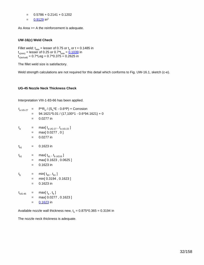
UG-45 Nozzle Neck Thickness Check
Interpretation VIII-1-83-66 has been applied.
ta UG-27 = P*Rn / (Sn*E - 0.6*P) + Corrosion= 94.1621*5.01 / (17,100*1 - 0.6*94.1621) + 0= 0.0277 in
ta = max[ ta UG-27 , ta UG-22 ]= max[ 0.0277 , 0 ]= 0.0277 in
tb1 = 0.1623 in
tb1 = max[ tb1 , tb UG16 ]= max[ 0.1623 , 0.0625 ]= 0.1623 in
tb = min[ tb3 , tb1 ]= min[ 0.3194 , 0.1623 ]= 0.1623 in
tUG-45 = max[ ta , tb ]= max[ 0.0277 , 0.1623 ]= 0.1623 in
Available nozzle wall thickness new, tn = 0.875*0.365 = 0.3194 in
The nozzle neck thickness is adequate.
32/158

Reinforcement Calculations for MAP
Available reinforcement per UG-37 governs the MAP of this nozzle.
UG-37 Area Calculation Summary (in2) UG-45Summary (in)
For P = 130.38 psi @ 70 °FThe opening is adequately reinforced
The nozzle passesUG-45
Arequired
Aavailable A1 A2 A3 A5
Awelds treq tmin
1.2665 1.2666 0.8518 0.2946 -- -- 0.1202 0.1385 0.3194
UG-41 Weld Failure Path Analysis Summary
The nozzle is exempt from weld strength calculations per UW-15(b)(1)
UW-16 Weld Sizing Summary
Weld description Required weldthroat size (in)
Actual weldthroat size (in) Status
Nozzle to shell fillet (Leg41) 0.1477 0.2625 weld size is adequate
Calculations for internal pressure 130.38 psi @ 70 °F
Parallel Limit of reinforcement per UG-40
LR = MAX(d, Rn + (tn - Cn) + (t - C))= MAX(10.02, 5.01 + (0.365 - 0) + (0.211 - 0))= 10.02 in
Outer Normal Limit of reinforcement per UG-40
LH = MIN(2.5*(t - C), 2.5*(tn - Cn) + te)= MIN(2.5*(0.211 - 0), 2.5*(0.365 - 0) + 0)= 0.5275 in
Nozzle required thickness per UG-27(c)(1)
trn = P*Rn / (Sn*E - 0.6*P)= 130.3818*5.01 / (17,100*1 - 0.6*130.3818)= 0.0384 in
Required thickness tr from UG-37(a)(c)
tr = P*K1*Do / (2*S*E + 0.8*P)= 130.3818*0.9*42.75 / (2*20,000*1 + 0.8*130.3818)= 0.1251 in
33/158

Required thickness tr per Interpretation VIII-1-07-50
tr = P*Do*K / (2*S*E + 2*P*(K - 0.1))= 130.38*42.75*1 / (2*20,000*0.85 + 2*130.38*(1 - 0.1))= 0.1628"
Area required per UG-37(c)
Allowable stresses: Sn = 17,100, Sv = 20,000 psi
fr1 = lesser of 1 or Sn / Sv = 0.855
fr2 = lesser of 1 or Sn / Sv = 0.855
A = d*tr*F + 2*tn*tr*F*(1 - fr1)= 10.02*0.1251*1 + 2*0.365*0.1251*1*(1 - 0.855)= 1.2665 in2
Area available from FIG. UG-37.1
A1 = larger of the following= 0.8518 in2
= d*(E1*t - F*tr) - 2*tn*(E1*t - F*tr)*(1 - fr1)= 10.02*(1*0.211 - 1*0.1251) - 2*0.365*(1*0.211 - 1*0.1251)*(1 - 0.855)= 0.8518 in2
= 2*(t + tn)*(E1*t - F*tr) - 2*tn*(E1*t - F*tr)*(1 - fr1)= 2*(0.211 + 0.365)*(1*0.211 - 1*0.1251) - 2*0.365*(1*0.211 - 1*0.1251)*(1 - 0.855)= 0.0899 in2
A2 = smaller of the following= 0.2946 in2
= 5*(tn - trn)*fr2*t= 5*(0.365 - 0.0384)*0.855*0.211= 0.2946 in2
= 5*(tn - trn)*fr2*tn= 5*(0.365 - 0.0384)*0.855*0.365= 0.5096 in2
A41 = Leg2*fr2= 0.3752*0.855= 0.1202 in2
Area = A1 + A2 + A41
= 0.8518 + 0.2946 + 0.1202= 1.2666 in2
34/158

As Area >= A the reinforcement is adequate.
UW-16(c) Weld Check
Fillet weld: tmin = lesser of 0.75 or tn or t = 0.211 intc(min) = lesser of 0.25 or 0.7*tmin = 0.1477 intc(actual) = 0.7*Leg = 0.7*0.375 = 0.2625 in
The fillet weld size is satisfactory.
Weld strength calculations are not required for this detail which conforms to Fig. UW-16.1, sketch (c-e).
UG-45 Nozzle Neck Thickness Check
Interpretation VIII-1-83-66 has been applied.
ta UG-27 = P*Rn / (Sn*E - 0.6*P) + Corrosion= 130.3818*5.01 / (17,100*1 - 0.6*130.3818) + 0= 0.0384 in
ta = max[ ta UG-27 , ta UG-22 ]= max[ 0.0384 , 0 ]= 0.0384 in
tb1 = 0.1385 in
tb1 = max[ tb1 , tb UG16 ]= max[ 0.1385 , 0.0625 ]= 0.1385 in
tb = min[ tb3 , tb1 ]= min[ 0.3194 , 0.1385 ]= 0.1385 in
tUG-45 = max[ ta , tb ]= max[ 0.0384 , 0.1385 ]= 0.1385 in
Available nozzle wall thickness new, tn = 0.875*0.365 = 0.3194 in
The nozzle neck thickness is adequate.
35/158

Cylinder #1
ASME Section VIII Division 1, 2010 Edition, A11 Addenda
Component Cylinder
Material SA-516 70 (II-D p. 18, ln. 19)
ImpactTested Normalized Fine Grain
Practice PWHT Optimize MDMT/Find MAWP
No No No No No
DesignPressure (psi)
DesignTemperature (°F)
DesignMDMT (°F)
Internal 50 350 -20
Static Liquid Head
Condition Ps (psi) Hs (in) SG
Test horizontal 1.9 52.539 1
Dimensions
Outer Diameter 42.75"
Length 600"
Nominal Thickness 0.211"
Corrosion Inner 0.0625"
Outer 0"
Weight and Capacity
Weight (lb) Capacity (US gal)
New 4,742.89 3,654.98
Corroded 3,342.96 3,676.6
Insulation
Thickness (in) Density (lb/ft3) Weight (lb)
Insulation 2 15 1,464.44
Spacing(in) Individual Weight (lb) Total Weight (lb)
InsulationSupports 132 813 3,252
Radiography
Longitudinal seam Spot UW-11(b) Type 1
Top Circumferentialseam Spot UW-11(b) Type 1
Bottom Circumferentialseam User Defined (E = 0.5)
36/158

Results Summary
Governing condition Internal pressure
Minimum thickness per UG-16 0.0625" + 0.0625" = 0.125"
Design thickness due to internal pressure (t) 0.1253"
Design thickness due to combined loadings + corrosion 0.1422"
Maximum allowable working pressure (MAWP) 118.43 psi
Maximum allowable pressure (MAP) 168.48 psi
Rated MDMT -55 °F
UCS-66 Material Toughness Requirements
Governing thickness, tg = 0.211"
Exemption temperature from Fig UCS-66 Curve B = -20°F
tr = 79.74*21.375 / (20,000*0.85 + 0.4*79.74) = 0.1001"
Stress ratio = tr*E* / (tn - c) = 0.1001*0.85 / (0.211 - 0.0625) = 0.5728
Reduction in MDMT, TR from Fig UCS-66.1 = 45.4°F
MDMT = max[ MDMT - TR, -55] = max[ -20 - 45.4 , -55] = -55°F
Material is exempt from impact testing at the Design MDMT of -20°F.
Design thickness, (at 350 °F) Appendix 1-1
t = P*Ro / (S*E + 0.40*P) + Corrosion= 50*21.375 / (20,000*0.85 + 0.40*50) + 0.0625= 0.1253"
Maximum allowable working pressure, (at 350 °F) Appendix 1-1
P = S*E*t / (Ro - 0.40*t) - Ps= 20,000*0.85*0.1485 / (21.375 - 0.40*0.1485) - 0= 118.43 psi
Maximum allowable pressure, (at 70 °F) Appendix 1-1
P = S*E*t / (Ro - 0.40*t)= 20,000*0.85*0.211 / (21.375 - 0.40*0.211)= 168.48 psi
% Extreme fiber elongation - UCS-79(d)
EFE = (50*t / Rf)*(1 - Rf / Ro)= (50*0.211 / 21.2695)*(1 - 21.2695 / ∞)= 0.496%
The extreme fiber elongation does not exceed 5%.
37/158

Thickness Required Due to Pressure + External Loads
Condition Pressure P (psi)
AllowableStress BeforeUG-23 StressIncrease ( psi)
Temperature (°F)
Corrosion C(in) Load Req'd Thk Due to
Tension (in)Req'd Thk Due toCompression (in)
St Sc
Operating, Hot & Corroded 50 20,000 11,110 350 0.0625 Wind 0.0797 0.0004
Seismic 0.0552 0.0241
Operating, Hot & New 50 20,000 12,347 350 0 Wind 0.0792 0.0014
Seismic 0.0557 0.0219
Hot Shut Down, Corroded 0 20,000 11,110 350 0.0625 Wind 0.0355 0.0402
Seismic 0.011 0.0181
Hot Shut Down, New 0 20,000 12,347 350 0 Wind 0.0351 0.037
Seismic 0.0116 0.018
Empty, Corroded 0 20,000 11,677 70 0.0625 Wind 0.0363 0.0372
Seismic 0.0104 0.015
Empty, New 0 20,000 13,063 70 0 Wind 0.0359 0.0341
Seismic 0.011 0.015
Hot Shut Down, Corroded, Weight& Eccentric Moments Only 0 20,000 11,110 350 0.0625 Weight 0.004 0.0083
Allowable Compressive Stress, Hot and Corroded- ScHC, (table CS-2)A = 0.125 / (Ro / t)
= 0.125 / (21.375 / 0.1485)= 0.000868
B = 11,110 psi
S = 20,000 / 1.00 = 20,000 psi
ScHC = min(B, S) = 11,110 psi
Allowable Compressive Stress, Hot and New- ScHN, (table CS-2)A = 0.125 / (Ro / t)
= 0.125 / (21.375 / 0.211)= 0.001234
B = 12,347 psi
S = 20,000 / 1.00 = 20,000 psi
ScHN = min(B, S) = 12,347 psi
Allowable Compressive Stress, Cold and New- ScCN, (table CS-2)A = 0.125 / (Ro / t)
= 0.125 / (21.375 / 0.211)= 0.001234
B = 13,063 psi
S = 20,000 / 1.00 = 20,000 psi
ScCN = min(B, S) = 13,063 psi
38/158

Allowable Compressive Stress, Cold and Corroded- ScCC, (table CS-2)A = 0.125 / (Ro / t)
= 0.125 / (21.375 / 0.1485)= 0.000868
B = 11,677 psi
S = 20,000 / 1.00 = 20,000 psi
ScCC = min(B, S) = 11,677 psi
Allowable Compressive Stress, Vacuum and Corroded- ScVC, (tableCS-2)A = 0.125 / (Ro / t)
= 0.125 / (21.375 / 0.1485)= 0.000868
B = 11,110 psi
S = 20,000 / 1.00 = 20,000 psi
ScVC = min(B, S) = 11,110 psi
Operating, Hot & Corroded, Wind, Bottom Seam
tp = P*R / (2*St*Ks*Ec + 0.40*|P|) (Pressure)= 50*21.2265 / (2*20,000*1.20*0.50 + 0.40*|50|)= 0.0442"
tm = M / (π*Rm2*St*Ks*Ec) (bending)
= 666,297 / (π*21.30082*20,000*1.20*0.50)= 0.039"
tw = 0.6*W / (2*π*Rm*St*Ks*Ec) (Weight)= 0.60*9,163.7 / (2*π*21.3008*20,000*1.20*0.50)= 0.0034"
tt = tp + tm - tw (total required, tensile)= 0.0442 + 0.039 - (0.0034)= 0.0797"
tpc = P*R / (2*Sc*Ks + 0.40*|P|) (Pressure)= 50*21.2265 / (2*11,109.56*1.20 + 0.40*|50|)= 0.0398"
tmc = M / (π*Rm2*Sc*Ks) (bending)
= 666,297 / (π*21.30082*11,109.56*1.20)= 0.0351"
twc = W / (2*π*Rm*Sc*Ks) (Weight)= 9,163.7 / (2*π*21.3008*11,109.56*1.20)= 0.0051"
tc = tmc + twc - tpc (total required, compressive)= 0.0351 + (0.0051) - (0.0398)= 0.0004"
39/158

Maximum allowable working pressure, Longitudinal Stress
P = 2*St*Ks*Ec*(t - tm + tw) / (R - 0.40*(t - tm + tw))= 2*20,000*1.20*0.50*(0.1485 - 0.039 + (0.0034)) / (21.2265 - 0.40*(0.1485 - 0.039 + (0.0034)))= 128 psi
Operating, Hot & New, Wind, Bottom Seam
tp = P*R / (2*St*Ks*Ec + 0.40*|P|) (Pressure)= 50*21.164 / (2*20,000*1.20*0.50 + 0.40*|50|)= 0.0441"
tm = M / (π*Rm2*St*Ks*Ec) (bending)
= 666,924 / (π*21.26952*20,000*1.20*0.50)= 0.0391"
tw = 0.6*W / (2*π*Rm*St*Ks*Ec) (Weight)= 0.60*10,624.5 / (2*π*21.2695*20,000*1.20*0.50)= 0.004"
tt = tp + tm - tw (total required, tensile)= 0.0441 + 0.0391 - (0.004)= 0.0792"
tpc = P*R / (2*Sc*Ks + 0.40*|P|) (Pressure)= 50*21.164 / (2*12,347.29*1.20 + 0.40*|50|)= 0.0357"
tmc = M / (π*Rm2*Sc*Ks) (bending)
= 666,924 / (π*21.26952*12,347.29*1.20)= 0.0317"
twc = W / (2*π*Rm*Sc*Ks) (Weight)= 10,624.5 / (2*π*21.2695*12,347.29*1.20)= 0.0054"
tc = tmc + twc - tpc (total required, compressive)= 0.0317 + (0.0054) - (0.0357)= 0.0014"
Maximum allowable working pressure, Longitudinal Stress
P = 2*St*Ks*Ec*(t - tm + tw) / (R - 0.40*(t - tm + tw))= 2*20,000*1.20*0.50*(0.211 - 0.0391 + (0.004)) / (21.164 - 0.40*(0.211 - 0.0391 + (0.004)))= 200.1 psi
Hot Shut Down, Corroded, Wind, Bottom Seam
tp = 0" (Pressure)tm = M / (π*Rm
2*St*Ks*Ec) (bending)= 666,297 / (π*21.30082*20,000*1.20*0.50)= 0.039"
tw = 0.6*W / (2*π*Rm*St*Ks*Ec) (Weight)= 0.60*9,163.7 / (2*π*21.3008*20,000*1.20*0.50)= 0.0034"
40/158

tt = tp + tm - tw (total required, tensile)= 0 + 0.039 - (0.0034)= 0.0355"
tmc = M / (π*Rm2*Sc*Ks) (bending)
= 666,297 / (π*21.30082*11,109.56*1.20)= 0.0351"
twc = W / (2*π*Rm*Sc*Ks) (Weight)= 9,163.7 / (2*π*21.3008*11,109.56*1.20)= 0.0051"
tc = tmc + twc - tpc (total required, compressive)= 0.0351 + (0.0051) - (0)= 0.0402"
Hot Shut Down, New, Wind, Bottom Seam
tp = 0" (Pressure)tm = M / (π*Rm
2*St*Ks*Ec) (bending)= 666,924 / (π*21.26952*20,000*1.20*0.50)= 0.0391"
tw = 0.6*W / (2*π*Rm*St*Ks*Ec) (Weight)= 0.60*10,624.5 / (2*π*21.2695*20,000*1.20*0.50)= 0.004"
tt = tp + tm - tw (total required, tensile)= 0 + 0.0391 - (0.004)= 0.0351"
tmc = M / (π*Rm2*Sc*Ks) (bending)
= 666,924 / (π*21.26952*12,347.29*1.20)= 0.0317"
twc = W / (2*π*Rm*Sc*Ks) (Weight)= 10,624.5 / (2*π*21.2695*12,347.29*1.20)= 0.0054"
tc = tmc + twc - tpc (total required, compressive)= 0.0317 + (0.0054) - (0)= 0.037"
Empty, Corroded, Wind, Bottom Seam
tp = 0" (Pressure)tm = M / (π*Rm
2*St*Ks*Ec) (bending)= 666,297 / (π*21.30082*20,000*1.20*0.50)= 0.039"
tw = 0.6*W / (2*π*Rm*St*Ks*Ec) (Weight)= 0.60*7,163.2 / (2*π*21.3008*20,000*1.20*0.50)= 0.0027"
tt = tp + tm - tw (total required, tensile)= 0 + 0.039 - (0.0027)
41/158

= 0.0363"
tmc = M / (π*Rm2*Sc*Ks) (bending)
= 666,297 / (π*21.30082*11,677.24*1.20)= 0.0334"
twc = W / (2*π*Rm*Sc*Ks) (Weight)= 7,163.2 / (2*π*21.3008*11,677.24*1.20)= 0.0038"
tc = tmc + twc - tpc (total required, compressive)= 0.0334 + (0.0038) - (0)= 0.0372"
Empty, New, Wind, Bottom Seam
tp = 0" (Pressure)tm = M / (π*Rm
2*St*Ks*Ec) (bending)= 666,924 / (π*21.26952*20,000*1.20*0.50)= 0.0391"
tw = 0.6*W / (2*π*Rm*St*Ks*Ec) (Weight)= 0.60*8,624.1 / (2*π*21.2695*20,000*1.20*0.50)= 0.0032"
tt = tp + tm - tw (total required, tensile)= 0 + 0.0391 - (0.0032)= 0.0359"
tmc = M / (π*Rm2*Sc*Ks) (bending)
= 666,924 / (π*21.26952*13,062.94*1.20)= 0.0299"
twc = W / (2*π*Rm*Sc*Ks) (Weight)= 8,624.1 / (2*π*21.2695*13,062.94*1.20)= 0.0041"
tc = tmc + twc - tpc (total required, compressive)= 0.0299 + (0.0041) - (0)= 0.0341"
Hot Shut Down, Corroded, Weight & Eccentric Moments Only, Bottom Seam
tp = 0" (Pressure)tm = M / (π*Rm
2*Sc*Ks) (bending)= 34,240 / (π*21.30082*11,109.56*1.00)= 0.0022"
tw = W / (2*π*Rm*Sc*Ks) (Weight)= 9,163.7 / (2*π*21.3008*11,109.56*1.00)= 0.0062"
tt = |tp + tm - tw| (total, net compressive)= |0 + 0.0022 - (0.0062)|= 0.004"
tc = tmc + twc - tpc (total required, compressive)
42/158

= 0.0022 + (0.0062) - (0)= 0.0083"
Operating, Hot & Corroded, Seismic, Bottom Seam
tp = P*R / (2*St*Ks*Ec + 0.40*|P|) (Pressure)= 50*21.2265 / (2*20,000*1.20*0.50 + 0.40*|50|)= 0.0442"
tm = M / (π*Rm2*St*Ks*Ec) (bending)
= 245,508 / (π*21.30082*20,000*1.20*0.50)= 0.0144"
tw = (0.6 - 0.14*SDS)*W / (2*π*Rm*St*Ks*Ec) (Weight)= 0.59*9,163.7 / (2*π*21.3008*20,000*1.20*0.50)= 0.0034"
tt = tp + tm - tw (total required, tensile)= 0.0442 + 0.0144 - (0.0034)= 0.0552"
twc = (1 + 0.14*SDS)*W / (2*π*Rm*St*Ks*Ec) (Weight)= 1.01*9,163.7 / (2*π*21.3008*20,000*1.20*0.50)= 0.0058"
tc = |tmc + twc - tpc| (total, net tensile)= |0.0144 + (0.0058) - (0.0442)|= 0.0241"
Maximum allowable working pressure, Longitudinal Stress
P = 2*St*Ks*Ec*(t - tm + tw) / (R - 0.40*(t - tm + tw))= 2*20,000*1.20*0.50*(0.1485 - 0.0144 + (0.0034)) / (21.2265 - 0.40*(0.1485 - 0.0144 + (0.0034)))= 155.87 psi
Operating, Hot & New, Seismic, Bottom Seam
tp = P*R / (2*St*Ks*Ec + 0.40*|P|) (Pressure)= 50*21.164 / (2*20,000*1.20*0.50 + 0.40*|50|)= 0.0441"
tm = M / (π*Rm2*St*Ks*Ec) (bending)
= 264,306 / (π*21.26952*20,000*1.20*0.50)= 0.0155"
tw = (0.6 - 0.14*SDS)*W / (2*π*Rm*St*Ks*Ec) (Weight)= 0.59*10,624.5 / (2*π*21.2695*20,000*1.20*0.50)= 0.0039"
tt = tp + tm - tw (total required, tensile)= 0.0441 + 0.0155 - (0.0039)= 0.0557"
twc = (1 + 0.14*SDS)*W / (2*π*Rm*St*Ks*Ec) (Weight)= 1.01*10,624.5 / (2*π*21.2695*20,000*1.20*0.50)= 0.0067"
43/158

tc = |tmc + twc - tpc| (total, net tensile)= |0.0155 + (0.0067) - (0.0441)|= 0.0219"
Maximum allowable working pressure, Longitudinal Stress
P = 2*St*Ks*Ec*(t - tm + tw) / (R - 0.40*(t - tm + tw))= 2*20,000*1.20*0.50*(0.211 - 0.0155 + (0.0039)) / (21.164 - 0.40*(0.211 - 0.0155 + (0.0039)))= 226.97 psi
Hot Shut Down, Corroded, Seismic, Bottom Seam
tp = 0" (Pressure)tm = M / (π*Rm
2*St*Ks*Ec) (bending)= 245,508 / (π*21.30082*20,000*1.20*0.50)= 0.0144"
tw = (0.6 - 0.14*SDS)*W / (2*π*Rm*St*Ks*Ec) (Weight)= 0.59*9,163.7 / (2*π*21.3008*20,000*1.20*0.50)= 0.0034"
tt = tp + tm - tw (total required, tensile)= 0 + 0.0144 - (0.0034)= 0.011"
tmc = M / (π*Rm2*Sc*Ks) (bending)
= 245,508 / (π*21.30082*11,109.56*1.20)= 0.0129"
twc = (1 + 0.14*SDS)*W / (2*π*Rm*Sc*Ks) (Weight)= 1.01*9,163.7 / (2*π*21.3008*11,109.56*1.20)= 0.0052"
tc = tmc + twc - tpc (total required, compressive)= 0.0129 + (0.0052) - (0)= 0.0181"
Hot Shut Down, New, Seismic, Bottom Seam
tp = 0" (Pressure)tm = M / (π*Rm
2*St*Ks*Ec) (bending)= 264,306 / (π*21.26952*20,000*1.20*0.50)= 0.0155"
tw = (0.6 - 0.14*SDS)*W / (2*π*Rm*St*Ks*Ec) (Weight)= 0.59*10,624.5 / (2*π*21.2695*20,000*1.20*0.50)= 0.0039"
tt = tp + tm - tw (total required, tensile)= 0 + 0.0155 - (0.0039)= 0.0116"
tmc = M / (π*Rm2*Sc*Ks) (bending)
= 264,306 / (π*21.26952*12,347.29*1.20)= 0.0126"
44/158

twc = (1 + 0.14*SDS)*W / (2*π*Rm*Sc*Ks) (Weight)= 1.01*10,624.5 / (2*π*21.2695*12,347.29*1.20)= 0.0054"
tc = tmc + twc - tpc (total required, compressive)= 0.0126 + (0.0054) - (0)= 0.018"
Empty, Corroded, Seismic, Bottom Seam
tp = 0" (Pressure)tm = M / (π*Rm
2*St*Ks*Ec) (bending)= 222,902 / (π*21.30082*20,000*1.20*0.50)= 0.013"
tw = (0.6 - 0.14*SDS)*W / (2*π*Rm*St*Ks*Ec) (Weight)= 0.59*7,163.2 / (2*π*21.3008*20,000*1.20*0.50)= 0.0026"
tt = tp + tm - tw (total required, tensile)= 0 + 0.013 - (0.0026)= 0.0104"
tmc = M / (π*Rm2*Sc*Ks) (bending)
= 222,902 / (π*21.30082*11,677.24*1.20)= 0.0112"
twc = (1 + 0.14*SDS)*W / (2*π*Rm*Sc*Ks) (Weight)= 1.01*7,163.2 / (2*π*21.3008*11,677.24*1.20)= 0.0039"
tc = tmc + twc - tpc (total required, compressive)= 0.0112 + (0.0039) - (0)= 0.015"
Empty, New, Seismic, Bottom Seam
tp = 0" (Pressure)tm = M / (π*Rm
2*St*Ks*Ec) (bending)= 241,734 / (π*21.26952*20,000*1.20*0.50)= 0.0142"
tw = (0.6 - 0.14*SDS)*W / (2*π*Rm*St*Ks*Ec) (Weight)= 0.59*8,624.1 / (2*π*21.2695*20,000*1.20*0.50)= 0.0032"
tt = tp + tm - tw (total required, tensile)= 0 + 0.0142 - (0.0032)= 0.011"
tmc = M / (π*Rm2*Sc*Ks) (bending)
= 241,734 / (π*21.26952*13,062.94*1.20)= 0.0109"
twc = (1 + 0.14*SDS)*W / (2*π*Rm*Sc*Ks) (Weight)= 1.01*8,624.1 / (2*π*21.2695*13,062.94*1.20)
45/158

= 0.0042"
tc = tmc + twc - tpc (total required, compressive)= 0.0109 + (0.0042) - (0)= 0.015"
46/158

MW2 (20-150 RFWN)
ASME Section VIII Division 1, 2010 Edition, A11 Addenda
Note: round inside edges per UG-76(c)
Location and Orientation
Located on Cylinder #1
Orientation 0°
Nozzle center line offset to datum line 92.0584"
End of nozzle to shell center 31.375"
Passes through a Category A joint No
Nozzle
Description NPS 20 Sch 20 (Std)
Access opening Yes
Material specification SA-106 B Smls pipe (II-D p. 10, ln. 40)
Inside diameter, new 19.25"
Pipe nominal wall thickness 0.375"
Pipe minimum wall thickness1 0.3281"
Corrosion allowance 0.0625"
Projection available outside vessel, Lpr 4.31"
Internal projection, hnew 1"
Projection available outside vessel to flange face, Lf 10"
Local vessel minimum thickness 0.211"
Liquid static head included 0 psi
Longitudinal joint efficiency 1
Welds
Inner fillet, Leg41 0.3125"
47/158

Lower fillet, Leg43 0.25"
Nozzle to vessel groove weld 0.211"1Pipe minimum thickness = nominal thickness times pipe tolerance factor of 0.875.
ASME B16.5-2009 Flange
Description NPS 20 Class 150 WN A105
Bolt Material SA-193 B7 Bolt <= 2 1/2 (II-D p. 334, ln. 32)
Blind included Yes
Rated MDMT -55°F
Liquid static head 0 psi
MAWP rating 215 psi @ 350°F
MAP rating 285 psi @ 70°F
Hydrotest rating 450 psi @ 70°F
PWHT performed No
Impact Tested No
Circumferential joint radiography Full UW-11(a) Type 1
Bore diameter, B (specified by purchaser) 19.25"
Notes
Flange rated MDMT per UCS-66(b)(3) = -155°F (Coincident ratio = 0.2798)Bolts rated MDMT per Fig UCS-66 note (c) = -55°F
UCS-66 Material Toughness Requirements Nozzle At Intersection
Governing thickness, tg = 0.211"
Exemption temperature from Fig UCS-66 Curve B = -20°F
tr = 79.74*21.375 / (20,000*1 + 0.4*79.74) = 0.0851"
Stress ratio = tr*E* / (tn - c) = 0.0851*1 / (0.211 - 0.0625) = 0.573
Reduction in MDMT, TR from Fig UCS-66.1 = 45.4°F
MDMT = max[ MDMT - TR, -55] = max[ -20 - 45.4 , -55] = -55°F
Material is exempt from impact testing at the Design MDMT of -20°F.
UCS-66 Material Toughness Requirements Nozzle
tr = 79.74*9.6875 / (17,100*1 - 0.6*79.74) = 0.0453"
Stress ratio = tr*E* / (tn - c) = 0.0453*1 / (0.3281 - 0.0625) = 0.1705
Stress ratio ≤ 0.35, MDMT per UCS-66(b)(3) = -155°F
Material is exempt from impact testing at the Design MDMT of -20°F.
48/158

Reinforcement Calculations for MAWP
Available reinforcement per UG-37 governs the MAWP of this nozzle.
UG-37 Area Calculation Summary (in2) UG-45Summary (in)
For P = 79.74 psi @ 350 °FThe opening is adequately reinforced
The nozzle passesUG-45
Arequired
Aavailable A1 A2 A3 A5
Awelds treq tmin
1.6563 1.6567 1.2228 0.1696 0.1587 -- 0.1056 0.1078 0.3281
UG-41 Weld Failure Path Analysis Summary
The nozzle is exempt from weld strength calculations per UW-15(b)(1)
UW-16 Weld Sizing Summary
Weld description Required weldthroat size (in)
Actual weldthroat size (in) Status
Nozzle to shell fillet (Leg41) 0.1039 0.2188 weld size is adequate
Calculations for internal pressure 79.74 psi @ 350 °F
Parallel Limit of reinforcement per UG-40
LR = MAX(d, Rn + (tn - Cn) + (t - C))= MAX(19.375, 9.6875 + (0.375 - 0.0625) + (0.211 - 0.0625))= 19.375 in
Outer Normal Limit of reinforcement per UG-40
LH = MIN(2.5*(t - C), 2.5*(tn - Cn) + te)= MIN(2.5*(0.211 - 0.0625), 2.5*(0.375 - 0.0625) + 0)= 0.3713 in
Inner Normal Limit of reinforcement per UG-40
LI = MIN(h, 2.5*(t - C), 2.5*(ti - Cn - C))= MIN(0.9375, 2.5*(0.211 - 0.0625), 2.5*(0.375 - 0.0625 - 0.0625))= 0.3713 in
Nozzle required thickness per UG-27(c)(1)
trn = P*Rn / (Sn*E - 0.6*P)= 79.7387*9.6875 / (17,100*1 - 0.6*79.7387)= 0.0453 in
49/158

Required thickness tr from UG-37(a)
tr = P*Ro / (S*E + 0.4*P)= 79.7387*21.375 / (20,000*1 + 0.4*79.7387)= 0.0851 in
Required thickness tr per Interpretation VIII-1-07-50
tr = P*Ro / (S*E + 0.4*P)= 79.7387*21.375 / (20,000*0.85 + 0.4*79.7387)= 0.1001 in
Area required per UG-37(c)
Allowable stresses: Sn = 17,100, Sv = 20,000 psi
fr1 = lesser of 1 or Sn / Sv = 0.855
fr2 = lesser of 1 or Sn / Sv = 0.855
A = d*tr*F + 2*tn*tr*F*(1 - fr1)= 19.375*0.0851*1 + 2*0.3125*0.0851*1*(1 - 0.855)= 1.6563 in2
Area available from FIG. UG-37.1
A1 = larger of the following= 1.2228 in2
= d*(E1*t - F*tr) - 2*tn*(E1*t - F*tr)*(1 - fr1)= 19.375*(1*0.1485 - 1*0.0851) - 2*0.3125*(1*0.1485 - 1*0.0851)*(1 - 0.855)= 1.2228 in2
= 2*(t + tn)*(E1*t - F*tr) - 2*tn*(E1*t - F*tr)*(1 - fr1)= 2*(0.1485 + 0.3125)*(1*0.1485 - 1*0.0851) - 2*0.3125*(1*0.1485 - 1*0.0851)*(1 - 0.855)= 0.0527 in2
A2 = smaller of the following= 0.1696 in2
= 5*(tn - trn)*fr2*t= 5*(0.3125 - 0.0453)*0.855*0.1485= 0.1696 in2
= 5*(tn - trn)*fr2*tn= 5*(0.3125 - 0.0453)*0.855*0.3125= 0.357 in2
A3 = smaller of the following= 0.1587 in2
= 5*t*ti*fr2
50/158

= 5*0.1485*0.25*0.855= 0.1587 in2
= 5*ti*ti*fr2= 5*0.25*0.25*0.855= 0.2672 in2
= 2*h*ti*fr2= 2*0.9375*0.25*0.855= 0.4008 in2
A41 = Leg2*fr2= 0.31252*0.855= 0.0835 in2
A43 = Leg2*fr2= 0.16072*0.855= 0.0221 in2
Area = A1 + A2 + A3 + A41 + A43
= 1.2228 + 0.1696 + 0.1587 + 0.0835 + 0.0221= 1.6567 in2
As Area >= A the reinforcement is adequate.
UW-16(c) Weld Check
Fillet weld: tmin = lesser of 0.75 or tn or t = 0.1485 intc(min) = lesser of 0.25 or 0.7*tmin = 0.1039 intc(actual) = 0.7*Leg = 0.7*0.3125 = 0.2188 in
The fillet weld size is satisfactory.
Weld strength calculations are not required for this detail which conforms to Fig. UW-16.1, sketch (c-e).
UG-45 Nozzle Neck Thickness Check (Access Opening)
ta UG-27 = P*Rn / (Sn*E - 0.6*P) + Corrosion= 79.7387*9.6875 / (17,100*1 - 0.6*79.7387) + 0.0625= 0.1078 in
ta = max[ ta UG-27 , ta UG-22 ]= max[ 0.1078 , 0 ]= 0.1078 in
Available nozzle wall thickness new, tn = 0.875*0.375 = 0.3281 in
51/158

The nozzle neck thickness is adequate.
52/158

Reinforcement Calculations for MAP
Available reinforcement per UG-37 governs the MAP of this nozzle.
UG-37 Area Calculation Summary (in2) UG-45Summary (in)
For P = 116.75 psi @ 70 °FThe opening is adequately reinforced
The nozzle passesUG-45
Arequired
Aavailable A1 A2 A3 A5
Awelds treq tmin
2.4098 2.41 1.6561 0.2787 0.3383 -- 0.1369 0.066 0.3281
UG-41 Weld Failure Path Analysis Summary
The nozzle is exempt from weld strength calculations per UW-15(b)(1)
UW-16 Weld Sizing Summary
Weld description Required weldthroat size (in)
Actual weldthroat size (in) Status
Nozzle to shell fillet (Leg41) 0.1477 0.2188 weld size is adequate
Calculations for internal pressure 116.75 psi @ 70 °F
Parallel Limit of reinforcement per UG-40
LR = MAX(d, Rn + (tn - Cn) + (t - C))= MAX(19.25, 9.625 + (0.375 - 0) + (0.211 - 0))= 19.25 in
Outer Normal Limit of reinforcement per UG-40
LH = MIN(2.5*(t - C), 2.5*(tn - Cn) + te)= MIN(2.5*(0.211 - 0), 2.5*(0.375 - 0) + 0)= 0.5275 in
Inner Normal Limit of reinforcement per UG-40
LI = MIN(h, 2.5*(t - C), 2.5*(ti - Cn - C))= MIN(1, 2.5*(0.211 - 0), 2.5*(0.375 - 0 - 0))= 0.5275 in
Nozzle required thickness per UG-27(c)(1)
trn = P*Rn / (Sn*E - 0.6*P)= 116.746*9.625 / (17,100*1 - 0.6*116.746)= 0.066 in
53/158

Required thickness tr from UG-37(a)
tr = P*Ro / (S*E + 0.4*P)= 116.746*21.375 / (20,000*1 + 0.4*116.746)= 0.1245 in
Required thickness tr per Interpretation VIII-1-07-50
tr = P*Ro / (S*E + 0.4*P)= 116.746*21.375 / (20,000*0.85 + 0.4*116.746)= 0.1464 in
Area required per UG-37(c)
Allowable stresses: Sn = 17,100, Sv = 20,000 psi
fr1 = lesser of 1 or Sn / Sv = 0.855
fr2 = lesser of 1 or Sn / Sv = 0.855
A = d*tr*F + 2*tn*tr*F*(1 - fr1)= 19.25*0.1245*1 + 2*0.375*0.1245*1*(1 - 0.855)= 2.4098 in2
Area available from FIG. UG-37.1
A1 = larger of the following= 1.6561 in2
= d*(E1*t - F*tr) - 2*tn*(E1*t - F*tr)*(1 - fr1)= 19.25*(1*0.211 - 1*0.1245) - 2*0.375*(1*0.211 - 1*0.1245)*(1 - 0.855)= 1.6561 in2
= 2*(t + tn)*(E1*t - F*tr) - 2*tn*(E1*t - F*tr)*(1 - fr1)= 2*(0.211 + 0.375)*(1*0.211 - 1*0.1245) - 2*0.375*(1*0.211 - 1*0.1245)*(1 - 0.855)= 0.092 in2
A2 = smaller of the following= 0.2787 in2
= 5*(tn - trn)*fr2*t= 5*(0.375 - 0.066)*0.855*0.211= 0.2787 in2
= 5*(tn - trn)*fr2*tn= 5*(0.375 - 0.066)*0.855*0.375= 0.4954 in2
A3 = smaller of the following= 0.3383 in2
= 5*t*ti*fr2
54/158

= 5*0.211*0.375*0.855= 0.3383 in2
= 5*ti*ti*fr2= 5*0.375*0.375*0.855= 0.6012 in2
= 2*h*ti*fr2= 2*1*0.375*0.855= 0.6413 in2
A41 = Leg2*fr2= 0.31252*0.855= 0.0835 in2
A43 = Leg2*fr2= 0.252*0.855= 0.0534 in2
Area = A1 + A2 + A3 + A41 + A43
= 1.6561 + 0.2787 + 0.3383 + 0.0835 + 0.0534= 2.41 in2
As Area >= A the reinforcement is adequate.
UW-16(c) Weld Check
Fillet weld: tmin = lesser of 0.75 or tn or t = 0.211 intc(min) = lesser of 0.25 or 0.7*tmin = 0.1477 intc(actual) = 0.7*Leg = 0.7*0.3125 = 0.2188 in
The fillet weld size is satisfactory.
Weld strength calculations are not required for this detail which conforms to Fig. UW-16.1, sketch (c-e).
UG-45 Nozzle Neck Thickness Check (Access Opening)
ta UG-27 = P*Rn / (Sn*E - 0.6*P) + Corrosion= 116.746*9.625 / (17,100*1 - 0.6*116.746) + 0= 0.066 in
ta = max[ ta UG-27 , ta UG-22 ]= max[ 0.066 , 0 ]= 0.066 in
Available nozzle wall thickness new, tn = 0.875*0.375 = 0.3281 in
55/158

The nozzle neck thickness is adequate.
56/158
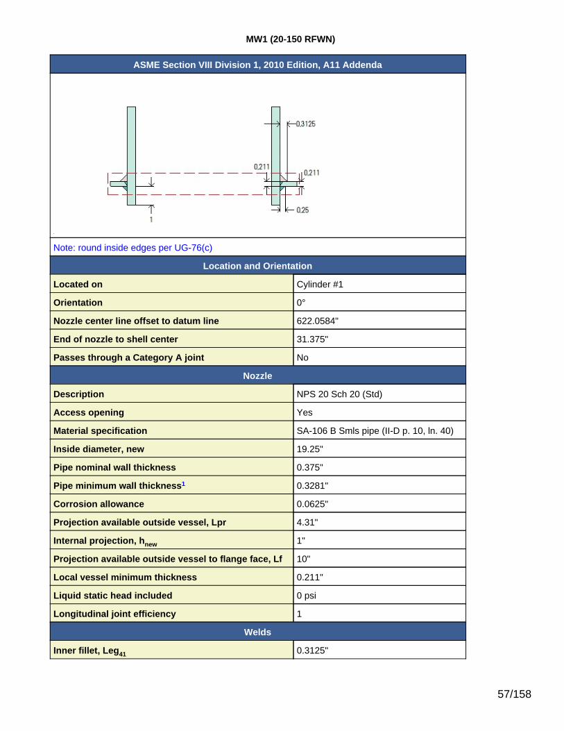
MW1 (20-150 RFWN)
ASME Section VIII Division 1, 2010 Edition, A11 Addenda
Note: round inside edges per UG-76(c)
Location and Orientation
Located on Cylinder #1
Orientation 0°
Nozzle center line offset to datum line 622.0584"
End of nozzle to shell center 31.375"
Passes through a Category A joint No
Nozzle
Description NPS 20 Sch 20 (Std)
Access opening Yes
Material specification SA-106 B Smls pipe (II-D p. 10, ln. 40)
Inside diameter, new 19.25"
Pipe nominal wall thickness 0.375"
Pipe minimum wall thickness1 0.3281"
Corrosion allowance 0.0625"
Projection available outside vessel, Lpr 4.31"
Internal projection, hnew 1"
Projection available outside vessel to flange face, Lf 10"
Local vessel minimum thickness 0.211"
Liquid static head included 0 psi
Longitudinal joint efficiency 1
Welds
Inner fillet, Leg41 0.3125"
57/158

Lower fillet, Leg43 0.25"
Nozzle to vessel groove weld 0.211"1Pipe minimum thickness = nominal thickness times pipe tolerance factor of 0.875.
ASME B16.5-2009 Flange
Description NPS 20 Class 150 WN A105
Bolt Material SA-193 B7 Bolt <= 2 1/2 (II-D p. 334, ln. 32)
Blind included Yes
Rated MDMT -55°F
Liquid static head 0 psi
MAWP rating 215 psi @ 350°F
MAP rating 285 psi @ 70°F
Hydrotest rating 450 psi @ 70°F
PWHT performed No
Impact Tested No
Circumferential joint radiography Full UW-11(a) Type 1
Bore diameter, B (specified by purchaser) 19.25"
Notes
Flange rated MDMT per UCS-66(b)(3) = -155°F (Coincident ratio = 0.2798)Bolts rated MDMT per Fig UCS-66 note (c) = -55°F
UCS-66 Material Toughness Requirements Nozzle At Intersection
Governing thickness, tg = 0.211"
Exemption temperature from Fig UCS-66 Curve B = -20°F
tr = 79.74*21.375 / (20,000*1 + 0.4*79.74) = 0.0851"
Stress ratio = tr*E* / (tn - c) = 0.0851*1 / (0.211 - 0.0625) = 0.573
Reduction in MDMT, TR from Fig UCS-66.1 = 45.4°F
MDMT = max[ MDMT - TR, -55] = max[ -20 - 45.4 , -55] = -55°F
Material is exempt from impact testing at the Design MDMT of -20°F.
UCS-66 Material Toughness Requirements Nozzle
tr = 79.74*9.6875 / (17,100*1 - 0.6*79.74) = 0.0453"
Stress ratio = tr*E* / (tn - c) = 0.0453*1 / (0.3281 - 0.0625) = 0.1705
Stress ratio ≤ 0.35, MDMT per UCS-66(b)(3) = -155°F
Material is exempt from impact testing at the Design MDMT of -20°F.
58/158

Reinforcement Calculations for MAWP
Available reinforcement per UG-37 governs the MAWP of this nozzle.
UG-37 Area Calculation Summary (in2) UG-45Summary (in)
For P = 79.74 psi @ 350 °FThe opening is adequately reinforced
The nozzle passesUG-45
Arequired
Aavailable A1 A2 A3 A5
Awelds treq tmin
1.6563 1.6567 1.2228 0.1696 0.1587 -- 0.1056 0.1078 0.3281
UG-41 Weld Failure Path Analysis Summary
The nozzle is exempt from weld strength calculations per UW-15(b)(1)
UW-16 Weld Sizing Summary
Weld description Required weldthroat size (in)
Actual weldthroat size (in) Status
Nozzle to shell fillet (Leg41) 0.1039 0.2188 weld size is adequate
Calculations for internal pressure 79.74 psi @ 350 °F
Parallel Limit of reinforcement per UG-40
LR = MAX(d, Rn + (tn - Cn) + (t - C))= MAX(19.375, 9.6875 + (0.375 - 0.0625) + (0.211 - 0.0625))= 19.375 in
Outer Normal Limit of reinforcement per UG-40
LH = MIN(2.5*(t - C), 2.5*(tn - Cn) + te)= MIN(2.5*(0.211 - 0.0625), 2.5*(0.375 - 0.0625) + 0)= 0.3713 in
Inner Normal Limit of reinforcement per UG-40
LI = MIN(h, 2.5*(t - C), 2.5*(ti - Cn - C))= MIN(0.9375, 2.5*(0.211 - 0.0625), 2.5*(0.375 - 0.0625 - 0.0625))= 0.3713 in
Nozzle required thickness per UG-27(c)(1)
trn = P*Rn / (Sn*E - 0.6*P)= 79.7387*9.6875 / (17,100*1 - 0.6*79.7387)= 0.0453 in
59/158

Required thickness tr from UG-37(a)
tr = P*Ro / (S*E + 0.4*P)= 79.7387*21.375 / (20,000*1 + 0.4*79.7387)= 0.0851 in
Required thickness tr per Interpretation VIII-1-07-50
tr = P*Ro / (S*E + 0.4*P)= 79.7387*21.375 / (20,000*0.85 + 0.4*79.7387)= 0.1001 in
Area required per UG-37(c)
Allowable stresses: Sn = 17,100, Sv = 20,000 psi
fr1 = lesser of 1 or Sn / Sv = 0.855
fr2 = lesser of 1 or Sn / Sv = 0.855
A = d*tr*F + 2*tn*tr*F*(1 - fr1)= 19.375*0.0851*1 + 2*0.3125*0.0851*1*(1 - 0.855)= 1.6563 in2
Area available from FIG. UG-37.1
A1 = larger of the following= 1.2228 in2
= d*(E1*t - F*tr) - 2*tn*(E1*t - F*tr)*(1 - fr1)= 19.375*(1*0.1485 - 1*0.0851) - 2*0.3125*(1*0.1485 - 1*0.0851)*(1 - 0.855)= 1.2228 in2
= 2*(t + tn)*(E1*t - F*tr) - 2*tn*(E1*t - F*tr)*(1 - fr1)= 2*(0.1485 + 0.3125)*(1*0.1485 - 1*0.0851) - 2*0.3125*(1*0.1485 - 1*0.0851)*(1 - 0.855)= 0.0527 in2
A2 = smaller of the following= 0.1696 in2
= 5*(tn - trn)*fr2*t= 5*(0.3125 - 0.0453)*0.855*0.1485= 0.1696 in2
= 5*(tn - trn)*fr2*tn= 5*(0.3125 - 0.0453)*0.855*0.3125= 0.357 in2
A3 = smaller of the following= 0.1587 in2
= 5*t*ti*fr2
60/158

= 5*0.1485*0.25*0.855= 0.1587 in2
= 5*ti*ti*fr2= 5*0.25*0.25*0.855= 0.2672 in2
= 2*h*ti*fr2= 2*0.9375*0.25*0.855= 0.4008 in2
A41 = Leg2*fr2= 0.31252*0.855= 0.0835 in2
A43 = Leg2*fr2= 0.16072*0.855= 0.0221 in2
Area = A1 + A2 + A3 + A41 + A43
= 1.2228 + 0.1696 + 0.1587 + 0.0835 + 0.0221= 1.6567 in2
As Area >= A the reinforcement is adequate.
UW-16(c) Weld Check
Fillet weld: tmin = lesser of 0.75 or tn or t = 0.1485 intc(min) = lesser of 0.25 or 0.7*tmin = 0.1039 intc(actual) = 0.7*Leg = 0.7*0.3125 = 0.2188 in
The fillet weld size is satisfactory.
Weld strength calculations are not required for this detail which conforms to Fig. UW-16.1, sketch (c-e).
UG-45 Nozzle Neck Thickness Check (Access Opening)
ta UG-27 = P*Rn / (Sn*E - 0.6*P) + Corrosion= 79.7387*9.6875 / (17,100*1 - 0.6*79.7387) + 0.0625= 0.1078 in
ta = max[ ta UG-27 , ta UG-22 ]= max[ 0.1078 , 0 ]= 0.1078 in
Available nozzle wall thickness new, tn = 0.875*0.375 = 0.3281 in
61/158

The nozzle neck thickness is adequate.
62/158

Reinforcement Calculations for MAP
Available reinforcement per UG-37 governs the MAP of this nozzle.
UG-37 Area Calculation Summary (in2) UG-45Summary (in)
For P = 116.75 psi @ 70 °FThe opening is adequately reinforced
The nozzle passesUG-45
Arequired
Aavailable A1 A2 A3 A5
Awelds treq tmin
2.4098 2.41 1.6561 0.2787 0.3383 -- 0.1369 0.066 0.3281
UG-41 Weld Failure Path Analysis Summary
The nozzle is exempt from weld strength calculations per UW-15(b)(1)
UW-16 Weld Sizing Summary
Weld description Required weldthroat size (in)
Actual weldthroat size (in) Status
Nozzle to shell fillet (Leg41) 0.1477 0.2188 weld size is adequate
Calculations for internal pressure 116.75 psi @ 70 °F
Parallel Limit of reinforcement per UG-40
LR = MAX(d, Rn + (tn - Cn) + (t - C))= MAX(19.25, 9.625 + (0.375 - 0) + (0.211 - 0))= 19.25 in
Outer Normal Limit of reinforcement per UG-40
LH = MIN(2.5*(t - C), 2.5*(tn - Cn) + te)= MIN(2.5*(0.211 - 0), 2.5*(0.375 - 0) + 0)= 0.5275 in
Inner Normal Limit of reinforcement per UG-40
LI = MIN(h, 2.5*(t - C), 2.5*(ti - Cn - C))= MIN(1, 2.5*(0.211 - 0), 2.5*(0.375 - 0 - 0))= 0.5275 in
Nozzle required thickness per UG-27(c)(1)
trn = P*Rn / (Sn*E - 0.6*P)= 116.746*9.625 / (17,100*1 - 0.6*116.746)= 0.066 in
63/158

Required thickness tr from UG-37(a)
tr = P*Ro / (S*E + 0.4*P)= 116.746*21.375 / (20,000*1 + 0.4*116.746)= 0.1245 in
Required thickness tr per Interpretation VIII-1-07-50
tr = P*Ro / (S*E + 0.4*P)= 116.746*21.375 / (20,000*0.85 + 0.4*116.746)= 0.1464 in
Area required per UG-37(c)
Allowable stresses: Sn = 17,100, Sv = 20,000 psi
fr1 = lesser of 1 or Sn / Sv = 0.855
fr2 = lesser of 1 or Sn / Sv = 0.855
A = d*tr*F + 2*tn*tr*F*(1 - fr1)= 19.25*0.1245*1 + 2*0.375*0.1245*1*(1 - 0.855)= 2.4098 in2
Area available from FIG. UG-37.1
A1 = larger of the following= 1.6561 in2
= d*(E1*t - F*tr) - 2*tn*(E1*t - F*tr)*(1 - fr1)= 19.25*(1*0.211 - 1*0.1245) - 2*0.375*(1*0.211 - 1*0.1245)*(1 - 0.855)= 1.6561 in2
= 2*(t + tn)*(E1*t - F*tr) - 2*tn*(E1*t - F*tr)*(1 - fr1)= 2*(0.211 + 0.375)*(1*0.211 - 1*0.1245) - 2*0.375*(1*0.211 - 1*0.1245)*(1 - 0.855)= 0.092 in2
A2 = smaller of the following= 0.2787 in2
= 5*(tn - trn)*fr2*t= 5*(0.375 - 0.066)*0.855*0.211= 0.2787 in2
= 5*(tn - trn)*fr2*tn= 5*(0.375 - 0.066)*0.855*0.375= 0.4954 in2
A3 = smaller of the following= 0.3383 in2
= 5*t*ti*fr2
64/158

= 5*0.211*0.375*0.855= 0.3383 in2
= 5*ti*ti*fr2= 5*0.375*0.375*0.855= 0.6012 in2
= 2*h*ti*fr2= 2*1*0.375*0.855= 0.6413 in2
A41 = Leg2*fr2= 0.31252*0.855= 0.0835 in2
A43 = Leg2*fr2= 0.252*0.855= 0.0534 in2
Area = A1 + A2 + A3 + A41 + A43
= 1.6561 + 0.2787 + 0.3383 + 0.0835 + 0.0534= 2.41 in2
As Area >= A the reinforcement is adequate.
UW-16(c) Weld Check
Fillet weld: tmin = lesser of 0.75 or tn or t = 0.211 intc(min) = lesser of 0.25 or 0.7*tmin = 0.1477 intc(actual) = 0.7*Leg = 0.7*0.3125 = 0.2188 in
The fillet weld size is satisfactory.
Weld strength calculations are not required for this detail which conforms to Fig. UW-16.1, sketch (c-e).
UG-45 Nozzle Neck Thickness Check (Access Opening)
ta UG-27 = P*Rn / (Sn*E - 0.6*P) + Corrosion= 116.746*9.625 / (17,100*1 - 0.6*116.746) + 0= 0.066 in
ta = max[ ta UG-27 , ta UG-22 ]= max[ 0.066 , 0 ]= 0.066 in
Available nozzle wall thickness new, tn = 0.875*0.375 = 0.3281 in
65/158

The nozzle neck thickness is adequate.
66/158

N4 (12-150 RFWN)
ASME Section VIII Division 1, 2010 Edition, A11 Addenda
Note: round inside edges per UG-76(c)
Location and Orientation
Located on Cylinder #1
Orientation 90°
Nozzle center line offset to datum line 92.0584"
End of nozzle to shell center 29.375"
Passes through a Category A joint No
Nozzle
Service REBOILER RETURN
Description NPS 12 Std Weight
Access opening No
Material specification SA-106 B Smls pipe (II-D p. 10, ln. 40)
Inside diameter, new 12"
Pipe nominal wall thickness 0.375"
Pipe minimum wall thickness1 0.3281"
Corrosion allowance 0"
Projection available outside vessel, Lpr 3.5"
Internal projection, hnew 1"
Projection available outside vessel to flange face, Lf 8"
Local vessel minimum thickness 0.211"
Liquid static head included 0 psi
Longitudinal joint efficiency 1
Welds
67/158

Inner fillet, Leg41 0.375"
Lower fillet, Leg43 0.25"
Nozzle to vessel groove weld 0.211"1Pipe minimum thickness = nominal thickness times pipe tolerance factor of 0.875.
ASME B16.5-2009 Flange
Description NPS 12 Class 150 WN A105
Bolt Material SA-193 B7 Bolt <= 2 1/2 (II-D p.334, ln. 32)
Blind included No
Rated MDMT -55°F
Liquid static head 0 psi
MAWP rating 215 psi @ 350°F
MAP rating 285 psi @ 70°F
Hydrotest rating 450 psi @ 70°F
PWHT performed No
Impact Tested No
Circumferential joint radiography Full UW-11(a) Type 1
Notes
Flange rated MDMT per UCS-66(b)(3) = -155°F (Coincident ratio = 0.2798)Bolts rated MDMT per Fig UCS-66 note (c) = -55°F
UCS-66 Material Toughness Requirements Nozzle At Intersection
Governing thickness, tg = 0.211"
Exemption temperature from Fig UCS-66 Curve B = -20°F
tr = 79.74*21.375 / (20,000*1 + 0.4*79.74) = 0.0851"
Stress ratio = tr*E* / (tn - c) = 0.0851*1 / (0.211 - 0.0625) = 0.573
Reduction in MDMT, TR from Fig UCS-66.1 = 45.4°F
MDMT = max[ MDMT - TR, -55] = max[ -20 - 45.4 , -55] = -55°F
Material is exempt from impact testing at the Design MDMT of -20°F.
68/158

UCS-66 Material Toughness Requirements Nozzle
tr = 79.74*6 / (17,100*1 - 0.6*79.74) = 0.0281"
Stress ratio = tr*E* / (tn - c) = 0.0281*1 / (0.3281 - 0) = 0.0855
Stress ratio ≤ 0.35, MDMT per UCS-66(b)(3) = -155°F
Material is exempt from impact testing at the Design MDMT of -20°F.
69/158

Reinforcement Calculations for MAWP
Available reinforcement per UG-37 governs the MAWP of this nozzle.
UG-37 Area Calculation Summary (in2) UG-45Summary (in)
For P = 90.77 psi @ 350 °FThe opening is adequately reinforced
The nozzle passesUG-45
Arequired
Aavailable A1 A2 A3 A5
Awelds treq tmin
1.1726 1.1727 0.6143 0.2177 0.1984 -- 0.1423 0.1593 0.3281
UG-41 Weld Failure Path Analysis Summary
The nozzle is exempt from weld strength calculations per UW-15(b)(1)
UW-16 Weld Sizing Summary
Weld description Required weldthroat size (in)
Actual weldthroat size (in) Status
Nozzle to shell fillet (Leg41) 0.1039 0.2625 weld size is adequate
Calculations for internal pressure 90.77 psi @ 350 °F
Parallel Limit of reinforcement per UG-40
LR = MAX(d, Rn + (tn - Cn) + (t - C))= MAX(12, 6 + (0.375 - 0) + (0.211 - 0.0625))= 12 in
Outer Normal Limit of reinforcement per UG-40
LH = MIN(2.5*(t - C), 2.5*(tn - Cn) + te)= MIN(2.5*(0.211 - 0.0625), 2.5*(0.375 - 0) + 0)= 0.3713 in
Inner Normal Limit of reinforcement per UG-40
LI = MIN(h, 2.5*(t - C), 2.5*(ti - Cn - C))= MIN(0.9375, 2.5*(0.211 - 0.0625), 2.5*(0.375 - 0 - 0.0625))= 0.3713 in
Nozzle required thickness per UG-27(c)(1)
trn = P*Rn / (Sn*E - 0.6*P)= 90.7745*6 / (17,100*1 - 0.6*90.7745)= 0.032 in
70/158

Required thickness tr from UG-37(a)
tr = P*Ro / (S*E + 0.4*P)= 90.7745*21.375 / (20,000*1 + 0.4*90.7745)= 0.0968 in
Required thickness tr per Interpretation VIII-1-07-50
tr = P*Ro / (S*E + 0.4*P)= 90.7745*21.375 / (20,000*0.85 + 0.4*90.7745)= 0.1139 in
Area required per UG-37(c)
Allowable stresses: Sn = 17,100, Sv = 20,000 psi
fr1 = lesser of 1 or Sn / Sv = 0.855
fr2 = lesser of 1 or Sn / Sv = 0.855
A = d*tr*F + 2*tn*tr*F*(1 - fr1)= 12*0.0968*1 + 2*0.375*0.0968*1*(1 - 0.855)= 1.1726 in2
Area available from FIG. UG-37.1
A1 = larger of the following= 0.6143 in2
= d*(E1*t - F*tr) - 2*tn*(E1*t - F*tr)*(1 - fr1)= 12*(1*0.1485 - 1*0.0968) - 2*0.375*(1*0.1485 - 1*0.0968)*(1 - 0.855)= 0.6143 in2
= 2*(t + tn)*(E1*t - F*tr) - 2*tn*(E1*t - F*tr)*(1 - fr1)= 2*(0.1485 + 0.375)*(1*0.1485 - 1*0.0968) - 2*0.375*(1*0.1485 - 1*0.0968)*(1 - 0.855)= 0.0485 in2
A2 = smaller of the following= 0.2177 in2
= 5*(tn - trn)*fr2*t= 5*(0.375 - 0.032)*0.855*0.1485= 0.2177 in2
= 5*(tn - trn)*fr2*tn= 5*(0.375 - 0.032)*0.855*0.375= 0.5499 in2
A3 = smaller of the following= 0.1984 in2
= 5*t*ti*fr2
71/158

= 5*0.1485*0.3125*0.855= 0.1984 in2
= 5*ti*ti*fr2= 5*0.3125*0.3125*0.855= 0.4175 in2
= 2*h*ti*fr2= 2*0.9375*0.3125*0.855= 0.501 in2
A41 = Leg2*fr2= 0.3752*0.855= 0.1202 in2
(Part of the weld is outside of the limits)
A43 = Leg2*fr2= 0.16072*0.855= 0.0221 in2
Area = A1 + A2 + A3 + A41 + A43
= 0.6143 + 0.2177 + 0.1984 + 0.1202 + 0.0221= 1.1727 in2
As Area >= A the reinforcement is adequate.
UW-16(c) Weld Check
Fillet weld: tmin = lesser of 0.75 or tn or t = 0.1485 intc(min) = lesser of 0.25 or 0.7*tmin = 0.1039 intc(actual) = 0.7*Leg = 0.7*0.375 = 0.2625 in
The fillet weld size is satisfactory.
Weld strength calculations are not required for this detail which conforms to Fig. UW-16.1, sketch (c-e).
UG-45 Nozzle Neck Thickness Check
ta UG-27 = P*Rn / (Sn*E - 0.6*P) + Corrosion= 90.7745*6 / (17,100*1 - 0.6*90.7745) + 0= 0.032 in
ta = max[ ta UG-27 , ta UG-22 ]= max[ 0.032 , 0 ]= 0.032 in
72/158

tb1 = P*Ro / (S*E + 0.4*P) + Corrosion= 90.7745*21.375 / (20,000*1 + 0.4*90.7745) + 0.0625= 0.1593 in
tb1 = max[ tb1 , tb UG16 ]= max[ 0.1593 , 0.0625 ]= 0.1593 in
tb = min[ tb3 , tb1 ]= min[ 0.3281 , 0.1593 ]= 0.1593 in
tUG-45 = max[ ta , tb ]= max[ 0.032 , 0.1593 ]= 0.1593 in
Available nozzle wall thickness new, tn = 0.875*0.375 = 0.3281 in
The nozzle neck thickness is adequate.
73/158

Reinforcement Calculations for MAP
Available reinforcement per UG-37 governs the MAP of this nozzle.
UG-37 Area Calculation Summary (in2) UG-45Summary (in)
For P = 129.68 psi @ 70 °FThe opening is adequately reinforced
The nozzle passesUG-45
Arequired
Aavailable A1 A2 A3 A5
Awelds treq tmin
1.6739 1.6741 0.8652 0.297 0.3383 -- 0.1736 0.1382 0.3281
UG-41 Weld Failure Path Analysis Summary
The nozzle is exempt from weld strength calculations per UW-15(b)(1)
UW-16 Weld Sizing Summary
Weld description Required weldthroat size (in)
Actual weldthroat size (in) Status
Nozzle to shell fillet (Leg41) 0.1477 0.2625 weld size is adequate
Calculations for internal pressure 129.68 psi @ 70 °F
Parallel Limit of reinforcement per UG-40
LR = MAX(d, Rn + (tn - Cn) + (t - C))= MAX(12, 6 + (0.375 - 0) + (0.211 - 0))= 12 in
Outer Normal Limit of reinforcement per UG-40
LH = MIN(2.5*(t - C), 2.5*(tn - Cn) + te)= MIN(2.5*(0.211 - 0), 2.5*(0.375 - 0) + 0)= 0.5275 in
Inner Normal Limit of reinforcement per UG-40
LI = MIN(h, 2.5*(t - C), 2.5*(ti - Cn - C))= MIN(1, 2.5*(0.211 - 0), 2.5*(0.375 - 0 - 0))= 0.5275 in
Nozzle required thickness per UG-27(c)(1)
trn = P*Rn / (Sn*E - 0.6*P)= 129.6796*6 / (17,100*1 - 0.6*129.6796)= 0.0457 in
74/158

Required thickness tr from UG-37(a)
tr = P*Ro / (S*E + 0.4*P)= 129.6796*21.375 / (20,000*1 + 0.4*129.6796)= 0.1382 in
Required thickness tr per Interpretation VIII-1-07-50
tr = P*Ro / (S*E + 0.4*P)= 129.6796*21.375 / (20,000*0.85 + 0.4*129.6796)= 0.1626 in
Area required per UG-37(c)
Allowable stresses: Sn = 17,100, Sv = 20,000 psi
fr1 = lesser of 1 or Sn / Sv = 0.855
fr2 = lesser of 1 or Sn / Sv = 0.855
A = d*tr*F + 2*tn*tr*F*(1 - fr1)= 12*0.1382*1 + 2*0.375*0.1382*1*(1 - 0.855)= 1.6739 in2
Area available from FIG. UG-37.1
A1 = larger of the following= 0.8652 in2
= d*(E1*t - F*tr) - 2*tn*(E1*t - F*tr)*(1 - fr1)= 12*(1*0.211 - 1*0.1382) - 2*0.375*(1*0.211 - 1*0.1382)*(1 - 0.855)= 0.8652 in2
= 2*(t + tn)*(E1*t - F*tr) - 2*tn*(E1*t - F*tr)*(1 - fr1)= 2*(0.211 + 0.375)*(1*0.211 - 1*0.1382) - 2*0.375*(1*0.211 - 1*0.1382)*(1 - 0.855)= 0.0774 in2
A2 = smaller of the following= 0.297 in2
= 5*(tn - trn)*fr2*t= 5*(0.375 - 0.0457)*0.855*0.211= 0.297 in2
= 5*(tn - trn)*fr2*tn= 5*(0.375 - 0.0457)*0.855*0.375= 0.5279 in2
A3 = smaller of the following= 0.3383 in2
= 5*t*ti*fr2
75/158

= 5*0.211*0.375*0.855= 0.3383 in2
= 5*ti*ti*fr2= 5*0.375*0.375*0.855= 0.6012 in2
= 2*h*ti*fr2= 2*1*0.375*0.855= 0.6413 in2
A41 = Leg2*fr2= 0.3752*0.855= 0.1202 in2
A43 = Leg2*fr2= 0.252*0.855= 0.0534 in2
Area = A1 + A2 + A3 + A41 + A43
= 0.8652 + 0.297 + 0.3383 + 0.1202 + 0.0534= 1.6741 in2
As Area >= A the reinforcement is adequate.
UW-16(c) Weld Check
Fillet weld: tmin = lesser of 0.75 or tn or t = 0.211 intc(min) = lesser of 0.25 or 0.7*tmin = 0.1477 intc(actual) = 0.7*Leg = 0.7*0.375 = 0.2625 in
The fillet weld size is satisfactory.
Weld strength calculations are not required for this detail which conforms to Fig. UW-16.1, sketch (c-e).
UG-45 Nozzle Neck Thickness Check
ta UG-27 = P*Rn / (Sn*E - 0.6*P) + Corrosion= 129.6796*6 / (17,100*1 - 0.6*129.6796) + 0= 0.0457 in
ta = max[ ta UG-27 , ta UG-22 ]= max[ 0.0457 , 0 ]= 0.0457 in
tb1 = P*Ro / (S*E + 0.4*P) + Corrosion= 129.6796*21.375 / (20,000*1 + 0.4*129.6796) + 0
76/158

= 0.1382 in
tb1 = max[ tb1 , tb UG16 ]= max[ 0.1382 , 0.0625 ]= 0.1382 in
tb = min[ tb3 , tb1 ]= min[ 0.3281 , 0.1382 ]= 0.1382 in
tUG-45 = max[ ta , tb ]= max[ 0.0457 , 0.1382 ]= 0.1382 in
Available nozzle wall thickness new, tn = 0.875*0.375 = 0.3281 in
The nozzle neck thickness is adequate.
77/158

Trays #1
ASME Section VIII Division 1, 2010 Edition, A11 Addenda
Inputs
Number of Trays in Group 20
Distance from Bottom Tray to Datum 130.0583"
Space Between Trays 24"
Number of Passes 1
Weight
Tray Weight 5.00 lb/ft2
Tray Diameter 42"
Support Weight 0 lb each
Operating Liquid Depth on Tray 2"
Tray Liquid Specific Gravity 1.00
Estimated Tray Weight, Empty 48.1 lb each
Estimated Tray Weight, Operating 148.1 lb each
Loading Conditions
Included in Vessel Lift & Shipping Weight No
Present When Vessel is Empty Yes
Present During Test Yes
78/158

Ellipsoidal Head #2
ASME Section VIII Division 1, 2010 Edition, A11 Addenda
Component Ellipsoidal Head
Internal Head Yes
Material SA-516 70 (II-D p. 18, ln. 19)
Attached To Cylinder #2
ImpactTested Normalized Fine Grain
Practice PWHT Optimize MDMT/Find MAWP
No No No No No
DesignPressure (psi)
DesignTemperature (°F)
DesignMDMT (°F)
Internal 50 350 -20External 50 350
Static Liquid Head
Condition Ps (psi) Hs (in) SG
Test horizontal 1.88 52.164 1
Dimensions
Outer Diameter 42.328"
Head Ratio 2
Minimum Thickness 0.375"
Corrosion Inner 0.0625"
Outer 0.0625"
Length Lsf 2"
Nominal Thickness tsf 0.375"
Weight and Capacity
Weight (lb)1 Capacity (US gal)1
New 244.11 52.49
Corroded 162.73 53.05
Insulation
Thickness (in) Density (lb/ft3) Weight (lb)
Insulation 2 15 41.7
Spacing(in) Individual Weight (lb) Total Weight (lb)
InsulationSupports 132 813 813
Radiography
Category A joints Seamless No RT
79/158

Head to shell seam User Defined (E = 0.5)1 includes straight flange
Results Summary
Governing condition external pressure
Minimum thickness per UG-16 0.0625" + 0.125" = 0.1875"
Design thickness due to internal pressure (t) 0.1869"
Design thickness due to external pressure (te) 0.3241"
Maximum allowable working pressure (MAWP) 203.78 psi
Maximum allowable pressure (MAP) 306.1 psi
Maximum allowable external pressure (MAEP) 73.38 psi
Maximum external pressure at test temperature (new) 131.42 psi
Straight Flange governs MDMT -155°F
Factor K
K = (1/6)*[2 + (D / (2*h))2]
Corroded K = (1/6)*[2 + (41.703 / (2*10.457))2] 0.996
New K = (1/6)*[2 + (41.578 / (2*10.3945))2] 1
Design thickness for internal pressure, (Corroded at 350 °F) Appendix 1-4(c)
t = P*Do*K / (2*S*E + 2*P*(K - 0.1)) + Corrosion= 50*42.328*0.996021 / (2*20,000*0.85 + 2*50*(0.996021 - 0.1)) + 0.125= 0.1868"
Maximum allowable working pressure, (Corroded at 350 °F) Appendix 1-4(c)
P = 2*S*E*t / (K*Do - 2*t*(K - 0.1)) - Ps= 2*20,000*0.85*0.25 / (0.996021*42.328 - 2*0.25*(0.996021 - 0.1)) - 0= 203.78 psi
Maximum allowable pressure, (New at 70 °F) Appendix 1-4(c)
P = 2*S*E*t / (K*Do - 2*t*(K - 0.1)) - Ps= 2*20,000*0.85*0.375 / (1*42.328 - 2*0.375*(1 - 0.1)) - 0= 306.1 psi
Design thickness for external pressure, (Corroded at 350 °F) UG-33(d)
Equivalent outside spherical radius (Ro)Ro = Ko*Do
= 0.8843*42.328= 37.432 in
A = 0.125 / (Ro / t)= 0.125 / (37.432 / 0.199081)= 0.000665
80/158

From TableCS-2: B = 9,401.1678
psi
Pa = B / (Ro / t)= 9,401.1678 / (37.432 / 0.1991)= 50 psi
t = 0.1991" + Corrosion = 0.1991" + 0.125" = 0.3241"Check the external pressure per UG-33(a)(1) Appendix 1-4(c)
t = 1.67*Pe*Do*K / (2*S*E + 2*1.67*Pe*(K - 0.1)) + Corrosion= 1.67*50*42.328*0.996021 / (2*20,000*1 + 2*1.67*50*(0.996021 - 0.1)) + 0.125= 0.2127"
The head external pressure design thickness (te) is 0.3241".
Maximum Allowable External Pressure, (Corroded at 350 °F) UG-33(d)
Equivalent outside spherical radius (Ro)Ro = Ko*Do
= 0.8843*42.328= 37.432 in
A = 0.125 / (Ro / t)= 0.125 / (37.432 / 0.25)= 0.000835
From TableCS-2: B = 10,987.51
psi
Pa = B / (Ro / t)= 10,987.51 / (37.432 / 0.25)= 73.3832 psi
Check the Maximum External Pressure, UG-33(a)(1) Appendix 1-4(c)
P = 2*S*E*t / ((K*Do - 2*t*(K - 0.1))*1.67)= 2*20,000*1*0.25 / ((0.996021*42.328 - 2*0.25*(0.996021 - 0.1))*1.67)= 143.56 psi
The maximum allowable external pressure (MAEP) is 73.38 psi.
Maximum Allowable External Pressure, (New at 70 °F) UG-33(d)
Equivalent outside spherical radius (Ro)Ro = Ko*Do
= 0.8843*42.328= 37.432 in
A = 0.125 / (Ro / t)= 0.125 / (37.432 / 0.375)= 0.001252
81/158

From TableCS-2:
B = 13,118.27psi
Pa = B / (Ro / t)= 13,118.27 / (37.432 / 0.375)= 131.4212 psi
Check the Maximum External Pressure, UG-33(a)(1) Appendix 1-4(c)
P = 2*S*E*t / ((K*Do - 2*t*(K - 0.1))*1.67)= 2*20,000*1*0.375 / ((1*42.328 - 2*0.375*(1 - 0.1))*1.67)= 215.64 psi
The maximum allowable external pressure at test temperature (new) (MAEP) is 131.42 psi.
% Extreme fiber elongation - UCS-79(d)
EFE = (75*t / Rf)*(1 - Rf / Ro)= (75*0.375 / 7.2558)*(1 - 7.2558 / ∞)= 3.8762%
The extreme fiber elongation does not exceed 5%.
82/158

Cylinder #2
ASME Section VIII Division 1, 2010 Edition, A11 Addenda
Component Cylinder
Material SA-516 70 (II-D p. 18, ln. 19)
ImpactTested Normalized Fine Grain
Practice PWHT Optimize MDMT/Find MAWP
No No No No No
DesignPressure (psi)
DesignTemperature (°F)
DesignMDMT (°F)
Internal 50 350 -20
Static Liquid Head
Condition Ps (psi) Hs (in) SG
Test horizontal 1.51 41.953 1
Dimensions
Outer Diameter 42.75"
Length 60"
Nominal Thickness 0.211"
Corrosion Inner 0.0625"
Outer 0"
Weight and Capacity
Weight (lb) Capacity (US gal)
New 453.07 309.58
Corroded 319.36 312.07
Insulation
Thickness (in) Density (lb/ft3) Weight (lb)
Insulation 2 15 146.44
Spacing(in) Individual Weight (lb) Total Weight (lb)
InsulationSupports 132 813 813
Radiography
Longitudinal seam Spot UW-11(b) Type 1
Top Circumferentialseam User Defined (E = 0.5)
Bottom Circumferentialseam Spot UW-11(b) Type 1
83/158

Results Summary
Governing condition Internal pressure
Minimum thickness per UG-16 0.0625" + 0.0625" = 0.125"
Design thickness due to internal pressure (t) 0.1253"
Design thickness due to combined loadings + corrosion 0.114"
Maximum allowable working pressure (MAWP) 118.43 psi
Maximum allowable pressure (MAP) 168.48 psi
Rated MDMT -55 °F
UCS-66 Material Toughness Requirements
Governing thickness, tg = 0.211"
Exemption temperature from Fig UCS-66 Curve B = -20°F
tr = 73.38*21.375 / (20,000*0.85 + 0.4*73.38) = 0.0921"
Stress ratio = tr*E* / (tn - c) = 0.0921*0.85 / (0.211 - 0.0625) = 0.5272
Reduction in MDMT, TR from Fig UCS-66.1 = 52.6°F
MDMT = max[ MDMT - TR, -55] = max[ -20 - 52.6 , -55] = -55°F
Material is exempt from impact testing at the Design MDMT of -20°F.
Design thickness, (at 350 °F) Appendix 1-1
t = P*Ro / (S*E + 0.40*P) + Corrosion= 50*21.375 / (20,000*0.85 + 0.40*50) + 0.0625= 0.1253"
Maximum allowable working pressure, (at 350 °F) Appendix 1-1
P = S*E*t / (Ro - 0.40*t) - Ps= 20,000*0.85*0.1485 / (21.375 - 0.40*0.1485) - 0= 118.43 psi
Maximum allowable pressure, (at 70 °F) Appendix 1-1
P = S*E*t / (Ro - 0.40*t)= 20,000*0.85*0.211 / (21.375 - 0.40*0.211)= 168.48 psi
% Extreme fiber elongation - UCS-79(d)
EFE = (50*t / Rf)*(1 - Rf / Ro)= (50*0.211 / 21.2695)*(1 - 21.2695 / ∞)= 0.496%
The extreme fiber elongation does not exceed 5%.
84/158

Thickness Required Due to Pressure + External Loads
Condition Pressure P (psi)
AllowableStress BeforeUG-23 StressIncrease ( psi)
Temperature (°F)
Corrosion C(in) Load Req'd Thk Due to
Tension (in)Req'd Thk Due toCompression (in)
St Sc
Operating, Hot & Corroded 50 20,000 11,110 350 0.0625 Wind 0.0515 0.0087
Seismic 0.0339 0.012
Operating, Hot & New 50 20,000 12,347 350 0 Wind 0.0512 0.0089
Seismic 0.0342 0.0105
Hot Shut Down, Corroded 0 20,000 11,110 350 0.0625 Wind 0.0255 0.0485
Seismic 0.0079 0.0214
Hot Shut Down, New 0 20,000 12,347 350 0 Wind 0.0253 0.0446
Seismic 0.0083 0.0212
Empty, Corroded 0 20,000 11,677 70 0.0625 Wind 0.026 0.0451
Seismic 0.0074 0.018
Empty, New 0 20,000 13,063 70 0 Wind 0.0257 0.0412
Seismic 0.0078 0.0179
Hot Shut Down, Corroded, Weight& Eccentric Moments Only 0 20,000 11,110 350 0.0625 Weight 0.0038 0.0103
Allowable Compressive Stress, Hot and Corroded- ScHC, (table CS-2)A = 0.125 / (Ro / t)
= 0.125 / (21.375 / 0.1485)= 0.000868
B = 11,110 psi
S = 20,000 / 1.00 = 20,000 psi
ScHC = min(B, S) = 11,110 psi
Allowable Compressive Stress, Hot and New- ScHN, (table CS-2)A = 0.125 / (Ro / t)
= 0.125 / (21.375 / 0.211)= 0.001234
B = 12,347 psi
S = 20,000 / 1.00 = 20,000 psi
ScHN = min(B, S) = 12,347 psi
Allowable Compressive Stress, Cold and New- ScCN, (table CS-2)A = 0.125 / (Ro / t)
= 0.125 / (21.375 / 0.211)= 0.001234
B = 13,063 psi
S = 20,000 / 1.00 = 20,000 psi
ScCN = min(B, S) = 13,063 psi
85/158

Allowable Compressive Stress, Cold and Corroded- ScCC, (table CS-2)A = 0.125 / (Ro / t)
= 0.125 / (21.375 / 0.1485)= 0.000868
B = 11,677 psi
S = 20,000 / 1.00 = 20,000 psi
ScCC = min(B, S) = 11,677 psi
Allowable Compressive Stress, Vacuum and Corroded- ScVC, (tableCS-2)A = 0.125 / (Ro / t)
= 0.125 / (21.375 / 0.1485)= 0.000868
B = 11,110 psi
S = 20,000 / 1.00 = 20,000 psi
ScVC = min(B, S) = 11,110 psi
Operating, Hot & Corroded, Wind, Bottom Seam
tp = P*R / (2*St*Ks*Ec + 0.40*|P|) (Pressure)= 50*21.2265 / (2*20,000*1.20*0.85 + 0.40*|50|)= 0.026"
tm = M / (π*Rm2*St*Ks*Ec) (bending)
= 809,634 / (π*21.30082*20,000*1.20*0.85)= 0.0278"
tw = 0.6*W / (2*π*Rm*St*Ks*Ec) (Weight)= 0.60*10,473.2 / (2*π*21.3008*20,000*1.20*0.85)= 0.0023"
tt = tp + tm - tw (total required, tensile)= 0.026 + 0.0278 - (0.0023)= 0.0515"
tpc = P*R / (2*Sc*Ks + 0.40*|P|) (Pressure)= 50*21.2265 / (2*11,109.56*1.20 + 0.40*|50|)= 0.0398"
tmc = M / (π*Rm2*Sc*Ks) (bending)
= 809,634 / (π*21.30082*11,109.56*1.20)= 0.0426"
twc = W / (2*π*Rm*Sc*Ks) (Weight)= 10,473.2 / (2*π*21.3008*11,109.56*1.20)= 0.0059"
tc = tmc + twc - tpc (total required, compressive)= 0.0426 + (0.0059) - (0.0398)= 0.0087"
86/158

Maximum allowable working pressure, Longitudinal Stress
P = 2*St*Ks*Ec*(t - tm + tw) / (R - 0.40*(t - tm + tw))= 2*20,000*1.20*0.85*(0.1485 - 0.0278 + (0.0023)) / (21.2265 - 0.40*(0.1485 - 0.0278 + (0.0023)))= 236.89 psi
Operating, Hot & New, Wind, Bottom Seam
tp = P*R / (2*St*Ks*Ec + 0.40*|P|) (Pressure)= 50*21.164 / (2*20,000*1.20*0.85 + 0.40*|50|)= 0.0259"
tm = M / (π*Rm2*St*Ks*Ec) (bending)
= 810,577 / (π*21.26952*20,000*1.20*0.85)= 0.028"
tw = 0.6*W / (2*π*Rm*St*Ks*Ec) (Weight)= 0.60*12,163.5 / (2*π*21.2695*20,000*1.20*0.85)= 0.0027"
tt = tp + tm - tw (total required, tensile)= 0.0259 + 0.028 - (0.0027)= 0.0512"
tpc = P*R / (2*Sc*Ks + 0.40*|P|) (Pressure)= 50*21.164 / (2*12,347.29*1.20 + 0.40*|50|)= 0.0357"
tmc = M / (π*Rm2*Sc*Ks) (bending)
= 810,577 / (π*21.26952*12,347.29*1.20)= 0.0385"
twc = W / (2*π*Rm*Sc*Ks) (Weight)= 12,163.5 / (2*π*21.2695*12,347.29*1.20)= 0.0061"
tc = tmc + twc - tpc (total required, compressive)= 0.0385 + (0.0061) - (0.0357)= 0.0089"
Maximum allowable working pressure, Longitudinal Stress
P = 2*St*Ks*Ec*(t - tm + tw) / (R - 0.40*(t - tm + tw))= 2*20,000*1.20*0.85*(0.211 - 0.028 + (0.0027)) / (21.164 - 0.40*(0.211 - 0.028 + (0.0027)))= 359.29 psi
Hot Shut Down, Corroded, Wind, Bottom Seam
tp = 0" (Pressure)tm = M / (π*Rm
2*St*Ks*Ec) (bending)= 809,634 / (π*21.30082*20,000*1.20*0.85)= 0.0278"
tw = 0.6*W / (2*π*Rm*St*Ks*Ec) (Weight)= 0.60*10,473.2 / (2*π*21.3008*20,000*1.20*0.85)= 0.0023"
87/158

tt = tp + tm - tw (total required, tensile)= 0 + 0.0278 - (0.0023)= 0.0255"
tmc = M / (π*Rm2*Sc*Ks) (bending)
= 809,634 / (π*21.30082*11,109.56*1.20)= 0.0426"
twc = W / (2*π*Rm*Sc*Ks) (Weight)= 10,473.2 / (2*π*21.3008*11,109.56*1.20)= 0.0059"
tc = tmc + twc - tpc (total required, compressive)= 0.0426 + (0.0059) - (0)= 0.0485"
Hot Shut Down, New, Wind, Bottom Seam
tp = 0" (Pressure)tm = M / (π*Rm
2*St*Ks*Ec) (bending)= 810,577 / (π*21.26952*20,000*1.20*0.85)= 0.028"
tw = 0.6*W / (2*π*Rm*St*Ks*Ec) (Weight)= 0.60*12,163.5 / (2*π*21.2695*20,000*1.20*0.85)= 0.0027"
tt = tp + tm - tw (total required, tensile)= 0 + 0.028 - (0.0027)= 0.0253"
tmc = M / (π*Rm2*Sc*Ks) (bending)
= 810,577 / (π*21.26952*12,347.29*1.20)= 0.0385"
twc = W / (2*π*Rm*Sc*Ks) (Weight)= 12,163.5 / (2*π*21.2695*12,347.29*1.20)= 0.0061"
tc = tmc + twc - tpc (total required, compressive)= 0.0385 + (0.0061) - (0)= 0.0446"
Empty, Corroded, Wind, Bottom Seam
tp = 0" (Pressure)tm = M / (π*Rm
2*St*Ks*Ec) (bending)= 809,634 / (π*21.30082*20,000*1.20*0.85)= 0.0278"
tw = 0.6*W / (2*π*Rm*St*Ks*Ec) (Weight)= 0.60*8,472.8 / (2*π*21.3008*20,000*1.20*0.85)= 0.0019"
tt = tp + tm - tw (total required, tensile)= 0 + 0.0278 - (0.0019)
88/158

= 0.026"
tmc = M / (π*Rm2*Sc*Ks) (bending)
= 809,634 / (π*21.30082*11,677.24*1.20)= 0.0405"
twc = W / (2*π*Rm*Sc*Ks) (Weight)= 8,472.8 / (2*π*21.3008*11,677.24*1.20)= 0.0045"
tc = tmc + twc - tpc (total required, compressive)= 0.0405 + (0.0045) - (0)= 0.0451"
Empty, New, Wind, Bottom Seam
tp = 0" (Pressure)tm = M / (π*Rm
2*St*Ks*Ec) (bending)= 810,577 / (π*21.26952*20,000*1.20*0.85)= 0.028"
tw = 0.6*W / (2*π*Rm*St*Ks*Ec) (Weight)= 0.60*10,163.1 / (2*π*21.2695*20,000*1.20*0.85)= 0.0022"
tt = tp + tm - tw (total required, tensile)= 0 + 0.028 - (0.0022)= 0.0257"
tmc = M / (π*Rm2*Sc*Ks) (bending)
= 810,577 / (π*21.26952*13,062.94*1.20)= 0.0364"
twc = W / (2*π*Rm*Sc*Ks) (Weight)= 10,163.1 / (2*π*21.2695*13,062.94*1.20)= 0.0049"
tc = tmc + twc - tpc (total required, compressive)= 0.0364 + (0.0049) - (0)= 0.0412"
Hot Shut Down, Corroded, Weight & Eccentric Moments Only, Bottom Seam
tp = 0" (Pressure)tm = M / (π*Rm
2*Sc*Ks) (bending)= 51,249 / (π*21.30082*11,109.56*1.00)= 0.0032"
tw = W / (2*π*Rm*Sc*Ks) (Weight)= 10,473.2 / (2*π*21.3008*11,109.56*1.00)= 0.007"
tt = |tp + tm - tw| (total, net compressive)= |0 + 0.0032 - (0.007)|= 0.0038"
tc = tmc + twc - tpc (total required, compressive)
89/158

= 0.0032 + (0.007) - (0)= 0.0103"
Operating, Hot & Corroded, Seismic, Bottom Seam
tp = P*R / (2*St*Ks*Ec + 0.40*|P|) (Pressure)= 50*21.2265 / (2*20,000*1.20*0.85 + 0.40*|50|)= 0.026"
tm = M / (π*Rm2*St*Ks*Ec) (bending)
= 294,089 / (π*21.30082*20,000*1.20*0.85)= 0.0101"
tw = (0.6 - 0.14*SDS)*W / (2*π*Rm*St*Ks*Ec) (Weight)= 0.59*10,473.2 / (2*π*21.3008*20,000*1.20*0.85)= 0.0023"
tt = tp + tm - tw (total required, tensile)= 0.026 + 0.0101 - (0.0023)= 0.0339"
twc = (1 + 0.14*SDS)*W / (2*π*Rm*St*Ks*Ec) (Weight)= 1.01*10,473.2 / (2*π*21.3008*20,000*1.20*0.85)= 0.0039"
tc = |tmc + twc - tpc| (total, net tensile)= |0.0101 + (0.0039) - (0.026)|= 0.012"
Maximum allowable working pressure, Longitudinal Stress
P = 2*St*Ks*Ec*(t - tm + tw) / (R - 0.40*(t - tm + tw))= 2*20,000*1.20*0.85*(0.1485 - 0.0101 + (0.0023)) / (21.2265 - 0.40*(0.1485 - 0.0101 + (0.0023)))= 271.05 psi
Operating, Hot & New, Seismic, Bottom Seam
tp = P*R / (2*St*Ks*Ec + 0.40*|P|) (Pressure)= 50*21.164 / (2*20,000*1.20*0.85 + 0.40*|50|)= 0.0259"
tm = M / (π*Rm2*St*Ks*Ec) (bending)
= 316,303 / (π*21.26952*20,000*1.20*0.85)= 0.0109"
tw = (0.6 - 0.14*SDS)*W / (2*π*Rm*St*Ks*Ec) (Weight)= 0.59*12,163.5 / (2*π*21.2695*20,000*1.20*0.85)= 0.0026"
tt = tp + tm - tw (total required, tensile)= 0.0259 + 0.0109 - (0.0026)= 0.0342"
twc = (1 + 0.14*SDS)*W / (2*π*Rm*St*Ks*Ec) (Weight)= 1.01*12,163.5 / (2*π*21.2695*20,000*1.20*0.85)= 0.0045"
90/158

tc = |tmc + twc - tpc| (total, net tensile)= |0.0109 + (0.0045) - (0.0259)|= 0.0105"
Maximum allowable working pressure, Longitudinal Stress
P = 2*St*Ks*Ec*(t - tm + tw) / (R - 0.40*(t - tm + tw))= 2*20,000*1.20*0.85*(0.211 - 0.0109 + (0.0026)) / (21.164 - 0.40*(0.211 - 0.0109 + (0.0026)))= 392.29 psi
Hot Shut Down, Corroded, Seismic, Bottom Seam
tp = 0" (Pressure)tm = M / (π*Rm
2*St*Ks*Ec) (bending)= 294,089 / (π*21.30082*20,000*1.20*0.85)= 0.0101"
tw = (0.6 - 0.14*SDS)*W / (2*π*Rm*St*Ks*Ec) (Weight)= 0.59*10,473.2 / (2*π*21.3008*20,000*1.20*0.85)= 0.0023"
tt = tp + tm - tw (total required, tensile)= 0 + 0.0101 - (0.0023)= 0.0079"
tmc = M / (π*Rm2*Sc*Ks) (bending)
= 294,089 / (π*21.30082*11,109.56*1.20)= 0.0155"
twc = (1 + 0.14*SDS)*W / (2*π*Rm*Sc*Ks) (Weight)= 1.01*10,473.2 / (2*π*21.3008*11,109.56*1.20)= 0.0059"
tc = tmc + twc - tpc (total required, compressive)= 0.0155 + (0.0059) - (0)= 0.0214"
Hot Shut Down, New, Seismic, Bottom Seam
tp = 0" (Pressure)tm = M / (π*Rm
2*St*Ks*Ec) (bending)= 316,303 / (π*21.26952*20,000*1.20*0.85)= 0.0109"
tw = (0.6 - 0.14*SDS)*W / (2*π*Rm*St*Ks*Ec) (Weight)= 0.59*12,163.5 / (2*π*21.2695*20,000*1.20*0.85)= 0.0026"
tt = tp + tm - tw (total required, tensile)= 0 + 0.0109 - (0.0026)= 0.0083"
tmc = M / (π*Rm2*Sc*Ks) (bending)
= 316,303 / (π*21.26952*12,347.29*1.20)= 0.015"
91/158

twc = (1 + 0.14*SDS)*W / (2*π*Rm*Sc*Ks) (Weight)= 1.01*12,163.5 / (2*π*21.2695*12,347.29*1.20)= 0.0062"
tc = tmc + twc - tpc (total required, compressive)= 0.015 + (0.0062) - (0)= 0.0212"
Empty, Corroded, Seismic, Bottom Seam
tp = 0" (Pressure)tm = M / (π*Rm
2*St*Ks*Ec) (bending)= 267,748 / (π*21.30082*20,000*1.20*0.85)= 0.0092"
tw = (0.6 - 0.14*SDS)*W / (2*π*Rm*St*Ks*Ec) (Weight)= 0.59*8,472.8 / (2*π*21.3008*20,000*1.20*0.85)= 0.0018"
tt = tp + tm - tw (total required, tensile)= 0 + 0.0092 - (0.0018)= 0.0074"
tmc = M / (π*Rm2*Sc*Ks) (bending)
= 267,748 / (π*21.30082*11,677.24*1.20)= 0.0134"
twc = (1 + 0.14*SDS)*W / (2*π*Rm*Sc*Ks) (Weight)= 1.01*8,472.8 / (2*π*21.3008*11,677.24*1.20)= 0.0046"
tc = tmc + twc - tpc (total required, compressive)= 0.0134 + (0.0046) - (0)= 0.018"
Empty, New, Seismic, Bottom Seam
tp = 0" (Pressure)tm = M / (π*Rm
2*St*Ks*Ec) (bending)= 289,998 / (π*21.26952*20,000*1.20*0.85)= 0.01"
tw = (0.6 - 0.14*SDS)*W / (2*π*Rm*St*Ks*Ec) (Weight)= 0.59*10,163.1 / (2*π*21.2695*20,000*1.20*0.85)= 0.0022"
tt = tp + tm - tw (total required, tensile)= 0 + 0.01 - (0.0022)= 0.0078"
tmc = M / (π*Rm2*Sc*Ks) (bending)
= 289,998 / (π*21.26952*13,062.94*1.20)= 0.013"
twc = (1 + 0.14*SDS)*W / (2*π*Rm*Sc*Ks) (Weight)= 1.01*10,163.1 / (2*π*21.2695*13,062.94*1.20)
92/158

= 0.0049"
tc = tmc + twc - tpc (total required, compressive)= 0.013 + (0.0049) - (0)= 0.0179"
93/158

MW3 (20-150 RFWN)
ASME Section VIII Division 1, 2010 Edition, A11 Addenda
Note: round inside edges per UG-76(c)
Location and Orientation
Located on Cylinder #2
Orientation 0°
Nozzle center line offset to datum line 24"
End of nozzle to shell center 31.375"
Passes through a Category A joint No
Nozzle
Description NPS 20 Sch 20 (Std)
Access opening Yes
Material specification SA-106 B Smls pipe (II-D p. 10, ln. 40)
Inside diameter, new 19.25"
Pipe nominal wall thickness 0.375"
Pipe minimum wall thickness1 0.3281"
Corrosion allowance 0.0625"
Projection available outside vessel, Lpr 4.31"
Internal projection, hnew 1"
Projection available outside vessel to flange face, Lf 10"
Local vessel minimum thickness 0.211"
Liquid static head included 0 psi
Longitudinal joint efficiency 1
Welds
Inner fillet, Leg41 0.3125"
94/158

Lower fillet, Leg43 0.25"
Nozzle to vessel groove weld 0.211"1Pipe minimum thickness = nominal thickness times pipe tolerance factor of 0.875.
ASME B16.5-2009 Flange
Description NPS 20 Class 150 WN A105
Bolt Material SA-193 B7 Bolt <= 2 1/2 (II-D p. 334, ln. 32)
Blind included Yes
Rated MDMT -55°F
Liquid static head 0 psi
MAWP rating 215 psi @ 350°F
MAP rating 285 psi @ 70°F
Hydrotest rating 450 psi @ 70°F
PWHT performed No
Impact Tested No
Circumferential joint radiography Full UW-11(a) Type 1
Bore diameter, B (specified by purchaser) 19.25"
Notes
Flange rated MDMT per UCS-66(b)(3) = -155°F (Coincident ratio = 0.2575)Bolts rated MDMT per Fig UCS-66 note (c) = -55°F
UCS-66 Material Toughness Requirements Nozzle At Intersection
Governing thickness, tg = 0.211"
Exemption temperature from Fig UCS-66 Curve B = -20°F
tr = 73.38*21.375 / (20,000*1 + 0.4*73.38) = 0.0783"
Stress ratio = tr*E* / (tn - c) = 0.0783*1 / (0.211 - 0.0625) = 0.5273
Reduction in MDMT, TR from Fig UCS-66.1 = 52.5°F
MDMT = max[ MDMT - TR, -55] = max[ -20 - 52.5 , -55] = -55°F
Material is exempt from impact testing at the Design MDMT of -20°F.
UCS-66 Material Toughness Requirements Nozzle
tr = 73.38*9.6875 / (17,100*1 - 0.6*73.38) = 0.0417"
Stress ratio = tr*E* / (tn - c) = 0.0417*1 / (0.3281 - 0.0625) = 0.1569
Stress ratio ≤ 0.35, MDMT per UCS-66(b)(3) = -155°F
Material is exempt from impact testing at the Design MDMT of -20°F.
95/158

Reinforcement Calculations for MAWP
Available reinforcement per UG-37 governs the MAWP of this nozzle.
UG-37 Area Calculation Summary (in2) UG-45Summary (in)
For P = 79.74 psi @ 350 °FThe opening is adequately reinforced
The nozzle passesUG-45
Arequired
Aavailable A1 A2 A3 A5
Awelds treq tmin
1.6563 1.6567 1.2228 0.1696 0.1587 -- 0.1056 0.1078 0.3281
UG-41 Weld Failure Path Analysis Summary
The nozzle is exempt from weld strength calculations per UW-15(b)(1)
UW-16 Weld Sizing Summary
Weld description Required weldthroat size (in)
Actual weldthroat size (in) Status
Nozzle to shell fillet (Leg41) 0.1039 0.2188 weld size is adequate
Calculations for internal pressure 79.74 psi @ 350 °F
Parallel Limit of reinforcement per UG-40
LR = MAX(d, Rn + (tn - Cn) + (t - C))= MAX(19.375, 9.6875 + (0.375 - 0.0625) + (0.211 - 0.0625))= 19.375 in
Outer Normal Limit of reinforcement per UG-40
LH = MIN(2.5*(t - C), 2.5*(tn - Cn) + te)= MIN(2.5*(0.211 - 0.0625), 2.5*(0.375 - 0.0625) + 0)= 0.3713 in
Inner Normal Limit of reinforcement per UG-40
LI = MIN(h, 2.5*(t - C), 2.5*(ti - Cn - C))= MIN(0.9375, 2.5*(0.211 - 0.0625), 2.5*(0.375 - 0.0625 - 0.0625))= 0.3713 in
Nozzle required thickness per UG-27(c)(1)
trn = P*Rn / (Sn*E - 0.6*P)= 79.7387*9.6875 / (17,100*1 - 0.6*79.7387)= 0.0453 in
96/158

Required thickness tr from UG-37(a)
tr = P*Ro / (S*E + 0.4*P)= 79.7387*21.375 / (20,000*1 + 0.4*79.7387)= 0.0851 in
Required thickness tr per Interpretation VIII-1-07-50
tr = P*Ro / (S*E + 0.4*P)= 79.7387*21.375 / (20,000*0.85 + 0.4*79.7387)= 0.1001 in
Area required per UG-37(c)
Allowable stresses: Sn = 17,100, Sv = 20,000 psi
fr1 = lesser of 1 or Sn / Sv = 0.855
fr2 = lesser of 1 or Sn / Sv = 0.855
A = d*tr*F + 2*tn*tr*F*(1 - fr1)= 19.375*0.0851*1 + 2*0.3125*0.0851*1*(1 - 0.855)= 1.6563 in2
Area available from FIG. UG-37.1
A1 = larger of the following= 1.2228 in2
= d*(E1*t - F*tr) - 2*tn*(E1*t - F*tr)*(1 - fr1)= 19.375*(1*0.1485 - 1*0.0851) - 2*0.3125*(1*0.1485 - 1*0.0851)*(1 - 0.855)= 1.2228 in2
= 2*(t + tn)*(E1*t - F*tr) - 2*tn*(E1*t - F*tr)*(1 - fr1)= 2*(0.1485 + 0.3125)*(1*0.1485 - 1*0.0851) - 2*0.3125*(1*0.1485 - 1*0.0851)*(1 - 0.855)= 0.0527 in2
A2 = smaller of the following= 0.1696 in2
= 5*(tn - trn)*fr2*t= 5*(0.3125 - 0.0453)*0.855*0.1485= 0.1696 in2
= 5*(tn - trn)*fr2*tn= 5*(0.3125 - 0.0453)*0.855*0.3125= 0.357 in2
A3 = smaller of the following= 0.1587 in2
= 5*t*ti*fr2
97/158

= 5*0.1485*0.25*0.855= 0.1587 in2
= 5*ti*ti*fr2= 5*0.25*0.25*0.855= 0.2672 in2
= 2*h*ti*fr2= 2*0.9375*0.25*0.855= 0.4008 in2
A41 = Leg2*fr2= 0.31252*0.855= 0.0835 in2
A43 = Leg2*fr2= 0.16072*0.855= 0.0221 in2
Area = A1 + A2 + A3 + A41 + A43
= 1.2228 + 0.1696 + 0.1587 + 0.0835 + 0.0221= 1.6567 in2
As Area >= A the reinforcement is adequate.
UW-16(c) Weld Check
Fillet weld: tmin = lesser of 0.75 or tn or t = 0.1485 intc(min) = lesser of 0.25 or 0.7*tmin = 0.1039 intc(actual) = 0.7*Leg = 0.7*0.3125 = 0.2188 in
The fillet weld size is satisfactory.
Weld strength calculations are not required for this detail which conforms to Fig. UW-16.1, sketch (c-e).
UG-45 Nozzle Neck Thickness Check (Access Opening)
ta UG-27 = P*Rn / (Sn*E - 0.6*P) + Corrosion= 79.7387*9.6875 / (17,100*1 - 0.6*79.7387) + 0.0625= 0.1078 in
ta = max[ ta UG-27 , ta UG-22 ]= max[ 0.1078 , 0 ]= 0.1078 in
Available nozzle wall thickness new, tn = 0.875*0.375 = 0.3281 in
98/158

The nozzle neck thickness is adequate.
99/158

Reinforcement Calculations for MAP
Available reinforcement per UG-37 governs the MAP of this nozzle.
UG-37 Area Calculation Summary (in2) UG-45Summary (in)
For P = 116.75 psi @ 70 °FThe opening is adequately reinforced
The nozzle passesUG-45
Arequired
Aavailable A1 A2 A3 A5
Awelds treq tmin
2.4098 2.41 1.6561 0.2787 0.3383 -- 0.1369 0.066 0.3281
UG-41 Weld Failure Path Analysis Summary
The nozzle is exempt from weld strength calculations per UW-15(b)(1)
UW-16 Weld Sizing Summary
Weld description Required weldthroat size (in)
Actual weldthroat size (in) Status
Nozzle to shell fillet (Leg41) 0.1477 0.2188 weld size is adequate
Calculations for internal pressure 116.75 psi @ 70 °F
Parallel Limit of reinforcement per UG-40
LR = MAX(d, Rn + (tn - Cn) + (t - C))= MAX(19.25, 9.625 + (0.375 - 0) + (0.211 - 0))= 19.25 in
Outer Normal Limit of reinforcement per UG-40
LH = MIN(2.5*(t - C), 2.5*(tn - Cn) + te)= MIN(2.5*(0.211 - 0), 2.5*(0.375 - 0) + 0)= 0.5275 in
Inner Normal Limit of reinforcement per UG-40
LI = MIN(h, 2.5*(t - C), 2.5*(ti - Cn - C))= MIN(1, 2.5*(0.211 - 0), 2.5*(0.375 - 0 - 0))= 0.5275 in
Nozzle required thickness per UG-27(c)(1)
trn = P*Rn / (Sn*E - 0.6*P)= 116.746*9.625 / (17,100*1 - 0.6*116.746)= 0.066 in
100/158

Required thickness tr from UG-37(a)
tr = P*Ro / (S*E + 0.4*P)= 116.746*21.375 / (20,000*1 + 0.4*116.746)= 0.1245 in
Required thickness tr per Interpretation VIII-1-07-50
tr = P*Ro / (S*E + 0.4*P)= 116.746*21.375 / (20,000*0.85 + 0.4*116.746)= 0.1464 in
Area required per UG-37(c)
Allowable stresses: Sn = 17,100, Sv = 20,000 psi
fr1 = lesser of 1 or Sn / Sv = 0.855
fr2 = lesser of 1 or Sn / Sv = 0.855
A = d*tr*F + 2*tn*tr*F*(1 - fr1)= 19.25*0.1245*1 + 2*0.375*0.1245*1*(1 - 0.855)= 2.4098 in2
Area available from FIG. UG-37.1
A1 = larger of the following= 1.6561 in2
= d*(E1*t - F*tr) - 2*tn*(E1*t - F*tr)*(1 - fr1)= 19.25*(1*0.211 - 1*0.1245) - 2*0.375*(1*0.211 - 1*0.1245)*(1 - 0.855)= 1.6561 in2
= 2*(t + tn)*(E1*t - F*tr) - 2*tn*(E1*t - F*tr)*(1 - fr1)= 2*(0.211 + 0.375)*(1*0.211 - 1*0.1245) - 2*0.375*(1*0.211 - 1*0.1245)*(1 - 0.855)= 0.092 in2
A2 = smaller of the following= 0.2787 in2
= 5*(tn - trn)*fr2*t= 5*(0.375 - 0.066)*0.855*0.211= 0.2787 in2
= 5*(tn - trn)*fr2*tn= 5*(0.375 - 0.066)*0.855*0.375= 0.4954 in2
A3 = smaller of the following= 0.3383 in2
= 5*t*ti*fr2
101/158

= 5*0.211*0.375*0.855= 0.3383 in2
= 5*ti*ti*fr2= 5*0.375*0.375*0.855= 0.6012 in2
= 2*h*ti*fr2= 2*1*0.375*0.855= 0.6413 in2
A41 = Leg2*fr2= 0.31252*0.855= 0.0835 in2
A43 = Leg2*fr2= 0.252*0.855= 0.0534 in2
Area = A1 + A2 + A3 + A41 + A43
= 1.6561 + 0.2787 + 0.3383 + 0.0835 + 0.0534= 2.41 in2
As Area >= A the reinforcement is adequate.
UW-16(c) Weld Check
Fillet weld: tmin = lesser of 0.75 or tn or t = 0.211 intc(min) = lesser of 0.25 or 0.7*tmin = 0.1477 intc(actual) = 0.7*Leg = 0.7*0.3125 = 0.2188 in
The fillet weld size is satisfactory.
Weld strength calculations are not required for this detail which conforms to Fig. UW-16.1, sketch (c-e).
UG-45 Nozzle Neck Thickness Check (Access Opening)
ta UG-27 = P*Rn / (Sn*E - 0.6*P) + Corrosion= 116.746*9.625 / (17,100*1 - 0.6*116.746) + 0= 0.066 in
ta = max[ ta UG-27 , ta UG-22 ]= max[ 0.066 , 0 ]= 0.066 in
Available nozzle wall thickness new, tn = 0.875*0.375 = 0.3281 in
102/158

The nozzle neck thickness is adequate.
103/158

N5 (8-150 RFWN)
ASME Section VIII Division 1, 2010 Edition, A11 Addenda
Note: round inside edges per UG-76(c)
Location and Orientation
Located on Cylinder #2
Orientation 90°
Nozzle center line offset to datum line 42"
End of nozzle to shell center 29.375"
Passes through a Category A joint No
Nozzle
Service ACID GAS OUT
Description NPS 8 Sch 40 (Std)
Access opening No
Material specification SA-106 B Smls pipe (II-D p. 10, ln. 40)
Inside diameter, new 7.981"
Pipe nominal wall thickness 0.322"
Pipe minimum wall thickness1 0.2818"
Corrosion allowance 0.0625"
Projection available outside vessel, Lpr 4"
Projection available outside vessel to flange face, Lf 8"
Local vessel minimum thickness 0.211"
Liquid static head included 0 psi
Longitudinal joint efficiency 1
Welds
Inner fillet, Leg41 0.375"
104/158

Nozzle to vessel groove weld 0.211"1Pipe minimum thickness = nominal thickness times pipe tolerance factor of 0.875.
ASME B16.5-2009 Flange
Description NPS 8 Class 150 WN A105
Bolt Material SA-193 B7 Bolt <= 2 1/2 (II-D p.334, ln. 32)
Blind included No
Rated MDMT -55°F
Liquid static head 0 psi
MAWP rating 215 psi @ 350°F
MAP rating 285 psi @ 70°F
Hydrotest rating 450 psi @ 70°F
PWHT performed No
Impact Tested No
Circumferential joint radiography Full UW-11(a) Type 1
Notes
Flange rated MDMT per UCS-66(b)(3) = -155°F (Coincident ratio = 0.2575)Bolts rated MDMT per Fig UCS-66 note (c) = -55°F
UCS-66 Material Toughness Requirements Nozzle At Intersection
Governing thickness, tg = 0.211"
Exemption temperature from Fig UCS-66 Curve B = -20°F
tr = 73.38*21.375 / (20,000*1 + 0.4*73.38) = 0.0783"
Stress ratio = tr*E* / (tn - c) = 0.0783*1 / (0.211 - 0.0625) = 0.5273
Reduction in MDMT, TR from Fig UCS-66.1 = 52.5°F
MDMT = max[ MDMT - TR, -55] = max[ -20 - 52.5 , -55] = -55°F
Material is exempt from impact testing at the Design MDMT of -20°F.
UCS-66 Material Toughness Requirements Nozzle
tr = 73.38*4.053 / (17,100*1 - 0.6*73.38) = 0.0174"
Stress ratio = tr*E* / (tn - c) = 0.0174*1 / (0.2818 - 0.0625) = 0.0795
Stress ratio ≤ 0.35, MDMT per UCS-66(b)(3) = -155°F
Material is exempt from impact testing at the Design MDMT of -20°F.
105/158

Reinforcement Calculations for MAWP
Available reinforcement per UG-37 governs the MAWP of this nozzle.
UG-37 Area Calculation Summary (in2) UG-45Summary (in)
For P = 84.68 psi @ 350 °FThe opening is adequately reinforced
The nozzle passesUG-45
Arequired
Aavailable A1 A2 A3 A5
Awelds treq tmin
0.7392 0.7392 0.467 0.152 -- -- 0.1202 0.1529 0.2818
UG-41 Weld Failure Path Analysis Summary
The nozzle is exempt from weld strength calculations per UW-15(b)(1)
UW-16 Weld Sizing Summary
Weld description Required weldthroat size (in)
Actual weldthroat size (in) Status
Nozzle to shell fillet (Leg41) 0.1039 0.2625 weld size is adequate
Calculations for internal pressure 84.68 psi @ 350 °F
Parallel Limit of reinforcement per UG-40
LR = MAX(d, Rn + (tn - Cn) + (t - C))= MAX(8.106, 4.053 + (0.322 - 0.0625) + (0.211 - 0.0625))= 8.106 in
Outer Normal Limit of reinforcement per UG-40
LH = MIN(2.5*(t - C), 2.5*(tn - Cn) + te)= MIN(2.5*(0.211 - 0.0625), 2.5*(0.322 - 0.0625) + 0)= 0.3713 in
Nozzle required thickness per UG-27(c)(1)
trn = P*Rn / (Sn*E - 0.6*P)= 84.6825*4.053 / (17,100*1 - 0.6*84.6825)= 0.0201 in
Required thickness tr from UG-37(a)
tr = P*Ro / (S*E + 0.4*P)= 84.6825*21.375 / (20,000*1 + 0.4*84.6825)= 0.0904 in
106/158

Required thickness tr per Interpretation VIII-1-07-50
tr = P*Ro / (S*E + 0.4*P)= 84.6825*21.375 / (20,000*0.85 + 0.4*84.6825)= 0.1063 in
Area required per UG-37(c)
Allowable stresses: Sn = 17,100, Sv = 20,000 psi
fr1 = lesser of 1 or Sn / Sv = 0.855
fr2 = lesser of 1 or Sn / Sv = 0.855
A = d*tr*F + 2*tn*tr*F*(1 - fr1)= 8.106*0.0904*1 + 2*0.2595*0.0904*1*(1 - 0.855)= 0.7392 in2
Area available from FIG. UG-37.1
A1 = larger of the following= 0.467 in2
= d*(E1*t - F*tr) - 2*tn*(E1*t - F*tr)*(1 - fr1)= 8.106*(1*0.1485 - 1*0.0904) - 2*0.2595*(1*0.1485 - 1*0.0904)*(1 - 0.855)= 0.467 in2
= 2*(t + tn)*(E1*t - F*tr) - 2*tn*(E1*t - F*tr)*(1 - fr1)= 2*(0.1485 + 0.2595)*(1*0.1485 - 1*0.0904) - 2*0.2595*(1*0.1485 - 1*0.0904)*(1 - 0.855)= 0.0431 in2
A2 = smaller of the following= 0.152 in2
= 5*(tn - trn)*fr2*t= 5*(0.2595 - 0.0201)*0.855*0.1485= 0.152 in2
= 5*(tn - trn)*fr2*tn= 5*(0.2595 - 0.0201)*0.855*0.2595= 0.2656 in2
A41 = Leg2*fr2= 0.3752*0.855= 0.1202 in2
(Part of the weld is outside of the limits)
Area = A1 + A2 + A41
107/158

= 0.467 + 0.152 + 0.1202= 0.7392 in2
As Area >= A the reinforcement is adequate.
UW-16(c) Weld Check
Fillet weld: tmin = lesser of 0.75 or tn or t = 0.1485 intc(min) = lesser of 0.25 or 0.7*tmin = 0.1039 intc(actual) = 0.7*Leg = 0.7*0.375 = 0.2625 in
The fillet weld size is satisfactory.
Weld strength calculations are not required for this detail which conforms to Fig. UW-16.1, sketch (c-e).
UG-45 Nozzle Neck Thickness Check
ta UG-27 = P*Rn / (Sn*E - 0.6*P) + Corrosion= 84.6825*4.053 / (17,100*1 - 0.6*84.6825) + 0.0625= 0.0826 in
ta = max[ ta UG-27 , ta UG-22 ]= max[ 0.0826 , 0 ]= 0.0826 in
tb1 = P*Ro / (S*E + 0.4*P) + Corrosion= 84.6825*21.375 / (20,000*1 + 0.4*84.6825) + 0.0625= 0.1529 in
tb1 = max[ tb1 , tb UG16 ]= max[ 0.1529 , 0.125 ]= 0.1529 in
tb = min[ tb3 , tb1 ]= min[ 0.3443 , 0.1529 ]= 0.1529 in
tUG-45 = max[ ta , tb ]= max[ 0.0826 , 0.1529 ]= 0.1529 in
Available nozzle wall thickness new, tn = 0.875*0.322 = 0.2818 in
The nozzle neck thickness is adequate.
108/158

Reinforcement Calculations for MAP
Available reinforcement per UG-37 governs the MAP of this nozzle.
UG-37 Area Calculation Summary (in2) UG-45Summary (in)
For P = 120.42 psi @ 70 °FThe opening is adequately reinforced
The nozzle passesUG-45
Arequired
Aavailable A1 A2 A3 A5
Awelds treq tmin
1.0367 1.0368 0.6516 0.265 -- -- 0.1202 0.1284 0.2818
UG-41 Weld Failure Path Analysis Summary
The nozzle is exempt from weld strength calculations per UW-15(b)(1)
UW-16 Weld Sizing Summary
Weld description Required weldthroat size (in)
Actual weldthroat size (in) Status
Nozzle to shell fillet (Leg41) 0.1477 0.2625 weld size is adequate
Calculations for internal pressure 120.42 psi @ 70 °F
Parallel Limit of reinforcement per UG-40
LR = MAX(d, Rn + (tn - Cn) + (t - C))= MAX(7.981, 3.9905 + (0.322 - 0) + (0.211 - 0))= 7.981 in
Outer Normal Limit of reinforcement per UG-40
LH = MIN(2.5*(t - C), 2.5*(tn - Cn) + te)= MIN(2.5*(0.211 - 0), 2.5*(0.322 - 0) + 0)= 0.5275 in
Nozzle required thickness per UG-27(c)(1)
trn = P*Rn / (Sn*E - 0.6*P)= 120.4183*3.9905 / (17,100*1 - 0.6*120.4183)= 0.0282 in
Required thickness tr from UG-37(a)
tr = P*Ro / (S*E + 0.4*P)= 120.4183*21.375 / (20,000*1 + 0.4*120.4183)= 0.1284 in
109/158

Required thickness tr per Interpretation VIII-1-07-50
tr = P*Ro / (S*E + 0.4*P)= 120.4183*21.375 / (20,000*0.85 + 0.4*120.4183)= 0.151 in
Area required per UG-37(c)
Allowable stresses: Sn = 17,100, Sv = 20,000 psi
fr1 = lesser of 1 or Sn / Sv = 0.855
fr2 = lesser of 1 or Sn / Sv = 0.855
A = d*tr*F + 2*tn*tr*F*(1 - fr1)= 7.981*0.1284*1 + 2*0.322*0.1284*1*(1 - 0.855)= 1.0367 in2
Area available from FIG. UG-37.1
A1 = larger of the following= 0.6516 in2
= d*(E1*t - F*tr) - 2*tn*(E1*t - F*tr)*(1 - fr1)= 7.981*(1*0.211 - 1*0.1284) - 2*0.322*(1*0.211 - 1*0.1284)*(1 - 0.855)= 0.6516 in2
= 2*(t + tn)*(E1*t - F*tr) - 2*tn*(E1*t - F*tr)*(1 - fr1)= 2*(0.211 + 0.322)*(1*0.211 - 1*0.1284) - 2*0.322*(1*0.211 - 1*0.1284)*(1 - 0.855)= 0.0803 in2
A2 = smaller of the following= 0.265 in2
= 5*(tn - trn)*fr2*t= 5*(0.322 - 0.0282)*0.855*0.211= 0.265 in2
= 5*(tn - trn)*fr2*tn= 5*(0.322 - 0.0282)*0.855*0.322= 0.4044 in2
A41 = Leg2*fr2= 0.3752*0.855= 0.1202 in2
Area = A1 + A2 + A41
= 0.6516 + 0.265 + 0.1202
110/158

= 1.0368 in2
As Area >= A the reinforcement is adequate.
UW-16(c) Weld Check
Fillet weld: tmin = lesser of 0.75 or tn or t = 0.211 intc(min) = lesser of 0.25 or 0.7*tmin = 0.1477 intc(actual) = 0.7*Leg = 0.7*0.375 = 0.2625 in
The fillet weld size is satisfactory.
Weld strength calculations are not required for this detail which conforms to Fig. UW-16.1, sketch (c-e).
UG-45 Nozzle Neck Thickness Check
ta UG-27 = P*Rn / (Sn*E - 0.6*P) + Corrosion= 120.4183*3.9905 / (17,100*1 - 0.6*120.4183) + 0= 0.0282 in
ta = max[ ta UG-27 , ta UG-22 ]= max[ 0.0282 , 0 ]= 0.0282 in
tb1 = P*Ro / (S*E + 0.4*P) + Corrosion= 120.4183*21.375 / (20,000*1 + 0.4*120.4183) + 0= 0.1284 in
tb1 = max[ tb1 , tb UG16 ]= max[ 0.1284 , 0.0625 ]= 0.1284 in
tb = min[ tb3 , tb1 ]= min[ 0.2818 , 0.1284 ]= 0.1284 in
tUG-45 = max[ ta , tb ]= max[ 0.0282 , 0.1284 ]= 0.1284 in
Available nozzle wall thickness new, tn = 0.875*0.322 = 0.2818 in
The nozzle neck thickness is adequate.
111/158

N11 (8-150 RFWN)
ASME Section VIII Division 1, 2010 Edition, A11 Addenda
Note: round inside edges per UG-76(c)
Location and Orientation
Located on Cylinder #2
Orientation 270°
Nozzle center line offset to datum line 24"
End of nozzle to shell center 29.375"
Passes through a Category A joint No
Nozzle
Service VAPOR INLET (VAPOR)
Description NPS 8 Sch 40 (Std)
Access opening No
Material specification SA-106 B Smls pipe (II-D p. 10, ln. 40)
Inside diameter, new 7.981"
Pipe nominal wall thickness 0.322"
Pipe minimum wall thickness1 0.2818"
Corrosion allowance 0.0625"
Projection available outside vessel, Lpr 4"
Projection available outside vessel to flange face, Lf 8"
Local vessel minimum thickness 0.211"
Liquid static head included 0 psi
Longitudinal joint efficiency 1
Welds
Inner fillet, Leg41 0.375"
112/158

Nozzle to vessel groove weld 0.211"1Pipe minimum thickness = nominal thickness times pipe tolerance factor of 0.875.
ASME B16.5-2009 Flange
Description NPS 8 Class 150 WN A105
Bolt Material SA-193 B7 Bolt <= 2 1/2 (II-D p.334, ln. 32)
Blind included No
Rated MDMT -55°F
Liquid static head 0 psi
MAWP rating 215 psi @ 350°F
MAP rating 285 psi @ 70°F
Hydrotest rating 450 psi @ 70°F
PWHT performed No
Impact Tested No
Circumferential joint radiography Full UW-11(a) Type 1
Notes
Flange rated MDMT per UCS-66(b)(3) = -155°F (Coincident ratio = 0.2575)Bolts rated MDMT per Fig UCS-66 note (c) = -55°F
UCS-66 Material Toughness Requirements Nozzle At Intersection
Governing thickness, tg = 0.211"
Exemption temperature from Fig UCS-66 Curve B = -20°F
tr = 73.38*21.375 / (20,000*1 + 0.4*73.38) = 0.0783"
Stress ratio = tr*E* / (tn - c) = 0.0783*1 / (0.211 - 0.0625) = 0.5273
Reduction in MDMT, TR from Fig UCS-66.1 = 52.5°F
MDMT = max[ MDMT - TR, -55] = max[ -20 - 52.5 , -55] = -55°F
Material is exempt from impact testing at the Design MDMT of -20°F.
UCS-66 Material Toughness Requirements Nozzle
tr = 73.38*4.053 / (17,100*1 - 0.6*73.38) = 0.0174"
Stress ratio = tr*E* / (tn - c) = 0.0174*1 / (0.2818 - 0.0625) = 0.0795
Stress ratio ≤ 0.35, MDMT per UCS-66(b)(3) = -155°F
Material is exempt from impact testing at the Design MDMT of -20°F.
113/158
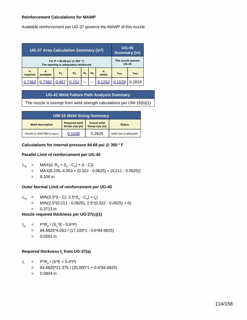
Reinforcement Calculations for MAWP
Available reinforcement per UG-37 governs the MAWP of this nozzle.
UG-37 Area Calculation Summary (in2) UG-45Summary (in)
For P = 84.68 psi @ 350 °FThe opening is adequately reinforced
The nozzle passesUG-45
Arequired
Aavailable A1 A2 A3 A5
Awelds treq tmin
0.7392 0.7392 0.467 0.152 -- -- 0.1202 0.1529 0.2818
UG-41 Weld Failure Path Analysis Summary
The nozzle is exempt from weld strength calculations per UW-15(b)(1)
UW-16 Weld Sizing Summary
Weld description Required weldthroat size (in)
Actual weldthroat size (in) Status
Nozzle to shell fillet (Leg41) 0.1039 0.2625 weld size is adequate
Calculations for internal pressure 84.68 psi @ 350 °F
Parallel Limit of reinforcement per UG-40
LR = MAX(d, Rn + (tn - Cn) + (t - C))= MAX(8.106, 4.053 + (0.322 - 0.0625) + (0.211 - 0.0625))= 8.106 in
Outer Normal Limit of reinforcement per UG-40
LH = MIN(2.5*(t - C), 2.5*(tn - Cn) + te)= MIN(2.5*(0.211 - 0.0625), 2.5*(0.322 - 0.0625) + 0)= 0.3713 in
Nozzle required thickness per UG-27(c)(1)
trn = P*Rn / (Sn*E - 0.6*P)= 84.6825*4.053 / (17,100*1 - 0.6*84.6825)= 0.0201 in
Required thickness tr from UG-37(a)
tr = P*Ro / (S*E + 0.4*P)= 84.6825*21.375 / (20,000*1 + 0.4*84.6825)= 0.0904 in
114/158

Required thickness tr per Interpretation VIII-1-07-50
tr = P*Ro / (S*E + 0.4*P)= 84.6825*21.375 / (20,000*0.85 + 0.4*84.6825)= 0.1063 in
Area required per UG-37(c)
Allowable stresses: Sn = 17,100, Sv = 20,000 psi
fr1 = lesser of 1 or Sn / Sv = 0.855
fr2 = lesser of 1 or Sn / Sv = 0.855
A = d*tr*F + 2*tn*tr*F*(1 - fr1)= 8.106*0.0904*1 + 2*0.2595*0.0904*1*(1 - 0.855)= 0.7392 in2
Area available from FIG. UG-37.1
A1 = larger of the following= 0.467 in2
= d*(E1*t - F*tr) - 2*tn*(E1*t - F*tr)*(1 - fr1)= 8.106*(1*0.1485 - 1*0.0904) - 2*0.2595*(1*0.1485 - 1*0.0904)*(1 - 0.855)= 0.467 in2
= 2*(t + tn)*(E1*t - F*tr) - 2*tn*(E1*t - F*tr)*(1 - fr1)= 2*(0.1485 + 0.2595)*(1*0.1485 - 1*0.0904) - 2*0.2595*(1*0.1485 - 1*0.0904)*(1 - 0.855)= 0.0431 in2
A2 = smaller of the following= 0.152 in2
= 5*(tn - trn)*fr2*t= 5*(0.2595 - 0.0201)*0.855*0.1485= 0.152 in2
= 5*(tn - trn)*fr2*tn= 5*(0.2595 - 0.0201)*0.855*0.2595= 0.2656 in2
A41 = Leg2*fr2= 0.3752*0.855= 0.1202 in2
(Part of the weld is outside of the limits)
Area = A1 + A2 + A41
115/158

= 0.467 + 0.152 + 0.1202= 0.7392 in2
As Area >= A the reinforcement is adequate.
UW-16(c) Weld Check
Fillet weld: tmin = lesser of 0.75 or tn or t = 0.1485 intc(min) = lesser of 0.25 or 0.7*tmin = 0.1039 intc(actual) = 0.7*Leg = 0.7*0.375 = 0.2625 in
The fillet weld size is satisfactory.
Weld strength calculations are not required for this detail which conforms to Fig. UW-16.1, sketch (c-e).
UG-45 Nozzle Neck Thickness Check
ta UG-27 = P*Rn / (Sn*E - 0.6*P) + Corrosion= 84.6825*4.053 / (17,100*1 - 0.6*84.6825) + 0.0625= 0.0826 in
ta = max[ ta UG-27 , ta UG-22 ]= max[ 0.0826 , 0 ]= 0.0826 in
tb1 = P*Ro / (S*E + 0.4*P) + Corrosion= 84.6825*21.375 / (20,000*1 + 0.4*84.6825) + 0.0625= 0.1529 in
tb1 = max[ tb1 , tb UG16 ]= max[ 0.1529 , 0.125 ]= 0.1529 in
tb = min[ tb3 , tb1 ]= min[ 0.3443 , 0.1529 ]= 0.1529 in
tUG-45 = max[ ta , tb ]= max[ 0.0826 , 0.1529 ]= 0.1529 in
Available nozzle wall thickness new, tn = 0.875*0.322 = 0.2818 in
The nozzle neck thickness is adequate.
116/158

Reinforcement Calculations for MAP
Available reinforcement per UG-37 governs the MAP of this nozzle.
UG-37 Area Calculation Summary (in2) UG-45Summary (in)
For P = 120.42 psi @ 70 °FThe opening is adequately reinforced
The nozzle passesUG-45
Arequired
Aavailable A1 A2 A3 A5
Awelds treq tmin
1.0367 1.0368 0.6516 0.265 -- -- 0.1202 0.1284 0.2818
UG-41 Weld Failure Path Analysis Summary
The nozzle is exempt from weld strength calculations per UW-15(b)(1)
UW-16 Weld Sizing Summary
Weld description Required weldthroat size (in)
Actual weldthroat size (in) Status
Nozzle to shell fillet (Leg41) 0.1477 0.2625 weld size is adequate
Calculations for internal pressure 120.42 psi @ 70 °F
Parallel Limit of reinforcement per UG-40
LR = MAX(d, Rn + (tn - Cn) + (t - C))= MAX(7.981, 3.9905 + (0.322 - 0) + (0.211 - 0))= 7.981 in
Outer Normal Limit of reinforcement per UG-40
LH = MIN(2.5*(t - C), 2.5*(tn - Cn) + te)= MIN(2.5*(0.211 - 0), 2.5*(0.322 - 0) + 0)= 0.5275 in
Nozzle required thickness per UG-27(c)(1)
trn = P*Rn / (Sn*E - 0.6*P)= 120.4183*3.9905 / (17,100*1 - 0.6*120.4183)= 0.0282 in
Required thickness tr from UG-37(a)
tr = P*Ro / (S*E + 0.4*P)= 120.4183*21.375 / (20,000*1 + 0.4*120.4183)= 0.1284 in
117/158
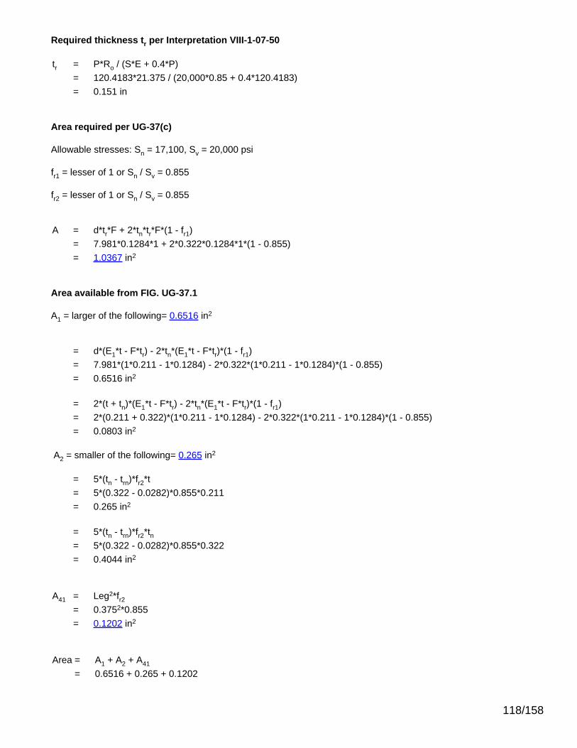
Required thickness tr per Interpretation VIII-1-07-50
tr = P*Ro / (S*E + 0.4*P)= 120.4183*21.375 / (20,000*0.85 + 0.4*120.4183)= 0.151 in
Area required per UG-37(c)
Allowable stresses: Sn = 17,100, Sv = 20,000 psi
fr1 = lesser of 1 or Sn / Sv = 0.855
fr2 = lesser of 1 or Sn / Sv = 0.855
A = d*tr*F + 2*tn*tr*F*(1 - fr1)= 7.981*0.1284*1 + 2*0.322*0.1284*1*(1 - 0.855)= 1.0367 in2
Area available from FIG. UG-37.1
A1 = larger of the following= 0.6516 in2
= d*(E1*t - F*tr) - 2*tn*(E1*t - F*tr)*(1 - fr1)= 7.981*(1*0.211 - 1*0.1284) - 2*0.322*(1*0.211 - 1*0.1284)*(1 - 0.855)= 0.6516 in2
= 2*(t + tn)*(E1*t - F*tr) - 2*tn*(E1*t - F*tr)*(1 - fr1)= 2*(0.211 + 0.322)*(1*0.211 - 1*0.1284) - 2*0.322*(1*0.211 - 1*0.1284)*(1 - 0.855)= 0.0803 in2
A2 = smaller of the following= 0.265 in2
= 5*(tn - trn)*fr2*t= 5*(0.322 - 0.0282)*0.855*0.211= 0.265 in2
= 5*(tn - trn)*fr2*tn= 5*(0.322 - 0.0282)*0.855*0.322= 0.4044 in2
A41 = Leg2*fr2= 0.3752*0.855= 0.1202 in2
Area = A1 + A2 + A41
= 0.6516 + 0.265 + 0.1202
118/158

= 1.0368 in2
As Area >= A the reinforcement is adequate.
UW-16(c) Weld Check
Fillet weld: tmin = lesser of 0.75 or tn or t = 0.211 intc(min) = lesser of 0.25 or 0.7*tmin = 0.1477 intc(actual) = 0.7*Leg = 0.7*0.375 = 0.2625 in
The fillet weld size is satisfactory.
Weld strength calculations are not required for this detail which conforms to Fig. UW-16.1, sketch (c-e).
UG-45 Nozzle Neck Thickness Check
ta UG-27 = P*Rn / (Sn*E - 0.6*P) + Corrosion= 120.4183*3.9905 / (17,100*1 - 0.6*120.4183) + 0= 0.0282 in
ta = max[ ta UG-27 , ta UG-22 ]= max[ 0.0282 , 0 ]= 0.0282 in
tb1 = P*Ro / (S*E + 0.4*P) + Corrosion= 120.4183*21.375 / (20,000*1 + 0.4*120.4183) + 0= 0.1284 in
tb1 = max[ tb1 , tb UG16 ]= max[ 0.1284 , 0.0625 ]= 0.1284 in
tb = min[ tb3 , tb1 ]= min[ 0.2818 , 0.1284 ]= 0.1284 in
tUG-45 = max[ ta , tb ]= max[ 0.0282 , 0.1284 ]= 0.1284 in
Available nozzle wall thickness new, tn = 0.875*0.322 = 0.2818 in
The nozzle neck thickness is adequate.
119/158

Straight Flange on Ellipsoidal Head #3
ASME Section VIII Division 1, 2010 Edition, A11 Addenda
Component Cylinder
Material SA-516 70 (II-D p. 18, ln. 19)
ImpactTested Normalized Fine Grain
Practice PWHT Optimize MDMT/Find MAWP
No No No No No
DesignPressure (psi)
DesignTemperature (°F)
DesignMDMT (°F)
Internal 50 350 -20
Static Liquid Head
Condition Ps (psi) Hs (in) SG
Test horizontal 1.51 41.953 1
Dimensions
Outer Diameter 42.75"
Length 2"
Nominal Thickness 0.211"
Corrosion Inner 0.0625"
Outer 0"
Weight and Capacity
Weight (lb) Capacity (US gal)
New 15.96 12.18
Corroded 11.25 12.26
Insulation
Thickness (in) Density (lb/ft3) Weight (lb)
Insulation 2 15 0
Spacing(in) Individual Weight (lb) Total Weight (lb)
InsulationSupports 0 0 0
Radiography
Longitudinal seam Seamless No RT
Top Circumferentialseam Spot UW-11(b) Type 1
120/158

Results Summary
Governing condition Internal pressure
Minimum thickness per UG-16 0.0625" + 0.0625" = 0.125"
Design thickness due to internal pressure (t) 0.1253"
Design thickness due to combined loadings + corrosion 0.1142"
Maximum allowable working pressure (MAWP) 118.43 psi
Maximum allowable pressure (MAP) 168.48 psi
Rated MDMT -55 °F
UCS-66 Material Toughness Requirements
Governing thickness, tg = 0.211"
Exemption temperature from Fig UCS-66 Curve B = -20°F
tr = 73.38*21.375 / (20,000*0.85 + 0.4*73.38) = 0.0921"
Stress ratio = tr*E* / (tn - c) = 0.0921*0.85 / (0.211 - 0.0625) = 0.5272
Reduction in MDMT, TR from Fig UCS-66.1 = 52.6°F
MDMT = max[ MDMT - TR, -55] = max[ -20 - 52.6 , -55] = -55°F
Material is exempt from impact testing at the Design MDMT of -20°F.
Design thickness, (at 350 °F) Appendix 1-1
t = P*Ro / (S*E + 0.40*P) + Corrosion= 50*21.375 / (20,000*0.85 + 0.40*50) + 0.0625= 0.1253"
Maximum allowable working pressure, (at 350 °F) Appendix 1-1
P = S*E*t / (Ro - 0.40*t) - Ps= 20,000*0.85*0.1485 / (21.375 - 0.40*0.1485) - 0= 118.43 psi
Maximum allowable pressure, (at 70 °F) Appendix 1-1
P = S*E*t / (Ro - 0.40*t)= 20,000*0.85*0.211 / (21.375 - 0.40*0.211)= 168.48 psi
% Extreme fiber elongation - UCS-79(d)
EFE = (50*t / Rf)*(1 - Rf / Ro)= (50*0.211 / 21.2695)*(1 - 21.2695 / ∞)= 0.496%
The extreme fiber elongation does not exceed 5%.
121/158
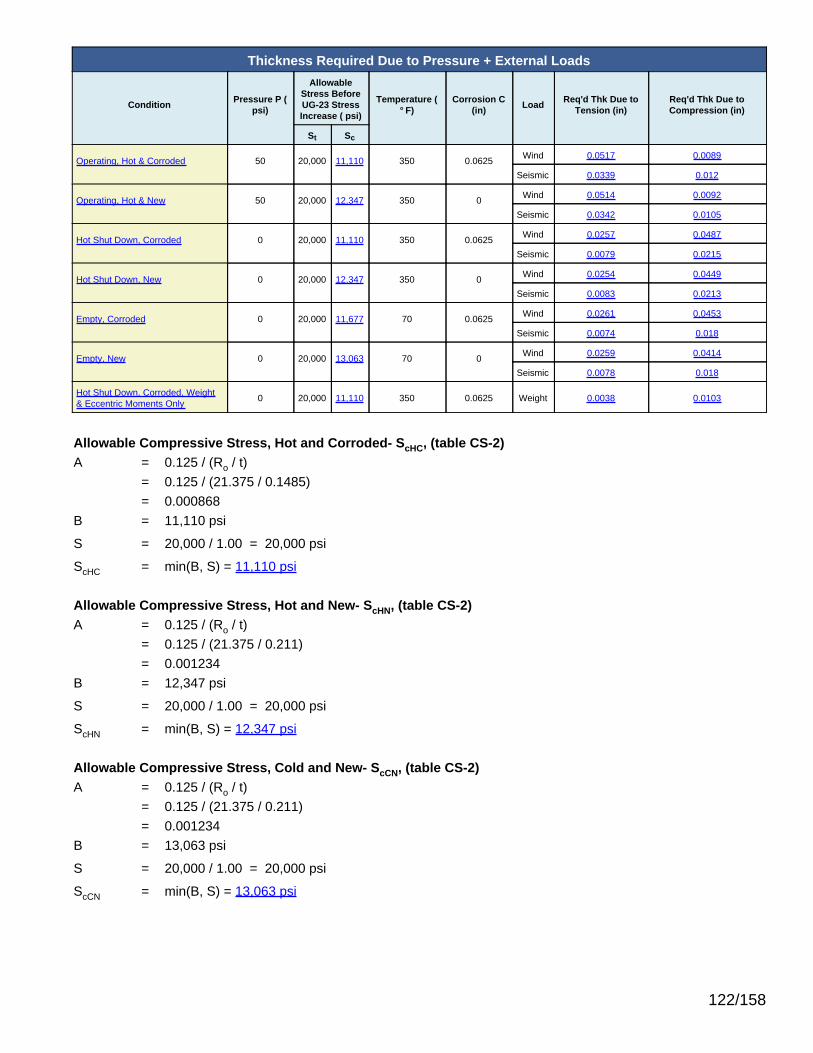
Thickness Required Due to Pressure + External Loads
Condition Pressure P (psi)
AllowableStress BeforeUG-23 StressIncrease ( psi)
Temperature (°F)
Corrosion C(in) Load Req'd Thk Due to
Tension (in)Req'd Thk Due toCompression (in)
St Sc
Operating, Hot & Corroded 50 20,000 11,110 350 0.0625 Wind 0.0517 0.0089
Seismic 0.0339 0.012
Operating, Hot & New 50 20,000 12,347 350 0 Wind 0.0514 0.0092
Seismic 0.0342 0.0105
Hot Shut Down, Corroded 0 20,000 11,110 350 0.0625 Wind 0.0257 0.0487
Seismic 0.0079 0.0215
Hot Shut Down, New 0 20,000 12,347 350 0 Wind 0.0254 0.0449
Seismic 0.0083 0.0213
Empty, Corroded 0 20,000 11,677 70 0.0625 Wind 0.0261 0.0453
Seismic 0.0074 0.018
Empty, New 0 20,000 13,063 70 0 Wind 0.0259 0.0414
Seismic 0.0078 0.018
Hot Shut Down, Corroded, Weight& Eccentric Moments Only 0 20,000 11,110 350 0.0625 Weight 0.0038 0.0103
Allowable Compressive Stress, Hot and Corroded- ScHC, (table CS-2)A = 0.125 / (Ro / t)
= 0.125 / (21.375 / 0.1485)= 0.000868
B = 11,110 psi
S = 20,000 / 1.00 = 20,000 psi
ScHC = min(B, S) = 11,110 psi
Allowable Compressive Stress, Hot and New- ScHN, (table CS-2)A = 0.125 / (Ro / t)
= 0.125 / (21.375 / 0.211)= 0.001234
B = 12,347 psi
S = 20,000 / 1.00 = 20,000 psi
ScHN = min(B, S) = 12,347 psi
Allowable Compressive Stress, Cold and New- ScCN, (table CS-2)A = 0.125 / (Ro / t)
= 0.125 / (21.375 / 0.211)= 0.001234
B = 13,063 psi
S = 20,000 / 1.00 = 20,000 psi
ScCN = min(B, S) = 13,063 psi
122/158

Allowable Compressive Stress, Cold and Corroded- ScCC, (table CS-2)A = 0.125 / (Ro / t)
= 0.125 / (21.375 / 0.1485)= 0.000868
B = 11,677 psi
S = 20,000 / 1.00 = 20,000 psi
ScCC = min(B, S) = 11,677 psi
Allowable Compressive Stress, Vacuum and Corroded- ScVC, (tableCS-2)A = 0.125 / (Ro / t)
= 0.125 / (21.375 / 0.1485)= 0.000868
B = 11,110 psi
S = 20,000 / 1.00 = 20,000 psi
ScVC = min(B, S) = 11,110 psi
Operating, Hot & Corroded, Wind, Bottom Seam
tp = P*R / (2*St*Ks*Ec + 0.40*|P|) (Pressure)= 50*21.2265 / (2*20,000*1.20*0.85 + 0.40*|50|)= 0.026"
tm = M / (π*Rm2*St*Ks*Ec) (bending)
= 814,094 / (π*21.30082*20,000*1.20*0.85)= 0.028"
tw = 0.6*W / (2*π*Rm*St*Ks*Ec) (Weight)= 0.60*10,484.4 / (2*π*21.3008*20,000*1.20*0.85)= 0.0023"
tt = tp + tm - tw (total required, tensile)= 0.026 + 0.028 - (0.0023)= 0.0517"
tpc = P*R / (2*Sc*Ks + 0.40*|P|) (Pressure)= 50*21.2265 / (2*11,109.56*1.20 + 0.40*|50|)= 0.0398"
tmc = M / (π*Rm2*Sc*Ks) (bending)
= 814,094 / (π*21.30082*11,109.56*1.20)= 0.0428"
twc = W / (2*π*Rm*Sc*Ks) (Weight)= 10,484.4 / (2*π*21.3008*11,109.56*1.20)= 0.0059"
tc = tmc + twc - tpc (total required, compressive)= 0.0428 + (0.0059) - (0.0398)= 0.0089"
123/158

Maximum allowable working pressure, Longitudinal Stress
P = 2*St*Ks*Ec*(t - tm + tw) / (R - 0.40*(t - tm + tw))= 2*20,000*1.20*0.85*(0.1485 - 0.028 + (0.0023)) / (21.2265 - 0.40*(0.1485 - 0.028 + (0.0023)))= 236.6 psi
Operating, Hot & New, Wind, Bottom Seam
tp = P*R / (2*St*Ks*Ec + 0.40*|P|) (Pressure)= 50*21.164 / (2*20,000*1.20*0.85 + 0.40*|50|)= 0.0259"
tm = M / (π*Rm2*St*Ks*Ec) (bending)
= 815,038 / (π*21.26952*20,000*1.20*0.85)= 0.0281"
tw = 0.6*W / (2*π*Rm*St*Ks*Ec) (Weight)= 0.60*12,179.4 / (2*π*21.2695*20,000*1.20*0.85)= 0.0027"
tt = tp + tm - tw (total required, tensile)= 0.0259 + 0.0281 - (0.0027)= 0.0514"
tpc = P*R / (2*Sc*Ks + 0.40*|P|) (Pressure)= 50*21.164 / (2*12,347.29*1.20 + 0.40*|50|)= 0.0357"
tmc = M / (π*Rm2*Sc*Ks) (bending)
= 815,038 / (π*21.26952*12,347.29*1.20)= 0.0387"
twc = W / (2*π*Rm*Sc*Ks) (Weight)= 12,179.4 / (2*π*21.2695*12,347.29*1.20)= 0.0062"
tc = tmc + twc - tpc (total required, compressive)= 0.0387 + (0.0062) - (0.0357)= 0.0092"
Maximum allowable working pressure, Longitudinal Stress
P = 2*St*Ks*Ec*(t - tm + tw) / (R - 0.40*(t - tm + tw))= 2*20,000*1.20*0.85*(0.211 - 0.0281 + (0.0027)) / (21.164 - 0.40*(0.211 - 0.0281 + (0.0027)))= 359 psi
Hot Shut Down, Corroded, Wind, Bottom Seam
tp = 0" (Pressure)tm = M / (π*Rm
2*St*Ks*Ec) (bending)= 814,094 / (π*21.30082*20,000*1.20*0.85)= 0.028"
tw = 0.6*W / (2*π*Rm*St*Ks*Ec) (Weight)= 0.60*10,484.4 / (2*π*21.3008*20,000*1.20*0.85)= 0.0023"
124/158

tt = tp + tm - tw (total required, tensile)= 0 + 0.028 - (0.0023)= 0.0257"
tmc = M / (π*Rm2*Sc*Ks) (bending)
= 814,094 / (π*21.30082*11,109.56*1.20)= 0.0428"
twc = W / (2*π*Rm*Sc*Ks) (Weight)= 10,484.4 / (2*π*21.3008*11,109.56*1.20)= 0.0059"
tc = tmc + twc - tpc (total required, compressive)= 0.0428 + (0.0059) - (0)= 0.0487"
Hot Shut Down, New, Wind, Bottom Seam
tp = 0" (Pressure)tm = M / (π*Rm
2*St*Ks*Ec) (bending)= 815,038 / (π*21.26952*20,000*1.20*0.85)= 0.0281"
tw = 0.6*W / (2*π*Rm*St*Ks*Ec) (Weight)= 0.60*12,179.4 / (2*π*21.2695*20,000*1.20*0.85)= 0.0027"
tt = tp + tm - tw (total required, tensile)= 0 + 0.0281 - (0.0027)= 0.0254"
tmc = M / (π*Rm2*Sc*Ks) (bending)
= 815,038 / (π*21.26952*12,347.29*1.20)= 0.0387"
twc = W / (2*π*Rm*Sc*Ks) (Weight)= 12,179.4 / (2*π*21.2695*12,347.29*1.20)= 0.0062"
tc = tmc + twc - tpc (total required, compressive)= 0.0387 + (0.0062) - (0)= 0.0449"
Empty, Corroded, Wind, Bottom Seam
tp = 0" (Pressure)tm = M / (π*Rm
2*St*Ks*Ec) (bending)= 814,094 / (π*21.30082*20,000*1.20*0.85)= 0.028"
tw = 0.6*W / (2*π*Rm*St*Ks*Ec) (Weight)= 0.60*8,484 / (2*π*21.3008*20,000*1.20*0.85)= 0.0019"
tt = tp + tm - tw (total required, tensile)= 0 + 0.028 - (0.0019)
125/158

= 0.0261"
tmc = M / (π*Rm2*Sc*Ks) (bending)
= 814,094 / (π*21.30082*11,677.24*1.20)= 0.0408"
twc = W / (2*π*Rm*Sc*Ks) (Weight)= 8,484 / (2*π*21.3008*11,677.24*1.20)= 0.0045"
tc = tmc + twc - tpc (total required, compressive)= 0.0408 + (0.0045) - (0)= 0.0453"
Empty, New, Wind, Bottom Seam
tp = 0" (Pressure)tm = M / (π*Rm
2*St*Ks*Ec) (bending)= 815,038 / (π*21.26952*20,000*1.20*0.85)= 0.0281"
tw = 0.6*W / (2*π*Rm*St*Ks*Ec) (Weight)= 0.60*10,179 / (2*π*21.2695*20,000*1.20*0.85)= 0.0022"
tt = tp + tm - tw (total required, tensile)= 0 + 0.0281 - (0.0022)= 0.0259"
tmc = M / (π*Rm2*Sc*Ks) (bending)
= 815,038 / (π*21.26952*13,062.94*1.20)= 0.0366"
twc = W / (2*π*Rm*Sc*Ks) (Weight)= 10,179 / (2*π*21.2695*13,062.94*1.20)= 0.0049"
tc = tmc + twc - tpc (total required, compressive)= 0.0366 + (0.0049) - (0)= 0.0414"
Hot Shut Down, Corroded, Weight & Eccentric Moments Only, Bottom Seam
tp = 0" (Pressure)tm = M / (π*Rm
2*Sc*Ks) (bending)= 51,249 / (π*21.30082*11,109.56*1.00)= 0.0032"
tw = W / (2*π*Rm*Sc*Ks) (Weight)= 10,484.4 / (2*π*21.3008*11,109.56*1.00)= 0.0071"
tt = |tp + tm - tw| (total, net compressive)= |0 + 0.0032 - (0.0071)|= 0.0038"
tc = tmc + twc - tpc (total required, compressive)
126/158

= 0.0032 + (0.0071) - (0)= 0.0103"
Operating, Hot & Corroded, Seismic, Bottom Seam
tp = P*R / (2*St*Ks*Ec + 0.40*|P|) (Pressure)= 50*21.2265 / (2*20,000*1.20*0.85 + 0.40*|50|)= 0.026"
tm = M / (π*Rm2*St*Ks*Ec) (bending)
= 295,168 / (π*21.30082*20,000*1.20*0.85)= 0.0102"
tw = (0.6 - 0.14*SDS)*W / (2*π*Rm*St*Ks*Ec) (Weight)= 0.59*10,484.4 / (2*π*21.3008*20,000*1.20*0.85)= 0.0023"
tt = tp + tm - tw (total required, tensile)= 0.026 + 0.0102 - (0.0023)= 0.0339"
twc = (1 + 0.14*SDS)*W / (2*π*Rm*St*Ks*Ec) (Weight)= 1.01*10,484.4 / (2*π*21.3008*20,000*1.20*0.85)= 0.0039"
tc = |tmc + twc - tpc| (total, net tensile)= |0.0102 + (0.0039) - (0.026)|= 0.012"
Maximum allowable working pressure, Longitudinal Stress
P = 2*St*Ks*Ec*(t - tm + tw) / (R - 0.40*(t - tm + tw))= 2*20,000*1.20*0.85*(0.1485 - 0.0102 + (0.0023)) / (21.2265 - 0.40*(0.1485 - 0.0102 + (0.0023)))= 270.98 psi
Operating, Hot & New, Seismic, Bottom Seam
tp = P*R / (2*St*Ks*Ec + 0.40*|P|) (Pressure)= 50*21.164 / (2*20,000*1.20*0.85 + 0.40*|50|)= 0.0259"
tm = M / (π*Rm2*St*Ks*Ec) (bending)
= 317,488 / (π*21.26952*20,000*1.20*0.85)= 0.011"
tw = (0.6 - 0.14*SDS)*W / (2*π*Rm*St*Ks*Ec) (Weight)= 0.59*12,179.4 / (2*π*21.2695*20,000*1.20*0.85)= 0.0026"
tt = tp + tm - tw (total required, tensile)= 0.0259 + 0.011 - (0.0026)= 0.0342"
twc = (1 + 0.14*SDS)*W / (2*π*Rm*St*Ks*Ec) (Weight)= 1.01*12,179.4 / (2*π*21.2695*20,000*1.20*0.85)= 0.0045"
127/158

tc = |tmc + twc - tpc| (total, net tensile)= |0.011 + (0.0045) - (0.0259)|= 0.0105"
Maximum allowable working pressure, Longitudinal Stress
P = 2*St*Ks*Ec*(t - tm + tw) / (R - 0.40*(t - tm + tw))= 2*20,000*1.20*0.85*(0.211 - 0.011 + (0.0026)) / (21.164 - 0.40*(0.211 - 0.011 + (0.0026)))= 392.22 psi
Hot Shut Down, Corroded, Seismic, Bottom Seam
tp = 0" (Pressure)tm = M / (π*Rm
2*St*Ks*Ec) (bending)= 295,168 / (π*21.30082*20,000*1.20*0.85)= 0.0102"
tw = (0.6 - 0.14*SDS)*W / (2*π*Rm*St*Ks*Ec) (Weight)= 0.59*10,484.4 / (2*π*21.3008*20,000*1.20*0.85)= 0.0023"
tt = tp + tm - tw (total required, tensile)= 0 + 0.0102 - (0.0023)= 0.0079"
tmc = M / (π*Rm2*Sc*Ks) (bending)
= 295,168 / (π*21.30082*11,109.56*1.20)= 0.0155"
twc = (1 + 0.14*SDS)*W / (2*π*Rm*Sc*Ks) (Weight)= 1.01*10,484.4 / (2*π*21.3008*11,109.56*1.20)= 0.0059"
tc = tmc + twc - tpc (total required, compressive)= 0.0155 + (0.0059) - (0)= 0.0215"
Hot Shut Down, New, Seismic, Bottom Seam
tp = 0" (Pressure)tm = M / (π*Rm
2*St*Ks*Ec) (bending)= 317,488 / (π*21.26952*20,000*1.20*0.85)= 0.011"
tw = (0.6 - 0.14*SDS)*W / (2*π*Rm*St*Ks*Ec) (Weight)= 0.59*12,179.4 / (2*π*21.2695*20,000*1.20*0.85)= 0.0026"
tt = tp + tm - tw (total required, tensile)= 0 + 0.011 - (0.0026)= 0.0083"
tmc = M / (π*Rm2*Sc*Ks) (bending)
= 317,488 / (π*21.26952*12,347.29*1.20)= 0.0151"
128/158

twc = (1 + 0.14*SDS)*W / (2*π*Rm*Sc*Ks) (Weight)= 1.01*12,179.4 / (2*π*21.2695*12,347.29*1.20)= 0.0062"
tc = tmc + twc - tpc (total required, compressive)= 0.0151 + (0.0062) - (0)= 0.0213"
Empty, Corroded, Seismic, Bottom Seam
tp = 0" (Pressure)tm = M / (π*Rm
2*St*Ks*Ec) (bending)= 268,702 / (π*21.30082*20,000*1.20*0.85)= 0.0092"
tw = (0.6 - 0.14*SDS)*W / (2*π*Rm*St*Ks*Ec) (Weight)= 0.59*8,484 / (2*π*21.3008*20,000*1.20*0.85)= 0.0018"
tt = tp + tm - tw (total required, tensile)= 0 + 0.0092 - (0.0018)= 0.0074"
tmc = M / (π*Rm2*Sc*Ks) (bending)
= 268,702 / (π*21.30082*11,677.24*1.20)= 0.0135"
twc = (1 + 0.14*SDS)*W / (2*π*Rm*Sc*Ks) (Weight)= 1.01*8,484 / (2*π*21.3008*11,677.24*1.20)= 0.0046"
tc = tmc + twc - tpc (total required, compressive)= 0.0135 + (0.0046) - (0)= 0.018"
Empty, New, Seismic, Bottom Seam
tp = 0" (Pressure)tm = M / (π*Rm
2*St*Ks*Ec) (bending)= 291,058 / (π*21.26952*20,000*1.20*0.85)= 0.01"
tw = (0.6 - 0.14*SDS)*W / (2*π*Rm*St*Ks*Ec) (Weight)= 0.59*10,179 / (2*π*21.2695*20,000*1.20*0.85)= 0.0022"
tt = tp + tm - tw (total required, tensile)= 0 + 0.01 - (0.0022)= 0.0078"
tmc = M / (π*Rm2*Sc*Ks) (bending)
= 291,058 / (π*21.26952*13,062.94*1.20)= 0.0131"
twc = (1 + 0.14*SDS)*W / (2*π*Rm*Sc*Ks) (Weight)= 1.01*10,179 / (2*π*21.2695*13,062.94*1.20)
129/158

= 0.0049"
tc = tmc + twc - tpc (total required, compressive)= 0.0131 + (0.0049) - (0)= 0.018"
130/158

Ellipsoidal Head #3
ASME Section VIII Division 1, 2010 Edition, A11 Addenda
Component Ellipsoidal Head
Material SA-516 70 (II-D p. 18, ln. 19)
Attached To Cylinder #2
ImpactTested Normalized Fine Grain
Practice PWHT Optimize MDMT/Find MAWP
No No No No No
DesignPressure (psi)
DesignTemperature (°F)
DesignMDMT (°F)
Internal 50 350 -20
Static Liquid Head
Condition Ps (psi) Hs (in) SG
Test horizontal 1.51 41.953 1
Dimensions
Outer Diameter 42.75"
Head Ratio 2
Minimum Thickness 0.211"
Corrosion Inner 0.0625"
Outer 0"
Length Lsf 2"
Nominal Thickness tsf 0.211"
Weight and Capacity
Weight (lb)1 Capacity (US gal)1
New 140.74 55.16
Corroded 99.39 55.74
Insulation
Thickness (in) Density (lb/ft3) Weight (lb)
Insulation 2 15 42.31
Spacing(in) Individual Weight (lb) Total Weight (lb)
InsulationSupports 132 813 813
Radiography
Category A joints Seamless No RT
Head to shell seam Spot UW-11(b) Type 1
131/158

1 includes straight flange
Results Summary
Governing condition UG-16
Minimum thickness per UG-16 0.0625" + 0.0625" = 0.125"
Design thickness due to internal pressure (t) 0.125"
Maximum allowable working pressure (MAWP) 119.31 psi
Maximum allowable pressure (MAP) 169.32 psi
Straight Flange governs MDMT -55°F
Factor K
K = (1/6)*[2 + (D / (2*h))2]
Corroded K = (1/6)*[2 + (42.453 / (2*10.6445))2] 0.9961
New K = (1/6)*[2 + (42.328 / (2*10.582))2] 1
Design thickness for internal pressure, (Corroded at 350 °F) Appendix 1-4(c)
t = P*Do*K / (2*S*E + 2*P*(K - 0.1)) + Corrosion= 50*42.75*0.996091 / (2*20,000*0.85 + 2*50*(0.996091 - 0.1)) + 0.0625= 0.125"
Maximum allowable working pressure, (Corroded at 350 °F) Appendix 1-4(c)
P = 2*S*E*t / (K*Do - 2*t*(K - 0.1)) - Ps= 2*20,000*0.85*0.1485 / (0.996091*42.75 - 2*0.1485*(0.996091 - 0.1)) - 0= 119.31 psi
Maximum allowable pressure, (New at 70 °F) Appendix 1-4(c)
P = 2*S*E*t / (K*Do - 2*t*(K - 0.1)) - Ps= 2*20,000*0.85*0.211 / (1*42.75 - 2*0.211*(1 - 0.1)) - 0= 169.32 psi
% Extreme fiber elongation - UCS-79(d)
EFE = (75*t / Rf)*(1 - Rf / Ro)= (75*0.211 / 7.3013)*(1 - 7.3013 / ∞)= 2.1674%
The extreme fiber elongation does not exceed 5%.
132/158

Support Skirt #1
ASME Section VIII Division 1, 2010 Edition, A11 Addenda
Component Support Skirt
Skirt is Attached To Ellipsoidal Head #3
Skirt Attachment Offset 4.0032" down from the top seam
Material
SA-516 70 (II-D p. 18, ln. 19)
ImpactTested1 Normalized Fine Grain
Practice
No No No
Design Temperature
Internal 650°F
External 650°F
Dimensions
Inner Diameter Top 42"
Botttom 42"
Length (includes base ringthickness) 56"
Nominal Thickness 0.375"
Corrosion Inner 0"
Outer 0"
Weight
New 777.03 lb
Corroded 777.03 lb
Joint Efficiency
Top 0.55
Bottom 0.81Impact testing requirements are not checked for supports
Skirt design thickness, largest of the following + corrosion = 0.0816 in
The governing condition is due to wind, compressive stress at the base, operating & new.
The skirt thickness of 0.375 in is adequate.
133/158

Results Summary
Loading ConditionTensile or
CompressiveSide
GoverningSkirt
Location
Temperature(°F)
AllowableStress(psi)
CalculatedStress/E
(psi)
Requiredthickness
(in)
Wind
operating, corroded Tensile top 650 18,800 2,458.32 0.049
Compressive bottom 9,966.68 2,131.64 0.0802
operating, new Tensile top 650 18,800 2,423.69 0.0483
Compressive bottom 9,966.68 2,168.15 0.0816
empty, corroded Tensile top 70 20,000 2,502.03 0.0469
Compressive bottom 15,264.57 2,091.57 0.0514
empty, new Tensile top 70 20,000 2,467.4 0.0463
Compressive bottom 15,264.57 2,128.08 0.0523
Seismic
operating, corroded Tensile top 650 18,800 670.11 0.0134
Compressive bottom 9,966.68 962.61 0.0362
operating, new Tensile top 650 18,800 710.09 0.0142
Compressive bottom 9,966.68 1,045.76 0.0393
empty, corroded Tensile top 70 20,000 621.52 0.0117
Compressive bottom 15,264.57 865.28 0.0213
empty, new Tensile top 70 20,000 661.62 0.0124
Compressive bottom 15,264.57 948.5 0.0233
Loading due to wind, operating & corroded
Windward side (tensile)
Required thickness, tensile stress at base:
t = -0.6*W / (π*D*St*E) + 48*M / (π*D2*St*E)
= -0.6*17,045.03 / (π*42.375*18,800*0.8) + 48*78,897.5 /(π*42.3752*18,800*0.8)
= 0.0395 in
Required thickness, tensile stress at the top:
t = -0.6*Wt / (π*Dt*St*E) + 48*Mt / (π*Dt2*St*E)
= -0.6*16,268 / (π*42.375*18,800*0.55) + 48*68,205.1 / (π*42.3752*18,800*0.55)= 0.049 in
Leeward side (compressive)
Required thickness, compressive stress at base:
t = W / (π*D*Sc*Ec) + 48*M / (π*D2*Sc*Ec)= 17,045.03 / (π*42.375*9,967*1) + 48*78,897.5 / (π*42.3752*9,967*1)= 0.0802 in
134/158

Required thickness, compressive stress at the top:
t = Wt / (π*Dt*Sc*Ec) + 48*Mt / (π*Dt2*Sc*Ec)
= 16,268 / (π*42.375*9,967*1) + 48*68,205.1 / (π*42.3752*9,967*1)= 0.0705 in
Loading due to wind, operating & new
Windward side (tensile)
Required thickness, tensile stress at base:
t = -0.6*W / (π*D*St*E) + 48*M / (π*D2*St*E)
= -0.6*18,778.28 / (π*42.375*18,800*0.8) + 48*78,976.1 /(π*42.3752*18,800*0.8)
= 0.0391 in
Required thickness, tensile stress at the top:
t = -0.6*Wt / (π*Dt*St*E) + 48*Mt / (π*Dt2*St*E)
= -0.6*18,001.25 / (π*42.375*18,800*0.55) + 48*68,283.8 / (π*42.3752*18,800*0.55)= 0.0483 in
Leeward side (compressive)
Required thickness, compressive stress at base:
t = W / (π*D*Sc*Ec) + 48*M / (π*D2*Sc*Ec)= 18,778.28 / (π*42.375*9,967*1) + 48*78,976.1 / (π*42.3752*9,967*1)= 0.0816 in
Required thickness, compressive stress at the top:
t = Wt / (π*Dt*Sc*Ec) + 48*Mt / (π*Dt2*Sc*Ec)
= 18,001.25 / (π*42.375*9,967*1) + 48*68,283.8 / (π*42.3752*9,967*1)= 0.0719 in
Loading due to wind, empty & corroded
Windward side (tensile)
Required thickness, tensile stress at base:
t = -0.6*W / (π*D*St*E) + 48*M / (π*D2*St*E)
= -0.6*15,044.62 / (π*42.375*20,000*0.8) + 48*78,897.5 /(π*42.3752*20,000*0.8)
= 0.0377 in
135/158

Required thickness, tensile stress at the top:
t = -0.6*Wt / (π*Dt*St*E) + 48*Mt / (π*Dt2*St*E)
= -0.6*14,267.58 / (π*42.375*20,000*0.55) + 48*68,205.1 / (π*42.3752*20,000*0.55)= 0.0469 in
Leeward side (compressive)
Required thickness, compressive stress at base:
t = W / (π*D*Sc*Ec) + 48*M / (π*D2*Sc*Ec)= 15,044.62 / (π*42.375*15,265*1) + 48*78,897.5 / (π*42.3752*15,265*1)= 0.0514 in
Required thickness, compressive stress at the top:
t = Wt / (π*Dt*Sc*Ec) + 48*Mt / (π*Dt2*Sc*Ec)
= 14,267.58 / (π*42.375*15,265*1) + 48*68,205.1 / (π*42.3752*15,265*1)= 0.045 in
Loading due to wind, empty & new
Windward side (tensile)
Required thickness, tensile stress at base:
t = -0.6*W / (π*D*St*E) + 48*M / (π*D2*St*E)
= -0.6*16,777.86 / (π*42.375*20,000*0.8) + 48*78,976.1 /(π*42.3752*20,000*0.8)
= 0.0373 in
Required thickness, tensile stress at the top:
t = -0.6*Wt / (π*Dt*St*E) + 48*Mt / (π*Dt2*St*E)
= -0.6*16,000.83 / (π*42.375*20,000*0.55) + 48*68,283.8 / (π*42.3752*20,000*0.55)= 0.0463 in
Leeward side (compressive)
Required thickness, compressive stress at base:
t = W / (π*D*Sc*Ec) + 48*M / (π*D2*Sc*Ec)= 16,777.86 / (π*42.375*15,265*1) + 48*78,976.1 / (π*42.3752*15,265*1)= 0.0523 in
Required thickness, compressive stress at the top:
t = Wt / (π*Dt*Sc*Ec) + 48*Mt / (π*Dt2*Sc*Ec)
= 16,000.83 / (π*42.375*15,265*1) + 48*68,283.8 / (π*42.3752*15,265*1)= 0.0459 in
136/158

Loading due to seismic, operating & corroded
Tensile side
Required thickness, tensile stress at base:
t = -(0.6 - 0.14*SDS)*W / (π*D*St*E) + 48*M / (π*D2*St*E)= -(0.6 - 0.14*0.0875)*17,045.03 / (π*42.375*18,800*0.8) + 48*27,191.9 / (π*42.3752*18,800*0.8)= 0.0104 in
Required thickness, tensile stress at the top:
t = -(0.6 - 0.14*SDS)*Wt / (π*Dt*St*E) + 48*Mt / (π*Dt2*St*E)
= -(0.6 - 0.14*0.0875)*16,268 / (π*42.375*18,800*0.55) + 48*24,684.1 / (π*42.3752*18,800*0.55)= 0.0134 in
Compressive side
Required thickness, compressive stress at base:
t = (1 + 0.14*SDS)*W / (π*D*Sc*Ec) + 48*M / (π*D2*Sc*Ec)
= (1 + 0.14*0.0875)*17,045.03 / (π*42.375*9,967*1) + 48*27,191.9 /(π*42.3752*9,967*1)
= 0.0362 in
Required thickness, compressive stress at the top:
t = (1 + 0.14*SDS)*Wt / (π*Dt*Sc*Ec) + 48*Mt / (π*Dt2*Sc*Ec)
= (1 + 0.14*0.0875)*16,268 / (π*42.375*9,967*1) + 48*24,684.1 /(π*42.3752*9,967*1)
= 0.0335 in
Loading due to seismic, operating & new
Tensile side
Required thickness, tensile stress at base:
t = -(0.6 - 0.14*SDS)*W / (π*D*St*E) + 48*M / (π*D2*St*E)= -(0.6 - 0.14*0.0875)*18,778.28 / (π*42.375*18,800*0.8) + 48*29,307.8 / (π*42.3752*18,800*0.8)= 0.0111 in
Required thickness, tensile stress at the top:
t = -(0.6 - 0.14*SDS)*Wt / (π*Dt*St*E) + 48*Mt / (π*Dt2*St*E)
= -(0.6 - 0.14*0.0875)*18,001.25 / (π*42.375*18,800*0.55) + 48*26,552.6 / (π*42.3752*18,800*0.55)= 0.0142 in
137/158

Compressive side
Required thickness, compressive stress at base:
t = (1 + 0.14*SDS)*W / (π*D*Sc*Ec) + 48*M / (π*D2*Sc*Ec)
= (1 + 0.14*0.0875)*18,778.28 / (π*42.375*9,967*1) + 48*29,307.8 /(π*42.3752*9,967*1)
= 0.0393 in
Required thickness, compressive stress at the top:
t = (1 + 0.14*SDS)*Wt / (π*Dt*Sc*Ec) + 48*Mt / (π*Dt2*Sc*Ec)
= (1 + 0.14*0.0875)*18,001.25 / (π*42.375*9,967*1) + 48*26,552.6 /(π*42.3752*9,967*1)
= 0.0364 in
Loading due to seismic, empty & corroded
Tensile side
Required thickness, tensile stress at base:
t = -(0.6 - 0.14*SDS)*W / (π*D*St*E) + 48*M / (π*D2*St*E)= -(0.6 - 0.14*0.0875)*15,044.62 / (π*42.375*20,000*0.8) + 48*24,689.9 / (π*42.3752*20,000*0.8)= 0.009 in
Required thickness, tensile stress at the top:
t = -(0.6 - 0.14*SDS)*Wt / (π*Dt*St*E) + 48*Mt / (π*Dt2*St*E)
= -(0.6 - 0.14*0.0875)*14,267.58 / (π*42.375*20,000*0.55) + 48*22,468.3 / (π*42.3752*20,000*0.55)= 0.0117 in
Compressive side
Required thickness, compressive stress at base:
t = (1 + 0.14*SDS)*W / (π*D*Sc*Ec) + 48*M / (π*D2*Sc*Ec)= (1 + 0.14*0.0875)*15,044.62 / (π*42.375*15,265*1) + 48*24,689.9 / (π*42.3752*15,265*1)= 0.0213 in
Required thickness, compressive stress at the top:
t = (1 + 0.14*SDS)*Wt / (π*Dt*Sc*Ec) + 48*Mt / (π*Dt2*Sc*Ec)
= (1 + 0.14*0.0875)*14,267.58 / (π*42.375*15,265*1) + 48*22,468.3 /(π*42.3752*15,265*1)
= 0.0196 in
138/158

Loading due to seismic, empty & new
Tensile side
Required thickness, tensile stress at base:
t = -(0.6 - 0.14*SDS)*W / (π*D*St*E) + 48*M / (π*D2*St*E)= -(0.6 - 0.14*0.0875)*16,777.86 / (π*42.375*20,000*0.8) + 48*26,808.8 / (π*42.3752*20,000*0.8)= 0.0096 in
Required thickness, tensile stress at the top:
t = -(0.6 - 0.14*SDS)*Wt / (π*Dt*St*E) + 48*Mt / (π*Dt2*St*E)
= -(0.6 - 0.14*0.0875)*16,000.83 / (π*42.375*20,000*0.55) + 48*24,339.9 / (π*42.3752*20,000*0.55)= 0.0124 in
Compressive side
Required thickness, compressive stress at base:
t = (1 + 0.14*SDS)*W / (π*D*Sc*Ec) + 48*M / (π*D2*Sc*Ec)= (1 + 0.14*0.0875)*16,777.86 / (π*42.375*15,265*1) + 48*26,808.8 / (π*42.3752*15,265*1)= 0.0233 in
Required thickness, compressive stress at the top:
t = (1 + 0.14*SDS)*Wt / (π*Dt*Sc*Ec) + 48*Mt / (π*Dt2*Sc*Ec)
= (1 + 0.14*0.0875)*16,000.83 / (π*42.375*15,265*1) + 48*24,339.9 /(π*42.3752*15,265*1)
= 0.0215 in
139/158

Skirt Base Ring #1
Inputs
Base configuration double base plate
Base plate material
Base plate allowable stress, Sp 20,000 psi
Foundation compressive strength 1,658 psi
Concrete ultimate 28-day strength 3,000 psi
Bolt circle, BC 48"
Base plate inner diameter, Di 40"
Base plate outer diameter, Do 52.25"
Base plate thickness, tb 1"
Gusset separation, w 4"
Gusset height, h 5"
Gusset thickness, tg 0.375"
Compression ring width 4.75"
Compression ring thickness, tc 1.25"
Anchor Bolts
Material
Allowable stress, Sb 20,000 psi
Bolt size and type 1" series 8 threaded
Number of bolts, N 8
Corrosion allowance (applied to root radius) 0"
Anchor bolt clearance 0.375"
Bolt root area (corroded), Ab 0.55 in2
Diameter of anchor bolt holes, db 1.375"
Initial bolt preload 0% (0 psi)
Bolt at 0° No
140/158

Results Summary
Load Vesselcondition
Base V(lbf)
Base M(lbf-ft)
W(lb)
Requiredbolt area
(in2)
trBase(in)
Foundationbearingstress(psi)
tr compring(in)
trgusset
(in)
Wind operating, corroded 2,371 78,897.5 17,580 0.4272 0.8149 230.45 0.5371 0.1133
Wind operating, new 2,371 78,976.1 19,313.3 0.4212 0.8202 233.5 0.5304 0.1128
Wind empty, corroded 2,371 78,897.5 15,579.6 0.4347 0.8088 227.03 0.5452 0.114
Wind empty, new 2,371 78,976.1 17,312.9 0.4287 0.8144 230.21 0.5386 0.1135
Seismic operating, corroded 538.2 27,191.9 17,580 0.1054 0.5189 93.45 0.2302 0.096
Seismic operating, new 591.2 29,307.8 19,313.3 0.1122 0.5392 100.92 0.2361 0.0962
Seismic empty, corroded 476.9 24,689.9 15,579.6 0.0971 0.4938 84.63 0.2227 0.0957
Seismic empty, new 530 26,808.8 17,312.9 0.104 0.5152 92.12 0.2288 0.0959
Anchor bolt load (operating, corroded + Wind)
P = -0.6*W / N + 48 * M / (N*BC)= -0.6*17,580.03 / 8 + 48 * 78,897.5 / (8*48)= 8,543.68 lbf
Required area per bolt = P / Sb = 0.4272 in2
The area provided (0.551 in2) by the specified anchor bolt is adequate.
Support calculations (Jawad & Farr chapter 12, operating, corroded + Wind)
Base plate width, tc: 6.125 inAverage base plate diameter, d: 46.125 inBase plate elastic modulus, Es: 29.0E+06psiBase plate yield stress, Sy: 36,000 psi
Ec = 57,000*Sqr(3,000) = 3,122,019 psi
n = Es/Ec = 29.0E+06 / 3,122,019 = 9.2889
ts = (N*Ab) / (π*d)= (8*0.551) / (π*46.125)= 0.0304 in
From table 12.4 for k = 0.168738:
K1 = 2.7304, K2 = 1.1147
L1 = 15.2835, L2 = 29.4644, L3 =6.191
Total tensile force on bolting
T = (12*M - 0.6*W *(L1 + L3)) / (L2 + L3)= (12*78,897.5 - 0.6*17,580.03 *(15.2835 + 6.191)) / (29.4644 + 6.191)= 20,200.51 lbf
Tensile stress in bolts use the larger of fs or bolt preload = 0 psi
141/158

fs = T / (ts * (d / 2) * K1)= 20,200.51 / (0.0304 * (46.125 / 2) * 2.7304)= 10,546 psi
Total compressive load on foundation
Cc = T + W + Bolt Preload= 20,200.51 + 17,580.03 + 0= 37,780.54 lbf
Foundation bearing stress
fc = Cc / (((tc - ts) + n*ts)*(d / 2)*K2)= 37,780.54 / (((6.125 - 0.0304) + 9.2889*0.0304)*(46.125 / 2)*1.1147)= 230 psi
As fc <= 1,658 psi the base plate width is satisfactory.
k = 1 / (1 + fs / (n*fc))= 1 / (1 + 10,546 / (9.2889*230))= 0.168738
Base plate required thickness (operating, corroded + Wind)
From Brownell & Young, Table 10.3:, l / b = 0.3369
Mx = 0.0083*230*14.09962 = 378.4 lbf
My = -0.4257*230*4.752 = -2,213.3 lbf
tr = (6*Mmax / Sp)0.5
= (6*2,213.33 / 20,000)0.5
= 0.8149 in
The base plate thickness is satisfactory.
Check the compression ring for bolt load (Jawad & Farr equation 12.13)
tcr = (3.91*F / (Sy*(2*b / w+w / (2*l)-db*(2 / w+1 / (2*l)))))0.5
= (3.91*5,810.65 / (36,000*(2*4.75 / 4+4 / (2*2.625)-1.375*(2 / 4+1 / (2*2.625)))))0.5
= 0.5371 in
The compression ring thickness is satisfactory.
Check gusset plate thickness (Bednar chapter 4.3)
Radius of gyration of gusset
r = 0.289*tg= 0.289*0.375= 0.1084 in
Cross sectional area of one gusset
Ag = tg*(b - 0.25)= 0.375*(4.75 - 0.25)
142/158

= 1.6875 in2
Gusset allowable stress
Sa = 17000 - 0.485*(h / r)2
= 17000 - 0.485*(5 / 0.1084)2
= 15,968 psi
Gusset axial stress due to bolt load
Sg = F / (2 * Ag)= 5,810.65 / (2 * 1.6875)= 1,722 psi
The gusset plate thickness is satisfactory.
Check skirt thickness for bolt load reaction (Brownell & Young eq. 10.59)
t = 1.76*(F*l / (Mb*hc*Ss))2 / 3*(ODs / 2)1 / 3
= 1.76*(5,810.65*2.625 / (16.7879*7.25*28,200))2 / 3*(42.75 / 2)1 / 3
= 0.132 in
The skirt thickness is satisfactory.
Anchor bolt load (operating, new + Wind)
P = -0.6*W / N + 48 * M / (N*BC)= -0.6*19,313.28 / 8 + 48 * 78,976.1 / (8*48)= 8,423.52 lbf
Required area per bolt = P / Sb = 0.4212 in2
The area provided (0.551 in2) by the specified anchor bolt is adequate.
Support calculations (Jawad & Farr chapter 12, operating, new + Wind)
Base plate width, tc: 6.125 inAverage base plate diameter, d: 46.125 inBase plate elastic modulus, Es: 29.0E+06psiBase plate yield stress, Sy: 36,000 psi
Ec = 57,000*Sqr(3,000) = 3,122,019 psi
n = Es/Ec = 29.0E+06 / 3,122,019 = 9.2889
ts = (N*Ab) / (π*d)= (8*0.551) / (π*46.125)= 0.0304 in
From table 12.4 for k = 0.174209:
K1 = 2.7182, K2 = 1.1333
L1 = 15.0312, L2 = 29.2855, L3 =6.3906
Total tensile force on bolting
143/158

T = (12*M - 0.6*W *(L1 + L3)) / (L2 + L3)= (12*78,976.1 - 0.6*19,313.28 *(15.0312 + 6.3906)) / (29.2855 + 6.3906)= 19,606.35 lbf
Tensile stress in bolts use the larger of fs or bolt preload = 0 psi
fs = T / (ts * (d / 2) * K1)= 19,606.35 / (0.0304 * (46.125 / 2) * 2.7182)= 10,281 psi
Total compressive load on foundation
Cc = T + W + Bolt Preload= 19,606.35 + 19,313.28 + 0= 38,919.63 lbf
Foundation bearing stress
fc = Cc / (((tc - ts) + n*ts)*(d / 2)*K2)= 38,919.63 / (((6.125 - 0.0304) + 9.2889*0.0304)*(46.125 / 2)*1.1333)= 234 psi
As fc <= 1,658 psi the base plate width is satisfactory.
k = 1 / (1 + fs / (n*fc))= 1 / (1 + 10,281 / (9.2889*234))= 0.174209
Base plate required thickness (operating, new + Wind)
From Brownell & Young, Table 10.3:, l / b = 0.3369
Mx = 0.0083*234*14.09962 = 383.4 lbf
My = -0.4257*234*4.752 = -2,242.6 lbf
tr = (6*Mmax / Sp)0.5
= (6*2,242.61 / 20,000)0.5
= 0.8202 in
The base plate thickness is satisfactory.
Check the compression ring for bolt load (Jawad & Farr equation 12.13)
tcr = (3.91*F / (Sy*(2*b / w+w / (2*l)-db*(2 / w+1 / (2*l)))))0.5
= (3.91*5,665.1 / (36,000*(2*4.75 / 4+4 / (2*2.625)-1.375*(2 / 4+1 / (2*2.625)))))0.5
= 0.5304 in
The compression ring thickness is satisfactory.
Check gusset plate thickness (Bednar chapter 4.3)
Radius of gyration of gusset
r = 0.289*tg= 0.289*0.375= 0.1084 in
144/158

Cross sectional area of one gusset
Ag = tg*(b - 0.25)= 0.375*(4.75 - 0.25)= 1.6875 in2
Gusset allowable stress
Sa = 17000 - 0.485*(h / r)2
= 17000 - 0.485*(5 / 0.1084)2
= 15,968 psi
Gusset axial stress due to bolt load
Sg = F / (2 * Ag)= 5,665.1 / (2 * 1.6875)= 1,679 psi
The gusset plate thickness is satisfactory.
Check skirt thickness for bolt load reaction (Brownell & Young eq. 10.59)
t = 1.76*(F*l / (Mb*hc*Ss))2 / 3*(ODs / 2)1 / 3
= 1.76*(5,665.1*2.625 / (16.7879*7.25*28,200))2 / 3*(42.75 / 2)1 / 3
= 0.1298 in
The skirt thickness is satisfactory.
Anchor bolt load (empty, corroded + Wind)
P = -0.6*W / N + 48 * M / (N*BC)= -0.6*15,579.62 / 8 + 48 * 78,897.5 / (8*48)= 8,693.71 lbf
Required area per bolt = P / Sb = 0.4347 in2
The area provided (0.551 in2) by the specified anchor bolt is adequate.
Support calculations (Jawad & Farr chapter 12, empty, corroded + Wind)
Base plate width, tc: 6.125 inAverage base plate diameter, d: 46.125 inBase plate elastic modulus, Es: 29.0E+06psiBase plate yield stress, Sy: 36,000 psi
Ec = 57,000*Sqr(3,000) = 3,122,019 psi
n = Es/Ec = 29.0E+06 / 3,122,019 = 9.2889
ts = (N*Ab) / (π*d)= (8*0.551) / (π*46.125)= 0.0304 in
From table 12.4 for k = 0.162522:
K1 = 2.7443, K2 = 1.0932
145/158

L1 = 15.5701, L2 = 29.6671, L3 =5.9641
Total tensile force on bolting
T = (12*M - 0.6*W *(L1 + L3)) / (L2 + L3)= (12*78,897.5 - 0.6*15,579.62 *(15.5701 + 5.9641)) / (29.6671 + 5.9641)= 20,921.93 lbf
Tensile stress in bolts use the larger of fs or bolt preload = 0 psi
fs = T / (ts * (d / 2) * K1)= 20,921.93 / (0.0304 * (46.125 / 2) * 2.7443)= 10,867 psi
Total compressive load on foundation
Cc = T + W + Bolt Preload= 20,921.93 + 15,579.62 + 0= 36,501.55 lbf
Foundation bearing stress
fc = Cc / (((tc - ts) + n*ts)*(d / 2)*K2)= 36,501.55 / (((6.125 - 0.0304) + 9.2889*0.0304)*(46.125 / 2)*1.0932)= 227 psi
As fc <= 1,658 psi the base plate width is satisfactory.
k = 1 / (1 + fs / (n*fc))= 1 / (1 + 10,867 / (9.2889*227))= 0.162522
Base plate required thickness (empty, corroded + Wind)
From Brownell & Young, Table 10.3:, l / b = 0.3369
Mx = 0.0083*227*14.09962 = 372.8 lbf
My = -0.4257*227*4.752 = -2,180.4 lbf
tr = (6*Mmax / Sp)0.5
= (6*2,180.41 / 20,000)0.5
= 0.8088 in
The base plate thickness is satisfactory.
Check the compression ring for bolt load (Jawad & Farr equation 12.13)
tcr = (3.91*F / (Sy*(2*b / w+w / (2*l)-db*(2 / w+1 / (2*l)))))0.5
= (3.91*5,987.63 / (36,000*(2*4.75 / 4+4 / (2*2.625)-1.375*(2 / 4+1 / (2*2.625)))))0.5
= 0.5452 in
The compression ring thickness is satisfactory.
Check gusset plate thickness (Bednar chapter 4.3)
146/158
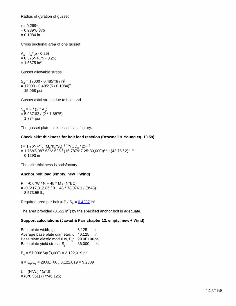
Radius of gyration of gusset
r = 0.289*tg= 0.289*0.375= 0.1084 in
Cross sectional area of one gusset
Ag = tg*(b - 0.25)= 0.375*(4.75 - 0.25)= 1.6875 in2
Gusset allowable stress
Sa = 17000 - 0.485*(h / r)2
= 17000 - 0.485*(5 / 0.1084)2
= 15,968 psi
Gusset axial stress due to bolt load
Sg = F / (2 * Ag)= 5,987.63 / (2 * 1.6875)= 1,774 psi
The gusset plate thickness is satisfactory.
Check skirt thickness for bolt load reaction (Brownell & Young eq. 10.59)
t = 1.76*(F*l / (Mb*hc*Ss))2 / 3*(ODs / 2)1 / 3
= 1.76*(5,987.63*2.625 / (16.7879*7.25*30,000))2 / 3*(42.75 / 2)1 / 3
= 0.1293 in
The skirt thickness is satisfactory.
Anchor bolt load (empty, new + Wind)
P = -0.6*W / N + 48 * M / (N*BC)= -0.6*17,312.86 / 8 + 48 * 78,976.1 / (8*48)= 8,573.55 lbf
Required area per bolt = P / Sb = 0.4287 in2
The area provided (0.551 in2) by the specified anchor bolt is adequate.
Support calculations (Jawad & Farr chapter 12, empty, new + Wind)
Base plate width, tc: 6.125 inAverage base plate diameter, d: 46.125 inBase plate elastic modulus, Es: 29.0E+06psiBase plate yield stress, Sy: 36,000 psi
Ec = 57,000*Sqr(3,000) = 3,122,019 psi
n = Es/Ec = 29.0E+06 / 3,122,019 = 9.2889
ts = (N*Ab) / (π*d)= (8*0.551) / (π*46.125)
147/158

= 0.0304 in
From table 12.4 for k = 0.167844:
K1 = 2.7324, K2 = 1.1116
L1 = 15.3247, L2 = 29.4936, L3 =6.1583
Total tensile force on bolting
T = (12*M - 0.6*W *(L1 + L3)) / (L2 + L3)= (12*78,976.1 - 0.6*17,312.86 *(15.3247 + 6.1583)) / (29.4936 + 6.1583)= 20,322.98 lbf
Tensile stress in bolts use the larger of fs or bolt preload = 0 psi
fs = T / (ts * (d / 2) * K1)= 20,322.98 / (0.0304 * (46.125 / 2) * 2.7324)= 10,602 psi
Total compressive load on foundation
Cc = T + W + Bolt Preload= 20,322.98 + 17,312.86 + 0= 37,635.84 lbf
Foundation bearing stress
fc = Cc / (((tc - ts) + n*ts)*(d / 2)*K2)= 37,635.84 / (((6.125 - 0.0304) + 9.2889*0.0304)*(46.125 / 2)*1.1116)= 230 psi
As fc <= 1,658 psi the base plate width is satisfactory.
k = 1 / (1 + fs / (n*fc))= 1 / (1 + 10,602 / (9.2889*230))= 0.167844
Base plate required thickness (empty, new + Wind)
From Brownell & Young, Table 10.3:, l / b = 0.3369
Mx = 0.0083*230*14.09962 = 378 lbf
My = -0.4257*230*4.752 = -2,210.9 lbf
tr = (6*Mmax / Sp)0.5
= (6*2,210.94 / 20,000)0.5
= 0.8144 in
The base plate thickness is satisfactory.
Check the compression ring for bolt load (Jawad & Farr equation 12.13)
tcr = (3.91*F / (Sy*(2*b / w+w / (2*l)-db*(2 / w+1 / (2*l)))))0.5
= (3.91*5,841.6 / (36,000*(2*4.75 / 4+4 / (2*2.625)-1.375*(2 / 4+1 / (2*2.625)))))0.5
= 0.5386 in
148/158

The compression ring thickness is satisfactory.
Check gusset plate thickness (Bednar chapter 4.3)
Radius of gyration of gusset
r = 0.289*tg= 0.289*0.375= 0.1084 in
Cross sectional area of one gusset
Ag = tg*(b - 0.25)= 0.375*(4.75 - 0.25)= 1.6875 in2
Gusset allowable stress
Sa = 17000 - 0.485*(h / r)2
= 17000 - 0.485*(5 / 0.1084)2
= 15,968 psi
Gusset axial stress due to bolt load
Sg = F / (2 * Ag)= 5,841.6 / (2 * 1.6875)= 1,731 psi
The gusset plate thickness is satisfactory.
Check skirt thickness for bolt load reaction (Brownell & Young eq. 10.59)
t = 1.76*(F*l / (Mb*hc*Ss))2 / 3*(ODs / 2)1 / 3
= 1.76*(5,841.6*2.625 / (16.7879*7.25*30,000))2 / 3*(42.75 / 2)1 / 3
= 0.1271 in
The skirt thickness is satisfactory.
Anchor bolt load (operating, corroded + Seismic)
P = -(0.6 - 0.14*SDS)*W / N + 48 * M / (N*BC)= -(0.6 - 0.14*0.0875)*17,580.03 / 8 + 48 * 27,191.9 / (8*48)= 2,107.39 lbf
Required area per bolt = P / Sb = 0.1054 in2
The area provided (0.551 in2) by the specified anchor bolt is adequate.
Support calculations (Jawad & Farr chapter 12, operating, corroded + Seismic)
Base plate width, tc: 6.125 inAverage base plate diameter, d: 46.125 inBase plate elastic modulus, Es: 29.0E+06psiBase plate yield stress, Sy: 36,000 psi
Ec = 57,000*Sqr(3,000) = 3,122,019 psi
149/158

n = Es/Ec = 29.0E+06 / 3,122,019 = 9.2889
ts = (N*Ab) / (π*d)= (8*0.551) / (π*46.125)= 0.0304 in
From table 12.4 for k = 0.309364:
K1 = 2.4218, K2 = 1.5344L1 = 8.7945, L2 = 24.7513, L3 = 11.2985
Total tensile force on bolting
T = (12*M - (0.6 - 0.14*SDS)*W *(L1 + L3)) / (L2 + L3)= (12*27,191.9 - (0.6 - 0.14*0.0875)*17,580.03 *(8.7945 + 11.2985)) / (24.7513 + 11.2985)= 3,292.31 lbf
Tensile stress in bolts use the larger of fs or bolt preload = 0 psi
fs = T / (ts * (d / 2) * K1)= 3,292.31 / (0.0304 * (46.125 / 2) * 2.4218)= 1,938 psi
Total compressive load on foundation
Cc = T + (1 + 0.14*SDS)*W + Bolt Preload= 3,292.31 + (1 + 0.14*0.0875)*17,580.03 + 0= 21,087.62 lbf
Foundation bearing stress
fc = Cc / (((tc - ts) + n*ts)*(d / 2)*K2)= 21,087.62 / (((6.125 - 0.0304) + 9.2889*0.0304)*(46.125 / 2)*1.5344)= 93 psi
As fc <= 1,658 psi the base plate width is satisfactory.
k = 1 / (1 + fs / (n*fc))= 1 / (1 + 1,938 / (9.2889*93))= 0.309364
Base plate required thickness (operating, corroded + Seismic)
From Brownell & Young, Table 10.3:, l / b = 0.3369
Mx = 0.0083*93*14.09962 = 153.4 lbf
My = -0.4257*93*4.752 = -897.5 lbf
tr = (6*Mmax / Sp)0.5
= (6*897.48 / 20,000)0.5
= 0.5189 in
The base plate thickness is satisfactory.
Check the compression ring for bolt load (Jawad & Farr equation 12.13)
150/158

tcr = (3.91*F / (Sy*(2*b / w+w / (2*l)-db*(2 / w+1 / (2*l)))))0.5
= (3.91*1,067.73 / (36,000*(2*4.75 / 4+4 / (2*2.625)-1.375*(2 / 4+1 / (2*2.625)))))0.5
= 0.2302 in
The compression ring thickness is satisfactory.
Check gusset plate thickness (Bednar chapter 4.3)
Radius of gyration of gusset
r = 0.289*tg= 0.289*0.375= 0.1084 in
Cross sectional area of one gusset
Ag = tg*(b - 0.25)= 0.375*(4.75 - 0.25)= 1.6875 in2
Gusset allowable stress
Sa = 17000 - 0.485*(h / r)2
= 17000 - 0.485*(5 / 0.1084)2
= 15,968 psi
Gusset axial stress due to bolt load
Sg = F / (2 * Ag)= 1,067.73 / (2 * 1.6875)= 316 psi
The gusset plate thickness is satisfactory.
Check skirt thickness for bolt load reaction (Brownell & Young eq. 10.59)
t = 1.76*(F*l / (Mb*hc*Ss))2 / 3*(ODs / 2)1 / 3
= 1.76*(1,067.73*2.625 / (16.7879*7.25*28,200))2 / 3*(42.75 / 2)1 / 3
= 0.0427 in
The skirt thickness is satisfactory.
Anchor bolt load (operating, new + Seismic)
P = -(0.6 - 0.14*SDS)*W / N + 48 * M / (N*BC)= -(0.6 - 0.14*0.0875)*19,313.28 / 8 + 48 * 29,307.8 / (8*48)= 2,244.54 lbf
Required area per bolt = P / Sb = 0.1122 in2
The area provided (0.551 in2) by the specified anchor bolt is adequate.
Support calculations (Jawad & Farr chapter 12, operating, new + Seismic)
Base plate width, tc: 6.125 inAverage base plate diameter, d: 46.125 in
151/158

Base plate elastic modulus, Es: 29.0E+06psiBase plate yield stress, Sy: 36,000 psi
Ec = 57,000*Sqr(3,000) = 3,122,019 psi
n = Es/Ec = 29.0E+06 / 3,122,019 = 9.2889
ts = (N*Ab) / (π*d)= (8*0.551) / (π*46.125)= 0.0304 in
From table 12.4 for k = 0.315021:
K1 = 2.4095, K2 = 1.5493L1 = 8.5351, L2 = 24.5589, L3 = 11.5014
Total tensile force on bolting
T = (12*M - (0.6 - 0.14*SDS)*W *(L1 + L3)) / (L2 + L3)= (12*29,307.8 - (0.6 - 0.14*0.0875)*19,313.28 *(8.5351 + 11.5014)) / (24.5589 + 11.5014)= 3,445.6 lbf
Tensile stress in bolts use the larger of fs or bolt preload = 0 psi
fs = T / (ts * (d / 2) * K1)= 3,445.6 / (0.0304 * (46.125 / 2) * 2.4095)= 2,038 psi
Total compressive load on foundation
Cc = T + (1 + 0.14*SDS)*W + Bolt Preload= 3,445.6 + (1 + 0.14*0.0875)*19,313.28 + 0= 22,995.38 lbf
Foundation bearing stress
fc = Cc / (((tc - ts) + n*ts)*(d / 2)*K2)= 22,995.38 / (((6.125 - 0.0304) + 9.2889*0.0304)*(46.125 / 2)*1.5493)= 101 psi
As fc <= 1,658 psi the base plate width is satisfactory.
k = 1 / (1 + fs / (n*fc))= 1 / (1 + 2,038 / (9.2889*101))= 0.315021
Base plate required thickness (operating, new + Seismic)
From Brownell & Young, Table 10.3:, l / b = 0.3369
Mx = 0.0083*101*14.09962 = 165.7 lbf
My = -0.4257*101*4.752 = -969.2 lbf
tr = (6*Mmax / Sp)0.5
= (6*969.23 / 20,000)0.5
= 0.5392 in
152/158

The base plate thickness is satisfactory.
Check the compression ring for bolt load (Jawad & Farr equation 12.13)
tcr = (3.91*F / (Sy*(2*b / w+w / (2*l)-db*(2 / w+1 / (2*l)))))0.5
= (3.91*1,123.11 / (36,000*(2*4.75 / 4+4 / (2*2.625)-1.375*(2 / 4+1 / (2*2.625)))))0.5
= 0.2361 in
The compression ring thickness is satisfactory.
Check gusset plate thickness (Bednar chapter 4.3)
Radius of gyration of gusset
r = 0.289*tg= 0.289*0.375= 0.1084 in
Cross sectional area of one gusset
Ag = tg*(b - 0.25)= 0.375*(4.75 - 0.25)= 1.6875 in2
Gusset allowable stress
Sa = 17000 - 0.485*(h / r)2
= 17000 - 0.485*(5 / 0.1084)2
= 15,968 psi
Gusset axial stress due to bolt load
Sg = F / (2 * Ag)= 1,123.11 / (2 * 1.6875)= 333 psi
The gusset plate thickness is satisfactory.
Check skirt thickness for bolt load reaction (Brownell & Young eq. 10.59)
t = 1.76*(F*l / (Mb*hc*Ss))2 / 3*(ODs / 2)1 / 3
= 1.76*(1,123.11*2.625 / (16.7879*7.25*28,200))2 / 3*(42.75 / 2)1 / 3
= 0.0441 in
The skirt thickness is satisfactory.
Anchor bolt load (empty, corroded + Seismic)
P = -(0.6 - 0.14*SDS)*W / N + 48 * M / (N*BC)= -(0.6 - 0.14*0.0875)*15,579.62 / 8 + 48 * 24,689.9 / (8*48)= 1,941.62 lbf
Required area per bolt = P / Sb = 0.0971 in2
The area provided (0.551 in2) by the specified anchor bolt is adequate.
153/158

Support calculations (Jawad & Farr chapter 12, empty, corroded + Seismic)
Base plate width, tc: 6.125 inAverage base plate diameter, d: 46.125 inBase plate elastic modulus, Es: 29.0E+06psiBase plate yield stress, Sy: 36,000 psi
Ec = 57,000*Sqr(3,000) = 3,122,019 psi
n = Es/Ec = 29.0E+06 / 3,122,019 = 9.2889
ts = (N*Ab) / (π*d)= (8*0.551) / (π*46.125)= 0.0304 in
From table 12.4 for k = 0.302519:
K1 = 2.4367, K2 = 1.5159L1 = 9.112, L2 = 24.9863, L3 = 11.05
Total tensile force on bolting
T = (12*M - (0.6 - 0.14*SDS)*W *(L1 + L3)) / (L2 + L3)= (12*24,689.9 - (0.6 - 0.14*0.0875)*15,579.62 *(9.112 + 11.05)) / (24.9863 + 11.05)= 3,098.43 lbf
Tensile stress in bolts use the larger of fs or bolt preload = 0 psi
fs = T / (ts * (d / 2) * K1)= 3,098.43 / (0.0304 * (46.125 / 2) * 2.4367)= 1,812 psi
Total compressive load on foundation
Cc = T + (1 + 0.14*SDS)*W + Bolt Preload= 3,098.43 + (1 + 0.14*0.0875)*15,579.62 + 0= 18,868.82 lbf
Foundation bearing stress
fc = Cc / (((tc - ts) + n*ts)*(d / 2)*K2)= 18,868.82 / (((6.125 - 0.0304) + 9.2889*0.0304)*(46.125 / 2)*1.5159)= 85 psi
As fc <= 1,658 psi the base plate width is satisfactory.
k = 1 / (1 + fs / (n*fc))= 1 / (1 + 1,812 / (9.2889*85))= 0.302519
Base plate required thickness (empty, corroded + Seismic)
From Brownell & Young, Table 10.3:, l / b = 0.3369
Mx = 0.0083*85*14.09962 = 139 lbf
My = -0.4257*85*4.752 = -812.8 lbf
154/158

tr = (6*Mmax / Sp)0.5
= (6*812.81 / 20,000)0.5
= 0.4938 in
The base plate thickness is satisfactory.
Check the compression ring for bolt load (Jawad & Farr equation 12.13)
tcr = (3.91*F / (Sy*(2*b / w+w / (2*l)-db*(2 / w+1 / (2*l)))))0.5
= (3.91*998.67 / (36,000*(2*4.75 / 4+4 / (2*2.625)-1.375*(2 / 4+1 / (2*2.625)))))0.5
= 0.2227 in
The compression ring thickness is satisfactory.
Check gusset plate thickness (Bednar chapter 4.3)
Radius of gyration of gusset
r = 0.289*tg= 0.289*0.375= 0.1084 in
Cross sectional area of one gusset
Ag = tg*(b - 0.25)= 0.375*(4.75 - 0.25)= 1.6875 in2
Gusset allowable stress
Sa = 17000 - 0.485*(h / r)2
= 17000 - 0.485*(5 / 0.1084)2
= 15,968 psi
Gusset axial stress due to bolt load
Sg = F / (2 * Ag)= 998.67 / (2 * 1.6875)= 296 psi
The gusset plate thickness is satisfactory.
Check skirt thickness for bolt load reaction (Brownell & Young eq. 10.59)
t = 1.76*(F*l / (Mb*hc*Ss))2 / 3*(ODs / 2)1 / 3
= 1.76*(998.67*2.625 / (16.7879*7.25*30,000))2 / 3*(42.75 / 2)1 / 3
= 0.0392 in
The skirt thickness is satisfactory.
Anchor bolt load (empty, new + Seismic)
P = -(0.6 - 0.14*SDS)*W / N + 48 * M / (N*BC)= -(0.6 - 0.14*0.0875)*17,312.86 / 8 + 48 * 26,808.8 / (8*48)= 2,079.14 lbf
155/158

Required area per bolt = P / Sb = 0.104 in2
The area provided (0.551 in2) by the specified anchor bolt is adequate.
Support calculations (Jawad & Farr chapter 12, empty, new + Seismic)
Base plate width, tc: 6.125 inAverage base plate diameter, d: 46.125 inBase plate elastic modulus, Es: 29.0E+06psiBase plate yield stress, Sy: 36,000 psi
Ec = 57,000*Sqr(3,000) = 3,122,019 psi
n = Es/Ec = 29.0E+06 / 3,122,019 = 9.2889
ts = (N*Ab) / (π*d)= (8*0.551) / (π*46.125)= 0.0304 in
From table 12.4 for k = 0.309039:
K1 = 2.4225, K2 = 1.5335L1 = 8.8096, L2 = 24.7624, L3 = 11.2867
Total tensile force on bolting
T = (12*M - (0.6 - 0.14*SDS)*W *(L1 + L3)) / (L2 + L3)= (12*26,808.8 - (0.6 - 0.14*0.0875)*17,312.86 *(8.8096 + 11.2867)) / (24.7624 + 11.2867)= 3,251.45 lbf
Tensile stress in bolts use the larger of fs or bolt preload = 0 psi
fs = T / (ts * (d / 2) * K1)= 3,251.45 / (0.0304 * (46.125 / 2) * 2.4225)= 1,913 psi
Total compressive load on foundation
Cc = T + (1 + 0.14*SDS)*W + Bolt Preload= 3,251.45 + (1 + 0.14*0.0875)*17,312.86 + 0= 20,776.31 lbf
Foundation bearing stress
fc = Cc / (((tc - ts) + n*ts)*(d / 2)*K2)= 20,776.31 / (((6.125 - 0.0304) + 9.2889*0.0304)*(46.125 / 2)*1.5335)= 92 psi
As fc <= 1,658 psi the base plate width is satisfactory.
k = 1 / (1 + fs / (n*fc))= 1 / (1 + 1,913 / (9.2889*92))= 0.309039
Base plate required thickness (empty, new + Seismic)
From Brownell & Young, Table 10.3:, l / b = 0.3369
156/158

Mx = 0.0083*92*14.09962 = 151.3 lbf
My = -0.4257*92*4.752 = -884.7 lbf
tr = (6*Mmax / Sp)0.5
= (6*884.73 / 20,000)0.5
= 0.5152 in
The base plate thickness is satisfactory.
Check the compression ring for bolt load (Jawad & Farr equation 12.13)
tcr = (3.91*F / (Sy*(2*b / w+w / (2*l)-db*(2 / w+1 / (2*l)))))0.5
= (3.91*1,054.17 / (36,000*(2*4.75 / 4+4 / (2*2.625)-1.375*(2 / 4+1 / (2*2.625)))))0.5
= 0.2288 in
The compression ring thickness is satisfactory.
Check gusset plate thickness (Bednar chapter 4.3)
Radius of gyration of gusset
r = 0.289*tg= 0.289*0.375= 0.1084 in
Cross sectional area of one gusset
Ag = tg*(b - 0.25)= 0.375*(4.75 - 0.25)= 1.6875 in2
Gusset allowable stress
Sa = 17000 - 0.485*(h / r)2
= 17000 - 0.485*(5 / 0.1084)2
= 15,968 psi
Gusset axial stress due to bolt load
Sg = F / (2 * Ag)= 1,054.17 / (2 * 1.6875)= 312 psi
The gusset plate thickness is satisfactory.
Check skirt thickness for bolt load reaction (Brownell & Young eq. 10.59)
t = 1.76*(F*l / (Mb*hc*Ss))2 / 3*(ODs / 2)1 / 3
= 1.76*(1,054.17*2.625 / (16.7879*7.25*30,000))2 / 3*(42.75 / 2)1 / 3
= 0.0406 in
The skirt thickness is satisfactory.
157/158

Weight Summary
Weight (lb) Contributed by Vessel Elements
Component MetalNew*
MetalCorroded Insulation Insulation
Supports Lining Piping+ Liquid
Operating Liquid Test Liquid SurfaceAreaft2New Corroded New Corroded
Ellipsoidal Head #1 135.3 95.6 42.3 813 0 0 0 0 470.5 475.3 17
Cylinder #1 4,742.9 3,343 1,464.4 3,252 0 0 2,000.4 2,000.4 30,581.6 30,763.1 554
Ellipsoidal Head #2 244.1 162.7 41.7 813 0 0 0 0 437.6 442.3 N/A
Cylinder #2 453.1 319.4 146.4 813 0 0 0 0 2,641.1 2,662.9 53
Ellipsoidal Head #3 140.7 99.4 42.3 813 0 0 0 0 459.9 464.8 17
Support Skirt #1 777 777 0 0 0 0 0 0 0 0 104
Skirt Base Ring #1 535 535 0 0 0 0 0 0 0 0 31
TOTAL: 7,028.2 5,332.1 1,737.2 6,504 0 0 2,000.4 2,000.4 34,590.8 34,808.4 777
*Shells with attached nozzles have weight reduced by material cut out for opening.
Weight (lb) Contributed by Attachments
Component Body Flanges Nozzles &Flanges Packed
BedsLadders &Platforms
Trays TraySupports
Rings &Clips
VerticalLoads
SurfaceAreaft2
New Corroded New Corroded
Ellipsoidal Head #1 0 0 66.4 66.2 0 0 0 0 0 0 3
Cylinder #1 0 0 1,210.6 1,189.7 0 0 962.1 0 0 0 30
Ellipsoidal Head #2 0 0 0 0 0 0 0 0 0 0 0
Cylinder #2 0 0 653.7 639.3 0 0 0 0 0 0 18
Ellipsoidal Head #3 0 0 0 0 0 0 0 0 0 0 0
Support Skirt #1 0 0 0 0 0 0 0 0 0 0 0
TOTAL: 0 0 1,930.7 1,895.1 0 0 962.1 0 0 0 51
Vessel Totals
New Corroded
Operating Weight (lb) 20,163 18,431
Empty Weight (lb) 18,162 16,431
Test Weight (lb) 51,016 49,502
Surface Area (ft2) 828 -
Capacity** (US gal) 4,127 4,153
**The vessel capacity does not includevolume of nozzle, piping or otherattachments.
Vessel Lift Condition
Vessel Lift Weight, New (lb) 15,463
Center of Gravity from Datum (in) 248.876
Note: Vessel lift weight includes weight ofinsulation and tray supports as they areassumed to be shop installed.
158/158

Pasadena, TX • Corpus Christi, TX • New Orleans, LA • Baton Rouge, LA Joliet/Chicago, IL • Beaumont/Groves,TX • Erie, MI • Odessa/Midland, TX
Section 6Tray 7 Attachment Weld- Northwest
Tray 7 Attachment Ring- Through Wall Hole 2.25" in Length
TÜV SÜD America Phone: (281) 884-51001474 E. Sam Houston Pkwy.Pasadena, TX 77503 E-mail: @tuvam.com
http://www.tuv-sud-america.com/
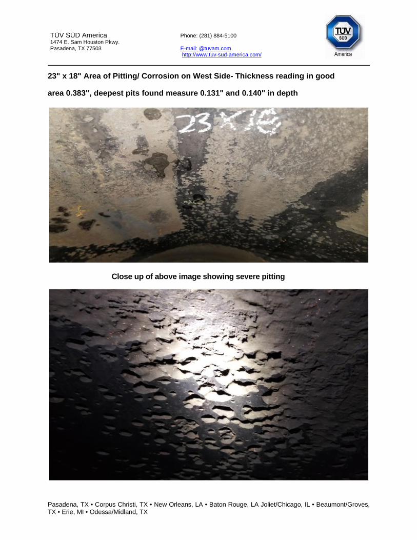
Pasadena, TX • Corpus Christi, TX • New Orleans, LA • Baton Rouge, LA Joliet/Chicago, IL • Beaumont/Groves,TX • Erie, MI • Odessa/Midland, TX
TÜV SÜD America Phone: (281) 884-51001474 E. Sam Houston Pkwy.Pasadena, TX 77503 E-mail: @tuvam.com
http://www.tuv-sud-america.com/
23" x 18" Area of Pitting/ Corrosion on West Side- Thickness reading in good
area 0.383", deepest pits found measure 0.131" and 0.140" in depth
Close up of above image showing severe pitting

Pasadena, TX • Corpus Christi, TX • New Orleans, LA • Baton Rouge, LA Joliet/Chicago, IL • Beaumont/Groves,TX • Erie, MI • Odessa/Midland, TX
TÜV SÜD America Phone: (281) 884-51001474 E. Sam Houston Pkwy.Pasadena, TX 77503 E-mail: @tuvam.com
http://www.tuv-sud-america.com/
Circumferential/ Seam Weld Junction- 0.140" Weld Erosion
34" x 5.5" Area of Corrosion between Tray 15 and 16 showing a 0.160" Pit
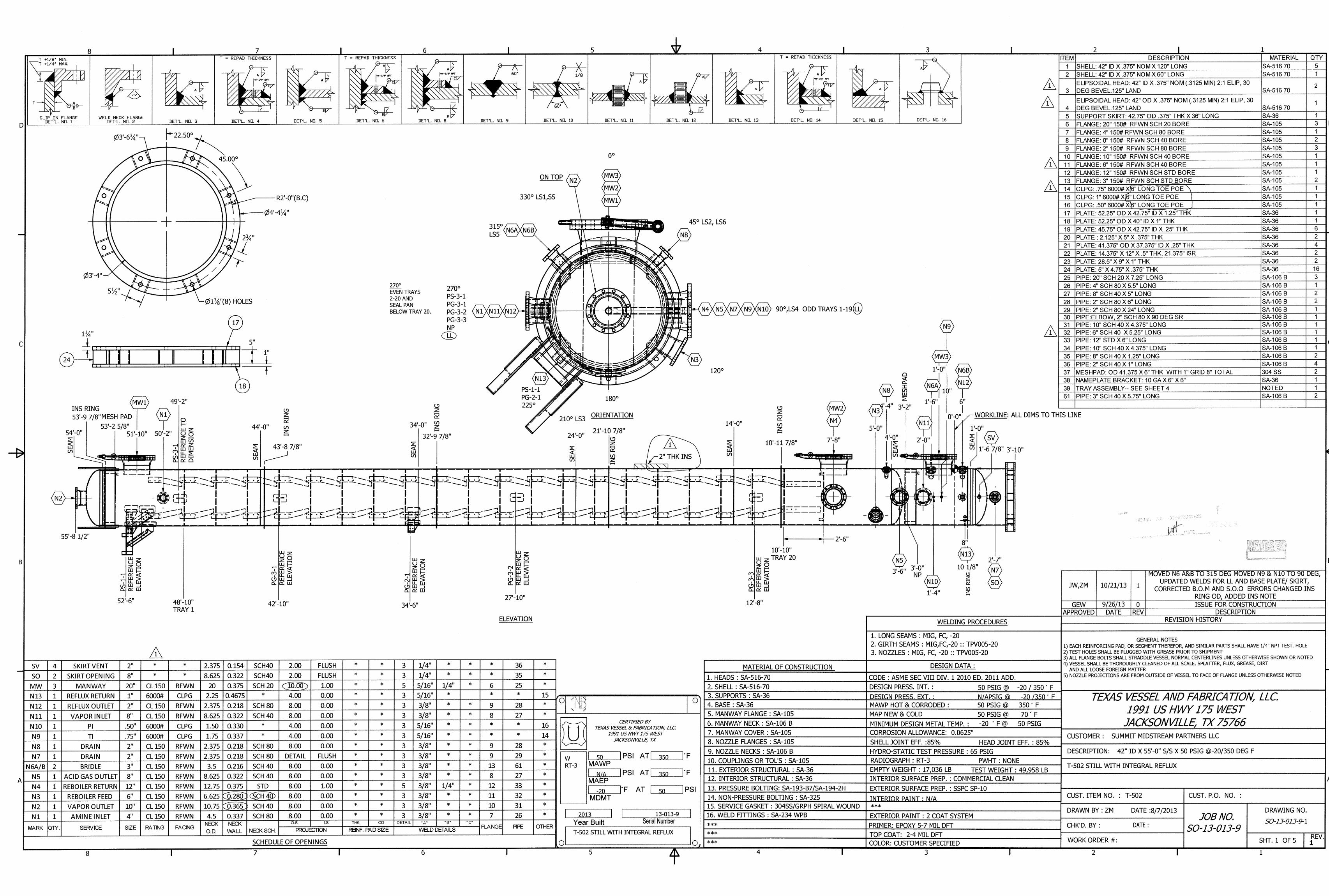


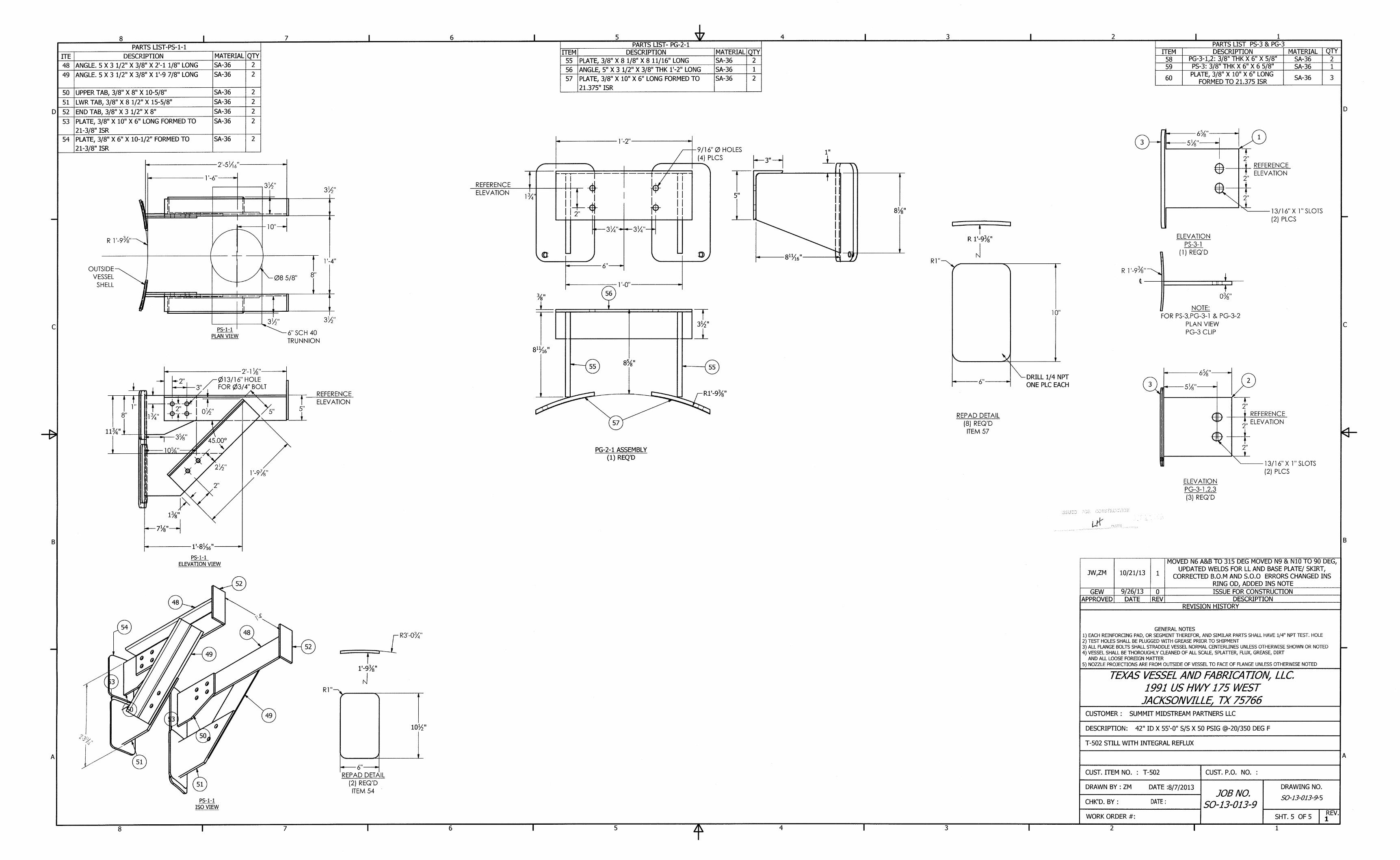

Ê
ELE
VA
TIO
N
NO
ZZ
LE
S &
T
RA
YS
O
RIE
NT
AT
IO
N
Ê
9102708-D
000
2013 K
OC
H-G
LIT
SC
H, LP
. A
LL R
IG
HT
S R
ES
ER
VE
D
CU
ST
OM
ER
T
O C
ON
FIR
M
ALL T
HE
E
LE
VA
TIO
NS
& O
RIE
NT
AT
IO
NS
O
F N
OZ
ZLE
S
PR
ELIM
IN
AR
Y: N
OT
F
OR
F
AB
RIC
AT
IO
N.

Pasadena, TX • Corpus Christi, TX • New Orleans, LA • Baton Rouge, LA Joliet/Chicago, IL • Beaumont/Groves, TX •Erie, MI • Odessa/Midland, TX
Section 7
NDE Data
ACFM Calibration Standard Showing 0.250" Deep EDM Notch
ACFM Data showing noise from corrosion on the weld- No Useable Data

Client:
QWCF:
SO#
Location Date: 11/7/2018
Welder's
Stamp: NAEquipment
Line #: Specification: Per Client Material: SA-516-70
Instrument Model
Instrument S/N
Probes Used Angle Frequency Wave Mode
.100"-.500" D-790 0° 5 Mhz Longitudinal
Inspection Results
Level:
Level II
Sensitivity Block
Calibration Block
Johnson County
Per Client
UT Thickness
Examination Report
Step Wedge
Joco/Summit Midstream
38DL+
171432601
Equipment Used
.375"
T-502
Exam Specifics
General Information
722827977
NDT Procedure # C-UT-02 Rev 6
Component
Tested:Amine Still Location within plant (unit):
Type of Weld Joint: Buttweld
Material Thickness:
Surface Condition: Poor
Couplant used: Ultragel
Inspector Name Date:Signature
Andrew Martinez Andrew Martinez 11/7/2018
Scope:Manual thickness readings were taken above and below the Circ Seams for T-502 Amine Still on four quadrants. North, South,East and West. Due to poor surface area thickness readings were difficult to obtain. These readings may not be the lowestreading in area.Results:See below for Data

Client:
QWCF:
SO#
Location Date: 11/7/2018
Welder's
Stamp: NAEquipment
Line #: Specification: Per Client Material: SA-516-70
Instrument Model
Instrument S/N
.100"-.500"
Inspection Results
Level:
Level IIAndrew Martinez Andrew Martinez 11/7/2018
Couplant used: Ultragel Per Client
Inspector Name Signature Date:
Sensitivity Block
Calibration Block Step Wedge
Surface Condition: Poor
Material Thickness: .375" Husky
NDT Procedure # C-UT-02 Rev 6 A001
T-502
Exam Specifics
Type of Weld Joint: Buttweld Equipment Used
General Information
Johnson County
Component
Tested:Amine Still Location within plant (unit):
Pit Guage Readings Joco/Summit Midstream
Examination Report722827977
Scope:Manual pit gauge readings were taken at random locations on T-502 Amine Still tower. Due to poor surface area readings weredifficult to obtain. These readings may not be the lowest reading in area.Results:See below for Data

Pasadena, TX • Corpus Christi, TX • New Orleans, LA • Baton Rouge, LA Joliet/Chicago, IL • Beaumont/Groves, TX •Erie, MI • Odessa/Midland, TX
Disclaimer:
PetroChem thanks you for the opportunity to provide this service to you. Our scope of the service
will be limited to the relevant contract, purchase order, and/or similar agreements. While every effort
has been made to provide comprehensive, accurate, and useful results, it is understood that all
comments, descriptions, etc. contained in this report represent the opinions of the examiner based
on the current conditions of the component and the information provided. PetroChem does not
warrant or guarantee the information, content or accuracy of the information in this report with
respect to the actual condition of the parts inspected. Furthermore, PetroChem will not be held liable
for the manner in which the information contained within this report is used.

Andrew Martinez
Shane Sexton
Component:
DCU2 Amine Still
Unit:
Location:
Summit Midstream JOCO Friday, November 23, 2018
Client: Date:
AUT Assistant
T-502
Client Representative:
Sales Order Number:
Erica Frisbie Engineering Manager
This Report is subject to final review for content and clarity. Supplements or Revisions will be made as necessary based on Client feedback and TUV SUD America Chemical, Oil & Gas Division final review.
Automated UltrasonicPulse Echo
Corrosion Mapping Examination
Sr. AUT Specialist, Level II
Identification Number:
722827977
Examination & Report By:
Additional Technician:
Additional Technician:
TUV SUD America Chemical, Oil & Gas DivisionAdvanced Services1475 E. Sam Houston Parkway SouthSuite #100Pasadena, TX 77503(281) 884-5100
Page 1 of 27

Table of Contents Page
3
Calibration 5
ACAD Drawings and Mappings 6
Scan Sheet 9
C-Scan Data 10
Damage Rating Assessment (DRA) 25
AUT Equipment 26
Guide to Interpretation 27
Scope of Work and Summary
Page 2 of 27

3
TUV SUD America Chemical, Oil & Gas DivisionAdvanced Services1475 E. Sam Houston Parkway SouthSuite #100Pasadena, TX 77503(281) 884-5100
Scope of WorkTUV SUD America Chemical, Oil & Gas Division was asked to perform a detailed Automated Ultrasonic Pulse Echo C-Scan Examination on the reamainig unscanned top half of T-502 Amine Still, while the equipment was out of service.The vessel was painted and the surface condition was fair. .
The purpose of this examination was to detect any potential I.D wall-loss for the accessible areas using longitudinalwaves (for corrosion mapping) looking for service related damage. This examination was focused on the "Shell".
The examination was performed in accordance with our C-UT-15, Rev-5 procedure "Automated Ultrasonic CorrosionMapping Examinations" and the calibrations documented in the "Calibration" section of this report.
TUV SUD America Chemical, Oil & Gas Division utilized a state-of-the art Multi-Channel AUT system interfaced to a2-Axis scanner and specially designed transducer for the 0º. The transducer contains a dual element 5 MHz 0°-longitudinal wave capable of resolving a .125” long by .050” (50 mils) deep notch, flaw and corrosion or pitting of .25”diameter and .050” (50 mils) in depth
Executive Summary
For the shell material examined, the lowest remaining wall detected was .131" which represents a 65.07% wall loss basedon a nominal wall thickness of .375". This area was found on Shell course 3 Scan 19.
Based on the data gathered, this equipment has been given a Damage Rating Assessment of DRA-6 COR6 Corrosion-6:Corrosion, either general wall-loss or pitting that exceeds 50% wall-loss (>50%), in accordance with the attachment“Damage Rating Assessment”. This is based on significant wall losses >50% and <50% of the nominal wall thickness.
Refer to the attached Individual Summaries, ACAD, Scan Sheet and AUT data for full details.
The examinations performed represent one of the most comprehensive inspections that can be performed on piping. Thisdata offers an excellent benchmark for any future examinations or monitoring. The overall responsibility for mechanicalintegrity of this equipment rests with the client and monitoring should be in accordance with your engineering practicesand/or RBI risk management philosophies.
Page 3 of 27

For HIC
TUV SUD America Chemical, Oil & Gas DivisionAdvanced Services1475 E. Sam Houston Parkway SouthSuite #100Pasadena, TX 77503(281) 884-5100
Summary for the Piping Material Examined
0° Thickness Mapping :
A total of fifteen (15) AUT scans were performed on the shell, which consisted of 968,800 equivalent UT thicknessreadings.
A total of three (3) scans were performed on Shell course 3, with the lowest detected UT reading was a 0.131"; whichrepresents a 65.07% wall loss based on a nominal thickness of 0.375". The overall average wall thickness wasdetermined to be .299". The data collected in this Section had severe wall loss throughout all scanned areas.
A total of seven (7) scans were performed on Shell course 4, with the lowest detected UT reading was a 0.145"; whichrepresents a 61.33% wall loss based on a nominal thickness of 0.375". The overall average wall thickness wasdetermined to be .297". The data collected in this Section had major to severe wall loss throughout all scanned areas.
A total of five (5) scans were performed on Shell course 5, with the lowest detected UT reading was a 0.244"; whichrepresents a 34.93% wall loss based on a nominal thickness of 0.375". The overall average wall thickness wasdetermined to be .344". The data collected in this Section had minor to major wall loss throughout all scanned areas.
See the AutoCAD roll out for each section for the C-Scan merges and see data pages for eachindividual breakdown and readings.
Page 4 of 27

ImagesAUT System Mfg: Model: S/N:
Settings 4 Horz. Vert. Yes No8 Horz. Vert. Arm Length 24"
Dynamic CalibrationArm Orientation Axial Scan Speed
TrackAccuScan S/N:Scanner Mfg:
Wheels Orientation Circ. Scan SpeedAUT Solutions Automated
x xModel: Manual250
x 4 x x x x
x xAUT Solutions 3 Longitudinal Dual 0.375'' 5 MHz 0 28890
x x x xx 2 x x x x
Transducer Ch. Mode Single/Dualx 1 x x
AUT Solutions ProScan 8 100
Reference Reflector.400"
Size Frequency (MHz.) Angle S/N
Technique Calibration Block Block 'T' Block MaterialPulse Echo AUT Calibration Block 0.1" to 1.5" Carbon Steel
O.D. SurfaceMaterial Component Nominal 'T' Surface Condition
Carbon Steel Amine Still 0.375'' FairInspection Surface
Corrosion Mapping Examination November 23, 2018
C-UT-15 (HIC, Pulse Echo) 05 Client
Summit Midstream
0˚ Data
45˚ Data 45˚ Data
Ultrasonic Procedure Revision
Examination Type Date
Acceptance Criteria
Client
CALIBRATION
Page 5 of 27

3
Client: Summit Midstream 0" ReferenceLocation: JOCO X-axis = TDC (Pos. dir. CW looking West)
Equipment: Amine Still Y-axis = CW-1 (Pos. dir. Upward)Equipment Number: T-502 Nominal 'T': 0.375'' Material: Carbon Steel
Plant Drawing
Examination type: Corrosion Mapping Examination Circumference.: 132" Length: 660"
Page 6 of 27

3
T-502 0.375''Nominal 'T':Equipment Number:Circumference.: 132"
Client:Location:
Summit MidstreamJOCO
0" ReferenceX-axis = TDC (Pos. dir. CW looking West)
ACAD Drawing
Examination type: Length: 660"
Equipment: Amine StillCarbon Steel
Corrosion Mapping Examination
Y-axis = CW-1 (Pos. dir. Upward)Material:
Page 7 of 27

3
Equipment Number: T-502
X-axis = TDC (Pos. dir. CW looking West)
Carbon Steel
Location:Equipment:
Material:Nominal 'T': 0.375''
0" Reference
Y-axis = CW-1 (Pos. dir. Upward)
Client: Summit MidstreamJOCOAmine Still
Auto-Cad Drawing with C-scan Image Merged.
Examination type: Length: 660"Circumference.: 132"Corrosion Mapping Examination
Page 8 of 27

Circ.: 132" 87120''
Length: 660" 24220''
Thickness: 0.375'' 27.80%
Start Stop Interval Start Stop IntervalShell Course 3 19 0.0'' 132.0'' 0.500'' 365.0'' 385.0'' 0.050'' Opp. 105600 2640'' 0.131'' 0.299'' 65.07% 0.375'' Severe ID wall loss detected.
Shell Course 3 20 66.5'' 129.0'' 0.500'' 398.0'' 418.0'' 0.050'' Same 50000 1250'' 0.170'' 0.316'' 54.67% 0.375'' Severe ID wall loss detected.
Shell Course 3 21 2.0'' 32.5'' 0.500'' 398.0'' 418.0'' 0.050'' Opp. 24400 610'' 0.168'' 0.303'' 55.20% 0.375'' Severe ID wall loss detected.
Shell Course 4 22 0.0'' 32.5'' 0.500'' 418.0'' 438.0'' 0.050'' Opp. 26000 650'' 0.200'' 0.293'' 46.67% 0.375'' Major ID wall loss detected.
Shell Course 4 23 66.5'' 132.0'' 0.500'' 418.0'' 438.0'' 0.050'' Same 52400 1310'' 0.145'' 0.297'' 61.33% 0.375'' Severe ID wall loss detected.
Shell Course 4 24 0.0'' 124.0'' 0.500'' 438.0'' 458.0'' 0.050'' Opp. 99200 2480'' 0.178'' 0.313'' 52.53% 0.375'' Severe ID wall loss detected.
Shell Course 4 25 0.0'' 124.0'' 0.500'' 458.0'' 478.0'' 0.050'' Opp. 99200 2480'' 0.151'' 0.319'' 59.73% 0.375'' Severe ID wall loss detected.
Shell Course 4 26 0.0'' 124.0'' 0.500'' 478.0'' 498.0'' 0.050'' Opp. 99200 2480'' 3.000'' 0.342'' -700.00% 0.375'' Major ID wall loss detected.
Shell Course 4 27 2.0'' 20.0'' 0.500'' 498.0'' 518.0'' 0.050'' Opp. 14400 360'' 0.237'' 0.353'' 36.80% 0.375'' Major ID wall loss detected.
Shell Course 4 28 50.0'' 129.0'' 0.500'' 498.0'' 518.0'' 0.050'' Same 63200 1580'' 0.243'' 0.344'' 35.20% 0.375'' Major ID wall loss detected.
Shell Course 5 29 4.0'' 129.0'' 0.500'' 532.0'' 552.0'' 0.050'' Same 100000 2500'' 0.244'' 0.344'' 34.93% 0.375'' Major ID wall loss detected.
Shell Course 5 30 0.0'' 132.0'' 0.500'' 552.0'' 572.0'' 0.050'' Same 105600 2640'' 0.275'' 0.360'' 26.67% 0.375'' Moderate ID wall loss detected.
Shell Course 5 31 0.0'' 28.0'' 0.500'' 572.0'' 592.0'' 0.050'' Same 22400 560'' 0.311'' 0.407'' 17.07% 0.375'' Moderate ID wall loss detected.
Shell Course 5 32 44.0'' 132.0'' 0.500'' 572.0'' 592.0'' 0.050'' Same 70400 1760'' 0.284'' 0.359'' 24.27% 0.375'' Moderate ID wall loss detected.
Shell Course 5 33 78.0'' 124.0'' 0.500'' 592.0'' 612.0'' 0.050'' Same 36800 920'' 0.313'' 0.373'' 16.53% 0.375'' Minor ID wall loss detected.
Totals 968800 24220 0.131'' 0.335'' 65.07%
Scanner Location Min. 'T' Avg.'T'
Total UT Readings
Wall loss (%) Nom. 'T'
T-502Equipment Number:
Client: Summit Midstream 0" Reference
Amine StillEquipment:
Axial (Y-Axis)Scan Location or Weld # File Name
Circumferential (X-Axis)
Comments / AnalysisCoverage (Sq. In.)
Component Specifications
Component (Sq.In.): X-axis = TDC (Pos. dir. CW looking West)
Scan#
Corrosion Mapping ExaminationExamination type:
AUT Area (Sq.In.):
AUT Coverage (%):
Y-axis = CW-1 (Pos. dir. Upward)
Scan Sheet
Page 9 of 27

-
3
0.13
0.299''
0.000''
Actual Min. Thickness Detected:
Remaining Wall percentage:
0.131''
34.93%
Statistical
0.309''
Temperature of component (Fº):
Actual Average Thickness Detected:
Wall loss percentage: 65.07%
70°
Severe ID wall loss detected.
Minimum thickness detected in scan: 0.141''
0.010''
Temperature Correction:
Average paint coating thickness:
Course 3
Comments
Circumference.: 132" Length:
Average thickness detected in scan:
660"
Scan: 19
Carbon Steel
0" ReferenceX-axis = TDC (Pos. dir. CW looking West)Y-axis = CW-1 (Pos. dir. Upward)
Nominal 'T': 0.375'' Material:
Summit Midstream
Equipment:T-502
Examination type:Equipment Number:
Client:Location: JOCO
Amine Still
Corrosion Mapping Examination
Channel 1 45˚ S-wave data
Channel 245˚ S-wave data
Page 10 of 27

-
-69.67
Equipment Number:
Actual Average Thickness Detected: 0.316''
Temperature of component (Fº): 70°Temperature Correction: 0.000''
Comments
Actual Min. Thickness Detected: 0.170''
0.010''
Remaining Wall percentage: 45.33%Wall loss percentage: 54.67%
0.326''Average paint coating thickness:
132"
Course 3
Average thickness detected in scan:
Severe ID wall loss detected.
StatisticalMinimum thickness detected in scan: 0.180''
Scan: 20
Equipment: Amine Still Y-axis = CW-1 (Pos. dir. Upward)Material:
Length: 660"Carbon Steel
Examination type: Corrosion Mapping Examination Circumference.:
Client: Summit Midstream 0" ReferenceLocation: JOCO X-axis = TDC (Pos. dir. CW looking West)
T-502 Nominal 'T': 0.375''
Channel 1 45˚ S-wave data
Channel 245˚ S-wave data
Page 11 of 27

-
-69.69
Wall loss percentage: 55.20%
Severe ID wall loss detected.
Actual Average Thickness Detected: 0.303''Remaining Wall percentage: 44.80%
Statistical
Temperature Correction: 0.000''
Actual Min. Thickness Detected: 0.168''
Temperature of component (Fº): 70°Average paint coating thickness: 0.010''
Minimum thickness detected in scan: 0.178''Average thickness detected in scan: 0.313''
T-502 Nominal 'T': 0.375''
Course 3
Examination type: Corrosion Mapping ExaminationEquipment Number:
Scan: 21
Circumference.:
Location: JOCO X-axis = TDC (Pos. dir. CW looking West)Y-axis = CW-1 (Pos. dir. Upward)Equipment: Amine Still
Client: Summit Midstream 0" Reference
Material: Carbon SteelLength:
Comments
660"132"
Channel 1 45˚ S-wave data
Channel 245˚ S-wave data
Page 12 of 27

-
-69.70
X-axis = TDC (Pos. dir. CW looking West)Y-axis = CW-1 (Pos. dir. Upward)
Material: Carbon Steel
Course 4
0.210''
Scan: 22
Average thickness detected in scan:
Statistical
0.303''
Major ID wall loss detected.
Minimum thickness detected in scan:
Examination type: Corrosion Mapping Examination Circumference.: 132"
Equipment:
Length:
Temperature Correction:
Actual Average Thickness Detected: 0.293''Remaining Wall percentage: 53.33%
Wall loss percentage: 46.67%
Client: Summit Midstream 0" Reference
Equipment Number: T-502 Nominal 'T': 0.375''
Location: JOCOAmine Still
660"
Comments
Average paint coating thickness: 0.010''Temperature of component (Fº):
0.000''
Actual Min. Thickness Detected: 0.200''
70°
Channel 1 45˚ S-wave data
Channel 245˚ S-wave data
Page 13 of 27

-
-69.69
X-axis = TDC (Pos. dir. CW looking West)Y-axis = CW-1 (Pos. dir. Upward)
Actual Average Thickness Detected: 0.297''Remaining Wall percentage: 38.67%
Wall loss percentage: 61.33%
Temperature Correction: 0.000''
Actual Min. Thickness Detected: 0.145''
Average thickness detected in scan: 0.307''
Severe ID wall loss detected.
StatisticalMinimum thickness detected in scan: 0.155''
Comments
Client: Summit Midstream
Scan: 23Course 4
Equipment Number: T-502Examination type: Corrosion Mapping Examination
Equipment: Amine Still
Length: 660"Nominal 'T':
Location: JOCO
Circumference.: 132"Carbon Steel0.375'' Material:
0" Reference
Average paint coating thickness: 0.010''Temperature of component (Fº): 70°
Channel 1 45˚ S-wave data
Channel 245˚ S-wave data
Page 14 of 27

-
-69.68
Remaining Wall percentage: 47.47%Wall loss percentage: 52.53%
Temperature of component (Fº): 70°
Actual Average Thickness Detected: 0.313''
Temperature Correction: 0.000''
Actual Min. Thickness Detected: 0.178''
Scan: 24Course 4
Equipment Number: T-502Examination type: Corrosion Mapping Examination
Equipment: Amine Still Y-axis = CW-1 (Pos. dir. Upward)Location: JOCO X-axis = TDC (Pos. dir. CW looking West)
Client: Summit Midstream 0" Reference
Minimum thickness detected in scan: 0.188''
Carbon SteelCircumference.: 132" Length: 660"
CommentsSevere ID wall loss detected.
Statistical
Average thickness detected in scan: 0.323''
Nominal 'T': 0.375'' Material:
Average paint coating thickness: 0.010''
Channel 1 45˚ S-wave data
Channel 245˚ S-wave data
Page 15 of 27

-
-69.67
Scan: 25Course 4
Equipment Number: T-502Examination type: Corrosion Mapping Examination
0.319''Remaining Wall percentage: 40.27%
Wall loss percentage: 59.73%
Temperature of component (Fº): 70°
Actual Average Thickness Detected:
Temperature Correction: 0.000''
Actual Min. Thickness Detected: 0.151''
0.010''
Length: 660"
Comments
Average thickness detected in scan: 0.329''
Severe ID wall loss detected.
132"
StatisticalMinimum thickness detected in scan:
Equipment: Amine Still Y-axis = CW-1 (Pos. dir. Upward)Nominal 'T': 0.375'' Material: Carbon Steel
Location: JOCO X-axis = TDC (Pos. dir. CW looking West)Client: Summit Midstream 0" Reference
Average paint coating thickness:
0.161''
Circumference.:
Channel 1 45˚ S-wave data
Channel 245˚ S-wave data
Page 16 of 27

-
-69.65
Wall loss percentage: 43.73%
0.342''
Course 4
Temperature Correction: 0.000''
Actual Min. Thickness Detected: 0.211''
0.221''
0.010''70°
X-axis = TDC (Pos. dir. CW looking West)
Remaining Wall percentage: 56.27%
Y-axis = CW-1 (Pos. dir. Upward)Equipment: Amine StillEquipment Number: T-502
26
Client:
660"
Scan:
Examination type: Corrosion Mapping Examination
Location: JOCO
Nominal 'T': 0.375'' Material: Carbon Steel
Summit Midstream 0" Reference
Circumference.: 132"
Statistical
Length:
Major ID wall loss detected. Comments
Minimum thickness detected in scan:
Actual Average Thickness Detected:
Temperature of component (Fº):
Average thickness detected in scan: 0.352''Average paint coating thickness:
Channel 1 45˚ S-wave data
Channel 245˚ S-wave data
Page 17 of 27

-
-69.64
Scan: 27Course 4
Y-axis = CW-1 (Pos. dir. Upward)Equipment Number: T-502
Remaining Wall percentage: 63.20%Wall loss percentage: 36.80%
Temperature of component (Fº): 70°
Actual Average Thickness Detected: 0.353''
Temperature Correction: 0.000''
Actual Min. Thickness Detected: 0.237''
660"
Comments
Average thickness detected in scan: 0.363''
Major ID wall loss detected.
StatisticalMinimum thickness detected in scan: 0.247''
Client: Summit Midstream
Examination type: Corrosion Mapping Examination Circumference.: 132"
Location: JOCO X-axis = TDC (Pos. dir. CW looking West)Equipment: Amine Still
Nominal 'T':
Average paint coating thickness: 0.010''
0.375'' Material: Carbon Steel
0" Reference
Length:
Channel 1 45˚ S-wave data
Channel 245˚ S-wave data
Page 18 of 27

-
-69.65
Length: 660"Circumference.: 132"
Temperature of component (Fº): 70°
0.344''Actual Average Thickness Detected:Remaining Wall percentage: 64.80%
Wall loss percentage: 35.20%
Temperature Correction: 0.000''
Actual Min. Thickness Detected: 0.243''
Examination type: Corrosion Mapping Examination
0.253''
Average paint coating thickness: 0.010''
Course 4 Scan: 28
Comments
Equipment: Amine Still Y-axis = CW-1 (Pos. dir. Upward)Carbon SteelNominal 'T': 0.375'' Material:Equipment Number: T-502
Location:Client: Summit Midstream 0" Reference
JOCO X-axis = TDC (Pos. dir. CW looking West)
Average thickness detected in scan: 0.354''
Major ID wall loss detected.
StatisticalMinimum thickness detected in scan:
Channel 1 45˚ S-wave data
Channel 245˚ S-wave data
Page 19 of 27

-
-69.65
Scan: 29Course 5
Equipment Number: T-502Examination type:
Equipment: Amine StillLocation:
Actual Average Thickness Detected: 0.344''Remaining Wall percentage: 65.07%
Wall loss percentage: 34.93%
0.000''
Actual Min. Thickness Detected: 0.244''
Temperature of component (Fº): 70°Average paint coating thickness: 0.010''
Temperature Correction:
Average thickness detected in scan: 0.354''
Major ID wall loss detected.
Circumference.: 132"Corrosion Mapping Examination
StatisticalMinimum thickness detected in scan:
Y-axis = CW-1 (Pos. dir. Upward)
Length: 660"
Comments
JOCO X-axis = TDC (Pos. dir. CW looking West)Client: Summit Midstream 0" Reference
0.254''
Carbon Steel0.375'' Material:Nominal 'T':
Channel 1 45˚ S-wave data
Channel 245˚ S-wave data
Page 20 of 27

-
-69.63
Actual Average Thickness Detected: 0.360''Remaining Wall percentage: 73.33%
Wall loss percentage: 26.67%
Temperature of component (Fº): 70°
0.375''
30Course 5 Scan:
Temperature Correction: 0.000''
Actual Min. Thickness Detected: 0.275''
Average thickness detected in scan:
Equipment: Amine Still
Length: 660"Equipment Number: T-502
Examination type: Corrosion Mapping ExaminationNominal 'T':
Y-axis = CW-1 (Pos. dir. Upward)Location: JOCO
Client: Summit Midstream
Material: Carbon Steel
X-axis = TDC (Pos. dir. CW looking West)0" Reference
Circumference.: 132"
Moderate ID wall loss detected. Comments
Minimum thickness detected in scan: 0.285''Statistical
Average paint coating thickness: 0.010''0.370''
Channel 1 45˚ S-wave data
Channel 245˚ S-wave data
Page 21 of 27

-
-69.58
Scan: 31Course 5
Y-axis = CW-1 (Pos. dir. Upward)Equipment Number: T-502
0.417''
Statistical
Remaining Wall percentage: 82.93%Wall loss percentage: 17.07%
Temperature of component (Fº): 70°
Actual Average Thickness Detected: 0.407''
Temperature Correction: 0.000''
Actual Min. Thickness Detected: 0.311''
Minimum thickness detected in scan: 0.321''
Examination type: Corrosion Mapping Examination Circumference.: 132"
Moderate ID wall loss detected. Comments
Equipment: Amine Still
0" ReferenceLocation: JOCO X-axis = TDC (Pos. dir. CW looking West)
Client: Summit Midstream
Average thickness detected in scan:Average paint coating thickness: 0.010''
Material: Carbon SteelNominal 'T': 0.375''Length: 660"
Channel 1 45˚ S-wave data
Channel 245˚ S-wave data
Page 22 of 27

-
-69.63
Remaining Wall percentage: 75.73%Wall loss percentage: 24.27%
660"
Average paint coating thickness: 0.010''
Actual Average Thickness Detected: 0.359''
70°
Course 5
Equipment Number: T-502Examination type: Corrosion Mapping Examination
Scan: 32
132"
Equipment: Amine Still Y-axis = CW-1 (Pos. dir. Upward)Carbon SteelNominal 'T': 0.375'' Material:
Length:Circumference.:
Location:Client: Summit Midstream 0" Reference
JOCO X-axis = TDC (Pos. dir. CW looking West)
0.294''
0.284''Actual Min. Thickness Detected:
Temperature Correction: 0.000''Temperature of component (Fº):
Average thickness detected in scan:
Comments
0.369''
Moderate ID wall loss detected.
StatisticalMinimum thickness detected in scan:
Channel 1 45˚ S-wave data
Channel 245˚ S-wave data
Page 23 of 27

-
-69.62
Actual Average Thickness Detected: 0.373''Remaining Wall percentage: 83.47%
Wall loss percentage: 16.53%
0.000''
Actual Min. Thickness Detected: 0.313''
Temperature Correction:
Average thickness detected in scan: 0.383''
Minor ID wall loss detected.
StatisticalMinimum thickness detected in scan:
Temperature of component (Fº): 70°Average paint coating thickness: 0.010''
Scan: 33
0.323''
Course 5
Length: 660"
Comments
Equipment: Amine Still
Circumference.: 132"Equipment Number: T-502
Examination type: Corrosion Mapping Examination
Y-axis = CW-1 (Pos. dir. Upward)Nominal 'T':
Location: JOCO X-axis = TDC (Pos. dir. CW looking West)Client: Summit Midstream 0" Reference
Carbon Steel0.375'' Material:
Channel 1 45˚ S-wave data
Channel 245˚ S-wave data
Page 24 of 27

DRA-1NRI
IL/I-1
DRA-2COR2L/B
L/I-2DRA-3
COR3
C3B
DRA-4
DRA-5COR5
SWC1
DRA-6COR6
SWC2C6
Corrosion-5: Corrosion, either general wall-loss or pitting that exceeds 50% wall-loss (>50%), and/or
Corrosion-5: Corrosion, either general wall-loss or pitting that exceeds 25% wall-loss (>25%) and less than 50% wall loss (<50%) and/or,
Stepwise Cracking: Blistering that has linked up (multi-level) with cracks usually embedded and are not yet surface connected and/or,
C3 Cracking: Cracking with established lengths and thru-wall depths greater than 25% thickness (>25%) and less than 50% thickness (<50%).
Blistering: Confirmed blistering with a total loss in back-wall response; typically associated with H2S service.
COR4 Corrosion-4: Corrosion, either general wall-loss or pitting that exceeds the corrosion allowance but is less than 25% wall-loss (<25%),and/or
C4 Cracking: Confirmed cracking with established lengths and thru-wall depths greater than 10% thickness (>10%) and less than 25% thickness (<25%).
Corrosion-3: Corrosion, either general wall-loss or pitting that is greater than 0.050" in depth and within the corrosion allowance, and/orCracking: Potential shallow I.D. cracking (<10% thickness) that may or may not be associated with service, and/or
SCCStress Corrosion Cracking; general term referring to cracking caused by environmental conditions other than H2S; typically found in austenitic stainless steel's under tensile stress.
Corrosion-2: Corrosion, either general wall loss or pitting 0.050" or less in depth from the nominal wall thickness, and/or
No Reportable Indications or NO detectable service related damage, orInclusions: Small inherent fabrication anomalies as scattered small indications, orLaminar/Inclusions: Inherent inclusions or laminations that are the result of rolling of steel.
The damage rating assessments identified above have been provided only as a guide for the various different damage mechanisms. A damage rating assessment of 1 (DRA-1) is typical for a vessel showing no signs of service related damage for the data collected. A damage rating assessment of 6 (DRA-6) is typical for a vessel showing conclusive evidence of severe damage for the data collected. The damage rating assessments of 2-5 (DRA-2 – DRA-5) are typical for vessels having varying degrees of damage and can be subjective depending on the level of analysis performed, technicians interpretations and can be influenced by comparison with previous inspection data.
It is the responsibility of the client to determine how this evaluation affects the overall vessel's fitness-for-service.
COR Corrosion, Erosion, Wastage; general term relating to wall reduction or wall losses due to service related damage.
HICHydrogen Induced Cracking (literal definition); general term referring to Wet H2S service damage mechanisms such as SOHIC, Blistering, Incipient HIC and Stepwise Cracking.
Stepwise Cracking: Blistering that has linked up (multi-level) with cracks that have linked up to the I.D. or O.D. surface(s), and/orCracking: Severe cracking with thru-wall depths greater than 50% thickness (>50%).
Laminar/Blistering: Laminar inclusions that show initial signs of blistering or large area laminations. Typically, there is a diminished or total loss of back-wall response, and/or
Laminar/Inclusions: Indications typical of the initial stages of material degradation; i.e. hydrogen accumulation, etc.
DAMAGE RATING ASSESSMENT
Terms & Definitions
Page 25 of 27

3
C-Scan display represents a Top or Plan view of theobject. 0º Mapping data is usually presented in ‘Depth’and shearwave in ‘Amplitude’
B-Scan display represents a Side-view along the strokefor the object (Y-axis). The colors in this view representamplitude of the signals.
B-Scan (B-Prime) display represents an End view alongthe X-axis index.
TUV SUD America Chemical, Oil & Gas Division utilizes state-of-the-art computerized robotic technology and advanced ultrasonic testingtechniques to provide the oil & gas industry one of the mostcomprehensive inspection programs in our industry; AutomatedUltrasonic (AUT).
AUT is a fully automated ultrasonic inspection technique, whichutilizes a multi-channel ultrasonic imaging system and encoded roboticscanners. The major advantage of AUT is that it provides detailedinspection data at a high rate of speed with exceptional accuracy andrepeatability.
AUT is capable of inspecting pressure vessels, piping,storage tanks, and other equipment while in service forpotential service related damage. AUT offers a fullvolumetric inspection providing details on shell materialdegradation such as erosion, corrosion, hydrogenblisters, hydrogen induced cracking (HIC), and relatedinterlinking cracking.
This system can also be utilized in weld inspection forthe detection of both service and fabrication relateddefects implementing the pulse-echo or Time of FlightDiffraction (TOFD) techniques.
Advantages:· In-service examinations at elevated temperatures (Up to 650º direct scanner contact)· High-speed data acquisition, up to 30 inches per second.· Minimizes the need for costly internal entry.· Detailed information for fitness for service evaluation.· Exceptional repeatability, encoded scanning accurate to .001”.· Multi-tasking capabilities utilizing a full array of transducers simultaneously.· Optimize inspection dollar.
EQUIPMENT
Y-axis stoke
X-axis stoke
AUT Transducer
AUT Scanner
How it works
AUT Scanner
Page 26 of 27

3
GUIDE TO INTERPRETATION
Heat Exchanger - Roll out drawing with C-scans images superimposed.
Referring to the UT Depth Color Pallet, the blue areas in the above C-scan image represent the nominal thickness and the green, yellow, red areas represent I.D. wall-loss.
Examples of Corrosion Mapping
TDC (12:00)
BDC (6:00)
TDC (12:00)
(3:00)
(9:00)
Column - Roll out drawing with C-scans images superimposed.
I.D. Corrosion
Y-axis location (Inches)
C-scan (Plan View)
B-scan(Y-axis Cross Sectional View)
Y-axis location (Inches)
A-scan (Raw RF Waveform)
O.D. Surface
I.D. Surface
I.D. Corrosion
I.D. Corrosion
X-axis location (Inches)
Y-axis location (Inches)
Example: AUT scan with corrosion present
I.D. Pit
Tray attachement weld
Page 27 of 27

Client:
QWCF:
SO#
Location Date: 11/7/2018
Welder's
Stamp: NAEquipment
Line #: Specification: Per Client Material: SA-516-70
Instrument Model
Instrument S/N
Probes Used Angle Frequency Wave Mode
.100"-.500" D-790 0° 5 Mhz Longitudinal
Inspection Results
Level:
Level II
Inspector Name Date:Signature
Andrew Martinez Andrew Martinez 11/7/2018
Surface Condition: Poor
Couplant used: Ultragel
722827977
NDT Procedure # C-UT-02 Rev 6
Component Tested: Amine Still Location within plant (unit):
Type of Weld Joint: Buttweld
Material Thickness:
Per Client
UT Thickness
Examination Report
Step Wedge
Joco/Summit Midstream
38DL+
171432601
Equipment Used
.375"
T-502
Exam Specifics
General Information
Sensitivity Block
Calibration Block
Johnson County
Scope: Manual thickness readings were taken above and below the Circ Seams for T-502 Amine Still on four quadrants. North, South, East and West. Due to poor surface area thickness readings were difficult to obtain. These readings may not be the lowest reading in area. C-Scan of the OD of vessel is recommended for better data.Results:See below for Data


Client:
QWCF:
SO#
Location Date: 11/7/2018
T-502 Diameter: 42 132.174
Per Client Height: 648
Coverage(Sq. In.)
Shell /Ring Indication Low Area
Repair(Sq. In.)
Scan 5 2 N/A
Scan 6 2 N/A
Scan 7 2 N/A
Scan 8 2 N/A
Scan 9 2 N/A
Scan 10 2 1 253.7 254.5 32.5 34.5 1"x 2" 1.5
Scan 11 2 N/A
Scan 12 2 2 280 281.2 102.5 108.5 1 1/4" x 2" 7.23 279.5 280.8 87 93.5 2" x 6 1/2" 8.4
Scan 13 3 N/A
Scan 14 3 N/A
Scan 15 3 4 305 306 25 42 1" x 17" 17
Scan 16 3 N/A
Scan 17 3 5 325 327.9 95.5 115 2.9" x 19.5" 56.5
Scan 18 3 6 350.6 353.8 19.5 43 3.2" x 23.5" 75
Scan 19 2640 3 7 376 378 104.5 111.5 2" x 7" 14
Scan 20 1250 3 N/A
Scan 21 610 3 N/A
Scan 22 650 4 N/A
Scan 23 1310 4 8 425.7 426.7 97 99.5 1" x 2.5" 2.59 424.5 425 97 99.5 .5" x 2.5" 1.2510 421 422 101.5 104 1" x 2.5" 2.5
Scan 24 2480 4 N/A
UT Thickness Joco/Summit Midstream
Examination Report722827977
General Information
Johnson County
Component: Equipment #:
Material: Specification:
Shell
SA-516-70
Vertical Circ.
Y X

Client:
QWCF:
SO#
Location Date: 11/7/2018
T-502 Diameter: 42 132.174
Per Client Height: 648
Coverage(Sq. In.)
Shell /Ring Indication Low Area
Repair(Sq. In.)
UT Thickness Joco/Summit Midstream
Examination Report722827977
General Information
Johnson County
Component: Equipment #:
Material: Specification:
Shell
SA-516-70
Vertical Circ.
Y X
Scan 25 2480 4 N/A
Scan 26 2480 4 N/A
Scan 27 360 4 N/A
Scan 28 1580 4 N/A
Scan 29 2500 5 N/A
Scan 30 2640 5 N/A
Scan 31 560 5 N/A
Scan 32 1760 5 N/A
Scan 33 920 5 N/A
Recommendation(s)
The data indicate there is multiple locations with the wall thickness less than .142" which is below the Tmin andcorrosion allowance. Recommend repair or replacement of these areas.


WORKING RECOMMENDATION DRAFT
Project: APPLICATION USING BELZONA® 1511/1391T
Prepared For : Mark Bryson AEON PEC Prepared By : Shannon Collum
Belzona Houston Inc 1709 East South Street Alvin, TX 77511 Cell:318-525-4082 Office: 281-585-1600 E-mail: [email protected]
Date Prepared: November, 2018 DRAFT
Draft Rev. A Rev. B Rev. C
APPROVED (BELZONA)
APPROVED (CONTRACTOR)
APPROVED (CLIENT)
APPROVED (Inspector)

I. TABLE OF CONTENTS
II. DEFINITIONS
III. APPLICATION OF THE COATING SYSTEM 1. FORWARD
2. HEALTH & SAFETY
a. MSDS Data sheets
b. General Health and Safety
3. PRE-SURFACE PREPARATION
4. SURFACE PREPARATION
a. Blast Cleaning
5. COATING PROCEDURE TEST (CPT) PANEL
6. APPLICATION OF FILLER MATERIAL
a. Application of Filler Material to Individual Pits
b. Application of Filler Material to Fill Areas of Multiple Pits
c. Overlaying Newly Welded Areas (if required)
7. APPLICATION OF HAND-APPLIED COATING MATERIAL
a. Application of the Stripe Coat
b. Application of the First Coat
c. Inspection of the First Coat
d. Application of the Second Coat
9. INSPECTION OF THE COATING SYSTEM
10. REMEDIAL WORK
11. FINAL INSPECTION
12. INTERRUPTION TO APPLICATION
13. FORCE CURING
14. PREQUALIFICATION REQUIREMENTS
15. MANUFACTURER REPRESENTATION
IV. APPENDICES
A. BELZONA PRODUCT DOCUMENTATION
B. LIST OF REFERRED STANDARDS
C. LIST OF TABLES
I. Inspection of Coating Application - TABLE B
D. QALITY ASSURANCE INSPECTION FORM

II. DEFINITIONS
Coating Materials All materials specified for protection of Customer’s asset, as described by the Manufacturer of Materials.
Customer Aeon Pec
Manufacturer or Materials Belzona, Inc. in Miami, FL
Material Supplier Belzona Houston, Inc. of Alvin, Texas
Application Contractor Client selected
Inspector Client selected
Stripe Coating Material Belzona 1391T
Hand-Applied Coating Material
Belzona 1391T
Spray Material N/A
Vessel, Tank,
Hold Point (H) An identified inspection point, beyond which work shall not proceed until the specified activity, work, or function is witnessed and/or verified by the Inspector.
Inspection Point (P) An identified inspection Point, which shall be witnessed or verified by Inspector. If Inspector is not present at notified time, work may proceed.
Cleaner/Degreasers Chemical detergent solution without soluble salt and oil based contaminants, or cellulose based solvents without impurities.
Surface Preparation Operations necessary to prepare the surface, or parts of, prior to the successful application of the Filler Material or Hand-Applied Coating Material.
Confined Space Entry
The action by which a person passes through an opening into a permit-required confined space. Entry includes ensuing work activities in that space and is considered to have occurred as soon as any part of the entrant’s body breaks the plane of an opening into the space.
Occupational Exposure Limits
An upper limit on the acceptable concentration of a hazardous substance in workplace air for a particular material or class of materials. It is typically set by competent national authorities and enforced by legislation to protect occupational safety and health.
Permit To Work
A required internal management system that ensures the Client authorizes work to be carried out in their property with specific focus on certain unit(s), and with detailed outlines of each step, hazard, risk and mitigating action to ensure the safety of every one involved.
Hot-Work
Work which involves burning, welding, riveting, grinding, using fire or spark producing tools, or other work that produces a source of ignition.

Sweep/Frost Grit Blast
A superficial abrasive blast with angular grit carried out with the objective of removing the luster of previously applied Filler Material or Hand-Applied Coating Material, producing a frosted finish without excessive removal of the previously applied material (a typical profile of minimum 1 mil).
Relative Humidity The ratio of the amount of water in the air at a give temperature to the maximum amount it could hold at that temperature; expressed as a percentage.
Coating Procedure Test (CPT)
A specified trial to test the performance of the coating system (typically to destruction) after all application procedures have been completed.
Coating Procedure Test Panel
A coupon made of the same substrate as the vessel, if elected by client, of minimum 2’ x 2’ x 1/8”, which will be treated exactly as the area to be coated and kept in the same conditions during surface preparation, cleaning, application, cure, etc. Client will provide test panel. It will provide a test bed for the (CPT) without damaging the coating system in the vessel.
Pit A concavity on the surface to be coated, such that the there is a discontinuity on the face of the vessel shell.
Stripe Coat Hand-Applied Coating Material to all edges and protrusions on the surface of the vessel shell that are likely to have low thickness due to the surface discontinuities.
Wet Film Thickness (WFT) The thickness of the uncured Hand-Applied Coating Material after it is deposited on the substrate.
Wet Film Thickness Gauge A tool that provides the user with measurement points (teeth on a comb) to gauge the thickness of an uncured coating.
Wet Sponge Test
Technique suitable for locating pinholes through a non-conductive coating on a conductive substrate. A sponge, moistened with a wetting agent, is supplied with a low voltage. Normal tap water can be used to moisten the sponge as it contains salts that keep its electrical conductivity relatively high. When the sponge is moved over a pinhole, liquid penetrates the flaw and flows to the substrate and completes the electrical circuit. The resulting current flow generates an audible and visual alarm in the detector.

Page 5 of 27
III. APPLICATION OF THE COATING SYSTEM 1. FORWARD The purpose of this document is to outline the special requirements for selection of coating materials, surface preparation, application procedures, and provide specific instruction for all inspection points. This is for the protective coating system designed for the internal lining of the *****.
This document realizes the need for special attention when selecting suitable coating materials for operation at elevated temperature and as such may differ from other documents governing the selection and application of organic coatings.
Any requirements stated in this document are in addition to those stipulated in the Instructions For Use sheets (hereinafter referred to as IFUs) for Belzona® 1391T hereinafter referred to as the Stripe Coating Material, Belzona 1391Sherinafter referred to as the Spray Coating Material, and the Hand-Applied Coating Material). All Belzona products should be stored at recommended application temperatures, as per IFU.
This document, IFUs for the Hand-Applied Coating Material, and Spray Material any other document provided by Belzona, Inc. (hereinafter referred to as the Material Manufacturer), and/or any document provided by Belzona Houston, Inc. (hereinafter referred to as the Material Supplier and/or Application Contractor) shall in no way supersede any internal standards or accreditations used by Client (hereinafter referred to as the Customer). It shall be the responsibility and authority of Client Inspector (hereinafter referred to as the Inspector), to witness, verify, and document that all inspection points be completely satisfied as indicated in this document with Hold Points (H) and Witness Points (W).
All test data and testimonials are given in good faith and where required may be pursued with the person responsible for their content.
2. HEALTH & SAFETY
a. MSDS Data sheets
i. All products supplied shall be accompanied with MSDS information and shall comply with the relevant
H Hold Point – an identified inspection point, beyond which work shall not proceed until the specified activity, work, or function is witnessed and/or verified by the Inspector.
W Inspection Point – an identified inspection Point, which shall be witnessed or verified by Inspector. If Inspector is not present at notified time, work may proceed.

Page 6 of 27
regulatory information regardless of where coating application takes place.
ii. In addition to supplying the above information for the materials, the same information shall be supplied for any ancillary materials involved in the coating process (e.g. cleaner/degreasers, etc.).
iii. All materials are to be correctly packaged according to the transport requirements pertaining to transport to the point of application.
b. General Health and Safety
i. The Customer shall be responsible for ensuring safe access for entry and egress from the vessel and adequate lighting, according to SSPC Technology Guide No. 12 Guide for Illumination of Industrial Painting Projects, are provided for all work to be done. Lighting shall not interfere with the condition of the blast-cleaned surface.
ii. The Application Contractor shall be responsible for ensuring that all documentation pertaining to the safe use of any of the materials used within the repair process is available for review, and a copy is located at the application site for use in an emergency.
iii. The Application Contractor shall also be responsible for ensuring that all requirements for Personal Protective Equipment (PPE) are met by all personnel, and in addition any other regulations, such as those governing Occupational Exposure Limits, are also met.
iv. All surface preparation, application, and inspection shall be carried out within the prescribed Health and Safety framework of the installation at which such work takes place.
v. All regulations pertaining to Permit To Work systems shall be strictly observed.
vi. Particular attention shall be paid to regulations governing Confined Space Entry.
3. PRE-SURFACE PREPARATION
i. Prior to any type of blast cleaning, all adjoining equipment and structures shall be fully protected from

Page 7 of 27
mechanical damages and ingress of dust and abrasive from the blast cleaning process.
ii. Where surface defects are revealed during blast cleaning these shall be identified and reported back to the Customer’s Inspection department and following guidance for remedial work the areas shall be suitably dressed and the area concerned re-blasted to the original standard.
iii. Any welds shall be repaired where necessary prior to final blasting.
iv. Where weld repairs exist, dye penetrate shall be washed with detergent solution until it is removed from the surface, leaving no residue. Rise shall be carried out as in Section 3.v.
v. In some instances, where it is not possible to carry out some of the actions described above (due to limitations on grinding and other hot-work), it is accepted that a higher than average number of coating defects may need to be remedied around such areas.
vi. If welding is not possible, as in Section 3.viii., then the Filler Material can be used after blasting and cleaning to smooth and fair out the rough areas.
4. SURFACE PREPARATION
a. Blast Cleaning
i. UNDER NO CIRCUMSTANCES SHALL BLAST CLEANING, OR
APPLICATION OF FILLER MATERIAL OR HAND-APPLIED
COATING, BE UNDERTAKEN IF THE RELATIVE HUMIDITY IS
MORE THAN 85% OR THE SUBSTRATE TEMPERATURE IS LESS
THAN 5°F ABOVE THE DEW POINT. TOOL BOX TALKS SHALL
BE CARRIED OUT BETWEEN THE SUPERVISORY TEAM AND THE
COATING TEAM PRIOR TO COMMENCING ANY PHASE OF THE
APPLICATION.
ii. Dehumidification equipment may be used in conjunction with climate control if required, as per NACE Publication 6A192/SSPC-TR3.
iii. Prior to commencing blast cleaning, Customer shall ensure that all of the requirements described in Section 3, Pre-Surface Preparation have been met.

Page 8 of 27
iv. Blast cleaning abrasives shall be clean, dry, and free from any contaminants
v. Prior to blast cleaning, the area to be blasted will be clearly defined and these limits explained to the blasting contractor and operator.
vi. Under no circumstances shall chilled Iron grit be used on Stainless Steel surfaces. Only angular abrasives will be used, and the use of shot, or bead media, is not recommended.
vii. All blast cleaning equipment shall be free from moisture and/or oil. Suitable oil/water traps shall be installed on all compressed air supplies.
viii. Prior to commencing grit blasting of the entire vessel internal shell a small test area must be undertaken to demonstrate to Inspector that:
1. A surface cleanliness of NACE No. 2/SSPC-SP10 Near-White Metal Blast Cleaning can be achieved.
2. A minimum surface profile of 3 mils, as per NACE RPO 287 -2002 Field Measurement of Surface Profile of Abrasive Blast-Cleaned Steel Surfaces Using Replica Tape, can also be achieved.
ix. A permanent record of all readings shall be produced on the quality assurance form for the equipment concerned.
x. Areas around nozzles shall be stripe-coated out a minimum of 3”-6” out from the edge of the nozzle.
Areas that require Stripe Coating Material shall be stripe coated a minimum of 2” around all edges inside the vessel shell.
xi. All edges and protrusions from the vessel shell shall be stripe coated a minimum of 3” out from the edge/protrusion.
xii. These areas can be coated with the Hand-Applied Coating Material prior to final grit blasting of the remainder of the vessel shell.
xiii. A requirement may arise that requires ‘Sweep/Frost’ grit blast onto areas which have previously been coated or

Page 9 of 27
areas that have been rebuilt with the Filler Material, if the over coating window of these materials have been exceeded (refer to IFUs).
xiv. When grit blasting the Coating Material the requirement for a minimum 3 mil profile is substituted with the objective of producing a frosted finish without excessive removal of the Filler Material or the Hand-Applied Coating Material (1-1.5 mils).
xv. The condition of the blasted surface must be maintained until application of the first coat. If this is not possible, then the surface shall be re-blasted prior to application of the coating system.
xvi. Great care must be taken not to contaminate the surface once it has been blasted, so the use nitrile gloves, over shoes, and any other reasonable protective measure by personnel entering the vessel should be considered.
5. COATING PROCEDURE TEST (CPT) PANEL
i. At the same time as surface preparation is carried out, if elected and provided by client, identical preparation can be carried out to a CPT PANEL provide by client. This panel shall be a minimum of 2’ x 2’ x 1/8” and made of the same material as the vessel shell.
ii. The panel shall be stored under the same conditions as the vessel to be coated, preferably inside the vessel itself until such time as coating application commences.
iii. Destructive tests such as adhesion and indentation hardness shall only be carried out on test panels, not on the coated areas of the vessels themselves, unless

Page 10 of 27
a specific recommendation for repair of any damage caused has been approved.
iv. The CPT panels should be blasted at the same time as the vessel areas, and the panels can be the last area coated.
6. APPLICATION OF FILLER MATERIAL IF REQUIRED
a. Application of Filler Material to Individual Pits
i. UNDER NO CIRCUMSTANCES SHALL BLAST CLEANING, OR
APPLICATION OF FILLER MATERIAL OR HAND-APPLIED
COATING, BE UNDERTAKEN IF THE RELATIVE HUMIDITY IS
MORE THAN 85% OR THE SUBSTRATE TEMPERATURE IS LESS
THAN 5°F ABOVE THE DEW POINT. TOOL BOX TALKS SHALL
BE CARRIED OUT BETWEEN THE SUPERVISORY TEAM AND THE
COATING TEAM PRIOR TO COMMENCING ANY PHASE OF THE
APPLICATION.
ii. Dehumidification equipment, if required, may be used in conjunction with climate control, as per NACE Publication 6A192/SSPC-TR3.
iii. Pits with depths greater than their widths shall be weld-overlaid, as per Customer’s standard GP19-4-1.
iv. Pits with depths equal to or less than their widths shall be filled with the Filler Material prior to coating.
v. All pitted areas shall be prepared in accordance with Section 4, Surface Preparation.
vi. The Filler Material shall be mixed as per IFU.
vii. The Filler Material shall be scrubbed into the pitted areas to wet out the substrate completely and be hand applied.
viii. Once wetted out, additional material shall be applied taking care to fill the pit and not just bridge over it.
ix. On completion, a Belzona Plastic Applicator may be used to contour the Filler Material to the shape of the vessel, leaving it smooth with no ridges or high spots that could protrude through the coating.
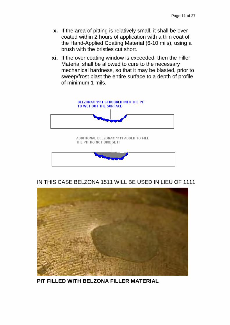
Page 11 of 27
x. If the area of pitting is relatively small, it shall be over coated within 2 hours of application with a thin coat of the Hand-Applied Coating Material (6-10 mils), using a brush with the bristles cut short.
xi. If the over coating window is exceeded, then the Filler Material shall be allowed to cure to the necessary mechanical hardness, so that it may be blasted, prior to sweep/frost blast the entire surface to a depth of profile of minimum 1 mils.
IN THIS CASE BELZONA 1511 WILL BE USED IN LIEU OF 1111
PIT FILLED WITH BELZONA FILLER MATERIAL

Page 12 of 27
b. Application of Filler Material to Fill Areas of Multiple Pits
i. UNDER NO CIRCUMSTANCES SHALL BLAST CLEANING, OR
COATING, BE UNDERTAKEN IF THE RELATIVE HUMIDITY IS
MORE THAN 85% OR THE SUBSTRATE TEMPERATURE IS LESS
THAN 5°F ABOVE THE DEW POINT. TOOL BOX TALKS SHALL
BE CARRIED OUT BETWEEN THE SUPERVISORY TEAM AND THE
COATING TEAM PRIOR TO COMMENCING ANY PHASE OF THE
APPLICATION.
ii. Dehumidification equipment, if required, may be used in conjunction with climate control, as per NACE Publication 6A192/SSPC-TR3.
iii. Pits with depths greater than their widths shall be weld-overlaid, as per Customer’s standard GP19-4-1.
iv. Pits with depths equal to or less than their widths shall be filled with the Filler Material prior to coating.
v. All pitted areas shall be prepared in accordance with Section 4, Surface Preparation.
vi. The Filler Material shall be mixed as per IFU.
vii. The Filler Material shall be scrubbed into the pitted areas to wet out the substrate completely. A brush with the bristles cut short (1” of bristles left), or applicator may be used for this. This should also include the area between the pits.
viii. Once wetted out, additional Filler Material shall be applied taking care to fill the pits and not just bridge over them.
ix. On completion, a Belzona Plastic Applicator may be used to contour the Filler Material to the shape of the vessel, leaving it smooth with no ridges or high spots that could protrude through the coating.
x. The Filler Material shall be allowed to cure to the necessary mechanical hardness, so that it may be blasted, prior to sweep/frost blasting of the entire surface before coating with the Hand-Applied Coating Material.

Page 13 of 27
PITTED SHELL
PITTING FILLED WITH BELZONA FILLER MATERIAL
Depending on the extent of the pitting, grit blasting should only take place over the area of the shell that can comfortably be filled in each shift. It may take a number of shifts to fill the pitting and leave a smooth finish. Time spent filling pits will greatly benefit the quality of application of the Hand-Applied Coating Material.

Page 14 of 27
7. APPLICATION OF HAND-APPLIED COATING MATERIAL
a. Application of the Stripe Coat
i. UNDER NO CIRCUMSTANCES SHALL BLAST CLEANING, OR
COATING, BE UNDERTAKEN IF THE RELATIVE HUMIDITY IS
MORE THAN 85% OR THE SUBSTRATE TEMPERATURE IS LESS
THAN 5°F ABOVE THE DEW POINT. TOOL BOX TALKS SHALL
BE CARRIED OUT BETWEEN THE SUPERVISORY TEAM AND THE
COATING TEAM PRIOR TO COMMENCING ANY PHASE OF THE
APPLICATION.
ii. Dehumidification equipment, if required, may be used in conjunction with climate control, as per NACE Publication 6A192/SSPC-TR3.
iii. Areas that require stripe coating shall be blasted as per NACE No. 2/SSPC-SP10 Near-White Metal Blast Cleaning to a 3 mil profile minimum.
iv. Following completion of blast cleaning, all dust, blast media, and any other debris shall be removed by sweeping and vacuuming. If the disconnected nozzles in the base of the vessel are of sufficient size, they may be used to allow emptying of any blasting grit and debris.
v. The condition of the blasted surface must be maintained until application of the Hand-Applied Coating Material. If this is not possible, then the surface shall be re-blasted prior to application of the coating system.
vi. Great care must be taken not to contaminate the surface once it has been blasted. Anyone entering the vessel shall use nitrile gloves, over shoes, and any other reasonable protective measure adopted on site.
vii. Following satisfactory inspection, the areas which have been grit blasted shall be cleaned as per IFU.
viii. Weld seams, etc., shall be identified and visually inspected to ensure there are no obstructions, debris, or defects.
i. The stripe coat will be hand applied.
ii. Throughout the course of application regular wet film thickness checks shall be made, as per ASTM D4414 – 95 (2007) Standard Practice for Measurement of Wet

Page 15 of 27
Film Thickness by Notch Gages. The Material Manufacturer’s coverage rates shall be strictly adhered to, as per IFU. Indentations made by the wet film gauges shall be brushed. The coating supervisor shall ensure that the issue of brushing out of wet film thickness marks in the coating is covered in the Tool Box talks prior to the commencement of each application.
iii. The application of the Hand-Applied Coating Material shall be carried out in one continuous operation.
iv. After completion of the first stripe coat, the Hand-Applied Coating Material shall be allowed to cure as per IFU, but should not be left longer than stated per IFU.
v. The Hand-Applied Coating Material shall be mixed and applied as in Sections 7.x. – 7.xii., to produce a wet film thickness of 18 mils extending across the internal surface of the nozzles and on the internal vessel shell.

Page 16 of 27
b. Application of the First Coat
8. HAND APPLICATION OF BELZONA 1391T TO VESSEL INTERNAL SHELL.
i. UNDER NO CIRCUMSTANCES SHALL BLAST CLEANING, OR
COATING, BE UNDERTAKEN IF THE RELATIVE HUMIDITY IS
MORE THAN 85% OR THE SUBSTRATE TEMPERATURE IS LESS
THAN 5°F ABOVE THE DEW POINT. TOOL BOX TALKS SHALL
BE CARRIED OUT BETWEEN THE SUPERVISORY TEAM AND THE
COATING TEAM PRIOR TO COMMENCING ANY PHASE OF THE
APPLICATION.

Page 17 of 27
ii. It is of paramount importance that the Coating Material is kept a suitable temperature prior to mixing, as detailed in the IFU. The actual temperature shall be taken on at least one batch and recorded on the quality assurance document.
iii. Dehumidification equipment, if required, may be used in conjunction with climate control, as per NACE Publication 6A192/SSPC-TR3.
iv. Prior to commencing lining of the vessel internal shell, ensure that all of the requirements of Section 4 (Surface Preparation) and Section 5 have been met.
v. Application shall be carried out using suitable airless spray equipment see IFU for details.
vi. It is of paramount importance that the Belzona® 1391T is at a temperature above 50°F prior to loading in sprayer, as detailed in the IFU. The actual temperature shall be taken on at least one batch and recorded on the Quality Plan.
vii. Adjacent areas not to be coated, including nozzles, shall be protected.
viii. The Belzona® 1391T product must only be applied within those areas, which have been subjected to surface preparation as detailed in Section 4 & 5.
ix. Special attention needs to be paid to the environmental requirements for coating as laid down in the Belzona® 1391T IFU.
x. Prior to application the ambient conditions shall be checked and found to be in accordance with the coatings manufacturer's instructions.
xi. These will be recorded in the quality control documentation. These shall be maintained throughout the course of the application and will be checked on a regular basis.
xii. Any sudden changes in atmospheric conditions shall also be recorded on the quality control documentation.
xiii. Ensure that adequate lighting is available

Page 18 of 27
xiv. Starting at the end furthest away from the exit manway apply the first coat of Belzona 1391T in accordance with the Instructions for Use.
xv. From this point apply material evenly retreating towards the exit manway. Upon leaving the vessel, the floor area beneath the manway shall be coated along with the manway flange.
xvi. Belzona® 1391T is applied as a two coat application the Belzona® 1391T should be overlapped onto the Belzona® 1391T this must be carried out within the over coating window of the Belzona® 1391T per the IFU.
xvii. Voids, runs, sags and drips shall be corrected and brushed out immediately.
xviii. Throughout the course of application regular wet film thickness checks shall be made and the manufacturer’s coverage rates shall be strictly adhered to. Indentations made by the wet film gauges shall be brushed out to ensure an uninterrupted coating. The coating supervisor shall ensure that the issue of brushing out of wet film thickness marks in the coating is covered in the Tool Box talks prior to the commencement of each application.
xix. The applied material shall be visually checked for pinholes and where found these should be brushed out.
xx. Batch numbers of all materials mixed shall be recorded on the quality control form for the equipment. Where necessary this should be continued on to a separate form and the forms relevant to each work period securely fastened together.
xxi. Care shall be taken to ensure that material is not applied outside of its usable life.
xxii. Manufacturers specified ambient conditions shall be maintained throughout the application and shall regularly be checked and the results recorded. Unless

Page 19 of 27
stated otherwise the minimum frequency for such checks shall be hourly.
xxiii. UNDER NO CIRCUMSTANCES SHALL COATINGS BE APPLIED AT GREATER THAN 85% RELATIVE HUMIDITY OR WHEN THE SUBSTRATE TEMPERATURE IS BELOW 50°F OR LESS THAN 5°F ABOVE THE DEW POINT. THE JOB SUPERVISOR MUST DISCUSS THIS ISSUE DURING THE TOOL BOX TALK WITH THE COATING TEAM PRIOR TO THE COMMENCEMENT OF THE JOB.
xxiv. Any sudden changes in ambient conditions shall be recorded on the quality control documentation.
xxv. Such inspection as is in the quality plan shall be carried out and the results recorded on the quality control documentation.
xxvi. Should the application have to stop for any reason, or require to be completed in several parts, refer to Section 10 for the procedure to follow regarding Interrupted Application.
xxvii. On completion of the first coat it should be left for a period as recommended in the IFU to cure before the second coat is applied in exactly the same manner as the first.
b. Inspection of the First Coat
i. Ensure the first coat is ready to accept second coat.
ii. If the overcoat window has passed since the start of mixing of the first unit of Coating Material applied for the first coat, then the first coat shall be allowed to cure to mechanical hardness, necessary for Sweep/Frost grit blast.
iii. If sweep/frost blasting is required, it shall be carried out as in Sections 4.a.15.-4.a.16 Sweep/Frost grit blast.
c. Application of the Second Coat

Page 20 of 27
i. UNDER NO CIRCUMSTANCES SHALL BLAST CLEANING, OR
COATING, BE UNDERTAKEN IF THE RELATIVE HUMIDITY IS
MORE THAN 85% OR THE SUBSTRATE TEMPERATURE IS LESS
THAN 5°F ABOVE THE DEW POINT. TOOL BOX TALKS SHALL
BE CARRIED OUT BETWEEN THE SUPERVISORY TEAM AND THE
COATING TEAM PRIOR TO COMMENCING ANY PHASE OF THE
APPLICATION.
ii. It is of paramount importance that the Coating Material is kept a suitable temperature prior to mixing, as detailed in the IFU. The actual temperature shall be taken on at least one batch and recorded on the quality assurance document.
iii. Dehumidification equipment, if required, may be used in conjunction with climate control, as per NACE Publication 6A192/SSPC-TR3.
iv. Adjacent areas not to be coated, including nozzles, shall be protected. The Coating Material product must only be applied within those areas, which are ready to receive a second coat (i.e. will not be disturbed by a second coat), but have not been allowed to cure for four hours or more, or those that have been allowed to cure to mechanical harness required for blasting and have been subjected to surface preparation as detailed in Sections 4.a.15.-4.a.16 Sweep/Frost grit blast.
v. Ensure all areas to be coated are clean, free of dust, debris, and any obstructions.
vi. Follow recommended procedures as the first coat.
9. INSPECTION OF THE COATING SYSTEM
i. The entire coated surface shall be inspected, by Inspector, for any visible defects such as runs, sags, drips, voids or misses. Any defects found shall be marked with a suitable marker for remedial work to take place.
ii. All equipment used by the Inspector of the vessel shall be uniquely identified and shall be demonstrated to have been calibrated to a recognized traceable standard.

Page 21 of 27
iii. Dry film thickness checks shall be carried out by Inspector to ensure that the minimum of 16 mils thickness has been achieved as per SSPC-PA2.
Greater coating thickness shall not be reason for repair or a defect to be marked. Over-thickness of either the Filler Material or the Hand-Applied Coating Material will not have a negative effect on the performance of this coating system
iv. Inspection for holidays shall be carried out by Inspector using a low voltage wet sponge tester (LVHD).
v. Inspection shall be documented. The table, Inspection of Coating Application - Table A, shall be used to direct inspection and all points outlined in this table shall be carried out.
vi. The vessel shall remain accessible until a final inspection of any remedial work has been carried out.
10. REMEDIAL WORK
i. UNDER NO CIRCUMSTANCES SHALL BLAST CLEANING, OR
COATING, BE UNDERTAKEN IF THE RELATIVE HUMIDITY IS
MORE THAN 85% OR THE SUBSTRATE TEMPERATURE IS LESS
THAN 5°F ABOVE THE DEW POINT. TOOL BOX TALKS SHALL
BE CARRIED OUT BETWEEN THE SUPERVISORY TEAM AND THE
COATING TEAM PRIOR TO COMMENCING ANY PHASE OF THE
APPLICATION.
ii. It is of paramount importance that the Hand-Applied Coating Material is kept a suitable temperature prior to mixing, as detailed in the IFU. The actual temperature shall be taken on at least one batch and recorded on the quality assurance document.
iii. Dehumidification equipment may be used in conjunction with climate control, as per NACE Publication 6A192/SSPC-TR3.

Page 22 of 27
iv. All pinholes and misses detected by the inspection procedure shall be marked during inspection, and be ready for remedial work.
v. If the coating is still within the over coating window then additional material can be applied over the defective area without further preparation.
vi. However, if the coating is outside its over coating window then the surface of the coating material shall be prepared by either:
A- Sweep/Frost Blasting as in Sections 4.a.xv.-4.a.xvi. Blasting Cleaning.
B- Manual preparation using a grinder fitted with a suitable abrasive flap disc (P80 grade or less). Care should be taken to ensure that the coating is not removed to the substrate; otherwise re-preparing the surface by grit blasting will be required.
vii. Following preparation, the surface shall be cleaned and left free of debris.
viii. The surrounding area shall be masked off so as to ensure that the entire repair remains within the prepared area.
ix. The Hand-Applied Coating Material shall be mixed and applied using a suitable brush, with the bristles cut short (1” of bristles left), Belzona applicator, squeegee, or trowel, wetting it out completely at the required film thickness, as per IFU.
x. For extremely small defects that are not visible to the naked eye but are revealed by inspection, the defect should be carefully widened using a sharp knife, prior to preparation as per above.
xi. Once the material is sufficiently cured then re-inspect, as per Section 8.
11. FINAL INSPECTION

Page 23 of 27
i. The vessel shall be inspected in accordance with the quality assurance document until the entire acceptance criteria have been met, by Inspector
ii. Ancillary items, such as flange covers etc. shall be handled carefully to avoid damage to the coating system. Under no circumstances shall they be moved or fitted prior to the coating having cured to an acceptable level.
iii. A final integrity check will be performed once all internal furniture has been refitted and the vessel is considered to be ready for service. This should highlight any damage to the coating and allow remedial work to take place.
12. INTERRUPTION TO APPLICATION
i. Where it is not possible to complete the entire surface of a vessel in any one continuous period, accommodation must be made for overlapping the coating system onto the previously applied material by a minimum of 1”.
ii. Prior to carrying out this operation if the previously applied material has passed its over coating window it shall be flash blasted to give a minimum1mil depth of profile.
iii. The area prepared shall be cleaned.
iv. The area of overlap shall be a minimum of 1”.
v. Prior to commencing application the area that has been prepared shall be clearly defined so as to prevent application on unprepared surfaces.
vi. This procedure shall be followed on all areas where it is necessary to overlap the coating material.
vii. This requirement is in addition to the requirements for preparation of the substrate as listed under Section 4.1, Blast Cleaning.
13. POST CURING

Page 24 of 27
i. If determined needed for the application, follow instructions per the IFU.
14. PRE-QUALIFICATION REQUIREMENTS
i. For this particular application Belzona 1391T, 1511 are recommended.
ii. IFUs, Product Specification Sheets, and Safety Data Sheets will provided for all materials supplied.
15. MANUFACTURERS REPRESENTATION
i. Should the Customer so request then a representative of the coating manufacturer may be made available to advise during the application at additional cost.
ii. The cost for this representation will be agreed in advance between the Material Supplier and the Customer.
iii. In addition to this, distribution of the following costs will also be agreed in advance:
1. Travel to and from site
2. Accommodation costs

Page 25 of 27
APPENDIX B - List of Referred Standards
ASTM D4414 - 95(2007) Standard Practice for Measurement of Wet Film Thickness by Notch Gages
NACE No. 11/SSPC-PA 8, Thin-Film Organic Linings Applied in New Carbon Steel Process Vessels
SSPC Technology Guide No. 12 Guide for Illumination of Industrial Painting Projects NACE No. 2/SSPC-SP10 Near-White Metal Blast Cleaning NACE RPO 287 -2002 Field Measurement of Surface Profile of Abrasive Blast-Cleaned Steel Surfaces Using Replica Tape
NACE Publication 6A192/SSPC-TR3 Dehumidification and Temperature Control During Surface Preparation, Application, and Curing for Coatings/Linings of Steel Tanks, Vessels, and Other Enclosed Spaces

Page 26 of 27
APPENDIX C - List of Tables
Inspection of Coating Application - Table B
Test Test method Frequency Acceptance Criteria
Consequence
ENVIRONMENTAL
CONDITIONS
AMBIENT AND STEEL
TEMPERATURE
RELATIVE HUMIDITY
STEEL TEMPERATURE
START OF EACH
SHIFT + HOURLY
THROUGHOUT
SHIFT.
START OF EACH
SHIFT THEN
CONSTANTLY
MINIMUM OF 5°F
ABOVE DEW POINT
<85% R.H.
AIR TEMPERATURE
AS PER IFU
NO COATING
VISUAL
EXAMINATION VISUAL FOR RUNS, SAGS, DRIPS AND
VOIDS.
100% OF ALL
SURFACES NO DEFECTS ALL DEFECTS TO
BE REMEDIED
DURING
APPLICATION
WHEREVER
POSSIBLE.
PRODUCT
IDENTIFICATION RECORDING OF
BATCH NUMBERS ALL BATCH
NUMBERS SHALL BE
RECORDED.
WET FILM
THICKNESS TESTING 3 PER 10 SF COATING
APPLICATORS WILL
BE RESPONSIBLE
FOR CHECKING WET
FILM THICKNESS
DURING
APPLICATION. IN
ADDITION THE
SUPERVISOR OR
INSPECTOR WILL
MAKE RANDOM
CHECKS TO VERIFY
THESE AS BEING
CORRECT.
MATERIAL TO BE
APPLIED TO
CORRECT
THICKNESS.

Page 27 of 27
APPENDIX D - Quality Assurance Inspection Form
REPORT NUMBER DATE
INSPECTOR TIME START
SUBSTRATE TIME FINISH
APPLICATION METHOD DRAWING No.
BELZONA PRODUCT USED VESSEL No.
PROJECT REFERENCE LOCATION OF APPLICATION
INSPECTION STAGES COVERED IN THIS REPORT (Check all that apply)
SUBSTRATE CLEANLINESS
COATING
APPLICATION
HOLIDAY
TEST
REMEDIAL REPAIR
SECTION 1 CLIMATIC CONDITIONS
Period Time Air
Temp. [°F]
Surface Temp.
[ºF] %RH
Dew Point [ºF]
Weather changes?
Location of test
Shift start
Mid shift
Shift end
SECTION 2 SURFACE PREPARATION
Oil/ moisture free air
Yes Abrasive Type
Ave surface profile in mils (Grit blast only)
Surface preparation
No
Substrate cleanliness standard = ISO 8501-1 Sa 2½
Yes Degreasing carried out prior to grit blast. (If required)
Yes Sufficient access provided to work area. (If no record details below in comments section)
Yes
No No No
SECTION 3 NON-VISIBLE SALT CONTAMINATION
Test kit used Serial No
Test result recorded (μg/cm²)
SECTION 4 COATING APPLICATION
Product correctly mixed
Yes ISO 8502-3 Visible dust contamination level acceptable. No worse than rating “2” on approved clear tape. Dust tape attached to Cleanliness Report.
Rating
No
Coat No.
Color Time Area WFT [mils]
Batch No. Base
Batch No. Solidifier
Full / Part Mixing ratio
(part pack only)
SECTION 5 HOLIDAY TEST
Integrity test method Voltage setting Date
Equipment model No of defects
Serial number Location
Comments: (Log findings if any of the NO boxes in section 2, 3 and 4 have been crossed and record details of all other activities during shift.
Note: All replica tape measurements, location drawings and photographic records are attached to this document.
ACCEPTANCE APPLICATOR BELZONA Ltd FABRICATOR Pkg CONTRACTOR
EPIC CONTRACTOR
ASSET OPERATOR REVIEWED ONLY
COMPANY
NAME
POSITION
SIGN
DATE

Product Belzona 1511 Product Belzona 1391TDate Number of Kits Date Number of Kits12/12/2018 4 12/10/2018 1212/13/2018 4 12/11/2018 18
12/12/2018 1012/13/2018 22
Total 8 Total 62
Summit - Johnson County

11. Personal protective equip./apparel plus respiratory
Surface Profile Mils
Smooth 30
14. Any safety hazards/incidents today?
1. Coating equipment/materials meets specifications?
4. Any non-conformance issues today?
(If yes, explain in Remarks or document & attach.)
protection as required by HAZCOM?
12. MSDS readily available?
10. Any Third Party Contacts/Meetings today?
+
+
+
+
+
+
A. Did ABNORMAL working conditions adversely affect construction progress?
3. Applied coatings are holiday free?
2. Pipe surface prepared in accordance with specs.?
INSPECTOR'S CHECK LIST
Technical Third Party / Landowner Contacts
If Yes, Attach Third Party Contact Report:
Environmental
Voltage From Station
5. Any mixing of topsoil with subsoil?
6. Any excessive R-O-W damage (rutting, etc.)?
7. Coating/cleaning mat'l stored per HAZMAT req'ts?
8. Silt fence/straw bales install'd/maintain'd as req'd?
9.Temp. waterbars installed/maintained as required?
12/12/18 2
To Station
3000
of coating was was 29.9 mils. Moved to next 8' section and it was blasted cleaned to SP10 with an average anchor profile of 5.2 mils. 5 kits of Belzona 1511 rebuild was applied to this
section. DH unit was run throughthe night and first coat will be applied on 12-13-2018 at start of operations. 12 kits of Belzona 1391T used on first coat.
Coating DataJeep Voltage Data
Alignment Station
REMARKS (Explain Answers to Questions above)
Coating of this second 8' was inspected at start. Coating had an average DFT of 20 mils. Second coat using 10 kits was applied at applied and completed at approx. 1130 .
At approx 1400 this area was inspected. Several holidays were detected. Areas were marked and repaired. After repair no holidays were detected. Average DTF for this second 8'
Distribution: OCM/Office Mgr. Chief Inspector Hours Worked Mileage
14 290
Inspector's Name (print) Inspector's Signature Work Date Report No.
13. General Safety Rules followed? (see chart)
CONTRACTOR'S LABOR & EQUIPMENT
Contractor's Labor Classification Number Hours Contractor's Equipment Classification Number Hours
++
Inspected From To Today
Coating of 8' 8++
B. Any Contractor caused delays, downtime or other reduced progress? (If yes, explain in Remarks or document & attach.)
CONSTRUCTION PROGRESS
Work or Operation Alignment Station Feet
WORKING CONDITIONS
Weather Conditions Cloudy
Right-of-Way Conditions
COATING INSPECTOR'S DAILY REPORTContractor Martin Specialty Coatings / Summit Midstream Johnson County Equipment No.
Contractor's Foreman Curtis Tuminello Total Length (ft)No. of Crews
Yes No
Y N N/A
Yes No
Y N N/A
Y N N/A
Y N N/A
Y N N/A
Y N N/A
Y N N/A
Y N N/A
Y N N/A
Y N N/A
Y N N/A
Y N
Y N N/A
Y N N/A