Flexible blue-emitting encapsulated organic semiconductor DFB laser
11
Flexible blue-emitting encapsulated organic semiconductor DFB laser J. Herrnsdorf, 1,3 B. Guilhabert, 1,4 Y. Chen, 1 A. L. Kanibolotsky, 2 A. R. Mackintosh, 2 R. A. Pethrick, 2 P. J. Skabara, 2 E. Gu, 1 N. Laurand, 1 and M. D. Dawson 1 1 Institute of Photonics, University of Strathclyde, Glasgow G4 0NW, UK 2 Department of Pure and Applied Chemistry, WestCHEM, University of Strathclyde, Glasgow G1 1XL, UK 3 [email protected] 4 [email protected] Abstract: An organic laser based on a monodisperse star-shaped oligoflu- orene gain medium has been embodied in mechanically flexible format with distributed feedback templated from a holographic master grating. Laser emission was obtained from 425 to 442.5 nm with lowest soft pump thresh- old at 14.4 μ J/cm 2 (2.7 kW/cm 2 ). We compare the performance of such lasers with and without encapsulation. Encapsulation enables stable opera- tion in ambient atmosphere at a 1/e degradation energy dosage of 53 J/cm 2 . © 2010 Optical Society of America OCIS codes: (140.3490) Lasers, distributed-feedback; (220.4241) Nanostructure fabrication; (160.4890) Organic materials; (140.7270) Vertical emitting lasers; (310.1515) Protective coat- ings. References and links 1. I. Samuel and G. Turnbull, “Organic Semiconductor Lasers,” Chem. Rev. 107, 1272–1295 (2007). 2. C. Kallinger, M. Hilmer, A. Haugeneder, M. Perner, W. Spirkl, U. Lemmer, J. Feldmann, U. Scherf, K. M¨ ullen, A. Gombert, and V. Wittwer, “A Flexible Conjugated Polymer Laser,” Adv. Mater. 10, 920–923 (1998). 3. M. Berggren, A. Dodabalapur, R. E. S. A. Timko, and O. Nalamasu, “Organic solid-state lasers with imprinted gratings on plastic substrates,” Appl. Phys. Lett. 72, 410–411 (1998). 4. S. Riechel, C. Kallinger, U. Lemmer, J. Feldmann, A. Gombert, V. Wittwer, and U. Scherf, “A nearly diffraction limited surface emitting conjugated polymer laser utilizing a two-dimensional photonic band structure,” Appl. Phys. Lett. 77, 2310–2312 (2000). 5. S. Riechel, U. Lemmer, J. Feldmann, S. Berleb, A. G. M¨ uckl, W. Br¨ utting, A. Gombert, and V. Wittwer, “Very compact tunable solid-state laser utilizing a thin-film organic semiconductor,” Opt. Lett. 26, 593–595 (2001). 6. M. Lu, B. Cunningham, S.-J. Park, and J. Eden, “Vertically emitting, dye-doped polymer laser in the green (λ ∼ 536 nm) with a second order distributed feedback grating fabricated by replica molding,” Opt. Commun. 281, 3159–3162 (2008). 7. S. Richardson, “The Fabrication and Lithography of Conjugated Polymer Distributed Feedback Lasers and De- velopment of their Applications,” Ph.D. thesis, University of St. Andrews, School of Physics and Astronomy (2007). 8. S. Richardson, O. P. M. Gaudin, G. A. Turnbull, and I. D. W. Samuel, “Improved operational lifetime of semi- conducting polymer lasers by encapsulation,” Appl. Phys. Lett. 91, 261104 (2007). 9. D. Pisignano, L. Persano, P. Visconti, R. Cingolani, G. Gigli, G. Barbarella, and L. Favaretto, “Oligomer-based organic distributed feedback lasers by room-temperature nanoimprint lithography,” Appl. Phys. Lett. 83, 2545– 2547 (2003). 10. J. R. Lawrence, G. A. Turnbull, and I. D. W. Samuel, “Polymer laser fabricated by a simple micromolding process,” Appl. Phys. Lett. 82, 4023–4025 (2003). 11. M. Ichikawa, Y. Tanaka, N. Suganuma, T. Koyama, and Y. Taniguchi, “Low-Threshold Photopumped Distributed Feedback Plastic Laser Made by Replica Molding,” Jpn. J. Appl. Phys. 42, 5590–5593 (2003). 12. M. H. Song, B. Wenger, and R. H. Friend, “Tuning the wavelength of lasing emission in organic semiconducting laser by the orientation of liquid crystalline conjugated polymer,” J. Appl. Phys. 104, 033107 (2008). #134271 - $15.00 USD Received 30 Aug 2010; revised 1 Oct 2010; accepted 4 Oct 2010; published 22 Nov 2010 (C) 2010 OSA 6 December 2010 / Vol. 18, No. 25 / OPTICS EXPRESS 25535
-
Upload
independent -
Category
Documents
-
view
0 -
download
0
Transcript of Flexible blue-emitting encapsulated organic semiconductor DFB laser

Flexible blue-emitting encapsulatedorganic semiconductor DFB laser
J. Herrnsdorf,1,3 B. Guilhabert,1,4 Y. Chen,1 A. L. Kanibolotsky,2
A. R. Mackintosh,2 R. A. Pethrick,2 P. J. Skabara,2 E. Gu,1
N. Laurand,1 and M. D. Dawson1
1Institute of Photonics, University of Strathclyde, Glasgow G4 0NW, UK2Department of Pure and Applied Chemistry, WestCHEM, University of Strathclyde, Glasgow
G1 1XL, [email protected]
Abstract: An organic laser based on a monodisperse star-shaped oligoflu-orene gain medium has been embodied in mechanically flexible format withdistributed feedback templated from a holographic master grating. Laseremission was obtained from 425 to 442.5 nm with lowest soft pump thresh-old at 14.4 μJ/cm2 (2.7 kW/cm2). We compare the performance of suchlasers with and without encapsulation. Encapsulation enables stable opera-tion in ambient atmosphere at a 1/e degradation energy dosage of 53 J/cm2.
© 2010 Optical Society of America
OCIS codes: (140.3490) Lasers, distributed-feedback; (220.4241) Nanostructure fabrication;(160.4890) Organic materials; (140.7270) Vertical emitting lasers; (310.1515) Protective coat-ings.
References and links1. I. Samuel and G. Turnbull, “Organic Semiconductor Lasers,” Chem. Rev. 107, 1272–1295 (2007).2. C. Kallinger, M. Hilmer, A. Haugeneder, M. Perner, W. Spirkl, U. Lemmer, J. Feldmann, U. Scherf, K. Mullen,
A. Gombert, and V. Wittwer, “A Flexible Conjugated Polymer Laser,” Adv. Mater. 10, 920–923 (1998).3. M. Berggren, A. Dodabalapur, R. E. S. A. Timko, and O. Nalamasu, “Organic solid-state lasers with imprinted
gratings on plastic substrates,” Appl. Phys. Lett. 72, 410–411 (1998).4. S. Riechel, C. Kallinger, U. Lemmer, J. Feldmann, A. Gombert, V. Wittwer, and U. Scherf, “A nearly diffraction
limited surface emitting conjugated polymer laser utilizing a two-dimensional photonic band structure,” Appl.Phys. Lett. 77, 2310–2312 (2000).
5. S. Riechel, U. Lemmer, J. Feldmann, S. Berleb, A. G. Muckl, W. Brutting, A. Gombert, and V. Wittwer, “Verycompact tunable solid-state laser utilizing a thin-film organic semiconductor,” Opt. Lett. 26, 593–595 (2001).
6. M. Lu, B. Cunningham, S.-J. Park, and J. Eden, “Vertically emitting, dye-doped polymer laser in the green(λ ∼ 536 nm) with a second order distributed feedback grating fabricated by replica molding,” Opt. Commun.281, 3159–3162 (2008).
7. S. Richardson, “The Fabrication and Lithography of Conjugated Polymer Distributed Feedback Lasers and De-velopment of their Applications,” Ph.D. thesis, University of St. Andrews, School of Physics and Astronomy(2007).
8. S. Richardson, O. P. M. Gaudin, G. A. Turnbull, and I. D. W. Samuel, “Improved operational lifetime of semi-conducting polymer lasers by encapsulation,” Appl. Phys. Lett. 91, 261104 (2007).
9. D. Pisignano, L. Persano, P. Visconti, R. Cingolani, G. Gigli, G. Barbarella, and L. Favaretto, “Oligomer-basedorganic distributed feedback lasers by room-temperature nanoimprint lithography,” Appl. Phys. Lett. 83, 2545–2547 (2003).
10. J. R. Lawrence, G. A. Turnbull, and I. D. W. Samuel, “Polymer laser fabricated by a simple micromoldingprocess,” Appl. Phys. Lett. 82, 4023–4025 (2003).
11. M. Ichikawa, Y. Tanaka, N. Suganuma, T. Koyama, and Y. Taniguchi, “Low-Threshold Photopumped DistributedFeedback Plastic Laser Made by Replica Molding,” Jpn. J. Appl. Phys. 42, 5590–5593 (2003).
12. M. H. Song, B. Wenger, and R. H. Friend, “Tuning the wavelength of lasing emission in organic semiconductinglaser by the orientation of liquid crystalline conjugated polymer,” J. Appl. Phys. 104, 033107 (2008).
#134271 - $15.00 USD Received 30 Aug 2010; revised 1 Oct 2010; accepted 4 Oct 2010; published 22 Nov 2010(C) 2010 OSA 6 December 2010 / Vol. 18, No. 25 / OPTICS EXPRESS 25535

13. A. L. Kanibolotsky, R. Berridge, P. J. Skabara, I. F. Perepichka, D. D. C. Bradley, and M. Koeberg, “Synthesisand Properties of Monodisperse Oligofluorene-Functionalized Truxenes: Highly Fluorescent Star-Shaped Archi-tectures,” J. Am. Chem. Soc. 126, 13695–13702 (2004).
14. G. Tsiminis, Y. Wang, P. E. Shaw, A. L. Kanibolotsky, I. F. Perepichka, M. D. Dawson, P. J. Skabara, G. A.Turnbull, and I. D. Samuel, “Low-threshold organic laser based on an oligofluorene truxene with low opticallosses,” Appl. Phys. Lett. 94, 243304 (2009).
15. Y. Wang, G. Tsiminis, Y. Yang, A. Ruseckas, A. L. Kanibolotsky, I. F. Perepichka, P. J. Skabara, G. A. Turnbull,and I. D. Samuel, “Broadly tunable deep blue laser based on a star-shaped oligofluorene truxene,” Synth. Met.160, 1397–1400 (2010).
16. B. Guilhabert, N. Laurand, J. Herrnsdorf, Y. Chen, A. R. Mackintosh, A. L. Kanibolotsky, E. Gu, P. J. Skabara,R. A. Pethrick, and M. D. Dawson, “Amplified spontaneous emission in free-standing membranes incorporatingstar-shaped monodisperse π-conjugated truxene oligomers,” J. Opt. 12, 035503 (2010).
17. G. Stephan, “Semiclassical study of the laser transition,” Phys. Rev. A 55, 1371–1384 (1997).18. Y. Boucher, A. Deryagin, V. Kuchinskii, and G. Sokolovskii, “Near-threshold spectral and modal characteristics
of a curved-grating quantum-well distributed-feedback laser,” Nanotechnology 14, 615–618 (2003).19. Y. Boucher and P. Feron, “Generalized transfer function: A simple model applied to active single-mode microring
resonators,” Opt. Commun. 282, 3940–3947 (2009).20. G. Pert, “Output characteristics of amplified-stimulated-emission lasers,” J. Opt. Soc. Am. B 11, 1425–1435
(1994).21. L. D. Negro, P. Bettotti, M. Cazzanelli, D. Pacifici, and L. Pavesi, “Applicability conditions and experimental
analysis of the variable stripe length method for gain measurements,” Opt. Commun. 229, 337–348 (2004).22. A. Costela, O. Garcıa, L. Cerdan, I. Garcıa-Moreno, and R. Sastre, “Amplified spontaneous emission and optical
gain measurements from pyrromethene 567 - doped polymer waveguides and quasi-waveguides,” Opt. Express16, 7023–7036 (2008).
23. A. Costela, O. Garcıa, L. Cerdan, I. Garcıa-Moreno, and R. Sastre, “Amplified spontaneous emission and opticalgain measurements from pyrromethene 567 - doped polymer waveguides and quasi-waveguides: erratum,” Opt.Express 16, 7587 (2008).
24. The Mathworks, Matlab Documentation. Available online at http://www.mathworks.com/.25. R. Xia, W.-Y. Lai, P. A. Levermore, W. Huang, and D. D. C. Bradley, “Low-Threshold Distributed-Feedback
Lasers Based on Pyrene-Cored Starburst Molecules with 1,3,6,8-Attached Oligo(9,9-Dialkylfluorene) Arms,”Adv. Funct. Mater. 19, 2844–2850 (2009).
26. G. A. Turnbull, P. Andrew, M. J. Jory, W. L. Barnes, and I. D. W. Samuel, “Relationship between photonic bandstructure and emission characteristics of a polymer distributed feedback laser,” Phys. Rev. B 64, 125122 (2001).
1. Introduction
In recent years, much effort has been put into the development of solid-state organic lightemitters. In particular, the success of organic light emitting diodes combined with advances inpolymeric waveguides has been accompanied by increased interest in organic semiconductorlasers. Such devices have a number of benefits compared to their inorganic counterparts, in-cluding simplified production methods and the avoidance of highly toxic materials [1]. Anotherattractive property of organics is their compatibility with a large range of different materialsthus allowing for example the usage of mechanically flexible substrates [2–6].
One of the key challenges in the development of these lasers is their susceptibility to photo-induced oxidation which limits their useful lifetime. To date the majority of organic film laserdemonstrations required the laser structure to be pumped in vacuum or in a protective inertgas atmosphere [7]. For example the first flexible organic semiconductor laser reported [2] wascharacterized in vacuum. In general, only limited information on quantitative analysis of or-ganic laser degradation, both in vacuum and aerobic operating conditions, has been published.One possible approach to address the issue of photo-degradation is to create a multilayer struc-ture where the active medium is enclosed in between layers of a transparent polymer that servesas an oxygen and water barrier. Encouraging results by Richardson et al. [7, 8] on red-emittingMEH-PPV are based on such an encapsulation technique.
A commonly used resonator layout for organic thin-film lasers is based on distributed feed-back (DFB), where the optical feedback and out-coupling are provided by Bragg reflections ofdifferent order from a grating within the film [1]. DFB gratings are typically custom made
#134271 - $15.00 USD Received 30 Aug 2010; revised 1 Oct 2010; accepted 4 Oct 2010; published 22 Nov 2010(C) 2010 OSA 6 December 2010 / Vol. 18, No. 25 / OPTICS EXPRESS 25536

by electron beam lithography, two-beam interference or deep-ultraviolet photo-lithography.These methods can be quite complicated and expensive thus counteracting the organic semi-conductors’ important potential for of low-cost production. In order to simplify matters soft-lithographic imprint methods to replicate a master grating have been developed [9–11]. Ourapproach is based on soft lithography using commercially available holographic reflective grat-ings as a master. Commercially available gratings have been used before by Song, Wenger andFriend [12] for the fabrication of unencapsulated devices on glass substrates. DFB resonatorsare particularly suitable for building flexible lasers and a number of reports on such deviceshave been published. However, all reported flexible devices, with the exception of the LPPP-based work by Scherf et al. [2, 4], are based on dye-doped polymers with thresholds rangingfrom 16 μJ/cm2 [5] to 800 μJ/cm2 [6]. The lasers presented here are based on an oligomericorganic semiconductor.
Monodisperse star-shaped oligomers, are a very recent addition to the family of organic lasermaterials. In particular, tris(trifluorene)truxenes (T3), which are basically nanoscale emitters,were shown to have a high photoluminescence quantum yield and to form low-loss film onto ahard substrate when deposited from solution [13, 14]. Consequently, low threshold for opticalgain and laser oscillation were reported for such non-flexible devices [14, 15]. However, nodata on the operating lifetime was given. Also, to our knowledge, no encapsulation work onmonodisperse oligomers has been published yet. In this manuscript, we report mechanicallyflexible lasers that use encapsulated T3 nanochromophores as the active region and operate atdeep-blue wavelengths from 425 to 442 nm. Furthermore, we show that even without encapsu-lation the truxenes have better photo-stability properties than other star-shaped molecules.
In the next section, the device fabrication is described. We then present the emission char-acteristics under pulsed ultra-violet (UV) optical pumping. The power transfer function showsa soft threshold which is fitted with a microresonator model and an ASE based theory for thethreshold transition. Angle resolved spectroscopy is used to analyze the DFB grating effect.Finally, device operational lifetimes are examined.
2. Fabrication
An important feature of the lasers presented here is their simple production. The grating struc-ture is copied from the master grating into a UV-transparent polymer that is obtained byphoto-curing 1,4-cyclohexyldimethanol divinyl ether (CHDV) with added photo-acid generator(PAG). As PAG we use 4-octyloxy diphenyliodonium hexafluoroantimonite which is dissolvedin the CHDV at a weight ratio of 0.2 %. The solution is then mixed in an ultrasonic bath for atleast 5 min and degassed. It is in principle possible to incorporate the T3 molecules directly intothe CHDV matrix resulting in a nanocomposite that is capable of providing optical gain [16]though this paper will focus on stacked structures where the undoped CHDV grating is over-coated by a layer of pure T3. A schematic of the structure is shown in Figs. 1(a) and 1b.
After preparation, the PAG/CHDV solution is drop-coated onto the substrate. As a substratewe use commercially available actetate sheets of 0.1 mm thickness made for ink-jet printedtransparencies.
The substrate with the film on it is pressed onto the master grating. We use a commerciallyavailable holographic reflection grating with 3600 lines/mm, i.e. a period of 278 nm. The grat-ing surface is a polymer overcoated with aluminum. The photoresist is cured by flooding withUV light at an exposure dose of 30.5 J/cm2 through the substrate while in contact with themaster grating. Finally, the grating stucture is peeled off from the master. An approximate areaof 1 cm2 with high quality grating can be obtained by this method which is sufficient to pro-duce several devices at a time. Analysis by AFM [a scan profile is shown in Figs. 1(c) and 1(d)]reveals that the resulting grating has an average modulation depth of 21 nm in a scanned area of
#134271 - $15.00 USD Received 30 Aug 2010; revised 1 Oct 2010; accepted 4 Oct 2010; published 22 Nov 2010(C) 2010 OSA 6 December 2010 / Vol. 18, No. 25 / OPTICS EXPRESS 25537

T3
CHDV
substrate
T3
CHDV
substrate
OA
a)
b)
d)
c)
Fig. 1. On the left, schematics of the device structure are shown: (a) unencapsulated and(b) encapsulated by an optical adhesive (OA). On the right side is (c) an AFM image of thereproduced grating and at the bottom (d) a plot of the surface profile perpendicular to thegrating.
3.7×3.7 μm2. The thickness of the CHDV layer has been measured with a caliper and a valueof 30 μm was found. The refractive index of this material is nCHDV = 1.472 (Sigma-Aldrich,Inc.).
The T3 molecules are spin-coated from 20 mg/ml toluene solution onto the grating at a spin-ning speed of 2700 to 3200 RPM, resulting in films of different thickness (100 nm - 150 nm)which impacts the laser emission wavelength as discussed below in Section 3.2. Further over-coating with optical adhesives provides protection of the chromophores against oxygen andmoisture. We present devices that are encapsulated with Norland optical adhesive (NOA) 88by drop-coating a 1 mm thick top layer of refractive index nNOA = 1.56 (Norland Products,Inc.). The transmission spectrum of acetate is shown in Fig. 2 together with PL and absorptionspectra of the chromophores. Detailed analysis of the truxene PL and absorption has been doneby Kanibolotsky et al. [13] and the refractive index of the active material is nT3 = 1.77 [15].
3. Optical characterization
The organic DFB lasers were optically pumped with pulsed ultraviolet laser light at 355-nmwavelength, 5-ns pulse duration and a 10-Hz repetition rate. The pump source is a frequencytripled Q-switched Nd:YAG laser delivering pump energies ranging from 6 nJ to 3 mJ perpulse. A knife-edge method has been employed to measure the pump beam dimensions. A fullwidth half maximum (FWHM) of 2.9 mm across the beam has been measured at 6 cm and40 cm distance from the attenuator wheel, i.e. the beam divergence is negligible within thelength scales used in the setup. The samples were placed at a 45◦ angle with respect to thebeam axis resulting in an elliptical pump spot of 2.9 mm× 4.1 mm FWHM. Energy densities
#134271 - $15.00 USD Received 30 Aug 2010; revised 1 Oct 2010; accepted 4 Oct 2010; published 22 Nov 2010(C) 2010 OSA 6 December 2010 / Vol. 18, No. 25 / OPTICS EXPRESS 25538

Fig. 2. Transmission spectrum of an acetate sheet and normalized spectra of the PL andabsorption of T3 in toluene solution.
given in the text and figures are peak values assuming a Gaussian shaped beam cross section.The vertical emission from the sample surface was monitored by a 50-μm-core optical fiberwhich is connected to a CCD-spectrometer with a maximum spectral resolution of 0.13 nm.The detection angle is controllably variable which enables mapping of the beam profile withan angular resolution of 0.45◦ (7.8 mrad). During measurements, the samples are exposed tonormal ambient air at room temperature. No vacuum or inert gases are used to protect the activematerial. A schematic of the setup is shown in Fig. 3. Control of the pump energy is achieved bymonitoring the pump power with a powermeter and attenuation by a λ/2-waveplate followedby a polarizer and an attenuator wheel. A dichroic mirror is used to filter out 532 nm lightthat is leaking from the laser aperture. It is possible to focus the pump spot using a 75 mmspherical lens. In this case, an approximate pump area of 0.0014 cm2 has been measured (areawith intensity higher than half the peak value) by monitoring the pump spot luminescence witha CCD camera.
pump laser aperture
λ/2 waveplate
attenuator wheel
flip top mirrorpolarizer
dichroic mirror
sample
optical fiber to spectrometer
powermeter
2.9 mm
Fig. 3. Schematic of the setup for optical characterization.
Upon appropriate pulsed UV excitation, laser action is observed with a soft threshold behav-ior that is discussed in the next section. Above threshold, a fan-shaped beam is visible which isthe typical mode profile of one dimensional DFB grating lasers.
#134271 - $15.00 USD Received 30 Aug 2010; revised 1 Oct 2010; accepted 4 Oct 2010; published 22 Nov 2010(C) 2010 OSA 6 December 2010 / Vol. 18, No. 25 / OPTICS EXPRESS 25539

3.1. Threshold crossing
When pumping close to threshold for optical gain, we observe a gradual steepening of the laseremission intensity from the initial photo-luminescence (PL) slope towards the final laser slope,rather than a well defined sharp threshold. Theoretical work by Stephan [17] and Boucher etal. [18, 19] suggests that such a soft threshold can be expected to be fairly typical for mi-croresonator lasers in general and DFB lasers in particular. The origin of this behavior is thesignificant contribution of ASE and hence unsaturated gain when close to threshold.
It is possible to understand soft threshold behavior as a property of ASE using a variationof the variable stripe length equation that includes saturation and has been discussed before byPert [20], Dal Negro et al. [21] and Costela et al. [22, 23]:
dIASE
dx=
aFp
1+ IASE/Isat+bIASE
(Fp/Fth
1+ IASE/Isat−1
)(1)
where Fp is the pump fluence, x ∈ [0,1] is the position along an optical path normalized to thepath length, Fth is the pump threshold for optical gain, Isat the saturation intensity, a the sponta-neous emission rate and b the scattering and absorption losses. Equation (1) can be integratednumerically from x = 0, IASE(0) = 0 to x = 1. It is assumed that IASE(1) is directly proportionalto the detected intensity. This model has four parameters, Fth, Isat ,a and b, that have to be opti-mized when fitting experimental data. Boucher and Feron [19] suggested that a three-parametermodel may be suitable for microresonators:
Ilaser =IsatκFp/Fth
1+ Ilaser/Isat −Fp/Fth(2)
The dimensionless parameter κ basically accounts for the coupling of spontaneous emissioninto the laser mode. Here again, it is the contribution of unsaturated stimulated emission that isresponsible for the softness of the threshold.
0
1
2
3x 10
4
inte
nsi
ty [
cou
nts
]
0 10 20 30 40 50−1
0
1
Fp [μJ/cm2]
resi
du
als
datafit 1 & 2
Fig. 4. Threshold measurement of an unencapsulated device fitted with Eq. (1) (fit 1) and(2) (fit 2). The curves given by the two models are not distinguishable at the scale of thisplot. Fitting parameters are given in table 1.
For fitting experimental data, the saturation intensity Isat is treated as a linear parame-ter and solved for by linear regression while the other parameters are optimized using thefminsearch function from Matlab (details on this function can be found in the Matlab doc-umentation [24]). Both models fit experimental measurements quite well as shown in Fig. 4. In
#134271 - $15.00 USD Received 30 Aug 2010; revised 1 Oct 2010; accepted 4 Oct 2010; published 22 Nov 2010(C) 2010 OSA 6 December 2010 / Vol. 18, No. 25 / OPTICS EXPRESS 25540

Table 1. Fitting parameters used in Fig. 4Fit Fth Isat a b κ
[μJ× cm−2] [counts] [counts/(μJ× cm−2)
]fit 1 21.69 1.655×10⁴ 540 20.3 -fit 2 21.67 1.653×10⁴ - - 3.46×10⁻²
the example given in Fig. 4, the two models agree with each other extremely closely, both incurve shape and in the values for threshold and saturation intensity (Table 1). More generallywe observe that both models rarely deviate from each other by more than 10 %. In conclusionthe three-parameter model, Equation (2), should be preferred for fitting microresonator thresh-olds because it has one numerical variable less, needs significantly less computation time andyields similar results as the ASE based model.
426 427 428 429 430 4310
0.2
0.4
0.6
0.8
1
λ [nm]
no
rmal
ized
inte
nsi
ty
0 50 100 0
2
4
6
Fp [μJ/cm2]
I lase
r [a.
u.]
dataF
th = 14.4 μJ/cm2
Fig. 5. Laser spectrum fitted by Gaussian decomposition. The unencapsulated sample hasbeen pumped with the unfocussed (2.9 mm diameter) beam and satellite peaks are visible.The dominant peak has a linewidth of 0.25 nm full width half maximum. Inset: Thresholdmeasurement fitted with Eq. (2).
The power transfer function of the lasers was extracted from the spectra at different pumpfluences. In Fig. 5 we see that a typical laser spectrum consists of a dominant peak and a coupleof smaller satellite peaks. The individual laser emission peaks have a spectral width of 0.25 nmor less. If we integrate the intensity over the spectral range of the dominant peak, we get theslope measurement shown in the inset of Fig. 5. For the best sample, a threshold pump fluenceof 14.4 μJ/cm2 (2.7 kW/cm2) has been found by fitting model [Eq. (2)] with the spontaneousemission coupling coefficient being κ = 0.13. This value is just below the ASE threshold of aneat truxene film on a hard silica substrate (16 μJ/cm2,4 kW/cm2) but higher than the low-est truxene DFB laser threshold on a corrugated silica substrate (2.7 μJ/cm2,270 W/cm2)measured by Tsiminis et al. [14]. Both of these earlier reported values were achieved usingprotection of the sample by vacuum. The higher threshold in our devices can be explained byslightly lower grating quality and poorer confinement of the transverse optical mode to the ac-tive layer because of reduced refractive index contrast in between the layers. An early laserdemonstration with a different type of star-shaped oligomers by Xia et al. [25] revealed an evenlower threshold of 0.16− 0.28 μJ/cm2 (38− 65 W/cm2) though we will show in Section 3.3that the pyrene-cored molecules in that report are less stable than truxene-cored oligofluorenes.
A sample encapsulated by drop-coating had a higher threshold of 63 μJ/cm2 (12.2 kW/cm2).
#134271 - $15.00 USD Received 30 Aug 2010; revised 1 Oct 2010; accepted 4 Oct 2010; published 22 Nov 2010(C) 2010 OSA 6 December 2010 / Vol. 18, No. 25 / OPTICS EXPRESS 25541

The main factors contributing to the increase of threshold are believed to be a lensing effect dueto the curvature of the of the encapsulation surface, reduced overlap of the transverse opticalmode with the active layer and pump absorption in the optical adhesive.
Precise measurements of the threshold of high-quality devices pumped with the focussed(0.0014 cm2) pump spot were not possible because limits of the setup were reached, especiallyin terms of detector sensitivity. It is clear however, that the lowest threshold pump energies inthis configuration are slightly below 30 nJ (∼ 21 μJ/cm2,4 kW/cm2). This indicates that forpump spot sizes ranging from 0.0014 cm2 to 0.093 cm2 (1:1.4 elliptical pump spot shape) thethreshold pump fluence is independent of the pump spot size.
3.2. Properties of the laser beam
Above threshold, a fan shaped laser beam was observed on a white screen placed parallel tothe surface of the sample. Photographic images of the operating sample and the laser beamare shown in Figs. 6(a) and 6(b), respectively. Figure 6(c) shows a photo of the sample un-der illumination from a UV lamp. The set of graphics in Fig. 7 shows polarisation resolvedspectral maps across the beam waist. In these measurements the effect of the grating yields anX-shaped structure. The wavelength of the crossing point of this structure is the position of thestop band [26]. Laser oscillation occurs at that wavelength if the material is able to provideoptical gain. The position of the stop-band can be controlled by the spin-coating parametersthus allowing tuning of the laser wavelength between 425 nm and 442 nm, corresponding toan in-plane effective refractive index in between ne f f = 1.529 and ne f f = 1.590. In general,an increase of the spinning speed will blue-shift the stop-band because the film thickness andthus the effective refractive index decrease. The effective refractive index can also be estimatedfrom the waveguide materials’ refractive indices given in Section 2 by solving the boundaryconditions of the fundamental TE0 at the top and bottom surfaces of the active layer for a givenlayer thickness. The above values are consistent with the thickness of the T3 layer ranging from100 nm to 150 nm. Encapsulation with NOA 88 raised the effective index to 1.592 (442.5 nmlaser wavelength of the encapsulated device, corresponding to a 110 nm thick T3 layer) whichis higher than the index of the cladding material. Optical confinement is therefore still providedin this configuration.
75 mm lens
Screen
Sample
a) b) c)
Fig. 6. (a) Photo of the operating sample, pumped with a focussed pump spot. (b) Image ofthe beam profile that is visible on the screen. The spectral maps in Fig. 7 are recorded fromleft to right across the waist of the fan-shaped beam. (c) Photography of a laser demonstrat-ing mechanical flexibility. UV illumination is used to show the devices fluorescence.
The spectral maps plotted in Fig. 7(a) show that the output has a low angular divergence of1◦ (17.5 mrad) and is TE polarised, i.e. the electric field is polarised parallel to the grating. This
#134271 - $15.00 USD Received 30 Aug 2010; revised 1 Oct 2010; accepted 4 Oct 2010; published 22 Nov 2010(C) 2010 OSA 6 December 2010 / Vol. 18, No. 25 / OPTICS EXPRESS 25542

is consistent with the laser operating in the TE0 mode. In some cases, an unpolarised isotropicASE background is observed. It is likely that in these cases the ASE originates from regions ofpoor grating quality that lie within the large area of the unfocussed pump spot. When the pumpbeam is focussed by a spherical 75-mm lens, we observe that satellite peaks in the spectrum arereduced and the angular beam divergence is improved to (or below) the resolution of our setupof 0.45◦ (7.8 mrad) as can be seen in Fig. 7(b). This effect is probably due to reduced influenceof inhomogenities in the sample structure.
detection angle [°]
TE
λ [n
m]
−4 −2 0 2 4
415
420
425
430
435
440
445
detection angle [°]
TM
−4 −2 0 2 4
415
420
425
430
435
440
445
detection angle θ [°]
λ [n
m]
−1.5 −1 −0.5 0 0.5 1 1.5
428
429
430
431
a)
b)
Fig. 7. Spectral map across the laser beam. (a) Pumped with the unfocussed 2.9 mm di-ameter beam at 4× threshold. A polariser has been used to distinguish the electrical fieldcomponenents polarised parallel (TE) and perpendicular (TM) to the grating. (b) The samesample pumped with a focussed pump spot (0.0014 cm2) at 5.5× threshold. Only a TEpolarised signal has been detected.
3.3. Lifetime
A crucial aspect of organic solid-state light emitters is their susceptibility to photo-induced oxi-dation which is ultimately limiting the device lifetime. The ASE intensity of an unencapsulatedT3 layer that is directly exposed to air follows an exponential decrease with the number ofabsorbed pump pulses as shown in Fig. 8 for a film of T3 on silica pumped at 0.5 mJ/cm2.During the 1/e lifetime, the sample was exposed to a total pump energy of Fdeg = 7 J/cm2.This is substantially better than the result by Xia et al. [25] on pyrene-cored oligomers which isFdeg = 176 mJ/cm2 within the time during which the laser output decreased to half the initialvalue.
Possible figures of merit for the characterization and comparison of laser operational life-times are the already introduced degradation energy dosage Fdeg that the sample has been ex-posed to during its lifetime and the fraction of this degradation dosage and the threshold pumpfluence γ := Fdeg/Fth. In case of the pyrenes this value is γ = 6.4× 10⁵ − 1.1× 10⁶. To our
#134271 - $15.00 USD Received 30 Aug 2010; revised 1 Oct 2010; accepted 4 Oct 2010; published 22 Nov 2010(C) 2010 OSA 6 December 2010 / Vol. 18, No. 25 / OPTICS EXPRESS 25543
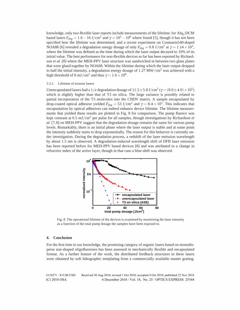
knowledge, only two flexible laser reports include measurements of the lifetime: for Alq3:DCMbased lasers Fdeg = 1.6−16 J/cm2 and γ = 105 −106 where found [5], though it has not beenspecified how the lifetime was determined, and a recent experiment on Coumarin540-dopedNOA88 [6] revealed a degradation energy dosage of only Fdeg = 0.8 J/cm2 at γ = 1.14×10³,where the lifetime was defined as the time during which the laser output decayed to 10% of itsinitial value. The best performance for non-flexible devices so far has been reported by Richard-son et al. [8] where the MEH-PPV laser structure was sandwiched in between two glass platesthat were glued together by NOA68. Within the lifetime during which the laser output droppedto half the initial intensity, a degradation energy dosage of 1.27 MW/cm2 was achieved with ahigh threshold of 8 mJ/cm2 and thus γ = 1.6×10⁸.
3.3.1. Lifetime of truxene lasers
Unencapsulated lasers had a 1/e degradation dosage of 11.5±5.8 J/cm2 (γ =(8.0±4.0)×105)which is slightly higher than that of T3 on silica. The large variance is possibly related topartial incorporation of the T3 molecules into the CHDV matrix. A sample encapsulated bydrop-coated optical adhesive yielded Fdeg = 53 J/cm2 and γ = 8.4× 10⁵. This indicates thatencapsulation by optical adhesives can indeed enhance device lifetime. The lifetime measure-ments that yielded these results are plotted in Fig. 8 for comparison. The pump fluence waskept constant at 0.5 mJ/cm2 per pulse for all samples, though investigations by Richardson etal. [7,8] on MEH-PPV suggest that the degradation dosage remains the same for various pumplevels. Remarkably, there is an initial phase where the laser output is stable and at some pointthe intensity suddenly starts to drop exponentially. The reason for this behavior is currently un-der investigation. During the degradation process, a redshift of the laser emission wavelengthby about 1.5 nm is observed. A degradation-induced wavelength shift of DFB laser emissionhas been reported before for MEH-PPV based devices [8] and was attributed to a change inrefractive index of the active layer, though in that case a blue-shift was observed.
0 20 40 60 80
10−1
100
total pump dosage [J/cm2]
no
rmal
ized
inte
nsi
ty
encapsulated laserunencapsulated laserT3 on silica (ASE)
1/e
Fig. 8. The operational lifetime of the devices is examined by monitoring the laser intensityas a function of the total pump dosage the samples have been exposed to.
4. Conclusion
For the first time to our knowledge, the promising category of organic lasers based on monodis-perse star-shaped oligofluorenes has been assessed in mechanically flexible and encapsulatedformat. As a further feature of the work, the distributed feedback structures in these laserswere obtained by soft lithographic templating from a commercially available master grating.
#134271 - $15.00 USD Received 30 Aug 2010; revised 1 Oct 2010; accepted 4 Oct 2010; published 22 Nov 2010(C) 2010 OSA 6 December 2010 / Vol. 18, No. 25 / OPTICS EXPRESS 25544

Encapsulation increases the 1/e degradation energy dosage in ambient from 11.5 J/cm2 toFdeg = 53 J/cm2. Measured relative to the threshold of the encapsulated device, this latter valuecorreponds to Fdeg/Fth = 8.4×10⁵.
Acknowledgment
The authors thank the Engineering and Physical Sciences Research Council for funding underthe grant EP/F05999X/1, HYPIX, Hybrid organic semiconductor/gallium nitride/CMOS smartpixel arrays.
#134271 - $15.00 USD Received 30 Aug 2010; revised 1 Oct 2010; accepted 4 Oct 2010; published 22 Nov 2010(C) 2010 OSA 6 December 2010 / Vol. 18, No. 25 / OPTICS EXPRESS 25545