Light commercial reciprocating compressors For refrigeration
Upload
khangminh22Category
view
1download
0
SPC/Fisheries 17/WP.2 12 June, 1985
ORIGINAL: ENGLISH
SOUTH PACIFIC COMMISSION
SEVENTEENTH REGIONAL TECHNICAL MEETING ON FISHERIES (Noumea, New Caledonia, 5-9 August, 1985)
FISHERIES SECTOR REFRIGERATION SYSTEMS
IN PACIFIC ISLAND COUNTRIES
by
G.L. Preston Assistant Fisheries Officer South Pacific Commission
and
M.A. Vincent Refrigeration Engineer
United Nations
South Pacific Commission Noumea, New Caledonia
March 1985
(i)
526/85

Copyright 1985, South Pacific Commission
Original Text : English
This report was prepared and published
with the financial support of the
United Nations Development Programme
(ii)

FISHERIES SECTOR REFRIGERATION SYSTEMS IN PACIFIC ISLAND COUNTRIES
Page
1) INTRODUCTION 1
2) BACKGROUND 2
3) FUNDAMENTAL PRINCIPLES OF REFRIGERATION
3.1 General 6 3.2 Sensible and latent heat 6 3.3 Surface area to volume ratio 7 3.4 Steady state heat transfer 8 3.5 Refrigerating fish 9
4) BASIC REFRIGERATION CYCLES
4.1 General 12 4.2 The compression system 12 4.3 The absorption system 14 4.4 Electronic (thermo-electric) refrigeration 14
5) STANDARD REFRIGERATION SYSTEM COMPONENTS
5.1 5.2 5.3 5.4 5.5 5.6 5.7 5.8 5.9 5.10 5.11
General Compressor Evaporator Condenser Expansion valve Oil separator
Liquid receiver Drier Ac c umu1a t o r Other system components Refrigerants
15 15 17 18 18 19 20 20 20 20 21
6) COUNTRY EXPERIENCE OF REFRIGERATION EQUIPMENT
6.1 General 22 6.2 Summary of questionnaire responses 22 6.3 Compressors 23 6.4 Air and water cooled condensers 24 6.5 Forced air evaporators 25 6.6 'Plug' Units 26 6.7 Walk-in holding freezers, chill stores
and blast freezers 26 6.8 Display cabinets and domestic equipment 29 6.9 Block ice machines and brine systems 30 6.10 Flake ice machines (drum, tube and plate) 32 6.11 Contact plate freezers 33 6.12 Adaptions to solar power 34
7) CRITERIA FOR EQUIPMENT SELECTION
7.1 General 35 7.2 Qualities of ice 35 7.3 Ice machines 36 7.4 Storage temperature requirements 37 7.5 Storage capacity requirements 39 7.6 Heat load calculations 40 7.7 Refrigeration capacity requirements 43 7.8 Capital -vs- running costs 44 7.9 Other considerations in plant design 47
8) REGIONAL TRAINING NEEDS AND OPPORTUNITIES
8.1 General 49 8.2 Personnel requirements in the refrigeration field 49 8.3 Specialised needs of the fisheries sector 51 8.4 Existing training opportunities 52 8.5 Recommendations for future training 53
APPENDICES:
1. a) Sample survey questionnaire 55 b) Summary of Part I responses 60 c) Summary of Part II responses 62
2. Partial listings of Pacific Fisheries Sector Refrigeration Equipment 65 a) Federated States of Micronesia 66 b) Fiji 70 c) French Polynesia 71 d) Kiribati 72 e) Marshall Islands 73 f) Papua New Guinea 73 g) Solomon Islands 75 h) Tonga 77 i) Tuvalu 79 j) Vanuatu 80 k) Western Samoa 82
3. Proposed outline syllabus for Refrigeration Technicians Training Course 83

1
1. INTRODUCTION
This report is the result of a six week survey carried out in selected countries of the Pacific region on behalf of the South Pacific Commission, between August and October 1984.
During the survey, a large amount of fisheries sector refrigeration equipment was examined and its performance discussed with operators and users in a total of eleven Pacific Island countries and territories. The equipment examined ranged from domestic chest freezers pressed into heavy service in local fish markets, through small to medium-sized commercial freezing, storage and ice making units, to industrial capacity freezers and cold stores associated with the region's tuna industry. The survey covered installations located in urban centres, and in remote areas, institutions offering training in the refrigeration field, private sector service and supply companies, technical research centres, commercial or Government fish marketing organisations, and offices or other bodies concerned with the planning and implementation of fisheries development activities.
We hope we have been able to distil the experience of these institutions and their personnel into a document which, while general, manages to give an overview of fisheries sector refrigeration problems and in some cases, their solutions in the region, and in particular which will assist those planning future installations to identify and avoid areas of potential difficulty.
The authors would like to acknowledge, on behalf of the South Pacific Commission, the generous financial support of the United Nations Development Project, which made the survey possible. On a more personal level, we are grateful, and indebted, to Mr. Harry Sperling, UNDP Regional Fisheries Co-ordinator (South Pacific), and the more than 120 government and private sector personnel who gave us the benefit of their time and experience of the countries and territories visited during the survey.
2
2. BACKGROUND
Almost all of the 22 Pacific Island countries and territories which are members of the South Pacific Commission are committed to the development of their marine resources for subsistence or commercial use. The past decade has seen a growing awareness of the potential of marine resources by individual countries, and this has in general been accompanied by positive efforts to develop subsistence, commercial and industrial harvesting sectors, the importance of each depending on the national development objectives and philosophy of the country concerned. Whether or not these efforts have been wholly successful, parallel developments of fish collection, storage, distribution and marketing facilities have occurred or are imminent in most SPC countries and all these incorporate some type of refrigeration equipment.
Such developments are generally based on one or more of the following principles:
(i) Policy is to encourage fishermen to chill their catch, in order to improve its quality for subsequent refrigerated storage or for sale, or as a prelude to the development of more sophisticated distribution systems.
(ii) Refrigerated storage facilities are seen as a means of stabilising fish supplies and/or prices, and of providing a guaranteed market for fishermen and a guaranteed supply for consumers.
(iii) Catches have reached, or are expected to reach, levels above the requirements of markets adjacent to the areas of production and surplus catches must be exported to other localities or overseas.
(iv) Export of produce from areas of production, irrespective of production levels, is an economic development strategy, either to generate foreign revenue, or, by exporting to other locations in the same country, to substitute for imported produce.
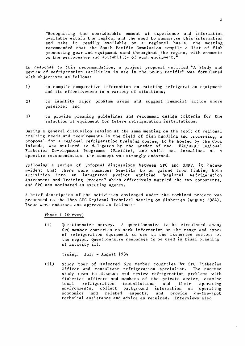
Whatever the rationale, the development of refrigeration-based fish storage, distribution and marketing systems has proliferated in recent years. Numerous Installations have been established to service or assist developing local fisheries by Government fisheries services, semi-Government companies and private enterprise. These systems characteristically include ice machines, walk in chill stores and storage freezers, blast or contact (plate) freezers, retail type refrigerated display cabinets, domestic type chest freezers and refrigerated containers of the kind used for shipping. They are also characterised by a generally small size, being mostly of less than 100 tonnes storage capacity and often less than 10 tonnes. In general, installations of this type have been plagued by continued technical difficulties and poor economic performance and as a result, fisheries development plans have been hindered, sometimes severely.
These problems were recognised and discussed in detail during a workshop on Fish Handling and Processing, held as part of the 15th SPC Regional Technical Meeting on Fisheries in August 1983. A number of common problems emerged and the meeting concluded its discussions by making the following recommendation:
3
"Recognising the considerable amount of experience and information available within the region, and the need to summarise this information and make it readily available on a regional basis, the meeting recommended that the South Pacific Commission compile a list of fish processing gear and equipment used throughout the region, with comments on the performance and suitability of such equipment."
In response to this recommendation, a project proposal entitled "A Study and Review of Refrigeration Facilities in use in the South Pacific" was formulated with objectives as follows:
1) to compile comparative information on existing refrigeration equipment and its effectiveness in a variety of situations;
2) to identify major problem areas and suggest remedial action where possible; and
3) to provide planning guidelines and recommend design criteria for the selection of equipment for future refrigeration installations.
During a general discussion session at the same meeting on the topic of regional training needs and requirements in the field of fish handling and processing, a proposal for a regional refrigeration training course, to be hosted by the Cook Islands, was outlined to delegates by the Leader of the FAO/UNDP Regional Fisheries Development Programme (Pacific), and while not formalised as a specific recommendation, the concept was strongly endorsed.
Following a series of informal discussions between SPC and UNDP, it became evident that there were numerous benefits to be gained from linking both activities into an integrated project entitled "Regional Refrigeration Assessment and Training Project" which effectively married the two components, and SPC was nominated as excuting agency.
A brief description of the activities envisaged under the combined project was presented to the 16th SPC Regional Technical Meeting on Fisheries (August 1984). These were endorsed and approved as follows:-
Phase I (Survey)
(i) Questionnaire survey. A questionnaire to be circulated among SPC member countries to seek information on the range and types of refrigeration equipment in use in the fisheries sectors of the region. Questionnaire responses to be used in final planning of activity ii).
Timing: July - August 1984
(ii) Study tour of selected SPC member countries by SPC Fisheries Officer and consultant refrigeration specialist. The two-man study team to discuss and review refrigeration problems with fisheries officers and members of the private sector, examine local refrigeration installations and their operating environments, collect background information on operating economics and related aspects, and provide on-the-spot technical assistance and advice as required. Interviews also

4
to be carried out with prospective trainees for the Phase II training course to determine their qualifications and suitability and enable fine-tuning of the course syllabus to the needs and problems of the region.
Timing: September - October 1984
(iii) Preparation of report, which will comprise an inventory of refrigeration equipment in use withing the region, detailed documentation setting out prevailing operating conditions and suitable equipment characteristics, identifying problem areas and recommending design criteria for future installations, and an assessment of the immediate and long-term refrigeration training requirements for the region.
Timing: November 1984
Phase II (Training)
(i) Refrigeration training course, 8 hours/day for 18 weeks in Rarotonga, Cook Islands. Course co-ordination to be by the same consultant refrigeration specialist with additional assistance from short-term consultants where required. The course to include lecture time devoted to theory and technical training (estimated 210 hours), laboratory or workshop hours for practical training (estimated 430 hours) and work experience (160 hours).
Timing: February - June 1985
The Phase I study tour was carried out from 24 August - 6 October 1984. The countries visited by the study team were determined in consultation with delegates to the meeing as follows (in the order visited):
Papua New Guinea Solomon Islands Kiribati Tuvalu Marshall Islands Federated States of Micronesia French Polynesia Western Samoa Tonga Fiji Vanuatu
The questionnaires, a sample of which is shown in Appendix la, were almost all completed before the arrival of the study team and were an invaluable aid to the site visits and discussions held.
5
This report is the result of Phase I of the Project. It aims to document the main types of refrigeration equipment used in the fisheries sectors of Pacific Island countries; to describe their shortcomings and where possible, determine their causes and possible remedies; and to assess training needs in this specialised field. However, it should be noted that the report is not intended to cover industrial-scale refrigeration installations, ie those which service the region's industrial tuna fisheries. These are characterised by a much higher storage capacity (400-2000 tonnes) and, being associated with well-capitalised companies who are able to employ qualified full-time refrigeration mechanics, generally demonstrate long and mainly trouble-free service lives. Also, outside the scope of this document is shipboard refrigeration equipment, other than where comments on general refrigeration principles apply, and in reference to refrigerated shipping containers and deck-mounted ice making machines which are also commonly used in shore-based installations.

6
3. FUNDAMENTAL PRINCIPLES OF REFRIGERATION
3.1 General
Refrigeration is the process by which the normal direction of heat transfer from a warmer body to a cooler one is reversed. While this report is not intended to serve as a reference text on the subject, it is necessary to outline several important principles which are the bases of some of the later discussions. This section has been kept as brief and simple as possible, consistent with the need to assist the non-specialist reader understand the sections which follow. More detailed texts on various aspects of refrigeration theory and practice are listed in Appendix 3a.
3.2 Sensible and latent heat
Sensible heat is the heat energy absorbed or released when a substance changes temperature. Energy must be provided to any substance in order to cause a temperature increase. The amount of energy needed to raise the temperature of one gramme of a substance by 1 deg.C. is characteristic for that substance and is called its specific heat capacity. When one gramme of the substance cools, or is cooled, by 1 deg.C, the specific heat is released to the surrounding environment. The specific heat of water is 4.187 joules, the joule (J) being the basic metric (Systeme International) unit of energy. In refrigeration work, the kilojoule (kj) is more often used, 4.187 kJ being required to raise the temperature of 1 kg water by 1 deg.C. In imperial measure, the unit of heat energy, the British thermal unit (Btu) is defined as the amount of heat necessary to raise the temperature of 1 lb of water by 1 degree Farenheit. The kJ and the Btu represent approximately equal amounts of heat energy (lkJ = 0.9630 Btu : 1 Btu = 1.0384 kJ). Table 1 shows the specific heat capacities of some commonly encountered materials.
Table 1: Specific heat capacities of some common materials
Material Specific Heat Capacity
Wood Iron Copper Glass Brick Ice Water 20% sa R717 (, R502 R12 R22
(After
It brine ammonia)
kJ/kg/deg.C
1.369 0.540 0.398 0.783 0.837 2.110 4.187 3.559 4.606 1.068 0.892 1.089
Althouse, Turnquist and
Btu/lb/deg.F
0.327 0.129 0.095 0.187 0.200 0.504 1.0 0.85 1.1 0.255 0.213 0.26
Bracciano, 1982. Modern Refrigeration and Air Conditioning)

7
Latent, or hidden, heat is the heat energy absorbed or released when a substance changes state from solid to liquid (or vice versa) or from liquid to gas (or vice versa). Latent heat transfer is not accompanied by a temperature change but is far more important in refrigeration than the transfer of sensible heat because the quantities of energy involved are greater. When water at 0 deg.C. changes state to become ice at 0 deg.C, the latent heat of fusion, or solidification, which for water is 335 kj/kg (144 Btu/lb) is released to the surrounding environment. Conversely, the same amount of energy is absorbed when ice at 0 deg.C. melts to become water at 0 deg.C. As noted above, the amount of heat then required to raise the temperature of this water is only 4.187 kJ/kg/deg.C. (1.0 Btu/lb/deg.F.), hence as much heat is required to change 1 kg of ice into 1 kg of water as is required to raise the temperature of that same kg of water from 0 deg.C. to 85 deg.C.
These principles are the basis of conventional refrigeration cycles. Normally, the refrigerant is brought into proximity with the product to be cooled, and there encouraged to undergo a change of state from liquid to gas, thus absorbing its latent heat of evaporation from the product. It is then transported away from the product and r-orced t 0 condense to a liquid state, during which process it releases the heat it has absorbed to the environment. The cooling properties of a substance which changes state are far greater than those of one which does not. Table 2 shows the latent heat of vaporisation of several refrigerants.
Table 2: Latent heat of vaporisation of common refrigerants
Refrigerant Latent heat of vaporisation (or condensation) kJ/kg Btu/lb
Water 2257 at 100 deg.C 970.4 at 212 deg.F R717 (Ammonia) 1314 at -15 deg.C 565.0 at 5 deg.F R502 160 at -15 deg.C 69.0 at 5 deg.F R12 159 at -15 deg.C 68.2 at 5 deg.F R22 217 at -15 deg.C 93.2 at 5 deg.F
(After Althouse, Turnquist and Bracciano, 1982. Modern Refrigeration and Air-conditioning)
3.3 Surface area to volume ratio
Since any body loses or gains heat by transfer across its surface, then the rate of heat transfer is related to the surface area. The amount of heat which can be absorbed, stored or released by the body in question is determined by its volume. A body with a large volume can retain a greater amount of heat than one with a small volume, while a body with a large surface has a greater capacity for heat transfer than one with small surface. The ratio of surface area to volume (SAV) is therefore important in determining the heat retention and transfer characteristics of a body.
Small bodies generally have much higher SAV ratios than large ones. A 16 gramme cube of ice of side 2 cm has an SAV ratio of 24/8 or 3.0 whereas an 8 kg ice block of dimensions 40 cm x 20 cm x 10 cm has an SAV ratio of 2,800/8,000 or 0.35. If the same 8 kg block was moulded as a cube of side 20 cm, its SAV ratio would be 2,400/8,000 or 0.30. Of these two ice blocks, the latter would show a slower rate of melting than the former under the same conditions due to the smaller surface area available for heat transfer.

8
This concept also applies to freezer boxes and other items of refrigeration equipment. A small domestic chest freezer will have a higher rate of heat absorption from its environment per unit of volume than a 10-tonne walk-in freezer, which in turn will have a higher ratio than a 400-tonne coldstore. The contribution to effective operation made by improved insulation is therefore proportionally greater for smaller units.
3.4 Steady state heat transfer
The rate of transfer of heat from a warmer area to a cooler area through a solid material depends on the temperature difference between the two areas, the thermal conductivity rate (K) of the material concerned and the distance across which the heat must travel. As noted above, heat loss or gain to a body occurs across its surface and heat energy is therefore constantly being transferred to and from the surface. The principle of insulation of freezer boxes, etc. is to reduce surface heat transfer by the use of surface materials with a low thermal conductivity rate, and of adequate thickness. The K values of some common materials are as follows:-
Table 3: Thermal conductivity rates of selected materials
Material Thermal conductivity rate (K value)
Expanded polystyrene and similar plastics Air Balsa wood Softwoods Hardwoods Glass, plastics (not expanded)
Concrete Wall Lead, Iron, Steel Aluminium Copper, Brass
J/s/m/ "/metre thickness/deg.C
0.025 0.04 0.07 0.10 0.15
1.1 1.8
55 100 200
Btu/hr thickn
0.1 0.0175 0.32 0.45 0.67
5 8
245 450 895
(various sources)
Most materials with low conductivity rates have these by virtue of the fact that they contain large quantities of air spaces, air being a very good insulator.

9
Heat transfer rates through a given area of material can be calculated by use of the formula:
„ _ K x A x (T,-T„)
Where R is the rate of transfer (in joules/second) K is the therraal conductivity rate (joules/second/m /
metre thickness/deg.C) A is the surface area (square metres) T, is the temperature (Deg.C) on the high side
T„ is the temperature (Deg.C) on the low side
L is the material thickness (metres)
As an example, one square metre area of a 4 cm (0.04m) thick polyurethane foam wall (K value 0.025) on a freezer at -20 deg.C. in ambient air temperatures of +20 deg.C. will allow the transfer of:
2 . . 2 0.025 x 1 x (40) 25 joules/second (watts)/m or 90 kilojoules/hour/m
0.04 (equivalent to 5.6 Btu/hour/sq. foot)
Doubling the thickness of the insulant would halve the heat loss to 45 kilojoules/hour.
In practice other factors complicate the picture. For instance, the amount of heat available to the external walls of a freezer cabinet is greatly influenced by air movement. In a static situation, a layer of still air around the cabinet will act as an additional insulant. On the back of a refrigerated truck travelling at 40 kph, turbulent air flow will prevent this phenomenon and greatly increase the rate at which heat is provided to the external surface of the insulation.
The concept of steady state heat transfer is generally applicable when considering heat gain by refrigeration units, where internal and external temperatures are, or are assumed to be, relatively constant. In other circumstances, unsteady state heat transfer occurs, and the above simple methods of estimating heat transfer rates cannot be used. An example is in the freezing of fish produce: as an individual fish, or a carton of fish, is cooled, the outer layers freeze first, and in freezing change their heat transfer characteristics. As the produce cools, the temperature difference between the inside of the fish and the surrounding air declines, further affecting the heat transfer rate. In such a situation, therefore, the effects of the cooling process are described by a more complicated series of equations.
3.5 Refrigerating fish
Fish and other marine products are essentially composed mainly of proteins, fats and water in which are many dissolved salts, sugars and other substances. When a fish dies bacteria begin to decompose the proteins, fats and other nutrients: the fats oxidise due to contact with air, and become rancid: and enzymes in the fishes' cells and body fluids start to cause denaturation of the proteins. All these processes, which occur more quickly at higher temperatures,
10
lead to fish spoilage and the purpose of refrigeration is to reduce the rate at which they occur.
Simple chemical reactions approximately double the rate at which they occur if the temperature increases by 10 deg.C, and this is a rough rule of thumb which can be applied to the rates of enzymatic and oxidative spoilage. Bacterial spoilage is not affected in the same way. Bacteria are abundant on the slime and in the guts of living fish, but diffferent fish, fishing areas or depths will result in different bacterial flora on the fish itself. These may display different temperature preferences, with some being more active at low temperatures than others. In general, however, all microbial growth reduces with declining temperature, and stops below -10 deg.C.
Cooling fish thus greatly delays spoilage by all means. Freezing takes the process a stage further by causing solidification of the substances of which the fish is composed. This prevents the movement of molecules to the sites of spoilage reactions, greatly increasing the possible storage time, or shelf life, of the product. However, it should be noted that at no time is a fish fully frozen. As the temperature is reduced, the components selectively solidify or freeze. Fish tissue water starts to freeze at -2 to -3 deg.C, due to its being a solution of salts. As freezing starts many dissolved compounds are 'squeezed out' of the ice and remain in solution in increased concentration, thus further depressing the freezing point of the remaining liquid. Other substances show different properties, but the net result is that some of the fish always remains unfrozen. At -5 deg.C about 75-85 percent is frozen. At -20 deg.C, this increases to 85-93 percent and at -100 deg.C about 99 percent is frozen. At -180 deg.C, there is no evidence to suggest that more than 99 percent is frozen.
The relationship between temperature and shelf life is not simple, due to chemical changes in the composition of the fish as it becomes more deeply frozen. In particular, a temperature of about -15 deg.C represents a 'turning point1 after which shelf life increases much more rapidly with reducing temperature. This is explained by the fact that, at temperatures between -2 deg.C and -15 deg.C, tissue water is incompletely frozen and dissolved enzymes and salts are increasingly concentrated, thus increasing their potential for chemically reacting and negating to some degree the beneficial effects of cooling. Below -15 deg.C tissue water is frozen and these chemical compounds are mostly immobilised.
tVhen a fish, or anything else, is placed in a reduced-temperature environment, it loses heat from its surface and thus the outer layers cool first. As the process continues, the cooling effect, or 'cold front1 advances deeper into the product. In doing so, its surface area decreases, so the rate of heat transfer decreases. The fact that heat from inside the fish must be transferred all the way to the surface before it can be removed further retards the heat transfer process. This distance is greater in large, round-bodied fish, and can result in substantial delays in cooling down the inner portions, during which enzymatic and perhaps other forms of spoilage may be continuing. This is one of the two main reasons why rapid freezing of fish, in a refrigeration unit designed specifically for freezing, is to be preferred over slow freezing, which occurs if fish are frozen in a unit intended mainly as a storage freezer.
The second reason relates to the chemical properties of crystals, including ice crystals. If large and small crystals are present together in a solution, then molecules will tend to migrate from the small ones to the large ones. This process will ultimately result in the disappearance of most of the smaller

11
crystals and the accumulation of all the molecules as a relatively small number of large crystals.
In a fresh, unfrozen fish, tissue water is mostly located within the body cells. When freezing is rapid, small ice crystals form in each cell, with the result that the tissues themselves remain largely physically unaltered when the product is thawed.
When freezing is slow, the process starts with the formation of a few scattered ice crystals. Further ice formation then occurs by enlargement of these crystals, rather than by the generation of new ones. Crystals tend to form between cells rather than inside them, and as water then migrates through cell walls to the site of the enlarging crystal, some cells collapse through evacuation. When a product which has been frozen in this way is thawed, the tissue fluids are no longer contained in the body cells, and escape from the flesh, causing 'drip' and leaving a tough dehydrated product.
The process of recrystallisation occurs during frozen storage if there are fluctuations in temperature. Every time the temperature of the product rises, some of the ice in it will melt. When the temperature goes down again, this water will re-freeze on the surface of the larger ice crystals. If there are lumps of ice on the outside of the product (which can form, for example, when opening doors introduces humid air which condenses on the product surface), then ice will migrate out of the fish at each temperature change. This is a particular problem with products displayed in self-service type freezer cabinets, where customers rummaging around among the products repeatedly bury them and then bring them to the surface again, causing a very uneven temperature history.
A final note concerns dehydration during chill or cold storage. Evaporation of water occurs at all temperatures, including when it is deep frozen. Conventional freezers and chill stores circulate refrigerated air and this can extract moisture from the product, which then condenses on the evaporator coils or elsewhere. In a chill store, this results in a wrinkled, dried up looking product, a problem which can be easily prevented by sprinkling with a layer of ice. In a freezer store, the result is 'freezer burn1, a condition which, when extreme, results in the affected fish looks fibrous and full of pores or cavities, resembling the appearance of balsa wood. This can be countered by glazing fish after freezing, or by packing in cartons or plastic bags. These processes are desirable anyway, as reduced contact of the product with air will further reduce fat oxidation and rancidity, which continue to slowly occur in frozen produce.

12
4. BASIC REFRIGERATION SYSTEMS
4.1 General
Currently available refrigeration equipment effects the transfer of heat from a cooler body to a warmer one by one of three processes: the compression system, the absorption system, or by electronic means (Peltier effect). Of these, the first is by far the most common and is used in all commercial and industrial in scale fisheries sector refrigeration equipment in Pacific Island countries and in most domestic equipment. The absorption system is found in domestic gas or in kerosene-powered refrigerators and freezers, and some experimental work is currently underway with solar powered absorption units, which may have application in the region in the future. Electronic refrigeration is expensive and specialised and of restricted application. Although solar units of this type are currently being experimented with, their coming into use seems unlikely in the near future.
4.2 The compression system
The fundamental principle underlying mechanical refrigeration is the evaporation of a liquid refrigerant. To enable evaporation to take place, the refrigerant must absorb its latent heat of vaporisation from its environement, that is it must boil. The temperature at which this evaporation occurs is dependent upon the pressure at the surface of the liquid. For instance, water boils at 100 deg.C (212 deg.F) at an absolute pressure of 1.03 kg/cm2 (14.7 lb/sq.in) atmospheric pressure at sea level) but if the pressure is increased to 7.0 kg/cm2 (100 lb/sq/in) then the boiling temperature is raised to 170 deg.C. (338 deg.F). Conversely, if the pressure is reduced to 0.07 kg/cm2 (llb/sq.in) then the boiling temperature is reduced to 39 deg.C (102 deg.F)
Water can be used as a primary refrigerant but very low pressures must be maintained to achieve the evaporation temperatures usually required. Consequently other liquids having lower boiling temperatures at atmospheric pressure are employed as primary refrigerants, for example, ammonia (R717) and various types of halogenated-carbon refrigerant (Rll, R12, R22, R502).
The compression cycle involves four main components: the evaporator (cooling coil) in which the selected refrigerant boils; the compressor, a pump which forces refrigerant in its gaseous state through the system, and which by reducing the pressure in the evaporator allows the refrigerant to boil at a lower temperature; the condenser, which is usually cooled by air or water and is the site of ondensation of, and consequent heat discharge by, the refrigerant; and the expansion valve, which controls the flow of liquid refrigerant back to the evaporator, and whose adjustment permits overall control of the systems internal pressure, and therefore its cooling capacity. The basic circuit is illustrated in Figure 1.

13
THERMOSTAT
LVi%y.g-.A»V.te?wnc/ttiff.vf>.fcvvsrt/.i
jrv^-.t-~--..>»'».-?-i.r».*...>»*t yw» THERMOSTATIC
EXPANSION VALVE
POWER LINE
HIGH-PRESSURE VAPOR
HIGH-PRESSURE LIQUID m LOW-PRESSURE
VAPOR LOW-PRESSURE LIQUID
Figure 1. The basic compression refrigeration circuit (After Althouse, Turnquist and Bracciano: Modern Refrigeration and airconditioning).

14
Additional to the fundamental elements are numerous other components associated with powering, controlling and monitoring the system. These include: compressor motors, fans and motors to increase air circulation over condenser and evaporator coils, water cooling towers and pumps, lubricant oil separators and accumulators, refrigerant driers and sightglasses, by-pass valves, solenoids and electrical control switches, as well as the specialised assemblies used for ice making, plate freezing, etc. System components are dealt with in Section 5.
4.3 The absorption system
Use of this system for fisheries-related purposes is restricted to domestic-type gas or kerosene powered freezers and refrigerators, usually used in remote locations where alternative power sources are absent. The fundamental difference between compression and absorpotion systems is that in the former, a pump (compressor) is used to circulate the refrigerant as described above. In he latter, a heat source (gas or kerosene flame, electric heating element) is used to ciculate the refrigerant by causing a certain amount of evaporation and tus pressure increase. Extraction of gas from the evaporator is produced by its active dissolution in a liquid solvent. In domestic units, the refrigerant is generally ammonia and the solvent water. The water absorbs the ammonia (hence the system's name), releasing it at a later point in the cycle.
Modified absorption systems, in which solar heating replaces conventional means, are presently under study by some agencies concerned with research into renewable energy. However, given the present restricted use of absorption systems, the absence of all but domestic-type units from fisheries-related operations in Pacific Island countries, and the unlikelihood of absorption systems coming into more widespread use in the near future, they re not treated further in this report.
4.4 Electronic (thermo-electric) refrigeration
Electronic refrigeration is based on the Peltier effect, where by using semi-conductors of different materials in an electrical circuit, some can be induced to absorb heat and others release it. A refrigeration system based on this principle employes a low voltage direct current flowing through components which are the seat of heat absorption, the electrons themselves acting as the 'refrigerant'. This method is generally restricted to low power applications and is currently found only in small luxury units for leisure use (cars and boats) in developed countries. There are no units of this type used in fisheries development activities in the Pacific. The system has potential applications for use with photovoltaic power (solar electricity) but commercial development is unlikely in the South Pacific region in the near future.

15
5. STANDARD REFRIGERATION SYSTEM COMPONENTS
5.1 General
Although the refrigeration equipment in use in the fisheries sectors of Pacific Island countries is of varied design and function, the system components themselves are remarkably standard. For any given component there are only a handful of different variations to the basic type, and in some instances, components marketed under different brand names are actually identical units from one manufacturer. Therefore, although the variety of permutations of available components is almost endless, identical compressors may be found on a chill store and an ice machine, or the same evaporator coils on a 1-tonne blast freezer and a 10-tonne cold room.
The aim of this section is to describe briefly the functions of the main types of standard component, before discussing the systems in which they are combined. Since all the commercially-used fisheries sector refrigeration equipment (and almost all other equipment) observed during this survey was based on the compression cycle, no reference is made to other refrigeration systems (absorption or electronic).
In addition to the basic components of compressor, evaporator, condenser and expansion valve (referred to in Chapter 4) which are fundamental to the systems function, a large number of other items of equipment are generally incorporated for control, safety and a variety of other purposes. Some of these are essential, while others are needed only in special circumstances or on particular system configurations. Figure 2 shows the locations of the components which can be expected on most units.
5.2 Compressors
The compressor removes the refrigerant vapour formed in the evaporator and compresses it to a pressure at which it can be condensed.
Compressors in the SPC region are usually single-acting reciprocating (piston) types although others such as single or twin screw, or centrifugal types may occasionally be seen. Reciprocating compressors are generally multi-cylinder high speed machines, the cylinders arranged in 1, 2, 3 or 4 banks on a single crankcase. The tendency these days is to have relatively large numbers of small diameter pistons and crankshaft speeds in the range of 750 to 1500 rpm. To allow for varying capacity requirements from larger units, one or more cylinders or banks of cylinders may be rendered inoperative by either lifting the suction valves off their seats, shutting off the supply of suction vapour to the appropriate cylinders, or using a solenoid switch to open and close a valve which by-passes some cylinders.
Reciprocating compressors are of three main types:-
i) open-drive, in which the compressor is driven by belts, or some other mechanical means from a separate electric motor or combustion engine.
ii) semi-hermetic, in which the compressor is integrally coupled to an electric motor. These are sealed together in the same bolt-fastened casing.

16
THERMOSTATIC EXPANSION VALVE
LIQUID LINE SUCTION LINE
DISCHARGE SHUTOFF VALVE
AIR-COOLED CONDENSER
II nimil|||l'IHlllllimiMI|HIIIHIIIIIIIIIIIIII|l|lllllllH"llll|Mir
LOAD LEVEL TEST PORT
HIGH-PRESSURE LIQUID
3 LOW-PRESSURE LIQUID
3 LOW-PRESSURE VAPOR
Imimtmuitt* HIGH-PRESSURE VAPOR
\tutimtKtv\ HIGH-PRESSURE SATURATED VAPOR
Figure 2. Layout of major components' of a typical Refrigeration System. (After Althouse, Turnquist and Bracciano: Modern Refrigeration and airconditioning).
17
iii) hermetic, in which the compressor and electric motor are sealed together inside a welded casing. Hermetic types are usually 5 hp and under and are found mostly on domestic and small commercial equipment.
Each of these types is widely encountered in fisheries sector equipment in the region and each has its advantages and disadvantages. With an open type a burned out motor or broken-down engine can easily be substituted or replaced, but the open system requires more maintenance in aligning belts, servicing bearings and anticipating compressor shaft seal leaks. The semi-hermetic unit's electric motor is protected from damage by moisture and dust but is more difficult to service and a burned out motor must be replaced by another of the same specifications and physical dimensions. Hermetic types must be cut open for service and re-welded afterwards, hence these are generally servicable only by specialists. Hermetic and semi-hermetic units can also suffer from acid build-up and consequent corrosion of the motor windings in conditions of high heat and oil contamination.
5.3 Evaporator
This is the component where the refrigerating effect is produced. The simplest form of evaporator would be a vessel containing the liquid refrigerant surrounded by the substance being cooled, which may be air, water, brine, etc. The surface area is generally maximised to ensure a high rate of heat transfer and consequently improved efficiency of the system. Examples of small evaporators include the ice unit in a domestic refrigerator. Larger versions may be a series of tube grids, fitted to the ceiling and walls of a cold chamber and causing cooling by natural air circulation; or a compact series of tubes, with or without external fins, with air being drawn or blown through the 'coil block' by means of a fan. If a liquid is to be cooled then the evaporator may be in the form of a grid submerged in a tank containing the liquid, or of a 'shell-and-tube' type, where the refrigerant may be in the shell whilst the liquid being cooled is circulated through the tubes, or, more recently, vice versa. Other more specialised types of evaporator are used for freezng applications, such as the hydraulically compressed evaporator plates in a contact freezer.
In coldroom and freezing chambers used for fisheries applications in this region, forced air circulation is generally used. Although much more efficient than static or natural circulation systems, this involves extra maintenance of the fan and motor, increased drying out of the product, and, generally increased drying out of the product, and, generally increased ice formation on the evaporator coils. Adequare regular defrosting is essential and most coils are now fitted with automatic electrical defrost heaters or other defrost systems (ie hot gas) which operate up to several times per day.
18
5.4 Condenser
This is part of the circuit where the compressed vapour is cooled and condensed and the heat absorbed by the evaporator, plus the heat equivalent of the compressor horsepower, are rejected from the system to the condenser cooling medium. Condensers may be water cooled or air cooled or a combination of both. Most of the condensers examined during this survey were air cooled, operating on the same principle as the automobile radiator. The condenser consists of a convoluted pipe whose surface area is increased by closely spaced fins, over which air is forced by a fan. As with evaporators, the fan requires additional maintenance and power but greatly increases the condensers efficiency over the static type, whose use is generaly restricted to very small units such as domestic refrigerators and freezers.
Because of their more compact size, water cooled condensers are generally used with large scale refrigeration plant, but are also increasingly being found on the medium-to-small scale commercial equipment covered by this report as efficient and compact recirculating water cooling towers are developed. In water cooled condensers, a tube-and-shell or other type of heat exchanger is used, in which water flowing through the tubes absorbs the heat from the condensing refrigerant in the outer shell. In a situation where ample low cost fresh water is available, a waste water system is used, being simply piped through the condenser and then discharged. It is more usual, however, to re-use the water after pumping it through a cooling tower, where it loses some of its latent heat of evaporation. In small commercial cooling towers, the water is pumped to the top of the tower and then gravity fed onto a series of plates or baffles whose large surface area increases the rate of evaporation. This is further enhanced by a blower fan which forces air across the baffles. The cooled water drips back into a sump at the base of the tower, from where it is recirculated to the condenser. An excess of make-up water is fed into the system, to replace the water lost by evaporation and splashing, and to allow a small overflow from the sump which continually dilutes any dirt or contaminants which have entered the system.
5.5 Expansion valve
The function of the expansion valve is to control the rate at which liquid refrigerant is supplied to the evaporator. If the amount of heat being taken up by the evaporator varies from time to time, as it usually does, then the rate at which the refrigerant is being evaporated may not be the same as the rate at which it is being supplied. Thus, the main limitation of the simplest form of regulator, ie the hand-controlled valve, is that unless the conditions of loading are steady the regulator will require frequent adjustment. Consequently, various forms of automatic regulators have been developed to accommodate load changes, and these fall into three main types:-
i) Capillary Tube
This is a long, small diameter tube found in domestic and small commercial units, which supplies a set amount of refrigerant to the evaporator irrespective of load conditions. This system is very simple and cheap, but lacks the advantages of the thermostatic expansion valve noted below. It is also necessary to size the capillary tube according to the maximum load the system will have to cope with, since the rate of refrigerant flow does not vary during operation.

19
ii) Thermostatic expansion (TX) valve
This is by far the most commonly used regulator in the plant with which this report is concerned. The TX valve maintains a constant temperature difference between the evaporating temperature and the temperature of the vapour leaving the evaporator by adjusting the amount of liquid entering the evaporator. This is done by means of a sensor bulb located at the outlet pipe of the evaporator. The bulb is connected via a narrow pipe to the TX valve, which is located at the entry pipe on the evaporator. Expansion or contraction of the bulb gas acts on an internal diaphragm which causes opening and closing of a needle valve, varying the quantity of refrigerant which can pass. The net result is that as the vapour leaving the evaporator cools down (indicating that the heat load is diminishing) the bulb charge contracts and exerts less pressure to open the needle valve. The counteracting pressures of a pre-set spring, plus the high-side refrigerant passing through the valve, close the valve and reduce the refrigerant flow. At a certain point, the valve will close altogether. As the compressor continues to pump vapour from the evaporator, low-side pressure falls until it activates a pressure switch which closes down the whole system. If properly adjusted, shutdown will not occur until the compressor has pumped almost all the refrigerant into the liquid receiver. This system thus prevents evaporator flooding and subsequent start-up difficulties.
iii) Other types
There are a number of other types of regulator but these are not widely used. The automatic expansion (AX) valve maintains a constant evaporating pressure, the pressure being the lowest at which the plant is required to operate. This has been used on small plant such as domestic refrigerators, frozen food cabinets, etc. in the past but has now been superseded in these applications by the capillary tube. Also occasionally seen are various types of regulator controlled by floats inside refrigerant chambers, but these are confined in this region to industrial-scale ammonia plant.
5.6 Oil separators
Most compressors pump over a certain amount of lubricating oil which passes from the crankcase into the cylinders, to circulate with the refrigerant gas and return to the compressor via the suction line. In most cases it is desirable to limit the quantity of oil entering the evaporator to an absolute minimum as its presence reduces the efficiency of both the refrigerant and the evaporator coils. It is therefore essential to fit a means of removing oil from the delivery gas before it enters the evaporator. Oil droplets may be separated from the gas by reduction in gas velocity, by centrifugal action, or by impingement. Most oil separators rely upon a combination of these principles, such as a large diameter vessel packed with some form of 'fill' such as granules or a knitted wire mesh pad to give both velocity reduction and impingement. Oil collects at the bottom of the separator from whence it is usually returned to the compressor crankcase by means of a float valve.
It should be noted that oil separators are not 100 percent efficient and consequently, there is a quantity of oil which will be passing through to the condenser and on into the evaporator. In the case of refrigerant 12, the oil will be completely miscible with the liquid refrigerant even at low

20
temperatures and consequently, the evaporator may be fitted with an oil rectifier, which, by heating small amounts of the oil-rich mixture, evaporates off the refrigerant and returns the residue to the compressor crankcase.
5.7 Liquid receiver
Since load variations are usually encountered, the refrigerant charge required in the evaporator will vary considerably. This variation of charge has to be automatically accommodated in the circuit at some point between the condenser and expansion valve. This is accomplished by the introduction of a liquid receiver immediately after the condenser. The liquid receiver consists of a suitably sized vessel having liquid inlet and outlet connections, sometimes an additional connection from the top of the vessel to the condenser to act as a vent.
In some cases, this liquid receiver is of sufficient capacity to accommodate the total refrigerant charge, a facility can be made use of when servicing the plant.
5.8 Drier
The purpose of this is to remove moisture from the refrigerant change. Moisture entering the system through leaks, etc. will cause corrosion of some metals, acid build-up in the lubricant oil, and ineffective operation of the expansion valve due to ice formation within it. The drier consists essentially of a vessel with the liquid flowing from the bottom to the top through a charge of suitable drying agent such as silica gel or activated alumina. Usually a sight glass is situated in the system, adjacent to the drier. This allows checking of the refrigerant levels and usually has an indicator which changes colour in the presence of moisture.
5.9 Accumulator
This is located immediately before the compressor on some systems to prevent any liquid refrigerant entering the compressor. Compressors are designed to pump only vapour, hence the accumulator acts as an evaporation chamber.
5.10 Other system components
Various other components may be added to the basic system shown at Figure 2, depending on the special requirements or functions of the equipment. These include suet ion/liquid heat exchangers, suction separators, intercoolers, back pressure regulators and other control valves. Some systems also incorporate low and high pressure cutouts set to close down the system in case of malfunction or if certain preset temperature limits are exceeded.

21
5.11 Refrigerants
The primary refrigerant used in the compression cycle is usually one of four compounds: refrigerant 12 (R12), R22, R502 or ammonia (R717). The former three compounds belong to a family of halogenated hydrocarbon refrigerants, or safe refrigerants, which have in the main replaced ammonia because they are non-toxic, non-flammable and non-corrosive, all of which are faults of ammonia. Nevertheless, ammonia continues to be used in older large-scale plants where its low cost and effectiveness as a refrigerant outweigh its disadvantages.
Of the three safe refrigerants, each has its own application:
i) R12. Boils at about -29 deg.C (-21 deg.F) at atmospheric pressure. Has the lowest latent heat absorption factor of the three, and is found in most domestic and medium temperature (coldstores, some ice machines) equipment.
ii) R22. Boils at about -41 deg.C (-42 deg.F) at atmospheric pressure. Better latent heat properties than R12 and is used in some ice machines and freezers but is not nearly as common (or as readily available in this region) as R12 or R502.
iii) R502. Boils at about -46 deg.C (-51 deg.F) at atmospheric pressure. R502 is an azeotropic mixture of 48.8 percent R22 and 51.2 percent R115. The resultant latent heat factor is the highest of the three and R502 is generally found in low temperature applications such as blast and contact freezers.
The use of the lower temperature refrigerants requires correspondingly higher system pressures and hence the equipment has to be more heavily made, adding to manufacturing costs and increasing the likelihood of leaks.
A secondary refrigerant acts as a carrier of heat from the product being cooled to the evaporator. In a conventional blast freezer or cold store, air is the secondary refrigerant, but some applications, such as block ice machines and immersion freezers, use liquids which can include water, alcohols, glycols or salts. Sodium or calcium chloride brines are almost universally used in block ice machines and brine freezers in the SPC region.

22
6. COUNTRY EXPERIENCE OF REFRIGERATION EQUIPMENT
6.1 General
A wide variety of fisheries sector refrigeration equipment was examined and discussed in detail during the visits to eleven Pacific Island countries and territories on which this report is based. The equipment, inventorised in Appendix 2, fell into the following broad categories:-
block ice machines and, rarely, other systems, such as brine freezers, employing a secondary refrigerant
drum, tube and plate flake ice machines
walk-in chill rooms and storage freezers of varying dimensions, and air blast freezers
rarely, other types of freezer (eg contact plate)
retail refrigerated display cabinets
equipment principally intended for domestic use such as household chest freezers and, rarely, refrigerators.
Although of varied form and function, all this equipment relies on the mechanical compression refrigeration cycle for its operation, and the basic systems have much in common. In particular, compressors, condensers and, to a lesser extent, evaporators, are fundamental components and in many cases, are interchangeable, within certain limits, among systems.
The following sections describe some of the problems experienced with refrigeration equipment in the countries visited. A brief summary of responses to the questionnaire circulated among member countries is presented first. The main refrigeration components are then dealt with, followed by equipment in the categories above, and comments are offered on the advantages and disadvantages of each type, based on discussions with users and operators, and characteristics observed by the authors. Because only small numbers of each of a wide variety of brands of equipment were observed, it is difficult to make objective comparisons between the products of one manufacturer and another. Comments are therefore meant to be broadly applicable to the type of equipment nider discussion, rather than to specific brands names, unless otherwise Indicated.
6.2 Summary of questionnaire responses
A good response was obtained to the questionnaire circulated prior to the survey. 15 completed copies of part 1, which aimed to estimate the number of major items of refrigeration equipment in use in the Pacific fisheries sector by broad category, were returned. These estimates are presented in Appendix lb.
Part 2 of the questionnaire dealed with the performance of individual items of equipment. 109 forms were returned, although not all compilers answered all questions. A number of generalised comments can be made based on the summary of these responses, which are detailed at appendix 2c.
23
i) About 30% of refrigeration plant was described as 'completely satisfactory in use'. This comment mainly, though not always, applied where the equipment was less than three years old. The remaining 70% had experienced operational problems of varying degrees.
ii) Difficulty in obtaining spare parts is the major reason for refrigeration equipment down-time. Dirty fuel or irregularities in the (electrical) power supply and lack of adequate maintenance were the other two main causes of breakdowns.
iii) Lack of trained technicians was noted as an important contributing factor to refrigeration equipment problems in 50% of the responses to this question.
iv) 47% of responses to the question on cost-effectiveness indicated that the item of equipment in question was not utilised to its full capacity. 40% also noted time spent broken down or otherwise inoperative as an important constraint to cost effective operation.
In the main, the observations made during the survey supported the conclusions drawn from the questionnaire responses. The survey team felt that the importance of regular planned maintenance schedules for refrigeration equipment was perhaps underestimated in the region, and that the lack of trained technicians was more important than the questionnaire responses indicated. The team also felt that in many situations no attempt had been made to monitor the cost-effectiveness of refrigeration equipment, and that there was a general lack of accurate information in this area.
6.3 Compressors
All the compressors seen were single acting reciprocating types of a wide range of sizes and capacities, and operating in a variety of configurations in different refrigerating systems.
In general, problems with the actual compressor itself are rare, and the few broken-down units observed during this survey had either seized up due to lack of oil (in the case of one brand, caused by manufacturers failure to incorporate an oil separator in the refrigeration system) or had developed crankshaft oil-seal leaks and were under repair. This latter feature was seen only on belt-driven open types, and could probably be attributed to operators not maintaining the drive belts at the correct tension. A number of spare or unused compressors were seen stored in a position such that the weight of the compressor rested on the edge of the belt pulley. This is bad practice and over a long period of time will cause compression of the shaft seal in one place, guaranteeing leaks when the compressor is put into service.
There were, however, substantial problems with the compressor drive units in some locations, and this was particularly the case with semi-hermetic and, to a lesser extent, hermetic types. Drive units in these are always electric, and in many instances the motors had burned out due to voltage fluctuations in the mains power supply. There were instances where this problem had been compounded by poor work practice in replacing burned-out motors. Grease and dirt contamination of the windings of the replacement motors had contributed to subsequent burnouts, and some units seen had had their motors replaced three or four times. In a hermetic or semi-hermetic unit, the replacement motor must be of identical dimensions to the original. Obtaining such a replacement can take
24
time, during which the entire system may be out of action, and it is unlikely to be cheapest drive unit available. A competent and careful electrician is required to install the motor in order to ensure clean workmanship and reduce the likelihood of a repeat burnout, which may in any case happen again if there are further severe voltage fluctuations.
Hermetic and semi-hermetic units require little, if any, regular maintenance, whereas an open-type constantly requires attention to ensure the belt is well adjusted, bearings are lubricated, etc. However, this type of routine maintenance is within the capabilities of virtually untrained operators, and the open-type system has the considerable advantage that, if the drive unit breaks down, it can be replaced quickly and comparatively easily by another of roughly similar horsepower. The drive can be electric, diesel, gasoline, etc. and if out of action can be substituted by another unit while under repair.
In countries where voltage fluctuations or power cuts are likely to occur (ie most Pacific Island countries), these considerations argue very strongly in favour of open-type compressors. If semi-hermetic or hermetic units are obligatory, or already installed, consideration should be given to voltage protection, despite the extra cost this involves.
6.4 Air and water-cooled condensers
Most condensers observed during the survey were conventional air-cooled types, frequently not carrying a brand name, using cooling fans for forced air circulation. However, a number of small water cooled units are also in use, generally on flake ice machines, and these are likely to become more popular as small, efficient recirculating water towers are developed.
Air cooled condensers should ideally be located outside the building housing the refrigeration unit itself, in a well-ventilated location shielded from the elements (rain, salt, air or sea spray, etc.) but in a position to take advantage of shade and breeze. This has seldom been achieved in practice in this region. Where outside installations have been made, the condensers are usually exposed and in many cases has suffered corrosion to the coils and rain water damage to electric fan motors and control circuits, resulting in rapid deterioration of the unit. More often, however, the condenser is found inside the main building which houses the refrigeration unit, particularly in the case of small walk-in freezers and similar units where it is not feasible to install the piping and wiring required for remote condenser placement. As a result of interior placement, however, high air temperatures arise inside the building causing overheating of the condenser, overwork and consequent reduced life expectancy of the compressor, reduction of the effectiveness of the refrigeration system as a whole, and discomfort to operators who have to work in the building. In some of the units observed, the operating efficiency of the system was severely retarded due to poor air circulation around the condenser, usually when these were installed in tight corners or on top of freezer boxes close to the ceiling. In some cases, the condensers used were suitable for temperate climates but should have been oversized to allow for the higher tropical temperatures and restricted air circulation.
Overheating and reduced efficiency can also occur in air-cooled condensers if dust or dirt is allowed to accumulate between the cooling fins. This can be easily prevented by regular cleaning with a soft brush. Other than this, condensers which are protected from the elements require little maintenance and generally give trouble-free service.

25
Water-cooled condensers are more efficient than air-cooled ones and can achieve the same cooling effect from a smaller sized unit. In small, modern water towers, water consumption is low and the condenser is able to operate at a lower pressure than its air-cooled equivalent, reducing power consumption and the load on the compressor.
The maintenance requirements of water-cooled condensers are, however, higher. There are moving parts, including water pumps and an electric fan motor, and a water circulation s^jtem which can be blocked in areas of hard or unchlorinated water by the build-up of lime scale and algae respectively. These were minor problems in one or two of the few water-cooled systems observed during this survey. However, most were relatively new and had given satisfactory performance, with the exception of one unit which had virtually disintegrated due to corrosion of the tower housing and metal baffle plates caused by salt-laden sea air. Use of non-corrosible materials at least in the baffles, and preferably the housing, is essential for towers installed in coastal areas or where the water supply may be brackish.
6.5 Forced-air evaporators
Evaporator coils come in many shapes and sizes, depending on their application. In general, they consist of a long convoluted pipe, and this may be arranged on the inside wall of a brine or block ice tank, around the same outside wall of the ice drum of a flake ice machine, or through the plates of a contact freezer. This section deals only with the forced-air evaporators typically used in coldrooras and blast freezers. Other more specialised evaporator systems are referred to, where necessary, under the sections on specific types of equipment which follow.
Forced air evaporators are in appearance somewhat like an air-cooled condenser, ie a coil of piping whose area is increased by closely spaced fins through which air is drawn or blown by an electric fan. The rate of refrigerant flow through the evaporator, and hence its cooling capacity, is determined by the thermostatic expansion valve.
Like air-cooled condensers, evaporators of this type seldom give trouble if properly installed and treated. Apart from fan motors, there are few moving parts to malfunction. Ice build-up between the fins can cause a severe reduction in efficiency, but can be countered by regular defrosting. On most modern evaporators, defrosting is automatic. In the generally humid climates of the tropical Pacific Islands, frequent opening of coldroom or freezer doors, and the consequent ingress of humid air, increases the rate of frosting of evaporator coils, and this has often not been planned for in installations in the region. Few other evaporator problems were noted, although some displayed bent and damaged fins due to careless treatment by staff working in the freezers.
In a number of installations examined, systems which were said to be operating inefficiently or below rated capacity were actually suffering from iced-up evaporators and badly arranged shelving or obstructed air flow which reduced the circulation of refrigerated air around the product. This is a problem of design or operation, not of the evaporator, and is discussed under Section 6.7.

26
6.6 'Plug' units
The principle of the 'plug' unit is similar to that of the air-conditioner : the entire refrigeration system is contained in a compact unit with the evaporator on one side and the condenser on the other. These units are installed through holes in the walls or roof of an insulated cabinet, and are usually completely self contained as regards metering and temperature regulation.
This type of unit has become more popular in recent years as compact lightweight models with a high refrigerating capacity have been developed, and improved. Plug units were observed in use in a number of freezer and coldstore applications during the survey. They have several advantages over more conventional refrigeration systems : they are transportable, simple to install and replace, and can be easily removed for better access while servicing or repairing. Also, multiple units can be fitted to a cold chamber to allow for variations in refrigerating capacity requirements with one or more being shut down when not needed.
Plus units do, however, suffer from a number of limitations. The need for lightness of construction results in the units being less robust than conventional equipment, and it seems unlikely that they will demonstrate long service lives in general. Several units fitted through exterior walls were observed to have suffered very badly from corrosion and the effects of weathering. In most cases, however, plug units are fitted through the walls of refrigerated cabinets which are themselves housed within buildings. In this situation, the units discharge heat inside the building, increasing ambient temperatures and thus leading to a reduction in efficiency, as well as discomfort for operatives working in the vicinity.
For service and repair, plug units have the advantage of being easily dismounted and transported to a workshop facility when necessary, and a replacement unit fitted if one is available. However, this advantage is counterbalanced to some extent by the compact and space-saving construction which makes access to many components difficult, as compared to the open layout of a conventional refrigeration system. Most plug units use semi-hermetic compressors, hence the intrinsic disadvantages of this compressor type apply (see section 6.3), and plug units should be protected from electrical voltage fluctuations where possible. There is a general reduction in the extent to which parts can be substituted, due to space restrictions, hence an open refrigeration system is more versatile as to the extent to which repairs can be 'improvised'. In many situations, the use of plug units may result in substantial saving on facility construction and system installation costs, although the power consumption of plug units is likely to be higher than that of an equivalent conventional system in the long run. Units can be added or subtracted to alter the capacity of a freezer or coldstore with relative ease, installation is simple, and the units are more amenable to service by technicians used to dealing with air-conditioning and domestic-scale equipment. Despite their limitations, therefore, plug units are likely to increase in popularity in this region due to their flexibility in planning and use.
6.7 Walk-in holding freezers, chill stores and blast freezers
A unit of this type consists of an insulated box or chamber equipped with a refrigeration system which produces a reduced internal temperature. Cooling is usually, but not invariably, by a forced-air evaporator. Blast freezers have a
27
high enough refrigeration capacity to enable rapid removal of heat from an unfrozen product. During the freezing process much of the water and some oils contained in the product release their latent heat of fusion. Hence, the refrigerating capacity of a blast freezer system needs to be far greater than that of a holding freezer or chiller, in which the refrigeration system is intended only to remove ambient heat which enters the cabinet through the insulation, door opening, etc. The volume of the chamber, the capacity of the refrigeration system, and the quantity, type and arrangement of product placed inside will therefore collectively determine the ability of the chamber to achieve and maintain the desired temperatures in the desired time under prevailing conditions.
This latter factor, quantity, type and arrangement of product, is fundamentally important. Systems may be designated blast freezers, holding coldstores rated for a certain temperature, chill stores, etc. but this specification relates to a particular quantity of product in a specified form. A blast freezer intended to freeze 800 kg of 1-kg fish, arranged in trays, down to -20 deg.C. in four hours will not produce the same effect if 1200 kg of fish are introduced, or if the original 800 kg are heaped on the floor or against a wall, or if 800 1-kg snappers are substituted by 16 50-kg tuna. Likewise, a holding freezer designed to keep 10-tonnes of pre-frozen fish at -20 deg.C. will be vastly overloaded if 1-tonne of unfrozen fish at +25 deg.C. is introduced to it in an attempt to freeze it down, and it may take days to achieve this effect (see Section 7.6).
These may appear to be fundamental truths, but the fact is that at a high proportion of the refrigeration installations visited, system abuses such as those described above were the rule rather than the exception. This is not to say that system operators are wrong to fill up a storage freezer with buckets of water to produce ice. The constraints of operating in any given situation usually force the operator to bend the rules to get the job done, and if fishermen want to buy ice and the block ice maker is broken down, then using the storage freezer to produce ice is an obvious temporary solution. However, when this option is chosen, there is little point in blaming the refrigeration system for its inability to hold the cabinet temperature at -20 deg.C. and for the deterioration of the frozen fish stored inside.
This fictitious example illustrates what emerged to be perhaps the most important problem in fisheries sector refrigeration plants throughout the region: the fact that poor performance of refrigeration systems is generally blamed on the equipment itself rather than on the fact that the system is being used for a purpose other than that for which it was designed. This situation was generally confined to walk-in and domestic freezers and chillers, since it is difficult to use other categories, such as ice machines, for other purposes.
The problem of system abuse is exacerbated by the fact that, with very few exceptions, the commercial scale equipment observed was being underutilised, as regards its true function. For example, many of the holding freezers examined were observed to contain quantities of fish far less than their true storage capacity. In this situation, it is difficult not to develop a philosophy of false thrift, and use the excess space in the storage freezer to freeze down some fresh fish rather than waste energy by turning on the blast freezer. Again, this philosophy is acceptable when based on knowledge rather than ignorance -in this case knowledge that use of the freezer in this way is bad for the produce being frozen, bad for the product in storage, and bad for the equipment.
28
The ways in which these considerations should be accounted for in planning and operating refrigeration installations are discussed in detail in Chapter 8. However, they are raised here since, against this background, it is difficult to provide an objective comparison or assessment of much of the region's refrigeration equipment. Apart from when occasional obvious deficiences in materials or coldroom construction techniques have occurred, the relative performance of different types and sizes of coldstore and freezer is difficult to measure, particularly in economic terms. In the uncommon cases where data on product throughput and operating costs are available, these may be meaningless if the storage freezer is being overloaded by freezing down product which then has to be sold as third grade fish because it has been so slowly frozen, or if the freezer doors are being left open for long periods of time each day.
Nevertheless, some general defects were seen among the systems examined. One was a tendency to under-insulation. Most walk-in units were constructed of 3"-4" (7-10 cm) aluminium cladded, expanded polyurethane or polystyrene panels with integral vapour barriers. In some cases the panels were as thin as 2" (5 cm). Heat loss across the walls of a cold-chamber can be substantial, particularly in smaller units with a high surface area to volume ratio. Where the unit is not being used to full capacity, the walls can represent the major source of heat ingress. Chapter 8 details how to estimate the power savings which are generated by over-insulation. While the relative importance of poor insulation varies from situation to situation, 6" (15 cm) would be an appropriate rule of thumb for this region. This thickness of insulation was only encountered on domestic units being manufactured in French Polynesia for use with solar power.
A further source of heat and humidity ingress to insulated cabinets is from doors which are constantly being opened and closed, and from deteriorated air seals around the doors. Both these features were observed to contribute widely to icing up of evaporator coils, as well as unnecessarily introducing unwanted heat into the chamber. Door seals should therefore be regularly checked and if damaged, repaired or replaced. In some situations, careless opening and leaving open of doors by staff is a problem recognised by managers. While there is no substitute for thoughtfulness on the part of the operators, some institutions in the USA, faced with the same problem, took the step of installing extremely loud and disturbing door alarms which sound after a door has been open for a given length of time, say two minutes. This approach may be worth considering in some locations in this region, where left-open coldstore doors are a continual problem.
In a number of the chambers observed the insulated wall panels had been damaged, sometimes badly, by carelessness in handling packing cases etc., inside the chamber. Insulated panels are rigid enough to be self-supporting in small chambers but are not strong enough to have cases and trolleys banged against them, and should be protected internally and, in collision-prone areas, externally, by wooden cladding. Perforations to the aluminium walls of the panels may appear superficial but in fact result in breakage of the integral vapour barrier which prevents moisture entering the insulant. When this happens, the panel gradually loses its insulating capacity as moisture permeates the foam. Additionally, in sub-zero temperatures, the moisture will freeze, during which process it expands, crushing the cell structure of the insulant foam and splitting the aluminium panel walls from it. In one cabinet observed, all the aluminium cladding had fallen from the ceiling panels, probably as a result of this process.
29
Another fault encountered on some units was breakage of door sills which were an inch or two above floor level. As well as reducing the sealing effectiveness of the door, this breaks the vapour barrier in the insulating wall, and subsequent moisture penetration reduces the effectiveness of the insulant. This problem can be overcome simply and easily be having doors set at floor level, without a sill, or by having the internal floor an inch or two higher than externally. In the latter case, the door sels against the upraised floor, which also makes cleaning out the freezer easier.
6.8 Display cabinets and domestic equipment
These units are categorised together since they share many features in common, being mainly of low refrigerating capacity and designed as holding units for small quantities of product only.
Retail display equipment is of specialised application and no major difficulties with this type of unit were recorded during the survey. Most units seen consisted of a refrigerated tray with a glass fronted cabinet allowing access to the product only by sales personnel, and not by the customer. This type is preferable in most cases, as proper shop hygiene can be maintained and product handling controlled. A few units were of the self-service type, consisting essentially of a freezer or cold chest with a glass lid through which the customer could view and select his fish, and subsequently remove it. In most cases, condensation on the uninsulated glass top prevented the fish from being clearly seen, and the lid had to be opened anyway. 'Self-service' also appeals to the customers penchant for rummaging around among the frozen product before making his selection. Movement of the product inevitably results in temperature change to individual items and consequent ice migration as detailed in Section 3.5, which reduces product quality and is to be avoided. Self-service display units are therefore generally not appropriate for marketing frozen fishery produce in the tropics.
Some users of display cabinets commented on the propensity of the product on display to become dried out due to forced air circulation in the cabinet. Internal fans designed to ensure the product remains cold actually resulted in its dehydration. This is a problem to which there are no immediately obvious solutions other than sprinkling a layer of ice on and around the product. This somewhat defeats the purpose of a refrigerated cabinet, although it can add to the attractiveness of the product on display.
Domestic chest freezers and similar units are also commonly found in fish marketing operations in the region, where they are variously used for freezing down the product, storing it for shorter or longer periods of time, and presenting it to the buyer. In the latter case, the comments on 'self-service' units above apply generally. Customers will frequently open the freezer lid or door, introducing warm and humid air which will cause fluctuating temperatures and ice crystal migration in the product. Opening a chest freezer lid can cause a complete air change and this may occur several times per hour.
In general, domestic freezers are not intended for freezing down large quantities of produce, although they are able to cope with small amounts. Some models which have an air circulating fan also have a freezing basket located directly in front of it, where product can be frozen in the manner of a blast freezer. The fact that this type of basket generally accepts a maximum of about 10 kg of produce indicates the true capacity of these units for freezing, and there is no disputing the fact that they are intended mainly or only as holding
30
units. Filling them with unfrozen produce, as often occurs, not only overloads the refrigeration system but results in extremely slow freezing and gives a poor quality product. On occasion fish has been observed to be rotten when thawed out, particularly in the case of large ungutted individuals where the gut enzymes have had plenty of time to act on the inner part of the meat before it has frozen. There is little doubt that much of the fish produce frozen in domestic freezers and subsequently sold would actually be condemned by health inspectors.
Domestic-type units also have inherent physical features which render them less than perfect for commercial use. The most obvious is under-insulation, which can lead to very high heat ingress in tropical climates, resulting in extra work for the refrigeration system and high running costs. Insulation is seldom more than 7.5 cm (3 in) and usually much less, sometimes down to 2.5 cm (1 in). As noted earlier, the importance of effective insulation increases with diminishing size of a refrigerated unit.
Other weaknesses are the generally light construction, which is not intended for the commercial situation. The insulation is only lightly panelled and is very prone to damage from rough or careless treatment or from corrosion caused by salt water dripping off freshly caught fish, etc. Once the panelling is holed, the vapour barrier is usually no longer effective and moisture penetration into the insulant is rapid, particularly where wide temperature fluctuations occur. As well as damaging the insulant, this leads to more serious problems in the majority of units where the evaporator tubing is located in the freezer walls. This tubing is generally made of low-grade steel and is subject to rapid corrosion once the vapour seal is broken, resulting ultimately in leaks which will render the freezer inoperative. While it is technically easy to repair freezers in this condition by replacing the tubing, the amount of labour involved usually makes such repair too expensive to perform.
6.9 Block ice machines and brine systems
Most of the units observed in this category were block ice machines of small capacity, but the brine-freezing principle is the same, except that fish produce is frozen, rather than ice moulds containing water.
These units are the only ones among Pacific Island fisheries sector lefrigeration equipment to use a liquid secondary refrigerant, which is always sodium chloride or calcium chloride brine. The unit consists of a brine tank, around the inside walls of which runs the evaporator, which comprises a long and convoluted pipe. The brine is cooled by the evaporator pipe, and in turn cools smaller water tanks (ice block moulds), or any other product, suspended it it. This system allows for maximum contact across the cooling surfaces of the evaporator coil and the ice moulds. In some units a pump or impeller circulates the brine, further enhancing the rate of heat exchange.
Brine systems have a number of inherent advantages, one of the principle ones being relative simplicity of function and operation. Apart from the components of the refrigeration system, there are few additional moving parts requiring adjustment, maintenance and repair, as there are in other types of ice machines. Most components are easily accessible and are compactly arranged for easy inspection and maintenance. Many units are designed to be transportable and need not be permanently installed. There are, however, several disadvantages, some of which are inherent in the use of the brine system, and

31
some which are related to specific pieces of equipment and methods of operation.
A major problem is the fact that sodium and calcium chloride brines are highly corrosive in themselves, and also serve as electrolytic agents which facilitate the galvanic processes which occur between dissimilar metals. Since the brine tank, evaporator tubing, ice moulds, circulating fan, etc. are usually made of different metals, there is considerable potential for damage by the brine, and several block ice machines observed had developed leaks in the evaporator or the main tank whicu aad finally put them out of service. In some units the ice moulds themselves were of zinc-galvanised steel, and the zinc thus acted as the anode in the system, causing early destruction of the ice moulds but protecting the rest of the system to some extent. Nevertheless, this is hardly acceptable given the cost of replacing moulds.
One manufacturer (Norden) has begun to produce block ice machines with fibreglass brine tanks, which will reduce the problem. However, for the most effective cooling, the evaporator and ice moulds must be metallic (but see next paragraph), so significant problems will remain if electrolytic brines continue to be used. The life of the system will be increased if sacrificial anodes of zinc are placed in the tank in electrical contact with the evaporator tubing. Ice moulds are less subject to problems of corrosion, since they present a large combined surface area, thus diluting the galvanic effect, and since in practice they generally succumb to normal wear and tear (such as being dropped while full of ice) before problems of corrosion render them useless. If it is desired to protect them the best way is to attach a small zinc anode to each one. Painting with anodic zinc-based coatings or protective epoxy or other marine paints is not recommended. If such a coating is chipped or cracked, the exposed small area will be subject to intense galvanic action, particularly if the moulds are of aluminium, which is one of the least passive cathodic metals.
Little consideration seems to have been given to the possibility of producing ice moulds in a plastic material such as polyethylene. These would reduce corrosion problems and could, if mass produced, be cheaper to buy and replace when damaged, as frequently occurs. The main objection usually raised is that polyethylene is a poor heat conductor. However, in the production of block ice, the inside of the mould becomes coated with an ever thickening layer of ice which soon comes to negate the effects of high thermal conductivity in a metal mould. Since an ice block is usually at least 10-20 cm thick when frozen, the insulating effects of two millimetres or less of polyethylene would be relatively unimportant if significant advantages were gained in other directions.
An alternative to all these problems is to use a non-corrosive 'brine'. The main obstacles to this in Pacific Island countries are cost and availability. Sodium chloride is generally cheap and easy to obtain and these are significant short-term advantages in most cases. Additionally, most other secondary refrigerants are mildly toxic, and this is a consideration when producing ice which will ultimately be used to cool fish. Contaminaton of ice by the brine is almost unavoidable under most circumstances.
Another physical problem with block ice machines throughout the region is excessive vibration when the compressor is driven directly by diesel power. Generally block ice machines are fitted with open-type compressors, usually
belt driven, which permits the manufacturer to fit diesel, petrol or electric motors to the system as per the buyer's requirement. The whole system is assembled on a frame or chassis which enables easy transportation and delivery.

32
Unfortunately, the vibration which results from fitting small two-cylinder diesel engines in this type of system is excessive and in some cases has literally shaken the machine to pieces. Vibration causes fatigue and cracking in metal pipes and rigid parts of the chassis, and excessive wear of the compressor and fan bearings. The simple solution is to mount the motor separately from the rest of the assembly. This has been done on some more recent machines, in which the chassis is delivered as two sections bolted together. For installation, the frame is taken apart and the two sections fixed down separately. The use of flexible connector hoses instead of rigid metal ones further reduces vibration problems in this situation.
A final comment on block ice machines relates to their operating efficiency. Most block ice machines examined operated on a roughly 12-hour production cycle, giving about two batches of ice blocks per day. In some locations, the requirement for ice was less than the capacity of the machine to produce, hence it was turned off for part of the day, and only used to make one batch. In this situation, the energy which has gone into cooling the substantial volume of secondary refrigerant (the brine) is lost as it warms up again while the machine is off. When the machine is turned back on, the brine must be cooled again, and this can add substantially to the batch production time and power costs. This is a disadvantage of under-utilised block ice machines which does not apply to most other types of ice maker.
6.10 Flake ice machines (drum, tube and plate)
This type of machine forms ice by freezing a thin layer of water which is sprayed or run across a cooling surface. The surface is either a flat plate, the interior of a large diameter drum, or the interior or exterior of a small diameter (typically 6 inches) tube. The evaporator consists of a cooling coil located on the back of the ice-forming surface. Harvesting mechanisms for the ice differ. Drum machines typically have a set of slowly rotating blades which crack the ice from the surface, causing it to fall into a storage bin below. Tube and plate ice machines generally harvest by diverting hot refrigerant through the evaporator, or by otherwise heating the freezing surface, causing the ice to release its grip and fall down through a rotating crusher into a storage bin beneath. In the Pacific region, this type of machinery is in use where ice requirements exceed a tonne a day, below which block ice machines are generally used. The smallest flake ice machine observed was rated at 1-tonne/day, and most were of 5-tonne/day or greater capacity.
The advantages of units of this type are numerous. They are generally fairly compact for their capacity (excluding the ice bin), although this is not universally true. Ice production begins almost immediately the machine is swtiched on, rather than in batches as with block machines. However, perhaps the greatest advantage is the fact that harvesting is automatic. With block ice machines, harvesting is manual and at full production there is generally at least one batch which must be harvested at an inconvenient time. This requires manual unloading and refilling of the moulds and transport of the ice to a coldroom. With a flake ice machine, ice supply falls into the storage bin and the only work needed is an occasional levelling of the pile by a man with a shovel.
As with all equipment, however, there are inherent disadvantages with flake ice machines and these tend to be exaggerated in Pacific Island localities as they mostly relate to the need for careful maintenance and operating procedures. Any type of flake ice machine is far more sophisticated than a block ice maker,

33
having more moving parts and more adjustments to make to ensure correct operation. An important adjustment is the cutting angle and distance from the freezing surface of the scraper blades in a drum ice machine. If the blades are set too far away from the freezing surface, excessive ice build-up will reduce the efficiency of production and may cause jamming of the blades. If they are set too close, the freezing surface will be damaged, particularly if the bearings on the blade axle are worn and their motion is slightly uneven.
Most of the flake ice units observed during this survey were relativly new and have had little opportunity to give trouble. Several older units, however, were inoperative due to unrepaired breakdowns, while a number of others displayed reduced performance due to maladjustment and to problems with water quality. In areas of hard water, lime scale builds up inside water pipes and sprays, causing a gradual reduction of water flow over an extended time period. The addition of water softeners to the water supply would counter this problem but they may be expensive or unavailable, or the problem may be unrecognised or neglected. In areas where the water supply is hard to the point of being occasionally almost brackish, then corrosion of pipework, freezing surfaces, etc. can and will occur. Some manufacturers recommend the addition of a small amount of salt to the water supply, as this produces a softer ice which cracks and parts from the freezing surface easily. However, if the salt added is in excess of manufacturers recommendations, then corrosion of the freezing surface will occur. Rust on this surface will not only impede the freezing process but will act as a key to which the ice will grip tightly, thus negating the original function of the salt. Ice sticking to the freezing surface, due to corrosion or for other reasons, can be prevented or retarded by the use of a food-grade silicon-based lubricant spray. The surface should be dried and sprayed at roughly three-month intervals, or as required.
In general, the power consumption of a flake ice machine should be less, per kilo of ice produced, than for block ice, due to the more efficient freezing process. However, this is a very difficult generalisation to make because of the varying efficiency and auxiliary power requirements of individual units and there are probably many exceptions to the case. Flake ice machines have a greater propensity than block ice machines for running below full capacity if poorly maintained or maladjusted, and, as already noted, a greater likelihood of down-time simply because there are more things to go wrong. In installing a flake ice-machine, therefore, confidence in local service and maintenance facilities is the most important consideration.
...11 Contact plate freezers
These units have multiple evaporator coils located in a series of flat plates between which the produce is frozen. The plates may be horizontal or vertical: in horizontal types, the produce usually has to be boxed: in vertical types, this is not necessary, and the product can be in a semi-fluid form. In either case, the product is frozen in blocks of regular shape and size, and this is the main application of this type of freezer.
In general use, plate freezers have been superseded by blast freezers, which are more efficient, less mechanically complicated, and usually cheaper. Only two plate freezers were seen during this survey, one of which had never been used, and the other only on a handful of occasions. There is, therefore, little experience of the pros and cons of this type of equipment on which to draw.
34
It is possible, however, to generalise and say that, in Pacific small-scale fisheries operations, there is no application for a plate freezer which would not be better served by a blast freezer. Although some countries are now marketing fish fillets and other products in boxes or packs of regular shape, these generally comprise only a small proportion of total throughput. A blast freezer is as effective in freezing this type of product as it is whole fish, etc., whereas a plate freezer is not generally suitable for the latter product form. There is little, if any, production of semi-fluid products (such as small fish, squid, etc., which can be poured into a vertical plate freezer and frozen into a solid block) which would justify the use of plate freezers in this region.
6.12 Adaptions to solar power
Solar powered refrigeration systems are currently under study by a number of research organisations world-wide. Experimental units are on trial in several Pacific countries, although these are in the main not associated with fisheries sector activities. The leader in the field of solar energy research in this region is French Polynesia, where an active extension programme has also encouraged the installation of solar power in many homes on the scattered and often remote islands of the territory. Solar powered domestic-type refrigerators and freezers are commercially available, either as modified brand-name units, or in the form of locally manufactured cabinets which are very heavily insulated and fitted with 12v or 24v DC refrigeration systems. In both cases, options are available which allow the unit to be run directly from photovoltaic cells (solar panels), in which case refrigeration only occurs during the hours of adequate sunlight, or from banks of batteries which provide continual power, and which are themselves charged up by solar panels.
Also installed in French Polynesia is an experimental solar-powered chilling unit intended for fish preservation. The unit consists essentially of a large brine tank which is chilled by a solar-powered refrigeration system, and into which freshly caught fish are unloaded for chilling. The system relies on the fact that fish will be sold within a few days of receipt, and essentially replaces iced or chill storage in a more conventional fish marketing operation. The system makes use of the eutectic properties of the brine, by using it as a 'cold sink' where 'coldness' can be slowly accumulated and stored. This allows the refrigeration effect to be produced by a low energy input over a relatively long period of time (rather than the short, high-energy input required in conventional forced-air chilling) and is thus ideal for adaptation to solar ^ower or other forms of natural energy which vary in intensity.
Improvements in the performance and life expectancy of photovoltaic panels, coupled with a continuing drop in their cost as mass production grows and cheaper materials are developed, are continuing to improve the economic competitiveness of solar power systems as compared to fossil-fuel-based electricity generation. In many remote Pacific locations where fossil fuels are extremely costly, generator maintenance is a continual problem, and the initial cost of wiring all houses into a mains electricity system is high, separate solar power facilities for individual households are becoming more of a reality. It seems likely that the use of solar power for household use in the Pacific region will increase considerably in the coming decade, and equally likely that there will be parallel developments of small-scale solar powered refrigeration systems which will be introduced into the commercial fisheries sector of the region.
35
7. CRITERIA FOR EQUIPMENT SELECTION
7.1 General
The following considerations, which should be taken into account when planning fisheries refrigeration installations, are based on the fundamental principles of refrigeration plant design, but take into account observed deficiencies or shortcomings of existing plant.
7.2 Qualities of ice
It was once imagined that, by increasing development and application, mechanical refrigeration would replace the use of ice, particularly in developed countries. In fact, the opposite has proved true: advances in mechanical refrigeration have served to make ice more readily available and have increased its field of application. Several desirable properties of ice account for this:
i) raw material (water) is cheap and usually readily available hence it is the most economical and practical method for storing and transporting refrigeration
ii) it is clean, non-toxic and chemically stable, and can therefore be brought into direct contact with the produce
iii) it has inherent thermostatic and hydrostatic properties, maintaining the temperature at 0 deg.C (32 deg.F), and a high relative humidity
iv) it has a high latent heat of melting and is therefore an effective refrigerant, absorbing a relatively large amount of heat for little melting
v) the capital investment and maintenance needed to operate a mechanical refrigeration system are not required when refrigeration is by the use of ice.
These properties confer many advantages on the use of ice in situations where cooling but not freezing of the product is required, and it seems likely that ice will continue to be preferred to mechanical systems by small-scale users. Pacific Island countries will, in general, find an increasing demand for ice within the fisheries sector, particularly in those cases where Government policy is to promote ice use. In deciding on the correct ice production system for a given situation, it is necessary to consider the following aspects of ice quality:
i) ice may be wet or dry. Wet ice is at or just below 0 deg.C and slow surface melting maintains it in this condition. Dryness is achieved by sub-cooling the ice several degrees below 0 deg.C preventing surface melting. This is an important characteristic if the ice is to be stored for any length of time, as wet ice will show a much stronger tendency to agglomerate or freeze together and may become very difficult to distribute evenly over the product to be chilled.

36
ii) particle size. At the point of use, ice is generally required in small pieces, which have a high surface area to volume ratio and thus allow more contact with the product and a faster heat transfer. It may seem advantageous to manufacture ice in the form in which it will be used, but this may not always be the case, particularly in a situation where the ice may have to be stored for some time before use. Large blocks take up less storage space and having a lower surface area:volume ratio, will melt slower than small ice under the same conditions.
iii) ice may be opaque or clear. Opaque ice is so because salts and other solids precipitate out during the freezing process. This will generally not be a major consideration but in some locations experience has shown that consumers regard opaque ice as dirty or tainted and show a preference for clear ice. Opaque ice is usually not suitable for catering purposes, and clear ice is generally preferred for use in retail ice displays, depending upon the sophistication of the market.
As well as the characteristics of the ice machine, the anticipated properties and use of the ice itself are therefore important factors in determining the best ice production system.
7.3 Ice machines
The types of ice machines currently in evidence in Pacific Island countries include block, drum, tube, plate, and on occasion, cube (party) types, which have the following characteristics:
i) Block ice machines. Units are available which produce amounts as small as a fraction of a tonne, up to hundreds of tones a day. Larger installations may be semi- automated and may harvest on a batch or continuous basis. We are concerned here with small units, which are always manual and are batch-harvested usually on a 12-hour cycle. At full production, at least one batch/day will have to be harvested at an inconvenient time, particularly if production is to continue over the weekends. Blocks, which generally weigh between 12 and 25 kg, are convenient units for storage, transport and sale, as they do not require bagging as does small ice. Ice is usually opaque but if air agitation is used in the moulds, can be clear. Ice can be wet, or dry and sub-cooled.
ii) Drum ice machines. Mechanically more complex than block ice machines but the refrigeration system itself is the least complex of all types of flake ice machine, as harvesting is by a rotating scraper or cutter, rather than by defrost. Ice is opaque, and usually dry and sub-cooled.
iii) Plate ice and tube ice machines. These rely on hot gas defrost for harvesting, which involves flushing hot refrigerant back through the system. Hence, the refrigeration system is more complex than in the preceding types, and the mechanical system usually incorporates a rotating crusher blade. Ice is clear and wet.

37
iv) Party ice machines. These are little used specifically for fisheries applications but are being considered in some areas where demand is expected to be very small, as units producing as little as 100 kg/day are available. These machines are relatively inefficient due to generally small size, and fall more into the category of domestic rather than commercial equipment. Ice is clear and dry.
In most fishery-related situations, dry sub-cooled ice is to be preferred over wet ice, opacity is not a consideration, and small ice is required at the point of use, though not necessarily prior to this.
During the survey, it was noted that demand for ice was very variable at most locations visited, depending on short term weather changes which affect the frequency of fishing, seasonal changes in fishing activity, and local requirements for cash for social or festive occasions, which are generally reflected in the amount of fishing carried out. Many plants visited had theoretical ice production capacity equivalent to the estimated demand, but were unable to cope with fluctutations due to inadequate storage space. As a rule of thumb, storage space for at least a weeks ice production should be available.
Storage itself is usually in an insulated box or cabinet which in the Pacific is seldom refrigerated. Flake ice machines are located on the top of the box and ice simply drops into it, to be occassionaly levelled with a shovel. Automatic levelling rakers have been provided with some machines but have invariably given trouble and are not recommended for this region. With block ice machines, blocks are manually loaded into the storage cabinet and stacked or shelved. When ice is sold, however, blocks are of standard weight and are relatively easily handled, while flake ice must be shovelled into bags and weighed. In most locations visited, this work was done by the buyer (the fisherman) and not the sales operative.
Finally, although ice storage is usually insulated but not refrigerated, there is some merit in refrigeration for this purpose if storage is likely to be long or if the ice is not very dry. As well as preventing the gradual melting which will slowly occur in an unref rigerated box, the refrigeration can be used to give sub-cooling and therefore minimise later handling difficulties associated with wet flake ice.
7.4 Storage temperature requirements
With the exception of ice machines, which have already been discussed, and refrigerated display cabinets, which play a relatively minor role, all fisheries sector refrigeration equipment in this region is used for refrigerated storage, of fish produce or ice (or both), either chilled or frozen, for shorter or longer periods of time. Since extended storage requires lower temperatures if quality is to be maintained then expected rates of throughput or stock turnover will have a bearing on the operating temperature of the system selected.
In almost any situation, freezing fish is more expensive than icing or chilling it because of the energy input required. Additionally, in most locations frozen fish is regarded as an inferior product to fresh fish of the same species or type, and hence retails for less (this preference is so pronounced in some Pacific locations that consumers will buy very obviously deteriorating 'fresh' fish in preference to frozen produce). Hence, freezing fish at a stroke both

38
adds substantially to the cost of handling the product while reducing its value. There is little doubt that economic failure of some Pacific Island fisheries refrigeration installations is mainly due to the fact that freezing has been selected as the means of preserving the catch, when chilling or icing would have been adequate under the circumstances.
Given a consignment of fish, freshly caught, gutted (guts and gills are the major source of bacterial spoilage), iced on capture and otherwise reasonably well handled, and brought down to storage temperature within a few hours, the following very approximate shelf lives might be expected to apply:
Table 4. Shelf life of fish stored at different temperatures
Storage Temperature Expected Shelf Life (days)
0 deg.C 10 - 20 -5 deg.C 15 - 35 -10 deg.C 30 - 75 -15 deg.C 75 -160 -20 deg.C 160 -320 -25 deg.C 320 -640 -30 deg.C 640-1280
The lower figures would apply to fattier species such as sardines, mackerels and tunas, the higher figures to white-fleshed species. Note that these values can be very drastically reduced by poor handling and high initial temperatures immediately after capture. For every hour a fish lies on a boat deck in the sun one or two days can be subtracted from its shelf life at 0 deg.C, and proportionally higher periods at lower temperatures.
These figures indicate that in situations where produce is landed in good condition, and will be sold or disposed of within 1-2 weeks, ice or chill storage at or near 0 deg.C. is adequate and freezing is not required. In this situation, it is worth noting that chillers have a propensity to dehydrate the product. It is therefore usually necessary to add some ice in order to maintain a high humidity adjacent to the product, even if the ice is not the main source of cooling.
If storage is to be for longer than 2-3 weeks, or if the produce is not of the highest quality when landed, then freezing will be required. However, in the latter case, strict attention should be paid to the selection of fish which are accepted for freezing and those which are rejected. Freezing does not result in any improvement in quality (and bad freezing practice certainly diminishes quality) and a fish which is unacceptable or in poor condition when fresh will be worse after freezing.
Given that freezing is definitely required, it should be carried out quickly for the reasons described above. Air blast freezers are the most versatile type but brine freezers can also be used. Contact plate freezers are generally unsuitable for applications in the Pacific Islands. Temperatures below -15 deg.C (5 deg.F) and down to -30 deg.C (-22 deg.F) are to be preferred for long-term storage, for reasons outlined earlier. The National Association of Food Processers in Britain recommends in its Code of Practice that when frozen fish is to be kept for more than three weeks, it should be held in cold storage at -29 deg.C (-20 deg.F).

39
7.5 Storage capacity requirements
Before discussing this item, it is important to note that 'storage capacity' is a very vaguely defined phrase when used with reference to refrigeration equipment, being sometimes quoted as internal volume of the chamber, sometimes the expected volume inside the chamber which can be occupied by product, and sometimes the weight of product which the chamber can accommodate following correct shelving and loading procedures. In the latter case, weight expressed in tonnes may be based on the assumption that 1 tonne = 1 cubic metre of volume, as in shipping calculations. Alternatively, the weight given may be based on more realisitic packing ratios of 500 kg or less per m usable space, or 300 kg or less per m total space. Hence, it is important that buyers of refrigeration equipment obtain precise specifications of storage space. It is worth noting that in small installations it is difficult to utilise more than 30 percent of available space. Huge industrial coldstores with computerised stock control and automated loading and unloading facilities seldom achieve 60 percent utilisation.
This note aside, the most prevalent feature among the refrigerated storage installations inspected during this survey was the fact that, almost without exception, such installations were running below rated capacity. Blast freezers designed to freeze 3-4 tonnes of fish per batch were actually used once or twice a week, while 20 tonne freezer stores were running to store 2 tonnes of fish. Under such circumstances, economic failure of a unit is likely unless the high cost of storage is passed onto the consumer, which is undesirable and usually not possible without drastically diminishing the market.
Many fish markets or distribution centres are designed around an anticipated increase in production which is expected to occur in response to development efforts in the harvest sector. In most cases, for one reason or another, these increased landings have failed to happen, while in others they have occurred only seasonally. While it is always well to look to the long-term, some forecasts of increased production have been markedly over-optimistic, and have resulted in refrigeration plant which is oversized for present needs, and whose running costs do not, unfortunately, decrease in proportion to the shortfall n throughput.
Perhaps the most important recommendation that can be made to planners of future refrigeration installations, then, is to be realistic about catch projections and where possible, COMPARTMENTALISE and standardise. If the anticipated need is for 50 tonnes of storage space, then this should be installed in 10 identical 5-tonne units. Similarly, if the expected blast freezing requirement is 2 tonnes per day, this should be installed as 2 identical 1-tonne units or even smaller sizes. In this way, some units can be closed down when production or stock is low. Multiple units also serve a very important back-up function, so that if one malfunctions, only a small proportion of the total capacity is lost. In the (frequently observed) situation of several units being out of commission simultaneously, it may be possible to repair one using parts from another. The cost of stocking an adequate selection of spare parts is also minimised.
From experience in several Pacific Island countries, it is clear that the importance of compartmentalisation and accompanying standardisation cannot be stressed too strongly. Just about the only objection to this approach is the higher capital cost because of the extra equipment required. This is dealt with in section 7.8.

40
7.6 Heat load calculations
As well as knowing the temperature and storage capacity requirements of the refrigeration system, planners must also know how much heat energy input the system will have to cope with so as to ensure that its refrigerating capacity will be adequate to remove this amount. This section attempts to describe the main sources of heat load and the means by which they can be quantified - it must be very clearly °mphasised, however, that the figures presented here are general and must be regarded as indicative only. They are for use by planners, fisheries officers, and other non-specialists who are required to compare options in the early stages of planning a refrigeration installation. Calculations should always be re-done more acurately by a qualified refrigeration plant engineer later in the planning process, and any assumptions made should be compared to available measured environmental data or empirically derived performance data from the manufacturers, to assess the assumptions' val idity.
The main sources of heat ingress to a refrigerated space are:
i) the product heat load
ii) through the insulation, including, when applicable, direct solar heat gain
iii) fresh (outside) air infiltration
iv) lighting
v) body heat from operators working inside
vi) heat from cooler fans
vii) heat from defrosting coolers.
In systems where vegetable produce is stored, heat is also generated by the respiration of vegetable material. In very large stores where fork-lift trucks or other machinery operate inside, this is also a source of heat gain. Neither of these sources are considered here.
i; The product heat load will depend on its temperature, and whether it is already in a frozen condition or not. The specific heat capacity of fish, ie the amount it will release in cooling, is between 3 and 3.8 kJ/kg/deg.C (0.7-0.9 Btu/lb/deg.F), fattier fish having a lower specific heat. The latent heat given off during freezing is typically 198.5 kj/kg (83.2 Btu/lb), although this too is variable, depending on the type of fish. As noted earlier, fish do not freeze completely but gradually, with decreasing temperature. However, for the purpose of design calculations, all the latent heat of freezing can be assumed to have been given off at the recommended frozen storage temperature of between -15 deg.C and -30 deg.C (5 deg.F and 22 deg.F).
Calculations of the head load of the product are relatively straightforward, the load being simply the difference between the products' starting temperature and its finishing, or storage, temperature multipied by its specific heat capacity. If the storage temperature is below -3 deg.C, the latent heat value should also be
41
added. Hence, i f t he system i s r equ i r ed t o c h i l l 1-tonne of f i s h a t 25 deg.C t o 0 deg.C, then the heat to be removed i s :
Temperature Specif ic heat x Weight (kg) difference (deg.C) Capacity (kJ/kg/deg.C)
= 25 x 4 .0 x 1000 = 100,000 k J .
I t i s always wise when performing c a l c u l a t i o n s of t h i s type to d e l i b e r a t e l y e r r on the s ide of s a f e t y . Hence, a s l i g h t l y i n f l a t e d value of 4 .0 kJ/kg/deg.C has been used for the s p e c i f i c heat value of the f i s h in ques t ion , ins tead of the more accu ra t e 3.0 - 3.8 kJ /kg /deg .C .
If, i n s t e a d , t he system were r equ i r ed to freeze the same f i s h down t o -20 deg.C then the hea t to be removed i s :
KTemperature Specific heat \ + Latent heat
difference (deg.C) X Capacity (kJ/kg/deg.C)/ Capacity (kJ/kg)J = 45 x 4.0 + 200 x 1000 = 380,000 kJ.
Weight (kg)
Again, the latent heat capacity has been rounded up from 198.5 kJ/kg to 200 kJ/kg as a safety factor. Note that the heat to be removed in this case is almost four times as great as in the first example, although the temperature difference is less than twice as much. More than half of the 380,000 kJ to be removed originates from the latent heat given out during the freezing process.
ii) Apart from heat to be removed from the product, most heat ingress into a refrigerated space is usually via the insulation. Heat delivered to the outer surface of the insulated walls of the chamber is conducted to the inner surface at a rate determined by the thermal properties and thickness of the wall. The concepts of steady state heat transfer and thermal conductivity rates (K) have been introduced in Section 3.4. However, the concept of K value applies only to uniform materials. Insulated walls are by necessity composed of a number of materials with different conductivity rates, and it is necessary to allow for these by calculating the composite thermal conductivity rate, designated U. This is simply calculated as the reciprocal of the walls resistivity (R), which is the sum of the thicknesses of all the materials involved divided by their K values. For example, in an insulated panel comprised of 1 mm aluminium sheeting externally and 2 mm plastic sheeting internally, with 8 cm (3 inches) expanded polystyrene sandwiched between, the resistivity of the wall would be:
R thickness aluminium(m) thickness (m) thickness plastic(m) K value (aluminium) K value(polystyrene) K value (plastic)
= 0.001 0.08 0.002 100 + 0.025 1.1
= 3.202 Watts / m2 / deg.C.
= 0.00001 + 3.2 + 0.0018
As would be expected, the polystyrene foam in this case is the main source to the walls' heat resistivity and the R value of the composite wall effectively the same as the K value of polystyrene. However, in some cases, where walls are cladded in wood or other protective materials, these can contribute significantly to the insulating effect. The U value is the reciprocal of R, ie U = 1/3.202 = 0.312 J/m /s/deg.C, or 1.12 kj/m /hour/deg.C, calculated in metric units. This is equivalent to 0.14 Btu/hr/^q.ft./deg.F in imperial units.
In a cold store of dimensions 4m x 4m x 4m, the surface area of the walls and ceiling combined is 5 x 4 x 4 = 80 m . Heat will also be lost via the floor but to a much lesser degree, and will be ignored for the moment. If this cold store is required to operate at -20 deg.C, and ambient air temperature is 25 deg.C, then heat gain through the walls and ceiling can be calculated using U, in the same way as K, as follows:
Heat gain = U x surface area x temp difference
= 1.12 x 80 x 45 = 4,032 kj/hour or 96,768 kJ/day (101,990 Btu/day)
This is the same amount of energy required to freeze 250 kg of fish from 25 deg.C to -20 deg.C. If heat gain through the floor is added into the calculation, then total heat ingress would be an estimated 100,000 kJ/day (105,400 Btu/day) at least.
In this example, doubling the thickness of the insulation to 16cm (6 inches) would result in a U value of 0.156 J/m /s/deg.C (0.56 kj/m /hour/deg.C), and a resultant heat ingress of 48,390 kj/day (51,000 Btu/day), about half of the 96,768 kJ/day (101,990 Btu/day) calculated earlier. Since the floor would be unaffected by this increase in insulation, applying the same estimate of roughly 3200 kJ/day (3400 Btu/day) from this source gives a total heat ingress of about 51,600 kJ/day (54,375 Btu/day).
Fresh (outside) air infiltration is normally a secondary source of heat ingress to refrigeration plant, but in many Pacific Island installations is probably the main source, due to carelessness on the part of operatives who leave doors open for long periods of time, or frequent opening to load or unload small quantities of product. Any time a door is opened, some cold air will flow out and be replaced with warmer air from outside. The amount of heat which will enter the store depends upon the size of door opening, the length of time the door is open, the volume of the store, the difference in ambient and store temperatures, and the ambient relative humidity. This latter factor is especially important in humid tropical climates, as most of the moisture contained in humid air introduced to the store will ultimately condense on the evaporator coils, product, walls or elsewhere, releasing its latent heat of fusion in the process.
Accurate determination of heat input due to air infiltration is almost impossible as the quantity of the air change is difficult to estimate or measure. Designers often assume a figure of 2-8 air changes a day
43
for larger cold stores and up to 20 for smaller types such as those used in the Pacific region. However, observation during this survey indicated that a figure between 100-200 changes per day and in some cases more, would be reasonable assumptions for this region, due to the generally small size of the stores in question. As a rough rule of thumb, moist tropical air would release heat of the order of 150 to 250 kj/m when introduced to a cold store, the quantity depending on the humidity, ambient temperature and store temperature. In a store of 4m x 4x x 4m operating at -20 deg.C, ten air changes could thus be expected to introduce 4 x 4 x 4 x 200 kJ = 12,800 kj (13,500 Btu), and 100 air changes, 128,000 kj (135,000 Btu). The first figure is somewhat less than the heat estimated to be entering the system via the insulated walls in the calculation shown above, while the second figure considerably exceeds it.
iv) Lights are generally of 50-200 W (180-720 kj/hr) output, and there may be several in a chamber. All of the electrical power input required for lighting is effectively converted to heat and must be added to the systems heat load.
v) Body heat from operators working inside the building varies but is generally estimated to contribute a load of about 250-350 W, or about 900 to 1300 kJ (950-1400 Btu) per man per hour.
vii) Inevitably, during normal cooling in low temperature stores, water vapour condenses on evaporator surfaces and if not removed will reduce refrigeration performance due to blanketing of the evaporator surface and reduction in air flow. Removal is usually effected by electric or hot gas defrost, and in Pacific Island countries, this usually needs to be carried out at least daily. Some heat will therefore be introduced into the store and like other heat inputs must ultimately be removed again by the refrigeration plant.
When considering the summation of these loads, it should be noted that only insulation losses, product cooling, and cooler fan and defrost heat occur continuously or intermittently throughout the 24 hour cycle. Loads from air infiltration, lighting, operators working and the introduction of new product occur only during the working day.
7.7 Refrigeration capacity requirements
A systems refrigeration capacity is its ability to remove heat, and this is usually expressed as part of the manufacturers specifications either in kJ/hour or, more frequently, Btu/hour.
In determining the required refrigeration capacity, firstly the expected heat load must be estimated according to the guidelines in Section 7.6, preferably incorporating safety factors to allow for materials performing below specification and for the 'human factor'. Ideas of heat loads from cooling fans and defrost cycles should be obtained from the equipment manufacturer if available.
44
As noted earlier, only some of the expected heat loads occur throughout the 24-hour cycle, others being concentrated during the working day. If a system of sufficient capacity to maintain design temperatures during the working day is installed, it will be greatly over-rated for night time operation. Hence, it is normally accepted practice by manufacturers and plant design engineers to expect and allow for a small rise in store temperature during the working day, provided it returns to the design level during the night. The practical method is therefore adopted of averaging all of the loads over a 24 hour period.
Continuous operation of refrigeration plant 24 hours per day, seven days a week, is not desir?K1e as this allows no margin of safety against excessive ambient heat loads, introduction of product in excess of that allowed for in the design, defrost time, etc. It is normal practice therefore to install a plant with sufficient capacity to perform the design 24 hour load in 18 or 20 hours. Operation would normally be almost continuous during the working day when heat loads are maximum and for two to four hours thereafter. Then as the rate of heat extraction exceeded the rate of ingress, the plant would begin to cycle, that is to run for occasional short periods in response to automatic temperature controls.
7.8 Capital -vs- running costs
A very high proportion of the refrigeration equipment examined during this survey or described in questionnaire forms was provided as part of bilateral or multilateral aid agreements in support of fisheries develoment projects. In a very few cases, the equipment had been purchased by the Government concerned, either using foreign aid funds or at its own expense. Only in the latter case are accurate details of capital equipment and associated costs, such as site preparation and construction, available. These are highly variable, due to exchange rate variations, shipping costs, and the price differences to be expected between equipment manufacturers.
With very few exceptions, the running costs of fisheries sector refrigeration installations in Pacific Island countries are largely undocumented and information on them is difficult to obtain because the power supply to refrigeration equipment is not separately metered, staff may not be assigned full-time to the refrigeration operation, and accurate purchase and sales figures (including estimates of product loss through deterioration or for other reasons) are not available. In some situations the system is managed as part of a larger operation and detailed specific records are not required. In others, losses are effectively written off as part of the Government's subsidy to fiseries development, without detailed records being kept which might enable these losses to be identified and reduced.
For these reasons, we are not able to give even indicative figures for capital and running costs of fisheries sector refrigeration equipment in the region. The range of equipment in use, the paucity of data, and the variability from one situation to another preclude this. In some cases, a thorough accounting of existing records would probably yield a reasonably reliable economic analysis of the operation in question, but such an analysis is beyond the scope of this report and would have been impossible in the time available.
There are, however, some generalisations which can be made regarding the economic philosophy adopted when installing fisheries refrigeration plant. The usual situation is that capital costs are provided as aid or from a Government allocation which is not expected to be recovered. Running costs, on the other

45
hand, are the responsibility of the country or organisation concerned. Even in the rare events that partial or full running costs for an initial start-up period are provided by the capital funding source, they will eventually revert to the operator. As time goes by these costs will increase due to increased maintenance requirements and reduced performance of the equipment. In most situations, therefore, the philosophy should be to minimise expected running costs even at the expense of substantial increases in capital cost. Low running costs obviously increase the chance of economic success where this is a requirement, and relieve the financial burden where the cost is regarded as a subsidy.
Running costs include both fixed and variable costs in the following categories:
i) Power
ii) Labour costs of operators and maintenance repair/technicians
iii) Parts
iv) Other items (rent, management costs, etc.)
Items i) to iii) are the main variable running costs which can be partially defrayed against higher capital costs as follows.
i) Power costs vary greatly from country to country, as the following table shows:
Table 5 - Power costs in some Pacific Island countries
Country
FSM (Ponape)
Fiji
Kiribati
New Caledonia
Approx exch. rate Nov. 84 US$1.00 =
US$1.00
FJ$1.11
A$1.17
CFP 175
Consumption or rate
0-1000 kWh 1000-10000 kWh 10,000 kWh +
Commercial rate
Commercial Rate
0-30 kWh 30-60 kWh 60-90 kWh 90 kWh
Electricity cost/kWh Local currency
3 cents 8 cents 23 cents
15 cents
32 cents
36.2 CFP 25.3 CFP 19.9 CFP 14.5 CFP
US$ equivalent
3 cents 8 cents 23 cents
13.5 cents
27 cents
21 cents 14 cents 11 cents 8 cents
Solomon Islands
SI$1.27 Commercial Rate 23.5 cents 18.5 cents
Tonga (Tongatapu)
Tuvalu
T$1.15
A$1.17
0-525 kWh 525 kWh +
0-100 kWh 100 + kWh
19.0 cents 16.5 cents 17.8 cents 15.2 cents
30 cents 38 cents
25.7 cents 32.6 cents

As can be seen, the lowest commercial rate is US13.5cents/kWh in Fiji, while the highest observed was US32.6cents/kWh in Tuvalu. Higher rates still were indicated in Vanuatu and possibly other countries, but the complex system of charging, with different rates for high and low tension supply, day and night rates, and depending on consumption, makes the information too complex to present in this simple analysis.
As an indication of the extent to which power costs can be altered by structural modifications to the equipment, take the example of the 4m x 4m x 4m cold store operating at -20 deg.C quoted in section 7.6 ii). The heat load calculations showed that with 8cm (3") insulation, heat ingress via walls and ceiling approximated 100,000 kJ (105,400 Btu)/day, reduced to 51,600 kJ (54,375 Btu)/day when the insulation was increased to 16 cm (6"). lkWh is equivalent to 3,600 kJ, hence heat infiltration in the first case is equivalent to 27.8 units of electricity and 14.2 in the second. This represents a potential daily cost of between US$3.75 and US$9.06 in the first case, and US$1.93 and US$4.66 in the second. Doubling the insulation thus results in daily savings of between US$1.82 and US$4.40, equivalent to US$660-1606/year. Note that this is for a single freezer of, for this region, fairly large size, (64m , or about 20 tonnes). The importance of heat ingress via the insulation is proportionally greater for smaller units.
Damage to the insulation is inevitable and will lead to reductions in its efectiveness. This should be prevented by fitting internal and damage-prone external walls with wooden cladding or other protective material.
As described earlier, there are many other sources of extraneous heat load. In many cases air changes due to excessive door opening probably cause more heat ingress than enters via the insulation. This can be reduced by the use of refrigerated air curtains and vinyl strip-doors. Where operators' neglect of door closing is a problem, door alarms are suggested as a means of discouraging this.
Finally, savings in power consumption can be achieved by compartmentalising equipment, thus allowing shutdown of some units when stock or throughput is low. The equipment should be shaded from solar heat gain, and condensers should be located in a ventilated space so that heat is not returned to the refrigerated chamber.
Like power, labour cost is very variable between countries and thus its importance as a proportion of overall running costs will also vary. Also, in many cases labour represents a fixed cost which is difficult to economise on. The main savings to be made are in the selection of batch-operated units such as block ice machines and freezers. At full production these units will often require shift work or overtime by operatives. In cases where labour rates are high flake ice machines may be preferred for this reason. Similarly, multiple blast freezing or similar units may work out cheaper than paying overtime or night shift rates.
Maintenance and repair labour costs are equally variable particularly as this work may be done by private sector personnel or by staff already employed in the plant. Some aid packages including refrigeration plant also make provision for an expatriate engineer to oversee its operation
47
for a year or two after installation, and to train a local counterpart. Other arrangements have involved sending the local engineer for overseas training with the company manufacturing the plant immediately before installation. Any training of this type is valuable in reducing the costs involved when it is necessary to resort to private sector or other departmental refrigeration mechanics, always assuming that these are available.
iii) A large stock of parts and supplies should always be acquired with the equipment as part of the initial investment. These should include ample stocks of expendable items, such as refrigerant, driers, drive belts, oil, etc: semi-expendable or accident/damage prone items such as fan blades, compressor shaft seals, solenoids, and electric motors. The manufacturers should be able to recommend a comprehensive set of spares for the unit in question. An added benefit of compartmentalising refrigeration systems is that a larger stock of spare parts is easier to rationalise when multiple identical units are in use.
7.9 Other considerations in plant design
i) Refrigerants
Of the four commonly used refrigerants (ammonia, R12, R22 and R502) , ammonia is the cheapest but is toxic and difficult to handle. R502 has advantages in special applications but is expensive and can be difficult to obtain. These two refrigerants are therefore not recommended.
R22 is probably the most commonly used of the four but in very high ambient temperatures unacceptably high compressor and condenser pressures and temperatures may develop. R12 is cheaper than R22, is usually easily available, and is suitable for use in the highest ambient temperatures. It does, however, have a relatively low coefficient of performance, and larger capacity compressors and bigger motors must be used than for other refrigerants.
ii) Standby facilities and insurance
A coldstore may contain several tonnes of product worth hundreds or thousands of dollars which will be lost in the event of a serious breakdown if adequate standby facilities are not available. The fact that most stores are designed to achieve their rated capacity in 18-20 hours provides a limited amount of backup. If the system is compartmentalised into small units then product can be transferred to other stores if necessary.
Lloyds, and possibly other insurance companies, insures many cold stores and their contents. Acceptance for insurance by Lloyds is conditional on the store being designed and operated in accordance with Lloyds "Rules for the Survey and Classification of Refrigerated Stores" which, amongst other requirements, specifies the level of standby facility which must be provided.
Simplicity and similarity
With the continuously increasing degree of sophistication of control and other equipment, there is inevitably a tendency on the part of purchasers to call for features and facilities which, whilst they may be of use and value, are potential sources of embarrassment if not properly adjusted and maintained by competent service engineers. Similarly, the designer is often tempted or encouraged to incorporate systems of control which improve the facilities but which are really too complex for the operator to understand and utilise fully.
In all respects (initial cost, serviceability and reliability) it is usually better for all concerned if the cold store plant is kept as simple as possible commensurate with what the operator actually requires, and not what he, or the designer, imagines may be required at some future time.
Installations with multiple compressors, condensers and evaporators should wherever possible be designed to incorporate the minimum number of different sizes or types of equipment. For example, the compressors should be of the same type with the same cylinder bore and stroke, electric motors should all be from the same manufacturer, etc. In this way, the operator or engineer can become more easily familiar with his machinery and the spare parts stock can be kept to a minimum.
Safety
Temperatures far below 0 deg.C can kill a person quite quickly, particularly if he is not adequately clothed. It should always be possible to open coldstore doors from the inside, even when locked, so that no one can become accidentaly trapped inside.
Operational records
Where possible, individual pieces of equipment should have separate electricity meters even though this will involve some initial capital outlay. Accurate records of power consumption and stocks in stores should always be kept so that good stock rotation is ensured and the cost-effectiveness of the operation can be assesed. Only in this way can the true economic performance of supposedly profit-making activities be gauged over the long term.
Availability of service personnel
Confidence in local maintenance and repair servicemen is of the utmost importance. Plant planners should bear in mind the availability of specialists to ensure adequate maintenance of the equipment, and should organise training of technicians if necessary and possible. It is worth noting that some of the larger refrigeration plant examined during this survey had been subject to planned regular maintenance schedules by competent service personnel and were still functioning effectively after more than 30 years, while small plant denied this type of service was frequently seen to be inoperative after as little as twelve months.
Availability of training of service persoanel is dealt with more fully in Section 8.

49
8. TRAINING NEEDS AND OPPORTUNITES
8.1 General
One of the mandates of this survey was to review the regions needs and opportunities for training in the refrigeration field, with specific reference to the fisheries sector. The need for training was firstly addressed in the questionnaire circulated prior to the country visits. Of 95 responses to Question 2.6ii a) ('lack of trained technicians'), 50 indicated that this was a problem hindering the effective operation of the equipment in question (see Appendix lc). The only specific problem identified as being more immediately important was difficulty in obtaining spare parts.
A number of training institutions in the countries covered by the survey were also visited, to obtain information on their activities in this field, and views on the question of refrigeration training in general. These were (in order visited):
Port Moresby Technical College, Papua New Guinea Tarawa Technical Training Institute, Kiribati Lycee Technique d'Etat, French Polynesia Western Samoa Technical Institute, Western Samoa Fiji Institute of Technology, Fiji
Also visited were many private sector refrigeration firms, who can be regarded as the 'consumers' of the 'product' of the training institutions. The following paragraphs summarise the main comments and observations made.
8.2 Personnel requirements in the refrigeration field
Both government and private sectors require the services of trained
refrigeration personnel to enable servicing and maintenance of equipment in the
folowing categories, listed in order of priority:
i) office and domestic air-conditioners
ii) domestic refrigerators and freezers
iii) commercial refrigeration equipment
iv) automobile air-conditioners
The equipment in category iv) is generally serviced by automobile mechanics and constitutes a small part of their work. Faults with automobile systems are frequently not directly associated with the refrigeration system itself and it is rare that a refrigeration technician would be required for this type of work. Special short courses, or options in longer engineering courses, are available for mechanics who may be involved in air-conditioning repair.
Repairs to items in category ii) are often relatively simple but may be unjustifiably costly due to the many man-hours involved. The truth of this statement varies depending on local labour costs and other factors. In Western Samoa, where labour costs are low, the currency is weak and exchange controls apply, one company manually produces its own evaporator and condenser coils, a situation which would not be an economic proposition in many other Pacific

50
countries. In general terms, therefore, repair of domestic equipment is generally confined to replacing or repairing small hermetic compressors and soldering up minor accessible leaks.
Equipment in the first category, air-conditioners, creates the greatest demand for service and repair work. This is partly due to the nature of the equipment, which includes no insulation to prevent access to components, and partly because users tend to be mainly Government and private offices, banks and affluent householders who are able to afford to have repairs carried out. The type of repair work which can be carried out is more extensive than for domestic refrigeration equipment but is essentially related, in that the systems involve small hermetic compressors and fragile condensers and evaporators. As with domestic equipment, repair is generally carried out in the mechanics' workshop rather than on site.
Commercial refrigeration equipment (category iii) differs in its requirements in several respects, the most important being that no two systems are exactly alike. The non-standard nature of commercial units, and the fact that a variety of parts which are not used on domestic equipment, may or may not be incorporated, requires a much greater degree of expertise and familiarity with refrigeration systems on the part of the technician. In most cases the equipment is permanently installed and many components cannot be easily removed to the workshop, hence much repair work needs to be on site. Components and tubing are of heavier grades and higher pressures are used in the system, which may also incorporate complex electrical pressure or temperature control mechanisms.
Commercial scale equipment somewhat by definition tends to be operated by retail and wholesale distributors and other private concerns whose financial well-being revolves around their continued successful operation. The larger among these companies generally have a parent firm in an industrialised country and it is usual for them to recruit experienced refrigeration mechanics from overseas rather than train local mechanics. Where local counterparts or trainees are employed, they are usually sent overseas, generally to Australia or New Zealand, for practical training with a major refrigeration manufacturing or service company.
Smaller stores, supermarkets and other establishments are generally not in a position to employ their own refrigeration mechanics and usually make use of general or automobile mechanics for repair work in the first instance, turning to a specialised refrigeration service when all else fails. This approach us lally results in one of two outcomes: the problem is identified and repaired by the non-specialist mechanic, or it is made worse than it originally was and the refrigeration technician finds himself involved in a major repair job which was originally unnecessary. Few smaller establishments institute regular maintenance programmes.
The above circumstances dictate that the main training need within the region is for personnel to work on air-conditioning and domestic equipment. There are secondary requirements for more highly trained personnel familiar with commercial equipment, and for automobile mechanics with adequate knowledge of refrigeration to perform repairs to automobile air conditioners.

51
8.3 Specialised needs of the fisheries sector
Fisheries sector refrigeration equipment falls within the commercial category defined above, but the operating background of such equipment differs markedly in most cases from the commercial situation. Many fisheries sector refrigeration establishments are Government-owned and operated, and whether by intent or not, frequently run at a deficit rather than a profit.
Where the establishment is tied into the Government system, it is usual that Government service personnel are called on for maintenance and repair work. As noted above, Government personnel are generally required to work mostly on air-conditioning and domestic refrigeration equipment.
In some cases, the refrigeration establishment is part of an integrated development activity which involves the operation of vessels and vehicles. In such a situation, at least one general-purpose mechanic is usually on site and responsible for the overall well-being of all plant, including the refrigeration equipment. Larger stations may have two or three mechanics, of varying qualifications, but often without specialist knowledge of refrigeration systems.
In some cases, fisheries refrigeration equipment is operated by private or semi-Government companies which are not obliged (or able) to use Government mechanics for service and repair work. In a small station of this nature, the station manager will have responsibility for all aspects of the station's functions, including minor repairs and maintenance of the equipment. (This is particularly true in remotely located establishments where access by service personnel is difficult). For specialised repair and maintenance work, private sector technicians are usually called in as required, as in the case of most small retail and commercial outlets operating refrigeration equipment. In remote locations, poor communications can result in considerable delays in obtaining service, and very high labour charges because the mechanic must be paid, and usually accommodated, until he can return to his base.
Each fisheries refrigeration establishment operates under unique conditions and each country presents different operating constraints to such establishments. It is therefore not possible to make generalisations on the regional requirements for fisheries sector refrigeration personnel which will be true in all situations. Nevertheless, the broad requirements for training in this field can be identified as follows, in order of priority:
i) Training of government-employed refrigeration mechanics who are currently working mainly on air-conditioning and domestic equipment, to a more advanced level whereby they can effectively service commercial-scale equipment.
ii) Training of government-employed mechanics currently attached to fisheries stations and working as vessel engineers, automobile mechanics, or electricians (or a combination of these) in commercial refrigeration plant service and maintenance.
iii) Training of fish market managers or supervisory personnel in maintenance and service of commercial scale refrigeration equipment, and location and diagnosis of faults.

52
iv) Training of private sector refrigeration mechanics, currently working mainly on air-conditioning and domestic equipment to a more advanced level, as in i) above.
8.4 Existing training opportunities
The broad personnel requirements outlined in Section 8.2 are well recognised both by employers and by those responsible for implementing training activities in the countries of the region. A number of the training institutions visited during the survey are catering to the requirements of their own countries, and some, particularly the Fiji Institute of Technology, are providing training opportunites for students from other countries. Port Moresby Technical College, Fiji Institute of Technology, and the Lycee Technique d'Etat (State Technical College) in French Polynesia, all operate apprentice-level courses in refrigeration, concentrating mainly on domestic and air-conditioning equipment. Western Samoa's Technical Institute is planning to implement a basic refrigeration course in 1985. However, only the Port Moresby and Fiji colleges are able to provide students with exposure to commercial-scale equipment, and in both situations, this is restricted to one or two pieces of equipment.
Employers in the private sector generally expressed satisfaction with the products of the refrigeration training courses in the region. Most graduates entering employment generally take up jobs as apprentices or at an equivalent level, and are required to gain several years experience before being regarded as qualified for unsupervised work on domestic and air conditioning equipment. Where mechanics are required to work full-time on commercial-scale equipment, they have usually been sent overseas for extended training (6 months - 2 years) with a refrigeration company or a technical college or both. Many refrigeration manufacturers appear keen to accept trainee mechanics from overseas as this ultimately results in increased familiarity with their product, and thus improved service and reputation, and a tendency on the mechanics' part to favour that brand. Among overseas training institutions, the Petone Technical Institute in New Zealand was noted by several individuals as being well-regarded in the refrigeration field.
The fact that the private sector almost invariably arranges overseas training for mechanics working on commercial-scale equipment points to a gap in training opportuities in this field within the region. This is easily explained in terms of demand and cost-effectiveness. No one country is likely to have sufficent trainees of the right calibre and background to undertake a reasonably advanced refrigeration course dealing with commercial equipment, to justify implementing such a course. If it did, the cost of acquiring the specialised training equipment required, plus adequate amounts of refrigeration equiment and parts for the students to work on, would probably be unjustifible in terms of the returns to that country, and the employment opportunitiies subsequently likely to be available. These considerations are particularly true in reference to the specialised needs of the fisheries sector referred to in section 8.3. The variety of specialised equipment used would be very difficult for a technical college to effectively cover without considerable capital expenditure which may be difficult to justify when related to other training priorities.

53
8.5 Recommendations for future training
The above arguments point to the need to conduct commercial refrigeration training, particularly for the fisheries sector, at a regional level. There are no regional technical training institutes, but regional technical training activities of a one-off or non-perennial nature are frequently conducted by international development organisations. The South Pacific Commission, in particular, is a suitable vehicle for this type of training due to its wide membership and the fact that it has recently been mandated by the regions Fisheries Officers to increase its involvement in providing technical training to the fisheries sector.
As noted in Section 1 of this report, a fisheries-orientated refrigeration course was already envisaged under this project in view of specific requests for training of this type from several countries of the region. The results of this survey endorse the need for such training, and also give guidelines as to how it should be conducted and the material which should be covered. An outline syllabus for the course, together with details of methods of instruction and presentation, is shown at Appendix 4. The planned course is practical in nature and through it, the participants will gain experience of a wide variety of component types and system configurations.
Looking to the longer term, it does not appear justified at present to advocate the establishment of a permanent training facility or a perennial training course in commercial refrigeration for the region. This is not to say that the requirement is lacking. The survey results indicate that the main constraint will be on the availability both of suitable candidates for training and of subsequent employment opportunities for them. There is no doubt that the amount of small commercial refrigeration equipment in use in the region will increase, particularly in the fisheries sector. However, the employment of trained refrigeration technicians is unlikely to show a parallel increase until Pacific Island countries show an increased awareness of the importance of good maintenance schedules and service facilities to ensuring that this equipment remains properly functional and cost effective. Hopefully, this report and the forthcoming training course will contribute to increasing that awareness.
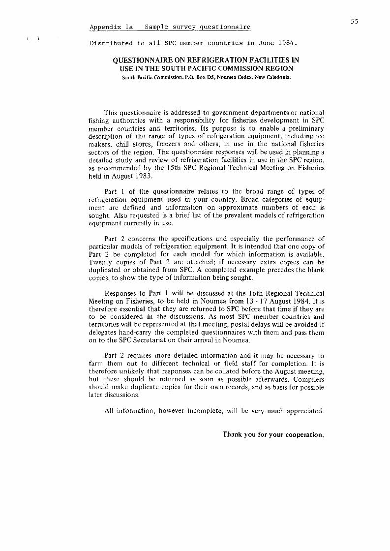
Appendix la Sample survey questionnaire
Distributed to all SPC member countries in June 1984.
QUESTIONNAIRE ON REFRIGERATION FACILITIES IN USE IN THE SOUTH PACIFIC COMMISSION REGION South Pacific Commission, P.O. Box D5, Noumea Cedex, New Caledonia.
This questionnaire is addressed to government departments or national fishing authorities with a responsibility for fisheries development in SPC member countries and territories. Its purpose is to enable a preliminary description of the range of types of refrigeration equipment, including ice makers, chill stores, freezers and others, in use in the national fisheries sectors of the region. The questionnaire responses will be used in planning a detailed study and review of refrigeration facilities in use in the SPC region, as recommended by the 15th SPC Regional Technical Meeting on Fisheries held in August 1983.
Part 1 of the questionnaire relates to the broad range of types of refrigeration equipment used in your country. Broad categories of equipment are defined and information on approximate numbers of each is sought. Also requested is a brief list of the prevalent models of refrigeration equipment currently in use.
Part 2 concerns the specifications and especially the performance of particular models of refrigeration equipment. It is intended that one copy of Part 2 be completed for each model for which information is available. Twenty copies of Part 2 are attached; if necessary extra copies can be duplicated or obtained from SPC. A completed example precedes the blank copies, to show the type of information being sought.
Responses to Part 1 will be discussed at the 16th Regional Technical Meeting on Fisheries, to be held in Noumea from 13-17 August 1984. It is therefore essential that they are returned to SPC before that time if they are to be considered in the discussions. As most SPC member countries and territories will be represented at that meeting, postal delays will be avoided if delegates hand-carry the completed questionnaires with them and pass them on to the SPC Secretariat on their arrival in Noumea.
Part 2 requires more detailed information and it may be necessary to farm them out to different technical or field staff for completion. It is therefore unlikely that responses can be collated before the August meeting, but these should be returned as soon as possible afterwards. Compilers should make duplicate copies for their own records, and as basis for possible later discussions.
All information, however incomplete, will be very much appreciated.
Thank you for your cooperation.
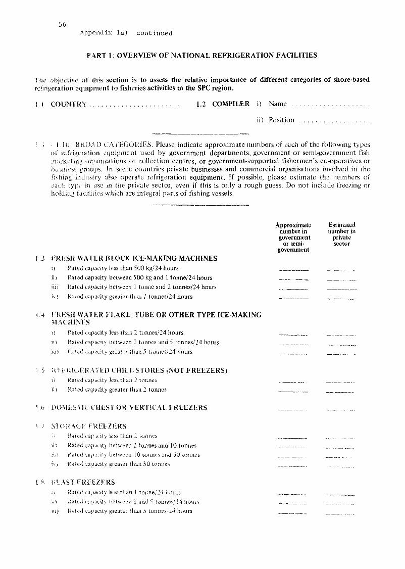
56 Appendix la) continued
PART 1: OVERVIEW OF NATIONAL REFRIGERATION FACILITIES
The abjective of this section is to assess the relative importance of different categories of shore-based refrigeration equipment to fisheries activities in the SPC region.
1 ( COUNTRY 1.2 COMPILER i) Name
ii) Position
1.10 BROAD CATEGORIES. Please indicate approximate numbers of each of the following types of refrigeration equipment used by government departments, government or semi-government fish marketing organisations or collection centres, or government-supported fishermen's co-operatives or business groups, fn some countries private businesses and commercial organisations involved in the fishing industry also operate refrigeration equipment. If possible, please estimate the numbers of each type in use m the private sector, even if this is only a rough guess. Do not include freezing or holding facilities which are integral parts of fishing vessels.
Approximate Estimated number in number in government private
or semi- sector government
! 3 FRESH WATER BLOCK ICE-MAKING MACHINES i) Rated capacity less than 500 kg/24 hours
is) Rated capacity between 500 kg and I tonne/24 hours
i.ii> Rated capacity between 1 tonne and 2 tonnes/24 hours
iv) Ruted capacity greater than 2 tonnes/24 hours
I 4 FRESH WAT ER I LAKE, TUBE OR OTHER TYPE ICE-MAKING MACHINES
i) Rated capacity less than 2 tonnes/24 hours
it) Rated capacity between 2 tonnes and 5 tonnes/24 hours _. iU) l<\m't! oupacity greato than 5 Tormes/24 hours
1.5 REFRIGERATED CHILL STORES (NOT FREEZERS) \) Rated capacity less than 2 tonnes ii) Rated capacity greater than 2 tonnes
M> DOMESTIC CHEST OR VERTICAL FREEZERS _ _ . .
•< 1 STORAGE FREEZERS i' Rated capicity less than 2 tonnes ii) Rated capacity between 2 tonnes and 10 tonnes .. in) Kated capacity between 10 tonnes and 50 tonnes ivt Rated capacity greater than 50 tonnes
1 8 BLAST FREEZERS
i/ Rated capacity less titan 1 tonne/24 hours iO Rated capacity between 1 and 5 tonnes/24 hours _.... .__. in) Rated capacity greater than 5 tonnes/24 hours _

Appendix la) continued
1.9 PLATE FREEZERS i) Rated capacity less than 500 kg/24 hours ii) Rated capacity between 500 kg and 2 tonnes/24 hours iii) Rated capacity greater than 2 tonnes/24 hours
1.10 OTHER EQUIPMENT (Please specify — include sea-water ice-making, machines, immersion freezing equipment, retail-type display chillers or freezers, refrigerated vehicles, etc.)
i)
ii)
iii)
iv)
v)
1.11 MODELS. Many different models of refrigeration equipment of all types are in use throughout the SPC region. Please list as comprehensively as possible all models you know to be in use in your country. Ideally each item listed should be in the format:
Manufacturer : Model number : Description : Rated capacity (where applicable)
Example: RESCO B400 BLOCK ICE MAKER 408 KG/24 HRS
1.11 ITEM NUMBER IN USE
i)
ii)
iii)
iv)
v)
vi)
vii)
viii)
ix)
x)
xi)
xii)
xiii)
xiv)
xv)
57
Approximate number in government
or semi-government
Estimated number in
private sector

58
Appendix la ) continued
PART 2: EXPERIENCE WITH SPECIFIC EQUIPMENT
The aim of Part 2 is to enable a comparison of the broad specifications of refrigeration equipment currently in use in the SPC region, together with general comments on its performance. It is intended that one copy of the question sheet be used for each model of equipment for which information is available. Any information is useful, however incomplete. If technical specifications or manufacturer's information leaflets are available for any of the models described, we would be very grateful if copies could be attached to the relevant question sheets.
2.1 COUNTRY 2.2 COMPILER i) Name . .
ii) Position
2.3 TYPE OF EQUIPMENT i) Manufacturer: ii) Model: iii) Country of origin: iv) Country where purchased : v) Description (please include details of rated capacity, power supply and other relevant characteristics)
vi) Number in use:
2.4 SELECTION. Many factors influence the selection of refrigeration equipment. Please tick the appropriate boxes to indicate the importance of the following in the choice of this equipment.
i) Chosen from a wide range of options as the best for the job ii) Limited information on alternatives restricted choice iii) Local availability of parts and/or service greatly influenced choice iv) Low purchase price greatly influenced choice v) Anticipated low operating costs greatly influenced choice vi) Restrictions on choice imposed by financing body or donor aid
agency (e.g. country of origin stipulations) vii) Other considerations (please specify):
Yes No
n n • • •
Not Applicable
• • • • • • • •
2.5 PERFORMANCE. Has this equipment proved:
i) Completely satisfactory in use
ii) Generally satisfactory but with minor problems (please specify)
Yes
• •
No
• •
iii) Unsatisfactory with major problems (please specify) • • iv) Other comments on performance
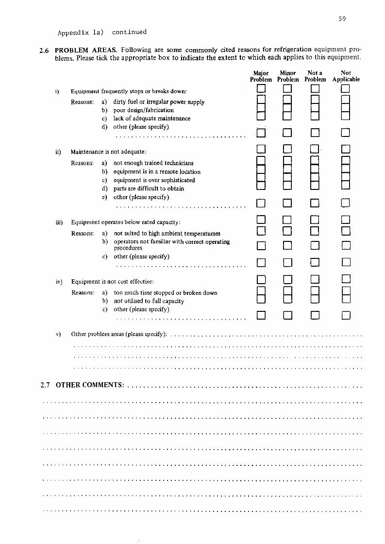
59
Appendix la) continued
PROBLEM AREAS. Following are some commonly cited reasons for refrigeration equipment problems. Please tick the appropriate box to indicate the extent to which each applies to this equipment.
iv)
Equipment frequently stops or breaks down:
Reasons: a) dirty fuel or irregular power supply b) c) d)
poor design/fabrication lack of adequate maintenance other (please specify)
ii) Maintenance is not adequate:
Reasons: a) not enough trained technicians b) equipment is in a remote location c) equipment is over sophisticated d) parts are difficult to obtain e) other (please specify)
iii) Equipment operates below rated capacity:
Reasons: a) not suited to high ambient temperaturses b) operators not familiar with correct operating
procedures c) other (please specify)
Equipment is not cost effective:
Reasons: a) too much time stopped or broken down b) not utilised to full capacity c) other (please specify)
Major Minor Not a Not Problem Problem Problem Applicable • • •
• • • D Q
•
• •
a • D a • a s a
a a a a a a
a
a a a a • a
a
• a • • a a
a v) Other problem areas (please specify):
OTHER COMMENTS:

60
Appendix lb) Summary of ques t i onna i r e Par t 1 responses
l—i ctj 4-1
O H
4J O to B OJ (3
^ 'yj
3 • U d 3 P 03
, - i
? P
H
^ 61, P 0
H
p vi O 0 B C O re r-t -H O c/j
Ol M
<_ P4
r H rH W d o
£1 P 0) cfl P H co en £ H
•H
rt O
• H I-i • H
^ "}T"vj " a H P en QJ J) M p
M< !>
Q
•7 (• ' -<
f/;
CO ( r- l
CN O 1 CO CN
< -' CO
-̂ -̂ cN r^
1 1
CO MD
-—l
1 i
CO C I
1
CI
( 1
r 1
I .-
CO l
C O
-̂1
-̂ . 1
I—1
--, 1
,-i
-̂ 1
O l
<T
-*
i
*-H
1
H
1 r H
-̂ O J
1
t - 1
c i
—.. C N
i
C O
I
CO
C O
v£)
1
^
1
-̂. 1
r i
' O
C O
O N
1
OJ
1
r H
C 1
1
V > J 3
< N
r H CO CN r H
1
I D
1 1
^D r H
1
—(
-̂ <n
l
--*. *-%,. O CN •—t
| r H
C N r H
r - l
1
o U"l
1 • - , . - " ,
t
r i
1 1
CO co
-* 0 0
O N
<r
l
- T
O
d CN
u-l •H • " • « .
C N CN
O r - t
r -
m n
CO
P ccj 5
<o
Tw
*n
m O N C N i m ~4 ~H
--» *--. ^ \ vD M CTi ^D r H CN
1 1 CO r H
1 J 3
"--. "*̂ CN i
1
r H
| a \
1 r H 1 1
-̂-. *-«~ -~. ---CN 1 CN CN
1 f O CN
CN <T rH.
1 r H 1
CN I r H
r H OJ
1 1
i O l
o-. i
o m 1/1 . (
r-( CN
' i'1 i ' ; co e l c-i
r—t
I CN 1
m < t r v
1
1
C N
1
r H
1
C N
1
r H
1
o O l
r l
1 1 1
1 1 1
r H CN 1
1
r - l
r-H
1
P I
p tfl cn OJ
p d) OJ
s * J
a)
p OJ
c; S P Q)
P at u CO
CJ
U
. I .
n) M
H
J l
c>1
^ vH •H
at i J to
u l
3
11 r i
fO
,<̂ ^ • H
ci) a m ;* at u -1 QJ
r t U [J -H ca CJ p ta (0 n . cJ cd
nl a* in t o
• H
Cl CO
p . n) u
Ul
&. o E--
r 5 H I
l i ^ t i
n
w w 4J
M
r 1 .
U r j P ca a
nl 01 I-I M
t )
a a «J u
r <
>-,
^ • H
^ •H • r <
M
^
o p p m
J= 4-J
Ui
01 01 - 1
c ai <u '.i n .11
.a
c a) OJ
^ n
«.
M U U It) (II M t o
PJ M r .J
P: p ,
i . i t:>
CC
P cO CJ
' U 0 J (.J cO
p i
rr, P «t CJ
• u QJ J-J
aj
^
ra p . to
-o Ot p m
^
CCl P m CJ
•n fl) w
,3
p . p . O. (0 cj cd U U CJ
• o r v ; -cj a) '4) CJ
co cvJ ro |U^ I'H X
^ - . -H ^-v -H TH •H -H -H
cn
r : c : [ . 1 M (-••,
(-. r«J
«c,
P>
P . CO CJ
• o fli
iv;
| i i
• H
n ;fl CJ
• r t CJ
i t ]
u,
^̂ • r ^
6 01
• u OJ
HI
.-• H
• H
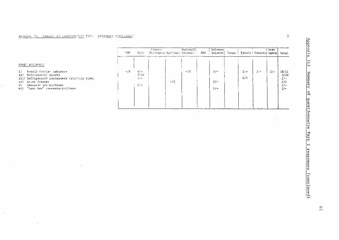
Anoendir lb" burrc^srv of Questicnn.-.ire Par" resDrnsec (crr.tinued)
OTEE? EQUIPMENT
i ) i i )
R e t a i l display c a b i n e t s Refrigerated t r u c k s
i i i ) Refrigerated c o n t a i n e r s ^shippin iv) t r i n e freezer v) Seawater ice machines v i ) "Bush box1' f r e e z e r s / c h i l l e r s
rs>'
-IS
Fiji
6/-3/20 1/-
1/-
frenci, i
Polvnesia1 Kiribati '
-n
Marsr.all islands
-/3
PNG Solomon Islands
5/-
21-
11-
Tonga
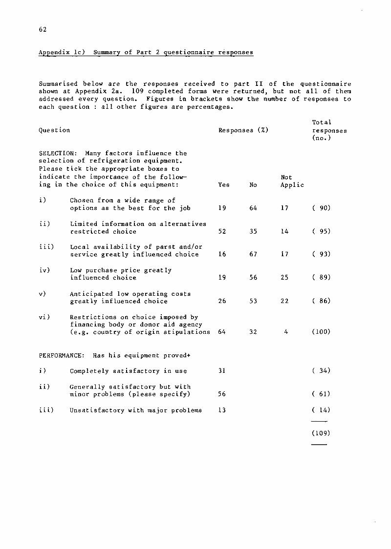
62
Appendix lc) Summary of Part 2 questionnaire responses
Summarised below are the responses received to part II of the questionnaire shown at Appendix 2a. 109 completed forms were returned, but not all of them addressed every question. Figures in brackets show the number of responses to each question : all other figures are percentages.
Total Question Responses (%) responses
(no.)
SELECTION: Many factors influence the selection of refrigeration equipment. Please tick the appropriate boxes to indicate the importance of the following in the choice of this equipment: Yes No
i) Chosen from a wide range of options as the best for the job 19 64
ii) Limited information on alternatives restricted choice 52 35
iii) Local availability of parst and/or service greatly influenced choice 16 67
iv) Low purchase price greatly influenced choice 19 56
v) Anticipated low operating costs greatly influenced choice 26 53 22 ( 86)
vi) Restrictions on choice imposed by financing body or donor aid agency (e.g. country of origin stipulations 64 32 4 (100)
PERFORMANCE: Has his equipment proved+
i) Completely satisfactory in use 31 ( 34)
ii) Generally satisfactory but with
minor problems (please specify) 56 ( 61)
iii) Unsatisfactory with major problems 13 ( 14)
Not Applic
17
14
17
25
( 90)
( 95)
( 93)
( 89)
(109)
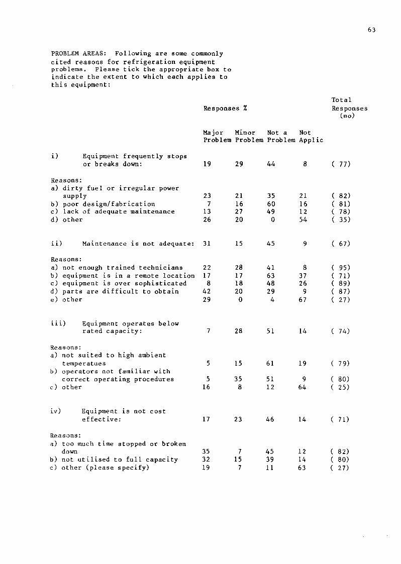
63
PROBLEM AREAS: Following are some commonly cited reasons for refrigeration equipment problems. Please tick the appropriate box to indicate the extent to which each applies to this equipment:
Responses % Total Responses (no)
Major Minor Not a Not Problem Problem Problem Applic
i) Equipment frequently stops or breaks down: 19 29 44 ( 77)
Reasons: a) dirty fuel or irregular power
supply b) poor design/fabrication c) lack of adequate maintenance d) other
23 7 13 26
21 16 27 20
35 60 49 0
21 16 12 54
( 82) ( 81) ( 78) ( 35)
i ) Maintenance is not adequate: 31 15 45 ( 67)
Reasons: a) not enough trained technicians b) equipment is in a remote location c) equipment is over sophisticated d) parts are difficult to obtain e) other
22 17 8 42 29
28 17 18 20 0
41 63 48 29 4
8 37 26 9 67
( 95) ( 71) ( 89) ( 87) ( 27)
Equipment operates below rated capacity: 28 51 14 ( 74)
Reasons: a) not suited to high ambient
temperatues b) operators not familiar with
correct operating procedures c) other
15 61 19 ( 79)
5 16
35 8
51 12
9 64
( 80) ( 25)
iv) Equipment is not cost effective: 17 23 46 14 ( 71)
Reasons: a) too much time stopped or broken
down b) not utilised to full capacity c) other (please specify)
35 32 19
7 15 7
45 39 11
12 14 63
( 82) ( 80) ( 27)

65
Appendix 2. Partial listing of Pacific fisheries sector refrigeration equipment (continued)
This section provides a condensed listing of the refrigeration equipment in use in government or commercial fisheries development activities in Pacific Island countries. The inventory can in no way be regarded as complete but it is, or ought to be, representative. The information is compiled from questionnaire responses (countries marked 'Q' in the list below) and from discussions held and observations made during the survey visits (countries marked 'S'). In many cases specifications are lacking but where these are available, they are presented according to a simple standard format, which gives basic descriptive information consistent with the need for brevity.
Countries for which information is available are:
a) Federated States of Micronesia Q, S b) Fiji Q, S c) French Polynesia Q, S d) Kiribati Q, S e) Marshall Islands Q, S f) Papua New Guinea S g) Solomon Islands Q, S h) Tonga S i) Tuvalu Q, S j) Vanuatu Q, S k) Western Samoa Q, S
Where information is based on questionnaire responses, specifications are presented exactly as given in the questionnaire sheets. Units are converted from those used by the original compiler, to 'standard' units according to the following equivalents:
. , x „ 3 Storage Capacity " " Drive unit power Cooling capacity
1 tonne (weight) = 3 m~ 1 horsepower = 0.74 kW lkW = 3414 Btu
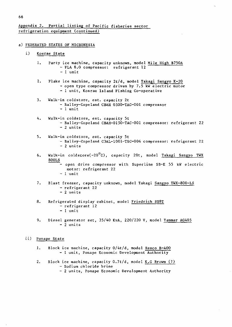
66
Appendix 2. Partial listing of Pacific fisheries sector refrigeration equipment (continued)
a) FEDERATED STATES OF MICRONESIA
i) Kosrae State
1. Party ice machine, capacity unknown, model Mile High B750A - FLA 8.0 compressor: refrigerant 12 - 1 unit
2. Flake ice machine, capacity 2t/d, model Takagi Sangyo K-20 - open type compressor driven by 7.5 kW electric motor - 1 unit, Kosrae Island Fishing Co-operative
3. Walk-in coldstore, est. capacity 2t - Balley-Cope land CBAH 0300-TAC-001 compressor - 1 unit
4. Walk-in coldstore, est. capacity 5t - Balley-Copeland CBAH-0150-TAC-001 compressor: refrigerant 22 - 2 units
5. Walk-in coldstore, est. capacity 5t - Balley-Copeland C3AL-1001-TSC-006 compressor: refrigerant 22 - 2 units
6. Walk-in coldstore(-20°C), capacity 20t, model Takagi Sangyo TWX 800LS
- open drive compressor with Superline SB-E 55 kW electric motor: refrigerant 22
- 1 unit
7. Blast freezer, capacity unknown, model Takagi Sangyo TWX-800-LS - refrigerant 22 - 2 units
8. Refrigerated display cabinet, model Friedrich SS8T - refrigerant 12 - 1 unit
9. Diesel generator set, 35/40 KvA, 220/220 V, model Yanmar AG405 - 2 units
ii) Ponape State
1. Block ice machine, capacity 0/4t/d, model Resco B-400 - 1 unit, Ponape Economic Development Authority
2. Block ice machine, capacity 0.7t/d, model K.G Brown (?) - Sodium chloride brine - 2 units, Ponape Economic Development Authority

67
Appendix 2. Partial listing of Pacific fisheries sector refrigeration equipment (continued)
a) FEDERATED STATES OF MICRONESIA (continued)
ii) Ponape State (continued)
3. Flake (tube) ice machine, capacity 2t/d, model Turbo SBF45CA
- Copelamatic est 10 h.p. semi-hermetic compressor: refrigerant 22
- 1 unit, Ponape Economic Development Authority
4. Flake ice machine, capacity 2t/d, model Northstar (?) - 1 unit, Ponape Economic Development Authority
5. Flake ice machine, capacity 5t/d, model Northstar M10 - 1 unit, Tekhetic refrigeration facility
6. Walk-in chill (ice) store, est capacity 5t - Coolclad prefabricated insulated chamber: Copeland
est. 1.5 hp hermetic compressor - 1 unit, Ponape Economic Development Authority
7. Walk-in chill store, est. capacity 5t - local construction insulated chamber: Recold PL5A
'plug' refrigeratin unit - 1 unit, Tekhetic refrigeration facility
8. Walk-in chill store, est. capacity lOt - Coolclad prefabricated insulated chamber: 2 x Copeland
est 1.5 hp hermetic compressors - 1 unit, Ponape Economic Development Authority
9. Walk-in chill (ice) store, est. capacity lOt - local construction insulated chamber: Recold PL5A
'plug' refrigeration unit - 1 unit, Tekhetic refrigeration facility
10. Walk-in coldstore, est. capacity 7t - local construction insulated chamber: Recold PL5A
'plug' refrigeration unit - 1 unit, Tekhetic refrigeration facility
11. Blast freezer, capacity 4 t/d - local construction insulated storage room: Recold PLlOA
'plug' refrigeration unit - 1 unit, Tekhetic refrigeration facility
iii) Truk State
1. Flake ice machine, capacity 3t/d, model Northstar MlO/71 - 1 unit
2. Flake ice machine, capacity 3t/d, model Turbo SBF65CA - 1 unit
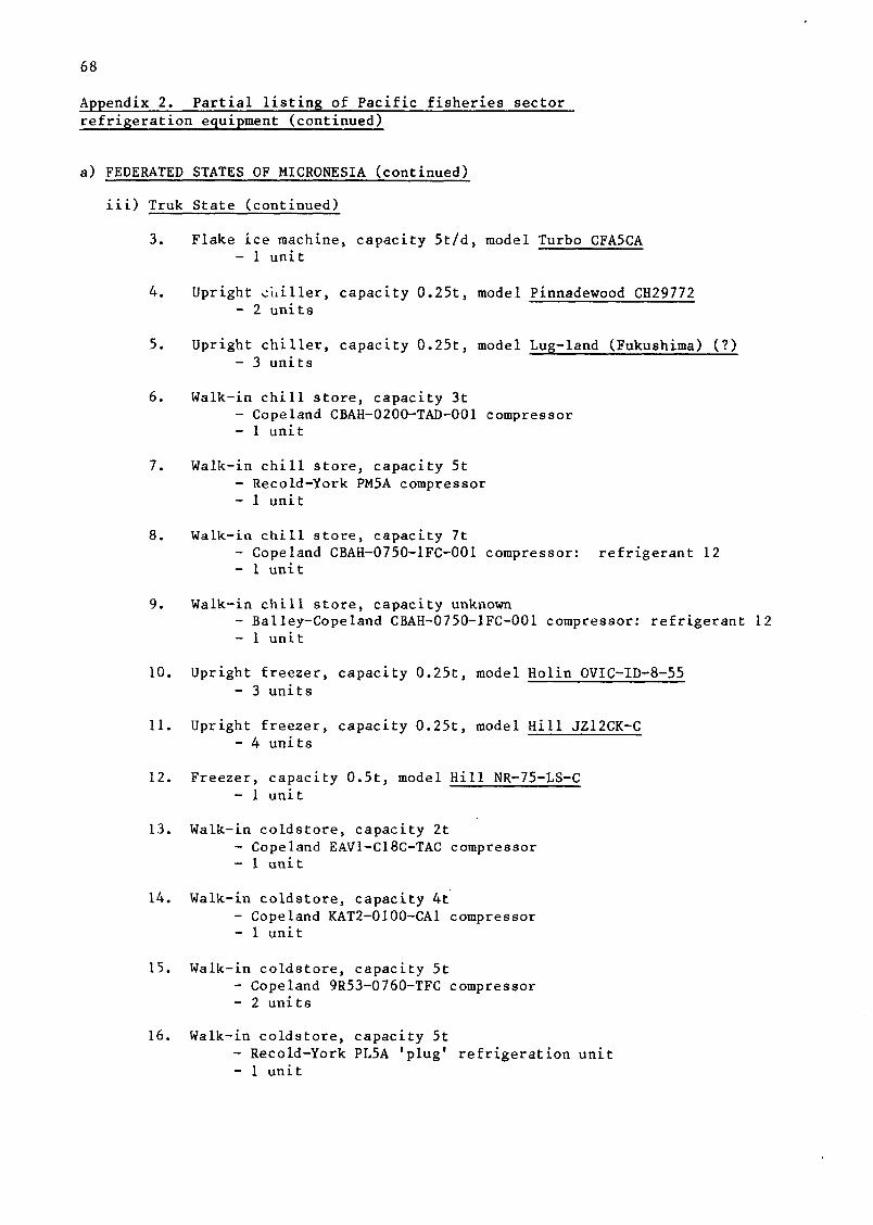
68
Appendix 2. Partial listing of Pacific fisheries sector refrigeration equipment (continued)
a) FEDERATED STATES OF MICRONESIA (continued)
iii) Truk State (continued)
3. Flake ice machine, capacity 5t/d, model Turbo CFA5CA - 1 unit
4. Upright e'uiller, capacity 0.25t, model Pinnadewood CH29772 - 2 units
5. Upright chiller, capacity 0.25t, model Lug-land (Fukushima) (?) - 3 units
6. Walk-in chill store, capacity 3t - Cope land CBAH-0200-TAD-001 compressor - 1 unit
7. Walk-in chill store, capacity 5t - Recold-York PM5A compressor - 1 unit
8. Walk-in chill store, capacity 7t - Copeland CBAH-0750-1FC-001 compressor: refrigerant 12 - 1 unit
9. Walk-in chill store, capacity unknown - Balley-Cope land CBAH-0750-1FC-001 compressor: refrigerant 12 - 1 unit
10. Upright freezer, capacity 0.25t, model Holin OVIC-ID-8-55 - 3 units
11. Upright freezer, capacity 0.25t, model Hill JZ12CK-C - 4 units
12. Freezer, capacity 0.5t, model Hill NR-75-LS-C - 1 unit
13. Walk-in coldstore, capacity 2t - Copeland EAV1-C18C-TAC compressor - 1 unit
14. Walk-in coldstore, capacity 4t - Copeland KAT2-0100-CA1 compressor - 1 unit
15. Walk-in coldstore, capacity 5t - Copeland 9R53-0760-TFC compressor - 2 units
16. Walk-in coldstore, capacity 5t - Recold-York PL5A 'plug' refrigeration unit - 1 unit

69
Appendix 2. Partial listing of Pacific fisheries sector refrigeration equipment (continued)
a) FEDERATED STATES OF MICRONESIA (continued)
iii) Truk State (continued)
17. Walk-in coldstore, capacity 20t - Copeland C3AL-1002-T8D-001 compressor - 2 units
18. B las t f r e e z e r , c apac i t y 20t /d - Recold-York PLlOB ' p l u g ' r e f r i g e r a t i o n u n i t - 2 u n i t s
19. Blast freezer, capacity 40t/d - Copeland C3AL-1002-T8D-001 compressor - 1 unit
iv) Yap State
1. Flake ice machine, capacity 2t/d, model Takagi Sangyo K-20 - open-type compressor driven by 7.5 kw electric motor - 2 units
2. Flake ice machine, capacity unknown - Tecumseh LH7517A compressor - 1 unit, Yap Fishing Authority
3. Flake ice machine, capacity unknown, model King Seeley Thermos MFGAE-34
- 2 units, Yap Fishing Authority
4. Walk-in chill store, capacity unknown, model Mitsubishi HC-15TMA - 3 units
5. Walk-in coldstore, capacity 1.5t, model Mitsubishi HC-llTMA - two semi-hermetic compressors - 1 unit
6. Walk-in coldstore, capacity 3t - Copelamatic LAMI-0310-SAB compressor - 1 unit
7. Walk-in coldstore, capacity 20t, model Takagi Sangyo TWX 800LS - open drive compressor with Superline 5.5 kW electric
motor: refrigerant 22 - 2 units
8. Walk-in coldstore, capacity unknown, model Takagi Sangyo TWX-800-LS - 1 unit
9. Blast freezer, capacity unknown, model Takagi Sangyo TWX-800-LS - refrigerant 22 - 1 unit

70
Appendix 2. Partial listing of Pacific fisheries sector refrigeration equipment (continued)
b) FIJI
1. Block ice machine, capacity 0.4t/d, model Resco B-400 - 1 unit
2. Block ice machine, capacity 0.8t/d, model Resco B-800 - 2 units
3. Flake ice machine, capacity 5t/d, model Resco SEW-5600 - 1 unit, located Lami
4. Flake ice machine, capacity 5t/d. model Nissin NI-FS-5U - Taito-Seiko TS-5U plate ice maker: Mitsubishi open-drive
compressor with 1.5 kW electric motor: refrigerated storage chamber
- 3 units at Wainibokasi, Savusavu and Taveuni
5. Flake ice machine, capacity lOt/d, model McAlpine MD10 - 1 unit, Lami
6. Flake ice machine, capacity lOt/d. model Northstar M10 - 1 unit, Labasa
7. Flake ice machine, capacity 20t/d, model Northstar M20-77 - 2 ice drums: refrigerated chamber: water cooling tower - 1 unit, Lautoka
8. Walk-in chill store, capacity 40t - Mitsubishi model WA-25C semi-hermetic compressor:
water cooling tower (shared with item 11): refrigerant 22 - 2 units, National Marketing Authority, Lami
9. Walk-in coldstore, capacity 5t - 2 units at Labasa and Savusavu
10. Shipping container/coldstore, est. capacity 15t - 3 units, 2 at Labasa, 1 at National Marketing Authority,
Lami
11. Walk-in coldstore, capacity 20t - Mitsubishi model WB-3MC semi-hermetic compressor: water
cooling tower (shared with item 8) - 2 units, National Marketing Authority, Lami
12. Blast freezer, capacity 20t/d - Mitsubishi model WB-65C semi-hermetic compressor: water
cooling tower: refrigerant 502 - 1 unit, located National Marketing Authority, Lami
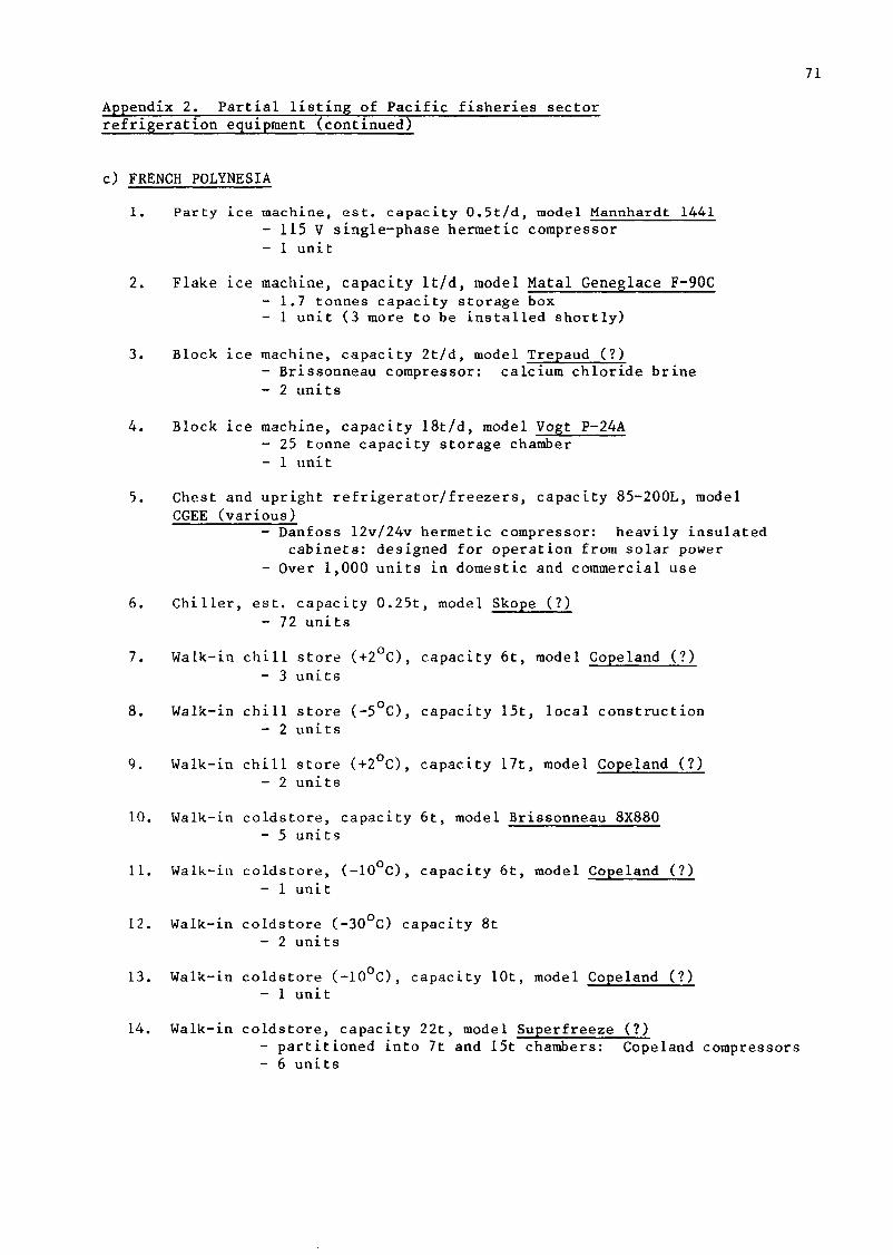
71
Appendix 2. Partial listing of Pacific fisheries sector refrigeration equipment (continued)
c) FRENCH POLYNESIA
1. Party ice machine, est. capacity 0.5t/d, model Mannhardt 1441 - 115 V single-phase hermetic compressor - 1 unit
2. Flake ice machine, capacity lt/d, model Matal Geneglace F-90C - 1.7 tonnes capacity storage box - 1 unit (3 more to be installed shortly)
3. Block ice machine, capacity 2t/d, model Trepaud (?) - Brissonneau compressor: calcium chloride brine - 2 units
4. Block ice machine, capacity 18t/d, model Vogt P-24A - 25 tonne capacity storage chamber - 1 unit
5. Chest and upright refrigerator/freezers, capacity 85-200L, model CGEE (various)
- Danfoss 12v/24v hermetic compressor: heavily insulated cabinets: designed for operation from solar power
- Over 1,000 units in domestic and commercial use
6. Chiller, est. capacity 0.25t, model Skope (?) - 72 units
7. Walk-in chill store (+2 C), capacity 6t, model Copeland (?) - 3 units
8. Walk-in chill store (-5 C), capacity 15t, local construction - 2 units
9. Walk-in chill store (+2°C), capacity 17t, model Copeland (?) - 2 units
10. Walk-in coldstore, capacity 6t, model Brissonneau 8X880 - 5 units
11. Walk-in coldstore, (-10 C), capacity 6t, model Copeland (?) - 1 unit
12. Walk-in coldstore (-30°C) capacity 8t - 2 units
13. Walk-in coldstore (-10 C), capacity lOt, model Copeland (?) - 1 unit
14. Walk-in coldstore, capacity 22t, model Superfreeze (?) - partitioned into 7t and 15t chambers: Copeland compressors - 6 units
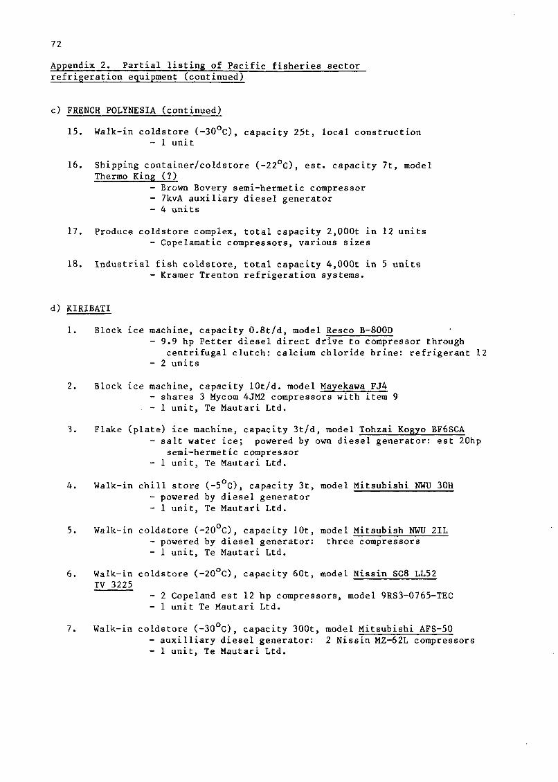
72
Appendix 2. Partial listing of Pacific fisheries sector refrigeration equipment (continued)
c) FRENCH POLYNESIA (continued)
15. Walk-in coldstore (-30°C), capacity 25t, local construction - 1 unit
16. Shipping container/coldstore (-22°C), est. capacity 7t, model Thermo King (?)
- Brown Bovery semi-hermetic compressor - 7kvA auxiliary diesel generator - 4 units
17. Produce coldstore complex, total capacity 2,000t in 12 units - Copelamatic compressors, various sizes
18. Industrial fish coldstore, total capacity 4,000t in 5 units - Kramer Trenton refrigeration systems.
d) KIRIBATI
1. Block ice machine, capacity 0.8t/d, model Resco B-800D - 9.9 hp Petter diesel direct drive to compressor through
centrifugal clutch: calcium chloride brine: refrigerant 12 - 2 units
2. Block ice machine, capacity lOt/d. model Mayekawa FJ4 - shares 3 Mycom 4JM2 compressors with item 9 - 1 unit, Te Mautari Ltd.
3. Flake (plate) ice machine, capacity 3t/d, model Tohzai Kogyo BF6SCA - salt water ice; powered by own diesel generator: est 20hp
semi-hermetic compressor - 1 unit, Te Mautari Ltd.
4. Walk-in chill store (-5°C), capacity 3t, model Mitsubishi NWU 30H - powered by diesel generator - 1 unit, Te Mautari Ltd.
5. Walk-in coldstore (-20°C), capacity lOt, model Mitsubish NWU 2IL - powered by diesel generator: three compressors - 1 unit, Te Mautari Ltd.
6. Walk-in coldstore (-20°C), capacity 60t, model Nissin SC8 LL52 TV 3225
- 2 Copeland est 12 hp compressors, model 9RS3-0765-TEC - 1 unit Te Mautari Ltd.
7. Walk-in coldstore (-30°C), capacity 300t, model Mitsubishi AFS-50 - auxilliary diesel generator: 2 Nissin MZ-62L compressors - 1 unit, Te Mautari Ltd.
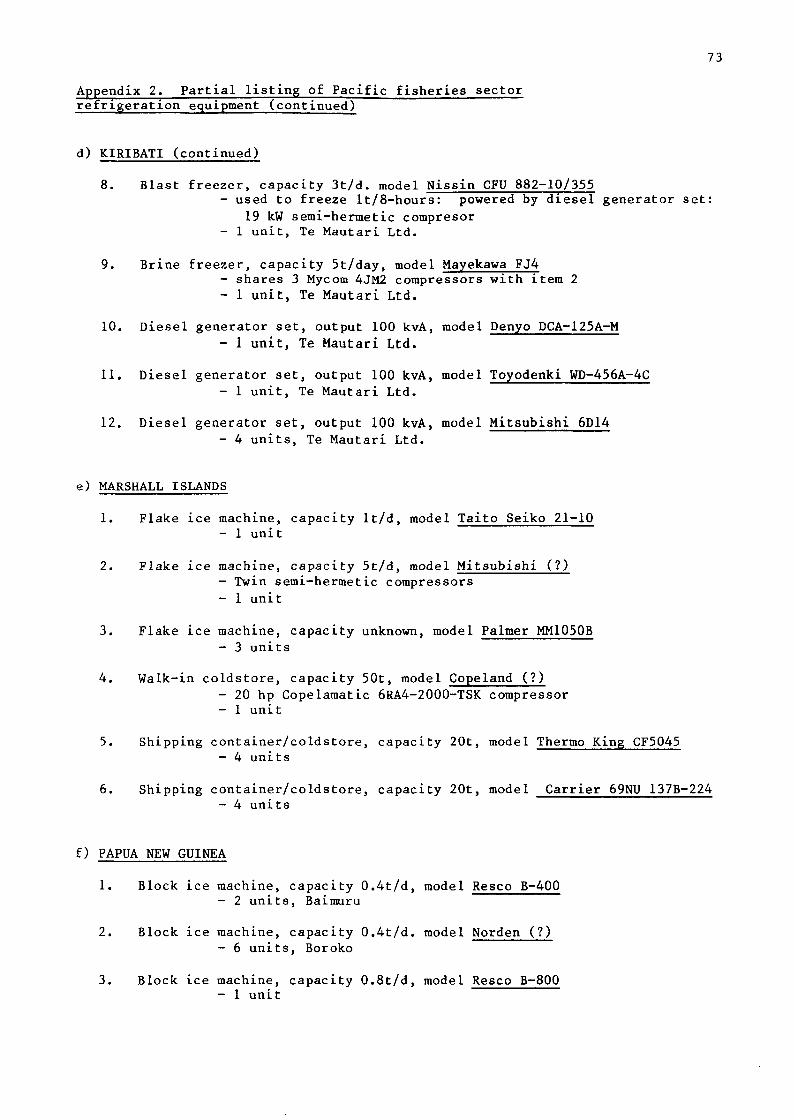
73
Appendix 2. Partial listing of Pacific fisheries sector refrigeration equipment (continued)
d) KIRIBATI (continued)
8. Blast freezer, capacity 3t/d. model Nissin CFU 882-10/355 - used to freeze lt/8-hours: powered by diesel generator set:
19 kW semi-hermetic compresor - 1 unit, Te Mautari Ltd.
9. Brine freezer, capacity 5t/day, model Mayekawa FJ4 - shares 3 Mycom 4JM2 compressors with item 2 - 1 unit, Te Mautari Ltd.
10. Diesel generator set, output 100 kvA, model Denyo DCA-125A-M - 1 unit, Te Mautari Ltd.
11. Diesel generator set, output 100 kvA, model Toyodenki WD-456A-4C - 1 unit, Te Mautari Ltd.
12. Diesel generator set, output 100 kvA, model Mitsubishi 6D14 - 4 units, Te Mautari Ltd.
e) MARSHALL ISLANDS
1. Flake ice machine, capacity lt/d, model Taito Seiko 21-10 - 1 unit
2. Flake ice machine, capacity 5t/d, model Mitsubishi (?) - Twin semi-hermetic compressors - 1 unit
3. Flake ice machine, capacity unknown, model Palmer MM1050B - 3 units
4. Walk-in coldstore, capacity 50t, model Copeland (?) - 20 hp Copelamatic 6RA4-2000-TSK compressor - 1 unit
5. Shipping container/coldstore, capacity 20t, model Thermo King CF5045 - 4 units
6. Shipping container/coldstore, capacity 20t, model Carrier 69NU 137B-224 - 4 units
f) PAPUA NEW GUINEA
1. Block ice machine, capacity 0.4t/d, model Resco B-400 - 2 units, Baimuru
2. Block ice machine, capacity 0.4t/d. model Norden (?) - 6 units, Boroko
3. Block ice machine, capacity 0.8t/d, model Resco B-800 - 1 unit

74
Appendix 2. Partial listing of Pacific fisheries sector refrigeration equipment (continued)
f) PAPUA NEW GUINEA (continued)
4. Block ice machine, capacity 0.8t/d, model Norden (?) - 1 unit, Boroko
5. Block ice machine, capacity 0.8t/d. model Bitzer (?) - 1 unit, Boroko
6. Flake ice machine, capacity 5t/d, model Northstar M-10 - 1 unit, Daru
7. "Bush box" chiller/freezer, capacity It local construction assembled from scrap auto
airconditioning parts - 1 unit, Daru (Western District Seafoods)
8. Walk-in coldstore, capacity 6t - 1 unit, Daru (Western District Seafoods)
9. Walk-in freezer, est. capacity 7t - Kelvinator semi-hermetic compressor - 1 unit, Boroko
10. Walk-in freezer, est. capacity 15t - Hunt & Baird prefabricated chamber: Kelvinator TE82 open
drive compressor: Bitzer condenser unit - 2 units, Port Moresby
11. Walk-in freezer, est. capacity 18t - Hunt & Baird prefabricated chamber: open type compressor
driven by Toshiba electric motor: Bitzer condenser unit - 1 unit, Port Moresby
12. Walk-in freezer, capacity 20t - Isowall prefabricated cabinet: two 4 kw Kelvinator semi-
hermetic compressors - 1 u n i t , Baimuru
13. Walk-in f r eeze r , c apac i ty 20t - Sanders-Rolbond p r e f a b r i c a t e d c a b i n e t : McAlpine P res t co ld
semi-hermetic compressor - 1 unit, Daru
14. Walk-in freezer, capacity 24 t - partitioned into three chambers: 3 Copeland semi-hermetic
compressors - 1 unit, Daru

75
Appendix 2. Partial listing of Pacific fisheries sector refrigeration equipment (continued)
f) PAPUA NEW GUINEA (continued)
15. Walk-in frezer, capacity 50 t - Hunt & Baird prefabricated chambers: Kelvinator open drive
compressors powered by Asea electric motors - 2 units, Port Moresby
16. Walk-in cold store, capacity lOOt, model MacGregor (?) - multiple Kelvinator TE-82 compressors - 1 unit, Port Moresby
17. Freezer complex: a) walk-in freezer, capacity 20t b) walk-in freezer, capacity 60t c) blast freezer, capacity lOt/d
- sharing 4 Kelvinator open-drive compressors with electric motors 5-15hp
- 1 unit, Daru (Western District Seafoods)
18. Blast freezer, capacity lOt/d - Hunt & Baird prefabricated chamber: Kelvinator open-drive
compressor with 11 kw electric motor: Muller evaporator - 1 unit, Baimuru
19. Diesel generator set, capacity 25 kvA, model Lister HR3 - 1 unit, Baimuru
20. Diesel generator set, capacity 52 kW, model Caterpillar SR-4 - 1 unit, Port Moresby
21. Diesel generator set, capacity 65 kvA, model Lister HR56431 - 1 unit Baimuru
22. Diesel generator set, capacity 90 kvA, model Lister 169JA6 A28 - 1 unit Baimuru
23. Diesel generator set, capacity 95 kvA, model Lister HR6 - Electric Construction Corporation BRF 2501 brushless
alterantor - 1 unit, Daru (Western District Seafoods)
g) SOLOMON ISLANDS
1. Block ice machine, capacity 0.4t/d, model Resco B-400 - Bitzer compressor - 3 units
2. Block ice machine, capacity 0.5t/d, model McGregor M-400 - open-drive compressors powered by own diesel engines:
propylene glycol secondary refrigerant - 3 units

76
Appendix 2. Partial listing of Pacific fisheries sector refrigeration equipment (continued)
g) SOLOMON ISLANDS (continued)
3. Block ice machine, capacity 0.5t/d, model Winter WB500 - 3 units
4. Block ice machine, capacity 0.7t/d, model McGregor M-800 - some open-drive compressors with own diesel engine:
others semi-hermetic, driven by diesel generator: propylene glycol secondary refrigerant
- 10 units
5. Block ice machine, capacity 0.8t/d, model Resco B-800 - Bitzer compressor - 3 units
6. Block ice machine, capcity lt/d, model Lightfoot VT7 - calcium chloride brine - 1 unit, Honiara
7. Flake ice machine, capacity 0.4t/d, model McGregor V160 - 1 unit
8. Flake ice machine, capacity lt/d, model Mycom MPI-1 - semi hermetic compressor: powered by own diesel generator,
model Daewoo DGR, 3-phase, 220v, 25 kVA output: refrigerant 22
- 2 units
9. Walk-in chill store, capacity 1.5t - Coldstream 1 h.p. open-drive compressor - 1 unit, Gizo
10. Walk-in chill store (-5°c), capacity 2t, model Frigidaire AD - 3 units
11. Refrigeration 'plug' units, model Mitsubishi AFL-3 - various configurations - 7 units
12. Upright and chest freezers, capacities up to 2501, various models - 22 units
13. Walk-in freezer, capacity 2t, model Prestcold (?) - 2 units
14. Walk-in freezer (-20UC), capacity ot - Hemsec prefabricated cabinet: Frigidaire 7.5 hp
compressor - 1 unit
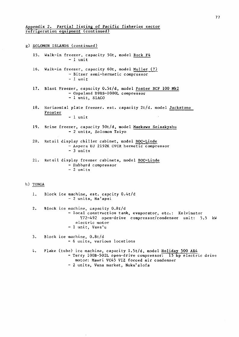
77
Appendix 2. Partial listing of Pacific fisheries sector refrigeration equipment (continued)
g) SOLOMON ISLANDS (continued)
15. Walk-in freezer, capacity 50t, model Bock F4 - 1 unit
16. Walk-in freezer, capacity 60t, model Muller (?) - Bitzer semi-hermetic compressor - 1 unit
17. Blast Freezer, capacity 0.5t/d, model Foster BCF 100 Mk2 - Copeland D9RS-1000L compressor - 1 unit, SIACO
18. Horizontal plate freezer, est. capacity 2t/d. model Jackstone Froster
- 1 unit
19. Brine freezer, capacity 50t/d, model Maekawa Seisakyshu - 2 units, Solomon Taiyo
20. Retail display chiller cabinet, model BOC-Linde - Aspera UJ 2192K CVCR hermetic compressor - 3 units
21. Retail display freezer cabinets, model BOC-Linde - Hubbard compressor - 2 units
h) TONGA
1. Block ice machine, est. capcity 0.4t/d - 2 units, Ha'apai
2. Block ice machine, capacity 0.8t/d - local construction tank, evaporator, etc.: Kelvinator
Y72-492 open-drive compressor/condenser unit: 5.5 kW electric motor
- 1 unit, Vava'u
3. Block ice machine, 0.8t/d - 6 units, various locations
4. Flake (tube) ice machine, capacity 1.5t/d, model Holiday 500 AR4 - Terry 100B-502L open-drive compressor: 15 hp electric drive
motor: Mauri VC45 VIZ forced air condenser - 2 units, Vuna market, Nuku'alofa

78
Appendix 2. Partial listing of Pacific fisheries sector refrigeration equipment (continued)
h) TONGA (Continued)
5. Walk-in chill store, est. capacity 5t - Wilkins and Davies prefaricated chamber: McAlpine Prestcold
est 3 hp semi-hermetic compressor/condenser unit - 1 unit, Vuna market, Nuku'alofa
6. Walk-in chill store, capacity 8t - Olympic Hunt & Baird prefabricated chamber: Kelvinator
K-62-702 open drive compressor/condenser unit: 2.2 kW electric drive motor: Recold LLE4 dual temperature evaporator
- 1 unit, Vava'u
7. Walk-in chill store, capacity lOt - 1 unit, Vava'u
8. Walk-in coldstore, est. capacity 5t - Wilkins and Davies prefabricated chamber: McAlpine Prestcold
est 3 hp semi-hermetic compressor/condenser unit - 1 unit, Vuna market, Nuku'alofa
9. Walk-in coldstore, est. capacity 6t, model Resco (?) - Petter PJl 12hp diesel engine drive unit - 1 unit, Commodities Board, Ha'apai
10. Walk-in coldstore, capacity 7t - 1 unit, Vava'u
11. Walk-in coldstore est. capacity 8t - Olympic Hunt and Baird prefabricated chamber: Kelvinator
Y72-372 open-drive compressor/condenser unit: 3kW electric drive motor: Recold LLEL dual temperature evaporator
- 1 unit, Vava'u
12. Walk-in coldstore, est. capacity lOt - Mitsubishi prefabricated chamber: two Mitsubishi NWU-2TL
1.5 kW refrigeration 'plug' units - 1 unit, Nuku'alofa
13. Walk-in coldstore, capacity lOt - 1 unit Vava'u
14. Walk-in coldstore, est capacity lOt - Olympic Hunt and Baird prefabricated chamber: Kelvinator
B29-140N open drive compressor/condenser unit: 5.5 kW electric drive motor: Cartwright Taylor HDPF293 evaporator
- 1 unit, Ha'apai

79
Appendix 2. Partial listing of Pacific fisheries sector refrigeration equipment (continued)
h) TONGA (continued)
15. Walk-in coldstore, capacity unknown - 2 units, Ha'apai
16. Shipping container/coldstore, capacity 17t - Copeland semi-hermetic compressor - 1 unit, Nuku'alofa
17. Blast freezer, est. capacity 5t/d - Olympic Hunt and Baird prefabricated chamber: Kelvinator
B29-140N open drive compressor/condenser unit: 5.5 kW electric drive motor: Cartwright Taylor HDPF293 evaporator
- 1 unit, Ha'apai
18. Blast freezer, est. capacity 7t/d - Olympic Hunt and Baird prefabricated chamber: Kelvinator
T-82 open drive compressor/condenser unit: llkW electric drive motor: Cartwright Taylor CT HAC 127 parallel high-load condensers: Cartwright Taylor W6CTFS evaporator
- 2 units, Vava'u
19. Horizontal plate freezer, est. capcity lt/d Nissin BF-500 - 14 kW semi-hermetic compresor - 1 unit, Nuku'alofa
20. Diesel generator set capacity 35 kvA - Lister HL diesel engine: Dunlite 415v 3-phase brushless
alternator - 1 unit, Ha'apai (provides main power for items 1, 14 and 17)
i) TUVALU
1. Flake ice machine, capacity 0.3t/d, model Ziegra UB300 - 1 unit
2. Walk-in chill store (-5 C), capacity 4t - Hemsec prefabricated chamber: Watford Refrigeration 'plug'
unit - 1 unit
3. Chest freezer, capacity 0.5t, model Leonard 4500FF - 1 unit
4. Walk-in coldstore, est capacity 3t - Frascold lhp compressor - 1 unit

80
Appendix 2. Partial listing of Pacific fisheries sector refrigeration equipment (continued)
i) TUVALU (continued)
5. Walk-in coldstore, est. capacity 3t - Frigid prefabricated chamber: Terry refrigeration 'plug'
unit with Copeland A112M lhp hermetic compressor - 3 units
6. Walk-in coldstore (-20°C) est. capacity 4t - Hemsec prefabricated chamber: Watford Refrigeration 'plug'
unit - 1 unit
7. Retail display chiller cabinet (-5°C), model Frigcool (?) - 2 units
j) VANUATU
1. Block ice machine, capacity 0.2t/d - Hitachi brine tank: Hitachi 501S2-SLR compressor:
Satake Chemical Co. brine agitator - 1 unit, Port Vila
2. Block ice machine, capacity 0.25t/d, model McGregor M-200 - Tecumseh open-drive compressor: electric drive motor - 1 unit
3. Block ice machine, capacity 0.25t/d, model Cool Zone (?) - Tecumseh open-drive compressor: Hatz 4.5 hp diesel
engine drive - 1 unit
4. Block ice machine, capacity 0.4t/d - Hitachi brine tank: Hitachi 751S2-SLR compressor:
Satake Chemical Co. brine agitator - 1 unit, Luganville
5. Block ice machine, capacity 0.4t/d, model McGregor M400D - Tecumseh open-drive compressor: Petter PHI 9hp diesel
engine drive - 2 units
6. Flake ice machine, capacity 0.25t/d, model Hoshizaki F-510 AWC - Insulated storage chamber capacity It - 2 units, Port Vila
7. Walk-in chill store, est. capacity 2t - Hitachi Reinetsu 60R-1010 prefabricated chamber: Hitachi
RU-150 CAM compressor - 1 unit Luganville
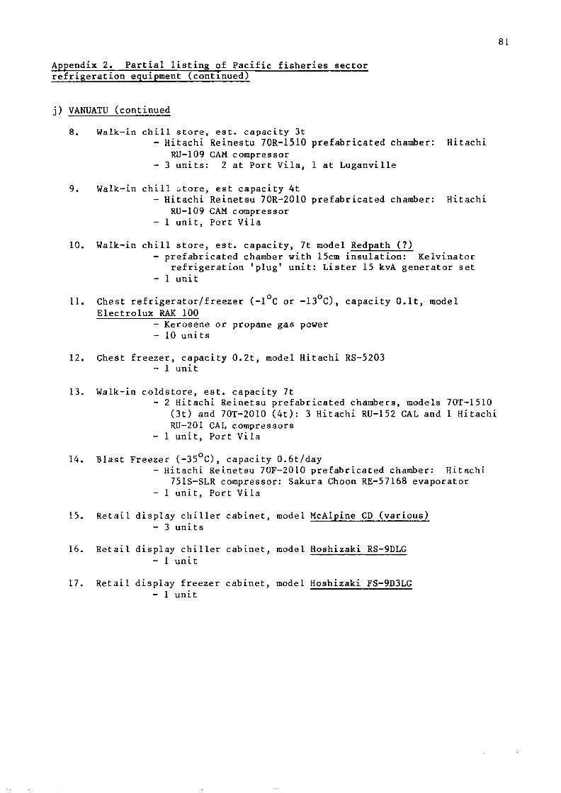
81
Appendix 2. Partial listing of Pacific fisheries sector refrigeration equipment (continued)
j) VANUATU (continued
8. Walk-in chill store, est. capacity 3t - Hitachi Reinestu 70R-1510 prefabricated chamber: Hitachi
RU-109 CAM compressor - 3 units: 2 at Port Vila, 1 at Luganville
9. Walk-in chill store, est capacity 4t - Hitachi Reinetsu 70R-2010 prefabricated chamber: Hitachi
RU-109 CAM compressor - 1 unit, Port Vila
10. Walk-in chill store, est. capacity, 7t model Redpath (?) - prefabricated chamber with 15cm insulation: Kelvinator
refrigeration 'plug' unit: Lister 15 kvA generator set - 1 unit
11. Chest refrigerator/freezer (-1 C or -13 C), capacity O.lt, model Electrolux RAK 100
- Kerosene or propane gas power - 10 units
12. Chest freezer, capacity 0.2t, model Hitachi RS-5203 - 1 unit
13. Walk-in coldstore, est. capacity 7t - 2 Hitachi Reinetsu prefabricated chambers, models 70T-1510
(3t) and 70T-2010 (4t): 3 Hitachi RU-152 CAL and 1 Hitachi RU-201 CAL compressors
- 1 unit, Port Vila
14. Blast Freezer (-35°C), capacity 0.6t/day - Hitachi Reinetsu 70F-2010 prefabricated chamber: Hitachi
751S-SLR compressor: Sakura Choon RE-57168 evaporator - 1 unit, Port Vila
15. Retail display chiller cabinet, model McAlpine CD (various) - 3 units
16. Retail display chiller cabinet, model Hoshizaki RS-9DLG - 1 unit
17. Retail display freezer cabinet, model Hoshizaki FS-9D3LG - 1 unit

82
Appendix 2. Partial listing of Pacific fisheries sector refrigeration equipment (continued)
k) WESTERN SAMOA
1. Flake ice machine, capacity lt/d, model Tagawa Nl-FS-1 - open-type compressor belt-driven by 5.5 kW electric
motor: water-cooled condenser with cooling tower - 1 unit
2. Walk-in chill store (-5 C), est. capacity 5t - prefabricated chamber: Mitsubishi NWU-31H refrigeration
'plug' unit - 1 unit
3. Walk-in cold store (-20 C), est. capacity 8t - prefabricated chamber: twin Mitsubishi NWU-21L
refrigeration 'plug' units - 3 units
4. Walk-in coldstore (-20°C), est. capacity lOt prefabricated chamber: three Mitsubishi NWU-20L
refrigeration 'plug' units - 1 unit
5. Retail display chiller chabinet, model McAlpine Snowline A8SM - 2 units
6. Diesel generator set, capacity 35 kvA, model Yanmar YPG-40 - 1 unit

83
Appendix 3. Proposed outline syllabus for refrigeration Technicians Training Course
1. Course goals
To develop tin* necessary skills and understanding in refrigeration to enable
Pacific Inland fisheries refrigeration technicians to maintain and repair
refrigeration equipment in their home localities.
2. Conrsi* aniline
a) Basic refrigeration (3 weeks)
Familiarisation with underlying principles of refrigeration systems including theory and practical applications:
- incrluini.cn 1 refrigeration cycle - mechanical controls
- refrigerants and oils - tools and instruments .
• \
b) Electricity (4 weeks)
Instruction on electrical systems used in refrigeration, including theory and
practical applications:
- Ohms law
- AC/DC generators and motors - electrical components of refrigeration systems
- schematic diagrams
c) Diesel maintenance (1 week)
Basic maintenance schedules and fault-finding on diesel motors used as refrigeration system drive or power units:
- diesel theory and function
- fuel system
- lubrication system
- valve adjustments
- decarbonisation
d) Welding (3 weeks)
Theory and practice of welding as applied to refrigeration systems:
- oxyacetylene gas welding
- br :iz i ng
- si Iver and other solders
- alumi n ium
- electric arc welding

84
Appendix 3. Proposed outline syllabus for Refrigeration Training Course (continued)
e) Refrigeration maintenance and troubleshooting (6 weeks)
Practical application of sections a) - d) in field situation:
- planning of maintenance schedules - maintenance service visits - fault diagnosis and repair - record-keeping - use of parts catalogues and parts ordering
f) Introduction to unit construction and design (1 week)
Basic instruction in planning appropriate refrieration installations and equipment selection:
- heat load calculations - properties of construction materials - location of refrigeration equipment
g) Product storage and handling (1 week)
Theory and practice of refrigerated storage of marine products:
- fish spoilage - effects of freezing -; - • - factors affecting shelf life - loading and handling
h) Student evaluation (1 week) '
To be carried out by an internal specialist who will assess the levels of competence reached by the trainees.
Copyright © 2022 FDOKUMEN