
Fire Investigations Richard L. P. Custer, Chai~, Custer Powell ...
86
Report of the Committee on Fire Investigations Richard L. P. Custer, Chai~, Custer Powell, Inc., MA Thomas W. Aurnhammer, Farmngton Fire Dept., NM Joseph Cailahan, Aetna Life & Casualty, CT Daniel L. Churchward, Royal Insurance, IN John David DeHaan, California Cximinalistics InsL, CA Rep. California Dept. of justice/Bureau of Forensic Services Michael DhMascio, Solutions Engineering Inc., MA Philip J. DiNenno, Hughes Associates Inc., MD BruceV. Ettiing, T. F. I. Services, WA Donald C. Garner, Factory Mutual Engineering Association, MA Ronald L. Hopkins, Eastern Kentucky University, KY Rep. NFPA Fire Service Section DawdJ. icove, Federal Bureau of Investigation, VA Patrick M. I~nnedy, John A. Kennedy & Assoc., IL Rep. National Association of Fire Investigators Terry B. King, Anderson Fire Dept., IN Georgia L. LL~nhart, Timonium, MD Robert S. Levine, National Institute of Standards & Technolgy, MD Hal C. Lyson, Robins, Kaplan, Miller & Ciresi, MN James N. Macdonald, Travelers Insurance Co., CT Jl~evinmes L. Mazerat, INS Investigations Bureau, LA J. McGurk, Connecticut Depc of Public Safety, CT Thomas E. Minnich, U~S. Fire Administration, MD Roger D. Overton, Insurance Crime Prevention Bureau, Canada Kenneth IL Sharp, Department of Fire Programs, VA Dennis W. Smith, Atlantic City Fire Dept., NJ David M. Smith, Associated Fire Consultants, AZ Rep. International Fire Service Training Association David A. Sprowi, McDermott, Will & Emery, CA Joseph P. Toscano, American Re-Insurance, NJ Rep. International Association of Arson Investigators Inc. Charles It. Watson, S.E.A., Inc., OH Ronald W. Woodfin, Belfort Engineering, CA Alternates Russel K. Chandler, Virginia Department of Fire Programs, VA (Alt. IL R. Sharp) Scot Deal, National Institutes of Standards & Technology, MD (Alt. to IL S. Levine) Andrew M. Giglio, U.S. Fire Administration, MD (Alt. to T. E.Minnich) Hunter B. Lacy, Royal Insurancy, NC (AlL to D. I~ Churchward) Harold E. Nelson, Hughes Assoc. Inc., MD (AIt. to P.J. DiNenno) Michael J. Schulz, John A. Kennedy & Assoc., IL (AlL to P. M. Kennedy) Barry W. Slotter, Robins, Kaplan, Miller & Ciresi, GA (Alt. to H. C. Lyson) Kim IL Mniszewski, Varley-Campbell & Associates, IL (AlL to VC, SeARep) Staff Liaison: Carl E. Peterson This list represents the membership at the time the Cmnmittee was balloted on the text of this edition. Since that time, changes in the membership may have occurred. Committee Scope: This Committee shall have primary responsibility for documents relating to techniques to be used in investigating fires, and equipment and facilities designed to assist or be used in developing or verifying data needed by fire investigators in the determination of the origin and development of hostile fires. The Report of the Committee on Fire Investigations is presented for adoption in 2 parts. Part I of this Report was prepared by the Technical Committee on Fire Investigations andproposes withdrawal of NFPA 907M-1988, Manual for the Determination of Electrical Fire Causes. NFPA 907M-1988 is published in Volume 11 of the 1993 National Fire Codes and in separate pamphlet form. Part I of this Report has been submitted to letter ballot of the Technical Committee on Fire Investigations which consists of voting members; of whom all 29 voted affirmatively. Part II of this Report was prepared by the Technical Committee on lrtre Investigations and proposes for adoption amendments to NFPA 921-1992, Guide for Fire and Explosion Investigations. NFPA 921- 1992 is published in Volume 11 of the 1993 National Fire Codes and in separate pamphlet form. Part II of this Report has been submitted to letter ballot of die Technical Committee on Fire Investigations which consists of 29 voting members; of whom 28 voted affirmatively, and I voted negative (Mr. Mniszewski). Mr. Mniszewski voted negatively because he does not feel that the "reworked" Chapter 13 on Explosions is suitable for publication yet due to problems in organization, technical content and missing material. He contends that not all material proposed by the task group is contained in this chapter. 88
-
Upload
khangminh22 -
Category
Documents
-
view
0 -
download
0
Transcript of Fire Investigations Richard L. P. Custer, Chai~, Custer Powell ...
Report of the Committee on
Fire Investigations
Richard L. P. Custer, Chai~, Custer Powell, Inc., MA
Thomas W. Aurnhammer, Farmngton Fire Dept., NM Joseph Cailahan, Aetna Life & Casualty, CT Daniel L. Churchward, Royal Insurance, IN John David DeHaan, California Cximinalistics InsL, CA
Rep. California Dept. of justice/Bureau of Forensic Services Michael DhMascio, Solutions Engineering Inc., MA Philip J. DiNenno, Hughes Associates Inc., MD BruceV. Ettiing, T. F. I. Services, WA Donald C. Garner, Factory Mutual Engineering Association, MA Ronald L. Hopkins, Eastern Kentucky University, KY Rep. NFPA Fire Service Section
DawdJ. icove, Federal Bureau of Investigation, VA Patrick M. I~nnedy, John A. Kennedy & Assoc., IL
Rep. National Association of Fire Investigators Terry B. King, Anderson Fire Dept., IN Georgia L. LL~nhart, Timonium, MD Robert S. Levine, National Institute of Standards & Technolgy, MD Hal C. Lyson, Robins, Kaplan, Miller & Ciresi, MN James N. Macdonald, Travelers Insurance Co., CT Jl~evinmes L. Mazerat, INS Investigations Bureau, LA
J. McGurk, Connecticut Depc of Public Safety, CT Thomas E. Minnich, U~S. Fire Administration, MD Roger D. Overton, Insurance Crime Prevention Bureau, Canada Kenneth IL Sharp, Department of Fire Programs, VA Dennis W. Smith, Atlantic City Fire Dept., NJ David M. Smith, Associated Fire Consultants, AZ
Rep. International Fire Service Training Association David A. Sprowi, McDermott, Will & Emery, CA Joseph P. Toscano, American Re-Insurance, NJ
Rep. International Association of Arson Investigators Inc. Charles It. Watson, S.E.A., Inc., OH Ronald W. Woodfin, Belfort Engineering, CA
Alternates
Russel K. Chandler, Virginia Department of Fire Programs, VA (Alt. IL R. Sharp)
Scot Deal, National Institutes of Standards & Technology, MD (Alt. to IL S. Levine)
Andrew M. Giglio, U.S. Fire Administration, MD (Alt. to T. E.Minnich)
Hunter B. Lacy, Royal Insurancy, NC (AlL to D. I~ Churchward)
Harold E. Nelson, Hughes Assoc. Inc., MD (AIt. to P.J. DiNenno)
Michael J. Schulz, John A. Kennedy & Assoc., IL (AlL to P. M. Kennedy)
Barry W. Slotter, Robins, Kaplan, Miller & Ciresi, GA (Alt. to H. C. Lyson)
Kim IL Mniszewski, Varley-Campbell & Associates, IL (AlL to VC, SeA Rep)
Staff Liaison: Carl E. Peterson
This list represents the membership at the time the Cmnmittee was balloted on the text of this edition. Since that time, changes in the membership may have occurred.
Committee Scope: This Committee shall have primary responsibility for documents relating to techniques to be used in investigating fires, and equipment and facilities designed to assist or be used in developing or verifying data needed by fire investigators in the determination of the origin and development of hostile fires.
The Report of the Committee on Fire Investigations is presented for adoption in 2 parts.
Part I of this Report was prepared by the Technical Committee on Fire Investigations andproposes withdrawal of NFPA 907M-1988, Manual for the Determination of Electrical Fire Causes. NFPA 907M-1988 is published in Volume 11 of the 1993 National Fire Codes and in separate pamphlet form.
Part I of this Report has been submitted to letter ballot of the Technical Committee on Fire Investigations which consists of voting members; of whom all 29 voted affirmatively.
Part II of this Report was prepared by the Technical Committee on lrtre Investigations and proposes for adoption amendments to NFPA 921-1992, Guide for Fire and Explosion Investigations. NFPA 921- 1992 is published in Volume 11 of the 1993 National Fire Codes and in separate pamphlet form.
Part II of this Report has been submitted to letter ballot of die Technical Committee on Fire Investigations which consists of 29 voting members; of whom 28 voted affirmatively, and I voted negative (Mr. Mniszewski).
Mr. Mniszewski voted negatively because he does not feel that the "reworked" Chapter 13 on Explosions is suitable for publication yet due to problems in organization, technical content and missing material. He contends that not all material proposed by the task group is contained in this chapter.
88

NFPA 907M - - F94 TCR
PART !
(Log #CP1 ) 907M- 1 - (Entire Document): Accept SUBMITrER: Technical Committee on Fire Investigations, RECOMMENDATION: Withdraw NFPA 907M, Manual for the Determination of Electrical Fire Causes. SUBSTANTIATION: The Fire Investigation Committee has developed a new chapter on electrical fires which is being added to NFPA 921, Guide for Fire and Explosion Investigation. This new chapter and the existing chapters in NFPA 921 cover much of the material currently covered in NFPA 907M. As the relevant material is now in NFPA 921 aspart of a broader document on fire investiga- tion, there is no need for a single document on determining electric,'d fire causes and the committee recommends withdrawal of NFPA 907M. COMMITrEE ACTION: Accept.
(Log #7) O07M- 2 - (Figures 10-6(a), (b), and (c)): Accept SUBMITTER: Ray C Mullin, Northbrook, IL RECOMMENDATION: In the caption, replace "Bussmann Mfg. Division, McGraw-Edison Company ~ with ~Bussmann Division, Cooper Industries." SUBSTANTIATION: Present wording is incorrect. COMMITrEE ACTION: Accept. CoMMrI ' rEE STATEMENT: This material has been integrated into NFPA 921, Guide for Fire and Explosion Investigation and the proposed change are shown in Fignres 14-3.5(a), 14-3.5(b) and 14-3.5(c).
(Log #I) 907M- 3 - (I0-6.1): Accept SUBMITTER: Ray C Mullin, Northbrook, IL
I RECOMMENDATION: Revise 4th line by inserting "easily ~ between "cannot" and "be." SUBSTANTIATION: Since nothing is impossible to remove, the word "easil)/' will infer that it is difficult to remove the adaptor. COMMITTEE ACTION: Accept. COMMITrEE STATEMENT: This material has been integrated into NFPA 921, Guide for Fire and Explosion Investigation and dae proposed change is sllown in paragraph 14-3.5.1.
(Log #6) 907M- 4 - (Appendix A - Part II, Service Equipment, Form 3, 13j (New) and 13k(New)): Reject SUBMITTER: Ray C Mullin, Northbrook, IL RECOMMENDATION: Add new text to read as follows:
13j. What was file available short-circuit current at the main overcurrent protective device(s)?
13k. What was the interrupting rating of the main overcurrent grotective device(s) ?
UBSTANTIATION: Need to ask these questions so as m meet Sections 110-9, 110-10 and 230-65 of the NEC-NFPA 70. COMMI'I'rEE ACTION: Reject. COMMITTEE STATEMENT: NFPA 907, Manual for the Determi- nation of Electrical Fire Causes is being proposed for withdrawal and a new cbapter on electrical fires is being added to NFPA 921, Guide for Fire and Explosion Investigation. The committee has decided not to continue reproducing dds material which was designed by the United States Fire Administration in cooperation wi& the U.S. Consumer Product Safety Commission.
(Log #4) 907M- 5 - (Appendix A - Part II, Distribution Panel, Form 4, 21a): Reiect SIJBMITTEIta Ray C MuUin, Northbrook, IL RECOMMENDATION: Revise text to read as follows:
21a. What was the ampere raring and interrupting rating of the over current protective device (s) ? SUBSTANTIATION: Need to ask dais question to meet Sections 110-9, 110.10, 2~g)-65 of NEC-NFPA 70.
COMMITrEE ACTION: Reject. COMMITTEE STATEMENT: NFPA 907, Manual for the Determi- nation of Electrical Fire Causes is being proposed for withdrawal and a new chapter on electrical fires is being added to NFPA 921, Guide for Fire and Explosion Investigation. The committee has decided not to continue reproducing this material which ~ras designed by the United States Fire Administration in cooperation with the U.S. Consumer Product Safety Commission.
(Log #3) 907M- 6 - (Appendix A - Part II, Distribution Pane[, Form 4, 21e (New)): Reject SUBMITrEIh Ray C Mullin, Northbrook, IL RECOMMENDATION: Add new text to read as follows: 21e. What was the available short-circuit current at this device(s)?
SUBSTANTIATION: Need to ask dais question to see if there might have been a Code violation- Sections 110-9, 110-10, 230-65 of NEG- NFPA 70. COMMITrEE ACTION: Reject. COMMITrEE STATEMENT: NFPA 907, Manual for die Determi- nation of Electrical Fire Causes is being proposed for withdrawal and a new chapter on electrical fires is being added to NFPA 921, Guide for Fire and Explosion Investigation. The commhtee has decided not to continue reproducing this material which was designed by the United States Fire Administration in cooperation with the U.S. Consumer Product Safety Commission.
(Log #5) 907M- 7 - (Appendix A - Part II, Distribution Panel, Form 4, 8a and 8b): Reject SUBMITTRR: Ray C Mullin, Northbrook, IL RECOMMENDATION: Revise text to read as follows:
8a. What was the ,ampere rating and interrupting rating of the overcurrent device(s)?
8b. What was the available short-circuit current at panel? SUBSTANTIATION: Need to ask these question.,; to meet Sections 110-9, 110.10, 230-65 of NEC-NFPA 70. COMMITTEE ACTION: Reject. COMMITrEE STATEMENT: NFPA 907, Manual for the Determi- nation of Electlical Fire Causes is being proposed for withdrawal and a new chapter on electrical fires is being added to NFPA 921, Guide for Fire and Explosion Investigation. The commit:tee has decided not to continue reproducing this material which vras designed by the United States Fire Administration in cooperation with the U.S. Gonsu mer Product Safety Commission.
(Log #'2) 907M- 8 - (Appendix A - Part 1I, Lighting Fixture, Form 8, 8b (New) and 8c (New)): Reject SUBMITTER: Ray C Mullin, Northbrook, IL RECOMMENDATION: Add new text to read as tollows: 8b. Was the ballast rated Class P? 8c. Was the ballast individuall fused?
What ampere rating fuse? SUBSTANTIATION: Good question to ask when checking ballast failures. COMMITI"EE ACTION: Reject. COMMITTEE STATEMENT: NFPA 907, Manual for the Determi- nation of Electrical Fire Causes is being proposed for withdrawal and a new chapter on electrical fires is beingadded to NFPA 921, Guide for Fire and Explosion Investigation. The committee has decided not to continue reproducing this material which was designed by tile United States Fire Administration in cooperation with the U.S. Consumer Product Safety Commission.
89

NFPA 921 - - F94 TCR
PART lI
(Log#4)
921- I - (Index): Accept in Principle SUBMITTER: Bernard A. Schwartz, Schwartz Fire Specialists RECOMMENDATION: Substitute d~e following index for present index:
"A" Absolute temperature 1-3 3-2.3 Abstract & t i t l e co. 7-6.8 Accelerant cottectlon 9-5.3 Acceteronts 4-14 4-8.2 Acceterants 4-6.1 I-3 Accelerants on concrete 9-5,3,1 Acceteronts on sollds 9-5.2.2 Accident 1-3 Accidental f ire cause 12-5 Accidental f ire cause 12-2.1 Acetone 1able 3-3.4 Acetylene Table 3-3.4 A~estves 4-16,1.3 Adjuster 6-5.6 Admin. search uarront 5-2.3.3 Aerial Photographs 8-2.5.11 Aerosols, f lwm~bltlty 9-I0,2.17 Airflow 3-7.2 Atcchot 3-6 Alligatortng 4-5.5 Alloying of metals 4-8,2 Alterations, sfte 11-3,3 Aluminum Table 4-8 Aluminum 4-8.2 13-9 Aluminum (dust) Vsble 3-3.4 Ambient (definition) 1-3 Am~r. Sac. for Testing/Mat. 7-6.3 Analyze epicenter 13-13 Angle of plume 3-7.1 Anlayze cause, explosion 13-16 Annealing 4-14 Appliances, samples 9-5.6 Approve~ 1-3 Arc (definition) 1-3 Architecture[ drawings 8-4,6 Architectural schedutoe 8-$ Area of Ortoln 1-3 Area patterns 4-19 Areas of Oewrcetion 4-3,1 Arrc~ Pattern (define) 1-3 Arrot4 patterns 4-3.4 4-17.6 Arson 5-4.1 Arson ilrmanlty 5"5 Arson lnfo. Mgt. gys. (ALMS)4.14 7-5 Arson reporting 5-5 Arson Statutes 5-4.1.1 Arson (o~finitton) 1-3 Ascorblc Acid 13-9 Ash 3-6 Aspirin 13-9 Assessor's Office 7.5.1.2 A$IM (test methods} 9-10,3 Atomic Absorption (AA ) 9-10,2.4 Atomized Liquids 3-3.2 Attorney 6-5.7 Attorney/client 7-2.2 Authority to conduct 5-2.1 Autoignition tt~erature I-3 Autoignttton (definition) 1-3
7.5.1.3
9-10,2. I I
4-6
"O" gackdraft 1-3 13-10 Backdroft 13-7.4 Belied rags Table 3-3.5 Barriers 3-7.1 Basic Methodology 2-4 Basswood Table 3-3.1 lending 4-9 Table 3-3
Black oxide 4-7 Black smoke 3-6 Blast Front Shape 13-4.1.3 Blast pressure wave 13-4.1 13-2 BLEVE 13-2.1 13-2 OLEVE (definition) 1-3 B l i s t e r s 4-5.5 Blue-grey (iron or steel) 4-7 Board of Edusetton 7-5.1.7 goiter explosions 13-6,2 Botts 3-2.1 Bomb Calorimeter 9-10.2.12 Bottom of surfaces 4-17.7.1 Brass 4-8,2 tabh Brewing grains table 3-3.5 Brick 4-6 Fig d British Thermal Unlt (defln)l-3 Br i t t le , i re 4-8.2 Bronze 1able 4-8 euldt lag contents 4-16.3 Bul Idlng col tepee &- 17.7.2 But tdlng Oepertments 7-5.1.5 Burn patterns 3-L2 Buen time 4-5.5 Burning rate (define) 1-3 Bystanders 10-2.5
-C~ Calcination 4-12 cons 9-6,1 Carbon monoxide 3-5,3.2 Cascade explosion 13-9.6 Cascade explosions 13-8.7 Cast tron 1able 4-8 Cause 5-6.1 Cause classification 12-2 Cause determination 11-8 Chept Cause of f i re 12-5 Cause (see f i re cause) 1-3 Ceiling height 3-$.4.2 Ceiling layer fig. 3-5,3.2(b) Ca|ling layer temps. Fig. 3-5.3.1(b) Ceiling layer (define) !-3 Ca! i Jag Patterns 4 ~ 16.1 Ceilings 3-5.3.1 Ceramic t i le 3~6 Certtainty of opinions 12-6 Chain of custody 9~9 5-3.2. Chair Table 3-A Char 4-5 Char blisters (define) 1-3 (:her grid disgrm 11-2.4 Char (definition) 1-3 Char (depth analysis) 4-5.].2 Char (depth of) 4-5.3 Char (masurlng) 4-5.3.3 Char (misconceptions) 4-5.S Char (oxidation) 4-7 Char (rate of) 4-5.2 Char (with fuel gases) 4-5.4 Char (~)od) 4-5.1 Charcoal TabLe 3-3.5 Charring 4~17,6 Chemical engineer 6-5.4 Chemical explosions 13-6,3 13-2.2 Chmlcal oxidizers 3- I. 1.2 Chem Reaction (sustained) 3-1,t.4 Chemicals, flamm. | fel ts 9-10,2.22 Chemist 6-$.4 Chemistry of Combustion 3-1 Chlorine 3-1,1.2 Christmas trees Table 3-4 Chromium flable 4-8 Cigarette ~abte 3-3 CIg. tgn. resist, of furn, 9-10.2.14 Circular pattern 4-17.7 4-17.7 Civil l i t igation 5-6 Classification of cayuse 12-2 Clean Burn 4-11 4-7

NFPA 921 - - F94 T C R
Clerks Office Clevtencl Open Cup Clothing, safety Coal (dust) Code (def in i t ion) Cedes/standards Coefficient of expansion Color changes Cater of smoke CoMbustible gas indicator CoMIxmt Ibte (def in i t ion) Combustion explosions Contult ion products Combustion (chemistry) Conibust I on (def in i t ion) Conlbust ion- set f sustained Combust. Liquid (define) Conibust. Liquid (pooled) Camper i son sompt • Compor i t lye test ing Comportment f i r es Comportment f i res Complexity of incident Computers ( f i r e models) Computers ( information) Concentrat ion I iml ts Concrete Concrete (spal I lag) Conducted heat Conduct i on
• conduction (de f i n i t i on ) Cone calorimeter Cone pattern Confident let Communi cat tons Configuration of fuel Conf i ned Confined f i r es Confined fuel gas Consent Coast i tut i anal consider. Consultants, technical Containers, evidence Cant 8 i resent vessel Contamination of evidence Contents r amoral Contents (anaLysis) Convec t i on Convection (de f in i t i on ) Copper Copper Copper-nickel a l loy Corner ef fects Corners, burning Coroner/medical examiner Cotton ba l ls Cotton chair Cotton mattress County assessor County clerk County coroner County government County Recorder County sher i f fs dept. County treasurer Crocks in f loor Cr'szing Criminal act Criminal oct Criminal Prosecution Criminnt search xarrant Cr i t i ca l Rodiemt Flux Crowd photographs Custodial set t ing
1-5.1.1 7-5.1.2 9-10.2.7 10-1.2 Table 3-3.4 1-3 5-6.2 4-20.2 4-12 4-3.2 3"6 1-3 1"3 13-2.3 13-2.2 3-6 1-3 3-1 1-3 3-1.1.4 1-3 13-7.2 9-2.2 9-10.4 3-1.1.2 Ftg. 3-5.3.1(o) 3-5.4.3 3-5.3.2 6-2.4 11-7.4 7-3.4 7-5.4.14 9-10.2.22 4-6 Table 3-2.1 4-6.1 4-15.1 3-2.1 3-2 1-3 9-10.2.26 4-17.2 4-17.2.1 7-2.3 12-4 3-5.3.1 3-5.3 3-5.3.2 13-6.3 5-2.3 5-2.3 5-3.4.1 6-5 9-6 13-5.1 9-4 11-7.3 11-9 13-12.3.3 3-2.2 3-7.2 3-2 1-3 4-8.2 Table 4-8 4-7 Table 3-2.1 Table 3-3 3-5.4.3 3-3.1 7-5.2.5 9-5.3.1 Table 3-4 Table 3-4 7-5.2.3 7-5.2.2 7-5.2.5 7-5.2 7-5.2.1 7-5.2 .6 7-5.2.4 4-16.1.3 4-13.1 5-4.1.2 5-4.2 5-4 5-2.3 .4
9-10.2.20 8-2.3.2 5-3.4.1
"On Damage assessment 11-2 Damage Effects 13-12.3.1 Ommge ( f u e l / a i r ) 13-8.2 Damage (vapor denisty) 13-8.5 Damage, pro and post-blest 13-12.3.2
6-2.6 11-5.5
Debris removal 11-7.2 11-9 Deductive Reasoning 2-3.6 Defects, L i a b i l i t y 5-6.4 Defining the Problem 2-3.2 Def in i t ions 1-3 Oeftegrstion 13-11.1 115-7 13-1 Peflegretion 13-2.3 Deftogrstion tmq~ermtures 13-4.3 Deftmgrmtion (def in i t ion) 1-3 Deformation 4-9 Deformed metaL 3-7.2 DemoLition ( injunction) 5-2.2 Demonstrative Evidence 5-3.2.1 Density 3-2.1 Density of f loor ing 4-17.7.2 Density ( ign i t ion ) 3-3.1 Depth of char 4-5.3 4-5.3.2 4-5.3.3 Depth of char 4-5.2 4.5.5 Depth of char 11-2.4 4-5.4 Dept. of Agriculture 7-5.4.1 Dept. of Commerce 7-5.4.2 Dept. of Defense 7-5.4.3 Dept. of Energy 7-5.4.12 Dept. f leatth/HtmmServ. 7-5.4.4 Dept. Houslng/UrbonOev. ?-5.4.5 Dept. of In te r io r t -5.4.6 Dept. of Justice 7-5.4.11 Dept. of Labor 7-5.4.7 Dept. of state ?05.4.8 Dept. of troneportetlon 7-5.4.9 Dept. of treemury 7-5.4.10 Design defect 5-6.4 Detection (de f in i t i on ) 1-3 Detonation temperatures 13-4.3 Detonation (de f in i t ion) 1-3 Detonetlone 13-6 1~ i -11 .2 13-2.3 Oetormttone 13-5.3 1~i-2,3 13-4.3 Oisgrm (char) 11-2.4 4-5.3.1 DlNIrem (exptos. dynmlcm) 13-3 Diagram (vector) 11-2.3 O l s g r m 5-3.2.1.1 Dlkobeted devices 11-6.1 Disposable gloves 9-4.2 Documentary Evidence S-3.2.2 Door char 3-7.2 Door closed 3-7.2 Doors and uindous 11-5.3 Door. open or closed 11-5.3 Poubtedemges 5-6.1 Doughnut pattern 4-17.7.3 Prosing Schedutes 8-5 Drawing symbols 8-4.4 Drsxlng types 8-4.2 Drsxing var iat ion 8-4.6.1 Drawings 8.4 Drsxings, srchttecturol 8-4.6 Droxlngs, engineering 8-4.6 Drawings, minimum 8-4.5 Drop Dotm 4-16.4.2 Prop doun (def in i t ion) 1-3 Dust concentration 13-9.2 Dust explosions 13-7.3 13-13 13-9 Dust explos iv l ty 9-10.2.25 Dust' turbulence 13-9.3 Dust/moisture 13-9.4 ~uty 5-6.1
.E,, [o~Jcotiono( inst i tu t ions 7-6.11 Effect of pressure xoves TabLe Effects of explosions 13-4 Electr ical engineer 6-5.3 Electr ical Samples 9-5.5 Electromgnetic waves 3-2.3 Electronic Info. t-3.A Elevstlon, patterns 4-16.4 Etlmnete other causes 2-3.6 Ember Tabte 3-3 Emperlcol dote 2-3.4 Enclosures, f i r e grouth 3-5.4 Energy f loe 3-2 Englneerlngdrouings 8-4.6
13-12.5.1
2-3.3
91

NFPA 921 - - F94 TCR
Engineering schedules Engineers Entrain (definit ion) Entrelmont Entry (method) Entry (right of) Equipment & Fsci l t i tes Estld)llMtlng the scene Ethanol Evidence Evidence Ixip Evidence cans Evidence collection Evidence contsiners Evidence Containers Evidence contamination Evidence custody Evidence delivery Evidence destruction Evidence documentation Evidence examination Evidence Ident i f icat ion Evidence moving Evidence Photographs Evidence Preservation Evidence removal Evidence report Evidence shipment Evidence testing Evidence transportation Evidence, moving Evidence, rules of Evidence, types of Exemplars Exigent circumtnce Exothermic Reaction Exothermic reactions Expert testimoney Expert witness Experts Explosion Explosion characteristics Explosion damage effects Explosion dynamics analysis Explosion effects Explosion evidence Explosion fuel source Explosions Explosions, multiple Explosion, analyze cause Explosion, chemical Explosion, Ignit ion source Explosion, mechanical Explosive Explosive investigation Exptosive material-define Explosives Exposed surface (define) Exterior damage Exterior exam/nation Exterior examination External surfaces Extinguish (def in i t ion)
8-5 6-5 1"3 3-5.3.1 3-5.1 3-7.1 5"2 6-2.7 6-4.1 13-12.1.1 Table 3-3.4 5-3 9-6.1 9-6.1.3 9-6.1.1 9-5 9-5.2 2-4.5 9-6 9-7 9-4.1 9-5.3 9-4 9-9 5-3.2.1 9-8.1 11-7.2 5-2.2 9-5.1 9-10 Chept. 9 9-7 9-5.1 8-2.5.7 2-4.5 5-2.2 Fig. 9-9 9-8.2 9-10 9-8 9-3.2 5-3 5-3.2 9-10.4 5-2.3.2 5-2.3 3-1.1.4 4-8.1 5-7 5-7.2 6-5 1-3 table 13-12.2 13-12.3.1 13-13 13-5 11-5.4 13-14 4-17.8 Chnpt. 13 13-8.7 13-16 13-2.2 13-15 13-2.1 I-3 13-12 1-3 13-6.1 13-11 I-3 11-5.5 11-5 11-3.3 4-16.2 1-3
"F" Failure 5-6.1 Failure analysis 1-3 2-4.6 Failure (def in i t ion) I-3 Fall down 1-3 4-16.4.2 Federal agencies 7-5.6 Federal rules of evidence 5-3.1 Felony 5-4.1.1 Fifth en~mdment 5-3.4.1 Financial Insti tut ions 7-6.1 7-6.9 Fir 1able 3-3.1 Fire analysis I-3 Fire brick Table 4-8 Fire cause (def lnt t l lon) 1-3 Fire development 3-5 Fire f ighting 3-6 Fire Investigation define I-3
Fire location Fire Hershal Office Fire models Fire Pattern devetopmmt Fire Patterns Fire point Fire propagation Fire Protection Eng. Fire scene reconstruction Fire Science Fire spread scenario Fire spread (def ini t ion) Fire letrehedron Fire (def in i t ion) First ignited First meterta( Ignited Fish meal Flame extension Flame front (def ini t ion) Flame height Flme length Flame temperature Flame (def in i t ion) Flmeover Flame, premlxed (define) Fleming coMMJst I on Flmmmbte Flammable fT:Tt pr°per ty Flammable I fquJd Flammable I Iquld Flammable I iquld Flmmeble I Iquld Fl~mDble ! Jquld P l m b l e l iquid (define) Flammable Liquid (pooled) l i a b l e range F l m b t e (def in i t ion) Flemm. of text i les Flm. of aerosot8 FIm. of f loor covering Flash f i re Flash f i re (def in i t ion) Flash Point Flash ~o!nt of • l iquid Flash ~olnt, closed Flash ~olnt, closed Flash )slat, closed Flash point, open Flesh point, open Flsshover Flsshover Fteshover Flashover Fleshover (definit ion) Flashover, f i re patterns Floor covering systems Floor covering, flammable Floors, f i re patterns Flour Foam rubber Force Vectors Force Vectors Forced entry Forensic (definit ion} Form of a fuel Form of heat of ignition Form of Info. Freedom of Informal. Act Fuel Fuel configuration Fuel controlled f i re Fuel gas Fuel gas Jet Fuel gas pattern Fuel Gas (definit ion) Fuel Fuel F:15' F,~! el t Fuel source, explosion Fuel turbulence Fuet (definit ion) Fuel, In i t ia l
3-5.4.3 7-5.3.10 11-7.4 3-7 4-I 4-4 9-10.2.9 9-10.2.7 I-3 6-5.5 1-3 Chspt 3 11-8 1-3 3-1.1 1-3 3-5.3.2 3-7 12-4 Table 3-3.5 3-1.1.2 I-3 3-5.5 3-5 .4 .3 4-8.1 I -3 3-5 .3 .2 1-3 3-1.1.4 Table 13.8 1-3 3-1.1.2
3-6 4-17.7.2 4-6.1 4-18.1 4-6 4-17.2 1-3 13-7.2 3-1.1.2 1-3 9-10.13 9-10.2.17 9-10.2.16 4-19 4-19.2 I -3 3-3.2 I-3 9-10.2.10 9-10.2.6 9-10.2.8 9-10.2.? 9-10.2.9 4-17.7.2 3-2.2 Fig. 3-5.3.2(d) 3-6 3-5.3.2 3-4 3-5.4.3 1-3 4-19.1 9-10.2.20 9-10.2.16 4-16.1 9-5.3.1 1able 3-3.5 13-12.3.4 13-13 13-12.3.4 11-5.3 1-3 3-1.1.1 lZ-3 7-3 7-2.1 3-1.1.1 12-4 1-3 3-1.1.2 11-6.2 13-0.6 4-18.3 4-17.9 1-3 13-7.1 4-5.4 1-3 3-4 3-6 13-14 13-3.4 1"3 ~ 12-4
4-17.7.3 4-17.2.1
3-$.3.? 4-16.1.7
3-2.2

N F P A 921 - - F94 T C R
Fuel/Air mix vs damage Furniture Furniture springs
NGU Galvanized steel Gas chromatography Gas explosivity Gas indicator 6as Jet Gee Odorant. Gas (defini t ion) Gaseous samples Gases present in f i res G~ses, ignit ion Gasoline Gasoline (flame tamp) Gasoline/Kerosone 08s, LP Gas, natural Gas, natural (explosion) Gas/vapor explosion General witness Glass Glass jars Glass size Gloss Steins Glass (explosions) Glass (melting) Glass (patterns) Glass, broken Glass, (melting) Glazing Gloves, disposable Glowing combustion Glowing embers Gold Government info. Grain Grain (dust) Gypsum plaster Gypsum wallboard
nHn Hard Wood Hay Hazards Hazards ( f i r e scene) Health Personnel Heat Heat capacity
'heat detectors Heat d is tor t ion Heat f lux (def in i t ion) Heat Generation Rate Heat of combustion Heat of Ig in i t ion He~t of Ignit ion Heat release Heat Release Rote Heat release rate (define) Heat release rotes Heat release (flashover) Heat ahodouing Heat Source Heat Transfer Heat Transfer Heat & Combustion Heat (def in i t ion) Heat, radiant (define) Height of burn Hemlock High density materials High explosive (define) High explosives High order explosion High order explosions Holes Holes in floors Hourglass Pattern Hydrocarbon fuels
13-8.2 4-16.1.3 4-14
4-7' 9-10.2.1 9-10.2.25 4-17.7.2 4-3.3 13-8.8 1-3 9-5.4 9-10.2.23 3-3.3 1able 3-3 Table 3-3.4 4-8.1 Table 3-4 13-8.5 4-17.9 4-17.2.3
13.8.5 13-8 5-7.1 3-6 4-13.2 9-6.1 9-6.1.2 4-13.1 4-13.2 13-12.3.2 4-8 4-13 11-5.3 4-13.1 4-10 4-13 9-4.2 1-3 3-?.2 Table 4-8 7-5 Table 3-3.5 Table 3-3.4 Table 3-2.1 4-12 4-7
Table 4-8
4-5
Table 3-3.4 Table 3-3.5 6-2.5 1-3 10-2 10-1.3 10-1.4 3-2 3-2.1 3-5.3.1 4-20.2 4-20.1 1-3 3-3.5 9-10.2.12 12-3 1-3 3-5.3.2 Table 3-4 3-5 3-5.5 3-4 1-3 3-7.2 9-10.2.24 3-5.4.1 4-15,1 11-2.3 11-2.3 3-3 3-2.1 3-2 3-1.1.3 1-3 1-3 4-16.4 Tabte 3-3.1 3-2.1 1-3 13-11.2 1-3 13-3.2 4-3.3 3-7.2 4-17.2 3-6
13-3 13-12.2.2 13-10 13-8.4 3-7.2 4-17.7.3 4-16.1.3 4-17.3 3-7.1
Hydrocarbon Vapors 3-5.3.2 Hydrogen 3-1.1.2 Hydrogen Cyanide 3-6 Hypothesis . 2-3.5 Hypothesis-cause determine 12-6 Hypothesis, teatlng 2-3.6
Nin Identification-evidence Identi fy explosion Ignitable Ilqutd (define) Ignit ion Ignit ion Ignit ion energy (define) Ignit ion factor igni t ion of Gases Ignit ion of Liquids Ignit ion Process Ignit ion properties IgnltionSeclusnce Ignl t lonlource, exptuston Ignit ion Temperature Ignit ion Time Ignl l ion, duets Ignit ion, heat of Ignit ion, solids Ignit ion, spontaneous Insdequaate warnings Incendiary f i re cause Incomplete codx~tion lnducttve Reasonlng Industry expert lnfometlon sources Infrared spectrometer I n i t i a l assessment Inorgenic Materiels Insulation Effect Insurance agent Insurance Industry Intensity patterns Intensity patterns inter ior exmelnst Ion Inter ior surfaces Interview documentation Interview preparer Ion intervleu types Interview - Caution Interview - dimtrust In terv ie t l - trust Interviews Inter. Ass. Arson Invest. Inverted cone pattern Inverted cone pattern Investigation &supress ion Iron I rregutar patterns leacher leachers I .A .A . I .
Jets, fuel gas JP-4
. j .
IIKn Kerosene Kerosene/Gasoline gilouatt (definit ion) Kindling temperature
IILN Laboratory examination Laboratory testing Lateral extension Lead Legal Considerations Length of intervleu Letter of Transmittal L iab i l i t y , s t r ic t Light bulbs Lime
9-7 13-12.2.1 1-3 1-3 3-3 1-3 12-5 3-3.3 12-3 3-3.2 12-3 Table 3-3.4 12-5 13-15 13-5.2 3-3 I-3 3-3.1 !-3 13-9.5 1-3 3-3.1 3-3.5 5-6.4 12-2.3 3-6 2-3.4 6-5.6 Chapt. 7 9-10.2.3 13-12.2 3-3.5 3-3.5 6-5.8 7-6.10 4-4.2 4-4 11-3.4 11-6 7-4.7 7-4.3 7-4.2 7-4.5 7-4.6 7-4.4 7-4 5-3.4 7-6.5 7-6.5 7-17.2.2 4-I?.2.1 4-17'.2 4-1T.2.3 10-2,1 4-8,2 Table 4-8 4-17.8 4-17.7.2 1-3 rig 8-4.2(f) 11-2.4 7-6.5
4-18.3 Table 3-3
Table 3-3.4 Table 3-4 1-3 1-3
9-10.1 9-10.1 3-7.1 4-0.2 Table 4-8 Chlmt 5 5-3.4.1 9-8.2 5-6.4 4-20.1 9-5.3.1
Table
93

NFPA 921 - - F94 TCR
4-1 Linear Pattern 4-3C1 Lines of Omercation Linseed Oil 3-3.5 TabLe 3-3.5 Liquid 3-7.2 Liquid Acceterents 9-5.3.1 4-5.5 Liquid explosions 4-17.8 Liquids 4-17.2 4-16.1.3 4-17.2 Liquids 4-3.3 4-17.7.2 Liquids, Atomized 3-3.2 Liquids, combustible 13-7.2 LIquids, Lgnition 3-3.2 Liquids, malted solids 4-17.8 Locate evidence 13-12.3.3 Location of f i re 3-5.4.3 Loss 5-6. I LON Burn 4-16.4. I LoN density materials 3-2.1 Lot~ explosive I-3 13-11. I Lou order explosion 1-3 13-10 13-3.1 LoN order explosions 13-8.3 13-3 Lower Explosive Limit 13-8.3 Loulhlgh order explosion 13-12.2.2 LP gas 13-8.5 LPG, ( f i re patterns) 4-17.9
IIM|I Hagnesium 13-9 1able 4-8 Hsiicious burning 5-4.1 Hsnufacturing defect 5-6.6 Manure Table 3-3.5 Hops 5-3.2.1.1 Harsh gas 13-16 Hasonry 4-6 Hess rat io 3-3.1 Haas spectrometry 9-10.2.2 Material distort ion 4-20 Ma te r i a i f i r s t ignited 1-3 Hateriets engineer 6-5.1 Haximumpressure 13-4.1.6 Heasurement, units of I-4 Hechanica[ engineer 6-5.2 Hechonicai explosion 13-2.1 Mechanical Spark TabLe 3-3 Hedicat exminer Z-5.2.5 Heitedsoitds 4-17.8 Helting 4-3.2 4-9 Halting of Hateriels 4-6 Hatting temperatures 6-8 Table 4-8 Hercaptan 13-8.6 Metal cans 9-6.1.1 Metal construction element 4-20.2 Metal distort ion 4-20.2 Hetals, alloying 4-8.2 Hetals, burning 4-8.1 Hetats, melting 4-8.2 Hethane Table 3-3.4 Hethonol Table 3-3 Table 3-3.4 Method of entry 5-2.3 Methyl Ethyl Ketone Table 3-3.4 Hlchlgan vs Cl i f ford 5-2.3.3 Richlgenvs Tyler 5-2.3.2 H i n i u Ignit ion energy 13-8.1 13-9.5 13-9.4 Mlranchl Rule 5-3.4.1 Hisdemeanor 5-4.1.1 Hists 3-3.2 Model Penal Code 5-4.1 Models 5-3.2.1.1 Hodels In reconstruction 11-7.6 Movement pattens Hovement patterns 4-4 p 4-4.1 Navies 8-2.6 5-3.2.1.1 Huttipte ExpLosions 13-8.7 Hunicipel Assessor 7-5.I.2 Hunicipei brd. of eck~. 7-5.1.7 Hunicipai Building asps. 7-5.1.5 Hunicipot clerk 7-5.1.1 Hunicipal Fire Dept. 7-5.1.9 Municipal health dept. 7-5.1.6 Hunicipet police dept 7-5.1.8 Hunicipat street dept. 7-5.1.4 Hunfcfpal treasurer 7-5.1.3
"N" Nell plates 3-2.1 Nsits 3-2.1 Narrou "V" pattern 3-7.1 4-1T.1.1 Natural f i re cause 12-2.2 Natural Gas 13-14 13-8.5 4-IT.2,1 Natural Gas 3-6 4-17.2 4-17.2.3 Natural gas 13-14 Table 3-3.6 Natural Gas 13-8.6 Natural Gas-fire patterns 4-17.2.2 4-t7.9 Natural 9oalLP gas 13-8.5 Nature of damage 6-2.6 Nature of Fire Investig. 2-1 Not. Assoc. Fire Invest. 7-6.4 Nat. Fire Incident Rapt. 7-5.4.14 Not. Fire Prot. Assoc. 7-6.1 Negative pressure phase 13-4.1.2 Negligence 5-6.1 5-6.4 Nickel Table 4-8 Nitrogen Oxides 3-6 Noncodx;st fbl • Heterla! 1-3 N o n f l m b t e (def ini t ion) 1-3 Non-seated expLosion 13-13 13-? Note taking 8-3 11-2.1 NucLear Explosions 13-2.4 NyLon carpet 4-17.7.2 N.A.F.I. 7-6.4
"0" Oak TabLe 3-2.1 oak flooring 4-17.7.2 Oak, red Table 3-3.1 Occupancy 11-3.3 Odorant, gas 13-8.8 13-8.6 Optimum rat io 3-1.1.2 Order of explosions 13-3 Organic Heterleis 3-3.5 Organizing investigation 6-3 Origin dstemlnetlon Chapter 11 Origin, area of (define) I-3 Origin, deternlne 2-4.3 Origin, explosion Chapter 13 Origin, point of (define) 1-3 Outside surfaces 4-16.2 Oxidation 4-3.2 4-7 Oxidizing agent 3-t.1.2 Oxygen deflcency 1-3 Oxygen enriched 3-1.1.2
"p" Paint 4-3.2 Paraffin labte 4-8 PprtJcte size 13-9.1 Pattern geometry 4-1T Patterns 4-1 Patterns, area 4-19 p~tterns, arrow 4-17.6 Patterns, arrou (define) 1-3 Patterns, calcination 4-12 Patterns, ceilings 4-16.1.2 Pptterne, circular 4-17.7 Patterns, circular 4-17.7 Patterns, clean burn 4-11 Patterns, DeveLopment of 3-T Patterns, doughnut 4-17.7.3 Patterns, fe l t dean 4-16.4.2 Patterns, f i re 3-7 Patterns, flash f ires 4-19.2 Patterns, fiashover 4-19.1 Patterns, floors 4-16.1.3 Patterns, fuel gas 4-17.9 Patterns, intensity 4-4 Patterns, Irregular 6-17.7.2 Patterns, irregular 4-17.8 Patterns, linear 4-18 Patterns, movement 4-4 Patterns, nsrrou 3-7.1 Patterns, oxidation 4-7 Patterns, plume 3-7.1 F?tterns, pointer 4-17.6 Patterns, poet shaped 4-17.T.2 Patterns, smcldte burn 4-1~.1
13-14
4-5 /,-7
3-7.2
94

N F P A 921 - - F94 T C R
Patterns, search 13-12.1.2 Patterns, shadovtng 4-15. I Patterns, t rat iers 4-18.1 Patterm, truncated 4-17.5 Patterns, U shape 4-9 4-11.10 Patterns, U shape 4-17.4 3-7.1 Patterns, V 4-17.1 4-17.1.1 Patterns, vet t 4-16.1.1 Patterns, vide 3-7.1 P~tk heat release Table 3-4 Panetret ions (Horizontal) 4-3.3 PemJky-Msrtans Tester 9-10.2.8 Parsonnel, Specialized 6-3 PetroLeum preducts 4-10 Photographic survey 9-8.2 Phetogrepha 5- 3.2.1.1 Photography 8- 2 11- 2.2 Photography Tips 8-2.6 Photngruphy, video 0-2.4 Photos. aerial 8-2.5.1 Photos. overtopping 8-2.4(b) Photos., crowd 8-2.5.2 Photos., victim 8-2 .5 .9 Photo. Diagram 8-2.3.3 Photo. Mosaics 8-2.3.2 Photo. preservation-scene 8-2.1 Photo. Sequential 8-2.3.1 Photo. techniques 8-2.3 Photo. types 8-2.2.7 Photo.- Lighting 8-2.2.6 Physical evidence 9-2 Piloted ignit ion temp. 1-3 Pine Table 3-2.1 Pine shavings 3-4 Planning investigation 6-1 Piaster 4-3.2 Piaster, calcination 4-12 Piaster, thermal expend 4-9 Plastic 3-6 4-16.1.3 Plastic bags 9-6.1.4 Plastic Ign. Test 9-10.2.27 Plastic (melted) 4-17.8 Plasticizer 4-16.1.3 Plastics 4-10 3-4 Plastics 13-9 Plastic, burning of 4-17.7.2 Plastic, experts on 6-5.1 Plastic, (def in i t ion) 1"3 Platinum Table 4-8 Ployviny( Chloride Table 3-2.1 Plume 1-3 3-5.4.3 Plume angle 3-7.1 Plmm boundry 3-7.1 PlLane generated patterns 3-7.1 Plfme ten~erature 3-5.4.3 PI tl~;e width 3-7.1 P I Lm.eS 3-5.1 Plume. truncated 3-7.1 Pocketing of gases 13-8.7 ~olnt of origin 3-7 • olnt of origin (define) 1-3 )sister patterns 4-17.6 ~olnter (def in i t ion) 1-3 )alice Departments 7-5.3.9 7-5.1.8 ~ol yethylene Table 3-2.1 =olystyrene Table 3-3.4 :olyurethane Table 3-2. I Polyurethane chair Table 3-4 :olyurethene foam 3-6 Table 3-3.4 )olyurethane mattress Table 3-4 ~olyurethsne sofa Table 3-4 3ool shst:~l patterns 4-17.7.2 )ogled l iquid explosion 13-7.2 )orcel in Table 4-8 )osltive pressure phase 13-4.1.1 )ossibly true 12-6(c) Post-blast demge 13-12.3.2 Post-f Ire condition Post-f ire condition 11-6.1 11-5.1 Pot merit Tabte 4-8 Potential fuel type 13-12.2.5
Table 3-3.1
Table 4-8
3-5 .3 .1
Table 3-3.4 Table 3-2.1
Pramlxed flame (define) I-3 Preservation of evidence 9-3 Preservation-fire scene 9-3 Preservation (di f tne) 1-3 Pressure 4-13.1 Pressure rise 13-4.1.4 Pre-btsst damage 13-12.3.2 Pre-f lre conditions 11-5.1 Pre-f lre - Inter ior 11-6.1 Pre-ftashover Fig. 3-5.3.2(¢) Pre-lnvestJgetJonmtg. 6-4 Private Info. sources 7-6 Pr|vitegedcommnlcatlon 7-2.2 Probable cause 5-2.3.4 5-2.3.3 Probably true 12-61b) Product L iab i l i ty 5-6.4 5-6.3 Products of Combustion 3-6 1-3 Progression of explosion 13-9.6 Propane 13-8.6 Table 3-3.4 Propoptlng reactions 13-2.2 13-4.1.3 Protected ereas 4-15.2 4-119.2 Protective Clothing 6-2.5 10-1.2 Protective Clothing 6-4.1 9-4.2 Proxlmte cause (define) 1-3 Purpose 1-2 Purpose of Investigation 6-2.8 PVC Table 3-3.4 PVC chair Table 3-4 Pyrollsis genes 3-5.3.2 Pyrolsls (def ini t ion) 1-3
"0" Quartz
nRn Radiant heat Radiant heat (define) Radiant ignit ion Radiated heat Radiated heat Radiation Radiation Radiation Radiation (def ini t ion) Rate of char Rate of heat generation Rate of heat reLease Rate of Pressure Rise Rate of Pressure Rise Reel estate Industry Rea~nabtedegree-certalnty Reasonable time Reconstruction safety Reconstruction-fire scene Recording the scene Redook Red oxide Redwood Regional f i re inv. org. Regulations, violation Rekindle (defini t ion) Rel iabi l i ty of Info. Reprotlng procedure Response Time Return receipts Right of entry Risk (definit ion) Rocks Rotlover Roof coverings (tests) Room f i re experiments Roam Volume Rule out a cause Rules of evidence Rust
llSU Saddle Burn Safety Safety Safety equipmnt
Table 4-8
3-2.3 1-3 3-5.2 3-5.1 4-15.1 4-11 3-5.3.1 3-5.3.2 3-2.2 3-2,3 3-2 3 - t . 2 1-3 4-5.2 3-3.5 1-3 13-9.1 13-4.1.4 13-9.3 9-10.2.25 7-6.7 12-6(a)
5-2.3 .2 11-7.1 11-7 2-4.4 Chapt. 8 Table 3-3.1 4-7 ;able 3-3.1 7-6.6 5-6.2 1-3 7-1.2 2-5 3-5.3.1 9-8.2 5-2.2 1-3 4-7 3-5.3.2 9-10.2.19 9-10.2.21 3-5.4.2 12-5 5-3.1 4-7 3-1.1.4
4-16.1.3
4-17.10 13-12.1.3 chept. 10 6-4.1
95

NFPA 921 - - F94 T C R
Safety of 8ystanclers 10-2.5 Safety shoes 10-1.2 Safety - clothing 10-1.2 SampLe containers 9-6 SampLe surf icency 9-10.3 Samples. air 13-14 SUul)tWs, appliances 9-5.6 Smplea, chela of custody 5-3.2.1.2 SampLes, caper Leon 9-2.2 Smq)Lea, eLectricaL 9-5.5 Samples, gaseous 9-5.4 Send Table 4-8 Sauclust TabLe 3-3.5 Scenario development 11-4 Scene lllelllSLqlt 11-3 13-12.3 Scene safety 13-12.1.3 Scienti f ic method 2-3 Scientif ic gethod (define) 1-3 Scientif ic Nethod, cause 12-5 Scientists 6-5.1 Scope 1 - I Scrul0bing 13-8.6 Search pattern 13-12.1.2 Search varrent 5-2.3 Seat of ExpLosion 1-3 Seated ExpLosion (define) 1-3 Seated explosions 13-6 Seated/nonseated explosion 13-12.2.3 Secof~l item ignited 3-5.3.2 Secondary ExpLosion 1-3 13-6 Secretary of state 7-5.3.3 Security of scene 13-12.1 13-12.1 6-2 .7 Seismic Effect 13-4.4 Set f-Heat ing 3-3.5 Sol f-heat ins (clef ins) 1-3 Sol f - i g n i t ion 3-3.5 Self- igni t ion temperature 1-3 Set f- igni t ion (define) 1-3 Self-sustained Chem React. 3-1.1.4 Setaf lash Tester 9-10.2.10 Sewer gas 13-14 Shape 4-3.2 Shape of SLeet Front 13-4.1.3 Shinny bt asters 4-5.5 Shoes, safety 10-1.2 Shrapnel Effect 13-4.2 SiLk 3-6 Si tver Table 4-8 Site al terat ion 11-3.4 Sixth mmnerxJnwnt 5-3.4. I Size of Incident 6-2.4 Sketches 5-3.2.1.1 Sloping sides 4-3.3 Smoke 3-6 4-10 Smoke color 3-6 Smoke condensate (define) I-3 Smoke condensates 4-10 Smoke detectors 3-5.3.2 3-5.3.1 Smoke explosion 1-3 13-10 13-7.4 Smoke pat terns 3-6 Smoke Patterns 4-10 Smoke Production Itatee 3-6 Smoke release retee 9-10.2.24 Smoke (def in i t ion) I-3 Smtder Ing comlxJst Ion & -14 3-1.1.4 Smoldering Fires 4-10 Smoldering (def in i t ion) 1-3 Smoldering (holes) 4-3.3 snow 6-2.3 Sac. of Fire Prot. Eng. 7-6.2 Soft Uood Table 3-3.4 Sol t 4-7 Solder Tebte 4-8 SoLder (melting) 4-8 Solid SampLes 9-5.2.3 Solids, igni t ion of 3-3.1 Solo Invest igot ion 10-1.1 Soot 3-6 3-5.3.2 4-7 Soot deposits 4-10 Soot (def in i t ion) 1-3 Soot, patterns 4-10 4-13.2 Source of heat 11-2.3
Source-heat of ignit ion Sources of info. Spel I ing spat t Ins of concrete Spatting (defini t ion) spai l ing (misconceptions) Spark (def ini t ion) Spark, electr ic (def!ne) Spec i a t i zed Personnel Specifications Spontaneous heat ins Spontaneous Ignition Spr ! ngs sprinkler oparst ion SprinkLers (def ini t ion) Spruce StainLess steel Standard Standard conditions Standards, violation of Standing voter State Dept. Nat. Resource State dept of revenue State Dept. ReguLation State Dept. of Trenspart. State Oept. Vital s ta te . State f i re mrshstt State government State Insurance. C u l l . State police State treasurer Steady state Steel Steel O e m (bending) Steel Toot Steel (meLting) Stelner tunnel Stolchimetr lc rat io Stress [ooclirql Str ict l i a b i l i t y Structural StabiLity Structural Stabl t I ty Styrene Supress I on act iv i t ies Supresaion Photographs Supresslou (def ini t ion) Supreselon, s ta tus Surface area Surface burning character. Surface covering Surface effect Surface temperature Surface/mass rat io Surrounding Areas Suspected to be true Suspicious f i re cause Suspicious origin Svamp gas Sy~b0ts Systematic Approach
" l " TabLes (char pattern)
9-10.2.26 fAG open cup Tamarack Tepe recorders Tar Target fuel Team concept Technical Consultants Temperature demarcation Temperature & heat Temperature (defini t ion) Temperatures (Ignit ion) Temperatures, f i re Temperature, Ignition Temperature, melt Ins Test methods Test Imony Testimony, expert Test ino
12-3 Chapt. 7 4"6 3"7.2 1"3 4"6.1 1"3 1-3 6"5 0-6 1-3 1"3 3-3.5 4-14 3-5.3.1 3-5.3.2 TabLe 3-3.1 4-7 1-3 3-1.1.1 5-6.2 10-2.4 7-5.3.7 7-5.3.4 7-5.3.5 7-5.3.6 7-5.3.3 7-5.3.10 7-5.3 7-5.3.8 7-5.3.9 7-5.3.2 3-2.1 4-7 TabLe 4-8 4-9 TabLe 3-3 4-8 9-10.2.18 13-8.4 3-1.1.2 4-6 5-6.4 11-3.3 10-2.2 13-12.1.3- 3-6 11-5.5 8-2.5.3 1-3 10-2.1 4-3.2 3-3.1 9-10.2.18 4-3.2 4-3.2 4-5 3-5.3.2 12-4 11-3.1 12-6(d) 12-2.4 5-5 12-2.~ 13-14 8-4.4 2-2
4-17.7'.1 9-10.2.9 Table 3-3.1 8-3.1 3-6 3-5.3.2 6-1 6-5 4-8.1 3-2 1-3 Table 3-3 to-8.1 13-9.5 4-8 9-10.2 5-3.3 5-7' 9-10
9B

N F P A 921 - - F94 T C R
Testing, 8cceterant Testing, comparative Testing, methods Testing, text i les Textiles,flammability Texture lhmet effect lhermt column Thermal conductivity Thermot expa~lon Thermot Inertia IherMt inert ia (define) Thermal Properties Thermoplastic Thermoplastics (melting) lhemoset plastic Thickness/time Thick/thin lhlopane Threshold Thresholds Tile (curled edges) Time Line (definit ion) Time of burning Time to ftnshover Time to ignite Tin Titanium Toluene Toots Total burns Toxic fumes Trade organizations Trailers Transportation of evidence Trash bags Trespassing Truncated cone Tr~x¢oted Cone patterns Truncated plume Turbulance, explosions VV sets Type of explosion Type of structure
'lUg U pattern U pattern Unconfined f i res Ufdergroundmigrntlon-gas Urdetermined f i re cause Uniform reactions Units of Heasure Unknown cause Upholstered Furniture Upholstered Furniture Upper Explos. Limit Use of structure U t i l i t i e s U t i l i t i e s , exterior U t i l i t i e s , inter ior U t i l i t i e s , status U t i l i t y companies U.S. Fire Admln. U.S. Postal service
"V n V pattern V pattern V pattern (misconception) Vapor density (define) Vapor density/damage Vapor (def ini t ion) Vapors Vapors, confined Vapors, i n i t i a l fuel Varnish, bl ister ing Vector Vector diagram Vent (def ini t ion) Ventilation
9-5.3 9-10.4 9-10.2 9-10.2.13 '9-10.13 4-3.:~ 13-4.3 1-3 3-2.1 1-3 4-9 3-3 3-2.1 1-3 Table 3-2.1 1-3 4-8 1-3 Ftg 3-3. l(b) 3-3.1 Fig 3-3.1(o) 13-8.6 3-7.2 4-16.1.3 4-16.1.3 1-3 4-5.5 3-5.3.2 TabLe 3-3.1 Table 4-8 13-9 Table 3-3 .4 6-4.1 11-9 10-2.6 7-6.13 4-18.1 9-8 Table 3-4 5-2.2 4-17.2.1 4-17.5 3-7.1 13-5.4 13-9.3 table 3-4 13-12.2.4 6-2 .5
4-17.10 4-9 3-7.1 4-17.4 3-5.2 13-8.6 12-2.4 13-2.2 13-4.1.3 1-4 2-3.6
9-10.2.15 13-8.7 13-8.3 6-2 .5 10-2.3 11-5.2 11-6.2 10-2.3 7-6.12 7-5 .4 .14 7 -5 .4 .12
4-17.5 4-17.3 3-7 4-9 4-17.1.1 1-3 13-8.5 1 - 3 4-19.2 13.6.3 12-4 Fig 4-19.2 1-3 11-2.3 1-3 3-t.2 13-5.3
12-3(c)
9-10.2.14
4-17.1
Ventilation 3-5.3.2 13-4.1.3 Ventilation Controlled 3-5.3.2 )-1.1.2 Ventilation factor 3-5.4.1 Venti lation patterns 3-7.2 Ventilation opani 3-5.4.1 Ventilation (deflnn?tien) 1-3 V e n t i l a t i o n - s e l f ignit ion 3-3.5 Ventilation-controlled 1-3 venting I-3 Venting, explosion 13-5.3 Verbal Information 7-3.1 Victim Photographs 8-2.5.8 video 8-2.4 Vinyl 4-5 Vinyl t i l e 4-16.1.3 Visual tnformmt|en 7-3.3
IIWN
Well studs (patterns) 4-17 Walt studs (patterns) 4-20.2 Wallboard 4-7 4-12 Wallpaper 4-5 4-3.2 Welts, patterns 4-16.1 WeLLs, relat ive to f i re 3-5.4.3 Warnings, inadequate 5-6.4 Waste basket Table 3-4 Waterless cleaners 9-4.2 Water, standing 10-2.4 Wax Table 4-8 Wear on floor 4-18.2 Weather 11-3.2 Weather conditions 6-2.3 Western Larch Table 3-3.1 White pot metal Table 4-8 Wide "V" pattern 3-7.1 4-17.1.1 Winclow GLass 4-13 Wlndous end doura 11-5.3 Wlncloua, venti lat ion 3-7.2 Witness s t e t e m o n t s 5 - 3 . 2 . 2 Witness s t a t e m e n t s 5-3.4 Witness, expert 5-7.2 Wood 3-6 Table 3-3 Wood char 4-5.1 Wood f lour 3-4 Wood moisture (Char) 4-5.2 Wood smoke 3-6 Wood (flame temp.) 4-8.1 Wool 3-6 Wool wastes Table 3-3 .5 Written evidence 5-3.2.2 Written Information 7-3.2
X-ray Fluorescence 9-10.2.5
-Z N Zinc 4-8.2 Table 4-8
4-5
SUBSTANTIATION: NFPA 921 contains numerous items of use to an investigator, however, the present index does not permit easy reference to specific items of interest. The submitl:edindex provides a direct reference to specific items which are likely to be referenced by an investigator during an investigation and/or subsequent trial prel?aration. In addition to numerous new refere~Lces, the submit- ted index includes all of tile items in tile present text. COMMI'ITEEACTION: Acceptin Principle. COMMITI'Rlg STATI~MRNT: While the indexing of documents is a staff function, the committee requests that this ma~Lerial be imple- mented in the index for tile next edition.
97

N F P A 921 1 F 9 4 T C R
(Log #2)
921- 2 - (1-2): Accept SUBMITTER: Robert Lister, American Insurance Services Group RECOMMENDATION: Revise tile sentence to read as follows:
"The purpose of this . . . . . document is to establish guidelines and recommended pracuce for the safe and systemanc mvesngauon or analysis of fire and explosion incidents." SUBSTANTIATION: No where in the Scope or Purpose of tile document is there a ment ion of any concern for tile well being or safety of those performing the investigations. This should not be an implied, but stated, intent o f the document . COMMITTEE ACTION: Accept.
(Log #6)
921- 3 - (1-3 Air Ent rapment (New)): Reject SUBMITTER: Patrick M. Kennedy, National Assn of Fire Investiga- tors RECOMMENDATION: Add a new definition as follows: Air Entrainment. The drawing in of air into a fire plume.
SUBSTANTIATION: Term is used in tile text in Chapter 3 ,and is sufficiently unique to require addition to tile glossary. COMMITrEE ACTION: Reject. COMMITrEE STATEMENT: The term is adequately defined at the point of nse in the document .
(Log #CPg)
921- 4 - (1-3 Ampacity, Ampere, Arcing Through Char, Bead, Ground Fault, Ohm, Overcurrent, Overload, Short Circuit, Volt (New)): Accept SUBMITTER: Technical Committee on Fire Investigations, RECOMMENDATION: Add tile following definitions. Ampacity. The current in amperes that a conductor can carry
continuously under the conditions of use without exceeding its temperature rating. ,,v,Ampere. The unit of electrical current represented by the symbol
Arcing Through Char. Arcing associated will1 a matrix of charred material (e.g.charred conductor insulation) which acts as a semiconducfive material.
Bead. A round globule of resolidified metal at the end of the remains of an electrical conductor that was caused by arcing.
Ground Fault. A current that flows outside file normal circuit pafli StlC[1 as : - through tile equipment grounding conductor - through conducuve material other than the electrical system
ground (metal water or plumbing pipes, etc.) - through a person - through a combination of these ground return paths. Ohm. Tile unit of electrical resistance represented by the symbol
"R'. A single ohm is the resistance between two points o f a conductor when a constant difference of potential of one volt between these two points produces in this conductor a current of one ,ampere.
Overcurrent. Any current in excess of the rated current of equipment or die ampaclty of a conductor. It may result fi'om an overload (see definition), short circuit, or g round fault.
Overload. Operation of equipment in excess of normal, full-load rating, or of a conductor in excess of rated ampacity which, when it PdaerSists for a sufficient length of time, would cause damage or
ngerous overheating. A fauh, such as a short circuit or g round fauh, is not an overload (see Overcurrent) Short Circuit. An abnormal connect ion of low resistance, between
normal circuit conductors where file resistance is normally much g r a t e r . This is an overcurrent sitnation but it is not an overload.
Volt. Tile unit of electrical pressure (electromotive force) represented by the symbol "E". The difference in potential required to make a current of one ampere flow dlrough a resistance of one ohm. SUBSTANTIATION: These definitions are needed to define terms used in file new Chapter 14, "Electricity and Fire." COMMITTEE ACTION: Accept.
(Log #CP8)
021- 5 - (1-3 Blast Pressure Front (New) and Flame Front (New)): Accept SUBMITTER: Technical Committee on Fire Investigations, RECOMMENDATION: Add file following two definitions
Blast Pressure Front. The expanding leading edge of an explosion reaction which separates a major difference in pressure between normal ambient pressure allead of die front and potentially damaging h ighpressure at and behind file front.
Flame Front. The leading edge of burning gases of a combustion reaction. SUBSTANTIATION: These 2 definitions are needed to define terms used in file changes made in Chapter 13 on explosions. COMMITTEE ACTION: Accept.
(Log #7)
921- 6 - (1-3 Convection): Reject SUBMITTER: Patrick M. Kennedy, National Assn of Fire Investiga- tors RECOMMENDATION: Revise definition as follows:
Convection. Heat transfer by means of circulation of a fluid medium, such ,as a gas or liquid.
SUBSTANTIATION- Circulation of the transfer medium itself is file heat transfer mechanism of convection, not circulation within file medium. Circulation ~ the medium is conduction. COMMITTEE ACTION: Reject. COMMITTEE STATEMENT: The committee feels file current definition is adequate.
(Log #36)
921- 7- (I-3 Explosion): Accept SUBMITTE~ John D. DeHaan, CA Dept of Justice BFS RECOMMENDATION: Replace existing definition witil:
Explosion. Tile sudden conversion of potential energy (chemical or mechanical) into kinetic energy with file production a n d / o r release of gases under high pressure. These high pressure gases then do mechanical work such as moving, changing, or silattering nearby materials. SUBSTANTIATION: Present definition is confusing and not in accord with other definitions of explosion. Conf inement is not a necessary componen t of all explosions. COMMITTEE ACTION: Accept.
(Log #37)
921- 8 - (1-3 Explosive): Reject $UBMITrER: `john D. DeHaan, CA Dept of Justice BF$ RECOMMENDATION: Replace existing definition with:
Explosive. Any material (or combination of materials) that can undergo a sudden conversion of physical form with a release of
S ~ A N T I A T I O N : Definition is circular - use of word "explosion" in definition of "explosive." COMMITTEE ACTION: Reject. COMMITTEE STATEMENT: The current definition is more satisfactory to file text of the document and is tile official definition of die Institute of Makers of Explosives.
(Log #8)
921- 9 - (1-3 Failure): Accept in Principle SUBMITTER: Patrick M. Kennedy, National Assn of Fire Investiga- tors RECOMMENDATION: Revise definition as follows:
Failure. Distortion, breakage, deterioration, or other fault in a structure, item. component , or system resulting in unsatisfactory performance of the function for which it was designed. SUI~TANTIATION: Editorial: add the word "item."
98

N F P A 9 2 1 ~ F 9 4 T C R
COMMITTEE ACTION: Accept in Principle. Revise definit ion as follows: Failure. Distortion, breakage, deteriorat ion, or o ther fault in an
item, componen t , system, assembly or structure, result ing in unsatisfactory per formance of d ie funct ion for which it was designed. COMMITTEE STATEMENT: T he commit tee is in a g r e e m e n t with adding the word item but also wants to include "assemblies" for consistency with the definit ion of failure analysis.
(Log #9)
021- 10 - (1-3 Failure Analysis): Accept in Principle SUBMITTER: Patrick M. Kennedy, National Assn of Fire Investiga- tors RECOMMENDATION: Revised text:
Failure Analysis. A logical, systematic examinat ion of an item, componen t , ~ or assembly, and its place and funct ion in a system, to identify and analyze the probability, causes, and conse- quences o f potential and real faihtres. SUBSTANTIATION: Editorial: add die word ~system". This is in ag r eemen t with the general ASTM listings of dt ings which can be evaluated or fail. COMMITTEE ACTION: Accept in Principle.
Revise the deft nit ion of failure analysis to read: ~A logical, systematic examinat ion of an item, componen t , system,
assembly, or s t ructure and its place and funct ion in a system, to identify and analyze the probability, causes, and consequences of potential and real failures. ~ COMMITTEE STATEMENT: T he commit tee is in a g r e e m e n t with add ing die word "system" but also wants to include "structures ~ so die defini t ion is consistent with the defini t ion of"fai lure."
(Log #41)
091- 11 - (1-3 Finish Rating (New)): Accept in Principle SUBMITTER: James N. Macdonald, Travelers Insurance Co RECOMMENDATION: Add new definit ion as follows:
Finish Rating. The d m e in minutes at which the wood s tud or jois t in a p ro tec tedcombus t ib le assembly reaches an average tempera ture rise of 250°F (121°C) or an individual t empera tu re rise of 325°F (163°C) as measured on die plane of the wood neares t the fire beh ind the protective m e m b r a n e . SUBSTANTIATION: New definit ion to go with new text to help the fire investigator unde r s t and heat transfer f rom a c o m p a r t m e n t fire into a protected assembly with no holes in the assembly's membrane . COMMITTEE ACTION: Accept in Principle. Add a new definit ion as follows: Finish Rating. The t ime in minutes at which die wood s tud or jois t
in contact with the exposed protective m e m b r a n e in a protected combust ible assembly reaches an average t empera tu re rise of 950°F (121°C) or an individual t empera tu re rise of 325°F (163°C) as measured beh ind the protecuve m e m b r a n e neares t the fire on the pclane of the wood.
O M M I T r E E STATEMENT: T he commit tee agrees with adding a definit ion but has revised it for technical ch'u'ity.
(Log#10)
921- 12 - (1-3 Fire Analysis): Accept SUBMITrER: Patrick M. Kennedy, National Assn of Fire Investiga- tors RECOMMENDATION: Revise definit ion as follows:
Fire Analysis. Tile process o f de t e rmin ing the origin, cause, development , and responsibility as well as the failure analysis of a fire or explosion. SUBSTANTIATION: Editorial: Addit ion o f t h e w o r d "develop- ment" will make die defini t ion be in better ha rmony with file definit ion of Fire Investigation already in die document . COMMITTEE ACTION: Accept.
(LOg#11)
921- 13 - (1-3 Fire Cause): Accept in Principle SUBMITI'ER: Patrick M. Kennedy, National Assn 0fFire Investiga- tors RECOMMENDATION: Revise def int ion as foliow~;:
Fire Cause. The circumstances, conditions, or agencies tha t br ing together a fuel, m,M-m'r ignition source, and oxidant - :2 . ~l.c t3. ;.t.c. ,d, v, ,,~7~c,, resultin~ in combust ion, a fire or explosion. SUBSTANTIATION:~Changes to the defini t ion a~e more accurate and less restrictive in terms of die oxidant. COMMITTEE ACTION: Accept in Principle.
Revise the definit ion of "Fire Cause" to read: "See Cause." Revise die defini t ion o f "Cause ~ to read: ~The circumstances, condit ions, or agencies that bring together a
fuel, ignition source, a n d oxidizer (such as air or oxygen) resulting in a fire or a combust ion explosion. ~ COMMITTEE STATEMENT: The commit tee has decided to reverse the references to "cause ~ a n d "fire cause ". The commit tee agrees with the submi t ted substant iat ion and is aco.~pting the definit ion proposed with fur ther modificat ions to make it less restrictive as the definit ion of"cause ."
(Log #12)
921- 14 - (1-3 Fire Scene Reconstruct ion): Reject SUBMITTER: Patricit M. Kennedy, National Assn of Fire lnvestiga. tor$ RECOMMENDATION: Revise definit ion as follows:
Fire Scene Reconstruction. The process of recreat ing a concent o f the physical scene du r ing fire scene analysis th rough the removal of debris and the rep lacement of contents or structural e lements in their pre-fire positions. SUBSTANTIATION: The cur ren t definit ion could be confused to mean the actual physical repair of the scene. COMMITTEE ACTION: Reject. COMMITTEE STATEMENT: Tile commit tee feels the cur ren t definit ion is adequate.
(Log #13)
921- 15 - (1-3 Flammable Limit): Accept in Principle SUBMITrER: Patrick M. Kennedy, National Assn of Fire Investiga- togs RECOMMENDATION: Revise defini t ion as follows:
Flammable Limit. Tile ex t reme UDDer or lower concentra t ion i imi~ of a f lammable ~as or vapor of 'an ignitable li,auid, an d air. expressed as a nercen/:a~'e o f fuel bv volume.........,'~.....~LI.. :.. ~ .
t J , . I ~ L t • ! 7 r l _ ~ • t , ¢ • • ~ t l . , . ~ a t r o l l ~ u ~ t l n t t J ~ t t a g l ~ t l ~ ~ 1 4 ~ l u l ~ a t ~ ~ l l l ~ I ~ U I J U ~ t v
propagate which can be i~nited at t t ~ il specified igllilJ.QR tempera- ture and pressure. SUBSTANTIATION: This is a more specific and accurate defini- tion. Flammable limits are def ined in air, no t with other oxidants. COMMITTEE ACTION: Accept in Principle.
Revise the definit ion as follows: Flammable Limit. The uppe r or lower concentra t ion limits at a
specified tempera ture and pressure of a f lammable gas or a vapor of an ignitable h'quid, and air, expressed as a percent~tge o f fuel by volume which can be ignited. COMMITTEE STATEMENT: The commit tee has rear ranged the submit ted wording for clarity.
(Log #14)
g21- 16 - 0 - 3 Flash Fire): Accept in Principle SUBM]TTER: Patrick M. Kennedy, National Assn of Fire Investiga- tors RECOMMENDATION: Revise definit ion as follom~:
Flash ~ re . A fire d l a t sp reads width ex~eme ~oidi ty , ~
f lammable liouids, wi thout die nroduct ion of a d a r n a ~ n ~ nressure front. SUBSTANTIATION: This definit ion better describes tile passage of the f lame f ront t h rough tile diffuse fuel and differentiates the flash fire &ore an explosion.
99

N F P A 921 - - F94 T C R
COMM]TrEE ACTION: Accept in Principle. Revise the definition of "flash fire ~ to read: "A fire that spreads rapidly through a diffuse fuel such as dust, gas,
or tim vapors of an ignitable l iquid, wi thout fi le production of damaging pressure . - - COMMITI'EE STATEMENT: Tile committee accepts the submitters ideas and has further editorially cleaned up file defini- tion.
(Log #CP17)
921- 17- (1-3 Flashover): Accept SUBMI'IWER: Technical Committee on Fire Investigations, RECOMMENDATION: Revise the definition of "Flashover" to read:
"A stage in the development of a contained fire in which surfaces exposed to thermal radiation reach ignition temperature more or less simultaneously and fire spreads rapidly throughout the space." SUBSTANTIATION: The definition is being revised to be more consistent with other changes being proposed in Chapter 3. COMMITTEE ACTION: Accept.
SUBSTANTIATION: Ignition temperature need not necessarily be only at the surface of a material. COMMITI'EE ACTION: Reject. COMMITI'EE STATEMENT: Ignition is a surface phenomenon although reported values are not always measured at file surface.
(Log #CP4)
921- 22 - (1-3 lgnition Temperature): Accept SUBMITTER: Technical Committee on Fire Investigations, RECOMMENDATION: Modify file first sentence to read:
"Minimum surface temperature a solid substance must attain...." Add an additional second sentence to read: "Reported values are obtained under specific test conditions and
may not reflect a measurement at the substances surface." SUBSTANTIATION: The first sentence as written could be incorrect under certain situations and the changes clarify the definition relative to solids versus liquids and gases. COMMITrEE ACTION: Accept.
(Log #15)
921- 18- (1-3 Heat of Ignition): Reject SUBMITTER: Patrick M. Kennedy, National Assn of Fire Investiga- tors RECOMMENDATION: Revise definition as follows:
"Heat of Ignition The ~ heat energy . . . . . . . necessary to brm~ about i~nmon. Heat energy...
SUBSTANTIATION: Editorial. Tiffs wording is more accurate. COMMITrEE ACTION: Re je~ COMMITTEE STATEMENT: Heat of ignition is not a single measurable quantity. The current definition relates to source and form of heat of ignition as defined in NFPA 901, Uniform Coding for Fire Protection.
(Log #CP3)
921- 19- (1-3 Heat of Ignition): Accept SUBMITTER: Tedmical Committee on Fire Investigations, RECOMMENDATION: Add the parenthetical expression "(defini- tion from NFPA 901, Uniform Coding for Fire Protection)" to the definition of"Heat of Ignition." SUBSTANTIATION: This definition is from NFPA 901 and providing that reference will help tie the fire investigation to fire reporting. COMMITrEE ACTION: Accept.
(Log #38)
921-20 - (1-3 High Explosive): Accept SUBMITTER: John D. DeHaan, CA Dept of Justice BFS RECOMMENDATION: Replace existing definition with:
High Explosive. A materialwhich is capable ofsustalning a reaction front witich moves through tile unreacted material at a speed equal to or greater than that of sound in that medium (typically 3300 ft/second); a material capable of sustaining a detonation (see Detonation). SUBSTANTIATION: Present definition seems arbitrary and incomplete• CO~D, flTI'EE ACTION: Accept.
(Log #! 6)
921-21 - (1-3 Ignition Temperature): Reject SUBMITTER: Patrick M. Kennedy, National Assn of Fire Investiga- tors RECOMMENDATION: Revise definition as follows:
"Ignition Temperature. Minimum sttrf~ee temperature..."
(Log #17)
921- 23 - (1-3 Origin (New)): Accept SUBM/'UrER: Patrick M• Kennedy, National Assn of Fire Investiga- tors RECOMMENDATION: Add new definition:
Origin. See "Point of Origin" or "Area of Origin." SUIK~TANTIATION: Editorial: To assist the reader in finding the FSMropriate definitions
TrEE ACTION: Accept.
(Log #45)
921- 24- (35.3.2): Reject SUBMITI'EPa James N. Macdonald, Travelers Insurance Co RECOMMENDATION: In a residential occupancy, flashover is frequently accompanied by a window breaking. The broken window allows the hot unburned gases or vapors from the flashed over compartment to exit causing their autoignition and burning outside.
Tile breakingof the window and introduction of air to the unburned fuels of the flashed over compartment causes noise. The noise is often described by neighbors as an explosion. It is not an explosion by the definition of this standard as it causes no additional damage.
As reported by neighbors, windows rattle, walls shake, people wake up in the middle of file night, dogs begin to bark and file fire deparunent receives several calls simultaneously.
Research has shown that file larger the window broken, file louder the noise. SUI~TANTIATION: This is new material to help the fire investiga- tor better understand some of the phenomenon that occurs at fiashover. This will help distinguish between a gas explosion and a room fire that goes to flashover. COMMITrEE ACTION: Reject. COMMITFEE STATEMENT: Flashover can occur widlout noise. Breaking glass at flashover does not help distinguish between a gas explosion and flashover.
(Log #49)
921-25 - (3-5.3.2): Accept in Principle SUBMIT'IT.R: Richard L.P. Custer, Custer Powell, Incorporated RECOMMENDATION: Change the last sentence in paragraph 8 to read:
"Flameover or rollover generally occurs at tile onset of flashover but may not always result in flashover conditions throughout a compartment particularly where there is a large volume or high ceilin- g involved or there is limited fuel present." SUBSTANTIATION: Tile sentence, as written, is inconsistent with file concept of flashover as a transition condition (see subsequent proposal) and leaves the reader with no guidance regarding when the situation described will occur.
I00
N F P A 921 - - F 9 4 T C R
COMMITIT.E ACTION: Accept in Principle. Cl~ange tile last sentence in paragraph 8 to read: "Flameover or rollover generally occurs prior to flashover but may
not always result in flashover conditions dwoughout a compartment particularly where there is a large volume or high ceiling involved or there is limited fuel present.* Also add two definitions to 1-3 as follows: Flameover. The condition where flames propagate through or
across the ceiling layer only and do not involve tile surfaces of target fuels.
RoUover. See Flameover COMMI3~lgE STATEMENT: The committee is in agreement with tile submitters addition except wants to maintain tile idea that flameover is prior to flashover as opposed to at tile onset of flashover. Also the committee feels that definitions of 'flameover" and "rollover" would be helpful in tile definitions section.
(Log #52)
921- 26 - (3-5.3.2 (New)): Accept in Principle SUBMITI'ER: Richard L.P. Custer, Custer Powell, Incorporated RECOMMENDATION: Insert the following paragraphs after paragraph 8.
"Flashover is not a discrete event but represents a transition from a condition wilere the fire is dominated by burning of the first item ignited (and nearby items subject to direct ignition) to a condition wilere file fire is dominated by burning of all items in tile compart- ment, This post flashover condition is called full room involvement. The onset of flashover occurs when the hot gas layer imposes radiant energy levels (flux) on unignited fuels of approximately 20 kW per sq meter. Tids flux level is usually sufficient to ignite ordinary combustible materials. Flux levels in full room involvement are considerably higher than at the beginning of flashover. Levels at the floor of 170 kW per sq meter have been recorded.
Once flashover conditions have been reached, full room involve- ment will flow in tile majority of f'wes unless the fuel is exhausted or dm fire is extinguished. In full room involvement, the hot layer is essentially at floor level." SUBSTANTIATION: The existing text only describes part of ti~e development of compartment fires. In interpreting fire damage and burn patterns, it is important for investigators to be aware of the fact that flashover is a triggering condition not a closed ended event. The basis for tile flux values presented is found in Drysdale, D.D., An Introducfon to Fire Dynamics and Fang and Breese, "Fire Develop- ment in Basement Rooms," NBSIR 80-2120, Center for Fire Research, National Bureau of Standards, U.S. Department of Commerce, October 1980. COMMITI'EE ACrlON: Accept in Principle.
Insert tile following new paragraphs after paragraph 7. "Flashover represents a transition from a condftion where tile fire is
dominated by burning of the first item ignited (and nearby items subject to direct ignition) to a condition wilere tile fire is dominated by burning of all items in the compartment. It is important for investigators to be aware of the fact dlat flashover is a triggering condition not a closed ended event. Tile post flashover condition is called full room involvement. The onset of flashover occurs wilen the hot gas layer imposes radiant energy levels (flux) on unignited fuels of approximately 20 kW per sq meter. TilLs flux level is usually sufficient to ignite ordinary combustible materials. Flux levels in full room involvement are considerably higher than at tile beginning of flashover. Levels at tile floor of 170 kW per sq meter have been recorded.
Once flashover conditions have been reached, full room involve- ment will follow in tile majority of fires unless the fuel is exhausted, the fire is oxygen deprieved, or the fire is extinguished. In full room involvement, the hot layer can be at floor level but tests and actual fires have shown the hot layer is not always at floor level." COMMITrEE STATEMENT: The committee is in agreement with tile submission and has expanded it slightly to provide additional explanation. This expansion indudes using some of the wording in the submitter's substantiation.
(Log #ss)
921- 27 - (Figure 3-5.3.2(a)): Reject SUBMITTER: John D. DeHaan, CA Dept of Justice BFS RECOMMENDATION: A small arrow near floor pointing into room (to left) to indicate some (small) draw of outside air into room.
SUBSTANTIATION: The reader may be confnsedL by a diagram wifich shows all net movement of air outward from a compartment in early (free-burning) stage. Surely, air being used up in a small fire has to be replaced from somewilere? COMMI'ITEE ACTION: Reject. C O ~ E E STATI~IENT: There is a brief period early in the fire when tile volume of air in the room or compmUnent is expanding due to the fire's growth. During that time, all airflow will be out of the room or compartment as a piston effect is occurring.
(Log #S4)
921- 28 - (3-5.5): Reject SUBMITrRI~ Joim D. DeHaan, CA Dept of justice BFS RECOMMENDATION: Is it possible to give a couple of simple examples of flame height vs. HRR2
e.g. A 200 KW flame is typically 1M in height, wilere the flame p.[Rnlg o f a 2MW flame would be on the border of 3M(?) high (if not limited by ceiling height). SUI~TANT1ATION: Discussion is incomplete. "/11e text says HRR can be determined but doesn't say how or give ex.'unples. COMMrI ' rgg ACTION: Reject. COMMITrRE STATEMENT.. The submitter Ires not provided any text for tile committee to consider. It is suggested the submitter propose a table or present relevant dam for the committee to consider.
(Log #47)
921-29- (3-7.3 (New)): Accept in Prindple SUBMrrl 'ER: Richard L.P. Custer, Custer Powell, Incorporated RgCOMMF.NDATION: Add a new paragraph 3-'L3 Flashover Patterns as follows:
"At tile onset of flashover, the radiant flux from Ore hot gas layer flproduces damage to tile upper surfaces of room contents and
ooring materials. If the fire does not progress to full room involvement (see 3-5.3.2), tile following damage can be observed by the investigator. The damage may include blistering, charring or melting. Protected surfaces may exhibit no damage. At this time in the fire development, a line of demarcation representing the lower extent of the hot gas layer will form on vertical surfaces. The degree of damage will be generally uniform except where there is drop down, burning of isolated items that are easily igadted or protected areas. Damage to the undersides of furnishings below tile bottom of the hot layer is unlikely." SUBSTANTIATION: No guidance is presented for investigators to understand tile role offlashover condaions in the development of bum damage patterns. COMMrI[TE£ ACTION: Accept in Principle.
Add a new paragraph 3-7.3 Flashover Generated Patterns as follows: "At the onset of flashover, die radiant flux from the hot gas layer
[~roduces damage to tile upper surfaces of room contents and ooring materials. If the fire does not progress to full room
involvement (see 3-5.3.2), the damage may include blistering, charring or melting. Protected surfaces may exhibit no damage. At this time in tile fire development, a line of demarcation representing tile lower extent of the hot gas layer may form on vertical surfaces. The degree of damage will be generally uniform except where there is drop down, burning of isolated items that are easily ignited, or protected areas. Damage to the undersides of furnishings below the bottom of the hot layer is unfikely." COMMITTEE STATEMENT: The committee has changed tile suggested title to ~Flashover Generated Patterns" as being more descriptive and has made some minor editorial changes for consistency.
(Log #48)
921- 30 - (3-7.4 (New)): Accept in Principle SUBMITTER: Richard LP. Custer, Custer Powell, Incorporated RECOMMENDATION: Add a new paragraph .'.b7.4 Post Flashover Patterns as follows:
"Ira fire progresses to full room involvement (3-5.3.2), extensive damage wdl be found at low levels in the room down to and including the floor. Damage will include charring of the undersides of furniture, burning of carpet under furniture, uniform burning
lOl

N F P A 9 2 1 - - F 9 4 T C R
around ruble legs, burning of baseboards and the undersides of doors and burning on floor covering in corners. Holes can be burned through carpet and floors. "Hie effects of protected areas and floor clutter on low bum patterns should be considered (see 4-17.7.2 and 4.18.2.) Although the degree of damage will increase widl time, the extreme conditions of the post flashover environment o.n produce major damage in a few minutes depending on ventilation and fuels present." SUBSTANTIATION: No guidance has been provided for investiga- tors to understand the role of post flashover conditions in die development of burn damage patterns COMMITTEE ACTION: Accept in Principle. Add a new paragraph 3-7.4 as follows: 3-7.4 Pa~ems Generated by Full Room Involvement. Ifa fire rOgresSes tO full room involvement (see 3-5.3.2), damage found at w levels in the room down to and including the floor o.n be more
extensive due to the effects of high radiative flux and the convected heat from the descending hot gas layer. Damage will include charring of the undersides of furniture, burning of carpet tinder furniture, uniform burning around table legs, burning of baseboards and the undersides of doors and burning on floor covering in comers. Holes can be burned through carpet and floors. T h e effects of protected areas and floor clutter on low burn patterns should be considered (see 4-17.7.2 and 4-18.2.) Although tile degree of damage will increase with time, the extreme conditions of the full room involvement can produce major damage in a few minutes depending on ventilation and fuels present. COMMITYEE STATEMENT: Tile committee has editorially reworked the submitters ideas to provide additional explanation for the user.
(Log #'23)
921- 31 - (4-3.5 (New)): Accept in Principle SUBMITTER: Dennis W. Smith, Atlantic City Fire Department, NJ RECOMMENDATION: Add new section to read as follows: 4.3.5 Victim Injuries. Tile investigator should correlate and
determine the relationship between a victim's injuries, particularly burns, with the overall fire paRern analysis. Fire burns to a vlcdm are another "fire pattern' which should be viewed, explained and analyzed within the context of the complete fire scene examination. SUBSTANTIATION: This new section directs tile investigator in patterns analysis, and the relationship between fire bums and fire patterns. COMMITTEE ACTION: Accept in Principle. Add a new section 4.$.5 to read: 43.5 Victim Injuries. The investigator should carefully note and
document the position and condition of any fire victims and their relationship to other objects or victims. Autopsy reports and medi~--d records may provide usefu.I information regarding burn dantage. For example, burn damage patterns and protected areas can be used in a similar way as damage to furniture and other items discussed in previous sections. COMMITTEE STATEMENT: The committee agrees to add a paragraph on vicdm injuries but is providing additional explanation to assist the investigator.
(Log #43)
921- 32 - (4-4.2.1 (New)): Accept in Principle SUBMITTER: James N. Macdonald, Travelers Insurance Co RECOMMENDATION: New paragraph: 4-4.2.1 Finish rating, as defined, is measured when a protected
combustible building assembly such as a wood stud partition or wood joist floor or room assembly is tested in a standard fire test to establish a fire resistance rating.
The average temperature rise of 250°F or an individual tempera- ture rise of 325°F is measured on tile surface of the wood member facing the furnace behind tile protective membrane. The finish radng in minutes is a practical measure of heat transfer
through the protective membrane, such as plaster board, to the wood structural member. Shortly after tile finish rating time, the wood structural members inside the assemblywill begin to bum. Theywill continue to bum inside the partition until tile completion of the tesL
This concept can be applied in fire investigation when determining the direction of heat flow. Figure 4-17.1 shows some surfaces of tile wood studs facing the room are charred.
This shows that tile direction of beat flow was from a fire in die
room near tile wall through the plaster board membrane into tile partition, and not from a fire starting in the partition.
In a situation such as 4-17.1 if fire damaged wiring is found inside die partition, without understanding the heat flow direction, tile cause of the fire could erroneously be called elec~riraL Examples of typical finish ratings are as follows:
Hourly Ratine 2 v 60 1 25
3/4 15 I/2 8
It should be realized that time temperature curves for typically furnished living rooms or bedrooms are higher than the standard time temperature curve in file first 15 to 20 minutes of a fire. "Hlerefore in a fire it is logical to expect shorter finish ratings for combustible partitions than published for standard fire tests of floor/roof assemblies of one bour or less. The finish rating concept explains how fire gets inside walls and
subsequently spreads with no break in tile membrane (plaster board) surface. SUBSTANTIATION: To include this important heat transfer principle in tile standard. To help fire investigators understand direction of heat transfer. COMMITTEE ACTION: Accept in Principle. Add a new 4-16.1.3 to read: "Damage Inside Walls and Ceilings. Fire damage to combustible
construction elements behind walls and ceilings has sometimes been interpreted to mean that tile fire started within tile wall or ceiling. This may not always be correct.
It is possible for tile heat of a fire to be conducted through a wall or ceiling surface and ignite wooden structural members within tile wall or ceiling. The ability of the surface to wid'tstand the passage of heat over time is called its finish rating. While the finish rating of a surface material only represents tile performance of the material in a specific laboratory test (e.g.U.L 263, Standard for Safety Fire Tests of Building Construction and Materials), and not necessarily tile actualperformance of the material in a real fire event, knowledge of the finish ratings concept can be of value to an investigator's overall fire spread analysis. This heat transfer process can be observed by the charting of the
surface of the wooden structural element covered by the protective membrane. See figure 4.16.1.3." Renumber current 4.16.1.$ as 4.16.1.4.
COMMITTEE STATEMENT: The committee agrees with tile general concept presented but feels the material is better presented as a new section 14-16.1.$.
(Log #5)
921- 55- (4-13.1): Accept in Principle SUBMITrER: Bernard A. Schwartz, Schwartz Fire Specialists RECOMMENDATION: Replace file second paragraph:
If flame suddenly contacts one side of a glass pane while tile unexposed side is relatively cool, a stress will develop between the two faces and tile glass will fracture between the faces. With tile following: If the edge of tile glass is mounted in a frame which protects the
edge from the radiated heat of the fire, a temperature difference can develop between the unprotected center portion of tile glass and tile protected edge. "Hlls often results in cracks that spread throughout the glass Milch join together and result in collapse of tile pane. When tile edges are unprotected relatively few cracks occur and there is often no propagation across tile glass. It should be remembered that. glass breakage does not necessarily mean that tile cracked glass will fall from tile frame. SUBSTANTIATION: The current paragraph implies that tile glass breakage is related to uneven heating of opposite sides of tile glass. Tile only research which I could locate concerning glass breakage is "An Experimental Investigation of Glass Breakage in Compartment Fires" by MichaelJ. Skelly- NIST-GCR-90-578. The work discussed in this text does not support the uneven heating of tile opposite sides of a pane of glass, hut does support tile protected edge theory. COMMITI'EE ACTION: Accept in Principle. Add tile concept of the proposers paragraph as an additional
paragraph after tile first paragraph and reuse it to read: "if the edge of the glass is mounted in a frame witich ~rotects the edge from file radiated heat of the fire, a temperature difference can develop between tile unprotected center portion of the glass and the protected edge. This can result in cracks that spread throughout tile glass which join together and can result in collapse of the pane. Cracked glass may or may not fall from the frame.
102

N F P A 9 2 1 - - F 9 4 T C R
Revise the current second paragraph (to be the third paragraph) by chan~ng die word ~will" to " can ' i n 2 places. COMMITTEE STATEMENT: The committee agrees with adding the substance of the submitters new paragraph but is dropping the proposed third sentence as it is redundant. However, thecommit tee does wish to retain die current second paragraph but changing the "wiU" to "may" as a less definite statement.
(Log #ss)
921- 34- (4-13.1): Accept in Principle SUBMITTER: John D. DeHaan, CA Dept of Justice BFS RECOMMENDATION: Suggest adding text:
"It appears that a very complicated pattern of cracks (crazing) in window glass is the result of sudden cooling of hot glass rather than the reaction of the glass to sudden, intense heat." SUBSTANTIATION: New work (Lentini) shows sudden immersion of glass in very hot environment or exposure to fire does not craze but shatters or breaks in large pieces.
Observations (by me) in recent fire tests confirm crazing caused by sunnresslon (water). COMMrI 'rEE ACTION: Accept in Principle.
Revise the current third paragraph to read: "Crazing is a term used in die fire investigation community to
describe a complicated pattern of short cracks in glass. These cracks may be straight or crescent shaped and may or may not extend through the thickness of the glass. Crazing has been theorized as belng the result of very rapidheat ing of one side of the glass while the other side remains relatively cool. There is no published research to confirm this theory. However, there is published research establishing that crazing carj be created by the rapid cooling of glass in a h o t environment by the application on water spray."
Add an appendix to 4-13.1 to read: A-4-13.1 For more information, see Lentini,JohnJ., Smith, David
M., and Henerson, Dr. Richard W., "Baseline Characteristics of Residential Structures Whidl Have Burned To Completion: The Oakland Experience", Fire Technology, Vol. 28, No. 3, August 1992, [CgO" 195-214.
MMITrEE STATEMENT: The new text identifies the argument that crazing may be created by more than one means and there is need for more research.
(Log #24)
921- 35 - (4-15.2): Accept in Prindple SUBMITTER: Dennis W. Smith, Atlantic City Fire Department, NJ RECOMMENDATION: Revise as follows:
~closely related in appearance to the resulting pattern of heat shadowing is a protected area, A protected area results from a object prohibiting the products of combustion from depositing on the material that the object protects, or prohibits the protected material from burning. The object prohibiting the depositing of products of combustion
may be a solid or liquid, combustible or noncombustible. Any object that prohibits the settling of the products of combustion, or prohibits the burning of the material, may cause the prohibition of a pattern on the mate~al it protects.
Patterns produced by protected areas may, however, assist the fire investigator in the process o f ~ reconstruction during the origin determination, by indicating die Io~xtlon of o~ects in their nre-fire locations. (See Section 11771. SUBSTANTIATION: Additional text adds to the clarification ,and significance of protected areas, particularly for reconstruction. COMMITTEE ACTION: Accept in Principle.
Revise 4-15.2 as follows: "Closely related in appearance to the resulting pattern of heat
shadowing is a protected area. A protected area results from an object preventing the products of combustion from depositin~ on the material that the object protects, or prevents the protected material from burning.
The object preventing the depositing of products of combustion may be a solid or liquid, combustible or noncombustible. Any object that prevents the settling of the products of combustion, or prevents the burning of the material, may prevent the development of a pattern on the material it protects.
Patterns produced by protected areas may, however, assist the fire investigator in the process of fire scene reconstruction during the
origin determination, by indicating the location ,~f objects in their pre-fire locations. (See Section 11-7)." COMMITrRE STATEMENT: The committee is accepting the changes as suggested except is editorially changing the word "prohiblt" to ~prevent. ~
(Log#53)
921- $6 - (4-16.1.3): Accept in Principle SUBMITTER: James N. Macdonald, Travelers llasurance Co RECOMMENDATION: New paragraphs 2 and ~ - old paragraph 2 to become paragraph 4.
4-16.1.3 new paragraph 2 "Carpeting and rugs manufactured and sold in the U.S. since 1970
and sold in pieces over 24 sq ft have to p.ass the Methanamine Pill Test. Carpeting and rugs passing the pdl test will bare very limited ability to spread flame or char in a horizontal direction. The carpet or rug when tested cannot char an area over 6 in. in diameter. See NFPA Fire Protection Handbook 17th Edition "moor Coverings'."
"Fire will not spread across a room on the sur~Lce of these carpets or rugs without external help such as from a fl2unmable liquid. The carpet will burn when the room reaches flashoeer since the radiant heat flux at flashover will exceed the carpet's ~itical radiant flux. See NFPA 253 Floorin~ Radiant Panel Test for information on floor covering critical radiaft flux, as well as the NFPA Fire Protection Handbook 17th Edition ~Fioor Coverings'." SUBSTANTIATION: Some fire investigators misunderstand the way ~.rpet burns and feel an ignition source such a~; a cigarette will cause flame spread across the carpet. COMMITTEE ACTION: Accept in Principle. Add the following material after the first paragrapb of 4-16.1.3 "Since 1970, carpeting and rugs manufactured or imported to be
sold in the United States have been resistant to ignition or fire spread. Typically, cigarettes or matches dropped on carpet will not set them on fre . ASTM D2859, "Standard Test Method for Flammability of Finished Textile Floor Covering Materials" (Methanamine Pill Test) describes the test usedto measure the ignition characteristics of carpeting from a small ignition source. Carpeting and rugs passing the pU/test will have very limited ability to spread flame or char in a bonzontal direction wi~en exposed to small ignition sources such as a cigarette or match.
Fire will not spread across a room on the su~,ce of these carpets or rugs wifllout external help such as from a fire external to fl*e carpet in witich case the fire spread on the carpet will terminate at a point where the radiant energy fi'om the exposing fire is less than the minimum needed to support flame spread on the carpet. The carpet will burn wilen the room reaches flashover since the radiant heat flux at fiashover will exceed the carpet's critical radiant flux." Add an appendix to read: A-4-16.1.3 For more information, see NFPA ~153 Wlooring Radiant
Panel Test" for information on floor covering critical radiant flux, as well as the NVPA Fire Protection Handbook i / t h Edition Floor Coverings." COMMITTEE STATEMENT: The committee is in agreement with the submission and has expanded it slightly to provide additional explanation.
(Log #42)
921- 37- (4-17.1): Reject SUBMITrERa James N. Macdonald, Travelers Insurance Co RECOMMENDATION: New paragraph at the end of 4-17.1:
"Some of file edges of the wood studs facing the room in Figure 4-17.1 are charred. This char pattern is produced by heat flowfrom the room fire through the plaster board to th.~ surface of the stud facing the room. This fire did not start in the wall. The fire in the wall was caused by the heat from the room fire being transferred I ~ I I A N I the plaster board to the wood studs. ~
TIATION: To include this important heat transfer princi pie and pattern. .in the standard. This ,411 i~elp investigators understand tl~e dwecuon of heat transfer. COMMITTEE ACTION: Reject. COMMITTEE STATEMENT: The photograph does not show this. The fire is from the other side of the wall ancithe picture is presented only to show a W ~ pattern.
103

NFPA 921 - - F94 T C R
(Log #25)
921- ~8 - (Figure 4.17.6(a)): Accept in Principle SUBMITrER: Dennis W. Smith, Atlantic CityFire Department, NJ RECOMMENDATION: Provide a directional arrow indicating the "Source of Heat" in an opposite direction of die directional arrow indicating die "Direction of Fire Travel". The figure with the added directional arrow should appear as follows:
r - - - - - - r . . . . I t -~ I I
\ ~-, t - I
I
_._._.J
~ i ] I
.I I I I
\1 \1
Wall studs
%
~.=mr
SUBSTANTIATION: The inclusion of an arrow indicating the direction of =Source of Heat" is consistent with die text in section 4-! 7.6, second ~ g r a . ph, wi~ich states: "The shape of the studs' cross section will tend to produce "arrows" pointing t~tck toward the general area of the source of heat (emphasis added).* COMMITTEE _ACTION: Accept in Principle. Add the words Source of Heat within a pictogram that looks like a
fire to die right side of die current diagram. COMMITrEE STATEMENT: The committee feels the arrow may be confusing and adding a pictogram with wording in die location where die heat source Would be located will better ,xssist die user.
Direction of fire travel SoUrce of heat
Figure 4-17.6(a)
(Log #96)
921-39- (Figure 4-17.6(b)): Accept in Principle SUBMITTER: Dennis W. Smith, Atlantic City Fire Department, NJ RECOMMENDATION: Provide a directional arrow indicating the "Source of Heat" in an opposite direction of the directional arrow indicating die "Direction of Fire Travel". The figure with die added directional arrow should appear as follows:
Direction of l fire travel ~ Remaining stud
I Source I I of heat
I I I I I I I I I I
F~lgure 4-17.6(b)
SUBSTANTIATION: The inclusion of an arrow indicating the direction of "Source of Heat is consistent with the text in Section 4-17.6, second p.aragraph, wtlich states: "The shape of the studs' cross section wdi tend to produce "arrows" pointing back toward die general area of due sourc* of heat (emphasis added)." COMMITrEE ACTION: Accept in Prindple. Add the words "Source of Heat" within a pictogram that looks like a
fire to due bottom of the current diagram. COMMITrEE STATEMENT: The committee feels the arrow may be confusing and adding a pictogram with wording in due location where the heat source would be located will better assist die user.
104

N F P A 921 - - F94 T C R
(Log #50)
921- 40 - (4-17.7.2): Accept in Principle SUBMITTER: Richard L.P. Custer, Custer Powell, Incorporated RECOMMENDATION: Replace die last sentence o f paragraph 3 with tile following:
~lt should be no ted that pyrolysis products can be detected as hydrocarbons in chromatic analysis of fire debris in the absence of the use of acceilerants. This can occur, for example, in burned carpet o f padding containing petroleum-bnsed materials. It is often helpfid when analyzing carpet debris, to burn a portion of the comparison sample, run a GC and compare the results to die debris sample." SUI|STANTIATION: Tile problem of confusing pyrolysis products with accellerants in burn debris is not limited to carpets. Testing of a bu rued sample of the comparison carpet sample has been discussed in theJourna l of Forensic Science and is being done in a number of labs. COMMITI'EE ACTION: Accept in Principle.
Replace the last sentence of paragrapb 3 with the following: ~It should be noted that pyrolysis products including hydrocarbons
~m be detected in gas chromatography analysis of fire debris in the absence of ti~e use ofaccelerants. It can be helpful when analyzing carpet debris for tile laboratory to burn a port ion of the comparison sample and run a gas chromatography analysis on both. By comparing tile results of the burned and unburned comparison samples with those from the fire debris sample, it may be possible to de termine whetiler or not hydrocarbon residues in die debris sample were products of pyrolysis or residue of an accelerant." COMMITTEE STATEMENT: Tile committee is in agreement with tile concept of file submission and has editorially reworked it and expanded the text to provide additional explanation.
(Log #44)
921- 41 - (4-19.1): Reject SUBMI'UrER: James N. Macdonald, Travelers Insurance Co RECOMMENDATION: In a residential occupancy, flashover is f requendy accompanied by a window breaking. Tile broken window allows tile hot unburned gases or vapors from the flashed over compar tment to exit causing their autoignition and burning outside. The breaking of the window and introduction of air to the
unburned fuels o f the flashed over compar tment causes noise. The noise is often described by neighbors as an explosion. It is not an explosion by the definition of this standard, as it causes no addi- tional damage. As repor ted by neigiabors, windows rattle, walls silake, people wake
up in the middle of the night, dogs begin to bark and the fire deparm~ent receives several calls simultaneously.
Research has shown that the larger the window broken, the louder the noise. SUBSTANTIATION: This is new material to help tile fire investiga- tor better unders tand some of the p h e n o m e n o n that occurs at flashover. This will help distinguish between a gas explosion and a room fire that goes to flashover. COMMITrEE ACTION: Reject. COMMITFEE STATEMENT: Flasiiover can occur without noise. Breaking glass at flashover does not help distinguish between a gas explosion and flashover.
(Log#51)
921- 42 - (4-19.1 ): Accept in Principle SUBMITTER= Richard L.P. Custer, Custer Powell, Incorporated RECOMMENDATION: Revise tile paragraph as follows:
4-19.1 Flashover and Full Room Involvement. When flashover conditions are reached in a compartment , fire spreads rapidly to all combustible materials as tile fire progresses to full room involvement (see 5-5.3.2.) This process can produce relatively even burning on vertical surfaces, f f t he fire is terminated before dill room involve- ment, relatively uniform burning tan be evident above the bottom of the hot layer. When die fire has progressed to full room involve- ment, die area pattern can extend to floor level. SUBSTANTIATION: The current language is inconsistent with room fire growth and development. COMMITrEE ACTION: Accept in Principle.
Revise the paragraph as follows: 4-19.1 Flashover and Full Room Involvement. In the course of a
flashover transition, fire spreads rapidly to all combustible materials
as the fire progresses to full room involvement (see 3-5.3.2.) This process can produce relatively even burn ing on vertical surfaces. If the fire is terminated before full room involvement, relatively uniform burning can be evident above the bot tom of the ho t layer. When the fire has progressed to full room involvement, die area pattern may be uneven and extend to the base ol['the wall. COMMITrEE STATEMENT: The committee is in agreement witil the concept of the submission and has editorialist reworked the first and last sentences to improve the wording.
(Log #3)
921- 43 - (5-7.3 (New)): Reject SUBMITrER: Fred O'Donnell , Fred S. O 'Donnel Fire Investiga- tions RECOMMENDATION: New text:
5-7.3 No Federal, state or local legislation should preclude or limit by licensing, any individual who is engaged in a particular profession or field of expertise, whereby they are exclusively utilized and confined to conducting an investigation in that profession or field o f expertise, inasmuch as the context and extent o f their inquiry and investigation does no t exceed tile particular areas of their profession or field of expertise and where the purpose of their inquiry is to form the basis of an opinion as to a specific scientific fact or facts within tile scope of flint profession or field of exjaenise. This would include but no t be limited to fire investigators, tare scene analysts, fire protection engineers, electrical, mechanical or other similar consultants. SUBSTANTIATION: Many states require licensing of experts as private investigators. Prerequisites for licensing of private investiga- tors are not germane to recognized qualifications in the fire investigation profession. Tiffs limits or denies individuals, legal counsel and insurance companies access to informed consultants o f tileir choice. COMMITrEE ACTION: Reject. COMMITrEE STATEMENT: It is outside the scope of this document to advise file federal, state or local government wilo tiley should allow to investigate fires and under what conditions within their jurisdictional boundaries.
(Log #27)
921- 44 - (6.3): Accept SUBMITTER: Dennis W. Smith, Atlantic City Fire Department, NJ RECOMMENDATION: Remove the word ~and" before tile word "evidence." Add "and safety assessment (see Chapter 10)" to end of tile sentence. SUBSTANTIATION: The inclusion of "Safety Assessment" as a primary investigative function indicates the importance in the overall investigation. COMMITI'EE ACTION: Accept.
(Log #CPt)
921- 45 - (6-5): Accept SUBMITT~R: Technical Committee on Fire Investigations, RECOMMENDATION: Add a sentence at file end of the second paragraph to read:
"Tius"--" section is not in tended to list all sources for these specialized personnel and technical consultants."
Add a new fourth paragraph to 6-5 to read: ~The following descriptions are general and do not imply tilat tile
presence or absence of a referenced area of t i n n i n g ,affects tile qualifications of a particular specialist." SUBSTANTIATION- -: The committee is adding tiiese two sentences because riley do no t want to imply that these are the only disciplines or areas of expertise fl~at can be helpful to the investigator. The failure to ment ion a particular expertise should no t be construed as diminishing that persons ability to assist the investigator. COMMITTEE ACTION: Accept.
105

NFPA 921 ~ F94 T C R
(Log #18)
921- 46 - (6-5.X (New)): Accept in Principle SUBMITTER: Patrick M. Kennedy, National Assn of Fire Investiga- tors RECOMMENDATION: Add new section as follows:
6-5.X Fire EngineeringTechnologist. Individuals with Bachelor of Science degrees in FtreEngineering Technology, Fire and Safety Engineering Technology or similar disciplines typically have studied fire dynamics and fire science; fire and arson investigation, fire suppression technology, fire extinguishment tactics, and fire department management; fire protection; fire protection structures and systems design; fire prevention; hazardous materials; applied upper-level mathematics and computer science; fire-relatedhurruan behavior; safety and loss management; fire and safety codes and standards; and fire science research. They typically may specialize in Fire Cause and Arson Investigation, Fire Protection Administration, Fire Prevention Technology, Fire Administration and Management, Fire and Safety Engineering Technology. Industrial Risk Manage- ment, Loss Management, Fire Protection Engineering Technology, or similar specialties. SUBSTANTIATION: A current SFPE "White Paper" recognizes die fire protection engineering related professions of Teclmologists (BS degree) and Technicians (AS degree). There are currently more Fire Protection Engineering Technology and Fire Engineering Technology degrees, both Associate and Baccalaureate, being granted by accredited colleges and universities in the United States, tltm~ FPE degrees, COMMrITEEACTION: Accept in Principle. Add new section 6-5.5.2 as follows: 6-5.5.2 Fire Engineering Technologist. Individuals with Bachelor
of Science degrees in Fire Engineering Technology, Fire and ,Safety Engineering Technology or a similar disciplines, or a recognized equivalent, typically have studied fire dynamics and fire science; fire and arson investigation, fire suppression technology, fire exdngnish- ment tactics, ,and fire department management; fire protection; fire protection structures and systems design; fire prevention; hazardous
aterials; applied upper-level mathematics and computer science; fire-related human behavior; safety and loss management; fire and safety codes and standards; and fire science research. COMMITTEE STATEMENT: The committee has deleted the pro p osed last sentence . . . . as this is a list of college pro~gra .m .names .and (foes not help determine how the mdmdual can assist the mvesttga- tot. The committee has also added the wording "or recognized equivalent" in the first sentence to allow for recognition of persons who may not have an educational degree but have achieved recognition by examination or recognition by a professional o rganizati on.
(Log #19)
921-47 - (6-5.X (New)): Accept in Principle SUBMITTERa Patrick M. Kennedy, National Assn of Fire Investiga- tors R E C O M M E N D A T I O N : Add new section as follows:
6-5.X Fire Engineering Technician. Individuals with Associate of Science level degrees in Fire and Safety Engineering Technology or similar disciplines, typically may have studied fire dynamics ,and fire science; fire and arson investigation; fire suppression technology, tactics, and management; fire protection; fire protection structures and systems design; fire prevention; h,ao.ardous materials; mathemat- ics and computer science topics; fire-related human behavior; safety ,and loss management; fire and safety codes and standards; or fire science research. SUBSTANTIATION: A current SFPE 'qNhite Paper" recognizes the fire protection engineering related professions of Technologists (BS Degree) and Technicians (AS degree). There are currently more Fire Protection Engineering Technology and Fire Engineering Technology degrees, both Associate and Baccalaureate, being granted by accredited colleges and tmiversities in the United States, than FPE degrees. COMMIT]['EE ACTION: Accept in Principle. Add die proposed paragraph as 6-5-5.3 and add die words "or
recognized equivalenC after the words "or similar disciplines," COMMITTEE STATEMENT: The added wording will allow for recognition of persons who may not have an educational degree but have achieved recognition by examination or recognition by a professional organization.
(Log #20)
921- 48:- (6-5.X (New)): Reject SUBMITTER: Patrick M. Kennedy, National Assn of Fire Investiga- tors RECOMMENDATION: Add new section:
6-5.X Fire Protection Technician. Individuals with associate degrees or the equivalent experience in the installation and maintenance of fire protection and detection systems, including tbe production of engineering drawings and systems designs to be approved by a registered fire protection engineer. SUBSTANTIATION: A current SFPE ~White Paper" recognizes die fire protection engineering related professions of Technologists (BS Degree) and Technicians (AS degree). There are currendy more Fire Protection Engineering Teclmology and Fire Engineering Technology degrees, both Associate and Baccalaureate, being granted by accredited colleges and universities in the United States, than FPE degrees. COMMITTEE ACTION: Reject. COMMITrEE STATEMENT: The committee feels dlese persons are covered in the current document as industry experts.
(Log #21)
921- 49 - (6-5.5): Reject SUBMITTER: Patrick M. Kennedy, National Assn of Fire Investiga- tors RECOMMENDATION: Change current section as follows:
0-5.5 Fire Protection Engineer. Fire protection engineering encompasses ~ ~ file traditional engineering
disciplines in. _d)e s cie?ce and tec!mology of fire and exelos!on.s. " : " 7 " t 7 ' u ~ Y ~ ' . ~ . t ' ~ ' ? " ~. '~7. . . . . . ~ " ' ~ " 7 , " Y u k ~ ' " v Y * " P " ; Y 7 "
f.,~. "¢;~ ;.; ohc :. Fire Protection Engineers are also concerned with the dynamics of fire, and how it affec~ts various types of materials and structures. The fire protection engineer should also have knowledge of how fire detection and suppression systems (e.g., smoke detectors, automad[ sprinklers, or H alon systenxs) function. &,~d bc z blc to
Additionally a fireprotection engineer should be able to provide knowledge of building and fire codes, fire test methods, fire performance of materials, computer modeling of fires, and failure analysis. SUBSTANTIATION: The vast majority of fire protection engineers have received no training in fire investigation as part of their formal college education. A survey of tile former and current fire protec- tion engineering curricular at the Illinois Institute of Technology (former I~S and current minor programs), the University of Maryland (KS), ,and Worcester Polytechnic Institute (Masters and Ph.D), revealed only one required course which touched in part upon fire investigation issues (Failure Analysis at WPI's master program). The current paragraph 6-5.5 inaccurately indicates that all FPEs are qualified to render origin and cause opinions. Refer- ence: current paragraph three of section 6-5. GOMMITrEE ACTION: Reject. COMMITrEE STATEMENT: The committee feels the current description is proper for a fire protection engineer. The basis of engineering is understanding of science so it can be applied to engineering situations. The current description discusses the expertise, not the education.
(Log #CPS)
921- 50 - (6-5.5 (New)): Accept SUBMITTER: Technical Committee on Fire investigations, RECOMMENDATION: Add a new 6-5.5 to read:
"Fire Science and Engineering. Widlin the field of fire science and engineering, there are a number of areas of special expertise that can provide advice and assistance to investigator."
Renumber current 6-5.5 as 6-5.5.1 SUBSTANTIATION: Public Proposals 921-46 (Log #18) and 921-47 (Log #19) propose material that logically belongs with file current 6-5.5 and the committee is providing an opening sentence and renumbering to accommodate this new material. COMMITrEE ACTION: Accept.
106

N F P A 9 2 1 ~ F 9 4 T C R
(Log #32)
921-51 - (7-6, 7-6.5): Accept in Principle SUBMITTER: Robert B. Whitemore, International Assoc. of Arson Investigators RECOMMENDATION: Add the following: Tile International Association of Arson Investigators was founded
in 1949 by a group of public and private officials to address fire and arson issues. The current membership ofapproxlmately 8,000 includes representation of the fire service, insurance indnstry, technical experts and law enforcement located in $6 countries. Tile purpose of the Assodation is, tiwough education and training, to strive and control arson and odaer related crimes in addition to providing basic and advanced fire investigator training. The IAAI has 57 chapters located in the United States, Canada and through- out pordons of the world.
In addition to an annual seminar, there are six regional seminars held annually in the United States .and Canada focusing on fire investigator training and education. The Associationpublishes the Fire and Arson Investigator. a quarterly magazine, a n d t h e Selected Articles, a compilation of the latest technical papers on fire investigation. Tiae IAAI also offers a written examination for investigators, meeting minimum qualifications to become a certified fire investigator (CFI). SUBSTANTIATION: Present wording does not adequately represent the history, scope, ,and activities of the IAAI. COMMITrEE ACTION: Accept in Principle. Replace 7-6.5 with the following: "The International Association of Arson Investigators (IAAI) was
founded in 1949 by a group of public and private officials to address fire and arson issues. The purpose of the Association is, through education and training, to strive to control arson and other related crimes in addition to providing basic and advanced fire investigator training. Tile IAAI has chapters located throughout the world.
In addition to an annnal seminar, there are also regional seminars focusing on fire investigator training and education. Tile Associa- tion publishes the Fire and Arson Investiltator. a quarterly magazine. The IAAI offers a written examination for investigators, meeting IAAI minimum qualifications to become an IAAI certified fire investigator (CFI)." COMMITTEE STATEMENT: The committee has revised dae submission to conform more closely to the other paragraphs in this section.
(Log #40)
921- 52 - (8-2.4): Reject SUBMITTER: Jolm D. DeHaan, CA Dept ofJustice BFS RECOMMENDATION: Propose adding:
"The dadty of die derail in video images is not adequate to allow comparison or identification of many features. Video should not be used as the sole medium to preserve impression or blood stain evidence or detail in bhrn patterns; use still photography instead." SUBSTANTIATION: The present text does not go far enough in warning the investigator as to limitation of video. Fine detail is not captured by any present video system. COMMITI'EE ACTION: Reject. COMMITTEE STATEMENT: While tile committee agrees that die use of video should be approached cautiously, it could be all that is available. The committee has provided warnings in the last paragraph of 8-2.4. Also the quality of video and lighting is improving all the time and the committee does not want to discourage the use of improving technology where it is appropriate.
(Log #CP7)
921- 53 - (8-2.5.7): Accept SUBMITTER: Technical Committee on Fire Investigations, RECOMMENDATION: Revise paragraph 8-2.5.7 read as follows:
8-2.5.7 Utility and Appliance Photographs. The utility (gas, electric) entrances and controls both inside and outside a structure should be photographed. This includes gas and electric meters, gas regulators, and their location relative to tile strncmre. Also the electric utility pole(s) near the structure that are equipped with die transformer serving the structure and the electrical services coming into the structure, and the fuse or circuit breaker panels should be photographed. If there are gas appliances in die fire area of origin, the position of all controls on the gas appliances should be photographed. When photographing electrical circuit breaker
panels, the position of all circuit breaker handles, and tile panel schedule indicating what electrical equipment is supplied by each breaker should be photographed. Likewise, all electrical cords and convenience outlets pertinent to the fire's location should be photographed. ~UBS~I'ANTIATION: Tile additions to dais paragraph are important considerations for the investigator and are part of the additions being made to this document to accommodate the material previously in NFPA 907M. COMMITTEE ACTION: Accept.
(Log #CP10)
921- 54- (Chapter 9): Accept SUBMITTER: Tedmical Committee on Fire Investigations, RECOMMENDATION: Revise Chapter 9 to read ,as follows:
Cllapter 9 Physical Evidence 9-1 General. During the course ofanyfire investigation, tiae fire
investigator is likely to be responsible for locating, collecting, identifying, storing, examining and arranging fcr testing of physical evidence. Tile fire investigator must be thoroughly familiar with the recommended and accepted methods of proceg;ing such physical evidence.
9-2 Physic~-fl Evidence. Physical evidence, defined generally, is any ~,h)~ical or tangible item that tends toprove or disprove aparticular tact or issue. Physical evidence at the fire scene may be relevant to the issues of the origin, cause, spread, or the responsibility for the fire.
9-2.1 Authority and Decision to Collect Physical Evidence. The decision on what physical evidence to collect at d~e incident scene for submission to a'laboratory or other testing fadlity for examina- tion and testing, or for support of a fact or opinion, rests with d~e fire investigator. This decision may be based upon a variety of considerations, such as the scope of the investigation, legal requirements, or prohibition (see 5-2). Additional evidence may also be collected by others, including other investigators, insurance company representatives, manufacturer's representatives, owners, and occupants.
9-2.2 Comparison Samples. When collecting physical evidence for exarainadon and testing, it is often necessary to also collect comparison samples.
The collection. .°f comparison samples, is esp.ecially ira. p ortant when collecung materials that are beheved to contain liqmd or solid accelerant. For example, the comparison sample for physical evidence consisting of a piece of carpeting believed to contain a liquid accelerant would be a piece of the same ,:arpeting that does not contain any of the liquid accelerant. Comparison samples allow the laboratory to evaluate the possible contributions of volatile pyrolysis products to the analysis and also to estimate the flanamabil- Ity properties of the normal fuel present.
If mechanical or electrical equipment is suspected in file fire ignition, similar equipment maybe identifiedor collected as a comparison sample.
Figure 9-2.2 Collection of a Comparison Sample (.See NFPA 021, Figure 9.2.2 for actual fgure)
9.3 Preservation of the Fire Scene and PhysicaJ Evidence. 9.3.1 Preservation of the Fire Scene. The fire scene itself should be
considered evidence because the examination and analysis of timt fire scene is vitally important in determining the origin of the fire, the cause of the fire, and the responsibility for the fire. The preservation of the fire scene should begin with arriving fire fighting units. Improper preservation of the fire scene will usually result in the contamination, loss, or unnecessary movement of other physical evidence within that fire scene, any one of whizh may reduce the evidentiaryvalue o ld ie physical evidence. Th,; fire investigator should, therefore, secure die fire scene from u n a u t h o r i z e d intrusions. Access to file fire scene should be limited to only fl~ose persons who need to be there.
Figure 9-3.1 Physical evidence that could easily get destroyed or lost (See NFPA 921, Figure 9.3.1 for actual figure)
9-3.2 Preservation of Physical Evidence. The fire investigator will usually locate specific items of physical evidence within the fire scene. The movement of such physical evidence should be avoided whenever possible until it has been properly documented.
Often, it will be necessary for the fire investi~;ator to preserve and protect specific items of physical evidence. Bnrn patterns on the floor, for example, may have to be roped off c,r covered with a tarp to prevent them from being walked on. Other physical evidence
107

N F P A 9 2 1 - - F 9 4 T C R
may have to be covered with cardboard boxes to protect it. What- ever type of physical evidence is encountered, the fire investigator should hake every reasonable precaution to preserve and protect it.
9.4 Contamination of Physical Evidence. Contamination of physical evidence can occur from improper methods of collection, storage, or shipment. Like improper preservation of the fire scene, any contamination of physical evidence may reduce the evidentiary value of the physical evidence.
9-4.1 Contamination of Evidence Containers. Often, physical evidence becomes contaminated through the use of contaminated evidence containers. As such, the fire investigator should take every reasonable precaution to ensure that new and uncontaminated evidence containers are stored separately from used containers or contaminated areas.
9-4.2 Contamination during Collection. Most contamination of physical evidence occurs dunng its collection. This is especially true during the collection of liquid and solid accelerant evidence. The liquid and solid accelerant may be absorbed by the fire investigator's gloves or may be transferred onto the collection tools and instru- ments. Avoiding cross contamination of any subsequent physical evidence,
therefore, becomes . . . . . critical to the fire investigator. To prevent such cross contarmnauon, the fire invesugator can wear d~sposable plastic gloves or place his or her hands into plastic bags during the collection of the liquid or solid accelerant evidence. New gloves or bags should always be used during the collection of each subsequent item of liquid or solid accelerant evidence. An alternative method to limit contamination during collection is
to utilize the evidence container itself as the collection tool. For example, the lid of a metal can may be used to scoop the physical evide/~ce into the can, thereby eliminating any cross contamination from the fire investigator's hands, gloves, or tools.
Likewise, any collection tools or instruments utilized by the fire investigator need to be thoroughly cleaned between the collection of each item of liquid or solid accelerant evidence to prevent similar cross contamination. The fire investigator should be careful, however, not to use waterless or other types of cleaners that may contain volatile solvents. 9-5 Methods of Collection. The collection of physical evidence is
an integral part of a properly conducted fire investigation. The method of collection of the physical evidence is determined by many factors including:
(a) Physical state ~ whether the physical evidence is a solid, liquid, orgas
(b) Physical characteristics - - the size, shape, and weight of the physical evidence
(c) Fragility-- how easily the physical evidence may be broken, damaged, or altered
(d) Volatility - - how easily the physical evidence may evaporate. Regardless of which method of collection is employed, the fire
investigator should be guided by the policies andprocedures of the laboratory that will examine or test the physical evidence. 9-5.1 Documenting the Collection of Physical Evidence. Physical
evidence should be thoroughly documented before it is moved. This documentation can be best accomplished through field notes, written reports, sketches, and diagrams with accurate measurements and photography. The diagramming and photography should always be accomplished before the physical evidence is moved or disturbed. Tile investigator should endeavor to maintain a list of all evidence removed and who removed i~ ASTM E-1188, Standard Practice for Collection and Preservation of Information and Physical Items by a Technical Investigator, provides guidance useful to the investigator.
The purpose of such documentation is two-fold. First, the documentation should assist the fire investigator in establishing the origin of .the physical evidence,, includin. .g not only its location at the time of discovery, but also its relatmnslup to the fire investigation. Secondly, the documentation should also assist the fire investigator in establishing that the physical evidence has not been contaminated or altered.
Figure 9-5.1 Using photography to document the collection of evidence
(See NFPA 921, Figure 9-5.1 for actual figure)
9.5.2 Collection of Traditional Forensic Physical Evidence. Traditional forensic physical evidence includes, but is not limited to, finger and palm prints, bodily fluids such as blood and saliva, hair and fibers, footwear impressions, tool marks, soils and sand, woods and sawdust, glass, paint, metals, handwriting, questioned docu- ments, voiceprints, and general types of trace evidence. Ahhough usually assocmted with other types of investigations, these types of physical evidence may also become part of a fire investigation. The recommended methods of collection of such traditional forensic physical evidence varies greatly. As such, the fire investigator sbould
consult with the forensic laboratory that will examine or test tile physical evidence. 9-5.3 Collecton of Evidence for Accelerant Testing. An accelerant
is any agent, often an ignitable liquid, used to initiate or speed the spread of fire. Accelerant may be found in any state: gas, liquid, or solid. Evidence for accelerant testing should be collected and tested in accordance with ~STM E1387, Standard Test Method for Flammable or Combustible Liquid Residue in Extracts from Samples of Fire Debris by Gas Chromatography.
Liquid accelerants have unique characteristics that are directly related to their collection as physical evidence. These characteristics include file following:
(a) Liquid accelerants are readily absorbed by most structural components, interior furnishings, and other fire debris.
(b) Generally, liquid accelerants float when in contact with water (alcohol is a noted exception).
(c) Liquid accelerams have remarkable persistence (survivability) when trapped within porous material.
9-5.3.1 Collection o f Liquid Samples for Accelerant Testing. When a possible liquid accelerant is found in a liquid state, it can easily be collected using any one of a variety of methods. Whichever method is employed, however, the fire investigator mnst be certain that the evidence does not become contaminated.
If readily accessible, the liquid accelerant may be collected with a new syringe, eye dropper, pipette, siphoning device, or the evidence container itself. Sterile cotton balls or gauze pads may also be used to absorb the liquid. This method of collection will result in the liquid accelerant becoming absorbed by the cotton balls or gauze pads. The cotton balls or gauze pads and their absorbed contents then become the physical evidence that must be sealed in an airtight container and submitted to the laboratory for examination and testing.
In those situations where liquid accelerants are believed to have become trapped in porous material such as a concrete floor, the fire investigator may use absorbent materials such as lime, diatomaceous earth, or flour. This method of collection involves spreading the absorbent onto the concrete surface, allowing it to stand for 90-30 minutes, and securing it in a clean, airtight container. The absorbent is then extracted in the laboratory. The investigator should be careful to use clean tools and containers for the recovery step since the absorbent is easily contaminated. A sample of the unused absorbent should be preserved separately for analysis as a comparison sample.
9-5.3.2 Collection of Liquid Evidence Absorbed by Solid Materials. Often liquid accelerant evidence may be found only if the liquid accelerant has been absorbed by solid materials, including soils and sands. This method of collection merely involves the collection of these solid materials with their absorbed contents. The collection of these solid materials may be by scooping them with the evidence container itself or by cutting, sawing, or scraping. Core drilling may be useful in taking deep samples of wood or other porous materials. Raw (unsealed or sawed) edges of plaster, sheetrock, or weed are particularly good areas to sample.
9-5.3.3 Collection Of Solid Samples for Accelerant Testing. Solid accelerant may be common household materials and compounds or dangerous chemicals. When collecting solid accelerant exadence, the fire investigator must ensure that the solid accelerant evidence is maintained in the physical state in which it is found. Since some incendiary materials remain corrosive or reactive, care must be taken in packaging to ensure the corrosive nature of these residues does notat tack the packaging container. In addition such materials should be handled carefully by personnel for their own safety.
9-5.4 Collection of Gaseous Samples. During certain types of fire and explosion investigations, especially those involving fuel gases, it may become necessary for the fire investigator to collect a gaseous sample. The collection of gaseous samples may be accomplished by several methods.
The first method involves the use of commercially available mechanical sampling devices. These devices merely draw a sample of the gaseous atmosphere and contain it in a sample chamber or draw it through a trap of cllarcoal or polymer adsorbing material for later analysis. Another method is the utilization of evacuated air sampling cans.
These cans are specifically designed for h-aking gaseous samples. Still another method employs the use of a clean glass bottle filled
with distilled water. Distilled water is utilized as it has had most of the impurities removed from it. This method simply requires that the fire investigator pour the distilled water out of its bottle in the atmosphere to be sampled. As the distilled water leaves the bottle, it is replaced by the gaseous sample. The bottle is then capped, and the sample has been obtained.
9-5.5 Collection of Electrical Equipment and Components. Before attempting to collect electrical equipment or components, the fire investigator should verify that all sources of electricity are off or disconnected. All safety procedures described in Chapter 10
108

N F P A 921 - - F94 T C R
(Safety) should be followed. Electrical equipment and components may be collected as physical evidence to assist the fire invesngator in determining whether or not the component was related to the cause of the fire.
Electrical components, after being involved in a fire, may become brittle and subject to damage if mishandled. Therefore, methods and procedures used in collection must preserve, as far as practical, the condition in which the physical evidence was found. Before any electrical component is collected as physlca/evidence, it should be thoroughly documented, including being photographed and diagrammed. Electrical wiring can usually be easily cut and removed. This type of evidence may consist of a short piece, a severed or melted end, or it might be a much longer piece, including an unburned section where the wiring's insulation is still intact. The fire investigator should collect die longest section of wiring practicable so that any remaining insulation can also be examined. Before wires are cut, a photograph should be taken of the wire(s), and then both ends of the wire should be tagged and cut so that they can be identified as to:
(a) The device or appliance to which itwas attached or from which it was severed,
(b) The circuit breaker or fuse number or location to which the wire was attached or from which it was severed,
(c) The wire's path or the route it took between die device and the circuit protector.
Elecmcal switches, receptacles, thermostats, relays, junction boxes, electrical distribution panels, and similar equipment and compo- nents are often collected as physical evidence. It is recommended that these types of electrical evidence be removed intact, in the condition in which they were found.
When practical, it is recommended that any fixtures housing such equipment and components be removed without disturbing the components within them. Electrical distribution panels, for example, should be removed intact. .~,n alternative method, however, would be the removal of individual fuse holders or circuit breakers from the panel. If the removal of individual components becomes necessary, the fire investigator should be careful not to operate or manipulate them, and to ~.refully document thelr position and function in the overall electrical distribution system.
ff the investigator is unfamiliar with the equipment, he or she should obtain assistance from someone knowledgeable regarding the equipment prior to disassembly or on-scene testing to prevent damage to the equipment or components.
9-5.6 Collection of Appliances or Small Electrical Equipment. Whenever an appliance or other type of equipment is believed to be part of the ignition scenario, it is recommended that the fire mvestigatorhave it examined or tested. Appliances may be collected as physical evidence to support the fire investigator's determination that file appliance was or was not the cause of the fire. This type of physical evidence may include many diverse items from the large (furnaces, water heaters, stoves, washers, dryers) to the small (toasters, coffee pots, radios, irons, lamps). Where practical, the entire appliance or item of equipment should
be collected as physical evidence. This includes any electrical power cords or fuel lines supplying or controlling it.
Where the size or damaged condition of an appliance or item of equipment makes it . . . . impractiad to be removed in its entirety, it is recommended that tt be secured m place for exammauon and testing. Often, however, only a single component or group of components in an appliance or item of equipment may be collected as physical evidence. In that case, the fire investigator must ensure that the removal, transportation, and storage of such evidence maintains the physical evidence in its originally discovered condi- tion.
9-6 Evidence Containers. Once collected, physical evidence should be placed and stored in an appropriate evidence container. Like the collection of the physical evidence itself, the selection of an appropriate evidence container is also dependent upon the physical state, physical characteristics, fragility, and volatility of the physical evidence. The evidence container should preserve the integrity of die evidence and prevent any change to or contamination of the evidence.
Evidence containers may be common items, such as envelopes, paper bags, plastic bags, glass containers, or metal cans, or they may be containers specifically designed for certain types of pbysical evidence. The investigator's selection of an appropriate evidence container should be guided by the policies and procedures of the laboratory that will examine or test file physical evidence or the use to wi~ich the evidence will be subjected.
9-0.1 Liquid and Solid Accelerant Evidence Containers. It is recommended that containers used for the collection of liquid and solid accelerant evidence be limited to four types. These include metal cans, glass jars, special evidence bags, and common plastic evidence bags.
Tile fire investigator should be concerned with preventing tile evaporation of the accelerant and preventing its contamination. It is important, therefore, that the container used be completely sealed to prohibit such evaporation or contamination.
9-6.1.1 Metal Cans. The recommend container for die collection of liquid and solid accelerant evidence is an unm~ed, unlined metal can. It is important that the can be unlined as the common lacquer linings in some cans may cause erroneous test results during laboratory examination and testing of the physi~d evidence contained in such cans. In order to allow space for vapor samples to be taken during such examinations and testing, the can should not be more than two-thirds full.
The advantages of using metal cans include theiir availability, economic price, durability, and ability to prevent the evaporation of volatile liquids.
The disadvantages, however, include tile inability to view the evidence without opening the container, the space requirements for storage, and the tendency of the container to ru.,~t when stored for long periods of time.
Figure 9-6.1.1 Various types of metal cans (See NFPA 921, Figure 9-6.1.1 for actual figure)
9-6.1.2 GlassJars. Cdassjars can also be used for the collection of liquid and solid accelerant evidence. It is important that the jars not have glued cap liners or rubber seals, especially l~len bulk liquids are collected. The glue often contains traces of:~olvent that can contaminate the sample, and rubber seals can soften or even dissolve in the presence of liquid accelerants or their vaF,ors, allowing leakage or loss of the sample. In order to allow .,;pace for vapor samples to be taken during examination and testing, the glass jar should not be more than twoalfirds full.
The advan .t~es of using glass jars include their availability, low price, the abihty to view the evidence without opening the jar, the ability to prevent the evaporation of volatile liquids, and their lack of deterioration when stored for long periods of time.
The disadvantages, however, include their tendency to break easily and their physical size, wllich often prohibits the storage of large quantities of physical evidence.
9-6.1.:3 Special Evidence Bags. Special bags designed specifically for liquid and solid accelerant evidence can als0 be used for collection. Unlike common plastic evidence bags, these spedal evidence bags do not have a chemical composition that will cause erroneous test results during laboratory examination and testing of the physical evidence contained in such bags.
The advantages of using special evidence bags include their ready availability in a variety of shapes and sizes, economic price, ability to view the evidence without opening the bag, ease of storage, and ability to prevent the evaporation of volatile liquids.
Tile disadvantages, however, are that theyare :;usceptible to being damaged easily, resulting in the contamination of the physical evidence contained in them, they may be difficult to seal adequately, and they have a tendency to degrade or decompose when in contact with some types of liquid and solid accelerant.
9-6.1.4 Common Plastic Bags. Common plastic bags mayalso be used for the collection of liquid and solid acceh.'rant evidence. However, they may have a chemical compositio:n that may cause erroneous test results during laboratory exami~Lation and testing of the physical evidence contained in such bags. /ks such, common plastic hags should be used only when no other alternative is available.
The advantages of using commonplastic bags include their ready availability in a variety of shapes and sizes, economic price, ability to view the evidence without opening the bag, and ease of storage.
The disadvantages, however, are their susceptibility to easy damage, resulting in the contamination of the physical evidence contained in them and their marked inability to retain light hydrocarbons, resulting in loss of the sample or mlsldentification.
9-7 Identification of Physical Evidence. All esidence must be marked or labeled for identification at the time of collection.
Recommended identification includes the name of the fire investil~ator collecting the physical evidence, the date and time of collecuon, an identification name or number, ,~he case number and item designation, a description of the physical evidence, and where die physical evidence was located. This can be accomplished directly on the container or on a pre-printed t~g or label wifich is then securely fastened to the container.
The fire investigator should be careful that file identification of the Palhysical evidence cannot be easily damaged, lest, removed, or
tered. The fire investigator should also be caxeful that the placement of the identification, especially adhesive labels, does not interfere with subsequent examination or testing of fl~e physical evidence at tile laboratory.
I09

N F P A 921 - - F94 T C R
Figure 9-7 Marking of the evidence container (See NFPA 921, Figure 9-7 for actual figure)
9-8 Transportation of Physical Evidence. Transportation of physical evidence to the laboratory or testing facility can be done either by hand delivery or shipment.
9-8.1 Hand Delivery. Whenever possible, it is recommended that physical evidence be hand delivered for examination and testing. Hand delivery minimizes tile potential of tile physical evidence becoming damaged, misplaced, or stolen.
During such hand delivery, the fire investigator should take every precaution to preserve the integrity of the physical evidence. It is recommended that the physical evidence remain in the immediate possession and control of tile fire investigator until arrival and transfer of custody at tile laboratory or testing facility.
The fire investigator should define the scope of the examination or testing desired in writing. Tiffs request should include tile name, address, and telephone number of the fire investigator, a detailed listing of tile physical evidence being submitted for examination and testing, and .any other information required, dependent upon the nature and scope of the examination and testing requested. This request may also include tile facts and circumstances of the incident yielding the physical evidence.
9-8.2 Shipment. It may sometimes become necessary to ship physical evidence to a laboratory or testing facility for examination and testing. When this becomes necessary, the fire investigator should take every precaution to preserve the integrity of that physical evidence. The fire investigator should choose a cardboard box of sufficient
size to adequately hold all of the individual evidence containers from a single investigation. Never place physical evidence from more than one investigation in the same shipment.
Package the individual evidence containers securely within the cardboard box. Seal the cardboard box with tamper-resistant tape to detect nnauthorized opening. Conspicuously mark the outside of the cardboard box to indicate that it contains physical evidence.
Place a "Letter of Transmittal" in a sealed envelope and attach it to tile sealed cardboard box. A letter of transmittal is a written request for laboratory examination and testing. It should include the name, address, and telephone number of tile fire investigator, a detailed listing of tile physical evidence being submitted for examination and testing, the nature and scope of the examination and testing desired, ,and any other information required, dependent upon the nature and scope of the examination and testing requested. This letter of transmittal may also include tile facts ,and circumstances of the incident yielding the physical evidence.
Both the sealed cardboard box and the sealed envelope containing tile letter of transmittal should then be wrapped in I~arcel wrapping paper. This outer wrapping should also be sealed ruth tamper- resistant tape. This outer wrapping allows review of the letter of transmittal before actual opening of the cardboard box containing the physical evidence. (See Figure 9-8.2).
Before shipment, it is recommended that the fire investigator perform a photographic survey of tile sealed package. A photo- graphic survey is simply a series of photographs that show tile condition of the sealedpackage prior to its shipment. Ship tile sealed package by Registered United States Mail or ,any
commercial courier service. The fire investigator should, however, always request return receipts and signature surveillance.
Figure 9-8.2 Shipping evidence (See NFPA 921, Figure 9-8.2 for actual figure)
9-8.2.1 Shipping Electrical Evidence. In addition to tile proce- dures described in 9-8.2, file investigator should be aware that some electrical-equipment components with sensitive electro-mechanical components may not be suitable for shipment. Examples include certain circuit breakers, relays or thermostats. The fire investigator should consult personnel at laboratory or testing facilities for advice on bow to transport the evidence.
9-8.2.2 Volatile or Hazardous Materials. Tile fire investigator is cautioned about shipping volatile or hazardous materials. The investigator must ensure that such shipments are made in accor- dance with applicable federal, state, and local law. When dealing with volatile evidence it is important that the evidence be protected from extremes of temperature. Freezing or heating of the volatile may affect lab test results. Generally the lower the temperature at which the evidence is stored, the better tile volatile sample will be preserved, but it should not be allowed to freeze.
9-9 Chain of Custody of Physical Evidence. Tile value of physical evidence depends entirely upon the fire investigator's efforts to maintain the security and integrity of that physical evidence from the time of its initial discovery and collection to its subsequent examina- tion and testing. At all times after its discovery and collection, physical evidence shonld be stored in a secured location that is
designed and designated for tiffs purpose. Access to this storage location must be limited in order to limit the chain of custody to as few persons as possible. Whereverpossible, the desired storal~e location is one that is under the sole control of the fire investagator.
When it is necessary topass chain of custody from one person to another, this should be done using a form on which the receiving person signs for the physical evidence. Figure 9-9 shows an example of such a form.
Figure 9-9 Custody of evidence form (See NFPA 921, Figure 9-9 for actual figure)
9-10 Examination and Testing of Physical Evidence. Once collected, physical evidence is usually examined and tested in a laboratory or other testing facility. Physical evidence may be examined and tested to identify its chemical composition, to establish its physical properties, to determine its conformity or lack of conformity to certain legal standards, to establish its operation, inoperation, or malfunction, to determine its design sufficiency or deficiency, or other issues that will provide the fireinvestigator with an opportunity to understand and determine the origin of a fire, tile speafic cause of a fire, the contributing factors to the fire's spread, or the responsibility for file fire. Tile investigator should consult with rite laboratory or other testing facility to determine what specific services are provided and what limitations are in effect.
9-10.1 Laboratory Examination and Testing. A wide variety of standardized tests is available depending upon the physical evidence and the issue or hypothesis being examined or tested. Such tests should be performed and carried out by procedures that have been standardized by some recognized group. Such conformance will better assure that the results are valid and that they will be compa- rable to results from other laboratories or testing facilities.
It should be noted that file results of many laboratory examinations and tests may be affected by a variety of factors. These factors include the abilities of the person conducting or interpreting the test, the capabilities of the particular test apparatus, the mainte- nance or condition of the particular test apparatus, sufficiency of the test protocol, and tile quality of the sample or specimen being tested. Fire investigators must be aware of these factors when using tile interpretations of test results.
If it is determined that testing might alter tile evidence interested parties should be notifiedprior to testing to allow them opportunity to object or be present at file testing. Guidance regarding notification can be found in ASTME860, Standard Practice for Examininl~ and Testing Items That Are or May Become Involved in Product Liability Litigation.
9-10.2 Test Methods. Tile following is a listing of selected analytical methods and tests that are applicable to certain fire investigations. When utilizing laboratories to perform any of these tests, investigators should be aware of the quality of the laboratory results that can be expected. 9-10.2.1 Gas Chromatography (GC). The test method separates
tile mixtures into their individual components and then provides a
~heP hical representation of each component and its relative amount. method is useful for mixtures of gases or liquids that can be
vaporized without decomposition. Gas chromatography is some- times a preliminary test that may indicate the need for additional testing to specifically identify the components. For most petroleum distillate accelerants, gas chromatography provides adequate characterization if conducted according to accepted methods. Tilese methods are described in ASTME1387, Standard Test Method for Flammable or Combustible Liquid Residues in Extracts from Samples of Fire Debris by Gas Chromatography.
9-10.2.2 Mass Spectrometry (MS). This test method is usually employed in conjunction with gas chromatography. Tile method further analyzes tile individual components that have been separated during gas chromatography.
9-10.2.$ Infrared Spectrophotometer (IR). This test method can identify some chemical species by their ability to absorb infrared light in specific wavelength regions.
9-10.2.4 Atomic Absorption (AA). Tills test method identifies the individual elements in nonvolatile substances, such as metals, ceramics, or soils.
9-10.2.5 X-Ray Fluorescence. This test analyzes for metallic elements by evaluatingan element's response to X-rayphotons. 9-10.2.6 Flash Polntby Tag Closed Tester (ASTM D56). This test
method covers file determination of the flash point, by Tag closed tester, of liquids having low viscosity and a flash point below 200°F (93°C). Asphalt and those liquids that tend to form a surface film under test conditions and materials that contain suspended solids ,are tested using the Pensky-Martens closed tester.
9-10.2.7 Flash and Fire Points by Cleveland Open Cup (ASTM D92). This test method covers determination of the flash and fire points of all petroleumproducts, except oils, and those having an open cup flash below 175°F (79°C).
110

N F P A 921 1 F 9 4 T C R
9-10.2.8 Flash Point by Pensky-Martens Closed Tester (A~rM D93). These test methods cover the determination of the flash point by Pensky-Martens closed<up tester of fuel oils, lubricating oils, suspensions of solids, liquids that tend to form a surface film under test conditions, and other liquids. 9-10.2.9 Flash Point and Fire Point of Liquids by Tag Open-Cup
Apparatus (ASTM D1M0). This test method covers the determina- tion by Tag open<up apparatus of the flash point and fire point of liquids having flash points between 0°F and 325°F (-I 8°C and 163°C) and fire points up to 325°F (163°C).
9-10.2.10 Flash Point bySetaflash Closed Tester (ASTM D3828). These test methods cover procedures for file determination of flash point by a Setaflash closed tester. Setaflash methods require smaller specimens tilan the other flash point tests.
9-10.2.11 Autoignition Temperature of Liquid Chemicals (AffI'M E659). This method covers file determination of hot- and cool-flame autoignition temperatures of a liquid chemical in air at atmospheric pressure in a uniformly heated vessel.
9-10.2.12 Heat of Combustion of Hydrocarbon Fuels by Bomb Calorimeter (High Precision Method) (ASTM D2382). This test method covers the determination of the heat of combustion of hydrocarbon fuels. It is desil~ed specifically for use widl aviation fi~eis when die permissible difference between duplicate determina- tions is of the order of 0.1 percent. It can be used for a wide range of volatile and nonvolatile materials where slighdy greater differ- ences in precision can be tolerated.
9-10.2.13 Flammability of Apparel Textiles (AS'TM D1230). This test method covers the evaluation of the flammability of textile fabrics as dley reach the consumer for or from apparel other than children's sleep wear or protective clothing.
9-10.2.14 Cigarette Igmdon Resistance of Mock-Up Upholstered Furniture Assemblies (A,$TM E1352). This test method is intended to cover die assessment of file resistance of upholstered furniture mock-up assemblies to combustion after exposure to smoldering cigarettes under specified conditions.
9-10.2.15 Cigarette Ignition Resistance of Components of Upbolstered Furniture (ASTM E1353). These test methods are intended to evaluate the ignition resistance of upilolstered furniture component assemblies when exposed to smoldering cigarettes under specified conditions.
9-10.2.16 Flammability Of Finished Textile Floor Covering Materials (ASTM D2859). This test method covers &e determina- tion of file flammability of finisbed textile floor covering materials when exposed to an ignition source under controlled Laboratory conditions. It is applicable to all types of textile floor coverings regardless of the method of fabrication or wiledler they are made from natural or man-made fibers. Althougll this test method may be applied to unfinished material, sucb a test is not considered satisfactory for the evaluation of a textile floor covering material for ultimate consumer use.
9-10.2.17 Flammability of Aerosol Products (ASTM D3065). These methods cover the determination of flammability hazards for aerosol products.
9-10.2.18 Su fface Burning Characteristics of Bu tiding Materials (ASTM E84). This test method for the comparative surface burning behavior of building materials is applicable to exposed surfaces, such as ceilings or walls, provided that die material or assembly of materials, by its own structural quality or the manner in which it is tested and intended for use, is capable of supporting itself in position or being supported during the test period. This test is conducted with die material in the ceiling position. This test is not recommended for use with cellular plastic. 9-10.2.19 Fire Tests o f Roof Coverings (ASTM El08). These
methods cover the measurement of relative fire characteristics o f roof coverings under simulated fire originating outside the building. They are applicable to roof coverings intended for installation on either combustible or noncombustible decks, wben applied as intended for use.
9-10.2.20 Critical Radiant Flux of Floor-Covering Systems Using a Radiant Heat Energy Source (ASTM E648). This test medlod describes a procedure for measuring die critical radiant f lux o f l lorizontal ly mounted f loor covering systems exposed to a f laming ignit ion source in graded radiant heat energy environment, in a test chamber. The specimen can be mounted over underlayment, a simulated concrete structural f loor, bonded to a simulated structural f loor, or otherwise mounted in a typical and representative way.
9-10.2.21 Room Fire Experiments (ASTM E603). This guide covers fuU-scale compartment fire experiments that are designed to evaluate the fire characteristics of materials, products, or systems tinder actual fire conditions. It is intended to serve as a guide for tile design of the experiment and for the interpretation of its results. Tile guide may be used as a guide for establishml~ laboratory conditions that simulate a given set of fire condioons to the greatest extent possible.
9-10.2.22 Concentration Limits of Flammability of Chemicals (ASTM E681 ). This test method covers the determination of the lower and upper concentration limits of flammability of chemicals having sufficient vapor pressure to form flammable mixtures in air at one atmosphere pressure at the test temperature. This method may be used to determine these limits in file presence of inert dilution gases. No oxidant stronger than air should be u~ed.
9-i0.2.23 Measurement of Gases Present or Generated during Fires (ASTM ES00). Analytical methods for the measurement of carbon monoxide, carbon dioxide, oxygen, nitrogen oxides, sulfur oxides, carbonyl sulfide, hydrogen halide, hydrogen cyanide, aldebydes, and hydrocarbons are described, along with sampling considerations. Many of these gases may be present in any fire environment. Several analytical techniques are described for each gaseous species, together widl advantages and disadvantages of each. The test environment, sampling constraints, analytical range, and accuracy often dictate use of one analytical method over another.
9-I0.2.24 Heat and Visible Smoke Release Rattm for Materials and Products (ASTM E906). This test method can be used to determine the release rates of ileat and visible smoke from materials and products when exposed to different levee of radiant heat using the test apparatus, specimen configurations, and procedures described in this test method.
9-10.2.25 Test Method for Pressure and Rate of Pressure Rise for Combustible Dusts (ASTM E1226). This test method can be used to measure composition limits of explosibility, east: of ignition, and explosion pressures of dusts and gases.
9-10.2.26 Heat and Visible Smoke Release Rat,~ for Materials and Products Using an Oxygen Consumption Calorimeter (,~STM E1354). This test method is a bench-scale laboratory instrument for measuring heat release rate, radiant ignitibility, smoke production, mass loss rate, and certain toxic gases of materi~LIs.
9-10.2.2'/ Standard Test Method for Ignition Properties of Plastics (&STM D1929). This test method covers a laboratory determination of the self4gnidon and flaslvignition temperatures of plastics using a hot-air ignition furnace.
9-10.2.28 Standard Test Method for Flammabitlity of Apparel Fabrics by Semi-Restralnt Method. This test method covers the evaluation of the flammable properties of fabrk* in a vertical configuration.
9-10.2.29 Dielectric Withstand Voltage (Mil-Std-292F Method 30! ). This test method also called high potential, over potential, voltage- breakdown, or dielectric-strength test consists o f the application of a voltage higller than rated voltage for a specific time between mutually insulated portions of a component p~rt or between insulated portions and ground.
9-10.9.30 Insulation Resistance - (Mil~Std-202F Method 302). Tllis test is to measure the resistance offered by the insulatin~ members of a component part to an impressed direct vol,uage tending to produce a leakage current through or on the surface of these members.
9-10.3 Suffidency Of Samples. Fire investigators often misunder- stand tile abilities of laboratory personnel and die capabilities of their scientific laboratocyequipment. These misconceptions usually result in the fire investigator collecting a quantity of physical evidence that is too small to examine or test.
Certainly, the fire investigator will not alwa~ have file opportunity to determine file quantity of physical evidence he or she can collect. Often, die fire investigator can collect only that quantity that is discovered during his or her investigation.
Each laboratory examination or test will require a certain minimum quantity of physical evidence to facilitate proper and accurate results. As such, the fire investigator must be fiwniliar widi these minimum requirements. The laboratory that villi examine or test the pilysical evidence should be consulted concerning these minimum quantities.
9-10.4 Comparative Examination and Testing. Durin~ the course of certain fire investigations, the fire investigator may wish to have appliances, electrical equipment, or other products examined to determine their compliance with recognized standards. Such stancLards arepublished by the American Society" For Testing and Materials, Underwriters Laboratories Inc., and other agencies.
Another method of comparative examination and testing involves the use of an exemplar appliance or product. Utilizing an exemplar allows die testing of an undamaged example of a particular appliance or product to determine whether or not it was capable of causing file fire. Care should be taken that the sample is the same make and model as file product involved in the fire.
9-11 Evidence Disposition. The fire investigator is often faced wifll disposing of evidence a~er an investigation ha~ been completed. The investigator should not destroy or discard evidence unless proper authorization is received. Circumstances may require that evidence be retained for many years and ultimately maybe re tomed to die owner.
III

N F P A 921 - - F94 T C R
Criminal cases such as arson require that die evidence be kept until the case is adjudicated. During the trial, evidence submit ted such as reports, photographs, diagrams, and items of physical evidence will become part of the court record and will be kept by the courts. Volatile or large physical items may be r e tu rned to the investigator by die court. There may be other evidence still in the investigators possession dlat was not used in the trial. Once all appeals have been exhausted, the investigator may petition the court to eifller destroy or distribute ,all of the evidence accordingly• A written record of authorization to dispose of the evidence should be kept. The crimin,'d investigator silould be mindful of potential civil cases resulting . . . . from dlis incident. This may require retention of the e~dence beyond tile cnrmnal proceedings. SUBSTANTIATION: The committee is incorporating the relevant material from NFPA 907M, Manual for the Determination of Electrical Fire Causes, as it relates to physical evidence, into NFP A 921 in anticipation of withdrawing NFPA 907M. In addit ion the committee has added some explanation or additional information in areas wilere questions have arisen with the current text or where new informat ionhas been brought to file at tention of the committee. COMMITTEE ACTION: Accept.
(Log #1 )
921- 55 - (9-4.2): Accept SUBMITTEPa JohnJ . Lentini, M,'uietta, GA RECOMMENDATION: Delete file following sentence in the second paragraph of this section:
"The gloves or bags should then be ~laced into the evidence container with the physical evidence. SUBSTANTIATION: Latex gloves can and do cause the production of peaks when a s a m # e including latex gloves is analyzed using any of several ASTM procedures.
If the purpose of the sentence is to allow the field investigator to "prove" dlat he or she used latex gloves, that end can be accom- plished with just as much credibility througll die investigator's sworn testimony.
Tbis is an unnecessary requirement, wilich has the potential to contaminate die sample analysis procedure, and to provide yet anod~er avenue of attack by people wilo wish to quibble over methodological subtleties. Also, since an alternative med lod not requiring die use of gloves is described, the presence or absence of gloves in die sample container is not meaningful. COMMITTEE ACTION: Accept.
(Log #39)
921- 56 - (9-5.4, Figure 9-5.4): Accept,in Principle SUBMITTERa John D. Della.an, CA Dept ofJnstice BFS RECOMMENDATION: Delete last paragraph and photos dealing with gaseous sampling in empty plastic bottle. SUBSTANTIATION: I have never seen dfis method ~ anywhere and have only seen it in a Russian textbook on Crime Scenes. From a scientific standpoint, there is no way to seal such a pl~t ic bottle to prevent loss and no way to analyze it in the lab. (If there is enough m the air at the scene to be detectable in a sample like this, there is a rich source of the volatile liquid in the vicinityl). COMMITTEE ACTION: Accept in Principle.
Delete thephotographs . COMMITTEE STATEMENT: The committee agrees a plastic bottle should not be used but feels the sample collection me thod is valid if a glass container is used as described in the text.
(Log #CPI 1)
921- 57 - (Chapter 1O): Accept SUBMITTER: Technical Committee on Fire Investigations, RECOMMENDATION: Revise Chapter 10 to read as follows:
Chapter 10 Safety 10-1" General. Fire scenes by dleir nature are dangerous places.
Fire investigators bare a duty to themselves and to others who may be endangered at fire scenes to exercise due caution dur ing their investigations.
10-1.1 Investigating die Scene Alone. Fire scene examinations should not be under taken alone. A min imum of two individuals should be present. In that way, if an investigator should become trapped or injured, assistance would be at band.
If it is impossible for the investigator to be accompanied, he or she should, at-the least, notify a responsible person of where they will be and when they can reasonably be expected to return.
10-1.2 Safety Clothing and Equipment. Proper safety equipment, including safety shoes or boots, gloves, safety helmet, and protective clothing, such as coveralls or turnout gear, should be worn at all times while investigating tile scene.
Certain other equipment might also be necessary to maintain safety. This equipment includes: flashlights or portable lighting, safety glasses or g ogg.les, appro, p date filter masks or self-contained breathing apparatus, lifelines or nets, ladders, and hazardous • envir°nment, suits. . Some. of this equipment requires special training m Its use. The investigator should not a t tempt to use personal protective equipment or other safety equipment without the appropriate a 'aining.
10-1.3 Fire Scene Hazards. The investigator should remain aware of the general and particular dangers of the scene that is under investigation. The investigator should keep in mind the potential for serious injury at any time and not become complacent or take unnecessary risks. The need for this awareness is especially impor- tant when the structural stability of the scene is unknown or when die investigation requires that tile investigator be working above or below ground level.
10-1.4 Personal Health and Safety. The investigator must be cognizant of factors associated with chemical, biological, radlologi- cal, or other potential hazards that may threaten personal health and safety while conduct ing fire scene examinations. Where tl~ese conditions exist, special precaut ions should be taken as necessary. Special equ ipment may be required, such as rubber gloves, specialized filter masks or self~contai ned breathing apparatus (SCBA), or hazardous material suits.
10-1.5 Investigator Fatigue. It is common for investigators to put in long periods of strenuous personal labor during an incident scene investigation. This may result in fatigue which can adversely influence an investigators physical coordination, strength or j udgmen t to recognize or respond to hazardous conditions or situations.
Periodic rest, fluid replacement and nour ishment should be provided. This is particularly necessary on large or major incident scenes,
10-2 Factors Influencing Scene Safety. Many varying factors can influence the danger potential of a fire or explosion scene. The investigator should be constantly on the alert for dlese conditions and ensure appropriate safety precautions are taken by all persons working at the scene.
10-2.1 Status of Suppression. If the investigator is going to enter parts o f the structure before the fire is completely extinguished, he or she must receive permission from the fire ground commander . The investigator must coordinate his or her activities with file fire siippression personnel and keep the fire ground commander advised of the areas into which he or she will be enter ing and working. The investi, gator, should not move into other areas of the structure without mformmg die fire ground commander . The investigator should never enter a burning structure unless accompa- nied by fire suppression personnel. When conducting an investigation in a structure soon after the fire
is believed extinguished, tile investigator should be mindful of the possibility of a rekindle. The investigator should be alert for cont inued burning or a rekindle and remain aware at all times of the fastest or safest means of egress.
10-2.2 Smlctural Stability. By their nature, most strnctures that have been involved in fires or explosions are structurally weakened. Roofs, ceilings, partitions, load bearing walls, and floors may have been comprorru'sed by the fire or explosion.
Tile investigator's task requires that he or she enter these structures and often requires that he or she perform tasks of debris removal that may dislodge or fiirther weaken these already unsound strnctures. Before enter ing such structures, or beginning debris removal, the investigator should make a careful assessment of the structural stability and safety of the structure. If necessary, the investigator should seek the help of qualified structural experts to assess the need for the removal of dangerously weakened construc- tion or make provisions for shoring up load bearing walls, floors, ceilings, or roofs.
The investigator should also be especially mindful of h idden holes in floors or other dangers that may be hidden by standin~ water or loosely stacked debris. The investigator should also keep m mind that die presence of pooled extinguishment water or weather-related factors, such as file weight of rain water, high winds, snow, and ice, can affect tile ability of structures to remain sound. For example, a badly damaged structure may only continue to stand until the ice melts.
10-2.3 Utilities. The investigator should learn the status of all utilities (electric, gas, and water) within the structure under investigation. He or she must know, before entering, if electric lines
112

NFPA 921 - - F94 T C R
are energized,. . fuel gas lines, charged, or if water mains and lines are operauve. Th,s knowledge ,s necessary to prevent die possibility of electrical shock or inadvertent release of fuel gases or water during the course of die investigation.
10-2.4 Electrical Hazards. Althougi~ the fire investigators mayarrive on the scene . . . . . . . hours or even days later, they must recognize potential hazards m order to avoid injury or even death. Sermus injury or death can result f rom electric shocks or burns. Investigators as well as fire officers should learn to protect themselves from the dangers of electricity while conducting fire scene examinations. The risk is particularly high during an examination of the scene immediately following the fire. When conditions warrant, the investigator should ensure that the power to the building or the area affected, has been disconnected. The fire investigator should not disconnect the buildings electric power, but should ensure the authorized utility does so.
When electrical service has been interrnpted and the power supply h ~ been disconnected, a tag or lock should be attached to the meter indicating that power has been shut off. In considering potential electrical hazards, always assume that danger is present. Tile investigator should personally verify that the power has been disconnected. If any doubt exists as to whether the equipment is energized, adl the local electric utility for verification.
The investigator may be working at fire scenes that have been equipped with temporary wiring. The investigator should be aware that temporary wiring for lighting or power arrangements are often improperly installed, improperly grounded, not properly insulated, ,and may be unsafe.
The investigator should consider the following electrical hazards wilen examining the fire scene.
(a) Consider all wires energized or "hot, ~ even when the meter has been removed or disconnected.
(b) When approaching a fire scene, be alert to fallen electrical wires on the street, ground, or in contact with a metal fence, guard rail, or other conductive material, including water.
(c) Look out for antennas that have fallen on existing power lines, metal siding that has become energized, and underground wiring.
(d) Use caution when using or operating ladders or elevating equipment in the vicinity of overhead electric lines.
(e) Note that building services are capable of delivering higii amperage and that short circuiting can result in an intense electrical flash with file possibility of serious physical injury and burns.
(f) Do not depend on your rubber footwear as an insulator. (g) Do not enter a f looded basement if the electrical system is
energized. Never manually switch off energized electrical equip- ment wiaUe standing in water.
(h) Avoid operating any electrical switch or non-explosion proof equipment in the area that might cause an explosion if flammable gas or vapors are suspected of be ing present. (.See 10.2.7) When electric power must be shut off, it should be done at a point remote from the explosive atmosphere.
(i) Establish lines of communicat ion and close cooperation with the utility company. Power company personnel possess the expertise ,and equipment necessary to deal with electrical emergencies.
(j) Lomate and avoid underground electric supply cables before digging or excavating on the fire scene.
(k) Be aware of multiple electrical services which may not be disconnected, extension cords from neighboring buildings, and similar installations.
(1) Always use a meter to determine whether the electricity is o f fo r r i o t .
10-2.5 Standing Water. Standing water can provide a variety of dangers to the investigator. Puddles of water in the presence of energized electrical systems can be lethal if the investigator should touch an energized wire while standing in a puddle.
Pools of water that may appear to be only inches deep may in fact be well over the investigators head and pose the danger of drowning. Pools of water may also conceal h idden danger, such as boles or dangerous objects, that may trip or otherwise injure the investigator.
Investigators must be cognizant of these hidden dangers and take proper precautions to avoid injury.
10.2.6 Safety of Bystanders. Fire and explosion scenes always generate the interest o f bystanders. Their safety, as well as die security of the scene and its evidence, must be addressed by the investigator.
The investigation scene should be secured from entry by the curious. This may be accomplished by the mere roping o f fo f the area and the posting of "Keep Out" signs or may require the assistance of police officers, fire servicepersonnel , or other persons serving as guards. Any unanthorized individuals found, within, die fire investigation scene area slmuld be identified, their Mentity noted, a n d t h e n required to leave.
10-2.7 &'fret), of the Fire Scene Atmosphere. Fires and explosions often generate toxic or noxious gases. The presence of hazardous materials in the structure is certain. Homes contain chemicals in the
kitchen, bath, and garage dlat can create great risk to the investiga- tor if he or she is exposed to them. Commercial and business structures are generally more organized in the storage of hazardous materials, but the invest i~tor cannot assume that the risk is less in such structures. Many buddings older than 20 years will contain asbestos. The investigator should be aware of the possibility that he or she could become exposed to dangerous atmospheres during the course of an investigation.
In addition, it is not uncommon for atmospheres with insufficient oxygen to be present within a structure that has been exposed to fire or explosion. Fire scene atmospheres may contain ignitable gas, vapors, and liquids. Tile a tmosphere should be ~Lested using appropriate equipment to de termine if such ha~:ards or conditions exist before working in or introducing ignition ,.;ources into the area. Such ignition sources may include electrical arcs f rom flashlights, radios, cameras and their flashes, and smoking materials. Add the following to Appendix A: A-10.1 For additional information concerning safety requirements
or training, see appropriate local, state or federal occupauonal safety and health regulations. SUBSTANTIATION: The committee is incorporating file relevant material from NFPA 907M, Manual for the Determination of Electrical Fire Causes, into NFPA 921 in anticiIxltlon of withdrawing NFPA 907M. The changes proposed here discuss issues specific to
Safety as associated with electrical problems. In addition the committee has added some explanation or additional information in areas where questions have arisen with the current text or where new informat ionhas been brought to the attention of the committee. COMMITIT, E ACTION: Accept.
(Log #SO)
921-58- (12-2.1): Reject SUBMITTER= MaryNachbar, Minnesota State Fire Marshal Division RECOMMENDATION: Change cause designation from "acciden- tal" to "unintentional" and eliminate all referewce to accidental by using the term "unintentional." SUBSTANTIATION: The term "accidental" to many people means "Act of God" or "uncontrollable event." Webster 's 1st definition of "accident" is la) An event or condition occurring by chance or arising from unknown or remote causes; b) lack of intention or necessity:. CHANCE." c) an unforeseen, unplanned event or condition. The word "unintentional" means "not the result of intent or design."
The apathy and attitude regarding fire by the i~eneral public must change. The myth that fire is a chance h a p p e m n g will perpetuate this aRitude. By use of the word, "unintentiomd" we foster the attitude that it was an act caused by people that could imve been avoided. This is a future attitude we are trying to foster, Please help US.
COMMITI'EE ACTION: Reject. COMMITrEE STATEMENT: The language used in this section is consistent fire investigation and fire report ing terminology as used in the profession.
( Log #CP 1 )
921- 59 - (12-6): Accept in Principle SUBMITTER= Technical Committee on Fire 12avestigations, RECOMMENDATION: 1. Replace current Se.ction 126 with the following language.
12-8 Opinions. When fo rming opinions or hypotheses about fires or explosions, the investi~gator should set standards for file degree of confidence in those opinions. Use of the scientific me thod dictates that any hypothesis formed from an analysis of the data collected in an investigation must stand the challenge of reasonable examina- tion. (See Chapter 2.)
There are four levels of confidence that can be regularly applied to such opinions.
(a) Conclusive. At dais level of confidence, all reasonable alternatives to the hypothesis are considered and eliminated, leaving only that hypothesis under consideration as true.
(b) Probable. This level of confidence corresponds to being more likely true than not. At this level of confideno.' , the chance o f the hypothesis being true is more than 50 percent,
(c) Possible. At &is level o f confidence, the hypothesis can be demonst ra ted to be feasible but cannot be declared probable.
(d) Suspected. This level of confidence corresponds to a perception that the hypothesis may be true, but there are insuffi-
113

N F P A 921 - - F94 T C R
cient data to draw a conclusion to the exclusion of any other reasonable conclusion.
Ultimately tile decision as to the level of confidence in data collected in the investigation or any hYl~Othesls drawn from an analysis of the data rests with the investJgator. The fin,'fl opinion is only as good as the quality of the data used in reaching that opinion. ff the confidence level of the opinion is only *possible" or "sus- pected," die cause should be listed as unknown, undetermined, or tinder investigation. SUBSTANTIATION: This Tentative Interim Amendmen t (TIA) is proposed by the Fire Investigation Committee as a result of problems brought to the Committee 's attention. These problems have arisen when fire investi~ators at tempt to render opinion in testimony regarding the origin and cause of fires. The current wording in Section 12-6 states, in effect, that an opinion "to a reasonable degree of scientific and engineering certainty" can only be held if file opinion is "beyond a reasonable doubt." This is a standard that is stricter than that held by the court where "to a reasonable degree of scientific and engineering certainty" is the test for rendering opinion in general and does not relate to the levels of proof Obeyond a reasonable doubt" or "preponderance of the evidence."
The Committee prepared existing Section 12-6 with file objective of providing, general, . guidelines, for stating. .°pini°ns" Itwas never the Committee s intent to hnk these gmdehnes to the legal test for proof. Rather than help fire investigators, this section as worded has had a strong adverse impact in that community. Further the Committee feels that the proposed TIA is of an emergency nature in that continuance of the existing language until the normal revision cycle for NFPA 921 could result in potentially serious problems where opinions of fire investi~.ators and forensic fire consultants are offered Ill civil and criminal litigation.
The wordin~ in the proposed TIA has been developed to take the Committee 's retentions clear ,and is based on similar guidelines used by the Criminaiistics Division of the American Academy of Forensic Sciences. COMMITI'EE ACTION: Accept in Principle.
I. Replace current Section 12-6 with file following language: 12-6 Opinions. When forming opinions from hypotheses about
fires or explosions, the investigator should set standards for the degree of confidence in those opinions. Use of the scientific method dictates that any hypodlesis formed from ,an analysis of the data collected in ,an investigation must stand the challenge of reasonable examination. (See Chapter 2.)
There are four levels of confidence that can be regularly applied to such opinions.
(a) Conclusive. At this level of confidence, the hypodleses has been tested and withstood all appropriate challenges while all reasonable alternatives to the hypotheses have been considered and eliminated due to their failure to wifl~stand a valid challenge, leaving only that hypothesis under consideration as true.
(b) Probable. This level of confidence corresponds to being more likely true than not. At this level of confidence, the chance o f file hypothesis being true is more than 50 percent.
(c) Possible. At this level of confidence, the hypothesis can be demonstrated to be feasible but cannot be declared probable.
(d) Suspected. This level of confidence corresponds to a perception that the hypothesis may be true, but there are insuffi- cient data to draw a conclusion to the exclusion of any other re~onab le con tus ion .
Ultimately the decision as to tile level of confidence in data collected in the investigation or any hypothesis drawn from ,an analysis of the data rests with the investigator. Tile final opinion is only as good as the quality of the data used in reaching that opinion. If the confidence level of the opinion is only "possible" or ~sns- peered," the cause should be listed as unknown, undetermined, or tinder investigation. COMMITI'EE STATEMENT: The committee agrees with the wording presented in the TIA except in the first sentence is changing the word "or" to ~from" as opinions are formed from hypothesis, the two not being equal. Also the committee has revised (a) to better define the process of eliminating the hypotheses from fitrther consideration.
(Log #46)
921- 60- (Chapter 13): Accept in Principle SUBMI'VFER: Kim R. Mniszewski, Varley-Campbell & Associates RECOMMENDATION: Revise Chapter 13 "Explosions" entirely:
Chapter 13 Explosions 13-1 Genera l An explosion is a very rapid expansion of matter
into a volume greater than its original one. Tile sudden release of
energy required, for. the. ex p ansion might come from. combustion, detonation, electrical discharge, or a purely mechamG'fl process such as the bursting of a cylinder of compressed gas. Tile distinguishing property of an explosion is tile very rapid expansion of matter, so that energy ~ ,~s fe r to the surroundings is almost entirely by mass motion. The more rapid fl~e release and the greater file available energy, the more violent is the explosion.
Heat and light usually accompany any explosion to different degrees. Although an explosion is almost always accompanied by the production of a loud noise, the noise itself is not an essential e lement in the definition of an explosion.
13-2 Types of Explosions. There are two major types of explosions which investigators are routinely involved with; mechanical and chemical with several sub-types wid~in these. These types are differentiated by the source or mechanism by which file explosive pressures ,are produced.
13-2.1 Mechanical Explosions. These are explosions in which the high pressure gas is produced by purely Iphysical reactions. None of the reactions involves changes in the basle chemical nature of the substances. The most commonly used example of a mechanical explosion is the bursting of a steam boiler. The source of over- pressure is the steam created by heating and vaporizing water. When the pressure of tile steam can no longer be confined by the boiler, the vessel fails and an explosion results. No chemical, combustion, or nuclear reaction is necessary. The steam under pressure is file energysource. The chemical nature of die steam (H20) is not changed. The boiling liquid expanding vapor explosion (BLEVE) is a type of
mechanical explosion. 13-2.1.1 BLEVEs. The word "BLEVE" is the acronym for a boiling
liquid expanding vapor explosion. It is aphysical p h e n o m e n o n which resuRs from tile sudden release from conf inement of a liquid at a temperature above its atmospheric boiling point. Tile sudden decrease in pressure results in explosive vaporization of a fraction of the liquids ,and a cloud of vapor and mist, with accompanying blast effects. If the material is flammable and an ignition source is
~ resent, a fireball may be a further hazardous consequence of the LEVE. Ignition usually is either from the original external heat
that caused the BLEVE or from some electrical or friction source created by the blast or shrapnel. A BLEVE can occur in vessels as small as disposable lighters or
aerosol cans and as large as tank cars or industrial storage tanks. If tile contents are noncombustible, there can still be a BLEVE, but
the ignition of the vapors and subsequent fire will not occur. BLEVE's can result from exposure to fire, mechanical damage, overfilling, runaway reaction, overheating, vapor-space explosion ,and mechanical failure.
13-2.2 Chemical Explosions. In chemical explosions the genera- tion of high pressure gas is the result of exothermic reactions wherein the fundamental chemical nature of the fuel is changed. Chemlcal reactions of the type involved in an explosion usually propagate in a reaction front away from the point of ignition.
13-2.2.1 Combustion Explosions. Tile most common of the chemical explosions are those caused by the burning of diffnse hydrocarbons fuels. These are combustion explosions and are characterized by the presence of a fuel with air as an oxidizer. A combustion explosion may involve flammable gases, vapors and dusts as a fuel. In combustion explosions, the elevated pressures are created by the rapid burning of tile fuel and rapid production of large volumes of combustion by-products and heated gases. Because these events are most likely to be encountered by the fire investiga- tor, combustion explosions are considered here as a unique explosion type.
Combustion reactions are classified as either deflagrations or detonations, depending upon the velocity of the reaction front propa~.,ration through the fuel. Several subtypes of combustion explosions can also be classified by the type of fuels involved.
13-2.2.2 Deflagration. Deflagrations are those explosions in which the velocity of the reaction is less than the speed of sound in the unreacted fuel medium. Here, the reaction is most often initiated by heat, and propagates by a thermal expansion mechanism.
Ignition of a flammable gas-air mixture in a closed container will usually result in a deflagration. Most common to the investigator are file defiagrations with gases, vapors, and dusts, together with air (or other oxidizer).
13-2.2.3 Detonation. Detonations are those explosions in which the velocity of the reaction is faster than the speed of sound in tile unreacted fuel medium. In the case of high explosives, the reaction of the material is ignited by heat or shock, and propagates by a shock wave detonation mechanism. The reaction front is behind the shock front.
Detonations are uncommon in most accident fuel-air explosions. Some exceptions include cases where (1) the initiation energy is extremely high, (2) the fuel-air mixture is highly turbulent, or (3) tile geometry of the container is very long.
l l 4

N F P A 9 2 1 - - F 9 4 T C R
13-2.3 Electrical Explosions. In electrical explosions the pressure wave is created by a rapid discharge of an electrical device, such as a large capacitor or laxge fuse. Tile rapid heating of tile surrounding ~ r results in a mechanical pressure wave disturbance.
13.2.4 Nuclear Explosions. In nuclear explosions the high ressure wave is created by tremendous energy release resulting om die fusion or fission of the nuclei of atoms. Tile investigation
of nuclear explosions is not covered by this document. 13-3 Explosion Phenomenologyand Effects. When an explosion
occurs, most of the available energy in the explosive materials is converted into some form of mechanical energy. This energy manifests itself in airblast, fragmentation of close materials, and possible cratering of the gr~round (where an explosive charge is placed on the ground). The remaining portion of the explosive ,az,uuenerg~/.remains in thermal form and is of concern because of its fire
13-3.1 Free-field Explosions. Freefield explosions are those where minimal structural resistance to an expanding pressure wave front occurs, ideally from a high explosive charge. The idealized characteristics of dlese explosions are described below.
13-3.1.1 Shape of the Blast Front. Gases are rapidly released in ,an explosion, resulting in a pressure wave front which travels away from the center. As it increases wldl distance from the center, its magnitude decreases. Tile shape of the blast front is generally in the shape shown in Figure 13-3-1.1, and consists of a positive and a negative phase. An instantaneous rise to peak overpressure is shown followed by a decay to less than ambient pressure. The positive phase portion is the overpressure portion. It is generally much larger allan the negative portion and is responsible for most of die pressure related damage of an explosion. The area under die pressure-time curve is caJtea me -impulse" of die explosion. This area is important in that it, together with peak overpressure, is responsible for damage in many types of explosions. A negative phase low pressure region is formed behind the
pressure wave due to the inertia of the outward expanding gases. As a result, air rushes back towards the center of the explosion as it returns to atmospheric pressure. Though normally weak, this negadve pressure is sometimes responsible for additional damage. Air flow movement back towards the center of explosion can carry debris back and might conceal the origin in some cases.
As a blast wave advances away fi'om the center of the explosion, it loses intensity, as shown in Figure 13-3.1.1 (b).
ILl re
03 03 I11 n- n n" u4
8
h
~ / ~ t -"-'m" U 2// '
DISTANCE F R O M EXPLOSION
Figure 13-3.1.1(b)
13-3.1.2 Missiles and Fragments. Missiles and fragments are physical objects propelled outward by an explosion. They may be formed from debris in die path of file blast wave, from pieces of damaged structure or may be formed intentionally from the explosive casing, as in military weapons.
The velocity of a missile can be substantial in lille case of explosives, sometimes faster than file blast wave involved. Thus, it can be quite damaging. The distances to which missiles can be propelled outward from an explosion depend greatly on their initial direction. Odler factors include their weight and aerodynamic characteristics. An idealized diagram for missile trajectories is shown in Figure 13-3.1.2 for several different initial directions. The actual distances that missiles can travel depend greatly on aerodynamic conditions and occurrence of ricochet impacts.
P ~ a
w
w a.
AMBIENT, Po
t o
TIME AFTER EXPLOSION
Figure 13-3.1.1(a) Idealized Blast Wave Shape
DISTANCE
Figure 13-3.1.2 Idealized missile trajectories for several initial flight directions.
115

N F P A 9 2 1 1 F 9 4 T C R
120
IO0
"~ 80 a_
n.
,,, 6O
w a. 40
I
I
i
I
g O - -
0
I I I I I
0 .2 0 .4 0 .6 0.8 1.0 I .Z
T I M E , se(:
F ' ~ r e 13-3.2.1 (a) Pressure history for the explosion of a stoichio- m eric methane,air mixture (75°F) in a 12 ft diameter sphere at
atmospheric pressure, a strongly confined explosion.
13-3.1.3 Thermal Effects. Fireballs and firebrands are possible thermal effects of explosions, particularly BLEVEs involving flammable vapors. Fireballs are tile momentary ball of flame present during or after the explosive event. High intensity, short duration thermal radiation may be present with a fireball. Firebrands are hot or burning fragments propel led from the explosion. All these effects may serve to initiate fires away from the center of tile explosion.
13.3.1.4 Cratering and Ground Shock. When a explosion occurs underground or on or near the surface, there are two major effects in addition to airblast. These are ground shock and crateriug. The ground sllock is similar to a seismic disturbance f rom an earthquake, and can travel relatively long distances. The distances at which darna[{e due to ground shock occurs is controlled by he properties of the sod (ground) and the explosive material properties, primarily pressure and impulse.
An explosion occurring in contact with, or near the surface of the eaxth may cause a crater to be formed. The material thrown out of the crater is called ejecta and may range from large rocks to fine dust.
These effects are usually negligible for diffuse fuel-air explosions investigated in structures, but are important for large explosives and some industrial process explosions.
13.3.1.5 Blast Wave Modifiers. Various phenomena affect the characteristics o f a blast wave as it travels away from tile source. These are described below.
13.3.1.5.1 Reflection. As a blast wave encounters objects in its path, due pressure wave may amplify due to its reflection. This reflection in some cases will cause the overpressure to double and sometimes amplify it as much as eight times at the surface of reflection, depend ing on the angle of incidence. Tiffs effect is negligible with deflagrations, wilere the pressure in an entire vessel equalizes at approximately due speed of sound in air (i.e. s trong siuock wave not present).
1 3.3.1.5.2 Refraction and Blast Focusing. Atmospheric inhomogeneit ies can cause nonideal blast wave behavior at times. When a blast wave encounters a layer of air at a significantly different temperature, it may cause it to bend, or refract. This is because the speed of sound is proportional to the square root of temperature in air. A low-level temperature inversion can cause an initially hemispheriGai blast front to refract and focus on due ground around due ce/ater of explosion. Severe weather-related wind shear ~an cause focusing in the downwind direction.
1 3-3.2* Internal Explosions. Internal blast is file effect of pressure rise within a structure caused by either, (1) a diffuse fuel-air mixture
within the structure, or (2) explosives within the structure. Tile blast wave effects due to each of these is uniquely different.
The damage caused by an internal blast is most dependen t on the rate of energy release and its resultant rate of pressure rise. Since most structures have some degree of inherent venting, it will often have a strong effect on the rate of pressure rise within the contain- ment. Relatively slow rates of pressure rise will produce pushing or bulging types of damage effects often seen in residential construc- tion fuel-air explosions. Where the rate of pressure rise is very rapid such as in a detonation, there may be more shattering (brittle failure) o f the confining structure and debris will be thrown greater distances, as the venting effects are not sufiqdent. Shattering effects depend on the materials of construction, as well as the pressure- history. Venting of a confining vessel or structure may also cause damage
outside of due vessel or structure. The most damage can be expected in due path of venting. For example, the blast pressure wave in a room may travel through a doorway and damage items or materials directly in line with the doorway in dle adjacent room. The same relative effect may be seen directly in line widl the structural seam of a umk or drum that fails before dle sidewalls.
13-3.2.1 Diffuse Fuel-Air Internal Explosions. In a diffuse fuel-air internal explosion, dle pressure rise is caused by rapid combustion of fuel dispersed within a confined volume of air. Internal blast pressure results f rom combustion that causes an increase in temperature of the confined air, which causes file gas pressure to increase. The resulting pressure can impose destructive mechanical loads on the confining sttucture if it is not designed to resist it. Such explosions are usually deflagrations. Theoretical maximum pressures for fuel-air explosions are on the order of 7-0 atmospheres.
Explosion pressures in conventional structures usually do not approach their theoretical maximum due to venting from failed structural containments. Typical overpressures in conventional structures may only be a few psi. However, the pressure wave duration can be quite long, i.e. on tile order of seconds, compared to milliseconds for that due to an explosive device.
Strong containments are those which can hold up to maximum pressures with minimal venting. A typical pressure-time Itistory for such an explosion is shown in Figure 13.3.2.1(a). There are three distinct pressure regions.. First, dlere, is an. initial pressure.rise that occurs at a rate de te rnuned by tile kineucs of the combusuon
The high pressure region, occurs at the center portion of trace where pressures are limited by heat sinks of chemical
dissociation. The third region, is tile pressure decay that results from the cooling effects of tile confining walls, plus any pressure relief effects through small leaks or vents.
13-3.2.2 Explosives in Internal Explosions. In a structure where explosives have been detonated, the blast pressure wave is initially similar to dlat of a free-field explosion described earlier, until a wall or other obstruction is reached . However, several blast wave reflections from confining walls and obstructions will dlen add to the initial effects. The entire explosive event may be over in milliseconds, rather than seconds as in diffuse filel-air explosions.
The resulting pressure and impulse can impose destructive mechanical loads on tile 'confining structure if it is not designed to resist it. Theoretical maximum pressures for explosions involving explosives in structures can be nearly anything depending on the location of the explosives, size of the explosive and type, size of structure, venting effects, etc. Also, pressure-time histories at different locations in tile structure will be, due to shock wave decay characteristics and reflections. Locations a t t h e site of the explosives may experience pressures on the order of a million psi.
13-3.2.3 Internal Explosions Involvin~ Boilers and Pressure Vessels. Boiler and pressure vessel explosions wll exhibit effects similar to explosives, though with lesser localized overpressure near the source. Each of these involve a rapid release of energy from a containment vessel resulting in a pressure wave whidl decays with distance.
13-4 Gas/Vapor Explosions. The most commonly encountered explosions are those involving gases or vapors, especially LP-Gas or the vapors of flammable liquids. Violent explosions can be encountered with lighter-than-air gases such as natural gas but are reported less frequently than with gases or vapors having vapor densities higher than 1.0 (heavier than air). Table 13-4 provides some useful properties of common flammable gasses. NFPA 68 provides a more complete introduction to the fundamentals of these explosions.
13-4.1 Minimum Ignition Energy: Gaseous fuel /a i r mixtures are tile most easily ignitable fuels capable of causing an explosion. Minimum ignition energies are as low as 0.25 millijoules for some gases. I~[nition temperatures in tile 700-1100°F (370-590°C) range are typicaJ.
1 3.4.2 Burning Velocity and Flame Speed in Deflagrations. The flame speed is file local velocity of a freely propagating flame relative to a fixed point. It is due sum of the burning velocity mad the
116

N F P A 921 1 F94 T C R
translational velocity of the flame front. The maximum laminar flame speed for methane and propane are 11.5 and 13.1 ft/sec, respectively. The relationship is shown by:
Sf = Su + St
,St" = flame speed, ft/sec Su = burning velocity, ft/sec St = translational velocity, ft/sec
The burning velocity is the velocity at which a flame reaction front moves into the unburned mixture as it dlemically transforms the fuel and oxidant into combustion products. It is only a fraction of the flame speed. The translation velocity is the sum of the velocity of the flame front caused by the volume expansion of the combustion products due to the increase in temperature and any increase in the number of moles and any flow velocity due to motion of the gas mixture prior to ignition. The burning velocity, of the flame front can be mlculated from the fundamental burning velocity, which is reported (NFPA 68) at standardized conditions of temperature, pressure and. composition of.unburned, gas. As p.ressure and turbulence increase substanuaily dunng an explosion, the funda- mental burning velocity will increase, further accelerating the rate of pressure increase. NFPA 68 lists data on the fundamental burning velocity of various materials.
15-4.3 Relationship of Fuel/Air Mixture to Damage. Often the nature of damage to the confining structure can be an indicator of the fuel/air mixture ratio at the time of ignition.
Some fire investigation literature has indicated than an entire volume, must be occupied by a flammable mixture of gas and air for there to be an explosion. This is not the case, as relatively small volumes of explosive mixtures capable of causing damage may result from gases collecting in a given area. (See 13-4.4.)
Explosions that occur in mixtures at or near the lower explosive limit (LEL) or upper explosive limit (UEL) of agas or vapor produce less violent explosions than those near the optimum concentration (i.e. usually just slightly rich of stoichio-metric). This is because the less-than-optimum ratio of fuel and air results in lower flame speeds and lower maximum pressures. In general these explosions tend to push and h~ve at the conventional confined structures, as opposed to causing shattering (brittle failure) effects.
Explosions of mixtures near the LEL do no tend to produce large quantities of post-explosion fire, as nearly all of the available fuel is consumed during the explosive propagation. Explosions of mixtures near the UEL tend to produce post-
explosion fires because of the fuel-rich mixtures. The delayed combustion of the remaining fuel produces the post-explosion fire, Often a portion of the mixture being over the UEL has fuel that does not burn until it is mixed with air during the explosion's venting phase or negative pressure phase, thereby producing the characteristic following ftre. When optimum (most violent) explosions occur, it is almost always
at mixtures near or just above the stoichiometric mixture (slightly fuel rich). This is the optimum mixture. These mixtures produce the most efficient combustion and therefore the highest flame
~ eeds, rates of pressure rise, maximum pressures, and cousequendy e most damage. Post-explosion fires can occur if there are pockets
of overly rich mixture. For common fuel gases (e.g. natural gas, propane) in residential
buildings, an explosion involving an optimum concentration will sometimes result in some destructive sllattering effects of wooden structural materials.
Fi~ure 13-4.S illustrates the maximum deflagration pressure attmnable from methane at various concentrations.
In cases wilere detonation occurs (e.g. in long pipes, long galleries, or in very turbulent mixtures) relatively more shattering effects will be present. Peak pressures may be as high as 18 times that of ambient in a detonation.
15-4.4 Relationship of Vapor Density to Damage. The vapor density of the gas or vapor fuel can have a marked effect upon the nature of the explosion damage to the confining structure. This is especially true in dwellings and other buildings.
Heavier than air gases and vapors (vapor density greater than 1.0), such as from ignitable liquids and LP-Gases, tend to settle to lower areas. Lighter than air gases, such as natural gas, tend to rise and collect in upper areas. For example: signs of postbl~t burning in pocketed areas between ceiling joists may be indicative of a lighter- than-air fuel rather dlan heavier than air gases or vapors. (See 4-17.9)
A natural gas leak in the first story o f t multistory structure may well be manifested in an explosion centered in an upper story. The natural gas, being lighter than air, will have a tendency to rise through natural 6penings and may even mitigate inside walls. The gas will continue to disperse in the structure undl an ignition source is encountered.
I n _
Q:
c/) W n,, Q.
I I 0 I I I I
DC
g O - ]
8 0
eo l
/ -I \ 4 a - i il ' / I
I I I
" !I '
.oi I I
~o i I I 1 I I
4 6 8 I 0 12 14
METHANEvolume pct
16
Figure 13-4.3 Effect of fuel concentration on ezplosion pressure for methane.alr mixtures (75°F) ha a 244 has vessel at atmospheric
pressure.
An LP-Gas leak on the first story of a house, if it is not ignited there, will tend to disperse below its source due to its density. Thus, the gas may collect in lower areas of the house. Ignition of the gas will only occur if the concentration is within the flammable limits and an ignition source is present. Whether lighter- or heavier-than-air gases are i~volved, there may be evidence of the passage of flame where the fuel-air layer was. Scorching, blistering of paintwork, eta, showing "tide marks" are indicators of this type of phenomena. Other evidence may be provided by the location of . . . . burn injuries suffered by~eersons unfortunate enough to be revolved m the madent. Bums to the head and upper part of the body, but not the legs and lower torso, would suggest dlat a ceiling layer (buoyant gas) had been involved. Bums reswicted to the lower part of the body ~ould indicate the opposite.
FuU-scale testing of the distribution of flamrm~ble gas concentra- tions in rooms has shown that near uniform concentrations of gas will develop between the location of the leak aud either (1) the ceiling for lighter than air gases, or (2) the floor for heavier-than-air gases. It is a/so reported that a heavier-than-air gas leaked at floor level would create a greater concentration at floor level and the gas would slowly diffuse upward. A similar but inverse relationship is true for a lighter-than-alr gas leaked at ceiling height. Ventilation, both natura] and mechanical, can change the movement and mixing of the gas and can result in gas spreading to adjacent rooms. The vapor density of the fuel is not necessarii y indicated by the
relative elevation of the structural explosion d~unage above floor level. Itwas once widely thought that if the walls of a particular
117

NlCPA 921 ~ F94 T C R
smmture were blown out at floor level, the fuel gas was heavier than ,air, and conversely if the walls were blown out at ceiling level, tile filel was lighter than air. Since explosive pressure within a room equilibriates at tile speed of sound, a wall will experience a similar pressure-time history across its entire height. The level of the explosion damage within a conventional room is a function of the constructlon strength of the wall headers and bottom plates, tile least resistive giving away first.
13-4.5 Turbulence. Turbulence within a fuel-air mixture increases the fundamental burning velocity, and therefore greatly increases die rate of combustion and the rate of pressure rise. The shape and size of the confining vessel can have a profound effect upon the severity of the explosion by ,affecting the nature of turbulence. The presence of many obstacles in the path of die combustion wave has shown to increase turbulence and greatiyincrease the severity of the explosion, mainly due to increasing the burning velocity of the mixture involved.
13-4.6 Underground Migration of Fuel Gases. It is possible for fuel gases that have leaked from underground piping systems to migrate underground (sometimes for great distances), enter structures, and c r ~ t e flammable atmospheres. Both lighter- and heavier-than-air fuel gases can migrate through the soil or follow the exterior o f underground pipes ( through annular void spaces) and can enter structures in these manners. These gases are commonly referred to as "fugitive" gases because riley have escaped from tile confines of piping or gas system components .
Fuel gases such as natural gas and propane have little or no odor. themselves. In order for these gases to be detected when leaking, they inust be artificially odorized by the addition of such odorant chemicals as u-butyl mercaptan, ethyl mercaptan, thiopane, or similar chemicals. The mixture of the fuel gas and odorant is not always stable and can be degraded by passage of the fuel gases through materials tilat adsorb odorant (i.e. soil, etc.) or react with it (i.e. new steel piping and tanks). In manysoils tile odor can be sufficiently changed so that is is not recognized as leaking gas, if its path is sufficiently thick. This p h e n o m e n o n is known as"scrubbing" and can result in deodorized gas enter ing a structure undetected.
Fuel gases migrating underground have been known to enter buildings b)' seeping into underground sewer lines, electrical or te lephone conduits, drain tiles, or even directly through basement and foundation walls. These gases can also permeate the soil and dissipate harmlessly into the air. However, if the surface of the flg~ound is obstructed by rain, snow, frozen eardl, water, or paving,
e gases may migrate laterally and enter stnictures. Long existing underground leaks may be located by the presence of grass or other vegetation that has been killed or turned brown over tile area of the leak.
13-4.7 Multiple Explosions. A migration and pocketing effect is also often manifested by the production of multiple explosions, generally referred to as secondary explosions (and sometimes cascade explosions). Gas and vapors that have migrated to adjacent stories or rooms can collect or pocket on each level. When an ignition ,and explosion takes place in one story or room, subsequent explosions can occur in adjoining areas or stories, as long as there is a mode of propagation between them.
The migration and pocketing of gases often produces areas or pockets with different air/fuel mixtures. One pocket could be within the explosive range of the fuel while a pocket.in. . . an adjoining room or story could be above the upper explosive imut (UEL). When the first mixture is ignited andexplodes , damaging die structure, the dynamic forces of the explosion, including the positive and negative pressure phases, can result in mixing air into a fuel-rich mixture and bringing it into tile explosive range. This mixture in turn will explode if an ignition source of suffc ient energy is present. In this waya series of vapor/gas explosions is possible.
Multiple explosions are a common occurrence. However, the explosions can occur so rapidly that witnesses often report bearing only one, but file physical evidence, including multiple centers, indicates more than one explosion. 13-4.8 Importance of Gas Odorant . LP and natural gas do not
inherendyhave an odor. A disagreeable smelling odorant is added as a safety feature. Odorant is required in most natural and LP- gases. N-Butyl Mereaptan and Ethyl Mercaptan are the most common odorants in natural and LP-Gas, respectively. Odorant verification should be part of any explosion investll~ation involving, or potentially involving a flammable fuel gas, especially if it appears that there were no indications of a leaking gas detected by people present. I tspresence should be verified. Stain tubes can be used in the field, a n d gas chromatography or mass spectrometry can be used as a lab test for more accurate results. Some people cannot detect these odorants for various reasons, and under certain conditions the odorant 's effectiveness can be reduced to a point that it cannot be detected.
1 3-5 Dust Explosions. Finely divided solid materials (dusts and fines), when dispersed in the air, can fuel particularly violent and
destructive explosions. Even materials that are not normally considered t o b e combustible, such as aspirin or aluminum, can produce explosions when burned as dispersed dusts.
Dust explosions occur in a wide variety of materials: agricultural products, such as grain dusts and sawdust; carbonaceous materials, such as coal and charcoal; chemicals; drugs, such as aspirin and ascorbic acid (Vitamin C); dyes and pigments; metals, such as aluminum, magnesium, and titanium; plastics; and resins, such as synthetic rubber.
NFPA 08 provides a more complete introduction to fundamentals o f dust explosions.
13-5.1 Particle Size. Since the combustion reaction takes place at the surface of the dust particle, the rates of pressure rise generated by combustion are largely dependen t upon tile surface a/ea of the dispersed dust panicles. For a given mass of dust material tile total surface area, and consequently tile violence of file explosion, increases as the particle size decreases. The finer the dust, the more violent the explosion. In general, an explosion hazard concentra- tion of combustible dusts can exist when the panicles are 400 microns in diameter of less.
13-5.2 Concentration. The concentrat ion of the dust in air has a profound effect upon its ignitability and violence of the blast pressure wave. As with ignitable vapors and gases, there are minimum explosive concentrations of specific dusts for a propagat- ing combustion reaction to ocevr. Minimum concentrations can vary with the specific dust, though range about 20-250 grams per cubic meter for many dusts.
Unlike most gases and vapors, however, there is generally no reliable maximum limit of concentration due to experimental difficulties in achieving dust dispersion. The reaction rate is controlled more by the surface area to mass ratio than by a maximum concentration. Similar to gases and vapors, the rate of pressure rise and die
maximum pressure that occur in the dust explosion are higher if the initial dust concentration is at or close to the opt imum mixture. The combustion rate and maximum pressure decrease if the mixture is fuel-ricii or fuel-lean. Tile rate of pressure rise and total explosion pressure are very low at the lower explosive limit and at very high fuel-rich concentrations.
1 3-5.3 Turbulence. Turbulence within the suspended dust /a i r mixture gready increases tile rate of combustion and thereby the rate of pressure rise, similar to gas/vapor explosions. The shape and size of the confining vessel can have a p rofound effect upon the severity of the dust explosion by affectang the nature of turbulence. An example is the turbulent a tmosphere within an operated bucket elevator for grain.
13-5.4 Moisture. Generally, increasing tile moisture content of the dust particles increases the minimum energy required for ignition and tile ignition temperature of dust suspension. The initial increase in ignition energy and temperature is generally low, but, as the limiting value of moisture concentrat ion is approached, the rate of increase in ignition ene:rgy;and tern perature becomes high . Above the limiting values of moisture, suspensions of the dust will not ignite. The moisture content of the surrounding air, however, has little effect upon the propagation reaction once ignition has occurred.
1 3-5.5 Minimum Ignition Energy. Dust explosions have been ignited by open flames, smoldering materials, light bulb filaments, welding and cutting, electric arcs, static electric discharges, friction sparks, heated surfaces, and spontaneous lleating.
Ignition temperatures for most material dusts range f rom 600 to 1100°F (320-590°C). Layered dusts have generally lower ignition temperatures than the same dusts suspended in air. Minimum ignition energies are higher for dusts than for gas or vapor fuels and generally faU within the range of 10 to 40 milijoules, higher than most flammable gases/vapors.
13-5.6 Multiple Explosions. Dust explosions in industrial scenarios usually occur t'n a series. The initial ignition and explosion are most often less severe than subsequent secondary explosions. However, tile first explosion puts additional dust into suspension, which results in ,additional explosions. The mechanism for this is that structural vibrations, due to one .expl°si°n will propagate faster . . . . than the combusuon wave, lofting dust allead of IL In facihnes such as grmn elevators these secondary explosions often progress from one area to ,another, or building to building.
13-6 Backdraft or Smoke Explosions. When fires occur within rooms or structures that are relatively airtight, it is common for fires to become oxygen depleted. In these cases high concentrations of heated, airborne particulate, carbon monoxide, and other flam- mable gases can be generated due to incomplete combustion. These heated fuels will collect in a structure where there is insufficient oxygen to allow combustion to occur and insufficient ventilation to allow them to escape.
When this accumulations of fuels mix with air, such as by the opening of a window or door, they can ignite and burn sufficiently
118

N F P A 921 - - F94 T C R
fast to produce a powerful heaving type of explosion, though usually with less than 2 psi overpressure in conventional structures. These are called backdrafts or smoke explosions.
13-7 Unconfined Vapor-Air Explosions. An Unconfined Vapor-Air Explosion is the result of the acodentai release of gas/vapor/mist or dust into the atmosphere formin~g a cloud within the fuel's flam- mable limits, and subsequent ignition. Tlaeprincipal characteristic of the event is damaging pressure forces within and beyond the boundary of the cloud due to deflagration or detonation phenom- en~ The meaning of tile term "unconfined" does not exclude the partial restriction of natural or man-made structures and ground.
During an unconfined vapor-air exploslon,pressure waves through the cloud may be uniform, though they will dissipate outside the cloud in a manner similar to a free-field explosion.
Unconfined Vapor-Air Explosions have generally occurred wiflfin process plants, in flammable liquid/gas storage areas and bare involved large transport vehicles (e.g. railroad tank car). Large amounts of fuel (hundreds of pounds or more) are generally involved. Tile Fiixborough, England process plant explosion in 1974 involving cylcohexane, is the classic example of such an explosion.
13-8 Explosives. Explosives are any cbemic,'d compound, mixture, or device, file primary purpose of which is to function on demand to result in an explosion. Explosives are categorized into two main types, low explosives and high ekplosives.
13-8.1 Low Explosives. Low explosives are characterized by a deflagradon propagation mechanism. When compared to high explosives, the rate of reaction and pressure rise are relatively low. Common low explosives are smokeless gunpowder, flash powders, solid rocket fuels, and black powder. Low explosives are designed to work by the pushing or heaving effects of the rapidly produced hot reaction gases.
It should be noted that low explosives can achieve detonation under some circumstances where the initiation source is excessive or instabilities in combustion occur.
13-8.2 High Explosives. High explosives are characterized by a detonation, p ro p,agadon mechanism . Common high explosives are dynamites, water gel, TNT, ANFO, RDX, and PETN. High explo- sives are designed to produce shattering effects by nature of their high rate-of-pressure rise and extremely high detonation pressure (i.e. on file order of one million psi). These high localized pressures are responsible for cratering ,and localized damage n~a- the center of the explosion.
13.8.3 Effects of High Explosives. The effects produced bydiffuse (fuel/air) explosions and solid explosives are very different.
a diffuse phase explosion (usually deflagration), structural damage will tend to be uniform and omnidirectional, and there will be relatively widespread evidence of burning, scorching and blistering. In contrast, the rate of combustion of a solid explosive is extremely fast in comparison to the speed of sound. Therefore, pressure does not equalize flwough the explosion volume and extremely high pressures are generated near the explosive. The pressure and the resultant level of damage rapidly decays with distance away from the center of the explosion. At the location of the explosive, there should be evidence of crushing, splintering and shattering effects produced by the higher pressures. Away from the source of file explosion there is usually very little evidence of intense burning or scorching.
13-8.4 Investigation of Incidents Involving Explosives. The investigation of incidents involving explosives requires very specialized training. Explosives are slrictly regulated by local and federal laws, so most explosives incidents will be investigated by law enforcement or regulatory agencies. It is suggested that only investigators with the appropriate training endeavor to conduct such investigations. Tilose without dais training should contact law enforcement or other agencies for assistance.
13.9 Investigating the Explosion Scene. Tile objectives of file explosion scene investigation are no different from those for a regular fire investigation: determine the origin, identify the fuel and ignition source, determine file cause, and establish file responsibility for the incident. A systematic approach to the scene examination is equally or even more important with an explosion investigation than in a fire investigation. Explosion scenes can be larger and more disturbed than fire scenes. Without a preplanned, systematic approach, explosion investigations become even more difficult or impossible to conduct effectively. Typical explosive incidents can ran. ge from a small . . . . pipe bomb in a
dwellin~etO, a lar .g e process, ex~piIosmn descnbe~tP~low encom, assmg an enure fact hty. While mvestagative procedures are more comprehensive for the large incidents, the same principles should be applied to small incidents, with appropriate simplification. When damage is very extensive andincludes much structural
damage, an explosion dynamics expert and structural expert sllould be consulted early in the investigation to ,aid in the complex issues involved.
13-9.1 Securing the Scene. Tile first duty of the. investigator is to secure the scene of the explosion. First responders to the explosion should establish and maintain physical control of the strncture and surrounding areas. Unauthorized persons should be prevented from entering the scene or touching blast debris remote from the scene itself because the critical evidence from an explosion (whether accidental or criminal) may be very small and may be easily disturbed or moved by people passing through. Evidence is also easily picked up on shoes and tracked out. Properly securing the scene also tends to prevent additional injuries to unauthorized persons or the curious who may attempt to enter an unsafe area.
13-9.2 Establishing the Scene. As a general rule the outer perimeter of the incident scene should be establi.,;hed at I - I /2 times the distance of the farthest piece of debris found. Significant pieces of blast debris can be propelled great distances ot into nearby buildings or vehicles, and these areas should be included in the scene perimeter, ffadditional pieces of debris are found, the scene perimeter should be widened.
13-9.3 Obtain Background Information. Before beginning any search, all relevant information should be obtained pertaining to the accident. Tills should include a description of the accident site and systems or operations involved, and conditions and events that led to the accident. The locations of any combustibles and oxidants dmt were present and what abnormal or hazardous conditions existed that might account for the accident need to be determined. Any pertinent itfformation regarding suspected explosive materials and causes will of course be of interest and will aid in the search as well.
Examination should be made of wimess accounts, maintenance records, operational logs, manuals, weather reports, previous accident reports and other relevant records in developing the evidence. Recent changes in equipment, procedures andoperat ing conditions can be especially significant.
Obtaining drawings of the building or process will greatly improve documentation of the scene, especially if notes ca~l be made on dlem.
13-9.4 Establish a Scene Search Pattern. The investigator sllould establish a scene search pattern. With the assistan ce of investigation te~aln members, the scene should be searched from the outer perimeter inward toward the area of greatest damage. Tile final determination of the location of the explosion's eplcenter should be made only after all of tlae scene has been examined.
The search pattern itseff may be spiral, circular, or grid shaped. Often theparticular circumstances of the scene will dictate the nature of the pattern. In any case, the assigned ar,ms of the search pattern should overlap so that no evidence will be lost at file edge of any search area. It is often useful to search areas more than once. When tiffs is done, a different searcher may be used to help ensure that evidence is not overlooked. Tile number of actual searchers will depend upon file physical size
and complexity of the scene. Tile investigator in charge should keep in mind, however, that too many searchers can often be as counter- productive as too few. Searchers should be briefed~ as to the proper procedures for identifying, logging, photographing, and marking and mapping the location of evidence. Consistent procedures are imperative whenever there are several searchers involved.
Tile locations of evidence may be marked with chalk marks, spray paint, flags, stakes, or other marking means. After photographing, tile evidence may be tagged, moved, and secured. (See Chapters 8 and 9).
15-9.5 Safety at the Explosion Scene. All of the fire investigation safety recommendations listed in Chapter 10 also apply for tile investigation of explosions. In addition, there are some special safety considerations when dealing with an explosion scene.
Structures that have suffered explosions are often more structurally damaged than burned buildings. Tile possibility of floor, wall, ceiling, roof, or entire building collapse is greater ~a~d should always be considered.
In the case of fuel gas or dust explosions, secondary explosions are file rule rather than the exception. Early responders need to remain alert to that possibility. Leaking ~gas or pools of flammable liquids need to be made safe before the investigation is begun. Toxic materials in the air or on material surfaces need to be neutralized or dealt with by use of personal safety ec]uipment.
Explosion scenes tl-lat involve bombings or explosives have added dangers. Investigators should be on the lookout for additional devices and undetonated explosives, Tile modus operandi (M.O.) of some bomber/arsonists includes using secondary explosive devices specifically targeted for the law enforcement or fire service person- r/el who will be responding to the bombing incident.
A thorough search of the scene should be conducl:ed for any secondary devices prior to the initiation of the postblast investiga- tion. ffundetonated explosive devices or explosive:~ are found, it is imperative flint daey not be moved or touched. The area should be evacuated and isolated, and explosives disposal audlorities sum- moned.
119
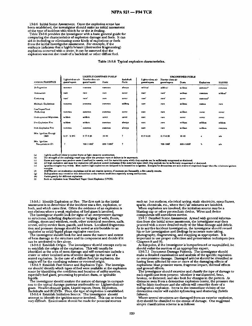
NFPA 921 - - F94 TCR
13-9.6 lnidal Scene Assessment. Once the explosion scene has been established, the investigator should make an initial assessment of the type of incident with widch lie or she is dealing. Table 13-9.6 provides die investigator with a basic general guide for
comparing die characteristics of explosion damage and fuels. It can aid in including or eliminating some kinds of explosions or fuels from the initi,-dinvestigative assessment. For example, if die evidence indicates that a highly brisant (destructive fragmenting) explosion occurred with a crater, it can be assumed that the explosion was not the result o fa backdraft or other diffuse fuel.
Table 13-9.6 Typical explosion characteristics.
CI|ARACTElUSTIC8
Ih.flngration
Detonation
Cratering
Multiple Explosions
Gas/Vapor/Dust I'(~'keting
Underground Migration
Ih'e-Explosion Fire
F'oat-Explosion Fire
M/n, Ignitton Energy (M J)
Min, Isn i t lon Temperatu re (F)
I , IGnTI ,Y-CONFINEn I,'UEI,8" Lightor-than-air Heavier-than-air Backdral~ gases/vapors gaaetv'vs pore Dusts I;'uels
common comn~m cOmll~n always
rare rare rare never
rare" rare' rare never
common common commen seldom
common common common never
seldom seldom never never
seldom seldom common always
common common common always
0.17 • 0.251 0.1"/-0.25 1040 ?
? 700-1 loop 600-1100F ?
UNCONFINlgD FUIgL8 I.ishter-than-sir Heavier-than air gases/vapors gases/vapors Dusts Explosivos BI~,VKS
seldom' seldom' 8shinto common| common
rare' rare' seldom common seldom'
rare" rare" never common'
rare rare seldom conmn rare
rare rare seldom never never
rare rare never never never
rare rare seldom seldom seldom
rare rare seldom seldom common
0.V/-0.25 0.17-0.25 1040 • n/a
'/On- IOOF GO0.I I00P h n/a
(a) I.ightlyamnfined refors to typical frame or light masonry consttxtction. (b) The strength of the confining vcqmel may allow the p rea~re wave at faibare to be aulmraonlo. (e) Oases and vapors may produce seato if confined in vessels, and the mater ia l | upon which they explode can be ~f lk len t ly compressed or shattered. (d) All high explosives and some low explosives will produce seated explosions if the materials upon whkh the,/explode can be raffi¢iently ~mpresoed or shattered. (e) Iginit icnenersiesverywidcly. Most modern hlshexpfosivesare deslsnedtobelnsensi t ive tel~Mtion. Energies for detonations are n i n e o r d e r s o f m a ~ i t u d e l a r g e r than the minimum ignition
energies. 03 BIJgggs are not rumba•tins ~¢plmions and de not require ignition; Ifeantento are flammab/e, • fire umal ly rosults. (S) Deflagrstlons may transition into detonations under certain renditions especially etmn s confinement. (h) Varies greatly for different explosives. (i) Such an explosion is an Unconfined Vapor Cloud Explosion (UVCEL
13-9.6.1 Identify Explosion or Fire. The first task in the initial assessment is to determine if the incident was a fire, explosion, or both, and which came first. Often the evidence of an explosion is not obvious where a weak explosion of fuel gases is involved. The investigator should look for signs of an overpressure damage
to structures, including displacement or bulging of walls, floors, ceilings, doors and windows, roofs, other structural members, nails, screws, ntilityservice lines, panels, and boxes. Localized fragmenta- tion and pressure damage should be noted as attributable to an explosive or solid/liquid phase explosive reaction. The investigator should look for and assess the nature and extent
of heat damage to the s~ructure and its component and decide if it can be attributed to fire alone.
13-9.6.2 Establish Origin. The investigator should attempt early on to establish file origin of the explosion. This will usually be identified as file area of most damage and will sometimes include a crater or other localized area of severe damage in the case of a seated explosion. In file case of a diffuse fuel/Mr explosion, the origin wil/be the confining volume or room-of-origin.
13-9. 6.3 Establish Fuel Source and Explosion Type. The investiga- tor should identify which types of fuel were available at die explosion scene by identifying the condition and location of utility services, especially fuel gases, processing by-product dusts, or ignitable liquicls.
The investigator should ,analyze die nature of damage in compari- son to die typical damage patterns attributable to: Lighter-than-air gases. Heavier-than.air gases, Liquid vapors, Dusts, Explosives, 8ackdrafts and BLEVEs. Thus, tile type of explosion is established.
13-9.6.4 Establish Initiation Source. The investigator should attempt to identify die ilignition source involved. This can at times be very difficuh. Examinauon should be made for potential sources
such as: hot surfaces, electrical arcing, static electricity, open flames, sparks, chemicals, etc., where fuel/Mr mixtures are involved.
When explosives are involved, the initiation source may be a blasting cap or other pyrotechnic device, Wires anddevice components will sometimes survive.
13-9.7 Detailed Scene Assessment. Armed with general informa- tion from the initial scene assessment, tile investigator may fllen proceed with a more detailed study of the blast damage and debris. As in any fire incident investigation, the investigator should record his or her investigation and findings by accurate note taking, photography, diagramming, and mapping as appropriate. It is important to use proper collection and preservation techniques (see Chapters 8 and 9). At this point, if the investigator is inexperienced or unqualified, he
should enlist the services of an appropriate expert. 13-9.7.1 Document Damage Patterns. The investigator should
make a detailed examination and analysis of the specific explosion or over-pressure damage. Damaged articles should be identified as having been affected by one or more of the damaging effects of explosions: blast pressure waves, fragment impact, thermal effects and ground effects.
The investigator should examine and classify the type of damage to ead~ significant item present: whether it was shattered, bent, broken, or flattened, and also look for changes in the pattern. At distances away from a detonation explosion center, the pressure rise will be fairly moderate and the effects will resemble those of a deflagration explosion. Items in the immediate vicinity of file detonation center will exhibit splintering and shattering (brittle failure).
Where several structures are damaged from an exterior explosion, they should be classified to tile extent of damage. One suggested simple classification scheme is as follows:
120

N F P A 921 - - F94 T C R
minor: damage from glass `and small items; some windows blown in
slight: windows ,and doors blown in; interior partitions cracked; sashes or frames removed; light siding ripped off
moderate: building frame distortion; plaster ,and wall board broken; studs ,and rafters broken; exterior walls bulged or cracked; roof severely damaged; some interior partitions blown down
severe: shanding but su bstan tinily destroyed; severe frame distortion or shattering; some collapse of bearing walls; complete collapse in some cases
demolished: not standing
The scene should be carefully examined and fragments of any foreign material recovered, as well as debris from the seat itself. The fragments may require forensic laboratory analysis for their identification, but whether they are fragments of the oril~inal vessel or container, or portions of an improvised explosive device, they may be critical to the investigation.
Table 13-9.7.1 can be used as a simplified guide to estimate the peak blast overpressure from the observed building damage ,and casualty data. These data are from peak overpressure applied to the structure's exterior. The effects of overpressure on dae inside of the structure are considered to be similar, but the overpressure values may be different in some Gases, depending on the construction involved.
It is noted dlat tile estimation of structural d,'unage from an explosion is a very complex topic. A thorough treatment involves maximum pressure `andimpulse of the explosion, as well as the natural period `and strength characteristics of the confining structure. Generally, one can expect a peak overpressure of 1 to 2 psi to cause the failure of most ligbt structural assemblies such as nonreinforced wood siding, corrugated steel panels, or masonry block walls. In comparison, much higher overpressures can be tolerated when the structural design is reinforced particularly with materials of good ductility (e.g. steel). (See Table 13-9.7.1 on pages 122 ,and 123.)
13-9.7.2 Identify Preblast ,and Postblast Fire Damage. Fire or heat damage should be identified as having been caused by a preexisting fire or by the thermal effect of the explosion. Debris that has been propelled away from tile point of origin should be examined to determine if it has been burned. Debris of this nature that is burned may be an indicator that a fire preceded the explosion.
Probably the most common sign of an overpressure condition is window glass thrown some distance from the windows of the structure. The residue of smoke or soot on fragments of window glass or other structural debris reveals that tile explosion followed a fire by some time, whereas perfectly clean pieces of glass or debris, thrown large distances from the structure indicate an explosion preceding the fire.
The direction of flow of melted ,and resolidified debris may tell the investigator the position or attitude of file debris at the time of heat exposure.
13-9.7.3 Locate and Identify Pbysical Articles of Evidence. Investigators should locate, identify, note, log, photograph, ,and map ,any of tile many ,and varied articles of physical evidence. Because o f tile propelling nature of explosions, the investigator should keep in mind that significant pieces of debris evidence may be found in a wide variety of locations including: outside file exploded structure, embedded in the walls or other structural members of the exploded structure, on or in nearby vegetation, into the ground, inside adjacent strnctures or vehicles, or embedded in these adjacent structures. In the case of bombing incidents involving the explosion of tanks, appliances, or equipment, significant pieces of evidence debris may have pierced the bodies of victims or be contained in their clotifing.
The clothing of anyone injured in an explosion should be obtained for examination and possible ,analysis. The investigator should ensure that photographs are taken of the injuries ,and that ,any material removed from tile victims during medical treatment or surgery is preserved. This is true whether the person survives or not.
In~,estigators should note the condition and position of any damaged and displaced structural components such as: walls, ceiling, floors, roofs, foundations, support columns, doors, windows, sidewalks, driveways, and pauos.
Investigators should note the condition ,and position of ,any damaged ,and displaced utility equipment such as: fuel gas meters ,and regulators, fuel gas piping and tanks, electrical boxes/meters, electrical conduits and conductors, heating oil tanks, parts of explosive devices, or fuel vessels.
18-9.7.4 Establish Causation. Using some of the ,analysis tech- niques described, the cause should be established. Additional ,analysis techniques to establish causation are descxlbed below. It should be noted that due to the destructive effects of fire ,and explosions, the cause cannot always be establishe<L
13-10 Analysis to Establish Causation. Many teclaniques are suggested, below to aid. in establishing causatlon. . The. choice of tbe tecbmque(s) used vail depend upon the umque circumstances of the incident.
13-10.1 Timeline Analysis. Based on the background information gathered (i.e. statements, logs, etc.), a sequence of events should be tabulated for both prior to the explosion `and during the explosion. Consistencies `and inconsistencies wid~ causation theories can then be surmised ,and a "best fit ~ theory should be estal)lished.
13-10.2 Damage Pattern Analysis. Various types of damage patterns can be documented for further ,analysis, principally debris ,and structural damage. 13-10.2.1 Debris Analysis. As stated above, investigators should
identify, diagram, photograph, ,and note those pieces of debris that indicate the direction and relative force of the explosion. In general, tile greater the explosive energy, die farther that similar pieces of debris will be thrown from the center of the explosion. However, different drag/lift (aerodynamic) characteristics of various fT~le ent shapes will tend to favor some going farther.
distance as well "as the direction of significant pieces of evidence from the apparent center of the explosion may be critical. The Iocadon of all significant pieces should be completely docu- mented on the explosion scene diagram along with notes as to both distance ,and direction. This allows the investigator to reconstruct the trajectories of various components. In some rises it is desirable to weigh and make geometric measurements of significant missiles, especially, large ones. This can be then used in a ~ o r e complete engmeenng `analysis of trajectories.
1 3-10.2.9- Analysis of Relative Structural Damage. Investigators should diagram the areas surrounding the explosion site as to relative damage. Such a diagram can be called an *iso-damage contour m a p . Criteria for contours may be simple over pressure levels in some cases, or the relative damage ratings for structures such as listed above in section 13-9.6.1. Such an analysis wi|l give additional clues to explosion propagation, `and car, be used for further input to a more complete engineering `analysis, such as described in 1 3-10.3.2.
13-10.3 Correlation of BlastYield with Damage Incurred. This type of ̀ analysis is valuable in correlating the degree of damage with the stifficient amount of explosive material.
13-10.$.1 Explosions within Structures. For fuel-air (e.g. gas/ vapor, dust) explosions within structures, the amount of fuel necessary to achieve the damage present can be bounded by the damage incurred `and a knowledge of the fuel concentration necessary to achieve that overpressure and rate-of-pressure loading.
For solid/liquid phase explosives, a methodology such as that presented inTMS-1300 (see A-13.1.1) can be used to estimate the amount of explosive necessary and in what configu ration, as necessary to cause the damage.
13-10.3.2" Explosions Outside of Stnlctures. Far.field effects are associated with the explosion damage that results from the air blast waves and flying fragments. These effects are especially evident where strong containments fail owing to detonations or highly energetic deflagrations. Here tile investigator should estimate the TNT energy equivalent of the explodingsystem from the available chemical energy or potential useful work (gas exp2slsion) based on tile damage incurred; apply the cube-root scaling law for predicting blast pressures a tany distance from ,any mass equivalent of TNT; and correlate the estimated blast pressures to published damage thresholds for structural a n d h u m a n targets.
1 3.10.4 Structural Analysis of Damaged Items and Structures. Occasionally, important information re~garding the amount ,and type of energetic material present can be esumated from a detailed analysis of file structure involved. However, dais usually entails file services of a structural engineer trained in this area.
1 3.10.5 Correlation of Thermal Effects. A downr.mge collection of articles exhibit ingheat damage from an explosive event may be evidence of a fireball or fire during the sequence of events. This may be further proof that the explosion involved a BLEVE, a ptiressurized fire, or other phenomena depending on the character of
nose articles. Specialized ,analysis of thermal dmmtge effects can be conducted by ,an engineer trained in dais area.
Appendix A A-I 3-1.1 The following references are of value when considering
additional technical information on explosions involving structures or vessels.
Bodurtha, F.T., Industrial Exolosion Prevention and Protection. McGraw Hill, Inc., 1980.
Eckhoff, ILK., Dust Explosions in the Process Industries. Bu tterworth-Heinmann, 1991.
121

N F P A 921 ~ F94 T C R
Table 13-9.7.1 Human Injury Criteria.
Over~1'l~sgrl~
0.6
1.0-2.0
IJ
2.0 - 3 .0
2.4.
2.8
3.0
In)my Com~ms Souse
3.4
4.O - $.{3
6,3
7.0 - 8.0
I(~0
14J
16,0
17.5
2JJ
27.0
~om e,/~ Slm"
~ Jor sJcln x~s'=toa eua ayms zm
eo~ un~tp~ sloth paeu'ss:iom tram
Th.,eslmM for m'iom ~mm~ ~,:m aytns stm
Tlu'mbaM for ~ r~pm~
1o~ pmbstm~ of ~ntn~ mpm~
~ ~ hurl a pecan ta U~ l~m~
! ~ : ~ mt smdJim m ~ s t m e . a n ~
amat o a , a m y m
B a l d on m , n s nJmp -.," ~
Bm~ o~ A m y ~
C.onafcU~ d m oa emmum m
~ d m o a m m p m m
Om mmm roll.mat m
for IMs z~ea
(IFle~er, Yeh~mn 1.~o)
(Lm lmO)
Y e ~ 19eo)
( l .m 1.~o)
(lees 1.~o)
(1.m I.~o)
(Bnuie and Simpson LVa)
29.0
I ~ an:tx'um rapm~
serious / ~ ~y'm| Sms ~ s r ~ pme~dlty
pm~sUm: ~
Seno= ,muds ~'ms: e~q l~s m r 100S pm~sn~t~
"13zze~:old lsmg Ismartssm
~audlty ~a~nJmld d ~ bbm e~em~
from dL-e~ ~m~ e~zas
~0~ pmt~MI/~y of ~sut//ty ~"om ~ blast zS~eca
go~ pml~tsSlfty of ~sutffty ~'mn dfs'z~ blsst
M~a ~ biB: elm
Inmrprem~ of mblm c~ ~ pemen~l
Not • smlous I~
Bas~ em Army dam
Bm~ em sm~s
~ d m e m a~mn rupm~
SmKi on Ae~ ma
Nm a sm'~m I m ~ (apl~S m • Mm at I o ~ (mw~0 met); ~-S0 I=i mluml
3 ms~ d~ama ~uvas)
r - m ~ t~,msa~ m l u s i smm'm~
so~e ot rib ew tnJmm wuuld tw sm, m'e
Coaalmq d m ms mmaUsy
Coammq dsss oa mosuJ~
momUsy
A M l i s m o f m lsmZ tnlmeim (:qppJm m a Mm at ~ asssjm (met 50 ms=); e0..v0 lm ~ fro'3 mNC ~nEIom ~m,m)
Co::~Ja:lq elm ms mm'm~
~ :'eLzne~z.
(U.S. DOT I9~)
(l.ms imm
(Fseztsa. P, lcl:nsoue. Yelwa'mn 1ram)
(Iz= ssao)
(;.m 1~o)
(us. DOT 19ea)
(Lea 190)
(OX DOT ~ )
(Lea 1~0)
(Lm 1~0)
(Lea lea0)
('d.S. DOT I ~ )
122

N F P A 9 2 1 - - F 9 4 T C R
l'itolqg~lY n , t~ tGZ
c~m ~ ~ o~ms~ stm (t~= zsso) madams zixzsdy m z ~ zmm:
l . , :~ a o ~ (z~Ma). Seaic ~mm (Zza ,t..~o) St=s e~az~
• ~0 Basmlle o~ mnmm. smU. md~ s m ~ ( l z a tgeo)
c~t~ "t~p~m p m m z ~ sins ~ C~zm tsso)
Som~ a m q ~ m ~ o m muaSs. Io~ w ~ w Slm mu~m.
0.4
0~-L0
0.7
1.0
1.0 - 2.0
].3
2.0
2.0 - 3.0
23
2.~
3.0
3.0 - 4.0
4.0
4.8
5.0
5.0 - 7.0
7.0
7.0 - &O
9.0
10.0
M ~ z ~ m ~ m m
d a m ~ to wmdaw ~:mm. Om somm mpon~ ~ ~mm -, 0.141 is~
~ o r d ~ q s m / m
~ dumUUon d lmmm. m m u m l e
s ~ z m s o ~ s m ~ m ~
F-sam o~ m~x~ ~ pm~s ( ~ I~smS c c ~ a m z ~ )
Sm~ m u m o~ cu~t ~ a m ~ s u ~ W ~ s m r ~ t
Pm.ml muap~ c~ mtlls s~l ma~ ~ I zmm
s h s n a ~ oL ~ m a a m o~ dmlcr
Lom~ limil o~ smom s m s : m ~ d m s ~
50~ ~ m ~ d a ~ a~ bri~mark d ~
couspse o~ s e u . m m ~ m ~ l m ~ ~ p Ruptm~ of oil s tump taala Snsppms ~ m z . ~mo~m m ~ mare
C~m~S o~US~ m m m m nqnm~
F-~Im o ~ m m u
s - - ~ ~ u m . ~ ~
Nmr~ ~ d a m = U ~ o~ ~ m m
~ ~ ' ~ " train mqlom mm'tm'az~
S ~ s r m ~ ~ ot tmck ~m~ lmsras (S-12 ~mc~s tbtck, nm minored)
Sl~s blmm in oL s~, l tmme tnsEdl~lS
Owam,mmll of Iol lai r ~ ross
laamtat u'~ta t m . m a m m p i m q ~ m o l / s l ~
P m m ~ m ~ ~ o~tm~U~s
StNI Iom~s Mmm dmm
Crau~ dasmtF
123
(McRae 19K Lem Urn)
( ;~sm -,~ Simpson isa, ALr F-onz 1983, US. DOT Ism~
(Lea ZS~O)
(Iza Lq0)
( B n ~ m t .Simp~s l g ~ Air Porcc 1 ~ . US. ~ 19U, Lea 1,~0)
(Lm Z~0)
( L m L.~0)
(eamc and .~z~so. l g ~ air F-o~ 1~3.
(Z~a l~0)
(toss l~0)
(Bmsiz and S~,~ou US. DOT 1 ~ t.a:s 19so)
(Lm ISm0)
(Mcl~az 19~)
(Brain md Simpson
( I za L~0)
( l z a lSm)
(Bra~ aid Skapson Igml. Air Po~z 19a3, U..q. DOT LVn, Lea Lga0)
(A~ Forcz 1983)
(Brsm ~d S~amon US. DOT ISm)
(Las l~0)
196L A~ Porto L~3)
(Mca~ I~4)

N F P A 921 - - F94 T C R
Netdeton, Ma~., Gaseous Detonations: Their Nature. Causes and ~ R o u t i e d g e , Chapman and Hall, NewYork, NY 1987.
Harris, R.J., The InvestKration and Control of Gas Exnlosions in Buildings and Heating Pl~t . E&FN Spoon, Ltd., London and New York, 1ff83
Stull, D.R., Fimdamentals of Fire and F~olosigo, AIChE Mono- raph Series No. 10, VoL 73, American Ir~titute of Chemical ngineers, New York, NY 1977 Baker, l~plosion Hazards and Evaluations. Elsevier Publishers,
Amsterdam - New York, 1983. Baker and Tang, Gas. Dust ,and Hybrid Explosions. Elsevier
Publishers, Amsterdam - NewYork, 1991. Kinney, et al, Explosion Shocks in Air. Springer-Verlag, Berlin -
New York, 1985. Kucbta, lnvestiwation of Fire and Exnlosion Accidents in the
Chemical Minin~ and Fuel-Related lridustdes - A Manual. United States Bureau of'Mines Report 680, 1985.
Gugan, K., Unconfined Vanor Cloud Exnlosions. Gulf Publishing Houston, TX, 1978. " " Ba~necht , W., I ~ Springer-Verlag, Berlin - New
York, 1989. Strucuires to Resist the Effects of Accidental Exn|osions. United
States Army Technical Manual, TM 5-3000, Revislon 1, November, 1990. Formal Interpretation. Prugb, R.W., "Qnantitadve Evahmtion of "BLEVE" Hazards",
Journal of Fire Protection Engineering, vol. 3, no. 1, March 1981 Anon, FIr* and Exnlosinn Manual for Aircraft Accident Investiga-
tions. Bureau of Mines, AD-771191, August 1973 NFPA 68, "Venting of Deflagrations', National Fire Protection
Association, 1988 edition. NFPA 69, "Standard on Explosion Prevention Systems", National
Fire Protection Association, 1992 edition. CPIA, Hazards of Chemical Reactants and Pronellants. Chemical
Propulsion Information Agency, CPIA publlcati'on 394, September 1984. A-13-3.2 Some Investigators classify structural damage using the
terms qfigh" and qow" order, based on the nature of damage created by the explosion. Experience has shown difficulties in applying these terms, as evidence often exhibits both degrees of damage. Also, the terms are confused with "high" and "low" explosives, ,as well as "high" and "low" order phenomena involving detonatable explosives.
A-13-I0.3.2 TNT Equivalency Concepts for Correlating Blast Danmge With Yield. Free-field explosions can be analyzed using the concept of TNT equivalency. This is based on the concept that flae damagingeffects of many free-field explosions can be related to that of TNT. Explosion effects parameters of TNT are well known, reproducible, and scalable, where charge geometries are similar. One set of scaled explosion parameters are shown in Figure A-13-I0.~.2 for hemispherical charges of TNT at ground level. There are many other such data collections, though this is of the most use for typical explosion accidents. When different size charges of TNT are exploded, similar blast
waves will begenerated at distances that are proportional to the diameter, and energy of the charge. Since tile energy of a charge is proportional to its weight, W, the scaling parameter Z, is
Z = R/W^I/S
Thus, Z is the proportionality constant or "scaled distance" from the center of the explosion.
In the generalized form, the scaled range Z may be used to evaluate various p,'u-ameters of interest at a distance R, including: peak pressure, peak reflected pressure, the blast wave arrival time, impulse, reflected impulse, pulse duration, etc. Peak pressures are those which are measured perpendicular to tile direction of the blast wave propagation.
When not dealing with TNT, a TNT equivalent weight must be esti mated. Where experimental data is lacking, this can be done on an energy basis by dividing the material weight, W, times the material's heat of explosion Ho by the heat of explosion of TNT, Hint.
Weqv = (Wx Hc) /Hmt
It should be noted that the use of the TNT equivalency concept can be very crude in some applications because the scaling relationships become less accurate with materials with different properties than TNT, different charge geometries, obstructions in the blast wave resulting in an axisymmetric blast field, etc. Additional complica- tions arise when utilizing it for analysis of filel-air vapor cloud explosions, where the equivalency on a weight basis may range from less than 1% to 20%.
lO000O
10fl0
O.l O.OOt O. ! 1 lO tO0
OISTRNCE, FL
F'tgure A-13-10.3.2 Airblast Parameters versus Distance for a One Pound Mass TNT Hemispherical Ground Burst.
SUBSTANTIATION: Major issues are listed below. a. TIA 92-1 was issued on 4/24/92 as an emergency measure to
alleviate some of the problems in application of this chapter. The T1A warns the reader of the numerous factors controlling explosion effects and tile nature of damage, and that many of the analysis techniques within tile chapter relate primarily to those involving diffuse filel/,'fir sources in lightweight containment structures. The reader is reminded that application of these concepts to other structures is not necessarily applicable, and he/she is referred to numerous references added with the TIA. This revision eliminates the need for TIA 92-1. b. Incorrect and Incomplete PhenomenologyDescriptions.
Section 13-4 descriptions of explosions phenomenology are lacking and incorrect in several cases.
Discussions of the shape of the pressure wave and blast reflection require considerably more discussion and explanatory diagrams. There is no discussion of explosions internal vs external to
structures. There is very little description of structural failure phenomena.
The behavior of structures when subject to blast effects is an important topic for understanding this subject area. Itis important to note that much better information exists than that in Table 13-12.3.1, "Effect of Pressure Waves" (see Baker,
1983). There is no discussion of how structures and materials respond when subjected to blast, how they ultimately fail, and in what modes of failure.
There is no discussion of TNT equivalency and blast scaling concepts
c. Unconfined Vapor Cloud Explosions (UVCE) are not addressed. Such explosions can be devastating and are most likely to occur where large quantities of liquefied and com ~ressed fuel gaseesare stored or processed, usually in industrial faolities. The classic example of a major UVCE that has occurred in recent years is the Flixborougb explosion, England, 1974, which resulted in 28 fatalities
124

N F P A 921 - - F94 T C R
and which involved cyclohexane as a fuel (from Gugan, Vaoor Cloud Exnlosions. 1978). This class of exi~losions has unique characteristics constrained by
weather and fue/characteristies.Mudl information is in tile literature regarding such explosions and their energy yield characteristics.
Note that by tile current section 13-1 definition of an explosion, a UVCE cannot exist, because of the required confinement. There- fore, the basic definition of an explosion in tile guide must be changed as well. d. There is confusion in the discussion between condensed
explosives and diffuse fuel/air explosions. Most of tile text is written in terms of diffuse fuel/air systems inside
structures, particularly those involving LPG or natural gas. There is not enough emphasis on distinct differences between high explo- sives and diffuse fuel/air types (e.g. high explosives may produce high velocity fragments at > 1000 ft/s, whereas diffuse explosions will itypically produce fragments at velocities of 1-3 orders of magnitude ess). With ltigh explosives, both overpressure ,and fragments may
produce serious structural damage. With diffuse fuel/air explosions, overpressure will produce the majority of structural damage.
Close-in pressures from high explosives can be several orders of magnitude greater than diffuse types, tilough tile duration of the pressure puise may be much less
e. High/low order description of phenomena is unnecessary and confnsing (it is utilized in sections 1-3, 13-3.1, 13-3.2, 13-8.$, 13-8.4, 13-12.2.2, Table 13.12.2). High/low order terminology is used by some investigators in tile fieldto describe qualitative damage effects. The terminology is vague and shouldn't be encouraged. It is crudely derived from explosives industry terminology having totally different meanings:
"where high order refers to tile proper detonation of a conven- tional high explosive; low order refers to tile nonideal or partial detonation/defia~ration of a conventional high explosive due to inadequate initiauon, material discontinuities, etc.~(De Haan, Kirk's Fire Investigation, p241) The nature of explosions cannot be so easily classified into two
regimes Imsed on the d,'mmge. Differences in damage are due to the maximum pressure and impulse of the explosion, as well as tile natural period and strength characteristics of tile confining strncture. While some weak generalizations regarding damage effects can be made for gas'explosions widlin wood frame dwellings, they certainly cannot be applied across the board for all types of explosions and strnctures.
Explosions of typically produce a spectrum of damage whicb varies as a function of distance from its ortgin. For example, a small high explosive detonation within a large structure may produce so-called qow order" damage effects a ta distance from the center of explosion. Proper investigation technique characterizes tile damage pattern as a function of distance from tile center. The application of "high/low" order damage effect terminology to
explosions with strong containments is extremely confusing and can Lead to incorrect conclusions. Also, the 900 psi/sec threshold criteria for high order described in
section 1 3.3.2 is unsubstantiated and unrecognized by the scientific community. f. The "force vector" analysis (13-12.3.4) as described is misleading
,and may lead an investigator to make erroneous conclusions. The "force vectors" described are actually displacement indicators, not vectors. A vector should indicate both magnitude and direction. It is possible to derive tile direction and magnitude of energy released by ,an explosion by analysis of fragment trajectories, though not as described in the text.
No information is given on die effects of fi'agment shape and drag proper ties aitecting fragment trajectories. No structural consider- ations are given. An investigator might erroneously conclude that a fallen roof or ceiling in a structure might be the result of overpres- sures above it, and might locate "force vectors" incorrectly in tile analysis.
g. There is no coordination of the Chapter 13 with other NFPA standards involving explosion phenomena (i.e. NFPA 68, 69,..)
b. Table 13-9.6 has numerous technical flaws and needs to be corrected. One updated version is attached.
i. References are Inadequate. Adequate references are not provided throughout the current text. Accepted investigative and scientific references should be cited throughout the text, as is in die rest of tile guide. COMMITTEE ACTION: Accept in Principle.
Revise Chapter 13 to read as follows: Chapter 13 Explosions 13-1" General. Historically, the term explosion has been difficult
to define precisely. The manifestation that an explosion occurred includes damage or
change brought about by tile restriction of the expanding blast
pressure front as an integral element, produdng physical effects on containers or nearby surfaces. This effect can result from the confinement of the blast pressure
front or the impact of an unconfined pressure or shock wave upon an object, such as a person or structure.
For fire and explosion investigations, an explosion is a physical reaction characterized by the presence of four major elements:
(a) high pressure gas, (b) confinement or restriction of the pressure, (c) rapid production or release of that pressure, and (d) change or damage to file confining (restricting) structure,
container, or vessel caused by the pressure release. Although an explosion is almost always accompanied by the
production of a loud noise, the noise itself is not an essential element in the definition of an explosion. The generation and violent escape of gases are tile primary criteria of an explosion.
Although tile ignition of a flammable vapor/air mixture within a can, which bursts the can or even only pops offthe lid, is considered an explosion, the ignition of the same mixture in open field, while it is a deflagration, may not be an explosion as defined in this document even thougb there may be the release of high pressure gas, a localized increase in air pressure, and a distinct noise. The failure and bursting of a tank or vessel from hydrostatic pressure of a non-compressible fluid such as water is not an explosion because the pressure is not created by gas. Explosions must be gas dynamic.
In applying this chapter, the investigator should keep in mind that there are numerous factors that control the effects of explosions and the nature of the damage produced. These factors include the type, quantity, and configuration of the fuel; the size and shape of the containment vessel or swucture; the type and strength of the materials of construction of the containment vessel or structure; and tile type and amount of venting present (see Section 13-5).
Sections of this chapter present explosion analysis techniques and terms dlat have been developed pri/narUy from the analysis of explosions involving diffuse fuel sources such as combustible industrial and fuel gases, dusts, and tile vapors from ignitable liquids in buildings of lightweight construction. The reader is cautioned tilat application of these principles to structures of other construc- tion types may require additional research to other references on explosions.
13-2" Types of Explosions. There are two major types of explosions widl which investigators are routinely involved: mechanical and chemical, with several subtypes within these. These types are differentiated by the source or mecbanism by which the explosive pressures are produced.
13.2.1 Mechanical Explosions. These are explosions in which the high pressure gas is produced by purely physical reactions. None of these reactions involve changes in the basic chemical nature of the substances. The most commonly used example of a mechanical explosion is the bursting of a steam boiler. The source of over- Ptlressure is die steam created by heating and vaporizing water. When
ie pressure of the steam can no longer be confined bythe boiler, tile vessel falls and an explosion results. No chemical, combustion, or nuclear reaction is necessary. The steam under pressure is the energy source. Tile chemical nature of the steam (H~O) is not changed. 13.2.2" Chemical Explosions. In chemical explosions the genera-
tion of high pressure gas is the result of exothennic reactions wherein the fundamental chemical nature of the fuel is changed. Cbemical reactions of the type involved in an explosion usually propagate in a reaction front away from the point of initiation.
More common are the propagating reactions found with gases, vapors, and dusts. Such combustion reactions are called propagation reactions because they occur progressively through tile reactant (fuel) with a definable flame front separating the reacted and unreacted fuel. Most chemical explosions, including combustion explosions, are the result of propagation rad~er than uniform chemical reactions.
13.2.2.1 Combustion Explosions. The most common of the chemical explosions are those caused by the burning of combustible hydrocarbon fuels. These are combustion explosions and are characterized by the presence of a fuel with air as an oxidizer. A combostion explosion may .also involve dusts. In combustion explosions the elevated pressures are created by the rapid burning of the fuel and rapid production of large volumes of combustion by- products and heated gases. Because these events are likely to be encountered by tile fire investigator, combustion explosions are considered here as a separate explosion type.
Combustion reactions are classified as either deflagrations or detonations, depending upon the velocity of the flame front propagation through the fuel. Defiagrations are combustion reactions in which the velocity of the reaction is less than the speed of sound in the unreacted fuel medium. Detonations are combus- tion reactions in which tile velocity of the reaction is faster than tile speed of sound in tile unreacted fuel medium.
125

N F P A 9 2 1 ~ F 9 4 T C R
The flame speed is die local velocity of a freely propagat ing flame relative to a fixed point. It is die s u m ofd~e burn ing velocity and tile translational velocity of tile flame front. The m a x i m u m laminar flame speed for med lane and p ropane are 11.5 and 13.1 f t / sec respectively. The relationship is shown by
Sf = S u + S t Sf= Flame speed, f t / s e c . S u = Burning Velocity S t = Translational velocity, f t / s ec
Note: S t is equal to S u t imes a funct ion of the bu rned gases. Since turbulence can increase Su, it also increases S t.
The burn ing velocity is die rate of f lame propagat ion relative to tile velocity of die u n b u r n e d gas ahead of it. The fundamenta l burn ing velocity, Su, is tile bu rn i ng velocity for laminar f lame u n d e r stated conditions of composit ion, temperature , and pressure of die u n b u r n e d gas. Flame speed, Sf, is die speed o f a f lame f ront relative to a fixed reference point. Funcl,amental burn ing velocity is an inhe ren t characteristic of a combust ible and is a fixed value whereas flame speed can vary widely d e p e n d i n g upon dae existing parameters of temperature , pressure, conf ining vo lume ,and confignration, combustible concentrat ion, and turbulence.
The bu rn ing velocity is tile velocity at which a f lame reaction f ront moves into die u n b u r n e d mixture as it chemically t ransforms die flJel and oxidant into combust ion products. It is only a fraction of the flame speed. The transitional velocity is d ie sum ofdae velocity of the f lame front caused by die volume expansion o f die combus- tion products due to dae increase in t empera ture and ,any increase in die n u m b e r of moles and any flow velocity due to mot ion o f die gas mixture prior to ignition. T he burn ing velocity o f the f lame f ront can be calculated f rom die fundamenta l bu rn ing velocity which is repor ted in NFPA 68 a t s tandardized condit ions of temperature , pressure and composi t ion of u n b u r n e d gas. As pressure and turbulence increase substantially dur ing an explosion, file fimcLa- mental burn ing velocity will increase, fur ther accelerating die rate of pressure increase. NFPA 68 lists data on the various materials.
Several subtypes of combust ion explosions can be classified according to die types of fuels involved. Tile most c o m m o n of flaese filels are:
(a) Flammable gases (b) Vapors of ignitable (f lammable and combustible) liquids (c) Dusts (d) Low explosives (dlose fllat undergo deflagration) (e) n i g h explosives (dlose d-tat unde rgo detonat ion) (O Smoke and f lammable products of incomplete combust ion
( backdr,'fft explosions). NOTE: The chemical s tructure of h igh explosives allows for
oxidation reactions to occur du r ing detonat ion. Detonat ion of a h igh explosive is no t a combust ion reaction in file usual sense. There is no separate oxidizer. Raffler, file explosive c o m p o u n d decomposes as a shock wave travels flarough it a t supersonic speed. The reaction is exofllermic.
13-2.3 Electrical Explosions. High energy electrical arcs may generate sufficient hea t to cause an explosion. Tile rapid heat ing of tile su r round ing gases results in a mechanical explosion tha t may or may no t cause a fire. Tile clap o f f l lunder accompanying a l ighming bolt is an example of an electrical explosion effect. Electrical explosions require special expertise to investigate ,and are no t covered in d~is document .
13-2,4 Nuclear Explosions. In nuclear explosions file high pressure is created hy d~e fusion or fission of the nuclei of atoms. T he investigation of nuclear explosions is no t covered by dfis document .
13-2.5 BLEVEs. The boiling liquid expand ing vapor explosion (BLEVE) is a type of mechanical explosion that will be encoun te red most frequently by the fire investigator. These are explosions involving vessels that contain liquids unde r pressure at temperatures above their a tmospher ic boiling points. The liquid need not be f lammable. BLEVEs are a subtype of mechanical explosions. They ,are sufficiently c o m m o n fllat dley are treated here as a separate explosion type. A BLEVE can occur in vessels as small as disposable lighters or aerosol cans and as large as tank cars or industrial storage tanks. A BLEVE frequent ly occurs when file t empera tu re of die liquid
and vapor widlin a conf ining tank or vessel is raised by an exposure fire to die point where tile increasing internal pressure can no longer be conta ined and dae vessel explodes. This rupture o f tile confining vessel releases dae pressurized liquid and allows it to vaporize a lmost instantaneously. If die contents are ignitable, daere is a lmost always a fire. Ifdae contents are noncombust ib le , daere can still be a BLEVE, but no ignition of die vapors. Ignidon usually occurs eidaer f rom die original external hea t daat caused die BLEVE or f rom some electrical or friction source created by die blast or shrapnel .
BLEVE's may also result f rom mechanical damage, overfilling, runaway reaction, overheat ing vapor-space explosion and mechani- cal failure.
Figure 13-2.5(a) An LP-Gas cylinder that suffered a BLEVE as a result of exposure to an external fire.
126

N F P A 9 2 1 ~ F 9 4 T C R
Figure 13-2.5(13) A railroad tank car of butadiene that suffered a BLEVE as a result o f heating created by an internal chemical reaction.
13-3 Characterization of Explosion Damage. For descriptive and investigative purposes, it can be helpful to characterize incidents,
rticularly in structures, on die basis of tile type of darru'tge noted. e terms high order and low order explosion have been used to
characterize explosion damage. The terms high and low yield explosion have also been used. Use of die terms high and low order damage is r ecommended to reduce confusion widl similar terms used to describe the energy release from explosives. (See 13-12.) Tile differences in damage are more a function of the rate of pressure rise and file strength of die confining or restTicting structure, than d~e maximum pressures reached.
13-3.1 Low Order Damage. Low order damage is charactedzed by walls bulged out or laid down, virtually intact, next to die structure. Roofs may be lifted slightly and return to dleir approximate original
~ osition. Windows may be dislodged often wid/out glass being roken, Debris produced is generally large and dlrown short
distances. Low order damage is produced by rates of pressure rise. (See Fignre 13-3.1 on page 128.)
13-3.2" High Order Damage. High order damage is characterized by shattering of file structure producing small, pulverized debris. Walls, roofs, and structural members are splintered or shattered with the building completely demolisiaed. Debris is thrown great distances possibly hundreds of feet. High order explosions are the results of rapid rates of pressure rise. (See Figure 13-3.2 on page 128.)
127

N F P A 921 ~ F 9 4 T C R
Figure 13-3.1 Low order damage in a dwelling.
128

N F P A 921 ~ F 9 4 T C R
Figure 13-3.2 H|gh order damage showing debris t h r o w n o v e r a large a r e a .
13-4 Effects of Explosions. An explosion is a gas dynamic phenom- enon dlat under ideal dleoretical circumstances will manifest itself
an expanding spheric~al heat and pressure wave front. Tile heat and pressure waves produce the damage characteristic of explosions. The effects of explosions can be observed in four major groups: blast pressure wave effect, shrapnel effect, thermal effect, and seismic effect.
13-4.1 Blast Pressure Front Effect. The explosion of a material produces a large quantity of gases. These gases expand at a high
~i eed and move outward fi*om dae point of origin. The gases and dae splaced air moved by dae gases produce a pressure front daat is
primarily responsible for the damage and injuries associated with expl osi ous. The blast pressure front occurs in two distinct phases based upon
the direction of the forces in relation to tile point of origin of die explosion. These are tile positive pressure phase and negative pressure phase. The shape of the graph of die blast pressure front is generally in
the shape of a wave as shown in Figure 13-4.1 and consists of a positive and negative phase. The ,area under the pressure-time curve is called tile "impulse" ofdae explosion.
13-4.1.1 Positive Pressure Phase. The positive pressure phase is dlat portion of die blast pressure f ront in which d~e expanding gases are moving away from dae point of origin. The positive pressure phase is usually more powerful than dae negative and is responsible for the majority of pressure damage.
13-4.1.2 Negative Pressure Phase. As die extremely rapid expansion of die positive pressure phase of die explosion moves outward from the origin of the explosion, it displaces, compresses, and heats the ~unbient surrounding air. A low air pressure condition (relative to ambient) is created at the epicenter or origin. When the positive pressu re phase dissipates, air rushes back to the area of origin to equilibrate the low air pressure condition, creating the negative pressure p h ~ e .
The negative pressure phase can cause secondary damage and move items of physical evidence toward the point of origin. Movement of debris during die negative pressure phase may conceal the point of origin. The negative pressure phase is usually of considerably less power then the positive pressure phase but may be of sufficient strengd~ to cause collapse of structura/features already weakened by the positive pressure phase.
P s o ~
LM
UJ n- (3.
AMBIENT, Po
I \
posrnvE I PHASE L NEGATIVE DURATION, DURATIC
t o
TIME AFTER EXPLOSION
i PHASE DURATION, t6
Figure 13-4.1 Idealized Detonation Blast Wave Shape
129

N F P A 9 2 1 - - F 9 4 T C R
15-4.1.3 Shape of Blast Front. Under ideal theoretical conditions the shape of the blast front from an explosion would be spherical. It would expand evenly in all directions from the epicenter. This never occurs in the real world because conf inement or obstruction of the blast pressure wave cbanges and modifies the direction, shape, and force of the front itself.
Venting of the confining vessel or structure may cause damage outside of the vessel or structure. The most damage can be expected to be in the path of the venting. For example, the blast pressure front in a room may travel through a doorway and damage items or materials directly in line with the doorway in the adjacent room. The same relative effect may be seen directly in line with the structural seam of a hank or drum that fails before the sidewalls.
The blast pressure f ront may also be reflected off solid obstacles and redirected, resulting in a substantial increase or possible decrease in pressure depending on the cbaracteristics of the obstacle struck.
In uniform reactions and ,after propagating reactions have consumed their available fuel, the force of the expanding blast pressure front decreases with the increase in distance from the epicenter of the explosion.
13-4.1.4 Rate of Pressure Rise vs. Maximum Pressure. The type of damage caused by the blast pressure front o f an explosion is dependen t no t only on the total amount of energy generated but also, and often, to ,a larger degree, u.pon the rate of energy release and the resulung rate of pressure rise.
Relatively slow rates of pressure rise will produce the pushing or bulging type of damage effects seen in low order damage. The weal<er parts o f die confining structure, such as windows or structural seams, will rupture first, thereby venting the blast pressure wave and reducing the toh~ damage effects o f the explosion.
In explosions where the rate of pressure rise is very rapid, there will be more shattering of the confining vessel or container, and debris will be thrown great distances, as the venting effects ,are not allowed sufficient time to develop. This is characteristic o f high order damage.
Where the pressure rise is less rapid, the venting effect will have ~m important impact on the maximum pressure developed. See NFPA 68 for equations, dam, and guidance on calculating the theoretical effect of venting on pressure during a deflagration. While the m,'tximum tileoretical pressure developable by a deflagration man, under some circumstances be as high as 7-9 aunosplleres (in the range of 120 psi). Such calculations assume a structure or vessel timt man sustain such a high pressure. In commonly encountered situations, such a fugitive gas explosions in residential or commercial buildings, the maximum pressure will be limited to a level slightly higher d~an die pressure that major elements of the building enclosure (walls, roof, large windows, etc. can sustain without rupture. In a well built residence, this will seldom exceed 3 psi.
13-4.2 Shrapnel Effect. When the containers, structures, or vessels that contain or restrict the blast pressure fronts are rnpmred, they are often broken into pieces that may be thrown over grcat disumces. These pieces of debris are called shrapnel. They can cause great dama. ge and personal . . . . . injury often far from the source of the explosmu. In addinon, shrapnel can often sever electric uuhty lines, tirol gas or other flammable tirol lines, or storage containers, thereby adding to the size and intensity of post-explosion fires or causing additional explosions.
The distance to which missiles can be propelled outward from an explosion depend greatly on their initial direction. Other factors include their weight and aerodynamic characteristics. An idealized diagram for missile trajectories is shown in figure 13-4.5' for several different initial directions. The actual distances that missiles can travel del~end greatly on aerodynamic conditions and occurrences of ricochet impacts.
15.4.3 Tl~ermal Effect. Combustion explosions release qu,'mtities of energy flint heat combustion gases and ambient ,-air to high temperatures. This energy can ignite nearby combustibles or cause burn injuries to personnel. These secondary fires increase the damage and injury from the explosion and complicate the investiga- tion process. Often it is difiScult to de termine which occurred first, the fire or the explosion. All chemical explosions produce great quantifies of heat. The
specific temperatures produced depend on the nature of the explosion fuel ,as well as the duration of that peak temperature. [)etonating explosions produce extremely high ~mpera tu res of very limited duration, witereas d e f l a ~ t i o n explosions produce lower temperatures but for much longer periods. The durat ion and intensity of the heat greatly affect the damage and injury potential of the explosion.
Fireballs and firebrands are possible tbermal effects of explosions, particularly BLEVEs involving flammable vapors. Fireballs are the momentary ball of flame present during or ,after the explosive event. High intensity short duration thermal radiation may be present with a fireball. Firebrands are ho t or burning fragments propel led from
DISTANCE
Figure 13-4.2 Idealized missile trajectories for s.~veral initial flight direcuons
the explosion. All these effects may serve to initiate fires away from the center of the explosion.
15-4.4 Seismic Effect. As the blast pressure wave expands, and as the damaged portions of large structures are knocked to the ground, significant localized seismic or earth tremors can be transmitted through the ground. These seismic effects, though uncommon and usually of short duration and distance, can p roduce addition,'d damage to structures and underground utility services, pipelines, tanks, or cables.
15-5 Factors Controlling Explosion Effects. Factors that can control the effects of explosions indude: the type and configuration of the fuel; nature, size, volume and shape of any containment vessel or object affected; location and magnitude of ignition source; venting of the blast pressure wave; relative maximum pressure; and rate of pressure rise. The nature of these factors and their various combina- tions in any one explosion incident can produce a wide variety of physical effects with which the investigator will be confronted.
1 5.5.1 Blast Pressure Front Modifiers. Various F,henomena affect the characteristics of a blast pressure front as it travels away from the source. These are described below.
13-5.1.1 Reflection. As a blast pressure front encounters objects in its path, the. blast, pressure front, may amlplify due to its reflection. This reflecuon m some cases vail cause the overpressure to double and sometimes amplify it as much as eight times at the surface of reflection, depending on the angle of incidence. Tiffs effect is negligible with deflagrations, where the pressure in an entire vessel equalizes at approximately the speed of sound in air (i.e. s trong shock wave not present).
15.5.1.5' Refraction and Blast Focusing. Atmospheric inhomogeneit ies can cause nonideal blast pressure f ront behavior at times. When a blast pressure f ront encounters a layer of air at a significantly different temperature, it may cause it to bend, or refract. This is because the speed of sound is proportional to the square root oftemnp.eerature in air. A low-level temperature inversion can cause an mluaily hemispherical blast front to refract and focus on the g round around the center of explosion. Severe weather- related wind shear can cause focusing in the dovmwind direction. This effect is negligible with deflagrations.
15.6" Seated Explosions. The "seat" of an explosion is def ined as the crater or area of great damage located at the point of initiation (epicenter) of an explosion. Material may be thrown out of the crater. This material is called ejecta and may raJage from large rocks to fine dust. The presence of a seat indicates the explosion of a concentrated fuel source in contact with or in close proximity to the seat.
These "seats" typically range in size from a few inches to 25 ft or more in diameter. They display an easily recognizable crater of
ulverized soil floors or walls located at the center of otherwise less P , ~ . dat raged areas. Seated explosmns are generally cllaractenzed by hig pressure and rapid rates of pressure rise.
Only certain specific types or configurations of explosive fuels can produce seated explosions. These include: exptosives, steam boilers, tigi~tly confined filel gases or liquid fuel vapors, and BLEVEs occurring in relatively small containers, such as cans or barrels.
130
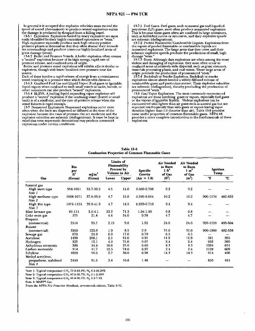
N F P A 9 2 1 - - F 9 4 T C R
In general it is accepted dlat explosive velocities must exceed the speed of sound (detonations) to produce seated explosions unless the damage is produced by shrapnel from a failing vessel.
13-6.1 Explosives. Explosions fueled by many explosives are most easily identified by their highly centralized epicenters or "seats." High explosives especially produce such high velocity positive pressure phases at detonation that alley often shatter their immedi- ate surrotmdings and produce craters or highly localized areas of great damage (seats).
13-6.2 Boiler and Pressure Vessels. A boiler explosion often creates a "seated" explosion because of its high energy, rapid rate of pressure release, and confined area of origin.
Boiler and pressure vessel explosions will exhibit effects similar to explosives, though with lesser localized over pressure near die s o u r c e .
Each of dlese involve a rapid release of energy from a containment vessel resulting in a pressure wave which decays widl distance.
13-6.3 Confined Fuel Gas and Liquid Vapor. Fuel gases or ignitable liquid vapors when confined to sudl small vessels as mxlks, barrels, or outer containers can ,also produce "seated" explosions.
13-6.4 BLEVE. A boiling liquid expanding vapor explosion will produce a "seated" explosion if the confining vessel (bmTel or small tank) is of a small size, and die rate of pressure release when the vessel failures is rapid enougll.
13.7 Nonseated Explosions. Nonseated explosions occur most often when the filels are dispersed or diffused at die time of the explosion because tile rates of pressure rise are moderate and the explosive velocities are subsonic (deflagrations). It must be kept in mind that even supersonic detonations may produce nonseated explosions under certain conditions.
13-7.1 Fuel Gases. Fuel gases, such as natural gas and liquefied petroleum (LP) gases, most often produce nonseated explosions. This is because dlese gases often are confined in large containers, such as individual rooms or structures, and tileir explosive speeds are subsonic (deflagrations),
13-7.2 Pooled Flammable/Combustible Liquids. Explosions from the vapors of pooled, flammable or combustible liquids are nonseated explosions. The large areas that they cover ,and daetr subsonic explosive speeds preclude tile production of small, high damage "seats."
13-7.3 Dusts. Although dust explosions are often among file most violent and damaging of explosions, tiley most often occur in confined ,areas of relatively wide dispersal, such as grain elevators, materials processing plants, and coal mines. These large areas of origin prechtde the production of pronounced "seats."
13-7.4 Backdraft o~Smoke Explosion. Backdraft or smoke explosions almost always involve a widely diffused volume of combustible gases and particulate matter. Their explosive velocities are subsonic (defla~ranon), dlereby precluding die production of pronounced "seats.
13-8 Gas/Vapor Explosions. The most commonly encountered explosions are those involving gases or vapors, especially fuel gases or the vapors of ignitable liquids. Violent explosions can be encountered with lighter than air gases such as natural gas but are reported less frequently than with gases or vapors having vapor densities higher than 1.0 (heavier dmn air). Table 13-8 provides some ttsefid properties of common, flammable, gases. NFPA 68 provides a more complete introduction to rite fundamentals of these explosions.
Table 13-8 Combustion Properties of Common Flammable Gases
Gas
Limits of Air Needed Air Needed Btu Flammability to Burn to Burn per Percent by Specific 1 ft s 1 m s ft s mj/m s Volume in Air Gravity of Gas of Gas
(Gross) (Gross) Lower Upper (Air = 1.0) (ft s) (m s)
Ignition Temp
o F °C
Natural gas High inert type 958-1051 35.7-39.2 4.5 14.0 0.660-0.708 9.2 Note 1 High methane type 1008-1071 37.6-39.9 4.7 15.0 0.590-0.614 10.2 Note 2 High Btu type 1071-1124 39.9-41.9 4.7 14.5 0.620-0.719 9.4 Note 3
Blast furnace gas 81-111 3.0-4.1 33.2 71.3 1.04-1.00 0.8 Coke oven gas 575 21.4 4.4 34.0 0.38 4.7 Propane
(commercial) 2516 93.7 2.15 9.6 1.52 24.0 Butane
(commercial) 3300 122.9 1.9 8.5 2.0 31.0 Sewage gas 670 24.9 6.0 17.0 0.79 6.5 Acetylene 1499 208.1 2.5 81.0 0.91 11.9 Hydrogen 325 12.1 4.0 75.0 0.07 2.4 Anhydrous ammonia 386 14.4 16.0 25.0 0.60 8.3 Carbon monoxide 314 11.7 12.5 74.0 0.97 2.4 Ethylene 1600 59.6 2.7 36.0 0.98 14.3 Methyl acetylene,
propadiene, stabilized 2450 91.3 .3.4 10.8 1.48 -- Note 4
9.2
10.2
9.4
0.8 4.7
24.0
31.0 6.5
11.9 2.4 8.3 2.4
14.3
900-1170
i
920-1120
900-1000
581 932
1204 1128 914
850
482-632
i
i
493-604
482-538
3O5 500 651 609 490
454
Note 1: Typical composition CH 4 71.9-83.2%; N 2 6.3-16.20% Note 2: Typical composition CH 4 87.6-95.7%; N 2 0.1-2.39% Note 3: Typical composition CH 4 85.0-90.1%; N 2 1.2-7.5% Note 4: MAPP ° Gas From the NFPA Fire Protection Handbook, seventeenth edition, Table 3-7C,
131

N F P A 9 2 1 ~ F 9 4 T C R
1 3 - 8 . 1 " Min imum Ignition Energy for Gases and Vapors. Gaseous fue l /a i r mixtures are the mos t easily ignitable fuels capable of causing an explosion. Ignition tempera tures in the 700-1100°F (370- 590°(3) range are comanon. M i n i mum ignition energies begin at approximately 0.25 millijoules.
1 3-8.2 Interpretat ion of Explosion Damage. Tile explosion damage to structures (low order and higb order) is related to a immber of factors. These include tile filel-air ratio, vapor density of the filel, tu rbulence effects, volume of the conf ining space, location and magrfitude of die ignition source, vent ing and the characteristic s t rength of the structure.
1 3 - 8 . 2 . 1 Fuel Air Ratio. Often the na ture of damage to the confining structure can be an indicator of the fisel/air mixture ratio at the t ime of ignition.
Some fire investigation literature has indicated than an entire volume, mus t be occupied by a f lammable mixture of gas and air for there to be an explosion. This is no t the case, as relatively small volumes of explosive mixtures capable of causing damage may result f rom gases or vapors collecting in a given area. (See 13-8.2.2.)
Explosions that occur in mixtures at or near the lower explosive limit (LEL) or upper explosive limit (UEL) of a gas or vapor produce less violent explosions than those near tile op t imum concentra t ion (i.e. usually jus t slightly rich of stoichiometric). This is because tile less- than-optimum ratio of fuel and air results in lower flame speeds and lower m a x i m u m pressures. In general these explosions tend to push and heave at the confining structure producing low order damage.
Explosions of mixtures near tile LEL do no t t end to produce large quantit ies of post-explosion fire, ,as nearly all of the available fiiel is consumed dur ing die explosive propagation.
Explosions of mixtures near the UEL tend to produce post- explosion fires because of the fuel-rich mixtures. Tile delayed combust ion of tile remain ing fuel produces the post-explosion fire. () • . . _ ften a port ion of the mixture b e m g over the UEL has fuel that does not bu rn until it is mixed with ,air dur ing the explosion 's vent ing phase or nel~ative pressure phase, thereby producing die characteristic following fire.
When op t imum (most violent) explosions occur, it is a lmost always at mixtures near or jus t above tile stoichiometric mixture (sligbtly fuel rich). This is d ie op t i mum mixture. These mixtures p roduce the most efficient combust ion and therefore tile h ighes t flame speeds, rates of pressure rise, m a x i m u m pressures, and consequent ly the most damage. Post-explosion fires can occur if there are pockets of overly rich mixm re.
For c o m m o n lighter than air gases in residential buildings, an explosion involving an o p t i m u m concentra t ion will s o m e u m e s result in some destructive shat ter ing effects of wooden structural materials.
1 3 - 8 . 2 . 2 Vapor Density. The vapor density of tile gas or vapor fuel can have a marked effect upon the na tu re of the explosion damage to die confining structure. This is especially true in dwellings and other buildings.
Heavier th:m air gases and vapors (vapor density greater than 1.0), such as f rom ignitable liquids and LP-Gases, tend to settle to lower areas. Lighter than air gases, such as natural gas, t end to rise and collect in uppe r areas. For example: signs o f post-blast bu rn ing in pocketed areas between ceUingjoists may be indicative of a lighter- than-air filel rather than heavier than air gases or vapors. (See 4-17.9.)
A natural gas leak in the first story of a multistory structure may well be manifested in an explosion with an epicenter in an upper story. The natural gas, being lighter than air, will have a tendency to rise th rough natural openings and may even migrate inside walls. The gas will cont inue to disperse in the s tructure until an ignition source is encountered .
An LP-Gas leak on the first story of a house, if it is not ignited there, can travel away f rom the source and due to its density will t end to migrate downward. The gas may collect in lower areas of the house and concentrate.
Ignition o f the gas will only occur if tile concentra t ion is within the f lammable limits and an ignition source is present.
Whe the r l ighter or heavier than air gases are involved, there may be evidence of the passage of flame where d~e fuel air layer was. Scorching, blistering of paintwork, etc. showing "tidemarks" ,are indicators of this type of phenomena . Tile operat ion of hea t ing and air coudi t ioning systems, t empera ture gradients and the effects o f wind on a bui lding can cause m i x i n g a n d m o v e m e n t dlat can reduce die effects of vapor density. Vapor density effects are greatest in still air conditions.
Full-scale testing of the distribution of f lammable gas concentra- tions in rooms has shown that near stoichiometric concentrat ions of gas would develop between the location of the leak and ei ther (1) the ceiling for lighter than air gases, or (2) the floor for heavier than mr gases. It was also repor ted that a heavier than air gas leaked at floor level would create a greater concentra t ion at floor level ,and the gas would slowly diffuse upward. A similar bu t inverse relation-
ship is t rue for a ligbter-than-air gas leaked at ceiling height. Veiatilation, both natural and mecbanical , can change the move- men t and mixing o f the gas and can result in gas spreading to adjacent rooms.
The vapor density of the fuel is no t necessarily indicated by the relative elevation of tile structural explosion damage above floor level. It was once widely t hough t that if tile walls of a pard cular structure were blown out at floor level, the fuel gas was heavier than ,air, and conversely if the walls were blown out at ceiling level, tile fuel was lighter than air. Since explosive pressure within a room equilibrates at the speed of sound , a wall will experience a similar pressure-time history across its entire height. The level o f the explosion damage within a conventional room is a f imction of tile construct ion s t rength of the wall headers a n d bot tom plates, the least resistive giving away first.
13-8.2.3 Turbulence. Turbu lence within a fuel-air mixture increases file f lame speed and therefore greatly increases the rate of combust ion and file rate o fp ressure rise. Turbu lence can produce rates of pressure rise with relatively small amoun t s of fuel that can result in hlgb order damage even though there may have only been a lean limit (LFL) mixture present. The shape and size of the confining vessel can have a p rofound effect upon the severity of the explosion by affecting tile nature of turbulence. Tile presence of many obsW, cles in the path of tile combust ion wave has shown to increase turbulence and ~-eatly increase the severity of tile explosion, mainly due to increasing file flame speed of the mixture involved. Other mixing and turbulence sources, such as fans and forced air ventilation, may increase the explosion effects.
. 1 3 - 8 . 2 . 4 Volume of Confining Space. Tile na ture of con ta inment vessel, its size, shape, construction, volume, materials, and design will also greatly change tile effects of tile explosion. For example, a specific percentage by volume of natural gas mixed with air will produce completely different effects if it is contained in a 1000-cu ft room than if it is contained in a 10,000-cu ft room at the t ime of ignition. This is tnle even though the velocity of the f lame front and the m a x i m u m over-pressure achieved will be essentially file same.
In general, file smaller the volume of the vessel, the ltigher tile rate of pressure rise for a given fue l / a i r mixture, and the more violent the explosion.
Dur ing file explosion, turbulence caused by obstrtlctions within the con ta inmen t vessel can increase the damage effects. This turbulence ~ m be caused by solid obstructions, such as co lumns or posts, machinery, or wall partitions, which may concentrate or reflect the blast pressure wave.
13-8.2.5" Location and Magni tude of Ignition Source. The highest rate of pressure rise wilt occur if the ignition source is in the center of die confining structure. Tile closer the ignition source to the walls o f the confining vessel or structure, the sooner the f lame f ront will reach the wall and be cooled by heat transfer to the walls. The result is a loss of energy and a cor responding lower rate of pressure rise and a less violent explosion. The energy of the ignition source general ly has a minimal effect on the course of an explosion but unusual ly large ignition sources can significantly increase the spread of pressure deve lopment and in some instances cause a deflagration to transit ion into a detonat ion.
13-8.2.6 Venting. With gas, vapor, or dus t fueled explosions, the vent ing of the con ta inmen t vessel will also have a p ro found effect upon tile na ture of explosion damage. For example, it is possible to cause a length of steel pipe to burst in the center, if it is sufficiently long, in spite of the fact that it may be open at both ends. Tbe number , size, and location of doors and windows in a room may de te rmine ff tile room experiences complete destruct ion or merely a slight m o v e m e n t of the walls and ceiling.
Venting of a conf ining vessel or structure may also cause damage outside of the vessel or structure. The most damage can be expected in the path of venting. For example, the blast pressure front in a room may travel th rough a doorway and damage i tems or materials directly in line with the doorway in the adjacent room The same relative effect may be seen direcdy in line with the structural seam of a tank or d r u m that fails before tile sidewalls.
With detonations, vent ing effects are minimal as the high speeds of die blast pressure fronts ,are too fast for ,any vent ing to relieve file pressures.
1 3 - 8 . 3 U n d e r g r o u n d Migration of Fuel Gases. It is possible for fliel gases that have leaked from u n d e r g r o u n d piping systems to migrate u n d e r g r o u n d (somet imes for great distances), en ter structures, and create f lammable a tmospheres . Both lighter and heavier than air fuel gases can migrate darough the soil or follow the exterior of u n d e r g r o u n d pipes ( th rough annu la r void spaces) and can enter s tructures in these manners . These gases are commonly referred to
"fugitive" gases because they have escaped from the confines of p lpmg or gas system components .
Fuel gases such as natural gas and p ropane have little or no odor themselves. In order. . for these, gases to be detected., when leaking, they mus t be arnflclally odortzed by the a d d m o n of such odorant
132

N F P A 9 2 1 - - F 9 4 T C R
chemicals as n-butyl mercaptan, ethyl mereaptan, Thiopane, or similar chemicals. The mixture of the fuel gas and odorant is not always stable and can be altered by passage of the fuel gases through materials that adsorb or absorb odorant (i.e. soil, etc.) or react widl it (i.e. new steel piping and tanks). In many soils the odor can be sufficiently changed so that it is not recognized as leaking gas. This phenomenon is known as "scrubbing" and can result in deodorized gas entering a structure undetected.
Fuel gases migrating underground have been known to enter buildings by seeping into underground sewer lines, electrical or telephone conduits, drain tiles, or even directly through basement and fovndation walls, none of witich are as gas tight as water or gas lines. These gases can also permeate die soil and dissipate harmlessly into the air. However, if the surface of the ground is obstructed by rain, snow, frozen earth or water, or paving, the gases may migrate laterally and enter structures. Long existing underground leaks may be located by die presence of grass or other vegetation dlat has been killed or turned brown over die area of the leak.
13-8A Multiple Explosions. A migration and pocketing effect is also often manifested by die production of multiple explosions, generally referred to as secondary explosions (and sometimes cascade, explosions) . Gas and vapors dlat have migrated to adjacent stones or rooms can collect or pocket on each level. When an ignition and explosion takes place in one story or room, subsequent explosions can occur in adjoining areas or stories. The migration and pocketing of gases often produces areas or
pockets with different air/fuel mixtures. One pocket could be within die explosive range of die fuel while a pocket m an adjoining room or story could be over the upper explosive limit (UEL). When die first mixture is ignited and explodes, damaging die smJcture, die dynamic forces of the explosion, including the positive and negative pressure phases, tend to mix air into file fuel-rich mixture and bring it into the explosive range. This mixture in turn will explode if an ignition source of sufficient energy is present. In dlis way a series of vapor/gas explosions is possible.
Multiple explosions are a very common occurrence. However, often die explosions occur so rapidly that wimesses report hearing only one, but die physical evidence, including multiple epicenters, indicates more than one explosion.
13-8.5* Importance of Gas Odorant. LP and natural gas do not inherently have an odor. A disagreeable smelling odorant is added ,as a safety feature. Odorant is required in most natural and LP- Gases. Butyl mercaptans are the most common odorants in natural gas, and ethyl mercaptan and thiopane are die most common odorants in LP gas. Odorant verification should be part of any explosion investigation involving, or potentially involving, flammable gas, especially if it appears dlat dlere were no indications of a leaking gas detectedby peoplepresent, ltspresence should be verified. Stain tubes can be usedin the field, and gas chromatogra- phy can be used as a lab test for more accurate results. Some people cannot detect dlese odorants for various reasons, and under certain conditions the odorant's effectiveness can be reduced to a point that it cannot be detected.
1 3-9 Dust Explosions. Finely divided solid materials (dusts and fines), when dispersed in the air, can fuel particularly violent and destructive explosions. Even materials dlat are not normally considered to be combustible, such as aspirin or aluminum, can produce explosions when burned as dispersed dusts.
Dust explosions occur in a wide variety of materials: agricultural products, such as grain dusts and sawdust; carbonaceous materials, such as coal and charcoal; chemicals; drugs, such as aspirin and ascorbic acid (Vitamin C); dyes and pigments; metals, such as aluminum, magnesium, and titanium; plastics; and resins, such as synthetic rubber.
NFPA 68, Guide for Venting of Deflagrations, provides a more complete introduction to fundamentals of dust explosions.
1 3.9.1" Particle Size. Since die combustion reaction hakes place at the surface of the dust particle, the rates of pressure rise generated by combustion are largely dependent upon die surface area of the dispersed dust particles. For a given mass of dust material the total surface area, and consequently die violence of the explosion, increases as the particle size decreases. The finer die dust, die more violent the explosion. In general, an explosion hazard concentration of combustible dusts can exist when die partides are 420 microns or less in diameter.
13-9.2" Concentration. The concentration of the dust in air has a profound effect upon its ignitibility and violence of die blast pressure wave. As with ignitable vapors and gases, dlere are minimum explosive concentrations of specific dusts for a propagat- ing combustion reaction to occur. Minimum concentrations can vary with the specific dust from as low as 0.015 to 2.0 oz/cu ft (20-2000 ~eamS per cubic meter) with the most common concentrations
ing less than 1.0 oz/cu ft. (1000 grams per cubic meter) Unlike. most. gases .and. yap ors, however., there is g.enerally no,
rehable maximum hm~t of concentration. The reaction rate is
controlled more bythe surface area to mass ratio than by a maximum concentration. Similar to gases and vapors, the rate of pressure rise and the
maximum pressure that occur in the dust explosion are higher if the pre-explosion dust concentration is at or close to the optimum mixture. The combustion rate and maximum pressure decrease if the mixture is fuel-rich or fuel-lean. The rate of pressure rise and total explosion pressure are very low at the lower explosive limit and at very high fuel-rich concentrations.
13-9.3 Turbulence in Dust Explosions. Turbulence within die suspended dust/air mixture gready increases die rate of combustion and thereby die rate of pressure rise. The shape and size of die confining vessel can have a profound effect upon the severity of the dust explosion by affecting the nature of turbulence. An example is dle~. pouring of grain from a great height into a iarg yet em pry storage D i n .
13-9.4" Moisture. Generally, increasing the moisture content of the dust particles increases the minimum energy required for ignition and the ignition temperature of the dust suspension. The initial increase in ignition energy and temperature is generally low, but, as the limiting value of moisture concentration is approached, die rate of increase in ignition energy and temperature becomes high. Above the limiting values of moisture, suspensions of the dust wUl not ignite. The moisture content of the surrounding air, however, has little effect upon die propagation reaction once ignition has occurred.
15-9.5 Minimum Ignition Energy for Dust. Dust explosions have been ignited by open flames, smoking materials, light bulb illa- ments, welding and cutting, electric arcs, static electric discharges, friction sparks, heated surfaces, and spontaneous heating.
Ignition temperatures for most material dusts range from 600 to 1100°F (320-590°C). Layered dusts have generally lower ignition temperatures than the same dusts suspended in air. Minimum ignition energies are higher for dusts than for gas or vapor fuels and generally fall within die range of 10 to 40 miilijoules, lligher tban most flammable gases or vapors.
13-9.6 Multiple Explosions. Dust explosions in industrial scenarios usually occur m a series. The initial ignition and explosion are most often less severe than subsequent secondary explosions. However, the first explosion puts additional dust into suspension, which results in additional explosions. The mechanism for dlis is dlat structural vibrations due to one explosion will propagate faster dlan the combustion wave, lofting dust allead of it. In facilities such as grain elevators these secondary explosions often progress from one area to another, or building to building.
1 3-10 Backdraft or Smoke Explosions. When fires occur within rooms or structures dlat are relatively airtight, it is common for fires to become oxygen depleted. In dlese cases high concentrations of heated, airborne particulate, carbon monoxide, and other flam- mable gases can be generated due to incomplete combustion. These heated fuels will collect in a structure where there is insufficient oxygen to allow combustion to occur and insufficient ventilation to allow them to escape.
When dlis accumulation of fuels mix with air, such as by die opening of a window or door, they can ignite and burn sufficiently fast to produce low order damage dlough usually with less than 2 psi overpressure in conventional structures. These are called backdrafts and smoke explosions.
13-11 Outdoor Vapor Cloud Explosions. An outdoor vapor cloud explosion is the result of the release of gas, vapor, or mist into die atmosphere forming a cloud within the fuel's flammable limits, and subsequent ignition. The principal characteristic of d~e event is potentially damaging pressures within and beyond the boundary of die cloud due to deflagration or detonation phenomena. This phenomena has also been referred to as an "unconfined
vapor-air explosion" or "unconfined vapor-cloud explosion." While completely unconfined vapor cloud explosions are possible, most involve at least some partial restriction of pressure by man-made or natural structures.
Outdoor vapor cloud explosions have generally occurred at process plants, in flammable liqmd or flammable gas storage areas, or have involved large transport vehicles (e.g. railroad tank cars.) Large amounts of fuel (hundreds of pounds or more) are generally involved, the Flixborough England process plant explosion in 1974 involving cyclohexane is a classic example of such an explosion.
, 1 3.12 Explosives. Explosives are any chemical compound, mixture, or device, the primary purpose of which is to function by explosion. Explosives are categorized into two main types, low explosives andhigh explosives (not to be confused with the low order and high order damage).
1 $-12.1 Low Explosives. Low explosives are characterized by deflagration (subsonic blast pressure wave) or a relatively slow rate of reaction and the development of low pressure wilen initiated. Common low explosives are smokeless gunpowder, flashpowders, solid rocket fuels, and black powder. Low explosives are designed to
135

N F P A 921 ~ F 9 4 T C R
work by the pushing or heaving effects of the rapidly produced hot reaction gases.
It should be noted that some low explosives (such as double base smokeless powder) can achieve detonation under circumstances where confinement is ,adequate to produce adequate reaction speed, where the ignition source is very strong, or where instabilities in combustion occur.
13-12.2 High Explosives. High explosives are characterized by a detonation propagation mechanism. Common high explosives ,are dynamites, water gel, TNT, ANFO, RDX, and PETN. High explosives are designed to produce shattering effects by nature of their high rate-of-pressure rise and extremely high detonation pressure (i.e. on the order of one million psi). These high localized pressures are responsible for cratering and localized damage near file center of tile explosion. The effects produced by diffuse phase (tirol/air) explosions and
solid explosives are very different. In a diffuse phase explosion (usually deflagratioh), structural damage will tend to be uniform and omnidirectional, and there will be relatively widespread evidence of burning, scorching and blistering. In contrast, the rate of combnstion of a solid explosive is extremely fast in comparison to the speed of sound. Therefore, pressure does not equalize through the explosion volume and extremely high pressures are generated near the explosive. The pressure and the resultant level of damage rapidly decays with distance away from the center of the explosion. At the location of the explosive, there should be evidence of crushing, splintering and shattering effects produced by the higher pressures. Away from tl~e source o f the explosion tllere is usually very little evidence of intense burning or scorching.
13-12.3 Investigation of Explosive Incidents. The investigation of incidents involving explosives requires very specialized training. Explosives are strictly regulated by local and federal laws, so most explosives incidents will be investigated by law enforcement or regadatory agencies. It is suggested that only investigators with the appropriate training endeavor to conduct such investigations. Those without tiffs training should contact law enforcement or other agencies for assistance.
13-13 Investigating tile Explosion Scene. The objectives of the explosion scene investigation are no different from those for a regular fire investigation: determine the origin, identify tile fuel and ign-ition source, det- ermine the cause, and establish the responsibility for the incident. A systematic approach to the scene examination is equally or even more important with an explosion investigation than in a fire investigation. Explosion scenes are often larger and more disturbed than fire scenes. Without a preplanned, systematic approach, explosion investigations become even more difficult or impossible to conduct effectively. Typical explosion incidents can range from a small pipe bomb in a
dwelling to a large process explosion encompassing an entire facility. While the investigative procedures describedbelow ,are more comprehensive for die large incidents, the same principles should be applied to small incidents, with appropriate simplification. When damage is very extensive andincludes much structural
d.amage, an explosion dynamics expert and structural expert should be consulted early in d~e investigation to aid in file complex issues involved.
13-13.1 Securing file Scene. The first duty of file investigator is to secure the scene of tile explosion. First responders to the explosion should establish and maintain physical control of file structure and surrounding areas. Unauthorized persons should be prevented from entering the scene or touching blast debris remote from tile scene itself because the criti~d evidence from an explosion (whether accidental or criminal) may be very small and may be easily disturbed or moved by people passing through. Evidence is also easily picked up on shoes and tracked out. Properly securing the scene also tends to prevent additional injuries to unautllorized persons or the curious who may attempt to enter an unsafe area.
13-13.l.l Establishing the Scene. As a gener,-d rule the outer perimeter of file incident scene should be establisbed at I 1/2 times the distance .°f the fardaest piece of debris, found. Si. gnificant pieces of blast debr is can be propelled great distances or into nearby buildings or vehicles, and these areas should be included in tile scene perimeter. If additional pieces of debris are found, file scene perimeter should be widened.
13-13.1.2 Obtain Background Information. Before beginning ,'my search, all relevant information should be obtained pertaining to the incident. This should include a description of the incident site ,and systems or operations involved, and conditions and events that led to the incident. The locations of any combustibles and oxidants that were present and what abnormal or hazardous conditions existed dlat might account for the incident need to be determined. Any pertinent information regarding suspected explosive materials and causes will of course be of interest and will aid in file search as well. Examination should be made ofwimess accounts, maintenance
records, operational logs, manuals, weather reports, previous incident reports and odler relevant records in developing the evidence. Recent ch,'mges in equipment, procedures and operating conditions can be especially significant. Obtaining drawings of the building or process will greatly improve
documentation of tile scene, especially if notes can be made on them.
13-13.1 Establish a Scene Search Pattern. The investigator should establish a scene search pattern. With the assistance of investigation team members, tile scene should be searched from the outer dPeximeter inward toward the area of greatest damage. The final
etermination of the location of the explosion's, epicenter should be made only after all of the scene has been examined. The search pattern itself may be spiral, circular, or grid shaped.
Often theparticular circumstances of the scene will dictate die nature of the pattern. In any case, the assigned areas of the search pattern should overlap so that no evidence will be lost at the edge of any search area. It is often useful to search areas more allan once. When this is done, a different searcher should be nsed to help ensure that evidence is not overlooked. The number of actual searchers will depend upon the physical size
and complexity of the scene. The investigator in charge should keep in mind, however, that too many searchers can often be as counter- productive as too few. Searchers should be briefed as to tile proper procedures for identifying, logging, photographing, and marking and mapping the location of evidence. Gonsistent procedures are imperative whenever there are several searchers involved. The location of evidence may be marked with chalk marks, spray
paint, flags, stakes, or other marking means. After photographing, the evidence may be tagged, moved, and secured. (See Chapters 8 and 9.)
13-13.1.4 Safety at the Explosion Scene. All of die fire investigation safety recommendations listed in Chapter 10 also apply for the investigation of explosions. In addition, there are some special safety considerations when dealing with an explosion scene. Structures that have suffered explosions are often more structurally
damaged than merely burned buildings. The possibility of floor, wall, ceiling, roof, or entire building collapse is much greater and should always be considered.
In the case of fuel gas or dust explosions, secondary explosions are the rule rather than die exception. Early responders need to remain alert to that possibility. Leaking gas or pools of flammable liquids need to be made safe before the investigation is begun. Toxic materials in tile air or on material surfaces need to be neutralized. Tile use of appropriate personal safety equipment is recommended.
Explosion scenes that involve bombings or explosives have added dangers. Investigators should be on file lookout for addldonal devices and undetonated explosives. T h e modus operandi (M.d.) of some bomber/arsonists includes using secondary explosive devices specifically targeted for the law enforcement or fire service person- nel who will be responding to the bombing incident. A dlorough search of the scene should be conducted for any
secondary devices prior to the initiation of file post-blast investiga- tion. If undetonated explosive devices or explosives are found, it is imperative daat they not be moved or touched. The ,area should be evacuated and isolated, and explosives disposal authorities sum- moned.
13-13.2 Initial Scene Assessment. Once the explosion scene has been established, the investigator should make an initial assessment of the type of incident with wltich lie or she is dealing. If at ,any time during tlae investigation die investigator determines that the explosion was fueled by explosives or involved an Improvised Explosive Device (lED), he or she should discontinue die scene investigation, secure the scene, and contact the appropriate law enforcement agency. Table 13-13.2provides the investigator with a basic general guide
for comparing the characteristics of explosion damage and fuels. It can aid in including or eliminating some kinds of explosions or fuels from die initial investigative assessment. For example, if the evidence indicates that high order damage occurred, it can be assumed dmt tile explosion was not die result of a backdraft.
134

N F P A 921 - - F 9 4 T C R
Table 13-13.2 Typical Explosion Characteristics
0 = Never 1 = Seldom 2 = sometimes 3 = Often 4 = Nearly Always 5 = Always
Typical Lighter than Heavier than Liquid Dusts Explosives Backdrafts BLEVEs Characteristics Air Gases Air Gases Vapors
Low Orde r Explosion
High O r d e r Explosion
Secondary Explosion
Gas/Vapor/Dust Pocketing A
Deflagration Detonatton U n d e r g r o u n d
Migratmn BLEVEs Post-Explosion
Fires Pre-Explosion
Fires Seated
Explosions Min. Ignition E
Energy (m J)
3 4 4 2 2 5 2
2 1 1 2 3 0 2
3 3 2 4 0 1 0
3 2 2 2 0 0 0 4 4 4 4 1 5 4 B 1 1 1 1 4 0 1 B
2 2 2 0 0 0 0 2 3 5 0 0 0 5
3 3 4 3 1 5 3
2 2 2 3 2 5 4
0 C 0 C 0 C 0 4 D 0 2
0.17-0.25 0.17-0.25 0.25 10-40 E F
Deflagrations may transition into detonations under certain conditions. aThe strength of the confining vessel may allow the pressure wave at failure to be supersonic. CGases and vapors may prpduce seats if confined in small vessels, and the materials upon which they explode can be sufficiently compressed or shattered. t'All high explosives and some low explosives will produce seated explosions if the materials upon which they explode can he sufficiently compressed or shat-
tered. E Ignition energies vary widely. Most modern high explosives are designed to be insensitive to ignition. Energies for detonations are nine orders of magnitude larger than the minimum ignition energies.
F BLEVEs are not combustion explosions and do not require ignitions.
15-13.2.1 Identify Explosion or Fire. The first task in the initial assessment is to de termine if the incident was a fire, explosion, or both, and which ~-'une first. Often tile evidence of an explosion is not obvious, e.g. where a weak explosion of fuel gases is involved. Tile investigator should look for signs of an over-pressure condition
existing within the structure, including displacement or bulgin~ of walls, tloors, ceilings, doors and windows, roofs, o ther structural members, nails, screws, utility service lines, panels, and boxes. Localized fragmentation and pressure damage should be noted as attributable to condensed phase explosive fuel reaction.
The investigator shottld look for and assess the nature and extent of heat damage to die structure and its components and decide ff it can be attributed to fire alone.
13-13.2.2 High or Low Order Damage. The investigator should at tempt to de termine if tile nature of damage indicates high order or low order damage. (See Section 13-K) This will help classify the type, quantity, and mixture of the fuel involved.
13-13.2.3 Seated or Nonseated Explosion. The investil~,~tor should determine if tile explosion was seated or nonseated. This will help classify tile type of possible fuel involved. (See Section 13-6.)
13-13.2.4 Identify Type of Explosion. Tile investigator should identify the type of explosion involved, e.g., mechanical, combus- tion, other chemical reaction, or BLEVE.
13-13.2.5 Identify Potential General Fuel Type. Tile investigator should identify which types of fuels were potentially available with the explosion scene by identifying tile condition and location of utility services, especially fuel gases, processing by-product dusts, or ignitable liquids. T h e invesugator should analyze the nature of damage in compari-
son to the typical damage patterns available from: (a) Lighter than air gases (b) Heavier than air gases (c) Liquid vapors (d) Dusts (e) Explosives (f) Back drafts (g) BLEVEs. 15-13.2.6 Establish the Origin. The investigator should at tempt
early on to establish the origin of the explosion. This will usually be identified as file area of most damage and will sometimes include a crater or other localized area of severe damage in the ~ s e of a
seated explosion. In the case of a diffuse fuel /a i r explosion, the origin wil/be tile confining volume or room-of-origin.
15-13.2.7 Establish tile Fuel Source and Explosion Type. The investigator should identify which types of fuel were available at tile explosion scene by identifying the condition and location of utility services, especially fuel gases, processing by-product dusts, or ignitable liquids.
I ne invesugator should analyze the nature of damage in compari- son to the typical damage patterns attributable to: Lighter-than-air gases. Heavier-than-ah" gases, Liquid vapors, Dusts, Explosives, Backdrafts and BLEVEs. Thus, tile type of explosion is established.
15-13.2.8 Establish Ignition Source. The investigator should at tempt to identify the ignition source involved. This can at times be very difficult. Examination should be made for potential sources such as: hot surfaces, electrical arcing, static electricity, open flames, sparks, chemicals, e ta , where fuel /a i r mixtures are involved.
When explosives are involved, the initiation source may be a blasting cap or other pyrotechnic device, Wires and device compo- nents will sometimes survive.
15-13.3 Detailed Scene Assessment. Armed with general informa- tion from the initial scene assessment, the investigator may now begin a more detailed study of the blast damage and debris. As in any fire incident investigation, the investigator should record his or her investigation and findings by accurate note taking, photography, diagramming, and mapping. It is important to use proper collection and preservation techniques. (see Chapters 8 and 9.)
15-13.3.1 Identify Damage Effects of Explosion. The investigator should make a detailed examination and analysis o f the specific explosion or over-pressure damage. Damaged articles should be identified ,as having been affected by one or more of the following typical explosion forces:
(a) Blast pressure wave - - positive phase (b) Blast pressure wave - - negative phase (c) Shrapnel impact (d) The/real - (e) Seismic. The investigator should examine and classify the type of damage
present: whether it was shattered, bent, broken, or flattened, and also look for chanl~[es in the pattern. At distances away from a detonation exploston epicenter, the pressure rise will be fairly moderate and die effects will resemble those o f a defiagration
135

N F P A 921 - - F94 T C R
explosion, while materials in the immediate vicinity of the detona- tion epicenter will exhibit splintering and shattering. The investigator should make a detailed examination and analysis
of the specific explosion or over-pressure damage. D,'unaged articles should be identified as having been affected by one or more of the damaging effects of explosions: Mast pressure fronts, shrapnel impact, dlermal effects and ground effects. The investigator should examine and classify the type of damage to each significant item present: whether it was shattered, bent, broken, or flattened, and also look for changes in die pattern. At distances away from a detonation explosion center, the pressure rise will be fairly moderate and file effects will resemble those of a deflagration explosion. Items in the immediate vicinity of the detonation center will exhibit splintering and shattering (britde failure).
The scene should be carefully examined and fragments of any foreign material recovered, as well as debris from the seat itself. The fragments may require forensic laboratory analysis for their identification, but whether they are fragments of the original vessel or container, or portions of an improvised explosive devtce, they may be critical to the inves6gation.
Table 13-13.3.1 can be used as a simplified guide to estimate the peak blast overpressure from the observed building damage and casualty data. T h e s e data are from peak overpressure applied to the structure's exterior. The effects ofoverpressure on the inside of the structure are considered to be similar, but the overpressure values may be different in some cases, depend ing on the construction involved.
Table 13-13.3.1 Human Injury Criteria (Includes Injury from Flying Glass and Direct O w e s m n ' e Effects)
Injury C o m m i t s Source
0.6
1.0 -2.0
1.5
2.0 - 3.0
2.4
2.8
3.0
3.4
4.0 - 5.0
5.8
6.B
7.0 - 8.0
10.0
Threshold for injury from flying glass*
Threshold for skin laceration from flying glass
Threshold for multiple skin penetrations from flying glass (bare skin)*
Threshold for serious wounds from flying glass
Threshold for eardrum rupture
10% probability of eardrum rupture
Overpressure will hurl a person to the ground
1% eardrum rupture
Serious wounds from flying glass near 50% probability
Threshold for body-wall penetration from flying glass (bare skin)*
50% probability of eardrum rupture
Serious wounds from flying glass near 100% probability
Threshold lung hemorrhage
14.5
16.0
17.5
20.5
25.5
27.0
Fatality threshold for direct blast effects
50% eardrum rupture
10% probability of fatality from direct blast effects
50% probability of fatality from direct blast effects
90% probability of fatality from direct blast effects
1% Mortality
29.0 99% probability of fatality from direct blast effects
*In mrpretation of tables of data presented in reference.
A. Flemher, Richmond, and Yelverron, 1980
Based on studies using sheep and dogs
Based on Army data
Based on studies using sheep and dogs
Based on Army data
Conflicting data on eardrum rupture
Conflicting data on eardrum rupmre
One source suggested an overpressure of 1.0 psi for this effect
Not a serious lesion
Based on Army data
Based on studies using sheep and dogs
Conflicting data on eardrum rupture
Based on Arm data
Not a serious lesion (applies to a blast of long duradon (over 50 msec); 20-30 psi required for 3 msec duration waves)
Fatality primarily from lung hemorrhage
Some of the ear injuries would be severe
Conflicting data on mortality
Conflicting data on mortality
Conflicting data on mortality
A high incidence of severe lung injuries (applies to a blast o f long duration (over 50 msec); 60-70 psi required fo~ 3 msec duration waves)
Conflicting data on mortality
B. Lees, F.P. Loss Prevention in the Process Industries ,Vol I, Buttecworths, London and Boston, 1980 C. Brasie and Simpson, 1968 D. US Deparunent of Transportation, 1988 E. U.S. Aifforce 1983 F. McRae, 1984
D
B
A
B
B
B
D
B
B
B
D
B
136

N F P A 921 w F 9 4 T C R
Propet~y Damage Criteria
Overpressm, e Damage Source(s) (psi)
0.03
0.04
0.10
0.15
0.30
0.4
0.5- 1.0
0.7
1.0
1 .0 - 2.0
1.3
2.0
2.0 - 3.0
2.3
2.5
3.0
$.0-4.10
4.0
4.8
5.0
5.0 - 7.0
7.0
7.0 - 8.0
9.0
10.0
30.0
88.0
Occasional breaking of large glass windows already understrain B
I-~ud noise (14MB). Sonic boom glass failure B
Breakage of windows, small, under swain B
Typical pressure for glass failure B
"Safe distance" (probability 0.95 no serious damage beyond this value). Missile limit. Some B damage to house ceilings. 10% window glass broken.
Minor structural damage B, D
Shattering of glass windows, occassional damage to window frames. One source reported glass B, C, E, F failure at 0.147 psi.
Minor damage to house structures B
Partial demolition of houses, made uninhabitable B
Shattering of corrugated asbestos siding B, C, E, F Failure of corrugated aluminum/steel paneling Failure of wood siding panels (standard homing construction
Steel frame of clad building slightly distorted B
Partial collapse of walls and roofs of homes B
Shattering of non-reinforced concrete or cinder block waft panels (1.5 psi according to another B, (2, D, E Source)
Lower limit ofser iom structural damage B
50% destruction of brickwork of house B
Steel frame building distorted and pulled away from foundations B
Collapse of serf-framing steel panel buildings B,C,D Rupture of oil storage tanks Snapping failure -wooden utility tanks
Cladding of light industrial buildings ruptured B
Failure of reinforced concrete, structures F
Snapping failure - wooden utility poles B,C
Nearly complete destruction of houses B
Loaded train wagons overturned B
Shearing/flexure failure o fbdck wall panels (8 - 12 inches thick, not reinforced) B,C,D,E
Sides blown in of steel fram buildings E
Overturning of loaded rail cars C, D Loaded train box-cars completely demolished B
Probable total destruction of buildings B
Steel towers blown down C,D
Crater damage F
It is noted dlat the estimation of structural damage f rom an explosion is a very complex topic. A thorough t reatment involves maximum pressure and impulse of the explosion, as well as the natural per iod and strength characteristics of the confining structure. Generally, one can expect a peak overpressure of 1 to 2 psi to cause the failure of most light structural assemblies such as nonreinforced wood siding, corrugated steel panels, or masonry block walls. In comparison, much higher overpressures can be tolerated when the structural design is reinforced particularly with materials of good ductility (e.g. steel).
1 3 - 1 3 . 3 . 2 Identify Preblast and Postblast Fire Damage. Fire or heat damage should be identified as having been caused by a preexisting fire or by the thermal effect o f the explosion. Debris that Ilas been
P d r o p e l l e d away from file point o f origin should be examined to etermine if it has been burned. Debris of this nature that is burned
may be an indicator that a fire preceded the explosion. Probably the most common sign of an over-pressure condition is
window glass thrown some distance from the windows of the structure. The residue of smoke or soot on fragments of window glass or other structural debris reveals that the explosion followed a fire by some time, whereas perfectly clean pieces of glass or debris, thrown large distances from the structure indicate an explosion preceding the fire. The direction of flow of melted and resolidified debris may tell the
investigator the position or attitude of the debris at the time of heat exposure.
137

N F P A 921 ~ F 9 4 T C R
13-13.3.3 Locate and Identify Articles of Evidence. Investigators should locate, identify, note, log, photograph, ,and map any of the many and varied articles of physical evidence. Because of die propelling nature of explostons, the investigator should keep in mind that significant pieces of evidence may be found in a wide variety of locations including: outside the exploded structure, embedded in the walls or other strnctnral members of tile exploded structure, on or in nearby vegetation, inside adjacent structures or vehicles, or embedded in these adjacent structures. In die case of bombing incidents or incidents involving the explosion of tanks, appliances, or equipment, significant pieces of evidence debris may have, pierced the bodies of victims. . or be contained in their clodfin, g.
The clothing of anyone injured m an explosion should be obtained for examination and possible analysis. The investigator should er|sure that photographs are taken of the injuries and that any material removed from the victims during medical t reatment or surgery is preserved. This is true whether the person survives or not.
Investigators should note file condition and position of any damaged and displaced stnlctural components such ,as: walls, ceiling, floors, roofs, foundations, support columns, doors, windows, sidewalks, driveways, and patios.
Investigators should note die condition and position of any damaged and displaced building contents SUCh as: furnishings, appliances, heating or cooking equipment, manufacturing equip- ment, victims' clotiting, and personal effects.
Investigators should note the condition and position of any damaged and displaced utiliiy equipment such as: fuel gas meters and regulators, fuel gas piping and tanks, electrical boxes/meters , electrical conduits and conductors, beating oil tanks, parts of explosive devices, or fuel vessels.
13-13.3.4 Identify Force Vectors. Investigators should identify, diagram, photograph, and note those pieces of debris that indicate the direction and relative force of the explosion. Keep in mind that the force necessary to shatter a wall is more than that necessary to merely dislodge or displace it. The force necessary to shatter a window is less than that to displace a wall, but more than that necessary to blow out a window intact. The greater the force, the farther that similar pieces of debris will be thrown from the epicenter.
Log, diagram, and photograph varying missile distances and directions of travel for similar debris, such as window glass. Larger, more massive missiles should be measured and weighed for comparison of the forces necessary to propel them.
The distance as well ,as the direction of significant pieces of evidence from the apparent epicenter of the explosion may be critical. The location of all significant pieces should be completely documented on dae explosion scene diagram ,along with notes ,as to both distance and direction. This allows the investigator to recon- struct the trajectories of various components .
13-14 Analyze Origin (Epicenter). After identifying the force vectors, the, investigator should trace backward from the least to the most damaged areas following the general path of the explosion force vectors. This is known as an explosion dynamics analysis. It can be accomplished most efficiently by plotting on a diagram of the exploded structure the various directions of debris movement and if possible, an estimate of the relative force necessary for the damage or movement of each significant piece of debris. (See the Explosion Dynamics Diagram, Figalre 13-14.) The analysis of the explosion dynamics is based upon die debris
movement away from the epicenter of the explosion in a roughly .spherical pattern and the decreasing force of the explosion ,as die distance from the epicenter increases.
Often more than one explosion dynamics diagram is necessary. The first would show a relatively large area that may indicate a specific area or room for fur ther study ,as the origin. A second, smaller scale diagram can than be constructed to ,analyze the explosion dynamics of tile area of origin itself. This is especially usefifl when dealing with a "seated" explosion.
Often, especially when dealing wida "nonseated" explosions such as fugitive fuel gas explosions, tile epicenter may not be pinpointed any more than to a specific room or area. Tbe explosion dynamics ,analysis is often complicated by evidence
of a series of explosions each with its own epicenter. This situation calls for a detailed comparison of the force vectors. Movement of more solid debris, such as walls, floors, and roofs, is generally less in subsequent explosions than in die first. The first forcefifl explosion tends to vent the structure allowing more of the positive pressure phase of subsequent explosions to be released.
This is true, however, only when file second,'wy explosions are of the same or lesser force than the first. Dust explosions are a notable exception to dtis p h e n o m e n o n widl subsequent explosions almost always being more powerful than the first. (See Figure 13-14 on page 139.)
13-15 Analyze Fuel Source. Once the origin or epicenter of the explosion has been identified, the investigator should determine fl~e filel. This is done by a comparison of the nature and type of damage to die known available fuels at d~e scene. All available fuel sources must be considered and eliminated until
one fuel can be identified ,as meeting all of the physical damage criteria. For example: if the epicenter of the explosion is identified as a 6-ft crater of pulverized concrete in the center of the floor, fugitive natural gas can be elinfinated as the fuel, and only fuels that can create "seated" explosions should be considered.
Chemical analysis of debris, soot, soil, or air samples can be helpfill in identifying the fuel. M/ida explosives or liquid fuels, gas chroma- tography, mass spectrography, or odler chemical tests of properly collected samples may be able to identify their presence.
Air samples taken in file vicinity of the area of origin can be used in identifying gases or the vapors of liquid fuels. For example, commercial "natural gas" is a mixture of methane, ethane, propane, nitrogen, and butane. The presence of ethane in an air sample may show that commercial "natural gas" was flaere rather than naturally occurring "swamp, marsh, or sewer" gas, wlfich is all methane.
Once a fuel is identified, the investigator should determine its source. For example: if the fuel is identified as a lighter-than-air gas and the structure is serviced by natural gas, the investigator should locate the source of gas d~at will most likely be at or below the epicenter, possibly from a leaking service line or malfunctioning gas appliance.
All gas piping, including from the street mains or LP-Gas storage tanks, up to and through die service regulator and meter, to and including all appliances, should be examined and leak tested if possible. (See NFPA 54, National Fuel Gas Code, and NFPA 58, Standard for the Storage and Handling of Liquefied Petroleum Gases.)
Odorant verification should be part of any explosion investigation involving, or potentially involving, flammable gas, especially if there are indications that there were no indications of a leaking gas detected by people present. Its presence should be verified. Stain tubes can be used in the field, and gas claromatography cart be used as a lab test for accurate results. (See Section 13-8.8.)
13-16 Analyze Ignition Source. When the origin and fuel are identified, the means of ignition must be analyzed. This is often die most difficult part of the overall explosion investigation because, especially with fugitive filel gases, multiple ignition sources are present. In the event o f multiple possible ignition sources, the investigator should take into consideration all the available information, including witness statements. A careful evaluation of every possible ignition source should be made. Factors to consider include:
(a) Minimum ignition energy of the fuel. (b) Ignition energy of die potential ignition source. (c) Ignition temperature of die fue l (d) Temperature of die ignition source. (e) Location of the ignition source in relation to the fuel. (f) Simulmaaeous presence of t i e fuel and ignition source at the
time of ignition. (g) Wimess accounts of conditions and actions immediately prior
to and at the time of the explosion. 13-17 Analyze to Establish Cause. Having identified the origin,
fuel, and ignition source, t i e investigator should now analyze and determine what brought together tile fuel and ignition at file origin. The circumstances that brought these elements together at that time and place are the cause (see Chapter 12).
Part o f this analysis may include considerations of how the explosion could have been prevented, such as failure to conform to existing codes or standards. It should be noted that due to the destnlctive effects of fire and explosions, file cause cannot always be determined.
Many techniques are suggested below to aid in establishing causation. Tile choice of die teclmique(s) used will depend upon the unique circumst,ances of the incident.
1 3-17.1 Time Line Analysis. Based on tile background information gathered (i.e. statements, logs, etc.), a sequence of events should be tabulated for both prior to the explosion and during the explosion. Consistencies and inconsistencies with causation fl~eories can then be snrmised and a "best fit" theory should be established.
13-17.2 l-~amage Pattern Analysis. Various types of damage patterns can be documented for further analysis, principally debris and structural damage.
138

NFPA 921 - - F94 TCR
Bedroom
Bath
Bedroom
! , \ ! II Oio,°ga.ea I r
-i t I [ l" Living area
Garage
Arrows indicate direction of displacement of walls, doors, and windows.
Figure 13-14 "Explosion Dynamics Diagram"
13-17.2.1 Debris Analysis. As stated above, investigators should identify, diagram, photograph, and note those pieces of debris that indicate the direction and relative force of the explosion. In general, the greater the explosive energy, the farther d~at similar pieces of debris will be thrown from the center o f the explosion. However, different drag/ l i f t (aerodynamic) characteristics of various f ragment shapes will t end to favor some going farther.
Tile distance as well as the direction of significant pieces of evidence from tile apparent center of the explosion may be critical. The location of all significant pieces should be completely docu- mented on the explosion scene diagram along wid~ notes as to both distance and direction. This allows die investigator to reconstruct tile trajectories of various components . In some cases it is desirable to weigh and make geometr ic measurements of significant missiles, especially large ones. This can he then used in a more complete engineering analysis of trajectories.
1 ?-17.2.2 Relative Structural Damage Analysis. Investigators should diagram the relative damage to the areas surrounding the explosion site. Such a diagram can be called an "iso-damage contour map." Criteria for contours may be simple overpressure levels in some cases, or the relative damage ratings for structures. Several techniques are employed for this purpose. Such an analysis will give additional clues to explosion I?ropagation, and can be used for fur ther input to a more complete engineering analysis.
17-17.3" Correlation of BlastYield with Damage Incurred. There are several methods d~at analysts use to correlate d~e degree of damage and projectile distance with die type and amount of fuel involved.
1 ?-17.4 Analysis o f Damaged Items and Structures. Frequently the determinat ion of the cause in explosion incidents requires a multldisciplinary approach to relate damage to the fuels involved. The use o f special experts may he necessary. (See Section 6-5.)
139

N F P A 921 - - F94 T C R
13-17.5 Correlation of Thermal Effects. A collection of articles exhibiting heat damage from an explosive event may be evidence of a fireball or fire during die sequence of events. This may be further proof fllat file explosion involved a BLEVE, a fuel j e t fire, or other phenomena depending on the character of those articles. Special- ized analysis of thermal damage effects can be conducted by an engineer trained in this area. From this material, an iso-thermal diagram (heat damage map) can be developed.
Appendix for Chapter 13 A-l 3-1 The following references ,are of value when considering
additional technical information on explosions involving structures o r vessels.
Bodurtha, F.T., Indnstrial Explosion Prevention and Protection. McGraw Hill, Inc., 1980.
Eckhoff, ILK., Dust Exnlosions in the Process Indnstries. Butterworth-Heinmann~ 1991.
Nettleton, M.A., Gaseous Detonations: Their Nature. Canses and ~ R o u t l e d g e , Chapman and Hall, NewYork, NY 1987.
Harris, R.J., The Investmation and Control of C~as Explosions in Buildings and Heating Plaint. E&FN Spoon, Ltd., London and New York, 1983
Stull, D.R., Fundamentals of Fire and Exnlosion. AIChE Mono- graph Series No. 10, VoL 73, American Institute of Chemical Engineers, NewYork, NY 1977
Baker, Exnlosion Hazards and Evaluations. Elsevier Publishers, Amsterdan~ - New York, 1983.
Baker and Tang, Gas. Dust and Hybrid Exnlosions. Elsevier Publishers, Amsterdam - New York," 1991.
Kinney, et al, Exnlosion Shocks in Air. Springer-Verlag, Berlin - New York, 1985.
Kuchta, Investi~ration of Fire and Exnlosion Acddents in the Chemical Minin~ and Fuel-Related lr~dustries -A Manual. United States Bureau o f Mines Report 680, 1985.
Gugan, K., Unconfined Vapor Cloud Explosions. Guff Publishing Houston, TX, 1978.
Bartknecht, W., ~ Springer-Verlag, Berlin - New York, 1989.
Structures to Resist die Effects of Accidental Exnlosions. United States Army Technical Manual, TM 5-3000, Revision 1, November, 1990. Formal Interpretation. Prugh, ILW., "Quantitative Evaluation of "BLEVE" Hazards",
Journal of Fire Protection Engineering, vol. 3, no. 1, M~ch 1981 Anon, Fire and Exoloslon Manual for Aircraft Accident Investiga-
tions. Bureau of Mi/aes, AD-771191, August 1973 NFPA 68, "Venting of Deflagrations', National Fire Protection
Association, 1988 edition. NFPA 69, "Standard on Explosion Prevention Systems", National
Fire Protection Association, 1992 edition. CPIA, Hazards of Chemical Reactants and Prooellants. Chemical
Propulsion Information Agency, CPIA publicati'on 394, September 1984. A-I 3-9 For more information, see the NFPA Fire Protection
Handbook, 17th Edition. A-I 5-2.2 For more information, see the NFPA Fire Protection
Handbook, 17th Edition. A-13-3.2 For more information, see Kennedy, P. and Kennedy, J ,
Explosion Investigation and Analysis, Investigations Institute, Chi~tgo IL, 1990. A-! 5-6 For more information, see Bomb Investigation, FBI Bomb
Data Program. A-I 3-8. l For more information, see NFPA 77, Recommended
Practice on Static Electricity. A-13-8.2.2 For more information, see the following: Kennedy, J. and Kennedy, P.M., Fires and Explosions I Determin-
ing Cmtse and Origin, Investigations Institute, Chicago, IL, 1985. lLabinkov, V. A., "The Distribution of Flammable Gas Concentra-
tions in Rooms," Fire Safety Journal, 13 (1988) 211-217. O'Loughlin, J. R. and Yokomoto, C. F., "Computation of One-
Dimensional Spread of Leaking Flammable Gas," Fire Technology, November (1989) 308-316.
A-I 5-8.2.4 For more information, see the following: Bartknecht, WoLfgang, Explosions ~ Course Prevention Protec-
tion. Springer-Verlag, New York, 1980; NFPA 68, Guide for Venting of Defiagrations; Zalosh, Robert, Explosion Protection, SFPE Handbook, Section 2,
Chapter 5, NFPA, Quincy. A-I 3-8.2.5 For more information, see NFPA 68, Guide for Venting
of Deflagrations. A-I 3-8.5 For more information see: NFPA 58, Standard for the
Storage and Handling of Liquefied Petroleum Gases; Colver, C. P. and Colver, J. C., Liquefied Petroleum Gas ~ The Odorant Problem {2m Lead to an Explosion, Trial, October (1988), p. 35-36; and Kennedy, P. and Kennedy, J , Explosion Investigation and Analysis, Investigations Institute, Chicago, IL, 1990.
A-13-9.1 For more information see, Hertzberg, M. and K. Cashdollar. "Domains of Flammability and Thermal Ignitibility for Pulverized Coals and Other Dusts: Par t i t e Size Dependence and Microscopic Residue Analyses," 19th Symposium on Combustion, Combustion Institute, 1982, pp. 1169-1180.
C, ashdollar, IC and M. Hertzberg. Explosibility and IgnitibUity of Plastic Abrasive Media, United State Bureau of Mines, Pittsburgh Research Center, Internal Report No. 4657,June 1987.
A-13-9.2 For more information, see U.S. Bureau of Mines' Report of Investil[~ations (RI) 6561, Pressure Development in Laboratory Dust Explosmns, 1964, pp 9-10. A-I 3-9.4 For more information, see U.S. Bureau of Mines' Report of
Investigations (RI) 6543, Preventing Ignition of Dust Dispersion by Inerting, 1964, p. 12. A-15-12 For more informati on, see Glossary of Commercial
Explosives lndnsa T Terms, Safety Librm T Publications No. 12, Institute of Makers of Explosives, Washington D.C., 1985. A-I 3-17.3 For condensed phase explosives, a methodology such as
that presented in TM 5-3000, Structures to Resist the Effects of Accidental Explosions. Revision 1, November, 1990. can be used to estimate die amount and configuration of explosive necessary to cause the damage.
Far-field effects are associated with the explosion damage that results from the air blast fronts and flying fragments. A TNT energy equivalent of the explodin~ system can be deduced from projectile weight, distance andresultmg damage. More details can be found in "Fire Dynamics Course Guide/Reader, Unit 4 - Explosions," Open Learning Fire Service Program, National Fire Academy, National Emergency Training Center. COMMITI'EE STATEMENT: Due to die extensive nature of the submission, a task group consisting of members of the Fire Investiga- tion Committee including die submitter, and odmr experts on explosions was convened to review the material and make recom- mendations to the Fire Investigation Committee. The revised chapter is a result of that task group's recommendations and the full technical committees review of the material.
(Log #CP2)
921- 61 - (13-1.1 (New), 13-3 ,and A-13-1.1 (New)): Accept in Principle SL~MITTER: Technical Committee on Fire Investigations, RECOMMENDATION: 1. Add a new 13-1.1":
13-1.1" Application. In applying this chapter, tile investigator should keep in mind that dlere are numerous factors that control the effects of explosions ,and die nature of the damage produced. These factors include the type, quantity, and configuration of the fuel; the size and shape of file containment vessel or structure; the type and strength of fl~e materials of construction of the contain- ment vessel or structure; and the type and amount of venting present (see Section 13-5.)
Sections of tltis chapter present explosion analysis teclmiques and terms that have been developed primarily from the analysis of explosions involving diffuse fuel sources such as combustible industrial and fuel gases, dusts, and the vapors from ignitable liquids in buildings of lightweight construction. The reader is cautioned fllat application of flaese principles to structures of other construc- tion types may require additional research to other references on explosmns.
2. Add a new paragraph to the end of Section 13-3 ,as follows: "This section, as written, is primarily directed to the analysis of
explosions from diffuse filel sources in buildings of lightweight construction. Examples of lightweight construction include wood, wood frame, wood frame with masonry veneer, or non-reinforced masonry (brick or concrete block.) There are also some wood or masonry constructed structures that are not lightweight. The reader is reminded that application of the concepts presented in dais section to structures of other construction types or strengths may require additional research to the references on explosions provided in Appendix A~"
3. Add a new A-15-1.1: A-1 5-1.1 The following references are of value when considering
explosions involving structures or vessels otiler than lightweight ,as described in Section 13-3.
Bodurtha, ET., Industrial Explosion Prevention and Protection, McGraw Hill, Inc., 1980.
Nettleton, M.A., Gaseous Detonations: Their Nature, Causes and Control, Roudedge, Chapman and Hail, NewYork, NY, 1987.
Harris, R.J., The Investigation and Control of Gas Explosions in Buildings and Heating Plant, E&FN Spon, Ltd., London and New York, 1983.
140

N F P A 9 2 1 - - F 9 4 T C R
SmU, D.IL, Fundamental of Fire and Explosions, AIChE Mono- graph Series No. 10, Vol. 73, American Institute of Chemical Engineers, NewYork, NY 1977.
Baker, Explosion Hazards and Evaluation, Elsevier Publishers, Amsterdam - NewYork, 1983.
Baker and Tang, Gas, Dust and Hybrid Explosions, Elsevier Publishers, Amsterdam - New York, 1991. Kinney, et al, Explosion Shocks in Air, Springer-Verlag, Berlin-New
York, 1985. Kuchta, "Investigation of Fire and Explosion Accidents in die
Chemical, Mining and Fuel-Related Industries - A Manual", United States Bureau of Mines Report 680, 1985.
Gugan, K., Unconfined Vapor Cloud Explosions, Cmlf Publishing, Houston, TX, 1978.
Bartknecht, W., Dust Explosions, Springer-Veriag, Berlin - New York, 1989.
"Structures to Resist the Effects of Accidental Explosions," United States Army Technical Manual, TM 5-3000, Revision 1, November, 1990. SUBSTANTIATION: Following tile public comment period for NFPA 921, Guide for Fire and Explosion Investigations, die Committee took action on a number of comments to the chapter on explosions. Included in these actions was a change associatedwith Comment 991-240 (Log#210). The change was intended to clarify and limit die scope of application of Section 13-3. These changes were published in die Fall 1991 TCD.
During the Technical Committee Report Session, at the Fall 1991 Meeting, a motion was made to accept Comment 921-228 (Log #198), which recommended die deletion of Chapter 1 $ in its entirety. In addition to other issues, it was suggested that die problem had not been fully resolved ,and that a reader could still mterpret Section 13-~ as applying to tile full range of possible construction types and explosion events. Although die motion to delete Chapter 13 fi'om die document was
defeated, the members of the Technical Committee present recognized fllat the wording and illustrations may still not clearly identify dae intended limits of Section 1 3-3. As a result, a Task Group was convened by die Chair of die Fire Investigation Commit- tee.
It is tile opinion of this Task Group as the submitters of die TIA that specific language is needed to clarify die intended limitations of the concepts presented in Section 15-3 and used in Chapter 13, as well as to point out that there are many factors that could impact on the nature of explosion damage. The Task Group feels dlat die proposed additional paragraphs and reference materials will meet dlat need. COMMITTEE ACTION: Accept in Principle. COMMITYEE STATEMENT: The committee has totally reworked chapter 13 and has incorporated die relevant material from this TIA into the reworked chapter. See Gommittee Action on Proposal 991-60 (Log #46) for die proposed new text of Olapter 13.
(Log #GPI 9)
991- 62 - (Chapter 14): Accept SUBMITTER: Technical Committee on Fire Investigations, RECOMMENDATION: Add a new chapter to NFPA 991 on "Electricity and Fire." The text of the chapter is as follows:
Chapter 14 Electricity and Fire 14-1 Introduction. This chapter discusses the analysis of electrical
systems and equipment. Tile primary emphasis is on buildings with 190/940 volt electrical systems. These voltages are typical in residential and commercial buildings. This chapter will discuss die basic principles of physics diat relate to electricity and fire.
Electrical equipment as an ignition source should be considered equally with all oilier sources and not as either a first or last choice. Tile presence of electrical wiring or equipment at or near file point of a fire does not necessarily mean that the fire was of electrical cause. Often the fire may destroy insulation or cause changes in the appearance of conductors or equipment that can lead to false assumptions if not carefully evaluated.
Electrical conductors and equipment dlat are appropriately used and protected by properly sized and operating fuses or breakers do not normally presenta fire hazard. They may, however, provide an ignition source if easUy ignitable materials are present.
14-2 Basic Electricity. 14-2.1 The purpose of this chapter is to present basic electrical
terms and concepts briefly and stmply in order to assist people in developing a working understanding of them.
14-2.2 Water flowing through a pipe is familiar to everyone. This has some similarities to electrical current flowing in an electrical system. Because of this, a limited comparison between a hydraulic system and an electrical system can be used to make it easier to understand an electrical system.
14-2.3 Below is a table of the basic elements of a hydraulic system along with die corresponding elements of an electrical system.
Elements of die Hydraulic System
Elements of the Electrical S~tena
pump generator pressure voltage pounds per square inch (psi) volts pressure gage voltmeter water electrons flow current
lOnS per minute (gpm) amperes (amps) eter ammeter
valve switch friction resistance (ohms) friction loss voltage drop pipe size - inside diameter wire size - AWG No.
14-2.4 In a hydraulic system, a pump is used to create the hydraulic pressure necessary to force file water through pipes. In an electrical system, a generator is used to create the necessary electrical pressure to force electrons along a wire. This electrical pressure is the voltage. The amount of hydraulic pressure is expressed in pounds per square inch and can be measured with a pressure I{age. The amount of electrical pressure is expressed in volts and zs measured with a voltmeter.
14-2.5 In the hydraulic system, it is water that flows in a useful way. In the electrical system, it is electrons fllat flow in a useful way, and this flow is called electrical current. The amount of water flow is expressed in gallons per minute (gpm) and maybe measured widl a flowmeter. The amount of electric~d current is expressed in amperes (amps) and may be measured with an ammeter. Electric current can be eRher direct current (dc), such as supplied by a battery, or alternating current (ac), such as supplied by the electric utility companies.
14-2.6 Direct current flows in only one direction, as in a circulating water system, while alternating current flows back and forth with a specific frequency. In the Umted States, the frequency of 60 Hertz or 60 cycles per second is used. For the majority of applications encounteredin this text, it is satisfactory to visualize ac circuits as if they are the more easily understood dc circuits. Notably excepted are transformers, which will not work on d~ The specifics of the differences between the behavior of alternating current versus direct current are beyond the scope of dais manual.
14-2.7 The water pipe provides the pathway for the water to flow. In the electrical system, conductors such as wire provide the pathway for the current.
14-2.8 In a closed circulating hydraulic system (as opposed to a fire hose delivery system where water is discharged out of the end), water flows in a loop, returning to the pump, where it is circulated again through the loop. If the valve is closed, the flow stops everywhere in file system. When the valve is opened, die flow resumes. An electrical system is also a closed system in that the current must flow in a loop or in a completed circuit. If the switch is turned on, the circuit is completed and file current flows. When the switch is turned off, the circuit is opened and current flow stops everywhere in the circuit. (See Figure 14-9.8.)
141

N F P A 9 2 1 - - F 9 4 T C R
PRESSURE GAUGE
l VALVE
~-~ PRESSURE PRESSURE PUMP DROP GAUGE
(CLOSED SYSTEM)
,)
SWITCH
GENERATOR
I VC 'METER
VOLTAGE DROP
/
F'tgure 14-2.8 Water pressure is measured by a pressure gage, Voltage is measured by a voltmeter. A valve is used to turn water on
and off. A switch is used to turn the electricity to a motor on and off. Pressure drop in a pipeline depends on gaBoas per minute and
can be measured by subtracting the reading of one pressure gage from that o f a second pressure gage. Voltage drop depends on the
resistance of the conductors and the. amperage throurou~, them. It can be measured by subtracbng the voltage read'rags.
14-2.9 Friction losses in pipes result in pressure drops. Electrical friction in wires and other parts, that is resistance, also results in electrical pressure drops or voltage drops. To express resistance as a voltage drop, Ohm's Law must be used. (See 14-2.13)
Wizen electricity flows through a conducting material such as a wire, a pipe or any piece of metal, some heat is generated. The amou nt of heat will depend on dae resistance of the material through which the current is flowing and the amount of current. Some electrical equipment such as headng units, is designed wifll appro p rriate resistance to convert . . . . electricity to heat.
14-2.10 The flow of water in a pipe at a gwen pressure drop is controlled by the pipe size. A larger pipe will allow more gallons per minute of water to flow than will a smaller pipe at a given pressure drop. Similarly, larger wires allow more current to flow than do smaller wires. Wire sizes are given American Wire Gage (AWG) numbers. The larger the number, the smaller the wire diameter. Small wire such as No. 22 AWG is used in te lephone and odler signal circuits where small currents are involved. Larger wires such as Nos. 14, 12, and I0 AWG are used in residential circuits. The larger the diameter (and hence the larger the cross-sectional area) of the wire, the lower the AWG number and the less the resistance of the wire. This means that a No. 12 AWG copper wire will be allowed to conduct a larger current than a smaller No. 14 AWG copper wire. (See Figure 14-2.10).
Solid Copper Wire
Diameter Resistance in Ohms per 1000 ft. at 70"C
14 AWG ~ • .064" 3.1
12 ,eWG ~ • - - .081" 2.0
I0 A W 6 ~ • - - .102" 1.2
F'~,ure 14-2.10 Conductors. American Wire Cage (AWC) sizes, diameters o f crom sections, and resistance of conductors commonly
found in building wiring.
14-2.11 The ampacity of a conductor is the current that can be safely carried without harmful heating of the insulation. For example, Table 310-16 from NFPA 70, National Electrical Code, (~ lists the ampacity of No. 8 AWG copper wire with TW insulation (moisture resistant thermoplastic) as 40 amperes. The table lists the same No. 8 AWG copper wire with THWN insulation (moisture and heat resistant dlermoplastic with n)4onjacke0 as 50 amperes. The table ampacity values may need to be adjusted for ambient
temperature, number of conductors in a conduit or other factors. 14-2.12 Some wire materials conduct current better, that is, with
less resistance, than others. Silver conducts better than copper, copper conducts better than aluminum, aluminum conducts better than steel, etc. This means that a No. 12 AWG copper wire will have less resistance than the same size No. 12 AWG aluminum wire.
14-2.13 Ohm's Law states that the voltage in a circuit is equal to the current multiplied by the resistance, or,
Voltage = Current x Resistance (E = I x R) Voltage (E) is measured in volts, current (I) is measured in
am~seres, and resistance (R) is measured in ohms. inl~ dais simple law, the voltage drop can be found if the current
and reststance are known. Rearranging the terms, we can solve for current if voltage and resistance ,are known. (Also see Figure 14-2.13.)
Volts Current = Reststance~ or Amperes = O"~f{'~ams
Also, resistance can be found if the current and voltage are known.
Voltage Volts Resistance = ~ or O h m s = Amperes Gurrent
~ ,
. (eesIsTA.Ce- O..S) • ,v- ~OLTAGE ] LAM~EnA~J /
V (VOLTAGE) • I (AMPERAGE) x R (RESISTANCE - OHMS)
v ~" VOLTAGe: "] I (AMPERAGE)• ~, LRE$1STANCE:OHMS J
A voltmeter and an ammeter can be used to determine the resistance. If the resistance and the voltage can be measured, the amperage can be calculated.
142

NFPA 921 - - F94 TCR
14-2.14 When electrons are moved (electrical current) through a resistance, electrical energy is spent. This energy may appear In a variety of ways such ,as light in a lamp, or heating of a conductor. The rate at wifich energy is used is called power. The amount of power is expressed in watts. A 100-watt light bulb generates more light and heat than a 60-watt light bulb, (See Figure 14.2.14.)
AMMETER
RATOR ~VOLTMETER
R--
~OAD
Figure 14-2.14 The power, in watts (P), consumed by a light bulb is a product o f the current (!) squared and the resistance (R) of the fight
bulb.
14-2.15 Power in electrical systems is measured in watts (P). Resistive appliances such as a hair dryer or light bulb are rated in watts. Power is computed as shown in the Ohms LawWheel, Figure 14-2.15. The relationships among power, current, voltage, and resistance are important to fire investigators because of the need to find out how manyamperes were drawn in a specific case. See Figures 14-2.15 for a summary of these relationships. If, for example, several appliances were found plugged into one extension cord or many appliances were plugged into several receptacles on file same circuit, die investigator could calculate die current draw to find if tile ampacity was exceeded.
F'tgure 14-2.15 Ohms LawWheel Resistive Circuits
For example, a hair dryer designed to operate on 120 volts draws 1500 watts.
watts 1500 Current ( I )= ~ = ~ = 12.5 amperes
Resistance (R) = (volta) 2watts = ~ = 9.6 ohms
To check results: Volts (E) = I x R = 12.5 x 9.6 = 120 volts Watts = (1) ~ x R = (12.5) ~ x 9.6 = 1500 watts
14-2.16 The following example will show how to f ind the total amperes assttming t h e h e a t e r and circuit protection are turn on and carrying current. A portable electric heater and cook ingpo t are found plugged into an extension cord made of two No. 18AWG conductors. The beater is rated at 1500 watts and the cooking pot is 900 watts. The previous relationships showed that current equaled power divided by voltage.
amperes (l) =
amperes (1) =
1500 w a ~ (P)volts (v) or ~ = 12.5 amperes for the heater
wa~ (P) 9oo volts(v) or ~ = 7.5 amperes for the pot
The total amperage of a circuit is file sum of the amperage of each device that is plugged into the circuit. The total amperage for a circuit consisting of three receptacles is the total amperage of all devices plugged into these receptacles. Similarly, the total amperage on an extension cord is file sum of the amperage of each device plugged into the extension cord.
In this example (see Figure 14-2.16), the calculated amperages were 12.5 a n d 7.5, so tile total amperage of that extension cord when both appliances were operating was 12.5 + 7.5 = ~ . 0 amperes. Tables of allowable ampacities (from NFPA 70, National Electrical Code, Table 400-5(a)) show that the maximum current should be 10 amperes in & e No. 18 AWG extension cord. Therefore, the cord was carrying an overcurrent. The question to be de termined is wilether this created an overload. D id the overcurrent last long enough to cause dangerous overheating or an overload. In a situation such as Figure 14-2.16 where it appears an overload existed, it is necessary to show that these conditions will create enough temperature rise to cause ignition. An overload is no t absolute p r o o f o f a fire cause. / f an overload occurred, this cord could be considered as a possible heat source, particularly if tile heat was confined or trapped, such as under a rug or between a mattress and box spring, preventing dissipation.
A similar situation exists when a short circuit, conductor to conductor contact occurs. This is by definition a connection of comparatively low resistance. As seen by Ohm' s Law, when the resistance goes down, the current flow goes up. Although a short circuit does cause a large current flow, the circuit overcurrent protection devices normally prevent this current from flowing long enough to cause overheating.
~ O R
EI_ECTRIC#~ LOAD- COOKII~ POT- 9 0 0 W , - -
AMMETER 20 ~ ~_
.//120 VOLTS
E - Volts R - Resistance I = Current P . Watts
=
ELECTRICAL LOAD- PORTABLE ELECTRIC-- HEATER-- I~)O W.
L.
C U R R E N T T H R O U G H P O R T A B L E H E A T E R , I - 1 5 0 0 W . 12.5 A M P S 120 V
C U R R E N T T H R O U G H C O O K I N G P O T , I - 9 0 0 W - 7.5 A M P S
120V
TOTAL CURRENT THROUGH NO. 18 FLEXIBLE CORD - 20 AMPS
Figure 14-2.16
143

N F P A 921 - - F94 T C R
1 4-5 Buildin~ Electrical Systems. To reach valid conclusions as to whether a fire is caused by an electrical source, a general under- standing of an electrical installation is necessary. This section will give a description of a 120/240 volt, single phase electrical service into and through a building. It is in tended to allow an investigator to recognize the various devices and to generally unders tand their functions. Most residences and small commercial buildings receive electricity from a transformer d~rough daree wires, either overhead from a pole or underground. Two of the wires are insulated and are considered the hot wires. The third is a neutral wire that is connected to the ground and may be uninsulated. The voltage between either of the hot wires and the grounded wire is 120 volts. The voltage between the two l~ot wires is 240 volts. The incoming wires go to a utility meter and, from the meter, to a box that contains either fuses or circult breakers. These main fuses, together with a switch or circuit breakers, provide a means of disconnect ing the power to the building. These switches or breakers are called service entrance disconnecting means. From dais point, electricity is distributed by means of branch circuits to various parts of the building and to appliances and other equipment. This permits the use of smaller wires and smaller fuses or circuit breakers.
Failure mechanisms that can ultimately result in electrical fires include:
(a) Deterioration; (b) Misuse or misapplication of the componen t parts of the system,
including deliberate acts (arson); (c) Improper installation of electrical systems and equipment; (d) Accidents; (e) Design deficiency; (f) Manufacturing deficiency. 14-3.1 Service Equipmen~ 14-3.1.1 The overhead conductors that come from the pole to a
building are called the service drop. They are usually owned and installed by the power company. There will usually be three conductors, but commercial and industrial buildings will often have four. The three conductors might be separate, but for many years, two insulated conductors have been wrapped a round a bare grounded conductor to form a cable called a triplex drop. The service drop enters a pipe (service raceway) through a weatherhead. This keeps water out of the pipes. The utility service may be underground and is called a service lateral. [See Figure 14-3.1.1 (a) and 14.3.1.1 (b).]
~ - WEATHERHEAD
OVERHEAD
SERVICE - SERVICE RACEWAY DROP
Ii cH ),~-- WEATHE RHEAD
L TRIPLEX ~- SERVICE RACEWAY INSULATEDI
OVERHEAD WIRES I SERVICE DROP
I @ METER
Figure 14-3.l.l(a) Overhead Service.
mtQm T
UNDERGROUND SERVICE LATERAL
~ METER
Figure 14-3.1.1(b) Underground Service.
14-5.1.2 The service entrance conductors go to a meter Ixase and meter which measures how much energy is used. The meter is outside of most buildings. From the meter base, the service conductors go to the service equipment where a main switch or disconnect allows tlae turning Off of all power in the building. This might be a single box and switch or it might be part of a circuit breaker or fuse panel. If the disconnect is part of a breaker panel there might be up to six (or six pairs of) main breakers to turn off all power. (See Figure 14-5.1.2.)
M E T E R ' - - ~ I ~
MAIN ~-" DISCONNECTS
f BREAKER PANEL
FUSE PANEL
~ MAIN DISCONNECT
ADDED FUSES
F'~nwe 14-3.1.2 Service Equipment.
14-3.2 Grounding Requirements. 14-5.2.1 Grounding one conductor of an electrical system and
grounding all metal that may come in contact with an energized, ungrounded conductor ("hot" wire) reduces the potential hazards. Any contact between an energized ungrounded circuit conductor and grounded metal will cause a g round fault current to flow. When this current is of high enough magnitude, it causes the operation of the overcurrent devices in the ungrounded circuit conductor and eliminates the dangerous condition. All conductors and connec- t.ions in the grounding circuit should be of sufficient/y low resistance to assure that enough current will flow in the fault to operate the
144
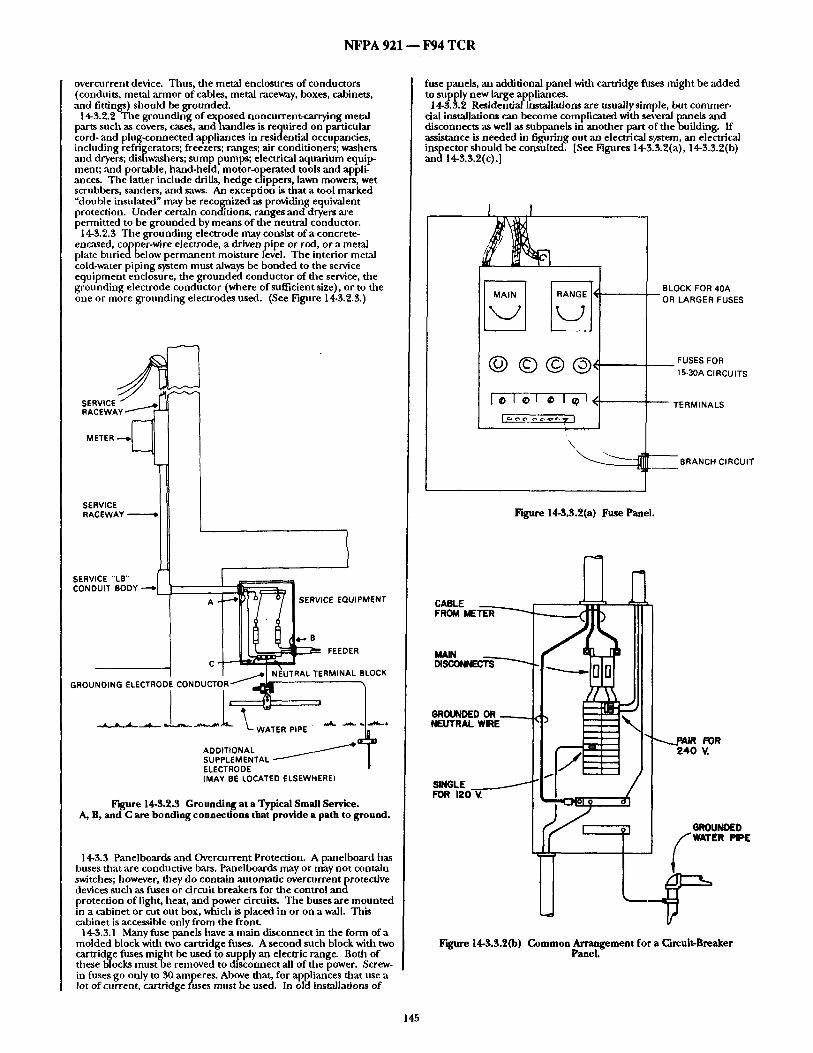
N F P A 921 - - F94 T C R
overcurrent device. Thus, the metal enclosures of conductors (conduits, metal ,armor of cables, metal raceway, boxes, cabinets, ,and fittings) should be grounded.
14-3.2.2 The grounding of exposed noncurrent-carrying metal parts such as covers, cases, and handles is required on particular cord- and plu~-connected appliances in residential occupancies, including refrigerators; freezers; ranges; air conditioners; washers and dryers; dishwashers; sump pumps; electrical aquarium equip- ment; and portable, hand-held, motor-operated tools and appli- ances. The latter include drills, hedge clippers, lawn mowers, wet scrubbers, sanders, and saws. An excepfon is that a toot marked "double insulated" may be recognized as providing equivalent protection. Under certain conditions, ranges and dryers are permitted to be grounded by means of the neutral conductor.
1 4-~.2.3 The grounding electrode may consist of a concrete- encased, copper-wire electrode, a driven pipe or rod, or a metal plate buriedbelow permanent moisture level. The interior metal cold-water piping system must always be bonded to the service equipment enclosure, the grounded conductor of the service, the grounding electrode conductor (where of sufficient size), or to the one or more grounding electrodes used. (See Figure 14-3.2.3.)
S E R V I C E ~
" 1
(MAY BE LOCATED ELSEWHEREI
Figure 14-$.2.3 Grounding at a Typical Small Service. A, B, and C are bonding connections that provide a path to ground.
14-3.3 Panelboards and Overcurrent Protection. A panelboard has buses that are conductive bars. Panelboards may or may not contain switches; however, d~ey do contain automatic overcurrentprotective devices such as fuses or circuit breakers for the control a n d protection of light, heat, and power circuits. The buses are mounted in a cabinet or cut out box, which is placed in or on a wall. This cabinet is accessible only from the front.
14-3.3.1 Many fuse panels have a main disconnect in the form of a molded block with two cartridge fuses. A second such block with two cartridge fuses might be used to supply an electric range. Both of these blocks mustbe removed to disconnect all of die power. Screw- in fuses go only to 30 amperes. Above that, for appliances that use a lot of cuiTent, cartridge fuses must be used. In old installa6ons of
fuse panels, an additional panel widl cartridge fuses might be added to supply new large appliances.
14-3.3.2 Residential installations are usuailysimple, but commer- cial installations can become complicated with several panels and disconnects ,as well as subpanels in another part of the building. If assistance is needed in figuring out an electrical system, an electrical inspector should be consulted. [See Figures 14-3.3.2(a), 14-3.3.2(b) and 14-3.3.2(c).]
I I
@ © © ® , '
BLOCK FOR 40A --OR LARGER FUSES
FUSES FOR 15-30A CI RCU ITS
[ - -~--~0 [ ~) I I~) I ~/~ ~ TERMINALS
" \ ~ - - BRANCH CIRCUIT
lrtgure 14-3.3.2(a) Fuse Panel.
CABLE FROM METER
MAIN DISCONN~'TS
GROUNDED OR , NEUTRAL WIRE
SINGLE FOR 12(
1
~--~JDAIR FOR 240 V.
GROUND~O
Figure 14-3.3.2(b) Common Arrangement for a Circuit-Breaker Panel.
145

N F P A 9 2 1 1 F 9 4 T C R
Figure 14-3.3.2(c) Photograph of a Circuit-Breaker Panel.
1 4 - 3 . 4 0 v e r c u r r e n t Protection. Overcurrent protection is provided for the purpose of open ing or d isconnect ing the circuit if the cur rent becomes excessive or if a fault occurs. In general, an overcnrrent device mus t be installed in each u n g r o u n d e d conductor ("hot" wire) of each circuit at the point where it receives its supply.
1 4 - 3 . 5 0 v e r c u r r e n t Protective Devices. The most commonly used overcurrent protective devices ,are circuit breakers and fllses. Plug fllses are of two basic types, the ordinary Edison-based type and tile S-type. Fuses larger tban 30 amperes are of the carlxidge type. Either of these may or may no t be of the t ime delay-type. [See Figures 14-3.5(a), 14-3.5(b), and 14-3.5(c).]
Figure 14-3.5(a) A Typical, Edison-based Nonrenewable Fuse, Single Element. (Bnssmann Division, Cooper Industries) For replacement
purposes only.
Figure 14-3.5(b) Another Edison-based Nonrenewable Fuse, Dual Element. (Bussmann Division, Cooper Industries) For replacement
purposes only.
Figure 14-3.5(c) A T y p e S Nonrenewable Fuse. The t ime lag type of fuse shown is acceptable but not required. These fuses have been
designed so that tampering or bridging can be done only with difficulty. NFPA 70, National Electrical Code, specifies that fuse
holders for plug fuses of 30 amperes or less shall not be used unless they are designed to use this Type S fuse or are made to accept a
Type S fuse through use of an adapter. (Bussmann Division, Cooper Industries)
14-3.5.1 S-Type Fuse. The S-type fuse is so des igned that uunper ing or bridging is usually difficult. They are des igned with adapters that fit the Edison-based fuse holders. After an adapter has been properly installed, it cannot be easily removed without damag ing the fuse bolder. The adapters are des igned to prevent the use o f Edison- based fuses in fl~e fuse holder, to prevent a larger fuse f rom being used in an adapter des igned for a lower rating, and to prevent file use of pennies and other br idging schemes. Edison-based fuses of :my size will fit Edison-based fu seho lde r s of,any size. They are no t allowed to be used on new installation and are suitable for replace- m e n t purposes only.
14-3.5.2 Time-Delay Type Plug Fuses. Whe the r of Type S or Edison-based design, the t ime delay-type fuses permi t short-t ime cur rent surges, such as starting currents for motors, without in terrupt ion of the circuit. While these momen ta ry surges can be up to 6 times greater than the motor ' s usual current , they are harmless because they last only a short time. This makes it possible to use Type S fuses in sizes small enough to give better protection than a nontime-delay type tha t mus t be oversized to allow for such surges. In the c~ase o f a silort circuit or h igh-current g r o u n d fault, however, the time-delay type fuse will operate and clear the circuit as rapidly as the nontime-delay type fuse.
14-3.5.3 Circuit Breakers. 14-3.5.3.1 Unlike fuses, which mus t be removed and replaced
before power can be restored, circuit breakers can be reset after they have tripped. The cur rent rat ing of tile breaker is usually given on the face of the handle . Breakers are des igned so that tile internal workings will trip with excessive current , even if the handle is somehow held in the on position. The on and off positions are indicated either on the handle or on the body. A circuit breaker in service canno t be manual ly placed in the t r ipped position. [See Figures 14-3.8.1 (a).] Figures 14-3.8.1(b), 14-3.8. ! (c) and
146

N F P A 921 - - F 9 4 T C R
14-3.8.1 (d) show a circuit breaker in three positions, on, offand tripped. The handle position shown at dae top of the photographs is different for each condition as are the contacts shown at tile lower left of the photographs. The arc chute which normally covers fine contact point bas been removed to permit a direct view of the conh ' tc ts .
CONNECTOR ~ ~ . . / TO BUS BA R
AMPERAGE RATING
~L--- "ON "' INDICATOR
l /~- - - CJRCUIT WIRE
Figure 14-3.5.3.1 (a) Typical Circuit Breaker.
Figure 14-3.5.3. I (b) A 15-Ampere Residential-type Circuit Breaker in the closed (on) position. (Challenger Electrlca] Equipment Corp.,
subsidiary of Westinghouse Electric Corp.)
Figure 14-$.5.3.1(e) A 15-Ampere Residential-type Circuit Breaker in the open (off) position. (Challenger Electrical Equipment Corp.,
subsidiary of Westinghouse Electric Corp.)
Figure 14-3.5.3.1 (d) A 15-Ampere Residential-type Circuit Breaker in the open (tripped) position. (Challenger Electrical Equipment
Corp., subsidiary of Westinghouse Electric Corp.)
147

N F P A 921 - - F94 T C R
1 4-3.5.3.2 Most residential circuit breakers are o f the thermal- magnet ic type. The thermal e lement , usually bimetallic, provides overload protection. T he magnet ic e l ement provides shor t circuit and g r o u n d fault protect ion for low-resistance g r o u n d faults.
14.3.5.3.3 In newer ins~'.llations, one of the breakers migh t have a but ton labeled "push to test." This circuit breaker houses a g r o u n d fault circuit in terrupter and t u r n s off with a sl ight g r o u n d fault to give better protection against electric shock. In addition, it operates as a typical circuit breaker.
14-3.5.4 Ground Fault Circuit Interrupter . A g r o u n d fault circuit in terrupter is a device in t ended for the protect ion of personnel tha t funct ions to de-energize a circuit or port ion the reof within an establisiled period o f t ime when a cur ren t to g r o u n d exceeds some prede te rmined value that is less tllan that required to operate die overcurrent protective device of file supply circuit.
1 4-$.6 Materials. This section will identify the various materials used in electrical installations and give informat ion on their properties. This section is concerned only with the fixed electrical rar ing and service equ ipment . Wiring and devices in appliances are covered in Chapter 18, Appliances.
14-3.6. l C, onductors . Conductors in electrical installations usually consists of copper or a l u m i n u m because they are economical and good conductors of electricity. Conductors made of o ther metals for special uses will be covered in Chapter 18, Appliances.
14-3.6.1.! Copper Conductors . T he chemical e l ement copper is used in a pure form to make conductors . The copper is drawn thrmlgll progressively smaller holes to squeeze it down to the desi red size. There is no identifiable crystal s tructure in such copper. Impurit ies or alloying e lements would make the copper less condnctive to electricity. Pure copper melts at 1089°(; or 1980°F. In fires, though , copper melts a long the surface of the conductor at temperatures somewhat below 1089°(; because of mixing with the co pper oxide that. forms in air. T ha t is.why cop, l~er conductors t end to mel t a long their surfaces to form pointed ends, globules, and t i t inned areas.
Copper conductors oxidize in fires when the insulat ion has been lost. The surface usually becomes blackened with cupric oxide. In some cases where the conductor was in a chemically reducing condition such asg lowing char before cooling, die surface may be either bare of oxide or be coated with a reddish cuprous oxide.
14-3.6.1.2 A lumi num Conductors . The chemical e lement a l uminum is used in pure form for conductors. Pure a l u m i n u m melts at 660°C (1220°F). A skin of a l u m i n u m oxide forms on the surface, but the oxide does no t mix with die metallic a l u m i n u m underneafl l . Therefore , the mel t ing tempera ture is no t reduced, and a l u m i n u m tends to mel t t h r o u g h o u t the conduc to r at one t ime instead of leaving a core as copper does. Melted a l u m i n u m can flow within the skin of oxide and cool to give odd silapes.
A l u m i n u m cables tha t are used for service drops may have steel s trands in the center for strength. In a triplex drop, the neutral would have the steel strand.
14-3.6.1.3 Copper-clad Conductors. Copper-cladalurrf inum conductors have been used but are not common . Since they are a l u m i n u m conductors with a skin of copper, their mel t ing character- istics would be similar to a l u m i n u m conductors .
14-3.6.2 Insulation. Insulation on wires prevents an energized wire f rom shor t ing or fault ing to some o ther wire or conductive object. Insulation could be made of a lmost any material that can be applied readily to the wire, does not conduc t electricity, and retains its properties for a long t ime even at elevated temperatures . For a summary of the types of insulation, see Table 310-13 in the National Electric (;ode. Air serves as an insulator when bare conductors are kept separated.
14-3.6.2.1 Polyvinyl chloride, or PVC, is file most commonly used thermoplast ic insulat ing material for wiring. PV(; mus t be b lended with plasticizers to make it soft. P igments and other modifiers are also ,added. PVC does not oxidize on aging, bu t it ~ slowly lose the plasticizers and become hard and brittle. Ti le hot ter the exposure and the longer the dura t ion of exposure, the more plasticizer is lost. At elevated tempera tures PVG becomes increasingly soft but does no t flow until abou t 175°(; (347°F). At Iligb tempera tures sucil as in direct fire exposure, it chars whUe giving off the corrosive gas, hydrogen chloride.
On an isolated nonmetal l ic cable or conductor at room tempera- lures, PVC insulation will no t cont inue to burn for more than a few seconds after the ignition source has been removed. Wilen many conductors ,are loosely bund led or with cables in a cable tray, small fires on eacll conductor or cable help to Ileat each other, and the fire ~ m grow and spread vertically or horizontally.
When PVC insulation is overheated, such as by ho t conductors inside, the plasticizers can be driven of fas a visible smoke. Tha t smoke can be ignited by outside sources or an arc, and the hot PVC can cont inue to burn.
14-3.6.9.9 Rubber. Rubber insulation was the most c o m m o n insulating material until abou t in the 1950's. Rubber insulation
contains p igments and various modifiers and antioxidants. In t ime it may oxidize and become britde, especially if kept hot. Embrit t led rubber has little s t rength and can be broken off of the conductor if it is ben t or scraped.
Rubber insulation on isolated conductors and cords at room tempera tures usually does not cont inue to b u m after exposure to and removal o f an ignition source because of added fire retardants and fillers. However, small residual fires in loose bundles of cords or conductors may grow and spread the fire. Rubber insulation chars when exposed to fire or very h igh tempera tures and leaves an ash when the rubber is completely b u r n e d away.
14-3.6.2.3 Other Materials. Polyethylene and closely related flPlOlyolefins are used as insulation, more commonly on large cables
inn on wiring that might be used in a home. Polyethylene has a fairly low mel t ing temperature , and so it is normally molecularly cross4inked to raise file mel t ing tempera ture and increase the toughness .
Nylon jackets are pu t a round odler insulat ing materials (usually PVC) to increase the thermal stability of the insulation.
14-3.6.3 Enclosures. Unde r most condit ions electrical wiring and equ ipmen t mus t be enclosed in some kind of protective device, especially at connections.
14-3.6.3.1 Cabinets. The service equ ipmen t (meter , main disconnect , and fuse or breaker panels) is enclosed in cabinets that are usually made of steel a l though they may be made of plastic or a luminum.
14-3.6.3.9 Raceways and Conduit . Steel, plastic and a l u m i n u m are used for raceways and conduit. Steel has good s t rength and generally will no t mel t in fires. However, because of its ability to conduct heat, it quickly allows wiring inside of it to get hot en o u g h to damage insulation in a fire. A l u m i n u m is somet imes used for conduit . It has good s t rength b u t c o n d u c t s h e a t q u i c k l y a n d m e l t s readi!y in fires. Plastic has good s t rength bu t is destroyed by fire. However, it will no t conduct hea t inside as fast as metal, and so in a very brief fire it migh t prevent fault ing in the wiring. Plastic does not conduc t electricity and so cannot be used for g r o u n d i n g as met,'d condui t can, and it cannot be involved in a g r o u n d fault.
14-3.6.3.3 Outlet and Junc t ion Boxes. Steel and plastic are used in outlet and junc t ion boxes. Most nonmetal l ic boxes are made of a the rmose t plastic that does no t cont inue to burn after the ignition source is removed. Such plastics char and burn in cont inued exposure to fire but do not melt. Some boxes are made of a thermoplast ic wbich can melt and char in the heat of a fire.
14-3.6.4 Fittings. Fittings are used to jo in sections of condui t or raceway to each other or to cabinets and boxes. The fittings are usually made of die cast a l u m i n u m or zinc. They have low melt ing tempera tures and so usually will be missing after a fire. Some fittings may have steel ring nuts or set screws which will usually survive a fire. Also, marks such as f rom set screws may be found on ends of steel condui t after a fire to indicate dlat connectors ilad been in-place at some time.
1 4.3.7 Identification of Conductors . 14.3.7.1 Grounded Conductor . A g r o u n d e d conductor , usually
called a neutral , is def ined as an intentionally g r o u n d e d system or circuit conductor . Widl few exceptions, interior wiring systems have a g rounded conductor that is cont inuously identified by an outer wtlite or natural gray color. For sizes larger than No. 6 AWG, identification may be by a distinctive wllite marking at the termina- tions.
In general , file terminals of electrical devices to which a g r o u n d e d conductor is to be connec ted are identified by being made of metal substantially white in color or having a metallic plate coating substantially wlfite in color. In the case of screw-shell type lampholders , file identified (wifite) terminal is file one that is connec ted to file screw shell.
13-3.7.9 U n g r o u n d e d Conductor . An u n g r o u n d e d conductor , often called tile ho t conductor , originates at a fnse or circuit breaker. The insulation most often is black ,although, it may be of any color except white or green. In 940 volt circuits, the two u n g r o u n d e d conductors are most often black and red. An un- g r o u n d e d condnctor a long with a g r o u n d e d conductor constitutes a 120 volt circuit. Terminals in tended for an u n g r o u n d e d conductor are made of
brass to distingnish them from file substantially white terminals of a g r o u n d e d conductor .
14-3.7.3 Equ ipment Grounding Conductor . An equ ipmen t g round ing conductor , usnally called a ground, is def ined ,as d~e conductor used to connect the noncurrent-carrying metal parts of e q u i p m e n t to the system g round ing conductor a n d t h e g r o u n d i n g electrode conductor at file service equipment .
The equ ipmen t g round ing conductor o f a branch circuit is identified by a cont inuous green color or green with one or more yellow stripes, or it may be bare. Larger condnctors may be str ipped bare for the entire exposed length or have a distinctive green marking.
148

N F P A 921 ~ F 9 4 T C R
14.3.8 Lighting and Appliance Branch Circuits. A branch circuit is that portion of a wiring system extending beyond the last overcurrent device protecting the circuit. A branch circuit for small appliances is one sup~plying one or more outlets to witich appliances are to be connected that has no permanently connected lighting fixtures and is usually protected by a 20-ampere overcurrent device. A general purpose branch circuit supplies two or more outlets for lighting and appliances and is usually protected by a 15- or 20- ampere overcurrent device. An individual branch circuit is one that usually supplies only one appliance, and overcurrent protection depends on the requirements of the device. Individual branch circuits may be 1 20 volt, 1 20/240 volt or 240 volt, and may be rated 15, 20, or 34) ampere and supply any load. (See Table 14-3.8.)
Table 14-3.8
Wire Size Ampacity Use
Copper Copper-clad aluminum and alu- minum
14 12 15 Branch circuit conductors supplying other than kitchen.
12 I0 20 25
Small appliance circuit conductors supplying outlets in kitchen for refrigerators, toasters, electric fry- ing pans, coffee makers, and similar appliances.
10 8 30 Large appliances such as ranges and dryers.
8 6 4,0
6 4 55
14-3.9 Switches. Switches are used for the control ofl ignts and appliances, and as the disconnecting means for motors and their controllers.
1 4-3.10 Receptacles. Fifteen- and 20-ampere receptacles used in recent construction must be the grounding type. They have a third hole to take a plug with a g round prong. One slot in the face of the receptacle is longer than the other. It is the "neutral" side, whereas the smaller slot is the "hot" side. Some plugs, such as on television sets, may be polarized so that they fit into the receptacle only one way. All grounding plugs are inherendypolar ized. Within the outlet box, the black insulated wire should be connected to the brass screw terminal, and the neutral wire to the silver or white screw. There is a green screw for. the grounding wire on grounding. receptacles. Nongroundmg-type receptacles may be found m older installations. [See Figures 14-3.10(a) and 14.3.10(b).]
I5 AMPERE
RECEPTACLE
I-I$R ( ~
PLUG
@ 1-15P
lrtgure 14-3.10(a) Nongrounding Type.
15 AMPERE
RECEPTACLE PLUG
20 AMPERE
RECEPTACLI" PLUG I
@ @ 5-20R .~-20P
Figure 14-3.10(b) Grounding Type.
14-4 Ignition. 14-4.1 General. For ignition to be from an electrical source, tile
following must occur: (a) Sufficient heat and temperature must have been produced at
tile point of origin by tile electrical source. (b) The electricity must imve been on or another source of
electrical energy must have been available, e.g., bau:ery hack-up, emergencypower system, other sources.
(c) T h e electrical wiring, equ ipment or componen t must have been energized.
Ignition by an electrical source involves generating both sufficiently high temperature and heat (competent ignition sovrce) by passage of electrical current to ignite material that is at the point of origin. Sufficient heat and temperatures may be generated by a wide variety of means such as electrical arcs, excessive current through wiring or equipment, resistance heating, or by ordinary heat sources such as light bulbs and heaters. The requirement for ignition is that the temperature of the electrical heat source be sustained Ionlg enough to bring the adjacent fuel up to its ignition temperature vath air present to allow combustion. (See Chapter 12)
Knowledge of the power or rate of heat generation is not sufficient by itself to identify a source of ignition. The distribution and retention of that heat must be considered. For example an electric blanket spread out on a bed can continuously dissil:ate 180 watts safely. If that same blanket is wadded up, the heating will be concentrated in a smaller space. Most o f the heat will be t rapped by the outer layers of the blanket which will lead to w~rmer internal temperatures, and the heat might no t be dissipated safely. In contrast to the 1 80 watts in an electric blanket, jus t a few watts in a small flashlight lamp will cause the filament to glow widte hog
In considering the possibility of electrical ignition, the temperature and duration of the heating must be great enough to ignite the initial fuels. The type and geometry of the fuel must be evaluated to be sure that the heat was sufficient to generate combustible vapors and for tile hea t source still to be hot enough to igtfite those vapors. If the reason for the electrical componen t to cause ~:he suspected ignition cannot be determined, then other causes should be investigated.
14-4.2 Resistance Heating. Whenever electric current flows through a conductive material, some amount of hea t will be produced. See Section 1 4-2-13 for the relationships of current, voltage, resistance and power (heating). With proper design and compliance with the codes, wiring systems and devices will have proper resistance so that the current-carryingparts :and connect ions should no t overheat Some specific parts are desig~ed to become very hot as is a lamp filament or heating element. In wiring systems by keeping resistance low with the use of copper or aluminum conductors of sufficient size (e.g. 1 2 AWG for up to 20 amperes for copper) the mild heating should cause no problenm.
Common heat-producing devices may cause fires when misused or with certain malfunctions. Examples are combustibles put too close to incandescent lamps or heaters, and coffee makers or deep fat fryers if the temperature controls fail. See Chapter 17 on appli- ances.
When there is a poor connect ion in a circuit, such as at a loose screw at a terminal, increased resistance causes heating at tile contact whid~ promotes formation of an oxide interface. The oxide conducts current and keeps the circuit functional, but the resistance of the oxide at that point is significantly greater thma in the metals. A spot o f beating develops at that oxide interface wlticb can become hot enough to glow. if combustible materials are close enough to the hot spot, they can be ignited, if the heating persists long enough, nearby insulation can fail producing a sho,x circuit or fault.
Another ~ p e c t that needs more study involves electrochemical corrosion of metals in the presence of water or moisture.
1 4 -4 .30ve rcu r ren t and Overload. Overcurrent is the condition in witich more current flows in a conductor than is allowed by the accepted safety standards. The magnitude and dur'-ttion of the overcurrent determines if there is an overload or a possible ignition
149

N F P A 921 - - F 9 4 T C R
source. An overcurrent at 25 ,amperes, for example, in a 14 AWG copper conductor, should pose no fire danger except in circum- stances that do not allow dissipation of the heat such as wllen thermally insulated or bundled in cable applications. A large overload of 120 amperes in a 14 AWG conductor, for example, would cause tile conductor to glow red ho t and could ignite adjacent combustibles. Very large overcurrents flint persist (overload) can bring a
conductor up to its melting temperature. There is a brief parting arc ,as the conductor melts in two. Tile melting opens the circuit and stops fur ther heating.
In order to get a large overcurrent, there must ei ther be a fault that bypasses the normal loads (short circuit) or far too many loads must be put on the circuit. To have a sustained overcurrent (overload), the protection (fuses or circuit breakers) must fall to open or must have been defeated. Ignition by overload is rare in circuits having the same size conductors throughout die circuit because most o f the time, die protection opens and stops further heating before ignition conditions are obtained. When there is a reduction in the conduc- tor size between the load and tile current protection, die smaller size conductor may be heated beyond its temperature rating. This can occur without activating die overcurrent protection. For example, see 14-2.16.
In a two-conductor nonmetallic sheathed cable, a short circuit, overcurrent would cause both circuit conductors to be equally heated. A fault through a g round path outside of the cable would cause only die ungrounded (hot) conductor to be heated, al though something in the ground path might be heated also. Thus for tile same amount of current, a short circuit would produce more heating in die cable than would a g round fault, Heating from a silort circuit is all within the cable instead of being partly in the external ground padx
14-4.4 Arcs. An arc is a high temperature luminous electric discharge across a gap. Temperatures within the arc are in the range of several thousand degrees depending on circumstances including current, voltage d rop and metal involved. For an arc to
j u m p even dm smallest gap in air spontaneously, dlere must be a voltage difference of at least 350 volts. In the 120/240 volt systems being considered, here, arcs do not form spontaneously under normal orcumstances. (See Static Electricity, Section 14-8)
In spite of the very high temperatures in an arc path, arcs may not be competent ignition sources for many fuels. In most cases, the arcing is so brief and localized that solid fuels such as wood strncturai members cannot be ignited. Fuels with high surface area to mass ratio, such as cotton batting and tissue paper, and combus- tible gases ,and vapors may be ignited when in contact with the arc.
144.4.1 High voltages can get into a 120/240 volt system through accidental contact between the distribution system of the power company and the system on the premises. Whether there is a momentary discharge or a sustained high voltage, an arc may occur in a device where the separation of conductive parts is safe at 240 volts but not at many thousands of volts. If easily i[{nitable materials are present along the arc padl, a fire can be started.
Liglltning can send extremely high voltage surges into an electrical installation. Because the voltages and currents from lightning strikes are so high, arcs can j u m p at many places, cause mechanical damage and ignite many kinds of combustibles. (See 14-8.8, Lightning).
144.4.2 Static electricity is a stationary charge that builds up. on some objects. Walking across a carpet in a dry a tmosphere roll produce a static charge which can produce an arc. Other kinds of motion can cause a build-up of charge including pulling off clothing, operating conveyor belts, and flowing liquids. (See Section 14-8, Static Electricity).
14-4.4.3 Parting arcs are brief discharges that occur as an energized electrical path is opened such as by turning o f f a switch or pulling a plug. The arc is not usually seen in tile switch but may be seen i fa
~ lug is pulled while the device is drawing current. Motors with rushes may produce a nearly continuous display of arcs between
the brushes and the commutator. At 120/240 volts AC a parting arc is not sustained, and will quickly be quenched. Ordinary parting arcs in electrical systems are usually so brief and of low enough energy dlat only. combustible gases, vapors and dusts can be .ignited"
In arc welding, the rod must first be toucbed to file work pJece to s t a r current flowing. Then the rod is withdrawn a small distance to create a parting arc. If the gap does not become too great, that arc will be sustained. A welding arc involves enough power to ignite nem'ly any combustible material. However, the sustained arc in a welder requires specific design characteristics not present in most parting arc situations in 120/240 volt systems.
Another kind of parting arc occurs wtlen there is a direct ground fault or a short circuit. The surge of current melts the metals at the
~ oint of contact and causes a brief parting arc as a gap develops etween the meutis. Tile arc quenches immediately, but the
explosive energy can throw particles of mel ted metal around. (See 14-4.5, Sparks).
14-4.4.4 Arcing can occur on or through a material that is not a normal part of tile circuit. When insulation has been charred by fire and the circuit is still energized, arcs may strike through the char. This is a normal consequence of a fire. (See 14-5.4, Arcing During Fires). Arcs tllat strike through charred electrical insulation do not draw
the high currents of a short circuit. Therefore, such arcs may not open the protection (fuses or circuit breakers) immediately. Continued arcing through char at thcse current levels may melt metals at the point of arcing.
14-4.4.5 Arcs may occur on surfaces of noncondu ctive materials if they become contaminated with salts, conductive dusts or liquids. It is thought that small leakage currents through such contamination causes degradation of the base material leading to the arc discharge igniting combustible materials around the arc. Arc tracking is a known p h e n o m e n o n at high voltages, however, it is still under study in 120/240 volt systems.
14-4.5 Sparks. Sparks are luminous particles that can be formed when an arc melts metal and spatters the particles away from die point of arcing. The term spark has commonly been used for a higil voltage discharge as witii a spark plug in an engine. For purposes of electrical fire investigation, the term spark is reserved for particles thrown out by ,arcs, whereas an arc is a luminous electrical discharge. Short drcuits and high current ground faults, sucll as when tile
ungrounded conductor (hot wire) touches the neutral or a ground, produce a violent event. Because dlere may be very little resistance in the short circuit, the current may be many hundreds or thousands of amperes. The energy tllat is dissipated at the point of contact is sufficient to melt tile metals involved, creating a gap and a visible arc, and throwing sparks. Protective devices in most cases will open (turn off the circuit) in a fraction of a second and prevent repetition of the event. When just copper and steel are involved in arcing, file spatters of
melted metal begin to cool immediately as theyfly through the air. However, when aluminum is involved in the faulting, the particles may actually bum as they fly and continue to be extremely hot until they burn out or are quenched by landing on some material. Burning aluminum sparks, therefore, may have a greater ability to ignite fine fuels than do sparks of copper or steel. However, sparks from arcs are inefficient., ignition sources and. can ignite only fine fuels wtlen condmons are favorable. In addition to the temperature, the size of file particles is important for the total heat content of the particles and the ability to ignite fuels. For example, sparks spattered from a welding arc can ignite many kinds of fuels because of tile relatively large size of the particles and the large total heat content.
144.6 Stray Currents Through Water. Electrical current will flow through water or moisture only when tlaat water or moisture contains contaminates such as dirt, dust, salts or mineral deposits. This stray current may compromise file integrity of electrical wiring, equipment or components. This condition may then result in that electrical wiring, equipment or components becoming an electrical ignition source.
14-5 ln terpre t ingDamage to Electrical Systems. 14-5.1 General. Electrical activity that can cause fires may produce
characteristic damage tilat may be recognizable after a fire. The damage may occur on conductors, contacts, terminals, housings or other components . However, many kinds of damage can occur from nonelectrical events or from electrical activity during a fire. This section will give guidelines for deciding if observed damage was the cause of a fire or the result of a fire. These guidelines are not absolute, and many times file physical evidence will not allow a definite conclusion.
14-5.2 Appearance of Arced and Fire Melted Conductors. When conductors are subjected to highly localized heating, such as from arcs, the ends of the individual conductors may become rounded or bave bulbous globules of resolidified molten metal. These globules are called beads. Beads can be differentiated from globules created by nonlocalized heating, such as overload or fire melting, by tile presence of a distinct and identifiable line of demarcation between the melted bead and the adjacent nonmel ted portion of the conductor.
Globules due to fire melting are irregular in shape and size, often tapered, and may be pointed. They have no distinct boundary lines of demarcation between the globule and the adjacent fire ileated conductor.
150

N F P A 9 2 1 - - F 9 4 T C R
Figure 14-5.2 Ends of the same conductor'which was exposed to h~ghly localized heating from an arc causing separation and the
bulbous globule appearance of the ends.
14-5.3 Short Circuit and Ground Fanlt Arcs. Whenever an energized conductor contacts a grounded conductor or a metal object that is grounded with nearly zero resistance in the circuit, there will be an arc discharge at the point of contact. The high current flow can melt dae metals in small a r e~ in the conductors or odaer metal objects involved producing a gap and the arc. A solid copper conductor typically appears as though it had been notched with a round file. The notch may or may not go fllrou~h the conductor. The conductor will break easily at the notctl upon
handling. The surface of the notch can be seen by microscopic examination to have been melted. Sometimes, fllere can be a projection of porous copper in file notch, ff the fault current is moderate (about 100-500 amperes), the notch will be shallow and sometimes rough looking. At low fault currents (under about 100 amperes), dae mark will be a small rough spot wifll little notching or loss of metal. The arcing faults melt tile metals only at file point of initial contact.
The adjacent surfaces will be unmelted unless fire or some oilier event causes subsequent melting. In the event of subsequent melting, it maybe difficult to identify file site of die arc. If die condnctors were insulated prior to die faulting, it will be necessary to determine how tile insulation failed or was removed and fl~e conductors came in contact with each odler, f fdle conductor or odmr metal object was bare of insulation at dm time of file faulting, fllere may be spatter of metal onto the odlerwise unmelted adjacent surfaces.
Stranded conductors, such as for lamp and appliance cords, appear to display effects from short circuits and groundfaul ts that are less consistent dlan dlose in solid conductors. A stranded conductor may exhibit a notch with only some of die strands severed, or all of the strands may be severed widl strands fused togefller or individual strands melted: Ends of individual strands may show globules that are difficult to distinguish from a bead.
Figure 14-5.3 Stranded copper lamp cord that was severed by a short circuit.
14-5.4 Arcing During Fires. Insulation on conductors when exposed to direct fire will likely be charred before being burned off. That char when exposed to fire is conductive enough to allow sporadic arcing darough die char. That arcing can leave surface melting at spots or can melt dlrough dae conductor, depending on die duration and repetition offlae arcing. There often will be multiplepoints of arcing. Several inches of conductor can be destroyedeidler by melting or severing of several small segments.
On appliance cords, lamp cords, extension cords and branch circuit conductors, arcing through die char may sever the conduc- tors. The remaining section of die conductors away from die power source becomes nonenergized. Those conductors will likely remain in dae debris widl part or all of its insulation destroyed. The remains offlae conductors between die point of arc severing and the power supply may remain energized if dae protection did not open. Those conductors can sustain further arcing through the char. Arc severing farthest from the power supply occurred first. It is necessary to find ,as mucli of die conductors as possible to determine the location of the first arc.
ff dm fault occurs in service entrance conductors, several feet of conductor may be partly melted or destroyed by repeated arcing because there is almost no overcurrent protection for die service
151

N F P A 921 ~ F 9 4 T C R
entrance. An elongated hole or series of holes ex tending several feet may be seen in the conduit . In branch circuits, boles ex tending for several inches may be seen in tbe condui t or in metal panels to which the conductor arced.
When a solid conductor is severed by arcing th rough the charred insulation it will have some form of a beaded end. See Figure 14-5.2. The bead migh t have a d iameter larger titan that of the conductor or it migh t have jus t a r o u n d e d end. T he beads are often fairly smootb but might be distorted and irregular. A c o m m o n character- istic is that the fiised metal of the bead will make an abrup t transition to the unme l t ed surface of the conductor , a ssuming no subsequen t melt ing by fire. When s t randed conductors are involved, a bead may be fo rmed that fuses most of the s t rands together at the severed end or at the point of arcing.
14-5.5 Overheat ing Connections. Metals at an overheat ing connect ion will be more severely oxidized than similar metals with equivalent exposure to the fire. The conductor and terminal parts may have pitted surfaces witere contact had been made. This effect is more likely to be seen with copper conductors and steel terminals. When brass or a l u m i n u m ,are involved at dae connect ion, file metals are more likelyto have mel ted than pitted. This mel t ing can occur from either resistance beat ing or the fire. Melted a l u m i n u m at the terminal can cause alloYing with consequen t pitting. (See section 14-6.3) 1 4-5.6 Overload. Currents in excess of rated ampaci ty produce
effects in propor t ion to the degree and durat ion of overcurrent. Overcurrents that are large enough and persist long enough to cause damage or create a dange r of fire are called overloads. U n d e r any circumstance, suspected overloads require that the circuit protection be examined. Mild overloads (about 2 times the ampacity) may cause long te rm deteriorat ion of insulation but do not cause changes in the conductor . Moderate overloads (about 2 times to 5 times ampacity) may melt the insulation at abou t 180°C (35fi°F), but any oxidation of the surface of the conductor would be masked by any subsequen t fire heating. Thus, evidence of mild to modera te overloads will likely no t be f o u n d on the conductor itself after a fi re.
However, evidence o f modera te overloads may be found on u n b u r n e d parts of rite circuit between the fire and the breaker or fltse panel if such an area exists. In tha t case, the insulation may be sleeved or mel ted off and possibly charred f rom the inside as well as melted. Sleeving is sof tened and sagged thermoplast ic conductor insulation due to beat ing of the conductor .
Overloads cause internal beat ing of file conductor . Tbis heat ing occurs in the e n t r e length a n d cross section of the conductor f rom the power source to the load. ff the overload is severe (greater than 5 times the ampacity), the conductor may become ho t e n o u g h to ignite fuels in contact with it as fire insulation melts off. Severe overloads may mel t the conductor , ff the conductor melts in two, the circuit is opened and fur ther hea t ing immediatelystops. The other places where mel t ing had started, then become frozen ,as offsets. This effect has been no ted in copper, a l u m i n u m and Nichrome conductors. See Figure 14-5.6. The f inding o f distinct offsets is a good indication of large overloads but tiley do not necessarily form with overload.
When an overload melts a conductor , the part ing arc can ignite t i m e s f rom rite PVC insulation whe reupon fire then can spread to adjacent combustibles. Such occurrences are very rare because in most instances overcurrent protect ion will open the circuit before the conductor can reach its mel t ing temperature . Evidence of overcurrent mel t ing of conductors is no t proof of ignition by tha t means. Damage du r ing a fire may cause shorts while the circuits ,are still energized.
Overload in service entrance cables is more c o m m o n than in branch circuits but is usually a result of fire. F a u l t n g in enlxance cables produces sparking. . and.mel t ing at the point of faul t ing unless. the conductors mainta in cont inuous contact to allow the susta ined massive overloads needed to mel t tile cables. Overload in entry cables usually causes only distortion or partial mel t ing of dae insulation back to the t ransformer.
14-6 Effects no t Electrically Caused. Conductors may be damaged before or dur ing a f i r e by o ther than electrical means and often fllese effects are dist inguishable f rom electrical activity.
14-6.1 Conductor Surface Colors. When the insulation is d am ag ed and removed from copper conductors by any means, hea t will cause oxidation of the conductor surface. Tha t oxidation may range from a dtin dark layer to a thicker black layer. W h e n the oxidized conductor is held u n d e r nonoxidiz ing conditions, a glaze of dark reddish cuprous oxide may be formed. Green or blue colors of copper salts may form when some acids are present. The most c o m m o n acid is hydrogen chloride that fo rms f rom decomposi t ion of PVC. These various colors are o f no value in de te rmin ing cause because they are nearly always results of fire fire condition.
14-6.2 Melting by Fire. When exposed to fire, copper conductors can reach mel t ing temperatures . At first there is blistering an d distortion of the surface. See Figures 14-6.2(a). The striations created on the surface of the wire du r ing the manufac tur ing become obliterated. The nex t stage is some flow of copper on the surface with some hang ing drops forming. Further melt ing may allow flow with thin areas (necking and drops) See Figure 14-6.2(b). In tha t circumstance, fire surface of the conduc to r tends to become smooth.
i: i!!: :i
Figure 14-6.2(a) Copper Conductors, l~re-heated to the Melting Temperature, Showing Regions of Flow of Copper, Blistering, and
No Surface Distortion.
Ftgure 14-6.2(b) Copper Conductors, Fire-heated, Showing Beads, Necking, and a Pointed End.
Figure 14-5.6 Aluminum Conductors Severed by Overcurrent Showing Offsets.
152

N F P A 921 - - F 9 4 T C R
Figure 14-6.2(e) Stranded copper conductor in which mel t ingby f'we caused the strands to be fused together.
F~ure 14-6:2(d) Aluminum cables that were melted by fire showing thinned areas, bulbous areas and pointed ends.
Figure 14-6.2(e) Aluminum cables that were melted by fire while partly protected in conduit.
With solid copper conductors, mel t ing by fire occurs first on the surface with an unme l t ed core in dae center. Tha t is caused by oxidation at the surface, thereby lowering the mel t ing t empera tu re o f the mixed metal and oxide, while the core is still pure copper. W h e n a conductor is severed by fire melting, the ends tend to be pointed because of the residual core which is the last to melt.
S t randed conductors that j u s t reach mel t ing temperatures become stiffened by the fused copper and oxide mixture on the strands. Fur ther hea t ing can let copper flow a m o n g the s t rands so that the conductor becomes solid with an irreguh'u- surface that can show where die individual strands were. Cont inued hea t ing can cause file flowing, th inn ing and drop format ion of solid conductors. Magnifi- cation is needed to see some of these effects. Large gauge s t randed conductors tha t mel t in fires can have the strands fused together by flowing metal or the strands may be t h inned and stay separated. In some cases, individual strands may display a bead-like globule even t hough the damage to the conductor was f rom melt ing.
Metallograpltic examinat ion of copper wires f rom fires will show differences in grain s tructure d e p e n d i n g on how m u c h the copper was hea ted or if it was melted. In mos t cases metal lographic examinat ion does not add mucll useful informat ion a n d t h e examinat ion required preparat ion is destructive. A l u m i n u m conductors mel t a n d resolidify into irregular shapes
which are of no value for interpret ing cause. Because of file relatively low mel t ing temperature , a l u m i n u m conductors can be expected to mel t in almost any fire and so are very rarely able to aid in f inding tile cause. Frequently there is mel t ing of componen t s that may be rile result of alloying of the metals involved (see 4-8.2).
14-6.3 Alloying. Metals such as a l u m i n u m and zinc can form alloys when mel ted in die presence o f o ther metals. I f a lun t inum drips onto a bared copper conduc tor dur ing a fire and cools, rile a l u m i n u m will be jus t lightly stuck to file copper, ff that spot is fu r ther heated by fire, the metals can penet ra te the oxide interface and form an alloy fl~at melts at a lower t empera tu re than does ei ther pure metal. After die fire an a h i m i n u m alloy spot may appear ,as a rough gray area on tile surface, or it may be a shiny silvery area. The copper -a luminum alloy is brittle, a n d the conductor may readily break if it is bent at the spot of alloying. If file mel ted alloy drips off of the conductor du r ing the fire, there would be a pit that is l ined widl alloy. The presence of alloys can be conf i rmed by chemical analysis.
153

N F P A 9 2 1 - - F 9 4 T C R
A l u m i n u m conductors that mel t f rom fire heat ing at a terminal may canse alloying and pitting of file terminal pieces. There is no clear way of visually distingalishing alloying f rom the effects of an overheating connect ion at this time.
Zinc forms a br:ass alloy readily with copper. It is yellowish in color arid not as brittle as tile a l u m i n u m alloy. These alloys or others usually have little value in interpret ing the cause of the fire.
14-6.4 Mechanical Gouges. Gouges and dents that are fo rmed in a conductor by mechanical means can usually be dis t inguished f rom arcing marks by microscopic examinat ion. Mechanical gouges will usuaUy show scratch marks f rom whatever caused tile gonge. Dents will show deformat ion o f the conductors beneadl t heden t s . Dents or ~ouges will not show tile fused surfaces of electrically caused melting.
14-7 Misconceptions and Cautions. The re ,are several ideas dlat have been c o m m o n a m o n g fire investigators which are either unproven, misconstrtled, incorrect or true unde r only limited ci r cu mstan ces.
14-7.1 Unders ized Conductors . Unders ized conductors , such as a 14 AWG conductor in a 20 ampere circuit, are somet imes t hough t to overheat and cause fires. There is a large s.'ffety factor in the allowed ampacities. Al though d~e cur rent in a 14 AWG conductor is supposed to be limited to 15 ,amperes, the extra hea t ing f rom increasing the cur ren t to 20 amperes would not necessarily indicate a fire cause. The h igher operat ing tempera ture would deteriorate tile insulation faster but would not mel t it or cause it to fall off and hare tile conductor without some addit ional factors to genera te or retain heat. The presence of unders ized conductors or overfitsed protection is no t proof of a fire cattse. See 14-2.16.
14-7.2 Nicked or Stretched Conductors . Conductors flint are reduced in cross-section by being nicked or goul~ed are somet imes thongh t to hea t excessively at die nick. C,'dculauons and experi- ments both have sbown that file addit ional beat ing is negligible. Also it is somet imes t hough t that pull ing conductors th rough condui t can stretch them like mgfy and reduce the cross-section to a size too small for the ampacity of the protection. Copper conduc- tors do not stretch that m u c h without breaking at the weakest point. Whatever s t retching can occur before tile range of plastic deforma- tion is exceeded would not cause either a significant redtlction in cross-section or excessive resistance heating.
14-7.3 Deteriorated Insulation. When dlermoplast ic insulation deteriorates with age and heating, it tends to become brittle and will crack if bent. Those cracks do not allow leakage cur ren t unless conductive solutions get into the cracks. Rubber insttlation does deteriorate more easily than thermoplast ic insulat ion and loses more mechanical s trength. Thus , rubber insulated Imnp or appliance cords that are subject to being moved can become hazardous because of embri t t ied insulation breaking off. However, s imple cracking of rubber insulation as with thermoplast ic insulation does not .allow leakage of cur ren t unless conductive solutions get into the cracks.
14-7 .40verdr iven Staple. It is somet imes t h o u g h t that staples driven too hard over nonmetal l ic cable cause heating. Tile . l} ' s u ~ )ositions include induced currents because of the stap.le being too close to the conductors to actnally cut t ing th rough the msulat ion to touch the conductors. A properly installed cable staple with a f lat tened top cannot be driven th rough the insulation. If the staple is hent over, die edge o f it can be driven th rongh the insulation to contact tile conductors. In that G'Lse a short circuit would occnr. Tha t c i rcumstance should be evident ,after a fire by ben t points of the staple and by melt spots on file staple and conductors . The short ing should open the protection and prevent any fur ther faulting. There would not be any cont inued hea t ing of the contact, only a fault or noth ing .
14-7.5 Short Circtfit. It is often t hough t that a shor t circuit in wiring on a branch circuit would ignite insulation on the conductors and allow fire to propagate. Normally, the quick flash of a par t ing arc prior to operat ion of the circuit protection canno t hea t insulation enough to genera te ignitable fumes even though the temp_erature of the core of the arc may be several t housand degrees.
14-7.6 Beaded Wire. It is a misconcept ion to believe that a bead on the end of a conduc tor in and of itself indicates file canse of the fire.
14-8 Static Electricity. 14-8.1 Introduct ion to Static Electricity. Static electricity is tile
electrical charging o f materials t h rough physical contact and separation, and tile various effects that result f rom tile positive and rmg~ttive electrical charges fo rmed by fills process. This is accom-
p lished by the transfer of electrons (negatively chaqjed) between odies, one giving lip electrons and becoming positwely charged
and the other gaining electrons and becoming oppositely, but equal/y, negatively charged.
C o m m o n sources of static electricity include: (a) Pulverized materials passing t h rough chutes or pneumat ic
conveyors,
(b) Steam, air, or gas flowin~ f rom any opening in a pipe or hose, when tile s team is wet or tile mr or gas s t ream contains particulate matter,
(c) Nonconduct ive power or conveyor belts in motion, (d) Moving vehicles, (e) Nonconduct ive liqnids flowing d l rough pipes or splashing,
pouring, or falling, (f) Movement of clothing layers against each other or contact of
footwear with floors and floor coverings while walking, (g) Thunde r s to rms which produce violent air currents an d
t empera tn re differences which move water, dust, and ice crystals creat ing lightning, and
(h) Motions of all sorts that involve changes in relative position of contact ing surfaces, usually of dissimilar liquids or solids.
14-8.2 Generat ion of Statlc Electricity. The genera t ion of static electricity canno t be prevented absolutely, bu t this is of little consequence becanse dm deve lopment o f electrical charges may not .in itseff b e . . a potential fire.or explosion hazard. For there. . to be an i g m u o n there mus t be a discharge or sudden recombmataon of the separated positive and negative charges in the form of an electric arc in an ignitable a tmosphere .
When an electrical charge is present on tile surface of a noncon- duct ing body, where it is t rapped or p revented f rom escaping, it is called static electricity. An electric charge on a conduct ing body which is in contact only wifll nonconductors is also prevented from escaping and is therefore nonmobi le or "static". In either case, the body is said to be "charged." The charge may ei ther positive (+) or negative (-).
14-8.2.1" Ignitable Liquids. Static is genera ted when liquids move in contact wkh o ther materials. This common ly occurs in operations such as flowing th rongh pipes, and in mixing, pouring, pumping , spraying, filtering, or agitating. Unde r certain conditions, particu- larly with liqnid hydrocarbons, static may accumula te in the liquid. If the accumulat ion of charge is sutticient, a static arc may occur. If die arc occurs in the presence of a f lammable vapor-air mixture, an ignition may resnlt.
Filtering with some types of clay or microfilters substantially increases the ability to genera te static charges. Tests and experience indicate that some filters of dais type have the ability to generate charges 100 to 200 t imes h igher than achieved without such filters.
The electrical conductivity of a liquid is a measure of its ability to create, accnmnlate , and hold a charge. The lower the conductivity, tile greater the ability of tile liquid to create and hold a charge. C o m m o n liquids tha t have low conductivity and therefore represent a hazardous static potential are given in Table 14-8.2.1. For compar ison distilled water has a conductivity of 100,000,000 Pico- Siemen.
Table 14-8.2.1 Common liquids that have low conductivity.
Conductance per meter Twical Conductivity Product in Pico,giemen*
Highly purified hydrocarbons A 0.01 Light distillates A 0.01 to 10 Commercial j e t filel B 0.2 to 50 Kerosene B 1 to 50 Leaded gasoline B above 50 Fuel with Anti-static additives B 50 to 300 Black oils A 1,000 to 100,000
A API 2003 Protection Against Ignitions Arising Ou t of Static, Lightning, and ,Stray Currents.; B Bustin, W. M. and Dukek, W. G. Electrostatic Hazards in Petroleum Industry. * Pico-siemen is the reciprocal of ohms.
14-8.2.2 Charges on the Surface of a Liquid. If an electrically charged liquid is poured, pumped , or otherwise t ransferred into a tank or container, file unit charges ofs imi larpolar i ty witllin the liquid will be repelled f rom each other t oward the outer surfaces of the liquid, including not only tile surfaces in contact with tile container walls bu t also the top surface adjacent to the air or vapor space, if any. It is the latter charge, often called the "surface charge," fllat is of most concern in manysi tuat ions . In most cases the container is of metal, ,and hence electrically conductive.
Even if the tank shell is g rounded , the t ime for dae charge to dissipate, known as relaxation time, may be as little as a few seconds up to several minutes . This rel,'txation time is d e p e n d e n t upon the
154

N F P A 921 ~ F94 T C R
conductivity of tile liquid and the rate and manner that the liquid is being introduced into die tank, dlerefore the rate at which die electrostatic charge is being accumulated.
If the electrical potential difference between any part o f rile liquid surface and the metal tank shell should become high enough, tile air above tile liquid may become ionized and an arc may discharge to tile sheU. However, an arc to the tank shell is less likely dlan an arc to some projection or to a conductive object lowered into die tank. These projections or objects are known as spark (arc) promoters. No bonding or grounding of the tank or container ~ua remove diis internal charge.
If the tank or container is ungrounded the charge can also be transmitted to die exterior of the m k and can arc to any g rounded object brought into proximity to die now charged tank external surface.
14-8.2.3 Switch Loading. Switch loading is a term used to describe a product being loaded into a tank or compar tment which previ- ously . . . . . . held a product o f different vapor pressure and flash poinL Switch . . . . . loading can result in an ~gnmou when a low vapor pressure/ lugher flash point product, such as d i d od, ~s put into a cargo tank conta in inga flammable vapor from a previous cargo, such as gasoline. Discharge of the stadc normally developed during the filling man ignite the vapor air mixture remaining from the low flashpoint liquid.
14-8.2.4 Spraying Operations. High pressure spraying of il,gnitable liquids such as in spray painting can produce significant stauc electric charges on the surfaces being sprayed and the ungrounded spraying nozzle or gnn.
If the material being sprayed can create an ignitable atmosphere, such as with paints utilizing flammable sol;cents, a static discharge c~an ignite tile fuel air mixture.
In general, high pressure ,airless spraying apparatus has a higher possibility for creating ckmgerous accumulations of static than low pressure compressed air sprayers.
14-8.2.5 Gases. When flowing gas is contaminated with metallic oxides or scale particles, dust, or wida liquid droplets or spray, static electric accumulations may result. A stream of particle-containing gas directed against a conductive object will charge die object unless die object is grounded, or bonded to the liquid discharge pipe. If the accumulation of charge is sufficient, a static arc may occur. If the arc occurs in the presence of an ignitable atmosphere, an ignition may result.
14-8.2.6 Dusts and Fibers. Generation of a static charge can happen during handl ing and processing of dusts and fibers in industry. Dust dislodged from a surface or created by die pouring or agitation of dust producing material, such as grain or pulverized material, can result in the accumulation of a static charge on any insulated conductive body widl which it comes in contact, The minimum electrical energy required to ignite a dust cloud is
typically in the range of 10 to 100 millijoules. Thus many dusts can ignite with less energy than might be expended by a static arc from machinery or die human body.
14-8.2.7 The Human Body. The human body can accumulate an electric charge that in dry atmospheres (less than 50 percent relative humidity) can be as high as several thousand volts.
14-8.2.8 Clothing. Outer garments can build up considerable static charges when layers of clothing are separated, when moved away fron~ the body, or removed entirely, particularly when of dissimilar fabrics. For some materials (particularly synthetic polymers) a n d / o r low humidity conditions, an electrostatic charge may be accumu- lated. The use of synthetic fabrics and the removal of outer garments in ignitable atmospheres can become an ignition source.
14-8.3* lncendive Arc. An arc which has enough energy to ignite an ignitable mixture is said to be incendive. A nonincendive arc does not possess the energy required to cause ignition even if the arc occurs widlin an ignitable mixture. An ignitable mixture is commonly a gas, vapor of an ignitable liquid, or dust.
When the stored energy is high enough, ,and the gap between two bodies is small enough, the stored energy is released, producing an arc. The energy so stored and released by die arc is related to tile capacitance of the charged body and tile voltage in accordance with the following formula:
CV 2 Es = ~ where
Es = Energy in Joules ~ Capacitance in farads
V ~ Voltage in volts
Static arc energy is typically reported in thousandths of a Joule (millljoules or mJ).
14-8.4 Ignition Energy. The ability of an arc to produce ignition is governed largely by its energy and file minimum ignition energy of the exposed fuel. Tile energy of file static arc will necessarily be some traction of its total s tored energy. Some of the total s tored energy will be expended in heating the electrodes. With fiat plane electrodes the min imum arc voltage to j u m p a gap (~.01 mm) is 350 volts. Increased gap widths, require.p roportionately, larger voltages, for example 1 mm requires approximately 4500 volts.
Though as little as 350 volts is required to arc across a small gap, it has been shown by practical and experimental experience that becanse of heat loss to the electrodes, arcs arising from electrical potential differences of at least 1500 volts are required to be
cendive. See Table 3-3.4, Ignition Properties of Selected Materials, and Table 13-12.2, Typical Explosion Clmracteristics, for minimum ignition energies.
Dusts and fibers require a discharge energy of 10 to 100 times greater dlan gases and vapors for arc ignitions of opt imum mixtures with air.
14-8.5 Controlling Accumulations of Static Electricity. A static charge can be removed or can dissipate naturally. A static charge cannot persist except on a body that is electrically insulated from its surroundings.
14-8.5.1 Humidification. Many commonly encountered materials which are not usually considered to be electrical conductors, such ,as paper, fabrics, carpet, clodfing and cellulosic and other dusts contain certain amounts of moisture in equUibrium with the surroundinl{ atmosphere. The electrical conductivity of these materials is increased in proport ion to the moisture content o f the material which depends on the relative humidity of die surrounding atmosphere.
Under conditions of high relative humidity, 50 percent or higher, these materials and the a tmosphere will reach equilibrium and contain enough moisture to make tile conductivity adequate to prevent significant static electricity accumulations. With low relative humidities of approximately 30 percent or less these materials dry out mad become good insulators so static accumul:,tious are more likely.
Materials such as plastic or rubber dusts, or machine drive belts, which do not appreciably absorb water vapor can remain insulating surfaces and accumulate static charges even d~ougla the relative humidity approaches 100 percent.
The conductivity of tile air itself is no t appreciably increased by humidity.
14-8.5.2 Bonding and Grounding. Bonding is the process of electrically connecting two or more conductive objects. Grounding is the process of electrically connect ing one or more conductive objects to ground potential, and is a specific form of bonding.
A conductive object may also be grounded by being bonded to another conductive object which is already at groutad potential. Some objects, such as underground metal pipe or large metal tanks resting on the earth, may be inlaerentiy grounded by their contact with the eardx
Bonding minimizes electrical potential differences between objects. Grounding minimizes potent ialdifferences between objects and die earth. Examples of these techniques include metal to metal contact between fixed objects, and pickup brushes between moving objects and earth.
Investigators should no t take tile conditions of bo ading or . grounding for granted just by the appearance or contact of the objects in question. Specific electrical testing shou/Id be done to confirm die bonding or grounding conditions.
If static arcing is suspected as an ignition source, examination and testing of the bonding, grounding or odler conductive padts should be made by qualified personnel using die criteria in NFPA 77, Recommended Practice on Static Electricity.
14-8.6 Conditions Necessary for Static Arc Ignition. In order for a static discharge to be a source of ignition, five conditions must be fulfilled:
(a) There must be an effective means of static charge generation, (b) There must be a means of accumulating and maintaining a
charge of sufficient electrical potential, (c) There must be a static electric discharge arc of sufficient
energy (see 12-3), (d) There must be a fuel source in the appropriate mixture widl a
minimum ignition energy less titan die energy of the static electric arc (See 12-4).
(e) The static arc and fuel source must occur together in the same place and at file same time.
14-8.7 Investigating Static Electric Ignitions. Often the investiga- tion of possible static electric ignitions is dependen t upon the discovery and analysis of circumstantial evidence and the elimination of other ignition sources, raffler than on direct physical evidence.
In investigating static electricity as a possible ignition source, the investigator should identify whether or not file five conditions necessary for ignition existed.
155

N F P A 9 2 1 - - F 9 4 T C R
Ar~ analysis must be made of tile mechanism by which static electricitywasgenerated. This analysis should inchlde the identifica- tion of the materials or implements which caused the static accumulation, die extent of their electrical conductivity, and dleir relative motion, contact and separation, or by means by which electrons are exchanged.
The means of accumulating cbarge to sufficient levels where it can discharge in the form of an incendive arc should be identified. The states of bonding, grounding, and conductance of the material which accumulates the charge or to wilich file arc discharges, should be identified.
Local records of meteorological conditions, including relative bumidity, should be ob t a inedand the possible influence on static accumulation or dissipation (relaxation) considered.
Tile location of die static electric arc should be de termined as exactly as possible. In doing so, there is seldom any direct physical evidence of the actual discharge arc, if it occurred. Occasionally tbere ,xre witness accounts which describe the arc taking place at the time of the ignition. However, the investigator should endeavor to verify witness accounts through ,analysis of physical ,and circumstan- tial evidence.
The investigator should determine if the arc discharge could have been of sufficient energy to be a competent ignition source for file initial fuel.
The potential voltage and energy of the ,arc in relation to die size of tile arc gap should be de termined to determine if the incendive arc is feasible.
The possibility for the incendive arc and the initial fuel (in tile proper configuration and mixture) to exist in the same place at the same time should be established.
14.8.8" Lightning. Lighming is another form of static electricity in which file charge builds up on and in clouds, and on file earth below. Movement of water droplets, dust, and iceparticles in tile violent winds and updrafts of a thunders torm buildup a polarized electrostatic charge in the clouds. When sufficient charge builds up, a discharge occurs in file form o f a ligiltning stroke between the charged cloud and objects of different potential.
Lightning strokes may occur between clouds or between clouds and the earth. In the latter, charges of opposite polarity are generated in tile cloud while the charge in the ground below the cloud is induced by the cloud charge. In effect, file result is a giant capacitor, and when the charge builds up sufficiently, a discharge occurs.
14-8.8.1 Lightning Bolt Characteristics. Typically l ighming bolts have a core of energy plasma 1/2 to 3 /4 inch in diameter, sur- rounded by a 4 inch tr ick channel of superheated ionized air. Lightning bolts average 24,000 amperes but can exceed 200,000 amperes and potentials can range up to 15,000,000 volts.
14-8.8.2 Lightning Strikes. Lightning tends to strike the tallest object on fl~e ground in the path of its discharge. Lightning enters structnres in four ways:
(a) By striking a metallic object like a TV antenna, a cupola, or an air-conditioning unit extending up and out from the building roof,
(b) By directly striking tile structure, (c) By hitting a nearby tree or other tall strucmre and moving
horizontally to the building, and (d) By striking nearby overhead wires ,and being conducted into
buildings along die normal power lines. The bolt generally follows a conductive path to ground. At points
along its path file main bolt may divert, for example from wiring to plumbing, particularly if underground water piping is used as a grounding device for die structure's electrical system.
14-8.8.3 Lightning Damage. Damage by l ighming is caused by two characteristic properties: first, the extremely high electrical potentials and energy in a lightning stroke; andsecond , the extremely high heat energy and temperatures generated by the electrical discharge. Examples of dlese effects are as follows:
(a) A tree may be shat tered by the explosive action of the lightning stroke striking die tree and the heat immediately vaporizing the moisture in tile tree into steam causing explosive effects.
(b) Copper conductors not des igned to carry die thousands of amperes of a lightning stroke may be melted, severed, or completely vaporized by the overcurrent effect of a lightning discharge. It is also characteristic for electrical conductors which have experienced significant overcurrents to become severed and disjointed at numerous locations along their length, due to the extremely powerful magnetic fields generated by such overcurrents.
(c) When l ighming strikes a steel reinforced concrete building, the electricity may follow the steel reinforcing rods as tile least resistive conductive path. The high energy and high temperature may destroy tile surrounding concrete with explosive forces.
Appendix A for Chapter 14 A-I 4-8.Z1 For more information on static in ignitable liquids, see
APt 2003, Protection Against Ignitions Arising Or"- it of Static, Lightning, and Stray Currents.
A-14-8.2.3 For more information on switch loading, see NFPA 30, Flammable and Combustible Liquids Code, ,Section 5-4.4, "Loading and Unloading Operations"; NFPA 385, Standard for Tank Vehicles for Flammable and Combustible Liquids, Appendix A, "Precautions against Ignition byStatic Electricity"; APl 1004, Bottom Loading and Vapor Recovery for MC-306 Tank Motor Vehicles; and API 2013, Cleaning mobile Tanks in Flammable or Combustible Liquid Service.
A-I 4-8.3 For more information, see NFPA 77, Recommended Practice on Static Electricity. A-14-8.8 For additional information, see NFPA Fire Protection
Handbook, Section 2, Chapter 32. SUBSTANTIATION: The committee has developed tills new chapter to incorporate material in NFPA 907M, Manual for tile Determination of Electrical Fire Causes. A task group was assigned to review the material in NFPA 907 and make recommendat ion to the Fire Investigation Committee as to how to integrate it into NFPA 921. While file bulk of the material is in this new chapter, other chapters have been revised to reflect this integration. The task group also suggested technical changes to die material to update tile information and add new technical information. The committee feels it is better to cover all aspects of fire investiga-
tion in one document than to bave separate subjects covered in separate documents. NFPA 907M will be withdrawn. COMMI'VI'EE ACTION: Accept.
(Log #CP13)
921- 63 - (Chapter 15 (New)): Accept $UBM]TTEI~ Technical Committee on Fire Investigations, RECOMMENDATION: Add a new chapter to NFPA 921 on "Investigation of Motor Vehicle Fires." The text of the chapter is as follows:
Chapter 15 Investigation of Motor Vehicle Fires 15-1 Introduction. This chapter deals with factors related to tile
investigation of fires involving motor vehicles. Included in this discussion are automobiles, trucks and recreational vehicles (motor homes). While vehicles that travel by air, on water or on mils are not covered, there are many factors relating to incident scene documen- tation, fuels, ignition sources and ignition scenarios that may apply.
The burn or d,'unage patterns remaining on the body panels and in the interior of the vehicle are often used to locate the point(s) of origin and for cause deterrrfination.
It was once felt dlat rapid fire growth and extensive damage was indicative of an incendiary fire. However, fills indicator was based on automobile construction, especially those produced prior to 1979, which did not include the type and quantity of combustible materials found in automobiles today. These materials when burned can produce this degree of damage without tile intentional addition of anodler fuel such as gasoline. I n the case of a total burnout, one ~ n n o t normally conclude whether or not tile fire was incendiary on the basis of observations of the vehicle alone. The use of fire patterns or degree of fire damage to determine a point of origin or cause should be used with caution. The interpretations drawn from these patterns should be verified by witness evidence, laboratory analysl"s, service records indicating mechanical or electrical faults or factory recall notices. The investigator should also be familiar with the composition of tile vehicle, and its normal operation. See Chapter 4. The relatively small compar tment sizes of vehicles may result in
more rapid fire growth given die same fuel and ignition source scenario, when compared to the larger compartments normally found in a sm~cture fire. However, the principles of fire dynamics are file same in a vehicle as in a structure and, fllerefore, file investigative methodology should be file same. See Chapters 2 and 3.
15-2 Fuels in Vehicle Fires. A wide variety of materials and substances may serve as tile first materials ignited in motor vehicle fires. These include engine fuels, transmission fluids, coolants and the vehicle interior materials or cargo. Once a fire is started, any of these materials may contribute as a secondary fuel affecting the fire growth rate and ultimate damage sustained.
15-2.1 Liquid Fuels. Liquid fuels are often associated with vehicle fires as they are almost universally present. These fuels may come in contact with an ignition source as tile result of a malfunction of one of the vehicle systems, an accident involving fuel release or an incendiary act. Table 15-2.1 provides some of file properties of commonly encountered liquid fuels.
Whether a given fuel can actually be ignited depends not only on its flash point and ignition temperature, but on die nature of the ignition source and the physical state of the fuel at die time of contact with file ignition source. Ignitable liquids in vehicles may be
156

N F P A 921 - - F94 T C R
already hea ted at tile t ime of their release due to the mode of use or they may contact ho t engine or exhaus t componen t s after release. In such cases, less ignition energy is required and ignition may result even though file ambien t t e m p e r a t u r e i s below the publ ished flash point for the liquid. Liquids that are released as sprays or fine mists are more likely to ignite than the same material in the bulk form. See Chapter ~ for addit ional informat ion on the process of ignition.
Table 15-2.1 Properties of Ignitable Liquids in Motor Vehide Fires
Flash Pt 3LL~
Brake Fluid C 240-$55 (115-179)
Brake Fluid D 298 (148)
Ethylene Glycol (100%) B 232 (111)
Ethylene Glycol (90%) B 270 (132)
Diesel #2D E 126-204 (52-96)
Kerosene 01 Fuel Oil E 100-162 (38-72)
Gasoline- 100 octane E -36 (-38)
Methanol E 52 (11)
Motor Oil A 410-495 (210-257)
Trans Fluid A 350 (177)
Trans Fluid D Dextron lIE 361-379 (183-193)
Dextron I1 367 (186) Type F (Ford) 347 (175)
Power Steering Fluid A 350 (177)
Ign Temp Flam Range % Boll Point Lower ]J~sr YY_(~
775 (413) 3.3
494 (257)
410 (210)
853 (456)
867 (464)
500-700 (260-371)
485 (252)
387 (197)
410-417 (210-214)
414 (212)
0,7 5.0 304-574 (151-301)
1.4 7.6 100-400 (38-204)
7.8 86.0 147 (64)
The data provided in this table is for generic or typical products .and .n~y not represent @e values for a specific product. When possible, values specific to the product involved should be obtained from a Material Satety Data Sheet or vy test.
References: The above information is from various sources within published literature: A - Automobile Collision Fires: D. M. Severy, D. M. BlaisdelI, J. F. Kerkhoff, SAE 741180 (1974) B - Industrial Solvents Handbook: 4th Ed,, Noyes Data Corp., Park Ridge, N.J., 1991, P.416 C - Flash Point Index of Trade Name Liquids, N FPA SPP 51 (1978) P. i g2 D - Dam provided by UNOCAL Lub Oils and Greases Div. E - NFPA 325M, Fire Hazard Properties of Flammable Liquids, Gases, and Volatile Solids, 1991 ed.
Vapor Density
1.1
15-2.2 Caseous Fuels. Alternate motor fuels, no t ab lyp ropane and compressed natural gas, ,are f ind ing increasing use in neets of automobi les and in trocks as well as some privately owned vehicles. The use o f dlese fuels is expected to increase in die future, a long with the in t roduct ion o f hydrogen. Propane is also found aboard the majority of recreational vehicles as a cooking, heat ing and refrigeration fi~el. Hydrogen and oxygen can be f o u n d in associa- t ion ~Rh wet cell lead acid batteries and may be released du r ing charging or as a consequence of a collision. Some propert ies of gaseous fuels are given in Table 15-2.2.
Table 15-2.2 t Gaseous Fuels in Motor Vehicles
Gas Ign Temp Boil Pt Flare Range % Vapor Dens YZ.(X3_ 2Et2_~ Lower !2pmr ~fire.tZ--
Hydrogen 932 (500) -422 (-252) 4.0 75.0 0.1 Natural Gas (Meth,'me) 999 (537) -259 (-162) 5.0 15.0 0.6 Propane Gas 842 (450) -44 (.42) 2.1 9.5 1.6
t From NFPA 325M F'we Hazard Properties of Flanunable Liquids, Gases, and Volatile Solids The data provided in this ruble is for generic or typical product and may not represent the values fDr a specific product. When possible, values specific to the product involved should be obtained from a Material Safety Data Sheet or by test.
157

N F P A 9 2 1 ~ F 9 4 T C R
15-2.3 Solid Fuels. Solid fuels are less c o m m o n than liquids and gases as the first materials ignited in motor vehicle fires except in scenarios where overloaded wiring or smoking materials are possible ignition sources or the vehicle is subjected to ,an exposure fire. Frictional heat ing may also be an ignition source involving drive belts, bearings or tires. Given even a small initial fire, solid fuels may significantly contr ibute to the speed of the fire growth and spread the extent of damage. Plastic materials can burn with heat release rates similar to those of ignitable hydrocarbon liquids. Metals such as a l u m i n u m and magnes ium and their alloys can also burn in vehicle fires adding additional fuel.
Investigators should no t interpret the presence o f mel ted metals to be an indicator of the use of an ignitable liquid as an accelerant in the belief that only an ignitable liquid can produce sufficiendy high temperatures . Melting tempera tures given in handbooks and in dlis guide are for d~e pure metal unless od~erwise stated. In m a n y cases, alloys are used rather than die pure metal. T he mel t ing tempera- ture of an alloy is generally less than that of its consti tuents. The actual composi t ion of a metal part and its mel t ing tempera ture should be de te rmined before drawing any conclusions f rom die fact that it has melted. Some properties and uses of solid fuels are given in Table 15-2.3.
15-3 Ignition Sources in Motor Vehicle.Fires. In most instances, the sources of i~ni t ion energy in motor vehicle fires are die same as those associatedwith structural fires, arcs, overloaded wiring, open flames and smoking materials for example. There are, however, some unique sources dlat should be considered such as tile ho t surfaces o f the catalytic converter, tu rbocharger and die manifold. Because some of these ignition sources may be difficult to identify following a fire, die following descript ions are provided to assist in their recognition.
15-3.1 Open Flames. The most c o m m o n open flame in a carbu retted vehicle is caused by a backfire th rough the carburetor. Ignition will rarely occur if the air c leaner is properly in place. Most vehicles today, however, use a fuel injection system which eliminates the need for a carburetor. Lighted matches in ash trays may ignite debris in the ash tray result ing in a fire that exposes combustible plastic dash or seat materials. In recreational vehicles appl iance pilot f lames or operat ing burners and ovens are open flame ignidon s o u r c e s ,
1 5-3.2 Electrical Sources. The primary source of electrical power in a vehicle is the battery. Wifll no battery, fllere can be no o ther electrical source of energy. With a battery, however, consistent energy can be p roduced by the genera to r or al ternator which is more than suflficient to cause a fire. Overcurrent protection devices such as fuses, circuit breakers, or fusible links are used on motor vehicles to provide safety. However, in some cases, breakdown of parts, improper use or installation of additional equ ipm en t can defeat these safeguards.
15 -3 .2 .10ver loadedWir ing . Un in t ended high resistance faults in wiring can raise the conductor tempera ture to file ignition point of tlae insulat ion, particularly in bundled cables such as the wiring harnesses or the accessory wiring u n d e r the dash where the hea t gtlenerated is no t readily dissipated. This can occur without activating
le circuit protection. Faults and mechanical failures of high cur rent devices such as power seat or window motors can also result in ignition of insulation, carpet materials or combustible debris that mayaccumula t e unde r seats. Pre-fire history o f electrical malfunc- tion may be a clue.
15-3.2.2 Electrical Arcing. In post-crash situations, arcs can be
~ enera ted dwough the c rush ing or cutt ing of wires, particularly attery and starter cables whiclt are not electrically protected and
are des igned to carry high currents. The large a m o u n t of energy available in a battery can be enough to ignite materials such ,as engine grease, some plastic materials, and electric insulation. Significant arc ing can also occur a long with the crushing of the battery or batteries.
15-3.2.3" Lamp fi laments of Broken Bulbs. Lamp fi laments of broken bulbs are also a source of ignition energy especially for gases, vapors, or liquid fuels in a spray or mist form. Normally operat ing head lamp f i laments have tempera tures on the order of 2550°F (1400°C).
Table 15-2.3 Solids Fuels in Motor Vehicle Fires
Material Ignition Temp Melting Point °F (°C) °F (°C)
Acrylic Fibers 1040 (560) 8 122 (50) B
Ahuninum Alloy 1031 (555) E* 1050 - 1200 A (566 -650)
ABS 871 (466) B 230- 257 C (110-1~5)
Fiberglass (Polyester resin) 1040 (560)B (220-260) 428- 500 (2
Magnesium AZ31B Alloy 1153 (623) E* I i 60 (627) A
Nylon A 790 (421) B (424-532) 349-509 C (176-265)
Polyethylene 910 (488) F 251 - 275 G (122 - 135)
Polystyrene 1063 (573) F 248- 320 G (120- 160)
Polyurethane-Foam 852 -1074 F (456- 579)
Polyurethane-Rigid 590 (310) B 248-320 C (120- 160)
Vinyl (PVC) 945 (507) F 167-221G (75-105)
* pure met.'d
C o m m e n t
Trim, engine parts
Body Panels - may be completely eonsmned,
Resin burns but not glass body panels
Wheels, trim
Trim, window gears, iming gears
Wiring insulation
Insulation, padding, trim
Seats, arm rests, padding
Trim
Wire insulation, upholstery
The data provided in this table is for generic or typical product and may not represent the values for a specific product. When possible, values specific to the product involved should be obtained from the manufacturer or by test.
A - Handbook of Chemistry .and Physics, 71st edition CRC Press, Boca Raton, 1990-1991 B - Hilado, c~ariosJ., Fkunmability Handbook for Plastics, 4th ed., Technomic Publishing Co. 1990 C - Guide to Plastics, McGraw Hill, Inc. New York, 1989 D - Marks Standard Handbook for Mechanical Engineers, Eighth Edition, McGraw Hill, Inc., New York E - Fire Protection Handbook, Table $-13A, NFPA (17 edition 1991) F - Fire Protection Handbook, Table A-6, NFPA (17 edition 1991) G - Plastics Handbook, 1986-1987 edition, McGraw Hill, Inc., NewYork, October 1986
158
N F P A 9 2 1 ~ F 9 4 T C R
15-3.2.4 External Electrical Sources Used in Vehicles. While most electrical sources in vehicles are serf-contained, there are situations wilere electrical power is provided from commercial facilities. Examples of these sources are electrical hook-ups used in recre- ational vehicles, trailers, or electric heaters for engines and vehicle interiors. Inspection for electrical power cords should be made when applicable, since an overload of die cord or failure of the appliance could be die cause of the fire. Where recreational vehicles are connected to commercial power, die branch circuit wiring should be inspected for indications that it was a possible ignition source.
15-3.3" Hot Surfaces. Exhaust manifolds and components can generate sufficient temperatures to ignite diesel spray and to vaporize gasoline. Automatic transrm'ssion fluid, particularly if heated due to .an overloaded transmission, can ignite on a hot manifold. Engine oil and certain brake fluids (DOT 3 and 4) dropping on a hot manifold can also ignite. The internal compo- nents o f a catalytic converter have operating temperatures in the range of 1292°F (700°C) under normal operation and can be much higher if unburned fuel is introduced due to afuel or ignition system malfunction. External temperatures of these converters can reach temperatures of O00°F (315°(3) under normal operation and higher where ventilation or air circulation is restricted.
15-$.4" Mechanical Sparks. Metal to pavement sparking can generate enough energy to ignite liquid fuel vapors or gaseous fuels. Sparks generated at speeds as low as 8 k m / h (5 mph) have been de termined to have temperatures of 1470°F (800°C) (orange sparks). Higher speeds have produced temperatures of 2190°F (1200°C) (white sparks). Sparks can also be caused by moving parts snch ,xs pulleys rubbing against otiler metallic objects. Sparks from tools striking metals seldom cause ignition.
15-3.5 Smoking Materials. Modern upholstery fabrics and materials are treated with flame retardant and are generally difficult to ignite widi a cigarette. Ignition may occur i fa lit cigarette becomes buried in a crevice between seat cushions, paper, o ther debris or if the seat material comes in contact with open flame.
15-4 Recording Motor Vehicle Fires. The same general tech- niques are employed for vehicles that are used for structural fires. Whenever possible, die vehicle should be examined in place at the scene. However, the investigator may no t have d ie opportunity to view die vehicle in place or at die fire scene.' For many reasons, die vehicle may have to be moved before the investigator reaches the scene. Frequently part o f the documentat ion takes place at a salvage yard, repair facility or warehouse. As the investigator commences the investigation, lie or she should
inclnde die following: 1. Identify the vehicle to be inspected and record the information.
This will entail describing it by make, model, model year, and including any other identifying features. The vehicle should accurately identified by means of the vehicle identification number (VIN). The composition of the VIN provides information on such things as the Manufacturer, Country of Origin, Body Style, Engine Type, Model yean, Assembly Plant and Production Number. The VIN plate is most commonly placed on die dash panel in front of the driver's position. It is affixed with rivets. If this plate survives the fire, the number should be recorded accurately. If it is rendered unreadable or appears to have been tampered with, then you should request the assistance of one of die following.
(a) a Police Auto Theft Unit (b) a member of the National Insurance Crime Bureau in U.S.A.
o r
(c) a member of the Canadian Automobile Theft Bureau in Canada.
These persons have the necessary expertise to identify the vehicle by means of confldentiai numbers located elsewhere on the vehicle. The VIN should be checked on either the National Crime Informa- tion Center (NCIC), or die Canadian Police Information Centre (CPIC), to ensure dlere is no record outstanding on iL 2. Once file vehicle has been positively identified as being the
subject o f the investigation, the mechanical functions of that particular vehicle, its composition, and its fire susceptibility should be reviewed. To ensure that no details are overlooked, die investigator may examine a vehicle of similar year, make, model and equipment, or the appropriate service manuals.
~. Information regarding fires and fire causes in vehicles of the same make, model and year can be obtained from the National Highway Safety Administration or from die Insurance Institute for Highway Safety, both located in Washington, DC. Auto Safety Hotline 1-800424-9393 or 202366-011~3. In Canada, contact the Depar tment of Transport, Ottawa. Phone: 615-998-1992,
154.1 Recording at the Scene. Make a diagram of the fire scene, showing points of reference and distances relative to die vehicle. The diagram should be of sufficient detail to pinpoint the location of the vehicle before its removal. Photograph die overall scene showing surrounding buildings, highway strnctures, vegetation,
other vehicles and impressions left by tires or footprints. Photo- graph and document all fire damage to any of fiLe above, or signs of rue/discharge to help in the analysis o f the fire spread. Document the location and condition of any parts or debris that are detached.
Photograpll the vehicle. Tile photographs should include all surfaces, including the top and underside. Photograph both the damaged and undamaged areas including the interior and exterior damage.
Photograph any evidence showing the path of fire spread either into or out of any compar tment (engine, passenger, trunk, cargo, etc.) or within any compartment . As with struct~re fires the path of fire travel may be difficult to de termine in a totally burned out vehicle.
Photograph the cargo spaces noting the type and quantity of cargo and any involvement in the fire.
ff possible, photograph the removal of the vehicle(s) and any damage that may result from the removal proce~;. Also photograph the scene after removal of the vehicle(s) noting burns on the eartb or roadway, and the location of glass and other debris.
Drawings and notes should be prepared to augment die photo- graphs.
154.2 Recording die Vehicle Away from the See.he. ff the vehicle has been removedf rom the scene, a visit should be made to the scene and any photographs that had been taken at the scene should be reviewed. Tbe basic process of document ing the condition of the vehicle is die same regardless of where it is. When the inspection is delayed and it is located at a remote location, parts may be missing or damaged. Additionally, the vehicle(s) mayhm,e been damaged by the elements and fire patterns, most notably thos,. ~ on metal surfaces, obscured. If outdoor storage is likely, arrangements should be made for die vehicle to be covered with a tarp or other ~uitable material.
Even if die vehicle was examined at die scene, there are advantages to inspecting a vehicle away f rom the scene. For exam. ]~le, it is easier. to move or remove bodypanels that may be blocking wew of criucal parts. Power is often available as are tools for dlsa.'~sembly if needed. Frequently arrangements can be made to have equipment such as a fork lift available to raise the vehicle for a more d,.~tailed inspection.
The vehicle should be thoroughly photographed as it is examined at locations away from die scene.
15-5 Examination of Vehicle Systems. For ease nfdiscussion, d ie detailed examination is broken down by components or areas that have a common function. It is suggested that an mtempt be made to develop a scenario of the events leading up to the fire as well as the progression of the fire itself. To do this, it is sugg,~ted tilat the operator of the vehicle, passengers, by-standers, the fire depar tment personnel and thepo l ice be interviewed separately. This informa- tion should be used to assist with die examination. Information regarding the operation of die vehicle immediately prior to die fire should be obtained from operator a n d / o r owner t:o determine:
- w b e n die vehicle was last driven and how far;, the total mileage on the vehicle if the vehicle was operating normally (stalli~Lg, electrical malfunctions); when the vehicle was last serviced - oil changed, repairs; when the vehicle was last fueled and the amount of fuel when and where the vehicle was parked;
- if the vehicle was seen again prior to the fire; what equipment die vehicle was equipped with - radio, CA), CB, mobile phone, electrical windows, seats, customized wheels, etc.; and
- wilat personal items were in the vehicle - clothing, tools, etc. If the vehicle was being driven at the time die fir(: occurred, the
following additional points should be covered: - how far the vehicle had been driven
what the route of travel was; if it was loaded, towing a trailer, being driven fast, etc.; if the vehide was operating normally; when the vehicle was last fueled and the amount of fuel; when and where the smell, smoke or flame ~ras not iced first; how die vehicle reacted - stalling, racing erratically, or indications of electrical malfunctions; what die operator did; wilat was observed; wilat attempts there were to put die fire out and how; die length of time the fire burned before he[l~ arrived; and die total length of time file fire burned until tt was extin- guished.
15-5.1 Motive Power Systems. Three main fuel systems provide the motive power for vehicles in use today. Fuels may be liquid or gaseous. Although electricity is no t a fuel, its use as an energy source for vehicles is increasing.
15-5.1.1 Gasoline Powered Vehicles. Inspect the gas tank for crushing or penetrations. Note die condition of the fuel filler pipe. Filler pipes are often two-piece systems with a rubb,er or flexible polymeric connection. This connect ion may release fuel by failing
159

N F P A 9 2 1 ~ F 9 4 T C R
mechanically during an accident or may burn through from an exposure fire. Some filler systems are inserted into die tank dlrough a rubber or polymeric bushing or gasket. Accident impacts may result in disconnection of the filler neck assembly from the tank and release of fuel. Tile presence or absence of the fuel tank cap and any fire or
mechanical damage at die end of the filler should be noted and recorded. Many fuel tank caps have plastic or low melting tempera- ture metal components that may be destroyed during the fire with the result that the metal parts may become dislodged, missing, or found in the fuel tank.
Fuel tanks exposed to heat or flame generally exhibit a line of demar~tt ion that represents the fuel level at the time the fire was extingatished.
Fuel supply ,,and vapor return lines should be insptected for ruptures ,and indications of fire damage. These lines usually have rubber or flexible polymeric connection hoses at one or more points along their length that may be points of fuel release. Examine and record the condition of lines passing near the catalytic converter and in any location where nonmetallic fuel supply or vapor return lines pass near exhaust manifolds or other source of heat or in locations subject to abrasion.
15-5.1.2 Diesel Powered Vehicles. In a diesel engine, ignitiou is caused by compression of a fuel /a i r mixture in the cylinder. Spark plugs are not used. Wifile diesel fuel is not ,as volatile ,as gasoline, diesel fuel leaking onto a hot manifold can ignite. Diesel powered vehicles share similarities with fuel systems components of fuel injected gasoline powered vehicles.
15-5.1.3 Natural Gas and Propane Gas. 15-5.1.3.1 These fuels are used boda as an engine fuel and for
appliances. Appliances are most often found in recreational vehicles ,and motor homes. Regardless of the use for the fuel, the investiga- tor should look for file same evidence and information. These fuels are stored under pressure. Leakage can result in a
flaming gas j e t fire. Rupture of the pressure tank can result in the release of large quantities of fuel and, if ignited, cause a large fire.
Examination of the tank should include noting anyphysical damage, die position of valve(s) (open or closed) a n d t h e tirol level if a gauge is present and undamaged. Fuel level can also be determined by weighing die tank.
The condition of the pressure regulator should be noted. Fuel lines sbould be checked for evidence of loose fittings that may
have permitted gas to escape, initiating or contributing to the fire. Presence of heat damage concen t ra teda t or near fittings can be a clue. Fittings may be loosened as a result of the fire due to differential expansion and cooling. "Leaks" found by post-fire pressure testing may not necessarily indicate a pre-fire leak. Appliances should be examined and the position of control valves
noted to determine if any were open at die tJme of the fire. Appliances can include stoves and ovens, water heaters and refrigerators.
15-5.1.3.2 information on natural gas systems can be found in NFPA 54, National Fuel Gas Code. Information on Propane systems can be found in NFPA 58, Storage and Handling of Liquified Petroleum Gases.
1 5-5.2 Auxiliary Fuel Equipment. The equipment used to distribute, store, or mix fuels can be a contributor to a fire, and their part in the system as a whole should be considered.
15-5.2.1 Mechanic,'d Fuel Pumps. Mecbanical fuel pumps are mounted on the engine block and will only pump fuel when the engine is running. The mecbanic.'d fuel pump should be inspected for leaking diaphragms or accident related mechanical damage or tampering or for heat damages from exposure.
1 5-5.2.9 Electric Fuel Pumps. Many modern motor vehicles, particularly those which are fuel injected, are equipped with electric fuel pumps. The operation, o f these puumps is electronically. . controlled and not directly powered by the running of the vehicle e n "he.
~'~rse fuel pumps can be found mounted within fuel tanks, attached to vehicle frames as an intermediate componen t of fuel lines, or in die vehicle engine compartment . In fuel injected gasoline engines, electric fuel pumps are designed to produce fuel pressures of approximately 40 prig. Some designs may utilize higher fuel pressures.
Some fuel injection systems involve two electric fuel pumps, a primary ,and a secondary pump which increase the fuel pressure in two stages respectively. In such a system, the primary upstream fuel pump generally contains a fuel reservoir holding a few liquid ounces of gasoline. As a safety feature, in order to prevent the operation of fuel pumps
,after collisions or when an engine is not running, vehicle manufac- turers have used inertial switches which are designed to de-energize the fuel pump in the event of a collision or extreme sudden stop. These inertial switches are commonly mounted in die trunks of antomobUes or in some cases, under the dashboard. Engine
operation sensors or oil pressure switches designed to de-energize file fuel pumps wilen tile engine is not running are also utilized. However, collisions have been known to cause damage that can negate the operation of these switches and accidental fires have been known to compromise electrical wiring causing the electric fuel pump to activate and provide fuel, spreading the fire. After the electric f u e l p u m p has been de-energized, there may be
residual pressure in the fuel lines. Breaks in the pressurized fuel lines can allow the escape of as much as one quart or more of gasoline as file pressure in the fuel system is relieved.
15-5.2.3 Carburetors. The antomobile carburetor is a source of a small amount (5 oz) of gasoline and could be damaged during an impact, lnspect the carburetor for damage. Note whether the air cleaner is in place and note any burn damage to tile filter e lement or soot inside that might point to the carburetor as the origin of the fire.
15-5.2.4 Fuel Injection. There are a number of fuel injection systems in use in today's automobiles. It is suggested that the type of system being{ used be de termined from the manufacturer or de:iler. Most fuel injection systems including the lines operate at approxi- mately 40 PSI although some may operate at higher pressures. Fuel injection systems ,also involve return fuel lines which convey unused gasoline liquids and vapors back to the fuel storage tank. A leak of even minute, proportions, for example a pinhole in file line or a loose fi tung will result in a fine spray of fuel in the engine compart- ment. A small spark could cause a fire. Even if the engine is not running, residual pressure can remain in the system.
15-5.2.5 Turbo-charger. Turbo-charging is the utilization of a turbine to add to the power output of an engine by increasing the ,amount of the air being forced into the cylinder. The turbine used to drive the compressor turns at up to 100,000 RPM's and the heat created can ignite fuels or other ignitable materials should they come in contact with the unit. Bofll gasoline and diesel fueled engines can be turbo-charged.
15-5.:$ Exhaust System. Examine the exhaust system, in particular, the exhaust manifold area and the catalytic converter. Look for concentrations of damage near possible fuel sources. The catalytic converter, or file exhaust manifold, muffler and exhaust pipe, can ignite trash, leaves or dry vegetative ground cover under a parked car, especially if the circulation around these exhanst components is blocked. A catalytic converter that is being fed raw or poorly burned fuel can generate sttfficient [teat to ignite carpet or padding inside the vehicle.
15-5.4 Emission Control System. The fuel tank and indeed the entire fuel system in today's vehicle is sealed. This is t op reven t fuel vapors from escaping into file atmospbere. The m e t h o d u s e d to collect these vapors is called the vapor control system. The vapors travel from the ~ tank and gas reservoir in the engine compart- ment into a canister which is /ocated in the engine compartment. The collected vapors form part of the air-gasoh'ne mixture when the engine is started.
A fire involving the canister can be severe. On occasion, gasoline fluid entering the canister can cause flooding. This concentration of fuel can be ignited by an electrical arc.
The presence of gasoline in the vapor canister can be caused by over-filling the fuel tank, which in turn forces gasoline into die vapor line and then into the canister.
In the case of recreational vehicles, vans, trucks etc, an extra fuel tank may be installed without making allowance for file increased amount of fuel and fuel vapor being forced through the vapor canister.
15-5.5 Windshield Washer System. Windshield washer solvent, if sprayed on a ho t surface, can form a vapor that may become ignited. Document the condition of file windshield washer fluid reservolr(s) noting crushing or rupture. The windshield washer solvent reservoir is usually a plastic material and may be consumed in a fire. If dais is the case, note whether body parts have penetra ted the space that would have been occupied by the reservoir. Solutions sufficiently diluted by water may not ignite.
15-5.6 Brake System. When brakes are applied, die fluid is under pressure. A small leak in the line or couplings could produce a spray that could be ignited if it came in contact with an adequate heat source.
15-5.7 Electrical System. The electrical system, starting with die battery, should be examined in detail. If the insulation has not been consumed in the fire, evidence of burned insulation, severance of the wire or other damage may be located that could be the origin of the fire. An overloaded wire beats uniformly along its entire length between its connection points or between die location of a short circuit and die energy source. It does not heat at a particular point along dlat length unless there is another connection there. Overloaded wiring ~ result in localized open flames at the connections. Tile location of these flames relative to other combustible materials is critical.
160

NFPA 921 ~ F94 T CR
Damage to the insulation from the point of the short to tile source of the electrical current can ,assist in locating the short. Most electrical circuits are protected by fuses, fusible links, or circuit breakers. Check for any tampering of these devices or any attempt to by-pass them as is often the case where amateur repairs or installations are made. A short circuit in file primary wiring may leave evidence of arcing or fusing of the metal. See also Section 15-3.2
Hydrogen and oxygen are present in motor vehicle batteries. Hydrogen can be released during charging operations or as the result of direct short of an unfused wire such as the starter cable. Small amounts of hydrogen and oxygen are also present inside sealed (no maintenance) batteries ,and Gm be released due to mechanical damage during a collision. Hydrogen gas has a very wide explosive range and is easily ignited by low energy sources. However, it is difficult to ignite hydrogen by a hot surface.
15-5.8 Power Steering System. Power steering fluid is an ignitable liquid and is under high pressure, when the steering is being utilized. Leaks can produce sprays or m~sts that can be ignited.
15-5.9 Transmission. Transmission fluid can be heated slguifi- can@ under conditions of heavy loads and insufficient cooling. Discharge of the hot fluid from file filler tube~ a ruptured or leaking line or seal can result in a fire. When the vehicle has been operating under a heavy load at the time of the fire, note whether or not there was ,an anxiliary transmission cooler or leaks in the lines. Check for cracks in the transmission casing or signs of overheated components inside the transmission.
15-5.10 Body System. Many body panels of modem motor vehicles are made of plastic, polymers or fibre glass materials and will bum during a fire. Often the entire cab of a tractor will be consumed or door and hood panels will be gone. The inside panels of the front fenders in many cars are plastic, when they burn through, addi- tional ventilation will be available for engine compartment fires. It should be noted that aluminum,magnesium and their alloys are being used in panels in some vehicles These panels will burn, often with great intensity.
The partition, between the engine compartment, and, the passen, ger compartment ts commonly referred to as either the fire wall, cowling or bulkhead. In modem motor vehicles this partition may have numerous penetrations, some associated with the heating and ,air conditioning system ducts. The ducts are usually made of reinforced plastic and can bum resulting in a path for fire spread into the passenger compartment. Fire can also spread by conduc- tion through tile metal partition to combustibles under the dash. During the examination, note damage to plastic body panels.
15-5.11 Switclles, Handles, Levers. During inspection of the vehicle interior note tile position of switches to determine whether riley were in the "on" position. Attempt to determine if windows were up or down and tileir condition prior to the fire. The position of the gear shift mechanism should be noted and the ignition switch should be examined if pnssible for any signs of a key, tampering or breaking of the lock. Most of these elements are made of material that will be easily consumed in afire, however, there may be enough residue left to assist in the investigation.
15-5.12 Interior Finishes and Accessories. The interior finishes and furnishings (seats and padding) of most modem motor vehicles represent a significant fuel load. ff the vehicle is burned out, try to determine what the original interior fuel load was and how it was arranged. Document tile presence (or absence) of seats, accessory equipment such as radios, CD players, telephones, etc.
15-5.13 Cargo Areas. A motor vehicle fire may involve the trunk of ,an automobile, file storage areas of a motor home or the cargo compartment of a truck. It is important to determine whether the fire originated in or spread to these areas. The investigator should make aia inventory of-the materials that were present in these areas. Inspection of the debris may be sufficient or it may be necessary to interview owners or occupants to obtain the information needed.
15-6 Recreational Vehicles. Recreational vehicles and motor homes and fires in them are similar in many ways to houses and mobile homes. Plywood flooring and panelling may be present and there will often be large fuel items like polyurethane foam couches or mattresses. During the examination, note the appliances present. Obtaining catalogues or sales brochures for these vehicles can help determine what appliances and furniture was present before the fire.
Add the following to Appendix A. A-15-3.2.3 For more information, see D.M. Severy, D.M. Blalsdell,
J.F. Kerkhoff, Automobile Collision Fires, SAE 741180 (1974) A-15-~.3 For more information, see Cole, Lee, The Investigation of
Motor Vehicle Fires: A Guide for Law Enforcement, Fire Depart- ment and Insurance Personnel, Srd Edition, Lee Books, 1992; and March, Gerry, F.I. Fire E "An Investigation and Evaluation of Fire and Explosion Hazards Resulting from Modem Developments in Vehicle Manufacture ~, Tyne and Wear Metropolitan Fire Brigade
A-15-3.4 For more information, see D.M. Severy, D.M. Blaisdell,J.F. Kerkhoff, Automobile Collision Fires, SAE 741180 (1974)
SUBSTANTIATION: The committee feels the subject of motor vehicle fires is an important area to be covered in NFPA 921 and as the subject matter is widlin the scope of the document, tile committee is proposingthis new chapter. COMMITrE~ ACTION: Accept.
(Log #CP14)
921- 64- (Chapter 16 (New)): Accept SUBM~TTER: Technical Committee on Fire Investigations, RECOMMENDATION: Add a new chapter to NlgPA 921 on "Management of Major Investigations." The text of the chapter is as follows:
Chapter 16 Management of Major Investigations 16-1 Introduction. This chapter is principally concerned with the
investigation of major fire and explosion incidents as a management function, with an organizational and managerial perspective. Major fire management characteristics include the cont~-ol of the scene, in which many interests participate simultaneously. This may include multiple public and private agencies, and likely ml investigation team for each interested party. A protocol should be developed to meet these Objectives. This chapter provided gnidance for these purposes. A major fire or explosion incident may include: lhtal fires, fires in
high-rise buildings, incidents involving major damage to large complexes or multiple buildings, conflagrations involving a large dollar loss, or fires resulting in a large number of personal injuries. While major incidents are not always large in size or magnitude, they do tend to be more complex. As a result, the primary goal in such drcumstances is to preserve the evidence and preserve the interests of the different parties involved.
Thorough investigations do not jns t happen, but are the result of careful planning, organization, and tile ability to ~aticlpate problems before they arise. Prior to actuaily beginning the scene investigation, numerous events, facts, and circumstances should be identified and considered before decisions are made as to how the investigation will flow. (See Chapter 6, Planning).
16-2. Understanding Between the Parties. Interested parties should be allowed to participate in the investigation and examine the evidence in its undisturbed condition. No party should remove evidence or materials without adequate notice to other interested parties.
Different parties can conduct a joint investigation and still have separate and independent examinations. A joint investigation allows recording and examination of the scene as it is altered, examined or evidence is collected. Allowing all interested parties an equal opportunity to establish the facts should eliminate future accusations of wrong doing, such as altering tile evidence or hiding facts. Tile parties should work together through coordination of the investiga- tion. Personal interests must be subjugated to the truth.
Public officials conducting an investigation may have concerns about allowingoti~er investigators to participate during a crimln.al investigation, bu t these concerns can b e alleviated through proper planning and communication. Other investigators may be able to assist the public officials by providing their expertise, other experts, equipment and manpower. The purpose of any incestigadon ts to seek the facts.
16-3 Agreement Between Parties. An understanding or agreement should be developed through a consensus of the in:terested parties prior to conducting the investigation. The agreement should cover the following issues when appropriate:
(a) Control and access to the site. (b) How and what information discovered during the investigation
will be shared (such as that through public agencies, interviews or researd0 .
(evidence. Joint custody and examination is nsua~ily a requirement for all parties. All parties should be notified prior to destructive examination. A sign-in sheet should be requwed to gain access to the evidence.
(d) Non-proprietary information needed from tile parties should be requested and processed through their identified representative.
(e) Release of information to the public may be coordinated through one spokesperson, usually tile public official.
(f) A protocol for the scene examination and debris removal is needed. This may require regular scheduled meetings to discuss the progress and the actiwties that are to be conducted A person may be selected to chair the meetings and "lead" the scene examination.
(g) the development o fa "Flow Chart" to provide guidance for the general scope of tile investigation.
Figure 16-3 is an example of a "Memorandum of Understanding" as an agreement for a jo int investigation.
161

N F P A 9 2 1 ~ F 9 4 T C R
This Memorandum of Understanding relates to the Investigation of the fire that occurred on July 1, 1992 at the Tall Building and Storage Facility, 1007 Main Ave.. Any City, USA. It recognizes that a number of independent investigations are being conducted simultaneously and coincidentally and all with a common goal: To determine the origin and cause of the fire. All interested parties recognize that cooperation with one another will be beneficial to each party and produce an efficient, quality outcome.
The parties agree to the following:
An origin and cause investigation is being conducted
The investigation is being conducted by the Yourtown Fi~e Department, The Federal Fire Investigations, Payall Insurance Company, Any Storage Company and The Tall Building Company
All investigation procedures and the physical collection of the evidence will be coordinated through regular meetings. The evidence will be collected and stored in a location where access is monitored. No testing or examination of the evidence shall be conducted until all parties are notified.
All requests for data of a non-proprietary nature from Tall Building Company or tenants should be processed through their identified representatives. Non-proprietary intormation provided by any party will be shared by all parties if requested.
All releases of information regarding the origin and cause of the fire will be coordinated through the Yourtown Fire Department and no pre-disclosure of information will be made by any party.
The protocol recognizes that to remove material or conduct testing will require the permission of the Yourtown Fire Department and the undersigned parties. The request should be in writing; however, verbal agreement of the parties is acceptable when time frames are short, which will be followed by written request and approval.
Testing and examination protocol of materials associated with this investigation: (1) All parties agree as to who will perform each examination and each test. (2) All parties agree to allow any other party to observe each test. (3) All parties agree to return any material remaining after each test to the storage facility.
Attached is an investigation flow chart to provide guidance for the general scope of the investigation.
F'tgure 16-3 Memorandum of Understanding
16-4 Organization of the Investigation. Each of the representative parties may develop a team with it's members conduct ing various
pects of dleir investigation. Interested parties may share the costs and services of specialized personnel such as evictence tecnnician,
~ hotographers, ,air quality people, safety coordinator, laborers, etc. ach of fl'~e teams should have a team leader who will participate in
the "Team Leader Commit tee" . Many functions of the "Team" and "Team Leader Committee" are similar in organization of their responsibilities. The Team Leader Committee organizes the investigation ,as a whole; and coordinates die access to the evidence and the scene.
16-5. Team Leader Committee. The Team Leader Committee should coordinate access to the site through whomever has control of the scene. This may be the building owner, the insurance company, the public authorities or file cour ts . The Committee should bold regular meetings to discuss the status of dxe investiga- tion and to obtain a consensus from die parties regarding actions to be taken. It may be helpful for the Committee to develop a flow
chart or plan to manage the investigation. Changes in dae plan should be discussed with tile participants in the investigation, so d~e Committee is aware of the changes and why the changes were made. Figure 16-5 is an example of a flow chart which could be used as a starting point in organizing an investigation.
A person should be selected to chair and organize the meetings. This person should have the responsibility to keep file meetings and the investigation moving, ttsing the flow chart as a guide. The Team Leader may coordinate reports, documents, interviews, etc. and may write a report on b i s /be r observations. In investigations with more than one interested party, the person selected usually has file same voting authority as the other investigators. The team leader should be ,an experienced fire investigator with the ability to identify problems that may be encountered by the team and to solicit solutions from the group. Oftentimes die public official or whoever has control of the site may be the most likely person for this position.
162

N F P A 921 ~ F94 T C R
I I N V E S T I G A T I O N F L O W C H A R T I I
DETERMIME RRE OUT
I
I TEMPORARY LIGHTING ESTABLISHED (ASSISTED BY INVES'I ~ATION TEAM)
~ i ' n O N NEEDS
OBTAIN ~ VEHICLES
TO ~ INVESTIGATORS
I TENANt'ACCESS
I ESTABLB-I PR3T(XX~ FOR TENNAN'r AgCE,~ AND L~E g x n s ~ oF OENSR~. mF.A OFOR~N)
(STRUCTURAUMECWELEGtrlVAC/FIRE PROTECTION/ETC. )
I PROOUCT
INFORMATION
I TENANT PFKXXJCT INFORMATION ISPECIFIC TO A/O)
BLUEPRINTS & SCHEMATICS
I I [
OUTSIDE ARF.~ OF ORIGIN
! I ' I
PHOTO ~ VIDEO [ ' 1 DRAWING
DOCLMB~
I , | I I •
TAGtGI~ DOCUMB~ PHOTONIDEO STORAGE
I I I I,
DETERMU, E PROTEGTIVE BREATHING NEEDS I
HVAC SYSTEM rlUZATION
MONITOR=~ I"F.AM
I ORIGIN & CAUSE INVESTIGATION
I INTERVIEWS OF INrrlAL w ~ s
I I I i J
I FRE DEPT. TENANTS. GK~US
(XU~NY ALARM COMPANY EttR.D, RES
VIDEO
]
AREA OF OI~GI~
I I ' I' MECH.t~IICAL I-NAG FIRE PROTECTION
PrlcTro ELB3"I~
i
EXAMINATION
I I
TEST OF ANALYSIS
I
F~.MOVAL PFK3TCX3OL I
D~'~qMII~ E Q U I ~ NEED6 I
~'EF:,d I1~ ,~VA~r.~3 ~I=OS~ PFK3CESS
F'~rure 16-5 Investigation Flow Chart
The person selected as Te,'un Committee Leader is generally one of the following:
(a) representative of an agency or depar tment having responsibil- it,/to investigate the incident, or
(b) person selected by consensus of fellow Team Leaders or (c) representative of t hepdva t e sector who has an interest in
determining the origin andcause of the incident. It is r ecommended that the team select a secretary to take minutes
of the meetings to include d ie date, time, location, persons at the meeting, subjects discussed and decisions reaciled. This record can be a tape recording with accompanying attachments. A meetin~ should take place prior to an on-scene investigation.
Personnelshould be ad~'sed of the condition of the scene and the safety precautions required. Jurisdi ctional responsibi|ities and interests should be identified. Federal or state Occupational Safety and Health Administration compliance and safety concerns should be discussed.
Each of the interested parties should have one spokes person at the meetings. Other representatives/investigators should be allowed to at tend the meetings but theyshould voice their co]acerns through their representative so the meetings run efficiendy.
It is reasonable to expect disputes, and efforts should he made to resolve these issues through proper planning and communications, including the meet ing format. Anticipate disputes concernin. ~ access to the scene, scene alterations, evidence collection, eviaence PSreservation and evidence disposition.
ome of the committee issues that need to be resolved may be as follows:
(a) The purpose of the investigation (b) The expected role of the committee and tearas (c) What agencies or parties are involved (local, ,=,rate, federal or
private). (d) Identification of team members (identification cards, patcll or
hats) .
163

N F P A 921 - - F 9 4 T C R
(e) Number of persons from each party or agency (0 Control of entry to the scene. 16-6 Planning. A plan, a systematic order for the tasks, should be
developed to conduct, the investi, ga.tion.. Changes in t h e p l a n or flow cbart may be required as the mvestigauon moves forward. The plan must bare some flexibility. See Chapter 6, Planning file Investiga- tion.
16-7 Occupant Access. If possible, die investigation should be conducted in such a manner to allow die occupants use of dlose portions of die facility not involved in tile incident. This may require a delay in conducting some of tile investigation until die situation can be stabilized for the occupants. Allowing die tenants / occupants to use space is important, but die fire or explosion scene must still be secured. This effort may help to lessen the business interruption and impact of the fire. Occupant access to any portions of die facility should be allowed only after the safety of the area has been established.
16-8" Organization of an Investigation Team. Organization of the team with the members ' responsibilities and duties should be addressed. Some team members may have to assume/per form more than one fimction. The function sbould be identified in file flow chart or plan.
Responsibilities of an investigative team include the functions of ,air
~ uality, structural safety, lighting, transportation and safety. Some of lese fimctions may be shared or organized with the other teams.
The interested parties should sbare and organize file evidence removal and examination.
The team size, organization, and individual roles need to be addressed. Too many people may have a detrimental effect on the scene; and likewise, too few may result in an incomplete or inefficient investiga- tion. The number of individuals involved in die investigation will depend on the size and complexity of the incident Also several responsibilities may fall under the same person. A major loss team may include:
Leader Secretary Evidence Technician Pbotograpber Diagramer Interviewer Searcher(s)
In addition, specialized personnel or skills should be used as necessary. (See Section 6-5.) A successfid major fire investigation requires proper management .
One management system is known as the Incident Command System (IC, S). ICeS provides a management structure and system for on site multi-disciplinary operations.
16-9 Regular Meetings. The Team Leader Committee should meet regularly to discuss the progress of the investigation, changes that may be required in the plan, and to inform the teams of what is going to happen and when it is going to happen. It is suggested that short meetings be held dally, and more dlorough meetings be held weekly.
Each of the teams should also meet daily to coordinate their activities ,and to disseminate information to other team members. The regular team meetings provide die forum to share information developed by tile team members such as information from inter- views, tile scene examination, document research, and safety conditions.
16-10 Resources. The investigators responsible for major loss investigations should identify resources at their disposal from within daeir depar tment or company, or from outside sources (pre- planning). Numerous fire investigators in rural areas and small investigation departments bare surmounted dleir resource deficiencies by locating additional resources of bodl manpower and material when pre-planning for major investigations. Unfortunately, the team concept, which can be utilized by both the public sector and die private sector, is often overlooked or disregarded because of budgetary constraints or because jurisdictional (turf) issues are allowed to take precedence over life safetyand the need to conduct an organized investigation.
Tile investigator in charge at many incident scenes may be responsible for die entire investigation. A task force and team concept allows responsibilities to be delegated or conducted by more tban one investigator.
16-11 Preliminary Information. The investigator should gain as much information as possible prior to developing the flow chart or plan e.g. magrfitude of die incident; die condition of die scene; information surrounding dae incident; type of structnre involved, use of die structure, and the nature and extent o f damage. This will allow file development of a plan tllat will address areas of impor- tance to die investigation without requiring major modification.
16-12. Safety. Safety is the responsibility of all team members but in some situations it may be necessary to designate one member as a
safety monitor (safety officer) who will be responsible for monitor- ing conditions at the fire or explosion scene to ensure the safety of all personnel. The investigation plan must address safety for not only the investigatots . . . . but for the tenants that will be utilizing the facility. The structure wdl need to be examined prior to conducung an investigation or removal of debris. Toxic gasses or hazardous materials may have been present at the time of the incident or are there as a result of the fire.
It may be necessary to continue to monitor die air quality, environmental conditions or structural stability while the investiga- tion continues. The building's ventilation system should be evaluated for possible use in providing air quality. If the air or the environment may not be rendered safe, die investigator(s) may be required to wear protective clothes, and an appropriate filter mask or self-contained breathing apparatus.
Investigator fatigue can be a safety consideration in a major fires and should be avoided. See Chapter 10.
16-13. Lighting. Temporary ligbting may be required. It is often better to have electricians install temporary lighdng than to use portable lights ,and flashlights for extended periods of time. The temporary lighting will allow die investigators to better view the scene. The need to install temporary lighting will be a function of current lighting conditions, die estimated time file investigation will take, and tbe availability of other lighting and electrical power.
16-14 Access for Investigator. Transportation may be needed to allow ease of movement of materials and investigators. There may be long distances to travel or it may be difficult to move equipment and personnel to the area. The fire area may be on higher floors that are difficult to reach. If these issues are addressedear ly it will make the task much easier.
Golf carts or small motorized vehicles, boats, four wheel drive vehicles, helicopter, or other means of transportation may be needed to provide transportation to areas that are difficult to reach. An . . . . . elevator in an adjoining building, fire depar tment ground or aerial ladders, or a man lift may asstst in reaching upper floors.
16-15 Securing the Scene. One of the first duties of the team is to secure the scene. First responders to die scene should establish and maintain control. Access should be strictly moni tored and all personnel should log on and off the scene. Access should be restricted to authorized personnel to bofll
facilitate the quality of the investigation and to prevent possible injury to unauthorized or curious onlookers.
The decision regarding authorization rests wifll whomever has control of the site.
It may be necessary to bire private securi typersonnel a n d / o r to install physical barriers to ensure the level of security needed.
16-16 Sanitary and Comfort Needs. Provisions should be made for sanitary facilities and drinking water. An uncontaminated area should be available for eating, resting and meeting.
16-17 Communications. A large incident ,area may create communication problems for file investigators. Communication may be provided via either mobile or fixed means. Portable radios, a temporary hardwired phone systems or cellular telephones may be used. A command post using temporary trailers or other facilities may be needed to act as a central point.
16-18 Interviews. Upon arrival at the scene, the Team Leader should insure that interviews are conducted of at least dae prelimi- nary witnesses. Examples of preliminary witnesses are: Fire Chief, fire prevention personnel, suppression personnel, police officers, passersby, neighbors, property owner(s), employees, tenants or people who may have information on fire discovery, events prior to fire depar tment arrival, fire suppression efforts, movement of the fire, and the building construction and contents. (See Chapter 7 on interviewing.)
Interviews can be conducted while other activities are being performed. It is usually better to subject a person to one dlorougb interview than to many interviews. If more dlan one party is participating in die investigation, a jo in t interview with a representa- tive from each of the interested parties will usually result in a more thorough interview and will not subject die person to several interviews. It is best to llave one person from each party participat- ing in the interview rather d~an muldple investigators from each party. This will limit the interview team to a manageable, , number. and the team size won' t overwhelm die person being interxaewed.
dl oint interviews will allow investigators to work off each otbets oughts and questions and the interview will cover more details ,and
topics. There will be times when jo in t interviews may not be tl]ractical, such as suspect interviews by public officials. Summaries of
le interviews shou l dbe made to facilitate die briefing of other team members. Transcripts of statements of significance may need to be prepared as soon as possible.
16-19 Plans and Drawings. Copies of blueprints and schematics may be obtained for the facility. The plans will assist in tracing the electrical system, determining file capabilities of tile HVAC system, and reviewing file fire protect ion/detect ion systems. It may assist in
164

N F P A 921 - - F 9 4 T C R
developing accura.te drawings of the investigation, and in locating or determining the operation of equipment. The plans may be obtained from the building owner, contractor, architect or tile public building depar tment .
i 6-20 Record ingThe Scene. Recording the scene and tl~e artifacts is required and is discussed in Chapter 8. Documentat ion includes photographs, videos, diagrams, a n d sketches.
16-21 Search Patterns. The personnel assigned to the physical examination of the scene should be the team members with experience and expertise in determining origin and cause of f i re / explosion incidents. A grid system may be developed to conduct the investigation by dividing the scene into specific areas. The search in each grid is documented and the evidence from each grid is identified. The geometry of the scene may determine the grid system, such as by floor or room.
Other methods include spiral, strip, or area searches. Regardless of the method used, the assigned search areas should overlap to ensure complete coverage.
16-22 Evidence. The removal of debris or evidence needs to be discussed with the interested parties/investigators prior to removal. The discussions may occur during the regular scheduled meetings, through correspondence, special meetings, or on the fire scene. The importance of report ing and properly securing evidence should be discussed with the team leader committee members.
One evidence technician should be selected to documen t the collection and preservation of all the evidence. Evidence should be handled and secured as discussed (See Chapter 9.) A protocol regarding the evidence collection, processing and
storage must address the type and location of the storage facility that is acceptable to the parties, and the methods of handl ing of the evidence. This often requires a secured location with a log-in sheet o f person(s) accessing the area. All evidence collected should be equally accessible to all teams involved in the investigation. Prior to any destructive examination or testing, all teams should be notified. Each of the interested parties may decide to have their own expert view or participate in the examination.
16-23 Release of Information. The team should be discrete when matters concerning the incident are discussed around persons other than team members. One person or agency should be designated to release information through the Team Leader Committee concern- ing the investigation. This may be the public information officer or the Fire Marshal.
16-24 Conducting the Scene Examination. Conducting the scene examination is discussed in other Chapters. The investigation techniques for major fires remain the same, but the scene typically is larger, requiring more interviews, more d.ata and more documenta- tion.
16-25 Pre-Plan for Major Fire Investigations. In many communities orprivate companies, the responsibility for determining the origin a n d canse of a major fire or explosion will be assigned to one or two investigators. The need to pre-plan the investigation remains constant.
This team or task force concept allows the investigation to proceed more rapidly and allows more time and resources to be spent on each rusk by assigning tasks to the investigators on the team. Add tile following to Appendix A. A-1 6-8 It may be appropriate to consider IC.S as a management tool
for major fire. investi, gallons . . . . . . . . since it is gaining such a wide use among public agencies vatil fire mvesugauon responstblhues. |nc~dent command information is available through NFPA, Federal Emer- gency Management Agency/Uni ted States Fire Administration, state fire agencies, and many colleges. SUBSTANTIATION: The committee feels die subject of managing major investigations is an important .area to be covered in NFPA 921 and .as the subject matter is within die scope of the document , the committee i sp ropos ing th i s new chapter. COMMITrEEACTION: Accept.
(Log #CPI 5)
921- 65 - (Chapter 17 (New)): Accept SUBMITrlgR: Technical Committee on Fire Investigations, RECOMMENDATION: Add a new chapter to NFPA 921 on "Incendiary Fires." The text of the chapter is as follows:
Chapter 17 Incendiary Fires 17-1 Introduction. An incendiary fire is a fire that has been
deliberately ignited under circumshances in which the person knows the fire should not be ignited. The following section provides guidance to. assist the investigator, in identifyin, g incendiary fires and documenung evidence regarding their origan and came. In the event the investigator concludes that a fire was incendiary, oliver evidentiary factors are addressed regarding suspect development
and identification. The existence of a single indicator or a combination of indicators is
not necessarily conclusive p roo f that a fire is of incendiary cause. However, tile presence of indicators may suggest that the fire deserves fur ther investigation.
17-2 Incendiary Fire Indicators. There are a number of conditions related to fire origin and spread that may provide physical evidence of an incendiary fire canse.
1%2.1 Multiple Fires. Multiple fires are two or more separate, non- related, simultaneously burning fires. The invest~Lgator should search to uncover any additional fire sets or points o f origin that may exist. In order m conclude that there are multiple fire,;, tile investigator must de termine that any "separate" fire was not the natural outgrowth of the initial fire.
Fires in different rooms, or on different stories with no connect ing fire, or separate fires inside and outside a buildit~g are examples o f multiple fires. A search of the fire building and i1~ surrounding areas should be conducted to determine whether there are multiple fires.
Apparent multiple fires can result through spread by: conduction, convection, or radiation ; flying brands; direct flame impingement; falling flaming materials (drop down) such as curtains; fire spread thrnugh shafts, such as pipe chases or air condition-
ing ducts; fire spread within wall or floor cavities within "balloon
construction;" overloaded electrical wiring; and utility system failures.
bApparent multiple points of origin can also result from cont inued urning at remote parts of a building dur ing fire suppression and
overhaul, particularly when building collapse or vartial building collapse is involved.
The earlier a fire is extinguished the easier it is to identify multiple points of origin. Once full room involvement or room-to-room extension has occurred identifying multiple fires becomes more difficult and a complete burnout or "black hole" may make identification impossible.
If there has been a previous fire in the building, care should be taken no t to confuse earlier damage witl~ a multiple fire situation.
Fire scene reconstruction (see Section 11-7), an important aspect of the fire scene examination, is especially important when multiple fires are suspected.
A careful examination of the fire scene may reveal additional fire sets, particularly in the same type of area- For ex~Jnple, if the investigator observes or discovers an area of origin in a closet, an examination of other closets for additional fires or fire sets (which are in tended to ignite additional fires) is p r u d e n t The investigator may be required to obtain legal authority to contract a search in areas not affected or involved in the discovered fire. See Sections 5-2.2 and 5-2.3.
Confirmation of multiple fires is a compelling indication that the fire was incendiary.
1%2.2 "Trailers ~. After incendiary fires when fuels have been intentionally distributed or "trailed" from one area to another, elongated patterns may be visible. Such fire patterns, known as "trailers," can be found ,along floors to connect separate fire sets, or up stairways to move fires from one story or level s~ithin a structure to another. Fuels used for trailers may be ignitable liquids, solids or combinations of these. (See Figure 4-18.1.)
Materials such as clothing, paper, straw and igukable liquids are often used. Remnants of solid materials frequently remain and should be collected and documented .
Ignitable liquids may leave linear patterns particularly when the fires are extinguished early. Radiant energy from the extension of flame or hot gases through corridors or up stairways can also produce linear patterns. As with suspected solid accelerams, samples of possible liquid accelerants should be collected and analyzed. (See Section 9-5).
Often when the floor area is cleared of debris to examine .chmage, long, wide, s t raightpat terns will be found showing areas of extensive heat damage, bounded on each side by undamaged or less damaged areas. These patterns have often been interpreted to be "trailers. While this is possible, the presence of furniture, stock, counters, or storage may result in these linear patterns. These patterns may also result f rom fire impact on worn areas of floors and the floor coverings. Irregularly shaped objects on the floor, such as clothing or bedding, may provide protection to the floor resulting in patterns dlat may be inaccurately interpreted.
For example, gasoline itself poured out to assist the fire is an accelerant. It is the deliberate use of the gasoline ~Lo spread the fire from one location to another that causes die stremn of gasoline to be a trailer. Trailing gasoline from one room to anott~er and up the staircase constitutes laying a trailer. Dousing a building with
165

N F P A 921 ~ F 9 4 T C R
gasoline from cellar to rooftop or over a widespread .area does not constitute laying a trailer, that is us ing an accelerant. So it can be seen that the fuel does no t consti tute a trailer, hu t ra ther tile m a n n e r in which the fuel or accelerant is used. This is similar to the "use" r equ i r emen t in the definit ion o f an accelerant. The burn ing action has no effect on whether or no t there is a trailer. Gasoline, rags, or newspapers can all be used as trailers but they burn differently. Tile pat tern flaat is left by a trailer is evidence of the trailer, the pat tern is no t tile trailer. If an arsonist lays a trailer but is arrested prior to ignition, there is still a trailer.
17-2.3 Lack of Expected Fuel Load or Ignition Sources. W h e n the fire damage at tile origin is inconsis tent with the expected low fire loads, l imited rates of hea t release, or l imited potential-accidental ignition sources, the fire may be incendiary. An example o f all d l ree is an isolated burn at floor level in a large, empty room. Examples of limited fire load areas include corridors and stairways. Stairways, while usually having l imited fire loads, may p romote rapid fire spread by allowing flames or ho t gases to travel vertically to o ther areas. This action may cause severe damage on exposed stairway surfaces. Additional examples of areas with l imi ted potential- accidental ignition sources include closets, crawl spaces and attics.
17-2.4 Unusual Fuel Load Or Configuration. If the investigation reveals the presence o f an umlsually large filel load in the area o f origin, or a fuel load in the area of origin that ei ther would normally not be expected in that area or would not be expected to be in the configuration it was found in, the fire may be incendiary. An example of an unusua l configurat ion is where furni ture , stock, or contents are deliberately stacked or piled in a configurat ion to encourage rapid or complete fire development . An example of an unusual ly large fuel load is where accumula t ions of trash, debris, or cardboard cartons are deliberately in t roduced into a room or space in order to encourage greater fire involvemenL
17-2.5 B u m Injuries. The m a n n e r and ex ten t of b u m injuries may provide clues to the origin, cause or spread of the fire. Burn injuries may be sustained while sett ing an incendiary fire. Tbe investigator should ascertain if the fire victim's burns and the na ture and extent o f t b e injuries are consistent with the investigative hypothesis regarding fire cause and spread.
17-2.6 Incendiary Devices. Incendiary device is a te rm used to describe a wide range of mechan i sms used to initiate an incendiary fire. in some cases, the fire set ter may have used more than one incendiary device. Frequently, remains o f t h e filel used will be found with the ignition device. If an incendiary fire is suspected, the investigator should search for o ther fire sets that may have bu rned out or failed to operate.
WARNING: When an incendiary device is discovered that has not activated, do not move itl Such devices mus t be hand led by specially trained explosive a nd ord inance disposal personnel . T o u c h i n g or moving such devices is extremely dangerous and can result in an ignition or explosion.
1%2.6.1 Examples of Incendiary Devices. Examples of some incendiary devices, and the evidence which may establish their presence or use, are :
(a) Books of paper matches and cigarettes f rom which die striker f rom the matchbook, cigarette filters, r emain ing cigarette ash and the combustible materials ignited by the matches or cigarettes may be found in the area of origin.
(b) C.andles f rom which their wax and the remains of any combustible material ignited byd l e candles may be found in tile area of origin.
(c) Wir ingsys tems or electric beat ing appliances to initiate a fire which may be evidenced by indications o f t amper ing or modification of the wiring system, the m o v e m e n t or a r r a n g e m e n t of hea t p roduc ing appliances to locations nea r combust ible materials, or evidence of combustible materials being placed on or near hea t p roduc ing appliances.
(d) Fire bombs, commonly called "Molotov Cocktails" which leave evidence in the form of the ignitable liquid, chemicals or com- pounds used within them; the broken containers; and wicks.
(e) Paraffin wax-sawdust incendiary device wbich can be evidenced by remains of wax impregna ted with sawdust (e.g. artificial fire logs).
17-2.6.2 Delay Devices. Timers or delay devices can be employed to allow the fire setter an oppor tnni ty to leave the scene and possibly establish an alibi prior to the ignition. C o m m o n delay devices include candles, cigarettes, and mechanical or electrical timers.
17-2.6.3 Presence of Ignitable Liquids in Area of Origin. Tbe use or presence of ignitable liquids is general ly referred to as a "liquid accelerant ' , when used in conjunct ion with an incendiary fire.
The presence o f ignltable liquids may indicate that a fire was incendiary, especially when they are f ound in areas in which they not normally expected. Containers of ignitable liquids in an automobile garage may no t be unusual , bu t a container of ignitable liquids f ound in a bed room may be unusual . In ei ther case, the presence of ignitable liquids near the area of origin should be fnlly investigated.
"Irregular patterns" (see section 4-17.7.2) may indicate tile presence of an ignitable liquid, f f t he investigator observes patterns associated with a liquid accelerant, he or she may also observe file remains of a container used to hold the liquid. Tbe investigator should insure that samples are taken f rom any area where ignitable liquids are suspected to be present.
17-2.7 Assessment of Fire Growth and Fire Damage. Investigators may form an opinion tha t the speed of fire g rowth or the extent of damage was greater tban would be expec ted fo r the "normal" fi~els believed to be present and file bui lding configuration. These opinions are subjective, however, as fire growda and damage are related to a large n u m b e r o f variables and the assumptions m ad e by the investigator are based on that investigators indiwdual t raining and experience, ffsubjective language is used, the investigator should be able to explain specifically why the fire was "excessive", unna tura l" or "abnormal".
Wha t an investigator may consider as" excessive," "unnatnral ," or "abnormal" can actually occur in an accidental fire dep en d in g upon the geometry of tbe space, file fuel characteristics and the ventila- tion of the compar tment . Some plastic fnels that are difficult to burn in the open may burn vigorously when subjected to infra-red radiation f rom other burn ing in the area ,as is f ound in a the condit ions dur ing or .after flashover. Tile investigator is strongly caut ioned against us ing subjective opinions to suppor t an incendiary cause de terminat ion in the absence of physical evidence.
Mathematical models of fire growth exist that can, if used properly, provide assismnce in assessing the potential accuracy of these subjective observations.
17-3 Potential Indicators Not Directly Related to Combust ion. 17-3.1 Remote Locations with View Blocked or Obscured. A fire in
a secluded location or where the view is b idden from observation may indicate a fire setter did no t want to be seen or caught. Fires at such locations would also allow the fire to develop before it was discovered (Examples include situations where windows are painted over or paper covers the windows)
17-3.2 Fires Near Service E.quipment & Appliances. A fire near gas or electrical equipment , appliances or fire places may be in tended to make the fire appear to be f rom an accidental cause. Tile investiga- tor shou ld examine the fuel-supply or service connections, to de te rmine if they were loose or disconnected, and then de termine whether t amper ing or sabotage of the equ ipmen t or appliances has occurred. If the investigator does not have sufficient knowledge regarding the equ ipmen t or appliance, it should be examined by qualified personnel .
17-3.3 Removal or Replacement of Contents Prior to the Fire. T h r o u g h the course of the investigation, the investigator may believe tha t prior to the fire, the contents of a bui lding have been removed or replaced witb less or more valued items.
17-3.3.1 Replacement , W h e n file investigator believes tbe contents have been replaced, as complete an inventory as possible of the contents should be made prior to release of the building. The inventory of the pre-fire s tructure should be obta ined and corrobo- rated th rough witness s tatements , invoice and inventory receipt, etc. Tbe insurance proof of loss and underwri t ing file will provide a list of wbat was claimed to bare been present.
Ttle items and contents which may be replaced depends upon the occupancy of the building or space. Cons ider the following examples:
Residential Occupancy:. furni ture, c lothing Indus t r ia l /Commercia l Occupancy. machinery, equipment ,
stock, merchandise Vehicles: tires, batteries
If contents that are abnormal to the occupancy are found, dais can be ano the r indicator.
17-3.3.2 Removal. Fire scenes or fire buildings wbich are devoid of the "normM" contents reasonably expected (or identified th rough witness statements, etc.) as being in the structure prior to the fire should be investigated and explained. The i tems removed are generally valuable items, (such as: television sets, VCR's, stereo systems, computers , camera equ ipment , stock, equ ipment , etc.) or i tems which are difficult to replace (including: files, business records, etc.).
Other i tems which tmty be removed prior to a fire may be those incr iminat ing to a fire setter.
17-3.3.3 Absence of Personal Items Prior to the Fire. Tbe absence of i tems wlfich are personal , irreplaceable or difficult items to replace shou ld be investigated. Examples include:jewelry, photo- graphs, awards, certificates, trophies, art, pets, sports and hobby equipment , etc. Also, the removal o f the impor tan t documen t s (e.g. fire insurance policy, business records, tax records) prior to the fire, should also be investigated and explained.
17-3.4 Entry Blocked or Obstructed. The ent rance to a structure, or the property may be blocked or obstructed to h a m p e r fire fighters f rom ext inguisbing the fire. Obstruct ions to the property may include: fallen trees, s treet barricades, or construct ion features
166

N F P A 9 2 1 - - - F 9 4 T C R
which deny fire vehicle access, such as masonry columns, fences, and gates.
Obstructions to the structure may include what appears to be "security" measures to the building, such as boarded up windows and doors, "security grills", chains and locks, etc.
17-3.5 Sabotage to the Structure or Fire Protection Systems. Sabotage refers to intentional damage or destruction to die physical structure of die building, or intentional damage to a fire protection system or system components .
A fire setter is often intent on developing conditions which will lead to the rapid and complete destruction of the building or its contents. In order to fulfill this goal, die fire setter may sabotage the structure (fire resistive assembly) or the fire protect ion systems.
Investigators should determine whether the failure of structural components or fire protection systems was the result of deliberate sabotage or other factors such as improper construction, lack of maintenance, systems shutdown for maintenance, improper design, or equipment or strnctural assembly failure.
17-.g.5.1 Damage to Fire Resistive Assemblies. Fire resistive design, accomplished through the construction of various fire-resistance- rated assemblies (walls, ceilings and floors), and die proper protection of opening (fire doors, windows and shutters, and fire dampers) , is in tended to separate portions of a structure into "compartments" or "fire areas", which confine a fire within die "compartment" in which die fire originated, preventing smoke and fire movement to other portions of the building.
Penetrations in fire-resistant assemblies may be an indication dlat die firesetter a t tempted to spread the fire from one area to another. The investigator should try to de termine if die penetrations occurred with the intent of spreading die fire. Penetrations of fire resistance rated construction may be die result of poor initial construction, renovations, service wiring or cables, or may be die result o f fire fighting activities, such as ventilation or overhaul.
Open doors are the most common method of fire travel through a strucnJre. Sabotage to fire or smoke doors or fire shutters, e.g. wedging doors open, can increase fire and smoke spread throughout the structure. Sabotage to stairway doors can further increase rapid smoke ,and fire spread. However, frequently these doors are held or p ropped open by building occupants to improve ventilation or • -Lccess durin, r eg ular build operations. The investigator. .must de termine ~¢~lether the doors and other opening protecuon were intentionally opened by die fire setter or were open as a normal operational use of die building.
17-3.5.2 Damage to Fire Protection Systems. Fire protection systems include: heat, smoke or flame detection; alarm and signaling systems; sprinkler and standpipe systems; special extin- guishing systems, such as dlose using carbon dioxide, foam, or halon; and private water mains and fire hydrants. Sabotage to fire protection systems or components can delay
notification to occupants and the fire depar tment , and prevent die control or ext inguishment of the fire. Such sabotage is in tended to allow die fire to develop fully, and create greater destruction.
Sabotage can include: removing or covering smoke detectors; obstructing sprinkler heads; shutt ing off control valves; damaging threads on standpipes, hose connections or fire hydrants; obstruct- ing or placing debris in fire depar tment siamese connections or fire hydrants; etc.
Another type of sabotage, al though more subtle, is igniting "multiple fires" (see 17-2.1). In addition to increased destruction from additional fires, "multiple fires" can have the effect of overtaxing die fire suppression system beyond it's design capabili- ties. Assistance may be needed to de termine the design limitations on the fire protection system. (See Section 6-5).
17-3.6 Open Windows and Exterior Doors. Open windows and exterior doors can speed the growth and spread of a fire. When these conditions exist during cold weather or in violation of normal building security, it may be an indicator someone a t tempted to provide extra ventilation for die fire. Windows may have been broken out for the same purpose.
17.4 Other Evidentlary Factors. Once the investigator has completed the fire scene examination and has concluded that die fire was "incendiary", there are other evidentiary factors whlch should be recorded and examined, which may be critical regarding future Suspect development and identification.
These evidentiary factors regardiu,g die identification of a suspected firesetter, or the ~motive or opportunity for die fire, cannot be substituted for a properly conducted investigation and determination of die fire's origin and cause.
In the absence of physical evidence of an incendiary fire, die investigator is strongly cautioned against using the discovery or
~ resence of these other evidentiary factors, in developing die ypothesis, forming opinions or drawing conclusions concerning the
cause of die fire. 17.4.1 Analysis of Confirmed Incendiary Fires. It is through die
analysis of conf i rmed incendiary fires that t rends or patterns in
repetitive fire setting behaviors may be detected. The key to fills analysis is the repetitive nature of the act off iresetdng. This analysis may assist the investigator in file development and identification of possible suspects. Repetitive fire setting refers to a series of two or more ( incendiary) fires, where file igmtion is attributed to file individual or a group acting together. There are three principle wends which may be identified through analysis. These are tile Geographic Area or Ousters, Temporal Frequency, and Materials and Methods.
17-4.1.1" Geographic Area, "Clusters" Repetitive firesettmg activities tend to group wlr.bin die same eographic location (e.g. same neighborhood) , or "cluster". orating incendiary fires, utilizing computer,assisted pattern
recognition systems such as die Arson Information Management System (AIMS), or on a map of the local area, can assist the investigator in identifying ~clusters."
17.4.1.9 Temporal Frequency. Incendiary fires :set by the same individual often occur during the same time per iod of the day, or the same day of the week. This may have several reasons, including: the level of activity in the area, die fire setter assessment of his chances of success, or the fire setter 's routine. For example, die fire setter may pass the location, (e.g. to or from work; from a bar) during a certain period of the day, or certain day of the week.
17.4.1.3 Materials and Method. The method and material used in the ignition of incendiary fires vary according to file firesetter. Generally, however, once a fire setter begins repetitive fire setting behavior, die materials and method tend to remain similar, as do the locations of the incendiary fires.
17.4.2 Evidence of Other Crimes, or "Crime Concealment". An incendiary fire may be an at tempt to conceal other crimes, such as homicides and burglaries. In other cases, a "staged" burglary may occur to disguise an incendiary fire. The issue of which occurred first, die other crime or the fire, is more related to the motive for the fire, and has little to do with the cause of the fire.
Though possible motives are not determinative in investigating a fire's cause, (i.e. if the motive was to burglarize the structure, and conceal the burglary with a fire, or the motive was to set a fire, but make it appear as a burglary) motives may lead the investigator to approach the investigation (and the search for evidence) and possible suspects differently.
17-4.3 Indications of Financial Stress. The investigation may reveal indicators of financial stress. These indicators may include: liens, attachments, unpaid taxes, mortgage payments in arrears, real estate for sale (inability to sell; property is non-marketal:,le; etc.), poor business location, or new competition.
Fiiaancial stress may also be indicated by factors associated with die use or type of occupancy of the building. For business occupancies, indicators may include: periods of economic decline, particularly within that industry; changes within an industry, in o t h e r product or equipment; obsolescence of equipment; and new competit ion within the industry. Other indicators can include factors, such as the need to relocate, or new competit ion in the same geographic region or area. Examples of financial stress for residential properties can include:
landlords who cannot collect rent, or rent-out vacmt units; rent control; the owner's need to relocate; mass loss of jobs within dle region resulting from industrial or cutbacks or closings. 17-4.4 Existing or History of Code Violations. CI osely related to,
and possibly another indication of financial stress, is the existence or a history of building, fire safety, housing or maintenance code violations. This may indicate either die financial inability to maintain the building, or the intentional choice to let the building deteriorate (refusal to reinvest in the structure). When the deterioration of a building is intentional, other
indicators related to financial stress, such as over insurance or the inability to sell the property may be discovered during the investiga- tion. 17.4.5 Owner with Fires at Other Properties. If a structure is
owned by persons who have had incendiary fires m: other properties, especially if' they have collected insurance as a result of those fires, there is a possibility they will experience another incendiary fire. 17.4.6 Over Insurance. another indicator closely related to
financial stress, is over insurance. Over-lnsurance is a condition when the insurance coverage is greater than the wlue of the PnrOperty in a valued policy state, or where there are multiple surance policies on the property. 17.4.7 Ti/ned Opportunity. Timed opportunity refers to dle
indicators that a f i re setter has t imed the fire to coincide with conditions or circumstances dlat assist the chances of successful destruction of die target (property), or to utilize those conditions or circumstances to increase the chances of not beins; apprehended.
17.4.7.1 Fires during Severe Weather Conditions. Fires during periods of extreme weather conditions such as floods, snowstorms or hurricanes, may delay fire depar tment response or h inder fire fighting capabilities.
167

N F P A 9 2 1 - - F 9 4 T C R
Other weather conditions to note are electrical storms, periods of high winds, low humidity, and freezing or extremely high tempera- tures.
17-4.7.2 Fires during Civil Unrest. This is a type of opportunistic fire. Odler indicators such as "financial stress" often accompany this indicator.
Also, incendiary fires during civil unrest usually do not involve elaborate ignition devices or materials, al though "fire bombs" or liquid accelerants are sometimes used. More often, available materials are utilized ,as an initial fuel. A similar pattern may develop when "repetitive fires", or a series of
incendiary fires occur in the same geograpllic area (see section 17-4.1.1. Geographic Clustering). The owners or occupants may at tempt to set a fire, and have die cause attributed to anod~er fire setter. In these instances, die investigator may discover a difference in die method (such as time of day, days of die week, location of die fire) and the materials used (such as different fuels) or different ignition source, wilicb do not fit die established firesetting pattern (see 17-4.1).
17-4.7.3 Fire Depar tment Unavailable. Fires may be set at times when die fire depar tment is unavailable. Examples include deliberately calling in a false alarm to get the fire depar tment away from the area, or starting die fire while dlere is a working fire in progress or 'alien d~e fire depar tment is involved in a parade or odler community fimction.
Add die following to Appendix A. A-17-4.1.1 For additional information, see Incendiary Fire Analysis
and Investigation, Dr. DavidJ. Icove, Open Learning Fire Science Program Course, Ginn Custom Publishing, Lexington, Massachu- setts, 1984.
Add die following to Appendix B. DeHaan, John D., Kirk's Fire Investigation, Third Edition, Brady
Fire Science Series, Prentice Hall, Inc. Engiewood Cliffs, New Jersey, 1990 SUBSTANTIATION: The committee feels the subject of incendiary fires is an important area to be covered in NFPA 921 and as the subject matter is widlin die scope of die document , die committee is proposing this new chapter. COMMITI'EE ACTION: Accept.
(Log #CPI 6)
921- 66- (Chapter 18 (New)): Accept SUBMITTER: Technical Committee on Fire Investigations, RECOMMENDATION: Add a new chapter to NFPA 921 on "Appliances. " T h e text o f die chapter is as follows:
Cllapter 18 Appliances 18-I Scope. Tlus chapter will cover die analysis of appliances ,as it
relates to die investigation of the cause of fires. The chapter will concentrate on appliances as ignition sources for fires but where applicable will also discuss appliances as ignition sources for explosions. This chapter ~ssumes that the origin of the fire has been determined and that an appliance at the origin is suspected of being an ignition source. Until an adequate origin determination has been done it is not r ecommended dtat any appliances be explored as a possible ignition source. Addressed in dais chapter are appliance components which are
common to many appliances found in the home and business. Sections of this chapter also deal with specific but common residential type appliances, and how riley fimction.
18-2 Appliance Scene Recording. Tile material presented in Chapter 8, Recording die Scene, should be used where appropriate to record the scene where an appliance is involved. Material presented in this section is supplemental and has specific application to appliances.
18-2.1 Once a specific appliance(s) has been identified in the area of origin, it must be carefully examined before it is disturbed in any way. The appliance should be photographed in place from as many angles as possible. Photographs should be close-ups of die appliance ,as well as more distant photographs which will show the appl-i~ince relative to file area of origin, nearest combustible material(s) and a readily identified reference point (e.g. window, doorway, piece of furniture, etc.). This reference point will greatly aid later recon- struction efforts in locating d~e exact location of the appliance at tile time of the fire. l fan appliance has been moved since die start of the fire dlen die same photographs should be taken where it was found, f l i t can be established where tile appliance was located at the time of tbe fire, such as by observing a protected ,area which matches tile appliance base or by talking to someone familiar with the f i rescene prior to die fire, file appliance should be moved to its prefire location and die same photographs taken. This movement by tile investigator may not be done until all other necessary documentat ion is completed.
18-2.2 The scene should be photographed and diagrammed ,as described in Section 8-4. The location of the appliance widfin the area of origin is particularly important. The investigator should take measurements which will establish the location of the appliance.
18-2.3 Special attention in tile pllotography and diagramming should be paid to the position of all controls (dials, switches, power settings, thermostat setting, valve position, etc.), position of movable parts (doors, vents, etc.), analog clock hand position, power supply (battery and AC house current), fuel supply, and any other item which would ,affect the operation of the appliance or indicate it's condition at the time of die fire.
18-2.4 The manufacturer, model number , serial number , date of manufacture, warnings, recommendations, and arty other data or labels located on file appliance should be documented. This information should be photographed and notes should be taken as these items may be difficult to photograph. Having notes will ensure dial this valuable information is preserved. See Chapter 8 for additional information. It is frequently necessary to move die appliance to obtain these data and dais should be done with minimal disturbance to the appliance and file remainder of the fire scene. In no case should the appliance be movedpr io r to file actions in paragra,, p b 18-2 . $ ,above . bein g completed..
18-2.5 When the apphance has been damaged by die fire or suppression effort, every effort should be made to gather all of the parts from the appliance and keep diem togedler. After exposure to fire many of the components may be brittle and may disintegrate widl handling which is why it is important to document their conditions at dais point. When it is considered helpful and will not result in significant damage to the remains of the appliance, some reconstruction of die parts may be done for documentat ion and analysis purposes. This could include replacing detached parts, and moving die appliance to its original location and position. Attempt- ing to operate or test an appliance should not be done during the fire scene examination as this may furdler damage the appliance, possibly destroying the critical clues within die appliance and its components . All testing at this point should be stricdy non- destructive and only for file purpose of gathering data on file condition of the appliance after the fire. Examples of non- destructive testing include using a vo l t /ohm meter to check resistance or continuity of appliance circuits.
18-3 Origin Anal)sis Involving Appliances Chapter 4, Fire Patterns and Chapter 11, Origin Determination, deal widl determining the origin of a fire in greater detail. The additional techniques and methodology presented here should be utilized when a fire involves an appliance. This is the case when die fire is confined to file ap~3hance or it is thought that a fire started by the appliance spread to mvolve other contents or the room.
18-3.1 It must be established that d-re appliance in question was in die area, of origin. Those.. appliances wialch were clearly located outside file area of ongm generally can be excluded as fire causes. In some cases appliance(s) remote from the area of origin may have someddng to do with die cause of tile fire and should be included in die invesugation. Examples of dlese are the use of an extension cord or the presence of a standing pilot on a gas appliance. When doubt exist as to die area of origin, it should have been classified as undetermined. When the origin is undetermined, examine and document the appliances in any suspected areas of origin.
18-3.2 Fire patterns must be carefully used in establishing an appliance at the point of origin. Definite and unambiguous fire patterns help to show tbat tile appliance was at d~e point of origin. Odler causes of dlese patterns must be eliminated. The degree of damage to the appliance may or may not be an adequate indication of origin. When tile overall relative damage to die scene is light to moderate and die damage to tile appliance is severe, then this may be an indicator of the origin. However, if there is widespread severe damage, other causes sucu as drop down, fuel load (i.e. fuelgas leak), ventilation and other effects should be considered a n d eliminated. If the degree of damage to file appliance is not appreciably greater dlan the rest of the fire scene at die fire origin dlen die task of identifying die role of die appliance in die cause will be more difficult.
18-3.5 Appliances wllich are constructed of plastic materials may be found at die fire scene widl severe damage. Tile appliance may be severely distorted, deformed or the combustible material may be burned away leaving only wire and other metallic components . This condition of an appliance in and of itself is not an adequate indicator of die point of origin. This is especially true when there was sufficient energy from the fire in the room to cause this damage by radiant heating and ignition. Conditions approaching, at, or following flashover can have sufficient energy to produce these effects some distance from die point of origin.
18-3.4 Reconstruction of the area of origin may be necessary to locate and document diose patterns and indicators which the investigator will be using to establish file area of origin. As much of die materiM from the appliance ~ possible should be re turned to its
168
NFPA 921 - - F94 T C R
original location and then recorded with photographs and a diagram. The help of a person familiar with the scene prior to die fire may be necessary.
18-4 Cause Analysis Involving Appliances. Tile material presented in Chapter 12, Cause Determination, should be used where
~p ropriate to analyze an appliance wilich may have caused a fire. tertal presented in this section is supplemental or has specific
application to appliances. 18-4.1 Before it can be concluded that a particular appliance has
caused die fire it must first be established [low tile appliance generated sufficient heat energy to cause ignition. The type of appliance will dictate whether this heat is possible t inder normal operating conditions or as a result o f abnormal conditions. The next step is to de termine the first material ignited and how ignition took place. The most likely ignition scenario(s) will remain after less likely or impossible i~nition scenarios have been eliminated. If no likely ignition scenmao exists, either accidental or intentional, then die cause should be classified as undetermined.
Patterns on die appliance may indicate the source of die ignition energy. However, h o t spots or other burn patterns may be the result o f other factors no t related to tile cause and need to be carefully considered. Patterns on nearby surfaces may provide information on tile ignition source.
18-4.2 The use and operation of an appliance must be well unders tood before it is identified as die fire cause. Some appliances are simple or very familiar to fire investigators and may not require in<lepth study. However, appliance design can be changed by die manufacturer or an appliance can be damaged or altered by the user and therefore each appliance warrants investigation. More complicated appliances may require die help of spedalized personnel to gain a full unders tanding of how they work and how they could generate sufficient energy for ignition.
18-4.3 Many appliances use electricity as the power source and electricity should be considered as a possible source for ignition. Tile material [presented in Chapter 14, Electridty and Fire, must be carefully considered and applied in this situation. Only under a specific., set of conditions can sufficient heat be. generated by electricity as a result of an overload or fault wtdlm or by an appliance and subsequendy cause ignition.
18-4.4 When it is necessary to disassemble an appliance (or its remains) recovered from a fire scene, each step must be docu- mented by pho to t raphy (See paragraph 9-10.1). This is done to . establish that the mvestigator did not haphazardly pull ti~e artifact apart, causing pieces to be further damaged or lost. The documen- tation should show the artifact at the start and at each stage of disassembly, from multiple angles if possible, keeping careful track of loose pieces. Some investigators f ind it he tpfu/ to videotape this process. The investigator should have at least one specific reason for disassembling an art~fact and once an answer has been found die disassembly process should stop. When an artifact cannot be easily disassembled or if the disassembly would be too destructive, die use of x-rays should be considered.
18-4.5 To more fully unders tand an appliance, to test its operation or to explore failure mechanisms the investigator may need to obtain an exact duplicate (i.e. an exemplar). For this the model and serial numbers may be required and the manufacturer may need to be contacted to determine the history of this appliance. It may be that they do not make the particular appliance any more or have changed it in some way. The investigator will need to determine if the exemplar located is similar enough to file artifact to be useful.
184.6 Exemplar appliances can be operated and tested to establish the validity of die proposed ignition scenario. If the ignition scenario requires die failure or malfunction of one or more appliance components , this can also be tested for validity on the exemplar. When extensive or repeated testing is foreseen die investigator will probably need more than one exemplar. The testing should show not just that die appliance is capable of generat ing heat but dlat such heat is of sufficient magnitude and durat ion to ignite combustible material.
18-5 Appliance Components . Appliances are diverse in what they do and how theyare constructed. Therefore this section will provide a description of each of die common parts or components that might be found in various appliances. When information is given in later sections about particular appliances, there will be references to die components that are used in dlose appliances.
18-5.1 Appliance Housings. Housings of appliances can be made ofvarlous materials. Tile nature of these materials can affect wilat happens to die appliances during fires and what die remains will Ioo-I~ like after a fit=e. Most housings are made of metal or plastic, but other materials such as wood, glass or ceramics might be found also.
18-5.1.1" Steel is used for the housings of many appliances because of its strength, durability and ease of forming. Stainless steel is used where high luster and resistance to rusting is needed such as in kitchen appliances or wherever appearance and sanitation, are . important. Other types of steel may be used and coated vath plasnc
or enamel to achieve the desired ap~oearance. Galvanized steel may be used where resistance to rusting is needed but appearance is not important such as inside of a washing machine.
Steel will not melt in fires except under very unusual circumstances of extremely high temperatures for extended times. Ordinarily steel will be oxidized by fires, and the surface will ordinarily be a dull blue-gray. The brown rust color does not appear until the steel item has been wet long enough to rust. When steel i.'; deeply oxidized by Iorlg exposure in a fire, the oxide layer likely will be thick enough to flake off. In severe cases, the flaking o f f m a y g o through tile steel and create a hole. In fires of short duration the surfaces of polished or plated steel can show various color fringes depending on the d e ~ e e of heating. After a fire, bare galvanized .,;reel will have a whitish coating from oxidation of the zinc. Often the surfaces of steel housings will have a mott led appearance ranging f rom blue gray to rust to white to black to reddish. The odd colors are usually from residues of decorative or protective coatings on the steel in addition to the oxides. Thepar t icular colors and the patterns depend on many factors, a n d n o t much importance should be put on the color and patterns without substantiating evidence.
On rare occasions a steel housing may be found with a hole made by ,alloying with zinc or aluminum. Most of tile time when one of these metals drips onto steel during a fire, die surface oxides keep die metals separated. During a long fire the molten metal might penetrate the oxide layers and alloy with the steel. If there is need to know die cause of the hole, analysis o f the steel at tile edge of the hole would show alloying elements or absence of them. A steel housing does not necessarily keep interrtal components
from reaching very high temperatures. I fa closed steel box is exposed to avigorous fire for a long enough time, the inside of the box can become hot enough to cook materials tc gray ashes or to melt copper.
18-5.1.2 Aluminum housings are commonly made from formed sheets or castings. Extruded pieces might be found on or in die appliance as trim or supports for other components . Aluminum has a fairly low melting temperature of 1220°F (660°C) ffpure; alloys melt at slightly lower temperatures. The extent o f damage to die a luminum housing can indicate the severity of the fire or heat source at that point.
18-5.1.3 Other metals such as zinc or brass might be used in housings. They would likely be just decorative pieces or be supports for other components. Zinc melts at the relatively low temperature of 419°C (786°F) and so is almost always found as a lump of gray metal. Brass is used in many electrical terminals. Brasses have ranges of meltin~ temperatures in the ne ighborhood of 950°C (1740°F). Brass items are often found to be parti,¢ melted or just distorted after afire. Becattse it is an alloy, brass .,;oftens over a range of temperatures rather than melting at a specific temperature.
18-5.1.4 Plastic housings are usedincreasingly for a wide range of appliances that do not operate at high temperatures. Most plastics are made of carben plus some other elements. Some plastics melt at low temperatures and then char and decompose at higher tempera- tures. Others do not melt but do char and decompose at higher temperatures. Nearly all plastics can form char when h e a t e d a n d will burn in existing fires. Many kinds of plastics will continue to burn by themselves if ignited. Other plastics will no t continue to burn from a small ignition source at room temperature because of their chemical compositions or because of added fire retardants. Many plastic housings of recent manufacture have considerable fire retard,ant added, and they usually will not continue to burn from a small source of ignition. Each appliance in question would need to be checked for ease of burning of the plastic. In some cases that can be done by qualified personnel if enough of the material remains or if the identical appliance can be obtained. After a brief fire, the plastic housing of an applia~ace may be melted
and partially charred. If tile pat tern of damage sh 0ws that the heat source was inside, fur ther examination of the remains is warranted. The plastics might show instead that die heat was from the outside and that the inside is less heated than the exterior. If the plastic housing has melted down to a partly charred mass, X-ray pictures can reveal encapsulated metal parts and wires. When a plastic housing has been mostly melted and burned by exterior fire, the underside of the appliance might still be intact or a metal base plate unheated.
When a fire was severe, allplastics might be consumed. Total consumption of file plastic does not by itself indic2~te that the fire started in the appliance.
Phenolic plastics are used for certain parts that must have resistance to heat, such as coffee pot handles and circuit breaker cases. Phenollcs do not melt and will not burn by themselves. They carl be consumed to a gray ash in a sustained fire. When a device which has been made with a molded phenolic body is moderately heated, the gray ash might be jus t a thin layer on die outside. Gray ash on the inside surfaces with little or no gray ash on the exterior may indicate internal heating.
169

N F P A 921 ~ F 9 4 T C R
When port ions of an appliance mel t ,and resolidify as a result of a fire, the direction of flow of the material ~-an indicate the orientat ion of the appliance at the t ime that die mel ted c o m p o n e n t material cooled.
18-5.1.5 Wood still has occasional use in appliance housings. Wood can be fully consumed in a fire or can show a pat tern of burn ing when only partly consumed. The pattern can help to show if the fire came from inside or outside o f the appliance.
18-5.1.6 Glass is used for t ransparent covers and doors on appliances. Glass might also be used in some decorations. Glass readily cracks when heated nonuni fo rmly and ~ m soften and sag or drip. Flame temperatures are h igher than die sof tening tempera- tures of glass, so the degree of sof tening of glass is more a funct ion of dura t ion and continuity o f exposure than of fire temperatures .
18-5.1.7 Ceramics may be used for some novelty housings and are used as supports for some electric~il components . Ceramics do not mel t in fires, bu t a decorative glaze on t hem could melt.
18-5.2 Power Sources. Power sources for c o m m o n appliances are usually tile al ternat ing cur rent that is suppl ied by the power companies. There are a few o ther sources that will be considered. This section will no t include voltages h igher than 240 or three phase power. For more detailed information on electrical power and devices see Chapter 14.
18-5.2.1 Power companies in the Uni ted States supply electrical power at 60 hertz and120-240 volts AC (often called 110/220 V). Most appliances are des igned to operate by plugging d iem into a 120 V outlet. Appliances that require more power, such as ranges and water beaters, operate at 240 V f rom the same electrical system in the structure.
Electrical cords that carry power to die appliance may be made of two or three conductors. T he conductors are s t randed to provide good flexibility. Some double insulated appliances and most appliances made before 1962 had only two-conductor cords. Newer large ap p/lances usually./lave dl ree-conductor cords with the third conductor for g round i ng as a safety feature. The s t randed conduc- tors of cords usually survive fires, but the remains will likely be embrit t led if the insulation was bu rned away dur ing the fire. Careless handl ing of brittle s t randed conductors can cause them to break apart. Cords should be checked for arcing damage. See Chapter 14 for information on electrical conductors and damage to them.
Plugs for connec t ing the power cord to die oude t have somewhat different designs depend i ng on die amperage of the appliance. Plugs made prior to 1987 for 20 anlperes or less were two straight prongs of the same width. Newer ones have the neutral p rong wider than the "hot" prong. Tile plug may have a third p rong for grounding. Factory-made plugs have die conductors a t tached to the prongs inside of a molded plastic body. Tha t body may melt or be entirely bu rned away in af ire . Tile conductors and brass prongs will usually survive a fire, but somet imes die brass parts may be melted. After a fire with only minor burn ing near the plug, file face of the plug will be nearly unhea t ed because of being protected against die receptacle. Tha t can show that the appliance was p lugged in. Also even after a more severe fire, the prongs may be less oxidized where they were protected in the receptacle dur ing file fire.
Plugs for h igher voltages or amperages wil /have larger prongs and die posit ioning will be different.
18-5.2.2 Many appliances that p lug into a wall receptacle actually operate at 6, ! 2 or o ther voltages less than 120 volts. Normally a step-down t ransformer is used to produce the lower voltage. The t ransformer will usually be part o t t h e appliance, bu t somet imes it is a separate uni t that plugs direcdy into the receptacle and feeds the appliance with a thin two-wire cord. Short ing of wiring at six volts is no t likely to cause af ire , but it can do so unde r circumstances where the energy (beat) can be concentra ted in a small area close to a combustible materi,al.
18-5.2.3 Batteries are used for portable appliances and some security devices. Batteries can range f rom car batteries to c o m m o n dry cells to small but ton batteries for cameras and watches. Batteries provide about 1.5 V of direct current. Batteries of 6 or 9 volts are actually made of four or six dry cells respectively in one package.
Remains of batteries tha t were present in an appliance can usually be found ,after a fire. They likelywould be damaged too m u c h to indicate if they provided power for ignition. However, what they were connected to could be important . O n e battery can provide enou~b power to ignite some materials unde r certain conditions. In most I)attery-powered devices, though, the normal circuitry will prevent the energy of die battery from being sufficiently concen- trated at one spot at one t ime to get ignition.
18-5.2.4 Protection against excessive damag ing cur ren t is provided by fuses or circuit breakers in many appliances. After a minor fire, die remains of die protective device migh t show if it operated. After a severe fire, tile metal parts of the protective device migh t be found to show at least that it was present.
Tile fusing e lement in a r i se can be one of several metals. In all fuses, tile e lement has the proper cross-section and electrical resistance for the tempera ture to rise to fl~e mel t ing point if cur ren t exceeds a specific level for a specified durat ion. If the excess cur ren t is modera te (less than twice file rating) the fuse e lement will mel t without vaporizing. If the cur rent is very h igh as with a dead short, the d e m e n t will usually partly vaporize to give an opaque deposit on a window or glass tube o f the fuse.
Most circuit breakers operate thermally or magnetically d ep en d in g on the level o f overcurrene Above a specific cur ren t level, a bimetal strip deflects enough to let a spr ing pull the contacts apart. With an inst,antaneous high current , such as with a dead shor t the magnet ic field pulls the mechan i sm so that the contacts open. A circuit breaker dlat is in a fire env i ronment can trip as the internal mechan i sm comes tip to the activating temperature . Circuit breakers in appliances have a reset but ton.
18-5.3 Switches. Switches are used in appliances to turn t h em on or o f f a n d to change the opera t ing conditions. Switches are found in a wide range of sizes, types and modes of operation. Examinat ion o f switches ,after a fire can be impor tan t for finding if the appliance was on or off or o ther aspects of its operation. The remains of switches might be very delicate. Other than n o t i n g a n d document - ing the positions of knobs, levers or shafts, or checking electrical continuity in-place, it is recommended, that the investigator not open, operate or disassemble any svatches. Tha t should be left to s o m e o n e with technical expertise. See section 9-10.1.
18-5.3.1 Many switches are in tended for file user to operate. These include on-offswitches and those to change functions, wattage, or other features of the appliance. The design of the switches can include moving lever ( togg le ) ,pusb botton, tu rn ing knob, or sliding knob. Those have metal parts than can be examined after a fire. When lightly damaged, the switch might still electrically test on or off or show which position it was in. W h e n severely damaged, the remains might show only whether the contacts were welded together. Switches will create a par t ing arc when they open. Therefore, appa ren t damage to the switch surface may be normal .
Electronic switches in many appliances may be too damaged by even minor fires to de te rmine if they had malfunct ioned. Examples of those switches include touch pads on microwave ovens and remote controlled TVs.
18-5.3.2 Many switches in appliances are automat ic and not in tended for the user to operate. Those switches generally are to keep file appliance operat ing wifllin its design parameters and to prevent uns,'ffe operation. Those kinds o f switches may be operated by electrical current , t empera ture or some kind of motion.
18-5.3.2.1 Fuses and circuit breakers are automatic switches dlat operate by overcurrent . Circuit breakers can be reset, but r i ses ,and fitsible links mus t be replaced.
18-5.3.2.2 Automat ic switches that operate by tempera ture and are in tended to keep die appliance operat ing within certain tempera- ture limits are called thermostats. Automat ic switches d~at are in t ended to prevent the appliance f rom exceeding certain param- eters are called cut-offs, limit switches or safeties.
Switches that operate by tempera ture can be based on expand ing metal, bimetal bending, fluid pressure or melting. These switches are usually used to prevent an appliance from operat ing outside of a fixed range of tempera tures or to prevent it f rom exceeding a set t empera ture (cut-off switches). They ordinarily have en o u g h metal parts to be recognizable after a severe fire, a l though it may no t be possible to de termine if the switch was funct ional at the t ime of the fire.
A few switches use expand ing metal where a long rod is posit ioned in the warm area. If that area becomes too ho t the rod expands and PclUShes contacts open. More c o m m o n is the bimetal type where two
issimilar metals are bonded together in a flat piece. O n e metal expands more than the other with increasing temperature , so as the tempera ture rises the piece bends. Tha t mot ion can open contacts to turn off the appliance. These switches are slow make-break which is more likely to cause either erosion or welding of the contacts. After a severe fire, the bimetal may be ben t far ou t o f position which is a result of hearing f rom the fire and does no t indicate a defective thermostat .
A bimetal disc operates on differential expansion but the disc snaps from a dish shape in one direction to a d ish in the o ther direction. The edge of the circular disc is fixed, and so the center snaps back or forth at particular tempera tures to open or close the contacts.
Some switches operate by expansion of a fluid in a bulb which is located in die hot area. The pressure of that fluid is passed to a bellows, often back at a control panel, t h rough a metal robe, commonly copper. Tile bellows push open the contacts.
These various mechanical switches can be a r ranged either to open contacts so as to shu t the appliance off or to close contacts so as to turn some th ing else on, such as a cooling fan, that will counter the high temperature . High t empera tu re cut-offswitches may be present in an appliance, bu t they should no t open the circuit except
170

N F P A 921 - - F94 T C R
when tile temperature becomes too high in file appliance. Tlle contacts o f switches should be examined by competent persons. If contacts in cutoffs are eroded by arcing from repeated opening, that can indicate that the appliance was operating in an overheated condition for an extended time, which may indicate a defect in tile appliance.
Mechanical switches can fail by overloads which overheat certain internal parts or by welding of the contacts. The latter can happen at normal currents as slow make and break contacts pass current without being firmly in contact. Poor connections internally such as where wiring is at tached or wilere brass parts are riveted can cause destructive beating and failure of the switch. The faces of contacts of thermostats will normally be somewhat pitted because they open and close frequently. Faces of contacts in devices used as s,'d'ety cut- offs silould not be slgnificandy pitted, because the devices should not operate except when there ts overheating. Tile contacts of a switch are more subject to surface pitting, erosion
and possibly welding when they slowly open and close. For that reason most switches, especially for carrying substantial currents, ,are made to snap open or closed. That can be accomplished with a bimetal disc, a flat spring or a magnet. When welded contacts are found after a fire, dlat fact does no t by itself prove that failure of the switch caused the fire. Heat damage in the appliance could have caused a current surge if power was still available. Electrically welded contacts will have normal shapes, but die faces will be stuck together. If the contacts are found melted together into one lump, that was more likely from severe fire exposure. The contacts are made of metals that have melting temperatures lower than that of copper and may melt together from fire exposure. There are some cut-off devices that operate by melting o f t material
internally which lets a spring push the contacts open. These are single use devices which must be replaced if they operate, although they are sometimes deliberately bypassed allowing the appliance to operate without protection.
Many appliances have switches that operate from motion of some part of the appliance. Limit switches on appliances daat have moving parts are in tended to keep t h e p a r t from moving too far. Forcedair furnaces may have a switch that operates by ,air flow pushing a vane lip to allow the furnace to continue. Major appliances often have door switches either to turn the appliance off as the door is opened or to turn a light on. Motors in major appliances can usually have a centrifugal switch to disengage die starting winding as die motor comes tip to speed. Those ss~itches ,also may control a heating circuit so as not to allow heating unless tile motor is running. As with all switches that operate from some mechanical action, these switclles can fail to operate if the compo- nents that they depend on become misal ignedor the switch comes loose in its holder.
Many portable electric heaters have a tip-over switd~ which often is built into tile thermostat. The switcil has a weighted ,arm that hangs down and opens the contacts if tile appliance is t ipped so that the arm is not in its normal position.
18-5.4 Solenoids and Relays. Solenoids and relays ,are used in appliances to control a high power circuit with one of lower power and often of low voltage. Activation of the low power circuit energizes a magnedc field or an electromagnet that causes an iron shaft or lever to move. That motion opens or closes the high power circuit. Remains of solenoids or relays would normally remain after a fire. Severe damage might make it impossible to de termine if they were operational or which position theywere in at the time of the fire. The contacts should be examined to f ind i f theywere stuck together during the fire.
18-5.5 Transformers. Transformers are used to reduce voltages from die normal 120 v and to isolate tile rest of die appliance from tile supply circuit. Some transformers are energized whenever the appliance isplugged in, so that tile primary windings are always being hea t e dby some amount of cur ren t In oilier appliances the transformer is not energized until file switch is tnrned on. Tile ap..p!iance is designed to keep heating of the transformer at a minimum under normal electrical loads. However, with long term use and if ventilation of the appliance is restricted, the temperature may increase and deteriorate die windings. As windings being to short to each other, die impedance drops and more current flows causing greater heating. That can lead to severe heating before die windings either fail by melting die wire or create a ground fault that could open the circuit protection. In some cases tile heated insulation or other combustibles in or on the transformer might be ignited before the electrical heating stops. Appliance transformers are usually made of steel cores and copper
windings, both of which will survive fires even when severely heated. Examination of a transformer from a burned appliance might show that tile interior windings are less heated and migilt even be of bright copper color. That shows that the heat ingwas external and riot from the transformer itself. A transformer from a severely burned appliance might have the windings baked to where they have
the appearance of oxidized copper with no surviving insulation down to the core. The remains of the windings would be somewhat loose on the core. That can happen from long exposure in any fire and does not prove that tile windings overheated and caused tile fire. Overheating of the windings can be de termined when there is a clear pattern of internal heating, ,arcing turn to tufa, and a pattern of fire tlavel out from dlat source. It is possible for a transformer to overheat even when protected by a fuse because the fuse must have a sufficient electrical rating to carry tile operating currents plus a safety factor.
Some transformers may be totally enclosed in steel and would likely not be able to ignite adjacent combustibles before being turned off by protection or internal failure. Other transformers are open and often have paper and plastics in their construction which can be ignited. F luorescent light ballasts are essentially transforrrLers. The ballasts
in indoor fixtures made after 1978 are required to have thermal protection. After 1990 thermal protection was required in ballasts for all f luorescent llgitt fixtnres ( indoor ,and outdoor). This is indicated by a "P" on the label or s tamped into the metal case. Tile pitch or pott ing compound from inside of the ballast will usually ooze out either from internal heating or from fire exposure. Ballasts are usually enclosed in a steel body of the fLxture. Any pitch that oozes out from internal heating of tile ballast will mostly be caught in the enclosure. Pitch dial does drip out of the f~xtnre will no t - ignite other materials unless die pitch is already burning.
18-5.6 Motors. Motors are common in appliances to provide mechanical action. They generally range from 1/3 to 1/4 horse- power motors in washing machines or other large appliances to tiny motors in small devices. Most common motors are designed to operate at certain speeds. If the rotor is s topped while the motor is still energized, the impedance falls and current flow increases. That can cause the motor windings to get hot enough l:o ignite the insulation and any plastics that are part of the construction.
Motors often have protection built into them which is in tended to stop the current if the temperature gets too high for safe operation. That protection can be a fuse link or a thermal cut-off (TCO) wlaich may reset itself wlaen the cut-off cools. A suspected motor and any
~ rotective device should be examined by competent personnel efore deciding on whether or not tile motor caused a fire. Windings of motors can be examined to find if~Lhey are relatively
unheated inside which would indicate that heating came from the outside. If the windiness are thoroughly baked with oxidized strands all dlrough, but materials a round tile motor are not so thoroughly heated, that indicates that tile windings overheated. If there is much fire around the motor, the windings will likely be flloroughly baked, whether the fire so r t ed in the motor or not.
Small motors that drive cooling fans or other devices are usually no t sources of ignition. They do not have enough torque to generate m u c h h e a t by friction. Some small motors are enclosed in metal cases, making ignition by internal heating unlikely. Shaded pole motors are often of open construction and could ignite combustibles that are in contact with them if the windings get hot enough.
18-5.'*/ Heating elements. Headng elements can be expected to get ho t enough to ignite combnstibles if they ar,~ in contact with tile element. The design and construction of the appliance will usually keepcombust ibles away from the e l emen t An exception is in cooking appliances where the hot e lement is exposed for use. Elements can be sheathed as is found in ovens ~md ranges, or they can be open wires that can get orange-hot during use. Open heating elements are usually wires or r ibbons made from a nlckel-chromium- iron alloy. Those dial are designed to operate at glowing tempera- tures willget a dull gray surface oxide layer. In some appliances a fan removes heat from the e lement fast enougl'~ to keep it from glowing. Those heating elements might retain their bright shiny surfaces after much use.
When awire e lement burns out, the ends at die break might be left dan~.ling. An end could contact the g rounded metal of die appliance and form a new circuit. Depending ~n how much resistance was left in the segment of the element, the contact ground fault could allow the appliance to continue to function, to overheat or to open die protecnon.
Sheathed elements consist of a resistance wire sur rounded by an insulator (magnesium oxide) and encased in a metal sheath. Tile sheath is usually made from steel but many baseboard or other space heaters have sheadls made from aluminum. Melting of an alumi- num sheadl is more likely a result of external tire dlan of internal heating; however, if melting and heating of the sheath, cooling fans or adjacent materials show a clear patte/-n of coming from the element, dial is good evidence that die eleme~]t overlleated. The e lement can be tested for electrical continuity and resistance. A burned out e lement might indicate overheating or it might be simply old age. X-rays can assist in diagnosing the internal condition of the element.
171

N F P A 921 - - F94 T C R
A few electrical heaters have failed by faulting between the e lement ,and die sheadl through the insulation. That leaves characteristic eruptions of melted metal at various points along die sheadx Although heaters are normally designed so that no combustible materials are close to die element, file spatter from such arcing might ignite close combustibles if the spatters get through the protective grill.
18-5.8 Lighting. Ligi~ting is used in many appliances to illuminate dials, work areas or internal cavities. They are normally of low wattage ,and not likely to be able to ignite anydting ordinarily in or on tile appliance. Most lighting will be incandescent but fluorescent
may be used to illuminate work spaces on die appliance. torescent lights have ballasts (essentially a transformer) that can
overheat. However, they have dlermal protection (except old ones) and are usually enclosed in die appliance where they would likely not be able to ignite anything. Fluorescent lamp tubes do not normally become hot enough to ignite adjacent combustibles, but some incandescent lamps may get ho t enough to ignite combus- tibles dial they touch.
18-5.9 Miscellaneous Components. There are miscellaneous devices such as dimmers and speed controllers that might be found ,as components of appliances. Generally, many of these devices are now solid-state, fully electronic. Older appliances may contain non- electronic devices such as rheostats or wire resistors. Electronic components ,are usually destroyed by fires unless the fire was brief. in most cases the remains of dimmers or other electronic devices using printed circuit, boards. . will not be ilelpful in f inding the cause because of their suscepnbihty to fire darmage. Timers c~an be built in or be used as separate devices. They are
driven by small clock motors with mechaniG'd actuation of switches. Remains of any timers that were present can usually be found ,after a fire, but dley may be badly damaged. Small t imer motors last a long time and will not overheat to cause a fire. Failure of the timers is usually, caused by the gears wearin, g out .°r loosing teeth. . Electronic timers may not leave recogmzable remams ,after bemg heated by fire.
Thermocouples are used to measure temperature differences. They function by creating a voltage at a junct ion of disslmilar metals which is compared to the rest of the circuit or to a reference Jdunction. The temperatures can be read on meters or on digital
evices. A thermopile is a series of thermocouples arranged so that the
voltages at die series of junct ions add to a large enough voltage to operate an electromagnet. Thermopiles have been used in gas appliances to keep a valve open when die pilot flame is burning but to let the valve close if t hepUot flame is out. Newer gas appliances use electric igniters i n s t eadof standing pilots.
18-6 Common Residential Appliances. A brief description of tile operation ,and components of common residential appliances is provided to assist the investigator in understanding how fllese appliances work.
18-6.1 Range or Oven. The heat is provided either by electricity p assin g throutglll resistance, beating, coils or by burning, natural gas or propane. In the oven the interior temperature ts controlled by a thermostat and a waive or switch on the fuel or power supply. On a gas range die fuel flow rate and heat intensity is usually controlled wldl tile burner fuel supply valve. An electric range typically utilizes a timing device which controls the cycling time of the burner. This device is manually adjusted, a high setting results in the longest (possibly continuous) on cycle. Ignit ion of the fuel gas in a gas range or oven may be by a standing pilot flame or by an electrical device which produces an arc for ignition. . .
18-6.2 Coffee Makers. Coffee makers have v inous destgns. The coffee maker design popular for home use consists of a water reservoir, heating tube, carafe and housing. When started the heating tube boils the water in it suppl ledby the reservoir. This boiling forces hot water to file area where die ground coffee is kept in a filter, and tile coffee dlen drips into die carafe. The carafe in many designs sits on a warming plate. The warming plate is usually heated by tile same resistance hea te r which lleats tile heating tube. Tile resistance heater is controlled by a thermostat which cycles it off when it reaches the upper limit of the d'mrmostat. The heater will cycle on once it has cooled to a point de te rmined by the thermostat. To prevent overheating by the heater a thermal cut-off (TCO) may be employed. If the maximum temperature of the TCO is reached it is designed to open the heater circuit and prevent fur ther heating. Some coffee maker designs may include multiple TCOs, automatic timing circuits which turn tile coffee maker offaf ter a fixed period, a clock or mRomatic brew mode which ulrns the coffee maker on at a
~ reset time. The TCO(s) should be checked to determine if it has een bypassed. 18-6.3 Toaster. The toaster uses electrical resistance heaters to
warm or toast food. It is a relatively simple appliance which utilizes an adjustable sensor to control die on-time. At tile conclusion of the heatin~ cycle a tray within die toaster may lift the food out from widtin IL Oilier than the timing device toasters generally have no
o ther controls except for the on/offswitch. 18-6.4 Electric Can Opener . The electric can opener uses an
electric motor to turn a can under a cutting wheel to open the can. Generally they will run only when a lever is manually held down. This seats and holds tile cutting wheel in place and closes the power switch to the motor. The electric motor may or may not be protected against overheating by a thermal cut-off switch.
18-6.5 Refrigerator. The common refrigerator and freezer utilizes a refrigeration cycle and ventilation system to keep the inside coml~artment at suih~ble temperatures. The refrigeration system consists of an evaporator (heat exchanger in file compartment) , a condenser (heat exchanger outside tile compartment) , a compres- sor, a heat exchange medium (typically a fluorocarbon or Freon) and tubing to connect dlese components. Warm air from inside the enclosure is used to evaporate tile heat exchange medium, the coohn t vapor moves to the compressor where it is compressed and condensedback to a liquid in the condenser. When the coolant condenses it gives off d~e heat it picked up in the enclosure. As a result, the air around the evaporator is cooled and the air around the condenser is heated. The cool air is circulated within die refrigerator and the hot air dissipates into the room in which tile appliance is located. This cooling cycle is controlled by a timing deiAce which regulates die length of die cycles or it may have a dlermostat device which controls the cycle.
The compressor ts typically powered by an electric motor which is usually protected with a d~ermal cut-off. The compressor is usually located in a sealed container which can prevent an overheated compressor from igniting nearby combustibles because it acts as a heatsink. Additional systems in a refrigerator include lighting, ice maker, ice and water dispenser, and a fan for the condenser and possibly one for the evaporator. The refrigerator may also have heating coils in various areas for
automatic defrosting and to prevent water condensation on outside surfaces. Automatic defrosters .are designed to operate at regular intervals to prevent the accumulation of frost on inside surfaces especially the freezer.
The anti-sweat (external condensation) heaters are located under exterior faces and they operate at regular intervals to prevent condensation. Some models allow this feature to be disabled to conserve power. In both cases these heaters are typically low wattage electrical resistance heaters.
18-6.6 Dishwasher. A dishwasher uses a pump to spray and distribute hot water and soap onto the dishes. An electric resistance heater is typically located in the bottom of the uni t where it further heats the water being used. Once the washing and rinsing is complete, die water ls drained, and die dishes are dried by tile resistance h~ater which is exposed to air after the water has drained. Some models allow file electric heater to be disabled for the drying cycle to save power. Other devices in die appliance include electrically operated valves and a timer control to regulate file various cycles. The electric pump motor may or may not be thermally protected. Some dishwashers have caused fires by electrical faulting in the push-button controls which then ignited the plastic housing.
18-6.7 Microwave Oven. A microwave oven utilizes a device known as a magnetron to generate and direct die radio waves (microwaves) into the enclosure. The frequency of these radio waves causes items placed in file oven to heat. To provide for even distribution of these waves a device will be used to scatter them inside tile enclosure and a food tray on die bottom may be rotated. The microwave oven will also have timing and control circuits, a transformer and internal lighting. The transformer is used to produce the high voltage required by the magnetron. Tim magnet ron will usually be provided with a thermal cut-offswitch. There may be thermal cutoffs above the oven compar tment to remove power in case of a fire in tile oven.
18-6.8 Portable Space Heaters. Portable space heaters for residential use have many designs but are generally divided into two groups: convective or radiative. A convective heater uses a fan to force room air past a hot surface or element. A radiative heater does not have a fan and uses heat transfer by radiation to heat the space. The energy provided to these heaters may be by electricity, or the combustion of solid, licluid or gaseous fuels. A complete discussion of the many heater designs is not appropriate here but the investiga- tor should become familiar with the particular design in question. Familiarization can be achieved by reviewing operating manuals, design drawings and by examining an exemplar heater. These heaters employ a variety of control methods and devices. Generally fllese devices are present to control the heater, prevent overi~eating or shut the ileater off ff it is upset from its normal position.
18-6.9 Electric Blanket. An electric blanket consists of an electric heating e lement within a blanket. The controls are typically located separate from tile blanket, on the power cord. Tile control is typically manually adjusted to control die o n / o f f cycle time. In one or more places near die heating elements within the blanket are located diermai cutoffs to prevent overheating of die appliance and
172

N F P A 921 ~ F 9 4 T C R
there may be as many as 12 or 15 of these depending on the appliance. An electric blanket is designed not to overheat wilen spread out flat. If it is wadded or folded up, heat may accumulate in the blanket and get it bot enough to char and ignite. Normally, tile cut-offs would prevent overbeanng.
18-6.10 Window Air Condit ioner Units. A window air condit ioner unit is designed to be placed in the window of a residence to cool the room. T h e unit does dais by means o f a refi'igeration cycle very similar to that used by refrigerators (see Section 18-6.5). Air from the room is circulated through the unit, past the evaporator which cools the air, and is then discharged to the room. A fan powered by an electric motor does the work of circulating the air. The fan motor is usually protected from overheating by a thermal cut-off. These units have controls for selecting fan speed, cooling capacity, and temperature. These units are powered by a nominal 120 VAC circuit or larger units may require nominal 240 VAC service.
18-6.11 Hair Dryers and Hair Curlers. Typical residential hair dryers use a high speed fan to direct air past an electric resistance beating coil. Controls are typically limited to on or off. Some units may bare more than one beater power (wattage) and fan speed settings. One or more resetable thermal cut-offswitcbes are typically provided near tile beaters to prevent tilem from overheating.
Flair curlers or balr curling wands use an electric resistance beater within the wand around wltich hair is wrapped to curl it. Some models allow the addition of water to a comparmaent whlch can be used to generate steam. Typical controls include an on-offswitcb, and a power setting. Most models include a light to indicate that tile unit is operating. Typically these units have one or more thermal cutoffs near the heating e lement witicb may or may not be resetable.
18-6.12 Clothes Iron. A modern clothes iron uses an electrical resistance heater located near the ironing surface to heat that surface. Many models require file addition of water which is used to distribute the beat and in the product ion of steam. The controls on typical irons range from a simple temperature selector and on-off switch to electronically controlled units wiaicb turn themselves off. Irons are designed to heat in both the vertical and horizontal position. Most irons are provided with one or more thermal cut-outs to prevent overheating.
18-6.13 Clotiles Dryers. All clodles dryers use electricity to rotate the clothing drum ,and to circulate air with a blower. Energy for file heat source may be by the combustion of a fuel gas or by electricity. All electric dryers a r epowered by either a nominal 120 VAC or a 240 VAC source. The clothing is dried by spinning it in a drum through witich heated ,air is circulated. Air is discharged from the dryer via a duct which is typically directed to the exterior of the house. Most dryers have filters to trap lint whicll can build up in the dryer. However, if the trap is clogged, no t working, or if the material being dried gives o f fa large quantity of lint, this material can accumulate in o ther areas of file dryer and its vent wiaicb can be a fire hazard. Frictional heating sufficient to cause ignition can result i f a piece of clodfing or other material becomes t rapped between file rotating drum arid a stationary pan. Fires havebeen reported in dryers when vegetable oil-soaked rags or p.lastic materials such as ligbt weight dry cleaner bags have been placed m the dryer.
Typical dryers have timing controls, humidity sensors, heat source ,and intensity selectors to control the operation of the dryer. Thermal cutoffs are provided to prevent overbeating of the dryer and components suchas the blower motor and beating elements.
18-6.14 Consumer Electronics. Consumer electronics include appliances such as televisions, VCRs, radios, CD players, video cameras, personal computers, etc. These devices are similar in their components in that they typically include a power supply, circuit boards with many electronic components attached, and a housing. Some of these appliances such as televisions and CD players have components which require high voltage. Additionally, many of these appliances can be operated via remote control. A complete discussion of the many designs of these appliances is not appropriate here but tile investigator should become familiar with the particular design in question. Familiarization can be achieved by reviewing operating manuals, design drawings and by examining an exemplar appliance.
18-6.15 Lighting. Typical residential lighting is either incandes- cen t or fluorescent type. I n c a n d e s c e n t lighting uses a fine metal filament within the bulb which has been filled with an inert gas such as argon or the bulb is evacuated and sealed. When an incandescent bulb is working a major by-product is the generation of beat. Fluorescent light bulbs use ltigh voltage from a transformer (the ballast) to initiate and maintain an electric discharge through the light tube. The interior o f the tube is coated with a material which fluoresces or gives off light when exposed to the electrical discbarge energy. The h'ght generating process in this case generates litde heat as a by product but the lxfllast typically will give off heat.
Thermally protected fluorescent light ballasts have a resetable thermal switch to prevent the ballast from overbearing. See section 18-5.5. Add the following to Appendix A: A-18-5.1.1 For additional information on steel and the effect of fire
on it see Lentini,J. , Smith, D., Henderson, R., Baseline Characteris- tics of ResidentialStructures Whid l Have Burned to Completion: Tile Oakland Experience, Fire Technology, Aug. 1992, pp. 195-214.
For additional information on the alloying of met2Js during a fire see Beland, B., Electrical Damages- Cause or Consequence?,Journal o f Forensic Science, July 1984, pp. 747-761, and Beland, B., Roy, C., and Tremblay, M., Copper-Aluminum Interaction in Fire Environ- ments, Fire Technology, Feb. 1983 (Vol. 19, No. 1) pp. 22-30. SUBSTANTIATION: The committee feels tile subject of the role appliances can play in the start of a fire is an impor~.nt area to be covered in NFPA 921 and as the subject matter is'within file scope of tile document , file committee is proposing this new chapter. COMMITrEE ACTION: Accept.
(Log #22)
921- 67 - (A-3-1.1.2 Note (New)): Accept in Principle SUBMITTER: Dennis W. Smith, Atlantic City Fire Department, NJ RECOMMENDATION: Add a note to A-3-1.1.2 to read:
"The following information represents examples of the relationship between increased temperatures and the reduced (percentage) volume of oxygen in air, which will continue to SUF,port flaming combustion:
Flaming c o m b u s t i o n will continue at 70 F, with 1(1% oxygen in ,air Flaming combustion will continue at 1112 F, with 2% oxygen in
air." SUBSTANTIATION: This description more clear!ly, and graphi- cally, illustrates the relationship. Tills information could also be contained in the section text, if deemed appropriate by the Committee, instead of the appendix. COMMITI'EE ACTION: Accept in Principle. Add the following text after the fifth sentence of the second
paragraph of 3-1.1.2: "While flaming combustion can occur at concentrations as low as
14-16 percent oxygen in air at room temperatures of 70°F (21°C), flaming c o m b u s t i o n can continue at close to 0 percent oxygen under post flashover temperature conditions." CO MITrEE STATEMENT: The committee agrees with the concept presented but feels it should be in tile body of the docu- ment, not the appendix. The material has been rewritten for inclusion at an appropriate position in the text.
(Log#S1)
921- 68 - (Various): Accept in Principle in Part SUBMITrER: Mary Nachbar, Minnesota State Fire Marshal Division RECOMMENDATION: Sections that need to be added to this manual /guide are:
1) luvenile Fire Setters - when is it arson or not; when does it go beyond curiosity or fire play: Confidentially issues; reluctant parents; intervention strategies- prevention ed. ~;. referral to mental health or juvenile court; profiling, etc.
2) Data Privacy. Issues (legal section) .~) Reoortin~ to state systems, i.e.; NFIRS/AIMS/UCR, etc. 4) Public Eel[ and AwaJ'eness: How to -what neo:ls to be done - who
are file resources. Note: This is a lot and will take considerable committee work; |
would, along with several colleagues, be willing to work on a subcommittee to help with dfis effort. SUBSTANTIATION: According to the scope an=l purpose, I feel the current document is incomplete without these sections noted above. An investigator's j ob goes far beyond the scene and tile courtroom. Fire and arson is a community problem, and the information we collect must be given back to the community to solve the problem. Though these topics may not be popular and unk, e additional efforts, I feel they are essential elements to all investiga- tors and investigation units, be they public or private. COMMITTEE ACTION: Accept in Principle m Part. COMMITI'EE STATEMENT: Tile committee would encourage tile submitter to work with the committee to develop material on juvenile fire setters for inclusion in a future chapter on Human Behavior. The committee feels that the items presented in 2, 3, and 4 are beyond the scope of this document .
173