![[2] PEMETAAN SK KD TIK SMA](https://static.fdokumen.com/doc/165x107/6315620c5cba183dbf07f625/2-pemetaan-sk-kd-tik-sma.jpg)
Finite element investigation of the behavior of SMA damage-control smart system
10
INSTITUTE OF PHYSICS PUBLISHING SMART MATERIALS AND STRUCTURES Smart Mater. Struct. 16 (2007) S71–S80 doi:10.1088/0964-1726/16/1/S08 Finite element investigation of the behavior of SMA damage-control smart system M Y Serry, W A Moussa and D W Raboud 4-9 Mechanical Engineering Building, Department of Mechanical Engineering, University of Alberta, Edmonton, Alberta T6G 2G8, Canada E-mail: [email protected] Received 5 April 2005, in final form 19 November 2005 Published 15 January 2007 Online at stacks.iop.org/SMS/16/S71 Abstract In this paper, a finite element procedure is presented to model a SMA-based damage control system that is applied to monitor and reduce the degradation in the bonding material of bonded composite patches used to maintain aerospace structure frames. A parametric study was performed to investigate the effect of various design parameters on the performance of the damage control system. Also, increasing the number of activated wires was found to reduce the amount of phase transformation and forces required per wire, which can increase the system sensitivity to small cracks. It is suggested that the difference between the initial temperature of the system and the austenite start temperature is minimized to achieve faster damage recovery. Furthermore, it was found that, by increasing the SMA wire diameter at constant power input, heat loss by conduction at the surface of the wires becomes the dominant effect on the recovery process; therefore, more time is needed to recover the crack as the wires’ diameters are increased. Finally, the modulus of elasticity of the matrix material for the bonding is found to have a major effect on the damage recovery process. Symbols ε ij Total strain components σ ij Applied stress components V Initial volume θ o Initial temperature vector H ri 2D polymeric matrix element’s shape functions ν Poisson’s ratio α r Polymeric matrix CTE E r Polymeric matrix modulus of elasticity K I Stress intensity factor ξ s Stress induced martensite volume fraction ξ Martensite volume fraction k A Thermal conductivity of the austenite phase k M Thermal conductivity of the martensite phase 1. Introduction The introduction of shape memory alloys (SMA) in composite materials, as embedded strain control elements, has recently become a very attractive application in the development of smart structures that can sense and adaptively control the fracture progression in aerospace and biomedical structures. It is predicted that the application of theses smart composite structures may significantly improve the performance of various aerospace systems such as aircraft wings, rotor blades, engine nozzles and air inlets. Efforts to investigate the behavior and to utilize the potentials of SMA smart composites could be tracked in the literature to 1993; work in this area can be categorized into five main categories. The first category is the work concerned with simulating and studying the mechanical behavior of SMA smart composites, in this essence DeBlonk et al (1995) presented a framework for the identification of the constitutive law for a class of nonlinear models of shape- memory-alloy-embedded elastomeric rods. Other work under this category has been done by Hebda et al (1995), Bruck and Moore (1999), Lurie et al (2000) and many others. The second category deals with the dynamic responses of SMA smart composite structures, such as the work done by Boller et al (2001), which discusses the hysteresis between 0964-1726/07/010071+10$30.00 © 2007 IOP Publishing Ltd Printed in the UK S71
Transcript of Finite element investigation of the behavior of SMA damage-control smart system

INSTITUTE OF PHYSICS PUBLISHING SMART MATERIALS AND STRUCTURES
Smart Mater. Struct. 16 (2007) S71–S80 doi:10.1088/0964-1726/16/1/S08
Finite element investigation of thebehavior of SMA damage-control smartsystemM Y Serry, W A Moussa and D W Raboud
4-9 Mechanical Engineering Building, Department of Mechanical Engineering,University of Alberta, Edmonton, Alberta T6G 2G8, Canada
E-mail: [email protected]
Received 5 April 2005, in final form 19 November 2005Published 15 January 2007Online at stacks.iop.org/SMS/16/S71
AbstractIn this paper, a finite element procedure is presented to model a SMA-baseddamage control system that is applied to monitor and reduce the degradationin the bonding material of bonded composite patches used to maintainaerospace structure frames. A parametric study was performed to investigatethe effect of various design parameters on the performance of the damagecontrol system. Also, increasing the number of activated wires was found toreduce the amount of phase transformation and forces required per wire,which can increase the system sensitivity to small cracks. It is suggested thatthe difference between the initial temperature of the system and the austenitestart temperature is minimized to achieve faster damage recovery.Furthermore, it was found that, by increasing the SMA wire diameter atconstant power input, heat loss by conduction at the surface of the wiresbecomes the dominant effect on the recovery process; therefore, more time isneeded to recover the crack as the wires’ diameters are increased. Finally, themodulus of elasticity of the matrix material for the bonding is found to have amajor effect on the damage recovery process.
Symbols
εi j Total strain componentsσi j Applied stress componentsV Initial volumeθo Initial temperature vectorHri 2D polymeric matrix element’s shape functionsν Poisson’s ratioαr Polymeric matrix CTEEr Polymeric matrix modulus of elasticityKI Stress intensity factorξs Stress induced martensite volume fractionξ Martensite volume fractionkA Thermal conductivity of the austenite phasekM Thermal conductivity of the martensite phase
1. Introduction
The introduction of shape memory alloys (SMA) in compositematerials, as embedded strain control elements, has recently
become a very attractive application in the development ofsmart structures that can sense and adaptively control thefracture progression in aerospace and biomedical structures.It is predicted that the application of theses smart compositestructures may significantly improve the performance ofvarious aerospace systems such as aircraft wings, rotor blades,engine nozzles and air inlets. Efforts to investigate the behaviorand to utilize the potentials of SMA smart composites couldbe tracked in the literature to 1993; work in this area can becategorized into five main categories. The first category is thework concerned with simulating and studying the mechanicalbehavior of SMA smart composites, in this essence DeBlonket al (1995) presented a framework for the identification ofthe constitutive law for a class of nonlinear models of shape-memory-alloy-embedded elastomeric rods. Other work underthis category has been done by Hebda et al (1995), Bruck andMoore (1999), Lurie et al (2000) and many others.
The second category deals with the dynamic responses ofSMA smart composite structures, such as the work done byBoller et al (2001), which discusses the hysteresis between
0964-1726/07/010071+10$30.00 © 2007 IOP Publishing Ltd Printed in the UK S71

M Y Serry et al
Signal AMP.
System Analyzer
Signal AMP.
Figure 1. Crack control smart system.
transformation to martensite and austenite in a SMA as anintrinsic material property to be used to enhance damping ofa shape memory alloy composite. The work done by Zhenget al (2001) studied the effect of partial cycling on the reversemartensitic transformation of TiNi fibers embedded in cementcomposite.
Other work was mainly devoted to the applications ofthe SMA smart composites such as Liang et al (1991) whopresented a theoretical analysis of sound transmission/radiationof SMA hybrid composite panels. Saunders et al (1991)demonstrated active control of sound radiation from a clamped,baffled, composite beam with embedded SMA fibers. Paineand Rogers (1995) addressed utilizing the SMA’s substantialcapacity to dissipate strain energy to increase the hybridcomposite’s static functionality. Giurgiutiu et al (1997) utilizeda composite consisting of shape memory alloy wires embeddedinto a polymeric matrix as a material for helicopter rotorsblades for achieving direct in-flight incremental adjustment ofthe tracking tab.
Furthermore, some of the work presented in the literaturewas only concerned with the fabrication of these composites,such as the work done by Wei et al (1997) who overviewedthe principles, the basic design concepts and the fabricationof SMA composites. Xu et al (2004) developed a newmethod to fabricate SMA/CFRP smart composites withoutusing special fixture jigs by controlling the transformationtemperatures of SMA during fabrication. And finally, effortsto investigate the self-damage control ability of the SMA smartcomposites are quite recent and rare (Wang 2002). Byunget al (2002) experimentally investigated the manufacturingand thermomechanical characterization on the pre-strainedSMA wires embedded in CFRP composites for the purpose ofdeveloping smart composites with self-damage control. And,recently, Burton et al (2006) presented a self-healing, metalmatrix composite reinforced by shape memory alloy wires thatis simulated using finite element analysis.
In the current work, a finite element (FE) based techniqueis utilized to investigate the damage-control performance ofSMA smart composite. In particular, this paper will focuson studying the characteristics of this system and the effectof various design parameters on its expected performanceon damage control. The FE simulation presented here wasdeveloped by Serry (2003) using a new 1D nonlinear SMAstructural and electro-thermal element developed specificallyfor this purpose. A thermo-structural linear isotropic elementis also used to model the polymeric matrix material. ThisFE layout model enables the smart composite material with
Figure 2. Profile, front and crack views of the model (dimensions inmm).
the embedded SMA to be continuously self-monitored forany cracks initiated under various operating conditions and toactuate the SMA wires, in real time, to reduce the openingdisplacement of these cracks and to reduce their propagationrates, which maintain this composite material’s structuralintegrity.
2. SMA smart system’s simulation and development
The proposed system shown in figures 1 and 2 consists of aset of SMA wires embedded in a polymeric matrix. Whenthe system is initially loaded during operation, assuming nocracks or air inclusions in the matrix, both the matrix andthe wires will be under uniform strain. A crack generated atany location in the polymeric matrix will result in an increasein the elongation of the wires at this location compared toelongation of the rest of the wires embedded in the matrix.Consequently, this increase in elongation will result in a changein the kinetic configurations of the SMA wire at the cracklocation (i.e. martensite volume fraction of the wires due tostress at this location will change), which will lead to changein the resistivity of the wire or group of wires affected by thecrack elongation. The change in resistivity could be sensedthrough the affected wires by means of an amplified electricalsignal. Analysis of the produced signal should point out thelocation and the size of the crack opening displacement, whichis calculated to estimate the amount of current required toactuate the affected wires in order to achieve the minimumcrack tip stress intensity. For a stable crack growth phase,
S72

Finite element investigation of the behavior of SMA damage-control smart system
Aircraft skin
Crack
SMA self-damage control composite. (smart bond)
Patch
Figure 3. An SMA self-damage control composite working as asmart bond between a patch and the aircraft skin.
this result should reduce the propagation rate of the initiatedcrack. After estimating the required current, a signal is thengenerated by the system analyzer and transferred to the SMAembedded wires through a signal amplifier to actuate the wiresback to their original shape. This system achieves continuous‘real time’ monitoring and damage-control of the compositestructure, which minimizes the risk of sudden failure in thesestructures.
One of the potential applications of this system couldlie in utilizing it for continuous monitoring and temporaryrepair of the bond material between a repair patch and aircraftfuselage. The SMA composite layout can be used as the‘smart’ bonding zone joining the repair patch to the aircraftskin where damage is being identified, as shown in figure 3.As the bond is cracked under variable operation loads, thisemerging crack will be sensed and controlled by the systemto minimize sudden disintegration of the bond at the locationof the crack. This system will be considered a useful tool forcontinuous monitoring of delamination in bonded patch repair.
3. Modeling and assumptions
Numerical simulation of the proposed damage-control systemwill require a full understanding of the sensing/actuatingmechanism of SMA, the modeling process of smart compositecomponents (i.e. SMA wires and the polymeric matrix) and itseffect on the crack tip SIF parameter, which will be discussedin the following subsections.
3.1. SMA wires’ sensing/actuating mechanisms
The unique characteristic of SMAs and its shape memory effectis the fundamental property utilized in the current damagecontrol application. If an SMA wire, initially at zero stressand 100% austenite (see State (1) in figure 4 and table 3), wasloaded to increase its stress at relatively constant temperature,partial transformation of the austenite to detwinned martensitewould take place, State (2) in figure 4. Detwinned martensiteis characterized by the development of the preferred variant inthe crystal structure, which leads to deformation of the SMAwire. If a partially austenite/partially detwinned martensitewire is unloaded at a temperature lower than the austenitestart temperature, the detwinned martensite remains stable andwill not transform back to twinned martensite, resulting in adeformed wire, State (3) in figure 4.
Str
ess,
MP
a
Temperature
0 20 40 60
0
100
200
300
400
500
1
2
3
4
AS AFMSMF
Figure 4. Schematic diagram of the SMA wires’ stress–temperatureloading.
The detwinned martensite can remain stable up to atemperature below the austenite start temperature. At thistemperature, the detwinned martensite phase is not stable and amartensite crystal will start to transform to the austenite parentcrystal. Therefore, if a partially austenite/partially detwinnedwire is initially at the austenite start temperature, the wire’sphase will be sensitive to any increase in its temperature orstress. This change in the wire phase could be utilized forboth sensing and actuating purposes. For sensing, as the crackopens and percentage elongation of wire increases, tensilestresses increase in the wire, and therefore the martensitevolume fraction of the wire changes. Resistivity of thewire could be transformed to percentage elongation in thewire by using the wire’s resistivity–phase transformation andconstitutive relations. To actuate the wire, an increase in thewire temperature will lead to phase transformation of the wirefrom martensite phase to austenite phase leading to contractionof the wire, which is the main actuation process required for thecurrent application.
3.2. SMA nonlinear structural finite element derivation
In order to model the electro-thermo-mechanical behavior ofSMA embedded wires with variable material properties, anonlinear 1D SMA finite element was developed by Serry et al(2003b). Embedded SMA wires in composite material canbe subjected to a large elastic strain up to 8%. Therefore, aSMA 1D finite element should take large deformations intoconsideration. The 1D SMA structural element introduced bySerry et al (2003b) is the element used here to mesh the SMAembedded wires for the structural analysis.
3.3. SMA electro-thermal finite element derivation
In this work, the embedded SMA wires in the bonding materialwill be actuated electro-thermally. Since the temperature ofa SMA has a significant effect on the phase transformationprocess, Leo et al (1993), a SMA nonlinear electro-thermal
S73

M Y Serry et al
element is constructed by Serry et al (2003b) to model theelectro-thermal behavior of these SMA embedded wires. Inthis case, the source of nonlinearity of the SMA electro-thermal element is the dependence of the material propertieson the martensite volume fraction which is dependent on thestress and temperature configurations of the system. Therefore,the thermal properties of the SMA elements are indirectlydependent on the temperature and stress configurations of thesystem, which leads to nonlinearity of the thermal system aswell.
3.4. Two-dimensional thermo-structural finite elementderivation
The matrix of the smart composite (bonding) material isassumed to be linear, elastic and isotropic. A linear two-dimensional element will be used to model this matrix.However, the thermal effect of the heated SMA wiresembedded in the matrix will lead to thermal expansion ofthe matrix. Therefore, thermo-structural effects must beconsidered in the composite-matrix element for which thethermal strain is given by:
εth11 = αr (θ − θo),
εth22 = αr (θ − θo) and εth
33 = 0.(3.1)
The total element stresses can then be obtained based on thetotal mechanical and thermal strains as follow (Bathe 1996):
σi j = Cr (εi j − εthi j ). (3.2)
For a plane stress thermo-structural element,
σi j = Erαr
1 − ν2
[ 1 ν 0ν 1 00 0 1−ν
2
] [ 110
]{4∑
i=1
(Hri θri ) − θo
},
(3.3)where the subscripts i j are all indices of the strain and stresscomponents.
The deformation of the crack is assumed to be in the elasticstage, therefore, the concepts and assumptions of linear elasticfracture mechanics (LEFM), are used to model the relationbetween the stresses at the surface of the crack and the cracktip SIF Serry et al (2003a).
3.5. SMA wires’ material properties evolution functions
The SMA material properties evolution functions at any time,t , are assumed to be linear with the martensite volume fraction.For example, the thermal conductivity evolution function of theSMA elements can be expressed as
t k(ξ ) = kA − tξ(kA − kM), (3.4)
where all other SMA properties, including the coefficient ofthermal expansion, are assumed to have the same relation withthe martensite volume fraction, (e.g. Amalraj et al 2000).
Figure 5. Schematic diagram of the system showing the constrainedaxes in the vertical and horizontal directions and the mesh.
(This figure is in colour only in the electronic version)
4. Model description and solution procedure
Figure 5 illustrates the plain strain FE model constructedfor the damage control system and the applied boundaryconditions. The parent material is modeled using a 4-nodequad elements matrix that is stiffened with 2-node SMA wireelements, where the nodes of both elements are coupled. Thecrack at the middle of the composite matrix is simulated bydisconnecting some of the matrix nodes. The convectionbetween both surfaces of the composite and the surroundingair is assumed, and the external forces are modeled as uniformdistributed loads at the top edge of the composite material,as shown earlier in figure 1. Details regarding the meshingprocess, the sequence of modeling and the solution are statedin the following points:
(1) The SMA wires are initially meshed using the SMAnonlinear structural finite elements, and connected to theelements of the polymeric matrix, which is meshed usingthe thermo-structural 2D elements with finer meshing atthe crack edges.
(2) The model is initially solved for structural deformationdue to applied stresses. Then, the SMA wires are modeledusing the electro-thermal SMA finite elements, and thewhole system is solved for temperatures at the nodes dueto the current going through the SMA wires.
(3) Temperatures at the nodes are used to solve for thedeformation and stresses of the polymeric matrix nodesdue to heat expansion and to estimate the phase of theSMA wire at the current time step.
(4) SMA wires are re-meshed again using the structural SMAelements and the system configurations obtained from theprevious step are, then, used for structural solution of thewhole system again.
(5) The system is checked for convergence, using the out-of-balance load vector criterion, Serry (2003).
S74

Finite element investigation of the behavior of SMA damage-control smart system
0.45 0.5 0.55 0.6 0.65 0.7 0.75 0.8 0.850
5
10
15
20
25
30
35
40
Martensite volume fraction (MVF)
Stre
ss I
nten
sity
Fac
tor,
KI
Figure 6. SMA martensite volume fraction versus SIF of the crack,for different cracks.
(6) Steps 3 and 4 are repeated until convergence is reached,the crack tip stress intensity factor is calculated accordingto step No 7 and the solution is incremented to the nexttime step configuration.
(7) The SIF of the crack is calculated by exporting the nodesand elements with their current force configuration tothe commercial FE package (ANSYS), where the SIFis calculated automatically using the fracture mechanicsmodule.
5. Results and discussion
This section will discusses the sensing and actuation processfor the presented damage-control system and presents theparametric study conducted to demonstrate the variation in itsexpected performance.
5.1. Damage-control system sensing
The sensing simulation was executed by initiating a small crack(1 mm) in the bonding material. External stresses are thenapplied to the smart composite without actuating the wires.The stress intensity factor (SIF) for this crack is a function of itsgeometry, i.e. its length and height. Under a specific load bothgeometric parameters remain constant until a critical SIF valueis reached; at which point the crack will then propagate. In thecurrent case, the existence of the SMA wire adds a stiffnessmember between two opposite points at the surface of theinitiated crack. When the stiffness of this wire decreases, thecrack opening displacement increases, which linearly increasesthe SIF value at the crack tip. The stiffness of the SMA wireis a linear function of its modulus of elasticity. Since themodulus of elasticity of the SMA wire is represented linearlyby the material properties’ evolution function of the martensitevolume fraction, the SIF value should then be expected tovary linearly with this volume fraction. Figure 6 shows thecalculated linear increase of the SIF with the increase of themartensite volume fraction of the SMA wire, i.e. decrease inits stiffness. The relation between the wires’ resistivity andwires’ martensite volume fraction is also calculated using the
0 5 10 15 20 25 30 35 40 45 50 55
-10
0
10
20
30
40
50
60
70
80
Current density, J = 6 amp/mm2Current density, J = 12 amp/mm2
ΔT (K)
Stre
ss D
iffe
renc
e,ΔS
(MPa
)
Figure 7. Typical SMA wires’ stress difference–temperaturedifference loading diagram.
evolution functions mentioned in section 3.5 and discussed indetail by Serry (2003).
5.2. Damage-control system response
In this stage, the calculated SIF values found in the sensingphase above is used as the input value to the actuating system,which consists of the system analyzer and the electro-thermalactuating devices shown in figure 1. The system analyzerwill be able to estimate the appropriate current that willbe applied to the SMA wires to reduce the crack openingdisplacement based on the calculated SIF values. Figure 7shows the relation between the variation in the stress valuesin the SMA wires compared to their initial stress, �S, andthe corresponding variation in the temperature of these wiresduring the application of the actuation current, �T . The SMAwires are found to be initially under a considerably smallernegative stress difference (i.e. the tensile stresses in the wiresare decreasing). The value of these stresses is then shown toincrease to a positive value when the transformation is initiated,which is due to the differences in the coefficients of thermalexpansion (CTE) between the SMA wires and the polymericmatrix. With no transformation, the SMA wires tend to expandmore than the polymeric matrix leading to slightly smallercompressive stresses applied on the SMA wires from thematrix. When the transformation starts, the SMA wires startto contract due to transformation forces, and at a certain point,a balance is established between the transformation forces andforces due to CTE difference, after which the transformationforces become higher and reactions of the polymeric matrixon the wires change from compressive to tensile. Figure 8shows the progression of the crack tip shape as SMA wiresare actuated. The crack front tends to close as temperatureincreases (i.e. wires are actuated) and the resulting crack SIF isdecreased.
5.3. Parametric study of the damage-control system.
Table 1 presents the unchanged values used in all the casesdiscussed in the following parametric study of the modeleddamage-control system. The objective of this study is to
S75

M Y Serry et al
Table 1. Unchanged properties for various cases.
Property Unit Value
Geometrical dimensions
Wire diameter mm 0.2Length mm 10Width mm 10Thickness mm 0.5Crack width mm 2No. of actuated wires/crack mm 5
SMA wires’ properties
Same as Liang et al SMA properties and Serry (2003) (refer table 3.1)
Polymeric matrix properties
Elastic modulus GPa 2.5CTE mm mm−1 K−1 15 × 10−6
Thermo-electrical boundary conditions
Initial temperature K 303Ambient temperature K 303H.Convection coeff. W mm−2 K−1 5 × 10⁻⁶
Current density A mm−2 8
0 0.1 0.2 0.3 0.4 0.5 0.6 0.7 0.8 0.9 10
0.002
0.004
0.006
0.008
0.01
0.012
0.014
0.016
0.018
0.02
(
Horizontal Coordinates (mm)
ΔΤ=1.15, ΚΙ=39.1ΔΤ=11.9, ΚΙ=25.2ΔΤ=13.8, ΚΙ=13
Ver
tical
Coo
rdin
ates
m
m)
Figure 8. Crack tip shape at the different temperatures at currentdensity of 6 A mm−2.
establish a thorough understanding of the factors that cansignificantly impact the performance of such a smart system.
5.3.1. Effect of current density. While fixing all the otherparameters, current density in the actuated wires was varied inthis case between 2 and 12 A mm−2. As shown in figure 9,changing the current density has mainly affected the timeneeded to minimize the crack SIF and achieve full crackrecovery. As the current increases, the heat power input isshown to increase leading to a higher variation rate of thetemperature and a faster phase transformation. The start ofthis phase transformation in the wires is noticed in figure 9by monitoring the sudden change in the curves’ slopes; thissudden change indicates that higher contraction forces aregenerated due to the phase transformation. Figure 10, showsthe effect of increasing the current density in the wires onthe stress intensity factors at different times; it is clear from
0 10 20 30 40 50 60 70 80 90
Current density, J = 2 amp/mm2
Current density, J = 4 amp/mm2
Current density, J = 6 amp/mm2
Current density, J = 8 amp/mm2
Current density, J = 10 amp/mm2
Current density, J = 12 amp/mm2
Stre
ss I
nten
sity
Fac
tor,
KI
Time (sec)
0
5
10
15
20
25
30
35
40
Figure 9. Time versus stress intensity factor at different currentdensities.
this figure that the SIF values of the recovering crack arediminishing at a higher rate with the increase in the appliedcurrent density. In the current cases, it is also recommendedthat the selected current densities should not be less than6 A mm−2 as shown in figure 10; below which, the appliedcurrent will have no effect on the recovery process as thesteady state heat transfer through the system is reached attemperatures lower than transformation temperatures, wheresufficient recovery forces are not generated.
5.3.2. Effect of number of actuated wires. Figure 11 is aschematic diagram that illustrates the mechanism of increasingthe number of actuated wires along the crack front. As thenumber of actuated wires per crack increases the summation offorces at the crack location also increases. Therefore, less forceper SMA wire is required to recover the crack; which meansless transformation is needed and consequently less recovery
S76
Finite element investigation of the behavior of SMA damage-control smart system
2 4 6 8 10 120
5
10
15
20
25
30
35
40Time= 20 secs.Time= 30 secs.Time= 50 secs.
Current Density (amp/mm2)
Stre
ss I
nten
sity
Fac
tor,
KI
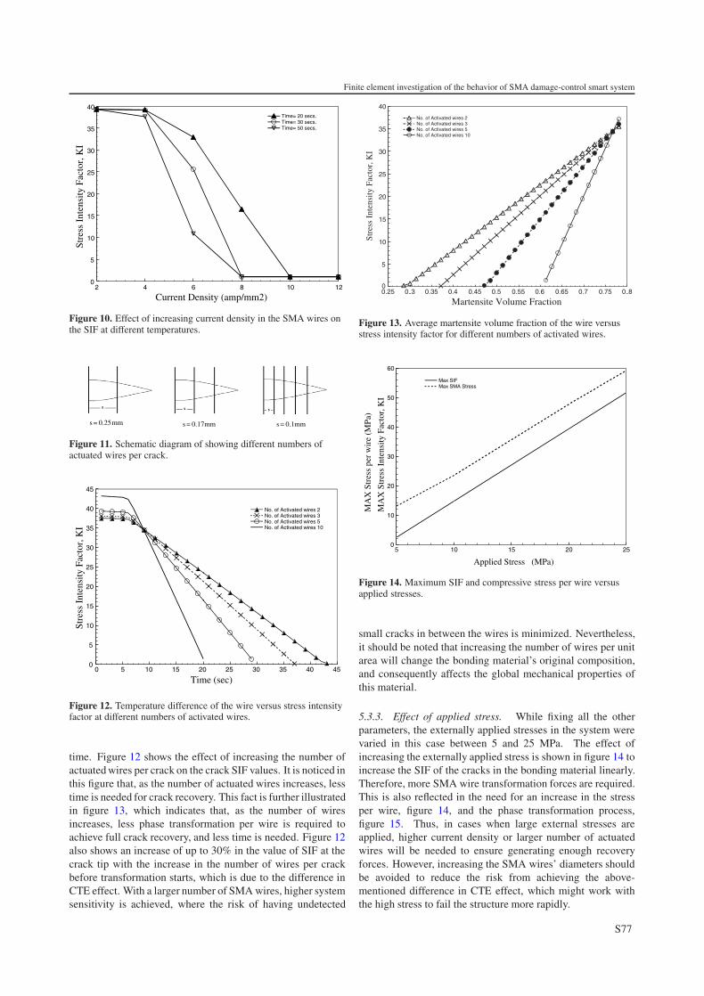
Figure 10. Effect of increasing current density in the SMA wires onthe SIF at different temperatures.
s = 0.25mm s = 0.17mm s = 0.1mm
Figure 11. Schematic diagram of showing different numbers ofactuated wires per crack.
0 5 10 15 20 25 30 35 40 450
5
10
15
20
25
30
35
40
45
No. of Activated wires 2No. of Activated wires 3No. of Activated wires 5No. of Activated wires 10
Stre
ss I
nten
sity
Fac
tor,
KI
Time (sec)
Figure 12. Temperature difference of the wire versus stress intensityfactor at different numbers of activated wires.
time. Figure 12 shows the effect of increasing the number ofactuated wires per crack on the crack SIF values. It is noticed inthis figure that, as the number of actuated wires increases, lesstime is needed for crack recovery. This fact is further illustratedin figure 13, which indicates that, as the number of wiresincreases, less phase transformation per wire is required toachieve full crack recovery, and less time is needed. Figure 12also shows an increase of up to 30% in the value of SIF at thecrack tip with the increase in the number of wires per crackbefore transformation starts, which is due to the difference inCTE effect. With a larger number of SMA wires, higher systemsensitivity is achieved, where the risk of having undetected
0.25 0..3 0.35 0.4 0.45 0.5 0.55 0.6 0.65 0.7 0.75 0..80
5
10
15
20
25
30
35
40
No. of Activated wires 2No. of Activated wires 3No. of Activated wires 5No. of Activated wires 10
Martensite Volume Fraction
Stre
ss I
nten
sity
Fac
tor,
KI
Figure 13. Average martensite volume fraction of the wire versusstress intensity factor for different numbers of activated wires.
5 10 15 20 250
10
20
30
40
50
60
Max SIFMax SMA Stress
Applied Stress (MPa)
MA
X S
tres
s In
tens
ity F
acto
r, K
I
MA
X S
tres
s pe
r w
ire
(MPa
)
Figure 14. Maximum SIF and compressive stress per wire versusapplied stresses.
small cracks in between the wires is minimized. Nevertheless,it should be noted that increasing the number of wires per unitarea will change the bonding material’s original composition,and consequently affects the global mechanical properties ofthis material.
5.3.3. Effect of applied stress. While fixing all the otherparameters, the externally applied stresses in the system werevaried in this case between 5 and 25 MPa. The effect ofincreasing the externally applied stress is shown in figure 14 toincrease the SIF of the cracks in the bonding material linearly.Therefore, more SMA wire transformation forces are required.This is also reflected in the need for an increase in the stressper wire, figure 14, and the phase transformation process,figure 15. Thus, in cases when large external stresses areapplied, higher current density or larger number of actuatedwires will be needed to ensure generating enough recoveryforces. However, increasing the SMA wires’ diameters shouldbe avoided to reduce the risk from achieving the above-mentioned difference in CTE effect, which might work withthe high stress to fail the structure more rapidly.
S77

M Y Serry et al
11 12 13 14 15 16 170
5
10
15
20
25
30
35
40
45
Applied Stress, S,10Applied Stress, S, 20Applied Stress, S, 25
Stre
ss I
nten
sit
Fac
tor
KI
ΔT (K)
Figure 15. Temperature difference of the wire versus stress intensityfactor for different applied stress.
11 12 13 14 15 16 17 18 19 200
5
10
15
20
25
30
35
40Prestrain 0.06
Prestrain 0.05
Prestrain 0.04
Prestrain 0.03
Prestrain 0.02
Time (sec)
Stre
ss I
nten
sity
Fac
tor,
KI
Figure 16. Time versus stress intensity factor for different wireprestrain.
5.3.4. Effect of SMA wires’ pre-strain. The pre-strainingin the SMA wires is varied in this case between 0.02 and0.06 while keeping all the other system properties unchanged.For pre-straining values larger than 0.02, figures 16 and 17,indicate that the SMA wires’ pre-straining has a diminishedeffect on the crack closing recovery process. This is furtherdemonstrated in figure 18, which shows that in these casesapproximately the same amount of transformation is neededper SMA wire to generate the required recovery forces. Thisrelation between this amount of transformation and the currentphase of the SMA wire, which is determined by the amountof prestrain in that wire, is shown to be very weak. Forprestraining values less than 0.02, however, the volume fractionof the detwinned martensite might not be enough to developsufficient forces when totally recovered, leading to incompletecrack closing.
5.3.5. Effect of heat convection. To study the effect of heatdissipation by convection on the crack recovery process ofthe damage control system, the heat convection coefficient
0.02 0.03 0.04 0.05 0.060
5
10
15
20
25
30
35
Time= 20 secs.
Time= 30 secs.
Time= 50 secs.
Str
ess
In
ten
sity
Facto
r K
I
Prestrain
,
Figure 17. Effect of increasing SMA wire prestrain on the SIF afterdifferent times.
0 0.1 0.2 0.3 0.4 0.5 0.6 0.7 0.80
5
10
15
20
25
30
35
40
Prestrain 0.06Prestrain 0.05Prestrain 0.04Prestrain 0.03Prestrain 0.02
Detwinned Martensite Volume Fraction, ζs
Stre
ss I
nten
sity
Fac
tor
KI
,
Figure 18. Martensite volume fraction of the wire versus stressintensity factor for different wire prestrains.
0 20 40 60 80 100 120 140 1600
5
10
15
20
25
30
35
40
heat convection Coeff 1e-4heat convection Coeff 5e-4heat convection Coeff 10e-4heat convection Coeff 15e-4heat convection Coeff 20e-4
Stre
ss I
nten
sity
Fac
tor,
KI
Time (sec)
Figure 19. Time versus stress intensity factor at different heatconvection coefficients.
at the surfaces of the smart composite is varied in thiscase between 1 × 10⁻⁴ and 20 × 10−4 W mm−2 K−1 while
S78

Finite element investigation of the behavior of SMA damage-control smart system
0 10 20 30 40 50 60 70 80 90-0.018
-0.016
-0.014
-0.012
-0.01
-0.008
-0.006
-0.004
-0.002
0
H.Convection Coeff, h= 1e-4H.Convection Coeff, h= 10e-4H.Convection Coeff, h= 15e-4H.Convection Coeff, h= 20e-4
Time (sec)
Mar
tens
ite V
ol. F
ract
ion
Rat
e of
C
hang
e ,(
sec
-1)
Figure 20. Time versus stress intensity factor at different heatconvection coefficients.
Table 2. Different linear isotropic materials used for the effect ofmatrix material case study.
Modulus of elasticity CTEMateriala (GPa) (μm mm−1 K−1)
1 11 212 3 253 2.5 154 2.7 605 20 14
a Materials 1 to 5 are different grades of the epoxypolymer.
keeping all other system properties unchanged. Figures 19and 20 show that, as the heat dissipation increases, the phasetransformation takes place at a slower rate. If the heatdissipation was high enough to reach steady state heat transfer,the rate of SMA wires’ phase transformation would reach zero,where the phase transformation is diminished. This processmay lead to an incomplete crack recovery process; a casethat should be avoided either by increasing the heat powerinput (through increasing the current density), decreasing therequired transformation (through increasing the number ofactuated wires per crack) or decreasing the heat dissipation byconvection (through decreasing the heat convection coefficientif it is controllable).
5.3.6. Effect of system’s initial temperature. This study wasmade by changing the initial temperature of wires and theinitial and ambient temperature of the whole system between278 and 303 K, while keeping all the other system propertiesunchanged. Note that the austenite start transformationtemperature of the wires is at 310 K (table 1). The system’sinitial temperature mainly affects the time required untiltransformation starts as well as the maximum SIF of thecrack tip. In the current case, the initial temperature ofthe SMA wires was varied between 278 and 303 K whilekeeping all other system properties unchanged. As the initialtemperature approached the austenite start temperature (310 Kas shown in table 1), the transformation process starts faster.However, if the initial temperature was considerably lowerthan the austenite start temperature, more time passes before
5 10 15 20 25 3036
37
38
39
40
41
42
43
Initial System Temperature (K)
Stre
ss I
nten
sity
Fac
tor,
KI
Figure 21. Initial system’s temperature versus stress intensity factor.
Table 3. Phases of different SMA wire states in figure 4.
Stress TemperatureState Phase state state
1 100% austenite Zero Ms < T < As
2 Austenite–detwinned >Zero Ms < T < As
martensite mix.
3 Detwinned M. + Arbitrary <As
austenite mix
4 Detwinned M. >Zero >As
partially transformedto Austenite
transformation starts, which might give a chance to the systemto reach steady state heat transfer prior to the point where thetransformation process is initiated. Moreover, having longertime to transformation will increase the negative effects due tothe difference in CTE tensile forces, which is demonstrated infigure 21 through the increase in SIF at the crack tip. This willeventually delay the crack recovery process. This effect canbe avoided by minimizing the difference between the initialtemperature and the austenite start temperature.
5.3.7. Effect of polymeric matrix material. In this case,different (linear isotropic) matrix materials were used withthe same SMA wire material while keeping all other systemproperties unchanged. A list of the tested matrix materialswith their properties is given in table 2. Figure 22 shows thatmaterials with similar modulus of elasticity for the polymericmatrix have similar crack recovery behavior, although theircoefficients of thermal expansion are widely different. Thus,it is clear here that the modulus of elasticity of the polymericmatrix for the bonding material has the dominant effect onthe crack recovery process rather than its CTE. Furthermore,figure 22 indicates that the higher the modulus of elasticity is,the faster the crack recovery process tends to be. Finally, thevariation of the martensite volume fraction rate with time isshown in figure 23 for different matrix materials. In this figure,it is noticed that the matrix material’s modulus of elasticity alsohas the main effect on the wire phase transformation process.
S79

M Y Serry et al
11.5 12 12.5 13 13.5 14 14.5 15 15.5 16 16.5 170
5
10
15
20
25
30
35
40
E=11GPa, CTE=21e-6E=3 GPa, CTE=25e-6E=2.7GPa ,CTE=60e-6E=20GPa,CTE=14e-6E=2.5GPa , CTE=15e-6
ΔT (K)
Stre
ss I
nten
sit
Fac
tor,
KI
y
Figure 22. Temperature difference of the wire versus stress intensityfactor for different matrix materials.
0 5 10 15 20 25 30-0.016
-0.014
-0.012
-0.01
-0.008
-0.006
-0.004
-0.002
0E=11GPa, CTE=21e-6E=3 GPa, CTE=25e-6E=2.7GPa ,CTE=60e-6E=2.5GPa , CTE=15e-6
Mar
tens
ite
Vol
. Fra
ctio
n R
ate
of
Cha
nge,
(se
c-1)
Time (sec)
Figure 23. Martensite volume fraction rate of change versus time fordifferent materials.
6. Conclusions
A finite element procedure is presented to model a SMA-based damage control system that is applied to monitor andreduce the degradation in the bonding material of bondedcomposite patches used to maintain aerospace structure frames.A parametric study was performed to investigate the effect ofvarious design parameters on the performance of the damage-control system. It was found that increasing current density inthe SMA wires used speeds up the recovery process by addingmore heat to the system. Also, it was found that, by increasingthe SMA wire diameter at constant power input, heat loss byconduction at the surface of the wires becomes the dominanteffect on the recovery process; therefore, more time is neededto recover the crack as the wires’ diameters are increased.Also, increasing the number of activated wires was found toreduce the amount of phase transformation and forces requiredper wire, which can increase the system sensitivity to smallcracks. It is suggested that the difference between the initialtemperature of the system and the austenite start temperatureis minimized to achieve faster damage recovery. Finally, the
modulus of elasticity of the matrix material for the bonding isfound to have a major effect on the damage recovery process.
References
Amalraj J J, Bhattacharyya A and Faulkner M G 2000 Finite-elementmodeling of phase transformation in shape memory alloy wireswith variable material properties Smart Mater. Struct. 9 622–31
Bathe K-J 1996 Finite Element Procedures 5th edn (EnglewoodCliffs, NJ: Prentice-Hall)
Boller C, Konstanzer P, Matsuzaki Y and Ikeda T 2001 Damping inSMA-reinforced composites using SMA-intrinsic propertiesProc. SPIE Int. Soc. Opt. Eng. 4332 471–9
Bruck H A and Moore C L 1999 Mechanical characterization ofshape memory alloy composites for designing smart structuresAm. Soc. Mech. Eng. Aerospace Division 59 99–103
Burton D S, Gao X and Brinson L C 2006 Finite element simulationof a self-healing shape memory alloy composite Mech. Mater.38 525–37
Byung K, Xu Y, Oishi R, Nagai H, Yoshida H, Akimune Y,Otsuka K and Kishi T 2002 Thermomechanical characterizationand development of SMA embedded CFRP composites withselfdamage control Proc. SPIE Int. Soc. Opt. Eng. 4699 182–90
DeBlonk B J, Kurdila J, Lagoudas C and Webb G 1995 Identificationof the transient response of SMA embedded flexible rods Proc.SPIE Int. Soc. Opt. Eng. 2443 349–59
Giurgiutiu V, Rogers C A and Zuidervaart J 1997 Incrementallyadjustable rotor-blade tracking tab using SMA compositesStruct. Dyn. Mater. Conf. 2 1456–66
Hebda D A, Whitlock M E, Ditman J B and White S R 1995Manufacturing of adaptive graphite/epoxy structures withembedded nitinol wires J. Intell. Mater. Syst. Struct. 6 220–8
Leo P H, Shield T W and Bruno O P 1993 Transient heat transfereffects on the pseudoelastic behavior of shape-memory wiresActa Metal. Mater. 41 2477–85
Liang C, Rogers C A and Fuller C R 1991 Acoustic transmission andradiation analysis of adaptive shape memory alloy reinforcedlaminated plates J. Sound Vib. 145 23–41
Lurie S A, Efimov D A and Poluhina N O 2000 Special feature of theSMA composite materials deformation Proc. SPIE Int. Soc.Opt. Eng. 3992 451–62
Paine J S and Rogers C A 1995 Shape memory alloys for damageresistant composite structures Proc. SPIE Int. Soc. Opt. Eng.2427 358–71
Saunders W R, Robertshaw H H and Rogers C A 1991 Structuralacoustic control of a shape memory alloy composite beamJ. Intell. Mater. Syst. Struct. 2 508–27
Serry M Y 2003 Nonlinear coupled field approach to the finiteelement simulation of shape memory alloy smart systems MScThesis University of Alberta
Serry M Y, Moussa W A and Raboud D W 2003a Finite-elementmodeling of shape memory alloy components in smartstructures, part II: application onshape-memory-alloy—embedded smart composite forself-damage control ICMENS2003 (Banff, Canada) pp 423–9
Serry M Y, Raboud D W and Moussa W A 2003b Finite-elementmodeling of shape memory alloy components in smartstructures, part I: non-linear coupled field finite elementprocedure ICMENS2003 (Banff, Canada) pp 15–21
Wang X 2002 Shape memory alloy volume fraction of prestretchedshape memory alloy wire-reinforced composites for structuraldamage repair Smart Mater. Struct. 11 590–5
Wei Z G, Tang C Y and Lee W B 1997 Design and fabrication ofintelligent composites based on shape memory alloys J. Mater.Process. Technol. 69 68–74
Xu Ya, Otsuka K, Toyama N, Yoshida H, Nagai H and Kishi T 2004A novel technique for fabricating SMA/CFRP adaptivecomposites using ultrathin TiNi wires Smart Mater. Struct.13 196–202
Zheng Y, Cui L, Li Y and Stalmans R 2001 Partial transformationbehavior of prestrained TiNi fibers in composites Mater. Lett.51 425–8
S80