
Fingerprint Orientation Field Estimation Algorithm Based on Optimized Neighborhood Averaging
7
Fingerprint Orientation Field Estimation Algorithm Based on Optimized Neighborhood Averaging H B Kekre 1 , V A Bharadi 2 Department of Computer Science Mukesh Patel School of Technology Management & Engineering, NMIMS University Mumbai, India [email protected] 1 , [email protected] 2 Abstract— Fingerprint orientation estimation is an important step in fingerprint pre-processing. Here we propose a new algorithm for fingerprint orientation estimation, which is based on gradient direction calculation and determining the orientation by considering the orientation of neighboring regions. This algorithm is mathematically simple and fast for real-time application. This algorithm shows performance improvement by giving better estimation of orientation field. Keywords- Fingerprint Pre-processing; Gradient; Orientation; Biometrics. I. INTRODUCTION Fingerprints are the oldest and most widely recognized biometric trait. All human being posses fingerprint and these fingerprints are result of unique ridge and valley structure formed by skin over the fingers [1]. Ridges and valleys are often run in parallel; these structures have bifurcation and ridge endings called as termination. The ridge structure as a whole takes different shapes, characterized by high curvature, terminations, bifurcations, cross-over etc. These regions are called singular regions or singularities. These singularities may be classified into three topologies; loop, delta and whorl. What makes fingerprint unique is the distribution of such structures at local level. These are called as minutiae [2]. Minutiae mean small details and this refers to the various ways that the ridges can be discontinuous. A sudden ridge end is called termination or it can divide into two ridges which is called bifurcations. Fig. 1 shows a fingerprint image. Figure 1. Typical fingerprint as scanned by optical fingerprint scanner Closer observation of such image can give us the location of present minutiae. Some of typical structures are shown in Fig. 2. We can see a ridge ending in Fig 2 (a), a core point in Fig 2(b). Fig. 2 (c) shows a ridge bifurcation. A loop present on a ridge is shown in Fig. 2(d) (a) (b) (c) (d) Figure 2. Typical Minutiae structures (a) Ridge ending (b) A core point. (c) Ridge bifurcation. (d) A loop present on a ridge Automatic Fingerprint Identification Systems (AFIS) try to match fingerprint by matching these ridge valley structure. Mainly two types are systems are there (a) Minutiae based matching (b) Correlation based matching Minutiae based system try to identify the location and type of minutia and match it with database template. The accuracy is totally dependent on the identification of minutia point [3][4][5]. In case of correlation based techniques, rather than detecting minutiae, we go for global matching of ridge valley structure, here we try to match the texture of fingerprint. Such techniques are robust but less accurate [6][7][8]. The Automatic Fingerprint Recognition Systems require a clear noise free fingerprint in order to process it for minutiae detection or correlation [3][4][5]. The fingerprint must be preprocessed to remove the effect of noise, effect of dryness, wetness of the finger and difference in the applied pressure while scanning the fingerprint. The preprocessing is a multi step process. The different steps in preprocessing are discussed as follows Fingerprint Preprocessing Steps [7] [8] 1. Smoothening Filter 2. Intensity Normalization Second International Conference on Emerging Trends in Engineering and Technology, ICETET-09 978-0-7695-3884-6/09 $26.00 © 2009 IEEE 228
-
Upload
independent -
Category
Documents
-
view
3 -
download
0
Transcript of Fingerprint Orientation Field Estimation Algorithm Based on Optimized Neighborhood Averaging
Fingerprint Orientation Field Estimation Algorithm Based on Optimized Neighborhood Averaging
H B Kekre1, V A Bharadi2 Department of Computer Science
Mukesh Patel School of Technology Management & Engineering, NMIMS University Mumbai, India
[email protected], [email protected]
Abstract— Fingerprint orientation estimation is an important step in fingerprint pre-processing. Here we propose a new algorithm for fingerprint orientation estimation, which is based on gradient direction calculation and determining the orientation by considering the orientation of neighboring regions. This algorithm is mathematically simple and fast for real-time application. This algorithm shows performance improvement by giving better estimation of orientation field.
Keywords- Fingerprint Pre-processing; Gradient; Orientation; Biometrics.
I. INTRODUCTION
Fingerprints are the oldest and most widely recognized biometric trait. All human being posses fingerprint and these fingerprints are result of unique ridge and valley structure formed by skin over the fingers [1]. Ridges and valleys are often run in parallel; these structures have bifurcation and ridge endings called as termination. The ridge structure as a whole takes different shapes, characterized by high curvature, terminations, bifurcations, cross-over etc. These regions are called singular regions or singularities. These singularities may be classified into three topologies; loop, delta and whorl. What makes fingerprint unique is the distribution of such structures at local level. These are called as minutiae [2]. Minutiae mean small details and this refers to the various ways that the ridges can be discontinuous. A sudden ridge end is called termination or it can divide into two ridges which is called bifurcations. Fig. 1 shows a fingerprint image.
Figure 1. Typical fingerprint as scanned by optical fingerprint scanner
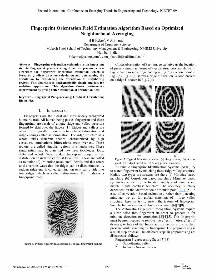
Closer observation of such image can give us the location of present minutiae. Some of typical structures are shown in Fig. 2. We can see a ridge ending in Fig 2 (a), a core point in Fig 2(b). Fig. 2 (c) shows a ridge bifurcation. A loop present on a ridge is shown in Fig. 2(d)
(a) (b)
(c) (d) Figure 2. Typical Minutiae structures (a) Ridge ending (b) A core point. (c) Ridge bifurcation. (d) A loop present on a ridge Automatic Fingerprint Identification Systems (AFIS) try
to match fingerprint by matching these ridge valley structure. Mainly two types are systems are there (a) Minutiae based matching (b) Correlation based matching Minutiae based system try to identify the location and type of minutia and match it with database template. The accuracy is totally dependent on the identification of minutia point [3][4][5]. In case of correlation based techniques, rather than detecting minutiae, we go for global matching of ridge valley structure, here we try to match the texture of fingerprint. Such techniques are robust but less accurate [6][7][8].
The Automatic Fingerprint Recognition Systems require a clear noise free fingerprint in order to process it for minutiae detection or correlation [3][4][5]. The fingerprint must be preprocessed to remove the effect of noise, effect of dryness, wetness of the finger and difference in the applied pressure while scanning the fingerprint. The preprocessing is a multi step process. The different steps in preprocessing are discussed as follows
Fingerprint Preprocessing Steps [7] [8] 1. Smoothening Filter 2. Intensity Normalization
Second International Conference on Emerging Trends in Engineering and Technology, ICETET-09
978-0-7695-3884-6/09 $26.00 © 2009 IEEE 228
3. Orientation Field Estimation 4. Fingerprint Segmentation 5. Ridge Extraction 6. Thinning Smoothening Filter includes median or Gaussian filtering
of fingerprint initially to remove noise at preliminary level. Intensity normalization removes effect of change in intensity level due to difference in pressure, fingerprint scanned form different types of scanners etc. Sometimes Histogram Equalization can also be performed.
Orientation estimation step gives the direction of gradient of fingerprint image segment. This operation is performed block wise (W*W Size Block typically 16*16 pixels). [9][10][11][12]. This step giver orientation field of the fingerprint, which can be used for band pass filtering [10][11] or Gaussian filtering [12]. This is one of the important and an inevitable stage. As further processing depends on the estimated orientation field
Ridge extraction is performed by frequency selective filtering of fingerprint image in the direction of gradient. This is performed by Gabor filtering; other approach involves Gaussian Filtering along the ridge lines [12] or overall Gaussian filtering by a kernel of varying size and local Binarization [13].
In this paper we deal with the Orientation Estimation step, we present an algorithm which is an extension of exiting algorithms and shows performance improvement. Though the complexity is high but the algorithm is using optimized and reusable calculation of orientation field to achieve a smoother field.
II. ORIENTATION FIELD ESTIMATION As discussed earlier for feature extraction we need ridge
structure; to obtain reliable ridge structure, most widely used approach is to go through the gradients of grey intensity [14]. There are some other methods available in literature like filter-bank based approach, spectral estimation, waveform projection, however the gradient based method provide better results[14][15].
Gradient based technique also have variations, researchers have proposed different ways to estimate orientation form gradients. W. Lee et. al. has proposed a simple technique based on direct calculation of orientation based on gradient in [16]. In [14][17] authors have discussed orientation estimation based on Eigen values of local structure tensor. In [18] Bazen has discussed PCA & Structure tensor based Orientation estimation algorithm based on gradients.
In [14] authors have proposed a modified technique based on gradient calculation which exploits the fact that the orientation field tend to be continuous in the neighboring regions, they have put an algorithm which assigns the orientation of central point based on the orientation of neighboring blocks at four corners and their field strength also called as coherence. In [10] Hong et. al. discuss a mechanism to achieve a smoother orientation field by a continuous vector field approach. They use an averaging filter to the continuous vector filed calculated from the local
gradient angle. Both the approaches give reasonably good approximation of the orientation field.
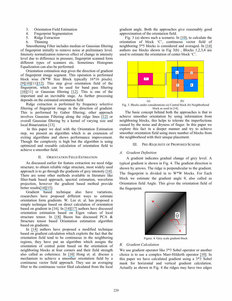
Fig. 3 (a) shows such a scenario. In [10], to calculate the orientation of block ‘C’, continuous vector field of neighboring 5*5 blocks is considered and averaged. In [14] authors use blocks shown in Fig 3(b) , Blocks 1,2,3,4 are used to estimate the orientation of center block ‘C’.
(a) (b)
Fig. 3. Blocks under considerations (a) Central block (b) Neighborhood block as used in [14].
The basic concept behind both the approaches is that to achieve smoother orientation by using information from neighboring blocks, this helps to tolerate the imperfections caused by the noise and dryness of finger. In this paper we explore this fact in a deeper manner and try to achieve smoother orientation field using more number of blocks from the neighborhood with their unique placement.
III. PRE-REQUISITE OF PROPOSED SCHEME
A. Gradient Definition A gradient indicates gradual change of grey level. A typical gradient is shown in Fig. 4. The gradient direction is shown by arrows. The ridge is perpendicular to the gradient. The fingerprint is divided in to W*W blocks. For Each block we estimate the gradient angle θ, also called as Orientation field Angle. This gives the orientation field of the fingerprint.
Figure. 4. Grey scale gradient block
B. Gradient Calculation We use gradient operator like 3*3 Sobel operator or another choice is to use a complex Marr-Hilderth operator [10]. In this paper we have calculated gradient using a 3*3 Sobel mask for horizontal and vertical gradient calculation. Actually as shown in Fig. 4 the ridges may have two edges
229
in a selected block, and hence the calculated gradient vectors at both sides of ridge are opposite to each other, the opposite gradients at both sides of a ridge are likely to cancel each other. To solve this problem we use a method used in [14], involves doubling the gradient angles before the averaging. This method involves calculation of squared gradient. The gradient vectors can be denoted as [gx, gy]T . Because of the doubling process the gradient angle (φ +π) becomes (2φ +2π). Practically 2φ is the angle of squared gradient vectors [gsx, gsy]T that has the following relation with [gx, gy]T , hence we can write using trigonometric identities [14].
22 2 2 2
2 2
cos 2 (cos sin )2sin 2 (2sin cos )
sx x
sy x y
g gg gg g gg g
ϕ ϕ ϕϕ ϕ ϕ
⎛ ⎞⎛ ⎞ ⎛ ⎞ ⎛ ⎞−= = = ⎜ ⎟⎜ ⎟ ⎜ ⎟ ⎜ ⎟ ⎜ ⎟−⎝ ⎠ ⎝ ⎠⎝ ⎠ ⎝ ⎠
(1)
The averaged squared gradients [ , ]sx syg g
in a block of size W*W can therefore be calculated by
2 2( )
2
sx x ysx W W
sy x ysyW W
g g ggg g gg
⎛ ⎞⎛ ⎞ −⎛ ⎞ ⎜ ⎟⎜ ⎟⎜ ⎟ = = ⎜ ⎟⎜ ⎟⎜ ⎟ ⎜ ⎟ ⎜ ⎟⎝ ⎠ ⎝ ⎠ ⎝ ⎠
∑ ∑∑ ∑
(2)
We divide the input fingerprint image into equal size blocks of W X W pixels, and average over each block independently. The direction of orientation field is calculated as follows
1 1 1
2 2
1 1
2 ( , ) ( , )1 tan2 2( ( , ) ( , ))
W W
x yi i
W W W
x yi i
g i j g i j
g i j g i j
πθ − = =
= =
⎛ ⎞⎜ ⎟⎜ ⎟= +⎜ ⎟⎜ ⎟⎝ ⎠
∑∑
∑∑
(3)
The desired range of θW is between [0, π]. This is perpendicular to gradient direction and gives direction of ridge in that block. In order to measure the reliability of estimation we also calculate one more parameter called coherence [14][18], which indicates strength of the averaged gradients, coherence is given by
1 1
1 1
| ( ( , ) ( , )) |
| ( , ) ( , ) |
W W
sx syi i
W W W
sx syi i
g i j g i jCoh
g i j g i j
= =
= =
=∑∑
∑∑
i
i
(4)
C. Block Numbering If we go for the orientation calculation by Eqn. (1) to (4) the resultant orientation is not smooth. To make it proper schemes are proposed in [10][14], here we propose another scheme which address the same problem. We divide the fingerprint image in to blocks of size W X W pixels. To find orientation of a specific block we consider neighborhood area of surrounding 8 blocks. Then we define total 21
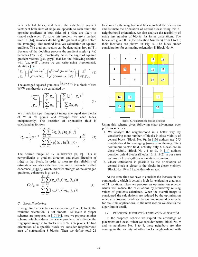
locations for the neighborhood blocks to find the orientation and estimate the orientation of central blocks using this 21 neighborhood orientation, we also analyze the feasibility of using less number of blocks for faster calculations. The blocks are given ID’s (Identification Numbers) from 1 to 21; their locations are shown in Fig. 5. The block under consideration for estimating orientation is Block No. 9.
Figure. 5. Neighborhood blocks locations.
Using this scheme gives following clear advantages over previous schemes. 1. We analyze the neighborhood in a better way, by
considering more number of blocks in close vicinity of central block (Block No. 9). In [10] authors use 5*5 neighborhood for averaging (using smoothening filter) continuous vector field, actually only 8 blocks are in close vicinity (Block No . 1 to 8). In [14] authors consider only 4 blocks (Blocks 16,18,19,21 in our case) and use field strength for orientation estimation.
2. Closer estimation is possible as the orientation of central block is closer to the blocks in closer vicinity; Block Nos.10 to 21 give this advantage.
At the same time we have to consider the increase in the
computation, which is actually high for evaluating gradients of 21 locations. Here we propose an optimization scheme which will reduce the calculations by recursively reusing values of gradients calculated. When the overall image is considered the calculations are reduced by the optimization scheme is proposed, and calculation time required is suitable for real-time applications. In the next section we discuss the algorithm in detail.
IV. PROPOSED ORIENTATION ESTIMATION ALGORITHM In the proposed scheme we exploit the advantage of
placement of blocks. When we consider central block No. 9 and its neighbors No. 1 to 8, these neighbors are also coming in the vicinity of other bocks neighborhood with
230
different block ID, hence if we calculate orientation of block no 1 to 8, some part of this can be copied (reused) to the orientation set of specific neighbor, without recalculation. In fig. 6 we describe this condition.
Consider block A & B which have an overlapping neighborhood. Block No.3 of A is also block No 1. Of B, similarly the other pairs are (A5, B4), (A8, B6). It means that three values from A neighborhood can be used in B’s neighborhood. This is a simple scenario, if we consider immediate neighbor of A which is block No. 5 of A, then we can use actually six values corresponding to overlapping blocks.
Figure 6. Overlapping Neighborhood
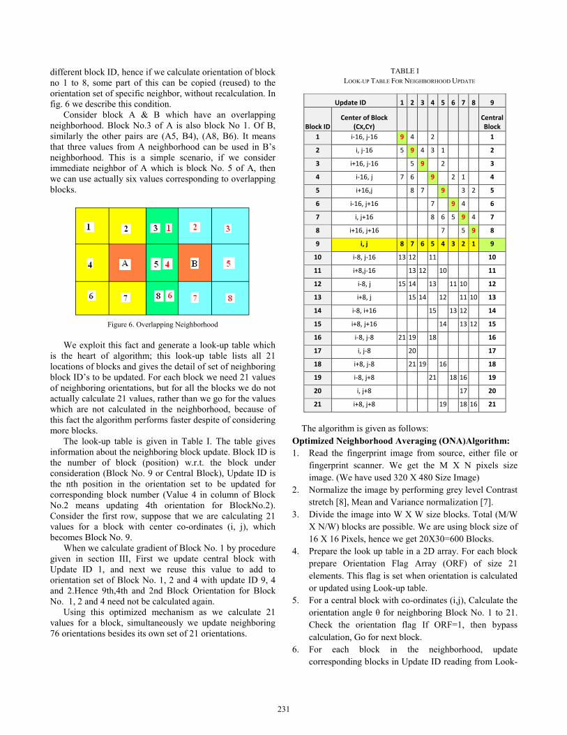
We exploit this fact and generate a look-up table which
is the heart of algorithm; this look-up table lists all 21 locations of blocks and gives the detail of set of neighboring block ID’s to be updated. For each block we need 21 values of neighboring orientations, but for all the blocks we do not actually calculate 21 values, rather than we go for the values which are not calculated in the neighborhood, because of this fact the algorithm performs faster despite of considering more blocks.
The look-up table is given in Table I. The table gives information about the neighboring block update. Block ID is the number of block (position) w.r.t. the block under consideration (Block No. 9 or Central Block), Update ID is the nth position in the orientation set to be updated for corresponding block number (Value 4 in column of Block No.2 means updating 4th orientation for BlockNo.2). Consider the first row, suppose that we are calculating 21 values for a block with center co-ordinates (i, j), which becomes Block No. 9.
When we calculate gradient of Block No. 1 by procedure given in section III, First we update central block with Update ID 1, and next we reuse this value to add to orientation set of Block No. 1, 2 and 4 with update ID 9, 4 and 2.Hence 9th,4th and 2nd Block Orientation for Block No. 1, 2 and 4 need not be calculated again.
Using this optimized mechanism as we calculate 21 values for a block, simultaneously we update neighboring 76 orientations besides its own set of 21 orientations.
TABLE I LOOK-UP TABLE FOR NEIGHBORHOOD UPDATE
Update ID 1 2 3 4 5 6 7 8 9
Block IDCenter of Block
(CX,CY) Central Block
1 i-16, j-16 9 4 2 1
2 i, j-16 5 9 4 3 1 2
3 i+16, j-16 5 9 2 3
4 i-16, j 7 6 9 2 1 4
5 i+16,j 8 7 9 3 2 5
6 i-16, j+16 7 9 4 6
7 i, j+16 8 6 5 9 4 7
8 i+16, j+16 7 5 9 8
9 i, j 8 7 6 5 4 3 2 1 9
10 i-8, j-16 13 12 11 10
11 i+8,j-16 13 12 10 11
12 i-8, j 15 14 13 11 10 12
13 i+8, j 15 14 12 11 10 13
14 i-8, i+16 15 13 12 14
15 i+8, j+16 14 13 12 15
16 i-8, j-8 21 19 18 16
17 i, j-8 20 17
18 i+8, j-8 21 19 16 18
19 i-8, j+8 21 18 16 19
20 i, j+8 17 20
21 i+8, j+8 19 18 16 21
The algorithm is given as follows:
Optimized Neighborhood Averaging (ONA)Algorithm: 1. Read the fingerprint image from source, either file or
fingerprint scanner. We get the M X N pixels size image. (We have used 320 X 480 Size Image)
2. Normalize the image by performing grey level Contrast stretch [8], Mean and Variance normalization [7].
3. Divide the image into W X W size blocks. Total (M/W X N/W) blocks are possible. We are using block size of 16 X 16 Pixels, hence we get 20X30=600 Blocks.
4. Prepare the look up table in a 2D array. For each block prepare Orientation Flag Array (ORF) of size 21 elements. This flag is set when orientation is calculated or updated using Look-up table.
5. For a central block with co-ordinates (i,j), Calculate the orientation angle θ for neighboring Block No. 1 to 21. Check the orientation flag If ORF=1, then bypass calculation, Go for next block.
6. For each block in the neighborhood, update corresponding blocks in Update ID reading from Look-
231
up table. Repeat this procedure for all 21 neighborhood locations. When the orientation is added to the specific blocks set of orientation, set the corresponding ORF=1. (ORF=1, indicates that orientation has been calculated for current ID).
7. Subsequently for each block before calculating the orientation check the orientation flag (ORF) and proceed.
8. Repeat steps 5 to 7 for all blocks in fingerprint image. 9. For each block assign the orientation value by
averaging selected number of orientation for neighboring 21 locations. All 21 values can be considered or some selection can be made.
10. Display the orientation map. Proceed for next step of pre-processing.
In [14] authors have used the block with maximum coherence (Eqn. 4), to assign orientation to the central block, in a set of four neighboring blocks. This algorithm is a special case of proposed algorithm, if we use only Block. No.16, 18, 19 and 21 for orientation estimation it becomes the same as proposed in [14], only we have to consider block with high field strength (Coherence Value). As we are using more blocks we use averaging which gave better results. We have also studied using different combinations of blocks to estimate orientation, as well as our algorithm is compared with existing techniques [10][14]. This is discussed in next section.
V. RESULTS This algorithm is implemented on MS Visual Studio 2005 platform, using Visual C# 2.0. The program was tested on AMD Athlon 64 processor running at 1.8 GHZ with 1.5GB DDRII RAM, operating system is Windows XP SP3. Block size considered is 16 X 16 pixels. We have tested three main algorithms, 1. Orientation Estimation using Squared Gradients only
[10],[14] 2. Orientation Estimation using Continuous Vector Field
[10]. 3. Optimized Neighborhood Averaging Algorithm. The scheme proposed in [14], can be treated as a special case for estimating algorithm using block number 16, 18, 19, 21 and assigning orientation of maximum field strength block to the center block. For testing purpose we have used FVC 2000, 2002 & 2004 Databases [19][20], we have also used optical fingerprint scanner Futronics FS88 for real-time application. Some scanned fingerprints and palmprint images were also used for testing. We show the results for FS 88, FVC2000, and FVC2002 DB Images. Our Algorithm was tested with following variations 1. All 21 Blocks - with averaging 2. Block Nos. - 9,10,11,12,13,14,15,16,17,18,19,20,21-
with averaging
3. Block Nos. - 9,12,13,16,17,18,19,20,21 - With Averaging
4. Block Nos. - 9,12,13,16,17,18,19,20,21 - With Continuous Vector Field[10].
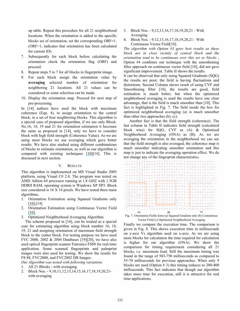
The algorithm with Option #3 gave best results as these block are in close vicinity of central block and the orientation tend to be continuous over this set or blocks , Option #4 combines our technique with the smoothening filter approach on continuous vector field [10], did not gave significant improvement. Table II shows the results. It can be observed that only using Squared Gradients (SQG) the results are poor; the field is having fluctuations and distortions. Second Column shows result of using CVF and Smoothening filter [10], the results are good, field estimation is much better, but when the optimized neighborhood averaging is used the results have one clear advantage, that is the field is much smoother than [10]. This fact is highlighted in Fig. 7. The field inside the box for optimized neighborhood averaging (a) is much smoother than other two approaches (b), (c).
Another fact is that the field strength (coherence). The last column in Table II indicates field strength (calculated block wise) for SQG, CVF as (A) & Optimized Neighborhood Averaging (ONA) as (B). As we are averaging the orientation in the neighborhood we can see that the field strength is also averaged, the coherence map is much smoother indicating smoother orientation and this map is just to indicate the averaging operation effect. We do not change any of the fingerprint characteristics.
Fig. 7. Orientation Fields form (a) Squared Gradient only (b) Contentious
Vector Field (c) Optimized Neighborhood Averaging Finally we compare the execution time. The comparison is given in Fig. 8. This shows execution time in milliseconds on y-axis Vs algorithm used on x-axis. As we are using more blocks for calculation the time required for calculation is higher for our algorithm (ONA). We show the comparison for timing requirement considering all 21 blocks, i.e. maximum load. Still the maximum timing was found in the range of 503-750 milliseconds as compared to 55-70 milliseconds for previous approaches. When only 9 blocks are used (Option # 3) this timing reduces to 200-400 milliseconds. This fact indicates that though our algorithm takes more time for execution, still it is attractive for real time applications.
232
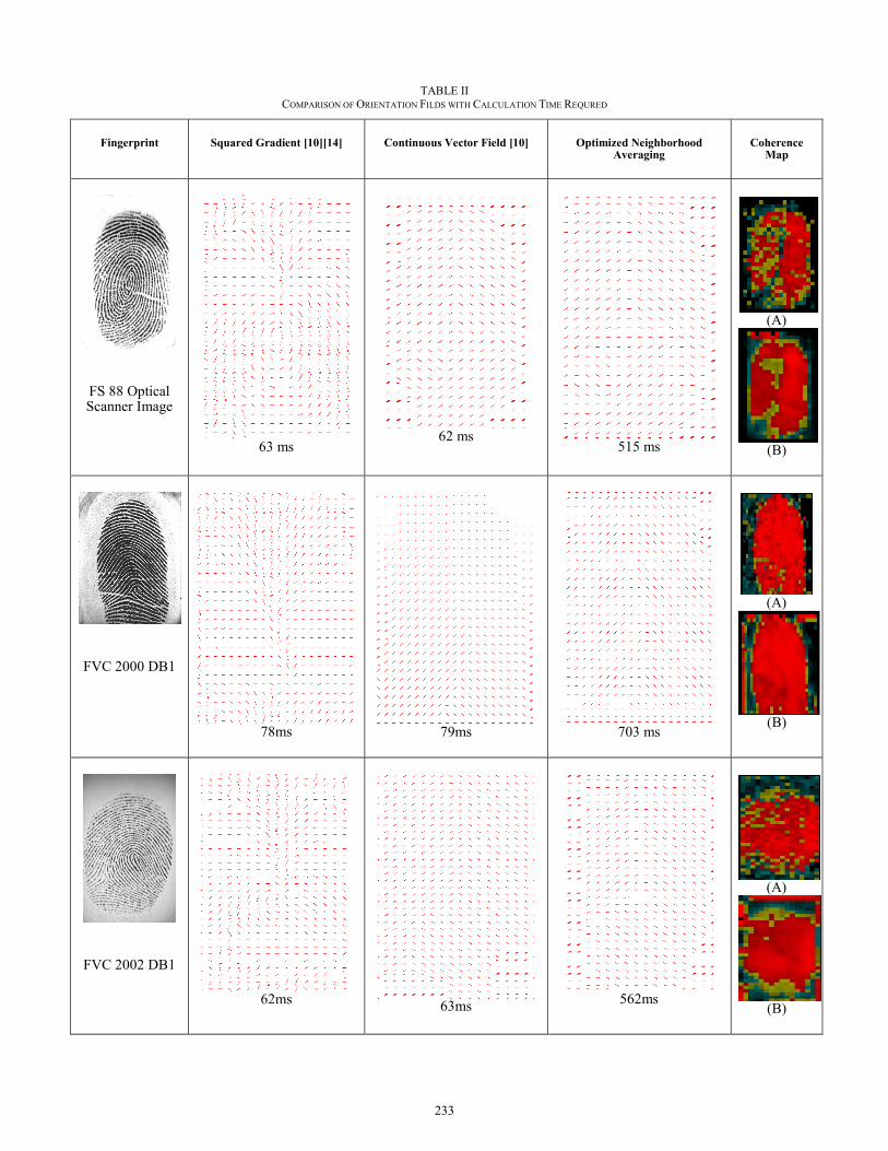
TABLE II COMPARISON OF ORIENTATION FILDS WITH CALCULATION TIME REQURED
Fingerprint Squared Gradient [10][14] Continuous Vector Field [10] Optimized Neighborhood Averaging
Coherence Map
FS 88 Optical Scanner Image
63 ms
62 ms
515 ms
(A)
(B)
FVC 2000 DB1
78ms
79ms
703 ms
(A)
(B)
FVC 2002 DB1
62ms 63ms
562ms
(A)
(B)
233
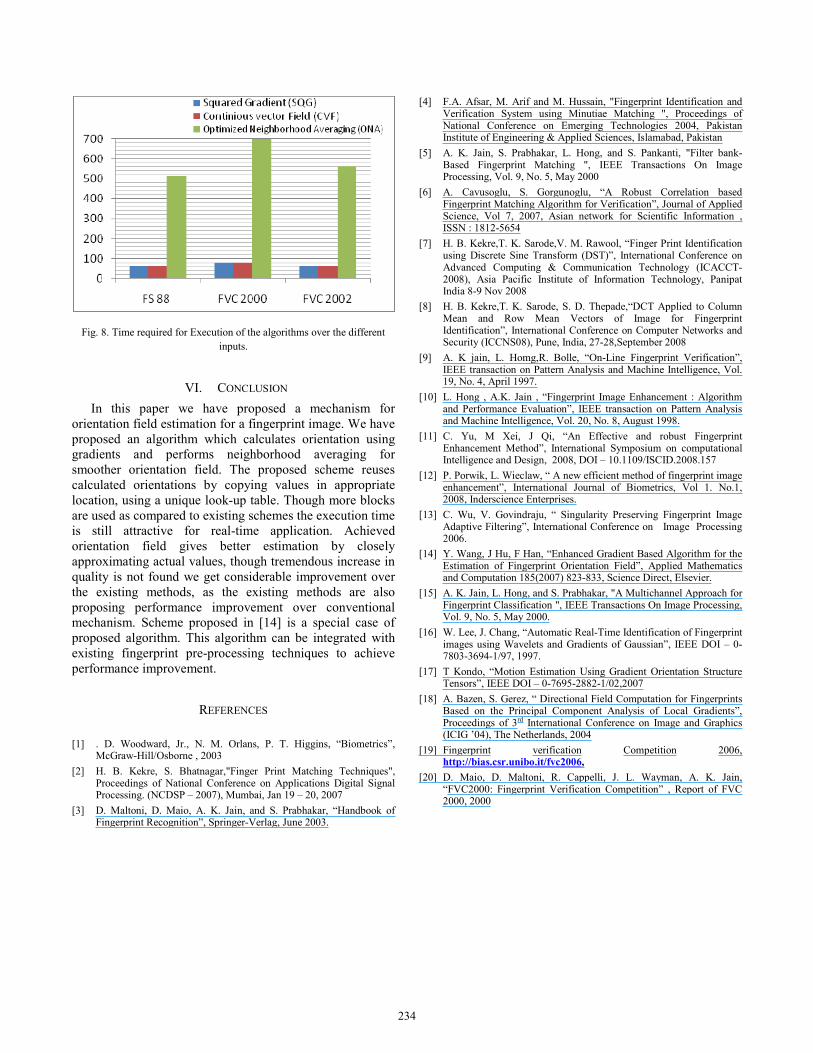
Fig. 8. Time required for Execution of the algorithms over the different inputs.
VI. CONCLUSION In this paper we have proposed a mechanism for
orientation field estimation for a fingerprint image. We have proposed an algorithm which calculates orientation using gradients and performs neighborhood averaging for smoother orientation field. The proposed scheme reuses calculated orientations by copying values in appropriate location, using a unique look-up table. Though more blocks are used as compared to existing schemes the execution time is still attractive for real-time application. Achieved orientation field gives better estimation by closely approximating actual values, though tremendous increase in quality is not found we get considerable improvement over the existing methods, as the existing methods are also proposing performance improvement over conventional mechanism. Scheme proposed in [14] is a special case of proposed algorithm. This algorithm can be integrated with existing fingerprint pre-processing techniques to achieve performance improvement.
REFERENCES
[1] . D. Woodward, Jr., N. M. Orlans, P. T. Higgins, “Biometrics”, McGraw-Hill/Osborne , 2003
[2] H. B. Kekre, S. Bhatnagar,"Finger Print Matching Techniques", Proceedings of National Conference on Applications Digital Signal Processing. (NCDSP – 2007), Mumbai, Jan 19 – 20, 2007
[3] D. Maltoni, D. Maio, A. K. Jain, and S. Prabhakar, “Handbook of Fingerprint Recognition”, Springer-Verlag, June 2003.
[4] F.A. Afsar, M. Arif and M. Hussain, "Fingerprint Identification and Verification System using Minutiae Matching ", Proceedings of National Conference on Emerging Technologies 2004, Pakistan Institute of Engineering & Applied Sciences, Islamabad, Pakistan
[5] A. K. Jain, S. Prabhakar, L. Hong, and S. Pankanti, "Filter bank-Based Fingerprint Matching ", IEEE Transactions On Image Processing, Vol. 9, No. 5, May 2000
[6] A. Cavusoglu, S. Gorgunoglu, “A Robust Correlation based Fingerprint Matching Algorithm for Verification”, Journal of Applied Science, Vol 7, 2007, Asian network for Scientific Information , ISSN : 1812-5654
[7] H. B. Kekre,T. K. Sarode,V. M. Rawool, “Finger Print Identification using Discrete Sine Transform (DST)”, International Conference on Advanced Computing & Communication Technology (ICACCT-2008), Asia Pacific Institute of Information Technology, Panipat India 8-9 Nov 2008
[8] H. B. Kekre,T. K. Sarode, S. D. Thepade,“DCT Applied to Column Mean and Row Mean Vectors of Image for Fingerprint Identification”, International Conference on Computer Networks and Security (ICCNS08), Pune, India, 27-28,September 2008
[9] A. K jain, L. Homg,R. Bolle, “On-Line Fingerprint Verification”, IEEE transaction on Pattern Analysis and Machine Intelligence, Vol. 19, No. 4, April 1997.
[10] L. Hong , A.K. Jain , “Fingerprint Image Enhancement : Algorithm and Performance Evaluation”, IEEE transaction on Pattern Analysis and Machine Intelligence, Vol. 20, No. 8, August 1998.
[11] C. Yu, M Xei, J Qi, “An Effective and robust Fingerprint Enhancement Method”, International Symposium on computational Intelligence and Design, 2008, DOI – 10.1109/ISCID.2008.157
[12] P. Porwik, L. Wieclaw, “ A new efficient method of fingerprint image enhancement”, International Journal of Biometrics, Vol 1. No.1, 2008, Inderscience Enterprises.
[13] C. Wu, V. Govindraju, “ Singularity Preserving Fingerprint Image Adaptive Filtering”, International Conference on Image Processing 2006.
[14] Y. Wang, J Hu, F Han, “Enhanced Gradient Based Algorithm for the Estimation of Fingerprint Orientation Field”, Applied Mathematics and Computation 185(2007) 823-833, Science Direct, Elsevier.
[15] A. K. Jain, L. Hong, and S. Prabhakar, "A Multichannel Approach for Fingerprint Classification ", IEEE Transactions On Image Processing, Vol. 9, No. 5, May 2000.
[16] W. Lee, J. Chang, “Automatic Real-Time Identification of Fingerprint images using Wavelets and Gradients of Gaussian”, IEEE DOI – 0-7803-3694-1/97, 1997.
[17] T Kondo, “Motion Estimation Using Gradient Orientation Structure Tensors”, IEEE DOI – 0-7695-2882-1/02,2007
[18] A. Bazen, S. Gerez, “ Directional Field Computation for Fingerprints Based on the Principal Component Analysis of Local Gradients”, Proceedings of 3rd International Conference on Image and Graphics (ICIG ’04), The Netherlands, 2004
[19] Fingerprint verification Competition 2006, http://bias.csr.unibo.it/fvc2006,
[20] D. Maio, D. Maltoni, R. Cappelli, J. L. Wayman, A. K. Jain, “FVC2000: Fingerprint Verification Competition” , Report of FVC 2000, 2000
234