Final chap1-5
94
1 Chapter I INTRODUCTION A. Background of the Study Irrigation system is a useful tool for cultivating healthy lawns and gardens. However, when not properly maintain, it can lead to misuse of water resources. Nowadays, water shortage is becoming one of the biggest problems in the world. In an article published at wired.com last March 19, 2006, farms and their wasteful irrigation systems are the major contributors to water scarcity on the globe and 70% of the water consumed goes to farming and most of its wasteful use. Water is basic a necessity, be it for human beings, animals, plants, etc. For an instance, water is considered as a vital source and foundation for a healthy and vigorous landscape. The field of Agriculture is where water is required in tremendous quantity. But water itself is one of our most precious resources. When water is scarcer than land, it may be beneficial to maximize water productivity in irrigation system management. Take, for example, a typical irrigation system that faces water shortage in the main reservoir. A usual response option of the
-
Upload
independent -
Category
Documents
-
view
1 -
download
0
Transcript of Final chap1-5

1
Chapter I
INTRODUCTION
A. Background of the Study
Irrigation system is a useful tool for cultivating healthy lawns
and gardens. However, when not properly maintain, it can lead to
misuse of water resources. Nowadays, water shortage is becoming
one of the biggest problems in the world. In an article published at
wired.com last March 19, 2006, farms and their wasteful irrigation
systems are the major contributors to water scarcity on the globe
and 70% of the water consumed goes to farming and most of its
wasteful use. Water is basic a necessity, be it for human beings,
animals, plants, etc. For an instance, water is considered as a vital
source and foundation for a healthy and vigorous landscape. The
field of Agriculture is where water is required in tremendous
quantity. But water itself is one of our most precious resources.
When water is scarcer than land, it may be beneficial to
maximize water productivity in irrigation system management.
Take, for example, a typical irrigation system that faces water
shortage in the main reservoir. A usual response option of the
2
irrigation system manager is to implement a system that will
minimize the water resources.
In the Philippines alone, agriculture as a whole is the greatest
consumer of water. Irrigation constitutes a large portion of total
water consumption by agriculture; it is considered the biggest water
user in the country, notwithstanding the fact that only 47% of the
potentially irrigable area of 3.16 million hectares is irrigated. About
95% of the irrigated area is devoted to paddy and about 70% of
paddy production comes from irrigated lands (Dayrit, 2001).
For years, many different methods are being developed for the
proper irrigation of water. In lieu with these reasons, the
proponents thought of designing an irrigation system using the
technology of microcontroller and GSM. The project aims for an
efficient and effective automatic irrigation system that seeks to
minimize water usage, requires minimal human effort and saves
time.
3
B. Statement of the Problem
Scientists predict a global water shortage, severely impacting
Philippines by 2025 (Vergano, 2003). The study intends to address
wasteful water used in irrigation by designing an automated system
with the help of microcontroller and GSM technology. Generally, a
microcontroller based plant irrigation system with SMS notification
and controller will be needed to minimize the usage when watering
the soil. Specifically the study aims to:
1. Determine how soil moisture content can be used as a
parameter to automate the watering of the plants;
2. Identify the target value and relative values of the soil
moisture;
3. Use GSM technology to allow notification about the status of the
soil moisture; and
4. Recognize method of controlling the irrigation system using
GSM technology.

4
C. Objectives of the Study
Generally, the objective of this study is to construct a
Microcontroller Based Plant Irrigation System with SMS Notification
and Controller that will minimize the water usage when watering
the soil. And specifically, it seeks to:
1. Automate the watering of the plants by using a microcontroller-
based system that will check the soil moisture content;
2. Display the relative value of the soil moisture content using a
16x2 LCD;
3. Provide a notification of the status of the soil using GSM
technology; and
4. Allow user to control the system by enabling the pump using
GSM technology.

5
D. Significance of the Study
This study minimizes the water usage by supplying enough
water to the soil. The system automatically waters the soil by
checking its soil moisture contents. It also discuss about the
importance of designing the system to the following:
For Department of Agriculture
This project would be beneficial to the department of the
government in charge of the Agriculture for this can make them
realize the importance of proper irrigation and monitoring of water
usage in the fields. Furthermore, this can make way for a further
study or even a project about proper irrigation of fields with the
help of the same technology.
For Farmers/Caretakers
This project is specifically made for monitoring the land and can
help the farmers to minimize human effort in manually checking if
the plants need to be watered. Instead, they can just rely on this
6
project by the SMS they receive through the GSM technology and
even send command to control the turning on/off of the pump.
For Land Owners
The project aims to minimize water usage where the land owners
will most benefit. Through an investment to this kind of system, the
land owners will have less expense on their water consumption.
For Future Computer Engineering Students
This can be beneficial for the Computer Engineering students
who will undertake a related project about irrigation system,
microcontroller, soil moisture sensor and GSM technology.

7
E. Scope and Delimitations of the Study
This project entitled, ―Microcontroller Based Plants Irrigation
System with SMS Notification and Controller‖ embodies the
following:
1. PIC16F877A microcontroller controls the components (soil
moisture sensors, LCD, submersible pump and GSM modem) of
the entire system;
2. The system uses five soil moisture gold immersion sensors to
monitor the soil moisture content of the plant;
3. The system only notifies the status of the plants if the user
sends an inquiry through a text command using a mobile phone.
Also, the user can turn on the pump by sending a text message.
However, the SIM cards of the mobile phone and GSM modem
should maintain enough balance;
4. The submersible pump turns on if the majority of the land area
is dry and if the user turns it on via sending SMS;
5. The testing of the system uses five land areas having one
sprinkler each;
6. The LCD displays five relative values of soil moisture sensors;
8
7. The system embodies a password for security which the user can
set; and
8. The target soil moisture can be accustomed depending on the
water requirements of the soil.
In the contrary, limitations were met during the construction of
the project due to limited time and resources. The project is limited
to these aspects:
1. The system is only capable of watering the plants;
2. The GSM module is only for receiving status (information) and
triggering the water pump;
3. The monitoring of the plants focuses on soil moisture content;
other factors are not included;
4. The testing of the system uses loamy soil; and
5. The system does not consider the type of plants as it focuses
only on one factor which is the soil moisture.

9
F. Definition of Terms
Center-pivot sprinkler system - is a self-propelled system in
which a single pipeline supported by a row of mobile towers is
suspended 2 to 4 meters above ground.
Embedded System - any electronic system that uses a computer
chip, but that is not a general-purpose workstation, desktop or
laptop computer. Such systems use microcontrollers (MCUs) or
microprocessors (MPUs), or they may use custom-designed chips.
GSM - short for Global System for Mobile Communications, one of
the leading digital cellular systems. GSM uses narrowband TDMA,
which allows eight simultaneous calls on the same radio frequency.
Hand move sprinkler system - are a series of lightweight pipeline
sections that are moved manually by hand. Lateral pipelines are
connected to a mainline which may be portable or buried. Hand
move systems are mainly used for smaller areas.
Irrigation - artificial supply of water to land, to maintain or
increase yields of food crops, a critical element of modern
10
agriculture. Irrigation can compensate for the naturally variable
rate and volume of rain.
LCD – short for Liquid Crystal Display It is an electronic display that
consists of segments of a liquid crystal whose reflectivity varies
according to the voltage applied to them.
Level Basin Systems - these systems differ from traditional
border check or flood systems in that slope of the land is level and
areas and is closed. Water is applied at high volumes to achieve an
even, rapid ponding of the desired application depth within basins.
Loamy soil - it contains a balance of all three soil materials: silt,
sand and clay—plus humus. It has a higher pH and calcium levels
because of its previous organic matter content.
Low Flow Irrigation Systems - these systems which include drip
and trickle use small diameter tubes placed above or below the soils
surface. Frequent, slow applications of water are applied to the soil
through small holes or emitters. The emitters are supplied by a
network of main, sub main and lateral lines.

11
MCU - short for microcontroller. It is a microprocessor that controls
some or all of the functions of an electronic device (as a home
appliance) or system.
Power Supply - a source of electric power (voltage and current) to
operate electronic circuits.
Probe - a small tube containing the sensing element of electronic
equipment, which can be lowered into a borehole to obtain
measurements and data.
Relay - an electromagnetic device for remote or automatic control
that is actuated by variation in conditions of an electric circuit and
that operates in turn other devices (as switches) in the same or a
different circuit.
Sensor - a device that measures or detects a real-world condition,
such as motion, heat or light and converts the condition into an
analog or digital representation.
Soil Moisture - ability of soil to supply moisture to plant.
12
Solid set/fixed sprinkler systems - sold set/ fixed refer to a
stationary sprinkler system. Water is supplied to pipelines and the
pipeline to a sprinkler nozzle which is elevated above the grounds
surface.
Submersible pump - it is similar to a turbine pump, but it is
attached to a submersible electric motor. The electric motor and the
pump are suspended in the water.
Travelling gun sprinkler systems - travelling gun systems use a
large sprinkler that is mounted on a wheel or trailer, fed by a
flexible rubber hose. The sprinkler is self- propelled while applying
water, travelling in a lane guided by a cable. The system requires
high operating pressures up to 100psi.
13
Chapter II
THEORETICAL AND CONCEPTUAL FRAMEWORK
A. Review of Related Literature and Studies
This section presents a discussion of related literature and
studies, both of which have significant relation to the development
of the present study.
First and foremost, Wikipedia, a free Encyclopedia website
defined irrigation as,
"The artificial application of water to the land or soil. It is used to
assist in the growing of agricultural crops, maintenance of
landscapes, and vegetation of disturbed soils in dry areas and
during periods of inadequate rainfall."
Moreover, an irrigation system is a method of delivering water to
an area where it is needed, but not normally present in the required
amounts. Generally, it is used for agriculture and landscaping
purposes. The effectiveness of the irrigation is determined by a
14
number of different factors, including the type of delivery system
and the conditions at its time of use.
The key to an effective irrigation system is to get as much water
to the plants, or into the soil, as possible. While this may seem like
an easy thing to do, it is not. In fact, water loss from these systems
can be up to 50% in some cases.
In an article published at www.lawnranger.com, irrigation
systems are classified according to the following types: hand move
sprinkler system, level basin systems, low flow irrigation systems,
and furrow systems, travelling gun sprinkler systems, solid
set/fixed sprinkler systems, side-roll wheel move systems, linear or
lateral- move systems and center-pivot sprinkler system.
Furthermore, one important component of an irrigation system is
the pumps. Pumps used in irrigation systems differ in design and
type. For the irrigation system to be efficient and effective, pumps
should be selected properly. Pumps used for irrigation should
always be in good working condition to ensure that the water being
pumped is free from contamination. Irrigation pumps should meet
15
the requirements of the irrigation equipment, the piping system and
most importantly, the source of water.
There are four types of pump namely: centrifugal pumps, deep-
well turbine pumps, submersible pumps, and propeller pumps.
(Fitzgerald, July 2012)
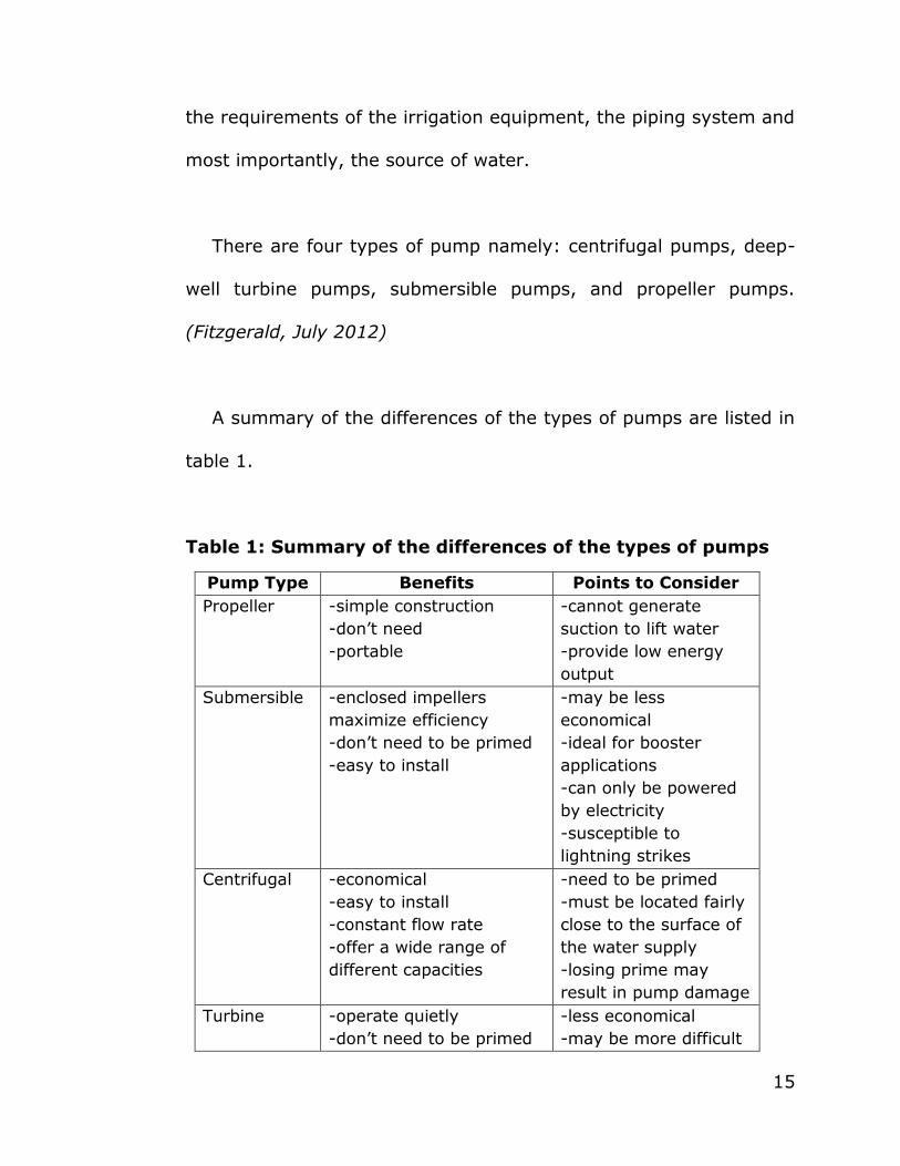
A summary of the differences of the types of pumps are listed in
table 1.
Table 1: Summary of the differences of the types of pumps
Pump Type Benefits Points to Consider
Propeller -simple construction
-don’t need
-portable
-cannot generate
suction to lift water
-provide low energy
output
Submersible -enclosed impellers
maximize efficiency
-don’t need to be primed
-easy to install
-may be less
economical
-ideal for booster
applications
-can only be powered
by electricity
-susceptible to
lightning strikes
Centrifugal -economical
-easy to install
-constant flow rate
-offer a wide range of
different capacities
-need to be primed
-must be located fairly
close to the surface of
the water supply
-losing prime may
result in pump damage
Turbine -operate quietly
-don’t need to be primed
-less economical
-may be more difficult

16
-may be used in wells
-may be used in
conditions where water
depth changes
to install, inspect, and
repair
-require periodic
impeller adjustments
to maintain efficiency
Aside from the kinds of pumps mentioned in Table 1, there is a
need to consider one important factor which is the soil moisture.
Sensors designed for soil moisture content can be interfaced to an
irrigation controller. Soil moisture sensor is used as a tool to
optimize irrigation and to protect plant stress at the dry or wet
ends.
Measuring soil moisture is important in agriculture to help
farmers manage their irrigation systems more efficiently. Not only
are farmers able to generally use less water to grow a crop, they
are able to increase yields and the quality of the crop by better
management of soil moisture during critical plant growth stages.
Soil moisture sensors are classified into two: the capacitive
sensor and resistive sensor. Capacitive sensor is used where soil
with moisture serves as dielectric, as the moisture changes the
capacitance changes, we can also use resistive sensor to sense the
moisture content. It employs a parallel plate capacitor in which
dielectric medium is the soil granules. The basic logic is as moisture

17
of soil will change capacitance will change. While, the resistive soil
moisture sensor is where electrical resistance is measured and
converted to soil moisture content. The sensor consists of
concentric electrodes which are surrounded by granular material
which is having good absorbent property like gypsum; cork etc. this
material absorbs water (moisture) in soil. When electrodes are
excited electrical resistance is measured. The resistance decreases
with increasing soil moisture. However, the soil moisture or the
ability of a soil to absorb water depends on its soil type.
There are different types of soil that gardeners and growers
usually use for the plants. These are the following: the sandy soil,
the silty, the clay, the peaty, saline soil and the loamy soil.
However, the type of soil that gardens and gardeners love is loamy
soil because it is an ideal material for plants. (Ganguly, 2011)
In addition to the discussion about types of irrigation and
pumps, there is also a need to tackle the importance of embedded
system. Embedded computing system plays a vital role in
developing automated systems. Embedded systems are defined as
a computer having a single task, or a very small number of related
tasks that are programmed to perform a dedicated function. In

18
general, embedded system is: a system built to perform its duty,
completely or partially independent of human intervention; specially
designed to perform a few tasks in the most efficient way; and
interacts with physical elements in our environment, viz. controlling
and driving a motor, sensing temperature, etc.
The implementation of embedded system usually involves
microcontroller. It is defined as
"A microcontroller includes a CPU, RAM, ROM, I/O ports, and
timers like a standard computer, but because they are designed to
execute only a single specific task to control a single system, they
are much smaller and simplified so that they can include all the
functions required on a single chip."
In a microcontroller all that you have to do is to make proper
connections of the pins and then feed a computer program into it.
After that your microcontroller responds in accordance with the
program that has been fed into it. In a microcontroller program you
receive the inputs from a set of input pins that you specify and then
process the input and produce your output on a set of output pins
in form digital signal.

19
Aside from the use of microcontroller, there has been rapid
introduction of GSM technology in different applications. In fact, the
paper, "A method for reducing a bumblebee noise generated by a
GSM technology in a smartphone" in particular stated that GSM
technology has a market share of almost more than 79% in the
world. (Soo-Woo, 2012) Today, GSM known as Global System for
Mobile Communications or simply Global System for Mobile is a
hugely successful wireless technology. As stated to European
Telecommunications Standards Institute,
"GSM is an open, digital cellular technology used for transmitting
mobile voice and data services. The technology behind the Global
System for Mobile communication (GSMTM) uses Gaussian Minimum
Shift Keying (GMSK) modulation a variant of Phase Shift Keying
(PSK) with Time Division Multiple Access (TDMA) signalling over
Frequency Division Duplex (FDD) carriers. Although originally
designed for operation in the 900 MHz band, it was soon adapted
for 1800 MHz".
A GSM network consists of a GSM modem. With reference a
journal "What is a GSM Modem?‖,

20
"A GSM modem is a specialized type of modem which accepts a
SIM card, and operates over a subscription to a mobile operator,
just like a mobile phone."
Additionally, when a GSM modem is connected to a computer,
this allows the computer to use the GSM modem to communicate
over the mobile network. While these GSM modems are most
frequently used to provide mobile internet connectivity, many of
them can also be used for sending and receiving SMS and MMS
messages.
Also, a GSM modem can be a dedicated modem device with a
serial, USB or Bluetooth connection, or it can be a mobile phone
that provides GSM modem capabilities. GSM modems can be a
quick and efficient way to get started with SMS, because a special
subscription to an SMS service provider is not required. In most
parts of the world, GSM modems are a cost effective solution for
receiving SMS messages, because the sender is paying for the
message delivery.
More so, the following related studies attempt to support the
present study.
21
As a start, the project "Automatic Irrigation System on Sensing
Soil Moisture Content", is designed to develop an automatic
irrigation system which switches the pump motor ON/OFF on
sensing the moisture content of the soil. The project uses an 8051
series microcontroller which is programmed to receive the input
signal of varying moisture condition of the soil through the sensing
arrangement. This is achieved by using an op-amp as comparator
which acts as interface between the sensing arrangement and the
microcontroller. Once the controller receives this signal, it
generates an output that drives a relay for operating the water
pump. An LCD display is also interfaced to the microcontroller to
display status of the soil and water pump. The sensing arrangement
is made by using two stiff metallic rods inserted into the field at a
distance. Connections from the metallic rods are interfaced to the
control unit (Galgalikar, 2010).
Next, "Project Report: Automated Irrigation System using
MSP430" aims of minimizing manual intervention of the farmers by
making MSP430G2231 microcontroller based system.
22
The micro-controller based Automated Irrigation system will
serve the following purposes:
1. As there is no un-planned usage of water, a lot of water is
saved from being wasted; and
2. The irrigation is only when there is not enough moisture in the
soil and the microcontroller decides when should the pump be
turned on/off, saves a lot time for the farmers. This also gives
much needed rest to the farmers, as they don’t have to go and
turn the pump on/off manually.
The project makes use of VG 400 Soil Moisture Sensor. It takes
its input from the soil. If there is less moisture in the soil, the
sensor would give an Analog input to the ADC inside the MSP430.
The ADC (Analog to Digital Converter) which is one of the most
important inbuilt features of the MSP. (Galgalikar, 2010)
Another project is the, "Automatic Irrigation Management
System" which seeks to monitor irrigation through MCU scheduling
and timing control.
23
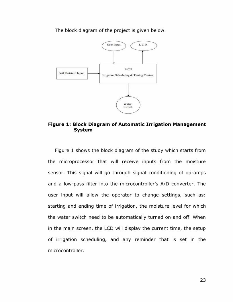
The block diagram of the project is given below.
Figure 1: Block Diagram of Automatic Irrigation Management System
Figure 1 shows the block diagram of the study which starts from
the microprocessor that will receive inputs from the moisture
sensor. This signal will go through signal conditioning of op-amps
and a low-pass filter into the microcontroller’s A/D converter. The
user input will allow the operator to change settings, such as:
starting and ending time of irrigation, the moisture level for which
the water switch need to be automatically turned on and off. When
in the main screen, the LCD will display the current time, the setup
of irrigation scheduling, and any reminder that is set in the
microcontroller.

24
From the main screen the operator can chose the menu and
select an option. There will also be three LEDs to indicate whether
or not the equipment is on or not. The water switch is controlled by
the microcontroller through a relay; the microcontroller takes the
soil moisture signal from the sensor, compares it with the pre-set
level, and makes the decision. The maximum dimensions are about
6x4x6 in. The control box will house the display, LEDs, control
buttons, the microcontroller and all the 5 volt DC devices. The input
line from the sensor will come into this box for signal conditioning
and processing. The control box will be supplied by an adaptor
through regular power line. (Galgalikar, 2010)
Additionally, from an online journal database, "Real-Time
Automation of Agricultural Environment for Social Modernization of
Indian Agricultural System focuses on using an ARM7TDMI Core 32-
bit microprocessor, GSM services which operate through SMS as a
link between ARM processor and centralized unit. GSM is used to
inform the user about exact field condition through a SMS on user
request. The GSM model is controlled by a standard set of AT
(Attention) commands. The system continuously monitors the soil
moisture, water level of the well, temperature, humidity, dew point,

25
weather conditions and provides the details about the field to user
though SMS.
The system consists of a centralized unit having a subscriber
number which forms a link between user and device and acts as a
primary node for sending and receiving the data though SMSs by
the user. The centralized unit communicates with the system
through SMSs which will be received by GS with the help of SIM
card; the GSM sends this data to ARM7, after processing it displays
it on the LCD. The activation command is given to start the motor
and indirectly activate the transistorized relay circuit to constantly
monitor the environmental factors and once the required level is
reached the motor is turned off and the message is sent to the
farmer. The system described uses ARM7, low power consuming
processor which is very important. GSM technology’s ready
availability, simplicity, less signal deterioration makes it better for
sending control signals and receiving updates over long distance.
(Galgalikar, 2010)
Next to that, "Real Time Automation of Indian Agricultural
System" which is very similar to the system presented in "Real-time
Automation of Agricultural Environment for Social Modernization of

26
Indian Agricultural System" deals with ARM7 and GSM combined
together for programming and developing the automated system. It
is. In the system, soil moisture is measured using dielectric
constant of soil and is informed to the centralized unit which sends
a message to the device which waits for a certain amount of default
time for user response if no response is received it continuously
monitors the field and keeps on sending the parameters to the
centralized unit where it is stored in the EEPROM of ARM.
Additionally, to monitor the plant or leaf’s health, a leaf wetness
sensor has been used allowing us to forecast disease and to protect
plan canopy. It uses ARM7TDMI, 16kb RAM, flash memory, In-
system programming with timers and serial interfaces and modems
for creating the real time applications. The system described also is
a low power consumer with simple and efficient GSM facilities. It
measures all possible soil environmental factors including the health
of the plant and detects amount of water or ice on the leaf’s surface
also. The drawbacks of the system are firstly farmer has to suffer
SMS costs due to the GSM facility, and bad range of the GSM
provider may also act as a limiting factor to the system.
(NagendraBabu, 2000)

27
Like the previous studies mentioned above, "Innovative GSM
Bluetooth Based Remote Controlled Embedded System for
Irrigation" proposes a system where GSM/Bluetooth based remote
controlled embedded system is used for irrigation. The system sets
the irrigation time depending on the environmental factors and can
automatically irrigate the field. Information, regarding the status of
power supply, is exchanged between the system using SMSs on
GSM network. In addition to the GSM a Bluetooth facility has also
been interfaced to the microcontroller for eliminating the SMS
charges and the range limitations. The system checks for the water
flow from the pump if no water supply is available system sends
information to user via Bluetooth/SMS. The sensor information is
sent to the farmer and the farmer sends data in the form of SMSs
in the GSM network to start of stop the irrigation according to the
received information. The system consists of an 8-bit PIC
microcontroller having inbuilt ADCs and interface to various sensor,
pump.
The system described above has incorporated Bluetooth for
remote monitoring which reduces the problem of range with GSM
network and saves SMS cost for the farmer. The sensors used to
send emergency information to user in case of fire in field or

28
burning of motor. The design is low power, low cost, small size,
robust and highly versatile. It has the same problems as the
systems above, that range of GSM and Bluetooth is not dependable
and user needs to familiarize too with many complexes AT
commands. (Gaatum, 2012)
Likewise, "Integration of Wireless Technologies for Sustainable
Agriculture" proposes the system that eliminates the use of wired
technology and improves the old method of collecting data and
allows the farmer to control their sprinklers remotely. It utilizes
wireless sensor networks to collect real time status of agricultural
field and uses mobile phone to control the watering of the field
using sprinkler.
The wireless sensor nodes collect information regarding water
level conditions and send the data to the central sink node which
processes the information and sends it to the user’s mobile phone
and he accordingly controls the watering of the field using sprinkler
controller. The nodes contain a sensor, radio transceivers, battery
and interfacing circuit. The system proposes the use of sprinklers
having two major features, pulsing (water application depth can be
controlled by a series of on-off cycles) and nozzle orifice control
29
(mechanically activated pin to alter the area which adjusts the
sprinkler flow rate), controlled by the sprinkler controller which in
turn has a GSM modem and a microcontroller. It uses a missed call
instruction format wherein each number of missed calls is
associated with a certain number of instructions to be performed,
which is calculated by the microcontroller. (Goli, 2011)
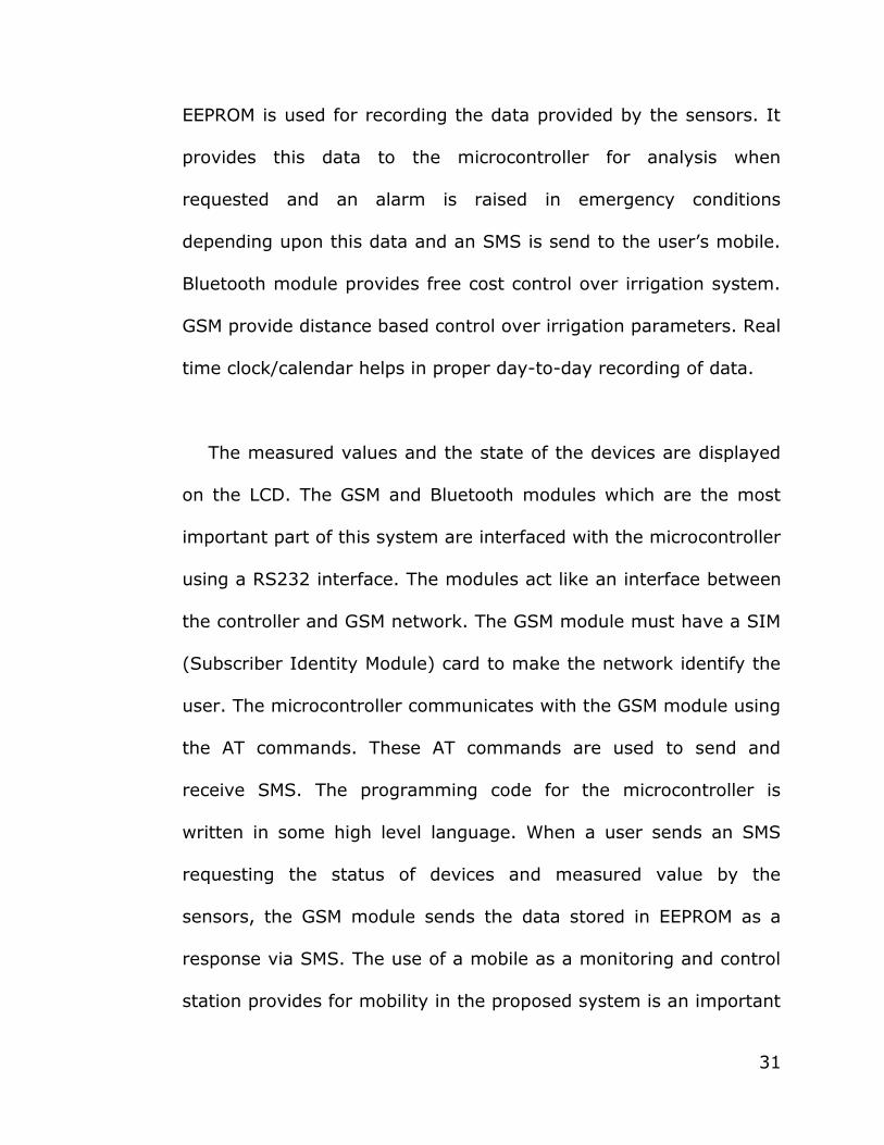
The paper "Design of Remote Monitoring and Control System
with Automatic Irrigation System using GSM-Bluetooth" gives a
review of remote control and monitoring systems based on existing
technologies and a GSM-Bluetooth based remote control and
monitoring system with automatic irrigation system. The design
presented has the advantage of both GSM and Bluetooth technology
and the sensors and devices are controlled by both by using
Bluetooth when in a limited range with the appliances and using
SMS for remote monitoring and control thereby reducing the usage
charges of GSM.

30
The figure below shows the block diagram of the system.
Figure 2: Block Diagram of Design of Remote Monitoring and Control System with Automatic Irrigation System
using GSM-Bluetooth
Figure 2 shows the block diagram of the system. The hardware
of the system mainly includes an 8-bit microcontroller chip, a GSM
module, a Bluetooth module and RS232 interfaces. The
microcontroller is interfaced with different sensors for controlling
different applications. Moisture sensor is used to sense the moisture
of soil moisture. Temperature sensor detects the temperature; CO2
gas sensor detects CO2 concentration and Humidity sensor
Humidity in analog form. The analog data from temperature sensor
and Humidity sensor is converted to digital using A/D converter.
31
EEPROM is used for recording the data provided by the sensors. It
provides this data to the microcontroller for analysis when
requested and an alarm is raised in emergency conditions
depending upon this data and an SMS is send to the user’s mobile.
Bluetooth module provides free cost control over irrigation system.
GSM provide distance based control over irrigation parameters. Real
time clock/calendar helps in proper day-to-day recording of data.
The measured values and the state of the devices are displayed
on the LCD. The GSM and Bluetooth modules which are the most
important part of this system are interfaced with the microcontroller
using a RS232 interface. The modules act like an interface between
the controller and GSM network. The GSM module must have a SIM
(Subscriber Identity Module) card to make the network identify the
user. The microcontroller communicates with the GSM module using
the AT commands. These AT commands are used to send and
receive SMS. The programming code for the microcontroller is
written in some high level language. When a user sends an SMS
requesting the status of devices and measured value by the
sensors, the GSM module sends the data stored in EEPROM as a
response via SMS. The use of a mobile as a monitoring and control
station provides for mobility in the proposed system is an important
32
backbone of all the existing internet based systems. (Purnima,
2011)
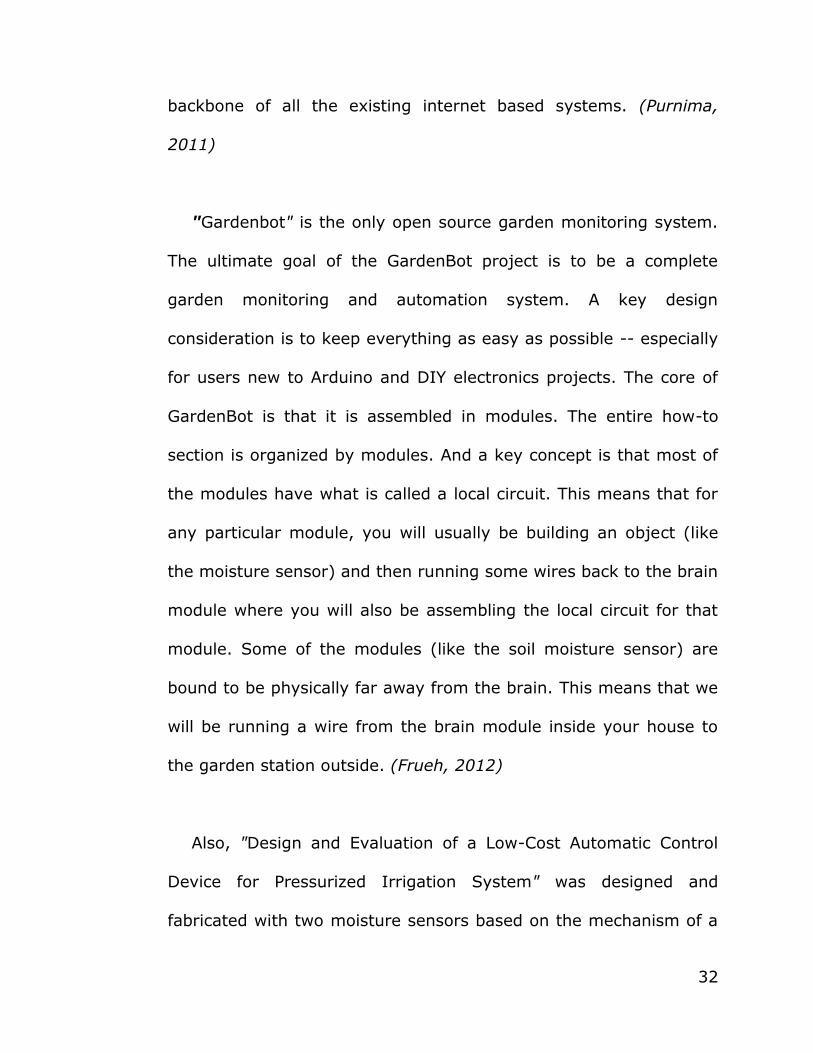
"Gardenbot" is the only open source garden monitoring system.
The ultimate goal of the GardenBot project is to be a complete
garden monitoring and automation system. A key design
consideration is to keep everything as easy as possible -- especially
for users new to Arduino and DIY electronics projects. The core of
GardenBot is that it is assembled in modules. The entire how-to
section is organized by modules. And a key concept is that most of
the modules have what is called a local circuit. This means that for
any particular module, you will usually be building an object (like
the moisture sensor) and then running some wires back to the brain
module where you will also be assembling the local circuit for that
module. Some of the modules (like the soil moisture sensor) are
bound to be physically far away from the brain. This means that we
will be running a wire from the brain module inside your house to
the garden station outside. (Frueh, 2012)
Also, "Design and Evaluation of a Low-Cost Automatic Control
Device for Pressurized Irrigation System" was designed and
fabricated with two moisture sensors based on the mechanism of a

33
typical home gardener’s soil moisture detector or sensor. The
sensors were actually resistance bridge circuits that compare the
resistance of the soil with reference values of the trimmer resistor
setting as indicated by the two LEDs (light emitting diode). Powered
by a 9V-battery when used as moisture sensor in home gardening,
the device was designed to drive other components of a pressurized
irrigation system like a 220-VAC electric motor and 6-A, 24-VAC
electric remote-control valves using power relays. The electric
motor was tasked to provide irrigation water to the system that
must be triggered by a relay synchronously connected with the
other driven units.
One of the solenoid valves served as a master valve. The master
valve, which is a necessary element of automated pressurized
irrigation, comes before series of valves to release pressure along
the pipe network. The probes were inserted into two pieces of
rubber at 5 cm apart to prevent them from short-circuiting. These
pieces of rubber were laid flat in the soil at 20 cm depth, the
average plowing and rooting depth of crops.
Using a 2.54-cm diameter pipe as soil sampler, moisture content
from each soil sample was determined by the gravimetric method.
34
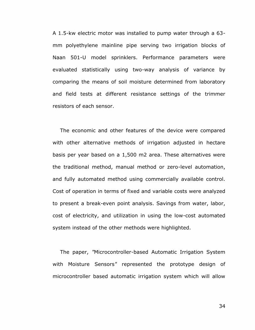
A 1.5-kw electric motor was installed to pump water through a 63-
mm polyethylene mainline pipe serving two irrigation blocks of
Naan 501-U model sprinklers. Performance parameters were
evaluated statistically using two-way analysis of variance by
comparing the means of soil moisture determined from laboratory
and field tests at different resistance settings of the trimmer
resistors of each sensor.
The economic and other features of the device were compared
with other alternative methods of irrigation adjusted in hectare
basis per year based on a 1,500 m2 area. These alternatives were
the traditional method, manual method or zero-level automation,
and fully automated method using commercially available control.
Cost of operation in terms of fixed and variable costs were analyzed
to present a break-even point analysis. Savings from water, labor,
cost of electricity, and utilization in using the low-cost automated
system instead of the other methods were highlighted.
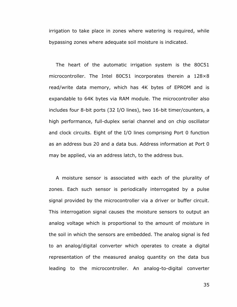
The paper, "Microcontroller-based Automatic Irrigation System
with Moisture Sensors" represented the prototype design of
microcontroller based automatic irrigation system which will allow
35
irrigation to take place in zones where watering is required, while
bypassing zones where adequate soil moisture is indicated.
The heart of the automatic irrigation system is the 80C51
microcontroller. The Intel 80C51 incorporates therein a 128×8
read/write data memory, which has 4K bytes of EPROM and is
expandable to 64K bytes via RAM module. The microcontroller also
includes four 8-bit ports (32 I/O lines), two 16-bit timer/counters, a
high performance, full-duplex serial channel and on chip oscillator
and clock circuits. Eight of the I/O lines comprising Port 0 function
as an address bus 20 and a data bus. Address information at Port 0
may be applied, via an address latch, to the address bus.
A moisture sensor is associated with each of the plurality of
zones. Each such sensor is periodically interrogated by a pulse
signal provided by the microcontroller via a driver or buffer circuit.
This interrogation signal causes the moisture sensors to output an
analog voltage which is proportional to the amount of moisture in
the soil in which the sensors are embedded. The analog signal is fed
to an analog/digital converter which operates to create a digital
representation of the measured analog quantity on the data bus
leading to the microcontroller. An analog-to-digital converter
36
suitable for use in the system is ADC 0809. It comprises a
monolithic CMOS device with an 8-bit A/D converter, an 8-channel
multiplexer and microcontroller compatible control logic. Using
successive approximation as the conversion technique, this 8-bit
A/D converter is readily interfaced to its associated microcontroller
by the latched and decoded multiplexer address inputs and latched
TTL tri-state outputs.
The heart of the automatic irrigation system is the 80C51
microcontroller. The Intel 80C51 incorporates therein a 128×8
read/write data memory, which has 4K bytes of EPROM and is
expandable to 64K bytes via RAM module. The microcontroller also
includes four 8-bit ports (32 I/O lines), two 16-bit timer/counters, a
high performance, full-duplex serial channel and on chip oscillator
and clock circuits. Eight of the I/O lines comprising Port 0 function
as an address bus 20 and a data bus. Address information at Port 0
may be applied, via an address latch, to the address bus.
A moisture sensor is associated with each of the plurality of
zones. Each buffer circuit. This interrogation signal causes the
moisture sensors to output an analog voltage which is proportional
to the amount of moisture in the soil in which the sensors are
37
embedded. The analog signal is fed to an analog/digital converter
which operates to create a digital representation of the measured
analog quantity on the data bus leading to the microcontroller. An
analog-to-digital converter suitable for use in the system is ADC
0809. It comprises a monolithic CMOS device with an 8-bit A/D
converter, an 8-channel multiplexer and microcontroller compatible
control logic. Using successive approximation as the conversion
technique, this 8-bit A/D converter is readily interfaced to its
associated microcontroller by the latched and decoded multiplexer
address inputs and latched TTL tri-state outputs. (AbhinavRajpal,
2012)
Lastly, "Microcontroller Based Drip Irrigation System" is
composed of moisture sensors, temperature sensors, Signal
conditioning circuit, Digital to analog converter, LCD Module, Relay
driver, solenoid control valves, etc.
The important parameters to be measured for automation of
irrigation system are soil moisture and temperature. The entire field
is first divided in to small sections such that each section should
contain one moisture sensor and a temperature sensor. RTD like
PT100 can be used as a temperature sensor while Densitometer can
38
be used as the moisture sensor to detect moisture contents of soil.
These sensors are buried in the ground at required depth. Once the
soil has reached desired moisture level the sensors send a signal to
the micro controller to turn off the relays, which control the valves.
The signal send by the sensor is boosted unto the required level by
corresponding amplifier stages. Then the amplified signal is fed to
A/D converters of desired resolution to obtain digital form of sensed
input for microcontroller use.
A 16X1 line LCD module can be used in the system to monitor
current readings of all the sensors and the current status of
respective valves. The solenoid valves are controlled by
microcontroller though relays. A Chemical injection unit is used to
mix required amount of fertilizers, pesticides, and nutrients with
water, whenever required. Varying speed of pump motor can
control pressure of water. It can be obtained with the help of PWM
output of microcontroller unit. A flow meter is attached for analysis
of total water consume. (Ashok, 2010)
To sum it all, this present study had surely been supported by
the related literature and studies presented above.

39
B. Synthesis
The proponents believe that each and every literature and
studies stated in this paper is similar on the present study. The
proponents relate and differentiate the studies based on the
implications of the concepts presented and the materials used.
Microcontroller plays a vital role in developing automated
systems. Numerous systems like that of the irrigation are being
controlled by different types of microcontroller. The study,
―Automatic Irrigation System on Sensing Soil Moisture Content‖,
programmed an 8051 series microcontroller to receive the input
signal of varying moisture condition of the soil through the sensing
arrangement. While that of, ―Project Report: Automated Irrigation
System using MSP430‖ make use of MSP430G2231, a 16-bit Ultra-
Low Power MCU to decides when should the pump be turned on/off.
Additionally, ―Real-Time Automation of Agricultural Environment for
Social Modernization of Indian Agricultural System‖ focused on
ARM7TDMI Core 32-bit microprocessor. Furthermore, the core of a
watering system named as ―GardenBot‖ is assembled in module of
an Arduino microcontroller. Meanwhile, Innovative ―GSM Bluetooth
Based Remote Controlled Embedded System for Irrigation‖ build
40
their system using 8-bit PIC microcontroller having inbuilt ADCs and
interface to various sensor, pump. Like the previous study, the
brain of this system, ―A Microcontroller Based Plants Irrigation
System with SMS Notification and Controller‖ will be constructed
using PIC16F877A. This will acts as the brain of the system that will
receive inputs from the sensors and GSM modem. As well as the
output data on a LCD and the SMS for the notification for the
farmers.
Different sensors are designed for various applications including
that for the irrigation. Sensors which are interface to the
microcontroller play a vital key in automating systems. “Project
Report: Automated Irrigation System using MSP430‖ which make
use of VG 400 soil moisture. The sensor takes input from the soil
and if there is less moisture in the soil, the sensor would give an
Analog input to the ADC inside the MSP430. Addition to that, the
study ―Remote Monitoring of Soil Moisture‖ used improvised
sensors, installed at several fairway locations, monitor soil moisture
by measuring the dielectric strength of the soil at depths of 4, 8,
and 16 inches. The data are transmitted directly to a base. Aside
from an improvised resistive soil moisture sensor, study like
―Gardenbot‖ used of LM 335 temperature sensor and light sensor
41
using photocell. While this study is designed with one calibrated
soil moisture sensor and four improvised resistive soil moisture.
Remote monitoring of the condition of the plants can be done
through various technologies. ―Automatic Irrigation Management
System‖ scheduled the irrigation through the settings set on a
computer desktop and in the microcontroller. From the main screen
the operator can chose the menu and select an option. While,
―Innovative GSM Bluetooth Based Remote Controlled Embedded
System for Irrigation‖ focused on the remote controlled embedded
system for irrigation through GSM and Bluetooth. The system sets
the irrigation time depending on the environmental factors and can
automatically irrigate the field. Information, regarding the status of
power supply, is exchanged between the system using SMSs on
GSM network. In addition to the GSM, a Bluetooth facility has also
been interfaced to the microcontroller for eliminating the SMS
charges and the range limitations. Lastly, this study covered GSM
modem to notify the user about the condition of the plants and
enable the user to control the turning on/off of the submerged
pump.
42
To sum it all, this study surely had been supported by the
related literature and studies presented above.
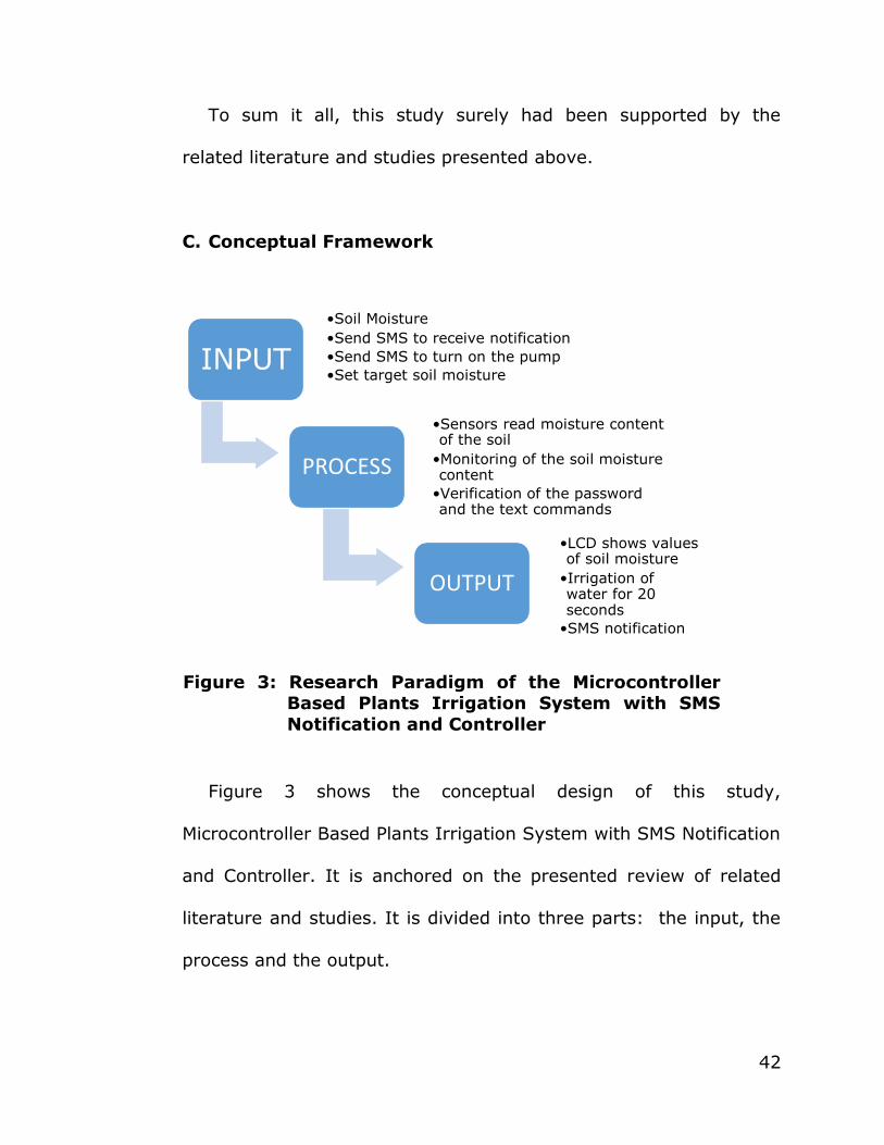
C. Conceptual Framework
Figure 3 shows the conceptual design of this study,
Microcontroller Based Plants Irrigation System with SMS Notification
and Controller. It is anchored on the presented review of related
literature and studies. It is divided into three parts: the input, the
process and the output.
INPUT
•Soil Moisture
•Send SMS to receive notification
•Send SMS to turn on the pump
•Set target soil moisture
PROCESS
•Sensors read moisture content of the soil
•Monitoring of the soil moisture content
•Verification of the password and the text commands
OUTPUT
•LCD shows values of soil moisture
•Irrigation of water for 20 seconds
•SMS notification
Figure 3: Research Paradigm of the Microcontroller Based Plants Irrigation System with SMS
Notification and Controller
43
The input to the system includes the value of the moisture
content of the soil that will be fed using the sensors employed in
different part of the land. The idea of putting more than one soil
moisture sensors is to make sure that the moisture content of every
portion of the land is being monitored. Also, the target soil moisture
depends on the desired value of the user. Next, the user will need
to send a SMS query to be able to receive a text notification
regarding the condition of the soil. Also, the user can send a SMS to
start the irrigation. The MCU will check if the right password and
text format is satisfied. A password had been set to ensure that
only authorize user/users will be able to control the system. Once,
the MCU has verified that the user wishes to receive a notification,
the system will send a text notification that contains the current soil
moisture values as well as the target soil moisture. The system will
start the irrigation process if the user sends to turn on the pump or
when majority of the soil moisture is above the target soil moisture.
The reason behind the remote control of the irrigation is to allow
the user to turn on the pump without solely relying on the soil
moisture content. The releasing of water is for only 20 seconds to
make sure that the water goes down to the bottom of the soil and
to prevent the top layer from being saturated. Then, for a minute
the process of monitoring will start again.
44
Chapter III
METHODOLOGY
This chapter discussed about the processes, technical procedures
and some concepts and specification of each components used in the
said project ―Microcontroller Based Plants Irrigation System with SMS
Notification and Controller‖ and on how it is to be done.
A. Research Design
The project entitled ―Microcontroller Based Plants Irrigation
System with SMS Notification and Controller‖ uses an experimental
type of research method where the researcher manipulates
independent variables and measures dependent variables in order
to establish cause-and-effect relationships between them. In this
project the independent variables are the detection of the moisture
and the GSM module while the dependent variable is the pump. The
proponents is developing a device that monitors the moisture of the
soil by using a soil moisture sensor/detector, a pump to irrigate
plants if needed, LCD display for the status of the soil, and a GSM
to be able the user to monitor his/her plant through SMS. The
researchers chose this method because it is the most appropriate,
45
and the project requires testing to determine every cause and effect
for the accuracy of the project.
B. Process
In achieving expected output for the Microcontroller based Plants
Irrigation System with SMS Notification and Controller, series of
study, planning and development are needed to be satisfy. In this
section, the proponents present the conceptual framework of the
design, the functional diagram of the prototype, how the prototype
will be developed as well as its functionality and the integration of
its hardware and software components, and its requirement
analysis and design.
1. Functional Block Diagram
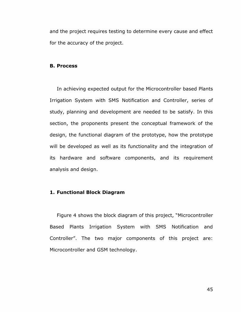
Figure 4 shows the block diagram of this project, ―Microcontroller
Based Plants Irrigation System with SMS Notification and
Controller‖. The two major components of this project are:
Microcontroller and GSM technology.
46
Figure 4: Block Diagram of Microcontroller Based Plants Irrigation with SMS Notification and Controller
The soil moisture content will be monitored base on the set
target soil moisture. The reading from the sensor will now be the
input to the microcontroller and will be the basis of the triggering of
the pump. If the reading of majority of the land area is below the
set target moisture the pump will be trigger and the sprinkler will

47
water the soil, otherwise the monitoring of the soil moisture
continue.
As for the GSM, the user can trigger the pump by texting or
make an inquiry to the prototype simply by encoding the password
and the command for the triggering of the pump or for the status of
the soil. The prototype will also be sending the current status of the
soil for the notification to the user.
2. Prototype Development
In order to develop an effective and efficient prototype, the
proponents prepared a set of objectives, to be able to meet the
desired functionality of the prototype. Also, the design of the
prototype and the hardware components is taking into
consideration to maximize the functionality of the prototype.

48
a. Prototype Objectives
The prototype aims to achieve the following objectives:
1. To be able to determine the target soil moisture and relative
values of a loamy soil using soil moisture sensor;
2. To be able to feed the values from the soil moisture sensors to
the microcontroller;
3. To be able to automate the watering of the plants using
submersible pump and sprinkler; and
4. To be able to interface GSM technology to the microcontroller.
b. Prototype Functionality
The prototype is design to meet its objectives and processes.
The functionality requirement of the system is divided into two
tasks: the automation of the watering of the plants through soil
moisture sensors interfaced to the microcontroller and the
notification and controller using GSM technology.
The interactions of components such as the soil moisture
sensors, LCD, pump and as well as the GSM modem takes place in

49
the microcontroller. The microcontroller receives the response of
the soil moisture sensors. The sensors make use of probes that
measure and convert electrical resistance to soil moisture content.
The soil moisture content is in terms of output voltage. The idea of
multiple sensors employ in the system is to be able to measure soil
moisture content at more than one place. Additionally, the concept
of majority wins condition in triggering the pump is based on the
fact that different parts of the field may have a different amount of
moisture at the same time but the interval for them to dry is close
considering they are in one place.
Additionally, the soil moisture content in terms of relative values
(ranging from 0-13) will be shown to LCD. The relative values make
it easier for the user to understand the soil moisture and avoid the
messy details of the digital output coming from the microcontroller.
In case majority of the soil moisture sensors reaches a critical level,
the pump turns on and the system starts to irrigate water using a
dedicated sprinkler for each land area. The system will pump water
for a predetermined time (20 seconds) to ensure that the upper
part of the soil will not be drown from too much water. After that,
the system will check if the plants are still thirsty. If the sensors

50
detect that the plants still need water, the process will repeat until
lower soil moisture content has been achieved.
The second component, GSM technology allows user to receive
notification about the status of the plants in terms of soil moisture.
However, to minimize the continuous notification that requires
monetary fund, the user can only receive a text notification if an
inquiry is made. Lastly, remote control by sending a text command
can be used to trigger the watering of the plants.
c. Prototype Design
To achieve an expected result, the design of the prototype
should take into consideration.
The proponents decided to have a rectangular land area and is
equally divided into five land area. Tubular aluminium is use as the
framework of the land area. Also, the proponents attached a PVC
tube to the tubular aluminium for the pathway of the water. A
sprinkler is also attached to each land area. An identical five basin
is use for the container of the soil each having a soil moisture
sensor. The reading of the moisture sensor will then be display on a

51
16x2 LCD. A nozzle hose is connected to the submersible pump to
the PVC tube for continuous circulation of the water.
Figure 5 is the prototype of the Microcontroller-Based Plants
Irrigation System with SMS Notification and Controller.
Figure 5: Prototype of the Microcontroller-Based Plant Irrigation System with SMS Notification and
Controller
The design is composed of the following:
1. Soil moisture sensor
2. Loamy soil
52
3. Hose with water sprinkler
4. LCD on control panel(unit)
5. Water container
6. Submersible water pump
7. Hose
d. Hardware Components
The following materials comprise the physical output of the
Microcontroller Base Plants Irrigation System with SMS Notification
and Controller. The integration of each component to the prototype
plays an important role to the implementation of the prototype.
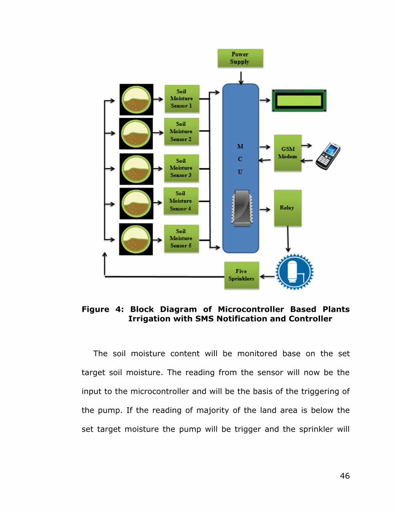
(1) Soil Moisture Sensor
Soil Moisture Sensor Immersion Gold is use for the prototype.
The soil moisture sensor is place underneath the soil and is
connected to the microcontroller. The proponents set relative values
that range from 0-13 that serves as the basis of the target soil
moisture.
53
Figure 6: Moisture Sensor
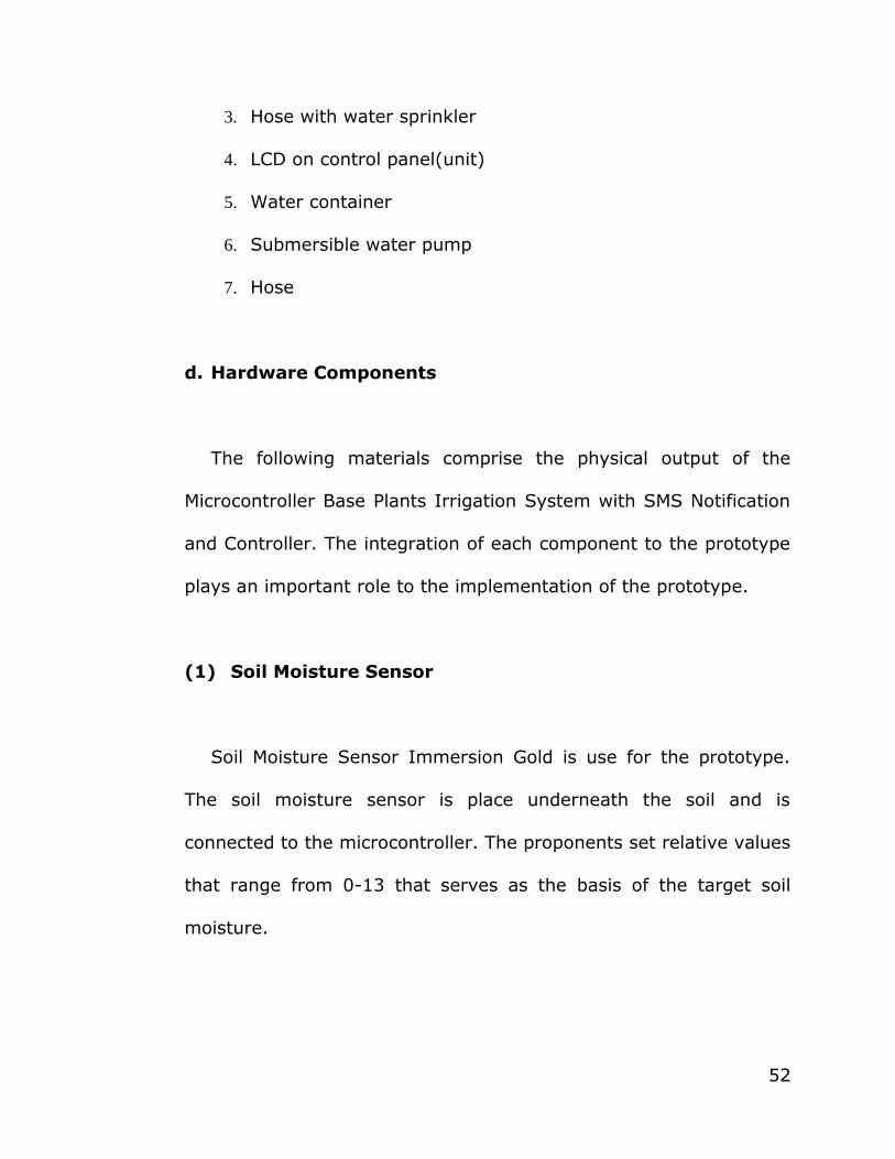
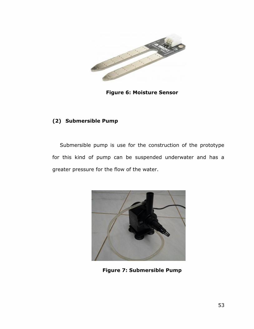
(2) Submersible Pump
Submersible pump is use for the construction of the prototype
for this kind of pump can be suspended underwater and has a
greater pressure for the flow of the water.
Figure 7: Submersible Pump
54
(3) Sprinkler
A sprinkler is use for the watering of the soil. An adjustable
sprinkler is chosen for the user to manipulate how the water will
output through the sprinkler.
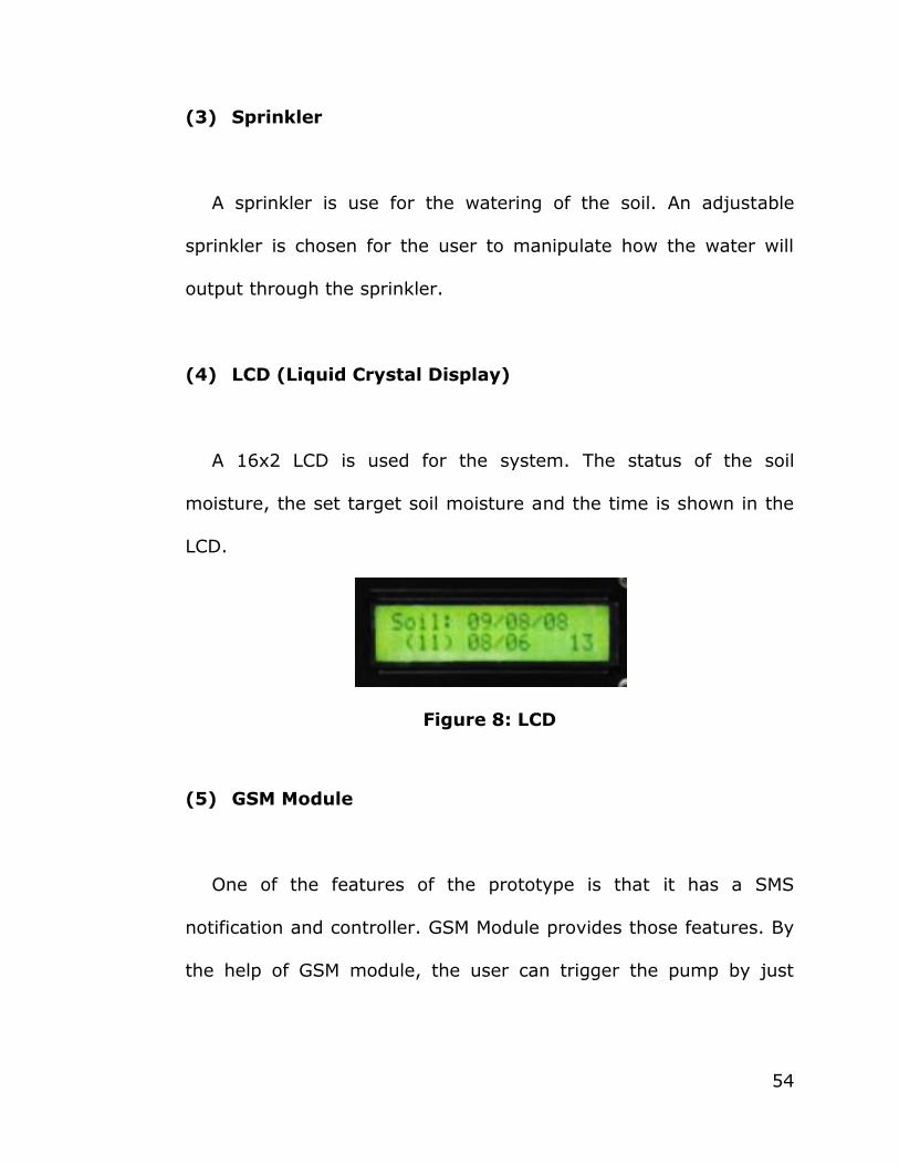
(4) LCD (Liquid Crystal Display)
A 16x2 LCD is used for the system. The status of the soil
moisture, the set target soil moisture and the time is shown in the
LCD.
Figure 8: LCD
(5) GSM Module
One of the features of the prototype is that it has a SMS
notification and controller. GSM Module provides those features. By
the help of GSM module, the user can trigger the pump by just

55
texting the system provided that the user input the right password
and format for the GSM module.
Figure 9: GSM Module
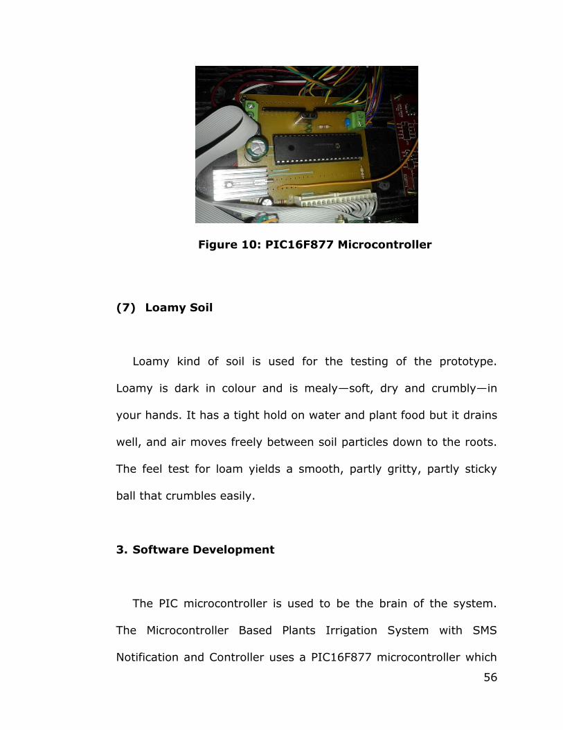
(6) PIC Microcontroller
PIC Microcontroller is used for the integration of the hardware
and software. PIC16F877 is a 40- pin microcontroller. Assembly
language is used as the programming language for the MCU.
56
Figure 10: PIC16F877 Microcontroller
(7) Loamy Soil
Loamy kind of soil is used for the testing of the prototype.
Loamy is dark in colour and is mealy—soft, dry and crumbly—in
your hands. It has a tight hold on water and plant food but it drains
well, and air moves freely between soil particles down to the roots.
The feel test for loam yields a smooth, partly gritty, partly sticky
ball that crumbles easily.
3. Software Development
The PIC microcontroller is used to be the brain of the system.
The Microcontroller Based Plants Irrigation System with SMS
Notification and Controller uses a PIC16F877 microcontroller which
57
is programmed using an assembly language. The development of
the software comprises of the integration of the program for the
GSM module, the reading of the soil moisture sensor to be
outputted using an LCD and the triggering of the water pump.
a. Requirement Analysis and Design
This project’s requirement is to be able to water the plants
whenever the target moisture is reached, the software is design to
decide if the target moisture is reached and trigger the pump if
needed. The proponents used Assembly Language to program the
software to the PIC Microcontroller.
b. System Design
The system has one design which is the unified parts of the
system: the automation of the watering of the plants and the
notification and controller using GSM technology.
For the automation of watering the plants this is composed of
soil moisture sensors and a submersible pump. These components
serve as an input/output to the microcontroller (a circuit that

58
manipulates and controls the whole system to function). The soil
moisture sensors will send a moisture value to the microcontroller
as an input. The microcontroller will read the value, it will trigger or
turn on the submersible pump if the reading is below the set target
moisture and if not, the soil moisture sensor will just continue
checking.
For the notification and controller, the GSM module can be used
to turn on the submersible pump to water the plants and to get
status of the plants. By sending a text message to the GSM, one
can control the system. Texting a four-digit password and a
command S the system will text back the status of the five land
area. For example: 1111 S send to 09182833954. And for watering
the plants, text 1111 S1.
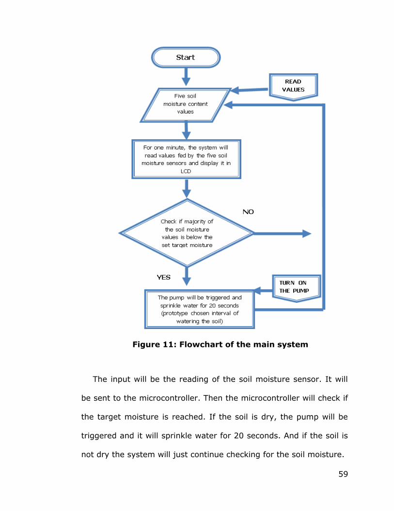
c. Flowchart
Figure 11 shows the flow of the system in automated watering of
the plants part. The flowchart is divided into two: first is the
automation of the watering of the plant; and the other is for the
notification and control of the system using the GSM Technology.
59
Figure 11: Flowchart of the main system
The input will be the reading of the soil moisture sensor. It will
be sent to the microcontroller. Then the microcontroller will check if
the target moisture is reached. If the soil is dry, the pump will be
triggered and it will sprinkle water for 20 seconds. And if the soil is
not dry the system will just continue checking for the soil moisture.
60
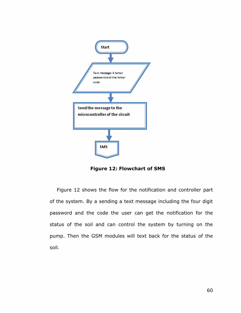
Figure 12: Flowchart of SMS
Figure 12 shows the flow for the notification and controller part
of the system. By a sending a text message including the four digit
password and the code the user can get the notification for the
status of the soil and can control the system by turning on the
pump. Then the GSM modules will text back for the status of the
soil.

61
Figure 13: Flowchart of the GSM module
62
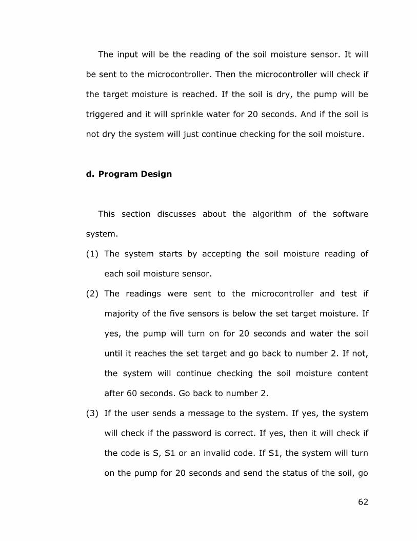
The input will be the reading of the soil moisture sensor. It will
be sent to the microcontroller. Then the microcontroller will check if
the target moisture is reached. If the soil is dry, the pump will be
triggered and it will sprinkle water for 20 seconds. And if the soil is
not dry the system will just continue checking for the soil moisture.
d. Program Design
This section discusses about the algorithm of the software
system.
(1) The system starts by accepting the soil moisture reading of
each soil moisture sensor.
(2) The readings were sent to the microcontroller and test if
majority of the five sensors is below the set target moisture. If
yes, the pump will turn on for 20 seconds and water the soil
until it reaches the set target and go back to number 2. If not,
the system will continue checking the soil moisture content
after 60 seconds. Go back to number 2.
(3) If the user sends a message to the system. If yes, the system
will check if the password is correct. If yes, then it will check if
the code is S, S1 or an invalid code. If S1, the system will turn
on the pump for 20 seconds and send the status of the soil, go

63
back to 2. If S, it will send the status of the soil go back to 2. If
invalid, then it will do nothing and go back to 2.
(4) If not, then it will do nothing and continue checking.
C. Prototype Construction
The project entitled Microcontroller Based Plants Irrigation
System with SMS Notification and Controller is composed of several
hardware components. This section tackles about how hardware
components are done. This include the step by step process on how
to do it, the materials used, the cost and the benefit of the user.
1. Procedures in the Construction of Prototype
This design project was constructed based on its functionality.
Since the entire system is composed of several components this
section tackles about how those components are done.
For the Microcontroller circuit
(a) Gather the materials needed
(b) Design a PCB Layout
(c) Solder the materials to the PCB

64
(d) Program the software into the microcontroller
For the power supply
(a) Gather the materials needed
(b) Design a PCB Layout
(c) Solder the materials to the PCB
For the packaging of the prototype
(a) Place the soil in a basin that measures approximately 1sq. ft.
(b) Cut the tubular aluminium, and form it in a rectangular
shape,
(c) Place the PVC tube around the rectangular shape and on
every front view of soil that look like a faucet to each basin of
soil
(d) At the end of the PVC on each basin of soil put a sprinkler
2. Materials Used
This section presents the materials used in the construction of
the prototype.
65
These soil moisture sensors can read the amount of moisture
present in the soil surrounding it. It uses the two probes to pass
current through the soil, and then it reads that resistance to get the
moisture level. More water makes the soil conduct electricity more
easily (less resistance); while dry soil conducts electricity poorly
(more resistance). The output of these sensors will be sent as an
input to the microcontroller.
The 16x2 LCD was used in this project. This is used to display
the dryness and wetness of the soil ranging from 0-13. This is
connected to the microcontroller where it will get the data being
displayed. It can display 16 characters per line and there are 2 such
lines. In this LCD each character is displayed in 5x7 pixel matrix.
This LCD has two registers, namely, Command and Data. The
command register stores the command instructions given to the
LCD. A command is an instruction given to LCD to do a predefined
task like initializing it, clearing its screen, setting the cursor
position, controlling display etc. The data register stores the data to
be displayed on the LCD. The data is the ASCII value of the
character to be displayed on the LCD.
66
This system also includes a GSM module for controlling the
system through a mobile phone. The user can enable the watering
of the plants through GSM module by using a mobile phone. For the
status of the plants, the user must subscribed first by sending a
command to the GSM module. This command is composed of a four
letter password, then space and then S for the Status. The
operation of the entire system will not be affected if the network of
the GSM module fails.
A submersible pump was used for the sprinklers to release
water. The MCU sends the output to the relay and triggers the
pump to release water when the soil is dry.
These 4 components are connected to the microcontroller. The
PIC 16F877A Microcontroller was used in this project. This was
programmed to manipulate the inputs to its respective outputs. The
PIC 16F877A is one of the most popular PIC microcontrollers and
it's easy to see why - it comes in a 40 pin DIP pin out and it has
many internal peripherals. The 40 pins make it easier to use the
peripherals as the functions are spread out over the pins. This
makes it easier to decide what external devices to attach without
worrying too much if there enough pins to do the job.

67
D. Implementation
The proponents take into consideration the important variables
in simulating the device, the simulation procedures in the setup of
the prototype, how the device operates, the experimental
procedures in testing the prototype, and the evaluation of the
effectiveness of the system by implementing and conducting
different types of testing.
1. Important Variable in Simulating the Device Prototype
The proponents considered variables in simulating the device
prototype. These are the following:
a. Soil moisture content
Soil moisture content should be considered in simulating the
device prototype because it is the input of the soil moisture sensor
to the microcontroller. The soil moisture content serves as a basis
in testing the dryness and wetness of the soil.

68
b. Time when to release water
The duration of how long the water will supply the soil is also
considered in simulating the device prototype since it will control
the amount of water to be released. The proponents set the timer
to 20 seconds. The time limit considered is just enough for the
submersible pump to supply all the spaces on the land area.
c. Prepaid balance
The prepaid balance or the load of the GSM module is also
considered in the simulation of the device prototype for it will be
used as the source of the GSM module should have enough balance
for the user to receive notifications of the status of the soil and to
be able to turn on the irrigation using text commands.
d. Land area
The land area is also an important variable in simulating the
device prototype because it determines the number of dry land
area. When the majority of the land area is dry, it is the only time
when the submersible pump will release water. For this system,
69
there are five moisture sensors in five land areas. Three or more
out of five dry land areas will trigger the submersible pump to
release water.
2. Simulation Procedure of the Prototype
In simulating the prototype, the proponents setup the following
procedures:
a. Place the controller to a secure area.
b. Place the moisture sensor to five different land areas.
c. Plugged in the controller to a 220-V power supply to initialize
the system.
d. Set the potentiometer by selecting an appropriate target
moisture content ranging from 0-15. This will serve as the
reference of the moisture sensor for the dryness and wetness
of the soil. Below the target moisture content means that the
soil is dry and vice versa.
e. The system will automatically check the status of the soil every
minute. Once the moisture sensor detects 3 or more out of five
dry land areas, the submersible pump will release water for 20
seconds and continue to check the status.
70
The user can also check the status of the soil and water the plant
by sending SMS to the system.
3. Device Operation
The device operation of the system has a soil moisture content
which serves as the input to the system. The microcontroller gets
its input to the moisture sensor and controls the other part of the
system. The step-by-step operation of the system is state below:
a. Initially, the moisture sensor checks the soil moisture content
of the soil.
b. The microcontroller serves as the heart of the system because
it is where all other parts are connected.
c. The relay will receive input to the microcontroller and will
trigger the submersible to release water.
d. The GSM module serves as a link between the user and the
controller to interact.

71
E. Experimental Procedures in Testing the Prototype
The step-by-step procedure in constructing and completing the
modules and components of the system for testing the prototype
are the following:
1. Gather all the materials needed for testing.
2. Setup all the gathered materials and test each component.
3. Test the moisture content of the soil by placing a moisture
sensor and wait for the checking of the status to be displayed in
the LCD.
4. Fill the container with water for the submersible pump. For when
the soil is dry, it will release water.
5. Set a password for the system.
6. The system will continually check the status of the soil.
F. Evaluation of the Effectiveness of the System
The testing of the effectiveness of the system is based on
different testing made by the proponents. They used different
parameters that will help in the performance of the prototype.
72
1. Testing the Effectiveness of the System
To check the system’s effectiveness, different tests will be
initiated. The system should deliver the right outcome by testing
the dryness and wetness of the soil and the amount of water
released by the submersible pump to test the effectiveness of the
system. Different parameters were performed to test the system
and these are the following:
a. Area – Since the land area is 1 ft.2 the amount of water
needed should be enough for the whole land area to be wet.
b. Force of the submersible pump – Since it was only a
prototype, the amount of water being released was sufficient
enough to water the whole land area. The speed of the
propeller should be considered.
c. Type of soil – The type of soil should be considered in testing
the effectiveness of the system because it will affect the
reference value of the soil moisture content. That is why the
proponents put a potentiometer on the controller to vary the
value to the type of soil used.
73
d. Power supply – The power supply which gives electrical
power to the system is another thing to consider, without this
the device would not work. A 220-V power supply is needed for
the system to operate.
2. System Evaluation
When the necessary modules and components are complete, the
first thing to do is to test every module by measuring the voltage to
ensure that the modules are working. Upon testing every unit of the
system, assembly is the next thing to do. Connect every module
and components according to the system design. When the
modules were connected, series of testing are conducted to ensure
that the desired collaboration between modules is aimed.
Upon checking each component of the system, the proponents
construct the system using the PIC microcontroller. After
constructing the correct program for the system using the MPlab
software, compile and upload to the PIC board. Connect each pin of
the components to the correct pin configuration to the PIC board.
74
Chapter IV
PRESENTATION AND INTERPRETATION OF DATA
This chapter presents the components used and shall discuss the
findings obtained from the primary instrument used in the study. In
order to simplify the discussions, the researcher provided tables to
summarize the gathered data.
A. Testing the Effectiveness of the System
The design undergoes different testing to attain the desirable
result. Different testing is consisting of the following:
1. Testing for the time needed to water the plants
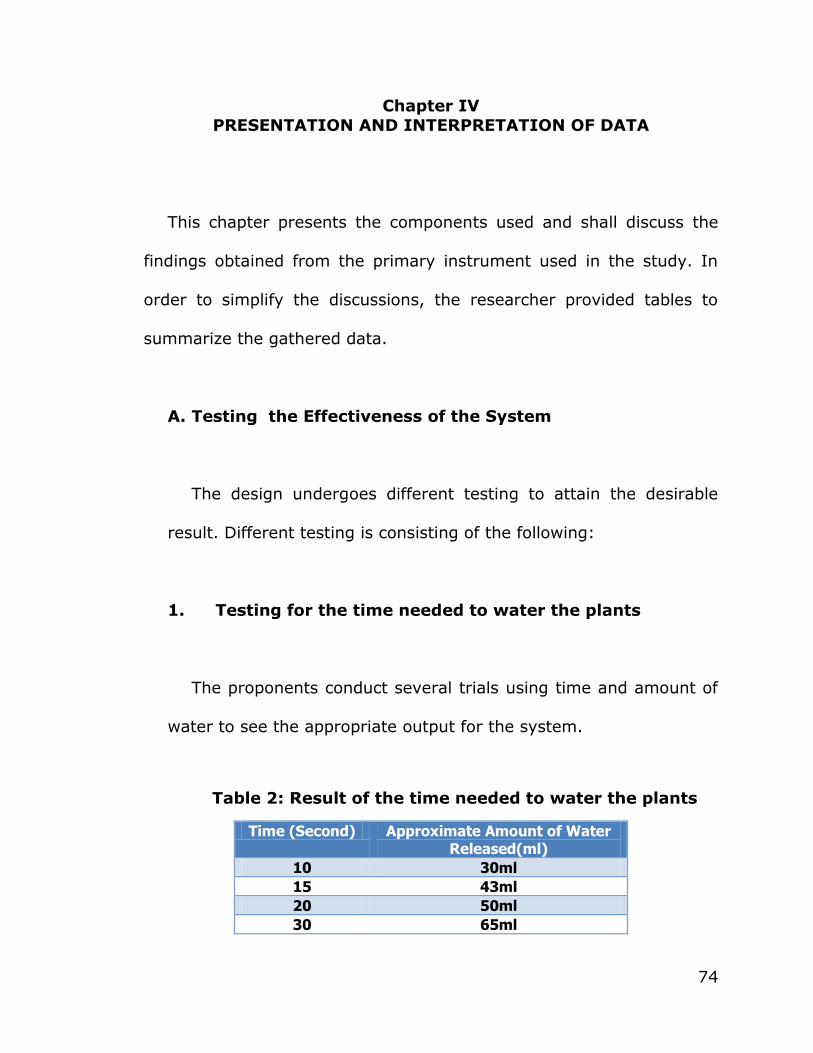
The proponents conduct several trials using time and amount of
water to see the appropriate output for the system.
Table 2: Result of the time needed to water the plants
Time (Second) Approximate Amount of Water Released(ml)
10 30ml
15 43ml
20 50ml
30 65ml
75
Table 3 shows that amount of water released by the submersible
pump that varies over time. The longer the time set, the higher the
amount of water being released. Among the time set, the most
desirable is 20 seconds because the water being released which is
approximately; 50 ml is enough to water per land area and
maintain the good condition of the soil.
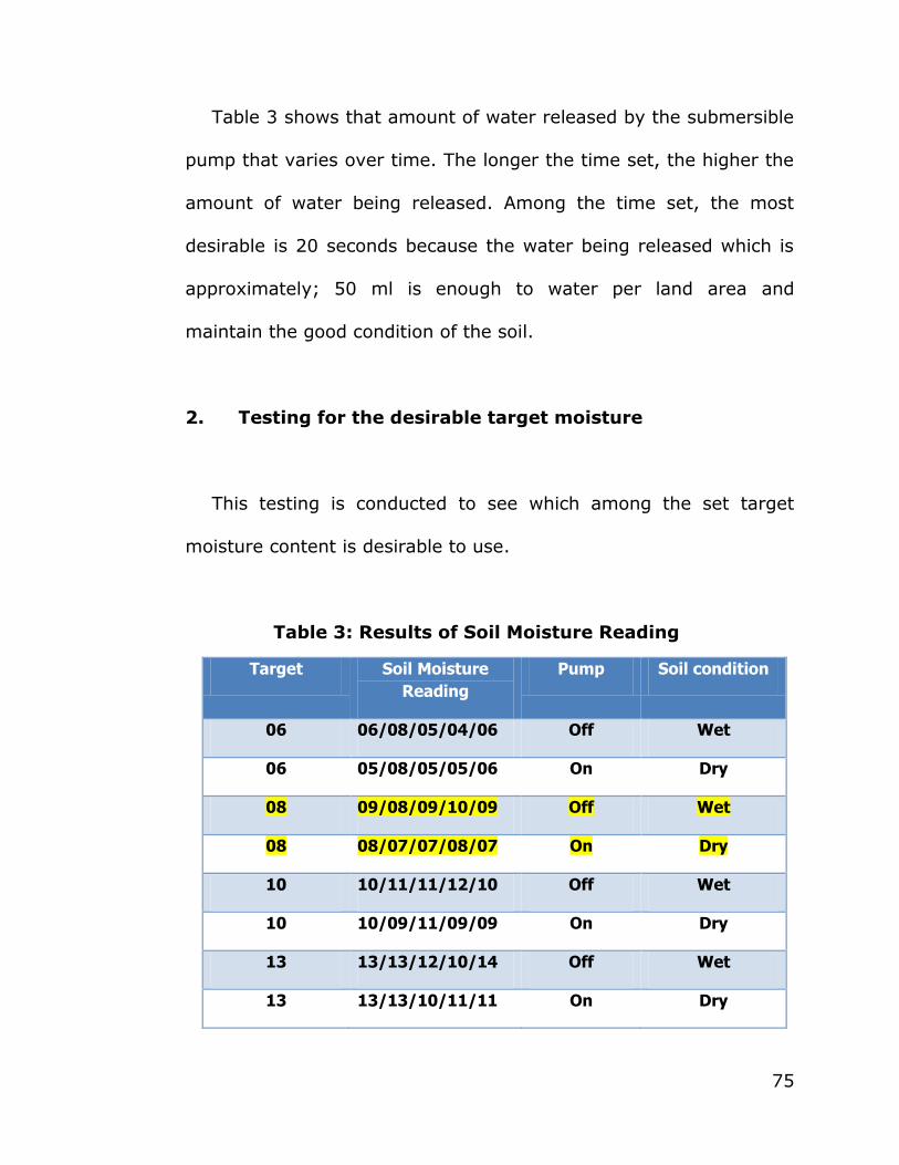
2. Testing for the desirable target moisture
This testing is conducted to see which among the set target
moisture content is desirable to use.
Table 3: Results of Soil Moisture Reading
Target Soil Moisture
Reading
Pump Soil condition
06 06/08/05/04/06 Off Wet
06 05/08/05/05/06 On Dry
08 09/08/09/10/09 Off Wet
08 08/07/07/08/07 On Dry
10 10/11/11/12/10 Off Wet
10 10/09/11/09/09 On Dry
13 13/13/12/10/14 Off Wet
13 13/13/10/11/11 On Dry

76
Table 4 shows different cases when varying the target soil
moisture. The system is constructed in such a way that target soil
moisture can be accustomed depending on the type of soil. Through
this testing, the proponents were able to determine the desirable
target moisture for a loamy soil which is 8. Also, it shows how
majority wins condition is being implemented in the system. If the
majority of the five relative values are lower than 8, it means that
the soil needs water and the system will react. Once, majority of
the five relative values read a value greater than the 8, the soil is
wet and does not need to be watered.
3. Testing for arbitrary of watering the plant (target
moisture is set to 08)
This test is conducted to see how the arbitration works on the
device. The conditions of the soil will control the triggering of the
pump to water the soil.

77
Table 4: Results in testing the majority wins logic
Trials Soil moisture
sensor readings
(NUMERICAL)
Soil
Condition
Pump
condition
1 07/06/07/08/08 DRY/DRY/DRY/WET/WET ON
2 06/08/06/07/07 DRY/WET/DRY/DRY/DRY ON
3 10/10/09/07/07 WET/WET/WET/DRY/DRY OFF
4 08/10/11/11/10 WET/WET/WET/WET/WET OFF
5 06/07/06/07/05 DRY/DRY/DRY/DRY/DRY ON
6 07/08/08/08/07 DRY/WET/WET/WET/DRY OFF
Table 5 shows that pump will only turn on when majority of the
soil is below the set target moisture. The pump will start to the
irrigation process if one of the following combinations of the soil
moisture is satisfied 3-dry 2-wet, 4-dry 1-wet or 5-dry 0-wet.
4. Testing of sending message to the system
This testing is conducted to see when the GSM will response of a
certain password and code. The operation of the pump is also taken
into consideration.
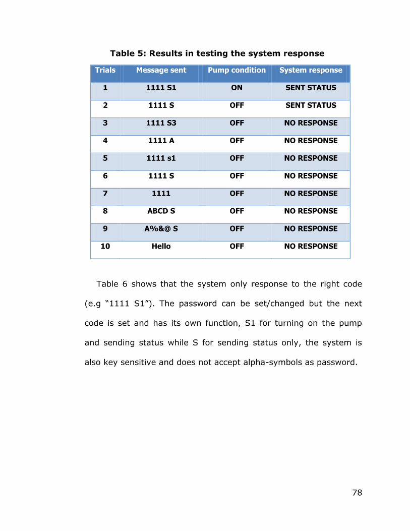
78
Table 5: Results in testing the system response
Trials Message sent Pump condition System response
1 1111 S1 ON SENT STATUS
2 1111 S OFF SENT STATUS
3 1111 S3 OFF NO RESPONSE
4 1111 A OFF NO RESPONSE
5 1111 s1 OFF NO RESPONSE
6 1111 S OFF NO RESPONSE
7 1111 OFF NO RESPONSE
8 ABCD S OFF NO RESPONSE
9 A%&@ S OFF NO RESPONSE
10 Hello OFF NO RESPONSE
Table 6 shows that the system only response to the right code
(e.g ―1111 S1‖). The password can be set/changed but the next
code is set and has its own function, S1 for turning on the pump
and sending status while S for sending status only, the system is
also key sensitive and does not accept alpha-symbols as password.
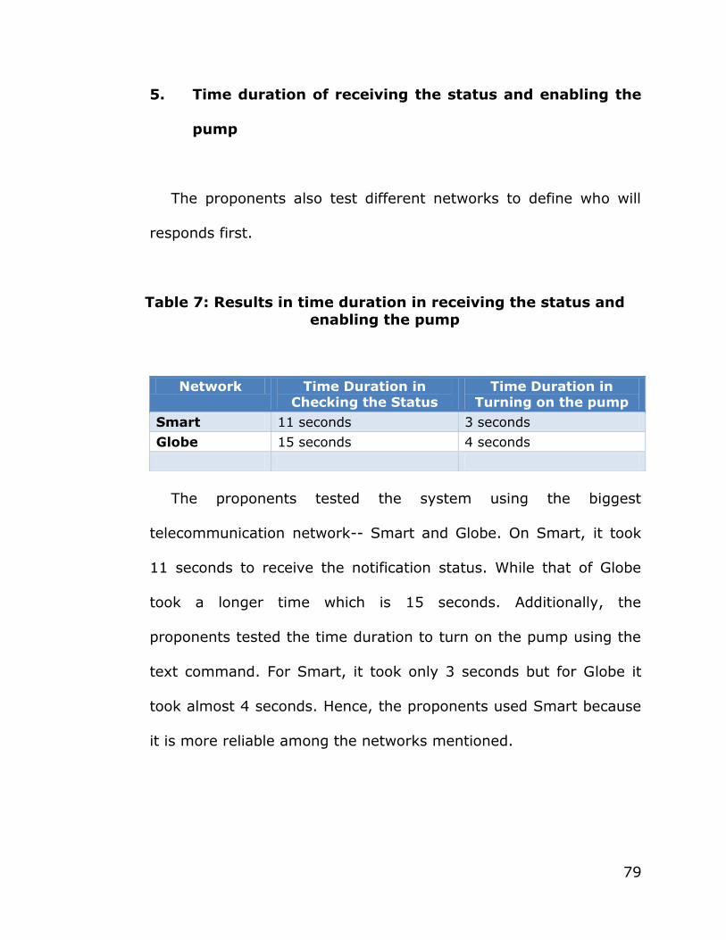
79
5. Time duration of receiving the status and enabling the
pump
The proponents also test different networks to define who will
responds first.
Table 7: Results in time duration in receiving the status and
enabling the pump
The proponents tested the system using the biggest
telecommunication network-- Smart and Globe. On Smart, it took
11 seconds to receive the notification status. While that of Globe
took a longer time which is 15 seconds. Additionally, the
proponents tested the time duration to turn on the pump using the
text command. For Smart, it took only 3 seconds but for Globe it
took almost 4 seconds. Hence, the proponents used Smart because
it is more reliable among the networks mentioned.
Network Time Duration in Checking the Status
Time Duration in Turning on the pump
Smart 11 seconds 3 seconds
Globe 15 seconds 4 seconds
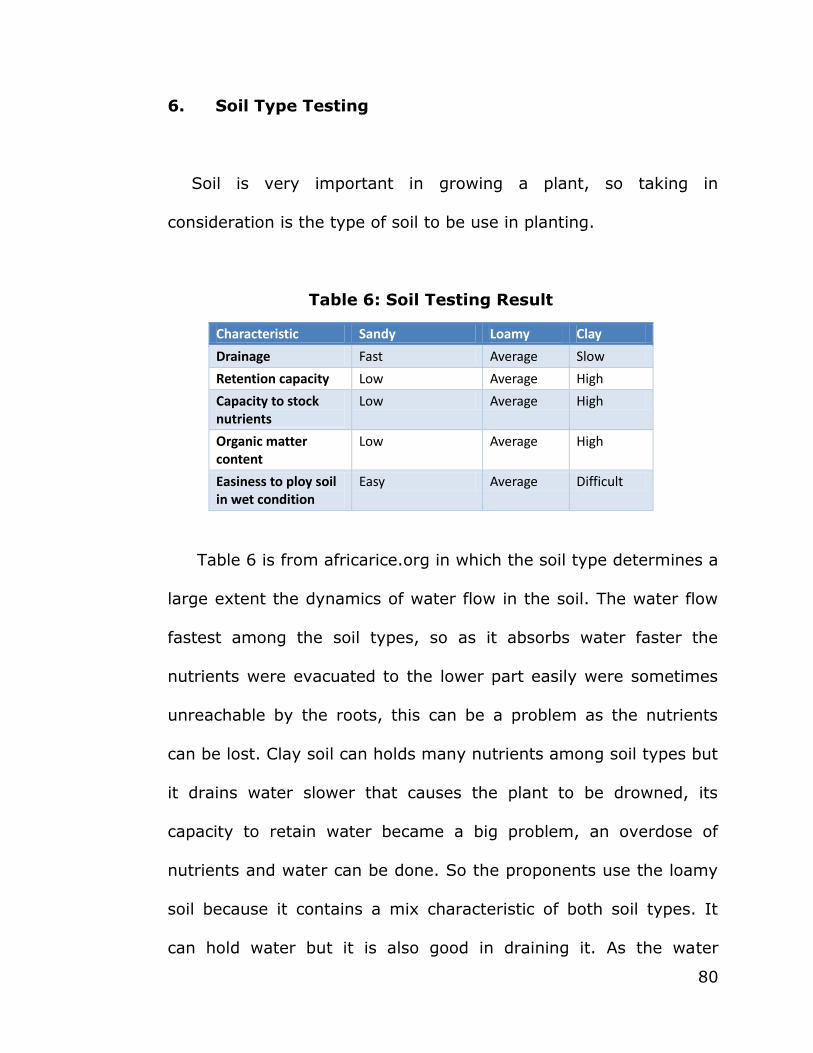
80
6. Soil Type Testing
Soil is very important in growing a plant, so taking in
consideration is the type of soil to be use in planting.
Table 6: Soil Testing Result
Characteristic Sandy Loamy Clay
Drainage Fast Average Slow
Retention capacity Low Average High
Capacity to stock nutrients
Low Average High
Organic matter content
Low Average High
Easiness to ploy soil in wet condition
Easy Average Difficult
Table 6 is from africarice.org in which the soil type determines a
large extent the dynamics of water flow in the soil. The water flow
fastest among the soil types, so as it absorbs water faster the
nutrients were evacuated to the lower part easily were sometimes
unreachable by the roots, this can be a problem as the nutrients
can be lost. Clay soil can holds many nutrients among soil types but
it drains water slower that causes the plant to be drowned, its
capacity to retain water became a big problem, an overdose of
nutrients and water can be done. So the proponents use the loamy
soil because it contains a mix characteristic of both soil types. It
can hold water but it is also good in draining it. As the water
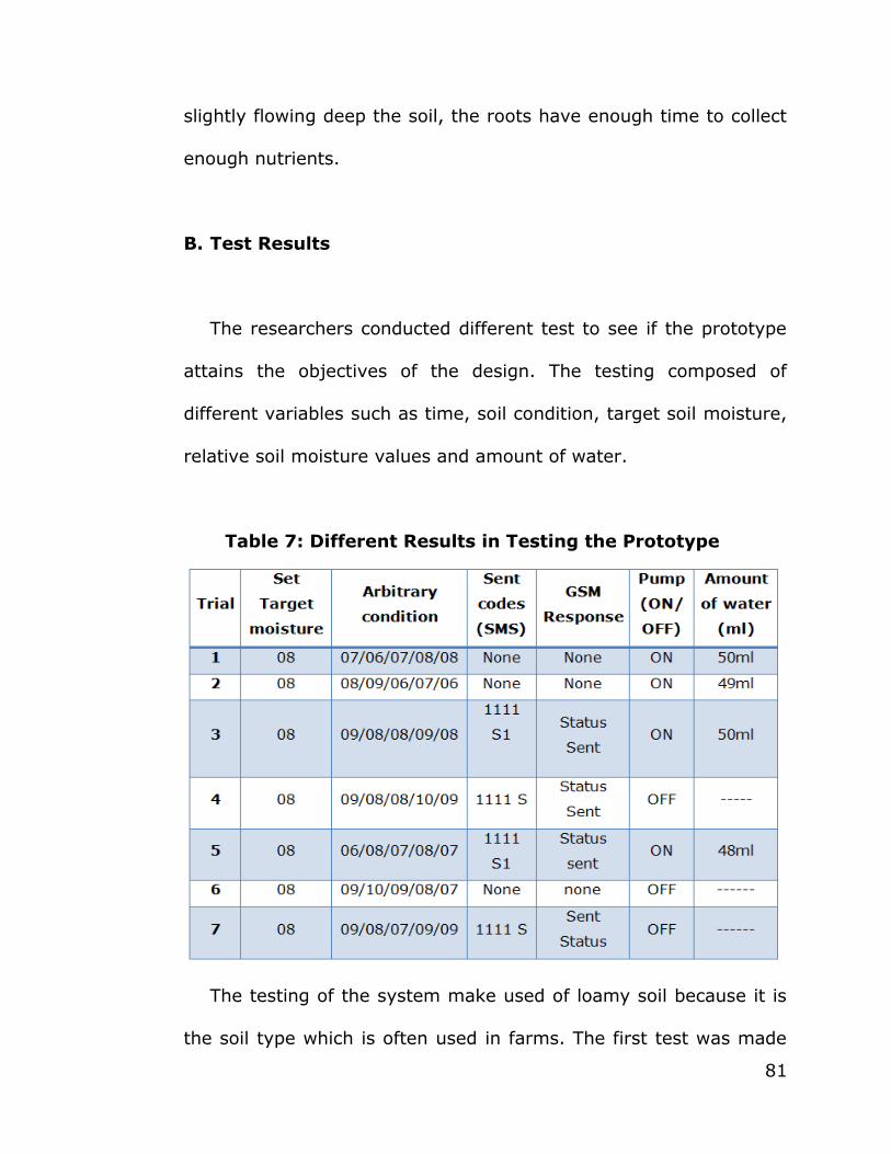
81
slightly flowing deep the soil, the roots have enough time to collect
enough nutrients.
B. Test Results
The researchers conducted different test to see if the prototype
attains the objectives of the design. The testing composed of
different variables such as time, soil condition, target soil moisture,
relative soil moisture values and amount of water.
Table 7: Different Results in Testing the Prototype
The testing of the system make used of loamy soil because it is
the soil type which is often used in farms. The first test was made
82
to determine time needed to water the soil in five land areas. Using
the time variables (10, 15, 20, 25 seconds), the test came up with
the result that 20 seconds is the most appropriate because it is
enough to water a rectangular basin with estimated size of 1 sq.
foot. The second testing make used of different target soil moisture
values to achieve the most desirable target soil moisture for a
loamy soil. In this test, proponents came up with the result of 8/13
(soil moisture rating from 0-13, below 8 means dry while 8 and
above means wet). Next, a testing on a different combinations on
the condition of the soil was made to ensure that the system follows
the majority wins condition when irrigating water. As expected, the
prototype implements that it the pump will only turn on given that
majority of the values read by the sensor is in a dry condition.
Lastly, the proponents tested the efficiency of the notification and
controlling process of the system by sending different text
commands and response of the system. The result shows that the
system only send a notification reply given that the user follows the
format, 1111 S. Also, the pump will only be turned on if the user
send 1111 S1. Lastly, the test shows that Smart is the most reliable
network to be used in the system because it took the shortest time
duration among others.

83
Overall, the testing of the system has been successful and got a
satisfying results. Though at times, the proponents encountered
problems in the control unit of the prototype.

84
Chapter V
SUMMARY, CONCLUSION, AND RECOMMENDATION
This chapter present a summary on the findings obtained in the
previous chapter, the conclusions obtained from it and the
recommendations needed for the improvement of the study.
A. Summary of Findings
From the analysis of the data, the findings were as follow:
1. The target soil moisture for a loamy type of soil is 8. Values less
than 8 means that the soil is in a dry condition and in need of
water, while that greater than 8 means that it is in a wet
condition.
2. Based on the testing, 20 seconds is the time that must be
allotted for the system to irrigate water in a given land area. The
system will water the plants for 20 seconds and after a minute,
the system will check again for one minute if the soil needs more
water.
85
3. Given 5 land area, the system will only irrigate water if one of
the following combinations is satisfied: 3-wet and 2-dry, 4-wet
1-dry or 5-wet 0-dry.
4. The system will only notify the user through a SMS if the correct
password which is 1111 and correct command which is S have
been sent to the designated number mounted to the GSM
module. Example Message: 1111 S
5. The irrigation of the system can be started if the correct
password which is 1111 and correct command which is S1 have
been sent to the designated number mounted to the GSM
module. Example Message: 1111 S1
B. Conclusions
The project ―Microcontroller Based Plants Irrigation System with
SMS Notification and Controller‖ proves to be a real time feedback
control system which monitors the soil moisture content of the
plants and controls the irrigation system using GSM technology.

86
Monitoring of the soil moisture content plays a vital role in
automating the watering of the plants. The soil moisture sensors
make it possible for the system to determine the desired target
value and relative values for the soil moisture. User does not need
to manually check if the soil needs water. Instead, they can just
rely on the values fed by the sensors employed in the soil. The
system is characterized by being versatile. The target soil moisture
can be accustomed depending on the user. Thus, the system is
applicable for different soil types. If the relative values are in a
critical level or below the target value, irrigation can be started for
a certain time. Therefore, using this method of irrigation water
usage will be monitored. Also, the idea of majority wins condition
make it possible for the irrigation to save water as irrigation can
only be started if the condition is satisfied. Additionally, the use of
GSM technology to notify the user about the status of the soil
moisture makes it easier for the user to know the condition of the
plants in terms of soil moisture content. Lastly, the use of GSM
technology provides user a remote control to start the irrigation.
The system has been successfully designed and tested. Also, it
has been developed by integrating features of all the hardware
components used. The presence of every components has been

87
reasoned out and placed carefully thus contributing to the best
working of the unit. The function of the irrigation is done
automatically using a microcontroller based system and soil
moisture content is considered as the parameter for the system.
Lastly, with the help of GSM technology the project has been
successfully implemented.
The present proposal is a model to modernize the agriculture
industries at a mass scale with optimum expenditure. Thus, using
this system, one can lessen water usage, save man power and
ultimately increase profit.
C. Recommendations
The system is more beneficial if added features will be added.
Thus, these recommendations are then suggested.
The testing of the system can be done on a larger location where
numerous soil moisture sensors can be employed. Also, sprinklers
and submerged pumps will be added depending on the need of the
land area. Additionally, since the user can adjust the value of target
soil moisture depending on the soil type. It is recommended that a

88
test using different soil types aside from loamy soil should be
undertaken. Aside from that, the system only focused on one
parameter which is the moisture content of the soil, it will be better
if other factors such as temperature will be included.
The following recommendations attempt to improve the present
study.
89
Executive Summary
This paper presents the study, Microcontroller Based Plants
Irrigation System with SMS Notification and Controller. This study
seeks to minimize water usage when watering the plants through the
use of an embedded system and GSM technology.
The first section introduces the underlying problems of water
usage on the irrigation. Specifically, based the discussion, it has been
noted that farms and their wasteful irrigation systems are the major
contributors to water scarcity on the globe. Worse, 70% of the water
consumed goes to farming and most of its wasteful use.
The second chapter provides a review on the related literature
and the comparative analysis on the existing studies about
microcontroller based irrigation systems.
The next chapter demonstrates of how the problems of irrigation
can be addressed through microcontroller and GSM technology. Also, a
prototype has been constructed to show the relevance of the
mentioned technologies in an automated irrigation system. More so,
this section presents the methodologies used in the integration of the

90
said technologies with the soil moisture control unit which includes the
soil moisture sensors, the submersible pump and the sprinklers.
The fourth chapter shows relevant data to the study.
Additionally, numerous testing were made to ensure that the
objectives of the study were attained.
Based the previous chapters, this study, Microcontroller Based
Plants Irrigation System with SMS Notification and Controller hereby is
a model to modernize the agriculture industries at a mass scale with
optimum expenditure. Thus, using this system, one can lessen water
usage, save man power and ultimately increase profit.

91
APPENDICES

92
Bibliography
Blogs:
Rana. (2011, July 24). Micro-Controller 8051: data acquisition and
control system. [Weblog]. Retrieved from http://microcontroller51.blogspot.com/2011/07/sms-based-
controlling-machines-using.html
Ahmed, V., & Ladhake, S. (2012). Design of Ultra Low Cost Cell Phone Based Embedded System for Irrigation. International Conference on
Machine Vision and Human Machine Interface, 718-721.
AjinkyaFotedar, P., AnimeshMathur, V. "Automated Irrigation System
using MSP430".
Ashok, P." Microcontroller Based Drip Irrigation SystemEngineers on April 30th", Retrieved 2010 from Prakasam Engineering College.
Chang,J. "Automatic Irrigation Management System". Western
Washington University, 11-22-2006.
Gaatum, I., & Reddy, S. (2012). Innovative Gsm Bluetooth based Remote Controlled Embedded System for Irrigation. International
Journal of Computer Applications (0975 – 888), 47, 13.
Galgalikar, M. (2010). Real-Time Automization Of Agricultural Environment for Social Modernization ofIndian Agricultural System.
The 2nd International Conference on Computer and Automation
Engineering (ICCAE), 1, 286-288.
Ganguly, P. (2011). Different Types of Soil. Retrieved January 10, 2013. http://www.buzzle.com/articles/different-types-of-soil.html
Goli,K., ThentuSravani,K. ―Integration of Wireless Technologies for
Sustainable Agriculture‖, Retrieved on 2011 from IJCST Journals database.
Kavanagh, K., Absalom, K., Beil, W., & Schliessmann,
L. (1999). Connecting and becoming culturally competent: A Lakota example. Advances in Nursing Science, 21, 9-31, Retrieved March 26,
2001 from ProQuest/Nursing Journals database.
93
NagendraBabu, M., Priyadarshini I. ―Real Time Automation of Indian Agricultural System‖.
Purnima, S., ―Design of Remote Monitoring and Control System with
Automatic Irrigation System using GSM-Bluetooth‖, Retrieved 2012 on IJCA Journals database.
SensorsAbhinavRajpal,S. "Microcontroller-based Automatic
IrrigationSystem with Moisture Institute of Telecom Technology & Management" .Amity University, Retrieved from U.P. Sector-125.
2012 Edgefx Kits, " Automatic Irrigation System on Sensing Soil
Moisture Content".
Website
European Telecommunications Standards Institute
http://www.etsi.org/index.php/technologies-clusters/technologies/mobile/gsm
Soo-won, K. "A method for reducing a bumblebee noise generated by
a GSM technology in a smartphone ". Retrieved from IEEE Xplore Digital Library. 927-930.
Irrigation. (n.d.). Retrieved December 28, 2012 from Wikipedia, the
free encyclopedia Web site: http://en.wikipedia.org/wiki/Irrigation
Irrigation Types. (n.d.). Retrieved January 10, 2013 from Darwin Irrigation & Mowing- Lawn Ranger Website:
http://www.lawnranger.com.au/pages/Irrigation-Types.html
LCD. (n.d.). Retrieved December 28, 2012 from EngineersGarage Web
site: http://www.engineersgarage.com/electronic-components/16x2-lcd-module datasheet
Microcontroller Tutorials 1. (n.d.). Retrieved December 28, 2012 from
Students’ Gymkhana IIT Kanpur Web site: http://students.iitk.ac.in/eclub/assets/lectures/Embedded-Old-1.pdf
Power Supply. (n.d.). Retrieved December 28, 2012 from Wikipedia,
the free encyclopedia Web site: http://en.wikipedia.org/wiki/Power_supply
94
Relays. (n.d.). Retrieved December 28, 2012 from The Electronics Club
Web site: http://www.kpsec.freeuk.com/components/relay.htm
Remote Monitoring of Soil Moisture. (n.d.). Retrieved January 10, 2013 from Southwest Hydrology Web site:
http://www.swhydro.arizona.edu/archive/V2_N5/feature7.pdf
SoilCOM Soil Moisture Monitoring Systems. (n.d.). Retrieved January 10, 2013 from Campbell Scientific Web site:
http://www.campbellsci.co.uk/index.cfm?id=205
Soil moisture sensor. (n.d.). Retrieved December 28, 2012 from Wikipedia, the free encyclopedia Web site:
http://en.wikipedia.org/wiki/Soil_moisture_sensor
Types of Pumps in Irrigation. (n.d.). Retrieved July 16, 2012 from
eHow Web site: http://www.ehow.com/list_5904414_types-pumps-irrigation.html
Types of Submersible Pumps. (n.d.). Retrieved December 28, 2012 from eHow Web site: http://www.ehow.com/list_6645212_types-
submersible-pumps.html#ixzz2HYXfL1VW
What is a GSM Modem?. (n.d.). Retrieved December 28, 2012 from now.sms Web site: http://www.nowsms.com/faq/what-is-a-gsm-
modem
What is an Irrigation System?. (n.d.). Retrieved January 10, 2013 from wiseGEEK Web site: http://www.wisegeek.org/what-is-an-
irrigation-system.htm