
fiber laser marker - lmf series - AMADA WELD TECH
384
990-559 REV K FIBER LASER MARKER LMF SERIES OPERATION MANUAL
-
Upload
khangminh22 -
Category
Documents
-
view
1 -
download
0
Transcript of fiber laser marker - lmf series - AMADA WELD TECH

990-559 REV K
FIBER LASER MARKER
LMF SERIES
OPERATION MANUAL
LMF SERIES LASER MARKERS
ii 990-559
Copyright © 2013 – 2019 Amada Miyachi America The engineering designs, drawings and data contained herein are the proprietary work of Amada Miyachi America and may not be reproduced, copied, exhibited or otherwise used without the written authorization of Amada Miyachi America.
Printed in the United States of America.
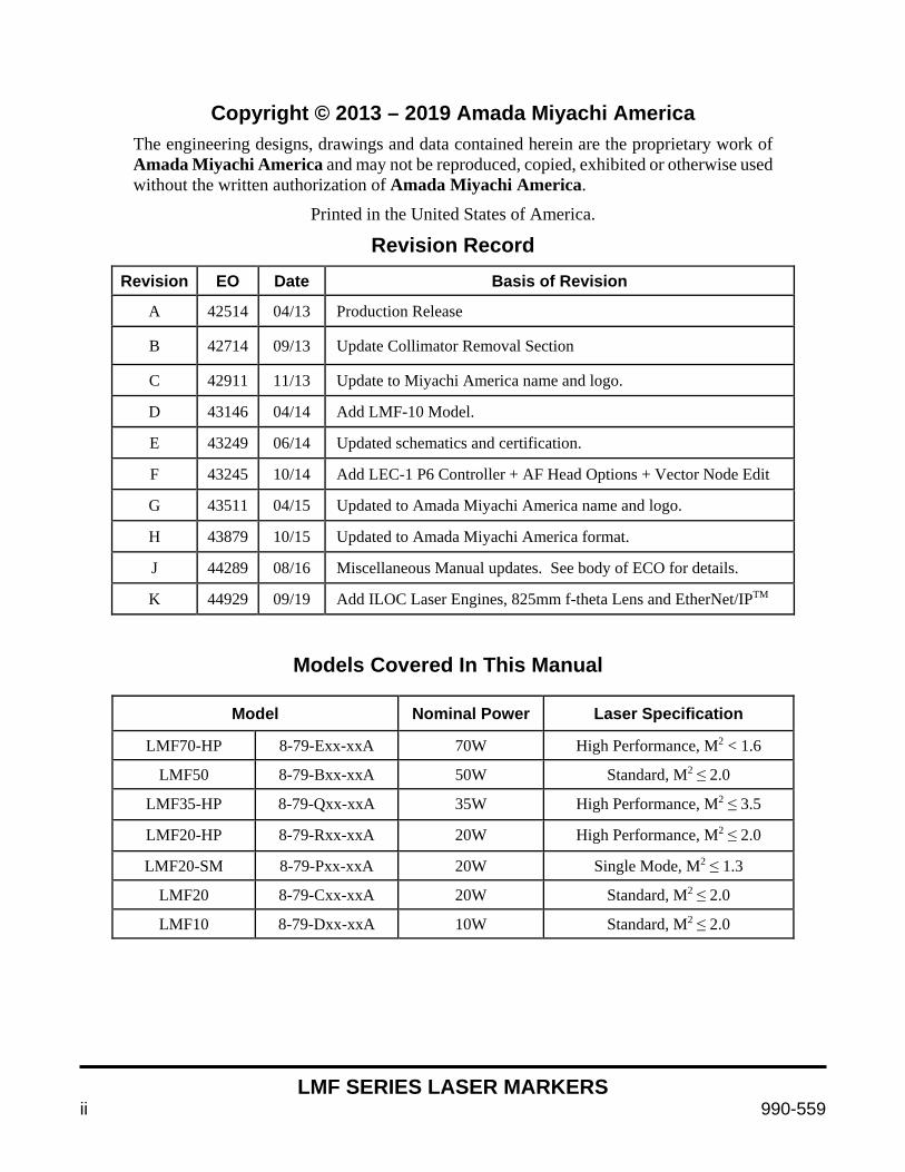
Revision Record
Revision EO Date Basis of Revision
A 42514 04/13 Production Release
B 42714 09/13 Update Collimator Removal Section
C 42911 11/13 Update to Miyachi America name and logo.
D 43146 04/14 Add LMF-10 Model.
E 43249 06/14 Updated schematics and certification.
F 43245 10/14 Add LEC-1 P6 Controller + AF Head Options + Vector Node Edit
G 43511 04/15 Updated to Amada Miyachi America name and logo.
H 43879 10/15 Updated to Amada Miyachi America format.
J 44289 08/16 Miscellaneous Manual updates. See body of ECO for details.
K 44929 09/19 Add ILOC Laser Engines, 825mm f-theta Lens and EtherNet/IPTM
Models Covered In This Manual
Model Nominal Power Laser Specification
LMF70-HP 8-79-Exx-xxA 70W High Performance, M2 < 1.6
LMF50 8-79-Bxx-xxA 50W Standard, M2 ≤ 2.0
LMF35-HP 8-79-Qxx-xxA 35W High Performance, M2 ≤ 3.5
LMF20-HP 8-79-Rxx-xxA 20W High Performance, M2 ≤ 2.0
LMF20-SM 8-79-Pxx-xxA 20W Single Mode, M2 ≤ 1.3
LMF20 8-79-Cxx-xxA 20W Standard, M2 ≤ 2.0
LMF10 8-79-Dxx-xxA 10W Standard, M2 ≤ 2.0

LMF SERIES LASER MARKERS
990-559 iii
Your LMF Fiber Laser Marker Shipment Contains The Following Items:
1. LMF Laser Marker and Power Supply 2. Scanner Control Cable DB25
• 2m, Amada Miyachi America # 4-66138-01 (1 each LMF20-HP & LMF20-SM only)
• 3m, Amada Miyachi America # 4-69398-01 (1 each all other models)
• 5m, Amada Miyachi America # 4-70263-01 (1 each LM10 model only) 3. Head I/O Cable DB15
• 2m, Amada Miyachi America # 4-66107-01 (1 each LMF20-HP & LMF20-SM only)
• 3m, Amada Miyachi America # 4-69397-01 (1 each all other models)
• 5m, Amada Miyachi America # 4-70264-01 (1 each LM10 model only) 4. Ship Kit, Amada Miyachi America Part Number 4-81221-01:
• Power Cord, CE, #14-3, Black, Amada Miyachi America # 205-133 (1 each)
• Cat 5e Crossover Cable, Amada Miyachi America # 205-318 (1 each)
• USB Flash Drive, Manuals, Amada Miyachi America # 4-77328-01 (1 each)
• System I/O Jumper Assembly, Amada Miyachi America # 4-69639-01 (1 each)
• Remote Interlock Test Jumper Assembly, Amada Miyachi America # 4-69640-01 (1 each)
• Emergency Stop Test Jumper Assembly, Amada Miyachi America # 4-69641-01 (1 each)
• Kit, Connectors and Backshells, I/O, Amada Miyachi America # 4-69642-01 (1 each) 5. Customer specified f-theta lens and collimator installed in the marker (where applicable)
LMF SERIES LASER MARKERS
iv 990-559
CONTENTS Page
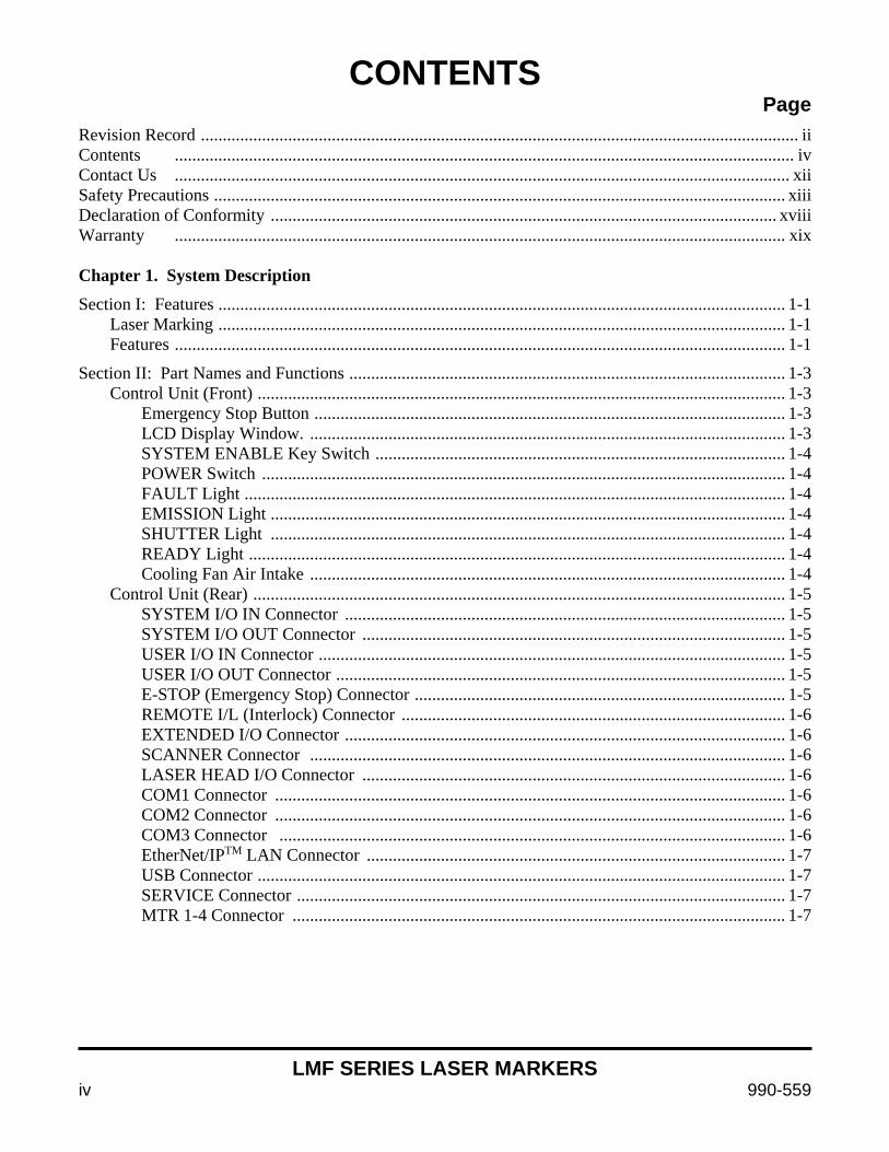
Revision Record ......................................................................................................................................... ii Contents .............................................................................................................................................. iv Contact Us ............................................................................................................................................. xii Safety Precautions ................................................................................................................................... xiii Declaration of Conformity .................................................................................................................... xviii Warranty ............................................................................................................................................ xix Chapter 1. System Description Section I: Features .................................................................................................................................. 1-1
Laser Marking .................................................................................................................................. 1-1 Features ............................................................................................................................................ 1-1
Section II: Part Names and Functions .................................................................................................... 1-3 Control Unit (Front) ......................................................................................................................... 1-3
Emergency Stop Button ............................................................................................................ 1-3 LCD Display Window. ............................................................................................................. 1-3 SYSTEM ENABLE Key Switch .............................................................................................. 1-4 POWER Switch ........................................................................................................................ 1-4 FAULT Light ............................................................................................................................ 1-4 EMISSION Light ...................................................................................................................... 1-4 SHUTTER Light ...................................................................................................................... 1-4 READY Light ........................................................................................................................... 1-4 Cooling Fan Air Intake ............................................................................................................. 1-4
Control Unit (Rear) .......................................................................................................................... 1-5 SYSTEM I/O IN Connector ..................................................................................................... 1-5 SYSTEM I/O OUT Connector ................................................................................................. 1-5 USER I/O IN Connector ........................................................................................................... 1-5 USER I/O OUT Connector ....................................................................................................... 1-5 E-STOP (Emergency Stop) Connector ..................................................................................... 1-5 REMOTE I/L (Interlock) Connector ........................................................................................ 1-6 EXTENDED I/O Connector ..................................................................................................... 1-6 SCANNER Connector ............................................................................................................. 1-6 LASER HEAD I/O Connector ................................................................................................. 1-6 COM1 Connector ..................................................................................................................... 1-6 COM2 Connector ..................................................................................................................... 1-6 COM3 Connector .................................................................................................................... 1-6 EtherNet/IPTM LAN Connector ................................................................................................ 1-7 USB Connector ......................................................................................................................... 1-7 SERVICE Connector ................................................................................................................ 1-7 MTR 1-4 Connector ................................................................................................................. 1-7
LMF SERIES LASER MARKERS
990-559 v
CONTENTS (Continued) Page
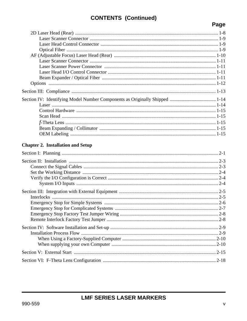
2D Laser Head (Rear) ...................................................................................................................... 1-8 Laser Scanner Connector .......................................................................................................... 1-9 Laser Head Control Connector ................................................................................................. 1-9 Optical Fiber ............................................................................................................................. 1-9
AF (Adjustable Focus) Laser Head (Rear) .................................................................................... 1-10 Laser Scanner Connector ........................................................................................................ 1-11 Laser Scanner Power Connector ............................................................................................ 1-11 Laser Head I/O Control Connector ......................................................................................... 1-11 Beam Expander / Optical Fiber .............................................................................................. 1-11
Options .......................................................................................................................................... 1-12
Section III: Compliance ....................................................................................................................... 1-13
Section IV: Identifying Model Number Components as Originally Shipped ...................................... 1-14 Laser ....................................................................................................................................... 1-14 Control Hardware ................................................................................................................... 1-15 Scan Head ............................................................................................................................... 1-15 f-Theta Lens ............................................................................................................................ 1-15 Beam Expanding / Collimator ................................................................................................ 1-15 OEM Labeling ........................................................................................................................ 1-15
Chapter 2. Installation and Setup Section I: Planning ................................................................................................................................. 2-1
Section II: Installation ........................................................................................................................... 2-3 Connect the Signal Cables ............................................................................................................... 2-3 Set the Working Distance ................................................................................................................ 2-4 Verify the I/O Configuration is Correct ........................................................................................... 2-4 System I/O Inputs ..................................................................................................................... 2-4
Section III: Integration with External Equipment .................................................................................. 2-5 Interlocks ......................................................................................................................................... 2-5 Emergency Stop for Simple Systems .............................................................................................. 2-6 Emergency Stop for Complicated Systems ..................................................................................... 2-7 Emergency Stop Factory Test Jumper Wiring ................................................................................. 2-8 Remote Interlock Factory Test Jumper ............................................................................................ 2-8
Section IV: Software Installation and Set-up ......................................................................................... 2-9 Installation Process Flow ................................................................................................................. 2-9 When Using a Factory-Supplied Computer ............................................................................. 2-10 When supplying your own Computer ...................................................................................... 2-10
Section V: External Start ..................................................................................................................... 2-15
Section VI: F-Theta Lens Configuration ............................................................................................. 2-18
LMF SERIES LASER MARKERS
vi 990-559
CONTENTS (Continued) Page
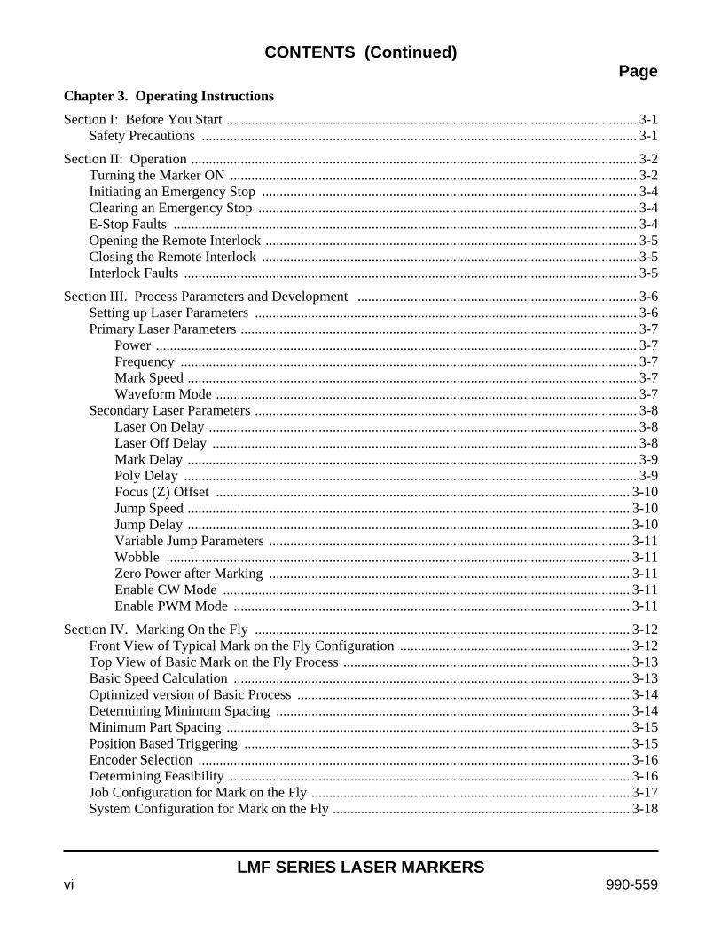
Chapter 3. Operating Instructions Section I: Before You Start .................................................................................................................... 3-1 Safety Precautions ........................................................................................................................... 3-1
Section II: Operation .............................................................................................................................. 3-2 Turning the Marker ON ................................................................................................................... 3-2 Initiating an Emergency Stop .......................................................................................................... 3-4 Clearing an Emergency Stop ........................................................................................................... 3-4 E-Stop Faults ................................................................................................................................... 3-4 Opening the Remote Interlock ......................................................................................................... 3-5 Closing the Remote Interlock .......................................................................................................... 3-5 Interlock Faults ................................................................................................................................ 3-5
Section III. Process Parameters and Development ............................................................................... 3-6 Setting up Laser Parameters ............................................................................................................ 3-6 Primary Laser Parameters ................................................................................................................ 3-7 Power ........................................................................................................................................ 3-7 Frequency ................................................................................................................................. 3-7 Mark Speed ............................................................................................................................... 3-7 Waveform Mode ....................................................................................................................... 3-7 Secondary Laser Parameters ............................................................................................................ 3-8 Laser On Delay ......................................................................................................................... 3-8 Laser Off Delay ........................................................................................................................ 3-8 Mark Delay ............................................................................................................................... 3-9 Poly Delay ................................................................................................................................ 3-9 Focus (Z) Offset ..................................................................................................................... 3-10 Jump Speed ............................................................................................................................. 3-10 Jump Delay ............................................................................................................................. 3-10 Variable Jump Parameters ...................................................................................................... 3-11 Wobble ................................................................................................................................... 3-11 Zero Power after Marking ...................................................................................................... 3-11 Enable CW Mode ................................................................................................................... 3-11 Enable PWM Mode ................................................................................................................ 3-11
Section IV. Marking On the Fly .......................................................................................................... 3-12 Front View of Typical Mark on the Fly Configuration ................................................................. 3-12 Top View of Basic Mark on the Fly Process ................................................................................. 3-13 Basic Speed Calculation ................................................................................................................ 3-13 Optimized version of Basic Process .............................................................................................. 3-14 Determining Minimum Spacing .................................................................................................... 3-14 Minimum Part Spacing .................................................................................................................. 3-15 Position Based Triggering ............................................................................................................. 3-15 Encoder Selection .......................................................................................................................... 3-16 Determining Feasibility ................................................................................................................. 3-16 Job Configuration for Mark on the Fly .......................................................................................... 3-17 System Configuration for Mark on the Fly .................................................................................... 3-18
LMF SERIES LASER MARKERS
990-559 vii
CONTENTS (Continued) Page
Section V. I/O Job Selection Configuration and Use ........................................................................... 3-19 How to exit I/O Job Selection Mode ............................................................................................. 3-25
Section VI. Vector Node Editing (Graphic File Editing) ..................................................................... 3-26 Accessing the Vector Edit Tool ..................................................................................................... 3-26 The Edit Tool Window and Icons .................................................................................................. 3-27 Editing Nodes ................................................................................................................................ 3-31 Polylines ........................................................................................................................................ 3-32 Jump ....................................................................................................................................... 3-32 Polyline A ............................................................................................................................... 3-33 Polyline B ............................................................................................................................... 3-33 Polyline C ............................................................................................................................... 3-33 Closing a Path ......................................................................................................................... 3-34 Combining Multiple Polylines into a Single Polyline ............................................................ 3-34 Closed Path ............................................................................................................................. 3-35 Selecting a Pen ....................................................................................................................... 3-35 Breaking Apart a Polyline ...................................................................................................... 3-35 Fixing Artwork that won’t Hatch Fill correctly ............................................................................. 3-36 Breaking up Artwork into Multiple WinLase Objects .................................................................. 3-37 Combining Multiple WinLase Objects into One ........................................................................... 3-39 Editing Individual Nodes ............................................................................................................... 3-40 Chapter 4. Maintenance Section I: Safety Precautions ................................................................................................................. 4-1
Section II: Troubleshooting ................................................................................................................... 4-2 8-79-P, Q, R, E Models ................................................................................................................... 4-2 8-79-B, C, D Models ....................................................................................................................... 4-3
Section III: Emergency Stop and Interlock Safety Controller Status and Error Indications ................. 4-4 Emergency Stop and Interlock Controller Status and Troubleshooting .......................................... 4-4 Status Indicators ............................................................................................................................... 4-5 Power (solid) ............................................................................................................................ 4-5 In1 (solid) ................................................................................................................................. 4-5 In2 (solid) ................................................................................................................................. 4-5 Out (solid) ................................................................................................................................. 4-5 Reset (solid) .............................................................................................................................. 4-5 Error Indicators and Suggested Resolution ..................................................................................... 4-6 Contact Malfunctions .............................................................................................................. 4-6
All LEDs off ............................................................................................................................ 4-6 Fault (solid) / Others (off) ........................................................................................................ 4-6
Fault (flashing) / Others (off) ................................................................................................... 4-6 Power (flashing) ....................................................................................................................... 4-6 In1, In2 (flashing alternately) / Fault (solid) ............................................................................ 4-6 In 1 (flashing) / Fault (solid) .................................................................................................... 4-6 In 2 (flashing) / Fault (solid) .................................................................................................... 4-6 Reset (flashing) / Fault (solid) .................................................................................................. 4-7
LMF SERIES LASER MARKERS
viii 990-559
CONTENTS (Continued) Page
Power + In1 + In2 + Out + Reset + Fault (solid) .................................................................... 4-7 Emergency Stop Controller Configuration Dial Setting .................................................................. 4-7 Interlock Controller Configuration Dial Setting .............................................................................. 4-7
Section IV: Lens Installation and Cover Glass Cleaning Instructions ................................................... 4-8
Section V: Remove / Install the Collimator ......................................................................................... 4-10 Removing the Collimator .............................................................................................................. 4-10 Collimator Installation ................................................................................................................... 4-11
Section VI: Replace the Air Filter ....................................................................................................... 4-12
Section VII: Firmware Update ............................................................................................................. 4-13
Section VIII: Repair Service ................................................................................................................ 4-14 Chapter 5. Integration and Remote Interface Section I: Understanding the Two Types of Integration ......................................................................... 5-1 Streaming Vs. Local Mode (Stand-alone) ....................................................................................... 5-1 Streaming Mode Summary of Options - See Section III of this Chapter ........................................ 5-2 Stand-alone Mode Summary of Options - See Section IV of this Chapter ...................................... 5-2
Section II: Selecting the Best Interface Mode for Your Application ..................................................... 5-3 How does one select the best mode for an application? ................................................................. 5-3 To Make a Selection ........................................................................................................................ 5-3 Important Feature Compatibility Issues Between Streaming and Local Modes ............................. 5-5 Control Mode-Based Compatibility for Data Changed At Runtime ............................................... 5-7
Section III: Streaming Mode and the WinLase LAN GUI .................................................................... 5-8 GUI (Graphical User Interface) Features ........................................................................................ 5-8 COM Server .................................................................................................................................... 5-9 Block Diagrams ............................................................................................................................. 5-10 Integration Notes: Semiautomatic Workstation Operating In Streaming Mode .......................... 5-11
Section IV: Using the Remote Command API to Control the Laser Marker in Stand-alone Mode .... 5-12 Remote Command API .................................................................................................................. 5-12 Using the API ................................................................................................................................ 5-12 Sample API Process Outline with Commands ............................................................................. 5-14 Tips on using the TCP/IP Interface ............................................................................................... 5-15 API Command Set ......................................................................................................................... 5-15 Remote Command API List ........................................................................................................... 5-16 I/O Job Selection – Up to 255 Jobs ............................................................................................... 5-16 Block Diagrams: Typical Stand-alone Mode Installations ........................................................... 5-17 Integration Notes: Automated Line Installation Operating In Local/Stand-alone Mode ............. 5-18
Section V: Using the TCP/IP and RS-232 ........................................................................................... 5-21 Streaming Mode Host Interface ..................................................................................................... 5-21 RS-232 and TCP/IP Commands and Functions ............................................................................. 5-21 RS-232 and TCP/IP Command List .............................................................................................. 5-21
LMF SERIES LASER MARKERS
990-559 ix
CONTENTS (Continued) Page
Chapter 6. Marker Motion Motion Control Section I: Overview ............................................................................................................................... 6-1 General Motor Specifications .......................................................................................................... 6-2 Marker Motion System Connection Diagram – Stepper Motors .................................................. 6-3
Section II: Fiber Laser Marker Motion Features ................................................................................ 6-4 System Specifications ..................................................................................................................... 6-4
Section III: Standard Cable Harness Configurations with Part Numbers ............................................... 6-5 Introduction ...................................................................................................................................... 6-5 Part Numbers – LMF Marker Motion ......................................................................................... 6-5
Section IV: Connection Using Customer-Supplied Stages ..................................................................... 6-6 Motor Input Wiring .......................................................................................................................... 6-6 Stage Limit Wiring .......................................................................................................................... 6-7 Securing Power and Communications Leads .................................................................................. 6-8
Section V. Software Configuration ........................................................................................................ 6-9 System Settings ................................................................................................................................ 6-9 Provisioning Tab ............................................................................................................................ 6-16 Microsteps/rev ........................................................................................................................ 6-16 Microstep Resolution .............................................................................................................. 6-17 Calibration Factor ................................................................................................................... 6-17 Hold Current ........................................................................................................................... 6-17 Run Current ............................................................................................................................ 6-17 Invert All Direction Coordinates ............................................................................................ 6-17 Program Hardware .................................................................................................................. 6-18 Encoder Tab ................................................................................................................................... 6-18 Enable Encoder Functions ...................................................................................................... 6-18 Deadband ................................................................................................................................ 6-19 Stall Factor .............................................................................................................................. 6-19 Enable Position Maintenance ................................................................................................. 6-19 Stop on Stall ........................................................................................................................... 6-19 Homing Tab ................................................................................................................................... 6-20 Sensor Type ............................................................................................................................ 6-20 Home Creep Velocity ............................................................................................................. 6-20 Home Slew Velocity ............................................................................................................... 6-20 Home Decel Rate .................................................................................................................... 6-21 Home Position ........................................................................................................................ 6-21 Sensor Debounce .................................................................................................................... 6-21 Homing Style .......................................................................................................................... 6-21 Slew in Minus direction, then creep in Plus direction ............................................................ 6-21 Slew in Minus direction, then creep in Minus direction ........................................................ 6-21 Slew in Plus direction, then creep in Minus direction ............................................................ 6-22 Slew in Plus direction, then creep in Plus direction ............................................................... 6-22 Run to Plus Limit Switch ....................................................................................................... 6-22 Run to Minus Limit Switch .................................................................................................... 6-22
LMF SERIES LASER MARKERS
x 990-559
CONTENTS (Continued) Page
At Home When ..................................................................................................................................... 6-22 Home input is floating ............................................................................................................ 6-22 Home input is pulled HIGH (or LOW) .................................................................................. 6-23 On Encoder Index Mark ......................................................................................................... 6-23 Limits Tab ...................................................................................................................................... 6-23 Sensor Debounce .................................................................................................................... 6-24 Sensor Type ............................................................................................................................ 6-24 At limit when .......................................................................................................................... 6-24 Limit is floating ...................................................................................................................... 6-24 Home input is pulled HIGH (or LOW) .................................................................................. 6-24 Ignore limits ............................................................................................................................ 6-24 Use deceleration ramp when limit is reached ......................................................................... 6-24 Motor Configuration and Programming ........................................................................................ 6-25 To Program an Axis ....................................................................................................................... 6-25
Section VI: Operation .......................................................................................................................... 6-27 Using System Motion .................................................................................................................... 6-27 Adding Motion to a Job .......................................................................................................... 6-27 Motion Objects ............................................................................................................................. 6-29 Linear Motion Properties ........................................................................................................ 6-29 XY Motion Properties ............................................................................................................ 6-32 Rotary Motion Properties ....................................................................................................... 6-36 The Motion Manager Window ...................................................................................................... 6-39 Opening the Motion Manager ................................................................................................ 6-39 Motion Manager Control Panel Settings ....................................................................................... 6-41 Advanced Motion Applications ..................................................................................................... 6-42 Choosing between Raster and Vector Marking ...................................................................... 6-42 Raster around a Cylinder ........................................................................................................ 6-43 Bitmap Marking Methods ....................................................................................................... 6-44 Manual ............................................................................................................................. 6-44 Automatic ........................................................................................................................ 6-45 Circumferential Marking ........................................................................................................ 6-46 Banding ................................................................................................................................... 6-48 Homing ................................................................................................................................... 6-49 Troubleshooting ...................................................................................................................... 6-50 Clearing Errors ................................................................................................................ 6-50 Categories of Errors and Potential Resolution ................................................................ 6-50 Verifying Motor Communication .................................................................................... 6-51 Chapter 7. Using Adjustable Focus Heads and Auto Focus Features Section I: Using the Adjustable Focus –AF Head .................................................................................. 7-1 How the –AF (Adjustable Focus) Head Works ............................................................................... 7-1 Using the –AF Head in WinLase ..................................................................................................... 7-2 Object Based Adjustments ............................................................................................................... 7-3 Autofocus Adjustments ................................................................................................................... 7-4
LMF SERIES LASER MARKERS
990-559 xi
CONTENTS (Continued) Page
Section II: Configuring for and using your –AF marker with Autofocus using the 8-921-xx Autofocus system ................................................................................................ 7-5 Configuration .................................................................................................................................. 7-6 Standalone Mode Configuration ...................................................................................................... 7-7 Configuring Autofocus in the WinLase GUI in streaming mode .................................................... 7-8 Using Autofocus .............................................................................................................................. 7-8
Section III: Autofocus Interface Controller Technical Information ..................................................... 7-9 Inputs (by pin number) ................................................................................................................... 7-9 Sample Input User Wiring Schematic .......................................................................................... 7-10 User I/O IN – Dry contact Input Switches (internally biased) ............................................... 7-10 Example of Input Protection Schematic ................................................................................. 7-10 Outputs (by pin number) ................................................................................................................ 7-11 Sample Output User Wiring Schematic ........................................................................................ 7-12 Example of Output Protection Schematic .............................................................................. 7-12 Autofocus Interface Controller Physical Attributes ...................................................................... 7-13 Autofocus Interface Controller Dimensions ................................................................................. 7-14 Sensor Manufacturer Specifications ............................................................................................. 7-17
Section IV: Calibrating the Autofocus Controller to a Laser Sensor ................................................... 7-18 Equipment Required ...................................................................................................................... 7-18 Setup ......................................................................................................................................... 7-18 Procedure ...................................................................................................................................... 7-19 Chapter 8. EtherNet/IPTM Communications Section I: Introduction ............................................................................................................................ 8-1 How the Input Data is Scanned ....................................................................................................... 8-1
Section II: EtherNet/IPTM Configurations ............................................................................................... 8-3
Section III: Data Models ....................................................................................................................... 8-16
Section IV: PLC Request Descriptions ................................................................................................. 8-26 Appendix A. Technical Specifications Section I. Laser Specifications .............................................................................................................. A-1
Section II. Warning and Identification Labels ...................................................................................... A-6
Section III. Engineering Drawings ..................................................................................................... A-11 Appendix B. Electrical and Data Connections ..................................................................................B-1 Appendix C. LMF HP Pulsed Fiber Laser Reference Material ......................................................C-1 Appendix D. Embedded Controller Remote Command API .......................................................... D-1

LMF SERIES LASER MARKERS
xii 990-559
CONTACT US
Thank you for purchasing an Amada Miyachi LMF Series Fiber Laser Marker.
Upon receipt of your equipment, please thoroughly inspect it for shipping damage prior to its installation. Should there be any damage, please immediately contact the shipping company to file a claim, and notify us at:
Amada Miyachi America 1820 South Myrtle Avenue Monrovia, CA 91016 Telephone: (626) 303-5676 FAX: (626) 358-8048 E-Mail: [email protected]
The purpose of this manual is to provide the information required for proper and safe operation and maintenance of the Amada Miyachi LMF Fiber Laser Marker.
We have made every effort to ensure that the information in this manual is both accurate and adequate. If you have any questions or suggestions to improve this manual, please contact us at the phone number or address above.
Amada Miyachi America is not responsible for any loss or injury due to improper use of this product.

LMF SERIES LASER MARKERS
990-559 xiii
SAFETY PRECAUTIONS General This Operator's Manual describes the Operation and Maintenance of the LMF Series Fiber Laser Marker, and provides instructions relating to its SAFE use. Procedures described in this manual must be performed as detailed by qualified and trained personnel.
For SAFETY, and to effectively take advantage of the full capabilities of the Marker, please read this instruction manual and the Laser Safety Manual (Part Number 990-502) thoroughly before attempting to use the Marker.
After reading this manual, retain it for future reference when any questions arise regarding the proper and SAFE operation of the Marker. Operation Follow all OSHA requirements for workplace safety. Appoint a Laser Safety Officer. The Laser Safety Officer (LSO) must provide personnel with sufficient training so that personnel can operate, maintain and service the Laser Marker safely. The LSO must take charge of the key to the Key Switch to ensure that only qualified and authorized personnel operate the Laser Marker.
Establish and control a dedicated Laser Operation Area. The Laser Safety Officer must isolate the Laser Operation Area from other work areas and display signs warning that the Laser Operation Area is off-limits to unauthorized personnel.
To prevent eye damage when operating, maintaining or servicing this equipment, laser protective goggles must be worn (per ANSI Z136.1). Laser goggles with an OD (optical density) of 7+ (at a wavelength of 1060-1150nm) are recommended or as directed by your LSO. Maintenance/Service Before performing any maintenance on the Marker, read Chapter 4, Maintenance thoroughly. Use the appropriate tools for terminating the connecting cables, being careful not to nick the wire conductors.
Procedures other than those described in this manual or not performed as prescribed in this manual, may expose personnel to electrical and/or laser radiation hazards.
Do not modify the Marker without prior written approval from Amada Miyachi America.

LMF SERIES LASER MARKERS
xiv 990-559
Before using this equipment, read the Safety Precautions carefully to understand the correct usage of the equipment. • These precautions are given for the safe use of the
Marker and for prevention of injury to operators or others.
• Be sure to read each of the instructions, as they are all important for safe operation.
• The meaning of the words and symbols are as follows:
These symbols denote PROHIBITION. They are warnings about actions that should not be performed because they can damage the equipment and will void the warranty.
CAUTION
These symbols denote actions which operators must take. Denotes operations and practices that
may result in personal injury or damage to the equipment if not correctly followed.
Each symbol with a triangle denotes that the contents gives notice of DANGER, WARNING, or CAUTION to the operator.
WARNING
Denotes operations and practices that may result in serious injury or loss of life if not correctly followed.
DANGER
Denotes operations and practices that may imminently result in serious injury or loss of life if not correctly followed.
DANGER
Do not touch inside the Marker when it is turned ON. Doing so may result in electric shock.
Never attempt to disassemble, repair, or modify the Marker. Doing so may result in electric shock or fire. Refrain from any mechanical adjustment other than the maintenance procedures specifically described in the operation manual.
Never expose eyes or skin to laser irradiation. Exposure to direct or scattered laser light is extremely hazardous. Direct exposure of the eye to laser beams may result in blindness.

LMF SERIES LASER MARKERS
990-559 xv
WARNING
Wear protective eyewear suitable for the laser being used. Always wear protective eyewear when using the Marker. Keep in mind that exposure of the eyes to direct laser irradiation may result in blindness, even when wearing protective eyewear.
Never aim the laser at any part of your own body or other people. Exposure to laser beams will cause severe burns. Never aim the laser at yourself or at anyone else.
Do not touch workpieces during or just after marking. Workpieces may be very hot.
Use only the specified cables. Make sure they are firmly connected. Using cables of inadequate current capacity or connecting cables loosely may result in fire or electric shock.
Avoid damaging power or connecting cables. Do not step on, twist, or pull cables. Damaged cables may result in electric shock, short circuits, or fires. To repair or replace cables, contact Amada Miyachi America.
Avoid damaging the delivery fiber. Do not twist, kink or attempt to remove the fiber. Do not attempt to coil or bend the fiber tighter than a 4.7 inch (120mm) radius. Doing any of these actions will required factory refurbishment of the laser and will void the warranty.
Stop using the Marker if any problems arise. Continuing to use the Marker in the presence of abnormalities (fumes, unusual sounds, excessive heat, smoke, and so forth) may result in electric shock or fire. In this case, immediately turn the Marker OFF and contact Amada Miyachi America.
Ground the Marker. Failure to ground the Marker may result in electric shock if the Marker is damaged or if electrical leaks occur.
Avoid spilling or splashing water on the Marker. The presence of water on electrical parts may result in electric shock or short circuits. Liquid spills may degrade the unit's insulation, resulting in electric leaks or fire.

LMF SERIES LASER MARKERS
xvi 990-559
CAUTION
Operate Marker in the proper environment Do not use Marker where there is considerable dirt, dust, oil mist, chemicals, fumes, moisture, or near a high-frequency noise source.
Use the appropriate tools to terminate the power cable (wire strippers, crimp tools, etc.). Failure to use the appropriate tools may result in damage to the wire core, resulting in fire or electric shock.
Install the Marker on a solid, level surface. Should the Marker tip over or fall, injury or damage to the unit may result.
Keep combustible materials away from the Marker. Sparks or spattering material may ignite combustible matter. To avoid the risk of fire, never apply the laser beam to flammable or combustible materials.
During use, do not cover the Marker with a blanket, cloth, or similar articles. When using the Marker, do not cover with a blanket, cloth, or similar articles. The Laser Marker may become extremely hot, resulting in fire.
Do not use the Marker for any purpose other than laser processing. Using the unit for non-specified applications may result in electric shock or fire.
Wear protective gear. Use protective gloves, long-sleeve garments, leather aprons, or other appropriate protective gear. Sparks or spattering material may burn the skin on contact.
Keep a fire extinguisher nearby. Keep a fire extinguisher in the marking area in case of fire.
Maintain and inspect the unit at periodic intervals. Maintain and inspect the unit at periodic intervals. Repair any damage before resuming use.

LMF SERIES LASER MARKERS
990-559 xvii
Guidelines for Normal Use 1. Appoint a Laser Safety Officer (LSO). Ensure that the LSO has as much expertise and experience
with lasers and laser equipment as possible.
The LSO, who will be in charge of the laser key switch, is responsible for familiarizing users with safety issues and for coordinating laser marking.
2. Partition off all areas that may be exposed to laser light.
The LSO is responsible for posting signs to keep unauthorized personnel out of the marking area.
3. Install the Marker on a solid, level surface in a laser safe enclosure that meets all applicable safety rules, regulations, and requirements. To prevent errant marking, place workpieces on the same stand as the Marker Head so that the workpieces do not vibrate during marking.
4. To ensure optimal marking quality, use the Marker in a location where ambient temperatures are 41ºF to 95ºF (5°C to 35°C), free of sudden temperature fluctuations and a relative humidity less than 90% (non-condensing). Do not use the marker in any of the following locations: • Locations with excessive dirt, dust, oil mist, fumes, or moisture. • Locations in which the unit may be subject to vibration or impact • Locations in which the unit may be exposed to chemicals • Locations near sources of high-frequency noise, or • Locations in which condensation may form on the unit's surface.
5. If the room temperature changes quickly (as when a heater is turned ON in cold weather), moisture may condense on the optical components, resulting in fogging or collection of dust.
Avoid sudden changes in temperature. Under the conditions in which condensation may occur, wait for a period of time after turning the unit ON before beginning operations.
6. If the exterior of the unit becomes soiled, wipe it with a soft lightly moistened or dry cloth.
Clean heavily soiled areas with a cloth moistened with diluted neutral detergent or alcohol. Do not use paint thinner, acetone, benzene, or similar chemicals, which may discolor or damage the unit.
7. Never place screws or other foreign objects inside the marker. Such objects can damage the unit.
8. Operate the switches and buttons gently by hand.
9. For more consistent marking, allow the unit to thermally stabilize for approximately 10 to 30 minutes before use. The appropriate warm-up time will depend on the ambient temperature and work piece material.
Refer to the following standards for more information on managing laser equipment:
IEC60825-1 Edition 1.2 “Safety of laser products Part1: Equipment Classifications, requirements and user's guide.”
Amada Miyachi America Laser Safety Manual (Part Number 990-502) Warning Labels Refer to Appendix A, Section II. Warning and Identification Labels for locations and content.
LMF SERIES LASER MARKERS
xviii 990-559
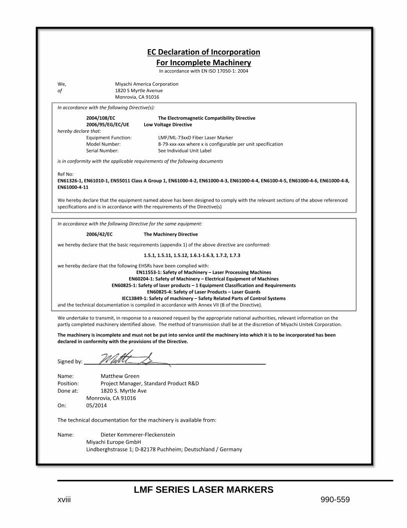
EC Declaration of Incorporation For Incomplete Machinery
In accordance with EN ISO 17050-1: 2004
We, Miyachi America Corporation of 1820 S Myrtle Avenue Monrovia, CA 91016
In accordance with the following Directive(s):
2004/108/EC The Electromagnetic Compatibility Directive 2006/95/EG/EC/UE Low Voltage Directive hereby declare that: Equipment Function: LMF/ML-73xxD Fiber Laser Marker Model Number: 8-79-xxx-xxx where x is configurable per unit specification Serial Number: See Individual Unit Label
is in conformity with the applicable requirements of the following documents Ref No: EN61326-1, EN61010-1, EN55011 Class A Group 1, EN61000-4-2, EN61000-4-3, EN61000-4-4, EN6100-4-5, EN61000-4-6, EN61000-4-8, EN61000-4-11 We hereby declare that the equipment named above has been designed to comply with the relevant sections of the above referenced specifications and is in accordance with the requirements of the Directive(s)
In accordance with the following Directive for the same equipment:
2006/42/EC The Machinery Directive
we hereby declare that the basic requirements (appendix 1) of the above directive are conformed:
1.5.1, 1.5.11, 1.5.12, 1.6.1-1.6.3, 1.7.2, 1.7.3
we hereby declare that the following EHSRs have been complied with: EN11553-1: Safety of Machinery – Laser Processing Machines
EN60204-1: Safety of Machinery – Electrical Equipment of Machines EN60825-1: Safety of laser products – 1 Equipment Classification and Requirements
EN60825-4: Safety of Laser Products – Laser Guards IEC13849-1: Safety of machinery – Safety Related Parts of Control Systems
and the technical documentation is compiled in accordance with Annex VII (B of the Directive). We undertake to transmit, in response to a reasoned request by the appropriate national authorities, relevant information on the partly completed machinery identified above. The method of transmission shall be at the discretion of Miyachi Unitek Corporation.
The machinery is incomplete and must not be put into service until the machinery into which it is to be incorporated has been declared in conformity with the provisions of the Directive. Signed by: _____________________________________________________________ Name: Matthew Green Position: Project Manager, Standard Product R&D Done at: 1820 S. Myrtle Ave Monrovia, CA 91016 On: 05/2014 The technical documentation for the machinery is available from: Name: Dieter Kemmerer-Fleckenstein Miyachi Europe GmbH Lindberghstrasse 1; D-82178 Puchheim; Deutschland / Germany

LMF SERIES LASER MARKERS
990-559 xix
LIMITED WARRANTY
GENERAL TERMS AND CONDITIONS FOR THE SALE OF GOODS 1. Applicability.
(a) These terms and conditions of sale (these “Terms”) are the only terms which govern the sale of the goods (“Goods”) by Amada Miyachi America, Inc. (“Seller”) to the buyer identified in the Sales Quotation and/or Acknowledgment (as each defined below) to which these Terms are attached or incorporated by reference (“Buyer”). Notwithstanding anything herein to the contrary, if a written contract signed by authorized representatives of both parties is in existence covering the sale of the Goods covered hereby, the terms and conditions of said contract shall prevail to the extent they are inconsistent with these Terms.
(b) The accompanying quotation of sale (the “Sales Quotation”) provided to Buyer, and/or sales order acknowledgement (“Acknowledgement”) and these Terms (collectively, this “Agreement”) comprise the entire agreement between the parties, and supersede all prior or contemporaneous understandings, agreements, negotiations, representations and warranties, and communications, both written and oral. For clarification, after the Acknowledgement is received by Buyer, the order for Goods is binding and cannot be cancelled by Buyer for any reason and the full purchase price amount set forth in the Acknowledgement shall be due and payable by Buyer to Seller pursuant to the payment schedule set forth in the Acknowledgement unless otherwise agreed to in writing by Seller. All terms and conditions contained in any prior or contemporaneous oral or written communication which are different from, or in addition to, the terms and conditions in this Agreement are hereby rejected and shall not be binding on Seller, whether or not they would materially alter this Agreement. These Terms prevail over any of Buyer’s terms and conditions of purchase regardless whether or when Buyer has submitted its purchase order or such terms. Fulfillment of Buyer’s order does not constitute acceptance of any of Buyer’s terms and conditions and does not serve to modify or amend these Terms. Notwithstanding anything herein to the contrary, all orders for Goods must be for a minimum purchase price of $100 or such orders will be rejected by Seller. 2. Delivery.
(a) The Goods will be delivered within a reasonable time after Seller provides Buyer the Acknowledgment, subject to availability of finished Goods. Seller will endeavor to meet delivery schedules requested by Buyer, but in no event shall Seller incur any liability, consequential or otherwise, for any delays or failure to deliver as a result of ceasing to manufacture any product or any Force Majeure Event. Delivery schedules set forth in the Acknowledgment are Seller’s good faith estimate on the basis of current schedules. In no event shall Seller be liable for special or consequential damages resulting from failure to meet requested delivery schedules.
(b) Unless otherwise agreed in writing by the parties in the Acknowledgement, Seller shall deliver the Goods to Amada Miyachi America, Inc.’s plant in Monrovia, CA, USA (the “Shipping Point”) using Seller’s standard methods for packaging and shipping such Goods. Buyer shall take delivery of the Goods within three (3) days of Seller’s written notice that the Goods have been delivered to the Shipping Point. Buyer shall be responsible for all loading costs (including freight and insurance costs) and provide equipment and labor reasonably suited for receipt of the Goods at the Shipping Point. Seller shall not be liable for any delays, loss or damage in transit.
(c) Seller may, in its sole discretion, without liability or penalty, make partial shipments of Goods to Buyer, if applicable. Each shipment will constitute a separate sale, and Buyer shall pay for the units shipped whether such shipment is in whole or partial fulfillment of Buyer’s purchase order.
(d) If for any reason Buyer fails to accept delivery of any of the Goods on the date fixed pursuant to Seller’s notice that the Goods have been delivered at the Shipping Point, or if Seller is unable to deliver the Goods at the Shipping Point on such date because Buyer has not provided appropriate instructions, documents, licenses or authorizations: (i) risk of loss to the Goods shall pass to Buyer; (ii) the Goods shall be deemed to have been delivered; and (iii) Seller, at its option, may store the Goods until Buyer picks them up, whereupon Buyer shall be liable for all related costs and expenses (including, without limitation, storage and insurance). 3. Non-delivery.
(a) The quantity of any installment of Goods as recorded by Seller on dispatch from Seller’s place of business is conclusive evidence of the quantity received by Buyer on delivery unless Buyer can provide conclusive evidence proving the contrary.
(b) Seller shall not be liable for any non-delivery of Goods (even if caused by Seller’s negligence) unless Buyer gives written notice to Seller of the non-delivery within three (3) days of the date when the Goods would in the ordinary course of events have been received.
(c) Any liability of Seller for non-delivery of the Goods shall be limited to (in Seller’s sole discretion) replacing the Goods within a reasonable time or adjusting the invoice respecting such Goods to reflect the actual quantity delivered. 4. Shipping Terms. Unless indicated otherwise in the Acknowledgment, Delivery shall be made EXW (Incoterms 2010), Shipping Point, including without limitation, freight and insurance costs. If no delivery terms are specified on the Acknowledgement, the method of shipping will be in the sole discretion of Seller. Unless directed in writing otherwise by Buyer, full invoice value will be declared for all shipments. 5. Title and Risk of Loss. Title and risk of loss passes to Buyer upon delivery of the Goods at the Shipping Point. As collateral security for the payment of the purchase price of the Goods, Buyer hereby grants to Seller a lien on and security interest in and to all of the right, title and interest of Buyer in, to and under the Goods, wherever located, and whether now existing or hereafter arising or acquired from time to time, and in all accessions thereto and replacements or modifications thereof, as well as all proceeds (including insurance proceeds) of the foregoing. The security interest granted under this provision constitutes a purchase money security interest under the California Commercial Code. 6. Amendment and Modification. These Terms may only be amended or modified in a writing which specifically states that it amends these Terms and is signed by an authorized representative of each party.

LMF SERIES LASER MARKERS
xx 990-559
7. Inspection and Rejection of Nonconforming Goods.
(a) Buyer shall inspect the Goods within two (2) days of receipt (“Inspection Period”). Buyer will be deemed to have accepted the Goods unless it notifies Seller in writing of any Nonconforming Goods during the Inspection Period and furnishes such written evidence or other documentation as required by Seller. “Nonconforming Goods” means only the following: (i) product shipped is different than identified in Buyer’s Acknowledgement; or (ii) product’s label or packaging incorrectly identifies its contents. Notwithstanding the foregoing, for shipped Goods that require field installation, the “re-verification” terms in the Acknowledgement shall apply and for custom installations, the inspection and verification shall take place at Buyer’s site immediately after the installation is completed.
(b) Seller will only accept Nonconforming Goods that are returned under Seller’s Return Material Authorization procedures then in effect (“RMA”). Buyer shall obtain a RMA number from Seller prior to returning any Nonconforming Goods and return the Nonconforming Goods prepaid and insured to Seller at 1820 South Myrtle Avenue, Monrovia, CA 91016 or to such other location as designated in writing by Seller for the examination to take place there. If Seller reasonably verifies Buyer’s claim that the Goods are Nonconforming Goods and that the nonconformance did not developed by use from Buyer, Seller shall, in its sole discretion, (i) replace such Nonconforming Goods with conforming Goods, or (ii) credit or refund the Price for such Nonconforming Goods pursuant to the terms set forth herein. Notwithstanding the foregoing, the only remedy for Nonconforming Goods that are custom systems is repair (not refund or replacement). No returns for Nonconforming Goods are allowed after thirty (30) days from the original shipping date.
(c) Buyer acknowledges and agrees that the remedies set forth in Section 7(a) are Buyer’s exclusive remedies for the delivery of Nonconforming Goods. Except as provided under Section 7(a) and Section 14, all sales of Goods to Buyer are made on a one-way basis and Buyer has no right to return Goods purchased under this Agreement to Seller. 8. Price.
(a) Buyer shall purchase the Goods from Seller at the prices (the “Prices”) set forth in Seller’s published catalogue literature in force as of the date of the Sales Quotation. However, the Prices shown in such catalogue literature or any other publication are subject to change without notice. Unless specifically stated to the contrary in the Sales Quotation, quoted Prices and discounts are firm for thirty (30) days from the date of the Sales Quotation. Unless otherwise stated, prices are quoted EXW (Incoterms 2010), Shipping Point. Unless otherwise stated in the Acknowledgement, if the Prices should be increased by Seller before delivery of the Goods to a carrier for shipment to Buyer, then these Terms shall be construed as if the increased prices were originally inserted herein, and Buyer shall be billed by Seller on the basis of such increased prices.
(b) All Prices are exclusive of all sales, use and excise taxes, and any other similar taxes, duties and charges of any kind imposed by any governmental authority on any amounts payable by Buyer. Buyer shall be responsible for all such charges, costs and taxes (present or future); provided, that, Buyer shall not be responsible for any taxes imposed on, or with respect to, Seller’s income, revenues, gross receipts, personnel or real or personal property or other assets. 9. Payment Terms.
(a) Unless otherwise provided in the Acknowledgement, if Buyer has approved credit with Seller, Buyer shall pay all invoiced amounts due to Seller within thirty (30) days from the date of Seller’s invoice. If Seller does not have Buyer’s financial information and has not provided pre-approved credit terms for Buyer, the payment must be made in cash with order or C.O.D. in US dollars. If Buyer has approved credit terms, the payment may be made by cash with order, wire transfer of immediately available funds, or check in US dollars. Certain products require a down payment. Any payment terms other than set forth above will be identified in the Acknowledgement. Notwithstanding anything herein to the contrary, all prepaid deposits and down payments are non-refundable. If a deposit is not received when due, Seller reserves the right to postpone manufacturing of Goods until payment is received. Seller will not be responsible for shipment delays due to deposit payment delays.
(b) In Seller’s sole discretion, Seller may access Buyer interest on all late payments at the lesser of the rate of 1.5% per month or the highest rate permissible under applicable law, calculated daily and compounded monthly. Buyer shall reimburse Seller for all costs incurred in collecting any late payments, including, without limitation, attorneys’ fees. In addition to all other remedies available under these Terms or at law (which Seller does not waive by the exercise of any rights hereunder), Seller shall be entitled to suspend the delivery of any Goods if Buyer fails to pay any amounts when due hereunder and such failure continues for ten (10) days following written notice thereof.
(c) Buyer shall not withhold payment of any amounts due and payable by reason of any set-off of any claim or dispute with Seller, whether relating to Seller’s breach, bankruptcy or otherwise. 10. Intellectual Property; Software License.
(a) To the extent that any Goods provided under this Agreement contains software, whether pre-installed, embedded, in read only memory, or found on any other media or other form (“Software”), such Software and accompanying documentation are licensed to Buyer, not sold and shall remain the sole and exclusive property of Seller or third party licensors of Seller. Seller grants Buyer a non-exclusive license to use the Software solely as provided in and in connection with the use of the Goods in which such Software is contained and in accordance with any applicable user documentation provided with such Goods and subject to the provisions of this Agreement. Certain of Seller’s Goods may include third party software such as computer operating systems. Licenses to such third party software are subject to the terms and conditions of any applicable third party software license agreements. Unless identified in the Acknowledgement, no license is granted by Seller with respect to such third party software products that may be provided with the Goods (if any). Seller makes no warranties regarding any third party software that may accompany the Goods or otherwise and such software is explicitly included in the definition of Third Party Products below.
(b) Buyer shall not copy, modify, or disassemble, or permit others to copy, modify, or disassemble, the Software, nor may Buyer modify, adapt, translate, reverse assemble, decompile, or otherwise attempt to derive source code from the Software. Buyer shall not transfer possession of the Software except as part of, or with, the Goods, and each such transfer shall be subject to the restrictions contained herein. Buyer may not sublicense, rent, loan, assign or otherwise transfer the Software or documentation, and Buyer shall retain on all copies of the Software and documentation all copyright and other proprietary notices or legends appearing therein or thereon. Seller may terminate this license upon written notice for any violation of any of the terms of this license or any material breach of any provision of this Agreement. Buyer shall immediately discontinue use of the Software upon any termination of this license or Agreement. This license shall terminate upon any termination of the Agreement.

LMF SERIES LASER MARKERS
990-559 xxi
(c) All patents, trademarks, copyrights or other intellectual property rights embodied in the Goods, including without limitation the Software, are owned by Seller and its licensors. Seller and its licensors retain all right, title and interest in such intellectual property rights. Except as expressly set forth herein, no license rights or ownership in or to any of the foregoing is granted or transferred hereunder, either directly or by implication. ALL RIGHTS RESERVED.
(d) If Buyer is the United States Government or any agency thereof, each of the components of the Software and user documentation are a “commercial item,” and “computer software” as those terms are defined at 48 C.F.R. 2.101, consisting of “commercial computer software” and “commercial computer software documentation,” as such terms are used in 48 C.F.R. 12.212. Consistent with 48 C.F.R. 12.212 and 48 C.F.R. 227.7202-1 through 227.7202-4, all United States government Buyers acquire only those rights in the Software and user documentation that are specified in this Agreement. 11. Installation and Other Services. Seller shall provide installation services (“Installation Services”) to Buyer if set forth in the Acknowledgment. If Installation Services are provided for in the Acknowledgement, Buyer will prepare the location for the installation consistent with Buyer’s written specifications and Buyer will install necessary system cable and assemble any necessary equipment or hardware not provided by Seller, unless agreed otherwise in writing by the parties. For Goods that will be operated on or in connection with Buyer supplied hardware or software, Buyer is responsible for ensuring that its hardware and software conform with Seller minimum hardware and software requirements as made available to Buyer. Seller shall provide other field services, such as maintenance visits and field repairs (the “Other Services” and together with the Installation Services, the “Services”) if set forth in the Acknowledgement. 12. Limited Warranty.
(a) Subject to the exceptions and upon the conditions set forth herein, Seller warrants to Buyer that for a period of one (1) year from the date of shipment (“Warranty Period”), that such Goods will be free from material defects in material and workmanship.
(b) Notwithstanding the foregoing and anything herein to the contrary, the warranty set forth in this Section 12 shall be superseded and replaced in its entirety with the warranty set forth on Exhibit A hereto if the Goods being purchased are specialty products, which include, without limitation, laser products, fiber markers, custom systems, workstations, Seller-installed products, non-catalogue products and other custom-made items (each a “Specialty Product”).
(c) EXCEPT FOR THE WARRANTY SET FORTH IN SECTION 12(A), SELLER MAKES NO WARRANTY WHATSOEVER WITH RESPECT TO THE GOODS (INCLUDING ANY SOFTWARE) OR SERVICES, INCLUDING ANY (a) WARRANTY OF MERCHANTABILITY; (b) WARRANTY OF FITNESS FOR A PARTICULAR PURPOSE; (c) WARRANTY OF TITLE; OR (d) WARRANTY AGAINST INFRINGEMENT OF INTELLECTUAL PROPERTY RIGHTS OF A THIRD PARTY; WHETHER EXPRESS OR IMPLIED BY LAW, COURSE OF DEALING, COURSE OF PERFORMANCE, USAGE OF TRADE OR OTHERWISE.
(d) Products manufactured by a third party and third party software (“Third Party Product”) may constitute, contain, be contained in, incorporated into, attached to or packaged together with, the Goods. Third Party Products are not covered by the warranty in Section 12(a). For the avoidance of doubt, SELLER MAKES NO REPRESENTATIONS OR WARRANTIES WITH RESPECT TO ANY THIRD PARTY PRODUCT, INCLUDING ANY (a) WARRANTY OF MERCHANTABILITY; (b) WARRANTY OF FITNESS FOR A PARTICULAR PURPOSE; (c) WARRANTY OF TITLE; OR (d) WARRANTY AGAINST INFRINGEMENT OF INTELLECTUAL PROPERTY RIGHTS OF A THIRD PARTY; WHETHER EXPRESS OR IMPLIED BY LAW, COURSE OF DEALING, COURSE OF PERFORMANCE, USAGE OF TRADE OR OTHERWISE. Notwithstanding the foregoing, in the event of the failure of any Third Party Product, Seller will assist (within reason) Buyer (at Buyer’s sole expense) in obtaining, from the respective third party, any (if any) adjustment that is available under such third party’s warranty.
(e) Seller shall not be liable for a breach of the warranty set forth in Section 12(a) unless: (i) Buyer gives written notice of the defect, reasonably described, to Seller within five (5) days of the time when Buyer discovers or ought to have discovered the defect and such notice is received by Seller during the Warranty Period; (ii) Seller is given a reasonable opportunity after receiving the notice to examine such Goods; (iii) Buyer (if requested to do so by Seller) returns such Goods (prepaid and insured to Seller at 1820 South Myrtle Avenue, Monrovia, CA 91016or to such other location as designated in writing by Seller) to Seller pursuant to Seller’s RMA procedures and Buyer obtains a RMA number from Seller prior to returning such Goods for the examination to take place; and (iii) Seller reasonably verifies Buyer’s claim that the Goods are defective and that the defect developed under normal and proper use.
(f) Seller shall not be liable for a breach of the warranty set forth in Section 12(a) if: (i) Buyer makes any further use of such Goods after giving such notice; (ii) the defect arises because Buyer failed to follow Seller’s oral or written instructions as to the storage, installation, commissioning, use or maintenance of the Goods; (iii) Buyer alters or repairs such Goods without the prior written consent of Seller; or (iv) repairs or modifications are made by persons other than Seller’s own service personnel, or an authorized representative’s personnel, unless such repairs are made with the written consent of Seller in accordance with procedures outlined by Seller.
(g) All expendables such as electrodes are warranted only for defect in material and workmanship which are apparent upon receipt by Buyer. The foregoing warranty is negated after the initial use.
(h) Subject to Section 12(e) and Section 12(f) above, with respect to any such Goods during the Warranty Period, Seller shall, in its sole discretion, either: (i) repair or replace such Goods (or the defective part) or (ii) credit or refund the price of such Goods at the pro rata contract rate, provided that, if Seller so requests, Buyer shall, at Buyer’s expense, return such Goods to Seller.
(i) THE REMEDIES SET FORTH IN SECTION 12(H) SHALL BE BUYER’S SOLE AND EXCLUSIVE REMEDY AND SELLER’S ENTIRE LIABILITY FOR ANY BREACH OF THE LIMITED WARRANTY SET FORTH IN SECTION 12(A). Representations and warranties made by any person, including representatives of Seller, which are inconsistent or in conflict with the terms of this warranty, as set forth above, shall not be binding upon Seller. 13. Limitation of Liability.
(a) IN NO EVENT SHALL SELLER BE LIABLE FOR ANY CONSEQUENTIAL, INDIRECT, INCIDENTAL, SPECIAL, EXEMPLARY, OR PUNITIVE DAMAGES, LOST PROFITS OR REVENUES OR DIMINUTION IN VALUE, LOSS OF INFORMATION OR DATA, OR PERSONAL INJURY OR DEATH ARISING IN ANY WAY OUT OF THE MANUFACTURE, SALE, USE, OR INABILITY TO USE ANY GOODS, SOFTWARE OR SERVICE, ORARISING OUT OF OR RELATING TO ANY BREACH OF THESE TERMS, WHETHER OR NOT THE POSSIBILITY OF SUCH DAMAGES HAS BEEN DISCLOSED IN ADVANCE BY BUYER OR COULD HAVE BEEN REASONABLY FORESEEN BY BUYER, REGARDLESS OF THE LEGAL OR EQUITABLE THEORY (CONTRACT, TORT OR OTHERWISE) UPON WHICH THE CLAIM IS BASED, AND NOTWITHSTANDING THE FAILURE OF ANY AGREED OR OTHER REMEDY OF ITS ESSENTIAL PURPOSE.

LMF SERIES LASER MARKERS
xxii 990-559
(b) IN NO EVENT SHALL SELLER’S AGGREGATE LIABILITY ARISING OUT OF OR RELATED TO THIS AGREEMENT, WHETHER ARISING OUT OF OR RELATED TO BREACH OF CONTRACT, TORT (INCLUDING NEGLIGENCE) OR OTHERWISE, EXCEED THE TOTAL OF THE AMOUNTS PAID TO SELLER FOR THE GOODS SOLD HEREUNDER.
(c) ALL WARRANTIES SET FORTH HEREIN, DIRECT OR IMPLIED, ARE VOIDED IF THE INITIAL INSTALLATION AND START-UP OF THE SUBJECT GOOD IS NOT SUPERVISED BY AN AUTHORIZED REPRESENTATIVE OF SELLER. AFTER INSTALLATION, ANY RE-ALIGNMENT, RE-CLEANING, OR RE-CALIBRATION, PROVIDED THEY ARE NOT RELATED TO A PROVEN DEFECT IN MATERIALS OR WORKMANSHIP, SHALL BE PERFORMED BY AN AUTHORIZED REPRESENTATIVE OF SELLERAT THE CURRENT SERVICE RATES.
(d) WHERE GOODS ARE SUBJECT TO A MOVE TO ANOTHER LOCATION AFTER THE ORIGINAL INSTALLATION HAS BEEN MADE, THE WARRANTY MAY BE MAINTAINED ONLY IF SUPERVISED BY AN AUTHORIZED REPRESENTATIVE OF SELLER. SELLER, FOR A SERVICE CHARGE, WILL ARRANGE FOR AND SUPERVISE THE DISCONNECTION, TRANSPORTATION, REINSTALLATION AND START-UP OF THE EQUIPMENT. CLAIMS FOR DAMAGE IN SHIPMENT ARE THE RESPONSIBILITY OF BUYER AND SHALL BE FILED PROMPTLY WITH THE TRANSPORTATION COMPANY. 14. Return Goods Policy. Seller’s products may be returned to Seller for credit within sixty (60) days of shipment subject to the following conditions.
(a) In order to return products for credit, Buyer must obtain a RMA number from Seller. Upon receipt, it must be executed by an authorized person and then returned with the Goods. Goods returned to Seller without a RMA will be returned at Buyer’s expense.
(b) Goods are to be returned to Seller at 1820 South Myrtle Avenue, Monrovia, CA 91016 with Freight Prepaid. Seller will not accept collect shipments.
(c) Restocking fees will be assessed in accordance with the following schedules: (i) Goods returned within the first thirty (30) days from shipment date will be restocked less twenty percent (20%) of the amount billed on the original invoice. (ii) Goods returned over thirty (30) days of shipment but less than sixty (60) days will be restocked less thirty percent (30%) of the amount billed on the original invoice. (iii) No returns are allowed after sixty (60) days from the original shipping date.
(d) The restocking fees set forth above are the minimum fees. If a returned Good requires rework to restore it to a saleable condition, further charges will be assessed. Seller’s quality assurance department will document the condition of the Goods when received by Seller and report their findings to Buyer.
(e) Notwithstanding the foregoing provisions of this Section 14, the following Goods cannot be returned, are not eligible for any credit and cannot be restocked: (i) custom or modified products and (ii) any expendable product(s) that have been used. 15. Compliance with Law and Indemnification. Buyer shall comply with all applicable laws, regulations and ordinances. Buyer shall maintain in effect all the licenses, permissions, authorizations, consents and permits that it needs to carry out its obligations under this Agreement. Buyer shall comply with all export and import laws of all countries involved in the sale of the Goods under this Agreement or any resale of the Goods by Buyer. Goods, Services and technical data delivered by Seller shall be subject to U.S. export controls. Buyer shall, and shall cause its customers to, obtain all licenses, permits and approvals required by any government and shall comply with all applicable laws, rules, policies and procedures of the applicable government and other competent authorities. Buyer will indemnify and hold Seller harmless for any violation or alleged violation by Buyer of such laws, rules, policies or procedures. Buyer shall not transmit, export or re-export, directly or indirectly, separately or as part of any system, the Goods or any technical data (including processes and Services) received from Seller, without first obtaining any license required by the applicable government, including without limitation, the U.S. government. Buyer also certifies that none of the Goods or technical data supplied by Seller under this Agreement will be sold or otherwise transferred to, or made available for use by or for, any entity that is engaged in the design, development, production or use of nuclear, biological or chemical weapons or missile technology. No Buyer information will be deemed “technical data” unless Buyer specifically identifies it to Seller as such. Buyer assumes all responsibility for shipments of Goods requiring any government import clearance. Seller may terminate this Agreement if any governmental authority imposes antidumping or countervailing duties or any other penalties on Goods. For all international shipments, Seller requires that all required Export Control documentations, including Form BIS-711 Statement by Ultimate Consignee and Purchases, are submitted by Buyer along with the purchase order. Seller reserves the right to postpone shipment until all documentations are completed and submitted to Seller. Seller will not be responsible for shipment delays due to non-compliance by Buyer of the foregoing two sentences. 16. Termination. In addition to any remedies that may be provided under these Terms, Seller may terminate this Agreement with immediate effect upon written notice to Buyer, if Buyer: (i) fails to pay any amount when due under this Agreement and such failure continues for ten (10) days after Buyer’s receipt of written notice of nonpayment; (ii) has not otherwise performed or complied with any of these Terms, in whole or in part; or (iii) becomes insolvent, files a petition for bankruptcy or commences or has commenced against it proceedings relating to bankruptcy, receivership, reorganization or assignment for the benefit of creditors. 17. Waiver. No waiver by Seller of any of the provisions of this Agreement is effective unless explicitly set forth in writing and signed by Seller. No failure to exercise, or delay in exercising, any rights, remedy, power or privilege arising from this Agreement operates or may be construed as a waiver thereof. No single or partial exercise of any right, remedy, power or privilege hereunder precludes any other or further exercise thereof or the exercise of any other right, remedy, power or privilege. 18. Confidential Information. All non-public, confidential or proprietary information of Seller, including, but not limited to, specifications, samples, patterns, designs, plans, drawings, documents, data, business operations, customer lists, pricing, discounts or rebates, disclosed by Seller to Buyer, whether disclosed orally or disclosed or accessed in written, electronic or other form or media, and whether or not marked, designated or otherwise identified as “confidential,” in connection with this Agreement is confidential, solely for the use of performing this Agreement and may not be disclosed or copied unless authorized in advance by Seller in writing. Upon Seller’s request, Buyer shall promptly return all documents and other materials received from Seller. Seller shall be entitled to injunctive relief for any violation of this Section 18. This Section 18 does not apply to information that is: (a) in the public domain through no fault of Buyer; (b) known to Buyer at the time of disclosure without restriction as evidenced by its records; or (c) rightfully obtained by Buyer on a non-confidential basis from a third party. 19. Force Majeure. Seller shall not be liable or responsible to Buyer, nor be deemed to have defaulted or breached this Agreement, for any failure or delay in fulfilling or performing any term of this Agreement when and to the extent such failure or delay is caused by or results from acts or circumstances beyond the reasonable control of Seller including, without limitation, acts of God, flood, fire, earthquake, explosion, governmental actions, war, invasion or hostilities

LMF SERIES LASER MARKERS
990-559 xxiii
(whether war is declared or not), terrorist threats or acts, riot, or other civil unrest, national emergency, revolution, insurrection, epidemic, lock-outs, strikes or other labor disputes (whether or not relating to either party’s workforce), or restraints or delays affecting carriers or inability or delay in obtaining supplies of adequate or suitable materials, materials or telecommunication breakdown or power outage (each a “Force Majeure Event”), provided that, if the event in question continues for a continuous period in excess of thirty (30) days, Buyer shall be entitled to give notice in writing to Seller to terminate this Agreement. 20. Assignment. Buyer shall not assign any of its rights or delegate any of its obligations under this Agreement without the prior written consent of Seller. Any purported assignment or delegation in violation of this Section 20 is null and void. No assignment or delegation relieves Buyer of any of its obligations under this Agreement. 21. Relationship of the Parties. The relationship between the parties is that of independent contractors. Nothing contained in this Agreement shall be construed as creating any agency, partnership, joint venture or other form of joint enterprise, employment or fiduciary relationship between the parties, and neither party shall have authority to contract for or bind the other party in any manner whatsoever. 22. No Third-Party Beneficiaries. This Agreement is for the sole benefit of the parties hereto and their respective successors and permitted assigns and nothing herein, express or implied, is intended to or shall confer upon any other person or entity any legal or equitable right, benefit or remedy of any nature whatsoever under or by reason of these Terms. 23. Governing Law. All matters arising out of or relating to this Agreement is governed by and construed in accordance with the internal laws of the State of California without giving effect to any choice or conflict of law provision or rule (whether of the State of California or any other jurisdiction) that would cause the application of the laws of any jurisdiction other than those of the State of California. 24. Dispute Resolution.
(a) If Buyer is an entity formed under the laws of the United States of America, or any of its states, districts or territories (“U.S. Law”), then any dispute, legal suit, action or proceeding arising out of or relating to this Agreement shall be adjudicated and decided in the federal courts of the United States of America or the courts of the State of California in each case located in the City of Los Angeles and County of Los Angeles, California and each party irrevocably submits to the exclusive and personal jurisdiction of such courts in any such dispute, suit, action or proceeding.
(b) If Buyer is an entity formed under the laws of any country, state, district or territory other than U.S. Law, then the parties irrevocably agree that any dispute, legal suit, action or proceeding arising out of or relating to this Agreement shall be submitted to the International Court of Arbitration of the International Chamber of Commerce (“ICC”) and shall be finally settled under the Rules of Arbitration of the ICC. The place and location of the arbitration shall be in Los Angeles, California, pursuant to the ICC’s Rules of Arbitration and shall be finally settled in accordance with said rules. The arbitration shall be conducted before a panel of three arbitrators. Each party shall select one arbitrator and the two arbitrators so selected shall select the third arbitrator, who shall act as presiding arbitrator. Notwithstanding the foregoing, if the matter under dispute is $500,000 or less, there shall only be one arbitrator who shall be mutually selected by both parties. If the party-selected arbitrators are unable to agree upon the third arbitrator, if either party fails to select an arbitrator, or in the case that only one arbitrator is required and the parties are unable to agree, then the International Court of Arbitration shall choose the arbitrator. The language to be used in the arbitral proceeding shall be English. The arbitrator(s) shall have no authority to issue an award that is contrary to the express terms of this Agreement or the laws of the State of California or applicable US Federal Law, and the award may be vacated or corrected on appeal to a court of competent jurisdiction for any such error. The arbitrator(s) shall be specifically empowered to allocate between the parties the costs of arbitration, as well as reasonable attorneys’ fees and costs, in such equitable manner as the arbitrator(s) may determine. The arbitrator(s) shall have the authority to determine issues of arbitrability and to award compensatory damages, but they shall not have authority to award punitive or exemplary damages. Judgment upon the award so rendered may be entered in any court having jurisdiction or application may be made to such court for judicial acceptance of any award and an order of enforcement, as the case may be. In no event shall a demand for arbitration be made after the date when institution of a legal or equitable proceeding based upon such claim, dispute or other matter in question would be barred by the applicable statute of limitations. Notwithstanding the foregoing, either party shall have the right, without waiving any right or remedy available to such party under this Agreement or otherwise, to seek and obtain from any court of competent jurisdiction any interim or provisional relief that is necessary or desirable to protect the rights or property of such party, pending the selection of the arbitrator(s) hereunder or pending the arbitrator(s)’ determination of any dispute, controversy or claim hereunder. 25. Notices. All notices, request, consents, claims, demands, waivers and other communications hereunder (each, a “Notice”) shall be in writing and addressed to the parties at the addresses set forth on the face of the Acknowledgement or to such other address that may be designated by the receiving party in writing. All Notices shall be delivered by personal delivery, nationally recognized overnight courier (with all fees pre-paid), facsimile (with confirmation of transmission) or certified or registered mail (in each case, return receipt requested, postage prepaid). Except as otherwise provided in this Agreement, a Notice is effective only (a) upon receipt of the receiving party, upon confirmation of delivery by nationally recognized overnight courier or upon forty-eight (48) hours after being sent by certified or registered mail (as applicable), and (b) if the party giving the Notice has complied with the requirements of this Section 25. 26. Severability. If any term or provision of this Agreement is invalid, illegal or unenforceable in any jurisdiction, such invalidity, illegality or unenforceability shall not affect any other term or provision of this Agreement or invalidate or render unenforceable such term or provision in any other jurisdiction. 27. Survival. Provisions of these Terms which by their nature should apply beyond their terms will remain in force after any termination or expiration of this Order including, but not limited to, the following provisions: Compliance with Laws, Confidentiality, Governing Law, Dispute Resolution, Survival, and the restrictions on Software in Sections 10(b), (c) and (d).

LMF SERIES LASER MARKERS
xxiv 990-559
Exhibit A Warranty For “Specialty Products”
LIMITED WARRANTY EXCEPT FOR THE WARRANTY SET FORTH BELOW IN THIS EXHIBIT A, SELLER MAKES NO WARRANTY WHATSOEVER WITH RESPECT TO THE GOODS (INCLUDING ANY SOFTWARE) OR SERVICES, INCLUDING ANY (a) WARRANTY OF MERCHANTABILITY; (b) WARRANTY OF FITNESS FOR A PARTICULAR PURPOSE; (c) WARRANTY OF TITLE; OR (d) WARRANTY AGAINST INFRINGEMENT OF INTELLECTUAL PROPERTY RIGHTS OF A THIRD PARTY; WHETHER EXPRESS OR IMPLIED BY LAW, COURSE OF DEALING, COURSE OF PERFORMANCE, USAGE OF TRADE OR OTHERWISE. Warranty Period: The Warranty Period for Specialty Products is for one (1) year, and the Warranty Period for laser welders and laser markers is two (2) years (unlimited hours), and the Warranty Period for the laser pump diodes or modules is two (2) years or 10,000 clock hours, whichever occurs first (as applicable, the “Warranty Period”). The Warranty Period begins as follows: (i) on orders for Goods purchased directly by Buyer, upon installation at Buyer’s site or thirty (30) days after the date of shipment, whichever occurs first; or (ii) on equipment purchased by a Buyer that is an OEM or systems integrators, upon installation at the end user’s site or six (6) months after the date of shipment, whichever occurs first. Acceptance Tests: Acceptance Tests (when required) shall be conducted at Amada Miyachi America, Inc., Monrovia, CA, USA (the “Testing Site”) unless otherwise mutually agreed in writing prior to issuance or acceptance of the Acknowledgement. Acceptance Tests shall consist of a final visual inspection and a functional test of all laser, workstation, enclosure, motion and accessory hardware. Acceptance Tests shall include electrical, mechanical, optical, beam delivery, and software items deliverable under the terms of the Acknowledgement. Terms and conditions for Additional Acceptance Tests either at Seller’s or Buyer’s facility shall be mutually agreed in writing prior to issuance or acceptance of the Acknowledgement. Performance Warranty: The system is warranted to pass the identical performance criteria at Buyer’s site as demonstrated during final Acceptance Testing at the Testing Site during the Warranty Period, as provided in the Acknowledgement. Seller explicitly disclaims any responsibility for the process results of the laser processing (welding, marking, drilling, cutting, etc.) operations. Exclusions: Seller makes no warranty, express or implied, with respect to the design or operation of any system in which any Seller’s product sold hereunder is a component. Limitations: The limited warranty set forth on this Exhibit A does not cover loss, damage, or defects resulting from transportation to Buyer’s facility, improper or inadequate maintenance by Buyer, Buyer-supplied software or interfacing, unauthorized modification or misuse, operation outside of the environmental specifications for the equipment, or improper site preparation and maintenance. This warranty also does not cover damage from misuse, accident, fire or other casualties of failures caused by modifications to any part of the equipment or unauthorized entry to those portions of the laser which are stated. Furthermore, Seller shall not be liable for a breach of the warranty set forth in this Exhibit A if: (i) Buyer makes any further use of such Goods after giving such notice; (ii) the defect arises because Buyer failed to follow Seller’s oral or written instructions as to the storage, installation, commissioning, use or maintenance of the Goods; (iii) Buyer alters or repairs such Goods without the prior written consent of Seller; or (iv) repairs or modifications are made by persons other than Seller’s own service personnel, or an authorized representative’s personnel, unless such repairs are made with the written consent of Seller in accordance with procedures outlined by Seller. Seller further warrants that all Services performed by Seller’s employees will be performed in a good and workmanlike manner. Seller’s sole liability under the foregoing warranty is limited to the obligation to re-perform, at Seller’s cost, any such Services not so performed, within a reasonable amount of time following receipt of written notice from Buyer of such breach, provided that Buyer must inform Seller of any such breach within ten (10) days of the date of performance of such Services. Seller shall not be liable for a breach of the warranty set forth in this Exhibit A unless: (i) Buyer gives written notice of the defect or non-compliance covered by the warranty, reasonably described, to Seller within five (5) days of the time when Buyer discovers or ought to have discovered the defect or non-compliance and such notice is received by Seller during the Warranty Period; (ii) Seller is given a reasonable opportunity after receiving the notice to examine such Goods and (a) Buyer returns such Goods to Seller’s place of business at Buyer’s cost (prepaid and insured); or (b) in the case of custom systems, Seller dispatches a field service provider to Buyer’s location at Buyer’s expense, for the examination to take place there; and (iii) Seller reasonably verifies Buyer’s claim that the Goods are defective or non-compliant and the defect or non-compliance developed under normal and proper use. All consumable, optical fibers, and expendables such as electrodes are warranted only for defect in material and workmanship which are apparent upon receipt by Buyer. The foregoing warranty is negated after the initial use. No warranty made hereunder shall extend to any product whose serial number is altered, defaced, or removed. Remedies. With respect to any such Goods during the Warranty Period, Seller shall, in its sole discretion, either: repair such Goods (or the defective part). THE REMEDIES SET FORTH IN THE FOREGOING SENTENCE SHALL BE BUYER’S SOLE AND EXCLUSIVE REMEDY AND SELLER’S ENTIRE LIABILITY FOR ANY BREACH OF THE LIMITED WARRANTY SET FORTH IN THIS EXHIBIT A. Representations and warranties made by any person, including representatives of Seller, which are inconsistent or in conflict with the terms of this warranty, as set forth above, shall not be binding upon Seller. Products manufactured by a third party and third party software (“Third Party Product”) may constitute, contain, be contained in, incorporated into, attached to or packaged together with, the Goods. Third Party Products are not covered by the warranty in this Exhibit A. For the avoidance of doubt, SELLER MAKES NO REPRESENTATIONS OR WARRANTIES WITH RESPECT TO ANY THIRD PARTY PRODUCT, INCLUDING ANY (a) WARRANTY OF MERCHANTABILITY; (b) WARRANTY OF FITNESS FOR A PARTICULAR PURPOSE; (c) WARRANTY OF TITLE; OR (d) WARRANTY AGAINST INFRINGEMENT OF INTELLECTUAL PROPERTY RIGHTS OF A THIRD PARTY; WHETHER EXPRESS OR IMPLIED BY LAW, COURSE OF DEALING, COURSE OF PERFORMANCE, USAGE OF TRADE OR OTHERWISE. Notwithstanding the foregoing, in the event of the failure of any Third Party Product, Seller will assist (within reason) Buyer (at Buyer’s sole expense) in obtaining, from the respective third party, any (if any) adjustment that is available under such third party’s warranty.

LMF SERIES LASER MARKERS
990-559 1-1
CHAPTER 1
SYSTEM DESCRIPTION Section I: Features
The LMF Series Fiber Laser Markers are high-precision scanning fiber laser markers, either pulsed or Q-switched depending on the configuration as delivered. For the rest of this manual, all models of the LMF Series Fiber Laser Markers will simply be referred to as “the Marker,” except in specific instances where unique descriptions are required such as specifications, connections, etc.
This Marker is configured to operate with WinLase laser control software. Please refer to the software manual for details. Laser Marking Advantages: Permanent marking.
In contrast to ink-based printing, laser marking is permanent, since the laser beam changes the material itself.
Environmentally friendly. No ink is needed, so no solvent is used. Use of recycling marked materials is easier because they contain no ink.
Non-contact marking. Permits marking of curved and concave surfaces.
Features Compact and lightweight.
Ideal for production lines where space is limited.
Energy efficient. Low power consumption, thanks to a highly efficient laser diode.
Fully air-cooled. Easy maintenance. No coolant needed.
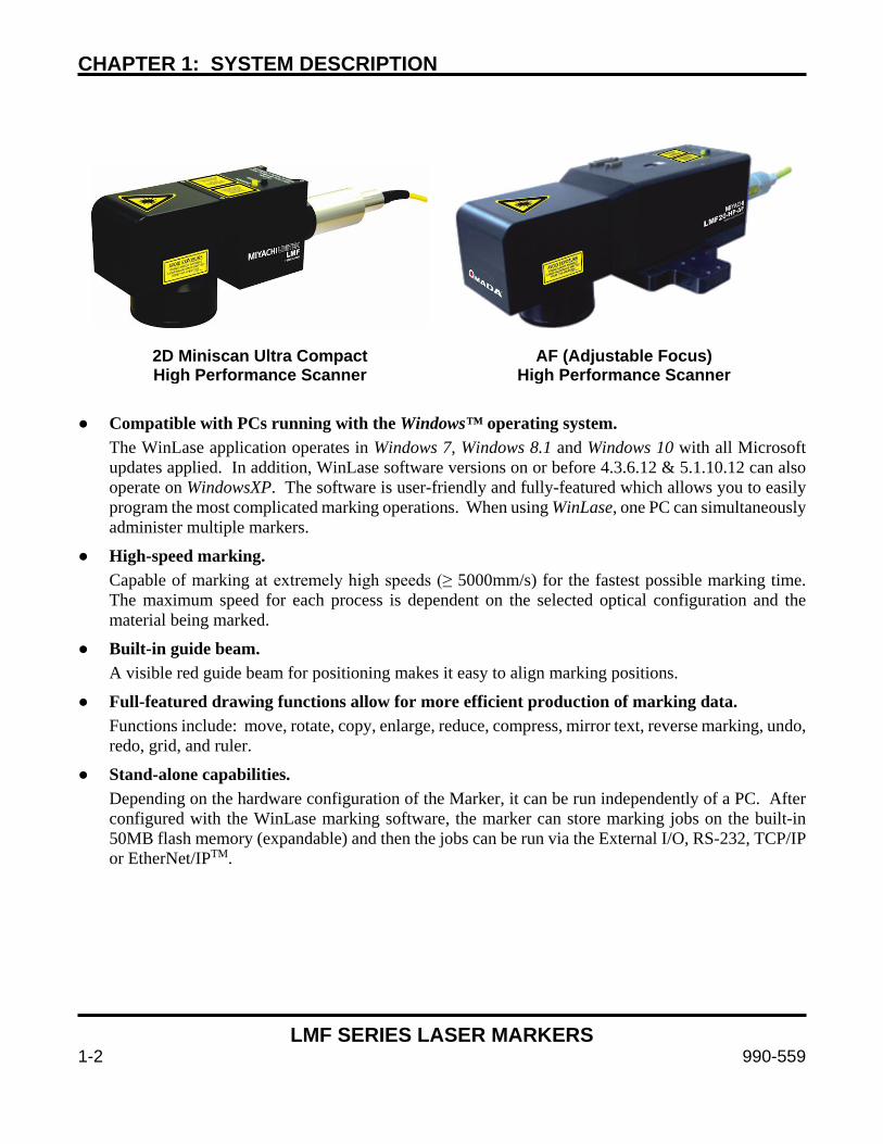
CHAPTER 1: SYSTEM DESCRIPTION
LMF SERIES LASER MARKERS
1-2 990-559
2D Miniscan Ultra Compact High Performance Scanner
AF (Adjustable Focus) High Performance Scanner
Compatible with PCs running with the Windows™ operating system.
The WinLase application operates in Windows 7, Windows 8.1 and Windows 10 with all Microsoft updates applied. In addition, WinLase software versions on or before 4.3.6.12 & 5.1.10.12 can also operate on WindowsXP. The software is user-friendly and fully-featured which allows you to easily program the most complicated marking operations. When using WinLase, one PC can simultaneously administer multiple markers.
High-speed marking. Capable of marking at extremely high speeds (≥ 5000mm/s) for the fastest possible marking time. The maximum speed for each process is dependent on the selected optical configuration and the material being marked.
Built-in guide beam. A visible red guide beam for positioning makes it easy to align marking positions.
Full-featured drawing functions allow for more efficient production of marking data. Functions include: move, rotate, copy, enlarge, reduce, compress, mirror text, reverse marking, undo, redo, grid, and ruler.
Stand-alone capabilities. Depending on the hardware configuration of the Marker, it can be run independently of a PC. After configured with the WinLase marking software, the marker can store marking jobs on the built-in 50MB flash memory (expandable) and then the jobs can be run via the External I/O, RS-232, TCP/IP or EtherNet/IPTM.
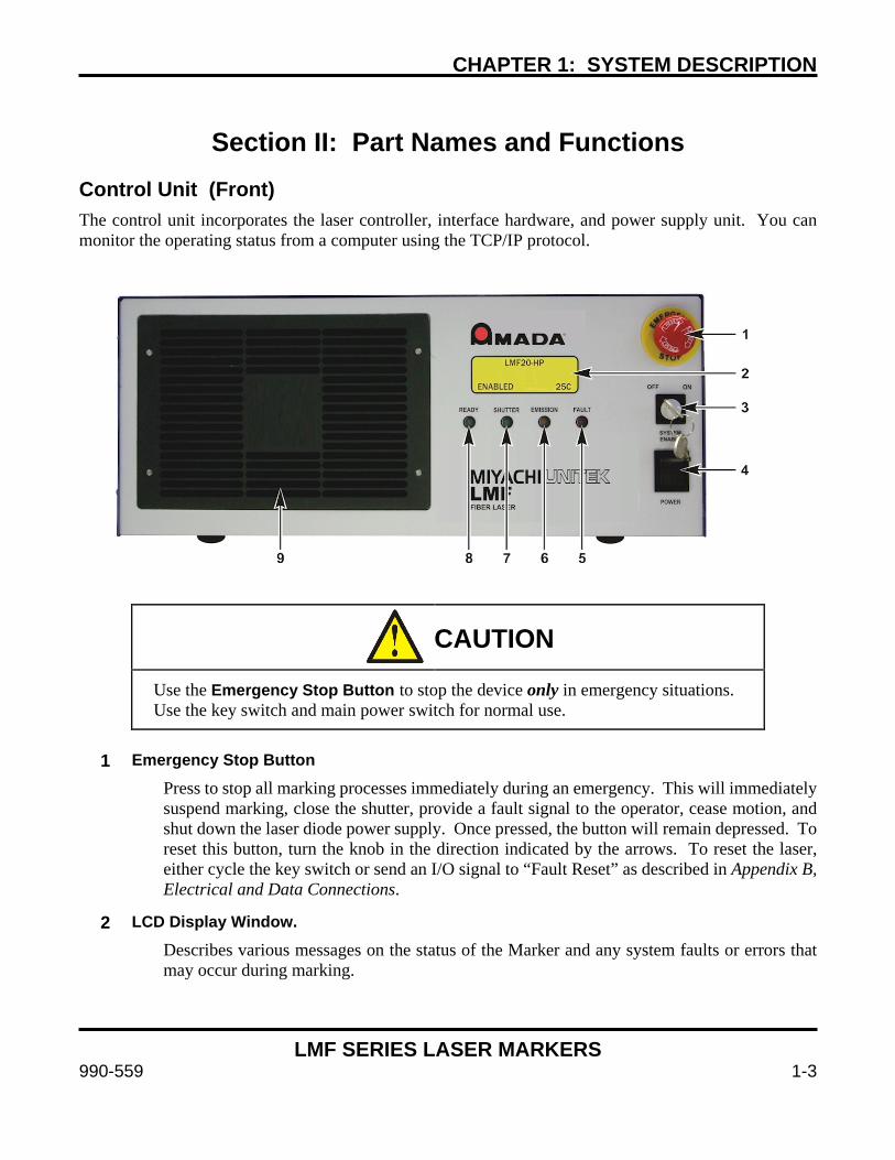
CHAPTER 1: SYSTEM DESCRIPTION
LMF SERIES LASER MARKERS
990-559 1-3
Section II: Part Names and Functions
Control Unit (Front) The control unit incorporates the laser controller, interface hardware, and power supply unit. You can monitor the operating status from a computer using the TCP/IP protocol.
CAUTION
Use the Emergency Stop Button to stop the device only in emergency situations. Use the key switch and main power switch for normal use.
1 Emergency Stop Button
Press to stop all marking processes immediately during an emergency. This will immediately suspend marking, close the shutter, provide a fault signal to the operator, cease motion, and shut down the laser diode power supply. Once pressed, the button will remain depressed. To reset this button, turn the knob in the direction indicated by the arrows. To reset the laser, either cycle the key switch or send an I/O signal to “Fault Reset” as described in Appendix B, Electrical and Data Connections.
2 LCD Display Window.
Describes various messages on the status of the Marker and any system faults or errors that may occur during marking.

CHAPTER 1: SYSTEM DESCRIPTION
LMF SERIES LASER MARKERS
1-4 990-559
3 SYSTEM ENABLE Key Switch
This key switch controls the power to the laser engine and must be in the ON position in order to open the safety shutter and enable marking. If the key switch is in the OFF position the marker is incapable of laser emission.
Performance note: Turn this key to the OFF position to prevent the laser engine “run hours” counter from continuously counting. The marker can still be operated using the guide beam only with the key switch in the OFF position.
4 POWER Switch
This switch allows the operator to turn the Marker ON and OFF.
5 FAULT Light
Indicates that the Laser Marker error has occurred. The specific fault will show on the LCD Display Window.
6 EMISSION Light
Indicates that marking is underway. This indicator will be briefly illuminated during initial power up as a self-check mechanism, but emission does not occur.
7 SHUTTER Light
Indicates that the Safety Shutter in the laser head is open.
8 READY Light
Indicates that the Marker is ready to mark and that the following conditions have been met:
• No Laser Marker system faults. • No E-stop (emergency stop) condition. • The System Enable Key Switch is ON. • The LEC Laser Controller has been initialized.
9 Cooling Fan Air Intake
Clean the air filter at regular intervals. See Chapter 4, Maintenance for more details.
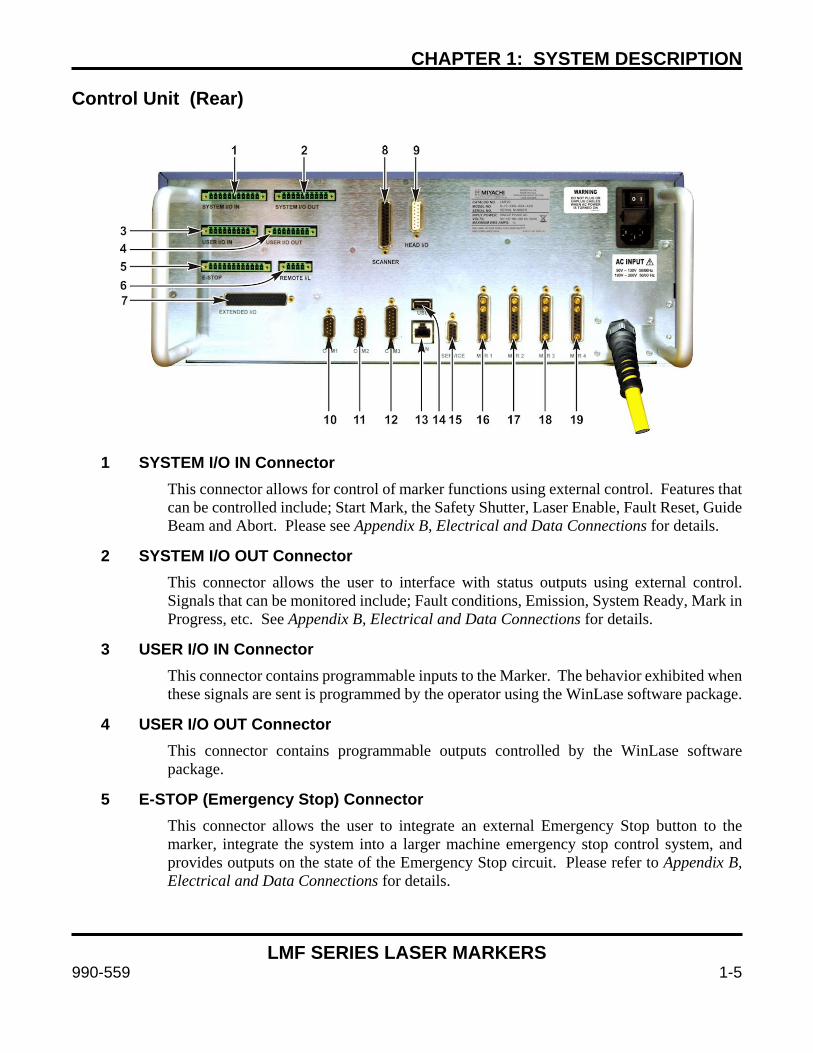
CHAPTER 1: SYSTEM DESCRIPTION
LMF SERIES LASER MARKERS
990-559 1-5
Control Unit (Rear)
1 SYSTEM I/O IN Connector This connector allows for control of marker functions using external control. Features that can be controlled include; Start Mark, the Safety Shutter, Laser Enable, Fault Reset, Guide Beam and Abort. Please see Appendix B, Electrical and Data Connections for details.
2 SYSTEM I/O OUT Connector This connector allows the user to interface with status outputs using external control. Signals that can be monitored include; Fault conditions, Emission, System Ready, Mark in Progress, etc. See Appendix B, Electrical and Data Connections for details.
3 USER I/O IN Connector This connector contains programmable inputs to the Marker. The behavior exhibited when these signals are sent is programmed by the operator using the WinLase software package.
4 USER I/O OUT Connector This connector contains programmable outputs controlled by the WinLase software package.
5 E-STOP (Emergency Stop) Connector This connector allows the user to integrate an external Emergency Stop button to the marker, integrate the system into a larger machine emergency stop control system, and provides outputs on the state of the Emergency Stop circuit. Please refer to Appendix B, Electrical and Data Connections for details.
CHAPTER 1: SYSTEM DESCRIPTION
LMF SERIES LASER MARKERS
1-6 990-559
6 REMOTE I/L (Interlock) Connector
This two channel dry contact connection is used to control the laser’s remote interlock. If the remote interlock is activated the safety shutter is immediately closed and laser emission is discontinued. An error message is sent to the front panel if a marking operation is in progress. Both Interlock channels need to simultaneously change state at the same time.
7 EXTENDED I/O Connector This connector allows the user to address 8-bit I/O job selection as well as additional I/O. Please refer to Appendix B, Electrical and Data Connections for details on how to wire this connector.
8 SCANNER Connector This 25-pin D-Sub cable contains power and digital communication signals for the laser scan head. Please do not operate the marker without this connected as it may damage the scanhead or cause un-aimed laser emission. Do not plug or unplug this connector when power is ON.
9 LASER HEAD I/O Connector This 15-pin D-Sub cable contains communication signals between the marker and laser head including head interlocks, shutter power and sensor signals, etc. If this cable is disconnected the marker will be in the Emergency Stop state.
10 COM1 Connector This connector is used to control the Laser Marker through an RS-232 connection via the WinLase Remote API. Refer to Appendix B: Electrical and Data Connections and Appendix D: Remote Interface Commands for more information.
Note: Operation via RS-232 and System I/O cannot be used at the same time.
11 COM2 Connector Same functionality as the COM1.
12 COM3 Connector This connector allows the user to connect serial stepper motors or an encoder to be used with Mark on the Fly. Motor connections to this port are for legacy motion applications requiring a separate motion power supply. When possible use MTR 1-4 connectors instead as power and control are available on these ports and no separate motion power supply is required. Please see Appendix B, Electrical & Data Connections for more details.
CHAPTER 1: SYSTEM DESCRIPTION
LMF SERIES LASER MARKERS
990-559 1-7
13 EtherNet/IPTM LAN Connector
Use this port to connect the marker to a Category 5e cable if using the WinLase software package. Select your Category 5e cable depending on the network configuration you plan to use. If the marker is to be directly connected to a PC, use a Cat 5e crossover type cable AMYA # 205-318). If the marker is to be connected to a Local Area Network via a hub or switch, use a standard Cat 5e patch cable (AMYA # 205-380).
14 USB Connector This port is used to add additional job and graphic storage to the unit. Use a USB flash drive only. Not all flash drives are supported.
Note: In order to save job files, the USB Flash Drive must be ≥ 1Gb. All job files are stored in an LEC folder in the root directory of the USB Flash Drive. Verify this folder exists before trying to save job files.
15 SERVICE Connector Reserved for factory diagnostic and configuration use.
16-19 MTR 1-4 Connector These connectors are used to connect individual serial stepper motors for motion control. Power and communication are provided on each individual connector. When using these connectors it is not necessary to use the motor signals on COM3.

CHAPTER 1: SYSTEM DESCRIPTION
LMF SERIES LASER MARKERS
1-8 990-559
2D Laser Head
2D Ultra Compact Laser Head (All Models) The ultra-compact laser head is equipped with a high performance Miniscan scanner and is packaged in an extremely small sealed enclosure. Using mass-reduced mirrors and high performance galvanometers with precise, matched drivers gives this scanner improved speed, thermal drift, temporal drift, and better overall repeatability. The extremely compact size makes it easier to fit into tight spaces. By special order, some Laser models can operate in ambient temperatures as high as 40° Celsius (Laser Head only). Some models include changeable beam diameter optics with “safety latch” features. Specifications include:
> 5.0m/s marking speed, > 9.0m/s positioning speed 12µrad Resolution 20µrad Repeatability 0.005%/K Maximum Gain Drift per axis 30µrad/K Maximum Offset Drift per axis < 300µrad Long Term Drift over 8 hours IP-54+ environmental protection
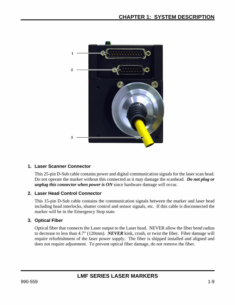
CHAPTER 1: SYSTEM DESCRIPTION
LMF SERIES LASER MARKERS
990-559 1-9
1. Laser Scanner Connector
This 25-pin D-Sub cable contains power and digital communication signals for the laser scan head. Do not operate the marker without this connected as it may damage the scanhead. Do not plug or unplug this connector when power is ON since hardware damage will occur.
2. Laser Head Control Connector This 15-pin D-Sub cable contains the communication signals between the marker and laser head including head interlocks, shutter control and sensor signals, etc. If this cable is disconnected the marker will be in the Emergency Stop state.
3. Optical Fiber Optical fiber that connects the Laser output to the Laser head. NEVER allow the fiber bend radius to decrease to less than 4.7” (120mm). NEVER kink, crush, or twist the fiber. Fiber damage will require refurbishment of the laser power supply. The fiber is shipped installed and aligned and does not require adjustment. To prevent optical fiber damage, do not remove the fiber.

CHAPTER 1: SYSTEM DESCRIPTION
LMF SERIES LASER MARKERS
1-10 990-559
AF (Adjustable Focus) Laser Head
AF (Adjustable Focus) Laser Head The AF (Adjustable Focus) laser head is equipped with a high performance Miniscan scanner and is packaged in an extremely small sealed enclosure. Using mass-reduced mirrors and high performance galvanometers with precise, matched drivers gives this scanner improved speed, thermal drift, temporal drift, and better overall repeatability. The extremely compact size makes it easier to fit into tight spaces. Some models can operate in ambient temperatures as high as 35° Celsius. Specifications include:
20µrad Repeatability 50 ppm/K Maximum Gain Drift per axis 30µrad/K Maximum Offset Drift per axis < 300µrad Long Term Drift over 8 hours 0.46ms Acceleration Time (10- 90%) ± 0.393 rad Typical Deflection
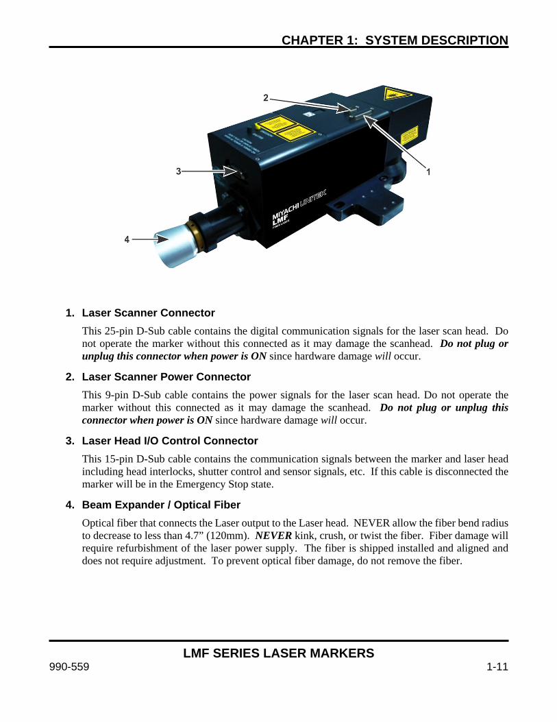
CHAPTER 1: SYSTEM DESCRIPTION
LMF SERIES LASER MARKERS
990-559 1-11
1. Laser Scanner Connector
This 25-pin D-Sub cable contains the digital communication signals for the laser scan head. Do not operate the marker without this connected as it may damage the scanhead. Do not plug or unplug this connector when power is ON since hardware damage will occur.
2. Laser Scanner Power Connector This 9-pin D-Sub cable contains the power signals for the laser scan head. Do not operate the marker without this connected as it may damage the scanhead. Do not plug or unplug this connector when power is ON since hardware damage will occur.
3. Laser Head I/O Control Connector This 15-pin D-Sub cable contains the communication signals between the marker and laser head including head interlocks, shutter control and sensor signals, etc. If this cable is disconnected the marker will be in the Emergency Stop state.
4. Beam Expander / Optical Fiber Optical fiber that connects the Laser output to the Laser head. NEVER allow the fiber bend radius to decrease to less than 4.7” (120mm). NEVER kink, crush, or twist the fiber. Fiber damage will require refurbishment of the laser power supply. The fiber is shipped installed and aligned and does not require adjustment. To prevent optical fiber damage, do not remove the fiber.
CHAPTER 1: SYSTEM DESCRIPTION
LMF SERIES LASER MARKERS
1-12 990-559
Options The following items are available as options:
Component Description
Protective Glass (Lens dependent)
The Marker is shipped with a protective glass affixed to the f-theta lens. If this glass becomes soiled or cracked, a replacement may be purchased. Refer to Chapter 4 Maintenance, Section IV for a list of replacement cover glass part numbers.
High Precision Serial Stepper Motors with cables
Up to 4 motors can be connected for stepper motor control with optional encoders. Contact Amada Miyachi America for more information.
Air Filter (Control Unit)
An air filter is installed in the Control Unit at the time of purchase. Additional filters are available. Amada Miyachi America Pt # 4-68423-01 (black) and 4-68424-01 (blue). Air filters should be replaced as a set with the black filter to the outside of the unit.
Lithium System Battery CR2032 (Backup battery for internal memory) – Amada Miyachi America Pt # 145-017.
Cat 5e Crossover Cable For communications with a computer. Amada Miyachi America Pt # 205-318.
Spares Kit, Level I Spares kit containing; Air Filter (set), back-up battery, Power Supply Fuse, Lens Cleaning solution + Tissue, Spare I/O connectors. Amada Miyachi America Pt # 8-707-04-01.
Spares Kit, Level II Spares Kit containing: All of the items from the 8-707-04-01 Level Kit + replacement PCB’s, fan and power supplies. Amada Miyachi America Pt # 8-707-04-0x (where x varies on model options).
Adjustable-Focus Head Options:
Adjustable-Focus (AF) Mounting Kit
The AF (Adjustable Focus) Mounting Kit includes all hardware necessary to mount an AF Sensor Kit (available separately). Amada Miyachi America Pt # 8-922-01. Note: The AF Mounting Kit bolts on to the bottom of the LMF Head and replaces the standard 4-70005-01 Base Plate. Used with AF Laser Heads only.
f100mm AF Sensor Kit
AF Sensor kit for the f100 mm f-theta lens, Amada Miyachi America Pt # 8-932-01. Kit includes all necessary hardware to implement the AF feature on the LMF Laser Marker (Sensor + cables + mounting kit+ hardware). See Chapter 7 for more details.
f 160mm / f 254mm AF Sensor Kit
AF Sensor kit for the f160 mm and f254 mm f-theta lens, Amada Miyachi America Pt # 8-932-02. Kit includes all necessary hardware to implement the AF feature on the LMF Laser Marker (Sensor + cables + mounting kit+ hardware). See Chapter 7 for more details.
CHAPTER 1: SYSTEM DESCRIPTION
LMF SERIES LASER MARKERS
990-559 1-13
Section III: Compliance Please refer to the Declaration of Incorporation in this manual for the fiber laser marker for compliance details. This product is sold ready for its intended purpose as a product for incorporation.
The end user and integrator are responsible for integration of the laser according to the information in this manual. With correct installation of the fiber laser marker in an appropriate enclosure the fiber laser marker system will comply with IEC13849-1 category 4. The PLr of this system is “e”. Incorrect installation can defeat safety features, cause hazards to personnel, and invalidate compliance or cause compliance to be to a lesser category.
Compliance with IEC13849-1 achieved using the installation instructions in this manual affects only the fiber laser marker. Any additional equipment including the laser enclosure, automation controller, motion hardware, or other must be separately developed to be compliant with this specification or fiber laser marker compliance will be invalidated.
If compliance with IEC13849-1 is a concern the end user must validate their complete machine against the specification.
If there is any doubt about implementation, installation, or construction of the safety features of a machine at large including a fiber laser marker do not proceed without appropriate guidance.
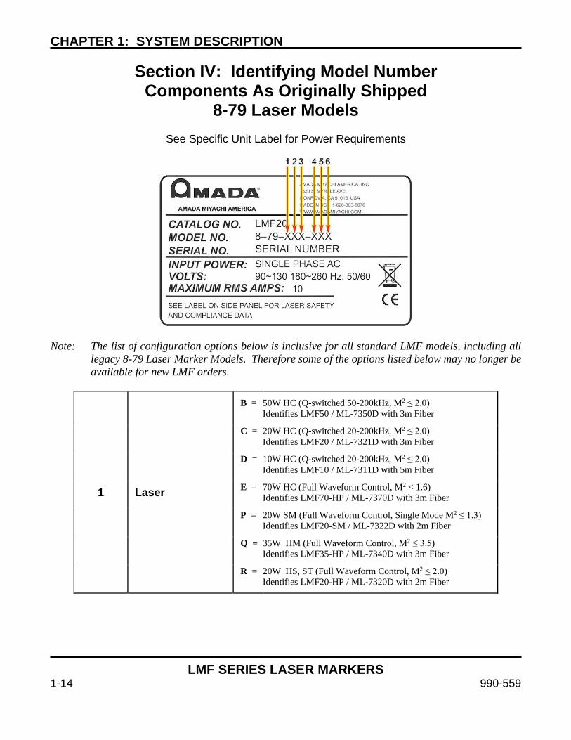
CHAPTER 1: SYSTEM DESCRIPTION
LMF SERIES LASER MARKERS
1-14 990-559
Section IV: Identifying Model Number Components As Originally Shipped
8-79 Laser Models
See Specific Unit Label for Power Requirements
Note: The list of configuration options below is inclusive for all standard LMF models, including all
legacy 8-79 Laser Marker Models. Therefore some of the options listed below may no longer be available for new LMF orders.
1 Laser
B = 50W HC (Q-switched 50-200kHz, M2 ≤ 2.0) Identifies LMF50 / ML-7350D with 3m Fiber
C = 20W HC (Q-switched 20-200kHz, M2 ≤ 2.0) Identifies LMF20 / ML-7321D with 3m Fiber
D = 10W HC (Q-switched 20-200kHz, M2 ≤ 2.0) Identifies LMF10 / ML-7311D with 5m Fiber
E = 70W HC (Full Waveform Control, M2 < 1.6) Identifies LMF70-HP / ML-7370D with 3m Fiber
P = 20W SM (Full Waveform Control, Single Mode M2 ≤ 1.3) Identifies LMF20-SM / ML-7322D with 2m Fiber
Q = 35W HM (Full Waveform Control, M2 ≤ 3.5) Identifies LMF35-HP / ML-7340D with 3m Fiber
R = 20W HS, ST (Full Waveform Control, M2 ≤ 2.0) Identifies LMF20-HP / ML-7320D with 2m Fiber
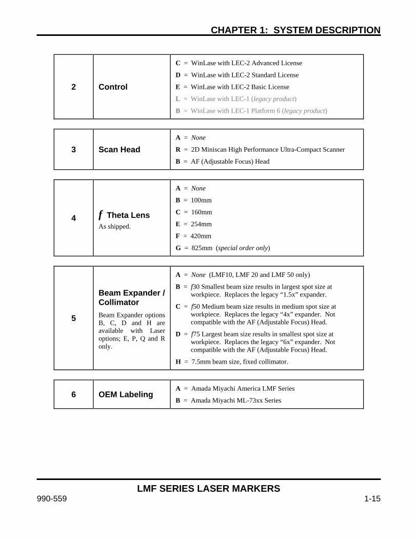
CHAPTER 1: SYSTEM DESCRIPTION
LMF SERIES LASER MARKERS
990-559 1-15
2 Control
C = WinLase with LEC-2 Advanced License
D = WinLase with LEC-2 Standard License
E = WinLase with LEC-2 Basic License
L = WinLase with LEC-1 (legacy product)
B = WinLase with LEC-1 Platform 6 (legacy product)
3 Scan Head A = None
R = 2D Miniscan High Performance Ultra-Compact Scanner
B = AF (Adjustable Focus) Head
4 f Theta Lens As shipped.
A = None
B = 100mm
C = 160mm
E = 254mm
F = 420mm
G = 825mm (special order only)
5
Beam Expander / Collimator Beam Expander options B, C, D and H are available with Laser options; E, P, Q and R only.
A = None (LMF10, LMF 20 and LMF 50 only)
B = f30 Smallest beam size results in largest spot size at workpiece. Replaces the legacy “1.5x” expander.
C = f50 Medium beam size results in medium spot size at workpiece. Replaces the legacy “4x” expander. Not compatible with the AF (Adjustable Focus) Head.
D = f75 Largest beam size results in smallest spot size at workpiece. Replaces the legacy “6x” expander. Not compatible with the AF (Adjustable Focus) Head.
H = 7.5mm beam size, fixed collimator.
6 OEM Labeling A = Amada Miyachi America LMF Series
B = Amada Miyachi ML-73xx Series


LMF SERIES LASER MARKERS
990-559 2-1
CHAPTER 2 INSTALLATION AND SETUP
Section I: Planning When planning for the installation of the Marker, make sure that the following conditions are met:
• The Marker should be placed in a dedicated laser operation area and/or integrated into a suitable laser safe enclosure that meets all relevant safety standards. The person responsible for the area (the Laser Safety Officer) must isolate the laser operation area from other work areas and display signs warning that the laser operation area is off limits to unauthorized personnel.
• See Appendix A: Technical Specifications for specific weight and dimensional requirements as well as mounting hardware location and information.
• Use proper tools (wire strippers, pressure wire connectors, etc.) for termination of the connecting cables.
• The Marker should be placed on a firm, level surface that is free from vibration. Install the head and workpiece on the same fixture to prevent marking distortion due to vibration.
• Mount the head on a platform of sheet metal at least 0.394” (10 mm) thick.
• Do not operate the unit where there is considerable dirt, dust, oil mist, chemicals, fumes, moisture, or near a high-frequency noise source.
• The ambient temperature should be between 41°F and 95°F (5°C and 35°C). The installation area should be free of sudden temperature fluctuations and have a relative humidity less than 90% (non-condensing). The area should have no rapid temperature fluctuations, which may cause dew condensation on the optical surfaces.
• If the outside of the Marker is stained, wipe it with a dry or slightly moistened cloth. If it is badly stained, use a neutral detergent or alcohol to clean it. Do not use paint thinner, acetone, benzene, etc. which can discolor or deform the parts.
• The Control Unit and Laser Head must be located within the overall length of the optical fiber/cable set. See Chapter 1, Section IV: Identifying Model Number for more information on the shipped fiber length. The computer can be located anywhere as long as both the marker and PC have network accessibility and can be located on the same subnet.
• When installing two opposing laser heads, install them so that neither unit is aimed at the other.
• Install the Laser Head in any orientation desired.
• Make sure that the bend radius of the optical fiber on the back of the Laser Head is greater than 4.7” (120mm).

CHAPTER 2: INSTALLATION AND SETUP
LMF SERIES LASER MARKERS
2-2 990-559
Allow adequate clearance on all sides of the Marker to allow for cooling, maintenance and servicing. Keep these following tips in mind during installation:
• When locating, ensure that the front air filter and side exhausts are clear for proper ventilation with
at least 6 inches (15cm) of clearance.
• Both the Control Unit and the Laser Head should have a minimum of 6 inches (≈ 15cm) behind the units for proper ventilation and cable clearance. The laser head is a sealed unit that requires no airflow clearance considerations be observed other than exposure to ambient air.
• The control unit must be placed on a hard surface to allow the bottom laser exhaust to function as designed.
• Do not block the bottom exhaust vent by placing the Control Unit on a soft surface like foam that can prevent adequate airflow.

CHAPTER 2: INSTALLATION AND SETUP
LMF SERIES LASER MARKERS
990-559 2-3
Section II: Installation
CAUTION
Do not attempt to remove the fiber at the rear of the marker head from the cylindrical isolator under any circumstances. Doing so will destroy the fiber and void the warranty. Amada Miyachi America assumes no liability for such action and the fiber will have to be replaced at the customer’s expense.
Connect the Signal Cables Connect the interconnect cables between the Marker Control Unit, Marker Head, and the Computer. Connect all cables as shown below. Secure all cables by fastening the connector backshells.
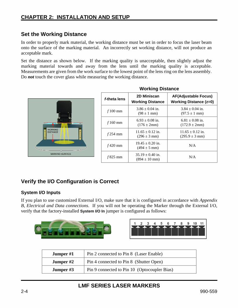
CHAPTER 2: INSTALLATION AND SETUP
LMF SERIES LASER MARKERS
2-4 990-559
Set the Working Distance In order to properly mark material, the working distance must be set in order to focus the laser beam onto the surface of the marking material. An incorrectly set working distance, will not produce an acceptable mark.
Set the distance as shown below. If the marking quality is unacceptable, then slightly adjust the marking material towards and away from the lens until the marking quality is acceptable. Measurements are given from the work surface to the lowest point of the lens ring on the lens assembly. Do not touch the cover glass while measuring the working distance.
Working Distance
f-theta lens 2D Miniscan Working Distance
AF(Adjustable Focus) Working Distance (z=0)
f 100 mm 3.86 ± 0.04 in. (98 ± 1 mm)
3.84 ± 0.04 in. (97.5 ± 1 mm)
f 160 mm 6.93 ± 0.08 in. (176 ± 2mm)
6.81 ± 0.08 in. (172.9 ± 2mm)
f 254 mm 11.65 ± 0.12 in. (296 ± 3 mm)
11.65 ± 0.12 in. (295.9 ± 3 mm)
f 420 mm 19.45 ± 0.20 in. (494 ± 5 mm) N/A
f 825 mm 35.19 ± 0.40 in. (894 ± 10 mm) N/A
Verify the I/O Configuration is Correct System I/O Inputs If you plan to use customized External I/O, make sure that it is configured in accordance with Appendix B, Electrical and Data connections. If you will not be operating the Marker through the External I/O, verify that the factory-installed System I/O In jumper is configured as follows:
Jumper #1 Pin 2 connected to Pin 8 (Laser Enable)
Jumper #2 Pin 4 connected to Pin 8 (Shutter Open)
Jumper #3 Pin 9 connected to Pin 10 (Optocoupler Bias)
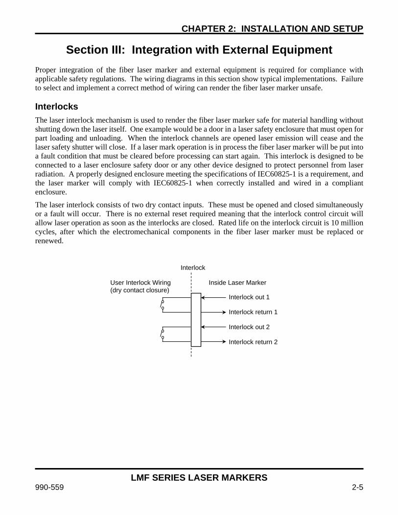
CHAPTER 2: INSTALLATION AND SETUP
LMF SERIES LASER MARKERS
990-559 2-5
Section III: Integration with External Equipment Proper integration of the fiber laser marker and external equipment is required for compliance with applicable safety regulations. The wiring diagrams in this section show typical implementations. Failure to select and implement a correct method of wiring can render the fiber laser marker unsafe. Interlocks The laser interlock mechanism is used to render the fiber laser marker safe for material handling without shutting down the laser itself. One example would be a door in a laser safety enclosure that must open for part loading and unloading. When the interlock channels are opened laser emission will cease and the laser safety shutter will close. If a laser mark operation is in process the fiber laser marker will be put into a fault condition that must be cleared before processing can start again. This interlock is designed to be connected to a laser enclosure safety door or any other device designed to protect personnel from laser radiation. A properly designed enclosure meeting the specifications of IEC60825-1 is a requirement, and the laser marker will comply with IEC60825-1 when correctly installed and wired in a compliant enclosure.
The laser interlock consists of two dry contact inputs. These must be opened and closed simultaneously or a fault will occur. There is no external reset required meaning that the interlock control circuit will allow laser operation as soon as the interlocks are closed. Rated life on the interlock circuit is 10 million cycles, after which the electromechanical components in the fiber laser marker must be replaced or renewed.
Interlock out 1 Interlock return 1 Interlock out 2 Interlock return 2
Interlock User Interlock Wiring Inside Laser Marker (dry contact closure)
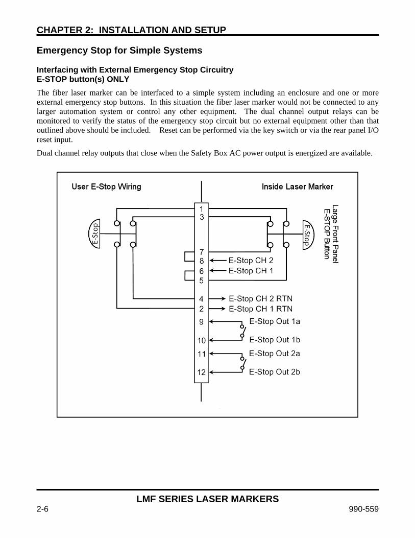
CHAPTER 2: INSTALLATION AND SETUP
LMF SERIES LASER MARKERS
2-6 990-559
Emergency Stop for Simple Systems Interfacing with External Emergency Stop Circuitry E-STOP button(s) ONLY The fiber laser marker can be interfaced to a simple system including an enclosure and one or more external emergency stop buttons. In this situation the fiber laser marker would not be connected to any larger automation system or control any other equipment. The dual channel output relays can be monitored to verify the status of the emergency stop circuit but no external equipment other than that outlined above should be included. Reset can be performed via the key switch or via the rear panel I/O reset input.
Dual channel relay outputs that close when the Safety Box AC power output is energized are available.

CHAPTER 2: INSTALLATION AND SETUP
LMF SERIES LASER MARKERS
990-559 2-7
Emergency Stop for Complicated Systems Interfacing with External Emergency Stop Circuitry User Supplied Safety Relay Module(s) Required Complicated Systems are those in which more than one emergency stop sub-circuit must be linked together. An example of this would be a machine that has a fiber laser marker, parts handler with pneumatic controls, PLC, and conveyor belt all of which have ESTOP buttons where one ESTOP button stops all devices. Any situation in which more than one device must be connected together and respond identically to an emergency stop event is considered a complicated system.
Complicated systems are integrated using certified safety controllers or safety relays. In this situation one device is the “master” and the rest of the devices are the “slaves”. The fiber laser marker is considered a slave device in this configuration and its emergency stop must be controlled by the larger machine’s safety controller. The output of the external safety relay module closes the input to the fiber laser marker safety box and allows the system to clear the emergency stop state.
In this wiring example a Pilz PNOZ family safety relay module controls the fiber laser marker and interfaces two external emergency stop buttons. In this example the Pilz device would also control additional emergency stop functions outside of the fiber laser marker using expansion contacts. The more devices which must be implemented the more expansion contacts must be added to the Safety Relay Module. Any suitable IEC13849-1 compliant safety relay controller is acceptable as long as it is implemented in this manner. The end user is responsible for verifying compliance of the machine as a whole.

CHAPTER 2: INSTALLATION AND SETUP
LMF SERIES LASER MARKERS
2-8 990-559
Emergency Stop Factory Test Jumper Wiring Make sure that the Emergency Stop is wired in accordance with Appendix B, Electrical and Data connections and the safety requirements listed above. The factory-installed jumper must be removed and rewired according to all applicable safety standards for the system to meet specified levels of machine safety. Do not operate the machine without correctly integrating it into a workstation with the appropriate level of safety.
The factory-installed jumper for testing only is configured as follows:
Jumper #1 Pin 1 connected to Pin 2
Jumper #2 Pin 3 connected to Pin 4
Jumper #3 Pin 5 connected to Pin 6
Jumper #4 Pin 7 connected to Pin 8 Remote Interlock Factory Test Jumper Make sure the Remote Interlock is wired in accordance with Appendix B, Electrical and Data connections. The factory test jumper must be removed and wired according to all applicable safety standards for the system to meet specified levels of machine safety. Observe all laser precautions when testing with the factory test jumper installed. The factory-installed jumper for testing is configured as follows:
Jumper #1 Pin 1 connected to Pin 2
Jumper #2 Pin 3 connected to Pin 4
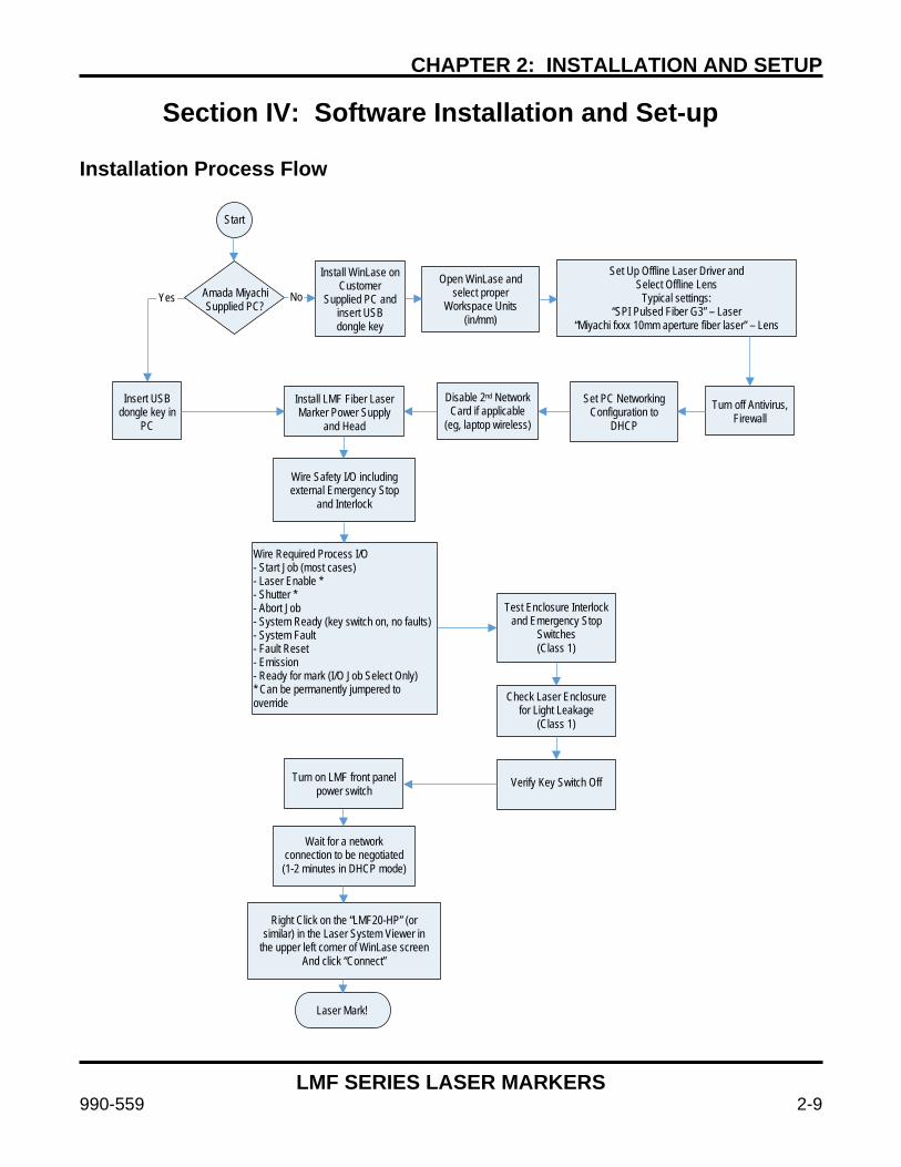
CHAPTER 2: INSTALLATION AND SETUP
LMF SERIES LASER MARKERS
990-559 2-9
Section IV: Software Installation and Set-up Installation Process Flow
Amada Miyachi Supplied PC?
Install WinLase on Customer
Supplied PC and insert USB dongle key
Open WinLase and select proper
Workspace Units (in/mm)
Set Up Offline Laser Driver and Select Offline Lens
Typical settings: “SPI Pulsed Fiber G3” – Laser
“Miyachi fxxx 10mm aperture fiber laser” – Lens
Insert USB dongle key in
PC
Set PC Networking Configuration to
DHCP
Install LMF Fiber Laser Marker Power Supply
and Head
Disable 2nd Network Card if applicable
(eg, laptop wireless) Turn off Antivirus,
Firewall
Wire Safety I/O including external Emergency Stop
and Interlock
Test Enclosure Interlock and Emergency Stop
Switches (Class 1)
Check Laser Enclosure for Light Leakage
(Class 1)
Verify Key Switch Off Turn on LMF front panel power switch
Wait for a network connection to be negotiated (1-2 minutes in DHCP mode)
Right Click on the “LMF20-HP” (or similar) in the Laser System Viewer in
the upper left corner of WinLase screen And click “Connect”
Laser Mark!
Wire Required Process I/O - Start Job (most cases) - Laser Enable * - Shutter * - Abort Job - System Ready (key switch on, no faults) - System Fault - Fault Reset - Emission - Ready for mark (I/O Job Select Only) * Can be permanently jumpered to override
Start
No Yes
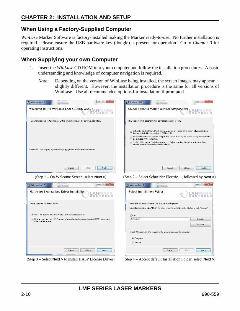
CHAPTER 2: INSTALLATION AND SETUP
LMF SERIES LASER MARKERS
2-10 990-559
When Using a Factory-Supplied Computer WinLase Marker Software is factory-installed making the Marker ready-to-use. No further installation is required. Please ensure the USB hardware key (dongle) is present for operation. Go to Chapter 3 for operating instructions. When Supplying your own Computer
1. Insert the WinLase CD ROM into your computer and follow the installation procedures. A basic understanding and knowledge of computer navigation is required.
Note: Depending on the version of WinLase being installed, the screen images may appear slightly different. However, the installation procedure is the same for all versions of WinLase. Use all recommended options for installation if prompted.
(Step 1 – On Welcome Screen, select Next >) (Step 2 – Select Schneider Electric…, followed by Next >)
(Step 3 – Select Next > to install HASP License Driver) (Step 4 – Accept default Installation Folder, select Next >)
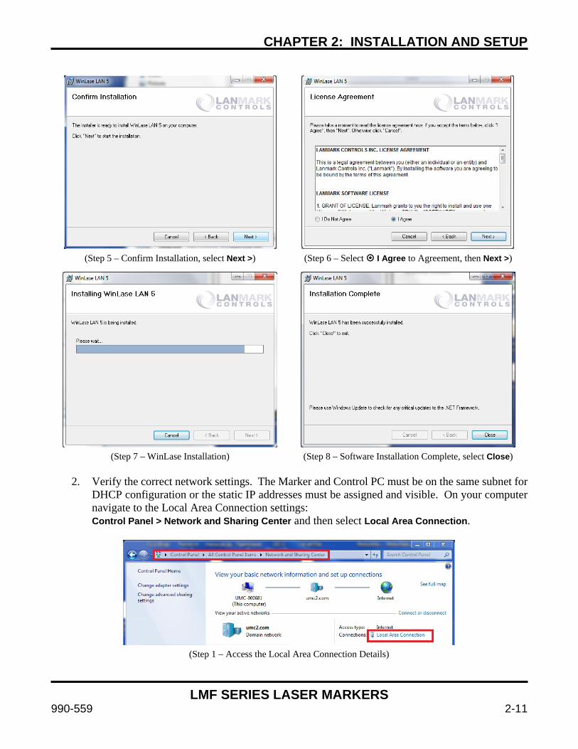
CHAPTER 2: INSTALLATION AND SETUP
LMF SERIES LASER MARKERS
990-559 2-11
(Step 5 – Confirm Installation, select Next >) (Step 6 – Select I Agree to Agreement, then Next >)
(Step 7 – WinLase Installation) (Step 8 – Software Installation Complete, select Close)
2. Verify the correct network settings. The Marker and Control PC must be on the same subnet for
DHCP configuration or the static IP addresses must be assigned and visible. On your computer navigate to the Local Area Connection settings: Control Panel > Network and Sharing Center and then select Local Area Connection.
(Step 1 – Access the Local Area Connection Details)
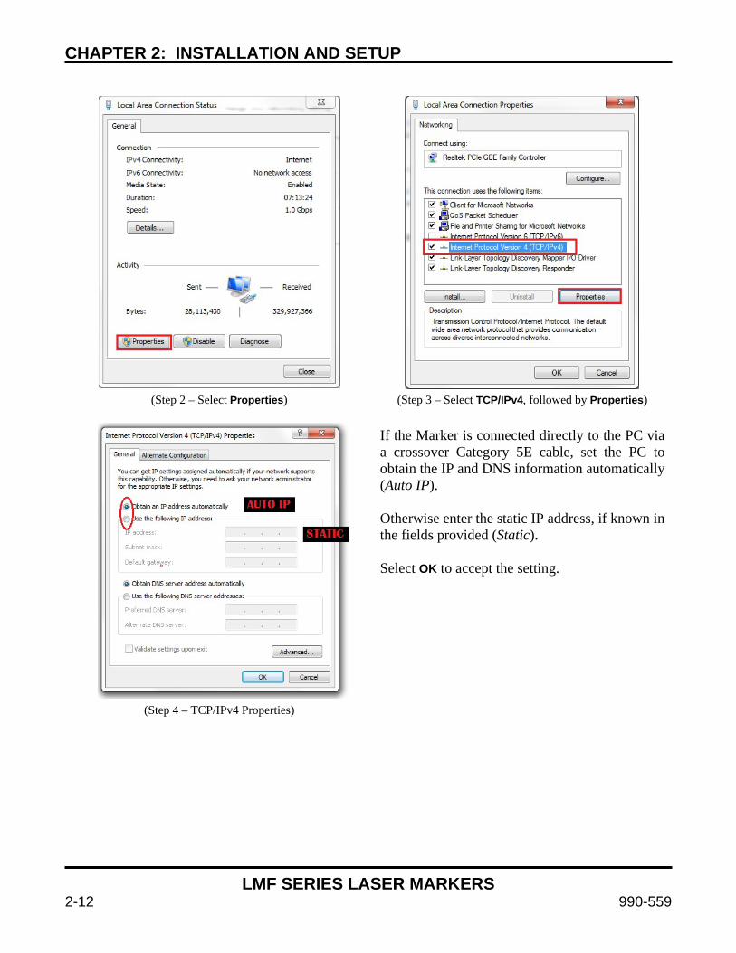
CHAPTER 2: INSTALLATION AND SETUP
LMF SERIES LASER MARKERS
2-12 990-559
(Step 2 – Select Properties) (Step 3 – Select TCP/IPv4, followed by Properties)
If the Marker is connected directly to the PC via a crossover Category 5E cable, set the PC to obtain the IP and DNS information automatically (Auto IP). Otherwise enter the static IP address, if known in the fields provided (Static). Select OK to accept the setting.
(Step 4 – TCP/IPv4 Properties)

CHAPTER 2: INSTALLATION AND SETUP
LMF SERIES LASER MARKERS
990-559 2-13
3. Establish communication between the PC and Laser Marker. Turn-on the Laser Marker and wait
30-60 seconds for the Marker to finish booting to allow time for network operations. Start WinLase. Once Winlase is open, select Connections > Manage from the Tools pull-down menu.
(Step 1 – WinLase splash screen) (Step 2 – Navigate to the Connection Window)
Note: If the Marker has booted and the network settings are correct, it will appear under Laser System name: in the left column of the Connections Manager window. If the Marker has not completed the boot process you will see Waiting for system connection in the Laser System name: window. Select the Laser Marker from the left column you want to connect to and then select Add >>. If there are multiple devices, choose one and set it as the default device. Select Save when finished. (Step 3 – Connections Manager screen)
If your PC has multiple network adapters and the wrong one appears in the Laser System Viewer, you can use the Network adapters tab in the Connections Manager to select the correct default adapter. Once the device has been added to the Automatic connections: list, a window will pop up indicating the connection status. Please wait until the status changes to Connected and the window has closed.
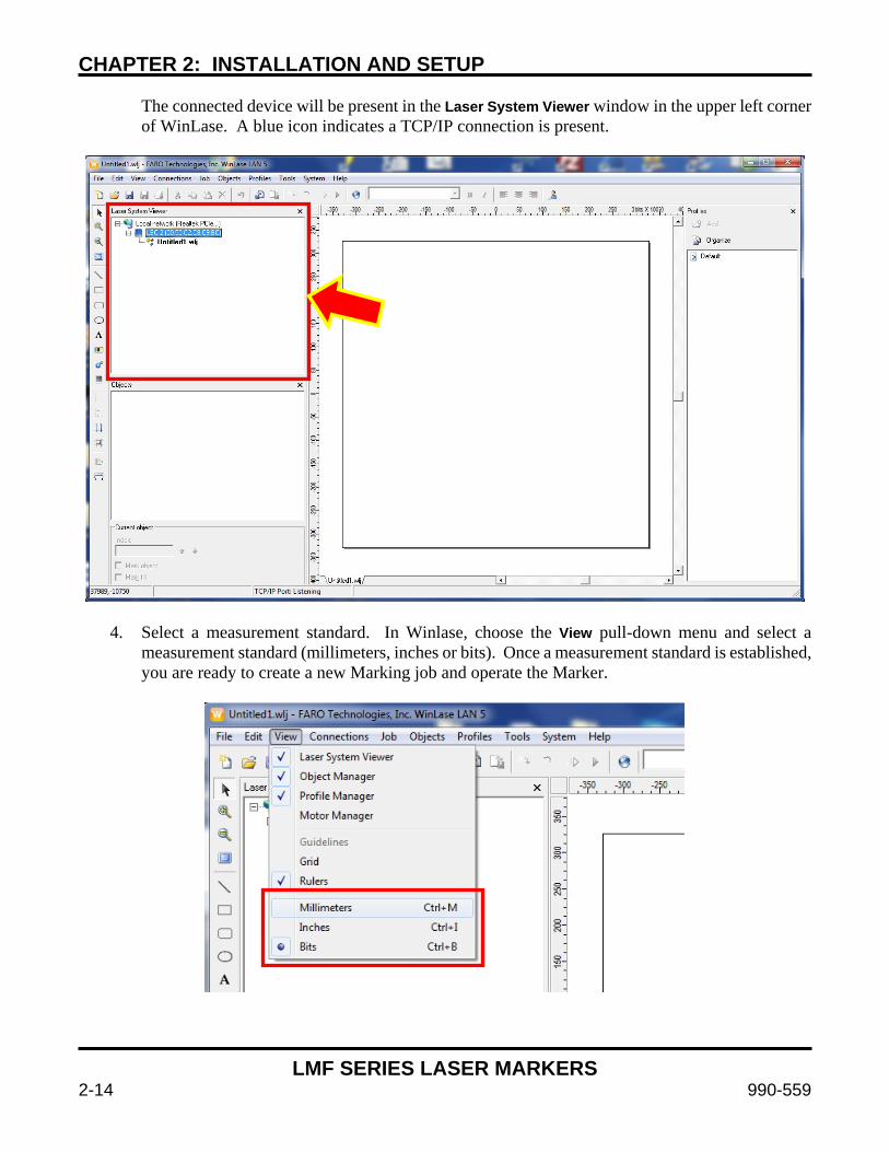
CHAPTER 2: INSTALLATION AND SETUP
LMF SERIES LASER MARKERS
2-14 990-559
The connected device will be present in the Laser System Viewer window in the upper left corner of WinLase. A blue icon indicates a TCP/IP connection is present.
4. Select a measurement standard. In Winlase, choose the View pull-down menu and select a measurement standard (millimeters, inches or bits). Once a measurement standard is established, you are ready to create a new Marking job and operate the Marker.
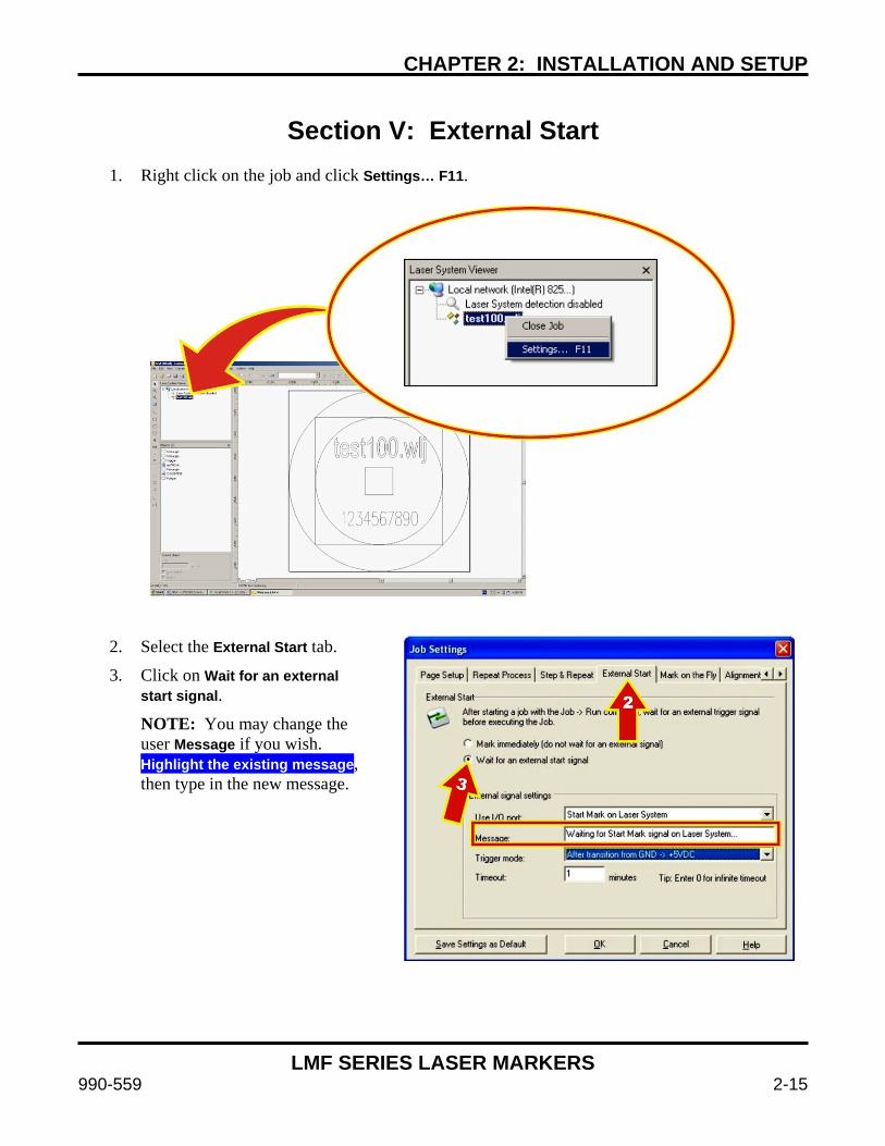
CHAPTER 2: INSTALLATION AND SETUP
LMF SERIES LASER MARKERS
990-559 2-15
Section V: External Start
1. Right click on the job and click Settings… F11.
2. Select the External Start tab.
3. Click on Wait for an external start signal.
NOTE: You may change the user Message if you wish. Highlight the existing message, then type in the new message.

CHAPTER 2: INSTALLATION AND SETUP
LMF SERIES LASER MARKERS
2-16 990-559
4. Make sure that the Trigger Mode is set to occur on a transition, LOWHIGH or HIGHLOW depending on if you want to trigger on the rising or falling edge of the input signal.
To change the Trigger mode, click on the arrow, select another mode.
5. You may change the Timeout if you wish. Highlight the existing time, then type in the new number of minutes.
6. After you click OK, in the Job Settings screen, click on the Run Process icon shown below.
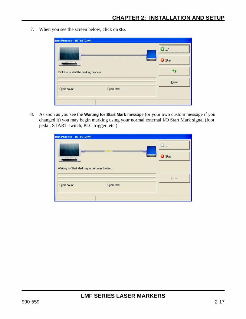
CHAPTER 2: INSTALLATION AND SETUP
LMF SERIES LASER MARKERS
990-559 2-17
7. When you see the screen below, click on Go.
8. As soon as you see the Waiting for Start Mark message (or your own custom message if you changed it) you may begin marking using your normal external I/O Start Mark signal (foot pedal, START switch, PLC trigger, etc.).

CHAPTER 2: INSTALLATION AND SETUP
LMF SERIES LASER MARKERS
2-18 990-559
Section VI: F-Theta Lens Configuration
After installing the new f-theta lens, select the System pull-down menu, select Preferences, and select the Hardware tab. Select the lens and click Change to select the new f-theta lens. It may be necessary to change lens collars when changing lenses. Please refer to the table below.
If you wish to adjust the scaling, rotation, or offset you can click Calibrate and follow the instructions provided.
Lens Ring Amada Miyachi America
Part Number “R” Option Scanner (Ex: 8-79-xxR-xxx)
Amada Miyachi America Part Number
“B” Option Scanner (Ex: 8-79-xxB-xxx)
100mm Lens Ring 475-468 475-557
160mm Lens Ring 475-468 475-557
254mm Lens Ring 475-471 475-558
420mm Lens Ring 475-471 N/A
825mm Lens Ring 475-004 N/A
See laser marker part number to determine installed f-theta lens.

LMF SERIES LASER MARKERS
990-559 3-1
CHAPTER 3 OPERATING INSTRUCTIONS
Section I: Before You Start Safety Precautions
DANGER
To prevent eye damage when operating this equipment, laser protective goggles must be worn at all times (per ANSI Z136.1). Laser goggles with an OD (optical density) of 7+ (at a wavelength of 1060-1150nm) are recommended or as directed by your LSO.
WARNING
Never operate the Marker in any manner other than described in this manual. Doing so may expose personnel to laser radiation or electrical hazards.
Before attempting to operate the Marker, have all personnel who will be working with the Marker read this manual and the Laser Safety Manual (Amada Miyachi America Part Number 990-502) thoroughly.
Notes
Verify that the electrical supply meets the electrical requirements, as shown in Appendix A: Technical Specifications. The electrical supply must meet all applicable local, state, and federal safety standards.
Before operating the Marker, be sure the protective lens cover is removed from the output lens.
Operate all Laser Marker switches and buttons carefully by hand.
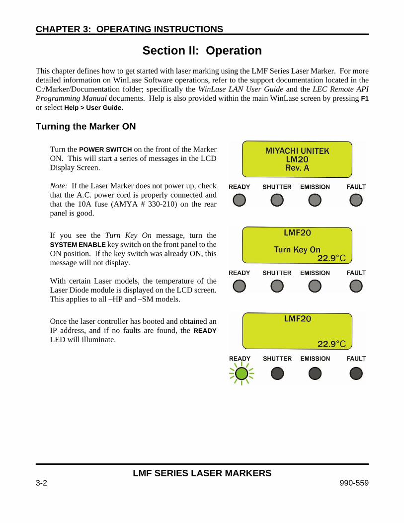
CHAPTER 3: OPERATING INSTRUCTIONS
LMF SERIES LASER MARKERS
3-2 990-559
Section II: Operation This chapter defines how to get started with laser marking using the LMF Series Laser Marker. For more detailed information on WinLase Software operations, refer to the support documentation located in the C:/Marker/Documentation folder; specifically the WinLase LAN User Guide and the LEC Remote API Programming Manual documents. Help is also provided within the main WinLase screen by pressing F1 or select Help > User Guide. Turning the Marker ON
Turn the POWER SWITCH on the front of the Marker ON. This will start a series of messages in the LCD Display Screen. Note: If the Laser Marker does not power up, check that the A.C. power cord is properly connected and that the 10A fuse (AMYA # 330-210) on the rear panel is good.
If you see the Turn Key On message, turn the SYSTEM ENABLE key switch on the front panel to the ON position. If the key switch was already ON, this message will not display. With certain Laser models, the temperature of the Laser Diode module is displayed on the LCD screen. This applies to all –HP and –SM models.
Once the laser controller has booted and obtained an IP address, and if no faults are found, the READY LED will illuminate.
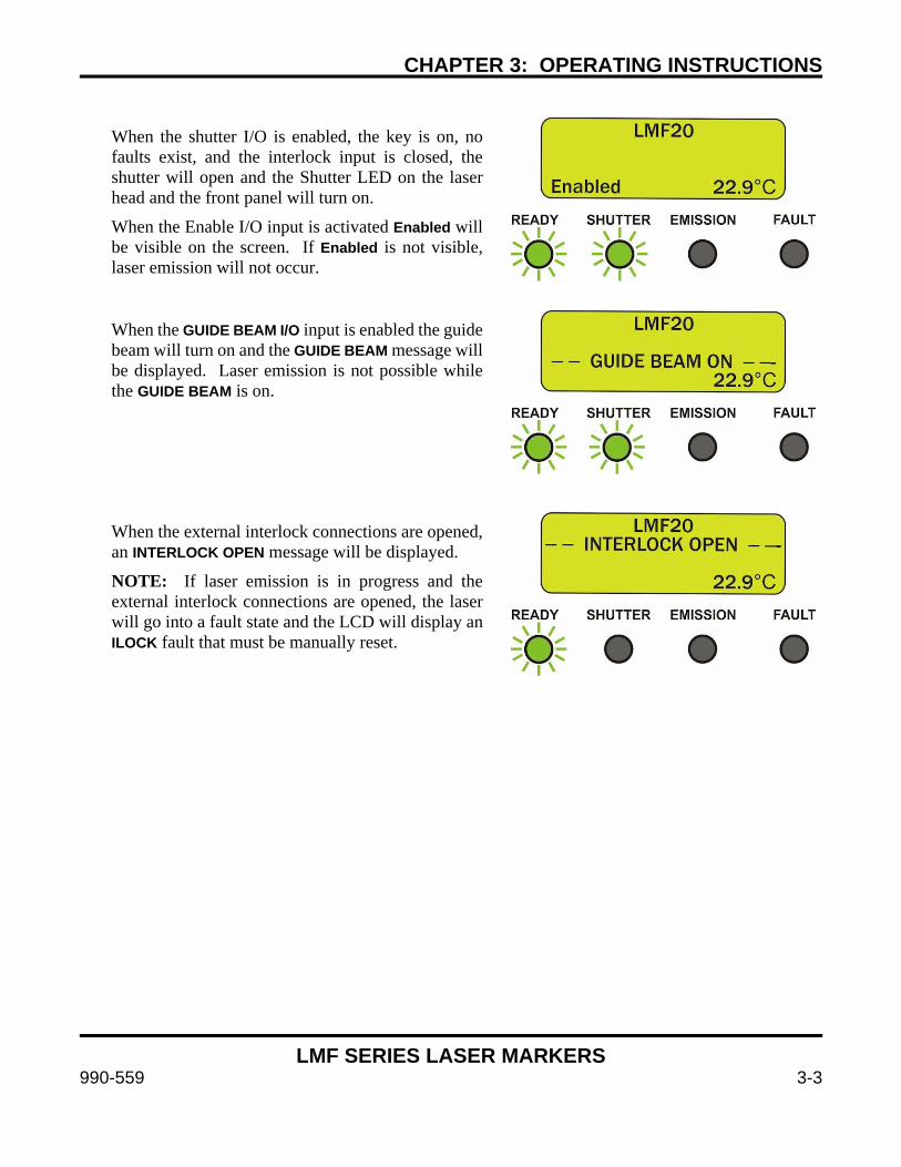
CHAPTER 3: OPERATING INSTRUCTIONS
LMF SERIES LASER MARKERS
990-559 3-3
When the shutter I/O is enabled, the key is on, no faults exist, and the interlock input is closed, the shutter will open and the Shutter LED on the laser head and the front panel will turn on.
When the Enable I/O input is activated Enabled will be visible on the screen. If Enabled is not visible, laser emission will not occur.
When the GUIDE BEAM I/O input is enabled the guide beam will turn on and the GUIDE BEAM message will be displayed. Laser emission is not possible while the GUIDE BEAM is on.
When the external interlock connections are opened, an INTERLOCK OPEN message will be displayed.
NOTE: If laser emission is in progress and the external interlock connections are opened, the laser will go into a fault state and the LCD will display an ILOCK fault that must be manually reset.

CHAPTER 3: OPERATING INSTRUCTIONS
LMF SERIES LASER MARKERS
3-4 990-559
Initiating an Emergency Stop To initiate an Emergency Stop, press the front panel EMERGENCY STOP button or open the external E-STOP connections on the rear panel of the laser control unit (refer to Chapter 2, Section III: Integration with External Equipment for more information). Either process will immediately de-energize the laser module, close the safety shutter, open the emergency stop contacts on the rear panel, turn on the FAULT LED and indicate the fault on the LCD display screen. An Emergency Stop action makes the fiber laser marker safe. Clearing an Emergency Stop Clearing an Emergency Stop can be performed by cycling the SYSTEM ENABLE key switch or sending a I/O reset signal to the Fault Reset input on the back of the laser marker (refer to Appendix B: Electrical and Data Connections for more information). Before this reset can be accomplished all Emergency Stop connections must be closed. If the EMERGENCY STOP button was used to initiate the Emergency Stop, simply turn the switch clockwise to release the switch and then reset the system.
If the emergency stop was initiated through the external I/O (refer to Chapter 2, Section III: Integration with External Equipment for more information), clear the E-Stop inputs and then reset the system. In order to properly reset the E-Stop Safety Relay, all channels must be opened and closed in tandem (within 250mS of each other) and then the system can be reset. E-Stop Faults There are a couple common reasons why an Emergency Stop condition cannot be cleared. See Chapter 4, Maintenance for details if further troubleshooting of the safety controller is required.
1. An EMERGENCY STOP switch (either on the Front Panel or connected externally) is activated and latched. Rotate the switch slightly clockwise to release.
2. Emergency Stop Input Channel 1 or Input Channel 2 dry contact closures open.
3. Emergency Stop Input Channel 1 or Input Channel 2 not closed at same time. Close channel 1 and channel 2 within 250ms of each other.
4. Short across channel 1 and channel 2 input contacts. Verify the wiring.
5. Damaged emergency stop safety controller. This will be present if the Fault LED is illuminated but no other faults are present. The safety controller will need to be replaced. This can be caused by applying any voltage or current input to the Interlock channel 1 and channel 2 pins. Use dry contact closures only.
6. Faulty Reset switch or circuitry.

CHAPTER 3: OPERATING INSTRUCTIONS
LMF SERIES LASER MARKERS
990-559 3-5
Opening the Remote Interlock To initiate a Remote Interlock, open the external dry contact interlock connections on the rear panel of the laser control unit (refer to Chapter 2, Section III: Integration with External Equipment for more information). When a Remote Interlock is initiated, the fiber laser marker safety shutter will close and all laser jobs in process will stop (laser emission is not possible). Closing the Remote Interlock To clear a remote interlock, close the external dry contact interlock connections on the rear panel of the laser control unit and the system will automatically reset. If the marker was processing a job when a Remote Interlock was initiated or if only one channel of the Interlock circuit is opened, the LCD screen will display INTERLOCK OPENED. In this case the Laser Marker must be manually reset. Interlock Faults There are a couple common reasons why an Interlock condition cannot be cleared. See Chapter 4, Maintenance for details if further troubleshooting of the safety controller is required.
1. Interlock Input Channel 1 or Input Channel 2 open.
2. Interlock Input Channel 1 or Input Channel 2 not closed at same time. Close channel 1 and channel 2 within 250ms of each other.
3. Short across Interlock Input Channel 1 and Channel 2 input contacts. Verify the wiring.
4. Damaged interlock safety controller. This will be present if the Fault LED is illuminated but no other faults are present. The safety controller will need to be replaced. This can be caused by applying any voltage or current input to the Interlock channel 1 and channel 2 pins. Use a dry contact closure only.
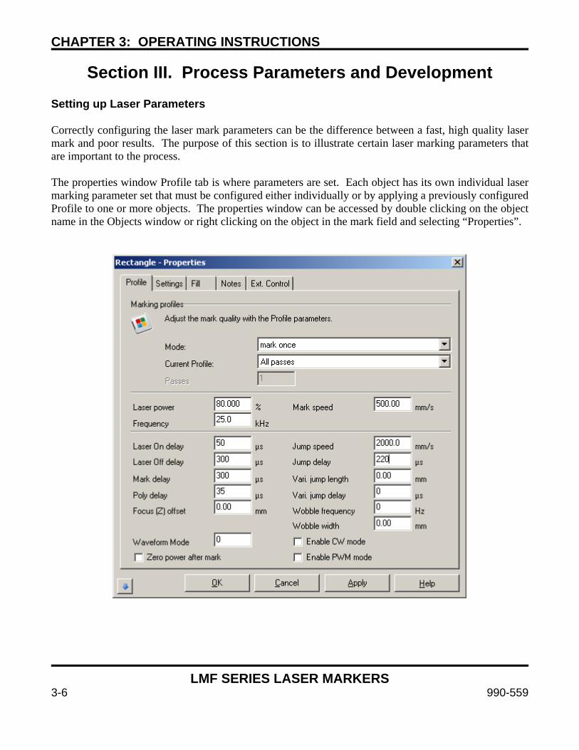
CHAPTER 3: OPERATING INSTRUCTIONS
LMF SERIES LASER MARKERS
3-6 990-559
Section III. Process Parameters and Development
Setting up Laser Parameters Correctly configuring the laser mark parameters can be the difference between a fast, high quality laser mark and poor results. The purpose of this section is to illustrate certain laser marking parameters that are important to the process. The properties window Profile tab is where parameters are set. Each object has its own individual laser marking parameter set that must be configured either individually or by applying a previously configured Profile to one or more objects. The properties window can be accessed by double clicking on the object name in the Objects window or right clicking on the object in the mark field and selecting “Properties”.
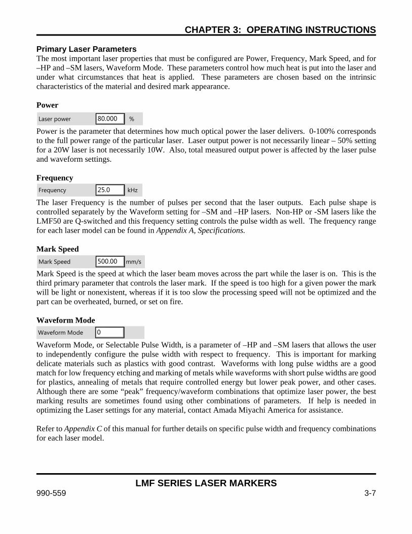
CHAPTER 3: OPERATING INSTRUCTIONS
LMF SERIES LASER MARKERS
990-559 3-7
Primary Laser Parameters The most important laser properties that must be configured are Power, Frequency, Mark Speed, and for –HP and –SM lasers, Waveform Mode. These parameters control how much heat is put into the laser and under what circumstances that heat is applied. These parameters are chosen based on the intrinsic characteristics of the material and desired mark appearance. Power Power is the parameter that determines how much optical power the laser delivers. 0-100% corresponds to the full power range of the particular laser. Laser output power is not necessarily linear – 50% setting for a 20W laser is not necessarily 10W. Also, total measured output power is affected by the laser pulse and waveform settings. Frequency
The laser Frequency is the number of pulses per second that the laser outputs. Each pulse shape is controlled separately by the Waveform setting for –SM and –HP lasers. Non-HP or -SM lasers like the LMF50 are Q-switched and this frequency setting controls the pulse width as well. The frequency range for each laser model can be found in Appendix A, Specifications. Mark Speed Mark Speed is the speed at which the laser beam moves across the part while the laser is on. This is the third primary parameter that controls the laser mark. If the speed is too high for a given power the mark will be light or nonexistent, whereas if it is too slow the processing speed will not be optimized and the part can be overheated, burned, or set on fire. Waveform Mode
Waveform Mode, or Selectable Pulse Width, is a parameter of –HP and –SM lasers that allows the user to independently configure the pulse width with respect to frequency. This is important for marking delicate materials such as plastics with good contrast. Waveforms with long pulse widths are a good match for low frequency etching and marking of metals while waveforms with short pulse widths are good for plastics, annealing of metals that require controlled energy but lower peak power, and other cases. Although there are some “peak” frequency/waveform combinations that optimize laser power, the best marking results are sometimes found using other combinations of parameters. If help is needed in optimizing the Laser settings for any material, contact Amada Miyachi America for assistance. Refer to Appendix C of this manual for further details on specific pulse width and frequency combinations for each laser model.
Laser power % 80.000
Frequency kHz 25.0
Mark Speed mm/s 500.00
Waveform Mode 0
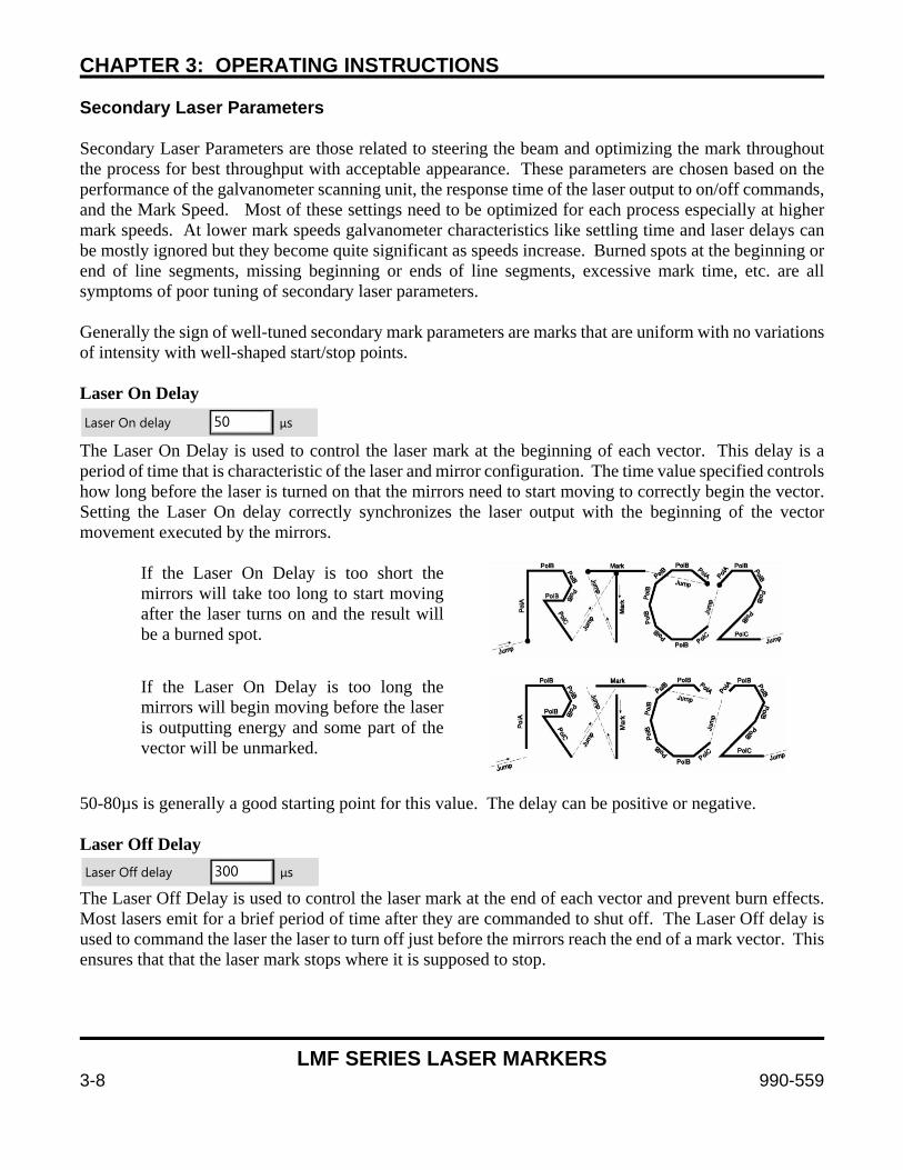
CHAPTER 3: OPERATING INSTRUCTIONS
LMF SERIES LASER MARKERS
3-8 990-559
Secondary Laser Parameters Secondary Laser Parameters are those related to steering the beam and optimizing the mark throughout the process for best throughput with acceptable appearance. These parameters are chosen based on the performance of the galvanometer scanning unit, the response time of the laser output to on/off commands, and the Mark Speed. Most of these settings need to be optimized for each process especially at higher mark speeds. At lower mark speeds galvanometer characteristics like settling time and laser delays can be mostly ignored but they become quite significant as speeds increase. Burned spots at the beginning or end of line segments, missing beginning or ends of line segments, excessive mark time, etc. are all symptoms of poor tuning of secondary laser parameters. Generally the sign of well-tuned secondary mark parameters are marks that are uniform with no variations of intensity with well-shaped start/stop points. Laser On Delay The Laser On Delay is used to control the laser mark at the beginning of each vector. This delay is a period of time that is characteristic of the laser and mirror configuration. The time value specified controls how long before the laser is turned on that the mirrors need to start moving to correctly begin the vector. Setting the Laser On delay correctly synchronizes the laser output with the beginning of the vector movement executed by the mirrors.
If the Laser On Delay is too short the mirrors will take too long to start moving after the laser turns on and the result will be a burned spot.
If the Laser On Delay is too long the mirrors will begin moving before the laser is outputting energy and some part of the vector will be unmarked.
50-80µs is generally a good starting point for this value. The delay can be positive or negative. Laser Off Delay The Laser Off Delay is used to control the laser mark at the end of each vector and prevent burn effects. Most lasers emit for a brief period of time after they are commanded to shut off. The Laser Off delay is used to command the laser the laser to turn off just before the mirrors reach the end of a mark vector. This ensures that that the laser mark stops where it is supposed to stop.
Laser On delay µs 50
Laser Off delay µs 300

CHAPTER 3: OPERATING INSTRUCTIONS
LMF SERIES LASER MARKERS
990-559 3-9
If the Laser Off Delay is too short marking will stop too soon and the vector endpoint will be missed.
If the Laser Off Delay is too long marking will continue after the mirrors stop and a burn-in point will occur at the endpoint of the vector.
200-300µs is generally a good starting point for this value. Mark Delay Mark Delay is the delay at the end of a line segment that allows the mirrors to complete the move to the required position prior to executing the next mark command. This is therefore more important for marks with many discontinuities during the process and less important for marks with few discontinuities or short jumps.
Too long of a Mark Delay does not adversely affect the mark quality but will affect cycle time by making the process increase longer.
If the Mark Delay is too short the mirrors will begin their jump before completing the previous vector segment.
150-300µs is generally a good starting point for this value. Poly Delay
Poly delay is the delay inserted between two sequential vectors. The minimum delay allows enough time for the galvos and mirrors to catch up with the command signal before a new command is issued to mark the next segment.
If the Poly Delay is too long there will be laser burn-in at the vector junctions.
Mark delay µs 300
Poly delay µs 35
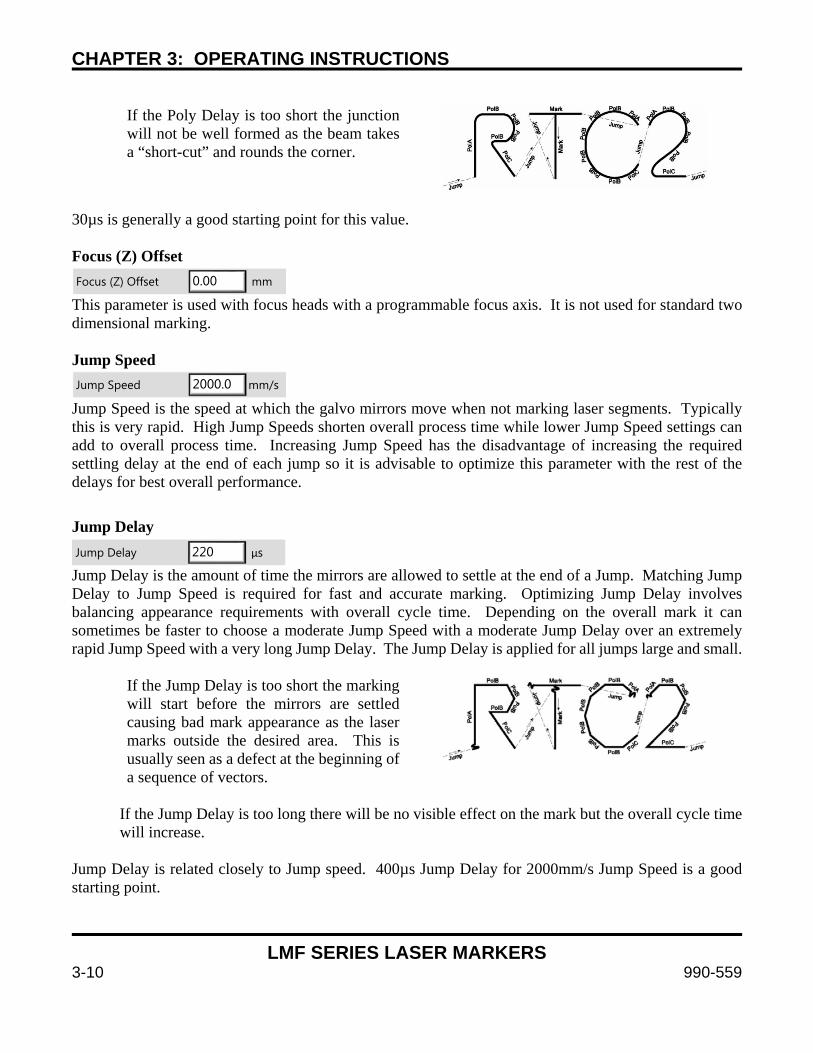
CHAPTER 3: OPERATING INSTRUCTIONS
LMF SERIES LASER MARKERS
3-10 990-559
If the Poly Delay is too short the junction will not be well formed as the beam takes a “short-cut” and rounds the corner.
30µs is generally a good starting point for this value. Focus (Z) Offset This parameter is used with focus heads with a programmable focus axis. It is not used for standard two dimensional marking. Jump Speed Jump Speed is the speed at which the galvo mirrors move when not marking laser segments. Typically this is very rapid. High Jump Speeds shorten overall process time while lower Jump Speed settings can add to overall process time. Increasing Jump Speed has the disadvantage of increasing the required settling delay at the end of each jump so it is advisable to optimize this parameter with the rest of the delays for best overall performance.
Jump Delay
Jump Delay is the amount of time the mirrors are allowed to settle at the end of a Jump. Matching Jump Delay to Jump Speed is required for fast and accurate marking. Optimizing Jump Delay involves balancing appearance requirements with overall cycle time. Depending on the overall mark it can sometimes be faster to choose a moderate Jump Speed with a moderate Jump Delay over an extremely rapid Jump Speed with a very long Jump Delay. The Jump Delay is applied for all jumps large and small.
If the Jump Delay is too short the marking will start before the mirrors are settled causing bad mark appearance as the laser marks outside the desired area. This is usually seen as a defect at the beginning of a sequence of vectors.
If the Jump Delay is too long there will be no visible effect on the mark but the overall cycle time will increase.
Jump Delay is related closely to Jump speed. 400µs Jump Delay for 2000mm/s Jump Speed is a good starting point.
Focus (Z) Offset mm 0.00
Jump Speed mm/s 2000.0
Jump Delay µs 220
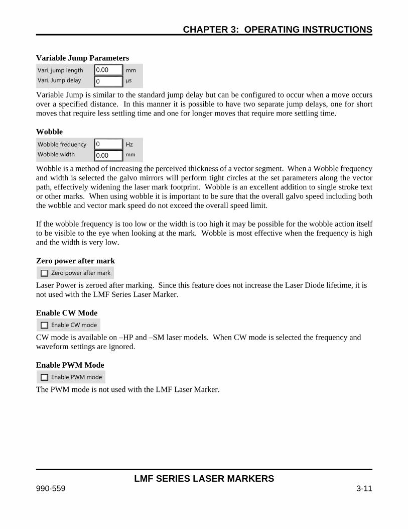
CHAPTER 3: OPERATING INSTRUCTIONS
LMF SERIES LASER MARKERS
990-559 3-11
Variable Jump Parameters Variable Jump is similar to the standard jump delay but can be configured to occur when a move occurs over a specified distance. In this manner it is possible to have two separate jump delays, one for short moves that require less settling time and one for longer moves that require more settling time. Wobble Wobble is a method of increasing the perceived thickness of a vector segment. When a Wobble frequency and width is selected the galvo mirrors will perform tight circles at the set parameters along the vector path, effectively widening the laser mark footprint. Wobble is an excellent addition to single stroke text or other marks. When using wobble it is important to be sure that the overall galvo speed including both the wobble and vector mark speed do not exceed the overall speed limit. If the wobble frequency is too low or the width is too high it may be possible for the wobble action itself to be visible to the eye when looking at the mark. Wobble is most effective when the frequency is high and the width is very low. Zero power after mark Laser Power is zeroed after marking. Since this feature does not increase the Laser Diode lifetime, it is not used with the LMF Series Laser Marker. Enable CW Mode CW mode is available on –HP and –SM laser models. When CW mode is selected the frequency and waveform settings are ignored. Enable PWM Mode The PWM mode is not used with the LMF Laser Marker.
Vari. jump length mm
Vari. Jump delay µs
0.00
0
Wobble frequency Hz
Wobble width mm
0
0.00
Zero power after mark
Enable CW mode
Enable PWM mode
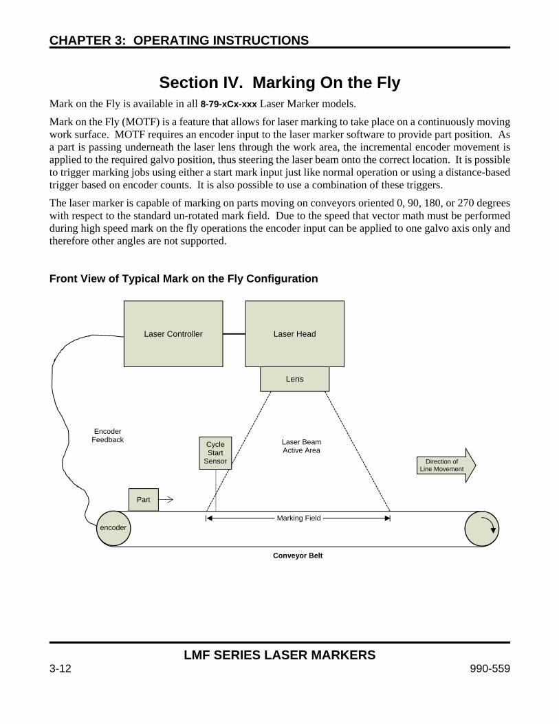
CHAPTER 3: OPERATING INSTRUCTIONS
LMF SERIES LASER MARKERS
3-12 990-559
Section IV. Marking On the Fly
Mark on the Fly is available in all 8-79-xCx-xxx Laser Marker models.
Mark on the Fly (MOTF) is a feature that allows for laser marking to take place on a continuously moving work surface. MOTF requires an encoder input to the laser marker software to provide part position. As a part is passing underneath the laser lens through the work area, the incremental encoder movement is applied to the required galvo position, thus steering the laser beam onto the correct location. It is possible to trigger marking jobs using either a start mark input just like normal operation or using a distance-based trigger based on encoder counts. It is also possible to use a combination of these triggers.
The laser marker is capable of marking on parts moving on conveyors oriented 0, 90, 180, or 270 degrees with respect to the standard un-rotated mark field. Due to the speed that vector math must be performed during high speed mark on the fly operations the encoder input can be applied to one galvo axis only and therefore other angles are not supported. Front View of Typical Mark on the Fly Configuration
Laser Controller
Laser Head
Lens
encoder
Conveyor Belt
Cycle Start
Sensor
Laser BeamActive Area
Part
Encoder Feedback
Direction of Line Movement
Marking Field
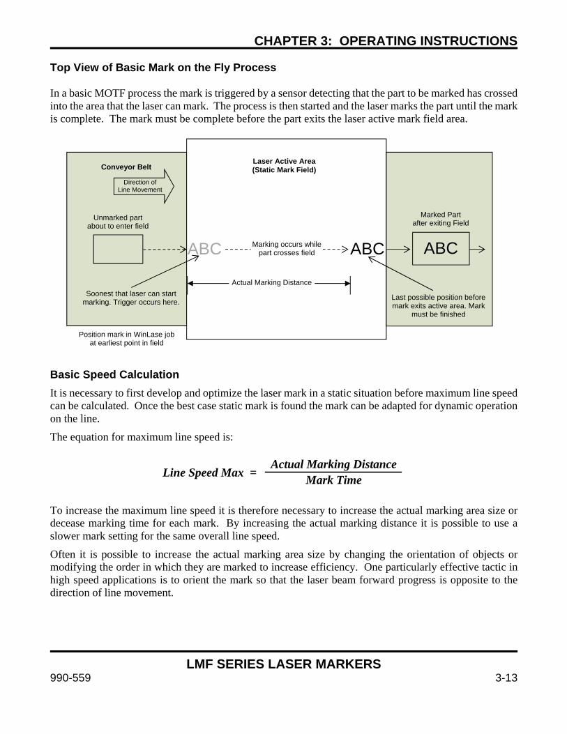
CHAPTER 3: OPERATING INSTRUCTIONS
LMF SERIES LASER MARKERS
990-559 3-13
Top View of Basic Mark on the Fly Process In a basic MOTF process the mark is triggered by a sensor detecting that the part to be marked has crossed into the area that the laser can mark. The process is then started and the laser marks the part until the mark is complete. The mark must be complete before the part exits the laser active mark field area. Basic Speed Calculation It is necessary to first develop and optimize the laser mark in a static situation before maximum line speed can be calculated. Once the best case static mark is found the mark can be adapted for dynamic operation on the line.
The equation for maximum line speed is:
To increase the maximum line speed it is therefore necessary to increase the actual marking area size or decease marking time for each mark. By increasing the actual marking distance it is possible to use a slower mark setting for the same overall line speed.
Often it is possible to increase the actual marking area size by changing the orientation of objects or modifying the order in which they are marked to increase efficiency. One particularly effective tactic in high speed applications is to orient the mark so that the laser beam forward progress is opposite to the direction of line movement.
Actual Marking Distance Mark Time
Line Speed Max =
Conveyor Belt
Direction of Line Movement
Unmarked part about to enter field
ABC ABCABC
Laser Active Area(Static Mark Field)
Marked Part after exiting Field
Soonest that laser can start marking. Trigger occurs here.
Actual Marking Distance
Last possible position before mark exits active area. Mark
must be finished
Position mark in WinLase job at earliest point in field
Marking occurs whilepart crosses field
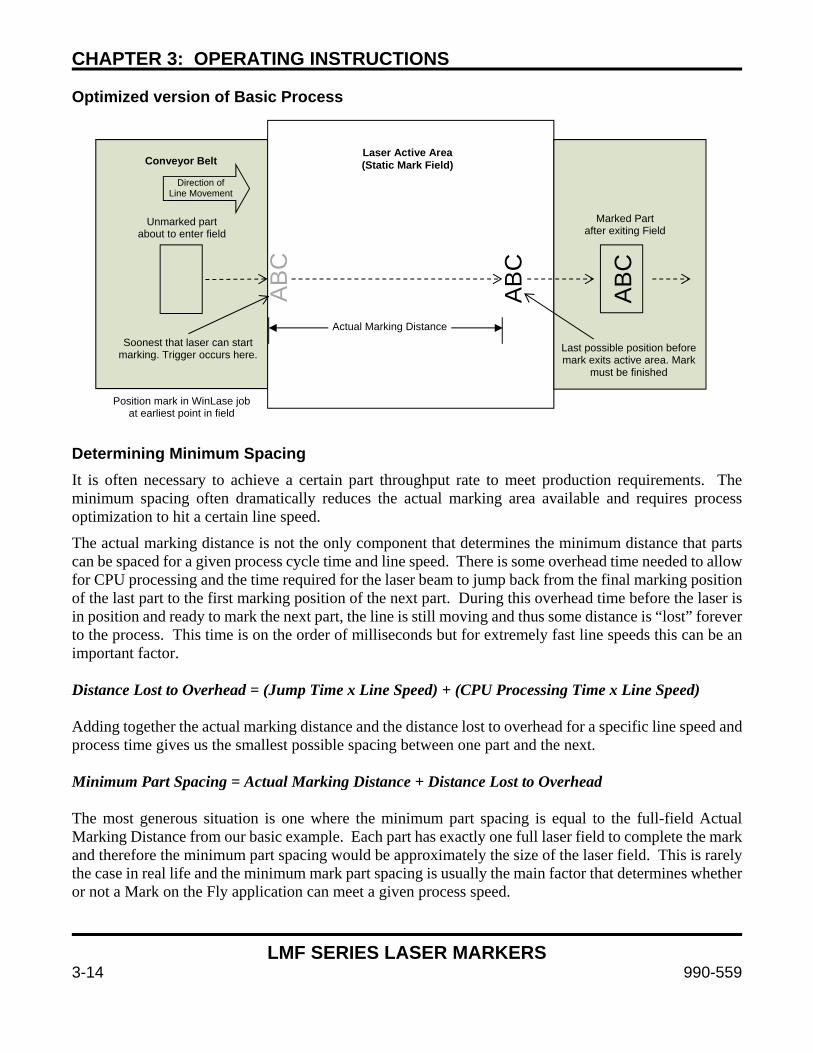
CHAPTER 3: OPERATING INSTRUCTIONS
LMF SERIES LASER MARKERS
3-14 990-559
Optimized version of Basic Process Determining Minimum Spacing It is often necessary to achieve a certain part throughput rate to meet production requirements. The minimum spacing often dramatically reduces the actual marking area available and requires process optimization to hit a certain line speed.
The actual marking distance is not the only component that determines the minimum distance that parts can be spaced for a given process cycle time and line speed. There is some overhead time needed to allow for CPU processing and the time required for the laser beam to jump back from the final marking position of the last part to the first marking position of the next part. During this overhead time before the laser is in position and ready to mark the next part, the line is still moving and thus some distance is “lost” forever to the process. This time is on the order of milliseconds but for extremely fast line speeds this can be an important factor. Distance Lost to Overhead = (Jump Time x Line Speed) + (CPU Processing Time x Line Speed) Adding together the actual marking distance and the distance lost to overhead for a specific line speed and process time gives us the smallest possible spacing between one part and the next. Minimum Part Spacing = Actual Marking Distance + Distance Lost to Overhead
The most generous situation is one where the minimum part spacing is equal to the full-field Actual Marking Distance from our basic example. Each part has exactly one full laser field to complete the mark and therefore the minimum part spacing would be approximately the size of the laser field. This is rarely the case in real life and the minimum mark part spacing is usually the main factor that determines whether or not a Mark on the Fly application can meet a given process speed.
Conveyor Belt
Direction of Line Movement
Unmarked part about to enter field
AB
C
AB
C
AB
C
Laser Active Area(Static Mark Field)
Marked Part after exiting Field
Soonest that laser can start marking. Trigger occurs here.
Actual Marking Distance
Last possible position before mark exits active area. Mark
must be finished
Position mark in WinLase job at earliest point in field
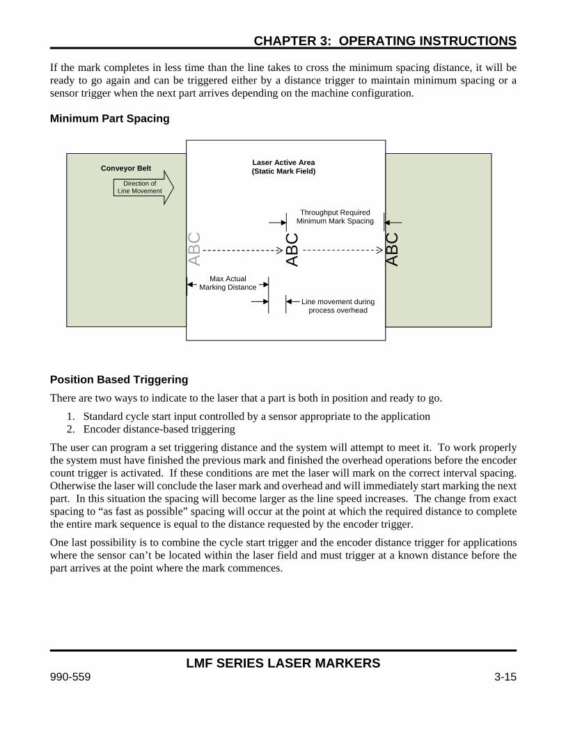
CHAPTER 3: OPERATING INSTRUCTIONS
LMF SERIES LASER MARKERS
990-559 3-15
If the mark completes in less time than the line takes to cross the minimum spacing distance, it will be ready to go again and can be triggered either by a distance trigger to maintain minimum spacing or a sensor trigger when the next part arrives depending on the machine configuration. Minimum Part Spacing Position Based Triggering There are two ways to indicate to the laser that a part is both in position and ready to go.
1. Standard cycle start input controlled by a sensor appropriate to the application 2. Encoder distance-based triggering
The user can program a set triggering distance and the system will attempt to meet it. To work properly the system must have finished the previous mark and finished the overhead operations before the encoder count trigger is activated. If these conditions are met the laser will mark on the correct interval spacing. Otherwise the laser will conclude the laser mark and overhead and will immediately start marking the next part. In this situation the spacing will become larger as the line speed increases. The change from exact spacing to “as fast as possible” spacing will occur at the point at which the required distance to complete the entire mark sequence is equal to the distance requested by the encoder trigger.
One last possibility is to combine the cycle start trigger and the encoder distance trigger for applications where the sensor can’t be located within the laser field and must trigger at a known distance before the part arrives at the point where the mark commences.
Conveyor Belt
Direction of Line Movement
AB
C
AB
C
Laser Active Area(Static Mark Field)
Line movement during process overhead
AB
C
Throughput Required Minimum Mark Spacing
Max Actual Marking Distance

CHAPTER 3: OPERATING INSTRUCTIONS
LMF SERIES LASER MARKERS
3-16 990-559
Encoder Selection Encoders must use 5V differential quadrature outputs with A and B channels. One recommended model is the AMCI Duracoder DC25F-B2NPGRMDE NEMA25 shaft style encoder. Another recommended model is the BetaLaserMike Laserspeed4000-1 laser encoder for high speed high accuracy line speed measurement. Wiring details can be found in Appendix B, Electrical and Data Connections of this document. Determining Feasibility Not every process is compatible with MOTF. For the process to work a balance of mark time, line speed, process settings, throughput, and mark design must all work together. Static process development and up front calculations are the most important steps that must be performed to determine if the process is compatible with MOTF before the time and expense of an integration onto a line.
As a general set of guidelines to determine if a process is compatible, follow these steps:
1) Develop the mark on a static workpiece and optimize every setting for best possible performance. 2) Consider MOTF in the mark time when designing the mark and optimize direction of mark so that
the laser moves generally in one direction as opposed to skipping back and forth. This will give the MOTF more time to work on the active area.
3) Once the best possible cycle time is determined calculate the best case line speed and compare with expectations.
4) If the best possible line speed based on actual mark area is within reason, consider minimum spacing and triggering requirements.
5) Test on a line simulator or integrate into a real assembly line.
Finally, there is no substitute for experimentation when optimizing a MOTF process. Once it is possible to test on a real line the optimizations made at the static stage can be massaged and improved to increase performance and margin of safety.
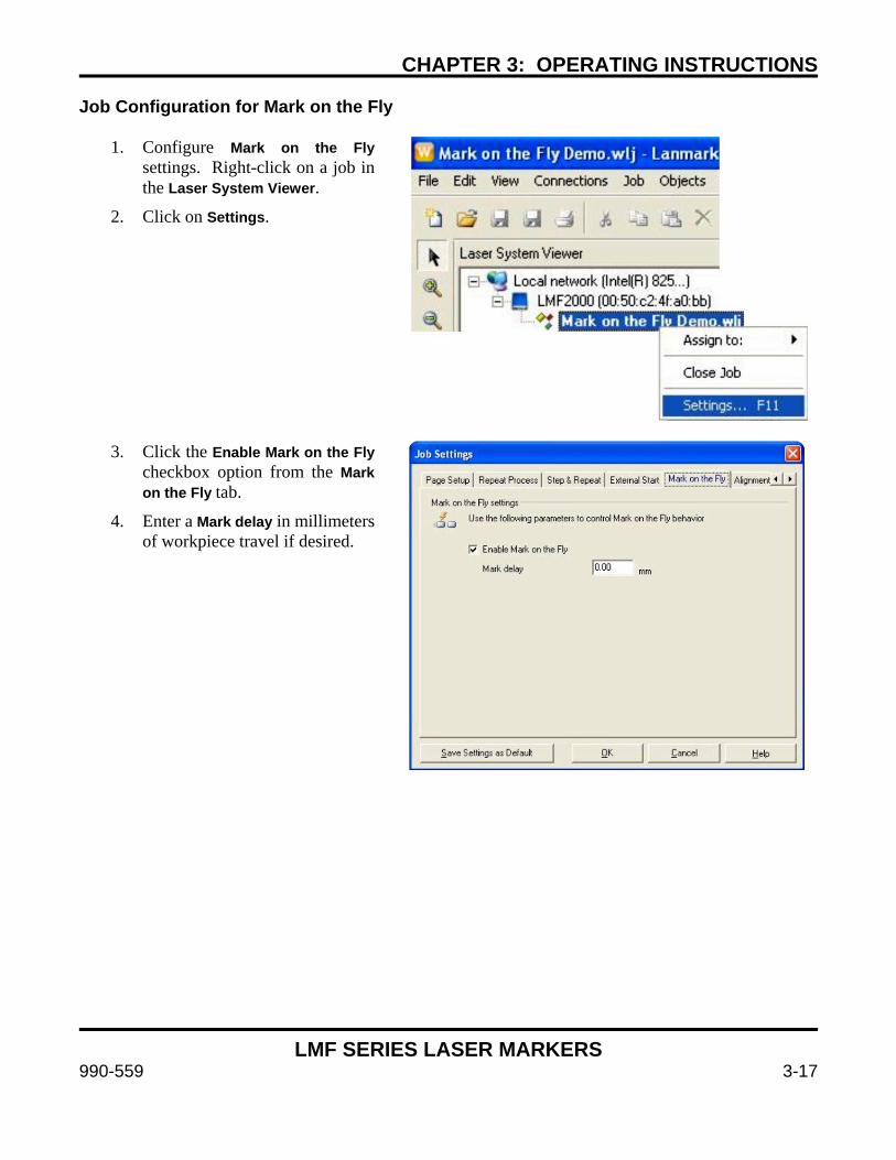
CHAPTER 3: OPERATING INSTRUCTIONS
LMF SERIES LASER MARKERS
990-559 3-17
Job Configuration for Mark on the Fly
1. Configure Mark on the Fly settings. Right-click on a job in the Laser System Viewer.
2. Click on Settings.
3. Click the Enable Mark on the Fly
checkbox option from the Mark on the Fly tab.
4. Enter a Mark delay in millimeters of workpiece travel if desired.
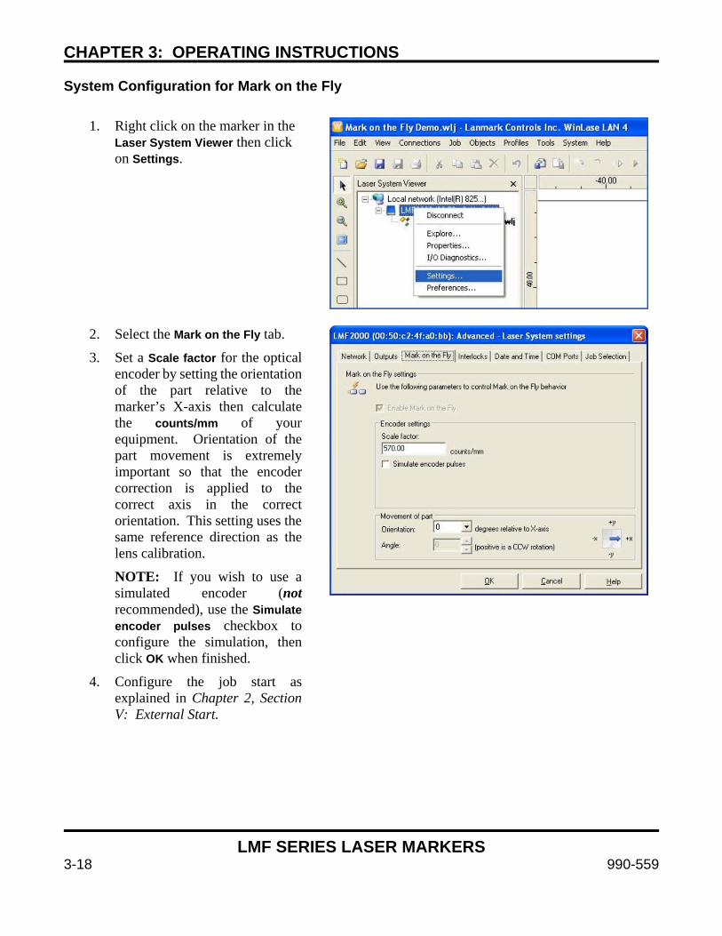
CHAPTER 3: OPERATING INSTRUCTIONS
LMF SERIES LASER MARKERS
3-18 990-559
System Configuration for Mark on the Fly
1. Right click on the marker in the Laser System Viewer then click on Settings.
2. Select the Mark on the Fly tab.
3. Set a Scale factor for the optical encoder by setting the orientation of the part relative to the marker’s X-axis then calculate the counts/mm of your equipment. Orientation of the part movement is extremely important so that the encoder correction is applied to the correct axis in the correct orientation. This setting uses the same reference direction as the lens calibration.
NOTE: If you wish to use a simulated encoder (not recommended), use the Simulate encoder pulses checkbox to configure the simulation, then click OK when finished.
4. Configure the job start as explained in Chapter 2, Section V: External Start.
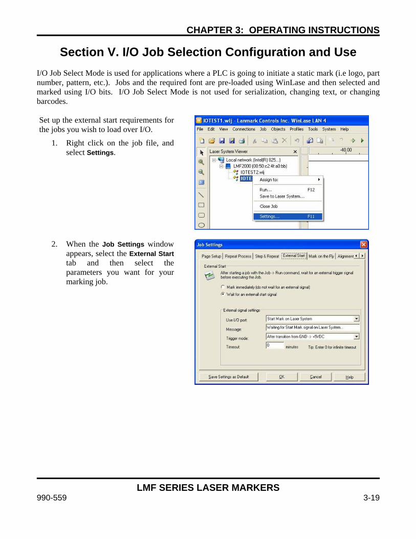
CHAPTER 3: OPERATING INSTRUCTIONS
LMF SERIES LASER MARKERS
990-559 3-19
Section V. I/O Job Selection Configuration and Use I/O Job Select Mode is used for applications where a PLC is going to initiate a static mark (i.e logo, part number, pattern, etc.). Jobs and the required font are pre-loaded using WinLase and then selected and marked using I/O bits. I/O Job Select Mode is not used for serialization, changing text, or changing barcodes. Set up the external start requirements for the jobs you wish to load over I/O.
1. Right click on the job file, and select Settings.
2. When the Job Settings window
appears, select the External Start tab and then select the parameters you want for your marking job.
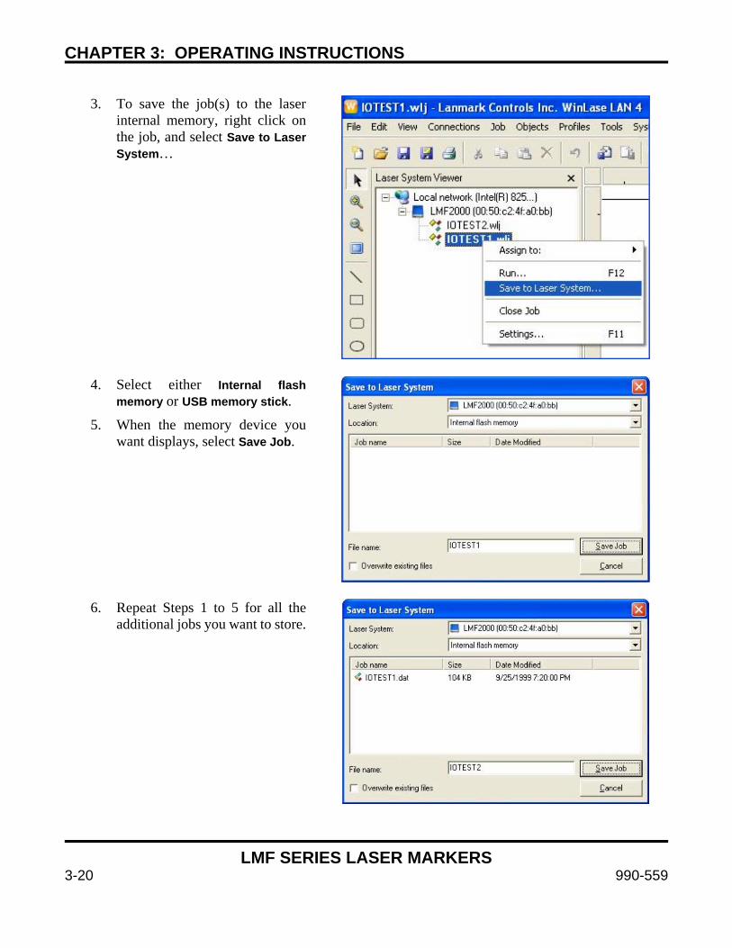
CHAPTER 3: OPERATING INSTRUCTIONS
LMF SERIES LASER MARKERS
3-20 990-559
3. To save the job(s) to the laser
internal memory, right click on the job, and select Save to Laser System…
4. Select either Internal flash
memory or USB memory stick.
5. When the memory device you want displays, select Save Job.
6. Repeat Steps 1 to 5 for all the
additional jobs you want to store.
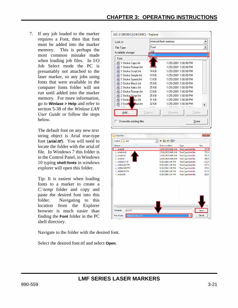
CHAPTER 3: OPERATING INSTRUCTIONS
LMF SERIES LASER MARKERS
990-559 3-21
7. If any job loaded to the marker
requires a Font, then that font must be added into the marker memory. This is perhaps the most common mistake made when loading job files. In I/O Job Select mode the PC is presumably not attached to the laser marker, so any jobs using fonts that were available in the computer fonts folder will not run until added into the marker memory. For more information, go to Winlase > Help and refer to section 5-38 of the Winlase LAN User Guide or follow the steps below. The default font on any new text
string object is Arial true-type font (arial.ttf). You will need to locate the folder with the arial.ttf file. In Windows 7 this folder is in the Control Panel, in Windows 10 typing shell:fonts in windows explorer will open this folder. Tip: It is easiest when loading fonts to a marker to create a C:\temp folder and copy and paste the desired font into this folder. Navigating to this location from the Explorer browser is much easier than finding the Font folder in the PC shell directory.
Navigate to the folder with the desired font. Select the desired font.ttf and select Open.
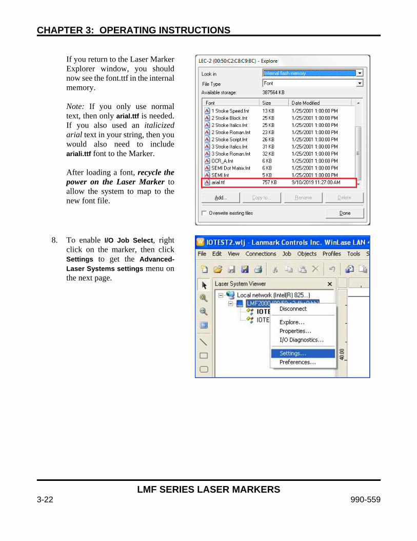
CHAPTER 3: OPERATING INSTRUCTIONS
LMF SERIES LASER MARKERS
3-22 990-559
If you return to the Laser Marker Explorer window, you should now see the font.ttf in the internal memory. Note: If you only use normal text, then only arial.ttf is needed. If you also used an italicized arial text in your string, then you would also need to include ariali.ttf font to the Marker. After loading a font, recycle the power on the Laser Marker to allow the system to map to the new font file.
8. To enable I/O Job Select, right
click on the marker, then click Settings to get the Advanced-Laser Systems settings menu on the next page.
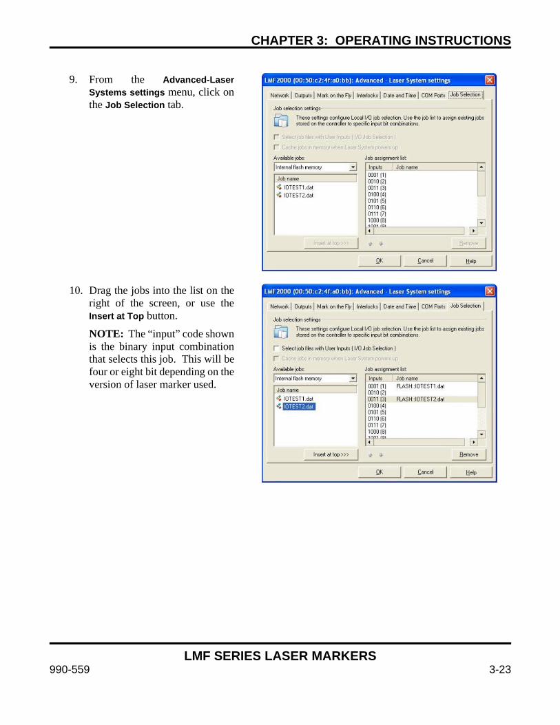
CHAPTER 3: OPERATING INSTRUCTIONS
LMF SERIES LASER MARKERS
990-559 3-23
9. From the Advanced-Laser
Systems settings menu, click on the Job Selection tab.
10. Drag the jobs into the list on the
right of the screen, or use the Insert at Top button.
NOTE: The “input” code shown is the binary input combination that selects this job. This will be four or eight bit depending on the version of laser marker used.
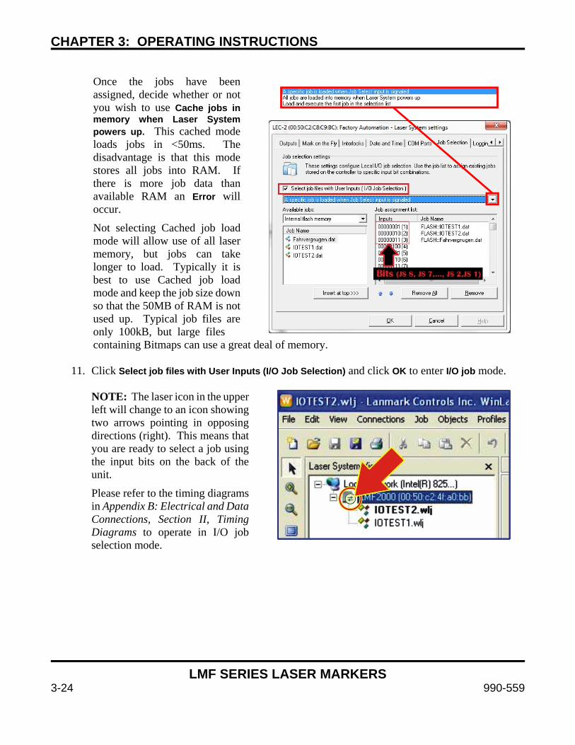
CHAPTER 3: OPERATING INSTRUCTIONS
LMF SERIES LASER MARKERS
3-24 990-559
Once the jobs have been assigned, decide whether or not you wish to use Cache jobs in memory when Laser System powers up. This cached mode loads jobs in <50ms. The disadvantage is that this mode stores all jobs into RAM. If there is more job data than available RAM an Error will occur.
Not selecting Cached job load mode will allow use of all laser memory, but jobs can take longer to load. Typically it is best to use Cached job load mode and keep the job size down so that the 50MB of RAM is not used up. Typical job files are only 100kB, but large files
containing Bitmaps can use a great deal of memory.
11. Click Select job files with User Inputs (I/O Job Selection) and click OK to enter I/O job mode.
NOTE: The laser icon in the upper left will change to an icon showing two arrows pointing in opposing directions (right). This means that you are ready to select a job using the input bits on the back of the unit.
Please refer to the timing diagrams in Appendix B: Electrical and Data Connections, Section II, Timing Diagrams to operate in I/O job selection mode.
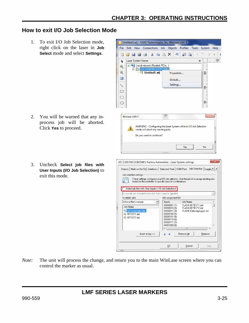
CHAPTER 3: OPERATING INSTRUCTIONS
LMF SERIES LASER MARKERS
990-559 3-25
How to exit I/O Job Selection Mode
1. To exit I/O Job Selection mode, right click on the laser in Job Select mode and select Settings.
2. You will be warned that any in-
process job will be aborted. Click Yes to proceed.
3. Uncheck Select job files with User Inputs (I/O Job Selection) to exit this mode.
Note: The unit will process the change, and return you to the main WinLase screen where you can control the marker as usual.

CHAPTER 3: OPERATING INSTRUCTIONS
LMF SERIES LASER MARKERS
3-26 990-559
Section VI. Vector Node Editing (Graphic File Editing)
Vector Node Editing (also known as Graphic File Editing) is a feature that allows the user to modify, repair, and optimize vector artwork for improved marking. Using the Vector Edit Tool, users can add and remove nodes, change the order of marking, repair polylines and optimize fill, break artwork into multiple pieces, assign different sections of artwork to different laser parameters, and combine multiple vectors into single artwork files. Vector Node Editing operations are performed on WinLase Object files (*.WLO). WLO files are WinLase’s native vector artwork format. When importing external artwork in other formats like .DXF, .AI, .DWG, .PLT, .DXF, etc. the WinLase importer tool converts the original file format into the native WLO file format. In addition, the WLO files can be exported as .PLT files to be used by other software. Vector Node Editing is a CPU-intensive process due to the number of vector calculations that must be performed. Vector artwork can have many nodes. Although artwork with many vectors can be imported and manipulated, to ensure good performance the editor selection tool (mouse selection box) is limited to selecting 1000 nodes at a time. When creating or importing artwork, it is helpful to minimize the number of unnecessary nodes and vectors. Each node in a laser marking process introduces delay so an optimized artwork file with a minimum number of nodes can mark much faster than a file with many unnecessary nodes while ending up with the same result. Accessing the Vector Edit Tool The Vector Edit Tool is accessed in a separate window launched from within the WinLase object screen by right-clicking on a vector object and selecting “Edit Vectors”. It can also be launched by right clicking on the artwork in the WinLase mark field screen and using the context menu. The object must first be selected before the Edit Tool can be launched. The Edit Tool can be resized by dragging the corner or boundary lines.
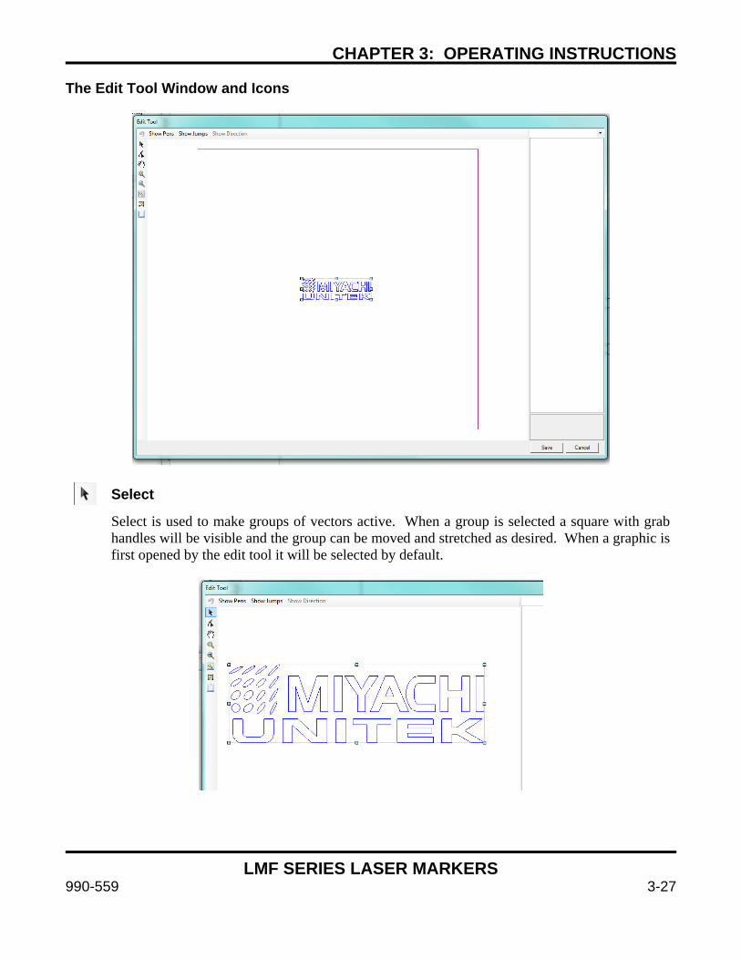
CHAPTER 3: OPERATING INSTRUCTIONS
LMF SERIES LASER MARKERS
990-559 3-27
The Edit Tool Window and Icons
Select
Select is used to make groups of vectors active. When a group is selected a square with grab handles will be visible and the group can be moved and stretched as desired. When a graphic is first opened by the edit tool it will be selected by default.
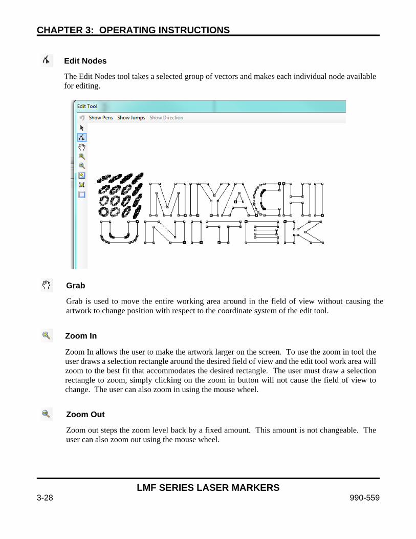
CHAPTER 3: OPERATING INSTRUCTIONS
LMF SERIES LASER MARKERS
3-28 990-559
Edit Nodes
The Edit Nodes tool takes a selected group of vectors and makes each individual node available for editing.
Grab
Grab is used to move the entire working area around in the field of view without causing the artwork to change position with respect to the coordinate system of the edit tool.
Zoom In
Zoom In allows the user to make the artwork larger on the screen. To use the zoom in tool the user draws a selection rectangle around the desired field of view and the edit tool work area will zoom to the best fit that accommodates the desired rectangle. The user must draw a selection rectangle to zoom, simply clicking on the zoom in button will not cause the field of view to change. The user can also zoom in using the mouse wheel.
Zoom Out
Zoom out steps the zoom level back by a fixed amount. This amount is not changeable. The user can also zoom out using the mouse wheel.
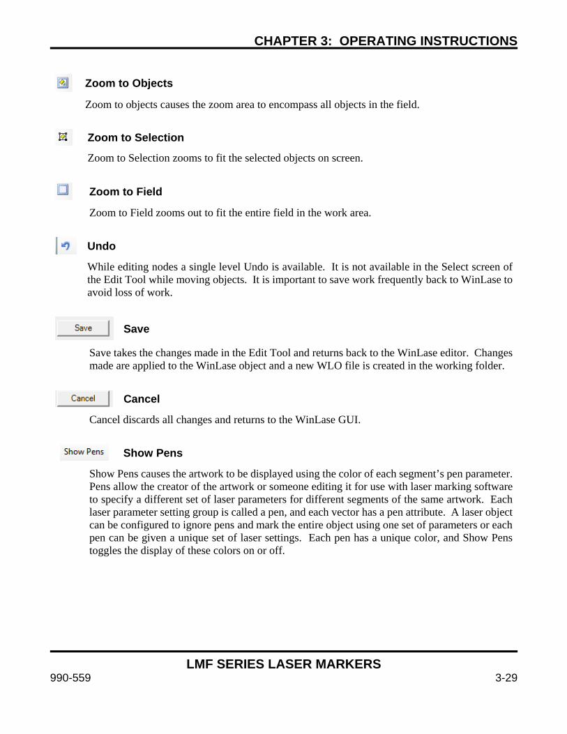
CHAPTER 3: OPERATING INSTRUCTIONS
LMF SERIES LASER MARKERS
990-559 3-29
Zoom to Objects
Zoom to objects causes the zoom area to encompass all objects in the field.
Zoom to Selection
Zoom to Selection zooms to fit the selected objects on screen.
Zoom to Field
Zoom to Field zooms out to fit the entire field in the work area.
Undo
While editing nodes a single level Undo is available. It is not available in the Select screen of the Edit Tool while moving objects. It is important to save work frequently back to WinLase to avoid loss of work.
Save
Save takes the changes made in the Edit Tool and returns back to the WinLase editor. Changes made are applied to the WinLase object and a new WLO file is created in the working folder.
Cancel
Cancel discards all changes and returns to the WinLase GUI.
Show Pens
Show Pens causes the artwork to be displayed using the color of each segment’s pen parameter. Pens allow the creator of the artwork or someone editing it for use with laser marking software to specify a different set of laser parameters for different segments of the same artwork. Each laser parameter setting group is called a pen, and each vector has a pen attribute. A laser object can be configured to ignore pens and mark the entire object using one set of parameters or each pen can be given a unique set of laser settings. Each pen has a unique color, and Show Pens toggles the display of these colors on or off.

CHAPTER 3: OPERATING INSTRUCTIONS
LMF SERIES LASER MARKERS
3-30 990-559
Show Jumps
Show Jumps causes the vector jumps to be displayed on the screen. Jumps are vector movements of the laser galvanometer head while the laser is turned off. Every polyline or individual vector has a jump as the first movement so the laser beam can begin marking the vector or polyline.
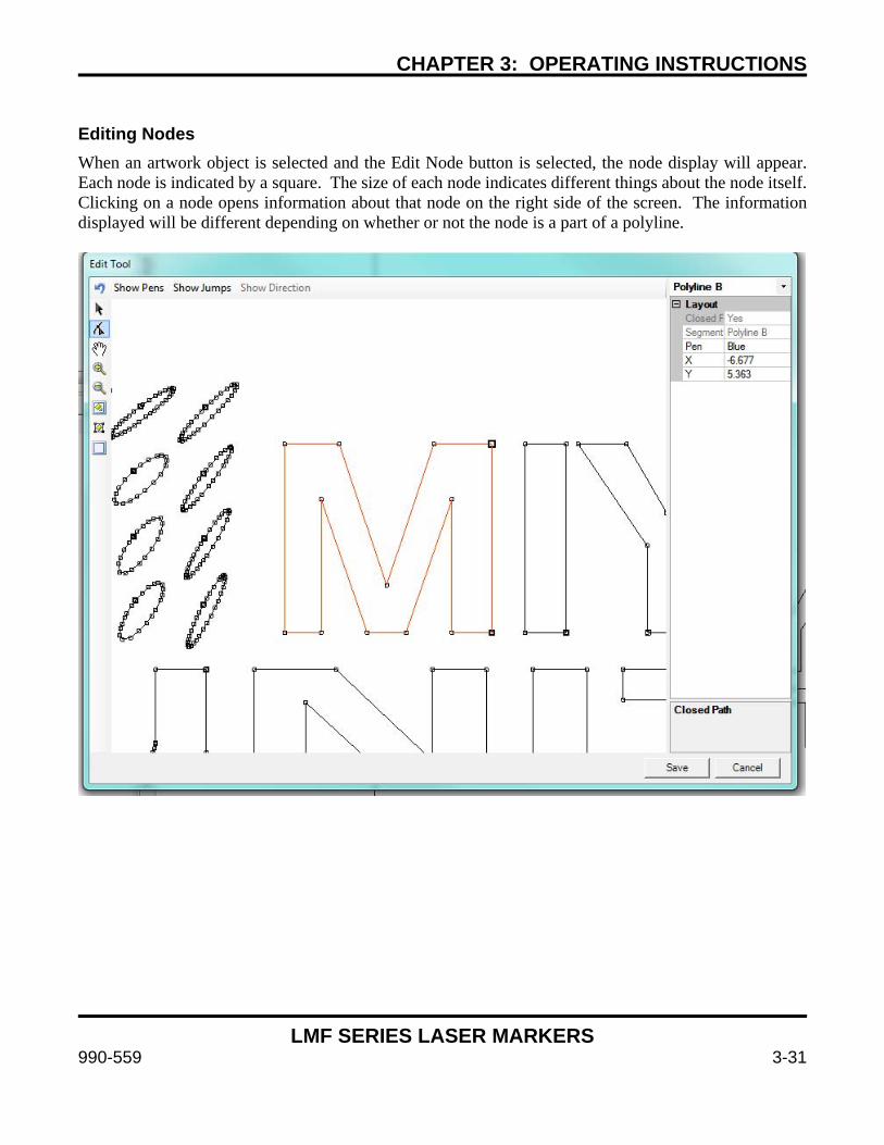
CHAPTER 3: OPERATING INSTRUCTIONS
LMF SERIES LASER MARKERS
990-559 3-31
Editing Nodes When an artwork object is selected and the Edit Node button is selected, the node display will appear. Each node is indicated by a square. The size of each node indicates different things about the node itself. Clicking on a node opens information about that node on the right side of the screen. The information displayed will be different depending on whether or not the node is a part of a polyline.
CHAPTER 3: OPERATING INSTRUCTIONS
LMF SERIES LASER MARKERS
3-32 990-559
PolyLines Polylines are a series of vectors marked sequentially end to end without jumps in the middle. At each node a Poly delay will occur before the laser moves to the next vector segment. A polyline is considered “Closed” if the first node (Jump) is at the same coordinate as the last node (Polyline C). For a section of artwork to be filled by WinLase’s Hatch Fill function it is required that all polylines in the artwork are closed. By far the most common cause for artwork that doesn’t fill correctly is unclosed polylines. It is often required to go through each polyline in a piece of artwork and verify that the “Closed Path” attribute is Yes, indicating that it will fill as a closed path. If multiple closed paths are nested within each other it will alternate hatch filling and not filling the closed paths. It will fill the outermost object, not fill the next one inside the outermost, then fill the next closed path, etc. Note that the name of the node indicates the type of operation that happened to get to that node – Jump means that the laser has jumped to that point, Polyline C means that a Polyline C segment preceded that node, etc. Polylines always exist as a series of connected nodes in the following order:
Jump Polyline A Polyline B ….. Polyline B Polyline C The first line of the information window will give you information on the type of node selected – the choices are: Jump – A Jump indicates that the laser beam will jump to this point and turn on the laser and mark
to the first A segment. A Jump vector is indicated by the “Jump” name in the first line and the Segment display. Also, a Jump is indicated by a large square when the vector is not selected and a filled large square when selected.
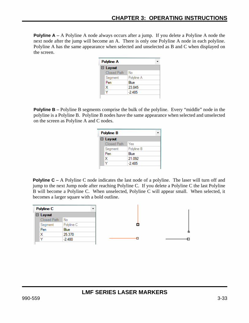
CHAPTER 3: OPERATING INSTRUCTIONS
LMF SERIES LASER MARKERS
990-559 3-33
Polyline A – A Polyline A node always occurs after a jump. If you delete a Polyline A node the
next node after the jump will become an A. There is only one Polyline A node in each polyline. Polyline A has the same appearance when selected and unselected as B and C when displayed on the screen.
Polyline B – Polyline B segments comprise the bulk of the polyline. Every “middle” node in the polyline is a Polyline B. Polyline B nodes have the same appearance when selected and unselected on the screen as Polyline A and C nodes.
Polyline C – A Polyline C node indicates the last node of a polyline. The laser will turn off and jump to the next Jump node after reaching Polyline C. If you delete a Polyline C the last Polyline B will become a Polyline C. When unselected, Polyline C will appear small. When selected, it becomes a larger square with a bold outline.
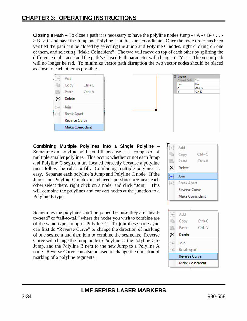
CHAPTER 3: OPERATING INSTRUCTIONS
LMF SERIES LASER MARKERS
3-34 990-559
Closing a Path – To close a path it is necessary to have the polyline nodes Jump -> A -> B-> … -
> B -> C and have the Jump and Polyline C at the same coordinate. Once the node order has been verified the path can be closed by selecting the Jump and Polyline C nodes, right clicking on one of them, and selecting “Make Coincident”. The two will move on top of each other by splitting the difference in distance and the path’s Closed Path parameter will change to “Yes”. The vector path will no longer be red. To minimize vector path disruption the two vector nodes should be placed as close to each other as possible.
Combining Multiple Polylines into a Single Polyline –
Sometimes a polyline will not fill because it is composed of multiple smaller polylines. This occurs whether or not each Jump and Polyline C segment are located correctly because a polyline must follow the rules to fill. Combining multiple polylines is easy. Separate each polyline’s Jump and Polyline C node. If the Jump and Polyline C nodes of adjacent polylines are near each other select them, right click on a node, and click “Join”. This will combine the polylines and convert nodes at the junction to a Polyline B type.
Sometimes the polylines can’t be joined because they are “head-to-head” or “tail-to-tail” where the nodes you wish to combine are of the same type, Jump or Polyline C. To join these nodes you can first do “Reverse Curve” to change the direction of marking of one segment and then join to combine the segments. Reverse Curve will change the Jump node to Polyline C, the Polyline C to Jump, and the Polyline B next to the new Jump to a Polyline A node. Reverse Curve can also be used to change the direction of marking of a polyline segments.
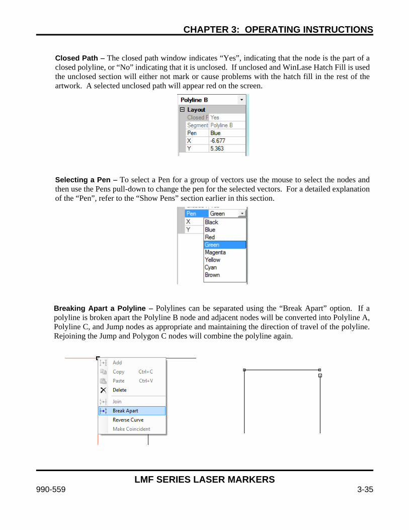
CHAPTER 3: OPERATING INSTRUCTIONS
LMF SERIES LASER MARKERS
990-559 3-35
Closed Path – The closed path window indicates “Yes”, indicating that the node is the part of a
closed polyline, or “No” indicating that it is unclosed. If unclosed and WinLase Hatch Fill is used the unclosed section will either not mark or cause problems with the hatch fill in the rest of the artwork. A selected unclosed path will appear red on the screen.
Selecting a Pen – To select a Pen for a group of vectors use the mouse to select the nodes and
then use the Pens pull-down to change the pen for the selected vectors. For a detailed explanation of the “Pen”, refer to the “Show Pens” section earlier in this section.
Breaking Apart a Polyline – Polylines can be separated using the “Break Apart” option. If a
polyline is broken apart the Polyline B node and adjacent nodes will be converted into Polyline A, Polyline C, and Jump nodes as appropriate and maintaining the direction of travel of the polyline. Rejoining the Jump and Polygon C nodes will combine the polyline again.
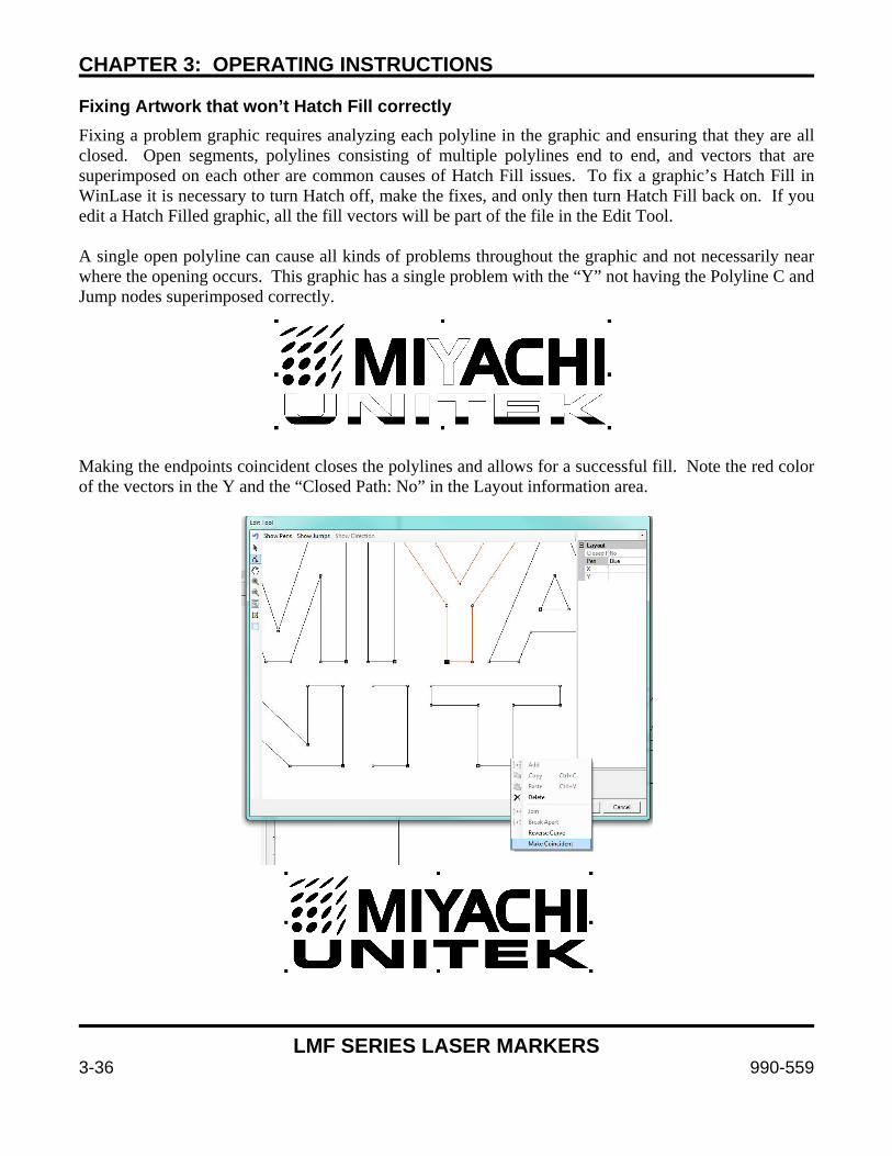
CHAPTER 3: OPERATING INSTRUCTIONS
LMF SERIES LASER MARKERS
3-36 990-559
Fixing Artwork that won’t Hatch Fill correctly Fixing a problem graphic requires analyzing each polyline in the graphic and ensuring that they are all closed. Open segments, polylines consisting of multiple polylines end to end, and vectors that are superimposed on each other are common causes of Hatch Fill issues. To fix a graphic’s Hatch Fill in WinLase it is necessary to turn Hatch off, make the fixes, and only then turn Hatch Fill back on. If you edit a Hatch Filled graphic, all the fill vectors will be part of the file in the Edit Tool. A single open polyline can cause all kinds of problems throughout the graphic and not necessarily near where the opening occurs. This graphic has a single problem with the “Y” not having the Polyline C and Jump nodes superimposed correctly.
Making the endpoints coincident closes the polylines and allows for a successful fill. Note the red color of the vectors in the Y and the “Closed Path: No” in the Layout information area.
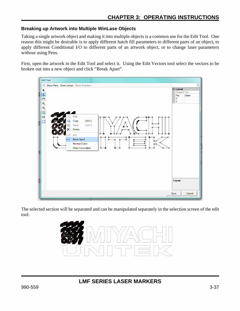
CHAPTER 3: OPERATING INSTRUCTIONS
LMF SERIES LASER MARKERS
990-559 3-37
Breaking up Artwork into Multiple WinLase Objects Taking a single artwork object and making it into multiple objects is a common use for the Edit Tool. One reason this might be desirable is to apply different hatch fill parameters to different parts of an object, to apply different Conditional I/O to different parts of an artwork object, or to change laser parameters without using Pens. First, open the artwork in the Edit Tool and select it. Using the Edit Vectors tool select the vectors to be broken out into a new object and click “Break Apart”.
The selected section will be separated and can be manipulated separately in the selection screen of the edit tool.
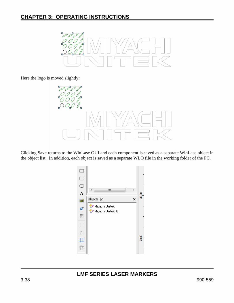
CHAPTER 3: OPERATING INSTRUCTIONS
LMF SERIES LASER MARKERS
3-38 990-559
Here the logo is moved slightly:
Clicking Save returns to the WinLase GUI and each component is saved as a separate WinLase object in the object list. In addition, each object is saved as a separate WLO file in the working folder of the PC.
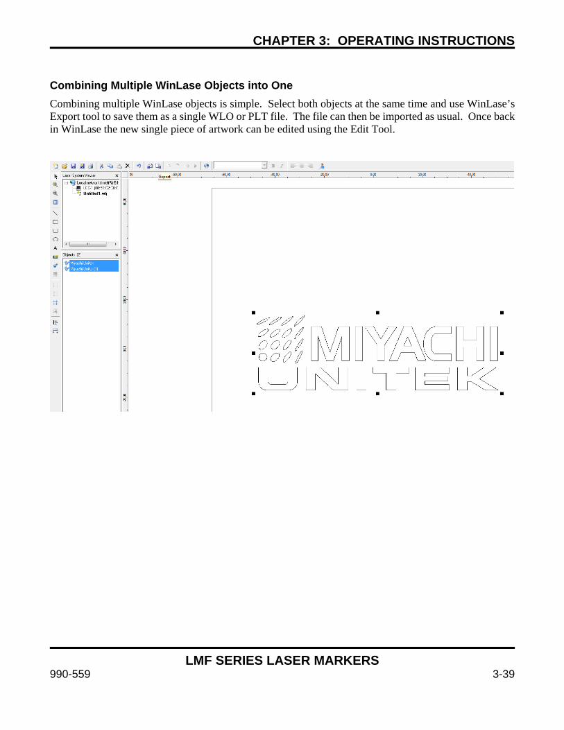
CHAPTER 3: OPERATING INSTRUCTIONS
LMF SERIES LASER MARKERS
990-559 3-39
Combining Multiple WinLase Objects into One Combining multiple WinLase objects is simple. Select both objects at the same time and use WinLase’s Export tool to save them as a single WLO or PLT file. The file can then be imported as usual. Once back in WinLase the new single piece of artwork can be edited using the Edit Tool.
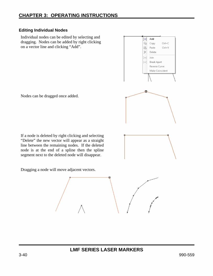
CHAPTER 3: OPERATING INSTRUCTIONS
LMF SERIES LASER MARKERS
3-40 990-559
Editing Individual Nodes Individual nodes can be edited by selecting and dragging. Nodes can be added by right clicking on a vector line and clicking “Add”.
Nodes can be dragged once added.
If a node is deleted by right clicking and selecting “Delete” the new vector will appear as a straight line between the remaining nodes. If the deleted node is at the end of a spline then the spline segment next to the deleted node will disappear.
Dragging a node will move adjacent vectors.

LMF SERIES LASER MARKERS
990-559 4-1
CHAPTER 4 MAINTENANCE
Section I: Safety Precautions
DANGER
To prevent eye damage when maintaining this equipment, laser protective goggles must be worn at all times (per ANSI Z136.1). Laser goggles with an OD (optical density) of 7+ (at a wavelength of 1060-1150nm) are recommended or as directed by your LSO.
WARNING
Before starting any maintenance procedure, read all of the instructions, including all CAUTION and WARNING messages.
Before starting maintenance work, turn the power to the Marker OFF and disconnect it from input AC power. Wait at least 5 minutes after turning OFF power before starting work.
Keep the exterior of the Marker clean. If the outside of the Marker is stained, wipe it with a dry or slightly moistened cloth. If badly stained, use a mild detergent or alcohol to clean it. Do not use paint thinner, acetone, benzene, etc. which can discolor or deform the parts.
CAUTION
Do not attempt to remove the fiber at the rear of the marker head from the isolator under any circumstances. Doing so will destroy the fiber and void the warranty. Amada Miyachi America assumes no liability for such action, the fiber will have to be replaced at the customer’s expense.

CHAPTER 4: MAINTENANCE
LMF SERIES LASER MARKERS
4-2 990-559
Section II: Troubleshooting If the Marker develops any fault conditions, the type of trouble will display in the LCD Display Screen and the Fault Indicator LEDs will flash. Several fault messages may display at the same time as shown on the sample LCD screen below. If you see the LEDs flashing, check the message on the display screen and refer to the chart below for assistance.
NOTE: The shutter will close immediately on any fault, and a power supply fault will occur in most cases. This power supply fault is an induced fault and not the primary fault unless it occurs alone.
To reset from a fault condition, clear the cause of the fault and cycle the key switch or send an I/O signal to the Fault Reset I/O bit as detailed in Appendix B.
LMF20-HP Fault Status Estop Temp ILock Shutter Closed LsrRdy Start
8-79-P, Q, R, E Models
Error Number of Flashes
LCD Screen Display Cause/Corrective Measures
Emergency Stop 3 EStop
Emergency stop circuit is open. Verify the E-Stop connector on the rear panel is closed, the E-Stop switch on the front panel is not active and the laser head cover is securely installed.
Startup Fault System Timeout 7 Start
The system has reached the end of its timeout without the laser or control hardware reaching a ready state. Please ensure that no other faults exist and clear by cycling the key switch.
Shutter Fault 2 Shutter
A shutter fault has occurred. Please cycle the key switch to try and recover. If the fault continues please check the remote interlock circuit. Ensure that a start job signal is not being sent through External I/O or Remote API within 100ms of a shutter open event. If the trouble continues, contact Amada Miyachi America.
Laser Ready Fault 4 LsrRdy A laser module fault has occurred. Contact Amada Miyachi
America if the problem cannot be cleared.
Laser Temperature 5 Temp
The laser temperature has exceeded the maximum allowable temperature for laser emission. Turn the machine off and allow the unit to cool down. If the laser temperature does not decrease after a period of time, the air filter may be clogged or airflow might otherwise be obstructed. Check that the ambient temperature is 94F (35C) or below for LMF35-HP models or 104F (40C) or below for other models. If the trouble continues, contact Amada Miyachi America. The laser module temperature is displayed on the front panel LCD screen for LMF Series “-HP” modules. The module temperature range varies between ambient and ambient +10C depending on the warmup state of the laser. Laser faults on non-HP models occur at 45C module temperatures, and 55C on –HP models.
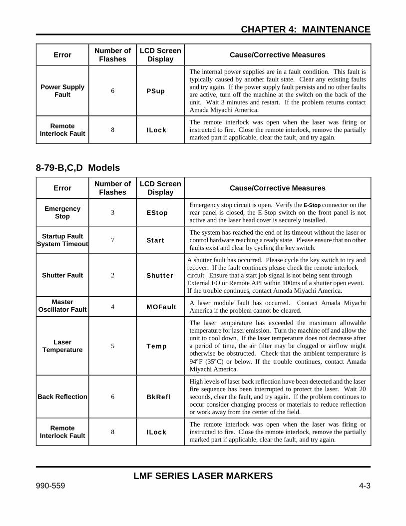
CHAPTER 4: MAINTENANCE
LMF SERIES LASER MARKERS
990-559 4-3
Error Number of Flashes
LCD Screen Display Cause/Corrective Measures
Power Supply Fault 6 PSup
The internal power supplies are in a fault condition. This fault is typically caused by another fault state. Clear any existing faults and try again. If the power supply fault persists and no other faults are active, turn off the machine at the switch on the back of the unit. Wait 3 minutes and restart. If the problem returns contact Amada Miyachi America.
Remote Interlock Fault 8 ILock
The remote interlock was open when the laser was firing or instructed to fire. Close the remote interlock, remove the partially marked part if applicable, clear the fault, and try again.
8-79-B,C,D Models
Error Number of Flashes
LCD Screen Display Cause/Corrective Measures
Emergency Stop 3 EStop
Emergency stop circuit is open. Verify the E-Stop connector on the rear panel is closed, the E-Stop switch on the front panel is not active and the laser head cover is securely installed.
Startup Fault System Timeout 7 Start
The system has reached the end of its timeout without the laser or control hardware reaching a ready state. Please ensure that no other faults exist and clear by cycling the key switch.
Shutter Fault 2 Shutter
A shutter fault has occurred. Please cycle the key switch to try and recover. If the fault continues please check the remote interlock circuit. Ensure that a start job signal is not being sent through External I/O or Remote API within 100ms of a shutter open event. If the trouble continues, contact Amada Miyachi America.
Master Oscillator Fault 4 MOFault A laser module fault has occurred. Contact Amada Miyachi
America if the problem cannot be cleared.
Laser Temperature 5 Temp
The laser temperature has exceeded the maximum allowable temperature for laser emission. Turn the machine off and allow the unit to cool down. If the laser temperature does not decrease after a period of time, the air filter may be clogged or airflow might otherwise be obstructed. Check that the ambient temperature is 94F (35C) or below. If the trouble continues, contact Amada Miyachi America.
Back Reflection 6 BkRefl
High levels of laser back reflection have been detected and the laser fire sequence has been interrupted to protect the laser. Wait 20 seconds, clear the fault, and try again. If the problem continues to occur consider changing process or materials to reduce reflection or work away from the center of the field.
Remote Interlock Fault 8 ILock
The remote interlock was open when the laser was firing or instructed to fire. Close the remote interlock, remove the partially marked part if applicable, clear the fault, and try again.

CHAPTER 4: MAINTENANCE
LMF SERIES LASER MARKERS
4-4 990-559
Section III: Emergency Stop and Interlock Safety
Controller Status and Error Indications
Emergency Stop and Interlock Controller Status and Troubleshooting
In some cases it might be necessary to observe the LED status indicators on the Emergency Stop and Interlock safety controllers. This might be necessary in a situation where it is not possible to reset the interlock or emergency stop circuit and everything externally seems correct. Examples of problems could be from miswiring of external emergency stop or interlock inputs, using a voltage or current source instead of a dry contact on the inputs, a shorted AC contactor, or other electronic failure.
To locate the Emergency Stop and Interlock controllers:
1. Power down the unit.
2. Remove the power cable from the back.
3. Wait 5 minutes.
4. Remove the screws holding the cover of the Laser Marker Control Unit and remove.
The controller modules are the yellow modules located in the front of the unit behind the LCD screen on top of the power supply mounting bracket. The thinner (top) module is the Interlock safety controller and the thicker (bottom) module is the Emergency Stop module.
Use the following information to understand the LED indicators and diagnose the problem.
INTERLOCK SAFETY MODULE EMERGENCY STOP MODULE
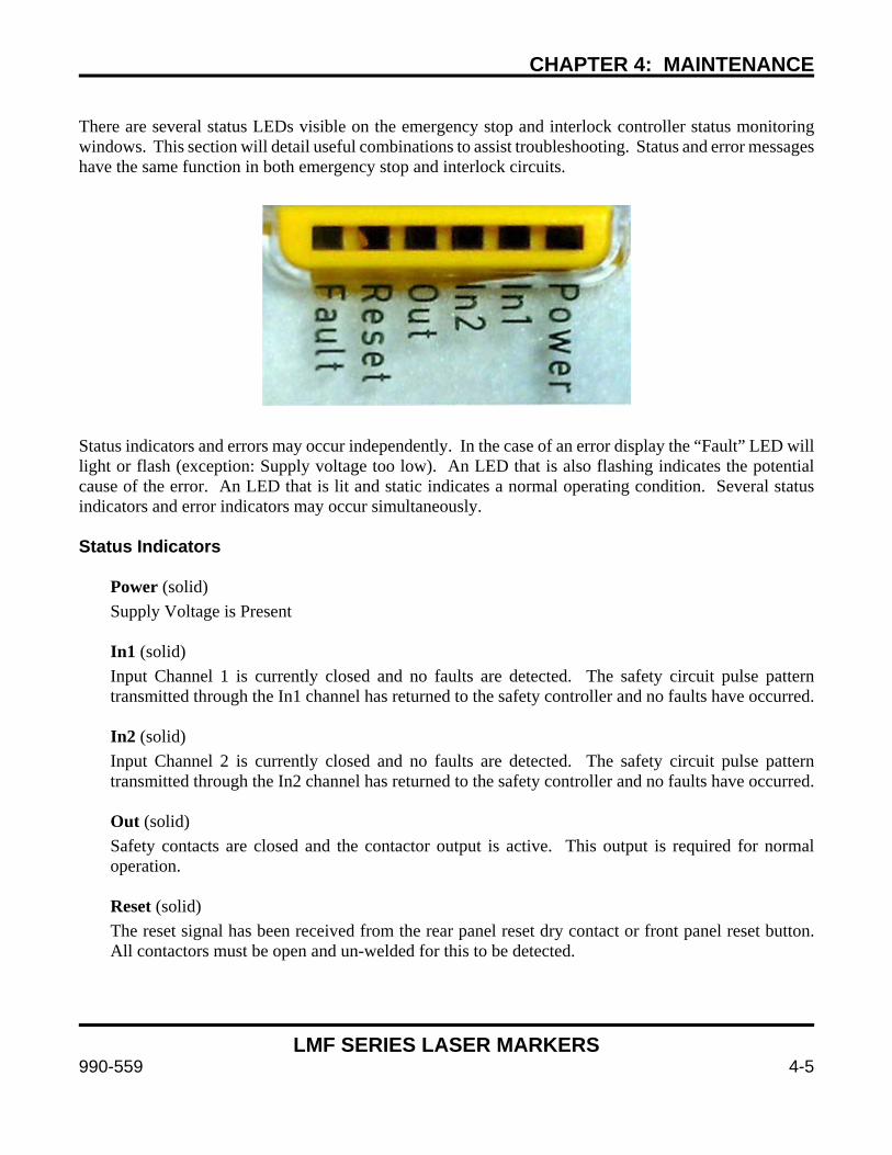
CHAPTER 4: MAINTENANCE
LMF SERIES LASER MARKERS
990-559 4-5
There are several status LEDs visible on the emergency stop and interlock controller status monitoring windows. This section will detail useful combinations to assist troubleshooting. Status and error messages have the same function in both emergency stop and interlock circuits.
Status indicators and errors may occur independently. In the case of an error display the “Fault” LED will light or flash (exception: Supply voltage too low). An LED that is also flashing indicates the potential cause of the error. An LED that is lit and static indicates a normal operating condition. Several status indicators and error indicators may occur simultaneously. Status Indicators
Power (solid) Supply Voltage is Present
In1 (solid) Input Channel 1 is currently closed and no faults are detected. The safety circuit pulse pattern transmitted through the In1 channel has returned to the safety controller and no faults have occurred.
In2 (solid) Input Channel 2 is currently closed and no faults are detected. The safety circuit pulse pattern transmitted through the In2 channel has returned to the safety controller and no faults have occurred. Out (solid) Safety contacts are closed and the contactor output is active. This output is required for normal operation. Reset (solid) The reset signal has been received from the rear panel reset dry contact or front panel reset button. All contactors must be open and un-welded for this to be detected.

CHAPTER 4: MAINTENANCE
LMF SERIES LASER MARKERS
4-6 990-559
Error Indicators and Suggested Resolution
Contact Malfunctions If the monitored AC contactor or safety controller contacts have welded together you will not be able to reactivate the circuit. Replace the necessary components.
All LEDs off Short across contacts to ground or unit switched off. Fix any shorts and switch off supply voltage for 1 minute. Verify the fuse block at the marker AC Input to verify correct input power. Fault (solid) Others (off) Safety controller plug terminator not connected. This situation not applicable to the marker. Contact Amada Miyachi America if this error occurs. Fault (flashing) Others (off) Internal error, safety controller defective or damaged. Verify no miswires in user wiring and replace safety controller. The most common cause is improper voltage or current applied to dry contact inputs via the interlock, reset, or emergency stop headers. Use dry contact closures only. Power (flashing) Internal error in marker power supply. Contact Amada Miyachi America for assistance. In1, In2 (flashing alternately) Fault (solid) Short detected between channel 1 and channel 2. Shut down marker power, rectify short across contacts, and try again. In 1 (flashing) Fault (solid) Open circuit detected in channel 1 or input circuits not closed simultaneously. An intermittent connection in channel 1 is also possible. To resolve, open both input circuits and close simultaneously. In 2 (flashing) Fault (solid) Open circuit detected in channel 2 or input circuits not closed simultaneously. An intermittent connection in channel 2 is also possible. To resolve, open both input circuits and close simultaneously.
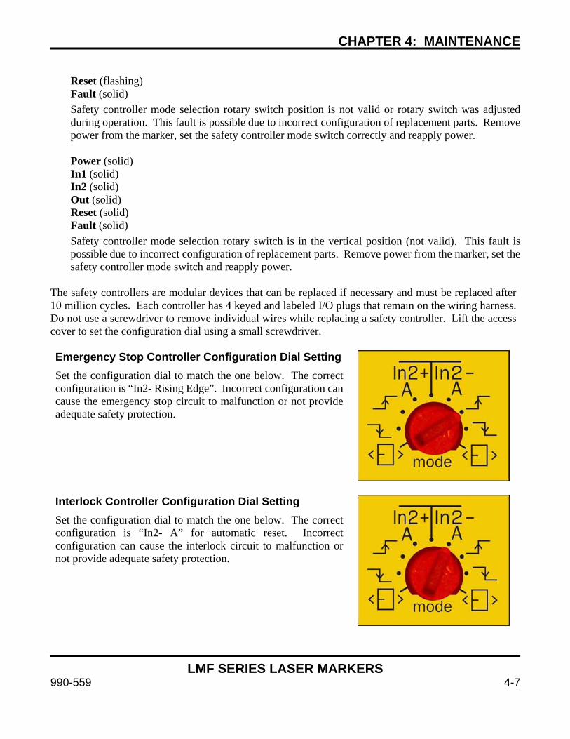
CHAPTER 4: MAINTENANCE
LMF SERIES LASER MARKERS
990-559 4-7
Reset (flashing) Fault (solid) Safety controller mode selection rotary switch position is not valid or rotary switch was adjusted during operation. This fault is possible due to incorrect configuration of replacement parts. Remove power from the marker, set the safety controller mode switch correctly and reapply power.
Power (solid) In1 (solid) In2 (solid) Out (solid) Reset (solid) Fault (solid) Safety controller mode selection rotary switch is in the vertical position (not valid). This fault is possible due to incorrect configuration of replacement parts. Remove power from the marker, set the safety controller mode switch and reapply power.
The safety controllers are modular devices that can be replaced if necessary and must be replaced after 10 million cycles. Each controller has 4 keyed and labeled I/O plugs that remain on the wiring harness. Do not use a screwdriver to remove individual wires while replacing a safety controller. Lift the access cover to set the configuration dial using a small screwdriver. Emergency Stop Controller Configuration Dial Setting Set the configuration dial to match the one below. The correct configuration is “In2- Rising Edge”. Incorrect configuration can cause the emergency stop circuit to malfunction or not provide adequate safety protection.
Interlock Controller Configuration Dial Setting Set the configuration dial to match the one below. The correct configuration is “In2- A” for automatic reset. Incorrect configuration can cause the interlock circuit to malfunction or not provide adequate safety protection.

CHAPTER 4: MAINTENANCE
LMF SERIES LASER MARKERS
4-8 990-559
Section IV: Cover Glass Cleaning Instructions and Lens Installation
Each f-theta lens is equipped with an optically-coated protective glass. When marking materials over a period of time, many of the airborne particles produced during the marking process can dirty or fog the protective glass. It is important to keep the protective glass clean. If the protective glass is dirty and continually used, the contaminants may permanently damage the glass surface. When cleaning the surface, use only lens cleaning paper. A scratched glass surface will cause undesirable marking results.
CAUTION
To prevent dust contamination, always wear powder free latex gloves before performing any steps involving optics. Perform the following steps in a location free of dust or other airborne contaminants.
Cover Glass Cleaning Required Items:
Lens Cleaning Paper (AMYA # 900-314 or equivalent) Lens Cleaning solution (AMYA # 900-342 or equivalent) or Acetone Air Blower Powder-free Vinyl / Nitrile Gloves or Finger Cots
1. Turn the power OFF.
2. Turn the protective glass holder CCW (counter-clockwise) to remove it. Take care not to drop it.
NOTE: Before you clean the protective glass, put on a pair of powder-free vinyl gloves or finger cots.
3. Clean the cover glass with lens paper and appropriate solvents.
When cleaning, draw a spiral pattern from the center of the glass as shown below.
NOTE: If you cannot get the protective glass clean after several attempts, replace the protective glass.
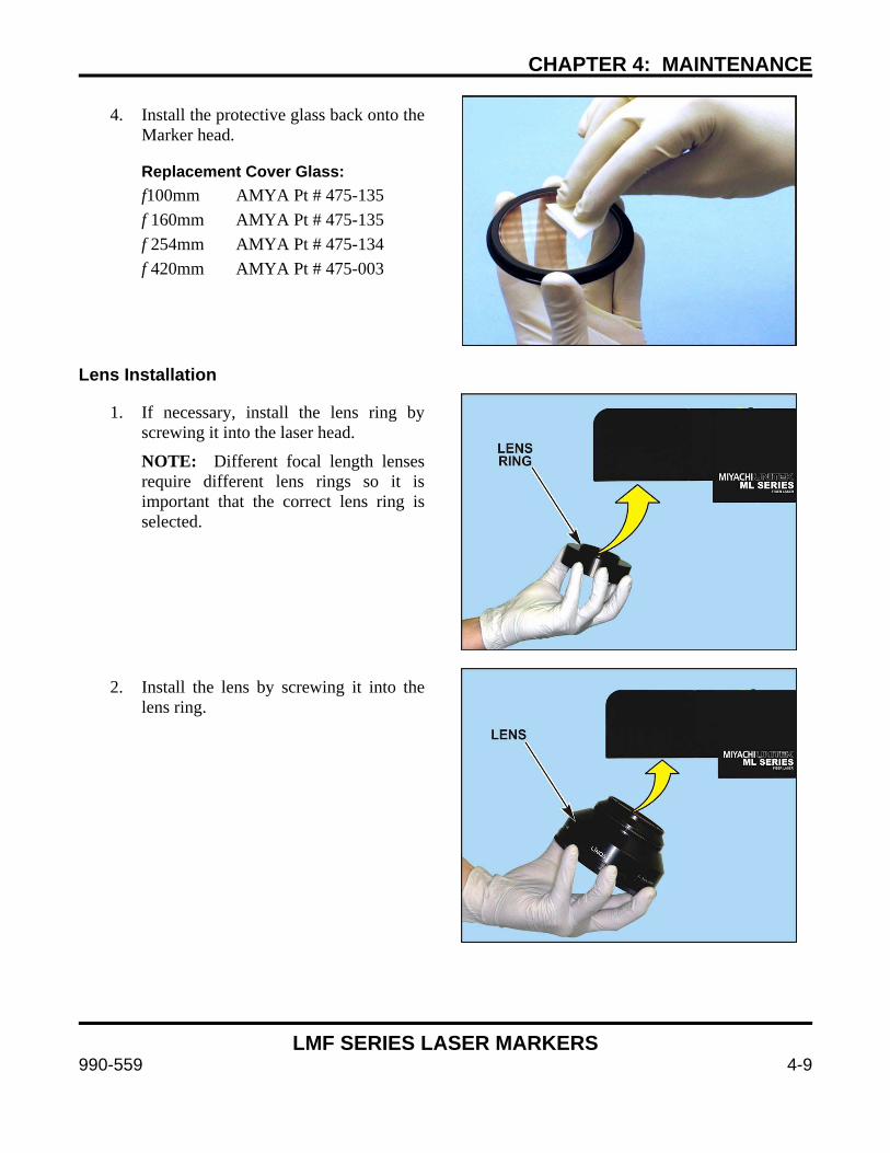
CHAPTER 4: MAINTENANCE
LMF SERIES LASER MARKERS
990-559 4-9
4. Install the protective glass back onto the Marker head.
Replacement Cover Glass: f100mm AMYA Pt # 475-135 f 160mm AMYA Pt # 475-135 f 254mm AMYA Pt # 475-134 f 420mm AMYA Pt # 475-003
Lens Installation
1. If necessary, install the lens ring by screwing it into the laser head.
NOTE: Different focal length lenses require different lens rings so it is important that the correct lens ring is selected.
2. Install the lens by screwing it into the lens ring.

CHAPTER 4: MAINTENANCE
LMF SERIES LASER MARKERS
4-10 990-559
Section V: Remove / Install the Collimator
Removing the Collimator
1. Loosen the clamp screw to allow for collimator removal.
2. Remove the collimator/isolator assembly from the head. Slight force will be required to overcome friction with the O-rings.
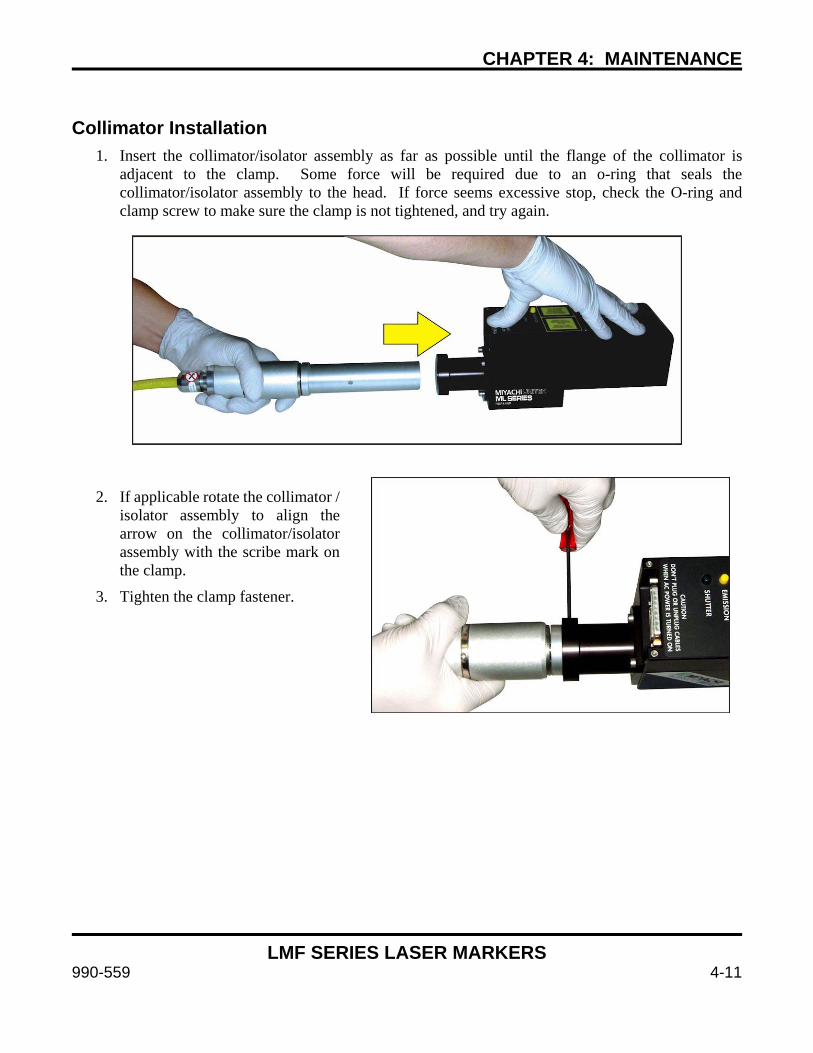
CHAPTER 4: MAINTENANCE
LMF SERIES LASER MARKERS
990-559 4-11
Collimator Installation
1. Insert the collimator/isolator assembly as far as possible until the flange of the collimator is adjacent to the clamp. Some force will be required due to an o-ring that seals the collimator/isolator assembly to the head. If force seems excessive stop, check the O-ring and clamp screw to make sure the clamp is not tightened, and try again.
2. If applicable rotate the collimator /
isolator assembly to align the arrow on the collimator/isolator assembly with the scribe mark on the clamp.
3. Tighten the clamp fastener.
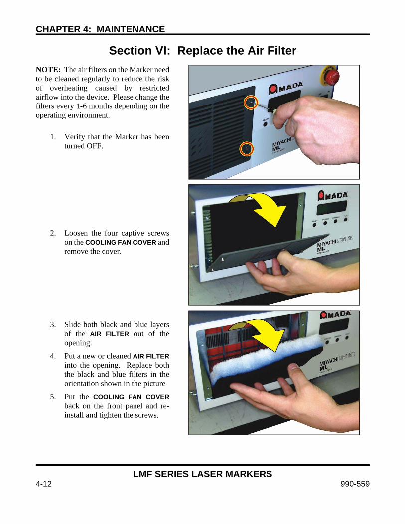
CHAPTER 4: MAINTENANCE
LMF SERIES LASER MARKERS
4-12 990-559
Section VI: Replace the Air Filter NOTE: The air filters on the Marker need to be cleaned regularly to reduce the risk of overheating caused by restricted airflow into the device. Please change the filters every 1-6 months depending on the operating environment.
1. Verify that the Marker has been turned OFF.
2. Loosen the four captive screws on the COOLING FAN COVER and remove the cover.
3. Slide both black and blue layers of the AIR FILTER out of the opening.
4. Put a new or cleaned AIR FILTER into the opening. Replace both the black and blue filters in the orientation shown in the picture
5. Put the COOLING FAN COVER back on the front panel and re-install and tighten the screws.
CHAPTER 4: MAINTENANCE
LMF SERIES LASER MARKERS
990-559 4-13
Section VII: Firmware Update
WARNING
When updating the marker firmware, all files stored locally on the marker will be lost. Backup all job files that have been stored in the marker’s flash memory.
From time to time, Lanmark Controls, Inc. will release an updated version of the firmware that is resident on the Controller Card inside the Laser Marker. This update may be in the form of a single file, or a web link. The Firmware update procedure needs to be completed in a specific way. An incorrect update will render the Controller Card inoperable and will need to be sent back to the factory for repair. Use extreme caution when updating the firmware in your Laser Marker. Please contact Amada Miyachi America for the latest update procedure. See CONTACT US in the front of this guide to get in touch with us by e-mail, telephone, or regular mail. In order to determine which Firmware Update Procedure you’ll need, please determine the model number of your Marker, then use the table below to determine the correct procedure to use:
LMF Marker Controller Correct Firmware Procedure 8-79-xLx-xxx LEC-1 2.x.x.x
MFG-364 (firmware update) 8-79-xBx-xxx LEC-1 Platform 6 6.x.x.x 8-79-xCx-xxx LEC-2 Advanced
7.x.x.x MFG-372 (replacement) MFG-382 (firmware update 7.1.2)
8-79-xDx-xxx LEC-2 Standard 8-79-xEx-xxx LEC-2 Basic

CHAPTER 4: MAINTENANCE
LMF SERIES LASER MARKERS
4-14 990-559
Section VIII: Repair Service If you have problems with your Laser Marker that you cannot resolve, please contact Amada Miyachi America; see CONTACT US in the front of this guide to get in touch with us by e-mail, telephone, or regular mail.
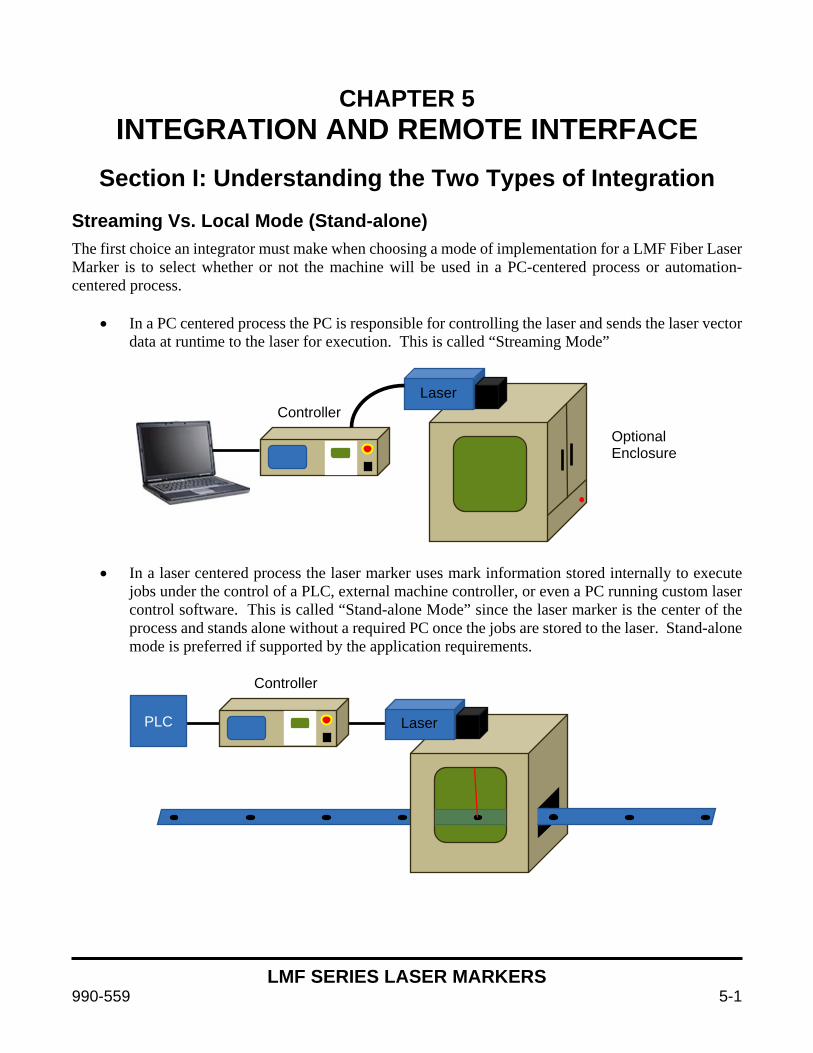
LMF SERIES LASER MARKERS
990-559 5-1
CHAPTER 5 INTEGRATION AND REMOTE INTERFACE
Section I: Understanding the Two Types of Integration
Streaming Vs. Local Mode (Stand-alone) The first choice an integrator must make when choosing a mode of implementation for a LMF Fiber Laser Marker is to select whether or not the machine will be used in a PC-centered process or automation-centered process.
• In a PC centered process the PC is responsible for controlling the laser and sends the laser vector data at runtime to the laser for execution. This is called “Streaming Mode”
• In a laser centered process the laser marker uses mark information stored internally to execute jobs under the control of a PLC, external machine controller, or even a PC running custom laser control software. This is called “Stand-alone Mode” since the laser marker is the center of the process and stands alone without a required PC once the jobs are stored to the laser. Stand-alone mode is preferred if supported by the application requirements.
Laser Controller
Controller
PLC Laser
Optional Enclosure
CHAPTER 5: INTEGRATION AND REMOTE INTERFACE
LMF SERIES LASER MARKERS
5-2 990-559
Streaming Mode Summary of Options - See Section III of This Chapter • The WinLase LAN™ GUI (Graphical User Interface) streams data at run time from the PC to the
laser marker when the operator uses the “Run” or “Quickmark” options. I/O for basic automation is supported.
• COM Server – A Streaming Mode variant that allows the user to program their own GUI to substitute for WinLase using a DLL library. Sometimes used for custom applications or processes requiring a customized user interface via PC. See details in the COM server manual installed in C:\marker\documentation provided via the WinLase install package. This has the highest initial requirements since a programmer must integrate laser DLL libraries to control the machine. This implementation is not recommended in most cases as it is easier and better to write a custom application that uses the Stand-alone mode interface.
• Streaming Mode HostLAN Interface –The Host interface is another way to interface with WinLase streaming mode over TCP/IP or RS-232. It uses a command set similar to the Remote Command API and requires a PC with WinLase running to interface to the external controller. The PC running WinLase software must be present at all times with WinLase running in the background. This interface can be used in situations where the Remote Command API may not support a specific feature. In all other situations the Remote Command API is preferable.
Stand-alone Mode Summary of Options - See Section IV of this chapter For all Stand-alone implementations the jobs are first created then stored in the laser marker storage. The external interface calls jobs, manipulates data, and executes processes under the direction of control equipment or custom PC software.
• Remote Command API (Application Programming Interface), for interaction with a PC or PLC through TCP/IP (Client/Server) or RS-232. In API Mode the data can be stored locally on the laser’s Flash memory and/or USB storage, or loaded remotely over the network. A PC running WinLase software is required only for setup but not for operation. When possible this is the preferred mode of operation due to speed and efficiency of laser marking processes. See Section III of this chapter.
• I/O Job Select Mode – up to 255 jobs can be stored on the laser marker and executed using simple I/O. It is possible to combine this mode with API commands for advanced data handling while still selecting jobs via I/O. This mode has the same speed and performance benefits as the Remote API.
It is the responsibility of the system integrator to choose the correct mode for the desired process. To ease in this choice, a Mode Selection Flowchart is included in Section II of this chapter. Please use this to determine which mode is best for your implementation. Consult Amada Miyachi America if questions arise.
Be aware that, due to the architecture differences between the modes, some features may be available in one mode but not another. Please consult the Feature Compatibility chart in this section.
Modes requiring data stored on the laser marker must keep individual job sizes under 10MB. 10MB of onboard flash storage is available and USB storage up to 2GB can be used to increase capacity. Large jobs over 10MB in size must be executed in streaming mode.

CHAPTER 5: INTEGRATION AND REMOTE INTERFACE
LMF SERIES LASER MARKERS
990-559 5-3
Section II: Selecting the Best Interface Mode For Your Application
How does one select the best mode for an application? Ask These Questions:
1. Is there data that changes from part to part?
2. Where does that data come from, and who puts it in?
3. How does the operator interface with and control the laser? Will standard WinLase allow for the desired experience? Is custom software required?
4. Are there any specific features in the desired mark that have mode compatibility considerations? (e.g., mark on the fly, marker motion, etc).
NOTE: See the compatibility matrix in this section to verify that all features needed work in the chosen mode.
To Make a Selection
• Answer the questions above, and follow the “Integration Mode” flowchart in this section.
• For simple systems (laser and enclosure) the streaming mode is preferred. This mode supports barcode scanner and operator input among other methods.
• For automated systems or systems accessing databases, files, etc. the Stand-alone mode is preferred. PLC controlled assembly lines require Stand-alone mode.
• Specific customer interface/process requirements require a custom program with an interface that uses Stand-alone mode.
• Some features (like Mark on the Fly) make the decision for you. Always verify features against the compatibility chart included in this section.
Once the decision between streaming and Stand-alone mode has been made there are several options on how to accomplish machine integration. Note that it is often possible to combine multiple interface modes to achieve the desired results.
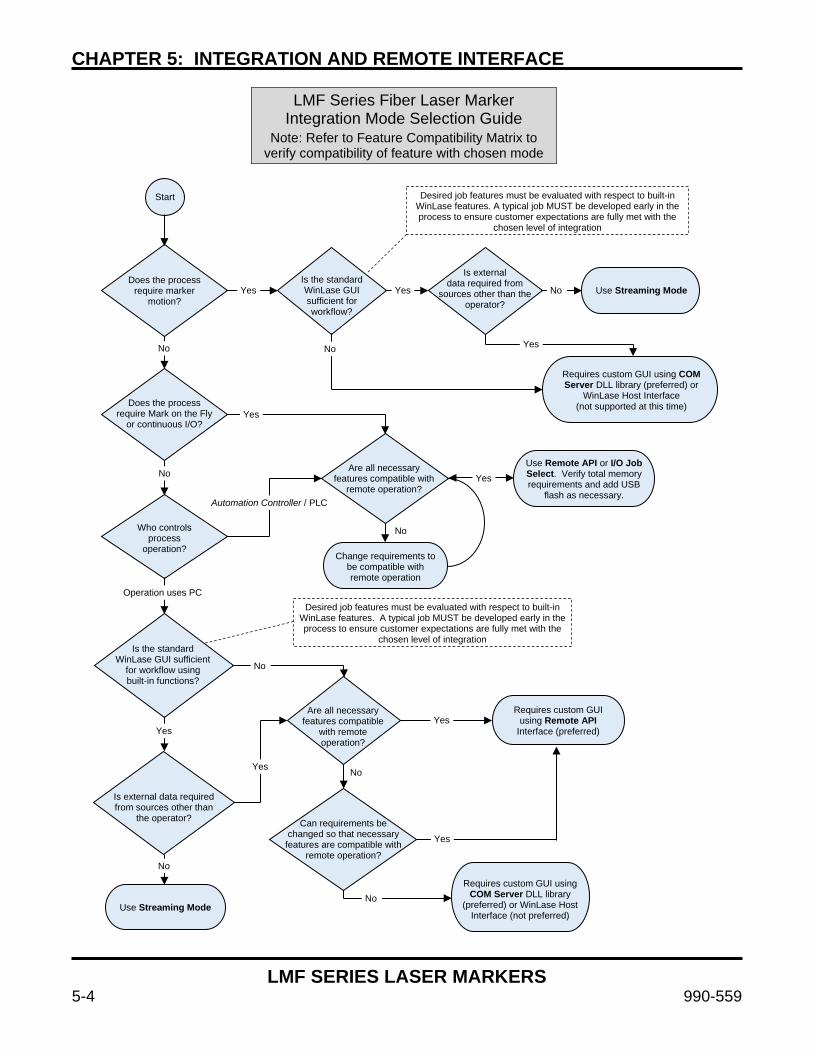
CHAPTER 5: INTEGRATION AND REMOTE INTERFACE
LMF SERIES LASER MARKERS
5-4 990-559
LMF Series Fiber Laser Marker Integration Mode Selection Guide
Note: Refer to Feature Compatibility Matrix to verify compatibility of feature with chosen mode
Does the process require marker
motion?
Is the standard WinLase GUI sufficient for workflow?
Is external data required from
sources other than the operator?
Does the process require Mark on the Fly
or continuous I/O?
Are all necessary features compatible with
remote operation?
Start
Use Streaming Mode
Requires custom GUI using COM Server DLL library (preferred) or
WinLase Host Interface (not supported at this time)
Use Remote API or I/O Job Select. Verify total memory requirements and add USB
flash as necessary.
Who controls process
operation? Change requirements to
be compatible with remote operation
Is the standard WinLase GUI sufficient
for workflow using built-in functions?
Are all necessary features compatible
with remote operation?
Desired job features must be evaluated with respect to built-in WinLase features. A typical job MUST be developed early in the process to ensure customer expectations are fully met with the
chosen level of integration
Yes Yes No
Yes No No
Yes
No Yes
Automation Controller / PLC
No
Operation uses PC Desired job features must be evaluated with respect to built-in
WinLase features. A typical job MUST be developed early in the process to ensure customer expectations are fully met with the
chosen level of integration
No
Requires custom GUI using Remote API
Interface (preferred) Yes
Yes
Is external data required from sources other than
the operator?
No Yes
Can requirements be changed so that necessary
features are compatible with remote operation?
Use Streaming Mode
Requires custom GUI using COM Server DLL library
(preferred) or WinLase Host Interface (not preferred)
No
No
Yes
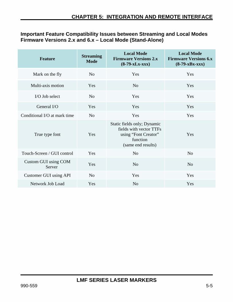
CHAPTER 5: INTEGRATION AND REMOTE INTERFACE
LMF SERIES LASER MARKERS
990-559 5-5
Important Feature Compatibility Issues between Streaming and Local Modes Firmware Versions 2.x and 6.x – Local Mode (Stand-Alone)
Feature Streaming Mode
Local Mode Firmware Versions 2.x
(8-79-xLx-xxx)
Local Mode Firmware Versions 6.x
(8-79-xBx-xxx)
Mark on the fly No Yes Yes
Multi-axis motion Yes No Yes
I/O Job select No Yes Yes
General I/O Yes Yes Yes
Conditional I/O at mark time No Yes Yes
True type font Yes
Static fields only; Dynamic fields with vector TTFs
using “Font Creator” function
(same end results)
Yes
Touch-Screen / GUI control Yes No No
Custom GUI using COM Server Yes No No
Customer GUI using API No Yes Yes
Network Job Load Yes No Yes
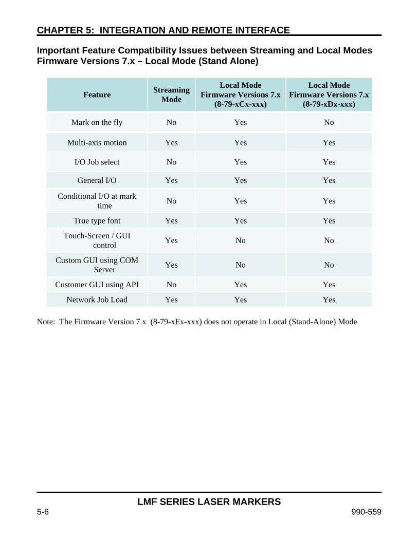
CHAPTER 5: INTEGRATION AND REMOTE INTERFACE
LMF SERIES LASER MARKERS
5-6 990-559
Important Feature Compatibility Issues between Streaming and Local Modes Firmware Versions 7.x – Local Mode (Stand Alone)
Feature Streaming Mode
Local Mode Firmware Versions 7.x
(8-79-xCx-xxx)
Local Mode Firmware Versions 7.x
(8-79-xDx-xxx)
Mark on the fly No Yes No
Multi-axis motion Yes Yes Yes
I/O Job select No Yes Yes
General I/O Yes Yes Yes
Conditional I/O at mark time No Yes Yes
True type font Yes Yes Yes
Touch-Screen / GUI control Yes No No
Custom GUI using COM Server Yes No No
Customer GUI using API No Yes Yes
Network Job Load Yes Yes Yes Note: The Firmware Version 7.x (8-79-xEx-xxx) does not operate in Local (Stand-Alone) Mode
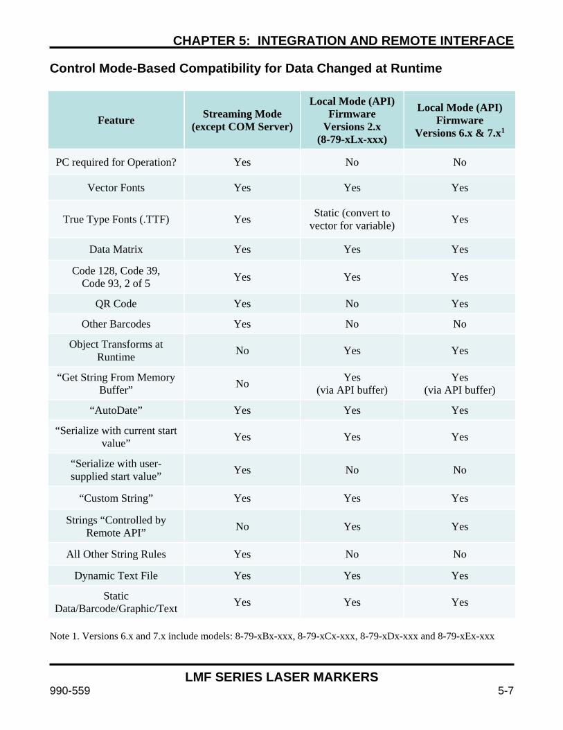
CHAPTER 5: INTEGRATION AND REMOTE INTERFACE
LMF SERIES LASER MARKERS
990-559 5-7
Control Mode-Based Compatibility for Data Changed at Runtime
Feature Streaming Mode (except COM Server)
Local Mode (API) Firmware
Versions 2.x (8-79-xLx-xxx)
Local Mode (API) Firmware
Versions 6.x & 7.x1
PC required for Operation? Yes No No
Vector Fonts Yes Yes Yes
True Type Fonts (.TTF) Yes Static (convert to vector for variable) Yes
Data Matrix Yes Yes Yes
Code 128, Code 39, Code 93, 2 of 5 Yes Yes Yes
QR Code Yes No Yes
Other Barcodes Yes No No
Object Transforms at Runtime No Yes Yes
“Get String From Memory Buffer” No Yes
(via API buffer) Yes
(via API buffer)
“AutoDate” Yes Yes Yes
“Serialize with current start value” Yes Yes Yes
“Serialize with user-supplied start value” Yes No No
“Custom String” Yes Yes Yes
Strings “Controlled by Remote API” No Yes Yes
All Other String Rules Yes No No
Dynamic Text File Yes Yes Yes
Static Data/Barcode/Graphic/Text Yes Yes Yes
Note 1. Versions 6.x and 7.x include models: 8-79-xBx-xxx, 8-79-xCx-xxx, 8-79-xDx-xxx and 8-79-xEx-xxx
CHAPTER 5: INTEGRATION AND REMOTE INTERFACE
LMF SERIES LASER MARKERS
5-8 990-559
Section III: Streaming Mode and the WinLase LAN GUI
The WinLase LAN Software includes the following: • WinLase Graphical User Interface • Lanmark Controls Inc. COM server object interface. • Full documentation on the features of the included software tools. See
C:\marker\documentation, created with the WinLase package installation. GUI (Graphical User Interface) Features WinLase elements include:
• Line-art graphics: CAD, line-drawings, logos. • Shaded graphics: photos, halftones & grayscale artwork. • TrueType fonts, filled or outline-only. • Single point or drill object arrays. • AutoDate, TextMerge, Serialization, and Barcode. • Automation: I/O control, 4-axis motor control, time delays, and custom operator messages.
WinLase facilitates the creation, editing, control, execution, and automation of all laser-marking tasks. The WinLase™ Software Suite includes the following features:
• Password-protected security lockout -- operators can be limited to only selected and running Jobs.
• Multiple open Jobs -- quickly switch between marking tasks with the click of a mouse. • Background template -- place an image of the parts tooling in the background to aid in mark
placement. • Full support for lasers with visible pointers for real time positioning of the mark. • HPGL (*.plt), WMF (*.wmf) EMF (*.emf), DXF (*.dxf), EPS (*.eps), JPEG (*.jpg), GIF
(*.gif), PCX (*.pcx), Adobe Illustrator (*.AI), Corel Draw (*.CDR) and Windows Bitmap (*.bmp) graphic filters.
• Internal capability to generate linear and radial text, barcodes, AutoDate™, serialization, and hole-drilling.
• Complete TrueType font support -- mark any TrueType font installed on the system. • Scale, move, rotate, group, or reverse any object on the screen. • Precise numerical control of laser-operation parameters. • Programmable alerts, warning, and run-time operator input of job numbers, batch numbers, etc. • Built-in 4-axis motor control -- use rotary tables, linear motion, and/or X-Y tables. • Text marking on cylindrical parts using an optional rotary indexer.
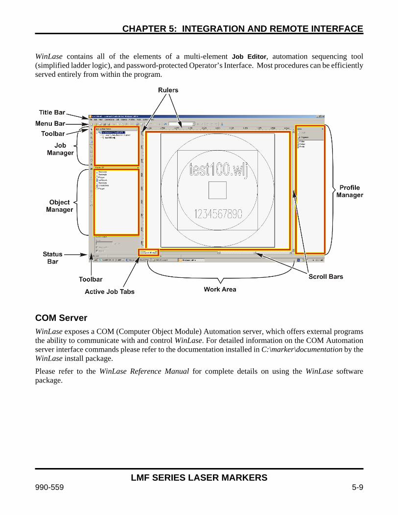
CHAPTER 5: INTEGRATION AND REMOTE INTERFACE
LMF SERIES LASER MARKERS
990-559 5-9
WinLase contains all of the elements of a multi-element Job Editor, automation sequencing tool (simplified ladder logic), and password-protected Operator’s Interface. Most procedures can be efficiently served entirely from within the program.
COM Server WinLase exposes a COM (Computer Object Module) Automation server, which offers external programs the ability to communicate with and control WinLase. For detailed information on the COM Automation server interface commands please refer to the documentation installed in C:\marker\documentation by the WinLase install package.
Please refer to the WinLase Reference Manual for complete details on using the WinLase software package.
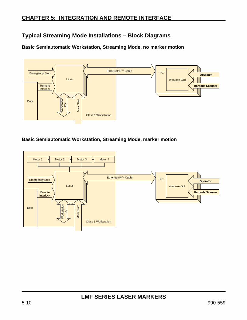
CHAPTER 5: INTEGRATION AND REMOTE INTERFACE
LMF SERIES LASER MARKERS
5-10 990-559
Typical Streaming Mode Installations – Block Diagrams Basic Semiautomatic Workstation, Streaming Mode, no marker motion Basic Semiautomatic Workstation, Streaming Mode, marker motion
Laser
PC
WinLase GUI
Operator
Barcode Scanner
EtherNet/IPTM Cable Emergency Stop
Remote Interlock
Class 1 Workstation
Door
Wor
ksta
tion
I/O
Mar
k S
tart
Motor 1 Motor 2 Motor 3 Motor 4
Laser
PC
WinLase GUI
EtherNet/IPTM Cable Emergency Stop Operator
Barcode Scanner Remote Interlock
Door
Class 1 Workstation
Wor
ksta
tion
I/O
Mar
k S
tart

CHAPTER 5: INTEGRATION AND REMOTE INTERFACE
LMF SERIES LASER MARKERS
990-559 5-11
Integration Notes: Semiautomatic Workstation Operating In Streaming Mode This style workstation is used for a process flow where an operator loads/unloads part(s) into a laser safe workstation and initiates the process start. Once the process has been concluded the doors will open and the operator will remove the part(s), insert the next batch, and continue.
• The operator loads the program using the WinLase GUI and selects the appropriate program. Programs should be configured to watch for the cycle start input.
• The operator begins the mark sequence by clicking “Run Process” in WinLase, after which WinLase will look for the Cycle Start input.
• Typically a Cycle Start button is used to begin the marking process so the operator does not need to use the PC between marks.
• Any necessary information will be entered by the operator in response to prompts on the PC monitor using the keyboard or barcode reader.
• Automated data input difficult – see Host or API modes for more information.
• All functions must be compatible with streaming mode. See WinLase Mode feature compatibility chart.
• Class I enclosure interlocks and emergency stop must be wired to laser. Interlock monitoring in laser should be enabled.
• Streaming mode includes network and data streaming delays that can increase average process time up to 300ms.
• Compatible with up to 4 axes of marker motion.
CHAPTER 5: INTEGRATION AND REMOTE INTERFACE
LMF SERIES LASER MARKERS
5-12 990-559
Section IV: Using the Remote Command API to Control
the Laser Marker in Stand-alone Mode Remote Command API The LEC embedded control card was designed to be a powerful Stand-alone controller with the ability to accept commands and return responses. The Remote Command API provides extended functionality to load jobs, manipulate marking objects, change administration settings, and many other functions.
There are two methods available for interfacing with the Remote Command API while in Local/Stand-alone mode:
• Message based TCP/IP socket connection • Message based RS-232 connection
All commands are ASCII based and follow the simple command/response handshake. Each command has an ASCII code that is used to assert the command. For example, TakeHostControl uses the ASCII code “2”. To call TakeHostControl the user would send a “2” followed by carriage return/line feed and wait for the response of “0”, or Command Success.
All interfaces are active simultaneously for interacting with the Remote Command API.
All interfaces support making calls to get parameters. Some commands, however require the client to "Take Control" of the LEC Host device. When a client has control, the client can send execution commands as well as commands to set parameters.
It is also common for one client to send certain commands (ex, populate serial number data) that do not require host control while a different client is in control (ex, PLC in I/O Job Selection mode) Using the API The LEC Remote Command API uses a message based communication protocol. The client (your program / PLC) and the Host (the LEC) must cooperate by sending messages back and forth in an alternating fashion. Specifically, after a command is sent by the client, the client must wait for a response from the Host. That response indicates the success (or failure) of the current command. It is illegal to send a new command to the Host before the previous command has been acknowledged with a response, and will result in undefined behavior.
Messages sent to the Host are text strings, and must end with a line feed. Messages received from the Host are text strings and end in a line feed. For all commands except SetObjectUTF8String, character data must be sent using either 7-bit Encoding (ASCII 0 - 127) or 8-bit Encoding (ASCII 0 - 255). To send extended character data when setting the string value of test or barcode objects, encode the character data to send using UTF-8 Encoding, and use the SetObjectUTF8String command.
The Remote Command API provides a rich set of commands for communication and control of an LEC. The API allows you to get and set system parameters, as well as perform actions with locally stored job files, and to control the behavior of individual objects within job files.
CHAPTER 5: INTEGRATION AND REMOTE INTERFACE
LMF SERIES LASER MARKERS
990-559 5-13
If you are loading and controlling the execution of locally stored jobs, use the TakeHostControl command to gain exclusive access to the server. Use the GetFlashJobFileList or GetUSBJobFileList commands to discover the locally stored job files.
Use the LoadJobFromFlash or LoadJobFromUSB command to load a job into memory. To select a job previously loaded into memory for execution, use the MakeJobActive command. An active job can be executed by using the ExecuteJobOnce or ExecuteJobContinuous commands. When you are finished sending and receiving commands, use the Abort command and then the ReleaseHostControl command to allow other hosts exclusive access to the device.
To read the status of server parameters, use any of the Get commands. Most of these commands do not require the client to have exclusive access to the server (Host).
To set server parameters, use the TakeHostControl command to gain exclusive access to the server. Use any of the Set commands to make changes to server parameters. When you are finished setting parameters, use the ReleaseHostControl command to allow other hosts access to the API. If any IP settings have been changed, these settings will not take effect until the board goes through a power cycle, or you call HardwareReset. Note: Depending on the LEC Firmware version, some API Commands may not be supported. Please refer to Appendix D for a list of supported API Commands based on Firmware version.
8-79-xLx-xxx - Firmware version 2.x 8-79-xBx-xxx - Firmware version 6.x 8-79-xCx-xxx - Firmware version 7.x 8-79-xDx-xxx - Firmware version 7.x 8-79-xEx-xxx - Firmware version 7.x
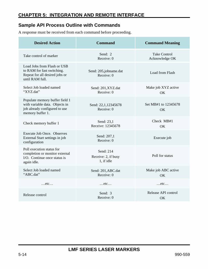
CHAPTER 5: INTEGRATION AND REMOTE INTERFACE
LMF SERIES LASER MARKERS
5-14 990-559
Sample API Process Outline with Commands A response must be received from each command before proceeding.
Desired Action Command Command Meaning
Take control of marker Send: 2 Receive: 0
Take Control Acknowledge OK
Load Jobs from Flash or USB to RAM for fast switching. Repeat for all desired jobs or until RAM full.
Send: 205,jobname.dat Receive: 0 Load from Flash
Select Job loaded named “XYZ.dat”
Send: 201,XYZ.dat Receive: 0
Make job XYZ active OK
Populate memory buffer field 1 with variable data. Objects in job already configured to use memory buffer 1.
Send: 22,1,12345678 Receive: 0
Set MB#1 to 12345678 OK
Check memory buffer 1 Send: 23,1 Receive: 12345678
Check MB#1 OK
Execute Job Once. Observes External Start settings in job configuration
Send: 207,1 Receive: 0 Execute job
Poll execution status for completion or monitor external I/O. Continue once status is again idle.
Send: 214 Receive: 2, if busy
1, if idle Poll for status
Select Job loaded named “ABC.dat”
Send: 201,ABC.dat Receive: 0
Make job ABC active OK
…etc… …etc… …etc…
Release control Send: 3 Receive: 0
Release API control OK
CHAPTER 5: INTEGRATION AND REMOTE INTERFACE
LMF SERIES LASER MARKERS
990-559 5-15
Tips on using the TCP/IP Interface In order for you to communicate with the LEC over TCP/IP, you must know the IP address and Port of the LEC.
By default, the LEC makes the Remote Command API Interface service available on Port 12500. The LEC can be configured to use a Static IP address, or to request an IP address each time it starts from a DHCP server. It is recommended in situations where the LAN-based Remote Command API is used, to configure Static IP addressing for the LEC. Using this approach, the Remote Command API client will know the IP address of the LEC without having to use other discovery techniques.
Remote control of the LEC can be established by any client computer that supports TCP/IP networking. This includes computers running Microsoft Windows, Linux, or other operating systems. Communication with the board is established by opening a socket connection using the IP address on port 12500. API Command Set The complete list of API commands is located in Appendix D. The interface provided by the Remote Command API is a message (character string) based protocol. All command strings must be terminated by a line feed, and all response strings are terminated by a line feed. The following list describes all the Remote Interface commands and their intended use, and is sorted in alphabetical order. Commands with multiple parameters are sent in comma delimited format, and responses with multiple parameters are returned in comma delimited format.
Note that all commands are text strings and are expressed in the table enclosed in quotes (" "). The quotation characters are NOT part of the command. This is also true for responses. Commands and arguments are case-sensitive.
The following convention will be used when indicating additional parameters: For example, to set the local IP address:
"506,ipaddress" is sent to the API as 506,192.168.42.1 (without exclamation marks).
A description of the command parameters follows each command.
CHAPTER 5: INTEGRATION AND REMOTE INTERFACE
LMF SERIES LASER MARKERS
5-16 990-559
Remote Command API List For the complete list of commands, see Appendix D, Remote Interface Commands. I/O Job Selection – Up to 255 Jobs I/O job selection timing can be found in Appendix B, Connections. Software configuration is covered in Chapter 3, Operating Instructions. I/O Job Selection allows the user to set an 8-bit bit pattern from 1-255 and load jobs using the Job Load input. The user observes the marker’s Job Ready for Mark output to determine the job load status. Job 0 can be used as an abort/clear or to reset the system after an interlock event.
There are two performance modes in I/O Job Select – Standard and Cached. In standard mode the jobs are loaded from flash or USB memory to RAM at the time of the job load command. This requires additional time as the jobs are loaded but you can have > 10MB of jobs available. In cached mode the laser marker caches all jobs in RAM at boot time and ensures switching times < 25ms. This can only be performed when the amount memory required is less than available RAM, typically 10MB. Use Cached mode for a small number of jobs that need to be switched between rapidly and standard mode when speed is not required or many jobs are necessary.
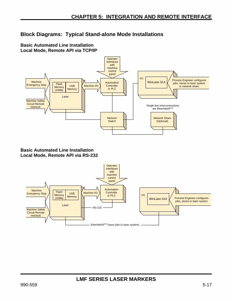
CHAPTER 5: INTEGRATION AND REMOTE INTERFACE
LMF SERIES LASER MARKERS
990-559 5-17
Block Diagrams: Typical Stand-alone Mode Installations Basic Automated Line Installation Local Mode, Remote API via TCP/IP Basic Automated Line Installation Local Mode, Remote API via RS-232
Machine Emergency Stop Flash
Memory (10Mb)
USB Memory
Laser
Operator interfaces
with machine control panel
Automation Controller
or PLC Machine I/O
WinLase GUI
PC Process Engineer configures jobs, stores to laser system
or network share
Machine Safety Circuit Remote
Interlock
Network Switch
Network Share (Optional)
Single line Interconnections are EtherNet/IPTM
Flash Memory (10Mb)
USB Memory
Machine Emergency Stop Machine I/O
Operator interfaces
with machine control panel
Automation Controller
or PLC WinLase GUI
PC Process Engineer configures jobs, stores to laser system
Laser Machine Safety Circuit Remote
Interlock
RS-232
EtherNet/IPTM (save jobs to laser system)
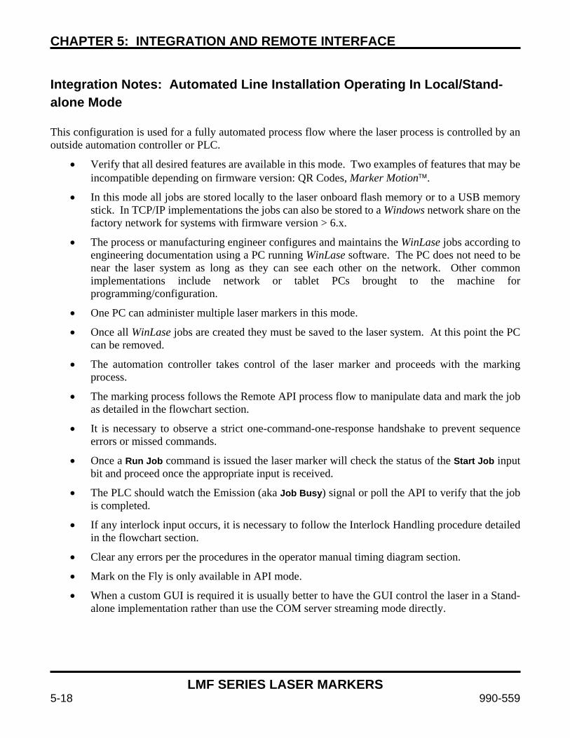
CHAPTER 5: INTEGRATION AND REMOTE INTERFACE
LMF SERIES LASER MARKERS
5-18 990-559
Integration Notes: Automated Line Installation Operating In Local/Stand-alone Mode This configuration is used for a fully automated process flow where the laser process is controlled by an outside automation controller or PLC.
• Verify that all desired features are available in this mode. Two examples of features that may be incompatible depending on firmware version: QR Codes, Marker Motion.
• In this mode all jobs are stored locally to the laser onboard flash memory or to a USB memory stick. In TCP/IP implementations the jobs can also be stored to a Windows network share on the factory network for systems with firmware version > 6.x.
• The process or manufacturing engineer configures and maintains the WinLase jobs according to engineering documentation using a PC running WinLase software. The PC does not need to be near the laser system as long as they can see each other on the network. Other common implementations include network or tablet PCs brought to the machine for programming/configuration.
• One PC can administer multiple laser markers in this mode.
• Once all WinLase jobs are created they must be saved to the laser system. At this point the PC can be removed.
• The automation controller takes control of the laser marker and proceeds with the marking process.
• The marking process follows the Remote API process flow to manipulate data and mark the job as detailed in the flowchart section.
• It is necessary to observe a strict one-command-one-response handshake to prevent sequence errors or missed commands.
• Once a Run Job command is issued the laser marker will check the status of the Start Job input bit and proceed once the appropriate input is received.
• The PLC should watch the Emission (aka Job Busy) signal or poll the API to verify that the job is completed.
• If any interlock input occurs, it is necessary to follow the Interlock Handling procedure detailed in the flowchart section.
• Clear any errors per the procedures in the operator manual timing diagram section.
• Mark on the Fly is only available in API mode.
• When a custom GUI is required it is usually better to have the GUI control the laser in a Stand-alone implementation rather than use the COM server streaming mode directly.
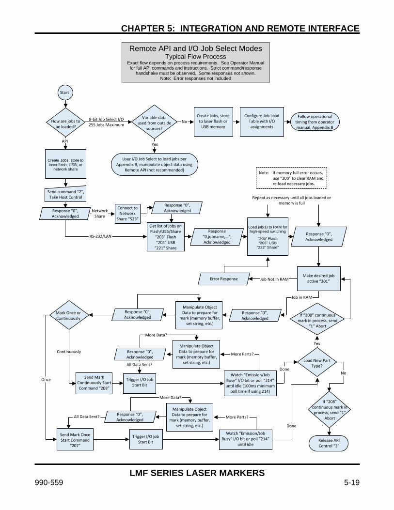
CHAPTER 5: INTEGRATION AND REMOTE INTERFACE
LMF SERIES LASER MARKERS
990-559 5-19
Remote API and I/O Job Select Modes Typical Flow Process
Exact flow depends on process requirements. See Operator Manual for full API commands and instructions. Strict command/response
handshake must be observed. Some responses not shown. Note: Error responses not included
Note: If memory full error occurs, use “200” to clear RAM and re-load necessary jobs.
Create Jobs, store to laser flash, USB, or
network share
Load job(s) to RAM for high-speed switching
“205” Flash “206” USB
“222” Share”
Start
Variable data used from outside
sources?
Create Jobs, store to laser flash or
USB memory
Configure Job Load Table with I/O assignments
Follow operational timing from operator manual, Appendix B
How are jobs to be loaded?
User I/O Job Select to load jobs per Appendix B, manipulate object data using
Remote API (not recommended)
Send command “2”, Take Host Control
Connect to Network
Share “523”
Response “0”, Acknowledged Response “0”,
Acknowledged
Get list of jobs on Flash/USB/Share
“203” Flash “204” USB
“221” Share
Response “0,jobname,…”, Acknowledged
Response “0”, Acknowledged
Make desired job active “201” Error Response
Manipulate Object Data to prepare for
mark (memory buffer, set string, etc.)
If “208” continuous mark in process, send
“1” Abort
Mark Once or Continuously
Response “0”, Acknowledged
Response “0”, Acknowledged
8-bit Job Select I/O 255 Jobs Maximum
No
Yes API
Network Share
Job in RAM
More Data?
Repeat as necessary until all jobs loaded or memory is full
Response “0”, Acknowledged
Manipulate Object Data to prepare for
mark (memory buffer, set string, etc.)
Yes
Continuously
Load New Part Type?
More Parts?
Done All Data Sent?
No Send Mark
Continuously Start Command “208”
Watch “Emission/Job Busy” I/O bit or poll “214” until idle (100ms minimum
poll time if using 214)
Once Trigger I/O Job Start Bit
If “208” continuous mark in process, send “1”
Abort
More Data?
Response “0”, Acknowledged
Manipulate Object Data to prepare for
mark (memory buffer, set string, etc.)
All Data Sent?
Done
More Parts?
Send Mark Once Start Command
“207”
Trigger I/O job Start Bit
Watch “Emission/Job Busy” I/O bit or poll “214”
until idle Release API Control “3”
RS-232/LAN
Job Not in RAM

CHAPTER 5: INTEGRATION AND REMOTE INTERFACE
LMF SERIES LASER MARKERS
5-20 990-559
System Interlock Monitoring Behavior and Reset Interlocks can occur at any time. Remote Interlock Input, Emergency Stop, Abort and
System Fault all monitored by the Interlock Monitoring circuit and considered interlocks for the purpose of this document.
Interlock Handling
in I/O Job Selection Mode
Interlock Handling in Remote API Mode
Start – Interlock Event Occurs
Start – Interlock Event Occurs
Laser Jobs in Process?
Laser Jobs in Process?
Mark in Process Aborted
Mark in Process Aborted
“Ready for Mark” I/O Bit
turned off
System Fault (except Abort)
System Fault (except Abort)
Active Job Cleared
Clear System Fault (except Abort)
I/O Job Load Bits 0-7 Reset
Toggle “I/O Job Load” Bit
Interlock Input Closed or reset?
Job Loads; “Ready for Mark” I/O bit turned on
Clear System Fault (except Abort)
Send Abort / Reset API command (1)
API replies “16”, Interlock Present
Interlock Input Closed or reset?
API replies “1”, Abort / Clear
Acknowledged
Make desired job active (“201,jobname”)
Proceed as normal Proceed as normal
Yes Yes
No
No
No
No
Yes
Yes

CHAPTER 5: INTEGRATION AND REMOTE INTERFACE
LMF SERIES LASER MARKERS
990-559 5-21
Section V: Using the TCP/IP and RS-232
Streaming Mode Host Interface
NOTE
This mode is not recommended unless no other options are available since it has a limited command set and certain limitations compared to other modes. When possible it is better to select the Remote API instead of the Host interface.
The Host interface is a special variant of streaming mode that combines many of the capabilities of the remote API with streaming mode. With WinLase running in the background a remote device such as a PLC can connect to the WinLase Host interface and remotely control the laser marker.
In terms of simplicity, the RS-232 port is easier to set up than the TCP/IP interface, because the cable connection between the two computers is direct and troubleshooting is much easier because HyperTerminal can be used to troubleshoot the connection.
TCP/IP, on the other hand, is a Client/Server protocol that is a bit more difficult to set-up. In order for you to communicate over TCP/IP, you must know the IP address and Port of the device you are communicating with. By default, WinLase makes the Remote Interface service available on Port 350. This can be changed in the Host Interface setup box if Port 350 conflicts with another installed port on your machine. Determining the IP address of the computer that WinLase is running on depends on how the TCP/IP stack is configured in Windows. Computers can either have a static IP address, or one that is dynamically allocated when the computer signs on to the network. RS-232 and TCP/IP Commands and Functions The interface provided for RS-232 and TCP/IP is textual; commands are sent over either port as ASCII text strings. These strings are interpreted by WinLase, and are executed accordingly. RS-232 and TCP/IP Command List For the complete list of Host mode commands, see Appendix D, Remote Interface Commands.


LMF SERIES LASER MARKERS
990-559 6-1
CHAPTER 6 Marker Motion™ MOTION CONTROL
Section I: Overview Marking systems are often required to control one or more motors or actuators to execute complex production sequences. Typical uses of Marker Motion™ in a laser marking environment are:
Adjust the XY table to implement step and repeat marking or locate parts with respect to the marker lens.
Adjust the rotary axis to locate parts with respect to the marker lens.
Adjust the height of the marker head to pre-programmed static positions to accommodate marking surfaces at different heights above the tooling plane.
Rotate a circular cylindrical part while marking to ensure mark completely wraps around part with no distortion or areas out of focus. This feature can be used with a basic implementation (“chuck on a stick”) or an advanced implementation which includes a stage with gearing and index (home) sensor.
The LMF family integrated Marker Motion™ system allows the user to control up to four stepper motors with integrated controllers using a the WinLase software interface for easy configuration and control without extensive hardware requirements. The system consists of two major components:
The LMF fiber laser marker running WinLase software is responsible for controlling motors and issuing serial commands to the individual motors and supplying power and safety control features. Markers configured as 8-79-xBx-xxx are capable of performing motion in API standalone jobs.
The motors themselves with integrated serial communication hardware, encoders, and sensor inputs.
The fiber laser marker is currently capable of controlling motion in streaming implementations and standalone modes depending on marker configuration. Various cable sets and hardware accessories are available to meet functionality requirements for each of the X, Y, Z, and rotary axes.
The motors selected are from the SCHNEIDERELECTRIC MDrivePlus family, and communicationbetween motors and laser marker is conducted usingthe SCHNEIDER ELECTRIC communicationprotocol.
The entire SCHNEIDER ELECTRIC MDrivePlusMDI1 family of motors is supported. Each motor communicates with the laser marker using the RS-422 protocol in a daisy-chain or parallelconfiguration. Power is supplied to each motordirectly from the power supply.
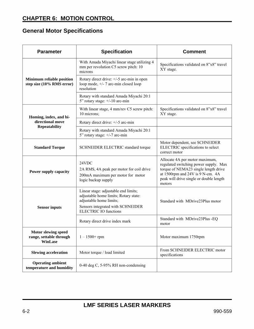
CHAPTER 6: MOTION CONTROL
LMF SERIES LASER MARKERS
6-2 990-559
General Motor Specifications
Parameter Specification Comment
Minimum reliable position step size (10% RMS error)
With Amada Miyachi linear stage utilizing 4 mm per revolution C5 screw pitch: 10 microns
Specifications validated on 8”x8” travel XY stage.
Rotary direct drive: +/-5 arc-min in open loop mode, +/- 7 arc-min closed loop resolution
Rotary with standard Amada Miyachi 20:1 5” rotary stage: +/-10 arc-min
Homing, index, and bi-directional move
Repeatability
With linear stage, 4 mm/rev C5 screw pitch: 10 microns;
Specifications validated on 8”x8” travel XY stage.
Rotary direct drive: +/-5 arc-min
Rotary with standard Amada Miyachi 20:1 5” rotary stage: +/-7 arc-min
Standard Torque SCHNEIDER ELECTRIC standard torque Motor dependent, see SCHNEIDER ELECTRIC specifications to select correct motor
Power supply capacity
24VDC
2A RMS, 4A peak per motor for coil drive
200mA maximum per motor for motor logic backup supply
Allocate 4A per motor maximum, regulated switching power supply. Max torque of NEMA23 single length drive at 1500rpm and 24V is 9 N-cm. 4A peak will drive single or double length motors
Sensor inputs
Linear stage: adjustable end limits; adjustable home limits; Rotary state: adjustable home limits;
Sensors integrated with SCHNEIDER ELECTRIC IO functions
Standard with MDrive23Plus motor
Rotary direct drive index mark Standard with MDrive23Plus -EQ motor
Motor slewing speed range, settable through
WinLase 1 – 1500+ rpm Motor maximum 1750rpm
Slewing acceleration Motor torque / load limited From SCHNEIDER ELECTRIC motor specifications
Operating ambient temperature and humidity 0-40 deg C, 5-95% RH non-condensing
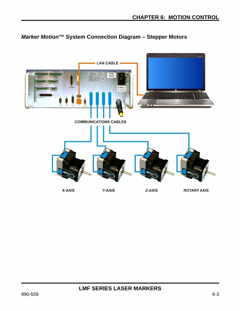
CHAPTER 6: MOTION CONTROL
LMF SERIES LASER MARKERS
990-559 6-3
Marker Motion™ System Connection Diagram – Stepper Motors
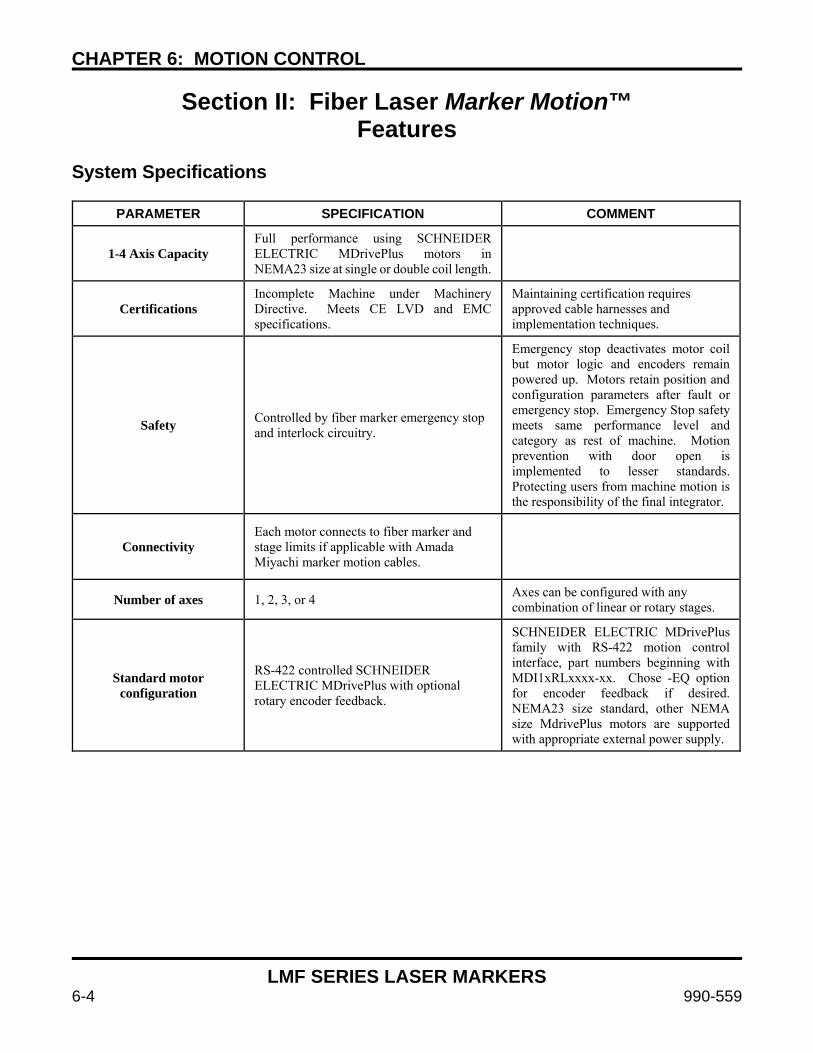
CHAPTER 6: MOTION CONTROL
LMF SERIES LASER MARKERS
6-4 990-559
Section II: Fiber Laser Marker Motion™ Features
System Specifications
PARAMETER SPECIFICATION COMMENT
1-4 Axis Capacity Full performance using SCHNEIDER ELECTRIC MDrivePlus motors in NEMA23 size at single or double coil length.
Certifications Incomplete Machine under Machinery Directive. Meets CE LVD and EMC specifications.
Maintaining certification requires approved cable harnesses and implementation techniques.
Safety Controlled by fiber marker emergency stop and interlock circuitry.
Emergency stop deactivates motor coil but motor logic and encoders remain powered up. Motors retain position and configuration parameters after fault or emergency stop. Emergency Stop safety meets same performance level and category as rest of machine. Motion prevention with door open is implemented to lesser standards. Protecting users from machine motion is the responsibility of the final integrator.
Connectivity Each motor connects to fiber marker and stage limits if applicable with Amada Miyachi marker motion cables.
Number of axes 1, 2, 3, or 4 Axes can be configured with any combination of linear or rotary stages.
Standard motor configuration
RS-422 controlled SCHNEIDER ELECTRIC MDrivePlus with optional rotary encoder feedback.
SCHNEIDER ELECTRIC MDrivePlus family with RS-422 motion control interface, part numbers beginning with MDI1xRLxxxx-xx. Chose -EQ option for encoder feedback if desired. NEMA23 size standard, other NEMA size MdrivePlus motors are supported with appropriate external power supply.

CHAPTER 6: MOTION CONTROL
LMF SERIES LASER MARKERS
990-559 6-5
Section III: Standard Cable Harness Configurations with Part Numbers
Introduction
The user should select appropriate standard cables depending on the application.
Motors and cables are selected separately
Use one cable per axis
Each cable can interface directly with Amada Miyachi standard stage limits Part Numbers – LMF with Marker Motion™
P/N 10-501-02-01 Motor, NEMA23, with Encoder
P/N 10-502-02-xx
Description Tab Number Length
Laser Marker to Motor Cable
-01 3m One per axis. Choose length as necessary.
-02 5m One per axis. Choose length as necessary.
-03 8m One per axis. Choose length as necessary.

CHAPTER 6: MOTION CONTROL
LMF SERIES LASER MARKERS
6-6 990-559
Section IV: Connection Using Customer-Supplied Stages
If desired, or necessary due to the system limitations or customer requirements, it is possible to use your own motion stages instead of those supplied by Amada Miyachi America. In this case it is necessary to wire the limits to the motors correctly. Standard motors are NEMA23 form factor.
It is the user’s responsibility to take all necessary precautions to make sure the user supplied equipment is safe to use and does not damage the fiber marker or motion systems. Damage to the fiber marker system or motion hardware caused by user implemented non-approved systems is not covered by the fiber marker warranty. If in doubt, please use the Amada Miyachi America supplied fiber marker motion control power supply.
WARNING
Do not hot plug the motors (plug or unplug them while voltage is present). Doing so will damage the motors.
Do not ground the aux logic supply at communications ground or the drive will be damaged. Ground aux logic at power ground only. There is a 100Ω resistor between communications ground and the motor common to prevent ground loops. Grounding any signal other than communications may damage the drive.
Do not unplug motors with the system power on. Doing so will destroy the motor.
Motor Input Wiring Use the following table to wire to the Limit connector attached to the 10-502-02-xx cable.
Pin Number Function Description
1 +24V Power for limits
2 GND Ground for limits
3 N/C Do not connect
4 Home Limit Motor I/O 1, Axis Home
5 N/C Do not connect
6 N/C Do not connect
7 CW Limit Motor I/O 3, Axis CW Limit
8 N/C Do not connect
9 CCW Limit Motor I/O 2, Axis CCW Limit
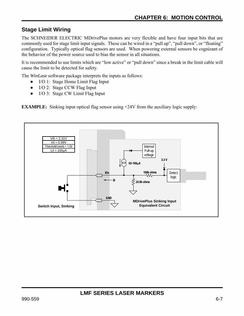
CHAPTER 6: MOTION CONTROL
LMF SERIES LASER MARKERS
990-559 6-7
Stage Limit Wiring The SCHNEIDER ELECTRIC MDrivePlus motors are very flexible and have four input bits that are commonly used for stage limit input signals. These can be wired in a “pull up”, “pull down”, or “floating” configuration. Typically optical flag sensors are used. When powering external sensors be cognizant of the behavior of the power source used to bias the sensor in all situations.
It is recommended to use limits which are “low active” or “pull down” since a break in the limit cable will cause the limit to be detected for safety.
The WinLase software package interprets the inputs as follows: I/O 1: Stage Home Limit Flag Input I/O 2: Stage CCW Flag Input I/O 3: Stage CW Limit Flag Input
EXAMPLE: Sinking input optical flag sensor using +24V from the auxiliary logic supply:
InternalPull-up voltage
Detect logic
65-160µA3.3 V
100k ohms
24.9k ohms
IOx
GND
lil
Vih = 2.31V Vil = 0.99V
Threshold (nom) = 1.5V Lil = 100µA
MDrivePlus Sinking Input Equivalent Circuit Switch Input, Sinking
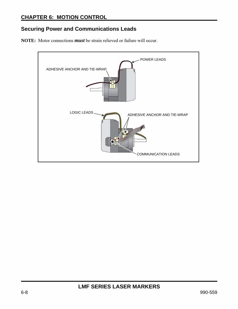
CHAPTER 6: MOTION CONTROL
LMF SERIES LASER MARKERS
6-8 990-559
Securing Power and Communications Leads NOTE: Motor connections must be strain relieved or failure will occur.
POWER LEADS
ADHESIVE ANCHOR AND TIE-WRAP
LOGIC LEADS ADHESIVE ANCHOR AND TIE-WRAP
COMMUNICATION LEADS
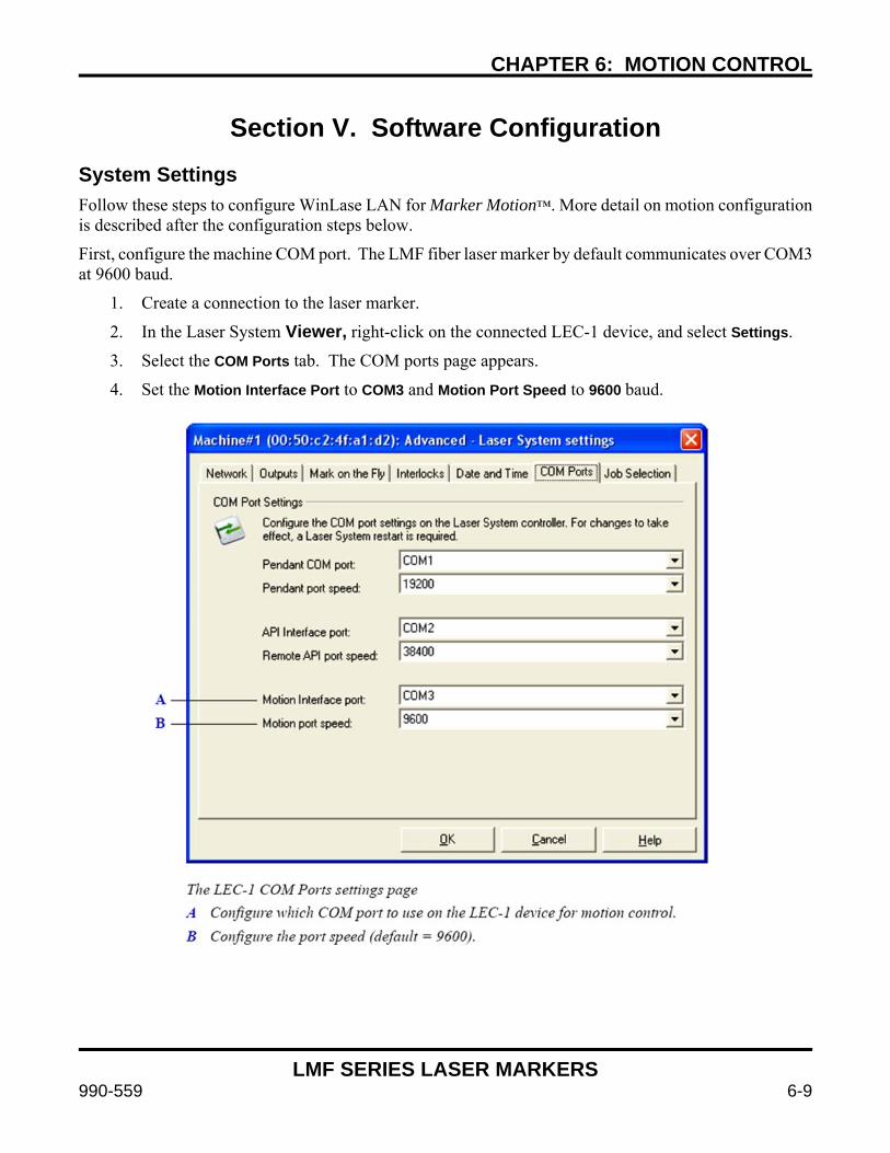
CHAPTER 6: MOTION CONTROL
LMF SERIES LASER MARKERS
990-559 6-9
Section V. Software Configuration System Settings Follow these steps to configure WinLase LAN for Marker Motion™. More detail on motion configuration is described after the configuration steps below.
First, configure the machine COM port. The LMF fiber laser marker by default communicates over COM3 at 9600 baud.
1. Create a connection to the laser marker.
2. In the Laser System Viewer, right-click on the connected LEC-1 device, and select Settings.
3. Select the COM Ports tab. The COM ports page appears.
4. Set the Motion Interface Port to COM3 and Motion Port Speed to 9600 baud.
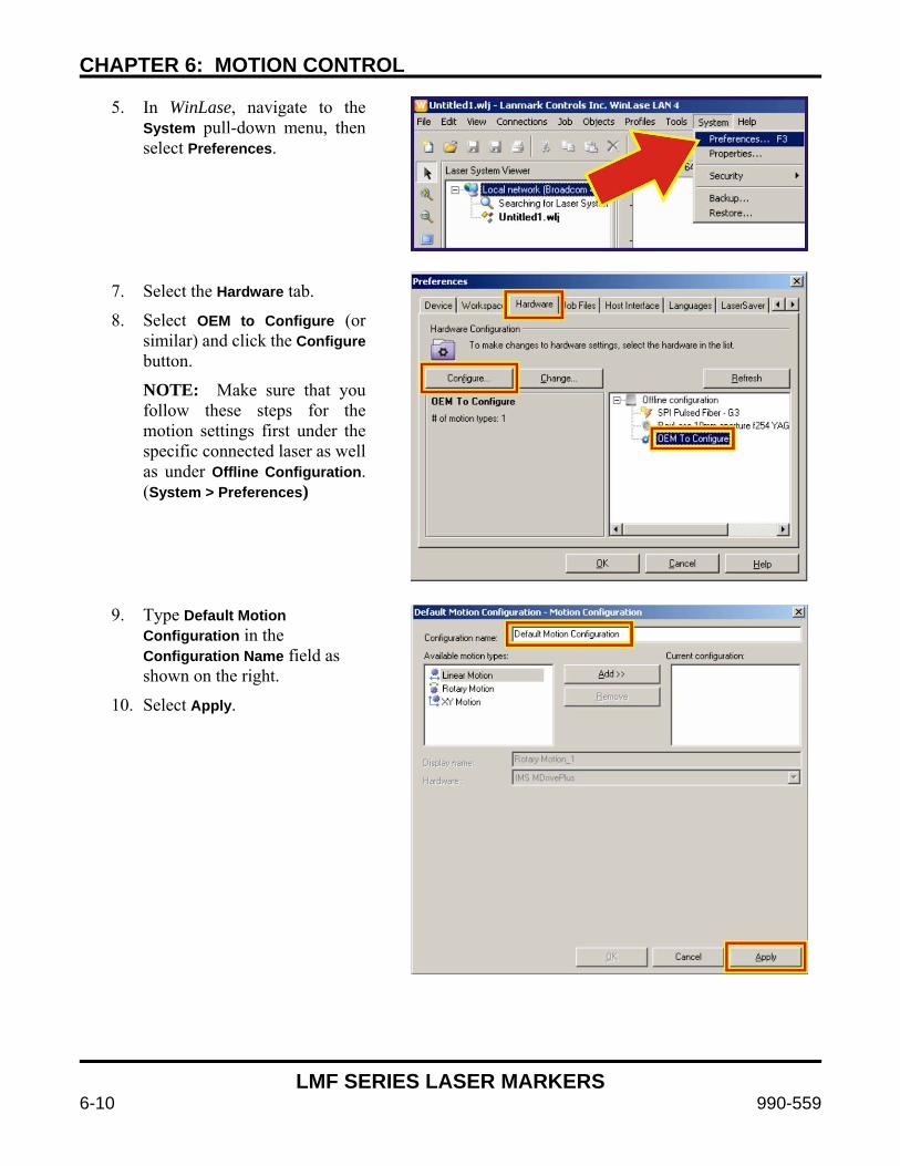
CHAPTER 6: MOTION CONTROL
LMF SERIES LASER MARKERS
6-10 990-559
5. In WinLase, navigate to the System pull-down menu, then select Preferences.
7. Select the Hardware tab.
8. Select OEM to Configure (or similar) and click the Configure button.
NOTE: Make sure that you follow these steps for the motion settings first under the specific connected laser as well as under Offline Configuration. (System > Preferences)
9. Type Default Motion
Configuration in the Configuration Name field as shown on the right.
10. Select Apply.
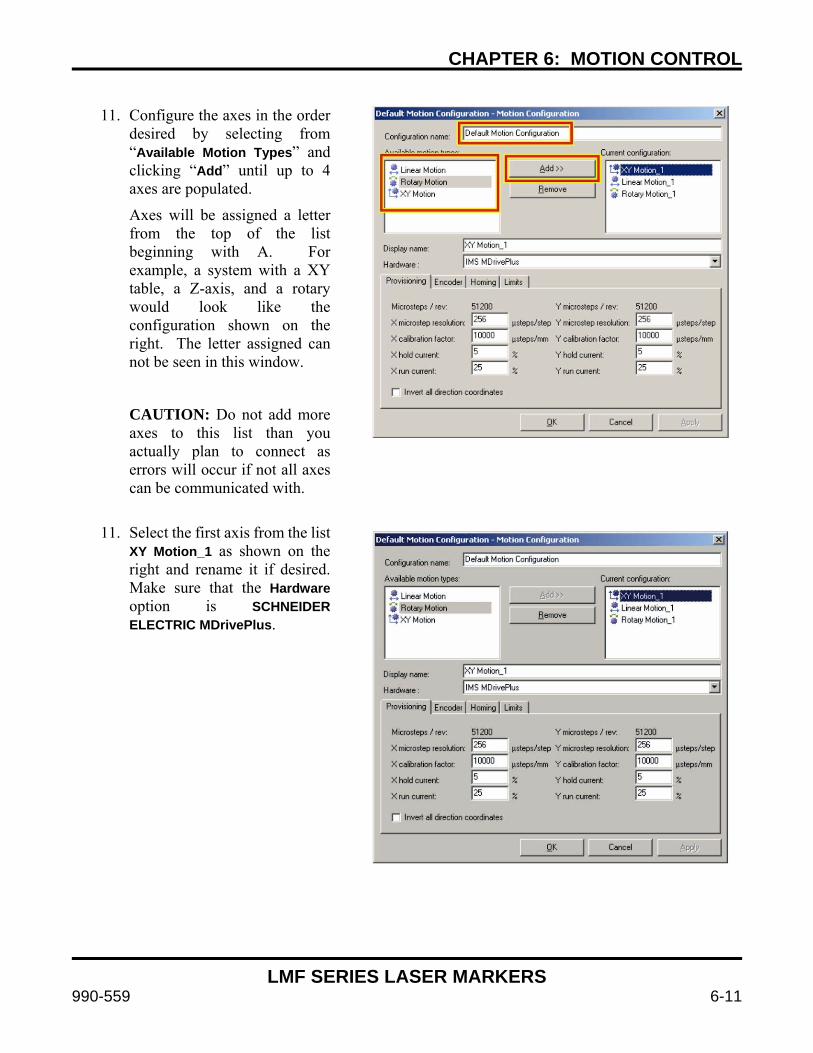
CHAPTER 6: MOTION CONTROL
LMF SERIES LASER MARKERS
990-559 6-11
11. Configure the axes in the order
desired by selecting from “Available Motion Types” and clicking “Add” until up to 4 axes are populated.
Axes will be assigned a letter from the top of the list beginning with A. For example, a system with a XY table, a Z-axis, and a rotary would look like the configuration shown on the right. The letter assigned can not be seen in this window.
CAUTION: Do not add more axes to this list than you actually plan to connect as errors will occur if not all axes can be communicated with.
11. Select the first axis from the list XY Motion_1 as shown on the right and rename it if desired. Make sure that the Hardware option is SCHNEIDER ELECTRIC MDrivePlus.

CHAPTER 6: MOTION CONTROL
LMF SERIES LASER MARKERS
6-12 990-559
12. Select the Encoder tab as
shown on the right. If the motor is equipped with an internal encoder (-EQ as the last two characters in the motor part number on the motor sticker), check Enable Encoder Functions.
13. Set the deadband to 5 and the stall factor to 25. Do not enable position maintenance.
14. Select Apply.
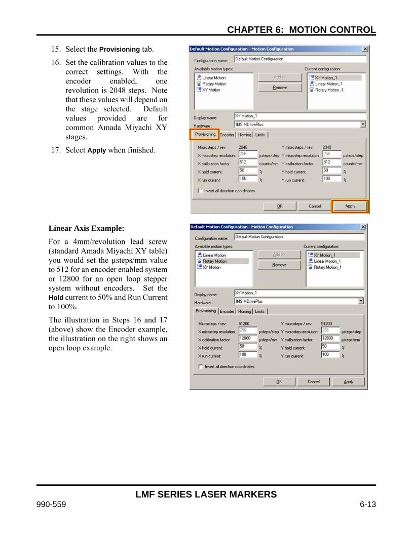
CHAPTER 6: MOTION CONTROL
LMF SERIES LASER MARKERS
990-559 6-13
15. Select the Provisioning tab.
16. Set the calibration values to the correct settings. With the encoder enabled, one revolution is 2048 steps. Note that these values will depend on the stage selected. Default values provided are for common Amada Miyachi XY stages.
17. Select Apply when finished.
Linear Axis Example: For a 4mm/revolution lead screw (standard Amada Miyachi XY table) you would set the µsteps/mm value to 512 for an encoder enabled system or 12800 for an open loop stepper system without encoders. Set the Hold current to 50% and Run Current to 100%.
The illustration in Steps 16 and 17 (above) show the Encoder example, the illustration on the right shows an open loop example.
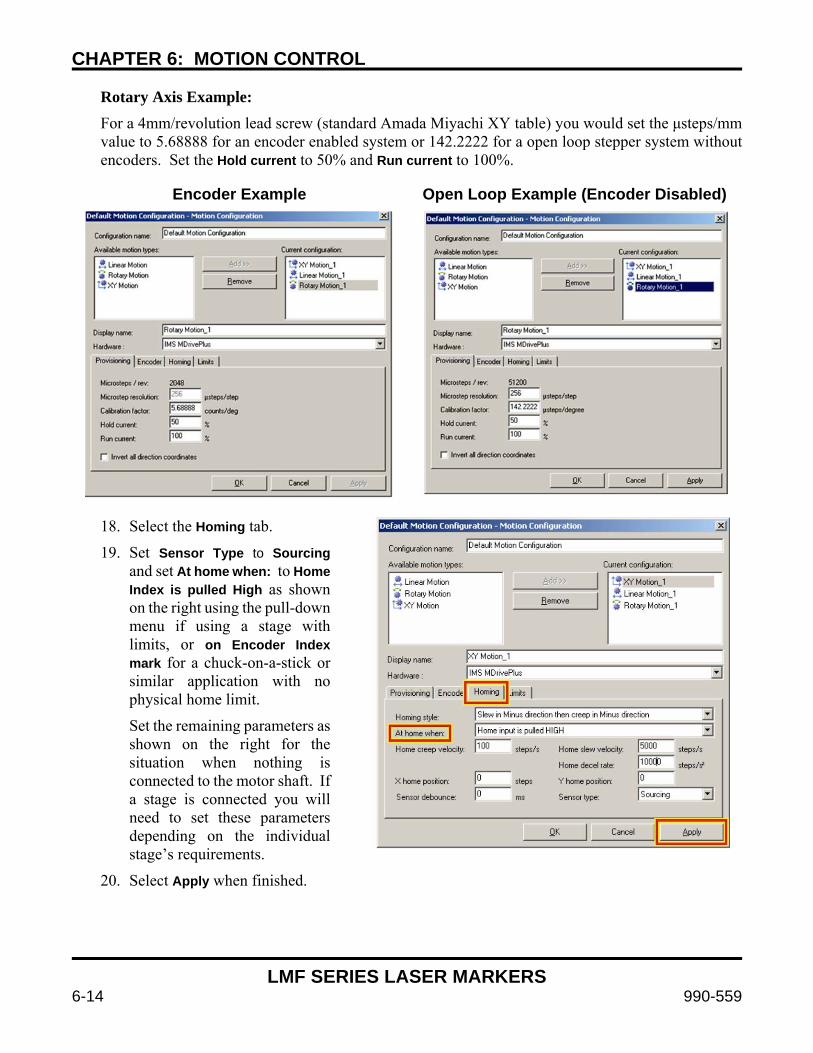
CHAPTER 6: MOTION CONTROL
LMF SERIES LASER MARKERS
6-14 990-559
Rotary Axis Example: For a 4mm/revolution lead screw (standard Amada Miyachi XY table) you would set the μsteps/mm value to 5.68888 for an encoder enabled system or 142.2222 for a open loop stepper system without encoders. Set the Hold current to 50% and Run current to 100%.
Encoder Example Open Loop Example (Encoder Disabled)
18. Select the Homing tab.
19. Set Sensor Type to Sourcing and set At home when: to Home Index is pulled High as shown on the right using the pull-down menu if using a stage with limits, or on Encoder Index mark for a chuck-on-a-stick or similar application with no physical home limit.
Set the remaining parameters as shown on the right for the situation when nothing is connected to the motor shaft. If a stage is connected you will need to set these parameters depending on the individual stage’s requirements.
20. Select Apply when finished.
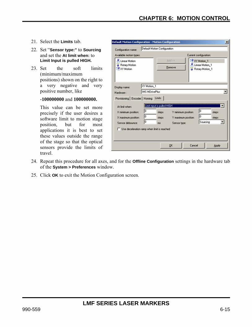
CHAPTER 6: MOTION CONTROL
LMF SERIES LASER MARKERS
990-559 6-15
21. Select the Limits tab.
22. Set “Sensor type:” to Sourcing and set the At limit when: to Limit Input is pulled HIGH.
23. Set the soft limits (minimum/maximum positions) shown on the right to a very negative and very positive number, like
-100000000 and 100000000. This value can be set more precisely if the user desires a software limit to motion stage position, but for most applications it is best to set these values outside the range of the stage so that the optical sensors provide the limits of travel.
24. Repeat this procedure for all axes, and for the Offline Configuration settings in the hardware tab of the System > Preferences window.
25. Click OK to exit the Motion Configuration screen.
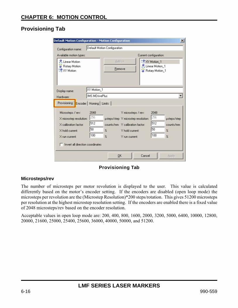
CHAPTER 6: MOTION CONTROL
LMF SERIES LASER MARKERS
6-16 990-559
Provisioning Tab
Provisioning Tab
Microsteps/rev The number of microsteps per motor revolution is displayed to the user. This value is calculated differently based on the motor’s encoder setting. If the encoders are disabled (open loop mode) the microsteps per revolution are the (Microstep Resolution)*200 steps/rotation. This gives 51200 microsteps per resolution at the highest microstep resolution setting. If the encoders are enabled there is a fixed value of 2048 microsteps/rev based on the encoder resolution.
Acceptable values in open loop mode are: 200, 400, 800, 1600, 2000, 3200, 5000, 6400, 10000, 12800, 20000, 21600, 25000, 25400, 25600, 36000, 40000, 50000, and 51200.
CHAPTER 6: MOTION CONTROL
LMF SERIES LASER MARKERS
990-559 6-17
Microstep Resolution This value selects the level of microstepping in open loop mode. Acceptable values are 2, 4, 5, 8, 10, 16, 25, 32, 50, 64, 100, 128, 200, 250, 256.
Other specialty values are:
18, corresponds to .01 degrees / μstep 108, corresponds to 1 arc minute / µstep 127, corresponds to .001mm / µstep
When encoders are enabled 256 microsteps/step is the only option. Calibration Factor This parameter selects the number of microsteps per unit distance at the part. It will be in units of µsteps/degree, µsteps/mm, µsteps/inch, etc. This multiplier is used to accommodate for any gearing changes and calibrate the system to the specific motion stage setup. For a typical 1:1 rotary stage, for example, this value will be the same as the number of microsteps/revolution divided by 360, or 142.2 µsteps/degree. A 20:1 high-precision stage would require this value to be multiplied by 20 to get the correct calibration factor. You know you have the calibration factor correct when you can move the stage a given distance and the actual traveled distance matches the given distance. Hold Current This parameter sets the motor hold current as a percentage of total current. Hold current is the amount of current that the motor uses to keep the motor static between movements. A stage which loads the motor at idle (like a Z-axis stage with a marker head attached) requires more current to maintain its current position, and thus a higher hold current value than a stage with lower load. A higher Run current uses more electricity and causes the motor to heat up, so it is important to balance the need for a stiff motor against the additional heat introduced into the system and the movement duty cycle. At high Run current values the motor can become hot to the touch. Run Current This parameter sets the motor run current as a percentage of total current. Run current is the amount of current the motor uses during movements. Faster movements, higher accelerations, and high stage loads increase the necessary run current. Set the Run current to a setting that allows the desired speeds and accelerations to run without stalling, but do not set the run current higher than is necessary to prevent the motor from becoming unnecessarily hot. It is important to balance the speeds and accelerations with the run current and duty cycle to find the optimal setting. Invert All Direction Coordinates This parameter reverses the direction the motor traverses with respect to the positive axis of the WinLase mark field. This setting is determined by the stage configuration.
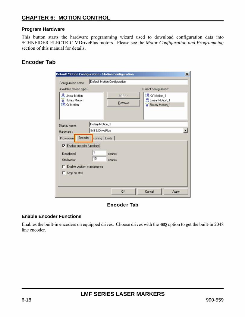
CHAPTER 6: MOTION CONTROL
LMF SERIES LASER MARKERS
6-18 990-559
Program Hardware This button starts the hardware programming wizard used to download configuration data into SCHNEIDER ELECTRIC MDrivePlus motors. Please see the Motor Configuration and Programming section of this manual for details.
Encoder Tab
Encoder Tab
Enable Encoder Functions Enables the built-in encoders on equipped drives. Choose drives with the -EQ option to get the built-in 2048 line encoder.
CHAPTER 6: MOTION CONTROL
LMF SERIES LASER MARKERS
990-559 6-19
Deadband This parameter sets the number of counts that determine the width of the “dead band”. In closed loop feedback mode the motor will compare the requested position with the encoder position and automatically make adjustments to ensure that the motor is in the correct place. The deadband is the zone around the requested point at which the motor considers it “close enough”.
It is important to balance the desire for a tight tolerance against the physical parameters of the stage and the extra current required to maintain a location against static load. This value is only meaningful when Enable position maintenance is checked. Stall Factor The stall factor sets the number of counts required for a stall error to be reported to the laser marker. If the motor’s current position is different from the current requested position by greater than the number of counts set in this stall factor the motor will error out and stop moving. This is useful to minimize damage in the case of motor crashes, part jams, or other issues. It is also useful in position maintenance mode because it causes a fault if the maintenance is unable to maintain the desired position. Enable Position Maintenance This checkbox turns on the closed-loop position maintenance algorithm. The motor will compare the requested position with the current position reported by the encoders and make any movements necessary to correct errors within the tolerance of the deadband. If the position errors are so great that they exceed the stall factor an error will be reported and the motor will stop moving if Stop on Stall is checked. When position maintenance is enabled it is important to properly set the deadband and stall factor to reasonable values, and ensure that the run current is high enough to allow the stage to move if position maintenance is required. This option should not be selected when safety is a concern since the motors can operate autonomously attempting to maintain their position and potential injury could result. Typically this option is only enabled for low torque motors in applications that do not represent a danger of pinching or other human danger. Stop on Stall This checkbox causes detected stalls to stop the motor from moving until the motor is reset. Use this option to protect the system from damage in the case of stage crashes or part jams.
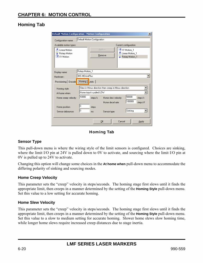
CHAPTER 6: MOTION CONTROL
LMF SERIES LASER MARKERS
6-20 990-559
Homing Tab
Homing Tab
Sensor Type This pull-down menu is where the wiring style of the limit sensors is configured. Choices are sinking, where the limit I/O pin at 24V is pulled down to 0V to activate, and sourcing where the limit I/O pin at 0V is pulled up to 24V to activate.
Changing this option will change some choices in the At home when pull-down menu to accommodate the differing polarity of sinking and sourcing modes. Home Creep Velocity This parameter sets the “creep” velocity in steps/seconds. The homing stage first slews until it finds the appropriate limit, then creeps in a manner determined by the setting of the Homing Style pull-down menu. Set this value to a low setting for accurate homing. Home Slew Velocity This parameter sets the “creep” velocity in steps/seconds. The homing stage first slews until it finds the appropriate limit, then creeps in a manner determined by the setting of the Homing Style pull-down menu. Set this value to a slow to medium setting for accurate homing. Slower home slews slow homing time, while longer home slews require increased creep distances due to stage inertia.
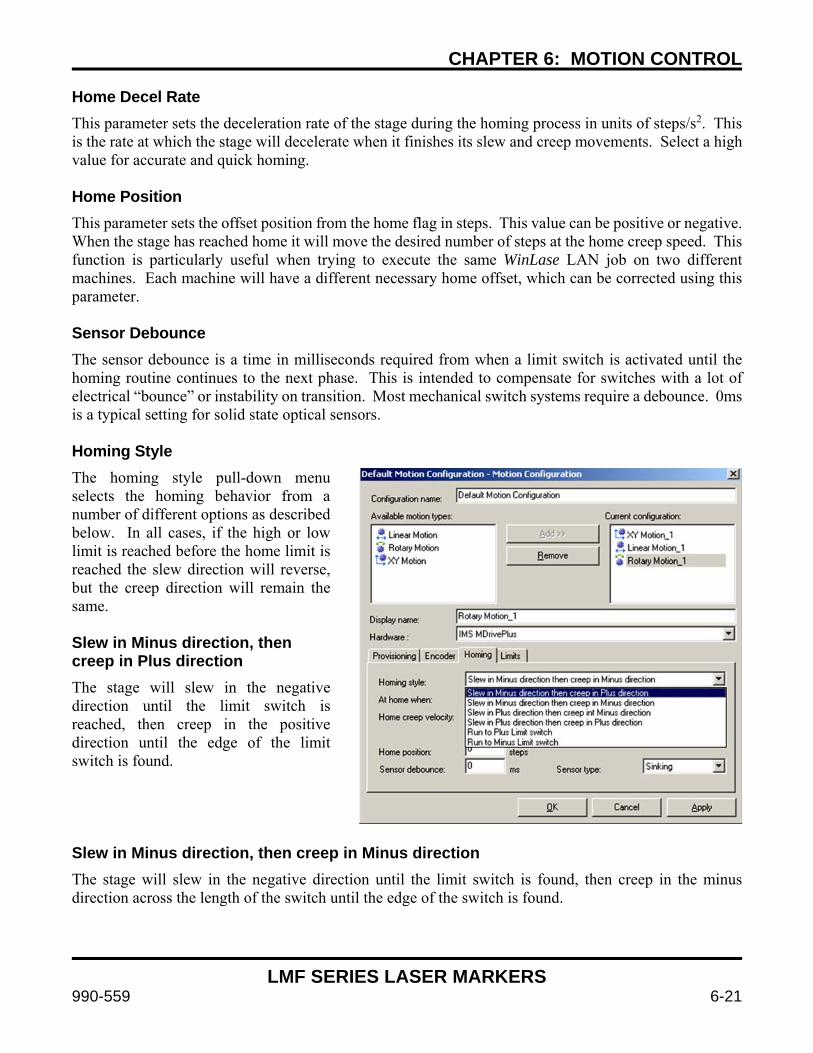
CHAPTER 6: MOTION CONTROL
LMF SERIES LASER MARKERS
990-559 6-21
Home Decel Rate This parameter sets the deceleration rate of the stage during the homing process in units of steps/s2. This is the rate at which the stage will decelerate when it finishes its slew and creep movements. Select a high value for accurate and quick homing. Home Position This parameter sets the offset position from the home flag in steps. This value can be positive or negative. When the stage has reached home it will move the desired number of steps at the home creep speed. This function is particularly useful when trying to execute the same WinLase LAN job on two different machines. Each machine will have a different necessary home offset, which can be corrected using this parameter. Sensor Debounce The sensor debounce is a time in milliseconds required from when a limit switch is activated until the homing routine continues to the next phase. This is intended to compensate for switches with a lot of electrical “bounce” or instability on transition. Most mechanical switch systems require a debounce. 0ms is a typical setting for solid state optical sensors. Homing Style The homing style pull-down menu selects the homing behavior from a number of different options as described below. In all cases, if the high or low limit is reached before the home limit is reached the slew direction will reverse, but the creep direction will remain the same. Slew in Minus direction, then creep in Plus direction The stage will slew in the negative direction until the limit switch is reached, then creep in the positive direction until the edge of the limit switch is found.
Slew in Minus direction, then creep in Minus direction The stage will slew in the negative direction until the limit switch is found, then creep in the minus direction across the length of the switch until the edge of the switch is found.
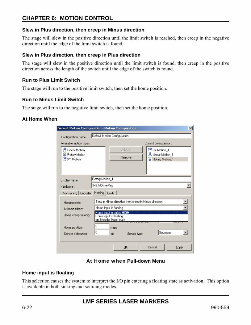
CHAPTER 6: MOTION CONTROL
LMF SERIES LASER MARKERS
6-22 990-559
Slew in Plus direction, then creep in Minus direction The stage will slew in the positive direction until the limit switch is reached, then creep in the negative direction until the edge of the limit switch is found. Slew in Plus direction, then creep in Plus direction The stage will slew in the positive direction until the limit switch is found, then creep in the positive direction across the length of the switch until the edge of the switch is found. Run to Plus Limit Switch The stage will run to the positive limit switch, then set the home position. Run to Minus Limit Switch The stage will run to the negative limit switch, then set the home position. At Home When
At Home when Pull-down Menu Home input is floating This selection causes the system to interpret the I/O pin entering a floating state as activation. This option is available in both sinking and sourcing modes.
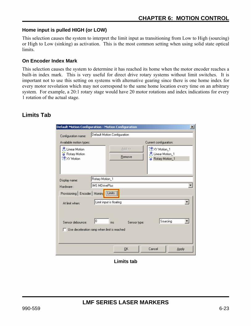
CHAPTER 6: MOTION CONTROL
LMF SERIES LASER MARKERS
990-559 6-23
Home input is pulled HIGH (or LOW) This selection causes the system to interpret the limit input as transitioning from Low to High (sourcing) or High to Low (sinking) as activation. This is the most common setting when using solid state optical limits. On Encoder Index Mark This selection causes the system to determine it has reached its home when the motor encoder reaches a built-in index mark. This is very useful for direct drive rotary systems without limit switches. It is important not to use this setting on systems with alternative gearing since there is one home index for every motor revolution which may not correspond to the same home location every time on an arbitrary system. For example, a 20:1 rotary stage would have 20 motor rotations and index indications for every 1 rotation of the actual stage. Limits Tab
Limits tab
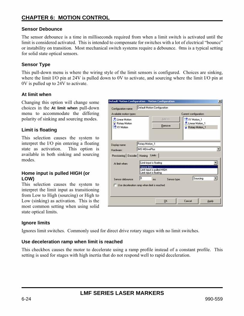
CHAPTER 6: MOTION CONTROL
LMF SERIES LASER MARKERS
6-24 990-559
Sensor Debounce The sensor debounce is a time in milliseconds required from when a limit switch is activated until the limit is considered activated. This is intended to compensate for switches with a lot of electrical “bounce” or instability on transition. Most mechanical switch systems require a debounce. 0ms is a typical setting for solid state optical sensors. Sensor Type This pull-down menu is where the wiring style of the limit sensors is configured. Choices are sinking, where the limit I/O pin at 24V is pulled down to 0V to activate, and sourcing where the limit I/O pin at 0V is pulled up to 24V to activate. At limit when Changing this option will change some choices in the At limit when pull-down menu to accommodate the differing polarity of sinking and sourcing modes. Limit is floating This selection causes the system to interpret the I/O pin entering a floating state as activation. This option is available in both sinking and sourcing modes.
Home input is pulled HIGH (or LOW) This selection causes the system to interpret the limit input as transitioning from Low to High (sourcing) or High to Low (sinking) as activation. This is the most common setting when using solid state optical limits. Ignore limits Ignores limit switches. Commonly used for direct drive rotary stages with no limit switches. Use deceleration ramp when limit is reached This checkbox causes the motor to decelerate using a ramp profile instead of a constant profile. This setting is used for stages with high inertia that do not respond well to rapid deceleration.
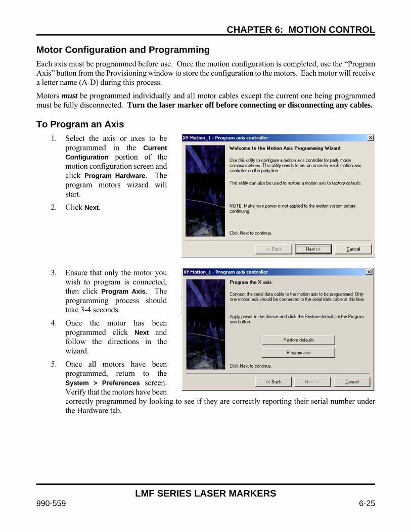
CHAPTER 6: MOTION CONTROL
LMF SERIES LASER MARKERS
990-559 6-25
Motor Configuration and Programming Each axis must be programmed before use. Once the motion configuration is completed, use the “Program Axis” button from the Provisioning window to store the configuration to the motors. Each motor will receive a letter name (A-D) during this process.
Motors must be programmed individually and all motor cables except the current one being programmed must be fully disconnected. Turn the laser marker off before connecting or disconnecting any cables. To Program an Axis
1. Select the axis or axes to be programmed in the Current Configuration portion of the motion configuration screen and click Program Hardware. The program motors wizard will start.
2. Click Next.
3. Ensure that only the motor you
wish to program is connected, then click Program Axis. The programming process should take 3-4 seconds.
4. Once the motor has been programmed click Next and follow the directions in the wizard.
5. Once all motors have been programmed, return to the System > Preferences screen. Verify that the motors have been correctly programmed by looking to see if they are correctly reporting their serial number under the Hardware tab.
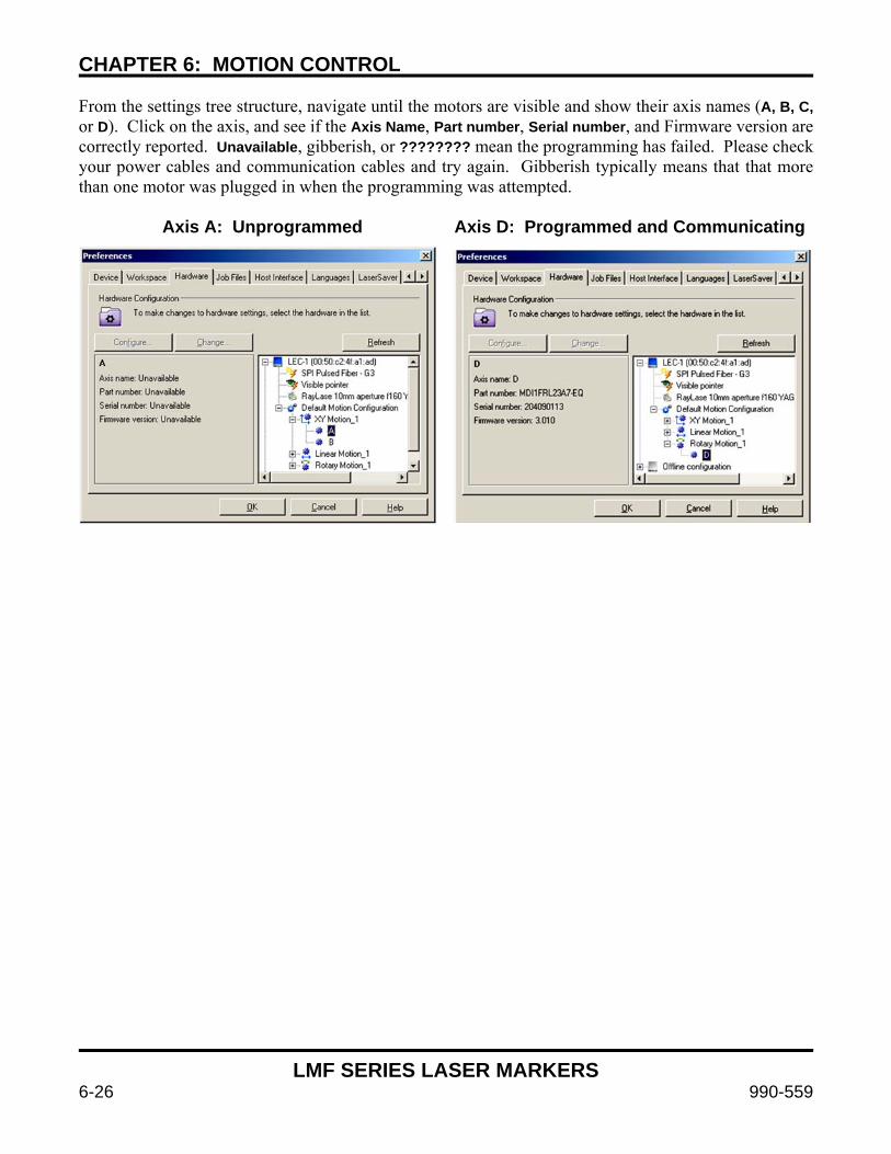
CHAPTER 6: MOTION CONTROL
LMF SERIES LASER MARKERS
6-26 990-559
From the settings tree structure, navigate until the motors are visible and show their axis names (A, B, C, or D). Click on the axis, and see if the Axis Name, Part number, Serial number, and Firmware version are correctly reported. Unavailable, gibberish, or ???????? mean the programming has failed. Please check your power cables and communication cables and try again. Gibberish typically means that that more than one motor was plugged in when the programming was attempted.
Axis A: Unprogrammed Axis D: Programmed and Communicating
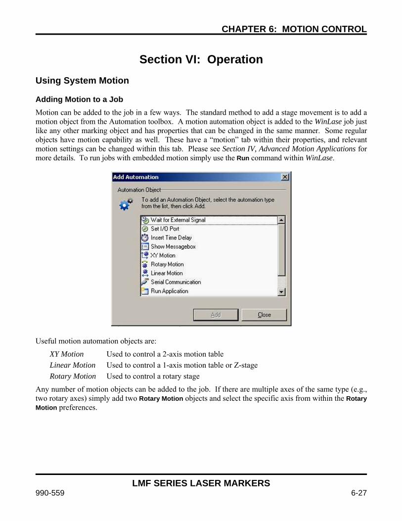
CHAPTER 6: MOTION CONTROL
LMF SERIES LASER MARKERS
990-559 6-27
Section VI: Operation Using System Motion Adding Motion to a Job Motion can be added to the job in a few ways. The standard method to add a stage movement is to add a motion object from the Automation toolbox. A motion automation object is added to the WinLase job just like any other marking object and has properties that can be changed in the same manner. Some regular objects have motion capability as well. These have a “motion” tab within their properties, and relevant motion settings can be changed within this tab. Please see Section IV, Advanced Motion Applications for more details. To run jobs with embedded motion simply use the Run command within WinLase.
Useful motion automation objects are:
XY Motion Used to control a 2-axis motion table
Linear Motion Used to control a 1-axis motion table or Z-stage
Rotary Motion Used to control a rotary stage
Any number of motion objects can be added to the job. If there are multiple axes of the same type (e.g., two rotary axes) simply add two Rotary Motion objects and select the specific axis from within the Rotary Motion preferences.
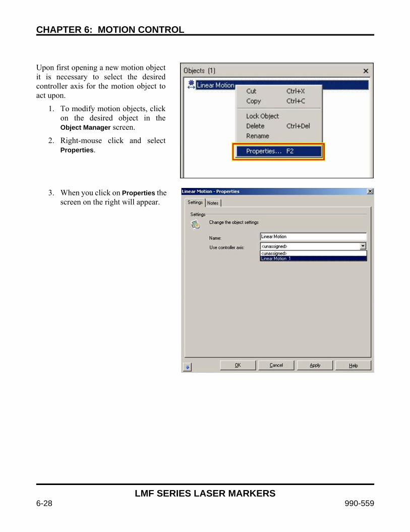
CHAPTER 6: MOTION CONTROL
LMF SERIES LASER MARKERS
6-28 990-559
Upon first opening a new motion object it is necessary to select the desired controller axis for the motion object to act upon.
1. To modify motion objects, click on the desired object in the Object Manager screen.
2. Right-mouse click and select Properties.
3. When you click on Properties the
screen on the right will appear.
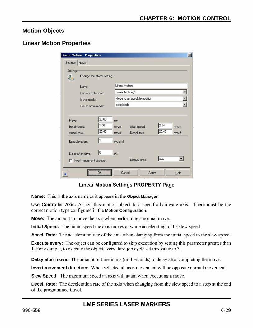
CHAPTER 6: MOTION CONTROL
LMF SERIES LASER MARKERS
990-559 6-29
Motion Objects Linear Motion Properties
Linear Motion Settings PROPERTY Page
Name: This is the axis name as it appears in the Object Manager.
Use Controller Axis: Assign this motion object to a specific hardware axis. There must be the correct motion type configured in the Motion Configuration.
Move: The amount to move the axis when performing a normal move.
Initial Speed: The initial speed the axis moves at while accelerating to the slew speed.
Accel. Rate: The acceleration rate of the axis when changing from the initial speed to the slew speed.
Execute every: The object can be configured to skip execution by setting this parameter greater than 1. For example, to execute the object every third job cycle set this value to 3.
Delay after move: The amount of time in ms (milliseconds) to delay after completing the move.
Invert movement direction: When selected all axis movement will be opposite normal movement.
Slew Speed: The maximum speed an axis will attain when executing a move.
Decel. Rate: The deceleration rate of the axis when changing from the slew speed to a stop at the end of the programmed travel.
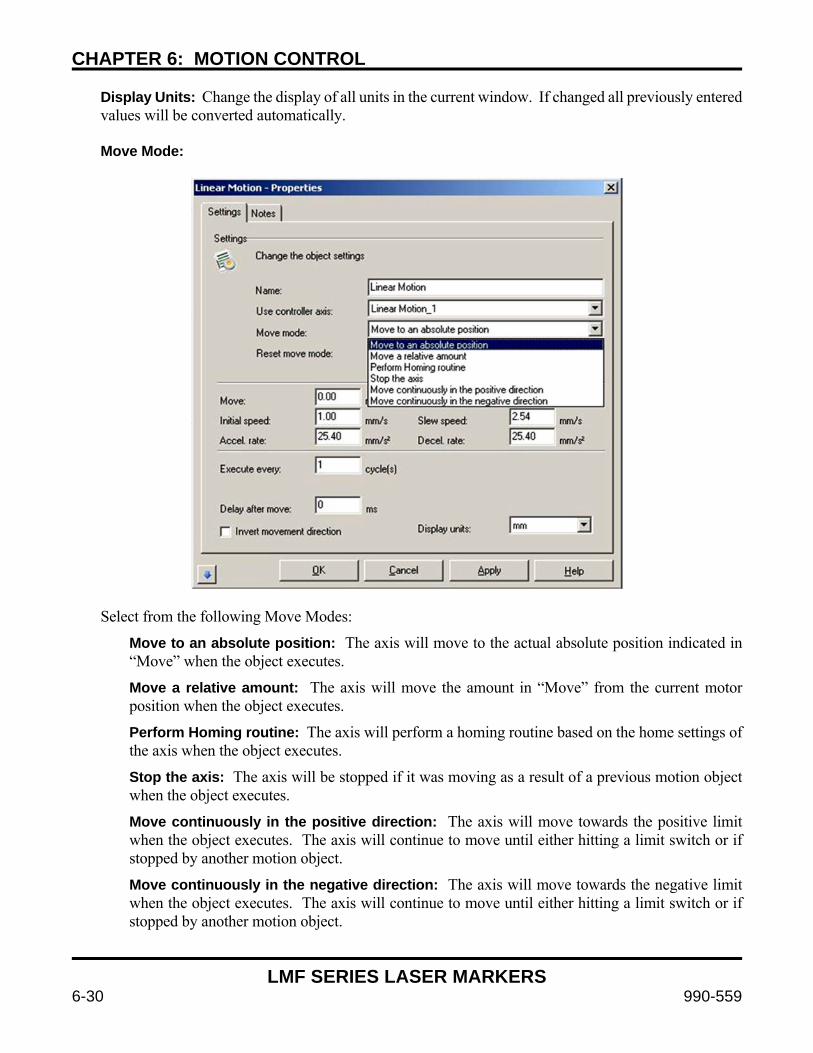
CHAPTER 6: MOTION CONTROL
LMF SERIES LASER MARKERS
6-30 990-559
Display Units: Change the display of all units in the current window. If changed all previously entered values will be converted automatically.
Move Mode:
Select from the following Move Modes:
Move to an absolute position: The axis will move to the actual absolute position indicated in “Move” when the object executes.
Move a relative amount: The axis will move the amount in “Move” from the current motor position when the object executes.
Perform Homing routine: The axis will perform a homing routine based on the home settings of the axis when the object executes.
Stop the axis: The axis will be stopped if it was moving as a result of a previous motion object when the object executes.
Move continuously in the positive direction: The axis will move towards the positive limit when the object executes. The axis will continue to move until either hitting a limit switch or if stopped by another motion object.
Move continuously in the negative direction: The axis will move towards the negative limit when the object executes. The axis will continue to move until either hitting a limit switch or if stopped by another motion object.
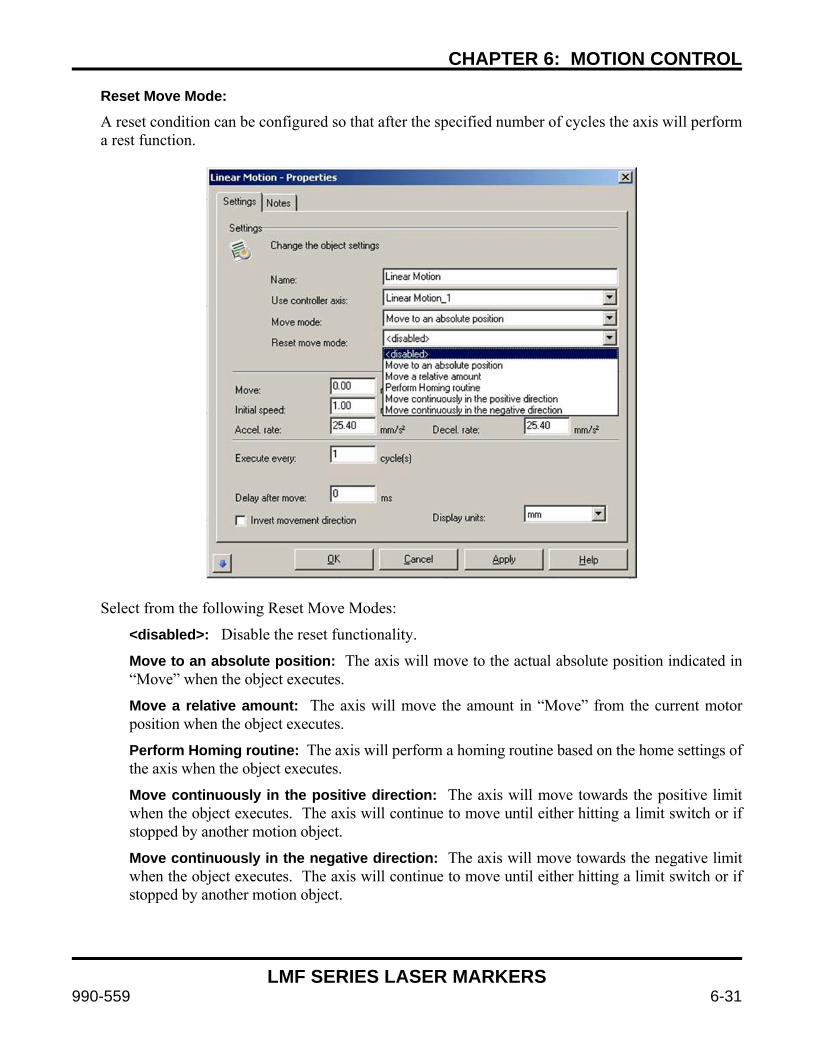
CHAPTER 6: MOTION CONTROL
LMF SERIES LASER MARKERS
990-559 6-31
Reset Move Mode:
A reset condition can be configured so that after the specified number of cycles the axis will perform a rest function.
Select from the following Reset Move Modes:
<disabled>: Disable the reset functionality.
Move to an absolute position: The axis will move to the actual absolute position indicated in “Move” when the object executes.
Move a relative amount: The axis will move the amount in “Move” from the current motor position when the object executes.
Perform Homing routine: The axis will perform a homing routine based on the home settings of the axis when the object executes.
Move continuously in the positive direction: The axis will move towards the positive limit when the object executes. The axis will continue to move until either hitting a limit switch or if stopped by another motion object.
Move continuously in the negative direction: The axis will move towards the negative limit when the object executes. The axis will continue to move until either hitting a limit switch or if stopped by another motion object.
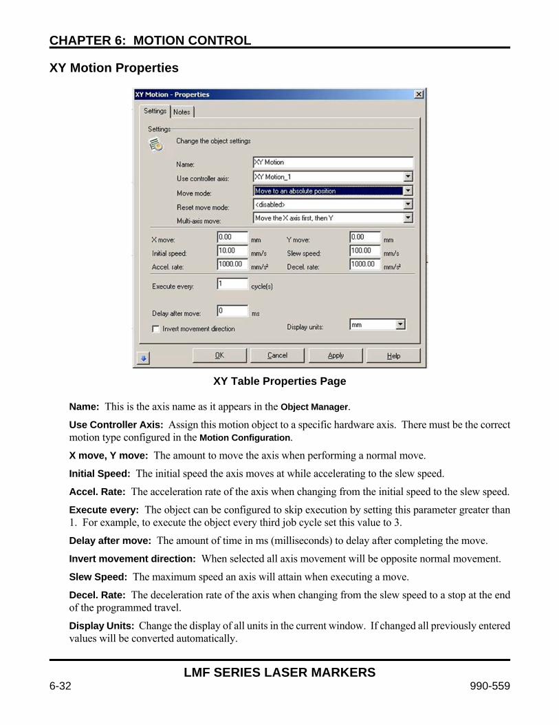
CHAPTER 6: MOTION CONTROL
LMF SERIES LASER MARKERS
6-32 990-559
XY Motion Properties
XY Table Properties Page
Name: This is the axis name as it appears in the Object Manager.
Use Controller Axis: Assign this motion object to a specific hardware axis. There must be the correct motion type configured in the Motion Configuration.
X move, Y move: The amount to move the axis when performing a normal move.
Initial Speed: The initial speed the axis moves at while accelerating to the slew speed.
Accel. Rate: The acceleration rate of the axis when changing from the initial speed to the slew speed.
Execute every: The object can be configured to skip execution by setting this parameter greater than 1. For example, to execute the object every third job cycle set this value to 3.
Delay after move: The amount of time in ms (milliseconds) to delay after completing the move.
Invert movement direction: When selected all axis movement will be opposite normal movement.
Slew Speed: The maximum speed an axis will attain when executing a move.
Decel. Rate: The deceleration rate of the axis when changing from the slew speed to a stop at the end of the programmed travel.
Display Units: Change the display of all units in the current window. If changed all previously entered values will be converted automatically.

CHAPTER 6: MOTION CONTROL
LMF SERIES LASER MARKERS
990-559 6-33
Move Mode:
Select from the following Move Modes: Move to an absolute position: The axis will move to the actual absolute position indicated in “Move” when the object executes.
Move a relative amount: The axis will move the amount in “Move” from the current motor position when the object executes.
Perform Homing routine: The axis will perform a homing routine based on the home settings of the axis when the object executes.
Stop the axis: The axis will be stopped if it was moving as a result of a previous motion object when the object executes.
Move continuously in the x positive, y positive direction: The axis will move towards the positive limit in both x and y axes when the object executes. The axis will continue to move until either hitting a limit switch or if stopped by another motion object.
Move continuously in the x negative, y negative direction: The axis will move towards the negative limit in both x and y axes when the object executes. The axis will continue to move until either hitting a limit switch or if stopped by another motion object.
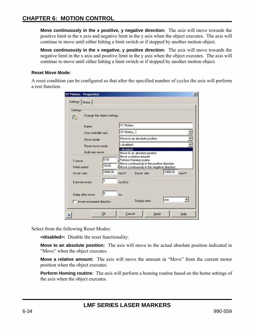
CHAPTER 6: MOTION CONTROL
LMF SERIES LASER MARKERS
6-34 990-559
Move continuously in the x positive, y negative direction: The axis will move towards the positive limit in the x axis and negative limit in the y axis when the object executes. The axis will continue to move until either hitting a limit switch or if stopped by another motion object.
Move continuously in the x negative, y positive direction: The axis will move towards the negative limit in the x axis and positive limit in the y axis when the object executes. The axis will continue to move until either hitting a limit switch or if stopped by another motion object.
Reset Move Mode:
A reset condition can be configured so that after the specified number of cycles the axis will perform a rest function.
Select from the following Reset Modes:
<disabled>: Disable the reset functionality.
Move to an absolute position: The axis will move to the actual absolute position indicated in “Move” when the object executes.
Move a relative amount: The axis will move the amount in “Move” from the current motor position when the object executes.
Perform Homing routine: The axis will perform a homing routine based on the home settings of the axis when the object executes.
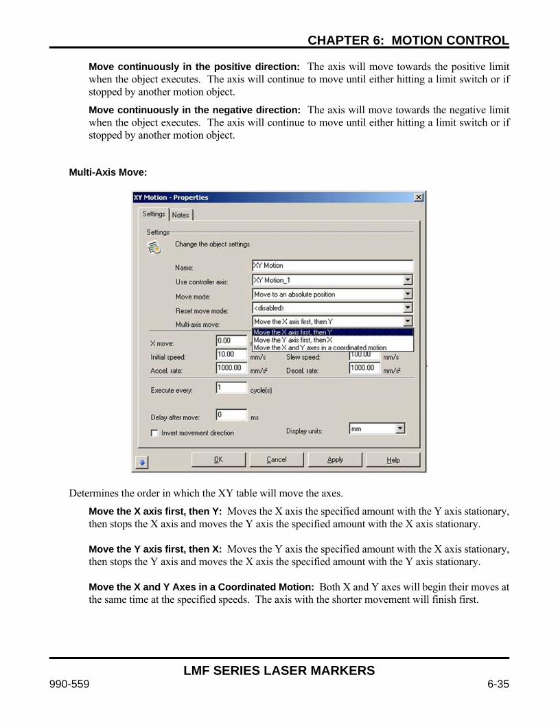
CHAPTER 6: MOTION CONTROL
LMF SERIES LASER MARKERS
990-559 6-35
Move continuously in the positive direction: The axis will move towards the positive limit when the object executes. The axis will continue to move until either hitting a limit switch or if stopped by another motion object.
Move continuously in the negative direction: The axis will move towards the negative limit when the object executes. The axis will continue to move until either hitting a limit switch or if stopped by another motion object.
Multi-Axis Move:
Determines the order in which the XY table will move the axes.
Move the X axis first, then Y: Moves the X axis the specified amount with the Y axis stationary, then stops the X axis and moves the Y axis the specified amount with the X axis stationary. Move the Y axis first, then X: Moves the Y axis the specified amount with the X axis stationary, then stops the Y axis and moves the X axis the specified amount with the Y axis stationary. Move the X and Y Axes in a Coordinated Motion: Both X and Y axes will begin their moves at the same time at the specified speeds. The axis with the shorter movement will finish first.
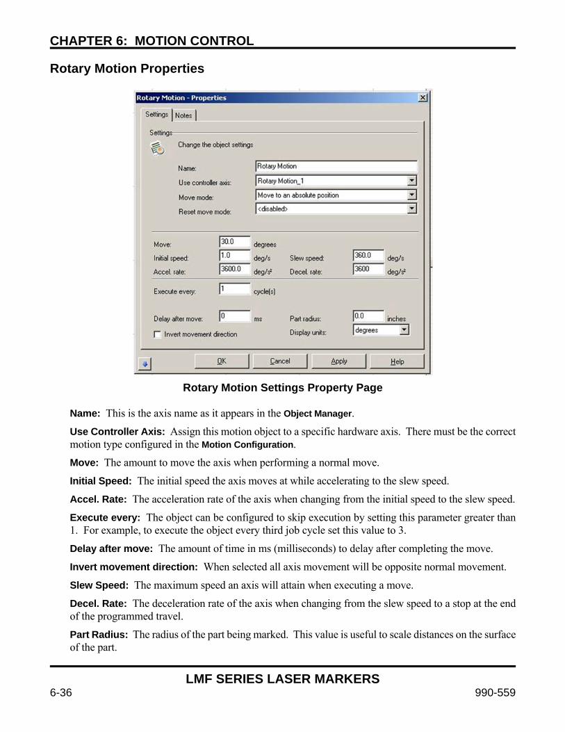
CHAPTER 6: MOTION CONTROL
LMF SERIES LASER MARKERS
6-36 990-559
Rotary Motion Properties
Rotary Motion Settings Property Page
Name: This is the axis name as it appears in the Object Manager.
Use Controller Axis: Assign this motion object to a specific hardware axis. There must be the correct motion type configured in the Motion Configuration.
Move: The amount to move the axis when performing a normal move.
Initial Speed: The initial speed the axis moves at while accelerating to the slew speed.
Accel. Rate: The acceleration rate of the axis when changing from the initial speed to the slew speed.
Execute every: The object can be configured to skip execution by setting this parameter greater than 1. For example, to execute the object every third job cycle set this value to 3.
Delay after move: The amount of time in ms (milliseconds) to delay after completing the move.
Invert movement direction: When selected all axis movement will be opposite normal movement.
Slew Speed: The maximum speed an axis will attain when executing a move.
Decel. Rate: The deceleration rate of the axis when changing from the slew speed to a stop at the end of the programmed travel.
Part Radius: The radius of the part being marked. This value is useful to scale distances on the surface of the part.
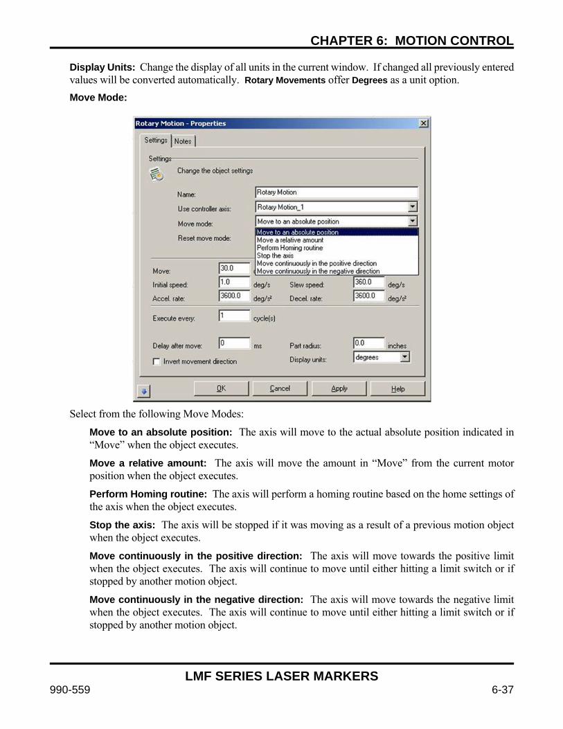
CHAPTER 6: MOTION CONTROL
LMF SERIES LASER MARKERS
990-559 6-37
Display Units: Change the display of all units in the current window. If changed all previously entered values will be converted automatically. Rotary Movements offer Degrees as a unit option.
Move Mode:
Select from the following Move Modes:
Move to an absolute position: The axis will move to the actual absolute position indicated in “Move” when the object executes.
Move a relative amount: The axis will move the amount in “Move” from the current motor position when the object executes.
Perform Homing routine: The axis will perform a homing routine based on the home settings of the axis when the object executes.
Stop the axis: The axis will be stopped if it was moving as a result of a previous motion object when the object executes.
Move continuously in the positive direction: The axis will move towards the positive limit when the object executes. The axis will continue to move until either hitting a limit switch or if stopped by another motion object.
Move continuously in the negative direction: The axis will move towards the negative limit when the object executes. The axis will continue to move until either hitting a limit switch or if stopped by another motion object.
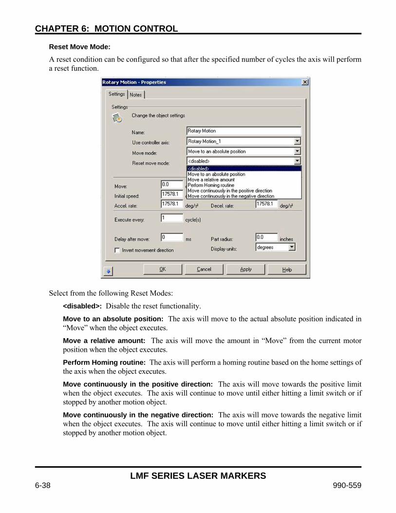
CHAPTER 6: MOTION CONTROL
LMF SERIES LASER MARKERS
6-38 990-559
Reset Move Mode:
A reset condition can be configured so that after the specified number of cycles the axis will perform a reset function.
Select from the following Reset Modes:
<disabled>: Disable the reset functionality.
Move to an absolute position: The axis will move to the actual absolute position indicated in “Move” when the object executes.
Move a relative amount: The axis will move the amount in “Move” from the current motor position when the object executes.
Perform Homing routine: The axis will perform a homing routine based on the home settings of the axis when the object executes.
Move continuously in the positive direction: The axis will move towards the positive limit when the object executes. The axis will continue to move until either hitting a limit switch or if stopped by another motion object.
Move continuously in the negative direction: The axis will move towards the negative limit when the object executes. The axis will continue to move until either hitting a limit switch or if stopped by another motion object.
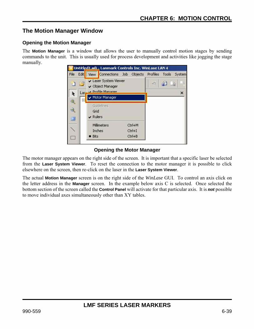
CHAPTER 6: MOTION CONTROL
LMF SERIES LASER MARKERS
990-559 6-39
The Motion Manager Window Opening the Motion Manager
The Motion Manager is a window that allows the user to manually control motion stages by sending commands to the unit. This is usually used for process development and activities like jogging the stage manually.
Opening the Motor Manager The motor manager appears on the right side of the screen. It is important that a specific laser be selected from the Laser System Viewer. To reset the connection to the motor manager it is possible to click elsewhere on the screen, then re-click on the laser in the Laser System Viewer.
The actual Motion Manager screen is on the right side of the WinLase GUI. To control an axis click on the letter address in the Manager screen. In the example below axis C is selected. Once selected the bottom section of the screen called the Control Panel will activate for that particular axis. It is not possible to move individual axes simultaneously other than XY tables.
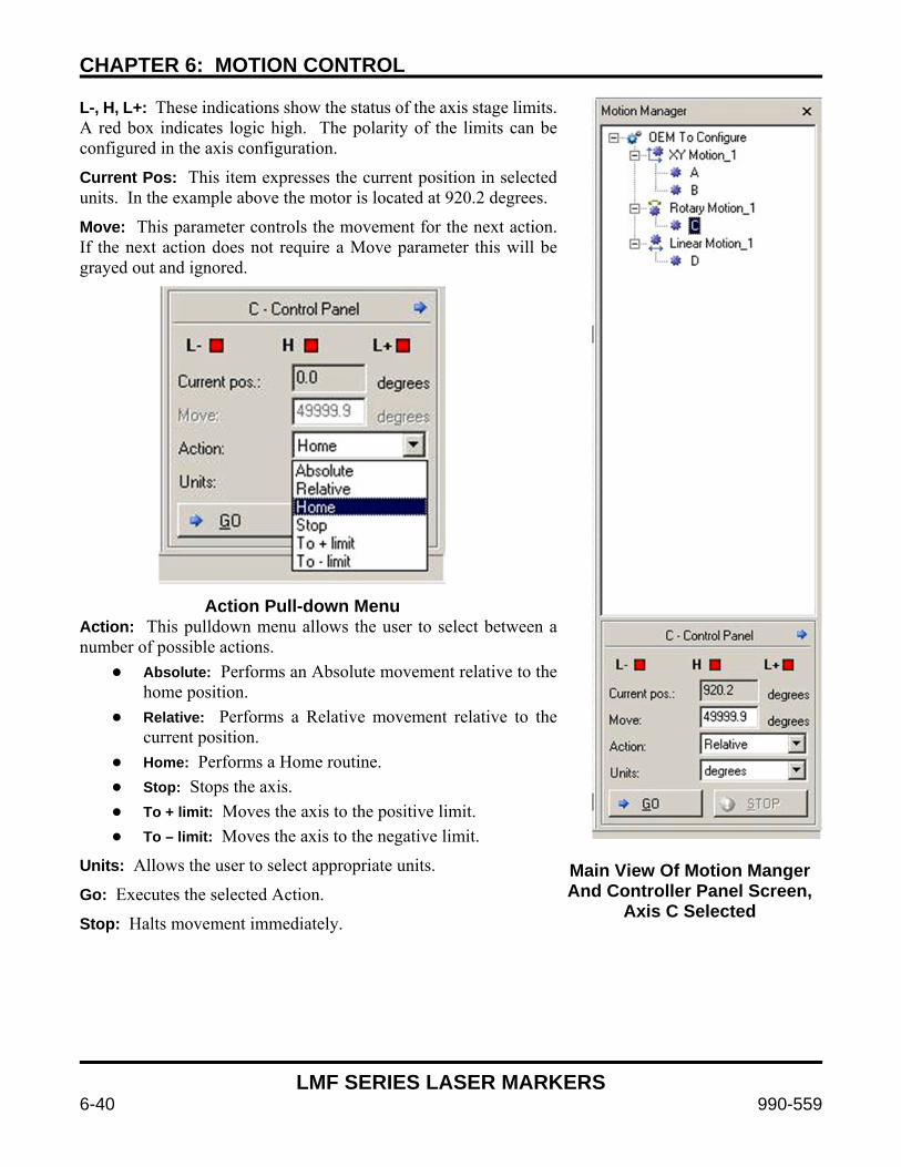
CHAPTER 6: MOTION CONTROL
LMF SERIES LASER MARKERS
6-40 990-559
L-, H, L+: These indications show the status of the axis stage limits.A red box indicates logic high. The polarity of the limits can be configured in the axis configuration.
Current Pos: This item expresses the current position in selectedunits. In the example above the motor is located at 920.2 degrees.
Move: This parameter controls the movement for the next action.If the next action does not require a Move parameter this will begrayed out and ignored.
Action Pull-down Menu Action: This pulldown menu allows the user to select between anumber of possible actions.
Absolute: Performs an Absolute movement relative to thehome position.
Relative: Performs a Relative movement relative to thecurrent position.
Home: Performs a Home routine.
Stop: Stops the axis.
To + limit: Moves the axis to the positive limit.
To – limit: Moves the axis to the negative limit.
Units: Allows the user to select appropriate units.
Go: Executes the selected Action.
Stop: Halts movement immediately.
Main View Of Motion Manger And Controller Panel Screen,
Axis C Selected
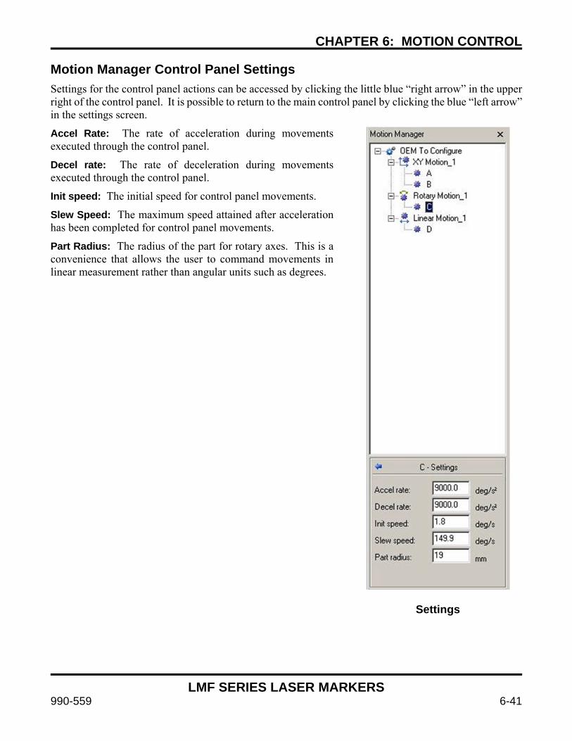
CHAPTER 6: MOTION CONTROL
LMF SERIES LASER MARKERS
990-559 6-41
Motion Manager Control Panel Settings Settings for the control panel actions can be accessed by clicking the little blue “right arrow” in the upper right of the control panel. It is possible to return to the main control panel by clicking the blue “left arrow” in the settings screen.
Accel Rate: The rate of acceleration during movements executed through the control panel.
Decel rate: The rate of deceleration during movements executed through the control panel.
Init speed: The initial speed for control panel movements.
Slew Speed: The maximum speed attained after acceleration has been completed for control panel movements.
Part Radius: The radius of the part for rotary axes. This is a convenience that allows the user to command movements in linear measurement rather than angular units such as degrees.
Settings

CHAPTER 6: MOTION CONTROL
LMF SERIES LASER MARKERS
6-42 990-559
Advanced Motion Applications Choosing between Raster and Vector Marking A laser marker by definition is a vector engine – the beam can only mark from one place to another using short line segments. This affects how certain marked objects must be configured and affects the final quality and speed of the marked part. It is important to understand this difference when setting up an advanced motion mark such as on a cylinder or other geometrical shape.
Vector graphics are composed of a series of lines – the marker completes these lines at the same power settings, and can perform direction changes at certain points. The letter C, for example, would be broken up into many tiny segments on the curved sections. In addition, if there is a closed polygon (like a square, or a letter) it is possible to use WinLase’s built in functions to fill it very quickly. This is ideal for laser marking since the laser marker simply turns the beam on and off at the beginning/end of each vector, and gives the highest resolution and smoothest lines. A vector format doesn’t mark empty areas. It is also substantially faster than a comparable raster mark.
Raster graphics like bitmap and jpg have a series of pixels depending on their resolution. Each pixel is individually marked at a different pulse width setting of the laser. Changing the mark characteristics of each pixel as the beam “rasters” back and forth marks the image. A bitmap with 256 shade grayscale is ideal since it gives the laser a range of “gray” colors to play with. Selecting the ideal resolution is the most important factor to get good results. The problem with raster marking is that it is necessary to mark a large number of pixels for good results. An extremely high resolution is usually necessary – ideal for a 160mm lens is well over 500dpi.
Typically a photo will look good to the naked eye above 250dpi. Although it’s hard to estimate dpi based on JPG file size since jpg is a compressed format a good rule of thumb is that bitmap files must be >2 MB to look good, more if the final image will be larger. JPG files that look good are typically 500KB or more. Since each line of pixels (which would be 500 per inch) must be rastered across to get the resolution for ideal performance it can be extremely slow. Marking a monochrome company logo, for example, can take two minutes when it would take 10 seconds or less with a similar vector file. For this reason vector logos are preferred in a non-motion environment.
Applying motion to the raster/vector image introduces a new level of complexity. Since the surface presented to the laser beam must always be in focus using motion control it is important to design the mark within the limits of the motion system. In the example of the company logo marked on a cylinder it is very difficult to achieve a good mark with a vector image. In this situation a rastered bitmap is the best solution since the motion control can slowly rotate the part while the laser marks constantly at its focal point. In addition, it is possible to mark a few lines of the bitmap and increment for better speed when the part has a large radius.
Certain types of objects, specifically text, do not work well as raster objects due to the necessary sharpness required to look good to the human eye. In this situation there is a technique called “circumferential marking” used to mark vector text on a cylinder’s circumference.
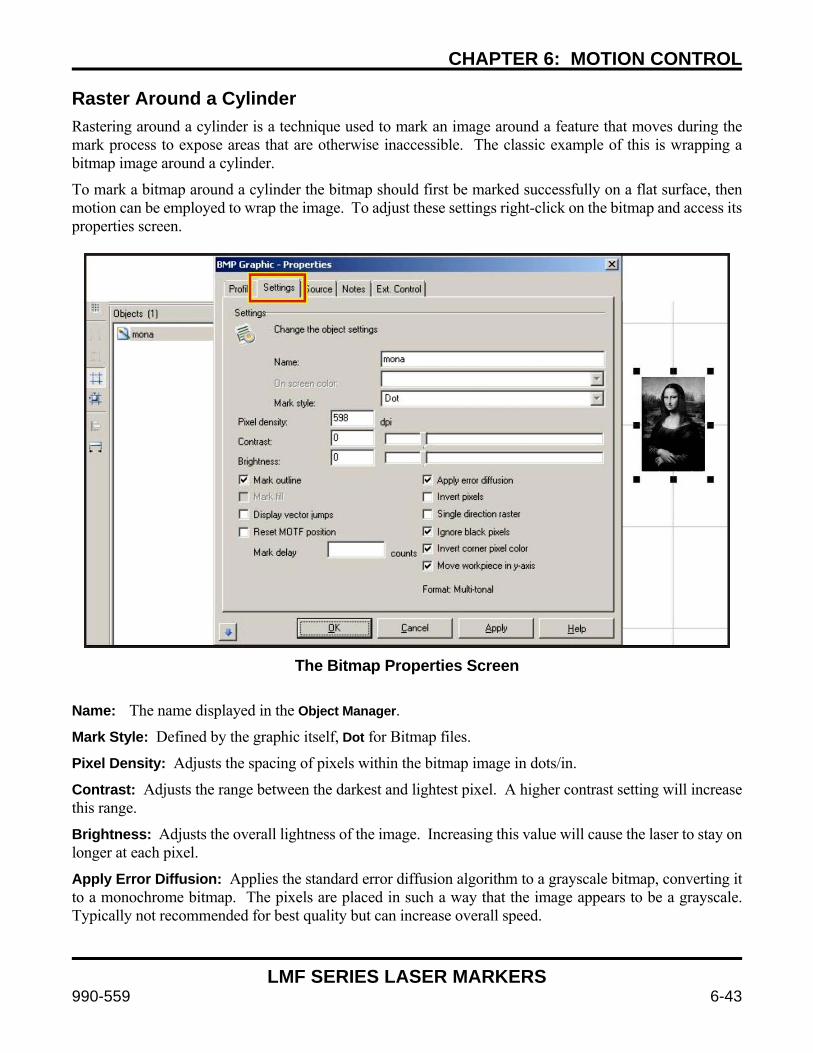
CHAPTER 6: MOTION CONTROL
LMF SERIES LASER MARKERS
990-559 6-43
Raster Around a Cylinder
Rastering around a cylinder is a technique used to mark an image around a feature that moves during the mark process to expose areas that are otherwise inaccessible. The classic example of this is wrapping a bitmap image around a cylinder.
To mark a bitmap around a cylinder the bitmap should first be marked successfully on a flat surface, then motion can be employed to wrap the image. To adjust these settings right-click on the bitmap and access its properties screen.
The Bitmap Properties Screen
Name: The name displayed in the Object Manager.
Mark Style: Defined by the graphic itself, Dot for Bitmap files.
Pixel Density: Adjusts the spacing of pixels within the bitmap image in dots/in.
Contrast: Adjusts the range between the darkest and lightest pixel. A higher contrast setting will increase this range.
Brightness: Adjusts the overall lightness of the image. Increasing this value will cause the laser to stay on longer at each pixel.
Apply Error Diffusion: Applies the standard error diffusion algorithm to a grayscale bitmap, converting it to a monochrome bitmap. The pixels are placed in such a way that the image appears to be a grayscale. Typically not recommended for best quality but can increase overall speed.
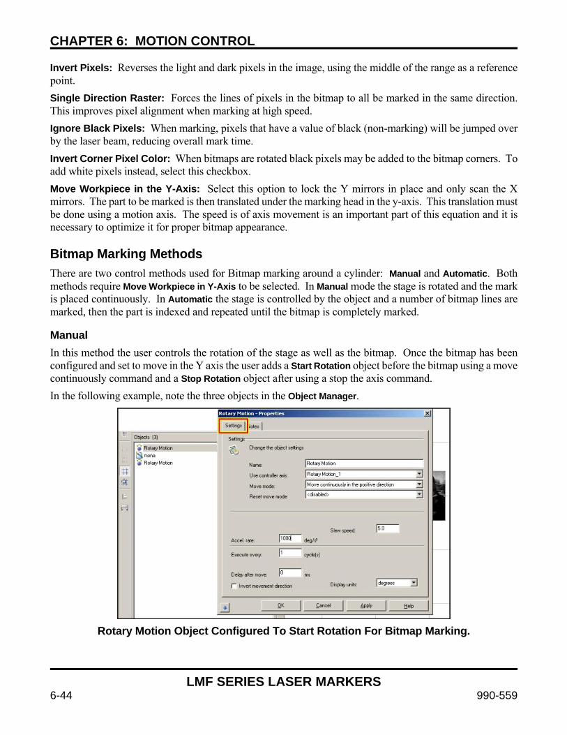
CHAPTER 6: MOTION CONTROL
LMF SERIES LASER MARKERS
6-44 990-559
Invert Pixels: Reverses the light and dark pixels in the image, using the middle of the range as a reference point.
Single Direction Raster: Forces the lines of pixels in the bitmap to all be marked in the same direction. This improves pixel alignment when marking at high speed.
Ignore Black Pixels: When marking, pixels that have a value of black (non-marking) will be jumped over by the laser beam, reducing overall mark time.
Invert Corner Pixel Color: When bitmaps are rotated black pixels may be added to the bitmap corners. To add white pixels instead, select this checkbox.
Move Workpiece in the Y-Axis: Select this option to lock the Y mirrors in place and only scan the X mirrors. The part to be marked is then translated under the marking head in the y-axis. This translation must be done using a motion axis. The speed is of axis movement is an important part of this equation and it is necessary to optimize it for proper bitmap appearance. Bitmap Marking Methods There are two control methods used for Bitmap marking around a cylinder: Manual and Automatic. Both methods require Move Workpiece in Y-Axis to be selected. In Manual mode the stage is rotated and the mark is placed continuously. In Automatic the stage is controlled by the object and a number of bitmap lines are marked, then the part is indexed and repeated until the bitmap is completely marked. Manual In this method the user controls the rotation of the stage as well as the bitmap. Once the bitmap has been configured and set to move in the Y axis the user adds a Start Rotation object before the bitmap using a move continuously command and a Stop Rotation object after using a stop the axis command.
In the following example, note the three objects in the Object Manager.
Rotary Motion Object Configured To Start Rotation For Bitmap Marking.
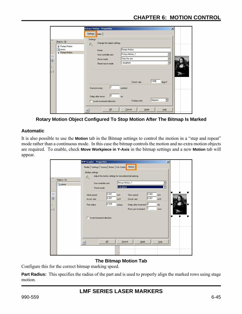
CHAPTER 6: MOTION CONTROL
LMF SERIES LASER MARKERS
990-559 6-45
Rotary Motion Object Configured To Stop Motion After The Bitmap Is Marked
Automatic It is also possible to use the Motion tab in the Bitmap settings to control the motion in a “step and repeat” mode rather than a continuous mode. In this case the bitmap controls the motion and no extra motion objects are required. To enable, check Move Workpiece in Y-Axis in the bitmap settings and a new Motion tab will appear.
The Bitmap Motion Tab Configure this for the correct bitmap marking speed.
Part Radius: This specifies the radius of the part and is used to properly align the marked rows using stage motion.

CHAPTER 6: MOTION CONTROL
LMF SERIES LASER MARKERS
6-46 990-559
Rows Per Increment: This specifies how many rows of the bitmap will be marked for each movement. Larger parts can handle more rows without the rows going out of focus. Make this value as large as possible such that good results are obtained. Circumferential Marking
Marking Vector Text around a Circumference. The Circumferential mark feature allows the user to mark vector text around the circumference of a round part. In this case the rotary axis will index after each letter to maintain the work area in laser focus. The text to be marked will “compress” on the laser marking field screen to show the laser marker’s view of the text to be marked. This is a fast and efficient way to mark high quality text around on a round or cylindrical object.
To use circumferential text with a compatible axis installed create a standard text object and open the String tab. Select Circumferential in the String Orientation pulldown. A Motion tab will appear
Selecting Circumferential Text Mode. Note the Motion tab.
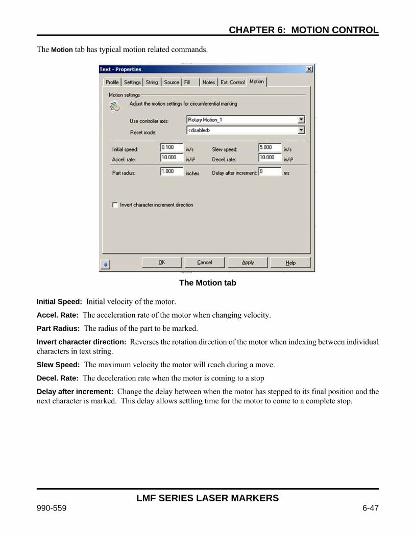
CHAPTER 6: MOTION CONTROL
LMF SERIES LASER MARKERS
990-559 6-47
The Motion tab has typical motion related commands.
The Motion tab Initial Speed: Initial velocity of the motor.
Accel. Rate: The acceleration rate of the motor when changing velocity.
Part Radius: The radius of the part to be marked.
Invert character direction: Reverses the rotation direction of the motor when indexing between individual characters in text string.
Slew Speed: The maximum velocity the motor will reach during a move.
Decel. Rate: The deceleration rate when the motor is coming to a stop
Delay after increment: Change the delay between when the motor has stepped to its final position and the next character is marked. This delay allows settling time for the motor to come to a complete stop.
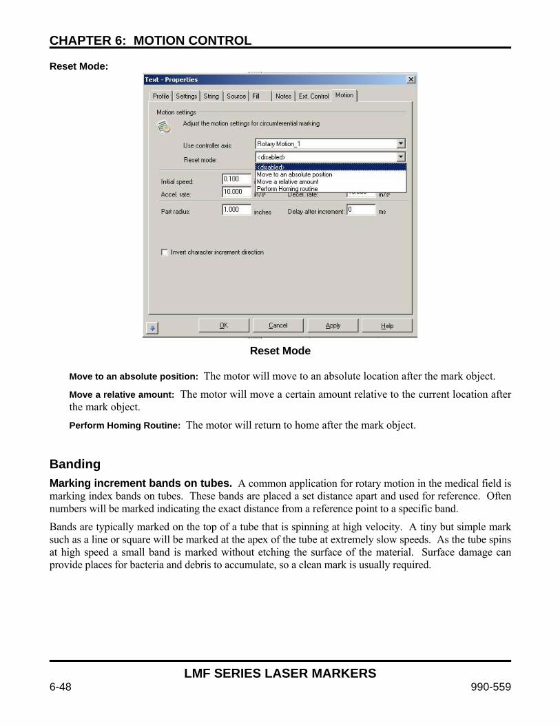
CHAPTER 6: MOTION CONTROL
LMF SERIES LASER MARKERS
6-48 990-559
Reset Mode:
Reset Mode Move to an absolute position: The motor will move to an absolute location after the mark object.
Move a relative amount: The motor will move a certain amount relative to the current location after the mark object.
Perform Homing Routine: The motor will return to home after the mark object. Banding Marking increment bands on tubes. A common application for rotary motion in the medical field is marking index bands on tubes. These bands are placed a set distance apart and used for reference. Often numbers will be marked indicating the exact distance from a reference point to a specific band.
Bands are typically marked on the top of a tube that is spinning at high velocity. A tiny but simple mark such as a line or square will be marked at the apex of the tube at extremely slow speeds. As the tube spins at high speed a small band is marked without etching the surface of the material. Surface damage can provide places for bacteria and debris to accumulate, so a clean mark is usually required.
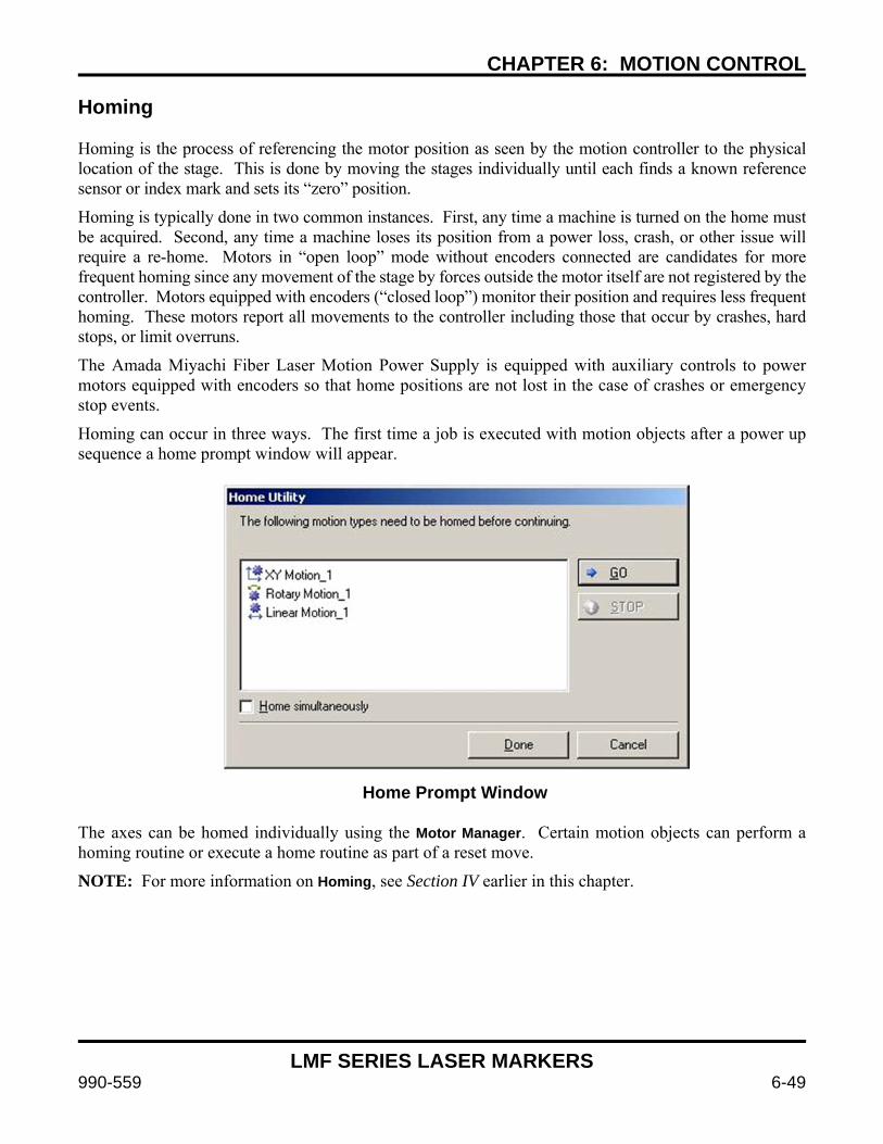
CHAPTER 6: MOTION CONTROL
LMF SERIES LASER MARKERS
990-559 6-49
Homing Homing is the process of referencing the motor position as seen by the motion controller to the physical location of the stage. This is done by moving the stages individually until each finds a known reference sensor or index mark and sets its “zero” position.
Homing is typically done in two common instances. First, any time a machine is turned on the home must be acquired. Second, any time a machine loses its position from a power loss, crash, or other issue will require a re-home. Motors in “open loop” mode without encoders connected are candidates for more frequent homing since any movement of the stage by forces outside the motor itself are not registered by the controller. Motors equipped with encoders (“closed loop”) monitor their position and requires less frequent homing. These motors report all movements to the controller including those that occur by crashes, hard stops, or limit overruns.
The Amada Miyachi Fiber Laser Motion Power Supply is equipped with auxiliary controls to power motors equipped with encoders so that home positions are not lost in the case of crashes or emergency stop events.
Homing can occur in three ways. The first time a job is executed with motion objects after a power up sequence a home prompt window will appear.
Home Prompt Window
The axes can be homed individually using the Motor Manager. Certain motion objects can perform a homing routine or execute a home routine as part of a reset move.
NOTE: For more information on Homing, see Section IV earlier in this chapter.

CHAPTER 6: MOTION CONTROL
LMF SERIES LASER MARKERS
6-50 990-559
Troubleshooting Clearing Errors. To attempt to clear a motion error the axis should be selected in the Motion Manager. Click on the laser name in the Laser System Viewer and open the Motion Manager. Click on the letter name of the axis that is causing problems. Send a command using the Motion Manager control panel and see if the runtime errors return.
When troubleshooting motion errors, verify:
Are there any errors on the Error Display located in the Motion Manager?
Is the motor communicating?
Are all cables connected?
Is the fiber marker turned on, booted, and connected to WinLase in the Laser System Manager?
Is the fiber marker system in a fault state like Emergency Stop that would disable motors?
Is the external power supply energized?
Are there any WinLase faults?
Is the appropriate COM port selected in the WinLase System Settings screen and set to 9600 baud? (LMF Laser Markers use COM3 by default)
Categories of Errors and Potential Resolution
WinLase cannot communicate with the motion system (tried and failed)
Most commonly caused by a disconnected or defective cable or power supply. Emergency Stop can result in this error as well if the auxiliary power supply is not connected.
Motion System Not Found (WinLase doesn’t even try and communicate)
Most commonly caused by improper WinLase configuration. Check baud/COM settings.
Limits have been reached unexpectedly The high or low limits have been activated and the process has been aborted. Ensure that the motion program does not cause the stages to reach their limits, or troubleshoot defective limit switches or wiring.
Motion has been aborted by user
Motion system has returned an unknown response
Bad response from the motion system. Try resetting the system and try the operation again. If problems continue to occur contact Amada Miyachi America for assistance.
Stall Detected An axis has stalled. This is nearly always caused by improper motion parameters or a stage which has mechanically locked up. Verify the acceleration, deceleration, initial speed, and slew speed of each motion axis and homing configuration. Any of these parameters can cause a stall if set outside the motors’ ability to move the stage appropriately. Verify encoder settings including appropriate deadband and stall detection parameters. Ensure that the stage has not crashed, gotten stuck, or otherwise become mechanically bound. Reset the motion system, lower speeds and/or accelerations, and try again. If problems continue to occur contact Amada Miyachi America for assistance.
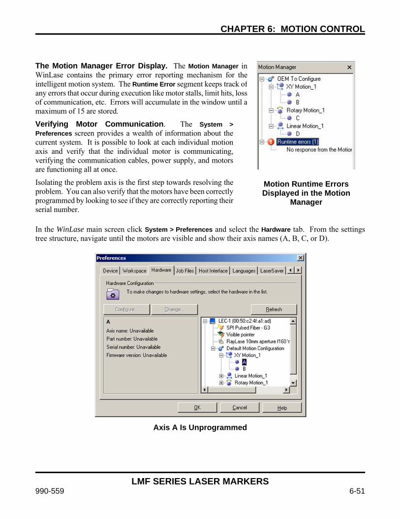
CHAPTER 6: MOTION CONTROL
LMF SERIES LASER MARKERS
990-559 6-51
The Motion Manager Error Display. The Motion Manager in WinLase contains the primary error reporting mechanism for theintelligent motion system. The Runtime Error segment keeps track of any errors that occur during execution like motor stalls, limit hits, loss of communication, etc. Errors will accumulate in the window until amaximum of 15 are stored.
Verifying Motor Communication. The System > Preferences screen provides a wealth of information about the current system. It is possible to look at each individual motion axis and verify that the individual motor is communicating, verifying the communication cables, power supply, and motors are functioning all at once.
Isolating the problem axis is the first step towards resolving the problem. You can also verify that the motors have been correctly programmed by looking to see if they are correctly reporting their serial number.
Motion Runtime Errors Displayed in the Motion
Manager
In the WinLase main screen click System > Preferences and select the Hardware tab. From the settings tree structure, navigate until the motors are visible and show their axis names (A, B, C, or D).
Axis A Is Unprogrammed
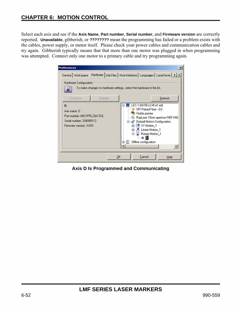
CHAPTER 6: MOTION CONTROL
LMF SERIES LASER MARKERS
6-52 990-559
Select each axis and see if the Axis Name, Part number, Serial number, and Firmware version are correctly reported. Unavailable, gibberish, or ???????? mean the programming has failed or a problem exists with the cables, power supply, or motor itself. Please check your power cables and communication cables and try again. Gibberish typically means that that more than one motor was plugged in when programming was attempted. Connect only one motor to a primary cable and try programming again.
Axis D Is Programmed and Communicating
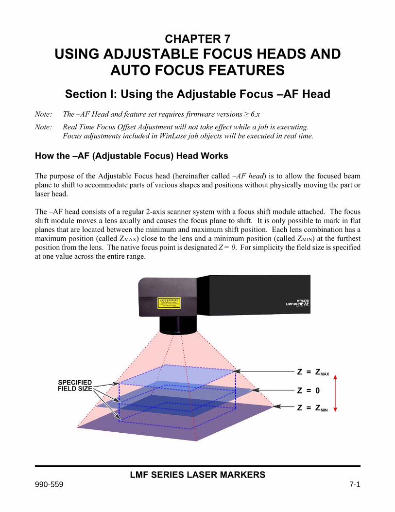
LMF SERIES LASER MARKERS
990-559 7-1
CHAPTER 7 USING ADJUSTABLE FOCUS HEADS AND
AUTO FOCUS FEATURES
Section I: Using the Adjustable Focus –AF Head
Note: The –AF Head and feature set requires firmware versions ≥ 6.x
Note: Real Time Focus Offset Adjustment will not take effect while a job is executing. Focus adjustments included in WinLase job objects will be executed in real time. How the –AF (Adjustable Focus) Head Works The purpose of the Adjustable Focus head (hereinafter called –AF head) is to allow the focused beam plane to shift to accommodate parts of various shapes and positions without physically moving the part or laser head. The –AF head consists of a regular 2-axis scanner system with a focus shift module attached. The focus shift module moves a lens axially and causes the focus plane to shift. It is only possible to mark in flat planes that are located between the minimum and maximum shift position. Each lens combination has a maximum position (called ZMAX) close to the lens and a minimum position (called ZMIN) at the furthest position from the lens. The native focus point is designated Z = 0. For simplicity the field size is specified at one value across the entire range.

CHAPTER 7: ADJUSTABLE FOCUS HEADS AND AUTO FOCUS FEATURES
LMF SERIES LASER MARKERS
7-2 990-559
Using the –AF Head in WinLase There are two types of focal adjustments made – individual Object Based Adjustments, and global Autofocus Adjustments. The sum of the two adjustments must be between ZMIN ≤ Z ≤ ZMAX. When the machine is first turned on the global adjustment defaults to Z = 0. Focus shift adjustments can be made for several reasons. Using multiple different fixtures or parts at different predetermined heights without moving the laser
head. This simplifies tooling since the tooling doesn’t need to conform to a regular fixed 2D laser focal position (Object Based Adjustment)
Marking on a part with multiple features or steps at different heights (Object Based Adjustment) Accommodating real-time changes in fixture position with vision system or part position sensor focus
changes (Autofocus Adjustments)
Setting up a new part or job of unknown height (Autofocus Adjustments) Refer to Appendix A for details on the allowable span of adjustment in the Z-axis direction.
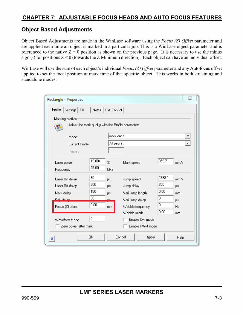
CHAPTER 7: ADJUSTABLE FOCUS HEADS AND AUTO FOCUS FEATURES
LMF SERIES LASER MARKERS
990-559 7-3
Object Based Adjustments Object Based Adjustments are made in the WinLase software using the Focus (Z) Offset parameter and are applied each time an object is marked in a particular job. This is a WinLase object parameter and is referenced to the native Z = 0 position as shown on the previous page. It is necessary to use the minus sign (-) for positions Z < 0 (towards the Z Minimum direction). Each object can have an individual offset. WinLase will use the sum of each object’s individual Focus (Z) Offset parameter and any Autofocus offset applied to set the focal position at mark time of that specific object. This works in both streaming and standalone modes.

CHAPTER 7: ADJUSTABLE FOCUS HEADS AND AUTO FOCUS FEATURES
LMF SERIES LASER MARKERS
7-4 990-559
Autofocus Adjustments Autofocus Adjustments are made using the remote API or HOST interface of the laser. They allow a global focus shift to be applied to all objects. The sum of the Autofocus shift and Object shift must be between ZMIN ≤ Z ≤ ZMAX so that the laser mark can occur in the working envelope of the –AF head. Syntax for an Autofocus Adjustment can be found in Appendix D of this manual or the appropriate WinLase manuals found in C:\marker\documentation. The Autofocus adjustment must occur over the API in standalone mode and HOST interface in streaming mode and can be made at any time in either mode. The offset applied can come from a laser sensor, vision sensor, PLC, or any other device capable of taking a measurement and sending to the laser and is measured in microns with respect to Z=0. The Autofocus Adjustment must be applied before the job is started so that the focus shift calculations have time to occur. In an automation environment with a sensor Syntax – Standalone Mode via Remote API Command: SetZOffsetRWU
Implementation: “76,zoffest”, where zoffset (in µm) is the z-axis focus change from Z=0. - The offset is absolute and can be positive or negative. - It must be between ZMIN ≤ Z ≤ ZMAX Ex: “76,-1000” offsets 1mm down
Response: An API response. “0”=Acknowledged, “9”=Bad Argument, etc.
See Appendix D for the full list of API response codes.
Streaming Mode via Host Interface
Command: Modify Zoffset Implementation: “MODIFY,zoffset,value”, where value is in microns referenced to Z=0. - The offset is absolute and can be positive or negative. - It must be between ZMIN ≤ Z ≤ ZMAX Ex: “MODIFY,zoffset,-1000” offsets 1mm down
Response: A HOST mode response.
To Reset: Send command with “0” to rest to Z=0 microns

CHAPTER 7: ADJUSTABLE FOCUS HEADS AND AUTO FOCUS FEATURES
LMF SERIES LASER MARKERS
990-559 7-5
Section II: Configuring for and using your -AF marker with Autofocus using the 8-921-0x Autofocus system
For convenience, Amada Miyachi America has made available a laser distance sensor based Autofocus kit that interfaces with laser markers equipped with the –AF adjustable focus head. The autofocus uses a laser distance sensor to register the distance between the known Z=0 laser focal plane and the user part. This measured distance is sent to the laser marker and the laser focus is adjusted so that the laser beam is focused on the part. It is the user’s responsibility to make sure that the sensor is aimed at the correct location and that the Z=0 position of the scan head and laser sensor are physically aligned.
The 8-921-01 (100mm) and 8-921-02 (300mm) Autofocus kits contain the following components:
1. An Omron ZX-1 or equivalent laser sensor wired appropriately for the interface box. a. 100mm focal length, Amada Miyachi America Pt Number 4-70245-01 (part of 8-921-01) b. 300mm focal length, Amada Miyachi America Pt Number 4-70245-02 (part of 8-921-02)
2. Autofocus Interface Controller, Amada Miyachi America Pt Number 4-70256-01 This interface controller translates the raw sensor output into API or HOST mode commands to apply the measured offset to the laser focus offset. In addition, the interface controller is the place where focus related I/O takes place including triggering a reading to be implemented by the laser.
3. RS-232 cable between the Autofocus Interface Controller and the laser API or PC COM port.
4. Autofocus Interface Controller power cable, Amada Miyachi America Pt Number 4-70337-01
In addition, an optional auto-focus mounting bracket system is available, Amada Miyachi America Part Number 8-922-01 (shown below)
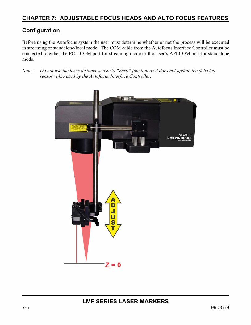
CHAPTER 7: ADJUSTABLE FOCUS HEADS AND AUTO FOCUS FEATURES
LMF SERIES LASER MARKERS
7-6 990-559
Configuration Before using the Autofocus system the user must determine whether or not the process will be executed in streaming or standalone/local mode. The COM cable from the Autofocus Interface Controller must be connected to either the PC’s COM port for streaming mode or the laser’s API COM port for standalone mode. Note: Do not use the laser distance sensor’s “Zero” function as it does not update the detected sensor value used by the Autofocus Interface Controller.

CHAPTER 7: ADJUSTABLE FOCUS HEADS AND AUTO FOCUS FEATURES
LMF SERIES LASER MARKERS
990-559 7-7
Standalone Mode Configuration 1. Connect the Autofocus Interface Controller to COM1 or COM2 of the laser rear panel using a RS-
232 cable. 2. Connect the Autofocus Interface Controller power to the laser marker.
3. Connect a PLC or similar I/O bit to the Trigger input of the Autofocus Interface Controller.
4. In WinLase right click on the laser in the Laser System Viewer and click “Settings”.
5. Navigate to the COM Ports tab.
6. Set COM2 to Remote API and COM2 baud rate to 9600.
7. Click “OK”.
8. Put a piece of test material at the Z=0 position of the laser marker.
9. Mark a test mark with the Focus (Z) Offset parameter in WinLase set to 0.
10. Physically adjust the laser distance sensor until the display reads zero.
11. Run a standalone job at Z=0.
12. Move the test material to some other Z position, send two Autofocus trigger events, and trigger the mark. The Autofocus Interface Controller may require a second trigger the first time it is used to automatically select mode between API and HOST commands.
13. Verify that the mark is in focus
14. If the mark is out of focus verify the Autofocus Interface Controller scaling is set appropriately using the instructions later in this chapter.
15. From this point forward the Autofocus Interface controller requires a single trigger before a cycle start to update focus position.
16. If the laser distance sensor is out of range a red LED will illuminate and the fault bit on the Autofocus Interface Controller will be active.

CHAPTER 7: ADJUSTABLE FOCUS HEADS AND AUTO FOCUS FEATURES
LMF SERIES LASER MARKERS
7-8 990-559
Configuring Autofocus in the WinLase GUI in streaming mode 1. Connect the Autofocus Interface Controller to the PC COM port a RS-232 cable. 2. Connect the Autofocus Interface Controller power to the laser marker. 3. Connect a PLC or similar I/O bit to the Trigger input of the Autofocus Interface Controller 4. In WinLase click on System from the dropdown menu at the top, then Preferences 5. Click the “COM Ports” tab 6. Click on “Host Interface” 7. Click “Make port available to Host Interface” 8. Use the “Port #” dropdown to select the COM port to which the Autofocus Interface Controller is
connected 9. Set Baud 9600, Data Bits 8, Stop Bits 1, Parity None and click “Apply” 10. Click the “Host Interface” tab 11. Change “Host Connection” to “RS-232” 12. Click OK 13. Put a piece of test material at the Z=0 position of the laser marker. 14. Mark a test mark with the Focus (Z) Offset parameter in WinLase set to 0 15. Physically adjust the laser distance sensor until the display reads zero 16. Run a job using “Run” 17. Move the test material to some other Z position, send two Autofocus trigger events, and again Run
the mark. The Autofocus Interface Controller may require a second trigger the first time it is used to automatically select mode between API and HOST commands.
18. Verify that the mark is in focus 19. If the mark is out of focus verify the Autofocus Interface Controller scaling is set appropriately using
the instructions later in this chapter. 20. From this point forward the Autofocus Interface controller requires a single trigger before a cycle
start to update focus position. 21. If the laser distance sensor is out of range a red LED will illuminate and the fault bit on the Autofocus
Interface Controller will be active.
Using Autofocus Once configured correctly using Autofocus is easy. Before running a job that needs an Autofocus just send a Trigger I/O bit to the Autofocus Interface Controller. Although the total speed of the Autofocus trigger event is variable depending on RS-232 timing it is usually completed in < 150ms.

CHAPTER 7: ADJUSTABLE FOCUS HEADS AND AUTO FOCUS FEATURES
LMF SERIES LASER MARKERS
990-559 7-9
Section III: Autofocus Interface Controller Technical Information
The Autofocus Interface Controller is a small box connected between the laser marker and the laser distance sensor. Its primary purpose is to sample the laser distance sensor analog reading on command, convert the reading into a real world unit value, and send via RS-232 to the fiber laser marker. The Autofocus Interface Controller has no user interface or monitoring features beyond what is available over I/O, RS-232, or on the sensor itself. Autofocus Interface Controller inputs and outputs are equivalent in specification to fiber laser marker inputs and outputs. The Autofocus Interface Controller is powered by the fiber laser marker and provides power to the laser distance sensor. A Microchip PIC16F1788 is used in the Autofocus Interface Controller to process I/O and communicate with the sensor and laser marker. Inputs (by pin number):
1. TRIGGER This input triggers a reading of the laser distance sensor. The autofocus interface controller samples the 4-20mA current output of the sensor, converts to a real world unit measurement in microns, and then sends the measurement to the laser marker.
2. TUNE1 Allows the user to trigger the TUNE1 input of the laser distance sensor to trigger tuning of the sensor’s OUT1 output.
3. TUNE2 Allows the user to trigger the TUNE2 input of the laser distance sensor to trigger tuning of the sensor’s OUT2 output.
4. ZERO DO NOT USE – Not compatible with Autofocus operation.
5. LD_OFF This input is used to turn off the laser diode in the laser distance sensor. The laser distance sensor’s LD Off input is also controlled by the fiber laser marker interlock circuit. The PIC microcontroller uses “OR” logic to turn off the laser diode when either the LD_OFF input or the laser marker interlock is activated.
6. +24V 24V power supply for input bias or triggering inputs depending on mode of integration.
7. INPUT_BIAS This input is used to set the optocoupler bias to determine the active state of input signals.
8. GND I/O Ground can be used to set input bias or trigger inputs depending on mode of integration.
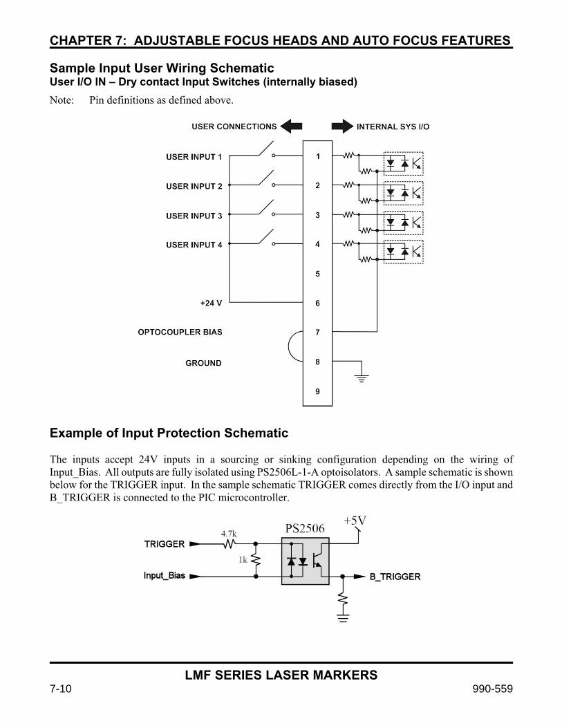
CHAPTER 7: ADJUSTABLE FOCUS HEADS AND AUTO FOCUS FEATURES
LMF SERIES LASER MARKERS
7-10 990-559
Sample Input User Wiring Schematic User I/O IN – Dry contact Input Switches (internally biased)
Note: Pin definitions as defined above.
Example of Input Protection Schematic The inputs accept 24V inputs in a sourcing or sinking configuration depending on the wiring of Input_Bias. All outputs are fully isolated using PS2506L-1-A optoisolators. A sample schematic is shown below for the TRIGGER input. In the sample schematic TRIGGER comes directly from the I/O input and B_TRIGGER is connected to the PIC microcontroller.

CHAPTER 7: ADJUSTABLE FOCUS HEADS AND AUTO FOCUS FEATURES
LMF SERIES LASER MARKERS
990-559 7-11
Outputs (by pin number)
1. OUT1 This output allows the user to monitor the laser distance sensor’s OUT1 output.
2. OUT2 This output allows the user to monitor the laser distance sensor’s OUT2 output.
3. ERROR This output allows the user to monitor the autofocus interface controller Error bit which indicates various errors including sensor out of range, fiber marker offset value out of range, and other cases. See the error definition section of this document.
4. 24V 24V power input to the autofocus interface controller. This must be connected to a 24V output on the back of the fiber laser marker.
5. GND Ground connection to autofocus interface controller. This must be connected to a Ground pin on a fiber laser marker I/O header. This is the primary ground between the fiber laser marker and the autofocus interface controller.
6. 24V 24V power supply for output biasing as needed
7. OUTPUT_BIAS Optocoupler biasing for outputs to determine active state of output signals
8. GND Ground for output biasing as needed
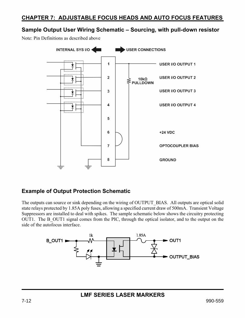
CHAPTER 7: ADJUSTABLE FOCUS HEADS AND AUTO FOCUS FEATURES
LMF SERIES LASER MARKERS
7-12 990-559
Sample Output User Wiring Schematic – Sourcing, with pull-down resistor
Note: Pin Definitions as described above
Example of Output Protection Schematic The outputs can source or sink depending on the wiring of OUTPUT_BIAS. All outputs are optical solid state relays protected by 1.85A poly fuses, allowing a specified current draw of 500mA. Transient Voltage Suppressors are installed to deal with spikes. The sample schematic below shows the circuitry protecting OUT1. The B_OUT1 signal comes from the PIC, through the optical isolator, and to the output on the side of the autofocus interface.

CHAPTER 7: ADJUSTABLE FOCUS HEADS AND AUTO FOCUS FEATURES
LMF SERIES LASER MARKERS
990-559 7-13
Autofocus Interface Controller Physical Attributes The 4-70256-01 Autofocus Interface Controller is a small inline box with mounting flanges. On one end it has a female DB9 connection to the fiber laser marker COM port as well as a female HD15 connection to the laser distance sensor.
The other end has two rows of connections for Phoenix 3.81mm screw type terminal blocks. The first row (A1-8) are inputs and the second row (B1-8) are outputs. Two LEDs (GREEN = Power, RED = Fault) are present next to the terminal connections but not shown in these photos.
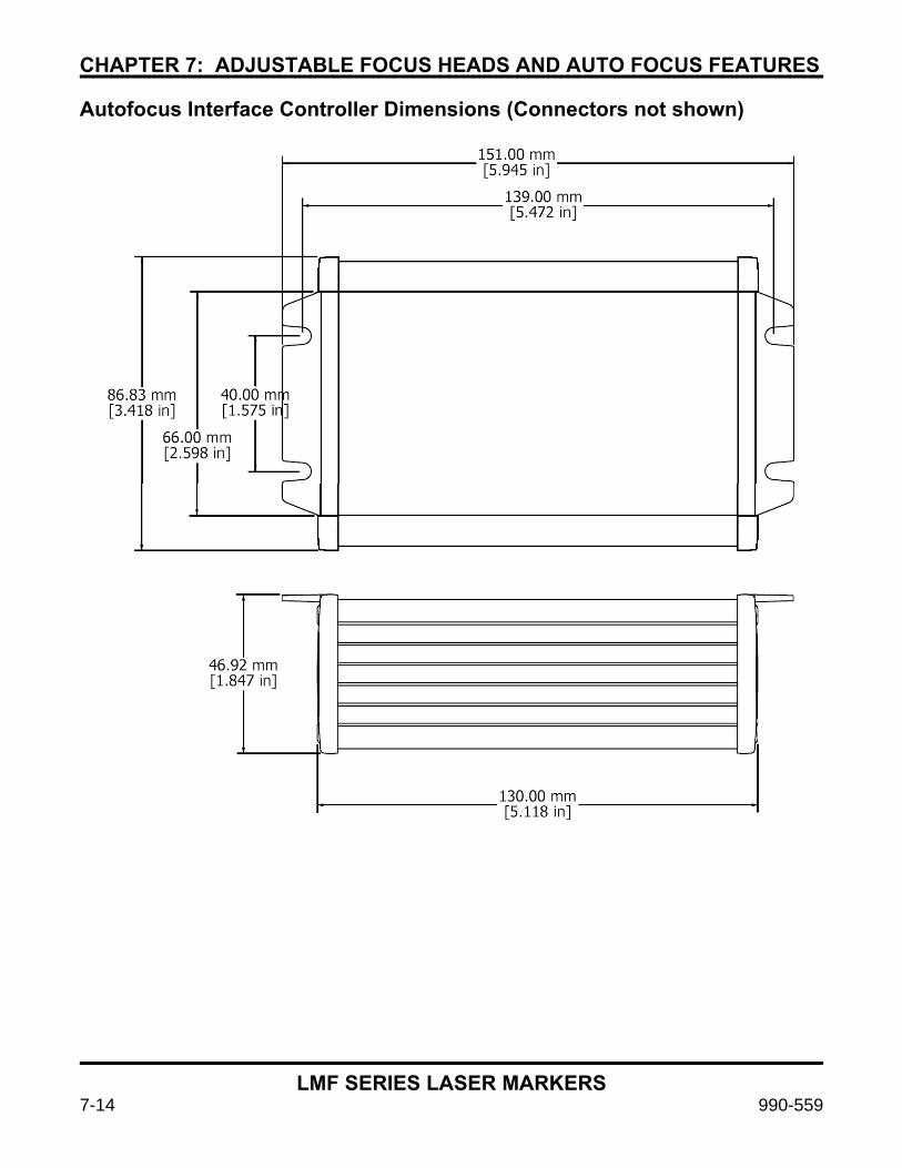
CHAPTER 7: ADJUSTABLE FOCUS HEADS AND AUTO FOCUS FEATURES
LMF SERIES LASER MARKERS
7-14 990-559
Autofocus Interface Controller Dimensions (Connectors not shown)

CHAPTER 7: ADJUSTABLE FOCUS HEADS AND AUTO FOCUS FEATURES
LMF SERIES LASER MARKERS
990-559 7-15
ZX1-LD100A Drawing – Amada Miyachi America Part Number 4-70245-01
ZX1-LD300A Drawing – Amada Miyachi America Part Number 4-70245-02
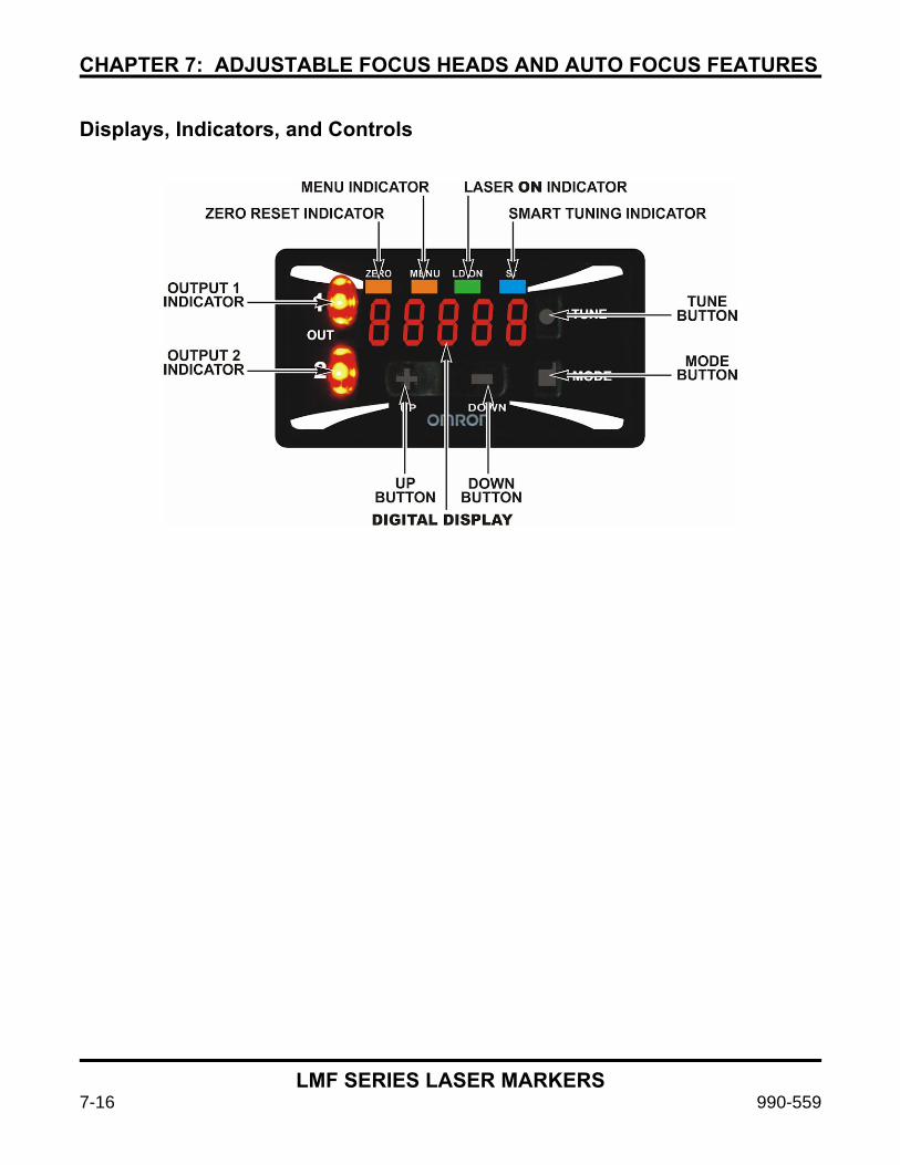
CHAPTER 7: ADJUSTABLE FOCUS HEADS AND AUTO FOCUS FEATURES
LMF SERIES LASER MARKERS
7-16 990-559
Displays, Indicators, and Controls
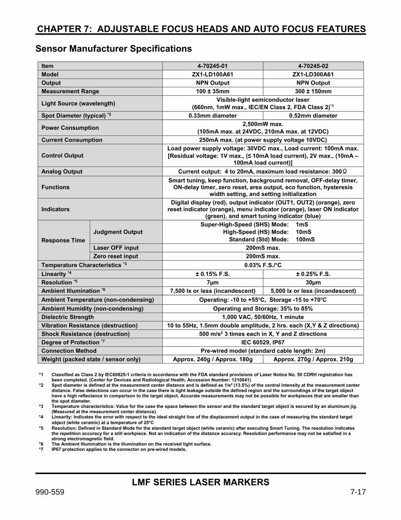
CHAPTER 7: ADJUSTABLE FOCUS HEADS AND AUTO FOCUS FEATURES
LMF SERIES LASER MARKERS
990-559 7-17
Sensor Manufacturer Specifications
Item 4-70245-01 4-70245-02
Model ZX1-LD100A61 ZX1-LD300A61
Output NPN Output NPN Output
Measurement Range 100 ± 35mm 300 ± 150mm
Light Source (wavelength) Visible-light semiconductor laser
(660nm, 1mW max., IEC/EN Class 2, FDA Class 2)*1
Spot Diameter (typical) *2 0.33mm diameter 0.52mm diameter
Power Consumption 2,500mW max.
(105mA max. at 24VDC, 210mA max. at 12VDC)
Current Consumption 250mA max. (at power supply voltage 10VDC)
Control Output Load power supply voltage: 30VDC max., Load current: 100mA max. [Residual voltage: 1V max., (≤ 10mA load current), 2V max., (10mA –
100mA load current)]
Analog Output Current output: 4 to 20mA, maximum load resistance: 300Ω
Functions Smart tuning, keep function, background removal, OFF-delay timer,
ON-delay timer, zero reset, area output, eco function, hysteresis width setting, and setting initialization
Indicators Digital display (red), output indicator (OUT1, OUT2) (orange), zero
reset indicator (orange), menu indicator (orange), laser ON indicator (green), and smart tuning indicator (blue)
Response Time
Judgment Output Super-High-Speed (SHS) Mode:
High-Speed (HS) Mode: Standard (Std) Mode:
1mS 10mS 100mS
Laser OFF input 200mS max.
Zero reset input 200mS max.
Temperature Characteristics *3 0.03% F.S./ºC
Linearity *4 ± 0.15% F.S. ± 0.25% F.S.
Resolution *5 7µm 30µm
Ambient Illumination *6 7,500 lx or less (incandescent) 5,000 lx or less (incandescent)
Ambient Temperature (non-condensing) Operating: -10 to +55ºC, Storage -15 to +70ºC
Ambient Humidity (non-condensing) Operating and Storage: 35% to 85%
Dielectric Strength 1,000 VAC, 50/60Hz, 1 minute
Vibration Resistance (destruction) 10 to 55Hz, 1.5mm double amplitude, 2 hrs. each (X,Y & Z directions)
Shock Resistance (destruction) 500 m/s2 3 times each in X, Y and Z directions
Degree of Protection *7 IEC 60529, IP67
Connection Method Pre-wired model (standard cable length: 2m)
Weight (packed state / sensor only) Approx. 240g / Approx. 180g Approx. 270g / Approx. 210g
*1 Classified as Class 2 by IEC60825-1 criteria in accordance with the FDA standard provisions of Laser Notice No. 50 CDRH registration has
been completed. (Center for Devices and Radiological Health, Accession Number: 1210041) *2 Spot diameter is defined at the measurement center distance and is defined as 1/e2 (13.5%) of the central intensity at the measurement center
distance. False detections can occur in the case there is light leakage outside the defined region and the surroundings of the target object have a high reflectance in comparison to the target object. Accurate measurements may not be possible for workpieces that are smaller than the spot diameter.
*3 Temperature characteristics: Value for the case the space between the sensor and the standard target object is secured by an aluminum jig. (Measured at the measurement center distance).
*4 Linearity: Indicates the error with respect to the ideal straight line of the displacement output in the case of measuring the standard target object (white ceramic) at a temperature of 25ºC
*5 Resolution: Defined in Standard Mode for the standard target object (white ceramic) after executing Smart Tuning. The resolution indicates the repetition accuracy for a still workpiece. Not an indication of the distance accuracy. Resolution performance may not be satisfied in a strong electromagnetic field.
*6 The Ambient Illumination is the illumination on the received light surface. *7 IP67 protection applies to the connector on pre-wired models.

CHAPTER 7: ADJUSTABLE FOCUS HEADS AND AUTO FOCUS FEATURES
LMF SERIES LASER MARKERS
7-18 990-559
Section IV: Calibrating the Autofocus Interface Controller to a Laser Sensor
The Autofocus Interface Controller is calibrated as shipped – if the sensor changes it may be necessary to repeat calibration. EQUIPMENT REQUIRED: 1. 8-921-01 or 8-921-02 Autofocus accessory kit.
2. PC equipped with a RS-232 port and terminal software.
3. Straight through RS-232 cable.
4. Adjustable fixture to mount laser sensor 100mm or 300mm away from nominal target for calibration purposes.
5. Laser to provide power.
6. Autofocus Interface Controller power cable.
SETUP: 1. Mount laser sensor approximately 100mm (for 8-921-01) or 300mm (for 8-921-02) away from target.
2. Plug laser sensor HD25 plug into interface box.
3. Use RS-232 cable to connect interface box to PC serial port.
4. Open terminal program and establish a connection at 9600 Baud, 8-N-1-None (no parity).
5. Connect test fixture I/O input and output harnesses.
6. Plug in autofocus interface controller power cable and turn on laser to provide power.
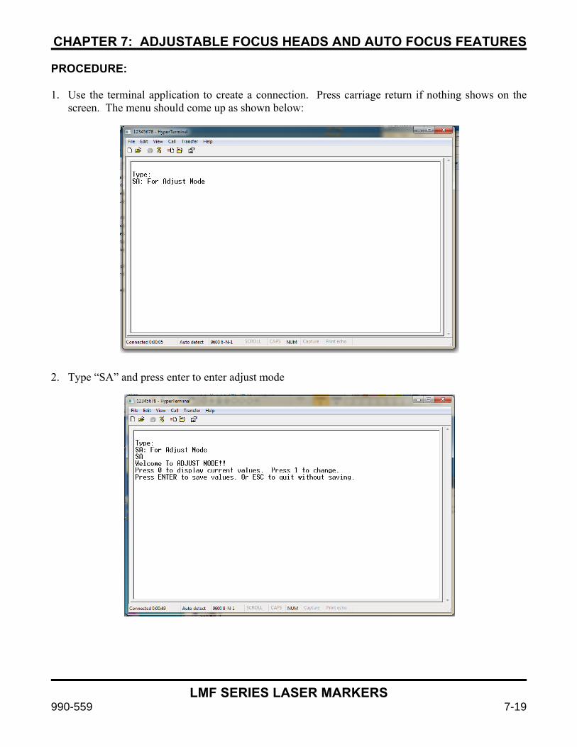
CHAPTER 7: ADJUSTABLE FOCUS HEADS AND AUTO FOCUS FEATURES
LMF SERIES LASER MARKERS
990-559 7-19
PROCEDURE:
1. Use the terminal application to create a connection. Press carriage return if nothing shows on the screen. The menu should come up as shown below:
2. Type “SA” and press enter to enter adjust mode
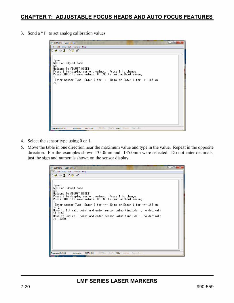
CHAPTER 7: ADJUSTABLE FOCUS HEADS AND AUTO FOCUS FEATURES
LMF SERIES LASER MARKERS
7-20 990-559
3. Send a “1” to set analog calibration values
4. Select the sensor type using 0 or 1.
5. Move the table in one direction near the maximum value and type in the value. Repeat in the opposite direction. For the examples shown 135.0mm and -135.0mm were selected. Do not enter decimals, just the sign and numerals shown on the sensor display.
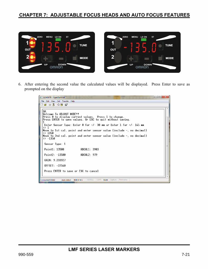
CHAPTER 7: ADJUSTABLE FOCUS HEADS AND AUTO FOCUS FEATURES
LMF SERIES LASER MARKERS
990-559 7-21
6. After entering the second value the calculated values will be displayed. Press Enter to save as prompted on the display
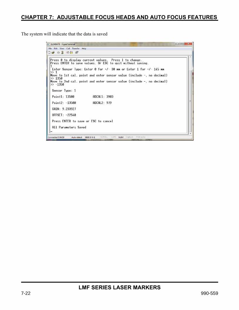
CHAPTER 7: ADJUSTABLE FOCUS HEADS AND AUTO FOCUS FEATURES
LMF SERIES LASER MARKERS
7-22 990-559
The system will indicate that the data is saved

LMF SERIES LASER MARKERS
990-559 8-1
CHAPTER 8
EtherNet/IPTM Communications
Section I: Introduction
This chapter provides instructions on how to setup connectivity to the LMF Laser Marker via EtherNet/IPTM. EtherNet/IPTM is available on all LMF Laser Markers with the Advanced LEC Controller Card installed and sold with the top-level part number:
8-79-xCx-xxx (where “C” defines the Advanced LEC Controller Card) The Advanced LEC-2 Controller Card is an embedded control card that is designed to be a powerful stand-alone controller with the ability to interface to EtherNet/IPTM devices. How the Input Data is Scanned For each PLC scan cycle, new data arrives at the LEC EtherNet/IPTM interface. Generally, the LEC will detect one change at a time before acting on it, ignoring the rest of the changes and then waiting for the next scan cycle. For the current cycle, the data is scanned in the following order:
• If Change Busy = 1, stop scanning and wait for next cycle.
• Job Name, Job Location Parameter, Data Request Parameter, String Data 1 and String Data 2 are all copied into the internal registers.
• If Error Clear – 0 → 1, and System Busy = 0, clear Error Status and Error Code, then stop scanning and wait for next cycle.
• If Change Exclusive Control = 0 → 1, and System Busy = 0, enable exclusive control mode, then stop scanning and wait for the next cycle.
• If Exclusive Control = 0, stop scanning and wait for next cycle.
• If Input Change Request data has changed, write new data to the internal registers, then continue scanning.
• If Output Change Request data has changed, write new data to the internal registers, then continue scanning.
• If Enable Marking = 0 → 1, start waiting for Start Mark signal, then stop scanning and wait for next cycle.
• If Enable Marking = 1 → 0, stop the running job, then stop scanning and wait for next cycle.
• If Start Mark = 0 → 1, and Ready To Mark = 1, start the marking process, then stop scanning and wait for next cycle. This bit is ignored if Hardware Start Mark = 1.
• If Load Job = 0 → 1, and Ready Job Change = 1, load the Job specified with the Job Location parameter and (optionally) the Job Name parameter, then stop scanning and wait for the next cycle.

CHAPTER 8: EtherNet IPTM
LMF SERIES LASER MARKERS
8-2 990-559
• If Clear Jobs = 0 → 1, and Ready Job Change = 1, clear all Jobs in RAM, then stop scanning and wait for next cycle.
• If Set Object String 0 → 1, and Ready String Change = 1, set the string in String Data into the object at Request Index, then stop scanning and wait for next cycle.
• If Get Object String = 0 → 1, and Ready String Change = 1, get the string in object at Request Index, place it in Response String Data, then stop scanning and wait for next cycle.
• If Set Mem Buffer = 0 → 1, and Ready String Change = 1, set the string in String Data into the memory buffer at Request Index, then stop scanning and wait for next cycle.
• If Get Mem Buffer = 0 → 1, and Ready String Change = 1, get the string in the memory buffer at Request Index, place it in Response String Data, then stop scanning and wait for next cycle.
• End of Data
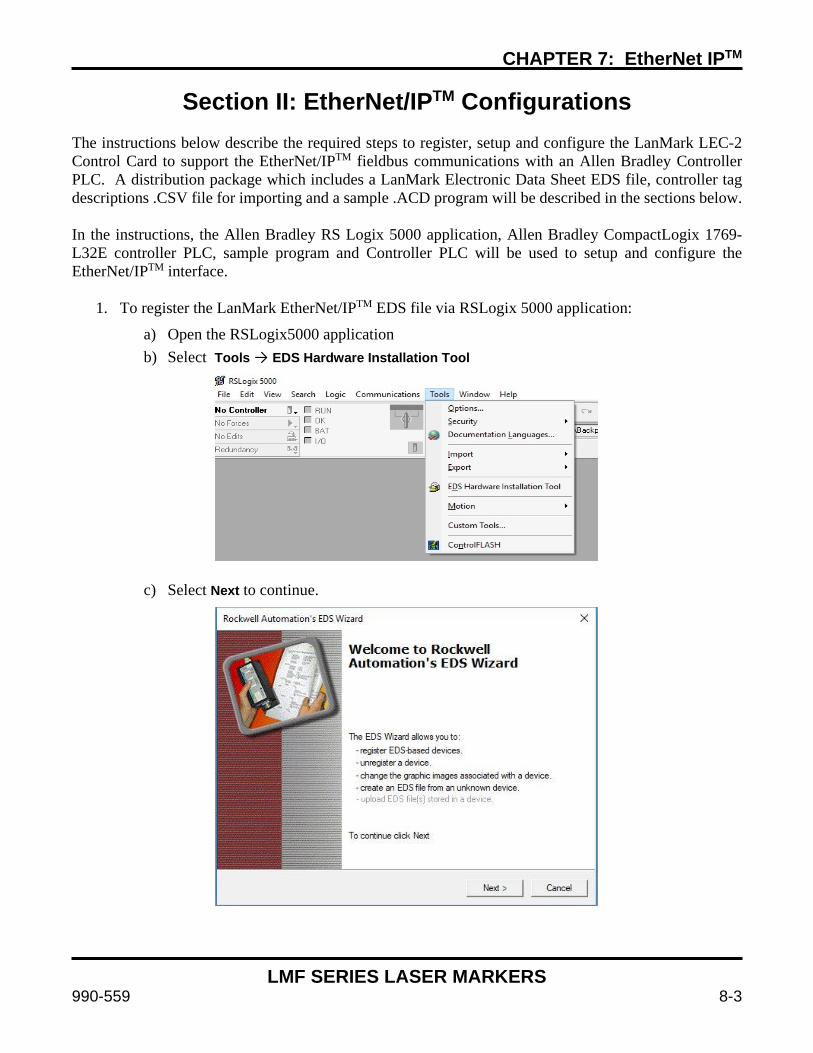
CHAPTER 7: EtherNet IPTM
LMF SERIES LASER MARKERS
990-559 8-3
Section II: EtherNet/IPTM Configurations
The instructions below describe the required steps to register, setup and configure the LanMark LEC-2 Control Card to support the EtherNet/IPTM fieldbus communications with an Allen Bradley Controller PLC. A distribution package which includes a LanMark Electronic Data Sheet EDS file, controller tag descriptions .CSV file for importing and a sample .ACD program will be described in the sections below. In the instructions, the Allen Bradley RS Logix 5000 application, Allen Bradley CompactLogix 1769-L32E controller PLC, sample program and Controller PLC will be used to setup and configure the EtherNet/IPTM interface.
1. To register the LanMark EtherNet/IPTM EDS file via RSLogix 5000 application:
a) Open the RSLogix5000 application b) Select Tools → EDS Hardware Installation Tool
c) Select Next to continue.
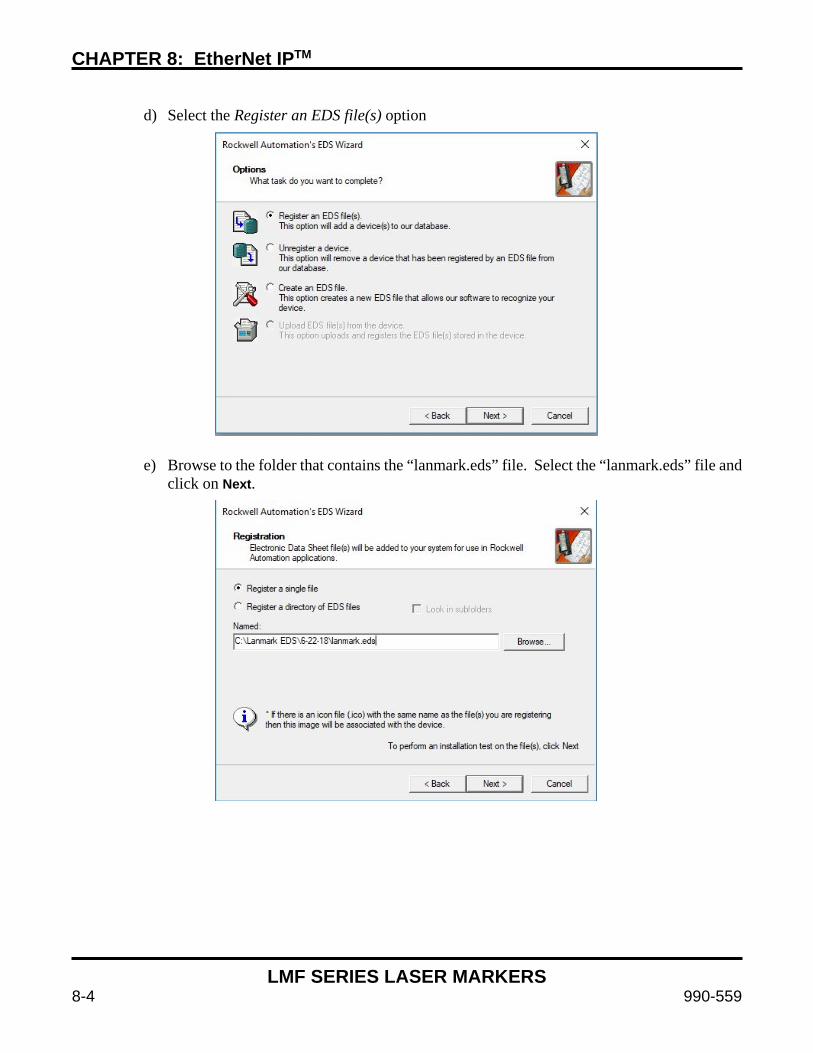
CHAPTER 8: EtherNet IPTM
LMF SERIES LASER MARKERS
8-4 990-559
d) Select the Register an EDS file(s) option
e) Browse to the folder that contains the “lanmark.eds” file. Select the “lanmark.eds” file and click on Next.
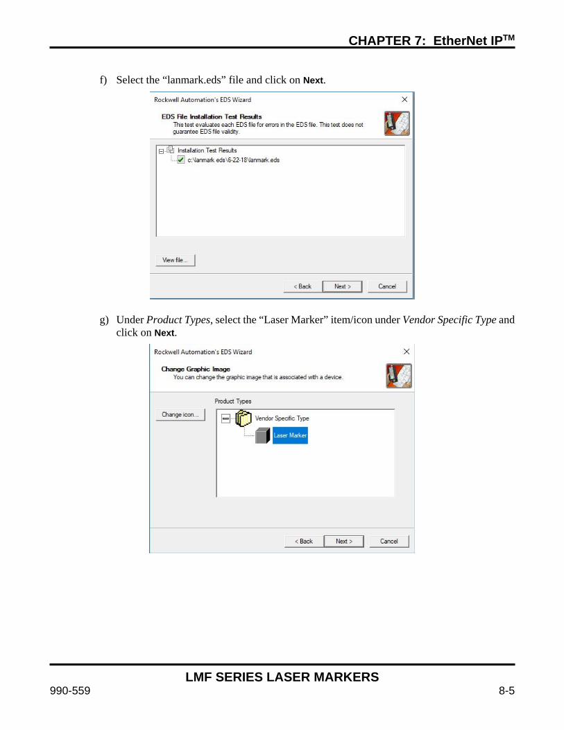
CHAPTER 7: EtherNet IPTM
LMF SERIES LASER MARKERS
990-559 8-5
f) Select the “lanmark.eds” file and click on Next.
g) Under Product Types, select the “Laser Marker” item/icon under Vendor Specific Type and click on Next.
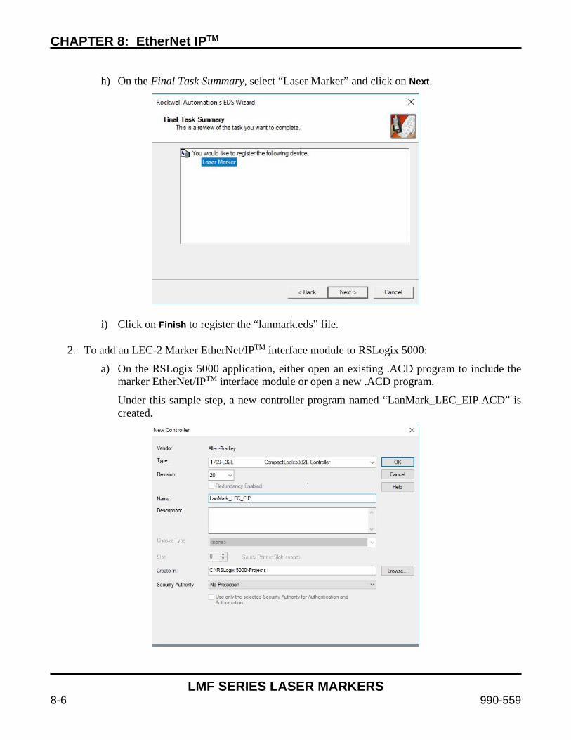
CHAPTER 8: EtherNet IPTM
LMF SERIES LASER MARKERS
8-6 990-559
h) On the Final Task Summary, select “Laser Marker” and click on Next.
i) Click on Finish to register the “lanmark.eds” file.
2. To add an LEC-2 Marker EtherNet/IPTM interface module to RSLogix 5000:
a) On the RSLogix 5000 application, either open an existing .ACD program to include the marker EtherNet/IPTM interface module or open a new .ACD program.
Under this sample step, a new controller program named “LanMark_LEC_EIP.ACD” is created.
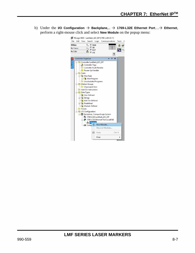
CHAPTER 7: EtherNet IPTM
LMF SERIES LASER MARKERS
990-559 8-7
b) Under the I/O Configuration → Backplane,.. → 1769-L32E Ethernet Port…→ Ethernet,
perform a right-mouse click and select New Module on the popup menu:

CHAPTER 8: EtherNet IPTM
LMF SERIES LASER MARKERS
8-8 990-559
c) When the Select Module Type window is displayed, select the “Laser Marker” from the
Vendor, LanMark Controls Inc.
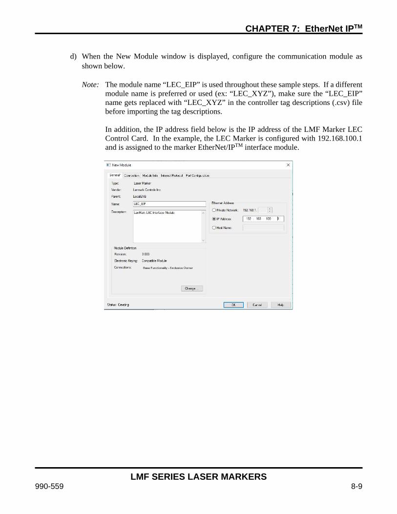
CHAPTER 7: EtherNet IPTM
LMF SERIES LASER MARKERS
990-559 8-9
d) When the New Module window is displayed, configure the communication module as
shown below. Note: The module name “LEC_EIP” is used throughout these sample steps. If a different
module name is preferred or used (ex: “LEC_XYZ”), make sure the “LEC_EIP” name gets replaced with “LEC_XYZ” in the controller tag descriptions (.csv) file before importing the tag descriptions.
In addition, the IP address field below is the IP address of the LMF Marker LEC Control Card. In the example, the LEC Marker is configured with 192.168.100.1 and is assigned to the marker EtherNet/IPTM interface module.
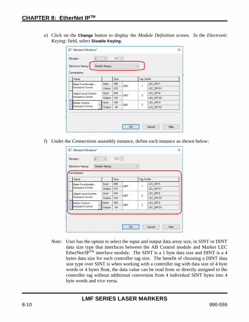
CHAPTER 8: EtherNet IPTM
LMF SERIES LASER MARKERS
8-10 990-559
e) Click on the Change button to display the Module Definition screen. In the Electronic
Keying: field, select Disable Keying.
f) Under the Connections assembly instance, define each instance as shown below:
Note: User has the option to select the input and output data array size, in SINT or DINT
data size type that interfaces between the AB Control module and Marker LEC EtherNet/IPTM interface module. The SINT is a 1 byte data size and DINT is a 4 bytes data size for each controller tag size. The benefit of choosing a DINT data size type over SINT is when working with a controller tag with data size of 4 byte words or 4 bytes float, the data value can be read from or directly assigned to the controller tag without additional conversion from 4 individual SINT bytes into 4 byte words and vice versa.
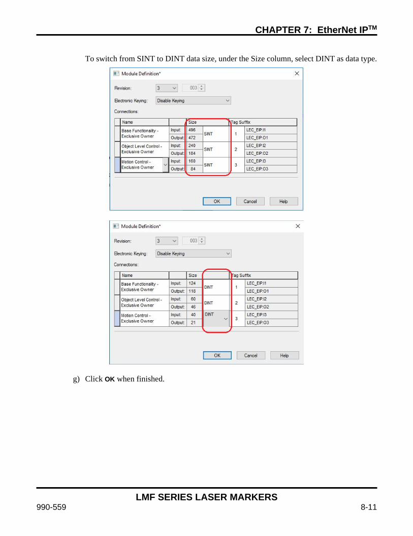
CHAPTER 7: EtherNet IPTM
LMF SERIES LASER MARKERS
990-559 8-11
To switch from SINT to DINT data size, under the Size column, select DINT as data type.
g) Click OK when finished.
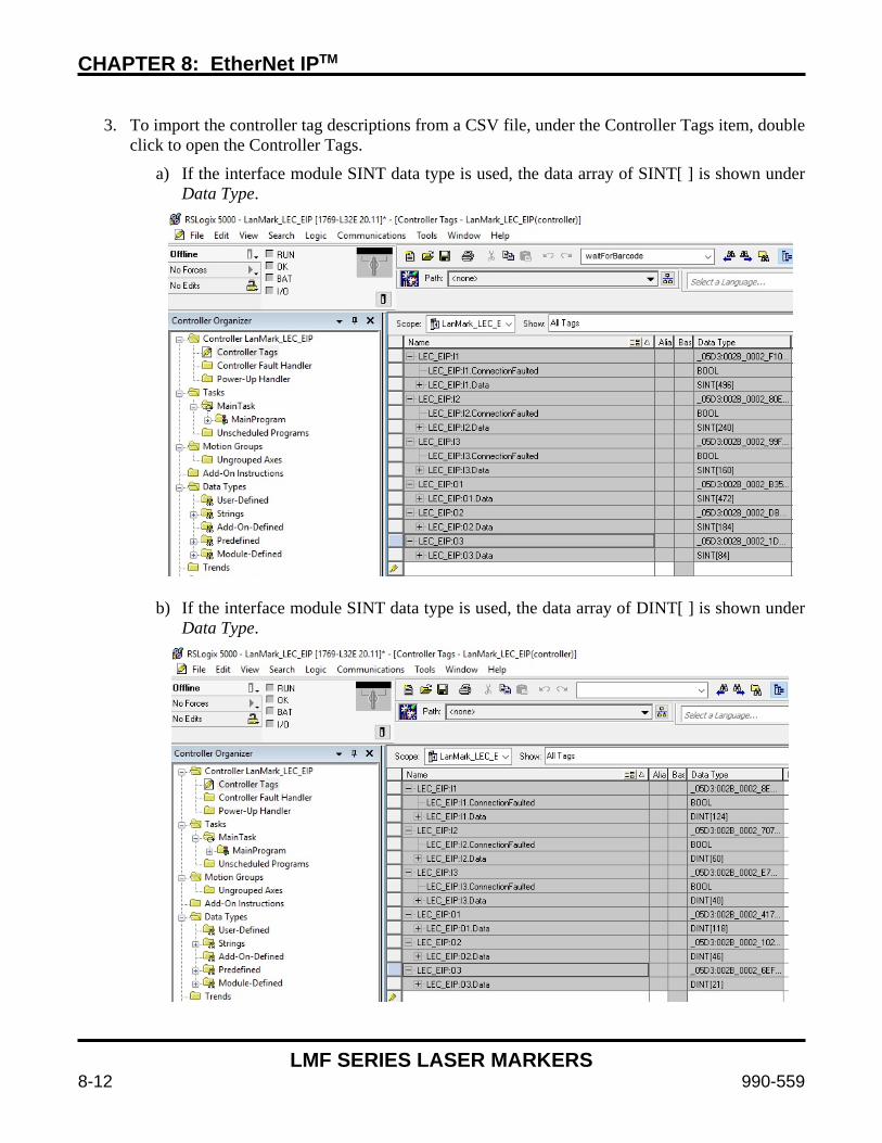
CHAPTER 8: EtherNet IPTM
LMF SERIES LASER MARKERS
8-12 990-559
3. To import the controller tag descriptions from a CSV file, under the Controller Tags item, double
click to open the Controller Tags.
a) If the interface module SINT data type is used, the data array of SINT[ ] is shown under Data Type.
b) If the interface module SINT data type is used, the data array of DINT[ ] is shown under Data Type.
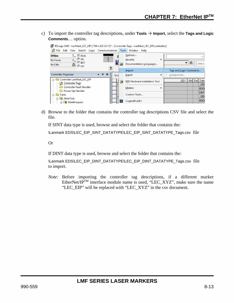
CHAPTER 7: EtherNet IPTM
LMF SERIES LASER MARKERS
990-559 8-13
c) To import the controller tag descriptions, under Tools → Import, select the Tags and Logic
Comments… option.
d) Browse to the folder that contains the controller tag descriptions CSV file and select the file.
If SINT data type is used, browse and select the folder that contains the:
\Lanmark EDS\LEC_EIP_SINT_DATATYPE\LEC_EIP_SINT_DATATYPE_Tags.csv file Or If DINT data type is used, browse and select the folder that contains the:
\Lanmark EDS\LEC_EIP_DINT_DATATYPE\LEC_EIP_DINT_DATATYPE_Tags.csv file to import. Note: Before importing the controller tag descriptions, if a different marker
EtherNet/IPTM interface module name is used, “LEC_XYZ”, make sure the name “LEC_EIP” will be replaced with “LEC_XYZ” in the csv document.

CHAPTER 8: EtherNet IPTM
LMF SERIES LASER MARKERS
8-14 990-559
e) Once the controller tag descriptions CSV file get imported, each controller tag will contain the descriptions as shown below.
4. To assign the Allen Bradley Controller PLC IP address, double click on the I/O Configuration →
Backplane,.. → 1769-L32E Ethernet Port…→ Ethernet → 1769-L32E Ethernet Port LocalENB to open module properties. Specify the IP Address of the Allen Bradley PLC.
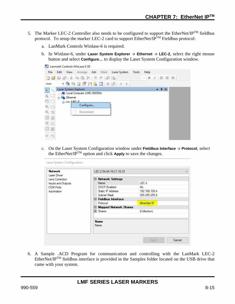
CHAPTER 7: EtherNet IPTM
LMF SERIES LASER MARKERS
990-559 8-15
5. The Marker LEC-2 Controller also needs to be configured to support the EtherNet/IPTM fieldbus
protocol. To setup the marker LEC-2 card to support EtherNet/IPTM Fieldbus protocol:
a. LanMark Controls Winlase-6 is required.
b. In Winlase-6, under Laser System Explorer → Ethernet → LEC-2, select the right mouse button and select Configure… to display the Laser System Configuration window.
c. On the Laser System Configuration window under Fieldbus Interface → Protocol, select the EtherNet/IPTM option and click Apply to save the changes.
6. A Sample .ACD Program for communication and controlling with the LanMark LEC-2 EtherNet/IPTM fieldbus interface is provided in the Samples folder located on the USB drive that came with your system.

CHAPTER 8: EtherNet IPTM
LMF SERIES LASER MARKERS
8-16 990-559
Section III: Data Models
Writing the LEC State (Controller) to a PLC Instance Slot Size Module Address Bit Name Data Description
0 0 8 System Status
0
0 Ready Job Change 0 = Not Ready 1 = Ready
Indicates the system is ready to accept Load Job, and Clear Jobs commands. When Exclusive Control = 1, System Busy = 0, Ready to Mark = 0 and Error Status = 1, this bit will be 1.
1 Ready Object Change 0 = Not Ready 1 = Ready
Indicates the system is ready to accept a Set Object String, Get Object String, Set Object Transform, Get Object Transform, Set Object Profile, Get Object Profile, Set Object Mark Flags or Get Object Mark Flags command. When Exclusive Control = 1, and Change Busy = 0 and Ready To Mark = 1 and Error Status = 1, this bit will be 1.
2 Exclusive Control 0 = Not in Control 1 = Exclusive Control
If the PLC has exclusive control, this bit will be 1. Use the Change Exclusive Control bit to obtain exclusive control.
3 Error Status 0 = Error 1 = OK
Indicates that a previous operation generated an error. See Error Codes Module for error code.
4 Ready Mem Buffer Change
0 = Not Ready 1 = Ready
Indicates the system is ready to accept a Set Mem Buffer or Get Mem Buffer command. When Exclusive Control = 1, and Change Busy = 0 and Ready to Mark = 1 and Error Status = 1, this bit will be 1.
5 Ready Motion Change 0 = Not Ready 1 = Ready
Indicates the system is ready to accept an Execute Motion or Get Motion Device Status command. When Exclusive Control = 1, and Change Busy = 0 and Error Status = 1, this bit will be 1.
6 Reserved 7 Reserved
1
0 Ready To Mark 0 = Not Ready 1 = Ready to Mark
Indicates system is ready to accept a Start Mark input. Exclusive Control, Waiting For Mark Start, Watchdog OK, Application OK and Error Status all must be 1 for this bit to be 1.
1 Waiting For Start Mark 0 = Not waiting 1 = Waiting
If the system is waiting for a Start Mark signal, this bit will be 1.
2 Reserved
3 Watchdog OK 0 = Watchdog signaled 1 = OK
Hardware watchdog status. If the hardware has an internal failure, this bit will be 0.
4 Application OK 0 = App Error signaled 1 = OK
Application status. If the application has an internal software error, this bit will be 0.
5 Reserved 6 Reserved 7 Reserved
2
0 System Busy 0 = Not Busy 1 = Busy If any Busy Status bit is 1, this bit will be 1.
1 Job Busy 0 = Not Busy 1 = Busy When a job is being executed, this bit will be 1.
2 Reserved
3 Change Busy 0 = Not Busy 1 = Busy
If Job Change Busy or Object String Change Busy or Mem Buffer String Change Busy or Exclusive Control Change Busy or Enable Marking Change Busy or Object Transform Busy or Object Profile Change Busy or Mark Flag Change Busy or Motion Change Busy is 1, this bit will be 1.
4 Job Change Busy 0 = Not Busy 1 = Busy
If a Load Job or Clear Jobs request is in process, this bit will be 1.
5 Object String Change Busy
0 = Not Busy 1 = Busy
If a Set Object String or Get Object String request is in process, this bit will be 1.
6 Mem Buffer String Change Busy
0 = Not Busy 1 = Busy
If a Set Mem Buffer or Get Mem Buffer request is in process, this bit will be 1.
7 Exclusive Control Change Busy
0 = Not Busy 1 = Busy
If a Change Exclusive Control request is in process, this bit will be 1.

CHAPTER 7: EtherNet IPTM
LMF SERIES LASER MARKERS
990-559 8-17
Instance Slot Size Module Address Bit Name Data Description
0
0 8 System Status
3
0 Enable Marking Change Busy
0 = Not Busy 1 = Busy If an Enable Marking operation is in process, this bit will be 1.
1 Object Transform Busy 0 = Not Busy 1 = Busy
If a Set Object Transform or Get Object Transform request is in process, this bit will be 1.
2 Object Profile Change Busy
0 = Not Busy 1 = Busy
If a Set Object Profile or Get Object Profile request is in process, this bit will be 1.
3 Mark Flag Change Busy
0 = Not Busy 1 = Busy
If a Set Object Mark Flags or Get Object Mark Flags request is in process, this bit will be 1.
4 Motion Change Busy 0 = Not Busy 1 = Busy
If an Execute Motion or Get Motion Device Status request is in process, this bit will be 1.
5 Reserved 6 Reserved 7 Reserved
4 Reserved 5 Reserved 6 Reserved 7 Reserved
1 4 Reserved 0 Reserved 2 4 Completion
Status 0 Reserved
3 8 Input Status
0
0 Local Start Mark 0 = Not Signaled 1 = Signaled State of the hardware Start Mark input
1 Network Start Mark 0 = Not Signaled 1 = Signaled State of the Start Mark bit
2 Local Abort 0 = Not Signaled 1 = Signaled State of the Hardware Abort input
3 Enable Marking 0 = Not Signaled 1 = Signaled State of the Enable Marking bit
4 Reserved 5 Reserved 6 Reserved 7 Reserved
1 0 Reserved
2
0 UserIn1 0 = Not Signaled 1 = Signaled State of the UserIn1 bit
1 UserIn2 0 = Not Signaled 1 = Signaled State of the UserIn2 bit
2 UserIn3 0 = Not Signaled 1 = Signaled State of the UserIn3 bit
3 UserIn4 0 = Not Signaled 1 = Signaled State of the UserIn4 bit
4 UserIn5 0 = Not Signaled 1 = Signaled State of the UserIn5 bit
5 UserIn6 0 = Not Signaled 1 = Signaled State of the UserIn6 bit
6 UserIn7 0 = Not Signaled 1 = Signaled State of the UserIn7 bit
7 UserIn8 0 = Not Signaled 1 = Signaled State of the UserIn8 bit
3
0 UserIn9 0 = Not Signaled 1 = Signaled State of the UserIn9 bit
1 UserIn10 0 = Not Signaled 1 = Signaled State of the UserIn10 bit
2 UserIn11 0 = Not Signaled 1 = Signaled State of the UserIn11 bit
3 UserIn12 0 = Not Signaled 1 = Signaled State of the UserIn12 bit
4 UserIn13 0 = Not Signaled 1 = Signaled State of the UserIn13 bit
5 UserIn14 0 = Not Signaled 1 = Signaled State of the UserIn14 bit
6 UserIn15 0 = Not Signaled 1 = Signaled State of the UserIn15 bit
7 UserIn16 0 = Not Signaled 1 = Signaled State of the UserIn16 bit
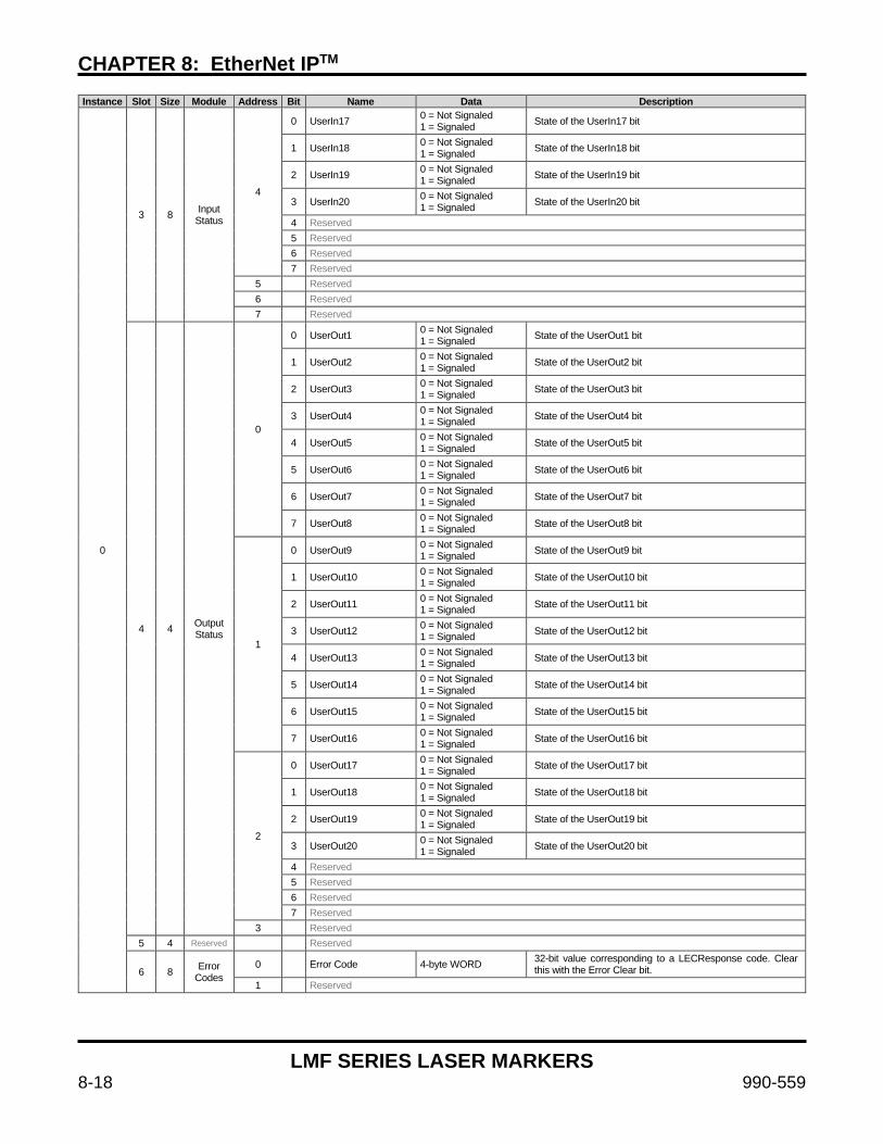
CHAPTER 8: EtherNet IPTM
LMF SERIES LASER MARKERS
8-18 990-559
Instance Slot Size Module Address Bit Name Data Description
0
3 8 Input Status
4
0 UserIn17 0 = Not Signaled 1 = Signaled State of the UserIn17 bit
1 UserIn18 0 = Not Signaled 1 = Signaled State of the UserIn18 bit
2 UserIn19 0 = Not Signaled 1 = Signaled State of the UserIn19 bit
3 UserIn20 0 = Not Signaled 1 = Signaled State of the UserIn20 bit
4 Reserved 5 Reserved 6 Reserved 7 Reserved
5 Reserved 6 Reserved 7 Reserved
4 4 Output Status
0
0 UserOut1 0 = Not Signaled 1 = Signaled State of the UserOut1 bit
1 UserOut2 0 = Not Signaled 1 = Signaled State of the UserOut2 bit
2 UserOut3 0 = Not Signaled 1 = Signaled State of the UserOut3 bit
3 UserOut4 0 = Not Signaled 1 = Signaled State of the UserOut4 bit
4 UserOut5 0 = Not Signaled 1 = Signaled State of the UserOut5 bit
5 UserOut6 0 = Not Signaled 1 = Signaled State of the UserOut6 bit
6 UserOut7 0 = Not Signaled 1 = Signaled State of the UserOut7 bit
7 UserOut8 0 = Not Signaled 1 = Signaled State of the UserOut8 bit
1
0 UserOut9 0 = Not Signaled 1 = Signaled State of the UserOut9 bit
1 UserOut10 0 = Not Signaled 1 = Signaled State of the UserOut10 bit
2 UserOut11 0 = Not Signaled 1 = Signaled State of the UserOut11 bit
3 UserOut12 0 = Not Signaled 1 = Signaled State of the UserOut12 bit
4 UserOut13 0 = Not Signaled 1 = Signaled State of the UserOut13 bit
5 UserOut14 0 = Not Signaled 1 = Signaled State of the UserOut14 bit
6 UserOut15 0 = Not Signaled 1 = Signaled State of the UserOut15 bit
7 UserOut16 0 = Not Signaled 1 = Signaled State of the UserOut16 bit
2
0 UserOut17 0 = Not Signaled 1 = Signaled State of the UserOut17 bit
1 UserOut18 0 = Not Signaled 1 = Signaled State of the UserOut18 bit
2 UserOut19 0 = Not Signaled 1 = Signaled State of the UserOut19 bit
3 UserOut20 0 = Not Signaled 1 = Signaled State of the UserOut20 bit
4 Reserved 5 Reserved 6 Reserved 7 Reserved
3 Reserved 5 4 Reserved Reserved
6 8 Error Codes
0 Error Code 4-byte WORD 32-bit value corresponding to a LECResponse code. Clear this with the Error Clear bit.
1 Reserved
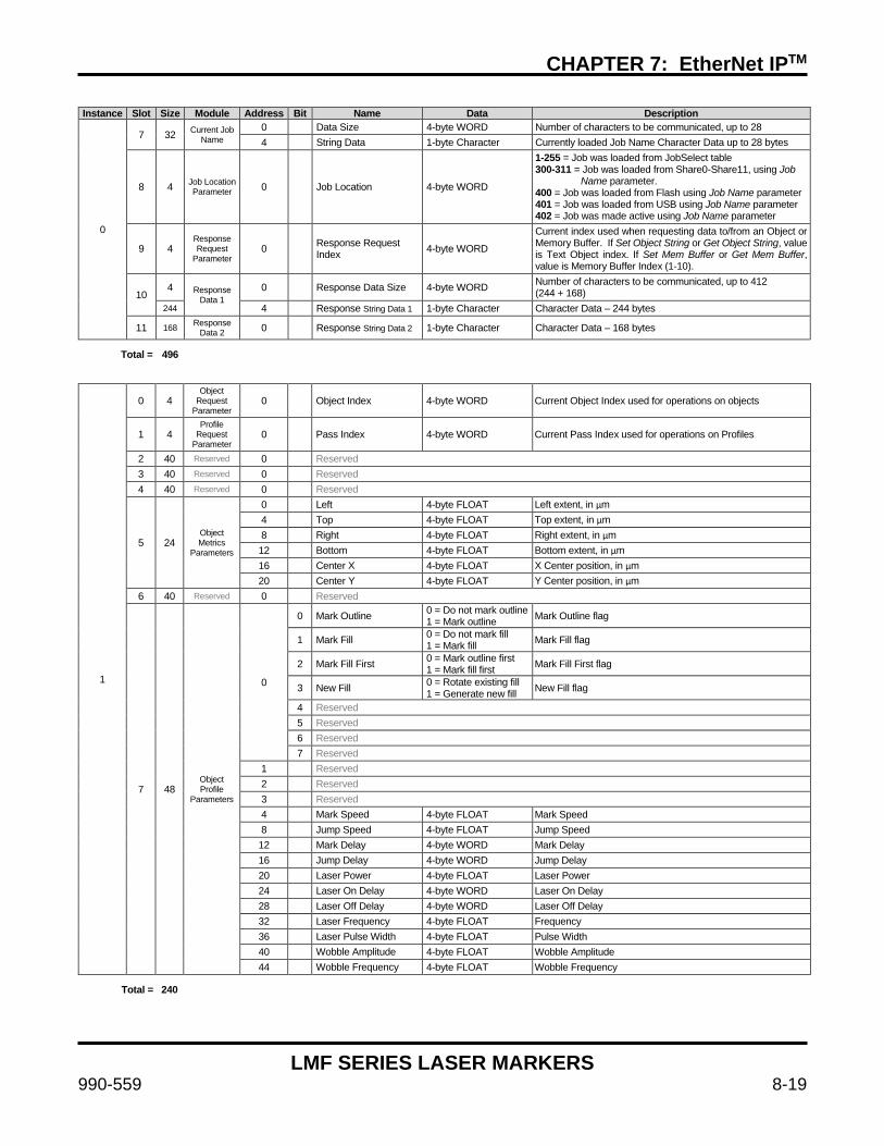
CHAPTER 7: EtherNet IPTM
LMF SERIES LASER MARKERS
990-559 8-19
Instance Slot Size Module Address Bit Name Data Description
0
7 32 Current Job Name
0 Data Size 4-byte WORD Number of characters to be communicated, up to 28 4 String Data 1-byte Character Currently loaded Job Name Character Data up to 28 bytes
8 4 Job Location Parameter 0 Job Location 4-byte WORD
1-255 = Job was loaded from JobSelect table 300-311 = Job was loaded from Share0-Share11, using Job Name parameter. 400 = Job was loaded from Flash using Job Name parameter 401 = Job was loaded from USB using Job Name parameter 402 = Job was made active using Job Name parameter
9 4 Response Request
Parameter 0 Response Request
Index 4-byte WORD
Current index used when requesting data to/from an Object or Memory Buffer. If Set Object String or Get Object String, value is Text Object index. If Set Mem Buffer or Get Mem Buffer, value is Memory Buffer Index (1-10).
10 4 Response
Data 1 0 Response Data Size 4-byte WORD Number of characters to be communicated, up to 412
(244 + 168) 244 4 Response String Data 1 1-byte Character Character Data – 244 bytes
11 168 Response Data 2 0 Response String Data 2 1-byte Character Character Data – 168 bytes
Total = 496
1
0 4 Object
Request Parameter
0 Object Index 4-byte WORD Current Object Index used for operations on objects
1 4 Profile
Request Parameter
0 Pass Index 4-byte WORD Current Pass Index used for operations on Profiles
2 40 Reserved 0 Reserved 3 40 Reserved 0 Reserved 4 40 Reserved 0 Reserved
5 24 Object Metrics
Parameters
0 Left 4-byte FLOAT Left extent, in µm 4 Top 4-byte FLOAT Top extent, in µm 8 Right 4-byte FLOAT Right extent, in µm 12 Bottom 4-byte FLOAT Bottom extent, in µm 16 Center X 4-byte FLOAT X Center position, in µm 20 Center Y 4-byte FLOAT Y Center position, in µm
6 40 Reserved 0 Reserved
7 48 Object Profile
Parameters
0
0 Mark Outline 0 = Do not mark outline 1 = Mark outline Mark Outline flag
1 Mark Fill 0 = Do not mark fill 1 = Mark fill Mark Fill flag
2 Mark Fill First 0 = Mark outline first 1 = Mark fill first Mark Fill First flag
3 New Fill 0 = Rotate existing fill 1 = Generate new fill New Fill flag
4 Reserved 5 Reserved 6 Reserved 7 Reserved
1 Reserved 2 Reserved 3 Reserved 4 Mark Speed 4-byte FLOAT Mark Speed 8 Jump Speed 4-byte FLOAT Jump Speed 12 Mark Delay 4-byte WORD Mark Delay 16 Jump Delay 4-byte WORD Jump Delay 20 Laser Power 4-byte FLOAT Laser Power 24 Laser On Delay 4-byte WORD Laser On Delay 28 Laser Off Delay 4-byte WORD Laser Off Delay 32 Laser Frequency 4-byte FLOAT Frequency 36 Laser Pulse Width 4-byte FLOAT Pulse Width 40 Wobble Amplitude 4-byte FLOAT Wobble Amplitude 44 Wobble Frequency 4-byte FLOAT Wobble Frequency
Total = 240
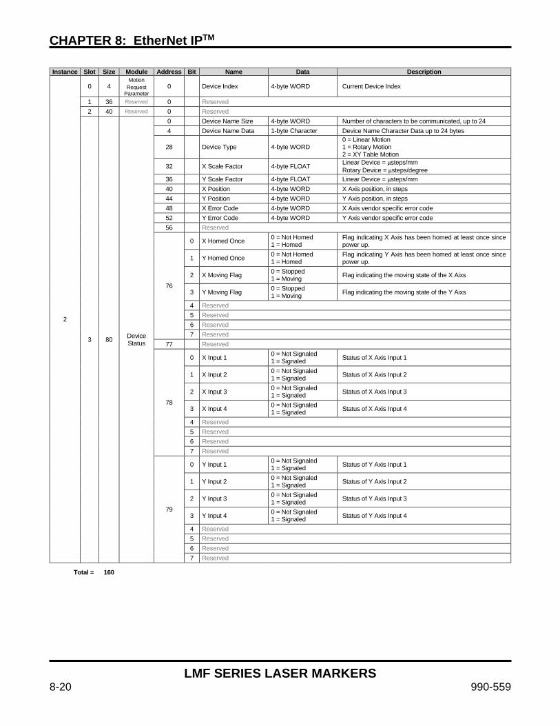
CHAPTER 8: EtherNet IPTM
LMF SERIES LASER MARKERS
8-20 990-559
Instance Slot Size Module Address Bit Name Data Description
2
0 4 Motion
Request Parameter
0 Device Index 4-byte WORD Current Device Index
1 36 Reserved 0 Reserved 2 40 Reserved 0 Reserved
3 80 Device Status
0 Device Name Size 4-byte WORD Number of characters to be communicated, up to 24 4 Device Name Data 1-byte Character Device Name Character Data up to 24 bytes
28 Device Type 4-byte WORD 0 = Linear Motion 1 = Rotary Motion 2 = XY Table Motion
32 X Scale Factor 4-byte FLOAT Linear Device = µsteps/mm Rotary Device = µsteps/degree
36 Y Scale Factor 4-byte FLOAT Linear Device = µsteps/mm 40 X Position 4-byte WORD X Axis position, in steps 44 Y Position 4-byte WORD Y Axis position, in steps 48 X Error Code 4-byte WORD X Axis vendor specific error code 52 Y Error Code 4-byte WORD Y Axis vendor specific error code 56 Reserved
76
0 X Homed Once 0 = Not Homed 1 = Homed
Flag indicating X Axis has been homed at least once since power up.
1 Y Homed Once 0 = Not Homed 1 = Homed
Flag indicating Y Axis has been homed at least once since power up.
2 X Moving Flag 0 = Stopped 1 = Moving Flag indicating the moving state of the X Aixs
3 Y Moving Flag 0 = Stopped 1 = Moving Flag indicating the moving state of the Y Aixs
4 Reserved 5 Reserved 6 Reserved 7 Reserved
77 Reserved
78
0 X Input 1 0 = Not Signaled 1 = Signaled Status of X Axis Input 1
1 X Input 2 0 = Not Signaled 1 = Signaled Status of X Axis Input 2
2 X Input 3 0 = Not Signaled 1 = Signaled Status of X Axis Input 3
3 X Input 4 0 = Not Signaled 1 = Signaled Status of X Axis Input 4
4 Reserved 5 Reserved 6 Reserved 7 Reserved
79
0 Y Input 1 0 = Not Signaled 1 = Signaled Status of Y Axis Input 1
1 Y Input 2 0 = Not Signaled 1 = Signaled Status of Y Axis Input 2
2 Y Input 3 0 = Not Signaled 1 = Signaled Status of Y Axis Input 3
3 Y Input 4 0 = Not Signaled 1 = Signaled Status of Y Axis Input 4
4 Reserved 5 Reserved 6 Reserved 7 Reserved
Total = 160
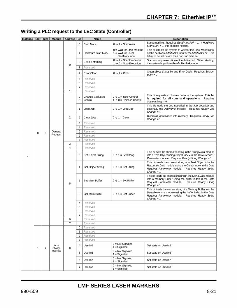
CHAPTER 7: EtherNet IPTM
LMF SERIES LASER MARKERS
990-559 8-21
Writing a PLC request to the LEC State (Controller) Instance Slot Size Module Address Bit Name Data Description
0
0 8 General Request
0
0 Start Mark 0 → 1 = Start mark Starts marking. Requires Ready to Mark = 1. If Hardware Start Mark = 1, this bit does nothing.
1 Hardware Start Mark 0 = Wait for Start Mark bit 1 = Wait for Local StartMark input
This bit directs the system to wait for the Start Mark signal on the hardware Start Mark input or the Start Mark bit. This bit must be set before the Load Job bit is set.
2 Enable Marking 0 → 1 = Start Execution 1 → 0 = Stop Execution
Starts or stops execution of the Active Job. When starting, the system is put into Ready To Mark mode.
3 Reserved
4 Error Clear 0 → 1 = Clear Clears Error Status bit and Error Code. Requires System Busy = 0
5 Reserved 6 Reserved 7 Reserved
1 Reserved
2
0 Change Exclusive Control
0 → 1 = Take Control 1 → 0 = Release Control
This bit requests exclusive control of the system. This bit is required for all command operations. Requires System Busy = 0.
1 Load Job 0 → 1 = Load Job This bit loads the Job specified in the Job Location and optionally the JobName module. Requires Ready Job Change = 1.
2 Clear Jobs 0 → 1 = Clear Clears all jobs loaded into memory. Requires Ready Job Change = 1
3 Reserved 4 Reserved 5 Reserved 6 Reserved 7 Reserved
3 Reserved 4 Reserved
5
0 Set Object String 0 → 1 = Set String This bit sets the character string in the String Data module into a Text Object using Object index in the Data Request Parameter module. Requires Ready String Change = 1
1 Get Object String 0 → 1 = Get String
This bit loads the current string of a Text Object into the Response Data module using the Object index in the Data Request Parameter module. Requires Ready String Change = 1
2 Set Mem Buffer 0 → 1 = Set Buffer
This bit loads the character string in the String Data module into a Memory Buffer using the buffer index in the Data Request Parameter module. Requires Ready String Change = 1
3 Get Mem Buffer 0 → 1 = Get Buffer
This bit loads the current string of a Memory Buffer into the Data Response module using the buffer index in the Data Request Parameter module. Requires Ready String Change = 1
4 Reserved 5 Reserved 6 Reserved 7 Reserved
6 Reserved 7 Reserved
1 4 Input
Change Request
0
0 Reserved 1 Reserved 2 Reserved 3 Reserved
4 UserIn5 0 = Not Signaled 1 = Signaled Set state on UserIn5
5 UserIn6 0 = Not Signaled 1 = Signaled Set state on UserIn6
6 UserIn7 0 = Not Signaled 1 = Signaled Set state on UserIn7
7 UserIn8 0 = Not Signaled 1 = Signaled Set state on UserIn8
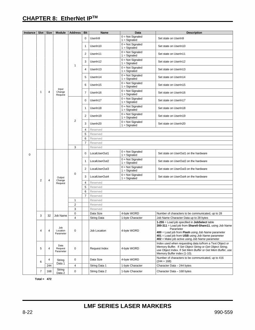
CHAPTER 8: EtherNet IPTM
LMF SERIES LASER MARKERS
8-22 990-559
Instance Slot Size Module Address Bit Name Data Description
0
1 4 Input
Change Request
1
0 UserIn9 0 = Not Signaled 1 = Signaled Set state on UserIn9
1 UserIn10 0 = Not Signaled 1 = Signaled Set state on UserIn10
2 UserIn11 0 = Not Signaled 1 = Signaled Set state on UserIn11
3 UserIn12 0 = Not Signaled 1 = Signaled Set state on UserIn12
4 UserIn13 0 = Not Signaled 1 = Signaled Set state on UserIn13
5 UserIn14 0 = Not Signaled 1 = Signaled Set state on UserIn14
6 UserIn15 0 = Not Signaled 1 = Signaled Set state on UserIn15
7 UserIn16 0 = Not Signaled 1 = Signaled Set state on UserIn16
2
0 UserIn17 0 = Not Signaled 1 = Signaled Set state on UserIn17
1 UserIn18 0 = Not Signaled 1 = Signaled Set state on UserIn18
2 UserIn19 0 = Not Signaled 1 = Signaled Set state on UserIn19
3 UserIn20 0 = Not Signaled 1 = Signaled Set state on UserIn20
4 Reserved 5 Reserved 6 Reserved 7 Reserved
3 Reserved
2 4 Output Change Request
0
0 LocalUserOut1 0 = Not Signaled 1 = Signaled Set state on UserOut1 on the hardware
1 LocalUserOut2 0 = Not Signaled 1 = Signaled Set state on UserOut2 on the hardware
2 LocalUserOut3 0 = Not Signaled 1 = Signaled Set state on UserOut3 on the hardware
3 LocalUserOut4 0 = Not Signaled 1 = Signaled Set state on UserOut4 on the hardware
4 Reserved 5 Reserved 6 Reserved 7 Reserved
1 Reserved 2 Reserved 3 Reserved
3 32 Job Name 0 Data Size 4-byte WORD Number of characters to be communicated, up to 28 4 String Data 1-byte Character Job Name Character Data up to 28 bytes
4 4 Job
Location Parameter
0 Job Location 4-byte WORD
1-255 = Load job specified in JobSelect table 300-311 = Load job from Share0-Share11, using Job Name Parameter 400 = Load job from Flash using Job Name parameter 401 = Load job from USB using Job Name parameter 402 = Make job active using Job Name parameter
5 4 Data
Request Parameter
0 Request Index 4-byte WORD
Index used when requesting data to/from a Text Object or Memory Buffer. If Set Object String or Get Object String, use Object Index. If Set Mem Buffer or Get Mem Buffer, use Memory Buffer index (1-10).
6 4 String
Data 1 0 Data Size 4-byte WORD Number of characters to be communicated, up to 416
(244 + 168) 244 4 String Data 1 1-byte Character Character Data – 244 bytes
7 168 String Data 2 0 String Data 2 1-byte Character Character Data – 168 bytes
Total = 472
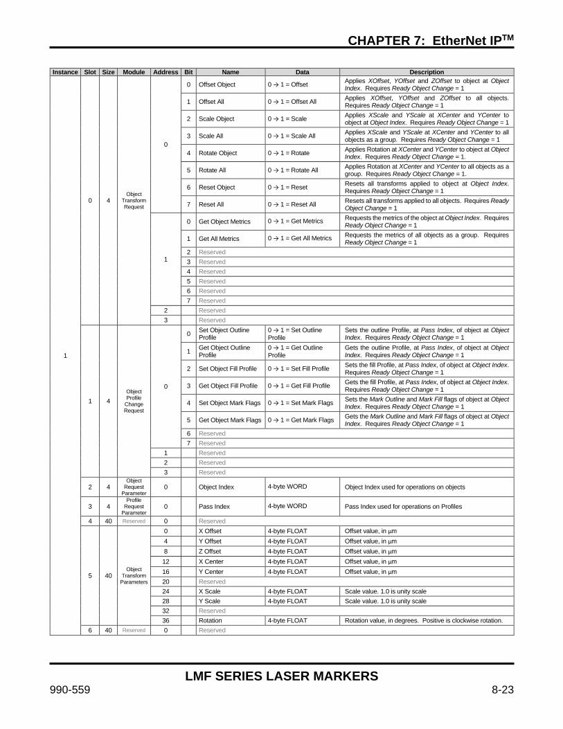
CHAPTER 7: EtherNet IPTM
LMF SERIES LASER MARKERS
990-559 8-23
Instance Slot Size Module Address Bit Name Data Description
1
0 4 Object
Transform Request
0
0 Offset Object 0 → 1 = Offset Applies XOffset, YOffset and ZOffset to object at Object Index. Requires Ready Object Change = 1
1 Offset All 0 → 1 = Offset All Applies XOffset, YOffset and ZOffset to all objects. Requires Ready Object Change = 1
2 Scale Object 0 → 1 = Scale Applies XScale and YScale at XCenter and YCenter to object at Object Index. Requires Ready Object Change = 1
3 Scale All 0 → 1 = Scale All Applies XScale and YScale at XCenter and YCenter to all objects as a group. Requires Ready Object Change = 1
4 Rotate Object 0 → 1 = Rotate Applies Rotation at XCenter and YCenter to object at Object Index. Requires Ready Object Change = 1.
5 Rotate All 0 → 1 = Rotate All Applies Rotation at XCenter and YCenter to all objects as a group. Requires Ready Object Change = 1.
6 Reset Object 0 → 1 = Reset Resets all transforms applied to object at Object Index. Requires Ready Object Change = 1
7 Reset All 0 → 1 = Reset All Resets all transforms applied to all objects. Requires Ready Object Change = 1
1
0 Get Object Metrics 0 → 1 = Get Metrics Requests the metrics of the object at Object Index. Requires Ready Object Change = 1
1 Get All Metrics 0 → 1 = Get All Metrics Requests the metrics of all objects as a group. Requires Ready Object Change = 1
2 Reserved 3 Reserved 4 Reserved 5 Reserved 6 Reserved 7 Reserved
2 Reserved 3 Reserved
1 4 Object Profile
Change Request
0
0 Set Object Outline Profile
0 → 1 = Set Outline Profile
Sets the outline Profile, at Pass Index, of object at Object Index. Requires Ready Object Change = 1
1 Get Object Outline Profile
0 → 1 = Get Outline Profile
Gets the outline Profile, at Pass Index, of object at Object Index. Requires Ready Object Change = 1
2 Set Object Fill Profile 0 → 1 = Set Fill Profile Sets the fill Profile, at Pass Index, of object at Object Index. Requires Ready Object Change = 1
3 Get Object Fill Profile 0 → 1 = Get Fill Profile Gets the fill Profile, at Pass Index, of object at Object Index. Requires Ready Object Change = 1
4 Set Object Mark Flags 0 → 1 = Set Mark Flags Sets the Mark Outline and Mark Fill flags of object at Object Index. Requires Ready Object Change = 1
5 Get Object Mark Flags 0 → 1 = Get Mark Flags Gets the Mark Outline and Mark Fill flags of object at Object Index. Requires Ready Object Change = 1
6 Reserved 7 Reserved
1 Reserved 2 Reserved 3 Reserved
2 4 Object
Request Parameter
0 Object Index 4-byte WORD Object Index used for operations on objects
3 4 Profile
Request Parameter
0 Pass Index 4-byte WORD Pass Index used for operations on Profiles
4 40 Reserved 0 Reserved
5 40 Object
Transform Parameters
0 X Offset 4-byte FLOAT Offset value, in µm 4 Y Offset 4-byte FLOAT Offset value, in µm 8 Z Offset 4-byte FLOAT Offset value, in µm 12 X Center 4-byte FLOAT Offset value, in µm 16 Y Center 4-byte FLOAT Offset value, in µm 20 Reserved 24 X Scale 4-byte FLOAT Scale value. 1.0 is unity scale 28 Y Scale 4-byte FLOAT Scale value. 1.0 is unity scale 32 Reserved 36 Rotation 4-byte FLOAT Rotation value, in degrees. Positive is clockwise rotation.
6 40 Reserved 0 Reserved
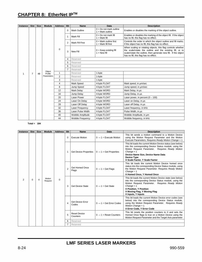
CHAPTER 8: EtherNet IPTM
LMF SERIES LASER MARKERS
8-24 990-559
Instance Slot Size Module Address Bit Name Data Description
1 7 48 Object Profile
Parameters
0
0 Mark Outline 0 = Do not mark outline 1 = Mark outline Enables or disables the marking of the object outline.
1 Mark Fill 0 = Do not mark fill 1 = Mark fill
Enables or disables the marking of the object fill. If the object has no fill, this flag has no effect.
2 Mark Fill First 0 = Mark outline first 1 = Mark fill first
Controls the order in which the object outline and fill marks. If the object has no fill, this flag has no effect.
3 New Fill 0 = Keep existing fill 1 = New fill
When scaling or rotating objects, this flag controls whether the scale/rotate the outline and the existing fill, or to scale/rotate the outline, then generate new fill. If the object has no fill, this flag has no effect.
4 Reserved 5 Reserved 6 Reserved 7 Reserved
1 Reserved 1-byte 2 Reserved 1-byte 3 Reserved 1-byte 4 Mark Speed 4-byte FLOAT Mark speed, in µm/sec 8 Jump Speed 4-byte FLOAT Jump speed, in µm/sec 12 Mark Delay 4-byte WORD Mark Delay, in µs 16 Jump Delay 4-byte WORD Jump Delay, in µs 20 Laser Power 4-byte FLOAT Laser power, in percent (0 – 100) 24 Laser On Delay 4-byte WORD Laser on Delay, in µs 28 Laser Off Delay 4-byte WORD Laser off Delay, in µs 32 Laser Frequency 4-byte FLOAT Laser frequency, in kHz 36 Laser Pulse Width 4-byte FLOAT Pulse Width, in µs 40 Wobble Amplitude 4-byte FLOAT Wobble Amplitude, in µm 44 Wobble Frequency 4-byte FLOAT Wobble frequency, in kHz
Total = 184 Instance Slot Size Module Address Bit Name Data Description
2 0 4 Motion Request 0
0 Execute Motion 0 → 1 = Execute Motion This bit sends a motion command to a Motion Device using the Motion Request Parameter and the Motion Execute Parameters. Requires Ready Motion Change = 1
1 Get Device Properties 0 → 1 = Get Properties
This bit loads the current Motion Device status (see below) into the corresponding Device Status module, using the Motion Request Parameter. Requires Ready Motion Change = 1 Device Name Size, Device Name Data Device Type X Scale Factor, Y Scale Factor
2 Get Homed Once Flags 0 → 1 = Get Flags
This bit loads the current Motion Device homed once status into the corresponding Device Status module, using the Motion Request Parameter. Requires Ready Motion Change = 1 X Homed Once, Y Homed Once
3 Get Device State 0 → 1 = Get State
This bit loads the current Motion Device state (see below) into the corresponding Device Status module, using the Motion Request Parameter. Requires Ready Motion Change = 1 X Position, Y Position X Moving Flag, Y Moving Flag X Inputs, Y Inputs
4 Get Device Error Codes 0 → 1 = Get Error Codes
This bit loads the current Motion Device error codes (see below) into the corresponding Device Status module, using the Motion Request Parameter. Requires Ready Motion Change = 1 X Error Code, Y Error Code
5 Reset Device Counters 0 → 1 = Reset Counters
This bit resets the position counters to 0 and sets the Homed Once flags to true on a Motion Device using the Motion Request Parameter and the Target Axis parameter
6 Reserved 7 Reserved
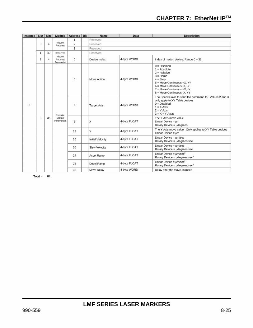
CHAPTER 7: EtherNet IPTM
LMF SERIES LASER MARKERS
990-559 8-25
Instance Slot Size Module Address Bit Name Data Description
2
0 4 Motion Request
1 Reserved 2 Reserved 3 Reserved
1 40 Reserved Reserved
2 4 Motion
Request Parameter
0 Device Index 4-byte WORD Index of motion device. Range 0 – 31.
3 36 Execute Motion
Parameters
0 Move Action 4-byte WORD
0 = Disabled 1 = Absolute 2 = Relative 3 = Home 4 = Stop 5 = Move Continuous +X, +Y 6 = Move Continuous -X, -Y 7 = Move Continuous +X, -Y 8 = Move Continuous -X, +Y
4 Target Axis 4-byte WORD
The Specific axis to send the command to. Values 2 and 3 only apply to XY Table devices 0 = Disabled 1 = X Axis 2 = Y Axis 3 = X + Y Axes
8 X 4-byte FLOAT The X Axis move value Linear Device = µm Rotary Device = µdegrees
12 Y 4-byte FLOAT The Y Axis move value. Only applies to XY Table devices Linear Device = µm
16 Initial Velocity 4-byte FLOAT Linear Device = µm/sec Rotary Device = µdegrees/sec
20 Slew Velocity 4-byte FLOAT Linear Device = µm/sec Rotary Device = µdegrees/sec
24 Accel Ramp 4-byte FLOAT Linear Device = µm/sec2 Rotary Device = µdegrees/sec2
28 Decel Ramp 4-byte FLOAT Linear Device = µm/sec2 Rotary Device = µdegrees/sec2
32 Move Delay 4-byte WORD Delay after the move, in msec
Total = 84
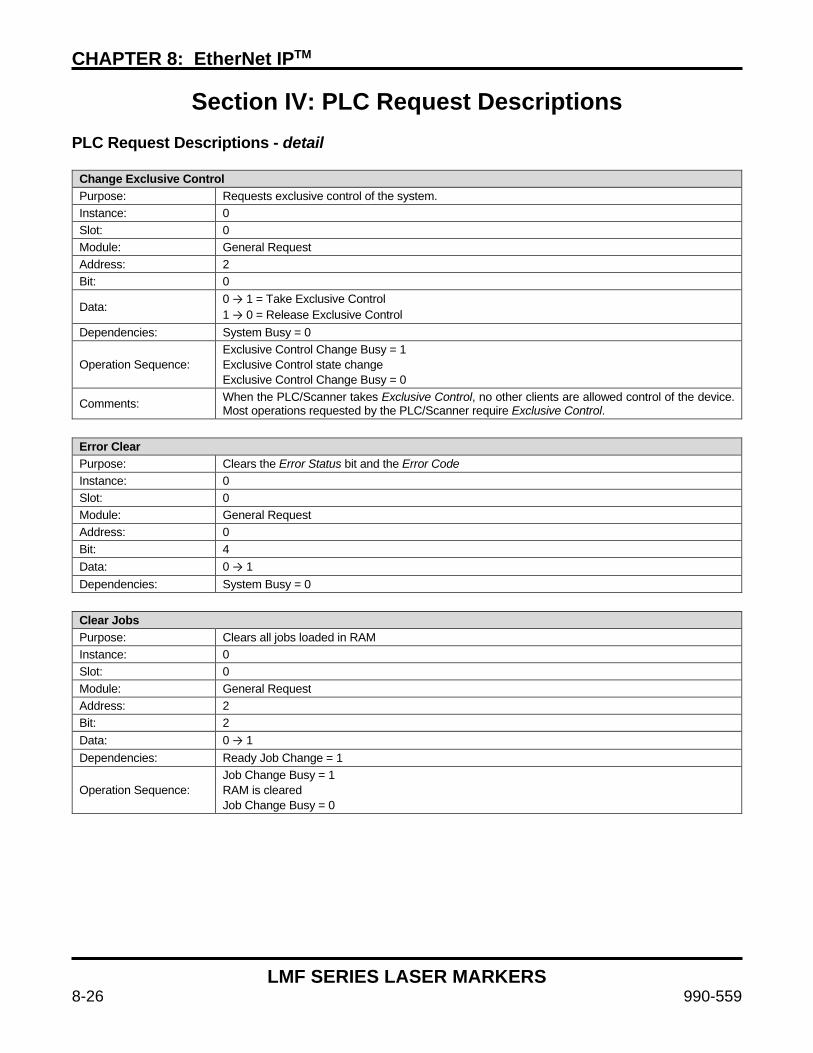
CHAPTER 8: EtherNet IPTM
LMF SERIES LASER MARKERS
8-26 990-559
Section IV: PLC Request Descriptions
PLC Request Descriptions - detail
Change Exclusive Control Purpose: Requests exclusive control of the system. Instance: 0 Slot: 0 Module: General Request Address: 2 Bit: 0
Data: 0 → 1 = Take Exclusive Control 1 → 0 = Release Exclusive Control
Dependencies: System Busy = 0
Operation Sequence: Exclusive Control Change Busy = 1 Exclusive Control state change Exclusive Control Change Busy = 0
Comments: When the PLC/Scanner takes Exclusive Control, no other clients are allowed control of the device. Most operations requested by the PLC/Scanner require Exclusive Control.
Error Clear Purpose: Clears the Error Status bit and the Error Code Instance: 0 Slot: 0 Module: General Request Address: 0 Bit: 4 Data: 0 → 1 Dependencies: System Busy = 0
Clear Jobs Purpose: Clears all jobs loaded in RAM Instance: 0 Slot: 0 Module: General Request Address: 2 Bit: 2 Data: 0 → 1 Dependencies: Ready Job Change = 1
Operation Sequence: Job Change Busy = 1 RAM is cleared Job Change Busy = 0

CHAPTER 7: EtherNet IPTM
LMF SERIES LASER MARKERS
990-559 8-27
Enable Marking Purpose: Start or stops executing the Active Job. Instance: 0 Slot: 0 Module: General Request Address: 0 Bit: 2
Data: 0 → 1 = Start executing the Active Job 1 → 0 = Abort the currently executing job
Dependencies: Exclusive Control = 1 An Active Job loaded in RAM
Operation Sequence: Enable Marking Change Busy = 1 Job is executed or aborted Enable Marking Change Busy = 0
Comments:
When the Enable Marking bit is set to 1, the system executes the ActiveJob. If Hardware Start Mark = 0, the system will set the Ready to Mark bit and wait for the Start Mark bit to be set before marking will start. If Hardware Start Mark = 1, the system will set the Ready To Mark bit and wait for the Local Start Mark input to be signaled before marking will start. The Trigger Mode settings of the Active Job will be used to determine when the Local Start Mark input is signaled. Depending on the Trigger Mode, the job may start marking immediately because the Trigger Mode condition is satisfied. When the Enable Marking bit is set to 0, the marking is aborted. Set the Enable Marking bit to 1 to execute the Job again.
Get Mem Buffer Purpose: Gets a character string from a string Memory Buffer Instance: 0 Slot: 0 Module: General Request Address: 5 Bit: 3 Data: 0 → 1 Parameters: Data Request Parameter = Index number of Memory Buffer Dependencies: Ready String Change = 1
Returns: Response Data – Response Data Size = Number of characters in string Response Data 1 = Character string Response Data 2 = Character string
Operation Sequence: Mem Buffer String Change Busy = 1 String is copied from Memory Buffer into Response buffer Mem Buffer String Change Busy = 0
Comments:
If the memory buffer contains a character string of up to 244 characters, the string is copied into Response Data 1. If the memory buffer contains a character string greater than 244 and less than 416 characters, both Response Data 1 and Response Data 2 are used. Strings greater than 416 characters are truncated.
See Also: Request Index, String Data 1, String Data 2
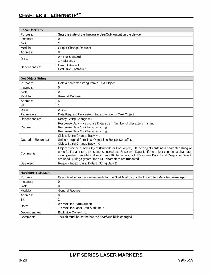
CHAPTER 8: EtherNet IPTM
LMF SERIES LASER MARKERS
8-28 990-559
Local UserOutx Purpose: Sets the state of the hardware UserOutx output on the device. Instance: 0 Slot: 2 Module: Output Change Request Address: 0
Data: 0 = Not Signaled 1 = Signaled
Dependencies: Error Status = 1 Exclusive Control = 1
Get Object String Purpose: Gets a character string from a Text Object Instance: 0 Slot: 0 Module: General Request Address: 5 Bit: 1 Data: 0 → 1 Parameters: Data Request Parameter = Index number of Text Object Dependencies: Ready String Change = 1
Returns: Response Data – Response Data Size = Number of characters in string Response Data 1 = Character string Response Data 2 = Character string
Operation Sequence: Object String Change Busy = 1 String is copied from Text Object into Response buffer. Object String Change Busy = 0
Comments:
Object must be a Text Object (Barcode or Font object). If the object contains a character string of up to 244 characters, the string is copied into Response Data 1. If the object contains a character string greater than 244 and less than 416 characters, both Response Data 1 and Response Data 2 are used. Strings greater than 416 characters are truncated.
See Also: Request Index, String Data 1, String Data 2
Hardware Start Mark Purpose: Controls whether the system waits for the Start Mark bit, or the Local Start Mark hardware input. Instance: 0 Slot: 0 Module: General Request Address: 0 Bit: 1
Data: 0 = Wait for StartMark bit 1 = Wait for Local Start Mark input
Dependencies: Exclusive Control = 1 Comments: This bit must be set before the Load Job bit is changed
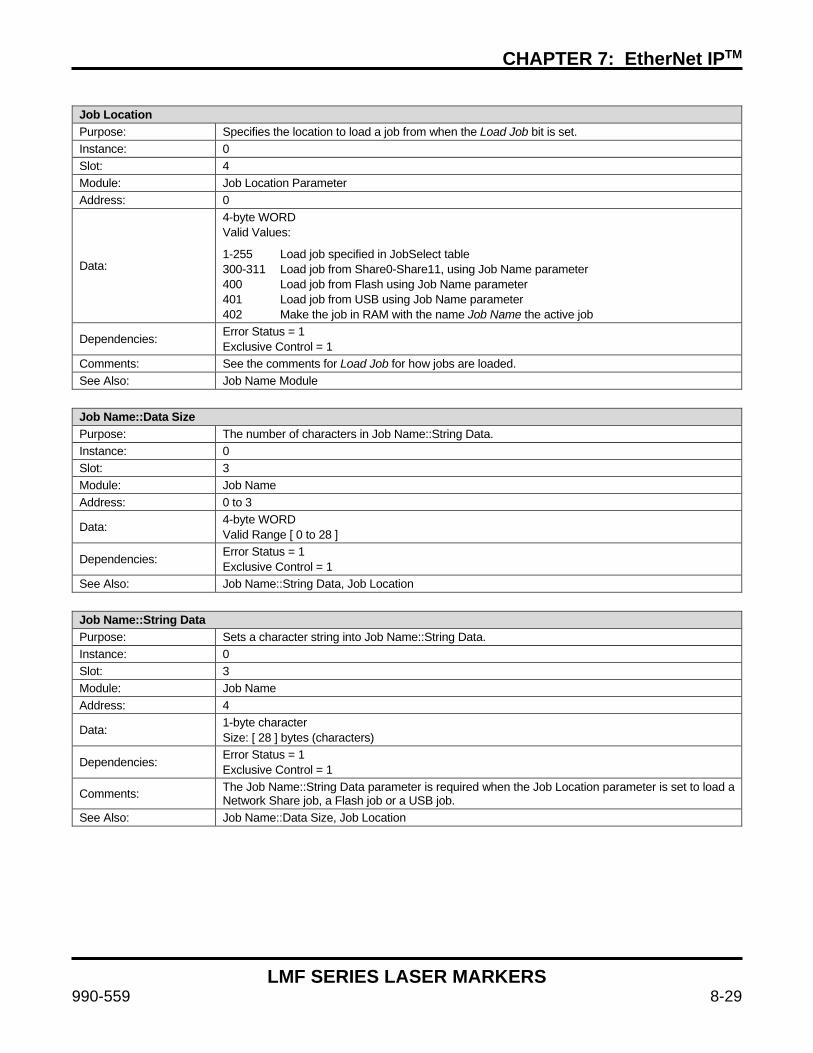
CHAPTER 7: EtherNet IPTM
LMF SERIES LASER MARKERS
990-559 8-29
Job Location Purpose: Specifies the location to load a job from when the Load Job bit is set. Instance: 0 Slot: 4 Module: Job Location Parameter Address: 0
Data:
4-byte WORD Valid Values:
1-255 Load job specified in JobSelect table 300-311 Load job from Share0-Share11, using Job Name parameter 400 Load job from Flash using Job Name parameter 401 Load job from USB using Job Name parameter 402 Make the job in RAM with the name Job Name the active job
Dependencies: Error Status = 1 Exclusive Control = 1
Comments: See the comments for Load Job for how jobs are loaded. See Also: Job Name Module
Job Name::Data Size Purpose: The number of characters in Job Name::String Data. Instance: 0 Slot: 3 Module: Job Name Address: 0 to 3
Data: 4-byte WORD Valid Range [ 0 to 28 ]
Dependencies: Error Status = 1 Exclusive Control = 1
See Also: Job Name::String Data, Job Location
Job Name::String Data Purpose: Sets a character string into Job Name::String Data. Instance: 0 Slot: 3 Module: Job Name Address: 4
Data: 1-byte character Size: [ 28 ] bytes (characters)
Dependencies: Error Status = 1 Exclusive Control = 1
Comments: The Job Name::String Data parameter is required when the Job Location parameter is set to load a Network Share job, a Flash job or a USB job.
See Also: Job Name::Data Size, Job Location

CHAPTER 8: EtherNet IPTM
LMF SERIES LASER MARKERS
8-30 990-559
Load Job Purpose: Loads or makes active the Job specified in Job Location and Job Name into RAM. Instance: 0 Slot: 0 Module: General Request Address: 2 Bit: 1 Data: 0 → 1
Parameters: Hardware Mark Start Job Location Job Name Module (optional)
Dependencies: Ready Job Change = 1
Operation Sequence: Job Change Busy = 1 Waiting for Start Mark = 1 Job Change Busy = 0
Comments:
The Hardware Start Mark, Job Location and Job Name Module parameters must be set before this bit is changed. After the Job is loaded into RAM, the Job is set as the active job, and is ready to execute by setting the Start Mark bit, or setting the Local Start Mark input to HIGH.
Multiple jobs with unique job names may be loaded into RAM at the same time, up to the limit of RAM storage. All job names must be unique, even if they are in different storage locations. For fast switching between jobs loaded in RAM, use Job Location = 402, with the name of the job to switch to in the Job Name module. For all other Job Location parameters, the job is always loaded from the storage location and will overwrite a job if one exists in RAM with the same name.
See Also: Hardware Start Mark, Job Name Module, Job Location
Request Index Purpose: Specifies the index when requesting data to/from a Text Object or Memory Buffer. Instance: 0 Slot: 5 Module: Data Request Parameter Address: 0
Data:
4-byte WORD
Set Object String, Get Object String – The index of the object in the Job. Valid Range [ 0 to object count – 1 ]
Set Mem Buffer, Get Mem Buffer – The Memory Buffer index. Valid Range [ 0 to 9 ]
Dependencies: Error Status = 1 Exclusive Control = 1
See Also: Set Object String, Get Object String, Set Mem Buffer, Get Mem Buffer

CHAPTER 7: EtherNet IPTM
LMF SERIES LASER MARKERS
990-559 8-31
Set Mem Buffer Purpose: Sets a character string into a string Memory Buffer. Instance: 0 Slot: 0 Module: General Request Address: 5 Bit: 2 Data: 0 → 1
Parameters:
Data Request Parameter = Index number of Memory Buffer. Valid Range [ 0 to 9 ]
String Data 1 – Data Size = Number of characters in string, without terminating character Valid Range [ 0 to 416 ]
String Data 1 = Character string. Valid Range [ 1 to 244 ] characters
String Data 2 = Character string. Valid Range [ 1 to 168 ] characters
Dependencies: Ready String Change = 1
Operation Sequence: Mem Buffer Change Busy = 1 String is copied into Memory Buffer Mem Buffer Change Busy = 0
Comments: For a character string up to 244 characters, use String Data 1. For a character string greater than 244 and less than 416 characters, use both String Data 1 and String Data 2.
See Also: Request Index, String Data 1, String Data 2
Set Object String Purpose: Sets a character string into a Text Object Instance: 0 Slot: 0 Module: General Request Address: 5 Bit: 0 Data: 0 → 1
Parameters:
Request Index – Index number of Text Object
String Data 1 – Data Size = Number of characters in string, without terminating character Valid Range [ 0 to 416 ]
String Data 1 = Character string Valid Range [ 1 to 244 ] characters
String Data 2 = Character string Valid Range [ 1 to 168 ] characters
Dependencies: Ready String Change = 1
Operation Sequence: Object String Change Busy = 1 String is copied into Text Object Object String Change Busy = 0
Comments: Object must be a Text Object (Barcode or Font object). For a character string up to 244 characters, use String Data 1. For a character string greater than 244 and less than 416 characters, use both String Data 1 and String Data 2.
See Also: Request Index, String Data 1, String Data 2

CHAPTER 8: EtherNet IPTM
LMF SERIES LASER MARKERS
8-32 990-559
Start Mark Purpose: Starts the marking process Instance: 0 Slot: 0 Module: General Request Address: 0 Bit: 0 Data: 0 → 1
Dependencies: Ready To Mark = 1 Hardware Start Mark = 0
Operation Sequence:
Waiting For Start Mark = 0 Job Busy = 1 Object In Progress Busy = 1 Object In Progress Busy = 0 Job Busy = 0 Waiting For Start Mark = 1 Repeat…
String Data 1 Purpose: Sets a character string into String Data 1 Instance: 0 Slot: 6 Module: String Data 1 Address: 4
Data: 1-byte character Size: [ 244 ] bytes (characters)
Dependencies: Error Status = 1 Exclusive Control = 1
Comments: To transmit a character string up to 244 characters, use String Data 1. For a character string greater than 244 characters, use String Data 1 for the first 244 characters and String Data 2 for the rest (up to a total of 416 characters).
See Also: String Data 1::Data Size, String Data 2, Request Index
String Data 1::Data Size Purpose: The number of characters in String Data 1 + String Data 2 Instance: 0 Slot: 6 Module: String Data 1 Address: 0
Data: 4-byte WORD Valid Range [ 0 to 416 ]
Dependencies: Error Status = 1 Exclusive Control = 1
Comments: To transmit a character string up to 244 characters, use String Data 1. For a character string greater than 244 characters, use String Data 1 for the first 244 characters and String Data 2 for the rest (up to a total of 416 characters)
See Also: String Data 1, String Data 2

CHAPTER 7: EtherNet IPTM
LMF SERIES LASER MARKERS
990-559 8-33
String Data 2 Purpose: Sets a character string into String Data 2 Instance: 0 Slot: 7 Module: String Data 2 Address: 0
Data: 1-byte character Size: [ 168 ] bytes (characters)
Dependencies: Error Status = 1 Exclusive Control = 1
Comments: To transmit a character string up to 244 characters, use String Data 1. For a character string greater than 244 characters, use String Data 1 for the first 244 characters and String Data 2 for the rest (up to a total of 416 characters).
See Also: String Data 1::Data Size, String Data 1, Request Index
UserInx Purpose: Sets the state of the Network UserInx bit Instance: 0 Slot: 1 Module: Input Change Request Address: 0 – 2
Data: 0 = Not Signaled 1 = Signaled
Dependencies: Error Status = 1 Exclusive Control = 1

CHAPTER 8: EtherNet IPTM
LMF SERIES LASER MARKERS
8-34 990-559
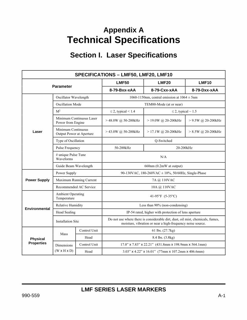
LMF SERIES LASER MARKERS
990-559 A-1
Appendix A Technical Specifications
Section I. Laser Specifications
SPECIFICATIONS – LMF50, LMF20, LMF10
Parameter LMF50 LMF20 LMF10
8-79-Bxx-xAA 8-79-Cxx-xAA 8-79-Dxx-xAA
Laser
Oscillator Wavelength 1060-1150nm, central emission at 1064 ± 5nm
Oscillation Mode TEM00-Mode (at or near)
M2 ≤ 2, typical < 1.4 ≤ 2, typical ~ 1.5
Minimum Continuous Laser Power from Engine > 48.0W @ 50-200kHz > 19.0W @ 20-200kHz > 9.5W @ 20-200kHz
Minimum Continuous Output Power at Aperture > 43.0W @ 50-200kHz > 17.1W @ 20-200kHz > 8.5W @ 20-200kHz
Type of Oscillation Q-Switched
Pulse Frequency 50-200kHz 20-200kHz
# unique Pulse Tune Waveforms N/A
Guide Beam Wavelength 660nm (0.2mW at output)
Power Supply
Power Supply 90-130VAC, 180-260VAC ± 10%, 50/60Hz, Single-Phase
Maximum Running Current 7A @ 110VAC
Recommended AC Service 10A @ 110VAC
Environmental
Ambient Operating Temperature 41-95°F (5-35°C)
Relative Humidity Less than 90% (non-condensing)
Head Sealing IP-54 rated, higher with protection of lens aperture
Installation Site Do not use where there is considerable dirt, dust, oil mist, chemicals, fumes, moisture, vibration or near a high-frequency noise source.
Physical Properties
Mass Control Unit 61 lbs. (27.7kg)
Head 8.4 lbs. (3.8kg)
Dimensions (W x H x D)
Control Unit 17.0” x 7.83” x 22.21” (431.8mm x 198.9mm x 564.1mm)
Head 3.03” x 4.22” x 16.01” (77mm x 107.2mm x 406.6mm)
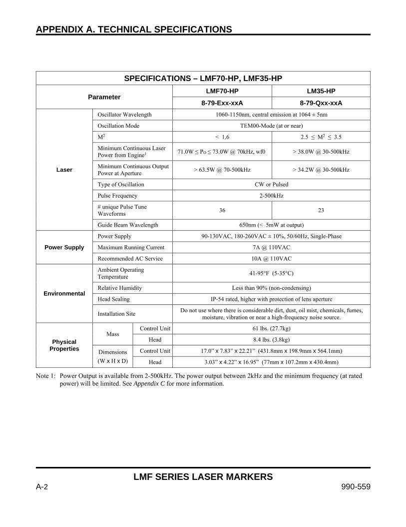
APPENDIX A. TECHNICAL SPECIFICATIONS
LMF SERIES LASER MARKERS
A-2 990-559
SPECIFICATIONS – LMF70-HP, LMF35-HP
Parameter LMF70-HP LM35-HP
8-79-Exx-xxA 8-79-Qxx-xxA
Laser
Oscillator Wavelength 1060-1150nm, central emission at 1064 ± 5nm
Oscillation Mode TEM00-Mode (at or near)
M2 < 1.6 2.5 ≤ M2 ≤ 3.5
Minimum Continuous Laser Power from Engine1
71.0W ≤ PO ≤ 73.0W @ 70kHz, wf0 > 38.0W @ 30-500kHz
Minimum Continuous Output Power at Aperture
> 63.5W @ 70-500kHz > 34.2W @ 30-500kHz
Type of Oscillation CW or Pulsed
Pulse Frequency 2-500kHz
# unique Pulse Tune Waveforms
36 23
Guide Beam Wavelength 650nm (< 5mW at output)
Power Supply
Power Supply 90-130VAC, 180-260VAC ± 10%, 50/60Hz, Single-Phase
Maximum Running Current 7A @ 110VAC
Recommended AC Service 10A @ 110VAC
Environmental
Ambient Operating Temperature
41-95°F (5-35°C)
Relative Humidity Less than 90% (non-condensing)
Head Sealing IP-54 rated, higher with protection of lens aperture
Installation Site Do not use where there is considerable dirt, dust, oil mist, chemicals, fumes,
moisture, vibration or near a high-frequency noise source.
Physical Properties
Mass Control Unit 61 lbs. (27.7kg)
Head 8.4 lbs. (3.8kg)
Dimensions
(W x H x D)
Control Unit 17.0” x 7.83” x 22.21” (431.8mm x 198.9mm x 564.1mm)
Head 3.03” x 4.22” x 16.95” (77mm x 107.2mm x 430.4mm)
Note 1: Power Output is available from 2-500kHz. The power output between 2kHz and the minimum frequency (at rated power) will be limited. See Appendix C for more information.
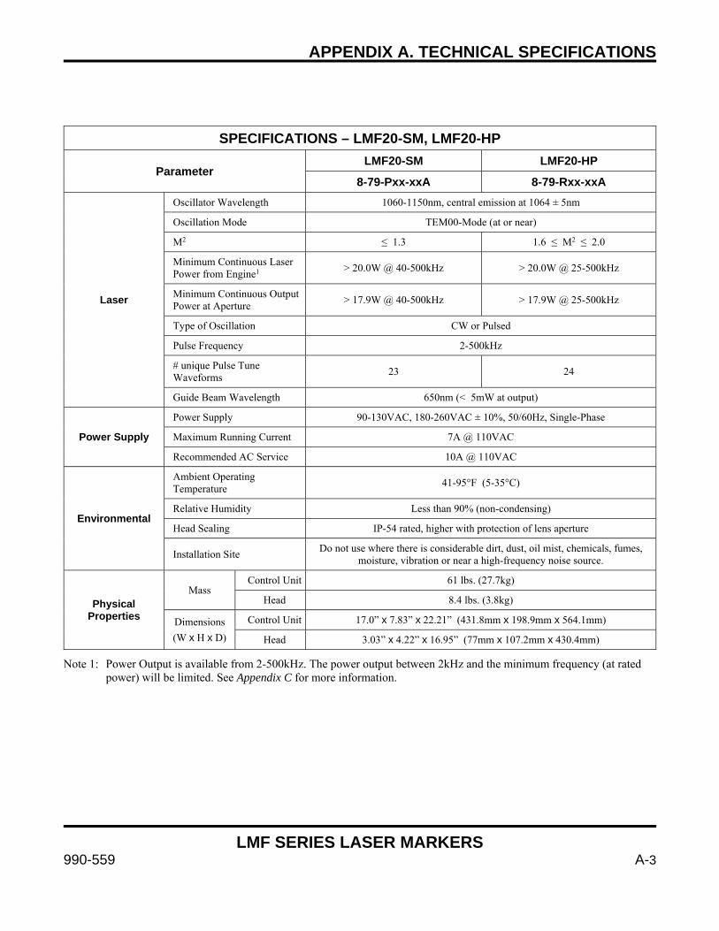
APPENDIX A. TECHNICAL SPECIFICATIONS
LMF SERIES LASER MARKERS
990-559 A-3
SPECIFICATIONS – LMF20-SM, LMF20-HP
Parameter LMF20-SM LMF20-HP
8-79-Pxx-xxA 8-79-Rxx-xxA
Laser
Oscillator Wavelength 1060-1150nm, central emission at 1064 ± 5nm
Oscillation Mode TEM00-Mode (at or near)
M2 ≤ 1.3 1.6 ≤ M2 ≤ 2.0
Minimum Continuous Laser Power from Engine1
> 20.0W @ 40-500kHz > 20.0W @ 25-500kHz
Minimum Continuous Output Power at Aperture
> 17.9W @ 40-500kHz > 17.9W @ 25-500kHz
Type of Oscillation CW or Pulsed
Pulse Frequency 2-500kHz
# unique Pulse Tune Waveforms
23 24
Guide Beam Wavelength 650nm (< 5mW at output)
Power Supply
Power Supply 90-130VAC, 180-260VAC ± 10%, 50/60Hz, Single-Phase
Maximum Running Current 7A @ 110VAC
Recommended AC Service 10A @ 110VAC
Environmental
Ambient Operating Temperature
41-95°F (5-35°C)
Relative Humidity Less than 90% (non-condensing)
Head Sealing IP-54 rated, higher with protection of lens aperture
Installation Site Do not use where there is considerable dirt, dust, oil mist, chemicals, fumes,
moisture, vibration or near a high-frequency noise source.
Physical Properties
Mass Control Unit 61 lbs. (27.7kg)
Head 8.4 lbs. (3.8kg)
Dimensions
(W x H x D)
Control Unit 17.0” x 7.83” x 22.21” (431.8mm x 198.9mm x 564.1mm)
Head 3.03” x 4.22” x 16.95” (77mm x 107.2mm x 430.4mm)
Note 1: Power Output is available from 2-500kHz. The power output between 2kHz and the minimum frequency (at rated power) will be limited. See Appendix C for more information.
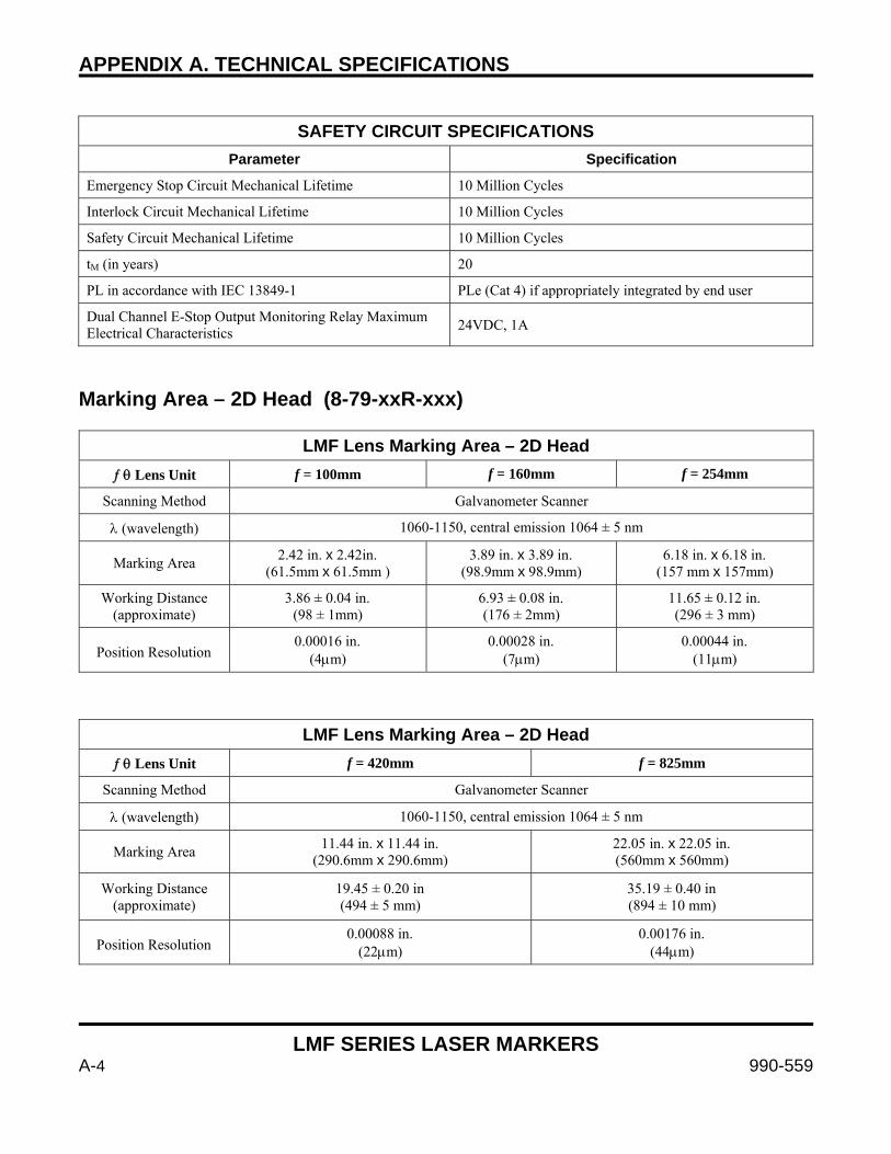
APPENDIX A. TECHNICAL SPECIFICATIONS
LMF SERIES LASER MARKERS
A-4 990-559
SAFETY CIRCUIT SPECIFICATIONS
Parameter Specification
Emergency Stop Circuit Mechanical Lifetime 10 Million Cycles
Interlock Circuit Mechanical Lifetime 10 Million Cycles
Safety Circuit Mechanical Lifetime 10 Million Cycles
tM (in years) 20
PL in accordance with IEC 13849-1 PLe (Cat 4) if appropriately integrated by end user
Dual Channel E-Stop Output Monitoring Relay Maximum Electrical Characteristics
24VDC, 1A
Marking Area – 2D Head (8-79-xxR-xxx)
LMF Lens Marking Area – 2D Head Lens Unit f = 100mm f = 160mm f = 254mm
Scanning Method Galvanometer Scanner
(wavelength) 1060-1150, central emission 1064 ± 5 nm
Marking Area 2.42 in. x 2.42in.
(61.5mm x 61.5mm ) 3.89 in. x 3.89 in.
(98.9mm x 98.9mm) 6.18 in. x 6.18 in.
(157 mm x 157mm)
Working Distance (approximate)
3.86 ± 0.04 in. (98 ± 1mm)
6.93 ± 0.08 in. (176 ± 2mm)
11.65 ± 0.12 in. (296 ± 3 mm)
Position Resolution 0.00016 in.
(4m) 0.00028 in.
(7m) 0.00044 in.
(11m)
LMF Lens Marking Area – 2D Head Lens Unit f = 420mm f = 825mm
Scanning Method Galvanometer Scanner
(wavelength) 1060-1150, central emission 1064 ± 5 nm
Marking Area 11.44 in. x 11.44 in.
(290.6mm x 290.6mm) 22.05 in. x 22.05 in. (560mm x 560mm)
Working Distance (approximate)
19.45 ± 0.20 in (494 ± 5 mm)
35.19 ± 0.40 in (894 ± 10 mm)
Position Resolution 0.00088 in.
(22m) 0.00176 in.
(44m)

APPENDIX A. TECHNICAL SPECIFICATIONS
LMF SERIES LASER MARKERS
990-559 A-5
Marking Area – AF (Adjustable Focus) Head (8-79-xxB-xxx)
LMF Lens Marking Area – AF Head Lens Unit f = 100mm f = 160mm
Scanning Method Galvanometer Scanner
(wavelength) 1060-1150, central emission 1064 ± 5 nm
Marking Area 1.42 in. x 1.42 in. (36mm x 36mm)
2.99 in. x 2.99 in. (76mm x 76mm)
Working Distance (approximate) 3.84 ± 0.04 in. (97.5 ± 1mm)
6.81 ± 0.08 in. (172.9 ± 2mm)
Z-Axis Adjustment ± 0.197 in. (± 5mm)
± 0.472 in. (±12mm)
LMF Lens Marking Area – AF Head Lens Unit f = 254mm
Scanning Method Galvanometer Scanner
(wavelength) 1060-1150, central emission 1064 ± 5 nm
Marking Area 5.59 in. x 5.59 in.
(142 mm x 142mm)
Working Distance (approximate) 11.65 ± 0.12 in. (295.9 ± 3 mm)
Z-Axis Adjustment ± 1.181 in. (± 30mm)
Note: The f420mm and f825mm f-theta lens options are not compatible with the AF head (8-79-xxB-xxx)
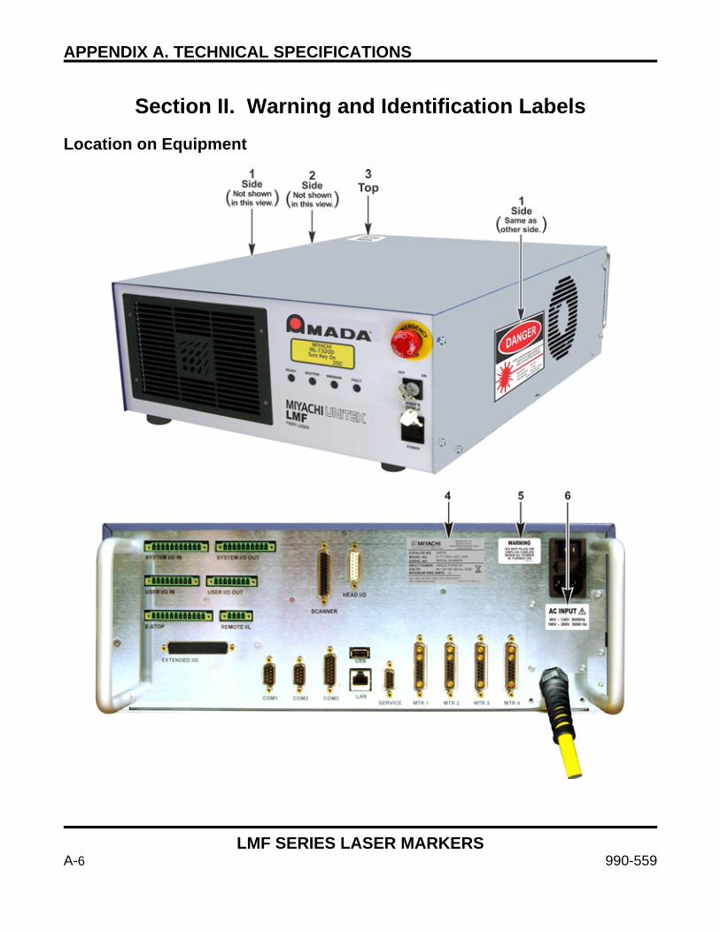
APPENDIX A. TECHNICAL SPECIFICATIONS
LMF SERIES LASER MARKERS
A-6 990-559
Section II. Warning and Identification Labels
Location on Equipment
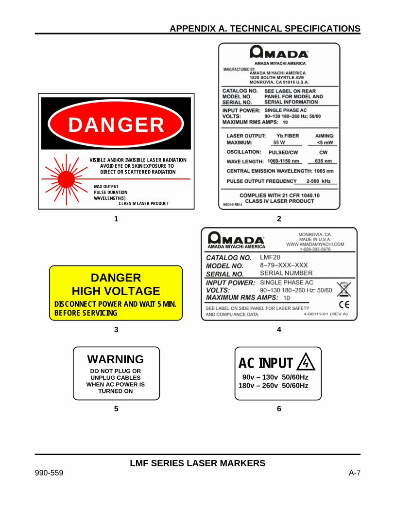
APPENDIX A. TECHNICAL SPECIFICATIONS
LMF SERIES LASER MARKERS
990-559 A-7
1 2
3 4
5 6
DANGER VISIBLE AND/OR INVISIBLE LASER RADIATION AVOID EYE OR SKIN EXPOSURE TO DIRECT OR SCATTERED RADIATION
MAX OUTPUT PULSE DURATION WAVELENGTH(S) CLASS IV LASER PRODUCT
DANGER HIGH VOLTAGE
DISCONNECT POWER AND WAIT 5 MIN.BEFORE SERVICING
WARNING DO NOT PLUG OR UNPLUG CABLES
WHEN AC POWER IS TURNED ON
AC INPUT 90v – 130v 50/60Hz 180v – 260v 50/60Hz

APPENDIX A. TECHNICAL SPECIFICATIONS
LMF SERIES LASER MARKERS
A-8 990-559
2D Head – Location on Ultra Compact Marker Head
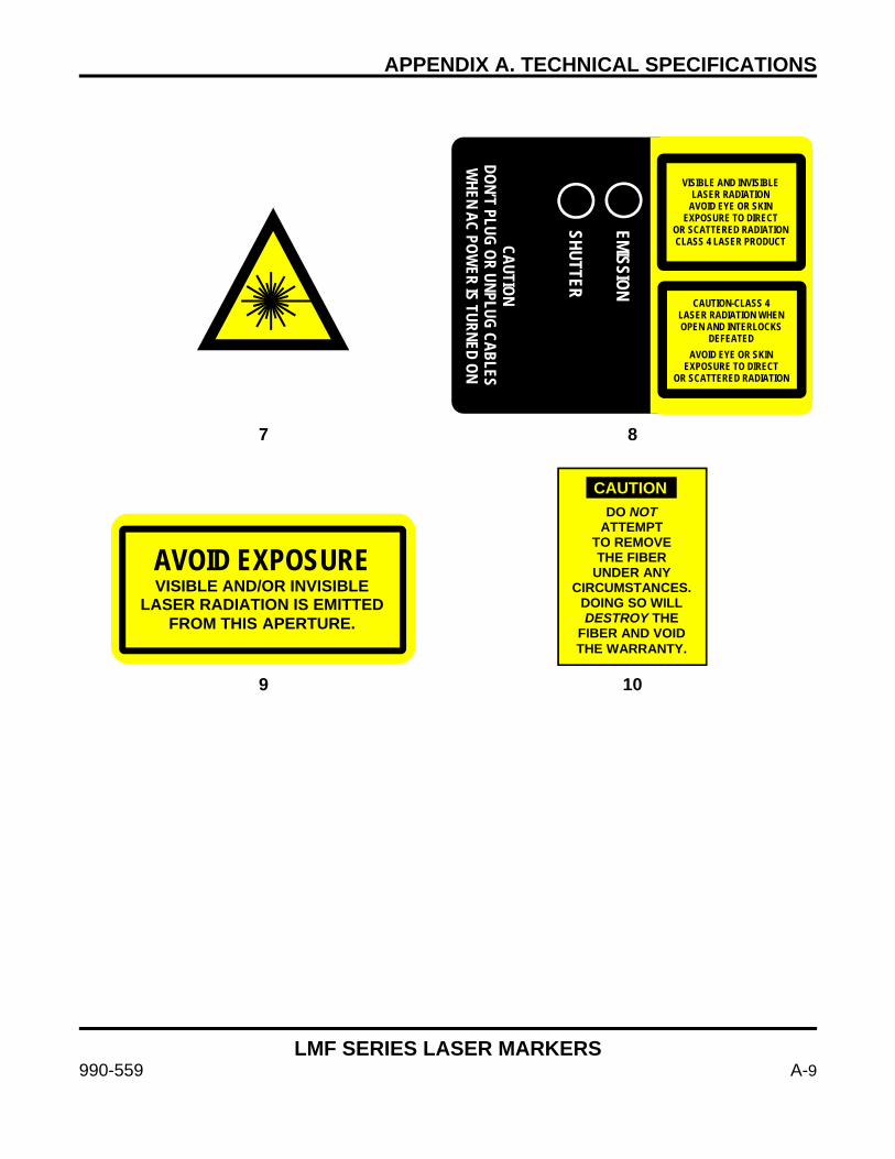
APPENDIX A. TECHNICAL SPECIFICATIONS
LMF SERIES LASER MARKERS
990-559 A-9
7 8
9 10
CAUTION DON’T PLUG OR UNPLUG CABLES W
HEN AC POWER IS TURNED ON
EMISSION SHUTTER
VISIBLE AND INVISIBLE LASER RADIATION
AVOID EYE OR SKIN EXPOSURE TO DIRECT
OR SCATTERED RADIATION CLASS 4 LASER PRODUCT
CAUTION-CLASS 4 LASER RADIATION WHEN OPEN AND INTERLOCKS
DEFEATED AVOID EYE OR SKIN
EXPOSURE TO DIRECT OR SCATTERED RADIATION
AVOID EXPOSURE VISIBLE AND/OR INVISIBLE
LASER RADIATION IS EMITTED FROM THIS APERTURE.
DO NOT ATTEMPT
TO REMOVE THE FIBER
UNDER ANY CIRCUMSTANCES.
DOING SO WILL DESTROY THE
FIBER AND VOID THE WARRANTY.
CAUTION
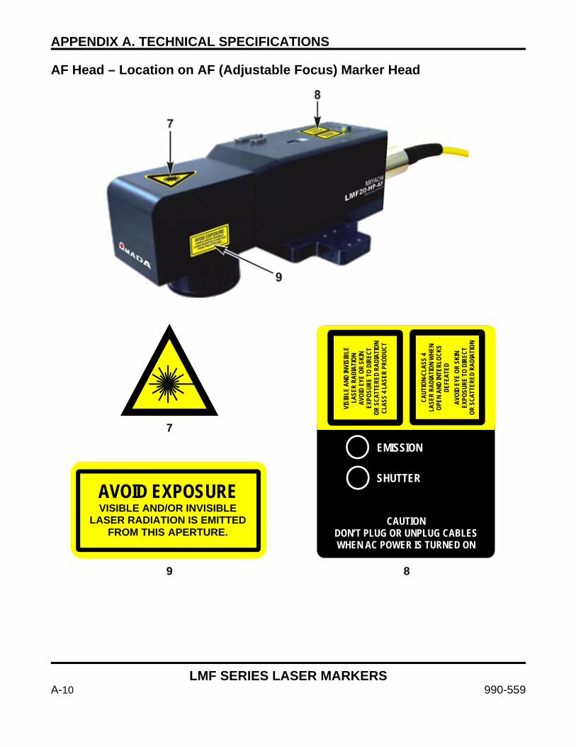
APPENDIX A. TECHNICAL SPECIFICATIONS
LMF SERIES LASER MARKERS
A-10 990-559
AF Head – Location on AF (Adjustable Focus) Marker Head
7
9 8
AVOID EXPOSURE VISIBLE AND/OR INVISIBLE
LASER RADIATION IS EMITTED FROM THIS APERTURE.
CAUTION DON’T PLUG OR UNPLUG CABLES WHEN AC POWER IS TURNED ON
EMISSION SHUTTER
VISI
BLE
AND
INVI
SIBL
E LA
SER
RADI
ATIO
N AV
OID
EYE
OR S
KIN
EXPO
SURE
TO
DIRE
CT
OR S
CATT
ERED
RAD
IATI
ON
CLAS
S 4 L
ASER
PRO
DUCT
CAUT
ION-
CLAS
S 4
LASE
R RA
DIAT
ION
WHE
N OP
EN A
ND IN
TERL
OCKS
DE
FEAT
ED
AVOI
D EY
E OR
SKI
N EX
POSU
RE T
O DI
RECT
OR
SCA
TTER
ED R
ADIA
TION
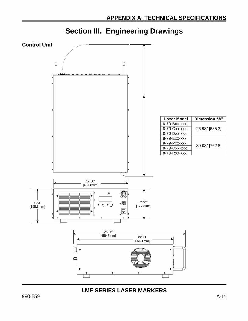
APPENDIX A. TECHNICAL SPECIFICATIONS
LMF SERIES LASER MARKERS
990-559 A-11
Section III. Engineering Drawings Control Unit
A
17.00” [431.8mm]
7.00” [177.8mm]
7.83” [198.8mm]
25.96” [659.5mm] 22.21
[564.1mm]
Laser Model Dimension “A” 8-79-Bxx-xxx
26.98” [685.3] 8-79-Cxx-xxx 8-79-Dxx-xxx 8-79-Exx-xxx
30.03” [762.8] 8-79-Pxx-xxx 8-79-Qxx-xxx 8-79-Rxx-xxx

APPENDIX A. TECHNICAL SPECIFICATIONS
LMF SERIES LASER MARKERS
A-12 990-559
Installation Drawing for LMF50, LMF20, and LMF10
Drawing applies to models: 8-79-BxR-xxx 8-79-CxR-xxx 8-79-DxR-xxx
CAUTION
Do not attempt to remove the fiber at the rear of the marker head under any circumstances. Doing so will destroy the fiber and void
the warranty. Amada Miyachi America assumes no liability for such action, the fiber will have to be replaced at the customer’s expense.
Lens Dimension “A” Lens Radius “R” f100
2.09” [53.2mm] 1.77” [45.0mm]
f160 f254
2.36” [59.9mm] f420 f825 1.75” [ 44.5mm] 2.56” [65.0mm]
R 3.15” [80mm] FIBER CABLE BEND RADIUS MUST BE MAINTAINED AT ALL TIMES
16.01” [406.6]
8.49” [215.6]
4.22” [107.2]
16.01” [406.6]
8.49” [215.6]
A
4.72” [120]
R
0.97” [24.8]
0.98” [24.8]
3.03” [77.0]
2.00”[50.9]
1.47” [37.3]
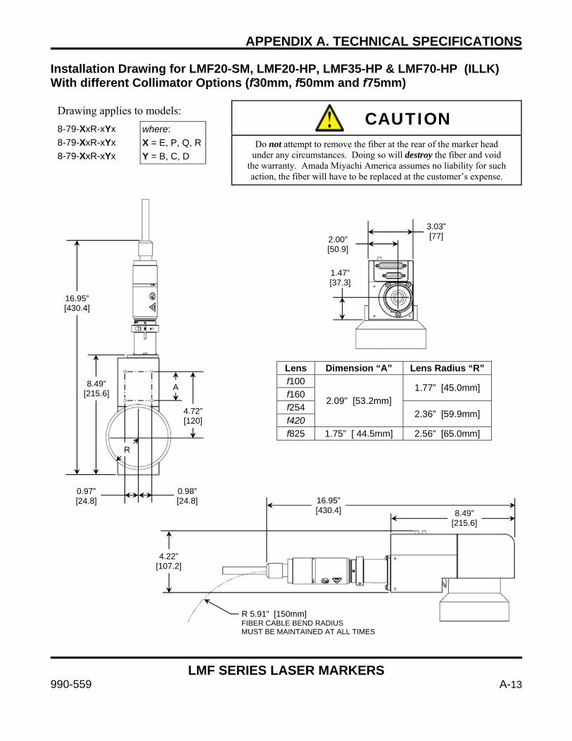
APPENDIX A. TECHNICAL SPECIFICATIONS
LMF SERIES LASER MARKERS
990-559 A-13
Installation Drawing for LMF20-SM, LMF20-HP, LMF35-HP & LMF70-HP (ILLK) With different Collimator Options (f30mm, f50mm and f75mm)
Drawing applies to models:
8-79-XxR-xYx 8-79-XxR-xYx 8-79-XxR-xYx
CAUTION
Do not attempt to remove the fiber at the rear of the marker head under any circumstances. Doing so will destroy the fiber and void
the warranty. Amada Miyachi America assumes no liability for such action, the fiber will have to be replaced at the customer’s expense.
where: X = E, P, Q, R Y = B, C, D
Lens Dimension “A” Lens Radius “R” f100
2.09” [53.2mm] 1.77” [45.0mm]
f160 f254
2.36” [59.9mm] f420 f825 1.75” [ 44.5mm] 2.56” [65.0mm]
1.47” [37.3]
2.00” [50.9]
3.03” [77]
8.49” [215.6]
16.95” [430.4]
0.97” [24.8]
0.98” [24.8]
A
4.72” [120]
R
4.22” [107.2]
8.49” [215.6]
R 5.91” [150mm] FIBER CABLE BEND RADIUS MUST BE MAINTAINED AT ALL TIMES
16.95” [430.4]
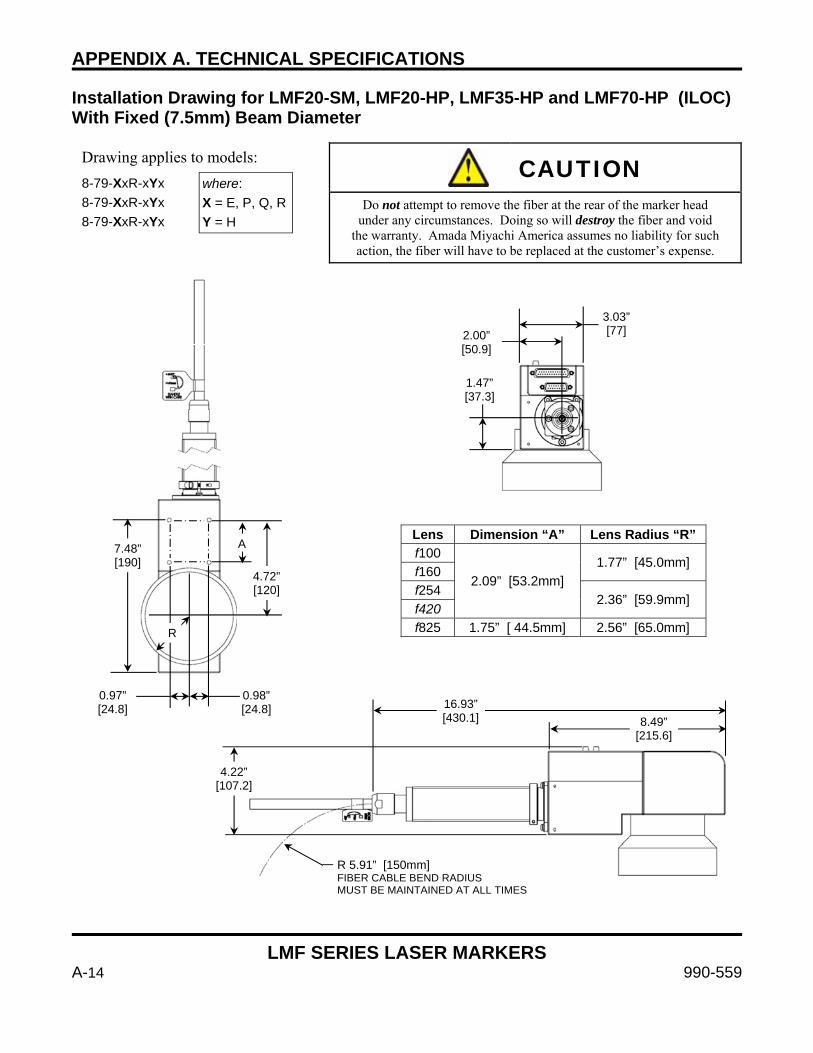
APPENDIX A. TECHNICAL SPECIFICATIONS
LMF SERIES LASER MARKERS
A-14 990-559
Installation Drawing for LMF20-SM, LMF20-HP, LMF35-HP and LMF70-HP (ILOC) With Fixed (7.5mm) Beam Diameter
Drawing applies to models:
8-79-XxR-xYx 8-79-XxR-xYx 8-79-XxR-xYx
CAUTION
Do not attempt to remove the fiber at the rear of the marker head under any circumstances. Doing so will destroy the fiber and void
the warranty. Amada Miyachi America assumes no liability for such action, the fiber will have to be replaced at the customer’s expense.
where: X = E, P, Q, R Y = H
Lens Dimension “A” Lens Radius “R” f100
2.09” [53.2mm] 1.77” [45.0mm]
f160 f254
2.36” [59.9mm] f420 f825 1.75” [ 44.5mm] 2.56” [65.0mm]
1.47” [37.3]
2.00” [50.9]
3.03” [77]
7.48” [190]
0.97” [24.8]
0.98” [24.8]
A
4.72” [120]
R
R 5.91” [150mm] FIBER CABLE BEND RADIUS MUST BE MAINTAINED AT ALL TIMES
16.93” [430.1] 8.49”
[215.6]
4.22” [107.2]
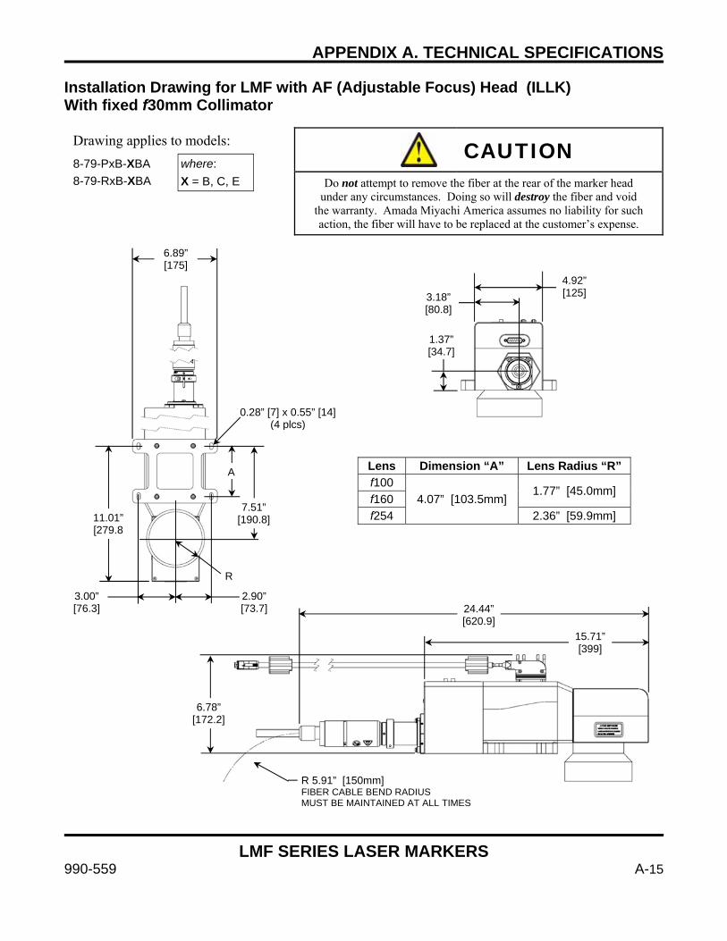
APPENDIX A. TECHNICAL SPECIFICATIONS
LMF SERIES LASER MARKERS
990-559 A-15
Installation Drawing for LMF with AF (Adjustable Focus) Head (ILLK) With fixed f30mm Collimator
Drawing applies to models:
8-79-PxB-XBA 8-79-RxB-XBA
CAUTION
Do not attempt to remove the fiber at the rear of the marker head under any circumstances. Doing so will destroy the fiber and void
the warranty. Amada Miyachi America assumes no liability for such action, the fiber will have to be replaced at the customer’s expense.
where: X = B, C, E
Lens Dimension “A” Lens Radius “R” f100
4.07” [103.5mm] 1.77” [45.0mm]
f160 f254 2.36” [59.9mm]
4.92” [125] 3.18”
[80.8]
1.37” [34.7]
11.01” [279.8
A
7.51” [190.8]
R
3.00” [76.3]
2.90” [73.7]
0.28” [7] x 0.55” [14](4 plcs)
6.89” [175]
6.78” [172.2]
R 5.91” [150mm] FIBER CABLE BEND RADIUS MUST BE MAINTAINED AT ALL TIMES
15.71” [399]
24.44” [620.9]
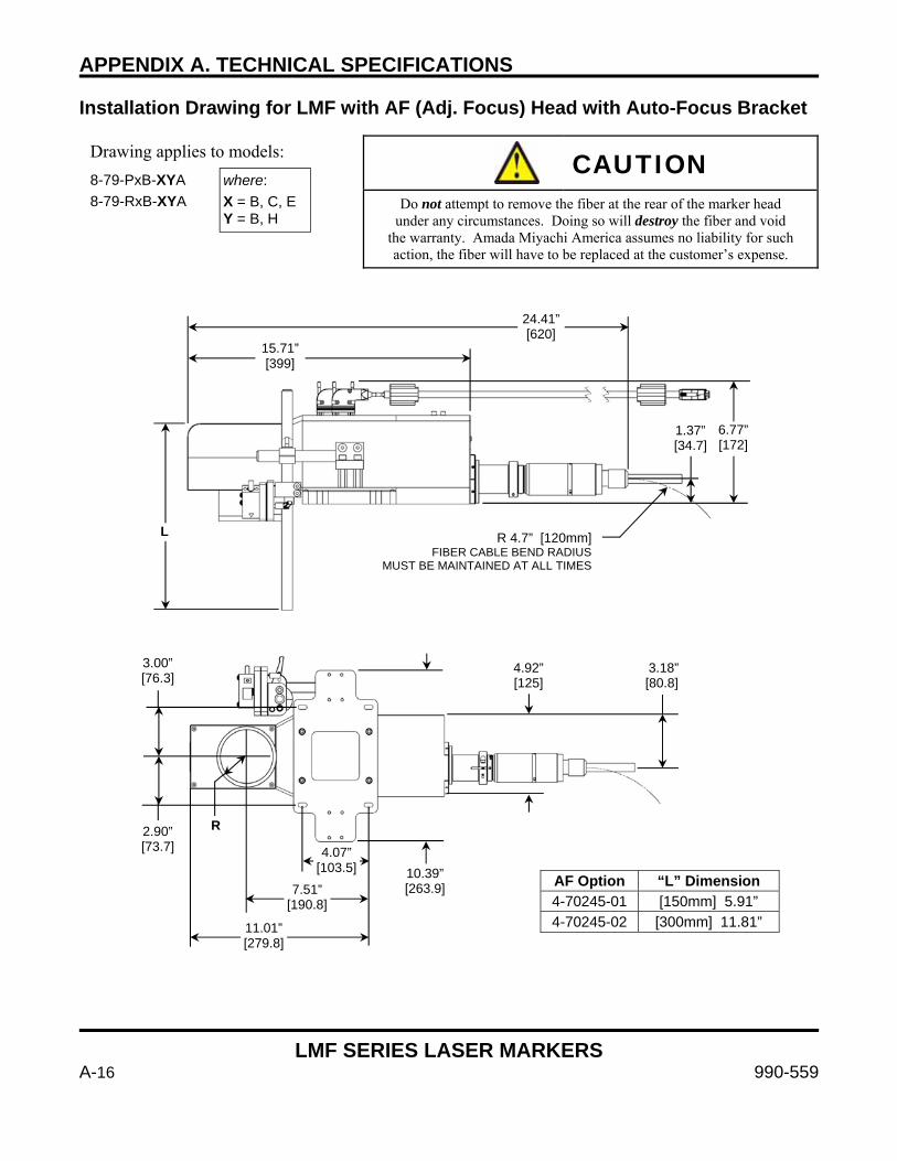
APPENDIX A. TECHNICAL SPECIFICATIONS
LMF SERIES LASER MARKERS
A-16 990-559
Installation Drawing for LMF with AF (Adj. Focus) Head with Auto-Focus Bracket
Drawing applies to models:
8-79-PxB-XYA 8-79-RxB-XYA
CAUTION
Do not attempt to remove the fiber at the rear of the marker head under any circumstances. Doing so will destroy the fiber and void
the warranty. Amada Miyachi America assumes no liability for such action, the fiber will have to be replaced at the customer’s expense.
where: X = B, C, E Y = B, H
24.41”[620]
15.71” [399]
L
6.77” [172]
1.37” [34.7]
R 4.7” [120mm]FIBER CABLE BEND RADIUS
MUST BE MAINTAINED AT ALL TIMES
AF Option “L” Dimension 4-70245-01 [150mm] 5.91” 4-70245-02 [300mm] 11.81”
4.92” 3.18” [125] [80.8]
3.00” [76.3]
2.90” [73.7]
R
4.07” [103.5] 10.39”
[263.9]7.51” [190.8]
11.01” [279.8]
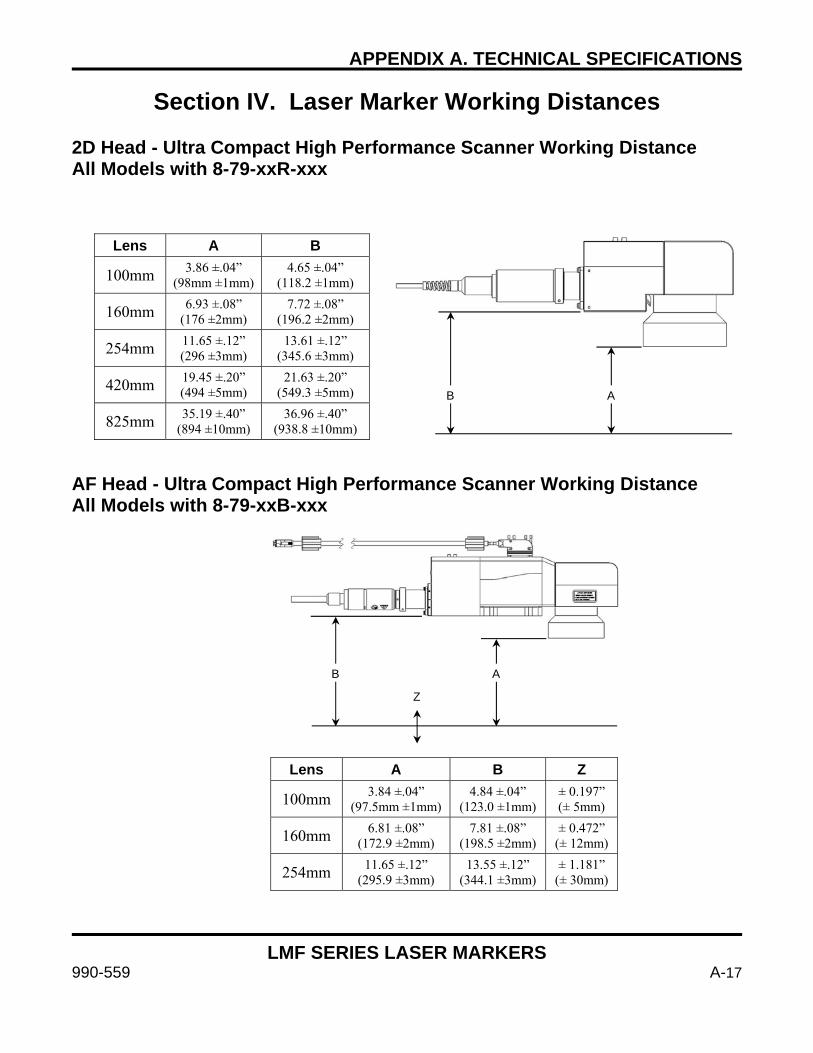
APPENDIX A. TECHNICAL SPECIFICATIONS
LMF SERIES LASER MARKERS
990-559 A-17
Section IV. Laser Marker Working Distances 2D Head - Ultra Compact High Performance Scanner Working Distance All Models with 8-79-xxR-xxx AF Head - Ultra Compact High Performance Scanner Working Distance All Models with 8-79-xxB-xxx
Lens A B
100mm 3.86 ±.04” (98mm ±1mm)
4.65 ±.04” (118.2 ±1mm)
160mm 6.93 ±.08” (176 ±2mm)
7.72 ±.08” (196.2 ±2mm)
254mm 11.65 ±.12” (296 ±3mm)
13.61 ±.12” (345.6 ±3mm)
420mm 19.45 ±.20” (494 ±5mm)
21.63 ±.20” (549.3 ±5mm)
825mm 35.19 ±.40” (894 ±10mm)
36.96 ±.40” (938.8 ±10mm)
A B
B A
Z
Lens A B Z
100mm 3.84 ±.04” (97.5mm ±1mm)
4.84 ±.04” (123.0 ±1mm)
± 0.197” (± 5mm)
160mm 6.81 ±.08” (172.9 ±2mm)
7.81 ±.08” (198.5 ±2mm)
± 0.472” (± 12mm)
254mm 11.65 ±.12” (295.9 ±3mm)
13.55 ±.12” (344.1 ±3mm)
± 1.181” (± 30mm)

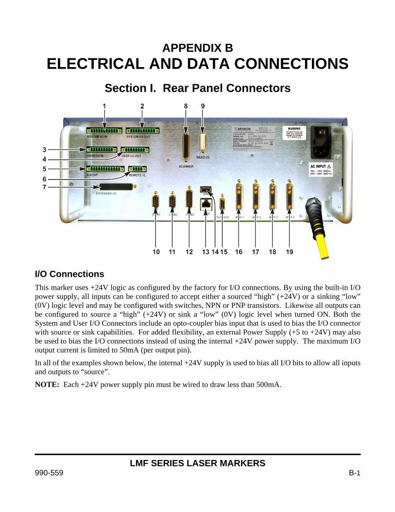
LMF SERIES LASER MARKERS
990-559 B-1
APPENDIX B ELECTRICAL AND DATA CONNECTIONS
Section I. Rear Panel Connectors
I/O Connections This marker uses +24V logic as configured by the factory for I/O connections. By using the built-in I/O power supply, all inputs can be configured to accept either a sourced “high” (+24V) or a sinking “low” (0V) logic level and may be configured with switches, NPN or PNP transistors. Likewise all outputs can be configured to source a “high” (+24V) or sink a “low” (0V) logic level when turned ON. Both the System and User I/O Connectors include an opto-coupler bias input that is used to bias the I/O connector with source or sink capabilities. For added flexibility, an external Power Supply (+5 to +24V) may also be used to bias the I/O connections instead of using the internal +24V power supply. The maximum I/O output current is limited to 50mA (per output pin).
In all of the examples shown below, the internal +24V supply is used to bias all I/O bits to allow all inputs and outputs to “source”.
NOTE: Each +24V power supply pin must be wired to draw less than 500mA.

APPENDIX B: ELECTRICAL AND DATA CONNECTIONS
LMF SERIES LASER MARKERS
B-2 990-559
Phoenix Connectors Connectors 1 through 4 on the Rear Panel are Phoenix-type connectors used for general purpose I/O. Depending on how these connectors are wired, the control can be configured several different ways in order to match your application needs. Configuration is achieved by using connectors with factory-installed jumpers, and by fabricating your own I/O cables.
Connectors 5 and 6 are Emergency Stop and Interlock connectors and should be configured appropriately using dry contact inputs. Connector 7 is a 50 pin D-Subminiature connector that contains expanded user inputs and outputs. These are configured similar to the I/O Phoenix connectors, but must be interfaced with using a 50 pin D-Sub connector. I/O biasing guidelines apply to this connector as well.
With the exception of connector 7 these connectors use screw-terminal wire connections. No soldering is required which makes configuring, or re-configuring, the connectors a simple task that can be done in just a few minutes. Connector 7 must be soldered or crimped depending on the choice of connector. Accessory connectors provided by Amada Miyachi America are solder-cup design.
Ensure that all connections are properly strain relieved to prevent pulling wires out of the connectors. Backshells are recommended on each connector.

APPENDIX B: ELECTRICAL AND DATA CONNECTIONS
LMF SERIES LASER MARKERS
990-559 B-3
1. SYSTEM I/O IN Connector
Pin # Signal IN/OUT Description Note
1 Start Job IN Start Job. Begins the job sequence. Photo coupler input
2 Laser Enable IN
Laser Enable. Enables the fiber laser marker. No laser emission is possible without triggering this input. This input can be used as a high speed process interrupt for resistor trimming or other similar applications.
Photo coupler input
3 Guide Beam IN
Guide Beam Control. Allows external control of visible guide beam NOTE: markers cannot emit laser radiation if the guide beam input is enabled. Turn off the guide beam before initiating process.
Photo coupler input
4 External Shutter Control IN
External Shutter Control. Allows external control of the safety shutter. This input must be triggered for the shutter to open and permit laser emission.
Photo coupler input
5 Fault Reset IN Fault Reset. Resets any fault conditions. Photo coupler input
6 Unused Unused
7 Abort Job IN Abort Job. Aborts the current job. Photo coupler input
8 +24 VDC +24V
9 DI Common Optocoupler Bias Input
10 0V GROUND
11 Unused Unused
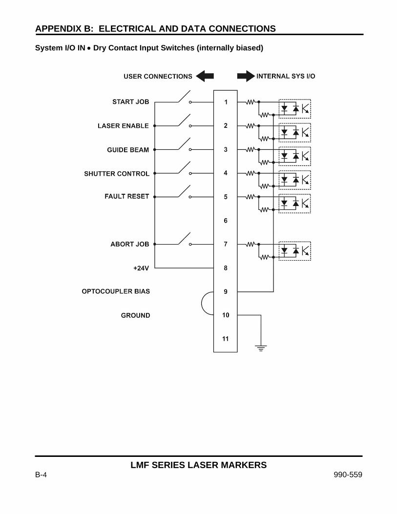
APPENDIX B: ELECTRICAL AND DATA CONNECTIONS
LMF SERIES LASER MARKERS
B-4 990-559
System I/O IN • Dry Contact Input Switches (internally biased)
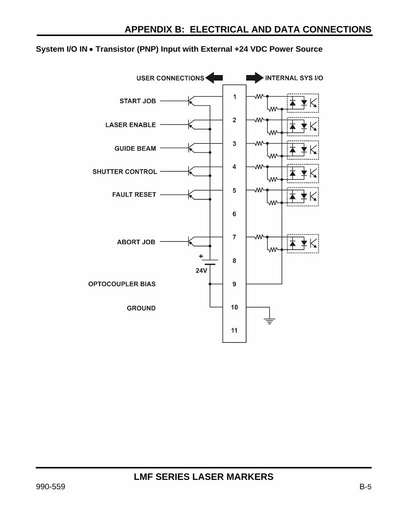
APPENDIX B: ELECTRICAL AND DATA CONNECTIONS
LMF SERIES LASER MARKERS
990-559 B-5
System I/O IN • Transistor (PNP) Input with External +24 VDC Power Source
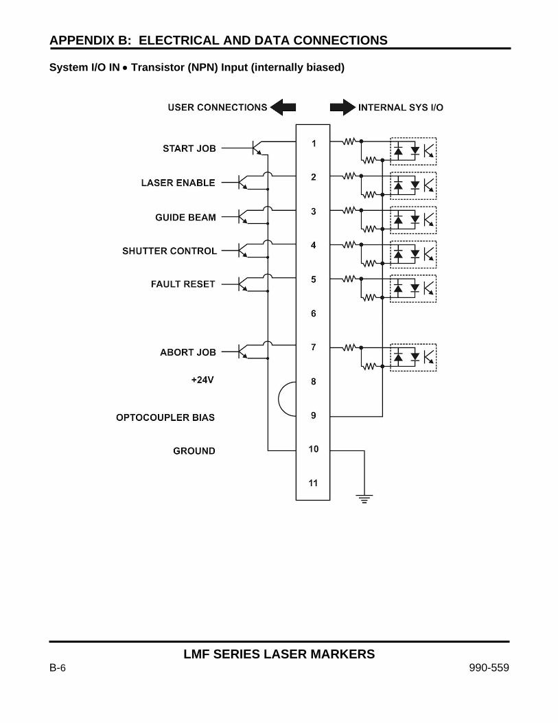
APPENDIX B: ELECTRICAL AND DATA CONNECTIONS
LMF SERIES LASER MARKERS
B-6 990-559
System I/O IN • Transistor (NPN) Input (internally biased)
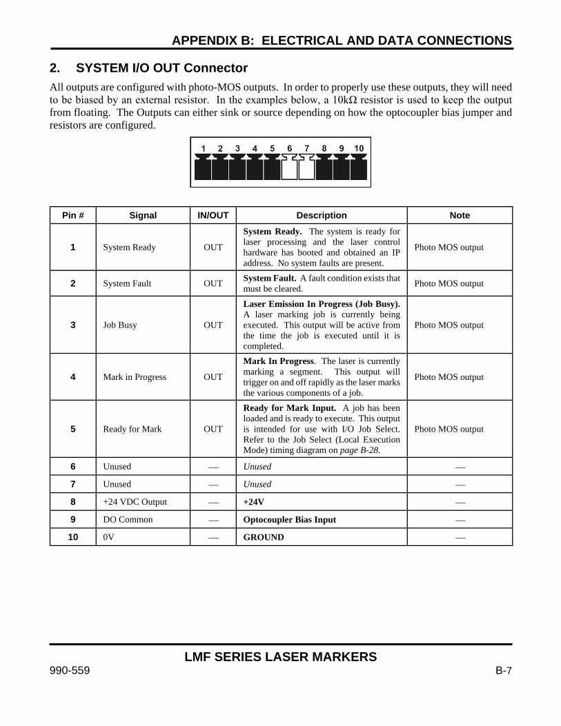
APPENDIX B: ELECTRICAL AND DATA CONNECTIONS
LMF SERIES LASER MARKERS
990-559 B-7
2. SYSTEM I/O OUT Connector All outputs are configured with photo-MOS outputs. In order to properly use these outputs, they will need to be biased by an external resistor. In the examples below, a 10kΩ resistor is used to keep the output from floating. The Outputs can either sink or source depending on how the optocoupler bias jumper and resistors are configured.
Pin # Signal IN/OUT Description Note
1 System Ready OUT
System Ready. The system is ready for laser processing and the laser control hardware has booted and obtained an IP address. No system faults are present.
Photo MOS output
2 System Fault OUT System Fault. A fault condition exists that must be cleared. Photo MOS output
3 Job Busy OUT
Laser Emission In Progress (Job Busy). A laser marking job is currently being executed. This output will be active from the time the job is executed until it is completed.
Photo MOS output
4 Mark in Progress OUT
Mark In Progress. The laser is currently marking a segment. This output will trigger on and off rapidly as the laser marks the various components of a job.
Photo MOS output
5 Ready for Mark OUT
Ready for Mark Input. A job has been loaded and is ready to execute. This output is intended for use with I/O Job Select. Refer to the Job Select (Local Execution Mode) timing diagram on page B-28.
Photo MOS output
6 Unused Unused
7 Unused Unused
8 +24 VDC Output +24V
9 DO Common Optocoupler Bias Input
10 0V GROUND
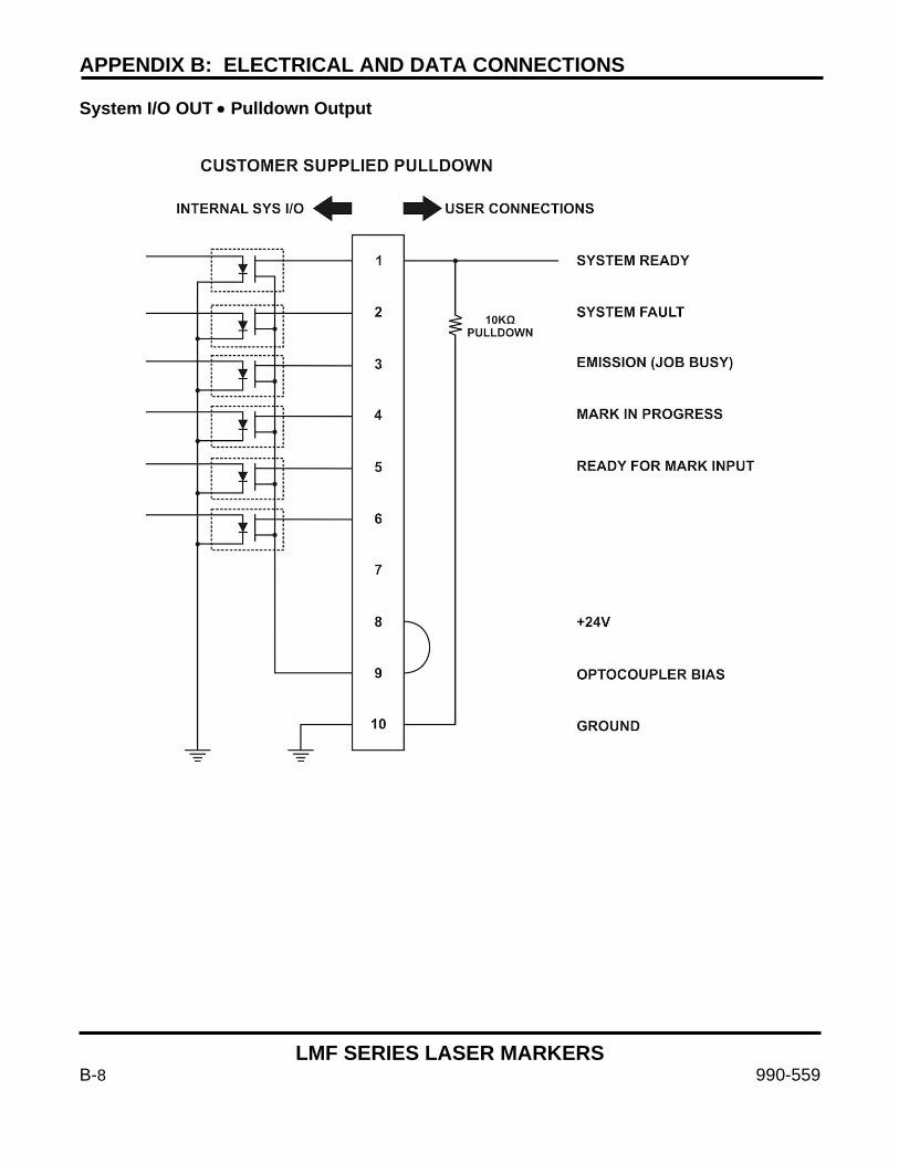
APPENDIX B: ELECTRICAL AND DATA CONNECTIONS
LMF SERIES LASER MARKERS
B-8 990-559
System I/O OUT • Pulldown Output

APPENDIX B: ELECTRICAL AND DATA CONNECTIONS
LMF SERIES LASER MARKERS
990-559 B-9
System I/O OUT • Pullup Output
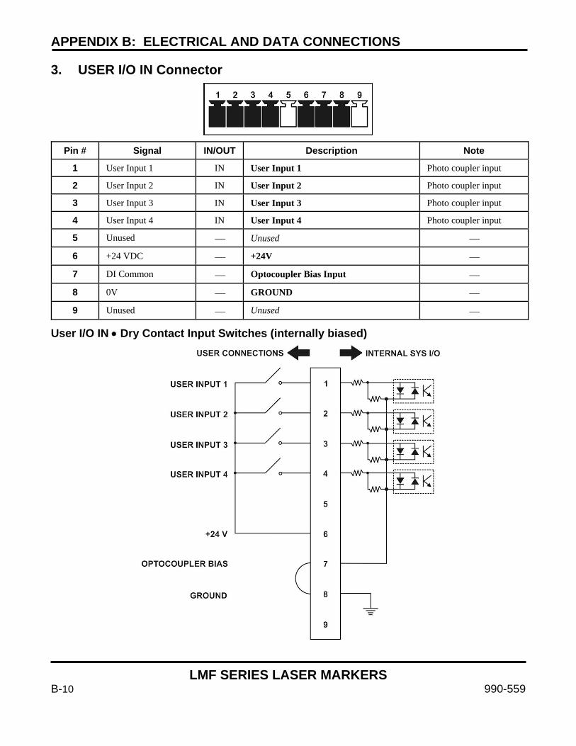
APPENDIX B: ELECTRICAL AND DATA CONNECTIONS
LMF SERIES LASER MARKERS
B-10 990-559
3. USER I/O IN Connector
Pin # Signal IN/OUT Description Note
1 User Input 1 IN User Input 1 Photo coupler input
2 User Input 2 IN User Input 2 Photo coupler input
3 User Input 3 IN User Input 3 Photo coupler input
4 User Input 4 IN User Input 4 Photo coupler input
5 Unused Unused
6 +24 VDC +24V
7 DI Common Optocoupler Bias Input
8 0V GROUND
9 Unused Unused
User I/O IN • Dry Contact Input Switches (internally biased)
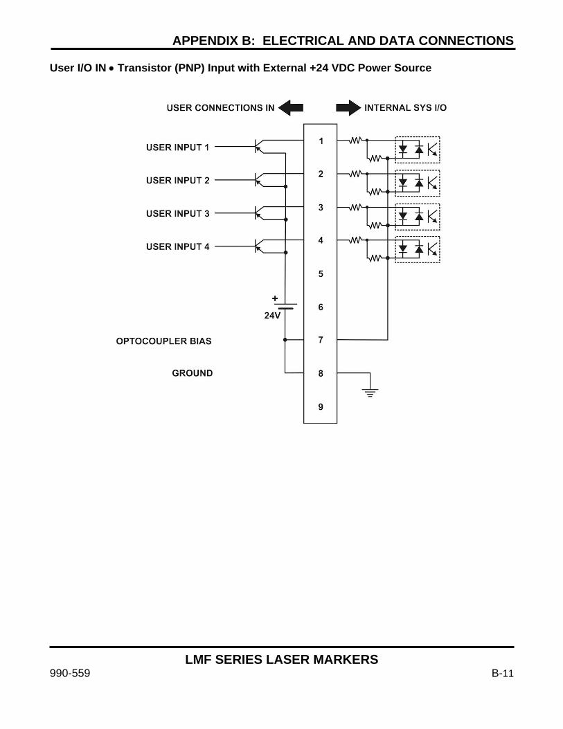
APPENDIX B: ELECTRICAL AND DATA CONNECTIONS
LMF SERIES LASER MARKERS
990-559 B-11
User I/O IN • Transistor (PNP) Input with External +24 VDC Power Source

APPENDIX B: ELECTRICAL AND DATA CONNECTIONS
LMF SERIES LASER MARKERS
B-12 990-559
User I/O IN • Transistor (NPN) Input (internally biased)

APPENDIX B: ELECTRICAL AND DATA CONNECTIONS
LMF SERIES LASER MARKERS
990-559 B-13
4. USER I/O OUT Connector
Pin # Signal IN/OUT Description Note
1 User Output 1 OUT User Output 1 Photo coupler input
2 User Output 2 OUT User Output 2 Photo coupler input
3 User Output 3 OUT User Output 3 Photo coupler input
4 User Output 4 OUT User Output 4 Photo coupler input
5 Unused Unused
6 +24 VDC Output +24V
7 DO Common Optocoupler Bias Input
8 0V GROUND
User I/O OUT • Pulldown Output
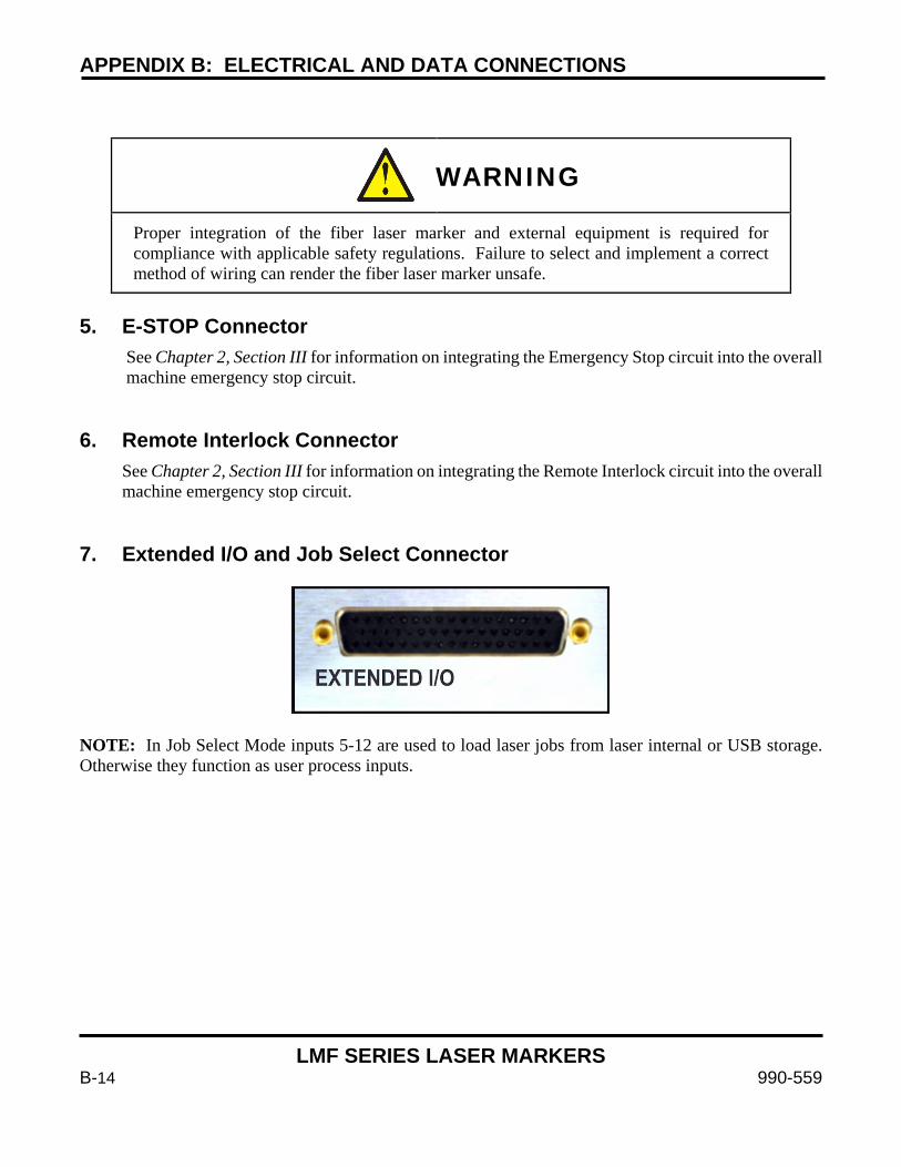
APPENDIX B: ELECTRICAL AND DATA CONNECTIONS
LMF SERIES LASER MARKERS
B-14 990-559
WARNING
Proper integration of the fiber laser marker and external equipment is required for compliance with applicable safety regulations. Failure to select and implement a correct method of wiring can render the fiber laser marker unsafe.
5. E-STOP Connector
See Chapter 2, Section III for information on integrating the Emergency Stop circuit into the overall machine emergency stop circuit.
6. Remote Interlock Connector
See Chapter 2, Section III for information on integrating the Remote Interlock circuit into the overall machine emergency stop circuit.
7. Extended I/O and Job Select Connector
NOTE: In Job Select Mode inputs 5-12 are used to load laser jobs from laser internal or USB storage. Otherwise they function as user process inputs.
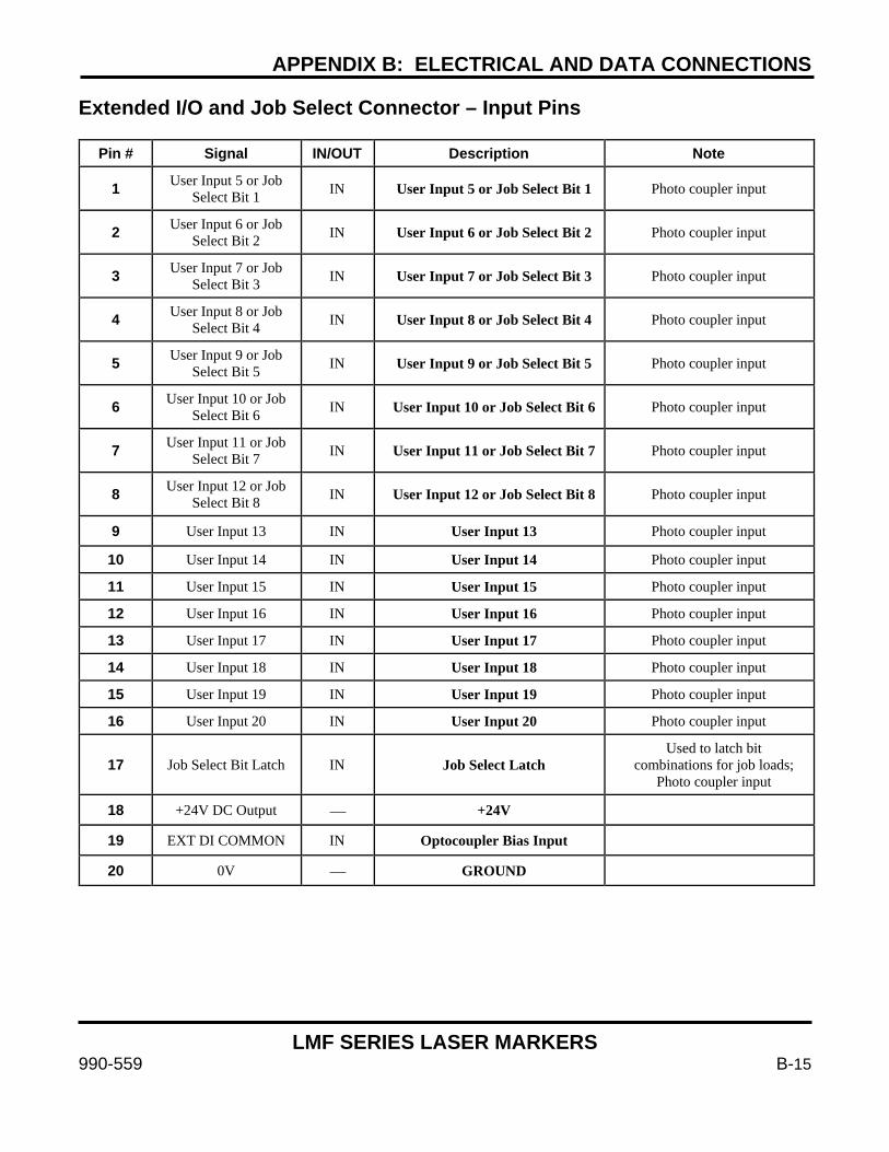
APPENDIX B: ELECTRICAL AND DATA CONNECTIONS
LMF SERIES LASER MARKERS
990-559 B-15
Extended I/O and Job Select Connector – Input Pins
Pin # Signal IN/OUT Description Note
1 User Input 5 or Job Select Bit 1 IN User Input 5 or Job Select Bit 1 Photo coupler input
2 User Input 6 or Job Select Bit 2 IN User Input 6 or Job Select Bit 2 Photo coupler input
3 User Input 7 or Job Select Bit 3 IN User Input 7 or Job Select Bit 3 Photo coupler input
4 User Input 8 or Job Select Bit 4 IN User Input 8 or Job Select Bit 4 Photo coupler input
5 User Input 9 or Job Select Bit 5 IN User Input 9 or Job Select Bit 5 Photo coupler input
6 User Input 10 or Job Select Bit 6 IN User Input 10 or Job Select Bit 6 Photo coupler input
7 User Input 11 or Job Select Bit 7 IN User Input 11 or Job Select Bit 7 Photo coupler input
8 User Input 12 or Job Select Bit 8 IN User Input 12 or Job Select Bit 8 Photo coupler input
9 User Input 13 IN User Input 13 Photo coupler input 10 User Input 14 IN User Input 14 Photo coupler input 11 User Input 15 IN User Input 15 Photo coupler input 12 User Input 16 IN User Input 16 Photo coupler input 13 User Input 17 IN User Input 17 Photo coupler input 14 User Input 18 IN User Input 18 Photo coupler input 15 User Input 19 IN User Input 19 Photo coupler input 16 User Input 20 IN User Input 20 Photo coupler input
17 Job Select Bit Latch IN Job Select Latch Used to latch bit
combinations for job loads; Photo coupler input
18 +24V DC Output +24V
19 EXT DI COMMON IN Optocoupler Bias Input
20 0V GROUND
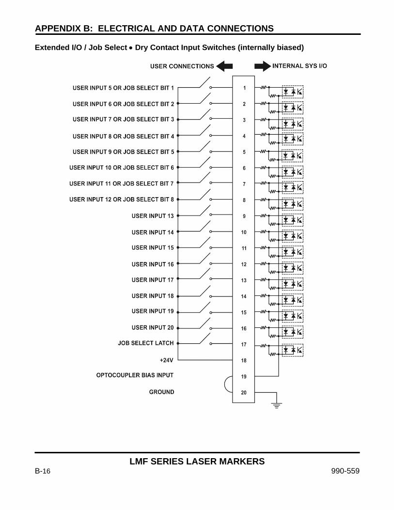
APPENDIX B: ELECTRICAL AND DATA CONNECTIONS
LMF SERIES LASER MARKERS
B-16 990-559
Extended I/O / Job Select • Dry Contact Input Switches (internally biased)
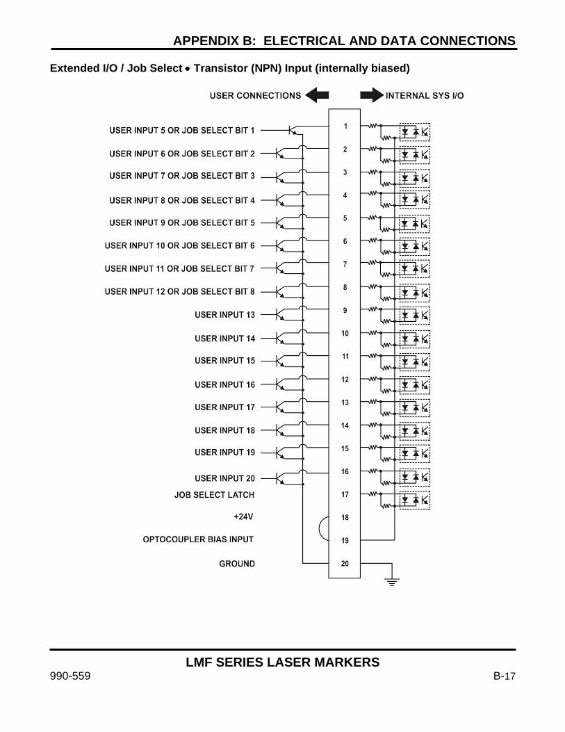
APPENDIX B: ELECTRICAL AND DATA CONNECTIONS
LMF SERIES LASER MARKERS
990-559 B-17
Extended I/O / Job Select • Transistor (NPN) Input (internally biased)
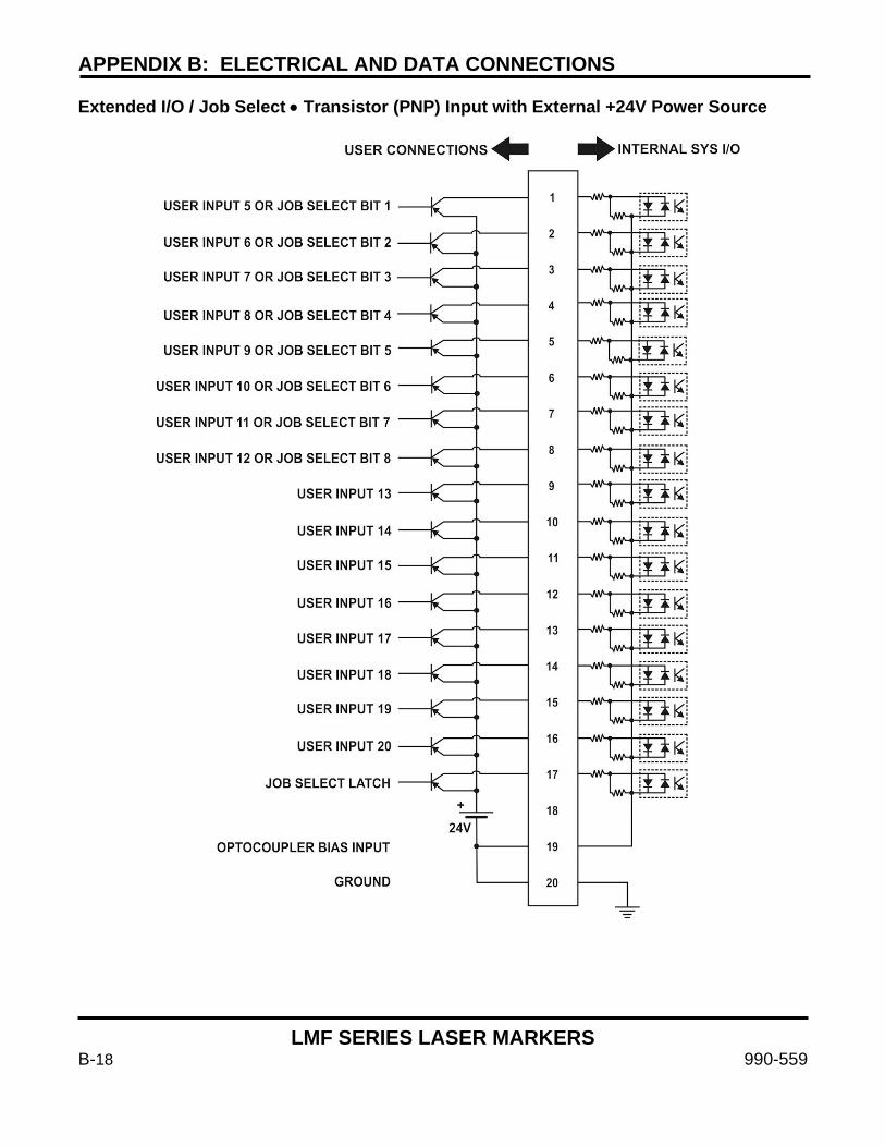
APPENDIX B: ELECTRICAL AND DATA CONNECTIONS
LMF SERIES LASER MARKERS
B-18 990-559
Extended I/O / Job Select • Transistor (PNP) Input with External +24V Power Source
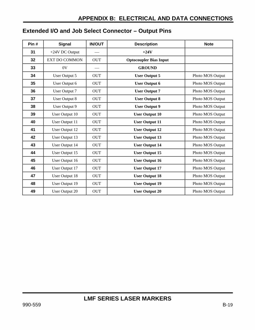
APPENDIX B: ELECTRICAL AND DATA CONNECTIONS
LMF SERIES LASER MARKERS
990-559 B-19
Extended I/O and Job Select Connector – Output Pins
Pin # Signal IN/OUT Description Note
31 +24V DC Output +24V
32 EXT DO COMMON OUT Optocoupler Bias Input
33 0V GROUND
34 User Output 5 OUT User Output 5 Photo MOS Output
35 User Output 6 OUT User Output 6 Photo MOS Output
36 User Output 7 OUT User Output 7 Photo MOS Output
37 User Output 8 OUT User Output 8 Photo MOS Output
38 User Output 9 OUT User Output 9 Photo MOS Output
39 User Output 10 OUT User Output 10 Photo MOS Output
40 User Output 11 OUT User Output 11 Photo MOS Output
41 User Output 12 OUT User Output 12 Photo MOS Output
42 User Output 13 OUT User Output 13 Photo MOS Output
43 User Output 14 OUT User Output 14 Photo MOS Output
44 User Output 15 OUT User Output 15 Photo MOS Output
45 User Output 16 OUT User Output 16 Photo MOS Output
46 User Output 17 OUT User Output 17 Photo MOS Output
47 User Output 18 OUT User Output 18 Photo MOS Output
48 User Output 19 OUT User Output 19 Photo MOS Output
49 User Output 20 OUT User Output 20 Photo MOS Output
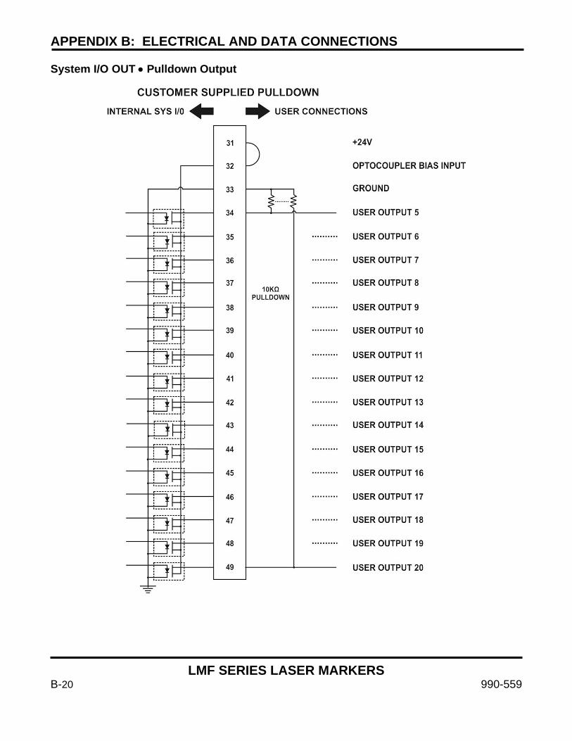
APPENDIX B: ELECTRICAL AND DATA CONNECTIONS
LMF SERIES LASER MARKERS
B-20 990-559
System I/O OUT • Pulldown Output
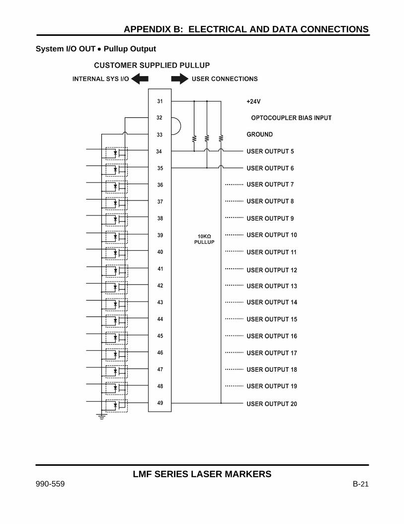
APPENDIX B: ELECTRICAL AND DATA CONNECTIONS
LMF SERIES LASER MARKERS
990-559 B-21
System I/O OUT • Pullup Output
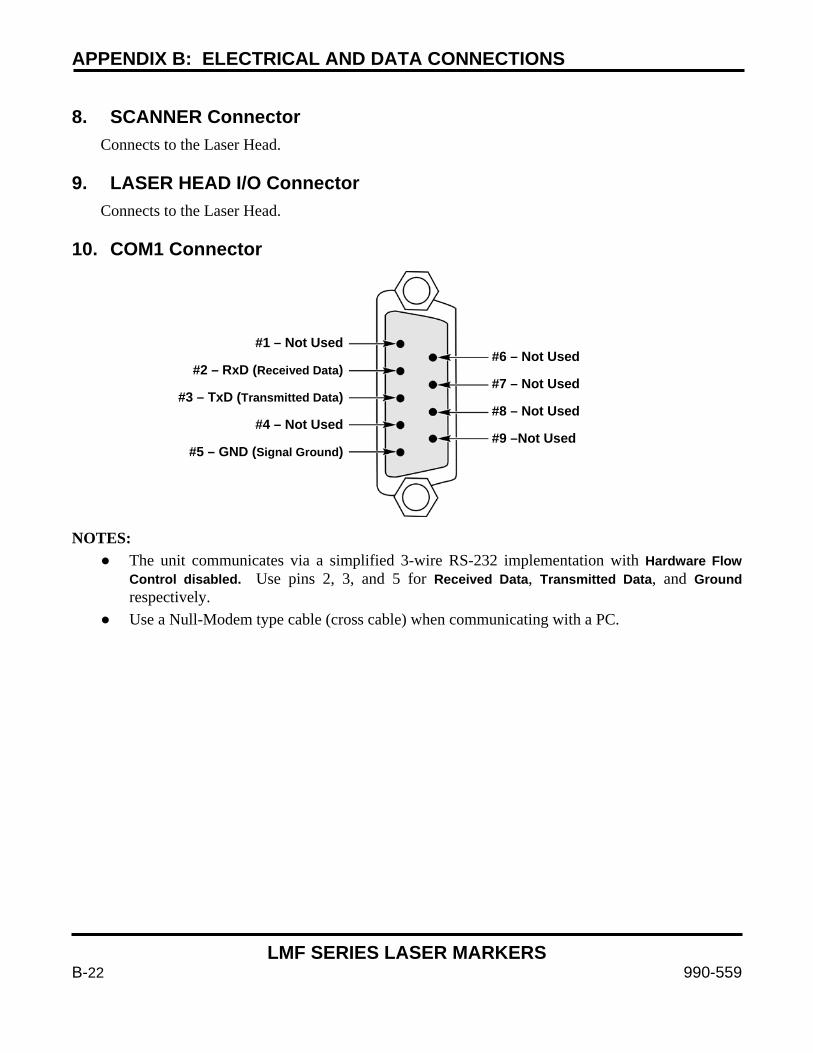
APPENDIX B: ELECTRICAL AND DATA CONNECTIONS
LMF SERIES LASER MARKERS
B-22 990-559
8. SCANNER Connector
Connects to the Laser Head. 9. LASER HEAD I/O Connector
Connects to the Laser Head. 10. COM1 Connector NOTES:
The unit communicates via a simplified 3-wire RS-232 implementation with Hardware Flow Control disabled. Use pins 2, 3, and 5 for Received Data, Transmitted Data, and Ground respectively.
Use a Null-Modem type cable (cross cable) when communicating with a PC.
#1 – Not Used
#2 – RxD (Received Data)
#3 – TxD (Transmitted Data)
#4 – Not Used
#5 – GND (Signal Ground)
#6 – Not Used
#7 – Not Used
#8 – Not Used
#9 –Not Used
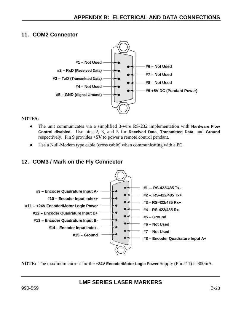
APPENDIX B: ELECTRICAL AND DATA CONNECTIONS
LMF SERIES LASER MARKERS
990-559 B-23
11. COM2 Connector NOTES:
The unit communicates via a simplified 3-wire RS-232 implementation with Hardware Flow Control disabled. Use pins 2, 3, and 5 for Received Data, Transmitted Data, and Ground respectively. Pin 9 provides +5V to power a remote control pendant.
Use a Null-Modem type cable (cross cable) when communicating with a PC. 12. COM3 / Mark on the Fly Connector
NOTE: The maximum current for the +24V Encoder/Motor Logic Power Supply (Pin #11) is 800mA.
#1 – Not Used
#2 – RxD (Received Data)
#3 – TxD (Transmitted Data)
#4 – Not Used
#5 – GND (Signal Ground)
#6 – Not Used
#7 – Not Used
#8 – Not Used
#9 +5V DC (Pendant Power)
#1 –. RS-422/485 Tx-
#2 –. RS-422/485 Tx+ #3 – RS-422/485 Rx+
#4 – RS-422/485 Rx-
#5 – Ground
#6 – Not Used
#7 – Not Used
#8 – Encoder Quadrature Input A+
#9 – Encoder Quadrature Input A-
#10 – Encoder Input Index+
#11 – +24V Encoder/Motor Logic Power
#12 – Encoder Quadrature Input B+ #13 – Encoder Quadrature Input B-
#14 – Encoder Input Index-
#15 – Ground
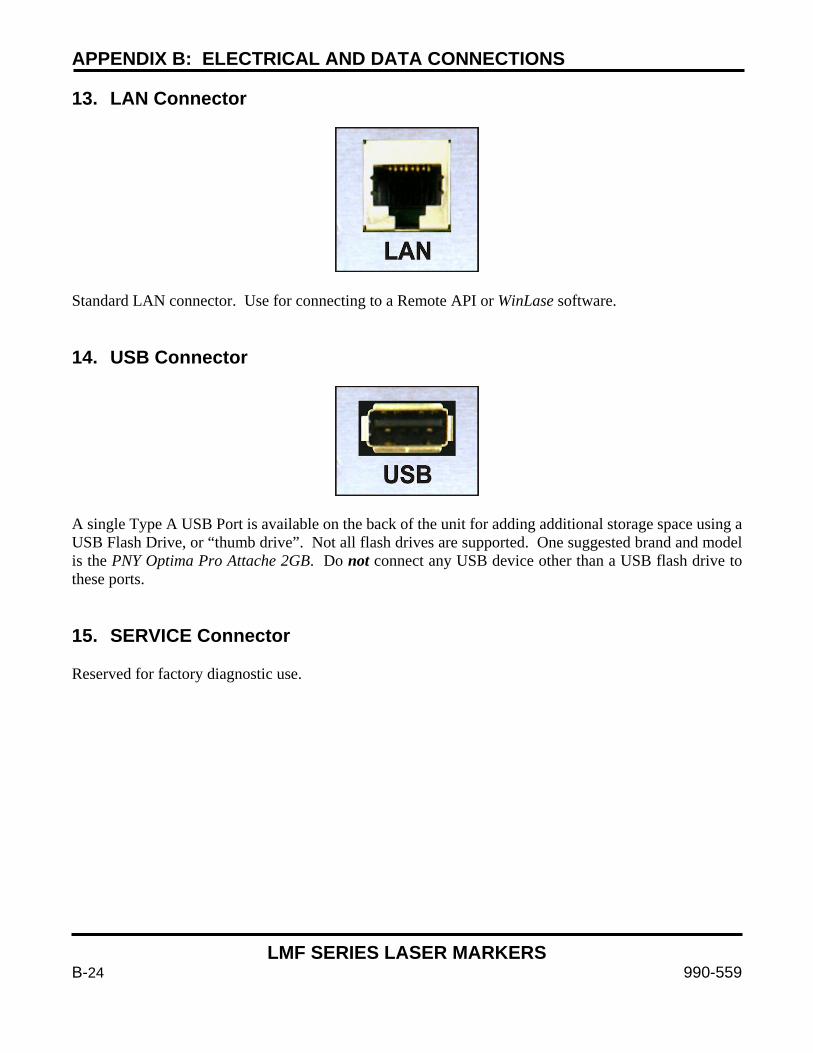
APPENDIX B: ELECTRICAL AND DATA CONNECTIONS
LMF SERIES LASER MARKERS
B-24 990-559
13. LAN Connector
Standard LAN connector. Use for connecting to a Remote API or WinLase software. 14. USB Connector
A single Type A USB Port is available on the back of the unit for adding additional storage space using a USB Flash Drive, or “thumb drive”. Not all flash drives are supported. One suggested brand and model is the PNY Optima Pro Attache 2GB. Do not connect any USB device other than a USB flash drive to these ports. 15. SERVICE Connector Reserved for factory diagnostic use.
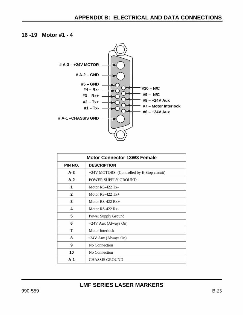
APPENDIX B: ELECTRICAL AND DATA CONNECTIONS
LMF SERIES LASER MARKERS
990-559 B-25
16 -19 Motor #1 - 4
Motor Connector 13W3 Female
PIN NO. DESCRIPTION
A-3 +24V MOTORS (Controlled by E-Stop circuit)
A-2 POWER SUPPLY GROUND
1 Motor RS-422 Tx-
2 Motor RS-422 Tx+
3 Motor RS-422 Rx+
4 Motor RS-422 Rx-
5 Power Supply Ground
6 +24V Aux (Always On)
7 Motor Interlock
8 +24V Aux (Always On)
9 No Connection
10 No Connection
A-1 CHASSIS GROUND
# A-3 – +24V MOTOR
# A-2 – GND
#5 – GND #4 – Rx- #3 – Rx+ #2 – Tx+ #1 – Tx-
# A-1 –CHASSIS GND
#10 – N/C #9 – N/C #8 – +24V Aux #7 – Motor Interlock #6 – +24V Aux
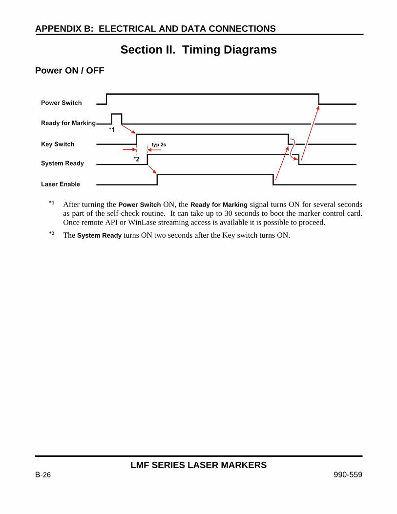
APPENDIX B: ELECTRICAL AND DATA CONNECTIONS
LMF SERIES LASER MARKERS
B-26 990-559
Section II. Timing Diagrams Power ON / OFF
*1 After turning the Power Switch ON, the Ready for Marking signal turns ON for several seconds as part of the self-check routine. It can take up to 30 seconds to boot the marker control card. Once remote API or WinLase streaming access is available it is possible to proceed.
*2 The System Ready turns ON two seconds after the Key switch turns ON.
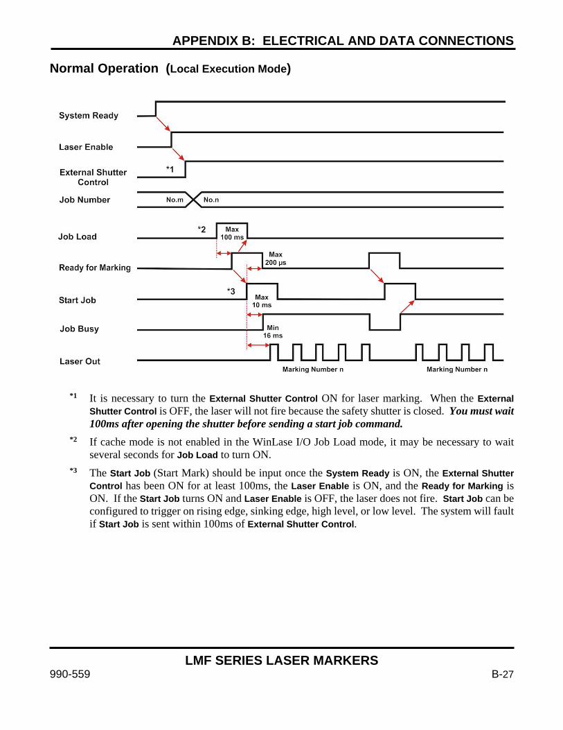
APPENDIX B: ELECTRICAL AND DATA CONNECTIONS
LMF SERIES LASER MARKERS
990-559 B-27
Normal Operation (Local Execution Mode)
*1 It is necessary to turn the External Shutter Control ON for laser marking. When the External Shutter Control is OFF, the laser will not fire because the safety shutter is closed. You must wait 100ms after opening the shutter before sending a start job command.
*2 If cache mode is not enabled in the WinLase I/O Job Load mode, it may be necessary to wait several seconds for Job Load to turn ON.
*3 The Start Job (Start Mark) should be input once the System Ready is ON, the External Shutter Control has been ON for at least 100ms, the Laser Enable is ON, and the Ready for Marking is ON. If the Start Job turns ON and Laser Enable is OFF, the laser does not fire. Start Job can be configured to trigger on rising edge, sinking edge, high level, or low level. The system will fault if Start Job is sent within 100ms of External Shutter Control.
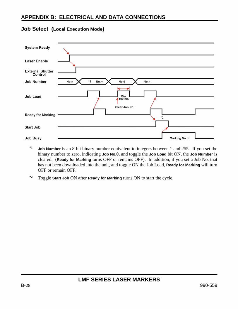
APPENDIX B: ELECTRICAL AND DATA CONNECTIONS
LMF SERIES LASER MARKERS
B-28 990-559
Job Select (Local Execution Mode)
*1 Job Number is an 8-bit binary number equivalent to integers between 1 and 255. If you set the binary number to zero, indicating Job No.0, and toggle the Job Load bit ON, the Job Number is cleared. (Ready for Marking turns OFF or remains OFF). In addition, if you set a Job No. that has not been downloaded into the unit, and toggle ON the Job Load, Ready for Marking will turn OFF or remain OFF.
*2 Toggle Start Job ON after Ready for Marking turns ON to start the cycle.
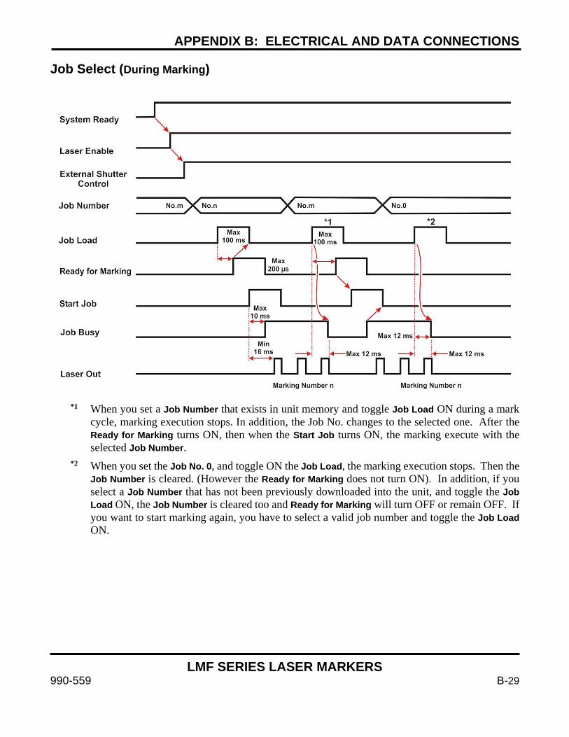
APPENDIX B: ELECTRICAL AND DATA CONNECTIONS
LMF SERIES LASER MARKERS
990-559 B-29
Job Select (During Marking)
*1 When you set a Job Number that exists in unit memory and toggle Job Load ON during a mark cycle, marking execution stops. In addition, the Job No. changes to the selected one. After the Ready for Marking turns ON, then when the Start Job turns ON, the marking execute with the selected Job Number.
*2 When you set the Job No. 0, and toggle ON the Job Load, the marking execution stops. Then the Job Number is cleared. (However the Ready for Marking does not turn ON). In addition, if you select a Job Number that has not been previously downloaded into the unit, and toggle the Job Load ON, the Job Number is cleared too and Ready for Marking will turn OFF or remain OFF. If you want to start marking again, you have to select a valid job number and toggle the Job Load ON.
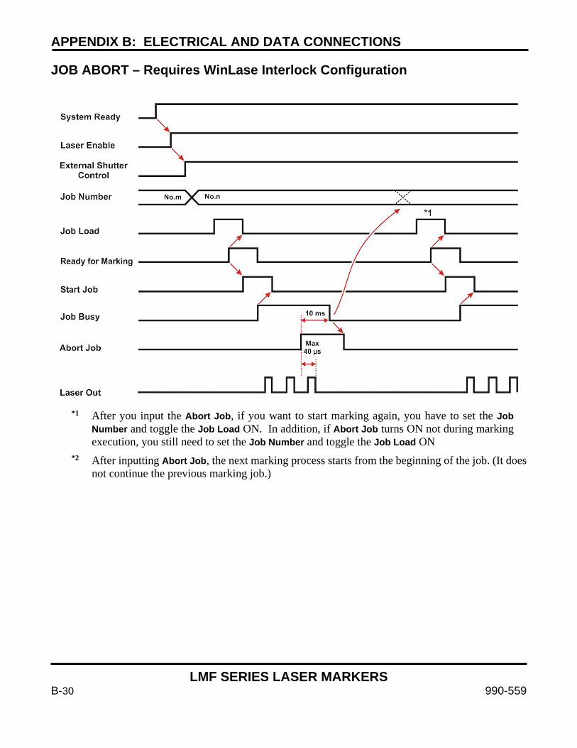
APPENDIX B: ELECTRICAL AND DATA CONNECTIONS
LMF SERIES LASER MARKERS
B-30 990-559
JOB ABORT – Requires WinLase Interlock Configuration
*1 After you input the Abort Job, if you want to start marking again, you have to set the Job Number and toggle the Job Load ON. In addition, if Abort Job turns ON not during marking execution, you still need to set the Job Number and toggle the Job Load ON
*2 After inputting Abort Job, the next marking process starts from the beginning of the job. (It does not continue the previous marking job.)

APPENDIX B: ELECTRICAL AND DATA CONNECTIONS
LMF SERIES LASER MARKERS
990-559 B-31
SYSTEM FAULT
*1 When the unit is in a fault condition, the System Fault is turned ON and the System Ready is turned OFF. Then when the System Fault is cleared using Fault Reset, (and Fault Reset is OFF), System Ready is turned ON 2 seconds later.
*2 After inputting Fault Reset, if you want to start marking again, you have to again set the Job Number and toggle Job Load ON.

APPENDIX B: ELECTRICAL AND DATA CONNECTIONS
LMF SERIES LASER MARKERS
B-32 990-559
EMERGENCY STOP
*1 After the Fault Reset is turned ON, in order to restart a job you need to set the job number and to turn the Job Load ON.
*2 After the Emergency Stop is released and the Fault Reset is toggled ON, or the key switch is cycled OFF then ON, the System Fault turns OFF. Once the Fault Reset is turned OFF the System Ready turns ON 2 seconds later. It is necessary to re-load the job by resetting the Job Number and toggling Job Load ON briefly to continue.
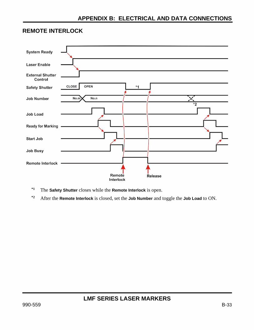
APPENDIX B: ELECTRICAL AND DATA CONNECTIONS
LMF SERIES LASER MARKERS
990-559 B-33
REMOTE INTERLOCK
*1 The Safety Shutter closes while the Remote Interlock is open. *2 After the Remote Interlock is closed, set the Job Number and toggle the Job Load to ON.

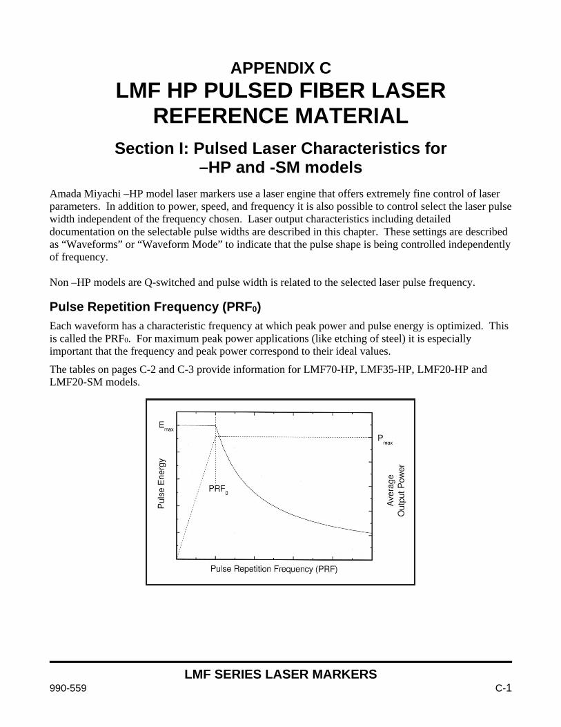
LMF SERIES LASER MARKERS
990-559 C-1
APPENDIX C LMF HP PULSED FIBER LASER
REFERENCE MATERIAL
Section I: Pulsed Laser Characteristics for –HP and -SM models
Amada Miyachi –HP model laser markers use a laser engine that offers extremely fine control of laser parameters. In addition to power, speed, and frequency it is also possible to control select the laser pulse width independent of the frequency chosen. Laser output characteristics including detailed documentation on the selectable pulse widths are described in this chapter. These settings are described as “Waveforms” or “Waveform Mode” to indicate that the pulse shape is being controlled independently of frequency. Non –HP models are Q-switched and pulse width is related to the selected laser pulse frequency. Pulse Repetition Frequency (PRF0) Each waveform has a characteristic frequency at which peak power and pulse energy is optimized. This is called the PRF0. For maximum peak power applications (like etching of steel) it is especially important that the frequency and peak power correspond to their ideal values.
The tables on pages C-2 and C-3 provide information for LMF70-HP, LMF35-HP, LMF20-HP and LMF20-SM models.
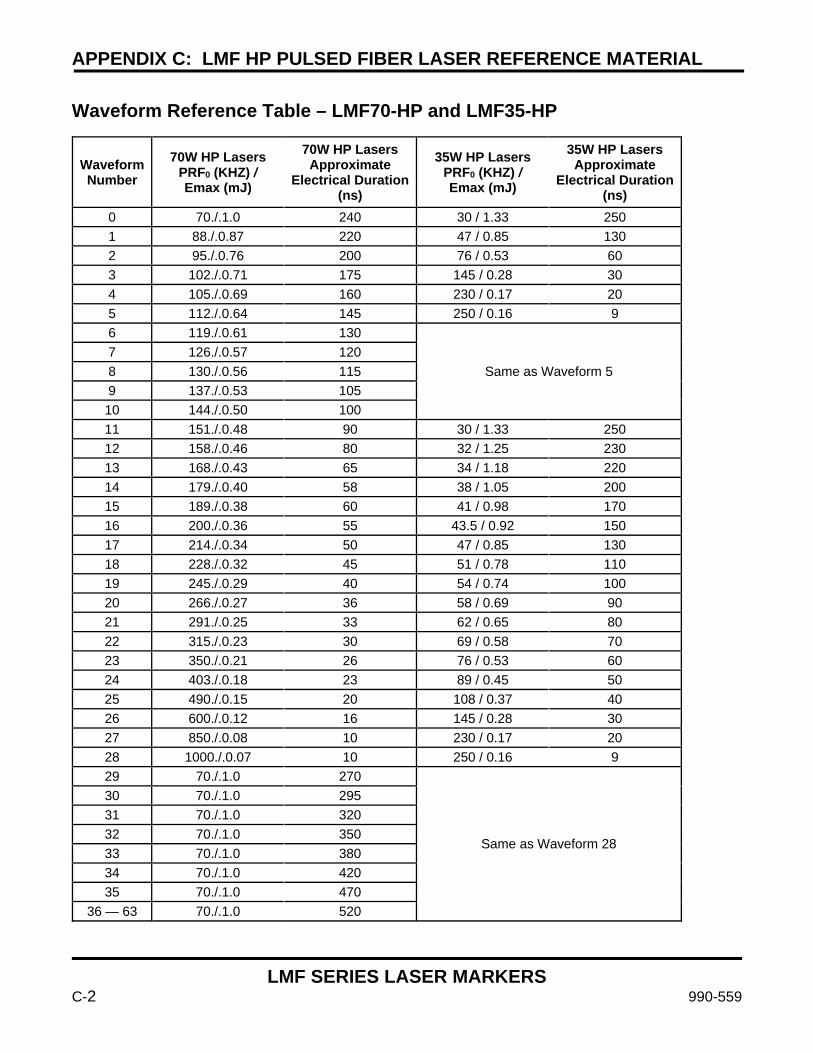
APPENDIX C: LMF HP PULSED FIBER LASER REFERENCE MATERIAL
LMF SERIES LASER MARKERS
C-2 990-559
Waveform Reference Table – LMF70-HP and LMF35-HP
Waveform Number
70W HP Lasers PRF0 (KHZ) / Emax (mJ)
70W HP Lasers Approximate
Electrical Duration(ns)
35W HP Lasers PRF0 (KHZ) / Emax (mJ)
35W HP Lasers Approximate
Electrical Duration(ns)
0 70./.1.0 240 30 / 1.33 250 1 88./.0.87 220 47 / 0.85 130 2 95./.0.76 200 76 / 0.53 60 3 102./.0.71 175 145 / 0.28 30 4 105./.0.69 160 230 / 0.17 20 5 112./.0.64 145 250 / 0.16 9 6 119./.0.61 130
Same as Waveform 5 7 126./.0.57 120 8 130./.0.56 115 9 137./.0.53 105 10 144./.0.50 100 11 151./.0.48 90 30 / 1.33 250 12 158./.0.46 80 32 / 1.25 230 13 168./.0.43 65 34 / 1.18 220 14 179./.0.40 58 38 / 1.05 200 15 189./.0.38 60 41 / 0.98 170 16 200./.0.36 55 43.5 / 0.92 150 17 214./.0.34 50 47 / 0.85 130 18 228./.0.32 45 51 / 0.78 110 19 245./.0.29 40 54 / 0.74 100 20 266./.0.27 36 58 / 0.69 90 21 291./.0.25 33 62 / 0.65 80 22 315./.0.23 30 69 / 0.58 70 23 350./.0.21 26 76 / 0.53 60 24 403./.0.18 23 89 / 0.45 50 25 490./.0.15 20 108 / 0.37 40 26 600./.0.12 16 145 / 0.28 30 27 850./.0.08 10 230 / 0.17 20 28 1000./.0.07 10 250 / 0.16 9 29 70./.1.0 270
Same as Waveform 28
30 70./.1.0 295 31 70./.1.0 320 32 70./.1.0 350 33 70./.1.0 380 34 70./.1.0 420 35 70./.1.0 470
36 — 63 70./.1.0 520
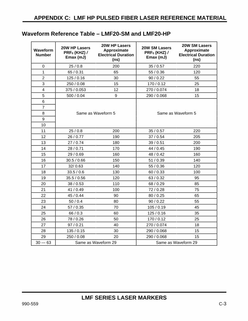
APPENDIX C: LMF HP PULSED FIBER LASER REFERENCE MATERIAL
LMF SERIES LASER MARKERS
990-559 C-3
Waveform Reference Table – LMF20-SM and LMF20-HP
Waveform Number
20W HP Lasers PRF0 (KHZ) / Emax (mJ)
20W HP Lasers Approximate
Electrical Duration(ns)
20W SM Lasers PRF0 (KHZ) / Emax (mJ)
20W SM Lasers Approximate
Electrical Duration(ns)
0 25 / 0.8 200 35 / 0.57 220 1 65 / 0.31 65 55 / 0.36 120 2 125 / 0.16 30 90 / 0.22 55 3 250 / 0.08 15 170 / 0.12 25 4 375 / 0.053 12 270 / 0.074 18 5 500 / 0.04 9 290 / 0.068 15 6
Same as Waveform 5 Same as Waveform 5 7 8 9 10 11 25 / 0.8 200 35 / 0.57 220 12 26 / 0.77 190 37 / 0.54 205 13 27 / 0.74 180 39 / 0.51 200 14 28 / 0.71 170 44 / 0.45 190 15 29 / 0.69 160 48 / 0.42 160 16 30.5 / 0.66 150 51 / 0.39 140 17 32/ 0.63 140 55 / 0.36 120 18 33.5 / 0.6 130 60 / 0.33 100 19 35.5 / 0.56 120 63 / 0.32 95 20 38 / 0.53 110 68 / 0.29 85 21 41 / 0.49 100 72 / 0.28 75 22 45 / 0.44 90 80 / 0.25 65 23 50 / 0.4 80 90 / 0.22 55 24 57 / 0.35 70 105 / 0.19 45 25 66 / 0.3 60 125 / 0.16 35 26 78 / 0.26 50 170 / 0.12 25 27 97 / 0.21 40 270 / 0.074 18 28 135 / 0.15 30 290 / 0.068 15 29 250 / 0.08 20 290 / 0.068 15
30 — 63 Same as Waveform 29 Same as Waveform 29
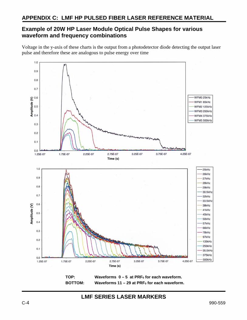
APPENDIX C: LMF HP PULSED FIBER LASER REFERENCE MATERIAL
LMF SERIES LASER MARKERS
C-4 990-559
Example of 20W HP Laser Module Optical Pulse Shapes for various waveform and frequency combinations Voltage in the y-axis of these charts is the output from a photodetector diode detecting the output laser pulse and therefore these are analogous to pulse energy over time
TOP: Waveforms 0 – 5 at PRF0 for each waveform. BOTTOM: Waveforms 11 – 29 at PRF0 for each waveform.
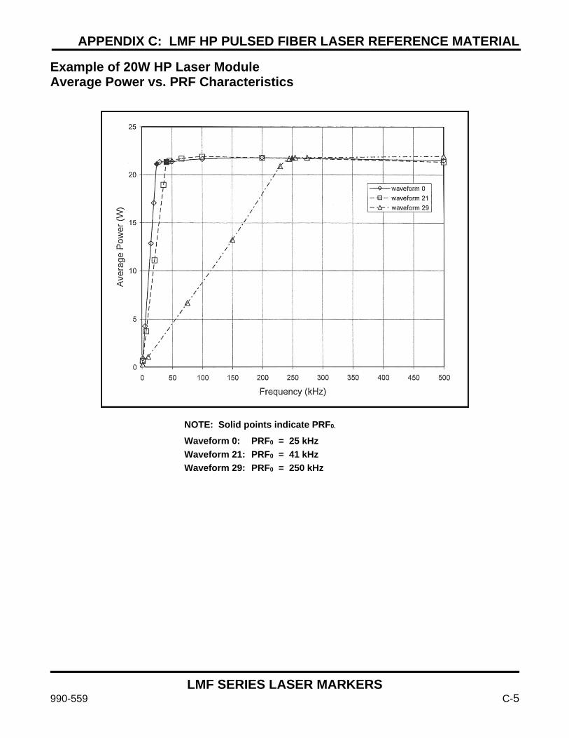
APPENDIX C: LMF HP PULSED FIBER LASER REFERENCE MATERIAL
LMF SERIES LASER MARKERS
990-559 C-5
Example of 20W HP Laser Module Average Power vs. PRF Characteristics
NOTE: Solid points indicate PRF0. Waveform 0: PRF0 = 25 kHz Waveform 21: PRF0 = 41 kHz Waveform 29: PRF0 = 250 kHz
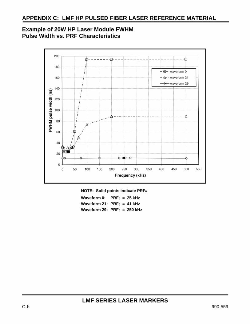
APPENDIX C: LMF HP PULSED FIBER LASER REFERENCE MATERIAL
LMF SERIES LASER MARKERS
C-6 990-559
Example of 20W HP Laser Module FWHM Pulse Width vs. PRF Characteristics
NOTE: Solid points indicate PRF0. Waveform 0: PRF0 = 25 kHz Waveform 21: PRF0 = 41 kHz Waveform 29: PRF0 = 250 kHz
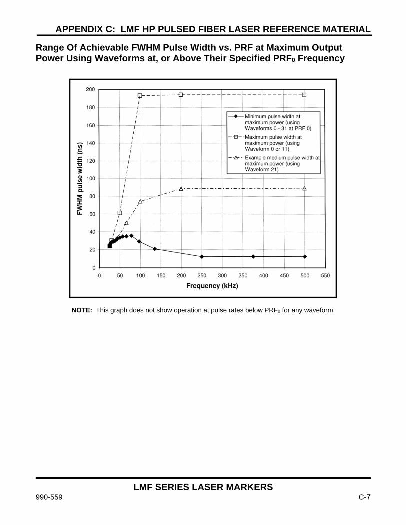
APPENDIX C: LMF HP PULSED FIBER LASER REFERENCE MATERIAL
LMF SERIES LASER MARKERS
990-559 C-7
Range Of Achievable FWHM Pulse Width vs. PRF at Maximum Output Power Using Waveforms at, or Above Their Specified PRF0 Frequency
NOTE: This graph does not show operation at pulse rates below PRF0 for any waveform.
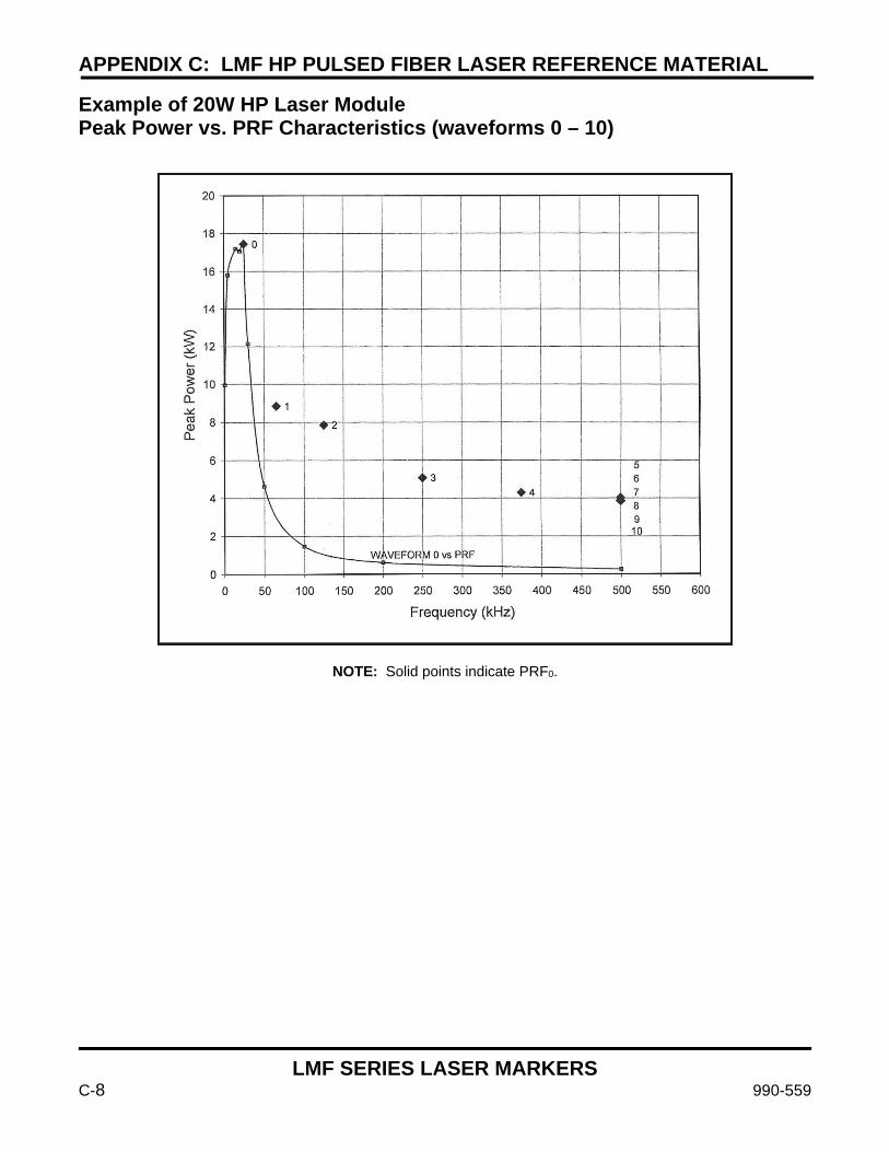
APPENDIX C: LMF HP PULSED FIBER LASER REFERENCE MATERIAL
LMF SERIES LASER MARKERS
C-8 990-559
Example of 20W HP Laser Module Peak Power vs. PRF Characteristics (waveforms 0 – 10)
NOTE: Solid points indicate PRF0.
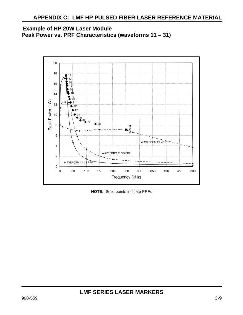
APPENDIX C: LMF HP PULSED FIBER LASER REFERENCE MATERIAL
LMF SERIES LASER MARKERS
990-559 C-9
Example of HP 20W Laser Module Peak Power vs. PRF Characteristics (waveforms 11 – 31)
NOTE: Solid points indicate PRF0.

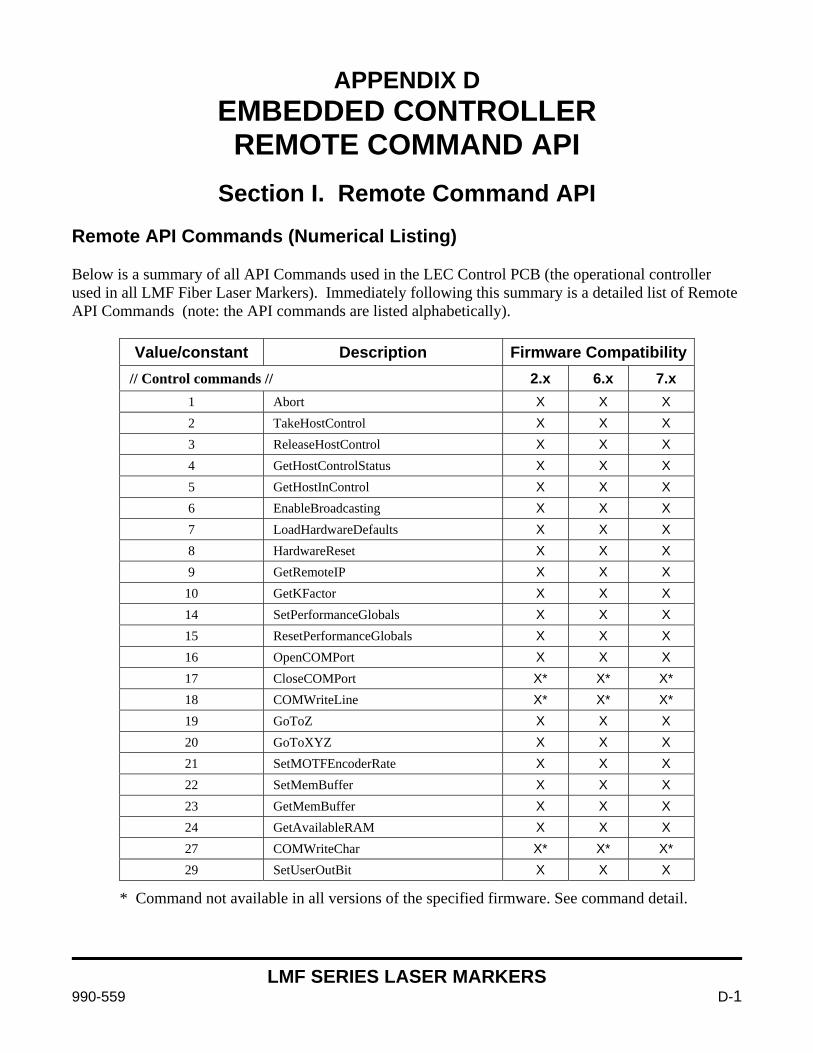
LMF SERIES LASER MARKERS
990-559 D-1
APPENDIX D
EMBEDDED CONTROLLER REMOTE COMMAND API
Section I. Remote Command API
Remote API Commands (Numerical Listing) Below is a summary of all API Commands used in the LEC Control PCB (the operational controller used in all LMF Fiber Laser Markers). Immediately following this summary is a detailed list of Remote API Commands (note: the API commands are listed alphabetically).
Value/constant Description Firmware Compatibility// Control commands // 2.x 6.x 7.x
1 Abort X X X 2 TakeHostControl X X X 3 ReleaseHostControl X X X 4 GetHostControlStatus X X X 5 GetHostInControl X X X 6 EnableBroadcasting X X X 7 LoadHardwareDefaults X X X 8 HardwareReset X X X 9 GetRemoteIP X X X
10 GetKFactor X X X 14 SetPerformanceGlobals X X X 15 ResetPerformanceGlobals X X X 16 OpenCOMPort X X X 17 CloseCOMPort X* X* X* 18 COMWriteLine X* X* X* 19 GoToZ X X X 20 GoToXYZ X X X 21 SetMOTFEncoderRate X X X 22 SetMemBuffer X X X 23 GetMemBuffer X X X 24 GetAvailableRAM X X X 27 COMWriteChar X* X* X* 29 SetUserOutBit X X X
* Command not available in all versions of the specified firmware. See command detail.
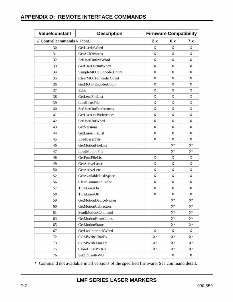
APPENDIX D: REMOTE INTERFACE COMMANDS
LMF SERIES LASER MARKERS
D-2 990-559
Value/constant Description Firmware Compatibility
// Control commands // (cont.) 2.x 6.x 7.x 30 GetUserInWord X X X 31 GetAllIOWords X X X 32 SetUserOutInitWord X X X 33 GetUserOutInitWord X X X 34 SampleMOTFEncoderCount X X X 35 ClearMOTFEncoderCount X X X 36 GetMOTFEncoderCount X X X 37 Echo X X X 38 GetLensFileList X X X 39 LoadLensFile X X X 40 SetUserOutPreferences X X X 41 GetUserOutPreferences X X X 42 SetUserOutWord X X X 43 GetVersions X X X 44 GetLaserFileList X X X 45 LoadLaserFile X X X 46 GetMotionFileList X* X* 47 LoadMotionFile X* X* 48 GetFontFileList X X X 49 GetActiveLaser X X X 50 GetActiveLens X X X 52 GetAvailableDiskSpace X X X 56 ClearCommandCache X X X 57 TurnLaserOn X X X 58 TurnLaserOff X X X 59 GetMotionDeviceNames X* X* 60 GetMotionCalFactors X* X* 61 SendMotionCommand X* X* 63 GetMotionErrorCodes X* X* 65 GetMotionStatus X* X* 67 GetLastInterlockWord X X X 72 COMWriteCharEx X* X* X* 73 COMWriteLineEx X* X* X* 75 CloseCOMPortEx X* X* X* 76 SetZOffsetRWU X X
* Command not available in all versions of the specified firmware. See command detail.

APPENDIX D: REMOTE INTERFACE COMMANDS
LMF SERIES LASER MARKERS
990-559 D-3
Value/constant Description Firmware Compatibility
// Object commands // 2.x 6.x 7.x 100 SetObjectString X X X 102 TransformObject X X X 103 GetObjectRect X X X 104 GetObjectCenter X X X 105 GetObjectType X X X 106 EnableObject X X X 107 GetObjectString X X X 108 GetObjectName X X X 109 SetObjectUserData X X X 110 GetObjectUserData X X X 111 ResetObject X X X 112 ResetUserTransform X X X 113 TransformObjectByName X X X 114 TransformObjectByNameEx X X X 115 SetObjectProfile X X X 116 GetObjectProfile X X X 117 SetObjectProfileFromFile X X X 118 GetObjectNumPasses X 119 SetObjectNumPasses X 120 GetObjectMarkMode X 121 SetObjectMarkMode X 122 GetObjectNumMarkingPasses X X 123 AddObjectMarkingPass X X 124 DeleteObjectMarkingPass X X 125 SetObjectPassRepetitions X X 126 GetObjectPassRepetitions X X 127 TransformObjectNewFill X X X 128 TransformObjectByNameNewFill X X X 136 NewObject X 137 SetObjectUnicodeString X 138 GetObjectUnicodeString X 139 GetObjectVectors X 140 SetObjectVectors X 141 RemoveObject X
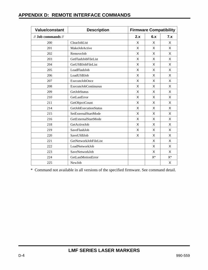
APPENDIX D: REMOTE INTERFACE COMMANDS
LMF SERIES LASER MARKERS
D-4 990-559
Value/constant Description Firmware Compatibility
// Job commands // 2.x 6.x 7.x 200 ClearJobList X X X 201 MakeJobActive X X X 202 RemoveJob X X X 203 GetFlashJobFileList X X X 204 GetUSBJobFileList X X X 205 LoadFlashJob X X X 206 LoadUSBJob X X X 207 ExecuteJobOnce X X X 208 ExecuteJobContinuous X X X 209 GetJobStatus X X X 210 GetLastError X X X 211 GetObjectCount X X X 214 GetJobExecutionStatus X X X 215 SetExternalStartMode X X X 216 GetExternalStartMode X X X 218 GetActiveJob X X X 219 SaveFlashJob X X X 220 SaveUSBJob X X X 221 GetNetworkJobFileList X X 222 LoadNetworkJob X X 223 SaveNetworkJob X X 224 GetLastMotionError X* X* 225 NewJob X
* Command not available in all versions of the specified firmware. See command detail.
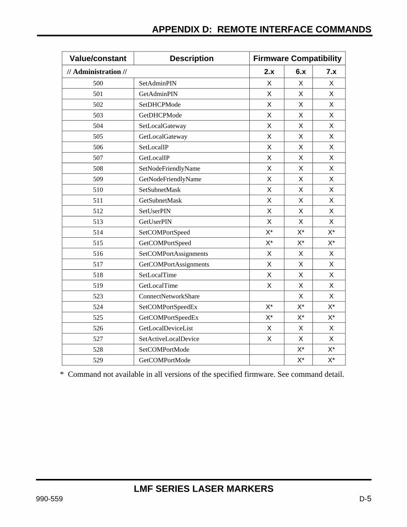
APPENDIX D: REMOTE INTERFACE COMMANDS
LMF SERIES LASER MARKERS
990-559 D-5
Value/constant Description Firmware Compatibility
// Administration // 2.x 6.x 7.x 500 SetAdminPIN X X X 501 GetAdminPIN X X X 502 SetDHCPMode X X X 503 GetDHCPMode X X X 504 SetLocalGateway X X X 505 GetLocalGateway X X X 506 SetLocalIP X X X 507 GetLocalIP X X X 508 SetNodeFriendlyName X X X 509 GetNodeFriendlyName X X X 510 SetSubnetMask X X X 511 GetSubnetMask X X X 512 SetUserPIN X X X 513 GetUserPIN X X X 514 SetCOMPortSpeed X* X* X* 515 GetCOMPortSpeed X* X* X* 516 SetCOMPortAssignments X X X 517 GetCOMPortAssignments X X X 518 SetLocalTime X X X 519 GetLocalTime X X X 523 ConnectNetworkShare X X 524 SetCOMPortSpeedEx X* X* X* 525 GetCOMPortSpeedEx X* X* X* 526 GetLocalDeviceList X X X 527 SetActiveLocalDevice X X X 528 SetCOMPortMode X* X* 529 GetCOMPortMode X* X*
* Command not available in all versions of the specified firmware. See command detail.
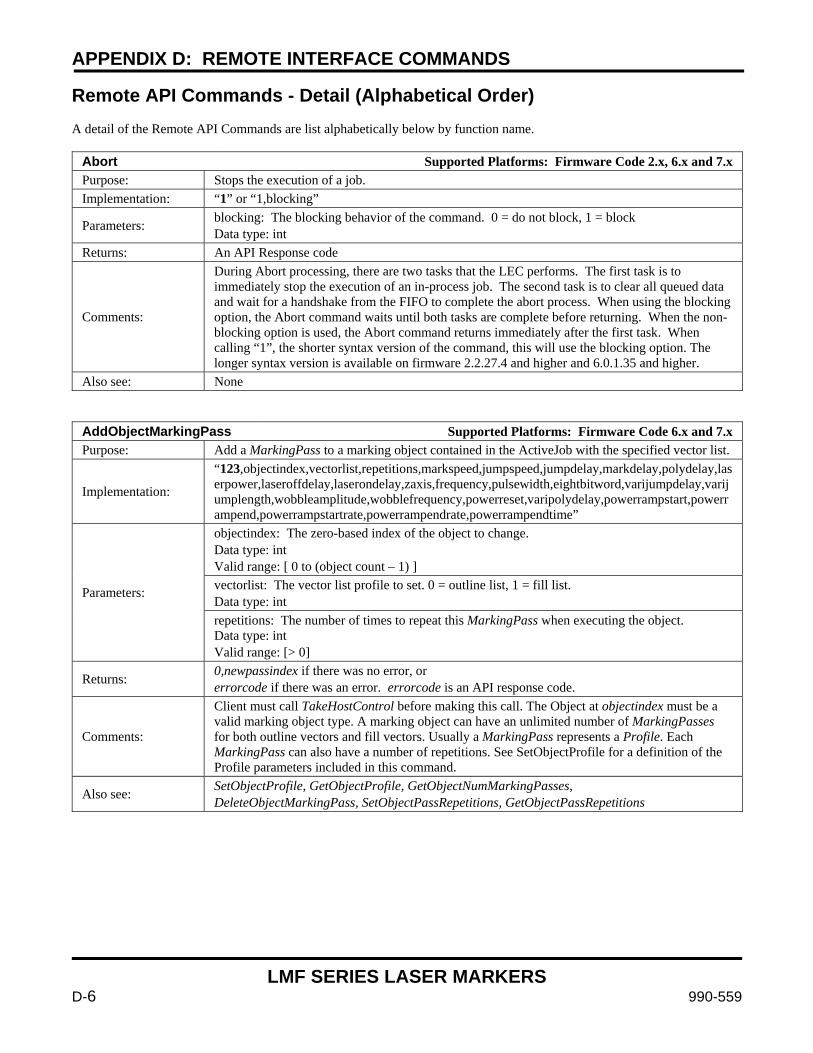
APPENDIX D: REMOTE INTERFACE COMMANDS
LMF SERIES LASER MARKERS
D-6 990-559
Remote API Commands - Detail (Alphabetical Order) A detail of the Remote API Commands are list alphabetically below by function name.
Abort Supported Platforms: Firmware Code 2.x, 6.x and 7.x Purpose: Stops the execution of a job. Implementation: “1” or “1,blocking”
Parameters: blocking: The blocking behavior of the command. 0 = do not block, 1 = block Data type: int
Returns: An API Response code
Comments:
During Abort processing, there are two tasks that the LEC performs. The first task is to immediately stop the execution of an in-process job. The second task is to clear all queued data and wait for a handshake from the FIFO to complete the abort process. When using the blocking option, the Abort command waits until both tasks are complete before returning. When the non-blocking option is used, the Abort command returns immediately after the first task. When calling “1”, the shorter syntax version of the command, this will use the blocking option. The longer syntax version is available on firmware 2.2.27.4 and higher and 6.0.1.35 and higher.
Also see: None
AddObjectMarkingPass Supported Platforms: Firmware Code 6.x and 7.x Purpose: Add a MarkingPass to a marking object contained in the ActiveJob with the specified vector list.
Implementation:
“123,objectindex,vectorlist,repetitions,markspeed,jumpspeed,jumpdelay,markdelay,polydelay,laserpower,laseroffdelay,laserondelay,zaxis,frequency,pulsewidth,eightbitword,varijumpdelay,varijumplength,wobbleamplitude,wobblefrequency,powerreset,varipolydelay,powerrampstart,powerrampend,powerrampstartrate,powerrampendrate,powerrampendtime”
Parameters:
objectindex: The zero-based index of the object to change. Data type: int Valid range: [ 0 to (object count – 1) ] vectorlist: The vector list profile to set. 0 = outline list, 1 = fill list. Data type: int repetitions: The number of times to repeat this MarkingPass when executing the object. Data type: int Valid range: [> 0]
Returns: 0,newpassindex if there was no error, or errorcode if there was an error. errorcode is an API response code.
Comments:
Client must call TakeHostControl before making this call. The Object at objectindex must be a valid marking object type. A marking object can have an unlimited number of MarkingPasses for both outline vectors and fill vectors. Usually a MarkingPass represents a Profile. Each MarkingPass can also have a number of repetitions. See SetObjectProfile for a definition of the Profile parameters included in this command.
Also see: SetObjectProfile, GetObjectProfile, GetObjectNumMarkingPasses, DeleteObjectMarkingPass, SetObjectPassRepetitions, GetObjectPassRepetitions
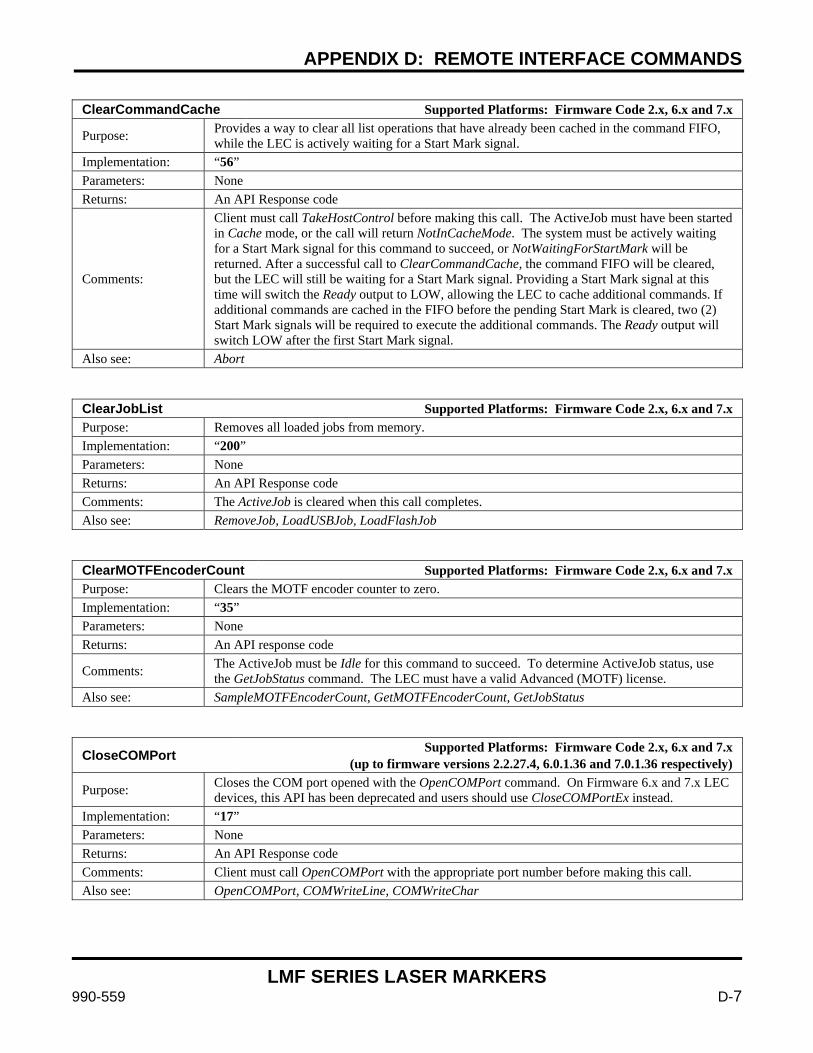
APPENDIX D: REMOTE INTERFACE COMMANDS
LMF SERIES LASER MARKERS
990-559 D-7
ClearCommandCache Supported Platforms: Firmware Code 2.x, 6.x and 7.x
Purpose: Provides a way to clear all list operations that have already been cached in the command FIFO, while the LEC is actively waiting for a Start Mark signal.
Implementation: “56” Parameters: None Returns: An API Response code
Comments:
Client must call TakeHostControl before making this call. The ActiveJob must have been started in Cache mode, or the call will return NotInCacheMode. The system must be actively waiting for a Start Mark signal for this command to succeed, or NotWaitingForStartMark will be returned. After a successful call to ClearCommandCache, the command FIFO will be cleared, but the LEC will still be waiting for a Start Mark signal. Providing a Start Mark signal at this time will switch the Ready output to LOW, allowing the LEC to cache additional commands. If additional commands are cached in the FIFO before the pending Start Mark is cleared, two (2) Start Mark signals will be required to execute the additional commands. The Ready output will switch LOW after the first Start Mark signal.
Also see: Abort
ClearJobList Supported Platforms: Firmware Code 2.x, 6.x and 7.x Purpose: Removes all loaded jobs from memory. Implementation: “200” Parameters: None Returns: An API Response code Comments: The ActiveJob is cleared when this call completes. Also see: RemoveJob, LoadUSBJob, LoadFlashJob
ClearMOTFEncoderCount Supported Platforms: Firmware Code 2.x, 6.x and 7.x Purpose: Clears the MOTF encoder counter to zero. Implementation: “35” Parameters: None Returns: An API response code
Comments: The ActiveJob must be Idle for this command to succeed. To determine ActiveJob status, use the GetJobStatus command. The LEC must have a valid Advanced (MOTF) license.
Also see: SampleMOTFEncoderCount, GetMOTFEncoderCount, GetJobStatus
CloseCOMPort Supported Platforms: Firmware Code 2.x, 6.x and 7.x (up to firmware versions 2.2.27.4, 6.0.1.36 and 7.0.1.36 respectively)
Purpose: Closes the COM port opened with the OpenCOMPort command. On Firmware 6.x and 7.x LEC devices, this API has been deprecated and users should use CloseCOMPortEx instead.
Implementation: “17” Parameters: None Returns: An API Response code Comments: Client must call OpenCOMPort with the appropriate port number before making this call. Also see: OpenCOMPort, COMWriteLine, COMWriteChar
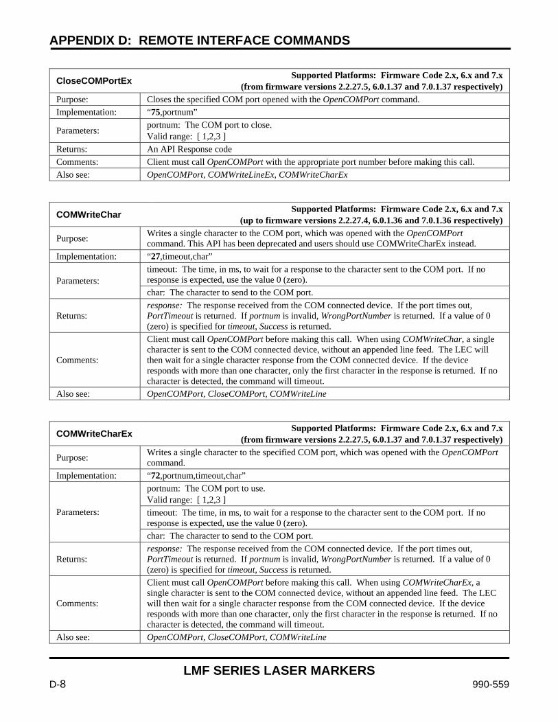
APPENDIX D: REMOTE INTERFACE COMMANDS
LMF SERIES LASER MARKERS
D-8 990-559
CloseCOMPortEx Supported Platforms: Firmware Code 2.x, 6.x and 7.x (from firmware versions 2.2.27.5, 6.0.1.37 and 7.0.1.37 respectively)
Purpose: Closes the specified COM port opened with the OpenCOMPort command. Implementation: “75,portnum”
Parameters: portnum: The COM port to close. Valid range: [ 1,2,3 ]
Returns: An API Response code Comments: Client must call OpenCOMPort with the appropriate port number before making this call. Also see: OpenCOMPort, COMWriteLineEx, COMWriteCharEx
COMWriteChar Supported Platforms: Firmware Code 2.x, 6.x and 7.x (up to firmware versions 2.2.27.4, 6.0.1.36 and 7.0.1.36 respectively)
Purpose: Writes a single character to the COM port, which was opened with the OpenCOMPort command. This API has been deprecated and users should use COMWriteCharEx instead.
Implementation: “27,timeout,char”
Parameters: timeout: The time, in ms, to wait for a response to the character sent to the COM port. If no response is expected, use the value 0 (zero). char: The character to send to the COM port.
Returns: response: The response received from the COM connected device. If the port times out, PortTimeout is returned. If portnum is invalid, WrongPortNumber is returned. If a value of 0 (zero) is specified for timeout, Success is returned.
Comments:
Client must call OpenCOMPort before making this call. When using COMWriteChar, a single character is sent to the COM connected device, without an appended line feed. The LEC will then wait for a single character response from the COM connected device. If the device responds with more than one character, only the first character in the response is returned. If no character is detected, the command will timeout.
Also see: OpenCOMPort, CloseCOMPort, COMWriteLine
COMWriteCharEx Supported Platforms: Firmware Code 2.x, 6.x and 7.x (from firmware versions 2.2.27.5, 6.0.1.37 and 7.0.1.37 respectively)
Purpose: Writes a single character to the specified COM port, which was opened with the OpenCOMPort command.
Implementation: “72,portnum,timeout,char”
Parameters:
portnum: The COM port to use. Valid range: [ 1,2,3 ] timeout: The time, in ms, to wait for a response to the character sent to the COM port. If no response is expected, use the value 0 (zero). char: The character to send to the COM port.
Returns: response: The response received from the COM connected device. If the port times out, PortTimeout is returned. If portnum is invalid, WrongPortNumber is returned. If a value of 0 (zero) is specified for timeout, Success is returned.
Comments:
Client must call OpenCOMPort before making this call. When using COMWriteCharEx, a single character is sent to the COM connected device, without an appended line feed. The LEC will then wait for a single character response from the COM connected device. If the device responds with more than one character, only the first character in the response is returned. If no character is detected, the command will timeout.
Also see: OpenCOMPort, CloseCOMPort, COMWriteLine
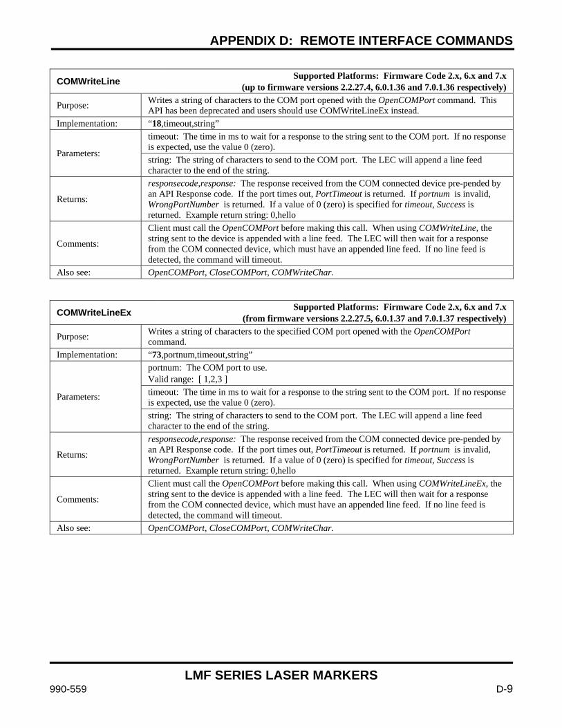
APPENDIX D: REMOTE INTERFACE COMMANDS
LMF SERIES LASER MARKERS
990-559 D-9
COMWriteLine Supported Platforms: Firmware Code 2.x, 6.x and 7.x (up to firmware versions 2.2.27.4, 6.0.1.36 and 7.0.1.36 respectively)
Purpose: Writes a string of characters to the COM port opened with the OpenCOMPort command. This API has been deprecated and users should use COMWriteLineEx instead.
Implementation: “18,timeout,string”
Parameters:
timeout: The time in ms to wait for a response to the string sent to the COM port. If no response is expected, use the value 0 (zero). string: The string of characters to send to the COM port. The LEC will append a line feed character to the end of the string.
Returns:
responsecode,response: The response received from the COM connected device pre-pended by an API Response code. If the port times out, PortTimeout is returned. If portnum is invalid, WrongPortNumber is returned. If a value of 0 (zero) is specified for timeout, Success is returned. Example return string: 0,hello
Comments:
Client must call the OpenCOMPort before making this call. When using COMWriteLine, the string sent to the device is appended with a line feed. The LEC will then wait for a response from the COM connected device, which must have an appended line feed. If no line feed is detected, the command will timeout.
Also see: OpenCOMPort, CloseCOMPort, COMWriteChar.
COMWriteLineEx Supported Platforms: Firmware Code 2.x, 6.x and 7.x (from firmware versions 2.2.27.5, 6.0.1.37 and 7.0.1.37 respectively)
Purpose: Writes a string of characters to the specified COM port opened with the OpenCOMPort command.
Implementation: “73,portnum,timeout,string”
Parameters:
portnum: The COM port to use. Valid range: [ 1,2,3 ] timeout: The time in ms to wait for a response to the string sent to the COM port. If no response is expected, use the value 0 (zero). string: The string of characters to send to the COM port. The LEC will append a line feed character to the end of the string.
Returns:
responsecode,response: The response received from the COM connected device pre-pended by an API Response code. If the port times out, PortTimeout is returned. If portnum is invalid, WrongPortNumber is returned. If a value of 0 (zero) is specified for timeout, Success is returned. Example return string: 0,hello
Comments:
Client must call the OpenCOMPort before making this call. When using COMWriteLineEx, the string sent to the device is appended with a line feed. The LEC will then wait for a response from the COM connected device, which must have an appended line feed. If no line feed is detected, the command will timeout.
Also see: OpenCOMPort, CloseCOMPort, COMWriteChar.
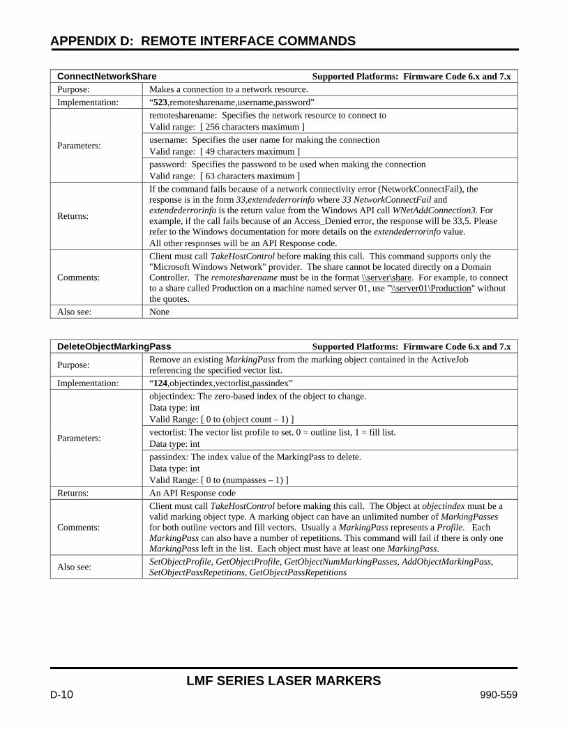
APPENDIX D: REMOTE INTERFACE COMMANDS
LMF SERIES LASER MARKERS
D-10 990-559
ConnectNetworkShare Supported Platforms: Firmware Code 6.x and 7.x Purpose: Makes a connection to a network resource. Implementation: “523,remotesharename,username,password”
Parameters:
remotesharename: Specifies the network resource to connect to Valid range: [ 256 characters maximum ] username: Specifies the user name for making the connection Valid range: [ 49 characters maximum ] password: Specifies the password to be used when making the connection Valid range: [ 63 characters maximum ]
Returns:
If the command fails because of a network connectivity error (NetworkConnectFail), the response is in the form 33,extendederrorinfo where 33 NetworkConnectFail and extendederrorinfo is the return value from the Windows API call WNetAddConnection3. For example, if the call fails because of an Access_Denied error, the response will be 33,5. Please refer to the Windows documentation for more details on the extendederrorinfo value. All other responses will be an API Response code.
Comments:
Client must call TakeHostControl before making this call. This command supports only the "Microsoft Windows Network" provider. The share cannot be located directly on a Domain Controller. The remotesharename must be in the format \\server\share. For example, to connect to a share called Production on a machine named server 01, use "\\server01\Production" without the quotes.
Also see: None
DeleteObjectMarkingPass Supported Platforms: Firmware Code 6.x and 7.x
Purpose: Remove an existing MarkingPass from the marking object contained in the ActiveJob referencing the specified vector list.
Implementation: “124,objectindex,vectorlist,passindex”
Parameters:
objectindex: The zero-based index of the object to change. Data type: int Valid Range: [ 0 to (object count – 1) ] vectorlist: The vector list profile to set. 0 = outline list, 1 = fill list. Data type: int passindex: The index value of the MarkingPass to delete. Data type: int Valid Range: [ 0 to (numpasses – 1) ]
Returns: An API Response code
Comments:
Client must call TakeHostControl before making this call. The Object at objectindex must be a valid marking object type. A marking object can have an unlimited number of MarkingPasses for both outline vectors and fill vectors. Usually a MarkingPass represents a Profile. Each MarkingPass can also have a number of repetitions. This command will fail if there is only one MarkingPass left in the list. Each object must have at least one MarkingPass.
Also see: SetObjectProfile, GetObjectProfile, GetObjectNumMarkingPasses, AddObjectMarkingPass, SetObjectPassRepetitions, GetObjectPassRepetitions
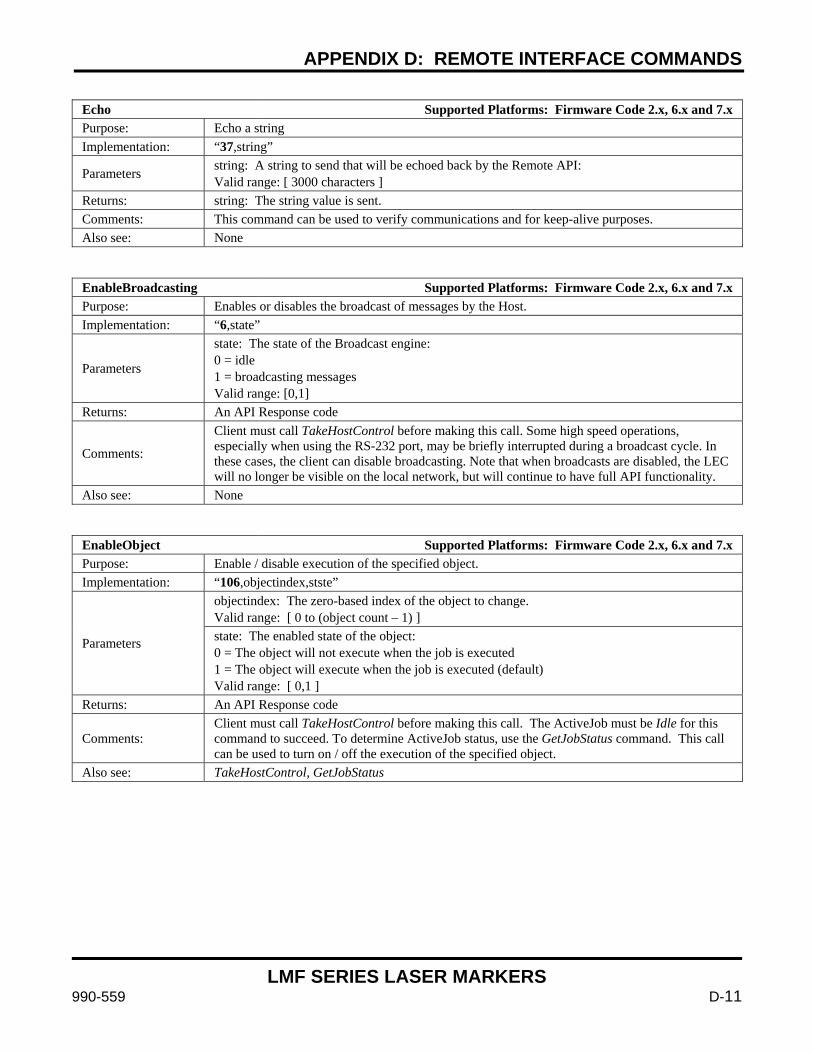
APPENDIX D: REMOTE INTERFACE COMMANDS
LMF SERIES LASER MARKERS
990-559 D-11
Echo Supported Platforms: Firmware Code 2.x, 6.x and 7.x Purpose: Echo a string Implementation: “37,string”
Parameters string: A string to send that will be echoed back by the Remote API: Valid range: [ 3000 characters ]
Returns: string: The string value is sent. Comments: This command can be used to verify communications and for keep-alive purposes. Also see: None
EnableBroadcasting Supported Platforms: Firmware Code 2.x, 6.x and 7.x Purpose: Enables or disables the broadcast of messages by the Host. Implementation: “6,state”
Parameters
state: The state of the Broadcast engine: 0 = idle 1 = broadcasting messages Valid range: [0,1]
Returns: An API Response code
Comments:
Client must call TakeHostControl before making this call. Some high speed operations, especially when using the RS-232 port, may be briefly interrupted during a broadcast cycle. In these cases, the client can disable broadcasting. Note that when broadcasts are disabled, the LEC will no longer be visible on the local network, but will continue to have full API functionality.
Also see: None
EnableObject Supported Platforms: Firmware Code 2.x, 6.x and 7.x Purpose: Enable / disable execution of the specified object. Implementation: “106,objectindex,stste”
Parameters
objectindex: The zero-based index of the object to change. Valid range: [ 0 to (object count – 1) ] state: The enabled state of the object: 0 = The object will not execute when the job is executed 1 = The object will execute when the job is executed (default) Valid range: [ 0,1 ]
Returns: An API Response code
Comments: Client must call TakeHostControl before making this call. The ActiveJob must be Idle for this command to succeed. To determine ActiveJob status, use the GetJobStatus command. This call can be used to turn on / off the execution of the specified object.
Also see: TakeHostControl, GetJobStatus

APPENDIX D: REMOTE INTERFACE COMMANDS
LMF SERIES LASER MARKERS
D-12 990-559
ExecuteJobContinuous Supported Platforms: Firmware Code 2.x, 6.x and 7.x Purpose: Starts the execution of the Active job and will execute the job in an infinite loop. Implementation: “208,cacheobjects”
Parameters
cacheobjects: Flag indicating whether to cache objects in the command FIFO. 0 = do not cache objects, but wait for the StartMark signal. 1 = cache objects immediately 2 = cache all instructions in hardware FIFO (from firmware versions 2.2.27.5, 6.0.1.37 and 7.0.1.37 respectively) Valid range: [ 0,1 ]
Returns: An API Response code
Comments:
Client must call TakeHostControl before making this call. The ActiveJob must be set to a job currently loaded in RAM with a call to MakeJobActive. The LEC will wait to start marking until a hardware StartMark signal is received, and will continue repeating this process until Abort is called. The cacheobjects flag effects how the list of marking objects is processed and sent to the command FIFO. If cacheobjects = 0, the system will wait for the StartMark signal before sending the objects in the list to the command FIFO. This option is useful when using External Control, etc. If cacheobjects = 1, all objects in the job are committed to the command FIFO (up to the memory capacity of the FIFO) as soon as the ExecuteJobContinuous command is received, or the previous cycle has completed. This option is useful when very high speed repetitive performance is required, and the data may change between each mark (serialization, transforms, etc.). If cacheobjects = 2, all objects in the job are committed to the hardware FIFO as soon as the ExecuteJobContinuous command is received. Since all commands are now in the hardware, variable marking data is not possible. This option is useful when very high speed repetitive performance is required, such as in a mark on the fly application with very high speed marks. This command returns a response immediately. If an Interlock has been signaled, the return value is ResetInterlock. The Interlock condition must be cleared, and a call made to Abort to clear the internal Interlock flag. To determine if the ActiveJob is loading, use the GetJobStatus command. To determine if the ActiveJob is executing, use the GetJobExecutionStatus command.
Also see: TakeHostControl, MakeJobActive, GetJobStatus, GetJobExecutionStatus, Abort, LoadFlashJob, LoadUSBJob

APPENDIX D: REMOTE INTERFACE COMMANDS
LMF SERIES LASER MARKERS
990-559 D-13
ExecuteJobOnce Supported Platforms: Firmware Code 2.x, 6.x and 7.x Purpose: Starts the execution of the ActiveJob, and runs it once without repeat. Implementation: “207,cacheobjects”
Parameters
cacheobjects: Flag indicating whether to cache objects in the command FIFO. 0 = do not cache objects, but wait for the StartMark signal. 1 = cache objects immediately Valid range: [ 0, 1]
Returns: An API Response code
Comments:
Client must call TakeHostControl before making this call. The ActiveJob must be set to a job currently loaded in RAM with a call to MakeJobActive. The LEC will wait to start marking until a hardware StartMark signal is received. The job can be stopped by calling Abort at any time. The cacheobjects flag effects how the list of marking objects is processed and sent to the command FIFO. If cacheobjects = 0, the system will wait for the StartMark signal before sending the objects in the list to the command FIFO. This option is useful when using External Control, etc. If cacheobjects = 1, all objects in the job are committed to the command FIFO (up to the memory capacity of the FIFO) as soon as the ExecuteJobOnce command is received. This option is useful when very high speed repetitive performance is required. This command returns a response immediately. If an Interlock has been signaled, the return value is ResetInterlock. The Interlock condition must be cleared, and a call made to Abort to clear the internal Interlock flag. To determine if the ActiveJob is loading, use the GetJobStatus command. To determine if the ActiveJob is executing, use the GetJobExecutionStatus command.
Also see: TakeHostControl, GetJobStatus, GetJobExecutionStatus, Abort, LoadFlashJob, LoadUSBJob
GetActiveJob Supported Platforms: Firmware Code 2.x, 6.x and 7.x Purpose: Gets the name and index value of the currently ActiveJob. Implementation: “218” Parameters None
Returns:
0,value,name if there was no error, where: value = the I/O Job Selection index of the job name = the name of the job or errorcode if there was an error. errorcode is an API response code
Comments: Before interacting with a job, it must be made active with the MakeJobActive command. Also see: LoadFlashJob, LoadUSBJob, MakeJobActive
GetActiveLaser Supported Platforms: Firmware Code 2.x, 6.x and 7.x Purpose: Gets the name of the currently active laser driver file. Implementation: “49” Parameters None
Returns: 0,laserfile if there was no error, or errorcode if there was an error. errorcode is an API response code.
Comments: None Also see: GetLaserFileList, LoadLaserFile
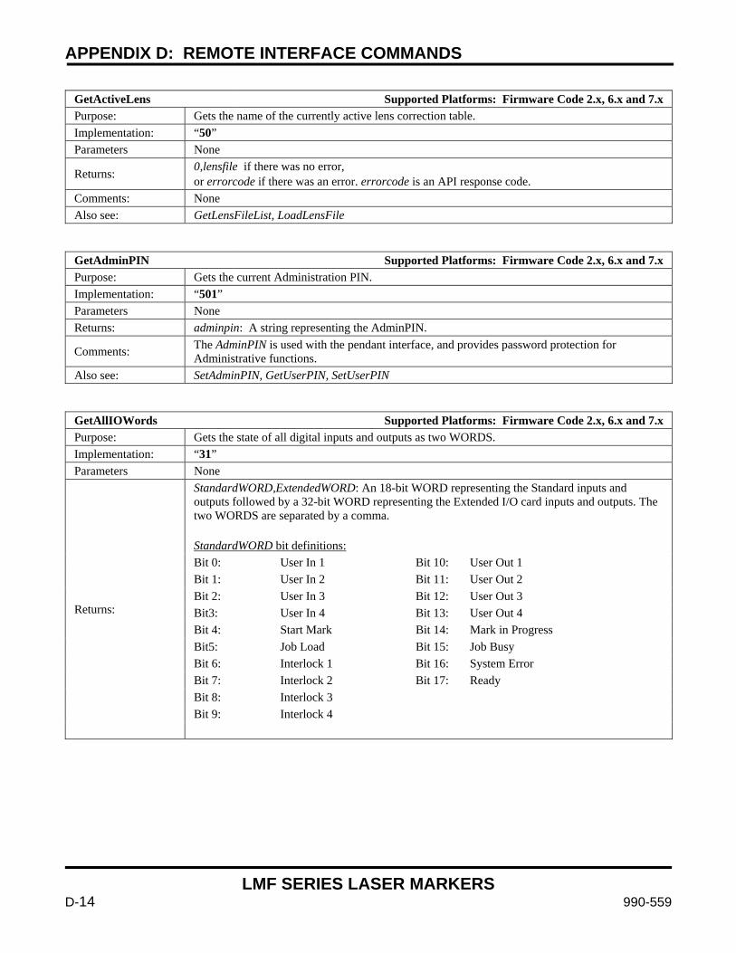
APPENDIX D: REMOTE INTERFACE COMMANDS
LMF SERIES LASER MARKERS
D-14 990-559
GetActiveLens Supported Platforms: Firmware Code 2.x, 6.x and 7.x Purpose: Gets the name of the currently active lens correction table. Implementation: “50” Parameters None
Returns: 0,lensfile if there was no error, or errorcode if there was an error. errorcode is an API response code.
Comments: None Also see: GetLensFileList, LoadLensFile
GetAdminPIN Supported Platforms: Firmware Code 2.x, 6.x and 7.x Purpose: Gets the current Administration PIN. Implementation: “501” Parameters None Returns: adminpin: A string representing the AdminPIN.
Comments: The AdminPIN is used with the pendant interface, and provides password protection for Administrative functions.
Also see: SetAdminPIN, GetUserPIN, SetUserPIN
GetAllIOWords Supported Platforms: Firmware Code 2.x, 6.x and 7.x Purpose: Gets the state of all digital inputs and outputs as two WORDS. Implementation: “31” Parameters None
Returns:
StandardWORD,ExtendedWORD: An 18-bit WORD representing the Standard inputs and outputs followed by a 32-bit WORD representing the Extended I/O card inputs and outputs. The two WORDS are separated by a comma. StandardWORD bit definitions: Bit 0: User In 1 Bit 10: User Out 1 Bit 1: User In 2 Bit 11: User Out 2 Bit 2: User In 3 Bit 12: User Out 3 Bit3: User In 4 Bit 13: User Out 4 Bit 4: Start Mark Bit 14: Mark in Progress Bit5: Job Load Bit 15: Job Busy Bit 6: Interlock 1 Bit 16: System Error Bit 7: Interlock 2 Bit 17: Ready Bit 8: Interlock 3 Bit 9: Interlock 4
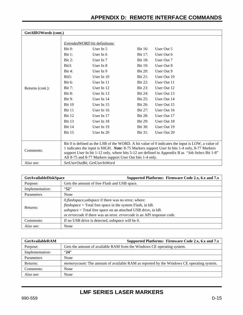
APPENDIX D: REMOTE INTERFACE COMMANDS
LMF SERIES LASER MARKERS
990-559 D-15
GetAllIOWords (cont.)
Returns (cont.):
ExtendedWORD bit definitions: Bit 0: User In 5 Bit 16: User Out 5 Bit 1: User In 6 Bit 17: User Out 6 Bit 2: User In 7 Bit 18: User Out 7 Bit3: User In 8 Bit 19: User Out 8 Bit 4: User In 9 Bit 20: User Out 9 Bit5: User In 10 Bit 21: User Out 10 Bit 6: User In 11 Bit 22: User Out 11 Bit 7: User In 12 Bit 23: User Out 12 Bit 8: User In 13 Bit 24: User Out 13 Bit 9: User In 14 Bit 25: User Out 14 Bit 10 User In 15 Bit 26: User Out 15 Bit 11 User In 16 Bit 27: User Out 16 Bit 12 User In 17 Bit 28: User Out 17 Bit 13 User In 18 Bit 29: User Out 18 Bit 14 User In 19 Bit 30: User Out 19 Bit 15 User In 20 Bit 31: User Out 20
Comments:
Bit 0 is defined as the LSB of the WORD. A bit value of 0 indicates the input is LOW, a value of 1 indicates the input is HIGH. Note: 8-75 Markers support User In bits 1-4 only, 8-77 Markers support User In bit 1-12 only, where bits 5-12 are defined in Appendix B as “Job Select Bit 1-8” All 8-75 and 8-77 Markers support User Out bits 1-4 only.
Also see: SetUserOutBit, GetUserInWord
GetAvailableDiskSpace Supported Platforms: Firmware Code 2.x, 6.x and 7.x Purpose: Gets the amount of free Flash and USB space. Implementation: “52” Parameters None
Returns:
0,flashspace,usbspace if there was no error, where: flashspace = Total free space in the system Flash, in kB. usbspace = Total free space on an attached USB drive, in kB. or errorcode if there was an error. errorcode is an API response code.
Comments: If no USB drive is detected, usbspace will be 0. Also see: None
GetAvailableRAM Supported Platforms: Firmware Code 2.x, 6.x and 7.x Purpose: Gets the amount of available RAM from the Windows CE operating system. Implementation: “24” Parameters None Returns: memorycount: The amount of available RAM as reported by the Windows CE operating system. Comments: None Also see: None
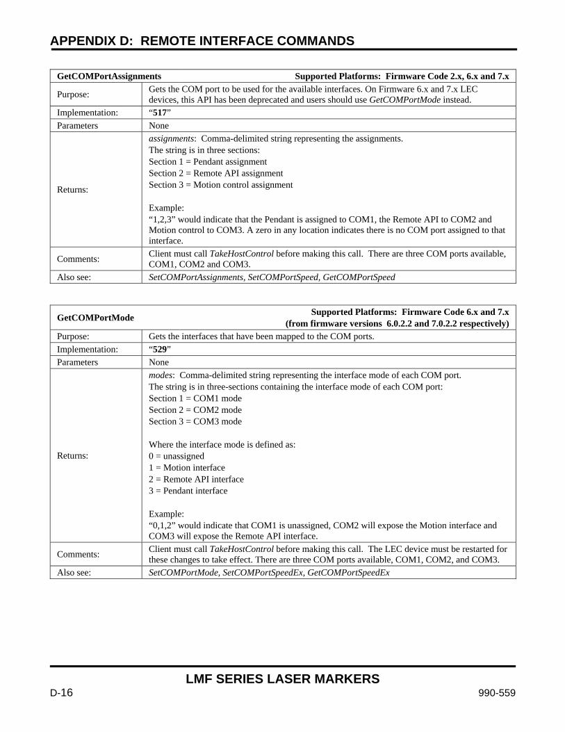
APPENDIX D: REMOTE INTERFACE COMMANDS
LMF SERIES LASER MARKERS
D-16 990-559
GetCOMPortAssignments Supported Platforms: Firmware Code 2.x, 6.x and 7.x
Purpose: Gets the COM port to be used for the available interfaces. On Firmware 6.x and 7.x LEC devices, this API has been deprecated and users should use GetCOMPortMode instead.
Implementation: “517” Parameters None
Returns:
assignments: Comma-delimited string representing the assignments. The string is in three sections: Section 1 = Pendant assignment Section 2 = Remote API assignment Section 3 = Motion control assignment Example: “1,2,3” would indicate that the Pendant is assigned to COM1, the Remote API to COM2 and Motion control to COM3. A zero in any location indicates there is no COM port assigned to that interface.
Comments: Client must call TakeHostControl before making this call. There are three COM ports available, COM1, COM2 and COM3.
Also see: SetCOMPortAssignments, SetCOMPortSpeed, GetCOMPortSpeed
GetCOMPortMode Supported Platforms: Firmware Code 6.x and 7.x (from firmware versions 6.0.2.2 and 7.0.2.2 respectively)
Purpose: Gets the interfaces that have been mapped to the COM ports. Implementation: “529” Parameters None
Returns:
modes: Comma-delimited string representing the interface mode of each COM port. The string is in three-sections containing the interface mode of each COM port: Section 1 = COM1 mode Section 2 = COM2 mode Section 3 = COM3 mode Where the interface mode is defined as: 0 = unassigned 1 = Motion interface 2 = Remote API interface 3 = Pendant interface Example: “0,1,2” would indicate that COM1 is unassigned, COM2 will expose the Motion interface and COM3 will expose the Remote API interface.
Comments: Client must call TakeHostControl before making this call. The LEC device must be restarted for these changes to take effect. There are three COM ports available, COM1, COM2, and COM3.
Also see: SetCOMPortMode, SetCOMPortSpeedEx, GetCOMPortSpeedEx
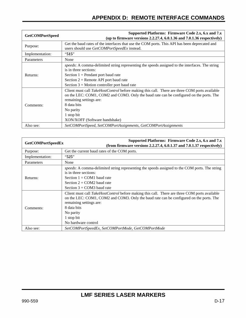
APPENDIX D: REMOTE INTERFACE COMMANDS
LMF SERIES LASER MARKERS
990-559 D-17
GetCOMPortSpeed Supported Platforms: Firmware Code 2.x, 6.x and 7.x (up to firmware versions 2.2.27.4, 6.0.1.36 and 7.0.1.36 respectively)
Purpose: Get the baud rates of the interfaces that use the COM ports. This API has been deprecated and users should use GetCOMPortSpeedEx instead.
Implementation: “515” Parameters None
Returns:
speeds: A comma-delimited string representing the speeds assigned to the interfaces. The string is in three sections: Section 1 = Pendant port baud rate Section 2 = Remote API port baud rate Section 3 = Motion controller port baud rate
Comments:
Client must call TakeHostControl before making this call. There are three COM ports available on the LEC: COM1, COM2 and COM3. Only the baud rate can be configured on the ports. The remaining settings are: 8 data bits No parity 1 stop bit XON/XOFF (Software handshake)
Also see: SetCOMPortSpeed, SetCOMPortAssignments, GetCOMPortAssignments
GetCOMPortSpeedEx Supported Platforms: Firmware Code 2.x, 6.x and 7.x (from firmware versions 2.2.27.4, 6.0.1.37 and 7.0.1.37 respectively)
Purpose: Get the current baud rates of the COM ports. Implementation: “525” Parameters None
Returns:
speeds: A comma-delimited string representing the speeds assigned to the COM ports. The string is in three sections: Section 1 = COM1 baud rate Section 2 = COM2 baud rate Section 3 = COM3 baud rate
Comments:
Client must call TakeHostControl before making this call. There are three COM ports available on the LEC: COM1, COM2 and COM3. Only the baud rate can be configured on the ports. The remaining settings are: 8 data bits No parity 1 stop bit No hardware control
Also see: SetCOMPortSpeedEx, SetCOMPortMode, GetCOMPortMode
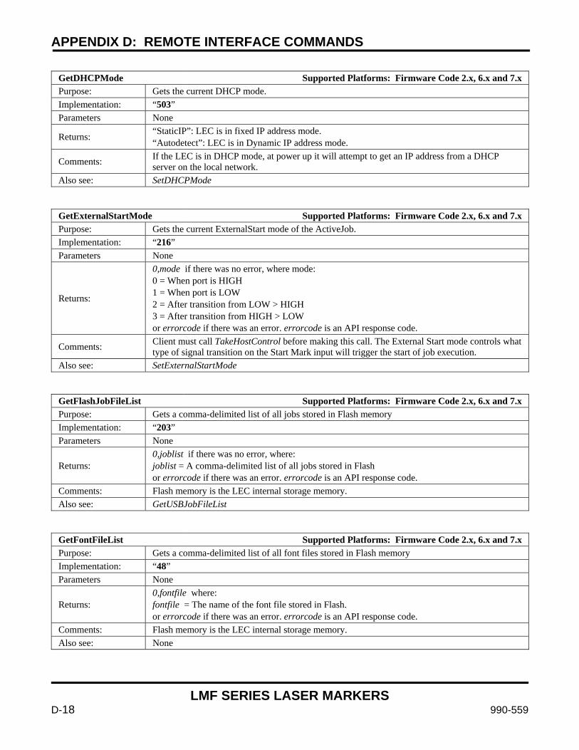
APPENDIX D: REMOTE INTERFACE COMMANDS
LMF SERIES LASER MARKERS
D-18 990-559
GetDHCPMode Supported Platforms: Firmware Code 2.x, 6.x and 7.x Purpose: Gets the current DHCP mode. Implementation: “503” Parameters None
Returns: “StaticIP”: LEC is in fixed IP address mode. “Autodetect”: LEC is in Dynamic IP address mode.
Comments: If the LEC is in DHCP mode, at power up it will attempt to get an IP address from a DHCP server on the local network.
Also see: SetDHCPMode
GetExternalStartMode Supported Platforms: Firmware Code 2.x, 6.x and 7.x Purpose: Gets the current ExternalStart mode of the ActiveJob. Implementation: “216” Parameters None
Returns:
0,mode if there was no error, where mode: 0 = When port is HIGH 1 = When port is LOW 2 = After transition from LOW > HIGH 3 = After transition from HIGH > LOW or errorcode if there was an error. errorcode is an API response code.
Comments: Client must call TakeHostControl before making this call. The External Start mode controls what type of signal transition on the Start Mark input will trigger the start of job execution.
Also see: SetExternalStartMode
GetFlashJobFileList Supported Platforms: Firmware Code 2.x, 6.x and 7.x Purpose: Gets a comma-delimited list of all jobs stored in Flash memory Implementation: “203” Parameters None
Returns: 0,joblist if there was no error, where: joblist = A comma-delimited list of all jobs stored in Flash or errorcode if there was an error. errorcode is an API response code.
Comments: Flash memory is the LEC internal storage memory. Also see: GetUSBJobFileList
GetFontFileList Supported Platforms: Firmware Code 2.x, 6.x and 7.x Purpose: Gets a comma-delimited list of all font files stored in Flash memory Implementation: “48” Parameters None
Returns: 0,fontfile where: fontfile = The name of the font file stored in Flash. or errorcode if there was an error. errorcode is an API response code.
Comments: Flash memory is the LEC internal storage memory. Also see: None
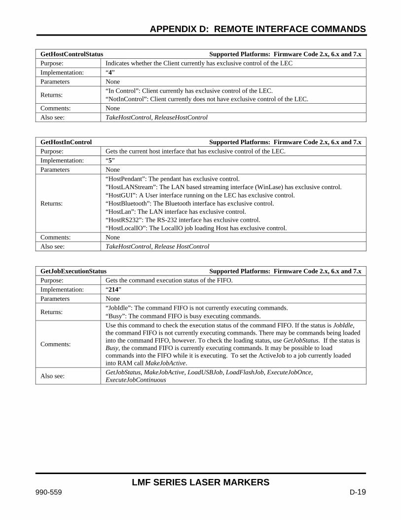
APPENDIX D: REMOTE INTERFACE COMMANDS
LMF SERIES LASER MARKERS
990-559 D-19
GetHostControlStatus Supported Platforms: Firmware Code 2.x, 6.x and 7.x Purpose: Indicates whether the Client currently has exclusive control of the LEC Implementation: “4” Parameters None
Returns: “In Control”: Client currently has exclusive control of the LEC. “NotInControl”: Client currently does not have exclusive control of the LEC.
Comments: None Also see: TakeHostControl, ReleaseHostControl
GetHostInControl Supported Platforms: Firmware Code 2.x, 6.x and 7.x Purpose: Gets the current host interface that has exclusive control of the LEC. Implementation: “5” Parameters None
Returns:
“HostPendant”: The pendant has exclusive control. ”HostLANStream”: The LAN based streaming interface (WinLase) has exclusive control. “HostGUI”: A User interface running on the LEC has exclusive control. “HostBluetooth”: The Bluetooth interface has exclusive control. “HostLan”: The LAN interface has exclusive control. “HostRS232”: The RS-232 interface has exclusive control. “HostLocalIO”: The LocalIO job loading Host has exclusive control.
Comments: None Also see: TakeHostControl, Release HostControl
GetJobExecutionStatus Supported Platforms: Firmware Code 2.x, 6.x and 7.x Purpose: Gets the command execution status of the FIFO. Implementation: “214” Parameters None
Returns: “JobIdle”: The command FIFO is not currently executing commands. “Busy”: The command FIFO is busy executing commands.
Comments:
Use this command to check the execution status of the command FIFO. If the status is JobIdle, the command FIFO is not currently executing commands. There may be commands being loaded into the command FIFO, however. To check the loading status, use GetJobStatus. If the status is Busy, the command FIFO is currently executing commands. It may be possible to load commands into the FIFO while it is executing. To set the ActiveJob to a job currently loaded into RAM call MakeJobActive.
Also see: GetJobStatus, MakeJobActive, LoadUSBJob, LoadFlashJob, ExecuteJobOnce, ExecuteJobContinuous
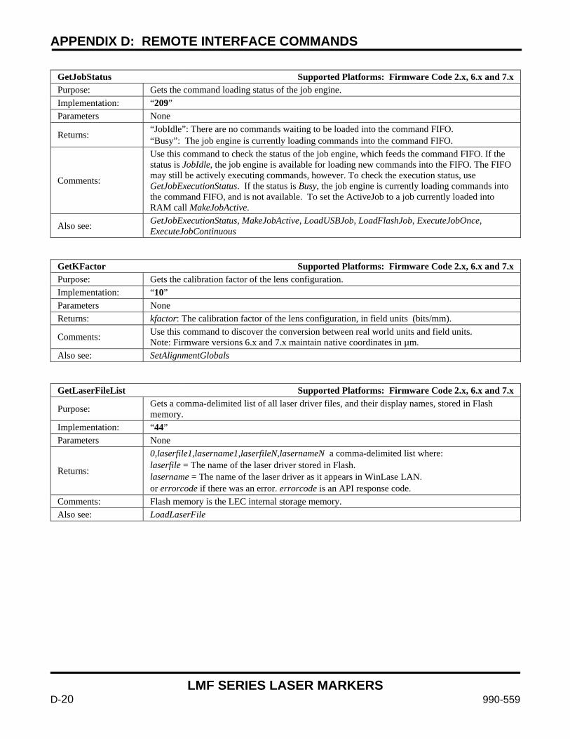
APPENDIX D: REMOTE INTERFACE COMMANDS
LMF SERIES LASER MARKERS
D-20 990-559
GetJobStatus Supported Platforms: Firmware Code 2.x, 6.x and 7.x Purpose: Gets the command loading status of the job engine. Implementation: “209” Parameters None
Returns: “JobIdle”: There are no commands waiting to be loaded into the command FIFO. “Busy”: The job engine is currently loading commands into the command FIFO.
Comments:
Use this command to check the status of the job engine, which feeds the command FIFO. If the status is JobIdle, the job engine is available for loading new commands into the FIFO. The FIFO may still be actively executing commands, however. To check the execution status, use GetJobExecutionStatus. If the status is Busy, the job engine is currently loading commands into the command FIFO, and is not available. To set the ActiveJob to a job currently loaded into RAM call MakeJobActive.
Also see: GetJobExecutionStatus, MakeJobActive, LoadUSBJob, LoadFlashJob, ExecuteJobOnce, ExecuteJobContinuous
GetKFactor Supported Platforms: Firmware Code 2.x, 6.x and 7.x Purpose: Gets the calibration factor of the lens configuration. Implementation: “10” Parameters None Returns: kfactor: The calibration factor of the lens configuration, in field units (bits/mm).
Comments: Use this command to discover the conversion between real world units and field units. Note: Firmware versions 6.x and 7.x maintain native coordinates in µm.
Also see: SetAlignmentGlobals
GetLaserFileList Supported Platforms: Firmware Code 2.x, 6.x and 7.x
Purpose: Gets a comma-delimited list of all laser driver files, and their display names, stored in Flash memory.
Implementation: “44” Parameters None
Returns:
0,laserfile1,lasername1,laserfileN,lasernameN a comma-delimited list where: laserfile = The name of the laser driver stored in Flash. lasername = The name of the laser driver as it appears in WinLase LAN. or errorcode if there was an error. errorcode is an API response code.
Comments: Flash memory is the LEC internal storage memory. Also see: LoadLaserFile
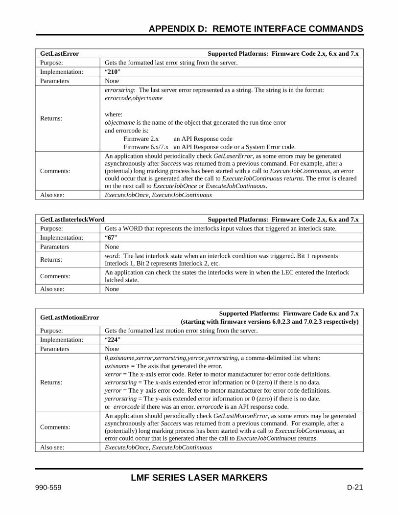
APPENDIX D: REMOTE INTERFACE COMMANDS
LMF SERIES LASER MARKERS
990-559 D-21
GetLastError Supported Platforms: Firmware Code 2.x, 6.x and 7.x Purpose: Gets the formatted last error string from the server. Implementation: “210” Parameters None
Returns:
errorstring: The last server error represented as a string. The string is in the format: errorcode,objectname where: objectname is the name of the object that generated the run time error and errorcode is: Firmware 2.x an API Response code Firmware 6.x/7.x an API Response code or a System Error code.
Comments:
An application should periodically check GetLaserError, as some errors may be generated asynchronously after Success was returned from a previous command. For example, after a (potential) long marking process has been started with a call to ExecuteJobContinuous, an error could occur that is generated after the call to ExecuteJobContinuous returns. The error is cleared on the next call to ExecuteJobOnce or ExecuteJobContinuous.
Also see: ExecuteJobOnce, ExecuteJobContinuous
GetLastInterlockWord Supported Platforms: Firmware Code 2.x, 6.x and 7.x Purpose: Gets a WORD that represents the interlocks input values that triggered an interlock state. Implementation: “67” Parameters None
Returns: word: The last interlock state when an interlock condition was triggered. Bit 1 represents Interlock 1, Bit 2 represents Interlock 2, etc.
Comments: An application can check the states the interlocks were in when the LEC entered the Interlock latched state.
Also see: None
GetLastMotionError Supported Platforms: Firmware Code 6.x and 7.x (starting with firmware versions 6.0.2.3 and 7.0.2.3 respectively)
Purpose: Gets the formatted last motion error string from the server. Implementation: “224” Parameters None
Returns:
0,axisname,xerror,xerrorstring,yerror,yerrorstring, a comma-delimited list where: axisname = The axis that generated the error. xerror = The x-axis error code. Refer to motor manufacturer for error code definitions. xerrorstring = The x-axis extended error information or 0 (zero) if there is no data. yerror = The y-axis error code. Refer to motor manufacturer for error code definitions. yerrorstring = The y-axis extended error information or 0 (zero) if there is no date. or errorcode if there was an error. errorcode is an API response code.
Comments:
An application should periodically check GetLastMotionError, as some errors may be generated asynchronously after Success was returned from a previous command. For example, after a (potentially) long marking process has been started with a call to ExecuteJobContinuous, an error could occur that is generated after the call to ExecuteJobContinuous returns.
Also see: ExecuteJobOnce, ExecuteJobContinuous
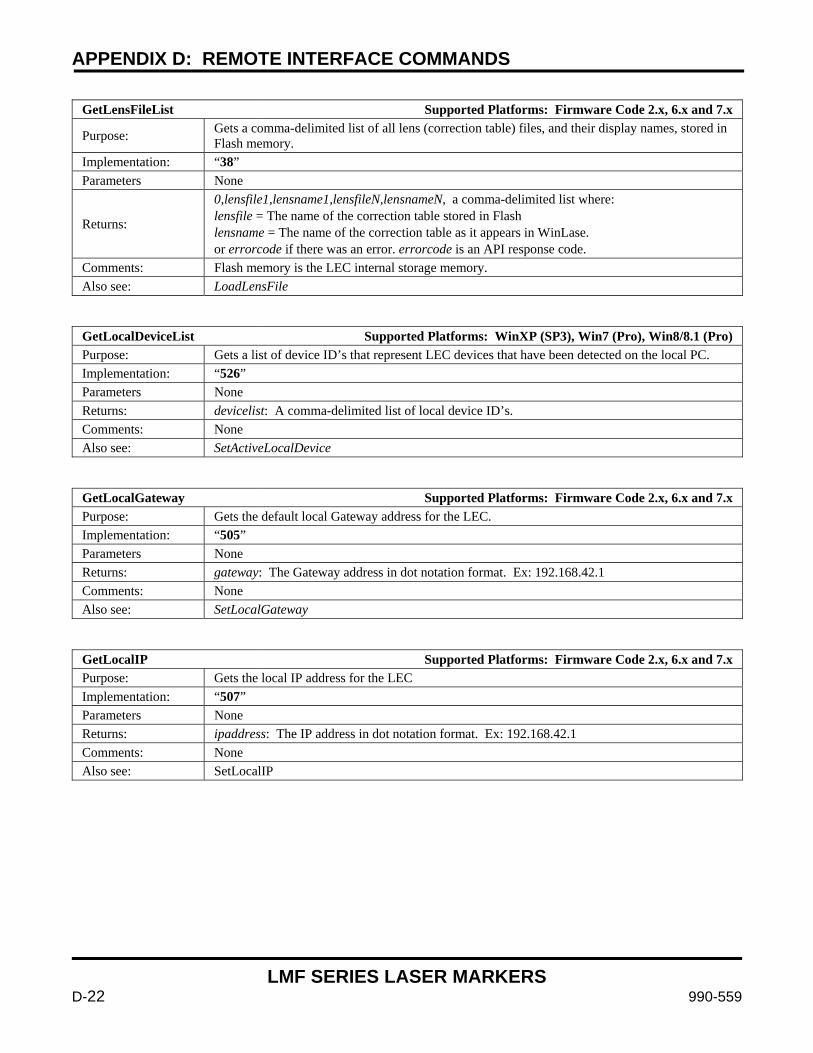
APPENDIX D: REMOTE INTERFACE COMMANDS
LMF SERIES LASER MARKERS
D-22 990-559
GetLensFileList Supported Platforms: Firmware Code 2.x, 6.x and 7.x
Purpose: Gets a comma-delimited list of all lens (correction table) files, and their display names, stored in Flash memory.
Implementation: “38” Parameters None
Returns:
0,lensfile1,lensname1,lensfileN,lensnameN, a comma-delimited list where: lensfile = The name of the correction table stored in Flash lensname = The name of the correction table as it appears in WinLase. or errorcode if there was an error. errorcode is an API response code.
Comments: Flash memory is the LEC internal storage memory. Also see: LoadLensFile
GetLocalDeviceList Supported Platforms: WinXP (SP3), Win7 (Pro), Win8/8.1 (Pro) Purpose: Gets a list of device ID’s that represent LEC devices that have been detected on the local PC. Implementation: “526” Parameters None Returns: devicelist: A comma-delimited list of local device ID’s. Comments: None Also see: SetActiveLocalDevice
GetLocalGateway Supported Platforms: Firmware Code 2.x, 6.x and 7.x Purpose: Gets the default local Gateway address for the LEC. Implementation: “505” Parameters None Returns: gateway: The Gateway address in dot notation format. Ex: 192.168.42.1 Comments: None Also see: SetLocalGateway
GetLocalIP Supported Platforms: Firmware Code 2.x, 6.x and 7.x Purpose: Gets the local IP address for the LEC Implementation: “507” Parameters None Returns: ipaddress: The IP address in dot notation format. Ex: 192.168.42.1 Comments: None Also see: SetLocalIP
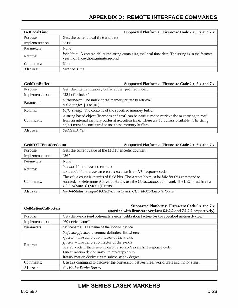
APPENDIX D: REMOTE INTERFACE COMMANDS
LMF SERIES LASER MARKERS
990-559 D-23
GetLocalTime Supported Platforms: Firmware Code 2.x, 6.x and 7.x Purpose: Gets the current local time and date Implementation: “519” Parameters None
Returns: localtime: A comma-delimited string containing the local time data. The string is in the format: year,month,day,hour,minute,second
Comments: None Also see: SetLocalTime
GetMemBuffer Supported Platforms: Firmware Code 2.x, 6.x and 7.x Purpose: Gets the internal memory buffer at the specified index. Implementation: “23,bufferindex”
Parameters bufferindex: The index of the memory buffer to retrieve Valid range: [ 1 to 10 ]
Returns: bufferstring: The contents of the specified memory buffer
Comments: A string based object (barcodes and text) can be configured to retrieve the next string to mark from an internal memory buffer at execution time. There are 10 buffers available. The string object must be configured to use these memory buffers.
Also see: SetMemBuffer
GetMOTFEncoderCount Supported Platforms: Firmware Code 2.x, 6.x and 7.x Purpose: Gets the current value of the MOTF encoder counter. Implementation: “36” Parameters None
Returns: 0,count if there was no error, or errorcode if there was an error. errorcode is an API response code.
Comments: The value count is in units of field bits. The ActiveJob must be Idle for this command to succeed. To determine ActiveJobStatus, use the GetJobStatus command. The LEC must have a valid Advanced (MOTF) license.
Also see: GetJobStatus, SampleMOTFEncoderCount, ClearMOTFEncoderCount
GetMotionCalFactors Supported Platforms: Firmware Code 6.x and 7.x (starting with firmware versions 6.0.2.2 and 7.0.2.2 respectively)
Purpose: Gets the x-axis (and optionally y-axis) calibration factors for the specified motion device. Implementation: “60,devicename” Parameters devicename: The name of the motion device
Returns:
0,xfactor,yfactor, a comma-delimited list where: xfactor = The calibration factor of the x-axis yfactor = The calibration factor of the y-axis or errorcode if there was an error. errorcode is an API response code. Linear motion device units: micro-steps / mm Rotary motion device units: micro-steps / degree
Comments: Use this command to discover the conversion between real world units and motor steps. Also see: GetMotionDeviceNames
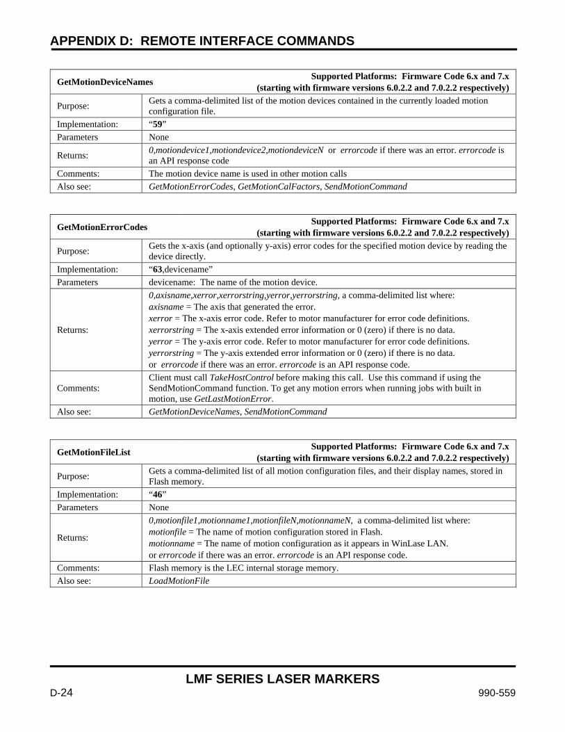
APPENDIX D: REMOTE INTERFACE COMMANDS
LMF SERIES LASER MARKERS
D-24 990-559
GetMotionDeviceNames Supported Platforms: Firmware Code 6.x and 7.x (starting with firmware versions 6.0.2.2 and 7.0.2.2 respectively)
Purpose: Gets a comma-delimited list of the motion devices contained in the currently loaded motion configuration file.
Implementation: “59” Parameters None
Returns: 0,motiondevice1,motiondevice2,motiondeviceN or errorcode if there was an error. errorcode is an API response code
Comments: The motion device name is used in other motion calls Also see: GetMotionErrorCodes, GetMotionCalFactors, SendMotionCommand
GetMotionErrorCodes Supported Platforms: Firmware Code 6.x and 7.x (starting with firmware versions 6.0.2.2 and 7.0.2.2 respectively)
Purpose: Gets the x-axis (and optionally y-axis) error codes for the specified motion device by reading the device directly.
Implementation: “63,devicename” Parameters devicename: The name of the motion device.
Returns:
0,axisname,xerror,xerrorstring,yerror,yerrorstring, a comma-delimited list where: axisname = The axis that generated the error. xerror = The x-axis error code. Refer to motor manufacturer for error code definitions. xerrorstring = The x-axis extended error information or 0 (zero) if there is no data. yerror = The y-axis error code. Refer to motor manufacturer for error code definitions. yerrorstring = The y-axis extended error information or 0 (zero) if there is no data. or errorcode if there was an error. errorcode is an API response code.
Comments: Client must call TakeHostControl before making this call. Use this command if using the SendMotionCommand function. To get any motion errors when running jobs with built in motion, use GetLastMotionError.
Also see: GetMotionDeviceNames, SendMotionCommand
GetMotionFileList Supported Platforms: Firmware Code 6.x and 7.x (starting with firmware versions 6.0.2.2 and 7.0.2.2 respectively)
Purpose: Gets a comma-delimited list of all motion configuration files, and their display names, stored in Flash memory.
Implementation: “46” Parameters None
Returns:
0,motionfile1,motionname1,motionfileN,motionnameN, a comma-delimited list where: motionfile = The name of motion configuration stored in Flash. motionname = The name of motion configuration as it appears in WinLase LAN. or errorcode if there was an error. errorcode is an API response code.
Comments: Flash memory is the LEC internal storage memory. Also see: LoadMotionFile
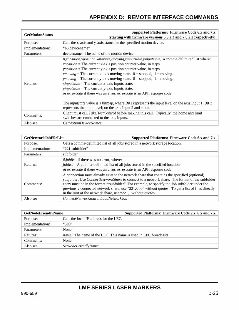
APPENDIX D: REMOTE INTERFACE COMMANDS
LMF SERIES LASER MARKERS
990-559 D-25
GetMotionStatus Supported Platforms: Firmware Code 6.x and 7.x (starting with firmware versions 6.0.2.2 and 7.0.2.2 respectively)
Purpose: Gets the x-axis and y-axis status for the specified motion device. Implementation: “65,devicename” Parameters devicename: The name of the motion device.
Returns:
0,xposition,yposition,xmoving,ymoving,xinputstate,yinputstate, a comma-delimited list where: xposition = The current x-axis position counter value, in steps. yposition = The current y-axis position counter value, in steps. xmoving = The current x-axis moving state. 0 = stopped, 1 = moving. ymoving = The current y-axis moving state. 0 = stopped, 1 = moving. xinputstate = The current x-axis Inputs state. yinputstate = The current y-axis Inputs state. or errorcode if there was an error. errorcode is an API response code. The inputstate value is a bitmap, where Bit1 represents the input level on the axis Input 1, Bit 2 represents the input level; on the axis Input 2 and so on.
Comments: Client must call TakeHostControl before making this call. Typically, the home and limit switches are connected to the axis Inputs.
Also see: GetMotionDeviceNames
GetNetworkJobFileList Supported Platforms: Firmware Code 6.x and 7.x Purpose: Gets a comma-delimited list of all jobs stored in a network storage location. Implementation: “221,subfolder” Parameters subfolder
Returns: 0,joblist if there was no error, where: joblist = A comma-delimited list of all jobs stored in the specified location or errorcode if there was an error. errorcode is an API response code.
Comments:
A connection must already exist to the network share that contains the specified (optional) subfolder. Use ConnectNetworkShare to connect to a network share. The format of the subfolder entry must be in the format “\subfolder”. For example, to specify the Job subfolder under the previously connected network share, use “221,\Job” without quotes. To get a list of files directly in the root of the network share, use “221,” without quotes.
Also see: ConnectNetworkShare, LoadNetworkJob
GetNodeFriendlyName Supported Platforms: Firmware Code 2.x, 6.x and 7.x Purpose: Gets the local IP address for the LEC. Implementation: “509” Parameters None Returns: name: The name of the LEC. This name is used in LEC broadcasts. Comments: None Also see: SetNodeFriendlyName

APPENDIX D: REMOTE INTERFACE COMMANDS
LMF SERIES LASER MARKERS
D-26 990-559
GetObjectCenter Supported Platforms: Firmware Code 2.x, 6.x and 7.x Purpose: Gets the geometric center of the specified object in field units. Implementation: “104,objectindex”
Parameters objectindex: The zero-based index of the object. Valid range: [ 0 to (object count – 1) ]
Returns:
x,y where: x = the x coordinate of the object center y = the y coordinate of the object center Units: [bits]
Comments:
Client must call TakeHostControl before making this call. The Object at objectindex must be a valid marking object type. The ActiveJob must be Idle for this command to succeed. To determine the ActiveJob status, use the GetJobStatus command. The marking field is described using a Cartesian coordinate system, with: Center: [(0,0)] Bottom Left: [(-fieldsize / 2, -fieldsize / 2)] bits Top Right: [(fieldsize / 2, fieldsize / 2)] bits
Also see: GetObjectRect, TransformObject, GetObjectCount, GetObjectType
GetObjectCount Supported Platforms: Firmware Code 2.x, 6.x and 7.x Purpose: Gets the number of objects in the ActiveJob. Implementation: “211” Parameters None
Returns: 0,objectcount if there was no error, or errorcode if there was an error. errorcode is an API response code.
Comments: Client must call TakeHostControl before making this call. There must be an ActiveJob. Also see: GetObjectType
GetObjectMarkMode Supported Platform: Firmware Code 2.x Purpose: Gets the MarkMode for the specified object. Implementation: “120,objectindex”
Parameters objectindex: The zero-based index of the object. Valid range: [ 0 to (object count – 1) ]
Returns:
0,markmode if there was no error, or errorcode if there was an error. errorcode is an API response code. markmode can be one of the following values: 0 = MarkOnce 1 = MarkMultiple 2 = TwoPassCutClean 3 = ThreePassCutClean 4 = FourPassCutClean
Comments: None Also see: SetObjectMarkMode, SetObjectNumPasses, GetObjectNumPasses
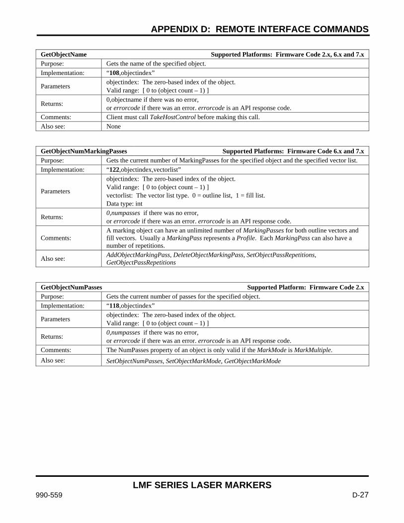
APPENDIX D: REMOTE INTERFACE COMMANDS
LMF SERIES LASER MARKERS
990-559 D-27
GetObjectName Supported Platforms: Firmware Code 2.x, 6.x and 7.x Purpose: Gets the name of the specified object. Implementation: “108,objectindex”
Parameters objectindex: The zero-based index of the object. Valid range: [ 0 to (object count – 1) ]
Returns: 0,objectname if there was no error, or errorcode if there was an error. errorcode is an API response code.
Comments: Client must call TakeHostControl before making this call. Also see: None
GetObjectNumMarkingPasses Supported Platforms: Firmware Code 6.x and 7.x Purpose: Gets the current number of MarkingPasses for the specified object and the specified vector list. Implementation: “122,objectindex,vectorlist”
Parameters
objectindex: The zero-based index of the object. Valid range: [ 0 to (object count – 1) ] vectorlist: The vector list type. 0 = outline list, 1 = fill list. Data type: int
Returns: 0,numpasses if there was no error, or errorcode if there was an error. errorcode is an API response code.
Comments: A marking object can have an unlimited number of MarkingPasses for both outline vectors and fill vectors. Usually a MarkingPass represents a Profile. Each MarkingPass can also have a number of repetitions.
Also see: AddObjectMarkingPass, DeleteObjectMarkingPass, SetObjectPassRepetitions, GetObjectPassRepetitions
GetObjectNumPasses Supported Platform: Firmware Code 2.x Purpose: Gets the current number of passes for the specified object. Implementation: “118,objectindex”
Parameters objectindex: The zero-based index of the object. Valid range: [ 0 to (object count – 1) ]
Returns: 0,numpasses if there was no error, or errorcode if there was an error. errorcode is an API response code.
Comments: The NumPasses property of an object is only valid if the MarkMode is MarkMultiple. Also see: SetObjectNumPasses, SetObjectMarkMode, GetObjectMarkMode
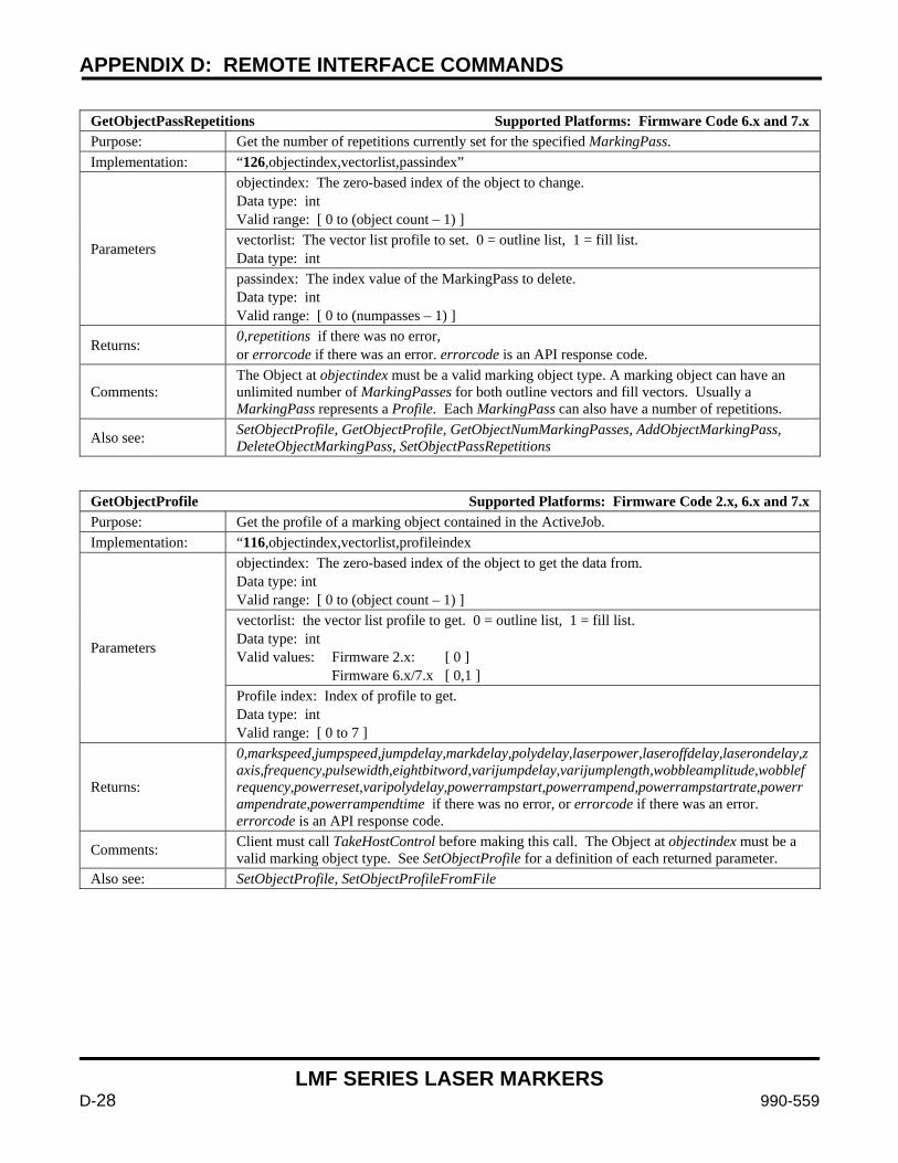
APPENDIX D: REMOTE INTERFACE COMMANDS
LMF SERIES LASER MARKERS
D-28 990-559
GetObjectPassRepetitions Supported Platforms: Firmware Code 6.x and 7.x Purpose: Get the number of repetitions currently set for the specified MarkingPass. Implementation: “126,objectindex,vectorlist,passindex”
Parameters
objectindex: The zero-based index of the object to change. Data type: int Valid range: [ 0 to (object count – 1) ] vectorlist: The vector list profile to set. 0 = outline list, 1 = fill list. Data type: int passindex: The index value of the MarkingPass to delete. Data type: int Valid range: [ 0 to (numpasses – 1) ]
Returns: 0,repetitions if there was no error, or errorcode if there was an error. errorcode is an API response code.
Comments: The Object at objectindex must be a valid marking object type. A marking object can have an unlimited number of MarkingPasses for both outline vectors and fill vectors. Usually a MarkingPass represents a Profile. Each MarkingPass can also have a number of repetitions.
Also see: SetObjectProfile, GetObjectProfile, GetObjectNumMarkingPasses, AddObjectMarkingPass, DeleteObjectMarkingPass, SetObjectPassRepetitions
GetObjectProfile Supported Platforms: Firmware Code 2.x, 6.x and 7.x Purpose: Get the profile of a marking object contained in the ActiveJob. Implementation: “116,objectindex,vectorlist,profileindex
Parameters
objectindex: The zero-based index of the object to get the data from. Data type: int Valid range: [ 0 to (object count – 1) ] vectorlist: the vector list profile to get. 0 = outline list, 1 = fill list. Data type: int Valid values: Firmware 2.x: [ 0 ] Firmware 6.x/7.x [ 0,1 ] Profile index: Index of profile to get. Data type: int Valid range: [ 0 to 7 ]
Returns:
0,markspeed,jumpspeed,jumpdelay,markdelay,polydelay,laserpower,laseroffdelay,laserondelay,zaxis,frequency,pulsewidth,eightbitword,varijumpdelay,varijumplength,wobbleamplitude,wobblefrequency,powerreset,varipolydelay,powerrampstart,powerrampend,powerrampstartrate,powerrampendrate,powerrampendtime if there was no error, or errorcode if there was an error. errorcode is an API response code.
Comments: Client must call TakeHostControl before making this call. The Object at objectindex must be a valid marking object type. See SetObjectProfile for a definition of each returned parameter.
Also see: SetObjectProfile, SetObjectProfileFromFile
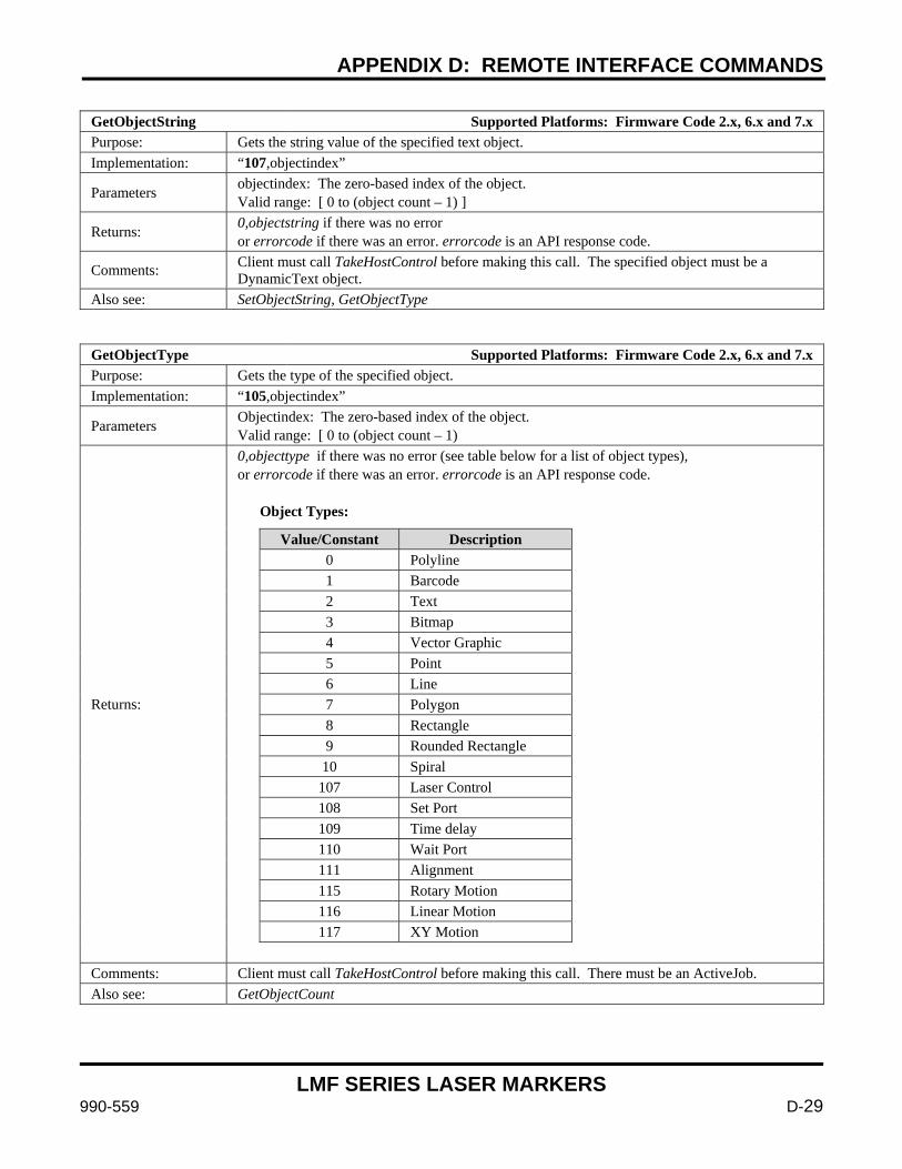
APPENDIX D: REMOTE INTERFACE COMMANDS
LMF SERIES LASER MARKERS
990-559 D-29
GetObjectString Supported Platforms: Firmware Code 2.x, 6.x and 7.x Purpose: Gets the string value of the specified text object. Implementation: “107,objectindex”
Parameters objectindex: The zero-based index of the object. Valid range: [ 0 to (object count – 1) ]
Returns: 0,objectstring if there was no error or errorcode if there was an error. errorcode is an API response code.
Comments: Client must call TakeHostControl before making this call. The specified object must be a DynamicText object.
Also see: SetObjectString, GetObjectType
GetObjectType Supported Platforms: Firmware Code 2.x, 6.x and 7.x Purpose: Gets the type of the specified object. Implementation: “105,objectindex”
Parameters Objectindex: The zero-based index of the object. Valid range: [ 0 to (object count – 1)
Returns:
0,objecttype if there was no error (see table below for a list of object types), or errorcode if there was an error. errorcode is an API response code. Object Types:
Value/Constant Description 0 Polyline 1 Barcode 2 Text 3 Bitmap 4 Vector Graphic 5 Point 6 Line 7 Polygon 8 Rectangle 9 Rounded Rectangle 10 Spiral 107 Laser Control 108 Set Port 109 Time delay 110 Wait Port 111 Alignment 115 Rotary Motion 116 Linear Motion 117 XY Motion
Comments: Client must call TakeHostControl before making this call. There must be an ActiveJob. Also see: GetObjectCount
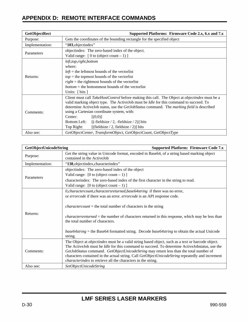
APPENDIX D: REMOTE INTERFACE COMMANDS
LMF SERIES LASER MARKERS
D-30 990-559
GetObjectRect Supported Platforms: Firmware Code 2.x, 6.x and 7.x Purpose: Gets the coordinates of the bounding rectangle for the specified object Implementation: “103,objectindex”
Parameters objectindex: The zero-based index of the object. Valid range: [ 0 to (object count – 1) ]
Returns:
left,top,right,bottom where: left = the leftmost bounds of the vectorlist top = the topmost bounds of the vectorlist right = the rightmost bounds of the vectorlist bottom = the bottommost bounds of the vectorlist Units: [ bits ]
Comments:
Client must call TakeHostControl before making this call. The Object at objectindex must be a valid marking object type. The ActiveJob must be Idle for this command to succeed. To determine ActiveJob status, use the GetJobStatus command. The marking field is described using a Cartesian coordinate system, with: Center: [(0,0)] Bottom Left: [(-fieldsize / 2, -fieldsize / 2)] bits Top Right: [(fieldsize / 2, fieldsize / 2)] bits
Also see: GetObjectCenter, TransformObject, GetObjectCount, GetObjectType
GetObjectUnicodeString Supported Platform: Firmware Code 7.x
Purpose: Get the string value in Unicode format, encoded in Base64, of a string based marking object contained in the ActiveJob
Implementation: “138,objectindex,characterindex”
Parameters
objectindex: The zero-based index of the object Valid range: [0 to (object count – 1) ] characterindex: The zero-based index of the first character in the string to read. Valid range: [0 to (object count – 1) ]
Returns:
0,charactercount,charactersreturned,base64string if there was no error, or errorcode if there was an error. errorcode is an API response code. charactercount = the total number of characters in the string charactersreturned = the number of characters returned in this response, which may be less than the total number of characters. base64string = the Base64 formatted string. Decode base64string to obtain the actual Unicode string.
Comments:
The Object at objectindex must be a valid string based object, such as a text or barcode object. The ActiveJob must be Idle for this command to succeed. To determine ActiveJobstatus, use the GetJobStatus command. GetObjectUnicodeString may return less than the total number of characters contained in the actual string. Call GetObjectUnicodeString repeatedly and increment characterindex to retrieve all the characters in the string.
Also see: SetObjectUnicodeString

APPENDIX D: REMOTE INTERFACE COMMANDS
LMF SERIES LASER MARKERS
990-559 D-31
GetObjectUserData Supported Platforms: Firmware Code 2.x, 6.x and 7.x Purpose: Gets the specified User Data stored by the specified object. Implementation: “110,objectindex,dataindex”
Parameters
objectindex: The zero-based index of the object Valid range: [0 to (object count – 1) ] dataindex: The zero-based index of the data. Valid range: [ 0 and 1 ]
Returns: 0,datastring if there was no error, or errorcode if there was an error. errorcode is an API response code.
Comments:
Client must call TakeHostControl before making this call. All objects have two string based data buffers (with index 0 and 1) available for the programmer to use for any reason. The maximum size of the buffers is 256. The data buffers are cleared when the object is first loaded, and are not persistent between job loads. The object does not use the data contained in the buffers.
Also see: SetObjectUserData
GetObjectVectors Supported Platform: Firmware Code 7.x
Purpose: Gets an array of floating point values, encoded as a Base64 string, that describe the outline vector list of the specified object.
Implementation: “139,objectindex,entryindex”
Parameters
objectindex: The zero-based index of the object Valid range: [0 to (object count – 1) ] entryindex: The zero-based index of the list entries Valid range: [0 to (totalentries – 1) ]
Returns:
0,vectorcount,vectorsreturned,base64string if there was no error, or errorcode if there was an error. errorcode is an API response code. vectorcount = the total number of outline vectors vectorsreturned = the number of vectors returned in this response, which may be less than the total number of vectors. base64string = the Base64 formatted string. Decode base64string to obtain the floating point array. The dimension of the float array is vectorsreturned.
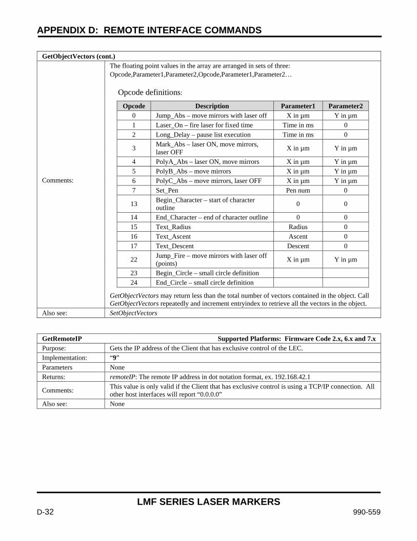
APPENDIX D: REMOTE INTERFACE COMMANDS
LMF SERIES LASER MARKERS
D-32 990-559
GetObjectVectors (cont.)
Comments:
The floating point values in the array are arranged in sets of three: Opcode,Parameter1,Parameter2,Opcode,Parameter1,Parameter2… Opcode definitions:
Opcode Description Parameter1 Parameter2 0 Jump_Abs – move mirrors with laser off X in µm Y in µm 1 Laser_On – fire laser for fixed time Time in ms 0 2 Long_Delay – pause list execution Time in ms 0
3 Mark_Abs – laser ON, move mirrors, laser OFF X in µm Y in µm
4 PolyA_Abs – laser ON, move mirrors X in µm Y in µm 5 PolyB_Abs – move mirrors X in µm Y in µm 6 PolyC_Abs – move mirrors, laser OFF X in µm Y in µm 7 Set_Pen Pen num 0
13 Begin_Character – start of character outline 0 0
14 End_Character – end of character outline 0 0 15 Text_Radius Radius 0 16 Text_Ascent Ascent 0 17 Text_Descent Descent 0
22 Jump_Fire – move mirrors with laser off (points) X in µm Y in µm
23 Begin_Circle – small circle definition 24 End_Circle – small circle definition
GetObjectVectors may return less than the total number of vectors contained in the object. Call GetObjectVectors repeatedly and increment entryindex to retrieve all the vectors in the object.
Also see: SetObjectVectors
GetRemoteIP Supported Platforms: Firmware Code 2.x, 6.x and 7.x Purpose: Gets the IP address of the Client that has exclusive control of the LEC. Implementation: “9” Parameters None Returns: remoteIP: The remote IP address in dot notation format, ex. 192.168.42.1
Comments: This value is only valid if the Client that has exclusive control is using a TCP/IP connection. All other host interfaces will report “0.0.0.0”
Also see: None
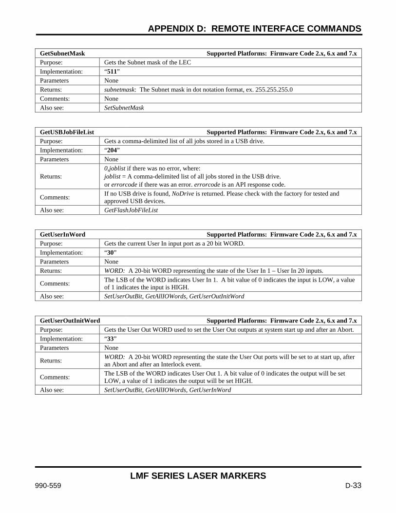
APPENDIX D: REMOTE INTERFACE COMMANDS
LMF SERIES LASER MARKERS
990-559 D-33
GetSubnetMask Supported Platforms: Firmware Code 2.x, 6.x and 7.x Purpose: Gets the Subnet mask of the LEC Implementation: “511” Parameters None Returns: subnetmask: The Subnet mask in dot notation format, ex. 255.255.255.0 Comments: None Also see: SetSubnetMask
GetUSBJobFileList Supported Platforms: Firmware Code 2.x, 6.x and 7.x Purpose: Gets a comma-delimited list of all jobs stored in a USB drive. Implementation: “204” Parameters None
Returns: 0,joblist if there was no error, where: joblist = A comma-delimited list of all jobs stored in the USB drive. or errorcode if there was an error. errorcode is an API response code.
Comments: If no USB drive is found, NoDrive is returned. Please check with the factory for tested and approved USB devices.
Also see: GetFlashJobFileList
GetUserInWord Supported Platforms: Firmware Code 2.x, 6.x and 7.x Purpose: Gets the current User In input port as a 20 bit WORD. Implementation: “30” Parameters None Returns: WORD: A 20-bit WORD representing the state of the User In 1 – User In 20 inputs.
Comments: The LSB of the WORD indicates User In 1. A bit value of 0 indicates the input is LOW, a value of 1 indicates the input is HIGH.
Also see: SetUserOutBit, GetAllIOWords, GetUserOutInitWord
GetUserOutInitWord Supported Platforms: Firmware Code 2.x, 6.x and 7.x Purpose: Gets the User Out WORD used to set the User Out outputs at system start up and after an Abort. Implementation: “33” Parameters None
Returns: WORD: A 20-bit WORD representing the state the User Out ports will be set to at start up, after an Abort and after an Interlock event.
Comments: The LSB of the WORD indicates User Out 1. A bit value of 0 indicates the output will be set LOW, a value of 1 indicates the output will be set HIGH.
Also see: SetUserOutBit, GetAllIOWords, GetUserInWord
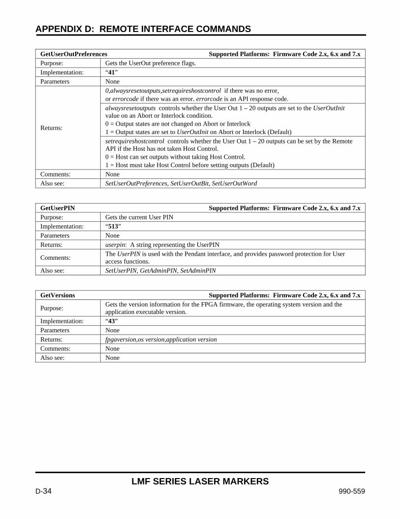
APPENDIX D: REMOTE INTERFACE COMMANDS
LMF SERIES LASER MARKERS
D-34 990-559
GetUserOutPreferences Supported Platforms: Firmware Code 2.x, 6.x and 7.x Purpose: Gets the UserOut preference flags. Implementation: “41” Parameters None
Returns:
0,alwaysresetoutputs,setrequireshostcontrol if there was no error, or errorcode if there was an error. errorcode is an API response code. alwaysresetoutputs controls whether the User Out 1 – 20 outputs are set to the UserOutInit value on an Abort or Interlock condition. 0 = Output states are not changed on Abort or Interlock 1 = Output states are set to UserOutInit on Abort or Interlock (Default) setrequireshostcontrol controls whether the User Out 1 – 20 outputs can be set by the Remote API if the Host has not taken Host Control. 0 = Host can set outputs without taking Host Control. 1 = Host must take Host Control before setting outputs (Default)
Comments: None Also see: SetUserOutPreferences, SetUserOutBit, SetUserOutWord
GetUserPIN Supported Platforms: Firmware Code 2.x, 6.x and 7.x Purpose: Gets the current User PIN Implementation: “513” Parameters None Returns: userpin: A string representing the UserPIN
Comments: The UserPIN is used with the Pendant interface, and provides password protection for User access functions.
Also see: SetUserPIN, GetAdminPIN, SetAdminPIN
GetVersions Supported Platforms: Firmware Code 2.x, 6.x and 7.x
Purpose: Gets the version information for the FPGA firmware, the operating system version and the application executable version.
Implementation: “43” Parameters None Returns: fpgaversion,os version,application version
Comments: None Also see: None

APPENDIX D: REMOTE INTERFACE COMMANDS
LMF SERIES LASER MARKERS
990-559 D-35
GoToXYZ Supported Platforms: Firmware Code 2.x, 6.x and 7.x
Purpose: Commands the x, y and z-axes to jump to the specified coordinate, at the specified jump speed, and inserts the specified jump delay after the jump.
Implementation: “20,xcoordinate,ycoordinate,zcoordinate,jumpspeed,jumpdelay”
Parameters
xcoordinate: The coordinate location, to jump to. Valid range: [-fieldsize / 2 to fieldsize / 2] bits ycoordinate: The coordinate location, to jump to. Valid range: [-fieldsize / 2 to fieldsize / 2] bits zcoordinate: The coordinate location, in bits, to jump to. Valid range: [-32768 to 32767] jumpspeed: The speed, in bits/millisecond, that the jump is executed at. Valid range: [ 1 to 65535 ] jumpdelay: The speed, in microseconds, to delay after the jump is executed. Valid range: [ 1 to 65535 ]
Returns: An API Response code
Comments:
Client must call TakeHostControl before making this call. The ActiveJob must be Idle for this command to succeed. GoToXYZ is a Control Command, and the instructions are placed in the FIFO immediately. The marking field is described using a Cartesian coordinate system, with: Center: [(0,0)] Bottom Left: [(-fieldsize / 2, -fieldsize / 2) bits Top Right: [(fieldsize / 2, fieldsize / 2) bits
Also see: GoToZ
GoToZ Supported Platforms: Firmware Code 2.x, 6.x and 7.x
Purpose: Commands the z-axis to jump to the specified coordinate, and inserts the specified jump delay after the jump.
Implementation: “19,zcoordinate,jumpdelay”
Parameters
zcoordinate: The coordinate location, in bits, to jump to. Valid range: [-32768 to 32767] jumpdelay: The time, in microseconds, to delay after the jump is executed. Valid range: [ 1 to 65535 ]
Returns: An API Response code
Comments: Client must call TakeHostControl before making this call. The ActiveJob must be Idle for this command to succeed. GoToZ is a Control Command, and the instructions are placed in the FIFO immediately.
Also see: GoToXYZ
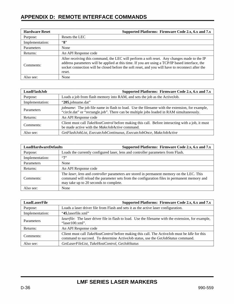
APPENDIX D: REMOTE INTERFACE COMMANDS
LMF SERIES LASER MARKERS
D-36 990-559
Hardware Reset Supported Platforms: Firmware Code 2.x, 6.x and 7.x Purpose: Resets the LEC Implementation: “8” Parameters None Returns: An API Response code
Comments:
After receiving this command, the LEC will perform a soft reset. Any changes made to the IP address parameters will be applied at this time. If you are using a TCP/IP based interface, the socket connection will be closed before the soft reset, and you will have to reconnect after the reset.
Also see: None
LoadFlashJob Supported Platforms: Firmware Code 2.x, 6.x and 7.x Purpose: Loads a job from flash memory into RAM, and sets the job as the ActiveJob. Implementation: “205,jobname.dat”
Parameters jobname: The job file name in flash to load. Use the filename with the extension, for example, “circle.dat” or “rectangle.job”. There can be multiple jobs loaded in RAM simultaneously.
Returns: An API Response code
Comments: Client must call TakeHostControl before making this call. Before interacting with a job, it must be made active with the MakeJobActive command.
Also see: GetFlashJobList, ExecuteJobContinuous, ExecuteJobOnce, MakeJobActive
LoadHardwareDefaults Supported Platforms: Firmware Code 2.x, 6.x and 7.x Purpose: Loads the currently configured laser, lens and controller parameters from Flash. Implementation: “7” Parameters None Returns: An API Response code
Comments: The laser, lens and controller parameters are stored in permanent memory on the LEC. This command will reload the parameter sets from the configuration files in permanent memory and may take up to 20 seconds to complete.
Also see: None
LoadLaserFile Supported Platforms: Firmware Code 2.x, 6.x and 7.x Purpose: Loads a laser driver file from Flash and sets it as the active laser configuration. Implementation: “45,laserfile.xml”
Parameters laserfile: The laser driver file in flash to load. Use the filename with the extension, for example, “laser100.xml”.
Returns: An API Response code
Comments: Client must call TakeHostControl before making this call. The ActiveJob must be Idle for this command to succeed. To determine ActiveJob status, use the GetJobStatus command.
Also see: GetLaserFileList, TakeHostControl, GetJobStatus
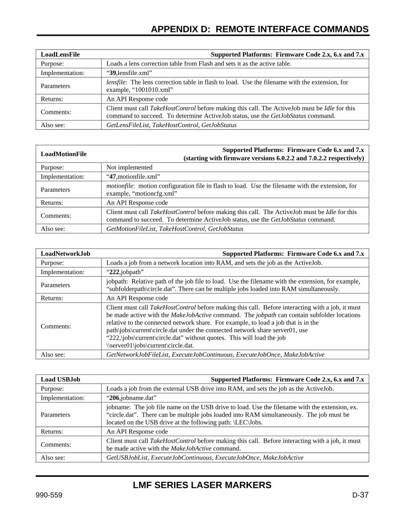
APPENDIX D: REMOTE INTERFACE COMMANDS
LMF SERIES LASER MARKERS
990-559 D-37
LoadLensFile Supported Platforms: Firmware Code 2.x, 6.x and 7.x Purpose: Loads a lens correction table from Flash and sets it as the active table. Implementation: “39,lensfile.xml”
Parameters lensfile: The lens correction table in flash to load. Use the filename with the extension, for example, “1001010.xml”
Returns: An API Response code
Comments: Client must call TakeHostControl before making this call. The ActiveJob must be Idle for this command to succeed. To determine ActiveJob status, use the GetJobStatus command.
Also see: GetLensFileList, TakeHostControl, GetJobStatus
LoadMotionFile Supported Platforms: Firmware Code 6.x and 7.x (starting with firmware versions 6.0.2.2 and 7.0.2.2 respectively)
Purpose: Not implemented Implementation: “47,motionfile.xml”
Parameters motionfile: motion configuration file in flash to load. Use the filename with the extension, for example, “motioncfg.xml”
Returns: An API Response code
Comments: Client must call TakeHostControl before making this call. The ActiveJob must be Idle for this command to succeed. To determine ActiveJob status, use the GetJobStatus command.
Also see: GetMotionFileList, TakeHostControl, GetJobStatus
LoadNetworkJob Supported Platforms: Firmware Code 6.x and 7.x Purpose: Loads a job from a network location into RAM, and sets the job as the ActiveJob. Implementation: “222,jobpath”
Parameters jobpath: Relative path of the job file to load. Use the filename with the extension, for example, “subfolderpath\circle.dat”. There can be multiple jobs loaded into RAM simultaneously.
Returns: An API Response code
Comments:
Client must call TakeHostControl before making this call. Before interacting with a job, it must be made active with the MakeJobActive command. The jobpath can contain subfolder locations relative to the connected network share. For example, to load a job that is in the path\jobs\current\circle.dat under the connected network share server01, use “222,\jobs\current\circle.dat” without quotes. This will load the job \\server01\jobs\current\circle.dat.
Also see: GetNetworkJobFileList, ExecuteJobContinuous, ExecuteJobOnce, MakeJobActive
Load USBJob Supported Platforms: Firmware Code 2.x, 6.x and 7.x Purpose: Loads a job from the external USB drive into RAM, and sets the job as the ActiveJob. Implementation: “206,jobname.dat”
Parameters jobname: The job file name on the USB drive to load. Use the filename with the extension, ex. “circle.dat”. There can be multiple jobs loaded into RAM simultaneously. The job must be located on the USB drive at the following path: \LEC\Jobs.
Returns: An API Response code
Comments: Client must call TakeHostControl before making this call. Before interacting with a job, it must be made active with the MakeJobActive command.
Also see: GetUSBJobList, ExecuteJobContinuous, ExecuteJobOnce, MakeJobActive
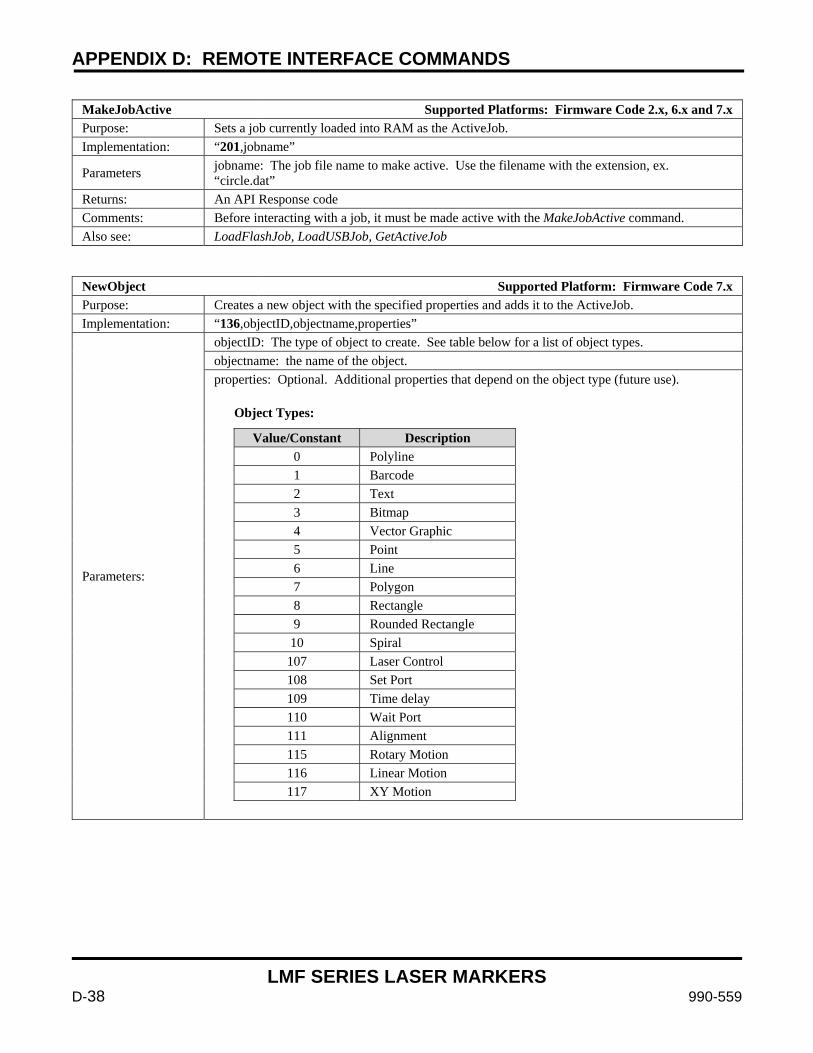
APPENDIX D: REMOTE INTERFACE COMMANDS
LMF SERIES LASER MARKERS
D-38 990-559
MakeJobActive Supported Platforms: Firmware Code 2.x, 6.x and 7.x Purpose: Sets a job currently loaded into RAM as the ActiveJob. Implementation: “201,jobname”
Parameters jobname: The job file name to make active. Use the filename with the extension, ex. “circle.dat”
Returns: An API Response code Comments: Before interacting with a job, it must be made active with the MakeJobActive command. Also see: LoadFlashJob, LoadUSBJob, GetActiveJob
NewObject Supported Platform: Firmware Code 7.x Purpose: Creates a new object with the specified properties and adds it to the ActiveJob. Implementation: “136,objectID,objectname,properties”
Parameters:
objectID: The type of object to create. See table below for a list of object types. objectname: the name of the object. properties: Optional. Additional properties that depend on the object type (future use). Object Types:
Value/Constant Description 0 Polyline 1 Barcode 2 Text 3 Bitmap 4 Vector Graphic 5 Point 6 Line 7 Polygon 8 Rectangle 9 Rounded Rectangle 10 Spiral 107 Laser Control 108 Set Port 109 Time delay 110 Wait Port 111 Alignment 115 Rotary Motion 116 Linear Motion 117 XY Motion
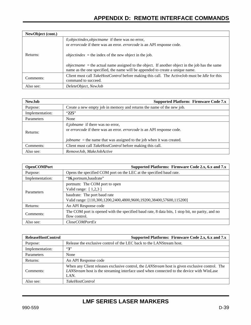
APPENDIX D: REMOTE INTERFACE COMMANDS
LMF SERIES LASER MARKERS
990-559 D-39
NewObject (cont.)
Returns:
0,objectindex,objectname if there was no error, or errorcode if there was an error. errorcode is an API response code. objectindex = the index of the new object in the job. objectname = the actual name assigned to the object. If another object in the job has the same name as the one specified, the name will be appended to create a unique name.
Comments: Client must call TakeHostControl before making this call. The ActiveJob must be Idle for this command to succeed.
Also see: DeleteObject, NewJob
NewJob Supported Platform: Firmware Code 7.x Purpose: Create a new empty job in memory and returns the name of the new job. Implementation: “225” Parameters None
Returns:
0,jobname if there was no error, or errorcode if there was an error. errorcode is an API response code. jobname = the name that was assigned to the job when it was created.
Comments: Client must call TakeHostControl before making this call. Also see: RemoveJob, MakeJobActive
OpenCOMPort Supported Platforms: Firmware Code 2.x, 6.x and 7.x Purpose: Opens the specified COM port on the LEC at the specified baud rate. Implementation: “16,portnum,baudrate”
Parameters
portnum: The COM port to open Valid range: [ 1,2,3 ] baudrate: The port baud rate Valid range: [110,300,1200,2400,4800,9600,19200,38400,57600,115200]
Returns: An API Response code
Comments: The COM port is opened with the specified baud rate, 8 data bits, 1 stop bit, no parity, and no flow control.
Also see: CloseCOMPortEx
ReleaseHostControl Supported Platforms: Firmware Code 2.x, 6.x and 7.x Purpose: Release the exclusive control of the LEC back to the LANStream host. Implementation: “3” Parameters None Returns: An API Response code
Comments: When any Client releases exclusive control, the LANStream host is given exclusive control. The LANStream host is the streaming interface used when connected to the device with WinLase LAN.
Also see: TakeHostControl
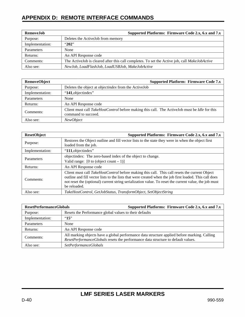
APPENDIX D: REMOTE INTERFACE COMMANDS
LMF SERIES LASER MARKERS
D-40 990-559
RemoveJob Supported Platforms: Firmware Code 2.x, 6.x and 7.x Purpose: Deletes the ActiveJob from memory Implementation: “202” Parameters None Returns: An API Response code Comments: The ActiveJob is cleared after this call completes. To set the Active job, call MakeJobActive Also see: NewJob, LoadFlashJob, LoadUSBJob, MakeJobActive
RemoveObject Supported Platform: Firmware Code 7.x Purpose: Deletes the object at objectindex from the ActiveJob Implementation: “141,objectindex” Parameters None Returns: An API Response code
Comments: Client must call TakeHostControl before making this call. The ActiveJob must be Idle for this command to succeed.
Also see: NewObject
ResetObject Supported Platforms: Firmware Code 2.x, 6.x and 7.x
Purpose: Restores the Object outline and fill vector lists to the state they were in when the object first loaded from the job.
Implementation: “111,objectindex”
Parameters objectindex: The zero-based index of the object to change. Valid range: [0 to (object count – 1)]
Returns: An API Response code
Comments:
Client must call TakeHostControl before making this call. This call resets the current Object outline and fill vector lists to the lists that were created when the job first loaded. This call does not reset the (optional) current string serialization value. To reset the current value, the job must be reloaded.
Also see: TakeHostControl, GetJobStatus, TransformObject, SetObjectString
ResetPerformanceGlobals Supported Platforms: Firmware Code 2.x, 6.x and 7.x Purpose: Resets the Performance global values to their defaults Implementation: “15” Parameters None Returns: An API Response code
Comments: All marking objects have a global performance data structure applied before marking. Calling ResetPerformanceGlobals resets the performance data structure to default values.
Also see: SetPerformanceGlobals
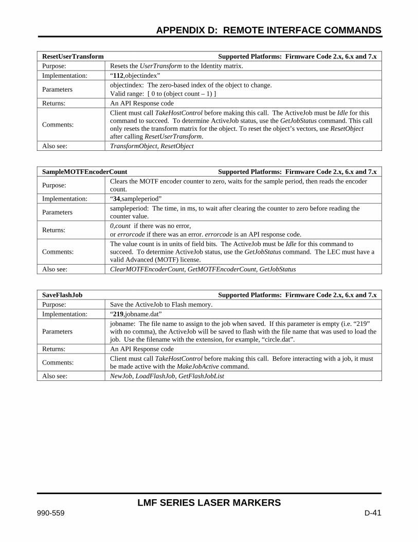
APPENDIX D: REMOTE INTERFACE COMMANDS
LMF SERIES LASER MARKERS
990-559 D-41
ResetUserTransform Supported Platforms: Firmware Code 2.x, 6.x and 7.x Purpose: Resets the UserTransform to the Identity matrix. Implementation: “112,objectindex”
Parameters objectindex: The zero-based index of the object to change. Valid range: [ 0 to (object count – 1) ]
Returns: An API Response code
Comments:
Client must call TakeHostControl before making this call. The ActiveJob must be Idle for this command to succeed. To determine ActiveJob status, use the GetJobStatus command. This call only resets the transform matrix for the object. To reset the object’s vectors, use ResetObject after calling ResetUserTransform.
Also see: TransformObject, ResetObject
SampleMOTFEncoderCount Supported Platforms: Firmware Code 2.x, 6.x and 7.x
Purpose: Clears the MOTF encoder counter to zero, waits for the sample period, then reads the encoder count.
Implementation: “34,sampleperiod”
Parameters sampleperiod: The time, in ms, to wait after clearing the counter to zero before reading the counter value.
Returns: 0,count if there was no error, or errorcode if there was an error. errorcode is an API response code.
Comments: The value count is in units of field bits. The ActiveJob must be Idle for this command to succeed. To determine ActiveJob status, use the GetJobStatus command. The LEC must have a valid Advanced (MOTF) license.
Also see: ClearMOTFEncoderCount, GetMOTFEncoderCount, GetJobStatus
SaveFlashJob Supported Platforms: Firmware Code 2.x, 6.x and 7.x Purpose: Save the ActiveJob to Flash memory. Implementation: “219,jobname.dat”
Parameters jobname: The file name to assign to the job when saved. If this parameter is empty (i.e. “219” with no comma), the ActiveJob will be saved to flash with the file name that was used to load the job. Use the filename with the extension, for example, “circle.dat”.
Returns: An API Response code
Comments: Client must call TakeHostControl before making this call. Before interacting with a job, it must be made active with the MakeJobActive command.
Also see: NewJob, LoadFlashJob, GetFlashJobList
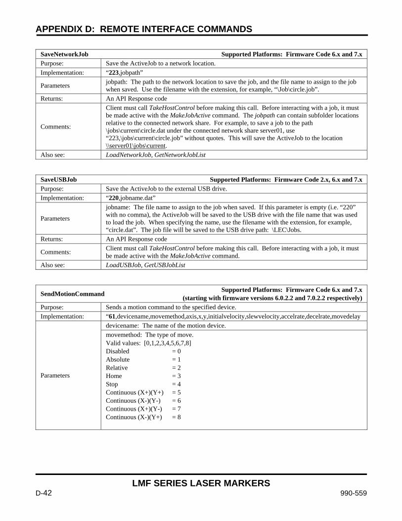
APPENDIX D: REMOTE INTERFACE COMMANDS
LMF SERIES LASER MARKERS
D-42 990-559
SaveNetworkJob Supported Platforms: Firmware Code 6.x and 7.x Purpose: Save the ActiveJob to a network location. Implementation: “223,jobpath”
Parameters jobpath: The path to the network location to save the job, and the file name to assign to the job when saved. Use the filename with the extension, for example, “\Job\circle.job”.
Returns: An API Response code
Comments:
Client must call TakeHostControl before making this call. Before interacting with a job, it must be made active with the MakeJobActive command. The jobpath can contain subfolder locations relative to the connected network share. For example, to save a job to the path \jobs\current\circle.dat under the connected network share server01, use “223,\jobs\current\circle.job” without quotes. This will save the ActiveJob to the location \\server01\jobs\current.
Also see: LoadNetworkJob, GetNetworkJobList
SaveUSBJob Supported Platforms: Firmware Code 2.x, 6.x and 7.x Purpose: Save the ActiveJob to the external USB drive. Implementation: “220,jobname.dat”
Parameters
jobname: The file name to assign to the job when saved. If this parameter is empty (i.e. “220” with no comma), the ActiveJob will be saved to the USB drive with the file name that was used to load the job. When specifying the name, use the filename with the extension, for example, “circle.dat”. The job file will be saved to the USB drive path: \LEC\Jobs.
Returns: An API Response code
Comments: Client must call TakeHostControl before making this call. Before interacting with a job, it must be made active with the MakeJobActive command.
Also see: LoadUSBJob, GetUSBJobList
SendMotionCommand Supported Platforms: Firmware Code 6.x and 7.x (starting with firmware versions 6.0.2.2 and 7.0.2.2 respectively)
Purpose: Sends a motion command to the specified device. Implementation: “61,devicename,movemethod,axis,x,y,initialvelocity,slewvelocity,accelrate,decelrate,movedelay
Parameters
devicename: The name of the motion device. movemethod: The type of move. Valid values: [0,1,2,3,4,5,6,7,8] Disabled = 0 Absolute = 1 Relative = 2 Home = 3 Stop = 4 Continuous (X+)(Y+) = 5 Continuous (X-)(Y-) = 6 Continuous (X+)(Y-) = 7 Continuous (X-)(Y+) = 8
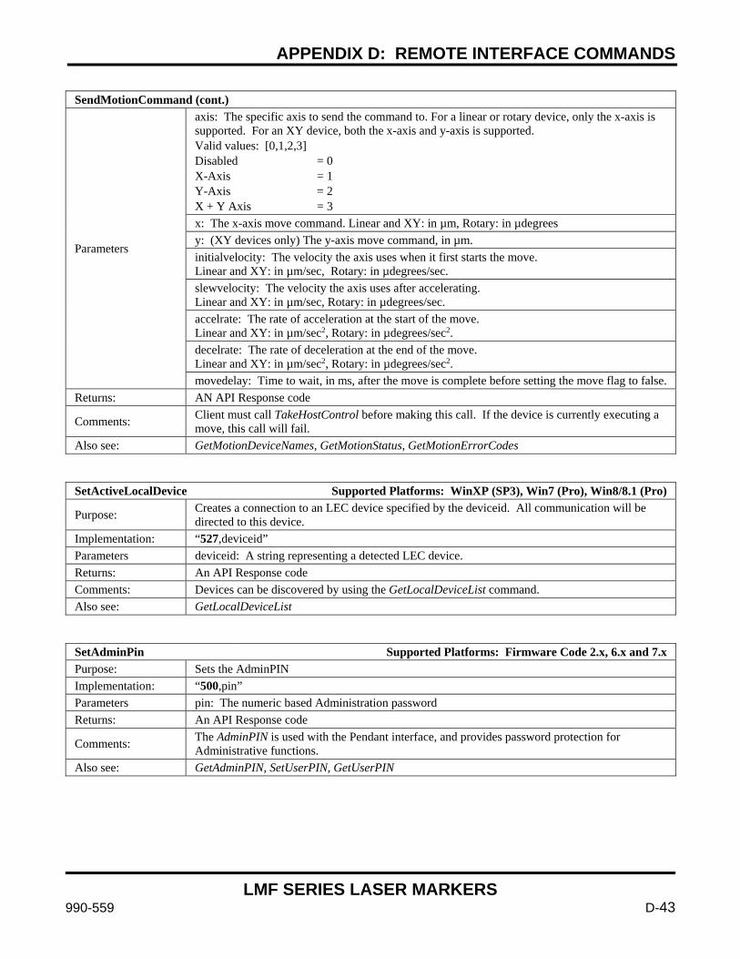
APPENDIX D: REMOTE INTERFACE COMMANDS
LMF SERIES LASER MARKERS
990-559 D-43
SendMotionCommand (cont.)
Parameters
axis: The specific axis to send the command to. For a linear or rotary device, only the x-axis is supported. For an XY device, both the x-axis and y-axis is supported. Valid values: [0,1,2,3] Disabled = 0 X-Axis = 1 Y-Axis = 2 X + Y Axis = 3 x: The x-axis move command. Linear and XY: in µm, Rotary: in µdegrees y: (XY devices only) The y-axis move command, in µm. initialvelocity: The velocity the axis uses when it first starts the move. Linear and XY: in µm/sec, Rotary: in µdegrees/sec. slewvelocity: The velocity the axis uses after accelerating. Linear and XY: in µm/sec, Rotary: in µdegrees/sec. accelrate: The rate of acceleration at the start of the move. Linear and XY: in µm/sec2, Rotary: in µdegrees/sec2. decelrate: The rate of deceleration at the end of the move. Linear and XY: in µm/sec2, Rotary: in µdegrees/sec2. movedelay: Time to wait, in ms, after the move is complete before setting the move flag to false.
Returns: AN API Response code
Comments: Client must call TakeHostControl before making this call. If the device is currently executing a move, this call will fail.
Also see: GetMotionDeviceNames, GetMotionStatus, GetMotionErrorCodes
SetActiveLocalDevice Supported Platforms: WinXP (SP3), Win7 (Pro), Win8/8.1 (Pro)
Purpose: Creates a connection to an LEC device specified by the deviceid. All communication will be directed to this device.
Implementation: “527,deviceid” Parameters deviceid: A string representing a detected LEC device. Returns: An API Response code Comments: Devices can be discovered by using the GetLocalDeviceList command. Also see: GetLocalDeviceList
SetAdminPin Supported Platforms: Firmware Code 2.x, 6.x and 7.x Purpose: Sets the AdminPIN Implementation: “500,pin” Parameters pin: The numeric based Administration password Returns: An API Response code
Comments: The AdminPIN is used with the Pendant interface, and provides password protection for Administrative functions.
Also see: GetAdminPIN, SetUserPIN, GetUserPIN

APPENDIX D: REMOTE INTERFACE COMMANDS
LMF SERIES LASER MARKERS
D-44 990-559
SetCOMPortAssignments Supported Platforms: Firmware Code 2.x, 6.x and 7.x
Purpose: Sets the COM port to be used for the Pendant, RS-232 Remote API and the Motion interfaces. On Platforms that use the 6.x and 7.x firmware code, this API has been deprecated and users should use SetCOMPortMode instead.
Implementation: “516,pendant,remoteapi,motioncontrol”
Parameters
pendant: The COM port to use for the Pendant interface. Valid range: [0,1,2,3] remoteapi: The COM port to use for the Remote API interface. Valid range: [0,1,2,3] motioncontrol: The COM port to use for the Motion Control interface. Valid range: [0,1,2,3]
Returns: An API Response code
Comments:
Client must call TakeHostControl before making this call. This setting will not take effect until the board is power cycled, or a HardwareReset command is issued. There are three COM ports available on the LEC: COM1, COM2, COM3. When issuing this command, you must assign a different COM port to each interface, or the command will fail. Use a 0 (zero) to clear a COM port assignment from the interface.
Also see: GetCOMPortAssignments, SetCOMPortSpeed, GetCOMPortSpeed
SetCOMPortMode Supported Platforms: Firmware Code 6.x and 7.x (starting with firmware versions 6.0.2.2 and 7.0.2.2 respectively)
Purpose: Sets the interface mode for three available COM ports. Implementation: “528,com1mode,com2mode,com3mode”
Parameters
com1mode: The COM1 interface mode. Valid range: [0,1,2,3] com2mode: The COM2 interface mode. Valid range: [0,1,2,3] com3mode: The COM3 interface mode. Valid range: [0,1,2,3]
Returns: An API Response code
Comments:
Client must call TakeHostControl before making this call. The LEC device must be restarted for changes to take effect. There are three COM ports available on the LEC: COM1, COM2 and COM3. The interface modes are defined as: 0 = unassigned 1 = Motion interface 2 = Remote API interface 3 = Pendant interface The Motion and/or Pendant interface can only be assigned to a single COM port or a BadArg response will be returned. The “unassigned” interface and the Remote API interface may be assigned to multiple COM ports.
Also see: GetCOMPortMode, SetCOMPortSpeedEx, GetCOMPortSpeedEx
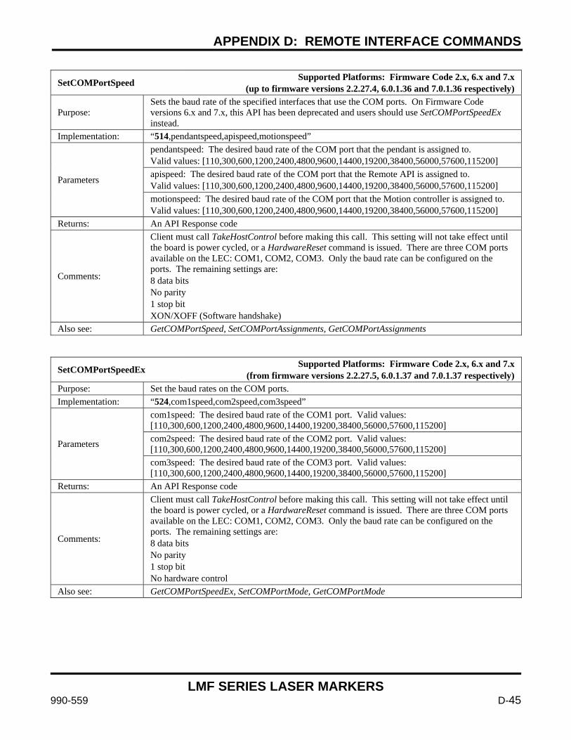
APPENDIX D: REMOTE INTERFACE COMMANDS
LMF SERIES LASER MARKERS
990-559 D-45
SetCOMPortSpeed Supported Platforms: Firmware Code 2.x, 6.x and 7.x (up to firmware versions 2.2.27.4, 6.0.1.36 and 7.0.1.36 respectively)
Purpose: Sets the baud rate of the specified interfaces that use the COM ports. On Firmware Code versions 6.x and 7.x, this API has been deprecated and users should use SetCOMPortSpeedEx instead.
Implementation: “514,pendantspeed,apispeed,motionspeed”
Parameters
pendantspeed: The desired baud rate of the COM port that the pendant is assigned to. Valid values: [110,300,600,1200,2400,4800,9600,14400,19200,38400,56000,57600,115200] apispeed: The desired baud rate of the COM port that the Remote API is assigned to. Valid values: [110,300,600,1200,2400,4800,9600,14400,19200,38400,56000,57600,115200] motionspeed: The desired baud rate of the COM port that the Motion controller is assigned to. Valid values: [110,300,600,1200,2400,4800,9600,14400,19200,38400,56000,57600,115200]
Returns: An API Response code
Comments:
Client must call TakeHostControl before making this call. This setting will not take effect until the board is power cycled, or a HardwareReset command is issued. There are three COM ports available on the LEC: COM1, COM2, COM3. Only the baud rate can be configured on the ports. The remaining settings are: 8 data bits No parity 1 stop bit XON/XOFF (Software handshake)
Also see: GetCOMPortSpeed, SetCOMPortAssignments, GetCOMPortAssignments
SetCOMPortSpeedEx Supported Platforms: Firmware Code 2.x, 6.x and 7.x (from firmware versions 2.2.27.5, 6.0.1.37 and 7.0.1.37 respectively)
Purpose: Set the baud rates on the COM ports. Implementation: “524,com1speed,com2speed,com3speed”
Parameters
com1speed: The desired baud rate of the COM1 port. Valid values: [110,300,600,1200,2400,4800,9600,14400,19200,38400,56000,57600,115200] com2speed: The desired baud rate of the COM2 port. Valid values: [110,300,600,1200,2400,4800,9600,14400,19200,38400,56000,57600,115200] com3speed: The desired baud rate of the COM3 port. Valid values: [110,300,600,1200,2400,4800,9600,14400,19200,38400,56000,57600,115200]
Returns: An API Response code
Comments:
Client must call TakeHostControl before making this call. This setting will not take effect until the board is power cycled, or a HardwareReset command is issued. There are three COM ports available on the LEC: COM1, COM2, COM3. Only the baud rate can be configured on the ports. The remaining settings are: 8 data bits No parity 1 stop bit No hardware control
Also see: GetCOMPortSpeedEx, SetCOMPortMode, GetCOMPortMode
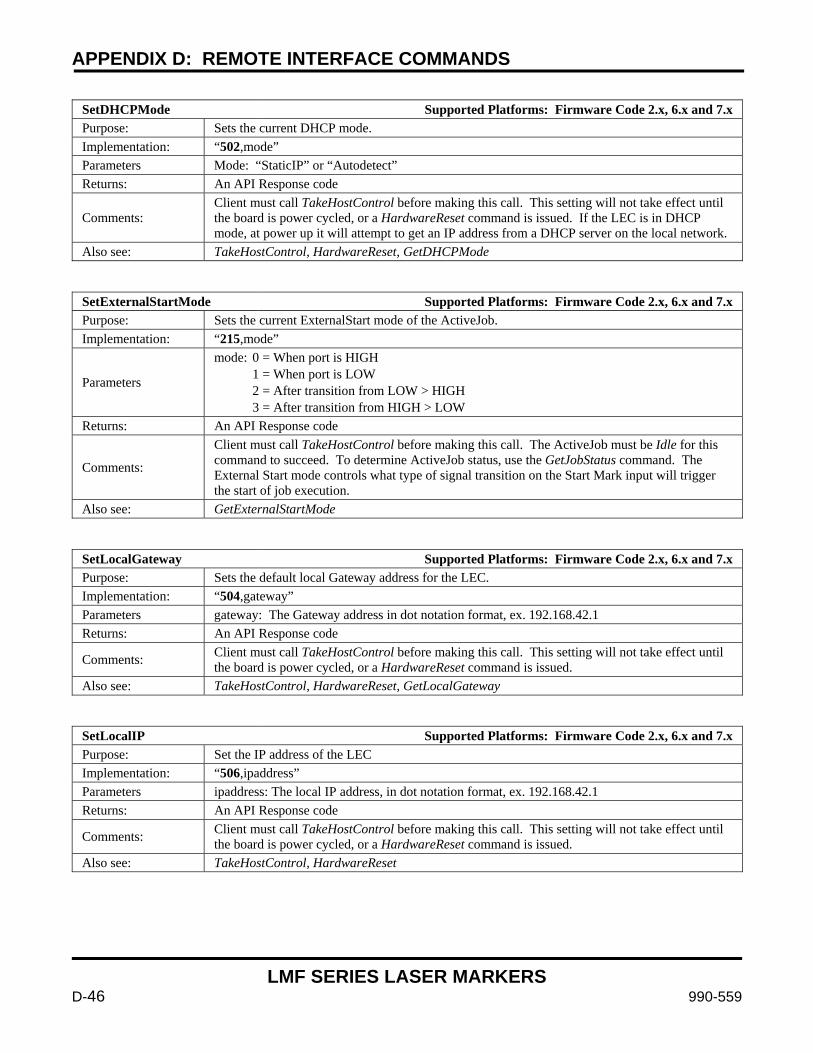
APPENDIX D: REMOTE INTERFACE COMMANDS
LMF SERIES LASER MARKERS
D-46 990-559
SetDHCPMode Supported Platforms: Firmware Code 2.x, 6.x and 7.x Purpose: Sets the current DHCP mode. Implementation: “502,mode” Parameters Mode: “StaticIP” or “Autodetect” Returns: An API Response code
Comments: Client must call TakeHostControl before making this call. This setting will not take effect until the board is power cycled, or a HardwareReset command is issued. If the LEC is in DHCP mode, at power up it will attempt to get an IP address from a DHCP server on the local network.
Also see: TakeHostControl, HardwareReset, GetDHCPMode
SetExternalStartMode Supported Platforms: Firmware Code 2.x, 6.x and 7.x Purpose: Sets the current ExternalStart mode of the ActiveJob. Implementation: “215,mode”
Parameters
mode: 0 = When port is HIGH 1 = When port is LOW 2 = After transition from LOW > HIGH 3 = After transition from HIGH > LOW
Returns: An API Response code
Comments:
Client must call TakeHostControl before making this call. The ActiveJob must be Idle for this command to succeed. To determine ActiveJob status, use the GetJobStatus command. The External Start mode controls what type of signal transition on the Start Mark input will trigger the start of job execution.
Also see: GetExternalStartMode
SetLocalGateway Supported Platforms: Firmware Code 2.x, 6.x and 7.x Purpose: Sets the default local Gateway address for the LEC. Implementation: “504,gateway” Parameters gateway: The Gateway address in dot notation format, ex. 192.168.42.1 Returns: An API Response code
Comments: Client must call TakeHostControl before making this call. This setting will not take effect until the board is power cycled, or a HardwareReset command is issued.
Also see: TakeHostControl, HardwareReset, GetLocalGateway
SetLocalIP Supported Platforms: Firmware Code 2.x, 6.x and 7.x Purpose: Set the IP address of the LEC Implementation: “506,ipaddress” Parameters ipaddress: The local IP address, in dot notation format, ex. 192.168.42.1 Returns: An API Response code
Comments: Client must call TakeHostControl before making this call. This setting will not take effect until the board is power cycled, or a HardwareReset command is issued.
Also see: TakeHostControl, HardwareReset
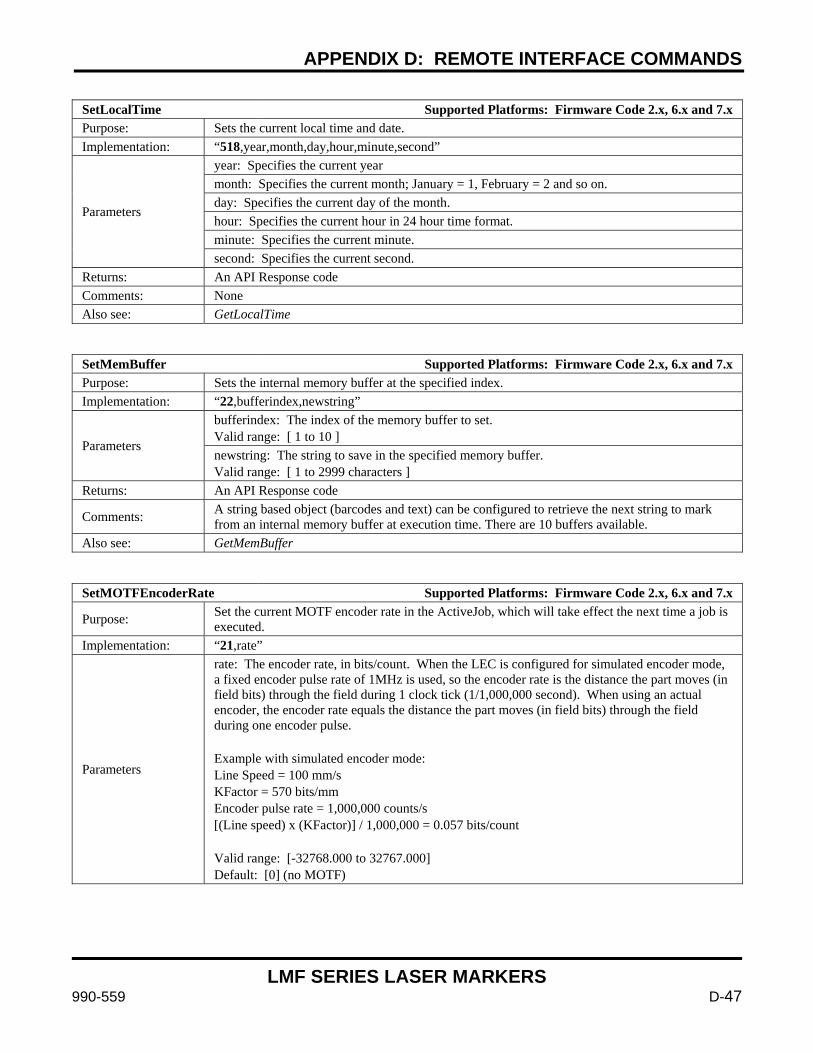
APPENDIX D: REMOTE INTERFACE COMMANDS
LMF SERIES LASER MARKERS
990-559 D-47
SetLocalTime Supported Platforms: Firmware Code 2.x, 6.x and 7.x Purpose: Sets the current local time and date. Implementation: “518,year,month,day,hour,minute,second”
Parameters
year: Specifies the current year month: Specifies the current month; January = 1, February = 2 and so on. day: Specifies the current day of the month. hour: Specifies the current hour in 24 hour time format. minute: Specifies the current minute. second: Specifies the current second.
Returns: An API Response code Comments: None Also see: GetLocalTime
SetMemBuffer Supported Platforms: Firmware Code 2.x, 6.x and 7.x Purpose: Sets the internal memory buffer at the specified index. Implementation: “22,bufferindex,newstring”
Parameters
bufferindex: The index of the memory buffer to set. Valid range: [ 1 to 10 ] newstring: The string to save in the specified memory buffer. Valid range: [ 1 to 2999 characters ]
Returns: An API Response code
Comments: A string based object (barcodes and text) can be configured to retrieve the next string to mark from an internal memory buffer at execution time. There are 10 buffers available.
Also see: GetMemBuffer
SetMOTFEncoderRate Supported Platforms: Firmware Code 2.x, 6.x and 7.x
Purpose: Set the current MOTF encoder rate in the ActiveJob, which will take effect the next time a job is executed.
Implementation: “21,rate”
Parameters
rate: The encoder rate, in bits/count. When the LEC is configured for simulated encoder mode, a fixed encoder pulse rate of 1MHz is used, so the encoder rate is the distance the part moves (in field bits) through the field during 1 clock tick (1/1,000,000 second). When using an actual encoder, the encoder rate equals the distance the part moves (in field bits) through the field during one encoder pulse. Example with simulated encoder mode: Line Speed = 100 mm/s KFactor = 570 bits/mm Encoder pulse rate = 1,000,000 counts/s [(Line speed) x (KFactor)] / 1,000,000 = 0.057 bits/count Valid range: [-32768.000 to 32767.000] Default: [0] (no MOTF)
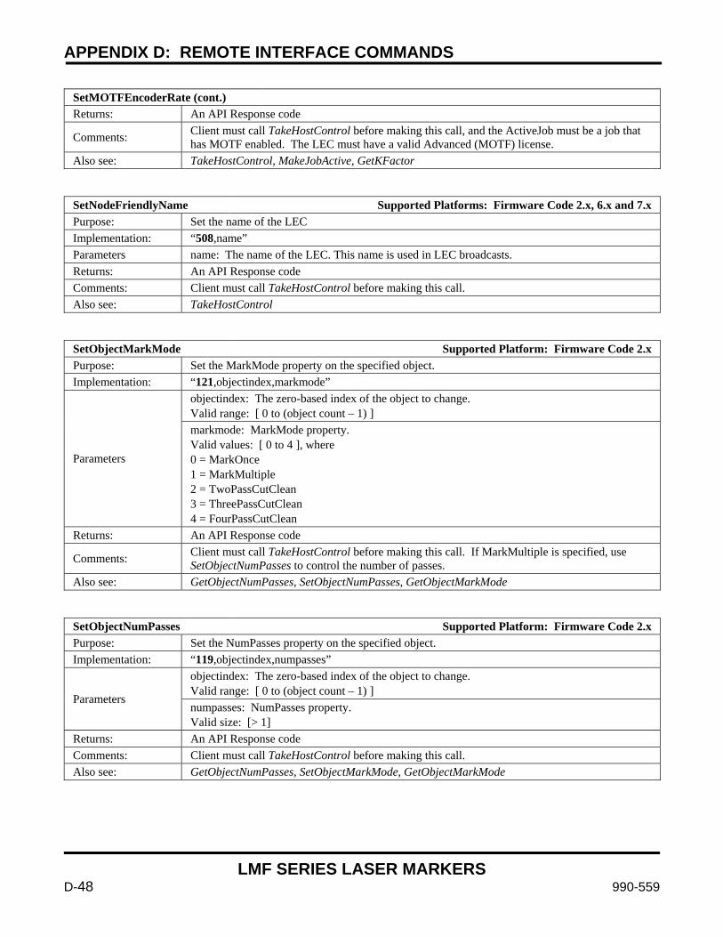
APPENDIX D: REMOTE INTERFACE COMMANDS
LMF SERIES LASER MARKERS
D-48 990-559
SetMOTFEncoderRate (cont.) Returns: An API Response code
Comments: Client must call TakeHostControl before making this call, and the ActiveJob must be a job that has MOTF enabled. The LEC must have a valid Advanced (MOTF) license.
Also see: TakeHostControl, MakeJobActive, GetKFactor
SetNodeFriendlyName Supported Platforms: Firmware Code 2.x, 6.x and 7.x Purpose: Set the name of the LEC Implementation: “508,name” Parameters name: The name of the LEC. This name is used in LEC broadcasts. Returns: An API Response code Comments: Client must call TakeHostControl before making this call. Also see: TakeHostControl
SetObjectMarkMode Supported Platform: Firmware Code 2.x Purpose: Set the MarkMode property on the specified object. Implementation: “121,objectindex,markmode”
Parameters
objectindex: The zero-based index of the object to change. Valid range: [ 0 to (object count – 1) ] markmode: MarkMode property. Valid values: [ 0 to 4 ], where 0 = MarkOnce 1 = MarkMultiple 2 = TwoPassCutClean 3 = ThreePassCutClean 4 = FourPassCutClean
Returns: An API Response code
Comments: Client must call TakeHostControl before making this call. If MarkMultiple is specified, use SetObjectNumPasses to control the number of passes.
Also see: GetObjectNumPasses, SetObjectNumPasses, GetObjectMarkMode
SetObjectNumPasses Supported Platform: Firmware Code 2.x Purpose: Set the NumPasses property on the specified object. Implementation: “119,objectindex,numpasses”
Parameters
objectindex: The zero-based index of the object to change. Valid range: [ 0 to (object count – 1) ] numpasses: NumPasses property. Valid size: [> 1]
Returns: An API Response code Comments: Client must call TakeHostControl before making this call. Also see: GetObjectNumPasses, SetObjectMarkMode, GetObjectMarkMode
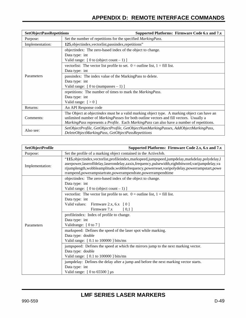
APPENDIX D: REMOTE INTERFACE COMMANDS
LMF SERIES LASER MARKERS
990-559 D-49
SetObjectPassRepetitions Supported Platforms: Firmware Code 6.x and 7.x Purpose: Set the number of repetitions for the specified MarkingPass. Implementation: 125,objectindex,vectorlist,passindex,repetitions”
Parameters
objectindex: The zero-based index of the object to change. Data type: int Valid range: [ 0 to (object count – 1) ] vectorlist: The vector list profile to set. 0 = outline list, 1 = fill list. Data type: int passindex: The index value of the MarkingPass to delete. Data type: int Valid range: [ 0 to (numpasses – 1) ] repetitions: The number of times to mark the MarkingPass. Data type: int Valid range: [ > 0 ]
Returns: An API Response code
Comments: The Object at objectindex must be a valid marking object type. A marking object can have an unlimited number of MarkingPasses for both outline vectors and fill vectors. Usually a MarkingPass represents a Profile. Each MarkingPass can also have a number of repetitions.
Also see: SetObjectProfile, GetObjectProfile, GetObjectNumMarkingPasses, AddObjectMarkingPass, DeleteObjectMarkingPass, GetObjectPassRepetitions
SetObjectProfile Supported Platforms: Firmware Code 2.x, 6.x and 7.x Purpose: Set the profile of a marking object contained in the ActiveJob.
Implementation:
“115,objectindex,vectorlist,profileindex,markspeed,jumpspeed,jumpdelay,markdelay,polydelay,laserpower,laseroffdelay,laserondelay,zaxis,frequency,pulsewidth,eightbitword,varijumpdelay,varijumplength,wobbleamplitude,wobblefrequency,powerreset,varipolydelay,powerrampstart,powerrampend,powerampstartrate,powerampendrate,powerrampendtime
Parameters
objectindex: The zero-based index of the object to change. Data type: int Valid range: [ 0 to (object count – 1) ] vectorlist: The vector list profile to set. 0 = outline list, 1 = fill list. Data type: int Valid values: Firmware 2.x, 6.x [ 0 ] Firmware 7.x [ 0,1 ] profileindex: Index of profile to change. Data type: int Validrange: [ 0 to 7 ] markspeed: Defines the speed of the laser spot while marking. Data type: double Valid range: [ 0.1 to 100000 ] bits/ms jumpspeed: Defines the speed at which the mirrors jump to the next marking vector. Data type: double Valid range: [ 0.1 to 100000 ] bits/ms jumpdelay: Defines the delay after a jump and before the next marking vector starts. Data type: int Valid range: [ 0 to 65500 ] µs
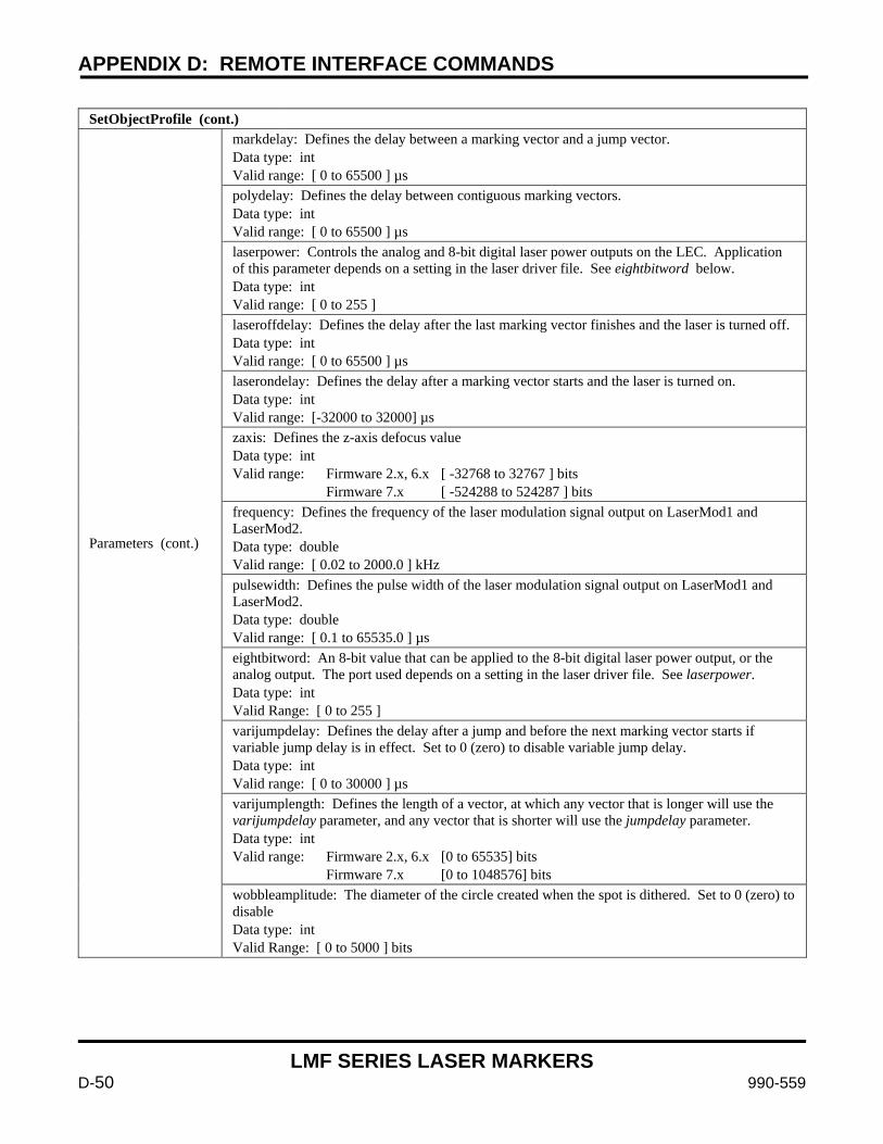
APPENDIX D: REMOTE INTERFACE COMMANDS
LMF SERIES LASER MARKERS
D-50 990-559
SetObjectProfile (cont.)
Parameters (cont.)
markdelay: Defines the delay between a marking vector and a jump vector. Data type: int Valid range: [ 0 to 65500 ] µs polydelay: Defines the delay between contiguous marking vectors. Data type: int Valid range: [ 0 to 65500 ] µs laserpower: Controls the analog and 8-bit digital laser power outputs on the LEC. Application of this parameter depends on a setting in the laser driver file. See eightbitword below. Data type: int Valid range: [ 0 to 255 ] laseroffdelay: Defines the delay after the last marking vector finishes and the laser is turned off. Data type: int Valid range: [ 0 to 65500 ] µs laserondelay: Defines the delay after a marking vector starts and the laser is turned on. Data type: int Valid range: [-32000 to 32000] µs zaxis: Defines the z-axis defocus value Data type: int Valid range: Firmware 2.x, 6.x [ -32768 to 32767 ] bits Firmware 7.x [ -524288 to 524287 ] bits frequency: Defines the frequency of the laser modulation signal output on LaserMod1 and LaserMod2. Data type: double Valid range: [ 0.02 to 2000.0 ] kHz pulsewidth: Defines the pulse width of the laser modulation signal output on LaserMod1 and LaserMod2. Data type: double Valid range: [ 0.1 to 65535.0 ] µs eightbitword: An 8-bit value that can be applied to the 8-bit digital laser power output, or the analog output. The port used depends on a setting in the laser driver file. See laserpower. Data type: int Valid Range: [ 0 to 255 ] varijumpdelay: Defines the delay after a jump and before the next marking vector starts if variable jump delay is in effect. Set to 0 (zero) to disable variable jump delay. Data type: int Valid range: [ 0 to 30000 ] µs varijumplength: Defines the length of a vector, at which any vector that is longer will use the varijumpdelay parameter, and any vector that is shorter will use the jumpdelay parameter. Data type: int Valid range: Firmware 2.x, 6.x [0 to 65535] bits Firmware 7.x [0 to 1048576] bits wobbleamplitude: The diameter of the circle created when the spot is dithered. Set to 0 (zero) to disable Data type: int Valid Range: [ 0 to 5000 ] bits
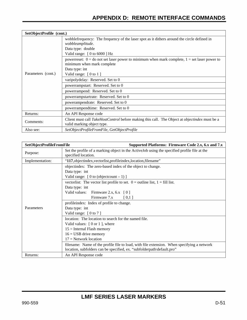
APPENDIX D: REMOTE INTERFACE COMMANDS
LMF SERIES LASER MARKERS
990-559 D-51
SetObjectProfile (cont.)
Parameters (cont.)
wobblefrequency: The frequency of the laser spot as it dithers around the circle defined in wobbleamplitude. Data type: double Valid range: [ 0 to 6000 ] Hz powerreset: 0 = do not set laser power to minimum when mark complete, 1 = set laser power to minimum when mark complete Data type: int Valid range: [ 0 to 1 ] varipolydelay: Reserved. Set to 0 powerrampstart: Reserved. Set to 0 powerrampend: Reserved. Set to 0 powerrampstartrate: Reserved. Set to 0 powerampendrate: Reserved. Set to 0 powerrampendtime: Reserved. Set to 0
Returns: An API Response code
Comments: Client must call TakeHostControl before making this call. The Object at objectindex must be a valid marking object type.
Also see: SetObjectProfileFromFile, GetObjectProfile
SetObjectProfileFromFile Supported Platforms: Firmware Code 2.x, 6.x and 7.x
Purpose: Set the profile of a marking object in the ActiveJob using the specified profile file at the specified location.
Implementation: “117,objectindex,vectorlist,profileindex,location,filename”
Parameters
objectindex: The zero-based index of the object to change. Data type: int Valid range: [ 0 to (objectcount – 1) ] vectorlist: The vector list profile to set. 0 = outline list, 1 = fill list. Data type: int Valid values: Firmware 2.x, 6.x [ 0 ] Firmware 7.x [ 0,1 ] profileindex: Index of profile to change. Data type: int Valid range: [ 0 to 7 ] location: The location to search for the named file. Valid values: [ 0 or 1 ], where 15 = Internal Flash memory 16 = USB drive memory 17 = Network location filename: Name of the profile file to load, with file extension. When specifying a network location, subfolders can be specified, ex. “subfolderpath\default.pro”
Returns: An API Response code
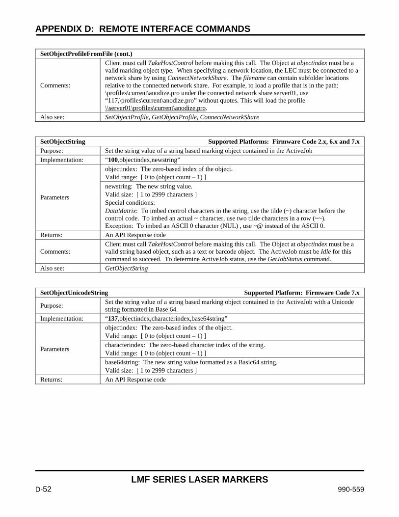
APPENDIX D: REMOTE INTERFACE COMMANDS
LMF SERIES LASER MARKERS
D-52 990-559
SetObjectProfileFromFile (cont.)
Comments:
Client must call TakeHostControl before making this call. The Object at objectindex must be a valid marking object type. When specifying a network location, the LEC must be connected to a network share by using ConnectNetworkShare. The filename can contain subfolder locations relative to the connected network share. For example, to load a profile that is in the path: \profiles\current\anodize.pro under the connected network share server01, use “117,\profiles\current\anodize.pro” without quotes. This will load the profile \\server01\profiles\current\anodize.pro.
Also see: SetObjectProfile, GetObjectProfile, ConnectNetworkShare
SetObjectString Supported Platforms: Firmware Code 2.x, 6.x and 7.x Purpose: Set the string value of a string based marking object contained in the ActiveJob Implementation: “100,objectindex,newstring”
Parameters
objectindex: The zero-based index of the object. Valid range: [ 0 to (object count – 1) ] newstring: The new string value. Valid size: [ 1 to 2999 characters ] Special conditions: DataMatrix: To imbed control characters in the string, use the tilde (~) character before the control code. To imbed an actual ~ character, use two tilde characters in a row (~~). Exception: To imbed an ASCII 0 character (NUL) , use ~@ instead of the ASCII 0.
Returns: An API Response code
Comments: Client must call TakeHostControl before making this call. The Object at objectindex must be a valid string based object, such as a text or barcode object. The ActiveJob must be Idle for this command to succeed. To determine ActiveJob status, use the GetJobStatus command.
Also see: GetObjectString
SetObjectUnicodeString Supported Platform: Firmware Code 7.x
Purpose: Set the string value of a string based marking object contained in the ActiveJob with a Unicode string formatted in Base 64.
Implementation: “137,objectindex,characterindex,base64string”
Parameters
objectindex: The zero-based index of the object. Valid range: [ 0 to (object count – 1) ] characterindex: The zero-based character index of the string. Valid range: [ 0 to (object count – 1) ] base64string: The new string value formatted as a Basic64 string. Valid size: [ 1 to 2999 characters ]
Returns: An API Response code
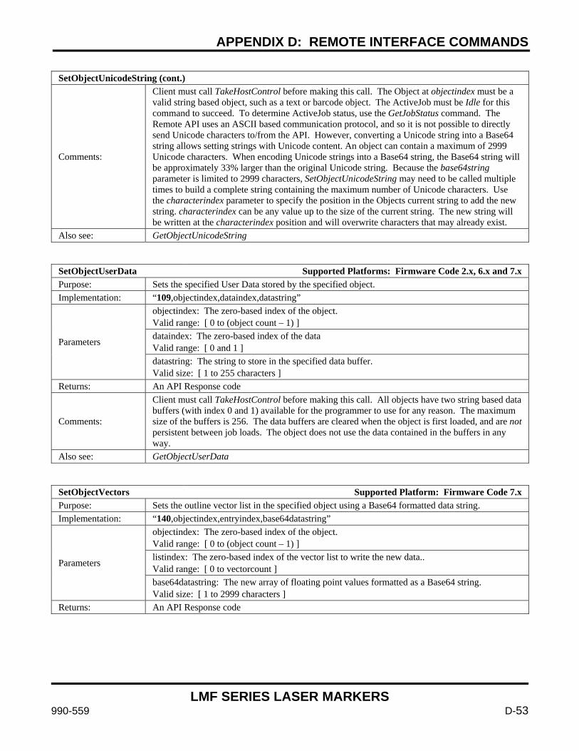
APPENDIX D: REMOTE INTERFACE COMMANDS
LMF SERIES LASER MARKERS
990-559 D-53
SetObjectUnicodeString (cont.)
Comments:
Client must call TakeHostControl before making this call. The Object at objectindex must be a valid string based object, such as a text or barcode object. The ActiveJob must be Idle for this command to succeed. To determine ActiveJob status, use the GetJobStatus command. The Remote API uses an ASCII based communication protocol, and so it is not possible to directly send Unicode characters to/from the API. However, converting a Unicode string into a Base64 string allows setting strings with Unicode content. An object can contain a maximum of 2999 Unicode characters. When encoding Unicode strings into a Base64 string, the Base64 string will be approximately 33% larger than the original Unicode string. Because the base64string parameter is limited to 2999 characters, SetObjectUnicodeString may need to be called multiple times to build a complete string containing the maximum number of Unicode characters. Use the characterindex parameter to specify the position in the Objects current string to add the new string. characterindex can be any value up to the size of the current string. The new string will be written at the characterindex position and will overwrite characters that may already exist.
Also see: GetObjectUnicodeString
SetObjectUserData Supported Platforms: Firmware Code 2.x, 6.x and 7.x Purpose: Sets the specified User Data stored by the specified object. Implementation: “109,objectindex,dataindex,datastring”
Parameters
objectindex: The zero-based index of the object. Valid range: [ 0 to (object count – 1) ] dataindex: The zero-based index of the data Valid range: [ 0 and 1 ] datastring: The string to store in the specified data buffer. Valid size: [ 1 to 255 characters ]
Returns: An API Response code
Comments:
Client must call TakeHostControl before making this call. All objects have two string based data buffers (with index 0 and 1) available for the programmer to use for any reason. The maximum size of the buffers is 256. The data buffers are cleared when the object is first loaded, and are not persistent between job loads. The object does not use the data contained in the buffers in any way.
Also see: GetObjectUserData
SetObjectVectors Supported Platform: Firmware Code 7.x Purpose: Sets the outline vector list in the specified object using a Base64 formatted data string. Implementation: “140,objectindex,entryindex,base64datastring”
Parameters
objectindex: The zero-based index of the object. Valid range: [ 0 to (object count – 1) ] listindex: The zero-based index of the vector list to write the new data.. Valid range: [ 0 to vectorcount ] base64datastring: The new array of floating point values formatted as a Base64 string. Valid size: [ 1 to 2999 characters ]
Returns: An API Response code
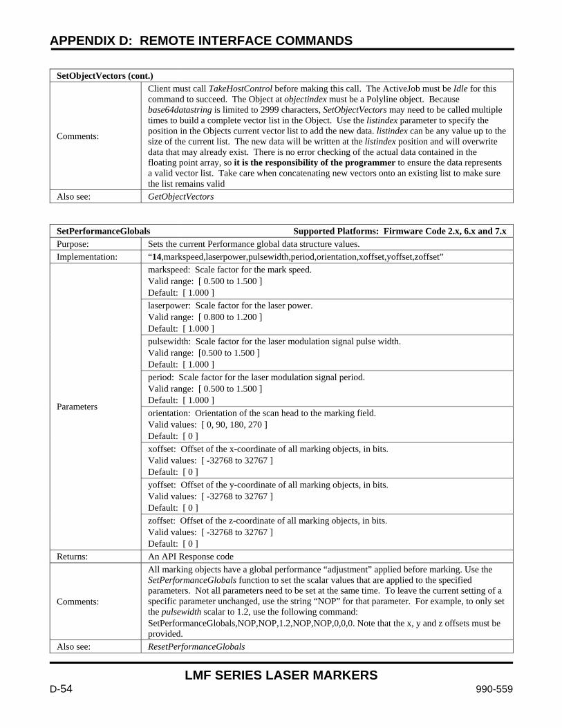
APPENDIX D: REMOTE INTERFACE COMMANDS
LMF SERIES LASER MARKERS
D-54 990-559
SetObjectVectors (cont.)
Comments:
Client must call TakeHostControl before making this call. The ActiveJob must be Idle for this command to succeed. The Object at objectindex must be a Polyline object. Because base64datastring is limited to 2999 characters, SetObjectVectors may need to be called multiple times to build a complete vector list in the Object. Use the listindex parameter to specify the position in the Objects current vector list to add the new data. listindex can be any value up to the size of the current list. The new data will be written at the listindex position and will overwrite data that may already exist. There is no error checking of the actual data contained in the floating point array, so it is the responsibility of the programmer to ensure the data represents a valid vector list. Take care when concatenating new vectors onto an existing list to make sure the list remains valid
Also see: GetObjectVectors
SetPerformanceGlobals Supported Platforms: Firmware Code 2.x, 6.x and 7.x Purpose: Sets the current Performance global data structure values. Implementation: “14,markspeed,laserpower,pulsewidth,period,orientation,xoffset,yoffset,zoffset”
Parameters
markspeed: Scale factor for the mark speed. Valid range: [ 0.500 to 1.500 ] Default: [ 1.000 ] laserpower: Scale factor for the laser power. Valid range: [ 0.800 to 1.200 ] Default: [ 1.000 ] pulsewidth: Scale factor for the laser modulation signal pulse width. Valid range: [0.500 to 1.500 ] Default: [ 1.000 ] period: Scale factor for the laser modulation signal period. Valid range: [ 0.500 to 1.500 ] Default: [ 1.000 ] orientation: Orientation of the scan head to the marking field. Valid values: [ 0, 90, 180, 270 ] Default: [ 0 ] xoffset: Offset of the x-coordinate of all marking objects, in bits. Valid values: [ -32768 to 32767 ] Default: [ 0 ] yoffset: Offset of the y-coordinate of all marking objects, in bits. Valid values: [ -32768 to 32767 ] Default: [ 0 ] zoffset: Offset of the z-coordinate of all marking objects, in bits. Valid values: [ -32768 to 32767 ] Default: [ 0 ]
Returns: An API Response code
Comments:
All marking objects have a global performance “adjustment” applied before marking. Use the SetPerformanceGlobals function to set the scalar values that are applied to the specified parameters. Not all parameters need to be set at the same time. To leave the current setting of a specific parameter unchanged, use the string “NOP” for that parameter. For example, to only set the pulsewidth scalar to 1.2, use the following command: SetPerformanceGlobals,NOP,NOP,1.2,NOP,NOP,0,0,0. Note that the x, y and z offsets must be provided.
Also see: ResetPerformanceGlobals
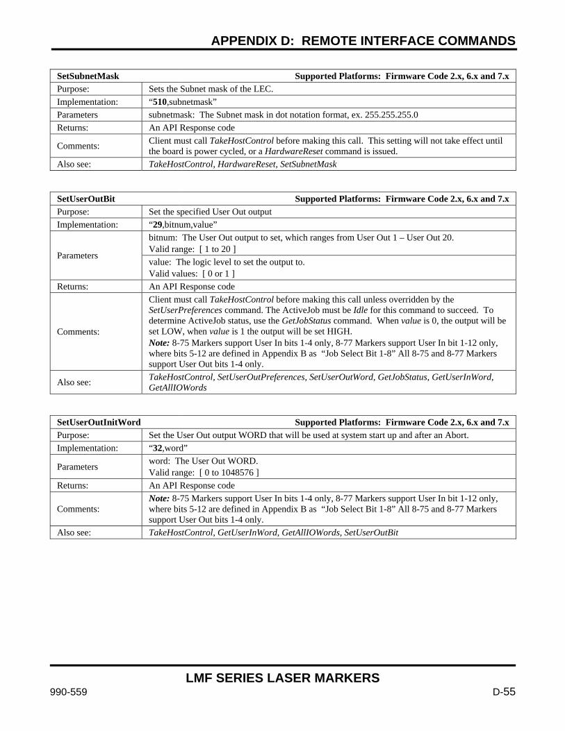
APPENDIX D: REMOTE INTERFACE COMMANDS
LMF SERIES LASER MARKERS
990-559 D-55
SetSubnetMask Supported Platforms: Firmware Code 2.x, 6.x and 7.x Purpose: Sets the Subnet mask of the LEC. Implementation: “510,subnetmask” Parameters subnetmask: The Subnet mask in dot notation format, ex. 255.255.255.0 Returns: An API Response code
Comments: Client must call TakeHostControl before making this call. This setting will not take effect until the board is power cycled, or a HardwareReset command is issued.
Also see: TakeHostControl, HardwareReset, SetSubnetMask
SetUserOutBit Supported Platforms: Firmware Code 2.x, 6.x and 7.x Purpose: Set the specified User Out output Implementation: “29,bitnum,value”
Parameters
bitnum: The User Out output to set, which ranges from User Out 1 – User Out 20. Valid range: [ 1 to 20 ] value: The logic level to set the output to. Valid values: [ 0 or 1 ]
Returns: An API Response code
Comments:
Client must call TakeHostControl before making this call unless overridden by the SetUserPreferences command. The ActiveJob must be Idle for this command to succeed. To determine ActiveJob status, use the GetJobStatus command. When value is 0, the output will be set LOW, when value is 1 the output will be set HIGH. Note: 8-75 Markers support User In bits 1-4 only, 8-77 Markers support User In bit 1-12 only, where bits 5-12 are defined in Appendix B as “Job Select Bit 1-8” All 8-75 and 8-77 Markers support User Out bits 1-4 only.
Also see: TakeHostControl, SetUserOutPreferences, SetUserOutWord, GetJobStatus, GetUserInWord, GetAllIOWords
SetUserOutInitWord Supported Platforms: Firmware Code 2.x, 6.x and 7.x Purpose: Set the User Out output WORD that will be used at system start up and after an Abort. Implementation: “32,word”
Parameters word: The User Out WORD. Valid range: [ 0 to 1048576 ]
Returns: An API Response code
Comments: Note: 8-75 Markers support User In bits 1-4 only, 8-77 Markers support User In bit 1-12 only, where bits 5-12 are defined in Appendix B as “Job Select Bit 1-8” All 8-75 and 8-77 Markers support User Out bits 1-4 only.
Also see: TakeHostControl, GetUserInWord, GetAllIOWords, SetUserOutBit
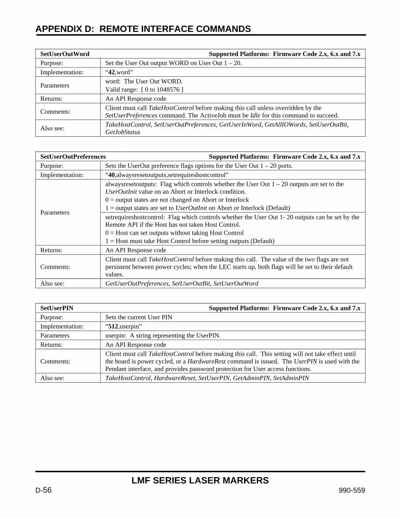
APPENDIX D: REMOTE INTERFACE COMMANDS
LMF SERIES LASER MARKERS
D-56 990-559
SetUserOutWord Supported Platforms: Firmware Code 2.x, 6.x and 7.x Purpose: Set the User Out output WORD on User Out 1 – 20. Implementation: “42,word”
Parameters word: The User Out WORD. Valid range: [ 0 to 1048576 ]
Returns: An API Response code
Comments: Client must call TakeHostControl before making this call unless overridden by the SetUserPreferences command. The ActiveJob must be Idle for this command to succeed.
Also see: TakeHostControl, SetUserOutPreferences, GetUserInWord, GetAllIOWords, SetUserOutBit, GetJobStatus
SetUserOutPreferences Supported Platforms: Firmware Code 2.x, 6.x and 7.x Purpose: Sets the UserOut preference flags options for the User Out 1 – 20 ports. Implementation: “40,alwaysresetoutputs,setrequireshostcontrol”
Parameters
alwaysresetoutputs: Flag which controls whether the User Out 1 – 20 outputs are set to the UserOutInit value on an Abort or Interlock condition. 0 = output states are not changed on Abort or Interlock 1 = output states are set to UserOutInit on Abort or Interlock (Default) setrequireshostcontrol: Flag which controls whether the User Out 1- 20 outputs can be set by the Remote API if the Host has not taken Host Control. 0 = Host can set outputs without taking Host Control 1 = Host must take Host Control before setting outputs (Default)
Returns: An API Response code
Comments: Client must call TakeHostControl before making this call. The value of the two flags are not persistent between power cycles; when the LEC starts up, both flags will be set to their default values.
Also see: GetUserOutPreferences, SetUserOutBit, SetUserOutWord
SetUserPIN Supported Platforms: Firmware Code 2.x, 6.x and 7.x Purpose: Sets the current User PIN Implementation: “512,userpin” Parameters userpin: A string representing the UserPIN. Returns: An API Response code
Comments: Client must call TakeHostControl before making this call. This setting will not take effect until the board is power cycled, or a HardwareRest command is issued. The UserPIN is used with the Pendant interface, and provides password protection for User access functions.
Also see: TakeHostControl, HardwareReset, SetUserPIN, GetAdminPIN, SetAdminPIN
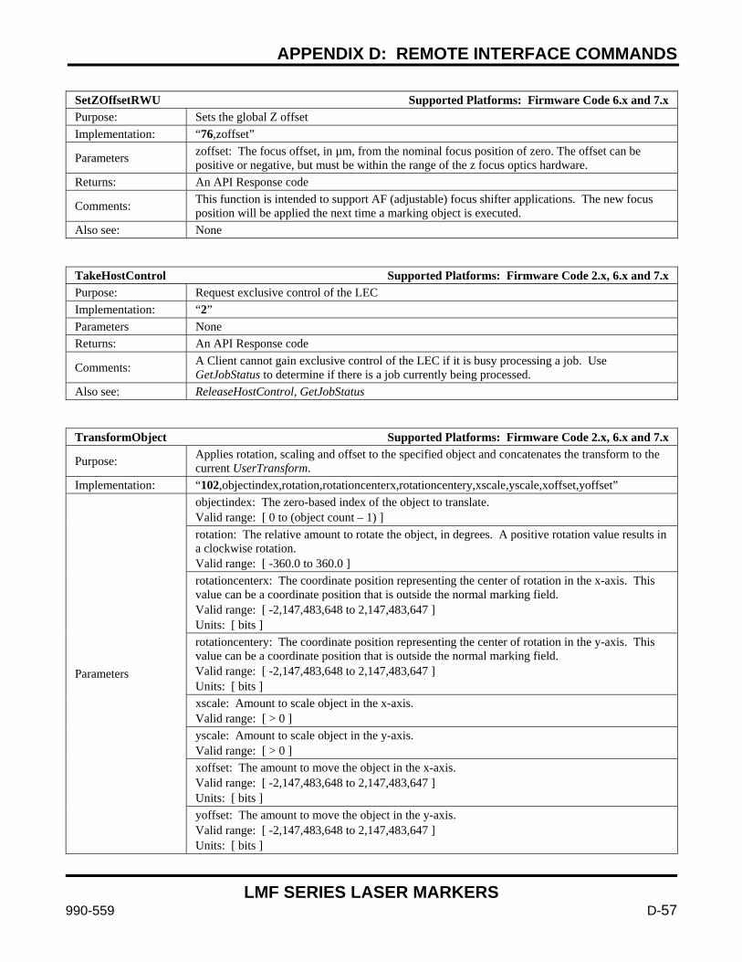
APPENDIX D: REMOTE INTERFACE COMMANDS
LMF SERIES LASER MARKERS
990-559 D-57
SetZOffsetRWU Supported Platforms: Firmware Code 6.x and 7.x Purpose: Sets the global Z offset Implementation: “76,zoffset”
Parameters zoffset: The focus offset, in µm, from the nominal focus position of zero. The offset can be positive or negative, but must be within the range of the z focus optics hardware.
Returns: An API Response code
Comments: This function is intended to support AF (adjustable) focus shifter applications. The new focus position will be applied the next time a marking object is executed.
Also see: None
TakeHostControl Supported Platforms: Firmware Code 2.x, 6.x and 7.x Purpose: Request exclusive control of the LEC Implementation: “2” Parameters None Returns: An API Response code
Comments: A Client cannot gain exclusive control of the LEC if it is busy processing a job. Use GetJobStatus to determine if there is a job currently being processed.
Also see: ReleaseHostControl, GetJobStatus
TransformObject Supported Platforms: Firmware Code 2.x, 6.x and 7.x
Purpose: Applies rotation, scaling and offset to the specified object and concatenates the transform to the current UserTransform.
Implementation: “102,objectindex,rotation,rotationcenterx,rotationcentery,xscale,yscale,xoffset,yoffset”
Parameters
objectindex: The zero-based index of the object to translate. Valid range: [ 0 to (object count – 1) ] rotation: The relative amount to rotate the object, in degrees. A positive rotation value results in a clockwise rotation. Valid range: [ -360.0 to 360.0 ] rotationcenterx: The coordinate position representing the center of rotation in the x-axis. This value can be a coordinate position that is outside the normal marking field. Valid range: [ -2,147,483,648 to 2,147,483,647 ] Units: [ bits ] rotationcentery: The coordinate position representing the center of rotation in the y-axis. This value can be a coordinate position that is outside the normal marking field. Valid range: [ -2,147,483,648 to 2,147,483,647 ] Units: [ bits ] xscale: Amount to scale object in the x-axis. Valid range: [ > 0 ] yscale: Amount to scale object in the y-axis. Valid range: [ > 0 ] xoffset: The amount to move the object in the x-axis. Valid range: [ -2,147,483,648 to 2,147,483,647 ] Units: [ bits ] yoffset: The amount to move the object in the y-axis. Valid range: [ -2,147,483,648 to 2,147,483,647 ] Units: [ bits ]
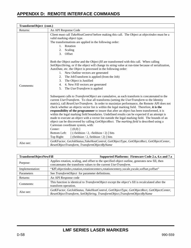
APPENDIX D: REMOTE INTERFACE COMMANDS
LMF SERIES LASER MARKERS
D-58 990-559
TransformObject (cont.) Returns: An API Response Code
Comments:
Client must call TakeHostControl before making this call. The Object at objectindex must be a valid marking object type. The transformations are applied in the following order:
1. Rotation 2. Scaling 3. Offset
Both the Object outline and the Object fill are transformed with this call. When calling SetObjectString, or if the object will change its string value at run-time because of serialization, AutoDate, etc. the Object is processed in the following order:
1. New Outline vectors are generated 2. The JobTransform is applied (from the Job) 3. The Object is Justified 4. 4. New Fill vectors are generated 5. The UserTransform is applied
Subsequent calls to TransformObject are cumulative, as each transform is concatenated to the current UserTransform. To clear all transforms (setting the UserTransform to the Identity matrix), call ResetUserTransform. In order to maximize performance, the Remote API does not check whether an objects vector list is within the legal marking field. Therefore, it is the responsibility of the programmer to insure that after an object has been transformed, it is within the legal marking field boundaries. Undefined results can be expected if an attempt is made to execute an object with a vector list outside the legal marking field. The bounds of an object can be discovered by calling GetObjectRect. The marking field is described using a Cartesian coordinate system, with: Center: [ (0,0) ] Bottom Left: [ (-fieldsize / 2, -fieldsize / 2) ] bits Top Right: [ (fieldsize / 2, fieldsize / 2) ] bits
Also see: GetKFactor, GetJobStatus,TakeHostControl, GetObjectType, GetObjectRect, GetObjectCenter, ResetObjectTransform, TransformObjectByName
TransformObjectNewFill Supported Platforms: Firmware Code 2.x, 6.x and 7.x
Purpose: Applies rotation, scaling, and offset to the specified object outline, generates new fill, then concatenates the transform values to the current UserTransform.
Implementation: “127,objectindex,rotation,rotationcenterx,rotationcentery,xscale,yscale,xoffset,yoffset” Parameters See TransformObject for parameter definitions. Returns: An API Response code
Comments: This function is identical to TransformObject except the object’s fill is recalculated after the transform operation.
Also see: GetKFactor, GetJobStatus, TakeHostControl, GetObjectType, GetObjectRect, GetObjectCenter, ResetObjectTransform, SetObjString, TransformObject,TransformObjectByName
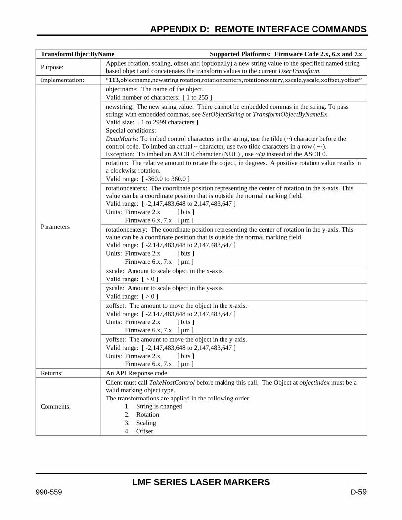
APPENDIX D: REMOTE INTERFACE COMMANDS
LMF SERIES LASER MARKERS
990-559 D-59
TransformObjectByName Supported Platforms: Firmware Code 2.x, 6.x and 7.x
Purpose: Applies rotation, scaling, offset and (optionally) a new string value to the specified named string based object and concatenates the transform values to the current UserTransform.
Implementation: “113,objectname,newstring,rotation,rotationcenterx,rotationcentery,xscale,yscale,xoffset,yoffset”
Parameters
objectname: The name of the object. Valid number of characters: [ 1 to 255 ] newstring: The new string value. There cannot be embedded commas in the string. To pass strings with embedded commas, see SetObjectString or TransformObjectByNameEx. Valid size: [ 1 to 2999 characters ] Special conditions: DataMatrix: To imbed control characters in the string, use the tilde (~) character before the control code. To imbed an actual ~ character, use two tilde characters in a row (~~). Exception: To imbed an ASCII 0 character (NUL) , use ~@ instead of the ASCII 0. rotation: The relative amount to rotate the object, in degrees. A positive rotation value results in a clockwise rotation. Valid range: [ -360.0 to 360.0 ] rotationcenterx: The coordinate position representing the center of rotation in the x-axis. This value can be a coordinate position that is outside the normal marking field. Valid range: [ -2,147,483,648 to 2,147,483,647 ] Units: Firmware 2.x [ bits ] Firmware 6.x, 7.x [ µm ] rotationcentery: The coordinate position representing the center of rotation in the y-axis. This value can be a coordinate position that is outside the normal marking field. Valid range: [ -2,147,483,648 to 2,147,483,647 ] Units: Firmware 2.x [ bits ] Firmware 6.x, 7.x [ µm ] xscale: Amount to scale object in the x-axis. Valid range: [ > 0 ] yscale: Amount to scale object in the y-axis. Valid range: [ > 0 ] xoffset: The amount to move the object in the x-axis. Valid range: [ -2,147,483,648 to 2,147,483,647 ] Units: Firmware 2.x [ bits ] Firmware 6.x, 7.x [ µm ] yoffset: The amount to move the object in the y-axis. Valid range: [ -2,147,483,648 to 2,147,483,647 ] Units: Firmware 2.x [ bits ] Firmware 6.x, 7.x [ µm ]
Returns: An API Response code
Comments:
Client must call TakeHostControl before making this call. The Object at objectindex must be a valid marking object type. The transformations are applied in the following order:
1. String is changed 2. Rotation 3. Scaling 4. Offset
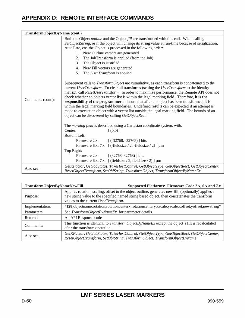
APPENDIX D: REMOTE INTERFACE COMMANDS
LMF SERIES LASER MARKERS
D-60 990-559
TransformObjectByName (cont.)
Comments (cont.):
Both the Object outline and the Object fill are transformed with this call. When calling SetObjectString, or if the object will change its string value at run-time because of serialization, AutoDate, etc. the Object is processed in the following order:
1. New Outline vectors are generated 2. The JobTransform is applied (from the Job) 3. The Object is Justified 4. New Fill vectors are generated 5. The UserTransform is applied
Subsequent calls to TransformObject are cumulative, as each transform is concatenated to the current UserTransform. To clear all transforms (setting the UserTransform to the Identity matrix), call ResetUserTransform. In order to maximize performance, the Remote API does not check whether an objects vector list is within the legal marking field. Therefore, it is the responsibility of the programmer to insure that after an object has been transformed, it is within the legal marking field boundaries. Undefined results can be expected if an attempt is made to execute an object with a vector list outside the legal marking field. The bounds of an object can be discovered by calling GetObjectRect. The marking field is described using a Cartesian coordinate system, with: Center: [ (0,0) ] Bottom Left: Firmware 2.x [ (-32768, -32768) ] bits Firmware 6.x, 7.x [ (-fieldsize / 2, -fieldsize / 2) ] µm Top Right: Firmware 2.x [ (32768, 32768) ] bits Firmware 6.x, 7.x [ (fieldsize / 2, fieldsize / 2) ] µm
Also see: GetKFactor, GetJobStatus, TakeHostControl, GetObjectType, GetObjectRect, GetObjectCenter, ResetObjectTransform, SetObjString, TransformObject, TransformObjectByNameEx
TransformObjectByNameNewFill Supported Platforms: Firmware Code 2.x, 6.x and 7.x
Purpose: Applies rotation, scaling, offset to the object outline, generates new fill, (optionally) applies a new string value to the specified named string based object, then concatenates the transform values to the current UserTransform.
Implementation: “128,objectname,rotation,rotationcenterx,rotationcentery,xscale,yscale,xoffset,yoffset,newstring” Parameters See TransformObjectByNameEx for parameter details. Returns: An API Response code
Comments: This function is identical to TransformObjectByNameEx except the object’s fill is recalculated after the transform operation.
Also see: GetKFactor, GetJobStatus, TakeHostControl, GetObjectType, GetObjectRect, GetObjectCenter, ResetObjectTransform, SetObjString, TransformObject, TransformObjectByName
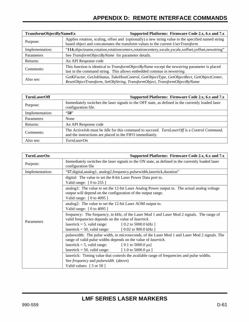
APPENDIX D: REMOTE INTERFACE COMMANDS
LMF SERIES LASER MARKERS
990-559 D-61
TransformObjectByNameEx Supported Platforms: Firmware Code 2.x, 6.x and 7.x
Purpose: Applies rotation, scaling, offset and (optionally) a new string value to the specified named string based object and concatenates the transform values to the current UserTransform.
Implementation: “114,objectname,rotation,rotationcenterx,rotationcentery,xscale,yscale,xoffset,yoffset,newstring” Parameters See TransformObjectByName for parameter details. Returns: An API Response code
Comments: This function is identical to TransformObjectByName except the newstring parameter is placed last in the command string. This allows embedded commas in newstring.
Also see: GetKFactor, GetJobStatus, TakeHostControl, GetObjectType, GetObjectRect, GetObjectCenter, ResetObjectTransform, SetObjString, TransformObject, TransformObjectByName
TurnLaserOff Supported Platforms: Firmware Code 2.x, 6.x and 7.x
Purpose: Immediately switches the laser signals to the OFF state, as defined in the currently loaded laser configuration file.
Implementation: “58” Parameters None Returns: An API Response code
Comments: The ActiveJob must be Idle for this command to succeed. TurnLaserOff is a Control Command, and the instructions are placed in the FIFO immediately.
Also see: TurnLaserOn
TurnLaserOn Supported Platforms: Firmware Code 2.x, 6.x and 7.x
Purpose: Immediately switches the laser signals to the ON state, as defined in the currently loaded laser configuration file
Implementation: “57,digital,analog1, analog2,frequency,pulsewidth,lasertick,duration”
Parameters
digital: The value to set the 8-bit Laser Power Data port to. Valid range: [ 0 to 255 ] analog1: The value to set the 12-bit Laser Analog Power output to. The actual analog voltage output will depend on the configuration of the output range. Valid range: [ 0 to 4095 ] analog2: The value to set the 12-bit Laser AOM output to. Valid range: [ 0 to 4095 ] frequency: The frequency, in kHz, of the Laser Mod 1 and Laser Mod 2 signals. The range of valid frequencies depends on the value of lasertick. lasertick = 5, valid range: [ 0.2 to 5000.0 kHz ] lasertick = 50, valid range: [ 0.02 to 900.0 kHz ] pulsewidth: The pulse width, in microseconds, of the Laser Mod 1 and Laser Mod 2 signals. The range of valid pulse widths depends on the value of lasertick. lasertick = 5, valid range: [ 0.1 to 5000.0 µs] lasertick = 50, valid range: [ 1.0 to 5000.0 µs ] lasertick: Timing value that controls the available range of frequencies and pulse widths. See frequency and pulsewidth (above) Valid values: [ 5 or 50 ]
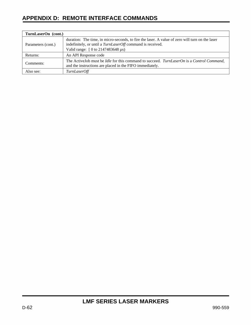
APPENDIX D: REMOTE INTERFACE COMMANDS
LMF SERIES LASER MARKERS
D-62 990-559
TurnLaserOn (cont.)
Parameters (cont.) duration: The time, in micro-seconds, to fire the laser. A value of zero will turn on the laser indefinitely, or until a TurnLaserOff command is received. Valid range: [ 0 to 2147483648 µs)
Returns: An API Response code
Comments: The ActiveJob must be Idle for this command to succeed. TurnLaserOn is a Control Command, and the instructions are placed in the FIFO immediately.
Also see: TurnLaserOff
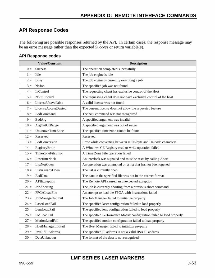
APPENDIX D: REMOTE INTERFACE COMMANDS
LMF SERIES LASER MARKERS
990-559 D-63
API Response Codes
The following are possible responses returned by the API. In certain cases, the response message may be an error message rather than the expected Success or return variable(s). API Response codes
Value/Constant Description 0 = Success The operation completed successfully 1 = Idle The job engine is idle 2 = Busy The job engine is currently executing a job 3 = NoJob The specified job was not found 4 = InControl The requesting client has exclusive control of the Host 5 = NotInControl The requesting client does not have exclusive control of the host 6 = LicenseUnavailable A valid license was not found 7 = LicenseAccessDenied The current license does not allow the requested feature 8 = BadCommand The API command was not recognized 9 = BadArg A specified argument was invalid
10 = ArgOutOfRange A specified argument was out of range 11 = UnknownTimeZone The specified time zone cannot be found 12 = Reserved Reserved 13 = BadConversion Error while converting between multi-byte and Unicode characters 14 = RegistryError A Windows CE Registry read or write operation failed 15 = TimeZoneFileError A Time Zone File operation failed 16 = ResetInterlock An interlock was signaled and must be reset by calling Abort 17 = ListNotOpen An operation was attempted on a list that has not been opened 18 = ListAlreadyOpen The list is currently open 19 = BadData The data in the specified file was not in the correct format 20 = APIException The Remote API caused an unexpected exception 21 = JobAborting The job is currently aborting from a previous abort command 22 = FPGALoadFile An attempt to load the FPGA with instructions failed 23 = JobManagerInitFail The Job Manager failed to initialize properly 24 = LaserLoadFail The specified laser configuration failed to load properly 25 = LensLoadFail The specified lens configuration failed to load properly 26 = PMLoadFail The specified Performance Matrix configuration failed to load properly 27 = MotionLoadFail The specified motion configuration failed to load properly 28 = HostManagerInitFail The Host Manager failed to initialize properly 29 = InvalidIPAddress The specified IP address is not a valid IPv4 IP address 30 = DataUnknown The format of the data is not recognized
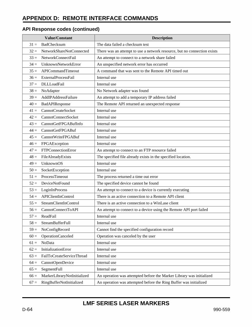
APPENDIX D: REMOTE INTERFACE COMMANDS
LMF SERIES LASER MARKERS
D-64 990-559
API Response codes (continued) Value/Constant Description
31 = BadChecksum The data failed a checksum test 32 = NetworkShareNotConnected There was an attempt to use a network resource, but no connection exists 33 = NetworkConnectFail An attempt to connect to a network share failed 34 = UnknownNetworkError An unspecified network error has occurred 35 = APICommandTimeout A command that was sent to the Remote API timed out 36 = ExternalProcessFail Internal use 37 = DLLLoadFail Internal use 38 = NoAdapter No Network adapter was found 39 = AddIPAddressFailure An attempt to add a temporary IP address failed 40 = BadAPIResponse The Remote API returned an unexpected response 41 = CannotCreateSocket Internal use 42 = CannotConnectSocket Internal use 43 = CannotGetFPGABufInfo Internal use 44 = CannotGetFPGABuf Internal use 45 = CannotWriteFPGABuf Internal use 46 = FPGAException Internal use 47 = FTPConnectionError An attempt to connect to an FTP resource failed 48 = FileAlreadyExists The specified file already exists in the specified location. 49 = UnknownOS Internal use 50 = SocketException Internal use 51 = ProcessTimeout The process returned a time out error 52 = DeviceNotFound The specified device cannot be found 53 = LoginInProcess An attempt to connect to a device is currently executing 54 = APIClientInControl There is an active connection to a Remote API client 55 = StreamClientInControl There is an active connection to a WinLase client 56 = CannotConnectToAPI An attempt to connect to a device using the Remote API port failed 57 = ReadFail Internal use 58 = StreamBufferFull Internal use 59 = NoConfigRecord Cannot find the specified configuration record 60 = OperationCanceled Operation was canceled by the user 61 = NoData Internal use 62 = InitializationError Internal use 63 = FailToCreateServiceThread Internal use 64 = CannotOpenDevice Internal use 65 = SegmentFull Internal use 66 = MarkerLibraryNotInitialized An operation was attempted before the Marker Library was initialized 67 = RingBufferNotInitialized An operation was attempted before the Ring Buffer was initialized
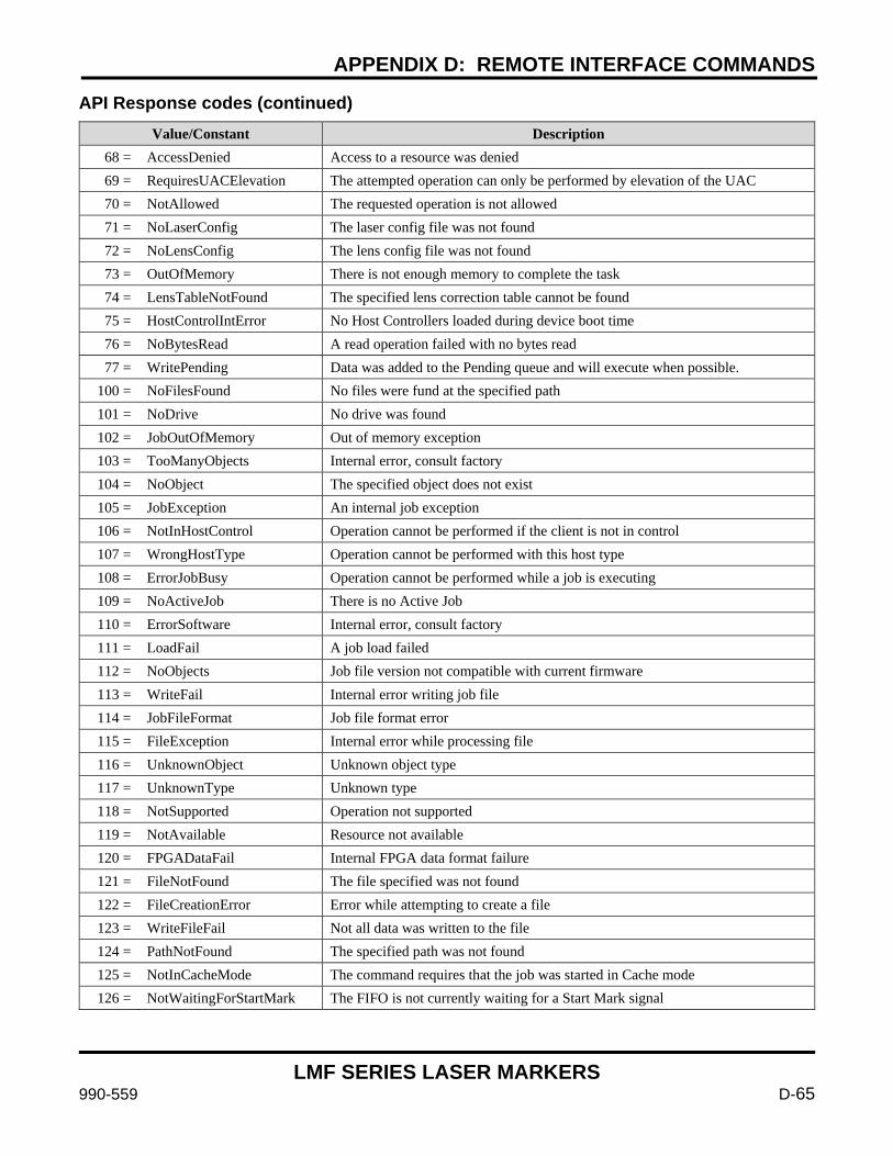
APPENDIX D: REMOTE INTERFACE COMMANDS
LMF SERIES LASER MARKERS
990-559 D-65
API Response codes (continued) Value/Constant Description
68 = AccessDenied Access to a resource was denied 69 = RequiresUACElevation The attempted operation can only be performed by elevation of the UAC 70 = NotAllowed The requested operation is not allowed 71 = NoLaserConfig The laser config file was not found 72 = NoLensConfig The lens config file was not found 73 = OutOfMemory There is not enough memory to complete the task 74 = LensTableNotFound The specified lens correction table cannot be found 75 = HostControlIntError No Host Controllers loaded during device boot time 76 = NoBytesRead A read operation failed with no bytes read 77 = WritePending Data was added to the Pending queue and will execute when possible.
100 = NoFilesFound No files were fund at the specified path 101 = NoDrive No drive was found 102 = JobOutOfMemory Out of memory exception 103 = TooManyObjects Internal error, consult factory 104 = NoObject The specified object does not exist 105 = JobException An internal job exception 106 = NotInHostControl Operation cannot be performed if the client is not in control 107 = WrongHostType Operation cannot be performed with this host type 108 = ErrorJobBusy Operation cannot be performed while a job is executing 109 = NoActiveJob There is no Active Job 110 = ErrorSoftware Internal error, consult factory 111 = LoadFail A job load failed 112 = NoObjects Job file version not compatible with current firmware 113 = WriteFail Internal error writing job file 114 = JobFileFormat Job file format error 115 = FileException Internal error while processing file 116 = UnknownObject Unknown object type 117 = UnknownType Unknown type 118 = NotSupported Operation not supported 119 = NotAvailable Resource not available 120 = FPGADataFail Internal FPGA data format failure 121 = FileNotFound The file specified was not found 122 = FileCreationError Error while attempting to create a file 123 = WriteFileFail Not all data was written to the file 124 = PathNotFound The specified path was not found 125 = NotInCacheMode The command requires that the job was started in Cache mode 126 = NotWaitingForStartMark The FIFO is not currently waiting for a Start Mark signal

APPENDIX D: REMOTE INTERFACE COMMANDS
LMF SERIES LASER MARKERS
D-66 990-559
API Response codes (continued) Value/Constant Description
127 = MotionNotHomed The command is not allowed if the device is not homed 128 = No3DModel The operation cannot complete because there is no 3D model loaded 129 = ProjectionError An error was encountered while projecting onto the 3D model 200 = NoProperties Object does not contain any properties 201 = ObjectException Internal object exception 202 = Abort Operation was aborted 203 = NoFontResource The font specified in the object was not found 204 = NoOverride Internal object error 205 = ExternalEnableDenied Operation denied by External control 206 = CannotCreatePort A port setting (baud rate, stop bits, etc.) is invalid 207 = CannotOpenPort Error while attempting to open COM port 208 = PortNotOpen Port must be open to execute command 209 = PortTimeout A port operation timed out 210 = WrongPortNumber Invalid port number 211 = WrongObjectType Operation is not supported by this object type 212 = AxisNotConfigured A motion control axis referenced in an object has not been configured 213 = TextBufferOverrun Too many characters in buffer (MAX 3000 including command opcode) 214 = InvBarcodeStringValue The barcode string to encode contains invalid characters 215 = InvBarcodeStringLength The length of the barcode string to encode is either too short or too long 216 = InvBarcodeNarrowWidth The Narrow to Wide ratio is invalid 217 = InvBarcodeWidthReduce The Width Reduction value is invalid 218 = InvBarcodeECC The ECC value is invalid, or cannot be used to encode the string 219 = BarcodeOutOfMemory There was insufficient memory to complete an internal barcode operation 220 = BarcodeUnknownError Undocumented error. Please notify the factory 221 = BarcodeException Incorrect data, or an internal operation resulted in an unexpected result 222 = NoVectors An object was saved to the job with both Mark Outline and Mark Fill disabled 223 = BadMotionResponse The motion controller responded with an unexpected value 224 = MotionDriverNotFound An object is referencing a motion driver that does not exist 225 = AxisNotFound An operation was attempted on an axis index that was not found
226 = EncoderNotFound An operation was attempted that depends on an encoder, and no encoder was found
227 = InvStringValue The string to process is not a valid string 228 = MotionControllerNotFound The motion system cannot detect a valid controller device 229 = MotorNotProvisioned The motor has not been provisioned for use with the LEC controller 230 = RuntimeMotionError An error was generated during a motor move operation 231 = ObjectOutOfBounds The object is outside the legal marking area 232 = InvVersion Invalid version 233 = NoOutline Not valid to have MarkOutline enabled with no outline to mark

APPENDIX D: REMOTE INTERFACE COMMANDS
LMF SERIES LASER MARKERS
990-559 D-67
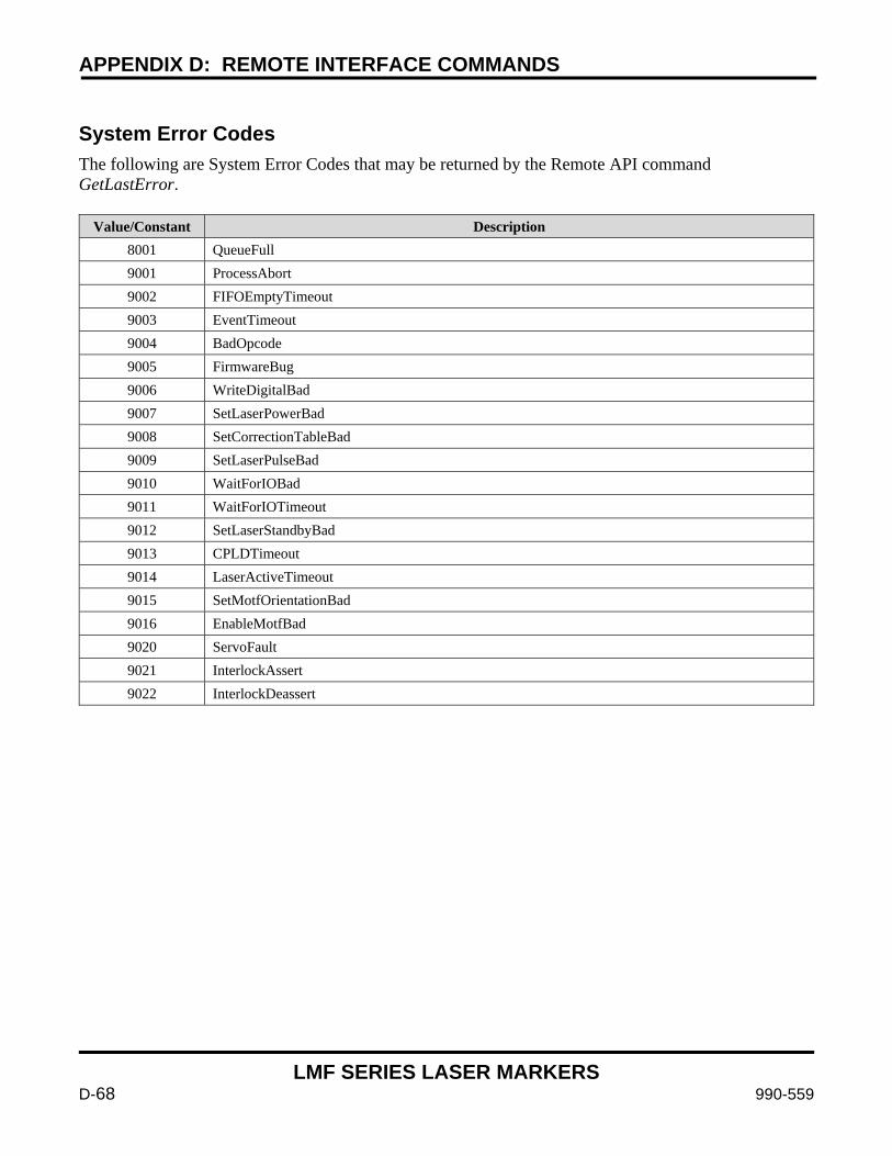
APPENDIX D: REMOTE INTERFACE COMMANDS
LMF SERIES LASER MARKERS
D-68 990-559
System Error Codes The following are System Error Codes that may be returned by the Remote API command GetLastError.
Value/Constant Description 8001 QueueFull 9001 ProcessAbort 9002 FIFOEmptyTimeout 9003 EventTimeout 9004 BadOpcode 9005 FirmwareBug 9006 WriteDigitalBad 9007 SetLaserPowerBad 9008 SetCorrectionTableBad 9009 SetLaserPulseBad 9010 WaitForIOBad 9011 WaitForIOTimeout 9012 SetLaserStandbyBad 9013 CPLDTimeout 9014 LaserActiveTimeout 9015 SetMotfOrientationBad 9016 EnableMotfBad 9020 ServoFault 9021 InterlockAssert 9022 InterlockDeassert
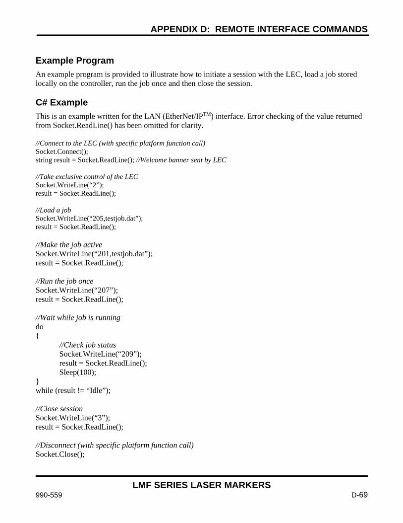
APPENDIX D: REMOTE INTERFACE COMMANDS
LMF SERIES LASER MARKERS
990-559 D-69
Example Program An example program is provided to illustrate how to initiate a session with the LEC, load a job stored locally on the controller, run the job once and then close the session. C# Example This is an example written for the LAN (EtherNet/IPTM) interface. Error checking of the value returned from Socket.ReadLine() has been omitted for clarity. //Connect to the LEC (with specific platform function call) Socket.Connect(); string result = Socket.ReadLine(); //Welcome banner sent by LEC //Take exclusive control of the LEC Socket.WriteLine(“2”); result = Socket.ReadLine(); //Load a job Socket.WriteLine(“205,testjob.dat”); result = Socket.ReadLine(); //Make the job active Socket.WriteLine(“201,testjob.dat”); result = Socket.ReadLine(); //Run the job once Socket.WriteLine(“207”); result = Socket.ReadLine(); //Wait while job is running do //Check job status Socket.WriteLine(“209”); result = Socket.ReadLine(); Sleep(100); while (result != “Idle”); //Close session Socket.WriteLine(“3”); result = Socket.ReadLine(); //Disconnect (with specific platform function call) Socket.Close();
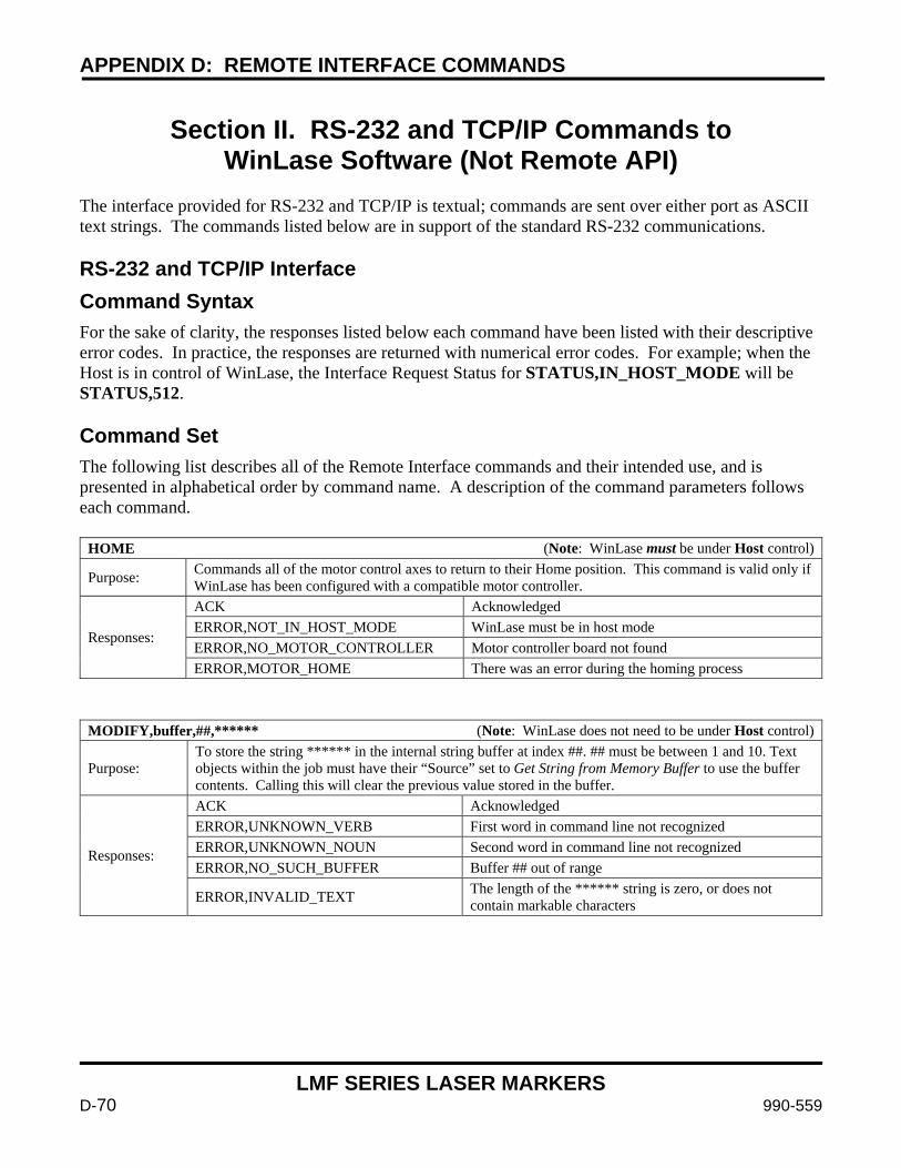
APPENDIX D: REMOTE INTERFACE COMMANDS
LMF SERIES LASER MARKERS
D-70 990-559
Section II. RS-232 and TCP/IP Commands to
WinLase Software (Not Remote API) The interface provided for RS-232 and TCP/IP is textual; commands are sent over either port as ASCII text strings. The commands listed below are in support of the standard RS-232 communications. RS-232 and TCP/IP Interface Command Syntax For the sake of clarity, the responses listed below each command have been listed with their descriptive error codes. In practice, the responses are returned with numerical error codes. For example; when the Host is in control of WinLase, the Interface Request Status for STATUS,IN_HOST_MODE will be STATUS,512. Command Set The following list describes all of the Remote Interface commands and their intended use, and is presented in alphabetical order by command name. A description of the command parameters follows each command.
HOME (Note: WinLase must be under Host control)
Purpose: Commands all of the motor control axes to return to their Home position. This command is valid only if WinLase has been configured with a compatible motor controller.
Responses:
ACK Acknowledged ERROR,NOT_IN_HOST_MODE WinLase must be in host mode ERROR,NO_MOTOR_CONTROLLER Motor controller board not found ERROR,MOTOR_HOME There was an error during the homing process
MODIFY,buffer,##,****** (Note: WinLase does not need to be under Host control)
Purpose: To store the string ****** in the internal string buffer at index ##. ## must be between 1 and 10. Text objects within the job must have their “Source” set to Get String from Memory Buffer to use the buffer contents. Calling this will clear the previous value stored in the buffer.
Responses:
ACK Acknowledged ERROR,UNKNOWN_VERB First word in command line not recognized ERROR,UNKNOWN_NOUN Second word in command line not recognized ERROR,NO_SUCH_BUFFER Buffer ## out of range
ERROR,INVALID_TEXT The length of the ****** string is zero, or does not contain markable characters
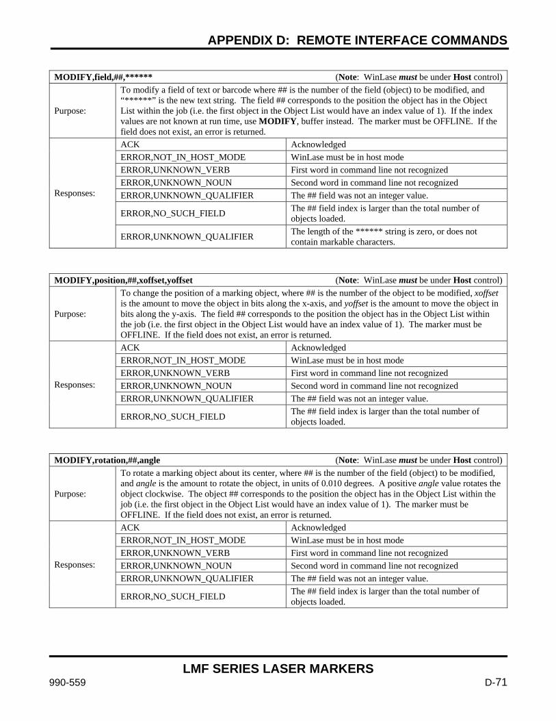
APPENDIX D: REMOTE INTERFACE COMMANDS
LMF SERIES LASER MARKERS
990-559 D-71
MODIFY,field,##,****** (Note: WinLase must be under Host control)
Purpose:
To modify a field of text or barcode where ## is the number of the field (object) to be modified, and “******” is the new text string. The field ## corresponds to the position the object has in the Object List within the job (i.e. the first object in the Object List would have an index value of 1). If the index values are not known at run time, use MODIFY, buffer instead. The marker must be OFFLINE. If the field does not exist, an error is returned.
Responses:
ACK Acknowledged ERROR,NOT_IN_HOST_MODE WinLase must be in host mode ERROR,UNKNOWN_VERB First word in command line not recognized ERROR,UNKNOWN_NOUN Second word in command line not recognized ERROR,UNKNOWN_QUALIFIER The ## field was not an integer value.
ERROR,NO_SUCH_FIELD The ## field index is larger than the total number of objects loaded.
ERROR,UNKNOWN_QUALIFIER The length of the ****** string is zero, or does not contain markable characters.
MODIFY,position,##,xoffset,yoffset (Note: WinLase must be under Host control)
Purpose:
To change the position of a marking object, where ## is the number of the object to be modified, xoffset is the amount to move the object in bits along the x-axis, and yoffset is the amount to move the object in bits along the y-axis. The field ## corresponds to the position the object has in the Object List within the job (i.e. the first object in the Object List would have an index value of 1). The marker must be OFFLINE. If the field does not exist, an error is returned.
Responses:
ACK Acknowledged ERROR,NOT_IN_HOST_MODE WinLase must be in host mode ERROR,UNKNOWN_VERB First word in command line not recognized ERROR,UNKNOWN_NOUN Second word in command line not recognized ERROR,UNKNOWN_QUALIFIER The ## field was not an integer value.
ERROR,NO_SUCH_FIELD The ## field index is larger than the total number of objects loaded.
MODIFY,rotation,##,angle (Note: WinLase must be under Host control)
Purpose:
To rotate a marking object about its center, where ## is the number of the field (object) to be modified, and angle is the amount to rotate the object, in units of 0.010 degrees. A positive angle value rotates the object clockwise. The object ## corresponds to the position the object has in the Object List within the job (i.e. the first object in the Object List would have an index value of 1). The marker must be OFFLINE. If the field does not exist, an error is returned.
Responses:
ACK Acknowledged ERROR,NOT_IN_HOST_MODE WinLase must be in host mode ERROR,UNKNOWN_VERB First word in command line not recognized ERROR,UNKNOWN_NOUN Second word in command line not recognized ERROR,UNKNOWN_QUALIFIER The ## field was not an integer value.
ERROR,NO_SUCH_FIELD The ## field index is larger than the total number of objects loaded.
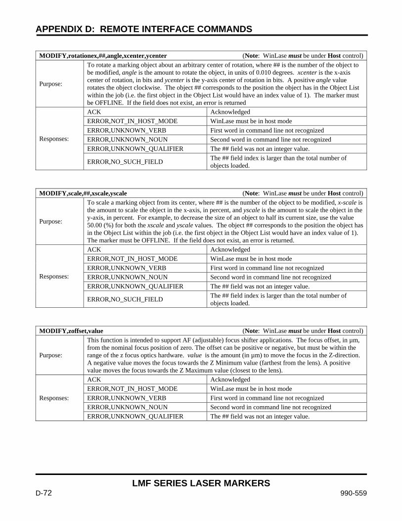
APPENDIX D: REMOTE INTERFACE COMMANDS
LMF SERIES LASER MARKERS
D-72 990-559
MODIFY,rotationex,##,angle,xcenter,ycenter (Note: WinLase must be under Host control)
Purpose:
To rotate a marking object about an arbitrary center of rotation, where ## is the number of the object to be modified, angle is the amount to rotate the object, in units of 0.010 degrees. xcenter is the x-axis center of rotation, in bits and ycenter is the y-axis center of rotation in bits. A positive angle value rotates the object clockwise. The object ## corresponds to the position the object has in the Object List within the job (i.e. the first object in the Object List would have an index value of 1). The marker must be OFFLINE. If the field does not exist, an error is returned
Responses:
ACK Acknowledged ERROR,NOT_IN_HOST_MODE WinLase must be in host mode ERROR,UNKNOWN_VERB First word in command line not recognized ERROR,UNKNOWN_NOUN Second word in command line not recognized ERROR,UNKNOWN_QUALIFIER The ## field was not an integer value.
ERROR,NO_SUCH_FIELD The ## field index is larger than the total number of objects loaded.
MODIFY,scale,##,xscale,yscale (Note: WinLase must be under Host control)
Purpose:
To scale a marking object from its center, where ## is the number of the object to be modified, x-scale is the amount to scale the object in the x-axis, in percent, and yscale is the amount to scale the object in the y-axis, in percent. For example, to decrease the size of an object to half its current size, use the value 50.00 (%) for both the xscale and yscale values. The object ## corresponds to the position the object has in the Object List within the job (i.e. the first object in the Object List would have an index value of 1). The marker must be OFFLINE. If the field does not exist, an error is returned.
Responses:
ACK Acknowledged ERROR,NOT_IN_HOST_MODE WinLase must be in host mode ERROR,UNKNOWN_VERB First word in command line not recognized ERROR,UNKNOWN_NOUN Second word in command line not recognized ERROR,UNKNOWN_QUALIFIER The ## field was not an integer value.
ERROR,NO_SUCH_FIELD The ## field index is larger than the total number of objects loaded.
MODIFY,zoffset,value (Note: WinLase must be under Host control)
Purpose:
This function is intended to support AF (adjustable) focus shifter applications. The focus offset, in µm, from the nominal focus position of zero. The offset can be positive or negative, but must be within the range of the z focus optics hardware. value is the amount (in µm) to move the focus in the Z-direction. A negative value moves the focus towards the Z Minimum value (farthest from the lens). A positive value moves the focus towards the Z Maximum value (closest to the lens).
Responses:
ACK Acknowledged ERROR,NOT_IN_HOST_MODE WinLase must be in host mode ERROR,UNKNOWN_VERB First word in command line not recognized ERROR,UNKNOWN_NOUN Second word in command line not recognized ERROR,UNKNOWN_QUALIFIER The ## field was not an integer value.
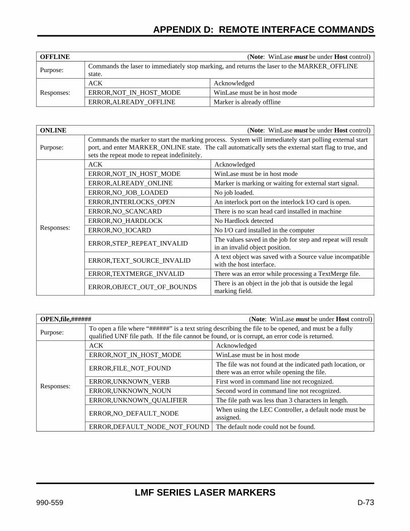
APPENDIX D: REMOTE INTERFACE COMMANDS
LMF SERIES LASER MARKERS
990-559 D-73
OFFLINE (Note: WinLase must be under Host control)
Purpose: Commands the laser to immediately stop marking, and returns the laser to the MARKER_OFFLINE state.
Responses: ACK Acknowledged ERROR,NOT_IN_HOST_MODE WinLase must be in host mode ERROR,ALREADY_OFFLINE Marker is already offline
ONLINE (Note: WinLase must be under Host control)
Purpose: Commands the marker to start the marking process. System will immediately start polling external start port, and enter MARKER_ONLINE state. The call automatically sets the external start flag to true, and sets the repeat mode to repeat indefinitely.
Responses:
ACK Acknowledged ERROR,NOT_IN_HOST_MODE WinLase must be in host mode ERROR,ALREADY_ONLINE Marker is marking or waiting for external start signal. ERROR,NO_JOB_LOADED No job loaded. ERROR,INTERLOCKS_OPEN An interlock port on the interlock I/O card is open. ERROR,NO_SCANCARD There is no scan head card installed in machine ERROR,NO_HARDLOCK No Hardlock detected ERROR,NO_IOCARD No I/O card installed in the computer
ERROR,STEP_REPEAT_INVALID The values saved in the job for step and repeat will result in an invalid object position.
ERROR,TEXT_SOURCE_INVALID A text object was saved with a Source value incompatible with the host interface.
ERROR,TEXTMERGE_INVALID There was an error while processing a TextMerge file.
ERROR,OBJECT_OUT_OF_BOUNDS There is an object in the job that is outside the legal marking field.
OPEN,file,###### (Note: WinLase must be under Host control)
Purpose: To open a file where “######” is a text string describing the file to be opened, and must be a fully qualified UNF file path. If the file cannot be found, or is corrupt, an error code is returned.
Responses:
ACK Acknowledged ERROR,NOT_IN_HOST_MODE WinLase must be in host mode
ERROR,FILE_NOT_FOUND The file was not found at the indicated path location, or there was an error while opening the file.
ERROR,UNKNOWN_VERB First word in command line not recognized. ERROR,UNKNOWN_NOUN Second word in command line not recognized. ERROR,UNKNOWN_QUALIFIER The file path was less than 3 characters in length.
ERROR,NO_DEFAULT_NODE When using the LEC Controller, a default node must be assigned.
ERROR,DEFAULT_NODE_NOT_FOUND The default node could not be found.
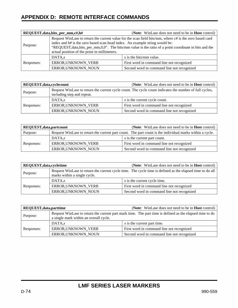
APPENDIX D: REMOTE INTERFACE COMMANDS
LMF SERIES LASER MARKERS
D-74 990-559
REQUEST,data,bits_per_mm,c#,h# (Note: WinLase does not need to be in Host control)
Purpose:
Request WinLase to return the current value for the scan field bits/mm, where c# is the zero based card index and h# is the zero based scan head index. An example string would be: “REQUEST,data,bits_per_mm,0,0”. The bits/mm value is the ratio of a point coordinate in bits and the actual position of the point in millimeters.
Responses: DATA,x x is the bits/mm value. ERROR,UNKNOWN_VERB First word in command line not recognized ERROR,UNKNOWN_NOUN Second word in command line not recognized
REQUEST,data,cyclecount (Note: WinLase does not need to be in Host control)
Purpose: Request WinLase to return the current cycle count. The cycle count indicates the number of full cycles, including step and repeat.
Responses: DATA,x x is the current cycle count. ERROR,UNKNOWN_VERB First word in command line not recognized ERROR,UNKNOWN_NOUN Second word in command line not recognized
REQUEST,data,partcount (Note: WinLase does not need to be in Host control) Purpose: Request WinLase to return the current part count. The part count is the individual marks within a cycle.
Responses: DATA,x x is the current part count. ERROR,UNKNOWN_VERB First word in command line not recognized ERROR,UNKNOWN_NOUN Second word in command line not recognized
REQUEST,data,cycletime (Note: WinLase does not need to be in Host control)
Purpose: Request WinLase to return the current cycle time. The cycle time is defined as the elapsed time to do all marks within a single cycle.
Responses: DATA,x x is the current cycle time. ERROR,UNKNOWN_VERB First word in command line not recognized ERROR,UNKNOWN_NOUN Second word in command line not recognized
REQUEST,data,parttime (Note: WinLase does not need to be in Host control)
Purpose: Request WinLase to return the current part mark time. The part time is defined as the elapsed time to do a single mark within an overall cycle.
Responses: DATA,x x is the current part time. ERROR,UNKNOWN_VERB First word in command line not recognized ERROR,UNKNOWN_NOUN Second word in command line not recognized
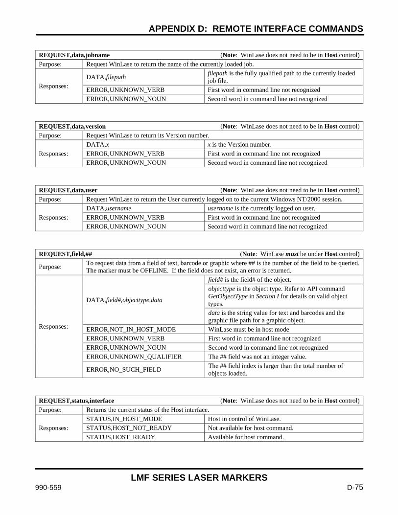
APPENDIX D: REMOTE INTERFACE COMMANDS
LMF SERIES LASER MARKERS
990-559 D-75
REQUEST,data,jobname (Note: WinLase does not need to be in Host control) Purpose: Request WinLase to return the name of the currently loaded job.
Responses: DATA,filepath filepath is the fully qualified path to the currently loaded
job file. ERROR,UNKNOWN_VERB First word in command line not recognized ERROR,UNKNOWN_NOUN Second word in command line not recognized
REQUEST,data,version (Note: WinLase does not need to be in Host control) Purpose: Request WinLase to return its Version number.
Responses: DATA,x x is the Version number. ERROR,UNKNOWN_VERB First word in command line not recognized ERROR,UNKNOWN_NOUN Second word in command line not recognized
REQUEST,data,user (Note: WinLase does not need to be in Host control) Purpose: Request WinLase to return the User currently logged on to the current Windows NT/2000 session.
Responses: DATA,username username is the currently logged on user. ERROR,UNKNOWN_VERB First word in command line not recognized ERROR,UNKNOWN_NOUN Second word in command line not recognized
REQUEST,field,## (Note: WinLase must be under Host control)
Purpose: To request data from a field of text, barcode or graphic where ## is the number of the field to be queried. The marker must be OFFLINE. If the field does not exist, an error is returned.
Responses:
DATA,field#,objecttype,data
field# is the field# of the object. objecttype is the object type. Refer to API command GetObjectType in Section I for details on valid object types. data is the string value for text and barcodes and the graphic file path for a graphic object.
ERROR,NOT_IN_HOST_MODE WinLase must be in host mode ERROR,UNKNOWN_VERB First word in command line not recognized ERROR,UNKNOWN_NOUN Second word in command line not recognized ERROR,UNKNOWN_QUALIFIER The ## field was not an integer value.
ERROR,NO_SUCH_FIELD The ## field index is larger than the total number of objects loaded.
REQUEST,status,interface (Note: WinLase does not need to be in Host control) Purpose: Returns the current status of the Host interface.
Responses: STATUS,IN_HOST_MODE Host in control of WinLase. STATUS,HOST_NOT_READY Not available for host command. STATUS,HOST_READY Available for host command.
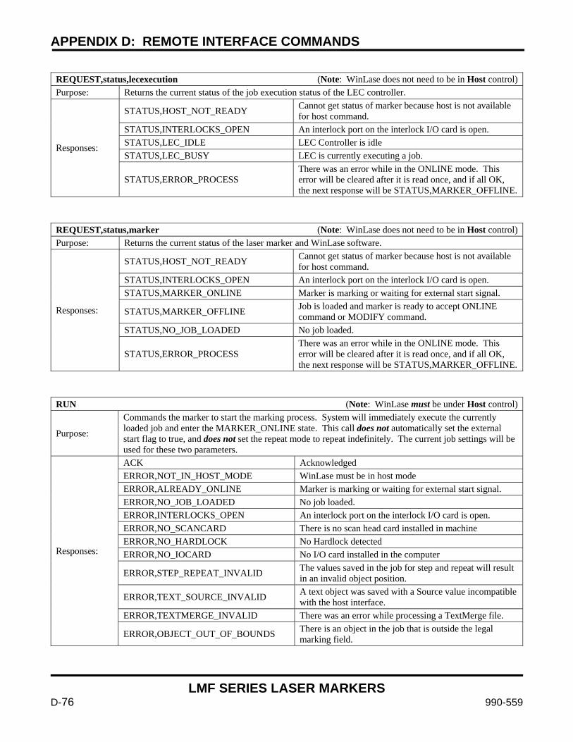
APPENDIX D: REMOTE INTERFACE COMMANDS
LMF SERIES LASER MARKERS
D-76 990-559
REQUEST,status,lecexecution (Note: WinLase does not need to be in Host control) Purpose: Returns the current status of the job execution status of the LEC controller.
Responses:
STATUS,HOST_NOT_READY Cannot get status of marker because host is not available for host command.
STATUS,INTERLOCKS_OPEN An interlock port on the interlock I/O card is open. STATUS,LEC_IDLE LEC Controller is idle STATUS,LEC_BUSY LEC is currently executing a job.
STATUS,ERROR_PROCESS There was an error while in the ONLINE mode. This error will be cleared after it is read once, and if all OK, the next response will be STATUS,MARKER_OFFLINE.
REQUEST,status,marker (Note: WinLase does not need to be in Host control) Purpose: Returns the current status of the laser marker and WinLase software.
Responses:
STATUS,HOST_NOT_READY Cannot get status of marker because host is not available for host command.
STATUS,INTERLOCKS_OPEN An interlock port on the interlock I/O card is open. STATUS,MARKER_ONLINE Marker is marking or waiting for external start signal.
STATUS,MARKER_OFFLINE Job is loaded and marker is ready to accept ONLINE command or MODIFY command.
STATUS,NO_JOB_LOADED No job loaded.
STATUS,ERROR_PROCESS There was an error while in the ONLINE mode. This error will be cleared after it is read once, and if all OK, the next response will be STATUS,MARKER_OFFLINE.
RUN (Note: WinLase must be under Host control)
Purpose:
Commands the marker to start the marking process. System will immediately execute the currently loaded job and enter the MARKER_ONLINE state. This call does not automatically set the external start flag to true, and does not set the repeat mode to repeat indefinitely. The current job settings will be used for these two parameters.
Responses:
ACK Acknowledged ERROR,NOT_IN_HOST_MODE WinLase must be in host mode ERROR,ALREADY_ONLINE Marker is marking or waiting for external start signal. ERROR,NO_JOB_LOADED No job loaded. ERROR,INTERLOCKS_OPEN An interlock port on the interlock I/O card is open. ERROR,NO_SCANCARD There is no scan head card installed in machine ERROR,NO_HARDLOCK No Hardlock detected ERROR,NO_IOCARD No I/O card installed in the computer
ERROR,STEP_REPEAT_INVALID The values saved in the job for step and repeat will result in an invalid object position.
ERROR,TEXT_SOURCE_INVALID A text object was saved with a Source value incompatible with the host interface.
ERROR,TEXTMERGE_INVALID There was an error while processing a TextMerge file.
ERROR,OBJECT_OUT_OF_BOUNDS There is an object in the job that is outside the legal marking field.
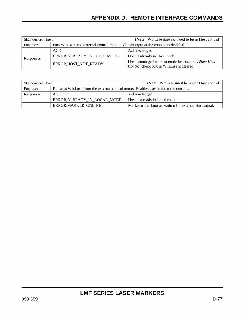
APPENDIX D: REMOTE INTERFACE COMMANDS
LMF SERIES LASER MARKERS
990-559 D-77
SET,control,host (Note: WinLase does not need to be in Host control) Purpose: Puts WinLase into external control mode. All user input at the console is disabled.
Responses:
ACK Acknowledged ERROR,ALREADY_IN_HOST_MODE Host is already in Host mode.
ERROR,HOST_NOT_READY Host cannot go into host mode because the Allow Host Control check box in WinLase is cleared.
SET,control,local (Note: WinLase must be under Host control) Purpose: Releases WinLase from the external control mode. Enables user input at the console. Responses: ACK Acknowledged ERROR,ALREADY_IN_LOCAL_MODE Host is already in Local mode. ERROR,MARKER_ONLINE Marker is marking or waiting for external start signal.
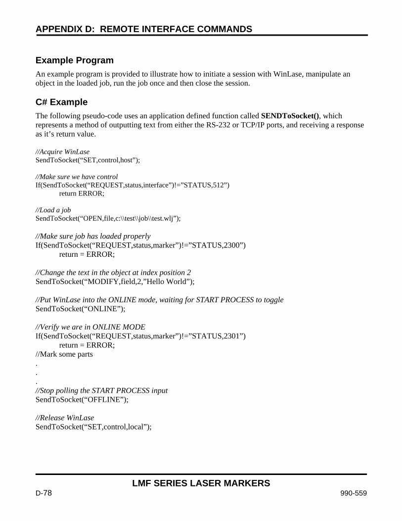
APPENDIX D: REMOTE INTERFACE COMMANDS
LMF SERIES LASER MARKERS
D-78 990-559
Example Program An example program is provided to illustrate how to initiate a session with WinLase, manipulate an object in the loaded job, run the job once and then close the session. C# Example The following pseudo-code uses an application defined function called SENDToSocket(), which represents a method of outputting text from either the RS-232 or TCP/IP ports, and receiving a response as it’s return value. //Acquire WinLase SendToSocket(“SET,control,host”); //Make sure we have control If(SendToSocket(“REQUEST,status,interface”)!=”STATUS,512”) return ERROR; //Load a job SendToSocket(“OPEN,file,c:\\test\\job\\test.wlj”); //Make sure job has loaded properly If(SendToSocket(“REQUEST,status,marker”)!=”STATUS,2300”) return = ERROR; //Change the text in the object at index position 2 SendToSocket(“MODIFY,field,2,”Hello World”); //Put WinLase into the ONLINE mode, waiting for START PROCESS to toggle SendToSocket(“ONLINE”); //Verify we are in ONLINE MODE If(SendToSocket(“REQUEST,status,marker”)!=”STATUS,2301”) return = ERROR; //Mark some parts . . . //Stop polling the START PROCESS input SendToSocket(“OFFLINE”); //Release WinLase SendToSocket(“SET,control,local”);

http://www.amy.amada.co.jp/e/
AMADA MIYACHI AMERICA, INC. 1820 South Myrtle Ave., Monrovia, CA 91016, U.S.A. TEL. +1‐626‐303‐5676 FAX. +1‐626‐358‐8048 http://amadamiyachi.com
AMADA MIYACHI CO., LTD. 200, Ishida, Isehara‐shi, Kanagawa 259‐1196, Japan
AMADA MIYACHI KOREA CO., LTD. 28, Dongtanhana 1‐gil, Hwaseong‐si, Gyeonggi‐do, 18423, Korea TEL. +82‐31‐8015‐6810 FAX. +82‐31‐8003‐5995
AMADA MIYACHI SHANGHAI CO., LTD. Room 01, 15th Floor, SML Center, No.610 Xujiahui Road, Huangpu District, Shanghai 200025, China TEL. +86‐21‐6448‐6000 FAX. +86‐21‐6448‐6550
AMADA MIYACHI EUROPE GmbH Lindberghstrasse 1, DE‐82178 Puchheim, Germany TEL. +49‐89‐839403‐0 FAX. +49‐89‐839403‐68
AMADA MIYACHI TAIWAN CO., LTD. Rm. 5, 2F., No. 9, Dehui St., Zhongshan Dist., Taipei 10461, Taiwan (R.O.C.) TEL. +886‐2‐2585‐0161 FAX. +886‐2‐2585‐0162
AMADA MIYACHI VIETNAM CO., LTD. 469 Ha Huy Tap Road, Yen Vien, Gia Lam, Ha Noi, Vietnam TEL. +84‐4‐6261‐4583 FAX. +84‐4‐6261‐4584
AMADA MIYACHI (THAILAND) CO., LTD. Asia Industrial Estate Suvarnabhumi (AIES) 88/41 Moo 4, Khlongsuan, Bangbo, Samutprakarn 10560, Thailand TEL. +66(0)2‐170‐5900 FAX. +66(0)2‐170‐5909
AMADA MIYACHI INDIA PVT. LTD. #906, Ground Floor, Raj Arcade 5th ‘A’ Cross, 1st Block, HRBR Layout, Kalyan Nagar, Bengaluru, ‐ 560043, India TEL. +91‐80‐4092‐1749 FAX. +91‐80‐4091‐0592
AMADA MIYACHI DO BRASIL LTDA. Av. Tamboré, 965/973, Salas P22e F11, bairro Tamboré, 06460‐000‐Barueri‐SP, Brazil TEL. +55‐11‐4193‐1187

AMADA MIYACHI AMERICA, INC. 1820 South Myrtle Ave., Monrovia, CA 91016, U.S.A. TEL. +1‐626‐303‐5676 FAX. +1‐626‐358‐8048