
feasibility study of large-format, freeform 3d printing for on ...
19
FEASIBILITY STUDY OF LARGE-FORMAT, FREEFORM 3D PRINTING FOR ON-ORBIT ADDITIVE MANUFACTURING D. Jonckers * , O. Tauscher * , E. Stoll † , and A. Thakur *‡ * Institute of Space Systems, Technical University Braunschweig, Braunschweig, Germany † Institute for Space Technology, Technical University Berlin, Berlin, Germany ‡ Corresponding author: [email protected] Abstract Large scale, on-orbit additive manufacturing (AM) and assembly is being considered as a modular and resource saving approach to facilitate permanent human presence in space. To realise this, a novel AM approach to freeform fabricate large, functional structures in space has been developed. Combining the reach of a free-flying CubeSat with a collaborative robotic arm and a 3D printer, large support-free thermoplastic structures can be manufactured beyond the size of the setup itself. The feasibility of the proposed fabrication approach was established using the Experimental Lab for Proximity Operations and Space Situational Awareness (ELISSA) system, where a modified fused filament fabrication setup was mounted on a free-flyer to 3D print free-standing structures. Using a continuous navigation path incorporating an infinite fabrication loop, over 70 centimetre long, support-free trusses were produced to well demonstrate the potential of the proposed method in boundless direct printing of complex structures, independent of gravity or printing orientation. Nomenclature and Abbreviations AM Additive Manufacturing DOF Degrees of Freedom ELISSA Experimental Lab for Proximity Operations and Space Situational Awareness FFF Fused Filament Fabrication GNC Guidance, Naviation and Control ISM In Space Manufacturing ISS International Space Station JWST James Webb Space Telescope OBC On-Board Computer PEEK Polyether Ether Ketone PID Proportional-Integral-Derivative (Controller) PLA Polylactic Acid ROS Robot Operating System SMC Sliding Mode Controller 1508 Solid Freeform Fabrication 2021: Proceedings of the 32nd Annual International Solid Freeform Fabrication Symposium – An Additive Manufacturing Conference Reviewed Paper
-
Upload
khangminh22 -
Category
Documents
-
view
1 -
download
0
Transcript of feasibility study of large-format, freeform 3d printing for on ...

FEASIBILITY STUDY OF LARGE-FORMAT, FREEFORM 3D PRINTING FORON-ORBIT ADDITIVE MANUFACTURING
D. Jonckers*, O. Tauscher*, E. Stoll†, and A. Thakur*‡*Institute of Space Systems, Technical University Braunschweig, Braunschweig, Germany
†Institute for Space Technology, Technical University Berlin, Berlin, Germany‡Corresponding author: [email protected]
Abstract
Large scale, on-orbit additive manufacturing (AM) and assembly is being considered as amodular and resource saving approach to facilitate permanent human presence in space. To realisethis, a novel AM approach to freeform fabricate large, functional structures in space has beendeveloped. Combining the reach of a free-flying CubeSat with a collaborative robotic arm and a 3Dprinter, large support-free thermoplastic structures can be manufactured beyond the size of the setupitself. The feasibility of the proposed fabrication approach was established using the ExperimentalLab for Proximity Operations and Space Situational Awareness (ELISSA) system, where a modifiedfused filament fabrication setup was mounted on a free-flyer to 3D print free-standing structures.Using a continuous navigation path incorporating an infinite fabrication loop, over 70 centimetrelong, support-free trusses were produced to well demonstrate the potential of the proposed methodin boundless direct printing of complex structures, independent of gravity or printing orientation.
Nomenclature and Abbreviations
AM Additive ManufacturingDOF Degrees of FreedomELISSA Experimental Lab for Proximity Operations and Space Situational AwarenessFFF Fused Filament FabricationGNC Guidance, Naviation and ControlISM In Space ManufacturingISS International Space StationJWST James Webb Space TelescopeOBC On-Board ComputerPEEK Polyether Ether KetonePID Proportional-Integral-Derivative (Controller)PLA Polylactic AcidROS Robot Operating SystemSMC Sliding Mode Controller
1508
Solid Freeform Fabrication 2021: Proceedings of the 32nd Annual International Solid Freeform Fabrication Symposium – An Additive Manufacturing Conference
Reviewed Paper

1. Introduction
Manufacturing large, permanent human settlements in space was popularised in the 1970sby American physicist Gerard K. O’Neill, who proposed cylindrical habitats, each capable
of supporting a population of over 10 000. Launching such large structures in to orbit from Earthwould be impractical, and as such O’Neill proposed utilising raw material from the Moon, andmanufacturing these habitats in situ [1]. In more recent years, Dunn et al. and Moraguez et al.highlighted the advantages of free-form fabrication processes such as 3D printing for In-SpaceManufacturing (ISM) [2, 3]. While on demand and spare part production play a contemporary rolein the operation of space stations, both authors emphasize the importance of large structure ISMsurpassing the limits of deployable structures. For example, space-based optical telescopes such asthe yet to be launched James Webb Space Telescope (JWST) must be designed to stow within avolume dictated by a launch vehicle’s fairing [4]. This results in the spacecraft needing to undergonumerous deployments, including the release of 178 mechanisms to reach its operational state [5].As deployment mechanisms are a known source of spacecraft failure, reducing the need for thesecould result in more reliable spacecraft [6]. Another advantage of in-space manufactured parts isthe neglection of mechanical loads during the spacecraft launch – in the case of the JWST of up to4.55 g1. Eliminating these loads can lead to structures that are optimised for its in-space applicationrather than launch, in turn leading to lighter structures and reduced launch costs [7].
Research into ISM techniques for large structural components has been conducted at least sincethe 1970s, when General Dynamics, under contract from NASA, produced a prototype “beambuilder” capable of producing hundred meter scale truss segments on orbit [8]. This machineused ultrasonic welding to manufacture a beam from single-ply graphite/glass impregnated with apolysulfone resin, and though the feasibility of the concept was proved, did not fly. No investigationwas done as to how more complex structures could be manufactured.
More recently, the focus has shifted to additive manufacturing processes with Tethers Un-limited, also under the contract from NASA, proposing a concept termed SpiderFab™ [9]. Thisrobot spacecraft would use an extruding nozzle, or spinneret, to extrude Carbon fibre reinforcedpolyetheretherketone (PEEK) segments. Its robotic arms would then, in conjunction with a joiningtool, assemble these segments into large structural components. A prototype truss manufacturingmachine was also built, using Twintex® , a continuous fibre reinforced thermoplastic yarn, to producetriangular trusses several metres in length. These could then be manipulated by SpiderFab™ toassemble higher order truss structures. A concept for a “trusselator” machine which could man-ufacture triangular trusses from rolls of Carbon Fibre /PEEK composite tape was also designed.The design fit into a 3U (30 cm × 10 cm × 10 cm) volume, and could therefore be integrated intoa CubeSat class spacecraft. In a later study, a prototype of this concept was built, though wasnot tested in a space representative environment [10]. A concept similar to SpiderFab™ namedArchinaut has been proposed by Made In Space Inc., which would use a combination of a 3Dprinthead, moving in two dimensions, and a robotic traverse system moving in a third, to allow themanufacture of 3D parts. One or more robotic manipulators would allow the assembly of printedparts into larger structures [11]. Again, truss elements are identified as a key application for ISM,
1Ariane 5 User’s Manual Issue 5 Revision 3, https://www.arianespace.com/wp-content/uploads/2016/10/Ariane5-users-manual-Jun2020.pdf
1509

with uses such as supporting solar sails, or forming the backbone of future space stations suggested.A prototype of this AM mechanism was produced which successfully printed a structural element ina space-like thermal-vacuum environment. Additionally, in a shirt-sleeve environment, a beam wasmanufactured with a length of 37.7 m, illustrating the feasibility of manufacturing structures largerthan the machine itself [12]. Both concepts share the idea of separate fabrication and assemblyprocesses. Whilst this allows for the manufacture of complex structures in 3D space, it increases thecomplexity of operations and therefore reduces the robustness of the system.
Fused Filament Fabrication (FFF) 3D printers have been used in space since 2014, when the 3DPrint experiment was operated on the the International Space Station (ISS) by Made in Space Inc.,proving the feasibility of the method in microgravity [7]. In 2016, a second FFF 3D printer wassent to the ISS, again by Made in Space [13]. The main stated aim of these printers is to allow themanufacture of replacement parts for crewed spacecraft, thereby reducing the logistical challenge oflong duration human spaceflight [14]. As such, whilst these printers are capable of manufacturingcomplex components, these must be smaller than the printer dimensions, and are therefore notsuitable for large scale ISM.
In microgravity, trusses could be manufactured by simply extruding material for the longeronsand struts into 3D space. On Earth, support-free printing of three-dimensional wireframe parts usingconventional FFF 3D printers has been investigated as a method for reducing the time required tomanufacture prototype structures. It was found that to extrude material directly into 3D space, it isrequired to keep the extruded material under tension whilst cooling it to its solidification temperature.The Wireprint study achieved this by pausing at the top of each upward stroke, the material wouldthen cool before the downward stroke was printed. It was also found that the geometry of support-freestructures are restricted by the nozzle geometry, in this case the authors were limited to a height of6 mm between layers, and an angle of no more than 32° with the horizontal for downward strokes[15].
In this paper, we suggest a concept which combines a free-flying satellite with a robotic arm, itselfequipped with a 3D printhead end effector. This would combine the flexibility of a 3D printer withthe reach of a robotic arm to enable the manufacture of large structures. Support-free 3D printingcould be achieved by inducing the spatial movement of the printhead through the combination ofthe satellite’s propulsion system and the robotic arm. The proposed concept has an advantage over“Archinaut” and “Trusselator” due to its ability to manufacture in all three dimensions rather than asingle axis. Target applications could also include the repair of existing structures. Furthermore, ithas been shown that 3D printed thermoplastic structures can be recycled back into filament, whichcan then be used print new structures [16]. This results in more sustainable manufacture, and couldbe used to alter the size and shape of the spacecraft throughout its lifetime. For example, at theend of its life, the cross-sectional area of the spacecraft could be increased to reduce the time untilre-entry.
This flexibility comes at a cost however, as it requires sophisticated control algorithms forsynchronised movements of the satellite and robotic arm. This paper presents a feasibility study ofusing a robotic arm on a small spacecraft to allow unlimited part manufacture in all three dimensions.A free-flying satellite mock-up is used on an air bearing table to simulate the friction-less environmentof space, in conjunction with an industrial robot arm and a 3D printhead for fused filament fabrication.
1510

Two methods of printing large structures – continuous movement of the free-flying satellite mock-upand robotic arm, and a segmented joining of individual trusses – are tested.
2. Experimental Setup
2.1. Satellite Simulation Test BedThe design and test of satellite Guidance Navigation and Control (GNC) algorithms requires the
replication or simulation of the microgravity space environment. These can be tested on Earth byusing the Experimental Lab for Proximity Operations and Space Situational Awareness (ELISSA).This is a 4 m × 7 m active air bearing table consisting of several panels at the Institute of SpaceSystems at TU Braunschweig [17]. So called “free-flyers” are fan-propelled satellite mock-ups thatfloat on an air cushion which is generated by a blower system located underneath the table. Thefree-flyers experience friction-less movement in three degrees of freedom – 𝑥, 𝑦 and \ (rotation about𝑧), allowing spacecraft GNC algorithms to be tested in a representative environment. It has beenfound that algorithms proven to work in 3 degrees of freedom (DOF) can be readily extended to the6 DOF experience in space [18, 19]; therefore, by using a free-flyer equipped with a robotic arm and3D printer, the feasibility of using currently available spacecraft GNC algorithms for manufacturinglarge structures can be assessed.
The free-flyer used for the experiments described in this paper is shown in Figure 1a and consistsof three modules – a propulsion module, containing eight fans; a service module, containing theon-board computer (OBC), as well as a battery; and the payload module, which supports a roboticarm, as well as an Ultimaker 2 extruder and printhead2. The fans and 3D printing equipment arecontrolled by microcontrollers; the OBC communicates with these via a serial USB connection.The six-axis industrial Meca500 robotic arm3 has a reach of 260 mm and contains an integratedcontroller, this communicates with the OBC via Ethernet. The free-flyer represents a small spacecraftwith an accompanying robotic arm, in this case an off-the-shelf industrial robotic arm is used due toits proven performance. In the future, a robotic arm which is optimised for the task of ISM could beinvestigated, which may have more or less degrees of freedom.
Robot Operating System (ROS) [20] is used to facilitate communication between the free-flyerand a ground station, that is a Linux PC which runs the GNC and 3D printing algorithms. Finally,an OptiTrack4 optical tracking system is used to measure the position of the free-flyer. This data isshared in real time with the ground station via Ethernet. Figure 1b illustrates how the subsystemsare interconnected.
A raised glass platform with paper base is used as the printing substrate, allowing the roboticarm to reach, and was found to provide good adhesion of the first printed layer. Though the roboticarm has six degrees of freedom, the nozzle was kept perpendicular to the print surface, as with astandard Cartesian printer. Future experiments will investigate the impact of varying the angle of the
2Ultimaker, The Netherlands3Mecademic, Canada4OptiTrack, USA
1511

printhead to vertical. Polylactic Acid (PLA) filament5 with a diameter of 2.85 mm was used due toits good printability characteristics, as well as low melting temperature, and sustainable manufacture[21].
Propulsion
Module
Service
Module
Payload
Module
Robotic
Arm
Filament Roll,
Extruder
Mechanism and
Microcontroller
Printhead
(a)
Free-flyer
Payload Module
Service Module
Propulsion Module
Robot
Arm
3D
Printer
OBC
MicrocontrollerGround station
OptiTrack
Ethernet
USB Serial
WiFi
(b)
Fig. 1 (a) Subsystems of the free-flyer with side and rear view, (b) a schematic showing thearchitecture of the free-flyer and how it interacts with the ground station and the OptiTracksystem
5Anthrazit V2 - Das Filament, Germany
1512

(a)
1 2 3
(b)
Fig. 2 Two different approaches of printing a long truss structure (free-flyer movementdepicted by red arrow and print head movement depicted by green arrow). (a) Shows thecontinuous printing approach with the free-flyer moving along 𝑥-axis and the printhead onthe robotic arm end effector moving in the 𝑦-direction. (b) Shows the segmented printingapproach with free-flyer only moving in the positive 𝑥-direction and maintaining its positionwhile printing each segment. The printhead end effector moves along both the 𝑥- and the𝑦-axis
2.2. Free-Form PrintingTwo methods for manufacturing large structures were investigated. The first combined the
movement of the free-flyer with simultaneous extrusion (shown in Figure 2a), this would allowthe creation of structures as large as the air bearing table, or in space, as large as the distance thespacecraft could travel. The shape of the structure was dictated by the trajectory of the free-flyer,along with the movements of the robotic arm. For traditional layer by layer printing, to ensure aconsistent print, the extrusion velocity is recommended to match the velocity of the printhead in 3Dspace, which is a combination of the free-flyer and robot end effector velocities. The position of thefree-flyer also needs to be tightly controlled to ensure that the printed structure matches the design.The segmented method splits a larger structure into smaller segments. Each segment would then beprinted whilst the free-flyer held a fixed position (shown in Figure 2b). By overlapping the segments,a single large structure could be manufactured. Though simpler from a control perspective, thisintroduces joints into the large structure, which may reduce overall structural strength. Additionally,any error in the position of the free-flyer could impact the shape of the printed structure.
Structures printed in this study are support-free truss structures, as these have been identified asone of the most useful candidates for large scale ISM [8, 9, 10, 12]. As described in Section 1, theheight between layers, and angle of downward strokes, are restricted by the nozzle geometry, inour case we were limited to a height of 5.5 mm and an angle of less than 45° with the horizontal.A printing temperature of 200 °C was used; though this is on the lower end of temperature range
1513

typically recommended for printing with PLA, it reduced the time required for the material to coolto its solidification temperature [21]. Larger nozzle diameters increase the the length of time thematerial takes to cool, a 0.8 mm diameter nozzle was found to result in an acceptable cooling time,whilst being sufficiently large to give printed parts stiffness.
The use of layer-by-layer AM with different orientations to the gravity vector has been investigatedto determine the feasibility of using this technique in microgravity [22, 23]. It was found that asimilar part quality can be achieved to conventional printing; however, to the author’s knowledge,support-free printing in these environments has not yet been explored. Therefore, to determine theeffects of modifying the print orientation to the gravity vector on support-free printing, a separatesetup was used. This consisted of a fixed six-axis UR3 robotic arm6, which has the same kinematicsas the Meca500. The same 3D printing equipment and printing parameters (0.8 mm diameter nozzle,print temperature of 200 °C) as used in the free-flyer experiments were applied.
2.3. Control SystemTwo GNC algorithms are used for controlling the movement of the free-flyer on the air bearing
table. The first is a proportional–integral–derivative (PID) control algorithm, which is used forstation keeping, i.e. when the free-flyer should maintain a given position and orientation, whilst therobotic arm is moving. Three separate controllers regulate the 𝑥-, 𝑦- and \-position; however, theydo not allow for velocity and acceleration control. A novel sliding mode controller (SMC) is used fornavigation along trajectories, allowing simultaneous position, velocity and acceleration control [24].
The free-flyer is exposed to different external disturbances that are caused by the system setupand are common to active air-bearing tables [25]. The most prominent is the residual accelerationdue to an inclined table surface. The air cushion allows a frictionless planar movement whichhowever, also leads to a movement of the free-flyer if the table is not aligned perpendicular to thegravitational pull vector. Aerodynamic forces and torques induced by pressure variations of theactive air blowing system play a subsidiary role. Measurements on ELISSA show that aerodynamicdisturbances are negligible while residual accelerations can reach up to 9.6 mm/s2. Imperfections ofthe individual table panels as well as the transition between them may increase the friction coefficientbetween the free-flyer and the table surface. The inclination of the table panels changes slowly witha maximal rate of 0.05 °/m along a panel which can be counteracted by the free-flyer control system.Table imperfections however, can cause a sudden change of frictional force between free-flyer andtable. The free-flyer control system is thus exposed to external disturbances of different magnitudeand rates of change.
The SMC is used for the continuous printing demonstration as shown Figure 2a in and thereforeperforms a constant velocity trajectory along the 𝑥-axis. The controller gains are tuned experimentally.The test trajectory spans a 0.7 m long strip while the constant velocity is set to 5 mm/s whichcorresponds to printing speeds of the robotic arm. An initial test examines the controller accuracywithout the extrusion of filament. The trajectory position and velocity profiles are shown in Figures 3aand 3b. Prior to the constant velocity movement, the velocity is increased in an S-curve profile to
6Universal Robots, Denmark
1514

0 100 200 300 400 500 600 700 800Relative x-Position [mm]
-1
0
1
2
3y
[mm
]ObservedTarget
(a)
0 20 40 60 80 100 120 140 160 180 200 220Time [s]
-2
0
2
4
6
8
Vel
ocity
[mm
/s]
Observed vx
Target vx
Observed vy
Target vy
(b)
Fig. 3 Comparison of target position and velocity profiles to observed motion of free-flyer,(a) shows the deviation of 𝑦-position from target trajectory, whilst (b) shows the velocitycomponents of moving free-flyer and target velocity profile
bring the free-flyer close to the target profile without deviations due to the system responsiveness.The free-flyer exhibits a maximum deviation from the linear trajectory of 2 mm as visible in Figure 3a.The velocity components 𝑣𝑥 and 𝑣𝑦 have maximum deviations of 1 mm/s and 1.5 mm/s from thetarget velocity profile respectively during the acceleration phase. The deviations during the constantvelocity phase are less than 0.5 mm/s (see Figure 3b).
The PID control system is used for the segmented printing method (see Figure 2b). For eachsegment, the free-flyer is held stationary while the robotic arm performs the printing movements.To achieve accurate results the free-flyer has to counteract the aforementioned external disturbances,but also the induced reaction forces due to the robotic arm movement, as well as adhesive forcesof the extruded filament. The PID controller gains are tuned experimentally. A test of the PIDcontroller without moving the robotic arm or extruding filament onto a substrate shows targetposition deviations of the free-flyer of less than ±1 mm at maximum and a standard deviation of0.4 mm.
1515

3. Results and Discussion
3.1. Variation of Print Orientation with Gravity VectorTo establish the feasibility of using the support-free printing method in microgravity, the effects
of varying the print orientation with respect to the gravity vector were investigated. Experimentswere carried out using a robotic arm mounted to a stationary platform, which printed a support-freetruss onto the substrate. This was performed with the substrate perpendicular to the gravity vector,once with the nozzle pointing downwards, i.e. in 1 g, and once with the nozzle pointing upwards, i.e.in −1 g. Figures 4a and 4b show the trusses printed in the conventional, and anti-gravity orientationsrespectively. It can be seen that there is no visible difference between the two, confirming thatsupport-free printing is possible independent of the gravity direction, and thereby implying that itwould also be suitable for a microgravity environment. Though no difference between the printperformance was observed, further investigations will evaluate mechanical properties betweentrusses printed in the two orientations, as it is beyond the scope of this initial feasibility analysis.
(a)
(b)
Fig. 4 A visual comparison of trusses printed with the print platform normal to the gravityvector, in (a) 1 and (b) -1 g, with the printing resolution and the nodal behaviour beingcomparable in both cases
1516

0 100 200 300 400 500 600 700 800Relative x-Position [mm]
-2
-1
0
1
2
3
y [m
m]
With ExtrusionWithout ExtrusionTarget
(a)
0 20 40 60 80 100 120 140 160 180 200 220Time [s]
-2
0
2
4
6
8
Vel
ocity
[mm
/s]
Observed vx
Target vx
Observed vy
Target vy
(b)
(c)
Fig. 5 Comparison of (a) deviation from the target 𝑦-position, (b) deviation from the targetvelocities, and (c) extruded material when printing using the SMC controller to follow aconstant velocity trajectory (beading highlighted by ellipses)
1517
3.2. Continuous PrintNext, the capability of printing a structure by extruding whilst moving the robotic arm and the
free-flyer using SMC, as explained in Section 2.2, was investigated. The extrusion of a continuoustruss element as displayed in Figure 2a requires the simultaneous control of free-flyer position,robotic arm movement and filament extruder velocity in a closed-loop system. To evaluate theinfluence of further external disturbances due to the material extrusion, a continuous line wasextruded using the same trajectory as in Figure 3, whilst keeping the robotic arm in a fixed position.
Figures 5a and 5b show the free-flyer’s trajectory profile in comparison to the targeted profile.Deviations of position and velocity are of a similar magnitude compared to the initial test withoutextrusion (Figure 3). The results show that the extrusion of material has no further effect on thefree-flyer. Figure 5c displays two extruded lines following the trajectory profile of Figures 5a and 5b.The extrusion appearance is consistent indicating that small deviations of free-flyer and extrudervelocity are tolerable. Beading is only visible during the acceleration and deceleration phase bynature of the uncoupled free-flyer and extruder velocities (highlighted in Figure 5c). The similarityof both extrusions demonstrate the repeatability of the SMC. The development of a closed-loopsystem incorporating the free-flyer, robotic arm and FFF printer setup would allow the manufactureof a continuous truss as shown in Figure 2a and will be investigated in the future.
3.3. Segmented PrintAs previously discussed, an alternative method for printing a large structure is to split it into
segments, each of which are printed in turn with the spacecraft in a different position. In the caseof a structure which follows a consistent pattern, such as a truss, it is possible to design a singlesegment which can be repeated until the desired size is achieved. The benefit of using this methodis the simplification of the spacecraft’s control, where only the position needs to maintained, andnot the velocity. As a spacecraft can move in 6 DOFs, these joints could be in any orientation, andwould allow the manufacture of structures with unlimited dimensions in any direction.
To investigate the feasibility of this manufacturing method, a design for a simple repeatabletruss was created. As the first segment was not required to join to an already present segment, itused a slightly modified design. Subsequent segments however, used an identical design. Figure 6ashows an example of the first segment printed using a robotic arm mounted to a stationary surface.The excess material to the right of the truss is used to prime the nozzle, whilst the material onthe left is where the next truss segment will be joined. As mentioned in the previous section, toallow support-free printing, the extrusion velocity must be lower than the printhead velocity; forthese experiments, a printhead velocity of 3.33 mm/s was used, whilst an extrusion velocity of2.75 mm/s was used. It should be noted that the design for each segment utilises a continuous printpath, opening up the possibility of using continuous fibre reinforcement in the future.
Figure 6b shows the same design printed using a free-flyer which was maintaining a fixedposition. It can be seen that though the basic shape remains the same, there is some inconsistency inthe print (e.g. missing node attachments). This is due to variations in the free-flyer’s position duringthe print. As seen in Figure 7, the free-flyer’s position varies by up to ±1 mm during a print, andit rotates up to ±1° (see Figure 7a). As the printer nozzle is located approximately 400 mm from
1518

(a)
(b)
Fig. 6 A comparison between printing a truss segment (a) using a robot arm mounted to astationary surface and (b) using a robot arm mounted to a free-flyer which is station keeping
the geometric centre of the free-flyer, the angle error translates to a position error for the nozzle of±6 mm in the 𝑥-direction, this is shown in green in Figure 7a. This angular error is partially due tothe movement of the robotic arm. Though the arm moves slowly, and has a low mass compared tothe total system, any movement by the arm induces a movement in the free-flyer due to dynamiccoupling. Furthermore, during printing the print nozzle experiences friction with the print platformwhich, due to the lever arm, results in a moment being applied to the free-flyer. To determine theextent to which the errors are due to dynamic coupling, and to what extent they are due to friction,the robotic arm was commanded to move through the same motions required to print a truss segment,whilst the extruder was turned off, and the print platform moved away. In this case the free-flyerorientation deviated by ±0.2°, which is also the error seen when the robotic arm does not move. Itwas therefore concluded that the error is due to friction experienced during printing, and that errorsdue to dynamic coupling are negligible.
This rotational error is an important design consideration for a spacecraft operating in all 6 DOFas, depending on the mounting position of the robotic arm, all three axes of rotation may have alarge impact on the position of the arm’s end effector. It may be possible to reduce the impact of theerror on the manufactured structure by having the robot arm actively compensate for any positionerror. However, a more robust control system coupled with reaction wheels, which are capable of
1519

generating a torque without residual linear forces, could eliminate this need. As the positional errorintroduced by the rotation of the free-flyer linearly scales with the length of the lever arm, it is alsoadvisable to reduce the lever arm length to a minimum.
0 100 200 300 400 500 600Time [s]
-1
-0.5
0
0.5
1
Orie
ntat
ion
Dev
iatio
n [d
eg]
(a)
-4 -2 0 2 4y [mm]
-8
-6
-4
-2
0
2
4
6
8m
]x
[m
Nozzle PositionFree-Flyer Position
10mm
100m
m
NozzlePosition Deviation
Free-Flyer Position Deviation
(b)
Fig. 7 Deviation of free-flyer whilst printing and station keeping, (a) shows the deviation inrotation, whilst (b) shows the deviation in 𝑥 and 𝑦 for both the free-flyer and the nozzle
1520

After the first segment was printed, the free-flyer was commanded to move to a second position100 mm from the first, before printing the second segment. To ensure that the two segmentssuccessfully overlapped, and to compensate for height inconsistencies in the print platform, theorigin of the print frame was meticulously set for the second segment. In the future, this could beachieved automatically using a camera and an object detection algorithm such as that used in [10].Further segments were printed until a structure consisting of 7 segments was produced, as shown inFigure 8a, resulting in a total length of the truss of over 700 mm. By further repeating this process,it would be possible to print a truss with a length limited only by the size of the air bearing table.Figure 8b shows the joint between two truss segments, it can be seen that the material overlapsbetween the two segments.
7 6 5 4 3 2 1
100mm
(a)
(b)
Fig. 8 Long truss consisting of 7 joined segments, (a) shows the whole truss which is over700 mm long, whilst (b) is a close-up view of the joint highlighted between sections 3 and 4
It can be seen that the printing inconsistencies are larger for some segments than others. Segment6 in particular experienced large inconsistencies. Some areas of the air bearing table experiencelarger external disturbances than others. Additionally, the compression of air by the active blowersystem generates a large amount of heat during operation, raising the room temperature over time,which impacts the cooling speed of the support free structures. However, these inconsistencies areall attributed to this experimental setup and are not present in the space manufacturing environment.
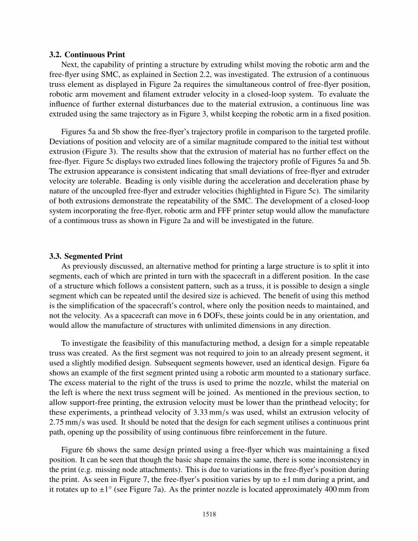
One of the advantages of our proposed manufacturing method is the capability to manufacturestructures with unlimited dimensions in any direction. To illustrate this, an ’L’-shaped truss sectionwas designed and printed, and an additional linear truss segment joined to it (see Figure 9). It can beseen that this could be further extended in both the 𝑥- and 𝑦-dimensions by adding more segments.
1521
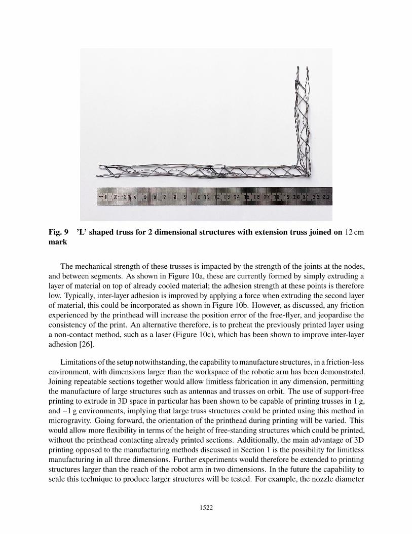
Fig. 9 ’L’ shaped truss for 2 dimensional structures with extension truss joined on 12 cmmark
The mechanical strength of these trusses is impacted by the strength of the joints at the nodes,and between segments. As shown in Figure 10a, these are currently formed by simply extruding alayer of material on top of already cooled material; the adhesion strength at these points is thereforelow. Typically, inter-layer adhesion is improved by applying a force when extruding the second layerof material, this could be incorporated as shown in Figure 10b. However, as discussed, any frictionexperienced by the printhead will increase the position error of the free-flyer, and jeopardise theconsistency of the print. An alternative therefore, is to preheat the previously printed layer usinga non-contact method, such as a laser (Figure 10c), which has been shown to improve inter-layeradhesion [26].
Limitations of the setup notwithstanding, the capability to manufacture structures, in a friction-lessenvironment, with dimensions larger than the workspace of the robotic arm has been demonstrated.Joining repeatable sections together would allow limitless fabrication in any dimension, permittingthe manufacture of large structures such as antennas and trusses on orbit. The use of support-freeprinting to extrude in 3D space in particular has been shown to be capable of printing trusses in 1 g,and −1 g environments, implying that large truss structures could be printed using this method inmicrogravity. Going forward, the orientation of the printhead during printing will be varied. Thiswould allow more flexibility in terms of the height of free-standing structures which could be printed,without the printhead contacting already printed sections. Additionally, the main advantage of 3Dprinting opposed to the manufacturing methods discussed in Section 1 is the possibility for limitlessmanufacturing in all three dimensions. Further experiments would therefore be extended to printingstructures larger than the reach of the robot arm in two dimensions. In the future the capability toscale this technique to produce larger structures will be tested. For example, the nozzle diameter
1522

(a) (b)
(c)
Fig. 10 Comparison of techniques for bonding material at nodes. (a) Shows the methodcurrently used, where material is joined by extruding the top layer on top of the previous layer.(b) Shows how material can be joined by applying a force when extruding the top layer. (c)Shows how material can be joined by preheating the already extruded layer
could be further increased if a method can be found to cool the filament sufficiently quickly, thiswould allow the production of stiffer structures, and minimise the impact of sub-millimeter positionerrors. Finally, the trusses printed did not have their mechanical strength tested; future experimentswill investigate this, as well as the use of other materials, and methods such as continuous fibrereinforcement to improve the mechanical properties of the printed structures. The impact of the jointsbetween segments on the mechanical properties on the larger structure will also be investigated.
4. Conclusion
In this paper, two methods for manufacturing large structures were explored using a roboticfree-flyer on an air bearing table: extruding whilst the free-flyer was moving; and splitting thelarge structure into segments which could be printed in turn. It was found that the continuousprinting method was capable of producing consistent results for a single line of material. Using thesegmented printing approach, it was possible to print a truss structure with a length over 700 mm.The dependency of the support-free printing method on the direction of the gravity vector wasexplored, and it was found through visual inspection that printing in −1 g produced no discernibledifferences with printing in 1 g. As such, it is posited that the method can be used independent ofthe gravity direction, and therefore also in microgravity. We have thus demonstrated the feasibilityof a small spacecraft to manufacture support-free structures larger than itself using a robotic armwith 3D printhead end effector. Using such a spacecraft would allow support-free 3D printingof structures with unlimited dimensions, and offers more flexibility than the truss manufacturingmachines proposed by others.
1523

References
[1] Gerard K. O’Neill. The colonisation of space. In Space Manufacturing Facilities, Reston,Virigina, 1975. American Institute of Aeronautics and Astronautics.
[2] Jason J. Dunn, David N. Hutchison, Aaron M. Kemmer, Adam Z. Ellsworth, Michael Snyder,William B. White, and Brad R. Blair. 3D printing in space: enabling new markets andaccelerating the growth of orbital infrastructure. 2010.
[3] Matthew Moraguez and Olivier de Weck. Benefits of in-space manufacturing technologydevelopment for human spaceflight. In 2020 IEEE Aerospace Conference, pages 1–11,Piscataway, NJ, 2020. IEEE.
[4] John Nella, Paul D. Atcheson, Charles B. Atkinson, Doug Au, Allen J. Bronowicki, Ed Bujanda,Andy Cohen, Don Davies, Paul A. Lightsey, Richard Lynch, Ray Lundquist, Michael T. Menzel,Martin Mohan, John Pohner, Paul Reynolds, Henry Rivera, Scott C. Texter, David V. Shuckstes,Debra D. Fitzgerald Simmons, Robert C. Smith, Pamela C. Sullivan, Dean D. Waldie, andRob Woods. James webb space telescope (JWST) observatory architecture and performance.In John C. Mather, editor, Optical, Infrared, and Millimeter Space Telescopes, volume 5487,pages 576 – 587. International Society for Optics and Photonics, SPIE, 2004.
[5] Matthew A. Greenhouse. The JWST science instrument payload: mission context and status.In Space Telescopes and Instrumentation 2016: Optical, Infrared, and Millimeter Wave, SPIEProceedings, page 990406. SPIE, 2016.
[6] Mak Tafazoli. A study of on-orbit spacecraft failures. Acta Astronautica, 64(2-3):195–205,2009.
[7] Enea Sacco and Seung Ki Moon. Additive manufacturing for space: status and promises. TheInternational Journal of Advanced Manufacturing Technology, 105(10):4123–4146, 2019.
[8] John G. Bodle. Development of a beam builder for automatic fabrication of large compositespace structures. Technical report, General Dynamics Convair Division, 1979.
[9] Robert Hoyt, Jesse Cushing, and Jeffrey Slostad. Spiderfab™: Process for on-orbit constructionof kilometer-scale apertures. Technical report, Tethers Unlimited, Inc., 2013.
[10] Robert Hoyt, Jesse Cushing, Gerg Jimmerson, Jeffrey Slostad, Robert Dyer, and Steve Alvarado.Spiderfab™: Process for on-orbit construction of kilometer-scale apertures. Technical report,Tethers Unlimited Inc., 2016.
[11] Justin Kugler, Juliana Cherston, Eric R. Joyce, Paul Shestople, and Michael P. Snyder.Applications for the archinaut in space manufacturing and assembly capability. In AIAASPACE and Astronautics Forum and Exposition, Orlando, Florida, 2017. American Institute ofAeronautics and Astronautics.
[12] Simon Patane, Eric R. Joyce, Michael P. Snyder, and Paul Shestople. Archinaut: In-space manufacturing and assembly for next-generation space habitats. In AIAA SPACE andAstronautics Forum and Exposition, Orlando, Florida, 2017. American Institute of Aeronauticsand Astronautics.
1524

[13] Derek Thomas, Michael P. Snyder, Matthew Napoli, Eric R. Joyce, Paul Shestople, and ToddLetcher. Effect of acrylonitrile butadiene styrene melt extrusion additive manufacturing onmechanical performance in reduced gravity. In AIAA SPACE and Astronautics Forum andExposition, Orlando, Florida, 2017. American Institute of Aeronautics and Astronautics.
[14] Mary J. Werkheiser, Jason Dunn, Michael P. Snyder, Jennifer Edmunson, Kennethe Cooper,and Mallory M. Johnston. 3D printing in zero-g ISS technology demonstration. In AIAA SPACE2014 Conference and Exposition, San Diego, CA, 2014. American Institute of Aeronauticsand Astronautics.
[15] Stefanie Mueller, Sangha Im, Serafima Gurevich, Alexander Teibrich, Lisa Pfisterer, FrançoisGuimbretière, and Patrick Baudisch. Wireprint. In Hrvoje Benko, Mira Dontcheva, and DanielWigdor, editors, Proceedings of the 27th annual ACM symposium on User interface softwareand technology, pages 273–280, New York, NY, USA, 2014. ACM.
[16] Peng Zhao, Chengchen Rao, Fu Gu, Nusrat Sharmin, and Jianzhong Fu. Close-looped recyclingof polylactic acid used in 3D printing: An experimental investigation and life cycle assessment.Journal of Cleaner Production, 197:1046–1055, 2018.
[17] C. Trentlage, J. Yang, M.K. Ben Larbi, C.A. de Alba Padilla, and E. Stoll. The ELISSAlaboratory: Free-floating satellites for space-related research. In Deutscher Luft- und Raum-fahrtkongress, Aug 2018.
[18] Tomasz Rybus and Karol Seweryn. Planar air-bearing microgravity simulators: Review ofapplications, existing solutions and design parameters. Acta Astronautica, 120:239–259, 2016.
[19] Markus Wilde, Casey Clark, and Marcello Romano. Historical survey of kinematic anddynamic spacecraft simulators for laboratory experimentation of on-orbit proximity maneuvers.Progress in Aerospace Sciences, 110:100552, 2019.
[20] Morgan Quigley, Ken Conley, Brian Gerkey, Josh Faust, Tully Foote, Jeremy Leibs, RobWheeler, Andrew Y Ng, et al. Ros: an open-source robot operating system. In ICRA workshopon open source software, volume 3, page 5. Kobe, Japan, 2009.
[21] Mohammad S. Alsoufi, Mohammed W. Alhazmi, Dhia K. Suker, Turki A. Alghamdi, Rayan A.Sabbagh, Mohammed A. Felemban, and Feras K. Bazuhair. Experimental characterizationof the influence of nozzle temperature in FDM 3D printed pure PLA and advanced PLA+.American Journal of Mechanical Engineering, 7(2):45–60, 2019.
[22] Robert Crocket, Dan Peterson, and Ken Cooper. Fused deposition modelling in microgravity.In 1999 Solid Freeform Fabrication Symposium Proceedings, pages 671–678, Austin, Texas,1999. University of Texas at Austin.
[23] Michael Snyder, Jason Dunn, and Eddie Gonzalez. The effects of microgravity on extrusionbased additive manufacturing. In AIAA SPACE 2013 Conference and Exposition, Reston,Virginia, 2013. American Institute of Aeronautics and Astronautics.
1525
[24] Juntang Yang and Enrico Stoll. Adaptive sliding mode control for spacecraft proxim-ity operations based on dual quaternions. Journal of Guidance, Control, and Dynamics,42(11):2356–2368, 2019.
[25] D. Ivanov, M. Koptev, Y. Mashtakov, M. Ovchinnikov, N. Proshunin, S. Tkachev, A. Fedoseev,and M. Shachkov. Determination of disturbances acting on small satellite mock-up on airbearing table. Acta Astronautica, 142:265–276, 2018.
[26] Pu Han, Alireza Tofangchi, Sihan Zhang, Anagh Desphande, and Keng Hsu. Effect of in-process laser interface heating on strength isotropy of extrusion-based additively manufacturedPEEK. Procedia Manufacturing, 48:737–742, 2020.
1526